Catalog 3WA Air Circuit Breakers EN 2021 04 - Digital Asset ...
76
Catalog Edition 10/2020 www.siemens.com/3WA SENTRON 3WA Air Circuit Breakers © Siemens 2020
-
Upload
khangminh22 -
Category
Documents
-
view
0 -
download
0
Transcript of Catalog 3WA Air Circuit Breakers EN 2021 04 - Digital Asset ...

CatalogEdition 10/2020 www.siemens.com/3WA
SENTRON
3WA Air Circuit Breakers
© Siemens 2020
We are there when you need usYour personal contact can be found at www.siemens.com/lowvoltage/contact
Catalog · 10/2020You will find the latest edition and all future editions in the Siemens Industry Online Support at www.siemens.com/lowvoltage/catalogs
Refer to the Industry Mall for current prices www.siemens.com/industrymall
The products and systems listed in this catalog are developed and manufactured using a certified quality management system in accordance with EN ISO 9001:2008.
Technical data The technical specifications are for general information purposes only. Always heed the operating instructions and notices on individual products during assembly, operation and maintenance.
All illustrations are not binding.
© Siemens 2020
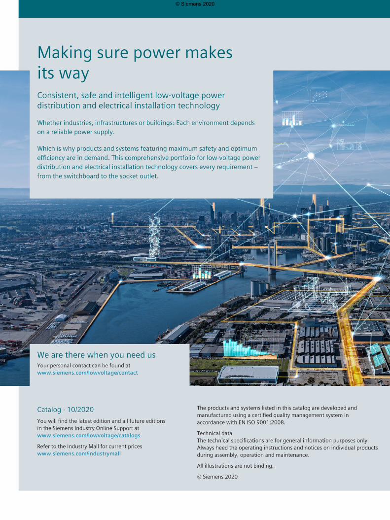
Making sure power makes its wayConsistent, safe and intelligent low-voltage power distribution and electrical installation technology
Whether industries, infrastructures or buildings: Each environment depends on a reliable power supply.
Which is why products and systems featuring maximum safety and optimum efficiency are in demand. This comprehensive portfolio for low-voltage power distribution and electrical installation technology covers every requirement – from the switchboard to the socket outlet.
© Siemens 2020
SENTRON
Introduction I/2
Air Circuit Breakers 1/1
Appendix A/1
Protecting
3WA Air Circuit Breakers
I
1
A
© Siemens 2020
I/2 Siemens · 10/2020 Delivery Q1 2021 (CY)
Introduction | The fast route to the product
I
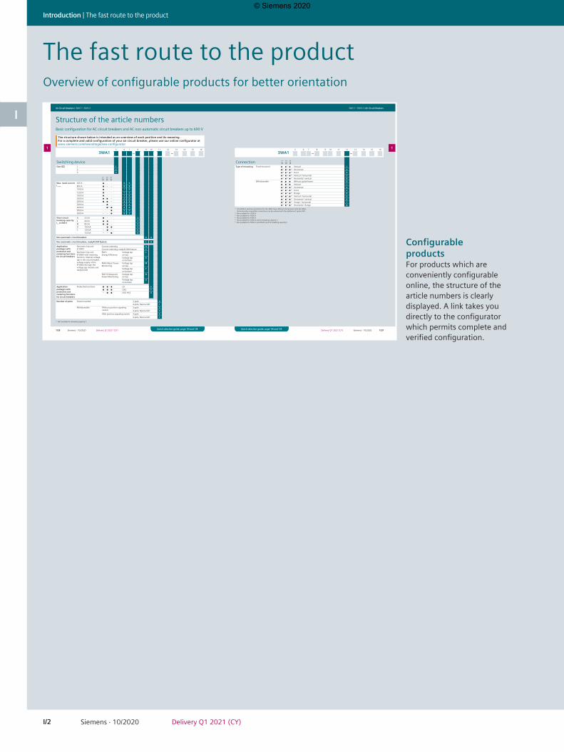
The fast route to the productOverview of configurable products for better orientation
1/28 1/29Siemens · 10/2020 Siemens · 10/2020Delivery Q1 2021 (CY)Delivery Q1 2021 (CY)
Air Circuit Breakers | 3WA11 – 3WA13 3WA11 – 3WA13 | Air Circuit Breakers
11
Quick selection guide, page 1/4 and 1/8 Quick selection guide, page 1/4 and 1/8Quick selection guide, page 1/4 and 1/8 Quick selection guide, page 1/4 and 1/8
Structure of the article numbersBasic configuration for AC circuit breakers and AC non-automatic circuit breakers up to 690 V
5 6 7 8 9 10 11 12 13 14 15 16
3WA1 – –
Switching deviceSize (SZ) 1 1
2 23 3
SZ 1
SZ 2
SZ 3
Max. rated current In max
630 A ■ – – 0 6800 A ■ – – 0 81000 A ■ – – 1 01250 A ■ – – 1 21600 A ■ – – 1 62000 A ■ ■ – 2 02500 A ■ ■ – 2 53200 A – ■ – 3 24000 A – ■1) ■ 4 05000 A – – ■ 5 06300 A – – ■ 6 3
Short-circuit breaking capacity Icu at 500 V
N 55 kA ■ – – 2S 66 kA ■ ■ – 3M 85 kA ■ ■ – 4H 100 kA – ■ ■ 5C 130 kA – ■ – 6
150 kA – – ■ 6
Non-automatic circuit breakers A A
Non-automatic circuit breakers, ready4COM feature C A
Application packages with protective and metering functions for circuit breakers
Electronic trip unit ETU600
Current metering ACurrent metering, ready4COM feature C
Electronic trip unit ETU600 with metering function, internal voltage tap in the circuit breaker, voltage supply of the ETU600 through the voltage tap module and ready4COM
PMF-I Energy Efficiency
Voltage tap on top
L
Voltage tap on bottom
E
PMF-II Basic Power Monitoring
Voltage tap on top
M
Voltage tap on bottom
F
PMF-III Advanced Power Monitoring
Voltage tap on top
N
Voltage tap on bottom
G
Application packages with protective and metering functions for circuit breakers
Protective functions ■ ■ ■ LSI E■ ■ ■ LSIG F– ■ ■ LSIG Hi-Z G
Number of poles Fixed-mounted 3-pole 04-pole, Neutral left 1
Withdrawable Without position signaling switch
3-pole 34-pole, Neutral left 4
With position signaling switch 3-pole 64-pole, Neutral left 7
The structure shown below is intended as an overview of each position and its meaning. For a complete and valid configuration of your air circuit breaker, please use our online configurator at www.siemens.com/lowvoltage/3wa-configurator
1) Not available for breaking capacity C
1) The 4000 A vertical connections for the 3WA1 have different dimensions from the 3WL1. Dimensionally compatible connections can be ordered with the additional Z option D01.2) Not available for 2500 A3) Not available for 4000 A4) Not available for 6300 A5) Not available for 4000 A and for breaking capacity C6) Not available for 5000 A and 6300 A and for breaking capacity C
5 6 7 8 9 10 11 12 13 14 15 16
3WA1 – –
Connection SZ 1
SZ 2
SZ 3
Type of mounting Fixed-mounted ◾ ◾ 1) ◾ Vertical 1◾ 2) ◾ 3) ◾ 4) Horizontal 2◾ 2) ◾ 5) ◾ 6) Front 3◾ 2) ◾ 3) ◾ 4) Vertical / horizontal 5◾ 2) ◾ 3) ◾ 4) Horizontal / vertical 6
Withdrawable ◾ ◾ ◾ Without guide frame 0◾ ◾ 1) ◾ Vertical 1◾ 2) ◾ 3) ◾ 4) Horizontal 2◾ 2) ◾ 5) ◾ 6) Front 3◾ 2) ◾ 5) ◾ 6) Flange 4◾ 2) ◾ 3) ◾ 4) Vertical / horizontal 5◾ 2) ◾ 3) ◾ 4) Horizontal / vertical 6◾ 2) ◾ 5) ◾ 6) Flange / horizontal 7◾ 2) ◾ 5) ◾ 6) Horizontal / flange 8
ConfigurableproductsFor products which are conveniently configurable online, the structure of the article numbers is clearly displayed. A link takes you directly to the configurator which permits complete and verified configuration.
© Siemens 2020
I/3Siemens · 10/2020Delivery Q1 2021 (CY)
The fast route to the product | Introduction
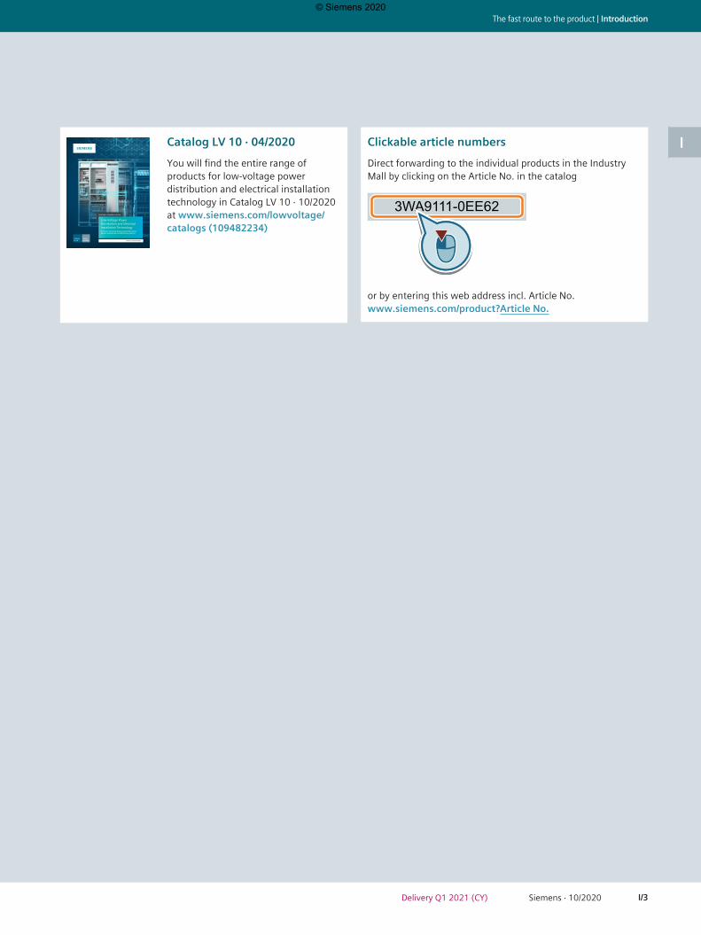
IClickable article numbers
Direct forwarding to the individual products in the Industry Mall by clicking on the Article No. in the catalog
3WA9111-0EE62
or by entering this web address incl. Article No. www.siemens.com/product?Article No.
Catalog LV 10
Edition 04/2020 siemens.com/lowvoltage
SENTRON • SIVACON • ALPHA
Low-Voltage Power Distribution and Electrical Installation TechnologyProtection, Switching, Measuring and Monitoring Devices, Switchboards and Distribution Systems
Catalog LV 10 · 04/2020
You will find the entire range of products for low-voltage power distribution and electrical installation technology in Catalog LV 10 · 10/2020 at www.siemens.com/lowvoltage/catalogs (109482234)
© Siemens 2020

I/4 Siemens · 10/2020 Delivery Q1 2021 (CY)
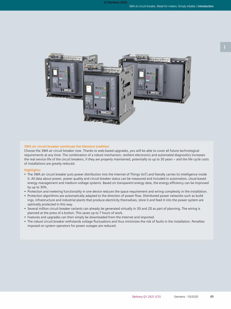
Introduction | 3WA air circuit breaker. Made for makers. Simply reliable.
I
3WA air circuit breaker. Made for makers. Simply reliable.
In an age of climate change, cost pressure and digitalization, the new 3WA air circuit breaker makes the electrical infrastructure more reliable, efficient and intelligent – for the benefit of everyone who plans, implements or uses it.
Whether a solid, traditional system is required or a communication-capable installation connected to the cloud, the air circuit breaker provides an individual solution for every case. It is a tried and tested quality product that provides reliable protection as a central component of the switchboard. It meets the highest standards in applications and for usability. It is a complete system consisting of integrated low-voltage components of the SENTRON portfolio to achieve perfect interaction in the switchboard.
The 3WA air circuit breaker is therefore the heart of future-proof, high-performance and long-life power distribution.
The 3WA air circuit breaker continues the globally acknowledged tradition at Siemens for circuit breakers with a high standard of quality and reliability. As the next evolutionary step, decisive aspects of its mechanical and electronic design have been improved. This adds new, sophisticated features that meet current market trends and set new standards.
© Siemens 2020
I/5Siemens · 10/2020Delivery Q1 2021 (CY)
3WA air circuit breaker. Made for makers. Simply reliable. | Introduction
I
3WA air circuit breaker continues the Siemens traditionChoose the 3WA air circuit breaker now. Thanks to web-based upgrades, you will be able to cover all future technological requirements at any time. The combination of a robust mechanism, resilient electronics and automated diagnostics increases the real service life of the circuit breakers, if they are properly maintained, potentially to up to 30 years – and the life cycle costs of installations are greatly reduced.
Highlights:• The 3WA air circuit breaker puts power distribution into the Internet of Things (IoT) and literally carries its intelligence inside
it. All data about power, power quality and circuit breaker status can be measured and included in automation, cloud-based energy management and medium-voltage systems. Based on transparent energy data, the energy efficiency can be improved by up to 30%.
• Protection and metering functionality in one device reduces the space requirement and wiring complexity in the installation.• Protection algorithms are automatically adapted to the direction of power flow. Distributed power networks such as build-
ings, infrastructure and industrial plants that produce electricity themselves, store it and feed it into the power system are optimally protected in this way.
• Several million circuit breaker variants can already be generated virtually in 3D and 2D as part of planning. The wiring is planned at the press of a button. This saves up to 7 hours of work.
• Features and upgrades can then simply be downloaded from the Internet and imported.• The robust circuit breaker withstands voltage fluctuations and thus minimizes the risk of faults in the installation. Penalties
imposed on system operators for power outages are reduced.
© Siemens 2020

I/6 Siemens · 10/2020 Delivery Q1 2021 (CY)
Introduction | 3WA air circuit breaker. Made for makers. Simply reliable.
I Trust the tried-and-tested.Equipped with the rock-solid 3WA air circuit breaker, you can deliver the reliable protec-tion that is generally expected in power distribution.
• Integrated, clearly structured portfolio that covers all requirements and makes the circuit breakers versatile.• Extensive, modular accessories that make functional expansions easy.• Proof of breaking capacity with voltage tolerance +10%. (The circuit breaker standard IEC 60947-2 only requires +5%.)• Long service life with low maintenance – for long-lasting reliability.• Additional test functionality of the electronic trip unit (ETU) for continuous self-monitoring, simple full-range verification of the
trip characteristic curves via USB and automatic creation of test reports for documentation purposes.
Benefit from efficiency.Equipped with the sophisticated 3WA air circuit breaker, you can efficiently meet the highest demands.
• Enhanced protective functions and high selectivity that ensure high availability of the installation.• Robust mechanics and unbeatable product quality that proves its value even in challenging applications. Highest load capability
of the circuit breaker on disconnecting prolonged short-time currents ICW with a duration of up to 3 s. Top performance for operating voltages up to 1150 V AC and ambient temperatures of –40 … +70 °C.
• Replacement as part of installation planning is simple: The 3WL air circuit breaker can be replaced by the 3WA air circuit breaker according to IEC 61439 without any additional testing if it is operated subject to the same technical requirements.
• Simple, easy, time-saving and cost-saving replacement of 3WL air circuit breakers with the 3WA air circuit breaker in the switchboard.
3WA air circuit breaker. Made for makers. Simply reliable.
© Siemens 2020

I/7Siemens · 10/2020Delivery Q1 2021 (CY)
3WA air circuit breaker. Made for makers. Simply reliable. | Introduction
ICreate solutions with potential.Equipped with the pioneering 3WA air circuit breaker, you can easily implement digitalization and automation.
• Individually selectable and subsequently upgradable functionality that provides long-term flexibility. The electronic trip unit ETU600 can be simply upgraded over its entire product life cycle with digital function packages.
• Powerful communication options that transfer data securely. The main focus here is on cyber security. Simultaneous use of two communication protocols in one communication module with switched Ethernet functionality (PROFINET for demanding industrial communication and Modbus TCP for e.g. power monitoring).
• Simple integration into energy management systems in accordance with ISO 50001.• Selection of the metering functionality according to the energy efficiency standard IEC 60364-8-1.
Enjoy seamless consistency.Equipped with the 3WA air circuit breaker and the SENTRON portfolio, you can create synergies for your switchgear panels.
• Seamless communication between all low-voltage components enables use of standardized tools and consistency in the data.• The extensive tool landscape and provision of all necessary engineering data simplifies selection, planning, ordering, configura-
tion and commissioning.• Less work thanks to data-based engineering.• Simple and quick planning with SIMARIS software tools, e.g. for verifying the selectivity of the entire power distribution.
© Siemens 2020

Air circuit breakers
Made for makers. Simply reliable.
All power distribution systems rely on a secure infeed of electrical energy. The 3WA air circuit breaker combines all of the functions which are required of power distribution equipment in the digital companies of today: from reliably protecting people and equipment from electrical accidents and damage, to flexible application and retrofit options, a long service life and low maintenance, to innovative features for integrated e-engineering, reliable energy data recording and seamless integration into digital environments.
As the central component of the electrical power distribution, the 3WA air circuit breaker provides the basis for a holistic energy system in the digital age.
© Siemens 2020

1/1Siemens · 10/2020Delivery Q1 2021 (CY)
Air circuit breakers
1
3WA Air Circuit Breakers
All the information you need 1/2
Quick selection guide 1/4
Switching devices for AC and DC 1/4
Switching devices for AC 1/8
Switching devices for DC 1/14
Electronic trip unit ETU600 1/17
Connection 1/22
Communication 1/23
3WA11 – 3WA13 1/24
System overview 1/24
Online configurator highlights 1/26
Structure of the article numbers 1/28
Accessory options 1/38
Guide frames for AC 1/41
Guide frames for DC 1/43
Accessories and spare parts 1/44
Delivery Q1 2021 (CY)
© Siemens 2020
1/2 Siemens · 10/2020 Delivery Q1 2021 (CY)
Air Circuit Breakers | All the information you need
1
A multitude of additional information ... ... can be found in our online services
Information + ordering
All the important things at a glance
Information to get you startedFor information about 3WA air circuit breakers, please visit our website www.siemens.com/3WA
Contact persons in your region
We are there when you need usYou can find your local contacts at www.siemens.com/lowvoltage/contact
Your product in detail
The Siemens Industry Online Support portal provides comprehensive information www.siemens.com/lowvoltage/product-support
• Quick selection guide – 3WA air circuit breakers (109781967)
• Brochure – 3WA air circuit breakers (109781968) The relevant tender specifications can be found at www.siemens.com/lowvoltage/tenderspecificationsUse our conversion tool for quick and easy conversion to Siemens products www.siemens.com/conversion-tool
Our video range
Siemens YouTube channel• Power Distribution Low Voltage (EN) bit.ly/3iiuhXS
Everything you need for your order
Refer to the Industry Mall for an overview of your products
• 3WA air circuit breakers sie.ag/3heeyYv Direct forwarding to the individual products in the Industry Mall by clicking on the Article No. in the catalog or by entering this web address incl. Article No. www.siemens.com/product?Article No.
Configurators
Exactly the right circuit breaker for your applicationThe configurator reduces the time and effort required in the planning and ordering process, and allows for individ-ual adaptations. Configure your 3WL air circuit breaker at www.siemens.com/lowvoltage/3wa-configuratorFor your configured 3WL air circuit breaker, you can additionally find
• 3D views• CAD data• Unit wiring diagrams• Dimension drawings
© Siemens 2020

1/3Siemens · 10/2020Delivery Q1 2021 (CY)
All the information you need | Air Circuit Breakers
A multitude of additional information ... ... can be found in our online services
Commissioning + operation
The fast way to get you to our online servicesThis page provides you with comprehensive information and links on air circuit breakerswww.siemens.com/lowvoltage/produkt-support (109781188)
Technical overview – Air circuit breakers
Configuration software
SENTRON powerconfigThe combined commissioning and service tool for communication-capable measuring devices and circuit breakers from the SENTRON portfolio. www.siemens.com/powerconfigFree download SENTRON powerconfig mobile via: App Store and Play Store
Your product in detail
The Siemens Industry Online Support portal provides detailed technical information www.siemens.com/lowvoltage/product-support
• Operating instructions• Characteristic curves• Certificates Engineering data for CAD or CAE systems are available in the CAx Download Manager at www.siemens.com/lowvoltage/cax
Training and tutorials
Our training courses can be found at www.siemens.com/sitrain-lowvoltage
Manuals
Manuals are available for downloading in Siemens Industry Online Support at www.siemens.com/lowvoltage/manuals
• Equipment manual – 3WA air circuit breakers (109763061)
The fast track to the experts
Competent expert advice on technical questions with a wide range of demand-optimized services for all our products and systems.Assistance with technical queries is provided at www.siemens.com/lowvoltage/support-requestWe offer a comprehensive portfolio of services. You can find your local contacts at www.siemens.com/lowvoltage/contactYou can find further information on services at www.siemens.com/service-catalog
© Siemens 2020
1/4 Siemens · 10/2020 Delivery Q1 2021 (CY)
Air Circuit Breakers | Quick selection guide
1
System overview, page 1/24
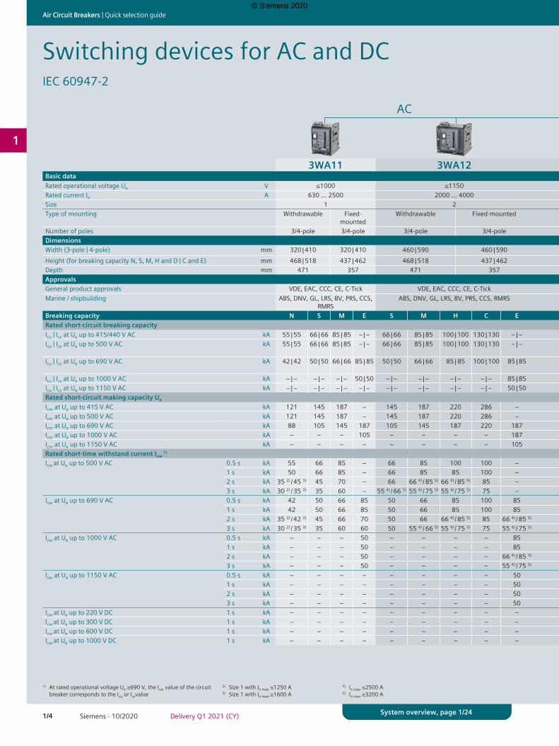
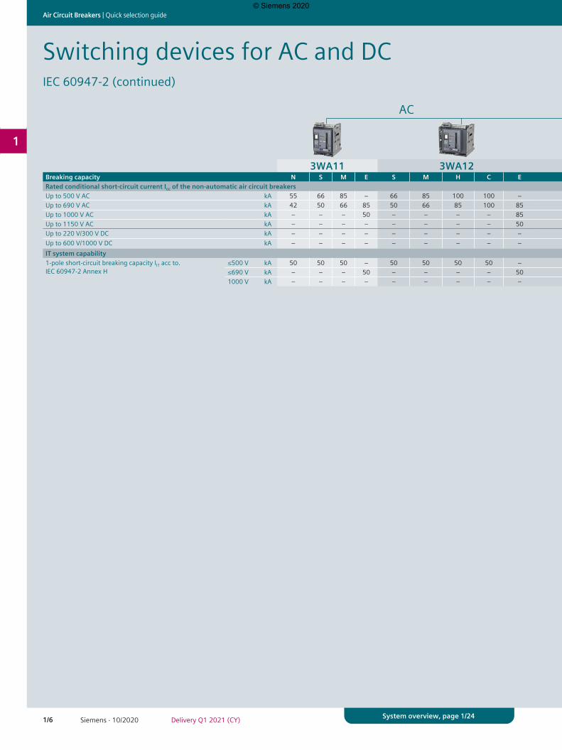
Switching devices for AC and DCIEC 60947-2
AC AC DC
3WA11 3WA12 3WA13 3WA12Basic dataRated operational voltage Ue V ≤1000 ≤1150 ≤1150 ≤600 / 1000Rated current In A 630 … 2500 2000 … 4000 4000 … 6300 1000 … 4000Size 1 2 3 2Type of mounting Withdrawable Fixed-
mountedWithdrawable Fixed-mounted Withdrawable Fixed-mounted Withdrawable Fixed-mounted
Number of poles 3/4-pole 3/4-pole 3/4-pole 3/4-pole 3/4-pole 3/4-pole 3/4-pole 3/4-poleDimensionsWidth (3-pole | 4-pole) mm 320 | 410 320 | 410 460 | 590 460 | 590 704 | 914 704 | 914 460 | 590 460 | 590Height (for breaking capacity N, S, M, H and D | C and E) mm 468 | 518 437 | 462 468 | 518 437 | 462 468 | 518 437 | 462 468 | 518 437 | 462Depth mm 471 357 471 357 471 357 471 357ApprovalsGeneral product approvals VDE, EAC, CCC, CE, C-Tick VDE, EAC, CCC, CE, C-Tick VDE, EAC, CCC, CE, C-Tick VDE, EAC, CCC, CE, C-TickMarine / shipbuilding ABS, DNV, GL, LRS, BV, PRS, CCS,
RMRSABS, DNV, GL, LRS, BV, PRS, CCS, RMRS ABS, DNV, GL, LRS, BV, PRS, CCS, RMRS ABS, DNV, GL, LRS, BV, PRS, CCS, RMRS
Breaking capacity N S M E S M H C E H C E D E D ERated short-circuit breaking capacityIcu | Ics at Ue up to 415/440 V AC kA 55 | 55 66 | 66 85 | 85 – | – 66 | 66 85 | 85 100 | 100 130 | 130 – | – – | – – | – – | – – | – – | – – | – – | –Icu | Ics at Ue up to 500 V AC kA 55 | 55 66 | 66 85 | 85 – | – 66 | 66 85 | 85 100 | 100 130 | 130 – | – 100 | 100 150 | 150 (3-pole);
130 | 130 (4-pole)– | – – | – – | – – | – – | –
Icu | Ics at Ue up to 690 V AC kA 42 | 42 50 | 50 66 | 66 85 | 85 50 | 50 66 | 66 85 | 85 100 | 100 85 | 85 85 | 85 150 | 150 (3-pole); 130 | 130 (4-pole)
150 | 150 (3-pole); 130 | 130 (4-pole)
– | – – | – – | – – | –
Icu | Ics at Ue up to 1000 V AC kA – | – – | – – | – 50 | 50 – | – – | – – | – – | – 85 | 85 – | – – | – 125 | 125 – | – – | – – | – – | –Icu | Ics at Ue up to 1150 V AC kA – | – – | – – | – – | – – | – – | – – | – – | – 50 | 50 – | – – | – 70 | 70 – | – – | – – | – – | –Rated short-circuit making capacity Ue
Icm at Ue up to 415 V AC kA 121 145 187 – 145 187 220 286 – 220 330 (3-pole); 286 (4-pole) – – – – –Icm at Ue up to 500 V AC kA 121 145 187 – 145 187 220 286 – 220 330 (3-pole); 286 (4-pole) – – – – –Icm at Ue up to 690 V AC kA 88 105 145 187 105 145 187 220 187 187 330 (3-pole); 286 (4-pole) 330 (3-pole); 286 (4-pole) – – – –Icm at Ue up to 1000 V AC kA – – – 105 – – – – 187 – – 275 – – – –Icm at Ue up to 1150 V AC kA – – – – – – – – 105 – – 154 – – – –Rated short-time withstand current Icw
1)
Icw at Ue up to 500 V AC 0.5 s kA 55 66 85 – 66 85 100 100 – 100 130 (3-pole); 120 (4-pole) 130 (3-pole); 120 (4-pole) – – – –1 s kA 50 66 85 – 66 85 85 100 – 100 130 (3-pole); 120 (4-pole) 130 (3-pole); 120 (4-pole) – – – –2 s kA 35 2) / 45 3) 45 70 – 66 66 4) / 85 5) 66 4) / 85 5) 85 – 100 130 (3-pole); 120 (4-pole) 130 (3-pole); 120 (4-pole) – – – –3 s kA 30 2) / 35 3) 35 60 – 55 4) / 66 5) 55 4) / 75 5) 55 4) / 75 5) 75 – 100 130 (3-pole); 120 (4-pole) 130 (3-pole); 120 (4-pole) – – – –
Icw at Ue up to 690 V AC 0.5 s kA 42 50 66 85 50 66 85 100 85 85 130 (3-pole); 120 (4-pole) 130 (3-pole); 120 (4-pole) – – – –1 s kA 42 50 66 85 50 66 85 100 85 85 130 (3-pole); 120 (4-pole) 130 (3-pole); 120 (4-pole) – – – –2 s kA 35 2) / 42 3) 45 66 70 50 66 66 4) / 85 5) 85 66 4) / 85 5) 85 130 (3-pole); 120 (4-pole) 130 (3-pole); 120 (4-pole) – – – –3 s kA 30 2) / 35 3) 35 60 60 50 55 4) / 66 5) 55 4) / 75 5) 75 55 4) / 75 5) 85 130 (3-pole); 120 (4-pole) 130 (3-pole); 120 (4-pole) – – – –
Icw at Ue up to 1000 V AC 0.5 s kA – – – 50 – – – – 85 – – 125 (3-pole); 120 (4-pole) – – – –1 s kA – – – 50 – – – – 85 – – 125 (3-pole); 120 (4-pole) – – – –2 s kA – – – 50 – – – – 66 4) / 85 5) – – 125 (3-pole); 120 (4-pole) – – – –3 s kA – – – 50 – – – – 55 4) / 75 5) – – 125 (3-pole); 120 (4-pole) – – – –
Icw at Ue up to 1150 V AC 0.5 s kA – – – – – – – – 50 – – 70 | 70 – – – –1 s kA – – – – – – – – 50 – – 70 | 70 – – – –2 s kA – – – – – – – – 50 – – 70 | 70 – – – –3 s kA – – – – – – – – 50 – – 70 | 70 – – – –
Icw at Ue up to 220 V DC 1 s kA – – – – – – – – – – – – 35 – 35 –Icw at Ue up to 300 V DC 1 s kA – – – – – – – – – – – – 30 – 30 –Icw at Ue up to 600 V DC 1 s kA – – – – – – – – – – – – 25 – 25 –Icw at Ue up to 1000 V DC 1 s kA – – – – – – – – – – – – – 20 – 20
1) At rated operational voltage Ue ≥690 V, the Icw value of the circuit breaker corresponds to the Icu or Icsvalue
2) Size 1 with In max ≤1250 A3) Size 1 with In max ≥1600 A
4) In max ≤2500 A5) In max ≥3200 A
© Siemens 2020
1/5Siemens · 10/2020Delivery Q1 2021 (CY)
Quick selection guide | Air Circuit Breakers
1
System overview, page 1/24
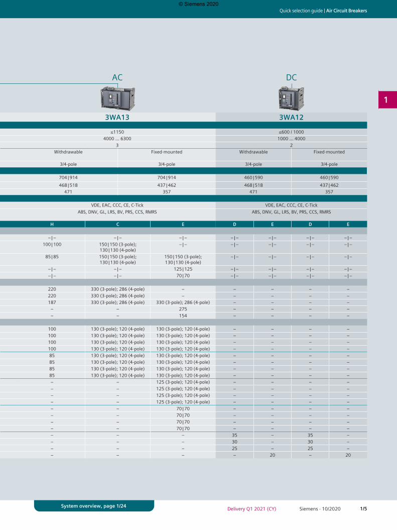
AC AC DC
3WA11 3WA12 3WA13 3WA12Basic dataRated operational voltage Ue V ≤1000 ≤1150 ≤1150 ≤600 / 1000Rated current In A 630 … 2500 2000 … 4000 4000 … 6300 1000 … 4000Size 1 2 3 2Type of mounting Withdrawable Fixed-
mountedWithdrawable Fixed-mounted Withdrawable Fixed-mounted Withdrawable Fixed-mounted
Number of poles 3/4-pole 3/4-pole 3/4-pole 3/4-pole 3/4-pole 3/4-pole 3/4-pole 3/4-poleDimensionsWidth (3-pole | 4-pole) mm 320 | 410 320 | 410 460 | 590 460 | 590 704 | 914 704 | 914 460 | 590 460 | 590Height (for breaking capacity N, S, M, H and D | C and E) mm 468 | 518 437 | 462 468 | 518 437 | 462 468 | 518 437 | 462 468 | 518 437 | 462Depth mm 471 357 471 357 471 357 471 357ApprovalsGeneral product approvals VDE, EAC, CCC, CE, C-Tick VDE, EAC, CCC, CE, C-Tick VDE, EAC, CCC, CE, C-Tick VDE, EAC, CCC, CE, C-TickMarine / shipbuilding ABS, DNV, GL, LRS, BV, PRS, CCS,
RMRSABS, DNV, GL, LRS, BV, PRS, CCS, RMRS ABS, DNV, GL, LRS, BV, PRS, CCS, RMRS ABS, DNV, GL, LRS, BV, PRS, CCS, RMRS
Breaking capacity N S M E S M H C E H C E D E D ERated short-circuit breaking capacityIcu | Ics at Ue up to 415/440 V AC kA 55 | 55 66 | 66 85 | 85 – | – 66 | 66 85 | 85 100 | 100 130 | 130 – | – – | – – | – – | – – | – – | – – | – – | –Icu | Ics at Ue up to 500 V AC kA 55 | 55 66 | 66 85 | 85 – | – 66 | 66 85 | 85 100 | 100 130 | 130 – | – 100 | 100 150 | 150 (3-pole);
130 | 130 (4-pole)– | – – | – – | – – | – – | –
Icu | Ics at Ue up to 690 V AC kA 42 | 42 50 | 50 66 | 66 85 | 85 50 | 50 66 | 66 85 | 85 100 | 100 85 | 85 85 | 85 150 | 150 (3-pole); 130 | 130 (4-pole)
150 | 150 (3-pole); 130 | 130 (4-pole)
– | – – | – – | – – | –
Icu | Ics at Ue up to 1000 V AC kA – | – – | – – | – 50 | 50 – | – – | – – | – – | – 85 | 85 – | – – | – 125 | 125 – | – – | – – | – – | –Icu | Ics at Ue up to 1150 V AC kA – | – – | – – | – – | – – | – – | – – | – – | – 50 | 50 – | – – | – 70 | 70 – | – – | – – | – – | –Rated short-circuit making capacity Ue
Icm at Ue up to 415 V AC kA 121 145 187 – 145 187 220 286 – 220 330 (3-pole); 286 (4-pole) – – – – –Icm at Ue up to 500 V AC kA 121 145 187 – 145 187 220 286 – 220 330 (3-pole); 286 (4-pole) – – – – –Icm at Ue up to 690 V AC kA 88 105 145 187 105 145 187 220 187 187 330 (3-pole); 286 (4-pole) 330 (3-pole); 286 (4-pole) – – – –Icm at Ue up to 1000 V AC kA – – – 105 – – – – 187 – – 275 – – – –Icm at Ue up to 1150 V AC kA – – – – – – – – 105 – – 154 – – – –Rated short-time withstand current Icw
1)
Icw at Ue up to 500 V AC 0.5 s kA 55 66 85 – 66 85 100 100 – 100 130 (3-pole); 120 (4-pole) 130 (3-pole); 120 (4-pole) – – – –1 s kA 50 66 85 – 66 85 85 100 – 100 130 (3-pole); 120 (4-pole) 130 (3-pole); 120 (4-pole) – – – –2 s kA 35 2) / 45 3) 45 70 – 66 66 4) / 85 5) 66 4) / 85 5) 85 – 100 130 (3-pole); 120 (4-pole) 130 (3-pole); 120 (4-pole) – – – –3 s kA 30 2) / 35 3) 35 60 – 55 4) / 66 5) 55 4) / 75 5) 55 4) / 75 5) 75 – 100 130 (3-pole); 120 (4-pole) 130 (3-pole); 120 (4-pole) – – – –
Icw at Ue up to 690 V AC 0.5 s kA 42 50 66 85 50 66 85 100 85 85 130 (3-pole); 120 (4-pole) 130 (3-pole); 120 (4-pole) – – – –1 s kA 42 50 66 85 50 66 85 100 85 85 130 (3-pole); 120 (4-pole) 130 (3-pole); 120 (4-pole) – – – –2 s kA 35 2) / 42 3) 45 66 70 50 66 66 4) / 85 5) 85 66 4) / 85 5) 85 130 (3-pole); 120 (4-pole) 130 (3-pole); 120 (4-pole) – – – –3 s kA 30 2) / 35 3) 35 60 60 50 55 4) / 66 5) 55 4) / 75 5) 75 55 4) / 75 5) 85 130 (3-pole); 120 (4-pole) 130 (3-pole); 120 (4-pole) – – – –
Icw at Ue up to 1000 V AC 0.5 s kA – – – 50 – – – – 85 – – 125 (3-pole); 120 (4-pole) – – – –1 s kA – – – 50 – – – – 85 – – 125 (3-pole); 120 (4-pole) – – – –2 s kA – – – 50 – – – – 66 4) / 85 5) – – 125 (3-pole); 120 (4-pole) – – – –3 s kA – – – 50 – – – – 55 4) / 75 5) – – 125 (3-pole); 120 (4-pole) – – – –
Icw at Ue up to 1150 V AC 0.5 s kA – – – – – – – – 50 – – 70 | 70 – – – –1 s kA – – – – – – – – 50 – – 70 | 70 – – – –2 s kA – – – – – – – – 50 – – 70 | 70 – – – –3 s kA – – – – – – – – 50 – – 70 | 70 – – – –
Icw at Ue up to 220 V DC 1 s kA – – – – – – – – – – – – 35 – 35 –Icw at Ue up to 300 V DC 1 s kA – – – – – – – – – – – – 30 – 30 –Icw at Ue up to 600 V DC 1 s kA – – – – – – – – – – – – 25 – 25 –Icw at Ue up to 1000 V DC 1 s kA – – – – – – – – – – – – – 20 – 20
© Siemens 2020
1/6 Siemens · 10/2020 Delivery Q1 2021 (CY)
Air Circuit Breakers | Quick selection guide
1
System overview, page 1/24
Switching devices for AC and DCIEC 60947-2 (continued)
AC AC DC
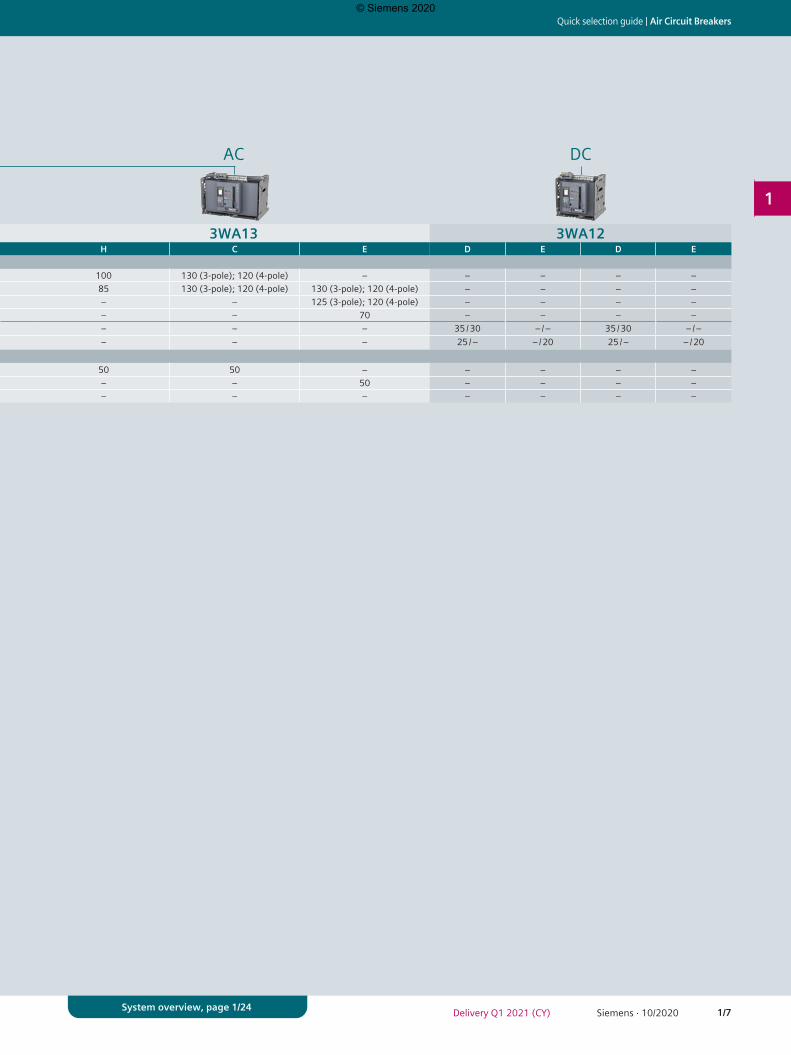
3WA11 3WA12 3WA13 3WA12Breaking capacity N S M E S M H C E H C E D E D ERated conditional short-circuit current Icc of the non-automatic air circuit breakersUp to 500 V AC kA 55 66 85 – 66 85 100 100 – 100 130 (3-pole); 120 (4-pole) – – – – –Up to 690 V AC kA 42 50 66 85 50 66 85 100 85 85 130 (3-pole); 120 (4-pole) 130 (3-pole); 120 (4-pole) – – – –Up to 1000 V AC kA – – – 50 – – – – 85 – – 125 (3-pole); 120 (4-pole) – – – –Up to 1150 V AC kA – – – – – – – – 50 – – 70 – – – –Up to 220 V/300 V DC kA – – – – – – – – – – – – 35 / 30 – / – 35 / 30 – / –Up to 600 V/1000 V DC kA – – – – – – – – – – – – 25 / – – / 20 25 / – – / 20IT system capability1-pole short-circuit breaking capacity IIT acc to. IEC 60947-2 Annex H
≤500 V kA 50 50 50 – 50 50 50 50 – 50 50 – – – – –≤690 V kA – – – 50 – – – – 50 – – 50 – – – –1000 V kA – – – – – – – – – – – – – – – –
© Siemens 2020
1/7Siemens · 10/2020Delivery Q1 2021 (CY)
Quick selection guide | Air Circuit Breakers
1
System overview, page 1/24
AC AC DC
3WA11 3WA12 3WA13 3WA12Breaking capacity N S M E S M H C E H C E D E D ERated conditional short-circuit current Icc of the non-automatic air circuit breakersUp to 500 V AC kA 55 66 85 – 66 85 100 100 – 100 130 (3-pole); 120 (4-pole) – – – – –Up to 690 V AC kA 42 50 66 85 50 66 85 100 85 85 130 (3-pole); 120 (4-pole) 130 (3-pole); 120 (4-pole) – – – –Up to 1000 V AC kA – – – 50 – – – – 85 – – 125 (3-pole); 120 (4-pole) – – – –Up to 1150 V AC kA – – – – – – – – 50 – – 70 – – – –Up to 220 V/300 V DC kA – – – – – – – – – – – – 35 / 30 – / – 35 / 30 – / –Up to 600 V/1000 V DC kA – – – – – – – – – – – – 25 / – – / 20 25 / – – / 20IT system capability1-pole short-circuit breaking capacity IIT acc to. IEC 60947-2 Annex H
≤500 V kA 50 50 50 – 50 50 50 50 – 50 50 – – – – –≤690 V kA – – – 50 – – – – 50 – – 50 – – – –1000 V kA – – – – – – – – – – – – – – – –
© Siemens 2020
1/8 Siemens · 10/2020 Delivery Q1 2021 (CY)
Air Circuit Breakers | Quick selection guide
1
System overview, page 1/24
3WA11 3WA12 3WA13
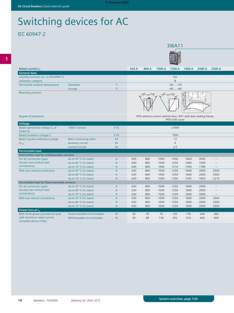
Rated current In 630 A 800 A 1000 A 1250 A 1600 A 2000 A 2500 A 2000 A 2500 A 3200 A 4000 A 4000 A 5000 A 6300 AGeneral dataIsolating function acc. to EN 60947-2 Yes Yes YesUtilization category B B BPermissible ambient temperature Operation °C –40 … +70 –40 … +70 –40 … +70
Storage °C –40 … +80 –40 … +80 –40 … +80Mounting position
Degree of protection IP20 without control cabinet door, IP41 with door sealing frame, IP55 with cover
IP20 without control cabinet door, IP41 with door sealing frame, IP55 with cover
IP20 without control cabinet door, IP41 with door sealing frame, IP55 with cover
VoltageRated operational voltage Ue at 50/60 Hz
1000 V version V AC ≤1000 ≤1150 ≤1150
Rated insulation voltage Ui V AC 1000 ≤1150 ≤1150Rated impulse withstand voltage Uimp
Main conducting paths kV 12 12 12Auxiliary circuits kV 4 4 4Control circuits kV 2.5 2.5 2.5
Permissible loadPermissible load for withdrawable versionsFor all connection types (except rear vertical main connections)
Up to 55 °C (Cu bare) A 630 800 1000 1250 1600 2000 – 2000 2500 3200 – 4000 5000 –Up to 60 °C (Cu bare) A 630 800 1000 1250 1600 1930 – 2000 2500 3020 – 4000 5000 –Up to 70 °C (Cu bare) A 630 800 1000 1210 1490 1780 – 2000 2280 2870 – 4000 5000 –
With rear vertical connections Up to 55 °C (Cu bare) A 630 800 1000 1250 1600 2000 2500 2000 2500 3200 4000 4000 5000 5920Up to 60 °C (Cu bare) A 630 800 1000 1250 1600 2000 2500 2000 2500 3200 3910 4000 5000 5810Up to 70 °C (Cu bare) A 630 800 1000 1250 1545 1855 2215 2000 2390 2945 3645 4000 5000 5500
Permissible load for fixed-mounted versionsFor all connection types (except rear vertical main connections)
Up to 55 °C (Cu bare) A 630 800 1000 1250 1600 2000 – 2000 2500 3200 – 4000 5000 –Up to 60 °C (Cu bare) A 630 800 1000 1250 1600 2000 – 2000 2500 3200 – 4000 5000 –Up to 70 °C (Cu bare) A 630 800 1000 1250 1600 2000 – 2000 2500 3200 – 4000 5000 –
With rear vertical connections Up to 55 °C (Cu bare) A 630 800 1000 1250 1600 2000 2500 2000 2500 3200 4000 4000 5000 6300Up to 60 °C (Cu bare) A 630 800 1000 1250 1600 2000 2500 2000 2500 3200 4000 4000 5000 6300Up to 70 °C (Cu bare) A 630 800 1000 1250 1600 2000 2500 2000 2500 3200 4000 4000 5000 5920
Power loss at InWith three-phase symmetrical load with maximum rated current, complete device (3/4p)
Fixed-mounted circuit breaker W 30 45 70 105 135 240 360 180 270 410 750 520 630 900Withdrawable circuit breaker W 55 85 130 205 310 440 600 320 520 710 1040 810 1050 1600
Switching devices for ACIEC 60947-2
© Siemens 2020

1/9Siemens · 10/2020Delivery Q1 2021 (CY)
Quick selection guide | Air Circuit Breakers
1
System overview, page 1/24
3WA11 3WA12 3WA13
Rated current In 630 A 800 A 1000 A 1250 A 1600 A 2000 A 2500 A 2000 A 2500 A 3200 A 4000 A 4000 A 5000 A 6300 AGeneral dataIsolating function acc. to EN 60947-2 Yes Yes YesUtilization category B B BPermissible ambient temperature Operation °C –40 … +70 –40 … +70 –40 … +70
Storage °C –40 … +80 –40 … +80 –40 … +80Mounting position
Degree of protection IP20 without control cabinet door, IP41 with door sealing frame, IP55 with cover
IP20 without control cabinet door, IP41 with door sealing frame, IP55 with cover
IP20 without control cabinet door, IP41 with door sealing frame, IP55 with cover
VoltageRated operational voltage Ue at 50/60 Hz
1000 V version V AC ≤1000 ≤1150 ≤1150
Rated insulation voltage Ui V AC 1000 ≤1150 ≤1150Rated impulse withstand voltage Uimp
Main conducting paths kV 12 12 12Auxiliary circuits kV 4 4 4Control circuits kV 2.5 2.5 2.5
Permissible loadPermissible load for withdrawable versionsFor all connection types (except rear vertical main connections)
Up to 55 °C (Cu bare) A 630 800 1000 1250 1600 2000 – 2000 2500 3200 – 4000 5000 –Up to 60 °C (Cu bare) A 630 800 1000 1250 1600 1930 – 2000 2500 3020 – 4000 5000 –Up to 70 °C (Cu bare) A 630 800 1000 1210 1490 1780 – 2000 2280 2870 – 4000 5000 –
With rear vertical connections Up to 55 °C (Cu bare) A 630 800 1000 1250 1600 2000 2500 2000 2500 3200 4000 4000 5000 5920Up to 60 °C (Cu bare) A 630 800 1000 1250 1600 2000 2500 2000 2500 3200 3910 4000 5000 5810Up to 70 °C (Cu bare) A 630 800 1000 1250 1545 1855 2215 2000 2390 2945 3645 4000 5000 5500
Permissible load for fixed-mounted versionsFor all connection types (except rear vertical main connections)
Up to 55 °C (Cu bare) A 630 800 1000 1250 1600 2000 – 2000 2500 3200 – 4000 5000 –Up to 60 °C (Cu bare) A 630 800 1000 1250 1600 2000 – 2000 2500 3200 – 4000 5000 –Up to 70 °C (Cu bare) A 630 800 1000 1250 1600 2000 – 2000 2500 3200 – 4000 5000 –
With rear vertical connections Up to 55 °C (Cu bare) A 630 800 1000 1250 1600 2000 2500 2000 2500 3200 4000 4000 5000 6300Up to 60 °C (Cu bare) A 630 800 1000 1250 1600 2000 2500 2000 2500 3200 4000 4000 5000 6300Up to 70 °C (Cu bare) A 630 800 1000 1250 1600 2000 2500 2000 2500 3200 4000 4000 5000 5920
Power loss at InWith three-phase symmetrical load with maximum rated current, complete device (3/4p)
Fixed-mounted circuit breaker W 30 45 70 105 135 240 360 180 270 410 750 520 630 900Withdrawable circuit breaker W 55 85 130 205 310 440 600 320 520 710 1040 810 1050 1600
© Siemens 2020
1/10 Siemens · 10/2020 Delivery Q1 2021 (CY)
Air Circuit Breakers | Quick selection guide
1
System overview, page 1/24
3WA11 3WA12 3WA13
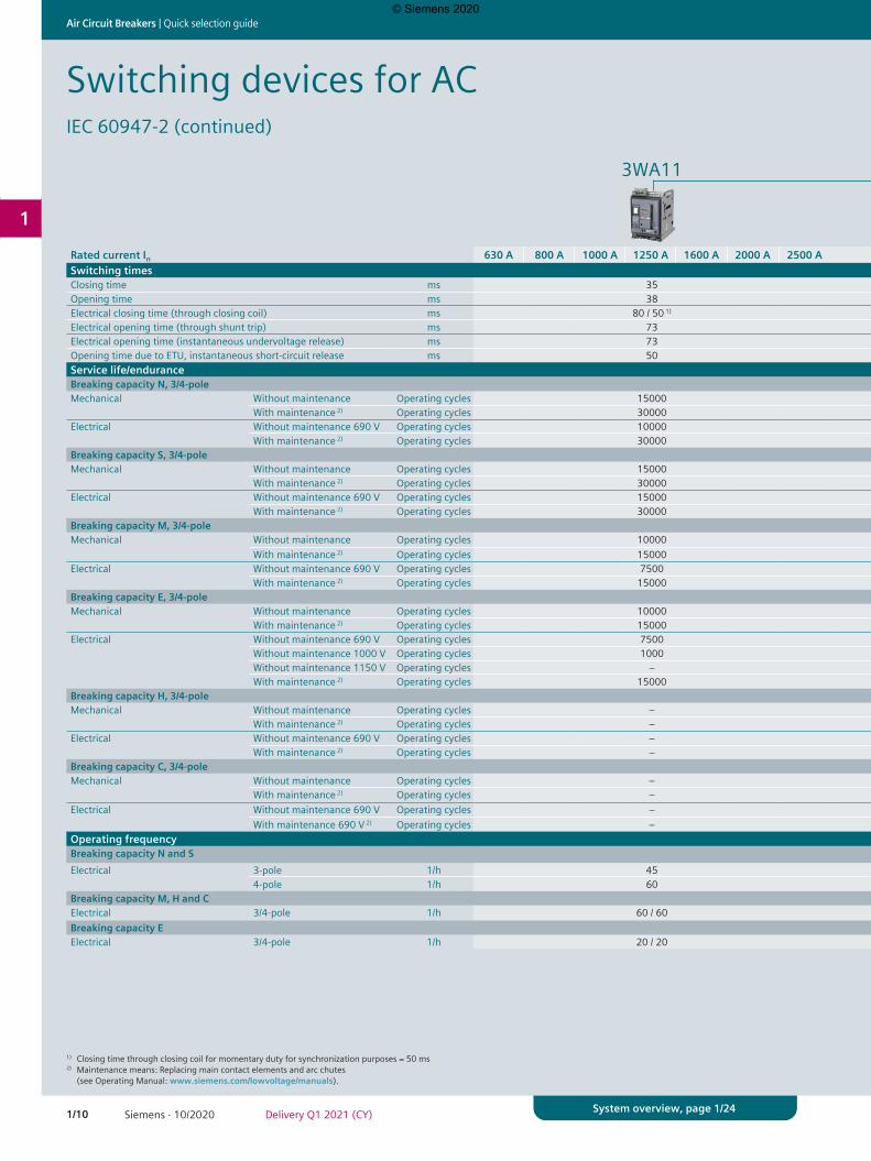
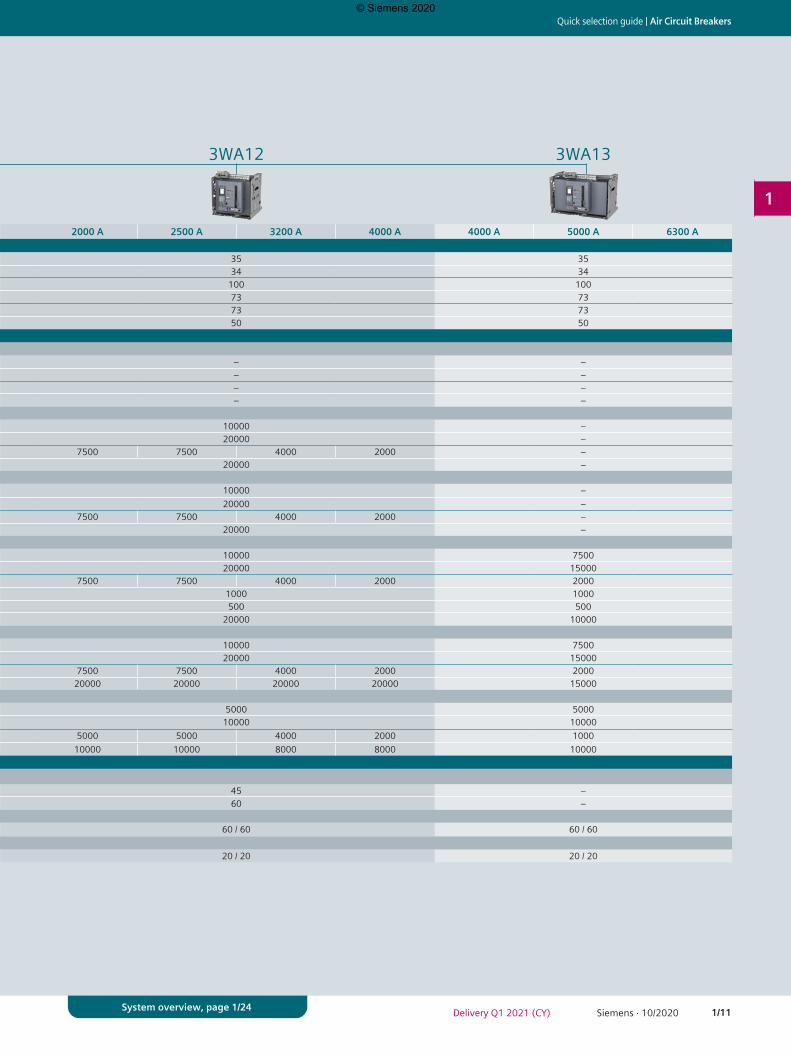
Rated current In 630 A 800 A 1000 A 1250 A 1600 A 2000 A 2500 A 2000 A 2500 A 3200 A 4000 A 4000 A 5000 A 6300 ASwitching timesClosing time ms 35 35 35Opening time ms 38 34 34Electrical closing time (through closing coil) ms 80 / 50 1) 100 100Electrical opening time (through shunt trip) ms 73 73 73Electrical opening time (instantaneous undervoltage release) ms 73 73 73Opening time due to ETU, instantaneous short-circuit release ms 50 50 50Service life/enduranceBreaking capacity N, 3/4-poleMechanical Without maintenance Operating cycles 15000 – –
With maintenance 2) Operating cycles 30000 – –Electrical Without maintenance 690 V Operating cycles 10000 – –
With maintenance 2) Operating cycles 30000 – –Breaking capacity S, 3/4-poleMechanical Without maintenance Operating cycles 15000 10000 –
With maintenance 2) Operating cycles 30000 20000 –Electrical Without maintenance 690 V Operating cycles 15000 7500 7500 4000 2000 –
With maintenance 2) Operating cycles 30000 20000 –Breaking capacity M, 3/4-poleMechanical Without maintenance Operating cycles 10000 10000 –
With maintenance 2) Operating cycles 15000 20000 –Electrical Without maintenance 690 V Operating cycles 7500 7500 7500 4000 2000 –
With maintenance 2) Operating cycles 15000 20000 –Breaking capacity E, 3/4-poleMechanical Without maintenance Operating cycles 10000 10000 7500
With maintenance 2) Operating cycles 15000 20000 15000Electrical Without maintenance 690 V Operating cycles 7500 7500 7500 4000 2000 2000
Without maintenance 1000 V Operating cycles 1000 1000 1000Without maintenance 1150 V Operating cycles – 500 500With maintenance 2) Operating cycles 15000 20000 10000
Breaking capacity H, 3/4-poleMechanical Without maintenance Operating cycles – 10000 7500
With maintenance 2) Operating cycles – 20000 15000Electrical Without maintenance 690 V Operating cycles – 7500 7500 4000 2000 2000
With maintenance 2) Operating cycles – 20000 20000 20000 20000 15000Breaking capacity C, 3/4-poleMechanical Without maintenance Operating cycles – 5000 5000
With maintenance 2) Operating cycles – 10000 10000Electrical Without maintenance 690 V Operating cycles – 5000 5000 4000 2000 1000
With maintenance 690 V 2) Operating cycles – 10000 10000 8000 8000 10000Operating frequencyBreaking capacity N and SElectrical 3-pole 1/h 45 45 –
4-pole 1/h 60 60 –Breaking capacity M, H and CElectrical 3/4-pole 1/h 60 / 60 60 / 60 60 / 60Breaking capacity EElectrical 3/4-pole 1/h 20 / 20 20 / 20 20 / 20
Switching devices for ACIEC 60947-2 (continued)
1) Closing time through closing coil for momentary duty for synchronization purposes = 50 ms2) Maintenance means: Replacing main contact elements and arc chutes (see Operating Manual: www.siemens.com/lowvoltage/manuals).
© Siemens 2020
1/11Siemens · 10/2020Delivery Q1 2021 (CY)
Quick selection guide | Air Circuit Breakers
1
System overview, page 1/24
3WA11 3WA12 3WA13
Rated current In 630 A 800 A 1000 A 1250 A 1600 A 2000 A 2500 A 2000 A 2500 A 3200 A 4000 A 4000 A 5000 A 6300 ASwitching timesClosing time ms 35 35 35Opening time ms 38 34 34Electrical closing time (through closing coil) ms 80 / 50 1) 100 100Electrical opening time (through shunt trip) ms 73 73 73Electrical opening time (instantaneous undervoltage release) ms 73 73 73Opening time due to ETU, instantaneous short-circuit release ms 50 50 50Service life/enduranceBreaking capacity N, 3/4-poleMechanical Without maintenance Operating cycles 15000 – –
With maintenance 2) Operating cycles 30000 – –Electrical Without maintenance 690 V Operating cycles 10000 – –
With maintenance 2) Operating cycles 30000 – –Breaking capacity S, 3/4-poleMechanical Without maintenance Operating cycles 15000 10000 –
With maintenance 2) Operating cycles 30000 20000 –Electrical Without maintenance 690 V Operating cycles 15000 7500 7500 4000 2000 –
With maintenance 2) Operating cycles 30000 20000 –Breaking capacity M, 3/4-poleMechanical Without maintenance Operating cycles 10000 10000 –
With maintenance 2) Operating cycles 15000 20000 –Electrical Without maintenance 690 V Operating cycles 7500 7500 7500 4000 2000 –
With maintenance 2) Operating cycles 15000 20000 –Breaking capacity E, 3/4-poleMechanical Without maintenance Operating cycles 10000 10000 7500
With maintenance 2) Operating cycles 15000 20000 15000Electrical Without maintenance 690 V Operating cycles 7500 7500 7500 4000 2000 2000
Without maintenance 1000 V Operating cycles 1000 1000 1000Without maintenance 1150 V Operating cycles – 500 500With maintenance 2) Operating cycles 15000 20000 10000
Breaking capacity H, 3/4-poleMechanical Without maintenance Operating cycles – 10000 7500
With maintenance 2) Operating cycles – 20000 15000Electrical Without maintenance 690 V Operating cycles – 7500 7500 4000 2000 2000
With maintenance 2) Operating cycles – 20000 20000 20000 20000 15000Breaking capacity C, 3/4-poleMechanical Without maintenance Operating cycles – 5000 5000
With maintenance 2) Operating cycles – 10000 10000Electrical Without maintenance 690 V Operating cycles – 5000 5000 4000 2000 1000
With maintenance 690 V 2) Operating cycles – 10000 10000 8000 8000 10000Operating frequencyBreaking capacity N and SElectrical 3-pole 1/h 45 45 –
4-pole 1/h 60 60 –Breaking capacity M, H and CElectrical 3/4-pole 1/h 60 / 60 60 / 60 60 / 60Breaking capacity EElectrical 3/4-pole 1/h 20 / 20 20 / 20 20 / 20
© Siemens 2020
1/12 Siemens · 10/2020 Delivery Q1 2021 (CY)
Air Circuit Breakers | Quick selection guide
1
System overview, page 1/24
3WA11 3WA12 3WA13
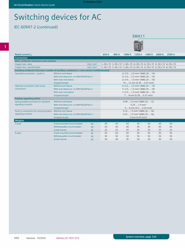
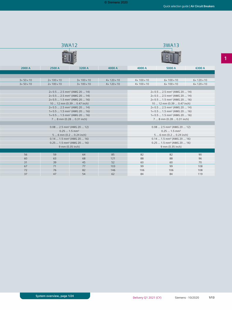
Rated current In 630 A 800 A 1000 A 1250 A 1600 A 2000 A 2500 A 2000 A 2500 A 3200 A 4000 A 4000 A 5000 A 6300 AConnectionMain conductor minimum cross-sectionsCopper bars, bare Unit, mm2 1× 40 × 10 1× 50 × 10 1× 60 × 10 2× 40 × 10 2× 50 × 10 3× 50 × 10 4× 50 × 10 3× 50 × 10 2× 100 × 10 3× 100 × 10 4× 120 × 10 4× 100 × 10 6× 100 × 10 6× 120 × 10Copper bars, painted black Unit, mm2 1× 40 × 10 1× 50 × 10 1× 60 × 10 2× 40 × 10 2× 50 × 10 3× 50 × 10 4× 50 × 10 3× 50 × 10 2× 100 × 10 3× 100 × 10 4× 120 × 10 4× 100 × 10 6× 100 × 10 6× 120 × 10Auxiliary conductor (Cu) max. number of auxiliary conductors × cross-section (solid/stranded)Standard connection = push-in Without end sleeve 2× 0.5 … 2.5 mm2 (AWG 20 … 14) 2× 0.5 … 2.5 mm2 (AWG 20 … 14) 2× 0.5 … 2.5 mm2 (AWG 20 … 14)
With end sleeve acc. to DIN 46228 Part 2 2× 0.5 … 2.5 mm2 (AWG 20 … 14) 2× 0.5 … 2.5 mm2 (AWG 20 … 14) 2× 0.5 … 2.5 mm2 (AWG 20 … 14)With twin end sleeve 2× 0.5 … 1.5 mm2 (AWG 20 … 16) 2× 0.5 … 1.5 mm2 (AWG 20 … 16) 2× 0.5 … 1.5 mm2 (AWG 20 … 16)Stripped length 10 … 12 mm (0.39 … 0.47 inch) 10 … 12 mm (0.39 … 0.47 inch) 10 … 12 mm (0.39 … 0.47 inch)
Optional connection with screw connection
Without end sleeve 2× 0.5 … 2.5 mm2 (AWG 20 … 14) 2× 0.5 … 2.5 mm2 (AWG 20 … 14) 2× 0.5 … 2.5 mm2 (AWG 20 … 14)With end sleeve acc. to DIN 46228 Part 2 1× 0.5 … 1.5 mm2 (AWG 20 … 16) 1× 0.5 … 1.5 mm2 (AWG 20 … 16) 1× 0.5 … 1.5 mm2 (AWG 20 … 16)With twin end sleeve 1× 0.5 … 1.5 mm2 (AWG 20 … 16) 1× 0.5 … 1.5 mm2 (AWG 20 … 16) 1× 0.5 … 1.5 mm2 (AWG 20 … 16)Stripped length 7 … 8 mm (0.28 … 0.31 inch) 7 … 8 mm (0.28 … 0.31 inch) 7 … 8 mm (0.28 … 0.31 inch)
Position signaling switchSpring-loaded terminals for standard signaling contacts
Without end sleeve 0.08 ... 2.5 mm² (AWG 20 ... 12) 0.08 ... 2.5 mm² (AWG 20 ... 12) 0.08 ... 2.5 mm² (AWG 20 ... 12)With end sleeve acc. to DIN 46228 Part 2 0.25 … 1.5 mm² 0.25 … 1.5 mm² 0.25 … 1.5 mm²Stripped length 5 … 6 mm (0.2 … 0.24 inch) 5 … 6 mm (0.2 … 0.24 inch) 5 … 6 mm (0.2 … 0.24 inch)
Push-in connection for communication signaling contacts
Without end sleeve 0.14 ... 1.5 mm² (AWG 20 ... 16) 0.14 ... 1.5 mm² (AWG 20 ... 16) 0.14 … 1.5 mm² (AWG 20 … 16)With end sleeve acc. to DIN 46228 Part 2 0.25 ... 1.5 mm² (AWG 20 ... 16) 0.25 ... 1.5 mm² (AWG 20 ... 16) 0.25 ... 1.5 mm² (AWG 20 ... 16)Stripped length 9 mm (0.35 inch) 9 mm (0.35 inch) 9 mm (0.35 inch)
Weights3-pole Fixed-mounted circuit breaker kg 43 43 43 43 43 43 43 56 59 64 85 82 82 90
Withdrawable circuit breaker kg 45 45 45 45 45 45 45 60 63 68 121 88 88 96Guide frames kg 25 25 25 25 25 25 25 31 39 45 52 60 60 70
4-pole Fixed-mounted circuit breaker kg 50 50 50 50 50 50 50 67 71 77 103 99 99 108Withdrawable circuit breaker kg 54 54 54 54 54 54 54 72 76 82 146 106 106 108Guide frames kg 30 30 30 30 30 30 30 37 47 54 62 84 84 119
Switching devices for ACIEC 60947-2 (continued)
© Siemens 2020
1/13Siemens · 10/2020Delivery Q1 2021 (CY)
Quick selection guide | Air Circuit Breakers
1
System overview, page 1/24
3WA11 3WA12 3WA13
Rated current In 630 A 800 A 1000 A 1250 A 1600 A 2000 A 2500 A 2000 A 2500 A 3200 A 4000 A 4000 A 5000 A 6300 AConnectionMain conductor minimum cross-sectionsCopper bars, bare Unit, mm2 1× 40 × 10 1× 50 × 10 1× 60 × 10 2× 40 × 10 2× 50 × 10 3× 50 × 10 4× 50 × 10 3× 50 × 10 2× 100 × 10 3× 100 × 10 4× 120 × 10 4× 100 × 10 6× 100 × 10 6× 120 × 10Copper bars, painted black Unit, mm2 1× 40 × 10 1× 50 × 10 1× 60 × 10 2× 40 × 10 2× 50 × 10 3× 50 × 10 4× 50 × 10 3× 50 × 10 2× 100 × 10 3× 100 × 10 4× 120 × 10 4× 100 × 10 6× 100 × 10 6× 120 × 10Auxiliary conductor (Cu) max. number of auxiliary conductors × cross-section (solid/stranded)Standard connection = push-in Without end sleeve 2× 0.5 … 2.5 mm2 (AWG 20 … 14) 2× 0.5 … 2.5 mm2 (AWG 20 … 14) 2× 0.5 … 2.5 mm2 (AWG 20 … 14)
With end sleeve acc. to DIN 46228 Part 2 2× 0.5 … 2.5 mm2 (AWG 20 … 14) 2× 0.5 … 2.5 mm2 (AWG 20 … 14) 2× 0.5 … 2.5 mm2 (AWG 20 … 14)With twin end sleeve 2× 0.5 … 1.5 mm2 (AWG 20 … 16) 2× 0.5 … 1.5 mm2 (AWG 20 … 16) 2× 0.5 … 1.5 mm2 (AWG 20 … 16)Stripped length 10 … 12 mm (0.39 … 0.47 inch) 10 … 12 mm (0.39 … 0.47 inch) 10 … 12 mm (0.39 … 0.47 inch)
Optional connection with screw connection
Without end sleeve 2× 0.5 … 2.5 mm2 (AWG 20 … 14) 2× 0.5 … 2.5 mm2 (AWG 20 … 14) 2× 0.5 … 2.5 mm2 (AWG 20 … 14)With end sleeve acc. to DIN 46228 Part 2 1× 0.5 … 1.5 mm2 (AWG 20 … 16) 1× 0.5 … 1.5 mm2 (AWG 20 … 16) 1× 0.5 … 1.5 mm2 (AWG 20 … 16)With twin end sleeve 1× 0.5 … 1.5 mm2 (AWG 20 … 16) 1× 0.5 … 1.5 mm2 (AWG 20 … 16) 1× 0.5 … 1.5 mm2 (AWG 20 … 16)Stripped length 7 … 8 mm (0.28 … 0.31 inch) 7 … 8 mm (0.28 … 0.31 inch) 7 … 8 mm (0.28 … 0.31 inch)
Position signaling switchSpring-loaded terminals for standard signaling contacts
Without end sleeve 0.08 ... 2.5 mm² (AWG 20 ... 12) 0.08 ... 2.5 mm² (AWG 20 ... 12) 0.08 ... 2.5 mm² (AWG 20 ... 12)With end sleeve acc. to DIN 46228 Part 2 0.25 … 1.5 mm² 0.25 … 1.5 mm² 0.25 … 1.5 mm²Stripped length 5 … 6 mm (0.2 … 0.24 inch) 5 … 6 mm (0.2 … 0.24 inch) 5 … 6 mm (0.2 … 0.24 inch)
Push-in connection for communication signaling contacts
Without end sleeve 0.14 ... 1.5 mm² (AWG 20 ... 16) 0.14 ... 1.5 mm² (AWG 20 ... 16) 0.14 … 1.5 mm² (AWG 20 … 16)With end sleeve acc. to DIN 46228 Part 2 0.25 ... 1.5 mm² (AWG 20 ... 16) 0.25 ... 1.5 mm² (AWG 20 ... 16) 0.25 ... 1.5 mm² (AWG 20 ... 16)Stripped length 9 mm (0.35 inch) 9 mm (0.35 inch) 9 mm (0.35 inch)
Weights3-pole Fixed-mounted circuit breaker kg 43 43 43 43 43 43 43 56 59 64 85 82 82 90
Withdrawable circuit breaker kg 45 45 45 45 45 45 45 60 63 68 121 88 88 96Guide frames kg 25 25 25 25 25 25 25 31 39 45 52 60 60 70
4-pole Fixed-mounted circuit breaker kg 50 50 50 50 50 50 50 67 71 77 103 99 99 108Withdrawable circuit breaker kg 54 54 54 54 54 54 54 72 76 82 146 106 106 108Guide frames kg 30 30 30 30 30 30 30 37 47 54 62 84 84 119
© Siemens 2020
1/14 Siemens · 10/2020 Delivery Q1 2021 (CY)
Air Circuit Breakers | Quick selection guide
1
System overview, page 1/24
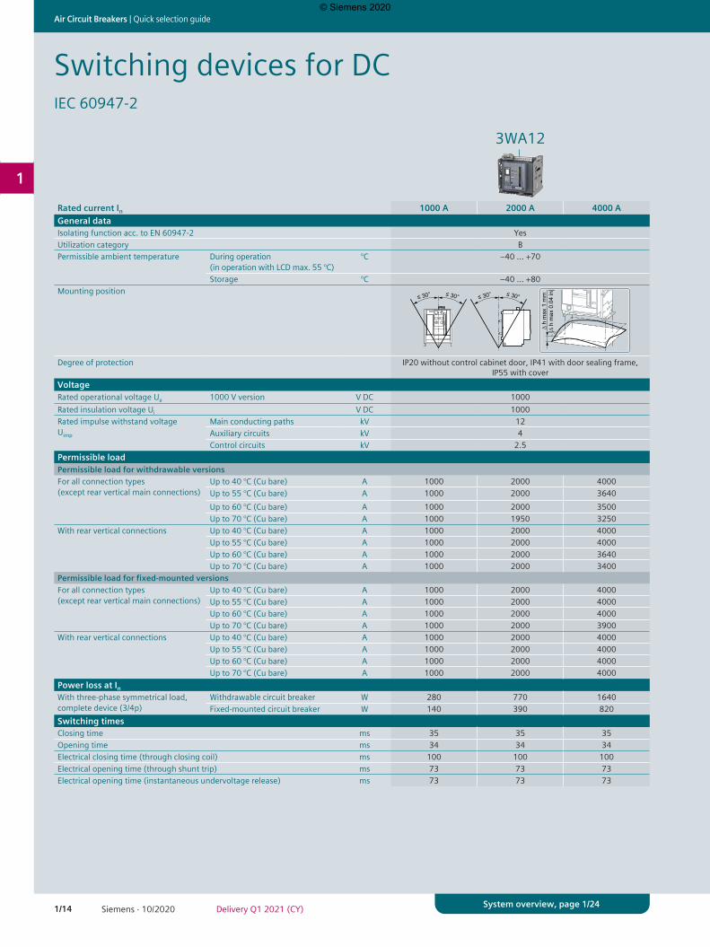
Switching devices for DCIEC 60947-2
3WA12
Rated current In 1000 A 2000 A 4000 AGeneral dataIsolating function acc. to EN 60947-2 YesUtilization category BPermissible ambient temperature During operation
(in operation with LCD max. 55 °C)°C –40 … +70
Storage °C –40 … +80Mounting position
Degree of protection IP20 without control cabinet door, IP41 with door sealing frame, IP55 with cover
VoltageRated operational voltage Ue 1000 V version V DC 1000Rated insulation voltage Ui V DC 1000Rated impulse withstand voltage Uimp
Main conducting paths kV 12Auxiliary circuits kV 4Control circuits kV 2.5
Permissible loadPermissible load for withdrawable versionsFor all connection types (except rear vertical main connections)
Up to 40 °C (Cu bare) A 1000 2000 4000Up to 55 °C (Cu bare) A 1000 2000 3640Up to 60 °C (Cu bare) A 1000 2000 3500Up to 70 °C (Cu bare) A 1000 1950 3250
With rear vertical connections Up to 40 °C (Cu bare) A 1000 2000 4000Up to 55 °C (Cu bare) A 1000 2000 4000Up to 60 °C (Cu bare) A 1000 2000 3640Up to 70 °C (Cu bare) A 1000 2000 3400
Permissible load for fixed-mounted versionsFor all connection types (except rear vertical main connections)
Up to 40 °C (Cu bare) A 1000 2000 4000Up to 55 °C (Cu bare) A 1000 2000 4000Up to 60 °C (Cu bare) A 1000 2000 4000Up to 70 °C (Cu bare) A 1000 2000 3900
With rear vertical connections Up to 40 °C (Cu bare) A 1000 2000 4000Up to 55 °C (Cu bare) A 1000 2000 4000Up to 60 °C (Cu bare) A 1000 2000 4000Up to 70 °C (Cu bare) A 1000 2000 4000
Power loss at InWith three-phase symmetrical load, complete device (3/4p)
Withdrawable circuit breaker W 280 770 1640Fixed-mounted circuit breaker W 140 390 820
Switching timesClosing time ms 35 35 35Opening time ms 34 34 34Electrical closing time (through closing coil) ms 100 100 100Electrical opening time (through shunt trip) ms 73 73 73Electrical opening time (instantaneous undervoltage release) ms 73 73 73
© Siemens 2020
1/15Siemens · 10/2020Delivery Q1 2021 (CY)
Quick selection guide | Air Circuit Breakers
1
System overview, page 1/24
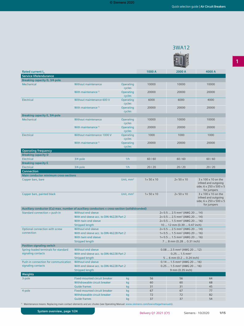
1) Maintenance means: Replacing main contact elements and arc chutes (see Operating Manual: www.siemens.com/lowvoltage/manuals).
3WA12
Rated current In 1000 A 2000 A 4000 AService life/enduranceBreaking capacity D, 3/4-poleMechanical Without maintenance Operating
cycles10000 10000 10000
With maintenance 1) Operating cycles
20000 20000 20000
Electrical Without maintenance 600 V Operating cycles
6000 6000 4000
With maintenance 1) Operating cycles
20000 20000 20000
Breaking capacity E, 3/4-poleMechanical Without maintenance Operating
cycles10000 10000 10000
With maintenance 1) Operating cycles
20000 20000 20000
Electrical Without maintenance 1000 V Operating cycles
1000 1000 1000
With maintenance 1) Operating cycles
20000 20000 20000
Operating frequencyBreaking capacity DElectrical 3/4-pole 1/h 60 / 60 60 / 60 60 / 60Breaking capacity EElectrical 3/4-pole 1/h 20 / 20 20 / 20 20 / 20ConnectionMain conductor minimum cross-sectionsCopper bars, bare Unit, mm2 1× 50 x 10 2× 50 x 10 3 x 100 x 10 on the
infeed and outgoing side; 6 x 250 x 500 x 5
for jumpersCopper bars, painted black Unit, mm2 1× 50 x 10 2× 50 x 10 3 x 100 x 10 on the
infeed and outgoing side; 6 x 250 x 500 x 5
for jumpersAuxiliary conductor (Cu) max. number of auxiliary conductors × cross-section (solid/stranded)Standard connection = push-in Without end sleeve 2× 0.5 … 2.5 mm2 (AWG 20 … 14)
With end sleeve acc. to DIN 46228 Part 2 2× 0.5 … 2.5 mm2 (AWG 20 … 14)With twin end sleeve 2× 0.5 … 1.5 mm2 (AWG 20 … 16)Stripped length 10 … 12 mm (0.39 … 0.47 inch)
Optional connection with screw connection
Without end sleeve 2× 0.5 … 2.5 mm2 (AWG 20 … 14)With end sleeve acc. to DIN 46228 Part 2 1× 0.5 … 1.5 mm2 (AWG 20 … 16)With twin end sleeve 1× 0.5 … 1.5 mm2 (AWG 20 … 16)Stripped length 7 … 8 mm (0.28 … 0.31 inch)
Position signaling switchSpring-loaded terminals for standard signaling contacts
Without end sleeve 0.08 ... 2.5 mm² (AWG 20 ... 12)With end sleeve acc. to DIN 46228 Part 2 0.25 … 1.5 mm²Stripped length 5 … 6 mm (0.2 … 0.24 inch)
Push-in connection for communication signaling contacts
Without end sleeve 0.14 ... 1.5 mm² (AWG 20 ... 16)With end sleeve acc. to DIN 46228 Part 2 0.25 ... 1.5 mm² (AWG 20 ... 16)Stripped length 9 mm (0.35 inch)
Weights3-pole Fixed-mounted circuit breaker kg 56 56 64
Withdrawable circuit breaker kg 60 60 68Guide frames kg 31 31 45
4-pole Fixed-mounted circuit breaker kg 67 67 77Withdrawable circuit breaker kg 72 72 82Guide frames kg 37 37 54
© Siemens 2020
1/16 Siemens · 10/2020 Delivery Q1 2021 (CY)
Air Circuit Breakers | Quick selection guide
1
System overview, page 1/24
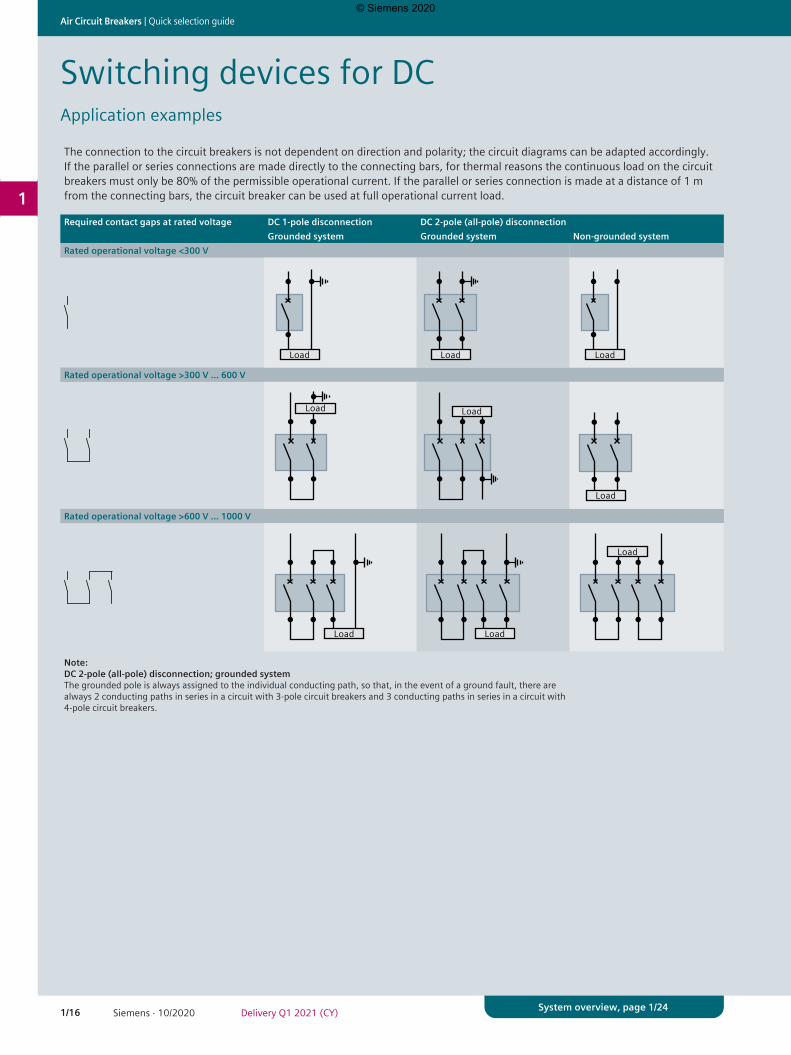
Switching devices for DCApplication examples
The connection to the circuit breakers is not dependent on direction and polarity; the circuit diagrams can be adapted accordingly. If the parallel or series connections are made directly to the connecting bars, for thermal reasons the continuous load on the circuit breakers must only be 80% of the permissible operational current. If the parallel or series connection is made at a distance of 1 m from the connecting bars, the circuit breaker can be used at full operational current load.
Required contact gaps at rated voltage DC 1-pole disconnection DC 2-pole (all-pole) disconnectionGrounded system Grounded system Non-grounded system
Rated operational voltage <300 V
Load Load
Load
Load
LoadLoad
Load
Load
Load Load
Load
Load
LoadLoad
Load
Load
Load Load
Load
Load
LoadLoad
Load
Load
Rated operational voltage >300 V … 600 V
Load Load
Load
Load
LoadLoad
Load
Load
Load Load
Load
Load
LoadLoad
Load
Load
Load Load
Load
Load
LoadLoad
Load
Load
Rated operational voltage >600 V … 1000 V
Load Load
Load
Load
LoadLoad
Load
Load
Load Load
Load
Load
LoadLoad
Load
Load
Load Load
Load
Load
LoadLoad
Load
Load
Note: DC 2-pole (all-pole) disconnection; grounded system The grounded pole is always assigned to the individual conducting path, so that, in the event of a ground fault, there are always 2 conducting paths in series in a circuit with 3-pole circuit breakers and 3 conducting paths in series in a circuit with 4-pole circuit breakers.
© Siemens 2020
1/17Siemens · 10/2020Delivery Q1 2021 (CY)
Quick selection guide | Air Circuit Breakers
1
System overview, page 1/24
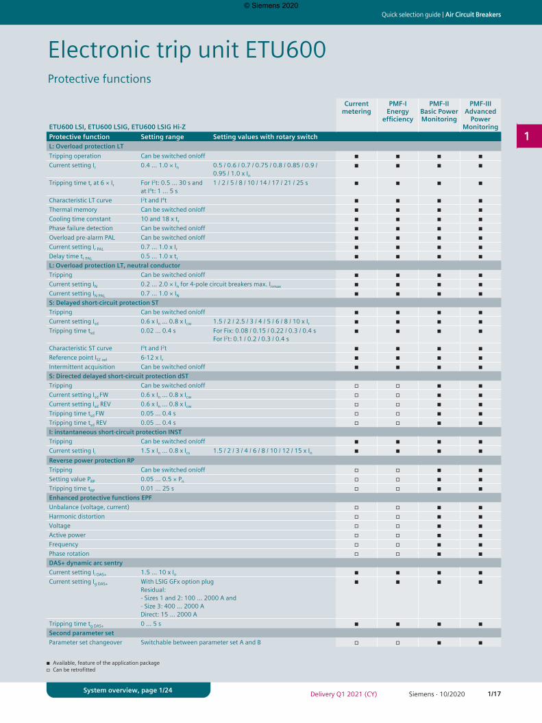
Electronic trip unit ETU600Protective functions
ETU600 LSI, ETU600 LSIG, ETU600 LSIG Hi-Z
Current metering
PMF-I Energy
efficiency
PMF-II Basic Power Monitoring
PMF-III Advanced
Power Monitoring
Protective function Setting range Setting values with rotary switchL: Overload protection LTTripping operation Can be switched on/off ◾ ◾ ◾ ◾Current setting Ir 0.4 … 1.0 × In 0.5 / 0.6 / 0.7 / 0.75 / 0.8 / 0.85 / 0.9 /
0.95 / 1.0 x In◾ ◾ ◾ ◾
Tripping time tr at 6 × Ir For I2t: 0.5 … 30 s and at I4t: 1 … 5 s
1 / 2 / 5 / 8 / 10 / 14 / 17 / 21 / 25 s ◾ ◾ ◾ ◾
Characteristic LT curve I2t and I4t ◾ ◾ ◾ ◾Thermal memory Can be switched on/off ◾ ◾ ◾ ◾Cooling time constant 10 and 18 x tr ◾ ◾ ◾ ◾Phase failure detection Can be switched on/off ◾ ◾ ◾ ◾Overload pre-alarm PAL Can be switched on/off ◾ ◾ ◾ ◾Current setting Ir PAL 0.7 … 1.0 x Ir ◾ ◾ ◾ ◾Delay time tr PAL 0.5 … 1.0 x tr ◾ ◾ ◾ ◾L: Overload protection LT, neutral conductorTripping Can be switched on/off ◾ ◾ ◾ ◾Current setting IN 0.2 … 2.0 × In for 4-pole circuit breakers max. Inmax ◾ ◾ ◾ ◾Current setting IN PAL 0.7 … 1.0 × IN ◾ ◾ ◾ ◾S: Delayed short-circuit protection STTripping Can be switched on/off ◾ ◾ ◾ ◾Current setting Isd 0.6 x In … 0.8 x Icw 1.5 / 2 / 2.5 / 3 / 4 / 5 / 6 / 8 / 10 x Ir ◾ ◾ ◾ ◾Tripping time tsd 0.02 … 0.4 s For Fix: 0.08 / 0.15 / 0.22 / 0.3 / 0.4 s
For I2t: 0.1 / 0.2 / 0.3 / 0.4 s◾ ◾ ◾ ◾
Characteristic ST curve I0t and I2t ◾ ◾ ◾ ◾Reference point IST ref 6-12 x Ir ◾ ◾ ◾ ◾Intermittent acquisition Can be switched on/off ◾ ◾ ◾ ◾S: Directed delayed short-circuit protection dSTTripping Can be switched on/off ◽ ◽ ◾ ◾Current setting Isd FW 0.6 x In … 0.8 x Icw ◽ ◽ ◾ ◾Current setting Isd REV 0.6 x In … 0.8 x Icw ◽ ◽ ◾ ◾Tripping time tsd FW 0.05 … 0.4 s ◽ ◽ ◾ ◾Tripping time tsd REV 0.05 … 0.4 s ◽ ◽ ◾ ◾I: instantaneous short-circuit protection INSTTripping Can be switched on/off ◾ ◾ ◾ ◾Current setting Ii 1.5 x In … 0.8 x Ics 1.5 / 2 / 3 / 4 / 6 / 8 / 10 / 12 / 15 x In ◾ ◾ ◾ ◾Reverse power protection RPTripping Can be switched on/off ◽ ◽ ◾ ◾Setting value PRP 0.05 … 0.5 × Pn ◽ ◽ ◾ ◾Tripping time tRP 0.01 … 25 s ◽ ◽ ◾ ◾Enhanced protective functions EPFUnbalance (voltage, current) ◽ ◽ ◾ ◾Harmonic distortion ◽ ◽ ◾ ◾Voltage ◽ ◽ ◾ ◾Active power ◽ ◽ ◾ ◾Frequency ◽ ◽ ◾ ◾Phase rotation ◽ ◽ ◾ ◾DAS+ dynamic arc sentryCurrent setting Ii DAS+ 1.5 … 10 x In ◾ ◾ ◾ ◾Current setting Ig DAS+ With LSIG GFx option plug
Residual: - Sizes 1 and 2: 100 ... 2000 A and- Size 3: 400 … 2000 ADirect: 15 … 2000 A
◾ ◾ ◾ ◾
Tripping time tg DAS+ 0 … 5 s ◾ ◾ ◾ ◾Second parameter setParameter set changeover Switchable between parameter set A and B ◽ ◽ ◾ ◾
◾ Available, feature of the application package◽ Can be retrofitted
© Siemens 2020
1/18 Siemens · 10/2020 Delivery Q1 2021 (CY)
Air Circuit Breakers | Quick selection guide
1
System overview, page 1/24
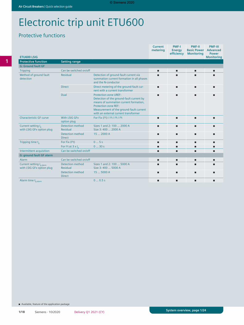
ETU600 LSIG
Current metering
PMF-I Energy
efficiency
PMF-II Basic Power Monitoring
PMF-III Advanced
Power Monitoring
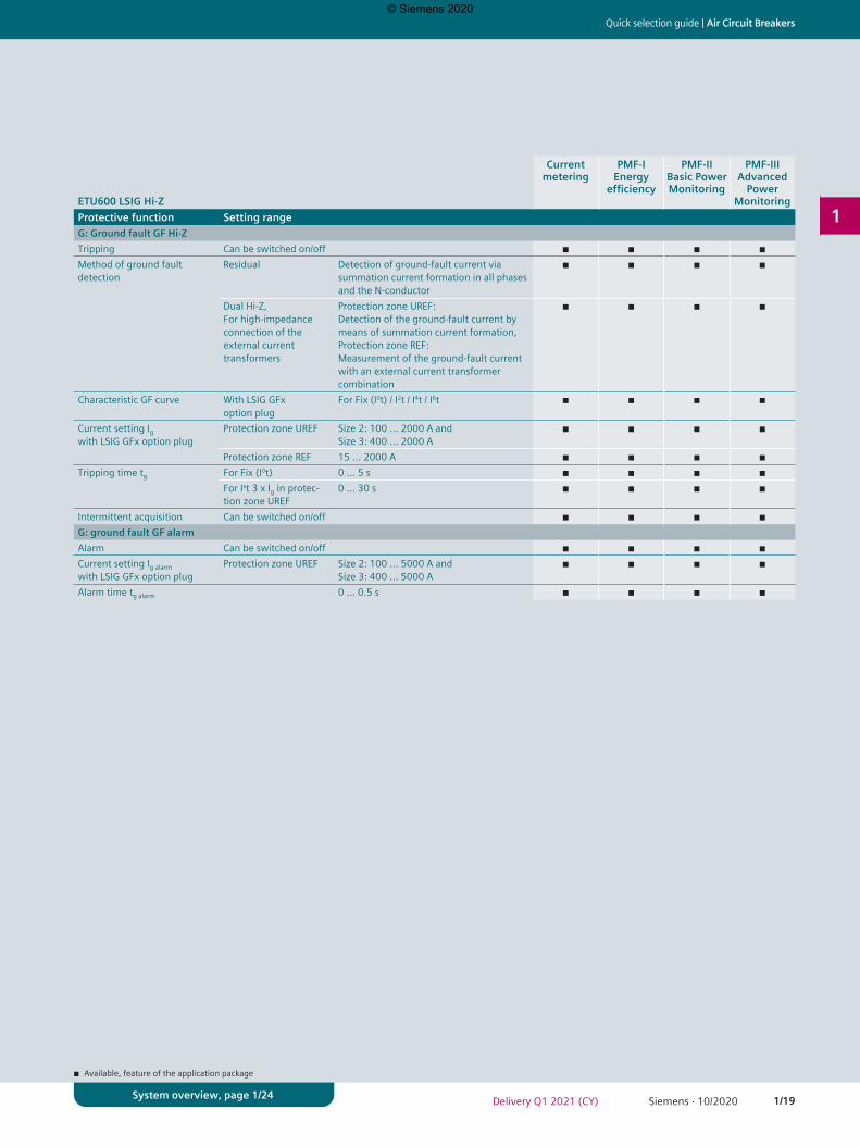
Protective function Setting rangeG: Ground fault GFTripping Can be switched on/off ◾ ◾ ◾ ◾Method of ground fault detection
Residual Detection of ground-fault current via summation current formation in all phases and the N-conductor
◾ ◾ ◾ ◾
Direct Direct metering of the ground-fault cur-rent with a current transformer
◾ ◾ ◾ ◾
Dual Protection zone UREF: Detection of the ground-fault current by means of summation current formation,Protection zone REF: Measurement of the ground-fault current with an external current transformer
◾ ◾ ◾ ◾
Characteristic GF curve With LSIG GFx option plug
For Fix (I0t) / I2t / I4t / I6t ◾ ◾ ◾ ◾
Current setting Igwith LSIG GFx option plug
Detection method Residual
Sizes 1 and 2: 100 … 2000 ASize 3: 400 … 2000 A
◾ ◾ ◾ ◾
Detection method Direct
15 … 2000 A ◾ ◾ ◾ ◾
Tripping time tg For Fix (I0t) 0 … 5 s ◾ ◾ ◾ ◾For Ixt at 3 x Ig 0 … 30 s ◾ ◾ ◾ ◾
Intermittent acquisition Can be switched on/off ◾ ◾ ◾ ◾G: ground fault GF alarmAlarm Can be switched on/off ◾ ◾ ◾ ◾Current setting Ig alarmwith LSIG GFx option plug
Detection method Residual
Sizes 1 and 2: 100 … 5000 ASize 3: 400 … 5000 A
◾ ◾ ◾ ◾
Detection method Direct
15 … 5000 A ◾ ◾ ◾ ◾
Alarm time tg alarm 0 … 0.5 s ◾ ◾ ◾ ◾
Electronic trip unit ETU600Protective functions
◾ Available, feature of the application package
© Siemens 2020
1/19Siemens · 10/2020Delivery Q1 2021 (CY)
Quick selection guide | Air Circuit Breakers
1
System overview, page 1/24
ETU600 LSIG Hi-Z
Current metering
PMF-I Energy
efficiency
PMF-II Basic Power Monitoring
PMF-III Advanced
Power Monitoring
Protective function Setting rangeG: Ground fault GF Hi-ZTripping Can be switched on/off ◾ ◾ ◾ ◾Method of ground fault detection
Residual Detection of ground-fault current via summation current formation in all phases and the N-conductor
◾ ◾ ◾ ◾
Dual Hi-Z,For high-impedance connection of the external current transformers
Protection zone UREF: Detection of the ground-fault current by means of summation current formation,Protection zone REF: Measurement of the ground-fault current with an external current transformer combination
◾ ◾ ◾ ◾
Characteristic GF curve With LSIG GFx option plug
For Fix (I0t) / I2t / I4t / I6t ◾ ◾ ◾ ◾
Current setting Igwith LSIG GFx option plug
Protection zone UREF Size 2: 100 ... 2000 A andSize 3: 400 … 2000 A
◾ ◾ ◾ ◾
Protection zone REF 15 … 2000 A ◾ ◾ ◾ ◾Tripping time tg For Fix (I0t) 0 … 5 s ◾ ◾ ◾ ◾
For Ixt 3 x Ig in protec-tion zone UREF
0 … 30 s ◾ ◾ ◾ ◾
Intermittent acquisition Can be switched on/off ◾ ◾ ◾ ◾G: ground fault GF alarmAlarm Can be switched on/off ◾ ◾ ◾ ◾Current setting Ig alarmwith LSIG GFx option plug
Protection zone UREF Size 2: 100 ... 5000 A andSize 3: 400 … 5000 A
◾ ◾ ◾ ◾
Alarm time tg alarm 0 … 0.5 s ◾ ◾ ◾ ◾
◾ Available, feature of the application package
© Siemens 2020

1/20 Siemens · 10/2020 Delivery Q1 2021 (CY)
Air Circuit Breakers | Quick selection guide
1
System overview, page 1/24
ETU600
Current metering
PMF-I Energy
efficiency
PMF-II Basic Power Monitoring
PMF-III Advanced
Power Monitoring
Non-automatic
circuit breakers
Operation and interfacesRotary switch ◾ ◾ ◾ ◾ –Display and operating keys ◾ ◾ ◾ ◾ –SENTRON powerconfig configuration software ◾ ◾ ◾ ◾ –Fieldbus communication ◾ ◾ ◾ ◾ –Color display ◾ ◾ ◾ ◾ –Bluetooth and USB interface ◾ ◾ ◾ ◾ –CommunicationPrepared for connection of a communication module (ready4COM feature)
Status messages of the circuit breaker ◽ ◾ ◾ ◾ ◽Status messages of the electronic trip unit ETU600
◽ ◾ ◾ ◾ –
Remote operation, requires a communication module, closing coil, shunt trip
◽ ◾ ◾ ◾ ◽
Communication module COM190 PROFINET-IO/Modbus-TCP ◽ ◽ ◽ ◽ ◽Digital input and output on the electronic trip unit ETU600Parameterizable input For activating DAS+ dynamic arc sentry or can be
used for parameter set changeover◾ ◾ ◾ ◾ –
Parameterizable output Can be used as a "life contact" and for display of "Parameter set B active" or "DAS+ dynamic arc sentry active".
◾ ◾ ◾ ◾ –
IOM230 digital input and output moduleTwo parameterizable inputs For controlling the circuit breaker and trans-
mitting information from the switchboard via communication.
◽ ◽ ◽ ◽ ◽
Three parameterizable outputs For signaling events, states, tripping operations or alarms of the switching device
◽ ◽ ◽ ◽ ◽
Electronic trip unit ETU600Operation, interfaces and metering function
– Not available◾ Available, feature of the application package◽ Can be retrofitted
© Siemens 2020
1/21Siemens · 10/2020Delivery Q1 2021 (CY)
Quick selection guide | Air Circuit Breakers
1
System overview, page 1/24
ETU600
Current metering
PMF-I Energy
efficiency
PMF-II Basic Power Monitoring
PMF-III Advanced
Power Monitoring
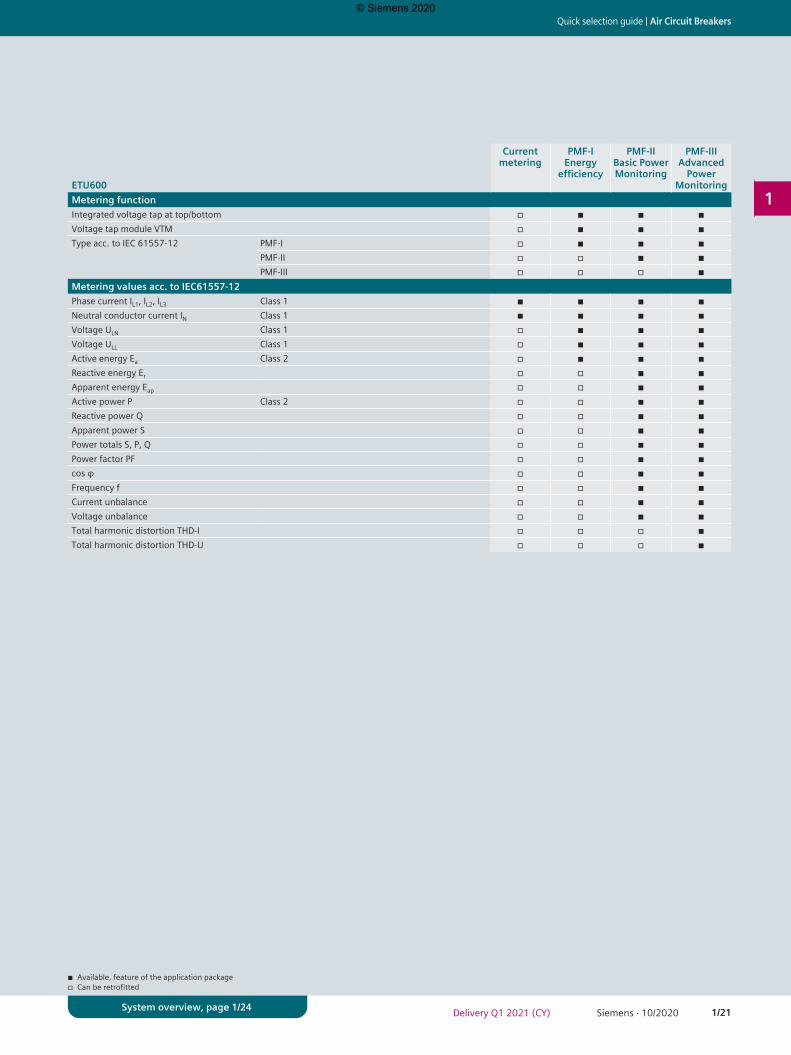
Metering functionIntegrated voltage tap at top/bottom ◽ ◾ ◾ ◾Voltage tap module VTM ◽ ◾ ◾ ◾Type acc. to IEC 61557-12 PMF-I ◽ ◾ ◾ ◾
PMF-II ◽ ◽ ◾ ◾PMF-III ◽ ◽ ◽ ◾
Metering values acc. to IEC61557-12Phase current IL1, IL2, IL3 Class 1 ◾ ◾ ◾ ◾Neutral conductor current IN Class 1 ◾ ◾ ◾ ◾Voltage ULN Class 1 ◽ ◾ ◾ ◾Voltage ULL Class 1 ◽ ◾ ◾ ◾Active energy Ea Class 2 ◽ ◾ ◾ ◾Reactive energy Er ◽ ◽ ◾ ◾Apparent energy Eap ◽ ◽ ◾ ◾Active power P Class 2 ◽ ◽ ◾ ◾Reactive power Q ◽ ◽ ◾ ◾Apparent power S ◽ ◽ ◾ ◾Power totals S, P, Q ◽ ◽ ◾ ◾Power factor PF ◽ ◽ ◾ ◾cos φ ◽ ◽ ◾ ◾Frequency f ◽ ◽ ◾ ◾Current unbalance ◽ ◽ ◾ ◾Voltage unbalance ◽ ◽ ◾ ◾Total harmonic distortion THD-I ◽ ◽ ◽ ◾Total harmonic distortion THD-U ◽ ◽ ◽ ◾
◾ Available, feature of the application package◽ Can be retrofitted
© Siemens 2020
1/22 Siemens · 10/2020 Delivery Q1 2021 (CY)
Air Circuit Breakers | Quick selection guide
1
System overview, page 1/24
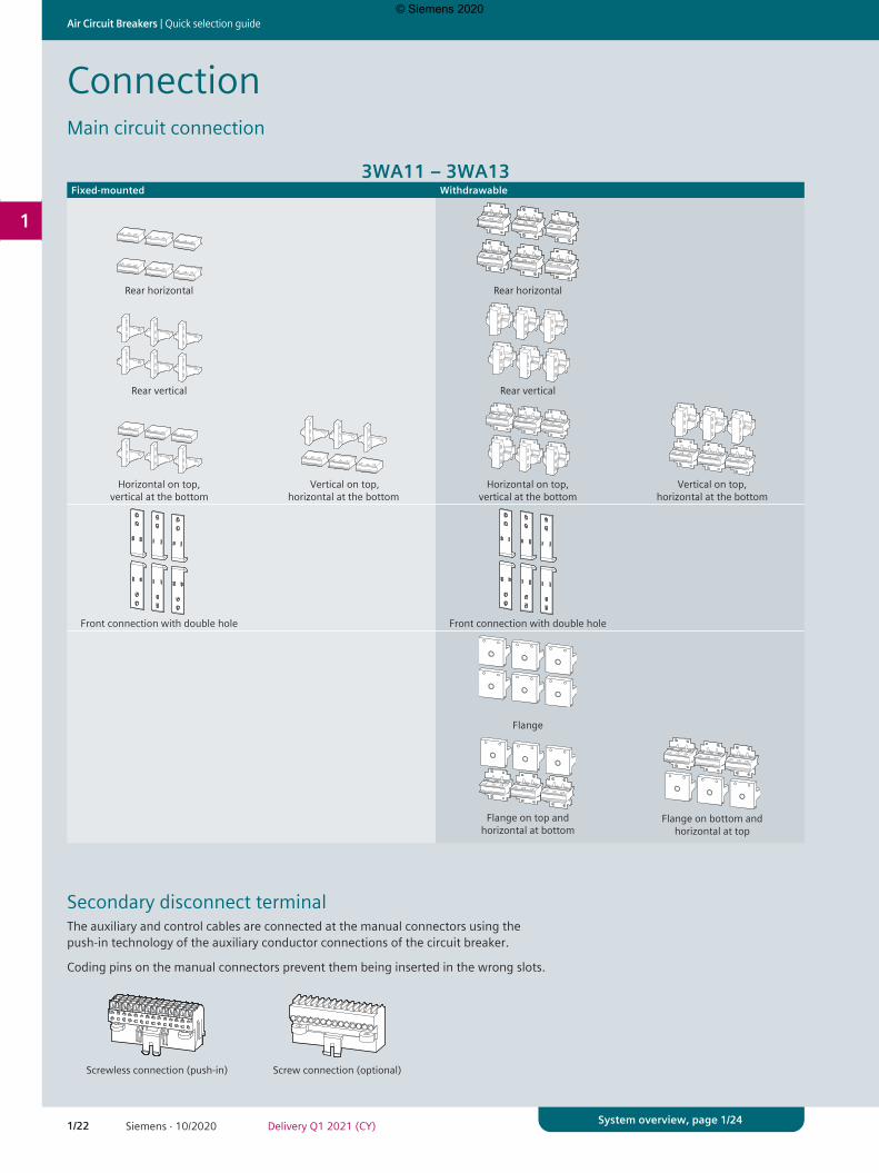
ConnectionMain circuit connection
Secondary disconnect terminal
3WA11 – 3WA13Fixed-mounted Withdrawable
Rear horizontal
Rear horizontal
Rear vertical
Rear vertical
Horizontal on top,
vertical at the bottom
Vertical on top,
horizontal at the bottom
Horizontal on top,
vertical at the bottom
Vertical on top,
horizontal at the bottom
Front connection with double hole
Front connection with double hole
Flange
Flange on top and
horizontal at bottom
Flange on bottom and
horizontal at top
The auxiliary and control cables are connected at the manual connectors using the push-in technology of the auxiliary conductor connections of the circuit breaker.
Coding pins on the manual connectors prevent them being inserted in the wrong slots.
Screwless connection (push-in) Screw connection (optional)
© Siemens 2020
1/23Siemens · 10/2020Delivery Q1 2021 (CY)
Quick selection guide | Air Circuit Breakers
1
System overview, page 1/24
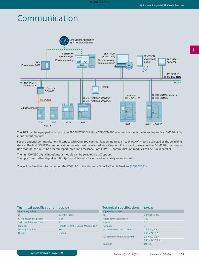
Communication
Power monitoring Commissioning /parameterization
with COM15, COM16
with COM060
with COM35with COM040, COM042with COM041, COM043
with max. 2 x COM190
PROFIBUS / Modbus RTU
PROFINET /Modbus TCP
SENTRON powerconfig
MindSphere ApplicationSENTRON powermind
SENTRON powerconfig mobile
SENTRON powermanager
3VA-line
3VA 3VA 3WL103VA273WL11 - 3WL133WA
I201_19702
COM100/COM800
DSP800
PAC3220PAC42007KN
Powercenter 3000
...
max. 8
The 3WA can be equipped with up to two PROFINET IO / Modbus TCP COM190 communication modules and up to five IOM230 digital input/output modules.
For the optional communications interface with COM190 communication module, a "ready4COM" must be selected as the switching device. The first COM190 communication module must be selected via a Z option. If you want to use a further COM190 communica-tion module, this must be ordered separately as an accessory. Both COM190 communication modules can be run in parallel.
The first IOM230 digital input/output module can be selected via a Z option. The up to four further digital input/output modules must be ordered separately as accessories.
You will find further information on the COM190 in the Manual – 3WA Air Circuit Breakers (109763061)
Technical specifications COM190Operating valuesUs 24 V DC ±20%Rated power dissipation 1 WSwitched Ethernet Ports 2Protocol PROFINET IO (CC-C) and Modbus TCPSecurity functions YesNumber Up to 2
Technical specifications IOM230Operating valuesUs 24 V DC ±20%Rated power dissipation 1 WInputs 2Outputs 3Maximum switching current 24 V DC, 4 A
250 V AC, 5 AMaximum continuous current 24 V DC, 0.2 A
250 V AC, 0.2 ANumber Up to 5
© Siemens 2020
1/24 Siemens · 10/2020 Delivery Q1 2021 (CY)
Air Circuit Breakers | 3WA11 – 3WA13
1
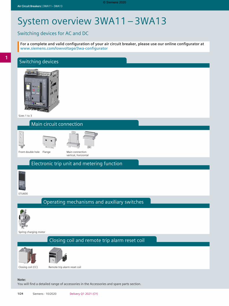
System overview 3WA11 – 3WA13Switching devices for AC and DC
Switching devices
Sizes 1 to 3
Main circuit connection
Front double hole Flange Main connection vertical, horizontal
Electronic trip unit and metering function
ETU600
Operating mechanisms and auxiliary switches
Spring charging motor
Closing coil and remote trip alarm reset coil
Closing coil (CC) Remote trip alarm reset coil
For a complete and valid configuration of your air circuit breaker, please use our online configurator at www.siemens.com/lowvoltage/3wa-configurator
Note: You will find a detailed range of accessories in the Accessories and spare parts section.
© Siemens 2020
1/25Siemens · 10/2020Delivery Q1 2021 (CY)
3WA11 – 3WA13 | Air Circuit Breakers
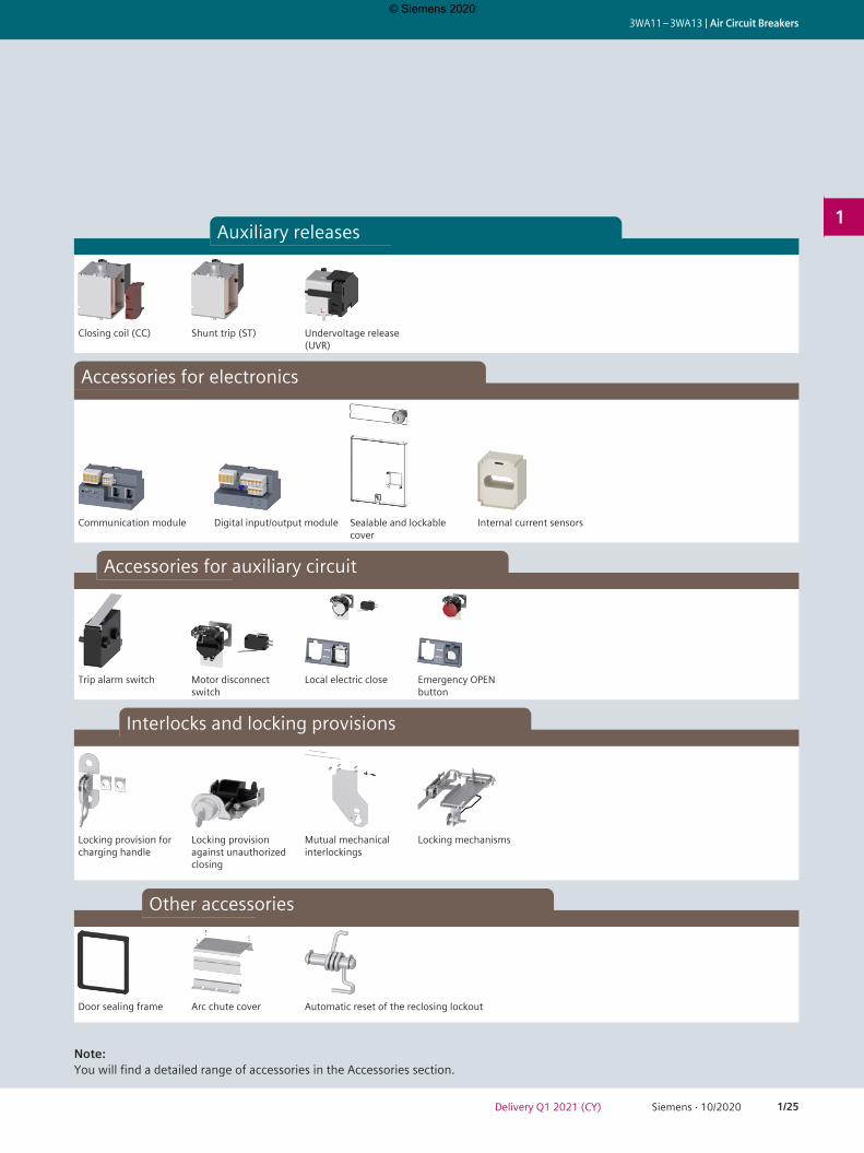
1Auxiliary releases
Closing coil (CC) Shunt trip (ST) Undervoltage release (UVR)
Accessories for electronics
Communication module Digital input/output module Sealable and lockable cover
Internal current sensors
Accessories for auxiliary circuit
Trip alarm switch Motor disconnect switch
Local electric close Emergency OPEN button
Interlocks and locking provisions
Locking provision for charging handle
Locking provision against unauthorized closing
Mutual mechanical interlockings
Locking mechanisms
Other accessories
Door sealing frame Arc chute cover Automatic reset of the reclosing lockout
Note: You will find a detailed range of accessories in the Accessories section.
© Siemens 2020
1/26 Siemens · 10/2020 Delivery Q1 2021 (CY)
Air Circuit Breakers | 3WA11 – 3WA13
1
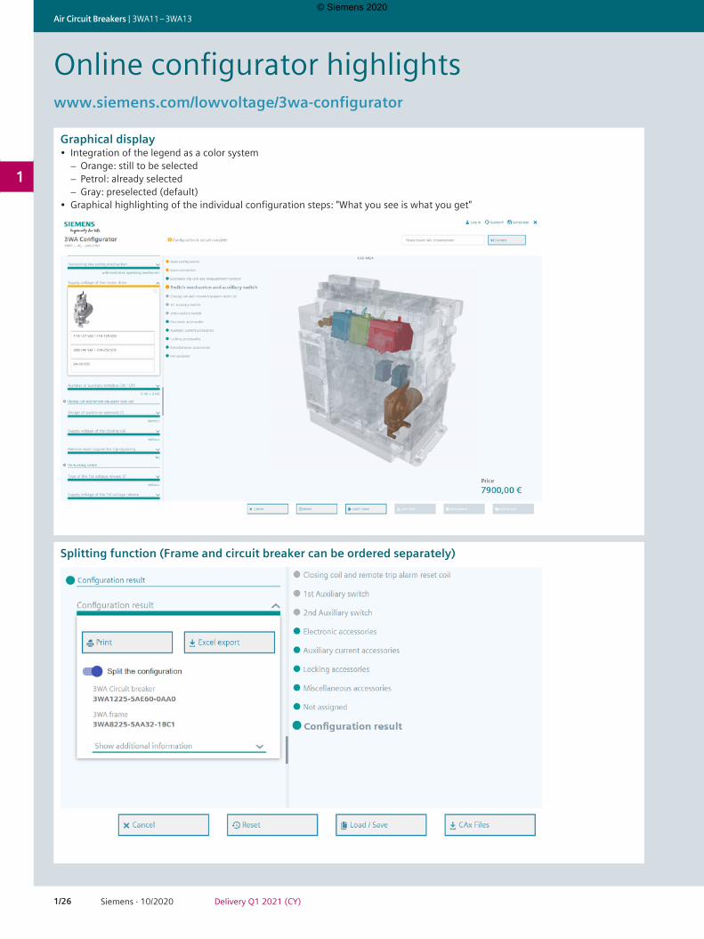
Online configurator highlightswww.siemens.com/lowvoltage/3wa-configurator
Graphical display • Integration of the legend as a color system
− Orange: still to be selected− Petrol: already selected− Gray: preselected (default)
• Graphical highlighting of the individual configuration steps: "What you see is what you get"
Splitting function (Frame and circuit breaker can be ordered separately)
© Siemens 2020
1/27Siemens · 10/2020Delivery Q1 2021 (CY)
3WA11 – 3WA13 | Air Circuit Breakers
1
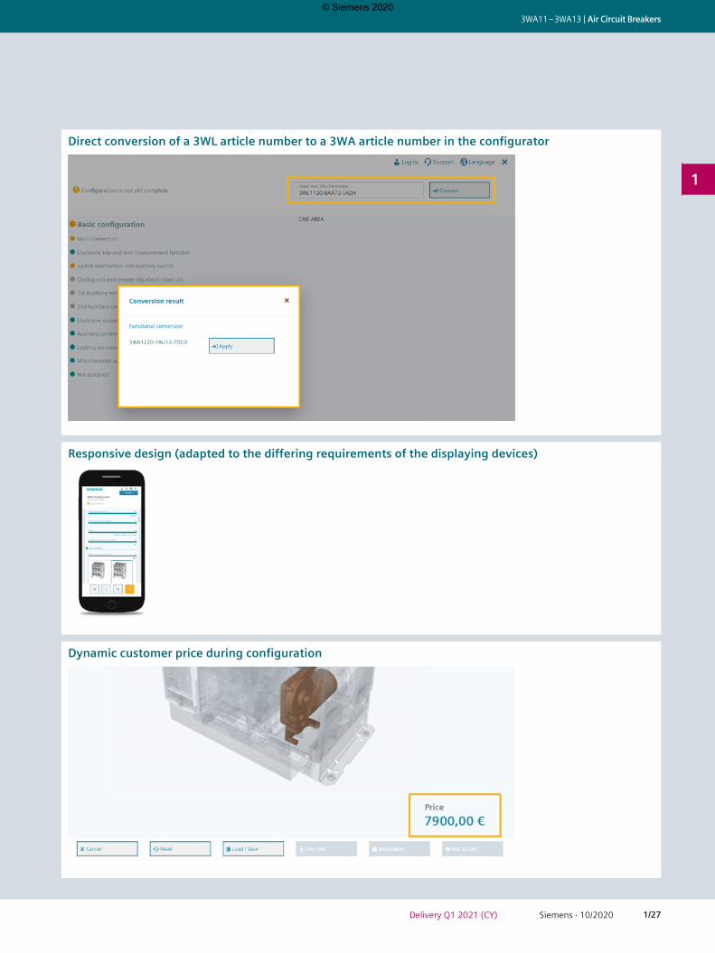
Direct conversion of a 3WL article number to a 3WA article number in the configurator
Responsive design (adapted to the differing requirements of the displaying devices)
Dynamic customer price during configuration
© Siemens 2020
1/28 Siemens · 10/2020 Delivery Q1 2021 (CY)
Air Circuit Breakers | 3WA11 – 3WA13
1
Quick selection guide, page 1/4 and 1/8Quick selection guide, page 1/4 and 1/8
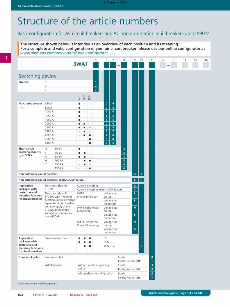
Structure of the article numbersBasic configuration for AC circuit breakers and AC non-automatic circuit breakers up to 690 V
5 6 7 8 9 10 11 12 13 14 15 16
3WA1 – –
Switching deviceSize (SZ) 1 1
2 23 3
SZ 1
SZ 2
SZ 3
Max. rated current In max
630 A ■ – – 0 6800 A ■ – – 0 81000 A ■ – – 1 01250 A ■ – – 1 21600 A ■ – – 1 62000 A ■ ■ – 2 02500 A ■ ■ – 2 53200 A – ■ – 3 24000 A – ■1) ■ 4 05000 A – – ■ 5 06300 A – – ■ 6 3
Short-circuit breaking capacity Icu at 500 V
N 55 kA ■ – – 2S 66 kA ■ ■ – 3M 85 kA ■ ■ – 4H 100 kA – ■ ■ 5C 130 kA – ■ – 6
150 kA – – ■ 6
Non-automatic circuit breakers A A
Non-automatic circuit breakers, ready4COM feature C A
Application packages with protective and metering functions for circuit breakers
Electronic trip unit ETU600
Current metering ACurrent metering, ready4COM feature C
Electronic trip unit ETU600 with metering function, internal voltage tap in the circuit breaker, voltage supply of the ETU600 through the voltage tap module and ready4COM
PMF-I Energy Efficiency
Voltage tap on top
L
Voltage tap on bottom
E
PMF-II Basic Power Monitoring
Voltage tap on top
M
Voltage tap on bottom
F
PMF-III Advanced Power Monitoring
Voltage tap on top
N
Voltage tap on bottom
G
Application packages with protective and metering functions for circuit breakers
Protective functions ■ ■ ■ LSI E■ ■ ■ LSIG F– ■ ■ LSIG Hi-Z G
Number of poles Fixed-mounted 3-pole 04-pole, Neutral left 1
Withdrawable Without position signaling switch
3-pole 34-pole, Neutral left 4
With position signaling switch 3-pole 64-pole, Neutral left 7
The structure shown below is intended as an overview of each position and its meaning. For a complete and valid configuration of your air circuit breaker, please use our online configurator at www.siemens.com/lowvoltage/3wa-configurator
1) Not available for breaking capacity C
© Siemens 2020

1/29Siemens · 10/2020Delivery Q1 2021 (CY)
3WA11 – 3WA13 | Air Circuit Breakers
1
Quick selection guide, page 1/4 and 1/8Quick selection guide, page 1/4 and 1/8
1) The 4000 A vertical connections for the 3WA1 have different dimensions from the 3WL1. Dimensionally compatible connections can be ordered with the additional Z option D01.2) Not available for 2500 A3) Not available for 4000 A4) Not available for 6300 A5) Not available for 4000 A and for breaking capacity C6) Not available for 5000 A and 6300 A and for breaking capacity C
5 6 7 8 9 10 11 12 13 14 15 16
3WA1 – –
Connection SZ 1
SZ 2
SZ 3
Type of mounting Fixed-mounted ◾ ◾ 1) ◾ Vertical 1◾ 2) ◾ 3) ◾ 4) Horizontal 2◾ 2) ◾ 5) ◾ 6) Front 3◾ 2) ◾ 3) ◾ 4) Vertical / horizontal 5◾ 2) ◾ 3) ◾ 4) Horizontal / vertical 6
Withdrawable ◾ ◾ ◾ Without guide frame 0◾ ◾ 1) ◾ Vertical 1◾ 2) ◾ 3) ◾ 4) Horizontal 2◾ 2) ◾ 5) ◾ 6) Front 3◾ 2) ◾ 5) ◾ 6) Flange 4◾ 2) ◾ 3) ◾ 4) Vertical / horizontal 5◾ 2) ◾ 3) ◾ 4) Horizontal / vertical 6◾ 2) ◾ 5) ◾ 6) Flange / horizontal 7◾ 2) ◾ 5) ◾ 6) Horizontal / flange 8
© Siemens 2020
1/30 Siemens · 10/2020 Delivery Q1 2021 (CY)
Air Circuit Breakers | 3WA11 – 3WA13
1
Quick selection guide, page 1/4 and 1/8Quick selection guide, page 1/4 and 1/8
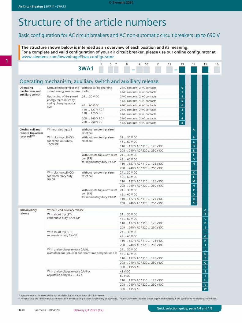
5 6 7 8 9 10 11 12 13 14 15 16
3WA1 – –
Operating mechanism, auxiliary switch and auxiliary releaseOperating mechanism and auxiliary switch
Manual recharging of the stored energy mechanism
Without spring charging motor
2 NO contacts, 2 NC contacts 04 NO contacts, 4 NC contacts 1
Recharging of the stored energy mechanism by spring charging motor (M)
24 ... 30 V DC 2 NO contacts, 2 NC contacts 24 NO contacts, 4 NC contacts 5
48 ... 60 V DC 4 NO contacts, 4 NC contacts 6110 ... 127 V AC / 110 ... 125 V DC
2 NO contacts, 2 NC contacts 34 NO contacts, 4 NC contacts 7
208 ... 240 V AC / 220 ... 250 V DC
2 NO contacts, 2 NC contacts 44 NO contacts, 4 NC contacts 8
Closing coil and remote trip alarm reset coil 1)2)
Without closing coil Without remote trip alarm reset coil
A
With closing coil (CC) for continuous duty, 100% OP
Without remote trip alarm reset coil
24 ... 30 V DC B48 ... 60 V DC C110 ... 127 V AC / 110 ... 125 V DC D208 ... 240 V AC / 220 ... 250 V DC E
With remote trip alarm reset coil (RR) for momentary duty 1% OP
24 ... 30 V DC F48 ... 60 V DC G110 ... 127 V AC / 110 ... 125 V DC H208 ... 240 V AC / 220 ... 250 V DC J
With closing coil (CC) for momentary duty, 5% OP
Without remote trip alarm reset coil
24 ... 30 V DC K48 ... 60 V DC L110 ... 127 V AC / 110 ... 125 V DC M208 ... 240 V AC / 220 ... 250 V DC N
With remote trip alarm reset coil (RR) for momentary duty 1% OP
24 ... 30 V DC P48 ... 60 V DC Q110 ... 127 V AC / 110 ... 125 V DC R208 ... 240 V AC / 220 ... 250 V DC S
2nd auxiliary release
Without 2nd auxiliary release AWith shunt trip (ST), continuous duty 100% OP
24 ... 30 V DC B48 ... 60 V DC C110 ... 127 V AC / 110 ... 125 V DC D208 ... 240 V AC / 220 ... 250 V DC E
With shunt trip (ST), momentary duty 5% OP
24 ... 30 V DC F48 ... 60 V DC G110 ... 127 V AC / 110 ... 125 V DC H208 ... 240 V AC / 220 ... 250 V DC J
With undervoltage release (UVR), instantaneous (≤0.08 s) and short-time delayed (≤0.2 s)
24 ... 30 V DC L48 ... 60 V DC N110 ... 127 V AC / 110 ... 125 V DC P208 ... 240 V AC / 220 ... 250 V DC Q380 ... 415 V AC R
With undervoltage release (UVR-t), adjustable delay 0.2 … 3.2 s
48 V DC S60 V DC T110 ... 127 V AC / 110 ... 125 V DC U208 ... 240 V AC / 220 ... 250 V DC V380 ... 415 V AC W
Structure of the article numbersBasic configuration for AC circuit breakers and AC non-automatic circuit breakers up to 690 V
The structure shown below is intended as an overview of each position and its meaning. For a complete and valid configuration of your air circuit breaker, please use our online configurator at www.siemens.com/lowvoltage/3wa-configurator
1) Remote trip alarm reset coil is not available for non-automatic circuit breakers2) When using the remote trip alarm reset coil, the reclosing lockout is generally deactivated. The circuit breaker can be closed again immediately if the conditions for closing are fulfilled.
© Siemens 2020
1/31Siemens · 10/2020Delivery Q1 2021 (CY)
3WA11 – 3WA13 | Air Circuit Breakers
1
Quick selection guide, page 1/4 and 1/8Quick selection guide, page 1/4 and 1/8
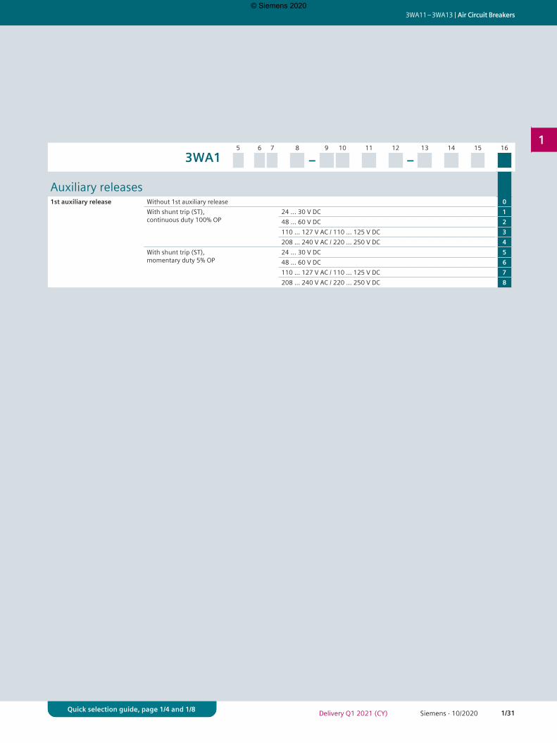
5 6 7 8 9 10 11 12 13 14 15 16
3WA1 – –
Auxiliary releases1st auxiliary release Without 1st auxiliary release 0
With shunt trip (ST), continuous duty 100% OP
24 ... 30 V DC 148 ... 60 V DC 2110 ... 127 V AC / 110 ... 125 V DC 3208 ... 240 V AC / 220 ... 250 V DC 4
With shunt trip (ST), momentary duty 5% OP
24 ... 30 V DC 548 ... 60 V DC 6110 ... 127 V AC / 110 ... 125 V DC 7208 ... 240 V AC / 220 ... 250 V DC 8
© Siemens 2020
1/32 Siemens · 10/2020 Delivery Q1 2021 (CY)
Air Circuit Breakers | 3WA11 – 3WA13
1
Quick selection guide, page 1/4 and 1/8Quick selection guide, page 1/4 and 1/8
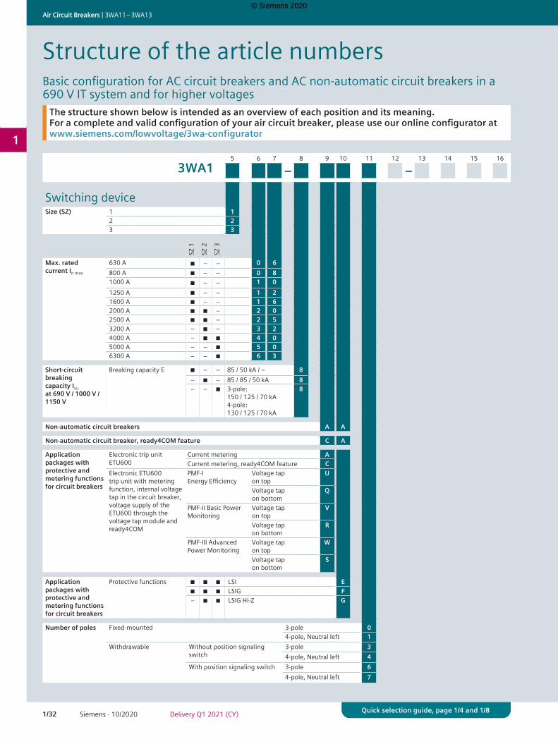
Structure of the article numbersBasic configuration for AC circuit breakers and AC non-automatic circuit breakers in a 690 V IT system and for higher voltages
5 6 7 8 9 10 11 12 13 14 15 16
3WA1 – –
Switching deviceSize (SZ) 1 1
2 23 3
SZ 1
SZ 2
SZ 3
Max. rated current In max
630 A ■ – – 0 6800 A ■ – – 0 81000 A ■ – – 1 01250 A ■ – – 1 21600 A ■ – – 1 62000 A ■ ■ – 2 02500 A ■ ■ – 2 53200 A – ■ – 3 24000 A – ■ ■ 4 05000 A – – ■ 5 06300 A – – ■ 6 3
Short-circuit breaking capacity Icu at 690 V / 1000 V / 1150 V
Breaking capacity E ■ – – 85 / 50 kA / – 8– ■ – 85 / 85 / 50 kA 8– – ■ 3-pole:
150 / 125 / 70 kA 4-pole: 130 / 125 / 70 kA
8
Non-automatic circuit breakers A A
Non-automatic circuit breaker, ready4COM feature C A
Application packages with protective and metering functions for circuit breakers
Electronic trip unit ETU600
Current metering ACurrent metering, ready4COM feature C
Electronic ETU600 trip unit with metering function, internal voltage tap in the circuit breaker, voltage supply of the ETU600 through the voltage tap module and ready4COM
PMF-I Energy Efficiency
Voltage tap on top
U
Voltage tap on bottom
Q
PMF-II Basic Power Monitoring
Voltage tap on top
V
Voltage tap on bottom
R
PMF-III Advanced Power Monitoring
Voltage tap on top
W
Voltage tap on bottom
S
Application packages with protective and metering functions for circuit breakers
Protective functions ■ ■ ■ LSI E■ ■ ■ LSIG F– ■ ■ LSIG Hi-Z G
Number of poles Fixed-mounted 3-pole 04-pole, Neutral left 1
Withdrawable Without position signaling switch
3-pole 34-pole, Neutral left 4
With position signaling switch 3-pole 64-pole, Neutral left 7
The structure shown below is intended as an overview of each position and its meaning. For a complete and valid configuration of your air circuit breaker, please use our online configurator at www.siemens.com/lowvoltage/3wa-configurator
© Siemens 2020

1/33Siemens · 10/2020Delivery Q1 2021 (CY)
3WA11 – 3WA13 | Air Circuit Breakers
1
Quick selection guide, page 1/4 and 1/8Quick selection guide, page 1/4 and 1/8
5 6 7 8 9 10 11 12 13 14 15 16
3WA1 – –
Connection SZ 1
SZ 2
SZ 3
Type of mounting Fixed-mounted ■ ■ 3) ■ Vertical 1■ 1) ■ 2) ■ 4) Horizontal 2■ 1) ■ 2) ■ 5) Front double hole 3■ 1) ■ 2) ■ 4) Vertical on top / horizontal at the bottom 5■ 1) ■ 2) ■ 4) Horizontal on top / vertical at the bottom 6
Withdrawable ■ ■ ■ Without guide frame 0■ ■ 3) ■ Vertical 1■ 1) ■ 2) ■ 4) Horizontal 2■ 1) ■ 2) ■ 5) Front double hole 3■ 1) ■ 2) ■ 5) Flange 4■ 1) ■ 2) ■ 4) Vertical on top / horizontal at the bottom 5■ 1) ■ 2) ■ 4) Horizontal on top / vertical at the bottom 6■ 1) ■ 2) ■ 5) Flange on top / horizontal at the bottom 7■ 1) ■ 2) ■ 5) Horizontal on top / flange at the bottom 8
1) Only ≤2000 A is available for size 12) Only ≤3200 A is available for size 23) Vertical connection for 3WA size 2 for 4000 A has different dimensions than for the 3WL. With Z option D01, vertical connection can be changed to the connection compatible with 3WL.4) Only ≤5000 A is available for size 35) Only for 4000 A is available for size 3
© Siemens 2020
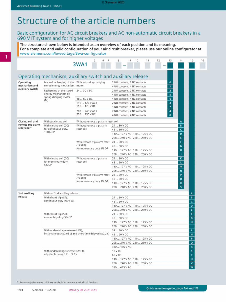
1/34 Siemens · 10/2020 Delivery Q1 2021 (CY)
Air Circuit Breakers | 3WA11 – 3WA13
1
Quick selection guide, page 1/4 and 1/8Quick selection guide, page 1/4 and 1/8
5 6 7 8 9 10 11 12 13 14 15 16
3WA1 – –
Operating mechanism, auxiliary switch and auxiliary releaseOperating mechanism and auxiliary switch
Manual recharging of the stored energy mechanism
Without spring charging motor
2 NO contacts, 2 NC contacts 04 NO contacts, 4 NC contacts 1
Recharging of the stored energy mechanism by spring charging motor (M)
24 ... 30 V DC 2 NO contacts, 2 NC contacts 24 NO contacts, 4 NC contacts 5
48 ... 60 V DC 4 NO contacts, 4 NC contacts 6110 ... 127 V AC / 110 ... 125 V DC
2 NO contacts, 2 NC contacts 34 NO contacts, 4 NC contacts 7
208 ... 240 V AC / 220 ... 250 V DC
2 NO contacts, 2 NC contacts 44 NO contacts, 4 NC contacts 8
Closing coil and remote trip alarm reset coil 1)
Without closing coil Without remote trip alarm reset coil AWith closing coil (CC) for continuous duty, 100% OP
Without remote trip alarm reset coil
24 ... 30 V DC B48 ... 60 V DC C110 ... 127 V AC / 110 ... 125 V DC D208 ... 240 V AC / 220 ... 250 V DC E
With remote trip alarm reset coil (RR) for momentary duty 1% OP
24 ... 30 V DC F48 ... 60 V DC G110 ... 127 V AC / 110 ... 125 V DC H208 ... 240 V AC / 220 ... 250 V DC J
With closing coil (CC) for momentary duty, 5% OP
Without remote trip alarm reset coil
24 ... 30 V DC K48 ... 60 V DC L110 ... 127 V AC / 110 ... 125 V DC M208 ... 240 V AC / 220 ... 250 V DC N
With remote trip alarm reset coil (RR) for momentary duty 1% OP
24 ... 30 V DC P48 ... 60 V DC Q110 ... 127 V AC / 110 ... 125 V DC R208 ... 240 V AC / 220 ... 250 V DC S
2nd auxiliary release
Without 2nd auxiliary release AWith shunt trip (ST), continuous duty 100% OP
24 ... 30 V DC B48 ... 60 V DC C110 ... 127 V AC / 110 ... 125 V DC D208 ... 240 V AC / 220 ... 250 V DC E
With shunt trip (ST), momentary duty 5% OP
24 ... 30 V DC F48 ... 60 V DC G110 ... 127 V AC / 110 ... 125 V DC H208 ... 240 V AC / 220 ... 250 V DC J
With undervoltage release (UVR), instantaneous (≤0.08 s) and short-time delayed (≤0.2 s)
24 ... 30 V DC L48 ... 60 V DC N110 ... 127 V AC / 110 ... 125 V DC P208 ... 240 V AC / 220 ... 250 V DC Q380 ... 415 V AC R
With undervoltage release (UVR-t), adjustable delay 0.2 … 3.2 s
48 V DC S60 V DC T110 ... 127 V AC / 110 ... 125 V DC U208 ... 240 V AC / 220 ... 250 V DC V380 ... 415 V AC W
The structure shown below is intended as an overview of each position and its meaning. For a complete and valid configuration of your air circuit breaker, please use our online configurator at www.siemens.com/lowvoltage/3wa-configurator
Structure of the article numbersBasic configuration for AC circuit breakers and AC non-automatic circuit breakers in a 690 V IT system and for higher voltages
1) Remote trip alarm reset coil is not available for non-automatic circuit breakers
© Siemens 2020
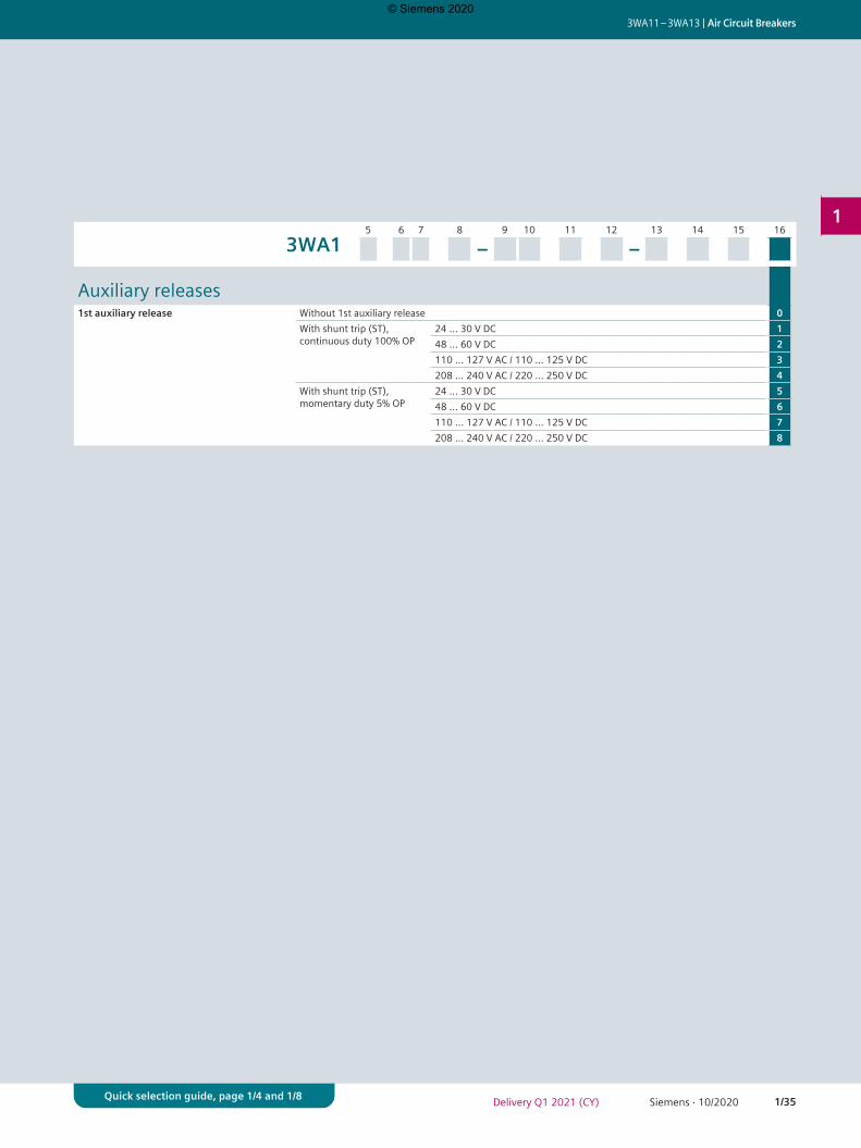
1/35Siemens · 10/2020Delivery Q1 2021 (CY)
3WA11 – 3WA13 | Air Circuit Breakers
1
Quick selection guide, page 1/4 and 1/8Quick selection guide, page 1/4 and 1/8
5 6 7 8 9 10 11 12 13 14 15 16
3WA1 – –
Auxiliary releases1st auxiliary release Without 1st auxiliary release 0
With shunt trip (ST), continuous duty 100% OP
24 ... 30 V DC 148 ... 60 V DC 2110 ... 127 V AC / 110 ... 125 V DC 3208 ... 240 V AC / 220 ... 250 V DC 4
With shunt trip (ST), momentary duty 5% OP
24 ... 30 V DC 548 ... 60 V DC 6110 ... 127 V AC / 110 ... 125 V DC 7208 ... 240 V AC / 220 ... 250 V DC 8
© Siemens 2020
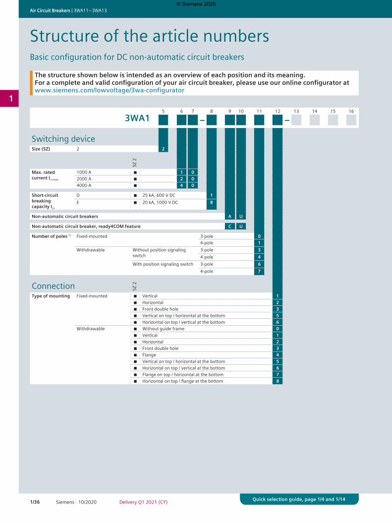
1/36 Siemens · 10/2020 Delivery Q1 2021 (CY)
Air Circuit Breakers | 3WA11 – 3WA13
1
Quick selection guide, page 1/4 and 1/14Quick selection guide, page 1/4 and 1/14
5 6 7 8 9 10 11 12 13 14 15 16
3WA1 – –
Switching deviceSize (SZ) 2 2
SZ 2
Max. rated current In max
1000 A ■ 1 02000 A ■ 2 04000 A ■ 4 0
Short-circuit breaking capacity Icc
D ■ 25 kA, 600 V DC 1E ■ 20 kA, 1000 V DC 8
Non-automatic circuit breakers A U
Non-automatic circuit breaker, ready4COM feature C U
Number of poles 1) Fixed-mounted 3-pole 04-pole 1
Withdrawable Without position signaling switch
3-pole 34-pole 4
With position signaling switch 3-pole 64-pole 7
Connection SZ 2
Type of mounting Fixed-mounted ■ Vertical 1■ Horizontal 2■ Front double hole 3■ Vertical on top / horizontal at the bottom 5■ Horizontal on top / vertical at the bottom 6
Withdrawable ■ Without guide frame 0■ Vertical 1■ Horizontal 2■ Front double hole 3■ Flange 4■ Vertical on top / horizontal at the bottom 5■ Horizontal on top / vertical at the bottom 6■ Flange on top / horizontal at the bottom 7■ Horizontal on top / flange at the bottom 8
Structure of the article numbersBasic configuration for DC non-automatic circuit breakers
The structure shown below is intended as an overview of each position and its meaning. For a complete and valid configuration of your air circuit breaker, please use our online configurator at www.siemens.com/lowvoltage/3wa-configurator
© Siemens 2020
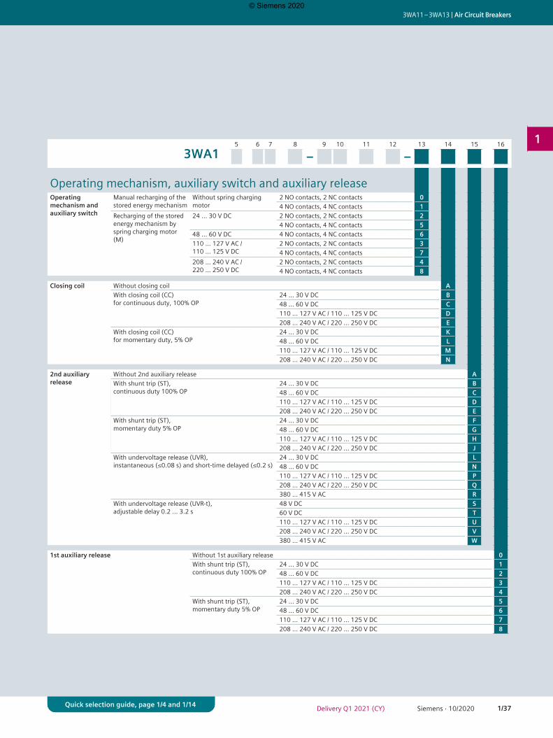
1/37Siemens · 10/2020Delivery Q1 2021 (CY)
3WA11 – 3WA13 | Air Circuit Breakers
1
Quick selection guide, page 1/4 and 1/14Quick selection guide, page 1/4 and 1/14
5 6 7 8 9 10 11 12 13 14 15 16
3WA1 – –
Operating mechanism, auxiliary switch and auxiliary releaseOperating mechanism and auxiliary switch
Manual recharging of the stored energy mechanism
Without spring charging motor
2 NO contacts, 2 NC contacts 04 NO contacts, 4 NC contacts 1
Recharging of the stored energy mechanism by spring charging motor (M)
24 ... 30 V DC 2 NO contacts, 2 NC contacts 24 NO contacts, 4 NC contacts 5
48 ... 60 V DC 4 NO contacts, 4 NC contacts 6110 ... 127 V AC / 110 ... 125 V DC
2 NO contacts, 2 NC contacts 34 NO contacts, 4 NC contacts 7
208 ... 240 V AC / 220 ... 250 V DC
2 NO contacts, 2 NC contacts 44 NO contacts, 4 NC contacts 8
Closing coil Without closing coil AWith closing coil (CC) for continuous duty, 100% OP
24 ... 30 V DC B48 ... 60 V DC C110 ... 127 V AC / 110 ... 125 V DC D208 ... 240 V AC / 220 ... 250 V DC E
With closing coil (CC) for momentary duty, 5% OP
24 ... 30 V DC K48 ... 60 V DC L110 ... 127 V AC / 110 ... 125 V DC M208 ... 240 V AC / 220 ... 250 V DC N
2nd auxiliary release
Without 2nd auxiliary release AWith shunt trip (ST), continuous duty 100% OP
24 ... 30 V DC B48 ... 60 V DC C110 ... 127 V AC / 110 ... 125 V DC D208 ... 240 V AC / 220 ... 250 V DC E
With shunt trip (ST), momentary duty 5% OP
24 ... 30 V DC F48 ... 60 V DC G110 ... 127 V AC / 110 ... 125 V DC H208 ... 240 V AC / 220 ... 250 V DC J
With undervoltage release (UVR), instantaneous (≤0.08 s) and short-time delayed (≤0.2 s)
24 ... 30 V DC L48 ... 60 V DC N110 ... 127 V AC / 110 ... 125 V DC P208 ... 240 V AC / 220 ... 250 V DC Q380 ... 415 V AC R
With undervoltage release (UVR-t), adjustable delay 0.2 … 3.2 s
48 V DC S60 V DC T110 ... 127 V AC / 110 ... 125 V DC U208 ... 240 V AC / 220 ... 250 V DC V380 ... 415 V AC W
1st auxiliary release Without 1st auxiliary release 0With shunt trip (ST), continuous duty 100% OP
24 ... 30 V DC 148 ... 60 V DC 2110 ... 127 V AC / 110 ... 125 V DC 3208 ... 240 V AC / 220 ... 250 V DC 4
With shunt trip (ST), momentary duty 5% OP
24 ... 30 V DC 548 ... 60 V DC 6110 ... 127 V AC / 110 ... 125 V DC 7208 ... 240 V AC / 220 ... 250 V DC 8
© Siemens 2020
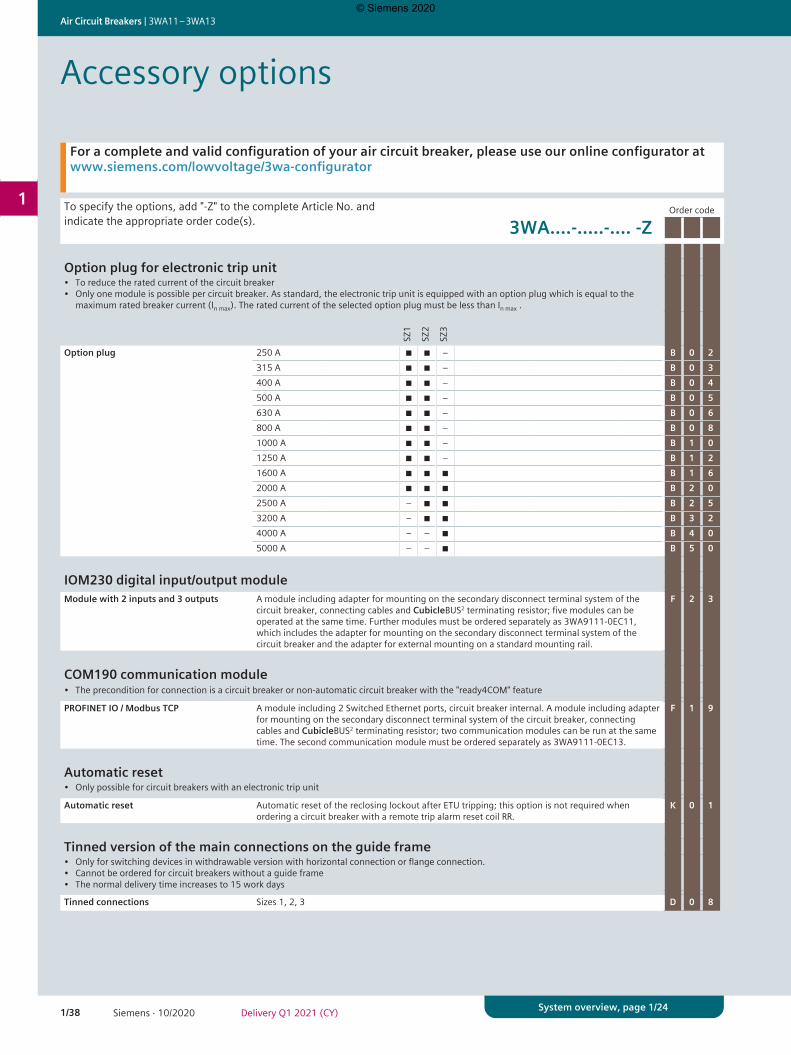
1/38 Siemens · 10/2020 Delivery Q1 2021 (CY)
Air Circuit Breakers | 3WA11 – 3WA13
1
System overview, page 1/24
Accessory options
For a complete and valid configuration of your air circuit breaker, please use our online configurator at www.siemens.com/lowvoltage/3wa-configurator
To specify the options, add "-Z" to the complete Article No. and indicate the appropriate order code(s).
Order code
3WA....-.....-.... -Z
Option plug for electronic trip unit• To reduce the rated current of the circuit breaker• Only one module is possible per circuit breaker. As standard, the electronic trip unit is equipped with an option plug which is equal to the
maximum rated breaker current (In max). The rated current of the selected option plug must be less than In max .
SZ1
SZ2
SZ3
Option plug 250 A ■ ■ – B 0 2315 A ■ ■ – B 0 3400 A ■ ■ – B 0 4500 A ■ ■ – B 0 5630 A ■ ■ – B 0 6800 A ■ ■ – B 0 81000 A ■ ■ – B 1 01250 A ■ ■ – B 1 21600 A ■ ■ ■ B 1 62000 A ■ ■ ■ B 2 02500 A – ■ ■ B 2 53200 A – ■ ■ B 3 24000 A – – ■ B 4 05000 A – – ■ B 5 0
IOM230 digital input/output moduleModule with 2 inputs and 3 outputs A module including adapter for mounting on the secondary disconnect terminal system of the
circuit breaker, connecting cables and CubicleBUS2 terminating resistor; five modules can be operated at the same time. Further modules must be ordered separately as 3WA9111-0EC11, which includes the adapter for mounting on the secondary disconnect terminal system of the circuit breaker and the adapter for external mounting on a standard mounting rail.
F 2 3
COM190 communication module• The precondition for connection is a circuit breaker or non-automatic circuit breaker with the "ready4COM" feature
PROFINET IO / Modbus TCP A module including 2 Switched Ethernet ports, circuit breaker internal. A module including adapter for mounting on the secondary disconnect terminal system of the circuit breaker, connecting cables and CubicleBUS2 terminating resistor; two communication modules can be run at the same time. The second communication module must be ordered separately as 3WA9111-0EC13.
F 1 9
Automatic reset• Only possible for circuit breakers with an electronic trip unit
Automatic reset Automatic reset of the reclosing lockout after ETU tripping; this option is not required when ordering a circuit breaker with a remote trip alarm reset coil RR.
K 0 1
Tinned version of the main connections on the guide frame• Only for switching devices in withdrawable version with horizontal connection or flange connection.• Cannot be ordered for circuit breakers without a guide frame• The normal delivery time increases to 15 work days
Tinned connections Sizes 1, 2, 3 D 0 8
© Siemens 2020
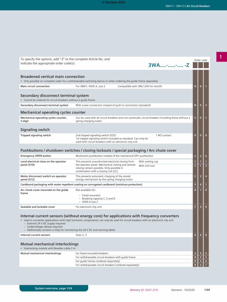
1/39Siemens · 10/2020Delivery Q1 2021 (CY)
3WA11 – 3WA13 | Air Circuit Breakers
1
System overview, page 1/24
To specify the options, add "-Z" to the complete Article No. and indicate the appropriate order code(s).
Order code
3WA....-.....-.... -Z
Broadened vertical main connection• Only possible on complete order for a withdrawable switching device or when ordering the guide frame separately
Main circuit connection For 3WA1, 4000 A, size 2 Compatible with 3WL1240 for retrofit D 0 1
Secondary disconnect terminal system• Cannot be ordered for circuit breakers without a guide frame
Secondary disconnect terminal system With screw connection instead of push-in connection (standard) N 0 3
Mechanical operating cycles counterMechanical operating cycles counter, 5-digit
Can be used with all circuit breakers and non-automatic circuit breakers including those without a spring charging motor
C 0 1
Signaling switchTripped signaling switch 2nd tripped signaling switch (S25)
1st tripped signaling switch included as standard. Can only be used with circuit breakers with an electronic trip unit
1 NO contact K 0 6
Pushbuttons / shutdown switches / closing lockouts / special packaging / Arc chute coverEmergency OPEN button Mushroom pushbutton instead of the mechanical OFF pushbutton C 2 5
Local electrical close on the operator panel (S10)
This prevents unauthorized electrical closing from the operator panel. Mechanical closing and remote closing remain possible. Only possible in combination with a closing coil (CC)
With sealing cap C 1 1With CES lock C 1 2
Motor disconnect switch on operator panel (S12)
This prevents automatic charging of the stored energy mechanism by the spring charging motor
C 2 4
Cardboard packaging with water-repellent coating on corrugated cardboard (moisture protection) P 6 1
Arc chute cover mounted on the guide frame
Not available for:
− Fixed-mounted − Breaking capacity C, E and D − 4000 A size 2
R 1 0
Sealable and lockable cover For electronic trip unit F 4 0
Internal current sensors (without energy core) for applications with frequency converters• Used in converter applications with high harmonic components; can only be used for circuit breakers with an electronic trip unit
− External 24 V DC supply required − Undervoltage release required − Additionally contains a relay for monitoring the 24 V DC and warning labels
Internal current sensors Sizes 2, 3 K 6 0
Mutual mechanical interlockings• Interlocking module with Bowden cable 2 m
Mutual mechanical interlockings For fixed-mounted breakers S 5 5For withdrawable circuit breakers with guide frame R 5 5For guide frames (ordered separately) R 5 6For withdrawable circuit breakers (ordered separately) R 5 7
© Siemens 2020
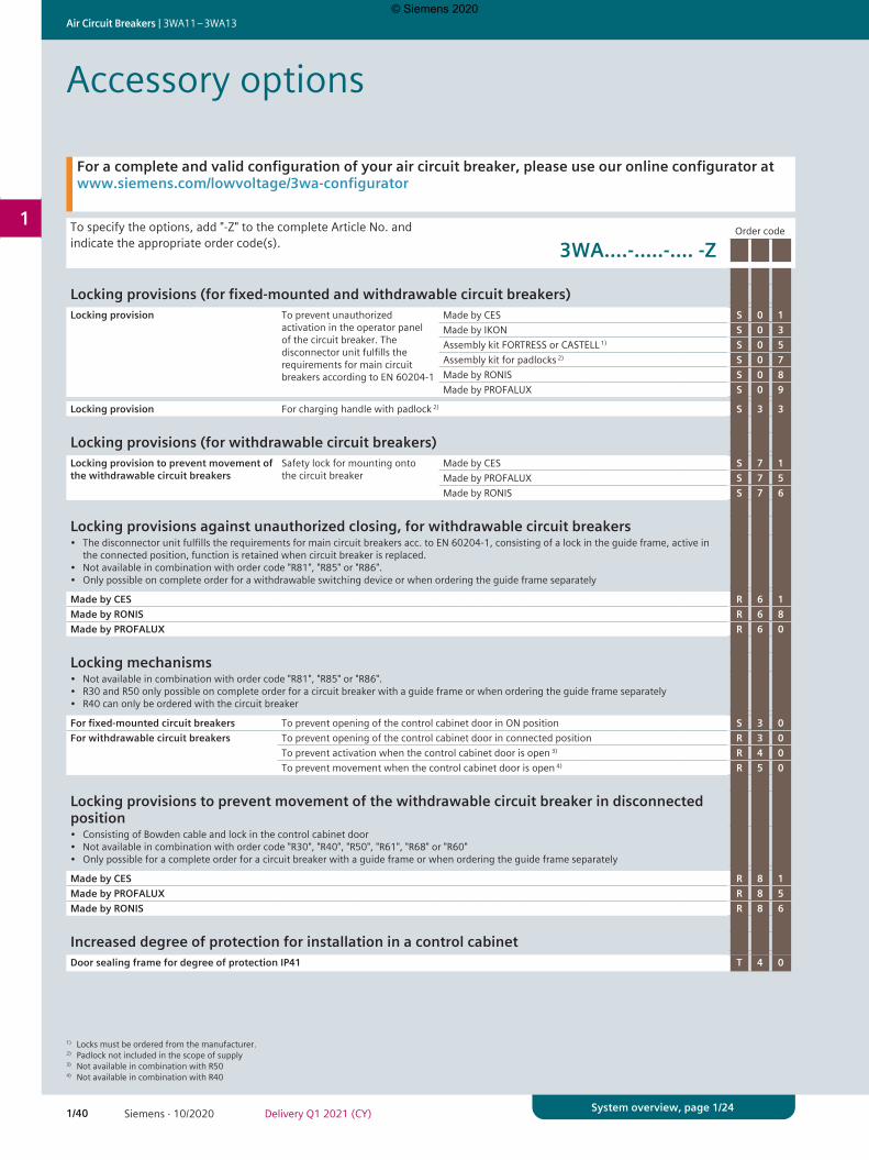
1/40 Siemens · 10/2020 Delivery Q1 2021 (CY)
Air Circuit Breakers | 3WA11 – 3WA13
1
System overview, page 1/24
To specify the options, add "-Z" to the complete Article No. and indicate the appropriate order code(s).
Order code
3WA....-.....-.... -Z
Locking provisions (for fixed-mounted and withdrawable circuit breakers)Locking provision To prevent unauthorized
activation in the operator panel of the circuit breaker. The disconnector unit fulfills the requirements for main circuit breakers according to EN 60204-1
Made by CES S 0 1Made by IKON S 0 3Assembly kit FORTRESS or CASTELL 1) S 0 5Assembly kit for padlocks 2) S 0 7Made by RONIS S 0 8Made by PROFALUX S 0 9
Locking provision For charging handle with padlock 2) S 3 3
Locking provisions (for withdrawable circuit breakers)Locking provision to prevent movement of the withdrawable circuit breakers
Safety lock for mounting onto the circuit breaker
Made by CES S 7 1Made by PROFALUX S 7 5Made by RONIS S 7 6
Locking provisions against unauthorized closing, for withdrawable circuit breakers• The disconnector unit fulfills the requirements for main circuit breakers acc. to EN 60204-1, consisting of a lock in the guide frame, active in
the connected position, function is retained when circuit breaker is replaced.• Not available in combination with order code "R81", "R85" or "R86".• Only possible on complete order for a withdrawable switching device or when ordering the guide frame separately
Made by CES R 6 1Made by RONIS R 6 8Made by PROFALUX R 6 0
Locking mechanisms• Not available in combination with order code "R81", "R85" or "R86".• R30 and R50 only possible on complete order for a circuit breaker with a guide frame or when ordering the guide frame separately• R40 can only be ordered with the circuit breaker
For fixed-mounted circuit breakers To prevent opening of the control cabinet door in ON position S 3 0For withdrawable circuit breakers To prevent opening of the control cabinet door in connected position R 3 0
To prevent activation when the control cabinet door is open 3) R 4 0To prevent movement when the control cabinet door is open 4) R 5 0
Locking provisions to prevent movement of the withdrawable circuit breaker in disconnected position• Consisting of Bowden cable and lock in the control cabinet door• Not available in combination with order code "R30", "R40", "R50", "R61", "R68" or "R60"• Only possible for a complete order for a circuit breaker with a guide frame or when ordering the guide frame separately
Made by CES R 8 1Made by PROFALUX R 8 5Made by RONIS R 8 6
Increased degree of protection for installation in a control cabinetDoor sealing frame for degree of protection IP41 T 4 0
Accessory options
For a complete and valid configuration of your air circuit breaker, please use our online configurator at www.siemens.com/lowvoltage/3wa-configurator
1) Locks must be ordered from the manufacturer.2) Padlock not included in the scope of supply3) Not available in combination with R504) Not available in combination with R40
© Siemens 2020
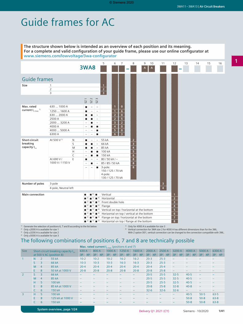
1/41Siemens · 10/2020Delivery Q1 2021 (CY)
3WA11 – 3WA13 | Air Circuit Breakers
1
System overview, page 1/24
Guide frames for AC
The structure shown below is intended as an overview of each position and its meaning. For a complete and valid configuration of your guide frame, please use our online configurator at www.siemens.com/lowvoltage/3wa-configurator
5 6 7 8 9 10 11 12 13 14 15 16
3WA8 – A A –
Guide framesSize 1 1
2 23 3
SZ 1
SZ 2
SZ 3
Max. rated current In max
1)630 … 1000 A ■ – – 1 01250 … 1600 A ■ – – 1 6630 … 2000 A ■ ■ – 2 02500 A ■ ■ – 2 52000 … 3200 A – ■ – 3 24000 A – ■ ■ 4 04000 … 5000 A – – ■ 5 06300 A – – ■ 6 3
Short-circuit breaking capacity Icu
At 500 V 1) N ■ – – 55 kA 2S ■ ■ – 66 kA 3M ■ ■ – 85 kA 4H – ■ ■ 100 kA 5C – ■ ■ 150 kA 6
At 690 V / 1000 V / 1150 V
E ■ – – 80 / 50 kA / – 8– ■ – 85 / 85 / 50 kA 8– – ■ 3-pole:
150 / 125 / 70 kA 4-pole:130 / 125 / 70 kA
8
Number of poles 3-pole 34-pole, Neutral left 4
Main connection ■ ■ 6) ■ Vertical 1■ 2) ■ 4) Horizontal 2■ 2) ■ 3) ■ 5) Front double hole 3■ 2) ■ 3) ■ 5) Flange 4■ 2) ■ 3) ■ 4) Vertical on top / horizontal at the bottom 5■ 2) ■ 3) ■ 4) Horizontal on top / vertical at the bottom 6■ 2) ■ 3) ■ 5) Flange on top / horizontal at the bottom 7■ 2) ■ 3) ■ 5) Horizontal on top / flange at the bottom 8
1) Generate the selection of positions 6, 7 and 8 according to the list below2) Only ≤2000 A is available for size 13) Only ≤3200 A is available for size 24) Only ≤5000 A is available for size 3
5) Only for 4000 A is available for size 36) Vertical connection for 3WA size 2 for 4000 A has different dimensions than for the 3WL.
With Z option D01, vertical connection can be changed to the connection compatible with 3WL.
Max. rated current In max (positions 6 and 7)Size Short-circuit breaking capacity Icu
at 500 V AC (position 8)630 A 800 A 1000 A 1250 A 1600 A 2000 A 2500 A 3200 A 4000 A 5000 A 6300 A3P 4P 3P 4P 3P 4P 3P 4P 3P 4P 3P 4P 3P 4P 3P 4P 3P 4P 3P 4P 3P 4P
1 N 2 55 kA 10-2 10-2 10-2 16-2 16-2 20-3 25-3 – – – –S 3 66 kA 10-3 10-3 10-3 16-3 16-3 20-3 25-3 – – – –M 4 85 kA 20-4 20-4 20-4 20-4 20-4 20-4 25-4 – – – –E 8 50 kA at 1000 V 20-8 20-8 20-8 20-8 20-8 20-8 25-8 – – – –
2 S 3 66 kA – – – – – 20-5 25-5 32-5 40-5 – –M 4 85 kA – – – – – 20-5 25-5 32-5 40-5 – –H 5 100 kA – – – – – 20-5 25-5 32-5 40-5 – –E 8 85 kA at 1000 V – – – – – 20-8 25-8 32-8 40-8 – –C 6 150 kA – – – – – 32-6 32-6 32-6 – – –
3 H 5 100 kA – – – – – – – – 40-5 50-5 63-5E 8 125 kA at 1000 V – – – – – – – – 50-8 50-8 63-8C 6 150 kA – – – – – – – – 50-8 50-8 63-8
The following combinations of positions 6, 7 and 8 are technically possible
© Siemens 2020
■ 3)

1/42 Siemens · 10/2020 Delivery Q1 2021 (CY)
Air Circuit Breakers | 3WA11 – 3WA13
1
System overview, page 1/24
Guide frames for AC
The structure shown below is intended as an overview of each position and its meaning. For a complete and valid configuration of your guide frame, please use our online configurator at www.siemens.com/lowvoltage/3wa-configurator
5 6 7 8 9 10 11 12 13 14 15 16
3WA8 – – 1 1
Push-in connection 1)
SZ 1, SZ 2, SZ 3 X7, X6, X5 Non-automatic circuit breakers without ready4COM feature
A
X8, X7, X6, X5 Circuit breakers/non-automatic circuit breakers with ready4COM feature
B
SZ 2 / SZ 3 X9, X8, X7, X6, X5 Including external trip controller ETC600 for circuit breakers with ETU600 LSIG Hi-Z
K
Position signaling switch
Without position signaling switch APosition signaling switch PSS (3x connected position, 2x test position, 1x disconnected position) CPosition signaling switch PSS-COM (1x connected position, 1x test position, 1x disconnected position) for connection to a communication module
G
1) Conversion to screw-type connection is possible with Z option N03.
© Siemens 2020
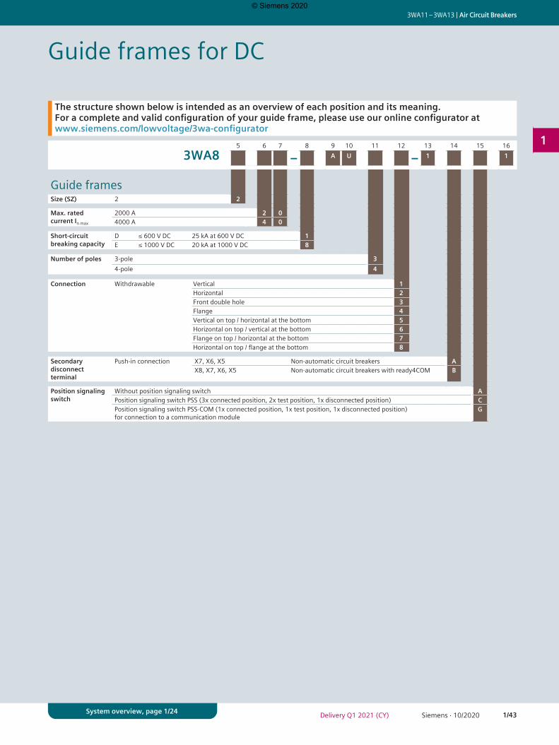
1/43Siemens · 10/2020Delivery Q1 2021 (CY)
3WA11 – 3WA13 | Air Circuit Breakers
1
System overview, page 1/24
Guide frames for DC
The structure shown below is intended as an overview of each position and its meaning. For a complete and valid configuration of your guide frame, please use our online configurator at www.siemens.com/lowvoltage/3wa-configurator
5 6 7 8 9 10 11 12 13 14 15 16
3WA8 – A U – 1 1
Guide framesSize (SZ) 2 2
Max. rated current In max
2000 A 2 04000 A 4 0
Short-circuit breaking capacity
D ≤ 600 V DC 25 kA at 600 V DC 1E ≤ 1000 V DC 20 kA at 1000 V DC 8
Number of poles 3-pole 34-pole 4
Connection Withdrawable Vertical 1Horizontal 2Front double hole 3Flange 4Vertical on top / horizontal at the bottom 5Horizontal on top / vertical at the bottom 6Flange on top / horizontal at the bottom 7Horizontal on top / flange at the bottom 8
Secondary disconnect terminal
Push-in connection X7, X6, X5 Non-automatic circuit breakers AX8, X7, X6, X5 Non-automatic circuit breakers with ready4COM B
Position signaling switch
Without position signaling switch APosition signaling switch PSS (3x connected position, 2x test position, 1x disconnected position) CPosition signaling switch PSS-COM (1x connected position, 1x test position, 1x disconnected position) for connection to a communication module
G
© Siemens 2020
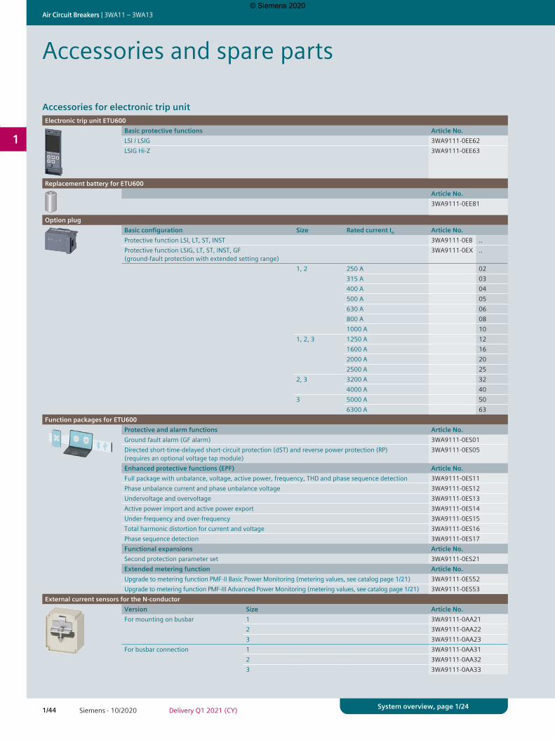
1/44 Siemens · 10/2020 Delivery Q1 2021 (CY)
Air Circuit Breakers | 3WA11 – 3WA13
1
System overview, page 1/24
Accessories and spare parts
Accessories for electronic trip unitElectronic trip unit ETU600
Basic protective functions Article No.LSI / LSIG 3WA9111-0EE62LSIG Hi-Z 3WA9111-0EE63
Replacement battery for ETU600Article No.3WA9111-0EE81
Option plugBasic configuration Size Rated current In Article No.Protective function LSI, LT, ST, INST 3WA9111-0EB ..Protective function LSIG, LT, ST, INST, GF (ground-fault protection with extended setting range)
3WA9111-0EX ..
1, 2 250 A 02315 A 03400 A 04500 A 05630 A 06800 A 081000 A 10
1, 2, 3 1250 A 121600 A 162000 A 202500 A 25
2, 3 3200 A 324000 A 40
3 5000 A 506300 A 63
Function packages for ETU600Protective and alarm functions Article No.Ground fault alarm (GF alarm) 3WA9111-0ES01Directed short-time-delayed short-circuit protection (dST) and reverse power protection (RP) (requires an optional voltage tap module)
3WA9111-0ES05
Enhanced protective functions (EPF) Article No.Full package with unbalance, voltage, active power, frequency, THD and phase sequence detection 3WA9111-0ES11Phase unbalance current and phase unbalance voltage 3WA9111-0ES12Undervoltage and overvoltage 3WA9111-0ES13Active power import and active power export 3WA9111-0ES14Under-frequency and over-frequency 3WA9111-0ES15Total harmonic distortion for current and voltage 3WA9111-0ES16Phase sequence detection 3WA9111-0ES17Functional expansions Article No.Second protection parameter set 3WA9111-0ES21Extended metering function Article No.Upgrade to metering function PMF-II Basic Power Monitoring (metering values, see catalog page 1/21) 3WA9111-0ES52Upgrade to metering function PMF-III Advanced Power Monitoring (metering values, see catalog page 1/21) 3WA9111-0ES53
External current sensors for the N-conductorVersion Size Article No.For mounting on busbar 1 3WA9111-0AA21
2 3WA9111-0AA223 3WA9111-0AA23
For busbar connection 1 3WA9111-0AA312 3WA9111-0AA323 3WA9111-0AA33
© Siemens 2020
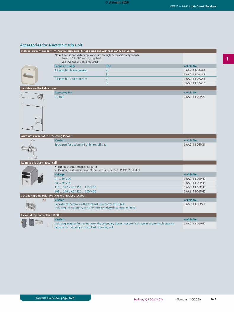
1/45Siemens · 10/2020Delivery Q1 2021 (CY)
3WA11 – 3WA13 | Air Circuit Breakers
1
System overview, page 1/24
Accessories for electronic trip unitInternal current sensors (without energy core) for applications with frequency converters
Note: Used in converter applications with high harmonic components − External 24 V DC supply required − Undervoltage release required
Scope of supply Size Article No.All parts for 3-pole breaker 2 3WA9111-0AA43
3 3WA9111-0AA44All parts for 4-pole breaker 2 3WA9111-0AA46
3 3WA9111-0AA47
Sealable and lockable coverAccessory for Article No.ETU600 3WA9111-0EM22
Automatic reset of the reclosing lockoutVersion Article No.Spare part for option K01 or for retrofitting 3WA9111-0EM31
Remote trip alarm reset coil• For mechanical tripped indicator• Including automatic reset of the reclosing lockout 3WA9111-0EM31Voltage Article No.24 … 30 V DC 3WA9111-0EM4248 ... 60 V DC 3WA9111-0EM44110 ... 127 V AC / 110 ... 125 V DC 3WA9111-0EM45208 ... 240 V AC / 220 ... 250 V DC 3WA9111-0EM46
Second tripping solenoid (F6) with reclose lockoutVersion Article No.For external control via the external trip controller ETC600, including the necessary parts for the secondary disconnect terminal
3WA9111-0EM61
External trip controller ETC600Version Article No.Including adapter for mounting on the secondary disconnect terminal system of the circuit breaker, adapter for mounting on standard mounting rail
3WA9111-0EM62
© Siemens 2020
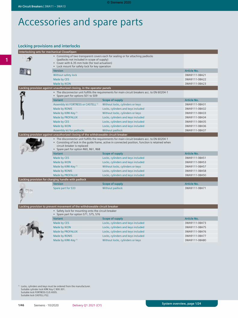
1/46 Siemens · 10/2020 Delivery Q1 2021 (CY)
Air Circuit Breakers | 3WA11 – 3WA13
1
System overview, page 1/24
Locking provisions and interlocksInterlocking sets for mechanical Close/Open
• Consisting of two transparent covers each for sealing or for attaching padlocks (padlocks not included in scope of supply)
• Cover with 6.35 mm hole (for tool actuation)• Lock mount for safety lock for key operationVersion Article No.Without safety lock 3WA9111-0BA21Made by CES 3WA9111-0BA22Made by IKON 3WA9111-0BA23
Locking provision against unauthorized closing, in the operator panels• The disconnector unit fulfills the requirements for main circuit breakers acc. to EN 60204-1• Spare part for options S01 to S09Variant Scope of supply Article No.Assembly kit FORTRESS or CASTELL 1) Without locks, cylinders or keys 3WA9111-0BA31Made by RONIS Locks, cylinders and keys included 3WA9111-0BA32Made by KIRK-Key 1) Without locks, cylinders or keys 3WA9111-0BA33Made by PROFALUX Locks, cylinders and keys included 3WA9111-0BA34Made by CES Locks, cylinders and keys included 3WA9111-0BA35Made by IKON Locks, cylinders and keys included 3WA9111-0BA36Assembly kit for padlocks Without padlock 3WA9111-0BA37
Locking provision against unauthorized closing of the withdrawable circuit breaker• The disconnector unit fulfills the requirements for main circuit breakers acc. to EN 60204-1• Consisting of lock in the guide frame, active in connected position, function is retained when
circuit breaker is replaced• Spare part for option R60, R61, R68Variant Scope of supply Article No.Made by CES Locks, cylinders and keys included 3WA9111-0BA51Made by IKON Locks, cylinders and keys included 3WA9111-0BA53Made by KIRK-Key 1) Without locks, cylinders or keys 3WA9111-0BA57Made by RONIS Locks, cylinders and keys included 3WA9111-0BA58Made by PROFALUX Locks, cylinders and keys included 3WA9111-0BA50
Locking provision for charging handle with padlockVersion Scope of supply Article No.Spare part for S33 Without padlock 3WA9111-0BA71
Locking provision to prevent movement of the withdrawable circuit breaker• Safety lock for mounting onto the circuit breaker• Spare part for option S71, S75, S76Variant Scope of supply Article No.Made by CES Locks, cylinders and keys included 3WA9111-0BA73Made by IKON Locks, cylinders and keys included 3WA9111-0BA75Made by PROFALUX Locks, cylinders and keys included 3WA9111-0BA76Made by RONIS Locks, cylinders and keys included 3WA9111-0BA77Made by KIRK-Key 1) Without locks, cylinders or keys 3WA9111-0BA80
1) Locks, cylinders and keys must be ordered from the manufacturer.Suitable cylinder lock KIRK Key C 900-301. Suitable lock FORTRESS CLIS X005. Suitable lock CASTELL FS2.
Accessories and spare parts
© Siemens 2020
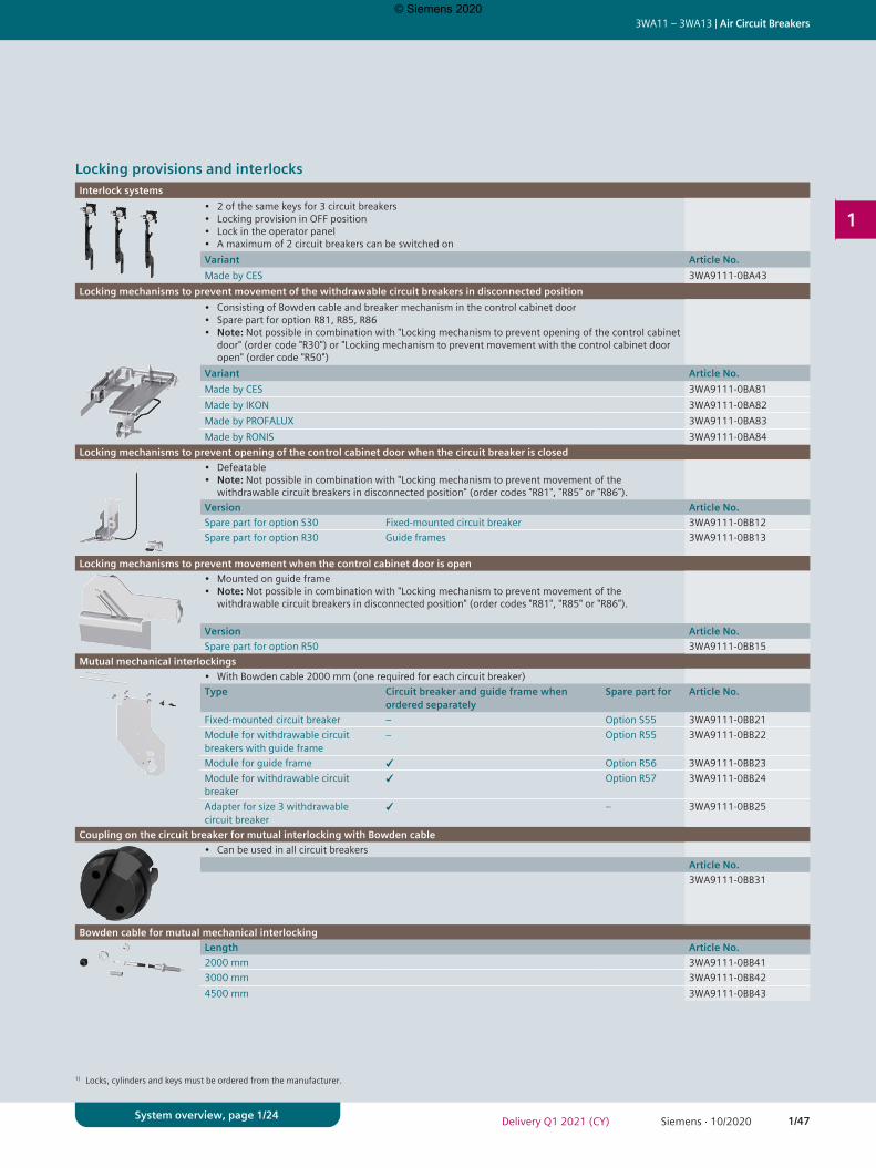
1/47Siemens · 10/2020Delivery Q1 2021 (CY)
3WA11 – 3WA13 | Air Circuit Breakers
1
System overview, page 1/24
1) Locks, cylinders and keys must be ordered from the manufacturer.
Locking provisions and interlocksInterlock systems
• 2 of the same keys for 3 circuit breakers• Locking provision in OFF position• Lock in the operator panel• A maximum of 2 circuit breakers can be switched onVariant Article No.Made by CES 3WA9111-0BA43
Locking mechanisms to prevent movement of the withdrawable circuit breakers in disconnected position• Consisting of Bowden cable and breaker mechanism in the control cabinet door• Spare part for option R81, R85, R86• Note: Not possible in combination with "Locking mechanism to prevent opening of the control cabinet
door" (order code "R30") or "Locking mechanism to prevent movement with the control cabinet door open" (order code "R50")
Variant Article No.Made by CES 3WA9111-0BA81Made by IKON 3WA9111-0BA82Made by PROFALUX 3WA9111-0BA83Made by RONIS 3WA9111-0BA84
Locking mechanisms to prevent opening of the control cabinet door when the circuit breaker is closed• Defeatable• Note: Not possible in combination with "Locking mechanism to prevent movement of the
withdrawable circuit breakers in disconnected position" (order codes "R81", "R85" or "R86").Version Article No.Spare part for option S30 Fixed-mounted circuit breaker 3WA9111-0BB12Spare part for option R30 Guide frames 3WA9111-0BB13
Locking mechanisms to prevent movement when the control cabinet door is open• Mounted on guide frame• Note: Not possible in combination with "Locking mechanism to prevent movement of the
withdrawable circuit breakers in disconnected position" (order codes "R81", "R85" or "R86").
Version Article No.Spare part for option R50 3WA9111-0BB15
Mutual mechanical interlockings• With Bowden cable 2000 mm (one required for each circuit breaker)Type Circuit breaker and guide frame when
ordered separatelySpare part for Article No.
Fixed-mounted circuit breaker – Option S55 3WA9111-0BB21Module for withdrawable circuit breakers with guide frame
– Option R55 3WA9111-0BB22
Module for guide frame ✓ Option R56 3WA9111-0BB23Module for withdrawable circuit breaker
✓ Option R57 3WA9111-0BB24
Adapter for size 3 withdrawable circuit breaker
✓ – 3WA9111-0BB25
Coupling on the circuit breaker for mutual interlocking with Bowden cable• Can be used in all circuit breakers
Article No.3WA9111-0BB31
Bowden cable for mutual mechanical interlockingLength Article No.2000 mm 3WA9111-0BB413000 mm 3WA9111-0BB424500 mm 3WA9111-0BB43
© Siemens 2020
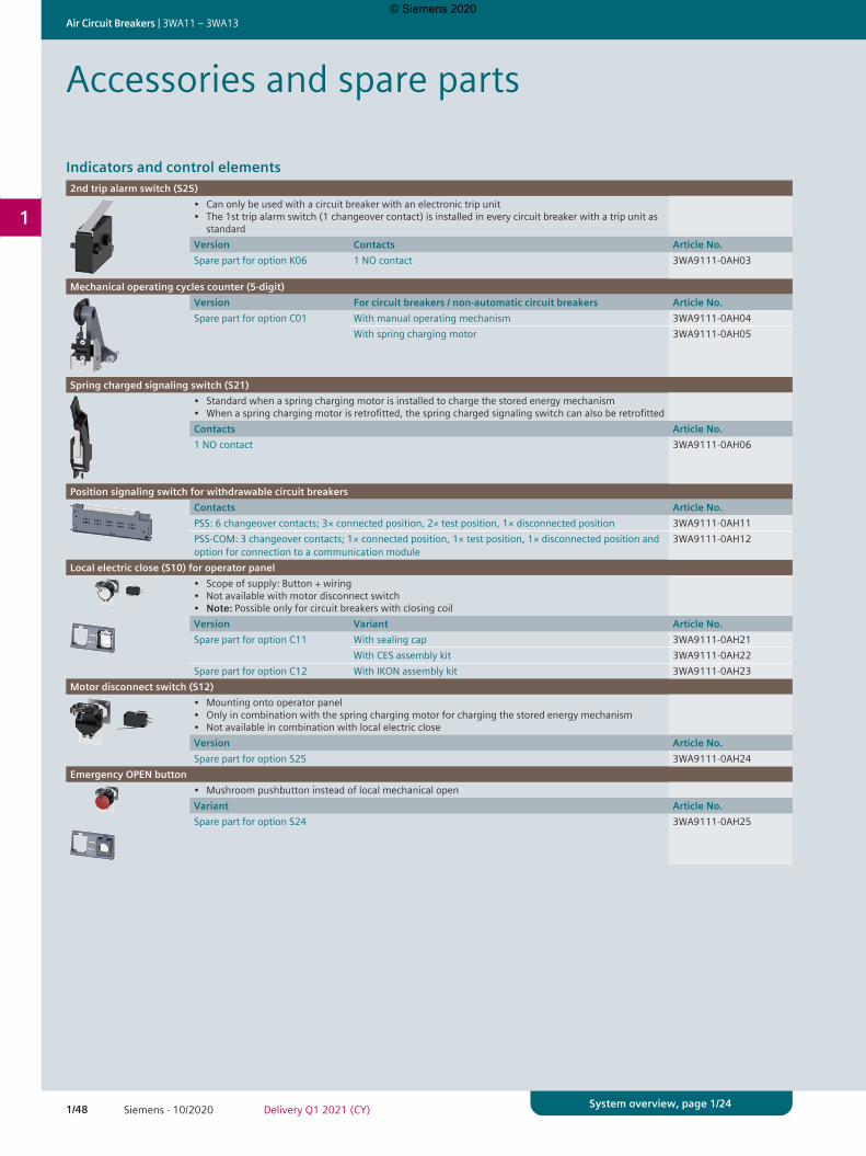
1/48 Siemens · 10/2020 Delivery Q1 2021 (CY)
Air Circuit Breakers | 3WA11 – 3WA13
1
System overview, page 1/24
Indicators and control elements2nd trip alarm switch (S25)
• Can only be used with a circuit breaker with an electronic trip unit• The 1st trip alarm switch (1 changeover contact) is installed in every circuit breaker with a trip unit as
standardVersion Contacts Article No.Spare part for option K06 1 NO contact 3WA9111-0AH03
Mechanical operating cycles counter (5-digit)Version For circuit breakers / non-automatic circuit breakers Article No.Spare part for option C01 With manual operating mechanism 3WA9111-0AH04
With spring charging motor 3WA9111-0AH05
Spring charged signaling switch (S21)• Standard when a spring charging motor is installed to charge the stored energy mechanism• When a spring charging motor is retrofitted, the spring charged signaling switch can also be retrofittedContacts Article No.1 NO contact 3WA9111-0AH06
Position signaling switch for withdrawable circuit breakersContacts Article No.PSS: 6 changeover contacts; 3× connected position, 2× test position, 1× disconnected position 3WA9111-0AH11PSS-COM: 3 changeover contacts; 1× connected position, 1× test position, 1× disconnected position and option for connection to a communication module
3WA9111-0AH12
Local electric close (S10) for operator panel• Scope of supply: Button + wiring• Not available with motor disconnect switch• Note: Possible only for circuit breakers with closing coilVersion Variant Article No.Spare part for option C11 With sealing cap 3WA9111-0AH21
With CES assembly kit 3WA9111-0AH22Spare part for option C12 With IKON assembly kit 3WA9111-0AH23
Motor disconnect switch (S12)• Mounting onto operator panel• Only in combination with the spring charging motor for charging the stored energy mechanism• Not available in combination with local electric closeVersion Article No.Spare part for option S25 3WA9111-0AH24
Emergency OPEN button• Mushroom pushbutton instead of local mechanical openVariant Article No.Spare part for option S24 3WA9111-0AH25
Accessories and spare parts
© Siemens 2020
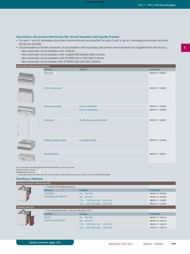
1/49Siemens · 10/2020Delivery Q1 2021 (CY)
3WA11 – 3WA13 | Air Circuit Breakers
1
System overview, page 1/24
Secondary disconnect terminals for circuit breakers and guide frames• For size 1, up to 4 secondary disconnect terminal blocks are possible; for sizes 2 and 3, up to 5 secondary disconnect terminal
blocks are possible• Circuit breakers and non-automatic circuit breakers with secondary disconnect terminal blocks are supplied from the factory:
− Non-automatic circuit breakers with 3 blocks − Non-automatic circuit breakers with ready4COM feature with 4 blocks − Non-automatic circuit breakers with ETU600 LSI or LSIG with 4 blocks − Non-automatic circuit breaker with ETU600 LSIG-HiZ with 5 blocks
Secondary disconnect terminalVersion Variant Article No.Base part 3WA9111-0AB01
1000 V extension 1) 3WA9111-0AB02
Manual connector Screw connection 3WA9111-0AB03Push-in connection 3WA9111-0AB04
Coding kit For fixed-mounted X5 to X8 3WA9111-0AB07
Sliding contact module For guide frames 3WA9111-0AB08
Blanking block 3WA9111-0AB12
For a complete secondary disconnect terminal block, you must order:Fixed-mounted version: + + Withdrawable version: + + 1) Secondary disconnect terminal for circuit breakers with breaking capacity C and E must be ordered separately
Auxiliary releasesClosing coil (CC) / shunt trip (ST)
• Suitable for continuous dutyVersion Voltage Article No.100% OP Switching time ≦80 ms
24 ... 30 V DC 3WA9111-0AD0248 ... 60 V DC 3WA9111-0AD04110 ... 125 V DC/110 ... 127 V AC 3WA9111-0AD05220 ... 250 V DC/208 ... 240 V AC 3WA9111-0AD06
Closing coil (CC)• For momentary duty, with cut-off switch S15Version Voltage Article No.5% OP Switching time 50 ms
24 ... 30 V DC 3WA9111-0AD1248 ... 60 V DC 3WA9111-0AD14110 ... 125 V DC/110 ... 127 V AC 3WA9111-0AD15220 ... 250 V DC/208 ... 240 V AC 3WA9111-0AD16
1
2
3
4
1 2 31 4 2
© Siemens 2020
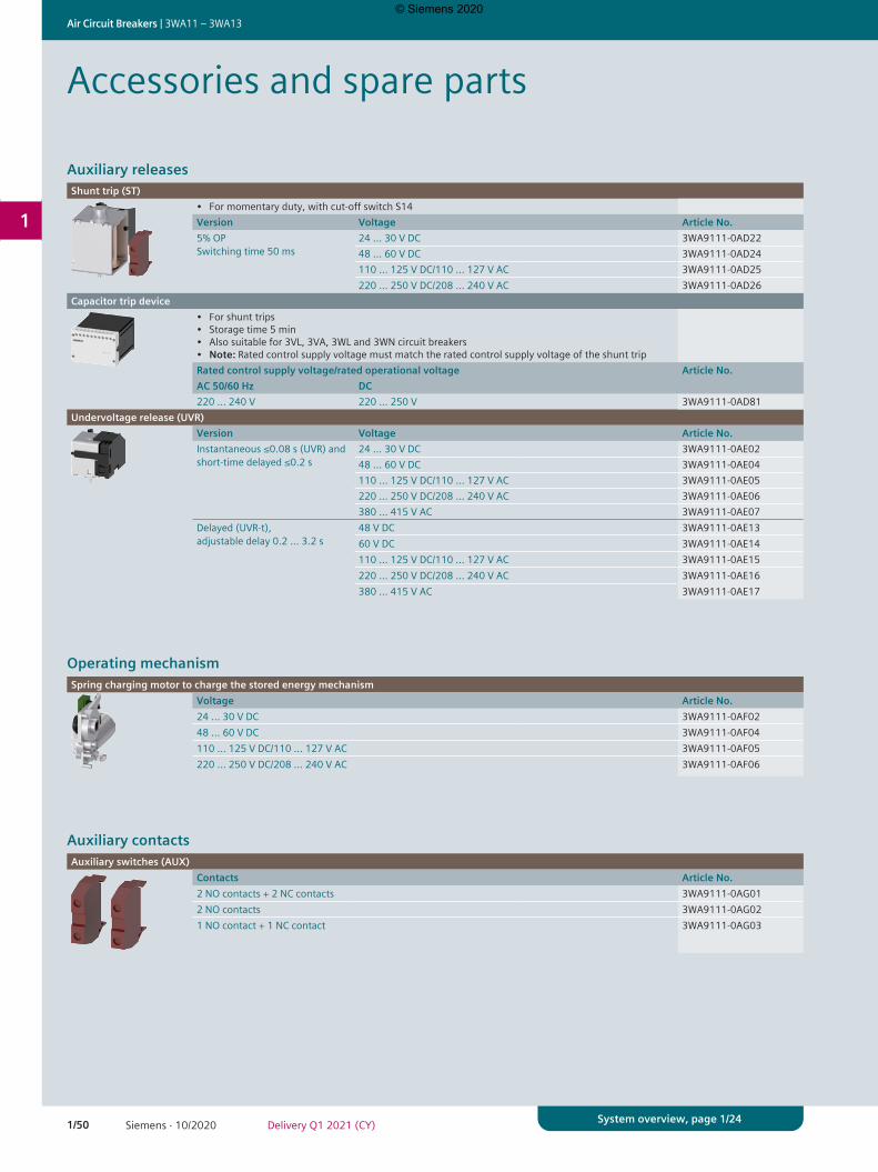
1/50 Siemens · 10/2020 Delivery Q1 2021 (CY)
Air Circuit Breakers | 3WA11 – 3WA13
1
System overview, page 1/24
Auxiliary releasesShunt trip (ST)
• For momentary duty, with cut-off switch S14Version Voltage Article No.5% OP Switching time 50 ms
24 ... 30 V DC 3WA9111-0AD2248 ... 60 V DC 3WA9111-0AD24110 ... 125 V DC/110 ... 127 V AC 3WA9111-0AD25220 ... 250 V DC/208 ... 240 V AC 3WA9111-0AD26
Capacitor trip device• For shunt trips• Storage time 5 min• Also suitable for 3VL, 3VA, 3WL and 3WN circuit breakers• Note: Rated control supply voltage must match the rated control supply voltage of the shunt tripRated control supply voltage/rated operational voltage Article No.AC 50/60 Hz DC220 … 240 V 220 … 250 V 3WA9111-0AD81
Undervoltage release (UVR)Version Voltage Article No.Instantaneous ≤0.08 s (UVR) and short-time delayed ≤0.2 s
24 ... 30 V DC 3WA9111-0AE0248 ... 60 V DC 3WA9111-0AE04110 ... 125 V DC/110 ... 127 V AC 3WA9111-0AE05220 ... 250 V DC/208 ... 240 V AC 3WA9111-0AE06380 ... 415 V AC 3WA9111-0AE07
Delayed (UVR-t), adjustable delay 0.2 … 3.2 s
48 V DC 3WA9111-0AE1360 V DC 3WA9111-0AE14110 ... 125 V DC/110 ... 127 V AC 3WA9111-0AE15220 ... 250 V DC/208 ... 240 V AC 3WA9111-0AE16380 ... 415 V AC 3WA9111-0AE17
Operating mechanismSpring charging motor to charge the stored energy mechanism
Voltage Article No.24 ... 30 V DC 3WA9111-0AF0248 ... 60 V DC 3WA9111-0AF04110 ... 125 V DC/110 ... 127 V AC 3WA9111-0AF05220 ... 250 V DC/208 ... 240 V AC 3WA9111-0AF06
Auxiliary contactsAuxiliary switches (AUX)
Contacts Article No.2 NO contacts + 2 NC contacts 3WA9111-0AG012 NO contacts 3WA9111-0AG021 NO contact + 1 NC contact 3WA9111-0AG03
Accessories and spare parts
© Siemens 2020
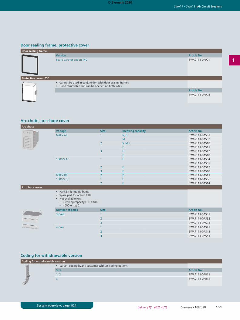
1/51Siemens · 10/2020Delivery Q1 2021 (CY)
3WA11 – 3WA13 | Air Circuit Breakers
1
System overview, page 1/24
Door sealing frame, protective coverDoor sealing frame
Version Article No.Spare part for option T40 3WA9111-0AP01
Protective cover IP55• Cannot be used in conjunction with door sealing frames• Hood removable and can be opened on both sides
Article No.3WA9111-0AP03
Arc chute, arc chute coverArc chute
Voltage Size Breaking capacity Article No.690 V AC 1 N, S 3WA9111-0AS01
M 3WA9111-0AS022 S, M, H 3WA9111-0AS10
C 3WA9111-0AS113 H 3WA9111-0AS17
C 3WA9111-0AS181000 V AC 1 E 3WA9111-0AS04
3WA9111-0AS052 E 3WA9111-0AS123 E 3WA9111-0AS18
600 V DC 2 D 3WA9111-0AS131000 V DC 1 E 3WA9111-0AS06
2 E 3WA9111-0AS14Arc chute cover
• Parts kit for guide frame• Spare part for option R10• Not available for:
− Breaking capacity C, D and E − 4000 A size 2
Number of poles Size Article No.3-pole 1 3WA9111-0AS31
2 3WA9111-0AS323 3WA9111-0AS33
4-pole 1 3WA9111-0AS412 3WA9111-0AS423 3WA9111-0AS43
Coding for withdrawable versionCoding for withdrawable version
• Variant coding by the customer with 36 coding optionsSize Article No.1, 2 3WA9111-0AR113 3WA9111-0AR12
© Siemens 2020
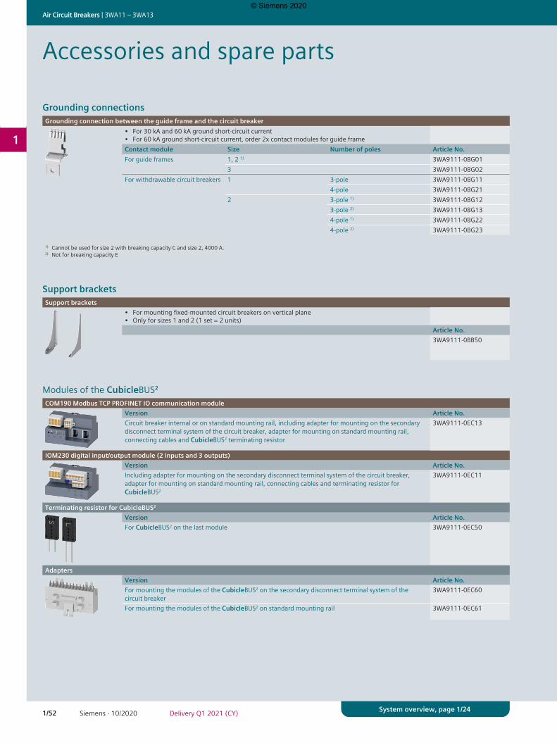
1/52 Siemens · 10/2020 Delivery Q1 2021 (CY)
Air Circuit Breakers | 3WA11 – 3WA13
1
System overview, page 1/24
Grounding connectionsGrounding connection between the guide frame and the circuit breaker
• For 30 kA and 60 kA ground short-circuit current• For 60 kA ground short-circuit current, order 2x contact modules for guide frameContact module Size Number of poles Article No.For guide frames 1, 2 1) 3WA9111-0BG01
3 3WA9111-0BG02For withdrawable circuit breakers 1 3-pole 3WA9111-0BG11
4-pole 3WA9111-0BG212 3-pole 1) 3WA9111-0BG12
3-pole 2) 3WA9111-0BG134-pole 1) 3WA9111-0BG224-pole 2) 3WA9111-0BG23
1) Cannot be used for size 2 with breaking capacity C and size 2, 4000 A.2) Not for breaking capacity E
Support bracketsSupport brackets
• For mounting fixed-mounted circuit breakers on vertical plane• Only for sizes 1 and 2 (1 set = 2 units)
Article No.3WA9111-0BB50
Modules of the CubicleBUS2
COM190 Modbus TCP PROFINET IO communication moduleVersion Article No.Circuit breaker internal or on standard mounting rail, including adapter for mounting on the secondary disconnect terminal system of the circuit breaker, adapter for mounting on standard mounting rail, connecting cables and CubicleBUS2 terminating resistor
3WA9111-0EC13
IOM230 digital input/output module (2 inputs and 3 outputs)Version Article No.Including adapter for mounting on the secondary disconnect terminal system of the circuit breaker, adapter for mounting on standard mounting rail, connecting cables and terminating resistor for CubicleBUS2
3WA9111-0EC11
Terminating resistor for CubicleBUS2
Version Article No.For CubicleBUS2 on the last module 3WA9111-0EC50
AdaptersVersion Article No.For mounting the modules of the CubicleBUS2 on the secondary disconnect terminal system of the circuit breaker
3WA9111-0EC60
For mounting the modules of the CubicleBUS2 on standard mounting rail 3WA9111-0EC61
Accessories and spare parts
© Siemens 2020
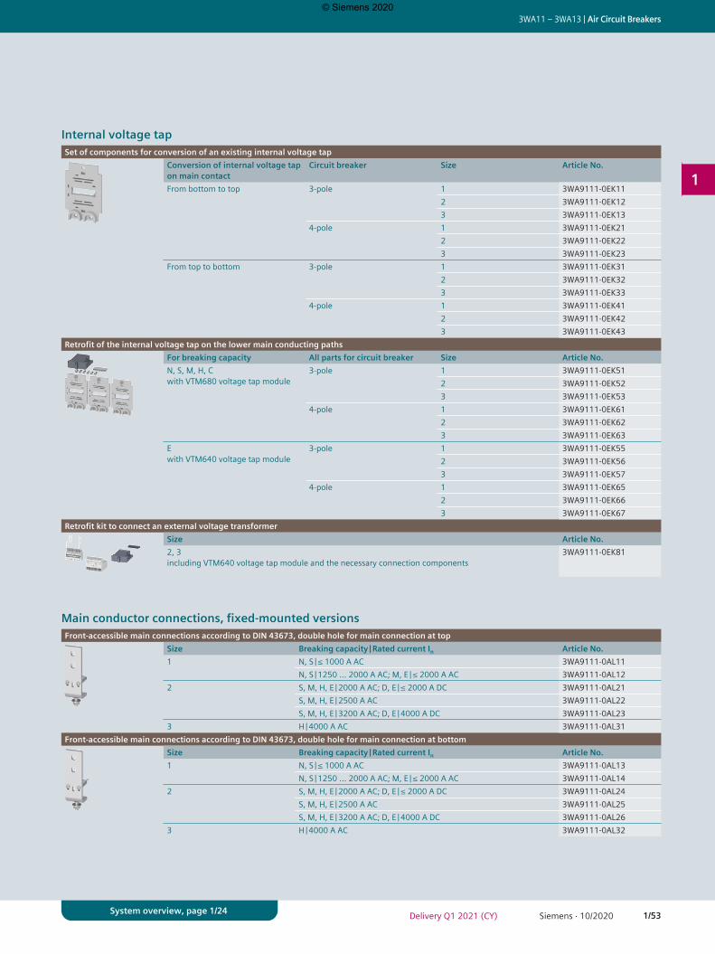
1/53Siemens · 10/2020Delivery Q1 2021 (CY)
3WA11 – 3WA13 | Air Circuit Breakers
1
System overview, page 1/24
Internal voltage tapSet of components for conversion of an existing internal voltage tap
Conversion of internal voltage tap on main contact
Circuit breaker Size Article No.
From bottom to top 3-pole 1 3WA9111-0EK112 3WA9111-0EK123 3WA9111-0EK13
4-pole 1 3WA9111-0EK212 3WA9111-0EK223 3WA9111-0EK23
From top to bottom 3-pole 1 3WA9111-0EK312 3WA9111-0EK323 3WA9111-0EK33
4-pole 1 3WA9111-0EK412 3WA9111-0EK423 3WA9111-0EK43
Retrofit of the internal voltage tap on the lower main conducting pathsFor breaking capacity All parts for circuit breaker Size Article No.N, S, M, H, C with VTM680 voltage tap module
3-pole 1 3WA9111-0EK512 3WA9111-0EK523 3WA9111-0EK53
4-pole 1 3WA9111-0EK612 3WA9111-0EK623 3WA9111-0EK63
E with VTM640 voltage tap module
3-pole 1 3WA9111-0EK552 3WA9111-0EK563 3WA9111-0EK57
4-pole 1 3WA9111-0EK652 3WA9111-0EK663 3WA9111-0EK67
Retrofit kit to connect an external voltage transformerSize Article No.2, 3 including VTM640 voltage tap module and the necessary connection components
3WA9111-0EK81
Main conductor connections, fixed-mounted versionsFront-accessible main connections according to DIN 43673, double hole for main connection at top
Size Breaking capacity | Rated current In Article No.1 N, S | ≤ 1000 A AC 3WA9111-0AL11
N, S | 1250 … 2000 A AC; M, E | ≤ 2000 A AC 3WA9111-0AL122 S, M, H, E | 2000 A AC; D, E | ≤ 2000 A DC 3WA9111-0AL21
S, M, H, E | 2500 A AC 3WA9111-0AL22S, M, H, E | 3200 A AC; D, E | 4000 A DC 3WA9111-0AL23
3 H | 4000 A AC 3WA9111-0AL31Front-accessible main connections according to DIN 43673, double hole for main connection at bottom
Size Breaking capacity | Rated current In Article No.1 N, S | ≤ 1000 A AC 3WA9111-0AL13
N, S | 1250 … 2000 A AC; M, E | ≤ 2000 A AC 3WA9111-0AL142 S, M, H, E | 2000 A AC; D, E | ≤ 2000 A DC 3WA9111-0AL24
S, M, H, E | 2500 A AC 3WA9111-0AL25S, M, H, E | 3200 A AC; D, E | 4000 A DC 3WA9111-0AL26
3 H | 4000 A AC 3WA9111-0AL32
© Siemens 2020
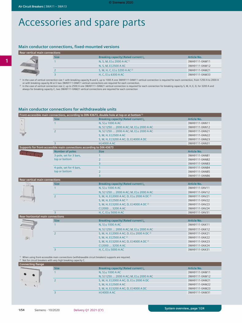
1/54 Siemens · 10/2020 Delivery Q1 2021 (CY)
Air Circuit Breakers | 3WA11 – 3WA13
1
System overview, page 1/24
Main conductor connections, fixed-mounted versionsRear vertical main connections
Size Breaking capacity | Rated current In Article No.1 N, S, M, E | ≤ 2000 A AC 1) 3WA9111-0AM11
N, S, M, E | 2500 A AC 3WA9111-0AM122 S, M, H, C, E | ≤ 3200 A AC 2) 3WA9111-0AM213 H, C, E | ≤ 6300 A AC 3WA9111-0AM33
1) In the case of vertical connection size 1 with breaking capacity N and S, up to 1000 A one 3WA9111-0AM11 vertical connection is required for each connection, from 1250 A to 2000 A or with breaking capacity M or E two 3WA9111-0AM11 vertical connections are required for each connection.2) In the case of vertical connection size 2, up to 2500 A one 3WA9111–0AM21 vertical connection is required for each connection for breaking capacity S, M, H, E, D, for 3200 A and always for breaking capacity C, two 3WA9111-0AM21 vertical connections are required for each connection
Main conductor connections for withdrawable unitsFront-accessible main connections, according to DIN 43673, double hole at top or at bottom 1)
Size Breaking capacity | Rated current In Article No.1 N, S | ≤ 1000 A AC 3WA9111-0AN11
N, S | 1250 … 2000 A AC; M, E | ≤ 2000 A AC 3WA9111-0AN122 N, S | 1250 … 2000 A AC; M, E | ≤ 2000 A AC 3WA9111-0AN21
S, M, H, E | 2500 A AC 3WA9111-0AN22S, M, H, E | 3200 A AC; D, E | 4000 A DC 3WA9111-0AN23
3 H | 4000 A AC 3WA9111-0AN31Supports for front-accessible main connections according to DIN 43673
Number of poles Size Article No.3-pole, set for 3 bars, top or bottom
1 3WA9111-0AN812 3WA9111-0AN823 3WA9111-0AN83
4-pole, set for 4 bars, top or bottom
1 3WA9111-0AN842 3WA9111-0AN853 3WA9111-0AN86
Rear vertical main connectionsSize Breaking capacity | Rated current In Article No.1 N, S | ≤ 1000 A AC 3WA9111-0AV11
N, S | 1250 … 2000 A AC; M, E | ≤ 2000 A AC 3WA9111-0AV122 S, M, H, E | 2000 A AC; D, E | ≤ 2000 A DC 2) 3WA9111-0AV21
S, M, H, E | 2500 A AC 2) 3WA9111-0AV22S, M, H, E | 3200 A AC; D, E | 4000 A DC 2) 3WA9111-0AV23C | 2000 … 3200 A AC 3WA9111-0AV24
3 H, C, E | ≤ 5000 A AC 3WA9111-0AV31Rear horizontal main connections
Size Breaking capacity | Rated current In Article No.1 N, S | ≤ 1000 A AC 3WA9111-0AX11
N, S | 1250 … 2000 A AC; M, E | ≤ 2000 A AC 3WA9111-0AX122 S, M, H, E | 2000 A AC; D, E | ≤ 2000 A DC 2) 3WA9111-0AX21
S, M, H, E | 2500 A AC 2) 3WA9111-0AX22S, M, H, E | 3200 A AC; D, E | 4000 A DC 2) 3WA9111-0AX23C | 2000 … 3200 A AC 3WA9111-0AX24
3 H, C, E | ≤ 5000 A AC 3WA9111-0AX31
1) When using front-accessible main connections (withdrawable circuit breakers) supports are required.2) Not for circuit breakers with very high breaking capacity C.Connecting flange
Size Breaking capacity | Rated current In Article No.1 N, S | ≤ 1000 A AC 3WA9111-0AW11
N, S | 1250 … 2000 A AC; M, E | ≤ 2000 A AC 3WA9111-0AW122 S, M, H, E | 2000 A AC; D, E | ≤ 2000 A DC 3WA9111-0AW21
S, M, H, E | 2500 A AC 3WA9111-0AW22S, M, H, E | 3200 A AC; D, E | 4000 A DC 3WA9111-0AW23
3 H | 4000 A AC 3WA9111-0AW31
Accessories and spare parts
© Siemens 2020

1/55Siemens · 10/2020Delivery Q1 2021 (CY)
3WA11 – 3WA13 | Air Circuit Breakers
1
System overview, page 1/24
Conversion kitConversion kit for converting fixed-mounted circuit breakers into withdrawable circuit breakers
• Guide frames and sliding contact modules must be ordered separately.• Conversion from fixed-mounted to withdrawable circuit breakers is not possible for 3WA circuit
breakers with breaking capacity C and size 3 with breaking capacity ENumber of poles Size Article No.3-pole 1 3WA9111-0BC11
2 3WA9111-0BC123 3WA9111-0BC13
4-pole 1 3WA9111-0BC142 3WA9111-0BC153 3WA9111-0BC16
Main contact elementsMain contact elements for AC circuit breakers
• Notes: − To be ordered only once for each circuit breaker − On the following circuit breakers, the main contact elements can only be replaced in the factory:
3WA1 size 1 breaking capacity M and E 3WA1 size 2 breaking capacity C 3WA1 size 3 breaking capacity C and E
Number of poles
Size Breaking capacity Rated current In Article No.
3 1 N ≤1000 A 3WA9111-0AQ011250 A 3WA9111-0AQ021600 A 3WA9111-0AQ04
S ≤ 1000 A 3WA9111-0AQ031250 … 1600 A 3WA9111-0AQ04
N, S 2000 … 2500 A 3WA9111-0AQ052 S, M , H, E 2000 A 3WA9111-0AQ08
2500 A 3WA9111-0AQ113200 A 3WA9111-0AQ13
S, M, H, E 4000 A 3WA9111-0AQ153 H 4000 A 3WA9111-0AQ20
5000 … 6300 A 3WA9111-0AQ224 1 N ≤ 1000 A 3WA9111-0AQ51
1250 A 3WA9111-0AQ521600 A 3WA9111-0AQ54
S ≤1000 A 3WA9111-0AQ531250 … 1600 A 3WA9111-0AQ54
N, S 2000 … 2500 A 3WA9111-0AQ552 S, M , H, E 2000 A 3WA9111-0AQ58
2500 A 3WA9111-0AQ613200 A 3WA9111-0AQ63
S, M, H, E 4000 A 3WA9111-0AQ653 H 4000 A 3WA9111-0AQ70
5000 … 6300 A 3WA9111-0AQ72Main contact elements for DC non-automatic circuit breakers
• Note: To be ordered only once for each circuit breakerNumber of poles
Size Breaking capacity Rated current In Article No.
3 2 D, E 1000 / 2000 A 3WA9111-0AQ174000 A 3WA9111-0AQ18
4 2 D, E 1000 / 2000 A 3WA9111-0AQ674000 A 3WA9111-0AQ68
© Siemens 2020

Appendix © Siemens 2020
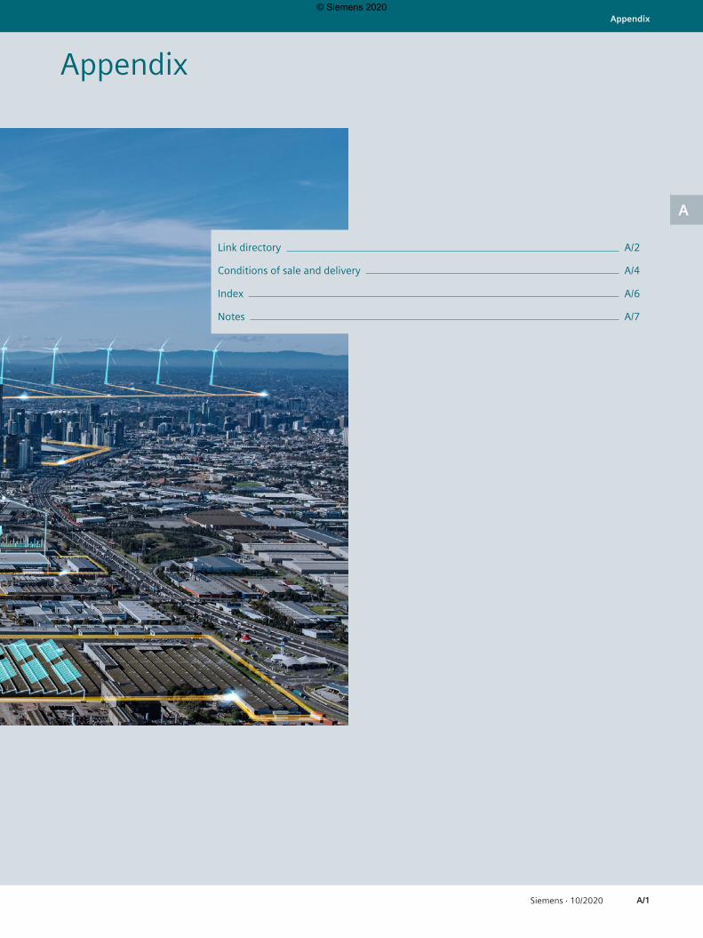
A/1Siemens · 10/2020
Appendix
A
Appendix
Link directory A/2
Conditions of sale and delivery A/4
Index A/6
Notes A/7
© Siemens 2020
A/2 Siemens · 10/2020
Appendix | Link directory
A
Link directoryCatalog
General informationInformation on low-voltage power distribution and electrical installation technology
www.siemens.com/lowvoltage
Tender specifications www.siemens.com/lowvoltage/tenderspecificationsConversion tool www.siemens.com/conversion-toolImage database www.siemens.com/lowvoltage/picturedbCAx download manager www.siemens.com/lowvoltage/caxNewsletter system www.siemens.com/lowvoltage/newsletterSiemens YouTube channel www.youtube.com/SiemensBrochures / catalogs www.siemens.com/lowvoltage/catalogsOperating instructions / manuals www.siemens.com/lowvoltage/manualsSiemens Industry Online Support www.siemens.com/lowvoltage/product-supportSiemens Industry Online Support app www.siemens.com/support-appMy Documentation Manager (MDM) www.siemens.com/lowvoltage/mdmConfigurators www.siemens.com/lowvoltage/configuratorsSiemens Industry Mall – product catalog and online ordering system
www.siemens.com/industrymall
Direct forwarding to the Industry Mall www.siemens.com/product?Article No.Training www.siemens.com/sitrain-lowvoltageLocal contacts www.siemens.com/lowvoltage/contactTechnical Support www.siemens.com/lowvoltage/support-requestInformation on services www.siemens.com/service-catalogControl panels for the North American market www.siemens.com/northamerican-standardsControl panel building www.siemens.com/controlpanelEnergy savings and amortization www.automation.siemens.com/sinasaveEnergy Suite www.siemens.com/energysuiteSITOP power supplies www.siemens.com/sitopPower distribution with Totally Integrated Power www.siemens.com/tip
© Siemens 2020

A/3Siemens · 10/2020
Link directory | Appendix
A
Information + orderingTechnical overviewsAir circuit breakers www.siemens.com/lowvoltage/produkt-support (109781188)All the important things at a glanceAir circuit breakers www.siemens.com/3WAYour product in detailQuick selection guide – 3WA air circuit breakers www.siemens.com/lowvoltage/produkt-support (109781967)Brochure – 3WA air circuit breakers www.siemens.com/lowvoltage/produkt-support (109781968)Siemens YouTube ChannelPower Distribution Low Voltage (EN) bit.ly/3iiuhXSEverything you need for your order3WA air circuit breakers sie.ag/3heeyYvConfigurators3WA air circuit breakers www.siemens.com/lowvoltage/3wa-configurator
Commissioning + operationTools / softwarepowerconfig configuration software www.siemens.com/powerconfigManualsEquipment manual – 3WA air circuit breakers www.siemens.com/lowvoltage/handbuch (109763061)
© Siemens 2020
A/4 Siemens · 10/2020
Appendix | Conditions of sale and delivery
A
Conditions of sale and delivery
1) The text of the Terms and Conditions of Siemens AG can be downloaded at https://mall.industry.siemens.com/legal/ww/en/terms_of_trade_en.pdf
1. General ProvisionsBy using this catalog you can purchase products (hardware, software and services) described therein from Siemens Aktienge-sellschaft subject to the following Terms and Conditions of Sale and Delivery (hereinafter referred to as „T&C“). Please note that the scope, the quality and the conditions for supplies and services, including software products, by any Siemens entity having a registered office outside Germany, shall be subject exclusively to the General Terms and Conditions of the respective Siemens entity. The following T&C apply exclusively for orders placed with Siemens Aktiengesellschaft, Germany.
1.1 For customers with a seat or registered office in GermanyFor customers with a seat or registered office in Germany, the following terms and conditions apply subordinate to T&C:
• for products, which include specific terms and conditions in the description text, these specific terms and conditions shall apply and subordinate thereto,
• for installation work the „General Conditions for Erection Works − Germany“1) („Allgemeine Montagebedingungen − Deutschland“ (currently only available in German)) and/or
• for stand-alone software products and software products forming a part of a product or project, the „General License Conditions for Software Products for Automation and Drives for Customers with a Seat or registered Office in Germany“1) and/or
• for consulting services the „General Terms and Conditions for Consulting Services of the Division DF − Germany“1) and/or
• for other supplies and/or services the „General Conditions for the Supply of Products and Services of the Electrical and Electronics Industry“1). In case such supplies and/or services should contain Open Source Software, the conditions of which shall prevail over the „General Conditions for the Supply of Products and Services of the Electrical and Electronics Indust-ry“1), a notice will be contained in the scope of delivery in which the applicable conditions for Open Source Software are specified. This shall apply mutatis mutandis for notices referring to other third party software components.
1.2 For customers with a seat or registered office outside GermanyFor customers with a seat or registered office outside Germany, the following terms and conditions apply subordinate to T&C:
• for products, which include specific terms and conditions in the description text, these specific terms and conditions shall apply and subordinate thereto,
• for services the „International Terms & Conditions for Servi-ces“1) supplemented by „Software Licensing Conditions“1) and/or
• for consulting services the „General Terms and Conditions for Consulting Services of the Division DF − Germany“1) and/or
• for other supplies of hard- and software the „International Terms & Conditions for Products“1) supplemented by „Software Licensing Conditions“1)
1.3 For customers with master or framework agreementTo the extent our supplies and/or services offered are covered by an existing master or framework agreement, the terms and conditions of that agreement shall apply instead of T&C.
2. Additional Terms and ConditionsThe dimensions are in mm. In Germany, according to the German law on units in measuring technology, data in inches apply only to devices for export.
Illustrations are not binding.
Insofar as there are no remarks on the individual pages of this catalog – especially with regard to data, dimensions and weights given – these are subject to change without prior notice.
3. Export RegulationsWe shall not be obligated to fulfill any agreement if such fulfillment is prevented by any impediments arising out of national or international foreign trade or customs requirements or any embargoes and/or other sanctions.
Export may be subject to license. We shall indicate in the delivery details whether licenses are required under German, European and US export lists.
Our products are controlled by the U.S. Government (when labeled with „ECCN“ unequal „N“) and authorized for export only to the country of ultimate destination for use by the ultimate consignee or end-user(s) herein identified. They may not be resold, transferred, or otherwise disposed of, to any other country or to any person other than the authorized ultimate consignee or end-user(s), either in their original form or after being incorporated into other items, without first obtaining approval from the U.S. Government or as otherwise authorized by U.S. law and regulations.
The export indications can be viewed in advance in the descripti-on of the respective goods on the Industry Mall, our online catalog system. Only the export labels „AL“ and „ECCN“ indicated on order confirmations, delivery notes and invoices are authori-tative.
Products labeled with „AL“ unequal „N“ are subject to European / national export authorization. Products without label, with label „AL:N“ / „ECCN:N“, or label „AL:9X9999“ / „ECCN: 9X9999“ may require authorization from responsible authorities depending on the final end-use, or the destination.
© Siemens 2020
A/5Siemens · 10/2020
Conditions of sale and delivery | Appendix
A
If you transfer goods (hardware and/or software and/or technolo-gy as well as corresponding documentation, regardless of the mode of provision) delivered by us or works and services (including all kinds of technical support) performed by us to a third party worldwide, you must comply with all applicable national and international (re-)export control regulations.
If required for the purpose of conducting export control checks, you (upon request by us) shall promptly provide us with all information pertaining to the particular end customer, final disposition and intended use of goods delivered by us respec-tively works and services provided by us, as well as to any export control restrictions existing in this relation.
The products listed in this catalog may be subject to European/German and/or US export regulations. Any export requiring approval is therefore subject to authorization by the relevant authorities.
Errors excepted and subject to change without prior notice.
© Siemens 2020
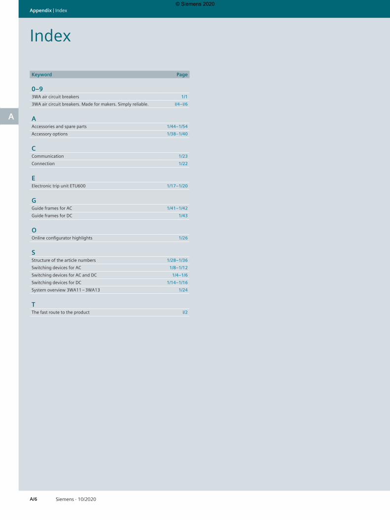
A/6 Siemens · 10/2020
Appendix | Index
A
Index
Keyword Page
0–93WA air circuit breakers 1/13WA air circuit breakers. Made for makers. Simply reliable. I/4–I/6
AAccessories and spare parts 1/44–1/54Accessory options 1/38–1/40
CCommunication 1/23Connection 1/22
EElectronic trip unit ETU600 1/17–1/20
GGuide frames for AC 1/41–1/42Guide frames for DC 1/43
OOnline configurator highlights 1/26
SStructure of the article numbers 1/28–1/36Switching devices for AC 1/8–1/12Switching devices for AC and DC 1/4–1/6Switching devices for DC 1/14–1/16System overview 3WA11 – 3WA13 1/24
TThe fast route to the product I/2
© Siemens 2020
A/7Siemens · 10/2020
Notes | Appendix
A
Notes
© Siemens 2020
A/8 Siemens · 10/2020
Appendix | Notes
A
Notes
© Siemens 2020
Catalogs and further information
The catalogs listed above and additional catalogs are available in PDF format at Siemens Industry Online Support www.siemens.com/lowvoltage/catalogs
Further information on low-voltage power distribution and electrical installation technology is available on the Internet at www.siemens.com/lowvoltage
IC 10Industrial ControlsSIRIUS
E86060-K1010-A101-B1-7600
Catalog LV 10
Edition 04/2020 siemens.com/lowvoltage
SENTRON • SIVACON • ALPHA
Low-Voltage Power Distribution and Electrical Installation TechnologyProtection, Switching, Measuring and Monitoring Devices, Switchboards and Distribution Systems
LV 10Low-Voltage Power Distribution and Electrical Installation TechnologySENTRON • SIVACON • ALPHA
Protection, Switching, Measuring and Monitoring Devices, Switchboards and Distribution Systems
PDF (E86060-K8280-A101-B1-7600)
Catalog LV 18
Edition 10/2020 siemens.com/lowvoltage
SENTRON • SIVACON • ALPHA
Low-Voltage Power Distribution and Electrical Installation TechnologyProtection, Switching, Measuring and Monitoring Devices, Switchboards and Distribution Systems
LV 18Air Circuit Breakers and Molded Case Circuit Breakers with UL CertificationSENTRON
PDF (E86060-K8280-E347-A4-7600)
Industry MallInformation and Ordering Platform on the Internet:
www.siemens.com/industrymall
Siemens TIA Selection Toolfor the selection, configuration and ordering of TIA products and devices
www.siemens.com/tst
Catalog LV 14
Edition 11/2020 siemens.com/powermonitoring
SENTRON
Power Monitoring Made Simple
LV 14Power Monitoring Made SimpleSENTRON
E86060-K1814-A101-A7-7600
ET D1Switches and Socket OutletsDELTA
Training for IndustrySITRAIN
www.siemens.com/sitrain
© Siemens 2020

Security informationSiemens provides products and solutions with industrial security functions that support the secure operation of plants, systems, machines and networks.
In order to protect plants, systems, machines and networks against cyber threats, it is necessary to implement – and continuously maintain – a holistic, state-of-the-art indus-trial security concept. Siemens’ products and solutions constitute one element of such a concept.
Customers are responsible for preventing unauthorized access to their plants, systems, machines and networks. Such systems, machines and components should only be connected to an enterprise network or the Internet if and to the extent such a connection is necessary and only when appropriate security measures (e.g. firewalls and/or network segmentation) are in place.
For additional information on industrial security measures that may be implemented, please visit https://www.siemens.com/industrialsecurity
Siemens’ products and solutions undergo continuous development to make them more secure. Siemens strongly recommends that product updates are applied as soon as they are available and that the latest product versions are used. Use of product versions that are no longer supported, and failure to apply the latest updates may increase customer's exposure to cyber threats.
To stay informed about product updates, subscribe to the Siemens Industrial Security RSS Feed under https://www.siemens.com/industrialsecurity
Get more informationwww.siemens.com/lowvoltage
Published by Siemens AG
Smart Infrastructure Electrical Products Siemensstraße 10 93055 Regensburg, Germany
PDF (E86060-K8280-E401-A1-7600) KG 1020 72 En Produced in Germany © Siemens 2020
Subject to changes and errors. The information given in this catalog only contains general descriptions and/or performance features which may not always specifically reflect those described, or which may undergo modification in the course of further development of the products. The requested performance features are binding only when they are expressly agreed upon in the concluded contract.
All product designations may be trademarks or other rights of Siemens AG, its affiliated companies or other companies whose use by third parties for their own purposes could violate the rights of the respective owner.
For the U.S. published by Siemens Industry Inc.
100 Technology Drive Alpharetta, GA 30005 United States
© Siemens 2020