CASTRO COUNTY JAIL - Southwest General Contractors
467
PROJECT MANUAL NO. 1 General Documents General Requirements Technical Specifications Div. 1-14 CASTRO COUNTY JAIL DIMMIT, TEXAS CASTRO COUNTY COMMISSIONERS COURT CARROLL GERBER COUNTY JUDGE PAUL RAMIREZ COMMISSIONER PCT. 1 TIM ELLIOT COMMISSIONER PCT. 2 MICHAEL GOOLSBY COMMISSIONER PCT. 3 RALPH BROCKMAN COMMISSIONER PCT. 4 SALVADOR RIVERA COUNTY SHERIFF DRG ARCHITECTS, PLLC 13300 OLD BLANCO RD., SUITE 175 SAN ANTONIO, TEXAS 78216 OCTOBER 2017 SET NUMBER_________
-
Upload
khangminh22 -
Category
Documents
-
view
2 -
download
0
Transcript of CASTRO COUNTY JAIL - Southwest General Contractors

PROJECT MANUAL NO. 1 General Documents
General Requirements Technical Specifications Div. 1-14
CASTRO COUNTY JAIL DIMMIT, TEXAS
CASTRO COUNTY COMMISSIONERS COURT CARROLL GERBER COUNTY JUDGE PAUL RAMIREZ COMMISSIONER PCT. 1 TIM ELLIOT COMMISSIONER PCT. 2 MICHAEL GOOLSBY COMMISSIONER PCT. 3 RALPH BROCKMAN COMMISSIONER PCT. 4 SALVADOR RIVERA COUNTY SHERIFF
DRG ARCHITECTS, PLLC 13300 OLD BLANCO RD., SUITE 175 SAN ANTONIO, TEXAS 78216 OCTOBER 2017 SET NUMBER_________

TITLE PAGE
TITLE OF THE WORK:
CASTRO COUNTY JAIL 1004 E. BEDFORD STREET DIMMIT, TEXAS 79027
OWNER:
CASTRO COUNTY, TEXAS by and through
THE CASTRO COUNTY COMMISSIONERS COURT 100 E. BEDFORD STREET DIMMIT, TEXAS 79027
ARCHITECT:
DRG ARCHITECTS, LLC 13300 OLD BLANCO RD., SUITE 175 SAN ANTONIO, TEXAS 78216 PHONE: (210) 349-7950
CIVIL ENGINEER:
AZ & B, LLC 13300 OLD BLANCO RD., SUITE 180 SAN ANTONIO, TEXAS 78216 PHONE: (325) 313-0452
STRUCTURAL ENGINEER:
INTELLIGENT ENGINEERING SERVICES 1001 REUNION PLACE, SUITE 200 SAN ANTONIO, TEXAS 78216 PHONE: (210) 349-9098
MECHANICAL / ELECTRICAL ENGINEER:
DBR, INC. 8626 TESORO DRIVE SAN ANTONIO, TEXAS 78217 PHONE: (210) 546-0200

CASTRO COUNTY JAIL TABLE OF CONTENTS
CASTRO COUNTY JAIL TABLE OF CONTENTS PAGE 1 OF 4 OCTOBER 2017
TITLE TITLE PAGE TABLE OF CONTENTS ENUMERATION OF CONTRACT DOCUMENTS DIVISION 0 - GENERAL DOCUMENTS DIVISION 0 - GENERAL DOCUMENTS Section 00020 - Request For Proposals………………………………………………………….00020-01 – 00020-05 Prevailing Wage Rates………..……………………………………………….……………..6 Pages Section 00100 - Instructions to Offerors…………………………………………………………00100-01 – 00100-05 Section 00300 - Form of Proposal………………………………………………………………..00300-01 – 00300-03 Section 00440 - Substitutions Prior to Bidding…………………………………………………..00440-01 – 00440-06 Section 00500 - Form of Agreement……………………………………………………………..00500-01 – 00500-03 Section 00600 - Performance Bond…………………………………………………………………………..00600-01 Section 00610 - Payment Bond………………………………………………………………………………00610-01 Section 00700 - General Conditions of the Contract for Construction………………………………………00700-01 SPECIFICATIONS DIVISION 1 - GENERAL REQUIREMENTS Section 01010 - Special Conditions.......................................................................................… 01010-01 - 0101007 Section 01015 - Foundation Investigation.................................................................................……….……01015-01 Geotechnical Engineering Study………………………………………..…………………25 Pages Section 01020 - Allowances.......................................................................................................01020-01 - 01020-02 Section 01030 - Alternates………………………………………………………………………………….01030-01 Section 01300 - Submittals.........................................................................................................01300-01 - 01300-05 Section 01410 - Testing Laboratory Services.............................................................................01410-01 - 01410-16 Section 01630 - Products and Substitutions....................................................................…........01630-01 - 01630-04 Section 01700 - Project Closeout................................................................................................01700-01 - 01700-05 DIVISION 2 - SITE WORK Section 02830 - Chain-Link Fencing..............................................................................................02830-01 - 02830-04 DIVISION 3 - CONCRETE Section 03 1000 - Concrete Formwork………….................................................................03 1000-01 - 03 1000-03 Section 03 2000 - Concrete Reinforcing.................................................. …………………03 2000-01 - 03 2000-02 Section 03 3000 - Cast-In-Place Concrete............................................................................03 3000-01 - 03 3000-03 Section 31 1000 - Site Clearing…………………………………………………………….31 1000-01 - 31 1000-02 Section 31 2200 - Grading………………………………………………………………….32 2200-01 - 32 2200-02 Section 31 2300 - Excavation and Fill………………………………………………………31 2300-01 - 31 2300-02 Section 32 1123 - Aggregate Base………………………………………………..…………32 1123-01 - 32 1123-02 Section 32 1723 - Pavement Markings……………………………………………………..32 1723-01 - 32 1723-02 Section 32 9119 - Landscape Grading……………………………………………………...32 9119-01 - 32 9119-02

CASTRO COUNTY JAIL TABLE OF CONTENTS
CASTRO COUNTY JAIL TABLE OF CONTENTS PAGE 2 OF 4 OCTOBER 2017
Section 03411 - Precast Hollow Core Plank……………………………………………………...03411-01 - 03411-04 DIVISION 4 - MASONRY Section 04105 - Masonry Grouts.......................................................................................…...04105-01 - 04105-03 Section 04150 - Masonry Reinforcement and Accessories.......................................................04150-01 - 04150-02 Section 04200 - Unit Masonry..............................................................................................…04200-01 - 04200-06 Section 04230 - Reinforced Unit Masonry.................................................................................04230-01 - 04230-05 Section 04720 - Cast Stone…………………………………………………………………….04720-01 - 04720-05 DIVISION 5 - METALS Section 05120 - Structural Steel Framing .................................................................................05120-01 - 05120-10 Section 05400 - Cold-Formed Metal Framing…………………………………………………05400-01 - 05400-03 Section 05500 - Miscellaneous Metals...............................................................................……...05500-01 - 05500-06 DIVISION 6 - WOODS AND PLASTIC Section 06100 - Carpentry, General...............................................................................….......06100-01 - 06100-04 Section 06101 - Rough Carpentry........................................................................................…06101-01 - 06101-08 Section 06200 - Architectural Woodwork................................................................................06200-01 - 06200-03 DIVISION 7 - THERMAL AND MOISTURE PROTECTION Section 07100 - Dampproofing and Waterproofing.................................................................07100-01 - 07100-03 Section 07240 - Thermal Insulation and Fire-Stopping............................................................07240-01 - 07240-02 Section 07720 - Roof Hatch….……………................................................................................…………..07720-01 Section 07900 - Caulking and Sealants...............................................................................….07900-01 - 07900-06 DIVISION 8 - DOORS, WINDOWS AND GLASS Section 08100 - Hollow Metal Doors and Frames....................................................................08100-01 - 08100-04 Section 08200 - Laminated Plastic Clad Wood Doors………………………………………...08200-01 - 08200-02 Section 08300 - Special Doors..................................................................................................08300-01 - 08300-04 Section 08305 - Access Doors..............................................................................................…08305-01 - 08305-03 Section 08410 - Aluminum Entrances and Storefronts.............................................................08410-01 - 08410-04 Section 08700 - Builder's (Finish) Hardware............................................................................08700-01 - 08700-02 Section 08800 - Glass and Glazing...........................................................................................08800-01 - 08800-05 DIVISION 9 – FINISHES Section 09250 - Gypsum Drywall..............................................................................................09250-01 - 09250-05 Section 09300 - Ceramic Tile…................................................................................................09300-01 - 09300-03 Section 09500 - Acoustical Ceilings..........................................................................................09500-01 - 09500-03 Section 09520 - Acoustical Wall Panels……......................................................................... 09520-01 - 09520-02 Section 09650 - Resilient Flooring............................................................................................09650-01 - 09650-03 Section 09670 - Special Floor Coating and Sealer.................................................................….09670-01 - 09670-03 Section 09671 - Seamless Flooring...........................................................................................09671-01 - 09671-02 Section 09672 - Shower Coating……………………………………………………………….09672-01 - 09672-03

CASTRO COUNTY JAIL TABLE OF CONTENTS
CASTRO COUNTY JAIL TABLE OF CONTENTS PAGE 3 OF 4 OCTOBER 2017
Section 09680 - Carpeting.................................................................................................…….09680-01 - 09680-03 Section 09900 - Painting and Finishing...............................................................................…...09900-01 - 09900-06 DIVISION 10 - SPECIALTIES Section 10000 - Miscellaneous Specialties...............................................................................10000-01 - 10000-05 Section 10165 - Plastic Laminate Toilet Partitions……………………………………………10165-01 - 10165-03 Section 10350 - Flagpole………………………………………………………………………10350-01 - 10350-03 Section 10400 - Identifying Devices and Graphics.....................................................................................10400-01 Section 10500 - Metal Lockers.................................................................................................10500-01 - 10500-03 Section 10523 - Fire Extinguishers...........................................................................................10523-01 - 10523-03 DIVISION 11 - EQUIPMENT Section 11000 - Miscellaneous Equipment…...........................................................................11000-01 - 11000-02 Section 11100 - Kitchen / Laundry Equipment.........................................................................11100-01 - 11100-10 Section 11190 - General Provisions for Detention Equipment..................................................11190-01 - 11190-10 Section 11191 - Detention Furnishings and Accessories........................................................….11191-01 - 11191-06 Section 11192 - Detention Steel Plate and Equipment...........................................................….1192-01 - 11192-03 Section 11193 - Security Hollow Metal Doors and Frames........................................................11193-01 - 11193-07 Section 11194 - Electro-mechanical Locks............................................................................….11194-01 - 11194-04 Section 11195 - Mechanical Security Locks / Security Hardware..............................................11195-01 - 11195-10 DIVISION 12 - FURNISHINGS Section 12300 - Prefinished Cabinets....................................................................................….12300-01 - 12300-04 DIVISION 13 – SPECIAL CONSTRUCTION Section 13122 - Pre-Engineered Metal Building Systems......................................................….13122-01 - 13122-14 Section 13700 - Electronic Security Systems - General.........................................……………..13700-01 - 13700-24 Section 13710 - Electronic Security Systems – PLC…..........................................……………..13710-01 - 13710-07 Section 13720 - Electronic Security Systems – Touch Screen...............................……………..13720-01 - 13720-13 Section 13730 - Electronic Security Systems – Audio...........................................……………..13730-01 - 13730-07 Section 13740 - Electronic Security Systems – CCTV..........................................……………..13740-01 - 13740-07 Section 13750 - Electronic Security Systems – Access Control.............................……………..13750-01 - 13750-07 Section 13760 - Electronic Security Systems – Auxiliary Controls.......................……………..13760-01 - 13760-05 Section 13770 - Electronic Security Systems – UPS…..........................................……………..13770-01 - 13770-03 Section 13701 - Electronic Security Systems – Camera Schedule………………………………13710-01 - 13710-02 DIVISION 14 – CONVEYING SYSTEMS NOT USED DIVISION 15 - MECHANICAL Section 15000 - Mechanical General Conditions................................................................….15000-01 - 15000-25 Section 15001 - Starting of Systems....................................................................................…15001-01 - 15001-03 Section 15121 - Pipe Expansion Compensation...................................................……………15121-01 - 15121-04

CASTRO COUNTY JAIL TABLE OF CONTENTS
CASTRO COUNTY JAIL TABLE OF CONTENTS PAGE 4 OF 4 OCTOBER 2017
Section 15140 - Supports and Anchors................................................................................…15140-01 - 15140-06 Section 15170 - Motors....................................................................................................……15170-01 - 15170-08 Section 15171 - Variable Frequency Motor Speed Control.................................................….15171-01 - 15171-08 Section 15172 - Enclosed Motor Controllers.......................................................................….15172-01 - 15172-04 Section 15190 - Mechanical Identification............................................................................…15190-01 - 15190-03 Section 15245 - Vibration Isolation.......................................................................................…15245-01 - 15245-03 Section 15260 - Piping Insulation.........................................................................................…15260-01 - 15260-07 Section 15280 - Equipment Insulation......................................................................................15280-01 - 15280-03 Section 15290 - Ductwork Insulation.......................................................................................15290-01 - 15290-05 Section 15310 - Fire Protection Piping..................................................................................…15310-01 - 15310-07 Section 15325 - Wet Pipe Fire Suppression Systems……………….........................................15325-01 - 15325-06 Section 15375 - Standpipe and Hose Systems........................................................................…15375-01 - 15375-04 Section 15410 - Plumbing Piping.............................................................................................15410-01 - 15410-12 Section 15430 - Plumbing Specialties......................................................................................15430-01 - 15430-07 Section 15440 - Plumbing Fixtures and Trim..........................................................................15440-01 - 15440-03 Section 15671 - Air Cooled Condensing Units.....................................................................…15671-01 - 15671-07 Section 15853 - Computer Room Air Conditioning Units........................................................15853-01 - 15853-08 Section 15855 - Air Handling Units.........................................................................................15855-01 - 15855-05 Section 15860 - Power Ventilators...........................................................................................15860-01 - 15860-11 Section 15885 - Air Cleaning Devices......................................................................................15885-01 - 15885-03 Section 15890 - Ductwork .......................................................................................................15890-01 - 15890-10 Section 15910 - Ductwork Accessories.................................................................................…15910-01 - 15910-08 Section 15930 - Air Terminal Unit……………………………………………………………15930-01 - 15930-12 Section 15940 - Air Inlets and Outlets.....................................................................................15940-01 - 15940-04 Section 15950 - HVAC Controls.......................................................................................……15950-01 - 15950-49 Section 15990 - Testing, Adjusting and Balancing...................................................................15990-01 - 15990-13 DIVISION 16 - ELECTRICAL Section 16010 - General Requirements for Electrical Work......................................................16000-01 - 16000-07 Section 16060 - Grounding……………………………………………………………………16060-01 - 16060-05 Section 16075 - Electrical Identification………………………………………………………16075-01 - 16075-04 Section 16123 - Wire and Cable………………………………………………………………..16123-01 - 16123-05 Section 16136 - Raceways……………………………………………………………………..16136-01 - 16136-09 Section 16140 - Wiring Devices………………………………………………………………....16140-01 - 16140-05 Section 16235 - Packaged Engine Generators........................................................……………16235-01 - 16235-13 Section 16300 - Automatic Transfer Switch.......................................................................……16300-01 - 16300-14 Section 16423 - Enclosed Contactors…………………………………………………………16423-01 - 16423-03 Section 16429 - Low Voltage Distribution Switch Boards……………………………………16429-01 - 16429-09 Section 16441 - Disconnect Switches…………………………………………………………16441-01 - 16441-04 Section 16442 - Panelboards…………………………………………………………………..16442-01 - 16442-09 Section 16443 - Motor Control Centers……………………………………………………….16443-01 - 16443-07 Section 16510 - Luminaires…………………………………………………………………...16510-01 - 16510-08 Section 16670 - Lightning Protection…………………………………………………………16670-01 - 16670-05 Section 16671 - Transient Voltage Surge Suppression…………………………………….…16671-01 - 16671-08 Section 16721 - Fire Alarm and Smoke Control Systems…………………………………….16721-01 - 16721-21 Section 16740 - Telephone System……………………………………………………………16740-01 - 16740-02 Section 16750 - Cable TV Systems…………………………………………………………….16750-01 - 16750-02

ENUMERATION OF CONTRACT DOCUMENTS CASTRO COUNTY JAIL
DIMMIT, TEXAS
ENUMERATION OF CONTRACT DOCUMENTS PAGE 1 OF 4
GENERAL DOCUMENTS SUBSTITUTIONS PRIOR TO BIDDING GENERAL CONDITIONS OF THE CONTRACT FOR CONSTRUCTION SUPPLEMENTAL GENERAL CONDITIONS SPECIFICATIONS DIVISIONS 1 through 16 (Refer to Table of Contents) DRAWINGS CIVIL C1 GENERAL NOTES C2 COORDINATE PLAN C3 DIMENSIONAL PLAN C4 GRADING PLAN C5 SPOT ELEVATIONS C6 PAVEMENT DETAIL C7 PAVEMENT MARKINGS C8 SAFETY END TREATMENT C9 TCP PLAN C10 UTILITY DISTRIBUTION PLAN C11 WATER DETAILS C12 SEWER DETAILS C13 SW3P STORM WATER POLLUTION PRESERVATION PLAN C14 FENCE AND BALED HAY (SW3P) C15 CONSTRUCTION EXITS (SW3P) ARCHITECTURAL G0.01 SYMBOLS AND LEGENDS A0.00 SURVEY A0.01 SITE PLAN A1.00 DETENTION WALL REINFORCING PLAN A1.01 DIMENSIONED FLOOR PLAN A1.02 REFERENCE FLOOR PLAN A1.03 ATTIC PLAN A1.04 ROOF PLAN AND DETAILS A2.01 EXTERIOR ELEVATIONS A3.01 WALL SECTIONS A3.02 WALL SECTIONS A3.03 WALL SECTIONS

ENUMERATION OF CONTRACT DOCUMENTS CASTRO COUNTY JAIL
DIMMIT, TEXAS
ENUMERATION OF CONTRACT DOCUMENTS PAGE 2 OF 4
A3.04 WALL SECTIONS A3.05 WALL SECTIONS A4.01 INTERIOR PARTITION TYPES A5.01 ARCHITECTURAL DOOR SCHEDULE, ELEVATIONS AND DETAILS A5.02 ARCHITECTURAL WINDOW ELEVATIONS AND DETAILS A5.03 ENLARGED TOILET ROOM PLANS AND ELEVATIONS A6.01 ENLARGED CONTROL ROOM PLANS AND ELEVATIONS AND MILLWORK A7.01 REFLECTED CEILING PLAN A8.01 MISCELLANEOUS DETAILS KITCHEN K1.01 ENLARGED KITCHEN / LAUNDRY PLANS DETENTION D1.01 DETENTION DOOR SCHEDULE, ELEVATIONS AND DETAILS D1.02 DETENTION DOOR DETAILS D2.01 DETENTION WINDOW ELEVATIONS AND DETAILS D3.01 DETENTION FURNISHINGS AND DETAILS D3.02 DETENTION FURNISHINGS AND DETAILS SECURITY ELECTRONICS SEC1.01 SECURITY ELECTRONICS PLAN STRUCTURAL S0.01 STRUCTURAL NOTES S0.02 STRUCTURAL NOTES S0.03 FOUNDATION LIVE LOAD PLAN S0.04 MEZZANINE LIVE LOAD PLAN S1.00 SLAB PLAN S1.01 FOUNDATION PLAN S1.02 ATTIC FRAMING PLAN S1.03 ROOF FRAMING PLAN S1.04 CMU WALL PLAN S2.01 TYPICAL FOUNDATION DETAILS

ENUMERATION OF CONTRACT DOCUMENTS CASTRO COUNTY JAIL
DIMMIT, TEXAS
ENUMERATION OF CONTRACT DOCUMENTS PAGE 3 OF 4
S2.02 TYPICAL FOUNDATION DETAILS S2.03 SECTIONS AND DETAILS S2.04 SECTIONS AND DETAILS S3.01 MASONRY TYPICAL DETAILS S3.02 HOLLOW CORE PLANK DETAILS AND SECTIONS MECHANICAL FA1.01 FIRST LEVEL FIRE ALARM PLAN FA1.02 ATTIC LEVEL FIRE ALARM PLAN FA3.01 FIRE ALARM RISER DIAGRAM FP2.01 FIRST LEVEL FIRE PROTECTION PLAN FP3.01 FIRE PROTECTION SCHEDULE NOTES AND DETAILS MEP0.01 MEP SITE PLAN MEP1.01 MEP ROOF PLAN M0.01 MECHANICAL SYMBOLS, ABBREVIATIONS AND GENERAL NOTES M2.01 FIRST LEVEL MECHANICAL PLAN M2.02 ATTIC MECHANICAL PLAN M4.01 MECHANICAL SCHEDULES M4.02 MECHANICAL SCHEDULES M5.01 MECHANICAL DETAILS M5.02 MECHANICAL DETAILS M6.01 MECHANICAL CONTROL DIAGRAMS M6.02 MECHANICAL CONTROL DIAGRAMS M6.03 MECHANICAL CONTROL DIAGRAMS M6.04 MECHANICAL CONTROL DIAGRAMS ELECTRICAL E1.01 FIRST LEVEL LIGHTING PLAN E2.01 FIRST LEVEL POWER PLAN E2.02 ATTIC LEVEL ELECTRICAL PLAN E3.01 ENLARGED ELETRICAL PLANS E4.01 ELECTRICAL ON-LINE DIAGRAM E5.01 ELECTRICAL SCHEDULES E5.02 ELECTRICAL PANEL BOARD SCHEDULES

ENUMERATION OF CONTRACT DOCUMENTS CASTRO COUNTY JAIL
DIMMIT, TEXAS
ENUMERATION OF CONTRACT DOCUMENTS PAGE 4 OF 4
E6.01 ELECTRICAL DETAILS E6.02 ELECTRICAL DETAILS PLUMBING P0.01 PLUMBING SYMBOLS, ABBREVIATIONS AND GENERAL NOTES P2.01 FIRST LEVEL PLUMBING PLAN P2.02 FIRST LEVEL PLUMBING GENERAL AND KEYED NOTES P2.03 ATTIC PLUMBING PLAN P3.01 PLUMBING DETAILS P3.02 PLUMBING DETAILS P4.01 PLUMBING SCHEDULES P4.02 PLUMBING GENERAL NOTES P5.01 PLUMBING RISERS – SEWER AND VENT P5.02 PLUMBING RISERS – DOMESTIC WATER P5.03 PLUMBING RISERS – GAS
*** END OF SECTION ***

SECTION 00440 SUBSTITUTIONS PRIOR TO PROPOSAL 00440-1
CASTRO COUNTY JAIL PROJECT NO. 201620 OCTOBER 2017
PART 1 - GENERAL 1.01 DESCRIPTION
A. Work includes:
1. Furnishing all work and services for providing, submitting, processing and handling of requests for substitutions prior to proposal;
2. Verifying all substitutions are in accord with the provisions of the Contract Documents; 3. Complete coordination with the work of other trades. 4. See appropriate sections for specific items. 5. See General Conditions for additional information.
1.02 DEFINITION
A. Substitution: A material or process offered by a responsible bidder in lieu of, and as being equivalent to, a specified material or process.
1.03 PRODUCT SELECTION – GENERAL
A. Certain types of products are described in the Contract Documents by means of trade names, catalog numbers and / or manufacturers’ names. This is not intended to exclude from consideration other products that may be capable of accomplishing the purpose indicated.
B. Products, other than those listed as "Base" or "Optional", may be acceptable to the Owner and the
Architect. Wherever a manufacturer is named as a Base or Optional Bidder for a product, the words "or approved substitute" should be read immediately following the manufacturer's name. Manufacturers not currently listed, but desiring consideration as optional manufacturers must file a request for substitution and be approved under the procedures outlined.
C. Listing of a manufacturer implies acceptance of them only as supplier of a product that complies with the
specifications.
D. The Architect reserves the right to require substitutions to comply color-wise and pattern-wise with base specified items.
E. No substitutions will be permitted after the execution of the Contract, except as allowed in Section 01630
– PRODUCTS AND SUBSTITUTIONS.
F. Conditional proposals and voluntary alternates will not be considered.
G. The Owner and Architect's decision of written acceptance or rejection of any substitution will be final. 1.04 REQUESTS FOR SUBSTITUTION
A. Only written requests with complete data for evaluation will be considered.
1. Requests for substitutions must be made in writing on or before seven (7) days prior to proposal date.2. Requests received late will not be considered. 3. Submit evaluation data with copy of attached form.
B. In making a request for substitution, or in using an approved substitute item, the supplier and the

SECTION 00440 SUBSTITUTIONS PRIOR TO PROPOSAL 00440-2
CASTRO COUNTY JAIL PROJECT NO. 201620 OCTOBER 2017
Contractor represent:
1. They have investigated the proposed product or method, and have determined that it is equal or superior in all respects to that specified, and that it will perform the intended function;
2. They will provide the same warranty for the substitute item as for the product or method specified; 3. They will coordinate installation of the accepted substitution into the Work, to include building
modifications if necessary, making such changes as may be required for the Work to be complete in all respects;
4. They waive all claims for additional costs or time extensions related to any substitution that subsequently become apparent or necessary;
5. They will pay all redesign and other costs caused by the substitution; 6. Acknowledgement of acceptance of these provisions in the request for substitution.
C. For bidding purposes, base all bids on materials, equipment and procedures as specified, or approved by
addenda.
D. Addenda listing approved substitutions will be issued. E. No verbal or written approvals other than by Addenda will be valid.
F. Address for submission of request for substitution:
DRG Architects, LLC 13300 Old Blanco Rd., Suite 175 San Antonio, Texas 78216
Attn: Perry Rabke
1.05 SUBSTITUTION-PRIOR-TO-PROPOSAL REQUEST
A. Submit complete data substantiating compliance of the proposed substitution with the Contract Documents.
B. For products:
1. Product identification, including manufacturer's name. 2. Manufacturer's literature, marked to indicate specific model, type, size and options to be considered:
a. Product description. b. Performance and test data. c. Reference standards. d. Difference in power demand, air quantities, etc. e. Dimensional differences from specified unit.
3. Full size samples, if requested. 4. The Architect reserves the right to retain samples until physical units are installed on the project for
comparison purposes. 5. Requester pay all costs of furnishing, and return of, the samples. 6. The Architect is not responsible for loss of, or damage to, the samples.
C. For construction methods:

SECTION 00440 SUBSTITUTIONS PRIOR TO PROPOSAL 00440-3
CASTRO COUNTY JAIL PROJECT NO. 201620 OCTOBER 2017
1. Detailed description of the proposed method. 2. Fully illustrated drawings and details of the proposed method.
D. Name and address of at least five (5) similar projects, five (5) years or older utilizing the proposed
product or method with name, address, telephone and fax number of owner's representative whom the Architect can contact to discuss the product, installation and field performance data.
E. Itemized comparison of the proposed substitute to the specified item.
F. Data relating to any changes in the construction schedule.
G. Relation to any separate contracts.
H. Cost of the proposed substitution in comparison with the product or method specified.
1.06 REJECTION OF SUBSTITUTIONS
A. Substitutions will not be considered if:
1. They are not submitted in accordance with this document. 2. Acceptance will require substantial revision of the Contract Documents or building spaces. 3. Request for substitution does not indicate the specific item for which the request is submitted.
Acceptance of a manufacturer only will not be made. 4. Request form is not properly executed.
*** END OF SECTION ***

SECTION 00440 SUBSTITUTIONS PRIOR TO PROPOSAL 00440-4
CASTRO COUNTY JAIL PROJECT NO. 201620 OCTOBER 2017
SUBSTITUTION REQUEST PROJECT: CROCKETT COUNTY JAIL TO: DRG Architects, LLC 13300 Old Blanco Rd., Suite 175 San Antonio, Texas 78216 ATTN: Perry Rabke FROM: (Complete Name, Address, Telephone and Facsimile Numbers) ABOVE FIRM HEREBY REQUESTS ACCEPTANCE OF THE FOLLOWING PRODUCT OR SYSTEM AS A SUBSTITUTION IN ACCORDANCE WITH THE PROVISIONS OF THE CONTRACT DOCUMENTS. SPECIFIED PRODUCT OR SYSTEM: Substitution request for: Specification Section Number: Article(s) / Paragraph(s): SUPPORTING DATA: Provide product data for the proposed substitution in accordance with the requirements of this section. Sample is attached: Yes No Sample will be sent if requested: Yes No QUALITY COMPARISON:
(Confirm with manufacturer's printed data highlighted to clearly indicate product’s performance and specifications)
SPECIFIED PRODUCT PROPOSED SUBSTITUTION Name, brand: Catalog No.: Manufacturer: Variations: Maintenance Service Available: Yes No If yes, location: Spare Parts Source:

SECTION 00440 SUBSTITUTIONS PRIOR TO PROPOSAL 00440-5
CASTRO COUNTY JAIL PROJECT NO. 201620 OCTOBER 2017
REASON FOR NOT GIVING PRIORITY TO SPECIFIED ITEMS: EFFECT OF SUBSTITUTION: Proposed substitution affects other parts of Work: Yes No (If yes, explain) Substitution requires dimensional revision or redesign of structure or Mechanical and Electrical Work: Yes No (If yes, explain) STATEMENT OF CONFORMANCE OF PROPOSED SUBSTITUTION TO CONTRACT REQUIREMENTS: I / we
o have investigated the proposed substitution fully; o believe that it is equal to or superior in all respects to the specified product, except as stated above; o will provide the same warranty as that specified; o have included complete cost data and implications of the substitution; o will pay any / all redesign and special inspection costs caused by use of this product; o will pay any / all additional costs to other contractors caused by the substitution; o will coordinate incorporation of the proposed substitution into the Work; o will modify other parts of the Work as may be needed, to make all parts of the Work complete and
functional; o waive future claims for added costs to the Contract caused by the substitution.
Additional comments:

SECTION 00440 SUBSTITUTIONS PRIOR TO PROPOSAL 00440-6
CASTRO COUNTY JAIL PROJECT NO. 201620 OCTOBER 2017
Firm: Date: Signed: By: (Type Name) Position: Address: Telephone: Facsimile: *** END OF SUBSTITUTION REQUEST FORM ***

SECTION 00700 GENERAL CONDITIONS OF THE CONTRACT FOR CONSTRUCTION 00700-1
CASTRO COUNTY JAIL PROJECT NO. 201620 OCTOBER 2017
1.01 GENERAL A. A.I.A. Document A201 – 2007, GENERAL CONDITIONS OF THE CONTRACT FOR
CONSTRUCTION, Fifteenth Edition, The American Institute of Architects, constitutes the General Conditions of this Contract, and shall have the same force and effect as though set forth here in full.
B. Copies of this document are on file in the Architect's offices and may be reviewed upon request.
*** END OF SECTION ***

SECTION 01010 SPECIAL CONDITIONS 01010-1
CASTRO COUNTY JAIL PROJECT NO. 201620 OCTOBER 2017
Ed 1.01 SPECIAL SECURITY CONSIDERATIONS
A. The Construction Manager and all Sub-Contractors shall be aware that much of the work will occur within the current jail facility and will, therefore, require special security considerations. All persons working or visiting the site will be subject to the Sheriff’s security criteria. The Sheriff reserves the right to disallow any person from working or visiting the site, due to security concerns.
1.02 CONTRACTOR'S RESPONSIBILITY
A. The Construction Manager shall be entirely responsible for the execution of the work of all trade(s) included under this Contract. The Construction Manager shall specifically, and distinctly, assume, and does so assume, all risks of damage or injury from any cause to property or persons used or employed on, or in connection with, his work, and of all damage or injury to any persons or property wherever located, resulting from any action or operation under his Contract or in connection with his work and undertakes and promises to protect and defend the Owner against all claims on account of such damage or injury.
B. The Construction Manager will be held responsible for the execution of a satisfactory and complete piece
of work in accordance with the true intent of the Drawings, Specifications and Addenda.
C. At the completion of the work, the Construction Manager shall remove all implements and appurtenances of construction and all debris and surplus materials occasioned by the work, leaving the building and grounds in a clean and orderly condition ready for use. It shall be the responsibility of the Construction Manager to clean up and repair or replace all plumbing fixtures, light fixtures, woodwork, window glass, and all floors that have been damaged, soiled or otherwise made unsightly as a result of the work as contracted under the Contract, all to the satisfaction of, and as directed by, the Architect.
D. The Detention Equipment Contractor (DEC) shall deliver and be responsible for placing in the building
all detention equipment that he is to install as part of his contract.
E. The Electrical Contractor shall furnish sufficient temporary electrical service to accommodate both his work and the work of other trades, including the DEC, which will include the use of 220V electric welding machines for installation of detention equipment.
F. The Electrical Contractor shall furnish and install all line voltage field wiring and conduits and make all
necessary field connections for electrical operation of security electronic systems in strict accordance with SEC's approved shop drawings.
G. The Construction Manager shall at all times allow the Architect and his authorized representatives, the
Owner and anyone employed directly or indirectly by Owner, and other contractors and their authorized representatives with whom the Owner enters into Contracts to perform services or other work, access to the building or premises. The Construction Manager shall provide all necessary facilities for easy and safe access to all parts of building for use of all concerned with the operation.
H. All detention equipment specified, except aluminum, bronze or stainless steel finish hardware and that
part of the work to be enameled or plated, shall be painted one shop coat of rust-resistant zinc chromate metallic primer, red oxide color, before shipping. Retouching of shop coat of paint after erection shall be done by the Construction Manager. All burns, welds and weld spatter on detention equipment caused by DEC shall be thoroughly cleaned and re-primed by DEC. Mortar, plaster, concrete, waterproofing, dust and other foreign matter on detention equipment shall be thoroughly cleaned by the Construction Manager at no cost to DEC.

SECTION 01010 SPECIAL CONDITIONS 01010-2
CASTRO COUNTY JAIL PROJECT NO. 201620 OCTOBER 2017
I. REPAIR OF METAL PRIMED SURFACES (Exterior and Interior): Prime painted metal structural
items, embeds, etc. that have the primer removed or disturbed by the construction process (i.e. welds, etc.) shall be touched up with a like primer paint material by the contractor causing the removal of the primer surface. Cleaning and brushing of scarred or damaged surfaces, including new welds, and touch up shall take place as soon as practical from the time the primer was removed.
J. The Construction Manager and each subcontractor shall be responsible for closing any and all gaps,
voids, spaces, etc., between their equipment or product and the materials or surfaces with which they come in contact. Security sealant, as specified and installed per Section 07900 – CAULKING AND SEALANTS, shall be used to seal tight all crevices between metal parts and masonry walls, concrete ceilings and floors in all areas accessible to inmates. Penetrations in the masonry or concrete walls and all rated ceilings shall be grouted or fire proofed as required by code around any penetrating element.
1.03 DEFINITIONS
A. References: References to known standard specifications in the Specifications shall mean and intend the latest edition of such specification adopted and published at the date of the invitation to submit Proposals, unless otherwise indicated.
B. Reference to technical society, organization or body is made in the Specifications in accordance with the
following abbreviations:
AIA American Institute of Architects ACI American Concrete Institute AIEE American Institute of Electrical Engineers AISC American Institute of Steel Contractors AISI American Iron and Steel Institute ANSI(USASI)(ASA) American National Standards Institute ASME American Society of Mechanical Engineers ASTM American Society for Testing and Materials AWSC American Welding Society Code AWWA American Water Works Association FS Federal Specification NBFU National Board of Fire Underwriters NBS National Bureau of Standards NEC National Electric Code UL Underwriters Laboratory, Inc.
1.04 COOPERATION WITH BUILDING OFFICIALS
A. The Construction Manager shall cooperate with all local and other governmental officials and inspectors at all times. If such official or inspector deems a special inspection is necessary, provide assistance and facilities that will expedite his inspection.
1.05 MANUFACTURER'S SPECIFICATIONS AND INSTRUCTIONS
A. The Construction Manager shall install all manufactured items, materials and equipment in strict accordance with manufacturer's recommended specifications except that the Specifications herein, where more stringent, shall be complied with.

SECTION 01010 SPECIAL CONDITIONS 01010-3
CASTRO COUNTY JAIL PROJECT NO. 201620 OCTOBER 2017
B. The Construction Manager shall, at completion of the Project and prior to final acceptance by the Owner, provide the Owner with three (3) complete sets of operating and maintenance instructions and manuals and fully demonstrate to him all procedures for proper operation and maintenance of all equipment. It shall be the responsibility of the Construction Manager to provide videotaping of the operations and maintenance instruction sessions. Two (2) copies of the videotape are to be submitted to the Owner at Final Acceptance.
1.06 MEASUREMENTS
A. Before doing any work or ordering any materials, the Construction Manager and subcontractors shall verify all measurements of existing and new work and shall be responsible for their correctness. Any differences that may be found shall be submitted to Architect for consideration before proceeding with work. No extra compensation will be allowed because of differences between actual dimensions and measurements indicated on the Drawings.
1.07 JOB MAINTENANCE
A. During the course of the Work, all crafts and trades shall protect all work that precedes theirs from damage and shall make repairs or replacement of any damage caused either directly or indirectly by them.
B. Site housekeeping and final cleaning shall be done in accordance with the requirements of Section 01700. C. The facility is to be considered fully tobacco-free at all times. The use of tobacco products is
expressly prohibited within the building. The Construction Manager will be required to post “No Smoking” signs throughout the building and to maintain the signage for the duration of the Project.
1.08 TEMPORARY FACILITIES
A. TEMPORARY FIELD OFFICE BUILDING – The Construction Manager shall provide and maintain for the duration of the Project, a weathertight, well-lighted building at the Project with raised floors and adequate space for layout tables, plan storage and file cabinets. Provide adequate office space for field personnel plus additional ample work area for incidental use by subcontractors' personnel. Unit shall be suitably finished, furnished, equipped and conditioned. Unit shall include a separate space for project meetings, with a table not less than 4'-0" x 12'-0", providing seating for not less than twelve (12) persons. Provide shelf space adequate for storage of approved samples. Provide a telephone in the field office near the layout tables. Submit the telephone number to the Architect. Provide a facsimile (fax) machine in the field office. Submit the fax number to the Architect.
B. STORAGE FACILITIES – The Construction Manager shall provide weathertight storage for cement,
paint, finish hardware, wall finish materials and materials requiring protection from the weather. Provide substantial floors at least five (5) inches off the ground.
C. SANITARY FACILITIES FOR WORKMEN
1. The Construction Manager shall provide and maintain toilet facilities for the use of all those
employed or otherwise involved in performing the Work for the entire construction period. Comply with all requirements of applicable codes and health authorities. When toilet facilities are no longer required, the Construction Manager shall remove them from the Project site.
2. The Construction Manager shall keep toilet facilities swept clean and supplied with toilet tissue at all times.

SECTION 01010 SPECIAL CONDITIONS 01010-4
CASTRO COUNTY JAIL PROJECT NO. 201620 OCTOBER 2017
3. If any new construction surfaces or finishes in the permanent project are soiled by urine or feces at any time, the entire area soiled shall be removed completely from the Project and rebuilt by the Construction Manager at no additional expense to the Owner.
D. WEATHER PROTECTION
1. The Construction Manager shall at all times provide protection against weather, so as to maintain all
work, materials, apparatus and fixtures free from injury and damages. At the end of a working day, all new work likely to be damaged shall be covered or otherwise protected.
2. The Construction manager shall provide temporary heat as required below, including equipment, fuel and attendance required during course of construction. Heat shall be of a non-smudging type.
3. The permanent heating system may be used for temporary heat when installed. Upon completion of construction and before acceptance of building, the Construction Manager shall repair all damage caused by such temporary use of the permanent heating system and shall pay for all necessary temporary connections.
4. When the outside temperature is below freezing, the inside of the building(s) shall be kept at, or above, 40 F. at all times, day and night. During painting and finishing operations, the temperature shall be kept at not less than 60° F. The Construction Manager shall make good all damage caused by insufficient heat.
5. The Construction Manager shall construct and maintain all necessary temporary drainage and do all pumping necessary to keep excavations, graded areas, floors, pits and trenches free of water.
E. When any temporary facility is no longer needed for proper conduct of the Work as determined by the
Architect, the Construction Manger shall remove it from project site and shall repair or replace all materials, equipment and finished surfaces damaged in doing so.
1.09 SCAFFOLDS AND RUNWAYS
A. The Construction Manager shall furnish, erect and maintain for the duration of the Work as required, all scaffolds, runways, guardrails, platforms and similar temporary construction, as may be necessary for the performance of the Contract. Such facilities shall be of a type and arrangement as required for their specific use; shall be substantially constructed throughout, strongly supported, well secured; and, shall comply with all applicable rules and regulations of Federal, State and local codes. Contractors shall comply with all applicable provisions of the National Occupational Safety and Health Act (NOSHA) 1970, or latest edition.
1.10 LOADS AND STRESSES FROM CONSTRUCTION OPERATIONS
A. The Construction Manager shall have full responsibility for preventing overstress of any parts of the structure during all construction operations.
B. The Construction Manager shall provide all temporary supports and connections necessary to assure
safety and stability of all work-in-place and to prevent overstress of any part thereof. 1.11 EQUIPMENT BASES AND ROOF OPENINGS
A. Equipment bases, foundations and roof opening sizes and locations as shown on the Drawings are approximate only.
B. Before constructing equipment bases, foundations and roof openings, the Construction Manager shall
verify the locations, sizes, number and type of anchor bolts against the requirements of the actual

SECTION 01010 SPECIAL CONDITIONS 01010-5
CASTRO COUNTY JAIL PROJECT NO. 201620 OCTOBER 2017
equipment to be installed. 1.12 APPROVAL OF WORKING SURFACE
A. Beginning of work by the Construction Manager or any Subcontractor shall constitute full acceptance of the previous work.
1.13 ACCIDENTS
A. The Construction Manager shall provide at the site, such equipment and medical facilities as are necessary to supply first aid service to anyone who may be injured in connection with the Work.
B. The Construction Manager shall report promptly, in writing, to the Owner through the Architect, all
accidents arising out of, or in connection with, performance of the Work, whether on, or adjacent to, the site, which caused death, personal injury or property damage, giving full details and statements of all witnesses. In addition, if death, serious injury or serious damage is caused, the accident shall be reported immediately by telephone or messenger.
1.14 JOB SIGN
A. The Construction Manager shall erect on the site one (1) painted sign, 4 feet x 8 feet, giving the names and addresses of the following:
1. The Project. 2. Architectural Firm. 3. General Contractor.
B. The format, color, lettering and location of the sign shall be as designated by the Architect.
C. No other signs or advertisements of any nature will be allowed to be displayed without the express
approval of the Architect and the Construction Manager. 1.15 TEMPORARY SERVICES
A. UTILITIES – The Construction Manager shall provide and shall pay for all temporary water, electricity and / or gas as required to complete the construction, including all work under the various Construction Contracts. As the existing utility meters are in the Owner's name, the Construction Manager will receive each month's billings from the Owner and make prompt payment directly to the Utility Company concerned.
B. TELEPHONE SERVICE – The Construction Manager shall provide a telephone for the use of all those
employed, or otherwise involved, in construction of the building. The Construction Manager shall pay for installation, maintenance, removal and all charges for the use of this telephone, except charges for long distance calls that will be paid by the persons making them. The telephone shall be removed when so directed by the Architect.
C. DUMPSTER – The Construction Manager shall provide and pay for regular trash removal.
1.16 MANUFACTURE AND ORIGIN OF MATERIALS
A. It is the intention of the Owner to use only materials that are mined and / or produced in the United States

SECTION 01010 SPECIAL CONDITIONS 01010-6
CASTRO COUNTY JAIL PROJECT NO. 201620 OCTOBER 2017
of America. Products that are not currently mined and / or produced nationally may be acquired from foreign countries or states with the Architect’s approval.
1.17 VANDALPROOF FASTENINGS
A. The Construction Manager and all of his subcontractors shall use vandal-resistant (non-removable) fasteners on all items exposed to inmates within the security perimeter, whether specifically hereinafter called for or not. Such devices as spanner head screws, patch bolts (snap-off head type), “nail-ins” and theft-proof slotted head screws will not be acceptable. "Phillips" head screws and "Allenhead" screws are not considered vandal-proof (non-removable) and will not be allowed. Only security / safety fasteners (i.e., Torx pinhead) with a center rejection pin are considered vandal-proof and may be used. The Construction Manager is to coordinate and confirm that all vandal-resistant fasteners used on the Project are from a single manufacturer.
1.18 SUPERVISION
A. The Construction Manager shall supervise the Work continually, either in person or through an acceptable superintendent who shall be at the jobsite at all times during performance of any work. The superintendent shall have full authority to act for the Construction Manager and shall be authorized to receive instructions from the Architect.
B. The project supervisor shall neither schedule nor take any accrued vacation time during the last
quarter of the project.
C. Supervisory personnel may not be changed without the Architect’s approval unless such change is proven to be beyond the control of the Construction Manager.
1.19 PROGRESS PHOTOGRAPHS
A. FREQUENCY – The Construction Manager shall provide photographs once a month of each building until all exterior construction is accepted as substantially complete. The Construction Manager shall take final photographs of the completed structure(s) and site development as directed by the Architect. A minimum of twelve (12) sets of four (4) photographs for each building will be required. A professional photographer acceptable to the Architect and Owner shall be employed by the Construction Manager for this work.
B. LOCATIONS – Four (4) separate locations at each building each month as directed by Architect.
C. SIZE – Minimum 8 in. x 10 in. with three (3) prints in color made from each negative. The prints shall
bear a legend identifying the project, location, date and other pertinent information as directed by Architect.
D. DISPOSITION – Deliver the prints and the negatives to the Architect each month as directed. Prints are
to be protected inside plastic sheet protectors and placed in 3-ring binders. 1.20 SAFETY PRECAUTIONS AND PROGRAMS
A. During the entire construction program, the Construction Manager, and each Subcontractor, is to use every precaution practicable, looking toward safety of employees and any other person within the construction area, and shall prohibit the loitering on, or about, the grounds of those persons who have no legitimate business there. Weekly safety meetings are highly recommended.

SECTION 01010 SPECIAL CONDITIONS 01010-7
CASTRO COUNTY JAIL PROJECT NO. 201620 OCTOBER 2017
B. It shall be the duty of the Construction Manager and each Subcontractor to be familiar and comply with
all of the requirements of Public Law 91-596, 29 U.S.C. Secs. 651 et seq., the Occupational Safety and Health Act of 1970 (OSHA), and all amendments thereto, and to enforce and comply with all of the provisions of this Act.
C. The Construction Manager shall assign a responsible employee the general duty of checking the grounds
just before quitting time each day and removing scraps of lumber with nails, filling in useless holes into which persons might step, and removing other obstructions which might cause injury.
D. The Construction Manager shall be responsible for checking rigidity and safety of all shoring, supports,
scaffolds and ladders being used.
E. Water barrels and other objects by which workmen commonly meet and stop for short periods shall be so located as to be protected from falling materials. Lumber, brick and similar materials shall be stacked in such manner as to prevent "fall-over", collapse or slides that might injure anyone on the jobsite.
1.21 ADHERENCE TO APPLICABLE CODES
The Construction Manager shall enforce adherence to all federal, state and local codes and ordinances having governance over the Project, giving special attention to the following: A. The Texas Accessibility Standards (TAS) of the Architectural Barriers Act, Article 9102, Texas Civil
Statutes, latest edition.
B. Texas Minimum Jail Standards Maximum Security Requirements, latest edition.
C. The International Building Code, latest edition.
D. International Energy Conservation Code, latest edition.
*** END OF SECTION ***

SECTION 01015 FOUNDATION INVESTIGATION 01015-1
CASTRO COUNTY JAIL PROJECT NO. 201620 OCTOBER 2017
A subsurface investigation was conducted by an Independent Testing Laboratory and is included herein as the “Geotechnical Study”, following this specification section Data included therein may be used by the bidder for his general information only. The Architect and Owner will not be responsible for the accuracy or applicability of data given therein. General Contractor(s) shall make any additional investigations he deems necessary to properly bid any and all work related thereto. No additional amounts will be made available to General Contractor for work arising from failure to examine the site and / or subsoil conditions unless specifically provided for elsewhere in the Specifications for this project. *** END OF SECTION ***

SECTION 01020 ALLOWANCES 01020-1
CASTRO COUNTY JAIL PROJECT NO. 201620 OCTOBER 2017
1.01 GENERAL
A. Applicable provisions of the General Conditions, Supplemental General Conditions and Special Conditions govern work under this Section.
1.02 ALLOWANCE PROCEDURES
A. Include in the Base Proposal amounts to fully cover the Allowances stated in the Contract Documents and cause all work covered by these Allowances to be performed for such amounts and by such persons as the Architect may direct.
1. Generally, work and materials covered in these Allowances shall be included in separate bids to be
taken during the construction period. The choice of Bidders and selection of materials will be by the Architect and Owner. The General Contractor will be advised of these choices and bid amounts by the Architect at appropriate times to insure proper coordination by the General Contractor.
2. The General Contractor will not be required to employ persons against whom he makes a reasonable
objection, in writing.
3. Unless otherwise noted in the Schedule of Allowances, the Allowances as scheduled herein shall cover net costs F.0.B. of materials and equipment delivered and unloaded at jobsite. The General Contractor's handling costs on-site, labor, installation costs, overhead, profit, taxes and other expenses contemplated for the original Allowance shall be included in the Contract Sum and not in the Allowances, unless otherwise stated in the provisions of the Allowance.
4. In the event that a particular item is purchased and delivered to the jobsite for a sum that is less than
the particular Allowance, then the General Contractor will credit to Owner's account by CHANGE ORDER to AGREEMENT BETWEEN OWNER AND GENERAL CONTRACTOR subtracting the difference in actual cost and the specified Allowance from the Contract Price. If the cost of a particular item exceeds the amount of the Allowance, then the Owner shall, by CHANGE ORDER to AGREEMENT BETWEEN OWNER AND GENERAL CONTRACTOR, add a sufficient amount to the Contract Price to cover any difference in accordance with Article 4.8 of THE GENERAL CONDITIONS OF THE CONTRACT. The Owner and Architect reserve the right to transfer allowance amounts between allowance items.
5. Deliver excess materials of allowance work to the Owner's storage space or dispose of by other means
as directed by Architect. 1.03 PRODUCT ALLOWANCES
A. Allow the sums listed for the purchase of:
Section 01410 – TESTING LABORATORY SERVICES Testing $27,500.00 Section 08700 – BUILDER’S (FINISH) HARDWARE
Builder's Hardware – $30,000.00
Section 09680 - CARPETING Carpet – $15.00 / sq. yd.

SECTION 01020 ALLOWANCES 01020-2
CASTRO COUNTY JAIL PROJECT NO. 201620 OCTOBER 2017
Division 11 – EQUIPMENT
A. Radio Tower and footings - $20,000.00 B. Interview Room recording equipment - $5,000.00
1.04 PRODUCT AND INSTALLATION ALLOWANCE
A. Allow the sums listed for the purchase and installation of: Section 10400 – IDENTIFYING DEVICES AND GRAPHICS Graphics - $7,500.00 Section 11100 – KITCHEN / LAUNDRY EQUIPMENT Short Life Equipment - $4,000.00
1.05 LANDSCAPE ALLOWANCE A. Allow the sum of $20,000.00 for the purchase and installation of plants and landscape materials. 1.06 BETTERMENT ALLOWANCE
A. General Contractor shall include in his proposal a Betterment Allowance in the amount of $75,000.00. The Owner shall have the right to apply any part of the Betterment Allowance for betterments under the Contract. The General Contractor shall, at the Owner's request, submit cost proposals for any betterments desired with a fully itemized actual cost statement.
B. The General Contractor will be allowed a markup of fifteen (15%) percent for overhead and profit for any
work performed by his own forces under this Allowance. No other markup or indirect cost will be allowed for the General Contractor with regards to this Allowance.
C. Subcontractors will be allowed a markup of fifteen (15%) percent for overhead and profit for any work
performed under this Allowance. D. The terms Cost and Overhead are defined in Section 00800.7.3.3.5. Any unexpended portion of the
Betterment Allowance left at the completion of work shall be credited to the Owner against the Contract Price.
*** END OF SECTION ***
SECTION 01030 ALTERNATES 01030-1
CASTRO COUNTY JAIL PROJECT NO. 201620 OCTOBER 2017
ALTERNATES 1.01 GENERAL
A. Applicable provisions of General Conditions, Supplemental General Conditions and Special Conditions govern work under this Section.
1.02 REQUIREMENTS
A. Work includes:
1. Furnish all labor, materials, tools, equipment, and services for all Alternates as indicated, in accordance with provisions of Contract Documents.
2. Completely coordinate with Work of all other trades. 3. Indicate pricing for Alternates on Bid Form. 4. Evaluation of Alternates - Any and/or all/none of the alternates may be considered in
evaluation. Owner may award Contract on base bid plus any and/or all/none of the alternates. Owner may delay decision on acceptance of alternates for up to 60 days after award of Base Bid.
5. Selected alternates will be made a part of Contract and Contract amount will be adjusted accordingly.
1.03 RELATED SECTIONS
Division 0 – General Requirements:
A. Instruction to Bidders, Bid From and Form of Agreement Between Owner and Contractor.
B. Divisions 1-16 – Technical Specifications, as applicable. 1.04 DESCRIPTION OF ALTERNATES
A. Alternate Proposal No. 1 –Add finish-out of certain detention areas as indicated on the Drawings and specified herein. Contractor shall add architectural finish work, detention furnishings, electrical and plumbing work in M.O. Cells 060 and 062, as well as Safety Vestibule 061. Contractor shall add lighting fixtures, electrical receptacles, plumbing fixtures and above floor piping within designated rooms, as indicated on Drawing sheets P1.01, P2.01, E1.01 and E2.01. Result of Alternate Proposal No.1 will be facility inmate capacity of 47 beds. (NOTE: If Alternate No. 1 is accepted, remove one bunk from M.O. Cell 059 to achieve the 47-capacity.)
B. Alternate Proposal No. 2 - Delete asphalt paving, base, concrete curbs, parking stripingand two
(2) light poles with bases at Staff Parking, as indicated on Civil drawings and Site Improvement Plan A0.01. Grade earth fill to provide drainage where parking is deleted.
*** END OF SECTION ***

SECTION 01300 SUBMITTALS 01300-1
CASTRO COUNTY JAIL PROJECT NO. 201620 OCTOBER 2017
PART 1 - GENERAL 1.01 DESCRIPTION
A. Work includes:
1. Furnish all labor, materials, tools, equipment and services for furnishing, processing, delivery, reproduction and other functions for scheduling and handling of submittals as indicated, in accord with the Contract Documents.
2. Completely coordinate with the work of all other trades. 3. Although such work is not specifically indicated, furnish and install all supplementary or
miscellaneous items, appurtenances and devices incidental to, or necessary for, completion of the work under this section.
B. Related sections:
1. Section 01630 – PRODUCTS AND SUBSTITUTIONS (after execution of the Contract). 2. Section 01700 – PROJECT CLOSEOUT. 3. Divisions 2 – 16.
C. See the General, Supplemental and Special Conditions for additional requirements.
1.02 DEFINITIONS
A. Shop Drawing Submittals are drawings, diagrams, schedules and other data specially prepared for the Work by the General Contractor, Subcontractor(s), manufacturer(s), supplier(s) or distributor(s) to illustrate some portion of the Work. Do not reproduce portions of the Contract Documents as the basis for Shop Drawings.
B. Product Data Submittals are illustrations, standard schedules, performance charts, instructions, brochures,
diagrams, test data and other information furnished by the General Contractor to illustrate materials, products or systems for some portion of the Work.
C. Sample Submittals are physical examples that illustrate materials, equipment or workmanship and
establish standards by which the Work will be judged.
1. Samples also include job site mockups.
D. Project Information Submittals are items pertaining to quality control and Owner information that do not require review or response by the Architect and are to be retained for the Project file only.
1. The Architect may review at his sole discretion project information for compliance with the Contract
Documents only. 2. Review will not constitute a detailed check of submitted design calculations. 3. Appropriateness and accuracy of calculations is the responsibility of the General Contractor (and
Contractor's professional engineer when such calculations are required to be professionally sealed). 4. Examples:
a. Test reports. b. Certifications.

SECTION 01300 SUBMITTALS 01300-2
CASTRO COUNTY JAIL PROJECT NO. 201620 OCTOBER 2017
c. Design calculations.
E. Contract Closeout Information Submittals are items pertaining to quality control and Owner information which are required at Substantial or Final Completion and do not require review or response by the Architect.
1. Architect may review at his sole discretion project information for compliance with the Contract
Documents only. 2. Examples:
a. Test reports. b. Warranties. c. Operation and maintenance data. d. Owner instruction reports.
F. Submittals for Substitutions should follow procedures outlined in Section 01630 – PRODUCTS AND
SUBSTITUTIONS. 1.03 TRANSMITTAL – GENERAL
A. Submit items to the Architect at the following address:
DRG Architects, PLLC 13300 Old Blanco Rd., Suite 175 San Antonio, TX 78216
B. The General Contractor is responsible for making all submissions.
1. Submit to address indicated above. 2. Transmit Submittal items with Submittal Transmittal Form. 3. Transmittal Form to clearly identify the Specification Section under which the submitted item is
required. 4. Transmittal Form to include items from one (1) specification section only.
C. Provide all information required for complete review of each item in one (1) submittal.
D. DO NOT SUBMIT INFORMATION ON A PORTION OF A SUBMITTAL.
E. Make submittals sufficiently in advance of the date required to allow the Architect reasonable time for
review, and re-submission, if necessary.
1. Allow a minimum of three (3) weeks, excluding mailing. 2. Items not submitted in accordance with provisions of this section will be returned, without action, for
re-submission. 3. Submissions on items not approved for use by Contract Documents will be rejected.
1.04 SHOP DRAWINGS AND PRODUCT DATA
A. Shop drawing and product data submittals are required as called for by specification section submittal paragraph.

SECTION 01300 SUBMITTALS 01300-3
CASTRO COUNTY JAIL PROJECT NO. 201620 OCTOBER 2017
B. Submit Shop Drawings and Product Data in the sequence shown on the Submittal Schedule and
Construction Schedule as required herein.
C. Identify drawings with manufacturer, item, use, type, project designation, specification section or drawing detail reference.
D. Product Data is to be highlighted to clearly identify the item submitted for compliance with the
Construction Documents.
E. Submit one four (4) copies of each shop drawing until review is complete.
1. PRINTS ALONE ARE NOT ACCEPTABLE. 2. Submit in mailing tube. 3. Do not fold. 4. Submit drawings 24" x 36"or not larger than 30" x 42". 5. Allow clear space, approximately 2" x 2", for review stamp on right hand side. 6. No contract drawing with changed title block will be accepted.
F. Submit six (6) copies of product data items such as equipment brochures, cuts of fixtures, standard
catalog items, etc.
1. Indicate exact item or model and all proposed options. Highlight item intended for use on the project. 2. Include scale details, sizes, dimensions, performance characteristics, capacities, wiring diagrams,
controls and other pertinent data. 3. Submit in envelope. 4. Do not fold.
1.05 SAMPLES
A. Sample submittals are required as called for by specification section submittal paragraph.
B. Identify samples with manufacturer's name, item, use, type, project designation, specification section or drawing detail reference, color, range, texture, finish and other pertinent data.
C. Submit samples to address indicated or construction site, if required.
D. The Architect may, at his option, retain samples for comparison purposes.
E. Field mockups: Fabricate on site in accord with specification section requiring them.
1.06 PROJECT INFORMATION AND CONTRACT CLOSEOUT INFORMATION
A. Submit project and contract closeout information as called for by individual specification section submittal paragraph or as required by the Contract Documents.
B. Submit three (3) copies of project and contract closeout information items to the General Contractor for
inclusion the Operations and Maintenance Manuals.

SECTION 01300 SUBMITTALS 01300-4
CASTRO COUNTY JAIL PROJECT NO. 201620 OCTOBER 2017
1. Include pertinent data, as required by the Contract Documents. 2. Submit information in an envelope. 3. Do not fold. 4. Submit 8 ½" x 11" or 8 ½" x 14" maximum copy.
1.07 CONTRACTOR ACTION
A. Review, approve, stamp and sign items prior to submission to the Architect.
B. Stamp indicates the Contractor has:
1. Verified all field dimensions and quantities. 2. Verified all field construction criteria, materials, catalog numbers and similar data. 3. Reviewed and coordinated all submittal data with requirements of the Work and the Contract
Documents. 4. Certified that submittals comply with the Contract Documents.
C. The Contractor shall reproduce and distribute approved submittals to subcontractor(s) / vendor(s).
D. Resubmit items stamped "Revise and Resubmit" or "Not Approved" until approval is received.
1. Add letter suffix to previous transmittal number, to indicate re-submission, for example 10000-1R. 2. The Contractor shall direct specific attention, in writing, on re-submitted Shop Drawings, Product
Data or Samples to revisions other than those requested by the Architect on previous submittals.
E. The Contractor shall direct specific attention, in writing, or on Shop Drawings, Product Data or Samples, to deviations from the Contract Documents.
1. The Contractor shall not be relieved of responsibility for any deviation from the requirements of the
Contract Documents by the Architect's approval of Shop Drawings, Product Data and / or Samples unless the Contractor has specifically informed the Architect, in writing, of such deviation at the time of submission and the Architect has given written approval to the specific deviation. Such deviations shall require the Owner's agreement unless it is considered a minor change in the Work and does not involve any adjustment in the Contract Sum or Contract Time.
F. The Contractor shall not be relieved from responsibility for errors or omissions in Shop Drawings,
Product Data or Samples by the Architect's approval thereof. 1.08 SUBMITTALS
A. Project information: 1. Schedule of Values: Submit prior to first application for payment in a form acceptable to the
Architect. 2. Contractor's Project Construction Schedule: Submit within fifteen (15) days after issuance of Notice
to Proceed, or prior to first application for payment in a form acceptable to the Architect. 3. Schedule of Submittals: Submit prior to first application for payment in a form acceptable to the
Architect. 1.09 SCHEDULE

SECTION 01300 SUBMITTALS 01300-5
CASTRO COUNTY JAIL PROJECT NO. 201620 OCTOBER 2017
A. Provide a complete schedule of required submittals indicating proposed submittal dates.
1. Include all shop drawings, product data, samples, project information and contract closeout information.
B. Schedule submittals requiring the Architect’s approval and project information during first quarter of the
construction period.
1. Schedule submittals requiring the Architect to make a color selection during first thirty (30) days of the construction period.
C. Progress payment requests will not be approved until a satisfactory schedule of submittals has been
received. 1.10 ARCHITECT APPROVAL: SHOP DRAWINGS, PRODUCT DATA AND SAMPLES
A. Approval is only for conformance with the design concept of the project and compliance with the intent of the information given in the Contract Documents. It does not relieve the Contractor of the responsibility of providing the Owner a fully operational facility, complete in every respect with regards to the intent of the Contract Documents.
B. The Contractor is responsible for confirmation and correlation of dimensions at the job site; for
information that pertains solely to fabrication processes or to techniques of construction; and, for coordination of the work of all trades.
C. All completed work will strictly conform to the approved samples, whether submitted or constructed on
site.
D. Do not start work that requires approved submittals prior to the return of those submittals with the Architect's stamp indicating such approval.
*** END OF SECTION ***

SECTION 01410 TESTING LABORATORY SERVICES 01410-1
CASTRO COUNTY JAIL PROJECT NO. 201620 OCTOBER 2017
PART 1 - GENERAL 1.01 GENERAL
A. Applicable provisions of the General Conditions, Supplemental General Conditions and Special Conditions govern work under this Section.
1.02 PROCEDURES
A. SELECTION AND PAYMENT – An independent Testing Laboratory will be selected and furnished by the Owner to inspect and test the materials and methods of construction as hereinafter specified for compliance with the specification requirements of the Contract Documents and to perform such other specialized technical services as required by the Owner or his representative. The General Contractor shall include in his Proposal amount the cash sum indicated in Section 01020 – ALLOWANCES to be allocated towards the construction of the entire work, to provide payment of fees to the Testing Laboratory for services as hereinafter specified. Costs for this service above or below the allowance amount will be adjusted by Change Order as directed by the Architect.
B. TEST REPORTS – The Testing Laboratory will furnish reports to the Architect, General Contractor and
Engineer covering all of its determinations and all of its control services. The reports shall show all data customarily listed by the laboratory in reporting such tests, including daily reports on the quantities and types of materials installed, together with the location in, or on, the project. The form of these reports shall be as approved by the Architect.
C. GENERAL CONTRACTOR'S RESPONSIBILITY – The General Contractor shall cooperate with the
Testing Laboratory and:
1. Make available, without cost, samples of all materials to be tested. The General Contractor shall provide to the Testing Laboratory representative, samples of materials proposed for use in the work in quantities sufficient for accurate testing as specified.
2. Furnish such normal labor as is necessary to obtain samples at the project, assist in making slump tests, aid in the casting, curing and protection of concrete test cylinders and otherwise facilitate all required inspections and tests.
3. Advise the Testing Laboratory of the identity of material sources and instruct these suppliers to allow on-site inspections by a Testing Laboratory representative and notify the Testing Laboratory sufficiently in advance of operations to allow for completion of initial tests and assignment of inspection personnel.
4. Advise the Architect, Engineer and Testing Laboratory a minimum of thirty-six (36) hours in advance of scheduled concrete pours and other operations for which testing will be required.
5. Shall submit copies of the proposed concrete mix design clearly indicating the quantity and quality of ingredients and mix proportions for various types and strengths of concrete to the Testing Laboratory, Architect and Engineer for review and testing prior to the placement of any concrete at the jobsite.
6. Shall arrange with the Testing Laboratory and pay for any additional samples and tests above those required by the Contract Documents as may be requested by the General Contractor for his convenience in performing the work.
7. Shall pay for any additional inspections, sampling, testing and retesting as required when initial tests indicate work does not comply with the requirements of the Contract Documents.
8. The General Contractor shall furnish and pay for the following items:

SECTION 01410 TESTING LABORATORY SERVICES 01410-2
CASTRO COUNTY JAIL PROJECT NO. 201620 OCTOBER 2017
a. Soil survey of the locations of borrow soil materials, samples of existing soil materials and delivery to the Testing Laboratory.
b. Concrete mix designs as prepared by his concrete supplier. c. Concrete coring, tests of below strength concrete and load tests, if ordered by the Owner,
Architect or Engineer. d. Certification of reinforcing steel mill order. e. Certification of structural steel mill order. f. Certification of Portland cement, lime and flyash. g. Certification of welders. h. Tests, samples and mock-ups of substitute material where the substitution is requested by the
Contractor and the tests are necessary in the opinion of the Owner, Architect or Engineer to establish equality with specified items.
i. Any other tests when such cost are required by the Contract Documents to be paid by the General Contractor.
9. The General Contractor shall be responsible for notifying the Owner, Architect, Engineer and Testing
Laboratory when the source of any material is changed after the original tests or inspections have been made.
10. If in the opinion of the Owner, Architect or Engineer any of the work of the General Contractor is not satisfactory, the General Contractor shall make all tests that the Owner, Architect or Engineer deem advisable to determine its proper construction. The owner shall pay all costs if the tests prove the questioned work to be satisfactory.
D. TESTING LABORATORY FEES – The cost of labor and other expenses of the General Contractor as
required to provide all necessary coordination with the Testing Laboratory is NOT to be included under the allowance stated above. The allowance is to be used strictly for the payment of invoices from the Testing Laboratory.
1.03 QUALIFICATIONS OF TESTING LABORATORY A. The Testing Laboratory selected shall meet the basic requirements of ASTM E329 "Standard of
Recommended Practice for Inspection and Testing Agencies for Concrete and Steel as Used in Construction", and shall submit to the General Contractor, Owner, Architect and Engineer, a copy of the report of inspection of their facilities made by the Materials Reference Laboratory of the National Bureau of Standards during the most recent tour of such inspections, and shall submit a memorandum stating steps taken to remedy all deficiencies reported by this inspection.
B. The Testing Laboratory selected shall meet "Recommended Requirements for Independent Laboratory
Qualification", latest edition, as published by the American Council of Independent Laboratories. C. The Testing Laboratory shall be one that is acceptable to the Building Official of the City of Ozona,
Texas to perform inspection and certification services as an approved inspector of the type of construction required for this facility.
D. Testing machines shall be calibrated at intervals not exceeding twelve (12) months by devices of accuracy
traceable to the National Bureau of Standards or accepted values of natural physical constants. The Testing Laboratory shall submit a copy of certificate of calibration made by an accredited calibration agency.
E. Tests and inspections shall be conducted in accordance with specified requirements, and if not specified,
in accordance with the applicable standards of the American Society for Testing and Materials or other

SECTION 01410 TESTING LABORATORY SERVICES 01410-3
CASTRO COUNTY JAIL PROJECT NO. 201620 OCTOBER 2017
recognized and accepted authorities in the field. 1.04 AUTHORITIES AND DUTIES OF THE TESTING LABORATORY A. Attending Pre-construction Conferences: The Testing Laboratory shall obtain and review the project
plans and specifications with the Architect and Engineer as soon as possible prior to the start of construction. The Testing Laboratory shall attend pre-construction conferences with the Architect, Engineer, General Contractor and Material Suppliers as required to coordinate materials inspection and testing requirements with the planned construction schedule. The Testing Laboratory will participate in such conferences throughout the course of the project.
B. Outline Testing Program: The Testing Laboratory shall be responsible for outlining a written detailed
testing program conforming to the requirements as specified in the Contract Documents and in consultation with the Owner, General Contractor, Architect and Engineer. The testing program shall contain an outline of inspections and tests to be performed with reference to applicable sections of the specifications or drawings and a list of personnel assigned to each portion of the work. Such testing program shall be submitted to the Architect and Engineer in advance of the start of construction so as not to delay the start of construction. It shall be the Testing Laboratory's responsibility that the program conforms to the requirements of the Contract Documents and falls within the budget for the Testing Laboratory Services. If the allocated budget is not sufficient to cover the services as outlined in the Specifications, it shall be the responsibility of the Testing Laboratory to notify the Architect so that the Testing Laboratory services can be modified accordingly prior to the start of construction. Furthermore, the Testing Laboratory shall monitor its expenditures throughout the course of the job and immediately notify the Architect of any significant deviation from the planned testing program and budget.
C. Cost Proposal: The Testing Laboratory's proposal to the Owner shall contain the outlined testing program
based on a unit price basis for tests and inspections and on an hourly basis for personnel. A total estimated price shall also be submitted.
D. Cooperation with Design Team: The Testing Laboratory shall cooperate with the Architect, Engineer and
General Contractor and provide qualified personnel promptly upon reasonable notice. E. The Testing Laboratory shall perform the required inspections, sampling and testing of materials as
specified under each section and observe methods of construction for compliance with the requirements of the Contract Documents.
F. Inspections Required by Government Agencies: The Testing Laboratory shall perform all inspections
and submit all reports and certifications as required by all government agencies. G. Notification of Deficiencies in the Work: The Testing Laboratory shall notify the Architect, Engineer
and General Contractor first by telephone, and then in writing, of observed irregularities and deficiencies of the work and other conditions not in compliance with the requirements of the Contract Documents.
H. Reports: 1. Information on Reports: The Testing Laboratory shall submit copies of all reports of inspections and
tests promptly and directly to the parties named below. All reports shall contain at least the following information:
a. Project Name. b. Date report issued.

SECTION 01410 TESTING LABORATORY SERVICES 01410-4
CASTRO COUNTY JAIL PROJECT NO. 201620 OCTOBER 2017
c. Testing Laboratory name and address. d. Name and signature of inspector. e. Date of inspection and sampling. f. Date of test. g. Identification of product and Specification section. h. Location in the project. i. Identification of inspection or test. j. Record of weather conditions and temperature (if applicable). k. Results of test regarding compliance with Contract Documents. 2. Copies: The Testing Laboratory shall send certified copies of test and inspection reports to the
following parties:
a. Two (2) copies to the General Contractor. b. One (1) copy to the Architect. c. One (1) copy to the Engineer of responsibility. d. One (1) copy to the Supplier of the material tested.
3. Certification by Notary Public: Upon completion of the job, the Testing Laboratory shall furnish to
the Owner, Architect and Engineer of responsibility, a statement certified by a Notary Public that all required tests and inspections were made in accordance with the requirements of the Contract Documents.
I. Accounting: The Testing Laboratory shall be responsible for separating and billing costs attributed to the
Owner and costs attributed to the General Contractor. J. Obtaining Product and Material Certifications: The Testing Laboratory shall be responsible for obtaining
all product and material certifications from manufacturers and suppliers as specified in the Contract Documents.
K. Limitations of Authority: The Testing Laboratory is not authorized to revoke, alter, relax, enlarge upon
or release any requirements of the Contract Documents or to approve, or accept, any portion of the work or to perform any duties of the General Contractor and his Subcontractors.
PART 2 - PRODUCTS (Not Used) PART 3 - EXECUTION 3.01 SCOPE OF WORK
The work to be performed by the Testing Laboratory shall be as specified in this Section of the Contract Documents, and as determined in meetings with the Contractor, Owner, Architect and Engineer.
3.02 EARTHWORK A. Tests of Proposed Fill Material: The Testing Laboratory shall conduct a survey of the General
Contractor's proposed location of borrow soil materials and shall establish the suitability of any proposed fill material by determining the required engineering properties. Soil tests shall include soil classification by the Atterberg Limit Tests ASTM D4138 and grain size as determined by ASTM D422 "Particle Size Analysis of Soils."
B. Quality Control Testing Required During Construction:

SECTION 01410 TESTING LABORATORY SERVICES 01410-5
CASTRO COUNTY JAIL PROJECT NO. 201620 OCTOBER 2017
1. Inspection of Subgrade and Fill: The Testing Laboratory shall inspect and approve the following
subgrades and fill layers before further construction work is performed thereon: a. Paved Areas and Sidewalk Subgrade: Make at least one (1) field density test of the natural
subgrade for every 2500 square feet of paved area or sidewalk, but in no case less than three (3) tests. In each compacted fill layer or lift, make one (1) field density test for every 2500 square feet of building slab on paved area but in no case less than three (3) tests.
2. Field Density Tests: Field Density Tests shall be run according to ASTM D 1556 "Density of Soil in
Place by the Sand Cone Method", ASTM D 2167 "Density of Soil in Place by the Rubber Balloon Method", ASTM D 2922 "Density of Soil and Soil Aggregate in Place by Nuclear Methods" or ASTM D 698 "Test Method for Laboratory Compaction Characteristics of Soil Using Standard Effort" as applicable.
3. Acceptance Criteria: The result of field density tests by the Testing Laboratory will be considered satisfactory if the average of any three (3) consecutive tests has a value not greater than two (2%) percent below the required density.
4. Report Copies: The Testing Laboratory shall submit all moisture density curves and results of field density tests to the parties specified earlier in this section.
5. Additional Testing: If reports by the Testing Laboratory indicate field densities lower than specified above, additional tests will be run by the Testing Laboratory with at least the frequencies scheduled above on re-compacted fill and / or natural subgrade. The Testing Laboratory shall notify the General Contractor on a timely basis for any required re-testing so as not to delay the work. The costs of such tests shall be borne by the General Contractor.
C. Foundation: 1. Field Inspection: The Testing Laboratory shall provide inspection of pier installations at a frequency
established for the project unless such inspection is performed by the Geotechnical Engineer. 2. Drilled Piers and Underreamed Footings: a. Concrete Cylinders: Make and test concrete cylinders as specified in Section 03300 – CAST-IN-
PLACE CONCRETE. b. Bearing Elevation: Observe that piers are founded in proper bearing strata as defined in the
Geotechnical Report and that the bottom of the hole is clean and properly formed. c. Concrete Quantities: Record quantity of concrete placed in each pier and compare against
theoretical quantity required. Report any discrepancies to the Architect / Engineer. d. Placement Method: Observe that piers are placed by approved methods as defined in the
Geotechnical Report. Confirm that casings are being used as recommended in the Geotechnical Report. Confirm that concrete is not being contaminated by soil encroaching into pier.
e. Reinforcing Steel: Inspect reinforcing steel for proper number and size of bars and confirm dowel or anchor bolt placement into top of pier.
D. Inspections by the Geotechnical Engineer: The Geotechnical Engineer shall provide inspection service of
the following items prior to pouring and placing foundation concrete. 1. Underream Footing Bearing Strata and Installation Method. 2. Such inspections shall verify that field conditions are consistent with soil report test results and that
the foundation is being installed in the proper soil strata at the proper elevation. The Geotechnical Engineer shall submit written field inspection reports promptly after inspection to all parties listed above and report his findings after each inspection by telephone to the Architect / Engineer. Refer to

SECTION 01410 TESTING LABORATORY SERVICES 01410-6
CASTRO COUNTY JAIL PROJECT NO. 201620 OCTOBER 2017
requirements in foundation section above. 3.03 REINFORCING STEEL A. Visual Inspection: The Testing Laboratory shall inspect the rebar to determine the following: 1. The bars should be free from injurious defects and shall have a workman-like finish. 2. Deformations shall be of the proper sizes, shapes and spacing as detailed in ASTM A-615. 3. The bars should not have excessive rust and / or pelting. 4. The bars shall not have any unusual twists or bends. B. Identified Stock: Where job material is taken from bundles as delivered from the mill, is properly
identified as to heat number and is accompanied by mill and analysis test reports, samples need not be submitted, provided an affidavit is given to the Testing Laboratory from the Supplier that the materials conform with the requirements of the ASTM specification as listed on the structural drawings. In case of controversy, the procedure as stipulated below for unidentified stock shall be followed.
C. Unidentified Stock: For all unidentified stock, the Testing Laboratory shall secure samples of the
reinforcing steel bars at the time of inspection. The samples shall conform to the following: 1. The sample shall include two (2) bars for each ten (10) tons or fraction thereof, of each bar size, heat
number and manufacturer being shipped. 2. The sample bars shall be a minimum of twenty-four (24") inches in length and should be identical to
the material being shipped. The Testing Laboratory shall tag each of the steel bundles with the Laboratory identification tag and
appropriately mark the samples corresponding to the steel being inspected and shipped. The fabricator will supply shipping lists showing the weight of each bar size in the shipment. The sample reinforcing bars shall be returned to the Testing Laboratory for tensile strength tests and bend tests according to ASTM A615. Bend tests will not be required for #14 and #18 bars.
3.04 CONCRETE MATERIALS AND POURED-IN-PLACE CONCRETE A. Concrete Mix Designs: The General Contractor shall submit for approval by the Engineer and Testing
Laboratory at least fifteen (15) days prior to the start of construction, concrete mix designs for each class of concrete indicated on the structural drawings and in the Contract Documents. The General Contractor shall not begin work until the applicable mix design has been approved.
1. The General Contractor acting in conjunction with his Concrete Supplier and the Testing Laboratory
shall submit in writing with his mix designs, whether the concrete is to be proportioned by either of the following methods as outlined in ACI 318:
a. Field Experience Method. b. Laboratory Trial Batch Method. When field experience methods are used to select concrete proportions, establish proportions as
specified in ACI 301 and ACI 211. When Laboratory trial batches are used to select concrete proportions, the procedure as outlined in ACI 318 shall be followed. Prepare test specimens in accordance with ASTM C 192 and conduct strength tests in accordance with ASTM C 39.
2. Required types of concrete and compressive strengths shall be as indicated in the Contract Documents.

SECTION 01410 TESTING LABORATORY SERVICES 01410-7
CASTRO COUNTY JAIL PROJECT NO. 201620 OCTOBER 2017
3. All mix designs shall state the following information: a. Mix design number or code designation by which the General Contractor shall order the concrete
from the Supplier. b. Structural member for which the concrete is designed (i.e. columns, shear walls, footings, etc.). c. Type of concrete whether normal weight or lightweight. d. 28 day compressive strength. e. Aggregate type, source, size, gradation, and fineness modulus. f. Cement type and brand. g. Fly ash type and brand (if any). h. Admixtures including air entrainment, water reducers, accelerators and retarders. i. Slump. j. Proportions of each material used. k. Water cement ratio and maximum allowable water content. l. Method by which the concrete is intended to be placed (bucket, chute or pump). 4. Concrete Suppliers Record of Quality Control: The concrete supplier's past record of quality control
shall be used in the design of the concrete mixes to determine the amount by which the average concrete strength (fcr) should exceed the specified strength (f'c) as outlined in ACI 318. If a suitable record of test results is not available, the average strength must exceed the design strength by 1200 PSI as specified in ACI 318. After sufficient data becomes available from the job, the statistical methods of ACI 214 may be used to reduce the amount by which the average strength must exceed f'c as outlined in ACI 318.
5. Admixtures: a. Admixtures to be used in concrete shall be subject to the approval of the Architect, Engineer and
Testing Laboratory. b. Quantities of admixtures to be used shall be in strict accordance with the manufacturer’s
instructions. c. Admixtures containing chloride ions shall not be used in pre-stressed concrete, in concrete
containing galvanized or aluminum embedments or in metal deck floors or roofs. d. Air entraining admixtures shall conform to "Specification for Air Entraining Admixtures for
Concrete" ASTM C 260. e. Water reducing admixtures, retarding admixtures, accelerating admixtures, water reducing and
retarding admixtures, and water reducing and accelerating admixtures shall conform to "Specification for Chemical Admixtures for Concrete" ASTM C 494.
f. Fly ash, or other pozzolons, used as admixtures, shall conform to "Specification for Fly Ash and Raw or Calcined Natural Pozzolons for use in Portland Cement Concrete" ASTM C 618. Obtain mill test reports for approval. Maximum flyash content shall be 20%.
g. Use amounts of admixtures as recommended by the manufacturer for climatic conditions prevailing at the time of placing. Adjust quantities of admixtures as required to maintain quality control.
6. Slump Limits: Unless shown otherwise in the Contract Documents, proportion and design mixes to
result in concrete slump at the point of placement as follows: a. Ramps and Sloping surfaces: 3" ± 1" b. Foundation concrete: 4-1/2" ± 1-1/2" c. All other concrete: 4" ± 1"

SECTION 01410 TESTING LABORATORY SERVICES 01410-8
CASTRO COUNTY JAIL PROJECT NO. 201620 OCTOBER 2017
When increased workability, pumpability, lower water-cement ratio, shrinkage reduction or permeability reduction is required, then a superplasticizer admixture shall be considered for use. The maximum slump with the use of superplasticizers shall be eight (8) inches unless approved otherwise by the Architect / Engineer and Testing Laboratory.
Any deviation from these values (such as concrete design to be pumped) shall be submitted to the
Architect / Engineer and Testing Laboratory for approval. 7. Adjustments of Concrete Mixes: Mix design adjustments may be requested by the General
Contractor when characteristics of materials, job conditions, weather, test results or other circumstances warrant. Such mix design adjustments shall be provided at no additional cost to the Owner. Any adjustments in approved mix designs including changes in admixtures shall be submitted in writing to the Architect / Engineer and Testing Laboratory for approval prior to field use.
8. Shrinkage: All concrete shall be proportioned for a maximum allowable unit shrinkage of 0.03% at
28 days as determined by ASTM C 157. 9. Chloride Ion Content: A written submittal shall be made with each mix design proposed for use on
the project that the chloride ion content from all ingredients including admixtures will not exceed the limits specified in Section 03300 – CAST-IN-PLACE CONCRETE.
B. Concrete Test Cylinders by the Testing Laboratory: 1. Molding and Testing: Cylinders for strength tests shall be molded and Laboratory-cured in
accordance with ASTM C 31 "Method of Making and Curing Concrete Test Cylinders in the Field" and tested in accordance with ASTM C 39 "Method of Testing for Compressive Strength of Cylindrical Concrete Specimens".
2. Field Samples: Field samples for strength tests shall be taken in accordance with ASTM C 172 "Method of Sampling Fresh Concrete".
3. Frequency of Testing: Each set of test cylinders shall consist of a minimum of four (4) standard test cylinders. A set of test cylinders shall be made according to the following frequency guidelines:
a. One (1) set for each class of concrete taken not less than once a day. b. Piers: One (1) set for each fifty (50 yd³) cubic yards or fraction thereof. c. Underreamed Footings: One (1) set for each fifty (50 yd³) cubic yards or fraction thereof. d. Floors: One (1) set for each one hundred fifty (150 yd³) cubic yards or fraction thereof, but not
less than one (1) set for each 5000 square foot of floor area. e. All Other Concrete: A minimum of one (1) set for each one hundred fifty (150 yd³) cubic yards
or fraction thereof. f. No more than one (1) set of cylinders at a time shall be made from any single truck. g. The above frequencies assume that one batch plant will be used for each pour. If more than one
batch plant is used, the frequencies cited above shall apply for each plant used. The cylinders shall be numbered, dated and the point of concrete placement in the building recorded.
Of the four cylinders per set break one (1) at seven days, two (2) at 28 days, and one (1) automatically at 56 days only if either 28 day cylinder break is below required strength.
4. Additional Cylinder for Floor Form Stripping: One (1) additional cylinder per set will be required for formed slab and pan joist floors for the purpose of evaluating the concrete strength at the time of form stripping. This cylinder shall be stored on the floor where form removal is to occur under the same exposure conditions as the floor concrete. The cylinder shall be cured under field conditions in

SECTION 01410 TESTING LABORATORY SERVICES 01410-9
CASTRO COUNTY JAIL PROJECT NO. 201620 OCTOBER 2017
accordance with ASTM C 31 "Method of Making and Curing Concrete Test Specimens in the Field." Field-cured test cylinders shall be molded at the same time and from the same samples as Laboratory-cured test specimens. The cylinder shall be broken at the time of form removal as directed by the Architect.
5. Cylinder Storage Box: The General Contractor shall be responsible for providing a protected concrete cylinder storage box at a point on the jobsite mutually agreeable with the Testing Laboratory for the purpose of storing concrete cylinders until they are transported to the Testing Laboratory.
6. Transporting Cylinders: The Testing Laboratory shall be responsible for transporting the cylinders to the Laboratory in a protected environment such that no damage or ill effect will occur to the concrete cylinders.
7. Information on Concrete Test Reports: The Testing Laboratory shall make and distribute concrete test reports after each job cylinder is broken. Such reports shall contain the following information:
a. Truck number and ticket number. b. Concrete Batch Plant. c. Mix design number. d. Accurate location of pour in the structure. e. Strength requirement. f. Date cylinders are made and broken. g. Technician making cylinders. h. Concrete temperature at placing. i. Air temperature at point of placement in the structure. j. Amount of water added to the truck at the batch plant and at the site and whether it exceeds the
amount allowed by the mix design. k. Slump. l. Unit weight. m. Air content. n. Cylinder compressive strengths with type of failure if concrete does not meet the requirements of
the Contract Documents. Seven day breaks are to be flagged if they are less than 60% of the required 28 day strength. 28 day breaks are to be flagged if either cylinder fails to meet the requirements of the Contract Documents.
C. Other Required Tests of Concrete by the Testing Laboratory (unless noted otherwise): 1. Slump Tests: Slump Tests (ASTM C 143) shall be made at the beginning of concrete placement for
each batch plant and for each set of test cylinders made. 2. Air Entrainment: Air entrainment (ASTM C 233) tests shall be made at the same time slump tests are
made as cited above. 3. Concrete Temperature: Concrete temperature at placement shall be measured at the same time slump
tests are made as cited above. 4. Shrinkage Tests: Three (3) 4" x 4" x 11¼" samples shall be made and tested according to ASTM
C157 for each proposed mix design for each class of concrete. 5. Chloride Ions: The Contractor shall have the Testing Laboratory verify in a written submittal with
the mix designs that the chloride ion concentration will not exceed the limits specified. Tests shall be run for each class of concrete according to AASHTO Designation T 260-82 "Sampling and
Testing for Total Chloride Ion in Concrete and Concrete Raw Materials" to determine that the maximum chloride ion content does not exceed the limits stated in Section 03300 – CAST-IN-PLACE CONCRETE. One (1) test shall be run for each set of cylinders specified to be taken for each class of concrete.
D. Evaluation and Acceptance of Concrete:

SECTION 01410 TESTING LABORATORY SERVICES 01410-10
CASTRO COUNTY JAIL PROJECT NO. 201620 OCTOBER 2017
1. Strength Test: A strength test shall be defined as the average strength of two (2) 28 day cylinder
breaks from each set of cylinders. 2. Quality Control Charts and Logs: The Testing Laboratory shall keep the following quality control
logs and charts for each class of concrete containing more than 2,000 cubic yards. The records shall be kept for each batch plant and submitted on a weekly basis with cylinder test reports:
a. Number of 28 day strength tests made to date. b. 28 day strength test results containing the average of all strength tests to date, the high test result,
the low test result, the standard deviation and the coefficient of variation. c. Number of tests under specified 28 day strength. d. A histogram plotting the number of 28 day cylinders versus compressive strength. e. Quality control chart plotting compressive strength test results for each test. f. Quality control chart plotting moving average for strength where each point plotted is the
average strength of three previous test results. g. Quality control chart plotting moving average for range where each point plotted is the average
of ten (10) previous ranges. 3. Acceptance Criteria: The strength level of an individual class of concrete shall be considered
satisfactory if both of the following requirements are met: a. The average of all sets of three (3) consecutive strength tests equal, or exceed, the required f'c. b. No individual strength test (average of two (2) 28 day cylinder breaks) falls below the required
f'c by more than 500 PSI. If either of the above requirements is not met, the Testing Laboratory shall immediately notify the
Engineer by telephone. Steps shall immediately be taken to increase the average of subsequent strength tests.
E. Investigation of Low Strength Concrete Test Results: 1. General Contractor Responsibility for Low-Strength Concrete: If any strength test of Laboratory-
cured cylinders falls below the required f'c by more than 500 psi, the General Contractor shall immediately take steps to assure that the load carrying capacity of the structure is not jeopardized.
2. Nondestructive Field Tests: The Testing Laboratory shall, under the direction of the Engineer, perform nondestructive field tests of the concrete in question using Swiss Hammer, Windsor Probe or other appropriate methods as approved by the Engineer and report the results in the same manner as for cylinder test reports.
3. Core Tests: If the likelihood of low-strength concrete is confirmed and computations indicate that the load carrying capacity of the structure has been significantly reduced, tests of cores by the Testing Laboratory, drilled from the area in question under the direction of the Engineer, will be required in accordance with ASTM C 42 "Method of Obtaining and Testing Drilled Cores and Sawed Beams of Concrete". In such case, three (3) cores shall be taken for each strength test more than 500 PSI below the required f'c. If concrete in the structure will be dry under service conditions, cores shall be air dried (temperature 60° to 80°F, relative humidity less than 60 percent) for seven (7) days before the test and shall be tested dry. If concrete in the structure will be more than superficially wet under service conditions, cores shall be immersed in water for at least 48 hours and tested wet. The General Contractor shall fill all holes made by drilling cores with an approved dry-pack concrete.
4. Acceptance Criteria for Core Tests: Concrete in an area represented by core tests shall be considered structurally adequate if the average of three (3) cores is equal to at least 85% of f'c and if no single core is less than 75% of f'c. If approved by the Engineer, locations of erratic core strengths may be

SECTION 01410 TESTING LABORATORY SERVICES 01410-11
CASTRO COUNTY JAIL PROJECT NO. 201620 OCTOBER 2017
retested to check testing accuracy. 5. Load Test: If the above criteria are not met and the structural adequacy remains in doubt, the
Engineer may order a load test as specified in ACI 318 for the questionable portion of the structure. 6. Strengthening of the Structure or Demolition: If the structural adequacy of the affected portion of the
structure remains in doubt, the Engineer may order the structure to be strengthened by an appropriate means, or demolished and rebuilt.
7. Cost of Investigations for Low-Strength Concrete: The costs of all investigations of low-strength concrete shall be borne by the General Contractor.
F. Jobsite Inspection: The scope of the work to be performed by the Testing Laboratory inspector on the
jobsite shall be as follows: 1. Verify that air temperatures at the point of placement in the structure are within acceptable limits
defined above prior to the ordering of concrete by the General Contractor. 2. Inspect concrete upon arrival to verify that the proper concrete mix number, type of concrete and
concrete strength is being placed at the proper location. 3. Inspect plastic concrete upon its arrival at the jobsite to verify proper batching. Observe mix
consistency and adding of water as required to achieve target slumps in mix designs. Record the amount of water added and note if it exceeds that allowed in the mix design. The responsibility for adding water to trucks at the jobsite shall rest only with the General Contractor's designated representative. The General Contractor is responsible that all concrete placed in the field is in conformance with the Contract Documents.
4. Obtain concrete test cylinders. 5. Perform slump tests and air entrainment tests. 6. Record information for concrete test reports. 7. Verify that all concrete being placed meets the requirements of the Contract Documents. Report
concrete not meeting the specified requirements and immediately notify the subcontractor, Batch Plant Inspector, General Contractor, Architect and Engineer.
8. Pick up and transport to the Testing Laboratory all cylinders cast the previous day. 9. Check concrete placing techniques to determine that concrete deposited is uniform and that vertical
drop does not exceed six (6') feet. 10. The jobsite inspector shall report any irregularities that occur in the concrete at the jobsite or test
results to the General Contractor, Architect and Engineer. G. Causes for Rejection of Concrete: The General Contractor shall reject all concrete delivered to the site
for any of the following reasons: 1. Wrong class of concrete (incorrect mix design number). 2. Air temperature: Air temperature limits shall be as follows: a. Cold Weather: Air temperature must be 40°F and rising b. Hot Weather: Air temperature must be cooler than 100°F. Concrete may be placed at other air temperature ranges only with approval of the job inspector for the
Testing Laboratory or other duly appointed representative. 3. Concrete with temperatures exceeding 95°F may not be placed in the structure. 4. Air contents outside the limits specified in the mix designs. 5. Slumps outside the limits specified in the mix designs. 6. Excessive Age: Concrete shall be discharged within 90 minutes of plant departure or before it begins
to set if sooner than 90 minutes unless approved by the Testing Laboratory job inspector or other duly appointed representative.

SECTION 01410 TESTING LABORATORY SERVICES 01410-12
CASTRO COUNTY JAIL PROJECT NO. 201620 OCTOBER 2017
The General Contractor is responsible that all concrete placed in the field is in conformance to the Contract Documents.
H. Concrete Batch Trip Tickets: All concrete batch trip tickets shall be collected and retained by the General
Contractor. Compressive strength, slump, air and temperature tests shall be identified by reference to a particular trip ticket. All tickets shall contain the information specified in ASTM C 94. Each ticket shall also show the amount of water that may be added in the field for the entire batch that will not exceed the specified water cement ratio for the design mix. The General Contractor and Testing Laboratory shall immediately notify the Architect / Engineer and each other of tickets not meeting the criteria specified.
3.05 ARCHITECTURAL AND STRUCTURAL PRE-CAST CONCRETE A. The Testing Laboratory shall furnish the necessary technicians and equipment to perform the following
tests and inspections at the Pre-cast Concrete Plant and at the jobsite after erection: 1. Inspection of members and connections after erection. B. Inspection After Erection: Inspection of members and connections after erection shall include the
following: 1. For hollow core pre-cast plank floor members, check the following: a. Proper length and width of bearing at each support end. b. Proper connection of planks to each other and to support members at each end. c. Proper vertical alignment of planks with respect to each other and to supports. d. Excessive camber or deflection. e. Any damage of planks sustained during erection or shipping. f. Any flexural cracking sustained in bottom webs after erection. 3.06 STRUCTURAL STEEL A. Contract Obligations: 1. General Contractor’s Responsibility: The General Contractor shall arrange with the Testing
Laboratory for a review of the certifications of all shop and field welders. Each bolting crew and welder shall be assigned an identifying symbol, or mark, and all shop and field connections shall be so identified so that the inspector can refer back to the person, or crew, performing the work. The costs of all re-testing of material or workmanship not in conformance with the Contract Documents shall be borne by the General Contractor. The Fabricator and Erector shall provide the Testing Laboratory inspector with access to all places where work is being done. A minimum of 24 hours notification shall be given prior to commencement of work. The General Contractor shall provide the Testing Laboratory with the following:
a. A complete set of Architect / Engineer reviewed shop and erection drawings including all
revisions and addenda. b. Cutting lists, order sheets, material bills, shipping bills and mill test reports. c. Information as to time and place of all rollings and shipment of material to shops. d. Representative sample pieces requested for testing. e. Full and ample means and assistance for testing all material. f. Proper facilities, including scaffolding, temporary work platforms, hoisting facilities, etc. for

SECTION 01410 TESTING LABORATORY SERVICES 01410-13
CASTRO COUNTY JAIL PROJECT NO. 201620 OCTOBER 2017
inspection of the work in the mills, shop and field. 2. Testing Laboratory’s Responsibility: Inspection of field work shall be completed promptly so that
corrections can be made without delaying the progress of the work. Inspections shall be performed by qualified technicians with a minimum of two (2) years experience in structural steel testing and inspection. All inspection personnel shall be certified in accordance with AWS QC-1. The Testing Laboratory shall provide test reports of all shop and field inspections. Shop test reports shall include shop welders’ certifications. All test reports shall indicate types and locations of all defects found during inspection, the measures required and performed to correct such defects, statements of final approval of all welding and bolting of shop and field connections, and other fabrication and erection data pertinent to the safe and proper welding and bolting of shop and field connections. In addition to the parties listed in this Specification, the Fabricator and Erector shall receive copies of all test reports.
3. Rejection of Material or Workmanship: The Owner, Architect, Engineer and Testing Laboratory reserve the right to reject any material or workmanship not in conformance with the Contract Documents at any time during the progress of the work. However, this provision does not allow waiving the obligation for timely, in sequence inspections.
B. Mill Tests of Structural Steel: 1. Mill Order Steel: The Fabricator shall furnish certified mill test reports and an affidavit stating that
the structural steel furnished meets the requirements of the grade specified on the structural drawings for all mill order steel. In case of controversy, tests of the material according to ASTM A 6 or A 568, as applicable, made by the General Contractor's independent Testing Laboratory with certified test reports paid for by the General Contractor shall be made to verify conformity with ASTM standards. Tests shall be made for each ten (10) tons of material used, unless approved otherwise by the Engineer.
2. Local Stock Steel: Materials taken from stock by a Fabricator for use for structural purposes must be of a quality at least equal to that required by the ASTM specifications applicable to the classification covering the intended use. Certified mill test reports shall be accepted as sufficient record of the quality of materials carried in stock by the Fabricator provided the stock steel can be identified by heat or melt numbers. In case of controversy, tests by the General Contractor's independent Testing Laboratory, with certified reports as specified for mill order steel, shall be required, at no additional cost to the Owner.
3. If tests are required, test specimens shall be taken by the General Contractor under the direction of the Testing Laboratory and shall be machined by the General Contractor’s independent Testing Laboratory to dimensions as required by the applicable ASTM standards, at no additional cost to the Owner.
C. Field Inspections and Tests: The Testing Laboratory shall provide inspection in the field for a period of
time as determined in consultation with the Architect, Owner and Engineer prior to the start of erection in a timely manner so as to not delay the start of erection. The following tests and inspections shall be made:
1. Obtain the planned erection procedure, and review with the Erectors supervisory personnel. 2. Check the installation of base plates for proper leveling, grout type and grout application. 3. Verify field welding procedures and obtain welder certificates. (Including welding of cold formed
framing.) 4. Check steel as received in the field for possible shipping damage, workmanship and piece marking. 5. Check plumbness and frame alignment as erection progresses. 6. Check pre-heating to assure proper temperature, uniformity and thoroughness through the full

SECTION 01410 TESTING LABORATORY SERVICES 01410-14
CASTRO COUNTY JAIL PROJECT NO. 201620 OCTOBER 2017
material thickness. 7. Review welding sequence. 8. Visually inspect all field welding for size, length and quality. 9. Perform non-destructive examination services for various weldments of field erection determined in
consultation with the Structural Engineer prior to the start of erection. The Testing Laboratory shall furnish a qualified technician with the necessary equipment to perform radiographic, ultrasonic, magnetic particle, or dye penetrant inspection as required for the item being tested and other duties as outlined for shop inspections. Unless specified otherwise, check all partial and complete penetration welds in connections of beams, girders, columns and braces. Check 10% of connections with fillet welds. Visual inspection is required for all welds.
10. Check high strength friction field bolted connections according to inspection procedures outlined in the "Specification for Structural Joints Using ASTM A 325 or A 490 Bolts." Unless specified otherwise, test 10% of the bolts, but not less than two (2) bolts, selected at random, in each connection. If any bolt is found to be improperly tightened, test all bolts in the connection. Visually inspect all bearing type bolts to verify that the bolts are snug tight.
11. Visually inspect the welding of metal deck to the structure. 12. Perform field tests on 10% of completed shear connectors in each beam according to inspection
procedures outlined in AWS D1.1
The costs of repairing all defective welds and the costs of retesting by the Testing Laboratory shall be borne by the General Contractor. If removal of a backing strip is required by the Testing Laboratory to investigate a suspected weld defect, such cost shall be borne by the General Contractor.
3.07 MASONRY A. Prism Tests: 1. Scope: Prism tests shall be made for each class of masonry (hollow masonry, grouted masonry or
composite masonry) on the Project using an assembly of actual masonry units, mortar and grout (if specified) as planned in the work.
2. Compressive Strength Test: Test shall be run according to the requirements of ASTM E 447 "Test Methods for Compressive Strength of Masonry Prisms". Each strength test shall be defined as the average of three (3) test prisms from the same class of masonry.
3. Frequency of Testing: a. Interior Non-Loadbearing Walls: One (1) strength test shall be run for each 5,000 square feet of
wall or fraction thereof. b. Exterior Walls and All Loadbearing Walls: One (1) strength test shall be run for each 5,000
square feet of wall area but not less than one (1) strength test for each day's operation for each class of wall. An additional test should be run whenever there is a change in mortar or grout proportions.
B. Mortar Test: 1. Scope: Mortar cube test shall be required only for loadbearing masonry construction (hollow or
grouted) for the purpose of measuring uniformity of field batching. 2. Compressive Strength Test: Tests shall be run according to the requirements of ASTM C 780 "Pre-
construction and Construction Evaluation of Mortars for Plain and Reinforced Unit Masonry". Each strength test shall be defined as the average of three (3) cube specimens two (2") inches in dimension, tested at 28 days.
3. Frequency of Testing: One (1) strength test shall be run for each 5,000 square feet of wall but not

SECTION 01410 TESTING LABORATORY SERVICES 01410-15
CASTRO COUNTY JAIL PROJECT NO. 201620 OCTOBER 2017
less than one (1) strength test for each day's operation for each class of wall. An additional test should be run whenever there is a change in mix proportions.
C. Grout Tests: 1. Scope: Grout prism tests shall be required for all grout used in masonry construction. 2. Compressive Strength Test: Specimens shall be 3½" x 3½" x 7" or 3" x 3" x 6" cast in molds with a
flat non-absorbent base and masonry units having the same moisture condition as those being laid forming the sides of the specimens. Specimens shall be capped according to ASTM C 617 and tested according to ASTM C 39. Each strength test shall be defined as the average of two (2) 28 day prisms.
3. Frequency of Testing: Four (4) grout prisms shall be made for each thirty (30 yd³) cubic yards of grout but not less than one (1) set for each day's operation. An additional set should be made whenever the grout mix is changed. One (1) prism shall be tested at 7 days, two (2) at 28 days, and one (1) at 56 days only if either 28 day test is low.
D. Hollow Load Bearing Concrete Masonry Units:
1. Scope: Hollow masonry units shall be tested only for loadbearing masonry construction. 2. Compressive Strength Test: Three (3) units from each 10,000 units or fraction thereof shall be tested
according to the requirements of ASTM C 140 "Sampling and Testing Concrete Masonry Units." Compressive strengths shall meet the requirements of ASTM C 90 as specified in the Contract Documents.
E. Experience Requirement: Field inspection of masonry construction by the Testing Laboratory as herein
described shall be performed by qualified technicians with a minimum of ten (10) years experience in masonry testing and inspection.
F. Field Inspection Requirements: The duties and responsibilities of the Testing Laboratory Inspector in the
field shall be as follows:
1. Review and become familiar with the Contract Documents. 2. Review all masonry materials used in the field for conformance to Project specifications. This shall
include masonry units, mortar, grout, Portland cement, masonry cement, sand, lime, horizontal joint reinforcement, ties, masonry anchoring devices to the structure and control joint strips.
3. Review proper horizontal joint reinforcement size and spacing. Review size and spacing of wall ties. 4. Review proper masonry construction practices for mortar including requirements for high and low lift
grouting. Check conformance with hot and cold weather construction requirements. 5. Verify proper mortar batching proportions. 6. Confirm clean outs for high lift grouting. 7. Verify construction tolerances. 8. Review and confirm installation of reinforcing steel size, spacing and splices in all walls, lintels,
pilasters and columns. 9. Confirm number and size of dowels in the foundation to walls and columns. 10. Take mortar, grout and prism samples as specified. 3.08 OPEN WEB STEEL JOISTS

SECTION 01410 TESTING LABORATORY SERVICES 01410-16
CASTRO COUNTY JAIL PROJECT NO. 201620 OCTOBER 2017
A. Scope: The Testing Laboratory shall perform inspection of open web steel joists in the field as herein described.
B. Obtaining Manufacturer's Product Certification: The Testing Laboratory shall obtain product
certifications for open web steel joists as required by the Contract Documents. C. Inspection in the Field: The duties of the Field Inspector shall be as follows: 1. Inspect joists for damage during shipment. 2. Verify proper bearing of joist supports. 3. Verify camber requirements of joists arriving in the field. 4. Confirm bridging size and location. 5. Confirm attachment of joists to supports (welding or bolting). 6. Confirm bolting of joists to supports at column lines as required by OSHA requirements. 7. Verify that no joists have been damaged during erection.
*** END OF SECTION ***

SECTION 01630 PRODUCTS AND SUBSTITUTIONS 01630-1
CASTRO COUNTY JAIL PROJECT NO. 201620 OCTOBER 2017
1.01 DESCRIPTION
A. Applicable provisions of the General Conditions, Supplemental General Conditions and Special Conditions govern work under this Section.
1.02 REQUIREMENTS INCLUDED
A. Products – General. B. Workmanship. C. Manufacturer’s Instructions. D. Transportation and Handling. E. Storage and Protection. F. Product Options. G. Substitutions.
1.03 PRODUCTS – GENERAL
A. Products include materials, equipment and systems.
B. Products, in general, shall:
1. Conform to applicable specifications and standards. 2. Comply with size, make, type and quality specified, or be as specifically approved in writing by the
Architect.
C. Manufactured and Fabricated Products:
1. Design, fabricate and assemble in accord with the best engineering and shop practices available. 2. Manufacture like parts of duplicate units to standard sizes and gauges, to be interchangeable. 3. Two (2) or more items of the same kind shall be identical, by the same manufacturer. 4. Products shall be suitable for service conditions. 5. Equipment capacities, sizes and dimensions, as shown and as specified, shall be adhered to unless
variations are specifically approved in writing by the Architect. 1.04 WORKMANSHIP
A. Comply with industry standards except where more restrictive tolerances or specified requirements indicate more rigid standards or more precise workmanship.
B. Perform work by persons qualified to produce workmanship of quality equal to that specified.
C. Secure products in place with positive anchorage devices designed and sized to withstand anticipated
stresses, vibration and racking. 1.05 MANUFACTURER'S INSTRUCTIONS

SECTION 01630 PRODUCTS AND SUBSTITUTIONS 01630-2
CASTRO COUNTY JAIL PROJECT NO. 201620 OCTOBER 2017
A. When work is specified to comply with manufacturer's printed instructions, obtain and distribute copies
of such instructions to all parties involved in the installation, including two (2) copies to the Architect at least two (2) weeks prior to start of such work.
1. Maintain one (1) set of such manufacturer's instructions at the jobsite during installation and until
completion. 2. Handle, install, connect, clean, condition and adjust all products in strict accord with such
instructions and in conformity with specified requirements. 3. Should job conditions or specified requirements conflict with manufacturer's instructions, consult
with the Architect for final instructions before proceeding with such work. 4. Do not proceed with any work without clear instructions.
1.06 TRANSPORTATION AND HANDLING
A. Arrange deliveries of products in accord with submitted construction schedules and in ample time to facilitate inspection prior to installation.
B. Coordinate product deliveries to avoid conflict with work and conditions at site.
C. Deliver products in undamaged conditions, in manufacturer's original containers or packaging, with
identifying labels intact and legible.
D. Immediately upon delivery, inspect each shipment to assure compliance with specification requirements and to confirm that products are properly protected and undamaged.
E. Provide equipment and personnel to handle products by the best methods to prevent damage to products,
packaging and project work. 1.07 STORAGE AND PROTECTION
A. Store products in accord with manufacturer's instructions, with seals and labels intact and legible. Store sensitive products in weather-tight enclosures; maintain within temperature and humidity ranges required by manufacturer's instructions.
B. For exterior storage of fabricated products, place on sloped supports above ground. Cover products
subject to deterioration with impervious sheet covering; provide ventilation to avoid condensation.
C. Store loose granular materials on solid surfaces in a well-drained area; prevent mixing with foreign matter.
D. Arrange storage to provide access for inspection. Periodically inspect to assure products are undamaged
and are maintained under required conditions.
E. PROTECTION AFTER INSTALLATION
1. Control construction traffic to prevent damage to materials, equipment and surfaces. 2. Provide approved coverings to protect finished surfaces from damage as follows:
a. Protect projections, corners, jambs, sills and soffits in areas used for traffic and / or for passage of
products to subsequent work.

SECTION 01630 PRODUCTS AND SUBSTITUTIONS 01630-3
CASTRO COUNTY JAIL PROJECT NO. 201620 OCTOBER 2017
b. Protect finished floors and stairs from dirt and damage as follows:
1. In areas subject to foot traffic, secure heavy paper, sheet goods or other approved materials in place.
2. For movement of heavy products, lay planking or similar approved materials in place.
3. Waterproofed and Roofed Surfaces:
a. Prohibit use of surfaces for traffic of any kind and for storage of products. b. When some activity must take place in order to carry out project work, obtain recommendations
of material manufacturer for protection of surface and:
1. Install recommended protection; remove upon completion of activity. 2. Restrict use of adjacent unprotected areas.
1.08 PRODUCT OPTIONS
A. Within thirty (30) days after the date of the Contract, submit a complete list of major products proposed for use, with the name of manufacturer, trade name and model number, when applicable.
B. GENERAL CONTRACTOR'S OPTIONS:
1. For products specified only by reference standards, select only products meeting the specified
standard. 2. For products specified by naming several products or manufacturers, select any one of the products or
manufacturers named which complies with the specifications. 3. For products specified by naming one (1) or more products or manufacturers and "or approved
equal", the General Contractor must submit a written request for approval for any product or manufacturer not specifically named. The use of products or manufacturers that have not been approved, or acknowledged by published addendum, will not be acceptable.
4. For products specified by naming only one (1) product and manufacturer, there is no option without approval by published addendum prior to receipt of bids.
1.09 SUBSTITUTIONS
A. After the date of the Contract, substitutions will be considered only when a product becomes unavailable beyond the control of the Contractor. Delays by the Contractor in the ordering of material(s) will be not considered just cause for a substitution request.
B. Submit a separate request for each product proposed for substitution, supported with complete data,
drawings and samples as appropriate, including:
1. Comparison of the qualities of the proposed substitution with the item specified. 2. Changes required in other details and features of the Work because of the substitution. 3. Effect on the project construction schedule. 4. Cost data comparing the proposed substitution with the product specified. 5. Availability of maintenance service, if applicable, and the source of replacement materials.
C. A request for substitution constitutes a representation that the General Contractor:
1. Has investigated the proposed product and has determined that it is equal, or superior, in all respects

SECTION 01630 PRODUCTS AND SUBSTITUTIONS 01630-4
CASTRO COUNTY JAIL PROJECT NO. 201620 OCTOBER 2017
to that specified. 2. Will provide the same warranties and bonds for the substitution as for the product specified. 3. Will coordinate installation of an accepted substitution into the Work and make such other changes as
may be required to make the Work complete in all aspects. 4. Waives all claims for additional costs related to substitution that may subsequently become apparent. 5. Will provide, at no cost to the Owner, the specified item if any failure of the substituted item occurs
within the warranty period.
D. Substitute products shall not be ordered or delivered to the jobsite prior to the Architect's written approval of the substitution.
E. Substitutions will not be considered when they are indicated or implied on shop drawings or product data
submittals without a separate written request or when acceptance would require a substantial revision of the Contract Documents.
F. The Architect will determine the acceptability of a proposed substitution and notify the General
Contractor of the acceptance or rejection, in writing, within a reasonable time. *** END OF SECTION ***

SECTION 01700 PROJECT CLOSEOUT 01700-1
CASTRO COUNTY JAIL PROJECT NO. 201620 OCTOBER 2017
1.01 GENERAL
A. Applicable provisions of the General Conditions, Supplemental General Conditions and Special Conditions govern work under this Section.
1.02 DESCRIPTION OF REQUIREMENTS
A. DEFINITIONS – Project Closeout is hereby defined to include all general requirements near the end of the Contract Time, in preparation for final acceptance, final payment, normal termination of contract, occupancy by the Owner and similar actions evidencing completion of the work. Specific requirements for individual units of work are specified in sections of Divisions 2 through 16.
1.03 PREREQUISITES TO SUBSTANTIAL COMPLETION
A. GENERAL – Prior to requesting the Architect's inspection for Certification of Substantial Completion (for either the entire work or portions thereof), complete the following:
1. Include supporting documentation for completion as required by the Contract Documents. 2. In the progress payment request coincident with, or first following, the date claimed, show either
100% completion for the portion of work claimed as "Substantially Complete" or list incomplete items, the value of the incomplete items and the reasons the items are incomplete.
3. Submit a statement showing all accounting of changes to the Contract Sum. 4. Advise the Owner, in writing, of pending insurance change-over requirements. 5. Submit specific warranties, workmanship / maintenance bonds, maintenance agreements, final
certifications and similar documents. 6. Obtain and submit releases enabling the Owner's full and unrestricted use of the work and access to
all services and utilities, including (as required) occupancy permits, operating certificates and similar releases.
7. Submit record drawings, maintenance manuals, final project photographs, damage or settlement survey, final property survey and similar final record information.
8. Deliver tools, spare parts, extra stocks of materials and similar physical items to the Owner. Provide complete listing of "attic stock", referencing each specification section where the items are noted.
9. Make the final change-over of all locks. Deliver, by transmittal, all keys to the Owner. Advise the Owner's personnel of the change-over in the project security provisions.
10. Complete start-up testing of all systems. Provide full and complete instruction of the Owner's personnel in the operation and maintenance of all systems. Discontinue (or change over) and remove from the project site all temporary facilities and services, along with all construction tools and facilities, mock-ups and similar elements.
11. Complete final cleanup requirements. 12. Repair, re-paint and fully restore all defective exposed finishes to the Architect's satisfaction. Spot
touch-up of surfaces will not be accepted. 13. Submit the Construction Manager’s comprehensive punch list, indicating the current status of
each item listed.
B. INSPECTION PROCEDURES – After completion of the Construction Manager’s own final punch list items and upon receipt of the Construction Manager’s request, the Architect will either proceed with his inspection or advise the CM of any prerequisites not currently fulfilled. Any observation of sight-apparent deficiencies will be sufficient cause to cancel the inspection. Following the successful initial inspection, the Architect will either prepare the Certificate of Substantial Completion or advise the Construction Manager of the work which must be performed prior to issuance of the certificate; and

SECTION 01700 PROJECT CLOSEOUT 01700-2
CASTRO COUNTY JAIL PROJECT NO. 201620 OCTOBER 2017
schedule a repeat inspection when requested and assured, in writing, that the work has been substantially completed. The results of the completed inspection will form the initial punch list for Final Acceptance.
1. PREPARATION FOR ACCEPTANCE – It shall be the duty of the Construction Manager or his
project superintendent to personally make a careful walk-through of all areas of the building as a whole, assuring himself the work on that part of the project is ready for a Substantial Completion inspection and to notify the Architect and Owner, in writing, to schedule such an inspection.
1.04 PREREQUISITES TO FINAL ACCEPTANCE
A. GENERAL – Prior to requesting the Architect's final inspection for the Certificate of Final Acceptance and Final Payment, as required by the General Conditions, complete the following, and list all known exceptions (if any) in the request:
1. Submit final Payment Request with final releases and supporting documentation not previously
submitted and accepted. Include Certificates of Insurance for all products and completed operations where required.
2. Submit an updated final statement, accounting for all additional (final) changes to the Contract Sum. 3. Submit for acceptance a copy of the Architect's final punch list of any itemized work to be completed
or corrected, certifying that each item has been completed or otherwise resolved to the Architect’s and Owner’s satisfaction. Upon acceptance the punch list is to be endorsed and dated by the Architect.
4. Submit final meter readings for all utilities, a measured record of all stored fuel and similar data as of the time of Substantial Completion or when the Owner took possession of, and responsibility for, all corresponding elements of the work.
5. Submit Consent of Surety. 6. Submit final originals of all Waiver and Subordination of Mechanic’s Lien Claims in a form
acceptable to the Architect and Owner. 7. Submit final liquidated damages settlement statement in a form acceptable to the Architect and
Owner. 8. Revise and submit all evidence of final, continuing insurance coverage complying with all insurance
requirements. 9. Submit final Project Record Documents for approval. B. REINSPECTION PROCEDURE – Upon the Architect’s receipt of the Construction Manager’s notice
that all work has been completed, including all punch list items resulting from earlier inspections, and excepting incomplete items delayed because of acceptable circumstances, the Architect will schedule a re-inspection of the work. Upon completion of the re-inspection, the Architect will either prepare the Certificate of Final Acceptance or advise the Construction Manager of any work not complete, or any obligations not fulfilled, as required for Final Acceptance.
1. If additional re-inspections are required of the Architect, beyond initial Substantial Completion and
Final Acceptance, the Construction Manager shall reimburse the Owner for the Architect's time required to complete the re-inspections based on an hourly rate to be determined by the Architect.
1.05 PROJECT RECORD DOCUMENTS SUBMITTALS
A. GENERAL – Specific requirements for the Project Record Documents are indicated in individual sections of these Specifications. Other requirements are indicated in the General Conditions and Divisions 1, 15 and 16. Do not use Project Record Documents for construction purposes; protect them from deterioration and loss in a secure, fire-resistive location; provide access to the Project Record Documents for the

SECTION 01700 PROJECT CLOSEOUT 01700-3
CASTRO COUNTY JAIL PROJECT NO. 201620 OCTOBER 2017
Architect's reference during normal working hours. B. RECORD DRAWINGS – Refer to Paragraphs 3.11.1.1 and 3.11.1.2 of the Supplemental General
Conditions for requirements of "AS BUILT" drawings.
C. RECORD SPECIFICATIONS – Maintain one (1) copy of the Specifications, including all Addenda, approved Architect’s Proposal Requests, Architect’s Supplemental Instructions, Change Orders and similar modifications issued in printed form during construction. Mark-up variations in the actual work in comparison with the text of the Specifications and modifications as issued. Give particular attention to substitutions, selection of options and similar information on work where it is concealed or cannot otherwise be readily discerned at a later date by direct observation. Upon completion of mark-up, submit to the Architect for the Owner's records.
D. RECORD PRODUCT DATA – Maintain one (1) copy of each product data submittal. Mark-up all
significant variations in the actual work in comparison with the submitted information. Include both variations in the product as delivered to the site and variations from the manufacturer's instructions and recommendations for installation. Give particular attention to all concealed products and portions of the work that cannot otherwise be readily discerned at a later date by direct observation. Make note all related change orders and mark-ups of the Record Drawings and Specifications. Upon completion of mark-up, submit the complete set to the Architect for the Owner's records.
E. RECORD SAMPLE SUBMITTAL – Immediately prior to Substantial Completion, the Architect will
meet with the Construction Manager at the jobsite and will determine which submitted samples maintained by the Construction Manager during the progress of the work are to be transmitted to the Owner for record purposes. Comply with the Architect's instructions for packaging, identification marking and delivery to the Owner as directed, at no additional expense to the Owner.
F. MISCELLANEOUS RECORD SUBMITTALS – Refer to other Sections of the Specifications for all
requirements of miscellaneous record keeping and submittals in connection with the actual performance of the work. Immediately prior to the date of Substantial Completion, complete all miscellaneous records and place in good order, properly identified, bound or filed and ready for continued use and reference. Submit to the Architect for the Owner's records.
G. MAINTENANCE MANUALS – Organize the maintenance and operations manual information into
suitable sets of manageable size and bind into individual binders properly identified on both the front and the spine of the binder. Indexes (thumb-tabs) are to be organized by Specification Section (name and number). The contents of each section shall include the following, and be arranged in the following sequence:
1. Title page, listing as follows:
a. Section Number; b. Section Name; c. Subcontractor’s or Supplier’s Name, Contact, Address, Telephone and Fax Numbers; d. A brief description of the Work performed.
2. A copy of the Specification Section marked and posted with any record changes (ASI, RFI, APR, etc.) made during construction;
3. Approved Submittals and Shop Drawings marked with any variations in the actual work performed, with complete performance and technical data;
4. Manufacturer’s installation brochure and / or instructions; 5. Manufacturer’s operating and maintenance brochure, including recommended turnaround cycles

SECTION 01700 PROJECT CLOSEOUT 01700-4
CASTRO COUNTY JAIL PROJECT NO. 201620 OCTOBER 2017
for replaceable items; 6. Manufacturer’s wiring installation diagrams; 7. Contractor’s field wiring diagrams, if they are different from the manufacturer’s
recommendations; 8. Manufacturer’s brochure listing replacement part numbers, part descriptions and supplier’s name,
phone number and address; 9. List of spare parts or attic stock provided to the Owner, including quantities; 10. Emergency procedure instructions; 11. Troubleshooting and Inspection procedures; 12. If applicable, a sheet indicating the Date and Time of the operations and maintenance instruction
session, with the signatures of the Owner’s personnel witnessing the instruction; 13. A copy of the Warranty; 14. Similar applicable information as may be required by the Architect.
Bind each manual of each set in a heavy-duty 3-ring, vinyl-covered binder, and include pocket folders for folded sheet information. Provide three (3) complete sets of manuals. Provide a separate binder containing all of the original Warranties indexed by Specification Section. Provide any additional manuals as required by the individual Specification Sections or as may be requested by the Architect.
2.01 CLOSEOUT PROCEDURES
A. GENERAL OPERATING / MAINTENANCE INSTRUCTIONS – Arrange for each installer of work requiring continuing maintenance and / or operation to meet with the Owner's personnel at the project site to provide basic instructions as required for proper operation and maintenance of the work and / or equipment. Include all instructions by the manufacturer's representatives where the installers are not experts in the required procedures. Review maintenance manuals, record documentation, tools, spare parts and materials, lubricants, fuels, identification systems, control sequences, hazards, cleaning and similar procedures and facilities. For operational equipment, demonstrate start-up, shut-down and emergency operations; noise and vibration adjustments; safety / economy / efficiency adjustments; and similar operations. Review maintenance and operations in relation to applicable warranties, agreements to maintain bonds and similar continuing commitments. Provide the Architect with the proposed scope of training and instruction schedule for review and approval at least thirty (30) days prior to the scheduled completion of the project. A mutually agreeable date for training must be arranged with the Owner and Architect, but the training must be completed before final acceptance of the facility.
2.02 FINAL CLEANING
A. GENERAL – The Construction Manager shall coordinate with all Subcontractors the responsibility of final cleaning included under this Section. Special cleaning for specific units of work is specified in Sec-tions of Divisions 2 through 16. Provide final cleaning of the work to a normal "clean" condition expected for a first-class building cleaning and maintenance program prior to final inspection. Comply with material manufacturer's instructions for cleaning methods and materials. The following are items requiring cleaning, but not by way of limitation, and cleaning levels required:
1. Remove all non-permanent labels. 2. Clean all transparent and reflective materials, including mirrors, windows and door glass, to a
polished condition, removing all substances that are vision-obscuring materials. Replace all broken glass and damaged transparent materials.
3. Clean all exposed exterior and interior hard-surfaced finishes to a dirt and discoloration free condition. Make all items free of dust, stains, films and similar noticeable distracting substances. Restore all reflective surfaces to maximum reflective condition.

SECTION 01700 PROJECT CLOSEOUT 01700-5
CASTRO COUNTY JAIL PROJECT NO. 201620 OCTOBER 2017
4. Wipe surfaces of all mechanical and electrical equipment clean, including elevator equipment and similar equipment; remove all excess lubrication and other substances.
5. Remove all debris and surface contaminants from non-public spaces including roofs, plenums, shafts, trenches, equipment vaults, manholes, attics and similar spaces.
6. Broom clean and wet-mop exposed concrete floors in all non-occupied spaces. 7. Vacuum clean all carpeted and similar soft-surface areas. 8. Clean all plumbing fixtures to a sanitary condition to be free of all stains, including those resulting
from water exposure. 9. Clean all food service equipment to a fully sanitary condition, ready and acceptable for use.
10. Clean all light fixtures and lamps to be free of dust and stains and as necessary to function with full efficiency.
11. Clean project site (yard and grounds), including landscape development area, to be free of litter and foreign substances. Sweep paved areas to a broom-clean condition and remove all stains, petrochemical spills and other foreign deposits. Rake all grounds that are neither planted nor paved to a smooth, even-textured surface.
B. PEST CONTROL – Engage an experienced exterminator to make a final inspection of the project and to
rid the entire building structure of rodents, insects and other pests. Provide a certified inspection report to the Architect.
C. REMOVAL OF PROTECTION – Remove all temporary protection devices and facilities that were
installed during the course of the work to protect previously completed work during the remainder of the construction period.
D. COMPLIANCES – Comply with all safety standards and governing regulations for cleaning operations.
Do not burn any waste materials at the jobsite or bury any debris and / or excess materials on the Owner's property. Any discharge of volatile and other harmful and dangerous materials into the drainage systems shall be expressly prohibited. Remove such waste materials from the site and dispose of them in a lawful manner at no expense to the Owner.
E. Where extra materials of value remaining after completion of the associated work have become the
Owner's property, dispose of these to the Owner's best advantage as directed by the Architect.
F. PROCEDURES:
1. Solid debris, such as brick bats, mortar and plaster droppings and excess concrete shall not be dumped on the grounds about the building.
2. All scrap from lumber, crating, packing materials, paper and similar types of trash shall be removed from the building site. Trash shall not be allowed to accumulate for periods longer than one (1) week. There must be a thorough clean up of the building and its surroundings every week.
3. All floors shall be gone over with a dry mop, and all glass, whether in windows, doors, cabinets or mirrors shall be cleaned and polished and the entire job placed in a "spic and span" condition for final inspection.
G. REPLACING BROKEN GLASS – It shall be the responsibility of the Construction Managerto determine
that all broken glass, as may occur before final acceptance of the work, is replaced. He shall determine the person, or persons, responsible for all broken glass, if any, and shall make his adjustments with those responsible without any additional cost to the Owner.
*** END OF SECTION ***
SECTION 02001 EROSION AND SEDIMENTATION CONTROLS
02001-1
CASTRO COUNTY JAIL OCTOBER 2017
PART 1 - GENERAL
1.1 SCOPE
A. This section covers the installation and maintenance of erosion and sedimentation controls on the
project site.
B. All erosion and sedimentation controls shall be installed prior to any site preparation work.
C. Any significant variation in materials or locations of controls from those shown on the plans must be
approved by the Engineer.
1.2 PAYMENT
No separate payment shall be made for labor or material under this item. All costs shall be included in the
lump sum or unit prices shown in the Proposal.
1.3 RELATED SECTIONS
Section 01300 - Submittals
1.4 PERMITTING REQUIREMENTS
A. The Environmental Protection Agency (EPA) requires construction activity for sites over five acres to
meet National Pollutant Discharge Elimination System (NPDES) requirements for storm water
discharges. The NPDES requirements include the submission of a “Notice of Intent for Storm Water
Discharges Associated with Industrial Activity under the NPDES General Permit” to seek coverage
under the EPA General Permit. The intent of the storm water management is to improve water quality
by reducing the pollutants in storm water discharges. “Storm water” is defined as storm water runoff
and surface runoff and drainage. Anyone who violates the EPA General Permit may be subject to
fines and/or imprisonment.
B. “Notice of Intent (NOI) for Storm Water Discharges Associated with Industrial Activity under the
NPDES General Permit”, EPA Form 3510-6 must be completed and retained on-site by the operator
of the construction site. The operator is defined as the party or parties that have operational control
over the site specifications (the Owner and the party or parties that have day-to-day operational
control of these activities at the site necessary to ensure compliance with the pollution prevention plan
requirements and permit conditions (the Contractor and his subs). The General Contractor will
complete and submit it to the Owner who will submit it to the EPA prior to beginning any
construction activity. A copy of the NOI must be retained on site at all times. If at any time the
Contractor is changed, another NOI must be submitted two days prior to when the new Contractor
commences work at the site. The new Contractor must indicate the pre-existing NPDES permit
number for discharge from the site.
C. Storm Water Pollution Prevention Plan (SWPPP)
1. An Erosion Control Plan has been prepared for this project. The SWPPP identifies potential
sources of pollution which may be expected to affect the quality of storm water discharges from
the construction site.

SECTION 02001 EROSION AND SEDIMENTATION CONTROLS
02001-2
CASTRO COUNTY JAIL OCTOBER 2017
It includes a basic plan with an introduction, project information, site description, erosion and
sediment controls, maintenance and inspection procedures, hazardous materials, spill prevention,
other waste materials, and an appendix including certification pages and NOI/NOT forms. The
Contractor shall sign the SWPPP certification (see paragraph on Certifications below). The
Contractor shall submit the NOI and shall retain a copy of the NOI and the SWPPP on site.
2. Certifications: In accordance with Part VI G of the Construction Permit Language (Part II) of the
Federal Register, dated September 9, 1992, a responsible corporate officer of the Contractor for
the project must certify the development and implementation of the SWPPP, respectively. The
Contractor must also identify any Subcontractors that are involved in implementing the SWPPP.
All Contractors or Subcontractors identified must sign and date a copy of the certification
statement (copy at the back of section). After completion, the Contractor shall give the
certification page to the Owner’s Representative to be signed by the responsible officer.
PART 2 - PRODUCTS
2.1 SILT FENCE
A. Fabric
1. General: The filter fabric shall be of nonwoven polypropylene, polyethylene or polyamide
thermoplastic fibers with non-raveling edges. The fabric shall be nonbiodegradable, inert to most
soil chemicals, ultraviolet resistant, unaffected by moisture or other weather conditions and
permeable to water while retaining sediment. The filter fabric shall be supplied in rolls a
minimum of 36 inches wide.
2. Physical Requirements: The fabric shall meet the following requirements when sampled and
tested in accordance with the methods indicated.
Physical Properties Method Requirements
Fabric Weight: (oz/sy) TEX-616-J 4.5 minimum
Water Flow Rate: (gal/sq. ft/minute TEX-616-J 40 maximum
Equivalent Opening Size: US CW-02215,
US Army Corps 40 to 100
of Engineers
Standard sieve. (number)
Mullen Burst Strength: (psi) ASTM D 3786 300 minimum
Ultraviolet Resistance; Strength ASTM D 1682 70 minimum
Retention: (%)

SECTION 02001 EROSION AND SEDIMENTATION CONTROLS
02001-3
CASTRO COUNTY JAIL OCTOBER 2017
B. Posts
1. Posts shall be painted or galvanized steel Tee or Y-posts with anchor plates, not less than 5 feet in
length with a minimum weight of 1.3 pounds per foot with a minimum Brinell Hardness of 143.
Hangers shall be adequate to secure fence and fabric to posts. Posts and anchor plates shall
conform to ASTM A 702.
C. Wire Fence
1. Wire fence shall be welded wire fabric 2 x 4-W1. 0 x W1.0.
2.2 STABILIZED CONSTRUCTION ENTRANCE
A. Aggregate for construction entrance shall conform to the following gradation: 8" - 0% retained, 5" -
90 - 100% retained, 2" - 100% retained.
PART 3 - EXECUTION
3.1 GENERAL CONDITIONS
A. Construction phasing shall be the sole responsibility of the Contractor. Contractor shall prepare a
Phasing Plan that will be acceptable to all regulatory agencies. If the Contractor needs to deviate from
this plan, it will be the Contractor’s responsibility to provide a revised plan complete with any
required revisions to the erosion and sediment control plan. It will be the Contractor’s sole
responsibility to ensure that all revisions comply with the Storm Water Pollution Prevention Plan and
“Part II Environmental Protection Agency Final NPDES General Permits for Storm Water Discharges
From Construction Sites”. The revised plan shall be reviewed by the Engineer. Any costs associated
with the revisions shall be borne by the Contractor.
B. On a weekly basis and after every measurable rainfall, the Contractor shall inspect and identify all
erosion and sediment controls that require cleaning, repair, or other maintenance in the presence of
the Inspector. Items identified as requiring maintenance shall immediately be repaired or cleaned as
needed. This provision applies to all site controls as well as controls installed for the material storage
site.
3.2 SILT FENCE
A. The silt fence fabric shall be attached securely to the posts and the wire support fence with the bottom
12 inches of the filter material buried in a trench a minimum of 6 inches deep and 6 inches wide to
prevent sediment from passing under the fence. When the silt fence is constructed on impervious
material, a 12-inch flap of fabric shall be extended upstream from the bottom of the silt fence and
weighted to limit particulate loss. No horizontal joints will be allowed in the filter fabric. Vertical
joints shall be overlapped a minimum of 12 inches with the ends sewn or otherwise securely tied.
B. The silt fence shall be a minimum of 24 inches high. Posts shall be embedded a minimum of 12
inches in the ground, placed a maximum of 8 feet apart and set on a slight angle toward the
anticipated runoff source. When directed by the Engineer, posts shall be set at specified intervals to
support concentrated loads.

SECTION 02001 EROSION AND SEDIMENTATION CONTROLS
02001-4
CASTRO COUNTY JAIL OCTOBER 2017
C. The silt fence shall be repaired, replaced, and/or relocated when necessary or as directed by the
Engineer. Accumulated silt shall be removed when it reaches a depth of 6 inches.
3.3 STABILIZED CONSTRUCTION ENTRANCE
A. All trees, brush, stumps, obstructions and other objectionable material shall be removed and disposed
of so as not to interfere with the excavation and construction of the entrance as indicated. The
entrance shall not drain onto the public right of way or leave the construction site.
B. When necessary, vehicle wheels shall be cleaned to remove sediment prior to entrance onto public
right of way. When washing is required, it shall be done on an area stabilized with crushed stone
which drains into an approved sediment trap or sediment basin. All sediment shall be prevented from
entering any storm drain, ditch or watercourse through use of sand bags, gravel, boards, silt fence or
other approved methods.
C. The entrance shall be maintained in a condition that will prevent tracking or disposition of sediment
onto public right of way. This may require periodic top dressing with additional stone as conditions
demand and repair and/or cleanout of any measures used to trap sediment. All sediment spilled,
dropped, washed or tracked onto public right of way must be removed immediately.
3.4 FINAL CLEAN UP
A. Upon completion and acceptance of the project and prior to final payment, Contractor shall remove
and legally dispose of all components of the erosion/sedimentation control system, together with any
dirt, material and debris accumulated along the system during construction.
***END OF SECTION***

SECTION 02010 SUBSURFACE CONDITIONS
02010-1
CASTRO COUNTY JAIL OCTOBER 2017
PART 1 - GENERAL
1.1 SCOPE
This item pertains to the existing conditions, the material that may be encountered in regard to the project,
and any investigations performed by the bidder and others.
1.2 PAYMENT
No classification of excavated materials will be made. No separate payment shall be made for labor or
material under this item. All costs shall be included in the lump sum or unit prices shown in the Proposal.
1.3 RELATED SPECIFICATIONS
02001 Erosion and Sedimentation Controls
02120 Preservation of Trees and Vegetation
02170 Manholes
02200 Excavation and Backfill
02211 Trench Safety Systems
02300 Pavements
02505 Concrete Work
02613 Sewer Installation
02606 Pipe Installation
1.4 RESPONSIBILITY
Each bidder must form his own opinion of the character of the materials which will be encountered from
an onsite inspection by him, from his own interpretation of existing conditions and such other
investigations as he may desire.
See Appendix A for geotechnical investigation performed on the project site.
***END OF SECTION***

SECTION 05500 SITE PREPARATION
02100-1
CASTRO COUNTY JAIL OCTOBER 2017
PART 1 - GENERAL
1.1 SCOPE
The site to be occupied by permanent construction, excavation, or embankments shall be cleared of all stumps,
logs, brush, roots, trees, large rocks, tree trimmings, debris, salvaged items not to be reused and other
objectionable materials.
1.2 PAYMENT
No separate payment shall be made for labor or material under this item. All costs shall be included in the lump
sum or unit prices shown in the Proposal.
1.3 RELATED SPECIFICATIONS
02001 Erosion and Sedimentation Controls
02120 Preservation of Trees and Vegetation
02170 Manholes
02200 Excavation and Backfill
02300 Pavements
02505 Concrete Work
02613 Sewer Installation
02606 Pipe Installation
PART 2 - PRODUCTS
The Contractor may use equipment and materials necessary to complete clearing and grubbing properly.
PART 3 - EXECUTION
3.1 CLEARING
Remove stumps, root, rubbish, large rocks or other objectionable matter from the construction area.
3.2 GRUBBING
Remove stumps and roots within the building foundations area to a depth of two feet below finish subgrade
elevation. In areas outside building foundations, remove stumps and roots to depth of two feet below finished
surface of required cross section.
3.3 PRESERVATION
Trees and shrubs designated for preservation by the Engineer for the Owner shall be trimmed carefully as directed
by the Owner and protected from scarring, barking, or other injuries during construction operations. Exposed ends
of pruned limbs shall be treated with an approved horticultural-type sealant material.
***END OF SECTION***

SECTION 02150 TOPSOIL AND GRASS
02150-1
CASTRO COUNTY JAIL OCTOBER 2017
PART 1 - GENERAL
1.1 SCOPE
This section covers topsoil and grass to be furnished and put in place by the General Contractor. The topsoil and
grass shall be placed over all earthen surface distributed or left bare of vegetation as a result of excavation,
grading or storage of soil or construction equipment and demolition.
1.2 PAYMENT
No separate payment shall be made for labor or material under this item. All costs shall be included in the lump
sum or unit prices shown in the Proposal.
1.3 RELATED SPECIFICATIONS
01300 Submittals
02100 Site Preparation
02200 Excavation and Backfill
1.4 SUBMITTALS AND SAMPLES
The Contractor shall submit source and sample of topsoil and grass materials for approval by the Engineer. The
material furnished shall conform to the sample from the approved source.
PART 2 - MATERIALS
2.1 FILL
The material used for the fill shall be selected for the purpose and free from stones and heavy lumps.
2.2 TOPSOIL
Topsoil shall be fertile, friable, natural loam containing a liberal amount of humus and capable of sustaining
vigorous plant growth. It shall be free from stones, lumps, clods of hard earth, plants and their roots, sticks and
other extraneous matter. The natural organic content by oven dry weight as measured by the “wet digestion”
method shall not be less than 1%. The pH of the topsoil shall not exceed 7.6. Sand content shall not exceed 50%,
oven dry weight. Soil tests shall be run prior to topsoil sample approval and at the Engineer’s discretion
throughout the topsoil installation. The cost of all preconstruction tests shall be borne by the Contractor. Topsoil
not meeting these requirements shall be rejected.
2.3 SEEDS
All seeds must meet the requirements of the Texas Seed Law including the labeling requirements for showing
pure live seed (PLS), name and type of seed. Seed furnished shall be of the previous season's crop, and the date of
analysis shown on each bag shall be within nine months of the time of delivery to the project. Each variety of seed
shall be furnished and delivered in separate bags or containers.

SECTION 02150 TOPSOIL AND GRASS
02150-2
CASTRO COUNTY JAIL OCTOBER 2017
2.4 FERTILIZER
Fertilizer shall be granulated with an analysis of 16.8.8 nitrogen, phosphoric and potash nutrients respectively
applied at the rate of 400 pounds per acre. Fertilizer of different concentration of nutrients may be substituted
provided the total amounts of nutrients applied per acre equals or exceeds that for the analysis specified.
2.5 WATER
Water shall be clean and free of industrial wastes and other substances harmful to the growth of grass or the area
irrigated.
PART 3 - EXECUTION
3.1 SUBGRADE PREPARATION
During excavation, fill and embankment operations, and before broadcasting of seeds, the surface shall be graded
ntour grades or elevations shown on the Plans. The subgrade surface shall
then be cleared of all stones 3 inches in greatest dimension and of all litter or debris which may be detrimental to
proper bonding of the topsoil and growth of the Bermuda grass.
Immediately prior to dumping and spreading of topsoil, the ground surface shall be to the required subgrade,
uniform, even and free of pockets and ridges. It shall then be loosened by scarifying to a depth of at least 2 inches
to facilitate bonding of the topsoil to the subgrade.
3.2 PREPARING SEED BED
After the designated areas have been rough graded to the lines, grades and typical sections indicated or as
provided for in other items of this contract and any other soil area disturbed by the construction, a suitable
seedbed shall be prepared. The seedbed shall consist of either 4 inches of approved topsoil or 4 inches of
approved salvaged topsoil cultivated and rolled sufficiently to a state of good tilth which could prevent the seed
from being covered too deep for optimum germination. The optimum depth for seeding shall be ¼ inch. Water
shall be applied as required to prepare the seedbed. Seeding shall be performed in accordance with the
requirements hereinafter described.
3.3 WATERING
All watering shall comply with City Ordinances. The broadcast and hydromulch seeded areas shall be watered
immediately with a minimum of 5 gallons of water per square yard or as needed and in the manner and quantity as
directed by the Engineer. Water shall be applied at a minimum rate of 10 gallons per square yard weekly.
3.4 BROADCAST SEEDING
The seed or seed mixture in the quantity specified shall be distributed uniformly over the prepared seedbed areas
indicated or where directed. If the sowing of seed is done by hand rather than mechanical methods, the seed shall
be sown in two directions at right angles to each other. If mechanical equipment is used, all varieties of seed as
well as fertilizer may be distributed at the same time, provided that each component is uniformly applied at the
specified rate. After planting, the planted area shall be rolled with a corrugated roller of the "Cultipacker" type.
All rolling of the slope areas shall be on the contour.

SECTION 02150 TOPSOIL AND GRASS
02150-3
CASTRO COUNTY JAIL OCTOBER 2017
Seed Mixture and Rate of Application for Broadcast Seeding: From September 15 to March 1, seeding shall be
with a combination of unhulled Bermuda grass at a rate of 2 pounds per 1000 square feet and winter rye at a rate
of 7 pounds per 1000 square feet that has a PLS = 0.83. From March 1 to September 15, seeding shall be with
hulled Bermuda grass at a rate of 2 pounds per 1000 square feet with a PLS = 0.83. Fertilizer shall be applied.
Spreading of topsoil shall be coordinated and scheduled such that other construction activities will not result in
damage to the topsoil surface.
The Contractor shall apply fertilizer to the grass and be responsible for proper care, watering, mowing and
maintenance of the planted areas until acceptable.
Areas which are damaged or become gullied or which do not show growth shall be corrected by replanting or
repairing as needed.
Acceptance will not be made until there is evidence of sound grass growth that will produce grass coverage over
the entire area planted with topsoil with grass.
***END OF SECTION***

SECTION 02170 MANHOLES
02170-1
CASTRO COUNTY JAIL OCTOBER 2017
PART 1 - GENERAL
1.1 SCOPE
This section covers standard manholes or manhole barrels complete with covers, fittings and other appurtenances as
shown on the Plans. At the option of the Contractor with approval by the Owner, certain manholes may be "poured-in-
place" concrete manholes.
1.2 PAYMENT
No separate payment shall be made for labor or material under this item. All costs shall be included in the lump
sum or unit prices shown in the Proposal.
1.3 RELATED SPECIFICATIONS
01300 Submittals
02505 Concrete Work
02614 Hydrostatic Testing
02615 Air Testing
1.4 TESTING
Sampling and testing of concrete materials shall be performed by an independent testing laboratory engaged by the
Owner.
1.5 INSPECTION
Pre-cast concrete sections shall be inspected when delivered and all cracked or otherwise visibly defective units
rejected.
1.6 SUBMITTALS
Drawings and data covering pre-cast concrete sections shall be submitted for review and comments by the Engineer
before the Contractor shall proceed with ordering.
PART 2 - MATERIALS
2.1 GENERAL
These specifications cover pre-cast reinforced concrete manhole section conforming to pre-cast reinforced concrete
manhole sections, ASTM Designation C 478 (C 478M), with the following additions:
A. All pipe shall be machine-made by a process which provides for uniform placement of zero slump
concrete in the form and compaction by mechanical devices which shall assure a dense concrete in the
finished product, except that reducer cones may be wet-cast.
B. Aggregates for the concrete shall comply with requirements of the current Concrete Aggregates,
ASTM Designation C 33, with the additional requirement that the aggregate shall have a minimum of
50 percent of calcium carbonate equivalent.

SECTION 02170 MANHOLES
02170-2
CASTRO COUNTY JAIL OCTOBER 2017
C. Minimum wall thickness for the manhole risers shall be as listed under Wall "B" in the "Class Tables"
of ASTM Designation C 76 (C 76M).
D. Unless otherwise noted, manhole steps shall not be furnished. If required, the steps shall be of the
plastic or rubber coated steel type, with a clear cleat space of 10 in. (25.4 cm) minimum that supports a
concentrated load of 300 pounds (136.2 kg).
E. Resilient connectors between reinforced concrete manhole structures and pipes shall meet the
requirements of ASTM Designation C 923 or ASTM C 443. The resilient connector shall provide an
airtight seal which eliminates infiltration and exfiltration.
F. Manholes shall be provided with pre-cast bases with grouted inverts sloped ½" per foot. Concrete
below invert shall be no less than 8 ½" thickness.
G. Pre-cast sections shall be designed to accommodate a press seal rubber boot connection to sewer pipe
to provide a flexible, watertight connection where pipe enters manhole.
Brick manhole construction is unacceptable.
2.2 JOINTS
Joints shall conform to the joint specification ASTM Designation C 478 (C 478M).
2.3 COATINGS AND LININGS
Coatings and liners called for in the specifications or indicated on the plans shall be installed or applied by the
manufacturer.
2.4 LIFTING DEVICES
Manhole sections and cones may be furnished with lift lugs or lift holes. If lift lugs are provided, they shall be
180° apart. Cast-in-place nuts must have clean threads capable of inserting lug bolts. The lift lug design must
be approved by the Owner. If lift holes are provided, they shall be plugged with a nonmetallic non-shrink grout
approved by the Owner. Field repairs shall not be allowed.
2.5 REJECTION
Manhole sections shall be subject to rejection because of failure to conform to any of the requirements
specified herein or have defects as follows:
A. Variations in any dimensions exceeding the permissible variation prescribed.
B. A piece broken out of the bell or spigot or tongue or groove in such size that the watertightness of
the joint should be impaired.
C. Any shattering or flaking of concrete or other conditions indicating an improper concrete mix.
D. Lack of uniformity in placement steel which might preclude all joints being typical of those tested.
E. Cracks sufficient to impair the strength, durability, or serviceability of the pipe.

SECTION 02170 MANHOLES
02170-3
CASTRO COUNTY JAIL OCTOBER 2017
F. Joint sections with spalls, cracks, fractures, or other imperfections that could adversely affect the
performance of the joint.
2.6 PRESS SEAL RUBBER BOOT CONNECTIONS
Press seal rubber boot connections shall be as manufactured by Press Seal Gasket Corporation model PSX or
approved equal. Take-up clamp and power sleeve shall be of stainless steel construction. Rubber gasket shall
be of nondeteriorating flexible rubber composition.
2.7 CASTINGS
Castings shall be as specified on the Plans or ASTM A-48, with hot asphaltum varnish coating applied at the
foundry.
PART 3 - EXECUTION
3.1 CONSTRUCTION
All mortar shall be used within 40 minutes after mixing. Mortar which has begun to take on initial set shall be
discarded and not mixed with additional cement or new mortar.
The shape of the invert shall conform exactly to the lower half of the pipe it connects. All inverts shall be
trowelled to a smooth clean surface.
Circular pre-cast sections shall be provided with a rubber or mastic gasket to seal joints between sections. The
space between connecting pipes and the wall of precast sections shall be completely filled with non-shrink
grout.
Annular space between connecting pipes and the manhole barrel shall be filled with well-tamped mortar for the
full thickness of the barrel.
3.2 CAST IRON MANHOLE FRAMES AND COVERS
Cast iron manhole frames and covers shall be made of superior quality gray cast iron conforming to the
requirements of ASTM Designation A48 and shall be of the types shown on the drawings. Covers on sanitary
sewer manholes shall be marked "SEWER." All other covers shall be unmarked unless noted on the drawings
or in other specification sections. All covers shall be furnished with machined bearing surface.
Where shown on the Plans, bolted manhole covers with gasket seals shall be furnished and installed.
***END OF SECTION***

SECTION 02200 EXCAVATION AND BACKFILL
02200-1
CASTRO COUNTY JAIL OCTOBER 2017
PART 1 - GENERAL 1.1 SCOPE This section covers excavation work in addition to the necessary site preparation, removal and disposal of all debris; excavation and trenching as required; handling, storage, transportation and disposal of all excavated material; all necessary sheeting, shoring, and protection work; preparation of subgrades; pumping and dewatering as necessary or required; protection of adjacent property and structures; backfilling; pipe embedment; construction of fills and embankments; surfacing and grading, and other appurtenant work. 1.2 PAYMENT No separate payment shall be made for labor or material under this item. All costs shall be included in the lump
sum or unit prices shown in the Proposal. 1.3 RELATED SPECIFICATIONS 02100 Topsoil and Grass 02211 Trench Safety Systems PART 2 - EXCAVATION 2.1 GENERAL REQUIREMENTS Excavation work shall be performed in a safe and proper manner with suitable precautions being taken against all hazards. Excavations shall provide adequate working space and clearances for the work to be performed therein and for installation and removal of concrete forms. Except where exterior surfaces are specified to be damp-proofed, monolithic concrete manholes and other concrete structures or parts which do not have footings that extend beyond the outside face of exterior wall may be poured directly against excavation faces without the use of outer forms, provided that such faces are stable and that a layer of polyethylene film is placed between earth or rock and the concrete as stipulated in the concrete section. Subgrade surfaces shall be cleaned and free of loose material of any kind when concrete is placed thereon. Backfilling and construction of fills and embankments during freezing weather shall not be done except by permission of the Engineer. No backfill, fill or embankment materials shall be installed on frozen surfaces, nor frozen materials, snow or ice be placed in any backfill, fill or embankment. 2.2 CLASSIFICATION OF EXCAVATED MATERIALS No classification of excavated materials will be made. Excavation and trenching work shall include the removal and subsequent handling of all materials excavated or otherwise removed in performance of the contract work regardless of the type, character, composition or condition thereof. 2.3 EXISTING UTILITIES The location of existing utilities shown on the Plans does not necessarily indicate all utilities that may be encountered during construction.

SECTION 02200 EXCAVATION AND BACKFILL
02200-2
CASTRO COUNTY JAIL OCTOBER 2017
The Contractor will be expected to make an examination of available records, uncover all existing underground obstructions ahead of trenching or excavating and proceed with his work in accordance with the information found. The Contractor shall exercise extra care when excavating near to, trenching over, or tunneling under existing utilities and adopt such construction methods and provide support as necessary to protect and permanently maintain the utilities in service during and after construction. The Contractor will be responsible for any injury he may inflict on a utility. All damages resulting from his operations shall be repaired at his expense. The existing utilities designated for either abandonment, relocation or replacement must remain functional as long as needed to maintain operations. Whenever a conflict either in grade or in alignment between an existing underground utility structure, conduit, main or service line and new construction becomes apparent, the Contractor shall contact the Engineer for changes in grade or alignment to clear the existing obstruction, and then proceed with the necessary adjustments. Any extra work resulting from grade or alignment changes in order to clear an obstruction shall be considered a subsidiary part of the work without additional compensation to the Contractor. 2.4 PRESERVATION OF TREES All trees outside of excavated or filled areas or which are not in direct conflict with construction shall be saved and protected. The Contractor shall not permit excavating machinery or trucks to scrape the bark or limbs from trees to be protected, or connect ropes or guy cables to such trees and if, in the opinion of the Engineer excavating machinery would damage trees, hand work would be required. Machinery and trucks shall be routed to avoid damage to and/or removal of limbs from trees to be left standing. Trimming of standing trees where required shall be directed by the Engineer. Each tree to be left standing shall be marked by the Contractor with orange plastic flagging material secured to the trunk and placed to be visible from all sides. The Contractor shall secure approval of the marking of trees to be saved before any tree or vegetation in conflict with construction is removed. 2.5 BLASTING Blasting will only be permitted as mandated by the conditions set forth by the appropriate governing agency within the jurisdiction of the Owner. All necessary permits and certificates required shall be obtained by the Contractor at his own expense. 2.6 SUBGRADE SOUNDINGS - Not Applicable 2.7 UNAUTHORIZED EXCAVATION Except where otherwise authorized, shown or specified, all material excavated below the bottom of concrete wall, footings slabs on grade, drilled piers and foundations shall be replaced by and at the expense of the Contractor with concrete placed at the same time and monolithic with concrete above.

SECTION 02200 EXCAVATION AND BACKFILL
02200-3
CASTRO COUNTY JAIL OCTOBER 2017
2.8 REMOVAL OF WATER The Contractor shall provide and maintain adequate dewatering equipment to remove and dispose of all surface and ground water entering excavations, trenches, or other parts of the work. Each excavation shall be kept dry during subgrade preparation and continually thereafter until the pipe to be installed is completed to the extent that no damage from hydrostatic pressure, flotation, or other cause will result. All excavations for concrete structures or trenches which extend down to or below static ground water elevations shall be dewatered by lowering and maintaining the ground water surface beneath such excavations at a distance of not less than 12 inches below the bottom of the excavation. Surface water shall be diverted or otherwise prevented from entering excavated areas or trenches to the greatest extent practicable without causing damage to adjacent property. The Contractor will be held responsible for the condition of any pipe or conduit which may be used for drainage purposes. All such pipes or conduits shall be left clean and free of sediment. 2.9 SHEETING AND SHORING Except where banks are cut back on a stable slope, excavation for structures and trenches shall be properly and substantially sheeted, braced, and shored as necessary to prevent caving or sliding, provide protection for workmen and the work, and protection for existing structures and facilities. Sheeting, bracing, and shoring shall be designed and built to withstand all loads that might be caused by earth movement or pressure and shall be rigid, maintaining shape and position under all circumstances. Trench sheeting shall not be pulled unless the pipe strength is sufficient to carry trench loads based on trench width to the back of sheeting and shall not be pulled after backfilling. Where trench sheeting is left in place, such sheeting shall not be braced against the pipe but supported in a manner which will preclude concentrated loads or horizontal thrusts on the pipe. Cross braces installed above the pipe to support sheeting may be removed after pipe embedment has been complete. 2.10 STABILIZATION Trench bottoms and subgrades for concrete structures shall be firm, dense, and thoroughly compacted and consolidated, free from mud and muck, and sufficiently stable to remain firm and intact under the feet of the workers. Trench bottoms or subgrades for concrete structures which are otherwise solid but become mucky on top due to construction operations shall be reinforced with crushed stone or gravel. The finished elevation of stabilized subgrades shall not be above subgrade elevations shown on the Plans. All stabilization work shall be performed by and at the expense of the Contractor. 2.11 CRUSHED ROCK OR GRAVEL FILLS Crushed rock or gravel fills shall be placed on suitably prepared subgrades and compacted by vibration or rodding. Crushed rock or gravel shall be free from dust, clay, or trash and graded 1½ inches to No. 4 as defined in ASTM C33. Where crushed rock or gravel fills are to be covered with concrete, the top surface shall be graded to the required subgrade and covered with polyethylene film.

SECTION 02200 EXCAVATION AND BACKFILL
02200-4
CASTRO COUNTY JAIL OCTOBER 2017
2.12 ROADWAY EXCAVATION Roadway excavation shall consist of excavation for the roadways and drives in conformity with lines, grades, cross-sections and dimensions shown on the drawings and include the excavation of all unsuitable material from the subgrade. After the subgrade has been shaped to line, grade and cross-section, it shall be rolled until compacted to a depth of at least 6 inches to 97 percent of maximum dry density at optimum moisture content as determined by TxDOT Test Method TEX-114E, using a compactive effort of 6.63 ft.-lbs. per cubic inch. This operation shall include any reshaping and wetting required to obtain proper compaction. All soft and otherwise unsuitable material shall be removed and replaced with suitable material, as approved by the Engineer. 2.13 FILLS AND EMBANKMENTS Fills and embankments shall be constructed to lines and grades shown on the Plans and as herein specified.
A. Materials
To the maximum extent available, excess earth obtained from structure and trench excavation shall be used for construction of fills and embankments.
All material placed in fills and embankments shall be free from rocks or stones larger than 6 inches in their greatest dimension, brush, stumps, logs, roots, debris, and organic or other deleterious materials and subject to the approval of the Engineer at all times. Rocks or stones shall not be placed in the upper 18 inches of any fill or embankment. Rocks or stones within the allowable size limit may be incorporated in the remainder of fills and embankments provided they are distributed so that they do not interfere with proper compaction.
B. Subgrade Preparation
After preparation of the fill or embankment site, the subgrade shall be leveled and rolled so surface materials of the subgrade will be as compact and well bonded with the first layer of the fill or embankment as specified for subsequent layers.
C. Placement and Compaction
All fill and embankment material shall be placed in approximately horizontal layers not to exceed 12 inches in uncompacted thickness. Material deposited in piles or windows by excavating and hauling equipment shall be spread and leveled before compaction. Each layer of material being compacted shall have the best practicable uniform moisture content to ensure satisfactory compaction. The Contractor will be required to add water and harrow, disc, blade, or otherwise work the material in each layer to ensure uniform moisture content and adequate compaction. Each layer shall be thoroughly compacted by rolling or other method approved by the Engineer to 95 percent of maximum density at optimum moisture content as determined by TxDOT Test Method TEX-114E using a compactive effort of 6.63 ft.-lbs. per cubic inch. If the material fails to meet the density specified, compaction methods shall be altered.
D. Pipelines in Fill or Embankment
Wherever a pipe passes through a fill or embankment, the fill or embankment material shall be placed and compacted to an elevation 12 inches above the top of the pipe before the trench is excavated.

SECTION 02200 EXCAVATION AND BACKFILL
02200-5
CASTRO COUNTY JAIL OCTOBER 2017
2.14 TRENCH EXCAVATION
A. Minimum Cover
Where pipe grades or elevations are not definitely fixed by the contract drawings, trenches shall be excavated to a depth sufficient to provide a minimum depth of 48 inches of backfill cover over the top of the pipe.
B. Limiting Trench Widths
Trenches shall be excavated to a width which will provide adequate working space and pipe clearances for proper pipe installation, jointing and embedment. However, limiting trench widths below an elevation of 6 inches above the top of installed pipe and minimum permissible clearances between the installed pipe and each trench wall, expressed in inches, shall be as follows:
Maximum Pipe Minimum Trench Size Clearance Width 60 18 Inches OD + 60 48 12.5 Inches OD + 36 36 10 Inches OD + 36 30 10 Inches OD + 36 24 8 Inches OD + 36 21 or smaller 6 Inches OD + 36 All Other Pipe or Conduit 6 Inches OD + 24
Stipulated minimum clearances are not minimum average clearances but are minimum clear distances which will be required. Where necessary to reduce earth load on trench banks to prevent sliding and caving, banks may be cut back on slopes which shall not extend lower than one foot above the top of the pipe.
C. Excavation Below Pipe Subgrade
Except where otherwise required, pipe trenches shall be excavated below pipe subgrade elevations as shown on Plans or provide for the installation of granular fill pipe foundation material.
D. Bell Holes
Bell holes shall provide adequate clearance for tools and methods used in installing pipe. No part of any bell or coupling shall be in contact with the trench bottom, trench walls, or granular fill when the pipe is jointed.
2.15 PIPE EMBEDMENT Embedment materials, both below and above the bottom of the pipe, classes of embedment to be used, and placement and compaction of embedment materials shall conform to the requirements shown by detail on the Plans and to the following supplementary requirements:

SECTION 02200 EXCAVATION AND BACKFILL
02200-6
CASTRO COUNTY JAIL OCTOBER 2017
A. Embedment Classes
1. Concrete
Arch encasement, concrete cradle or concrete jacket shall be used where required by the Plans or where trench conditions dictate the use thereof as determined by the Engineer from a consideration of pipe strength and trench loads.
2. Type I Bedding
Type I bedding shall be used for all water and wastewater lines installed under this Contract unless otherwise noted. Type I Bedding includes pea gravel (½" @ 0-25%, ¼" @ 90-100%), and bedding stone (1" @ 0-10%, ½" @ 40-85%, #4 @ 90-100%, #8 @ 95-100%).
B. Placement and Compaction
Granular fill material shall be spread and the surface graded to provide a uniform and continuous support beneath the pipe at all points between bell holes or pipe joints. Slightly disturbing the finished subgrade surface by the withdrawal of pipe slings or other lifting tackle is permissible. After each pipe has been graded, aligned, and placed in final position on the bedding material (trench bottom for 6-inch or smaller pipe) and shoved home, sufficient pipe embedment material shall be deposited and compacted under and around each side of the pipe and back of the bell or end thereof to hold the pipe in proper position and alignment during subsequent pipe jointing, embedment, and backfilling operations. Embedment material shall be deposited and compacted uniformly and simultaneously on each side of the pipe to prevent lateral displacement of the pipe. Tamped backfill materials shall be placed in uniform layers and have a moisture content which will ensure maximum density will be obtained with the compaction method used.
2.16 TRENCH BACKFILL All trench backfill above pipe embedment shall conform to the following requirements:
A. Tamped Backfill
Tamped backfill will be required for the full depth of the trench above the granular fill in the following locations:
1. Beneath pavements, surfacing, driveways, curbs, gutters, walks, or other surface construction or
structures.
2. Beneath fills or embankments.
3. Beneath areas to have topsoil.
Where the trench for one pipe passes beneath the trench for another pipe, backfill for the lower trench shall be tamped to the level of the bottom of the upper trench. Materials for tamped backfill and method of placement and compaction shall be as specified for tamped backfill for pipe embedment.

SECTION 02200 EXCAVATION AND BACKFILL
02200-7
CASTRO COUNTY JAIL OCTOBER 2017
The top portion of tamped backfill beneath areas to have topsoil shall be finished with not less than 12 inches of topsoil.
B. Uncompacted Backfill
Compaction of trench backfill above pipe embedment in locations other than those specified will not be required.
Uncompacted earth backfill material to be placed above embedments shall be free of brush, roots more than two inches in diameter, debris, and junk but may contain rubble and detritus from rock excavation, stones, and boulders in certain portions of the trench depth. Uncompacted backfill material above embedments may be placed by any method approved by the Engineer which will not impose excessive concentrated or unbalanced loads, shock, or impact on and which will not result in displacement of installed pipe. Compacted masses of stiff, mucky clay, gumbo, or other consolidated material more than 1 cubic foot in volume shall not be permitted to fall more than 5 feet into the trench unless cushioned by at least 2 feet of loose backfill above pipe embedment. No uncompacted trench backfill material containing rocks or rock excavation detritus shall be placed in the upper 18 inches of the trench except with specific permission of the Construction Engineer, nor shall any hard rock or stone or boulder larger than 8 inches in its greatest dimension be placed within 3 feet of the top of pipe. Large stones may be placed in the remainder of the trench backfill only if well separated and arranged so that no interference with backfill settlement will result.
C. Water Settled Earth Backfill
Water settlement of earth backfill will not be permitted. 2.17 STRUCTURAL EXCAVATION Excavation for all structures shall extend a sufficient distance from walls and footings to allow for forms, installation of pipes and for inspection, except that concrete for footings may be deposited directly against excavated surfaces.
A. Where slabs on bedrock occur, in order to provide a smooth surface for slabs, the Contractor may over-excavate no more than 12 inches and backfill to required subgrade elevation, using select material, placed and compacted in accordance with Paragraph 2.18, "Structural Backfill." Over-excavation for footing and column supports as well as over-excavating through fault of the Contractor must be backfilled with concrete.
B. The final elevation to which a foundation is to be constructed shall be as shown on the Plans or as
raised or lowered by written Change Order from the Engineer when such alterations are judged proper to satisfactorily comply with the design load requirements for the structure. Should it be necessary to revise the foundations or depth of footings or foundation slabs from that shown on the Plans, the alterations shall be accomplished in a manner as directed by the Engineer, who has the right by Change Order to substitute revised structural details resulting from a consideration of changes in the soil design conditions.

SECTION 02200 EXCAVATION AND BACKFILL
02200-8
CASTRO COUNTY JAIL OCTOBER 2017
The earth in the bottom of the excavation below the intended bottom of the foundation structure must not be loosened or disturbed. Removal of the last several inches of material required to reach the subgrade for the select fill shall not be removed until just before it is placed, except for the installation of pipes below the foundation structure, which shall be backfilled with lean concrete. If the excavating equipment is of such a nature as to disturb and loosen the foundation subgrade material, the last few inches must be removed by hand. No foundation structures shall be placed until after the Engineer has inspected and approved the depth of excavation and character of the foundation subgrade material.
2.18 STRUCTURAL BACKFILL All fills made under building floor slabs, rigid-mat foundations, and concrete pavement or any other portion of a structure which is to be soil supported shall be considered as structured fills and be provided by the Contractor. A minimum depth of twelve inches of select fill shall be required beneath any structural slab. The removal of the existing clay soil and placement of the select fill should extend a minimum of two feet beyond the building/foundation elements. The subgrade preparation and select fill shall be prepared according to these specifications. Additional fill required to achieve finished floor elevations under the foundations shall likewise meet this specification. When required by the Plans, a free draining granular backfill shall consist of no more than four percent passing the No. 200 sieve. This granular backfill should be compacted to within 95 percent to 100 percent of its maximum relative density as determined by ASTM D 4253. Acceptable backfill is concrete fine aggregate conforming to ASTM C-33.
A. Foundation Pad Preparation:
At grade structures prior to placing any fill material, all existing surface vegetation shall be removed to a minimum depth of six inches. All exposed subgrade shall then be compacted to a minimum of 95 percent of the maximum dry density as defined in ASTM D 698. At the time of compaction the moisture content of the subgrade shall be adjusted to and maintained within 3 percentage points of its optimum moisture content. In the event that soft areas or areas containing an appreciable amount of deleterious material are encountered, the material shall be removed and replaced with acceptable material placed in accordance with the recommendations contained herein.
B. Non-select Underslab Fill Specifications
General: Non-select underslab fill, if called for on the plans, shall be placed over prepared compacted foundation soil to the dimensions shown on the Plans. Material: Non-select underslab fill material shall be composed of fine non-expansive soil and meet the following criteria:
1. Gradation shall be as follows: Sieve Size Percent Finer by Weight 6" 100 no. 40 30 – 100

SECTION 02200 EXCAVATION AND BACKFILL
02200-9
CASTRO COUNTY JAIL OCTOBER 2017
2. Material passing the no. 40 sieve shall beet the following: Max. PI Min.PI 25 5
3. Maximum liquid limit of the minus no. 40 material shall be 45. 4. No organic matter is permitted or any particles larger than 6 inches nominal dimension.
Placement and Compaction: Stump holes or other small excavations in the limits of the fill shall be backfilled with suitable material and thoroughly tamped by approved methods before commencing fill construction. If the surface is roughened by small washes or otherwise, it shall be restored to approximately its original slope by blading or other methods. Topsoil and vegetation shall be stripped within the area to receive fill to a minimum depth of six inches. More soil may be required to be removed if indicated on plans. Trees, stumps, roots, vegetation, or other unsuitable materials shall not be placed in the fill. Compaction shall be to 95 percent of maximum laboratory density determined in accordance with American Society of Testing Materials, method ASTM D-698. The material should be within three percentage points of optimum moisture at time of compaction. Placement should be in lifts not exceeding eight inches after compaction. Each compacted lift should be inspected and tested for density compliance prior to placing the next lift. Compaction should be to 95 percent of maximum laboratory density determined in accordance with American Society of Testing Materials, method ASTM D 698. Material should be within 2 percent of optimum moisture at time of compaction. Placement should be in lifts not exceeding six inches after compaction. Each compacted lift should be inspected and tested for density compliance prior to placing the next lift. After completion, not less than plan thickness of select, compacted fill as herein specified shall exist beneath any portion of the foundation, even if additional excavation of existing ground is required to meet this requirement.
Inspection, Testing and Control: A 50-pound sample of proposed fill material should be submitted to the Engineer for approval and determination of moisture-density relationship at least seven days in advance of placement. Fill placement operations will be inspected and tested for uniformity, acceptable material and filed densities at the Engineer's option. Upon approval of the compacted subgrade and subgrade fill material, the site shall be filled to specified thickness and desired grade using a suitable select fill that meets the Select Fill Specifications. The select fill materials shall be placed in 6- to 8-inch loose lifts at a moisture content within three percentage points of the optimum moisture content. Each lift shall be compacted to a minimum of 95 percent of the maximum dry density as defined in ASTM D 698. Each lift should be inspected and tested by the Owner before another lift is added.

SECTION 02200 EXCAVATION AND BACKFILL
02200-10
CASTRO COUNTY JAIL OCTOBER 2017
C. Select Fill Specifications
General: Select fill shall be placed over compacted subgrade to the dimensions shown on the Plans or defined in these Specifications. Material: Select fill material shall be composed of hard durable particles of gravel or crushed stone and shall meet the following criteria:
1. Gradation shall be as follows:
SIEVE SIZE PERCENT FINER BY WEIGHT
1¾" 100
1½" 85 - 100 ¾" 45 - 75 No. 4 25 - 70 No. 40 10 - 40
2. Material passing the No. 40 sieve shall meet the following: PERCENT PASSING NO. 40 MAX. PI MIN. PI 25 - 40 15 3 10 - 25 20 4 3. Maximum liquid limit of the #40 shall be 45. 4. No organic matter is permitted.
Placement and Compaction: Compaction shall be to 95 percent of maximum laboratory density determined in accordance with American Society of Testing Materials, method ASTM D 698. Material should be within 3 percent of optimum moisture at time of compaction. Placement shall be in lifts not exceeding six inches after compaction. Each compacted lift may be inspected and tested for density compliance by the Owner prior to placing the next lift. After completion, not less than 12 inches of select, compacted fill as herein specified shall exist beneath any portion of the foundation, even if additional excavation of existing ground is required to meet this requirement. The uppermost one to two feet of the backfill adjacent to structural walls shall consist of an impervious material to restrict the inflow of rainfall and runoff water. The backfill shall be placed in eight-inch loose lifts compacted to a minimum of 95 percent of the maximum dry density as determined by ASTM D 698, Moisture-Density Relationship, at a moisture content varying within three percentage points of its optimum moisture content. Particular care shall be taken to compact structural backfill which will be beneath pipes, drives, roads, parking areas, walks, curbs, gutters, or other surface construction or structures. In addition, wherever a trench passes through structure backfill, the structural backfill shall be placed and compacted to an

SECTION 02200 EXCAVATION AND BACKFILL
02200-11
CASTRO COUNTY JAIL OCTOBER 2017
elevation 12 inches above the top of the pipe before the trench is excavated. Compacted areas in each case shall be adequate to support the items to be constructed or placed thereon. Backfilling shall not be made until all forms, debris and trash has been removed, approval of the Engineer has been secured, and concrete walls have attained their minimum intended strength.
At walls below grade which will have floors and roof slabs, backfilling shall not be made until such floor and roof slabs are completed and their design strengths have been achieved. The Contractor may provide temporary shoring in lieu of completing the floor and roof slabs before backfilling, but structural design calculations of the shoring must be approved by the Engineer prior to construction of shores. Inspection, Testing and Control: A 50-lb. sample of proposed fill material should be submitted to the Engineer for approval and determination of Moisture-Density Relationship, at least seven days in advance of placement. Fill placement operations will be inspected and tested for uniformity, acceptable material and filled densities at the Engineer's option. Testing and inspection will be at the Owner's expense. Retesting failed sections shall be paid for by the Contractor.
2.19 PIER EXCAVATION Drilled reinforced concrete piers shall extend a minimum depth as scheduled on the Plans. If water is encountered and cannot be pumped out immediately without any danger of wall collapse, the Contractor will be required to provide temporary steel casings. The use of steel casings will be authorized by the Engineer for all or part of the pier excavations. Pier shafts shall be carefully hand cleaned with soft and loose material to the satisfaction of the Engineer. The soil should not be permitted to change moisture content before piers are formed and poured into the drilled holes. Every reasonable effort shall be made to ensure that operations of drilling and cleaning of pier shafts are followed immediately by the placing of steel and filling the shafts with concrete. In no case is a completed shaft to be left longer than 8 hours without being filled with concrete. 2.20 EXISTING PAVEMENTS Wherever driveways, parking areas, walks and curbs are cut by trenching or damaged by the Contractor's operations, the Contractor shall at his own expense restore all trenched or damaged surfaces to their original condition including restoration of paving, walks and curbs. 2.21 COMPACTION TESTING Compaction testing, both field and laboratory, will be done at the Owner's discretion by a testing laboratory employed by the Owner. All costs of compaction testing will be paid for by the Owner except any subsequent field testing required for proof of compliance following recompaction due to non-compliance will be charged to the Contractor. 2.22 TOPSOIL All bare earth surfaces lying within excavation, fill or embankment limits or which have been disturbed by the Contractor shall be finished by the Contractor with a layer of select topsoil material.

SECTION 02200 EXCAVATION AND BACKFILL
02200-12
CASTRO COUNTY JAIL OCTOBER 2017
2.23 DISPOSAL OF EXCESS EXCAVATED MATERIALS Insofar as needed, suitable excavated materials shall be used in fills and embankments shown on the Plans. All unused and excess excavated materials together with all debris, junk, stones, logs, stumps, roots, and other unsuitable materials shall be removed from the site and disposed of by and at the expense of the Contractor. All debris, junk, large rock fragments, logs, stumps and roots shall be removed in accordance with Section 02100, "Site Preparation." 2.24 FINAL GRADING After other outside work has been finished and backfilling and embankments completed and settled, all areas on the site of the work which are to be graded shall be brought to grade at specified elevations, slopes and contours. Slopes shall be trimmed and dressed by hand. Other surfaces shall be graded to secure effective drainage. Unless otherwise shown, a slope of at least one (1%) percent shall be provided. Grading and surfacing shall be completed to the satisfaction of the Engineer. Should any embankment or fill and/or any graded earth surface lose stability or finish before final acceptance, it shall be recompacted and/or finished at the Contractor's expense. 2.25 BACKFILL SETTLEMENT The Contractor shall be responsible for all settlement of backfill which may occur within one (1) year after final completion of the Contract under which the backfilling work was performed. The Contractor shall make or cause to be made, all necessary backfill replacements and repairs or replacements appurtenant thereto within thirty (30) days after notice by Engineer or Owner.
***END OF SECTION***
SECTION 02211 TRENCH SAFETY SYSTEMS
02211-1
CASTRO COUNTY JAIL OCTOBER 2017
PART 1 - GENERAL 1.1 SCOPE This item consists of designing, furnishing, installing, dewatering, maintaining and removing safety systems for trench excavations as determined by Contractor's Trench Safety Engineer and/or Contractor's Competent Person(s). This includes special clearing, excavation and backfilling for safety systems. At a minimum, this work shall conform to United States Department of Labor Rules 29 CFR, Part 1926 (OSHA). 1.2 PAYMENT Payment for Trench Safety Systems will be made at unit price bid per centerline linear foot of trench per Contractor's plan and specifications which price shall include designing, furnishing, installing, dewatering, maintaining, replacing and removing the Trench Safety Systems, sloping, special clearing, and excavation necessary to safely implement the Trench Safety System Plan. Trench Safety Systems shall be measured by linear foot through pipe connections and other appurtenances along the centerline of trench conforming to Contractor's plans and specifications. Trench Safety Systems for excavations shall be paid per perimeter linear foot of excavation as calculated by the Engineer and stipulated in the Proposal. 1.3 RELATED SPECIFICATIONS 02200 Excavation and Backfill 02613 Sewer Installation PART 2 - MATERIALS - Not Applicable PART 3 - EXECUTION 3.1 TRENCH SAFETY SYSTEM PLAN SUBMITTAL Prior to award of contract, Contractor shall submit to Owner a Trench Safety System Plan sealed by a Professional Engineer registered in the State of Texas for inclusion into the contract. The Trench Safety System Plan, at a minimum, shall conform to OSHA standards for sloping of sides, utilization of trench boxes, and/or utilization of shoring, sheeting and bracing methods. Contractor shall be responsible for obtaining the necessary geotechnical information to design the Trench Safety System Plan. The Trench Safety System Plan submittal shall include: 1. A plan or other designation of areas in which each type of system is to be used, including length
of trench to be opened, length of time trench to remain opened, means of egress, storage of materials, allowable loads on trench walls, methods for filling/compacting bedding/backfill within the safety of the system, removal of system and equipment restrictions.
2. Drawings or manufacturer's data describing various elements of Trench Safety System with
sufficient detail for workers to properly install Trench Safety System, as applicable. 3. Recommendations and limitations for using systems.

SECTION 02211 TRENCH SAFETY SYSTEMS
02211-2
CASTRO COUNTY JAIL OCTOBER 2017
4. Sealed engineering calculations and/or equipment manufacturer's certifications, as applicable,
showing that system is designed to withstand anticipated loadings and can be fully installed in designated space within the street right-of-way or easement provided by Owner.
5. Certificate of Insurance of Trench Safety Engineer's Professional Liability Insurance coverage
written by a company acceptable to Owner and authorized to do business in the State of Texas at time policy is issued. Contractor's Trench Safety Engineer shall carry and maintain coverage with minimum limits of $250,000.
3.2 TRENCH SAFETY SYSTEM PLAN REVIEW Review of the Trench Safety System Plan by Owner is only for general conformance to OSHA standards and regulations. Owner's failure to note exception(s) to the submittal does not relieve Contractor of any or all responsibility or liability for the Trench Safety System Plan. Contractor remains solely and completely responsible for all trench safety systems and for the means, methods, procedures, and materials therefore. 3.3 CONSTRUCTION METHODS Contractor's Competent Person(s) shall maintain a copy of and implement OSHA trenching safety regulations at the worksite. Trenching shall be completed to lines and grades indicated or as specified in various technical specification items requiring excavation and trenching and/or backfilling. Contractor shall perform all trenching in a safe manner and maintain safety systems to prevent death or injury to personnel or damage to structures, utilities or property in or near excavation. If evidence of possible cave-ins or slides is apparent or an installed trench safety system is damaged, work in trench shall immediately cease, personnel shall be evacuated from hazardous area, and Owner notified. Personnel shall not re-enter excavation until necessary repairs or replacements are completed, inspected and approved by Contractor's Competent Person(s). Repair and replacement of damaged safety system shall be at Contractor's sole expense. 3.4 CHANGED CONDITIONS When changed conditions require modifications to the Trench Safety System, Contractor shall provide a new design or an alternate Trench Safety System designed by Contractor's Trench Safety Engineer adequate for conditions encountered. A copy thereof shall be provided to Owner for inclusion into the contract. Changes to the Trench Safety System Plan initiated by Contractor for operational efficiency or by changed conditions that could be reasonably anticipated will not be cause for contract time extension or cost adjustment thereof. When changes to the Trench Safety System Plan are the result of severe and uncharacteristic natural conditions or other conditions totally out of the control of the Contractor, Contractor may make a written request to Owner for a Change Order to address said work. Contractor shall notify Owner in writing immediately, but no later than 24 hours, whenever changed conditions are encountered that Contractor may claim for additional compensation. Only the work that Contractor deems immediately necessary to protect the safety of workers and public, equipment or materials, may be accomplished until Contractor makes the written request for a Change Order and Owner has a reasonable opportunity to investigate and respond in writing to the request.
***END OF SECTION***

SECTION 02300 PAVEMENTS
02300-1
CASTRO COUNTY JAIL OCTOBER 2017
PART 1 - GENERAL
1.1 SCOPE
This section covers paving and parking area roadwork necessary as part of the project.
1.2 PAYMENT
No separate payment shall be made for labor or material under this item. All costs shall be included in the
lump sum or unit prices shown in the Proposal.
1.3 RELATED SPECIFICATIONS
01300 Submittals
02100 Site Preparation
02200 Excavation and Backfill
02505 Concrete Work
1.4 REFERENCED SPECIFICATION
Texas State Department of Highways and Public Transportation, 2004 Standard Specifications for
Construction and Maintenance of Highways, Streets, and Bridges.
PART 2 - MATERIALS
2.1 FLEXIBLE BASE
Flexible base shall be from an approved source and shall conform to the Texas Department of
Transportation 2004 Standard Specifications Item 247, type A, grade 1.
2.2 HOT MIX ASPHALTIC CONCRETE
Hot Mix Asphaltic Concrete, HMAC, shall conform to TxDOT Item 340, Type D. The Contractor shall
furnish the Engineer HMAC mix designs for review and approval at least 30 days prior to laying any
HMAC. The mix designs shall have been completed by a materials testing laboratory of the Contractor's
choice and shall have been completed in accordance with Item 340 following the procedures of TxDOT
Bulletin C-14. A range of 3 to 8 percent air voids shall be contained in the compacted HMAC. The
percent air voids shall be calculated using the maximum theoretical specific gravity of the mixture
determined by TxDOT Test Method TEX-227-F.
The coarse aggregate portion of the HMAC shall be crushed to have a minimum of 50% by weight with
more than one crushed face. Lightweight aggregate and pea gravel are prohibited. Polish value of the
coarse aggregate shall not be less than 35 when tested in accordance with TEX-438-A.
Asphalt for the paving mixture shall be an AC-20 as per requirements of Item 300, "Asphalts, Oils, and
Emulsions".

SECTION 02300 PAVEMENTS
02300-2
CASTRO COUNTY JAIL OCTOBER 2017
2.3 CONCRETE PAVEMENT
Concrete pavement shall conform to TxDOT Item 360 and TxDOT Item 421, Class "C5" Concrete. The
Contractor shall furnish the Engineer concrete mix designs for review and approval at least 30 days prior
to commencing paving operations. The mix designs shall have been completed by a materials testing
laboratory of the Contractor's choice.
PART 3 - EXECUTION
3.1 CONSTRUCTION METHODS FOR HMAC PAVEMENTS
The subgrade material shall be graded to the dimensions and cross-sections as shown on the Plans. The
subgrade in the proposed pavement areas should be compacted in place to eight-inch depth.
The soils shall be compacted to a dry density of at least 95% of the standard Proctor maximum dry
density (ASTM D 698) at ±2% of the optimum moisture content when determined in accordance with
TxDOT Test Method TEX-113-E.
The flexible base shall not be placed until the subgrade is approved by the Engineer. The base shall be
compacted in lifts not to exceed six (6) inches compacted thickness at a minimum of 100 percent of
maximum dry unit weight within two (2) percentage points of optimum moisture when determined in
accordance with TxDOT Test Method TEX-113-E.
Upon acceptance of the flexible base by the Engineer, the entire surface of flexible base shall be primed
using the minimum recommended rate shown on the plans of MC-30 cutback asphalt. The MC-30 shall
meet the requirements of TxDOT Item 300.
The HMAC shall be placed at the rate and thickness shown on the plans and in accordance with TxDOT
Item 340. The practice of stockpiling of HMAC on the jobsite is not authorized. All HMAC shall be
transported from the mixing plant and directly dumped into the finishing machine.
The HMAC shall be compacted to a minimum of 96% of laboratory density prior to the HMAC
Contractor. Density testing will be completed by the Engineer. The Contractor will furnish cores cut from
the pavement as directed by the Engineer. The nuclear-density gauge or other methods which correlate
satisfactorily with results obtained from project roadway specimens may be used when approved by the
Engineer.
3.2 CONSTRUCTION METHODS FOR CONCRETE PAVEMENT
A. Subgrade and Foundation Soil Preparation
1. Strip and remove from construction area any top soil, organics and vegetation to a
minimum depth of six inches below the existing natural ground surface.
2. The subgrade material shall be graded to the dimensions and cross-sections as shown on
the Plans. The subgrade in the proposed pavement areas should be scarified and
recompacted in place to a depth of six (6) inches and mixed with a minimum 7 percent
hydrated lime (by dry soil weight) in conformance with TxDOT Standard Specification
Item No. 260 and as per the Geotechnical Engineering Report recommendations.
SECTION 02300 PAVEMENTS
02300-3
CASTRO COUNTY JAIL OCTOBER 2017
Where clayey sand is encountered, cement shall be used in lieu of lime for stabilization
and utilized at a rate of 5 percent Portland cement (by dry weight) in conformance with
TxDOT Standard Specification Item No. 275 and as per the Geotechnical Engineering
Report recommendations;
The soils shall be compacted to a dry density of at least 95% of the standard Proctor
maximum dry density (ASTM D 698) at ±2% of the optimum moisture content when
determined in accordance with TxDOT Test Method TEX-113-E.
3. Fill sections may be composed of on-site material excluding top soil, vegetation or
organics and should have a maximum particle size of 2 inches with a minimum of 10
percent passing the No. 40 sieve with no more than 50 percent passing the No. 40 sieve.
The material used shall have a plasticity index between 3 to 17. Fills shall be compacted
in lifts not exceeding eight inches after compaction and be compacted in accordance with
Item 2, above.
B. Crushed Limestone Base
1. CLB material shall be Type A, Grade 1 or better, according to the Texas Department of
Transportation Specification Item 247.
2. Thickness of the base course shall be as specified in Table 3.2.
3. Base course compaction shall be 100 percent of maximum dry density determined by
TxDOT TEX-113-E and be within 2 percentage points of optimum moisture. Density
control by means of field density determinations shall be exercised.
4. After compaction, testing and curing of the base material, the surface shall be primed
using a MC-30 prime coat.
C. Concrete paving shall consist of thicknesses as given in the following Table 3.2. The
concrete should develop a 28-day compressive strength of 3,500 P.S.I. Expansion joints shall
be as indicated on the Plans and be fully doweled. Expansion joints with bituminous fiber
filler shall be installed at contact with fixed structures.
D. General Conditions
1. Should at any stage during the construction of the pavement a non-stable or weaving
condition of the subgrade or base course is noted under the wheel loads of construction
equipment, such areas should be delineated and the Engineer consulted for remediation
before completing the pavement section.
2. Seepage areas or unusual foundation soil conditions should be similarly brought to the
Engineer's attention before proceeding with pavement construction.

SECTION 02300 PAVEMENTS
02300-4
CASTRO COUNTY JAIL OCTOBER 2017
TABLE 3.2
RIGID PAVEMENT, NEW CONSTRUCTION
Traffic Loading Portland Cement Crushed Limestone Compacted
Standard Concrete Base Subgrade
HS20 - 44 6.0 Inches 6.0 Inches 6.0 Inches *
*Lime stabilized or cement stabilized per Geotechnical Report
TABLE 3.2A
ASPHALTIC PAVEMENT, NEW CONSTRUCTION
Traffic Loading Hot Mix Crushed Limestone Compacted
Standard Base Subgrade
Standard Duty 2.0 Inches 8.0 Inches 6.0 Inches*
Heavy Duty 2.5 Inches 12.0 Inches 6.0 Inches*
*Lime stabilized or cement stabilized per Geotechnical Report
TABLE 3.2B
FLEXIBLE BASE PARKING AREA, NEW CONSTRUCTION
Crushed Limestone Compacted
Base Subgrade
8.0 Inches 6.0 Inches**
**Lime stabilization not required.
***END OF SECTION***

SECTION 02505 CONCRETE WORK
02505-1
CASTRO COUNTY JAIL OCTOBER 2017
PART 1 - GENERAL
1.1 SCOPE
The work covered by this section consists of furnishing all material and labor for reinforced concrete.
1.2 PAYMENT
No separate payment shall be made for labor or material under this item. All costs shall be included in the
lump sum or unit prices shown in the Proposal.
PART 2 - MATERIALS
2.1 CEMENT
Cement shall be standard Portland cement conforming to ASTM Specification C-150, Type I. Type III may
be used subject to approval of the Engineer. Upon approval by the Engineer, admixtures to improve
workability or dispersion may be added at the mixer.
2.2 AGGREGATES
Aggregates shall be from an approved source and conform to ASTM Specification C-33. The maximum
size aggregate shall be 1½ inches, provided that for thin sections the greatest dimension of coarse aggregate
shall be not greater than 1/6 of the section.
2.3 WATER
Water for concrete shall be clean and free from injurious or deleterious substances. Water suitable for
drinking purposes will be acceptable without being tested.
2.4 FORMS
The Contractor shall furnish forms that result in correctly aligned concrete for structures.
The centering shall be true and rigid, thoroughly braced horizontally and diagonally, sufficiently strong to
carry the weight of the concrete as liquid without deflection and tight enough to prevent leakage.
Forms shall be sound, seasoned lumber and lined with plywood or Masonite for exterior exposed surfaces
and interior of the branch crossing structures. Metal forms may be used subject to approval by the Engineer.
The inside of forms shall be thoroughly wetted or coated with an approved oil. Oil shall be applied before
placing reinforcement. Temporary openings shall be provided for cleaning and inspection especially near
the base of wall forms. Forms shall not be removed until the concrete has set for three days and for such
additional period of time as may be designated by the Engineer.
2.5 REINFORCING STEEL
Reinforcing steel shall be new billet stock of intermediate or hard grade conforming to ASTM Specification
A-615 or A-616, Grade 40 or 60 and deformed in accordance with ASTM Specification A-305. Welded
steel fabric shall conform to ASTM Specification A-185.

SECTION 02505 CONCRETE WORK
02505-2
CASTRO COUNTY JAIL OCTOBER 2017
The Contractor shall submit working drawings showing dimensions, bar schedules, bending details, and
stirrup spacings for approval by the Engineer. Details shall be carried out in accordance with ACI rules.
Contract drawings shall form the basis of working drawings.
Suitable chairs, wires and other devices for positioning of steel shall be used. The system of holding bars in
place must ensure that no displacement will occur from pouring concrete.
Wire ties shall be used at each intersection of bars. At least two wire ties shall be used for each lap or splice.
Splices shall be 30 bar diameter or more and staggered.
All reinforcement shall be in place and firmly wired before concreting starts.
No ties or spacers shall be permitted to remain within 1½ inches of finished surfaces.
Concrete shall no be placed until placement of steel has been approved by the Engineer.
2.6 GROUTS
The provision relating to concrete shall apply unless otherwise specified herein.
Inverts for manholes and boxes shall be formed of grout to a true shape, with smooth trowel-like finish, and
as necessary for a smooth transition to preclude turbulent flow insofar as possible. Inverts which connect
pipes or openings of different size and shape shall be warped and tapered as directed. Entrance to outlet
pipe shall be rounded.
Grout for inverts shall consist of a mixture of 1 part cement and 2½ parts sand, and not over 6 gallons water
per sack of cement. Grouts for connecting pipes to manholes and structures shall also include part ferrous
metallic admixture, Embeco, or equal. Pea gravel may be added where thickness is over 2 inches. Grout for
rounding manhole outlet shall be 1:1 with ½ part ferrous metallic admixture.
Grout for general purposes shall consist of one part cement and two parts sand unless otherwise specified. A
1-to-1 mix shall be used where the space to be grouted is less than 1 inch or inaccessible and difficult to
tamp.
Dry pack mortar shall be made with appropriate cement and aggregate thoroughly mixed, then wetted by
light sprinkling while mixing continues. Only enough water shall be added so that when mixture is
compressed by hand a cohesive mass will be produced.
PART 3 - EXECUTION
3.1 PROPORTIONING AND MIXING
Cement aggregates and water shall be proportioned and mixed to produce a homogeneous workable
mixture having compressive strength of 3500 psi at 28 days when tested by Standard ASTM Methods.
3500 psi concrete shall contain at least five bags of cement per cubic yard.
The maximum water-cement ration shall be 6 and the maximum slump 5 inches. Slump tests shall conform
to ASTM Specification C-145.

SECTION 02505 CONCRETE WORK
02505-3
CASTRO COUNTY JAIL OCTOBER 2017
The concrete shall be mixed for at least 1½ minutes in a mechanical mixer and have a jelly-like consistency
as dry as possible to work.
Air slaked cement or cement which is lumpy, whatever the cause, shall not be used.
Hand mixing will not be permitted except for small quantities and emergency use, and then only by
authorization of the Engineer.
Ready mix concrete shall be proportioned and mixed in accordance with the requirements stated herein and
meet the requirements of ASTM Specification C-94.
Before any concrete work is started, Contractor shall submit a copy of the mix design he proposes to use for
each mix showing source of materials, proposed slump and proportional weights of cement, saturated
surface dry aggregates and water. In addition, he shall submit a certificate showing slump and seven (7) day
and twenty-eight (28) day test results made in accordance with ASTM Methods by an approved commercial
testing laboratory on the mix he proposes to use. All or part of the mix design and testing may be waived by
the Engineer upon submission of a copy of a previously used mix design and test records of concrete made
with materials from the proposed source which is of the same quality for each mix to be furnished under this
Contract.
The water content shall not be increased from the amount shown by the approved mix unless extra cement
at the water-cement ratio of the mix is added.
3.2 PLACING
The method and manner of placing concrete shall be such as to avoid the possibility of segregation or
separation of the aggregate or displacement of the reinforcement. Concrete shall not have a free fall of more
than three feet, except in the case of thin walls. The splattering of forms or reinforcement bars shall be
prevented if the concrete splattered will dry or harden before being incorporated in the mass.
Each part of the form shall be filled by depositing concrete directly as near as its final position as possible.
The coarse aggregate shall be worked back from the face and the concrete forced under and around the
reinforcement bars without displacing them. Depositing large quantities at one point in the forms and
running or working it along the forms will not be allowed.
After the concrete has taken initial set, forms shall not be jarred or any strain placed on projecting
reinforcement.
All concrete shall be well compacted and the mortar flushed to the surface of the forms by continuous
working with concrete spading implements or approved mechanical vibrators.
For concrete deposited under water the limiting requirements shall be adjusted to provide not more than six
inches of slump and increase the cement factor by one sack per cubic yard.

SECTION 02505 CONCRETE WORK
02505-4
CASTRO COUNTY JAIL OCTOBER 2017
3.3 CONSTRUCTION JOINTS
3.4 CURING
The finished concrete shall be kept damp and cured for one week after pouring. Curing shall be done by
using wetted mats, burlap or other means, approved by the Engineer.
3.5 FINISH OF CONCRETE FOR STRUCTURES
Finishes for concrete structures shall be coordinated in the field and shall include broom finish, trowel
finish, “Thorocoat” and “Thoroseal” and other finishes as may be required.
***END OF SECTION***

SECTION 02510 PAVEMENT MARKINGS
02510-1
CASTRO COUNTY JAIL OCTOBER 2017
PART 1 - GENERAL
1.1 SCOPE
A. This section shall consist of the installation of paint pavement marking including surface
preparation, protection of unpainted surfaces and other appurtenant work.
1.2 PAYMENT
No separate payment shall be made for labor or material under this item. All costs shall be
included in the lump sum or unit prices shown in the Proposal.
1.3 RELATED SECTIONS
Section 01300 - Submittals
PART 2 - PRODUCTS
2.1 MATERIALS - GENERAL
A. Specific approval by the Engineer will be required for each type and brand of paint. The
Contractor shall submit a complete descriptive specification covering all products to the
Engineer for brand approval.
B. The paint shall be homogenous, well ground to a uniform and smooth consistency and shall
not skin, settle badly, cake, thicken or gel in the container.
C. The paint, when applied to a bituminous pavement surface under normal field conditions at
the required rate of .015 inch wet film thickness, shall have a maximum "no-pickup" drying
time of 30 minutes to prevent displacement or discoloration.
D. Materials selected for the coating systems for each type of surface shall be the product of a
single manufacturer.
E. The manufacturer's names and products where used in these specifications are intended to fix
the standards of materials. Any material equaling the standards fixed may be used in place of
that mentioned by the specifications if it is submitted to and approved by the Engineer. No
substitution shall be made unless definite approval has been obtained.
2.2 PAVEMENT MARKING PAINT
A. Acceptable Products:
1. Pittsburgh Paint and Glass Company (PPG)
Traffic and Zone Marking Paint
Alkyd Resin, Number 11-3
2. Continental Industrial Coatings, Inc.
Traffic and Highway Marking Paint
Modified Alkyd, Number 595

SECTION 02510 PAVEMENT MARKINGS
02510-2
CASTRO COUNTY JAIL OCTOBER 2017
3. Sherwin Williams Company
ProMar Traffic Marking Paint
Med. Oil Alkyd, Number B29WI
PART 3 - EXECUTION
3.1 GENERAL
A. The Contractor shall use a crew experienced in the work of installing pavement markings and
shall supply all the equipment, personnel and materials necessary for the placement of the
pavement markings as indicated or as directed by the Engineer.
B. Deliver all materials to the job site in original, new and unopened packages and containers
bearing the following information, which is subject to inspection by the Engineer:
1. Manufacturer's Name and Original Label
2. Manufacturer's Stock Number and Date of Manufacture
3. Contents by Volume, for Major Pigment and Vehicle Constituents
4. Thinning Instructions
5. Application Instructions
3.2 SURFACE PREPARATION
A. All surfaces to be painted shall be dry and thoroughly cleaned of all dirt, dust, sand, oil,
grease, organic growth or other objectionable substances that will prevent adhesion of the
paint to the pavement surface.
B. ASPHALT SURFACES
1. New and existing asphalt surfaces shall be prepared by removing all dirt, dust, oil or
grease stains or other foreign substances, by wire or fiber brushing or scrubbing, scraping
or other approved means.
2. Prior to mechanical cleaning, any oil or grease shall be removed with a solvent or
detergent.
3. All new asphalt surfaces should be properly cured before striping. New asphalt surfaces
will require a minimum of four weeks of curing.
C. CONCRETE SURFACES
1. New concrete pavement or curb and gutter shall be allowed to cure for 28 days prior to
painting.

SECTION 02510 PAVEMENT MARKINGS
02510-3
CASTRO COUNTY JAIL OCTOBER 2017
2. The presence of curing compounds or effervescence will interfere with adhesion of the
paint. Concrete that is to be painted shall be etched with an acid solution mixed in the
proportions of one part by volume commercial muriatic acid to four parts water and then
thoroughly rinsed with clean water.
3.3 EQUIPMENT
A. Paint striping equipment shall be capable of placing a 4-inch solid line with clean edges,
uniform cross section and clean square marking ends.
B. The equipment shall be maintained in satisfactory operating condition, with the tolerance for
stripe width to be ± 1/8 inch.
3.4 APPLICATION
A. Paint shall be applied in a neat manner with finished surfaces, free of runs, sags, ridges, laps
and brush marks. Each paint coat shall be hard and dry through the entire paint film before
the next coat is applied. Each coat shall be applied in a manner that will produce an even film
of uniform and proper thickness. In no case shall paint be applied at a rate of coverage per
gallon which is greater than the maximum rate recommended by the manufacturer.
B. Paint films showing sags, checks, blisters, teardrops, or fat edges will not be accepted. Paint
containing any of these defects shall be removed entirely and the surface repainted.
C. All surfaces to be painted shall be cleaned free of loose dirt and dust before painting is
started, and no sweeping shall be done near places where paint has not completely dried.
D. Paint shall not be applied during wet, damp or foggy weather, or when windblown dust, dirt,
debris, or insects will collect on freshly applied paint. Paint shall be applied only when
ambient temperatures are within those specified by the paint manufacturer.
E. Application Rate
1. Total required wet film thickness for all striping and lettering shall be 15 mils.
2. In areas where the paint is applied by brush, it will be applied in two coats of 7 mils, wet
film thickness.
3.5 MIXING AND THINNING
A. Paint shall be thoroughly mixed each time any is withdrawn from the container. Paint
containers shall be kept tightly closed except while paint is being withdrawn.
B. Unless otherwise authorized, all paint shall be factory-mixed to proper consistency and
viscosity for hot weather application without thinning. Thinning will be permitted only as
necessary to obtain recommended coverage at lower application temperatures. In no case
shall the wet film thickness of applied paint be reduced by addition of paint thinner or applied
at a rate below that represented by the recommended coverage.

SECTION 02510 PAVEMENT MARKINGS
02510-4
CASTRO COUNTY JAIL OCTOBER 2017
3.6 PROTECTION OF SURFACES
A. Throughout the work, the Contractor shall use drop cloths and other suitable measures to
protect all surfaces from accidental spraying, spattering, or spilling of paint. He shall be
responsible for and shall correct and repair any damaged condition resulting from his
operations or from the operations of all those who are responsible to him. Any paint
deposited on surfaces which are not being painted at the time shall be immediately removed.
3.7 TOUCH-UP
A. At completion of painting, retouching shall be done where required, whether defects are due
to painter negligence or due to negligence or necessity of others. If necessary to prevent the
retouching from showing to an extent not acceptable to the Engineer, the entire unit, stripe,
text or other piece of work involved shall be repainted.
3.8 CLEAN-UP
A. Upon completion of the work, Contractor shall remove all paint where it has been spilled,
splashed, splattered on adjacent surfaces.
B. Containers and other debris shall be removed by the Contractor and hauled off site.
C. The entire job shall be left clean and acceptable to the Owner and Engineer.
***END OF SECTION***

SECTION 02601 PVC PRESSURE PIPE
02601-1
CASTRO COUNTY JAIL OCTOBER 2017
PART 1 - GENERAL
1.1 SCOPE
This section covers the requirements for polyvinyl chloride (PVC) pressure rated pipe and fittings, including
jointing material and appurtenances for conveyance of potable water, reclaimed water, or wastewater.
1.2 PAYMENT
No separate payment shall be made for materials or labor under this item. All costs for furnishing and installing
PVC pressure pipe shall be included in the lump sum or unit prices listed in the Proposal.
1.3 RELATED SPECIFICATIONS
01300 Submittals
1.4 REFERENCE STANDARD
Polyvinyl chloride pipe shall conform to ASTM D2241, ASTM F 477, ASTM D 3139 or AWWA C900 or
AWWA C905 and supplemental requirements of this section.
1.5 INFORMATION TO BE SUPPLIED BY CONTRACTOR
The Contractor shall submit complete specifications, data, and details to the Engineer for approval in accordance
with the General Requirements.
PART 2 - PRODUCTS
All pipe and fittings shall be made from clean, virgin, NSF approved Type 1, Grade 1 PVC.
All polyvinyl chloride (PVC) pipe and fittings shall be of the rigid (unplasticized) type pressure rated at 150, 160
or 200 psi. All PVC for public water system potable water use must conform to American National Standards
Institute/National Sanitation Foundation (ANSI/NSF) Standard 61, be certified by an organization accredited by
ANSI, bear the National Sanitation Foundation Seal of Approval (NSF-pw), and have an ASTM design pressure
rating of at least 150 psi. Each joint of pipe shall consist of a single continuous extrusion. Pipe laying lengths shall
be 20 feet, nominally.
Pipe 4 inches in diameter and greater shall have push-on, rubber gasket joints of the bell and spigot type with
thickened integral bells or of the double spigot type with thickened coupling sleeves with rubber gasket joints.
The wall thickness of each pipe bell and joint coupling must be greater than the standard pipe barrel thickness.
Clearance must be provided in every gasket joint for both lateral pipe deflection and linear expansion and
contraction. Pipe fittings requiring joints to be made in the field by solvent welding are not acceptable.
Each fitting shall consist of a single injection molding or continuous extrusion or of solvent-welded assemblies of
such extruded or molded segments if entirely fabricated and solvent-welded by the original manufacturer of the
moldings or extrusions. Except for transition adapters and connecting pieces, PVC fittings, adapters, etc. after all
machining, must be greater than the standard pipe barrel thickness.

SECTION 02601 PVC PRESSURE PIPE
02601-2
CASTRO COUNTY JAIL OCTOBER 2017
Rubber gaskets shall be of such a cross section that compression of the gasket within the pipe joint and water
pressure within the pipe will cause a reaction by the gasket, which tends to seal the joint. Gaskets shall conform to
retaining grooves in the bell or coupling, shaped to position the gasket and aid in sealing the joint. Simple
"doughnut" type rubber rings are not acceptable.
2.1 FITTINGS FOR PVC PRESSURE RATED PIPE
All fittings for PVC Pressure Rated pipe shall be SSB Ductile Iron Mechanical Joint Class 350 meeting the
requirements of ANSI/AWWA - C153/A21.53 and C111/A21.11 Standards.
2.2 TRACER TAPE
Tracer tape shall be furnished with each linear foot of buried PVC pressure piping. Tape shall be approximately 2
inches in width and impregnated with metallic filings. The Tracer Detection Tape shall be placed directly above
the centerline of the pipe a minimum of 12 inches below the subgrade or a minimum of 18 inches below finished
grade in areas outside the limits of pavement in accordance with the manufacturer’s requirements. The tape shall
be encased in a protective, inert, plastic jacket and color-coded in accordance with APWA Uniform Color Code.
For POTABLE WATER lines the tape shall be BLUE in color with wording, "CAUTION - BURIED WATER
LINE BELOW".
For NON-POTABLE RECLAIMED WATER lines the tape shall be PURPLE in color with wording, "CAUTION
- BURIED NON-POTABLE WATER LINE BELOW".
For WASTEWATER lines the tape shall be GREEN in color with wording, "CAUTION - BURIED
WASTEWATER LINE BELOW".
2.3 COLOR CODING FOR NON-POTABLE RECLAIMED WATER
All PVC piping used for non-potable reclaimed water shall be purple in color.
PART 3 - EXECUTION
Permanent markings on the pipe and fitting shall include the following at intervals of not more than five feet:
A. Nominal pipe size.
B. The type of plastic material (e.g., PVC C-900).
C. The standard dimension ration (SDR) of the pressure rating in psi for water at 73.4°F. (e.g., DR 18,
150 psi).
D. The ASTM or AWWA designation with which the pipe complies.
E. Manufacturer's name or trademark and code, and the seal of approval (NSF mark) of the National
Sanitation Foundation for potable water.
***END OF SECTION***

SECTION 02602 DUCTILE IRON PIPE
02602-1
CASTRO COUNTY JAIL OCTOBER 2017
PART 1 - GENERAL
1.1 SCOPE
This section governs for ductile iron pipe and fittings, including jointing material, anchors, blocking and/or
appurtenances.
1.2 PAYMENT
Payment for furnishing and installing ductile iron pipe and its appurtenances shall be included in the lump sum or unit
prices as shown in the Proposal.
1.3 RELATED SPECIFICATIONS
01300 Submittals
01600 Material and Equipment
1.4 REFERENCE STANDARD
Ductile iron piping and its appurtenances shall conform to the current requirements of AWWA C-151 and AWWA
C-115 and supplemental requirements of this section.
1.5 INFORMATION TO BE SUPPLIED CONTRACTOR
The Contractor shall submit complete Specifications, data, and details to the Engineer for approval in accordance with
the General Requirements.
PART 2 - PRODUCTS
2.1 MATERIALS
Unless otherwise required by the Plans, joints in exterior locations shall be mechanical joint type, bells on wall pipes or
castings shall be mechanical joint type, and bells within structure shall be mechanical joint type unless shown otherwise
on the Plans.
A. Ductile Iron Pipe
Iron pipe shall be ductile iron pipe meeting all requirements of standards as follows:
For push-on and mechanical joint pipe: AWWA C-151
For flanged pipe: Barrels shall have a nominal thickness required by Table 1 of AWWA C-115, which
thickness corresponds to Special Class 53 in sizes through 54 inch, and Class 350 in 60 and 64-inch
sizes. Flanges shall be ductile iron (gray iron is not acceptable), Class 125 flanges as shown in
ANSI/ASME B16.1, and conform to dimensions shown in Table 2 and figure 1 of AWWA C115.
These have drilling which is standard for all flanges used with pipe, valve, and equipment units.
Flanges shall be fabricated and attached to the pipe barrels by U.S. fabricators using flanges and pipe
barrels of U.S. manufacture.

SECTION 02602 DUCTILE IRON PIPE
02602-2
CASTRO COUNTY JAIL OCTOBER 2017
If fabrication is by other than the pipe barrel manufacturer, a complete product submittal and approval
by the Water and Wastewater Utility will be required. Additionally, such fabricator shall furnish
certification that each fabricated joint has been satisfactorily tested hydrostatically at a minimum
pressure of 300 psi.
Linings and Coatings: Interior surfaces of all iron water pipe shall be cement-mortar lined and seal-
coated as required by AWWA C104. Pipe exteriors shall be coated as required by the applicable pipe
specification. The type and brand of interior lining shall be clearly marked on the outside of the pipe
and fittings. Only one type and brand of pipe lining shall be used on a given project except as
authorized by the Engineer.
Except as described above for flanged pipe (Thickness Class 53) and where not otherwise indicated,
ductile iron pipe shall be minimum Class 250 as defined by ANSI/AWWA C150/A21.50-current. All
ductile iron pipe and flanges shall meet the following minimum physical requirements:
Grade 60-42-10:
Minimum tensile strength: 60,000 psi (414 MPa)
Minimum yield strength: 42,000 psi (290 MPa)
Minimum elongation: 10 percent
The flanges for AWWA C115 pipe many also be made from:
Grade 70-50-05:
Minimum tensile strength: 70,000 psi (483 MPa)
Minimum yield strength: 50,000 psi (345 MPa)
Minimum elongation: 5 percent
B. Ductile Iron Fittings
Fittings shall be push-on, flanged or mechanical joint as indicated or approved and meet all
requirements of standards as follows:
Sizes 4 inch through 24 inch: AWWA C-110 or AWWA C-153
Sizes larger than 24 inch: AWWA C-110
Lining and Coating: Interior surfaces on all iron water pipe fittings shall be lined with cement-
mortar and seal-coated as required by AWWA C104. Fitting exteriors shall be coated as required
by the applicable pipe specification.
C. Joint Materials
Gaskets for mechanical joints shall conform to ANSI/AWWA A21.11/C-111.
Joining of slipjoint iron pipe shall be accomplished without exception with the natural or synthetic
rubber gaskets of the manufacturer of the particular pipe being used. A joint lubricant shall be
used and applicable recommendations of the manufacturer shall be followed.

SECTION 02602 DUCTILE IRON PIPE
02602-3
CASTRO COUNTY JAIL OCTOBER 2017
Gaskets for flanged joints shall be continuous full-face gaskets, c-inch minimum thickness of
natural or synthetic rubber, cloth-reinforced rubber or neoprene material, preferably of deformed
cross section design and meet all applicable requirements of ANSI/AWWA A21.11/C-111 for
gaskets. They shall be manufactured by, or satisfy all recommendations of, the manufacturer of the
pipe/fittings being used and be fabricated for use with Class 125 ANSI B16.1 flanges.
Tee-head bolts, nuts and washers for mechanical joints shall be high-strength, low-alloy,
corrosion-resistant steel stock equal to "COR-TEN A" having UNC Class 2 rolled threads or
alloyed ductile iron conforming to ASTM A536. Either shall be fabricated in accordance with
ANSI/AWWA A21.11/C-111.
Hex-head bolts and nuts shall satisfy the chemical and mechanical requirements of ASTM A449
SAE Grade 5 plain, and be fabricated in accordance with ASTM B 18.2 with UNC Class 2 rolled
threads.
Either Tee-Head or Hex-Head bolts, nuts and washers as required shall be protected with bonded
fluoropolymer corrosion resistant coating where specifically required by the Engineer.
All threaded fasteners shall be marked with a readily visible symbol cast forged or stamped on
each nut and bolt, which will identify the fastener material and grade. The producer and supplier
shall provide adequate literature to facilitate such identification. Painted markings are not
acceptable.
D. Polyethylene Film Wrap
All iron pipe, fittings and accessories shall be wrapped with standard 8 mil (minimum) low-
density polyethylene film or 4-mil (minimum) cross-laminated, high-density polyethylene
conforming to AWWA C-105, with all edges overlapped and taped securely with duct tape to
provide a continuous wrap to prevent contact between the piping and the surrounding backfill.
Repair all punctures of the polyethylene, including those caused in the placement of bedding
aggregates, with duct tape to restore the continuous protective wrap before backfilling.
E. Marking
Each pipe joint and fitting shall be marked as required by the applicable AWWA specification.
This includes in all cases: Manufacturer's identification, country where cast, year of casting, and
"DUCTILE" or "DI". Barrels of flanged pipe shall show thickness class, others shall show
pressure class. The flanges of pipe sections shall be stamped with the fabricator’s identification.
Fittings shall show pressure rating, the nominal diameter of openings and the number of degrees
for bends. Painted markings are not acceptable.
F. Field Painting
NOTE: Pipe and fittings installed in open locations and exposed to view, which are later to be,
field-painted shall not be coated with a bituminous material.
SECTION 02602 DUCTILE IRON PIPE
02602-4
CASTRO COUNTY JAIL OCTOBER 2017
G. Thrust Collars
Ductile iron pipe shall be provided with welded-on fabricated steel or annealed ductile iron thrust
collars on one or both sides of a point determined by the Engineer to require restraint. Concrete
shall be poured against the thrust collars for support. Thrust collar shall be a minimum of .75 inch
and support at least 92,000 pounds load for a 20-inch pipe.
PART 3 - EXECUTION
3.1 PIPE COATING AND LINING
The interior surfaces of all full-length bell and spigot, mechanical joint, and push-on joint cast or ductile iron
pipe shall be provided with cement lining. Where used for water service, the interior surfaces of all cast or
ductile iron pipe, regardless of length or type of joint, shall be cement lined.
The exterior surfaces of all cast or ductile iron pipe and fittings which, after installation will be exposed, shall
be shop primed only. All pipe or fittings to be installed in exposed locations will be field painted as specified in
the Painting Section. Any exterior bituminous coatings found on pipe exposed to view shall have the
bituminous coating removed by the Contractor using sandblasting or other approved methods before the field
coats are applied.
Flange faces shall be shop-coated with a rust-preventive compound. All other surfaces of cast or ductile iron
pipe and fittings shall be shop-coated with a heavy bituminous coating.
Polyethylene encasement tubing shall be furnished and installed with all buried ductile iron pipe in accordance
with ANSI/AWWA - C105/A 21.5.
3.2 HANDLING
Pipe, fittings and accessories shall be handled in a manner that will ensure installation in sound, undamaged
condition. Equipment, tools, and methods used in unloading, reloading, hauling, and laying pipe and fittings
shall be such that the pipe and fittings are not damaged. Hooks inserted in ends of pipe shall have broad, well-
padded contact surfaces.
Pipe and fittings in which the cement lining has been broken or loosened shall be replaced by and at the
expense of the Contractor. Where the damaged areas are small and readily accessible, the Contractor may be
permitted to repair the lining, subject to the approval of the Engineer.
All pipe coating which has been damaged shall be repaired by the Contractor before installing the pipe.
3.3 CUTTING PIPE
Cutting shall be done in a neat manner, without damage to the pipe or cement lining. Cuts shall be smooth,
straight, and at right angles to the pipe axis. All pipe cutting shall be done with mechanical pipe cutters except
where the use of mechanical cutters would be difficult or impracticable.

SECTION 02602 DUCTILE IRON PIPE
02602-5
CASTRO COUNTY JAIL OCTOBER 2017
3.4 CLEANING
The interior of all pipe and fittings shall be thoroughly cleaned of all foreign matter before being installed and
kept clean until the work has been accepted. Such surfaces shall be wire brushed, if necessary, and wiped clean
and dry and free from oil and grease before placing the spigot in the bell. All joint contact surfaces shall be
kept clean until the jointing is completed.
Every precaution shall be taken to prevent foreign material from entering the pipe while it is being installed.
No debris, tools, clothing, or other materials shall be placed in the pipe.
Whenever pipe laying in trench is stopped, the open end of the line shall be sealed with a watertight plug. All
water that may have entered the trench shall be removed prior to removing the plug. It is essential that no mud,
trench water, or other foreign matter be permitted to enter the pipe at any time.
3.5 INSPECTION
Pipe and fittings shall be carefully examined for cracks and other defects immediately before installation.
Spigot ends shall be examined with particular care since they are vulnerable to damage from handling. All
defective pipe and fittings shall be removed from the site of the work.
3.6 ALIGNMENT OF BELL AND SPIGOT OR MECHANICAL JOINT PIPE
Pipelines or runs intended to be straight shall be laid straight. Deflections from a straight line or grade,
measured between the centerlines extended of any two connecting piping units and expressed in inches per
linear foot, shall not exceed that shown in the following table:
Nominal Pipe Maximum Deflection Per Foot
Size B & S Joint Mechanical Joint
2" to 6" 1" 12"
8" to 12" :" 1"
14" to 18" 2" :"
20" to 24" 3" 2"
Either shorter pipe sections or special bends shall be installed where the alignment or grade requires them.
3.7 LAYING PIPE
Pipe shall be protected from lateral displacement by means of pipe embedment material installed as provided in
the trench backfill specification.
Under no circumstances shall pipe be laid in water or laid with the bell ends facing the direction of lying
except when making closures.
3.8 LEAD JOINTS - Not Applicable

SECTION 02602 DUCTILE IRON PIPE
02602-6
CASTRO COUNTY JAIL OCTOBER 2017
3.9 MECHANICAL JOINTS
Mechanical joints shall be carefully assembled in accordance with the manufacturer's recommendations. If
effective sealing is not obtained, the joint shall be disassembled, thoroughly cleaned, and reassembled.
Overtightening bolts to compensate for poor installation practices will not be permitted.
The holes in mechanical joints for double bell anchors shall be carefully aligned to permit installation of the
harness bolts. In flange and mechanical joint pieces, the holes in the mechanical joint bell as well as the flange
shall straddle the top (or side for vertical piping) centerline. The top (or side) centerline shall be marked on
each flange and mechanical joint piece at the foundry.
3.10 PUSH-ON JOINTS
All instructions and recommendations of the pipe manufacturer relative to gasket installation and other jointing
operations shall be followed by the Contractor. All joint surfaces shall be lubricated with heavy vegetable soap
solution immediately before the joint is completed. Each spigot end shall be suitably beveled to facilitate
assembly.
3.11 FLANGED JOINTS
When bolting flanged joints, care shall be taken to ensure that there is not restraint on the opposite end of the
pipe or fitting which would prevent uniform gasket compression or cause unnecessary stress in the flanges. All
gaskets for flanged pipe are to be full-face gaskets. Ring gaskets are not acceptable. One flange shall be free to
move in any direction while the flange bolts are being tightened. Bell and spigot joints shall not be packed or
assembled until all flanged joints affected thereby have been tightened. Bolts shall be tightened gradually and
at a uniform rate, so that gasket compression is uniform.
Special care shall be taken when connecting to pumping equipment to ensure that no stresses are transmitted to
the pump flanges by the connected piping. All such piping shall be permanently supported so that accurate
matching of boltholes and uniform contact over the entire surface of abutting pump and piping flanges are
obtained before installation of any bolts in those flanges. In addition, pump connection piping shall be free to
move parallel to its longitudinal centerline while the bolts are tightened.
Each pump shall be leveled, aligned, and wedged in a position which will fit the connecting piping, but shall
not be grouted until the initial fitting and alignment of the pipe so that the pump may be shifted on its
foundation as necessary. Each pump shall, however, be grouted before final bolting of the connecting piping.
3.12 VICTAULIC COUPLINGS
Victaulic couplings shall be carefully installed in accordance with the manufacturer’s recommendations. The
pipe shall be rigid grooved or shouldered as required for the coupling. Each coupling shall consist of malleable
iron housing-clamps in two or more parts, a single C-shaped composition-sealing gasket with internal sealing
lips projecting diagonally inward so that internal pressure serves to increase the tightness of the seal when
installed, and two or more track-head steel bolts as required to assemble the housing-clamps. The coupling
shall be as made by Victaulic Company of America, 3100 Hamilton Blvd., South Plainfield, N.J. 07080, or an
approved equal.

SECTION 02602 DUCTILE IRON PIPE
02602-7
CASTRO COUNTY JAIL OCTOBER 2017
3.13 FLANGED COUPLING ADAPTERS
Flanged coupling adapters shall be installed in strict accordance with the coupling manufacturer's
recommendations. After the pipe is in place and bolted tight, the proper location of holes for the anchor studs
shall be determined and the pipe field drilled. Hole diameter shall be not more than c inch larger than the stud
projection.
3.14 DRESSER COUPLINGS
Dresser couplings shall be carefully installed in strict accordance with the manufacturer's recommendations.
The ends of pipe to receive Dresser couplings shall be clean and smooth.
3.15 WALL CASTINGS
Unless otherwise shown on the Plans, wall castings shall be provided where cast-iron pipes pass through
concrete or masonry walls. Wall castings shall be of types shown on the Plans. Wall pipes shall be statically
cast pieces with integral wall collars.
3.16 REACTION AND ANCHORAGE AND BLOCKING
All ductile or cast-iron piping exposed in interior locations and subject to internal pressure in which
mechanical, Dresser, push-on or similar type joints are installed shall be blocked, anchored, or harnessed to
preclude separation of joints. Shop drawings shall show method of anchorage.
All unlugged bell and spigot or all-bell tees, Y-branches, bends deflecting 222 degrees or more, and plugs
which are installed in piping subjected to internal hydrostatic heads in excess of 30 feet in buried piping shall
be provided with suitable reaction blocking, struts, anchors, clamps, joint harness, or other adequate means for
preventing any movement of the pipe caused by unbalanced internal liquid pressure.
3.17 PROTECTION OF METAL SURFACES
All steel couplings, clamps, rods, bolts, joint harnesses and other components subject to submergence or
contact with earth or other fill material and not encased in concrete shall be protected from corrosion by two
coats of heavy coal tar paint applied to clean, dry metal surfaces. The first coat shall be dry and hard before the
second coat is applied. Metal surfaces exposed above grade or within structures shall be painted with two coats
(in addition to a primer coat) of a paint approved by the Engineer or specified in the painting section. The two
coats of coal tar paint shall be at least c" thick and shall be inspected for holidays. Inspection shall be by an
electric flaw detector of the spark coal type as approved by the Engineer. Inspection of exterior coal tar enamel
coatings after installation of the pipe, fitting, or special shall be made where, in the opinion of the Engineer, the
coating may have been damaged by handling during installation. Any flaws disclosed
shall be repaired, and at the expense of the Contractor, in accordance with the specification for exterior coal tar
enamel coatings.
3.18 BACKFILLING
Backfill adjacent to tar-coated steel surfaces shall be clean sand or pea gravel.

SECTION 02602 DUCTILE IRON PIPE
02602-8
CASTRO COUNTY JAIL OCTOBER 2017
3.19 LEAKAGE
All joints shall be watertight and free from visible leaks. Each leak which is discovered within one year after
final acceptance of the work by the Owner shall be repaired by and at the expense of the Contractor.
3.20 PRESSURE TEST
Cast or ductile iron pipelines shall be subjected to hydrostatic pressure tests as stipulated in the section for
hydrostatic tests.
***END OF SECTION***

SECTION 02603 VALVES
02603-1
CASTRO COUNTY JAIL OCTOBER 2017
PART 1 - GENERAL
1.1 SCOPE
This section covers miscellaneous valves. Unless otherwise shown or specified, valves 2 inches or larger shall
have mechanical joint ends where buried and flanged ends are exposed. Flanges shall conform to ANSI B16.1,
Class 125, flat-faced serrated finish with dimensions, drilling and facing to match pipe flanges. Valves 2½ inches
or smaller may have threaded ends.
1.2 PAYMENT
Payment for materials and labor under this item for furnishing valves and operators complete in place shall be
included in the lump sum or unit prices as shown in the Proposal.
1.3 RELATED SPECIFICATIONS
01300 Submittals
1.4 INFORMATION TO BE FURNISHED BY CONTRACTOR
Submit shop drawings showing principle dimensions, general construction and materials used in all parts of the
valve and operator.
PART 2 - PRODUCTS
2.1 GATE VALVES
Gate valves shall be in accordance with the AWWA Specification "Gate Valves for Ordinary Water Works
Service," C-509 latest revision. All gate valves shall be non-rising stem and turn counter clockwise to open. Gate
valves shall be resilient-seated, Mueller, or approved equal, and have mechanical joint ends and "O" ring packing.
It shall be the Contractor's responsibility to furnish, where required, valves with the proper length of extension
stems, valve boxes of proper size and length, supports or brackets for stems, and all other valve accessories
required wherever shown on the Plans and required for the operation of the lines.
2.2 PLUG VALVES - Not Applicable
2.3 BUTTERFLY VALVES - Not Applicable
2.4 BALL VALVES - Not Applicable
2.5 CHECK VALVES
Check valves shall comply with ANSI/AWWA C508 current, Check valves 3 inches or smaller shall be bronze
regrinding horizontal swing type with threaded ends. Valves 4 inches and larger shall be flanged, iron body,
horizontal swing with outside lever and weight designed for working pressure not less than 175 psi. Discs shall be
ASTM A126 Class B cast iron bronze faced. Seats, seat rings, pins, bushings and parts subject to wear shall be
ASTM B584 bronze. Shafts shall be stainless steel with both ends extending through bronze-bushed bearings and
outside stuffing box. Stuffing box to be “O” ring sealed. Valve seals to be self-adjusting, maintenance free.
Acceptable valve manufacturers for swing check valves are Mueller Company, American Darling Valve, M&H
Valve or Engineer-approved equal.

SECTION 02603 VALVES
02603-2
CASTRO COUNTY JAIL OCTOBER 2017
2.6 FLAP VALVES - Not Applicable
2.7 AIR RELEASE VALVE - Not Applicable
2.8 AIR/VACUUM VALVE - Not Applicable
2.9 COMBINATION AIR VALVE - Not Applicable
2.10 TAPPING TEE AND VALVE
Tapping tee or sleeve shall be mechanical joint type for the type of pipe involved, suitable for a working pressure
of 150 pounds per square inch, Clow F-5207 or equal.
Tapping valve shall conform to applicable portions of gate valve specifications, and be suitable for a working
pressure of 150 pounds per square inch.
Tapping valve and tee shall be Mueller or approved equal.
2.11 VALVE BOXES
Valve boxes shall be cast iron with cast iron lids marked "WATER." Boxes may be two-piece or three-piece, as
may be required for the size and depth of installation. Sliding type boxes shall be used on valves 6 inches and
larger. Valve boxes shall be Mueller, M&H, Tyler or approved equal. Lids shall be a deep-set type equal to Tyler
#6850 or #6855.
Valve boxes or vaults for all geared gate valves shall be constructed as shown on the Plans. The barrel of the box
shall conform to ASTM 676-56 specifications for standard strength reinforced concrete culvert pipe. The cast iron
frame and cover shall be similar and equal to Trinity Valley Iron and Steel Co. Pattern N-672, 24-inch standard
manhole ring and cover. The word "WATER" shall be cast on the cover. Cover and ring seats shall be machined
for true fit.
2.12 AIR VACUUM RELEASE VALVE MANHOLE – Not Applicable
2.13 DRAIN VALVE - Not Applicable
PART 3 - EXECUTION
3.1 PROTECTIVE COATINGS
Unfinished interior surfaces of all valves shall be painted or coated for water works service in conformity with the
standard practice of the manufacturer. All unfinished exterior surfaces of the valves, operators, and accessories
which are not exposed in manholes, buried or submerged, shall be thoroughly cleaned and prime-coated with
factory mixed rust inhibitive universal primer.
Valves exposed to view which are to be field-coated with enamel coatings shall receive shop primer equal to
Pittsburgh "Multiprime," Mobil 13-R-50 "Chromox Primer" or Tnemec "77 Chem-Prime."
Flange faces shall be shop-coated with a rust-preventative compound equal to Dearborn Chemical "No-Ox-Id
2W," Houghton "Rust Veto 344" or Rust-Oleum "R-9."

SECTION 02603 VALVES
02603-3
CASTRO COUNTY JAIL OCTOBER 2017
All exterior surfaces of valves which are exposed in manholes, buried or submerged, and their extension stems
and accessories shall be thoroughly cleaned and coated in the shop with coal tar primer, Kopper's "Bituminous
Mill Undercoat."
3.2 INSTALLATION
A. Setting Valves. All valves shall have laying lengths not greater than that indicated on the Plans.
Piping drawings shall be coordinated with valve drawings to assure proper fit. The Contractor shall
bear all expenses incurred for reworking piping systems, modifying structures and/or replacing valves
caused by miscoordination of the valve and pipe drawings.
Valves shall be carefully handled and lowered into position by mechanical equipment in such manner
as to prevent damage to any parts of the valve. Valves shall be placed in such a position as indicated
on the Plans with the stem in a true vertical or horizontal position and securely held until all
connections have been made. Flange valves shall be set in position with the flange facing so that
when bolted up will not cause an undue strain on either the valve or the connected piping. Gaskets of
proper material and thickness shall be placed in position as the valve is being centered.
B. Supports. The Contractor shall furnish all supports and hangers for valves and operators as shown on
the Plans or recommended by the manufacturer.
C. Valve Boxes. All buried valves shall be provided with valve boxes. Valve boxes shall be cast iron of
the extension sleeve type, suitable for the depth of cover over the pipeline as required by the Plans or
otherwise specified. Valve boxes shall be not less than 5 inches in diameter, have a minimum
thickness at any point of 3/16-inch and be provided with suitable cast iron bases and covers. Covers
shall have cast thereon an appropriate name designating the service for which the valve is used.
All parts of valve boxes, bases, and covers shall be coated by dipping in hot bituminous varnish.
D. Setting Outside Valves. Each valve which is installed in direct contact with earth backfill shall be
provided with a valve box of such type and design that surface loads, impact or shock will not be
transmitted through the box to the valve.
Valves and valve boxes shall be set plumb. Each valve box shall be placed directly over the valve it
serves, with the top of the box brought flush with the finished grade. After being placed in proper
position, earth shall be filled in around each valve box and thoroughly tamped for a distance on each
side of the box of 4 feet at the top of the pipe and 2 feet measured at the top of the trench.
Each valve shall be inspected before installation to ensure that all foreign substances have been
removed from within the valve body and be opened and closed to see that all parts are in first-class
working condition. Geared valves shall be inspected to ensure that the gears are properly lubricated.
Where buried valve's operating nuts are deeper than three feet below grade, extension stems shall be
provided and extend to within 6 inches of the surface of the ground. Each extension stem shall be
connected to the valve operator with a suitable universal joint type coupling. All connections shall be
pinned. Each extension stem shall be provided with spacers which will center the stem in a valve box
having an inside diameter of 5¼ inches and shall be equipped with a standard AWWA wrench nut as
described in Section 20 of AWWA C500.

SECTION 02603 VALVES
02603-4
CASTRO COUNTY JAIL OCTOBER 2017
3.3 INSPECTION
All valves and their operators shall be subject to inspection and approval by the Engineer who shall at times have
access to all places of manufacture where materials are being produced or fabricated or tests are being conducted
and who shall be accorded full activities for inspection and observation of tests.
3.4 TESTING
After manufacture, each valve shall be submitted to operation and hydrostatic tests at the manufacturer's plant.
Each valve shall be operated in the position for which it was designed to ensure free and perfect functioning of all
parts in the intended manner. Any defects of workmanship shall be corrected and tests repeated until satisfactory
performance is demonstrated.
***END OF SECTION***

SECTION 02604 FIRE HYDRANTS
02604-1
CASTRO COUNTY JAIL OCTOBER 2017
PART 1 - GENERAL
1.1 DESCRIPTION
A. Install fire hydrants and all associated appurtenances as delineated on the project plans.
1.2 PAYMENT
No separate payment shall be made for labor or material under this item. All costs shall be included in the lump
sum or unit prices shown in the proposal.
1.3 RELATED SECTIONS
01300 Submittals
02602 Ductile Iron Pipe
02603 Valves
PART 2 - PRODUCTS
2.1 MATERIALS - GENERAL
A. Fire hydrants shall conform to requirements and tests of AWWA Specification C502 "AWWA
Standard for Fire Hydrants for Ordinary Water Works Service" latest revision as the design,
component materials, construction and manufacture of all fire hydrants furnished under these
specifications except as otherwise modified or supplemented below:
B. Typical bury depth is four feet. Greater dimension may be necessary to fit finish grades as shown on
the plans. If bury depth increase is needed provide a one-piece hydrant of increased dimension, or
provide extensions (spools) in 6-inch increments to satisfy needs.
2.2 FIRE HYDRANTS
A. Fire hydrants furnished for this project shall be Mueller Super Centurion 250, 3-way fire hydrants.
B. The diameter of the valve opening shall not be less than 5-¼ inches, 6-inch inlet shoe of push-on or
mechanical joint, 150 psi working pressure, with non-tapped drain opening. The valve stem shall
operate to open counterclockwise. Hydrants shall be equipped with 2-½ inch hose nozzles and one
pumper nozzle, size and threads of both hose and pumper nozzles shall conform to standard now in
use by the City of Dimmitt.
C. All nozzles shall be provided with nozzle caps securely attached to the barrel with chains not less than
⅛-inch in diameter and with cap gaskets of rubber composition.
D. The barrel joint shall be designed so that the hydrant shutoff valve will remain closed and reasonably
tight against leakage in the event of an impact accident resulting in damage or breaking of the hydrant
above or near ground level. The joint shall be provided with a breakable safety flange and a valve
stem shall be provided with a stainless steel safety stem coupling at the barrel breakaway feature.

SECTION 02604 FIRE HYDRANTS
02604-2
CASTRO COUNTY JAIL OCTOBER 2017
PART 3 - EXECUTION
3.1 INSTALLATION
A. Fire hydrants shall be connected to the main by means of a 6-inch lead, mechanical joint gate
valve with valve box, and a variable length of C-900 pipe. The bury depth will vary depending
on depth of main. The runout pipe (lead) must be horizontal. Ground flange shall be set 3
inches above finish grade; 8 mil polywrapped up to subgrade. Concrete shall be installed (not
less than 3,000 psi) as a cradle or blocking as shown on the plans or where directed by
Engineer. Blocking shall be placed between solid undisturbed ground and the fire hydrant
elbow (inlet shoe).
***END OF SECTION***

SECTION 02605 MISCELLANEOUS PIPING
02605-1
CASTRO COUNTY JAIL OCTOBER 2017
PART 1 - GENERAL
1.1 SCOPE
This section covers small size steel pipe, PVC Sch. 40 and Sch. 80, non-ferrous metal pipe, fittings, flanges, bolts
and gaskets for piping systems used for drains, vents, instrument tubing, water piping, chlorine piping, sulfur
dioxide piping, ammonia piping, iron sulfate piping and other installations where piping material is not covered
by other sections.
1.2 PAYMENT
Payment for materials and labor under this item for furnishing miscellaneous piping including all appurtenances,
hangers and supports shall be included in the lump sum and unit prices shown in the Proposal.
1.3 RELATED SPECIFICATIONS
01300 Submittals
02606 Pipe Installation
1.4 SUBMITTALS
Submit information regarding materials for instrument tubing, water piping, chlorine piping and stainless steel
piping.
PART 2 - PRODUCTS
2.1 STEEL PIPE
Standard Weight ASTM A-120, standard weight (Schedule 40) or Fed. Spec. WW-P-406, Weight
"A".
Extra Heavy Weight Seamless ASTM A-120, extra heavy weight (Schedule 80) or Fed. Spec.
WW-P-406, Weight "B".
Nipples Extra strong, Fed. Spec. WW-N- 351, Type II; "close pattern" nipples will be
permitted only by special authorization in each case.
2.2 FITTINGS FOR STEEL PIPE
Drainage Fed. Spec. WW-P-491.
Malleable Iron Fed. Spec. WW-P-521, Type II (galvanized) for galvanized pipe or ASTM A53
(black) for ungalvanized pipe.
Forged Steel Schedule 80, 3,000 pounds for extra heavy weight pipe.
Ductile Iron 300 pound ASTM A-455.
Flanged Cast Iron, Class 125, ANSI B- 16.1.
Flanges ANSI B-16.1, Class 125.

SECTION 02605 MISCELLANEOUS PIPING
02605-2
CASTRO COUNTY JAIL OCTOBER 2017
Flange Bolts and Nuts ASTM A-307, Grade "B", galvanized and of such length that after installation
bolts will project ¼ to d inch beyond outer face of nut.
Flange Gaskets ASTM D-1330, Grade "I"; red rubber, ring type, 1/16-inch thick.
Malleable Iron Unions Fed. Spec. WW-U-531, Class "2"; Type "B" (galvanized) for galvanized pipe or
Type "A" (black) for ungalvanized pipe.
Ductile Iron Unions 300 pound, iron seats, ASTM A- 445.
Forged Steel Unions Tongue and groove flange type; Crane 1589 with Cranite gaskets, 1,000 pound
W.O.G.
Union Gaskets Lead (2% - 4% antimony)
2.3 I.P.S. BRASS PIPE – Not Applicable
2.4 COPPER PIPE AND TUBING – Not Applicable
2.5 COLD DRAWN STEEL TUBING – Not Applicable
2.6 STAINLESS STEEL PIPE – Not Applicable
2.7 ALUMINUM TUBING AND PIPE – Not Applicable
2.8 YELLOW POLYETHYLENE GAS PIPE AND TUBING
Pipe and Tubing Should meet or exceed the specifications for ASTM D 2513 with a material Type
II Grade P24 as defined by ASTM standard D 1248 and Cell Classification
234363E as defined by ASTM standard D 3350. Piping should bear NSF seal.
Fittings Joined by heat fusion (Butt or Socket) or by compression fittings.
2.9 PLASTIC PIPE - Schedule 40
Pipe Type "I", Grade "1", Schedule 40, rigid, unplasticized polyvinyl chloride (PVC,
normal impact per ASTM D-1785 bearing NSF seal).
Fittings Molded, Schedule 40, PVC with NSF seal. Fittings to be solvent welded.
Solvent Cement Conforming to ASTM D-2564
2.10 FLEXIBLE HOSE – Not Applicable
PART 3 - EXECUTION
3.1 SERVICE CONDITIONS
A. Standard weight galvanized steel pipe with threaded drainage fittings may be used at the following
locations:

SECTION 02605 MISCELLANEOUS PIPING
02605-3
CASTRO COUNTY JAIL OCTOBER 2017
All three (3) inch and smaller piping exposed to atmosphere or encased in concrete. At the option of
the Contractor, four (4) inch and larger piping exposed or encased in concrete may be either
galvanized steel with threaded drainage fittings or cast iron soil pipe as specified in the Plumbing
Specification. Galvanized steel pipe will not be permitted for underground installation or wherever
submerged in liquid.
Roof drain piping and floor drain piping, except where cast iron soil piping is specified.
Sump pump discharge piping.
Plumbing vent piping.
Drain piping from equipment.
Exposed non-potable water lines.
Wherever called for on Plans, except ductile or cast iron pipe, shall be used for any piping run which
comes in contact with earth or is submerged in water.
B. Standard weight galvanized steel pipe with malleable iron fitting shall be used for six (6) inch and
smaller pipe for plant air piping, process air piping, pipe sleeves and all piping not otherwise
specified.
C. Extra heavy black pipe and forged steel fittings and unions shall be used for chlorine piping and
ammonia piping.
D. I.P.S. brass pipe to be used for gauge piping on pumps and for threaded nipples on instrument air
piping.
E. Soft annealed copper tubing with flared fittings to be used where tubing is to be installed in contact
with earth or submerged on one (1) inch or smaller water piping, differential pressure lines from flow
meters to transmitters and sample piping.
F. Hard drawn copper tubing with solder fittings to be used in structures and buildings for two (2) inch
or smaller water piping and differential pressure lines from flow meters to transmitters and sample
pipings.
G. Hard drawn copper tubing with solder fittings to be used in structures and buildings for two (2) inch
or smaller water piping and differential pressure lines from flow meters to transmitters and for water
supply piping larger than one (1) inch where buried or submerged.
H. Copper instrument tubing with compression fittings to be used for instrument piping and ¾-inch
or smaller air supply piping and for pneumatic signal piping.
I. Stainless steel shall be used for iron sulfate piping, submerged lubrication lines and other service
as shown on the Drawings.
J. Plastic pipe shall be used where scheduled on the Drawings.

SECTION 02605 MISCELLANEOUS PIPING
02605-4
CASTRO COUNTY JAIL OCTOBER 2017
3.2 PIPE JOINTS
A. Threaded
Pipe threads shall conform to ANSI B-2.1, NPT, and shall be full and cleanly cut with sharp
dies. Not more than three (3) threads at each pipe connection shall remain exposed after
installation. Ends of pipe shall be reamed, after threading and before assembly, to remove all
burrs. Threaded joints shall be made using Teflon tape in lieu of a joint compound, and shall
be applied to male threads only.
B. Flared and Compression
Fittings and adapters for copper tubing shall be installed by competent and experienced
workers in accordance with the fitting manufacturer's instructions and recommendations.
Tubing shall be cut square and all burrs removed. Joint contact surfaces of tubing shall be
cleaned and burnished with "00" steel wool before assembly.
Ends of annealed copper tubing shall be flared with suitable tools.
C. Soldered
Surfaces to be joined shall be thoroughly cleaned with emery cloth and coated with a thin
film of flux. At each joint, the tubing shall enter to the full depth of the fitting socket.
Care should be taken to avoid overheating the flux. Each joint shall be uniformly heated to
the extent that solder will melt or contact with the metal. After soldering, but while the joint
is still hot, remove surplus solder and flux with a rag or brush.
D. Solvent Welded
The ends of plastic pipe shall be cut square and smooth and wiped clean. Solvent cement
shall be applied to the outside of the pipe and the inside of the fitting socket with a small
paintbrush. The coated surfaces shall be immediately pushed snugly together and the pipe
rotated approximately ½ turn to ensure uniform distribution of the cement. Excess cement
shall be removed by wiping.
E. Flanged
Flange bolts shall be tightened sufficiently to compress the gasket slightly and make a good
seal, but not so tight as to distort the flanges.
F. Welded
Welding shall conform to the Specifications and Recommendations contained in the "Code
for Pressure Piping," ASA B-31.1.

SECTION 02605 MISCELLANEOUS PIPING
02605-5
CASTRO COUNTY JAIL OCTOBER 2017
3.3 PIPE SLEEVES
Piping passing through concrete or masonry shall be installed through sleeves of standard weight
galvanized steel pipe installed before the concrete is placed or when masonry is laid. Pipe sleeves
installed through floors provided with a special finish or covering, such as resin terrazzo or vinyl-asbestos
tile, shall be flush with the finished floor surface and shall be provided with nickel or chromium-plated
floor plates. In all other locations where pipes pass through floors, pipe sleeves shall project not less than
one (1) inch or more than two (2) inches above the floor surface, with the projection uniform in each floor
area. In the case of insulated pipes, the insulation shall extend through pipe sleeves.
Holes drilled with a suitable rotary drill will be considered in lieu of sleeves for piping which pass
through interior walls and through floors having a special finish.
The annular space between outside surfaces of pipes passing through sleeves in exterior or water bearing
walls, and the interior surfaces of the wall sleeves therefor, shall be thoroughly caulked with lead wool or
otherwise sealed and watertight joints obtained. All sleeves and other openings through chlorine and
ammonia feed and storage room’s walls and floors shall be made dust tight and gas tight by caulking with
oakum and sealing on both sides with Thiokol sealer.
3.4 INSTALLATION OF PIPING AND VALVING
Pipe shall be installed as specified, indicated on the Plans, or in the absence of detail piping arrangement,
approved by the Engineer. The water supply piping at each fixture or unit of equipment shall be provided
with a shut-off valve and union, whether shown on the Plans or not, which will enable each item to be
isolated and disconnected without disturbing the remainder of the system.
Union shall also be provided in piping at locations adjacent to devices or equipment which may require
removal in the future and at locations required by the Plans or Specifications. Piping shall not obstruct
openings or passageways.
Pipe shall be cut from measurements taken at the site, and not from the plans, and all necessary provision
shall be taken in laying out piping to provide for expansion and contraction throughout. Pipes shall be
held free of contact with building construction so as not to transmit noise resulting from expansion.
All water supply piping within structures shall be arranged, and facilities provided, for complete drainage
thereof. All piping serving metering equipment shall be uniformly graded so that air traps are eliminated
and complete venting is provided.
Stuffing box leakage from water sealed pumps shall be piped to the nearest point of drainage collection
using plugged tees instead of ells and plugged crosses instead of tees when changing direction.
Taps for pressure gauge connections on the suction and discharge of pumping units shall be provided with
a nipple and a shutoff gauge cock.
A snubber and shutoff cock shall be provided in the piping to each pressure gauge. Unless otherwise
specified, snubbers shall be Operating and Maintenance Specialties "Ray Snubbers". Gauge cocks shall
be bronze, tee handle type, Lukenheimer 1178 or Powell 915.
An insulating fitting shall be provided and installed to prevent contact of dissimilar metals wherever
copper tubing or fittings are connected to iron or steel pipe or fittings.

SECTION 02605 MISCELLANEOUS PIPING
02605-6
CASTRO COUNTY JAIL OCTOBER 2017
3.5 CLEANING
The inside of all pipe, valves, and fittings shall be smooth, clean, and free from blisters, loose mill scale,
sand, and dirt when erected. All lines shall be thoroughly cleaned before placing in service.
3.6 TESTING
All specified tests shall be made by and at the expense of the Contractor in the presence and to the
satisfaction of the Engineer.
All water supply piping shall be tested under a pressure of 100 psi and remain absolutely tight at this
pressure for one hour. Air piping shall be tested with zero humidity air, Freon, nitrogen, or other suitable
gas under a pressure of 100 psi and shall be proved absolutely tight for a period of one hour. All other
piping shall be tested at 1½ times the working pressure. Leakage may be determined by loss of pressure,
soap solution, chemical indicator, or other positive and accurate method acceptable to the Engineer. All
fixtures, devices, or other accessories which are to be connected to the various lines and which would be
damaged if subjected to the specified test pressure shall be disconnected as required and the ends of the
various branch lines plugged or capped as required during the testing procedures.
Drainage and venting systems shall be tested by filling with water to the level of the highest vent stack.
Openings shall be plugged as necessary. Each system shall hold the water for 30 minutes without any
drop in the water level.
All necessary testing equipment and materials including tools, appliances, and devices, shall be furnished,
and all tests shall be made by and at the expense of the Contractor, and at such time as directed by the
Engineer.
It is intended that all joints in piping shall be tight. All joints which are found to leak by observation or
during any specified test shall be repaired by the Contractor and the tests repeated.
***END OF SECTION***

SECTION 02606 PIPE INSTALLATION
02606-1
CASTRO COUNTY JAIL OCTOBER 2017
PART 1 - GENERAL
1.1 SCOPE
This section covers installation of all pipelines, piping, valves, fittings and specials to be provided as shown on
the drawings. Pipe shall be laid to the grades shown or to an even grade from point to point for which elevations
are furnished. The provisions for Excavation and Backfill shall be as specified in Section 02200.
1.2 PAYMENT
No separate payment shall be made for material or labor under this item. All costs shall be included in the lump
sum or unit prices as shown in the Proposal.
1.3 RELATED SPECIFICATIONS
02200 Excavation and Backfill
PART 2 - PRODUCTS - Not Applicable
PART 3 - EXECUTION
3.1 HANDLING
Proper and suitable tools and appliances for the safe and convenient handling and placing of the pipes and
specials shall be used. All pieces shall be carefully examined for defects and no piece which is known to be
defective shall be laid. If any defective piece should be discovered after having been laid, it shall be removed and
replaced with a sound piece, in a satisfactory manner, by the Contractor at his own expense.
The pipes and specials shall be thoroughly cleaned before they are placed, kept clean until they are accepted in the
completed work, and when laid, shall conform accurately to the lines and elevations given by the Engineer or as
specified.
3.2 CUTTING PIPE
Cutting shall be done in a neat manner, without damage to the pipe or to the various linings. Cuts shall be
smooth, straight, and at right angles to the pipe axis. All pipe cutting shall be done with mechanical pipe cutters
except where the use of mechanical cutters would be difficult or impracticable.
3.3 CLEANING
The interior of all pipe and fittings shall be thoroughly cleaned of all foreign matter before being installed and
shall be kept clean until the work has been accepted. Such surfaces shall be wire-brushed, if necessary, and wiped
clean and dry and free from oil and grease before placing the spigot in the bell. All joint contact surfaces shall be
kept clean until the jointing is completed.
3.4 JOINTS
Joints at fittings or wall pipes shall be mechanical joint, flanged or as detailed on the Plans. All other joints in
straight runs of pipe shall be either bell and spigot with caulked joints or push-on type joints; "Bell-Tite" or
"Tyton" or approved equal. Joints made above grade shall be 125-pound flanges to meet ANSI B-16.10 and
A-21.15. Joints in force mains below grade shall be mechanical joint.

SECTION 02606 PIPE INSTALLATION
02606-2
CASTRO COUNTY JAIL OCTOBER 2017
3.5 MECHANICAL JOINTS
Where required, mechanical joints shall be carefully assembled in accordance with the manufacturer's
recommendations. If effective sealing is not obtained, the joint shall be disassembled, thoroughly cleaned, and
reassembled. Overtightening bolts to compensate for poor installation practice will not be permitted.
3.6 PUSH-ON JOINTS
All instructions and recommendations of the pipe manufacturer, relative to gasket installation and other jointing
operations, shall be followed by Contractor. All joint surfaces shall be lubricated with heavy vegetable soap
solution immediately before the joint is completed. Each spigot end shall be suitably beveled to facilitate
assembly.
3.7 FLANGED JOINTS
When bolting flanged joints, care shall be taken to ensure that there is no restraint on the opposite end of the pipe
or fitting which would prevent uniform gasket compression or which would cause unnecessary stress in the
flanges. One flange shall be free to move in any direction while the flange bolts are being tightened. Bell and
spigot joints shall not be packed or assembled until all flanged joints affected thereby have been tightened. Bolts
shall be tightened gradually and at a uniform rate, so that gasket compression is uniform.
3.8 ALIGNMENT
Pipelines or runs intended to be straight shall be laid straight. Deflections from a straight line or grade, measured
between the centerlines extended of any two connecting piping units and expressed in inches per linear foot, shall
not exceed the manufacturer's recommendation.
Either shorter pipe sections or special bends shall be installed where the alignment or grade
requires them.
3.9 WALL CASTING
Unless otherwise shown on the Plans, wall castings shall be provided where pipes pass through concrete walls.
Wall castings shall be ductile iron.
3.10 LAYING
Pipe shall be protected from lateral displacement by means of pipe embedment material installed as provided in
the trench backfill specifications.
Under no circumstances shall pipe be laid in water and no pipe shall be laid under unsuitable weather or trench
conditions.
Pipe shall be laid with the bell ends facing the direction of laying except when making closures.
3.11 REACTION ANCHORAGE AND BLOCKING
All PVC, ductile or cast-iron piping subject to internal pressures in which mechanical, couplings, push-on or
similar type joints are installed shall be blocked, anchored, or harnessed to preclude separation of joints. Shop
drawings shall show methods of anchorage.

SECTION 02606 PIPE INSTALLATION
02606-3
CASTRO COUNTY JAIL OCTOBER 2017
All unlugged bell and spigot or all-bell tees, "Y"-branches, bends deflecting 22½ degrees or more, and plugs
which are installed in piping subjected to internal hydrostatic heads shall be provided with suitable reaction
blocking, struts, anchors, clamps, joint harness, or other adequate means for preventing any movement of the pipe
caused by unbalanced internal liquid pressure.
3.12 TRENCH INSTALLATION
Trench excavation and backfill shall be as specified in Section 02200. Where in trench, the foregoing designated
fittings shall be provided with concrete thrust blocking between the fitting and solid, undisturbed ground in each
case. At the tops of slopes vertical angle bends shall be anchored by means of steel strap or rod anchors securely
embedded in or attached to a mass of concrete of sufficient weight to resist the hydraulic thrust at the maximum
pressures to which the pipe will be subjected. Concrete blocking and anchors shall be installed so that all joints
are accessible for repairs.
The bearing area of concrete reaction blocking against the ground or trench bank shall be as shown on the Plans or
as directed by the Engineer in each case. In the event that adequate support against undisturbed ground cannot be
obtained, metal harness anchorages consisting of steel rods or bolts across the joint and securely anchored to pipe
and fittings or other adequate anchorage facilities approved by the Engineer shall be installed to provide the
necessary support. Should the lack of a solid vertical excavation face be due to careless or otherwise improper
trench excavation, the entire cost of furnishing and installing metal harness anchorages in excess of the contract
value of the concrete blocking replaced by such anchorages shall be borne by the Contractor.
3.13 PIPING ERECTION
The drawing shows the routing of the more important lines. These routings are subject to minor changes as
required to accommodate the equipment valves and fittings actually furnished and the variations in equipment as
actually installed. If the valves, fittings, and other elements of the piping systems actually differ in dimensions
from those shown, the length of pipe, filler pieces, or fittings shall be altered by the Contractor to compensate for
these changes. After the piping has been in service, all piping and valve bonnet flanges shall be retightened and all
hangers shall be checked and adjusted as required.
All miscellaneous piping required for complete, safe, and reliable operation of the various systems shall be
installed whether shown on the plans or not. It shall be the responsibility of the Contractor to install such lines
complete, including necessary valves, unions, supports, etc., in accordance with good engineering practices. The
piping shall be installed in a neat rectangular form, and routing shall be subject to the approval of the Engineer.
Care shall be taken in the installation of pipe runs where drainage is required so that pipe runs will pitch toward
the point of drainage. Routings for piping shall be adjusted to avoid interference with the locations of lighting
fixtures, electrical raceways, or conduit, ductwork, etc. It shall be the Contractor's responsibility to check for such
interferences before beginning piping erection. Piping shall not be installed above or adjacent to electrical
equipment.
All piping shall be installed so that excessive destructive expansion forces will not exist either in the cold
condition or under the condition of maximum temperature. Where expansion joints or flexible connectors are
used, anchors shall be installed as required to prevent damage from the forces generated by the fluid pressure of
the line. All required expansion anchors shall be installed with care to make certain that full play is allowed at all
times from maximum to minimum temperatures.
The Contractor shall locate, furnish, and install all piping supports required for all piping erected under these
specifications. Where piping support details are shown on the plans, such details shall govern. The term "piping
supports" includes all items such as hangers, floorstands, anchors, guides, sway braces, vibration dampers, and
miscellaneous structural steel shapes required to support properly the piping in all cases.

SECTION 02606 PIPE INSTALLATION
02606-4
CASTRO COUNTY JAIL OCTOBER 2017
All piping support loadings, construction, materials, and installation shall be in accordance with ASA B31.1.
Piping supports shall not induce excessive strains in the piping or connected equipment. In no case shall the pipe
deflection between supports exceed ⅛ inch maximum. Insulation saddles, securely attached by welding or bolted
clamps, shall be used where required to prevent damage to pipe insulation. The suspended piping shall be
supported by hanger rods of not less than ⅜ inch in diameter. Such devices as pipe strap, chain, cable, or similar
material will not be permitted as pipe supports.
When attaching piping to equipment, special care shall be taken so that excessive strains or vibration are not
transmitted to and imposed upon such connections. Piping shall be installed and supported so that accurate
matching of boltholes and uniform contact over the entire flange area is obtained prior to the installation of any
flange bolts. Bolts shall be uniformly and carefully tightened to uniformly compress gaskets and minimize flange
stresses. After start-up, if the connecting piping is exerting excessive strains on the equipment, piping shall be
altered by adjusting the piping supports, cutting and rewelding joints, removing sections of pipe, all as necessary
to eliminate the excessive strains.
3.14 ANCHOR BOLTS AND CINCH ANCHORS
All anchors, bolts, nuts, washers, inserts, supports, and other accessories that are required for any work under this
contract shall be furnished and installed hereunder. Except where the use of noncorroding type material is
specified, all anchor bolts, nuts, and washers shall be hot-dip galvanized in conformity with the governing
requirements of ASTM Specifications A153 and A385.
All anchor bolts which are cast-in-place in concrete shall be provided with sufficient threads to permit a nut to be
installed on the concrete side of the concrete form or supporting template. When the bolt is installed, a second nut
shall be attached to the bolt on the outside of the form or supporting template, and the two nuts adjusted and
tightened in such a manner that the bolt will be rigidly held in proper alignment.
Cinch anchors shall be Type 1 or Type 2 ring wedge cinch anchors as manufactured by the National Lead
Company, and shall be furnished and installed where required by the plans and in all other locations where anchor
bolts are installed in hardened concrete. Unless otherwise required by the plans, all cinch anchors shall be of the
three-unit type. The minimum distance between the center of any anchor bolt installed in hardened concrete and
an edge or exterior corner shall be not less than (a) 4½ times the diameter of the hole in which the bolt is installed,
where the depth of the hole is four times its diameter, or (b) three times the diameter of the bolt hole where the
hole depth is as least six time the hole diameter, with a minimum edge distance of 3 inches in either case.
All anchor bolt holes shall be thoroughly cleaned by means of (a) compressed air followed by swabbing with a
wet rag, or (b) water applied as a jet from a hose nozzle.
Bolts, hole diameters, and installation methods for cinch anchors shall be in conformity with the manufacturer's
specifications except that in no case shall the depth of hole be less that four hole diameters. If the anchorage is in
shear, the annular space between the concrete and the bolt shall be filled with a suitable rigid material which will
prevent the bolt from bending.
***END OF SECTION***

SECTION 02611 PVC GRAVITY SEWER PIPE
02611-1
CASTRO COUNTY JAIL OCTOBER 2017
PART 1 - GENERAL
1.1 SCOPE
This Section covers PVC gravity sewer piping wherever shown or scheduled on the drawings.
1.2 PAYMENT
No separate payment shall be made for material or labor under this item. All costs for installing the PVC gravity sewer
pipe shall be included in the particular lump sums or unit prices as listed in the Proposal.
1.3 RELATED SPECIFICATIONS
01300 Submittals
01600 Materials and Equipment
02613 Sewer Installation
PART 2 - MATERIALS
2.1 PVC GRAVITY SEWER PIPING
PVC pipe for gravity sewers 15-inch nominal inside diameter or less shall conform to the requirements of ASTM
D3034 for sewer pipe and fittings. Minimum wall thickness shall correspond to the requirements of SDR 26.
PVC pipe for gravity sewers greater than 15-inch nominal inside diameter must meet all the performance requirements
of ASTM D 3034 and ASTM F 679-80 but may vary from the SDR 26 minimum wall thickness by maintaining a
uniform pipe stiffness of 46 psi, which is equivalent to SDR 26 PVC pipe in load carrying performance. Ribbed PVC
gravity sewer shall be manufactured in accordance with ASTM F 794-83. Acceptable pipe will be Johns-Manville
"Perma-loc" PVC pipe or approved equal.
2.2 JOINTS
Joints shall be so designed that when assembled, the gasket will be compressed radially on the pipe spigot or in the bell
to form a watertight seal in accordance with ASTM D 3212. The assembly of all joints shall be in accordance with the
manufacturer's recommendations.
2.3 FITTINGS
Fittings and accessories shall be as manufactured and furnished by the pipe supplier and shall be fabricated fittings.
Fabricated fittings shall be made in accordance with ASTM D 2855.
***END OF SECTION***

SECTION 02613 SEWER INSTALLATION
02613-1
CASTRO COUNTY JAIL OCTOBER 2017
PART 1 - GENERAL
1.1 SCOPE
This section covers installation of all pipelines, piping, valves, fittings and specials which shall be provided as shown
on the drawings. Pipe shall be laid to the grades shown or to an even grade from point to point for which elevations are
furnished. The provisions for Trenching and Backfill shall be as specified in Section 02200.
1.2 PAYMENT
No separate payment shall be made for material or labor under this item. All costs shall be included in the lump sum or
unit prices as shown in the Proposal.
1.3 RELATED SPECIFICATIONS
02200 Excavation and Backfill
PART 2 - PRODUCTS
Acceptable products for sewer piping are limited to PVC gravity sewer pipe, ductile iron pipe and PVC Pressure
Piping.
PART 3 - EXECUTION
3.1 HANDLING
Proper, suitable tools and appliances for the safe and convenient handling and placing of the pipes and specials shall be
used. All pieces shall be carefully examined for defects and no piece shall be laid which is known to be defective. If any
defective piece should be discovered after having been laid, it shall be removed and replaced with a sound piece, in a
satisfactory manner, by the Contractor at his own expense.
The pipes and specials shall be thoroughly cleaned before they are placed, kept clean until they are accepted in the
completed work and, when laid, conform accurately to the lines and elevations given by the Engineer or as specified.
3.2 CUTTING PIPE
Cutting pipe shall be done in a neat manner, without damage to the pipe or various linings. Cuts shall be smooth,
straight, and at right angles to the pipe axis. All pipe cutting shall be done with mechanical pipe cutters except where
the use of mechanical cutters would be difficult or impracticable.
3.3 CLEANING
The interior of all pipe and fittings shall be thoroughly cleaned of all foreign matter before being installed and shall be
kept clean until the work has been accepted. Such surfaces shall be wire-brushed, if necessary, and wiped clean and dry
and free from oil and grease before placing the spigot in the bell. All joint contact surfaces shall be kept clean until the
jointing is completed.

SECTION 02613 SEWER INSTALLATION
02613-2
CASTRO COUNTY JAIL OCTOBER 2017
3.4 PUSH-ON JOINTS
All instructions and recommendations of the pipe manufacturer relative to gasket installation and other jointing
operations shall be followed by Contractor. All joint surfaces shall be lubricated with heavy vegetable soap solution
immediately before the joint is completed. Each spigot end shall be suitably beveled to facilitate assembly.
3.5 TRENCH EXCAVATION
The amount of trench opened in advance of the completed line and the amount of trench left unfilled at any time shall
conform to restrictions imposed by the Engineer.
Trenches shall be excavated with vertical sides to a width not greater than pipe O.D. plus 24 inches or less than pipe
O.D. plus 16 inches from 12 inches above the top of the pipe to eight inches below the bottom of the pipe.
Trench sides from 12 inches above the top of the pipe to ground surface may be cut back on a stable slope provided the
trench width at ground surface does not exceed 10'-0" or such width as may be otherwise approved by the Engineer
during construction for each part of the line. A minimum clearance of 4" below and on each side to the trench wall and
floor shall be provided.
Trench walls shall be sheeted and braced as necessary to prevent caving or sliding, to provide protection for workers
and the pipe and to protect adjacent structures and facilities. After the pipe has been laid and the trench backfilled
twelve (12") inches above the top of the pipe, any sheeting, shoring and bracing may be removed, but with special care
that the pipe is not disturbed. As each piece of sheeting is removed, the space left by material, and provision made to
prevent the sides of the trench from caving until the backfill has been completed. Sheeting left in place will not be paid
for by the Owner.
Pipe laid in excessively wide trench, or in trench formed or bordered by loose fill, rubble or boulders, will not be
accepted. Where the trench width at the pipe zone (eight inches below to 12 inches above the outer projections of the
pipe) is wider than the width called for, the entire width between the earth walls of the trench shall be refilled at least 12
inches above the intended elevation of the top of the pipe with approved backfill material, thoroughly settled to at least
90 percent Proctor Density, and then re-excavated to the proper grade and dimensions or the Contractor shall furnish at
no extra cost concrete arch or cradle as directed for pipe in the portion or portions where the pipe zone trench width
exceeds that called for.
Wherever existing utilities, utility structures or branch connections present obstructions to the grade and alignment of
the pipe, they shall be permanently supported, removed, relocated, or reconstructed by the Contractor through
cooperation with the Owner of the utility, structure, or obstruction involved.
Temporary support, adequate protection and maintenance of all underground and surface utility structures, and other
obstructions encountered in the progress of the work shall be furnished by the Contractor at his own expense.
Where traffic must cross open trenches, the Contractor shall provide suitable bridges at street intersections and
driveways. Adequate provisions shall be made for the flow of sewers, drains, and watercourses encountered during
construction, and the structures which may have been disturbed shall be satisfactorily restored upon completion.
When rainfall or run-off is occurring or is forecast by the U.S. Weather Service, the Contractor shall not perform or
attempt any excavation of other earth-moving work in or near the flood plain of any system or watercourse, or on slopes
subject to erosion or run-off, unless given specific approval by the Engineer. When such conditions delay the work, an
extension of time will be allowed as provided for in the General Conditions.
SECTION 02613 SEWER INSTALLATION
02613-3
CASTRO COUNTY JAIL OCTOBER 2017
Excavation materials not intended for use as backfill shall be promptly hauled from the job site and disposed of by the
Contractor.
Excavated spoil, or backfill material, etc., shall not be placed directly on the surface of lawn or grass areas, parkways,
greenbelts, or other vegetation except where expressly instructed or approved by the Engineer. The ground surface and
vegetation of such areas shall be covered with a continuous mat of plywood, tarpaulins, or two (2) layers of 8-mil
plastic film, and the excavated material, then be stacked upon this protective mat. Such materials shall also be suitably
covered at the close of the day.
No compensation will be made to the Contractor for excavation as such. Excavation is considered to be a subsidiary
part of the items of work listed in the Proposal, and the Contract Prices for the various Bid Items shall be full payment
to the Contractor for all excavation work and the care, handling and disposal of excavated materials.
All excavation shall be unclassified, no extra compensation, or other consideration will be allowed due to rock,
pavement, caving, falling or rising water, or any other handicaps to excavation.
If required, blasting must be done under the conditions stipulated in the General Construction Provision. The
Contractor shall be solely responsible for any suits, actions, or claims brought on account of injuries or damages
received or sustained by any person or property due to the use of explosives on the project.
3.6 HANDLING MATERIALS
All recommendations of the manufacturer shall be carefully observed during handling and installation of each material.
Unless otherwise directed, all materials shall be unloaded at delivery from the manufacturer or agent, hauled to the
project, and distributed about the work site by the Contractor, each piece placed facing the proper direction near where
it will be installed.
The interior of all pipe, fittings, and other accessories shall be kept free from dirt and foreign matter at all times, and
stored in a manner that will protect them from damage. Stockpiled materials shall be stacked so as to minimize entrance
of foreign matter. The interior of all pipeline components shall be clean, dry, and unobstructed when installed. Any dirt,
debris or other contaminants shall be removed by cleaning, swabbing and flushing as necessary with water. Suitable
tools, implements and facilities satisfactory to the Engineer shall be provided and used by the Contractor to carefully
move and place the materials in a manner to prevent damage to the pipe or pipe joints. Piping materials shall not be
skidded or rolled against other pipe, etc. Under no circumstances shall pipe, fittings, or other accessories be dropped or
jolted.
3.7 PIPE EMBEDMENT
All pipe embedment material used for bedding the pipe and backfilling around and up to the springline or horizontal
centerline of the pipe shall be gravel or stone meeting the following requirements:
3.7.1. Gravel Bedding
Gravel bedding shall be clean, washed material, hard and insoluble in water, free of mud, clay, silt, vegetation or other
debris. Size gradations shall be as follows:
For pipe 12" in diameter and smaller, the gravel bedding shall meet ASTM C33 current for size #67 with
100% passing a 1" sieve, 95-100% passing a :" sieve, 20-55% passing a d" sieve, 0-10% passing a #4 sieve,
and 0-5% passing a #8 sieve.

SECTION 02613 SEWER INSTALLATION
02613-4
CASTRO COUNTY JAIL OCTOBER 2017
For piping of 12" to 30" diameter, gravel bedding shall meet ASTM C33 current for size #57 with 100%
passing a 12" sieve, 95-100% passing a 1" sieve, 25-60% passing a 2" sieve, 0-10% passing a #4 sieve, and
0-5% passing a #8 sieve.
3.7.2. Crushed Stone Bedding
Crushed stone for pipe bedding shall be clean, granular crushed limestone free of mud, clay, vegetation and
other debris and shall meet ASTM C33 standards. Size gradation shall be as follows:
For pipe less than 24" in diameter, crushed stone bedding shall have 100% passing a 1" sieve, 90-100%
passing a :" sieve, 20-55% passing a d" sieve, 0-10% passing a 4 mesh sieve, and 0-5% passing an 8
mesh sieve.
For pipe 24" diameter and larger, crushed stone bedding shall have 100% passing a 12" sieve, 90-100%
passing a 1" sieve, 15-60% passing a 2" sieve, 0-10% passing a 4 mesh sieve, and 0-5% passing an 8 mesh
sieve.
3.7.3. Other Requirements
Source and samples of all pipe embedment material shall, before using, be furnished to the Engineer for approval.
Material then furnished shall conform to approved samples taken from the approved source. Use of material not in
conformity with samples previously approved by the Engineer will not be permitted.
The embedment material shall be placed on the trench bottom so as to form an 8" thick bed under the pipe barrel. The
bedding shall be carefully prepared so that after installation the pipe will be true to line and grade. Bell holes shall be
excavated at each joint to provide full-length barrel support of the pipe and to prevent point loading at the bells.
Surface grade the bedding material beneath the pipe to provide a uniform and continuous support between the bell
holes. During the course of preparing the pipe bed, the material shall be compacted.
After each pipe has been brought to true line and grade sufficient embedment material shall be placed and compacted
under the pipe haunches on each side of the pipe to hold the pipe in proper position during subsequent pipe jointing,
bedding and backfilling operations. Embedment material shall then be placed and compacted uniformly and
simultaneously on each side of the pipe up to the springline of the pipe to prevent lateral displacement.
3.8 PIPE LAYING
Before attempting to lay pipe, all water, slush, debris, loose material, etc., encountered in the trench must be pumped or
bailed out, and the trench must be kept clean and dry while the pipe is laid and backfilled. Where needed, sump pits
shall be dug adjoining the trench and pumped as necessary to keep the excavation dewatered.
When pipe laying is not in progress, all joints and openings of the pipe in the trench shall be protected from damage
and properly plugged and blocked to prevent the entrance of trench water, dirt, etc. The interior of the completed
pipeline shall be clean, dry, and unobstructed.
During handling and placement, materials shall be carefully observed and inspected, and any damaged, defective, or
unsound materials shall be rejected and removed from the job site. Pipe joints which have been placed but not jointed,
backfilled, etc., shall be protected in a manner satisfactory to the Engineer.

SECTION 02613 SEWER INSTALLATION
02613-5
CASTRO COUNTY JAIL OCTOBER 2017
Clean joint contact surfaces immediately prior to jointing. Use lubricants, primers, or adhesives as recommended by the
pipe or joint manufacturer.
Unless otherwise required, lay all pipe straight between changes in alignment and at uniform grade between changes in
grade. Excavate bell holes for each pipe joint. When jointed in the trench, the pipe shall form a true and smooth line.
Keep trenches dry during pipe laying. Divert surface water from the trench area to the greatest extent practicable
without causing damage to the adjacent property. Before pipe laying is started, remove all water that may have entered
the trench.
Whenever practicable, start pipe laying at the lowest point and install the pipe so that the spigot ends point in the
direction of flow.
3.9 BACKFILLING
After the pipe is laid and backfilled with compacted embedment material up to the springline, the trench shall be
backfilled. In cases where concrete encasement, cradle or arch is installed, the backfilling shall be delayed until the
concrete has set sufficiently to support the backfill load.
Backfill material to be placed above the pipe embedment material to 12 inches above the top of the pipe shall be select
material free of any rocks, stones, clods, brush, debris and junk. This material shall be hand placed in thin layers, each
layer carefully and well compacted.
No rocks or stones larger than 4" in size will be allowed in the backfill material used within the next 3-foot depth of
backfill. Larger stones up to 12" in size will be permitted in the remainder of the trench backfill only if well separated
and arranged so that no interference with backfill settlement will result. The upper 24" of the trench backfill shall be
free of stones larger than 6" in size.
The backfill material from 12" above the top of the pipe to the ground surface shall consist of selected excavated
material free of brush, roots, debris, junk rubble or any stones larger than that stated above, or any clods of clay or
gumbo larger than one cubic foot in size. Hauling of such material from one trenched section to another shall be
considered a subsidiary part of the work.
3.10 CONCRETE ENCASEMENT
Wherever called for by the Plans or Specifications or Proposal, the Contractor shall provide concrete cradle, arch or
complete encasement of the pipe. All concrete used for cradles or encasement shall consist of a 5 sack mix having a
comprehensive strength of not less than 3000 psi at 28 days when tested using standard ASTM methods.
3.11 BACKFILL, COMPACTION, AND SURFACE FINISH
Compacted backfill will be required for the full depth of the trench above the granular embedment under the pipe at the
following locations:
A. Where beneath pavements, surfacings, curbs, walks, driveways or other street construction or structures or
areas designated to be future roadways or streets.
B. Where beneath embankments or sloped portions of creek banks subject to erosion.
C. Where beneath areas to be sodded or which were maintained and require replacement of topsoil.

SECTION 02613 SEWER INSTALLATION
02613-6
CASTRO COUNTY JAIL OCTOBER 2017
D. Where required as a condition stipulated in permits or easements.
Partially compacted backfill will be permitted in areas wherever surface settlement is not important and backfill shall
then be neatly mounded and rounded over the trench to a sufficient height to allow for settlement to grade by natural
consolidation.
The backfill material shall be placed by any method approved by the Engineer which will not impose excessive
concentrated or unbalanced, loads, shock, or impact on, and which will not result in displacement of installed pipe and
appurtenances.
All backfill in areas requiring a well compacted backfill shall be placed in layers not to exceed 12 inches loose depth
and each layer shall be tamped to a dry density of not less than 92% of maximum dry density as determined by THD
Test Method 113-E using a compactive effort of 6.63 ft. lbs. per cubic inch. The material shall be near optimum
workability and moisture content when tamped, with no discernible free water or puddles.
All backfill in areas where partial compaction is permissible shall be placed in lifts and in such a manner as approved
by the Engineer so as to achieve the maximum practical amount of compaction using dumping; spreading and hauling
equipment to travel over each lift as placed. Care shall be exercised in placing the material and operating the
equipment so as not to displace or damage the pipe.
The top portion of all backfill to be well compacted shall be as required for replacement of pavements, surfacings, etc.,
replacement of topsoil or sod, rip-rap and other protective surface treatments.
The top portion of all backfill which is to be only partially compacted and mounded shall be covered to a depth of at
least 12 inches with a layer of topsoil material suitable for growing of grasses. Such topsoil material shall be of the
same or better quality as that existing before trenching.
3.12 WATER JETTING
No water jetting to achieve compaction shall be used unless specifically approved by the Engineer in each instance.
Before approval can be given, the Contractor must demonstrate and prove that the nature of the material is such that it
will readily compact to the required density by jetting.
If permitted, jetting shall be done with a pipe jet or nozzle long enough to reach the bottom layer being compacted,
connected to a water hose of sufficient size, and pressure to settle the backfill quickly and thoroughly. The jetting
nozzle shall be applied to the backfill on each side of the pipeline at intervals of not more than five (5') feet, forced to
the bottom of the backfill layer, and then slowly removed in a manner which completely compacts the backfill material
without disturbing the position, grade or alignment of the pipeline.
The Contractor shall be entirely responsible for preventing damage to surrounding property, obstructions to traffic, etc.,
due to such operations. If such efforts are not satisfactorily controlled by the Contractor, the Engineer may order that
such water settling operations be stopped until working methods satisfactory to the Engineer have been arranged.
3.13 GRADING AND BACKFILL SETTLEMENT
The backfilling and settling of trenches and excavations shall include whatever methods and procedures as may be
necessary to restore the entire work area to a safe, useful, and geologically stable condition and generally equal or
superior to the conditions prior to construction.

SECTION 02613 SEWER INSTALLATION
02613-7
CASTRO COUNTY JAIL OCTOBER 2017
After backfilling has been completed and settled, all areas of the work site not requiring special surface treatment or
restoration shall be brought to required grade and contours and graded to secure effective drainage. All areas requiring
special treatment or restoration shall be graded as required for the surfacing to be furnished.
Should any surface loose grade, stability or finish before final acceptance, it shall be recompacted and/or restored
and/or refinished at Contractor's expense.
3.14 MANHOLE INSTALLATION
Excavation for manholes, junction boxes, and other structures shall be done in accordance with the lines and grades,
depths, and dimensions shown on the Plans or as established by the Engineer. Special care shall be taken not to disturb
the bottom of the excavation. Excavations carried below grade shall be backfilled with concrete. The Contractor shall
provide and maintain, at all times during the construction of the work, ample equipment to remove and dispose of any
water that may enter the excavations or other part of the work; and the Contractor shall keep said excavations free from
water until the structure is completed above the water level.
Excavation, when in rock, shall be a minimum of 18" outside dimension of structure to allow for placing and
compacting backfill or concrete. Excavation, when in material other than rock, shall be sufficient for form setting and
in no case less than 2'-0" outside dimensions of the structure nor more than three (3') feet. The Contractor shall brace
and sheet all excavations as necessary to prevent damage to adjoining property or facilities.
As soon as practicable, after the structures are completed, select material shall be placed around the structures. Backfill
material shall be placed in layers not exceeding ten (10") inches in depth and shall be manipulated, tamped and wetted
so as to compact satisfactorily. Compaction requirements shall be same as specified for trench backfill. Earth backfill
material shall be free from rock, large or frozen lumps, weeds, or other objectionable matter. Concrete including cradle
under inlet and outlet pipe or other special backfill shall be furnished when shown on Plans, or otherwise specified, at
no added cost to Owner. No backfill shall be placed against any structure until such has been in place for at least seven
(7) days, or such additional time as directed by the Engineer.
Not more than 8 feet of precast manhole rings shall be in place before backfilling is started and backfill shall be placed,
tamped and completed as additional precast rings are added in such a manner that the backfilling is carried upward with
the placement of precast rings, and that the placement of backfill will not disturb or displace the manhole rings or in any
way damage the joints.
3.15 SEWER LINE TESTING
All pipe installed under this Contract shall be tested for exfiltration or infiltration, pipeline settlement, and deflection.
3.16 SEPARATION DISTANCES
Separation distances between new sanitary sewer lines and existing water lines shall be in accordance with Appendix E
of Design Criteria for Sewerage Systems as published by the Texas Commission on Environmental Quality (formerly
the Texas Natural Resource Conservation Commission) as attached on the following page:
The following rules apply to separation distances between potable water and wastewater treatment plants, and
waterlines and sanitary sewers.
A. Water line/new sewer line separation
When new sanitary sewers are installed, they shall be installed no closer to waterlines than nine (9) feet in
all directions. Sewers that parallel waterlines must be installed in separate trenches. Where the nine-foot
separation distance cannot be achieved, the following guidelines will apply:

SECTION 02613 SEWER INSTALLATION
02613-8
CASTRO COUNTY JAIL OCTOBER 2017
1. Where a sanitary sewer parallels a waterline, the sewer shall be constructed of cast iron, ductile iron or
PVC meeting ASTM specifications with a pressure rating for both the pipe and joints of 150 psi. The
vertical separation shall be a minimum of two feet between outside diameters and the horizontal
separation shall be a minimum of four feet between outside diameters. The sewer shall be located
below the waterline.
2. Where a sanitary sewer crosses a waterline and the sewer is constructed of cast iron, ductile iron or
PVC with a minimum pressure rating of 150 psi, an absolute minimum distance of 6 inches between
outside diameters shall be maintained. In addition, the sewer shall be located below the waterline
where possible and one length of the sewer pipe must be centered on the waterline.
3. Where a sewer crosses under a waterline and the sewer is constructed of ABS truss pipe, similar semi-
rigid plastic composite pipe, clay pipe or concrete pipe with gasketed joints, a minimum two-foot
separation distance shall be maintained. The initial backfill shall be cement-stabilized sand (two or
more bags of cement per cubic
yard of sand) for all sections of sewer within nine feet of the waterline.
This initial backfill shall be from one-quarter diameter below the centerline of the pipe to one pipe
diameter (but not less than 12 inches) above the top of the pipe.
4. Where a sewer crosses over a waterline all portions of the sewer within nine feet of the waterline shall
be constructed of cast iron, ductile iron, or PVC pipe with a pressure rating of at least 150 psi using
appropriate adapters. In lieu of this procedure the new conveyance may be encased in a joint of 150-
psi pressure class pipe at least 18 feet long and two nominal sizes larger than the new conveyance.
The space around the carrier pipe shall be supported at 5 feet intervals with spacers to be filled to the
springline with washed sand. The encasement pipe should be centered on the crossing and both ends
sealed with cement grout or manufactured seal.
B. Water line/manhole separation
Unless sanitary sewer manholes and the connecting sewer can be made watertight and tested for no
leakage, they must be installed to provide a minimum of nine feet of horizontal clearance from an existing
or proposed waterline. Where the nine foot separation distance cannot be achieved, a carrier pipe as
described in subsection (A)(4) of this section may be used where appropriate.
***END OF SECTION***

SECTION 02614 HYDROSTATIC TESTING
02614-1
CASTRO COUNTY JAIL OCTOBER 2017
PART 1 - GENERAL
1.1 SCOPE
This section covers hydrostatic and leakage tests of piping and structures to be performed and at the expense of
the General Contractor in the presence and to the satisfaction of the Engineer, and following methods and
procedures of the Texas Commission on Environmental Quality. Small piping covered in the section for
miscellaneous piping shall be tested as stipulated therein.
1.2 PAYMENT
No separate payment shall be made for material or labor under this item. All costs shall be included in lump sum
or unit prices listed in the Proposal.
1.3 REQUIREMENTS
All piping and structures designed to exclude or to contain liquid shall be tight against leakage. All leakage found
during testing and within one year after final acceptance of the work shall be permanently corrected by the
Contractor at his own expense and to the satisfaction of the Engineer. Correction will be required to be equal in
design, quality and appearance to the original design.
The Contractor shall provide all necessary piping between the piping or structure to be tested and the nearest
source of water, all test pumping equipment, pressure gauges, test plugs and all other equipment, materials and
facilities necessary for the required tests. The Contractor shall also furnish and install all bulkheads, flanges,
valves, backing, blocking, or other temporary sectionalizing devices that may be required. All temporary
sectionalizing devices shall be removed by the Contractor after the tests have been completed.
PART 2 - PRODUCTS - Not Applicable
PART 3 - EXECUTION
3.1 PIPE TESTING
A. Gravity Lines
Gravity lines shall be tested for leakage using either the exfiltration or infiltration testing procedure as
follows:
Exfiltration Test
1. The portion of the main being tested shall be plugged and filled with water, care being taken to
prevent surges that may be caused by filling.
2. Time shall be allowed for absorption of water by the pipe.
3. The duration of the leakage test shall be 24 hours, and the quality of makeup water needed to
restore the test water surface at the end of the 24 hours shall be considered as the amount of
leakage per day.

SECTION 02614 HYDROSTATIC TESTING
02614-2
CASTRO COUNTY JAIL OCTOBER 2017
4. The maximum allowable rate of leakage, as determined by hydrostatic test, shall not exceed 50
gallons per inch diameter per mile of pipe per 24 hours, when subjected to not less than two feet
above the crown of the pipe at the upstream manhole.
Infiltration Test
1. The upper portion of the ditch backfill shall be removed to a depth of not less than 18 inches
below the finished surface and a width equal to the original trench width.
2. The trench shall then be flooded with water until it is completely saturated and water stands over
the ditch a minimum of 12 inches deep. In cases of steep terrain, earthen dikes shall be used to
assure that water will stand over the trench.
3. After it is apparent that the trench is completely saturated, the main shall be inspected for
infiltration. The main shall also be subjected at this time to inspection by the Wastewater
Department of the City using the closed-circuit television method. Any section of main or any
service connection stub inspected by television that indicates excessive infiltration shall be cause
for rejection.
4. The maximum allowable rate of leakage as determined by hydrostatic test shall not exceed 50
gallons per inch diameter per mile of pipe per 24 hours when subjected to not less than two feet
above the crown of the pipe at the upstream manhole.
B. Pressure Piping
All steel, cast or ductile iron, PVC, and concrete pipe, which will operate under pressure, shall be
pressure-tested after installation. Unless specifically authorized by the Engineer in each case,
underground, encased, or otherwise concealed piping shall be pressure-tested before covering the pipe
joints.
1. Testing Procedure
When filling a line for testing, care shall be taken so that adequate venting facilities are
installed and open in the section being filled. After the section of line to be tested has been
filled with water, the authorized test pressure shall be applied by means of a force pump of
such design and capacity that the required pressure can be applied and maintained without
interruption for the duration of the test. The test pressure shall be 150 psi. The test pressure
shall be measured by means of a tested and properly calibrated pressure gauge approved by
the Engineer. The test pressure shall be maintained for a sufficient length of time to permit
the Engineer to inspect all piping under test and for a period of not less than two hours. In
case repairs are required, the pressure test shall be repeated until the pipe installation
conforms to the specified requirements and is acceptable to the Engineer. The authorized test
pressure shall be 150 psig as per appropriate standard.
2. Leaks
All joints and seams, whether tested or not, shall be watertight and airtight. All exposed shop
and field-welded seams in steel pipe shall be inspected for leaks, and each leak shall be
plainly marked. Such marks shall not be removed until retest has shown that the defect has
been satisfactorily corrected.

SECTION 02614 HYDROSTATIC TESTING
02614-3
CASTRO COUNTY JAIL OCTOBER 2017
Leaks in welded joints shall be repaired by chipping out the defective parts and rewelding.
No hammering will be permitted. Joint bolts in flanged or mechanical joints shall not be
excessively tightened in making corrections.
3. Allowable Leakage Rate
The allowable leakage rate shall be based on the following formula:
L = ND(P)½
7,400
Where: L = Allowable leakage in gallons per hour
N = Number of joints in the length of pipeline tested
D = Nominal diameter of pipe in inches
P = Average test pressure during leakage test in psi (gauge)
3.2 STRUCTURES
After a structure has been completed and the final pour of concrete has been cured and aged for at least 28
days, it shall be hydrostatically tested. The structure shall be filled to its maximum level with potable
water and allowed to stand for 48 hours. The sequence of filling shall be such that all gates, structures,
and valves and piping that have not previously been tested can be tested for leaks. All leaks shall be
repaired and structures made watertight. Gates and valves shall be adjusted so that leakage is within the
limits stipulated in the governing specifications.
During this phase of testing, installation checks shall be performed for all pumping units, treatment and
process units, and instrumentation unless such equipment has previously been checked and operated to
the satisfaction of the Engineer.
3.3 MANHOLES
Manholes shall be tested for leakage separately and independently of water lines by hydrostatic
exfiltration.
Maximum leakage for hydrostatic exfiltration testing is 0.025 gallons per foot diameter per foot of
manhole depth per hour.
Hydrostatic exfiltration shall be performed as follows:
1. All wastewater lines coming into the manhole shall be sealed with an internal pipe plug.
2. The manhole shall be filled with water and maintained full for at least one hour.
Concrete manholes may use a 24-hour wetting period prior to testing to allow saturation of
the concrete.
***END OF SECTION***

SECTION 02615 AIR TESTING
02615-1
CASTRO COUNTY JAIL OCTOBER 2017
PART 1 - GENERAL
1.1 SCOPE
This section covers the recommended practice for using low-pressure air to demonstrate the integrity of
installed gravity sewer lines.
1.2 PAYMENT
No separate payment shall be made for materials or labor under this item. All costs shall be included in the
lump sum or unit prices of complete in place piping as listed in the Proposal.
1.3 RELATED SPECIFICATIONS
02613 Sewer Installation
PART 2 - PRODUCTS - Not Applicable
PART 3 - EXECUTION
3.1 STANDARDS OF PRACTICE
Air testing shall be accomplished in accordance with ASTM C- 828, ASTM C-924, ASTM F-1417 or other
appropriate procedures, except for testing times, as approved by the Engineer.
The test time is based on an average holding pressure of 3 psig. The test procedure allows a pressure drop of
1.0 psig from 3.5 psig to 2.5 psig over a specified time calculated for each section of piping being tested.
A. General
Wastewater lines shall be air tested between manholes. Backfilling to grade shall be completed
before the test and all laterals and stubs shall be capped or plugged by the Contractor so as not to
allow air losses that could cause an erroneous test result. Manholes are to be plugged so they are
isolated from the pipe and cannot be included in the test. All plugs used to close the sewer for the
air test must be capable of resisting the internal pressures and must be securely braced. Place all
air testing equipment above ground and allow no one to enter a manhole or trench where a
plugged sewer is under pressure. Release all pressure before the plugs are removed. The testing
equipment used must include a pressure relief device designed to relieve pressure in the sewer
under test at 10 psi or less and must allow continuous monitoring of the test pressures in order to
avoid excessive pressure. Use care to avoid flooding of the air inlet by infiltrated ground water
(inject the air at the upper plug if possible). Use only qualified personnel to conduct the test).
B. Ground Water
Since the presence of ground water will affect the test results, test holes shall be dug to the pipe
zone at intervals of not more than 100 feet and the average height of ground water above the pipe
(if any) shall be determined before starting the test.

SECTION 02615 AIR TESTING
02615-2
CASTRO COUNTY JAIL OCTOBER 2017
C. Test Procedure
At any time, the Engineer may require a calibration check of the instrumentation used. Use a
pressure gauge having minimum divisions of 0.10 psi and an accuracy of 0.0625 psi. (One ounce
per square inch.) All air used shall pass through a single control panel. Clean the sewer to be
tested and remove all debris where indicated. Wet the sewer prior to testing. The average back
pressure of any ground water shall be determined (0.433 psi) for each foot of average water depth
(if any) above the sewer.
Add air slowly to the section of sewer being tested until the internal air pressure is raised to 4.0
psig greater than the average back pressure of any ground water that may submerge the pipe.
After the internal test pressure is reached, allow at least two minutes for the air temperature to
stabilize, adding only the amount of air required to maintain pressure. After the temperature
stabilization period, disconnect the air supply.
Determine and record the time in seconds that is required for the internal air pressure to drop from
3.5 psig to 2.5 psig greater than the average back pressure of any ground water that may submerge
the pipe.
Compare the time recorded with the allowable time computed by the following equation:
T = 0.85DK/Q where T = time for pressure to drop 1.0 pound per square inch gauge in
seconds
K = .000419 DL, but not less than 1.0
D = average inside diameter in inches
L = length of line of same pipe size in feet
Q = rate of loss, assume 0.0015 ft3/min/sq ft internal surface
Any drop in pressure, from 3.5 psig to 2.5 psig, in a time less than that required by the above
equation shall be cause for rejection. When the line tested includes more than one size pipe, the
minimum time shall be that given for the largest size pipe included.
When lines are air tested, manholes are to be tested separately by exfiltration or infiltration.
***END OF SECTION***

SECTION 02616 DEFLECTION TESTING
02616-1
CASTRO COUNTY JAIL OCTOBER 2017
PART 1 - GENERAL
1.1 SCOPE
This section covers the recommended practice for deflection testing of flexible and semi-rigid pipe.
1.2 PAYMENT
No separate payment will be made for materials or labor furnished under this item. All costs shall be included
in the lump sum or unit prices of complete in place piping as listed in the Proposal.
1.3 RELATED SPECIFICATIONS
02613 Sewer Installation
PART 2 - PRODUCTS - Not Applicable
PART 3 - EXECUTION
The test shall be conducted after the final backfill has been in place at least 30 days. No pipe shall exceed a
deflection of 5 percent. If the deflection test is to be run using a rigid ball or mandrel, it shall have an outer
diameter equal to 95 percent of the inside diameter of the pipe. The test shall be performed without mechanical
pulling devices.
The inside diameter of the pipe, for the purpose of determining the outside diameter of the mandrel, shall be
the average outside diameter minus two minimum wall thicknesses for O.D. controlled pipe and the average
inside diameter for I.D. controlled pipe. All dimensions shall be per appropriate standard.
The rigid mandrel will be constructed of a metal or rigid plastic material that can withstand 200 psi without
being deformed. The mandrel will have 9+2x "runners" where x is any integer. The barrel section of the
mandrel will have a length of 75% of the inner diameter of the pipe. A proving ring will be supplied and used
for each size mandrel in use.
Adjustable or flexible mandrels are prohibited.
***END OF SECTION***

SECTION 02617 STERILIZATION
02617-1
CASTRO COUNTY JAIL OCTOBER 2017
PART 1 - GENERAL
1.1 SCOPE
This section covers the sterilization of all pipelines and structures provided or connected to under this
Contract for the purpose of conveying or storing potable water.
1.2 PAYMENT
No separate payment shall be made for material or labor under this item. All costs shall be included in
lump sum or unit prices listed in the Proposal.
1.3 RESPONSIBILITIES
The Owner will furnish all water used for sterilization and flushing purposes and for refilling after
flushing. Sterilization shall be done under direct supervision of the Engineer or the Owner’s personnel.
The General Contractor shall cooperate with the Owner’s personnel and supply all labor, equipment,
temporary lines, etc., as required to complete sterilization.
The Contractor shall furnish all chlorine and dechlorination agents as required. The Contractor shall
complete all sterilization and dechlorination at no additional cost to the Owner.
PART 2 - PRODUCTS - Not Applicable
PART 3 - EXECUTION
3.1 PIPING
All piping and appurtenances installed under this Contract requiring sterilization shall be chlorinated and
flushed in accordance with the requirements of AWWA C651 Standards for Disinfecting Water Mains
following methods and procedures of the Texas Commission on Environmental Quality in sterilizing
water mains before putting them in service.
3.2 STRUCTURES - AWWA C654
3.3 WATER STORAGE TANKS
The tank shall be sterilized in accordance with AWWA C652, AWWA Standard for Disinfection of
Water Storage Facilities.
3.4 WELLS – AWWA C654
PART 4 - TESTING
Following chlorination, flushing and refilling, samples of water will be taken from piping and structures
and tested to demonstrate that the facilities are in good sanitary condition before they are placed in
service. Samples will be taken and testing will be performed by Owner personnel.
***END OF SECTION***

SECTION 02830 CHAIN LINK FENCING
02830-1
CASTRO COUNTY JAIL OCTOBER 2017
PART 1 - GENERAL
A. Applicable provisions of the General Conditions, Supplemental Conditions and Special Conditions govern
work under this Section.
1.01 SECTION INCLUDES
A. Fence framework, fabric, and accessories.
B. Excavation for post bases and concrete foundation for posts.
C. Tennis court privacy screen fabric.
1.02 RELATED SECTIONS
A. Section 03300 – CAST-IN-PLACE CONCRETE.
1.03 REFERENCES
A. ANSI / ASTM A123 – Zinc (Hot-Dip Galvanized) Coatings on Iron and Steel Products.
B. ANSI / ASTM F567 – Installation of Chain-Link Fence.
C. ASTM A116 – Zinc Coated (Galvanized) Steel Woven Wire Fence Fabric.
D. ASTM A120 – Pipe, Steel Black and Hot-Dipped Zinc Coated (Galvanized) Welded and Seamless, for
Ordinary Uses.
E. ASTM A121 – Zinc Coated (Galvanized) Steel Barbed Wire.
F. ASTM A153 – Zinc Coating (Hot-Dip) on Iron and Steel Hardware.
G. ASTM A392 – Zinc Coated Steel Chain-Link Fence Fabric.
H. ASTM A569 – Steel, Carbon (0.15 Maximum Percent), Hot-Rolled Sheet and Strip Commercial Quality.
I. ASTM C94 – Ready-mixed Concrete.
J. Chain-Link Fence Manufactures Institute (CLFM1) – Product Manual.
K. FS RR-F-191 – Fencing, Wire and Post Metal (and Gates, Chain-Link Fence Fabric, and Accessories).
1.04 SYSTEM DESCRIPTION
A. Fence Height: as indicated in the Contract Documents.
B. Line Post Spacing: At equal intervals not exceeding 10 feet.
1.05 SUBMITTALS
A. Submit under provisions of Section 01300 – SUBMITTALS.

SECTION 02830 CHAIN LINK FENCING
02830-2
CASTRO COUNTY JAIL OCTOBER 2017
B. Shop Drawings: Indicate plan layout, spacing of components, post foundation dimensions, anchorage, and
schedule of components.
C. Product Data: Provide data in the form of manufacturer’s technical data, specifications and installation
instructions on fabric, posts, accessories, and fittings.
1.06 QUALITY ASSURANCE
A. Perform Work in accordance with ASNI / ASTM F567 FS RR-F-191.
1.07 QUALIFICATIONS
A. Manufacturer: Company specializing in manufacturing the products specified in this Section with a
minimum of three (3) years documented experience.
1.08 FIELD MEASUREMENTS
A. Verify that field measurements are as indicated on shop drawings or as instructed by the manufacturer.
PART 2 - PRODUCTS
2.01 MATERIALS
A. Framing (Steel): ASTM A120; Schedule 40 steel pipe, standard weight, one piece without joints.
B. Concrete: Type specified in Section 03300 – CAST-IN-PLACE CONCRETE.
2.02 COMPONENTS
A. Line Posts: 2 inch outside diameter.
B. Corner and Terminal Posts: 3.5 inch outside diameter.
C. Top and Brace Rail: 1.66 inch outside diameter, plain end, sleeve coupled.
D. Fabric: 2 inch diamond mesh interwoven wire, 9 gauge thick, top selvage twisted tight, bottom selvage
knuckle end closed.
E. Tension Wire: 6 gauge thick steel, single strand.
F. Tie Wire: Aluminum alloy steel wire.
2.03 ACCESSORIES
A. Caps: Cast steel galvanized Aluminum alloy; sized to post diameter, set screw retainer.
B. Fittings: Sleeves, bands, clips, rail ends, tension bars, fasteners and fittings; steel.

SECTION 02830 CHAIN LINK FENCING
02830-3
CASTRO COUNTY JAIL OCTOBER 2017
2.04 FINISHES
A. Components and Fabric: Galvanized to ANSI / ASTM A123, 1.8 – 2.0 oz / sf (550 – 600 g / sq m)
coating.
B. Hardware: Galvanized to ASTM A153, 1.8 – 2.0 oz / sf (550 – 600 g /sq m) coating.
C. Accessories: Same finish as framing and fabric.
2.05 TENNIS COURT PRIVACY SCREEN FABRIC
A. Privacy screen to be as available on FenceScreen.com, or equal, and have the following characteristics:
1. Constructed of tight-knit woven polypropylene to provide a minimum of 95% blockage/privacy.
2. Maximum UV protection.
3. Stain and fade resistant.
4. Minimum 3-year warranty.
5. Reinforced with quality binding and grommets.
6. Color to be selected from manufacturer’s standard colors.
PART 3 - EXECUTION
3.01 GENERAL
A. Install framework, fabric and accessories in accordance with ANSI / ASTM F567.
B. Set exterior line and corner posts plumb, in concrete footings with top of footing one (1”) inch above finish
grade. Slope top of concrete for water runoff.
C. Line Post Footing Depth Below Finish Grade: ANSI / ASTM F567 – three (3’) feet.
D. Corner, Gate and Terminal Post Footing Depth Below Finish Grade: ANSI / ASTM F567 – three (3’) feet.
E. Brace each corner post to adjacent line post with horizontal center brace rail and diagonal truss rods.
Install brace rail, one bay from end posts.
F. Provide top rail through line post tops and splice with six (6”) inch long rail sleeves.
G. Stretch fabric between terminal posts or at intervals of 100 feet (30 m) maximum, whichever is less.
H. Position bottom of fabric flush with finished grade or floor.
I. Fasten fabric to top rail, line posts, braces and bottom tension wire with tie wire at maximum fifteen (15”)
inches on centers.
J. Attach fabric to end and corner posts with tension bars and tension bar clips.
K. Install bottom tension wire stretched taut between terminal posts.

SECTION 02830 CHAIN LINK FENCING
02830-4
CASTRO COUNTY JAIL OCTOBER 2017
3.02 ERECTION TOLERANCES
A. Maximum Variation From Plumb: 1/4 inch.
B. Maximum Offset From True Position: 1 inch.
*** END OF SECTION ***

SECTION 02833 SLIDING GATE OPERATOR
02833-1
CASTRO COUNTY JAIL OCTOBER 2017
PART 1 - GENERAL
1.01 REFERENCED DOCUMENTS
A. Applicable provisions of General Conditions, Supplementary Conditions and Special Conditions
govern work under this Section.
1.02 RELATED SECTIONS
A. Section 02830 - Chain Link Fences and Gates
B. Section 03300 - Cast-in-Place Concrete
C. Division 16000 - Electrical - General Requirements
1.03 WORK INCLUDED
A. The contractor shall provide all labor, materials and apparatus necessary for installation of automatic
gate system and concrete pads, defined herein and described on the site improvement plan.
1.04 SYSTEM DESCRIPTION
A. The manufacturer shall supply complete automatic gate operator system including
accessories/components that can be factory mounted to operator. This shall provide complete integrity
of automatic gate system. The system shall include all hardware (brackets and accessories) required
for a complete system.
1.05 QUALITY ASSURANCE
A. Manufacturer of this type of equipment must have a minimum of 5 years experience in Access Control
products. Installer shall be factory approved and show proof of experience in installation and service
of this type equipment.
B. Accessories shall be provided by the manufacturer, factory mounted and wired to the fullest extent
possible to insure the proper integrating of equipment.
C. Operator shall be factory tested with accessories connected prior to shipping to provide a total system
package.
1.06 CODES AND REGULATORY REQUIREMENTS
A. Complete all electrical work according to local codes and National Electrical Code. Operator
controller shall be built to standards of E.T.L. Testing Laboratories and bear an E.T.L. label or equal.
All field work shall be to journeyman electrical standards.
1.07 SUBMITTALS
A. Submit manufacturer's certificate of compliance that the gate operators to be supplied and installed
meet all requirements specified herein.
B. Drawings and Submittals

SECTION 02833 SLIDING GATE OPERATOR
02833-2
CASTRO COUNTY JAIL OCTOBER 2017
1. Submit product information on all products, accessories and components listed herein.
2. Submit wiring diagrams of all operators with function sequence interface with detention
components and connection to building power.
3. Submit complete installation drawings of each gate showing all dimensions, concrete mounting
pads and conduit runs.
4. Submit proof of coordination with detention contractor for integration of detention/security
components with conformation that gate controls which are interfaced with detention components
will be compatible.
C. Test Reports: Submit certificates from manufacturers demonstrating that gate operating mechanism
has been tested over 100,000 cycles without breakdown.
D. Conform to the requirements of Section 01300 - Submittals.
1.08 PRODUCT HANDLING AND STORAGE
A. Upon receipt, all materials shall be checked to ensure that no damages occurred during handling or
shipping. Materials shall be stored in such a manner as to ensure proper ventilation and drainage,
weather, vandalism and theft.
1.09 WARRANTY
A. Gate operator shall be covered under a five year limited warranty from date of substantial completion
of the project.
B. Drive wheels shall be warranted for 2 years, under normal conditions.
1.10 OPERATION MANUALS
A. Provide three (3) operation and repair manuals for each gate assembly complete with wiring diagrams
and as built field information.
PART 2 - PRODUCTS
2.01 GATE OPERATOR
A. One horsepower units as scheduled.
1. Gate operator shall be designed for continuous duty operation. Gate operator shall be capable of
actuating single gate panel up to 80 feet in length and weighing up to 2,200 pounds with a
maximum pulling force of 200 pounds at not less than 1.0 feet per second.
2. Gate operator shall be model PR-100 as manufactured by Tri-Cor International, Inc. Lombard,
Illinois or approved equal by architect.
B. Provide optional vehicle detector with gate operator. Vehicle detector shall allow for free existing of
vehicles via automatic opening of sliding gate. Gate shall automatically close after exiting vehicles are
are clear of gate.

SECTION 02833 SLIDING GATE OPERATOR
02833-3
CASTRO COUNTY JAIL OCTOBER 2017
2.02 POWER SYSTEM/ELECTRICAL
A. One horsepower units as scheduled.
1. Standard power unit shall be 1 horsepower. The unit shall be made available from 208 volt three
phase AC voltage. Motor shall be Nema MGI high starting torque continuous duty motor attached
to a C face worm-gear speed-reducer. Motor shall utilize double shielded ball bearing.
2. Motor shall be protected against overload by either a thermal or current sensing overload device.
3. Controller shall be by means of an across-the-line mechanical contractor with electrical and
mechanical interlocks.
4. Wiring for gate operator shall be terminated at handy box that is attached to control box.
2.03 SPEED REDUCTION
A. The unit shall utilize gearhead drive motor. Gear shall consist of a hardened steel machine cut worm
and mating bronze gear running in oil bath. A #1500 specialty oil with a pour point of -60 degrees F
will be used to eliminate need for heaters in extremely cold areas. The anti-friction double shield
flange bearing shall be used on all drive shaft assemblies. All shafts are to be plated to prevent
corrosion.
2.04 GATE SPEED
A. Speed shall be minimum 1.0 feet per second.
2.05 DRIVE RAIL
A. The gate shall have an aluminum extruded or galvanized metal rail that will be attached to the full
length of the gate. The rail shall be friction fed between two spring loaded wheels. Drive rails shall
incorporate alignment pins for ease of replacement, splicing and for break-away design. Pins shall
provide perfect butt splice. The pressure required to provide ample friction to move gate shall be
adjustable to prevent slipping of the track.
2.06 LIMIT SWITCHES
A. The travel of the gate shall be resisted by positive limits, attached to the gate operator and activating a
NEMA 3 or greater limit switch from full open or full close. Limits shall be fully protected and
designed for exterior use.
2.07 SPEED REGULATOR
A. Regulator shall be a single enclosed unit in line with the motor shaft providing a minimum of 4 foot
pounds of stopping torque. The regulator shall require no field adjustments. The regulator shall
prevent excessive coasting of gate and enhance the ability of the gates to travel repeatedly to the same
open and same full close position. Motor and regulator are on opposite sides of the gear box for
service and parts availability. Solenoid Braking System shall not be used.
2.08 DRIVE DESIGN WITH MECHANICAL OVERLOAD PROTECTION
A. Shall be by a torque limiter that shall be an internal part of the power transmission. The torque limiter shall be multi disc assembly in a continuous oil bath that will prevent wear, or require replacement of any components. The torque limiting device shall be fully adjustable providing a full range of power transmission to gate. The torque limiter and
transmission shall be capable of self adjusting the speed, permitting gradual acceleration and

SECTION 02833 SLIDING GATE OPERATOR
02833-4
CASTRO COUNTY JAIL OCTOBER 2017
deceleration to the gate with no damage or wear to itself. The use of an external torque limiter, clutch,
or use of drive wheels as a torque limiting device shall be strictly prohibited. Clutching systems that
are not within the gear box unit shall not be used, nor hydraulic drive motors and pumps.
2.09 CONTROL CIRCUITRY
A. Control circuit shall be 24 VAC & operating controller shall be E.T.L. listed and bear E.T.L. label.
Operator shall be pre-wired to accept all options, including radio control, timer to close, vehicle
detectors, key card readers, pneumatic edge to reverse and key switch. Operator shall be equipped
with control circuit kill switch. When in manual operation, control circuit power is terminated,
preventing accidental electrical operation. Gate operator shall be controlled by a Tektronics control
board with self diagnostic capabilities. Fully insulated female quick slides and block spades shall be
furnished providing improved conductivity and flashover protection. An internal time delay shall be
furnished to protect gate/gate operator should gate be obstructed. After 90 seconds of running, in any
one direction, timer shall turn motor off.
B. Reversing Delay - Operator shall have open override circuit that provides complete control of gate
(from external control) while closing. Operator will pause to reverse, delay reversal of gate 1.5
seconds when signaled by and open button or reversing device to protect operator life.
C. Early Alert Audible Signal - Operator shall have an early audible signal which continues until gate
comes to a complete stop.
D. Warning Kit - Warning kit shall be provided including 36 yards of yellow/black caution tape meeting
OSHA specifications. Three internationally recognized indicating "Danger Do Not Touch" and five
yellow/black caution and warning signs shall be provided.
E. All low voltage wiring shall terminate on a clearly labeled terminal strip and shall be colored coded to
coded wiring diagram.
F. A wiring schematic shall be affixed to the inside of the lid of the control box.
G. Control of the gate shall be as scheduled.
2.10 FACTORY TESTING
A. Fully assemble and test, at the factory, each gate operator to assure smooth operation, sequencing and
electrical connection integrity. Apply loads to the operator to simulate field conditions. Tests shall
simulate physical and electrical loads equal to the fully rated capacity of the operator components.
B. Check all mechanical connections for tightness and alignment. Check all welds for completeness and
continuity. Check welded corners and edges to assure they are square and straight.
2.11 DRIVE HOUSING
A. The operator housing shall be the manufacturers standard 5" welded channel constructed frame, and
enclosed with weatherproof cover with welded seams; covers shall be powder coated. Material shall
be 16 gauge galvanized steel with rail deflective embossments that will not allow cover to collect
water. Operator cover shall have factory attached warning/caution signs.

SECTION 02833 SLIDING GATE OPERATOR
02833-5
CASTRO COUNTY JAIL OCTOBER 2017
B. Housing shall completely protect the operator and disconnect mechanism.
C. Housing shall be large enough for any additional apparatus such as vehicle detectors or timers.
2.12 MANUAL DISCONNECT RELEASE
A. The operator shall have a hand activated manual release which will disengage the drive wheels to
allow manual sliding of the gate panel in case of a power or a mechanical failure.
B. The disconnect shall be secured by a padlock.
C. Sliding Gate
1. Position: Where indicated on the site improvement plan Sheet A0.01.
2. Size of gate: 14'-0".
3. Motor size: 1 H.P.
4. Motor electrical: 208 volt, 3 phase, (PR-123-2.5)
5. Travel Speed: 2.5 feet per second.
6. Special features: Gate control functions to be wired to the door control panel in Central Control
095.
7. Motor case enclosures: Manufacturers Standard.
8. Gate controlled from: Central Control 095.
9. Gate function: Person opens and closes gate from Central Control Room 095.
10. Accessories:
a. Electric gate lock with status control to door control panel at CentralControl 095.
b. Aluminum drive rail, length as required by gate.
c. Switch in door control panel to open the gate, stop the gate, and close the gate. Switch to be
by the Detention Equipment Contractor.
d. NEMA control box to house arming equipment including all mounting and hookups.
e. 110 Volt convenience outlet in motor control housing.
PART 3 - EXECUTION
3.01 SITE EXAMINATION
A. Locate concrete mounting pad in accordance with approved shop drawings.
B. Insure that gate is operating smoothly under manual conditions before installation of gate operator. Do
not proceed if gate is binding or not properly aligned.
3.02 INSTALLATION
A. The gate operator installation shall be performed by or under the supervision of a factory certified
installer in strict accordance with manufacturer's printed instructions current at the time of installation.
3.03 COORDINATION
A. All systems and functions shall be coordinated with the Detention Equipment Contractor for
compatibility of switches and relays for a complete and smooth functioning system. All electronics
and controls provided by other contractors shall be confirmed and tested if required prior to submittal

SECTION 02833 SLIDING GATE OPERATOR
02833-6
CASTRO COUNTY JAIL OCTOBER 2017
of shop drawings. List of all required components by others shall be listed in the shop drawings with
conformation of all components.
3.04 WIRING AND HOOKUP
A. All wiring, conduit, transformers, etc. required shall be under this section of the work. Final hook up
to equipment supplied by the Detention Equipment Contractor shall be by the detention equipment
manufacturer with observation and concurrence of the power gate manufacturer. Testing and function
of the systems shall be conducted by both the power gate installers and the Detention Equipment
Contractor.
3.05 FIELD QUALITY CONTROL
A. The company's certified installer shall adjust the completed system and then operate it long enough to
assure that it is performing properly.
B. The operator shall operate without binding, scraping or uneven motion. Test limit switches for proper
gate position.
C. Operator must be set level and square with sliding gate panel.
D. Drive rail must be securely anchored to the gate panel and operator must be positioned so the driving
wheels are properly in contact with rail.
3.06 CONTINUED SERVICE AND DOCUMENTATION
A. Submit a written report of test results signed by the certified installer and representative of the General
Contractor and Owner to insure proper operation of gate operator.
B. Advise the Owner's personnel in the general maintenance of the gate operator and accessories and
provide three (3) copies of owner's manuals. Manuals will identify parts of equipment for future
procurement.
C. Train Owner's personnel in the proper use of the gate and proper maintenance procedures.
*** END OF SECTION ***

SECTION 03300 CAST-IN-PLACE CONCRETE 03300-1
CASTRO COUNTY JAIL PROJECT NO. 201620 OCTOBER 2017
PART 1 - GENERAL
1.01 RELATED DOCUMENTS
A. Drawings and general provisions of the Contract, including General and Supplementary Con-ditions and Division 01 Specification Sections, apply to this Section.
1.02 SUMMARY
A. Section includes cast-in-place concrete, including formwork, reinforcement, concrete
materials, mixture design, placement procedures, and finishes, for the following: 1. Footings. 2. Foundation walls. 3. Slabs-on-grade. 4. Concrete toppings.
B. Related Sections: 1. Division 31 Section "Earth Moving" for drainage fill under slabs-on-grade. 2. Division 32 Section "Concrete Paving" for concrete pavement and walks.
1.03 DEFINITIONS
A. Cementitious Materials: Portland cement alone or in combination with one or more of the following: fly ash and other pozzolans subject to compliance with requirements.
1.04 SUBMITTALS
A. Product Data: For each type of product indicated.
B. Design Mixtures: For each concrete mixture. Submit alternate design mixtures when characteristics of materials, Project conditions, weather, test results, or other circumstances warrant adjustments.
1. Indicate amounts of mixing water to be withheld for later addition at Project site.
C. Steel Reinforcement Shop Drawings: Placing drawings that detail fabrication, bending, and placement. Include bar sizes, lengths, material, grade, bar schedules, stirrup spacing, bent bar diagrams, bar arrangement, splices and laps, mechanical connections, tie spacing, hoop spacing, and supports for concrete reinforcement.
D. Construction Joint Layout: Indicate proposed construction joints required to construct the structure.
1. Location of construction joints is subject to approval of the Architect.
E. Samples: For vapor retarder.
F. Qualification Data: For Installer, concrete supplier and independent testing agency.
G. Material Certificates: For each of the following, signed by manufacturers:

SECTION 03300 CAST-IN-PLACE CONCRETE 03300-2
CASTRO COUNTY JAIL PROJECT NO. 201620 OCTOBER 2017
1. Cementitious materials. 2. Admixtures. 3. Steel reinforcement and accessories. 4. Waterstops. 5. Curing compounds. 6. Floor and slab treatments. 7. Bonding agents. 8. Adhesives. 9. Vapor retarders. 10. Semirigid joint filler. 11. Joint-filler strips. 12. Repair materials.
H. Material Test Reports: For the following, from a qualified testing agency, indicating compliance with requirements:
1. Aggregates. Include service record data indicating absence of deleterious expansion of
concrete due to alkali aggregate reactivity.
I. Minutes of preinstallation conference.
1.05 QUALITY ASSURANCE
A. Installer Qualifications: A qualified installer who employs on Project personnel qualified as ACI-certified Flatwork Technician and Finisher and a supervisor who is an ACI-certified Concrete Flatwork Technician.
B. Manufacturer Qualifications: A firm experienced in manufacturing ready-mixed concrete products and that complies with ASTM C 94/C 94M requirements for production facilities and equipment.
1. Manufacturer certified according to NRMCA's "Certification of Ready Mixed Concrete
Production Facilities."
C. Source Limitations: Obtain each type or class of cementitious material of the same brand from the same manufacturer's plant, obtain aggregate from single source, and obtain admixtures from single source from single manufacturer.
D. ACI Publications: Comply with the following unless modified by requirements in the Contract Documents:
1. ACI 301, "Specifications for Structural Concrete," Sections 1 through 5. 2. ACI 117, "Specifications for Tolerances for Concrete Construction and Materials."
E. Preinstallation Conference: Conduct conference at Project site.
1. Before submitting design mixtures, review concrete design mixture and examine proce-dures for ensuring quality of concrete materials. Require representatives of each entity directly concerned with cast-in-place concrete to attend, including the following:

SECTION 03300 CAST-IN-PLACE CONCRETE 03300-3
CASTRO COUNTY JAIL PROJECT NO. 201620 OCTOBER 2017
a. Contractor's superintendent. b. Independent testing agency responsible for concrete design mixtures. c. Ready-mix concrete manufacturer. d. Concrete subcontractor.
2. Review special inspection and testing and inspecting agency procedures for field quality
control, concrete finishes and finishing, cold- and hot-weather concreting procedures, curing procedures, construction contraction and isolation joints, and joint-filler strips, semirigid joint fillers, forms and form removal limitations, vapor-retarder installation, anchor rod and anchorage device installation tolerances, steel reinforcement installation, concrete repair procedures, and concrete protection.
1.06 DELIVERY, STORAGE, AND HANDLING
A. Steel Reinforcement: Deliver, store, and handle steel reinforcement to prevent bending and damage.
B. Waterstops: Store waterstops under cover to protect from moisture, sunlight, dirt, oil, and other contaminants.
PART 2 - PRODUCTS 2.01 FORM-FACING MATERIALS
A. Smooth-Formed Finished Concrete: Form-facing panels that will provide continuous, true, and smooth concrete surfaces. Furnish in largest practicable sizes to minimize number of joints.
1. Plywood, metal, or other approved panel materials. 2. Exterior-grade plywood panels, suitable for concrete forms, complying with DOC PS 1,
and as follows:
a. Medium-density overlay, Class 1 or better; mill-release agent treated and edge sealed.
B. Rough-Formed Finished Concrete: Plywood, lumber, metal, or another approved material. Provide lumber dressed on at least two edges and one side for tight fit.
C. Chamfer Strips: Wood, metal, PVC, or rubber strips, 3/4 by 3/4 inch (19 by 19 mm), minimum.
D. Form-Release Agent: Commercially formulated form-release agent that will not bond with, stain, or adversely affect concrete surfaces and will not impair subsequent treatments of concrete surfaces. 1. Formulate form-release agent with rust inhibitor for steel form-facing materials.
E. Form Ties: Factory-fabricated, removable or snap-off metal or glass-fiber-reinforced plastic form ties designed to resist lateral pressure of fresh concrete on forms and to prevent spalling of concrete on removal.

SECTION 03300 CAST-IN-PLACE CONCRETE 03300-4
CASTRO COUNTY JAIL PROJECT NO. 201620 OCTOBER 2017
1. Furnish units that will leave no corrodible metal closer than 1 inch (25 mm) to the plane of exposed concrete surface.
2. Furnish ties that, when removed, will leave holes no larger than 1 inch (25 mm) in diame-ter in concrete surface.
2.02 STEEL REINFORCEMENT
A. Reinforcing Bars: ASTM A 615/A 615M, Grade 60 (Grade 420), deformed.
B. Low-Alloy-Steel Reinforcing Bars: ASTM A 706/A 706M, deformed.
C. Plain-Steel Wire: ASTM A 82/A 82M, as drawn.
D. Plain-Steel Welded Wire Reinforcement: ASTM A 1046/A 11046M, plain, fabricated from as-drawn steel wire into flat sheets.
2.03 REINFORCEMENT ACCESSORIES
A. Joint Dowel Bars: ASTM A 615/A 615M, Grade 60 (Grade 420), plain-steel bars, cut true to length with ends square and free of burrs.
B. Bar Supports: Bolsters, chairs, spacers, and other devices for spacing, supporting, and fastening reinforcing bars and welded wire reinforcement in place. Manufacture bar supports from steel wire, plastic, or precast concrete according to CRSI's "Manual of Standard Practice," of greater compressive strength than concrete and as follows:
1. For concrete surfaces exposed to view where legs of wire bar supports contact forms, use
CRSI Class 1 plastic-protected steel wire or CRSI Class 2 stainless-steel bar supports.
2.04 CONCRETE MATERIALS
A. Cementitious Material: Use the following cementitious materials, of the same type, brand, and source, throughout Project:
1. Portland Cement: ASTM C 150, Type I/II, Supplement with the following:
a. Fly Ash: ASTM C 618, Class F or C.
B. Silica Fume: ASTM C 1240, amorphous silica.
C. Normal-Weight Aggregates: ASTM C 33, coarse aggregate or better, graded. Provide aggregates from a single source with documented service record data of at least 10 years' satisfactory service in similar applications and service conditions using similar aggregates and cementitious materials.
1. Maximum Coarse-Aggregate Size: 3/4 inches (19 mm) nominal. 2. Fine Aggregate: Free of materials with deleterious reactivity to alkali in cement.
D. Water: ASTM C 94/C 94M and potable.

SECTION 03300 CAST-IN-PLACE CONCRETE 03300-5
CASTRO COUNTY JAIL PROJECT NO. 201620 OCTOBER 2017
2.05 ADMIXTURES
A. Air-Entraining Admixture: ASTM C 260.
B. Chemical Admixtures: Provide admixtures certified by manufacturer to be compatible with other admixtures and that will not contribute water-soluble chloride ions exceeding those permitted in hardened concrete. Do not use calcium chloride or admixtures containing calcium chloride.
1. Water-Reducing Admixture: ASTM C 494/C 494M, Type A. 2. Retarding Admixture: ASTM C 494/C 494M, Type B. 3. Water-Reducing and Retarding Admixture: ASTM C 494/C 494M, Type D. 4. High-Range, Water-Reducing Admixture: ASTM C 494/C 494M, Type F. 5. High-Range, Water-Reducing and Retarding Admixture: ASTM C 494/C 494M,
Type G. 6. Plasticizing and Retarding Admixture: ASTM C 1017/C 1017M, Type II.
2.06 WATERSTOPS
A. Self-Expanding Butyl Strip Waterstops: Manufactured rectangular or trapezoidal strip, butyl rubber with sodium bentonite or other hydrophilic polymers, for adhesive bonding to concrete, 3/4 by 1 inch (19 by 25 mm).
1. Products: Subject to compliance with requirements, provide one of the following:
a. Carlisle Coatings & Waterproofing, Inc.; MiraSTOP. b. CETCO; Volclay Waterstop-RX. c. Concrete Sealants Inc.; Conseal CS-231. d. Greenstreak; Swellstop. e. Henry Company, Sealants Division; Hydro-Flex. f. JP Specialties, Inc.; Earth Shield Type 20.
2.07 VAPOR RETARDERS
A. Sheet Vapor Retarder: ASTM E 1745, Class A. Include manufacturer's recommended adhesive or pressure-sensitive tape.
1. Products: Subject to compliance with requirements, provide one of the following:
a. Carlisle Coatings & Waterproofing, Inc.; Blackline 400. b. Fortifiber Building Systems Group; Moistop Ultra 15 c. Grace Construction Products, W. R. Grace & Co.; Florprufe 120. d. Insulation Solutions, Inc.; Viper VaporCheck 16. e. Meadows, W. R., Inc.; Perminator 15 mil. f. Raven Industries Inc.; Vapor Block 15. g. Reef Industries, Inc.; Griffolyn 15 mil Green. h. Stego Industries, LLC; Stego Wrap 15 mil Class A.
B. Granular Fill: Clean mixture of crushed stone or crushed or uncrushed gravel; ASTM D 448,
Size 57, with 100 percent passing a 1-1/2-inch (37.5-mm) sieve and 0 to 5 percent passing a No. 8 (2.36-mm) sieve.

SECTION 03300 CAST-IN-PLACE CONCRETE 03300-6
CASTRO COUNTY JAIL PROJECT NO. 201620 OCTOBER 2017
C. Fine-Graded Granular Material: Clean mixture of crushed stone, crushed gravel, and manufactured or natural sand; ASTM D 448, Size 10, with 100 percent passing a 3/8-inch (9.5-mm) sieve, 10 to 30 percent passing a No. 100 (0.15-mm) sieve, and at least 5 percent passing No. 200 (0.075-mm) sieve; complying with deleterious substance limits of ASTM C 33 for fine aggregates.
2.08 CURING MATERIALS
A. Evaporation Retarder: Waterborne, monomolecular film forming, manufactured for application to fresh concrete.
1. Products: Subject to compliance with requirements provide one of the following:
a. Axim Italcementi Group, Inc.; CATEXOL CimFilm. b. BASF Construction Chemicals - Building Systems; Confilm. c. ChemMasters; SprayFilm. d. Conspec by Dayton Superior; Aquafilm. e. Dayton Superior Corporation; Sure Film (J-74). f. Edoco by Dayton Superior; BurkeFilm. g. Euclid Chemical Company (The), an RPM company; Eucobar. h. Kaufman Products, Inc.; Vapor-Aid. i. Lambert Corporation; LAMBCO Skin. j. L&M Construction Chemicals, Inc.; E-CON. k. Meadows, W. R., Inc.; EVAPRE. l. Metalcrete Industries; Waterhold. m. Nox-Crete Products Group; MONOFILM. n. Sika Corporation; SikaFilm. o. SpecChem, LLC; Spec Film. p. Symons by Dayton Superior; Finishing Aid. q. TK Products, Division of Sierra Corporation; TK-2120 TRI-FILM. r. Unitex; PRO-FILM. s. Vexcon Chemicals, Inc.; Certi-Vex Envio Set.
B. Absorptive Cover: AASHTO M 182, Class 2, burlap cloth made from jute or kenaf, weighing approximately 9 oz./sq. yd. (305 g/sq. m) when dry.
C. Moisture-Retaining Cover: ASTM C 171, polyethylene film or white burlap-polyethylene sheet.
D. Water: Potable.
E. Clear, Waterborne, Membrane-Forming Curing Compound: ASTM C 309, Type 1, Class B, dissipating.
1. Products: Subject to compliance with requirements, provide one of the following:
a. Anti-Hydro International, Inc.; AH Curing Compound #2 DR WB. b. BASF Construction Chemicals - Building Systems; Kure 200. c. ChemMasters; Safe-Cure Clear. d. Conspec by Dayton Superior; W.B. Resin Cure. e. Dayton Superior Corporation; Day-Chem Rez Cure (J-11-W).

SECTION 03300 CAST-IN-PLACE CONCRETE 03300-7
CASTRO COUNTY JAIL PROJECT NO. 201620 OCTOBER 2017
f. Edoco by Dayton Superior; Res X Cure WB. g. Euclid Chemical Company (The), an RPM company; Kurez W VOX;
TAMMSCURE WB 30C. h. Kaufman Products, Inc.; Thinfilm 420. i. Lambert Corporation; AQUA KURE - CLEAR. j. L&M Construction Chemicals, Inc.; L&M Cure R. k. Meadows, W. R., Inc.; 1100-CLEAR. l. Nox-Crete Products Group; Resin Cure E. m. Right Pointe; Clear Water Resin. n. SpecChem, LLC; Spec Rez Clear. o. Symons by Dayton Superior; Resi-Chem Clear. p. TK Products, Division of Sierra Corporation; TK-2519 DC WB. q. Vexcon Chemicals, Inc.; Certi-Vex Enviocure 100.
2.09 RELATED MATERIALS
A. Expansion- and Isolation-Joint-Filler Strips: ASTM D 1751, asphalt-saturated cellulosic fiber.
B. Semirigid Joint Filler: Two-component, semirigid, 100 percent solids, epoxy resin with a Type A shore durometer hardness of 80 per ASTM D 2240.
C. Bonding Agent: ASTM C 1059/C 1059M, Type II, non-redispersible, acrylic emulsion or styrene butadiene.
D. Epoxy Bonding Adhesive: ASTM C 881, two-component epoxy resin, capable of humid curing and bonding to damp surfaces, of class suitable for application temperature and of grade to suit requirements, and as follows:
1. Types I and II, non-load bearing for bonding hardened or freshly mixed concrete to hard-
ened concrete.
E. Reglets: Fabricate reglets of not less than 0.022-inch- (0.55-mm-) thick, galvanized-steel sheet. Temporarily fill or cover face opening of reglet to prevent intrusion of concrete or debris.
F. Dovetail Anchor Slots: Hot-dip galvanized-steel sheet, not less than 0.034 inch (0.85 mm) thick, with bent tab anchors. Temporarily fill or cover face opening of slots to prevent intrusion of concrete or debris.
2.10 REPAIR MATERIALS
A. Repair Underlayment: Cement-based, polymer-modified, self-leveling product that can be applied in thicknesses from 1/8 inch (3.2 mm) and that can be feathered at edges to match adjacent floor elevations.
1. Cement Binder: ASTM C 150, portland cement or hydraulic or blended hydraulic ce-
ment as defined in ASTM C 219. 2. Primer: Product of underlayment manufacturer recommended for substrate, conditions,
and application. 3. Aggregate: Well-graded, washed gravel, 1/8 to 1/4 inch (3.2 to 6 mm) or coarse sand as
recommended by underlayment manufacturer.

SECTION 03300 CAST-IN-PLACE CONCRETE 03300-8
CASTRO COUNTY JAIL PROJECT NO. 201620 OCTOBER 2017
4. Compressive Strength: Not less than 4100 psi (29 MPa) at 28 days when tested accord-ing to ASTM C 109/C 109M.
B. Repair Overlayment: Cement-based, polymer-modified, self-leveling product that can be applied in thicknesses from 1/4 inch (6.4 mm) and that can be filled in over a scarified surface to match adjacent floor elevations.
1. Cement Binder: ASTM C 150, portland cement or hydraulic or blended hydraulic ce-
ment as defined in ASTM C 219. 2. Primer: Product of topping manufacturer recommended for substrate, conditions, and
application. 3. Aggregate: Well-graded, washed gravel, 1/8 to 1/4 inch (3.2 to 6 mm) or coarse sand as
recommended by topping manufacturer. 4. Compressive Strength: Not less than 5000 psi (34.5 MPa) at 28 days when tested accord-
ing to ASTM C 109/C 109M.
2.11 CONCRETE MIXTURES, GENERAL
A. Prepare design mixtures for each type and strength of concrete, proportioned on the basis of laboratory trial mixture or field test data, or both, according to ACI 301.
1. Use a qualified independent testing agency for preparing and reporting proposed mixture
designs based on laboratory trial mixtures.
B. Cementitious Materials: Use fly ash as needed to reduce the total amount of portland cement. Limit percentage, by weight, of cementitious materials other than portland cement in concrete as follows:
1. Fly Ash: 20 percent.
C. Limit water-soluble, chloride-ion content in hardened concrete to 0.06 percent by weight of cement.
D. Admixtures: Use admixtures according to manufacturer's written instructions.
1. Use water-reducing, high-range water-reducing or plasticizing admixture in concrete, as required, for placement and workability.
2. Use water-reducing and retarding admixture when required by high temperatures, low humidity, or other adverse placement conditions.
3. Use water-reducing admixture in pumped concrete, concrete required to be watertight, and concrete with a water-cementitious materials ratio below 0.50.
4. Use corrosion-inhibiting admixture in concrete mixtures where indicated.
2.12 FABRICATING REINFORCEMENT
A. Fabricate steel reinforcement according to CRSI's "Manual of Standard Practice."

SECTION 03300 CAST-IN-PLACE CONCRETE 03300-9
CASTRO COUNTY JAIL PROJECT NO. 201620 OCTOBER 2017
2.13 CONCRETE MIXING
A. Ready-Mixed Concrete: Measure, batch, mix, and deliver concrete according to ASTM C 94/C 94M, and furnish batch ticket information. 1. When air temperature is between 85 and 90 deg F (30 and 32 deg C), reduce mixing and
delivery time from 1-1/2 hours to 75 minutes; when air temperature is above 90 deg F (32 deg C), reduce mixing and delivery time to 60 minutes.
PART 3 - EXECUTION 3.01 FORMWORK
A. Design, erect, shore, brace, and maintain formwork, according to ACI 301, to support vertical, lateral, static, and dynamic loads, and construction loads that might be applied, until structure can support such loads.
B. Construct formwork so concrete members and structures are of size, shape, alignment, elevation, and position indicated, within tolerance limits of ACI 117.
C. Limit concrete surface irregularities, designated by ACI 347 as abrupt or gradual, as follows: 1. Class A, 1/8 inch (3.2 mm) for smooth-formed finished surfaces. 2. Class B, 1/4 inch (6 mm) for rough-formed finished surfaces.
D. Construct forms tight enough to prevent loss of concrete mortar.
E. Fabricate forms for easy removal without hammering or prying against concrete surfaces. Provide crush or wrecking plates where stripping may damage cast concrete surfaces. Provide top forms for inclined surfaces steeper than 1.5 horizontal to 1 vertical. 1. Install keyways, reglets, recesses, and the like, for easy removal. 2. Do not use rust-stained steel form-facing material.
F. Set edge forms, bulkheads, and intermediate screed strips for slabs to achieve required elevations and slopes in finished concrete surfaces. Provide and secure units to support screed strips; use strike-off templates or compacting-type screeds.
G. Provide temporary openings for cleanouts and inspection ports where interior area of formwork is inaccessible. Close openings with panels tightly fitted to forms and securely braced to prevent loss of concrete mortar. Locate temporary openings in forms at inconspicuous locations.
H. Do not chamfer exterior corners and edges of permanently exposed concrete.
I. Form openings, chases, offsets, sinkages, keyways, reglets, blocking, screeds, and bulkheads required in the Work. Determine sizes and locations from trades providing such items.
J. Clean forms and adjacent surfaces to receive concrete. Remove chips, wood, sawdust, dirt, and other debris just before placing concrete.

SECTION 03300 CAST-IN-PLACE CONCRETE 03300-10
CASTRO COUNTY JAIL PROJECT NO. 201620 OCTOBER 2017
K. Retighten forms and bracing before placing concrete, as required, to prevent mortar leaks and maintain proper alignment.
L. Coat contact surfaces of forms with form-release agent, according to manufacturer's written instructions, before placing reinforcement.
3.02 EMBEDDED ITEMS
A. Place and secure anchorage devices and other embedded items required for adjoining work that is attached to or supported by cast-in-place concrete. Use setting drawings, templates, diagrams, instructions, and directions furnished with items to be embedded.
1. Install anchor rods, accurately located, to elevations required and complying with toler-
ances in Section 7.5 of AISC's "Code of Standard Practice for Steel Buildings and Bridg-es."
2. Install reglets to receive waterproofing and to receive through-wall flashings in outer face of concrete frame at exterior walls, where flashing is shown at lintels, shelf angles, and other conditions.
3.03 REMOVING AND REUSING FORMS
A. General: Formwork for sides of beams, walls, columns, and similar parts of the Work that does not support weight of concrete may be removed after cumulatively curing at not less than 50 deg F (10 deg C) for 24 hours after placing concrete. Concrete has to be hard enough to not be damaged by form-removal operations and curing and protection operations need to be maintained.
B. Clean and repair surfaces of forms to be reused in the Work. Split, frayed, delaminated, or otherwise damaged form-facing material will not be acceptable for exposed surfaces. Apply new form-release agent.
C. When forms are reused, clean surfaces, remove fins and laitance, and tighten to close joints. Align and secure joints to avoid offsets. Do not use patched forms for exposed concrete surfaces unless approved by Architect.
3.04 VAPOR RETARDERS
A. Sheet Vapor Retarders: Place, protect, and repair sheet vapor retarder according to ASTM E 1643 and manufacturer's written instructions.
1. Lap joints 6 inches (150 mm) and seal with manufacturer's recommended tape.
3.05 STEEL REINFORCEMENT
A. General: Comply with CRSI's "Manual of Standard Practice" for placing reinforcement.
1. Do not cut or puncture vapor retarder. Repair damage and reseal vapor retarder before placing concrete.

SECTION 03300 CAST-IN-PLACE CONCRETE 03300-11
CASTRO COUNTY JAIL PROJECT NO. 201620 OCTOBER 2017
B. Clean reinforcement of loose rust and mill scale, earth, ice, and other foreign materials that would reduce bond to concrete.
C. Accurately position, support, and secure reinforcement against displacement. Locate and support reinforcement with bar supports to maintain minimum concrete cover. Do not tack weld crossing reinforcing bars.
D. Set wire ties with ends directed into concrete, not toward exposed concrete surfaces.
E. Install welded wire reinforcement in longest practicable lengths on bar supports spaced to minimize sagging. Lap edges and ends of adjoining sheets at least one mesh spacing. Offset laps of adjoining sheet widths to prevent continuous laps in either direction. Lace overlaps with wire.
3.06 JOINTS
A. General: Construct joints true to line with faces perpendicular to surface plane of concrete.
B. Construction Joints: Install so strength and appearance of concrete are not impaired, at locations indicated or as approved by Architect.
1. Place joints perpendicular to main reinforcement. Continue reinforcement across con-
struction joints unless otherwise indicated. Do not continue reinforcement through sides of strip placements of floors and slabs.
2. Form keyed joints as indicated. Embed keys at least 1-1/2 inches (38 mm) into concrete. 3. Locate joints for beams, slabs, joists, and girders in the middle third of spans. Offset
joints in girders a minimum distance of twice the beam width from a beam-girder inter-section.
4. Use a bonding agent at locations where fresh concrete is placed against hardened or par-tially hardened concrete surfaces.
C. Contraction Joints in Slabs-on-Grade: Form weakened-plane contraction joints, sectioning concrete into areas as indicated. Construct contraction joints for a depth equal to at least one-fourth of concrete thickness as follows:
1. Grooved Joints: Form contraction joints after initial floating by grooving and finishing
each edge of joint to a radius of 1/8 inch (3.2 mm). Repeat grooving of contraction joints after applying surface finishes. Eliminate groover tool marks on concrete surfaces.
2. Sawed Joints: Form contraction joints with power saws equipped with shatterproof abra-sive or diamond-rimmed blades. Cut 1/8-inch- (3.2-mm-) wide joints into concrete when cutting action will not tear, abrade, or otherwise damage surface and before concrete de-velops random contraction cracks.
D. Isolation Joints in Slabs-on-Grade: After removing formwork, install joint-filler strips at slab junctions with vertical surfaces, such as column pedestals, foundation walls, grade beams, and other locations, as indicated. 1. Extend joint-filler strips full width and depth of joint, terminating flush with finished
concrete surface unless otherwise indicated. 2. Terminate full-width joint-filler strips not less than 1/2 inch (13 mm) or more than 1 inch
(25 mm) below finished concrete surface where joint sealants, specified in Division 07 Section "Joint Sealants," are indicated.

SECTION 03300 CAST-IN-PLACE CONCRETE 03300-12
CASTRO COUNTY JAIL PROJECT NO. 201620 OCTOBER 2017
3. Install joint-filler strips in lengths as long as practicable. Where more than one length is required, lace or clip sections together.
E. Doweled Joints: Install dowel bars and support assemblies at joints where indicated. Lubricate or asphalt coat one-half of dowel length to prevent concrete bonding to one side of joint.
3.07 WATERSTOPS
F. Self-Expanding Strip Waterstops: Install in construction joints and at other locations indicated, according to manufacturer's written instructions, adhesive bonding, mechanically fastening, and firmly pressing into place. Install in longest lengths practicable.
3.08 CONCRETE PLACEMENT
A. Before placing concrete, verify that installation of formwork, reinforcement, and embedded items is complete and that required inspections have been performed.
B. Do not add water to concrete during delivery, at Project site, or during placement unless approved by Architect.
C. Before test sampling and placing concrete, water may be added at Project site, subject to limitations of ACI 301. 1. Do not add water to concrete after adding high-range water-reducing admixtures to mix-
ture.
D. Deposit concrete continuously in one layer or in horizontal layers of such thickness that no new concrete will be placed on concrete that has hardened enough to cause seams or planes of weakness. If a section cannot be placed continuously, provide construction joints as indicated. Deposit concrete to avoid segregation. 1. Deposit concrete in horizontal layers of depth to not exceed formwork design pressures
and in a manner to avoid inclined construction joints. 2. Consolidate placed concrete with mechanical vibrating equipment according to ACI 301. 3. Do not use vibrators to transport concrete inside forms. Insert and withdraw vibrators
vertically at uniformly spaced locations to rapidly penetrate placed layer and at least 6 inches (150 mm) into preceding layer. Do not insert vibrators into lower layers of con-crete that have begun to lose plasticity. At each insertion, limit duration of vibration to time necessary to consolidate concrete and complete embedment of reinforcement and other embedded items without causing mixture constituents to segregate.
E. Deposit and consolidate concrete for floors and slabs in a continuous operation, within limits of construction joints, until placement of a panel or section is complete.
1. Consolidate concrete during placement operations so concrete is thoroughly worked
around reinforcement and other embedded items and into corners. 2. Maintain reinforcement in position on chairs during concrete placement. 3. Screed slab surfaces with a straightedge and strike off to correct elevations. 4. Slope surfaces uniformly to drains where required.

SECTION 03300 CAST-IN-PLACE CONCRETE 03300-13
CASTRO COUNTY JAIL PROJECT NO. 201620 OCTOBER 2017
5. Begin initial floating using bull floats or darbies to form a uniform and open-textured sur-face plane, before excess bleedwater appears on the surface. Do not further disturb slab surfaces before starting finishing operations.
F. Cold-Weather Placement: Comply with ACI 306.1 and as follows. Protect concrete work from physical damage or reduced strength that could be caused by frost, freezing actions, or low temperatures. 1. When average high and low temperature is expected to fall below 40 deg F (4.4 deg C)
for three successive days, maintain delivered concrete mixture temperature within the temperature range required by ACI 301.
2. Do not use frozen materials or materials containing ice or snow. Do not place concrete on frozen subgrade or on subgrade containing frozen materials.
3. Do not use calcium chloride, salt, or other materials containing antifreeze agents or chemical accelerators unless otherwise specified and approved in mixture designs.
G. Hot-Weather Placement: Comply with ACI 301 and as follows: 1. Maintain concrete temperature below 90 deg F (32 deg C) at time of placement. Chilled
mixing water or chopped ice may be used to control temperature, provided water equiva-lent of ice is calculated to total amount of mixing water. Using liquid nitrogen to cool concrete is Contractor's option.
2. Fog-spray forms, steel reinforcement, and subgrade just before placing concrete. Keep subgrade uniformly moist without standing water, soft spots, or dry areas.
3.09 FINISHING FORMED SURFACES
A. Rough-Formed Finish: As-cast concrete texture imparted by form-facing material with tie holes and defects repaired and patched. Remove fins and other projections that exceed specified limits on formed-surface irregularities. 1. Apply to concrete surfaces not exposed to public view.
B. Smooth-Formed Finish: As-cast concrete texture imparted by form-facing material, arranged in an orderly and symmetrical manner with a minimum of seams. Repair and patch tie holes and defects. Remove fins and other projections that exceed specified limits on formed-surface irregularities. 1. Apply to concrete surfaces exposed to public view or to receive a rubbed finish.
C. Rubbed Finish: Apply the following to smooth-formed finished as-cast concrete where indicated: 1. Smooth-Rubbed Finish: Not later than one day after form removal, moisten concrete sur-
faces and rub with carborundum brick or another abrasive until producing a uniform col-or and texture. Do not apply cement grout other than that created by the rubbing process.
2. Grout-Cleaned Finish: Wet concrete surfaces and apply grout of a consistency of thick paint to coat surfaces and fill small holes. Mix one part portland cement to one and one-half parts fine sand with a 1:1 mixture of bonding admixture and water. Add white port-land cement in amounts determined by trial patches so color of dry grout will match adja-

SECTION 03300 CAST-IN-PLACE CONCRETE 03300-14
CASTRO COUNTY JAIL PROJECT NO. 201620 OCTOBER 2017
cent surfaces. Scrub grout into voids and remove excess grout. When grout whitens, rub surface with clean burlap and keep surface damp by fog spray for at least 36 hours.
3. Cork-Floated Finish: Wet concrete surfaces and apply a stiff grout. Mix one part port-land cement and one part fine sand with a 1:1 mixture of bonding agent and water. Add white portland cement in amounts determined by trial patches so color of dry grout will match adjacent surfaces. Compress grout into voids by grinding surface. In a swirling motion, finish surface with a cork float.
D. Related Unformed Surfaces: At tops of walls, horizontal offsets, and similar unformed surfaces adjacent to formed surfaces, strike off smooth and finish with a texture matching adjacent formed surfaces. Continue final surface treatment of formed surfaces uniformly across adjacent unformed surfaces unless otherwise indicated.
3.10 FINISHING FLOORS AND SLABS
A. General: Comply with ACI 302.1R recommendations for screeding, restraightening, and finishing operations for concrete surfaces. Do not wet concrete surfaces.
B. Scratch Finish: While still plastic, texture concrete surface that has been screeded and bull-floated or darbied. Use stiff brushes, brooms, or rakes to produce a profile amplitude of 1/4 inch (6 mm) in one direction. 1. Apply scratch finish to surfaces indicated and to receive concrete floor toppings or to re-
ceive mortar setting beds for bonded cementitious floor finishes.
C. Float Finish: Consolidate surface with power-driven floats or by hand floating if area is small or inaccessible to power driven floats. Restraighten, cut down high spots, and fill low spots. Repeat float passes and restraightening until surface is left with a uniform, smooth, granular texture. 1. Apply float finish to surfaces indicated and to receive trowel finish.
D. Trowel Finish: After applying float finish, apply first troweling and consolidate concrete by hand or power-driven trowel. Continue troweling passes and restraighten until surface is free of trowel marks and uniform in texture and appearance. Grind smooth any surface defects that would telegraph through applied coatings or floor coverings. 1. Apply a trowel finish to surfaces exposed to view or to be covered with resilient flooring,
carpet, ceramic or quarry tile set over a cleavage membrane, paint, or another thin-film-finish coating system.
2. Finish surfaces to the following tolerances, according to ASTM E 1155 (ASTM E 1155M), for a randomly trafficked floor surface: a. Specified overall values of flatness, F(F) 35; and of levelness, F(L) 25; with
minimum local values of flatness, F(F) 24; and of levelness, F(L) 17; for slabs-on-grade.
E. Trowel and Fine-Broom Finish: Apply a first trowel finish to surfaces indicated and where ceramic or quarry tile is to be installed by either thickset or thin-set method. While concrete is still plastic, slightly scarify surface with a fine broom. 1. Comply with flatness and levelness tolerances for trowel-finished floor surfaces.

SECTION 03300 CAST-IN-PLACE CONCRETE 03300-15
CASTRO COUNTY JAIL PROJECT NO. 201620 OCTOBER 2017
F. Broom Finish: Apply a broom finish to exterior concrete platforms, steps, ramps, and elsewhere as indicated. 1. Immediately after float finishing, slightly roughen trafficked surface by brooming with
fiber-bristle broom perpendicular to main traffic route. Coordinate required final finish with Architect before application.
3.11 MISCELLANEOUS CONCRETE ITEMS
A. Filling In: Fill in holes and openings left in concrete structures after work of other trades is in place unless otherwise indicated. Mix, place, and cure concrete, as specified, to blend with in-place construction. Provide other miscellaneous concrete filling indicated or required to complete the Work.
B. Curbs: Provide monolithic finish to interior curbs by stripping forms while concrete is still green and by steel-troweling surfaces to a hard, dense finish with corners, intersections, and terminations slightly rounded.
C. Equipment Bases and Foundations: Provide machine and equipment bases and foundations as shown on Drawings. Set anchor bolts for machines and equipment at correct elevations, complying with diagrams or templates from manufacturer furnishing machines and equipment.
D. Steel Pan Stairs: Provide concrete fill for steel pan stair treads, landings, and associated items. Cast-in inserts and accessories as shown on Drawings. Screed, tamp, and trowel finish concrete surfaces.
3.12 INSTALLATION OF NON-SHRINK GROUT UNDER BASE PLATES
A. Grout under all bearing and baseplates. Comply with manufacturer's instructions. Do not dry pack.
B. Mixing: Use a mechanical mixer. Add only enough water to make grout placeable. Do not mix more grout than can be used in 20 minutes. Under no circumstances shall grout be
3.12 CONCRETE PROTECTING AND CURING
A. General: Protect freshly placed concrete from premature drying and excessive cold or hot temperatures. Comply with ACI 306.1 for cold-weather protection and ACI 301 for hot-weather protection during curing.
B. Evaporation Retarder: Apply evaporation retarder to unformed concrete surfaces if hot, dry, or windy conditions cause moisture loss approaching 0.2 lb/sq. ft. x h (1 kg/sq. m x h) before and during finishing operations. Apply according to manufacturer's written instructions after placing, screeding, and bull floating or darbying concrete, but before float finishing.
C. Formed Surfaces: Cure formed concrete surfaces, including underside of beams, supported slabs, and other similar surfaces. If forms remain during curing period, moist cure after loosening forms. If removing forms before end of curing period, continue curing for the remainder of the curing period.

SECTION 03300 CAST-IN-PLACE CONCRETE 03300-16
CASTRO COUNTY JAIL PROJECT NO. 201620 OCTOBER 2017
D. Unformed Surfaces: Begin curing immediately after finishing concrete. Cure unformed surfaces, including floors and slabs, concrete floor toppings, and other surfaces.
E. Cure concrete according to ACI 308.1, by one or a combination of the following methods: 1. Moisture Curing: Keep surfaces continuously moist for not less than seven days with the
following materials: a. Water. b. Continuous water-fog spray. c. Absorptive cover, water saturated, and kept continuously wet. Cover concrete sur-
faces and edges with 12-inch (300-mm) lap over adjacent absorptive covers.
2. Moisture-Retaining-Cover Curing: Cover concrete surfaces with moisture-retaining cov-er for curing concrete, placed in widest practicable width, with sides and ends lapped at least 12 inches (300 mm), and sealed by waterproof tape or adhesive. Cure for not less than seven days. Immediately repair any holes or tears during curing period using cover material and waterproof tape. a. Moisture cure or use moisture-retaining covers to cure concrete surfaces to receive
floor coverings. b. Moisture cure or use moisture-retaining covers to cure concrete surfaces to receive
penetrating liquid floor treatments. c. Cure concrete surfaces to receive floor coverings with either a moisture-retaining
cover or a curing compound that the manufacturer certifies will not interfere with bonding of floor covering used on Project.
3. Curing Compound: Apply uniformly in continuous operation by power spray or roller according to manufacturer's written instructions. Recoat areas subjected to heavy rainfall within three hours after initial application. Maintain continuity of coating and repair damage during curing period. a. Removal: After curing period has elapsed, remove curing compound without damag-
ing concrete surfaces by method recommended by curing compound manufactur-er unless manufacturer certifies curing compound will not interfere with bonding of floor covering used on Project.
4. Curing and Sealing Compound: Apply uniformly to floors and slabs indicated in a con-tinuous operation by power spray or roller according to manufacturer's written instruc-tions. Recoat areas subjected to heavy rainfall within three hours after initial application. Repeat process 24 hours later and apply a second coat. Maintain continuity of coating and repair damage during curing period.
3.13 JOINT FILLING
A. Prepare, clean, and install joint filler according to manufacturer's written instructions.
1. Defer joint filling until concrete has aged at least one month. Do not fill joints until con-struction traffic has permanently ceased.
SECTION 03300 CAST-IN-PLACE CONCRETE 03300-17
CASTRO COUNTY JAIL PROJECT NO. 201620 OCTOBER 2017
B. Remove dirt, debris, saw cuttings, curing compounds, and sealers from joints; leave contact faces of joint clean and dry.
C. Install semirigid joint filler full depth in saw-cut joints and at least 2 inches (50 mm) deep in formed joints. Overfill joint and trim joint filler flush with top of joint after hardening.
3.14 CONCRETE SURFACE REPAIRS
A. Defective Concrete: Repair and patch defective areas when approved by Architect. Remove and replace concrete that cannot be repaired and patched to Architect's approval.
B. Patching Mortar: Mix dry-pack patching mortar, consisting of one part portland cement to two and one-half parts fine aggregate passing a No. 16 (1.18-mm) sieve, using only enough water for handling and placing.
C. Repairing Formed Surfaces: Surface defects include color and texture irregularities, cracks, spalls, air bubbles, honeycombs, rock pockets, fins and other projections on the surface, and stains and other discolorations that cannot be removed by cleaning. 1. Immediately after form removal, cut out honeycombs, rock pockets, and voids more than
1/2 inch (13 mm) in any dimension to solid concrete. Limit cut depth to 3/4 inch (19 mm). Make edges of cuts perpendicular to concrete surface. Clean, dampen with water, and brush-coat holes and voids with bonding agent. Fill and compact with patching mor-tar before bonding agent has dried. Fill form-tie voids with patching mortar or cone plugs secured in place with bonding agent.
2. Repair defects on surfaces exposed to view by blending white portland cement and stand-ard portland cement so that, when dry, patching mortar will match surrounding color. Patch a test area at inconspicuous locations to verify mixture and color match before pro-ceeding with patching. Compact mortar in place and strike off slightly higher than sur-rounding surface.
3. Repair defects on concealed formed surfaces that affect concrete's durability and structur-al performance as determined by Architect.
D. Repairing Unformed Surfaces: Test unformed surfaces, such as floors and slabs, for finish and verify surface tolerances specified for each surface. Correct low and high areas. Test surfaces sloped to drain for trueness of slope and smoothness; use a sloped template. 1. Repair finished surfaces containing defects. Surface defects include spalls, popouts, hon-
eycombs, rock pockets, crazing and cracks in excess of 0.01 inch (0.25 mm) wide or that penetrate to reinforcement or completely through unreinforced sections regardless of width, and other objectionable conditions.
2. After concrete has cured at least 14 days, correct high areas by grinding. 3. Correct localized low areas during or immediately after completing surface finishing op-
erations by cutting out low areas and replacing with patching mortar. Finish repaired ar-eas to blend into adjacent concrete.
4. Correct other low areas scheduled to receive floor coverings with a repair underlayment. Prepare, mix, and apply repair underlayment and primer according to manufacturer's written instructions to produce a smooth, uniform, plane, and level surface. Feather edg-es to match adjacent floor elevations.
5. Correct other low areas scheduled to remain exposed with a repair topping. Cut out low areas to ensure a minimum repair topping depth of 1/4 inch (6 mm) to match adjacent

SECTION 03300 CAST-IN-PLACE CONCRETE 03300-18
CASTRO COUNTY JAIL PROJECT NO. 201620 OCTOBER 2017
floor elevations. Prepare, mix, and apply repair topping and primer according to manu-facturer's written instructions to produce a smooth, uniform, plane, and level surface.
6. Repair defective areas, except random cracks and single holes 1 inch (25 mm) or less in diameter, by cutting out and replacing with fresh concrete. Remove defective areas with clean, square cuts and expose steel reinforcement with at least a 3/4-inch (19-mm) clear-ance all around. Dampen concrete surfaces in contact with patching concrete and apply bonding agent. Mix patching concrete of same materials and mixture as original concrete except without coarse aggregate. Place, compact, and finish to blend with adjacent fin-ished concrete. Cure in same manner as adjacent concrete.
7. Repair random cracks and single holes 1 inch (25 mm) or less in diameter with patching mortar. Groove top of cracks and cut out holes to sound concrete and clean off dust, dirt, and loose particles. Dampen cleaned concrete surfaces and apply bonding agent. Place patching mortar before bonding agent has dried. Compact patching mortar and finish to match adjacent concrete. Keep patched area continuously moist for at least 72 hours.
E. Perform structural repairs of concrete, subject to Architect's approval, using epoxy adhesive and patching mortar.
F. Repair materials and installation not specified above may be used, subject to Architect's approval.
3.15 FIELD QUALITY CONTROL
A. Testing and Inspecting: Owner will engage a special inspector and qualified testing and inspecting agency to perform field tests and inspections and prepare test reports.
B. Inspections: 1. Steel reinforcement placement. 2. Steel reinforcement welding. 3. Headed bolts and studs. 4. Verification of use of required design mixture. 5. Concrete placement, including conveying and depositing. 6. Curing procedures and maintenance of curing temperature. 7. Verification of concrete strength before removal of shores and forms from beams and
slabs.
C. Concrete Tests: Testing of composite samples of fresh concrete obtained according to ASTM C 172 shall be performed according to the following requirements: 1. Testing Frequency: Obtain one composite sample for each day's pour of each concrete
mixture exceeding 5 cu. yd. (4 cu. m), but less than 25 cu. yd. (19 cu. m), plus one set for each additional 50 cu. yd. (38 cu. m) or fraction thereof. a. When frequency of testing will provide fewer than five compressive-strength tests for
each concrete mixture, testing shall be conducted from at least five randomly selected batches or from each batch if fewer than five are used.

SECTION 03300 CAST-IN-PLACE CONCRETE 03300-19
CASTRO COUNTY JAIL PROJECT NO. 201620 OCTOBER 2017
2. Slump: ASTM C 143/C 143M; one test at point of placement for each composite sample, but not less than one test for each day's pour of each concrete mixture. Perform addition-al tests when concrete consistency appears to change.
3. Air Content: ASTM C 231, pressure method, for normal-weight concrete; one test for each composite sample, but not less than one test for each day's pour of each concrete mixture.
4. Concrete Temperature: ASTM C 1064/C 1064M; one test hourly when air temperature is 40 deg F (4.4 deg C) and below and when 80 deg F (27 deg C) and above, and one test for each composite sample.
5. Unit Weight: ASTM C 567, fresh unit weight of structural lightweight concrete; one test for each composite sample, but not less than one test for each day's pour of each concrete mixture.
6. Compression Test Specimens: ASTM C 31/C 31M. a. Cast and laboratory cure two sets of two standard cylinder specimens for each com-
posite sample.
7. Compressive-Strength Tests: ASTM C 39/C 39M; test one set of two laboratory-cured specimens at 7 days and one set of two specimens at 28 days. a. Test one set of two field-cured specimens at 7 days and one set of two specimens at
28 days. b. A compressive-strength test shall be the average compressive strength from a set of
two specimens obtained from same composite sample and tested at age indicated.
8. When strength of field-cured cylinders is less than 85 percent of companion laboratory-cured cylinders, Contractor shall evaluate operations and provide corrective procedures for protecting and curing in-place concrete.
9. Strength of each concrete mixture will be satisfactory if every average of any three con-secutive compressive-strength tests equals or exceeds specified compressive strength and no compressive-strength test value falls below specified compressive strength by more than 500 psi (3.4 MPa).
10. Test results shall be reported in writing to Architect, engineer, concrete manufacturer, and Contractor within 48 hours of testing. Reports of compressive-strength tests shall contain Project identification name and number, date of concrete placement, name of concrete testing and inspecting agency, location of concrete batch in Work, design com-pressive strength at 28 days, concrete mixture proportions and materials, compressive breaking strength, and type of break for both 7- and 28-day tests.
11. Nondestructive Testing: Impact hammer, sonoscope, or other nondestructive device may be permitted by Architect but will not be used as sole basis for approval or rejection of concrete.
12. Additional Tests: Testing and inspecting agency shall make additional tests of concrete when test results indicate that slump, air entrainment, compressive strengths, or other re-quirements have not been met, as directed by Architect. Testing and inspecting agency may conduct tests to determine adequacy of concrete by cored cylinders complying with ASTM C 42/C 42M or by other methods as directed by Architect. a. When the strength level of the concrete for any portion of the structure, as
indicated by cylinder tests, falls below the specified requirements, the Contractor shall provide improved curing conditions and/or adjustments to the mix design as required to obtain the required strength. If the average strength of the laboratory control cylinders falls so low as to be deemed unacceptable, the Contractor shall

SECTION 03300 CAST-IN-PLACE CONCRETE 03300-20
CASTRO COUNTY JAIL PROJECT NO. 201620 OCTOBER 2017
follow the core test procedure set forth in ACI 301, Chapter 17. Locations of core tests shall be approved by the Architect. Core sampling and testing shall be at Contractors expense.
b. If the results of the core tests indicate that the strength of the structure is inadequate, any replacement, load testing, or strengthening as may be ordered by the Architect shall be provided by the Contractor without cost to the Owner.
13. Additional testing and inspecting, at Contractor's expense, will be performed to determine compliance of replaced or additional work with specified requirements.
14. Correct deficiencies in the Work that test reports and inspections indicate do not comply with the Contract Documents.
15. Measure floor and slab flatness and levelness according to ASTM E 1155 (ASTM E 1155M) within 24 hours of finishing.
***END OF SECTION***

SECTION 03300 CAST-IN-PLACE CONCRETE 03300-21
CASTRO COUNTY JAIL PROJECT NO. 201620 OCTOBER 2017
MIX DESIGN SUBMITTAL FORM Project: _______________________________________________________________ Method used to select proportions (ACI 318, Sect. 5.3): ___ field experience or ___ trial mixture Person that prepared the submittal: _________________________________________ Signed: ______________________ Date: ______________ Person selecting the mixture proportions: ____________________________________ Ready-Mix Supplier Company: __________________________________________ Contact Person: ___________ Phone Number: ___________ Date: _____________ Main Plant Location: ______________________________ Miles from Project: ____ Secondary Plant Location: __________________________ Miles from Project: ____ SELECTION OF CONCRETE MIX PROPORTIONS 1. CEMENTITIOUS MATERIALS Cement: ____(lbs) ____(cu.ft.) Type: _____ Source: ________ Manufacturer _______ Fly Ash: ____(lbs) ____(cu.ft.) Type: _____ Source: ________ Manufacturer _______ Other: ____(lbs) ____(cu.ft.) Type: _____ Source: _______ Manufacturer ________ Fly ash replacement: ______ % 2. AGGREGATES Fine: ____(lbs) ____(cu.ft.) Size: ________ Type: _______ Source: ____________ Coarse: ____(lbs) ____(cu.ft.) Size: _______ Type: _______ Source: ____________ Total: ____(lbs) ____(cu.ft.) Size: ________ Type: _______ Source: ____________ 3. WATER Water: ____(lbs) ____(cu.ft.) Source: ______________ 4. ADMIXTURES HRWR______________ oz. per 100# cement dosage range Non-Corrosive Accelerator ________ oz. per 100# Cement W.R.______________ oz. per 100# Cement A.E.A.____________ oz. per 100# Cement Fibers or color pigments or other additions_____________ oz. per 100# Cement FRESHLY MIXED CONCRETE PROPERTIES Slump before additive = _________ in. Air Content = _____________ % Final Slump after additive = _________ in. Unit Dry Wt. = _____________ pcf Unit Wet Wt. = _________ pcf Placement Method = ____________________

SECTION 03300 CAST-IN-PLACE CONCRETE 03300-22
CASTRO COUNTY JAIL PROJECT NO. 201620 OCTOBER 2017
DOCUMENTATION OF COMPRESSIVE STRENGTH AND REQUIRED STRENGTH ON THE BASIS OF FIELD EXPERIENCE Check one, complete blanks and attach historical data used for these calculations: o Records attached represent 30 or more consecutive, recent tests of concrete within 1000 psi of the
required, which was produced with similar materials and procedures, and under similar conditions, per ACI 318, paragraph 5.3.1.
S= ____________, f’c = _________, f’cr= _________, f’c(avg) = _________ o Records attached represent two groups totaling 30 or more consecutive, recent tests of concrete within
1000 psi of the required, which was produced with similar materials and procedures, and under simi-lar conditions, per ACI 318, paragraph 5.3.1
S(avg)= ________, f’c = _________, f’cr= _________, f’c(avg) = _________ o Records attached represent 15-29 consecutive, recent tests of concrete within 1000 psi of the required,
which was produced with similar materials and procedures, and under similar conditions per ACI 318, paragraph 5.3.1.2, spanning a period of not less than 45 days.
S(mod)=_______, f’c = _________, f’cr= _________, f’c(avg) = _________ o Records attached represent 10-15 recent tests of concrete with similar materials and conditions, per
ACI 318, paragraphs 5.3.2.2 and 5.3.3.1, spanning a period of not less than 45 days.
f’c = _________, f’cr= _________, f’c(avg) = _________ DOCUMENTATION OF COMPRESSIVE STRENGTH AND REQUIRED STRENGTH ON THE BASIS OF TRIAL MIXTURES Age Mix #1 Mix #2 Mix #3 (days) (f’c. – W/C ratio) (f’c. – W/C ratio) (f’c – W/C ratio) 28 _______________ ______________ _______________ 28 _______________ ______________ _______________ 28 _______________ ______________ _______________ Attach a water cement ratio vs. f’c graph. Show W/C ratio selected based on f’c & f’cr from T5.3.2.2 Show mix design proportioned to achieve f'cr = f'c + 1200 psi (1400 psi for strength higher than 5000 psi at 28 days) ATTACHMENTS Manufacturers certification of cement materials Grading chart of Aggregate Admixture certification Water cement ratio vs. f’c graph Past performance record submittal

SECTION 03411 PRECAST CONCRETE HOLLOW CORE PLANK 03411-01
CASTRO COUNTY JAIL PROJECT NO. 201620 OCTOBER 2017
PART 1 - GENERAL 1.01 SUBMITTALS
A. Submit design calculations indicating compliance with ACI 318 and all applicable codes, which are sealed by a Registered Professional Engineer in the State of Texas.
B. Submit shop and erection drawings showing identifying marks of each unit,
prestressing strands, holes and anchorage details. Indicate proposed method for providing openings in planks (field cut, extruded, etc.)
C. Submit compression test reports made by manufacturer’s representative of concrete
cast each day during manufacture of precast units.
D. Submit list of five similar, recent projects completed by proposed subcontractor for architect’s review prior to installation of planks.
E. Submit certification by a professional engineer registered in the State of Texas
indicating that loading capacity of concrete planks will not be diminished by inclusion of cut or extruded openings required by Contract Documents.
1.02 PROJECT CONDITIONS
A. Scheduling and Sequencing 1. Do not transport precast units to the project site until bearing surfaces have been
inspected and accepted by the manufacturer. 2. Schedule plank work so that precast units may be transferred from the
transporting vehicle to the final position in the project without storing and rehandling.
B. Inspect job in accordance with provisions of other sections of these specifications for
conditions, which would prevent execution of this work as specified. Do not proceed until such conditions are corrected.
1.03 QUALITY CRITERIA
A. Subcontractors shall have the following qualifications: 1. At least five years experience in manufacturing, transporting and erecting precast
concrete plank units. 2. Satisfactory completion of at least five similar projects. 3. Equipment and experienced personnel to manufacture, transport, and erect
precast concrete plank units in accordance with the Contract Documents.
B. Manufacturer shall construct and test concrete compression specimens representative of the work in accordance with ASTM C31 and C39. Tests shall be made from each 50 cubic yards or fraction thereof cast each day.
C. Planks shall comply with the following industry standards and reference
specifications: 1. American Concrete Institute (ACI) 2. ACI 301-72 Specifications for Structural Concrete for Buildings

SECTION 03411 PRECAST CONCRETE HOLLOW CORE PLANK 03411-02
CASTRO COUNTY JAIL PROJECT NO. 201620 OCTOBER 2017
3. ACI 308-71 Recommended Practice for Curing Concrete 4. ACI 318-77 Building Code Requirements for Reinforced Concrete 5. American Society for Testing and Materials (ASTM) 6. ASTM A185-73 Specifications for Welded Steel Wire Fabric for Concrete
Reinforcement 7. ASTM A416-74 Specifications for Uncoated Seven-Wire Stress-Relieved Strand
for Prestressed Concrete 8. ASTM A615-76 Specifications for Deformed and Plain Billet-Steel Bars for
Concrete Reinforcement 9. ASTM C31-69 Making and Curing Concrete Compressive and Flexural Strength
Test Specimens in the Field 10. ASTM C33-74 Specifications for Concrete Aggregates 11. ASTM C39-72 Test for Compressive Strength of Cylindrical Concrete
Specimens 12. ASTM C150-74 Specifications for Portland Cement 13. ASTM C330-69 Specifications for Lightweight Aggregate for Structural
Concrete 14. All applicable local codes
D. Tolerances 1. Width – 1/8” per foot of width variation allowed 2. Depth - plus or minus ¼” allowed 3. Length – plus or minus ½” allowed 4. Vertical differential @ adjacent units – 1/8” total differential between adjacent
planks at top surface of unit 5. Warp – none allowed
PART 2 - PRODUCTS 2.01 PRECAST CONCRETE PLANKS
A. Planks shall be ten inches thick, 3’-4” minimum width. 2’-0” planks shall not be acceptable.
B. Acceptable manufacturers and products shall include the following:
1. Houdaille Industries, Inc. – Houdaille-Span 2. Span-Deck, Inc. - Span-Deck 3. The Flexicore Co., Inc. - Hi-Stress Deck 4. Formigli Corporation - Stresscore Slabs 5. Manco 6. Similar products of other manufacturers shall be subject to Architect’s review.
C. Manufacture 1. Method shall be extruded, machine cast or slip formed. 2. Openings shall be placed in accordance with manufacturer’s reviewed shop
drawings. Shop drawings shall indicate openings required by Contract Documents.
3. Each unit shall be match marked with shop drawings on top surface of plank. 4. Unit weight shall be 63 psf maximum for 8” deep section. 5. Excessive porosity on exposed finished surfaces of plank units, as determined by
the Architect and Owner, shall be concealed using masonry filler paint provided

SECTION 03411 PRECAST CONCRETE HOLLOW CORE PLANK 03411-03
CASTRO COUNTY JAIL PROJECT NO. 201620 OCTOBER 2017
and installed by Construction Manager. Paint shall be rolled on in a number of coats sufficient to totally conceal all porosity to Architect’s satisfaction prior to application of ceiling finish.
D. Concrete shall have 5000 psi 28 day compressive strength. Concrete shall consist of
the following substances: 1. Cement shall comply with ASTM C150 2. Aggregates shall comply with ASTM C33 or C330. 3. Water shall comply with ACI 318. 4. The Architect in writing prior to its inclusion must review proposed usage of any
admixture.
E. Reinforcement 1. Bars shall comply with ASTM A615. State grade in design calculations and on
the shop drawings. (See Section 03 200 – Concrete Reinforcement). 2. Mesh shall comply with ASTM A185. 3. Prestress strand shall comply with ASTM A416, 270 Grade.
2.02 GROUT
A. Grout for keyway joints shall be 3:1 mixture of sand and cement with a six-inch slump. Substitutions shall be subject to Architect/Engineer’s review.
PART 3 - EXECUTION 3.01 TRANSPORTING AND HANDLING
A. Precast units shall be transported with marked surface up and stacked with 2” X 4” wood bearing spacers.
B. Handling and hoist with metal slings in contact with the concrete will not be allowed.
Bottom soffit and edges must be free of marks and chips.
C. Precast units shall not be installed prior to curing of concrete. Installation shall not take place for at least three days following complete cure of plank concrete.
D. Spalled and chipped areas shall be patched immediately using a bonding agent and
grouted to match plank surface. Patches on bottom surface that do not match surrounding plank surface shall be cause for rejection.
3.02 BEARING AND ANCHOR DEVICES
A. Provide true and level-bearing surfaces for precast units. B. Set anchor dowels and special reinforcement in accordance with reviewed shop and
erection drawings. 3.03 ERECTION
A. Precast units shall be aligned, leveled and anchored prior to grouting keyway joints.

SECTION 03411 PRECAST CONCRETE HOLLOW CORE PLANK 03411-04
CASTRO COUNTY JAIL PROJECT NO. 201620 OCTOBER 2017
B. Shim bearing ends and shore mid span of precast units as required to produce even adjacent bottom surfaces. There shall be not more than 1/8” elevation differential of top surfaces between adjacent plank units. Bottom surfaces between adjacent panels shall have no elevation differential.
C. Do not grout joints until units have been leveled and shimmed as necessary to
achieve the requirements of item “B” above.
D. Do not place precast units on load bearing walls until walls have been in place a minimum of two days (48 hours). Coordinate with masonry subcontractor.
E. Openings in precast units required by Contract Documents should be field cut or
extruded.
F. Fill joints in exposed plank ceiling locations between adjacent planks with security sealant. Refer to architectural for requirements.
G. Keyways shall not be grouted by “Flooding” the keys and upper plank surface with
grout. Grout shall be carefully placed in keyways, flush with top plank surface. Any additional grout spillage over plank surfaces shall be removed to architect’s satisfaction.
***End of Section***

SECTION 04105 MASONRY GROUTS 04105-01
CASTRO COUNTY JAIL PROJECT NO. 201620 OCTOBER 2017
PART 1 - GENERAL 1.01 SCOPE A. This section covers the furnishing and placing of grout for masonry construction. SUBMITTALS
A. Submit complete plan of procedure before starting construction when grouting is to be placed in temperatures less than 40 degrees F.
1.02 DELIVERY, STORAGE AND HANDLING
A. Store cementitious materials in a place and manner to prevent contamination from moisture and other substances.
B. Deliver and store aggregates in a manner to avoid segregation or contamination from other
aggregate size fractions or other materials. 1.03 QUALITY CRITERIA
A. Sampling, testing and reporting shall conform to the applicable requirements of ASTM E329 and this section. Testing agency shall be employed by the Owner. Testing agency shall be acceptable to the Architect and Structural Engineer.
B. Testing agency shall perform grout tests on samples taken at the site during construction by the
following procedure:
1. Place masonry units with same moisture content as those being placed on nonabsorptive base to form a void for a square prism with a height twice the side and a minimum side of 3 inches.
2. Line the side faces of the prism with permeable paper or other porous separator to allow
water passage through liner into masonry units.
3. Fill prism with a fully representative grout sample in two layers. Each layer shall be puddled with a puddle stick approximately 1 x 2 inches to eliminate air voids.
4. Level off specimen and maintain in a damp condition.
5. After 48 hours remove masonry units, ship prisms to laboratory and store in fog room until
testing.
6. Cap and make compressive strength test with prism in vertical position in accordance with applicable provisions of ASTM C 39.
C. The following standards are declared to be part of this specification section:
-American Society of Testing and Materials
-C 476-71 Specification for Mortar and Grout for Reinforced Masonry

SECTION 04105 MASONRY GROUTS 04105-02
CASTRO COUNTY JAIL PROJECT NO. 201620 OCTOBER 2017
-E 329-72 Recommended Practice for Inspection and Testing Agencies for Concrete, Steel and Bituminous Materials as Used in Construction
PART 2 - PRODUCTS 2.01 MATERIALS
A. Mortar for laying all masonry work shall be Type S mortar and shall be proportioned 1 cu. ft. portland cement, ¼ cu. ft. properly aged and screened lime putty, and 4 cu. ft. approved washed and uniformly graded masonry sand. Lime putty shall be slaked on site in accordance with Standard practice. At Contractor's option, brand of prepared mortar-mix as approved by Architect may be used.
B. All mortar shall be thoroughly mixed in mechanical batch mixer for not less than 1-1/2 minutes
after all ingredients are in mixer. Mortar shall be used fresh without retempering. Mixer and all handling equipment shall be kept clean.
C. Admixtures may be used when acceptable to the Architect. Contractor shall obtain written
indication from architect that admixture will be acceptable for use prior to incorporating them. Use potable water for all mixing procedures. Grout shall have a slump of 9" to 11".
PART 3 - EXECUTION 3.01 GENERAL
A. Set reinforcing steel and anchors in required position and secure against displacement before grouting is started.
B. Proportion materials by volume in accordance with ASTM 476 using one part portland cement
and 1/10 part lime to aggregate proportioned at not less than 2 1/4 or more than three times the sum of volumes of cementitious materials used.
C. Mix grout thoroughly for a minimum of five minutes in a mechanical mixer with sufficient
water to bring the mixture to a fluid pouring consistency without segregation of materials.
D. Place grout in cores while fluid and before initial set has taken place. Puddle or vibrate grout into place.
E. Grout bond beams over wall openings in one continuous operation following installation of
reinforcing steel in bond beams.
F. Grout vertical cores in 5 feet maximum lifts. Stop grout pours 1 1/2 inches below a mortar joint, except at top of wall. Where bond beams are used, stop grout pour 1/2 inch below top.
G. Use metal lath, mortar or special units to confine grout to area required. Do not use materials
which may inhibit bond or are combustible.
H. Provide 12 square inch inspection holes in CMU walls at base of each lift opposite vertical rebar to confirm grout is solid for full height of wall. Inspection hole shall be grouted flush with face of CMU wall.
3.02 LOW-LIFT GROUTING

SECTION 04105 MASONRY GROUTS 04105-03
CASTRO COUNTY JAIL PROJECT NO. 201620 OCTOBER 2017
A. In hollow concrete masonry unit construction, limit low-lift grouting to maximum wall height of 4'-8" per lift. Vertical cores to be grouted shall have minimum clear dimension between sides of the core of two inches and clear area of eight square inches. CMU wall height shall be constructed to a maximum height of 4'-8" prior to low lift grouting.
B. Inspection holes are not required at the base of CMU walls which have been low lift grouted.
3.03 HIGH-LIFT GROUTING
A. Grout hollow concrete masonry units in accordance with this section when erected to height in excess of five feet. Vertical cores to be grouted shall have minimum clear dimension of three inches and clear area of 10 square inches.
B. Clean cores of mortar droppings and foreign material, position reinforcement and close
cleanout openings before grouting.
C. Place vertical barriers consisting of masonry units and mortar in bond beam type concrete masonry units to be grouted at 30 ft. maximum intervals to limit horizontal flow of grout.
D. Pour grout in 5 feet maximum lifts, allowing minimum of 30 minutes and maximum of one
hour before pouring next lift. Grout shall be consolidated by puddling or vibrating at time of pouring and then reconsolidated before plasticity is lost. Reconsolidation may occur as next lift is poured.
E. Do not erect masonry to a height of more than 80 times minimum clear grout space before
grouting unless otherwise acceptable to the Architect. 3.05 CONSTRUCTION PROTECTION
A. Do not use high-lift grouting method until concrete masonry units have been in place for three days minimum, unless otherwise permitted by the Architect.
B. Do not permit water or foreign material to fall in grout space during grouting and curing.
3.06 CLEANUP
A. Remove misplaced grout immediately and clean affected areas.
***End of Section***

SECTION 04150 MASONRY REINFORCEMENT AND ACCESSORIES 04150-01
CASTRO COUNTY JAIL PROJECT NO. 201620 OCTOBER 2017
PART 1 - GENERAL 1.01 SUBMITTALS A. Submit manufacturer's product data of all accessories and masonry reinforcement products to
Architect for review. 1.02 DELIVERY, STORAGE AND HANDLING
A. Deliver materials to project site in manufacturer's original packaging. B. Store materials off ground and under weatherproof cover.
C. Install no materials which are damaged or corroded.
PART 2 - PRODUCTS 2.01 MASONRY JOINT REINFORCEMENTS
A. Acceptable manufacturers of masonry joint reinforcement products shall include the following: 1. AA Wire Products Company 2. Dur-O-Wal, Inc. 3. Heckmann Building Products, Inc. 4. Hohmann and Barnard, Inc. 5. "Ty Wall" by Jim Taylor, Inc. (must be used where air space exceeds 1 1/2")
B. Masonry joint reinforcement in exterior walls exposed to the weather shall be hot dipped, galvanized trussed steel wire. Other reinforcement shall be mill galvanized. All joint reinforcement shall comply with the following requirements: 1. Fabricate reinforcement from cold-drawn wire complying with ASTM A82. 2. Longitudinal rods shall be 9 gauge deformed wires with 9 gauge galvanized cross wires
welded to form a triangular pattern. 3. Width of reinforcement shall be 2" less than width of masonry wall. 4. Provide reinforcement in 10'-0" lengths with prefabricated corners and tees.
2.01 COLUMN TIES A. Typical ties shall be 1/8" thick x 10" long x 2" wide with a 2" 90 bend. Ties shall be G-90
galvanized at exterior walls. B. Ties at expansion joints shall match typical ties except they shall have a 1/4" wide x 1 3/4" deep
vee section for expansion.
2.03 DOVETAIL ANCHORS AND SLOTS
A. Dovetail Anchors and Slots 1. Anchor Characteristics: 16 ga. galvanized steel, 5" long by 1" wide shank by 1-1/2" wide
flared end with mortar lug. 2. Dovetail slot characteristics: 22 ga. galvanized steel, 1" wide back by 1" deep with 5/8"
throat.

SECTION 04150 MASONRY REINFORCEMENT AND ACCESSORIES 04150-02
CASTRO COUNTY JAIL PROJECT NO. 201620 OCTOBER 2017
PART 3 - EXECUTION 3.01 INSTALLATION
A. Install reinforcement and accessories in accordance with manufacturer's printed instructions. B. Install masonry joint reinforcement in masonry walls at 16" on center vertically. Lap side rods
6" minimum at splices. Stop reinforcement one inch back from expansion joints and openings in masonry walls. Install reinforcement in first and second bed joint and over and under openings, with non-continuous reinforcement extending 2'-0" beyond jamb on each side.
C. When masonry is installed, reinforcement and accessories shall be clean and free of anything that will inhibit bond.
D. Install dovetail anchor slots at 16" o.c. vertically in cast- in-place concrete surfaces adjacent to masonry walls where indicated on structural drawings.
E. Column ties shall be welded to steel columns at 2'-0" o.c. vertically.
***End of Section***

SECTION 04200 UNIT MASONRY 04200-1
CASTRO COUNTY JAIL PROJECT NO. 201620 OCTOBER 2017
PART 1 - GENERAL 1.01 REFERENCED DOCUMENTS A. Applicable provisions of General Conditions, Supplementary Conditions and Special Conditions
govern work under this Section. 1.02 DESCRIPTION OF WORK
A. Extent of work under this Section consists of furnishing and installing all new face brick and all concrete masonry work, including reinforcing of masonry walls, grouting cells and cavities where required, and furnishing and installing related items.
B. As work progresses, mason shall build in place all bolts, anchors, inserts, sleeves, conduits, door,
window and louver frames, etc. to fasten various parts of construction securely and to accommodate other trades and purposes for satisfactory completion of work. Mason's attention is called to inserts, door frames and other items in connection with detention equipment, as furnished by the Detention Equipment Manufacturer, which mason shall set and build into masonry. Mason's attention is also called to the requirement of furnishing and installing grout and steel reinforcing in masonry walls where specifically indicated on Drawings.
1.03 RELATED SECTIONS A. Section 03200 - Concrete Reinforcement
B. Section 03300 - Cast-in-Place Concrete C. Section 04105 – Masonry Grouts D. Section 04150 – Masonry Reinforcement and Accessories
E. Section 06100 - Carpentry, General
F. Section 07100 - Dampproofing and Waterproofing
G. Section 07900 - Caulking and Sealants
G. Section 08100 - Hollow Metal Doors and Frames
H. Section 09900 - Painting and Finishing
I. Section 11193 - Security Hollow Metal Doors and Frames
1.04 QUALITY ASSURANCE
A. Perform masonry work in accordance with applicable requirements of ANSI/NBS 211 and as specified herein.
B. FIRE-RESISTANCE RATED MASONRY: Comply with requirements for materials and installation
established by governing authorities for the construction and fire-resistance ratings indicated.

SECTION 04200 UNIT MASONRY 04200-2
CASTRO COUNTY JAIL PROJECT NO. 201620 OCTOBER 2017
C. CONSTRUCTION TOLERANCES
1. Variation from Plumb: For vertical lines and surfaces of columns, walls, and arises, do not exceed ¼ in. in 10 ft., or 3/8 in. in a story height not to exceed 20 ft., nor ½ in. in 40 ft. or more. For external corners, expansion joints, control joints, and other conspicuous lines, do not exceed ¼ in. in any story of 20 ft. maximum, nor ½ in. in 40 ft. or more.
2. Variation from Level: For lines of exposed lintels, sills, parapets, horizontal grooves and other
conspicuous lines, do not exceed ¼ in. in any bay or 20 ft. maximum, nor ¾ in. in 40 ft. or more.
3. Variation of Linear Building Line: For position shown in plan and related portion of columns, walls and partitions, do not exceed ½ in. in any bay or 20 ft. maximum, nor ¾ in. in 40 ft. or more.
4. Variation in Cross-Section Dimensions: For columns and thickness of walls, from dimensions
shown, do not exceed minimum ¼ in. nor plus ½ in.
D. Mortar Mix Design and mixing will be tested and verified with cube tests at material testing laboratory. Results to be submitted to Architect, Engineer and Construction Manager prior to use in the work.
1.05 SUBMITTALS
A. Conform to the Section 01300–SUBMITTALS . B. Submit manufacturer's data on fabrication of masonry units showing conformance with specifications.
C. Submit manufacturer's standard drawings for each type of unit used.
D. Submit manufacturer's data sheet showing specification conformances to all accessories, mortar, etc.,
listed herein. PART 2 - PRODUCTS 2.01 UNIT MASONRY
A. Use masonry units from one manufacturer, of uniform texture and color for each kind required. B. Concrete Masonry Units (CMU): Type 1 - (Interior and Exterior Application) Nominal size of 8” x 16” in depths as indicated on
drawings, with standard finish both faces. Type 2 - (Interior Application) Nominal size of 8” x 16” in depths as indicated on drawings and/or
listed within this specification, with bullnosed edges at corners. Type 3 – (Interior Application) Nominal size of 4” x 8” x 16” with bullnosed edges at corners, to be
used at column pilasters and other locations as required and as shown on the drawings. Type 4 – (Exterior Application) Nominal size of 4” x 8” x 16”. Units to have split-face one side and
integral color, as selected by Architect. Provide split-faced corner units, as required.

SECTION 04200 UNIT MASONRY 04200-3
CASTRO COUNTY JAIL PROJECT NO. 201620 OCTOBER 2017
C. Provide corners, bases, bond beams, lintels, fillers, soaps, bull-nosed corners at all 90° outside corners
(except where gypsum drywalls align) and other special shapes to match and compliment concrete masonry units.
D. Hollow Load-Bearing Units: ASTM C90, Grade N, Type I, normal weight.
E. Hollow Non Load-Bearing : ASTM C129, Type I, normal weight. Hollow load-bearing units may be
used in lieu of non load-bearing units.
F. See Architectural and Structural drawings for location of walls to be fully grouted.
G. ACCEPTABLE MANUFACTURERS:
1. Barrett Industries
2. Featherlite 2.02 BRICK UNITS A. Use brick units from one manufacturer, of uniform texture and colors for each kind required. See
section 01020–ALLOWANCES, for cost range of brick units. B. Size: Provide nominal standard modular (4" x 2-2/3" x 8") brick units, in colors as selected by
Architect. C. Quality Standard: ASTM C-216, grade SW, type FBS. D. Texture: Velour E. Provide solid units at corners of all soldier and rowlock coursing, at top members of stack bond
detailing and at other locations requiring solid units. 2.03 MORTAR
A. Mortar for laying all masonry work shall be Type S mortar and shall be proportioned 1 cu. ft. portland cement, ¼ cu. ft. properly aged and screened lime putty, and 4 cu. ft. approved washed and uniformly graded masonry sand. Lime putty shall be slaked on site in accordance with Standard practice. At Contractor's option, brand of prepared mortar-mix as approved by Architect may be used.
B. All mortar shall be thoroughly mixed in mechanical batch mixer for not less than 1-1/2 minutes after
all ingredients are in mixer. Mortar shall be used fresh without retempering. Mixer and all handling equipment shall be kept clean.
2.04 MISCELLANEOUS MASONRY ACCESSORIES
A. Non-metallic Expansion Joint Strips: Premolded filler strips complying with ASTM D 1056, Type 2 (closed cell), Class A (cellular rubber and rubber-like materials with specific resistance to petroleum base oils), Grade 1 (compression-deflection range of 2 - 5 psi), compressible up to thirty-five percent (35%), of width and thickness indicated, formulated from polyvinyl.

SECTION 04200 UNIT MASONRY 04200-4
CASTRO COUNTY JAIL PROJECT NO. 201620 OCTOBER 2017
B. Bond Breaker Strips: Asphalt-saturated organic roofing felt complying with ASTM D 226, Type I (No. 15 asphalt felt).
C. Weepholes: Provide 3/8" O. D. x 1/4" I. D. x 4" plastic weepholes in exterior wythe of cavity,
composite and veneer walls located immediately above ledges and flashing, spaced 32" O. C. unless otherwise indicated.
PART 3 - EXECUTION 3.01 INSTALLATION
A. Units shall be furnished in sizes and shapes to fit different details and construction needs, including stretchers, corners, double corners, jambs, headers, channel lintels, etc. with square corners. All fittings shall be provided in full and half lengths as required.
B. External corners of concrete block in corridors and other heavy traffic areas, as well as units used at
column pilasters and wet area screen walls at inmate housing, holding and detox cells, shall be furnished with bullnose corners.
C. The mason shall lay back-up in areas to be dampproofed to permit the placing of the dampproofing
and shall not proceed further with the masonry work until all dampproofing is completed and approved.
D. JOINTS AND BONDING - Concrete block in walls and partitions shall be laid in a common joint
pattern. Horizontal and vertical joints shall have a uniform thickness of 3/8 inch and be slightly concaved by tooling. Exterior brick and split-faced CMU joints shall be raked. Tool horizontal joints first and vertical joints second. After tooling, brush surfaces to remove all excess mortar.
E. LAYING - Masonry work shall be carefully laid out as above specified, and all corners, jambs, caps,
lintels, etc. shall be provided with shapes, fittings and cuts to conform to construction needs. Walls and partitions shall be laid plumb and true to lines with accurately spaced courses. Maintain vertical continuity of core or cell cavities which are to be reinforced and/or grouted. Keep cavities free of mortar.
F. Over plumbing and pounding of corners and jambs after being set in position shall be avoided by
mason. Where adjustment must be made after mortar has started to harden, remove mortar and replace with fresh mortar.
G. Chases, air spaces, space between double walls, etc. shall be kept free of mortar and other debris at all
times.
H. Metal frames shall be anchored into masonry and filled solidly with mortar as work progresses.
I. Concrete masonry unit lintels shall be provided where indicated or required and reinforced as detailed.
J. Cutting of all masonry shall be done with motor-driven masonry saw.
K. Concrete masonry units shall be protected from rain prior to laying.

SECTION 04200 UNIT MASONRY 04200-5
CASTRO COUNTY JAIL PROJECT NO. 201620 OCTOBER 2017
L. Build-in all work required such as anchors, bolts, angles, lintels, control joints, accessories, weeps, vents, and items usually installed by other trades such as blocking, grounds, flashing, conduits, boxes, panelboards, etc. and other items indicated or necessary.
M. Provide continuous horizontal joint reinforcing as shown and specified. Fully embed longitudinal
side rods in mortar for their entire length with minimum cover of 5/8 in. on exterior side of exterior walls and 1/2 in. at other locations. Lap reinforcement minimum of 6 in. at ends of units. Do not bridge control joints with reinforcing. Provide continuity at corners and wall intersections by use of prefabricated "L" and "T" sections. Cut and bend units as recommended by manufacturer for continuity at returns, offsets, pipe enclosures and other special conditions. Space continuous horizontal reinforcing 16 in. o.c. vertically unless otherwise shown.
N. Provide masonry lintels where shown and wherever openings of more than 1 foot are shown without
structural steel or other supporting lintels. Provide formed-in-place masonry lintels. Temporarily support formed-in-place lintels. Unless otherwise shown, provide 1 reinforcing bar for each 4 in. of wall thickness and of a size number not less than the number of feet of opening width. Use specially formed "U" shaped lintel units with reinforcing bars placed as shown and filled with concrete grout.
O. Place vertical reinforcement prior to laying of CMU. Extend above elevation of maximum pour
height as required for splicing. Support in position at vertical intervals not exceeding 6 feet.
P. Lay masonry to maximum pour height of 4 feet, or if bond beam occurs below 4 feet height, stop pour at course below bond beam.
Q. Pour grout using chute or container with spout. Rod or vibrate grout during placing. Place grout
continuously; do not interrupt pouring of grout more than one hour.
R. Bond Beams: Place horizontal reinforcement in bond beams; lap at corners and intersections and fill bond beam with grout.
S. Build-in related masonry accessory items as masonry work progresses. Rake out mortar in
preparation for applying caulking and sealants, as required for surface of sealant to be recessed 1/4 inch below adjacent surfaces.
T. Install reglets and nailers for other related work where shown to be built into masonry work.
U. CLEANING AND POINTING - Upon completion, walls and partitions shall be carefully pointed and
cleaned. Remove mortar and other foreign materials from exposed faces to masonry by washing with clean water and stiff brushes.
3.02 QUALITY CONTROL
A. Masonry Prisms shall be made and tested in accordance with Section "Unit Masonry." B. Prism Strength
1. Compressive Strength, f'm. The compressive strength of reinforced concrete masonry, f'm, as
determined by prism tests shall be as indicated below: Class of Reinforced Masonry 28 Day Compressive Strength, f'm a. Single-Wythe Grouted Masonry 2000 psi

SECTION 04200 UNIT MASONRY 04200-6
CASTRO COUNTY JAIL PROJECT NO. 201620 OCTOBER 2017
b. Multi-Wythe Grouted Masonry 2000 psi c. Composite Brick and Block Masonry 2000 psi
C. Grout Tests
1. Grout shall be sampled and tested in accordance with ASTM C 1019 for every 2,500 square feet of masonry.
3.03 FORMWORK
A. Temporary Formwork:
Provide formwork and shores as required for temporary support of reinforced masonry elements, and wherever else required.
B. Construct formwork to conform to shape, line and dimensions shown. Make sufficiently tight to
prevent leakage of mortar, grout or concrete (if any). Brace, tie and support as required to maintain position and shape during construction and curing of reinforced masonry.
C. Formwork shall not be removed until the reinforced masonry member has cured sufficiently to carry
its own weight and any other loads that may be placed on it during construction. Allow not less than the following minimum time to elapse after completion of the member before removing shores or forms provided adequate curing conditions have been obtained during the curing period.
1. Lintels and beams - 10 days. 2. Reinforced masonry soffits - 7 days.
3. Allow 16 hours to elapse after completion of masonry columns and walls before placing floor or
roof construction loads. 3.04 RUBBISH AND CLEANUP
A. As work progresses, all rubbish, waste, brick batts, mortar droppings, cement sacks, cartons, and/or trays and all other accumulations occasioned by work of erecting masonry shall be cleaned up, removed and disposed of off premises.
*** END OF SECTION ***

SECTION 04230 REINFORCED UNIT MASONRY
04230-1
CASTRO COUNTY JAIL PROJECT NO. 201620 OCTOBER 2017
PART 1 - GENERAL 1.01 RELATED DOCUMENTS A. Drawings and general provisions of the Contract, including the General and Supplemental Conditions
and Division 1 Specification Sections, apply to work of this section. B. Requirements of Section 04200 – UNIT MASONRY apply to the work of this section. 1.02 DESCRIPTION OF WORK A. The extent of each type of reinforced unit masonry work is indicated in the Contract Documents and
in the applicable schedules. Provide all labor, materials, equipment and services necessary for, and incidental to, the installation of all reinforced masonry construction as indicated in the Contract Documents and specified herein. Reinforced unit masonry construction includes reinforced (engineered) brick and reinforced concrete masonry units, including concrete-filled masonry beams, columns, pilasters, lintels and soffits. Accessories include, but are not necessarily limited to, ties, horizontal and vertical reinforcement, anchors to the structure and control joints.
1.03 SUBMITTALS
A. Shop Drawings: Submit shop drawings for fabrication, bending and placement of reinforcement bars and for steel templates for layout of dowels for columns and pilasters. Comply with ACI 315 "Manual of Standard Practice for Detailing Reinforced Concrete Structures". Show bar schedules, diagrams of bent bars, stirrup spacing, lateral ties and other arrangements and assemblies as required for fabrication and placement of reinforcement for concrete masonry unit work.
B. Comply with Section 01300 – SUBMITTALS. PART 2 - PRODUCTS 2.01 MATERIALS
A. General: Refer to Section 04200 – UNIT MASONRY for masonry materials and accessories not included in this section.
B. Reinforcement Bars: Provide deformed bars of the following grades complying with ASTM A 615,
except as otherwise indicated.
1. Provide Grade 60 for bars No. 3 to No. 11, except as otherwise indicated. 2. Where No. 2 bars are shown, provide plain, round, carbon steel bars; ASTM A 675, Grade 80. 3. Shop fabricate reinforcement bars that are shown to be bent or hooked.
PART 3 - EXECUTION 3.01 GENERAL Refer to Section 04200 – UNIT MASONRY for general installation requirements of unit masonry. 3.02 PLACING REINFORCEMENT

SECTION 04230 REINFORCED UNIT MASONRY
04230-2
CASTRO COUNTY JAIL PROJECT NO. 201620 OCTOBER 2017
A. General: Clean reinforcement of loose rust, mill scale, earth, ice or other materials that will reduce
bonding to mortar or grout. Do not use reinforcement bars with kinks or bends not shown in the Contract Documents or final shop drawings, or bars with reduced cross-section due to excessive rusting or other causes.
B. Position reinforcement accurately at the spacing indicated. Support and secure vertical bars against
displacement. Vertical bars shall be held in position at the top and bottom and at intervals not exceeding 8'-0" with a minimum clearance of ¼" from the face of the masonry and not less than one (1) bar diameter or 1" (whichever is greater) between adjacent bars.
C. For columns, piers and pilasters, provide a clear distance between vertical bars as indicated, but not
less than 1½ times the nominal bar diameter or 1 ½", whichever is greater. Provide lateral ties as indicated.
D. All dowels shall be grouted into a cell even if the dowel is in an adjacent cell to the vertical steel.
Unless detailed otherwise in the Contract Documents, dowels shall be the same size and number as the vertical steel. Unless noted otherwise, provide a lap length of dowels to vertical reinforcement equal to 50 times the nominal dowel diameter. Dowels for columns and pilasters shall be set using templates. Templates shall be detailed and submitted with reinforcing steel shop drawings.
E. All horizontal reinforcing steel shall be placed in a continuous bond beam or lintel block units and
shall be solidly grouted in place. Maintain a minimum of one (1) bar diameter or 1" (whichever is greater) clearance between adjacent bars and a minimum of ¼" clearance from the face of the masonry. Horizontal reinforcement may be placed as the masonry work progresses.
F. Splice reinforcement bars where shown; do not splice at other points unless acceptable to the
Architect / Engineer. Where splices occur, adjacent splices shall be staggered so that no more than 25% of the total number of bars are spliced at any one point, with a minimum stagger between splices in adjacent bars of at least double the lap length. Provide lapped splices, unless otherwise indicated. In splicing vertical bars or attaching to dowels, lap ends, place in contact and wire tie. Minimum lap splice length shall be 50 bar diameters unless indicated otherwise.
G. Where reinforcement is prefabricated into cage units before placing, fabricate units with vertical
reinforcement bars and lateral ties of the size and spacing indicated. 3.03 FORMWORK
A. Temporary Formwork: Provide formwork and shores as required for temporary support of reinforced masonry elements.
B. Construct formwork to conform to shape, line and dimensions shown. Make sufficiently tight to
prevent leakage of mortar, grout or concrete (if any). Brace, tie and support as required to maintain position and shape during construction and curing of reinforced masonry.
C. Formwork shall be designed, and shop drawings prepared, by a registered professional engineer in the
state where the project is located. D. Formwork shall not be removed until the reinforced masonry member has cured sufficiently to carry
its own weight and any other loads that may be placed on it during construction. Allow not less than

SECTION 04230 REINFORCED UNIT MASONRY
04230-3
CASTRO COUNTY JAIL PROJECT NO. 201620 OCTOBER 2017
the following minimum time to elapse after completion of the member before removing shores or forms provided adequate curing conditions have been obtained during the curing period:
1. Lintels and beams – Ten (10) days. 2. Reinforced masonry soffits – Seven (7) days. 3. Allow 16 hours to elapse after completion of masonry columns and walls before placing floor or
roof construction loads. Allow an additional 48 hours before applying concentrated loads such as girders, beams or trusses.
3.04 INSTALLATION OF REINFORCED CONCRETE UNIT MASONRY A. General: 1. Do not wet concrete masonry units (CMU). 2. Lay CMU units with full-face shell mortar beds. Fill vertical head joints (end joints between
units) solidly with mortar from face of unit to a distance behind face equal to not less than the thickness of longitudinal face shells. Solidly bed cross-webs of starting courses in mortar. Maintain head and bed joint widths shown, or if not shown, provide 3/8" joints.
B. Walls:
1. Pattern Bond: Lay CMU wall units in ½ running bond with vertical joints in each course centered on units in courses above and below, unless otherwise indicated. Bond and interlock each course at corners and intersections. Use special-shaped units where shown, and as required, for corners, jambs, sash, control joints, lintels, bond beams and other special conditions.
2. Maintain vertical continuity of core or cell cavities that are to be reinforced and grouted to provide minimum clear dimensions indicated and to provide minimum clearance and grout coverage for vertical reinforcing bars. Keep cavities free of mortar. Solidly bed webs in mortar where adjacent to reinforced cores or cells.
3. Provide #4 reinforcing steel at 48" on center horizontally in addition to joint reinforcing specified. Where horizontal reinforced beams (bond beams) are shown, use special units to allow for placement of continuous horizontal reinforcement bars. Provide units with solid bottoms.
C. Columns, Piers and Pilasters:
1. Use CMU units of the size, shape and number of vertical core spaces shown. If not shown, use units that provide minimum clearances and grout coverage for number and size of vertical reinforcement bars shown.
2. Provide pattern bond shown, or if not shown, alternate head joints in vertical alignment. 3. Where bonded pilaster construction is shown, lay wall and pilaster units together to maximum
pour height specified.
D. Grouting:
1. General:
a. Use "Fine Grout" per ASTM C 476 for filling spaces less than 4" in one or both horizontal directions (2,000 psi).
b. Use "Coarse Grout" per ASTM C 476 for filling 4" spaces or larger in both horizontal directions (2,000 psi).

SECTION 04230 REINFORCED UNIT MASONRY
04230-4
CASTRO COUNTY JAIL PROJECT NO. 201620 OCTOBER 2017
c. Use 3000 psi normal-weight concrete for filling spaces 10" and larger in both directions. d. Grouting Technique: At the Contractor's option, use either low-lift or high-lift grouting
techniques subject to requirements that follow.
2. Low-Lift Grouting:
a. Provide minimum clear dimension of 2" and clear area of 8 square inches in vertical cores to be grouted.
b. Place vertical reinforcement prior to laying of CMU. Extend above elevation of maximum pour height as required for splicing. Support in position at vertical intervals not exceeding 192 bar diameters nor ten (10) feet.
c. Lay CMU to maximum pour height. Do not exceed five (5) feet in height, or if bond beam occurs below five (5) feet height, stop pour at course below bond beam.
d. Pour grout using chute or container with spout. Rod or vibrate grout during placing. Place grout continuously; do not interrupt pouring of grout for more than one (1) hour. Terminate grout pours 1½" below top course of pour.
e. Bond Beams: Stop grout in vertical cells 1½" below bond beam course. Place horizontal reinforcement in bond beams; lap at corners and intersections as shown. Place grout in bond beam course before filling vertical cores above bond beam.
3. High-Lift Grouting:
a. Do not use high-lift grouting technique for grouting of CMU unless minimum cavity dimension and area is 3" and 10 square inches, respectively.
b. Provide clean-out holes in the first course of masonry by omitting every other masonry unit along the foundation, over all bond beams, door headers or other openings. Use a high pressure water jet to remove excess mortar and drippings from grout core and from reinforcement each day during construction.
c. Do not plug clean-out holes until condition of area to be grouted has been accepted. d. Construct masonry to full height of maximum grout pour specified, prior to placing grout. e. Limit grout lifts to a maximum height of five (5) feet and grout pour to a maximum height of
twenty-four (24) feet, for single-wythe hollow concrete masonry walls, unless otherwise indicated.
f. Place horizontal beam reinforcement as the masonry units are laid. g. Embed lateral tie reinforcement in mortar joints where indicated. Place as masonry units are
laid, at vertical spacing shown. h. Where lateral ties are shown in contact with vertical reinforcement bars, embed additional
lateral tie reinforcement in mortar joints. Place as shown, or if not shown, provide as required to prevent grout blowout or rupture of CMU face shells, but provide not less than #2 bars or 8-gage wire ties spaced 16" on center for members with 20" or less side dimensions, and 8" on center for members with side dimensions exceeding 20".
4. Preparation of Grout Spaces: Prior to grouting, inspect and clean grout spaces. Remove dust,
dirt, mortar droppings, loose pieces of masonry and other foreign materials from grout spaces. Clean reinforcement and adjust to proper position. Clean top surface of structural members supporting masonry to ensure bond. After final cleaning and inspection, close cleanout holes and brace closures to resist grout pressures.
5. Do not place grout until entire height of masonry to be grouted has attained sufficient strength to resist displacement of masonry units and breaking of mortar bond. Install shores and bracing, if required, before starting grouting operations.

SECTION 04230 REINFORCED UNIT MASONRY
04230-5
CASTRO COUNTY JAIL PROJECT NO. 201620 OCTOBER 2017
6. Place grout by pumping into grout spaces. 7. Place grout in lintels or beams over openings in one continuous pour. 8. Where bond beam occurs more than one course below top of pour, fill bond beam course to
within 1" of vertically reinforced cavities, during construction of masonry. 9. When more than one pour is required to complete a given section of masonry, extend
reinforcement beyond masonry as required for splicing. Pour grout to within 1½" of top course of first pour. After grouted masonry is cured, lay masonry units and place reinforcement for second pour section before grouting. Repeat sequence if more pours are required.
E. Anchoring:
1. Anchor reinforced masonry work to supporting structure as indicated. 2. Anchor reinforced masonry walls to non-reinforced masonry where they intersect, unless shown
otherwise. 3.05 QUALITY CONTROL A. Masonry Prisms shall be made and tested in accordance with Section 04200 – UNIT MASONRY and
Section 01410 – TESTING LABORATORY SERVICES. B. Prism Strength
1. Compressive Strength, f'm: The compressive strength of reinforced concrete masonry (f'm), as determined by prism tests shall be as indicated below:
Class of Reinforced Masonry 28 Day Compressive Strength, f'm a. Single-Wythe Grouted Masonry 2000 psi b. Multi-Wythe Grouted Masonry 2000 psi c. Composite Brick and Block Masonry 2000 psi C. Grout Tests 1. Grout shall be sampled and tested in accordance with ASTM C 1019 for every 1,000 square feet
of masonry. Grout strength is to achieve 2,000 psi, minimum, at 28 days.
*** END OF SECTION ***

SECTION 04720 CAST STONE
04720-1
CASTRO COUNTY JAIL
PROJECT NO. 201620 OCTOBER 2017
PART 1 - GENERAL 1.01 SCOPE
A. All labor, materials and equipment to provide the Cast Stone shown on architectural drawings and as described in this specification.
B. Manufacturer shall furnish and deliver Cast Stone covered by this specification.
C. Setting contractor shall unload, store, furnish all anchors, set and clean Cast Stone.
1.02 QUALITY ASSURANCE
A. Manufacturer: Must have five (5) years minimum continuous operating experience and have facilities for manufacturing Cast Stone as described herein.
B. Manufacturer: Must be a member of the Cast Stone Institute.
C. Manufacturer: Must have a certified plant.
D. Stone setter: Must have five (5) years experience setting cast or natural building stone.
E. Reference Standards: Comply with applicable provisions and recommendations of the following, except
as otherwise shown or specified.
1. Cast Stone Institute Technical Manual 04720-(current edition).
2. ASTM C 150 – Specification for Portland Cement.
3. ASTM C 33 – Specification for Concrete Aggregates.
4. ASTM C 979 – Specification for Pigments for Integrally Colored Concrete.
5. ASTM C 494 – Specification for Chemical Admixtures for Concrete.
6. ASTM A 615 – Specification for Deformed and Plain Billet Steel Bars for Concrete Reinforcement.
7. ASTM C 1194 – Test method for Compressive Strength of Architectural Cast Stone.
8. ASTM C 1195 – Test method for Absorption of Architectural Cast Stone.
9. ASTM C 1364 – Standard Specification for Architectural Cast Stone.
10. ASTM D 2244 – Test Method for Calculation of Color Differences From Instrumentally Measured
color Coordinates.
11. ASTM C 666 – Test Method for Resistance of Concrete to Rapid Freezing and Thawing.

SECTION 04720 CAST STONE
04720-2
CASTRO COUNTY JAIL
PROJECT NO. 201620 OCTOBER 2017
F. Testing: Test three specimens per 500 cubic feet at random from jobsite or from plant production for compressive strength and absorption in accordance with referenced standards.
1.03 SUBMITTALS
A. Comply with provisions of Section 01300 – Submittals.
B. Submit for approval the following:
1. Samples of the Cast Stone specified which will be representative of the general range of color and finish to be furnished. Submit test results of similar Cast Stone previously made by the manufacturer.
2. Proof of plant certification.
3. List of jobs furnished by the manufacturer, which were similar in scope and at least five (5) years of
age.
C. Shop Drawings: Submit for approval the following:
1. Copies of shop drawings showing details of the stone to be provided including: Profiles, cross-sections, reinforcement, exposed faces, arrangement of joints, anchoring methods, anchors, annotation of stone types and their location.
2. Unless otherwise shown on contract drawings:
a. Provide suitable wash on all exterior sills, coping, projecting courses and pieces with exposed top
surfaces. b. Provide drips as needed.
1.04 MOCK-UP
A. Provide full size unit(s) for use in construction of sample wall. The mock-up becomes the standard of workmanship for the project.
PART 2 - PRODUCTS 2.01 MATERIALS
A. Physical properties: Provide the following:
1. Compressive Strength, ASTM C 1194: 7,000 psi min.
2. Absorption, ASTM C 1195: 6% max.
B. Raw materials:
1. Portland cement – Type I or III, white and/or grey, ASTM C 150.
2. Coarse aggregates – Granite, quartz or limestone, ASTM C 33.

SECTION 04720 CAST STONE
04720-3
CASTRO COUNTY JAIL
PROJECT NO. 201620 OCTOBER 2017
3. Fine aggregates – Manufactured or natural sands, ASTM C 33.
4. Colors – Inorganic iron oxide pigments, ASTM C 979.
5. Admixtures – ASTM C 494
6. Water – potable.
7. Reinforcement – ASTM A 615.
2.02 ACCEPTABLE MANUFACTURER
A. W. N. Russell and company – Wetmont, NJ 2.03 FABRICATION METHODS ALLOWED
A. Use Vibrant-Tamp method or machine manufacture using zero slump mixture to achieve desired appearance and physical properties.
B. All facing material shall be mixed in a muller mixer.
2.04 COLOR AND FINISH
A. Match sample on file in Architect’s office.
B. Exposed surfaces shall exhibit a fine grained texture similar to natural stone. No bugholes or air voids will be permitted.
C. Variation:
1. Must match color and finish of approved sample when viewed in direct daylight at a 10 foot distance.
2. Color variation allowed – 2%, hue; 6% lightness, chroma and hue combined. Test in plant by ASTM
D 2244. 2.05 REINFORCING
A. New billet steel reinforcing bars – ASTM A 615.
1. Reinforce units when necessary for safe handling and structural stress.
2. Reinforcement shall be galvanized or epoxy coated when covered with less than 1-1/2” of material. Minimum cover shall be twice the diameter of the bars.
3. Area of reinforcement in panels greater than 12” wide shall be not less than 1/4 percent of the cross
section area.

SECTION 04720 CAST STONE
04720-4
CASTRO COUNTY JAIL
PROJECT NO. 201620 OCTOBER 2017
2.06 CURING AND FINISHING
A. Cure units in a warm, moist curing chamber at 95% relative humidity in totally enclosed curing room under dense fog and water-spray for 24 hours.
B. Yard cure for 350 degree-days (i.e.7 days @ 50F or 5 days @ 70F) prior to shipment.
C. Acid-etch exposed surfaces to remove cement film prior to packaging for shipment.
2.07 RELATED MATERIALS
A. Anchors – Non-corrosive; galvanized, brass or stainless steel type 304.
B. Mortar – Type N, ASTM C 270. PART 3 – EXECUTION 3.01 TOLERANCES
A. Comply with Cast Stone Institute Technical Manual 04720 – (current edition).
B. Set stones 1/8” within plane of adjacent unit.
C. Joints, + 1/8”, – 1/8”. 3.02 JOINTING
A. Joint size:
1. At stone/brick joints – 3/8”.
2. At stone/stone joints in vertical position – 1/4”.
3. Stone/stone joints exposed on topside – 3/8”.
B. Joint material:
1. Use a full bed of mortar at all bed joints.
2. Flush vertical joints full with mortar.
3. Leave all joints with exposed tops open for sealant.
C. Location of joints: 1. As shown on approved shop drawings.
3.03 SETTING
SECTION 04720 CAST STONE
04720-5
CASTRO COUNTY JAIL
PROJECT NO. 201620 OCTOBER 2017
A. Drench stones with clear, running water just prior to setting.
B. Fill all dowel holes and anchor slots completely with mortar or non-shrink grout.
C. Set all stones in a full bed of mortar. Leave head joints in coping and similar stones open for sealant.
D. Rake mortar joints 3/4” for pointing. Sponge the face of each stone to remove excess mortar.
E. Tuck point stone joints to a slight concave.
F. Sealant joints – Prime the ends of stones, insert properly sized foam backup rod and gun-in sealant. Use sealant on all cornices, copings and, in general, all stone areas either partially or totally horizontal.
G. Protect stone while on ground (and after setting) from splashing mortar and damage from other trades.
3.04 CLEANING AND REPAIR
A. Clean stone by wetting with clear running water and applying a solution of “Sure Kleen #600” by ProSoCo Products, Inc. or equal.
B. Repair obvious chips with touchup material furnished by the manufacturer.
C. Inspect by Cast Stone Institute Standards.
*** END OF SECTION ***

SECTION 05120 STRUCTURAL STEEL FRAMING 05120-1
CASTRO COUNTY JAIL PROJECT NO. 201620 OCTOBER 2017
PART 1 - GENERAL 1.01 RELATED DOCUMENTS
A. Drawings and general provisions of the Contract, including General and Supplementary Conditions and Division 01 Specification Sections, apply to this Section.
1.02 SUMMARY
B. Section Includes:
1. Structural steel. 2. Grout. 3. Light gage purlins and girts
C. Related Sections: 1. Division 05 Section "Metal Stairs." 2. Division 09 Painting Sections for surface-preparation and priming requirements.
1.03 DEFINITIONS
A. Structural Steel: Elements of structural-steel frame, as classified by AISC 303, "Code of Standard Practice for Steel Buildings and Bridges."
B. Seismic-Load-Resisting System: Elements of structural-steel frame designated as "SLRS" or along grid lines designated as "SLRS" on Drawings, including columns, beams, and braces and their connections.
C. Heavy Sections: Rolled and built-up sections as follows:
1. Shapes included in ASTM A 6/A 6M with flanges thicker than 1-1/2 inches (38 mm). 2. Welded built-up members with plates thicker than 2 inches (50 mm). 3. Column base plates thicker than 2 inches (50 mm).
D. Protected Zone: Structural members or portions of structural members indicated as "Protected Zone" on Drawings. Connections of structural and nonstructural elements to protected zones are limited.
E. Demand Critical Welds: Those welds, the failure of which would result in significant degradation of the strength and stiffness of the Seismic-Load-Resisting System and which are indicated as "Demand Critical" or "Seismic Critical" on Drawings.
1.04 PERFORMANCE REQUIREMENTS
A. Connections: Provide details of simple shear connections required by the Contract Documents to be selected or completed by structural-steel fabricator, including comprehensive engineering design by a qualified professional engineer, to withstand loads indicated and comply with other information and restrictions indicated.

SECTION 05120 STRUCTURAL STEEL FRAMING 05120-2
CASTRO COUNTY JAIL PROJECT NO. 201620 OCTOBER 2017
1. Select and complete connections using schematic details indicated and AISC 360.
B. Construction: Combined system of moment frame and braced frame.
1.05 SUBMITTALS
A. Product Data: For each type of product indicated.
B. Shop Drawings: Show fabrication of structural-steel components. 1. Include details of cuts, connections, splices, camber, holes, and other pertinent data. 2. Include embedment drawings. 3. Indicate welds by standard AWS symbols, distinguishing between shop and field welds,
and show size, length, and type of each weld. Show backing bars that are to be removed and supplemental fillet welds where backing bars are to remain.
4. Indicate type, size, and length of bolts, distinguishing between shop and field bolts. Identify pretensioned and slip-critical high-strength bolted connections.
5. Identify members and connections of the seismic-load-resisting system. 6. Indicate locations and dimensions of protected zones. 7. Identify demand critical welds.
C. Welding Procedure Specifications (WPSs) and Procedure Qualification Records (PQRs): Provide according to AWS D1.1/D1.1M, "Structural Welding Code - Steel," for each welded joint, including the following: 1. Power source (constant current or constant voltage). 2. Electrode manufacturer and trade name, for demand critical welds.
D. Qualification Data: For qualified Installer, fabricator and testing agency.
E. Welding certificates.
F. Paint Compatibility Certificates: From manufacturers of topcoats applied over shop primers, certifying that shop primers are compatible with topcoats.
G. Mill test reports for structural steel, including chemical and physical properties.
H. Product Test Reports: For the following: 1. Bolts, nuts, and washers including mechanical properties and chemical analysis. 2. Direct-tension indicators. 3. Tension-control, high-strength bolt-nut-washer assemblies. 4. Shop primers. 5. Nonshrink grout.
I. Source quality-control reports.
1.06 QUALITY ASSURANCE
A. Fabricator Qualifications: The special inspector shall verify that the fabricator maintains detailed fabrication and quality control of the workmanship and the fabricator’s ability to

SECTION 05120 STRUCTURAL STEEL FRAMING 05120-3
CASTRO COUNTY JAIL PROJECT NO. 201620 OCTOBER 2017
conform to approved construction documents and referenced standards. The special inspector shall review the procedures for completeness and adequacy relative to the code requirements for the fabricators scope of work.
1. Exception: Special inspections shall not be required where the work is done on the premises of a fabricator that is enrolled in a nationally accepted inspections program acceptable to the registered design professional in responsible charge. At completion of fabrication, the approved fabricator shall submit a certificate of compliance to building official upon request and to the registered design professional in responsible charge stating that the work was performed in accordance with the approved construction documents.
B. Installer Qualifications: An installer specializing in performing work of this section with a documented record of successful projects of this nature. Minimum of 5 years experience.
C. Welding Qualifications: Qualify procedures and personnel according to AWS D1.1/D1.1M, "Structural Welding Code - Steel."
D. Comply with applicable provisions of the following specifications and documents: 1. AISC 303. 2. AISC 341 and AISC 341s1. 3. AISC 360. 4. RCSC's "Specification for Structural Joints Using ASTM A 325 or A 490 Bolts."
E. Preinstallation Conference: Conduct conference at the Project site.
1.07 DELIVERY, STORAGE, AND HANDLING
A. Store materials to permit easy access for inspection and identification. Keep steel members off ground and spaced by using pallets, dunnage, or other supports and spacers. Protect steel members and packaged materials from corrosion and deterioration. 1. Do not store materials on structure in a manner that might cause distortion, damage, or
overload to members or supporting structures. Repair or replace damaged materials or structures as directed.
B. Store fasteners in a protected place in sealed containers with manufacturer's labels intact. 1. Fasteners may be repackaged provided Owner's testing and inspecting agency observes
repackaging and seals containers. 2. Clean and relubricate bolts and nuts that become dry or rusty before use. 3. Comply with manufacturers' written recommendations for cleaning and lubricating
ASTM F 1852 fasteners and for retesting fasteners after lubrication.
1.08 COORDINATION
A. Coordinate selection of shop primers with topcoats to be applied over them. Comply with paint and coating manufacturers' recommendations to ensure that shop primers and topcoats are compatible with one another.

SECTION 05120 STRUCTURAL STEEL FRAMING 05120-4
CASTRO COUNTY JAIL PROJECT NO. 201620 OCTOBER 2017
B. Coordinate installation of anchorage items to be embedded in or attached to other construction without delaying the Work. Provide setting diagrams, sheet metal templates, instructions, and directions for installation.
PART 2 - PRODUCTS 2.01 STRUCTURAL-STEEL MATERIALS
A. W-Shapes: ASTM A 992/A 992M.
B. Channels, Angles: ASTM A 36/A 36M.
C. Plate and Bar: ASTM A 36/A 36M.
D. Cold-Formed Hollow Structural Sections: ASTM A 500, Grade B, structural tubing.
E. Corrosion-Resisting Cold-Formed Hollow Structural Sections: ASTM A 847/A 847M, structural tubing.
F. Steel Pipe: ASTM A 53/A 53M, Type E or S, Grade B. 1. Weight Class: Standard, Extra strong, or Double-extra strong. 2. Finish: Black except where indicated to be galvanized.
G. Welding Electrodes: Comply with AWS requirements.
H. Purlins and Girts: ASTM A 1011, minimum Fy of 57 ksi
2.02 BOLTS, CONNECTORS, AND ANCHORS
A. High-Strength Bolts, Nuts, and Washers: ASTM A 325 (ASTM A 325M), Type 1, heavy-hex steel structural bolts; ASTM A 563, Grade C, (ASTM A 563M, Class 8S) heavy-hex carbon-steel nuts; and ASTM F 436 (ASTM F 436M), Type 1, hardened carbon-steel washers; all with plain finish. 1. Direct-Tension Indicators: ASTM F 959, Type 325 (ASTM F 959M, Type 8.8),
compressible-washer type with plain finish.
B. High-Strength Bolts, Nuts, and Washers: ASTM A 490 (ASTM A 490M), Type 1, heavy-hex steel structural bolts; ASTM A 563, Grade DH, (ASTM A 563M, Class 10S) heavy-hex carbon-steel nuts; and ASTM F 436 (ASTM F 436M), Type 1, hardened carbon-steel washers with plain finish.
C. Unheaded Anchor Rods: ASTM F 1554, Grade 36 or ASTM A 572/A 572M, Grade 50 (345). 1. Configuration: Straight. 2. Nuts: ASTM A 563 (ASTM A 563M) hex carbon steel. 3. Plate Washers: ASTM A 36/A 36M carbon steel. 4. Washers: ASTM F 436 (ASTM F 436M), Type 1, hardened carbon steel. 5. Finish: Plain.

SECTION 05120 STRUCTURAL STEEL FRAMING 05120-5
CASTRO COUNTY JAIL PROJECT NO. 201620 OCTOBER 2017
D. Clevises and Turnbuckles: Made from cold-finished carbon steel bars, ASTM A 108, Grade 1035.
E. Eye Bolts and Nuts: Made from cold-finished carbon steel bars, ASTM A 108, Grade 1030.
F. Sleeve Nuts: Made from cold-finished carbon steel bars, ASTM A 108, Grade 1018.
2.03 PRIMER
A. Primer: Comply with Division 09 painting Sections. Verify that fabricator offers primers that meet limitations and characteristics in first paragraph below. Fabricator's standard primer requires SSPC-SP 2 surface preparation or better and usually provides minimal protection.
B. Primer: Fabricator's standard lead- and chromate-free, nonasphaltic, rust-inhibiting primer complying with MPI#79 and compatible with topcoat.
2.04 GROUT
A. Metallic, Shrinkage-Resistant Grout: ASTM C 1107, factory-packaged, metallic aggregate grout, mixed with water to consistency suitable for application and a 30-minute working time.
B. Nonmetallic, Shrinkage-Resistant Grout: ASTM C 1107, factory-packaged, nonmetallic aggregate grout, noncorrosive and nonstaining, mixed with water to consistency suitable for application and a 30-minute working time.
2.05 FABRICATION
A. Structural Steel: Fabricate and assemble in shop to greatest extent possible. Fabricate according to AISC's "Code of Standard Practice for Steel Buildings and Bridges" and AISC 360. 1. Identify high-strength structural steel according to ASTM A 6/A 6M and maintain
markings until structural steel has been erected. 2. Mark and match-mark materials for field assembly. 3. Complete structural-steel assemblies, including welding of units, before starting shop-
priming operations.
B. Thermal Cutting: Perform thermal cutting by machine to greatest extent possible. 1. Plane thermally cut edges to be welded to comply with requirements in
AWS D1.1/D1.1M.
C. Bolt Holes: Cut, drill, mechanically thermal cut, or punch standard bolt holes perpendicular to metal surfaces.
D. Finishing: Accurately finish ends of columns and other members transmitting bearing loads.
E. Cleaning: Clean and prepare steel surfaces that are to remain unpainted according to SSPC-SP 2, "Hand Tool Cleaning.

SECTION 05120 STRUCTURAL STEEL FRAMING 05120-6
CASTRO COUNTY JAIL PROJECT NO. 201620 OCTOBER 2017
F. Steel Wall-Opening Framing: Select true and straight members for fabricating steel wall-opening framing to be attached to structural steel. Straighten as required to provide uniform, square, and true members in completed wall framing.
G. Welded Door Frames: Build up welded door frames attached to structural steel. Weld exposed joints continuously and grind smooth. Plug-weld fixed steel bar stops to frames. Secure removable stops to frames with countersunk machine screws, uniformly spaced not more than 10 inches (250 mm) o.c. unless otherwise indicated.
H. Holes: Provide holes required for securing other work to structural steel and for other work to pass through steel framing members.
1. Cut, drill, or punch holes perpendicular to steel surfaces. Do not thermally cut bolt holes or enlarge holes by burning.
2. Baseplate Holes: Cut, drill, mechanically thermal cut, or punch holes perpendicular to steel surfaces.
3. Weld threaded nuts to framing and other specialty items indicated to receive other work.
I. Purlins, Girts and Clips: Shop fabricate framing components to indicated size and section by roll-forming or break-forming, with baseplates, bearing plates, stiffeners, and other plates required for erection welded into place. Cut, form, punch, drill, and weld secondary framing for bolted field connections to primary framing.
2.06 SHOP CONNECTIONS
A. High-Strength Bolts: Shop install high-strength bolts according to RCSC's "Specification for Structural Joints Using ASTM A 325 or A 490 Bolts" for type of bolt and type of joint specified.
1. Joint Type: Snug tightened.
B. Weld Connections: Comply with AWS D1.1/D1.1M for tolerances, appearances, welding procedure specifications, weld quality, and methods used in correcting welding work.
1. Assemble and weld built-up sections by methods that will maintain true alignment of axes without exceeding tolerances in AISC 303 for mill material.
2.07 SHOP PRIMING
A. Shop prime steel surfaces except the following: 1. Surfaces embedded in concrete or mortar. Extend priming of partially embedded
members to a depth of 2 inches (50 mm). 2. Surfaces to be field welded. 3. Surfaces to be high-strength bolted with slip-critical connections. 4. Surfaces to receive sprayed fire-resistive materials (applied fireproofing). 5. Galvanized surfaces.
B. Surface Preparation: Clean surfaces to be painted. Remove loose rust and mill scale and spatter, slag, or flux deposits. Prepare surfaces according to the following specifications and standards:

SECTION 05120 STRUCTURAL STEEL FRAMING 05120-7
CASTRO COUNTY JAIL PROJECT NO. 201620 OCTOBER 2017
1. SSPC-SP 2, "Hand Tool Cleaning." 2. SSPC-SP 3, "Power Tool Cleaning." 3. SSPC-SP 7/NACE No. 4, "Brush-Off Blast Cleaning." 4. SSPC-SP 11, "Power Tool Cleaning to Bare Metal." 5. SSPC-SP 14/NACE No. 8, "Industrial Blast Cleaning." 6. SSPC-SP 6/NACE No. 3, "Commercial Blast Cleaning." 7. SSPC-SP 10/NACE No. 2, "Near-White Blast Cleaning." 8. SSPC-SP 5/NACE No. 1, "White Metal Blast Cleaning." 9. SSPC-SP 8, "Pickling."
C. Priming: Immediately after surface preparation, apply primer according to manufacturer's written instructions and at rate recommended by SSPC to provide a minimum dry film thickness of 1.5 mils (0.038 mm). Use priming methods that result in full coverage of joints, corners, edges, and exposed surfaces. 1. Stripe paint corners, crevices, bolts, welds, and sharp edges. 2. Apply two coats of shop paint to surfaces that are inaccessible after assembly or erection.
Change color of second coat to distinguish it from first.
D. Painting: Prepare steel and apply a one-coat, nonasphaltic primer complying with SSPC-PS Guide 7.00, "Painting System Guide 7.00: Guide for Selecting One-Coat Shop Painting Systems," to provide a dry film thickness of not less than 1.5 mils (0.038 mm).
2.08 GALVANIZING
A. Hot-Dip Galvanized Finish: Apply zinc coating by the hot-dip process to structural steel according to ASTM A 123/A 123M. 1. Fill vent and drain holes that will be exposed in the finished Work unless they will
function as weep holes, by plugging with zinc solder and filing off smooth. 2. Galvanize lintels, shelf angles, and welded door frames attached to structural-steel frame
and located in exterior walls.
2.09 SOURCE QUALITY CONTROL
A. Testing Agency: Owner will engage an independent testing and inspecting agency to perform shop tests and inspections and prepare test reports. 1. Provide testing agency with access to places where structural-steel work is being
fabricated or produced to perform tests and inspections.
B. Correct deficiencies in Work that test reports and inspections indicate does not comply with the Contract Documents.
C. Bolted Connections: Shop-bolted connections will be inspected according to RCSC's "Specification for Structural Joints Using ASTM A 325 or A 490 Bolts."
D. Welded Connections: In addition to visual inspection, shop-welded connections will be tested and inspected according to AWS D1.1/D1.1M and the following inspection procedures, at testing agency's option:

SECTION 05120 STRUCTURAL STEEL FRAMING 05120-8
CASTRO COUNTY JAIL PROJECT NO. 201620 OCTOBER 2017
1. Liquid Penetrant Inspection: ASTM E 165. 2. Magnetic Particle Inspection: ASTM E 709; performed on root pass and on finished
weld. Cracks or zones of incomplete fusion or penetration will not be accepted. 3. Ultrasonic Inspection: ASTM E 164. 4. Radiographic Inspection: ASTM E 94.
E. In addition to visual inspection, shop-welded shear connectors will be tested and inspected according to requirements in AWS D1.1/D1.1M for stud welding and as follows: 1. Bend tests will be performed if visual inspections reveal either a less-than-continuous
360-degree flash or welding repairs to any shear connector. 2. Tests will be conducted on additional shear connectors if weld fracture occurs on shear
connectors already tested, according to requirements in AWS D1.1/D1.1M.
PART 3 - EXECUTION 3.01 EXAMINATION
A. Verify, with steel Erector present, elevations of concrete- and masonry-bearing surfaces and locations of anchor rods, bearing plates, and other embedments for compliance with requirements. 1. Prepare a certified survey of bearing surfaces, anchor rods, bearing plates, and other
embedments showing dimensions, locations, angles, and elevations.
B. Proceed with installation only after unsatisfactory conditions have been corrected.
3.02 PREPARATION
A. Provide temporary shores, guys, braces, and other supports during erection to keep structural steel secure, plumb, and in alignment against temporary construction loads and loads equal in intensity to design loads. Remove temporary supports when permanent structural steel, connections, and bracing are in place unless otherwise indicated.
3.03 ERECTION
A. Set structural steel accurately in locations and to elevations indicated and according to AISC 303 and AISC 360.
B. Base Bearing and Leveling Plates: Clean concrete- and masonry-bearing surfaces of bond-reducing materials, and roughen surfaces prior to setting plates. Clean bottom surface of plates. 1. Set plates for structural members on wedges, shims, or setting nuts as required. 2. Weld plate washers to top of baseplate. 3. Snug-tighten anchor rods after supported members have been positioned and plumbed.
Do not remove wedges or shims but, if protruding, cut off flush with edge of plate before packing with grout.

SECTION 05120 STRUCTURAL STEEL FRAMING 05120-9
CASTRO COUNTY JAIL PROJECT NO. 201620 OCTOBER 2017
4. Promptly pack grout solidly between bearing surfaces and plates so no voids remain. Neatly finish exposed surfaces; protect grout and allow to cure. Comply with manufacturer's written installation instructions for shrinkage-resistant grouts.
C. Maintain erection tolerances of structural steel within AISC's "Code of Standard Practice for Steel Buildings and Bridges."
D. Align and adjust various members that form part of complete frame or structure before permanently fastening. Before assembly, clean bearing surfaces and other surfaces that will be in permanent contact with members. Perform necessary adjustments to compensate for discrepancies in elevations and alignment. 1. Level and plumb individual members of structure. 2. Make allowances for difference between temperature at time of erection and mean
temperature when structure is completed and in service.
E. Splice members only where indicated.
F. Do not use thermal cutting during erection unless approved by Architect. Finish thermally cut sections within smoothness limits in AWS D1.1/D1.1M.
G. Do not enlarge unfair holes in members by burning or using drift pins. Ream holes that must be enlarged to admit bolts.
3.04 FIELD CONNECTIONS
A. High-Strength Bolts: Install high-strength bolts according to RCSC's "Specification for Structural Joints Using ASTM A 325 or A 490 Bolts" for type of bolt and type of joint specified. 1. Joint Type: Snug tightened.
B. Weld Connections: Comply with AWS D1.1/D1.1M for tolerances, appearances, welding procedure specifications, weld quality, and methods used in correcting welding work. 1. Comply with AISC 303 and AISC 360 for bearing, alignment, adequacy of temporary
connections, and removal of paint on surfaces adjacent to field welds. 2. Remove backing bars or runoff tabs, back gouge, and grind steel smooth. 3. Assemble and weld built-up sections by methods that will maintain true alignment of
axes without exceeding tolerances in AISC's "Code of Standard Practice for Steel Buildings and Bridges" for mill material.
3.05 FIELD QUALITY CONTROL
A. Testing Agency: Owner will engage a qualified independent testing and inspecting agency to inspect field welds and high-strength bolted connections.
B. Bolted Connections: Bolted connections will be inspected according to RCSC's "Specification for Structural Joints Using ASTM A 325 or A 490 Bolts."
C. Welded Connections: Field welds will be visually inspected according to AWS D1.1/D1.1M.

SECTION 05120 STRUCTURAL STEEL FRAMING 05120-10
CASTRO COUNTY JAIL PROJECT NO. 201620 OCTOBER 2017
1. In addition to visual inspection, field welds will be tested and inspected according to
AWS D1.1/D1.1M and the following inspection procedures, at testing agency's option:
a. Liquid Penetrant Inspection: ASTM E 165. b. Magnetic Particle Inspection: ASTM E 709; performed on root pass and on finished
weld. Cracks or zones of incomplete fusion or penetration will not be accepted. c. Ultrasonic Inspection: ASTM E 164. d. Radiographic Inspection: ASTM E 94.
D. In addition to visual inspection, test and inspect field-welded shear connectors according to requirements in AWS D1.1/D1.1M for stud welding and as follows: 1. Perform bend tests if visual inspections reveal either a less-than-continuous 360-degree
flash or welding repairs to any shear connector. 2. Conduct tests on additional shear connectors if weld fracture occurs on shear connectors
already tested, according to requirements in AWS D1.1/D1.1M.
E. Correct deficiencies in Work that test reports and inspections indicate does not comply with the Contract Documents.
3.06 REPAIRS AND PROTECTION
A. Galvanized Surfaces: Clean areas where galvanizing is damaged or missing and repair galvanizing to comply with ASTM A 780.
B. Touchup Painting: Immediately after erection, clean exposed areas where primer is damaged or missing and paint with the same material as used for shop painting to comply with SSPC-PA 1 for touching up shop-painted surfaces. 1. Clean and prepare surfaces by SSPC-SP 2 hand-tool cleaning or SSPC-SP 3 power-tool
cleaning.
***END OF SECTION***

SECTION 05500 MISCELLANEOUS METALS 05500-1
CASTRO COUNTY JAIL PROJECT NO. 201620 OCTOBER 2017
PART 1 - GENERAL 1.01 REFERENCED DOCUMENTS
A. Applicable provisions of General Conditions, Supplemental Conditions and Special Conditions govern work under this Section.
1.02 DESCRIPTION OF WORK
A. Work covered under this Section shall include furnishing and erecting of all miscellaneous metal work (steel, iron and aluminum) as shown in the Contract Documents, as specified herein and as required for full completion of miscellaneous metal work, but excluding all metal work described in Detention Equipment – Sections 11190 through 11195.
B. Materials shall be made to work in harmony with other materials and finishes to obtain final desired
result. Adjustment as necessary shall be made in different parts of the work. All metal shall be of sizes and sections shown and shall be clean and free from flaws. All castings shall be tough and sound; free from cold sheets, blow holes and other imperfections; sharp; clean and smooth; true to pattern; and of a workmanlike finish.
C. Provide bolts, screws, clips, anchors, shins and all other connection devices as required for a secure and
solid connection as required to complete the work. 1.03 QUALITY ASSURANCE
A. Work shall be fabricated in a shop capable of the highest grade metal work and whose principal business is the manufacture of architectural metal work.
B. Welding shall be in accordance with standards of the American Welding Society. After welding, grind all
exposed welds smooth.
C. Execute work with sharply defined profiles, surfaces true and in proper plane, exposed finished surfaces and edges smooth and free from defects. Joints are to be precision fitted. Conceal fastenings where possible.
D. Insofar as possible, shop assemble, otherwise trial fit at shop.
E. Provide holes as required for work of other trades.
1.04 REFERENCES
A. AA (Aluminum Association) – Aluminum Construction Manual: Aluminum Sheet Metal Work and Building Construction.
B. ASTM A36 – Structural Steel.
C. ASTM A53 – Hot-Dipped, Zinc-coated, Welded and Seamless Steel Pipe.
D. ASTM A167 – Stainless and Heat-Resisting Chromium-Nickel Steel Plate.
E. ASTM A307 – Low-Carbon Steel Externally and Internally Threaded Fasteners.

SECTION 05500 MISCELLANEOUS METALS 05500-2
CASTRO COUNTY JAIL PROJECT NO. 201620 OCTOBER 2017
F. ASTM A325 – High Strength Bolts for Structural Steel Joints.
G. ASTM A386 – Zinc-Coating (Hot-Dipped) on Assembled Steel Products.
H. ASTM A500 – Cold-Formed, Welded and Seamless, Carbon Steel Structural Tubing in Rounds and
Shapes. I. ASTM A501 – Hot-Formed, Welded and Seamless, Carbon Steel Structural Tubing.
J. ASTM A525 – Steel Sheet, Zinc Coated, (Galvanized) by the Hot-Dip Process.
K. ASTM B209 – Aluminum and Aluminum Alloy Sheet and Plate.
L. ANSI / ASTM B221 – Aluminum-Alloy, Extruded Bar, Rod, Wire, Shape, and Tube.
M. ANSI / ASTM B308 – Aluminum-Alloy, Standard Structural Shapes, Rolled or Extruded.
1.05 SHOP DRAWINGS
A. Conform to the requirements of Section 01300 – SUBMITTALS.
B. Submit shop drawings for all loose or fabricated items or items to be embedded into concrete. Drawings shall clearly indicate fabrication methods, member sizes, spacings and anchorage methods. All anchors shall be clearly indicated.
C. All embeds shall be detailed with erection / location drawings for cast-in-place concrete.
D. Coordinate final sizes of miscellaneous metal with the exact sizes required by the equipment being
supplied. PART 2 - PRODUCTS 2.01 MATERIALS - GENERAL
A. General: All materials provided shall match the adjacent material in color, finish, texture and level of quality. Where it is impossible to provide a perfect match, consult the Architect / Engineer for an acceptable alternate. Joints and material exposed to weather or moisture shall be formed to exclude water. Material exposed to view shall be square and level with smooth edges and tight corners and seams. Anchors and connectors shall be concealed when their use would expose them to view.
B. Dissimilar Materials: Where dissimilar metals are in contact with, or where aluminum is in contact with
concrete, mortar masonry, wet or pressure treated wood or absorptive materials subject to wetting, the surfaces shall be protected with a coating of bituminous paint or non-reactive material.
C. All fasteners exposed to inmate areas shall be tamper-resistant Torx-type with a center rejection pin.
D. Steel: Unless incompatible, all steel shall be ASTM A36 and primed for the appropriate finish coat.
E. Steel Piping and Tubing: ASTM A53, Type E or S, Grade B, primed as noted above.

SECTION 05500 MISCELLANEOUS METALS 05500-3
CASTRO COUNTY JAIL PROJECT NO. 201620 OCTOBER 2017
F. Stainless Steel: ASTM A167 / #304 commercial grade, finish in polished or brushed as with adjacent materials.
G. Sheet Steel: ASTM A36 in thickness as required and primed for the appropriate finish coat.
H. Galvanized Steel: Unless incompatible, all galvanized steel shall be in accordance with ASTM A386 or ASTM A446 as appropriate.
I. Aluminum: Unless otherwise incompatible, all aluminum shall be ASTM B209 and B22 / 6063-T5 in
mill finish. All material shall be anodized in a finish to match the adjacent and surrounding materials.
J. Copper: ASTM B370 / CDA110, of the appropriate thickness. K. Lead: Federal Specification Q-L-201/NCRP #49, #33 and #35 as appropriate.
L. Cast Iron: Shall be soft gray, straight, true to pattern, sharp and free of imperfections.
M. All Miscellaneous Sheeting Not Otherwise Specified: Shall conform to the general requirements stated
herein or shall be as required by the Architect.
N. Expansion Anchors: Shall be heavy duty, sleeve type, zinc plated of the appropriate size for the intended use and of an approved manufacturer.
O. Power-Driven Fasteners: May be used in limited application when no damage to surrounding surfaces or
edges will occur. Their specific use shall be approved by the Structural Engineer.
P. Bolts and Screws and Washers: Shall be ASTM A325, zinc plated for concealed use and, where exposed, shall be pre-finished to match the surrounding materials. Washers shall be lock-type unless required otherwise. All screws shall be countersunk and smooth with the adjacent surfaces.
Q. All Fasteners Required But Not Otherwise Specified: Shall conform to the general requirements
specified herein and its intended use. 2.02 SHOP PAINT
A. Unless otherwise specified, apply one shop coat of zinc chromate primer, minimum 2 mil D.F.T., to all steel work under this Section after fabrication, except that bolts and inserts may be furnished without paint.
PART 3 - EXECUTION 3.01 EXAMINATION
A. Verify that framing surfaces and substrates are ready to receive the work.
B. Verify field measurements are as shown on the approved shop drawings or as required by the manufacturer.
C. Beginning of installation means installer accepts existing conditions.
3.02 ERECTION

SECTION 05500 MISCELLANEOUS METALS 05500-4
CASTRO COUNTY JAIL PROJECT NO. 201620 OCTOBER 2017
A. Review each item section for specific erection requirements.
B. Erection shall be by mechanics experienced in this type of work and performed in a first class manner. C. Erect work plumb, square, straight, true and accurately fitted; tight, with securely anchored joints.
D. Provide anchorage devices and fasteners where necessary for securing miscellaneous metal items to
in-place construction, including threaded fasteners for concrete and masonry inserts, through-bolts, lag bolts and other connectors as required.
E. Perform cutting, drilling and fitting required for installation of miscellaneous metal items. Set work
accurately in location, alignment and elevation, plumb, level, true and free of rack; measured from established lines and levels. Provide temporary bracing or anchors in formwork for items that are to be built into concrete, masonry or similar construction.
F. Where joints cannot be shop welded because of shipping size limitations, fit exposed connections
accurately together to form tight hairline joints. Grind joints smooth and provide touch-up paint coat.
G. Comply with AWS Code for procedures of manual shielded metal-arc welding, appearance and quality of welds made and methods used in correcting welding work.
H. Immediately after erection, clean field welds, bolted connections and abraded areas of shop paint and
paint exposed areas with same materials as used for shop painting. PART 3A - LOOSE AND FABRICATED ITEMS
A. Refer to the Contract Documents for the full extent of miscellaneous metal items.
3.03 LOOSE STEEL LINTELS A. Structural steel shapes shall be of sizes indicated in the Contract Documents; hot-dip galvanized after
fabrication. Identification marking shall be on unexposed lintel faces. 3.04 MISCELLANEOUS STEEL AND IRON FITTINGS
A. Furnish, fabricate and erect all miscellaneous steel work as required for securing the work of other trades, unless otherwise specified. Fabricate from standard steel shapes, plates, bars, etc. in accordance with American Institute of Steel Construction Standards, whether bolted or welded. Provide bolt holes as required. Galvanized materials are required at all exterior locations.
B. Cooperate with other trades so that steel work, in conjunction with other work, will fit so as to properly
execute the completed work.
3.05 INTERCOM STAND
A. Furnish and install support stand for intercom unit as shown on Site Improvement Plan and as detailed. Fabricate from steel tube sections; cut, bent and welded, complete with base plate and anchor bolts. Grind all welds smooth. Unit to be shop painted. Coordinate installation with electrical contractor.
3.06 PIPE BOLLARDS

SECTION 05500 MISCELLANEOUS METALS 05500-5
CASTRO COUNTY JAIL PROJECT NO. 201620 OCTOBER 2017
A. Furnish and install 6" O.D. schedule 40 steel pipe. Prime pipe prior to setting and set into concrete base as detailed, completely fill with concrete and crown concrete at pipe top. Field paint bollard under Section 09900 – PAINTING AND FINISHING.
3.07 ROOF ACCESS LADDER A. Provide 3" wide by 3/8" thick steel plate in lengths as required, or shown in the Contract Documents, for
ladder brackets and supports. Provide 1" diameter steel bars in lengths shown in the Contract Documents for ladder rungs. Provide radiused edge on top of ladder brackets. Grind all edges and welds smooth.
A. Locations: In Attic Space near stairs (reference Attic Plan for location).
3.08 SHIPS LADDER
A. Equal to model SL24122 Ships Ladder, as manufactured by FS Industries, Inc., of Providence, Rhode Island.
B. The unit is to be of all welded construction and factory assembled (no field assembly) with standard
mill finish. C. Provide non-slip safety treads.
3.09 STEEL PIPE GUARDRAILS, HANDRAILS, BALUSTERS AND FITTINGS
A. Scope: 1. Steel pipe guardrails, handrails, balusters and fittings at all exterior concrete ramps, landings and
steps, where indicated in the Contract Documents and at interior steel stairs.
B. Structural Requirements: 1. Rails shall conform to the structural requirements of the International Building Code, the Americans’
With Disabilities Act (A.D.A.) and the State of Texas Accessibility Code (T.A.S.). 2. Lateral Loading: Railing assembly and attachments are to resist a lateral force of 200 lbs. per lineal
foot at the top rail without damage or permanent set.
C. Steel Railing System: 1. Fabricate from 1 1/4" O.D. round steel pipe to shape and sizes shown with all ends closed and welds
ground smooth. 2. Return ends to walls where rails are mounted on walls. 3. Comply with applicable building codes and accessibility regulations for extension of rails past steps. 4. Brackets shall be as required. 5. Provide all required anchoring and fastening devices. 6. Fittings: Elbows, Tee-shapes, Escutcheons, etc. of machined steel or pre-manufactured casting. 7. Splice Connectors: Steel concealed welding collars. 8. Apply shop coat of primer as specified under Section 09900 – PAINTING AND FINISHING.
D. Fabrication:

SECTION 05500 MISCELLANEOUS METALS 05500-6
CASTRO COUNTY JAIL PROJECT NO. 201620 OCTOBER 2017
1. Verify dimensions on site prior to shop fabrication. 2. Fit and shop assemble sections in largest practical sizes for delivery to site and installation. 3. Supply components required for secure anchorage of handrails. 4. Grind exposed welds smooth and flush with adjacent surfaces. 5. No welding ridges or marks remaining shall be allowed. Fill all holes and regrind. Provide smooth
flowing joints. 6. All joints shall be aligned, welded and ground smooth. No visible offsets will be allowed. 7. Tolerances: Tolerances are very tight. Secure a firm that can provide the tolerances required.
Defects subject to rejection shall be: a. Visible offsets in a straight run of pipe. b. Visible welding ridges or marks. c. Radii greater that ¼" on joints. d. Holes or projections of any kind. e. Radii and bents of tubing: within 1/8" of dimension.
f. Vertical deflection: 1/16" in 2 feet. g. Lateral deflection: ¼" in any run.
8. Accurately form components required for anchorage of railings to each other and to building
structure.
E. Preparation and Installation: 1. Supply setting templates and erection drawings for items to be cast into concrete to the appropriate
trades for proper installation in a timely manner. 2. Weld railings to stair stringers where shown in the Contract Documents. 3. Install in accordance with approved Shop Drawings. 4. Erect all work square and level, free from any distortion or defects detrimental to appearance or
performance. 5. Weld field connections and grind all welds smooth to complete the assembly. Touch-up welds with
primer.
*** END OF SECTION ***

SECTION 06100 CARPENTRY, GENERAL 06100-1
CASTRO COUNTY JAIL PROJECT NO. 201620 OCTOBER 2017
PART 1 - GENERAL 1.01 REFERENCED DOCUMENTS A. Applicable provisions of the General Conditions, Supplemental Conditions and Special Conditions
govern work under this Section. 1.02 DESCRIPTION OF WORK
A. The extent of Carpentry work is shown in the Contract Documents and schedules. Materials and installation requirements for other work, commonly assigned to the carpentry trade, are specified in other sections of these Specifications. The Contractor is responsible for proper assignment of such other work to carpentry trade.
1.03 RELATED WORK SPECIFIED ELSEWHERE A. Section 06101 – ROUGH CARPENTRY
B. Section 06200 – ARCHITECTURAL WOODWORK.
C. Section 09900 – PAINTING AND FINISHING.
D. Section 12300 – PREFINISHED CABINETS. 1.04 SUBMITTALS
A. Conform to the requirements of Section 01300 – SUBMITTALS.
B. Submit manufacturers’ (or producers’) product data, clearly indicating conformance to the products specified herein. Include structural data where product will be used for structural framing.
C. Clearly indicate each area of use for each product.
1.05 GENERAL CONSIDERATIONS
A. LUMBER STANDARDS: U.S. Product Standard PS 20 and applicable rules of respective grading and inspecting agencies for species and products required.
B. PLYWOOD PRODUCT STANDARDS: Comply, for each use, with requirements of U.S. Product
Standard PS-1 for "Softwood Plywood / Construction and Industrial", except as otherwise specified herein. Provide plywood of any PS-1 species classification group, except where particular species is shown or specified or where PS-1 limits groups for a particular grade specified.
C. Factory mark each piece of lumber and plywood to identify type, grade, agency providing inspection
service, producing mill and other qualities as specified herein. Marking may be omitted if certificate of inspection is provided for each shipment. Omit markings and provide certificate of inspection for material shown or scheduled to receive transparent or natural finish, if markings would be visible after finishing.
D. SIZE AND SHAPES: Nominal sizes shown and specified refer to undressed lumber dimensions. Dress
lumber on all four (4) sides (S4S) unless otherwise shown or specified and work to shapes and patterns

SECTION 06100 CARPENTRY, GENERAL 06100-2
CASTRO COUNTY JAIL PROJECT NO. 201620 OCTOBER 2017
shown. Detailed dimensions show actual lumber sizes required. Beams and stringers shall be rough sawn at full dimension and shall be un-sanded. Solid decking shall be dressed four (4) sides.
E. Obtain measurements and verify dimensions shown on shop drawings and details before proceeding with
carpentry work, wherever possible.
F. Correlate location of furring, nailers, blocking, grounds and similar supports so that attached work will comply with design requirements.
G. Fit carpentry work to other work. Scribe and cope as required for accurate fit.
H. Time delivery and installation of carpentry work to avoid delaying other trades whose work is dependent
on, or affected by, carpentry work and to comply with protection and storage requirements.
I. Keep carpentry materials dry during delivery and while stored at site. Store lumber and plywood in stacks with provision for air circulation within stacks. Protect bottom of stacks against contact with damp or wet surfaces. Protect exposed materials against weather.
1. Do not store dressed or treated lumber or plywood outdoors. 2. Store materials for which maximum moisture content is specified only in areas where relative
humidity has been reduced to level where specified moisture content can be maintained with a tolerance of plus or minus 1%.
J. Advise the Construction Manager of heating or cooling requirements for installation areas and for
maintaining required temperature until the Owner's acceptance of the work.
K. Protect installed carpentry work from damage by work of other trades until the Owner's acceptance of the work. Advise the Construction Manager of required protection procedures.
PART 2 - PRODUCTS 2.01 MATERIALS
A. LUMBER: 1. General:
a. Factory mark each piece of lumber with type, grade, mill and grading agency. b. Nominal sizes are indicated unless shown by detail dimensions. Provide actual sizes as required
by PS 20 for moisture-controlled lumber. 2. Framing Lumber
a. Unless indicated to be "stress graded", use "Stud" grade for stud framing and "Construction"
grade for other framing; Douglas Fir or Southern Pine. b. Provide dressed lumber, S4S, with maximum moisture content of 19% at time of dressing, unless
otherwise indicated. 3. Miscellaneous Lumber
a. Provide wood for attachment or support of other work, including rough bucks, nailers, blocking,

SECTION 06100 CARPENTRY, GENERAL 06100-3
CASTRO COUNTY JAIL PROJECT NO. 201620 OCTOBER 2017
furring, grounds, stripping and similar uses. Use "Construction Grade" light framing size lumber or boards of any species.
b. Preservative treat all miscellaneous lumber in contact with concrete, masonry, plaster, and at roof and exterior wall locations.
B. PLYWOOD
1. General: Identify each plywood panel with appropriate APA trademark. 2. Plywood Backing Panels: For mounting electrical or telephone equipment, provide fire-retardant
treated plywood panels with grade designation, APA C-D PLUGGED INT with exterior glue, in thickness indicated, or if not indicated, not less than ¾”.
C. ROUGH HARDWARE
1. Nails, Spikes and Staples: Galvanized for exterior locations, high humidity locations and treated
wood; plain finish for other interior locations; size and type to suit application. 2. Bolts, Nuts, Washers, Lags and Screws: Medium carbon steel; size and type to suit application;
galvanized for exterior locations, high humidity locations and treated wood; plain finish for other interior locations.
3. Fasteners: Toggle bolt type for anchorage to hollow masonry. Expansion shield and lag bolt type for anchorage to solid masonry and concrete. Bolts or powder-activated type for anchorage to steel, as recommended by manufacturer.
4. Joist hangers, clips and hardware: Galvanized metal products as manufactured by Simpson or TECO; types and sizes as indicated.
2.02 WOOD PRESERVATIVE TREATMENT
A. Lumber specified herein to be treated shall comply with applicable requirements of the American Wood Preservers Institute (AWPI).
B. Pressure treat following items with water-borne preservatives for above ground use; comply with AWPI
LP-2. 1. Wood cants, nailers, blocking, stripping, parapet bucks and similar members in connection with
roofing, flashing, vapor barriers and waterproofing. 2. Sleepers, blocking, furring, stripping and similar concealed members in contact with masonry or
concrete. C. FIRE RETARDANT TREATMENT:
1. Where fire-retardant treated lumber or plywood is specified or indicated, comply with AWP
standards for pressure impregnation with fire-retardant chemicals to achieve a flame-spread rating of not more than 75 when tested in accordance with UL Test 723, ASTM E 84, or NFPA Test 355.
2. Provide UL Label on each piece of fire-retardant lumber. 3. Kiln dry tested items to a maximum moisture content of 15 percent. 4. Complete fabrication of treated items prior to treatment wherever possible. If cut after treatment, coat
cut surfaces with heavy brush coat of same chemical used for treatment. PART 3 - EXECUTION 3.01 INSTALLATION

SECTION 06100 CARPENTRY, GENERAL 06100-4
CASTRO COUNTY JAIL PROJECT NO. 201620 OCTOBER 2017
A. GENERAL
1. Use only sound, thoroughly seasoned, well manufactured materials of longest practical lengths and
sizes to minimize jointing. Use materials free from warp that cannot be easily corrected by anchoring and attachment. Sort out and discard warped material and material with other defects that would impair quality of the work.
2. Securely attach carpentry work to substrates by anchoring and fastening as shown and as required by recognized standards.
a. Provide washers under bolt heads and nuts in contact with wood. b. Nail plywood to comply with recommendations of American Plywood Association. c. Countersink nail heads on exposed carpentry work and fill holes.
3. Set carpentry work accurately to required levels and lines with members plumb and true and
accurately cut and fitted. 4. Attachment and Anchorage: Use common wire nails, screws or bolts to attach to metal framing,
except as otherwise shown or specified herein. Use finishing nails for finish work. Do not wax or lubricate fasteners that depend on friction for holding power. Select fasteners of size that will not penetrate members where opposite side will be exposed to view or will receive finish materials. Make tight connections between members. Install fasteners without splitting of wood; re-drill as required. Do not drive threaded friction type fasteners; turn into place. Tighten bolts and lag screws at installation and retighten as required for tight connections prior to closing in or at completion of work.
5. Countersink expansion anchors in wood parapet bucks with washers. Anchor bucks @ 32" O.C. using expansion anchors that will have a full 3" penetration into the masonry substrate.
6. Provide wood grounds, nailers, blocking and sleepers wherever shown and where required for screeding or attachment of other work. Form to shapes as shown and cut as required for true line and level of work to be attached.
7. Coordinate installation with other work involved; refer to shop drawings of such work. 8. Attach to substrates securely with anchor bolts and other attachment devices as shown and as
required to support applied loading. Countersink bolts and nuts flush with surfaces, unless otherwise shown.
9. Set true to line and level, plumb, with intersections true to required angle. Build into masonry as work progresses, cutting to fit masonry unit side involved. Anchor to formwork before concrete placement.
10. Wood Furring: Install plumb and level with closures strips at all edges and openings. Shim with wood as required.
*** END OF SECTION ***

SECTION 06101 ROUGH CARPENTRY
06101-1
CASTRO COUNTY JAIL PROJECT NO. 201620 OCTOBER 2017
PART 1 - GENERAL 1.01 REFERENCED DOCUMENTS A. Applicable provisions of the General Conditions, Supplemental Conditions and Special Conditions
govern work under this Section. 1.02 DESCRIPTION A. The types of carpentry work specified in this section include, but are not limited to, the following: 1. Wood framing. 2. Wood furring. 3. Wood grounds, nailers, blocking and sleepers. 4. Miscellaneous wood framing. 5. Sheathing and substrates for applied finishes. 1.03 SUBMITTALS
A. Material Certificates: Where dimensional lumber is provided to comply with minimum allowable unit stresses, submit listing of species and grades selected for each use. Submit evidence of compliance with specified requirements. Compliance may be in the form of a signed copy of applicable portion of lumber producer's grading rules showing design values for selected species and grade. Design values shall be as approved by the Board of Review of American Lumber Standards Committee.
B. Certification:
1. Preservative Treatment: For each type specified, include certification by treating plant stating
type of preservative solution and pressure process used, net amount of preservative retained and conformance with applicable standards.
2. For water-borne treatment include statement that moisture content of treated materials was reduced to levels indicated prior to shipment to project site.
3. Fire-Retardant Treatment: Submit certification by treating plant that fire-retardant treatment materials comply with governing ordinances and that treatment will not bleed through finished surfaces.
1.04 PRODUCT DELIVERY, STORAGE AND HANDLING A. Store materials a minimum of 6" above ground on framework or blocking and cover with protective
waterproof covering providing for adequate air circulation or ventilation. B. Do not store seasoned materials in wet or damp portions of building.
C. Protect fire-retardant materials against high humidity and moisture during storage and erection.
D. Protect sheet materials from corners breaking and damaging surfaces while unloading. 1.05 JOB CONDITIONS

SECTION 06101 ROUGH CARPENTRY
06101-2
CASTRO COUNTY JAIL PROJECT NO. 201620 OCTOBER 2017
A. Coordinate location of furring, nailers, blocking, grounds and similar supports so that attached work
will comply with design requirements as detailed in the Contract Documents and specified in various sections of the specifications.
PART 2 - PRODUCTS 2.01 MATERIALS A. Lumber, General: 1. Grade Stamps: Factory-mark each piece of lumber with grade stamp of inspection agency
evidencing compliance with grading rule requirements and identifying grading agency, grade, species, and moisture content at time of surfacing and milling.
a. For exposed lumber apply grade stamps to ends or back of each piece or omit grade stamps
entirely and issue certificate of grade compliance from inspection agency in lieu of grade stamp.
2. Nominal sizes are indicated, except as shown by detail dimensions. Provide actual sizes as
required by PS 20, for moisture content specified for each use. 3. Provide dressed lumber, S4S, unless otherwise indicated.
4. Provide kiln-dried lumber with 15% maximum moisture content at time of dressing. B. Light Framing Lumber 2" x 2" through 4" x 6" wide
1. Stud Framing: 2" x 2" through 4" x 6"
a. Lengths of 10' and shorter, stud grade b. Lengths greater than 10', construction grade
2. Other light framing (less than 6" wide):
a. Construction grade, any species
3. Species
a. Douglas Fir or Douglas Fir-Larch graded, respectively, under WCLIB or WWPA rules b. Hem-Fir graded under WWPA rules c. Spruce-Pine-Fir graded under NLGA rules
C. Structural Light Framing (2" to 4" wide, 2" to 4" thick):
1. Provide the following grade:
a. No. 2
2. Species: a. Douglas Fir or Douglas Fir-Larch graded, respectively, under WCLIB or WWPA rules

SECTION 06101 ROUGH CARPENTRY
06101-3
CASTRO COUNTY JAIL PROJECT NO. 201620 OCTOBER 2017
b. Hem-Fir graded under WWPA rules c. Southern Pine graded under SPIB rules d. Spruce-Pine-Fir graded under NLGA rules D. Structural Framing (2" to 4" thick, 5" and wider through 4" x 16"):
1. Provide the following grade:
a. No. 1
2. Species a. Douglas Fir or Douglas Fir-Larch graded, respectively, under WCLIB or WWPA rules b. Hem-Fir graded under WWPA rules c. Southern Pine graded under SPIB rules d. Spruce-Pine-Fir graded under NLGA rules E. For exposed framing lumber, provide material complying with the following requirements: 1. Definition: Exposed framing refers to dimensioned and non-dimensioned lumber that is not
concealed by other work and is indicated to receive a stained or natural finish. 2. Grading: Hand select material at factory from lumber of species and grade indicated below for
compliance with "Appearance" grade requirements of ALSC National Grading Rule; issue inspection certificate of inspection agency for selected material.
a. Douglas Fir, Select Structural Grade per WWPA rules b. Hem-Fir, Select Structural Grade per WWPA rules c. Southern Pine, Select Structural Grade per SPIB rules d. Spruce Pine-Fir, Select Structural Grade per NLGA rules e. Inland Red Cedar, No. 1 Grade
F. Boards less than 2" thick: 1. Exposed Boards: Where boards will be exposed in the finished work, provide the following:
a. Moisture Content: 15% maximum, "MC-15" b. Where transparent or natural finish or no finish is indicated, provide No. 1 Grade or clear as
indicated. c. Where painted finish is indicated, provide Common Boards and better per WWPA rules. 2. Concealed Boards: Where boards will be concealed by other work, provide lumber of 19%
maximum moisture content (S-DRY) and of following species and grade: a. Any species graded Standard or No. 3 Common Boards (WCLIB or WWPA).
G. Miscellaneous Lumber: 1. Provide wood for support or attachment of other work including cant strips, bucks, nails,
blocking, furring, grounds, stripping and similar members. Provide lumber of sizes indicated, worked into shapes shown and as follows:

SECTION 06101 ROUGH CARPENTRY
06101-4
CASTRO COUNTY JAIL PROJECT NO. 201620 OCTOBER 2017
a. Moisture Content: 15% maximum for lumber items not specified to receive wood
preservative treatment. b. Grade: Standard Grade light framing size lumber of any species or board size lumber as
required. No. 3 Common or Standard grade boards per WCLIB or WWPA rules or No. 3 boards per SPIB rules.
H. Plywood:
1. Trademark: Identify each plywood panel with appropriate APA trademark.
2. Roof Sheathing (APA Rated Sheathing): a. Exposure Durability Classification: Exterior. b. Span Rating: As required to suit rafter spacing indicated. c. Thickness: As indicated. d. Edge: Tongue and groove. 3. Plywood Backing Panels: For mounting electrical or telephone equipment, provide fire-retardant
treated plywood panels with grade designation, APA C-D PLUGGED INT with exterior glue, in thickness indicated or, if not otherwise indicted, not less than ¾".
I. Concrete Backer Board:
1. ½" thick prefabricated panel consisting of an expanded shale, lightweight concrete core with both
faces surfaced with high density Portland cement over glass fiber reinforcement. 2. Fiber Glass Tape: Coated glass fiber tape, two inches wide as recommended by the manufacturer
of the concrete backer board.
J. Building Paper: 1. Asphalt-saturated organic felt: ASTM D226, Type I, non-perforated, 15 lb. type.
K. Miscellaneous Materials:
1. Fasteners and Anchorages: Provide size, type, material and finish as indicated and as recommended by applicable standards, complying with applicable Federal Specifications for nails, staples, screws, bolts, nuts, washers and anchoring devices. Provide metal hangers and framing anchors of the size and type recommended by the manufacturer for each use including recommended nails.
a. Where rough carpentry work is exposed to weather, in ground contact or in areas of high
relative humidity, provide fasteners and anchorages with a hot dip zinc coating (ASTM A 153).
2.02 FABRICATION
A. Fire-Retardant Treated Products:
1. Where fire-retardant lumber or plywood is specified or otherwise indicated, provide materials which comply with AWPA standards for pressure impregnation with fire-retardant chemical,

SECTION 06101 ROUGH CARPENTRY
06101-5
CASTRO COUNTY JAIL PROJECT NO. 201620 OCTOBER 2017
having a flame spread rating of not more than 25 when tested in accordance with UL Test 723 or ASTM E 84, showing no increase in flame spread and significant progressive combustion upon continuation of test for additional 20 minutes.
2. Where treated items are exposed to exterior or to high humidity, or are to have a transparent finish in the form of stain or sealer, provide materials which show no change in fire-hazard classification when subjected to standard rain test (UL 790 or ASTM B 2898).
3. Use fire-retardant treatment that will not bleed through or adversely affect type of finish indicated and which does not require brush treatment of field-made end cuts to maintain fire-hazard classification.
4. Where transparent finish is indicated, use type of treatment and species which permits milling of lumber after treatment without altering indicated fire-hazard classification, as determined by fire testing.
5. Kiln-dry treated items to maximum moisture content of 15%. 6. Provide UL label on each piece of fire-retardant lumber or plywood.
B. Preservative Treated Wood Products:
1. Wood shall be treated to comply with applicable requirements of AWP Standards C2 (lumber)
and C9 (plywood) and of AWPB Standards listed below. Mark each treated item with the AWBP Quality Mark Requirements.
2. Pressure-treat above-ground items with water-borne preservatives complying with AWBP LP-2. After treatment, kiln-dry lumber and plywood to a maximum moisture content of 15%. On site drying is not acceptable. Treat indicated items and the following: a. Wood cants, nailers, curbs, blocking, stripping and similar members in connection with
roofing, flashing, vapor retarders and waterproofing. b. Wood sills, sleepers, blocking, furring, stripping and similar concealed members in contact
with masonry or concrete. c. Wood framing members less than 18" above grade. d. Wood decks and handrails, as indicated. e. Ornamentation, light standards and fencing, as indicated. f. Other locations, as indicated.
3. Pressure-treat the following with water-borne preservatives for ground contact use complying
with AWPB LP-22: a. Wood members in contact with ground. b. Wood members in contact with fresh water. 4. Complete fabrication of treated items prior to treatment, when possible. If cut after treatment,
coat cut surfaces with heavy brush coat of same chemical used for treatment and to comply with AWPA M4.
5. For all treated wood items use galvanized or stainless steel fasteners. Galvanized fasteners should be hot dipped.
PART 3 - EXECUTION 3.01 GENERAL

SECTION 06101 ROUGH CARPENTRY
06101-6
CASTRO COUNTY JAIL PROJECT NO. 201620 OCTOBER 2017
A. Discard units of material which are unsound, warped, bowed, twisted, improperly treated, not adequately seasoned or too small to fabricate work with a minimum number of joints or optimum jointing arrangement.
B. Fit carpentry work to all other work. Scribe and cope for accurate fit. Set accurately to required
lines, with members plumb and true, unless otherwise indicated.
C. Shim with metal, nylon or slate for bearing on concrete and masonry substrates. Where indicated, grout with 1:3 Portland cement-sand grout for full-bearing.
D. Securely attach carpentry work to substrates by anchoring and fastening as shown and as required by
recognized standards.
1. Provide washers under bolt heads and nuts in contact with wood. 2. Nail plywood in accordance with recommendations of the American Plywood Association.
E. Fasteners: Use common wire nails, except as otherwise shown or specified herein. Do not wax or
lubricate fasteners that depend on friction for holding power. Select fasteners of size that will not penetrate members where opposite side will be exposed to view or will receive finish materials. Make tight connections between members. Install fasteners without splitting of wood; pre-drill as required. Do not drive threaded friction type fasteners; turn into place. Tighten bolts and lag screws at installation and retighten as required for tight connections prior to closing in, or at completion of, work. Nailing and spiking shall be done in a thorough manner with nails of ample size, using spikes larger than 20d where practicable.
3.02 WOOD FRAMING, GENERAL
A. Provide framing members of sizes and on spacings shown and frame openings as shown, or if not shown, comply with recommendations of "Manual for House Framing" of National Forest Products Association. Do not splice structural members between supports.
B. Anchor and nail as shown, and to comply with "Recommended Nailing Schedule" of "Manual for
House Framing" and "National Design Specifications for Wood Construction" published by N.F.P.A.
C. Fire-stop concealed spaces of wood framed walls and partitions at each floor level and at the ceiling line of the top story. Where firestops are not automatically provided by the framing system used, use closely-fitted wood blocks of nominal 2" thick lumber of the same width as framing members.
D. Installation of Plywood:
1. General: Comply with applicable recommendations contained in Form No. E 304, "APA Design / Construction Guide - Residential & Commercial," for types of plywood products and applications indicated.
2. Fasten panels as indicated below:
a. Sub-flooring: Glue and nail to framing. b. Sheathing: Nail or staple to framing.
3.03 WOOD GROUNDS, NAILERS, BLOCKING AND SLEEPERS

SECTION 06101 ROUGH CARPENTRY
06101-7
CASTRO COUNTY JAIL PROJECT NO. 201620 OCTOBER 2017
A. Coordinate location with other work; refer to shop drawings of such work. B. Attach to substrates securely with anchor bolts or other attachment devices as shown and as required
to support applied loading. Countersink bolts and nuts flush with surfaces. Build into masonry as work progresses, cutting to fit masonry unit size involved. Anchor to formwork before concrete placement.
C. Provide grounds of dressed, key-beveled lumber not less than 1½" wide and of thickness required to
bring face of ground to exact thickness of finish material involved. Remove temporary grounds where no longer required. Where indicated as permanent grounds, provide treated lumber.
D. The Contractor shall accomplish blocking, as required, to hold the work in proper position, including
wood nailers and blocking in connection with the roof construction. Blocking shall be concealed when the finished work is in place. Blocking for supporting members for hanging plumbing fixtures and "in-wall" blocking for securing toilet accessories shall be provided.
3.04 TEMPORARY BRACING AND CENTERING
A. The Contractor shall furnish and set temporary bracing, closures, guardrails and centering as is required to complete the work of all trades. Temporary protection devices for workmen shall be in complete compliance with OSHA regulations. Centering shall be maintained until the masonry is thoroughly set, then shall be removed by the Contractor.
3.05 NAILING AND BOLTING
A. Bolts shall be used at locations shown in the Contract Documents or as specified. Where bolts are used, holes shall be bored only slightly larger than the size of the bolts. Where non-coated metal bolts are exposed, the threads shall be trimmed off after the nuts are firmly tightened.
B. Galvanized bolts shall be of the proper lengths so that they will not need to be cut off for appearance
where exposed. Galvanized bolts shall be used at any location subject to weathering, unless noted otherwise and when used in conjunction with preservative treated wood.
C. Nails and screws used in conjunction with preservative treated wood shall be hot dipped galvanized
and sized to provide maximum holding strength. 3.06 ROUGH HARDWARE
A. Provide and install rough hardware and metal fasteners as shown on drawings, as specified herein or required for proper installation of carpentry and architectural woodwork. Nails, spikes, screws, bolts and other fastenings shall be of sizes and types required to rigidly secure members in place.
3.07 CONCRETE BACKER BOARD A. Provide board in maximum available lengths.
B. Secure backer board with screws spaced not more than 12" on center each way and not closer than ½" from the edge. Pre-drill board and install screws with a conventional screw gun so that heads are flush with the surface of the board.

SECTION 06101 ROUGH CARPENTRY
06101-8
CASTRO COUNTY JAIL PROJECT NO. 201620 OCTOBER 2017
C. Joint Treatment:
1. Fill space between edge of board and receptor with latex-Portland cement mortar. 2. Fill horizontal and vertical joints and corners with latex-Portland cement mortar. 3. Center and embed fiberglass tape in a skim coat of the same mortar at all joints and corners.
*** END OF SECTION ***

SECTION 06200 ARCHITECTURAL WOODWORK 06200-1
CASTRO COUNTY JAIL PROJECT NO. 201620 OCTOBER 2017
PART 1 - GENERAL 1.01 REFERENCED DOCUMENTS A. Applicable provisions of the General Conditions, Supplemental Conditions and Special Conditions
govern work under this Section. 1.02 DESCRIPTION OF WORK
A. Provide all architectural woodwork as shown in the Contract Documents and in schedules. Architectural Woodwork is defined to include (in addition to items designated in the Contract Documents) all miscellaneous exposed wood members commonly known as Finish Carpentry and items commonly known as Millwork. Provide laminated plastic countertops as shown.
B. Finishing of wood materials in this Section will be specified under Section 09900 – PAINTING AND
FINISHING. Hardware for work of this Section shall be furnished and installed as part of millwork and is not included under Section 08700 – BUILDER'S (FINISH) HARDWARE.
1.03 RELATED WORK SPECIFIED ELSEWHERE A. Section 12300 – PREFINISHED CABINETS. 1.04 GENERAL REQUIREMENTS
A. Except as otherwise shown or specified, comply with specified provisions of the Architectural Woodwork Institute (AWI) "Quality Standards" for "Custom Quality" construction.
B. Before proceeding with woodwork required to be fitted to other construction, obtain measurements and
verify dimensions and shop drawing details as required for accurate fit. 1.05 SUBMITTALS
A. Conform to requirements of Section 01300 – SUBMITTALS.
B. Submit shop drawings showing location of each item, dimensioned plans and elevations, large scale details, hardware, attachment devices and other components.
C. Submit samples of laminated plastic colors and patterns for the Architect's selection.
1.06 DELIVERY, STORAGE AND HANDLING
A. Protect woodwork during transit, delivery, storage and handling to prevent damage, soiling, and deterioration.
B. Do not deliver woodwork until painting, wet work, grinding and similar operations that could damage,
soil or deteriorate woodwork have been completed.
C. Store millwork in an approved ventilated place, protected from weather, with relative humidity of 50% or less at 700 F.

SECTION 06200 ARCHITECTURAL WOODWORK 06200-2
CASTRO COUNTY JAIL PROJECT NO. 201620 OCTOBER 2017
D. All millwork shall be mill-assembled as practical, ready for erection. Millwork items shall not be delivered to jobsite knocked down.
E. After fabrication, all mill-made items shall be thoroughly machine and hand sanded at the mill.
Immediately upon delivery to the job, the painter shall seal all items before they are handled for installation. All Architectural Woodwork shall be sealed on all surfaces before installation.
1.07 JOB CONDITIONS
A. Maintain proper temperature and relative humidity conditions until acceptance of the work. PART 2 - PRODUCTS 2.01 PLASTIC LAMINATE WORK
A. PLASTIC LAMINATE: Use 1/16” (0.0625) general purpose grade, high pressure decorative plastic laminate complying with Fed. Spec. L-P-00508e, Style D, Type I, Class 1 or NEMA Standard LD1, Type I general purpose laminates. Provide backing sheets where applicable: 0.025” cabinet liner. For post-forming purposes 0.050” thickness may be used.
B. PLYWOOD: 5-ply construction, Grade A face and Grade B back, thickness as shown.
C. WOOD PARTICLE BOARD
1. Comply with ANSI A208.1. 2. Physical Properties (Minimum)
a. Density: 45 lbs./cu. ft. b. Internal Bond: 80 psi c. Screw-holding capacity
1. Face: 300 lbs. 2. Edges: 250 lbs.
3. Moisture Content: Maximum 8%
2.02 CABINET HARDWARE
A. All drawers shall be provided with Accuride #2632 full extension drawer slides, or equal.
B. All cabinet doors shall be provided with Blum Concealed 32 MM self-closing #71-650 hinges, as applicable, or equal.
C. All cabinet doors and drawers shall be provided with Stanley #4483 pulls, or equal, US10B.
D. Adjustable shelves shall be provided with Knape & Vogt #255B adjustable shelf standards, recessed into
uprights, with #256B brackets, or equal.
E. Cam locks shall be provided at all cabinets and drawers in Evidence Clerk 034, Medical 140, Office 141, Drug Storage 142, and at any other locations noted on drawings. Cabinets common to a room shall be
SECTION 06200 ARCHITECTURAL WOODWORK 06200-3
CASTRO COUNTY JAIL PROJECT NO. 201620 OCTOBER 2017
keyed alike. PART 3 - EXECUTION 3.01 INSTALLATION
A. GENERAL
1. Install Architectural Woodwork as shown, fitting to adjacent surfaces. Apply and adjust hardware. Anchor cabinets with approved fasteners.
2. Cut holes and openings in cabinets as required for sinks, electrical and related items. Coordinate and cooperate with plumbing, mechanical and electrical subcontractors for proper and complete installation of all items.
3. Install woodwork in manner consistent with Custom Quality Grade to be plumb, level, true and straight with no distortions. Shim as required using concealed shims. Secure to grounds, stripping and blocking with countersunk, concealed fasteners and blind nailing as required for a complete installation. Scribe and cut for accurate fit to other finished work.
4. Repair damaged or defective work as directed. Adjust and lubricate hardware for proper operation. Clean exposed surfaces.
B. STANDING AND RUNNING TRIM : Install trim in single, un-jointed lengths for openings and for runs
less than 10 feet. For longer runs, use only one (1) piece less than 10 feet in any straight run. Stagger joints in adjacent members. Cope at returns and miter at corners. Blind nail where possible. Use fine finishing nails where exposed. Set exposed nail heads for filling. Secure woodwork to blocking built-in or directly attach to substrates. Clean woodwork and fill nail holes in preparation for finishes specified under Section 09900 – PAINTING AND FINISHING of these Specifications. Where woodwork is to receive a transparent finish, use matching wood filler.
*** END OF SECTION ***

SECTION 07100 DAMPPROOFING AND WATERPROOFING 07100-1
CASTRO COUNTY JAIL PROJECT NO. 201620 OCTOBER 2017
PART 1 - GENERAL 1.01 REFERENCED DOCUMENTS
A. Applicable provision of the General Conditions, Supplemental Conditions and Special Conditions govern work under this Section.
1.02 DESCRIPTION OF WORK
A. This Section covers dampproofing and waterproofing, provided complete, including:
1. Dampproofing Membrane (vapor barrier): Under on-grade concrete floor slabs. 2. Dampproofing: Exterior face of CMU back-up wall at cavity walls.
3. Water repellent coating for exterior face of masonry veneer. 4. Waterproofing: Exterior base course of all cavity walls, and at door and window heads. 1.03 QUALITY ASSURANCE
A. Contractor shall review in detail all other Sections of the Specifications affecting work covered under this Section.
B. Work shall be done in cooperation with several subcontractors and mechanics whose work requires
treatment as specified herein. 1.04 SUBMITTALS
A. Conform to requirements of Section 01300 – SUBMITTALS.
B. Submit manufacturer's product data, clearly indicating conformance to products specified herein. Clearly indicate the area of use for each product.
PART 2 - PRODUCTS 2.01 DAMPPROOFING
A. FLOOR SLAB DAMPPROOFING MEMBRANE (Vapor Barrier): Refer to under-slab vapor barrier as specified in Section 03300 – CAST-IN-PLACE CONCRETE.
B. DAMPPROOFING AT EXTERIOR FACE OF CMU BACK-UP WALL.
1. Un-fibered emulsion primer: Sonneborn "Hydrocide 600" or approved equal. 2. Semi-fibered Emulsion: Sonneborn "Hydrocide 700B" or approved equal.
C. INSTALLATION
1. Install vapor barrier over fill at all floor slabs of enclosed building area. Lap minimum 6” with top lap
in direction of spreading concrete. Extend vapor barrier into beam trenches full depth of beam. 2. Dampproof exterior face of CMU back-up wall.
a. All joints shall be stripped and sealed prior to the application of a brush or spray emulsion primer

SECTION 07100 DAMPPROOFING AND WATERPROOFING 07100-2
CASTRO COUNTY JAIL PROJECT NO. 201620 OCTOBER 2017
at the rate of 1 gallon per 100 sq. ft. of surface to be dampproofed. Apply first coat of dampproofing at rate of 1 gallon per 75 sq. ft. and second coat at rate of 3 gallons per 100 sq. ft.
b. Obtain the Architect's approval of dampproofing installation prior to installation of rigid wall insulation.
2.02 WATER REPELLENT COATING FOR EXPOSED SURFACES OF EXTERIOR MASONRY
A. MATERIAL: Chemprobe "Prime-A-Pell 200" penetrating, breathable-type water repellent coating.
B. LOCATIONS: Apply to all exposed surfaces of stone veneer, including backside of wall where exposed above the adjacent roof level.
C. APPLICATION: Apply in accordance with manufacturer's recommendations at rate of 1 gallon per
approximately 250 sq. ft. of surface to be treated. Apply evenly until surface is wet without run-down. Verify complete coverage by means of low-pressure water spray as directed by Architect.
2.03 WATERPROOFING AT EXTERIOR BASE COURSE, DOOR AND WINDOW HEADS A. Material:
1. Firestone EPDM Flashing Membrane (40 mil cured). 2. York Manufacturing, Inc. Wascoseal polyvinyl chloride waterproofing membrane. 3. Or approved equal..
B. Location: Exterior base course of all cavity walls, at exterior door and window heads and at other
locations as shown in the Contract Documents. C. Application: Membrane shall be laid in a slurry of fresh mortar and topped with a full bed of mortar.
Flashing shall be cut flush with the exterior face of the masonry wall and shall be carried to the exterior of the CMU back-up wall, up to the first course joint, turned and secured into the mortar joint. Follow manufacturer's recommendations for lapping corners and adhesives. Mason and waterproofer to coordinate their work to assure proper function of the membrane.
PART 3 - EXECUTION 3.01 CLEANING
A. Cleaning of adjacent materials which have been soiled shall be done immediately and all due care shall be exercised to prevent discoloration of any adjacent materials. The Construction Manager shall be responsible for, and bear cost of, replacing any damaged or discolored materials due to waterproofing and caulking.
*** END OF SECTION ***

SECTION 07240 THERMAL INSULATION AND FIRE-STOPPING 07240-1
CASTRO COUNTY JAIL PROJECT NO. 201620 OCTOBER 2017
PART 1 - GENERAL 1.01 REFERENCED DOCUMENTS
A. Applicable provisions of the General Conditions, Supplemental Conditions and Special Conditions govern work under this Section.
1.02 DESCRIPTION OF WORK
A. Rigid wall insulation at CMU back-up wall and exterior masonry veneer.
B. Batt Insulation at metal stud and masonry walls, and over wall intersections above lay-in ceilings, where indicated.
C. Locations as shown in the Contract Documents and details.
D. Roof insulation at metal roof panels is specified in Section 13122 – METAL ROOF SYSTEM AND
ACCESSORIES. 1.03 QUALITY ASSURANCE
A. THERMAL CONDUCTIVITY: Thickness shown or specified are for thermal conductivity (k-value at 750 F) specified. Where insulation is identified by "R" value, provide thickness required to achieve specified value.
B. FIRE AND RESISTIVE RATINGS: Comply with fire-resistance, flammability and fuel contribution
ratings required and comply with regulations as interpreted by governing authorities. 1.04 SUBMITTALS
A. Comply with requirements of Section 01300 – SUBMITTALS.
B. Submit insulation manufacturer's specifications and installation instructions. Include data substantiating that materials comply with specified requirements.
1.05 PRODUCT HANDLING
A. Do not allow insulation materials to become wet, soiled or covered with ice or snow. Comply with manufacturer's recommendations for handling, storage and protection during installation.
PART 2 - PRODUCTS 2.01 INSULATION AND FIRE SAFING PRODUCTS
A. RIGID WALL INSULATION: 2" thick 2 lbs. density extruded polystyrene – "R" value, minimum of R-5 per inch.
1. Dow "Styrofoam SM". 2. USG "Foamular 250". 3. Or approved equal.
B. BATT INSULATION: Type 3, Class "A", FS 25, pre-formed glass fiber roll, with reflective membrane

SECTION 07240 THERMAL INSULATION AND FIRE-STOPPING 07240-2
CASTRO COUNTY JAIL PROJECT NO. 201620 OCTOBER 2017
on one side. Minimum thickness of 6” at areas shown in the Contract Documents to achieve a minimum “R value” of 19. (Note: Provide unfaced batt insulation at walls and ceiling of security electronics room in attic above Central Control – see Attic Plan).
C. FIRE SAFING: Thermal fiber mineral fire proofing 8 lb./ft3 density, unfaced in sizes to meet project
requirements by USG Interiors, Inc or approved equal.
D. FIRE SAFING SEALING COMPOUND: Thermafiber smoke seal compound, smoke resistant. By USG Interiors, Inc or approved equal.
PART 3 - EXECUTION 3.01 INSTALLATION
A. RIGID WALL INSULATION AT CMU : Install rigid insulation against exterior face of CMU back-up wall from finish floor to ceiling. Use large head roofing nails or other approved fasteners for securing to CMU back-up wall after dampproofing has been installed and approved. See Section 09250 – GYPSUM DRYWALL for the furnishing and installation of sheet metal "Z" members spaced at 24" on centers vertically and the installation of rigid wall insulation furnished under this section on all walls scheduled to receive gypsum board over rigid wall insulation. Insulation at CMU shall fit and be supported by masonry wall anchors at 24" on center each way.
B. Install batt insulation at exterior wall faces as shown in the Contract Documents. Friction fit batts
continuously between studs. Secure flanges of insulation to studs. Tape edges, top and bottom.
C. Install batt insulation over suspended acoustical ceilings at all interior office partitions where shown in the Contract Documents. Extend insulation five (5’) feet both sides of partition, unless otherwise noted.
D. At locations where batt insulation is not enclosed by structure or drywall, support in place with
continuous wire netting.
E. THERMAFIBER FIRE-STOPPING INSULATION: Pack ceiling joints full at joints where CMU walls extend to roof structure with fire safing insulation. Refer to partition types in the Contract Documents for all applicable conditions. Apply a ½" sealant joint of smoke-sealing compound at attic side of joints having the fire-stopping insulation.
*** END OF SECTION ***

SECTION 07720 ROOF HATCH 07720-1
CASTRO COUNTY JAIL PROJECT NO. 201620 OCTOBER 2017
PART 1 – GENERAL 1.01 REFERENCED DOCUMENTS
A. Applicable provisions of the General Conditions, Supplemental General Conditions and Special Conditions govern work under this Section.
1.02 DESCRIPTION OF WORK
A. Furnish and install Roof Hatch and related items as required to complete work indicated in the Contract Documents and as specified herein.
1.03 SUBMITTALS A. Submit shop drawings for work specified in accordance with Section 01300 – SUBMITTALS. PART 2 – PRODUCTS 2.01 MATERIALS
A. ROOF HATCH
1. Roof Hatch from attic to roof: a. Roof Hatch from attic to roof shall be equal to Bilco type S-50C, with 12" high curb having a
3 ½" flange with holes for securing to the roof deck. The curb shall have an integral 14 gauge cap flashing, fully welded at corners for weathertightness. The curb insulation shall be 1" thick rigid fiberboard.
2. Detention deadlock are to be provided at each hatch by Detention Equipment Contractor (equal to
Southern Steel 1010-1). 3. Hatch shall be completely factory assembled and be equipped with automatic hold open arm with
grip handle. All hardware shall be zinc plated and chromate sealed.
4. Manufacturer shall guarantee against defects in material and workmanship for five (5) years.
B. ACCESSORIES 1. The roof hatch specified under this Section shall be provided with a ladder extension system equal to
Bilco Ladder Up Safety Posts. Extension system will mount on top two (2) ladder rungs and telescope up and down, locking in the upright position. System will allow lowering to retracted position with release lever.
PART 3 – EXECUTION 3.01 INSTALLATION A. Install roof hatch in locations as shown in the Contract Documents. Refer to Drawings for installation
details. Bolt and / or weld to structure. Install base flashing at roof hatch as required by the type of roof system involved.
*** END OF SECTION ***
SECTION 07900 CAULKING AND SEALANTS 07900-1
CASTRO COUNTY JAIL PROJECT NO. 201620 OCTOBER 2017
PART 1 - GENERAL 1.01 REFERENCED DOCUMENTS
A. Applicable provisions of the General Conditions, Supplemental Conditions and Special Conditions govern work under this Section.
1.02 DESCRIPTION OF WORK
A. Work of this Section shall include, but is not necessarily limited to:
1. Clean, prime and seal all exterior joints between adjacent dissimilar materials and all other locations as indicated or noted in the Contract Documents with approved sealant as specified herein.
2. Clean, prime and seal all expansion joints at fire-rated walls with approved fire stop sealant. Sealant is to be applied behind the expansion joint cover.
3. Sealing joints related to flashing and sheet metal is specified in this Section. 4. Clean and seal interior joints that, by nature of the joint, will obviously move, with an approved
sealant as specified herein. 5. Clean, prime and caulk interior joints that are designated to be caulked in the Contract Documents
with an approved caulking compound as specified herein. 6. Clean, prime, caulk and seal any / all penetrations through floors, walls and ceilings to prevent the
passage of air, sound and / or water from one level to another with an approved sealant or caulking compound.
7. Clean and seal around all light fixtures and detention air registers in separation cells, multi-occupancy cells, dormitories, dayrooms, detox cells, violent cells and holding cells with an approved security sealant designed for use in inmate areas.
8. Clean and seal around all detention-type plumbing fixtures and trim with approved security sealant designed for use in inmate areas.
9. Clean and seal around detention window and doorframes with approved security sealant designed for use in inmate areas.
10. Set exterior door thresholds in full bed of an approved sealant as specified herein. 11. Perform work included in this Section, review various other Sections of these Specifications and
perform related work as required. 12. Clean, prime and seal all pre-cast concrete ceiling joints not scheduled to be grouted that are exposed
to inmates with an appropriate security sealant designed for use in inmate areas. Refer to the structural drawings for concrete conditions not scheduled for grouting. NOTE: Only those surfaces exposed to inmates require security sealant.
B. RELATED WORK SPECIFIED ELSEWHERE:
1. Section 04200 – UNIT MASONRY.
2. Section 07100 – DAMPPROOFING AND WATERPROOFING. 3. Section 08800 – GLASS AND GLAZING.
4. Section 08400 – ALUMINUM DOORS, WINDOWS AND FRAMES. 5. Fire stop cement requirements are specified under Section 07240 – THERMAL INSUALTION AND
FIRESTOPPING. 6. Division 11, 15 and 16 subcontractors will be responsible for grouting, sealing, caulking and / or
fireproofing of all conduit, piping, ducts and tubing passing through ceilings, walls and floors and for any similar penetrations made for any items they install.
8. Standard plumbing fixtures and trim shall be sealed to walls and floors by mechanical trades under Division 15.

SECTION 07900 CAULKING AND SEALANTS 07900-2
CASTRO COUNTY JAIL PROJECT NO. 201620 OCTOBER 2017
1.03 QUALITY ASSURANCE
A. APPLICATOR QUALIFICATIONS: A firm that has specialized for not less than three (3) years in the installation of the type of sealants and caulking required for this project.
1.04 SUBMITTALS
A. Conform to the requirements of Section 01300 - SUBMITTALS.
B. Prior to the start of the sealant and caulking work, submit manufacturers' product data, technical information and installation instructions for each type of material proposed for use.
C. Submit for the Architect's approval, sample and color selections for each type material proposed for use.
D. Submit product data from manufacturers for each sealant, caulking and joint filler product required,
including instructions for joint preparation and joint sealer application.
E. Submit certificates from manufacturers of joint sealers attesting that their products comply with specification requirements and are suitable for the use indicated.
F. Submit shop drawings showing all details of construction and sealant relationship to adjacent materials
and finishes.
G. Submit compatibility and adhesion test reports from the elastomeric sealant manufacturer indicating that materials forming joint substrates and joint sealant backings have been tested for compatibility and adhesion with joint sealants. Include sealant manufacturer's interpretation of test results relative to sealant performance and recommendations for primers and substrate preparation needed to obtain adhesion.
1.05 DELIVERY AND STORAGE
A. Deliver, store and protect materials in accordance with product manufacturer's instructions and recommendations.
B. Deliver materials to project site in original unopened containers or bundles with labels informing about
manufacturer, product name and designation, color, expiration period of use, pot life, curing time and mixing instructions for multi-component materials.
C. Store and handle materials in compliance with manufacturer's recommendations to prevent their
deterioration or damage due to moisture, high or low temperatures, contaminants or other causes. 1.06 PROJECT CONDITIONS
A. Environmental Conditions: Do not proceed with installation of joint sealers under the following conditions:
1. When ambient and substrate temperature conditions are outside the limits permitted by joint sealer
manufacturer or below 40ºF (4.4ºC.). 2. When joint substrates are wet due to rain, frost, condensation or other causes.
B. Joint Width Conditions: Do not proceed with installation of joint sealers where joint widths are less than,
or greater than, allowed by joint sealer manufacturer for application indicated.

SECTION 07900 CAULKING AND SEALANTS 07900-3
CASTRO COUNTY JAIL PROJECT NO. 201620 OCTOBER 2017
C. Joint Substrate Conditions: Do not proceed with installation of joint sealers until contaminants capable of
interfering with their adhesion are removed from joint substrates. 1.07 WARRANTY
Provide a written two-year warranty (starting from the date of Substantial Completion of the project) to the Owner stating that the sealants, caulking and joint filler supplier and installer will, at their own expense, correct, repair or remove and replace any faulty joint sealers or leaks in joint sealers which may occur due to failure of material or workmanship of work specified in this Section.
PART 2 - PRODUCTS 2.01 QUALITY STANDARDS
A. SEALANTS AND CAULKING
1. Application:
a. At all intersections of dissimilar materials and at pre-cast ceiling joints not exposed to inmates. b. Type: Multi-component, chemically cured, polyurethane sealant for dynamically moving
building joints: TREMCO DYMERIC 511, or approved equal. c. Movement range: 50% extension, 50% compression. d. Maximum service temperature: 250ºF. e. Sealant must be oligomeric, dual cure blocked urethane.
f. Manufacturer must provide laboratory data on sealants performance in high heat, humidity and U.V. environments.
2. Application:
a. Metal to metal joints at roofing flashings and other full joint high movement areas. b. Type: TREMCO Butyl sealant, or approved equal. c. Non-staining.
d. Standard US T.T.-S-001657. Type 1.
3. Application:
a. Joints requiring fire stopping. b. Type: TREMCO Fyre-Sil Silicone firestopping system, or approved equal. c. Sealant shall provide UL or other recognized agency tested fire-stop of two (2) hours and four (4)
hours (UL 9002013 for two (2) hours walls and UL 900C for four (4) hour walls). d. Joint movement: + 100% / - 50%
4. Application:
a. All joints in food preparation areas. b. Type: Silicone Construction Sealant. TREMCO Proglaze, or approved equal. c. Acceptability: USDA / FDA accepted under food additive regulations 175.105 and 175.300. d. Minimum life: 20 years.
5. Application:

SECTION 07900 CAULKING AND SEALANTS 07900-4
CASTRO COUNTY JAIL PROJECT NO. 201620 OCTOBER 2017
a. Fire-stop joints between metal roof deck and CMU walls or two (2) hour rated gypsum wall
assemblies and bottom of metal roof deck or ceiling. b. Type: TREMCO TREMstop Acrylic SP in UL / cUL System No. HWD 0091 / 0092, or
approved equal. c. Mineral wool insulation contained by ½” thick sealant in a maximum 2" width each side of joint.
6. Application:
a. All locations specified, detailed or as directed by the Architect to be sealed with approved
security sealant. b. Type: Sikadur 31, Hi-Mod Gel LPL, as manufactured by Sika Corporation – (800) 933-7452.
7. Application:
a. All interior CMU control joints exposed to inmate cells. b. Type: Sikaflex 2c NS EZ Mix TG.
8. Application:
a. All interior CMU control joints not exposed to inmate cells. b. Type: Standard, non-secure, paintable caulk.
9. Application:
a. Standard plumbing fixtures. b. Type: GE Sanitary 1700, one-part silicone sealant or approved equal.
B. EXTERIOR JOINT BACK-UP MATERIAL: Closed cell polyethylene foam rod. Provide diameter in
accordance with manufacturer's instruction for joint widths encountered.
C. INTERIOR JOINT BACK-UP MATERIAL: Rope yarn, polyethylene foam rod or untreated oakum.
D. BOND-BREAKER TAPE: Polyethylene tape or other plastic tape as recommended by sealant manufacturer for preventing sealant from adhering to rigid, inflexible joint filler materials or joint surfaces at the back of the joint where such adhesion would result in sealant failure. Provide self-adhesive tape where applicable.
E. PRIMER: Provide type recommended by joint sealer manufacturer where required for adhesion of
sealant to joint substrates indicated, as determined from pre-construction joint sealer substrate tests and field tests.
F. CLEANERS FOR NON-POROUS SURFACES: Provide non-staining, chemical cleaners of types which
are acceptable to manufacturer of sealants and sealant backing materials, which are not harmful to substrates and adjacent non-porous materials, and which do not leave oily residues or otherwise have a detrimental effect on sealant adhesion or in-service performance.
G. MASKING TAPE: Provide non-staining, non-absorbent type compatible with joint sealants and to
surfaces adjacent to joints.

SECTION 07900 CAULKING AND SEALANTS 07900-5
CASTRO COUNTY JAIL PROJECT NO. 201620 OCTOBER 2017
H. ACCESSORY MATERIALS FOR FIRE-STOPPING SEALANTS: Provide forming, joint-fillers, packing and other accessory materials required for installation of fire-stopping sealants as applicable to installation conditions indicated for the rated assemblies as indicated.
PART 3 - EXECUTION 3.01 CONDITION OF SURFACES
A. Examine surfaces to receive work of this Section and report to the Construction Manager all conditions found to be unacceptable.
3.02 PREPARATION
A. Thoroughly clean joints, remove all matter such as dust, oil, grease, water, surface dirt and frost. Sealant or caulking compounds must be applied to a clean base surface. Previously applied primer must adhere permanently or be entirely removed and replaced as required by joint condition.
B. Clean porous materials such as concrete, masonry or pre-cast units where necessary by grinding, sand- or
water-blast cleaning, mechanical abrading, acid washing or combination of these methods as required to provide a clean, sound base surface for proper adhesion. Remove form oils by sand- or water-blast cleaning.
1. Remove loose particles present or resulting from grinding, abrading or blast cleaning by blowing out
joints with compressed air (oil free) prior to application of primer or sealant.
C. Clean nonporous surfaces, such as metal and glass, either mechanically or chemically. Remove protective coating on metallic surfaces by a solvent that leaves no residue. Use solvent with clean white cloths or lint-free paper towels and wipe dry with clean, dry white cloths or lint-free paper towels. Do not allow solvent to air dry without wiping. Clean joint areas protected with masking tape or strippable films as above after removal of tape or film.
D. Joints to receive sealant or caulking compound shall be as indicated herein and / or in the Contract
Documents. Do not seal joints until they are in compliance with the Contract Documents or meet with the approval of the Architect.
1. Joints to receive sealants or caulking compound shall be a minimum of ¼” wide by ¼” deep, unless
otherwise approved. 2. For joints in concrete, depth of sealant or compound may be equal to width in joints up to ½” wide.
For joints ½” to 1” wide, depth shall be ½”. For expansion and other joints 1” to 2” wide, depth shall not be greater than ½ the width.
E. Clean out joints to receive caulking compound, sealant, backup material or preformed joint filler. Rake to
full width and depth as required. F. Joints shall be of sufficient width and depth to accommodate specified backup material or preformed joint
filler, and sealant or caulking compound. Concrete shall be fully cured and free of laitance, loose aggregate, mold release agents, curing compounds, water repellents and other surface treatments. If surface treatments are present, test for adhesion before proceeding with specified work.
3.03 APPLICATION OF SEALANTS

SECTION 07900 CAULKING AND SEALANTS 07900-6
CASTRO COUNTY JAIL PROJECT NO. 201620 OCTOBER 2017
A. Install backup material or joint filler of type and size specified at proper depth in joint to provide sealant
dimensions as indicated. Do not apply sealant without back-up material, and if necessary, bond breaker strip. When using back-up of hose or rod stock, roll material into joint to avoid lengthwise stretching. Do not twist or braid hose or rod stock. Use bond breaker strip between sealant and supporting type back-up material and in joints where sufficient room for back-up does not exist.
B. Do not puncture back-up material. Punctured backer rods will be removed and discarded.
C. Installer shall allow backer rod to sit one hour prior to the installation of the sealant material.
D. Apply masking tape where required in continuous strips and in alignment with joint edge. Remove tape
immediately after joints have been sealed and tooled as directed.
E. Prime surfaces where required with primer as recommended by sealant manufacturer.
F. Follow sealant manufacturer's instructions regarding mixing, surface preparation, priming, application life and application procedure.
G. Neatly point or tool joint surfaces to provide concave contour, or as indicated.
H. All firestopping and security sealant systems shall be installed in strict conformance with the
manufacturer's instructions. Installation shall be inspected by a certified representative of the sealant company and a letter attesting to the correct application of the sealant shall be submitted to the Owner as part of the Operations and Maintenance Manuals.
I. An authorized factory representative from the sealant company shall attend a pre-installation meeting.
Review all pertinent installation procedures with the installer and the Construction Manager and be available to give advice on unique installation situations as they might arise.
3.04 APPLICATION OF CAULKING MATERIALS
A. Apply compound to insure complete filling of spaces or joints being caulked and fill flush with adjacent surfaces. Spaces requiring excessive amount of compound because of depth may first be filled or packed with oakum driven in place with caulking tool to distance of less than ½” back from face of surface. Remaining space shall then be filled with caulking compound.
B. Caulking materials shall not be adulterated, but shall be used as material arrives on the job in factory
sealed containers. Apply caulking compound by handgun. Use gun nozzles of proper size to fit joints and drive materials in with sufficient pressure to fill joints full. Finish caulking joints in internal corners shall be neatly pointed with caulker's finger using soapy water. Remove excess materials.
3.05 CLEANING
A. Clean adjacent materials which have been soiled immediately and leave work in a neat, clean, unsoiled condition. Exercise due care to prevent any damage or discoloration to any adjacent materials when removing excess caulking materials. Use solvent or cleaning agent as recommended by manufacturer.
*** END OF SECTION ***

SECTION 08100 HOLLOW METAL DOORS AND FRAMES 08100-1
CASTRO COUNTY JAIL PROJECT NO. 201620 OCTOBER 2017
PART 1 – GENERAL 1.01 GENERAL
A. Applicable provisions of the General Conditions, Supplemental General Conditions and Special Conditions govern work under this Section.
1.02 SCOPE
A. The work covered under this Section includes the furnishing of all labor, materials and equipment necessary to erect and complete all hollow metal doors and frames as scheduled, shown and required for the full completion of the building.
B. Consult the Contract Documents and Sections 11190 thru 11195 for metal doors and frames furnished
and installed by Detention Equipment Manufacturer.
C. All frames shall be self-anchored in position and must not become loose in the opening during use. They shall be set plumb, square and true and shall be well braced and secured until built into the adjoining wall construction. Doors and frames shall be drilled, tapped, cut out and reinforced for finish hardware, and hardware shall be installed where called for. All openings shall operate satisfactorily at the completion of the work.
D. Metal frames, transoms and sidelights are considered a part of the frame unit and shall be furnished under
this Section.
E. Architectural hollow metal window frames. 1.03 RELATED WORK SPECIFIED ELSEWHERE
A. Section 07900 – CAULKING AND SEALANTS.
B. Section 08200 – LAMINATED PLASTIC CLAD WOOD DOORS.
C. Section 08700 – BUILDER'S (FINISH) HARDWARE.
D. Section 09900 – PAINTING AND FINISHING. 1.04 QUALITY ASSURANCE
A. Provide hollow metal doors and frames manufactured by a single firm specializing in the production of this type of work.
B. Provide doors and frames bearing U. L. label, or proper designation, where so scheduled.
1.05 PRODUCT DELIVERY, STORAGE AND HANDLING
A. Deliver, store and handle hollow metal work in manner to prevent damage and deterioration.
B. Store doors upright in protected, dry area, off ground or floor, with at least ¼" space between individual pieces.
C. Ship frames with removable angle spreader; do not remove spreader until frame is installed.

SECTION 08100 HOLLOW METAL DOORS AND FRAMES 08100-2
CASTRO COUNTY JAIL PROJECT NO. 201620 OCTOBER 2017
1.06 SUBMITTALS
A. Conform to requirements of Section 01300 - SUBMITTALS.
B. Shop Drawings: Indicate locations using the Architect's plan numbers. Show elevations, details of construction, assembly and details of installation, hardware installation data, materials and finishes.
PART 2 – PRODUCTS 2.01 MATERIALS
A. Steel: Cold Rolled, ASTM A-366, gauges as indicated.
B. Insulation: Manufacturer's standard, sound deadening spun mineral wool.
C. Primer: Zinc-Chromate alkyd resin. 2.02 FABRICATION
A. General:
1. Fabricate hollow metal doors and frames to be rigid, neat in appearance and free from defects, warp or buckle.
2. Accurately form metal to required sizes and profiles. 3. Clearly identify work that cannot be permanently factory-assembled before shipment, to assure
proper assembly at project site. 4. Grind and dress exposed welds to form smooth, flush surfaces. 5. Do not use metallic filler to conceal manufacturing defects.
B. Doors:
1. Form interior and exterior face sheets of 18 gauge steel.
2. Internal stiffeners: Minimum 16 gauge steel spaced 6" on centers maximum, spot-welded to face sheets at 5" on center maximum.
3. Join door faces at vertical edges with continuous weld, filled and ground smooth. 4. Close top and bottom edges of doors with minimum 16 gauge steel channel, extending full width of
door, and spot-welded to both faces. 5. Form door seal mortise on door bottom. 6. Fill inside of exterior doors with insulation. 7. Door Silencers: Furnish frames with three (3) rubber insert silencers for single doors and two (2) for
double doors. C. Frames (door and / or window):
1. Gauges:
a. 14 gauge minimum for exterior openings and all interior openings over 4"-0" in width. b. 16 gauge minimum for interior openings less than 4"-0" in width.
2. Weld frames to form rigid, neat, square and true units free of defects, warp or buckle. 3. Close corner joints tight with trim faces mitered, continuously welded and ground smooth.

SECTION 08100 HOLLOW METAL DOORS AND FRAMES 08100-3
CASTRO COUNTY JAIL PROJECT NO. 201620 OCTOBER 2017
4. Weld temporary steel brace to both feet of jambs to serve as brace during shipping, handling and installation.
5. Anchors: a. Provide an anchor at each jamb for each 30" of door height or 24" of window height, or fraction
thereof. b. Frames for installation in masonry walls shall be provided with adjustable anchors not less than
16 gauge steel. Frames for installation in wood or metal stud partitions shall be provided with not less than 16 gauge steel anchors of suitable type for adjacent construction.
c. Provide one (1) welded-in-place floor anchor at each jamb.
D. Glazing Beads at Doors:
1. Manufacturer's standard screw-on type, mitered corners. 2. Form beads from minimum 20 gauge metal, prefitted for field glazing. 3. Locate screws within 1" of the ends of beads and spaced not more that 8" on center. All screws to be
tamperproof Torx-type with center rejection pin where exposed to inmates. 4. Glazing beads shall be acceptable for the UL Fire Rating of the door.
E. Edge Clearances:
1. Between doors and frames at head and jamb: 1/8".
2. At sills without thresholds: ¾". 3. At sills with thresholds: ¼" maximum between threshold and door. 4. Between meeting edges of pairs of doors: 1/8".
F. Preparation for Hardware:
1. Prepare hollow metal doors and frames to receive hardware using approved hardware schedule,
hardware templates and samples of physical hardware where necessary to insure correct fitting and installation.
2. Provide reinforcements for both concealed and surface applied hardware.
G. Finish:
1. Dress tool marks and surface imperfections to smooth surfaces and remove irregularities. 2. Chemically treat and clean doors and frames. 3. Apply manufacturer's standard prime coating.
H. Ship all door frames with removable spreader bar at sill of frame.
2.03 INSPECTION
A. Assure that frame openings correspond to dimensions of frame furnished.
B. Check that surfaces to contact frame are free of debris.
C. Inform the General Contractor of unsatisfactory conditions. Do not proceed with installation until unsatisfactory conditions are corrected.
PART 3 – EXECUTION

SECTION 08100 HOLLOW METAL DOORS AND FRAMES 08100-4
CASTRO COUNTY JAIL PROJECT NO. 201620 OCTOBER 2017
3.01 INSTALLATION
A. Carefully set frames to maintain scheduled dimensions, hold head level and maintain jambs plumb and square.
3.02 TOUCH-UP AND PROTECTION
A. Immediately after erecting the hollow metal door and / or frame, sand all areas where prime coat has been damaged and touch-up with the same primer as was applied at the manufacturer.
B. Remove or properly protect hardware until completion of painting.
*** END OF SECTION ***

SECTION 08200 LAMINATED PLASTIC CLAD WOOD DOORS 08200-1
CASTRO COUNTY JAIL PROJECT NO. 201620 OCTOBER 2017
PART 1 -- GENERAL 1.01 REFERENCED DOCUMENTS
A. Applicable provisions of the General Conditions, Supplemental General Conditions and Special Conditions govern work under this Section.
1.02 DESCRIPTION OF WORK
A. Extent of laminated plastic clad wood doors is shown in the Contract Documents. 1.03 RELATED WORK SPECIFIED ELSEWHERE
A. Section 08100 – HOLLOW METAL DOORS AND FRAMES
B. Section 08700 – BUILDER’S (FINISH) HARDWARE
C. Section 08800 – GLASS AND GLAZING 1.04 QUALITY ASSURANCE
A. Furnish doors bearing UL label designation where so scheduled in the Contract Documents. 1.05 SUBMITTALS A. Furnish shop drawings for approval. 1.06 PRODUCTS, DELIVERY, STORAGE AND HANDLING A. Store doors upright with at least ¼" between doors in protected, dry area. B. Handle doors in manner to prevent damage and soiling. 1.07 WARRANTY
A. Furnish manufacturer's written life of original installation warranty covering defects in materials and
workmanship for interior doors. PART 2 -- PRODUCTS 2.01 MATERIALS A. Flush wood doors, clad with flush laminated plastic faces. 1. Type: a. Labeled: AWI Type FD, Fire Door. b. Non-labeled: AWI Type PC, Particle Board Core. 2. Grade: AWI Custom Grade.
3. Faces / Panels: Laminated plastic, fire-rated, 0.050" thick, UL tested and labeled (where label is required) with ratings of 25 for flame spread, 25 for fuel contributed and minimum 100 for smoke developed where bonded to core materials.

SECTION 08200 LAMINATED PLASTIC CLAD WOOD DOORS 08200-2
CASTRO COUNTY JAIL PROJECT NO. 201620 OCTOBER 2017
PART 3 -- EXECUTION 3.01 PREPARATION A. Prior to installation, condition doors to average humidity that will be encountered after installation. 3.02 INSTALLATION A. INSPECTION 1. Examine door frames and verify that frames are correct type and have been installed as required
for proper hanging of corresponding doors. Notify Construction Manager and Architect of conditions detrimental to proper and timely installation of wood doors.
2. Install fire-rated doors in corresponding fire-rated frames in accordance with requirements of NFPA No. 80.
B. INSTALLATION 1. Condition doors to average prevailing humidity in installation area prior to hanging. 2. Hardware: For installation see Section 08700 – BUILDER’S (FINISH) HARDWARE of these
specifications. 3. Manufacturer's Instructions: Install doors in accordance with manufacturer's instructions. 4. Factory Fit Doors: Align door to frame for proper fit and uniform clearance at each edge and
machine for hardware. Seal all cut surfaces after fitting and machining. a. Bevel non-fire-rated doors 1/8" in 2" at lock and hinge edges. b. Bevel fire-rated doors 1/16" in 2" at lock edge. 5. Pre-fit Doors: Fit to frames and machine for hardware to whatever extent as required for proper
fit and uniform clearance at each edge. 6. Clearance requirements: a. For non fire-rated doors, provide clearances of 1/8" at jambs and heads; 1/8" at meeting stiles
for pairs of doors; and ½" from bottom of door to top of decorative floor finish or covering. Where threshold is shown or scheduled, provide ¼" clearance from bottom of door to top of threshold.
b. For fire-rated doors, provide clearances complying with the limitations of the authority having jurisdiction.
C. ADJUST AND CLEAN 1. Operation: Re-hang or replace doors that do not swing or operate freely, as directed by the
Architect. 2. Finished Doors: Refinish or replace doors damaged during installation, as directed by the
Architect. 3. Protection and Completed Work: Advise the Construction Manager of proper procedures
required for protection of installed wood doors from damage or deterioration until final acceptance of work.
*** END OF SECTION ***

SECTION 08300 SPECIAL DOORS 08300-1
CASTRO COUNTY JAIL PROJECT NO. 201620 OCTOBER 2017
PART 1 - GENERAL 1.01 REFERENCED DOCUMENTS
A. Applicable provisions of the General Conditions, Supplemental Conditions and Special Conditions govern work under this Section.
1.02 WORK INCLUDED
A. Vertical Rising Sectional Overhead doors - motor operated at Sallyport 099.
B. Vertical rising push-up rolling counter shutter at Dispatch/911 008. 1.03 RELATED SECTIONS
A. Section 13700 - ELECTRONIC SECURITY SYSTEMS A. Division 16 – ELECTRICAL for all power requirements of the motorized doors.
1.04 QUALITY ASSURANCE
A. All motorized vertical-rising coiling doors and all push-up rolling counter shutters shall be designed to cycle 25 cycles per day, with an overall maximum of 50,000 operating cycles for the life of the door.
B. All motors shall be heavy-duty horsepower or larger capacity designed to meet the cycle and frequency demand of the complete door assembly. 1.05 SUBMITTALS
A. Conform to the requirements of Section 01300 – SUBMITTALS.
B. Submit manufacturer's product data, clearly indicating conformance to products specified herein. Clearly indicate the area of use for each product.
C. Submit shop drawings for each door opening with complete connection details, all related wiring
diagrams and full product information clearly showing conformance to the types and mechanisms specified in this Section.
D. List each door assembly using the Architect’s door numbers.
PART 2 – PRODUCTS 2.01 VERTICAL-RISING SECTIONAL OVERHEAD DOOR – MOTOR OPERATED
A. Manufacturer: The Cookson Company, Type FCM – Motor (Belt drive) Operated Service Door, or approved equal.
B. Materials:
1. The door curtain shall be constructed of interconnected strip steel slats conforming to ASTM A-526,
utilizing 22 gauge No. 5 flat steel slats (2 ¼" high by 5/8" deep). The finish on the door curtain shall

SECTION 08300 SPECIAL DOORS 08300-2
CASTRO COUNTY JAIL PROJECT NO. 201620 OCTOBER 2017
consist of a hot-dipped galvanized G-90 coating consistent with ASTM A-525, a bonderized coating for prime coat adhesion and a factory applied powder coating with a minimum thickness of 0.2 mils. The color is to be selected by the Architect from manufacturer’s standard colors.
2. The bottom bar shall consist of two (2) 1/8" steel angles mechanically joined together and shall include the manufacturer's standard Safety edge system. The finish on the bottom bar shall be the same finish as indicated on the curtain section.
3. The guides shall consist of three (3) steel angles bolted together with 3/8" fasteners to form a channel for the curtain to travel on and shall include an extruded vinyl snap-on weatherstripping applied continuously along the exterior leg of the guide. The wall angle portion shall be continuous and be bolted to the structure with minimum ½" fasteners. The finish on the guides shall be the same finish as indicated on the curtain section.
4. The brackets shall be constructed of steel not less than ¼" thick and shall be bolted to the wall angle with minimum ½" fasteners. Brackets shall be the same finish as indicated on the curtain section.
5. The barrel shall be steel tubing of not less than 4" in diameter. Oil tempered torsion springs shall be capable of correctly counter-balancing the weight of the curtain. The barrel shall be designed to limit the maximum deflection to .03" per foot of opening width. The springs shall be adjusted by means of an exterior wheel. The finish on the barrel shall be one (1) coat of bronze rust-inhibiting paint.
6. The hood shall be fabricated from 24 gauge galvanized steel and shall be formed to fit the curvature of the brackets. The hood shall be corrugated every 1” along the curvature for the entire length of the hood. The hood shall contain a waterproof canvas baffle to control air infiltration. The finish on the hood shall be the same finish as indicated on the curtain section.
7. The hood and motor / drive assembly shall be completely weatherproof for exposure to the elements.
C. Motor:
1. The curtain shall be operated at a speed of 2/3 foot per second by an open drip-proof electric motor with the belt drive and roller chain sprocket reducer. The motor operator shall include a geared limit switch and an electrically interlocked emergency chain operator. The motor starter shall be housed in a NEMA 1 housing and include a magnetic reversing starter size 0, a 24-Volt control transformer and complete terminal strip to facilitate field wiring. The motor operator shall be activated by a switch at Central Control A067, as described under Paragraph 2.01.4. The motor shall be 208 Volts, 3 phase. The motor operator shall be mounted to the grille bracket as shown in the Contract Documents. All motor operators shall be U.L. listed.
2. Motor shall be vertically mounted in the space provided (refer to the Contract Documents). Motor mounting shall be modified if required to permit ease of replacement or maintenance on the motor assembly.
3. Motor shall be heavy duty, hoist type motor, grease designed to ACMA Standards, running in multi-temperature lubricant with a mechanical self-adjusting break.
4. Operation: The service door shall be provided with:
a. Rotary limit switch to set open and close positions; NEMA 1 motor controller with overcurrent protection; three (3) position pushbutton stations (open-close-stop) will be furnished and installed by Detention Equipment Manufacturer at the door control panel in Central Control A067. Each power operator shall be equipped with a connection that allows the door to be operated by use of removable hand crank when power is OFF.
b. Electrical contractor shall mount controller and connect pushbutton stations (furnished by Detention Equipment Manufacturer) and shall furnish and install disconnect switch, all conduit and wiring, with required voltages, in accordance with wiring diagram furnished by door manufacturer.
5. The service door shall include the Featheredge rolling door safety edge system, as manufactured by
the Cookson Company and shall include the following features:

SECTION 08300 SPECIAL DOORS 08300-3
CASTRO COUNTY JAIL PROJECT NO. 201620 OCTOBER 2017
a. The safety edge shall be installed on the bottom bar of the curtain and shall automatically reverse
the door if the device detects an obstruction in the downward travel of the door. b. The safety edge shall consist of a rubber boot attached below the bottom bar with an electrical
switch secured to the back of the bottom bar. The safety edge shall operate with airwave technology and shall not rely on pneumatic pressure or electrical strip contacts to operate properly. The safety edge shall create an airwave that shall be detected, reversing the direction of the rolling door.
c. The operation of the safety edge shall not be subject to interferences by temperature, barometric pressure, water infiltration or cuts in the rubber boot.
d. Connection from the safety edge to the motor relay shall be mounted on the exterior of the door in such a way so as not to be accessible to inmates from within the enclosed area.
6. The controller box shall be mounted in an enclosed area and shall be equipped with a locking device
to prohibit inmates from tampering with wires, relays, etc. All exposed wiring, including low voltage, shall be in rigid conduits securely anchored with vandal-resistant fasteners, as specified.
7. Locking Mechanisms:
a. Motor-operated rolling doors shall be secured by means of a cylinder lock in the bottom bar,
electrically interlocked to prevent the motor from operating when the door is locked. b. The rolling door shall have a self-activating lock device to prevent lifting of door when in the
down position.
8. The rolling door and complete assembly shall be warranted for a period of 12 months from the date of Substantial Completion against defects in workmanship and materials.
2.02 VERTICAL-RISING ROLLING COUNTER SHUTTER A. Manufacturer: Cookson type CD8-1 push-up rolling counter door, or approved equal. B. Materials: 1. The door curtain shall be constructed of interconnected .050" extruded aluminum No. 8 (1-5/16" high
by 3/8" deep) slats. The curtain shall receive a bronze anodized finish. 2. The bottom bar shall be constructed of tubular extruded aluminum measuring 1-5/16" deep by 2 ¼"
high with a double vinyl astragal on the bottom edge. The bottom bar shall receive a bronze anodized finish.
3. The guides shall be constructed of extruded aluminum and measure 1 ¾" square. The guides shall receive a bronze anodized finish.
4. The brackets shall be constructed of 3/16" thick die-cast aluminum. 5. The barrel shall be steel tubing of not less than 4" in diameter. Oil tempered torsion springs shall be
capable of correctly counter-balancing the weight of the curtain. The barrel shall be designed to limit the maximum deflection to .03" per foot of opening width. The barrel shall receive one (1) coat of bronze rust-inhibiting prime paint.
6. The hood shall be fabricated from .040" aluminum and shall be formed to fit the square brackets. The hood shall receive a bronze anodized finish.
C. Operation: 1. Push-up operated doors shall open and close with a maximum of 30 pounds of effort utilizing finger
lifts in the bottom bar.

SECTION 08300 SPECIAL DOORS 08300-4
CASTRO COUNTY JAIL PROJECT NO. 201620 OCTOBER 2017
D. Locking Mechanisms: 1. The push-up doors shall be secured by means of a concealed sliding bolt deadlock in the bottom bar
and operated by a thumb-turn. PART 3 – EXECUTION 3.01 INSTALLATION
A. Installer shall be factory approved and have a minimum of three (3) years experience in similar installations.
B. Installer shall inspect prepared door openings and inform the Architect and Construction Manager of any
deficiencies. All deficiencies shall be corrected prior to proceeding.
C. Installer shall coordinate installation with the Electrical Contractor and the Detention Equipment Contractor where doors are remotely controlled from within the facility. Compatibility of all materials and controls provided by other contractors shall be established prior to installation.
D. Installer shall follow manufacturer's installation instructions exactly. Follow all required procedures for
operation, weathertightness and U.L. ratings, where applicable.
E. Test, lubricate and adjust each door. Run each door through a full day of testing cycle with all Owners' representative present. Instruct the Owners' representative in the proper operation of the door.
F. Provide the Owner all maintenance manuals on each door, along with name, address and phone number
of local service in case of required additional adjustment or repair.
G. Clean up all areas of work at the end of each workday and at the completion of the work.
*** END OF SECTION ***

SECTION 08305 ACCESS DOORS 08305-1
CASTRO COUNTY JAIL PROJECT NO. 201620 OCTOBER 2017
PART 1 – GENERAL 1.01 RELATED DOCUMENTS
A. Applicable provisions of the General Conditions, Supplemental General Conditions and Special Conditions govern work under this Section.
1.02 WORK INCLUDED
A. Fire-resistive rated access doors and frames where located in fire-rated assemblies.
B. Provide access doors at all locations below equipment, controls, junction boxes, etc. where access above the ceiling is required by applicable codes, for maintenance purposes, etc., and in interior and exterior walls where access through the wall to mechanical, electrical or plumbing items is required, or as directed by the Architect. The General Contractor shall coordinate exact locations with the Architect prior to installation. Access doors and frames are to be provided by the contractor or trade responsible for the materials or equipment requiring access and installed by others as designated by the General Contractor.
C. Coordinate the work of this section with any access doors specified in Division 15 and 16.
1.03 RELATED WORK
A. Section 04200 – UNIT MASONRY. B. Section 09250 – GYPSUM DRYWALL.
C. Section 09900 – PAINTING AND FINISHING.
D. Division 15 – MECHANICAL.
E. Division 16 – ELECTRICAL.
1.04 QUALITY ASSURANCE
A. Manufacture fire-rated access door and frame assemblies to conform to UL requirements when located in a rated partition or ceiling assembly.
1.05 SUBMITTALS
A. Submit product data under provisions of Section 01300 – SUBMITTALS.
B. Submit manufacturer's product data and installation instructions. Include sizes, types, finishes, scheduled locations and details of adjoining work, locks and keying schedule.
PART 2 – PRODUCTS 2.01 MANUFACTURERS
A. Acceptable manufacturers of access doors are as follows:
1. Karp Associates, Inc., Maspeth, New York. 2. J.L. Industries, Bloomington, Minnesota.

SECTION 08305 ACCESS DOORS 08305-2
CASTRO COUNTY JAIL PROJECT NO. 201620 OCTOBER 2017
3. M.M. Systems Corp., Tucker, Georgia. B. Substitutions: Under provisions of Section 01630 – PRODUCTS AND SUBSTITUTIONS.
2.02 ACCESS DOORS
A. Access Door: Karp, Model MC Flush Access Door for walls and ceilings.
1. Material: 18 gauge steel. 2. Opening trim dimension: ¾" wide minimum. 3. Hinge: Concealed continuous piano. 4. Locks: Two (2) cylinder locks with dust shutter per door. 5. Finish: Rust inhibitive primer. 6. Size: 16" x 16" in walls; 24" x 24" in ceilings.
B. Security-Type Access Doors: Karp, Model DSB-123SD-MS Flush Access Door for walls and ceilings:
1. Frame shall be 1/8" x 1 ¼" x 1 ¾" angle welded with joints ground smooth. Include masonry anchor
straps on units to be installed in CMU walls. 2. Trim shall be 1 ¼" wide. 3. Door shall be 12 gauge steel. 4. Hinges shall be heavy duty and welded to door and frame. 5. Locks shall be spanner-head (tamper proof), flush to finished surface of door. 6. Size: 16" x 16" in walls; 24" x 24" in ceilings.
2.03 FABRICATION
A. Fabricate frames and flanges and door panels of gauge as specified above. Fire-rated doors to be insulated with non-combustible filler.
B. Weld, fill and grind joints to assure flush and square unit. C. Key all ceiling and wall access doors alike.
2.04 FINISH
A. Galvanized units are to be hot-dipped finish. Prime coat units with baked on primer. Provide paint finish as called for in Section 09900 – PAINTING AND FINISHING.
PART 3 – EXECUTION 3.01 INSPECTION
A. Verify rough openings provided for doors and frames are correctly sized and located. B. Beginning of installation means acceptance of existing conditions.
3.02 INSTALLATION
A. Install frame plumb and level in wall and ceiling openings. B. Position to provide convenient access to concealed work requiring access.

SECTION 08305 ACCESS DOORS 08305-3
CASTRO COUNTY JAIL PROJECT NO. 201620 OCTOBER 2017
C. Secure rigidly in place in accordance with manufacturer's instructions per the partition type. D. Secure access door frames to surrounding construction with welded, bolted or other permanent type
attachment that will withstand a point load of 500 lbs. without rupture or loosening. Use security-type screws, as specified elsewhere, at all access doors in inmate-accessible areas.
*** END OF SECTION ***

SECTION 08410 ALUMINUM ENTRANCES, STOREFRONTS AND WINDOWS 08410-1
CASTRO COUNTY JAIL PROJECT NO. 201620 OCTOBER 2017
PART 1 - GENERAL 1.01 REFERENCED DOCUMENTS
A. Applicable provisions of the General Conditions, Supplemental Conditions and Special Conditions govern work under this Section.
1.02 DESCRIPTION OF WORK
A. Aluminum windows, doors, door and sidelight frames and finish hardware for Architectural doors. 1.03 RELATED SECTIONS
A. Section 07900 – CAULKING AND SEALANTS. B. Section 08700 – BUILDER’S (FINISH) HARDWARE. C. Section 08800 – GLASS AND GLAZING. D. Section 13700 – ELECTRONIC SECURITY SYSTEMS.
1.04 QUALITY ASSURANCE
A. Installer Qualifications: Engage an experienced, qualified Installer to assume engineering responsibility and perform the work of this Section who has specialized in the installation of aluminum windows, entrances and storefront systems similar in design and scope to those required for the Project and who is acceptable to the manufacturer.
1. Engineering Responsibility: Prepare data for the aluminum windows, entrances and storefront
systems, including Shop Drawings, based on testing and engineering analysis of manufacturer’s standard units in assemblies similar in design and scope to those indicated for the Project.
B. Manufacturer’s Qualifications: Provide aluminum windows, entrances and storefront systems produced
by a qualified firm experienced in manufacturing systems similar in design and scope to those indicated for the Project and that have a record of successful performance over the past five (5) years.
C. Source Limitations: Material components of the aluminum windows, entrances and storefront installation
shall be from one source and from a single manufacturer.
D. Design Criteria: The Contract Documents indicate the size, profile and dimensional requirements for the aluminum windows, entrances and storefront and are not intended to be specific to any particular manufacturer.
E. Welding Standards: Comply with applicable provisions of AWS D1.2, “Structural Welding Code –
Aluminum”. 1.05 PROJECT CONDITIONS A. Field Measurements: Verify opening dimensions by field measurements before fabrication and indicate
such measurements on the Shop Drawings. Coordinate the fabrication schedule with the progress of the construction to avoid delaying the Work. Where field dimensions cannot be made in a timely manner so

SECTION 08410 ALUMINUM ENTRANCES, STOREFRONTS AND WINDOWS 08410-2
CASTRO COUNTY JAIL PROJECT NO. 201620 OCTOBER 2017
as not to impede the construction schedule, establish the proper dimensions with the Contractor and proceed with the fabrication of the systems without field dimensions. Coordinate fabrication tolerances to ensure a proper fit with all work-in-place at the time of installation.
1.07 SHOP DRAWINGS
A. Conform to the requirements of Section 01300 – SUBMITTALS.
B. Submit manufacturer’s product data, clearly indicating conformance to products specified herein. Clearly indicate the area of use for each product. Provide elevations, details, color selections and work to be performed by other trades.
1.08 WARRANTIES
A. Complete system shall be warranted for parts and labor for a period of one (1) year from the date of Substantial Completion.
B. Provide (4) four complete operation and maintenance manuals for doors, all moving parts and
accessories. PART 2 - PRODUCTS 2.01 MANUFACTURERS
A. Subject to compliance with the requirements of the Contract Documents, manufacturers offering aluminum windows, entrance and storefront systems that may be incorporated into the Work include, but are not limited to, the following:
1. Amarlite Architectural Products by ARCH Aluminum and Glass Co., Inc. 2. Atlas Architectural Metals, Inc. 3. EFCO Corporation 4. Kawneer Company, Inc. 5. Tubelite, Inc. 6. United States Aluminum Corp.
2.02 ALUMINUM WINDOWS, DOORS, SIDELIGHTS AND FRAMES
A. Aluminum windows, doors and frames shall be furnished to sizes as indicated in the Contract Documents. Window, door and frame sections shall be constructed from 0.125" thick 6063-T5 extruded aluminum alloy.
B. Narrow stiles and rails shall be constructed from extruded seamless tubing with corners carefully mitered
and reinforced by means of heavy corner castings welded to stile and rail members to form a hairline joint. Stiles and rails shall be not less that 1 ¾" x 2" and bottom rail not less than 1 ¾" x 10". Doors assembled with tension rods will not be acceptable.
C. Frames shall be constructed to conform to indicated plan arrangement from extruded sections of sizes
shown. Joint strength shall be developed by use of cast corner brackets. Concealed fastenings shall be used where practicable.
D. All aluminum materials shall be of uniform surface, free from scratches, stains and other blemishes. They

SECTION 08410 ALUMINUM ENTRANCES, STOREFRONTS AND WINDOWS 08410-3
CASTRO COUNTY JAIL PROJECT NO. 201620 OCTOBER 2017
shall receive dark bronze finish, Duranodic 313, thickness 0.7 mils. All hardware shall closely match the door in color and finish.
2.03 ALUMINUM DOOR HARDWARE
A. Aluminum door hardware shall be factory-furnished and applied by template milling and routing and shall be of domestic manufacture.
1. Except as noted, furnish for each door:
1 each Top and Bottom Pivot Set
1 each 3 ¾" x ½" Threshold – Bronze (aluminum not acceptable): where noted on Door
Schedule.
1 each Norton 1600 Series Streamlined Door Closer with 90 degree hold-open, or approved equal.
1 each Pull – Quality #521 bronze x 613, 1" diameter, 10' center-to-center, offset, with
concealed mountings to door.
1 each Master-Keyed Cylinder: In Hardware Allowance, Section 01020 - ALLOWANCES
1 each Electric Strike Release: where noted on Door Schedule – Folger Adam 310-4, 24V DC (Fail Safe), or approved equal. Refer to the Security Electronics Plan, Section 13700 – ELECTRONIC SECURITY SYSTEMS and Division 16 – ELECTRICAL for related controls, conduit and wiring by others.
1 each Exit Device: where noted on Door Schedule – Von Duprin C033L, or approved equal.
PART 3 - EXECUTION 3.01 CAULKING, GLASS, AND GLAZING
A. Glass to be furnished and glazing to be done is under Section 08800 – GLASS AND GLAZING.
B. Sealant: Two-part polyurethane. Reference Section 07900 – CAULKING AND SEALANTS. 3.02 INSTALLATION
A. Frames shall be factory assembled with butted hairline joints, joined with concealed fasteners and sealed at joints with butyl rubber base sealant. Frames shall be plumb, square and true, securely anchored at floor, jambs and head with concealed fasteners. Bed sill section in butyl rubber sealant. All surfaces in contact with masonry or concrete shall be coated with a bituminous paint. Protect all aluminum finish surfaces until final acceptance.
B. Coordinate installation of electric strike(s) with Electrical Contractor and Security Electronics Contractor.
C. Doors shall be installed in aluminum frames, plumb and true, with all hardware operating properly.

SECTION 08410 ALUMINUM ENTRANCES, STOREFRONTS AND WINDOWS 08410-4
CASTRO COUNTY JAIL PROJECT NO. 201620 OCTOBER 2017
3.03 ADJUSTING A. Adjust the operating hardware, door and frame prior to Final Acceptance to function smoothly, without
binding, and for weathertight closure. 3.04 CLEANING
A. All aluminum finish surfaces shall be thoroughly cleaned following the procedure recommended by the manufacturer, including washing with mineral spirits, followed by washing with mild soap and water. No abrasive, caustic or acid cleaning agents shall be used.
3.05 PROTECTION
A. Provide protective measures throughout the remainder of the construction period to ensure that the aluminum entrances and storefronts will be undamaged and will function properly at the time of Final Acceptance.
*** END OF SECTION ***

SECTION 08700 BUILDER'S (FINISH) HARDWARE 08700-1
CASTRO COUNTY JAIL PROJECT NO. 201620 OCTOBER 2017
PART 1 – GENERAL 1.01 GENERAL
A. Applicable provisions of the General Conditions, Supplemental Conditions and Special Conditions govern work under this Section.
PART 2 – PRODUCTS 2.01 FINISH HARDWARE
A. The Construction Manager shall include in his bid the Allowance amount noted for Builder’s (Finish) Hardware in Section 01020 – ALLOWANCES for finish hardware. This amount shall be figured as being the net cost of finish hardware to be selected and approved as to price and design by the Owner and Architect, but shall be actually ordered and paid for by the Construction Manager.
B. In addition to the Allowance, Construction Manager shall include in his bid the cost of installation,
overhead costs and profit for himself, and shall also include in his bid accessories necessary to install the hardware. At the completion of the work, any difference between the Allowance amount and the actual purchase price of the new finish hardware will be adjusted between the Owner and Construction Manager by Change Order.
C. Builder’s (Finish) Hardware shall include all hardware required for openings that are not otherwise
provided for under "Detention Equipment". Provide three (3) ball bearing butts (1-1/2 pair) for typical inside doors and doors with closers and, also, special hinges for doors with other conditions, etc., as required. Finish hardware shall also include exterior metal door thresholds and typical locksets, which will be master-keyed, as designated by the Architect. Finish hardware shall also include interior closers, push plates and pulls, kickplates and full mortise head and foot bolts in the edge of the inactive leaf of double doors. A stop shall be provided so as not to cause damage to any adjacent finished surface or to itself through its own action or the action of the door opening or closing. Fasten door closers and stop and / or holding devices to doors with through-bolts and grommet nuts. Closer brackets must be provided to prevent exterior exposure of closures and to prevent closers from striking adjacent wall. The Hardware Allowance will include all key cabinets, master-keyed cylinders and keys for aluminum doors, master-keyed cylinders, electric strike releases, exit devices and keypads where indicated on Architectural Door Schedule. The Hardware Allowance does not include closers, electric strikes and exit devices for aluminum storefront doors specified in Section 08410 – ALUMINUM ENTRANCES AND STOREFRONTS.
D. Electric Strike Releases:
1. Electric Strike Release at scheduled doors shall be Folger Adams #310 - 2¾ LCBM 24 VDC.
Electric strike shall be remotely operated and monitored as indicated on Security Electronics Plan. Refer to Security Electronics Plan(s), Section 13700 ELECTRONIC SECURITY SYSTEMS and Division 16 – ELECTRICAL for related controls, conduit and wiring by others.
E. The Hardware Allowance does not include rough hardware, hardware for prefinished cabinets, toilet
partition hardware, toilet accessories, hanging rods, lockers, clothing hooks and similar metal accessories.
F. Work of this Section shall comply with applicable requirements of : 1. Public Law 91-596, 29 U.S.C. Secs. 651 et seq., the Occupational Safety and Health Act of 1970

SECTION 08700 BUILDER'S (FINISH) HARDWARE 08700-2
CASTRO COUNTY JAIL PROJECT NO. 201620 OCTOBER 2017
(OSHA), and all amendments thereto. 2. The Texas Accessibility Standards (TAS) of the Architectural Barriers Act, Article 9102, Texas Civil Statutes, latest edition.
PART 3 – EXECUTION 3.01 CLEANING
A. Construction Manager shall be responsible to see that all finish hardware work is clean upon completion of the Project and all debris is removed and work areas left broom clean.
*** END OF SECTION ***

SECTION 08800 GLASS AND GLAZING 08800-1
CASTRO COUNTY JAIL PROJECT NO. 201620 OCTOBER 2017
PART 1 – GENERAL 1.01 REFERENCED DOCUMENTS
A. Applicable provisions of the General Conditions, Supplemental General Conditions and Special Conditions govern work under this Section.
1.02 DESCRIPTION OF WORK
A. Interior and exterior glazing as shown in the Contract Documents, including all glass in Aluminum Windows, Entrances and Storefronts.
B. Refer to Detention Door and Window Schedules for location of security glass to be furnished and
installed under guidelines set forth by this Section.
1.03 RELATED SECTIONS A. Section 08100 – HOLLOW METAL DOORS AND FRAMES. B. Section 08200 – LAMINATED PLASTIC CLAD WOOD DOORS C. Section 08410 – ALUMINUM ENTRANCES, STOREFRONTS AND WINDOWS. D. Section 11193 – SECURITY HOLLOW METAL DOORS AND FRAMES.
1.04 QUALITY ASSURANCE (EXCLUDING SECURITY GLASS)
A. As a minimum, and as applicable, comply with the following:
1. ANSI Z97.1 – Safety Performance Specifications and Methods of Test for Safety Glazing Material Used in Buildings.
2. Federal Specification DD-G-451-Glass, Float or Plate, Sheet, Figured (Flat, for Glazing, Mirrors and Other Uses).
3. Federal Specifications DD-G-1403-Glass, Plate (Float), Sheet, Figured, and Spandrel (Heat Strengthened and Fully Tempered).
4. Flat Glass Marketing Association – Glazing Manual.
B. DEFINITION – The term "glazing" as used herein shall include glass, glass products, installation of glass and glass products and materials to install glass and glass products. Glass products are herein defined to include glazing plastics.
C. UNIFORMITY – To the maximum degree possible, provide glass and glass products produced by one (1)
manufacturer.
D. ACCEPTABLE MANUFACTURERS
1. Architectural Glazing:
a. ASG Industries, Inc. (ASG). b. Combustion Engineering (C-E). c. Libbey-Owens-Ford (L-O-F).

SECTION 08800 GLASS AND GLAZING 08800-2
CASTRO COUNTY JAIL PROJECT NO. 201620 OCTOBER 2017
d. PPG Industries, Inc. (PPG). e. Approved equal.
2. Security Glazing: Manufacturer of security glazing shall be a nationally recognized firm specializing
in the design and manufacture of glazing as listed herein for a period of not less than five (5) years: a. Lexan MR10 – GE Plastics. b. Globe Amerada. c. Viracon. d. Insulgard.
1.05 SUBMITTALS
A. Conform to the requirements of Section 01300 – SUBMITTALS.
B. Submit manufacturer's product data, clearly indicating conformance to products specified herein. Clearly indicate the area of use for each product.
C. Prior to start of fabrication, submit:
1. Manufacturer's technical data for glazing sealants proposed for use, and glass and plastic sheet
manufacturer's literature pertaining to special handling or installation requirements for products proposed for use.
2. Two 8" x 10" examples of each type of glass and sheet plastic proposed for use. Samples shall be representative of the type, quality and edge finish of materials proposed for installation. Certify or label each product to indicate that materials meet specified requirements.
3. Shop drawings of fixed glass window work. 4. Provide six (6) copies of submittals, including manufacturer’s care and maintenance instructions.
Clearly indicate any technique or special care to be followed in the cleaning and replacement of the glazing units.
PART 2 – PRODUCTS 2.01 MATERIALS
A. TEMPERED DOUBLE-PANE BRONZE TINTED GLASS – Plate or float glass FS DD-G-1403, bronze-tinted as approved by the Architect, Type 1, which has been heat strengthened by manufacturer's standard process (after cutting to final size), to achieve a flexural strength of four (4) times normal glass strength. Provide at all exterior windows, storefront doors and sidelights. Glazing thickness, unless otherwise noted, is to be ¼", with the following characteristics:
1. Air space between panes: ¼” 2. Overall U-Value: 0.55 3. Shading Coefficient: 0.57
A. TEMPERED CLEAR GLASS – plate or float glass FS DD-G-1403, clear glass, as approved by the
Architects, Type 1, which has been heat strengthened by manufacturer’s standard process (after cutting to final size), to achieve a flexural strength of four(4) times normal glass strength. Use at all interior doors not scheduled to receive security glazing and at all interior storefront doors and / or windows.

SECTION 08800 GLASS AND GLAZING 08800-3
CASTRO COUNTY JAIL PROJECT NO. 201620 OCTOBER 2017
B. LAMINATED SAFETY WIRE GLASS shall be ½" total thickness constructed of ¼" wire glass and ¼" float glass. Wire glass shall comply with USA Federal Specification DD-G-451d, Type II, Class I & II, Form 1, quality q3 Mesh M1 & M2, polished both faces and ASTM Standard specifications for flat glass C-1036-85, and test standard 297.1 of the American National Standards Institute. Wire glass shall be tested and approved as a fire retardant glazing material for opening protection specified.
C. GLAZING COMPOUND – Shall be modified latex rubber and acrylic emulsion-polymer compounded
specifically as a glazing sealant with permanent flexibility (non-hardening), non-staining and non-bleeding.
1. TREMCO Proglaze, or approved equal.
D. LEXAN MR10 shall be constructed of ½" thick clean LEXAN polycarbonate with abrasion resistant
MARGARD II coating on each face. E. Glazing Sealants:
1. Comply with recommendation of sealant and glass manufacturers for selection of glazing sealants that have performance characteristics suitable for applications indicated and conditions at time of installation.
2. Select sealants with proven compatibility with surfaces contacted in the installation and under service conditions indicated, as demonstrated by testing and field experience.
a. Colors: Provide color of exposed sealant as selected by the Architect from manufacturer's standard
colors. b. Silicone Glazing Sealant: Single component elastomeric silicone sealant complying with FS TT-S-
001543, Class A, non-sag; and with ASTM C 920, Type S, Grade NS, Class 25, Use G and, as applicable to use indicated, Uses A and O; and with the following requirements:
1. High-modulus silicone glazing sealant manufacturer's standard high-modulus acid-curing
sealant.
c. Pre-formed Butyl-Polyisobutylene Glazing Tape: Blend of butyl-polyisobutylene rubber with solids content of 100%, in extruded tape form, complying with AAMA 807.1, packaged in rolls with a release paper on one (1) side, with or without continuous spacer rod as recommended by manufacturers of tapes and glass for application indicated.
1. Tape (at non-security glazing) – Shall be installed at entire perimeter of exterior and interior
sides of glass as follows:
a. 440 tape by Tremco Manufacturing Company. b. Approved Substitutes.
2. Butyl Filler Tape (at security glazing) – Shall be the same as listed above, but at the entire
perimeter on the non-inmate face only. At the inmate face, glazing shall be set with a bead of silicone glazing sealant between glazing and stop.
G. Setting Blocks – Shall be adjustable neoprene synthetic rubber 70 to 90 Shore A durometer hardness at
quarter points.

SECTION 08800 GLASS AND GLAZING 08800-4
CASTRO COUNTY JAIL PROJECT NO. 201620 OCTOBER 2017
2.02 SIZES
A. Sizes of glass indicated in the Contract Documents are approximate only. Determine actual sizes required by measuring frames to receive glazing at the project site. Dimensions for holding surrounds shall be coordinated to provide minimum clearance. Particular attention is called to tolerances required for installation of shims, setting blocks, tapes and gaskets. Maximum space between glass and stops on the inmate side shall be 1/16" and shall be beaded with silicone glazing sealant. Butyl Tape on non-inmate side shall be depressed ¼" below exposed edge of stop.
B. No attempts shall be made to change size of security type glass units after they leave the factory. All glass must be clean cut and laminated glass units must have edges pre-sealed before installation to protect edges against possible contact with sealant or other harmful materials. Nipping to remove flares or reduce oversized dimensions of any type glass will not be permitted.
PART 3 – EXECUTION 3.01 GENERAL REQUIREMENTS
A. Non-security Glazing:
1. Glazing shall not be permitted in air temperatures below 40° F. 2. Glazing rabbets shall be thoroughly clean, dry and free of projections. 3. In every case, the perimeter of each glazed lite shall be fully bedded in butyl tape as required by the
manufacturer. 4. Glazing clearances, unless otherwise detailed, shall be as recommended by the glazing manufacturer.
Generally, ⅛" all around (¼" total on length and width dimensions). B. Security Glazing:
1. Glazing shall not be permitted in air temperatures below 40° F. 2. Glazing rabbets shall be thoroughly clean, dry and free of projections. 3. Perimeters of each security glazing lite shall be fully bedded in butyl tape or in silicone glazing
sealant as indicated in 2.01.E.2.c.2. above. 4. Glazing clearance shall be 1/8" at non-inmate side and 1/16" at inmate side.
3.02 INSTALLATION
A. Only the use of vacuum cups specifically designed to lift insulated glass units shall be permitted. B. Check all sash for rabbet depth and dimensions as called for by manufacturer of glazing. Manufacturer's
preparation and installation instructions shall be followed for minimum requirements. C. Continuous stops with filler tapes and / or silicone glazing sealant shall be used. Detail to be used shall
be submitted to General Contractor for approval by the Architect and indicated on window and / or door details in shop prints prior to installation and in accordance with the Contract Documents.
D. Bottom stop shall be set in place first, then sides and top stops.
3.03 CLEANING

SECTION 08800 GLASS AND GLAZING 08800-5
CASTRO COUNTY JAIL PROJECT NO. 201620 OCTOBER 2017
A. After all other work in building is complete and coordinated with the Construction Manager, Detention
Equipment Contractor shall clean all security glazing throughout building. All glazing shall be thoroughly cleaned both sides. All paint, putty, labels, grease marks, etc., shall be removed without scratching the glazing. Replace all cracked, scratched or broken glazing at expense to contractor causing damage. DEC shall clean security glazing in accordance with printed instructions of security glazing manufacturer.
3.04 WARRANTY
A. Submit a written warranty agreeing to repair or replace glass and glazing materials which fail to perform as specified, including leakage of water, or failure in joint adhesion, cohesion, abrasion resistance, weather resistance, extrusion resistance, migration resistance, stain resistance, de-lamination, yellowing, breakage, coating failure and loss of light transmission for all assemblies, extending for five (5) years after the date of Substantial Completion of project.
B. Manufacturer's labels showing glass manufacturer's identity, type, thickness and quality will be required
on safety glass side of each piece of glazing. Label must remain on glass for Substantial Completion inspection.
*** END OF SECTION ***

SECTION 09250 GYPSUM DRYWALL 09250-1
CASTRO COUNTY JAIL PROJECT NO. 201620 OCTOBER 2017
PART 1 - GENERAL 1.01 REFERENCED DOCUMENTS
A. Applicable provisions of the General Conditions, Supplemental General Conditions and Special Conditions govern work under this Section.
1.02 DESCRIPTION OF WORK
A. Metal stud framing and furring for gypsum board construction; metal studding for furred ceiling construction as indicated in the Contract Documents.
B. Gypsum board (fire-rated for all work) and exterior gypsum sheathing.
C. Sound attenuation blankets.
D. Acoustical sealant.
1.03 QUALITY ASSURANCE
A. As a minimum, and as applicable, comply with the following:
1. ASTM C 754 – Installation of Steel Framing Members to receive Screw-Attached Gypsum Wallboard, Backing Board or Water-Resistant Backing Board.
2. Gypsum Association publications G-216 – Recommended Specifications for Application and Finishing of Gypsum Board.
B. FIRE-RESISTANCE RATING: Only gypsum drywall systems with fire-resistance ratings are permitted
for use and shall comply with the governing regulations. Provide materials and installations identical with applicable assemblies which have been tested and listed by UL or other recognized authorities.
C. MANUFACTURE: To the maximum extent possible, obtain gypsum board products and accessories
from one manufacturer or from manufacturers recommended by manufacturer of gypsum board used.
D. ALLOWABLE TOLERANCES: Do not exceed 1/8" offset between planes of adjacent board faces or ¼" in 8 feet for plumb, level, warp and bow.
1.04 SUBMITTALS
A. Submit per the requirements of Section 01300 – SUBMITTALS.
B. PRODUCT DATA: Submit manufacturer's product specifications and installation instructions for each gypsum drywall component, including data as may be required to show compliance with these specifications.
C. Submit samples of gypsum wallboard accessories proposed for use. D. Submit UL rated installation details for each type of fire rated partition for Architect's review.
1.05 JOB CONDITIONS

SECTION 09250 GYPSUM DRYWALL 09250-2
CASTRO COUNTY JAIL PROJECT NO. 201620 OCTOBER 2017
A. Deliver, identify, store and protect gypsum drywall materials to comply with GA G-216 and material manufacturer's recommendations.
B. ENVIRONMENTAL CONDITIONS: Comply with GA G-216.
PART 2 - PRODUCTS 2.01 PRODUCTS
A. METAL FRAMING SYSTEMS 1. For Ceilings and Furr-Downs:
a. Hanger Wires: ASTM A641, soft, Class 1, galvanized, minimum No. 12 USS gauge b. Cold-Rolled Channels:
1. U.S. Standard Gauge: 16 2. Depth of channel vs. weight / 1000 linear feet
a. 2" depth: 590 lbs. b. 1 ½" depth: 475 lbs. c. ¾" depth: 300 lbs.
3. Finish: Rust inhibitive shop paint coat
c. Hat-shaped furring channels: ASTM C645, 25 gauge, galvanized, 2 ¾" x 1 ½".
2. For Partitions and Wall Furrings:
a. Exterior Walls (Refer to structural plans for special conditions)
1. Provide 20 gauge x 6" channel type studs (Dietrich Industries or equal) at 16" o.c. and 20 gauge runners (USG/ Unimast-CR or equivalent) for upper floors. Runners shall have 1 1/4" legs.
2. Provide 20 gauge x 8" channel type studs (Dietrich Industries or equal) at 16" o.c. and 20 gauge runners (Dietrich Industries or equal) for first floor. Runners shall have 1 1/4" legs.
b. Interior Walls 1. Provide 25 gauge x 4" channel type studs (Dietrich Industries or equal) at 16" o.c. and
25 gauge runners (Dietrich Industries or equal) for heights up to 13'-0". Runners shall have 1 1/4" legs.
2. Provide 20 gauge x 4" channel type studs at 16" o.c. and 20 gauge runners for all heights for studs supporting ceramic tile. Runners shall have 1 1/4" legs.
3. For anchoring gypsum board over CMU back-up wall and rigid insulation.
a. USG, 2" deep, 25 gauge, zinc coat "Z" channels.
B. GYPSUM BOARD PRODUCTS
1. Gypsum Board Types:

SECTION 09250 GYPSUM DRYWALL 09250-3
CASTRO COUNTY JAIL PROJECT NO. 201620 OCTOBER 2017
a. For Single and Double Layer Construction: ASTM C36, Type "X", tapered long edges 5/8" thick, unless otherwise indicated; use maximum lengths possible. Provide fire-rated, water-resistant type in all toilet rooms and showers, drying rooms, etc.
b. Use moisture resistant gypsum board (green board) on walls and ceilings in all showers or "wet" areas. "Wet" areas shall be defined as any area in a room within an eight (8') foot spherical radius of any type of plumbing fixture. When the wall / ceiling type requires a double layer of gypsum wallboard in these areas, the first layer applied to the framing shall be Type "X" gypsum board, with moisture resistant gypsum board as the second, outside layer applied on the "wet" side of the framing.
2. Trim and Accessories:
a. At External Corners: Equal to USG Dur-A-Bead No. 103 b. At Interior Corners: Equal to USG No. 200A. c. At Discontinuous Edges: Equal to USG No. 200A or 200B. d. Control Joints: Equal to USG No. 093.
e. Furrdown edges: ¾" Bullnose with ¾" flanges. Equal to Plastic Components, Inc. No. 208. 3. Gypsum Board Fasteners:
a. For Metal Framing: Equal to USG "Type S", bugle head, lengths as recommended by
manufacturer. b. For Wood Framing: Equal to USG "Type W", bugle head, lengths as recommended by
manufacturer.
4. Joint Treatment: Equal to USG "Perf-A-Tape" system reinforcing tape and compound.
C. GYPSUM SHEATHING:
1. General: Provide gypsum board sheathing where indicated in the Contract Documents. Fasten to exterior face of stud framing on exterior walls. Use fasteners as indicated in 2.01.B.3 above. Keep perimeter fasteners 3/8" from edges and ends of board units. Fit boards tightly against each other and around openings.
2. Install 2' x 8' gypsum sheathing horizontally with long edges at right angles to studs, with grooved edge down. Center end joints over supports and stagger each course. Fasten to each support in accordance with manufacturer’s recommended spacing, but provide not less than four (4) fasteners per two (2') foot width per stud if framing is diagonally braced, or not less than seven (7) fasteners per two (2') foot width per stud if not braced.
3. Tape and seal all joints and screw holes with materials approved by the gypsum sheathing manufacturer and as directed by the Architect.
4. Gypsum Sheathing: Equal to DENS-GLASS GOLD, as manufactured by Georgia Pacific.
D. MISCELLANEOUS MATERIALS:
1. Sealant: Equal to USG "Acoustical Sealant”. 2. Sound Attenuation Insulation: Equal to USG "Thermafiber" sound attenuation blankets, 3" thickness,
friction fit between all studs.
E. Resilient channels RC-1 by USG, or approved equal. Attach to framing at16" on center horizontal, attachment edge down.

SECTION 09250 GYPSUM DRYWALL 09250-4
CASTRO COUNTY JAIL PROJECT NO. 201620 OCTOBER 2017
PART 3 - EXECUTION 3.01 INSTALLATION
A. METAL FRAMING ERECTION – GENERAL:
1. Erect metal framing in accordance with ASTM C754. 2. Install members true to lines and levels to provide surface flatness with maximum variation of 1/8" in
ten (10') feet in any direction. 3. Install supplementary framing, blocking and bracing to support fixtures, equipment, services, heavy
trim, furnishings and similar work which cannot be adequately supported by gypsum board alone.
B. METAL STUD ERECTION:
1. Isolate stud system from transfer of structural loading to system, both horizontally and vertically. Provide slip or cushioned type joints to attain lateral support and avoid axial loading.
2. Install runner tracks at floors, ceilings and structural walls and columns where gypsum drywall stud system abuts other work, unless otherwise directed.
3. Terminate partition stud system at structural support above, or as directed. 4. Space studs 16" on center (max.), or as indicated in the Contract Documents. 5. Blocking: Bolt or screw steel channel blocking to studs. Install wood blocking for support of toilet
partitions, wall cabinets, toilet accessories, hardware and similar items. 6. Coordinate installation of bucks, anchors, blocking, electrical and mechanical work which is to be
placed in, or behind, partition framing. Arrange for such items to be installed after framing is complete.
7. Do not connect wall system framing directly to metal roof deck. Support full height walls with cross-braced steel angles (4" x 4" x ¼"), welded to the bottom of the steel joists.
C. WALL FURRING INSTALLATION AT EXTERIOR WALLS:
1. Erect wall furring directly and securely attached to walls. 2. Space "Z" furring channels maximum 24" on center, vertically for the full height of walls. 3. Between the "Z" furring channels install the 2" thick rigid insulation furnished under Section 07240 –
THERMAL INSULATION AND FIRESTOPPING.
D. CEILING FRAMING INSTALLATION:
1. Install ceiling framing independent of walls, columns and above ceiling work. 2. Space main carrying channels at maximum 48" on center, not more than 6" from perimeter walls.
Lap splices minimum 12" and secure together 2" from each end of splice. 3. Place hat-shaped furring channels perpendicular to carrying channels at 24" on center not more than
2" from perimeter walls. Lap splices minimum 8' and secure together 1" from each end of splice. 4. Reinforce openings in ceiling suspension system that interrupt main carrying channels or furring
channels, with lateral channel bracing. Extend bracing minimum 25" past each end of openings. 5. Laterally brace suspension system as required for stiffness.
E. GYPSUM BOARD INSTALLATION – GENERAL:
1. Install gypsum board in accordance with recommendations of GA 216. 2. Erect single layer gypsum board horizontally with edges and ends occurring over solid bearing.

SECTION 09250 GYPSUM DRYWALL 09250-5
CASTRO COUNTY JAIL PROJECT NO. 201620 OCTOBER 2017
3. Use screws when fastening gypsum board to metal furring and framing. Use nails or screws when fastening gypsum board to wood furring and wood framing.
4. Treat cut edges and holes in moisture resistant gypsum board with sealant. 5. Place control joints as herein specified, unless otherwise indicated.
a. Install control joints where ceilings or soffits abut a structural element, dissimilar wall or
partition or other vertical penetration. b. Install control joints where ceiling dimensions exceed fifty (50') feet in either direction with
perimeter relief; thirty (30') feet without perimeter relief.
6. Place corner beads at external corners. Use longest practical lengths. Place edge trim where gypsum board abuts dissimilar materials and elsewhere as shown.
7. Tape, fill and sand exposed joints, edges, corners, openings, fittings and fasteners to produce surfaces ready to receive surface finishes (including gypsum board surfaces not scheduled to be painted on ground floor and in attic space). Do not apply finishes until sanded surfaces have been accepted by the Architect.
8. Install gypsum wallboard so that the joint between the floor and the bottom of the wallboard is no greater than 5/8".
F. GYPSUM BOARD INSTALLATION (DOUBLE LAYER):
1. Two layers 5/8" Type "X" gypsum board fastened to metal support members as specified herein or as
indicated. 2. Attach first layer with 1" Type S screws 24" on centers.
5. Attach face layer with 1 ½" Type G screws at 8" on centers at butt joints, 1 5/8" Type S screws at 12" on centers in field.
6. At rooms where two layers of gypsum board with 26 ga. Sheet metal laminated between layers are noted on plans, use same attachment methods described above, with sheet metal installed over first layer.
G. ACOUSTICAL ACCESSORIES INSTALLATION:
1. Wall Insulation Locations: Provide in stud cavity of all gypsum drywall partition scheduled for wall
insulation. 2. Place sound attenuation insulation in partitions tight within spaces, around cut openings, behind and
around electrical and mechanical items within or behind partitions and tight to items passing through partitions.
3. Place acoustical sealant at top, sides and bottom of drywall partitions in accordance with sealant manufacturer's recommendations. Provide sealant around all penetrations through, or in, partitions by conduit, pipe, ductwork, rough-in boxes and similar items. Provide sealant at all drywall to dissimilar material joints.
*** END OF SECTION ***

SECTION 09300 CERAMIC TILE 09300-1
CASTRO COUNTY JAIL PROJECT NO. 201620 OCTOBER 2017
PART 1 - GENERAL 1.01 REFERENCED DOCUMENTS
A. Applicable provisions of the General Conditions, Supplemental Conditions and Special Conditions govern work under this Section.
1.02 DESCRIPTION OF WORK
A. Ceramic floor tile and coved base. 1.03 QUALITY ASSURANCE
A. As a minimum, and as applicable, comply with the following: 1. TCA 137.1 – Recommended Standard Specifications for Ceramic Tile. 2. TCA – Handbook for Ceramic Tile Installation.
B. UNIFORMITY: Provide each type of tile as produced by one manufacturer, unless otherwise specified or
approved.
C. MANUFACTURE: 1. Tile Manufacturing Standard – TCA 137.1. Provide ceramic tile complying with Standard Grade
requirements. 2. Acceptable Tile Manufacturers:
a. American Olean Tile Company. b. Daltile Corporation. c. United States Ceramic Tile Company.
d. Crossville Ceramics Company. 1 .04 SUBMITTALS
A. Comply with requirements of Section 01300 – SUBMITTALS.
B. Prior to placing tile order, submit the following: 1. Manufacturer's product data, technical information and installation instructions for materials required,
except bulk materials. 2. For Initial Selection of Colors: Manufacturer's color charts consisting of actual tiles showing full
range of colors available, for each type of tile specified. Include samples of grout and accessories requiring color selection.
3. For Verification Purposes: a. Samples of each type of tile and color required; not less than 12" square, on plywood or
hardboard backing and grouted. b. Full size samples for each type of trim, accessory and color.

SECTION 09300 CERAMIC TILE 09300-2
CASTRO COUNTY JAIL PROJECT NO. 201620 OCTOBER 2017
1.05 PRODUCT HANDLING
A. Deliver package materials and store in original containers with seals unbroken and labels intact until time of use, in accordance with manufacturer's instructions.
1.06 JOB CONDITIONS
A. Maintain environmental conditions and protect work during and after installation in accordance with TCA and tile manufacturer's printed recommendations.
PART 2 - PRODUCTS 2.01 MATERIALS
A. CERAMIC FLOOR TILE 1. Traffic Master “Hacienda” 12" x 12" x ¼", unglazed porcelain type ceramic or equal as approved by
the Architect; cushion edge, TCA 137.1. 2. Dry-Set Mortar: ANSI A 118.1 (3/32” thick minimum) and Portland cement full bed method (see
Contract Documents for dropped floor areas). 3. Grout: Bostik "Hydroment", or approved equal.
B. CERAMIC WALL TILE – ACCENT ROW AND BASE 1. Daltile Corporation Marseilles Series “Tuscany Rouge” with cushioned edges: 6 1/2” x 6 1/2” x ¼",
unglazed interior porcelain wall tile. 2. Organic Adhesive: ANSI A136.1, Type I, waterproof type as approved for use over gypsum board. 3. Grout: Bostik "Hydroment" or approved equal.
C. SETTING BED REINFORCING: ASTM A-185 wire fabric, 16 gauge, 2" x 2' mesh. D. BOND COAT: Portland cement paste.
PART 3 - EXECUTION 3.01 GENERAL INSTALLATION
A. Extend tile work into recesses, and under and behind equipment and fixtures, to form a complete covering without interruptions. Terminate work neatly at obstructions, edges and corners without disrupting the pattern or joint alignments.
B. Accurately form intersections and returns. Perform cutting and drilling of tile without chipping visible
surfaces. Carefully grind cut edges of all tile abutting trim, finish and built-in items to provide straight, aligned joints. Fit tile closely to electrical outlets, piping, fixtures and other penetrations so that plates, collars and covers overlap tile.
C. Comply with manufacturer's instructions for mixing and installation of mortars and grouts.
3.02 TILE INSTALLATION STANDARDS
A. Install tile work in accordance with the following:

SECTION 09300 CERAMIC TILE 09300-3
CASTRO COUNTY JAIL PROJECT NO. 201620 OCTOBER 2017
1. Ceramic Mosaic Floor Tile and Base – ANSI A108.5. 2. Follow grout manufacturer's printed instructions and recommendations for grouting and curing tile
joints.
B. Reinforce setting beds greater than 1 ¼" thick with mesh reinforcing as directed. 3.03 CLEANING AND PROTECTION
A. Upon Completion of placement and grouting: 1. Remove rubbish, debris and unused materials. 2. Clean tile and joint surfaces so that they are free of foreign matter. 3. Protect metal surfaces and plumbing fixtures from effects of cleaning materials.
B. After cleaning, protect tile work with craft paper, or other heavy covering, until time of final acceptance.
C. Leave finished tile installation clean and free of cracked, chipped, broken, unbonded or otherwise
defective tile work.
*** END OF SECTION ***

SECTION 09500 ACOUSTICAL CEILINGS 09500-1
CASTRO COUNTY JAIL PROJECT NO. 201620 OCTOBER 2017
PART 1 – GENERAL 1.01 GENERAL
A. Applicable provisions of the General Conditions, Supplemental Conditions and Special Conditions govern work under this Section.
1.02 DESCRIPTION OF WORK
A. Acoustical Panels: 24” x 24”, for ceiling applications. Panels to have standard edges.
B. Exposed Steel Tee Suspension System for 24” x 24” acoustical panels.
1.03 RELATED WORK
A. COMPATIBILITY: Ceiling system shall be compatible with hanging devices, trim, plaster frames and other accessories required for installation of recessed light fixtures, speakers and alarm devices as specified in Division 16 – ELECTRICAL, and as indicated in the Contract Documents. Ceiling system shall be suitable for supporting air conditioning and ventilation devices as specified in Division 15 – MECHANICAL, and as indicated in the Contract Documents.
1.04 QUALITY ASSURANCE
A. As a minimum, and as applicable, comply with the following: 1. ASTM C 635 – Metal Suspension Systems for Acoustical Tile and Lay-In Panel Ceilings. 2. ASTM C 636 – Installation of Metal Ceiling Suspension Systems for Acoustical Tile Lay-In Panels.
B. The contractor shall be approved by the acoustical materials manufacturer and shall guarantee installed
materials to be free from warpage or deflection for a period of one (1) year from the date of Substantial Completion.
1.05 SUBMITTALS
A. Conform to requirements of Section 01300 – SUBMITTALS.
B. Submittal items: 1. Manufacturer's product data, technical information and installation instructions for all materials
required. 2. Samples of each type of acoustical unit, suspension system and accessory.
1.06 PRODUCT HANDLING
A. Deliver materials to the Project and store in the original containers with seals unbroken and labels intact until time of use, in accordance with manufacturer's instructions. Do not stack materials directly on the unfinished floors. Elevate so as to provide air circulation between the floor and the materials.

SECTION 09500 ACOUSTICAL CEILINGS 09500-2
CASTRO COUNTY JAIL PROJECT NO. 201620 OCTOBER 2017
1.07 JOB CONDITIONS
A. Do not install acoustical ceilings until building is enclosed, sufficient heat is provided, dust-generating activities have terminated and all major overhead mechanical and electrical work is completed, tested and approved.
B. Permit wet work to dry prior to commencement of installation.
C. Maintain temperature at a minimum of 60° F with a humidity of 40% to 50% prior to, during and after
installation. 1.08 SPARE TILE
A. Provide Owner with one (1) carton of acoustical tile for each type of tile selected. PART 2 - PRODUCTS 2.01 ACOUSTICAL UNITS
A. LAY-IN ACOUSTICAL PANELS: Non-combustible mineral fiber 24” x 24” x 5/8” lay-in board, non-directional fissured, white painted finish; NCR of 0.50 to 0.60; STC of 35 to 39.
1. Armstrong Minatone, Cortega Design, or approved equal. 2. Provide materials similar to 2.01.A.1 above as designed for use in damp areas. For ceilings in
employee and public toilets and similar areas. 2.02 SUSPENSION SYSTEMS
A. TYPE FOR NON-FIRE-RATED LAY-IN UNITS:
1. Equal to Chicago Metallic "Series 200 Snap Grid" exposed tee suspension system, with 1 ½" high main tees and 1 ½" cross tees, low gloss white painted finish.
B. Suspension system shall be furnished and installed complete with moldings, trim and accessories as
approved in accordance with applicable requirements of ASTM G 635 and G 636 for intermediate duty installation conditions.
C. Provide aluminum grid in all damp locations.
PART 3 - EXECUTION 3.01 INSTALLATION
A. Install acoustical ceiling systems in accordance with acoustical unit manufacturer's recommendations and ASTM G 636 to produce finished ceilings true to lines and levels and free from warped, soiled or damaged grid or lay-in panels.
B. Install ceiling grid system in a manner capable of supporting all superimposed loads, with maximum
permissible deflection of L/360 of span and maximum surface deviation of 1/8" in 10', non-cumulative.

SECTION 09500 ACOUSTICAL CEILINGS 09500-3
CASTRO COUNTY JAIL PROJECT NO. 201620 OCTOBER 2017
C. Install ceiling grid system after major above-ceiling work is complete. Coordinate location of hangers with other work. Ensure the layout of hangers and carrying channels are located to accommodate fittings and units of equipment that are to be placed after the installation of ceiling grid system.
D. Where ducts or other equipment prevent the regular spacing of hangers, reinforce the nearest adjacent
hangers and related carrying members as required to span the required distance. E. Hang ceilings independently of walls, columns, ducts, pipes and conduit. Where carrying members are
spliced, avoid visible displacement of the longitudinal axis or face plane of adjacent members.
F. Center ceiling systems on room axis leaving equal border pieces, unless otherwise approved.
G. Do not support fixtures from, or on, main runners or cross runners if the weight of the fixture causes the total dead load to exceed the deflection capability. In such cases, support fixture loads by supplementary hangers located within 6" of each corner, or support the fixtures independently.
H. Do not install fixtures such that main runners and cross runners will be eccentrically loaded. Where
fixture installation would produce rotation of runners, provide stabilizer bars.
I. Install edge moldings at intersection of ceiling and vertical surfaces, using maximum lengths, straight, true to line and level; miter all corners. Provide edge moldings at junctions with other ceiling finishes, light fixtures, ceiling diffusers and grilles as required.
J. Fix acoustical lay-in panels in place, free from damaged edges and other defects detrimental to
appearance and function. Fit cut units neatly against abutting surfaces.
K. At time of completion, ceiling contractor shall leave with the Owner as attic stock, one (1) complete carton of each type of ceiling tile provided on this project.
*** END OF SECTION ***

SECTION 09520 ACOUSTICAL WALL PANELS 09520-1
CASTRO COUNTY JAIL PROJECT NO. 201620 OCTOBER 2017
PART I - GENERAL 1.01 REFERENCED DOCUMENTS
A. Applicable provisions of the General Conditions, Supplemental Conditions and Special Conditions govern work under this Section.
1.02 DESCRIPTION OF WORK
A. Acoustical wall mounted panels and accessories, as described herein and in locations indicated in the Contract Documents.
1.03 RELATED SECTIONS
A. Section 09250 – GYPSUM DRYWALL. 1.04 QUALITY ASSURANCE
A. As a minimum, comply with the following:
1. ASTM E 84 – for flame spread rating. 2. ASTM C 423 – for acoustical performance. 1.05 SUBMITTALS
A. Conform to the requirements of Section 01300 – SUBMITTALS.
B. Submittal items:
1. Manufacturer's product data, technical information and installation instructions for all materials required.
2. Samples of each type of panel, acoustical insulation and accessories (including color ranges). 1.06 WARRANTY
A. Products shall be warranted against defects from the manufacturing process for a period of one (1) year from the date of Substantial Completion.
PART 2 - PRODUCTS 2.01 ACOUSTICAL WALL PANELS
A. Fabric-covered acoustical panels – Sound absorbing mineral fiber or fiberglass substrate with square edges.
B. Size: Full height of wall, with Class A fire rating. C. Equal to Armstrong Soundsoak.
D. Color: To be selected from manufacturer’s standard fabric coverings. E. Locations: At Interview Room 032.

SECTION 09520 ACOUSTICAL WALL PANELS 09520-2
CASTRO COUNTY JAIL PROJECT NO. 201620 OCTOBER 2017
PART 3 - EXECUTION 3.01 INSTALLATION
A. Install panels according to manufacturer’s recommendations and instructions.
F. Installation of acoustical panels shall not begin until all wet work (plastering, concrete, masonry, etc.) is completed and dry. Building is to be properly enclosed and the temperature range shall be 60° - 85° F, with relative humidity not more than 70% before installation begins. Do not expose panels to direct sunlight during installation to prevent distortion of panel surface.
G. The Contractor shall be responsible for the examination and acceptance of all surfaces and conditions
prior to panel installation.
H. Submit proposed method of installation and layout for the Architect’s review.
I. Installation of acoustical wall panels shall be by qualified installers, having a minimum of three (3) years experience installing similar products.
*** END OF SECTION ***

SECTION 09650 RESILIENT FLOORING 09650-1
CASTRO COUNTY JAIL PROJECT NO. 201620 OCTOBER 2017
PART 1 - GENERAL 1.01 REFERENCED DOCUMENTS
A. Applicable provisions of the General Conditions, Supplemental Conditions and Special Conditions govern work under this Section.
1.02 DESCRIPTION OF WORK
A. Labor, material, equipment and appurtenant accessories for the furnishing and installation of all resilient flooring and base; all as shown in the Contract Documents and as specified.
1.03 SUBMITTALS
A. Conform to the requirements of Section 01300 – SUBMITTALS.
B. Submit a minimum of two (2) samples for color selection from all available colors for each type of resilient flooring, base and termination and edge strips.
1.04 DELIVERY AND STORAGE
A. Deliver materials to jobsite in manufacturer's original unopened packaging and adequately protect against damage while stored in dry location at site.
B. Store resilient flooring materials in the spaces where they will be installed for at least 48 hours prior to
beginning installation.
C. Once stored on-site, maintain a minimum temperature of 55° F in areas where work is to be completed for the duration of the Project.
D. Do not install resilient flooring materials over concrete work until the concrete has been cured and
sufficiently dried to achieve bond with adhesive. 1.05 SPARE MATERIALS
A. This Contractor shall leave with the Owner, one (1) complete box of each color of tile flooring used on this project and 25 lineal feet of each type of wall base.
B. Contractor shall provide Owner with four (4) copies of the manufacturer’s recommended floor
maintenance program for each type of tile installed. PART 2 - PRODUCTS 2.01 ACCEPTABLE MANUFACTURERS
A. Resilient Flooring:
1. Armstrong World Industries, Inc. 2. Azrock Commercial, Domco, Inc., USA 3. Kentile Floors, Inc. 4. Mannington Mills, Inc.

SECTION 09650 RESILIENT FLOORING 09650-2
CASTRO COUNTY JAIL PROJECT NO. 201620 OCTOBER 2017
5. Tarkett, Inc.
B. Resilient Base:
1. Armstrong World Industries, Inc. 2. Flexco, Inc. 3. Kentile Floors, Inc. 4. Roppe Corporation
2.02 MATERIALS
A. VINYL COMPOSITION FLOOR TILE: FS-SS-W-40, asbestos-free vinyl composition tile, 12" x 12" x 1/8" thick, premium grade, in colors as selected by the Architect from the manufacturer's complete line of standard and premium colors.
B. RESILIENT BASE: Type TS, Thermoset extruded vinyl base; 4" high; 1/8" gauge; Style B (cove); a
maximum of two (2) colors will be selected by the Architect from the manufacturer's complete line of standard and premium colors; matte finish; supplied in rolls. Provide matching pre-molded corners for all right angles (inside and outside corners).
C. ADHESIVES AND FILLERS: Waterproof, asbestos-free; types as recommended by the resilient
flooring materials manufacturer.
D. UNDERLAYMENT: Latex type as recommended by the resilient flooring manufacturer.
E. PRIMER FOR CONCRETE FLOOR SURFACES: Type as recommended by the resilient flooring manufacturer.
F. CRACK FILLER FOR WALLS AND FLOORS: Type as recommended by the resilient flooring or wall
base manufacturer.
G. EDGING STRIPS: Where vinyl composition tile adjoins cement finish floors or other dissimilar floors, finish edge with suitable, approved beveled-edge resilient edge strip. Fasten to floor securely with recommended adhesive.
H. ACCESSORIES: Standard products of the resilient flooring manufacturer.
I. SEALANT: GE Sanitary 1700, one-part silicone sealant or approved equal. Provide at floor-to-wall
joints where rubber base is not called for. PART 3 - EXECUTION 3.01 INSPECTION
A. Examine all surfaces to receive work and report, in writing, to the Architect, any conditions detrimental to the proper installation of the resilient flooring materials. Failure to observe this requirement constitutes a waiver of any subsequent claims to the contrary and holds the resilient flooring subcontractor responsible for any and all corrections the Architect may require. Commencement of the work will be construed as acceptance of all sub-surfaces and responsibility for all results obtained.

SECTION 09650 RESILIENT FLOORING 09650-3
CASTRO COUNTY JAIL PROJECT NO. 201620 OCTOBER 2017
3.02 PREPARATION OF SURFACE
A. Do sweeping and other cleaning required to provide a surface satisfactory for the installation of floor tile.
B. Carefully examine surfaces to receive resilient flooring and report all unsatisfactory surfaces to the Architect, in writing. Otherwise, assume full responsibility for failure and defects in work resulting from such surfaces.
3.03 INSTALLATION
A. Comply with manufacturer's written instructions and use an installer approved by the manufacturer. Apply primer per recommendations of the manufacturer.
B. All preparation cleaners or conditioners and mastic adhesive shall be as recommended by the
manufacturer.
C. Lay tile symmetrically about centerlines of spaces with either joint or centerline of tile occurring in center. Cutting of field tiles not accepted.
D. Seat all units firmly into adhesives, make joints tight, straight and inconspicuous. Door openings
between spaces having different types of flooring at which no threshold occurs shall have the change of material made under the door when in the closed position.
E. Make finish work free of buckles, cracks, breaks, waves and projecting edges; neatly fit tightly against
other flooring types. Make joints in bases including those at pre-formed corners, plumb, flush, tight and inconspicuous. Seat top edge and back of base firmly against wall. Miter tightly to fit interior corners where pre-molded pieces cannot be utilized.
F. Apply rubber base to walls, columns, pilasters, casework and other permanent fixtures in rooms and areas
where base is required. Install rubber base in maximum lengths practicable, using pre-formed pieces at all right angles. Tightly bond rubber base to backing throughout the length of each piece, with continuous contact at horizontal and vertical surfaces.
3.04 CUTTING AND FINISHING
A. Execute as necessary to install tile around pipe, conduits, corners and similar places. 3.05 CLEANING AND FINISHING
A. At completion, and when sufficient time has elapsed to permit proper adhesion, make a thorough inspection and replace loose tiles, and other flooring, that is stained or otherwise defective.
B. As soon as resilient flooring is properly seated and damaged tile is replaced, thoroughly clean off excess
adhesive and other foreign material deleterious to appearance of finished flooring.
C. At a time designated by the Architect, thoroughly re-clean and buff all vinyl composition tile and provide a minimum of three (3) coats of acrylic polish. Apply polish according to floor tile manufacturer’s recommendations.
*** END OF SECTION ***

SECTION 09670 SPECIAL FLOOR COATING AND SEALER 09670-1
CASTRO COUNTY JAIL PROJECT NO. 201620 OCTOBER 2017
PART 1 - GENERAL 1.01 RELATED DOCUMENTS
A. Applicable provisions of the General Conditions, Supplemental Conditions and Special Conditions govern work under this Section.
1.02 DESCRIPTION OF WORK A. Provide special floor coating in inmate housing cells, dorms and related areas shown on plans.
Includes preparation of substrata in accordance with manufacturer’s recommendations. 1.03 RELATED SECTIONS
A. Section 03300 – CAST-IN-PLACE CONCRETE.
B. Section 09672 – SHOWER COATING C. Section 09673 – NON-SLIP FLOOR COATING
1.04 SUBMITTALS
A. Conform to the requirements of Section 01300 – SUBMITTALS.
B. Submit manufacturer's standard literature for all product components.
C. List all areas to receive the special floor coating finish by size, location and room name and number.
D. Submit manufacturer’s standard range of colors. 1.05 APPLICATOR EXPERIENCE
The applicator must have a minimum of three (3) years prior experience in the application of polyurethane to concrete floors. Work experience should include a minimum of ten (10) jobs or 500,000 square feet of successful applications. Preference will be given to turnkey operations that sell, apply and service a proprietary product.
1.06 SAFETY
The applicator shall take all necessary precautions to insure that the health and safety of all personnel on the job site is not adversely affected during the application. Prior to commencing work, and before materials are delivered to job site, the Contractor shall submit Material Safety Data sheets on all chemical materials to be used on the job.
1.07 SCHEDULING
Shall be coordinated with the General Contractor and coordinated with other trades working in the area. 1.08 CUSTOMER SUPPORT
SECTION 09670 SPECIAL FLOOR COATING AND SEALER 09670-2
CASTRO COUNTY JAIL PROJECT NO. 201620 OCTOBER 2017
The successful bidder shall be required, upon completion of the job, to submit a general floor care maintenance guide with instructions on the care of the newly applied urethane coating and recoating procedures.
1.09 WARRANTY
The material manufacturer shall guarantee all materials to be free of defects due to improper materials, formulations or manufacturing. The applicator shall guarantee the material against peeling due to improper preparation, application or workmanship for a period of not less than one (1) year from the date of Substantial Completion.
PART 2 - PRODUCTS 2.01 FLOORING MATERIAL
A. Provide labor, materials, equipment and necessary accessories for applying a one-coat moisture cure polyurethane coating and sealer over concrete floors in areas indicated on the Room Finish Schedule of the Contract Documents to receive a Special Coating and Sealer.
1. Polyurethane floor coating designed for application to concrete floor systems: DUR-A-GARD epoxy
coating, as manufactured by DUR-A-FLEX, 95 Goodwin St., East Hartford CT 06108 (800) 253-3539, or approved equal. The treatment shall include thorough cleaning and conditioning of the bare concrete, required number of coats of epoxy coating with a bonding additive and cleanup of all materials.
B. Repair voids and cracks with epoxy patching materials.
C. Shotblast after concrete repair and clean as recommended by the manufacturer.
C. Pre-coat floor with DUR-A-SHIELD, DUR-A-GLAZE WB, or DUR-A-GLAZE TIE-COAT, as recommended by the manufacturer.
D. Note that the showers and wet areas in inmate areas are to receive separate, non-slip coatings, as specified
in Section 09672 – SHOWER COATING and 09673 – NON-SLIP FLOOR COATING. 2.02 CHEMICAL RESISTANCE
Based on a one-day immersion test, the following chemicals shall have no adverse effect on the coating when spilled and left on the coating for 24 hours:
1. 10% Sulfuric Acid 2. 10% Hydrochloric Acid 3. 20% Sodium Hydroxide 4. Freon-11 5. SAE #20
PART 3 - EXECUTION 3.01 INSPECTION
A. Examine all surfaces to receive work and report in writing to the Architect any conditions detrimental to

SECTION 09670 SPECIAL FLOOR COATING AND SEALER 09670-3
CASTRO COUNTY JAIL PROJECT NO. 201620 OCTOBER 2017
proper installation of floor coating. Failure to observe this requirement constitutes a waiver of any subsequent claims to the contrary and holds flooring subcontractor responsible for any and all corrections the Architect may require. Commencement of work will be construed as acceptance of all sub-surfaces and full responsibility for results obtained.
3.02 INSTALLATION
A. COATING REMOVAL: All existing coatings, films or membranes are to be removed with the exception of magnesium-fluoroallicates, or other hardeners. All concrete floors shall be scrubbed with a degreaser to remove soilage. These films or coatings include waxes, oil, grease, paints, varnish seals and curing membranes. Removal of these materials must be complete. Materials and / or methods used must not react adversely with the concrete and must comply with the recommendations of the floor coating manufacturer.
B. PRIMING: Following removal of existing coatings or films, the bare concrete is to be primed with DUR-
A-SHIELD, DUR-A-GLAZE WB, or DUR-A-GLAZE TIE COAT, or other primer, as recommended by the manufacturer. Care must be taken to assure that the solution reacts with the concrete in a general and equal fashion over all areas. Steps must include:
1. Follow manufacturer's recommended instructions. 2. Repair concrete and install joint sealant as necessary. 3. Prepare floor by mechanical surface profiling. (Acid etching is not recommended). 4. Clean floors with degreaser. 5. Prime floors with manufacturer’s recommended primer. 6. Allow floor to dry thoroughly before applying the special floor coating.
Note: Un-buffered muratic or phosphoric acid is not to be used to condition the concrete.
C. ADDITIVES: A bonding additive is to be used per manufacturer's recommendations.
D. APPLICATION: Epoxy is to be applied evenly without bare spots or puddles at the rate of 100 square
feet per gallon, using a lamb’s wool applicator or 3/8" high quality solvent resistant roller with overhead roller frame. Allow to dry a minimum of 24 hours or more before opening to traffic.
E. CLEANUP: Following completion of the final coat, the applicator shall pick up and remove all debris
made during the working period.
F. WASTE DISPOSAL: It shall be responsibility of the Contractor to abide by all local, state and federal laws in the proper disposal of waste. If hazardous waste is generated, the applicator shall demonstrate knowledge of federal E.P.A. guidelines in the proper handling of such waste.
*** END OF SECTION ***

SECTION 09671 SEAMLESS FLOORING 09671-1
CASTRO COUNTY JAIL PROJECT NO. 201620 OCTOBER 2017
PART 1 - GENERAL 1.01 RELATED DOCUMENTS
A. Applicable provisions of the General Conditions, Supplemental Conditions and Special Conditions govern work under this Section.
1.02 DESCRIPTION OF WORK A. Provide seamless flooring and coved base in Kitchen and related areas shown on plans. Includes
preparation of substrata in accordance with manufacturer’s recommendations. 1.03 RELATED SECTIONS
A. Section 03300 – CAST-IN-PLACE CONCRETE. B. Section 04200 – UNIT MASONRY 1.04 SUBMITTALS
A. Conform to the requirements of Section 01300 – SUBMITTALS.
B. Submit manufacturer's standard literature for all product components.
C. Submit manufacturer’s standard range of colors. 1.05 APPLICATOR EXPERIENCE
The Applicator must be approved by the manufacturer as a licensed applicator of the product. 1.06 SAFETY
The applicator shall take all necessary precautions to insure that the health and safety of all personnel on the job site is not adversely affected during the application. Prior to commencing work, and before materials are delivered to job site, the Contractor shall submit Material Safety Data sheets on all chemical materials to be used on the job.
1.07 SCHEDULING
Shall be coordinated with the General Contractor and coordinated with other trades working in the area. 1.08 CUSTOMER SUPPORT
The successful bidder shall be required, upon completion of the job, to submit a general floor care maintenance guide with instructions on the care of the newly applied seamless flooring.
1.09 WARRANTY
The material manufacturer shall guarantee all materials to be free of defects due to improper materials, formulations or manufacturing. The applicator shall guarantee the material against failure due to improper preparation, application or workmanship for a period of not less than one (1) year from the date of Substantial

SECTION 09671 SEAMLESS FLOORING 09671-2
CASTRO COUNTY JAIL PROJECT NO. 201620 OCTOBER 2017
Completion. PART 2 - PRODUCTS 2.01 FLOORING MATERIAL
A. Seamless flooring to be equal to DUR-A-QUARTZ FLOOR SYSTEM, as manufactured by DUR-A-FLEX, 95 Goodwin St., East Hartford CT 06108, (800) 253-3539. Materials shall include:
1. DUR-A-GLAZE #4 (Regular) Resin/Hardener. 2. DUR-A-QUARTZ Aggregate. 3. Crack Filler: As recommended by Manufacturer.
2.02 PERFORMANCE CRITERIA
A. Product shall meet all applicable codes for use in food service areas, and shall have sufficient compressive strength, hardness and resistance to chemicals and abrasions for the specified use.
PART 3 - EXECUTION 3.01 INSPECTION
A. Examine all surfaces to receive work and report in writing to the Architect any conditions detrimental to proper installation of floor coating. Failure to observe this requirement constitutes a waiver of any subsequent claims to the contrary and holds flooring subcontractor responsible for any and all corrections the Architect may require. Commencement of work will be construed as acceptance of all sub-surfaces and full responsibility for results obtained.
3.02 INSTALLATION
A. PREPARATION: Clean surfaces with manufacturer-recommended cleaner/de-greaser. Fill all cracks and remove all dust and debris.
B. APPLICATION:
1. Primer: Apply per manufacturers recommendations. 2. Apply with a roller, squeegee or trowel. Typical yield at a nominal 1/8” thickness is approximately
30 sq. ft. per gallon of epoxy and ¾ of a lb. of DUR-A-QUARTZ aggregate per sq. ft. 2. Cleaning: Remove debris and clean per manufacturers recommendations.
*** END OF SECTION ***

SECTION 09672 SHOWER COATING 09672-1
CASTRO COUNTY JAIL PROJECT NO. 201620 OCTOBER 2017
PART 1 - GENERAL 1.01 RELATED DOCUMENTS
A. Applicable provisions of the General Conditions, Supplemental Conditions and Special Conditions govern work under this Section.
1.02 DESCRIPTION OF WORK
A. Provide seamless, non-slip, membrane flooring at all inmate showers, drying areas and wet areas around toilets designated to receive a shower coating in the detention area. At inmate showers, the material is to be coved slightly at the wall-to-floor joint and turned up the wall all the way to the top of the wall and applied to the ceiling, as well, all in a seamless installation. The wall and ceiling surface at the showers is to be the same material as the floor, but is to be smooth.
B. The work shall consist of preparation of the substrate, the furnishing and application of a spray-applied
wall, floor and ceiling system. 1.03 RELATED SECTIONS
A. Section 03300 – CAST-IN-PLACE CONCRETE.
B. Section 04200 – UNIT MASONRY C. Section 09670 – SPECIAL FLOOR COATING AND SEALER
1.04 SUBMITTALS
A. Conform to the requirements of Section 01300 – SUBMITTALS.
D. Submit manufacturer's standard literature for all product components.
E. Submit manufacturer’s standard range of colors.
F. Submit a 6” square sample of the proposed system. Color, texture and thickness shall be representative of overall appearance of finished system.
1.05 SAFETY
The applicator shall take all necessary precautions to insure that the health and safety of all personnel on the job site is not adversely affected during the application. Prior to commencing work, and before materials are delivered to job site, the Contractor shall submit Material Safety Data sheets on all chemical materials to be used on the job.
1.06 SCHEDULING
Shall be coordinated with the General Contractor and coordinated with other trades working in the area. 1.07 CUSTOMER SUPPORT
The successful bidder shall be required, upon completion of the job, to submit a general floor care

SECTION 09672 SHOWER COATING 09672-2
CASTRO COUNTY JAIL PROJECT NO. 201620 OCTOBER 2017
maintenance guide with instructions on the care of the newly applied shower flooring.
1.08 QUALIFICATIONS
A. The manufacturer shall have a minimum of 10 years experience in the production, sales, and technical support of the specified seamless coating system and related materials.
B. System shall be in compliance with requirements of the United States Department of Agriculture
(USDA), Food and Drug Administration (FDA), local Health Department, and certified by the National Sanitation Foundation (NSF).
C. The Applicator shall have been approved by the manufacturer in all phases of surface preparation and
application of the product to be used. 1.09 WARRANTY
The material manufacturer shall guarantee all materials to be free of defects due to improper materials, formulations or manufacturing. The applicator shall guarantee the material against failure due to improper preparation, application or workmanship for a period of not less than one (1) year from the date of Substantial Completion.
PART 2 - PRODUCTS 2.01 SHOWER COATING MATERIAL
A. Shower coating (including non-slip coating at floor) shall be equal to Epoxoprime Series 201, modified polyamine epoxy, as manufactured by Tnemec.
B. System to consist of the following:
1. Floor System: a. Shot blast or mechanically abrade ICRI CSP 3 minimum. b. Primer: Series 201 Epoxoprime, DFT 6.0 to 8.0 mils. c. Intermediate: Series 237 Power-Tread, (double broadcast or slurry/broadcast), DFT 1/8”. d. Finish Coat: Series 280 Tneme-Glaz, DFT 8.0 to 12.0 mils. e. Total DFT: Nominal 1/8” System. f. Cove Base to be constructed with 237/sand mixture to tie floor coating into wall coating.
2. Wall System: a. Block Filler: Tnemec Series 130 applied to 60 to 80 sq. ft. per gallon to provide a
monolithic surface. b. Prime Coat: Tnemec Series 201 Epoxoprime applied at 6.0 to 8.0 dry mils. c. Fiber Coat: Series 270 Stranlok applied at 25.0 to 40.0 dry mils. d. Finish Coat: Tnemec Series 280 Tneme-Glaz applied at 6.0 to 8.0 dry mils.
3. Ceiling System: a. Shot Blast or mechanically abrade, ICRI CSP # minimum. b. Primer: Series 201 Epoxoprime, DFT 6.0 to 8.0 mils. c. Intermediate: Series 280 Tneme-Glaz, DFT 8.0 to 12.0 mils. d. Finish Coat: Series 280 Tneme-Glaz, DFT 8.0 to 12.0 mils.
PART 3 - EXECUTION 3.01 INSPECTION

SECTION 09672 SHOWER COATING 09672-3
CASTRO COUNTY JAIL PROJECT NO. 201620 OCTOBER 2017
A. Examine all surfaces to receive work and report in writing to the Architect any conditions detrimental to
proper installation of floor coating. Failure to observe this requirement constitutes a waiver of any subsequent claims to the contrary and holds flooring subcontractor responsible for any and all corrections the Architect may require. Commencement of work will be construed as acceptance of all sub-surfaces and full responsibility for results obtained.
3.02 INSTALLATION
A. PREPARATION: Clean surfaces with manufacturer-recommended cleaner/de-greaser and remove all dust and debris. Further preparation shall follow manufacturer’s preparation recommendations.
B. APPLICATION: Follow manufacturer’s application recommendations.
C. CLEANUP: Dispose of remaining materials as recommended by manufacturer.
*** END OF SECTION ***

SECTION 09680 CARPETING 09680-1
CASTRO COUNTY JAIL PROJECT NO. 201620 OCTOBER 2017
PART 1 - GENERAL 1.01 RELATED DOCUMENTS
A. Applicable provisions of the General Conditions, Supplemental Conditions and Special Conditions govern work under this Section.
1.02 WORK INCLUDED
A. Provide and install carpet on floor surfaces as indicated on Room Finish Schedule and in the Contract Documents.
B. Refer to Section 01020 – ALLOWANCES for cash allowance covering carpeting as herein specified.
1.03 SUBMITTALS
A. Conform to the requirements of Section 01300 – SUBMITTALS.
B. Submit the full color range from a minimum of four (4) manufacturer product lines.
C. Submit as a minimum 12" X 12" samples of the color ranges that the Architect selects. D. Submit a diagram of proposed seam layout prior to installation. 1.04 MANUALS
A. Provide four (4) copies of the carpet manufacturer’s recommended floor care and carpet maintenance instructions.
B. Provide three (3) lists of all components used for the installation of the carpet and sources where
additional materials may be obtained.
C. Contractor to provide Owner with all carpet product remaining after installation. 1.05 WARRANTY
A. Provide a five (5) year written warranty for product and labor from the date of Substantial Completion. PART 2 - PRODUCTS 2.01 MATERIALS
A. Acceptable Manufacturers: 1. Shaw Industries. 2. Lees Carpets. 3. Gulistan Carpet, Inc. 4. Equal, as approved by the Architect.
B. Carpets provided for this project must meet, or exceed, the following specifications:
SECTION 09680 CARPETING 09680-2
CASTRO COUNTY JAIL PROJECT NO. 201620 OCTOBER 2017
1. Face Weight: 28 oz. 2. Yarn: Type 66 100% Solution-dyed nylon. 3. Texture: Level loop pile. 4. Gauge: 1/8" to 1/10". 5. Pile Height: 0.187". 6. Primary Backing: Woven Polypropylene with anti-static properties. 7. Secondary Backing: Unitary. 8. Class (Traffic): Extra-heavy commercial. 9. Static Control: Built-in positive static control (3.5 kV or lower).
10. Wear Warranty: 10-year, written. 11. Tuftbind: 20 psi, average.
12. De-lamination Warranty: 10-year, written. 13. Edge Ravel Warranty: 10-year, written. 14. Critical Radiant Flux Text: Class 1 (ASTM E648). 15. Stitches: 8.5 per 1”. 16. Flammability: Greater than 0.45 w/cm2 by ASTM E648.
C. Carpet Edge Guard, Non-metallic: Extruded or molded heavy-duty vinyl or rubber carpet edge guard of
size and profile indicated; minimum two (2") inch wide anchorage flange; colors as selected by the Architect from manufacturer’s standard colors.
D. Carpet Installation Adhesive: Water-resistant, non-staining adhesive as recommended by the carpet
manufacturer.
E. Seaming Carpet: Hot-melt seaming adhesive, or similar product recommended by the carpet manufacturer, for taping seams and butting cut edges at backing to form secure seams and preventing pile loss at seams.
F. Miscellaneous Materials: As recommended by manufacturers of carpet, cushions and other carpeting
products; selected by the Installer to meet the Project circumstances and requirements. PART 3 - EXECUTION 3.01 PREPARATION
A. Examine substrates for moisture content and other conditions under which carpeting is to be installed. Notify the General Contractor, in writing, of major conditions detrimental to proper completion of the work. Do not proceed until unsatisfactory conditions have been corrected. Commencement of carpet installation implies Installer's acceptance of substrate and that conditions are in compliance with manufacturer's recommendations.
B. Repair minor holes, cracks, depressions and rough areas using material recommended by carpet or
adhesive manufacturer.
C. Clear away all debris and scrape up excess cementitious deposits from the surfaces to receive carpeting; vacuum clean immediately before installation. Check the concrete surfaces to ensure there will be no dusting through the installed carpet; apply sealer (compatible with carpet and adhesive) where required to prevent dusting.
3.02 INSTALLATION

SECTION 09680 CARPETING 09680-3
CASTRO COUNTY JAIL PROJECT NO. 201620 OCTOBER 2017
A. Comply with the manufacturer's recommendations for seam locations and direction of carpet; maintain
uniformity of carpet location and lay of pile. Follow seaming diagram as previously submitted and approved. Cross seams shall be held to an absolute minimum. At doors, center seams under doors; do not place seams in traffic direction at doorway.
B. Seams must be seam-sealed.
C. Extend carpet under open-bottomed obstructions and under removable flanges and furnishings, and into
alcoves and closets of each space.
D. Provide cutouts where required and bind cut edges properly where not concealed by protective edge guards or overlapping flanges.
E. Install carpet edge guard where edge of carpet is exposed; anchor guards to substrate.
F. Fill strips shall not be less than nine (9") inches in width and at least twenty-six (26") inches in length.
G. The finished installation shall be free from tacks, scraps, carpet ripples, scallops and puckers. H. Glue-Down Installation.
1. Fit sections of carpet into each space prior to application of adhesive. Trim edges and butt cuts with
seaming cement. 2. Apply adhesive uniformly to substrate in accordance with manufacturer's instructions. Butt carpet
edges tightly together to form seams without gaps. Roll entire carpet area lightly to eliminate air pockets and ensure uniform bond. Remove any adhesive promptly from face of carpet by method that will not damage carpet face. Seams must be seam-sealed.
3.03 CLEANING
Remove and dispose of debris and unusable scraps. Vacuum carpet using commercial machine with face-beater element. Remove spots and replace carpet where spots cannot be removed. Remove protruding face yarn using sharp scissors. The Owner shall view all carpet scraps and retain any he chooses for future repairs before they are removed from the jobsite. Entire installation shall be left clean and in an approved condition.
3.04 PROTECTION
Provide protective methods and materials needed to ensure that carpeting will be without deterioration or
damage at time of substantial completion.
*** END OF SECTION ***

SECTION 09900 PAINTING AND FINISHING 09900-1
CASTRO COUNTY JAIL PROJECT NO. 201620 OCTOBER 2017
PART 1 - GENERAL 1.01 RELATED DOCUMENTS
A. Applicable provisions of the General Conditions, Supplemental Conditions and Special Conditions govern work under this Section.
1.02 DESCRIPTION OF WORK
A. Provide labor, materials, equipment and necessary accessories for painting and decorating all surfaces of the building and its appurtenances, both interior and exterior, unless specifically specified otherwise.
B. Where no specific finish is specified, surfaces shall receive three (3) coats of paint or stain and varnish as
directed by the Architect.
C. DETENTION EQUIPMENT NOTE: All detention equipment and furnishings herein specified is to be provided with a powder-coated finish, applied by the Detention Equipment Contractor. No painting of detention furnishings or equipment is required under this section. (Detention doors and frames and detention window frames DO need to be painted under this section.)
1.03 WORK NOT INCLUDED
A. Carefully examine other Sections to determine the extent of priming and finish painting that will be executed under those other Sections and include prime and finish painting for items if not otherwise specified.
B. Special equipment that comes factory finished or that is pre-finished will not require painting or finishing
by this Section.
C. Detention Equipment Manufacturer is responsible for touch-up of major defects and blemishes in the powder coating of detention equipment.
D. The following surfaces are NOT to be painted:
1. Exterior: Concrete paving, walkways, curbs, etc. 2. Acoustical tile and lay-in panels. 3. Hardware, unless specified as prime coat under Section 08700 – BUILDER’S (FINISH) `
HARDWARE. 4. Glass. 5. Plated hardware, light fixtures, plumbing fixtures. 6. Aluminum, stainless steel, chrome plated metals, bronze, copper. 7. Concrete floor slabs and resilient flooring, except as noted. 8. Mechanical / Electrical equipment concealed in inaccessible areas. 9. Interior wall surfaces of all Pipe Chases.
10. Exterior split-faced CMU and face brick. 1.04 QUALITY ASSURANCE
A. ACCEPTABLE MANUFACTURERS:
1. ICI Devoe Coatings.
SECTION 09900 PAINTING AND FINISHING 09900-2
CASTRO COUNTY JAIL PROJECT NO. 201620 OCTOBER 2017
2. Coronado Paints. 3. Sherwin Williams Company. 4. Equal, as approved by the Architect.
B. All paint on all interior surfaces shall be Class A (flame spread 0-25, smoke developed 0-450 in
accordance with NFPA 255, "Method of Test of Surface Burning Characteristics of Building Materials"). 1.05 SUBMITTALS
A. Before submitting samples, submit a complete schedule of manufacturers of products required throughout the work together with Specifications recommended by each manufacturer for each type of paint proposed for use. General approval of such a schedule shall not constitute a waiver of the specifications and the Architect may require specific guarantees from a manufacturer regarding his product.
B. Conform to the requirements of Section 01300 – SUBMITTALS.
C. Submit samples of all types of finishes specified herein. Before work is begun, the Architect will furnish
the Construction Manager a color schedule of colors selected either from manufacturer's stock colors or specially requested color mixes.
1.06 DELIVERY AND STORAGE
A. Deliver materials to site in manufacturer's sealed containers, legends and labels intact. Store materials and equipment as approved, enforce good housekeeping practice. Do not remove empty containers from the site until completion, or until directed by the Architect.
1.07 PAINT FOR MAINTENANCE
A. Provide the Owner with one (1) gallon of each paint product in each color selected for touch up work. Label each container as to location of use and provide application instructions with each product. Label each product with termination date of product shelf life.
PART 2 - PRODUCTS 2.01 PAINTING SCHEDULE
A. STEEL (including hollow metal doors and frames and hollow metal window frames):
1. First Coat: Zinc-chromate primer. 2. Second Coat: Industrial Enamel – semi-gloss. 3. Third coat: Industrial Enamel – semi-gloss. 4. Use For:
a. All metal doors and frames and all detention equipment and furnishings. b. Miscellaneous steel exposed to view. c. All other exterior ferrous metal surfaces, grilles, vents, etc. unless otherwise specified.
B. GALVANIZED METAL:
1. Pickle surface with an etching solution. 2. First Coat: Coronado Crylicote.

SECTION 09900 PAINTING AND FINISHING 09900-3
CASTRO COUNTY JAIL PROJECT NO. 201620 OCTOBER 2017
3. Second Cost: Coronado Crylicote. 4. Use For:
a. Galvanized sheet metal work, both interior and exterior that is exposed to view. b. All other galvanized surfaces, grilles, vents, etc. both interior and exterior where exposed to view
in the finish work.
C. INTERIOR CONCRETE CEILINGS: All interior concrete ceiling surfaces exposed to view (except in pipe chases) in finished work:
1. Prime coat: Sherwin Williams Promar 200 latex wall primer B28W200, applied at 4 to 5 mils wet;
1.1 to 1.4 mils dft. 2. Second and third coat: DTM acrylic coating (Waterborne) B66W200 series (semi-gloss), applied at
6.5 to 10 mils wet; 2.5 to 4 mils dft.
D. INTERIOR WOOD: All mill and job-built cabinet work, railings, trim, wood shelving, etc.: 1. First coat: Stain, color as selected. 2. Second coat: Sherwin-Williams sealer. 3. Third and Fourth coats: Sherwin-Williams varnish. E. INTERIOR CONCRETE MASONRY WALLS: Concrete masonry units: 1. First coat: Sherwin-Williams Pro-Mar blockfill. 2. Second and Third coats: Sherwin-Williams Tile Clad II Hipac Coating.
F. GYPSUM DRYWALL: Interior and exterior drywall partitions, ceilings and walls where exposed to view in the finished work:
1. First Cost: USG Sheetrock First Coat. (Texture: Medium orange peel). 2. Second Coat: P.V.A. Primer / Sealer. 3. Third Coat: Sherwin Williams Promar 400 Latex semi-gloss enamel.
G. PARKING AREA STRIPING: Furnish four (4") inch wide "white" straight division lines of shape and
extent as indicated on "Site Improvement Plan" using an approved traffic paint as recommended by manufacturer for Concrete Paving or Asphalt Paving. Paint type and application equal to products as listed in Section 02510 – PAVEMENT MARKINGS.
H. CONCRETE FLOOR SEALER (Floor coating for Pipe Chases and Sallyport):
1. Slab must cure for thirty (30) days prior to coating. 2. Follow manufacturer's recommendations for surface preparation and application temperature range. 3. Work coating into flooring per manufacturer's recommendations. 4. First and Second Coats: SAKRETE Cure’n Seal, water-based clear acrylic copolymer coating, or
approved equal. PART 3 - EXECUTION 3.01 INSPECTION
A. Examine all surfaces and substrates to receive work and report, in writing, to the Architect any, and all,

SECTION 09900 PAINTING AND FINISHING 09900-4
CASTRO COUNTY JAIL PROJECT NO. 201620 OCTOBER 2017
conditions detrimental to the work. Failure to observe this injunction constitutes a waiver to any subsequent claims to the contrary and holds the painting contractor responsible for any and all corrections the Architect may require. Commencement of work will be construed as acceptance of all surfaces and substrates.
3.02 SURFACE PREPARATION
A. Protect items not to be painted or remove prior to painting. If required to be removed, reposition after painting.
B. Make any exposed metal items, such as detention equipment, anchors, bucks, hollow metal frames, all
masonry surfaces, etc. that will be exposed to view and the like clean, free of rust, dust, grease and dirt. Remove all loose, flaking, peeling and chalking surfaces. On all unprimed steel, welds, unfinished bolts, etc., spot prime with zinc-chromate primer.
C. Clean visible portions of throats of galvanized steel ductwork with solvent, wipe dry with clean rags and
paint flat black.
D. Clean thoroughly; pickle with an etching solution unless galvanized item is factory primed. Wash unprimed galvanized steel with a solution of Galva-Cleanser. Allow to dry prior to painting.
E. Make all wood surfaces to be painted or stained, clean, smooth, dry and fully sanded. Knots and pitch
pockets under paint finish shall be sealed with shellac. Fill joints, cracks, nail holes, disfigurations, etc. with putty after priming and sand smooth.
F. At interior and exterior concrete ceilings: Remove dirt, dust and loose contaminants by using a stiff
brush, broom or similar device. Make sure concrete has cured a minimum of thirty (30) days prior to painting. Any curing compounds or form release agents must be removed prior to painting. Seal all concrete and similar surfaces to be painted and fill to smooth even surfaces after neutralizing with a wash of 4 lbs. sulphate of zinc and 1 gallon of water. Remove grease or oil and benzene. Water blast to clean exterior concrete walls to be painted and allow to dry for 24 hours.
G. Clean thoroughly all gypsum wallboard surfaces to be painted. Spackle all screw and nail holes after
primer is dry. Sand all rough surfaces until completely smooth.
H. Previously painted surfaces requiring repair: Remove all blistered, peeling and scaling paint to a sound substrate. Remove heavy chalk by scrubbing with soap and water. Sand any glossy areas and dust clean. Clean and spot prime any failed areas. Use soap and water on protected areas such as ceilings to remove invisible residues. Rinse clean and let dry. Any existing mildew on the surface must be completely killed and removed before applying paint.
I. Remove efflorescence from concrete surfaces. Thoroughly hand, or power tool, clean and spot prime
rusted or abraded areas on painted metal. Remove all old paint showing poor adhesion and prime the entire surface to be painted.
3.03 WORKMANSHIP
A. Do work under supervision of capable foreman per reference standard above.
B. Thoroughly cover all surfaces to a uniform color and finish applying number of coats specified (which is intended to be the minimum number of coats). Provide any additional number of coats to produce finish

SECTION 09900 PAINTING AND FINISHING 09900-5
CASTRO COUNTY JAIL PROJECT NO. 201620 OCTOBER 2017
work that is satisfactory to the Architect.
C. All air registers and grilles, flanges around ceiling fixtures, exposed electrical panelboards, primed hardware, etc. shall be painted to match adjacent surfaces.
3.04 APPLICATION
A. Apply all products to the manufacturer's recommended dry film thickness, unless noted otherwise.
B. During interior application, maintain a minimum temperature of 65° F. unless otherwise directed by the Architect or manufacturer's printed instructions. Hold temperature as constant as possible. Provide adequate ventilation at all times so humidity cannot rise above the dew point of the coldest surface to be painted. Do no exterior painting below 50º F.
C. Paint all exposed surfaces of every member. Paint anything inaccessible after installation, before
installation, if required to be painted.
D. Paint no items fitted with finish hardware until hardware has been temporarily removed.
E. Sand carefully between coats all finishes on smooth surfaces to insure good adhesion between subsequent coats.
F. Where coverage is incomplete or not uniform, provide additional coat at no extra expense to the Owner.
G. Each succeeding pigmented coat shall be distinguishably lighter than previous coat. Tint all prime and
undercoats to color similar to finish coat.
H. Apply putty, caulk, spackle after surface is primed and primer is dry.
I. Apply all coatings without reduction, except as specifically required by label directions or required by this Specification. In such cases, reduction shall be the minimum permitted.
J. Paint interior surfaces of ducts, where visible through registers or grilles, with a flat, non-specular black paint.
K. Apply prime coat to material which is required to be painted or finished, and which has not been prime
coated by others. Re-coat primed and sealed walls and ceilings where there is evidence of suction spots or unsealed areas in first coat to ensure a finish coat with no burn-through or other defects due to insufficient sealing. All welds, unfinished bolts, etc. shall be retouched with prime paint prior to finish coats.
L. Apply pigmented (opaque) finishes to completely cover and provide an opaque, smooth surface of
uniform finish, color, appearance and coverage. Cloudiness, spotting, holidays, laps, brush marks, runs, sags, ropiness and other surface imperfections WILL NOT BE ACCEPTABLE.
M. Spot touch-up of painted wall surfaces will not be allowed. When repairing damaged or unacceptable
areas, the full wall is to be painted from floor to ceiling and corner to corner after repairs are made. There are no exceptions to this requirement.
M. In inmate detention areas, a single paint color will be used for walls and ceilings; another paint color will
be used for doors, frames and detention furnishings.

SECTION 09900 PAINTING AND FINISHING 09900-6
CASTRO COUNTY JAIL PROJECT NO. 201620 OCTOBER 2017
3.05 COMPLETION AND CLEANING
A. On completion of work, carefully clean all glass, hardware, etc. and remove all misplaced paint, stain spots and spills and leave work in a condition acceptable to the Architect.
*** END OF SECTION ***

SECTION 10000 MISCELLANEOUS SPECIALTIES 10000-1
CASTRO COUNTY JAIL PROJECT NO. 201620 OCTOBER 2017
PART 1 – GENERAL 1.01 REFERENCED DOCUMENTS
A. Applicable provisions of the General Conditions, Supplemental General Conditions and Special Conditions govern work under this section.
1.02 DESCRIPTION OF WORK
A. Toilet Room Accessories.
B. Building Plaque.
C. Markerboard and Tackboard.
D. Surface Mounted Utility Shelf and Mop Rack.
E. Building Identification Letters.
F. Transaction Drawer.
G. Self-Contained Breathing Apparatus. H. Hose Rack and Hose.
1.03 RELATED SECTIONS
A. Section 01020 – ALLOWANCES. B. Section 06100 – CARPENTRY, GENERAL.
C. Division 16 – ELECTRICAL.
1.04 SUBMITTALS
A. Comply with requirements of Section 01300 – SUBMITTALS.
B. Submit manufacturer's standard data showing size, colors, connections to structure and any coordination with other trades.
C. Submit manufacturer's product data, clearly indicating conformance to products specified herein. Clearly
indicate the area of use for each product. PART 2 – PRODUCTS 2.01 TOILET ROOM ACCESSORIES (including mirrors)
A. Items to be furnished and installed by this Section include all Toilet Room Accessories as scheduled and shown in the Contract Documents.
B. Accessory numbers are taken from American Specialties, Inc. (ASI), and are not intended to exclude

SECTION 10000 MISCELLANEOUS SPECIALTIES 10000-2
CASTRO COUNTY JAIL PROJECT NO. 201620 OCTOBER 2017
other products, only to show type and quality required. Other acceptable manufacturers are American Specialties, Inc., Hall-Mack, Bradley, Miami-Carey, and G.M. Ketchum.
C. Handicap grab bars:
1. Location: At toilet fixtures in Rooms 003, 004, 010, 011, 027, 028, 047, 051, 059, 065, 073, 076,
085, 088 and 094, where indicated in the Contract Documents. Description: Type 01 grab bar 1¼" O.D. – 36” long at wet wall; 42” long at side wall. Fastening: Exposed with security head fasteners.
2. Location: At Handicap Accessible showers at Inmate Showers in 051, 059, 076 and 088 where indicated in the Contract Documents. (See Plumbing Drawings for pre-fabricated shower units with integral handicap grab bars).
Description: Type 60 "L" shaped bar 18" x 30". Fastening: Exposed with security head fasteners.
D. Folding shower seats:
1. For H. C. accessible showers in inmate areas: ASI Model 8206 folding seat, phenolic seat
constructed of ½" x 3" solid phenolic seat with perforations for water drainage, mounted on a tubular 1" type 304 frame, soft satin finish. Mount securely to CMU wall and / or ceramic tile wall with security type vandal proof anchors. Provide left hand or right hand as required.
2. For H. C. accessible showers in staff areas: See Plumbing Drawings for pre-fabricated shower units with integral accessible shower seats.
E. Submit manufacturer's complete specifications, including complete dimensions, mounting details,
materials and construction.
F. Securely attach accessories at locations and at heights as directed by the Architect and in compliance with the Architectural Barriers requirements of the State of Texas.
G. Acceptable Manufacturers:
1. Bobrick 2. American Specialties, Inc. 3. Bradley
2.02 BUILDING PLAQUE
A. Reference Section 01020 – ALLOWANCES.
B. The cost of the Plaque shall not exceed the amount stated section 01020 – ALLOWANCES. The Architect will furnish a sketch of the plaque after commencement of construction. Furnish rubbings of actual pattern for the Architect's approval prior to casting.
C. Plaque(s) shall be cast of virgin ingots of F-214 aluminum alloy. Casting shall be free of pits and gas
holes and all letters shall be sharp and hand tooled. Border and faces of raised letters shall be satin finish and background shall be stipple texture. Plaque(s) shall be chemically cleaned and etched and treated with alodine. Two (2) coats of clear acrylic lacquer shall be sprayed on the completed plaque. Mounting attachments for concealed mounting on wall shall be furnished.
D. Mount at the location, and in the position, as directed by the Architect.
SECTION 10000 MISCELLANEOUS SPECIALTIES 10000-3
CASTRO COUNTY JAIL PROJECT NO. 201620 OCTOBER 2017
2.03 MARKERBOARDS
A. ACCEPTABLE MANUFACTURERS
1. Claridge Products and Equipment Company. 2. Carolina Chalkboard. 3. Greensteel Division of IDT, Inc.
4. Lemco Corporation. 5. Nelson-Adams, Division of A. Lawer Corporation
6. Equal, as approved by Architect
B. MARKERBOARDS
1. Fixed one-piece markerboards 4'-0" high x length indicated in the Contract Documents and as scheduled herein. (See Referenced Floor Plan for locations.)
2. Markerboards shall have a porcelain enamel writing surface. The face sheet shall be 28 gauge enameling grade coil steel on manufacturer's standard 7/16" thick particle board core. The backing sheet shall be manufacturer's standard 0.0015" thick aluminum foil backing. The laminating adhesive shall be manufacturer's standard moisture resistant thermoplastic type.
3. Color as selected by the Architect. C. TACKBOARDS 1. Tackboards shall be one-piece cloth supported vinyl fabric over 1/8" cork on 3/8" fiberboard. a. Flame Spread: 10 b. Fire Contributed: 5 c. Smoke Developed: 0 2. Color as selected by the Architect.
D. Trim and Accessories.
1. Fabricate frames and trim of not less than 0.062" thick aluminum alloy, size and shape as shown, to suit the type of installation. Provide straight, single-length units where possible and keep joints to minimum. Miter corners to neat, hairline closure. Furnish exposed aluminum trim, accessories, and fasteners with satin anodized finish AA-M31A32, unless otherwise indicated.
a. Provide manufacturer's standard "wide" trim units, approximately 1½" wide. b. Provide structural support accessories as required for markerboards. In addition to normal trim,
provide additional support or modify trim as required to provide necessary support.
2. Field-Applied Trim: Provide factory assembled trim with no visible screws or exposed joints. 3. Chalk trough: Provide continuous aluminum chalk troughs for each markerboard, unless otherwise
indicated; provide solid extrusion, manufacturer's standard ribbed section, with exposed ends smoothly curved.
4. Map rail is not required.
E. INSTALLATION
1. Install units in locations and mounting heights as shown in the Contract Documents and in

SECTION 10000 MISCELLANEOUS SPECIALTIES 10000-4
CASTRO COUNTY JAIL PROJECT NO. 201620 OCTOBER 2017
accordance with manufacturer's instructions, keeping perimeter lines straight, plumb and level. Provide all grounds, clips, backing materials, brackets anchors, trim and accessories for complete installation.
F. ADJUST AND CLEAN
1. Verify that accessories required for each unit are properly installed and units properly arranged. 2. Clean units in accordance with manufacturer's instructions, breaking in only as recommended.
G. SCHEDULE
1. Markerboard Type "A" – LEMCO Model 254, four (4') feet high markerboard, eight (8') feet long in
Room 024. 2. Tackboard, No. 3058 – four (4') feet by four (4') feet with Type 3 trim or approved equal in Room
002.
2.04 SURFACE MOUNTED UTILITY SHELF AND MOP RACK
A. Equal to Bobrick B-224, 36" long, unless otherwise shown or noted. Place one (1) in each Janitor's closet., and at other locations as indicated on the drawings.
2.05 BUILDING IDENTIFICATION LETTERS (NOT IN ALLOWANCE)
A. At the building sign, furnish and install cast aluminum, Helvetica-medium letters as indicated in the Contract Documents and specified herein as part of the Base Bid.
B. Color shall be selected from manufacturer's complete line of baked-on enamel and anodized aluminum
colors.
C. Submit a detail sketch for the Architect's approval and a full size template showing the layout and position of the holes to be drilled in the erection of letters.
D. SCHEDULE
1. Provide up to thirty-four (34) characters in twelve (12") inch high letterforms, all upper case, located
as directed by the Architect.
2.06 TRANSACTION DRAWER
Armortex® transaction drawer SS-10D-D, as manufactured by Safeguard Security.This unit shall be manufactured from 16 gauge stainless steel and be of welded construction. The moveable drawer shall be supported on ball bearing slides and have a travel of not less than 10” front to back. Drawer in unit shall be 10” deep and 16” wide. All stainless steel surfaces shall have a brushed #3 finish. This device shall have a ballistic barrier of Armortex® O.F. in the front and back panel of the moveable tray. The Armortex® barrier shall provide a ballistic protection level of HPSA (.357 Magnum) as tested to UL 752 standard. All finish trim shall be stainless steel.
2.07 SELF-CONTAINED BREATHING APPARATUS A. Furnish and install two (2) self-contained breathing apparatus kits with wall cases and two (2) additional air cylinders.

SECTION 10000 MISCELLANEOUS SPECIALTIES 10000-5
CASTRO COUNTY JAIL PROJECT NO. 201620 OCTOBER 2017
B. Submit four copies of manufacturer’s technical data and installation instructions for self-contained breathing apparatus and mounting instructions for wall case.
C. Self-contained breathing apparatus shall be Scott Air–Pak Fifty 2.2 or approved equal, with pressure
demand – complete with face piece, regulator valves, straps, and light-weight cylinder. Breathing apparatus to be designed for a 30 minute duration of breathing air with an audible alarm which will warn user of diminishing air supply (approximately 20% of full rated pressure). Provide any additional accessories which are required for breathing apparatus to function in accordance with established rules of the Texas Commission on Jail Standards and State and Federal Life Safety Codes.
D. Provide wall cases – Encon Model # 01-3391 01, yellow plastic wall case with block lettered decals to identify contents. Wall cases shall have synthetic rubber bulb seal door gasket and walk-away quick- release brackets. Wall case to measure 34-3/8” H x 13-5/8” D x 18-3/8” W. Provide all necessary components and instructions for secure anchorage to wall. Provide a total of two (2) carrying cases.
E. Install breathing apparatus units and wall cases in locations as indicated on plans. Installation shall be as directed by manufacturer’s printed instructions.
F. Breathing apparatus cylinder shall be full and completely functional when installation is complete.
G. Manufacturers: Scott Pressure Pak – Scott Aviation, 225 Erie St, Lancaster N.Y. 14086, Tel (716) 683-
5100. Encon Wall Case – Encon Manufacturing, 6825 W. Sam Houston Pkwy., Houston, TX 77041, Tel (713) 466-1449.
2.08 HOSE RACK AND HOSE
A. Provide and install a hose rack, equal to Liberty Garden Model 691 and a 50’ long hose in Pipe Chase 066.
PART 3 – EXECUTION 3.01 INSTALLATION
A. Install products as indicated in material description PART 2 and in strict accordance with manufacture's directions.
B. Provide proper blocking to support items when mounted in metal stud and gypsum partitions.
C. All exposed fasteners used in jail areas shall be tamper proof, as specified.
*** END OF SECTION ***

SECTION 10165 PLASTIC LAMINATE TOILET PARTITIONS 10165-1
CASTRO COUNTY JAIL PROJECT NO. 201620 OCTOBER 2017
PART 1 - GENERAL 1.01 GENERAL A. Applicable provisions of the General Conditions, Supplemental Conditions and Special Conditions
govern work under this section. 1.02 DESCRIPTION OF WORK
A. Extent of toilet partition work is shown in the Contract Documents and shall include, but not necessarily be limited to, the following:
1. Floor mounted, overhead braced plastic laminate toilet partitions.
2. Wall mounted urinal screens. 3. All Hardware necessary for work of this Section.
1.03 QUALITY ASSURANCE
A. As a minimum, and as applicable, comply with the following: 1. ASTM A 167 – Stainless and heat-resisting chromium – Nickel Steel Plate, Sheet and Strip. 2. Federal Specification L-P-508 – Plastic sheet, laminated, decorative and non-decorative. 3. NEMA Standards Publication No. LD-3. B. FIELD MEASUREMENTS: 1. Take field measurements prior to preparation of shop drawings and fabrication where possible, to
ensure proper fitting of work. 2. Allow for adjustments within specified tolerances whenever taking of field measurements before
fabrication might delay work. C. COORDINATION: Furnish insert and anchorages which must be built into other work for installation of
toilet partitions and related work; coordinate delivery with other work to avoid delay. D. ACCEPTABLE MANUFACTURERS:
1. General Partitions Manufacturing Corporation 2. Henry Weis Company 3. Mid-South Manufacturing Company 4. The Mills Company 5. Sanymetal Products Company
1.04 SUBMITTALS
A. Prior to start of fabrication, submit:
1. Manufacturer's detailed technical data for materials, fabrication and installation, including catalog cut sheets of anchors, hardware, fastenings and accessories.
2. Shop drawings for fabrication and erection of toilet partitions and templates, or instructions, for installation of anchorage devices built into other work.

SECTION 10165 PLASTIC LAMINATE TOILET PARTITIONS 10165-2
CASTRO COUNTY JAIL PROJECT NO. 201620 OCTOBER 2017
3. Full range color samples for each type of toilet partition required. Submit 6" square samples of each color and finish on same substrate to be used in work, for color verification after selections have been made.
4. Samples of hardware and accessories, if requested. Submitted items may be used in work, if found to be acceptable.
PART 2 - PRODUCTS 2.01 MATERIALS A. PLASTIC LAMINATE SURFACING: General purpose type complying to NEMA Std. Ld-3 and FSLP -
508, Style D, Type I, Class 1; 1/16" thick, color as selected by the Architect. Apply laminate to edges before facings are applied.
B. CORE: Wood particle board complying with C.S.-236, Type I, density C; waterproof resin binders,
sanded faces; 1 1/8" thick for pilasters, ¾" thick for doors, panels and screens. C. PILASTER SHOES: Stainless steel, ASTM A 167, Type 302 / 304; not less than 3" high; 20 gauge;
finish to match hardware finish. D. HARDWARE AND FASTENING: Provide hardware and fastenings of stainless steel, chrome-plated
steel or chrome-plated brass. Provide approved through-bolted vandal-proof fasteners. Use of other types of metals and alloys for hardware and fastenings will be subject to the following:
1. The Construction Manager and installer shall jointly, and separately, furnish a written guarantee to
replace all hardware which fails, for any reason, within a period of two (2) years from the date of Substantial Completion, along with all portions of any partition damaged as a result of such hardware failure. All work shall be completed at no cost to Owner within thirty (30) days of written notice from Owner. No other guarantee will suffice.
E. OVERHEAD BRACING: Continuous extruded aluminum tubing in anti-grip, profile, with clear
anodized finish. ACCESSIBILTY NOTE: Maintain a minimum clearance of 80” from the finished floor to the bottom of all overhead bracing.
2.02 FABRICATION
A. GENERAL: Furnish doors, panels, screens and pilasters fabricated for partition system shown. Furnish units with cutouts, drilled holes and internal reinforcement to receive partition-mounted hardware, accessories and grab bars, as indicated. Per handicap codes, the entire front of the handicap accessible stalls must provide a toe clearance of 9” high (min.), with the exception of a foot or bracket support at the corner connection.
B. DOOR DIMENSIONS: Unless otherwise shown, furnish 25" wide in-swinging doors for regular toilet
stalls and 36" wide out-swinging doors at stalls equipped for use by the handicapped.
C. LAMINATED WORK: Pressure laminate one piece face sheets to core material with no splicing of joints after edge laminate has been applied. Seal exposed core material at cutouts to protect against moisture.

SECTION 10165 PLASTIC LAMINATE TOILET PARTITIONS 10165-3
CASTRO COUNTY JAIL PROJECT NO. 201620 OCTOBER 2017
D. Furnish galvanized steel supports and leveling bolts at pilasters as recommended by the partition manufacturer to suit floor conditions. Make provisions for setting and securing continuous aluminum overhead bracing tube at the top of each pilaster. Furnish shoes at each pilaster to conceal supports and leveling mechanism.
E. HARDWARE: Furnish for each compartment in partition system as follows:
1. Hinges: Cutout insert type, adjustable to hold door open at any angle up to 90 degrees. Provide
gravity type, spring-action cam type or concealed torsion rod type, to suit manufacturer's standards. 2. Latch and Keeper: Manufacturer’s standard unit. 3. Door Pull: Manufacturer’s standard unit (provide a pull on both sides of the handicap accessible
toilet stalls). 4. Clothing Hook: Manufacturer’s standard unit (mount at 48” a.f.f. to top of hook at handicap
accessible stalls). PART 3 - PROCEDURES 3.01 INSPECTION A. Examine job conditions prior to installation. B. Verify correct location of built-in framing, anchorage and bracing where required. C. Beginning of installation means acceptance of existing conditions and responsibility for results obtained
for work of this section. 3.02 INSTALLATION
A. Install partitions secure, plumb and square. B. Provide ½" space between wall and panels and between wall and end pilasters.
C. Attach panel / headrail brackets securely to walls using appropriate anchor devices. Provide a 4" x 4" x
1/8" steel plate finished to match the bracket between the bracket and the wall where the bracket attaches to gypsum board wall that is not covered with ceramic tile.
D. Attach panel and pilasters to bracket with through-bolts and nuts with tamperproof heads. Provide
minimum two (2) brackets per panel. Locate headrail at pilaster center lines. Extend pilasters to bracing above ceiling as required.
E. Equip each door with two (2) hinges, one (1) door latch, one (1) door pull and one (1) clothing hook and
bumper.
F. Install door strike keeper with door bumper on each pilaster in alignment with door latch.
G. Adjust and align hardware to provide a uniform clearance at vertical edges of doors not to exceed 3/16".
H. Adjust hinges to locate doors in partial open position when unlatched, except that out-swinging doors shall return to full closed position.

SECTION 10165 PLASTIC LAMINATE TOILET PARTITIONS 10165-4
CASTRO COUNTY JAIL PROJECT NO. 201620 OCTOBER 2017
3.03 CLEANING A. Clean surfaces of partition system using materials and methods recommended by partition manufacturer,
and provide protection as necessary to prevent damage during remainder of construction period. Remove protective coverings prior to Final Acceptance.
*** END OF SECTION ***

SECTION 10350 FLAGPOLE 10350-1
CASTRO COUNTY JAIL PROJECT NO. 201620 OCTOBER 2017
PART 1 – GENERAL 1.01 RELATED DOCUMENTS
A. Applicable provisions of General Conditions, Supplemental General Conditions and Special Conditions govern work under this Section.
1.02 DESCRIPTION OF WORK
A. Aluminum flagpoles and fittings:
1. One 35 ft. exposed height.
B. Foundation tubes and accessories.
1.03 QUALITY ASSURANCE
A. DESIGN CRITERIA: Un-flagged – resist without permanent deformation, 90 mile / hour wind velocity.
B. MANUFACTURING STANDARDS: Provide each flagpole as a complete unit produced by a single
manufacturer, including fittings, accessories, base tubes and anchorage devices.
C. ACCEPTABLE MANUFACTURERS:
1. American Flagpole, Division of Kearney-National, Inc. 2. Baartol Co., Inc.
3. Texas Flagpoles, Inc. 4. Morgan-Francis. 5. Concord Industries, Inc. 6. Pole Tech Company, Inc. 7. Equal, as approved by the Architect.
1.04 SUBMITTALS
A. Conform to the requirements of Section 01300 – SUBMITTALS.
B. Prior to start of fabrication, submit:
1. Manufacturer's printed specifications and installation instructions. 2. Shop drawings showing general layout, dimensions, base details, anchorage, finishes and components
of the system. 3. Samples of:
a. Metal finishes b. Accessories, if requested. Submitted items may be used in the work if acceptable.
1.05 DELIVERY, STORAGE AND HANDLING
A. Spiral wrap pole with heavy protective wrapping and pack in fiber tubes or similar containers prior to shipment.
B. Deliver pole and accessories properly identified for installation.

SECTION 10350 FLAGPOLE 10350-2
CASTRO COUNTY JAIL PROJECT NO. 201620 OCTOBER 2017
C. Handle and store pole and accessories at job site to prevent damage and defects.
PART 2 – PRODUCTS 2.01 QUALITY STANDARDS
A. POLE
1. Type: Ground set, cone tapered, seamless extruded aluminum tubing, heat treated and age hardened, 6063-T6 alloy; one piece.
2. Height:
a. Exposed height: 35 feet. b. Overall length: 40 feet . (Notify Architect if maximum one piece shipping length is less than 40
feet. Below ground dimension may be adjusted if manufacturer provides documentation that required wind load resistance will be met.)
3. Minimum Wall Thickness: 3/16" (0.1875 in.) 4. Outside Butt Diameter: 7" 5. Outside top diameter: 3½". 6. Finish: Dark Bronze anodized per NAAMMA-C22A42, equal to Alcoa Duranodic 313. Very fine,
nondirectional, mechanical polish prior to anodizing. Coat unexposed portion of pole (inside and out) with black asphaltum paint prior to shipment.
B. FOUNDATION SLEEVE: Shall be minimum 16 gauge corrugated, galvanized steel tube with minimum
¼" bottom steel plate and lightning ground rod. Furnish to Construction Manager for installation.
C. FINIAL: 6 inch diameter, 14 gauge spun aluminum, flush seam, finish to match pole.
D. TRUCK: Cast aluminum, revolving, non-fouling complete with twenty-six (26) stainless steel ball bearings and two (2) 2 3/8" diameter cast nylon sheaves.
E. HALYARD: Two (2) sets of 3/8" diameter No. 12 nylon braided rope and four (4) white neoprene
covered bronze snaps.
F. CLEATS: Two (2) 9" cast aluminum, with stainless steel socket-head bolts, screwed to pole. PART 3 – EXECUTION 3.01 INSPECTION
A. Verify concrete foundation location, size and sleeve position. If not correct, notify Architect and General Contractor prior to pole installation.
3.02 INSTALLATION
A. Install poles and accessories in accordance with the Contract Documents, manufacturer's approved shop drawings and installation instructions.
B. Provide positive lightning ground.

SECTION 10350 FLAGPOLE 10350-3
CASTRO COUNTY JAIL PROJECT NO. 201620 OCTOBER 2017
C. Check and adjust installed fittings for smooth operation prior to acceptance.
*** END OF SECTION ***
SECTION 10400 IDENTYFYING DEVICES AND GRAPHICS 10400-1
CASTRO COUNTY JAIL PROJECT NO. 201620 OCTOBER 2017
PART 1 – GENERAL 1.01 GENERAL
A. Applicable provisions of the General Conditions, Supplemental Conditions and Special Conditions govern work under this Section.
1.02 DESCRIPTION OF WORK
A. Work includes furnishing and installing interior signage and graphics and certain exterior signage as directed by the Architect.
1.03 GENERAL CONSIDERATIONS
A. Work of this Section shall comply with the applicable requirements of the Elimination of Architectural Barriers Act, Article 7, Article 601b, Texas Revised Civil Statutes and the Americans With Disabilities Act of 1990.
1.04 ALLOWANCES
A. The Contractor shall include in his bid the Cash Allowance, as described in Section 01020 – ALLOWANCES, for furnishing and installing identifying devices and graphics as directed by Architect.
*** END OF SECTION ***

SECTION 10500 METAL LOCKERS 10500-1
CASTRO COUNTY JAIL PROJECT NO. 201620 OCTOBER 2017
PART 1 - GENERAL 1.01 REFERENCED DOCUMENTS
A. Applicable provisions of General Conditions, Supplementary Conditions and Special Conditions govern work under this section.
1.02 SECTION INCLUDES
A. Staff lockers for clothing storage. B. Evidence storage lockers. C. Sizes, number of lockers per tier (openings per column of lockers) and locker particulars are
listed in the locker schedule at the end of this section. 1.03 RELATED SECTIONS
A. Section 06100 - Carpentry, General: Wood blocking. 1.04 REFERENCE STANDARDS
A. FS AA-L-00486H(1) Notice 1; Lockers, Clothing, Steel 1.05 SUBMITTALS
A. Submit shop drawings in accordance with Section 01300 - Submittals.
B. Indicate plan and elevations of lockers, full sections, thickness and gages of metal, fastenings, proposed method of anchoring, the size and spacing of anchors, details of construction, hardware, fittings, mounting, and other related items and installation details.
C. Manufacturer's Catalog Data: Submit manufacturer's standard catalog data of each item of
hardware, fitting, fastening, and each type of locker, complete with descriptions of materials, finishes, fastening and anchoring devices and appurtenances.
D. Submit full range of colors for Architects selection. Once color is selected, submit four samples 3
x 6 inches of each color selected on actual base material. 1.06 QUALITY ASSURANCE
A. Provide lockers from the same manufacturer. 1.07 PROTECTION
A. Store and protect lockers under provisions of Division 0 and Division 1.
B. Protect locker finishes and adjacent surfaces from damage during installation. PART 2 - PRODUCTS

SECTION 10500 METAL LOCKERS 10500-2
CASTRO COUNTY JAIL PROJECT NO. 201620 OCTOBER 2017
2.01 ACCEPTABLE MANUFACTURERS
A. Staff and Evidence Storage lockers systems or equal as approved by Architect.
1. American Locker Security Systems 2. Art Metal Products Company. 3. The Interior Steel Equipment Co. 4. List Industries, Inc. 5. Lyon Metal Products, Inc. 6. Penco Products, Inc. 7. Republic Storage Systems 8. Tennsco Corporation
2.02 MATERIALS
A. Staff and Evidence Storage lockers - American Locker, “Statesman” Series, fabricated from one coat electroplates zinc carbon steel with stainless steel hardware. (Evidence Lockers are front and rear loading)
1. Front frames and doors - 16 gauge
2. Bottoms and backs - 20 gauge at Staff Lockers; 18 gauge at Evidence Lockers.
3. Sides - 24 gauge at Staff Lockers; 18 gauge at Evidence Lockers.
4. Fabrication frames: Welded overlapping construction; channel formed with double
thickness lock and cash housing; channel formed and interlocked intermediate cross members.
5. Doors: Textured steel, self-closing, louverless, channel box formed with reinforced ends
returned and welded; two 2½" (64mm) stainless steel hinges; stainless steel door closure and handle.
6. Body: Flanged, reinforced and back ventilated. Provide bases and sloped tops at Staff
Lockers only.
7. Assembly: Totally factory assembled by riveting frame and doors to fully assembled body module three frames or less in width.
8. Locks: At Staff Lockers - Provide standard handles with built-in padlock loop. At
Evidence Lockers, provide master key-operated locks with key drop. All keys and cylinders to be manufactured by locker manufacturer.
9. Sizes as per locker schedule at end of this section.
10. Electroplated steel parts to be finished with baked-on coats of epoxy primer and finish
enamel color to be selected by Architect from manufacturers standard range.
11. Number all lockers starting with number 1. Provide separate number sequence for each group of lockers.

SECTION 10500 METAL LOCKERS 10500-3
CASTRO COUNTY JAIL PROJECT NO. 201620 OCTOBER 2017
12. Provide end panels on exposed ends. 13. Provide closure pieces as required so that no gaps remain between lockers and adjoining
walls. Locker Schedule:
ROOM NUMBER
LOCKER TYPE
LOCKER SIZE
WxDxH INCHES
NUMBER OF LOCKERS IN
COLUMN
LOCK TYPE
REMARKS
ADMINISTRATION AREA
Staff Lockers in Corridor 023
Staff
12x15x36
2
Handle w/Padlock Hole
22 Lockers
Total
Corridor 023 to Evidence Processing 025
Evidence
1-T-12x18x12
1-T-12x18x18
1-T-12x18x72
6
4
1
Key
11 Lockers
PART 3 - EXECUTION 3.01 ANCHORAGE
A. Securely anchor all units to concrete floor with manufacturer's recommended anchors. Anchor units against walls directly to wood blocking at stud/furred walls. Anchor each separate column of lockers to resist a pull out force of 250 lbs.
B. Securely anchor all bench pedestals to concrete floor.
3.02 INSTALLATION
A. Distribute locker units to the various rooms. Uncrate, assemble, adjust as necessary, and place as indicated complete with all accessories and hardware.
B. Closures: Secure closures, fillers and bases with sheet metal screws to tubular or channel
members of units, or with bolts where exposed on inside. 3.03 PROTECTION AND CLEANING
A. Protect units from damage by appropriate means.
B. Prior to final inspection, thoroughly clean locker surfaces inside and out of dirt, dust, oil, grease or other deleterious material.

SECTION 10500 METAL LOCKERS 10500-4
CASTRO COUNTY JAIL PROJECT NO. 201620 OCTOBER 2017
C. Repair or replace units damaged during the course of construction as directed prior to final
inspection. *** END OF SECTION ***

SECTION 10523 FIRE EXTINGUISHERS 10523-1
CASTRO COUNTY JAIL PROJECT NO. 201620 OCTOBER 2017
PART 1 - GENERAL 1.00 GENERAL
A. Applicable provisions of the General Conditions, Supplemental Conditions and Special Conditions govern work under this Section.
1.01 WORK INCLUDED
A. Fire extinguisher cabinets and fire extinguishers. 1.02 RELATED SECTIONS
A. Section 04200 – UNIT MASONRY. 1.03 SUMMARY
A. This section includes bracket-mounted extinguishers and surface-mounted cabinets. Refer to the Contract Documents for locations of each type of equipment.
1.04 REFERENCES
A. Conform to NFPA 10 requirements for extinguishers. 1.05 QUALITY ASSURANCE
A. Single Source Responsibility: Obtain fire extinguishers, cabinets and related items from one source, from a single manufacturer.
B. UL-Listed Products: Fire extinguishers UL-listed and bear UL "Listing Mark" for type, rating and
classification of extinguisher. 1.06 SUBMITTALS
A. Comply with provisions of Section 01300 – SUBMITTALS. B. Submit manufacturer's standard literature for cabinets and items of hardware and mounting methods. If
requested by the Architect, submit one full-size cabinet for review. Sample may be installed in the Work upon approval by the Architect.
C. Submit manufacturer's standard literature for fire extinguishers and mounting brackets.
D. Submit manufacturer's literature for fire extinguishers showing UL compliance.
1.07 OPERATION AND MAINTENANCE DATA
A. Submit manufacturer's operation and maintenance data for extinguishers. B. Include test, refill or recharge schedules, procedures and re-certification requirements, including
requirements applicable to the Work.
C. Include name and phone number of local servicing agency.

SECTION 10523 FIRE EXTINGUISHERS 10523-2
CASTRO COUNTY JAIL PROJECT NO. 201620 OCTOBER 2017
1.08 ENVIRONMENTAL REQUIREMENTS
A. Do not install extinguishers when ambient temperatures may cause freezing. PART 2 - PRODUCTS 2.01 MANUFACTURERS
A. Available Manufacturers: Subject to compliance with requirements, manufacturers offering products that may be incorporated in the Work include, but are not limited to, the following:
1. J.L. Industries. 2. Larsen's Manufacturing Co. 3. Potter-Roemer, Inc. 4. Or equal, as approved by the Architect.
2.02 FIRE EXTINGUISHERS
A. General: Provide fire extinguishers with brackets at locations indicated in the Contract Documents, in manufacturer's standard bright red or other finish, which comply with all requirements of the governing authorities.
1. Fill and service extinguishers to comply with requirements of governing authorities and
manufacturer. 2. Any abbreviations indicated below identify extinguisher types related to UL classification and rating
system and not necessarily to type and amount of extinguishing material contained in extinguisher. Contact the Architect or the local County Fire Coordinator for additional information on UL Classifications.
B. Multi-purpose Dry Chemical Type: 10 lb. nominal capacity, filled with non-toxic mono-ammonium
phosphate powder that smothers fires and helps prevent re-flash. Provide heavy-duty steel cylinder finished in manufacturer's standard bright red. Provide visual pressure gauge. Provide tags with wires on each extinguisher indicating date of last service and name of servicing firm. Provide only new extinguishers that have been filled and inspected. Locations: Provide at all locations where fire extinguishers are indicated on the Reference Floor Plans, except Kitchen 097.
C. Wet chemical Type: 2.5 lb. nominal capacity, filled with a low pH potassium acetate based solution,
which leaves no chemical residue. Provide a spray applicator wand so as to keep the operator a safe distance away from the fire. Provide visual pressure gauge. Provide tags with wires on each extinguisher indicating date of last service and name of servicing firm. Provide only new extinguishers that have been filled and inspected. Provide a nameplate indicating the fire extinguisher meets the requirements for combating Class K fires. Location(s): Kitchen 097.
D. Provide semi-recessed cabinet (2 ½” projection), Larsen Series 2409, or equal (solid steel door with lock,
painted) at extinguishers in the following locations: Corridor 015, Kitchen 097, Laundry 081, and Sallyport 099. Identify with letters spelling "FIRE EXTINGUISHER" applied on the door. Sizes to fit specified extinguishers.
2.03 MOUNTING BRACKETS

SECTION 10523 FIRE EXTINGUISHERS 10523-3
CASTRO COUNTY JAIL PROJECT NO. 201620 OCTOBER 2017
A. Provide brackets designed to mount extinguisher to walls and to inside of cabinets to prevent accidental dislodgment of extinguisher. Provide sizes required for type and capacity of extinguisher indicated, in plated finish.
2.04 IDENTIFYING DEVICES
A. Identify bracket-mounted extinguishers with red-letter decals spelling "FIRE EXTINGUISHER" applied to wall surface. Letter size, style and location as selected by the Architect.
2.05 ANCHORAGE
A. Fasteners:
1. Lag bolts for anchorage to wood. 2. Toggle bolts for anchorage to gypsum board. 3. Expansion shields and bolts for anchorage to masonry or concrete. 4. Drill and Tap for machine screws for anchorage to steel columns.
PART 3 - EXECUTION 3.01 INSTALLATION
A. Install items included in this section in locations and at mounting heights indicated, or if not indicated, at heights to comply with applicable regulations of governing authorities. Contact local County Fire Coordinator for local recommended mounting heights.
1. Securely fasten mounting brackets to structure, square and plumb, to comply with manufacturer's
instructions.
*** END OF SECTION ***

SECTION 11000 MISCELLANEOUS EQUIPMENT 11000-1
CASTRO COUNTY JAIL PROJECT NO. 201620 OCTOBER 2017
PART 1 - GENERAL 1.01 GENERAL
A. Applicable provisions of the General Conditions, Supplemental Conditions and Special Conditions govern work under this Section.
1.02 DESCRIPTION OF WORK
A. Training Room Sound System. 1.03 GENERAL CONSIDERATIONS
A. The General Contractor shall furnish and install all items of miscellaneous equipment, furnishings and accessories as shown and as scheduled in the Contract Documents.
B. The naming of a manufacturer, or of a particular manufacturer's product, trade-name, model number or
any other such reference is for the purposes of determining quality and design standards only. This in no way implies or informs that the General Contractor cannot substitute a similar product (or products) by another manufacturer.
C. The General Contractor shall furnish five (5) copies of each manufacturer's product literature, shop
drawings, color and material samples for each item specified herein and / or scheduled or otherwise called for in the Contract Documents. The General Contractor shall verify, in writing, to the Architect, the schedule of delivery for each item and shall be responsible for timely delivery and installation of each item so as not impede the progress of the Work.
D. All items of equipment shall be new and, unless otherwise specified, of domestic manufacture and shall
be delivered to jobsite unopened in manufacturer's original containers, packing crates and / or boxes suitably identified as to contents. The General Contractor shall be responsible for replacement of items that are damaged, mislaid and / or stolen prior to issuance of the CERTIFICATE OF SUBSTANTIAL COMPLETION by the Architect, regardless of the cause or circumstance.
E. The General Contractor shall remove and dispose of all packaging material and shall retain for the Owner
all manufacturer's warranty information, as well as care and maintenance information on each item. The General Contractor shall furnish to the Owner the name, address and telephone number of the company and / or individual serving as the manufacturer's representative from, and to whom, the order was placed and furnished.
PART 2 - PRODUCTS
2.01 TRAINING ROOM SOUND SYSTEM
A. System Description: The system shall provide sound reinforcement from a wireless lavaliere microphone to an overhead distributed speaker system.
B. Equipment:
1. The amplifier shall be an integrated mixer amplifier. Output power shall be a minimum of 30 watts. Amplifier shall be a TOAA503A, or approved equal.

SECTION 11000 MISCELLANEOUS EQUIPMENT 11000-2
CASTRO COUNTY JAIL PROJECT NO. 201620 OCTOBER 2017
2. Wireless microphone shall be a lavaliere type with a cardiod microphone element. Receiver shall be a diversity type in the frequency range of 169 to 240 MHZ with an audio frequency response of 50 to 15,000 HZ +/- 12db. System shall be Shure SLX14/84, or approved equal.
3. Speakers shall be Quam C10/B70/W with backcans and support trusses.
4. Amplifier and wireless receiver will be located as directed by the Architect.
*** END OF SECTION ***

SECTION 11100 KITCHEN / LAUNDRY EQUIPMENT 11100-1
CASTRO COUNTY JAIL PROJECT NO. 201620 OCTOBER 2017
PART 1 – GENERAL 1.01 REFERENCED DOCUMENTS A. Applicable provisions of the General Conditions, Supplemental General Conditions and Special
Conditions govern work under this Section. 1.02 GENERAL
A. Kitchen Equipment Subcontractor (KEC) shall be an established firm who is capable of coordinating the
work and servicing the equipment furnished. 1.03 SCOPE OF WORK A. This Section covers the furnishing and Installation of Food Service and Laundry Equipment. B. Related work specified elsewhere: 1. Division 15 – MECHANICAL.
2. Division 16 – ELECTRICAL. 1.04 ALLOWANCES
A. The Construction Manager shall include in his bid the Allowance amount as described in Section 01020 – ALLOWANCES for providing Short Life Equipment as directed by the Architect.
1.05 GENERAL REQUIREMENTS
A. The work under this Section includes providing all labor and materials required to furnish, fabricate, deliver, set-up and install all food service / laundry equipment, as herein scheduled and specified, and to provide a competent supervisor for the erection of equipment and to counsel with other trades in regard to connections and installation.
B. All flat metal work items, such as tables, sinks, counters, etc., described in these specifications, other than
by name and catalog numbers, shall be of uniform design and finish, fabricated by one manufacturer. The manufacturer shall be subject to the approval of the Architect.
C. All equipment is to be constructed in strict accordance with standards of the National Sanitation
Foundation, as outlined in their Bulletin of Food Service Equipment, and in full compliance with State and Local Rules and Regulations.
D. Submit shop drawings and brochures, promptly, as follows:
1. Complete and fully dimensioned plumbing, ventilating, and wiring and rough-in plans for all
equipment, including requirements for any Owner-furnished equipment. 2. Six (6) copies of shop detail drawings for all custom fabricated equipment. 3. Six (6) copies of manufacturer’s specifications and detail sheets bound in loose-leaf book form, for all
manufactured equipment. 4. The Architect's approval of submittals shall not relieve the supplier of responsibility for deviations
from the Contract Documents nor shall it relieve him from responsibility for errors or omissions in

SECTION 11100 KITCHEN / LAUNDRY EQUIPMENT 11100-2
CASTRO COUNTY JAIL PROJECT NO. 201620 OCTOBER 2017
such submissions.
E. The equipment supplier shall at all times cover and protect his work and materials, fixtures and apparatus from any damage by weather, or otherwise, and shall exercise due diligence to save these materials from all injury, and any damage resulting from such neglect shall be made good by him. He shall also be fully responsible for any damage done by him, or his agents, to the work of other contractors and shall make good any work so damaged.
F. The equipment supplier shall provide the Owner with a written guarantee for a period of one (1) year from
the date of Substantial Completion, including an extended four (4) year replacement warranty on all compressor bodies.
G. Components of equipment subject to replacement prior to one (1) year's use (such as refrigerator door
gaskets) and those items which may fail due to improper or inadequate periodic maintenance by the Owner / Operator (such as an un-cleaned refrigeration system condenser) are not intended to be included within the scope of the Guarantee.
H. The equipment supplier shall also, upon the Owner's acceptance of the equipment, provide full operating
instructions and demonstrate to the Owner's designated personnel, proper methods of care, operation and maintenance of the equipment.
I. The equipment supplier shall provide the Owner with three (3) sets of operation instructions, parts lists,
maintenance instructions and serial numbers, bound in loose-leaf hard cover binders, for all equipment furnished by him, and a list of names and phone numbers for all agencies who will service the equipment during the warranty period.
J. The Owner, Architect or their duly authorized representative shall have free access to supplier's shop,
during construction of this equipment, for inspection as to compliance with plans, specifications and job requirements. Any discrepancies found during such inspections, within the scope of approved plans and specifications, shall be corrected. Supplier shall also promptly remove from the grounds, or building, any materials, fixtures or apparatus, whether or not the same shall be installed, which the Architect shall deem to be unsound or fails to conform to the Contract Documents.
PART 2 – PRODUCTS 2.01 MATERIALS
A. Materials shall be new, of best quality, perfect and without flaws, and delivered upon completion in an undamaged condition.
2.02 SPECIFIC REQUIREMENTS
A. Electrical items shall be as follows: 1. Refer to the Contract Documents for specific requirements. 2. Equipment wired for three phase power shall have loads balanced as equally as possible. 3. Supply for each motorized appliance, or electrically heated unit, a suitable control switch, or starter, of
proper type in accordance with Underwriter's Code. Controls shall be mounted in such a way as to prevent damage.
4. All internal wiring for equipment, including all electrical devices, wiring controls, switches, etc., built

SECTION 11100 KITCHEN / LAUNDRY EQUIPMENT 11100-3
CASTRO COUNTY JAIL PROJECT NO. 201620 OCTOBER 2017
into or forming an integral part of the equipment, shall be installed by this supplier with all items completely wired to a junction box, within the equipment, ready for final connection to the building electrical service by the Electrical Contractor. All equipment with plug-in connections shall be provided with a suitable length, three wire, rubber covered cord with three-prong cap to fit grounding type receptacle.
B. Stainless steel shall be standard analysis 18-8 type 302. All exposed surfaces shall be given a finish equal
to No. 4. Factory or mill reject sheets, or sheets with less than No. 4 finish, shall not be used in this equipment. Sheet colors shall be uniform throughout and shall have uniform finish on all adjacent surfaces. Welds shall be arc-welded, using stainless steel electrodes, non-porous, free of pits and flaws, peened to remove flux and other impurities, ground smooth and polished to the original finish.
C. Galvanized metal shall be copper-bearing steel "Armco", "Toncan", or similar grade, with No. 1 finish.
Welds to be arc-welded using galvanized electrodes, free of pits and flaws, flux and impurities removed, ground smooth and metalized with molten zinc.
D. Working tops of fixtures, unless otherwise specified, are to be 14 gauge stainless steel, with free edges,
flanged down 1½" in a semi-roll with exposed corners bullnosed. Edges against walls are to be coved up 6" and over 1" with ends of splash closed, unless otherwise specified.
E. Open bases shall be constructed of 1½" O.D. galvanized or stainless steel tubing for legs and cross rails.
Cross rails shall be welded a full 360 degrees at 12" from the floor. The top of the legs shall be inserted into Klein No. 481-58 gussets welded to the table frame or sink bottom. Each leg is to have a Klein No. 222-585 stainless steel bullet foot.
F. Open base under shelves are solid 18 gauge galvanized or stainless steel rolled down 1 ½" over cross rails,
and die punched to fit around legs; made in removable sections. PART 3 – EXECUTION 3.01 FIELD MEASUREMENTS
A. Equipment supplier shall job-check room dimensions, prior to the fabrication of equipment, and be responsible for proper fitting of all equipment into the spaces provided for them, to make a first-class, neat and workmanlike installation.
3.02 INSTALLATION
A. The equipment shall be assembled, erected and set in place as shown in the Contract Documents; properly leveled and made ready for final connections being provided by other trades. All field joints shall be welded, ground smooth and polished. Provide stainless steel scribe strips, where necessary, to properly trim equipment to walls, etc. Where gaps of ¼" or less occur adjacent to, or between equipment, insert rope backing and smoothly apply clear, high temperature food-grade sealant as manufactured by General Electric. Remove excess sealant for a neat application.

SECTION 11100 KITCHEN / LAUNDRY EQUIPMENT 11100-4
CASTRO COUNTY JAIL PROJECT NO. 201620 OCTOBER 2017
PART 4 - FOOD SERVICE AND LAUNDRY EQUIPMENT SCHEDULE 4.01 ITEM SCHEDULE Item No. 1 - Walk-in Cooler Wire Shelving – 36” wide x 18” deep Quantity (4) Four
A. METRO, Metroseal II, with epoxy coating, each section to be four shelves high and have its own posts with no "S" Hooks to be used.
Item No. 1a – Walk-in Freezer Wire Shelving – 36” wide x 18” deep Quantity (5) Five
A. METRO, Metroseal II, with chrome or zinc coating, each section to be four shelves high and have it’s own posts with no “S” hooks to be used.
Item No. 2 – Dry Storage Wire Shelving – 48” wide x 24” deep Quantity (8) Eight
A. Same as Item No. 1a. Item No. 2A – Linen Storage Wire Shelving – 48” wide x 18” deep Quantity (5) Five
A. Same as Item No. 1a. Item No. 3 - Food Tray Transport Cart Quantity (2) Two
A. METRO, Model MY2030-34G, Polyethylene exterior, foam core, heavy-duty casters bolted to molded-in metal plates.
Item No. 4- Ice Machine and Bin Quantity (1) One
A. HOSHIZAKI Model KML-325 MAJ on B-500 Storage Bin.
1. Air-cooled ice machine using R-404A refrigerant. 2. 115V/60/1.
Bin to be one piece; gray polyethylene exterior and bin liner with stainless steel door. Item No. 5- Soap and Towel Dispenser - Bobrick Model B-262 and B-150 Quantity (1) One Item No. 6 – Stainless Steel Work Table Quantity (1) One
A. ADVANCE TABCO, Model TKLG-304, 30" x 48", with Galvanized Legs, Open Base. Item No. 7 - Metal Closure Angles (By Cooler / Freezer Manufacturer) Quantity (as required) Item No. 8 - Mixer Quantity (1) One A. Globe, Model SP8, 8-Quart Floor/counter Model.
1. Standard equipment furnished: Stainless Steel removable safety ring guard, Stainless Steel Bowl, Batter Beater and Wire Whip.
2. 1/4 HP, 8 amps,110V / 60 / 1 Phase.

SECTION 11100 KITCHEN / LAUNDRY EQUIPMENT 11100-5
CASTRO COUNTY JAIL PROJECT NO. 201620 OCTOBER 2017
Item No. 9 – Straining Basket for 20” x 20” sink Quantity (1) One
A. ADVANCE TABCO Model DTA-100.
1. Stainless steel strainer with slider rails. 2. Unit to be 19 ½” x 19 ½” x 4” deep.
Item No. 10 - Three-Compartment Sink with right & left Drain boards Quantity (1) One
A. ADVANCE TABCO 930 Series Model 93-43-72-24 RL, Three-Compartment Sink with right and left Drain boards
1. Two (2) each T&S Model B-231 Faucet. 2. Cutouts for Item No. 14: Sanitizing Sink Heater. Item No. 11 - Tray Make-Up Table – Three Top Openings - (With Pans) Quantity (1) One
A. DUKE, Model E303-25 PG, Electric Hot Food Unit.
1. Paint Grip Finish, Stainless Steel Top. 2. 120V / 60 / 1 Phase.
B. Continuous three bar stainless steel Tray Rail to run entire length of unit.
Item No. 12 - Reach-in Refrigerator – Two Door Quantity (1) One
A. Victory, Model RA-2D-S1, Anodized aluminum sides with stainless steel front and doors. Interior is heavy gauge aluminum. Provide three (3) adjustable shelves.
C. 115V / 60 / 1 Phase.
Item No. 13 – Scraping Block Quantity (2) Two
A. ADVANCE TABCO Model K-456.
1. 6” Diameter rubber scrap block. Item No. 14 – Stainless Steel Work Table Quantity (1) One A. ADVANCE TABCO, Model FAG 304, 30" x 48". 1. Galvanized legs and undershelf. Item No. 15 - Stainless Steel Work Table Quantity (1) One A. ADVANCE TABCO, Model FAG 304, 30” x 36” 1. Galvanized Legs and undershelf.

SECTION 11100 KITCHEN / LAUNDRY EQUIPMENT 11100-6
CASTRO COUNTY JAIL PROJECT NO. 201620 OCTOBER 2017
Item No. 16 – Stainless Steel Work Table Quantity (1) One A. ADVANCE TABCO, Model FAG 304, 30" x 36"
1. Galvanized legs and undershelf. 2. No sidesplash. Item No. 17 – Slicer Quantity (1) One A. GLOBE, Model 3600P, stainless steel, gravity feed.
1. 11 ½" Blade. 2. 115V / 60 / 1 Phase.
3. 1 ½ H.P. Motor Item No. 18 - Trash Can Quantity (1) One A. RUBBERMAID Round Brute Containers consisting of: 1. Model 2632, 44 gallon round container. 2. Model 2645, Lid for container. 3. Model 2640, Twist on / off dolly Item No. 19 - Wall Mounted Pot Rack with Shelf Quantity (1) One A. UNIVERSAL, Model WSP-1248, 48" stainless steel construction. 1. Stainless steel hooks to be welded to bar. Item No. 20 -Wall Mounted Utensil Rack, 36"W x 14"D. Quantity (1) One A. UNIVERSAL, Model PS-14-36. Item No. 21 - Fire System Controls Quantity (1) One A. ANSUL Wet System mounted in Kitchen Exhaust Hood. System to consist of ANSUL R-102 wet
chemical fire suppressant designed for flame knockdown and securement of grease related fires. System shall include remote manual pull station and mechanical gas line shutoff valve pressure switch and shall meet all local and federal codes
Item No. 22 - Kitchen Exhaust Hood System Quantity (1) One SPECIFIED ON MECHANICAL DRAWINGS Item No. 23 - Tray Drying Transport Cart Quantity (1) One A. METRO, Metroseal II, with epoxy coating, four shelves high, 36" W x 24" D, with the following
accessories:
1. Stem-type standard 5" casters.

SECTION 11100 KITCHEN / LAUNDRY EQUIPMENT 11100-7
CASTRO COUNTY JAIL PROJECT NO. 201620 OCTOBER 2017
2. TR2448XEA Cutting board and tray drying rack system (14 tray capacity). 3. 2448NK2 Shelving, wire, 24" D x 36" W.
4. 74UPK2 Posts, 74" high. Item No. 24 – Fire Extinguisher REFERENCE SPECIFICATION SECTION 10523 FOR SIZE AND TYPE Item No. 25 - Gas Tilting Braising Pan (Skillet) Quantity (1) One
A. Groen, Model BPM-30G, 30-Gallon Capacity. 1. Manual hand tilt. 2. Vented cover. 3. Pour lip strainer. 4. Electronic ignition and solid-state temperature controls for burners.
5. 1/2” Gas connection 6. 115/60/1, 5 amps.
Item No. 26- Stainless Steel Hand Sink and Faucet - see plumbing drawings Quantity (1) One Item No. 27 - 5' Gas Range Quantity (1) One A. Southbend, Model S60AA-3G/T(R) 1. Four (4) burners and 36”" griddle. 2. Two (2) Standard ovens, base. 3. ¾” Quick disconnect with flexible hose.
4. Stainless steel front, sides, back riser, shelf and legs. 5. 115/60/1, 3.8 amps.
Item No. 28 – Gas Stock Pot Range Quantity (1) One A. Southbend, Model SPR-1J
1. All welded, stainless steel construction. 1. Three-ring cast iron burner. 2. Welded 14 ga. Drip tray under burner. 3. ¾” Gas connection.
Item No. 29- Knife Cabinet Quantity (1) One
A. 1'-8" W x 2'-4" H x 5" D Knife Cabinet.
1. 12 gauge stainless steel cabinet and door. 2. 10" W x 1'-8" H Lexan MR10 glass window in door with removable glass stops anchored with
security screws at 6" on center. 3. Continuous stainless steel piano hinge. 4. Medeco security cam lock. 5. ¼" diameter x 3" long stainless steel rods welded to inside face of back plate at ½" on center (21

SECTION 11100 KITCHEN / LAUNDRY EQUIPMENT 11100-8
CASTRO COUNTY JAIL PROJECT NO. 201620 OCTOBER 2017
spaces). 6. Provide ¼" steel plate reinforcing on inside faces at hinge, lock and back. 7. Securely anchor to wall in a location as directed by the Architect.
Item No. 30- 18" x 24" Subway Style Grating w/ Floor Trough Quantity (1) One A. SERVO-LIFT EASTERN Model FT-1824 Stainless steel Floor Drain Trough and Model AFB-1824
Subway Style Grating. Items No. 31 - Walk-in Combination Cooler / Freezer Assembly Quantity (1) One A. One (1) KOLPAK prefabricated assembly. Alternate manufacturers: Hussman, Kalt or Harford. 1. Section assembly: Size / Shape as indicated on drawings, 8'-0" total height of unit. 2. Panels: 4" thick foamed in place urethane insulation. 3. Exterior and Interior finish to be 26-gauge stucco galvalume
4. Two (2) each self-closing doors with safety release, heaters and 14" x 14" heated vision panels in both doors.
5. 16 gauge stainless steel kickplates at door interior and exterior, 30" high. 6. Provide a stainless steel locking bar at cooler door mounted with stainless steel tamper proof screws.
Locking bar across full width of door with provisions for padlock. (Padlock by others). 7. Cooler and Freezer sections to have insulated floor of 14 gauge galvanized steel.
8. Provide four (4) vapor proof light fixtures. B. Two (2) KOLPAK Refrigeration System packages consisting of the following components:
1. System No. 1: Medium Temp for Cooler: Model PCL-70MOP, Air Cooled, Hermetic, Preassembled remote condenser, pre-charged lines, 208 / 230V / 1 Phase. Matching Evaporator Coil, 115 V / 1 Phase.
2. System No. 2: Low Temp for Freezer: Model PCL-170LOP, Air Cooled, Hermetic, Preassembled remote condenser, pre-charged lines, 208 / 230V / 3 Phase. Matching Evaporator Coil, 208 / 230V / 1 Phase.
Item No. 32 - Soiled Dish table Quantity (1) One A. ADVANCE TABCO, Model DTS-S60-48L, Soiled Dish table, 16-gauge type 300 stainless steel. 1. Standard 20" x 20" x 5" deep integrally welded sink. 2. Model DTO-10 Pre-rinse Basket with Welded Rack Slide Bar. 3. Model DTO-11-C Overhead Cantilevered Dish Rack Shelf. 4. Heavy Duty Pre-Rinse Faucet, Model F1-2210. 5. Rubber Scrap Block, Model DTO-17. 6. With stainless steel undershelf Item No. 33 – Dishwasher Quantity (1) One A. Insinger Model “Commander” 18-5H, corner model 1. Automatic single tank, door type ware washer and tray/utensil washer. 2. Electric tank heat.

SECTION 11100 KITCHEN / LAUNDRY EQUIPMENT 11100-9
CASTRO COUNTY JAIL PROJECT NO. 201620 OCTOBER 2017
3. Built-in electric booster heater 4. Stainless steel construction. 5. With optional security package.
6. 208/3/60 Item No. 34 – Clean Dish Table Quantity (1) One A. ADVANCE TABCO, Model DTS-S60-48R, Clean Dish table, 16-gauge type 300 stainless steel. 1. With stainless steel undershelf. Item No. 35 – Dish Machine Hood Quantity (1) One SPECIFIED ON MECHANICAL DRAWINGS Item No. 36 – Stainless Steel Beverage Table Quantity (1) One A. ADVANCE TABCO, Model SKG-243, 30” x 36”
1. With 5” x 30” urn trough. 2. With stainless steel under shelf and legs. Item No. 37 - Tea and Coffee Brewer Quantity (1) One
A. BUNN Model TU5Q (5 Gallon), stainless steel construction, with TDO-5 Dispenser.
1. Dual-purpose brewer to brew coffee and tea into satellite dispenses. 2. Hot water faucet, built-in heater, drip tray and recessed handles. 3. 120V / 1 phase / 15 amps.
Item No. 38 - Sanitizing Sink Heater Quantity (1) One A. HATCO, Model 3CS-6 1. 208 / 230V / 60 / 3 Phase Item No. 39 - Electric Washer Quantity (2) Two A. Equal to Whirlpool Model WFW75HEF 1. 4.5 Cu. Ft. capacity. 2. 8 Automatic cycles, 4 water temperatures and 4 water levels. 3. 120/60. Item No. 40 - Gas Dryer Quantity (2) Two A. Equal to Whirlpool Model CEM2795FQ 1. 7.4 Cu. Ft. capacity. 2. 3 Cycle selections (Heavy-Duty, Normal and Delicate). 3. High, Medium and Low drying temperatures.

SECTION 11100 KITCHEN / LAUNDRY EQUIPMENT 11100-10
CASTRO COUNTY JAIL PROJECT NO. 201620 OCTOBER 2017
4. 240V. Item No. 41 - Laundry Carts Quantity (1) One
A. DANDUX , Model 4007 (410-461-2100) Extra Duty Canvas Fabric Trucks.
1. 10 Bushel size, 36" L x 24" W x 30 ½" H. Item No. 42 - Future Dryer Item No. 43 – Future Washer Item No 44 – Straining Basket for 24” x 24” sink Quantity (1) One
A. ADVANCE TABCO Model DTA-59
1. Stainless steel strainer with slider rails. 2. Unit to be 24” x 24” x 4” deep.
*** END OF SECTION ***

SECTION 11190 GENERAL PROVISIONS FOR DETENTION EQUIPMENT 11190-1
CASTRO COUNTY JAIL PROJECT NO. 201620 OCTOBER 2017
PART 1 - GENERAL 1.01 GENERAL REQUIREMENTS
A. Limits and scope of work under the Detention Equipment Section shall be defined in these specifications Division 0, Division 1 and Sections 11190, 11191, 11192, 11193, 11194, 11195, 13700 through 13770, 13701 and correspondingly shown in the Contract Documents.
B. Provide materials, labor, equipment and services necessary to furnish, deliver and install work of this
Section complete. C. Section 11190 shall be the general provisions for Sections 11191, 11192, 11193, 11194, 11195, 13700
and 13701.
1.02 RELATED SECTIONS
A. Section 07900 – CAULKING AND SEALANTS.
B. Section 08800 – GLASS AND GLAZING.
C. Section 11191 – DETENTION FURNISHINGS AND ACCESSORIES.
D. Section 11192 – DETENTION STEEL PLATE AND EQUIPMENT.
E. Section 11193 – SECURITY HOLLOW METAL DOORS AND FRAMES.
F. Section 11194 – ELECTRO-MECHANICAL LOCKS.
G. Section 11195 – MECHANICAL SECURITY LOCKS / SECURITY HARDWARE.
H. Section 13700 through 13770 and 13701 – ELECTRONIC SECURITY SYSTEM.
I. Division 16 – ELECTRICAL. 1.03 DESCRIPTION
A. Scope and Responsibility: 1. Detention Equipment Contractor
a. A single Detention Equipment Contractor (DEC) listed herein as pre-approved or having met all requirements listed hereafter in Section 1.04.A shall assume control and accountability for furnishing and installing Detention Equipment and Detention Furnishings as hereafter specified in Sections 11191, 11192, 11193, 11194, 11195, 13700 through 13770 and 13701.
b. The DEC shall be responsible for the integration and interfacing of the products and systems specified in this Section, Sections 13700 through 13770 and 13701 and in accordance with shop drawings and submittals that have been approved by the Architect.
c. All DEC's must base their bid on the approved products listed herein or by Addendum. 2. The Detention Equipment Contractor's scope of work shall generally include the following, but shall
SECTION 11190 GENERAL PROVISIONS FOR DETENTION EQUIPMENT 11190-2
CASTRO COUNTY JAIL PROJECT NO. 201620 OCTOBER 2017
be defined in more detail hereafter:
a. Security Hollow Metal Doors and Frames. b. Hardware for Security Doors c. Security Locking Devices and Operators d. Steel Grating and Plate e. Detention Steel Channel Frames and Steel Plate Doors
3. The Detention Furnishings Contractor's scope of work shall generally include the following:
a. Detention Furnishings and Accessories.
B. Related Work Furnished and Installed by Others:
1. Furnishing and installing hardware for non-security doors. 2. Casework and Millwork. 3. Labor for receiving, unloading, distributing, setting and installation of all detention-related embedded
items. This includes bars, plates, angles, access frames and doors, security frames and miscellaneous items required by this Division.
4. Electrical work, except as specified herein. 5. All 110VAC ~ 120VAC branch circuits including conduit, wiring and connections from power
distribution panels to terminal strips and / or receptacles in electronic control panels and / or at electronic system devices. All 230VAC at three phase distribution circuits, including conduit, wiring and connections from power distribution panels to pneumatic compressor(s) motor control center(s) where Terminals shall be provided for termination. All distribution circuits described above shall be connected to the emergency power source.
6. Flashing and counter flashing. 7. Security and Non-Security sealant except as specifically mentioned as being the responsibility of the
DEC in the Contract Documents. 1.04 QUALIFICATION REQUIREMENTS/SUBMISSION OF INFORMATION
A. Qualifications of Detention Equipment Contractor and Detention Furnishings Contractor: Each DEC, except those listed in paragraph 1.04.D below, who submits a bid on this Section of the Specifications, shall submit the following qualification data, in writing, with their bid. All information shall be exactly as herein requested to be considered as a responsive bid. Grounds for disqualification shall exist if, in the opinion of the Architect, the information is inaccurate, incomplete or does not satisfy the qualification requirements.
1. Evidence that the DEC firm has a minimum of five (5) years experience in successfully completing
projects of equal scope and magnitude. This evidence shall consist of a list of five (5) projects that have been complete and operational for a minimum of three (3) years and a list of projects under construction.
2. For each facility list the following: Name and location of installation, date of occupancy by Owner, Owner's representative to contact and telephone number, Construction Manager or General Contractor, and Architect.
a. Provide project size, completed cost for detention systems and list of systems installed by
Detention Equipment Contractor or Detention Furnishings Contractor.

SECTION 11190 GENERAL PROVISIONS FOR DETENTION EQUIPMENT 11190-3
CASTRO COUNTY JAIL PROJECT NO. 201620 OCTOBER 2017
3. Provide independently audited financial statement. 4. Provide statement indicating DEC has not filed for bankruptcy protection within the past ten (10)
years. 5. Submit to the Architect a letter from the lock manufacturer stating that this firm is a factory-trained
fully authorized distributor and installer of their complete line of products.
B. All materials and labor specified in Sections 11192, 11193, 11194, 11195 and 13700 through 13770 shall be furnished by a single qualified DEC who shall assume responsibility for the detailing, coordinating, erecting (where applicable), performance and warranty of his work, in accordance with this specification section.
C. All materials and labor specified in Specification Section 11191 may be furnished by a separate qualified
Detention Furnishings Contractor who shall assume responsibility for the detailing, coordinating, installation, performance and warranty of his work in attendance with this specification; or may be furnished and installed by the Detention Equipment Contractor as listed in paragraph 1.04.B above.
D. The following DEC's are pre-approved to perform the work of Sections 11192,11193, 11194, 11195,
13700 through 13770 and 13701:
1. Maximum Security Products, San Antonio, TX 2. Cornerstone Detention, Madison, AL 3. Montgomery Technology Systems, San Antonio, Texas
Note: Approval of a firm as a DEC does not relieve that DEC from furnishing all materials as herein
specified. E. The following Detention Furnishings Contractors are pre-approved to perform the work of Section
11191: 1. Norshield, Montgomery, AL.
2. Southern Steel Co., San Antonio, TX. 3. KLN, San Antonio, TX. 4. TRANSAmerica Detention Systems, San Antonio, TX
Note: Approval of a firm as a Detention Furnishings Contractor does not relieve that contract or from
furnishing all materials as specified herein.
F. Qualifications of Manufacturers: Throughout the Contract Documents, types of materials may be approved and specified by the manufacturer's name and catalog number in order to establish standards of quality and performance. If the bidder elects to substitute, he must request the Architect's approval in writing fourteen (14) days prior to bid date, and then must receive written approval by Addendum, prior to bid date. The following paragraphs outline the submittals required by the Architect for review in order to consider approval of a substitute product.
1. Electromechanical Locks: Provide security locks and locking devices from manufacturing firms,
who at present, have products with not less than three (3) years successful field experience and shall now be actively engaged in the design and manufacture of security locks and locking devices of the type required for this project. The manufacturer shall provide in writing, a list of at least five (5) institutions for which similar products are currently in operation. For each facility, list the name and location of the installation, the Owner's representative and telephone number and type and quantity of

SECTION 11190 GENERAL PROVISIONS FOR DETENTION EQUIPMENT 11190-4
CASTRO COUNTY JAIL PROJECT NO. 201620 OCTOBER 2017
locks installed. Additionally, provide independently audited financial statement. 2. Electronic Components: Provide electronic components from manufacturers who at present have not
less than ten (10) years continuous successful experience in the design and manufacture of the type products required for this project.
3. Security Hollow Metal: Security hollow metal manufacturing firms, shall have not less than five (5) years continuous successful experience with hollow metal and shall now be actively engaged in the manufacture of security hollow metal doors of the type required for this project. Fabrication methods and product quality shall meet or exceed standards set by the Hollow Metal Manufacturers Association, (HMMA), a division of the National Association of Architectural Metal Manufacturers (NAAMM).
a. Submittal Requirements: In addition to a written request for substitutions, a full size corner
sample of each type door and frame showing door construction, face stiffening, insulation and top hinge reinforcements; details of each type of door and frame, performance data in accordance with performance tests specified below; catalog information and a written list showing the names, locations and Architects of a minimum of ten (10) projects which have been installed for a period of five (5) years shall also be submitted.
b. The manufacturer shall also submit an audited and certified financial statement. A list of ten (10) similar institutions where their product has been used for a minimum of five (5) years, and the name and telephone number of the person at the facility to contact for verification of product reliability.
c. Submit a statement letter from the Surety Company (that has an AM best "A15" rating) stating that a 100% Payment and Performance Bond will be supplied if selected as the successful Hollow Metal Manufacturer.
d. Performance Tests: All security hollow metal door manufacturers shall submit to the Architect an independent testing laboratory report certifying the following minimum performance of a typical security hollow metal door. The test report shall include complete details on test apparatus used, testing procedures and results, and construction of test sample.
1. Two (2) full flush 14 gauge security doors 3'-0" wide x 7'-0" high shall be prepared for
hardware as follows:
a. Lock: The door shall be prepared to receive a Folger-Adam Company #86 institutional lock using HM lock mounting, located at a height of 40-5/16" to centerline of bolt. A 3/16" thick x 7" x 10" cover plate shall be prepared and mounted to the door per template.
b. Hinges: The edge of the door, opposite the lock preparation, shall be prepared for 1-1/2 pair of 4-1/2" x 4-1/2" institutional hinges by Folger-Adam Company (template #4-1/2 FM). The spacing shall be 5" from the top of the door to the top of the first hinge, 10" from the bottom of the door to the bottom of the third hinge, and the middle hinge shall be equally spaced between the first and third hinges.
2. Static Load Test: One (1) door shall be supported in the horizontal position no more than
two (2") inches from each end. A test load of 14,000 lbs. shall be applied equally distributed between the quarter-points. The maximum deflection at enter span under full load shall be recorded and shall not exceed 0.58". After release of load, deformation shall not exceed 0.015".
3. Twist Test: The other door shall be held in a stationary cantilevered position no more than six (6") inches from the top. The lower corner on the hinge edge shall be supported by a stand whose door contact surface is no more than 6" x 6" square. A test load of 7,500 lbs.,

SECTION 11190 GENERAL PROVISIONS FOR DETENTION EQUIPMENT 11190-5
CASTRO COUNTY JAIL PROJECT NO. 201620 OCTOBER 2017
shall be applied in a downward direction to the unsupported corner.
a. The contact surface shall be no more than 7.10 square inches. The maximum deflection at full load shall not exceed 3.5"; and there shall be no failure of any welds or buckling of channel or stiffeners throughout the structure. After removal of load, the permanent deflection shall be recorded and shall not exceed 1.40".
4. Impact Load Test: A 3'-0" x 7'-0" door, frame and hardware assembly shall be constructed
and rigidly mounted in the vertical position so that the door and locking hardware are operable. The door shall swing on 1-1/2 pairs of full mortise butt hinges and shall be locked using a recognized detention security lock with bolt size not to exceed 2" high x 3/4" wide and latch throw not to exceed 5/8".
a. A door ram pendulum system capable of delivering consistent impacts of 200
foot-pounds shall be constructed so that impacts may be delivered to any area of the assembly.
b. The ram pendulum system shall be positioned opposite the door side of the assembly so that the door swings away from the ram. The ram shall be positioned so that the striking nose just touches the target area of the door. The striking nose of the ram shall be made of C1010 or C1020 low carbon steel. The striking surface area of the nose shall be 4.0 ± 0.04 sq. in.
c. With door closed and locked, and the above testing arrangement secured, a series of 400 impacts shall be delivered on the door within six (6") inches of the bolt, and a series 50 impacts shall be delivered on the door within six (6") inches of the middle hinge. The ram shall be raised to a height so that when released it will strike the door with 200 foot-pounds of energy with each impact.
d. The door shall remain closed and locked throughout the testing procedure, and the assembly shall not be damaged to the extent that forcible egress can be obtained. After testing is completed the door shall be capable of being unlocked and operated to provide egress.
5. Glass Stop Test: A rectangular view window test frame shall be constructed with a glass
opening size of 28" x 33" (±1"). The frame shall be constructed of commercial quality steel meeting ASTM standard A 366-72 or A 569-72, 12 gauge maximum.
a. A steel plate of 3/8" minimum thickness shall be glazed in place using the specified glass
stop method. b. The test frame assembly shall then be rigidly fixed in the horizontal position with the
removable glass stop on the lower side. c. A target on the top side of the 3/8" plate shall be marked in one corner no more than six
(6") inches away from the stops. d. An impact dart capable of developing 400 foot-pounds of impact energy to the plate and
whose impact surface area is 4 sq. in. shall be positioned to strike the target. e. Ten (10) impact blows of 400 foot-pounds each shall be delivered to the target. The
removable stop shall remain undamaged and the 3/8" plate shall remain firmly in place. There shall be no more than one (1) broken fastener in the assembly after the impact testing.
6. Manufacturer shall provide a product listing card, file number or other substantiation of the
capability of manufacturing fire-labeled detention door assemblies as specified in this

SECTION 11190 GENERAL PROVISIONS FOR DETENTION EQUIPMENT 11190-6
CASTRO COUNTY JAIL PROJECT NO. 201620 OCTOBER 2017
project. Substantiation shall be from a recognized independent testing laboratory having a factory inspection service (such as: Underwriters Laboratories or Warnock-Hersey).
1.05 QUALITY ASSURANCE
A. Bolting: Where legs of stiffening angles or other shapes are not exposed to inmates or to public view, they may be bolted together where practicable with 3/8" diameter bolts spaced not more than six (6") inches on center. Where bolted work does not reduce security and heads are exposed to inmates or exposed to view, special 3/8" diameter oval-head bolts may be used. Nuts shall be secured in such a way so they are not removable. Other recognized Detention Equipment Manufacturer's standard shapes, connections and methods of construction may be used subject to Architect's approval.
B. Welding: Electric arc and resistance welding may be used in fabrication and erection of work where
practicable and where security is equal to or stronger than bolted construction and executed in a neat workmanlike manner. Welding shall be executed by qualified welders in accordance with requirements of the American Welding Society. Loose scale, rust, oil or other foreign matter shall be cleaned from surfaces to be welded. Welds shall be 1½" in length, shown uniform sections, good penetration, smoothness of weld metal and a minimum of craters, porosity and clinkers. Exposed welds shall be ground smooth and spot primed.
C. Painting and Finishing of Detention Equipment:
1. All detention equipment and furnishings herein specified, except stainless steel, aluminum or bronze finish hardware and parts of work to be enameled or plated, shall be powder coated, prior to shipping. Interior un-exposed surfaces of cover panels, cover boxes and control cabinets, including all door locking and operating parts, shall be finish painted with one (1) coat of aluminum paint before shipping. Re-touching of powder coating on detention equipment and furnishings after erection and final adjustment including spot priming of field welds shall be done by Detention Equipment Contractor. Burns, welds and weld spatter on detention equipment and furnishings caused by Detention Equipment Contractor shall be thoroughly cleaned by Detention Equipment Contractor.
2. Mortar, plaster, concrete, waterproofing, dust and other foreign matter on detention equipment and furnishings shall be thoroughly cleaned by Construction Manager at no cost to Detention Equipment Contractor.
D. Grouting, Caulking, Sealants and Fireproofing:
1. Conform to requirements of Section 07900 – CAULKING AND SEALANTS for installation. 2. DEC shall be responsible for grouting, caulking, sealing and / or fireproofing of any penetrations
made for any items they install which pass through ceilings, walls, and floors.
1.06 SUBMITTALS AND SUBSTITUTIONS
A. Shop Drawings: Shop drawings on all materials and equipment of this Section shall be submitted for approval. They shall indicate item location, size, type of materials, construction, finishes, type and spacing of anchors and joinery details with adjacent work. Additional submittal requirements are listed in individual sections. The DEC will extensively check each of the submittals under his scope of work, insuring their correctness and compatibility not only with each other, but with the contract documents. It shall be the DEC responsibility to coordinate the DEC work with other trades.
B. Hollow Metal Drawings: The manufacturer shall indicate any specified fire-rated openings that cannot be

SECTION 11190 GENERAL PROVISIONS FOR DETENTION EQUIPMENT 11190-7
CASTRO COUNTY JAIL PROJECT NO. 201620 OCTOBER 2017
fire-labeled and reasons why they cannot. If the designer furnishes the name of an approved manufacturer who can supply the fire-labeled openings in question, the manufacturer shall be required to furnish the openings with fire-labels at no additional cost. Door assemblies that cannot be rated due to hardware or openings shall be constructed as a rated door and a black label provided on door that states "This door meets or exceeds the fire rating acceptance criteria of UL10B and ASTM E 152".
C. Templates: Upon receipt of the approved security hardware schedule, the DEC shall promptly provide the hardware manufacturer's templates to the metal door manufacturer or others requiring said information.
D. Submittals shall be organized by Specification Section and Paragraph with verbiage indicating submitted
item. E. Operating / Maintenance Manuals: DEC shall furnish four (4) copies of parts manuals for all security
hardware, all security locking devices and all components of the locking system. These manuals shall include instructions for the care and operation of the systems and materials. Also include a parts list to aid the Owner in ordering replacement parts, as well as instructions for contacting the appropriate personnel, not only during the warranty period, but beyond.
F. Packing and Marking: Each security door frame, security doors, security glazing, lock, locking device
and shipping carton furnished under this Section shall be packaged and marked according to the hardware set and / or door numbers on the approved hardware schedule.
G. Substitutions: Where specific product is listed as preferred, this means that it is the basis of the
specification and design. 1. Product will be considered for substitution only when submitted in strict accordance with
specifications and approved, in writing, by Architect and issued in Addendum. 2. The manufacturers listed herein are not to limit competition, but to provide for a measure of quality
as directed by the Owner. 3. Refer to Section 00440 – SUBSTITUTIONS PRIOR TO BIDDING for procedures and requirements
for substitution requests. 4. Substitutions after the bid will be considered only if a product ceases to be available. It will be the
contractor's responsibility to submit confirmation from the manufacturer. 5. Any additional materials, equipment, components, accessories, etc. required for the satisfactory
installation of approved substitute equipment shall be furnished and installed at no additional cost to the Owner.
1.07 PRODUCT HANDLING, STORAGE AND DELIVERY
A. Responsibility of the General Contractor:
1. Receive from carrier, unload and store all material that is furnished only by the DEC and installed by
others. 2. Insure that all embedded items are installed plumb and true. 3. Temporary access openings required through walls to permit the placing of the detention equipment
in the areas of the building where it is to be installed. Provide use of hoist, cranes, elevators and lifts and / or cranes on regular time with qualified operators.
B. Responsibility of the Detention Equipment Contractor:

SECTION 11190 GENERAL PROVISIONS FOR DETENTION EQUIPMENT 11190-8
CASTRO COUNTY JAIL PROJECT NO. 201620 OCTOBER 2017
1. DEC shall provide on-site verification all embedded items are installed in the correct location. 2. The DEC shall be responsible for receiving, unloading and distribution of all materials and products
to be installed by the DEC. 1.08 WARRANTY
A. The Detention Equipment Contractor warrants materials furnished by the DEC under this Section to be free from defects in material and workmanship for a period of one (1) year after the date of Substantial Completion. The DEC shall make good the defect at its own expense.
1. Nothing in the above warranty statement shall be deemed to apply to: Material which has been
misused, abused or neglected by the Owner, defects or damage caused by work or failure of work by others; ordinary wear and tear; or normal equipment adjustment which are within the Owner's operation and maintenance responsibility.
2. Additionally, any unauthorized modifications, repairs or tampering shall constitute termination of this warranty.
B. The DEC shall be fully reimbursed, including travel expenses, for service calls during the warranty period
that prove to be other than work covered by the DEC warranty. C. The DEC must have full time employees trained in and devoted to the maintenance and repair of this
equipment. D. The DEC shall restore system to functionability within twenty-four (24) hours of notification of defection
on a twenty-four (24) hour basis.
1.09 TRAINING
A. The Detention Equipment Contractor shall, without additional cost to the Owner, provide a representative specially trained in operation of detention / security equipment and systems with a thorough knowledge of its mechanisms. The representative must be capable of training the Owner's personnel in operation, repair and maintenance.
B. The DEC shall be responsible to notify the Architect two (2) weeks prior to the date of Substantial
Completion of the Detention System that training is scheduled and provide a detailed agenda of scheduled training. DEC is to be notified of all training participants by name and position. In addition, the Architect shall advise the DEC as to who will provide the system design and operational philosophy training.
C. Length of Training: The length of training shall in no case be less than three (3) days and may be
expanded to five (5) days as directed by the Owner or Architect. D. Training Staff:
1. Design Group:
a. The training program shall be staffed by a representative of the Architect / Engineer design group who is qualified to discuss the facility's design and operational philosophy.
b. The design team representative shall include in his presentation facility floor plans, anticipated traffic patterns, security concepts, etc.

SECTION 11190 GENERAL PROVISIONS FOR DETENTION EQUIPMENT 11190-9
CASTRO COUNTY JAIL PROJECT NO. 201620 OCTOBER 2017
2. Detention Equipment Contractor (DEC):
a. The DEC shall include in its training staff an individual, or individuals, knowledgeable of all of
the physical and electronic detention system components and how the total integrated detention system operates.
b. The DEC training representative will provide instruction and hands-on practice for the operation, trouble shooting, maintenance and repair of all applicable detention system components furnished and / or installed under this contract.
E. Course Structure:
1. The representative of the DEC shall prepare and present to the training group a detailed course
outline that specifies each major training module to be covered. The training program on the detention equipment shall include the sequences and instructions for proper use and maintenance of all hardware, locking devices, control and monitoring systems and panels. The material content shall be in simple layman's terminology and shall describe and demonstrate all step-by-step physical operations necessary for proper operation and necessary equipment adjustments. At the time of the training, each trainer shall present to the trainees detailed outlines of each training module to be covered and the specific skills and knowledge which the trainee is expected to master within each training module.
2. At a minimum, the training program shall be subdivided into the following Training Modules:
a. Facility Operational and Design Philosophy:
1. Floor plans and traffic patterns for staff and inmates. 2. Operational philosophy of the control rooms. 3. Design philosophy of the various system components.
b. Operation of the Locking System:
1. Operational characteristics and features and functions of all locks, sliding devices and their power source.
c. Trouble Shooting, General Maintenance, Equipment Adjustments, Repair and Replacement of
Security System Components:
1. Locks, locking device closers, door position switches, etc. 2. Air compressors and associated equipment.
3. At the conclusion of the Operation of the Systems and Trouble Shooting and Maintenance training modules, each trainee will be given a performance-based assessment of that module which will determine his / her acceptable mastery of each training module. Additional training shall be provided for trainees that do not show acceptable mastery of each training module.
4. In addition to training certification, the DEC shall video tape each training module. The video taping does not have to include individual student practice. The DEC, in preparing the video tape, shall structure it for easy reference by the facility's training officer for future use.
5. The tape shall include the entire presentation by the Design Team. The DEC trainer shall introduce each major security training module and, by means of a flip chart, show each sub-component to be covered next. As a part of the turnover of the training tapes, the DEC shall prepare a Training Index

SECTION 11190 GENERAL PROVISIONS FOR DETENTION EQUIPMENT 11190-10
CASTRO COUNTY JAIL PROJECT NO. 201620 OCTOBER 2017
denoting the location on the tape where each training section begins and ends.
F. Training Certification:
1. Each facility employee shall receive at the conclusion of the detention system training program a certificate certifying his attendance of the total session, or portion thereof, and his mastery of each of the training modules.
2. The trainee's mastery of each training module shall be a hands-on demonstration and a written questionnaire. The trainer shall give the written portion orally in the case of non-readers.
1.10 SPARE PARTS
A. Spare parts for all detention and security electronic serviceable devices and components shall be provided as listed in each individual Section.
*** END OF SECTION ***

SECTION 11191 DETENTION FURNISHINGS AND ACCESSORIES 11191-1
CASTRO COUNTY JAIL PROJECT NO. 201620 OCTOBER 2017
PART 1 - GENERAL 1.01 REFERENCED DOCUMENTS
A. Applicable provisions of the General Conditions, Supplemental Conditions and Special Conditions govern work under this Section.
B. Section 11190 – GENERAL PROVISIONS FOR DETENTION EQUIPMENT governs work in this
section. 1.02 RELATED SECTIONS
A. Section 11190 – GENERAL PROVISIONS FOR DETENTION EQUIPMENT.
1.03 WORK INCLUDED
A. The Detention Furnishings Contractor or the Detention Equipment Contractor shall furnish and install detention furnishing and accessories as indicated in the Contract Documents and specified herein, to include:
1. Freestanding single bunks. 2. Freestanding single bunks with table. 3. Freestanding double bunks. 4. Pedestal Table / Seat Units. 5. Table / Stool Units (for Handicapped separation cells). 6. Freestanding steel stools and swinging stool at visitation. 7. Detention mirrors. 8. Pistol Lockers. 9. Key Cabinets. 10. Violent Cell Padding. 11. Other detention accessories as indicated in the Contract Documents.
1.04 ACCEPTABLE MANUFACTURERS
A. Acceptable Manufacturers:
1. Southern Steel Company, San Antonio, TX. 2. TransAmerica Detention Systems, San Antonio, TX. 3. Norshield, Montgomery, AL 4. KLN, San Antonio, TX
B. Prequalification is not acceptance of manufacturer's standard products. Prequalification is only approval
to supply products meeting all specifications and details in the Contract Documents. 1.05 SUBMITTALS
A. Conform to the requirements of Section 01300 – SUBMITTALS.
B. Manufacturer's Data:
1. Submit seven (7) copies of manufacturer's products specifications and installation instructions for

SECTION 11191 DETENTION FURNISHINGS AND ACCESSORIES 11191-2
CASTRO COUNTY JAIL PROJECT NO. 201620 OCTOBER 2017
each type of detention furnishings and accessories.
C. Shop Drawings:
1. Submit one (1) sepia set and three (3) copies of all detention furnishings and accessories. Shop Drawings shall include layout, fasteners, anchorage details and inserts and dimensional construction details.
2. Submit one (1) sepia set and three (3) copies of shop drawings showing dimensional layout of furnishings and equipment for each typical housing area.
PART 2 - PRODUCTS 2.01 FABRICATION
A. Detention furnishing and accessories shall be fabricated and assembled in conformance with the Contract Documents and approved shop drawings.
B. Metal fabrications shall be square and true with smooth joints and edges.
C. All connections and assemblies shall be joined by electric arc welding or approved fasteners at such
points and intervals to develop adequate strength of all members. All welds shall be continuous, consistent in size and spacing, ground smooth and neat in appearance.
D. All finish work shall be neat and free of scale, pitting, coil breaks or other surface defects. All surfaces
shall be smooth and free of tool marks and imperfections prior to prime coat painting.
E. All metal surfaces shall be cleaned and free from oil, dirt or dust prior to prime coat painting.
F. All mild steel shall receive a factory applied prime coat of zinc chromate primer. All mild steel detention furnishings shall be provided with a powder-coated finish, applied by the Detention Equipment Contractor.
G. All stainless steel shall be Type 304 with a No. 3 finish.
H. Mild steel and stainless steel shall be of the sizes and gauges specified herein and indicated in the
Contract Documents.
I. Field bolted connections shall be tack welded to prevent removal of nuts and fasteners. 2.02 DETENTION FURNISHINGS
A. Freestanding Single Bunks:
1. Bunk pans shall be 10 gauge mild steel plate with front flanged down two (2") inches and back flanged up two (2") inches. Bunk pan shall have six one (1") inch diameter holes with edges of holes ground smooth. The ends of the bunk pan shall have a 2" x 2" x 3/16" steel angle turned up to a form a part of the bunk legs. Inside bunk pan dimension shall be 6'-3" x 2'-3".
2. Bunk legs shall be four (4) 2" x 2" x 3/16" steel angles securely welded to bunk pan and end angles. Angle legs shall be provided with integral mounting pads at bottom of each leg. Each mounting pad shall have a 7/16" hole for anchoring to floor. Bunk legs shall be of sufficient height so that final placement of bunk pan is 1'-4" above finished floor.

SECTION 11191 DETENTION FURNISHINGS AND ACCESSORIES 11191-3
CASTRO COUNTY JAIL PROJECT NO. 201620 OCTOBER 2017
B. Freestanding Single Bunks with Table:
1. Bunk pans shall be the same construction as paragraph 2.02.A.1. 2. Bunk legs shall be the same construction as paragraph 2.02.A.2. Two (2) end bunk legs shall extend
a sufficient height above bunk pan so that table height is 2'-8" above finished floor. 3. Table top shall be 12 gauge stainless steel with all four (4) sides flanged down two (2") inches.
Corners shall be welded and ground smooth. Table top shall be securely anchored to two (2) 3/16" steel gusset plates welded to bunk legs. Gusset plates shall extend from bunk legs to five (5") inches from front edge of table top. Gusset taper shall begin at nine (9") inches deep up to two (2") inches deep.
C. Freestanding Double Bunks:
1. Bunk pans shall be the same construction as paragraph 2.02.A.1. 2. Bunk supports shall be constructed of two (2) 2" x 2" x 3/16" steel angles cut, bent, welded, and
ground smooth to form "U" shaped end supports as indicated in the Contract Documents. End supports shall be braced with a 2" x 2" x 3/16" steel angle securely welded to support legs at a point ten (10") inches above bottom bunk pan. End supports shall be securely welded to bunk pans and end angles. Bunk pans shall be mounted so that the bottom bunk is 1'-4" above finished floor and top bunk is 4'-3" above finished floor. Bunk end supports shall be of sufficient height to extend ten (10") inches above top bunk pan. Each support leg shall be provided with an integral mounting pad. Each mounting pad shall have a 7/16" hole for anchoring to floor.
D. Table / Stool Units:
1. Table top shall be 12 gauge stainless steel with all sides flanged down three (3") inches. Corners
shall be welded and ground smooth. Table tops shall be securely anchored to supports with a minimum of eight (8) anchors.
2. Stool seat shall be twelve (12") inches in diameter with a 1 ½" flange all around. Seat shall be fabricated of 16 gauge stainless steel. Bottom of stool seats shall have an 8” x 8” x 10 ga. steel plate to anchor to steel tube support. Bolted connections shall be field welded. Supporting members shall be 4” x 3/16” steel tubes, securely braced. Provide four (4) or six (6) seats per table, as indicated on drawings.
3. Table and seat supports shall be constructed of 4” x 3/16" steel tubes, as detailed in the Contract Documents. Support framing members shall be securely welded or bolted together. All bolted connections shall be field welded. Mounting members for table and seat tops shall be 3/16" thick steel angles. Supports shall be securely anchored to 18” x 18" x 3/8" steel floor mounting plates with 9/16" diameter holes for anchoring to floor. Provide minimum of four (4) holes per mounting plate.
E. Table / Stool Units (for Handicapped separation cells):
1. Table top shall be 12 gauge stainless steel flanged down 1½" on three (3) sides. Corners shall be
welded and ground smooth. Table top shall be securely bolted to support frame. All bolted connections shall be field welded.
2. Table support frame shall be constructed of one (1) 1½" x 1½" x 3/16" angle brace welded under table top and steel angle leg support and one (1) 2" x 2" x 3/16" steel angle leg with integral mounting pad at bottom for anchoring to floor. Leg shall be of sufficient height so that final placement of table top is 2'-8" above finished floor. Support leg shall be securely anchored to floor and table top. Back edge of table shall be securely anchored to wall with expansion anchors.
3. Provide one (1) stool at Handicapped separation cells and provide two (2) stools at two (2) capacity

SECTION 11191 DETENTION FURNISHINGS AND ACCESSORIES 11191-4
CASTRO COUNTY JAIL PROJECT NO. 201620 OCTOBER 2017
M.O. Cells. Stool construction shall be same as paragraph 2.02.G.1 and 2.
F. Freestanding Steel Stools and swinging stool at visitation:
1. Stool seat shall be twelve (12") inches in diameter with a 1 ½" flange all around. Seat shall be fabricated of 16 gauge stainless steel. Bottom of stool seats shall have four (4) ¼" threaded studs to anchor to seat support. Bolted connections shall be field welded.
2. Seat shall be supported by a ten (10") inch diameter ¼" thick steel plate securely welded to a piece of two (2") inch ASTM A 120 schedule 40 steel pipe. Steel pipe shall be securely welded to 8" x 8" x 3/8" steel plate base. Mounting base shall have four (4) 7/16" holes for floor anchoring. Stool support shall be of sufficient height so that final location of seat is 1'-7" above finished floor.
3. Wall-mounted swinging stool at visitation: Stool seat shall be same construction as floor-mounted stools. Stool mast shall be of 3/8” x 4” steel and mounted to wall with a ¾” x 6” long steel pin welded to stool mast and set in a steel channel welded to a wall plate. Provide stops to prevent stool from coming into contact with wall.
G. Detention Mirror:
1. The mirror frame shall be fabricated of16 gauge cold-rolled carbon steel with 5/16" inner and outer
flanges. Frame shall be 1 ¼" wide and be chromium plated. Mirror plate shall be 20 gauge type 304 stainless steel with No. 8 finish. Mirror sizes shall be as indicated in the Contract Documents. Large mirrors shall be provided at handicapped accessible cells. Provide eight (8) ¼" diameter chrome-plated security type flat head machine screws for small mirror and twelve (12) ¼" diameter screws for large mirror.
2. Mounting plate shall be ¼" steel plate properly sized to provide a full mounting surface for mirror and extend past mirror ½" on all sides. Plate shall be drilled and tapped to receive mounting screws. Mounting plate shall be provided with four (4) bar anchors. Plate shall be furnished loose.
3. Mirrors shall be mounted at heights indicated in the Contract Documents. 4. Furnish mirrors in detention areas, wherever a detention-type lavatory, detention-type service sink in
dayrooms, individual handicapped lavatory or detention-type combination toilet / lavatory fixture are indicated in the Contract Documents.(Furnish two (2) large detention mirrors, one on top of the other at all handicapped detention lavatories).
H. Pistol Lockers:
1. Pistol locker shell, back and sides shall be constructed of 10 gauge sheet steel. Pistol locker
compartments and doors shall be fabricated of 14 gauge sheet steel as detailed in the Contract Documents. Compartment dividers shall be securely welded together. Compartment backs shall be provided with sufficient number of 7/16" diameter holes for anchoring to wall.
2. Compartment doors shall be securely anchored with a continuous steel piano hinge with non-removable hinge pin. Each door shall have an individual cam lock. Locks shall be individually keyed and master keyed. Doors shall be provided with brass label plates with ¼" stamped compartment number. Keys shall be provided with a brass key ring and tag with stamped corresponding number.
3. All compartment surfaces and doors shall be covered with thick felt of at least 1/8" in thickness. Felt shall be securely adhered to surfaces to resist extensive use.
4. Compartment size, quantity and locations shall be as indicated in the Contract Documents.
I. Key Cabinets:
1. Key cabinet shell and door shall be constructed of 10 gauge flanged steel plate as detailed on the Drawings. Corners shall be welded and ground smooth. Cabinet back shall have six (6) 7/16"

SECTION 11191 DETENTION FURNISHINGS AND ACCESSORIES 11191-5
CASTRO COUNTY JAIL PROJECT NO. 201620 OCTOBER 2017
diameter holes for anchoring to wall. 2. Door shall be securely anchored with a heavy continuous piano hinge with non-removable hinge pin.
Door and frame shall be provided with a Southern Steel 1010 dead bolt and appropriate lock keeper. Door shall have a brass knob pull.
3. Key holders shall be constructed of 14 gauge sheet steel with a 3/8" flanged up font edge. Knotches for keys in holders shall be properly sized for the type of keys to be held. Each knotch shall be capable of holding three (3) keys.
4. Size and location of key cabinet shall be as indicted in the Contract Documents or as directed by the Architect. One (1) additional cabinet capable of holding two (2) sets of all keys supplied by DEC shall be provided to be installed at a location to be determined by Owner.
5. DEC shall set up key index files for all Detention Locking System keys. Index shall be consistent with Owner's current key index system.
J. Violent Cell Padding: 1. Violent Cell Padding: All Surfaces (except ceiling and glazing) of the violent cell shall be covered with
a synthetic resinous material, Gold Medal Safety Padding, as formulated by Marathon Engineering Corp.
a. Surfacing material shall meet or exceed the following:
1. Hardness Range – 50 Shore A-2 typical ASTM D-2240. 2. Weight – Approximately 5 lbs. Per sq. ft. at 1inch thickness. 3. Tensile Strength – 300 p.s.i. (ASTM –412). 4. Temperature Stability – Resiliency virtually unaffected from 20 degrees to 120 degrees. 5. Compression Set – 90% recovery typical after 72 hours at 50% compression at 30 to 70 p.s.i. 6. Fungus Resistance – Completely Resistant – 0,0,0 per Mil-1-631. 7. Elongation at break – 150% typical (ASTM D-412). 8. Fire Rating – ASTM E84 Class A. 2. Gauge: 1 inch nominal thickness bonded to ½” fire retardant treated plywood for a panel thickness of 1 ½”. Door padding shall be ½” thick. 3. Bond Coat: Gold Medal Resilient Cell Padding bond cost to ensure complete compatibility with subsurface finish. Polymeric coating shall be scuff resistant and long lasting. 4. Installation: a. No curing or bonding agents shall be used on concrete floor. Grooves, cracks and other
imperfections in concrete shall be filled and leveled by others. Concrete shall cure for at least 60 days before
padding is installed.

SECTION 11191 DETENTION FURNISHINGS AND ACCESSORIES 11191-6
CASTRO COUNTY JAIL PROJECT NO. 201620 OCTOBER 2017
b. Padding shall be installed in 1½ inch thick prefabricated panels over vertical surfaces (except door surface), floor, top and front of bench, in accordance with manufacturer’s specifications. Panels shall be 4’ x 8’ securely anchored to substrate with Hilti-type pins. The pins shall be 1½” to 1¾” in length. Each 4’ x 8’ section shall receive a minimum of twelve to sixteen fasteners anchored in three rows of a min. of four pins each. Rows shall be 4” from both edges and one row in the center. Provide additional anchors to eliminate any hollow spots. A 1/8” gap shall be left between sheets. Door and window frames shall be covered as part of the vertical surface. Gaps between sheets and fasteners shall be filled with liquid padding material and sanded flush with adjacent surfaces for a smooth, consistent final finish. c. Door shall be removed, primed and coated with a ½’ thickness of Liquid Gold Medal Resilient Cell Padding material poured and allowed to cure in place. d. To ensure quality installation, the following precautions are required: 1) No smoking, open flames, or sparking from electrical equipment shall be permitted in area during application of materials. 2) Violent cell Padding shall not be installed until mechanical system is operational and adequate ventilation is available. 3) A minimum temperature of 50 degrees F shall be maintained for the duration of installation. 4) DEC Contractor shall provide all temporary electrical service, hoisting equipment and water required for a complete installation. 5) Installation of Gold Medal Resilient Cell Padding shall be guaranteed against defects in
materials and workmanship for a period of one year after substantial completion. PART 3 - EXECUTION 3.01 INSPECTION
A. Examine the areas and conditions under which the detention furnishings are to be installed. Notify the Architect and Construction Manager in writing of any conditions detrimental to the proper and timely completion of the work.
3.02 INSTALLATION
A. Install detention furnishings in accordance with the Contract Documents and approved shop drawings.
B. All furnishings and accessories shall be securely anchored to concrete floors, walls and ceilings with minimum 3/8" x 2 ½" Rawl Drive-in fasteners. Accessories in non-secure areas shall be installed with approved expansion anchors.
C. All field welds shall be neat and ground smooth.
D. Touch-up painting of factory primed items shall be completed by the DEC. Touch-up painting shall be
done in a quality manner to allow for a smooth final painted surface.

SECTION 11191 DETENTION FURNISHINGS AND ACCESSORIES 11191-7
CASTRO COUNTY JAIL PROJECT NO. 201620 OCTOBER 2017
E. All detention furnishings shall be thoroughly cleaned. Finishes shall be protected until the date of
Substantial Completion. *** END OF SECTION ***

SECTION 11192 DETENTION STEEL PLATE AND EQUIPMENT 11192-1
CASTRO COUNTY JAIL PROJECT NO. 201620 OCTOBER 2017
PART 1 - GENERAL: 1.01 WORK INCLUDES
A. Section 11190 – GENERAL PROVISIONS FOR DETENTION EQUIPMENT governs work in this section.
B. Detention Equipment Contractor:
1. Furnish and install Detention Frames and Equipment indicated in the Contract Documents. 2. Types of Detention Equipment:
a. Steel plate work. b. Security Bar Assembly. c. Woven wire mesh.
1.02 RELATED SECTIONS
A. Section 08800 – GLASS AND GLAZING. B. Section 11190 – GENERAL PROVISIONS FOR DETENTION EQUIPMENT. C. Section 11193 – SECURITY HOLLOW METAL DOORS AND FRAMES. D. Section 11194 – ELECTRO-MECHANICAL LOCKS. E. Section 11195 – MECHANICAL LOCKS / SECURITY HARDWARE.
1.03 QUALITY ASSURANCE
A. Approved Manufacturers:
1. Norment Industries, Montgomery, AL. 2. Southern Steel Co., San Antonio, TX. 3. TRANSAmerica Detention System, San Antonio, TX
1.04 SUBMITTALS
A. Conform to the requirements of Section 01300 – SUBMITTALS. B. Conform to the requirements of Section 01700 – PROJECT CLOSEOUT. C. Submit shop drawings of each door assembly. Indicate locations using Architect's place numbers. Show
elevations, details of construction, assembly and details of installation including jamb, head and sill details for each condition, hardware installation data materials and finishes.
D. Submit product data, layouts, construction details, material and finishes for all fabricated steel grating,
etc. Clearly indicate area of use.

SECTION 11192 DETENTION STEEL PLATE AND EQUIPMENT 11192-2
CASTRO COUNTY JAIL PROJECT NO. 201620 OCTOBER 2017
1.05 SPARE STOCK / SPARE PARTS / MANUALS
A. Provide four (4) manuals of manufacturer's recommendations for the care and maintenance of the items specified herein. Provide fabrication drawing for all items supplied that require maintenance and periodic replacement of parts.
PART 2 - PRODUCTS 2.01 SECURITY BAR ASSEMBLY
A. Security Bar assembly shall consist of 2½" x 2½" x ¼" steel angle frame and one (1") inch diameter tool-resisting steel vertical round bars, spaced not more than four (4") inches on center. Tool-resisting steel shall be laboratory tested to comply with ASTM Standard A 627. Tests shall be conducted by a recognized independent testing laboratory capable of complying with ASTM Standard 329. Cost of testing shall be borne by DEC. Security Bar assembly shall be installed in walls and ceilings as indicated in the Contract Documents and at all unsecured openings in walls and ceilings greater than 8" x 8" within the security perimeter. The limits of the security perimeter are defined in the Contract Documents. Openings in CMU walls above the concrete ceiling (in the attic space) are within the security perimeter and shall be secured with bar assembly. Openings with security glazing or security-type air devices are considered secured openings.
2.02 WOVEN WIRE MESH
A. Provide woven wire mesh at locations indicated in the Contract Documents.
B. Acceptable Manufacturers:
1. Acorn Wire and Iron Works, Inc. 2. Braden Wire and Metal Products, Inc. 3. Kentucky Metal Products Co. 4. Miller Wire Works, Inc. 5. Superior Wire and Metal Products, Inc. 6. Blue Island Wire and Iron Works.
C. Materials and Construction:
1. Mesh: Two (2") inch diamond, intermediate crimped, of No. 6 gauge (0.192) steel wire clinched and
welded to frames. 2. Perimeter Framing: 2" x 1" x 1/8" steel channels, welded to a 2" x 1/8" steel plate at sill member as
shown in the Contract Documents.
D. Installation:
1. Erect wire mesh enclosures, plumb, rigid, properly aligned and securely welded in place in accordance with the Contract Documents and approved shop drawings.
2. Clean all welds and provide a powder coated finish.
2.03 SECURITY / DETENTION EQUIPMENT ACCESSORIES

SECTION 11192 DETENTION STEEL PLATE AND EQUIPMENT 11192-3
CASTRO COUNTY JAIL PROJECT NO. 201620 OCTOBER 2017
A. Provide accessories, anchorage inserts and security fasteners for a complete tamperproof installation.
B. Exposed Security Fasteners:
1. Provide Torx-head (star with center rejection pin) security fasteners for anchoring work in exposed security areas. Spanner or other types are not acceptable.
2. Finish shall match that specified for the item anchored. 3. Provide tools for fastening devices.
PART 3 - EXECUTION 3.01 INSPECTION
A. Examine the areas and conditions under which Security / Detention Equipment is to be installed. Notify the Construction Manager, in writing, of conditions detrimental to the proper and timely completion of the work. Do not proceed with the work until unsatisfactory conditions have been corrected.
3.02 INSTALLATION
A. Comply with manufacturer's printed installation instructions. B. Touch-up of powder coated finish is the DEC responsibility. C. All exposed welds shall be ground smooth, conforming with requirements in Section 11190 – GENERAL
PROVISIONS FOR DETENTION EQUIPMENT. 3.03 PROTECTION
A. Protect equipment and finishes until the date of Substantial Completion. 3.04 CLEANING
A. Clean equipment thoroughly prior to the date of Substantial Completion.
***END OF SECTION***

SECTION 11193 SECURITY HOLLOW METAL DOORS AND FRAMES 11193-1
CASTRO COUNTY JAIL PROJECT NO. 201620 OCTOBER 2017
PART 1 - GENERAL 1.01 WORK INCLUDES
A. Section 11190 – GENERAL PROVISIONS FOR DETENTION EQUIPMENT governs work in this Section.
B. Detention Equipment Contractor:
1. Furnish and install security hollow metal doors, and door and window frames indicated in the
Contract Documents and detention door schedules. 2. Furnish and install 10 gauge security steel panels in window frames as indicated in the Contract
Documents. 3. Coordinate hardware requirements, electric hardware and control devices; junction boxes and
electrical requirements. 4. Provide labels for doors in accordance with door schedules and Section 11190 – GENERAL
PROVISIONS FOR DETENTION EQUIPMENT.
C. Electrical Subcontractor: 1. Coordinate electrical requirements with General Contractor and Detention Contractor.
1.02 RELATED SECTIONS
A. Section 07900 – CAULKING AND SEALANTS.
B. Section 08700 – BUILDER'S (FINISH) HARDWARE.
C. Section 08800 – GLASS AND GLAZING.
D. Section 09900 – PAINTING AND FINISHING.
E. Section 11190 – GENERAL PROVISIONS FOR DETENTION EQUIPMENT.
F. Section 11192 – DETENTION STEEL PLATE AND EQUIPMENT.
G. Section 11194 – ELECTRO-MECHANICAL LOCKS.
H. Section 11195 – MECHANICAL LOCKS / SECURITY HARDWARE.
1.03 QUALITY ASSURANCE
A. Acceptable Manufacturers:
1. Southern Steel, San Antonio, TX. 2. Tex Steel, Harlingen, TX. 3. Trussbilt, New Brighton, MN. 4. American Steel Products Corp., Farmingdale, NY. 5. Pioneer Industries, Hackensack, NJ.
B. All hollow metal doors shall comply with testing as described in Section 11190 – GENERAL

SECTION 11193 SECURITY HOLLOW METAL DOORS AND FRAMES 11193-2
CASTRO COUNTY JAIL PROJECT NO. 201620 OCTOBER 2017
PROVISIONS FOR DETENTION EQUIPMENT. 1.04 SUBMITTALS
A. Conform to the requirements of Section 01300 – SUBMITTALS. B. Conform to the requirements of Section 01700 – PROJECT CLOSEOUT. C. Submit shop drawings of each door and / or window unit and indicate locations using Architect's place
numbers. Show elevations, details of construction, assembly and details of installation, hardware installation data materials and finishes.
D. Submit detail drawing of all components built into the door or window unit. E. Submit information on calculated STC of hollow metal doors (without openings) based on the MASS
Law.
1.05 SPARE STOCK / SPARE PARTS / MANUALS
A. Provide four (4) manuals of manufacturer's recommendations for the care and maintenance of the doors and built-in components.
1.06 DELIVERY, STORAGE AND HANDLING
A. Deliver doors and frames cartoned or crated to provide protection during transit and job storage. B. Inspect doors and frames upon delivery for damage. Minor damages may be repaired provided finished
items are equal in all respects to new work and acceptable to the Architect; otherwise, remove and replace damaged items as directed.
C. Store doors and frames at building site under cover and in manner that will avoid rust and damage. Avoid
use of non-vented plastic or canvas shelters that could create a humidity chamber. Provide ¼" spaces between stacked doors to promote air circulation.
PART 2 - PRODUCTS 2.01 MATERIALS
A. Steel fabrications:
1. Doors and frames shall be constructed using commercial quality steel which complies with ASTM A 366-72 and A 568, shop primed. The steel used shall be free from scale, pitting, coil breaks or other surface imperfections. The steel shall be also free of buckles, waves or any other defects caused by the use of improperly leveled sheets. Face Sheets shall be not less than 14 gauge for doors. Exterior doors shall be galvanized steel sheets, complying with ASTM A 525, ASTM A 526, G60 Zinc coating, mill phosphatized.
B. Supports, anchors and fasteners:
1. Manufacturer's standard, not less than 16 gauge galvanized sheet steel, (12 gauge on frames).

SECTION 11193 SECURITY HOLLOW METAL DOORS AND FRAMES 11193-3
CASTRO COUNTY JAIL PROJECT NO. 201620 OCTOBER 2017
2. Fasteners: Exposed fasteners shall be Torx-head (star with center rejection pin) security type.
C. Shop Applied Primer: Manufacturer's standard rust inhibitive enamel. 2.02 FABRICATION
A. Hollow Metal Doors:
1. Provide metal doors of the types, styles and gauge indicated in the Contract Documents and schedules. Doors shall be two (2") inches thick by width and height as indicated on schedules.
2. Fabricate steel doors to be rigid, neat in appearance and free from defects, warp or buckle. Accurately form metal to required sizes and profiles as shown in the Contract Documents.
a. Door edge seams shall be welded and finished smooth with flush closed top and bottom edge. b. Edge bends shall be true and straight and of minimum radius for the gauge metal used.
3. After fabrication, interior doors shall be thoroughly cleaned, degreased, bonderized and provided
with one (1) coat of primer. 4. Fabricate exterior doors, panels and frames from galvanized sheet steel. 5. Clean and treat exposed, galvanized surfaces of fabricated hollow metal units. 6. Doors shall be prepared for hardware per the final approved Hardware Schedule.
a. Templates for all hardware attachments and security items are to be provided by the hardware suppliers to the DEC for transmittal to the door manufacturer.
b. Doors shall be mortised, reinforced, machined and prepared for all hardware. c. Coordinate electric hardware requirements to be integrally built into the door with the hardware
requirements. d. Coordinate with Section 08700 – BUILDER'S (FINISH) HARDWARE for doors that are
scheduled to be prepared for Architectural Hardware.
7. Internal Core Construction:
a. Face sheets shall be stiffened by continuous vertical formed steel hat sections that, upon assembly, shall span the full thickness of the interior space between door faces. These stiffeners shall be of 16 gauge steel such that the vertical interior webs shall be spaced no more than four (4") inches on center and shall be securely fastened to both face sheets and together by spot welds spaced a minimum of 2 ½" on center vertically. Spaces between stiffeners shall be filled with fiberglass or mineral rockwool sound deadening material to provide a calculated STC of 43 or greater, based on the MASS Law, for doors without view panels, food passes or speaking devices. The required calculated STC rating is the average calculated STC of the following frequencies (Hz): 125, 160, 200, 250, 315, 400, 500, 630, 800, 1000, 1250, 1600, 2000, 2500, 3150 and 4000.
8. Edge Treatment:
a. The top and bottom edges shall be closed with a continuous channel, not less than 12 gauge
welded to both face sheets at a minimum of four (4") inches on center. The 12 gauge closing end channel shall be reinforced with a full width 3/16" plate and continuously welded to the vertical edge of the door at all four corners producing a fully welded perimeter reinforcing channel. All edges shall be flush.
b. Edges: The vertical edges shall be reinforced by a continuous steel channel, not less than 12

SECTION 11193 SECURITY HOLLOW METAL DOORS AND FRAMES 11193-4
CASTRO COUNTY JAIL PROJECT NO. 201620 OCTOBER 2017
gauge, extending the full length of the door. Edge seams shall be continuously welded and finished smooth such that there are no visible seams. Lock and hinge edges shall be beveled 1/8" in 2"; horizontal track doors shall have a square profile.
9. Exterior Doors: Fabricate exterior doors of two (2) outer, galvanized, stretcher-leveled, steel sheets.
Construct doors with smooth, flush surfaces without visible joints or seams or exposed faces or stile edges, except around glazed or louvered panel inserts. Provide weep hole openings in the bottom of exterior doors to permit the escape of entrapped moisture.
10. Interior Doors: Fabricate interior doors of two (2) outer, cold-rolled, stretcher-leveled, steel sheets.
Construct doors with smooth, flush surfaces, without visible joints or seams on exposed faces or stile edges.
11. Hardware Reinforcement:
a. Doors shall be mortised, reinforced, drilled and tapped at the factory for all templated hardware including surface mounted hardware, in accordance with the final approved hardware schedule and templates provided by the hardware supplier.
b. Reinforce doors for the required finish hardware as follows:
1. Hinges: Provide a 3/16" thick hinge reinforcing channel, swagged not more than necessary to pass mortise butts where required. Provide an additional steel plate ¼" thick x 1½" wide x 10" high securely welded inside the edge channel at each butt location. The top hinge preparation shall be additionally braced by a 12 gauge channel welded to the back of the hinge reinforcing plate and inside the edge reinforcing channel.
2. Mortise Locksets and Dead Bolts: 3/16" thick steel sheet, welded to inside of door on detention side (cell side) and 3/16" thick steel lock mounting plate, beveled at edges, applied to the surface of the door with security screws.
3. Cylinder Locks: 12 gauge steel sheet, secured with not less than two (2) spot-welds. 4. Flush Bolts: 12 gauge steel sheet, secured with not less than two (2) spot-welds. 5. Concealed Closers: 12 gauge steel sheet, secured with not less than six (6) spot-welds. 6. Push Plates and Bars: 16 gauge steel sheet, secured with not less than two (2) spot-welds
(except when through bolts are shown or specified). 7. Pulls: 3/8" x 1½" x 10" reinforcing plate secured with spot welds at a minimum of four (4")
inches on center. 8. Surface Panic Devices: 14 gauge sheet steel, secured with not less than two (2) spot-welds
(except when through bolts are shown or specified). 9. Automatic Door Bottoms: Reinforce for mortise-type units with 12 gauge steel, and 16
gauge for surface-applied units. 10. Bent Plate Door Lock Guide at sliding devices: 3/16" thick reinforcing channel full width of
door securely welded to inside edge channel. 11. Vision Panels: 12 gauge steel sheet around perimeter, welded three (3") inches on center,
field installed. 12. Removable glass stops shall consist of 10 gauge angle securely fastened to the frame using
Torx-head (star with center rejection pin) security screws of the size, strength and spacing necessary to satisfy impact performance criteria.
13. Undercut cell doors 3/8" where no threshold is indicated. Provide undercut at doors with thresholds and sliding doors as indicated in the Contract Documents.
12. Glass Moldings and Stops: Where specified, doors shall be provided with steel moldings to secure
glazing in accordance with glass sizes and thickness shown on approved shop drawings.

SECTION 11193 SECURITY HOLLOW METAL DOORS AND FRAMES 11193-5
CASTRO COUNTY JAIL PROJECT NO. 201620 OCTOBER 2017
a. Fixed glass molding shall be no less than 12 gauge, and shall be welded to both face sheets at
five (5") inches on center, maximum. b. Removable glass stops shall be pressed steel angles 1-1/4" x 1-1/4" minimum, not less than 10
gauge or 1-1/4" x 1-1/4" steel tubes, not less than 12 gauge. Stops shall be tight fitting at the corner joints, and secured with 1/4-20 button head, self-tapping Torx screws located nine (9") inches on center, maximum.
c. Where glass thickness dictates, 12 gauge, offset surface-mounted glass stop shall be used. The corners shall be tight fitting and the glass stop shall be secured to the face of the door using 1/4-20 button head, self tapping Torx screws spaced nine (9") inches on center, maximum.
13. Food Pass: The food pass opening (see the Contract Documents for size) shall be flush opening,
continuously welded across the bottom and up both sides such that no food or liquid is able to penetrate, and also such that it will not be affected by tampering or scraping.
a. The food pass shutter shall be constructed from two (2) 3/16" steel plates welded together to
produce an inset fit that, when closed, will prevent tampering with the lock and hinges. b. The shutters shall be treated for maximum paint adhesion and given a shop coat of rust-inhibitive
primer. They shall be installed in the field.
B. Frames:
1. Materials: Frames for hollow metal security door and window units shall be made of 12 gauge commercial grade, cold rolled steel conforming to ASTM A 366.
2. Design and Construction:
a. Frames shall be custom made, welded units with integral trim of sizes and shapes shown on approved shop drawings.
b. Frames shall be strong and rigid, neat in appearance, square, true and free of defects, warp and buckle. Molded members shall be clean cut, straight and of uniform profile throughout their length. Prepare jamb and heads of standard architectural doors for rubber silencers (three (3) for single doors and four (4) for pair).
c. Jamb depths, trim, profile, and backbends shall be as shown on approved shop drawings. d. Corner joints shall have contact edges closed tight with trim faces mitered and continuously
welded and tops butted. Use of gussets shall not be permitted. e. Minimum depth of stops shall be 5/8" or as detailed. f. Frames for multiple openings shall have mullion and rail members that are closed tubular shapes
having no visible seams or joints. Joints between faces of abutting members shall be securely welded and finished smooth.
g. Hardware Reinforcements:
1. Frames shall be mortised, reinforced, drilled and tapped at factory for fully templated mortised hardware in accordance with Door Schedules.
2. Minimum thickness of 3/16" is required for hardware reinforcement of all security frames.
h. Floor Anchors: Shall be securely welded inside each jamb, with holes for floor anchorage. i. Jamb Anchors: For installation in masonry walls, provide adjustable jamb anchors of not less
than 16 gauge steel. See jamb detail drawings for anchor configurations. Provide minimum of three (3) anchors per jamb.
j. Frames requiring jamb-mounted electric locks shall be provided with special reinforced lock pocket and built-in conduit with pull wire from lock pocket to door position switch cutout.

SECTION 11193 SECURITY HOLLOW METAL DOORS AND FRAMES 11193-6
CASTRO COUNTY JAIL PROJECT NO. 201620 OCTOBER 2017
Provide dust box at position switch cutout. k. Loose glazing stops shall be of cold rolled steel, not less than 10 gauge thickness or as detailed in
the Contract Documents, butted at corner joints and secured to the frame with Torx-head countersunk cadmium or zinc-plated security screws.
2.03 SECURITY / DETENTION EQUIPMENT ACCESSORIES
A. Provide accessories, anchorage inserts and security fasteners for a complete, tamperproof installation.
B. Exposed Security Fasteners:
1. Provide Torx-head (star design with center rejection pin) security fasteners for anchoring work in exposed security areas. Provide one hundred (100) additional security glazing stop fasteners. Spanner and other types are not acceptable.
2. Finish shall match that specified of the item anchored. 3. Provide three (3) sets of tools for security fasteners.
2.04 MANUFACTURING TOLERANCES
A. Frames for single door or pair of doors width, measured between rabbets at the head: Nominal opening width + 1/16" / - 1/32"; height (total length of jamb rabbet): Nominal opening height ±3/64".
B. Cross Section profile dimensions:
1. Face: ±1/32". 2. Stop: ±1/32". 3. Rabbet: ±1/64". 4. Depth: ±1/32". 5. Throat: ±1/16".
C. Frames overlapping walls are to have a throat dimension 1/8" greater than dimensioned wall thickness to
accommodate irregularities in wall construction section. D. Hardware cutout dimensions:
1. Template dimensions: +1/64", -0". 2. Hardware location: ±1/32".
E. Doors:
1. Width: ±3/64". 2. Height: ±3/64". 3. Thickness: ±1/16". 4. Hardware cutout dimensions: Templates dimensions ±1/64", -0". 5. Hardware location: ±1/32".
PART 3 - EXECUTION 3.01 INSPECTION
A. Examine the areas and conditions under which hollow metal doors are to be installed. Notify the

SECTION 11193 SECURITY HOLLOW METAL DOORS AND FRAMES 11193-7
CASTRO COUNTY JAIL PROJECT NO. 201620 OCTOBER 2017
Construction Manager, in writing, of any conditions detrimental to the proper and timely completion of the work. Do not proceed with the work until unsatisfactory conditions have been corrected.
3.02 INSTALLATION
A. Install hollow metal doors and window units and accessories in accordance with final shop drawings and manufacturer's data, and as herein specified.
B. Door Installation:
1. Fit hollow metal doors accurately in their respective frames, within clearances specified in S.D.I. 100.
a. Jambs and head: 3/32". b. Meeting edges, pair of doors: 1/8". c. Bottom: 3/8" where no carpet or threshold. d. Bottom: 1/8" at threshold or carpet.
2. Install fire-rated doors in accordance with NFPA Standard No. 80.
3.03 ADJUST AND CLEAN
A. Final Adjustments:
1. Check and readjust operating finish hardware items in hollow metal work just prior to Final Inspection. Leave work in complete and proper operating condition. Remove and replace defective work, including doors or frames that are warped, bowed or otherwise damaged.
2. Prime Coat Touch-up: Immediately after erection, sand smooth any rusted or damaged areas of prime coat and apply touch-up of compatible air-drying primer.
***END OF SECTION***

SECTION 11194 ELECTRO-MECHANICAL LOCKS 11194-1
CASTRO COUNTY JAIL PROJECT NO. 201620 OCTOBER 2017
PART 1 - GENERAL 1.01 WORK INCLUDES
A. Section 11190 – GENERAL PROVISIONS FOR DETENTION EQUIPMENT governs work in this Section.
B. Section includes furnishing and installing electro-mechanical deadlocks for individual swinging detention
doors as scheduled. 1.02 RELATED SECTIONS
A. Section 11190 – GENERAL PROVISIONS FOR DETENTION EQUIPMENT. B. Section 11193 – SECURITY HOLLOW METAL DOORS AND FRAMES.
C. Sections 13700 through 13770 – ELECTRONIC SECURITY SYSTEM. D. Division 16 – ELECTRICAL.
1.03 QUALITY ASSURANCE
A. Acceptable Manufacturers: Except as otherwise specified herein, the equipment and materials of this section shall be components fabricated by one single manufacturer. The following manufacturers are pre-qualified to supply the products specified under this Section:
1. Southern/Folger Company, San Antonio, TX 2. R.R. Brink Company, Shorewood, IL
B. Pre-qualification is not acceptance of manufacturer's standard products. Pre-qualification is only
approval to supply products meeting the intended function, operation, quality and durability described within these specifications.
1.04 SUBMITTALS
A. Conform to the requirements of Section 01300 – SUBMITTALS.
B. Conform to the requirements of Section 01700 – PROJECT CLOSEOUT.
C. Submit shop drawings showing system layout and details of the system. Identify each component in the system and provide separate individual drawings for each component. Indicate exact size of each component and the required space and clearances around that component. Indicate each door served by the system using the Architect's plan numbers. Provide detailed drawings of each electro-mechanical locking device along with a description of its operation. Provide door elevation, head, jamb and sill details for each scheduled door.
1.05 SPARE STOCK / SPARE PARTS / MANUALS
A. Provide four (4) operation and maintenance manuals from the manufacturer. Include detailed maintenance instructions showing adjustments and repair of the electro-mechanical locking devices and electric locking systems.

SECTION 11194 ELECTRO-MECHANICAL LOCKS 11194-2
CASTRO COUNTY JAIL PROJECT NO. 201620 OCTOBER 2017
PART 2 – PRODUCTS 2.01 ELECTRO-MECHANICAL SWINGING DOOR LOCKS 10120 AM
A. Detention-type maximum security, jamb mounted, solenoid operated electro mechanical lock.
1. Series / Manufacturers:
a. 10120AM / Southern Steel. b. R.R. Brink (lock to be comparable to Southern Steel series 10120AM).
2. Function:
a. Remote switch activates a solenoid that retracts the latch bolt. Latch bolt remains retracted until door is opened approximately two (2") inches, latch automatically releases.
b. Latch bolt automatically deadlocks when door is closed. c. Latch bolt is retracted with paracentric key at the door and remains retracted until door is opened.
d. Latch bolt hold-back is activated mechanically by key at the door.
3. Mechanical Components:
a. Lock shall operate as a fail-secure slam lock. b. Lock cylinder shall be six (6) tumbler mogul type with brass tumbler. c. Lock case and cover shall be 10 gauge steel plate. d. Latch bolt shall be stainless steel with minimum one (1") inch throw. e. Lock shall be UL listed for use on a 3-hour fire door.
4. Electrical Components:
a. Solenoid shall be 24VAC, 1 phase, 60 Hz. Provide continuous duty solenoid. b. Fail secure electric operation. Door shall remain deadlocked when power is removed. c. Provide deadlock indication switch and connections with door position switch. d. Provide plug connectors for control and power wiring.
2.02 ELECTRO-MECHANICAL DEADLATCH 10300E
A. Detention-type, jamb mounted, solenoid operated electro mechanical deadlatch.
1. Series / Manufacturers:
a. 10300E / Southern Folger. b. R.R. Brink (lock to be comparable to Southern Folger series 10300E).
2. Function:
a. Remote switch activates a solenoid which retracts the latch bolt.. b. Latch bolt remains retracted until door is opened approximately 2”, then it releases, automatically
latches and deadlocks when the door is closed. c. Latch bolt is retracted with a builder’s key at the door and remains retracted until the door is
opened approximately 2”, then it releases and automatically latches and deadlocks when the door

SECTION 11194 ELECTRO-MECHANICAL LOCKS 11194-3
CASTRO COUNTY JAIL PROJECT NO. 201620 OCTOBER 2017
is closed.
3. Mechanical Components: a. Standard Builder’s cylinder. b. Lock case and cover shall be stainless steel.
c. Latch bolt shall be stainless steel with minimum 3/4" inch throw. 2.03 DOOR CONTROLS
A. Door Controls: Provide door control systems and related control components as specified in Sections 13700 through 13770 and consisting of controllers, switches, lights, relays and other components necessary to provide the following functions:
1. Door unlock. 2. Door open, stop, close. 3. Non-secure door light indication (red = open). 4. Door interlock. 5. Interlock override. 6. Power on-off. 7. Lamp test.
C. Detention Equipment Contractor shall properly install all locks, make all terminations and ensure door
control system is fully operational. Electrical Contractor shall provide all conduit and line-voltage wiring as necessary.
PART 3 – EXECUTION 3.01 INSPECTION
A. Examine the areas and conditions under which electro-mechanical locks are to be installed. Notify the Construction Manager, in writing, of any conditions detrimental to the proper and timely completion of the work. Do not proceed with the work until unsatisfactory conditions have been corrected.
3.02 INSTALLATION
A. Install electro-mechanical locks and accessories in accordance with final shop drawings and manufacturer's data, and as herein specified.
B. Detention Equipment Contractor shall properly install all locks, make all terminations and ensure door
control system is fully operational. Electrical Contractor shall provide all conduit and line-voltage wiring as necessary.
3.03 ADJUST AND CLEAN
A. Final Adjustments:
1. Check and readjust operation of electro-mechanical locks just prior to Final Inspection. Leave work in complete and proper operating condition. Remove and replace defective work, as directed by the Architect.
***END OF SECTION***

SECTION 11195 MECHANICAL SECURITY LOCKS / SECURITY HARDWARE 11195-1
CASTRO COUNTY JAIL PROJECT NO. 201620 OCTOBER 2017
PART 1 - GENERAL 1.01 WORK INCLUDES
A. Section 11190 – GENERAL PROVISIONS FOR DETENTION EQUIPMENT governs work in this Section. B. Detention Equipment Contractor:
1. Furnish and install security hardware as indicated in the schedules and detailed in the Contract
Documents. 2. Furnish to the Construction Manager any security hardware required for installation in Architectural
chain link gates and frames where indicated in the Contract Documents. Provide all necessary templates, etc. for installation.
3. Installation of locks shall be by manufacturer-approved Installers. C. General Contractor:
1. Install on Architectural chain link gates and frames any required security hardware being provided by the DEC as indicated in Paragraph 1.01.B.2 above.
2. Coordinate installation of security hardware with DEC. D. Security Electronics Contractor:
1. Coordinate conduit requirements and electrical requirements with Electrical Contractor and DEC. 2. Furnish and install security system controls. Coordinate with DEC.
1.02 RELATED SECTIONS
A. Section 07720 – ROOF HATCHES
B. Section 11190 – GENERAL PROVISIONS FOR DETENTION EQUIPMENT.
C. Section 11192 – DETENTION STEEL PLATE AND EQUIPMENT.
D. Section 11193 – SECURITY HOLLOW METAL DOORS AND FRAMES.
E. Section 11194 – ELECTRO-MECHANICAL LOCKS.
F. Division 16 – ELECTRICAL.
1.03 QUALITY ASSURANCE A. Acceptable Manufacturers:
1. Accept as otherwise specified herein the equipment and materials of this section shall be products of the following manufacturer's:

SECTION 11195 MECHANICAL SECURITY LOCKS / SECURITY HARDWARE 11195-2
CASTRO COUNTY JAIL PROJECT NO. 201620 OCTOBER 2017
ITEM
1
2
3
Hinges
Southern
Portlamd
Hager
Closers
LCN
Norton
Yale
Stops
Southern
Norment
Portland
Push, Pull
Protland
Brookline
Hager
Thresholds
Pemko
Reese
Zero
Weatherstrip
Pemko
Reese
Zero
Security Hardware
Southern
Brink
AirTeq
2. DESIGNATIONS: The following abbreviations identify listed manufacturers.
Brink R.R. Brink Co. Shorewood, IL Brookline Brookline Industries; Chicago, IL. Checkmate Rixson, Inc.; Franklin Park, IL. Glynn-Johnson Glynn-Johnson Corp.; Chicago, IL. Hager Hager Hinge Co.; St. Louis, MO. Ives H. B. Ives Div.; New Haven, CT. LCN LCN Closers; Princeton, IL. Norton Norton Closer Div.; Charlotte, NC. Pemko Pemko Mfg. Co.; Emeryville, CA. Portland Portland Hardware, Portland, OR Reese Reese Enterprises; Rosemount, MN. Southern Southern/Folger Co.; San Antonio, TX. Zero Zero Weatherstripping; Bronx, NY. AirTeq AirTeq; Lake Oswego, OR. Norment Norment Industries, Inc.; Montgomery, AL.
1.04 SUBMITTALS
A. Conform to the requirements of Section 01300 – SUBMITTALS. B. Conform to the requirements of Section 01700 – PROJECT CLOSEOUT. C. Submit manufacturer's product data for each hardware item or lock specified herein. Clearly show
conformance to the specifications in product materials, assembly, design and function. List all doors where hardware or locks are to be used using architects plan numbers. Provide Standard Finish options and samples for all hardware for selection by the Architect.

SECTION 11195 MECHANICAL SECURITY LOCKS / SECURITY HARDWARE 11195-3
CASTRO COUNTY JAIL PROJECT NO. 201620 OCTOBER 2017
1.05 SPARE STOCK / SPARE PARTS / MANUALS
A. Provide seven (7) operation and maintenance manuals for each type of hardware piece specified herein. B. Provide seven (7) operation and maintenance manuals for each lock specified herein. Manuals to include
installation, removal and maintenance instructions, lubrication, spare parts, drawings, re-keying instructions, lock tumbler removal and replacement.
C. Provide as spare parts 5% of the following hardware and locks for each type used on the project:
1. Hinges. 2. Closers. 3. Weatherstripping. 4. Glazing for observation panels. 5. All locks. 6. Door Position Devices.
PART 2 - PRODUCTS 2.01 MATERIALS
A. Screws, Fasteners and Tools:
1. Furnish exposed fasteners to match item fastened. Make fastener of the same metal as item fastened, except use plated brass or stainless steel for all aluminum items. Provide twenty (20) spares of each type of fastener used for anchoring hardware.
2. Provide Torx-head (star design with center rejection pin) security fasteners for exposed fasteners on all security hardware, regardless of manufacturer. Furnish six (6) tool holders and six (6) bits for each different size screw. Holders and bits shall be left at project after installation and become property of the Owner.
3. Provide two (2) alignment tools for medium security locks. B. Hinges:
1. Heavy duty five (5") inch hinge:
a. Series / Manufacturer:
1. 205FS / Southern Steel. b. Description: Butts to be 5-3/4" x 5" x 1/2" drop-forged mild steel leaves, heavy duty thrust
bearings, concealed and protected from tampering.
1. Doors less than 2'-4" x 6'-8": One (1) pair. 2. Doors over 2'-4" x 6'-8": One and one-half (1½) pair. 3. Doors wider than 3' wide: Two (2) pair.
2. Institutional Hinge:
a. Series / Manufacturer:
1. NS-4.5 FM / Norshield.

SECTION 11195 MECHANICAL SECURITY LOCKS / SECURITY HARDWARE 11195-4
CASTRO COUNTY JAIL PROJECT NO. 201620 OCTOBER 2017
2. 204 FM / Southern Steel.
b. Description: Butts to be cast brass or stainless steel as selected by the Architect; 4-1/2" x 4-1/2" x hospital tip x 0.180" minimum thickness. Pins shall be hardened, stainless steel, free to rotate in the barrel, completely concealed and non-removable. The knuckles shall be welded; the leafs shall be provided with a 1/2" diameter prison stud. Each butt shall be supplied with eight (8) 1/4-20 flat head Torx security fasteners. All exterior and labeled openings shall have stainless steel hinges.
1. Doors less than 3'-0" x 5'-0": One (1) pair. 2. Doors over 5' to 7'-6": One and one-half (1½) pair. 3. Doors over 7'-6" to 10'-0": Two (2) pair. 4. Doors over 3' wide: Two (2) pair.
3. Shutter Door Hinge:
a. Series / Manufacturer:
1. NS-60 / Norshield. 2. 203 FS / Southern Steel.
b. Description: Butt to be 3" x 4" with 0.210" minimum leaf thickness, fabricated from bonderized
steel and prime painted. Hinge barrels shall be solid and no pin line shall be visible. When door is closed the hinge presents a curved surface with no sharp angle pieces exposed. Pin is fully welded. Each butt shall be supplied with four (4) ¼-20 flat Torx screws. Screw holes in each leaf shall be countersunk.
4. Food Pass Hinge:
a. Series / Manufacturer:
1. NS-605FP / Norshield. 2. 203 FP / Southern Steel.
b. Description: Butt to be 3" x 4" with .210" minimum leaf thickness, fabricated from bonderized
steel and prime painted. Butts are provided with an applied stop capable of restricting the hinge from rotating more than 90 degrees, thus becoming a bracket and causing the food pass door to act as a shelf. Pin is fully welded. Each butt shall be countersunk and provided with four (4) 1/4-20 flat head Torx screws. No piano-type hinges will be allowed at food pass doors.
C. Door Pulls:
1. Grip Door Pull:
a. Series / Manufacturer:
1. NS-602 / Norshield. 2. 212B / Southern Steel.
b. Description: Pull shall be cast of brass, bronze, aluminum or chrome as selected by the Architect
with satin finish of approximately US4, unless specified otherwise in the hardware schedule.

SECTION 11195 MECHANICAL SECURITY LOCKS / SECURITY HARDWARE 11195-5
CASTRO COUNTY JAIL PROJECT NO. 201620 OCTOBER 2017
Overall length: 8-3/4"; hand hold: 5-1/4"; grip clearance: 1-1/2"; attachment holes: 7-3/4" on center. Provide two (2) 3/8-16 x 5/8" oval head Torx screws. Provide clear lacquer finish baked for 15 minutes at 350° and allow to cool before packaging.
2. Knob Door Pull: a. Series / Manufacturer:
1. NS-603 / Norshield.
b. Description: Pull shall be cast of brass, bronze, aluminum or chrome as selected by the Architect with satin finish of approximately US4, unless specified otherwise in hardware schedule. Diameter: 3-3/16"; projection: 2-1/4". Provide three (3) 10-24 x 1/2" oval head Torx screws. Provide clear lacquer finish, baked for 15 minutes at 350° and allow to cool before packaging.
3. Flush Door Pull:
a. Series / Manufacturer:
1. NS-604 / Norshield. 2. 214B / Southern Steel.
b. Description: Pull shall be cast of brass, bronze, aluminum or chrome as selected by the Architect
with satin finish of approximately US4, unless specified otherwise in hardware schedule. Size: 4" x 5" x 1/8"; pocket grip: 1" deep. Provide four (4) 1/4-20 x 5/16" oval head Torx screws. Provide 4553D clear lacquer finish, baked for 15 minutes at 350° and allow to cool before packaging.
D. Magnetic Recessed Door Position Switch at Hollow Metal Doors: The position sensor shall be a magnet
mortised type assembly used for remotely monitoring the door status / position. The device shall be moisture resistant and fit within a two (2") inch steel channel doorframe. The device shall be field adjustable on two (2) axis and supplied with a three (3') foot vinyl-jacketed lead wire and a three (3) pin Molex connector. The device shall be all steel construction. The switch and magnet shall be encased in epoxy resin. The overall dimension shall be 1 1/4" x 4 7/8" x 2".
1. Series / Manufacturer:
a. #NS6200 / Norshield. b. 200 MRS / Southern Steel.
E. Door Position Switch at Steel Plate and Grating Doors: The switch actuates a remote lamp indicator
when the door is moved from the fully-closed position. Switch is enclosed in a 10 gauge galvanized steel housing with sloped top for installation on the door frame above the top hinge. A pivoting operator that is attached to the door face with security screws activates the switch.
1. Series / Manufacturer:
a. 220L / Southern Steel.
F. Door Closer: All detention doors scheduled to have door closers shall be provided with vandal resistant
high security closers certified to exceed ten million full load operating cycles in independent testing.

SECTION 11195 MECHANICAL SECURITY LOCKS / SECURITY HARDWARE 11195-6
CASTRO COUNTY JAIL PROJECT NO. 201620 OCTOBER 2017
Closers shall carry a manufacturers ten year warranty. All exposed fasteners shall be Torx machine screws with security center rejection pin. Provide security heavy metal cover with four point mounting. Closer adjustments shall not be accessible when cover is installed. Finish shall be as selected by the Architect.
1. Provide LCN 2210 DPS
G. Door Stops: Provide floor door stop equal to Model PH 760, as manufactured by Portland Hardware Co.,
Inc. Stop to be 2” diam. x 3 ½” silicone rubber bumper with 5/8” diam. x 2 ½” long threaded steel shank, for embedding in concrete floor.
H. Door Shoes:
1. Locate at all doors scheduled to be smoke tight: 211AV / Pemko. 2. Aluminum, secured with stainless steel, Torx-head (star with center rejection pin) security screws.
I. Weatherstripping / Jamb and head:
1. Locate at all exterior doors scheduled to have weatherproofing. 2. Model / Manufacturer:
Rigid Head and Jamb Weatherstrip a. 305 / 308 x width #346 Raindrip / Pemko. b. #475 series with #11 Raindrip / Zero.
3. Aluminum with neoprene seal., finish as selected by the Architect. 4. Raindrip not required when door is protected with overhead roof covering.
J. Push Plates: 3/16" thick, 4" W x 16" H with no lip projection at bottom. Attach with security screws
(Torx head - star with center rejection pin).
1. Manufacturer:
a. Hiawatha. b. Brookline.
b. Hager.
K. Kickplates: Kickplates shall be .050" stainless steel with eased edges; ten (10") inches high (except reduce height ½" less than bottom rail when required) x two (2") inches less than door width on singles and one (1") inch less on pairs. Fasteners shall be full threaded, undercut, stainless steel Torx-head with center rejection pin security screws. Typical for all Architectural hardware fastened to a security door and frame.
L. Escutcheons: An escutcheon shall be required at all keyways. It shall be 1/8" thick solid brass, bronze or
stainless steel as selected by the Architect with US4 or US10 satin finish, mounted with at least two (2) ¼-20 x 5/16" security screws. A ½" diameter hole shall be punched in escutcheon that will reveal a plastic filler behind it and color-coded to match the key that unlocks and locks the door.
1. Escutcheon Size:

SECTION 11195 MECHANICAL SECURITY LOCKS / SECURITY HARDWARE 11195-7
CASTRO COUNTY JAIL PROJECT NO. 201620 OCTOBER 2017
a. Provide a three (3") inch diameter escutcheon at all paracentric cylinders. b. Provide a one and one-half (1½") inch diameter escutcheon at all Mogul cylinders.
M. Shutter: Shutter for observation panel and / or speaking device shall be constructed of 10 gauge mild
steel with 1½" flanged sides. All corners shall be continuously welded and ground smooth. Shutter door shall be hung on two (2) heavy-duty two (2") inch hinges. Provide steel knob pull and four-way catch. Provide shutters at observation panels where scheduled and shown in the Contract Documents.
N. Food Passes: Shall be framed in steel walls and doors where indicated in the Contract Documents and
schedules. Food passes shall be provided with hinged plate door (no piano-type hinges will be allowed) and constructed to form a shelf when in the open position. Doors shall be locked with Southern Steel 1017 detention-type, key-operated snap locks and framed to prevent passage of contraband when locked closed. Food passes shall be constructed as shown in the Contract Documents.
O. Observation Panels: Shall be glazed with no less than 13/16" thick laminated safety glass composed of
three (3) layers of 1/8" polycarbonate between two (2) layers of 1/8" H.S. glass. Between each layer of polycarbonate and polycarbonate / H.S. glass is .050" urethane. Observations panels shall be furnished where indicated in the Contract Documents and Detention Door Schedule. All observation panels in fire-rated walls and doors shall be wire glass and laminated safety glass constructed similar to standard observation panels specified in this paragraph except substituting one layer wire glass in lieu of one layer H.S. glass. Except where otherwise specified or indicated in the Contract Documents, observation panels shall be installed with lower edge approximately 4'-6" above floor. Details of construction shall be as shown in the Contract Documents.
P. Speaking Device: Shall be furnished and installed where indicated in the Contract Documents and
Detention Schedules. Construction shall not reduce security of walls or doors in which they are installed. Except where otherwise specified or indicated in the Contract Documents, speaking devices shall be installed with top edges about 4'-6" above floor and in connection with observation panels. Details of construction shall be as shown in the Contract Documents.
1. Provide Southern Steel 254 device (7-5/8" x 5-5/8" x 2") in steel plate doors and walls. 2. Provide Southern Steel 256 device (8" a 5½" x 2") in hollow metal doors. 3. Provide Southern Steel 255 device (5-5/8" x 1'-7" x 2") in detention windows above food passes as
detailed.
Q. Pass-proof Thresholds: Thresholds, located where indicated on Detention Door Schedule, shall be provided by Detention Equipment Contractor. Construction of pass-proof thresholds shall be as detailed in the Contract Documents. Pass-proof thresholds shall be securely anchored to floor with approved countersunk safety bolts with expansion shields. At exterior doors pass-proof thresholds shall be set in sealant. DEC shall coordinate pass-proof thresholds with scheduled floor finishes.
2.02 MECHANICAL LOCKS UTILIZING PARACENTRIC PRISON KEY
A. Lock case to be high tensile strength alloy steel with cold-rolled steel cover. Latchbolt to be cold-rolled steel with 1/4" diameter hardened steel inserts (2 each) unless otherwise specified.
1. Lock to operate by inserting paracentric key into matching alloy bronze cylinder and rotating key to
align five (5) or six (6) spring temper hardened brass lever tumblers. Lever tumblers to be held in position by flat phosphor bronze springs.
2. All lock steel parts shall be zinc-plated for corrosion protection.

SECTION 11195 MECHANICAL SECURITY LOCKS / SECURITY HARDWARE 11195-8
CASTRO COUNTY JAIL PROJECT NO. 201620 OCTOBER 2017
3. Keyed One Side (lock #1) or Keyed Two Sides (lock #2). 4. Mechanical Lock Accessories: As scheduled, detailed or required for proper installation, the
following shall be provided:
a. Mortise keeper. b. Mortise keeper with dust box. c. Surface mounted keeper. d. Food pass keeper (5017 and 5017M only). e. Mortise strike keeper switch, SPDT, 5 amp at 125 VAC, 0.5 amp at 125 VDC, UL recognized. f. Mortise strike keeper. g. Surface mounted strike keeper.
B. Mechanical Deadlocks:
1. Series / Manufacturer:
a. #5010 / AirTeq. b. #1010 / Southern Steel.
2. Lock size to be approximately 4-1/4" x" 1-1/4" x 3". Deadbolt to be 3/4" x 1-1/2" stainless steel with
5/8" throw. Deadbolt locking and unlocking activated by key only.(Note: See Section 07720 for 1010 locks to be provided at Roof Hatches).
C. Mechanical Latch (Food Passes and Knife Cabinet):
1. Series / Manufacturer:
a. #5017 / AirTeq. b. #1017 / Southern Folger.
2. Lock size to be approximately 4" x 1-1/4" x 2-3/4". Beveled latchbolt to be 1/2" x 1" stainless steel
with 7/16" throw. 3. Beveled latchbolt to be retracted by key operation only. Latchbolt to snap-lock on closing.
D. Detention-type medium security institutional mortise locks:
1. Classroom Lock
a. Series / Manufacturer: 1. #10505 / Southern Folger 2. AirTeq (lock to be comparable to Southern Folger series 10505).
b. Function:
1. Latch bolt operated by lever either side, except when outside lever is locked by key from the outside.
2. Lever inside is always operable. 3. Deadlock actuator.
2. Storeroom / Closet Lock a. Series / Manufacturer:

SECTION 11195 MECHANICAL SECURITY LOCKS / SECURITY HARDWARE 11195-9
CASTRO COUNTY JAIL PROJECT NO. 201620 OCTOBER 2017
1. #10507 / Southern Folger 2. AirTeq (lock to be comparable to Southern Folger series 10507).
b. Function: 1. Latch bolt operated by key outside and lever inside is always operable.
3. Lockset
a. Series / Manufacturer: 2. #10561 / Southern Folger 3. AirTeq (lock to be comparable to Southern Folger series 10561).
b. Function: 1. Latch bolt operated by lever either side, except when deadbolt is extended. 2. Key outside operates deadbolt.
2.03 KEYS AND KEYING
A. The DEC will prepare a proposed key schedule showing their recommendations for the system layout. The DEC will provide copies of the system layout sorted by both door number and key change. The Architect and Owner will review the schedule and make desired modifications. If required, the DEC, Architect and Owner shall meet to finalize the system layout.
B. Mogul-type cylinders shall be keyed in sets and master-keyed, grandmaster-keyed, etc. to level as
directed. Provide three (3) keys per key change and three (3) keys per master level. Stamp each with color, number or letter. All mogul-type cylinders shall be maxi-mogul type.
C. Paracentric prison locks shall be keyed in sets and provided with three (3) keys for each set. Each key to
be not less than 4-1/2" in length. Blade to be 7/8" wide by 5/32" thick. Key to have overlapping paracentric grooves to match similar grooves in cylinder. Handle to be of oval shape to properly fit hand, about 2-1/4" x 1-3/8" in size and separated from the key blade by 1/2" x 1-1//2" shank to provide clearance for officer's hand. Entire key to be made of polished alloy bronze having tensile strength of not less than 90,000 lbs. and a hardness on the Brinell scale of at least 150. Stamp each with color, number or letter that will correspond with escutcheon on door or frame.
PART 3 - EXECUTION 3.01 PREPARATION
A. Examine doors, frames and hardware for damage, defects and suitability for intended use. Restore all parts or items found damaged, defective or inadequate, or replace with new materials before installation.
3.02 INSTALLATION
A. Mounting Heights: Heights given are center-line heights up from finish floor, unless stated otherwise; heights given "Number to Number" indicate that all shall be at one height within limits given. Where heights of items are not listed, mount in accord with recommendations of Detention Hardware Installer.
1. Bottom hinge: 10 – 13 inches. 2. Top hinge: 6 – 8 inches down from head. 3. Intermediate hinges: Equally spaced. 4. Door knob: 36 – 40 inches. 5. Door pull: 42 – 45 inches.

SECTION 11195 MECHANICAL SECURITY LOCKS / SECURITY HARDWARE 11195-10
CASTRO COUNTY JAIL PROJECT NO. 201620 OCTOBER 2017
6. Locks: 40 inches from floor to centerline of lock. 7. Frame-Mounted stop: Locate at centerline of top hinge and bottom hinge.
B. Fitting: Fit all hardware accurately and properly. Remove exposed parts until after painter's finishing is
completed, then reinstall. Securely fasten all fixed parts. Fit faces of mortised parts snug and flush. Make sure operating parts move freely and smoothly without binding, sticking or excessive clearance.
C. Adjusting and Finishing: After work has been otherwise completed, examine all hardware for complete
and proper installation. Lubricate bearing surfaces of moving parts. Adjust latching and holding devices to proper function. Adjust door control devices to proper speed and power. Test keys for conformance to approved keying system. Clean all exposed surfaces, check for surface damage and polish.
D. Thresholds: Install in one continuous piece, full width of opening. Set in full bed of mastic and fasten
with countersunk anchors at six (6") inches on center. 3.03 DEFECTIVE WORK
A. Where hardware is found to be defective in materials or installation, rework, restore, replace or otherwise correct as directed.
B. The following will be considered as defective materials:
1. Unauthorized substitutes. 2. Items delivered with missing, broken, damaged or defaced parts. 3. Items of incorrect hand or function.
C. The following will be considered as defective installation:
1. Items broken, damaged, or defaced after delivery.
1. Items incomplete, misaligned or incorrectly located. 3.04 DOOR AND HARDWARE SCHEDULE See door and hardware schedules in the Contract Documents.
***END OF SECTION***

SECTION 12300 PREFINISHED CABINETS 12300-1
CASTRO COUNTY JAIL PROJECT NO. 201620 OCTOBER 2017
PART 1 - GENERAL 1.01 REFERENCED DOCUMENTS
A. Applicable provisions of the General Conditions, Supplemental Conditions and Special Conditions govern work under this Section.
1.02 DESCRIPTION OF WORK
A. Plastic laminate covered base and upper cabinets. B. Plastic laminate counter tops and backsplashes with base cabinets, drawers, etc. (Including solid surface
material at front face of Central Control and Processing area countertops). C. Cabinet hardware. D. Scope: Units included under this Section include all plastic laminate countertops with base cabinets,
drawers, etc., plastic laminate divider units and all plastic laminate upper cabinets as indicated in the Contract Documents.
E. See Section 06200 – ARCHITECTURAL WOODWORK for millwork. F. Refer to Division 16 – ELECTRICAL for electrical or communication conduit and junction boxes wired
through the case work. 1.03 QUALITY ASSURANCE
A. SINGLE RESPONSIBILITY: To the maximum degree possible, provide cabinets, tops, trim and accessories produced, or furnished, by one manufacturer.
B. MANUFACTURER: Acceptable Manufacturers must provide evidence that the firm has a minimum of
five (5) years experience in successful installation of work specified in this Section similar to that required by this project.
1.04 SUBMITTALS
A. Conform to requirements of Section 01300 – SUBMITTALS.
B. Prior to start of fabrication, submit: 1. Cabinet manufacturer's product data, specifications and installation instructions for every type of unit
proposed for use. Include certifications, etc. as required to show compliance with the Contract Documents.
2. Shop drawings showing locations, sizes, elevations, details of construction and extent of hardware and other pertinent data for each unit required.
3. Samples of plastic laminate colors and patterns for the Architect's selection.
C. Submit one (1) 24" base cabinet with doors, drawers, counter top and back splash and one (1) 24" wall cabinet, including hardware, as samples for the Architect's review of construction. Cabinets, if found acceptable, may be incorporated into the work.

SECTION 12300 PREFINISHED CABINETS 12300-2
CASTRO COUNTY JAIL PROJECT NO. 201620 OCTOBER 2017
1.05 PRODUCT HANDLING
A. Deliver pre-finished cabinets only after wet operations in building are completed. Proposed storage locations are to be approved by the Architect.
B. Store units in an approved ventilated place, protected from the weather, with relative humidity therein of
less than 50%, but greater than 25%, at 70° F.
C. Protect finished surfaces from soiling and damage during handling, storage and installation. Keep covered with approved protective coverings until Final Acceptance.
PART 2 - PRODUCTS 2.01 QUALITY STANDARDS
A. CONSTRUCTION: ¾" particle board (45 lbs./cu. ft.) surfaces with high pressure plastic laminate – "Wilson Art", or approved equal.
[Special Note: Use of the products of other plastic laminate manufacturers shall be contingent upon the Architect's approval of color match to laminate plastic color standard shown in Room Finish Schedules in the Contract Documents.]
Exposed exteriors: 0.030" vertical surfacing grade. Interiors: 0.025" high pressure plastic cabinet liner. Edges are to be plastic laminate or bound with T-shaped, extruded plastic. Finish backs and sides with plastic laminate where exposed.
B. COUNTER TOPS AND BACKSPLASHES: 1 1/8" thick particle board or plywood (45 lbs./cu. ft. and
not more than 7% moisture content) surfaced with 1/16" thick general purpose plastic laminate top, edges and four (4") inch backsplash, unless otherwise shown.
C. WOOD PARTICLE BOARD:
1. CORE STOCK: All core stock for side panels, tops, bottoms and drawer fronts are ¾" thick. Backs
on lower and upper cabinets shall be ¾" thick. The specifications for the board are as follows:
Moisture Content 7% Density 45 lbs. M.O.R. 2,400 psi M.O.F. 400,000 psi Interior Bond Strength 100 psi Hardness 1000 lbs Water Absorption 5% Thickness Swell 3% Screw Holding-Face 275 lbs. Screw Holding-Core 250 lbs.
D. SOLID WOOD: Hardwood, custom grade per PS58.
E. HARDBOARD : Equal to Masonite "Preswood", ¼" thick.
F. HARDWARE:

SECTION 12300 PREFINISHED CABINETS 12300-3
CASTRO COUNTY JAIL PROJECT NO. 201620 OCTOBER 2017
1. Hinges: Blum concealed 32 mm heavy duty with 170 degree opening swing, self closing (B71650)
in style as required by door location. 2. Pulls: Shall be equal to Hafele #116.39, four (4") inch solid brass with chrome finish. Provide two
(2) pulls on drawers greater than 22" wide. 3. Shelf Supports: FERUM PG607BR Solid brass with ¼" shank. 4. Drawer Slides: Shall be roller bearing side mounted extension slides with minimum 75 pound
capacity. Slides shall have positive stop to prevent accidental removal of drawer. Equal to Accuride AC3829, full extension; file drawers use Accuride #175, full extension, AC4437.
5. Locks: Shall be pin tumbler, grooved key permitting master keying. All locks shall be provided with two (2) keys. Master key all locks within one room area as directed. Exposed section of lock shall have a tight fitting escutcheon. (Note: Provide locks at all cabinets and drawers in Medical 083).
6. Keyboard Slide: Accuride #AC 2009 variable height C.R.T. keyboard slide rated for 75 lb. capacity (mount at 26" A.F.F. to bottom of keyboard shelf.)
7. Grommets for electric and computer cables thru counter tops: Hafele HA 429.93.322. (Provide at least one grommet for every countertop that has a keyboard slide.)
G. SOLID SURFACE MATERIAL: 1. Solid surface material equal to Corian at front faces of countertops at Central Control and Processing
Area, as indicated on drawings. 2.02 FABRICATION
A. All cabinets are manufactured with the "European 32 mm system". Assemble by the use of glue and metal fasteners.
B. Doors: Hinged doors shall be ¾" particle board core, with .030" high pressure laminate on exterior and
liner on inside to form 13/16" thick doors. Hinged doors over 36" high shall be hinged with three (3) hinges.
C. Drawers:
1. Drawer fronts shall be double panel construction. The front panel shall be veneered on both sides to a
¾" particle board core. Front panels are to be laminated with .030" high pressure laminate on the exterior and liner material (champagne color) on the inside. The two drawer panels are to be screwed together from the inside.
2. Drawer side, front and back are to be ½" thick plywood with urethane finish on each side. 3. Drawer bottoms shall be ¼" thick plywood with urethane finish on the surface side.
D. Standard shelves shall be ¾" core material finished with liner material on both sides. Any spans greater
than 36" shall utilize 1 1/8" core material. Provide one (1) shelf per wall cabinet and one (1) shelf per base cabinet.
E. Recessed Toes shall be faced with black plastic laminate or same laminate as cabinet.
F. Wall Cabinets shall have a finished dimension, front to back, of 14". Hinged door cabinets shall have a
finished dimension overall of 14 15/16".
G. Base and Full Height cabinets will have a finished dimension front to back of 23 ¾". Overall hinged door dimensions shall be 24 11/16".

SECTION 12300 PREFINISHED CABINETS 12300-4
CASTRO COUNTY JAIL PROJECT NO. 201620 OCTOBER 2017
H. Seal all raw particle board edges at bottoms, tops and back sides. Sealer shall be polyurethane or hot melt
vinyl. PART 3 - EXECUTION 3.01 INSTALLATION
A. Install cabinets as shown, fitting to adjacent surfaces. Apply and adjust hardware. Anchor cabinets with approved fasteners. Provide appropriate fasteners for anchoring cabinets, counters, back panels, etc., to adjacent wall material.
B. Cut holes and openings in cabinets as required for sinks, electrical and related items. Coordinate and
cooperate with plumbing, mechanical and electrical subcontractors for proper and complete installation of all items.
C. Provide fillers and scribes to match cabinets to partitions and columns.
D. Provide closure panels at top and bottom of wall-hung cabinets at corner intersections.
*** END OF SECTION ***

SECTION 13122 PRE-ENGINEERED METAL BUILDING 13122-1
CASTRO COUNTY JAIL
PROJECT NO. 201620 OCTOBER 2017
PART 1 - GENERAL 1.01 REFERENCE DOCUMENTS A. The Drawings and General Provisions of the Contract, including the General and Supplemental
Conditions and Division 1 Specification Sections, apply to work specified in this Section. B. Refer to Structural Drawings for additional requirements. 1.02 DESCRIPTION OF WORK
A. Pre-engineered metal building system consisting of the following: 1. Shop-fabricated structural steel rigid frames.
2. Primary and secondary framing members. 3. Roof Purlins. 4. Wall and Roof Panel systems and accessories. 5. Roof and Wall Insulation. 6. Metal Building roof curbs. 7. Gutters, downspouts, leader heads, flashing and sealants. 8. Soffit panels and accessories. 9. Accessories. 10. Light-Transmitting Roof Panels.
B. Building type is a rigid frame metal building of nominal width, length, wall height and roof pitch as
indicated in the Contract Documents. 1. Manufacturer’s standard components may be used, providing the components, accessories and
complete structure conform to the architectural design appearance shown in the Contract Documents and to specified requirements.
C. Concrete floor and foundations and installations of anchor bolts are specified in Division 3 –
CONCRETE. 1.03 RELATED WORK SPECIFIED IN OTHER SECTIONS
A. Section 01410 – TESTING LABORATORY SERVICES.
B. Section 03300 – CAST-IN-PLACE CONCRETE. 1.04 REFERENCE STANDARDS A. AISC: Specifications for Structural Steel Buildings.
B. AISI: Specifications for the Design of Cold-Formed Steel Structural Members. C. AISI: Specifications for Design of Light Gauge Steel Diaphragms. D. American Society for Testing Materials (ASTM):
SECTION 13122 PRE-ENGINEERED METAL BUILDING 13122-2
CASTRO COUNTY JAIL
PROJECT NO. 201620 OCTOBER 2017
1. ASTM A 36 - Structural Steel. 2. ASTM A 53 - Pipe, Steel, Black and Hot-Dipped, Zinc-Coated Welded and Seamless. 3. ASTM A 123 - Zinc (Hot-Galvanized) Coatings on Products Fabricated from Rolled, Pressed and
Forged Steel Shapes, Plates, Bars and Strip. 4. ASTM A 307 - Low-Carbon Steel Externally and Internally Threaded Standard Fasteners. 5. ASTM A 325 - High-Strength Bolts for Structural Steel Joints, including Suitable Nuts and Plain
Hardened Washers. 6. ASTM A 446 - Steel Sheet, Zinc-Coated (Galvanized) by Hot-Dip Process, Structural Quality. 7. ASTM A 525 - Steel Sheet, Zinc-Coated (Galvanized) by Hot-Dip Process, General Requirements.
a. ASTM A 529 - Structural Steel with 42 ksi (290 MPa) Minimum Yield Point (1/2” Maximum Thickness).
b. ASTM A 570 - Steel, Sheet and Strip, Carbon, Hot-Rolled, Structural Quality. c. ASTM A 572 - High-Strength, Low-Alloy Columbium-Vanadium Steels of Structural
Quality. d. ASTM A 607 - Steel, Sheet and Strip, High-Strength, Low-Alloy Columbium or Vanadium,
or Both, Rolled and Cold-Rolled. e. ASTM A 792 - Steel Sheet, Aluminum-Zinc Alloy-Coated by the Hot-Dip Process, General
Requirements.
8. AWS D1.1 - Structural Welding Code - Steel. 9. International Conference of Building Officials (ICBO): Evaluation Report No. 4018, December
1990. 10. Metal Building Manufacturer's Association (MBMA): Low Rise Building Systems Manual,
1986, or latest edition. 11. SMACNA - Architectural Sheet Metal Manual, Fourth Edition, 1987, or latest edition. 12. Steel Structure Painting Council (SSPC): a. Painting Manual, Vol. 1, Good Painting Practices. b. Painting Manual, Vol. 2, Systems Specifications. 13. International Building Code (IBC), 2006 Edition, or latest edition.
1.05 SYSTEM DESCRIPTION
A. Design Concept: 1. Design of structural system shall be multi-span rigid frame with straight or tapered columns at the
Contractor’s option and tapered roof beams, with roof slopes as indicated in the Contract Documents.
2. The Manufacturer is responsible for, and shall be "Engineer of Record" for, structural engineering of the work covered by this Section.
3. The Architect / Engineer will perform a cursory review of the Manufacturer’s structural design for conformance to overall design concept only.
4. Maintain design concept shown without altering profiles, finishes and alignments. Make modifications from what is shown only to meet performance requirements and coordinate work.
5. Clearly identify deviations from requirements of the Contract Documents on Shop Drawings.

SECTION 13122 PRE-ENGINEERED METAL BUILDING 13122-3
CASTRO COUNTY JAIL
PROJECT NO. 201620 OCTOBER 2017
B. System:
1. Primary Framing: Transverse rigid frames, beams, girders, columns, bearing end frames, endwall
columns and wind bracing. 2. Secondary Framing: Purlins, girts, eave struts, flange bracing, sill support, clips and other
miscellaneous structural parts. 3. Building Width and Length: Measured from inside face to inside face of wall covering. 4. Eave Height: Measured from finished floor to top of eave purlin. 5. Wall and Roof Systems: Pre-formed metal panels with sub-girt framing, anchorage assembly,
insulation and accessory components. C. Design Criteria:
1. Structural Framing and Roof and Wall Panels: Design primary and secondary structural members
and exterior covering materials in accordance with the building codes of the City of Dimmit, Castro County, Texas and the Metal Building Manufacturer's Association (MBMA) "Low Rise Building Systems Manual," as a minimum, except as follows:
a. Where more stringent requirements are specified in this Specification Section. b. Calculate wind pressures and lateral drift as specified. 2. Structural Steel: Design structural steel members in accordance with AISC "Specifications for
Structural Steel Buildings" for design requirements and allowable stresses. Design primary structural frames as pinned-base frames. Limit lateral drift of primary frames as defined in Structural Drawings General Notes and Details.
3. Light Gauge Steel: Design light gauge steel members in accordance with AISI "Specification for Design of Cold-Formed Steel Structural Members" and "Specification for the Design of Light Gauge Steel Diaphragms" for design requirements and allowable stresses. Total load deflections shall be limited to L/240. Limit deflection to L/360 where girts connect to masonry walls.
4. Welded Connections: AWS D1.1, for welding procedures. 5. Tolerances: Meet fabrication tolerances published in MBMA "Common Industry Practices." 6. Anchor Bolts: Design anchor bolts to resist horizontal and uplift reactions at column bases, in
accordance with IBC Sections 1912 and 1913. Minimum length of bolt, anchorage and bolt projection are to be as shown in the Contract Documents. All column bases shall be designed as “pinned” connections.
7. “X” bracing may be used in lieu of portal frames only where it does not interfere with architectural finishes and building floor plan.
8. Depth of structural beams (“bents”) shall be kept to the minimum necessary to allow for ductwork to be placed per the mechanical drawings, especially at the low eaves. Refer to mechanical drawings for ductwork sizes.
D. Design Loads:
1. Basic design loads, as well as collateral loads shall be as specified. a. Basic design loads in addition to dead load: include live load, wind load and snow load. b. Collateral loads include dead loads over and above the weight of the metal building system,
such as mechanical, electrical and plumbing systems and ceiling systems. Insulation weight

SECTION 13122 PRE-ENGINEERED METAL BUILDING 13122-4
CASTRO COUNTY JAIL
PROJECT NO. 201620 OCTOBER 2017
is considered part of the metal building system. c. Design each member to withstand stresses resulting from combinations of loads that produce
maximum stresses in that member. 2. Roof Live Load: a. 0 - 200 square feet - tributary area: 20 lbs / f². b. 201-600 square feet - tributary area: 16 lbs / f². c. 601 square feet or greater - tributary area: 12 lbs / f². d. Roof Covering: 50 lbs / f² or 200 pounds concentrated load located at center of maximum
roof panel span. 3. Dead Load: Withstand the weight of the pre-engineered metal building system. 4. Snow Loads: as per applicable local and national Building Codes. 5. Collateral Load: Withstand weight of additional imposed loads of mechanical, plumbing and
electrical systems, ceiling and other elements. a. Mechanical / Electrical: 5 lbs / f² minimum and concentrated loads in excess of 100 pounds. b. Ceiling, etc.: Where ceilings, etc. are scheduled, determine loads based upon materials used
– 5 lbs / f² minimum. c. Additional Loads: Refer to the Contract Documents. 6. Thermal Load: Withstand movement caused by an ambient temperature range of 120° Fahrenheit
(66° Celsius) and a surface temperature range of 160° Fahrenheit (90° Celsius). 7. Special Loads: Provide support beams in addition to roof purlins to support loads greater than
100 pounds. 8. Wind Uplift Rating: UL Class 90 wind uplift rating on the roof deck system. E. Wind Design: 1. For design of primary members, as well as for wall and roof elements and components, calculate
wind pressures based upon wind speed scheduled in the Contract Documents and in accordance with IBC, Section 1609.
a. As an option, wind pressures may be calculated in accordance with MBMA "Low Rise
Building Systems Manual" subject to restrictions of ICBO Evaluation Report No. 4018, as an "approved national standard".
b. Refer to General Notes in the Contract Documents for definitions of which buildings are considered "open", "partially enclosed" and "enclosed" for purposes of calculating with loads using MBMA method.
2. Wind pressures shall not be reduced for purposes of calculating column base reactions for anchor
bolt design. 3. Use importance factor for "Essential Facilities" (IBC Occupancy Category IV – Table
1604.5). 4. Uplift resistance shall be based on the ASTM E 1592 test method. F. Primary Frame Lateral Drift:

SECTION 13122 PRE-ENGINEERED METAL BUILDING 13122-5
CASTRO COUNTY JAIL
PROJECT NO. 201620 OCTOBER 2017
1. Wind pressures for purposes of calculating lateral drift of primary frames shall be based on a 50-year mean recurrence interval using scheduled wind speed.
2. Lateral Drift Calculation: a. Assume frames are pinned-base with no partial base fixity. b. Consider frames as "bare" frames, with no additional stiffness provided by roof. c. Load sharing between frames is not permitted. 3. Lateral Drift Limit: See Structural General Notes. G. Design Load Combinations: Loading combinations of dead load, live load, wind load and snow load
shall be in accordance with MBMA recommendations, Section 9 of Design Practices and as noted in the Contract Documents.
1.06 SUBMITTALS A. Procedures for Submitting: Section 01300 – SUBMITTALS. B. Product Data: Manufacturer's product data and specifications for building components and
accessories. Include a specimen copy of manufacturer's warranties. C. Shop Drawings: Submit, as a minimum, the following: 1. Complete erection drawings showing anchor bolt settings, sidewall, endwall, roof framing, panel
profiles, material, connections, attachment methods, transverse cross-sections, covering and trim details, gutters and downspouts and accessory installation details to clearly indicate proper assembly of building components.
2. Samples and product data on insulation, batt and thermal blocks, insulation facing, roof and wall panels (including colors and coatings), gutters and fascias, fasteners, curb material and coating, sealants and pipe penetration jacks.
3. Complete details of support beams and other items supporting special loads and schedules of where ceiling loads change or vary.
4. Certification and seal of the Registered Professional Engineer, licensed to practice in the State of Texas.
5. Deviations from requirements of the Contract Documents shall be clearly identified. D. Quality Control Submittals (for information only): 1. Written certification and design calculations prepared and signed by a Professional Engineer,
registered to practice in the State of Texas, verifying that the building design, anchor bolt design and metal wall and roof system design meets indicated loading requirements and specified design criteria.
2. Manufacturer's certification that the pre-engineered metal building system fabricator / erector is a manufacturer's authorized or franchised dealer.
E. Project Record Documents: Record all changes in building sizes, components or loading. F. Warranties: Signed copies of manufacturer's warranties.

SECTION 13122 PRE-ENGINEERED METAL BUILDING 13122-6
CASTRO COUNTY JAIL
PROJECT NO. 201620 OCTOBER 2017
G. Guarantees:
1. Roof Panels: a. Twenty (20) year guarantee against rupture, structural failure and perforation due to normal
atmospheric corrosion.
2. Finish (non-aluminized surfaces): a. Twenty-five (25) year guarantee against blistering, peeling, cracking, flaking, checking and
chipping. b. Twenty (20) year guarantee against excessive color change (five (5) N.B.S. units as
determined by ASTM D 2244.64T), latest edition). c. Twenty (20) year guarantee against excessive chalking (maximum rating of eight (8) as
determined by ASTM D-659-44, latest edition). 3. Weathertightness: a. The erector will issue a roof agreement assuring the Owner that the erector will make, for a
period of ten (10) years, at his own cost and expense, any repairs of damage to the metal roofing resulting from ordinary exposure to the elements as necessary to maintain the roof in a watertight condition.
b. The entire roof system including all sub-framing, roof panels, flashing, curbs, etc., shall be warranted against leaks for a period of ten (10) years.
c. The warranty shall be issued to the Owner by the manufacturer. d. The maximum liability of the manufacturer is limited to the total contract for the
installed roof system. H. Completed Windstorm Building Certificate, Texas Department of Insurance, form WPI-1 and WPI-2.
Certification shall include work required by this Section 13122 – PRE-ENGINEERED METAL BUILDING only.
1.07 QUALITY ASSURANCE A. Manufacturer's Qualifications: Minimum five (5) years successful experience in fabrication of pre-
engineered metal buildings of type and quality required. B. Designer's Qualifications: Professional Structural Engineer, registered to practice in the State of
Texas, with a minimum of five (5) years experience in the work of this Section. C. Fabricator / Erector Qualifications: Minimum five (5) years documented experience in work of this
Section. Fabricator / erector shall be an authorized, or franchised, dealer / installer of the manufacturer.
D. Welder's Qualifications: AWS D1.1. 1.08 DELIVERY, STORAGE, AND HANDLING

SECTION 13122 PRE-ENGINEERED METAL BUILDING 13122-7
CASTRO COUNTY JAIL
PROJECT NO. 201620 OCTOBER 2017
A. Structural Components:
1. Store structural members above ground on platforms, skids or other supports. 2. Store all components flat, without warpage of any kind.
3. Protect steel from corrosion. 4. Keep primed steel off ground by placing on wooden supports; separate with wooden separator. 5. Avoid damaging prime coat; use wooden protectors to prevent damage from chain or cable
cinches. 6. Deliver and handle roof and wall materials in a manner to prevent damage to finished surface. 7. Replace all damaged materials. PART 2 - PRODUCTS 2.01 MANUFACTURERS A. Building systems specified are manufactured by Butler Building Systems and are listed as a standard
of quality. B. Building systems of the following manufacturers are acceptable, subject to meeting specification
requirements:
1. MBCI. 2. Tri-City Steel Co. 3. Alliance Steel 4. American Steel Building Co., Inc. 5. Armco Steelox Building Systems. 6. Atlantic Building Systems. 7. Behlen Manufacturing Co. 8. Bigbee Steel Buildings, Inc. 9. Butler Manufacturing Co. 10. Ceco Buildings Division. 11. Chief Industries, Inc. 12. Dean Steel Buildings, Inc. 13. Garco Building Systems. 14. Gulf States Manufacturers, Inc. 15. Kirby Building Systems, Inc. 16. Mesco Metal Buildings Corp. 17. Package Steel Buildings Corp. 18. Pascoe Building Systems. 19. Southern Structures, Inc. 20. Space Master Buildings. 21. Star Buildings Division, H. H. Robertson Co. 22. United Structures of America. 23. Varco-Pruden Buildings.
24. Whirlwind Steel Buildings, Inc C. Substitutions: Under provisions of Section 01000 – SUBSTITUTIONS PRIOR TO BIDDING.

SECTION 13122 PRE-ENGINEERED METAL BUILDING 13122-8
CASTRO COUNTY JAIL
PROJECT NO. 201620 OCTOBER 2017
2.02 BASIC MATERIALS A. Metals: 1. Hot-Rolled Structural Shapes: ASTM A 36, A 529 or A 572. 2. Pipe: ASTM A 500, Grade B; ASTM A 501; or ASTM A 53. 3. Plate or Bar Stock: 42,000 psi minimum yield strength, ASTM A 529, A 570 or A 572. 4. Cold-Formed Members: ASTM A 607, Grade 50. 5. Galvanized Steel Sheet: ASTM A 446, with G90 coating, “Class” to suit manufacturer’s
standards. 5. Sheet Steel, Aluminum-Zinc Alloy Coated: ASTM A 792, with AZ50 coating, Galvalume by
Bethlehem Steel Corporation. B. Paints: 1. Shop Primer for Ferrous Metal: SSPC Paint, Specification No. 11 or 25 2. Shop Primer for Galvanized Members: Zinc dust / zinc oxide primer, selected for compatibility
with galvanized substrate, SSCP Paint Specification No. 5. C. Fasteners: 1. Primary Framing: ASTM A 325, with hardened washers on oversized holes. 2. Secondary Framing: ASTM A 307. D. Anchor Bolts: ASTM A 307, Grade A with suitable nuts and washers. 2.03 TYPICAL FRAMING COMPONENTS A. Framing Member Thickness (minimum):
1. Cold-Formed Primary Framing Members: 14 gauge. 2. Cold-Formed Secondary Framing Members: 16 gauge. 3. Intermediate Tube Columns: 3/16". 4. Webs of Welded Built-Up Members: 1/8". 5. Flanges of Welded Built-Up Members: 3/16". 6. Bracing Rods: 1/2" diameter, with turnbuckles (cables are not allowed).
B. Rigid Frames, Wind Unit Frames and Canopy Beams: 1. Fabricate rigid frames from structural steel (built-up). Provide built-up "I-beam" shape rigid
frames, consisting of either tapered or parallel flanged beams factory-welded and shop-painted. Furnish frames complete with attachment plates, bearing plates and splice members. Factory drill frames for bolted field assembly, including holes for attaching purlins and girts.
2. Provide length of span and spacing of frames, as indicated in the Contract Documents. 3. Provide pipe or tube sections at interior columns, where noted in the Contract Documents.

SECTION 13122 PRE-ENGINEERED METAL BUILDING 13122-9
CASTRO COUNTY JAIL
PROJECT NO. 201620 OCTOBER 2017
C. Bearing End Frames: Provide columns at building corners and a continuous rafter beam supported by endwall columns.
D. Endwall Columns: 8" minimum, deep cold-formed "C" sections, or welded built-up "I" shapes. E. Purlins and Girts: Roll-formed "Z" sections, depth and flange width as required, with stiffening lips
formed at an angle of 50° with flanges to facilitate nesting. Where holes are required in the purlin bottom flange for mechanical and electrical hangers, reduction of section shall be accounted for in the design.
1. Purlins shall be compatible with roof deck, insulation and fastening systems to deck and
structural steel. 2. Lap opposing purlins over supports. Lap lengths shall be determined by the manufacturer. 3. Purlins shall be fastened to supporting steel by bolting or welding. F. Eave Struts: "C" sections formed to provide adequate backup for both roof and wall panels at building
eaves. G. Wind Bracing (when required): 1. Method: a. Roof: Diagonal rod bracing in the roof plane, as required by the design. Locations shown in
the Contract Documents are schematic; actual locations may vary by design, as approved by the Architect.
b. Wall: Diagonal rod bracing or pinned-base rigid portal frames in sidewalls and endwalls, as required by design and where shown in the Contract Documents.
2. Reinforcing: If required by the pre-engineered metal building designer, provide double roof purlins, inter-connected by diaphragms, between the rigid frames at points of attachment of diagonal roof bracing.
3. Provide adequate means of load transfer along eaves between roof bracing and wall bracing. 4. Provide temporary bracing during erection of structure. H. Flange Bracing: Inside flange of rigid frames shall be braced laterally by angles connected to flange
and web of frame and to web of purlin or girt so that allowable compressive stress is adequate for any combination of loading.
I. Base Support: Provide a L-shaped 18 gauge, galvanized continuous member for attachment of base
of wall covering. Anchor securely to concrete foundation with approved fasteners. J. Framed Openings: Provide structural framing members at openings, sized to support specified design
loads. Hot-dip galvanize all framing members exposed to weather. 2.04 SHOP PAINTING A. Paint: Shop paint steel surfaces, except surfaces to be welded, contact surfaces of high strength
friction type bolted connections and surfaces to be galvanized. 1. Surface Preparation:

SECTION 13122 PRE-ENGINEERED METAL BUILDING 13122-10
CASTRO COUNTY JAIL
PROJECT NO. 201620 OCTOBER 2017
a. Primary framing: SSPC SP2 - Hand Tool Cleaning or SP3 - Power Tool Cleaning. b. Secondary framing: SSPC SP8. 2. Application: One coat; follow coating manufacturer's instructions. 3. Minimum dry film thickness: 1.0 mils for primary framing, 0.5 mil for purlins and girts. B. Galvanized Finish: ASTM A 123. 2.05 WALL PANELS (AT METAL BUILDING FRAME) A. Qualities: Nominal 36" wide with four (4) major corrugations 1 ¼" to 2" high, spaced at 12" on
center. Panels shall be fabricated in one piece from base to eave, except as otherwise specified. 1. Material: 26 gauge galvanized sheet steel. 2. Finish: Fluoropolymer coating based on Kynar 500, colors selected from manufacturer’s
standard colors with a twenty (20) year manufacturer’s finish warranty. B. Type: BR II by Butler Manufacturing, or approved equal. Wall and roof panels shall be from same
manufacturer. 2.06 ROOF PANELS A. Material: 24 gauge steel. B. Profile: 2" – 3" high ribs at 24" on center. C. Finish: Galvalume (aluminum-zinc alloy) coated both sides, applied by continuous hot dip method. D. System: Shall be MR 24 standing seam roof system by Butler Manufacturing, or approved equal.
Roof and Wall panels shall be from the same manufacturer. 1. The exposed roof panels shall be 24 gauge (minimum) steel galvalume coated panels. Panels
shall be of "Standing-Seam Interlocking" design. The standing seams shall have a factory-applied, non-hardening sealant and the seams shall be continuously locked or crimped together by mechanical means during erection. Light-transmitting roof panels shall be made of translucent, colourless, thermosetting and unsaturated polyester resin with thoroughly impregnated glass-fibre reinforcement, as well as a Tedlar coating to prevent deterioration. Panels shall completely match the width and corrugation of the metal wall panels and shall be able to interlock with the adjoining metal panels to provide the same weathertightness.
2. Deflection of the roof panels shall not exceed L/180 for the specified loading. 3. Secure roof panels to structure with self-centering, concealed clips and shoulder screws. 4. Provide roof clips that allow for placement of insulation between purlins and roof panels or
provide thermal spacers over all framing systems. 5. Provide all accessories required including neoprene closures, flashing, sealants, etc. 6. Gutter design shall allow for overflow with no possibility of the rain water backing up into the
roofing system or under the eave line. Gutter hangers shall hold gutter away from building and / or outside gutter lip will be lower in order to allow for overflow.
7. Roof panels shall include factory-applied tape and sealant and dimpled fastener locations at end

SECTION 13122 PRE-ENGINEERED METAL BUILDING 13122-11
CASTRO COUNTY JAIL
PROJECT NO. 201620 OCTOBER 2017
laps to assure proper alignment of panels and watertight connection. Panels to overlap a minimum of six (6") inches at end laps.
8. Provide swaged standing rib at upper panel that nests with the lower panel. Provide backing plate for connection with structure to allow thermal movement at end lap.
9. Finish Protection: Provide finish protection in shipping and erection of components. 10. Concealed clips, washers and backing plates shall have two-way expansion and shall be classified
by UL Class 90 uplift.
E. Trim and Accessories: 1. Provide manufacturer's standard fascia trim, gutters and downspouts, gutter hangers, conductor
boxes at ends of gutters and other accessories which meet the design intent of profiles as indicated in the Contract Documents. Gutters and downspouts shall be sized by the manufacturer based on rainfall intensity rates for the region in which the project is situated, but shall be not less than eight (8’) feet in length.
2. Flashing including two piece counter flashing, to be formed from Aluminized Steel, Type 2, 24 gauge minimum.
3. Finish: All fascia trim, gutters, downspouts, hangers, ridge caps, etc. are to have Kynar finish. Color to be selected by the Architect from the manufacturer's standard color range.
2.07 FASTENERS A. Roof panel to structure (eaves): Galvanized steel hex head self-drilling screws with steel backed
neoprene washers.
B. Wall panel to structure: Manufacturer's standard self-drilling screws. C. Wall panel to panel: Manufacturer's standard self-drilling screws. D. Paint Finish: 1. Required, except on unpainted panels. 2. Color to match panels. 3. Paint durability to match panels. 2.08 ROOF ACCESSORIES A. General: Coordinate locations, type and quantity with mechanical and electrical drawings. B. Roof Openings: Roof jacks. 1. Openings 11" in diameter or smaller, may be flashed and sealed to the roof panels with "Dektite"
E.P.D.M. pile flashing system, or approved equal. 2. EPDM Roof jacks shall have the following features: a. Ribbed aluminum base. b. Adjustable pipe diameter adaptability with cone design. c. Service temperature range - 40º F to + 190º F. d. Resistance to ozone, acid rain, and ultraviolet.

SECTION 13122 PRE-ENGINEERED METAL BUILDING 13122-12
CASTRO COUNTY JAIL
PROJECT NO. 201620 OCTOBER 2017
e. UL fire resistance per UL-94, with results of UL-94HB. f. Tear resistance per ASTM 2262; warp 25 lb., fill 25CB. 3. Openings larger than 12" in diameter, either round or square, shall be framed with .025" thick
aluminum or 16 gauge aluminized steel. The base shall be supported by the roof structure and / or header framing, if required. The base shall have a minimum projection of 8" above the weather surface of the roof and the configuration of the flanges shall match the roof panel. The flange-to-panel joint shall be sealed with a non-hardening sealant and fastened in such a manner to provide complete support and weathertightness.
4. Provide the manufacturer's standard accessories and flashing for all roof penetrations that are compatible with roofing system used. Color and finish to match roof panels.
2.09 ROOF CURBS A. General: Coordinate locations, type and quantities with mechanical and electrical drawings and roof
plans. B. Curbs: Provided with a horizontal (rectangular or square) top flange projecting a minimum of 8"
above the weather surface plane. Coordinate required size with mechanical drawings. Top surface shall be fabricated to be dead level once installed. Provide products of L & M roofing products, Butler Building Systems or equal as approved by the Architect.
C. Finish: Galvalume. D. Provide cricket or water diverter on high side of curb. E. All seams shall be continuously welded watertight. F. Curb shall be reinforced, if required, to support the intended load. G. Curbs shall be approved as acceptable to the roof panel manufacturer for use on the intended roofing
system.
H. Sealants, including tapes, shall conform to the manufacturer's standards. As a minimum, a double continuous bead shall be required.
I. Curb end flanges shall extend sufficiently to provide a minimum 6" cover on the adjacent roofing. J. Fasteners and closures shall conform to the roof panel manufacturer's standards and be compatible
with the roof covering furnished. K. Install in a shingle lap fashion to facilitate the shedding of rain water. 2.10 SEALANTS A. When product lappings require additional sealant refer to Section 07900 – CAULKING AND
SEALANTS for Butyl Sealant. B. For flashing at top of reglet refer to Section 07900 – CAULKING AND SEALANTS for Multi-

SECTION 13122 PRE-ENGINEERED METAL BUILDING 13122-13
CASTRO COUNTY JAIL
PROJECT NO. 201620 OCTOBER 2017
Component polyurethane. 2.11 INSULATION
A. Fiberglass blanket (R Value of R-19 at roof; R-11 at walls) with an integral vapor barrier facing; the combined assembly, of which, must carry a fire hazard classification (ASTM E-84) indicating a flame spread rating no greater than 25 and smoke development less than 450. Using roof clips allowing for placement of insulation between purlins and roof panels or thermal spacers and a blanket having 0.6 lbs / f³ density. Vapor barrier facing shall be "LAMTEC" WMP-10 reinforced vapor barrier or approved equal.
2.12 SOFFIT PANELS
A. 24 gauge, interlocking metal panels maximum twelve inches (12”) wide and 3/8” high.
B. Panels shall be installed at locations shown on the Contract Documents, using concealed fasteners and providing a flat, smooth appearance.
C. Panels to have Kynar 500 finish with twenty (20) year manufacturer’s finish warranty. Provide manufacturer’s standard colors to the Architect for final selection.
D. Berridge Vented Vee-Panel, or equal.
E. Erect structural framing true to line, level, plumb, rigid and secure. 2.13 FINISH A. Shop-prepare and prime exposed ferrous metal surfaces for painting under Section 09900 –
PAINTING AND FINISHING. All exposed flashings not having a pre finished surface shall be painted.
B. Back-paint flashings with bituminous paint where expected to be in contact with cementitious materials or
dissimilar metals. PART 3 - EXECUTION 3.01 FABRICATION A. Coordinate members and connection system with structural steel fabricator to assure accurate bolt
holes and proper fitting of parts. B. Shop weld in accordance with AWS Structural Welding Code. C. Members shall be straight and true within tolerances specified below. 3.02 TOLERANCES A. Fabrication Tolerances:
1. Variation in Height: Plus or minus 1/8".

SECTION 13122 PRE-ENGINEERED METAL BUILDING 13122-14
CASTRO COUNTY JAIL
PROJECT NO. 201620 OCTOBER 2017
2. Variation in Width: Plus or minus 1/4". 3. Camber: 1/8" per 10'-0" of length, 1/2" maximum. 4. Sweep: 3/8" per 10'-0" of length, 1" maximum.
3.03 ERECTION A. Framing: 1. Install in accordance with AISC and AISI Specifications, manufacturer's instructions and
reviewed shop drawings. 2. Erect structural framing true to line, level, plumb, rigid and secure. 3. Level base plates to a true even plane, with full bearing to supporting structures set with double-
nutted anchor bolts. Use a non-shrinking grout to obtain uniform bearing and to maintain a level base line elevation, in accordance with Section 03300 – CAST-IN-PLACE CONCRETE. Moist-cure grout for a minimum of seven (7) days after placement.
4. Fit members square against abutting components. 5. Temporarily brace members until permanently fastened. 6. Align and adjust various members forming parts of a complete frame or structure after assembly
but before fastening. 7. Rigidly connect members using welds or bolts. Welding in accordance with AWS D1.1. B. Purlins and Girts: 1. Provide rake or gable purlins with tight fitting closure channels and fascias.
2. Locate and space wall girts to suit door arrangements and heights. 1. Secure purlins and girts to structural framing and hold rigidly to a straight line by sag rods. 2. Nested laps shall fit tightly and be fastened together.
5. Top surfaces of all purlins must form a common plane in order that the roof deck lie straight and true, without visible humps or sags. Contractor shall survey in-place deviation from the theoretical roof plane using a transit or laser instrument to confirm that specified tolerances have been met. Measure deviation of each purlin at each support and midway between supports.
6. Design girts for L/360 where masonry walls occur. 7. Bracing: Provide specified wind bracing in roof, sidewalls and elsewhere to meet design
requirements. C. Framed Openings: 1. Install steel framing to reinforce openings and to carry loads and vibrations imposed, including
equipment furnished under mechanical and electrical work. 2. Securely attach to building structural frame. D. Erection Tolerances: 1. Differential camber between adjacent purlins: 1/4". 2. Spacing: 1". 3. Web out of square with support: 3/8". 4. Top flange deviating from theoretical roof deck plane at any point: minus 1/4" to plus 1/2".

SECTION 13122 PRE-ENGINEERED METAL BUILDING 13122-15
CASTRO COUNTY JAIL
PROJECT NO. 201620 OCTOBER 2017
3.04 ADJUSTING A. After erection of structural steel, touch up bolt heads and nuts, field welds and abrasions with the
same primer used in the fabrication shop. B. Touch up field cuts, scratches and abrasions on exposed panel surfaces and trim to match factory
finish. 3.05 FIELD QUALITY CONTROL A. Laboratory testing and inspection, as indicated in the Contract Documents and in this Section.
B. The building manufacturer shall inspect the erected structure and submit a letter with a Professional Engineer’s seal stating that the building was constructed in accordance with all applicable codes.
*** END OF SECTION ***

SECTION 13700 ELECTRONIC SECURITY SYSTEMS - GENERAL 13700-1
CASTRO COUNTY JAIL PROJECT NO. 201620 OCTOBER 2017
SECTION 13700— SECURITY AUTOMATION SYSTEM
PART 1— GENERAL
1.1 OVERVIEW DESCRIPTION
A. Provide a PLC-based digital security automation/control system (SAS) that fully integrates all Division 13 systems and applicable Division 16 systems with the touch screen control system (TSCS) to ensure seamless integration and to allow for future expansion. This system shall allow any security function to be addressed by the touch screen station in primary control of that particular area or by central control.
B. The Security Automation System shall be comprised of one or more programmable logic controllers (PLCs). The PLC system shall receive discrete inputs, and through the use of control functions via the touch screen control stations control panels.
C. Security Automation System is to include but not be limited to: 1. Programmable Logic Control System
2. Touch Screen Control Stations/System
3. Intercom/Paging System
4. CCTV System
5. Access Control System
6. Door Control System
7. Security Management Server
8. Auxiliary Control Systems (Division 16 contractor to supply and terminate all
switch legs to Division 13 relay panels located in ELECTRONIC SECURITY SYSTEMS room in attic)
1.2 GENERAL
A. Applicable provisions of applicable sections of Division 16, “General Conditions,” “Supplementary General Conditions,” “General Requirements,” and Division One, govern work under this Section.
B. The work described herein this section of the specifications governs all sections of Division 13.
C. The work described herein and on the drawings consists of all labor, materials, equipment, and services necessary and required to provide, terminate and test a complete security automation system. Any material not specifically mentioned in this

SECTION 13700 ELECTRONIC SECURITY SYSTEMS - GENERAL 13700-2
CASTRO COUNTY JAIL PROJECT NO. 201620 OCTOBER 2017
specification or not shown on the drawings but required for proper performance and operation shall be provided.
D. The drawings and specifications herein comply with the best of the engineer’s knowledge with all applicable codes at the time of design. Any discrepancies are to be brought to the engineer’s attention at least seven (7) days prior to bid. Drawings are diagrammatic and provide the basis of physical design. This is a performance based specification unless stated otherwise in each section. Specified components are minimum standards of compliance.
E. The Division 13 contractor shall be responsible for coordinating the conduit raceway system , including furnishing any non-standard or oversized backboxes, for installation by Division 16, and designing, providing and installing the wire/cable system required for the Division 13 supplied material. The riser diagrams included in the security drawings are diagrammatic only and do not show specific routing of conduits. The actual routing of conduits is to be determined by the Division 13 Contractor with consideration to the actual construction documents, while coordinating with other trades.
F. The Division 13 Contractor shall coordinate, furnish and install all low voltage wiring and cabling required for a complete and fully functional system, as intended by these specifications. All wiring and/or cabling shall be in conduit provided by Division 16 contractor. Division 13 Contractor shall submit conduit size and route raceways to accommodate the proper installation of the system cabling to the Architect for Division 16 to use for construction once approved.
G. Cabling shall be continuous and shall not be spliced between the field-mounted device and the head-end equipment termination location(s). All cabling located underground and exterior to a building shall be UL listed for wet locations. The Division 13 contractor shall provide that all system wiring is color-coded with labeling and coding as submitted and approved by shop drawings. Color coding and tagging shall be maintained throughout the system at all accessible locations to the cabling.
H. The Division 13 contractor shall perform an acceptance test of all installed cabling for the security systems. All low voltage cabling shall be tested for open circuit, ground fault or line-to-line shorts. Cabling found defective during cable testing or upon final system checkout shall be replaced by the Division 13 contractor at no cost to the project.
I. The Division 13 contractor shall be responsible for all Division 13 field devices and head-end equipment installation and terminations. The Division 13 contractor shall provide camera lens adjustments, system start up and documentation detailing the installation.
J. The Division 13 contractor shall be responsible for the coordination of doorframes and hardware and their required conduit entries with Division 11. The Division 13 contractor shall coordinate pre-cast equipment and steel cell equipment rough-in

SECTION 13700 ELECTRONIC SECURITY SYSTEMS - GENERAL 13700-3
CASTRO COUNTY JAIL PROJECT NO. 201620 OCTOBER 2017
requirements and all conduit routings with the Division 11 contractor. The Division 13 contractor shall be responsible for coordinating with Division 11, the power and cabling requirements of all electric strikes, electro-mechanical locks, solenoids, door position indicators, or any other device associated and controlled/monitored by the Security Automation System.
K. Door locks or operators and door position indicating switches are to be furnished and installed by Division 8 for builder’s hardware type and Division 11 for detention type.
L. All Security Automation Systems shall all be housed in security equipment racks (SER or SEC) specified herein this Division of the specifications.
M. The Contractor shall provide and install all systems specified in Division 13 (including all equipment, wiring, etc.) in accordance with the Manufacturer’s recommendations. 1. Installation of devices shall be in accordance with the Manufacturer’s requirements
as well as the requirements of the Contract Documents. Recommendations by the Manufacturer for the proper installation of the security automation system and its equipment shall not preclude the requirement for the Contractor to comply with the requirements of the Contract Documents.
2. Terminations for each system shall be in accordance with the Manufacturer’s recommendations, applicable requirements of the National Electric Code (NFPA 70), ADA, and other applicable Codes and the Contract Documents.
N. The Security Automation System contractor shall be responsible for ensuring that prior
to bidding the project the Contractor understands the raceway requirements for the project. Claims by the contractor after award of the project in regard to additional raceway required either by the SAS Manufacturer’s recommendations for proper installation of the system and its associated equipment, or for compliance with the requirements of the contract documents, shall not be allowed.
O. The contractor responsible for this Division of the work (Division 13) is to coordinate with the contractor responsible for Division 16 work to assure that all work required for a complete and operational system is provided in contract bid. Including all necessary electrical services, pathways, etc. for all systems specified in this division of the specifications.
1.3 RELATED DOCUMENTS
A. Drawings and general provisions of Contract, including General and Supplementary Conditions and Division 1 and 16 Specifications, apply to this Division of the Specifications.
B. Related Sections: The following sections contain requirements that relate to this section:

SECTION 13700 ELECTRONIC SECURITY SYSTEMS - GENERAL 13700-4
CASTRO COUNTY JAIL PROJECT NO. 201620 OCTOBER 2017
1. Division 8 Section Builder’s Hardware
2. Division 11 Section Detention Door Hardware
3. Division 16 (All Sections)
4. Division 13 (All Sections)
1.4 SUMMARY
A. Provide and install a fully functional, operational and integrated security automation system as described in these specifications and shown in the drawings.
1.5 SURGE SUPPRESSION
A. The contractor shall have equipment installed on the AC voltage supply and other lines taking care to arrest damaging electrical transient and spikes which can cause damage to the microprocessor components of all systems.
B. Provide and install all materials, labor and auxiliaries required to furnish and install complete surge suppression for the protection of Division 13 building systems from the effects of induced transient voltage surge and lightning discharge as indicated on drawings or specified in this section and/or Division.
C. All surge protection devices shall have the lowest surge voltage rating per U.L. 1449 that is consistent with the line levels.
D. Provide surge suppression equipment at the following locations: 1. All data, power, and video signal cables entering the facility from a point exterior
to the building (and not mounted to the building) shall be equipped with a silicon avalanche diode type of lightning protection.
2. On each conductor pair and cable sheath entering or leaving a building.
3. Protector shall be located at the first cabinet through which the cable or conductor passes upon entering the building.
E. 120VAC surge protection shall be installed on each non-UPS or emergency circuit feeding security devices.
F. Approved surge protection manufacturers: Northern Technologies, Transtector, Edco, and Leviton.
1.6 DEFINITIONS/ABBREVIATIONS
A. Horizontal pathways. Horizontal pathways are facilities for the installation of communication cable from the communications closet to the work area

SECTION 13700 ELECTRONIC SECURITY SYSTEMS - GENERAL 13700-5
CASTRO COUNTY JAIL PROJECT NO. 201620 OCTOBER 2017
communications outlet. Horizontal pathways encompass under floor, access floor, conduit, tray and wire ways, ceiling, sleeves, perimeter facilities and applicable fireproofing.
B. Backbone Pathways. Backbone pathways consist of intrabuilding and interbuilding pathways. The term backbone replaces rise, house, and building tie cable terminology. Backbone pathways may be either vertical or horizontal. Interbuilding backbone pathways extend between buildings. Intrabuilding backbone pathways are contained within a building.
C. Intra-building pathways consist of conduit, sleeves or slots, and trays, within a building, and provide the means for placing backbone cables from systems room to systems room.
D. Inter-building pathways interconnect separate buildings such as in campus environments. These consist of underground pathways.
E. Systems Room. The systems room is a dedicated room for termination of cable to house SAS equipment.
F. Contractor. See general conditions of the contract. It is the intent herein that the term contractor is to refer to the successful bidder of the entire project.
G. SAS. Security Automation System
H. TSCS. Touch Screen Control Station
I. SER/SEC. Security Equipment Rack or Cabinet.
1.7 SUBMITTALS
A. General: Submit the following in accordance with conditions on Contract.
B. Shop Drawings: Submit typical wiring diagram of each system, plan of building(s) and site showing pathways with cable noted, detail drawings of each of the facilities systems device location and equipment rack elevations with hub details. Shop drawings, detailing the Security Automation System are to include but not limited to the following: 1. All drawings shall be drawn to scale that detail racks, enclosures, and/or field
devices. All devices shall be shown.
2. All Security Automation System drawings generated for this project shall be created utilizing AutoCAD LT 2008 or greater file format. Drawings shall be submitted on a minimum of 21” x 15” (“C” size) sheets of paper.

SECTION 13700 ELECTRONIC SECURITY SYSTEMS - GENERAL 13700-6
CASTRO COUNTY JAIL PROJECT NO. 201620 OCTOBER 2017
3. Drawings shall be provided for each field device detailing wiring and mounting instructions.
4. Point-to-point wiring data shall be provided, utilizing a combination of AutoCAD generated drawings and security control point schedules. The schedules shall be created with Microsoft Excel and shall cross-reference AutoCAD drawings as required. Schedules shall detail all equipment being provided and controlled/monitored by the Security Automation System. The schedules shall be organized according to different system functionality. Typical schedules shall include, but not be limited to, sections for cabling information, control locations, door hardware interface, intercom, paging, cameras, CCTV monitors, access control, duress, video visitation, etc. The drawings and schedules shall indicate the wiring of components and all connections to be made. Terminal connections in the equipment shall be numbered to correspond to drawings and schedules for use in making connections. All schedules shall be included with the product data sheets in three ring binders.
5. Drawings for the PLC configuration shall include model numbers of each component used.
6. Provide all touch screen layouts. Layouts shall be created by the touch screen configuration software and shall not consist of line drawings created by CAD programs. The owner reserves the right to request the division 13 contractor to make changes to the touch screen layouts based on the owner’s policies and procedures, without incurring any additional cost to the owner.
7. Drawings of equipment cabinet(s) or racks shall detail the arrangement of all components installed.
8. Provide power distribution and power loading detail drawings.
9. Provide overall Security Automation System Riser diagrams. Drawings shall include all interconnecting wiring, cable types and sizing. Provide manufacturers wire type where required.
10. Provide wiring diagrams, detailing wiring for power, signal and control, differentiating clearly between manufacturers installed wiring and field installed wiring. Indentify terminals to facilitate installation, operation and maintenance.
11. Submit a power system design spreadsheet of power loading for all DC power supply circuits and AC UPS circuits required by the Security Automation System. The spreadsheet shall consist of each circuit, each device controlled by the Security Automation System with each device’s steady state and in-rush load, and a loading summary of all device types for each circuit. This design requires coordination with other subcontractors who provide such equipment as (but not limited to) the

SECTION 13700 ELECTRONIC SECURITY SYSTEMS - GENERAL 13700-7
CASTRO COUNTY JAIL PROJECT NO. 201620 OCTOBER 2017
door locks, lighting circuits, water solenoids, and any other device controlled by the Security Automation System.
C. Product Data: Provide product data sheet(s) for type of product specified within section 13000 through 13900 of these specifications. Data sheets showing multiple products or models shall be clearly marked identifying the specific product or model being proposed. Provide original data sheets only. Fax copies are not acceptable. Product data sheets shall include the specification section that the product is located in at the top of each data sheet. Product data sheets shall be provided in three ring binders with tabs identifying each specification section.
D. Submittals that do not include all items as listed above, and as required elsewhere in these specifications shall, at the discretion for the engineer, shall not be reviewed and shall be returned to the contractor for re-submittal.
E. Any substitutions for specified equipment must be pre-approved by the Architect at least 10 working days prior to bid date. Provide complete product data, diagrams and block diagrams for substitution.
F. Attempts by the Division 13 contractor to use non-approved manufacturer’s products, shall be grounds for termination of the contractor and removal of the contractor from the project.
1.8 OPERATIONS AND MAINTENANCE MANUALS
A. General: Provide the following in accordance with the conditions of Contract.
B. Provide maintenance data for materials and products, for inclusion in Operating and Maintenance Manual specified in Division 1 and Division 16 “Basic Electrical Requirements.” Provide complete manual material concurrently with the system submittal. Manuals shall include product data sheets for all equipment, operational description of all equipment software for each system using easy-to-understand terminology, detailed instructions programming/configuration instructions for all systems and all software programs, trouble shooting, repair, and preventative maintenance procedures. Manuals shall also include a complete list of PLC input and output points referencing the field device being controlled and/or monitored. Provide 3 updated final versions, in hard cover binders, of the manuals upon final system turnover.
C. Provide a list of spare parts that are being provided as a requirement of the Division 13 specifications. Provide direct telephone numbers for service (normal and emergency).
D. A “software binder” shall be provided to the owner upon final system turnover. This software binder shall consist of a three ring, hard cover binder that shall include at a minimum, the following items: all computer manufacturers’ backup/recovery discs touch screen overlay software driver disc, software drivers for peripheral equipment (i.e. printers, touch screen configuration software licenses and digital intercom

SECTION 13700 ELECTRONIC SECURITY SYSTEMS - GENERAL 13700-8
CASTRO COUNTY JAIL PROJECT NO. 201620 OCTOBER 2017
administrator software (if provided). Provide one DVD clone copy of each touch screen control station computer and Security Management Server computer in the system. Original passwords (provided at the time of final completion) provided to access devices such as CCTV keyboards, Security Management Server, touch screen control stations, digital video recording client software, etc., shall be provided in document format.
E. Operation Data: Include instructions for adjusting, operating, and extending the system.
F. Maintenance Data: Include repair procedures and spare parts documentation.
G. Test Data. Record of results for all cable(s) runs tested, (including OTDR test results).
H. Data sheets showing all field labeling used for termination blocks, cable (outside plant, backbone, riser and horizontal) runs, and telecommunications outlets.
I. Cable Data: 1. Part number 2. Fiber type 3. Attenuation specifications 4. Bandwidth specifications
1.9 QUALIFICATIONS
A. Contractor: Qualified integrator with minimum five (5) years documented experience in Security Electronics Systems pertaining to Detention Facilities.
B. Contractor shall qualify as a State Certified Low Voltage Electrical Contractor as required by authority having jurisdiction.
C. Only prequalified systems contractors are allowed to bid Division 13. Pre-approved contractors bidding Division 13, as per plans and specifications, shall provide their price for and Add or Deduct to the Base Bid price. Approval as any alternate contractor is NOT to be deemed as an acceptance of any products typically used by the contractor.
1. Approved Contractors:
a. Maximum Security Products b. Master Control Service, LLC c. Accurate Controls d. Stanley Security

SECTION 13700 ELECTRONIC SECURITY SYSTEMS - GENERAL 13700-9
CASTRO COUNTY JAIL PROJECT NO. 201620 OCTOBER 2017
D. Firms not listed and wishing to be pre-qualified to BID these specifications as a contractor must: A) Provide non-proprietary systems that utilize standard off the shelf hardware and software from providers and manufacturers of industrial automation companies that can be easily modified by any integrator; B) NOT use “in-house developed” proprietary IO Drivers that communicate between PLC’s and HMI software and; C) submit in writing, no later than 10 working days before the bid, a prequalification package including the following:
1. A list of at least 10 other similar projects using industrial programmable controllers
in a security application within the last 3 years. The 10 projects should be similar in size, scope, and price to this project. For each one, list the brand of equipment used, approximate values or the subsystems and technically describe their integration with each other.
2. The names and up-to-date phone numbers of the architect, engineer and owner of all security applications within the last 3 years.
3. Submit an AIA-305A Contractor Qualification Statement.
4. Provide a “YES” response for compliance to each paragraph in Division 13 or “NO” response for non-compliance to each paragraph in Division 13. If “NO”, provide an explanation of your non-compliance. Provide this as a notarized document from an authorized company representative, being aware that no substitutions will be allowed after the BID.
5. State in writing, your intent to “comply fully with the requirements of this specification and to hold harmless the Architect, Engineer and Owner from omissions of a casual nature that would be considered to be an implied requirement for a fully operational security automation system.”
6. A list of all understanding OR past judgments or lawsuits against the company of owners under their current name or any previous name or business entity.
7. Company’s history providing detention control systems.
8. Organizational chart with the resumes of individuals.
9. Provide a technical proposal which indicates an understanding of the scope, quality, and technical aspects of the work and shall include the following: a) A technical description of the integrator’s approach to implementing each of
the major systems included in the work. Interfaces with other contractor’s work, if any, must be specifically addressed.
b) For each major system, a delineation of the tasks to be performed by the integrator’s staff.

SECTION 13700 ELECTRONIC SECURITY SYSTEMS - GENERAL 13700-10
CASTRO COUNTY JAIL PROJECT NO. 201620 OCTOBER 2017
c) A list of major systems components, to be used on this project. Detailed technical specifications and catalog cut sheets must accompany any proposed substitutions for the specified equipment in accordance with Division 1 requirements.
d) A description of the overall system integration, which shall include a functional block diagram of the integrated system. For each functional unity shown on the diagram, the integrator shall provide a description of the functional capabilities and characteristics of the unit, including the hardware and software systems associated with the functional unit.
e) A functional description of the software to be furnished. Software that is currently available and software that is to be developed by the integrator shall be identified.
10. A letter from the Surety Company reflecting the Surety Company’s history and
experience with the Division 13 Contractor and the current bonding limit.
11. State drive time, in hours, from the closest company owned service entity with the ability to service, maintain, and upgrade project hardware and software.
1.10 MAINTENANCE SERVICE AND WARRANTY
A. Comply with all provisions of the Contract and the General Conditions.
B. Furnish service and maintenance of system for one year from Date of Substantial Completion.
C. Extended Warrantee. 1. Offer owner an extended warrantee for each of the systems included herein. Owner
may or may not, at their discretion, accept extended warrantee upon agreement from both parties.
PART 2— PRODUCTS
2.1 GENERAL
A. All basic products, including but not limited to: racks, raceways, conduits, pathways, wire, cables, labeling, outlets, junction boxes, cabinets, cable trays, identification, ground bus, surge suppression, etc. shall comply with applicable section of the Division 16 of these specifications.
B. BACK UP POWER 1. The Division 13 contractor shall provide a ‘True On-Line’ UPS for each security
equipment rack and PLC CPU location.

SECTION 13700 ELECTRONIC SECURITY SYSTEMS - GENERAL 13700-11
CASTRO COUNTY JAIL PROJECT NO. 201620 OCTOBER 2017
2. The UPS shall provide power to complete SAS for a period of ten (10) minutes.
3. The UPS shall provide power to the complete Video Visitation System, including the visitation units, for a period of thirty (30) minutes.
4. Provide the size and quantity of UPS units required to support the attached load with 25% headroom.
5. The UPS system shall interface with the PLC System providing indication of “UPS trouble” status of the unit(s).
6. Approved manufacturer; APC, rack-mount units or approved equal.
C. SECURITY EQUIPMENT RACKS 1. All SAS logic equipment shall be mounted in 19” EIA width freestanding racks.
This includes all system power supplies.
2. All fuses shall be labeled and numbered for easy identification.
3. 24VDC power supplies shall be provided with clear, protective, Plexiglas covers to protect against shock.
4. Racks shall be ventilated and provided with fan units, as required, according to manufacturer’s recommendations and actual heat loads of installed equipment.
5. Provide blank fillers for unused mounting spaces. Panel shall consist of 16 gauge steel, flanged top and bottom and available in 1-6 space sizes.
6. Provide multi-outlet plug strips as required for installed equipment.
7. The depth of each rack shall be sized to accommodate the equipment contained in the rack.
8. Equipment racks that include video recording equipment shall be sized at a minimum depth of 30”. Each rack unit shall include front and rear doors with locks provided and installed by the manufacturer. All locks shall be keyed alike. Racks shall be closed and locked upon the system turnover. Provide owner with all spare keys at system turnover.
9. The division 13 contractor shall provide a complete design showing the layout of all components housed in the racks.
10. Provide cable management devices (clamps, guides, supports, etc.) as required to neatly dress/organize cables in and out of rack (or enclosure).

SECTION 13700 ELECTRONIC SECURITY SYSTEMS - GENERAL 13700-12
CASTRO COUNTY JAIL PROJECT NO. 201620 OCTOBER 2017
11. Rack area to include two (2) 20 amp, 120 V duplex receptacles, each connected to separate 20 amp, 120V dedicated circuit. Mount in bottom area of rack.
12. Rack to include one (1) power strips. Power strip to plug into contractor provided UPS power back up system which to be plugged into duplex receptacle noted above.
14. Rack area to include Systems ground bus bar on wall.
15. Rack Clearance:
a) No floor rack shall be mounted closer than 36” from any surface horizontal and vertical.
D. SECURITY EQUIPMENT CABINETS
1. All termination boards shall be mounted in NEMA Type 1 wall mount enclosures
or free standing data racks as required by the contractor.
2. Provide cable management for routing all cabling.
3. Cabinets shall be sized per contract drawings and/or manufacturer’s recommendation.
E. NETWORK SWITCHES 1. IEEE 802.1x allows dynamic, port-based security, providing user authentication.
2. IEEE 802.1x with VLAN assignment allows a dynamic VLAN assignment for a
specific user regardless of where the user is connected.
3. Port-based ACLs for Layer 2 interfaces allow security policies to be applied on individual switch ports.
4. VLAN trunks can be created from any port, using either standards-based 802.1Q tagging.
5. 256 VLAN IDs are supported.
F. CATEGORY 5 DATA HORIZONTAL CABLE
1. General: Data pairs shall be extended between devices and their associated equipment rack. The cable shall consist of 4 pair 24 gauge, solid copper conductors, Certified to the Category 5 standards. ETL or UL Verified for EIA/TIA electrical performance Comply with FCC Part 68. Cables shall be terminated on each of the 8-position modular jacks provided at each outlet.

SECTION 13700 ELECTRONIC SECURITY SYSTEMS - GENERAL 13700-13
CASTRO COUNTY JAIL PROJECT NO. 201620 OCTOBER 2017
2. Cable selection shall be based upon meeting an end-to-end channel performance and shall be shown to have been tested with the proposed component manufacturer’s products and warranted as a complete permanent link and channel solution.
3. Cable Insulation and Jacket: Cable jacket shall comply with Article 800 NEC for the environment in which the cable will be installed. All cables shall bear the U.L. and NEC, CMR, or MPR markings. (All cable shall be RISER rated unless otherwise specified or required by code.) All PLENUM cables shall bear the UL and National Electric Code, CMP or MPP markings. Cables utilizing 2x2, 3x1, or other combinations of construction shall not be acceptable.
4. Horizontal Cables drops from the equipment racks to specified outlets locations are to be without splices.
5. Properties: Electrical Characteristics for horizontal cable tested on 100m length shall be as follows:
TIA/EIA CAT 5 Frequency 250 MHz Characteristic Impedance 100Ω+15% NEXT (DB) 38.3dB Minimum PS NEXT 26.3dB Minimum ELFEXT 19.8dB Minimum PSELFEXT 16.8 Minimum ACR 5.5dB Minimum PSACR 3.5dB
G. HORIZONTAL CABLE
1. Basis of Design:
a) Superior Essex, DataGain (Cat.5) or approved equal
I. Patch panels shall be provided in 24 port configurations as shown on the drawings or as required for the termination of all system outlets.
1. Basis of Design:

SECTION 13700 ELECTRONIC SECURITY SYSTEMS - GENERAL 13700-14
CASTRO COUNTY JAIL PROJECT NO. 201620 OCTOBER 2017
a) Hubbell Premise Wiring Category 5 or approved equal
J. Identification: Designation strips for each port shall be provided on the patch panel. All cables shall be terminated in numerical sequence and each position labeled as to outlet number and jack position as is noted for the outlets.
K. Category 5 Modular Patch Cords: The contractor must supply the same brand of patch cables as the Jack/patch panel manufacturer in order to maintain the requirement for a channel warranty.
1. All cords shall be round, and consist of stranded conductors insulated with high-density polyethylene and jacketed with flame retardant PVC. Cords shall be a component part of the proposed CAT 5 channel solution and have been tested as such. a) Basis of Design:
1. (Data) Hubbell 3’ blue or approved equal
L. FIBER OPTIC CABLING
1. General: Multi-mode and/or single mode fiber optic cabling shall be provided between equipment rooms as designated on the contract drawings or as required by system design.
2. Backbone/Riser Fiber Optic Cable shall be Multi-mode or Single-mode as specified.
a) Have fiber strand count as specified and as called for on Drawings.
b) Cables that provide additional fibers to replace defective fibers in the cable shall not be permitted.
c) Interior building cables shall be tight buffered, non gel-filled design.
d) Cable shall be plenum rated and marked OFNP (UL) and UL-910 standards.
e) Cable maybe non-plenum rated where installed in non-plenum spaces/areas.
f) Cable used for multi-story building risers must be marked OFNR (UL) and meet UL 1666 flame test or be plenum cable as specified above.
g) Underground and exterior cables shall be loose tube, gel-filled design.

SECTION 13700 ELECTRONIC SECURITY SYSTEMS - GENERAL 13700-15
CASTRO COUNTY JAIL PROJECT NO. 201620 OCTOBER 2017
h) Loose Tube, gel-filled cables shall be cleaned and terminated according to Cable Manufacturer and specifications within this document. The use of fan-out kits are required.
i) Multi-mode Fiber Optic Cable shall: 1. Be multi-mode 50 micron core diameter/125 micron cladding diameter 2. Meet all applicable specifications for FDDI physical media.
3. Fiber used in cable shall:
a. Be reusable and capable of Category 5E 100 Mbps data rates or greater. b. Support applications using a bandwidth in excess of 1 GHz. c. Meet EIA/TIA 492 AAAA standard.
4. Single-Mode Fiber Optic cable shall:
a. Be single mode 9 micron core diameter/125 micron cladding diameter. b. Meet all applicable specifications for FDDI physical media.
M. FIBER OPTIC TERMINATION
1. Rack Mounted Panels: Fiber optic cabling shall be terminated in Fiber Distribution Units (FDU) as described herein. Provide blanking modules in all unused connection ports. FDUs shall be provided in quantities and configurations as shown on the drawings or as required to terminate all fibers, complete with loaded ST (for Multi Mode) and SC (for Single Mode) Style adapter plates for a minimum of 24 fiber terminations, unless otherwise indicated. Provide additional terminations where so required to terminate all fibers called for. All FDUs shall be provided with rack mounting hardware allowing the unit to be placed in a standard EIA 19” rack. Provide blank adapter in all unused openings in the FDU. All panels shall include strain relief points where fiber optic cable strength members shall be securely attached.
N. FIBER-OPTIC PATCH CABLES
1. The fiber optic cladding shall be covered by aramid yard and an OFNR jacket. Specialty use patch cords shall have a jacket suitable for inended use.
2. Provided factory assembled patch cords with ST or SC style conenctors with ceramic ferrules.

SECTION 13700 ELECTRONIC SECURITY SYSTEMS - GENERAL 13700-16
CASTRO COUNTY JAIL PROJECT NO. 201620 OCTOBER 2017
3. Provide one (1) duplex patch cord for each Fiber Optic Patch Panel termination pair.
4. Provide patch cables sized to routing requirements.
5. Single mode patch cords shall be yellow.
O. LOGIC POWER SUPPLIES
1. Logic Power Supplies feed power to the PLC, Data Modules, Intercom Amplifiers, and Discrete I/O Modules.
2. Power supplies should be sized per manufacturer’s recommendation.
3. Power supplies for the Data Modules and Discrete I/O Modules shall be din rail mountable.
4. Power supplies should accept an input voltage range of 90-264VAC.
P. ELECTRIC LOCK INTERFACE SYSTEM 1. Provide interface assembly between PLC and electric locks, door position indicators,
door operators and door control components. The items specified herein shall establish minimum requirements for the door locking control system.
2. If the door hardware allows, the system shall monitor the status of the door position and lock position switches. The door position and lock position switches shall be terminated in series at the door and shall be monitored by a single input to the PLC.
3. Field terminations shall be accomplished with screw type compression terminals. Each terminal block shall be designated with the function of the associated terminal. The blocks shall be labeled with the door number, which shall be easily visible after all field conductors have been terminated.
4. Each locking termination board shall provide for terminations and shall have the following features: a) Normally open, normally closed, fused line, and common connections per address
for door control.
b) Door status input per address.
c) Socket relay connectors.
d) Individually fused door lock circuits.

SECTION 13700 ELECTRONIC SECURITY SYSTEMS - GENERAL 13700-17
CASTRO COUNTY JAIL PROJECT NO. 201620 OCTOBER 2017
e) Capability of providing isolated line voltages.
5. The locks shall be controlled using mechanical relays. The relays shall plug into the
locking termination board. Each relay shall have a normally open and closed output rated at a minimum of eight amps.
6. SPARE PARTS: Provide the following a) Provide 5% spare relays
Q. DURESS ALARM SYSTEM
1. The system shall consist of both fixed wall mounted and “under the desk” DURESS
switches, where indicated on the drawings. a) Wall mounted pushbuttons shall be mushroom push-pull, maintained contact
switch. The device shall be mounted in a standard single gang 3 ½” deep electrical box and furnished with a stainless steel, 11 gauge cover plate. Provide Telemechanique mushroom button model ZB2-B554 and model ZB2-BZ1026 Contact Block or approved equal.
b) Under desk type switch shall be a flush style stainless steel button mounted on a single gang electrical box. Provide Quam model CIB-2 or approved equal.
c) Activation of any panic pushbutton shall sound an audible tone in the control room and cause the associated icon located on the central control touch screen to flash. The audible tone may be silenced from central control at which time, the icon will illuminate steady. The touch screen icon may not be cleared until the panic device has been reset.
PART 3— EXECUTION
3.1 QUALITY ASSURANCE
A. Sole source responsibility: The Division 13 contractor shall perform all work necessary for the complete and operational integration of all sections of Division 13. The contractor will assume all responsibility for the system and shall NOT subcontract or in any way use another company to develop, integrate or program any portion of the SAS.
B. Installer Qualifications: Engage an experienced installer who is a qualified trained service representative to perform the work in this section.
C. Electrical Component Standard: Components and installation shall comply with NFPA 70, “National Electric Code.”

SECTION 13700 ELECTRONIC SECURITY SYSTEMS - GENERAL 13700-18
CASTRO COUNTY JAIL PROJECT NO. 201620 OCTOBER 2017
D. EIA Compliance: Comply with the Electronics Industries Association standards.
E. Compliance with Local Requirements: Comply with the applicable building code, state
and local ordinances, and regulations and the requirements of the authority having jurisdiction.
F. NFPA Compliance: Provide systems conforming to the requirements of the NFPA 101, “Life Safety.”
G. UL Listing and Labeling: Provide components specified in this Section that are listed and labeled by UL.
3.2 EXAMINATION
A. Examine conditions, with the Installer present, for compliance with requirements and other conditions affecting the performance of the intercommunication system work.
B. Do not proceed until unsatisfactory conditions have been corrected.
C. Verify that surfaces and areas are ready to receive work.
D. Verify field measurements as instructed by manufacturer.
E. Verify that required utilities are available, in proper location, and ready for use.
3.3 INSTALLATION
A. Weatherproofing: Provide weatherproof enclosures for items to be mounted outdoors or exposed to weather.
B. Repairs: Wherever walls, ceilings, floors or other building finishes are cut for installation, repair, restore, and refinish to original appearance.
C. All system cables and power wiring shall be kept physically isolated from each other at all points. Lace and form wires from components to terminals and fasten securely.
D. Wires and cables in equipment cabinets and service cabinets shall terminate on terminal strips or on connectors provided with equipment. All terminals must be permanently marked with room numbers. Cable splicing is not acceptable. Contractor shall coordinate exact location of all components of the system and their function with Owner/Architect prior to any rough-in of installation.
E. Install equipment, cables, and contacts as required to comply with all applicable requirements of the references and/or regulatory requirements called for under PART

SECTION 13700 ELECTRONIC SECURITY SYSTEMS - GENERAL 13700-19
CASTRO COUNTY JAIL PROJECT NO. 201620 OCTOBER 2017
1 of this section of specifications, as a minimum installation requirement. Exceed this minimum requirement when called for herein.
F. Install all electrical basic materials power applicable sections of these specifications.
G. Install system equipment panels in locations shown; arrange to provide adequate ventilation and access.
H. Properly ground system per applicable sections of these specifications.
I. Install system wiring and/or raceways away from any surface that may become hot, including and not limited to, hot water piping and heating ducts.
J. Install system wiring with at least 12 inches of separation from line voltage power wiring on parallel runs. Wiring crossing power circuits shall be at right angles. For metal enclosed electric light or power or Class 1 circuits, separation may be reduced as described in 1990 NEC 800-52 (a) (1). Increase separation if so required to comply with EIA/TIA referenced standards.
K. All raceways shall meet requirements for raceway per applicable requirement of sections within Division 16 of these specifications.
L. Raceway shall not be shared by power or any other electrical wiring that is not part of the low voltage Security Automation System.
M. Install polyethylene pulling string in each empty conduit over 10 feet in length or containing a bend.
N. All exposed wiring inside and outside the control console, cabinets, boxes and similar enclosures, shall be dressed down neatly and secured with wiring cleats or wire ties.
O. System devices identified on building drawings are intended to generally indicate areas where such devices are to be located. Security Contractor shall be responsible for determining final location of these devices in accordance with OWNER’S requirements.
P. Grounding:
1. Provide and install complete grounding system as required to comply with all sections of these specifications and applicable codes.
2. Connect metal conduit (via grounding bushing) to “systems” ground busbar.
3. Connect cable shields to “systems” ground busbar.
4. Connect surge suppression equipment to “systems” ground busbar.
SECTION 13700 ELECTRONIC SECURITY SYSTEMS - GENERAL 13700-20
CASTRO COUNTY JAIL PROJECT NO. 201620 OCTOBER 2017
5. Connect terminal cabinet “local” ground bus to “systems” ground bus installed per
Division 16 with minimum copper insulated wire (unless otherwise noted) in conduit.
6. Note that “systems” ground bar is also to be used for power transformation found (480V to 208V) where applicable.
7. Surge suppression equipment grounding.
8. Connect each surge suppressor to local ground bus in terminal cabinet with wire sized as recommended by manufacturer. Where “M” block type terminations/surge suppressors are used, bond ground rail to local ground bar with wire as recommended by manufacturer.
9. Coordinate with Division 16 contractor to assure that 120VAC power source/supply surge suppressor is also grounded to same local ground bus as surge suppressors provided in this section.
3.4 GROUNDING CONNECTORS
A. Connectors, splices, and other fittings used to interconnect grounding conductors, bond to equipment or grounding bars, shall be accepted by NEC or U.L. for the purpose,
B. All connectors and fittings shall be of the Nicopress crimp or compression set screw type.
3.5 INITIAL PROGRAMMING AND CONFIGURATION
A. Contractor shall provide initial programming and configuration of the security management system. Programming shall include defining hardware, doors, monitor points, clearance codes, time codes, door groups, alarm groups, operating sequences, camera call-ups, and the like. Input of all program data shall be by the contractor. Contractor shall consult with Security Consultant and Owner to determine operating parameters.
B. Contractor shall develop and input system graphics, such as maps and standby screens. Owner shall provide floor plan drawings as the basis for the creation of maps. Development of maps shall include the creation of icons for all doors, monitor points, and tamper circuits. Owner shall provide floor plan drawings; in the form of AutoCAD .DWG or .DXF files, as the basis for the creation maps.
C. Owner, with the cooperation and assistance of Contractor, will enroll the template of each authorized system user.
D. Contractor shall maintain hard copy worksheets, which fully document the system program and configuration. Contractor shall keep worksheets up to date on a daily

SECTION 13700 ELECTRONIC SECURITY SYSTEMS - GENERAL 13700-21
CASTRO COUNTY JAIL PROJECT NO. 201620 OCTOBER 2017
basis until final acceptance by owner. Worksheets shall be subject to inspection and approval by owner. Provide final copies to owner prior to project close-out.
E. Contractor shall maintain a complete, up-to-date backup of the system configuration database. Backup shall be maintained throughout programming period until final acceptance by owner. Submit backup media to owner upon final acceptance.
3.6 FACTORY TESTING
A. The security automation system, excluding field devices, shall be assembled complete and 100% tested in the Division 13 contractor’s facility prior to shipment of the head-end equipment to site. This includes all applicable equipment specified in all sections of Division 13 and any other component deemed necessary by the Architect to be demonstrated. All software for all systems shall be programmed and tested. Coordinate with and notify the owner and/or architect the date of the factory test should they choose to attend and witness the test.
3.7 COMMISSIONING
A. Place entire system into full and proper operation as designed and specified.
B. Verify that all hardware components are properly installed, connected, communicating, and operating correctly.
C. Verify that all system software is installed, configured, and complies with specified functional requirements.
D. Perform final acceptance testing in the presence of OWNER’S representative, executing a point by point inspection against a documented test plan that demonstrates compliance with system requirements as designed and specified.
E. Submit documented test plan to OWNER at least 14 days in advance of acceptance test, inspection, and check-off.
F. Conduct final acceptance tests in presence of OWNER’S representative, verifying each device point and sequence is operating correctly and properly reporting back to control panel and control center.
G. Acceptance by Owner is contingent on successful completion of check-off; if check-off is not completed due to additional work required, reschedule and perform complete check-off until complete in one pass, unless portions of system can be verified as not adversely affected by additional work.
H. The system shall not be considered accepted until all acceptance test items have been successfully checked-off. Beneficial use of part of all of the system shall not be considered as acceptance.
3.8 FIELD QUALITY CONTROL

SECTION 13700 ELECTRONIC SECURITY SYSTEMS - GENERAL 13700-22
CASTRO COUNTY JAIL PROJECT NO. 201620 OCTOBER 2017
A. Manufacturer’s Field Services: Provide services of a factory trained service representative to supervise the field assembly and connection of components and the pre-testing, testing and adjustment of the system.
B. Pre-testing: Upon completing installation of the system, align, adjust and balance the system and perform complete pre-testing. Determine, through pre-testing, the conformance of the system to the requirements of drawings and specifications. Correct deficiencies observed in pre-testing. Replace malfunctioning or damaged items with new and retest until satisfactory performance and conditions are achieved.
C. Testing: Upon completion of pre-testing, notify the Architect a minimum of 10 days in advance, of acceptance test performance schedule and conduct tests in his or her presence. Provide a written record of test results. This process shall be known as the “system validation.”
D. Operational Test: Perform an operational system test to verify conformance of system to these specifications.
E. Inspection: Make observations to verify that units and controls are properly labeled and interconnecting wires and terminals are identified.
F. Retesting: Rectify deficiencies indicated by tests and completely retest work affected by such deficiencies at Division 13 contractor’s expense. Verify by the system test that the total system meets the Specifications and complies with applicable standard
3.9 ADJUSTING, CLEANING, and PROTECTION
A. At final completion all hardware shall be left clean and free from disfigurement. The contractor shall make a final adjustment to all Division 13 devices, in strict compliance with manufacturer’s instructions. Where hardware is found defective, repair or replace or otherwise correct as directed.
B. Prior to final acceptance, clean system components and protect from damage and deterioration.
C. The Contractor is responsible for the proper protection of all items of hardware, as it is stored on site in a covered and dry place, and is installed during construction.
3.10 TRAINING
A. Train Owner’s maintenance and operator personnel in the procedures and schedules involved in operating, programming, troubleshooting, servicing, and preventative maintenance of the system. Provide a minimum of 24 hours training during normal business hours. Training shall include 3 sessions at 8 hours each classroom instruction for the people selected by the owner, plus one (1) week of onsite project completion. Hands-on training shall include the opportunity for each person to operate the system, and to practice each operation that an operator would be expected to perform.

SECTION 13700 ELECTRONIC SECURITY SYSTEMS - GENERAL 13700-23
CASTRO COUNTY JAIL PROJECT NO. 201620 OCTOBER 2017
B. Schedule training with the owner through the architect, with at least seven (7) days advance notice.
C. Provide a system specific, professionally edited DVD training video to the owner. DVDs of only recorded video during owner training sessions shall not be acceptable. The DVD training video shall contain training modules for each specific portion of the system. Each training module shall cover all system operation and maintenance of the security automation system. Provide three (3) copies of the DVD training video to the owner upon substantial completion.
D. Provide system operations, administration, and maintenance training by factory trained personnel qualified to instruct:
E. OWNER will designate personnel to be trained.
F. Provide printed training materials for each trainee including product manuals, course outline, workbook, or student guides, and written examinations for certification.
G. Training shall be oriented to the specific system being installed under this contract as designed and specified.
H. Training shall include the following: 1. Operation of system
2. Functionality of system
3. System set-up and template database configuration
4. Access control features
5. Alarm monitoring features
6. Report generation and searches
7. Backup procedures
8. Routine maintenance and adjustment procedures
I. Training sessions are to be held at Owner’s facility and are to be scheduled at the convenience of owner. Contractor shall provide written training outline and agenda for each training session prior to scheduling.
J. Contractor shall provide five (5) copies of written training materials.
3.11 MAINTENANCE AND SERVICE

SECTION 13700 ELECTRONIC SECURITY SYSTEMS - GENERAL 13700-24
CASTRO COUNTY JAIL PROJECT NO. 201620 OCTOBER 2017
A. The contractor shall use technicians that are trained by the manufacturers of the Security Automation System components.
B. During the warranty period, all service (including equipment, labor, travel, expenses, etc.) is to be provided during normal working hours at no cost to the Owner. On-site service must also be made available at times other than normal working hours to the owner and shall be charged by the contractor’s service representatives at current rates of labor and travel. The contractor shall provide the owner with a manned, 24-hour phone number for service. The contractor shall provide an on-site response time of one business day for system critical items during regular business hours. “Critical” items are items that compromise the overall security of the facility. Critical item components shall include PLC system components, touch screen control station, video matrix switching equipment, perimeter detection equipment, officer duress equipment, intercom head-end equipment and uninterruptable power supplies.
C. The guarantee shall exclude acts of God, vandalism, physical abuse or operator misuse. The contractor shall not be required to provide or diagnose problems associated with door switch or lock problems without additional reimbursement. The contractor shall not be responsible for any existing field devices/equipment that is not functional for whatever reason
D. Basic Services: Provide a routine maintenance visit at the end of the warranty period at a time coordinated with the owner. Adjust and replace defective parts and components with original manufacturer’s replacement parts, component, and supplies.
E. Additional Services: Perform services within the above 12 month period not classified as routine maintenance or as warranty work as described in Division 1 Section “Warranties and Bonds” when authorized in writing. Compensation for additional services must be agreed upon in writing prior to performing services.
F. Renewal of Maintenance Service Contract: No later than 60 days prior to the expiration of the maintenance services contract, deliver to the owner a proposal to provide contract maintenance and repair services for an additional one-year term. Owner will be under no obligation to accept maintenance service proposal.
3.16 AS-BUILT DRAWINGS
A. Prior to acceptance inspection, the Contractor shall furnish complete as-built drawings of the security system. Compile in book form complete as-built drawings and service manuals with schematics of all components used in the system. As-built drawings shall include layout diagrams with appropriate later connection information. Complete cable routings and exact locations of all devices incorporated into the system.
END OF SECTION

SECTION 13000 GENERAL PROVISIONS FOR SECURITY ELECTRONICS 13000-1
CASTRO COUNTY JAIL
PROJECT NO. 201620 OCTOBER 2017
PART 1 - GENERAL
7. Card Reader Access System
Detention Lighting Control SystemSUMMARY
A.This section defines the General Provision for furnishing materials, equipment, and
labor for the installation of the security electronics shown on the drawings and in these specifications.
B.Related Work Specified Elsewhere: Refer to all other Division 13 specification
sections and drawings.
1.2REFERENCES
A. Where applicable, all fixtures, equipment, and materials shall be as approved or
listed by the following:
1. Underwriters Laboratories, Inc. (UL). 2. National Electrical Manufacturers Association (NEMA).
B. All work shall conform to all federal, state, and local ordinances. C. References to the National Electrical Code (NEC) and National Fire Protection
Association (NFPA) are a minimum installation requirement standard. Special consideration should be given to Article 725 of the NEC.
1.3SUBMITTALS
A. Submit items in accordance with Division 1.
1. Identify each piece of information using the applicable specification section number.
2. Indicate description and manufacturer. 3. Submittals for a specification section must contain all information
application to that section. Partial submittals shall not be accepted.
B. Shop Drawings - General:

SECTION 1300 GENERAL PROVISIONS FOR SECURITY ELECTRONICS 13000-2
CASTRO COUNTY JAIL
PROJECT NO. 201620 OCTOBER 2017
1. Shop drawings are required on all items and equipment to be used in the construction of the Project.
2. Definition - Shop drawing submittals are drawings, diagrams, schedules
and other data that illustrates material and work to be supplied. Shop drawings shall include complete installation drawings including system block and functional diagrams and terminal point to terminal point wiring diagrams with interfaces to related systems.
a. The submittal shall be complete and done, in a timely manner. b. All shop drawings shall be created using AutoCAD or AutoCAD
compatible version. Incorporate revisions and submit as-built drawings in both hard copy and electronic files upon completion of work.
3. Review of shop drawings or schedules shall not relieve the Contractor
from responsibility for providing a complete and working system.
4. Product Data Submittal: The Product data submittal shall include catalog cuts, and any other data necessary to comply with specification requirements. Catalog cuts shall be legible and clearly identify equipment being submitted. Submittals shall be marked with specification section and paragraph numbers.
5. Test Plan Submittal: The submittal shall outline a formal test plan and test
procedure. 6. Operation and Maintenance Manual: Submit information required in the
OPERATIONS AND MAINTENANCE MANUAL section.
7.As-Built Drawings: Submit information as required in the AS BUILT DRAWINGS section.
8. 8.Submittal Milestones. Unless indicated otherwise, the following submittal
milestones shall apply to Division 13 systems.
a.45 days after award: System Drawing, Product Date Submittal, and Test Plan Submittal.
b.10 days after Substantial Completion: Operation and Maintenance Manual.
c.10 days after Substantial Completion: As-Built Drawings

SECTION 13000 GENERAL PROVISIONS FOR SECURITY ELECTRONICS 13000-3
CASTRO COUNTY JAIL
PROJECT NO. 201620 OCTOBER 2017
1.4OPERATIONS AND MAINTENANCE MANUAL
A. Submit three identical manuals. The cover of the manual shall state the following
information:
1.Project name B. 2.Location D. 3.Owner F. 4.Division l3 contractor (Name,Address, Phone Number) H. I. Date of Project Completion
B. The Operations and Maintenance Manual shall be an updated version of the
Product Data Submittal. In addition to the information that was originally submitted in the Product Data Submittal, the Operations and Maintenance Manual shall include the following information:
A. In the front of the Operations and Maintenance Manual provide:
1. A written guarantee as required in Part One of this Specification Section,
"Guarantee".
2. The instructions for Maintenance Staff to place service calls. The instructions should include a 24 hour telephone number, and mailing address.
3. A list of recommended inspection and/or test procedures, including
frequency, to be performed by the facilities maintenance staff.
4. A list of the spare parts that will be turned over to the Owners.
5. A description of the operation of the Control Panels and Touch screens. B. Behind each piece of product data literature that was originally included in
the Product Data Submittal:
1. Insert all installation and operational manuals that were shipped with the equipment from the manufacturer.
C. Along with the Operations and Maintenance Manual, furnish:

SECTION 1300 GENERAL PROVISIONS FOR SECURITY ELECTRONICS 13000-4
CASTRO COUNTY JAIL
PROJECT NO. 201620 OCTOBER 2017
A. All software and applicable licensing required for all computers, PLC's, and other similar equipment installed on-site. Software shall be turned over in the original packaging on compact disk or similar. Software shall include but is not limited to all operating systems, databases, PLC programming software and source code, touchscreen programming software and source code.
2.Three sets of As-Built drawings on Bond Paper and one set of As-Built
drawings in electronic format AutoCad (dwg files).
1.5AS BUILT DRAWINGS
As-Built drawings shall be defined as updated shop drawings that include corrections noted during the installation.
Maintain a complete set of shop drawings in the job site office. At project completion, submit As-Built Drawings (corrected shop drawings). Areas which have changed shall be clouded and marked.
1.6QUALITY ASSURANCE
A.Installer Qualifications: coordinate and install the work shown and described in the Division 13 drawings and specifications.
B. The Division 13 Contractor shall be a company specializing in the design, fabrication, and installation of integrated security electronic control systems. The company shall comply with the requirements of DIVISION 13 INSTALLER QUALIFICATIONS described in this section. C. All equipment and materials required for installation under these specifications shall be new and without blemish or defect. D. All material and equipment shall be listed, labeled or certified by Underwriters' Laboratories, Inc. where such standards have been established. E. All custom equipment assemblies, including equipment cabinets, control consoles, and control panel stations, shall be UL listed 508A Standard for Industrial Control Panels.

SECTION 13000 GENERAL PROVISIONS FOR SECURITY ELECTRONICS 13000-5
CASTRO COUNTY JAIL
PROJECT NO. 201620 OCTOBER 2017
All equipment and devices connected to Class 1 circuits shall be UL listed. Equipment and devices connected to class 2 circuits on the load side of a class 2 power supply are not required to be UL Listed, unless specifically required by the Authority Having Jurisdiction. 3.Where Class 2 power supplies are not installed in a custom equipment assembly, the Class 2 power supplies must be clearly labeled as listed Class 2 supplies in accordance with NEC 725.
1.7PROTECTION OF SYSTEMS AND EQUIPMENT Protect all materials and equipment from damage during storage at the site and throughout the construction period. During installation, equipment shall be protected against entry of foreign matter on the inside, and be vacuum cleaned before testing, or operating. Damaged equipment shall be, placed in perfect operating condition. Refurbished equipment shall not be acceptable. D.Damaged paint on equipment and materials shall be repainted with painting equipment and finished with same quality of paint and workmanship as used by manufacturer so repaired areas are not obvious.
1.8INTERPRETATION OF CONTRACT DOCUMENTS
A.This section of the specifications and related drawings describe general provisions applicable to every section of Division 13. B.No exclusions from, or limitations in, the language used in the drawings or specifications shall be interpreted as meaning that the appurtenances or accessories necessary to complete any required system or item of equipment are to be omitted.
1.9DELINEATION OF WORK:
Check proposed equipment against space available as indicated on drawings, and make sure that proposed equipment can be accommodated
1. Division 13 is required to supply all necessary supervision and coordination of information to any contractor who is performing work to accommodate Division 13 installations.

SECTION 1300 GENERAL PROVISIONS FOR SECURITY ELECTRONICS 13000-6
CASTRO COUNTY JAIL
PROJECT NO. 201620 OCTOBER 2017
The list below sets forth this delineation to the extent that it affects the Division 13 work category.
1. General Contractor shall be responsible for coordination of all conduit, equipment, wiring, installation, and testing of systems defined in Division 13.
2. Unless specifically noted otherwise, all conduit systems for Division 13
shall be furnished and installed by Division 16, in accordance with the Division 16 specifications; however, Division 13 shall be responsible for any additional conduits as required or increase in size of conduits to effect the installation of the systems defined in Division 13. Division 13 shall verify and review the conduit system with Division 16 prior to installation.
3. Cables and conductors for the Division 13 equipment shall be pulled
through the conduit system by Division 16. Division 13 shall be responsible for providing all the cables required to support the Division 13 systems.
4. All wiring to final connections for door locking and monitoring systems
shall be the responsibility of Division 13.
5. Division 16 shall be responsible for furnishing and installing the power grounding system for all security electronics equipment.
6.Unless specifically excluded, any 120VAC connections required to complete
the Division 13 systems shall be the responsibility of Division 16. 7.
1.10GUARANTEE
A. Work shall be guaranteed to be free from defects. Defective materials and workmanship, as well as damage to the work of other trades resulting from same, shall be replaced or repaired as directed by the Contracting Officer for the duration of the stipulated guarantee periods. B. Furnish to the Contracting Office a written guarantee that the installation. C. The guarantee period shall commence upon final acceptance by the owners. D.During the guarantee period, there shall be no charges to the owners for service of guaranteed work. DIVISION 13 INSTALLER QUALIFICATIONS: General Requirements:

SECTION 13000 GENERAL PROVISIONS FOR SECURITY ELECTRONICS 13000-7
CASTRO COUNTY JAIL
PROJECT NO. 201620 OCTOBER 2017
1.The Division 13 Installer shall have total responsibility for the coordination and installation of
the work shown and described in the Division 13 drawings and specifications. The Division 13 Installer shall be a company specializing in the design, fabrication, and installation of integrated security electronics, communications, and fire alarm control systems. The company shall have a minimum of five years of experience in this specialized field and shall have completed a minimum of five projects similar in scope to this project.
2.It is the responsibility of the General Contractor and the Division 13 installer to ensure that licensing requirements are meet. The Division 13 installer must provide evidence of a performance bond to the General Contractor. B.Contractor Qualifications: 1.The principle members and key personnel to be assigned to the project shall each have a minimum of five (5) years experience in completing projects of equal scope, quality, type, and complexity to that required herein. 2.The company shall have a minimum 5 years of experience in the field of integrated Security Electronics. 3.The company shall have completed a minimum of 5 projects using the same equipment to be submitted on for this project. These projects must have been in operation for a minimum of 4 years. The Division 13 contract value of the project shall be similar to the Division 13 contract value for this project. 4.The company shall be certified and shall have met all of the requirements to build custom control panels and control consoles that are UL listed 508A (Standard for Industrial Control Panels).
C.Technical Qualification Requirements:
1.The Division 13 Installer shall submit to the Government the following information.
a.A history of the company that reflects the length of time the Division 13 Installer has performed services similar to those required for this project. b.Name, address, and telephone number of the organization's current bonding company. c.Evidence that the principle members and key personnel of the organization have experience in

SECTION 1300 GENERAL PROVISIONS FOR SECURITY ELECTRONICS 13000-8
CASTRO COUNTY JAIL
PROJECT NO. 201620 OCTOBER 2017
successfully completing projects of equal scope, quality, type and complexity. Include resume(s) of personnel in the employ of the organization that have experience in the design, fabrication, and installation of comparable systems. d.List of at least 5 comparable completed projects on which work has been performed that are operational for at least 4 years and accepted by the owner, (Secure-Tech, SecurePlex, MTI type systems are not comparable to Omron/Modicon, GE Type PLC systems). Include for each facility the following:
1)Name and location of project.
2)Date of occupancy.
3)Name, address, and telephone number of owner.
4)Name, address, and telephone number of Contracting Officer.
5)Name, address, and telephone number of Engineer of Record.
6)A description of the systems involved, including manufacturer names and models of equipment.
7)The contract amount for work performed.
e.List of all projects, within the last 5 years, in which the organization has been involved in litigation with a city, county, state, or Federal Government agency. Include summary of final decisions and status of pending litigation.
2.The technical qualifications shall also indicate an understanding of the scope, quality, and technical aspects of the Division 13 work.
a.A technical description of the Division 13 Installer's approach to
implementing each of the major systems included in Division 13. D.Pre-qualified Division 13 Contractors:
1.EO Integrated Systems Inc.
1.12COOPERATION WITH OTHER TRADES:
A.Coordinate the Work of this Section with that of other Sections as required to ensure that the entire work of this Project will be carried out in an orderly, complete and coordinated fashion.
B.Check equipment against space available as indicated on the Drawings, and make sure

SECTION 13000 GENERAL PROVISIONS FOR SECURITY ELECTRONICS 13000-9
CASTRO COUNTY JAIL
PROJECT NO. 201620 OCTOBER 2017
that the proposed equipment can be accommodated. If interferences occur, bring them to the attention of Architect/Engineer, in writing. Otherwise, the Division 13 contractor shall, at his own expense, provide proper materials, equipment, and labor to correct
PART 2 - PRODUCTS
2.1GENERAL:
A.Materials and equipment furnished shall be of current production by manufacturers regularly engaged in the manufacture of such items. B.When more than one unit of the same class of equipment or material is required, such units shall be the products of a single manufacturer. C.All products shall be new and unused and without blemish or defect.
2.2EQUIPMENT IDENTIFICATION:
A.Nameplates shall be a laminated black phenolic resin with a white core and engraved lettering a minimum of 8-l/2” high.
2.3SECURITY FASTENERS:
A.Security Fasteners for Division 13 shall be provided and shall be torx head with peg. Fasteners for exterior devices shall be stainless steel. Break off head style fasteners shall not be used for any Division 13 equipment. B.Security Fasteners for Division 13 equipment shall be torqued to the fastener manufacturer's recommended minimum torque value.
2.4SPARE PARTS
A.Division 13 shall maintain a spare parts inventory.
2.5SUBSTITUTIONS:
A.Substitutions shall be submitted in accordance with Section XXXX Materials & Equipment.

SECTION 1300 GENERAL PROVISIONS FOR SECURITY ELECTRONICS 13000-10
CASTRO COUNTY JAIL
PROJECT NO. 201620 OCTOBER 2017
PART 3 - EXECUTION
3.1WORK AREAS Prior to any work the contractor shall inspect the work of all other trades and verify that all such work is complete. In the event of discrepancy, immediately notify the Contracting Officer. Do not proceed with installation in areas of discrepancy until such discrepancies have been resolved.
3.2INSTALLATION Install all equipment in strict accordance with the manufacturer's recommendations and reviewed shop drawings. Equipment Location: As close as practicable to locations shown on drawings. All devices mounted in the floors, walls or in a dropped ceiling should be flush mounted unless noted otherwise.
3.3SURGE AND LIGHTNING PROTECTION Electrical circuits supplying power to system components shall be equipped with surge protectors. All Division 13 metallic cables and conductors entering the facility from a point exterior to the building shall be equipped with surge protection.
3.4TEST PROCEDURES Testing - General Verify that all requirements of this specification are fulfilled. The Contracting Officer shall be allowed to witness any demonstrations and tests. Each assembled component of a system specified in Division 13 shall be tested to verify its proper functioning. Testing - Specific Factory Tests: Demonstrate the operation of the system to the Contracting Officer and his or her

SECTION 13000 GENERAL PROVISIONS FOR SECURITY ELECTRONICS 13000-11
CASTRO COUNTY JAIL
PROJECT NO. 201620 OCTOBER 2017
designated representatives. The demonstrations shall consist of the following:
a. All equipment cabinets and control stations shall be completely assembled and ready for shipment to the job site. All of the cabinets and control stations shall be networked together via temporary cables as required to effect a working system.
Demonstrate the operation of the Division 13 Systems including the touch screens, control panels, programmable logic controllers, CCTV systems, and input / output of every field device. The demonstration should last less than eight hours.
d. Any deficiency pertaining to specification requirements shall be corrected prior to shipment of the equipment to the project site.
Systems Test: When the Division 13 systems are fully functional, at the site, conduct a formal test to be known as the “Systems Test,” in which all components and systems of Division 13 are demonstrated to operate together as one system.
a. The Contractor shall test every component of the system using the check list and procedures developed for the "Test Plan" described in part one of this section.
3.5CLEANUP
Bright metal or plated work shall be thoroughly polished. Pasted labels, dirt, and stains shall be removed from the devices. Daily during construction remove from the premises and dispose of all packing material and debris caused by Division 13. C.Remove all dust and debris from the interior and exterior of the equipment cabinets.
3.6TRAINING
Division 13 shall be responsible for the training of the facility’s personnel. Operation training shall be provided for the following systems: Control Panel Operation

SECTION 1300 GENERAL PROVISIONS FOR SECURITY ELECTRONICS 13000-12
CASTRO COUNTY JAIL
PROJECT NO. 201620 OCTOBER 2017
Touch screen System
Digital Video Recording System PLC Operation All training materials shall be provided. Sixteen hours of training shall be provided within a consecutive three day period. B.All training sessions shall be video taped using a VHS video format. Three copies of each tape shall be provided to the Contracting Officer upon completion of the training program.
***END SECTION***
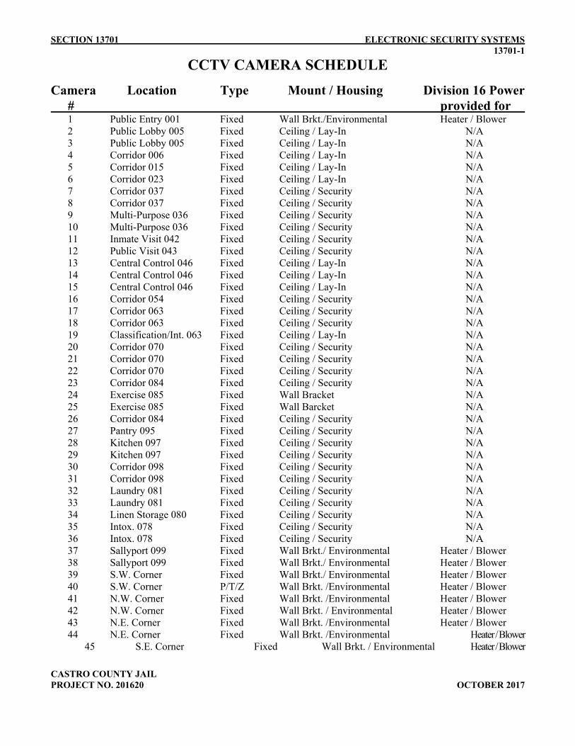
SECTION 13701 ELECTRONIC SECURITY SYSTEMS 13701-1
CASTRO COUNTY JAIL PROJECT NO. 201620 OCTOBER 2017
CCTV CAMERA SCHEDULE
Camera Location Type Mount / Housing Division 16 Power # provided for
1 Public Entry 001 Fixed Wall Brkt./Environmental Heater / Blower 2 Public Lobby 005 Fixed Ceiling / Lay-In N/A 3 Public Lobby 005 Fixed Ceiling / Lay-In N/A 4 Corridor 006 Fixed Ceiling / Lay-In N/A 5 Corridor 015 Fixed Ceiling / Lay-In N/A 6 Corridor 023 Fixed Ceiling / Lay-In N/A 7 Corridor 037 Fixed Ceiling / Security N/A 8 Corridor 037 Fixed Ceiling / Security N/A 9 Multi-Purpose 036 Fixed Ceiling / Security N/A 10 Multi-Purpose 036 Fixed Ceiling / Security N/A 11 Inmate Visit 042 Fixed Ceiling / Security N/A 12 Public Visit 043 Fixed Ceiling / Security N/A 13 Central Control 046 Fixed Ceiling / Lay-In N/A 14 Central Control 046 Fixed Ceiling / Lay-In N/A 15 Central Control 046 Fixed Ceiling / Lay-In N/A 16 Corridor 054 Fixed Ceiling / Security N/A 17 Corridor 063 Fixed Ceiling / Security N/A 18 Corridor 063 Fixed Ceiling / Security N/A 19 Classification/Int. 063 Fixed Ceiling / Lay-In N/A 20 Corridor 070 Fixed Ceiling / Security N/A 21 Corridor 070 Fixed Ceiling / Security N/A 22 Corridor 070 Fixed Ceiling / Security N/A 23 Corridor 084 Fixed Ceiling / Security N/A 24 Exercise 085 Fixed Wall Bracket N/A 25 Exercise 085 Fixed Wall Barcket N/A 26 Corridor 084 Fixed Ceiling / Security N/A 27 Pantry 095 Fixed Ceiling / Security N/A 28 Kitchen 097 Fixed Ceiling / Security N/A 29 Kitchen 097 Fixed Ceiling / Security N/A 30 Corridor 098 Fixed Ceiling / Security N/A 31 Corridor 098 Fixed Ceiling / Security N/A 32 Laundry 081 Fixed Ceiling / Security N/A 33 Laundry 081 Fixed Ceiling / Security N/A 34 Linen Storage 080 Fixed Ceiling / Security N/A 35 Intox. 078 Fixed Ceiling / Security N/A 36 Intox. 078 Fixed Ceiling / Security N/A 37 Sallyport 099 Fixed Wall Brkt./ Environmental Heater / Blower 38 Sallyport 099 Fixed Wall Brkt./ Environmental Heater / Blower 39 S.W. Corner Fixed Wall Brkt./ Environmental Heater / Blower 40 S.W. Corner P/T/Z Wall Brkt. /Environmental Heater / Blower 41 N.W. Corner Fixed Wall Brkt. /Environmental Heater / Blower 42 N.W. Corner Fixed Wall Brkt. / Environmental Heater / Blower 43 N.E. Corner Fixed Wall Brkt. /Environmental Heater / Blower
44 N.E. Corner Fixed Wall Brkt. /Environmental Heater / Blower 45 S.E. Corner Fixed Wall Brkt. / Environmental Heater / Blower

SECTION 13701 ELECTRONIC SECURITY SYSTEMS 13701-2
CASTRO COUNTY JAIL PROJECT NO. 201620 OCTOBER 2017
46 S.E. Corner Fixed Wall Brkt. / Environmental Heater / Blower
CCTV MONITOR / CONTROL SCHEDULE
CENTRAL CONTROL 046 4 – 24" Color Monitors (Counter-mounted) 2 – 42" Color Monitors (Wall-mounted / Adjustable Wall Brackets) 2 – “Touch Screen” Monitors with Keyboard 3 – DVR Units SHERIFF 011 1 – 20” Color Monitor 1 - DVR Unit INTOXILYZER 069 1-20” Color Monitor (for monitoring camera 36 only) 1-DVR Unit (for audio / video recording in Intoxilyzer 078 only) 1- Ceiling-mounted microphone (Note: Reference also Section 13700 – Part 2.04 for the video recording system)
*** END OF SECTION ***

SECTION 13710 ELECTRONIC SECURITY SYSTEMS - PLC 13710-1
CASTRO COUNTY JAIL PROJECT NO. 201620 OCTOBER 2017
SECTION 13710—PROGRAMMABLE LOGIC CONTROL SYSTEM
PART 1—GENERAL
1.1 SUMMARY A. This section includes the requirements and operational characteristics for the
Programmable Logic Control (PLC) System.
1.2 SYSTEM DESCRIPTION A. The PLC System provides the logic control for the Security Automation System.
Unless noted otherwise, all user-initiated interfaces to the PLC system is performed through the Touch Screen Control Stations (reference section 13720).
B. The PLC System CPU program(s) shall execute all system commands and operations. The Touch screen control station(s) are for operator interface only. All control functions are to be executed by the PLC CPU program(s).
C. The Security Automation System (SAS) network shall be a distributed, fault-tolerant
network. PLC CPU or communication failures shall not affect other PLC’s or touch screen control station(s) on the network.
1.3 SYSTEM REQUIREMENTS
A. General: Provide a complete and fully functional Ethernet based PLC System using
materials and equipment of types, sizes, and rating, as required to meet performance requirements. Use materials and equipment that comply with referenced standards and manufacturers’’ standard design and construction, in accordance with published product information. Coordinate the features of all materials and equipment so they form an integrated system, with components and interconnections matched for optimum performance of specified functions.
B. All components of the PLC System shall be regularly sold to the corrections market. The PLC manufacturer must guarantee the availability of spare parts for a period of 10 years. All components shall be housed in structurally sound and finished metal cabinets. All switches and other operator-controlled devices shall be of the size and durability for their intended use as is normally offered for industrial applications.
C. Modular components of the system shall be UL listed or recognized.

SECTION 13710 ELECTRONIC SECURITY SYSTEMS - PLC 13710-2
CASTRO COUNTY JAIL PROJECT NO. 201620 OCTOBER 2017
1.4 RELATED DOCUMENTS
A. Drawings and general provisions of Contract, including General and Supplementary Conditions and Division 1 and 16 Specifications apply to this section of the specifications.
B. See Section 13700 of these specifications for additional work that governs this section of the specifications.
PART 2—PRODUCTS
2.1 EQUIPMENT AND MATERIALS
A. PLC Central Processing Unit
1. The central processing unit (CPU) shall be microprocessor based and shall provide the logic control functions and data transfer based upon the program stored in memory and the status of the inputs and outputs. The controller must be expandable in order to provide the required input and outputs as well as spare capacity.
2. Each PLC communication shall be done over a single embedded Ethernet port.
3. The PLC Network shall follow the network guidelines previously set forth in these specifications.
4. The minimum standard control functions of the CPU shall include:
a) Higher Language Programming (spread sheet type format).
b) Latching relays
c) Timer clock pluses (.02s, 1s, 0.2s, 1s, & 1m) and timers (.01 & 0.1 sec. Increments).
d) Counters (up/down)
e) Data comparison (=, <,>), data range comparison, and data table comparison.
f) Data transfers (single register, blocks of registers, data distribution and collection using pointer).
g) Synchronous shift registers forward and reverse (multiple channel length bit shifts).

SECTION 13710 ELECTRONIC SECURITY SYSTEMS - PLC 13710-3
CASTRO COUNTY JAIL PROJECT NO. 201620 OCTOBER 2017
h) One-shot output and input controls.
i) Master control relays (interlocks)
j) Bit reads and moves.
k) I/O forcing and setting.
l) BCD to Binary or Hexadecimal conversion.
m) Binary or Hexadecimal to BCD conversion.
n) I/O Refresh on command, immediate I/O inputs, and scheduled interrupt on
command.
o) On-line program edit capabilities.
5. The following minimum modes of operation of the CPU must be selectable via programming software commands: a) PROGRAM – Processor is not scanning program in memory and all outputs are
held OFF.
b) MONITOR – Processor is executing program and changes in user memory and data memory are allowed
c) RUN – Processor is executing program in memory and outputs are controlled by the program. No editing of program or data registers is allowed.
6. The above settings shall require either a programming console with a key, or programming software loaded on a computer to change the operating mode of the CPU.
7. The processor shall incorporate extensive self-diagnostic features, which will not halt the processor. In addition, separate visual indicators will annunciate at the following conditions: a) POWER – Logic power is applied to the CPU and I/O rack from the power
supply.
b) RUN – Processor is executing the program in memory and outputs are being controlled according to the program.
c) NETWORK ACTIVITY – Indicating the CPU communication with the network.

SECTION 13710 ELECTRONIC SECURITY SYSTEMS - PLC 13710-4
CASTRO COUNTY JAIL PROJECT NO. 201620 OCTOBER 2017
d) NETWORK LINK – Indicating the CPU is connected to a network.
8. In addition to visual self-diagnostic indicators (LED’s) the processor shall have a
specifically designated block of at least 100 words and bits. These shall provide more detailed system status and fault diagnostic information accessible by programming equipment or intelligent peripherals.
9. The processor must contain an error log area. This area must be able to log what error occurred and when the error happened, giving exact time and date. This area must be able to store a minimum of 1,000 records.
10. A single embedded LAN communication port shall be used for software based PLC programming.
11. Approved Manufacturers:
a) OMRON b) Allen Bradley c) Rockwell d) Square D e) GE Fanuc f) or approved equal
B. Remote IO Module
1. The module shall support 8 independent data channels. Each channel must support up to 64 discreet IO.
2. All communications between the PLC and Remote IO Module shall be Ethernet based.
3. Each Remote IO Module shall distribute all power to the local discrete I/O modules and termination boards.
4. Remote IO Modules shall be powered by a 12V DC power supply and shall be capable of supplying up to 12 watts of power to each data channel.
C. Discrete I/O Module
1. Each discrete I/O module shall be a self-contained unit housed within an enclosure so that no part of its circuit board is exposed to contact by handling.
2. Discrete I/O modules shall be UL listed.
3. It shall be possible to replace any I/O module without removing or disturbing user field wiring.

SECTION 13710 ELECTRONIC SECURITY SYSTEMS - PLC 13710-5
CASTRO COUNTY JAIL PROJECT NO. 201620 OCTOBER 2017
4. All I/O modules units shall be solid state in nature. The output units shall be
transistor types for long life and high DC reliability.
5. I/O modules should control 16 outputs and monitor 16 inputs.
6. The I/O modules shall communicate with the Remote IO Module
7. I/O updates shall take no longer than 50 milliseconds.
D. PLC Programming
1. The PLC programming can be done in high level language (such as a spreadsheet format) or ladder logic programming that utilize traditional rungs utilizing IO addressing with contacts/coils. Proprietary programming is unacceptable. PLC ladder logic programming should be grouped, separated and categorized for each system type (i.e. DOORS, INTERCOMS, CCTV, etc).
2. All PLC ladder logic programming shall be documented at each rung and/or function to describe in general terms what programmed logical control is being performed.
3. Any ladder or ladder element delete function must require at least two steps to prevent accidental deletion of any part of the ladder program.
4. It shall be possible to program and monitor any PLC from a single host computer via the LAN.
5. Programming software must be compatible with any IBM AT compatible computer running Windows 7, 8 or 10.
6. The programming software must not require the use of any hardware protection key, any special internal circuit board on the computer, or any sort of floppy disk to operate.
7. It shall be possible to search the program for any contact number, coil number, storage register type and number, address location, or special function number that the CPU supports.
8. It shall be possible to delete part of the program without affecting the remainder of the program. In either case, the program must automatically recompile to accept the new addition or remove the gap left by any deletion.
9. It shall be possible to force any input, output, or internal bit ON or OFF using either the programming console or the computer-based programming software.

SECTION 13710 ELECTRONIC SECURITY SYSTEMS - PLC 13710-6
CASTRO COUNTY JAIL PROJECT NO. 201620 OCTOBER 2017
10. Programming of nested branches and rungs with multiple outputs must be possible.
11. It shall be possible to program any given I/O point or internal bit or register as often as desired.
12. Using the computer-based programming software, it shall be possible to simultaneously display the following information for any desired rung: a) The ON or OFF state of any contact or coil.
b) The contents of any given storage register.
c) Whether a coil is standard, normally closed, one-shot or a latching relay.
13. The computer-based programming software must be capable of displaying non-
adjacent rungs during program monitoring operation.
14. If a rung of logic is satisfied, then the complete line should be highlighted not just the contacts/coils.
15. Monitoring or any bit/word across the network from any PLC should be supported to aid troubleshooting.
16. It should be able to: a) Operate without using the mouse.
b) Navigate using directory tree displays.
c) Enter bit input/output instructions with function keys.
d) Split the screen 2 or 4 ways.
e) Convert from text inputs to ladder programs by either inputting mnemonics to
ladder diagram displays or convert text input with text editors or word processors.
f) It shall be possible to program with names rather than specific addresses.
g) Have the ability to utilize name, addresses, I/O comments, and other data from Microsoft Excel.
h) Drag and drop DOS files between Memory Cards in the computer and in the PLC.
i) Display error histories from the CPU Unit with time stamping.

SECTION 13710 ELECTRONIC SECURITY SYSTEMS - PLC 13710-7
CASTRO COUNTY JAIL PROJECT NO. 201620 OCTOBER 2017
j) Protect programs from access using passwords.
k) Have the ability to run and monitor multiple programs all at one time.
17. PLC output modules shall not be allowed to directly drive electric locks, sliding
doors, lighting circuits, or any other device with continuous duty current or surge current in excess of 500 milliamps. Output boards shall drive interposing relays.
18. The PLC supplier shall provide unlimited phone technical support at no charge to the end user.
E. Spares:
1. Provide 5% spare input and output installed capacity at the completion of the project.
2. Provide one (1) spare PLC. 3. Provide one (1) spare Remote I/O Module. 4. Provide one (1) spare Discrete I/O Module of each type used.
5. Provide ten (10) spare relays for each type used
6. Provide ten (10) spare fuses for each type used
PART 3—EXECUTION
3.1 GENERAL
A. All work required herein shall comply with applicable sections of Division 16 and 13700 requirements.
END OF SECTION

SECTION 13720 ELECTRONIC SECURITY SYSTEMS - TOUCHSCREEN 13720-1
CASTRO COUNTY JAIL PROJECT NO. 201620 OCTOBER 2017
SECTION 13720 TOUCH SCREEN CONTROL STATIONS
PART 1—GENERAL
1.1 SUMMARY A. This section includes the requirements and operational characteristics for the Touch
Screen Control Stations (TSCS) comprised of the following equipment that shall be 100% integrated with the Security Automation System. 1. Touch Screen Computer and Monitor
2. Touch Screen Software
3. Wireless PDAs (as required by drawings)
1.2 SYSTEM DESCRIPTION A. The Touch Screen Control Station (TSCS) shall operate as a graphical human machine
interface (HMI) between the correction officer and the electronic security monitoring and control equipment. The TSCS shall display the status of monitored points and shall control output points.
B. A network connection shall exist between all the TSCS stations and the Programmable Logic Controllers (PLC). The TSCS shall not directly control the security devices. The security devices will be controlled by the PLC using interposing relays as described elsewhere in this specification.
C. Provide wireless controls (as shown on drawings) as described in these specifications for the areas indicated on the contract drawings. Wireless devices include PDA type handhelds. The wireless control devices shall connect to the Security Automation System (SAS) via IEEE 802.11 protocol and shall support VOIP (Voice over IP) so that the wireless device can be used as a Master intercom Station.
D. The SAS shall allow for all TSCSs and wireless devices to operate together as a seamless, integrated system.
1.3 RELATED DOCUMENTS
A. Drawings and general provisions of Contract, including General and Supplementary Conditions and Division 1 and 16 Specifications apply to this section of the specifications.

SECTION 13720 ELECTRONIC SECURITY SYSTEMS - TOUCHSCREEN 13720-2
CASTRO COUNTY JAIL PROJECT NO. 201620 OCTOBER 2017
B. See Section 13700 of these specifications for additional work that governs this section of the specifications.
1.4 SOFTWARE REQUIREMENTS A. The TSCS shall have the following software requirements to allow for seamless control
and maximum flexibility. 1. Control Icons
a) Central Control shall have the ability to view and control all screens of the
facility with status of all devices regardless of which TSCS has primary control of those devices.
b) Local TSCSs shall display icons of doors, intercoms, cameras, etc., which are
under its’ primary control. Local TSCSs shall have the ability to be assigned to different ‘task groups’ to allow for maximum operational flexibility.
2. Takeover
a) The Central Control TSCS(s) shall have the ability to takeover or disable any
combination of TSCSs and wireless devices.
b) Upon takeover from Central, the intercom queues from the disabled stations will rollover to the Central Control TSCS.
3. Touchscreen Login Validation a) Each TSCS shall require Login Validation from the Security Management
Server (SMS) via a PIN code. On the Login Screen, the TSCS shall display a keypad for the operator to enter a PIN code.
b) As an option, the TSCS shall require Login Validation from the SMS via a local proximity card reader or a USB fingerprint reader connected to the TSCS.
c) Login Validation shall be integrated with the SMS’s database to allow tracking of the operator’s name for all functions at each TSCS until it is logged off.

SECTION 13720 ELECTRONIC SECURITY SYSTEMS - TOUCHSCREEN 13720-3
CASTRO COUNTY JAIL PROJECT NO. 201620 OCTOBER 2017
d) If the TSCS cannot communicate with the SMS, then the TSCS shall authenticate users against a local cache of credentials generated from the previously successful authentication attempts.
e) An operator remains the current operator until logged out or until the TSCS is taken over or disabled.
f) Wireless devices shall logon users by inputting user name, PIN, and selecting the pre-defined area of control.
4. Event Logging
a) All actions taken by the TSCS operator shall be logged to the SMS.
5. Graphic display call-up time of one second maximum for all graphics.
6. Variable update time of one second for variables from multiple PLC’s.
1.5 SYSTEM OPERATION
A. Unlock Function – Swing: 1. Pressing the door icon will apply power to the lock and activate the unlock cycle.
2. The icon will illuminate steady red when the door is open or unlocked. The icon
will be black when the door is closed and locked.
3. Two or more doors may be in an interlock group. When any door in an interlock group is open or unlocked, the remaining doors in that group cannot be opened without using interlock override. (See: “Interlock Operation”)
B. Open/Stop/Close Operation 1. Pressing the open icon will cause the door/gate to begin opening. The door/gate
will continue opening until fully open or until the stop or close icon is pressed.
2. While in motion, pressing the stop icon will cause the door/gate to stop.
3. Pressing the close icon will cause the door/gate to begin closing. The gate will continue closing until fully closed or until the stop or open icon is pressed.
4. The icons will illuminate steady red when the door/gate is open or unlocked. The icons will be black when the gate is closed and locked.

SECTION 13720 ELECTRONIC SECURITY SYSTEMS - TOUCHSCREEN 13720-4
CASTRO COUNTY JAIL PROJECT NO. 201620 OCTOBER 2017
C. Monitored Door Operation: 1. The icon will illuminate steady red when the door is open or unlocked. The icons
will illuminate steady green when the door is closed and locked.
D. Intercom Operation: 1. When a call button on a remote intercom station is pressed, the icon will flash green
and an audible intercom tone will sound.
2. Pressing the intercom icon will cause the flashing green icon to illuminate steady green, silence the audible tone and connect the remote intercom station speaker to the touch screen intercom amplifier.
3. While connected, sound in the area of the remote intercom station will be transmitted to the touch screen.
4. The TSCS operator can talk to the selected intercom station by pressing and holding the Push to Talk (PTT) icon on the TSCS. When the PTT icon is released, sound from the intercom station shall again be transmitted to the TSCS.
5. Pressing the intercom icon again will disconnect the remote speaker from the touch screen intercom amplifier and turn the icon back to gray.
6. The touch screen operator may connect the remote intercom station to the touch screen intercom amplifier as in b) without the remote call button being pressed as in a).
7. Intercoms can also be answered / reset by using the intercom icons. a) When a remote intercom station is pressed, the intercom call will be listed in
the intercom queue. The queue shall show the intercom station call-ins in the order received.
b) Pressing the Select (SEL) icon will connect the intercom station at the top of the queue and change the screen to display the selected intercom station.
c) The intercom-reset icon will disconnect any currently connected intercom station.
d) If the control system has CCTV system integration included, the camera associated with a selected intercom station shall be pulled up on the spot monitor when an intercom station is selected.
E. Duress Operation:

SECTION 13720 ELECTRONIC SECURITY SYSTEMS - TOUCHSCREEN 13720-5
CASTRO COUNTY JAIL PROJECT NO. 201620 OCTOBER 2017
1. Pressing a duress button anywhere in the facility will generate a “duress alarm” condition.
2. The associated duress alarm icon will flash, an alarm description will be displayed in the alarm status bar, an audible duress alarm will sound, and the “go to alarm” icon will flash red.
3. Pressing the flashing “go to alarm” icon will change the screen to display the active alarm.
4. Pressing the flashing duress alarm icon and then pressing the acknowledgement button will silence the audible tone and turn the duress alarm icon to a steady red.
5. After the alarm condition has been cleared (the duress button has been reset), pressing the duress alarm icon and then selecting the reset button will reset the alarm and the duress alarm icon will disappear.
F. Emergency Release Operation: a) Pressing the emergency release icon will activate a red pop up window displaying
the text “EMERGENCY RELEASE – ARE YOU SURE? YES or NO”.
b) Pressing the YES button will activate the emergency release function. The emergency release icon will flash red, and all associated doors will open and REMAIN open.
c) Pressing the NO button will close the pop-up window and cancel the action.
G. Group Release Operation: a) Pressing the group icon will open all of the doors in that group. Individual doors
may be removed from group release by touching the ‘Protect/Isolate’ icon and then touching the desired door. When a door has been isolated from the group mode, the door icon will become shaded grey and that action will be recorded to the Alarm/Event logging. To remove a door from the protect/isolate mode, touch the ‘Protect’ icon and then the door icon. The grey shading on the icon will disappear and that action will be logged to the activity report screen.
H. Camera Operation: a) Pressing a camera icon will display the associated camera on the spot monitor, and
the icon will illuminate green.
b) Pressing the camera icon a second time will turn the associated camera icon to gray.
I. Interlock Operation:

SECTION 13720 ELECTRONIC SECURITY SYSTEMS - TOUCHSCREEN 13720-6
CASTRO COUNTY JAIL PROJECT NO. 201620 OCTOBER 2017
a) If any door in an interlock group is open or unlocked, the other doors in that group
will have a yellow border around their icons.
b) To open more than one door in an interlock group, press the interlock override icon and the next door in the interlock group you wish to open. This action will be displayed in the activity/event screen and logged.
c) The interlock function remains active for a period of time adjustable from 0-30 seconds.
J. TSCS Disable Operation: a) To disable a TSCS, press the TSCS disable icon. All functions of the selected TSCS
will be disabled immediately and will be transferred to Central Control.
b) The TSCS disable icon will be shown with an “X” over it.
c) To enable the control panel, press the TSCS disable icon. All functions of the selected TSCS will be enabled and will be transferred back to the selected TSCS.
d) The enabled TSCS operator will have to log in to the control software to fully restore control.
e) The TSCS disable icon will be shown without the “X” over it.
f) The Central Control TSCS shall have the ability to disable and enable any remote TSCS.
K. Utilities Control 1. Utilities control is a feature that allows the operator to control and/or monitor other
systems or devices in the facility. Pressing a utility icon shall cause the utility to be turned on if it is off, or turned off it is on. The icon will change color and state when changing from off/on. a) LIGHTS – Dayroom lights, individual cell day/night lights shall be controlled
from the TSCS. If the lights are on, the light icon shall be yellow. If the lights are off, the light icon shall be gray.
b) TELEPHONES – Inmate telephones shall be controlled from the TSCS. If the telephones are on, the telephone icon shall be yellow. If the telephones are off, the telephone icon shall be gray.

SECTION 13720 ELECTRONIC SECURITY SYSTEMS - TOUCHSCREEN 13720-7
CASTRO COUNTY JAIL PROJECT NO. 201620 OCTOBER 2017
c) TV RECEPTACLES – TV receptacles shall be controlled from the TSCS. If the TV is on, the TV icon shall be yellow. If the TV is off, the TV icon shall be gray.
d) WATER VALVES – Water solenoid valves shall be controlled from the TSCS. If the valves are on, the valve icon shall be yellow. If the valves are off, the valve icon shall be gray.
L. Page Operation
1. The TSCS operator shall have the ability to address individual paging zones or all
page zones at once using an “All Call”.
2. To address individual page zones, the TSCS operator shall first select the page zone by direct selecting the desired page icon. (see “Intercom Operation”)
3. When a page zone is selected, the corresponding page icon will illuminate green.
4. While a page zone is selected, sound shall be transmitted from the TSCS to the corresponding paging speakers OR intercoms.
5. Once a page is complete, the TSCS operator shall end the page by direct selecting the page icon.
6. The page icon shall be gray when the corresponding page zone is not selected.
M. Site Screen Operation 1. The TSCS shall have a separate screen which shows a site plan. The site plan shall
show a graphical rendition of all areas of the facility under the TSCS’s control.
2. Pressing an outlined area for a particular section of the facility shall cause the TSCS to go directly to the screen that controls the touched area.
3. The site plan shall be located on each screen and shall be sized to prevent obstruction of the floor plan on each screen. The area on the site plan that represents the current screen shall be highlighted in white so that the operator knows exactly what screen is active in relation to the other parts of the facility.
N. Power Supply Alarm Operation
1. When the loss of main AC power is detected and the control system reverts to UPS
or emergency power, the power supply alarm icon shall flash red and an alarm shall sound. The power supply alarm shall remain in alarm mode until main AC power has been restored.

SECTION 13720 ELECTRONIC SECURITY SYSTEMS - TOUCHSCREEN 13720-8
CASTRO COUNTY JAIL PROJECT NO. 201620 OCTOBER 2017
2. The alarm shall be silenced and the power supply alarm icon shall be solid red when the Alarm Silence button is pressed.
3. Once main AC power has been restored, the power supply alarm shall automatically clear if the alarm has not been silenced. If the power supply alarm is silenced and main AC power has been restored, the alarm shall clear when the Alarm Reset button is pressed.
O. Ground Fault Operation
1. When a ground fault is detected, the ground fault icon shall be solid red. The ground
fault icon shall remain solid red until the ground fault has been cleared from the system.
P. Alarm Silence Operation
1. Pressing the Alarm Silence icon shall silence the audible enunciators used to
indicate alarms.
Q. Alarm Reset Operation 1. Pressing the Alarm Reset icon shall reset an alarm as long as the cause of the alarm
has been addressed.
R. Menu Options 1. The following software functions shall be selectable from a menu when an The
Breach option shall be selected for a door by placing the mouse pointer over the desired door, pressing the right button on the mouse, and selecting the Breach option.
a) Prop Alarm
1. If the Prop option is selected for a door and the door is propped or held open
longer than the assigned time, an alarm will sound at the TSCS, notifying the operator of an unsecured condition. An operator must have administrator rights to set a Prop alarm.
b) Breach Alarm
1. If the Breach option is selected for a door and the door is opened by any
means other than from the TSCS, a breach alarm will sound at the TSCS, to

SECTION 13720 ELECTRONIC SECURITY SYSTEMS - TOUCHSCREEN 13720-9
CASTRO COUNTY JAIL PROJECT NO. 201620 OCTOBER 2017
notify the operator of that condition. An operator must have administrator rights to set a Breach alarm.
c) Hold Open
1. If the Hold Open option is selected for a door, the door lock for the selected
door shall be held in until the Hold Open option is turned off for that door.
d) Protect 1. If the Protect option is selected for a door, the door shall not open by any
other means than by the operator directly selecting the door. If the Protect option is selected for an intercom, the intercom icon shall flash but not sound when the call-in button is pressed at the remote intercom station. Icons that are ‘Protected’ shall be shaded gray on the TSCS.
PART 2—PRODUCTS
2.1 EQUIPMENT AND MATERIALS
A. Touch Screen Station Computer: The computer shall have the following minimum requirements: 1. Quad Core Intel Processor 2.0GHz
2. Windows 7, 8 or 10 Professional, SP1
3. 4GB, DDR2 SDRAM Memory, 533 MHz
4. Integrated Video Graphics Processor
5. Minimum 80 GB, 7200 RPM hard drive
6. Gigabit Ethernet adapter
7. USB keyboard
8. Optical Mouse
9. Display Port for multiple monitor support.
10. Shall be powered by UPS.
11. Approved Manufacturers:
a) HP

SECTION 13720 ELECTRONIC SECURITY SYSTEMS - TOUCHSCREEN 13720-10
CASTRO COUNTY JAIL PROJECT NO. 201620 OCTOBER 2017
b) Dell
c) ASUS
B. Minimum Touch Screen Monitor requirements:
1. Display Size: 27” diagonal 2. Viewable Size 27" diagonal (23.54" horizontal x 13.24" vertical) 3. Touchscreen Type Projected Capacitive 4. Number of Touch Points 10 5. Touchscreen Interface USB 6. Contrast Ratio (typ) 1000:1 7. Viewing Angle (typ) 138° H,V 8. Response Time (typ) 14 ms 9. Brightness (w/touchscreen) 213 cd/m² 10. Brightness (w/o touchscreen) 250 cd/m² 11. Display Type Edge-Lit LED LCD 12. Display Resolution 1920 x 1080 13. Aspect Ratio 16:9 14. Tilt Range +15° to +70° and flat 15. Palette 16.7 million colors 16. Video Inputs Analog, HDMI, DisplayPort 17. Audio Output 2 speakers, 2W/ch 18. Compatibility Windows® 7, 8 or 10 - HID Compliant - no drivers needed for basic
touchscreen operation
C. TSCS Human Machine Interface (HMI) Software 1. The software shall consist of supervisory and process control, real-time data
acquisition, alarm and event management, historical data collection, report generation, local or remote telemetry communications to PLC’s, and internet/intranet access. The software shall be easy-to-use, with an object-oriented graphics development environment and have an open architecture, which utilizes the latest in Windows 7, 8 or 10 Professional client/server networking technology. Software shall be a standard separately licensed Runtime/Development package for each TSCS shown on the drawings – NO EXCEPTIONS. Where development software packages are sold as a company/facility subscription, provide a minimum of three (3) year’s subscription for use on all TSCS’s provided.
2. Acceptable HMI Software:
a) Wonderware b) Indusoft c) Intellution d) RSView

SECTION 13720 ELECTRONIC SECURITY SYSTEMS - TOUCHSCREEN 13720-11
CASTRO COUNTY JAIL PROJECT NO. 201620 OCTOBER 2017
3. HMI Software communicating to traditional PLC’s shall utilize “off the shelf” IO
server software applications provided and written by the HMI software provider and UNDER NO EXCEPTION WILL THE HMI SOFTWARE COMMUNICATE WITH AN “IN-HOUSE” IO SERVER DEVELOPED BY THE INSTALLER
4. RUNTIME USER INTERFACE SOFTWARE REQUIREMENTS:
1) This section describes the various user interface functions of the SCADA
system in the runtime mode. The software shall be licensed to support any of the hardware levels of user interface in any combination as follows: a) Server, workstation or desktop PC running the latest version of Microsoft
Windows. b) Handheld devices running Windows CE.
5. Runtime Security:
a) The runtime software shall include a security system under Windows security
to enable various operator tasks based on the user level and password. Access to all displays and to all command functions shall be based on the operator’s security level to protect against unauthorized use. After initial creation, only an assigned user with proper authorization or the system administrator shall modify the password.
b) The security system shall be capable of disabling access to all Microsoft Windows controls (file menu, close, minimize, etc.) and keyboard commands (Ctrl-ESC, Alt-Tab, and Ctrl-Alt-Del).
6. Logging Operator Actions: a) All operator actions shall be logged to an event logger. The event logger shall
keep track of each new operator log-on, log-off or device control. b) Each event log shall record the date, time, operator logged in and the type of
action taken.
7. Alarm Management Functions:
a) Alarms shall be detected and reported by an Alarm Manager Service. The Alarm Manager Service shall support no less then forty (40) simultaneous alarm client displays.

SECTION 13720 ELECTRONIC SECURITY SYSTEMS - TOUCHSCREEN 13720-12
CASTRO COUNTY JAIL PROJECT NO. 201620 OCTOBER 2017
b) It shall be possible for the operator to filter the alarm display based on priority level, groups or process area. In distributed network systems, alarms shall be viewed and acknowledged from any workstation and the information shall be distributed to all clients. The name of the operator and the node acknowledging the alarm shall be capable of being displayed in the Alarm Summary.
c) The alarm display shall support up to eight different combinations of colors based on the priority of the alarm and whether it is acknowledged or unacknowledged.
d) The system shall provide a method of notifying the user when a new alarm has occurred.
e) The operator shall be able to select and acknowledge alarms individually, by group or area. The operator shall also be able to acknowledge only those alarms visible in the display, only those selected, only the most recent alarm or all alarms in the system. The alarm display shall allow alarms to be selected by clicking on them with the mouse at runtime.
f) The operator shall be able to select an alarm from the alarm summary display and the system shall switch to the corresponding screen as to the particular section of the control system where the alarm originated.
g) It shall be possible to inform the operator of an alarm condition via an audible tone, a pop-up display, or any combination of animation types on the screen.
h) Alarms shall be logged to the SMS.
i) Alarms may be printed to a locally connected or network printer from the SMS.
D. TSCS Development Software 1. Each TSCS shall have a full version of the touch screen database development
software.
2. The touch screen database shall be developed using a standard Windows based software package and is 100% compatible with the specified PLC programming software.
3. The development software shall support the Windows CE platform used on the wireless handheld devices.
4. The software manufacturer shall provide a regular schedule for training classes to be held at the manufacturer’s factory.

SECTION 13720 ELECTRONIC SECURITY SYSTEMS - TOUCHSCREEN 13720-13
CASTRO COUNTY JAIL PROJECT NO. 201620 OCTOBER 2017
5. The software manufacturer shall provide free phone technical support for the life of the software.
E. Wireless PDA Devices (if utilized) 1. Wireless handheld devices shall be capable of controlling and monitoring devices
as described above. Areas of control shall be pre-defined by the Architect/Owner. 2. The PDA devices shall have an internal antenna and be able to communicate with
the control system via 802.11 protocol. 3. All devices to be controlled or monitored by the handheld device shall be displayed
in a list. 4. Selecting a specific device shall cause an icon to be shown, that when pushed will
activate the device. 5. Each PDA shall include a built-in speaker and microphone for digital intercom
communications with remote intercom stations. 6. The handheld device shall come with a charging/programming cradle, spare
battery, and built-in barcode scanner. 7. The supplied battery shall have a life of 8 hours (minimum). 8. Approved Wireless PDA Devices:
a) Symbol Model MC70
F. Spare Parts
1. Provide one fully-loaded TSCS. The computer shall be loaded with all of the TSCS
configuration software applications so that it can be used at any of the TSCS locations in the facility. At the Windows Logon Screen, there shall be icons for each TSCS on the project. Upon selection of a TSCS icon, the specific database for that area shall be automatically loaded.
PART 3—EXECUTION
3.1 GENERAL
A. All work required herein shall comply with applicable sections of Division 16 and 13700 requirements.
END OF SECTION

SECTION 13730 ELECTRONIC SECURITY SYSTEMS - AUDIO 13730-1
CASTRO COUNTY JAIL PROJECT NO. 201620 OCTOBER 2017
SECTION 13730—INTERCOM SYSTEMS
PART 1—GENERAL
1.1 SUMMARY
A. This section includes the requirements and operational characteristics for an Intercom System, which is an integral part of the Security Automation System and integrated into the touchscreen control stations. Intercom Systems included are: 1. Remote intercom stations, ceiling-mounted speaker assemblies and speaker horns.
2. Audio system head-end and control components.
3. General and emergency paging components.
4. Touch screen control station audio components.
B. Provide all labor, equipment, materials, and supervision to install, program, calibrate, adjust, document, and test the total system as required herein and on the drawings.
1.2 SYSTEM DESCRIPTON
A. Provide a PLC-controlled, facility-wide, Intercom System, which is fully integrated with the Security Automation System. This system shall provide two-way, remote reply intercommunication between touch screen control station(s) and users and remote intercom stations, speakers, and horns. This system shall allow any remote intercom station or ceiling monitoring speaker to be answered by the touch screen control station in primary control of that particular area, or by the touch screen station(s) in Central Control during a ‘take-over’ situation.
1.3 SYSTEM FEATURES AND SOFTWARE REQUIREMENTS
A. The Intercom System shall have the following system features and software requirements to allow for seamless control and future flexibility. 1. The audio system will be free from any ‘popping’, ‘cracking’, or ‘humming’ at all
times.
2. Every Touch Screen shall have the capability to talk to any intercom station if desired by the owner. System shall provide for call forwarding/takeover from one touch screen control station to another. See security system drawings for additional information regarding talk paths and takeover.

SECTION 13730 ELECTRONIC SECURITY SYSTEMS - AUDIO 13730-2
CASTRO COUNTY JAIL PROJECT NO. 201620 OCTOBER 2017
3. The Intercom System shall interface with the CCTV system. When an intercom talk path is established, the CCTV system shall automatically call up any CCTV camera(s) on the intercom call-up monitor of the associated touch screen control station when the remote intercom station is in the camera(s) field of view.
4. Each remote intercom station or ceiling monitoring speaker shall be annunciated on any touch screen control station in primary control of that intercom station or speaker’s area. a) When a station or speaker is off, the icon shall be gray.
b) When a station or speaker initiates a call to the touch screen control station, the
icon shall flash green and be accompanied by a distinctive audible tone.
c) When a station or speaker is on, the icon shall be green and the audible tone associated with the call shall be off. When there is a camera monitoring the location, the associated camera icon shall turn green.
d) The remote intercom station or ceiling monitoring speaker’s audio shall be driven through the touch screen control station computer speakers. Audio from the touch screen control station condenser microphone to the remote intercom station or ceiling speaker shall only be active while the touch screen control station push-to-talk push button is depressed.
7. The paging system shall have the capability of reaching individual areas of the facility, or the entire facility.
a) The operator may select a paging zone or zones through selecting paging icons. b) Paging zones shall be grouped logically and final zone configuration shall be
coordinated with the architect and owner.
8. Remote intercom stations shall be programmed to call a designated touch screen control station when activated. If the designated touch screen control station is disabled or not occupied, the call shall be automatically forwarded to a secondary backup touch screen control station.
9. Dual Talk Paths shall be provided for all intercom stations in common controlled areas in order to allow simultaneous communications with intercom stations by the primary and central control computers. It is not required that the computers be able to talk to the same intercom station at the same time.
1.4 SPARES

SECTION 13730 ELECTRONIC SECURITY SYSTEMS - AUDIO 13730-3
CASTRO COUNTY JAIL PROJECT NO. 201620 OCTOBER 2017
A. Provide two spare remote intercom stations.
B. Provide two spare ceiling speakers.
C. Provide one spare remote intercom amplifier.
PART 2—PRODUCTS
2.1 EQUIPMENT AND MATERIALS
A. The basis for most of the audio functions in this specification is a PLC-controlled audio communications system. Provide all necessary PLC inputs and outputs to interface to the specified equipment for an operational audio communications system. Audio control and field device components manufactured by companies other than those expressly approved shall not be acceptable.
B. Remote Intercom Stations
1. Intercom stations shall be mounted directly into recessed, standard, readily available electrical back boxes.
2. The station shall be vandal-resistant in design and shall be 11Ga stainless steel with brushed finish. Tamper-proof mounting hardware as described elsewhere in this specification shall be provided.
3. The station shall provide a momentary push-button type call-in switch. The switch assembly shall be of vandal-proof construction. The actuator shall be of metal construction.
4. The station shall include a speaker-microphone. There shall be at least two baffles separating the speaker cone from the faceplate to prevent contact with the cone with a wire or other sharp object.
5. Approved Manufacturers:
a) Quam CIS4/25 or equal
C. Call-In Only Stations
1. Intercom stations shall be mounted directly into recessed, standard, readily available electrical back boxes.
2. The station shall be vandal-resistant in design and shall be 11Ga stainless steel with
brushed finish. Tamper-proof mounting hardware as described elsewhere in this specification shall be provided.

SECTION 13730 ELECTRONIC SECURITY SYSTEMS - AUDIO 13730-4
CASTRO COUNTY JAIL PROJECT NO. 201620 OCTOBER 2017
3. The station shall provide a momentary push-button type call-in switch. The switch
assembly shall be of vandal-proof construction. The actuator shall be of metal construction.
4. Approved Manufacturer:
a) Quam CIB2 or equal
D. Ceiling-Mounted Speaker Assembly
1. Ceiling mounted speaker assemblies shall consist of an 8 Watt speaker, a baffle, and appropriate back box for the required mounting. Provide all required transformers.
2. Approved manufacture:
a) Ceiling/Wall Mount Speakers: Quam System 1VP or equal b) In-ceiling Speakers: Quam Solution1 or equal
c) Wall mount exterior Speakers: Quam model System 2VP or equal
E. Single Audio Channel Relay Selection Board
1. The relay selection board shall provide individual relay control speaker lines for intercom/paging. Provide all required PLC input and outputs for interface to relay selection board(s) for a fully-functional audio communications system.
2. The board shall contain control circuits, one per speaker line that shall provide for
the selection of any line for intercom/paging. The board shall provide a common audio input for all speaker lines. The board shall contain relays that operate to connect the common audio input with the appropriate speaker lines as controlled by the intercom control circuits. The board shall contain a program bus that shall provide for program distribution to all speaker lines.
3. The panel relays shall be of sealed type construction with a life expectancy of
10,000,000 operations. Relay contacts shall be rated at 2A. Less than 0.75A at 12Vdc shall be required to operate all sixteen relays simultaneously.

SECTION 13730 ELECTRONIC SECURITY SYSTEMS - AUDIO 13730-5
CASTRO COUNTY JAIL PROJECT NO. 201620 OCTOBER 2017
4. All wire connectors to the panel shall be to insulation displacement connectors. The connectors shall accommodate 22 AWG for speaker line connections and 18 AWG for audio input connections.
5. Boards shall be designed for wall mounted cabinets and shall provide for various
switching of audio lines including page functions. 6. The termination board shall have sixteen headers for audio threshold modules.
F. Dual Audio Channel Relay Selection Board
1. The relay selection board shall provide dual relay control of speaker lines for intercom/paging. Provide all required PLC input and outputs for interface to relay selection board(s) for a fully-functional audio communications system.
2. The board shall contain control circuits, two per speaker line that shall provide for the selection of any line for intercom/paging. The board shall provide a common audio input for all 16 speaker lines. The board shall contain relays that operate to connect the two common audio inputs with the appropriate speaker lines as controlled by the intercom control circuits. The board shall contain two program buses that shall provide for program distribution to all speaker lines.
3. The panel relays shall be of sealed type construction with a life expectancy of 10,000,000 operations. Relay contacts shall be rated at 2A. Less than 2A at 12Vdc shall be required to operate all thirty-two relays simultaneously.
4. All wire connectors to the panel shall be to insulation displacement connectors. The connectors shall accommodate 22 AWG for speaker line connections and 18 AWG for audio input connections.
5. Boards shall be designed for wall mounted cabinets and shall provide for various switching of audio lines including page functions.
G. Digital Remote Intercom Amplifier
1. Each Designated Work Station shall communicate to remote stations via a single channel intercom amplifier. All audio between the work station and intercom amplifier shall be over Ethernet.
2. Units shall have solid-state amplifiers capable of 8 watts RMS, with balanced inputs and balanced outputs for operations on 25-volt speaker lines.
3. Units shall have 20dB of volume control.

SECTION 13730 ELECTRONIC SECURITY SYSTEMS - AUDIO 13730-6
CASTRO COUNTY JAIL PROJECT NO. 201620 OCTOBER 2017
4. Frequency response shall be shaped to deliver maximum voice intelligibility, and
hum and noise shall be at least 55dB below rated output.
5. The speaker and talk/listen switch shall be integrated into the graphic control panels as shown on the drawings.
6. The amplifier shall provide half-duplex operation during communication with remote intercom stations.
H. Paging Amplifier
1. Provide quantity required to support the number of field devices to be supported. 2. The paging amplifier shall be mounted in a standard 19-inch rack.
I. Touch Screen Control Station Audio Components
1. The touch screen monitor’s built-in speakers shall be used for digital audio communications. See section 13020 for specifications of monitor.
2. The microphone shall be a standard computer microphone plugged into the
microphone input of the computer. The microphone shall have the following minimum specifications: a) Sensitivity: -44+/- 3dB (0dB = 1 Pa, 1kHz)
b) Impedance: 2000Ω
c) Directivity: Omni-directional
d) Frequency: 20-16,000 Hz
e) Max. operation voltage: 10V
f) Standard operation voltage: 2.5V
g) Current consumption: Max. 0.6mA
h) Sensitivity reduction: Within -3dB at 2V

SECTION 13730 ELECTRONIC SECURITY SYSTEMS - AUDIO 13730-7
CASTRO COUNTY JAIL PROJECT NO. 201620 OCTOBER 2017
i) S/N ratio: More than 60dB
PART 3—EXECUTION
3.1 GENERAL
A. All work required herein shall comply with applicable sections of Division 16 and 13700 requirements.
END OF SECTION

SECTION 13740 ELECTRONIC SECURITY SYSTEMS - CCTV 13740-1
CASTRO COUNTY JAIL PROJECT NO. 201620 OCTOBER 2017
SECTION 13740—CCTV SYSTEM
PART 1—GENERAL
1.1 DESCRIPTION
A. Provide a PLC-controlled, facility-wide, IP based digitally recorded, Closed Circuit Television (CCTV) System, with is fully integrated with the Security Automation System. This system shall allow any remote CCTV camera to be viewed by monitors located in control rooms and controlled by the touch screen control station in primary control of that particular area, or by the touch screen control station(s) in Central/Main Control during a “take over” situation.
B. Provide a CCTV system to allow: 1. Video communication of persons desiring passage through remote doors.
2. Remote monitoring of areas, which are not under continuous staff supervision.
3. IP based digital recording of all cameras in the facility.
1.2 SUMMARY
A. This section includes the requirements and operational characteristics for a Video Communication system, which is an integral part of the Security Automation System. Video Communication systems included are:
1. IP based camera system
2. Video switching systems (mechanical and virtual)
3. Virtual Video multiplexers
4. Video recording system servers/clients
5. CCTV accessories
6. Fiber Optic transmission/reception equipment as required
7. Signal converters as required

SECTION 13740 ELECTRONIC SECURITY SYSTEMS - CCTV 13740-2
CASTRO COUNTY JAIL PROJECT NO. 201620 OCTOBER 2017
B. Provide all labor, equipment, materials, and supervision to install, program, calibrate, adjust, document, and test the total system as required herein and on the drawings.
1.3 SYSTEM FEATURES AND SOFTWARE REQUIREMENTS
A. The Video Communication System shall have the following system features software requirements to allow for seamless control and future flexibility.
8. Complete integration of video matrix switching (mechanical and virtual) system with PLC; touch screen-based control system utilizing and ASCII serial communications between the matrix switch and PLC.
1. The video system shall be configured such that any matrix switch video input can be displayed on any matrix switch video output.
2. Central control shall have the ability to assign any virtual multiplexed view to any monitor to allow owner flexibility in the use of the system.
3. The video matrix switch shall be programmed so that a description is associated with every camera. Integrator shall coordinate with owner.
4. The video system shall provide for call-up of camera signals to assigned monitor locations based on pre-programmed responses to operator input utilizing the touch screen control stations.
5. The video system shall be configured for automatic camera call-up for: a) Connected intercom calls.
B. Power to each camera shall be individually fused for the ease of troubleshooting and maintenance of individual 24-volt cameras.
C. The video system shall be integrated in such a way as to eliminate any ‘rolling’ of video images.
PART 2—PRODUCTS
2.1 EQUIPMENT AND MATERIALS
A. The basis for the specification is to provide a CCTV based IP recorded video system that is viewable from the owners network should they choose to put the CCTV system into their network.

SECTION 13740 ELECTRONIC SECURITY SYSTEMS - CCTV 13740-3
CASTRO COUNTY JAIL PROJECT NO. 201620 OCTOBER 2017
B. Detention Grade Fixed Dome Cameras 1. IP based video viewing shall be utilized for all cameras. The product specified shall be
a vandal/tamper resistant, minimum 540 TVL resolution color dome camera designed for outdoor applications using a 1/3-inch format CCD imager. The unit is prepackaged in cast aluminum housing with a heater, a polycarbonate dome bubble, and a hardened inner liner capable of withstanding the equivalent of 120 lbs of force. The dome bubble is supplied with a UV blocking anti-scratch coating. The camera comes complete with all of the following automatic iris, integral, varifocal lenses, as required by the application, to allow manual zoom and focus adjustment:
2. The camera module setups and adjustments shall be made using an on-screen display in conjunction with push button keys. In addition, the dome camera specified shall be equipped with a coaxial communications transceiver that incorporates a technology to allow camera setup via the coaxial cable using bi-directional communication. The manufacturer shall offer optional configuration software that operates in conjunction with the bi-directional communication technology for adjustment of the camera from the head-end side of the coaxial cable.
3. The camera module positioning shall be adjustable along three (3) axes to allow a viewing adjustment range of 360° pan, 90° tilt, and ±90° azimuth.
4. The manufacturer of the specified dome camera shall provide an adjustment cap for the lens to be used during setup to ensure that the image sharpness (focus) and the field of view remain the same when the setup is complete and the dome bubble is installed.
5. The specified camera shall be equipped with a heater and be capable of operating in the temperature range of -50°C to 50ºC (-58°F to 122ºF).
6. The manufacturer shall offer models of the camera for use in NTSC (60 Hz) or PAL (50 Hz) CCTV systems. The cameras shall operate within the voltage range of 10.8 to 39 VDC or 12 to 28 VAC, 45-65Hz and require no more than 6 watts of power to operate.
7. The camera shall have line-lock capability when powered by AC to synchronize the camera to the power line zero crossing for roll-free vertical interval switching. For vertical synchronization in multiphase power installations, the camera shall provide 0 to 358° of continuously adjustable vertical phase delay. Crystal-lock shall be selected when DC voltage is supplied or the line-lock function is switched off.
8. The manufacturer of the specified color dome camera shall provide optional hardware to allow the camera to be surface mounted, wall mounted, pendant pipe mounted, and internal corner mounted. The camera shall be designed to mount to a standard 4S electrical box and a suspended ceiling.
9. A UTP (unshielded twisted pair) adapter, that allows a balanced video signal to be transmitted over UTP video cable, shall be available as an optional accessory from the manufacturer to allow a UTP video cable to be connected to the standard BNC connector.
10. Approved manufacturers: A. BOSCH B. PELCO C. VICON
C. Monitors

SECTION 13740 ELECTRONIC SECURITY SYSTEMS - CCTV 13740-4
CASTRO COUNTY JAIL PROJECT NO. 201620 OCTOBER 2017
a. Viewable Size 24" diagonal (11.97" x 8.98") b. Aspect Ratio 5:4; 16:9 c. Contrast Ratio (typ) 1000:1 d. Viewing Angle (typ) 130° Horizontal and 160° Vertical e. Response Time (typ) 5 ms f. Brightness (Typical) 250 cd/m² g. Display Type Edge-Lit LED LCD h. Display Resolution 1280 x 1024 SXGA i. Tilt Range -5° to +20° j. Palette 16.7 million colors k. Pixel Pitch 0.294 mm l. Refresh Rate 75 Hz max m. Video Inputs VGA and Composite Video (BNC x 2) n. External Connections D-Sub 15 pin, 2 x BNC in, 2 x BNC out, Audio in
R/LAudio Output 1w x 2 o. Compatibility PC and Mac® (adapter may be required for Mac) p. VESA Compatible/Location Built-in 100 mm VESA, back q. Service and Support 3-Year Customer First™ 2-Day Advance Replacement
Warranty for three full years r. Options / Features Anti-glare coating, Multi-language display, On screen
display (OSD),
D. Virtual Matrix Switcher
1.The product described in this specification shall be based on a switcher/control system that is capable of integration to IP based video systems. This system can switch up to 256 camera inputs to 64 monitor outputs. The system should also provide biphase control code output used to control cameras and other switcher/control system accessories. A master control software package or GUI Series server package shall be used as required enhance the operation of the switcher/controller system functions.
2.The matrix switching hardware architecture of the video switcher/controller system shall be designed to require only 2 equipment bays containing all the video input and output cards to configure a 256 video input by 64 monitor output system. This may be accomplished either mechanically with the switcher and/or virtually with IP based software and converters.
3.The switcher/controller system shall provide, but not be limited to, the following features: a. Unlimited cross-point matrix switching and control capability. b. Capability to program multiple cameras to be sequenced as a synchronized
group (SalvoSwitching®) to any of the display monitors.

SECTION 13740 ELECTRONIC SECURITY SYSTEMS - CCTV 13740-5
CASTRO COUNTY JAIL PROJECT NO. 201620 OCTOBER 2017
c. The system can serve as the master switcher bay in a Bosch Satellite Switch configuration system or it may be configured as the remote satellite switcher. Multiple satellite systems may be combined to provide a reliable distributed processing system.
d. Storage of up to 60 programmable sequences that can be run independently of each other in a forward or reverse direction.
e. The base system provides three user-selectable alarm response modes: Basic, Sequence & Display, and Auto-build.
f. A logging printer port that provides a hardcopy printout of either the system status changes or system Tables and Sequences.
g. Keyboard log-on/log-off with password protection and built-in operator priority levels.
h. A 16-character camera ID may be programmed for display, however, a 16-character alarm title can be selected to appear during alarm conditions instead of the camera ID. Over 1000 characters shall be available for programming titles.
i. A 6-digit camera identification number consisting of a two-digit site number plus a 4-digit camera identification number.
j. Accommodate up to 32 RS-485 keyboards and 1024 alarm points.
4.The switcher/controller system shall provide biphase control code that can be transmitted via shielded twisted pair cable or optional fiber optic system to compatible receiver/driver units or PTZ cameras. On site receiver/drivers allow control of Pan, Tilt, Auto-pan, random pan, four auxiliaries, Zoom, Focus, Iris and set and call of pre-positions. The system also supports variable speed operation and full programming functions for the PTZ dome cameras.
5.Via Master Control Software package, the system shall provide, but not be limited to, the following enhanced features:
a. Combine any or all of the standard alarm modes within the same system (VersAlarm).
b. Program up to 64 timed-event functions. c. Program user restriction tables. d. Program up to 128 custom alarm titles for display upon activation of a
system alarm. e. Download preprogrammed sequences and tables. f. Contact inputs may be configured to activate a simple camera-to-monitor
switching operation rather than reacting as an actual alarm. g. Video signal loss detection.
6.An optional GUI software package shall be available that is designed around an intuitive graphic-based interface. The GUI shall provide programming, control, and monitoring of all system functions and status events by using on-screen icons to reflect real time status of the devices controlled by the system. System alarms, switching functions,

SECTION 13740 ELECTRONIC SECURITY SYSTEMS - CCTV 13740-6
CASTRO COUNTY JAIL PROJECT NO. 201620 OCTOBER 2017
sequence events, sequence keyboard actions and video loss information can be viewed in real time on the PC screen, locked to the PC hard drive.
7.Via its integral RS-232 port, the system shall be capable of being controlled via an access control system or other computing device.
8. System shall be provided in rack mountable bays conforming to EIA 19-inch standards.
9.Electrical Specifications: a. Input voltage level: 0.5 Vp-p to 2 Vp-p (Composite negative sync) b. Power: 200 W at rated voltage with fully loaded bay c. Gain: Unity ± 4% (75 Ohm terminated) d. Video Bandwidth (-3 dB): 15 MHz e. Frequency Response (± 0.5 dB): 12 MHz f. Signal-to-Noise Ratio: 70 dB at 3.58 MHz unified unweighted minimum g. Crosstalk (at 3.58 MHz): h. Input to Input: –60 dB i. Adjacent Channel: –50 dB (typical) j. Hum: 60 dB below the composite 1 Vp-p video signal from 60 Hz to 6 MHz k. DC Output: 0.34 V
10. All equipment bays shall be rack mountable to EIA Industry Standards
G. IP based Digital Video Recording
1. Software and storage shall be capable of recording continuously for a minimum of 15 frames per second (FPS) for each individual camera and up to 30FPS at 640x480 resolution for 90 days (2160 hours) minimum.
2. Incorporate Image integrity using proprietary time/date stamp and watermark authentication.
3. Integrator to provide storage capacity for recording as required. 4. Software shall provide simultaneous recording and playback. 5. Software shall provide configurable motion detection zones per camera for alarm
generation. 6. Software shall provide a function to bookmark a specific time and date of a video file
for easy retrieval at a later date. 7. Software shall provide pre and post alarm recording. 8. Software shall provide both local and remote pan/tilt/zoom control. 9. Software shall provide interface connection to allow video archiving to a Network
Addressable Storage Server. 10. Software shall be capable of recording audio. 11. Software shall include remote viewer Graphical User Interface (GUI) software to allow
simultaneous access via Ethernet to live and recorded video. A minimum of 5 licenses shall be provided.
12. The software shall have remote administrator configuration capability.

SECTION 13740 ELECTRONIC SECURITY SYSTEMS - CCTV 13740-7
CASTRO COUNTY JAIL PROJECT NO. 201620 OCTOBER 2017
H. Power Supplies
1. The power supplies shall provide 24VAC outputs for 8, 16, or 32 cameras in combined POE switches if necessary. The power supplies shall be sized according to the current requirements of cameras connected to the system. Each power supply output point shall be limited to one camera.
2. Provide surge protection for all exterior cameras not mounted to the building structure. The camera power and signal lines shall be protected.
K. Spares:
1. Provide one spare camera of each type used.
PART 3—EXECUTION
3.1 GENERAL
A. All work required herein shall comply with applicable sections Division 16 and 13 requirements.
B. The integrator shall provide a block-switching table that incorporates all requirements of the intercom, video call up and alarming specified in all other sections of this division. The owner shall maintain the right to request modifications at any time during the warranty period at no charge.
C. Cameras located in holding cells shall be mounted as close as possible to the corner of the cell and towards the ceiling to obtain the greatest possible view of the room.
D. All cameras are to be installed per the manufacturer requirements.
E. Electrical connections to exterior cameras shall be made by means of NEMA rated, weatherproof junction boxes and conduit terminations.
F. Seal-tite flexible conduits, with suitable fittings, shall be utilized where connections will need to be flexible.
G. Where raceways penetrate exterior walls, the point of penetration shall be sealed internally, around the wiring, in order to prevent formation and collection of condensation.
END OF SECTION

SECTION 13750 ELECTRONIC SECURITY SYSTEMS – ACCESS CONTROL 13750-1
CASTRO COUNTY JAIL PROJECT NO. 201620 OCTOBER 2017
SECTION 13750—ACCESS CONTROL SYSTEM
PART 1—GENERAL
1.1 SUMMARY
A. This section includes the requirements and operational characteristics for an Access Control System, which is an integral part of the Security Automation System.
B. Provide all labor, equipment, materials, and supervision to install, program, calibrate, adjust, document, and test the total system as required here in and on the drawings.
1.2 SYSTEM DESCRIPTION
A. Provide a facility-wide, Access Control System, which is fully integrated with the Security Automation System.
B. Where shown on the documents, provide proximity card readers and biometric readers. Token readers shall consist of proximity readers, biometrics reader, and other access control system devices. Upon presenting a token (i.e.—proximity card, etc.), the system shall grant access to a controlled device or resource.
1.3 INTEGRATION REQUIREMENTS
A. The Access System shall have the following integration requirements to allow for seamless control and future flexibility.
1. The Access Control System’s database shall be fully integrated with the database of the Security Management Server (SMS), allowing the token user’s Name, not ID code, to be logged by the SMS upon any use of a token reader. The system shall log all access control events, including access granted, access denied used. All access control events shall be associated with the token user’s Name.
2. The Access Control System’s database (located on the SMS), shall be capable of a minimum of 25,000 user accounts. The Access Control System shall be capable of supporting 1000 client licenses.
3. The Access Control System shall be a robust, user-friendly, easily expandable solution. Users shall be added, modified, and deactivated using a Windows-based GUI interface. Each user shall be given customized access rights to controlled devices and other resources based on the time of day, day of the week, and restricted dates. In addition, users must be able to be assigned to customized user groups, which system administrators shall be able to create in order to streamline the access management process and tailor it to their own needs.

SECTION 13750 ELECTRONIC SECURITY SYSTEMS – ACCESS CONTROL 13750-2
CASTRO COUNTY JAIL PROJECT NO. 201620 OCTOBER 2017
4. The Access Control System shall integrate seamlessly with the Touchscreen Control System to visually alert operators when a door has been accessed via the token reader system and shall allow Touchscreen operators to isolate (disable) individual token readers to prevent access (reference section 13720 for Touchscreen functionality). The SMS shall be able to log requests at doors with an isolated reader. Token users shall be capable of entering proximity reader/keypads, which shall activate at that location on one or more Touchscreens. The same level of integration shall also be seen on the SMS, which shall record the user’s Name and time when a resource is accessed, and shall include a full range of reporting features. Login to the Access Control software shall be password protected and access shall be logged to the SMS.
5. The access system shall prompt a response of opening of any doors. It shall make door open requests of the PLC System. The PLC System shall verify interlocking of the requested door and status of the token reader prior to any unlocking.
6. The system shall also have a Windows-based help system.
1.4 SYSTEM FEATURES
A. User Configuration Functions: A user shall include any individual that uses the access control system to access resources, such as a door, software application, or Touchscreen. A user shall also include an administrator who is using the access client software to add users and set permissions and rules. User configuration functions shall include the following:
1. Creating a New User
a) Provide a User Configuration screen that shall allow the operator to create a new user or display information about current users. The information fields displayed shall include the flowing; Last Name, First Name, Middle Name and ID Number. The ID Number shall be any combination of letters and numbers up to a maximum of 50 characters.
b) An image shall be capable of being associated with a user and stored in the SMS database for retrieval from the client software or touchscreen(s).
2. Modify a User (Searching)
a) Provide a means to modify information about existing users.

SECTION 13750 ELECTRONIC SECURITY SYSTEMS – ACCESS CONTROL 13750-3
CASTRO COUNTY JAIL PROJECT NO. 201620 OCTOBER 2017
b) Provide a User Search dialog box that, by default, displays all active users in the database. The User Configuration screen for each user shall be displayed upon the selection of a user in the database.
c) Provide a means to facilitate a more refined search. The operator shall be capable of selecting a field (i.e.—Last Name, First Name, ID Number, token, etc.) to search on in a “Search” list and typing the desired text in a “For” box. The operator shall also be capable of searching for deactivated accounts by means of a checkbox selection.
3. Acquiring an Image for a User
a) Provide a means to capture an image and associate it with an individual user in the database.
b) Provide an Image Acquire screen that shall allow an operator to capture an image via an image capture device (i.e.—USB camera).
c) Provide a preview window that displays a live video stream.
d) Provide an Image Capture button for the operator to select once the user is positioned properly in the preview window. Once picture is acquired, it is saved directly to the user’s record.
e) Provide an Import Image screen that shall allow an operator to import an existing image. Provide a window for the operator to browse to an existing image and open the image once it is found.
4. Assigning a User to User Groups
a) Provide a means to allow users to be assigned to User Groups. A User Group shall be defined as a specific group of users who share the same permissions and rules. When a user is assigned to a group, they shall receive the same permission and rules that the group has, in addition to their own individual permissions and rules. Users shall be capable of belonging to more than one user group.
5. Assigning Rules to a User
a) Provide a means to assign rules to a user. Assigning rules to a user shall allow the user’s permissions to be restricted to specific days of the week, as well as specific times of the day. Provide a means to have a user’s access to activate

SECTION 13750 ELECTRONIC SECURITY SYSTEMS – ACCESS CONTROL 13750-4
CASTRO COUNTY JAIL PROJECT NO. 201620 OCTOBER 2017
or expire on a specific day or prevent them from using permissions on restricted dates.
b) Provide an ‘Allow access only during time range’ checkbox for users that are allowed access only during specific times. Provide time configuration boxes for ‘No earlier than’ and ‘No later than’ that include the time in hours, minutes and seconds. Provide indications for “AM” and “PM”.
c) Provide an ‘Unrestricted Access’ setting to select for users that have no access restrictions based on the time of the day and the day of the week.
6. Assigning Tokens to a User
a) Provide a means to assign tokens to a user. Assigning Tokens to a user consists of assigning items such as a PIN code, proximity card number, password, etc. that the Access Control System uses to identify a user.
b) Provide a Proximity Card field that shall be sued to assign a proximity card ID number to the user. For this feature, a proximity reader enrollment station may be used. The operator shall activate an Enroll button and swipe a proximity card at the enrollment reader. The proximity ID will appear in the field when the card is read.
c) Provide a Personal Identification Number field that shall be used to assign a unique number to a user for use with proximity readers with a keypad option. Upon correct entry of a personal identification number at a keypad, the user shall be up to a maximum of 12 digits long, and unique for all users.
7. Creating a New User Group
a) Provide a means to create User Groups, which shall allow the operator to easily assign the same permissions and rules to many users.
b) Provide a Group Configuration screen that shall allow the operator to create a new group or display information about current groups.
8. Assigning Permissions to a User Group
a) Provide a means to allow user groups access to system resources.
9. Assigning Rules to a User Group
SECTION 13750 ELECTRONIC SECURITY SYSTEMS – ACCESS CONTROL 13750-5
CASTRO COUNTY JAIL PROJECT NO. 201620 OCTOBER 2017
a) Provide a means to assign rules to user groups. Assigning rules to a user group shall allow the user group’s permissions to be restricted to specific days of the week, as well as specific times of the day. Provide a means to have a user group’s access to activate or expire on a specific day or prevent the group from using permissions on restricted dates.
10. Assigning Users to a User Group
a) Provide a means to assign users to user groups. When a user is assigned to a user group, they receive the permissions and rules of the user group.
11. Adding/Modifying/Deleting Restricted Dates
a) Provide a Restricted Dates screen that shall allow the administrator to create new, modify existing, or delete existing restricted dates. Restricted Dates shall be defined by the administrator on this screen. The administrator shall be capable of assigning a name, as well as a date for the restricted date on this screen. A minimum of 1000 administrator-definable restricted dates shall be available.
b) Once defined, access on restricted dates shall be granted by going to the assign Rules tab within the User Configuration screen, and checking the ‘Allow access on restricted dates’ checkbox.
1.5 RELATED DOCUMENTS
A. Drawings and general provisions of Contract, including General and Supplementary Conditions and Division 1 and 16 Specifications apply to this section of the specifications.
B. See Section 13700 of these specifications for additional work that governs this section of the specifications.
PART 2—PRODUCTS
2.1 EQUIPMENT AND MATERIALS
A. Proximity Reader
1. Dimensions: 5.0” x 5.0” x 1.0”
2. Material: Polycarbonate UL 94
3. Power Supply: 10-28.5 VDC

SECTION 13750 ELECTRONIC SECURITY SYSTEMS – ACCESS CONTROL 13750-6
CASTRO COUNTY JAIL PROJECT NO. 201620 OCTOBER 2017
4. Current Requirements: Average—100mA (12VDC), Peak—120mA (24VDC)
5. Operating Temperature: -22° to 150°F (-30° to 65°C)
6. Operating Humidity: 0-95% relative humidity, non-condensing
7. Transmit and Excite Frequency: 125kHz
8. The proximity reader shall be a HID Corp. model 5355AGN.
9. Provide one proximity reader enrollment station per PC (with access control system
software installed) that is designated as an enrollment station.
B. Access Control System Integration
1. Proximity readers and other token readers shall interface to the security network via serial devices servers.
2. Provide serial device servers that meet the following specifications:
a) Wiegand Interface: 26 or 32 bit
b) Wiegand Readers: Support up to eight (8) wiegand readers
c) Serial Interface: RS422
d) Power Requirements: Power input: 12VDC; Power Consumption: 200mA
e) Board shall be capable of supplying power to all eight readers.
f) Environmental Specifications: Operating Temperature: 32 to 112°F (0 to 55°C), 5 to 95% RH; Storage Temperature: -4 to 167°F (-20 to 75°), 5 to 95% RH.
3. Provide quantity of serial device servers to interface to all proximity readers, proximity/keypad readers and other token readers as shown on the plans.
C. Cards
1. Provide 100 cards to owner.
F. Spares:

SECTION 13750 ELECTRONIC SECURITY SYSTEMS – ACCESS CONTROL 13750-7
CASTRO COUNTY JAIL PROJECT NO. 201620 OCTOBER 2017
1. Provide one of each type of proximity reader used.
PART 3—EXECUTION
3.1 GENERAL
a. All work required herein shall comply with Applicable Division 16 and section 13700 requirements.
END OF SECTION

SECTION 13770 ELECTRONIC SECURITY SYSTEMS - UPS 13770-1
CASTRO COUNTY JAIL PROJECT NO. 201620 OCTOBER 2017
PART 1 – GENERAL 1.1 SUMMARY OF WORK
A. Provide a UPS system for the Security Electronics Division and it’s subsystems as described in this specification. Provide any pieces and parts to make this a fully operational piece of the Security System.
B. These systems shall be fully integrated with the other sections of the Security Electronics
as called out on the plans and in this specification.
1.2 REFERENCES - This section references all other sections of the Security Electronics Division, Division 1, 11, 16.
PART 2 – PRODUCTS 2.1 UNINTERRUPTIBLE POWER SUPPLY SYSTEM:
A. Acceptable Manufacturers - Except as otherwise specified, herein, or in the General Conditions, the equipment and materials of this Section shall be products of the following manufacturers, subject to compliance with specification requirements and provided each manufacturer meets all requirements of the Quality Assurance Section of this specification.
1. Powerware/Eaton 2. Best Energy Systems 3. International Power Machines Corp
B. General: Provide for each Division 13 electronic equipment room as shown on the plans
an Uninterruptible Power Supply system to supply 120 volt AC power for all PLC, intercom masters/amps, CCTV, video recording and door control for a period of 30 minutes in the event of primary power failure.
C. Each UPS system shall independently receive its power supply directly from the
main/emergency power supply of the facility. The UPS system shall have the capacity to furnish this required total power for not less than ten (30) minutes in the event of failure of the normal and emergency power source. The UPS system shall have visual and audible trouble indicators and annunciator as scheduled.
D. The UPS system shall include the electrical operation of the door control system, intercom
and CCTV system, simultaneously in the event of power outage. E. Construction: The Uninterruptible power supply shall have an output voltage of 120 volts
and a full load current capable of supplying all systems indicated herein. The unit shall operate with an input voltage of 120 volts, single phase, 60 cycles. The output frequency

SECTION 13770 ELECTRONIC SECURITY SYSTEMS - UPS 13770-2
CASTRO COUNTY JAIL PROJECT NO. 201620 OCTOBER 2017
stability when operating without an input shall be +/- 0.25%. Static voltage regulation shall not exceed +/- 2% with a dynamic regulation of +/- 10% for any load change not exceeding 20% of full load rating. The security contractor is responsible for sizing all UPS systems to meet the ten (10) minute requirements. 1. The unit shall operate normally with a +/- 10 volts input voltage with a .85 power factor,
from 0 degrees to 40 degrees in a humidity of 0% to 95% and shall deliver 150% of rated power for 10 seconds and 125% for 10 minutes.
2. In the event of an inverter malfunction, the system shall switch to the incoming AC line through a solid state static transfer switch in less than 50 milliseconds. The inverter shall shut down and give an alarm when the input voltage drops below 95 volts DC.
3. Batteries: The batteries shall be sealed lead calcium, heavy duty and radial grids for
mechanical strength with low grid corrosion rate PVC plastic separators for low internal resistance. Each cell shall furnish a minimum of 59 amps at 12 volts for one hour. The batteries shall be protected with a circuit breaker and the charger shall give a fault indication and shut down if an over voltage condition exists. Furnish the required number of batteries to supply 120 volts to the load for a period of ten (10) minutes. The complete system (batteries and UPS system) shall be furnished and guaranteed by the same manufacturer.
4. The unit shall have a DC voltmeter, AC voltmeter, DC ammeter, AC ammeter, frequency meter and the following LED system status indicators: a. AC Input Line Present, GREEN b. Rectifier Output Normal, GREEN c. Battery Charger Normal, GREEN d. Inverter Normal, GREEN e. Critical Load Source Normal, GREEN f. Critical Load On Bypass Line, RED g. Over Temperature, RED h. Bypass Line Fuse Open, RED i. Battery Breaker Open, RED j. Rectifier Inoperative, RED k. Inverter Source Normal, GREEN l. Operating From Battery, RED m. Battery Charger Inoperative, RED n. Battery Low, RED o. Inverter Overload, RED p. Inverter Inoperative, RED q. Critical Load Power Normal, GREEN
5. Provide power load calculations for each UPS in the Security System Submittals
2.2 PC SIZE UPS UNITS
A. Acceptable Manufacturers: APC, Powerware, and Tripps

SECTION 13770 ELECTRONIC SECURITY SYSTEMS - UPS 13770-3
CASTRO COUNTY JAIL PROJECT NO. 201620 OCTOBER 2017
B. General: Provide one 1000VA uninterruptible power supply for each and every PC that is supplied with the Security Electronics System. Each unit will contain non-spillable sealed lead acid type batteries that can deliver 8-10 minutes of power, full load approx 5 minutes.
PART 3 - EXECUTION 3.1 EXAMINATION
A. Working Order – Verify that all equipment is in working order and within heat tolerances. B. Installation – Verify that the equipment has been installed in accordance will all codes and
complies with the Security Electronics General Section and Division 16 requirements C. Confirm and verify all equipment is in a pristine new condition with manufacturers
warranty still intact. Make sure all wiring has been tied down and dressed out to professional standards.
D. Confirm all equipment is clean, wiped off and ready for occupancy and owners use.
3.2 CLOSEOUT
A. In the presence of an owners representative and the architect, verify that the material and software provided meets this specification. If there are deficiencies and the contractor was at fault or negligent, the contractor is responsible for immediate correction.
B. Training - Verify all training has been completed as is described in Security Electronics
General Section C. As-Built Documentation – Deliver as-built documents for this section and all sections of
the Security Electronics Division. Also deliver all documents, instructions and literature that came with the material in this section.
END OF SECTION