CASE Report Multifamily Indoor Air Quality - California Energy ...
270
DOCKETED Docket Number: 19-BSTD-03 Project Title: 2022 Energy Code Pre-Rulemaking TN #: 235290 Document Title: CASE Report Multifamily Indoor Air Quality Description: Codes and Standards Enhancement (CASE) Initiative Report for the 2022 California Building Energy Efficiency Standards, submitted by staff Filer: Haile Bucaneg Organization: California Energy Commission Submitter Role: Commission Staff Submission Date: 10/19/2020 7:32:37 AM Docketed Date: 10/19/2020
-
Upload
khangminh22 -
Category
Documents
-
view
0 -
download
0
Transcript of CASE Report Multifamily Indoor Air Quality - California Energy ...

DOCKETED Docket Number: 19-BSTD-03
Project Title: 2022 Energy Code Pre-Rulemaking
TN #: 235290
Document Title: CASE Report Multifamily Indoor Air Quality
Description:
Codes and Standards Enhancement (CASE) Initiative Report
for the 2022 California Building Energy Efficiency Standards,
submitted by staff
Filer: Haile Bucaneg
Organization: California Energy Commission
Submitter Role: Commission Staff
Submission Date: 10/19/2020 7:32:37 AM
Docketed Date: 10/19/2020

Codes and Standards Enhancement (CASE) Initiative 2022 California Energy Code
Multifamily Indoor Air Quality
2022-MF-IAQ-F | Multifamily HVAC | October 2020 FINAL CASE REPORT
Prepared by TRC
Please submit comments to [email protected].
This report was prepared by the California Statewide Codes and Standards Enhancement (CASE) Program that is funded, in part, by California utility customers under the auspices of the California Public Utilities Commission.
Copyright 2020 Pacific Gas and Electric Company, Southern California Edison, San Diego Gas & Electric Company, Los Angeles Department of Water and Power, and Sacramento Municipal Utility District. All rights reserved, except that this document may be used, copied, and distributed without modification.
Neither Pacific Gas and Electric Company, Southern California Edison, San Diego Gas & Electric Company, Los Angeles Department of Water and Power, Sacramento Municipal Utility District or any of its employees makes any warranty, express or implied; or assumes any legal liability or responsibility for the accuracy, completeness or usefulness of any data, information, method, product, policy or process disclosed in this document; or represents that its use will not infringe any privately-owned rights including, but not limited to, patents, trademarks or copyrights.

2022 Title 24, Part 6 Final CASE Report – 2022-MF-IAQ-F | 1
Document Information
Category: Codes and Standards
Keywords: Statewide Codes and Standards Enhancement (CASE) Initiative;
California Statewide Utility Codes and Standards Team; Codes
and Standards Enhancements; 2022 California Energy Code;
2022 Title 24, Part 6; efficiency; indoor air quality, multifamily, heat
recovery ventilator (HRV), energy recovery ventilator (ERV),
balanced ventilation, duct sealing, shaft sealing, duct testing,
range hood, kitchen exhaust
Authors: Marian Goebes, Robert Grindrod, Gwen McLaughlin, Mia
Nakajima, Neil Perry, Elizabeth McCollum (TRC); David Springer,
Alea German, Josh Peralta (Frontier Energy); Nelson Dichter,
Curtis Harrington (UC Davis); Nick Young (Association for Energy
Affordability)
Prime Contractor: TRC
Project
Management:
California Statewide Utility Codes and Standards Team: Pacific
Gas and Electric Company, Southern California Edison, San
Diego Gas & Electric Company, Sacramento Municipal Utility
District, Los Angeles Department of Water and Power.

2022 Title 24, Part 6 Final CASE Report – 2022-MF-IAQ-F | 2
Table of Contents
Table of Contents _____________________________________________________ 2
Executive Summary __________________________________________________ 11
Introduction ______________________________________________________ 26
Measure Description _______________________________________________ 29
2.1 Submeasure A: ERV/HRV .................................................................................. 29
2.2 Submeasure B: Kitchen Exhaust Minimum Capture ........................................... 47
2.3 Submeasure C: Central Ventilation Duct Sealing ............................................... 70
Market Analysis ___________________________________________________ 82
3.1 Submeasure A: ERV/HRV .................................................................................. 82
3.2 Submeasure B: Kitchen Exhaust Minimum Capture ........................................... 90
3.3 Submeasure C: Central Ventilation Duct Sealing ............................................... 99
Energy Savings __________________________________________________ 104
4.1 Submeasure A: ERV/HRV ................................................................................ 104
4.2 Submeasure B: Kitchen Exhaust Minimum Capture ......................................... 115
4.3 Submeasure C: Central Ventilation Duct Sealing ............................................. 117
Cost and Cost Effectiveness ________________________________________ 129
5.1 Submeasure A: ERV/HRV ................................................................................ 129
5.2 Submeasure B: Kitchen Exhaust Minimum Capture ......................................... 154
5.3 Submeasure C: Central Ventilation Duct Sealing ............................................. 157
First-Year Statewide Impacts _______________________________________ 170
6.1 Submeasure A: ERV/HRV ................................................................................ 170
6.2 Submeasure B: Kitchen Exhaust Minimum Capture ......................................... 175
6.3 Submeasure C: Central Ventilation Duct Sealing ............................................. 175
Proposed Revisions to Code Language ______________________________ 180
7.1 Guide to Markup Language .............................................................................. 180
7.2 Standards ......................................................................................................... 180
7.3 Reference Appendices ..................................................................................... 194
7.4 ACM Reference Manual ................................................................................... 201
7.5 Compliance Manuals ........................................................................................ 202
7.6 Compliance Documents ................................................................................... 204
Bibliography _____________________________________________________ 212
Appendix A : Statewide Savings Methodology ___________________________ 220
Appendix B : Embedded Electricity in Water Methodology _________________ 225
Appendix C : Environmental Impacts Methodology _______________________ 226

2022 Title 24, Part 6 Final CASE Report – 2022-MF-IAQ-F | 3
Appendix D : California Building Energy Code Compliance (CBECC) Software Specification _______________________________________________________ 227
8.1 Submeasure A: ERV/HRV ................................................................................ 227
8.2 Submeasure B: Kitchen Exhaust Minimum Capture ......................................... 228
8.3 Submeasure C: Central Ventilation Duct Sealing ............................................. 228
Appendix E : Impacts of Compliance Process on Market Actors ____________ 230
Appendix F : Summary of Stakeholder Engagement ______________________ 237
8.4 Submeasure A: ERV/HRV ................................................................................ 239
8.5 Submeasure B: Kitchen Exhaust Minimum Capture ......................................... 239
8.6 Submeasure C: Central Ventilation Duct Sealing ............................................. 241
Appendix G : Infiltration Assumptions and Multifamily Building Leakage Data 242
Appendix H : Prototype Building Description ____________________________ 249
Appendix I : Methodology for Testing Capture Efficiency for Sample of Range Hoods ____________________________________________________________ 254
Appendix J : Range Hood Capture Efficiency Test Results _________________ 258
Appendix K : Nominal TDV Energy Savings _____________________________ 264
List of Tables Table 1. Minimum Range Hood Capture Efficiency (CE) or Airflow Requirements by
Dwelling Unit Floor Area and Range Fuel, For Demand-Controlled Range Hoods . 14
Table 2. Minimum Range Hood Capture Efficiency (CE) or Airflow Requirements by
Dwelling Unit Floor Area and Range Fuel, for Demand-Controlled Range Hoods .. 16
Table 3: Scope of Code Change Proposal .................................................................... 17
Table 4: Percent of compliant range hood products with proposed requirements ......... 18
Table 5: First-Year Statewide Energy and Impacts ....................................................... 21
Table 6: First-Year Statewide GHG Emissions Impacts ................................................ 22
Table 7. Minimum capture efficiency needed to maintain PM2.5 and NO2 within
acceptable levels by dwelling unit floor area ........................................................... 49
Table 8. Minimum Range Hood Capture Efficiency or Airflow Based on Dwelling Unit
Size and Fuel Type ................................................................................................. 50
Table 9. Percentage of HVI Products Compliant with Proposed Requirements ............ 51
Table 10. Minimum Range Hood Capture Efficiency (CE) or Airflow Requirements by
Dwelling Unit Floor Area and Range Fuel, for Demand-Controlled Range Hoods .. 63

2022 Title 24, Part 6 Final CASE Report – 2022-MF-IAQ-F | 4
Table 11. Minimum Dwelling Unit Floor Area to Meet ASHRAE Standard 62.2
Combustion Requirements for Atmospherically-vented and Solid-fuel Appliances . 68
Table 12: Example Products of HRVs and ERVs with MERV 13 or HEPA Filter Options
................................................................................................................................ 83
Table 13: Overview of HRV and ERV Strategies for Multifamily Buildings .................... 84
Table 14. Percentage of HVI Products Compliant with Proposed Requirements .......... 91
Table 15: Count of Microwave Range Hoods That Could Meet Proposed Requirement
(Horizontal Discharge) ............................................................................................. 96
Table 16: Count of Undercabinet Range Hoods That Could Meet Proposed
Requirement (Horizontal Discharge) ....................................................................... 96
Table 17. Count of Chimney Range Hoods That Could Meet Proposed Requirement
(Vertical Discharge) ................................................................................................. 96
Table 18. Cost Impacts of Proposed Range Hood Requirements ................................. 97
Table 19: Prototype Buildings Used for Energy, Demand, Cost, and Environmental
Impacts Analysis ................................................................................................... 107
Table 20: Savings (in TDV $) From ERV/HRV Proposal Under Different Infiltration
Assumptions in CBECC-Comm ............................................................................. 109
Table 21: Modifications Made to Standard Design in Each Prototype to Simulate
ERV/HRV Code Change ....................................................................................... 110
Table 22: Residential Building Types and Associated Prototype Weighting ................ 112
Table 23: First-Year Energy Impacts Per Dwelling Unit – Low-Rise Garden-Style ..... 112
Table 24: First-Year Energy Impacts Per Dwelling Unit – Low-Rise Loaded Corridor . 113
Table 25: First-Year Energy Impacts Per Dwelling Unit – Mid-Rise Mixed Use .......... 114
Table 26: First-Year Energy Impacts Per Dwelling Unit – High-rise Mixed-Use .......... 114
Table 27: Prototype Buildings Used for Energy, Demand, Cost, and Environmental
Impacts Analysis ................................................................................................... 119
Table 28: Modifications Made to Standard Design in Each Prototype to Simulate Central
Ventilation Duct Sealing Code Change ................................................................. 121
Table 29: Residential Building Types and Associated Prototype Weighting ................ 123
Table 30: First-Year Energy Impacts Per Dwelling Unit – High-Rise Mixed Use ......... 124
Table 31: First-Year Energy Impacts Per Dwelling Unit – Low-Rise Loaded Corridor . 127
Table 32: First-Year Energy Impacts Per Dwelling Unit – Mid-Rise Mixed Use .......... 127

2022 Title 24, Part 6 Final CASE Report – 2022-MF-IAQ-F | 5
Table 33: 2023 PV TDV Energy Cost Savings Over 30-Year Period of Analysis – Per
Dwelling Unit – ERV/HRV in Low-Rise Garden-style New Construction ............... 135
Table 34: 2023 PV TDV Energy Cost Savings Over 30-Year Period of Analysis – Per
Dwelling Unit – ERV/HRV in Low-Rise Loaded Corridor New Construction .......... 135
Table 35: 2023 PV TDV Energy Cost Savings Over 30-Year Period of Analysis – Per
Dwelling Unit – ERV/HRV in Mid-Rise Mixed-Use New Construction ................... 136
Table 36: 2023 PV TDV Energy Cost Savings Over 30-Year Period of Analysis – Per
Dwelling Unit – ERV/HRV in High-Rise Mixed-use New Construction .................. 137
Table 37: 2023 PV TDV Energy Cost Savings Over 30-Year Period of Analysis – Per
Dwelling Unit – ERV/HRV in High-rise Mixed-use New Construction without Bypass
Function Enabled .................................................................................................. 138
Table 38: Cost Multipliers by Climate Zone ................................................................. 139
Table 39: Cost of Base Case: Discrete Supply In-line Fan .......................................... 140
Table 40: Cost of Proposed Case: ERV ...................................................................... 140
Table 41: Unitary ERV Incremental Cost by Climate Zone per Dwelling Unit .............. 141
Table 42: Cost of Base (Supply Fans) and Proposed Case (Central ERV) ................. 143
Table 43: Central ERV Incremental Cost by Climate Zone per Dwelling Unit ............. 144
Table 44: Statewide Average Replacement Cost of Base (Supply Fan) and Proposed
Case (Unitary ERV) ............................................................................................... 145
Table 45: Incremental Replacement Cost of Base (Supply Fan) and Proposed Case
(Unitary ERV) for all Climate Zones ...................................................................... 146
Table 46: Replacement Cost of Base (Supply Fan) and Proposed Case (Central ERV)
.............................................................................................................................. 147
Table 47: Incremental Measure Cost (IMC) for Replacement by Climate Zone – Central
ERV ....................................................................................................................... 148
Table 48: 30-Year Cost-Effectiveness Summary Per Dwelling Unit – Low-rise Garden
Style ...................................................................................................................... 150
Table 49: 30-Year Cost-Effectiveness Summary Per Dwelling Unit – Low-rise Loaded
Corridor ................................................................................................................. 151
Table 50: 30-Year Cost-Effectiveness Summary Per Dwelling Unit – Mid-Rise Mixed
Use ........................................................................................................................ 152
Table 51: 30-Year Cost-Effectiveness Summary Per Dwelling Unit – High-Rise Mixed
Use ........................................................................................................................ 153

2022 Title 24, Part 6 Final CASE Report – 2022-MF-IAQ-F | 6
Table 52: Sampled Costs of Microwave Range Hood Products – 250 cfm Requirement
.............................................................................................................................. 156
Table 53: Sampled Costs of Undercabinet Range Hood Products – 250 cfm
Requirement .......................................................................................................... 156
Table 54: Sampled Costs of Microwave Range Hood Products – 290 cfm Requirement
.............................................................................................................................. 156
Table 55: Sampled Costs of Undercabinet Range Hood Products – 290 cfm
Requirement .......................................................................................................... 157
Table 56: Nominal TDV Energy Cost Savings Over 30-Year Period of Analysis – Per
Dwelling Unit – New Construction – High-Rise Mixed Use: 2023 PV TDV Energy
Cost Savings Over 30-Year Period of Analysis – Per Dwelling Unit – New
Construction – High-Rise Mixed Use ..................................................................... 158
Table 57: Labor Cost Multipliers by Climate Zone ....................................................... 159
Table 58: Material Cost Assumptions for Central Shaft Sealing .................................. 161
Table 59: Labor Cost Assumptions for Central Shaft Sealing ..................................... 163
Table 60: Cost for Leakage Testing Central Ventilation Ducts without Sampling ........ 165
Table 61: Cost for Leakage Testing Central Ventilation Ducts with Sampling ............. 166
Table 62: Labor Rate Assumptions for Central Ventilation Duct Testing ..................... 166
Table 63: Comparison of Sealing Costs ...................................................................... 167
Table 64: 30-Year Cost-Effectiveness Summary Per Dwelling Unit – High-Rise Mixed
Use ........................................................................................................................ 169
Table 65: Statewide Energy and Energy Cost Impacts – New Construction ............... 171
Table 66: Statewide Energy and Energy Cost Impacts – New Construction, Alterations,
and Additions ........................................................................................................ 171
Table 67: First-Year Statewide GHG Emissions Impacts: ERV/HRV .......................... 172
Table 68: Base Case and Proposed Case Materials for Unitary ERV/HRV ................ 173
Table 69: Base Case and Proposed Case Materials for Central ERV/HRV ................ 174
Table 70: First-Year Statewide Impacts on Material Use ............................................ 174
Table 71: Statewide Energy and Energy Cost Impacts – New Construction ............... 176
Table 72: Statewide Energy and Energy Cost Impacts – New Construction, Alterations,
and Additions ........................................................................................................ 177
Table 73: First-Year Statewide GHG Emissions Impacts ............................................ 178

2022 Title 24, Part 6 Final CASE Report – 2022-MF-IAQ-F | 7
Table 74: First-Year Statewide Impacts on Material Use ............................................ 179
Table 75: Proposed Changes to Compliance Forms – CF1R ..................................... 205
Table 76: Proposed Changes to Compliance Forms – CF2R ..................................... 205
Table 77: Proposed Changes to Compliance Forms – CF3R ..................................... 207
Table 78: Proposed Changes to Compliance Forms – NRCC .................................... 208
Table 79: Proposed Changes to Compliance Forms – NRCA ..................................... 209
Table 80: Proposed Changes to Compliance Forms – NRCV ..................................... 210
Table 81: ERV/HRV Estimated New Construction and Existing Building Stock for
Multifamily Buildings by Climate Zone ................................................................... 221
Table 82: Kitchen Exhaust Minimum Estimated New Construction and Existing Building
Stock for Multifamily Buildings by Climate Zone .................................................... 222
Table 83: Percent of Dwelling Units Meeting Central Ventilation Duct Requirements by
Prototype ............................................................................................................... 223
Table 84: Central Ventilation Duct Sealing Estimated New Construction and Existing
Building Stock for Multifamily Buildings by Climate Zone ...................................... 224
Table 85: Roles of Market Actors in the Proposed Compliance Process – ERV/HRV 231
Table 86: Roles of Market Actors in the Proposed Compliance Process – Kitchen
Exhaust ................................................................................................................. 233
Table 87: Roles of Market Actors in the Proposed Compliance Process – Central
Ventilation Duct Sealing ........................................................................................ 235
Table 88: Schedule for Stakeholder Meetings ............................................................. 238
Table 89: Stakeholders that Provided Feedback for ERV/HRV Submeasure ............. 239
Table 90: Stakeholder Participants in Kitchen Exhaust System Proposal Discussion on
October 2, 2019..................................................................................................... 240
Table 91: Attendees of Central Ventilation Shaft Sealing Discussion on October 16,
2019 ...................................................................................................................... 241
Table 92: Table Summary of Proposed Prototype Characteristics .............................. 250
Table 93: Range Hood Products Tested ..................................................................... 256
Table 94: Target Airflows for Capture Efficiency Testing ............................................. 256
Table 95: Equipment List and Calibration Status ........................................................ 261
Table 96: Capture Efficiency Results Recorded at Two Static Pressure for Each Fan 262

2022 Title 24, Part 6 Final CASE Report – 2022-MF-IAQ-F | 8
Table 97: Nominal TDV Energy Cost Savings Over 30-Year Period of Analysis - Per
Dwelling Unit – ERV/HRV in Low-Rise Garden-style New Construction ............... 264
Table 98: Nominal TDV Energy Cost Savings Over 30-Year Period of Analysis - Per
Dwelling Unit – ERV/HRV in Low-Rise Loaded Corridor New Construction .......... 265
Table 99: Nominal TDV Energy Cost Savings Over 30-Year Period of Analysis - Per
Dwelling Unit – ERV/HRV in Mid-Rise Mixed-Use New Construction ................... 266
Table 100: Nominal TDV Energy Cost Savings Over 30-Year Period of Analysis - Per
Dwelling Unit – ERV/HRV High-Rise Mixed-Use New Construction...................... 267
Table 101: Nominal TDV Energy Cost Savings Over 30-Year Period of Analysis – Per
Dwelling Unit – Central Ventilation Duct Sealing - High-Rise Mixed Use New
Construction .......................................................................................................... 268
List of Figures Figure 1: Overview of multifamily dwelling units affected by proposed ERV/HRV code
change. ................................................................................................................... 31
Figure 2: Example HRV diagram. .................................................................................. 32
Figure 3: Current requirements for economizer high limit shut-off control requirements in
table 140.4(e). ......................................................................................................... 41
Figure 4: Energy recovery requirements for central systems in ASHRAE 90.1-2019 for
California. ................................................................................................................ 44
Figure 5: Map of ASHRAE Climate Zone 3C compared with California climate zones
with proposed requirement. ..................................................................................... 45
Figure 6: Estimated population averaged annual cost, in disability adjusted life years
(DALYs), of pollutants with highest median DALY estimates shows PM2.5 with
highest median DALY estimate. .............................................................................. 48
Figure 7: Illustration of range hood plume spillage at different airflow rates. ................. 54
Figure 8: Capture efficiency of kitchen range hoods, as measured via “pollutant
method”. .................................................................................................................. 56
Figure 9: Frequency of the kitchen range hood usage. ................................................. 57
Figure 10: Reasons for not using kitchen exhaust. ....................................................... 58
Figure 11. Sound comparison at 250 cfm for lower sone and current sone requirements.
................................................................................................................................ 59
Figure 12: Typical kitchen range hood system and fan curves. ..................................... 60
Figure 13: Diagram of central ventilation duct system components. ............................. 71

2022 Title 24, Part 6 Final CASE Report – 2022-MF-IAQ-F | 9
Figure 14: Ventilation duct leakage, with hypothetical flow rates. ................................. 72
Figure 15: Boxplot of SRE of ERVs and HRVs (30-100cfm) from the HVI Certified
Products database. ................................................................................................. 85
Figure 16: Net sensible recovery effectiveness of ERV/HRVs in AHRI database
(Courtesy Red Car Analytics). ................................................................................. 86
Figure 17: Fan efficacy of HRVs and ERVs in HVI database. ....................................... 87
Figure 18: Capture efficiencies of example undercabinet and microwave range hoods.
................................................................................................................................ 93
Figure 19: Half (1/2) section rectangle duct. ................................................................ 100
Figure 20: Round duct with seam showing. ................................................................. 100
Figure 21: Duct with mastic applied............................................................................. 100
Figure 22: Kitchen range hood power per unit of flow. ................................................ 117
Figure 23: Central fan flow rates (cfm) pre- and post-sealing of central ventilation shafts
in retrofitted multifamily building. ........................................................................... 125
Figure 24: Base case: discrete supply in-line fan. ....................................................... 130
Figure 25: ERV proposed case. .................................................................................. 131
Figure 26: Central ERV strategy for high-rise mixed-use prototype. ........................... 132
Figure 27: Floor plan of base case for in-unit exhaust ducting. ................................... 133
Figure 28: Floor plan of proposed (central ERV) case for in-unit exhaust ducting. ..... 133
Figure 29: ERV/HRV cost – benefit analysis summary ............................................... 154
Figure 30: Multifamily leakage (measured at the whole building level) compared to
CBECC-Comm infiltration assumption. ................................................................. 244
Figure 31: Leakage results in multifamily dwelling units: total envelope leakage and
exterior leakage only. ............................................................................................ 245
Figure 32: Airtightness of multifamily buildings versus age of air barrier. .................... 246
Figure 33: Airtightness of multifamily buildings versus building height. ....................... 246
Figure 34: Low-rise garden style isometric view. ......................................................... 251
Figure 35: Low-rise garden first and second floor plan................................................ 251
Figure 36: Low-rise loaded corridor isometric view. .................................................... 251
Figure 37: Low-rise loaded corridor second and third floor plan. ................................. 251
Figure 38: Mid-rise mixed use isometric view. ............................................................. 252
2022 Title 24, Part 6 Final CASE Report – 2022-MF-IAQ-F | 10
Figure 39: Mid-rise mixed use second through fifth floor plan. .................................... 252
Figure 40: High-rise mixed use isometric view. ........................................................... 253
Figure 41: High-rise mixed use second through tenth floor plan. ................................ 253
Figure 42: Test chamber side view with dimensions. .................................................. 259
Figure 43: Test chamber front view with dimensions. ................................................. 259
Figure 44: WRH1........................................................................................................ 263
Figure 45: WRH2........................................................................................................ 263
Figure 46: WRH3 ........................................................................................................ 263
Figure 47: OTR2 ......................................................................................................... 263

2022 Title 24, Part 6 Final CASE Report – 2022-MF-IAQ-F | 11
Executive Summary
This document presents recommended code changes that the California Energy
Commission will be considering for adoption in 2021. If you have comments or
suggestions prior to the adoption, please email [email protected].
Comments will not be released for public review or will be anonymized if shared.
Introduction
The Codes and Standards Enhancement (CASE) Initiative presents recommendations
to support the California Energy Commission’s (Energy Commission) efforts to update
the California Energy Code (Title 24, Part 6) to include new requirements or to upgrade
existing requirements for various technologies. Three California investor owned utilities
(IOUs)—Pacific Gas and Electric Company, San Diego Gas and Electric, and Southern
California Edison—and two public utilities—Los Angeles Department of Water and
Power and Sacramento Municipal Utility District (herein referred to as the Statewide
CASE Team when including the CASE Author)—sponsored this effort. The program
goal is to prepare and submit proposals that will result in cost-effective enhancements
to improve energy efficiency and energy performance in California buildings. This report
and the code change proposals presented herein are a part of the effort to develop
technical and cost-effectiveness information for proposed requirements on building
energy-efficient design practices and technologies.
The Statewide CASE Team submits code change proposals to the Energy Commission,
the state agency that has authority to adopt revisions to Title 24, Part 6. The Energy
Commission will evaluate proposals submitted by the Statewide CASE Team and other
stakeholders. The Energy Commission may revise or reject proposals. See the Energy
Commission’s 2022 Title 24 website for information about the rulemaking schedule and
how to participate in the process: https://www.energy.ca.gov/programs-and-
topics/programs/building-energy-efficiency-standards/2022-building-energy-efficiency.
The overall goal of this Final CASE Report is to present a code change proposal for
multifamily indoor air quality (IAQ). The report contains pertinent information supporting
the code change.
Measure Description
Background Information
This report provides proposed updates to Title 24, Part 6 for three submeasures related
to ventilation in multifamily dwelling units. Submeasure A would require heat or energy
recovery in multifamily units for whole dwelling unit ventilation in select climate zones
and primarily provides energy benefits. Submeasure B addresses kitchen ventilation to

2022 Title 24, Part 6 Final CASE Report – 2022-MF-IAQ-F | 12
reduce pollution from cooking and kitchen appliances, and primarily provides IAQ
benefits. The requirements are structured by dwelling unit size; while the scope of this
Final CASE Report is only multifamily buildings, the Statewide CASE Team
recommends that similar requirements be made for single family multifamily units.
Submeasure C addresses sealing of central ventilation ducts in multifamily buildings; it
primarily provides IAQ benefits, but also results in statewide energy savings. While all
relate to dwelling unit ventilation, each is a stand-alone measure and discussed
separately in this report.
A. Energy or heat recovery ventilator (ERV or HRV). This proposed measure builds
on existing language in the 2019 Title 24, Part 6 Standards that require that all
new construction multifamily units either provide balanced ventilation or
demonstrate “compartmentalization”—i.e., demonstrate through a blower door
test that leakage of the dwelling unit envelope area does not exceed a certain
value. For projects following the balanced ventilation path, the proposed
requirement for the 2022 Title 24, Part 6 code cycle adds HRV or ERV as a
prescriptive requirement in California Climate Zones 1-2 and 11-16. This
proposal aligns with a measure in American Society of Heating, Refrigerating,
and Air Conditioning Engineers (ASHRAE) Standard 90.1 (added to the 2019
version) that will require an HRV or ERV for high-rise (buildings with four
occupiable floors or higher) multifamily dwelling units of new construction in all
climate zones except ASHRAE—International Energy Conservation Code (IECC)
3C (mild, marine climate zone), which generally maps to California Climate
Zones 3 through 6. The proposed prescriptive requirement specifies the
following, to be verified by the building inspector:
a. Unitary equipment (one ERV or HRV serving each dwelling unit) must
have a sensible heat recovery efficiency of at least 67 percent, and fan
efficacy ≤ 0.6 W/ cubic feet per minute (cfm);
b. Central equipment (one ERV or HRV serving multiple dwelling units) must
have a sensible heat recover effectiveness1 of at least 67 percent,
minimum fan efficacy as required in Section 140.4, and include a bypass
function whereby the intake air bypasses the heat exchanger and the
equipment functions similar to an economizer.
1 Unitary equipment is typically packaged and rated with a sensible recovery efficiency, which accounts
for the heat transferred from the outgoing air to the incoming airstream and includes the recovery core
and fan. Central equipment is typically rated with a sensible recovery effectiveness, which accounts for
the heat transferred from the outgoing air to the incoming airstream and includes only the recovery core,
since it is sometimes paired with different fans.

2022 Title 24, Part 6 Final CASE Report – 2022-MF-IAQ-F | 13
These requirements would be assumed for the standard design in the
performance path in Climate Zones 1, 2, and 11-16. In addition, the proposal
adds a mandatory measure for fan efficacy of 1.0 W/cfm for unitary ERVs/HRVs
for all climate zones. Projects using central ERVs/HRVs in climate zones not
regulated under the proposed requirement would continue to comply with
applicable requirements in Title 24, Part 6 Section 140.4.
B. Kitchen exhaust minimum capture. California’s 2019 Title 24, Part 6 Standards
require that dwelling units meet all requirements of ASHRAE Standard 62.2,
except where specified. The proposed changes are new requirements for range
hoods to better ensure that a kitchen exhaust system can adequately remove
cooking-related pollution. Specifically, the proposal builds upon recent research
from Lawrence Berkeley National Laboratory (LBNL) that estimated the minimum
range hood capture efficiency needed to maintain fine particulate matter (PM2.5,
for all ranges) and to maintain nitrogen dioxide (NO2, for natural gas-fueled
ranges) at acceptable levels specified, depending on the size of the dwelling unit.
Both pollutants have been linked to numerous health problems. While a
requirement based exclusively on capture efficiency would be the most direct
approach to address IAQ, manufacturers have not yet published the capture
efficiency of their equipment, so there is little market data regarding capture
efficiency of available products. LBNL research and research conducted for this
Final CASE Report have found a direct relationship between airflow and capture
efficiency (i.e., a higher airflow generally results in a higher capture efficiency).
As additional background, manufacturers are moving toward increasing the static
pressure requirements during testing through industry stakeholder groups and
through a working group formed by the ASHRAE 62.2 committee. The proposed
requirement avoids retesting of range hoods should manufacturer testing
requirements change. Consequently, the proposal requires that all multifamily
dwelling units have an exhaust system in the kitchen that meets one of the
following compliance pathways:
1. A vented range hood with a minimum capture efficiency shown in Table 1,
using ASTM Standard E3087-18 at nominal installed airflow (defined in
HVI Publication 920), or
2. A vented range hood with a minimum airflow shown in Table 1, at 0.1
inches water column (w.c.) (25 Pascals [Pa]), or
3. A vented downdraft kitchen exhaust fan with a minimum airflow of 300 cfm
at 0.1 inches w.c. (25 Pa) or higher, or
4. A continuous exhaust system with a minimum airflow equal to five kitchen
air changes per hour at 50 Pa for enclosed kitchens only (an enclosed
kitchen is defined as a kitchen whose permanent openings to interior

2022 Title 24, Part 6 Final CASE Report – 2022-MF-IAQ-F | 14
adjacent spaces do not exceed a total 60 square feet (ft2) [6 square
meters]).
Table 1. Minimum Range Hood Capture Efficiency (CE) or Airflow Requirements by Dwelling Unit Floor Area and Range Fuel, For Demand-Controlled Range Hoods
Floor area of dwelling unit
Hood over electric range Hood over natural gas range
<750 ft2 65% CE or 250 cfm 75% CE or 290 cfm
751 – 999 ft2 55% CE or 200 cfm 65% CE or 250 cfm
1,000 – 1,500 ft2 55% CE or 175 cfm 55% CE or 200 cfm
>1,500 ft2 50% CE or 175 cfm
Pathway 1 is new and pathway 2 is a modification to the existing standard. Pathways 3
and 4 are kitchen exhaust requirements under ASHRAE Standard 62.2 and adopted
under California’s 2019 Title 24, Part 6 Standards. California’s 2019 Title 24, Part 6
Standards added one amendment to ASHRAE Standard 62.2, allowing sound to be
rated at working speed, as defined by HVI Publication 916.2 The proposed requirement
maintains these existing requirements. Capture efficiency and airflow would be
determined in a laboratory and published by manufacturers, as is currently done for
sound ratings.
C. Central ventilation duct sealing. This proposal defines a “central ventilation duct”
(also referred to as a “central ventilation shaft”) as ductwork that serves multiple
dwelling units and provides dwelling unit ventilation supply or exhaust air. 2019
Title 24, Part 6 Standards include a requirement that central ventilation systems
be balanced, to ensure that each dwelling unit receives the required ventilation
rate. The proposed measure builds on this requirement by requiring that project
teams seal central ventilation duct systems that provide continuous ventilation
airflows or that serve as part of dwelling units’ balanced ventilation system. The
proposed measure requires field verification of shaft leakage using a fan
pressurization test to ensure that leakage does not exceed 10 percent of the
central (e.g., rooftop) fan airflow rate at 50 Pa (0.2 inches w.c.) for central
ventilation duct serving more than six dwelling units, and does not exceed 6
percent of the central fan airflow rate at 25 Pa (0.1 inches w.c.) for central
2 As defined in HVI Standard 916: working speed is defined as the speed that produces 100 cfm, or the
lowest speed above 100 cfm that a hood can produce, when working on the same duct system as the
maximum speed test. For consistency, if the airflow is less than 60% of the high speed rating, the
Member may rate working speed at 0.03’’ w.g. For many products, the HVI database publishes multiple
speeds, including the working speed (which may be rated at less than 0.1” w.c.) and low, medium, boost,
or high speed, which are typically rated at 0.1” w.c. or 0.25” w.c.

2022 Title 24, Part 6 Final CASE Report – 2022-MF-IAQ-F | 15
ventilation duct serving six or fewer dwelling units. The lower test pressure for
ducts serving fewer units aligns with current low-rise duct testing requirements,
and ducts serving fewer units typically have a lower static pressure.
D. This measure provides cost-effective energy savings through reduced fan energy
and reduced loss of conditioned air. In addition, central ventilation shaft sealing
provides IAQ benefits by improving the reliability of supply and exhaust rates,
and reducing the leakage of exhausted air, which can include various pollutants
such as PM2.5, NO2, volatile organic compounds (VOCs), and relative humidity
(which can cause mold) into other interior spaces, including other dwelling units.
Proposed Code Change
In order to compare proposed code changes to the current language, the Statewide
CASE Team refers to the current sections of the 2019 Title 24, Part 6 Standards. The
current standard has separate sections for low-rise and high-rise multifamily dwelling
units. However, if the proposed code requirement for a unified multifamily section is
accepted, the Statewide CASE Team would make one requirement for all multifamily
units.
This Final CASE Report proposes three sets of requirements, one that is primarily
prescriptive but includes a mandatory fan efficacy requirement, and two that are
mandatory, for ventilation in all multifamily new construction and additions:
• Submeasure A: ERV/HRV - For multifamily dwelling units following the balanced
ventilation path in Section 150.0(o)1Ei (in the low-rise residential standards) or
Section 120.1(b)2Aivb1 (in the nonresidential standard), this proposal would
require that an ERV or HRV be installed in California Climate Zones 1, 2, and 11-
16. The HRV or ERV must provide sensible heat recovery of at least 67 percent.
HRVs or ERVs serving multiple dwelling units must have a bypass function, in
which the incoming outdoor air bypasses the heat exchanger when the outdoor
air temperature is below the cooling set point. The presence of the bypass
function on central ERVs/HRVs would be verified by the building inspector, and
functional testing of the bypass function would be conducted by an Acceptance
Testing Technician (ATT).
• Submeasure B: Kitchen exhaust minimum capture - All kitchen exhaust systems
must meet one of four pathways. The first path is a minimum capture efficiency
and the second is a minimum airflow for demand-controlled hoods. As shown in
Table 2, the requirements vary by dwelling unit size, because a smaller unit
provides less volume for diluting pollutants, and requirements are higher for
hoods over natural gas ranges because of the nitrogen dioxide and other
pollutants released. Capture efficiency is measured at nominal installed airflow
(defined by HVI Publication 920) and airflow at 0.1 inches w.c. (25 Pa).

2022 Title 24, Part 6 Final CASE Report – 2022-MF-IAQ-F | 16
Table 2. Minimum Range Hood Capture Efficiency (CE) or Airflow Requirements by Dwelling Unit Floor Area and Range Fuel, for Demand-Controlled Range Hoods
Floor area of dwelling unit
Hood over electric range Hood over natural gas range
<750 ft2 65% CE or 250 cfm 75% CE or 290 cfm
751 – 999 ft2 55% CE or 200 cfm 65% CE or 250 cfm
1,000 – 1,500 ft2 55% CE or 200 cfm 55% CE or 200 cfm
>1,500 ft2 50% CE or 175 cfm
The third path is kitchen exhaust systems may consist of a downdraft kitchen
exhaust with a minimum airflow of at least 300 cfm at 0.1 inches w.c. (25 Pa) fan.
The fourth path (available for enclosed kitchens only) is a continuous exhaust
system with a minimum airflow of at least 5 air changes per hour at 50 Pa.
• Submeasure C: Central ventilation duct sealing—All ventilation ducts serving
multiple dwelling units that provide continuous airflows or serve as part of
dwelling units’ balanced ventilation systems must be sealed. Field verification
must be done by an ATT. The ATT must show that leakage does not exceed 6
percent of central (e.g., rooftop) fan design airflow rate at 50 Pa (0.2 inches w.c.)
for central ventilation ducts serving more than six units and at 25 Pa (0.1 inches
w.c.) for those serving six or fewer units, and the ATT can use sampling for the
field verification.
Scope of Code Change Proposal
Table 3 summarizes the scope of the proposed changes and which sections of
standards, Reference Appendices, Alternative Calculation Method Reference Manual,
and compliance documents would be modified as a result of the proposed change(s).
All proposed changes would apply to new construction and additions. Alterations would
only be affected if the existing ventilation systems are replaced as part of an alteration
to an existing building for low-rise multifamily units (under existing language in Section
150.2), and if the existing range hood system is replaced as part of an alteration to an
existing building for high-rise multifamily units (under proposed language in Section
141.0).

2022 Title 24, Part 6 Final CASE Report – 2022-MF-IAQ-F | 17
Table 3: Scope of Code Change Proposal
Measure Name
Type of Requirement
Modified Section(s) of Title 24, Part 6
Modified Title 24, Part 6 Appendices
Would Compliance Software Be Modified
Modified Compliance Document(s)
ERV/HRV Prescriptive 120.1(b)2Aivb and 140.X for high-rise, 150.0(o)1E, 150.1(c)X for low-rise multifamily
Nonresidential Appendix 2.4, Residential Appendix 3.4.4
Y CF1R, CF2R, CF3R, NRCA, NRCC, NRCV
Kitchen Exhaust Minimum Capture
Mandatory 120.1(b)2Avi, 141.0(a), 141.0(b) for high-rise; 150.0(o)1G for low-rise multifamily
Nonresidential Appendix 2.2.4.1.3,
Residential Appendix 3.7.4.3
N CF2R, CF3R, NRCA, NRCC, NRCV
Central Ventilation Duct Sealing
Mandatory 120.4(g), 120.5(a)3, 140.4(l) and 141.0(b)2 for high-rise, 150.0(m)11 for low-rise multifamily
Nonresidential Appendix 1.6.3, 1.9.1, 2.1.4.2
Residential Appendix 2.6.2
Y CF2R, CF3R, NRCA, NRCC, NRCV
Market Analysis and Regulatory Assessment
In general, this analysis found that all three measures are technically feasible for all
multifamily new construction prototypes.
ERVs and HRVs are not frequently used in the market for multifamily projects,3 but are
sometimes used under local ordinances such as San Francisco Article 38 (which
requires MERV-13 filtered balanced or supply-only ventilation in areas of San Francisco
with high outdoor particulate matter). ERVs and HRVs are likely to become more
common as a balanced ventilation pathway under 2019 Title 24, Part 6, which requires
3 ERVs and HRVs have become more common for single family homes under Title 24-2016, in part
because the modeling software allowed projects to assume a balanced ventilation (with two fans) as the
standard model, which allowed the projects to claim more energy savings than compared to an exhaust-
only (one-fan) ventilation system.

2022 Title 24, Part 6 Final CASE Report – 2022-MF-IAQ-F | 18
either balanced ventilation or air tightness (“compartmentalization”) for all new
construction multifamily dwelling units. Under the proposed requirement for HRVs or
ERVs project teams could choose to install either unitary ERVs or HRVs—i.e., one per
dwelling unit, or central ERVs or HRVs—i.e., each ERV or HRV serves multiple dwelling
units. Different approaches may be optimal under different scenarios.
Kitchen ventilation should always be installed in new construction multifamily units
under current requirements. This proposal adds a new compliance path for kitchen
exhaust: a minimum capture efficiency for range hoods. Because the capture efficiency
test method is new and manufacturer organizations are in the process of establishing
rating points for capture efficiency, there are no published capture efficiency values in
product specifications or range hood databases. Consequently, the Statewide CASE
Team provides alternative compliance paths based on airflows. The second compliance
path increases the minimum airflow rate of range hoods from 100 cfm (in 2019 Title 24,
Part 6 by reference to ASHRAE Standard 62.2). The minimum capture efficiency and
airflow depend on unit size and fuel type. In general, the minimum range hood capture
efficiency and airflow are higher for small dwelling units due to the smaller volume of air
for dilution, and over natural gas ranges due to the nitrogen dioxide they generate. The
alternative pathways based on airflow (cfm) enable project teams to immediately identify
which products can comply and would help ensure that adequate capture efficiency is
achieved until the industry transitions to the capture efficiency metric.
The Statewide CASE Team conducted analyses of products in the Home Ventilating
Institute (HVI) database and found that most products comply with the proposed
requirements, except for microwave range hoods over natural gas ranges in dwelling
units smaller than 750 ft2.
Table 4: Percent of compliant range hood products with proposed requirements
Minimum airflow Trigger under proposal Percent of compliant products (vertical discharge)
≥175 cfm Hoods over electric ranges in units 1,000 ft2 or larger, or hoods over natural gas ranges in units 1,500 ft2 or larger
93% microwave,
98% undercabinet,
100% chimney
≥200 cfm Hoods over electric ranges in units 750 to 1,000 ft2, or hoods over natural gas ranges in units 1,000 to 1,500 ft2
93% microwave,
98% undercabinet,
100% chimney
≥250 cfm Hoods over electric ranges in units smaller than 750 ft2, or hoods over natural gas ranges in units 750 to 1,000 ft2
77% microwave,
84% undercabinet,
100% chimney

2022 Title 24, Part 6 Final CASE Report – 2022-MF-IAQ-F | 19
≥290 cfm Hoods over natural gas ranges in units smaller than 750 ft2
19% microwave,
67% undercabinet,
92% chimney
In addition, the proposed requirement retains two other compliance options (in 2019
Title 24, Part 6 by reference to ASHRAE I Standard 62.2): downdraft exhaust with a
minimum airflow rate of 300 cfm, or, in enclosed kitchens only, continuous airflow of five
kitchen air changes per hour at 50 Pa (0.2 inches w.c.) (ACH50).
Central ventilation ducts are sometimes used in new construction multifamily buildings,
particularly for high-rise buildings. While 2019 Title 24, Part 6 required leakage testing
for certain types of ducts—including some types of ducts carrying conditioned air in
commercial buildings and ducts carrying conditioned air in residential buildings—
leakage testing is not required for ventilation ducts in multifamily buildings. Industry
standard practice also does not call for leakage testing of multifamily ventilation ducts,
because they typically have a pressure lower than the 3 inches w.c. that has
traditionally been the recommended minimum for triggering duct testing. Because ATTs
(as well as HERS Raters) test leakage in other types of ducts, the market should be
equipped for leakage testing multifamily ventilation ducts.
Cost Effectiveness
The benefit-to-cost (B/C) ratio compares the benefits or cost savings to the costs over
the 30-year period of analysis. Proposed code changes with a B/C ratio of 1.0 or greater
are cost effective. The larger the B/C ratio, the faster the measure pays for itself from
energy cost savings. All cost-effectiveness analysis was done for new construction
buildings. The same analysis should apply for additions. The proposals do not apply to
alterations except where these types of ventilation systems are replaced as part of
alterations to an existing building in low-rise multifamily units (under existing language in
Section 150.2) and if the existing range hood system is replaced as part of an alteration
to an existing building for high-rise multifamily units (under proposed language in
Section 141.0).
• Submeasure A: ERV/HRV - The proposed ERV/HRV code change was found to
be cost effective for all climate zones where it is proposed to be required:
California Climate Zones 1, 2, and 11-16. The B/C ratio for this measure ranged
between 1.25 and 4.5 depending on climate zone, for all climate zones where the
measure is proposed.
• Submeasure B: Kitchen exhaust minimum capture - The Statewide CASE Team
did not estimate cost effectiveness for the proposed kitchen exhaust system code
change, because the primary purpose is improving IAQ. The purpose of this
measure is to ensure adequate IAQ, given new envelope requirements that

2022 Title 24, Part 6 Final CASE Report – 2022-MF-IAQ-F | 20
should reduce natural infiltration. These requirements include the requirement for
Quality Insulation Installation (QII) for low-rise multifamily buildings in 2019 Title
24, Part 6; a proposed version of QII for high-rise multifamily buildings for 2022
Title 24, Part 6; and the compartmentalization path added in 2019 Title 24, Part
6. Consequently, the Statewide CASE Team does not need to show that the
measure is cost effective. Based on a comparison of a sample of ranges that do
and do not comply with the proposed minimum airflow requirement of 250 cfm
and 290 cfm (for units less than 750 ft2 with electric range or less than 1,000 with
gas range), the Statewide CASE Team found compliant products were on
average more expensive than non-compliant products at these high airflows,
which are required for small dwelling units, and particularly with natural gas
ranges. However, research has highlighted higher airflows are needed to
maintain acceptable IAQ in these scenarios.
• Submeasure C: Central ventilation duct sealing - The proposed code change was
found to be cost effective for all climate zones. The B/C ratio for this measure
ranged between 4 and 50 depending on climate zone and prototype. The
Statewide CASE Team proposes that ATTs can test a sample of central
ventilation ducts to reduce costs, when conducting the leakage test.
CASE Reports have historically assumed 30 years for residential measures, 30 years
for commercial envelope measures, and 15 years for other commercial measures (such
as lighting and heating, ventilation, and air conditioning [HVAC] proposals). Because
these measures only affect the residential spaces in multifamily buildings, the Statewide
CASE Team applied the residential assumptions of 30 years. Furthermore, the
Statewide CASE Team used a 30-year period of analysis instead of a 15-year period of
analysis for the ERV/HRV and central ventilation duct sealing measures because a
strategy that includes heat or energy recovery, particularly the associated supply and
exhaust ductwork, would be expensive to switch out. As such, the ductwork is expected
to be maintained for at least 30 years. For the central ventilation duct sealing measure,
the general ventilation strategy is unlikely to change in the future. For example, if a
building has central ventilation ducts, it is unlikely that it would be altered to individual
dwelling unit (unitary) ventilation within 30 years.
See Section 5 for the methodology, assumptions, and results of the cost-effectiveness
analysis.
Statewide Energy Impacts: Energy, Water, and Greenhouse Gas (GHG) Emissions Impacts
Table 5 presents the estimated energy and demand impacts of the proposed code
changes for the ERV/HRV and central ventilation duct sealing measures that would be
realized statewide during the first 12 months that the 2022 Title 24, Part 6 requirements

2022 Title 24, Part 6 Final CASE Report – 2022-MF-IAQ-F | 21
are in effect. First-year statewide energy impacts are represented by the following
metrics: electricity savings in gigawatt-hours per year (GWh/yr), peak electrical demand
reduction in megawatts (MW), natural gas savings in million therms per year (million
therms/yr), and time dependent valuation (TDV) energy savings in British thermal units
per year (TDV kBtu/yr). See Section 6 for more details on the first-year statewide
impacts, and Section 4 contains details on the per-unit energy savings calculated by the
Statewide CASE Team.
Table 5 does not include energy savings for the Submeasure B kitchen exhaust
minimum capture proposed code change, because the primary purpose of this measure
is to improve IAQ. As described in Section 2.2.2 cooking pollution includes PM2.5, NO2
(from gas-fired cooking equipment), and carbon monoxide (CO), which have significant
deleterious health effects, and it is important that occupants have an appliance that can
effectively remove this pollution, particularly as the industry moves to tighten envelopes
for energy efficiency. In general, the Statewide CASE Team does not anticipate a
significant energy impact from the proposed kitchen exhaust measure, as described in
Section 4.2.
Table 5: First-Year Statewide Energy and Impacts
Measure
Electricity Savings
(GWh/yr)
Peak Electrical Demand Reduction
(MW)
Natural Gas Savings
(million therms/yr)
TDV Energy Savings
(TDV kBtu/yr)
Submeasure A: ERV/ HRV (Total)
0.04 1.23 0.20 81.52
New Construction 0.04 1.23 0.20 81.52
Additions and Alterations
N/A N/A N/A N/A
Submeasure C: Central Ventilation Duct Sealing (Total)
0.29 0.91 0.20 59.18
New Construction 0.29 0.91 0.20 59.18
Additions and Alterations
N/A N/A N/A N/A
Table 6 presents the estimated avoided GHG emissions associated with the proposed
code change for the first year the standards are in effect. Avoided GHG emissions are
measured in metric tons of carbon dioxide equivalent (Metric Tons CO2e). Assumptions
used in developing the GHG savings are provided in Section 6.3.2 and Appendix C of
this report. The monetary value of avoided GHG emissions is included in TDV cost
factors and is thus included in the cost-effectiveness analysis.
2022 Title 24, Part 6 Final CASE Report – 2022-MF-IAQ-F | 22
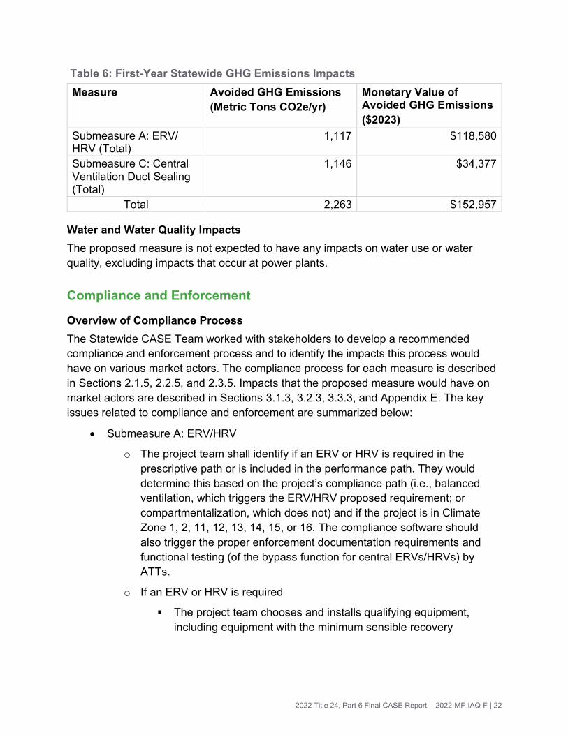
Table 6: First-Year Statewide GHG Emissions Impacts
Measure Avoided GHG Emissions
(Metric Tons CO2e/yr)
Monetary Value of Avoided GHG Emissions
($2023)
Submeasure A: ERV/ HRV (Total)
1,117 $118,580
Submeasure C: Central Ventilation Duct Sealing (Total)
1,146 $34,377
Total 2,263 $152,957
Water and Water Quality Impacts
The proposed measure is not expected to have any impacts on water use or water
quality, excluding impacts that occur at power plants.
Compliance and Enforcement
Overview of Compliance Process
The Statewide CASE Team worked with stakeholders to develop a recommended
compliance and enforcement process and to identify the impacts this process would
have on various market actors. The compliance process for each measure is described
in Sections 2.1.5, 2.2.5, and 2.3.5. Impacts that the proposed measure would have on
market actors are described in Sections 3.1.3, 3.2.3, 3.3.3, and Appendix E. The key
issues related to compliance and enforcement are summarized below:
• Submeasure A: ERV/HRV
o The project team shall identify if an ERV or HRV is required in the
prescriptive path or is included in the performance path. They would
determine this based on the project’s compliance path (i.e., balanced
ventilation, which triggers the ERV/HRV proposed requirement; or
compartmentalization, which does not) and if the project is in Climate
Zone 1, 2, 11, 12, 13, 14, 15, or 16. The compliance software should
also trigger the proper enforcement documentation requirements and
functional testing (of the bypass function for central ERVs/HRVs) by
ATTs.
o If an ERV or HRV is required
▪ The project team chooses and installs qualifying equipment,
including equipment with the minimum sensible recovery

2022 Title 24, Part 6 Final CASE Report – 2022-MF-IAQ-F | 23
efficiency (SRE)4 and fan efficacy. If a central ERV or HRV would
be used, the project team would ensure the system includes a
bypass function. The CBECC-Com performance compliance form
(NRCC-PRF-01) indicates whether the bypass function has been
checked.
▪ The building inspector verifies that the equipment is installed if
required, and it has bypass (if required). A HERS Rater or ATT
verifies that the ERV or HRV meets the minimum SRE and fan
efficacy requirements based on the model number, and that the
bypass (for central ERVs/HRVs) is reported in the compliance
document.
o If an ERV or HRV is not required but the project team elects to install
one, the building inspector verifies that it meets the minimum fan efficacy
in the mandatory requirements proposed for ERVs/HRVs in this Final
CASE Report.
• Submeasure B: Kitchen exhaust minimum capture
o The project team specifies a kitchen exhaust system that complies with
the requirement based on its sound rating and either its capture
efficiency or its airflow information, using product information in the
Home Ventilating Institute (HVI) or Association of Home Appliance
Manufacturers (AHAM) Certified Products Directory. The project team
installs the equipment.
o The building inspector verifies that the kitchen has exhaust that vents to
outside the building per one of the allowable kitchen exhaust compliance
paths.
o A HERS Rater or ATT verifies that the installed equipment complies with
at least one of the compliance paths using the product make and model
number and the HVI or AHAM database.
• Submeasure C: Central ventilation duct sealing
o The project team identifies the location of central ventilation ducts and
specifies sealing materials and strategies.
o The project team seals the central ventilation ducts during construction.
4 Or in the case of a central HRV or ERV, minimum sensible recovery effectiveness

2022 Title 24, Part 6 Final CASE Report – 2022-MF-IAQ-F | 24
o The ATT determines the maximum amount of leakage based on the
number of units it serves and verifies that the total measured leakage
rate of the central ventilation ducts meets the maximum leakage
requirement using a fan pressurization test. Field verification of the
system total leakage for all systems in a building may use sampling
according to the procedures described in RA2 and NA1, although the
Statewide CASE Team proposes a higher sampling rate for this measure
(one in three) than exists for other measures (one in seven).
Field Verification and Diagnostic Testing
• Submeasure A: ERV/HRV
o A HERS Rater or ATT confirms that the equipment and intake and
exhaust ducting are installed where required, documents the model
number, confirms that it meets SRE and fan efficacy requirements, and
(if it is a central ERV or HRV) verifies that it includes bypass.
• Submeasure B: Kitchen exhaust minimum capture
o An ATT or HERS Rater documents the model number and verifies that
the installed equipment complies with at least one of the compliance
paths.
• Submeasure C: Central ventilation duct sealing
o The ATT verifies that a sample of central ventilation ducts meet the
maximum leakage requirement using a fan pressurization test and
documents the leakage test results, using sampling procedures. The
Statewide CASE Team is proposing that the sampling procedures
described in RA2 and NA1 be expanded to address this measure but
specify that a minimum of one in three central ventilation duct systems
be tested. This is more stringent than the sampling requirement of one in
seven used for other measures. The Statewide CASE Team proposes a
higher sampling rate for this measure, because some buildings would
only have a few central ventilation duct systems (e.g., seven systems in
the strategy assumed for the high-rise prototype), so testing only one
system would not provide enough rigor. In addition, the cost of testing is
fairly low (as documented in this report), and the measure is still cost
effective at the higher sampling rate of one in three. For each system
sampled for testing, the ATT must test the entire central ventilation duct
system from its connection point with the central fan to the connection
point within the unit; testing sections of the system is not permitted.

2022 Title 24, Part 6 Final CASE Report – 2022-MF-IAQ-F | 25
See Section 2.1.5, Section 2.2.5, and 2.3.5 for additional information on compliance and
enforcement for the ERV/HRV, kitchen exhaust minimum capture, and central
ventilation duct sealing submeasures, respectively.

2022 Title 24, Part 6 Final CASE Report – 2022-MF-IAQ-F | 26
Introduction This document presents recommended code changes that the California Energy
Commission will be considering for adoption in 2021. If you have comments or
suggestions prior to the adoption, please email [email protected].
Comments will not be released for public review or will be anonymized if shared.
The Codes and Standards Enhancement (CASE) initiative presents recommendations
to support the California Energy Commission’s (Energy Commission) efforts to update
the California Energy Code (Title 24, Part 6) to include new requirements or to upgrade
existing requirements for various technologies. Three California Investor Owned Utilities
(IOUs)—Pacific Gas and Electric Company, San Diego Gas and Electric, and Southern
California Edison—and two Public Utilities —Los Angeles Department of Water and
Power and Sacramento Municipal Utility District (herein referred to as the Statewide
CASE Team when including the CASE Author)—sponsored this effort. The program
goal is to prepare and submit proposals that would result in cost-effective
enhancements to improve energy efficiency and energy performance in California
buildings. This report and the code change proposal presented herein are a part of the
effort to develop technical and cost-effectiveness information for proposed requirements
on building energy-efficient design practices and technologies.
The Statewide CASE Team submits code change proposals to the Energy Commission,
the state agency that has authority to adopt revisions to Title 24, Part 6. The Energy
Commission will evaluate proposals submitted by the Statewide CASE Team and other
stakeholders. The Energy Commission may revise or reject proposals. See the Energy
Commission’s 2022 Title 24 website for information about the rulemaking schedule and
how to participate in the process: https://www.energy.ca.gov/programs-and-
topics/programs/building-energy-efficiency-standards/2022-building-energy-efficiency.
The overall goal of this Final CASE Report is to present a code change proposal for
multifamily indoor air quality. The report contains pertinent information supporting the
code change.
When developing the code change proposal and associated technical information
presented in this report, the Statewide CASE Team worked with a number of industry
stakeholders including manufacturers, mechanical engineers, HERS Raters, sheet
metal workers, utility incentive program managers, Title 24, Part 6 energy analysts, and
others involved in the code compliance process. The proposal incorporates feedback
received during public stakeholder workshops that the Statewide CASE Team held on
August 22, 2019 and on March 25, 2020. The Energy Commission also hosted an IAQ
workshop to discuss research related to the range hood topic on September 30, 2020.
Notes from the stakeholder meetings are available here:

2022 Title 24, Part 6 Final CASE Report – 2022-MF-IAQ-F | 27
https://title24stakeholders.com/wp-content/uploads/2019/07/T24-2022-MF-HVAC-
Envelope-Meeting-Notes_Final.pdf
The following is a brief summary of the contents of this report:
• Section 2: Measure Description of this Final CASE Report provides a description
of the measure and its background. This section also presents a detailed
description of how this code change is accomplished in the various sections and
documents that make up the Title 24, Part 6 Standards.
• Section 3: In addition to the Market Analysis, this section includes a review of the
current market structure. Sections 3.1.2, 3.2.2, and 3.3.2 describe the feasibility
issues associated with the code change, including whether the proposed
measure overlaps or conflicts with other portions of the building standards, such
as fire, seismic, and other safety standards, and whether technical, compliance,
or enforceability challenges exist.
• Section 4: Energy Savings presents the per-unit energy, demand reduction, and
energy cost savings associated with the proposed code change. This section
also describes the methodology that the Statewide CASE Team used to estimate
per-unit energy, demand reduction, and energy cost savings.
• Section 5: This section includes a discussion and presents analysis of the
materials and labor required to implement the measure and a quantification of
the incremental cost. It also includes estimates of incremental maintenance
costs, i.e., equipment lifetime and various periodic costs associated with
replacement and maintenance during the period of analysis.
• Section 6: First-Year Statewide Impacts presents the statewide energy savings
and environmental impacts of the proposed code change for the first year after
the 2022 code takes effect. This includes the amount of energy that will be saved
by California building owners and tenants and impacts (increases or reductions)
on material with emphasis placed on any materials that are considered toxic by
the State of California. Statewide water consumption impacts are also reported in
this section.
• Section 7: Proposed Revisions to Code Language concludes the report with
specific recommendations with strikeout (deletions) and underlined (additions)
language for the Standards, Reference Appendices, Alternative Calculation
Method (ACM) Reference Manual, Compliance Manual, and compliance
documents.
• Section 8: Bibliography presents the resources that the Statewide CASE Team
used when developing this report.

2022 Title 24, Part 6 Final CASE Report – 2022-MF-IAQ-F | 28
• Appendix A: Statewide Savings Methodology presents the methodology and
assumptions used to calculate statewide energy impacts.
• Appendix B: Embedded Electricity in Water Methodology presents the
methodology and assumptions used to calculate the electricity embedded in
water use (e.g., electricity used to draw, move, or treat water) and the energy
savings resulting from reduced water use.
• Appendix C: Environmental Impacts Methodology presents the methodologies
and assumptions used to calculate impacts on greenhouse gas (GHG) emissions
and water use and quality.
• Appendix D: California Building Energy Code Compliance (CBECC) Software
Specification presents relevant proposed changes to the compliance software (if
any).
• Appendix E: Impacts of Compliance Process on Market Actors presents how the
recommended compliance process could impact identified market actors.
• Appendix F: Summary of Stakeholder Engagement documents the efforts made
to engage and collaborate with market actors and experts.
• Appendix G: Infiltration Assumptions and Multifamily Building Leakage Data
describes the infiltration assumptions used for the mid-rise and high-rise
prototypes for the ERV/HRV measure and supporting data for those assumptions
• Appendix H: Prototype Building Description shows the prototype assumptions for
the energy models, including number of floors, building dimensions, and example
floor lay-outs
• Appendix I: Methodology for Testing Capture Efficiency for Sample of Range
Hoods describes how range hoods were selected and tested for laboratory
testing of capture efficiency
• Appendix J: Range Hood Capture Efficiency Test Results provides the full results
for capture efficiency of six range hoods tested in a laboratory through this
project
• Appendix K: Nominal TDV Energy Savings provides monetized energy savings in
nominal dollars, without net present values applied

2022 Title 24, Part 6 Final CASE Report – 2022-MF-IAQ-F | 29
Measure Description This Final CASE Report proposes three changes related to multifamily dwelling unit
ventilation requirements, all of which either improve indoor air quality, provide energy
savings, or accomplish both:
• Submeasure A: Heat Recovery Ventilator (HRV)/Energy Recovery Ventilator
(ERV)
• Submeasure B: Kitchen Exhaust Minimum Capture
• Submeasure C: Central Ventilation Duct Sealing
For all submeasures, because Title 24, Part 6, Sections 120.1, 140.X, 150.0(o), and
150.1(c)X apply only to newly constructed buildings, unless where specified, the
proposals would not affect alterations unless the existing ventilation equipment is
replaced. The Statewide CASE Team is proposing that all submeasures affect
additions, since the new construction energy, cost, and market analysis for these
measures would apply to additions.
In order to compare proposed code changes to the current language, the Statewide
CASE Team refers to the current sections of the 2019 Title 24, Part 6 Standards. The
current standard has separate sections for low-rise and high-rise multifamily dwelling
units. However, if the proposed code requirement for a unified multifamily section is
accepted, the Statewide CASE Team would make one requirement for all multifamily
units.
These measures are stand-alone (i.e., are separate proposals). However, a balanced
ventilation system using central ventilation ducts—defined here as ventilation duct
systems serving more than one dwelling unit—would be affected by the requirements in
both Submeasure A (heat or energy recovery ventilation), and Submeasure C (central
ventilation duct sealing).
2.1 Submeasure A: ERV/HRV
2.1.1 Measure Overview
An HRV captures outgoing energy (sensible) in exhausted air and transfers it to
incoming air, thus essentially preheating or precooling incoming air. An ERV does the
same thing but also transfers moisture, thereby transferring latent energy. ERVs and
HRVs span a wide range of costs, and this analysis did not conduct a robust
comparison of costs between HRVs and ERVs. However, ERVs tend to be slightly more
expensive. The Statewide CASE Team also found that ERVs were more likely to
include an option for MERV 13 filtration, which is a requirement in 2019 Title 24, Part 6.

2022 Title 24, Part 6 Final CASE Report – 2022-MF-IAQ-F | 30
The ERV/HRV submeasure is primarily an energy savings measure, and the proposed
code change would only apply to climates zones where analysis shows it is cost
effective. The submeasure would also provide comfort and air quality benefits to
occupants compared to other balanced ventilation strategies that provide unconditioned
supply air.
For multifamily dwelling units following the balanced ventilation path in Section
150.0(o)1E (for low-rise multifamily dwelling units) or 120.1(b)2Aivb (for high-rise
dwelling units), this proposal would set the prescriptive standard for the ventilation
system to an ERV or HRV in California Climate Zones 1, 2, and 11-16. The standard
HRV or ERV would have a heating sensible recovery efficiency (SRE) or a heating net
sensible effectiveness of 67 percent and fan efficacy of 0.6 W/cfm.
For multifamily dwelling units following the compartmentalization path in Section
120.1(b)2Aivb (for high-rise dwelling units) or Section 150.0(o)1E (for low-rise
multifamily dwelling units), there is no additional requirement. The exception is, if project
teams choose to install HRVs or ERVs where they are not required in the prescriptive
path, the equipment must meet a minimum fan efficacy: 1.0 W/cfm for unitary ERVs /
HRVs (each one serving a single dwelling unit) and the fan efficacy requirements in Title
24, Part 6 Section 140.4 for central ERVs/HRVs (one ERV or HRV serves multiple
dwelling units). This mandatory fan efficacy is intended as a backstop to eliminate the
least efficient ERVs or HRVs from use.
The proposal is a prescriptive measure and would affect all multifamily dwelling units
that are new construction and additions. As a prescriptive measure, the Standard
Design in the performance approach would include this measure. The Statewide CASE
Team proposes this as a prescriptive, rather than a mandatory measure, to provide
project teams with more flexibility: Project teams in the affected climate zones that use a
performance approach could choose not to install this measure but would have to
exceed energy efficiency requirements elsewhere in their design.
This requirement only affects alterations that replace ventilation equipment in low-rise
multifamily units (under existing language in Section 150.2). Many existing multifamily
buildings have no whole dwelling unit ventilation and use operable windows, but no
continuous exhaust or balanced ventilation system. Adding an ERV or HRV—which
may include adding ductwork if the dwelling unit does not have forced air heating or
cooling—could be costly and difficult because of existing space constraints (e.g., less
space for soffits for ductwork).
Any project that is not subject to this requirement, but chooses to install an ERV or
HRV, would not be subject to the prescriptive minimum SRE proposed. For example, for
newly constructed multifamily dwelling units in Climate Zones 3-10 or units that use
compartmentalization to meet the requirements of Section 150.0(o)1E or Section

2022 Title 24, Part 6 Final CASE Report – 2022-MF-IAQ-F | 31
120.1(b)2Aivb, the prescriptive baseline ventilation system would not include heat
recovery.
The following flow chart provides an overview of the proposed scope. To avoid
confusion, a flowchart similar to below could be incorporated into the compliance
manual.
Figure 1: Overview of multifamily dwelling units affected by proposed ERV/HRV code change.
This proposal adds field verification to ensure that the HRV or ERV equipment meets
the sensible heat recovery requirement. The proposal would add requirements for a
technology that had been allowed under current and past requirements of Title 24, Part
6, but were not required previously.
2.1.2 Measure History
This proposal would provide cost-effective energy savings by requiring the exhaust
stream of a balanced ventilation system to pass through an ERV or HRV so that
incoming ventilation air is preheated or precooled.
As background, HRVs and ERVs transfer heat between exhaust and fresh intake air in
order to reduce heating and cooling loads in a building. Heat can be transferred
between the two air supplies using rotary wheels, fixed plate heat exchangers, heat
pipes, and run-around systems. Latent heat and sensible heat can be transferred using
rotary wheels (a circular honeycomb structure that is rotated within the air streams) or
fixed plate heat exchangers (stacked metal plates that may be humidity permeable used
to pass air through in order to transfer heat through plates). Figure 2 provides an
example schematic.

2022 Title 24, Part 6 Final CASE Report – 2022-MF-IAQ-F | 32
Figure 2: Example HRV diagram.
Source: BC Housing, n.d.
The difference between an HRV and ERV is that while both transfer sensible energy, an
ERV transfers additional latent energy because it also transfers humidity. Sensible
energy heat exchange is the difference in the dry bulb temperature between the
incoming outdoor air and the exhausted indoor air. During the heating season, the ERV
also transfers moisture from the outgoing air to the incoming airstream. Conversely,
during the cooling season, the ERV transfers moisture to or from the outdoor airstream
depending on which whether outdoor humidity is lower or higher than indoors. The
proposed code change would allow project teams to choose either an HRV or ERV
system.
Unitary HRV and ERV equipment have an SRE rating, which is defined as follows by
the Home Ventilating Institute (HVI):
“SRE: The net sensible energy recovered by the supply airstream as adjusted by
electric consumption, case heat loss or heat gain, air leakage, airflow mass
imbalance between the two airstreams and the energy used for defrost (when
running the Very Low Temperature Test), as a percent of the potential sensible
energy that could be recovered plus the exhaust fan energy ” (Home Ventilating
Institute 2017).
Thus, the SRE signifies how much sensible energy in the outgoing airstream is
transferred to the incoming airstream, and a higher SRE denotes more energy returned
to the conditioned space captured. This proposal uses an SRE value, which captures
sensible but not latent heat recovery because the HVI database currently lists SRE
values but not an indicator of total (sensible and latent) recovery efficiency. For
California’s dry summer and mild winter climates, SRE is the important metric.
As described in Section 3.1.2, the median SRE is 69 percent for both ERVs and HRVs
in the HVI database, so project teams should not have difficulty meeting the proposed
requirement with either an HRV or ERV.

2022 Title 24, Part 6 Final CASE Report – 2022-MF-IAQ-F | 33
Unitary equipment is typically packaged and rated with an SRE, which accounts for the
heat transferred from the outgoing air to the incoming airstream and includes the
recovery core and fan. Central equipment is typically rated with a sensible recovery
effectiveness, which accounts for the sensible heat transferred from the outgoing air to
the incoming airstream and includes only the recovery core, since it is sometimes paired
with different fans. CBECC-Res and CBECC-Comm allow users to input an SRE value
and a sensible recovery effectiveness value, respectively. The Statewide CASE Team
proposes the same minimum value—67 percent, for both the minimum SRE (typically
used for unitary equipment) and sensible recovery effectiveness (typically used for
central equipment).
This is the first proposed code change that would require ERVs or HRVs for Title 24,
Part 6. The 2019 Title 24, Part 6 Standards have allowed ERVs and HRVs under the
performance approach, but there is no existing requirement for them in California’s
Energy Code.
The 2022 version of ASHRAE Standard 90.1 includes a new addendum requiring an
HRV or ERV in high-rise multifamily buildings. This addendum provides an exception for
International Energy Conservation Code (IECC) Climate Zone 3C, which covers almost
all of California Climate Zones 3 through 6 and parts of California Climate Zones 1, 2, 6
and 9. Figure 5 in Section 2.1.4.4 provides a map comparing ASHRAE Climate Zone 3c
and the California climate zones. The Statewide CASE Team based its requirements on
which climate zones this analysis showed the ERV/HRV measure to be cost effective.
The Statewide CASE Team may have found that the measure is cost effective for
different areas of California than ASHRAE 90.1 because of several differences in
methodology. This includes that the Statewide CASE Team used TDV savings, whereas
ASHRAE 90.1 uses a different metric; the Statewide CASE Team modeled savings at a
more granular level within California (the 16 climate zones designated by the California
Energy Commission), rather than the IECC climate zones, which are coarser for
California (for example, IECC Climate Zone 3C covers part of six climate zones as
designated by the Energy Commission); and the Statewide CASE Team used the
prototype buildings approved by the Energy Commission.
2.1.3 Summary of Proposed Changes to Code Documents
The sections below summarize how the standards, Reference Appendices, ACM
Reference Manuals, and compliance documents would be modified by the proposed
change. See Section 7 of this report for detailed proposed revisions to code language.
The Energy Commission is planning consolidation of low-rise and high-rise multifamily
requirements under a new multifamily section(s) in 2022 Title 24, Part 6. Restructuring
the standards for multifamily building may also result in revisions to Reference
Appendices, ACM Reference Manuals, compliance manuals, and compliance
documents. Location and section numbering of the 2022 Standards and supporting

2022 Title 24, Part 6 Final CASE Report – 2022-MF-IAQ-F | 34
documents for multifamily buildings depend on the Energy Commission’s approach to
and acceptance of a unified multifamily section(s). For clarity, the changes proposed in
this Final CASE Report are demonstrated in terms of the 2019 structure and language.
2.1.3.1 Summary of Changes to the Standards
This proposal would modify the following sections of Title 24, Part 6 as shown below.
See Section 7.2 of this report for marked-up code language.
SECTION 120.1 – REQUIREMENTS FOR VENTILATION AND INDOOR AIR QUALITY and SECTION 150.0 – MANDATORY FEATURES AND DEVICES
Sections 120.1(b)2Aivb and 150.0(o)1E: For systems that serve multifamily dwelling
units following the balanced ventilation path for compliance, the proposed code change
would add the following mandatory fan efficacy requirements: Unitary heat or energy
recovery ventilation (one ERV or HRV serving each dwelling unit) must have fan
efficacy of ≤ 1.0 W/cfm.
SECTION 140.0 – PERFORMANCE AND PRESCRIPTIVE COMPLIANCE APPROACHES
SECTION 140.X – PRESCRIPTIVE REQUIREMENTS FOR VENTILATION SYSTEMS:
The proposed code chance would add a new section of prescriptive requirements
specifically for ventilation system. Dwelling units that follow the balanced ventilation
path in 120.1(b)2Aivb in Climate Zones 1, 2, or 11-16 must include a heat or energy
recovery ventilator (HRV or ERV) that meets one of the following:
• Unitary heat or energy recovery ventilation (one ERV or HRV serving each
dwelling unit) with minimum sensible heat recovery efficiency of 67 percent at 32
°F (0 °C), as listed by the Home Ventilating Institute – HVI), and fan efficacy less
than or equal to 0.6 W/cfm.
• A central HRV or ERV system that provides ventilation to more than one dwelling
unit with have a minimum sensible heat recovery efficiency or effectiveness of 67
percent at 32 °F (0 °C), fan efficacy that meets the requirements of Section
140.4, and include a bypass function that enables it to function in an economizer
mode to take advantage of free cooling. An ATT shall conduct functional testing
of controls as listed under Section NA 7.5.4 Air Economizer Controls.
Section 141.0(a) Additions: The proposed code change would add ventilation systems
to the list of newly installed equipment that must meet requirements.
Section 141.0(b) Alterations: Alterations would not trigger this requirement in high-rise
dwelling units.

2022 Title 24, Part 6 Final CASE Report – 2022-MF-IAQ-F | 35
Section 150.1(c)X Prescriptive Standards/Component Package: The proposed code
change would add a new subsection of prescriptive standards for ventilation systems
similar to what is added to 140.X.
Dwelling units that follow the balanced ventilation path in 150.0(o)1E in Climate Zones
1, 2, or 11-16 must include a heat or energy recovery ventilator (HRV or ERV) that
meets one of the following:
• Unitary heat or energy recovery ventilation (one ERV or HRV serving each
dwelling unit) with minimum sensible heat recovery efficiency of 67 percent at
32°F (0°C), as listed by the Home Ventilating Institute – HVI), and fan efficacy
less than or equal to 0.6 W/cfm.
• A central HRV or ERV system that provides ventilation to more than one dwelling
unit with have a minimum sensible heat recovery efficiency or effectiveness of 67
percent at 32°F (0°C), fan efficacy meeting Section 140.4 requirements, and a
bypass function that enables it to function in an economizer mode to take
advantage of free cooling.
Table 150.1-B COMPONENT PACKAGE – Multifamily Standard Building Design would
need to be updated to include ERV/HRV requirements.
2.1.3.2 Summary of Changes to the Reference Appendices
This proposal would modify the sections of the Reference Appendices identified below.
See Section 7.3 of this report for the detailed proposed revisions to the text of the
reference appendices.
The Reference Appendices are currently structured to distinguish between low-rise and
high-rise requirements. For this measure, the Statewide CASE Team proposes that the
distinction be made based on whether the ERVs/HRVs are unitary (each serves an
individual dwelling unit) or central (each serves multiple dwelling units).
NONRESIDENTIAL APPENDIX
NA2 – Nonresidential Field Verification and Diagnostic Test Procedures: The
proposed change would add a Subsection: NA2.4: Rated Heat Recovery and Energy
Recovery Ventilation Verification Procedures. This new subsection would specify the
procedure for verifying required information for HRV and ERV equipment if these are
installed to meet the requirements of Section 120.1(b)2Aivb.
1. If unitary ERVs/HRVs (each ERV/HRV serves one dwelling unit) are listed on the
compliance forms, a HERS Rater would verify in the field that an ERV or HRV is
installed, that airflows for the dwelling unit’s balanced ventilation systems would
be met, and that the prescriptive requirements are met by looking up the nominal
SRE and fan efficacy for the installed model in product databases (HVI, Air

2022 Title 24, Part 6 Final CASE Report – 2022-MF-IAQ-F | 36
Conditioning, Heating, Refrigeration Institute [AHRI]) or from product
specifications from the manufacturer.
2. If central ERVs/HRVs (each ERV/HRV serves multiple dwelling units) are listed
on the compliance forms, an ATT would verify in the field that an ERV or HRV is
installed, that airflows for the dwelling unit’s balanced ventilation systems would
be met, and that the prescriptive requirements are met by looking up the nominal
SRE and fan efficacy for the installed model in product databases (HVI, AHRI) or
from product specifications from the manufacturer. The ATT would also field
verify that the bypass function exists and conduct functional testing as listed
under Section NA 7.5.4 Air Economizer Controls.
Section 141.0(b) Alterations. Alterations would not need to follow this requirement.
RESIDENTIAL APPENDIX
RA3.4.4 HVAC System Verification Procedures (low-rise multifamily dwelling
units): The proposed change would add a Subsubsection: RA3.7.4.4: Rated Heat
Recovery and Energy Recovery Ventilation Verification Procedures. This new
subsection would specify the procedure for verifying required information for HRV and
ERV equipment if these are installed to meet the requirements of 150.0(o)1E.
For unitary ERVs/HRVs, a HERS Rater will:
1. Verify if an ERV/HRV is needed, depending on the project’s compliance path—
balanced ventilation or compartmentalization—and the project’s climate zone.
2. If it is required, verify in the field that an ERV or HRV is installed, that airflows for
the dwelling unit’s balanced ventilation systems will be met, and that the
prescriptive requirements are met by looking up the nominal SRE and fan
efficacy for the installed model in product databases (HVI, AHRI) or from product
specifications from the manufacturer.
For central ERVs/HRVs, an ATT will conduct steps 1 and 2 above for unitary
ERVs/HRV. In addition, an ATT will
3. Verify that the bypass function exists from the cut-sheet, and conduct functional
testing as listed under NA 7.5.4 Air Economizer Controls.
2.1.3.3 Summary of Changes to the Residential and Nonresidential ACM Reference Manuals
This proposal would modify the following sections of the Residential and Nonresidential
ACM Reference Manual as shown below. See Section 7.4 of this report for the detailed
proposed revisions to the text of the ACM Reference Manual.

2022 Title 24, Part 6 Final CASE Report – 2022-MF-IAQ-F | 37
This proposal would modify the following sections of the Residential/Nonresidential
ACM Reference Manual as shown below. See Section 7.4 of this report for the detailed
proposed revisions to the text of the ACM Reference Manual.
RESIDENTIAL ACM REFERENCE MANUAL
Section 2.4.9 Indoor Air Quality Ventilation: Add a reference for the Standard Design
that multifamily dwelling units will be evaluated as a balanced ventilation system with a
sensible heat recovery of 67 percent and minimum fan efficacy of 0.6 W/cfm in Climate
Zones 1, 2, and 11 through 16.
NONRESIDENTIAL ACM REFERENCE MANUAL
Section 5.6.6.4 Outdoor Air Ventilation: Add a new box called Heat Recovery that
specifies a sensible heat recovery of 67 percent to the Standard Design in Climate
Zones 1, 2, and 11 through 16.
ACM Reference Manual 2.4.9: Indoor Air Quality Ventilation. Changes will be made
to this section to reference new requirements for the standard design.
For multifamily dwelling units:
• Currently, if the proposed design uses exhaust-only, the model assumes
exhaust-only for ventilation. There will be no change if the project uses
compartmentalization.
• Currently, if the proposed design uses balanced ventilation, the model assumes
balanced fans without heat recovery. This will be changed for California Climate
Zones 1, 2, and 11-16 so that it includes heat recovery and the operating set
points for SRE and fan efficacy of the prescriptive requirements.
• For a unitary system, for the performance path, the standard design is modeled
with the same fan efficacy if the proposed design fan efficacy does not exceed
0.6 W/cfm. If the project installs a unitary ERV/HRV with a worse fan efficacy
(e.g., 0.8 W/cfm), the proposed design uses 0.8 W/cm while the standard design
assumes 0.6 W/cfm, so the model will show a penalty for fan energy (at least part
of which will be offset by the heating and energy recovery). The Statewide CASE
Team also proposes a backstop of 1.0 W/cfm; i.e., projects using the
performance approach could install a unitary ERV/HRV with a fan efficacy better
(less than) 0.6 W/cfm and receive energy savings, an ERV/HRV with a fan
efficacy of 0.6 W/cfm for no energy savings, or an ERV/HRV with a fan efficacy
between 0.6 and 1.0 W/cfm and receive an energy penalty. For central
ERV/HRVs, the same approach would be used for the performance path except
the assumed efficacy is the requirements in Section 140.4.

2022 Title 24, Part 6 Final CASE Report – 2022-MF-IAQ-F | 38
• Currently, the California Building Energy Code Compliance for commercial
buildings (CBECC-Com) software, which is used for modeling multifamily
buildings with more than three occupiable floors,5 has a bypass check-box
(options of yes/no). The Statewide CASE Team proposes to change the CBECC-
Com software so that, for buildings using a central ventilation system in the
climate zones affected by the measure, the software assumes a heat recovery
system with bypass. The California Building Energy Code Compliance for
residential buildings software (CBECC-Res), which is used for modeling
multifamily buildings with three occupiable floors or less, does not have a bypass
function or allow central systems. The Statewide CASE Team will propose to add
a feature so that CBECC-Res has a bypass function.
2.1.3.4 Summary of Changes to the Residential and Nonresidential Compliance Manuals
The proposed code change would modify the following section of the Residential and
Nonresidential Compliance Manuals:
RESIDENTIAL COMPLIANCE MANUAL
Section 4.6 – Indoor Air Quality and Mechanical Ventilation: The manual will include
language that summarizes the requirement. The manual will provide an overview of
strategies to meet the requirement, including unitary HRVs or ERVs; or central ERVs
such as rooftop HRVs or ERVs serving a vertical column of units, or HRVs or ERVs
serving a cluster of units (such as one on every floor). The sizing and installation of
bypass ducting will be illustrated and discussed.
The manual would also include language recommending that, for all multifamily projects
that install HRVs or ERVs (including in climate zones not regulated by this requirement),
the HRVs or ERVs include a bypass function, or that the dwelling units have mechanical
cooling, to prevent overheating. The purpose of this language is to promote energy-
efficient thermal comfort for occupants.
ERV/HRVs can use multiple strategies for distributing outside air and (if interfacing with
an air handling unit) integrating the supply duct into an AHU. However, the outside air
distribution issues for ERV/HRVs will be similar to issues faced under the current
requirements for other types of balanced ventilation systems. 2019 Title 24, Part 6
prohibits the “continuous operation of central forced air system air handlers used in
central fan integrated ventilation systems”. There are no requirements in ASHRAE
Standard 62.2 for distributing outside air within the dwelling unit—i.e., providing all
outdoor air through one supply register is compliant, although it is best practice to
5 Parking garages are not considered occupiable.

2022 Title 24, Part 6 Final CASE Report – 2022-MF-IAQ-F | 39
distribute it throughout the dwelling unit, particularly when the outside air is outside of
thermostat set points. The manual should describe at least two options for how outside
air can be distributed within the dwelling unit:
1. One example in which the ERV/HRV has its own duct work, and supply air is
distributed to each bedroom and the living area, and
2. One example in which the ERV/HRV interfaces with the heating, ventilation, and
air conditioning (HVAC) system, by ducting the supply air into the return plenum
of the forced air system.
Section 4.6.1 – Compliance and Enforcement: The manual will stipulate that the
HERS Rater must document the SRE or effectiveness and verify it is ≥67 and that fan
efficacy is a value of 0.6 W/cfm or lower.
Section 4.6.3.3 – Multifamily Dwelling Unit Compartmentalization: The manual will
describe the new requirement for an ERV or HRV in certain climate zones for projects
following the balanced ventilation path.
NONRESIDENTIAL COMPLIANCE MANUAL
Sections 4.3.2 – High-Rise Residential Dwelling Unit Mechanical Ventilation: The
manual will include language that summarizes the requirement. The manual will provide
an overview of strategies to meet the requirement, including unitary HRVs or ERVs, and
central HRVs or ERVs serving multiple dwelling units.
The manual would also include language recommending that, for all multifamily projects
that install HRVs or ERVs (including in climate zones not regulated by this requirement),
the HRVs or ERVs include a bypass function, or that the dwelling units have mechanical
cooling, to prevent overheating. The purpose of this language is to promote thermal
comfort for occupants. The manual will frame this guidance, so it is clear what is
required, versus what is recommended. The current compliance manual uses this
approach for other measures, such as Section 4.5.2.4 for Supply-Air Temperature
Reset Control, which specifies certain set points for this measure and provides
recommendations for how this can be achieved.
Section 4.3.2.5.3 – Multifamily Dwelling Unit Compartmentalization (which
describes the balanced ventilation alternative to compartmentalization): The manual will
describe that an ERV or HRV is required in certain climate zones for projects following
the balanced ventilation path.
2.1.3.5 Summary of Changes to Compliance Documents
The proposed code change would modify the compliance documents listed below.
Examples of the revised documents are presented in Section 7.6.

2022 Title 24, Part 6 Final CASE Report – 2022-MF-IAQ-F | 40
The proposed measure would necessitate several changes to compliance forms,
including for low-rise multifamily:
• Certificate of Compliance (CF1R): Ventilation Cooling section will need to be
revised to include references to ERV/HRV with bypass.
• Certificate of Installation (CF2R): Several sections would need to reflect the
proposed ERV/ HRV requirements, including A. Central Fan Ventilation Cooling,
B. Local Mechanical Exhaust System, C. Air Moving Equipment, G., Other
Requirements, and H. Air Moving Equipment.
• Certificate of Verification (CF3R): Several sections would need to reflect the
proposed ERV/HRV requirements, including A. Central Fan Ventilation Cooling
System, and B. Local. Mechanical Exhaust system.
Similarly, for high-rise multifamily:
• Nonresidential Certificate of Compliance (NRCC): Any new NRCI, NRCA, or
NRCV forms will need to be referenced, and information on ERV/HRV systems,
as well as any central shafts requiring sealing will need to be included.
• Nonresidential Certificate of Acceptance (NRCA): Section A. Construction
Inspection would need to include the proposed requirements.
• Nonresidential Certificate of Verification (NRCV): Several sections would need to
reflect the proposed ERV/HRV requirements, including B. Local Mechanical
Exhaust System and D. Air Moving Equipment.
2.1.4 Regulatory Context
2.1.4.1 Existing Requirements in the California Energy Code
There are no relevant existing requirements in the California Energy Code for ERV or
HRV. Projects may use them under the performance approach, but they are not
currently mandatory or prescriptive.
One related requirement is 2019 Title 24, Part 6 Section 120.1(b)2iv (for high-rise
multifamily dwelling units) and Section 150.0(o)1E (for low-rise multifamily dwelling
units), which requires that multifamily dwelling units have either balanced ventilation or
meet a compartmentalization requirement.
Another related requirement is 2019 Title 24, Part 6, Section 120.1(b)1C (for high-rise
dwelling units) and Section 150.0(m)12C (for low-rise dwelling units) which requires
Minimum Efficiency Reporting Value (MERV) 13 filtration for heating, cooling, and
ventilation air.
2019 Title 24, Part 6 Section 140.4(e) Economizers includes Table 140.4(e) for High
Limit Shut Off Control Requirements. The Statewide CASE Team refers to this table of

2022 Title 24, Part 6 Final CASE Report – 2022-MF-IAQ-F | 41
requirements for economizer shut-offs for the bypass or free-cooling function proposed
for the central ERV or HRV path and presents it here as Figure 3.
Figure 3: Current requirements for economizer high limit shut-off control requirements in table 140.4(e).
2.1.4.2 Relationship to Requirements in Other Parts of the California Building Code
While there are no directly related requirements in other parts of the California Building
Code, Title 24, Part 4 (the California Mechanical Code, or CMC), Section 311.3 requires
that outside air not be taken from less than 10 feet in distance from an appliance vent
outlet, or the discharge outlet of an exhaust fan, unless the outlet is three feet above the
outside-air inlet. This is to reduce the risk of contaminating the incoming air with
outgoing exhaust. This minimum separation distance can be challenging to achieve,
particularly for multifamily projects with small dwelling units. However, the proposed
requirement for an ERV/HRV should not be more difficult than the existing requirement
for balanced ventilation in terms of this CMC requirement. ASHRAE Standard 62.2 also

2022 Title 24, Part 6 Final CASE Report – 2022-MF-IAQ-F | 42
requires a minimum 10 foot (3 meter) separation distance, but allows several
exceptions:
1. Ventilation openings in the wall may be as close as a stretched-string distance of
3 ft (1 m) from sources of contamination exiting through the roof or dryer
exhausts.
2. No minimum separation distance shall be required between windows and local
exhaust outlets in kitchens and bathrooms.
3. Vent terminations covered by and meeting the requirements of the National Fuel
Gas Code (NFPA 54/ANSI Z223.1) or equivalent.
4. Where a combined exhaust/intake termination is used to separate intake air from
exhaust air originating in a living space other than kitchens, no minimum
separation distance between these two openings is required. For these
combined terminations, the exhaust air concentration within the intake airflow
shall not exceed 10 percent, as established by the manufacturer.
The Statewide CASE Team recommends that the Energy Commission coordinate
across agencies to include these exceptions in the CMC requirements for separation. In
particular, the fourth exception may be advantageous for “through-wall” ERVs/HRVs
installed at the wall that do not require ducting.
Title 24, Part 11 (CALGreen) requires that bathroom exhaust fans be ENERGY STAR®
compliant, ducted to terminate outside the building, and (unless functioning as a
component of a whole house ventilation system) include a humidity controller. Based on
interviews with six subject matter experts (a mix of HERS Raters and multifamily
mechanical engineers), dwelling units with ERVs and HRVs typically have an intake in
the bathroom that is ducted to the ERV or HRV, rather than a stand-alone bath fan.
Thus, the market appears to be interpreting this requirement as not applying when a
bathroom is connected to an ERV or HRV. The Statewide CASE Team also discussed
the CALGreen requirement with Housing and Community Development (HCD) staff.
They reported they were aware of the potential conflict between the CALGreen
requirement for an ENERGY STAR bath fan and typical installation of an HRV or ERV,
and reported that they will likely revise the language in the CALGreen requirement to
allow for an exception to the ENERGY STAR fan requirement if an ERV or HRV is used.
The proposed exemption from the HCD is below. Changes to the CALGreen
requirement are marked with red underlining (new language) and strikethroughs
(deletions).
Section 4.506 Indoor Air Quality and Exhaust
4.506.1 Bathroom exhaust fans. Each bathroom shall be mechanically ventilated and
shall comply with the following:

2022 Title 24, Part 6 Final CASE Report – 2022-MF-IAQ-F | 43
1. Fans shall be ENERGY STAR compliant and be ducted to terminate
outside the building.
Exception to 1: Fans functioning as a component of an energy or heat recovery
ventilation system do not need to comply with Section 4.506.1(1).
2. Unless functioning as a component of a whole house ventilation system,
fans must be controlled by a humidity control.
a. Humidity controls shall be capable of adjustment between a relative
humidity range of ≤ 50 percent to a maximum of 80 percent. A humidity
control may utilize manual or automatic means of adjustment.
b. A humidity control may be a separate component to the exhaust fan and is
not required to be integral (i.e., built-in).
Exception to 2: Fans functioning as a component of a whole house ventilation
system do not need to comply with Section 4.506.1(2).
Notes:
1. For the purposes of this section, a bathroom is a room which contains a
bathtub, shower, or tub/shower combination.
2. Lighting integral to bathroom exhaust fans shall comply with Title 24, Part
6.
The Statewide CASE Team also examined whether the Nonresidential HVAC CASE
proposal for the Fan Energy Index (FEI) or fan power budget would affect this measure.
The proposal affects equipment 5 horsepower (hp) or higher; unitary ERVs/HRVs
typically have a lower horsepower so would not be impacted. Larger central ERVs or
HRVs would be impacted. The proposed language in this report would meet the current
requirements for fan efficacy in 2019, Title 24, Part 6 Section 140.4. If the FEI and fan
power budget proposal is adopted, those new requirements would apply instead.
2.1.4.3 Relationship to Local, State, or Federal Laws
There are no known relevant local, state, or federal laws for any of the multifamily IAQ
submeasures.
2.1.4.4 Relationship to Industry Standards
ASHRAE Standard 90.1-2019, which applies to multifamily buildings four stories and
higher, has two requirements for heating and cooling energy recovery for ventilating
systems in Section 6.5.6.1.
The first requirement is triggered by climate zone and fraction of outside air; this
requirement was also in the previous version of the standard – ASHRAE Standard 90.1-
2016. Most unitary ventilation systems (i.e., those serving individual multifamily dwelling

2022 Title 24, Part 6 Final CASE Report – 2022-MF-IAQ-F | 44
units) are exempt from this requirement, because the requirements for ASHRAE
Climate Zone 3 (which covers most of California—as shown in the map in Figure 5) start
at a minimum airflow rate of 80 cfm, which is higher than typical multifamily dwelling unit
ventilation rates (typically 30 to 70 cfm, with the airflow rate depending on unit size and
number of bedrooms). For central supply air—i.e., for supply ventilation systems serving
multiple dwelling units— heat and energy recovery is required depending on the airflow
rate as shown in Figure 4: Energy recovery requirements for central systems in
ASHRAE 90.1-2019 for California.
ASHRAE
Climate Zone
% Outdoor Air at Full Design Airflow Rate
≥10% and <20%
≥20% and <30%
≥30% and <40%
≥40% and <50%
≥50% and <60%
≥60% and <70%
≥70% and <80%
80%
Design Supply Fan Airflow Rate, cfm
3C NR NR NR NR NR NR NR NR
0B, 1B, 2B, 3B, 4C, 5C6
NR ≥19,500 ≥9000 ≥5000 ≥4000 ≥3000 ≥1500 ≥120
0A, 1A, 2A, 3A, 4B, 5B7
≥2500 ≥2000 ≥1000 ≥500 ≥140 ≥120 ≥100 ≥80
4A, 5A, 6A, 7, 88 ≥200 ≥130 ≥100 ≥80 ≥70 ≥60 ≥50 ≥40
a. NR – Not required
Figure 4: Energy recovery requirements for central systems in ASHRAE 90.1-2019 for California.
Source: (ASHRAE 2019b).
The second requirement for heat or energy recovery of ventilation systems is a new
requirement (i.e., adopted for the 2019 version of ASHRAE 90.1), and is specific to
multifamily dwelling units. The requirement calls for heating and cooling energy
recovery with an enthalpy recovery ≥50 percent at cooling & 60 percent at heating in
dwelling units. The requirement has an exemption for dwelling units smaller than 500
square feet, with an exception to the proposed requirement for ASHRAE Climate Zone
3C. While there is not a direct mapping between the ASHRAE climate zones and
California climate zones, ASHRAE Climate Zone 3C roughly corresponds to the
southern parts of California Climate Zones 1 and 2, and parts or all of California Climate
Zones 3, 4, 5, 6, and 9, as shown in Figure 5.
6 Roughly corresponds to parts or all of California Climate Zones 1, 11, 12, 13, 14, 15, 16.
7 Roughly corresponds to parts or all of California Climate Zones 12, 14, 16.
8 Does not correspond to any California climate zones.

2022 Title 24, Part 6 Final CASE Report – 2022-MF-IAQ-F | 45
Figure 5: Map of ASHRAE Climate Zone 3C compared with California climate zones with proposed requirement.
Source: Created by Statewide CASE Team using California Energy Commission 2017 and International
Code Council data, 2012.
2.1.5 Compliance and Enforcement
When developing this proposal, the Statewide CASE Team considered methods to
streamline the compliance and enforcement process and how negative impacts on
market actors who are involved in the process could be mitigated or reduced. This
section describes how to comply with the proposed code change. It also describes the
compliance verification process. Appendix E presents how the proposed changes could
impact various market actors.
The activities that need to occur during each phase of the project are described below.
In general, compared to the current compliance process which must verify installation of
a balanced ventilation system for projects pursuing that path (as opposed to
compartmentalization), the proposed requirement would require verification of the

2022 Title 24, Part 6 Final CASE Report – 2022-MF-IAQ-F | 46
specific ERV/HRV equipment installed and that it meets requirements for recovery
effectiveness and (if a central system) requirements for a bypass function.
• Design Phase: The building design team identifies if the project is in a climate
zone where the requirement applies. If applicable, the building design team
specifies the make and model of the ERV or HRV and ensures it meets minimum
recovery efficiency via compliance documentation. The plans or specifications
listing the manufacturer and model number are provided to the compliance
consultant for inclusion in the NRCC or CF1R.
• Permit Application Phase: The project team submits design documents
showing the make and model of ERV or HRV equipment supported by
compliance documentation. Design of the ducts is submitted for approval. The
plans examiner reviews the drawings and specifications to ensure the ERV or
HRV meets the proposed requirements.
• Construction Phase: The project team installs the HRV or ERV equipment and
ducts. The general contractor’s procurement staff must ensure that the product
ordered matches the model number in the plans and specifications or equivalent
substitutions documented in change orders. The contractor provides a Certificate
of Installation (CF2R for low-rise or NRCI for high-rise) confirming the specified
ERV/HRV designed has been installed on the project. The HVAC subcontractor
must ensure that the duct system is properly installed.
• Inspection Phase: The building inspector visually confirms that the HRV or ERV
is installed and that the ducts are properly installed. To best align with current
procedures, unitized equipment will be verified by HERS Raters and central
equipment will be verified by ATTs, as described here:
o For projects using unitary ERVs/HRVs (i.e., one per dwelling unit), a
HERS Rater captures the make and model of equipment, verifies that the
equipment’s recovery efficiency or effectiveness and its fan efficacy meets
the proposed requirement using the product’s cut sheet or information
available online. Verification procedures would be documented via
applicable Certificate of Verification/ NRCV/ CF3R.
o For projects using central ERVs/HRVs (i.e., one serves multiple dwelling
units), an ATT captures the make and model of equipment, verifies that
the equipment’s recovery efficiency or effectiveness and its fan efficacy
meets the proposed requirement using the product’s cut sheet or
information available online, and verifies the ERV or HRV has a bypass or
free cooling function if it is a central system. The ATT would also conduct
function testing of the bypass function. Verification procedures would be
documented via applicable Certificate of Acceptance/NRCA.

2022 Title 24, Part 6 Final CASE Report – 2022-MF-IAQ-F | 47
Note that the differentiation of verification procedures by equipment type (unitized vs.
central) rather than by number of stories (low-rise vs. high-rise) aligns with the
movement toward multifamily unification that is proposed for 2022-Title 24, part 6. In
some cases, HERS raters would verify equipment in high-rise multifamily buildings, if
the projects use unitized ERVs/HRVs. Conversely, ATTs would verify equipment in low-
rise multifamily buildings, if the projects use central ERVs/HRVs. Alternatively, HERS
Raters and ATTs could be allowed to verify this requirement in all types of multifamily
buildings, if proper training is required.
2.2 Submeasure B: Kitchen Exhaust Minimum Capture
2.2.1 Measure Overview
The purpose of this submeasure is to improve IAQ. As Title 24 evolves to require more
envelope tightening, the need for adequate ventilation increases. For example, 2019
Title 24, Part 6 added the Quality Insulation Installation (QII) procedures to the
prescriptive path for low-rise multifamily buildings, and proposed requirements for 2022
Title 24, Part 6 include a version of QII for the prescriptive path for high-rise multifamily
buildings. Increased sealing measures in QII reduces infiltration, which provides energy
savings, but also heightens the need for adequate ventilation.
Cooking-related pollution carries various health risks, and there is a growing body of
research that highlights the health impacts from cooking-related pollution. Cooking over
any type of cooktop (natural gas or electric) releases ultrafine and fine particles such as
particulate matter 2.5 micrometers or smaller (PM2.5), as well as other irritants and
potentially harmful gases including formaldehyde, acetaldehyde, acrolein, and polycyclic
aromatic hydrocarbons (Singer and Chan 2018). The use of natural gas burners and
ovens also releases nitrogen dioxide (NO2) and carbon monoxide (CO).
Figure 6 shows adjustments in disability-adjusted life years (DALY – which measures
one year of healthy life lost due to exposure from various pollutants, several of which
are associated with cooking [shown in red boxes]). As shown in this figure, PM2.5 is
typically the most harmful pollutant in residences (Logue, et al. 2011). PM2.5 can travel
into the lungs and bloodstream, causing respiratory and cardiovascular impacts, and
NO2 is associated with respiratory problems such as chest tightness, shortness of
breath, and wheezing (EPA n.d.).

2022 Title 24, Part 6 Final CASE Report – 2022-MF-IAQ-F | 48
Figure 6: Estimated population averaged annual cost, in disability adjusted life years (DALYs), of pollutants with highest median DALY estimates shows PM2.5 with highest median DALY estimate.
Source: Logue, et al. 2011.
NO2 also causes other deleterious health effects. For example, a study found that
asthmatic children are at higher risk for more severe asthma symptoms at low levels of
NO2 and that the risk rises as levels of NO2 rise (Belanger 2013). Another study found
that homes with gas stoves have 50 percent to 400 percent higher concentrations of
NO2 than homes with electric stoves (EPA 2008). CO is released by natural-gas stoves
and also produces deleterious health effects. However, past research found that NO2
and PM2.5 safe levels were often exceeded from cooking and cooking equipment, while
CO typically was not (Singer, Pass and Delp 2017), (Logue, et al. 2014). Consequently,
this analysis followed the example of Lawrence Berkeley National Laboratory (LBNL)
simulations (Chan, et al. 2020) and developed requirements to maintain PM2.5 and
NO2 levels at acceptable concentrations, because these should also be protective for
CO.
It is particularly important that kitchen exhaust systems in multifamily dwelling units
effectively remove kitchen exhaust, since these residences can have their air degraded
by both their own kitchen pollution and from pollution transferred from adjacent units.
The Statewide CASE Team investigated the effectiveness of kitchen range hoods in
removing pollutants. Range hoods are devices that include a fan above or next to the

2022 Title 24, Part 6 Final CASE Report – 2022-MF-IAQ-F | 49
stove or cooktop and serve to remove pollution from cooking. They may be also
combined with microwave ovens. Simulation results done by LBNL (Chan, et al. 2020)
have shown that for almost all California new homes, a range hood capture efficiency of
at least 70 percent is required to avoid exceeding unhealthy levels of NO2 (1-h average
concentration of 100 parts per billion from the U.S. Environmental Protection Agency
[EPA]), and 60 percent is required to avoid unhealthy levels of PM2.5 (24-h average of
25 microgram per cubic meter from World Health Organization 2006).9 Furthermore,
LBNL recently conducted additional analysis that considered more granular size ranges
of dwelling units. Based on personal communications with the LBNL authors, as shown
in Table 7, at least 65 percent capture efficiency is needed to maintain PM2.5 and 75
percent capture efficiency is needed to maintain NO2 withing acceptable levels in
dwelling units less than 750 ft2.
Table 7. Minimum capture efficiency needed to maintain PM2.5 and NO2 within acceptable levels by dwelling unit floor area
Floor area of dwelling unit
Hood over electric range for PM2.5 control
Hood over natural gas range for NO2 control
≤ 750 ft2 65% CE or 250 cfm 75% CE or 290 cfm
750 – 1,000 ft2 55% CE or 200 cfm 65% CE or 250 cfm
1,000 - 1,500 ft2 50% CE or 175 cfm 55% CE or 200 cfm
>1,500 ft2 50% CE or 175 cfm 50% CE or 175 cfm
Source: Personal communication with Brett Singer and Rengie Chan, September 29, 2020
Range hoods are also typically demand controlled (user-operated). The capture
efficiency evaluated under the ASTM test method corresponds to a lower field condition
capture efficiency in the field (Singer, Delp and Apte 2012), because the airflow of the
range hood is often lower in the field than under laboratory test conditions due to
exhaust duct restrictions that increase static pressure, and because the person cooking
disturbs the plume, which reduces capture efficiency. However, the proposed
requirement for this code cycle balance IAQ needs with availability and pricing of
compliant products.
The proposed code change would be a mandatory measure that requires a kitchen
exhaust system with either a minimum capture efficiency or minimum airflow. The
kitchen exhaust system must meet one of the following paths:
9 These results were generated using models to enable variations in cooking-event time, cooking
technique (e.g., boiling versus frying), size of the kitchen, and other parameters that can affect results.

2022 Title 24, Part 6 Final CASE Report – 2022-MF-IAQ-F | 50
1. A vented range hood with a minimum capture shown in Table 8, per ASTM
Standard E3087-18 at nominal installed airflow, per HVI Publication 920, or
2. A vented range hood with a minimum airflow shown in Table 8, at a static
pressure of 0.1 inches w.c. or greater,
Table 8. Minimum Range Hood Capture Efficiency or Airflow Based on Dwelling Unit Size and Fuel Type
Floor area of dwelling unit
Hood over electric range Hood over natural gas range
<750 ft2 65% CE or 250 cfm 75% CE or 290 cfm
750 – 999 ft2 55% CE or 200 cfm 65% CE or 250 cfm
1,000 – 1,500 ft2 55% CE or 200 cfm 55% CE or 200 cfm
>1,500 ft2 50% CE or 175 cfm
or
3. A vented downdraft exhaust with a minimum airflow of 300 cfm at a static
pressure of 0.1 inches w.c. or greater, or
4. For enclosed kitchens only, continuous kitchen exhaust at a minimum of five
kitchen air changes per hour at 50 Pa. An enclosed kitchen is defined as a
kitchen whose permanent openings to interior adjacent spaces do not exceed a
total 60 ft2 [6 square meters]).
The first path is new. The second path increases the minimum airflow requirement. The
third and fourth paths exist in the current requirements and have been retained.
For the first path, the nominal installed airflow is defined in HVI Publication 920 as a
“normalized airflow rate calculated by applying the normalized airflow curve ratio to the
airflow determined by the intersection of a kitchen range hood’s test report airflow curve
and the nominal duct system curve” (Home Ventilating Institute 2020, 8). HVI
Publication 920 also defines a normalized system curve, which should be used when
identifying the nominal installed airflow for consistency.
For the second path, the Statewide CASE Team considered multiple options for
minimum airflow. While the correlation of airflow and capture efficiency is not well
established, the Statewide CASE Team used laboratory testing of kitchen range hoods
to estimate a relationship between capture efficiency and airflow, as shown in Section
3.2.2.2. The Statewide CASE Team also found that the majority of range hood products
in the HVI database comply with the proposed requirement. Table 9 below shows the
percentage of microwave, undercabinet and chimney range hoods in the HVI database
that would comply with the proposed requirements. Note that the first path is more
stringent than the second, since the static pressure at the nominal installed airflow
(typically 0.2 to 0.25 inches w.c.) is almost always higher than 0.1 inches w.c., and

2022 Title 24, Part 6 Final CASE Report – 2022-MF-IAQ-F | 51
airflow increases as static pressure decreases. Because capture efficiency generally
increases as airflow increases, capture efficiency should also increase as static
pressure decreases, as supported by Figure 18 in Section 3.2.2.
Table 9. Percentage of HVI Products Compliant with Proposed Requirements
Minimum Airflow (cfm)
Vertical Discharge Horizontal Discharge
Microwave (n=107)
Undercabinet (n=45)
Chimney (n=61)
Microwave (n=104)
Undercabinet (n=32)
Chimney (n=4)
175 93% 98% 100% 86% 91% 100%
200 93% 98% 100% 82% 91% 100%
250 77% 84% 95% 16% 69% 100%
290 19% 67% 92% 8% 56% 100%
The third and fourth paths generally remain unchanged from current requirements. The
Statewide CASE Team did not find new data on downdraft exhausts or continuous
kitchen ventilation effectiveness. Consequently, the Statewide CASE Team did not alter
these paths, except to specify that the airflow for the downdraft exhaust systems should
be measured at 0.1 inches w.c., consistent with the second path.
Range hoods must continue to meet the current requirement for sound: no greater than
three sones tested at 100 cfm or higher for demand-controlled products. Note that this
study does not propose an associated sound requirement at the capture efficiency or
higher airflows described above. This is because adding a sound rating at the proposed
capture efficiency and proposed higher airflow would require manufacturers to retest
their products for sound at the higher airflow, and because the Statewide CASE Team
did not find data indicating acceptable sound levels for range hood products.
For enforcement, field verification will confirm that the range hood is vented to outdoors;
recirculation type hoods shall not be allowed. The model of the kitchen range hood shall
be verified and recorded on the compliance documentation for the project, and the
HERS Rater or ATT shall verify that the HVI rating for this model meets the minimum
capture efficiency or airflow and sound limit specified.
This proposal would be a mandatory requirement and affect all multifamily dwelling units
that are new construction or additions.
This measure does not impact alterations, unless an existing vented range hood is
replaced in low-rise units. In that case, under existing language in Section 150.2, the
new equipment would need to meet the proposed requirement.
Because the scope of this Final CASE Report is multifamily indoor air quality, this Final
CASE Report does not explicitly include recommendations for single family dwelling
units. However, the Statewide CASE Team recommends that the Energy Commission
provide the same range hood requirements for single family dwelling units as what is

2022 Title 24, Part 6 Final CASE Report – 2022-MF-IAQ-F | 52
proposed here to ensure adequate kitchen ventilation. Furthermore, the proposed
requirements would not significantly restrict what types of range hoods could be
installed in most single family units: This analysis found that the vast majority of range
hoods (including all chimney hoods) included a speed of at least 200 cfm, which is the
minimum demand-control airflow proposed in dwelling units 750 to 1,000 ft2 with electric
ranges and in dwelling units 1,000 to 1,500 ft2 with natural gas ranges. (Larger dwelling
units must meet a minimum airflow of 175 cfm, which nearly all products meets.)
Imposing the same requirements for single family dwelling units would have the greatest
impacts on small dwelling units (smaller than 1,000 ft2). Because these small single
family units would have less dilution air to reduce pollutant levels (similar to multifamily
units), they should also meet the same range hood requirements. Furthermore, this
analysis found that the proposed requirements can be feasibly met, including with
microwave-range hood and undercabinet products that may be common in small single
family dwelling units.
2.2.2 Measure History
This proposal addresses IAQ problems resulting from inadequate exhaust of pollutants
from cooking, which include PM2.5 and other hazardous pollutants, as well as pollutants
from natural-gas fired cooking appliances, including NO2. As multifamily building
envelopes tighten under Quality Insulation Installation (QII), increasingly stringent
requirements for envelope insulation, and other requirements, it is important that
cooking-related pollution is properly ventilated.
2.2.2.1 Current Requirements
Currently, 2019 Title 24, Part 6 requires by reference to ASHRAE Standard 62.2 that a
local mechanical exhaust system be installed in each kitchen. In addition, 2019 Title 24,
Part 6 (by reference to ASHRAE Standard 62.2) allows three kitchen exhaust systems:
a range hood, a downdraft exhaust system, and (in enclosed kitchens only) continuous
exhaust; all must be vented to the outdoors. The proposed language for 2022 Title 24,
Part 6 would not alter the requirement that kitchen exhaust be vented, and for the
purposes of this Final CASE Report, the Statewide CASE Team uses the terms “range
hood” and “kitchen exhaust” to refer to vented systems only. For both low-rise and high-
rise buildings, under 2019 Title 24, Part 6, the kitchen exhaust must meet one of three
paths:
1. A demand-controlled range hood with an airflow of at least 100 cfm, or
2. A downdraft exhaust system with an airflow of at least 300 cfm, or

2022 Title 24, Part 6 Final CASE Report – 2022-MF-IAQ-F | 53
3. For enclosed kitchens only:10 continuous exhaust with an airflow of at least five
kitchen air changes per hour at 50 Pa.
Equipment must be rated by HVI (Home Ventilating Institute 2015) or AHAM to not
exceed three sones at 100 cfm for demand-controlled equipment, or to not exceed one
sone for continuous exhaust.
In the existing 2019 Title 24, Part 6 language, HERS Raters are required to verify that
an HVI label is present on the installed range hood, and that the range hood complies
with these requirements. Current Title 24, Part 6 Standards have no requirements for
capture efficiency for removing pollutants.
Recirculating range hoods (which exhaust air back into the kitchen after passing
through a filter) are not currently permitted in new construction. The Statewide CASE
Team conducted a literature review to investigate if some types of recirculating range
hoods should be permitted—particularly to explore whether a requirement should be
added for alterations that would use recirculating range hoods (so would not depend on
installation of exhaust duct). A 2017 literature review by Rojas et al. found there were no
scientific studies available on the performance of recirculating range hoods. However,
the literature review found a German consumer magazine, Stiftung Warentest, that
tested 21 different range hoods in both extracting and recirculating configurations.
Results of tests were rated on a five-level scale ranging from “very good” to
“insufficient.” Although all products were rated “very good” for odor removal in extraction
mode, only two models had ratings of either “very good” or “good” in recirculation mode.
The rest of the models had ratings between medium and insufficient (Rojas, Walker and
Singer 2017). A typical recirculating range hood has an activated carbon filter which
may remove pollutants such as VOCs but the filtration efficiency over time for PM and
odors are unknown (EPA n.d.; Rojas, Walker and Singer 2017). There is also little
evidence of recirculating range hoods that can remove carbon monoxide or water vapor
(Stratton and Singer 2014). Furthermore, if the home has gas cooking equipment, this
equipment would produce NO2, which would need to be removed through a vented
exhaust system.
2.2.2.2 Illustration of Capture Efficiency
Capture efficiency is measured as the mass of pollutant removed by the range hood per
mass of pollutant released. A higher capture efficiency indicates that more pollutant is
removed. The recently updated ASTM Standard E3087-18 provides a test method for
capture efficiency, and HVI is currently developing the HVI Range Hood Capture
10 ASHRAE Standard 62.2 defines an enclosed kitchen as a kitchen whose permanent openings to
interior adjacent spaces do not exceed a total of 60 ft2 (6 m2).

2022 Title 24, Part 6 Final CASE Report – 2022-MF-IAQ-F | 54
Efficiency Testing and Rating Procedure (HVI Publication 917), which refines ASTM
methods based on results from laboratory work at Texas A&M University. Figure 7
shows how capture efficiency can vary with airflow rate. This figure shows results in an
airflow rate (cfm) per linear foot but capture efficiency results as described in this report
are presented compared with airflow rate (cfm), since industry databases (such as HVI)
list products by airflow (cfm).
Figure 7: Illustration of range hood plume spillage at different airflow rates.
Source: (ASHRAE 2011).
Note that capture efficiency varies by distance of the hood relative to the kitchen range.
However, optimal placement varies by product. Neither 2019 Title 24, Part 6 nor the
California Mechanical Code (CMC) require a specific range hood installation height, but
range hoods should be installed at a distance above the range according to
manufacturers’ instructions.
2.2.2.3 Related Progress Underway by Stakeholder Working Groups
Given the health impacts associated with kitchen pollution, several industry groups are
working to incorporate a capture efficiency rating or requirement, including the ASHRAE
Standard 62.2 committee. This committee established a working group in 2019 to
develop recommendations for a capture efficiency requirement for future versions of the
ASHRAE 62.2 Standard. The working group membership included members from the
ASHRAE 62.2 committee and range hood manufacturers as well as researchers from
LBNL and engineering staff from HVI and AHAM. In developing the proposed
requirements, the Statewide CASE Team collaborated with these groups to coordinate
development of test conditions for the proposed requirement, so that test conditions are
aligned as much as possible between 2022 Title 24, Part 6 and industry testing.

2022 Title 24, Part 6 Final CASE Report – 2022-MF-IAQ-F | 55
2.2.2.4 Rationale for Airflow Compliance Paths for Kitchen Range Hoods
Because manufacturers are still finalizing test conditions for the capture efficiency test
and are not yet publishing the capture efficiency of their equipment, the Statewide
CASE Team has proposed the alternative compliance options for kitchen exhaust
equipment listed in Section 2.2.1.
The first compliance option—for a minimum capture efficiency—anticipates that capture
efficiency listings by HVI, AHAM, and other agencies are forthcoming within the 2022
code cycle, and requires that the ratings be verified to meet a minimum capture
efficiency that varies by dwelling unit type and fuel for the range. HVI indicated that
capture efficiencies would be included in listings by October 2020 on a voluntary basis
and would be made mandatory in October 2021. The second, third, and fourth options
allow verification based on minimum airflow rates, using data from HVI, the AHAM
database, or other listings. Section 3.2.2.2 provides data from a sample of range hood
products that estimates a relationship between capture efficiency and airflow.
The rationale for compliance paths based on minimum airflow is that laboratory testing
shows that range hood capture efficiency generally increases airflow, as shown in data
from LBNL presented in Figure 8. Note that this figure provides results using a different
method (called the “pollutant method”) than the ASTM Standard E3087-18. This figure
is presented because there is no equivalent data available using ASTM Standard
E3087-18, and this figure illustrates how capture efficiency increases with airflow rate.
Although the quantitative relationship (correlation) between capture efficiency and
airflow will be different under ASTM Standard E3087-18, the qualitative finding
(increased capture efficiency with increased airflow) will hold. In the figure, each range
hood product is represented by a letter and number (e.g., L1, B1). The figure also
illustrates that capture efficiency is higher at the same airflow for back burner cooking
than front burner. For example, the regression lines indicate that at 200 cfm, back
burner capture efficiency is approximately 85 percent while front burner capture
efficiency is approximately 50 percent.

2022 Title 24, Part 6 Final CASE Report – 2022-MF-IAQ-F | 56
Figure 8: Capture efficiency of kitchen range hoods, as measured via “pollutant method”.
Source: Performance Assessment of U.S. Residential Cooking Exhaust Hoods (Delp and Singer 2012)
2.2.2.5 Consumer Range Hood Behavior
Because range hoods typically require occupants to turn them on, the Statewide CASE
Team investigated how often occupants engage their range hoods as part of its market
research. Figure 9, below, provides results of a survey from LBNL in the Healthy
Efficient New Gas Homes (HENGH) project of how often occupants reportedly used
range hoods when they used the cooktop. As shown, most occupants reported using
their range hood at least sometimes, although most do not use it all the time that they
cook.

2022 Title 24, Part 6 Final CASE Report – 2022-MF-IAQ-F | 57
Figure 9: Frequency of the kitchen range hood usage.
Source: (Chan, et al. 2019)
Figure 10 presents the results of a survey question that asked why occupants do not
use the range hood for all cooking events. As shown, consumer selected “not needed”
most often, followed by “too noisy”.

2022 Title 24, Part 6 Final CASE Report – 2022-MF-IAQ-F | 58
Figure 10: Reasons for not using kitchen exhaust.
Source: (Chan, et al. 2019)
Overall, results indicate that most consumers sometimes do use their range hood –
specifically when they believe it is needed. The airflow-based compliance path aligns
with this market research finding, because it will provide users with range hoods that are
effective at removing pollution when they choose to operate them.
During the standard development process, several stakeholders recommended
requiring automated range hoods, since many consumers do not always operate their
hoods when cooking. The concept of requiring the hood to turn on automatically
whenever temperature sensors show that cooking is occurring, or when pollutant
sensors indicate ventilation is needed, is an exciting idea that should be explored in
future code cycles as a means of increasing the IAQ benefits to occupants. Energy
impacts, pollutant impacts, and user acceptability of automated kitchen ventilation (e.g.
whether there are risks of occupants tampering with automated functions if they do not
like them) should also be considered.
The survey responses also highlight the importance of tightening the sound
requirement. The new requirement may still not be stringent enough to encourage
consumer range hood use during all cooking events, particularly because range hoods

2022 Title 24, Part 6 Final CASE Report – 2022-MF-IAQ-F | 59
will have a higher sone rating at the higher airflow or capture efficiency required in this
proposal. Since adding a sound rating requirement at a higher airflow would require
product retesting, the Statewide CASE Team considered dropping the allowable sound
requirement at 100 cfm from three sones to two sones. However, the Statewide CASE
Team could not find a strong correlation showing that lower sound levels at lower airflow
corresponded to higher sound levels at higher airflow. Figure 11 shows a comparison of
predicted sone levels at 250 cfm for compliant (has sone rating of less than or equal to
two sones at working speed) and noncompliant (has sone rating of greater than two
sones at working speed). The sone levels at 250 cfm are predicted through interpolation
or extrapolation of the provided sound and airflow ratings from the HVI database.
Although on average compliant products had a lower sound rating, sound ratings at the
higher airflow ratings were highly variable, and only resulted in a reduction of about 0.5
sones compared to the noncompliant group. Future code cycles should consider a
sound requirement at a higher airflow.
Figure 11. Sound comparison at 250 cfm for lower sone and current sone requirements.
Finally, the data above highlight a need for consumer education. For this proposal, the
Statewide CASE Team has recommended adding language in Section 10-103. It would
require that builders provide instructions to tenants on the operation and maintenance of
local exhaust systems, including when they should be operated. For buildings with
multiple tenants, these instructions will be provided to the owner, with additional
instructions to provide them to each tenant at the beginning of their occupancy. Shortly
before the Final CASE Report due date, based on stakeholder feedback, the Statewide
CASE Team considered requiring a label in the kitchen for range hoods to educate the

2022 Title 24, Part 6 Final CASE Report – 2022-MF-IAQ-F | 60
resident of when the hood should operate and health consequences if this is not
followed. However, a consumer-facing label requires careful and precise wording with
stakeholder input and (if possible) testing with a sample of consumers, which was not
possible at that point in the cycle. A future code cycle could consider requiring labels to
educate residents about range hood use.
2.2.2.6 Relationship of Airflow to Static Pressure and Expected Performance under Installed Conditions
The proposed requirement calls for capture efficiency or airflow measured at a minimum
static pressure, since higher static pressure generally leads to lower airflow, and lower
airflow generally leads to lower capture efficiency.
Each unique kitchen range hood responds differently to static pressure as defined by its
“fan curve.” Each field installation will have a unique “system curve” that is determined
by the size and length of the duct and the number and type of fittings. As shown in
Figure 12, the intersection of the two curves determines the volume of air a fan will
deliver. Most range hoods are currently rated at 0.1 inches w.c., but under actual
installed conditions, the static pressure may be much higher. As shown in the figure
below, the airflow decreases with increasing static pressure. Because capture efficiency
decreases as airflow decreases, a range hood with a capture efficiency of 70 percent at
0.1 inches w.c. (as tested in the laboratory) will have a lower capture efficiency when
installed in the field.
Figure 12: Typical kitchen range hood system and fan curves.

2022 Title 24, Part 6 Final CASE Report – 2022-MF-IAQ-F | 61
The method for measuring airflow prescribed by the Home Ventilating Airflow Test
Procedure (HVI Publication 916) is to take measurements at ten or more static
pressures. Airflow is reported at high speed at a static pressure of 0.1 inches w.c. (or
higher at the manufacturers’ option), and at a lower “working speed” setting for which
the static pressure is determined from the high speed system curve. The February 2020
HVI 920 publication establishes another rating point at the nominal installed airflow. The
nominal installed airflow is calculated from the intersection of the airflow curve and a
nominal system curve (as in Figure 12). The nominal system curve is calculated using
10 feet of duct with the same dimensions as the hood connection, two elbows, and a
vent termination fitting. This new HVI 920 requirement agrees with the approach
proposed by the ASHRAE Standard 62.2 Capture Efficiency Working Group.
Because of the additional static pressure in the field, and the resulting decrease in
capture efficiency and air flow, range hood products that comply with the proposed
airflow requirements will likely provide lower results than the laboratory test. For
example, a range hood that is shown in laboratory testing to achieve 290 cfm at 0.1
inches w.c., corresponding to 75 percent capture efficiency, will likely achieve lower
airflow and therefore lower capture efficiency as installed. Consequently, it may not
maintain PM2.5 and NO2 concentrations at acceptable values. Future code proposals
should consider adjusting the proposed requirement to address the higher static
pressure of installed conditions, preferably in alignment with the direction of industry.
2.2.3 Summary of Proposed Changes to Code Documents
The sections below summarize how the Standards, Reference Appendices, ACM
Reference Manuals, and compliance documents will be modified by the proposed
change. See Section 7 of this report for detailed proposed revisions to code language.
2.2.3.1 Summary of Changes to the Standards
This proposal would modify the following sections of Title 24, Part 6 as shown below.
See Section 7.2 of this report for marked-up code language.
SECTION 10-103 PERMIT, CERTIFICATE, INFORMATIONAL, AND ENFORCEMENT
REQUIREMENTS FOR DESIGNERS, INSTALLERS, BUILDERS, MANUFACTURERS,
AND SUPPLIERS
The proposed change would add language in the “Ventilation information” section for
builders to provide at the time of permitting. The proposed language would:
• Add a requirement for the builder to provide instructions for proper operation and
maintenance of local exhaust systems, including instructions for when any user-
controlled systems should be used.
• Provide uniform language in this section for low-rise and high-rise multifamily
buildings.

2022 Title 24, Part 6 Final CASE Report – 2022-MF-IAQ-F | 62
• Require that, for systems in buildings or tenant spaces that are not individually
owned and operated, the instructions shall state that the building’s owner or their
representative shall provide copies of instructions for these systems to all tenants
at the start of their occupancy. For systems in buildings or tenant spaces that are
centrally operated, the information shall be provided to the person(s) responsible
for operating and maintaining the feature, material, component or mechanical
ventilation device installed in the building.
SECTION 100.1 – DEFINITIONS AND RULES OF CONSTRUCTION
The proposed change would define “ASTM Standard E3087-18,” used in the first
compliance pathway below.
The proposed change would also add “kitchen, enclosed” to the definitions, using the
existing definition in ASHRAE Standard 62.2.
SECTION 120.1 – REQUIREMENTS FOR VENTILATION AND INDOOR AIR QUALITY and SECTION 150.0 – MANDATORY FEATURES AND DEVICES
Section 120.1(b)2A (for high-rise dwelling units): Language should be added to the
beginning of this section to state that the ventilation requirements of CMC Chapter 7 (to
ensure sufficient combustion air for combustion appliances) and the informational
requirements of 10-103 (requiring the builder to provide instructions on ventilation
systems) be met.
Section 120.1(b)2Avi (for high-rise dwelling units): The proposed change modifies
requirements for kitchen exhaust systems in multifamily dwelling units that are new
construction or additions, or in existing kitchen ventilation systems that are replaced as
part of an alteration to an existing building. The exhaust system must comply with at
least one of the following:
1. A vented kitchen range hood with a minimum capture efficiency shown in Table
10, as measured according to ASTM Standard E3087-18 at nominal installed
airflow described in HVI Publication 920, or
2. A vented kitchen range with at least one speed setting with a minimum airflow
shown in Table 10, at 25 Pa (0.1 inches w.c.) static pressure as measured
according to HVI Publication 916

2022 Title 24, Part 6 Final CASE Report – 2022-MF-IAQ-F | 63
Table 10. Minimum Range Hood Capture Efficiency (CE) or Airflow Requirements by Dwelling Unit Floor Area and Range Fuel, for Demand-Controlled Range Hoods
Floor area of dwelling unit
Hood over electric range Hood over natural gas range
<750 ft2 65% CE or 250 cfm 75% CE or 290 cfm
751 – 999 ft2 55% CE or 200 cfm 65% CE or 250 cfm
1,000 – 1,500 ft2 50% CE or 175 cfm 55% CE or 200 cfm
>1,500 ft2 50% CE or 175 cfm
or
3. A vented downdraft kitchen exhaust fan with at least one speed setting with a
minimum airflow of 300 cfm at 25 Pa (0.1. inches w.c.) or higher, or
4. For enclosed kitchens only: A continuous exhaust system with a minimum airflow
equal to five kitchen air changes per hour at 50 Pa.
Section 150.0(o) (for low-rise multifamily): Language should be added to the
beginning of this section to state that the ventilation requirements of CMC Chapter 7 (to
ensure sufficient combustion air for combustion appliances) and the informational
requirements of 10-103 (requiring the builder to provide instructions on ventilation
systems) shall be met. Language should also be added referencing the requirements in
ASHRAE Standard 62.2 Section 6.4.2 for atmospherically vented combustion
appliances or solid-fuel-burning appliances. Given the kitchen range hood airflow
requirements, this will prohibit the installation of atmospherically vented combustion
appliances or solid-fuel-burning appliances in multifamily units smaller than 1,000
square feet, and require a calculation of minimum floor area compared with the two
largest exhaust fans for larger dwelling units.
Section 150.0(o)1G (for low-rise multifamily): The language above would be
repeated in Section 150.0(o)1G for low-rise multifamily:
The proposed change modifies requirements for kitchen exhaust systems in multifamily
dwelling units that are new construction or additions. The exhaust system must comply
with one of the following:
1. A vented kitchen range hood with a minimum capture efficiency shown in Table
10, as measured according to ASTM Standard E3087-18 at nominal installed
airflow described in HVI Publication 920, or
2. A vented kitchen range with at least one speed setting with a minimum airflow
shown in Table 10, at 25 Pa (0.1 inches w.c.) static pressure as measured
according to HVI Publication 916, or
3. A vented downdraft kitchen exhaust fan with at least one speed setting with a
minimum airflow of 300 cfm at 25 Pa (0.1. inches w.c.) or higher, or

2022 Title 24, Part 6 Final CASE Report – 2022-MF-IAQ-F | 64
4. For enclosed kitchens only: A continuous exhaust system with a minimum airflow
equal to five kitchen air changes per hour at 50 Pa.
Section 141.0(a) Additions
Additions would need to follow proposed language for new construction. The Statewide
CASE Teams proposes to add “or ventilation” system in the new multifamily chapter to
the list of newly installed equipment that meets requirements.
Section 141.0(b) Alterations
Current language in Section 141.0(b) do not require alterations in high-rise dwelling
units to meet ventilation requirements. Under the Mandatory requirements for
Alterations, the Statewide CASE Team proposes to add a new section, 141.0(b)1D for
“Ventilation in high-rise residential”, where the altered kitchen ventilation component
and any newly installed equipment serving the ventilation alteration shall meet the
applicable requirements of 120.1(b)Avi. The proposed language is based on the
language for alterations in low-rise multifamily units in Section 150.2.
Section 150.2 Additions and Alterations
Low-rise additions and alterations are already required to meet requirements of Section
150.0(o) in altered components or replaced equipment of the alteration, so no changes
are needed.
2.2.3.2 Summary of Changes to the Reference Appendices
This proposal would modify the sections of the Reference Appendices identified below.
See Section 7.3 of this report for the detailed proposed revisions to the text of the
reference appendices.
NONRESIDENTIAL APPENDIX
NA2.2.4.1.3 – Kitchen Range Hood Verification (high-rise dwelling units). The
proposed change would add a requirement that verification of the range hood include
the rated capture efficiency as listed by HVI or AHAM, or verification of the
manufacturer’s rating of the airflow, which is similar to the verification method in
NA2.2.4.1.3.
RESIDENTIAL APPENDIX
RA3.7.4.3 – Kitchen Range Hood Verification (low-rise dwelling units). The
proposed change would add a requirement that verification of the range hood include
the rated capture efficiency as listed by HVI or AHAM, or verification of the
manufacturer’s rating of the airflow, which is similar to the verification method in
RA3.7.4.3.

2022 Title 24, Part 6 Final CASE Report – 2022-MF-IAQ-F | 65
In the verification section, the Statewide CASE Team proposes to replace “installed
kitchen range hood” with “installed kitchen exhaust system” so it more broadly covers
range hoods as well as downdraft exhaust and continuous exhaust systems.
2.2.3.3 Summary of Changes to the Residential and Nonresidential ACM Reference Manuals
The proposed code change would not modify the ACM Reference Manual.
2.2.3.4 Summary of Changes to the Residential and Nonresidential Compliance Manuals
The proposed code change would modify the following sections of the Nonresidential
and Residential Compliance Manuals:
NONRESIDENTIAL COMPLIANCE MANUAL
Section 4.3.2 – High-Rise Residential Dwelling Unit Mechanical Ventilation, and Section
4.3.2.3 – Air-Moving Equipment Requirements: Would add a description of the new
requirements proposed by this submeasure.
Section 4.3.2.4 – Compliance and Enforcement: Would add capture efficiency to the
certificate of compliance enforcement requirements.
Section 4.3.2.7.3 – Ventilation Rate for Demand-Controlled Local Exhaust: Will add a
description of the new requirements.
RESIDENTIAL COMPLIANCE MANUAL
Section 4.6.1 – Compliance and Enforcement: Would summarize the requirement
and add capture efficiency to certificate of compliance enforcement requirements and
CF2R-MCH-01 listings.
Section 4.6.7 – Local Exhaust: Would modify the section describing the ASHRAE
Standard 62.2 requirements to clarify that multifamily dwelling units that are new
construction or additions must use one of the kitchen exhaust compliance paths in Title
24, Part 6 Section 150.0(o)1G.
Section 4.6.7.1 – Demand Controlled (Intermittent) Exhaust: Would add a description of
the new requirement.
Section 4.6.7.2 – Continuous Local Exhaust: Would add language describing that
continuous kitchen exhaust is not a code-compliant strategy for multifamily dwelling
units with non-enclosed kitchens.
2.2.3.5 Summary of Changes to Compliance Documents
The proposed code change would modify the compliance documents listed below.
Examples of the revised documents are presented in Section 7.6.

2022 Title 24, Part 6 Final CASE Report – 2022-MF-IAQ-F | 66
The proposed measure would necessitate several changes to compliance forms,
including:
• CF2R: Several sections would need to reflect the proposed kitchen exhaust
system requirements, including B. Local Mechanical Exhaust System and C.
Kitchen Exhaust System.
• CF3R: Several sections would need to reflect the proposed kitchen exhaust
system requirements, including B. Local Mechanical Exhaust system, to
document the ERV/HRV and bypass (if required).
• NRCA: Section A. Construction Inspection would need to include the proposed
requirements.
• NRCV: Several sections would need to reflect the proposed kitchen exhaust
system, including B. Local Mechanical Exhaust System and C. Kitchen Exhaust
System.
• NRCC: Any new NRCI or NRCA forms will need to be referenced, and
information on new kitchen exhaust requirements would have to be added.
2.2.4 Regulatory Context
2.2.4.1 Existing Requirements in the California Energy Code
Section 150.0(o) and Section 120.1(b)2 specify that all attached dwelling units must
meet all sections of ASHRAE 62.2, except where specified. ASHRAE 62.2 Section 5
includes language that all non-enclosed kitchens have a vented demand-controlled
range hood with an airflow of at least 100 cfm; enclosed kitchens can either meet that
intermittent range hood requirement or use continuous exhaust of at least five kitchen
air changes per hour. Because most new construction multifamily kitchens are non-
enclosed, most multifamily units must follow the vented range hood requirement under
current regulations.
There are no relevant existing requirements in Title 24, Part 6 for minimum capture
efficiency for kitchen range hoods. 2019 Title 24, Part 6, Section 150.0(o)1G requires
that kitchen range hoods be rated for sound in accordance with Section 7.2 of ASHRAE
62.2. 2019 Title 24, Part 6 Section 120.1(b)2Avi provides the same language for
dwelling units in high-rise buildings.
Section 7.2 of ASHRAE 62.2 requires that demand-controlled local exhaust fans in
kitchens be rated for sound at a maximum of three sones at one or more airflow settings
greater than or equal to 100 cfm and a maximum of one sone for continuous exhaust
fans. These measurements are to be done in accordance with the HVI Loudness
Testing and Rating Procedure (HVI Publication 915) and HVI Publication 916.

2022 Title 24, Part 6 Final CASE Report – 2022-MF-IAQ-F | 67
2019 Title 24, Part 6, Section 150.0(o)2B (for low-rise dwelling units) and 120.1(b)2Bii
(for high-rise dwelling units) require field verification that the kitchen range hood is HVI-
rated.
The current standards also require—through reference to ASHRAE Standard 62.2—that
local exhaust airflow rates be tested or that projects follow prescriptive duct sizing
requirements provided in a table in ASHRAE Standard 62.2. The table in ASHRAE
Standard 62.2 provides duct sizing at the static pressure of 0.25 inches w.c. The
proposed language for 2022 Title 24, Part 6 calls for range hoods that meet a minimum
airflow measured at 0.1 inches w.c. (to align with current listings in the HVI database) or
that meet a minimum capture efficiency measured at a nominal installed airflow. This
proposal does not make any change to the prescriptive duct sizing requirement. Project
teams can meet the minimum airflow requirement specified in the proposed requirement
for 2022 Title 24, Part 6 (at least 250 cfm at 0.1 inches w.c. as one compliance path)
and use the range hood’s fan curve to identify the minimum duct size to meet the
prescriptive duct sizing requirements in ASHRAE Standard 62.2 (based on the static
pressure of 0.25 inches w.c.). Note that the Statewide CASE Team does not
recommend that a table (similar to the prescriptive duct sizing table in ASHRAE
Standard 62.2) be developed at 0.1 inches w.c., because static pressures in the field
typically exceed this value.
2.2.4.2 Relationship to Requirements in Other Parts of the California Building Code
There are multiple parts of the Building Code related to kitchen exhaust system
requirements. CMC Table 403.7 requires a minimum exhaust rate of 100 cfm or 50 cfm
if exhaust is continuous. CMC Section 311.3 prohibits outside air from being taken less
than 10 foot horizontally from an exhaust discharge unless the outlet is three feet above
the outside air inlet. This minimum separation distance can be challenging to achieve,
particularly for multifamily projects with small dwelling units. However, the proposed
requirement for range hoods should not be more difficult than the existing requirement,
since 2019 Title 24, Part 6 already requires vented kitchen exhaust to outdoors through
its reference to ASHRAE Standard 62.2.
CMC Section 504.3 requires that ducts used for domestic kitchen ranges be of metal
with smooth interior surfaces but allows Schedule 40 PVC for downdraft grill ranges
where the duct is under a slab floor. CMC Section 701.3 requires makeup air where
kitchen ventilation systems interfere with the operation of appliances, such as gas
furnaces or water heaters that draw combustion air from within the space. Neither Title
24, Part 2 (California Building Code) nor Part 11 (CALGreen) include requirements for
domestic kitchen range hoods.

2022 Title 24, Part 6 Final CASE Report – 2022-MF-IAQ-F | 68
CMC Chapter 7 includes Section 701.4, which includes language specifying the
required volume of indoor air for each vented combustion appliance. The importance of
the CMC requirement will increase under the proposal to increase the range hood
airflow because more air will be exhausted. The Statewide CASE Team recommends
that language be added to the beginning of Section 120.1(b)2A for high-rise and the
beginning of 150.0(o) for low-rise multifamily dwelling units to state that the ventilation
requirements of CMC Chapter 7 be met.
In addition, ASHRAE Standard 62.2 Section 6.4 for Combustion and Solid-Fuel-Burning
Appliances requires the following: “Where atmospherically vented combustion
appliances or solid-fuel-burning appliances are located inside the pressure boundary,
the total net exhaust flow of the two largest exhaust fans (not including a summer
cooling fan intended to be operated only when windows or other air inlets are open)
shall not exceed 15 cfm per 100 ft2 (75 L/s per 100 m2) of occupiable space when in
operation at full capacity.” To meet this requirement and the proposed range hood
airflows, atmospherically vented and solid-fuel appliances may not be installed in
dwelling units smaller than 1,000 ft2. They may be installed in units larger than 1,000 ft2,
depending on the airflows of other exhaust fans in the unit, as shown in Table 11.
Table 11. Minimum Dwelling Unit Floor Area to Meet ASHRAE Standard 62.2 Combustion Requirements for Atmospherically-vented and Solid-fuel Appliances
Minimum hood airflow (cfm) in this proposal
Minimum dwelling unit size required by ASHRAE 62.2 for atmospherically-vented or solid-fuel appliance to meet range hood cfm
Atmospherically-vented or solid-fuel appliance allowed?
Dwelling unit size range
Over electric range
Over natural gas range
In unit with electric range
In unit with natural gas range
In unit with electric range
In unit with natural gas range
< 750 ft2 250 290 1,667 1,933 No No
751-999 ft2
200 250 1,333 1,667 No No
1,000 – 1,500 ft2
175 200 1,167 1,333 Maybe, depending on other exhaust fan airflows in unit > 1,500
ft2 175 175 1,167 1,167
The Statewide CASE Team investigated whether the FEI proposal would affect this
equipment. Because that requirement is for equipment of 5 hp or greater, and range
hoods are less than 1 hp, the FEI proposal would not impact this equipment.

2022 Title 24, Part 6 Final CASE Report – 2022-MF-IAQ-F | 69
2.2.4.3 Relationship to Local, State, or Federal Laws
There are no known relevant local, state, or federal laws for this submeasure.
2.2.4.4 Relationship to Industry Standards
There are no relevant industry requirements for kitchen range hood capture efficiency.
The ASHRAE 62.2 committee convened a working group of industry stakeholders to
develop testing conditions—including a representative system curve—for measuring
capture efficiency using ASTM Standard E3087-18, and to recommend a minimum
capture efficiency based on this method. The Statewide CASE Team collaborated with
this working group during the development of this proposal.
2.2.5 Compliance and Enforcement
When developing this proposal, the Statewide CASE Team considered methods to
streamline the compliance and enforcement process and how negative impacts on
market actors who are involved in the process could be mitigated or reduced. This
section describes how to comply with the proposed code change. It also describes the
compliance verification process. Appendix E presents how the proposed changes could
impact various market actors.
The activities that need to occur during each phase of the project are described below:
• Design Phase: The building design team selects a kitchen exhaust system that
complies with either the Title 24, Part 6 capture efficiency or airflow requirements
using listings from HVI, AHAM, or other listing agencies and product information
(cut sheet, online database), and specifies the manufacturer, model number, and
airflow or capture efficiency on the plans and/or specifications. Bid documents
must indicate that the substitutions shall meet the proposed requirements. The
design team member may be the architect, mechanical engineer/contractor, or
kitchen consultant. The plans or specifications listing the manufacturer and
model number are provided to the compliance consultant for inclusion in the
NRCC or CF1R. Duct systems will need to be designed and specified that allow
the chosen fan to meet air flow requirements.
• Permit Application Phase: The project team submits design documents
showing proposed kitchen hood equipment via compliance documentation. The
plans examiner reviews the drawings and specifications to ensure the exhaust
system complies with either the capture efficiency or airflow requirements, as
documented in the applicable Certificate of Compliance NRCC/CF1R form.
• Construction Phase: The project team installs the compliant kitchen hood. The
general contractor’s procurement staff must ensure that the product ordered
matches the model number in the plans and specifications or equivalent
substitutions documented in change orders. The Certificate of Installation

2022 Title 24, Part 6 Final CASE Report – 2022-MF-IAQ-F | 70
(CF2R/NRCI) provided by the installing contractor should confirm that the
specified kitchen hood designed has been installed on the project.
• Inspection Phase: The ATT or HERS Rater would be required to verify through
visual inspection that the kitchen exhaust equipment carries an HVI label and
verify that the airflow or capture efficiency for the HVI-listed product matches the
value entered in the Certificate of Installation and Certificate of Acceptance/
Verification documents (NRCI and NRCA for mid/high-rise or CF2R and CF3R
for low-rise multifamily). The HERS Rater or ATT follows verification procedures
and documents them via the applicable Certificate of Verification/Acceptance
NRCV/NRCA/CF3R. The building inspector will confirm that applicable
Installation/Verification/Acceptance documentation, along with ventilation system
instructions, have been made available to the building owner.
Title 24, Part 6, Sections 120.1(b) and 150.0(o) require that dwelling unit exhaust
systems meet sound and airflow ratings in accordance with ASHRAE Standard 62.2-
2016. Field verification that is already required to verify that the HVI-listed performance
is consistent with these requirements will continue with the new rating requirements.
HVI will add listings for capture efficiency as tests are completed. There will be no
change needed to product listings for the second compliance path (minimum airflow).
Modifications to forms will be needed to capture efficiency ratings.
2.3 Submeasure C: Central Ventilation Duct Sealing
2.3.1 Measure Overview
This measure is primarily for energy savings but would also result in IAQ benefits.
The measure would require duct sealing for ventilation ductwork serving multiple
dwelling units (referred to as “central ventilation ducts” in this report), and field
verification that a sample of ducts meets a maximum leakage requirement. The central
ventilation ductwork is typically comprised of a central fan (often located at the rooftop),
a central ventilation duct (“shaft”) that runs between floors, horizontal branches to
connect the dwelling units to the shaft, and in-unit connection points such as grilles to
deliver (for supply) or remove (for exhaust) air from each dwelling unit. The figure below
illustrates an example; in this example, there are no horizontal branches.

2022 Title 24, Part 6 Final CASE Report – 2022-MF-IAQ-F | 71
Figure 13: Diagram of central ventilation duct system components.
Source: Center for Energy and Environment 2016.
The requirement would affect central ventilation ducts providing continuous airflow or
airflows used to meet the balanced ventilation path (as opposed to
compartmentalization, in Section 120.1(b)2Aivb1 for high-rise and 150.0(o)1Ei for low-
rise multifamily dwelling units), because those airflows continuously or near
continuously. Intermittent flows, such as demand-controlled exhaust from kitchens,
bathrooms, or driers, would be exempt because these operate less often and therefore
have lower annual airflows, resulting in less energy savings from duct sealing.
Based on energy modeling and cost analysis completed by the Statewide CASE Team,
the proposed measure provides positive energy savings that is cost effective in all
climate zones. Energy savings comes from both reduced fan energy use and reduced
heating and cooling. For supply ventilation ducts, the reduction in heating and cooling is
due to reduced infiltration from supply ventilation ducts into the dwelling units; for
exhaust ventilation ducts, the reduction in heating and cooling is due to reduced
leakage of conditioned air from dwelling units to exhaust ducts.
There are also IAQ benefits from sealing both central supply and central ventilation
ducts. Tighter central supply ducts ensure that all multifamily units—particularly those at

2022 Title 24, Part 6 Final CASE Report – 2022-MF-IAQ-F | 72
the bottom or end of the central shaft—receive adequate ventilation airflow. Tighter
central exhaust ducts ensure that exhausted air does not leak into other dwelling units,
degrading their air quality by introducing pollutants. Bathroom exhaust is often a
continuous airflow, and it can contain high humidity from bathing activities and volatile
organic compounds (VOCs) from personal-care products. Humid air can cause mold on
interior surfaces such as walls and ceiling. Mold leads to respiratory problems, can
exacerbate asthma, and can also damage the structural integrity of the building. Finally,
tighter central ventilation ducts reduce the risk of air transfer, including reducing the risk
of airborne viral disease transmission.
Figure 14 illustrates duct leakage in a central ventilation duct with hypothetical airflow
rates. In this example, the central fan provides 166 cfm of airflow, but only 117 cfm
passes through the registers; the remaining 49 cfm (or 30 percent) is wasted, and not all
dwelling units receive equal or adequate ventilation.
Figure 14: Ventilation duct leakage, with hypothetical flow rates.
Source: Steven Winter and Associates 2013.
This proposal would be a mandatory code requirement and affect all new construction
multifamily buildings with central ventilation ducts. The proposed measure does not
impact alterations but would apply to additions.
Under the proposed code change, an ATT would conduct a fan pressurization test to
show that duct leakage is no greater than 6 percent leakage compared to a nominal
airflow rate at 0.2 inches water column (inch w.c.) (50 Pa) for ducts serving more than
six dwelling units and at 0.1 inches w.c. (25 Pa) for ducts serving six or fewer dwelling
units. The Statewide CASE Team proposes a more stringent requirement for ducts
serving more than six dwelling units because they will typically be under higher static
pressure, which results in greater leakage, which represents additional wasted energy.

2022 Title 24, Part 6 Final CASE Report – 2022-MF-IAQ-F | 73
In addition, SMACNA staff reported that sealing to SMACNA Seal Class C (which
applies to ducts up to 3 inches w.c.) corresponds to roughly 5 to 6 percent leakage.
The Statewide CASE Team proposes to use a fan pressurization test, which is already
referenced in 2019 Title 24, Part 6 Standards, with one modification: the test will be
conducted at a higher pressure (50 Pa, or 0.2 inches w.c.) for ducts serving more than
six dwelling units, to better represent operating conditions in large multifamily central
ventilation ducts. The ATT can use sampling for the fan pressurization test using the
sampling protocols, with a higher sampling rate for this measure, presented in Section
7.3.3. In addition, the ATT can conduct the fan pressurization test at rough-in, so that
leaks can be more easily sealed.
The airflow in these central ventilation ducts will vary by project, but overall airflow rates
are expected to be fairly low—e.g., 1,000 cfm or lower—and can typically be tested
using a duct blaster. This is because the proposed requirement is for ventilation air only,
so the airflow per unit will be approximately 30 to 60 cfm per dwelling unit (depending
on the unit size and number of bedrooms, and whether the central ventilation duct is
providing supply or exhaust air). As an example calculation, for a ten-story building with
a central ventilation duct providing continuous supply air to two dwelling units per floor—
each of which is two-bedrooms and 1,080 ft2, 55 cfm is needed per dwelling unit so total
airflow needed for the twenty units served by the central duct system is 1,100 cfm. This
is on par with the airflow needed for some space conditioning systems in single family
homes, which is also tested with a duct blaster.
2.3.2 Measure History
The current requirements in 2019 Title 24, Part 6 require duct sealing requirements for
conditioned air, but not ventilation air.
As was required in previous version of Title 24, Part 6, the current requirements in 2019
Title 24, Part 6 Section 140.4(l) stipulates duct sealing and duct leakage testing in
commercial buildings for ductwork that provides conditioned air to a single zone less
than 5,000 square feet. Similarly, 2019 Title 24, Part 6 Section 150.0(m)11 provides
requirements for sealing and testing duct systems in low-rise residential buildings
(including low-rise multifamily dwelling units) connected to space conditioning systems.
Although “conditioned air” could refer to ventilation air, in addition to heated and cooled
air, Energy Commission staff reported to the Statewide CASE Team that the
requirements in Section 140.4(l) and 150.0(m)11 are intended to cover heated and
cooled air only.
Consequently, ventilation ducts are not covered by the current requirements.
Continuous or near ventilation airflows—often used for bathroom exhaust or as part of a
balanced ventilation strategy—represent a significant energy use, both because of fan
energy and loss of conditioned air. Central ventilation ducts represent a particularly

2022 Title 24, Part 6 Final CASE Report – 2022-MF-IAQ-F | 74
important source of leakage to address, because a central fan (often located at the roof)
must provide significantly more air through leaky ductwork to ensure that the bottom
dwelling units receive adequate ventilation. 2019 Title 24, Part 6, Section 120.1(b)2B for
high-rise and Section 150.0(o)2A for low-rise dwelling units require field verification to
confirm that dwelling unit airflow meets the specified rate. If a supply ventilation duct is
excessively leaky, the ventilation fan will need to provide more supply air to meet the
dwelling unit ventilation rates—wasting energy.
In addition to the energy savings, the measure provides IAQ benefits. The proposed
code change works synergistically with the Section 120.1(b)2Av requirement that
central ventilation systems (i.e., those serving multiple dwelling units) be “balanced to
provide ventilation airflow to each dwelling-unit served at a rate equal to or greater than
the rate specified by Equation 120.1-B, but not more than 20 percent greater than the
specified rate.” A tight exhaust duct helps maintain the desired pressure in the duct. A
product description for a constant air regulator (CAR), which is one method for
balancing central duct systems, states that “Constant Airflow Regulators shall be
installed in tight ducting systems” (American Aldes 2014, 3). Regarding leakage of
exhausted air, while exhaust ducts should be negatively pressurized, these systems
could theoretically include areas of positive pressure due to stack effect—i.e., the
phenomenon of a tall building acting like a chimney, with warm air rising from floors
below causing a positive pressure at top floors; the proposed measure helps ensure
that exhaust air does not flow from the shaft to dwelling units.
Although there would be energy savings from intermittent exhaust flowrates—such as
those from demand-controlled exhaust in kitchens, bathrooms, and dryers, or other
areas, the proposed measure only covers continuous airflows or those used for
balanced ventilation, because they represent the highest energy savings. However,
future CASE Reports should investigate energy savings from intermittent ventilation. For
example, demand-controlled kitchen exhaust could have cost-effective savings,
because occupants most frequently use these exhaust systems during peak demand
times (early evening for dinner preparation).
Also, the requirements for duct sealing in commercial buildings are in Section 140.4(l) -
prescriptive section. Because the Statewide Multifamily IAQ CASE Team recommends
this as a mandatory requirement, this Final CASE Report recommends adding the
language in Section 120.4(g). The Statewide Nonresidential HVAC CASE Team
recommends that the previous language on duct testing for commercial buildings also
shift to 120.4(g). Consequently, the Multifamily IAQ CASE Report recommends that this
proposed requirement be included as 120.4(g)2, with commercial building duct leakage
requirements in 120.4(g)1 and 120.4(g)3.

2022 Title 24, Part 6 Final CASE Report – 2022-MF-IAQ-F | 75
2.3.3 Summary of Proposed Changes to Code Documents
The sections below summarize how the standards, Reference Appendices, ACM
Reference Manuals, and compliance documents will be modified by the proposed
change. See Section 7 of this report for detailed proposed revisions to code language.
2.3.3.1 Summary of Changes to the Standards
This proposal would modify the following sections of Title 24, Part 6 as shown below.
See Section 7.2 of this report for marked-up code language.
SECTION 120.4 – PRESCRIPTIVE REQUIREMENTS FOR SPACE CONDITIONING SYSTEMS
Section 120.4(g)2: Adds a requirement that ventilation ducts serving multiple dwelling
units and that are used for continuous airflows or airflows that are part of a balanced
ventilation strategy be sealed. Field verification shall confirm that leakage is no greater
than 6 percent of the central fan design airflow rate at a test pressure of 25 Pa (0.1
inches w.c.) if the duct serves six or fewer dwelling units and at 50 Pa (0.2 inches w.c.)
for ducts serving more than six dwelling units, as conducted using ASTM Standard
E1554.
Section 150.0(m)11: Adds a requirement that ventilation ducts serving multiple dwelling
units and that are used for continuous airflows or airflows that are part of a balanced
ventilation strategy be sealed. Field verification shall confirm that leakage is no greater
than 6 percent of the central fan design airflow rate at a test pressure of 25 Pa (0.1
inches w.c.) if the duct serves six or fewer dwelling units and at 50 Pa (0.2 inches w.c.)
for ducts serving more than six dwelling units, as conducted using ASTM Standard
E1554.
Section 141.0
Additions would need to follow proposed language for new construction. Alterations
would not need to follow the proposed requirement.
2.3.3.2 Summary of Changes to the Reference Appendices
NONRESIDENTIAL APPENDIX
NA1.6.3 – HERS Procedures – Group Sample Field Verification and Diagnostic
Testing: The proposed code language requires an ATT to test at least one in three
central ventilation duct systems for verifying the requirements in Section 120.4(g)2.
The Statewide CASE Team also proposes to change the name of this subsection to
“HERS and ATT Procedures – Group Sample Field Verification and Diagnostic Testing”,
to include ATT procedures.
NA1.9.1 – Duct Leakage Field Verification by the Acceptance Test Technician:

2022 Title 24, Part 6 Final CASE Report – 2022-MF-IAQ-F | 76
This section already states that duct leakage may be verified by an Acceptance Test
Technician (ATTs) instead of a HERS Rater. Language should specify that only ATTs
should conduct the duct leakage test in Section 120.4(g).
This section also states that duct leakage systems are not eligible for sampling. The
proposed code language would add an exception to allow sampling for the requirements
in Section 120.4(g)2.
NA2.1.4.2 – Diagnostic Duct Leakage:
The proposed code change will add the requirements of Section 140.4(1)3 to the
compliance criteria in Table NA2.1-1-1.
NA2.1.4.2.2: Diagnostic Ventilation Duct Leakage from Fan Pressurization of Ducts, and
subsequent subsections will be renumbered. The language in the new subsection will
be similar to that in the existing Subsection NA2.1.4.2.1: Diagnostic Duct Leakage from
Fan Pressurization of Ducts, which applies to testing of ducts providing conditioned air
at 25 Pa (0.1 inches w.c.). However, the new subsection will revise language so that it
applies to ventilation duct systems as opposed to space conditioning duct systems, and
specify that the test be conducted at 50 Pa (0.2 inches w.c.) for ducts serving more than
six dwelling units.
The revised language will also state that sampling can be used for duct testing following
NA1.6 procedures, but that a minimum of one in three central ventilation duct systems
must be tested. Language will be added stating that the leakage test can be conducted
at rough-in. Language will be added (similar to the language in RA3.1.4.3) stating if the
leakage test is conduct at rough-in, spaces between the supply or register boots and the
wallboard shall be sealed, and at least one supply and one return register must be
removed to verify proper sealing.
RESIDENTIAL APPENDIX
RA2.6.2 HERS Procedures - Initial Model Field Verification and Diagnostic Testing
Due to requests from the Energy Commission to limit any new testing requirements by
HERS raters, the Statewide CASE Team proposes that this measure be verified by
ATTs. While ATTs have historically conducted testing in nonresidential buildings
(including high-rise residential) but not low-rise residential buildings, the delineation of
low vs. high-rise multifamily buildings is decreasing with multifamily unification within
2022-Title 24, Part 6. To accommodate the utilization of ATTs for this measure, the
Statewide CASE Team recommends that the title of Subsection 2.6.2 be modified to
“HERS and ATT Procedures - Initial Model Field Verification and Diagnostic Testing ”,
and that this section state that this test be conducted by ATTs. In the future, if the
Energy Commission allows additional testing from HERS Raters, the Statewide CASE

2022 Title 24, Part 6 Final CASE Report – 2022-MF-IAQ-F | 77
Team recommends that both ATTs and HERS Raters be allowed to conduct this test in
both low-rise and high-rise multifamily buildings.
In addition, the revised language will state that sampling can be used for duct testing
following RA2.6.2 procedures. However the sampling group is up to three duct systems,
which is more stringent than the seven that is required for other measures.
RA3.1.4.3 Diagnostic Duct Leakage
The revised language will add this measure to the Table RA3.1-2 – Duct Leakage
Verification and Diagnostic Test Protocols and Compliance Criteria. The language will
include a new subsection stating how the test will be conducted. It will be based on the
current language in RA3.1.4.3.1 Diagnostic Duct Leakage from Fan Pressurization of
Ducts, but will revise language so that it applies to ventilation duct systems as opposed
to space conditioning duct systems, and specify a test pressure of 25 Pa (0.1 inches
w.c.) for ducts six or fewer units, and 50 Pa (0.2 inches w.c.) for ducts serving more
than six units.
Note that Section RA3.1.4.3 allows duct leakage testing at rough-in, and states that
after the finishing wall is installed, spaces between the register boots and the wallboard
shall be sealed, and at least one randomly chosen supply and one return register must
be removed to verify that the spaces between the register boot and the interior finishing
wall are properly sealed.
2.3.3.3 Summary of Changes to the Residential and Nonresidential ACM Reference Manuals
No changes are needed for this measure. While changes to the prototype model were
necessary for calculating energy savings for this measure, changes to the ACM
reference manuals are not required due to this measure being a mandatory requirement
and not performance based. No additional savings for reducing duct leakage below the
requirement is proposed so no specific guidance on how to appropriately model the
impact of duct leakage is provided.
2.3.3.4 Summary of Changes to the Residential and Nonresidential Compliance Manuals
NONRESIDENTIAL COMPLIANCE MANUAL
Section 2.2.8 – HERS and ATT Verification – Certificate of Field Verification and
Diagnostic Testing: The proposed requirement will expand the language in this
section—which currently describes the leakage test for ducts carrying conditioned air in
commercial buildings under Section 140.4(l)—to include the central ventilation duct
leakage test, and to update the section reference to 120.4(g).

2022 Title 24, Part 6 Final CASE Report – 2022-MF-IAQ-F | 78
RESIDENTIAL COMPLIANCE MANUAL
Section 2.5.1 – Measures Requiring HERS or ATT Field Verification and
Diagnostic Testing: The proposed requirement will expand the language in this
section—which currently describes the leakage test for ducts carrying conditioned air in
low-rise multifamily buildings under Section 150.0(m)11—to include the central
ventilation duct leakage test. Language will be added clarifying this test must be
conducted by an ATT.
See Section 7.5 of this report for the detailed proposed revisions to the text of the
Compliance Manuals.
2.3.3.5 Summary of Changes to Compliance Documents
The proposed code change would modify several compliance documents, including
those listed below. Note that the proposed requirements trigger some minor changes in
existing HERS measures, and some significant changes to NRCV forms to
accommodate some new testing procedures. Changes include:
• CF1R: This form would need to be revised to include the proposed requirements.
• CF2R: Several sections would need to reflect the proposed requirements,
including C. Air Moving Equipment and H. Air Moving Equipment
• CF3R: Several sections would need to reflect the proposed requirements,
including C. Air Moving Equipment and H. Air Moving Equipment
• NRCA: Several sections would need to reflect the proposed requirements,
including A. Construction Inspection and B. Functional Testing
• NRCV: Several sections would need to reflect the proposed requirements,
including D. Air Moving Equipment, and I. Air Moving Equipment
• NRCC: Any new NRCI, NRCA, or NRCV forms will need to be referenced, and
information on central shafts requiring sealing will need to be included.
Examples of the revised documents are presented in Section 7.6.
2.3.4 Regulatory Context
2.3.4.1 Existing Requirements in Title 24, Part 6
2019 Title 24, Part 6, Section 140.4(l) provides duct sealing requirements in high-rise
residential and nonresidential buildings for ducts carrying conditioned air. This
requirement was first added in the 2005 version of Title 24, Part 6, and it specifies a
maximum leakage rate of 6 percent of the nominal air handler airflow rate based on field
verification and diagnostic testing, in accordance with Reference Nonresidential
Appendix NA2. NA2 states duct leakage testing is done at 0.1 inch w.c. (25 Pa), which

2022 Title 24, Part 6 Final CASE Report – 2022-MF-IAQ-F | 79
is the same test pressure as for a residential duct leakage test. The leakage test in
Section 140.4(l)1 includes leakage of the entire system, including the air handling unit,
central shaft and horizontal branches, and grilles/fans within the conditioned space.
In addition to being limited to providing conditioned air, Section 140.4(l) is limited to
systems serving a single zone less than 5,000 ft2 of conditioned floor area. Based on
interviews with a subject matter expert, this was because the original research was
conducted on smaller buildings. The feasibility of conducting a leakage test in a shaft
serving a larger area is discussed in Section 3.3.2.
As described in Section 2.3.2, 2019 Title 24, Part 6 Section 150.0(m)11 provides
requirements for sealing and testing duct systems in low-rise residential buildings
(including low-rise multifamily dwelling units) connected to space conditioning systems.
Thus, 2019 Title 24, Part 6 includes requirements for duct sealing and testing of
conditioned air (interpreted by Energy Commission staff as air that is heated or cooled)
but not ventilation air.
In addition to expanding duct sealing requirements to ventilation air, the proposed code
change works synergistically with the Section 120.1(b)2Av requirement that central
ventilation systems (i.e., those serving multiple dwelling units) be “balanced to provide
ventilation airflow to each dwelling-unit served at a rate equal to or greater than the rate
specified by Equation 120.1-B, but not more than twenty percent greater than the
specified rate.” A tight exhaust duct helps maintain the desired pressure in the duct,
which helps maintain balance. Furthermore, for supply air ventilation ducts, 2019 Title
24, Part 6, Section 120.1(b)2B (for high-rise dwelling units) and Section 150.0(o)2A (for
low-rise dwelling units) require that field verification confirms that dwelling unit airflow
meets the specified rate. The proposed code measure will help enable dwelling unit
airflow to remain close to the specified rate.
2.3.4.2 Relationship to Requirements in Other Parts of the California Building Code
While the California Mechanical Code (CMC) has complementary requirements for duct
sealing, it does not include duct leakage testing for ventilation ducts in multifamily
buildings.
CMC Section 602.1 has requirements for duct construction for heating, cooling, or
evaporative cooling duct systems. But this section does not specify requirements for
ducts carrying only ventilation air. CMC Section 603.10 provides language on sealing
joints and seams of ducts, as excerpted below. This sealing language applies to
ventilation ducts in multifamily buildings.
603.10 Joints and Seams of Ducts: Joints and seams for duct systems shall comply with
Sheet Metal and Air Conditioning Contractors’ National Association (SMACNA) HVAC
Duct Construction Standards-Metal and Flexible. Joints of duct systems shall be made

2022 Title 24, Part 6 Final CASE Report – 2022-MF-IAQ-F | 80
substantially airtight by means of tapes, mastics, gasketing, or other means. Crimp
joints for round ducts shall have a contact lap of not less than 11/2 inches (38 mm) and
shall be mechanically fastened by means of not less than three sheet-metal screws
equally spaced around the joint, or an equivalent fastening method. Joints and seams
and reinforcements for factory-made air ducts and plenums shall comply with the
conditions of prior approval in accordance with the installation instructions that shall
accompany the product. Closure systems for rigid air ducts and plenums shall be listed
in accordance with UL 181A. Closure systems for flexible air ducts shall be listed in
accordance with UL 181B.
CMC includes Section 603.10.1 for Duct leakage Tests, which was not adopted by
California Housing and Community Development (HCD), so does not apply to low-rise
residential ductwork. Furthermore, CMC Section 603.10.1.1 Duct Leakage Tests for
Residential Buildings [HCD1 and HCD2] explicitly references Title 24, Part 6 for duct
leakage test requirements in all single and multifamily buildings by stating, “See
California Energy Code Section 150.0(m)(11) for low-rise residential; and Section
140.4(l) for duct leakage tests for other residential buildings.” The Energy Commission
should work with HCD staff to update the reference to 120.4(g).
2.3.4.3 Relationship to Local, State, or Federal Laws
There are no known relevant local, state, or federal laws for any of the multifamily IAQ
submeasures.
2.3.4.4 Relationship to Industry Standards
SMACNA is the industry practice leader for duct construction and testing. The SMACNA
HVAC Air Duct Leakage Test Manual 2nd edition states in Section 2.5.1 Leakage Tests,
“It is not required that duct systems constructed to 3 in. wg class or lower be tested.”11
Because central ventilation ducts in multifamily buildings typically have a static pressure
of 1 inch w.c. or less, this type of ductwork would not require testing under this manual.
However, SMACNA representatives reported to the Statewide CASE Team that they
support leakage testing for low pressure classes of ductwork, at a meeting held on
October 16, 2019.
2.3.5 Compliance and Enforcement
When developing this proposal, the Statewide CASE Team considered methods to
streamline the compliance and enforcement process and how negative impacts on
market actors who are involved in the process could be mitigated or reduced. This
section describes how to comply with the proposed code change. It also describes the
11 Note that “in. wg” is inches water gauge, which is the same as inches w.c.

2022 Title 24, Part 6 Final CASE Report – 2022-MF-IAQ-F | 81
compliance verification process. Appendix E presents how the proposed changes could
impact various market actors.
The activities that need to occur during each phase of the project are described below:
• Design Phase: The project team identifies the location of central ventilation
shafts, specifies sealing materials and strategies, and develops details and
specifications supporting a tight air barrier. The project team shall include in the
design documents duct sealing specifications including acceptable materials and
minimum site conditions, and outline oversight responsibilities.
• Permit Application Phase: The project team submits design documents
showing the location of central ventilation shafts and sealing materials.
Verification requirements are included in energy compliance documentation.
Building inspectors confirm these elements during plan review.
• Construction Phase: As the ducts are assembled, sheet metal workers shall
apply duct sealant to the seams and joints of the assembly, taking care to cover
the seams with sealant of a thickness and width as prescribed by the sealant
manufacturer, and ensuring that manufacturer’s recommendations for application
conditions (such as minimum temperature and moisture) are met.
• Inspection Phase: The ATT shall perform the duct pressurization test and
document results per the requirements of the Certificate of Acceptance
/Verification NRCV/NRCA/CF3R. The verifier shall select a sample of shafts for
testing. For this sample, the verifier shall temporarily seal the connection to (or
the opening to) each register, grille, or other connection with an airtight covering.
The verifier shall remove the existing central fan and mount a calibrated test fan
and seal it to the fan curb. The duct system shall be pressurized to 25 Pascals
(0.1 inch w.c.) for ducts serving six or fewer dwelling units and to 50 Pascals (0.2
inches w.c.) for ducts serving more than six dwelling units, and the flow rate
recorded. A passing flow rate equals 6 percent or less of the nominal flow rater of
the fan for the tested duct. The verifier then removes the test fan, reinstalls the
central fan, and removes any temporarily sealing materials from the registers.

2022 Title 24, Part 6 Final CASE Report – 2022-MF-IAQ-F | 82
Market Analysis For each submeasure, the Statewide CASE Team performed a market analysis with the
goals of identifying current technology availability, current product availability, and
market trends. It then considered how the proposed standard may impact the market in
general as well as individual market actors. Information was gathered about the
incremental cost of complying with the proposed measure. Estimates of market size and
measure applicability were identified through research and outreach with stakeholders
including utility program staff, Energy Commission staff, and various industry actors. In
addition to conducting personalized outreach, the Statewide CASE Team discussed the
current market structure and potential market barriers during public stakeholder
meetings that the Statewide CASE Team held on August 22, 2019 and on March 25,
2020. The Statewide CASE Team also held meetings with various industry
stakeholders, as described in Appendix F.
3.1 Submeasure A: ERV/HRV
3.1.1 Market Structure
The market can meet the proposed requirements for this measure, and some
multifamily projects have already installed HRVs or ERVs. It is the role of general
contractors and developers, in consultation with mechanical engineers, to identify
whether they will use ERVs or HRVs, or another ventilation strategy, in each project.
For projects where ERVs or HRVs are used, mechanical engineers identify an ERV or
HRV approach—both the overall strategy, such as unitary equipment (one ERV or HRV
per dwelling unit), or a central system serving multiple units, as well as the selection of
specific equipment. Various manufacturers or commercial and residential HVAC
equipment produce HRV and ERV products (e.g., Aldes, Broan, Panasonic, Zehnder,
Swegon, Greenheck, Annexair, and more) and rate them for recovery efficiency in a
certified laboratory.
3.1.2 Technical Feasibility, Market Availability, and Current Practices
3.1.2.1 Current Practices
While not a common practice, all types of multifamily projects are installing ERVs or
HRVs. Based on interviews conducted in 2016 with 12 HERS Raters and mechanical
engineers for the 2019 Title 24, Part 6 Residential Indoor Air Quality Final CASE
Report, ERVs and HRVs were not standard practice at the time, but they were
sometimes used in multifamily projects—particularly projects with high energy efficiency
goals. Various types of ERVs and HRVs are available for all types of multifamily
projects (Springer and Goebes 2017).

2022 Title 24, Part 6 Final CASE Report – 2022-MF-IAQ-F | 83
Interviewees also reported to the Statewide CASE Team that some projects are
installing ERVs or HRVs to meet the requirements of San Francisco Health Code Article
38. This requirement is unique to San Francisco, and requires mechanically supplied
dwelling unit ventilation air (i.e., exhaust-only ventilation cannot be used) with MERV 13
filtration in areas of the city with high ambient PM2.5 (San Francisco Department of
Public Health n.d.).
Based on a survey of plans for 12 multifamily projects in the 2016 to 2018 California
Multifamily New Homes (CMFNH) program, one high-rise project, which was subject to
San Francisco Article 38, showed unitary ERVs in the building plans. Based on a survey
of 29 multifamily buildings constructed since 2013, Evergreen Economics found that
three buildings have an HRV and one building has an ERV, all of which were central
equipment. Several manufacturers sell ERV and HRV equipment. While there are about
300 HRV and ERV in the HVI database, a much smaller subset use (or include an
option to use) MERV 13 filtration. The Statewide CASE Team conducted internet
research to identify HRV and ERV products that could provide unitary ventilation with
MERV 13 filtration. Table 12: Example Products of HRVs and ERVs with MERV 13 or
HEPA Filter Options lists examples, focusing on products with MERV 13 filtration that
could provide unitary (individual dwelling unit) ventilation. The required cfm/dwelling
ranges (e.g., from 31 cfm for the 540 ft2 studios to 72 cfm for the 3-bedroom, 1,410 ft2
units in the multifamily prototype buildings). Some of the equipment listed below could
serve one or multiple units.
Table 12: Example Products of HRVs and ERVs with MERV 13 or HEPA Filter Options
Manufacturer Product Product Name
Flowrate (cfm)
Cost ($)
SRE (%) Bypass filter?
American Aldes
HRV H280-SRG Up to 284 cfm
$979 75% at 64 cfm*
No
Venmar HRV EVO5 700 HRV HEPA
50-104 $999 65% at 51 cfm*
No
Panasonic ERV Panasonic Intellibalance 100
50-100 $94012 81% at 53 cfm*
No
Fantech HRV HERO 120H Fresh Air Appliance
56-136 $1,025 80% at 70 cfm*
No
12 Cost includes $900 for ERV and $40 for a MERV 13 filter replacement.

2022 Title 24, Part 6 Final CASE Report – 2022-MF-IAQ-F | 84
Zehnder HRV Q-600 25-353 $3,800 93% at 59 cfm**
Modulating Bypass
Zehnder ERV Q-600 25-353 $3,800 89% at 59 cfm**
Modulating Bypass
a. *SRE tested at supply air temperature of 0°C.
b. **Supply air temperature not found.
Sources: Zehnder 2019; American Aldes 2018; Venmar 2019; Panasonic 2019; fantech 2019. The
Statewide CASE Team also called respective manufacturers for additional information. Costs are based
on calls with manufacturers sales representative or prices found on Amazon, Home Depot, or Whole Sale
Radon Distributors.
In addition to the unitary ERV and HRV equipment shown above, project teams can
also install larger ERV or HRV equipment to serve multiple dwelling units. Table 13
provides an overview of ERV and HRV strategies, and design considerations for each
approach, based on interviews with three subject matter experts.
Table 13: Overview of HRV and ERV Strategies for Multifamily Buildings
Approach Description Pro Con
Unitary One ERV or HRV is provided per dwelling unit
Simple strategy that does not require central ventilation ducts or fire smoke dampers
More exterior penetrations, more units to maintain, accessibility to the equipment is more difficult
Centralized ERV(s) or HRV(s) serves multiple dwelling units. Examples include rooftop equipment serving a vertical column of units; or equipment located throughout the building and serving a cluster of dwelling units
Reduces the number of penetrations and typically does not require penetrations on the façade; provides some economies of scale for bypass function
More penetrations between units which require fire smoke dampers; can be more complicated to design
As another design consideration, project teams could install an ERV or HRV with MERV
13 filtration, or an ERV or HRV with lower MERV with an in-line MERV 13 filter.
The proposed requirement provides flexibility and allows project teams to choose an
ERV or HRV solution that works best for their project, including unitary, rooftop

2022 Title 24, Part 6 Final CASE Report – 2022-MF-IAQ-F | 85
centralized, or horizontal centralized; and an ERV or HRV with MERV 13 filtration or
with a stand-alone filter.
3.1.2.2 Sensible Recovery of Available Products
The Statewide CASE Team also analyzed SRE values of HRVs (Figure 15) and ERVs
(Figure 16: Net sensible recovery effectiveness of ERV/HRVs in AHRI database
(Courtesy Red Car Analytics).) in the HVI database and found that the majority of
product in the HVI database met or exceeded an SRE of 67 percent, as shown by the
products to the right of the dashed line in the figures below.
Figure 15: Boxplot of SRE of ERVs and HRVs (30-100cfm) from the HVI Certified Products database.
Source: Created by Statewide CASE Team using data from Home Ventilating Institute 2019.
Figure 16 was developed by the Nonresidential HVAC CASE Team for a heat recovery
ventilation proposal for nonresidential buildings. The data show the net sensible
recovery effectiveness for HRV and ERV systems in the AHRI database for airflows up
to 92,000 cfm. Products that would serve as a central ERV or HRV for multifamily
buildings may be listed in AHRI. SRE refers to recovery effectiveness of the entire
ERV/HRV product (heat recovery core and fan), while sensible recovery effectiveness
refers to the recovery efficiency of only the recovery core. The Statewide CASE Team
did not find a quantitative comparison of SRE and sensible recovery effectiveness but
proposes to use the same minimum value for each. As shown in the market availability
data in the figure below, most ERV and HRV products meet the proposed prescriptive
requirement of 67 percent net sensible recovery effectiveness.

2022 Title 24, Part 6 Final CASE Report – 2022-MF-IAQ-F | 86
Figure 16: Net sensible recovery effectiveness of ERV/HRVs in AHRI database (Courtesy Red Car Analytics).
3.1.2.3 Fan Efficacy Requirements
The Statewide CASE Team proposes fan efficacy requirements—with a more stringent
requirement in the prescriptive path and a “backstop” (more lenient allowance) in the
mandatory requirements.
Minimum fan efficacy requirements for unitary ERVs/HRVs are proposed as 0.6 W/cfm
in the prescriptive path and 1.0 W/cfm for mandatory requirements (i.e., for all unitary
ERVs and HRVs). The Statewide CASE Team found that 21 percent of ERVs and
HRVs in the HVI database meet the prescriptive requirement of 0.6 W/cfm but most (79
percent) meet the mandatory minimum efficacy requirement of 1.0 W/cfm. While only
one-fifth of products meet the prescriptive requirement, project teams using the
performance approach could install a product with a worse fan efficacy but trade this off
for a different measure.

2022 Title 24, Part 6 Final CASE Report – 2022-MF-IAQ-F | 87
Figure 17: Fan efficacy of HRVs and ERVs in HVI database.
For central ERV/HRV, the fan efficacy requirement would follow the current language in
2019 Title 24, Part 6 Section 140.4.
3.1.3 Market Impacts and Economic Assessments
During the March 25, 2020 multifamily IAQ stakeholder meeting, the Statewide CASE
Team asked participants how they would likely meet the proposed requirement in the
climate zones affected by this proposal: through installing unitary ERVs/HRVs, installing
central ERVs/HRVs (serving multiple dwelling units), or by meeting the
compartmentalization requirement that is the current alternative to balanced ventilation
in 2019 Title 24, Part 6.
Six of the twelve respondents reported they would use HRV or ERV (typically unitary) in
garden-style multifamily projects, and seven of eleven respondents reported they would
use HRV or ERV (typically central) in multifamily projects with common corridors. The
remainder (six of twelve for garden-style and four of eleven for buildings with common
corridors) reported they would use compartmentalization. These responses, though a
small sample size, indicate that the market may view ERV/HRV as roughly the same or
less onerous than compartmentalization.
3.1.3.1 Impact on Builders
Builders will need to incorporate ERV or HRV equipment into their multifamily projects in
the climate zones affected by this proposal. There are many off-the-shelf ERV and HRV
products that builders can choose from. Builders and developers of multifamily projects
with common corridors can also choose to install central ERV or HRV equipment.
Because the industry has been installing ERV and HRV in high efficiency projects or as
one solution to meeting San Francisco Article 38, various case studies exist that show
ERV and HRV in multifamily buildings. Furthermore, there are energy consultants and

2022 Title 24, Part 6 Final CASE Report – 2022-MF-IAQ-F | 88
mechanical engineers who can support builders and developers in identifying solutions
to their individual project needs. The revised compliance manuals along with
compliance improvement classes will provide instruction to the industry.
3.1.3.2 Impact on Building Designers and Energy Consultants
Building designers and energy consultants will need to identify an ERV or HRV strategy
for multifamily projects in climate zones in which this requirement applies. As discussed
above, they can choose between various strategies, including ERV or HRV equipment
serving individual dwelling units with MERV 13 filtration, ERV or HRV with low MERV
(e.g., MERV 8) with an in-line MERV 13 filter, and centralized equipment with MERV 13
filtration and bypass. Designers will need to consider specifics of the project, including
the necessary wall penetrations for each scenario, fire code requirements, first costs,
code limitations that specify minimum distances between intake and exhaust outlets,
and maintenance impacts.
3.1.3.3 Impact on Occupational Safety and Health
The proposed measure will not have a significant impact on occupational safety and
health.
3.1.3.4 Impact on Building Owners and Occupants
Owners will need to ensure that the ERV/HRV equipment is maintained, including
regular replacement of filters. Facility managers or third-party maintenance contractors
will most likely provide maintenance. The owner could potentially train tenants or
condominium owners for the filter replacement task. However, other types of balanced
ventilation systems that do not include heat or energy recovery ventilators must also
use MERV 13 filtration, so would also need to be replaced. Consequently, the Statewide
CASE Team does not anticipate a significant incremental difference to the owner from
the proposed measure compared to existing requirements.
This measure will provide improved occupant thermal comfort compared with other
balanced ventilation strategies that provide unconditioned outdoor air.
3.1.3.5 Impact on Building Component Retailers
For ERV/HRV, the “retailer” would most often be HVAC distributors who stock and sell
HVAC equipment for multiple manufacturers. A selection of models, types, and brands
of equipment would be available. Distributors compete for business with other suppliers,
which results in discounted prices for large projects. Online retailers, such as
Amazon.com, and brick-and-mortar retailers, such as Home Depot, also sell ERV and
HRV equipment.
HVAC distributors are likely to have slightly higher sales revenue because of this
measure. Distributors will sell more ERV and HRV, but less equipment to support other

2022 Title 24, Part 6 Final CASE Report – 2022-MF-IAQ-F | 89
balanced ventilation systems, including separate exhaust and supply fans. But because
the price of ERV and HRV equipment is higher than the price of separate exhaust and
supply fans, sales revenues should be higher.
3.1.3.6 Impact on Building Inspectors
The total amount of time needed to verify the ventilation system will be approximately
the same as now due to this measure. During the permit application phase, building
department plans examiners will need to confirm that the design includes HRV or ERV
for projects where it is required (i.e., for multifamily projects that follow the balanced
ventilation path in California Climate Zones 1, 2, and 11 through 16), and that the HRV
or ERV equipment specified meets the minimum sensible recovery requirements and
fan efficacy (if following the prescriptive path). During the inspection phase, the HERS
Rater or ATT will verify that the HRV or ERV equipment was installed, document the
model number, and check that it meets the prescriptive requirements for sensible
recovery and fan efficacy.
However, under the base case, a building inspector would need to verify that the
ventilation system meets the 2019 Title 24, Part 6 Standards definition of balanced
ventilation.
Because a building inspector would be identifying different elements of the ventilation
system for the proposed measure compared with the base case the total compliance
enforcement time should be roughly equal.
3.1.3.7 Impact on Statewide Employment
The proposed measure is not expected to have a significant impact on employment.
Instead of installing a different type of balanced system, project teams will install an
ERV or HRV. Labor hours may increase or decrease depending on the balanced
system installed in the base case, and the ERV or HRV strategy installed in the
proposed case. In general, because both the base case and proposed case include
supply and exhaust airflows, total labor is not expected to change significantly.
3.1.4 Economic Impacts
The Statewide CASE Team does not anticipate a significant change expected due to
this proposal, as the proposal recommends switching from one type of balanced system
(without heat or energy recovery) to one with heat or energy recovery. Therefore, the
Statewide CASE Team anticipates no significant change in full time employment or
businesses.
3.1.4.1 Creation or Elimination of Jobs
There is no expected change to the creation or elimination of jobs.

2022 Title 24, Part 6 Final CASE Report – 2022-MF-IAQ-F | 90
3.1.4.2 Creation or Elimination of Businesses in California
There is no expected change to the creation or elimination of businesses in California.
3.1.4.3 Competitive Advantages or Disadvantages for Businesses in California
There is no expected change to competitive advantage or disadvantages for businesses
in California.
3.1.4.4 Increase or Decrease of Investments in the State of California
There is no expected change to investments in California.
3.1.4.5 Effects on the State General Fund, State Special Funds, and Local Governments
There is no expected change to funds or local governments.
3.1.4.6 Impacts on Specific Persons
There is no expected change to specific persons.
3.2 Submeasure B: Kitchen Exhaust Minimum Capture
3.2.1 Market Structure
Depending on the size and type of project, kitchen exhaust systems and associated
equipment may be selected by the architect, mechanical engineer, or kitchen
consultant; in the case of small projects and design-build projects, the general or
mechanical contractor may make the selection. Whether the exhaust is vented through
the wall or to a common shaft (i.e., a central, vertical duct) will not likely affect the
selection of the hood.
Manufacturers have products rated in a certified laboratory for characteristics such as
airflow and sound. Few products have been tested for capture efficiency and HVI had
not begun providing listings as of February 28, 2020. The option of a certified capture
efficiency will not occur until 2022 Title 24, Part 6 goes into effect, giving manufacturers
two years to respond to the demands of their customers.
The proposed requirement for minimum range hood airflow is based on simulations
from LBNL that indicate what capture efficiency is needed to maintain acceptable levels
of PM2.5 in all dwelling units and NO2 in dwelling units with natural gas ranges. The
Statewide CASE Team estimated a correlation between airflow and capture efficiency
through laboratory testing. In addition, market data indicates that the majority of range
hoods could meet the requirements for electric ranges in units greater than 750 ft2 or for
natural gas ranges in units greater than 1,000 ft2 —i.e., an airflow of at least 200 cfm. A
significant proportion of products could meet the requirements for electric ranges for
units less than 750 ft2 or natural gas ranges in units greater than 750 ft2 but less than

2022 Title 24, Part 6 Final CASE Report – 2022-MF-IAQ-F | 91
1,000 ft2– i.e., an airflow of at least 250 cfm. There were fewer products meeting the
requirement for natural gas ranges in units less than 750 ft2—i.e., an airflow of at least
290 cfm. Table 14 shows the percentage of products in the HVI database compliant
under the proposed requirements. The data shows undercabinet and microwave-range
hood combination products, since they are most commonly installed in multifamily units.
This indicates that the market is equipped to meet this measure.
Table 14. Percentage of HVI Products Compliant with Proposed Requirements
Minimum Airflow (cfm)
Vertical Discharge Horizontal Discharge Electric Range Unit Floor Area (ft2)
Natural Gas Range Unit Floor Area (ft2)
Microwave (n = 107)
Under-cabinet (n = 45)
Microwave (n=104)
Under-cabinet (n=32)
175 93% 98% 86% 91% >1,000 >1,500
200 93% 98% 82% 91% 750-1,000
1,000 – 1,500
250 77% 84% 16% 69% <750 750-1,000
290 19% 67% 8% 56% NA <750
3.2.2 Technical Feasibility, Market Availability, and Current Practices
3.2.2.1 Industry Standard Practice
As described in this subsection, typical industry practice is to install kitchen exhaust in
each dwelling unit—either using a range hood or using a continuous exhaust fan.
To date, no kitchen range hood products are listed for capture efficiency, but a
laboratory at Texas A&M University has been applying the ASTM Standard E3087-18
and the HVI membership have approved HVI Publication HVI 917, which prescribes
detailed laboratory test procedures to improve consistency of test results. HVI 917 has
been published but, as of August 2020, has not been publicly released. However, HVI
plans to begin listing capture efficiencies in late 2020 and to make the listing mandatory
in October 2021. Thus, capture efficiency data will be available when the 2022 Title 24,
Part 6 code goes into effect.
The proposed alternative option for range hoods based on a minimum airflow does not
require additional testing or listings. The HVI database already includes airflow
measurements for products at the proposed minimum static pressure of 0.1 inches w.c.
As further market analysis, the Statewide CASE Team reviewed plans for 11 multifamily
projects in the 2016 to 2018 CMFNH program. These projects were permitted under
2013 or 2016 Title 24, Part 6, which did not require the kitchen exhaust requirements in
ASHRAE Standard 62.2. All eleven projects included at least some details of their
kitchen exhaust strategy. Based on this review:

2022 Title 24, Part 6 Final CASE Report – 2022-MF-IAQ-F | 92
• Almost all (ten of eleven) exhausted kitchen pollution to the outdoors. The
primary strategy for the projects that vented to the outdoors was unitary exhaust
(i.e., each unit’s kitchen was vented separately) through an exterior wall. One
project used central kitchen exhaust (i.e., kitchen exhaust from multiple dwelling
units are combined into one vertical duct) that was vented to the roof. Under the
proposed requirement, either unitary or central exhaust would be permitted.
• Most projects did not have complete mechanical plans available for review and
did not specify the kitchen ventilation equipment that would be used. Of the five
projects that did, the Statewide CASE Team found that:
o Two projects used a range hood exhausted to the outdoors, and would
comply with the proposed requirement.
o Two projects did not use a range hood for kitchen ventilation but instead
specified a bath fan operating continuously. One of these projects
appeared to meet the ASHRAE Standard 62.2 definition of an enclosed
kitchen (would comply with the proposed requirement), while the other did
not (not compliant).
o One project used a recirculating range hood (would not comply with the
proposed requirement or existing requirements).
Because the projects reviewed were permitted under 2013 or 2016 (rather than 2019)
Title 24, Part 6, the Statewide CASE Team cannot tell from this review how much
practices will change now that the 2019 Title 2, Part 6 requirements for kitchen exhaust
are in effect.
Based on a survey of 42 multifamily units in 29 buildings constructed since 2014,
Evergreen Economics found the following:
• 20 had range hoods that vented to the outdoors
• 3 had recirculating range hoods
• 19 had no mechanical exhaust (operable windows)
3.2.2.2 Capture Efficiency Results for a Sample of Range Hoods
Because capture efficiency results are not available from manufacturers at this time, the
Statewide CASE Team contracted with a certified range hood testing laboratory—the
Texas A&M RELLIS Energy Efficiency Laboratory (REEL)—to measure capture
efficiency for a sample of range hood products. Five undercabinet range hoods
representative of what would be installed in multifamily buildings were selected from
HVI listings, two of which were microwave range hood combinations (OTRs). All were
18 inches deep and were from five different manufacturers. Undercounter range hoods
were tested at a height of 24 inches above the cooktop surface, and microwave

2022 Title 24, Part 6 Final CASE Report – 2022-MF-IAQ-F | 93
combination hoods were tested at a height of 18 inches, which is typical for those
product types.
It is beyond the scope of this analysis to investigate degradation factors for range
hoods, such as whether capture efficiency drops over time. However, range hood
degradation is possible given grease buildup, wear and tear, or other factors.
Figure 18: Capture efficiencies of example undercabinet and microwave range hoods.
Figure 18 shows capture efficiency and airflow results for each product under two static
pressures: 0.1 inches w.c. and 0.25 inches w.c. The lower static pressure (0.1 inches
w.c.) is used for high speed ratings, and the higher static pressure (0.25 inches w.c.) is
a more accurate representation of installed conditions. Manufacturers have the option to
list their products at higher pressures (usually 0.25 inches w.c.) but the selected
products only have airflow listings at 0.1 inches w.c. The Statewide CASE Team
selected range hood products for testing and requested that manufacturers provide
airflow results (from previous testing done by third-party laboratories for HVI
certification) for a range of pressures. The Statewide CASE Team used second order
polynomial curve fits to develop the fan curve equations which were then solved for
airflow at 0.25 inches w.c. pressure. Further information on the methodology of the
capture efficiency testing is provided in Appendix I, and full results are shown in
Appendix J.
The Statewide CASE Team fit a line (R-squared value of 0.67) to the capture efficiency
and airflow results. For example, this analysis found that a capture efficiency of 75
percent corresponded to an airflow of 290 cfm, rounded to the nearest 5 cfm, and that
70 percent capture efficiency corresponded to 270 cfm.

2022 Title 24, Part 6 Final CASE Report – 2022-MF-IAQ-F | 94
While these values are based on a small sample of products, the general findings are
supported by past studies:
• LBNL testing (conducted using a different capture efficiency method) found that
“200 to 300 cfm are needed to achieve 70 percent capture efficiency for front
burner cooking” (Chan, et al. 2020). The ASTM Standard E3087-18 method used
to develop the results shown in Figure 18 simulates capture efficiency over front-
burner cooking. Thus, the Statewide CASE Team’s finding that an airflow of
approximately 270 cfm is needed for a capture efficiency of 70 percent using
ASTM Standard E3087-18 aligns with Chan, et al. 2020.
• The REEL testing conducted for the Statewide CASE Team included one
product—OR2—that had been tested by LBNL previously (Zhao, et al. 2020). For
front burner cooking, LBNL determined a capture efficiency of 63 percent for this
product at 210 cfm. The REEL testing measured 61.4 percent at 218 cfm and
58.0 at 201 cfm; interpolating results to 210 cfm would be 59.8 percent. This is
only a 3 percent difference in capture efficiency with LBNL results, indicating that
results from different laboratories are similar.
The LBNL simulations (Chan, et al. 2020) also show that a slightly higher capture
efficiency (and thus higher airflows) is needed to address NO2 from natural-gas
equipment than the capture efficiency needed to address PM2.5 generated from all
types of cooking equipment.
Figure 18 also highlights the need for an updated requirement. The 2019 Title 24, Part 6
requirement is a minimum airflow of 100 cfm. While the correlation between airflow and
capture efficiency may not be linear below the tested values, capture efficiency is likely
below 40 percent at 100 cfm. This is much lower than the 50 to 75 percent capture
efficiency (depending on dwelling unit size and range fuel) needed to maintain
pollutants within acceptable levels for IAQ.
The scatter of data indicates that, while there is clearly a correlation between increased
capture efficiency with increased airflow, the exact correlation in this function varies by
product (see Figure 8 in Section 2.2.2.4). This has been demonstrated through LBNL
correlations of capture efficiency (measured using the “pollutant-method” for capture
efficiency rather than ASTM Standard E3087-18). These variances highlight the
importance of providing a capture efficiency path as one option for compliance. While
there is more precision in measuring airflow than the newly developed capture efficiency
metric, capture efficiency is what impacts IAQ; airflow is only a proxy to capture
efficiency. Consequently, it is preferable to measure capture efficiency rather than
airflow, as it more directly measures a product’s ability to remove pollutants.

2022 Title 24, Part 6 Final CASE Report – 2022-MF-IAQ-F | 95
3.2.2.3 Market Availability of Products Meeting Compliance Path 2 (Minimum Airflow)
As described in Section 3.2.2.2, research conducted for this analysis and by LBNL
shows that capture efficiency generally increases with airflow. The REEL testing found
airflows that corresponded with the minimum capture efficiency needed based on LBNL
simulations that varied dwelling unit size and range fuel. The Statewide CASE Team
used market availability data to investigate availability of products with these minimum
airflows.
The following tables show results based on HVI database analysis. To look at kitchen
range hood products most likely to be used in a multifamily setting, the Statewide CASE
Team filtered the HVI database for products that were rated at a static pressure of at
least 0.1 inches w.c., were either a microwave or undercabinet range hood, and had
ducting sizes of either 3-inch by 10-inch, 3.25-inch by 10-inch, 6-inch diameter (round or
square ducting) or 7-inch diameter (round or square ducting). In addition, when
analyzing the HVI database, the Statewide CASE Team attempted to combine models
with nearly identical model numbers and performance characteristics (but which differed
by only aesthetic characteristics, such as color) based on unique sets of model
number/letters. Range hood products which were not explicitly categorized with a
subcategory (e.g., microwave range hood, undercabinet range hood) in the HVI
database were excluded from the analysis.
Table 15, Table 16 and Table 17 show products in the HVI database that have a
maximum sone rating of three sones at a working speed of at least 100 cfm and a
minimum airflow rating of 175, 200, 250 or 290 cfm at a static pressure of 0.1 inches
w.c. or higher. They also shows how many manufacturers have at least one product that
meets the proposed requirement. For most manufacturers, there was at least one
product that complied with the proposed requirements. The tables show products in the
configuration with lower percentage of products meeting proposed requirements to
show more conservative estimates.
Most (82 percent of microwave, 91 percent of undercabinet and all chimney) range
hoods would comply with the proposed 200 cfm minimum airflow requirement for units
greater than 750 ft2 for electric or 1,000 ft2 for natural gas ranges. Some (30 percent of
microwave, 69 percent of undercabinet and all chimney) range hoods would comply
with the proposed 250 cfm minimum airflow requirement for units less than 750 ft2 for
electric and between 750 and 1,000 ft2 for natural gas ranges. There would be less (8
percent microwave, 56 percent undercabinet, 92 percent chimney) range hoods that
meet the proposed 290 cfm minimum airflow requirement for units less than 750 ft2 with
natural gas ranges.

2022 Title 24, Part 6 Final CASE Report – 2022-MF-IAQ-F | 96
Table 15: Count of Microwave Range Hoods That Could Meet Proposed Requirement (Horizontal Discharge)
Rated CFM Models (n=104) Manufacturers (n=17)
Count Percentage Count
>=175 89 86% 17
>=200 85 82% 17
>=250 31 30% 14
>=290 8 8% 4
Table 16: Count of Undercabinet Range Hoods That Could Meet Proposed Requirement (Horizontal Discharge)
Rated CFM Models (n=32) Manufacturers (n=7)
Count Percentage Count
>=175 29 91% 7
>=200 29 91% 7
>=250 22 69% 7
>=290 18 56% 5
Table 17. Count of Chimney Range Hoods That Could Meet Proposed Requirement (Vertical Discharge)
Rated CFM Models (n=61) Manufacturers (n=9)
Count Percentage Count
>=175 61 100% 9
>=200 61 100% 9
>=250 61 100% 9
>=290 56 92% 9
3.2.3 Market Impacts and Economic Assessments
3.2.3.1 Impact on Builders
To meet 2019 Title 24, Part 6 requirements, and as shown in our market research, most
builders are installing some type of kitchen exhaust fan. Builders will need to identify
kitchen exhaust equipment that meets the proposed requirement. At this time,
manufacturers have not yet published capture efficiency, so builders cannot yet tell if
certain range hoods meet the capture efficiency compliance path. However, builders
can use HVI and AHAM database listings to see which range hoods meet the airflow
compliance path. Because the compliance paths for downdraft exhaust systems and
continuous kitchen exhaust (in enclosed kitchens) remain unchanged, builders can
continue to use product databases (in addition to dwelling unit dimensions, for the

2022 Title 24, Part 6 Final CASE Report – 2022-MF-IAQ-F | 97
continuous airflow method) to identify products to meet either of those paths. As shown
in Section 5.2, the Statewide CASE Team compared prices for a sample of products
that would and would not comply with the proposed requirements. On average,
compliant products were more expensive than noncompliant products at 250 cfm or
higher. The Statewide CASE Team found products that comply with the proposed
requirement of 250 cfm were on average more expensive than noncompliant products
by approximately 40 to 50 percent. For products that comply with the proposed
requirement of 290 cfm, compliant products were on average more expensive than
noncompliant products by approximately 60 percent for microwave and 50 percent for
undercabinet range hoods. There were not enough non-compliant products at the
proposed 175 cfm and 200 cfm minimum airflow requirements to compare costs.
Table 18. Cost Impacts of Proposed Range Hood Requirements
Minimum Airflow Requirement
Dwelling Unit Square Footage
Microwave-Range Hood Incremental Cost
Undercabinet Incremental Cost
250 cfm <750 ft2 with electric range, <1,000 ft2 with natural gas
$147 $200
290 cfm <750 ft2 with natural gas range
$226 $208
Because the capture efficiency and airflow are rated by manufacturers, builders do not
need to conduct any testing for this proposed measure.
3.2.3.2 Impact on Building Designers and Energy Consultants
Building designers and energy consultants will need to identify exhaust system
equipment that meets the proposed requirements, based on product specifications or
other information (e.g., cut-sheets).
3.2.3.3 Impact on Occupational Safety and Health
The proposed measure will not have a significant impact on occupational safety and
health.
3.2.3.4 Impact on Building Owners and Occupants
This measure would provide improved IAQ to occupants, because it increases the
amount of pollutants removed through the kitchen range hood. Section 2.2.2 describes
pollution from cooking and gas ranges, and Section 2.2.1 describes related health
impacts. The proposed requirements for Title 24, Part 1 Section 10-103 specify that
builders provide information to building operators and occupants for the operation of any
local exhaust fans, including range hoods.

2022 Title 24, Part 6 Final CASE Report – 2022-MF-IAQ-F | 98
3.2.3.5 Impact on Building Component Retailers
It is normal practice to sell range hoods as part of a coordinated kitchen appliance
package by equipment distributors that specialize in appliances. A bid request sheet
goes to the distributor from the project purchasing agent specifying model and number.
This supports a competitive situation, which will help lower prices compared to those
found in retail stores. Online retailers, such as Amazon.com, and brick-and-mortar
retailers, such as Home Depot, also sell range hood equipment.
The Statewide CASE Team does not anticipate that this measure will impact the total
volume of sales or their revenue. Most multifamily projects would need to install a range
hood to meet the 2019 Title 24, Part 6 Standards (including the requirements in
ASHRAE Standard 62.2-2016), which requires intermittent exhaust for non-enclosed
kitchens, and a maximum of three sones at an airflow of 100 cfm. The measure will
narrow the range of products that would comply.
3.2.3.6 Impact on Building Inspectors
The total amount of time needed to verify the range hood should not increase
significantly. HERS Raters or ATTs will conduct most of the verification. The 2019 Title
24, Part 6 Standards require that range hoods be HVI listed, so HERS Raters or ATTs
already need to collect range hood model information, compare it to the HVI or AHAM
database to verify it is listed, and confirm that it meets the airflow and sound
requirements. The proposed requirement will require them to check that the range hood
also meets the proposed capture efficiency or minimum airflow requirement in the same
HVI or AHAM listing by reviewing a few more fields in the HVI or AHAM database.
3.2.3.7 Impact on Statewide Employment
The proposed measure will not have a significant impact in employment. The majority of
multifamily units are installing some type of kitchen exhaust equipment already. This
requirement will affect the type of range hoods that project teams can install, but this
should not affect employment.
3.2.4 Economic Impacts
The Statewide CASE Team does not anticipate a significant change expected due to
this proposal, as the proposal recommends switching from one type of kitchen exhaust
system (one with lower capture efficiency or lower airflow) to a product that meets
proposal requirements (higher capture efficiency or higher airflow). Therefore, the
Statewide CASE Team anticipates no significant change in full-time employment or
businesses.
3.2.4.1 Creation or Elimination of Jobs
There is no expected change to jobs.

2022 Title 24, Part 6 Final CASE Report – 2022-MF-IAQ-F | 99
3.2.4.2 Creation or Elimination of Businesses in California
There is no expected change to creation or elimination of businesses.
3.2.4.3 Competitive Advantages or Disadvantages for Businesses in California
There is no expected change to advantages or disadvantages to businesses in
California.
3.2.4.4 Increase or Decrease of Investments in the State of California
There is no expected change to investments in California.
3.2.4.5 Effects on the State General Fund, State Special Funds, and Local Governments
There is no expected change to funds or local governments.
3.2.4.6 Impacts on Specific Persons
There is no expected change to specific persons.
3.3 Submeasure C: Central Ventilation Duct Sealing
3.3.1 Market Structure
Title 24, Part 6 requires ventilation for dwelling units, but does not specify how it must
be provided. For multifamily projects, mechanical engineers, general contractors, and
developers identify an overall ventilation strategy. These ventilation strategies could
include central ventilation ductwork that serves multiple dwelling units each with its own
unitary equipment or unitized ventilation systems for each unit. The ventilation strategy
decision may vary by airstream: supply air, bathroom exhaust, kitchen exhaust, etc.
Airflows in these central ventilation ducts may also be continuous or intermittent. Many
multifamily buildings use central ventilation ducts. For example, based on a survey from
Evergreen Economics of 29 buildings constructed since 2014, ten buildings had central
ventilation ducts with continuous airflow.
Ducts are composed of formed sheet metal components that fit together along seams,
and joints for exhaust systems13. Central duct shafts are typically made of ducts with a
rectangular cross section. The components are two “L” shaped sections that fit together
to form the rectangular duct, as shown in Figure 19.
13 In older multifamily buildings, ventilation systems sometimes use drywall cavities as ducts. However,
this is not typical practice in new construction (Springer and Goebes 2017), and projects would need to
use hard ducted systems to meet the proposed sealing requirement.

2022 Title 24, Part 6 Final CASE Report – 2022-MF-IAQ-F | 100
Figure 19: Half (1/2) section rectangle duct.
Source: (Home Depot n.d.)
Sealant is applied along the long axis (where the two “L”s attach) and along the joints
where two assembled duct sections meet.
Horizontal branches that connect the dwelling unit to the shaft are typically round
ductwork, as shown in Figure 20. Sealant is also applied where branch ducts attach to
the shaft and along seams in elbows and round duct seams as shown in Figure 21.
Figure 20: Round duct with seam showing.
Source: (Ferguson n.d.)
Figure 21: Duct with mastic applied.
Source: (Richardson 2014)

2022 Title 24, Part 6 Final CASE Report – 2022-MF-IAQ-F | 101
The market is equipped to meet this requirement, since duct sealing is required for
some commercial duct systems under 2019 Title 24, Part 6, Section 140.4(l), and for
industry standard practice (such as recommendations from SMACNA).
Mechanical engineers specify details for central ventilation ducts, including the number
of central ventilation ducts, location and sizing of ductwork, central fan model and
capacity, and balancing method. Testing and balancing contractors conduct balancing
to ensure each dwelling receives the required amount of ventilation.
To meet the proposed code change, mechanical engineers will also specify how and
where ducts will be sealed. General contractors will be responsible for ensuring that
subcontractors seal ducts according to the specifications. An ATT will conduct the
leakage test to measure leakage.
3.3.2 Technical Feasibility, Market Availability, and Current Practices
Based on Title 24, Part 6 requirements for sealing ducts carrying conditioned air and
SMACNA requirements for sealing higher pressure ducts, the industry often seals
ductwork. However, industry standard practice is to not seal ventilation ducts, because
they are low pressure and carry unconditioned air, or ventilation air with moderate
conditioning (from an ERV, HRV, or from a Dedicated Outdoor Air Supply [DOAS] with
moderate tempering).
The proposed measure is similar to the existing requirement in 2019 Title 24, Part 6,
Section 140.4(l), which requires a leakage test for commercial heating and cooling ducts
serving single-zone areas 5,000 square feet or less. The Statewide CASE Team
discussed the feasibility of conducting the leakage test in shafts serving larger areas
with staff from Association for Energy Affordability (AEA), which has conducted central
ventilation shaft leakage testing on many ducts in multifamily buildings that serve larger
areas, including shafts serving up to 14 stories. In almost all cases, AEA staff reported
they are able to conduct leakage measurements with a standard duct blaster test;
occasionally, they use a blower door fan to achieve the required pressure.
To increase the chance of passing the proposed requirement, the project team could
conduct qualitative inspections using visual observations or smoke pencil tests to
identify leakage paths and improve sealing.
One major reason why the Statewide CASE Team proposed this measure for new
construction and additions is because once construction is complete, most of the duct
system will be behind drywall, so visual inspection of the seams will be impractical, and
sealing becomes more difficult. Visual inspection will be possible where exposed in
mechanical rooms and other unfinished spaces. If supply or exhaust registers are
removed for cleaning or replacement, the seam between the register boot and drywall
assembly can be checked for cracks or separation and resealed as needed.

2022 Title 24, Part 6 Final CASE Report – 2022-MF-IAQ-F | 102
3.3.3 Market Impacts and Economic Assessments
3.3.3.1 Impact on Builders
Builders will need to seal ventilation ducts serving multiple dwelling units as required by
the CMC. Builders will also need to contract with an ATT to conduct leakage testing for
all or a sample of central ventilation ducts. Builders are accustomed to meeting field
verification requirements for duct leakage of space conditioning systems in residential
buildings, per 2019 Title 24, Part 6 Section 150.0(m)11. Although commercial projects
sometimes trigger the duct leakage testing requirement in Title 24, Part 6, Section
140.4(l), it is often not triggered because many duct systems are exempt (e.g., those
serving multiple zones, more than 5,000 square feet, or with less than 25 percent of
ducts in unconditioned spaces, outdoors or directly under a roof). Project teams may
need training to seal multifamily ventilation ductwork to the level needed to pass the
proposed requirements.
3.3.3.2 Impact on Building Designers and Energy Consultants
Building designers will need to identify sealing materials and sealing locations (e.g.,
joints, seams, connection points) in design specifications.
3.3.3.3 Impact on Occupational Safety and Health
The proposed measure will not have a significant impact on occupational safety and
health.
3.3.3.4 Impact on Building Owners and Occupants
This measure will provide energy savings to the building owner through reduced fan
energy, and to the occupants through reduced heating and cooling needs. In addition,
the measure will provide improved IAQ to occupants, because it helps ensure that (for
supply ventilation ducts) the ductwork provide sufficient fresh air to all units, and (for
exhaust ducts) it reduces the risk that exhausted air can leaks from the shaft to other
areas of the building. Exhausted air from bathrooms (which are often served by
continuous fans) can include VOCs and humid air. VOCs and humid air can lead to
mold, which can cause allergic reactions particularly in asthmatics, and can damage the
structure of the building. The measure will improve comfort because it will reduce odor
transfer between dwelling units.
3.3.3.5 Impact on Building Component Retailers
Retailers that provide sealing material, such as mastic and gasketing, will see an
increase in sales of these products.
3.3.3.6 Impact on Building Inspectors

2022 Title 24, Part 6 Final CASE Report – 2022-MF-IAQ-F | 103
Because the Statewide CASE Team proposes that an ATT conduct the duct leakage
testing, there will be little impact on building inspectors. Although ATTs conduct duct
leakage testing on some types of commercial and low-rise residential ductwork
systems, there may be a learning curve for ATTs to perform this test in large multifamily
buildings.
3.3.3.7 Impact on Statewide Employment
The proposed measure will slightly increase employment, because it will require a small
amount of additional sealing and leakage verification.
3.3.4 Economic Impacts
3.3.4.1 Creation or Elimination of Jobs
There is no expected significant change in jobs from this measure. There may be a
minor increase in jobs for verifying duct leakage.
3.3.4.2 Creation or Elimination of Businesses in California
There is no expected significant change in the number of businesses from this measure.
There may be a minor increase in business for verifying duct leakage.
3.3.4.3 Competitive Advantages or Disadvantages for Businesses in California
There is no expected change to advantages or disadvantages for businesses in
California.
3.3.4.4 Increase or Decrease of Investments in the State of California
There is no expected change to investments.
3.3.4.5 Effects on the State General Fund, State Special Funds, and Local Governments
There is no expected change to funds or local governments.
3.3.4.6 Impacts on Specific Persons
There is no expected change to specific persons.

2022 Title 24, Part 6 Final CASE Report – 2022-MF-IAQ-F | 104
Energy Savings
4.1 Submeasure A: ERV/HRV
4.1.1 Key Assumptions for Energy Savings Analysis
The energy and cost analysis presented for the ERV/HRV measure used the TDV
factors that were released in the 2022 CBECC-Res research versions released in
December 2019 for the low-rise prototypes, and the finalized 2022 TDV factors released
in June 2020 for the midrise and high-rise prototypes. The TDV factors released in
December 2019 and used in the low-rise prototypes were consistent with the TDV
factors that the Energy Commission presented during their public workshop on
compliance metrics held October 17, 2019 (California Energy Commission 2019). The
electricity TDV factors did not include the 15 percent retail adder and the natural gas
TDV factors did not include the impact of methane leakage on the building site, updates
that the Energy Commission presented during their workshop on March 27, 2020.
Presentations from Bruce Wilcox and NORESCO during the March 27, 2020 workshop
indicated that the 15 percent retail adder and methane leakage would result in most
energy efficiency measures having slightly higher TDV energy and energy cost savings
than using the TDV factors without these refinements. As a result, the TDV energy
savings presented in this report for the low-rise prototypes are lower than the values
that would have been obtained using TDV with the 15 percent retail adder and methane
leakage, and the proposed code changes will be more cost effective using the revised
TDV. The Energy Commission notified the Statewide CASE Team on April 21, 2020 that
they were investigating further refinements to TDV factors using 20-year global warming
potential (GWP) values instead of the 100-year GWP values that were used to derive
the current TDV factors. It is anticipated that the 20-year GWP values may increase the
TDV factors slightly making proposed changes that improve energy efficiency more cost
effective. Energy savings presented in kWh and therms are not affected by TDV or
demand factors. In short: the cost-effectiveness calculations for the low-rise prototypes
are slightly underestimated.
Project teams could meet the proposed ERV/HRV requirement using different
strategies, including unitary ERV or HRV (i.e., one ERV or HRV for each dwelling unit)
or central ERV or HRV (i.e., each ERV or HRV serves multiple dwelling units.) As
described in the subsections below, the Statewide CASE Team assumed a unitary ERV
for the low-rise and midrise prototypes and central ERV for the high-rise prototype.
One benefit that the Statewide CASE Team considered was equipment downsizing of
heating and cooling equipment due to the ERV/HRV. Based on the Statewide CASE
Team’s modeling for the low-rise garden style prototype in Climate Zone 12, heating
and cooling loads would drop by approximately 10 percent due to an HRV, which could

2022 Title 24, Part 6 Final CASE Report – 2022-MF-IAQ-F | 105
enable smaller capacity heating and cooling systems to be installed. The 10 percent
sizing reduction is estimated as a market average, because equipment typically comes
in increments of one-quarter or one-half ton. Consequently, some projects would not
downsize equipment because the loads would remain in the same size class, while
others would be able to drop down an entire size class (i.e., by more than 10 percent).
However, the heating and cooling loads for these multifamily units (which assumed
unitary heating and cooling equipment) were already smaller than most available
equipment, so the equipment could not be further downsized. Consequently, this
analysis did not include equipment downsizing in incremental cost calculations.
4.1.1.1 Unitary ERV for Low-rise Prototypes
For energy savings analysis, the Statewide CASE Team assumed one ERV/HRV per
dwelling unit (a “unitary ERV/HRV” approach) for the low-rise prototypes. Through email
communications and interviews, five HERS Raters and mechanical engineers reported
that this is the most common approach for low-rise projects. During the August 22,
2019, utility-sponsored stakeholder meeting, most stakeholders reported in a poll they
would use a unitary ERV or HRV approach to meet the requirement, instead of a central
ERV/HRV or compartmentalization. In addition, this aligns with the assumption in the
proposal that added the ERV/HRV requirement for multifamily dwelling units into the
2022 version of ASHRAE Standard 90.1.
For all calculations, the Statewide CASE Team assumed an ERV instead of an HRV,
based on product availability. Several unitary ERVs (but not HRVs) include MERV 13
filtration. Another strategy that project teams could use would be an HRV or ERV with a
lower filtration value (such as MERV 6) with an in-line filter that is MERV 13. The
Statewide CASE Team predicts that more project teams will install a product with built-
in MERV 13 filtration, to ensure the fan can overcome any additional static pressure of
this filter.
The Statewide CASE Team assumed a sensible heat recovery efficiency of 67 percent,
because most HRVs and ERVs (including those with MERV 13 filtration) meet this
requirement. Ventilation airflow was modeled to match the minimum code requirements
and fan power was assumed to be 0.60 watts per cfm. This fan power matches the
Energy Commission’s proposed changes to the ACM Reference Manual for multifamily
buildings for unitary systems. It also is representative of the unitary products with MERV
13 filtration that the Statewide CASE Team reviewed.
The low-rise analysis does not assume bypass because most unitary ERV products do
not include a bypass function. The Statewide CASE Team identified only one such
product, but its cost ranges from $2,650 to $3,350 (for maximum flow rates of 118 cfm
and 324 cfm, respectively), while other ERVs or HRVs with MERV 13 filtration cost but

2022 Title 24, Part 6 Final CASE Report – 2022-MF-IAQ-F | 106
without bypass cost $900 to $1,145 (for maximum flow rates of 100 to 269, cfm
respectively).
4.1.1.2 Central ERV Strategy in High-rise
For the high-rise multifamily building, the Statewide CASE Team assumed a central
ERV strategy—i.e., one rooftop ERV with rooftop ductwork that then branches into
seven ventilation shafts, each serving dwelling units in a vertical column. This aligns
with the high-rise multifamily prototype, which uses a central DOAS ventilation strategy.
This analysis assumed 67 percent sensible recovery effectiveness. For the high-rise
prototype, the Statewide CASE Team assumed that the ERV included a bypass function
which reduces the cooling penalty by bringing in outdoor air directly (without passing it
through the heat exchanger) when the outdoors is cooler than the cooling design
temperature. Ventilation airflow was modeled to match the minimum code requirements
and the CBECC-Com default fan power of 0.764 watts per cfm was used for each the
supply and return fan. Note that the Statewide CASE Team used a different fan efficacy
assumption for the unitary ERV modeling (0.6 W/cfm) than central ERV modeling (0.764
W/cfm), because they interpreted the recent guidance from the Energy Commission on
fan efficacy assumptions to apply to unitary ventilation systems only.
For both ERV strategies, the Statewide CASE Team assumed a 30-year measure life.
The Statewide CASE Team treats this multifamily measure similar to residential
measures with a 30-year lifetime, since this requirement exclusively covers residential
units. Furthermore, building owners are unlikely to install a completely different
ventilation approach within 30 years, because this may require different wall
penetrations, ductwork, mechanical closets, or other infrastructure. This is particularly
true for a central ERV, where the system has ductwork specific to its use. While the
project owner may install a different type of HRV or ERV, the Statewide CASE Team
believes it is unlikely they will install a different ventilation strategy without conducting a
major renovation.
4.1.2 Energy Savings Methodology
4.1.2.1 Energy Savings Methodology per Prototypical Building
The Energy Commission directed the Statewide CASE Team to model the energy
impacts using specific prototypical building models that represent typical building
geometries for different types of buildings. The Energy Commission introduced four
multifamily prototypes for the 2022 code cycle. These prototypes are defined in the
Multifamily Protype report funded by SCE (TRC 2019).
The prototype buildings that the Statewide CASE Team used in the analysis are
described in Appendix H.

2022 Title 24, Part 6 Final CASE Report – 2022-MF-IAQ-F | 107
Table 19: Prototype Buildings Used for Energy, Demand, Cost, and Environmental Impacts Analysis
Prototype Name Number of Stories
Floor Area
(ft2)
Description
Low-Rise Garden 2 7,680 2-story, 8-unit apartment building. Average dwelling unit size: 960 ft2. Individual gas instantaneous DHW.
Low-Rise Loaded Corridor
3 40,000 3-story, 36-unit apartment building. Average dwelling unit size: 960 ft2. Individual gas instantaneous DHW.
Mid-Rise Mixed Use
5 113,100 5-story (4-story residential, 1-story commercial), 88-unit building. Avg dwelling unit size: 870 ft2. Central gas storage DHW.
High-Rise Mixed Use
10 125,400 10-story (9-story residential, 1-story commercial), 117-unit building. Avg dwelling unit size: 850 ft2. Central gas storage DHW.
The Statewide CASE Team estimated energy and demand impacts by simulating the
proposed code change using the 2022 Research Version of the California Building
Energy Code Compliance (CBECC) software for low-rise residential buildings (CBECC-
Res) and the EnergyPlus software for high-rise residential buildings, using CBECC-Com
assumptions where possible. The following subsections provide detail on why
EnergyPlus was used instead of CBECC-Com.
CBECC-Res, CBECC-Com, and EnergyPlus generate two models based on user
inputs: the Standard Design and the Proposed Design.14 The Standard Design
represents the geometry of the design that the builder will like to build and inserts a
defined set of features that result in an energy budget that is minimally compliant with
2019 Title 24, Part 6 code requirements. Features used in the Standard Design are
described in the 2019 Residential ACM Reference Manual. The Proposed Design
represents the same geometry as the Standard Design, but it assumes the energy
features that the software user describes with user inputs. To develop savings
estimates for the proposed code changes, the Statewide CASE Team created a
Standard Design and Proposed Design for each prototypical building. There is an
existing Title 24, Part 6 requirement that covers the building system in question and
14 CBECC-Res creates a third model, the Reference Design, that represents a building similar to the
Proposed Design, but with construction and equipment parameters that are minimally compliant with the
2006 International Energy Conservation Code (IECC). The Statewide CASE Team did not use the
Reference Design for energy impacts evaluations.

2022 Title 24, Part 6 Final CASE Report – 2022-MF-IAQ-F | 108
applies to both new construction and alterations, so the Standard Design is minimally
compliant with the 2019 Title 24, Part 6 requirements, which is a balanced ventilation
system without heat recovery.
The Proposed Design was identical to the Standard Design in all ways except for the
revisions that represent the proposed changes to the code. Table 21 presents which
parameters were modified and what values were used in the Standard Design and
Proposed Design. The proposed conditions assume energy recovery for all ventilation
air. For the low-rise and mid-rise models, a unitary HRV or ERV was modeled; for the
high-rise model a central ventilation system with an ERV was assumed. The existing
functionality within CBECC-Com for modeling bypass of heat exchangers was used.
The only values updated was the sensible heat exchange effectiveness on the heating
and cooling conditions. Table 21 also provides details on modifications that were made
within EnergyPlus for the mid-rise and high-rise prototype modeling. In general, the
Statewide CASE Team used EnergyPlus for modeling the mid-rise and high-rise
prototypes, because this software enabled an adjustment to the infiltration assumption.
As described in Appendix G, investigations indicated that the infiltration assumption in
CBECC-Comm for multifamily buildings is much lower (i.e., assumes a much tighter
building) than what actual leakage data indicates, and this low infiltration assumption
significantly reduced energy savings from the ERV/HRV measure. Consequently, this
analysis used the higher (field-based) infiltration rates.
The measure was modeled for these prototypes by modifying the baseline EnergyPlus
input file generated by CBECC-Com and running the modified input file by specifying an
alternative proposed design in CBECC-Com. This process was completed for both the
Standard Design and the Proposed Design runs. Review of initial analysis results
showed a drastic difference in energy savings and ultimately cost effectiveness between
the low-rise and mid-rise prototypes even though both were applied a unitary ERV/HRV
with the same specifications. Specifically, the heating savings were much higher and
the cooling penalty much smaller for the low-rise. Review of the ACM Reference
Manuals identified very different assumptions for infiltration and natural ventilation
across CBECC-Res and CBECC-Com. CBECC-Res assumes 7 ACH50 for multifamily
buildings. CBECC-Com assumes a leakage of 0.0448 cfm per square feet of exterior
wall area. While a metric based on “cfm per square foot” is more appropriate to
characterize leakage for large buildings than an air exchange rate, for comparison, this
translates to 0.68 ACH50 for the midrise prototype. CBECC-Com also reduces this by
75 percent at all hours to account for building pressurization when the HVAC system is
operational, which is not realistic for residential buildings.
The Statewide CASE Team conducted analysis of HRV savings for Climate Zone 12
using the midrise prototype under improved infiltration assumptions. All runs assumed a
natural gas furnace and split air conditioning system, per Energy Commission request.

2022 Title 24, Part 6 Final CASE Report – 2022-MF-IAQ-F | 109
As shown in the table below, the energy savings from the ERV/HRV measure varies
significantly based on the infiltration assumption—with only $246 TDV savings under
the default assumptions in CBECC-Com (which translate to an infiltration rate of 0.68
ACH50 and infiltration schedule of 0.25). If infiltration is increased to the CBECC-Res
assumption of 7 ACH50 and an infiltration schedule of 1.0, savings in CBECC-Com are
$1,223, which is much closer to the savings found for the low-rise garden style building
of $1,652 per dwelling unit.
Table 20: Savings (in TDV $) From ERV/HRV Proposal Under Different Infiltration Assumptions in CBECC-Comm
TDV NPV 30-yr Savings per Unit
CBECC- Software
Prototype Assumed Infiltration rate (in ACH50), Infiltration schedule
Electricity Gas Total
Com Mid-rise Base run: 0.68 ACH50, 0.25 $(334) $581 $246
Com Mid-rise 1.6 ACH50, 0.25 $(240) $652 $412
Com Mid-rise 1.6 ACH50 + schedule 1.0 $(39) $816 $777
Com Mid-rise 7 ACH50 + schedule of 1.0 $160 $1,063 $1,223
Com High-rise Base run (with bypass): 1.6 ACH50, 1.0
$443 $860 $1,303
Com High-rise Base run (no bypass): 1.6 ACH50, 1.0
$(318) $1,085 $767
Res Low-rise Base run: 7 ACH50, 1.0 $237 $1,415 $1,652
To better reflect measured building characteristics (and secondarily to align with
ASHRAE 90.1 assumptions), the leakage rate in CBECC-Com was adjusted according
to the ratio of the building envelope area to exterior wall area. This ratio is 2.4 for the
mid-rise prototype and 1.5 for the high-rise prototype. In addition, the 75 percent
reduction to account for building pressurization was eliminated.
Comparing the energy impacts of the Standard Design to the Proposed Design reveals
the impacts of the proposed code change relative to a building that is minimally
compliant with the 2019 Title 24, Part 6 requirements.

2022 Title 24, Part 6 Final CASE Report – 2022-MF-IAQ-F | 110
Table 21: Modifications Made to Standard Design in Each Prototype to Simulate ERV/HRV Code Change
Prototype ID
Parameter Name Standard Design Parameter Value
Proposed Design
Parameter Value
ACM value (if Different)
Low-Rise Garden & Low-Rise Loaded Corridor
IAQ Fan: IAQ Fan Type
Balanced Balanced N/A
IAQ Fan: W/ CFM IAQ Vent
0.6 0.6 N/A
IAQ Fan: IAQ Recovery Effectiveness
N/A 67% N/A
Mid-Rise Zone System: Exh. Type
Balanced Heat Recovery N/A
Zone System: Rated Heat Recovery Eff.
N/A 67% N/A
Zone System: Rated Power
Adjusted to meet 0.6 W/cfm
Adjusted to meet 0.6 W/cfm
N/A
ZoneInfiltration:DesignFlowRate Flow per Exterior Surface Area (EnergyPlus object)
0.106 CFM/ ft2-ext-wall (0.000536 m3/s-m2-ext-wall)
0.106 CFM/ ft2-ext-wall (0.000536 m3/s-m2-ext-wall)
0.0448 CFM/ ft2-ext-wall (0.00022758 m3/s-m2-ext-wall)
ResidentialLivingInfiltration Schedule (EnergyPlus object)
1.0 fraction for all hours
1.0 fraction for all hours
0.25 fraction for all hours
High-Rise Heat Recovery: Type
N/A Plate N/A
Heat Recovery: Recovery Type
N/A Total N/A
Heat Recovery: 100% Flow Heating Sensible
N/A 67% N/A
Heat Recovery: 100% Flow Cooling Sensible
N/A 67% N/A
Heat Recovery: Has Bypass
N/A Yes N/A

2022 Title 24, Part 6 Final CASE Report – 2022-MF-IAQ-F | 111
Prototype ID
Parameter Name Standard Design Parameter Value
Proposed Design
Parameter Value
ACM value (if Different)
ZoneInfiltration:DesignFlowRate Flow per Exterior Surface Area (EnergyPlus object)
0.0665 CFM/ft2-ext-wall (0.000338 m3/s-m2-ext-wall)
0.0665 CFM/ft2-ext-wall (0.000338 m3/s-m2-ext-wall)
0.0448 CFM/ft2-ext-wall (0.00022758 m3/s-m2-ext-wall)
ResidentialLivingInfiltration Schedule (EnergyPlus object)
1.0 fraction for all hours
1.0 fraction for all hours
0.25 fraction for all hours
CBECC-Res and CBECC-Com calculate whole-building energy consumption for every
hour of the year measured in kilowatt-hours per year (kWh/yr) and therms per year
(therms/yr). The software then applies the 2022 time dependent valuation (TDV) factors
to calculate annual energy use in thousands of British thermal units per year (TDV
kBtu/yr) and annual peak electricity demand reductions measured in kilowatts (kW).
CBECC-Res and CBECC-Com also generate TDV energy cost savings values
measured in 2023 present value dollars (2023 PV$) and nominal dollars.
The energy impacts of the proposed code changes vary by climate zone. The Statewide
CASE Team simulated the energy impacts in every climate zone and applied the
climate-zone specific TDV factors when calculating energy and energy cost impacts.
Per-unit energy impacts for multifamily buildings are presented in savings per dwelling
unit. Annual energy and peak demand impacts for each prototype building were
translated into impacts per dwelling unit by dividing by the number of dwelling units in
the prototype building. This step enables a calculation of statewide savings using the
construction forecast that is published in terms of number of multifamily dwelling units
by climate zone.
4.1.2.2 Statewide Energy Savings Methodology
The per-unit energy impacts were extrapolated to statewide impacts using the
Statewide Construction Forecasts that the Energy Commission provided (California
Energy Commission n.d.). The Statewide Construction Forecasts estimate new
construction that will occur in 2023, the first year that the 2022 Title 24, Part 6
requirements are in effect. It also estimates the size of the total existing building stock in
2023 that the Statewide CASE Team used to approximate savings from building
alterations. The construction forecast provides construction (new construction and
existing building stock) by building type and climate zone. The building types used in the
construction forecast, Building Type ID, are not identical to the prototypical building
types available in CBECC-Com and CBECC-Res, so the Energy Commission provided

2022 Title 24, Part 6 Final CASE Report – 2022-MF-IAQ-F | 112
guidance on which prototypical buildings to use for each Building Type ID when
calculating statewide energy impacts. Appendix H presents the prototypical buildings
and weighting factors that the Energy Commission requested the Statewide CASE
Team use for each Building Type ID in the Statewide Construction Forecast.
Appendix A presents additional information about the methodology and assumptions
used to calculate statewide energy impacts.
Table 22: Residential Building Types and Associated Prototype Weighting
Building Type ID from Statewide Construction Forecast
Building Prototype for Energy Modeling
Weighting Factors for Statewide Impacts Analysis
Multifamily Low-riseGarden 4%
LoadedCorridor 33%
MidRiseMixedUse 58%
HighRiseMixedUse 5%
4.1.3 Per-Unit Energy Impacts Results
First-year energy savings and peak demand reductions per dwelling unit are presented
in the following tables, which are organized by prototype, and show savings from new
construction. Per CASE modeling guidance from the Energy Commission, this analysis
assumes that low-rise buildings are constructed as a mix of all-electric and mixed fuel
buildings (assumed here as 21 percent all-electric and 79 percent mixed fuel), while the
mid-rise and high-rise prototypes are assumed as 100 percent mixed fuel because there
is not currently an all-electric prescriptive baseline for high-rise residential buildings.
Consequently, electricity savings are higher (and natural gas savings are lower) for the
low-rise buildings.
Table 23: First-Year Energy Impacts Per Dwelling Unit – Low-Rise Garden-Style
Climate Zone
Electricity Savings (kWh)
Peak Electricity Demand Reductions (kW)
Natural Gas Savings (therms)
TDV Energy Savings (TDV kBtu)
1 100 2 34 16,084
2 54 1 19 9,444
3 19 1 11 5,251
4 13 1 11 5,380
5 16 1 10 4,519
6 (24) 0 3 457
7 (37) 0 2 (933)
8 (52) 0 1 71
9 (22) 0 4 2,224

2022 Title 24, Part 6 Final CASE Report – 2022-MF-IAQ-F | 113
Climate Zone
Electricity Savings (kWh)
Peak Electricity Demand Reductions (kW)
Natural Gas Savings (therms)
TDV Energy Savings (TDV kBtu)
10 4 1 7 4,167
11 85 1 17 11,083
12 43 1 16 9,097
13 78 1 14 9,562
14 91 1 16 10,709
15 131 1 0 6,470
16 88 2 32 15,463
Table 24: First-Year Energy Impacts Per Dwelling Unit – Low-Rise Loaded Corridor
Climate Zone
Electricity Savings (kWh)
Peak Electricity Demand Reductions (kW)
Natural Gas Savings (therms)
TDV Energy Savings (TDV kBtu)
1 74 0 30 12,916
2 (5) 0 19 6,460
3 (37) 0 11 2,787
4 (28) 0 13 3,944
5 (49) 0 11 2,602
6 (110) 0 3 (2,372)
7 (133) 0 0 (3,991)
8 (126) 0 1 (2,670)
9 (87) 0 3 (1,425)
10 (57) 0 4 699
11 61 0 18 9,086
12 (1) 0 17 6,524
13 46 0 16 8,252
14 66 0 18 9,002
15 106 0 0 4,958
16 75 0 35 14,823
Energy savings may be lower for the mid-rise mixed-use building compared to low-rise
due to the higher infiltration rates assumed in CBECC-Res than CBECC-Com,
differences between the prototype buildings, or other reasons.

2022 Title 24, Part 6 Final CASE Report – 2022-MF-IAQ-F | 114
Table 25: First-Year Energy Impacts Per Dwelling Unit – Mid-Rise Mixed Use
Climate Zone
Electricity Savings (kWh)
Peak Electricity Demand Reductions (kW)
Natural Gas Savings (therms)
TDV Energy Savings (TDV kBtu)
1 1 0 41 12,546
2 (71) 0 23 6,786
3 (64) 0 19 4,643
4 (82) 0 14 3,737
5 (105) 0 16 2,349
6 (125) 0 6 (658)
7 (161) 0 4 (2,621)
8 (135) 0 5 (772)
9 (101) 0 7 1,160
10 (74) 0 10 2,471
11 33 0 23 10,135
12 (36) 0 21 7,351
13 11 0 18 7,921
14 27 0 21 8,912
15 99 0 4 5,543
16 (22) 0 40 12,510
Below are results for the high-rise mixed-use prototype. Comparing results between the
low-rise garden-style and high-rise mixed-use, savings are about twice as high for the
same climate zone for the low-rise garden style. The differences between software
(including different infiltration assumptions) likely account for much of the discrepancy.
However, the high-rise mixed-use results include savings from the ERV/HRV bypass
function, which takes advantage of free cooling when the outdoor air is below the
cooling set point during cooling season; this significantly increases net electricity
savings.
Table 26: First-Year Energy Impacts Per Dwelling Unit – High-rise Mixed-Use
Climate Zone
Electricity Savings (kWh)
Peak Electricity Demand Reductions (kW)
Natural Gas Savings (therms)
TDV Energy Savings (TDV kBtu)
1 3 0 36 10,926
2 14 0 26 9,589
3 1 0 13 4,364
4 18 0 13 5,701
5 (1) 0 16 4,988
6 5 0 4 1,903

2022 Title 24, Part 6 Final CASE Report – 2022-MF-IAQ-F | 115
Climate Zone
Electricity Savings (kWh)
Peak Electricity Demand Reductions (kW)
Natural Gas Savings (therms)
TDV Energy Savings (TDV kBtu)
7 2 0 2 815
8 25 0 4 3,001
9 35 0 7 4,384
10 48 0 12 5,946
11 77 0 24 11,362
12 45 0 21 9,539
13 91 0 19 10,618
14 68 0 27 11,682
15 225 0 4 9,478
16 3 0 53 16,371
As expected, TDV energy savings varies by climate zone, with the highest savings in
the more extreme climate zones.
4.2 Submeasure B: Kitchen Exhaust Minimum Capture
4.2.1 Key Assumptions and Methodology for Energy Savings Analysis
As explained in Section 2.2.1, this measure is required to ensure IAQ, rather than
energy savings. However, the Statewide CASE Team investigated energy impacts of
the proposal.
Kitchen exhaust is already required under 2019 Title, Part 6 through its reference to
ASHRAE Standard 62.2. The code change proposal will not modify the energy
stringency of the requirement, but rather impose additional requirements on capture
efficiency or minimum airflow that will impact IAQ. Consequently, there will be no
significant energy savings from the measure. Section 4 of this Final CASE Report,
which typically presents the methodology, assumptions, and results of the per-unit
energy impacts, has been truncated for this measure. However, the Statewide CASE
Team did conduct investigations of energy impacts and results generally support the
assumption that the proposed will not significantly impact energy use.
To conduct analysis, the Statewide CASE Team compared Watts per cfm of airflow for
products that would and would not comply with the proposed requirement. A 2013
survey found that a minority of respondents always used their kitchen exhaust systems
when cooking, and when used, it was to remove smoke, odors, steam and moisture.
Reasons for not using their kitchen exhaust included that it was not needed, too noisy or
that they did not think of using it (Stratton and Singer 2014). Since survey results
indicated that occupants use their kitchen exhaust mostly when felt needed, the
Statewide CASE Team assumed that occupants would run range hoods until about the

2022 Title 24, Part 6 Final CASE Report – 2022-MF-IAQ-F | 116
same level of pollutants are cleared. Consequently, Watts per cfm, rather than just cfm
(airflow) is the relevant comparison, because range hoods with lower capture
efficiencies or lower airflow rates must run for a longer period of time in order to remove
the same amount of pollutants compared to range hoods with higher capture
efficiencies or higher airflow rates.
4.2.2 Per-Unit Energy Impacts Results
This analysis considered the power consumptions (Watts per cfm of airflow) for range
hoods that would and would not comply with the airflow compliance path, using
products in the HVI database.
Figure 22 below shows that all range hoods from the HVI database are compliant under
current requirement (sone rating of less than 3 sones at an airflow rate of 100 cfm or
higher). To look at kitchen range hood products most likely to be used in a multifamily
setting, the Statewide CASE Team filtered the HVI database for products that were
rated at a static pressure of at least 0.1 inches w.c., were either a microwave or
undercabinet range hood, and had ducting sizes of either 3-inch by 10-inch, 3.25-inch
by 10-inch, 6-inch diameter (round or square ducting) or 7-inch diameter (round or
square ducting). In addition, when analyzing the HVI database, the Statewide CASE
Team attempted to combine models with nearly identical model numbers and
performance characteristics (but which differed by only aesthetic characteristics, such
as color) based on unique sets of model number/letters.
For range hoods with airflow rates between 100 and 400 cfm, there was no statistically
significant correlation of power per unit of flow (watts/cfm) to the rated airflow (cfm). For
airflow rates between 100 and 600 cfm, there was a statistically significant positive
correlation at the 1 percent significance level (watts/cfm increases as cfm increases
indicating worse performance at higher airflow rates). While there was a statistically
significant difference for the wider range of airflows (100 to 600 cfm) the Statewide
CASE Team assumes that most products installed in multifamily units will be less than
400 cfm.

2022 Title 24, Part 6 Final CASE Report – 2022-MF-IAQ-F | 117
Figure 22: Kitchen range hood power per unit of flow.
Source: HVI Database
The Statewide CASE Team also used Welch’s t-test to compare the watts/cfm of range
hoods with airflow of 100 to 250 cfm and products with air flow of 250 to 400 cfm, since
250 cfm is the upper end of the required airflows. The analysis found a statistically
significant difference (p-value < 0.1) in the watts/cfm of the compliant and noncompliant
products. The range hoods with airflow of 100 to 250 cfm (noncompliant) had a higher
average W/cfm than range hoods with an airflow of 250 to 400 cfm (compliant)
indicating worse average fan performance of noncompliant range hoods. This indicates
that the proposed requirement should not significantly impact energy.
4.3 Submeasure C: Central Ventilation Duct Sealing
4.3.1 Key Assumptions for Energy Savings Analysis
The energy and cost analysis presented in this report used the TDV factors that were
released in the 2022 CBECC-Com and 2022 CBECC-Res research versions released in
December 2019. These TDV factors were consistent with the TDV factors that the
Energy Commission presented during their public workshop on compliance metrics held
October 17, 2019 (California Energy Commission 2019). The electricity TDV factors did
not include the 15 percent retail adder and the natural gas TDV factors did not include

2022 Title 24, Part 6 Final CASE Report – 2022-MF-IAQ-F | 118
the impact of methane leakage on the building site, updates that the Energy
Commission presented during their workshop on March 27, 2020. Presentations from
Bruce Wilcox and NORESCO during the March 27, 2020 workshop indicated that the 15
percent retail adder and methane leakage would result in most energy efficiency
measures having slightly higher TDV energy and energy cost savings than using the
TDV factors without these refinements. As a result, the TDV energy savings presented
in this report are lower than the values that would have been obtained using TDV with
the 15 percent retail adder and methane leakage, and the proposed code changes will
be more cost effective using the revised TDV. The Energy Commission notified the
Statewide CASE Team on April 21, 2020 that they were investigating further
refinements to TDV factors using 20-year global warming potential (GWP) values
instead of the 100-year GWP values that were used to derive the current TDV factors. It
is anticipated that the 20-year GWP values may increase the TDV factors slightly
making proposed changes that improve energy efficiency more cost effective. Energy
savings presented in kWh and therms are not affected by TDV or demand factors. In
short: the cost-effectiveness calculations in this Final CASE Report are slightly
underestimated.
Overall, this analysis used simulations in EnergyPlus to compare energy use in the
high-rise prototype under two different levels of duct leakage. The simulations used the
same ventilation fan object in EnergyPlus which supplies and exhausts air from the
units. In order to model the impact of central ventilation system sealing, the fan pressure
was adjusted based on estimates from four subject matter experts and corroborated
through feedback from attendees at the March 25, 2020 stakeholder meeting for this
topic, and the fan flow rate was adjusted based on the assumed starting leakage value
for a typical central ventilation duct system. The values for fan pressure and ventilation
flow rate were then adjusted again for the sealed condition based on the reduced
effective leakage area in the duct system. One key assumption is that the fan is
pressure and flow are adjustable and operate at the same efficiency. Energy savings
come from both reduced fan energy of the rooftop supply fan and reduced heating and
cooling energy from reduced loss of conditioned air. Because of the heating and cooling
impacts, energy savings vary by climate zone. However, the measure was found to be
cost effective in all climate zones.
The following subsections provides more detail on the energy savings methodology and
results.
4.3.2 Energy Savings Methodology
4.3.2.1 Energy Savings Methodology per Prototypical Building
The Energy Commission directed the Statewide CASE Team to model the energy
impacts using specific prototypical building models that represent typical building

2022 Title 24, Part 6 Final CASE Report – 2022-MF-IAQ-F | 119
geometries for different types of buildings. The prototype buildings that the Statewide
CASE Team used in the analysis are presented in Appendix H.
The Statewide CASE Team only modeled this measure in the high-rise prototype
because this is the only prototype with central ventilations systems.
Table 27: Prototype Buildings Used for Energy, Demand, Cost, and Environmental Impacts Analysis
Prototype Name
Number of Stories
Floor Area
(ft2)
Description
High-Rise Mixed Use
10 125,400 10-story (9-story residential, 1-story commercial), 117-unit building. Avg dwelling unit size: 850 ft2.
The Statewide CASE Team estimated energy and demand impacts by simulating the
proposed code change using the 2022 Research Version of the EnergyPlus software for
high-rise residential buildings, using CBECC-Com assumptions where possible. The
following subsections provide detail on why EnergyPlus was used instead of CBECC-
Com.
EnergyPlus generate two models based on user inputs: the Standard Design and the
Proposed Design.15 The Standard Design represents the geometry of the design that
the builder will like to build and inserts a defined set of features that result in an energy
budget that is minimally compliant with 2019 Title 24, Part 6 code requirements.
Features used in the Standard Design are described in the 2019 Residential ACM
Reference Manual. The Proposed Design represents the same geometry as the
Standard Design, but it assumes the energy features that the software user describes
with user inputs. To develop savings estimates for the proposed code changes, the
Statewide CASE Team created a Standard Design and Proposed Design for each
prototypical building. There is an existing Title 24, Part 6 requirement that covers the
building system in question and applies to both new construction and alterations, so the
Standard Design is minimally compliant with the 2019 Title 24, Part 6 requirements,
which is a balanced ventilation system without heat recovery.
The Proposed Design was identical to the Standard Design in all ways except for the
revisions that represent the proposed changes to the code.
15 CBECC-Res creates a third model, the Reference Design, that represents a building similar to the Proposed
Design, but with construction and equipment parameters that are minimally compliant with the 2006
International Energy Conservation Code (IECC). The Statewide CASE Team did not use the Reference Design
for energy impacts evaluations.

2022 Title 24, Part 6 Final CASE Report – 2022-MF-IAQ-F | 120
The Statewide CASE Team made the following assumptions for energy modeling. All
modeling was done in the high-rise prototype, because this is the only prototype that
assumes central ventilation systems. However, the per-dwelling unit modeling results
would apply to any central ventilation system including mid-rise and low-rise buildings,
with the energy savings scaling with the number of dwelling units if those systems
operate with similar fan pressures and leakage. Because the Statewide CASE Team
assumed a fairly low pressure for the central ventilation ducts in the modeling (125 Pa,
or 0.5 inches w.c.), results should be applicable to shorter buildings, such as the midrise
and low-rise common corridor prototypes.
This analysis assumed that the building had central supply ventilation, but unitized
exhaust (i.e., each individual dwelling unit had its own exhaust system). This was based
on data from Gabel Energy indicating that—of 38 midrise and high-rise new
construction projects—18 had central supply ventilation and unitized exhaust, 1 had
central supply and central exhaust, and the remainder had unitized ventilation and
exhaust or were exhaust-only projects. Note that, if this analysis had assumed central
supply ventilation and central exhaust, energy savings would roughly double. This is
because the supply and exhaust16 airflows would be the same for a balanced system,
so the fan energy savings would be the same. In addition, the Statewide CASE Team
assumed that the air lost through leakage would be conditioned. For supply air, the
leaked air represents additional air provided to dwelling units that would need to be
conditioned; for exhaust air, the leaked air represents additional air removed from the
dwelling units that was conditioned. Thus, energy saved for heating and cooling would
be the same for sealing either a supply or exhaust duct system.
The savings analysis for this report was also conducted assuming the requirement
would be 10 percent leakage at 50 Pa (0.2 inches w.c.) for all central ventilation ducts.
This is equivalent to the proposed requirement for ducts servings six or fewer dwelling
units maximum of 6 percent leakage at 25 Pa (0.1 inch w.c.), since 6 percent at 50 Pa
equates to 9.4 percent at 25 Pa. However, it is less stringent than the proposed
requirement for central ventilation ducts serving more than six units: no more than 6
percent leakage at 50 Pa (0.2 inches w.c.). Consequently, the modeled energy savings
underestimate savings. Since this is a worst-case assumption for savings, the Statewide
CASE Team did not repeat analysis under the proposal of 6 percent leakage at 50 Pa.
Table 28 summarizes key modeling assumptions used for this measure.
16 Recall that the proposed requirement only applies to continuous airflows or airflows that are part of a
balanced ventilation strategy.

2022 Title 24, Part 6 Final CASE Report – 2022-MF-IAQ-F | 121
Table 28: Modifications Made to Standard Design in Each Prototype to Simulate Central Ventilation Duct Sealing Code Change
Parameter Name
Standard Design Parameter Value
Proposed Design
Parameter Value
NR ACM value
Rationale for Different Assumption
Static Pressure at Fan
125 Pa 125 Pa 950 Pa Based on review of six central ventilation ducts in two projects within the CMFNH program, the average pressure at the fan is 280 Pa. However, this resulted in very high leakage (64% in the base case, since leakage increases with static pressure).To ensure a conservative savings estimate and to make the results more applicable to the low-rise and mid-rise prototypes, this analysis assumed 125 Pa
Leakage assumption
39% at 50 Pa 10% at 50 Pa
Unknown 39% at 50 Pa corresponds to 25% at 25 Pa, which was estimated as the baseline leakage value in the Title 24-2019 Residential IAQ CASE report
Actual operating leakage
50% 10% Unknown Based on operating pressure of fan and evenly distributed leaks17 located at each floor. To deliver the required ventilation rate to the lower dwelling units, and because leakage increases with pressure, fan flow must be increased by approximately 50% in the base case
Infiltration Same as NR ACM value
Same as NR ACM value
0.0448 cfm/ft2, infiltra-tion schedule of 25%
Based on comparison of runs at different infiltration schedules, different assumptions do not significantly impact savings from this measure, so no adjustments made (although data indicates infiltration is much lower than actual multifamily leakage)
Source of leakage
From/to conditioned space
N/A N/A Based on assumption that duct leakage in a building chase is drawn from interior spaces
17 Although stack effect may lead to different operating pressures by floor, stack effect changes
seasonally. Since it is simpler to model even distribution, and because total leakage results should be the
same if pressures vary by floor compared to even of leaks distribution, analysis assumed even
distribution. In addition, the analysis assumed 50 Pa across the grill due to the balancing effort, and the
magnitude of stack pressure will be small relative to the grill pressure.

2022 Title 24, Part 6 Final CASE Report – 2022-MF-IAQ-F | 122
The Statewide CASE Team modeled energy savings using the high-rise prototype using
EnergyPlus software, since the California Building Energy Code Compliance for
Commercial buildings (CBECC-Com) does not provide the user with the options to
adjust ventilation duct leakage.
The Statewide CASE Team assumed a base leakage of 39 percent of central fan airflow
rate at 50 Pa, since this corresponds to 25 percent leakage at 25 Pa, which was found
in interviews and a literature review in the 2019 Title 24 Residential IAQ CASE
research. While this is significant leakage, interviewees reported in the research
conducted for the last code cycle (2019 Title 24 Residential IAQ CASE research) that,
because there is no current requirement for leakage testing for these duct systems, they
are often sealed poorly. The Statewide CASE Team assumed proposed leakage of 6
percent of central fan airflow, at 25 Pa (0.1 inch w.c.) for ducts serving six or fewer
dwelling units, which aligns with the current requirement for 6 percent at 25 Pa for ducts
carrying conditioned air in Section 140.4(l), and with requirements in 150.0(m)11C.
The proposed requirement calls for a maximum leakage of 6 percent at 50 Pa (0.2
inches w.c.) for ducts serving more than six dwelling units. Because leakage increases
with static pressure, 6 percent at 50 Pa is equivalent to 9.4 at 25 Pa as shown in the
calculation below:
The duct leakage curve is defined by the following equation:
Q = C x Pn
Source: (The Energy Conservatory 2014)
Where Q is the leakage into or out of the system (in cfm), C is a coefficient that is
building specific (and determined through the field test), P is the pressure difference
inside and outside the duct system (in Pascals), and n is the coefficient that is curve-fit
based using empirical data if a multi-point duct blaster door test is conducted, or
typically assumed as 0.65 for a single-point test. Thus, for the same duct system, the
ratio of leakage at 50 Pascals (Q50) to leakage at 25 Pascals (Q25) equals the ratio of
pressure at 50 Pascals (P50) to pressure at 25 Pascals (P25), raised to the power of the
exponent (n = 0.65). Because this is the same duct system, the coefficient, C, is
constant so falls out of the equation.
Q50 / Q25 = (P50 / P25)0.65 = 20.65 = 1.57, and therefore Q50 = 1.57 x Q25 = 1.57 x 6% =
9.42% = Q50

2022 Title 24, Part 6 Final CASE Report – 2022-MF-IAQ-F | 123
4.3.2.3 Statewide Energy Savings Methodology
The per-unit energy impacts were extrapolated to statewide impacts using the
Statewide Construction Forecasts that the Energy Commission provided (California
Energy Commission n.d.). The Statewide Construction Forecasts estimate new
construction that will occur in 2023, the first year that the 2022 Title 24, Part 6
requirements are in effect. It also estimates the size of the total existing building stock in
2023 that the Statewide CASE Team used to approximate savings from building
alterations. The construction forecast provides construction (new construction and
existing building stock) by building type and climate zone. The building types used in the
construction forecast, Building Type ID, are not identical to the prototypical building
types available in CBECC-Com and CBECC-Res, so the Energy Commission provided
guidance on which prototypical buildings to use for each Building Type ID when
calculating statewide energy impacts. Table 29 presents the prototypical buildings and
weighting factors that the Energy Commission requested the Statewide CASE Team
use for each Building Type ID in the Statewide Construction Forecast.
Appendix A presents additional information about the methodology and assumptions
used to calculate statewide energy impacts.
Table 29: Residential Building Types and Associated Prototype Weighting
Building Type ID from Statewide Construction Forecast
Building Prototype for Energy Modeling
Weighting Factors for Statewide Impacts Analysis
Multifamily
Low-riseGarden 4%
LoadedCorridor 33%
MidRiseMixedUse 58%
HighRiseMixedUse 5%
4.3.3 Per-Unit Energy Impacts Results
4.3.3.1 Results for High-rise Mixed Use Building and Comparison with Field Measurements and Engineering Calculation
Table 30 shows energy impacts by climate for the central ventilation duct sealing
measure for the high-rise mixed-use building. Results are for new construction projects
at the per dwelling unit level. As shown, the measure does have significantly different
energy savings by climate zone, but has strong energy savings in all climate zones.

2022 Title 24, Part 6 Final CASE Report – 2022-MF-IAQ-F | 124
Table 30: First-Year Energy Impacts Per Dwelling Unit – High-Rise Mixed Use
Climate Zone
Electricity Savings (kWh)
Peak Electricity Demand Reductions (kW)
Natural Gas Savings (therms)
TDV Energy Savings (TDV kBtu)
1 43 (0.02) 34 8,228
2 22 0.05 23 14,437
3 (4) 0.01 17 3,683
4 12 0.04 17 5,108
5 (5) (0.01) 19 3,791
6 (23) 0.04 8 1,492
7 (45) 0.02 3 (325)
8 (4) 0.08 6 2,088
9 26 0.08 9 4,067
10 35 0.09 10 4,602
11 83 0.10 21 8,729
12 55 0.10 21 7,847
13 82 0.08 19 8,221
14 74 0.11 20 8,131
15 176 0.15 5 7,846
16 19 0.03 37 9,229
Because these results indicate high energy savings, the Statewide CASE Team
compared results using a case study from Association for Energy Affordability (AEA).
Field measurements from retrofitted buildings illustrate that this measure can
significantly reduce fan flow rate, which in turn results in significant energy savings. The
AEA shared a case study for this report of a nine-story multifamily building for which it
had conducted a retrofit project to seal its central exhaust shafts and install constant air
regulator (CAR) dampers.18 The leakage reduction ranged from 7 percent to 94 percent,
with an average reduction of 76 percent. Because of the reduced leakage, AEA was
able to reduce the central fan flow rates for these shafts by an order of magnitude for
some duct systems, as shown in the figure below, which shows central fan flow rates (in
cfm) pre- and post- retrofit. In addition, prior to the retrofit, the upper floors were over-
ventilated, and the middle and lower floors were under-ventilated, with almost no
exhaust flow recorded on the lower floors. Consequently, the project delivered both
energy savings and IAQ benefits in Figure 23.
18 CAR dampers are modulating orifices that automatically adjust airflows in duct systems to maintain
constant levels. Projects can use CAR dampers as one means of balancing airflow between units in a
central ventilation shaft.

2022 Title 24, Part 6 Final CASE Report – 2022-MF-IAQ-F | 125
Figure 23: Central fan flow rates (cfm) pre- and post-sealing of central ventilation shafts in retrofitted multifamily building.
Source: AEA 2012
Because of the high energy savings predicted, the Statewide CASE Team used
engineering calculations to estimate heating energy savings from this measure to
compare with the energy modeling results. Equation 1 shows the engineering
calculation for heating savings.
Equation 1: Savings Potential for Heating Savings from Ventilation Duct Sealing (Thermal)
𝐻𝑒𝑎𝑡𝑖𝑛𝑔 𝑆𝑎𝑣𝑖𝑛𝑔𝑠 (𝑇ℎ𝑒𝑟𝑚𝑠) =1.08 ∗ 𝐶𝐹𝑀 ∗ 𝐻𝐷𝐷 ∗ 𝑇
𝐸𝐹 ∗ 99,976
Where
Heating Savings = Annual space heating savings, in therms
1.08 = specific heat of air (in BTU/ft3/hr) at standard barometric pressure
CFM = Exhaust rate in cubic feet per minute
HDD = Heating degree days
T = Hours per day fan operates
EF = Seasonal heating system efficiency

2022 Title 24, Part 6 Final CASE Report – 2022-MF-IAQ-F | 126
99,976 = conversion factor from BTUs to 1 therm
For the High-rise Mixed-Use Building (total ventilation leakage sealed is 3,043 cfm) in
Sacramento (2,702 HDD), for continuous airflow (24 hours per day) at a heating system
efficiency of 80 percent, the calculation is:
𝐻𝑒𝑎𝑡𝑖𝑛𝑔 𝑆𝑎𝑣𝑖𝑛𝑔𝑠 (𝑇ℎ𝑒𝑟𝑚𝑠) =1.08 ∗ 3,043 ∗ 2,702 ∗ 24
0.80 ∗ 99,976= 2,664 𝑇ℎ𝑒𝑟𝑚𝑠
In comparison, the EnergyPlus simulations conducted in this analysis for Sacramento
estimated 2,442 therms savings at the building level. These estimates are similar (within
10 percent), which supports the modeling result for natural gas savings.
4.3.3.2 Results for the Midrise Mixed Use and Low-rise Common Corridor Buildings
For the midrise and low-rise common corridor analysis, the Statewide CASE Team did
not conduct energy simulations, in part because (unlike the high-rise prototype) these
prototypes do not assume central ventilation. Instead, this analysis assumed that
energy savings would be the same as what was found per dwelling unit in the high-rise
simulation. Per dwelling unit impacts should be roughly similar, as long as the static
pressure is the same. This is because, for these ventilation ducts providing continuous
airflows, the airflow will increase with the number of dwelling units (on average 40 cfm
per dwelling unit). The Statewide CASE Team interviewed two subject matter experts
on this method, and both agreed that energy savings should scale with the number of
dwelling units. They also reported that the static pressure assumed for the high-rise
prototype (0.5” w.c. [125 Pa]) is likely low for high-rise but typical for midrise and low-
rise. In addition, four participants at the March 25, 2020 stakeholder meeting responded
to a poll question on typical static pressures in central ventilation ducts; all reported it is
at least 0.5” w.c. (125 Pa) in high-rise buildings, and three of four reported it is at least
0.5” w.c. (125 Pa) for midrise and low-rise common corridor multifamily buildings19.
Energy Savings for the midrise and low-rise common corridor buildings are shown in the
Table 31 and Table 32 below.
19 Although approximately one hundred participants called into the stakeholder meeting, most did not
respond to these poll questions, likely because they did not feel qualified to answer them.

2022 Title 24, Part 6 Final CASE Report – 2022-MF-IAQ-F | 127
Table 31: First-Year Energy Impacts Per Dwelling Unit – Low-Rise Loaded Corridor
Climate Zone
Electricity Savings (kWh)
Peak Electricity Demand Reductions (kW)
Natural Gas Savings (therms)
TDV Energy Savings (TDV kBtu)
1 43 (0.02) 34 2,624
2 22 0.05 23 4,605
3 (4) 0.01 17 1,175
4 12 0.04 17 1,629
5 (5) (0.01) 19 1,209
6 (23) 0.04 8 476
7 (45) 0.02 3 (104)
8 (4) 0.08 6 666
9 26 0.08 9 1,297
10 35 0.09 10 1,468
11 83 0.10 21 2,784
12 55 0.10 21 2,503
13 82 0.08 19 2,622
14 74 0.11 20 2,594
15 176 0.15 5 2,503
16 19 0.03 37 2,944
Table 32: First-Year Energy Impacts Per Dwelling Unit – Mid-Rise Mixed Use
Climate Zone
Electricity Savings (kWh)
Peak Electricity Demand Reductions (kW)
Natural Gas Savings (therms)
TDV Energy Savings (TDV kBtu)
1 43 (0.02) 34 7,421
2 22 0.05 23 13,021
3 (4) 0.01 17 3,322
4 12 0.04 17 4,607
5 (5) (0.01) 19 3,419
6 (23) 0.04 8 1,346
7 (45) 0.02 3 (294)
8 (4) 0.08 6 1,883
9 26 0.08 9 3,668
10 35 0.09 10 4,151
11 83 0.10 21 7,873
12 55 0.10 21 7,077
13 82 0.08 19 7,414

2022 Title 24, Part 6 Final CASE Report – 2022-MF-IAQ-F | 128
Climate Zone
Electricity Savings (kWh)
Peak Electricity Demand Reductions (kW)
Natural Gas Savings (therms)
TDV Energy Savings (TDV kBtu)
14 74 0.11 20 7,333
15 176 0.15 5 7,077
16 19 0.03 37 8,324
2022 Title 24, Part 6 Final CASE Report – 2022-MF-IAQ-F | 129
Cost and Cost Effectiveness
5.1 Submeasure A: ERV/HRV
5.1.1 Energy Cost Savings Methodology
Energy cost savings were calculated by applying the TDV energy cost factors to the
energy savings estimates that were derived using the methodology described in Section
1044.1.2. TDV is a normalized metric to calculate energy cost savings that accounts for
the variable cost of electricity and natural gas for each hour of the year, along with how
costs are expected to change over the period of analysis (30 years for residential
measures and nonresidential envelope measures and 15 years for all other
nonresidential measures). In this case, the period of analysis used is 30 years. The TDV
cost impacts are presented in nominal dollars and in 2023 present value dollars and
represent the energy cost savings realized over 30 years.
The Statewide Case Team assumed different methods for low-rise and high-rise
multifamily buildings. For both low-rise and the mid-rise prototypes, the Statewide CASE
Team assumed a unitary ERV—i.e., one ERV in each dwelling unit. For the high-rise
prototypes, the Statewide CASE Team assumed a central ERV—i.e., one rooftop ERV
serving all dwelling units in the vertical column. The subsections below provide a
rationale for each assumption and details on each approach.
5.1.1.1 Unitary ERV for Low-rise Multifamily Prototypes
Based on interviews with six HERS Raters and mechanical engineers, unitary ERVs are
the most common solution for low-rise projects both garden and common corridor
styles. This is because central systems, such as ERV serving multiple dwelling units,
will require penetration of party walls. Figure 24 shows the lay-out assumed for the base
case, which uses an in-line fan that operates continuously for supply air and a
continuous bathroom exhaust fan to achieve balanced ventilation. Figure 25 shows the
lay-out for the proposed case, which uses an ERV serving the dwelling unit and a pick-
up in each bathroom in lieu of a bathroom fan. Both the in-line fan and ERV have MERV
13 filtration. The Statewide CASE Team assumed the least expensive ERV with MERV
13 filtration for this analysis, although there were three other products that had a similar
price. The ventilation distribution systems in both the base case and proposed case
were designed based on Energy Commission’s guidance for the prototypes. The
assumed heating and cooling system is a split air conditioner and gas furnace. In both
cases, the ventilation ductwork layout is the same and it is connected to the heating and
cooling distribution to reduce cost. The supply ducts extend from the registers at the
exterior wall to the bedroom and living area where they provide ventilation and
conditioned air. The exhaust ducts extend from the registers in the bathrooms to the
exterior wall where it is separated from the supply register by three vertical feet. The

2022 Title 24, Part 6 Final CASE Report – 2022-MF-IAQ-F | 130
Statewide CASE Team assumed 1.4 bathrooms per dwelling unit using a weighted
average from years 2016 to 2018 of number of bathrooms in the Western Region from
the United States Census (U.S. Department of Commerce 2018).
Figure 24: Base case: discrete supply in-line fan.

2022 Title 24, Part 6 Final CASE Report – 2022-MF-IAQ-F | 131
Figure 25: ERV proposed case.
The Statewide CASE Team used RSMeans to develop cost estimates for the equipment
in each case that differed.
5.1.1.2 Central ERV Strategy for High-rise Prototype
For the high-rise prototype, the Statewide CASE Team assumed a central ERV
strategy—i.e., one ERV serving a vertical column of units below it. This strategy
reduces the number of exterior penetrations, leads to easier maintenance, and provides
economies of scale for features such as bypass, which provides significant energy
savings during the cooling season. It also aligns with the high-rise mixed-use prototype,
which uses a dedicated outdoor air system (DOAS) ventilation system.
A consulting company that designs multifamily projects with central ERVs and DOAS
developed the Basis of Design (BOD) for both the base and proposed case, which the
Statewide CASE Team provided to a mechanical contractor for developing pricing.
Figure 26 show the schematics from the developed BOD. In the base case, the rooftop
equipment is DOAS while in the proposed case, the rooftop equipment is a central ERV
unit. Both cases use central supply ventilation air, but only the proposed (ERV) case
has central bathroom exhaust air. In the base case, all dwelling units have an ENERGY
STAR rated bathroom fan that is ducted through the wall to the exterior. Because the
high-rise prototype assumes that the bottom floor is commercial space, the ERV does
not serve this floor.

2022 Title 24, Part 6 Final CASE Report – 2022-MF-IAQ-F | 132
Figure 26: Central ERV strategy for high-rise mixed-use prototype.
As shown in the figure above, each rooftop supply fan or ERV would connect (via
rooftop ductwork) to vertical shafts. Six vertical shafts serve two dwelling unit from each
floor, and one vertical shaft serves one dwelling unit per floor. Each shaft has a short
horizontal run-out to the dwelling units on each floor and fire smoke dampers (FSDs) at
the entry of this duct to the dwelling unit.
The Statewide CASE Team sent the BOD to a California-based contractor to develop
cost estimates for the base and proposed cases.
One assumption that impacted price was the length of ductwork needed for each
dwelling unit. The Statewide CASE Team developed sample floor plans for two dwelling
units to estimate in-unit ductwork for connecting each bathroom to the exterior for the
base case—shown in Figure 27, and each bathroom to the central shaft in the proposed
case—shown in Figure 28. While in-unit ductwork is greater for the base case, the total
amount of ductwork is still higher for the proposed (ERV) case, because of the central
shaft.

2022 Title 24, Part 6 Final CASE Report – 2022-MF-IAQ-F | 133
Figure 27: Floor plan of base case for in-unit exhaust ducting.
Figure 28: Floor plan of proposed (central ERV) case for in-unit exhaust ducting.

2022 Title 24, Part 6 Final CASE Report – 2022-MF-IAQ-F | 134
5.1.1.3 Impact of ERV/HRV on Dwelling Unit Square Footage
The Statewide CASE Team considered the impact of ERV/HRV on dwelling unit square
footage compared to the base case. Four subject matter experts (mechanical engineers
or raters) reported that a dwelling unit ERV/HRV is typically installed in one of two ways,
depending on the dwelling unit’s heating/cooling system.
1. For an ERV/HRV installed in dwelling units with ducted heating/cooling systems,
such as those assumed for our assumed system in this report, the ERV/HRV is
installed in the mechanical closet. The ERV/HRV is installed vertically, so that its
length runs parallel to the heating/ cooling system’s air handling unit (AHU) and
there is a short duct to connect supply air from the ERV/HRV into the heating/
cooling system ductwork. Thus, the ERV/HRV has its own fan, but uses the
existing ductwork. This is the same strategy the Statewide CASE Team identified
in a CMNFH project with an in-line fan (the base case assumed here). Both the
ERV and in-line fan are approximately the same height (10.25” for the inline fan
and 12” for the ERV assumed for this analysis) so the mechanical closet would
need to be expanded by approximately the same amount to accommodate each.
Thus, there should be no significant impact on floor space.
2. For an ERV/HRV installed in dwelling units with non-ducted heating/cooling
systems (mini-splits, electric resistance heaters), the ERV/HRV is installed at the
ceiling in a soffit and has supply ductwork running to each bedroom or living
space. This is the same strategy that subject matter experts report is used for in-
line fans (the base case), except it would be a supply fan instead of an ERV/HRV
in the soffit. The ERV/HRV would take up more ceiling space than the in-line fan,
but this does not impact floor space. The CMNFH project that the Statewide
CASE Team identified with an ERV/HRV used this strategy.
For a central ERV/HRV, both the base case (DOAS ventilation) and proposed
ERV/HRV have a chase for central supply air. The chase would only need to be
expanded slightly to accommodate the central exhaust shaft for the central ERV/HRV
case.
Overall, the Statewide CASE Team found there was no significant impact on dwelling
unit square footage from installation of an ERV/HRV compared to the base case.
5.1.2 Energy Cost Savings Results
Below are energy savings estimates at the dwelling unit level in 2023 present value
(PV) savings for different prototypes. Some climate zones have negative electricity
savings, because the base case includes more nighttime “free cooling” (i.e., more
outside air is provided to the dwelling unit when the outdoor air is below the cooling set
point, thereby reducing cooling loads). A bypass function (which this analysis assumed

2022 Title 24, Part 6 Final CASE Report – 2022-MF-IAQ-F | 135
for the high-rise prototype) makes use of this free cooling so generates more energy
savings.
The following tables show results for each multifamily prototype.
Table 33: 2023 PV TDV Energy Cost Savings Over 30-Year Period of Analysis – Per Dwelling Unit – ERV/HRV in Low-Rise Garden-style New Construction
Climate Zone
30-Year TDV Electricity Cost Savings (2023 PV$)
30-Year TDV Natural Gas Cost Savings (2023 PV$)
Total 30-Year TDV Energy Cost Savings (2023 PV$)
1 $620 $2,162 $2,783
2 $362 $1,271 $1,634
3 $146 $762 $908
4 $191 $740 $931
5 $92 $690 $782
6 ($126) $205 $79
7 ($281) $119 ($161)
8 ($79) $92 $12
9 $117 $268 $385
10 $252 $468 $721
11 $776 $1,141 $1,917
12 $501 $1,073 $1,574
13 $733 $921 $1,654
14 $751 $1,102 $1,853
15 $1,097 $22 $1,119
16 $596 $2,080 $2,675
Table 34: 2023 PV TDV Energy Cost Savings Over 30-Year Period of Analysis – Per Dwelling Unit – ERV/HRV in Low-Rise Loaded Corridor New Construction
Climate Zone
30-Year TDV Electricity Cost Savings (2023 PV$)
30-Year TDV Natural Gas Cost Savings (2023 PV$)
Total 30-Year TDV Energy Cost Savings (2023 PV$)
1 $456 $1,778 $2,234
2 ($46) $1,163 $1,118
3 ($175) $658 $482
4 ($141) $823 $682
5 ($239) $689 $450
6 ($590) $179 ($410)
7 ($697) $6 ($690)
8 ($527) $65 ($462)

2022 Title 24, Part 6 Final CASE Report – 2022-MF-IAQ-F | 136
Climate Zone
30-Year TDV Electricity Cost Savings (2023 PV$)
30-Year TDV Natural Gas Cost Savings (2023 PV$)
Total 30-Year TDV Energy Cost Savings (2023 PV$)
9 ($429) $182 ($247)
10 ($142) $263 $121
11 $495 $1,077 $1,572
12 $84 $1,045 $1,129
13 $463 $964 $1,428
14 $466 $1,092 $1,557
15 $858 $0 $858
16 $469 $2,096 $2,564
Table 35: 2023 PV TDV Energy Cost Savings Over 30-Year Period of Analysis – Per Dwelling Unit – ERV/HRV in Mid-Rise Mixed-Use New Construction
Climate Zone
30-Year TDV Electricity Cost Savings (2023 PV$)
30-Year TDV Natural Gas Cost Savings (2023 PV$)
Total 30-Year TDV Energy Cost Savings (2023 PV$)
1 $43 $1,889 $1,932
2 ($52) $1,097 $1,045
3 ($177) $893 $715
4 ($99) $675 $575
5 ($402) $764 $362
6 ($387) $285 ($101)
7 ($600) $196 ($404)
8 ($347) $228 ($119)
9 ($171) $349 $179
10 ($950 $476 $380
11 $424 $1,137 $1,561
12 $125 $1,007 $1,132
13 $333 $887 $1,220
14 $337 $1,035 $1,372
15 $674 $179 $854
16 $39 $1,888 $1,926

2022 Title 24, Part 6 Final CASE Report – 2022-MF-IAQ-F | 137
Table 36: 2023 PV TDV Energy Cost Savings Over 30-Year Period of Analysis – Per Dwelling Unit – ERV/HRV in High-Rise Mixed-use New Construction
Climate Zone
30-Year TDV Electricity Cost Savings (2023 PV$)
30-Year TDV Natural Gas Cost Savings (2023 PV$)
Total 30-Year TDV Energy Cost Savings (2023 PV$)
1 $17 $1,665 $1,683
2 $234 $1,243 $1,477
3 $59 $613 $672
4 $255 $623 $878
5 $5 $763 $768
6 $88 $205 $293
7 $23 $102 $125
8 $244 $218 $462
9 $352 $323 $675
10 $339 $577 $916
11 $578 $1,172 $1,750
12 $428 $1,041 $1,469
13 $695 $940 $1,635
14 $493 $1,306 $1,799
15 $1,283 $177 $1,460
16 $24 $2,497 $2,521
Table 36 shows results for the high-rise dwelling units as assumed here—i.e., with
bypass (i.e., the ability of the HRV or ERV to take advantage of free cooling so that
incoming air bypasses the heat exchanger when outdoor air temperatures are below the
cooing set point during the cooling season). For comparison, the results in Table 37 do
not include bypass. When bypass is included, energy savings more than double in
climate zones with high cooling loads. The Statewide CASE Team does not propose
requiring bypass for unitary systems, because the only unitary ERV product identified
that included bypass was over $1,000 more than other ERV or HRV products, as shown
in Table 12 in 3.1.2. Central ERVs or HRVs, since they are larger equipment and have
some economies of scale, can more easily accommodate bypass. The Statewide CASE
Team recommends that the Residential and Nonresidential Compliance Manuals
include language describing bypass and its benefits and recommending its use.

2022 Title 24, Part 6 Final CASE Report – 2022-MF-IAQ-F | 138
Table 37: 2023 PV TDV Energy Cost Savings Over 30-Year Period of Analysis – Per Dwelling Unit – ERV/HRV in High-rise Mixed-use New Construction without Bypass Function Enabled
Climate Zone
15/30-Year TDV Electricity Cost Savings (2023 PV$)
15/30-Year TDV Natural Gas Cost Savings (2023 PV$)
Total 15/30-Year TDV Energy Cost Savings (2023 PV$)
1 N/A N/A N/A
2 N/A N/A N/A
3 ($1,370) $1,284 ($87)
4 N/A N/A N/A
5 N/A N/A N/A
6 N/A N/A N/A
7 N/A N/A N/A
8 N/A N/A N/A
9 N/A N/A N/A
10 ($942) $986 $44
11 N/A N/A N/A
12 ($851) $1,670 $820
13 N/A N/A N/A
14 N/A N/A N/A
15 N/A N/A N/A
16 N/A N/A N/A
Because the high-rise mixed use prototype includes central ventilation systems, this
analysis assumes a central ERV and consequently energy savings from bypass for the
high-rise mixed-use prototype for the cost-effectiveness calculations.
5.1.3 Incremental First Cost
Incremental first cost is the initial cost to adopt more efficient equipment or building
practices when compared to the cost of an equivalent baseline project. Therefore, it was
important that the Statewide CASE Team consider first costs in evaluating overall
measure cost effectiveness. Incremental first costs are based on data available today
and can change over time as markets evolve and professionals become familiar with
new technology and building practices.
This section provides incremental first-cost estimates. In general, the Statewide CASE
Team estimated an average cost (either a Statewide average value, or an estimate for
the Sacramento area) based on RSMeans, online prices, or manufacturer or contractor
quotes, and then developed climate-zone specific estimates by applying materials,
labor, and equipment multipliers based on cost differences by climate zone from
RSMeans. The table below shows the multipliers by climate zone compared to national

2022 Title 24, Part 6 Final CASE Report – 2022-MF-IAQ-F | 139
averages. Values in each column are normalized with respect to the appropriate climate
zone before being used.
Table 38: Cost Multipliers by Climate Zone
Climate Zone Material Equipment Labor
1 96.4 97.1 130.6
2 96.4 97.6 182.2
3 100.2 100.2 169.6
4 99.9 98.7 170.5
5 96.5 97.3 131
6 96.1 96.9 131
7 100 102.2 129.4
8 99.9 99.2 130.9
9 96.5 95.4 130.9
10 99.9 98.1 130.9
11 100.3 97.1 130.1
12 100.1 99 131.4
13 100.1 97.3 130.1
14 96.5 97.3 128.8
15 96.4 109.2 130.9
16 96.8 97.1 130.1
5.1.3.1 Unitary ERV for Low-rise Multifamily Prototypes
For the unitary ERV submeasure, the Statewide CASE Team estimated the cost to
comply with a base case and a proposed case. The base case assumed an inline fan
with MERV 13 filtration providing supply air and an average of 1.4 ENERGY STAR
rated bathroom fans providing exhaust air. The proposed case assumed an ERV with a
pick-up in the bathrooms that replaced the exhaust fan. The proposed case design was
based on interviews with six HERS Raters and mechanical engineers. The duct layout
is the same for the base case and the proposed case.
Most cost assumptions for the base case are based on price estimates from RSMeans
and internet research. However, because the labor cost for inline supply fan installation
is not listed in RSMeans, the Statewide CASE Team requested installation labor time
estimates from multifamily designers, then used RSMeans to translate labor time to
labor costs.
The cost of the base case in-line supply fan ($200) is typical for projects in California
multifamily incentive programs. It is slightly higher than the material cost for exhaust
fans in RSMeans. The cost of the supply fan air filter (MERV13) is from RSMeans. The
cost of the bathroom ENERGY STAR exhaust fans ($149 each) is from internet

2022 Title 24, Part 6 Final CASE Report – 2022-MF-IAQ-F | 140
research and is similar to exhaust fan material costs in RSMeans ($127). The Statewide
CASE Team requested installation labor time estimates for the in-line supply fan from
three mechanical engineers. The labor hours identified (1.5 hours) were multiplied by
national labor rates for exhaust fan installation from RSMeans, then the California
average multiplier was applied ($59.89/hour national x 1.45 for California average =
$86.84/hour). The exhaust fan installation labor cost is from RSMeans; it was multiplied
by the California average to find the labor rate.
For the proposed case, the Statewide CASE Team used internet research and calls with
manufacturers to find the ERV material cost estimate. The labor hours (1.5 hours) are
based on the multifamily designers’ estimates for supply fan installation and translated
to labor costs using RSMeans and the California average multiplier. The cost of ERV
filters is based on internet research (pack of eight costs, $319). This is similar to cost
estimates of high efficiency filters in RSMeans ($41) and other manufacturers’ materials
costs for MERV13 filters ($56 for an Aldes product).
The cost of the ductwork is equal in the base case and the proposed case.
The base case and proposed case costs using statewide average costs are provided in
Table 39 and Table 40.
Table 39: Cost of Base Case: Discrete Supply In-line Fan
Product Description
Quantity Material Cost
Labor Cost
Labor Hours
Cost per Residential Unit
Supply Fan 1 $200 $130 1.5 $330
Supply Air Filter (MERV13)
1 $41 $0 0 $41
Exhaust Fan 1.4 $209 $111 2.03 $319
Total Cost $690
Table 40: Cost of Proposed Case: ERV
Product Description Quantity Material Cost
Labor Cost
Labor Hours
Cost per Residential Unit
ERV 1 $900 $130 1.5 $1,030
ERV Filter (MERV 13 1 $40 $0 0 $40
Total Cost $1,070
As shown, the base case is $690 and proposed cost is $1,070, for an incremental first
cost of $380 per dwelling unit.

2022 Title 24, Part 6 Final CASE Report – 2022-MF-IAQ-F | 141
The Statewide CASE Team then applied the climate zone-specific multipliers for
materials and labor, as shown below.
Table 41: Unitary ERV Incremental Cost by Climate Zone per Dwelling Unit
Climate Zone
Incremental Equipment
Incremental Materials
Incremental Labor
Incremental Measure Cost
1 $476 $ - $(100) $376
2 $479 $ - $(139) $339
3 $491 $ - $(129) $362
4 $484 $ - $(130) $354
5 $477 $ - $(100) $377
6 $475 $ - $(100) $375
7 $501 $ - $(99) $402
8 $486 $ - $(100) $386
9 $468 $ - $(100) $368
10 $481 $ - $(100) $381
11 $476 $ - $(99) $377
12 $490 $ - $(100) $390
13 $477 $ - $(99) $378
14 $477 $ - $(98) $379
15 $535 $ - $(100) $436
16 $476 $ - $(99) $377
5.1.3.2 Central ERV for High-rise Prototype
To develop incremental cost estimates of the central ERV measure, a mechanical
contractor priced out the base case and proposed systems in the Basis of Design
described in Section 5.1.1.2. Table 37 shows costs of the base case of supply fans and
the proposed case of central ERVs. This example is shown for Sacramento (Climate
Zone 12), and the Statewide CASE Team then applied climate-zone specific multipliers
to estimate costs for each climate zone. The Statewide CASE Team made the following
assumptions:
• Both cases include one rooftop ventilation systems: one supply fan in the base
case and one ERV in the proposed case. The analysis assumes four hours per
system for installation. Consistent with the high-rise prototype, the base includes
tempering so that supply air is delivered between 55°F and 75°F.
• Bathroom exhaust fans are only included in the base case since there is a pickup
leading to a central shaft for the ERV strategy. The Statewide CASE Team
assumed 1.4 bathrooms per unit using a weighted average from years 2016 to

2022 Title 24, Part 6 Final CASE Report – 2022-MF-IAQ-F | 142
2018 of number of bathrooms in the Western Region from the United States
Census (U.S. Department of Commerce 2018).
• The ERV includes a bypass function and MERV 13 filtration.
• Bathroom exhaust fans in the base case are ducted to the exterior.
• This analysis includes three types of ductwork.
o Exhaust ducts: For the base case, this entails 7,722 pounds (lbs) of in-unit
ducts, which carries bathroom exhaust to the wall. The proposed case
includes a combination of central supply shafts and a small amount of
ductwork to carry exhaust air from the bathroom to the central shaft, for a
total of 6,285 lbs. Since the bathrooms are located close to the corridor,
much longer duct runs are needed in the base case to carry the bathroom
exhaust to the exterior wall than in the proposed case to carry bathroom
exhaust to the central shaft.
o Central supply ducts: The supply shafts (in both the base and proposed
cases) require 2,800 lbs of ductwork for the building.
o Roof supply ductwork to carry air from the central supply fan (base case)
or central ERV (proposed case). This requires 2,000 lbs for roof supply
ductwork. The proposed case requires another 2,000 lbs for exhaust
ductwork, or 4,000 lbs total. The Statewide CASE Team assumed supply
ductwork to have external insulation (included in the insulation cost) and
the exhaust ductwork to be uninsulated.
• The proposed case requires twice as many fire smoke dampers because there
are twice as many connections between a unit and a central shaft.
• For grilles, registers, dampers (GRDs) and exhaust louvers: The base case
includes exhaust louvers on the exterior, while the proposed case includes grilles
for the exhaust pick-up, which are less expensive than louvers. Both cases
include supply registers.
• For balancing and commissioning, the contractor assumed the same labor for
each system. This was based on four hours for commissioning the supply fan
and four hours for the ERV, and a half hour to commission or balance each
system in the dwelling unit (supply air and each bathroom fan in the base case;
supply air and each pick-up in the proposed case).
• The electrical budget is $10,000 for each supply fan or central ERV, since there
is one large system to wire in each case.
• There is no difference in design fee between the proposed and base cases.

2022 Title 24, Part 6 Final CASE Report – 2022-MF-IAQ-F | 143
Table 42: Cost of Base (Supply Fans) and Proposed Case (Central ERV)
Cost Category
Labor Rate
Base Scope (Supply Fans) Proposed Case: Central ERVs
Quantity Material Cost
Labor Hours
Total Cost Quantity Material Cost
Labor Hours
Total Cost
Filtered Supply Fans $106 1 $50,000 8 $50,848
Bathroom Fans $106 164 $24,570 328 $59,296
ERVs $106 1 $40,000 8 $40,848
Supply Ductwork $106 2,800 lbs $2,100 504 $55,524 2,800 lbs $2,100 504 $55,524
Roof Supply Ductwork $106 2,000 lbs $2,000 160 $18,960 4,000 lbs $6,150 320 $37,920
Exhaust Ductwork $106 7,722 lbs $4,050 387 $87,869 6,285 lbs $6,428 845 $95,951
Detailing & Material Handling
$106 134 $14,204 146 $15,476
Fire Smoke Dampers $106 117 $58,500 234 $83,304 234 $117,000 468 $166,608
GRDs/ Exhaust Louvers
$106 117 $29,250 117 $41,652 164 $8,190 82 $16,871
Startup, Balancing, & Commissioning
$104 144 $15,018 144 $15,018
Insulation Budget
4,100 ft2 $39,500 5,700 ft2 $71,500
Electrical Budget
$10,000 $10,000
Mark Up Rate Mark Up Rate
Taxes for material cost only (Sacramento)
7.75% $16,569 Taxes for material cost only (Sacramento)
7.75% $19,314
Design & Engineering 5% $23,809 Design & Engineering 5% $26,286
Permit, testing, & inspection 2.5% $11,904 Permit, testing, & inspection 2.5% $13,143
General Costs & Overhead 15% $79,269 General Costs & Overhead 15% $87,669
Contractor profit 5% $30,386 Contractor profit 5% $33,606
Total $638,112 Total $705,735
Incremental Cost for Building (117 dwelling units) $67,623
Incremental Cost per Dwelling unit $578

2022 Title 24, Part 6 Final CASE Report – 2022-MF-IAQ-F | 144
Table 43 shows incremental costs by climate zone for the central ERV measure.
Multipliers for equipment, materials and labor were used to translate costs for Climate
Zone 12 in Table 42 to the 16 climate zones. Costs for fans, ERVs, fire smoke dampers,
grilles and louvers were multiplied by material multipliers. Costs for ductwork and
insulation were multiplied by equipment multipliers.
Table 43: Central ERV Incremental Cost by Climate Zone per Dwelling Unit
Climate Zone
Incremental Equipment
Incremental Materials
Incremental Labor
Incremental Markups
Incremental Measure Cost
1 $24 $268 $118 $150 $560
2 $34 $268 $119 $154 $575
3 $32 $278 $122 $158 $590
4 $32 $278 $120 $157 $587
5 $24 $268 $119 $150 $561
6 $24 $267 $118 $149 $559
7 $24 $278 $125 $155 $582
8 $24 $278 $121 $154 $577
9 $24 $268 $116 $149 $558
10 $24 $278 $120 $154 $576
11 $24 $279 $118 $154 $575
12 $25 $278 $121 $155 $578
13 $24 $278 $119 $154 $575
14 $24 $268 $119 $150 $561
15 $24 $268 $133 $154 $580
16 $24 $269 $118 $150 $562
5.1.4 Incremental Maintenance and Replacement Costs
Incremental maintenance cost is the incremental cost of replacing the equipment or
parts of the equipment, as well as periodic maintenance required to keep the equipment
operating relative to current practices over the 30-year period of analysis. The present
value of equipment maintenance costs (savings) was calculated using a three percent
discount rate (d), which is consistent with the discount rate used when developing the
2022 TDV. The present value of maintenance costs that occurs in the nth year is
calculated as follows:
Present Value of Maintenance Cost = Maintenance Cost × ⌊1
1 + d⌋
n
The effective useful life of packaged HVAC equipment is 15 years. As such, ERVs and
HRVs, as well as supply and exhaust fans in the base case, will need to be replaced
every 15 years. Both the base and proposed cases will require replacement MERV 13

2022 Title 24, Part 6 Final CASE Report – 2022-MF-IAQ-F | 145
filters. Filter replacements should be at a similar rate, therefore no incremental
difference in cost is expected for filters.
Present Value of Maintenance Cost = Incremental Cost x (1+0.03)15
5.1.4.1 Unitary ERV
The Statewide CASE Team calculated the incremental maintenance and replacement
costs of unitary ERVs in the example dwelling unit under the base case and proposed
case. This analysis assumed that all mechanical equipment would be replaced at year
15—i.e., the supply and exhaust fans (in the base case) and the ERV (in the proposed
case). The Statewide CASE Team did not include filter replacements in this calculation,
because our research found the filter costs for the proposed and base case were the
same (approximately $40 per filter for each case), so the incremental cost is zero.
For the unitary ERV, the incremental cost is $380, so present value of maintenance cost
= $380 x (1+0.03)15 = $244
The total lifetime cost is $380 + $244 = $624.
The Statewide CASE Team found the statewide average replacement costs for the
base and proposed cases, as shown below.
Table 44: Statewide Average Replacement Cost of Base (Supply Fan) and Proposed Case (Unitary ERV)
Statewide Average Cost Statewide Average Replacement Cost in 2023 PV$
Material Labor Total Material Labor Total
Baseline
Supply Appliance: Stand-alone In-line Fan*
$198 $125 $675 $127 $80 $433
Exhaust Appliance: ENERGY STAR Multi-Speed Bath Fan
$206 $106 $132 $68
Filter: MERV13 $41 $0 $26 $0
Proposed Appliance: ERV* $889 $125 $1,053 $571 $80 $676
Filter: MERV13 $39 $0
$25 $0
Incremental Cost
$243
*For both the in-line fan and the ERV, the Statewide CASE Team identified products
that have a MERV 13 filtration option.

2022 Title 24, Part 6 Final CASE Report – 2022-MF-IAQ-F | 146
Table 45: Incremental Replacement Cost of Base (Supply Fan) and Proposed Case (Unitary ERV) for all Climate Zones
Climate Zone
IMC Replacement, First Year
IMC Replacement at Year 15 (2023 $)
Lifetime IMC (2023 $)
1 $376 $242 $618
2 $339 $218 $557
3 $362 $232 $594
4 $354 $227 $581
5 $377 $242 $619
6 $375 $241 $616
7 $402 $258 $661
8 $386 $248 $635
9 $368 $236 $604
10 $381 $245 $626
11 $377 $242 $619
12 $390 $250 $640
13 $378 $242 $620
14 $379 $243 $622
15 $436 $280 $715
16 $377 $242 $619
5.1.4.2 Central ERV
For the high-rise prototype, which assumes a central ERV, this analysis assumed the
ERV, supply and exhaust fans (in the base case), fire smoke dampers, and rooftop
insulation would be replaced in 15 years. While code requires periodic visual
inspections of fire smoke dampers (FSDs), the Statewide CASE Team assumed this
cost would be roughly equal between the base and proposed case, because the most
significant challenge is gaining access to the dwelling unit, and verifying two FSDs per
dwelling unit instead of one would not be a significant increase in time.
The following table shows the incremental replacement cost estimate for the central
ERV submeasure for Climate Zone 12.

2022 Title 24, Part 6 Final CASE Report – 2022-MF-IAQ-F | 147
Table 46: Replacement Cost of Base (Supply Fan) and Proposed Case (Central ERV)
Cost Category
Labor Rate
Base Scope (Supply Fans) Proposed Case: Central ERVs
Quantity Material Cost
Labor Hours
Total Cost Quantity Material Cost
Labor Hours
Total Cost
Filtered Supply Fans $106 1 $50,000 8 $50,848
Bathroom Exh. Fans $106 164 $24,570 328 $59,296
ERVs $106
1 $40,000 8 $40,848
Detailing $106
134 $14,204
146 $15,476
Fire Smoke Dampers $106 117 $58,500 234 $83,304 234 $117,000 468 $166,608
Startup, Balancing, & Commissioning
$104
144 $15,018
144 $15,018
Insulation Budget
1,600 ft2
$32,000 3,200 ft2
$64,000
Electrical Budget
$10,000
$10,000
Mark Up Rate Mark Up Rate
Tax for material (Sacramento)
7.75% $12,793 Taxes for material cost only (Sacramento)
7.75% $17,128
Design & Engineering 5% $13,233 Design & Engineering 5% $15,597
Permit, testing, & inspection 2.5% $6,617 Permit, testing, & inspection 2.5% $7,799
General Costs & Overhead 15% $44,597 General Costs & Overhead 15% $52,871
Contractor profit 5% $17,095 Contractor profit 5% $20,418
Total $359,005
$425,612
Incremental Cost for Building (117 dwelling units) at Year 15 $ 66,607
Incremental Cost per Dwelling unit at Year 15 $569
Incremental Cost per Dwelling unit (2023 $) $365

2022 Title 24, Part 6 Final CASE Report – 2022-MF-IAQ-F | 148
The following table shows the incremental (abbreviated as “Incr.”) replacement
(abbreviated as “Repl.”) cost estimate for the central ERV submeasure for all climate
zones, by applying materials, labor, and equipment multipliers specific to each climate
zone. The final column, Lifetime IMC, combines the first-year IMC (from Table 43) with
the IMC replacement Cost in 2023 ($).
Table 47: Incremental Measure Cost (IMC) for Replacement by Climate Zone – Central ERV
Climate Zone
Incr. Equipment
Incr. Materials
Incr. Labor
Incr. Markups
IMC Repl.
IMC Repl. (2023 $)
Lifetime IMC (2023 $)
1 $203 $263 $(73) $161 $555 $356 $917
2 $284 $263 $(73) $193 $667 $428 $1,003
3 $264 $274 $(75) $188 $651 $418 $1,008
4 $265 $273 $(74) $189 $654 $419 $1,006
5 $204 $264 $(73) $161 $556 $357 $918
6 $204 $263 $(72) $161 $555 $356 $915
7 $201 $273 $(76) $163 $561 $360 $943
8 $204 $273 $(74) $165 $567 $364 $941
9 $204 $264 $(71) $162 $558 $358 $916
10 $204 $273 $(73) $165 $568 $365 $940
11 $203 $274 $(73) $165 $569 $365 $941
12 $205 $274 $(74) $165 $569 $365 $943
13 $203 $274 $(73) $165 $568 $365 $940
14 $200 $264 $(73) $160 $552 $354 $915
15 $204 $263 $(82) $159 $544 $349 $929
16 $203 $264 $(73) $161 $556 $357 $919
Using Climate Zone 12 as an example, the total lifetime IMC for the central ERV is $943.
5.1.5 Cost Effectiveness
The proposed measure is a prescriptive requirement. Because the primary benefit of
this submeasure is energy savings, a cost analysis is required to demonstrate that the
measure is cost effective over the 30-year period of analysis. This section describes the
approach and results used for calculating cost effectiveness for the ERV/HRV. All
results reflect analysis for new construction, because the ERV/HRV measure is only
proposed for replaced components of an altered ventilation system in a low-rise
alteration, and are not proposed for alterations for high-rise or for the central ventilation
duct sealing measure. Results for additions should be similar as new construction.
The Energy Commission establishes the procedures for calculating cost effectiveness.
The Statewide CASE Team collaborated with Energy Commission staff to confirm that

2022 Title 24, Part 6 Final CASE Report – 2022-MF-IAQ-F | 149
the methodology in this report is consistent with their guidelines, including which costs
were included in the analysis. The incremental first cost and incremental maintenance
costs over the 30-year period of analysis were included. The TDV energy cost savings
from electricity and natural gas savings were also included in the evaluation.
Design costs were not included nor were the incremental costs of code compliance
verification.
According to the Energy Commission’s definitions, a measure is cost effective if the B/C
ratio is greater than 1.0. The B/C ratio is calculated by dividing the cost benefits realized
over 30 years by the total incremental costs, which includes maintenance costs for 30
years. The B/C ratio was calculated using 2023 PV costs and cost savings.
Table 48 presents results of the per-unit cost-effectiveness analyses for low-rise
garden-style new construction dwelling units. The Statewide CASE Team assumed both
low-rise prototypes and the mid-rise prototype would use unitary ERV, and the high-rise
would use a central ERV. This assumption aligned with the prototypes, which used
individual dwelling-unit ventilation for the low-rise and mid-rise prototypes, but central
ventilation for the high-rise prototypes. However, project teams could choose to install
either a unitary or central system (ERV or HRV) to meet the requirement. This analysis
found that the unitary ERV was cheaper, but that the central ERV provided more energy
savings. This is because the bypass function could be incorporated for a small
incremental cost for the central ERV, and this function provided significantly more
energy savings by leveraging the free cooling of nighttime outdoor air.
For simplicity and to promote multifamily unification, the Statewide CASE Team
required the measure only if the it was found to be cost effective for all prototypes in a
climate zone. As shown in the tables below, the benefit-to-cost ratio is greater than 1.0
for all prototypes for all climate zones where the requirement is proposed: 1, 2, and 11
through 16.

2022 Title 24, Part 6 Final CASE Report – 2022-MF-IAQ-F | 150
Table 48: 30-Year Cost-Effectiveness Summary Per Dwelling Unit – Low-rise Garden Style
Climate Zone
Benefits
TDV Energy Cost Savings + Other PV Savingsa
(2023 PV$)
Costs
Total Incremental PV Costsb
(2023 PV$)
Benefit-to-Cost Ratio
1 $2,783 $618 4.5
2 $1,634 $557 2.9
3 $908 $594 1.5
4 $931 $581 1.6
5 $782 $619 1.3
6 $79 $616 0.1
7 $(161) $661 (0.2)
8 $12 $635 0.0
9 $385 $604 0.6
10 $721 $626 1.2
11 $1,917 $619 3.1
12 $1,574 $640 2.5
13 $1,654 $620 2.7
14 $1,853 $622 3.0
15 $1,119 $715 1.6
16 $2,675 $619 4.3
a. Benefits: TDV Energy Cost Savings + Other PV Savings: Benefits include TDV energy cost savings over the period of analysis (Energy + Environmental Economics 2016, 51-53). Other savings are discounted at a real (nominal – inflation) three percent rate. Other PV savings include incremental first-cost savings if proposed first cost is less than current first cost. Includes PV maintenance cost savings if PV of proposed maintenance costs is less than PV of current maintenance costs.
b. Costs: Total Incremental Present Valued Costs: Costs include incremental equipment, replacement, and maintenance costs over the period of analysis. Costs are discounted at a real (inflation-adjusted) three percent rate and if PV of proposed maintenance costs is greater than PV of current maintenance costs. If incremental maintenance cost is negative, it is treated as a positive benefit. If there are no total incremental PV costs, the B/C ratio is infinite.

2022 Title 24, Part 6 Final CASE Report – 2022-MF-IAQ-F | 151
Table 49: 30-Year Cost-Effectiveness Summary Per Dwelling Unit – Low-rise Loaded Corridor
Climate Zone
Benefits
TDV Energy Cost Savings + Other PV Savingsa
(2023 PV$)
Costs
Total Incremental PV Costsb
(2023 PV$)
Benefit-to-Cost Ratio
1 $2,234 $618 3.6
2 $1,118 $557 2.0
3 $482 $594 0.8
4 $682 $581 1.2
5 $450 $619 0.7
6 $(410) $616 (0.7)
7 $(690) $661 (1.0)
8 $(462) $635 (0.7)
9 $(247) $604 (0.4)
10 $121 $626 0.2
11 $1,572 $619 2.5
12 $1,129 $640 1.8
13 $1,428 $620 2.3
14 $1,557 $622 2.5
15 $858 $715 1.2
16 $2,564 $619 4.1
a. Benefits: TDV Energy Cost Savings + Other PV Savings: Benefits include TDV energy cost savings over the period of analysis (Energy + Environmental Economics 2016, 51-53). Other savings are discounted at a real (nominal – inflation) three percent rate. Other PV savings include incremental first-cost savings if proposed first cost is less than current first cost. Includes PV maintenance cost savings if PV of proposed maintenance costs is less than PV of current maintenance costs.
b. Costs: Total Incremental Present Valued Costs: Costs include incremental equipment, replacement, and maintenance costs over the period of analysis. Costs are discounted at a real (inflation-adjusted) three percent rate and if PV of proposed maintenance costs is greater than PV of current maintenance costs. If incremental maintenance cost is negative, it is treated as a positive benefit. If there are no total incremental PV costs, the B/C ratio is infinite.

2022 Title 24, Part 6 Final CASE Report – 2022-MF-IAQ-F | 152
Table 50: 30-Year Cost-Effectiveness Summary Per Dwelling Unit – Mid-Rise Mixed Use
Climate Zone
Benefits
TDV Energy Cost Savings + Other PV Savingsa
(2023 PV$)
Costs
Total Incremental PV Costsb
(2023 PV$)
Benefit-to-Cost Ratio
1 $1,932 $618 3.1
2 $1,045 $557 1.9
3 $715 $594 1.2
4 $575 $581 1.0
5 $362 $619 0.6
6 $(101) $616 (0.2)
7 $(404) $661 (0.6)
8 $(119) $635 (0.2)
9 $179 $604 0.3
10 $380 $626 0.6
11 $1,561 $619 2.5
12 $1,132 $640 1.8
13 $1,220 $620 2.0
14 $1,372 $622 2.2
15 $854 $715 1.2
16 $1,926 $619 3.1
a. Benefits: TDV Energy Cost Savings + Other PV Savings: Benefits include TDV energy cost savings over the period of analysis (Energy + Environmental Economics 2016, 51-53). Other savings are discounted at a real (nominal – inflation) three percent rate. Other PV savings include incremental first-cost savings if proposed first cost is less than current first cost. Includes PV maintenance cost savings if PV of proposed maintenance costs is less than PV of current maintenance costs.
b. Costs: Total Incremental Present Valued Costs: Costs include incremental equipment, replacement, and maintenance costs over the period of analysis. Costs are discounted at a real (inflation-adjusted) three percent rate and if PV of proposed maintenance costs is greater than PV of current maintenance costs. If incremental maintenance cost is negative, it is treated as a positive benefit. If there are no total incremental PV costs, the B/C ratio is infinite.

2022 Title 24, Part 6 Final CASE Report – 2022-MF-IAQ-F | 153
Table 51: 30-Year Cost-Effectiveness Summary Per Dwelling Unit – High-Rise Mixed Use
Climate Zone
Benefits
TDV Energy Cost Savings + Other PV Savingsa
(2023 PV$)
Costs
Total Incremental PV Costsb
(2023 PV$)
Benefit-to-Cost Ratio
1 $1,683 $917 1.8
2 $1,477 $1,003 1.5
3 $672 $1,008 0.7
4 $878 $1,006 0.9
5 $768 $918 0.8
6 $293 $915 0.3
7 $125 $943 0.1
8 $462 $941 0.5
9 $675 $916 0.7
10 $916 $940 1.0
11 $1,750 $941 1.9
12 $1,469 $943 1.6
13 $1,635 $940 1.7
14 $1,799 $915 2.0
15 $1,460 $929 1.6
16 $2,521 $919 2.7
a. Benefits: TDV Energy Cost Savings + Other PV Savings: Benefits include TDV energy cost savings over the period of analysis (Energy + Environmental Economics 2016, 51-53). Other savings are discounted at a real (nominal – inflation) three percent rate. Other PV savings include incremental first-cost savings if proposed first cost is less than current first cost. Includes PV maintenance cost savings if PV of proposed maintenance costs is less than PV of current maintenance costs.
b. Costs: Total Incremental Present Valued Costs: Costs include incremental equipment, replacement, and maintenance costs over the period of analysis. Costs are discounted at a real (inflation-adjusted) three percent rate and if PV of proposed maintenance costs is greater than PV of current maintenance costs. If incremental maintenance cost is negative, it is treated as a positive benefit. If there are no total incremental PV costs, the B/C ratio is infinite.
This is a prescriptive requirement that will affect all multifamily dwelling units following
the balanced ventilation path in Section 150.0(o)1E (for low-rise multifamily dwelling
units) and Section 120.1(b)2Aivb (for high-rise multifamily dwelling units) that are new
construction or additions; it will only affect replaced ventilation equipment in alterations
in low-rise units. The B/C ratios are valid for additions, because the cost-effectiveness
analysis for this measure is the same for new construction and additions.
The following figure summarizes the costs compared to benefits (monetized energy
savings). For cost-effective savings, the yellow dot (low and mid-rise incremental cost)
must be lower than the light green, dark green, and light blue bars (low-rise garden, low-

2022 Title 24, Part 6 Final CASE Report – 2022-MF-IAQ-F | 154
rise loaded corridor, and midrise); and the purple dot (high-rise incremental cost) must
be lower than the dark blue bar (high-rise incremental cost).
Figure 29: ERV/HRV cost – benefit analysis summary
5.2 Submeasure B: Kitchen Exhaust Minimum Capture
5.2.1 Cost Impact Investigation Methodology
Section 5 of CASE Reports typically present a detailed cost-effectiveness analysis.
Because this proposed requirement is to ensure good IAQ rather than provide energy
savings, cost-effectiveness is not calculated. Instead, this section provides results of a
price comparison of range hoods that would and would not comply with the proposed
requirement—under the pathway for a minimum range hood airflow of 250 cfm and 290
cfm. There were not enough products without a minimum range hood airflow of 200 cfm
to analyze cost differences for the 175 cfm and 200 cfm minimum airflow requirements.
Most existing products would also comply with the 175 and 200 cfm minimum airflow
requirements.
The Statewide CASE Team used the HVI database to take a random sample of
products compliant under the minimum range hood airflow pathway (“compliant”
products: i.e., vented range hood over electric ranges in unit less than 750 ft2 with a
minimum airflow of 250 cfm at 0.1 inches w.c. static pressure or greater) and compare
them with those that comply with the current but not proposed requirement
(“noncompliant” products: vented range hood with airflow between 100 and 250 cfm at
0.1 inches w.c. in unit less than 750 ft2). The prices of products were found online (i.e.,
Home Depot, Amazon, Best Buy, Appliances Connection). To sample products that
would most likely be used in a multifamily building, the Statewide CASE Team only

2022 Title 24, Part 6 Final CASE Report – 2022-MF-IAQ-F | 155
considered microwave and undercabinet range hoods (commonly used in multifamily
dwelling units due to space constraints), and filtered out products with an airflow rating
of greater than 400 cfm. Some products had model numbers with similar numbers and
characters (usually constituting the same product but with different colors) and were
grouped as one product. Since prices differed by color, the price of the black product
was used if available. When black was not available, the next commonly available color
was stainless steel.
Because capture efficiency is not available for range hood products, the Statewide
CASE Team could not make a similar pricing comparison for products that do and do
not comply with the first proposed compliance path for kitchen exhaust (range hood
meeting the minimum capture efficiency requirement). Because the proposed
requirement would not make substantive changes to the third (downdraft exhaust with
airflow of at least 300 cfm) or fourth (continuous exhaust at five kitchen air changes per
hour at 50 Pa) compliance paths, this analysis does not provide a pricing comparison
for those paths.
5.2.2 Cost Impact Results
The below tables show the average prices found for a sample of products that would be
compliant and noncompliant with the proposed requirement. For each case, the
Statewide CASE Team used the Welch’s t-test to determine the significance of price
differences for compliant and noncompliant products. On average for the 250 and 290
cfm proposed requirements, compliant products were more expensive than non-
compliant products. For the requirement of a minimum airflow of 250 cfm (for units less
than 750 ft2 with electric range of less than 1,000 ft2 with natural gas range), the average
compliant product was more expensive by $147 and $200 for microwave and
undercabinet range hoods, respectively, and was found to be statistically significant at
the 5 percent significance level (since p-values were less than 0.05 for both microwave
and undercabinet range hoods). For the requirement of a minimum of 290 cfm (for units
less than 750 ft2 with natural gas range), compliant products had higher prices with
significance at the 10 percent significance level since p-values were less than 0.1.
Some of the product estimates had low precision for undercabinet range hoods (with
relative precision greater than 20 percent) due to low number of products or inability to
find cost information online.

2022 Title 24, Part 6 Final CASE Report – 2022-MF-IAQ-F | 156
Table 52: Sampled Costs of Microwave Range Hood Products – 250 cfm Requirement
Average Price
Standard Deviation
Precision Products Sampled
Total Products
p-value (two-tailed)
Microwave Range Hood Noncompliant: >100, <250 cfm
$358 $147 19% 12 25
0.02 Microwave Range Hood Compliant: ≥250 cfm
$500 $184 16% 19 82
Table 53: Sampled Costs of Undercabinet Range Hood Products – 250 cfm Requirement
Average Price
Standard Deviation
Precision Products Sampled
Total Products
p-value (two-tailed)
Undercabinet Range Hood Noncompliant; >100, <250 cfm
$304 $52 32% 3 7
0.01 Undercabinet Range Hood Compliant; ≥250
$541 $283 20% 17 39
Table 54: Sampled Costs of Microwave Range Hood Products – 290 cfm Requirement
Average Price
Standard Deviation
Precision Products Sampled
Total Products
p-value (two-tailed)
Microwave Range Hood Noncompliant; >100, <290 cfm
$370 $159 15% 25 87
0.01 Microwave Range Hood Compliant; ≥290
$596 $206 20% 9 20

2022 Title 24, Part 6 Final CASE Report – 2022-MF-IAQ-F | 157
Table 55: Sampled Costs of Undercabinet Range Hood Products – 290 cfm Requirement
Average Price
Standard Deviation
Precision Products Sampled
Total Products
p-value (two-tailed)
Undercabinet Range Hood Noncompliant; >100, <290 cfm
$420 $223 22% 10 15
0.05 Undercabinet Range Hood Compliant; ≥290
$628 $225 19% 11 30
5.3 Submeasure C: Central Ventilation Duct Sealing
5.3.1 Energy Cost Savings Methodology
Energy cost savings were calculated by applying the TDV energy cost factors to the
energy savings estimates that were derived using the methodology described in Section
4.3.2. TDV is a normalized metric to calculate energy cost savings that accounts for the
variable cost of electricity and natural gas for each hour of the year, along with how
costs are expected to change over the period of analysis (30 years for residential
measures and nonresidential envelope measures and 15 years for all other
nonresidential measures). In this case, the period of analysis used is 30 years. The TDV
cost impacts are presented in nominal dollars and in 2023 present value dollars and
represent the energy cost savings realized over 30 years.
The Statewide CASE Team modeled energy savings from the central ventilation duct
sealing measure using EnergyPlus, which enabled changes to rooftop fan pressure and
ventilation shaft leakage value. The default assumption in CBECC-Com is a fan
pressure of approximately 1,000 Pa (4 inches w.c.). Because leakage is proportional to
pressure, this resulted in very high energy savings, because it produced an assumption
that almost twice the air would need to be provided at the rooftop fan to provide the
ventilation air needed to all dwelling units. Two subject matter experts estimated static
pressure in these types of ducts in high-rise multifamily buildings at 125 to 250 Pa (0.5
to 1 inches w.c.), which was corroborated by the four participants that responded to a
poll as part of the March 25, 2020 stakeholder meeting. In addition, a review of rooftop
fans used in central ventilation ducts in CMFNH projects found their average pressure
was 280 Pa. To be conservative in savings estimates, this analysis assumed 125 Pa
(0.5 inches w.c.), which produced lower energy savings than the CBECC-Comm
assumptions.

2022 Title 24, Part 6 Final CASE Report – 2022-MF-IAQ-F | 158
Savings for this measure come from reduced fan energy and reductions in heating and
cooling needs. The Statewide CASE Team applied TDV factors to determine energy
savings. Section 4.3.1 provides an overview of key modeling assumptions. Energy cost
savings were determined for new construction, although additions (which would also be
affected by this measure) should have similar savings.
5.3.2 Energy Cost Savings Results
Per-unit energy cost savings for newly constructed buildings that are realized over the
30-year period of analysis are presented in 2023 dollars in the figures below. The TDV
methodology allows peak electricity savings to be valued more than electricity savings
during non-peak periods.
The following table provides TDV savings in 2023 present value ($) from central
ventilation duct sealing for the high-rise mixed-use prototype. As shown, savings range
from slightly negative in Climate Zone 7 to $2,223 in Climate Zone 2.
Table 56: Nominal TDV Energy Cost Savings Over 30-Year Period of Analysis – Per Dwelling Unit – New Construction – High-Rise Mixed Use: 2023 PV TDV Energy Cost Savings Over 30-Year Period of Analysis – Per Dwelling Unit – New Construction – High-Rise Mixed Use
Climate Zone
30-Year TDV Electricity Cost Savings
(2023 PV$)
30-Year TDV Natural Gas Cost Savings
(2023 PV$)
Total 30-Year TDV Energy Cost Savings
(2023 PV$)
1 $98 $1,169 $1,267
2 $3,405 -$1,181 $2,223
3 ($34) $601 $567
4 $175 $612 $787
5 ($85) $668 $584
6 ($60) $290 $230
7 ($174) $124 ($50)
8 $84 $238 $322
9 $308 $318 $626
10 $328 $381 $709
11 $596 $749 $1,344
12 $445 $763 $1,208
13 $581 $685 $1,266
14 $504 $748 $1,252
15 $1,038 $170 $1,208
16 $118 $1,303 $1,421

2022 Title 24, Part 6 Final CASE Report – 2022-MF-IAQ-F | 159
5.3.3 Incremental First Cost
Incremental first cost is the initial cost to adopt more efficient equipment or building
practices when compared to the cost of an equivalent baseline project. Therefore, it was
important that the Statewide CASE Team consider first costs in evaluating overall
measure cost effectiveness. Incremental first costs are based on data available today
and can change over time as markets evolve and professionals become familiar with
new technology and building practices.
To develop incremental cost estimates, the Statewide CASE Team estimated an
average cost (either a Statewide average value, or an estimate for the Sacramento
area) based on RSMeans, online prices, or manufacturer or contractor quotes. The
Statewide CASE Team then developed climate-zone specific estimates by applying
materials, labor, and equipment multipliers based on cost differences by climate zone
from RSMeans. The table below shows the multipliers by climate zone compared to
national averages. Values in each column are normalized with respect to the
appropriate climate zone before being used.
Table 57: Labor Cost Multipliers by Climate Zone
Climate Zone
Material Equipment Labor
1 96.4 97.1 130.6
2 96.4 97.6 182.2
3 100.2 100.2 169.6
4 99.9 98.7 170.5
5 96.5 97.3 131
6 96.1 96.9 131
7 100 102.2 129.4
8 99.9 99.2 130.9
9 96.5 95.4 130.9
10 99.9 98.1 130.9
11 100.3 97.1 130.1
12 100.1 99 131.4
13 100.1 97.3 130.1
14 96.5 97.3 128.8
15 96.4 109.2 130.9
16 96.8 97.1 130.1
For this measure, the Statewide CASE Team assumed central ventilation for supply air
and individual dwelling unit exhaust for the high-rise prototype, because three subject
matter experts reported that is what they commonly see for balanced ventilation in
multifamily buildings. This also aligns with data from Gabel Energy, which found that of

2022 Title 24, Part 6 Final CASE Report – 2022-MF-IAQ-F | 160
38 mid- and high-rise new construction projects in California, 18 projects used central
supply shafts with individual exhaust, one used central supply and central exhaust
shafts, and the remainder used unitized ventilation (i.e., each dwelling unit had its own
through-wall ventilation—either exhaust-only or balanced ventilation).
For the high-rise prototype, the analysis assumed:
• Seven shafts (i.e., vertical ducts serving multiple dwelling units) for ventilation
supply air, 90 feet long, (roof to first floor ceiling)
• Six of the shafts have two branches per shaft for each of nine floors– one for
each unit; serving 12 apartments per floor.
• One shaft has one branch serving one apartment per floor
• Shaft size: 8 inch by 18 inch (8x2+18x2)12 = 4.33 ft. perimeter
• Branch length: two feet with two elbows each. 2 x (3.14 x .5) = 3.14 ft2 of surface
area.
• Branch size six-inch diameter round.
Measure cost includes the cost of sealing and testing the shaft assemblies.
Based on RSMeans and assumptions outlined in Section 5.1.3, the Statewide CASE
Team developed the following labor and material first cost for sealing ducts.
5.3.3.1 Sealing Cost Assumptions
Duct sealing mastic is a water-based material with the consistency of drywall joint
compound; it is applied with a brush or an airless sprayer at a thickness of one-
sixteenth of an inch. It cures over one to three days. The cured product is flexible yet
aggressively adheres to the metal substrate. The material cost calculation below is
based on the manufacturer’s coverage data and a 10 percent waste allowance.
Material costs are based on coverage data given by the manufacturers and pricing
found on building supply and manufacturer’s websites (e.g. Grainger Industrial Supply,
RCD Corp, Home Depot, EFI.org, Amazon.com) for water-based mastic in gallons as
applied to the seams on the shafts and on the branches to the registers in the units.
Spray application of mastic is faster than brush and therefore less costly for the labor of
applying the coating. The spray equipment is a standard airless sprayer that can be
carried by one worker. The spray equipment operates off a 20 Amp, 110 Volt circuit.
The cost calculations assumed two components that would require sealing: the vertical
shaft, assumed to be rectangular and constructed of L-shaped sections, and horizontal
branches composed of circular ducts.

2022 Title 24, Part 6 Final CASE Report – 2022-MF-IAQ-F | 161
For the vertical shaft: the length of seams to be sealed is determined by the length of
the vertical shaft, the perimeter of the cross section of the shaft, and the number of
vertical shaft segments. The shafts are 90 feet long made up of 8 x 18 inch, 5 foot
sections made with two “L” shaped sections as shown in Figure 19. The number of
joints between segments are determined by dividing the length of the shaft by the length
of the segments. An additional joint is included to account for the end of the shaft.
The branch elbows have four seams and two ends each which need to be sealed.
Because they are short branches the Statewide CASE Team assumed that the whole
branch would be sealed. Based on the assumptions above and the materials costs from
web based suppliers mentioned above, the Statewide CASE Team developed the
central shaft sealing materials assumptions shown in Table 58.
Table 58: Material Cost Assumptions for Central Shaft Sealing
Sealing Component Assumption
Material RCD 6 water-based
mastic
Coverage: linear feet (LF) per gallon. Based on manufacturer’s data:
Wet film coverage at 50 mils thick x 3” wide
125 LF/gallon
Coverage: square feet (ft2) per gallon – 125 linear feet x 3/12 ft wide
31 ft2/gallon
Coverage per shaft: vertical seams plus connection seams
Length of seam from Table 59/ 125 LF/gallon = 262/125= 2.1 gallon/shaft
Cost per shaft: branches
Area of branch from Table 59 / 31 ft2/gallon = 3.14/31 = 0.10 gal/branch
Building total, vertical seams plus connection seams
7 shafts X 2.1 gallons/shaft 14.7 gallons
Building total, branches
1 shaft x 1 branch per floor x 9 floors x 0.10 gallons per branch
6 shafts x 2 branches per floor x 9 floors x 0.10 gallons per branch
0.90 gallons
1.9 gallons
Total Gallons = 14.7 + 0.9 + 1.9= 18 gallons
Waste allowance 15%
Waste and rounding(gallon) = 18*(1+15%) = 20.7 Gallons
Gallon cost (web pricing) $35.95/gallon
Total for all 7 shafts in building $744
Cost per dwelling unit: $744 / 117 units $6.36
For labor estimates, RS Means provides cost estimates for duct construction, which
includes duct sealing, but does not provide cost estimates for duct sealing on its own.

2022 Title 24, Part 6 Final CASE Report – 2022-MF-IAQ-F | 162
Because the duct sealing cost is not a stand-alone operation in RS Means, the
Statewide CASE Team estimated cost as follows: Duct sealing involves applying
sealant to seams and joints in the ductwork. Sealant is sprayed on or applied with a
brush, similar to painting. Therefore, labor cost pricing for painting for both brush-
applied and sprayed-on methods is a reasonable proxy for applying duct sealant. The
cost was therefore based on the time per linear foot (LF) or time per ft2 required for the
application of coatings times the labor rate for Sacramento, CA sheet metal worker.
• Labor rates are based on RS Means average rate for a sheet metal worker
including overhead and profit working in Sacramento, CA: $117.74/hour.
• Labor rate of linear application of sealant = 0.013 hour/linear foot per RS Means
reference number 099113800120.
• Labor time for area application of sealant = 0.012 hour/square foot per RS Means
reference number 099113601800
Following are the data and assumptions used to calculate duct sealing costs.

2022 Title 24, Part 6 Final CASE Report – 2022-MF-IAQ-F | 163
Table 59: Labor Cost Assumptions for Central Shaft Sealing
Length of seam to seal per shaft: (linear feet)
Long seams = length of shaft x 2 seams = 90 x 2 =
180 LF
Perimeter of 8in. x 18in. shaft =
(8*2+18x2)/12 = 4.33 ft
4.33 LF
Number of joint seams =
(Length of shaft / length of each segment) = 90 / 5 =
18
Total length of joint seams =
(No. of joints + end cap) x perimeter = (18+1) x 4.33
82.3 LF
Totals length of seam to seal:
Long seams + joint seams = 180 + 82.3
262.3 LF
Surface area of each branch
2ft length x 0.5ft diameter x 3.1415
3.14 ft2
Surface area of branches per shaft with 1 branch/floor
3.14 x 1 per floor x 9 floors
28.3 ft2
Surface area of branches on shafts with 2 branches/floor
3.14 x 2 per floor x 9 floors
56.6 ft2
labor time, 1 branch/floor shafts
262 LF / shaft x 0.013 hr. per linear foot coated = 3.4 hours
28.3 ft2 of branch per 1-branch shaft x .012 hr./ ft2 = 0.4 hrs.
Hours per 2 branch per floor shaft = 3.4 + 0.4=
3.7 hrs.
labor time, brush application: 2 branch/floor shafts
262 LF / shaft x 0.013 hr. per linear foot coated = 3.4 hours
56.5 ft2 of branch per 2-branch shaft x .012 hr./ ft2. = 0.7 hrs.
Hours per 2 branch per floor shaft = 3.4 + 0.7=
10.3 hrs.
Labor cost brush application: 1 branch/floor shafts
hrs. per shaft x 111.45
$412.24
Labor cost brush application: 2 branch/floor shafts
4.1 hrs. per shaft x 111.45
$455.57
Total Labor Brush Application: all 7 shafts
1 x $477.41 + 6 x $482.73
$3,145.65
Cost per shaft:
Total Cost / 7 shafts
$419.38
Cost per dwelling unit: $26.89
The total cost per dwelling units for the central shaft sealing is the combination of
material costs and labor costs: $6.36+$26.89 = $33.25.

2022 Title 24, Part 6 Final CASE Report – 2022-MF-IAQ-F | 164
5.3.3.3 Testing Cost and Sampling Assumptions
In addition, the sealing costs calculated above, a HERS Rater or ATT would need to
conduct a duct pressurization test for a sample of the central ventilation ducts, per the
proposed requirement. This section provides the cost estimate for that test.
To set up the leakage test, the tester would seal each opening (e.g., register) with a
temporary air barrier, such as self-sticking plastic sheeting made for this purpose or
plastic sheeting applied with masking tape. The tester would then remove the exhaust
fan and seal the test fan to the opening with tape and an air barrier such as cardboard.
The cost calculations assume one hour for mounting each duct tester fan, and one-
quarter hour for temporarily sealing each opening—i.e., each supply grille in the
multifamily unit.
The Statewide CASE Team proposes that sampling be allowed for the testing portion of
this measure. The Title 24 Nonresidential Appendices outlines a sampling protocol that
states 1 out of 7 unique systems shall be tested. The Statewide CASE Team proposes
to require a higher sampling rate of one (1) in three (3) for this measure, to provide
additional rigor for this new measure and because some buildings will have a small
number of duct systems that trigger this requirement (e.g., five or ten), which would
result in only one or two systems tested. The strategy assumed for the high-rise
prototype uses seven central ventilation duct systems, so three systems would need to
be sampled for testing in our example. This is somewhat of “worst case” assumption,
since one fewer systems (six total) would lead to only two systems sampled for testing.
As shown below, testing is not costly, and the measure is still cost effective under the
proposed sampling requirement of one in three.
The following table shows cost assumptions for leakage testing all shafts in the high-rise
prototype building, with labor and materials shown for Sacramento. The analysis
assumed a senior field engineer ($74.40 per hour in Sacramento) for mounting the duct
tester fans and junior field engineer ($38.48 per hour) for sealing the openings.
Material costs include seal adhering polyethylene duct mask that comes in 8 inch x 200
ft. rolls with perforations every four inches that cost about 0.05$ per 4” x 8” sheet
(TruTech Tools n.d.).
This analysis includes costs for project planning and mobilization, which include
coordinating with construction site personnel, travel, staging equipment and clean up.
Although the leakage test can be conducted at pre-drywall (so that leaks can be sealed
more easily), this cost analysis assumes that the ATT will inspect the seam sealant for
adequate thickness during construction (i.e., before the test). While this visual
inspection during construction is not required, it is helpful to verify the quality of work
before duct sealing is completed, to help assure that the duct systems pass the
pressure test.

2022 Title 24, Part 6 Final CASE Report – 2022-MF-IAQ-F | 165
Table 60: Cost for Leakage Testing Central Ventilation Ducts without Sampling
Cost Summary Count Labor (hours) each fan
Total hours
Labor rate per hour
Labor ($) each duct
Total labor
Mounting duct tester fans 2 person crew.
7 1.0 7.0 $181.48 $181.48 $1,270.38
Temporarily sealing openings 2 person crew.
117 0.3 29.3 $181.48 $45.37 $5,308.37
Run test. 2 person crew.
7 2.0 14.0 $181.48 $362.97 $2,540.76
Building Total
50.3
$9,119.50
Project Planning & Coordination
8.0 $119.35 $954.83 $954.83
Travel: 2 hour round trip, 2 person crew.
8.4 $181.48 $1,519.92 $1,519.92
Visual Inspection 3 ½-day trips includes travel
12.0 $119.35 $1,432.24 $1,432.24
Reporting
6.0 $119.35 $716.12 $716.12
Grand Total without sampling
84.6
$13,742.60
Cost per dwelling unit: without sampling
Grand total / 117 $117.46

2022 Title 24, Part 6 Final CASE Report – 2022-MF-IAQ-F | 166
Table 61: Cost for Leakage Testing Central Ventilation Ducts with Sampling
Costs with Sampling Count Labor (hours) each
Total hours
Labor rate per hour
Labor ($) each
Total labor
Mounting duct tester fans 2 person crew.
3 1.0 2.0 $181.48 $181.48 $544.44
Temporarily sealing openings 2 person crew.*
50 0.3 15 $181.48 $45.37 $2,268.50
Run test. 2 person crew. 3 2.0 6.0 $181.48 $362.97 $1,088.88
Building Total
23 $3,901.82
Project Planning & Coordination
6.0 $119.35 $716.12 $716.12
Travel: 2 hour round trip, 2 person crew.
2.1 $181.48 $385.65 $385.65
Visual Inspection 1 ½-day trips includes travel
4.0 $119.35 $477.41 $477.41
Reporting 4.0 $119.35 $477.41 $477.41
Grand Total with sampling
39.1 $5,958.41
Cost per dwelling unit with sampling
Total cost with sampling / 117 units $50.93
Labor rates are from the RS Means General Requirements -013113.2 Field Personnel
table with a Sacramento, California city index (Q1 2020) of 131.4 applied. For the
testing labor the Statewide CASE Team assumed a crew of one senior field engineer
and one junior field engineer would be adequate for the task.
Table 62: Labor Rate Assumptions for Central Ventilation Duct Testing
Rates RS Means Index Weekly Salary Hourly City Index Adjusted Hourly
jr eng 013113200100 $1,887.00 $47.18 132% $62.13
sr eng 013113200140 $3,625.00 $90.63 132% $119.35
Crew Hourly $181.48
5.3.3.4 Total Costs for Sealing and Testing
Combining the total central shaft sealing costs of $33 per unit with the testing costs of
$51 per unit, sampled, the total measure cost is $84 per dwelling unit.
In a 2014 study, The Western Cooling Efficiency Center (WCEC) estimated costs for
this central shaft sealing measure as $35 per dwelling unit for sealing and $50 per

2022 Title 24, Part 6 Final CASE Report – 2022-MF-IAQ-F | 167
dwelling unit for testing, based on a 80-unit prototype, with eight shafts (Western
Cooling Efficiency Center 2014).
Table 63 compares sealing and testing costs as estimated by this Final CASE Report
with the costs estimated by the previous studies. Values from the previous studies were
converted to 2019 dollars for a direct comparison with the estimates made in this Final
CASE Report.
Table 63: Comparison of Sealing Costs
Source Cost for Sealing
Cost for Testing
Total Cost
Cost for Sealing per dwelling unit (2019$)
Cost for Testing per dwelling unit (with sampling) (2019$)
Total Cost per dwelling unit (2019$)
Statewide CASE Team analysis conducted here
$33 per unit
$117 per unit without sampling, $51 with sampling
$151 per unit without sampling, $84 with sampling
$33 $51 $84
2005 Title 24 CASE Report
$200-300 for system serving 2,000 ft2
$150 $350-450 per 2,000 ft2
$121-181 $91 $212-272
WCEC (2014)
$35 per unit
$50 per unit
$85 per unit
$38 $54 $92
5.3.4 Incremental Maintenance and Replacement Costs
Incremental maintenance cost is the incremental cost of replacing the equipment or
parts of the equipment, as well as periodic maintenance required to keep the equipment
operating relative to current practices over the 30-year period of analysis. However, the
Statewide CASE Team does not anticipate maintenance requirements for this measure
within 30 years. Properly applied duct mastic will last the lifetime of the duct assembly.
The mastic is applied on the outside of the duct, so it is not in contact with moist air from
an exhaust stream.
5.3.5 Cost Effectiveness
The proposed measure is a mandatory requirement for all multifamily buildings with
central ventilation ducts. Because the primary benefit of this submeasure is energy
savings, a cost analysis is required to demonstrate that the measure is cost effective
over the 30-year period of analysis. This section describes the approach and results

2022 Title 24, Part 6 Final CASE Report – 2022-MF-IAQ-F | 168
used for calculating cost effectiveness for the ERV/HRV and central ventilation duct
sealing measures. All results reflect analysis for new construction, because the
measures only affect replaced components of an altered ventilation system, and results
for additions should be similar as new construction.
The Energy Commission establishes the procedures for calculating cost effectiveness.
The Statewide CASE Team collaborated with Energy Commission staff to confirm that
the methodology in this report is consistent with their guidelines, including which costs
were included in the analysis. The incremental first cost and incremental maintenance
costs over the 30-year period of analysis were included. The TDV energy cost savings
from electricity and natural gas savings were also included in the evaluation. Design
costs were not included nor were the incremental costs of code compliance verification.
According to the Energy Commission’s definitions, a measure is cost effective if the B/C
ratio is greater than 1.0. The B/C ratio is calculated by dividing the cost benefits realized
over 30 years by the total incremental costs, which includes maintenance costs for 30
years. The B/C ratio was calculated using 2023 PV costs and cost savings.

2022 Title 24, Part 6 Final CASE Report – 2022-MF-IAQ-F | 169
Table 64: 30-Year Cost-Effectiveness Summary Per Dwelling Unit – High-Rise Mixed Use
Climate Zone
Benefits
TDV Energy Cost Savings + Other PV Savingsa
(2023 PV$)
Costs
Total Incremental PV Costsb
(2023 PV$)
Benefit-to-Cost Ratio
1 $1,267 $78 16.2
2 $2,223 $84 26.6
3 $567 $84 6.7
4 $787 $83 9.4
5 $584 $78 7.4
6 $230 $78 2.9
7 $(50) $82 (0.6)
8 $322 $80 4.0
9 $626 $77 8.1
10 $709 $79 9.0
11 $1,344 $78 17.2
12 $1,208 $80 15.2
13 $1,266 $78 16.2
14 $1,252 $78 16.0
15 $1,208 $87 14.0
16 $1,421 $78 18.2
a. Benefits: TDV Energy Cost Savings + Other PV Savings: Benefits include TDV energy cost savings over the period of analysis (Energy + Environmental Economics 2016, 51-53). Other savings are discounted at a real (nominal – inflation) three percent rate. Other PV savings include incremental first-cost savings if proposed first cost is less than current first cost. Includes PV maintenance cost savings if PV of proposed maintenance costs is less than PV of current maintenance costs.
b. Costs: Total Incremental Present Valued Costs: Costs include incremental equipment, replacement, and maintenance costs over the period of analysis. Costs are discounted at a real (inflation-adjusted) three percent rate and if PV of proposed maintenance costs is greater than PV of current maintenance costs. If incremental maintenance cost is negative, it is treated as a positive benefit. If there are no total incremental PV costs, the B/C ratio is infinite.

2022 Title 24, Part 6 Final CASE Report – 2022-MF-IAQ-F | 170
First-Year Statewide Impacts
6.1 Submeasure A: ERV/HRV
6.1.1 Statewide Energy and Energy Cost Savings
The Statewide CASE Team calculated the first-year statewide savings for new
construction by multiplying the per-unit savings, which are presented in 4.1.3, by
assumptions about the percentage of newly constructed buildings that will be impacted
by the proposed code. The statewide new construction forecast for 2023 is presented in
Appendix A as are the Statewide CASE Team’s assumptions about the percentage of
new construction that will be impacted by the proposal (by climate zone and building
type).
The first-year energy impacts represent the first-year annual savings from all buildings
that were completed in 2023. The 30-year energy cost savings represent the energy
cost savings over the entire 30-year analysis period. The statewide savings estimates
do not take naturally occurring market adoption or compliance rates into account.
The Statewide CASE Team determined through a poll during the first stakeholder
meeting and through interviews with raters that most projects plan to use balanced
ventilation to meet the 2019 Title 24, Part 6 requirement for either compartmentalization
or balanced ventilation in all new construction multifamily dwelling units. This analysis
assumes that 20 percent of buildings will use compartmentalization and 80 percent will
use balanced ventilation. Projects using compartmentalization will not be affected by the
proposed requirement. In addition, due to the cost-effectiveness results, the Statewide
CASE Team is not proposing this measure in Climate Zones 3-10, so these climate
zones will not be affected by this proposed requirement.
Table 65 below presents the first-year statewide energy and energy cost savings from
newly constructed buildings by climate zone.

2022 Title 24, Part 6 Final CASE Report – 2022-MF-IAQ-F | 171
Table 65: Statewide Energy and Energy Cost Impacts – New Construction
Climate Zone
Statewide New Construction Impacted by Proposed Change in 2023 (multifamily: dwelling units in Millions)
First-Yeara Electricity Savings
(GWh)
First-Year Peak Electrical Demand Reduction
(MW)
First-Year Natural Gas Savings
(million therms)
30-Year Present Valued Energy Cost Savings
(PV$ million in 2023)
1 212 0.006 0.04 0.01 $0.44
2 1,258 (0.05) 0.11 0.03 $1.40
3 - - - - $0.00
4 - - - - $0.00
5 - - - - $0.00
6 - - - - $0.00
7 - - - - $0.00
8 - - - - $0.00
9 - - - - $0.00
10 - - - - $0.00
11 898 0.04 0.14 0.02 $1.43
12 5,068 (0.09) 0.53 0.10 $5.91
13 1,479 0.04 0.21 0.03 $1.96
14 672 0.03 0.10 0.01 $0.99
15 438 0.05 0.05 0.001 $0.39
16 271 0.0043 0.05 0.01 $0.60
TOTAL 10,296 0.04 1.23 0.20 $13.11
a. First-year savings from all buildings completed statewide in 2023.
Table 66 presents first-year statewide savings from newly constructed buildings by
climate zone.
Table 66: Statewide Energy and Energy Cost Impacts – New Construction, Alterations, and Additions
Construction Type
First-Year
Electricity Savings
(GWh)
First-Year Peak Electrical Demand Reduction (MW)
First -Year Natural Gas Savings (million therms)
30-Year Present Valued Energy Cost Savings (PV$ million in 2023)
New Construction
0.04 1.23 0.20 $13.11
TOTAL 0.04 1.23 0.20 $13.11

2022 Title 24, Part 6 Final CASE Report – 2022-MF-IAQ-F | 172
a. First-year savings from all alterations completed statewide in 2023.
6.1.2 Statewide Greenhouse Gas (GHG) Emissions Reductions
The Statewide CASE Team calculated avoided GHG emissions assuming the
emissions factors specified in the U.S. EPA Emissions & Generation Resource
Integrated Database (eGRID) for the Western Electricity Coordination Council California
(WECC CAMX) subregion. Avoided GHG emissions from natural gas savings
attributable to sources other than utility-scale electrical power generation are calculated
using emissions factors specified in U.S. EPA’s Compilation of Air Pollutant Emissions
Factors (AP-42). See Appendix C for additional details on the methodology used to
calculate GHG emissions. In short, this analysis assumes an average electricity
emission factor of 240.4 metric tons CO2e per GWh based on the average emission
factors for the CACX EGRID subregion.
Table 67 presents the estimated first-year avoided GHG emissions of the proposed
code change. During the first year, GHG emissions of 1,117 metric tons of carbon
dioxide equivalents (Metric Tons CO2e) will be avoided.
Table 67: First-Year Statewide GHG Emissions Impacts: ERV/HRV
Measure Electricity Savingsa (GWh/yr)
Reduced GHG Emissions from Electricity Savingsa
(Metric Tons CO2e)
Natural Gas Savingsa
(million therms/yr)
Reduced GHG Emissions from Natural Gas Savingsa
(Metric Tons CO2e)
Total Reduced CO2e Emissionsa,b
(Metric Tons CO2e)
ERV/HRV 0.04 9 0.20 1,108 1,117
TOTAL 0.04 9 0.20 1,108 1,117
a. First-year savings from all buildings completed statewide in 2023.
b. Assumes the following emission factors 240.4 MTCO2e/GWh and 5,454.4 MTCO2e/million therms.
6.1.3 Statewide Water Use Impacts
The proposed code change will not result in water savings.
6.1.4 Statewide Material Impacts
The proposal to require ERV or HRV in non-mild climate zones will have an impact on
material use. It will require switching existing types of equipment for new ones. This
impact is limited to the installed appliance, since it should not require significant
changes in duct design.

2022 Title 24, Part 6 Final CASE Report – 2022-MF-IAQ-F | 173
ERV and HRV do not typically contain heavy metals or other toxic materials, and the
materials increased will be primarily steel and plastic. The unitary ERV studied are
primarily steel with a polypropylene core.
To estimate the First-Year Statewide Impacts on Material Use, the Statewide CASE
Team used manufacturer’s data for the equipment studied for the base case and
proposed case for the cost-effectiveness analysis.
The base case design for unitary systems includes one exhaust fan and one supply fan.
According to product specification sheets, the exhaust and supply fans studied for the
cost analysis, which represent typical installed equipment, weigh 11 and 11.5 lbs,
respectively. Consequently, the base case materials total 22.5 lbs.
For the proposed case, the Statewide CASE Team averaged the weight of the ERV
assumed for the cost-effectiveness analysis and another unitary ERV with MERV 13
filtration. Based on product spec sheets, the average weight of two ERVs that could be
used for a unitary ERV approach is 56 lbs. The ERV has a polypropylene core and
polystyrene insulation weigh 10 lbs; the remainder of the weight (23.1 lbs) is steel.
Consequently, the incremental weight of the appliances is 33.5 lbs.
Table 68 summarizes the weight of the components of the base and proposed case
using manufacturer’s data for the equipment studied for the base case and proposed
case. All weights are shown as unit weights, since shipping weights may vary and the
difference between unit and shipping weights are minimal.
Table 68: Base Case and Proposed Case Materials for Unitary ERV/HRV
Appliance Weight (lbs)
ENERGY STAR Multi-speed Exhaust fan 11
In-line Supply fan 11.5
Total for Base Case 22.5
ERV (Average of two unitary ERVs with MERV 13 filtration) 56
Incremental Weight of Appliances 33.5
Table 69 summarizes the expected materials impact from the proposed measure for the
central ERV/HRV case. For the exhaust fans in the base case, this analysis assumed
the same Broan exhaust fan as in the materials estimate for the unitary case, multiplied
by the 1.4 bathrooms in each of the 117 dwelling units in the prototype. For the supply
fan (base case) and central ERV (proposed case), this analysis assumed the products
shown below.

2022 Title 24, Part 6 Final CASE Report – 2022-MF-IAQ-F | 174
Table 69: Base Case and Proposed Case Materials for Central ERV/HRV
Appliance Base case (lbs)
Proposed case (lbs)
Incremental Weight (lbs)
Exhaust fan: ENERGY STAR Multi-speed Bath Fan
1,886 N/A (1,886)
Supply fan (2500-8500 cfm) 494 N/A (494)
ERV (5500 cfm) with bypass 1,322 1,322
Supply Ductwork 2,800 2,800 -
Roof Supply Ductwork 2,000 4,000 2,000
Exhaust Ductwork 7,722 6,285 (1,437)
Fire Smoke Dampers 1,170 2,340 1,170
GRDs/Exhaust Louvers 234 328 94
Roof Supply Insulation 320 640 320
Table 70: First-Year Statewide Impacts on Material Use
Material Impact on Material Use (pounds/year)
Unitary ERV (Assumed for Low-rise and Mid-rise)
Per-Unit Impacts (I, D, or NC)a
Central ERV (Assumed for High-Rise):
Per-Unit Impacts (I, D, or NC)a
Bldgs impacted by proposal
% using unitary
% using central ERV
Unitary ERV:
First-Yearb Statewide Impacts
Central ERV: First-Yearb Statewide Impacts
Steel 23.5 (I) 19 (I) 13,440 95% 5% 300,048 (I) 12,768 (I)
Plastic 10 (I) 4 (I) 127,680 (I) 2,688 (I)
Aluminum 0 (NC) 3 (I) 0 (NC) 2,016 (I)
a. Material Increase (I), Decrease (D), or No Change (NC) compared to base case (lbs/yr).
b. First-year savings from all buildings completed statewide in 2023.
The number of buildings impacted by this proposal is from Appendix A: Statewide Savings Methodology.
All low rise and midrise are assumed to use unitary, and all the high rise use central ERV. Table 29
shows the percent of buildings that are low, mid, and high rise.
6.1.5 Other Non-Energy Impacts
In addition to the energy savings, the ERV/HRV measure would provide increased
thermal comfort, because it would pre-heat or pre-cool incoming ventilation air.

2022 Title 24, Part 6 Final CASE Report – 2022-MF-IAQ-F | 175
6.2 Submeasure B: Kitchen Exhaust Minimum Capture
6.2.1 Statewide Energy and Energy Cost Savings
The Statewide CASE Team did not calculate energy savings from this measure,
because they estimate there would be no significant difference in energy use from the
proposed requirement.
6.2.2 Statewide Greenhouse Gas (GHG) Emissions Reductions
The Statewide CASE Team did not calculate GHG emissions reductions from this
measure, because the Statewide CASE Team estimates there would be no significant
difference in energy use from the proposed requirement.
6.2.3 Statewide Water Use Impacts
The proposed code change would not result in water savings.
6.2.4 Statewide Material Impacts
The proposed measure would not impact materials, because kitchen ventilation is
already required under 2019 Title 24, Part 6. The requirement would limit the types of
kitchen range hoods that could be installed.
6.2.5 Other Non-Energy Impacts
This submeasure would provide significant IAQ benefits. As detailed throughout this
report, the kitchen exhaust minimum capture measure would improve IAQ by reducing
pollution released by cooking—both the act of cooking and natural gas ranges—which
can cause respiratory illnesses, cardiovascular disease, and other health problems.
6.3 Submeasure C: Central Ventilation Duct Sealing
6.3.1 Statewide Energy and Energy Cost Savings
The Statewide CASE Team calculated the first-year statewide savings for new
construction by multiplying the per-unit savings, which are presented in Section 4.3.3,
by assumptions about the percentage of newly constructed buildings that would be
impacted by the proposed code. The statewide new construction forecast for 2023 is
presented in Appendix A as are the Statewide CASE Team’s assumptions about the
percentage of new construction that would be impacted by the proposal (by climate
zone and building type).
The first-year energy impacts represent the first-year annual savings from all buildings
that were completed in 2023. The 30-year energy cost savings represent the energy
cost savings over the entire 30-year analysis period. The statewide savings estimates
do not take naturally occurring market adoption or compliance rates into account.

2022 Title 24, Part 6 Final CASE Report – 2022-MF-IAQ-F | 176
The Statewide CASE Team determined applicability of this measure based on
consultant data comprised of 39 multifamily projects. The Statewide CASE Team
reviewed the data to see how many projects have central ventilation and classified them
into the prototypes of interest based on the number of stories. Low-Rise projects are
those with one two three stories. Mid-Rise Mixed-Use projects are those that have
between four and six stories and High-Rise Mixed Use have seven stories and up.
Based on data from Gabel Energy, the Statewide CASE Team found that 9 in 14
(approximately 64 percent) of mid-rise projects with balanced ventilation and 9 of 11
(approximately 82 percent) of high-rise projects with balanced ventilation use central
ventilation strategies. For the purpose of this measure, the Statewide CASE Team
assumed that 10 percent of the Low-Rise Garden Style and Low-Rise Loaded Corridor
prototypes have central ventilation.
Table 71: Statewide Energy and Energy Cost Impacts – New Construction
Climate Zone
Statewide New Construction Impacted by Proposed Change in 2023
(multifamily: dwelling units)
First-Yeara Electricity Savings
(GWh)
First-Year Peak Electrical Demand Reduction
(MW)
First-Year Natural Gas Savings
(million therms)
30-Year Present Valued Energy Cost Savings
(PV$ million in 2023)
1 78 0.003 (0.001) 0.003 $0.08
2 461 0.010 0.024 0.011 $0.86
3 2,237 (0.008) 0.013 0.037 $1.06
4 1,165 0.014 0.049 0.019 $0.77
5 207 (0.001) (0.002) 0.004 $0.10
6 988 (0.022) 0.042 0.008 $0.19
7 1,062 (0.047) 0.017 0.004 -$0.04
8 1,389 (0.006) 0.108 0.009 $0.37
9 3,262 0.083 0.248 0.028 $1.71
10 1,152 0.040 0.106 0.012 $0.68
11 329 0.027 0.032 0.007 $0.37
12 1,857 0.101 0.178 0.038 $1.88
13 542 0.044 0.044 0.010 $0.58
14 246 0.018 0.026 0.005 $0.26
15 160 0.028 0.023 0.001 $0.16
16 99 0.002 0.003 0.004 $0.12
TOTAL 15,236 0.29 0.91 0.20 $9.16
a. First-year savings from all buildings completed statewide in 2023.

2022 Title 24, Part 6 Final CASE Report – 2022-MF-IAQ-F | 177
Table 72: Statewide Energy and Energy Cost Impacts – New Construction, Alterations, and Additions
Construction Type
First-Year
Electricity Savings
(GWh)
First-Year Peak Electrical Demand Reduction (MW)
First -Year Natural Gas Savings (million therms)
30-Year Present Valued Energy Cost Savings
(PV$ million in 2023)
New Construction
0.29 0.91 0.20 $9.16
TOTAL 0.29 0.91 0.20 $9.16
a. First-year savings from all alterations completed statewide in 2023.
6.3.2 Statewide Greenhouse Gas (GHG) Emissions Reductions
The Statewide CASE Team calculated avoided GHG emissions assuming the
emissions factors specified in the U.S. EPA Emissions & Generation Resource
Integrated Database (eGRID) for the Western Electricity Coordination Council California
(WECC CAMX) subregion. Avoided GHG emissions from natural gas savings
attributable to sources other than utility-scale electrical power generation are calculated
using emissions factors specified in U.S. EPA’s Compilation of Air Pollutant Emissions
Factors (AP-42). See Appendix C for additional details on the methodology used to
calculate GHG emissions. In short, this analysis assumes an average electricity
emission factor of 240.4 metric tons CO2e per GWh based on the average emission
factors for the CACX EGRID subregion.
Table 68 presents the estimated first-year avoided GHG emissions of the proposed
code change. During the first year, GHG emissions of 1,146 metric tons of carbon
dioxide equivalents (Metric Tons CO2e) would be avoided.

2022 Title 24, Part 6 Final CASE Report – 2022-MF-IAQ-F | 178
Table 73: First-Year Statewide GHG Emissions Impacts
Measure Electricity Savingsa (GWh/yr)
Reduced GHG Emissions from Electricity Savingsa
(Metric Tons O2e)
Natural Gas Savingsa
(million therms/yr)
Reduced GHG Emissions from Natural Gas Savingsa
(Metric Tons CO2e)
Total Reduced CO2e Emissionsa,b
(Metric Tons CO2e)
Central Ventilation
0.29 69 0.2 1,077 1,146
TOTAL 0.29 69 0.2 1,077 1,146
a. First-year savings from all buildings completed statewide in 2023.
b. Assumes the following emission factors: 240.4 MTCO2e/GWh and 5,454.4 MTCO2e/million therms.
6.3.3 Statewide Water Use Impacts
The proposed code changes would not result in water savings.
6.3.4 Statewide Material Impacts
The Statewide CASE Team estimated material impacts for the central ventilation duct
sealing measure based on the cost calculation discussed in Section 5.3.3. The
Statewide CASE Team is assuming no material impacts in the baseline case.
Additionally, more tape would be used to seal registers during the leakage test, but this
analysis does not account for material impacts from tape.
Mastic does not contain any significantly hazardous chemicals and does not pose a
significant risk to those handling it or the environment. It is primarily made of ground
limestone and hydrated aluminum silicate.
The Statewide CASE Team estimated that the materials impact from central ventilation
duct sealing is approximately 29 gallons for the High-Rise Mixed Use prototype as
shown in Table 58.
Since this prototype contains 117 dwelling units, about one quarter of a gallon is
required for shaft sealing per dwelling unit. Based on a density of 12.1 pounds per
gallon, shaft sealing uses about three gallons of mastic per unit (RCD 2008). To
extrapolate to statewide impacts, the Statewide CASE Team multiplied the number of
units impacted by this measure by the pounds of mastic used per dwelling unit.

2022 Title 24, Part 6 Final CASE Report – 2022-MF-IAQ-F | 179
Table 74: First-Year Statewide Impacts on Material Use
Material Impact on Material Use (pounds/year)
Central Ventilation Shaft Sealing
Per-Unit Impacts (I, D, or NC)a
Central Ventilation Shaft Sealing :
First-Yearb Statewide Impacts
Mastic 3 (I) 45,695 (I)
a. Material Increase (I), Decrease (D), or No Change (NC) compared to base case (lbs/yr).
b. First-year savings from all buildings completed statewide in 2023.
Overall, this measure has a relatively low materials impact.
6.3.5 Other Non-Energy Impacts
In addition to the energy savings, the proposed requirement would provide IAQ benefits.
The central ventilation duct sealing measure would improve IAQ by working with the
central ventilation shaft balancing requirement in 2019 Title 24, Part 6 to help ensure
that each dwelling unit receives the minimum ventilation rate—both at the time of testing
and in the future. In addition, the measure would help ensure that central ventilation
ducts carrying exhaust air would maintain negative pressure, thereby preventing
exhaust air transfer to dwelling units.

2022 Title 24, Part 6 Final CASE Report – 2022-MF-IAQ-F | 180
Proposed Revisions to Code Language
7.1 Guide to Markup Language
The proposed changes to the Standards, Reference Appendices, and the ACM
Reference Manuals are provided below. Changes to the 2019 documents are marked
with red underlining (new language) and strikethroughs (deletions).
The Energy Commission is planning consolidation of low-rise and high-rise multifamily
requirements under a new multifamily section(s) in 2022 Title 24, Part 6. Restructuring
the standards for multifamily building may also result in revisions to Reference
Appendices, ACM Reference Manuals, compliance manuals, and compliance
documents. Location and section numbering of the 2022 Standards and supporting
documents for multifamily buildings depend on the Energy Commission’s approach to
and acceptance of a unified multifamily section(s). For clarity, the changes proposed in
this Final CASE Report are demonstrated in terms of the 2019 structure and language.
7.2 Standards
The requirements proposed do not differ between low-rise and high-rise, but the
Statewide CASE Team has demonstrated the change through mark-up to the
requirements for both low-rise residential and high-rise residential. In some instances,
the Statewide CASE Team references a nonresidential appendix within the residential
standard, or requires ATT testing for residential measures. While this is not currently
done in the residential standard, this approach aligns with the unified multifamily code.
Note that these changes do not apply to low-rise single family or nonresidential
buildings.
7.2.1 Submeasure A: ERV/HRV
The proposed language would affect Section 120.1(b)2Aivb, 140.X, 141.0(a) and
141.0(b) for high-rise multifamily dwelling units and Section 150.0(o)1E, and 150.1 for
low-rise multifamily dwelling units.
Draft language for high-rise multifamily buildings:
Section 120.1(b)2Aivb
The mechanical ventilation system shall comply with one of the following subsections 1 or 2 below. When subsection 2 is utilized for compliance, all dwelling units in the multifamily building shall use the same ventilation system type.

2022 Title 24, Part 6 Final CASE Report – 2022-MF-IAQ-F | 181
1. Balanced Ventilation. A balanced ventilation system shall provide the required dwelling-unit ventilation airflow. Systems with heat or energy recovery serving a single dwelling unit shall have a fan efficacy of ≤1.0 W/cfm.
2. Compartmentalization. Continuously operating supply ventilation systems, or continuously operating exhaust ventilation systems shall be allowed to be used to provide the required dwelling unit ventilation airflow if the dwelling-unit envelope leakage is less than or equal to 0.3 cubic feet per minute at 50 Pa (0.2 inches water) per ft2 of dwelling unit envelope surface area as confirmed by field verification and diagnostic testing in accordance with the procedures specified in Reference Nonresidential Appendix NA7.18.2.
…
Section 140.X
When balanced ventilation is used to meet Section 120.1(b)Aivb in Climate Zones 1, 2, and 11-16, the ventilation system shall be a heat recovery ventilator (HRV) or energy recovery ventilator (ERV) system type that meets the requirements in either 140.X(a) or 140.X(b):
a. An ERV or HRV serving one individual dwelling unit shall be field verified in accordance with RA3.7.4 to confirm the model has a minimum sensible recovery efficiency of 67 percent, rated at 32 degrees F (0 degrees C), and a minimum fan efficacy of 0.6 W per cfm, or
b. An ERV or HRV serving multiple dwelling unit shall be field verified in accordance with NA2.4 to confirm the model has a minimum sensible recovery efficiency or effectiveness of 67 percent, rated at 32 degrees F (0 degrees C), fan efficacy meeting the requirements in Section 140.4, and recovery bypass or free cooling control capabilities to directly economize with ventilation air based on outdoor air limits that meet the requirements in Table 140.4(e). The bypass control capability shall be tested in accordance with NA7.5.4.
Additions would need to follow proposed language for new construction. The Statewide CASE Team proposes to add “or ventilation” system in the new multifamily chapter to the list of newly installed equipment that must meet requirements.
Section 141.0
Additions, alterations, and repairs to existing nonresidential, high-rise residential, and hotel/motel buildings, existing outdoor lighting for these occupancies, and internally and externally illuminated signs, shall meet the requirements specified in Sections 100.0 through 110.10, and 120.0 through 130.5 that are applicable to the building project, and either the performance compliance approach (energy budgets) in Section 141.0(a)2 (for additions) or 141.0(b)3 (for alterations), or the prescriptive compliance approach in

2022 Title 24, Part 6 Final CASE Report – 2022-MF-IAQ-F | 182
Section 141.0(a)1 (for additions) or 141.0(b)2 (for alterations), for the climate zone in which the building is located.
…
141.0(a) Additions
(a) Additions. Additions shall meet either Item 1 or 2 below.
1. Prescriptive approach. The envelope and lighting of the addition; any newly installed space-conditioning or ventilation system, electrical power distribution system, or water-heating system; any addition to an outdoor lighting system; and any new sign installed in conjunction with an indoor or outdoor addition shall meet the applicable requirements of Sections 110.0 through 120.7, 120.9 through 130.5, and 140.2 through 140.9.
2. Performance approach.
A. The envelope and indoor lighting in the conditioned space of the addition, and any newly installed
space-conditioning or ventilation system, electrical power distribution system, or water-heating system, shall meet the applicable requirements of Sections 110.0 through 120.7, 120.9 through 130.5; and
…
Section 141.0(b) Alterations
Alterations in high-rise dwelling units would not be required to meet this requirement.
Language for low-rise multifamily buildings:
Section 150.0(o)1E
E. Multifamily attached dwelling units shall have mechanical ventilation airflow provided at rates in accordance with Equation 150.0-B [ASHRAE 62.2:4.1.1] and comply with one of the following Subsections i or ii below. When Subsection ii below is utilized for compliance, all dwelling units in the multifamily building shall use the same ventilation system type.
i. Balanced Ventilation. A balanced ventilation system shall provide the required dwelling-unit ventilation airflow. Systems with heat or energy recovery serving a single dwelling unit shall have a fan efficacy of ≤1.0 W/cfm. Or
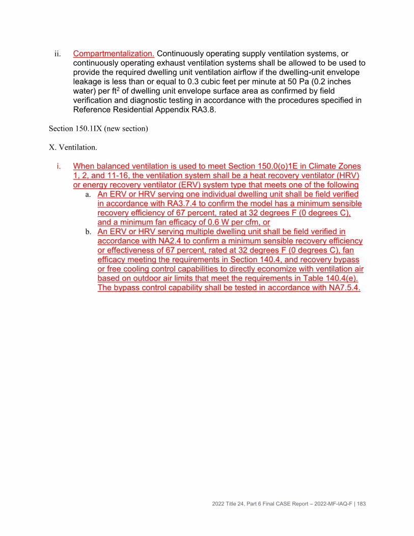
2022 Title 24, Part 6 Final CASE Report – 2022-MF-IAQ-F | 183
ii. Compartmentalization. Continuously operating supply ventilation systems, or continuously operating exhaust ventilation systems shall be allowed to be used to provide the required dwelling unit ventilation airflow if the dwelling-unit envelope leakage is less than or equal to 0.3 cubic feet per minute at 50 Pa (0.2 inches water) per ft2 of dwelling unit envelope surface area as confirmed by field verification and diagnostic testing in accordance with the procedures specified in Reference Residential Appendix RA3.8.
Section 150.1IX (new section)
X. Ventilation.
i. When balanced ventilation is used to meet Section 150.0(o)1E in Climate Zones 1, 2, and 11-16, the ventilation system shall be a heat recovery ventilator (HRV) or energy recovery ventilator (ERV) system type that meets one of the following
a. An ERV or HRV serving one individual dwelling unit shall be field verified in accordance with RA3.7.4 to confirm the model has a minimum sensible recovery efficiency of 67 percent, rated at 32 degrees F (0 degrees C), and a minimum fan efficacy of 0.6 W per cfm, or
b. An ERV or HRV serving multiple dwelling unit shall be field verified in accordance with NA2.4 to confirm a minimum sensible recovery efficiency or effectiveness of 67 percent, rated at 32 degrees F (0 degrees C), fan efficacy meeting the requirements in Section 140.4, and recovery bypass or free cooling control capabilities to directly economize with ventilation air based on outdoor air limits that meet the requirements in Table 140.4(e). The bypass control capability shall be tested in accordance with NA7.5.4.

2022 Title 24, Part 6 Final CASE Report – 2022-MF-IAQ-F | 184
TABLE 150.1-B COMPONENT PACKAGE – Multifamily Standard Building Design (continued)
Climate Zone
1 2 3 through 10
11 12 13 14 15 16
HVAC SYSTEM
Balanced Ventilation*
Unitary (serving one dwelling unit)
Sensible Recovery Efficiency
0.67 0.67 NR 0.67 0.67 0.67 0.67 0.67 0.67
Fan Efficacy (W/cfm)
0.6 0.6 1.0 0.6 0.6 0.6 0.6 0.6 0.6
Central (serving multiple dwelling units)
Sensible Recovery Efficiency or Effective-ness
067 0.67 NR 0.67 0.67 0.67 0.67 0.67 0.67
Bypass Function
Req Req NR Req. Req. Req. Req. Req. Req.
*Requirements only apply when using Balanced Ventilation to meet 150.0(o)1E.7
…
Section 150.2 Low-Rise Residential Buildings – Additions and Alterations to Existing Low-Rise Residential Buildings
Additions would need to follow proposed language for new construction. No changes are needed to the language in Section 150.2, since 150.0(o) is already listed as a requirement for additions.
Alterations would follow the proposed requirement for any replaced components of a ventilation system.

2022 Title 24, Part 6 Final CASE Report – 2022-MF-IAQ-F | 185
7.2.2 Submeasure B: Kitchen Exhaust Minimum Capture
For this submeasure:
• Black is the current language in 2019 Title 24, Part 6. • Purple is from ASHRAE Standard 62.2-2016, so required in 2019 Title 24, Part 6
by reference • Red is new proposed language
10-103 Permit, Certificate, Informational, and Enforcement Requirements for Designers, Installers, Builders, Manufacturers, and Suppliers
Section 10-103(b)4. Ventilation information. For low-rise residential buildings, the
enforcement agency shall require the builder to leave in the building, for the building
owner at occupancy:
i. Aa description of the quantities of outdoor air that the whole dwelling unit ventilation
system(s) are designed to provide to the building’s conditioned space, and instructions
for proper operation and maintenance of the ventilation system, and
ii. Instructions for proper operation and maintenance of local exhaust systems, including
instructions for when any user-controlled systems (such as kitchen range hoods and
bathroom exhaust fans) should be used.
For systems in buildings or tenant spaces that are not individually owned and operated,
instructions shall state that the building’s owner or their representative shall provide a
copy of such information to all tenants at the start of their occupancy. For systems in
buildings or tenant spaces that, or are centrally operated, such information shall be
provided to the person(s) responsible for operating and maintaining the feature,
material, component or mechanical ventilation device installed in the building. For some
multifamily buildings, this may require two sets of information: one for tenants and one
for the person(s) responsible for operating and maintaining the building. This
information shall be in paper or electronic format.
For nonresidential buildings, high-rise residential buildings and hotels, and motels, the
enforcement agency shall require the builder to provide the building owner at occupancy
a description of the quantities of outdoor and recirculated air that the ventilation systems
are designed to provide to each area. For buildings or tenant spaces that are not
individually owned and operated, or are centrally operated, such information shall be
provided to the person(s) responsible for operating and maintaining the feature,
material, component or mechanical device installed in the building. This information
shall be in paper or electronic format.

2022 Title 24, Part 6 Final CASE Report – 2022-MF-IAQ-F | 186
100.1 Definitions and Rules of Construction
ASTM Standard E3087-18 is the American Society of Testing and Materials document titled “Standard Test Method for Measuring Capture Efficiency of Domestic Range Hoods”, 2018
kitchen, enclosed: a kitchen whose permanent openings to interior adjacent spaces do not exceed a total of 60 ft2 (6 m2).…
vented: exhausting to the outdoors
Draft language for high-rise dwelling units
Section 120.1(b) High-rise Residential Buildings
…
1. Attached dwelling units. All dwelling units shall meet the requirements of ASHRAE Standard 62.2, Ventilation and Acceptable Indoor Air Quality in Residential Buildings, subject to the amendments specified in Subsection A below. All dwelling units shall comply with the Acceptance requirements specified in Subsection B below.
…
Section 120.1(b)2Avi. A local mechanical exhaust system shall be installed in each kitchen meeting the requirements of Section a and b below.
a. Kitchen exhaust systems range hoods shall be rated for sound in accordance with Section 7.2 of ASHRAE 62.2.
EXCEPTION to Section 120.1(b)2Avii: Kitchen range hoods may be rated for sound at a static pressure determined at working speed as specified in HVI Publication 916 Section 7.2.
b. Exhaust systems in non-enclosed kitchens must meet 1, 2, or 3 below, and exhaust systems in enclosed kitchens must meet 1, 2, 3, or 4 below:
1. A vented range hood with at least one speed setting with a minimum capture efficiency shown in Table 120.1-A, measured in accordance with ASTM Standard E3087-18 at nominal installed airflow described in HVI Publication 920; or
2. A vented range hood with at least one speed setting with a minimum airflow shown in Table 120.1-A at 25 Pa (0.1 inches w.c.) or higher; or

2022 Title 24, Part 6 Final CASE Report – 2022-MF-IAQ-F | 187
3. A vented downdraft kitchen exhaust fan with at least one speed setting with a minimum airflow of 300 cfm at 25 Pa (0.1 inches w.c.) or higher; or
4. Continuous exhaust system with a minimum airflow equal to five kitchen air changes per hour.
Table 120.1-A Minimum Capture Efficiency (CE) or Airflow (cfm) for demand-controlled range hoods
Dwelling unit floor area (ft2) Hood over electric range Hood over natural gas range
≤ 750 65% CE or 250 cfm 75% CE or 290 cfm
750 – 999 55% CE or 200 cfm 65% CE or 250 cfm
1,000 – 1,500
50% CE or 175 cfm
55% CE or 200 cfm
>1,500 50% CE or 175 cfm
…
Section 120.1(b)2C. Combustion Requirements and Ventilation information compliance
i. All ventilation systems shall meet the requirements of California Mechanical Code
Chapter 7, Combustion Air.
ii. To meet the kitchen range hood requirements in this section and requirements of ASHRAE Standard 62.2 Section 6.4 for Combustion and Solid-Fuel Appliances, neither atmospherically vented combustion appliances nor solid-fuel-burning appliances may be installed in dwelling units smaller than 1,000 ft2. For dwelling units larger than 1,000 ft2 with atmospherically vented combustion appliances or solid-fuel-burning appliances, the total net exhaust flow of the two largest exhaust fans shall not exceed 15 cfm per 100 ft2 of occupiable space.
iii. Builders for all high-rise residential units must meet the ventilation information requirements in Title 24, Part 1 Section 10-103.
…
Additions would need to follow proposed language for new construction. The Statewide CASE Team proposes to add “or ventilation” system in the new multifamily chapter to the list of newly installed equipment that must meet requirements.
Section 141.0
Additions, alterations, and repairs to existing nonresidential, high-rise residential, and hotel/motel buildings, existing outdoor lighting for these occupancies, and internally and externally illuminated signs, shall meet the requirements specified in Sections 100.0 through 110.10, and 120.0 through 130.5 that are applicable to the building project,

2022 Title 24, Part 6 Final CASE Report – 2022-MF-IAQ-F | 188
and either the performance compliance approach (energy budgets) in Section 141.0(a)2 (for additions) or 141.0(b)3 (for alterations), or the prescriptive compliance approach in Section 141.0(a)1 (for additions) or 141.0(b)2 (for alterations), for the climate zone in which the building is located.
…
141.0(a) Additions
(a) Additions. Additions shall meet either Item 1 or 2 below.
1. Prescriptive approach. The envelope and lighting of the addition; any newly installed space-conditioning or ventilation system, electrical power distribution system, or water-heating system; any addition to an outdoor lighting system; and any new sign installed in conjunction with an indoor or outdoor addition shall meet the applicable requirements of Sections 110.0 through 120.7, 120.9 through 130.5, and 140.2 through 140.9.
2. Performance approach.
A. The envelope and indoor lighting in the conditioned space of the addition, and any newly installed space-conditioning or ventilation system, electrical power distribution system, or water-heating system, shall meet the applicable requirements of Sections 110.0 through 120.7, 120.9 through 130.5; and
…
Section 141.0(b) Alterations
1. Mandatory Requirements. Altered components in a nonresidential, high-rise residential, or hotel/motel building shall meet the minimum requirements in this section.
….
D. Kitchen Ventilation in High-rise Residential Units. The altered component and any newly installed kitchen ventilation equipment in the alteration shall meet the applicable requirements of Section 120.1(b)2.
Language for low-rise multifamily dwelling units
Section 150.0(o). Requirements for Ventilation and Indoor Air Quality. All dwelling units shall meet the requirements of ASHRAE Standard 62.2, Ventilation and Acceptable Indoor Air Quality in Residential Buildings subject to the amendments specified in Section 150.0(o)1 below.
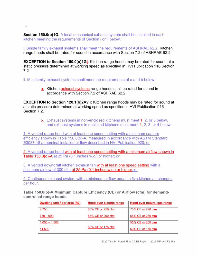
2022 Title 24, Part 6 Final CASE Report – 2022-MF-IAQ-F | 189
…
Section 150.0(o)1G. A local mechanical exhaust system shall be installed in each kitchen meeting the requirements of Section i or ii below.
i. Single family exhaust systems shall meet the requirements of ASHRAE 62.2. Kitchen range hoods shall be rated for sound in accordance with Section 7.2 of ASHRAE 62.2.
EXCEPTION to Section 150.0(o)1Gi: Kitchen range hoods may be rated for sound at a static pressure determined at working speed as specified in HVI Publication 916 Section 7.2
ii. Multifamily exhaust systems shall meet the requirements of a and b below:
a. Kitchen exhaust systems range hoods shall be rated for sound in accordance with Section 7.2 of ASHRAE 62.2.
EXCEPTION to Section 120.1(b)2Avii: Kitchen range hoods may be rated for sound at a static pressure determined at working speed as specified in HVI Publication 916 Section 7.2.
b. Exhaust systems in non-enclosed kitchens must meet 1, 2, or 3 below, and exhaust systems in enclosed kitchens must meet 1, 2, 3, or 4 below:
1. A vented range hood with at least one speed setting with a minimum capture efficiency shown in Table 150.0(o)-A, measured in accordance with ASTM Standard E3087-18 at nominal installed airflow described in HVI Publication 920; or
2. A vented range hood with at least one speed setting with a minimum airflow shown in Table 150.0(o)-A at 25 Pa (0.1 inches w.c.) or higher; or
3. A vented downdraft kitchen exhaust fan with at least one speed setting with a minimum airflow of 300 cfm at 25 Pa (0.1 inches w.c.) or higher; or
4. Continuous exhaust system with a minimum airflow equal to five kitchen air changes per hour.
Table 150.0(o)-A Minimum Capture Efficiency (CE) or Airflow (cfm) for demand-controlled range hoods
Dwelling unit floor area (ft2) Hood over electric range Hood over natural gas range
≤ 750 65% CE or 250 cfm 75% CE or 290 cfm
750 – 999 55% CE or 200 cfm 65% CE or 250 cfm
1,000 – 1,500
50% CE or 175 cfm
55% CE or 200 cfm
>1,500 50% CE or 175 cfm

2022 Title 24, Part 6 Final CASE Report – 2022-MF-IAQ-F | 190
…
Section 150.0(o)3. California Requirements and Ventilation information compliance
i. All ventilation systems shall meet the requirements of California Mechanical
Code Chapter 7, Combustion Air.
ii. To meet the kitchen range hood requirements in this section and requirements of ASHRAE Standard 62.2 Section 6.4 for Combustion and Solid-Fuel Appliances, neither atmospherically vented combustion appliances nor solid-fuel-burning appliances may be installed in dwelling units smaller than 1,000 ft2. For dwelling units larger than 1,000 ft2 with atmospherically vented combustion appliances or solid-fuel-burning appliances, the total net exhaust flow of the two largest exhaust fans shall not exceed 15 cfm per 100 ft2 of occupiable space.
iii. Builders for all dwelling units must meet the ventilation information requirements in Title 24, Part 1 Section 10-103.
…
Section 150.2 Low-Rise Residential Buildings – Additions and Alterations to Existing Low-Rise Residential Buildings
Additions would need to follow proposed language for new construction. No changes are needed to the language in Section 150.2, since 150.0(o) is already listed as a requirement.
Alterations are already required to meet 150.0(o) requirements for any altered components.
7.2.3 Submeasure C: Central Ventilation Duct Sealing
High-rise multifamily building requirements. Note that shifting requirements from Section 140.4(l) to Section 120.4(g) was done in coordination with the Statewide Nonresidential HVAC CASE Team, which is recommending changes to duct leakage requirements for other types of nonresidential buildings in Section 120.4(g)1 and 120.4(g)3. The recommended changes to Section 120.4(g)1 and 120.4(g)3 are not presented below due to timing issues, but will be available in the Nonres HVAC CASE report.
Section 140.4(l) 120.4(g). Requirements For Air Distribution System Ducts And Plenums. Air Distribution System Duct Leakage Sealing. Duct systems shall be sealed in accordance with a1, or b2, or c below:
a1. Systems serving high-rise residential buildings, hotel/motel buildings and nonresidential buildings other than healthcare facilities, the duct system shall be sealed to a leakage rate not to exceed 6 percent of the nominal air handler airflow rate as

2022 Title 24, Part 6 Final CASE Report – 2022-MF-IAQ-F | 191
confirmed through field verification and diagnostic testing, in accordance with the applicable procedures in Reference Nonresidential Appendices NA1 and NA2 if the criteria in Subsections A, B and C below are met:
A. The duct system provides conditioned air to an occupiable space for a constant volume, single zone, space-conditioning system; and
B. The space conditioning system serves less than 5,000 square feet of conditioned floor area; and
C. The combined surface area of the ducts located in the following spaces is more than 25 percent of the total surface area of the entire duct system:
i. Outdoors; or
ii. In a space directly under a roof that
a. Has a U-factor greater than the U-factor of the ceiling, or if the roof does not meet the requirements of Section 140.3(a)1B, or
b. Has fixed vents or openings to the outside or unconditioned spaces; or
iii. In an unconditioned crawlspace; or
iv. In other unconditioned spaces.
b2. Ventilation ducts in multifamily buildings shall meet duct sealing requirements in the California Mechanical Code Section 603.10 and confirmed through field verification and diagnostic testing conducted by a Certified Acceptance Test Technician per NA 2.1.4.2 that leakage is no greater than six percent of the rooftop or central fan design airflow rate if all criteria in Subsections A and B are met. The leakage test shall be conducted using NA 2.1.4.2 at a test pressure of 25 Pa (0.1 inches) for ducts serving six or fewer dwelling units and 50 Pa (0.2 inches) for ducts serving more than six dwelling units, and shall measure the leakage of all ductwork between the central fan and the connection point to the in-unit grille or fan.
A. The ventilation ducts serve multiple dwelling units.
B. The ventilation ducts provide continuous airflows or airflows to provide balanced ventilation to meet 120.1(b)2Aivb.
c. Duct systems serving healthcare facilities shall be sealed in accordance with the California Mechanical Code.
…

2022 Title 24, Part 6 Final CASE Report – 2022-MF-IAQ-F | 192
Section 120.5 Required Nonresidential Mechanical System Acceptance
Section 120.5(a)3. Duct systems shall be tested in accordance with NA7.5.3 where either:
A. They are new duct systems; or that meet the criteria of Sections 140.4(l)1, 140.4(l)2, and 140.4(l)3; or
B. They are part of an altered system. a system that meets the criteria of Section 141.0(b)2D.
Additions would need to follow the proposed requirement.
Section 141.0
Additions, alterations, and repairs to existing nonresidential, high-rise residential, and hotel/motel buildings, existing outdoor lighting for these occupancies, and internally and externally illuminated signs, shall meet the requirements specified in Sections 100.0 through 110.10, and 120.0 through 130.5 that are applicable to the building project, and either the performance compliance approach (energy budgets) in Section 141.0(a)2 (for additions) or 141.0(b)3 (for alterations), or the prescriptive compliance approach in Section 141.0(a)1 (for additions) or 141.0(b)2 (for alterations), for the climate zone in which the building is located.
…
141.0(a) Additions
(a) Additions. Additions shall meet either Item 1 or 2 below.
1. Prescriptive approach. The envelope and lighting of the addition; any newly installed space-conditioning or ventilation system, electrical power distribution system, or water-heating system; any addition to an outdoor lighting system; and any new sign installed in conjunction with an indoor or outdoor addition shall meet the applicable requirements of Sections 110.0 through 120.7, 120.9 through 130.5, and 140.2 through 140.9.
2. Performance approach.
A. The envelope and indoor lighting in the conditioned space of the addition, and any newly installed space-conditioning or ventilation system, electrical power distribution system, or water-heating system, shall meet the applicable requirements of Sections 110.0 through 120.7, 120.9 through 130.5; and
141.0(b) Alterations
Alterations would not need to follow the proposed requirements.
Low-rise multifamily requirements

2022 Title 24, Part 6 Final CASE Report – 2022-MF-IAQ-F | 193
Section 150.0(m)11
11. Duct System Sealing and Leakage Testing.
A. When space conditioning systems utilize forced air duct systems to supply conditioned air to an occupiable space, the ducts shall be sealed, as confirmed through field verification and diagnostic testing, in accordance with all applicable procedures specified in Reference Residential Appendix RA3.1, and the leakage compliance criteria specified in Reference Residential Appendix TABLE RA3.1-2, and conforming to one of the following Subsections A, B, or C as applicable:
Ai. For single family dwellings and townhouses with the air-handling unit installed and the ducts connected directly to the air handler, the total leakage of the duct system shall not exceed 5 percent of the nominal system air handler airflow as determined utilizing the procedures in Reference Residential Appendix Section RA3.1.4.3.1.
Bii. For single family dwellings and townhouses at the rough-in stage of construction prior to installation of the dwelling’s interior finishing:
ia. Air-handling unit installed. If the air-handling unit is installed and the ducts are connected directly to the air handler, the total leakage of the duct system shall not exceed 5 percent of the nominal system air handler airflow as determined utilizing the procedures in Reference Residential Appendix Sections RA3.1.4.3.2, RA3.1.4.3.2.1 and RA3.1.4.3.3.
iib. Air-handling unit not yet installed. If the air-handling unit is not yet installed, the total leakage of the duct system shall not exceed 4 percent of the nominal system air handler airflow as determined utilizing the procedures in Reference Residential Appendix Sections RA3.1.4.3.2, RA3.1.4.3.2.2 and RA3.1.4.3.3.
Ciii. For multifamily dwellings with the air-handling unit installed and the ducts connected directly to the air handler, regardless of duct system location:
ia. The total leakage of the duct system shall not exceed 12 percent of the nominal system air handler airflow as determined utilizing the procedures in Reference Residential Appendix Section RA3.1.4.3.1; or
iib. The duct system leakage to outside shall not exceed 6 percent of the nominal system air handler airflow as determined utilizing the procedures in Reference Residential Appendix Section RA3.1.4.3.4.
B. Ventilation ducts in multifamily buildings shall be sealed and confirmed through field verification and diagnostic testing conducted by a Certified Acceptance Test Technician per NA2.1 that leakage is no greater than six percent of the rooftop or central fan design airflow rate if all criteria in Subsections I and ii are met. The leakage test shall be conducted using NA2.1 at a test pressure of 25 Pa (0.1 inch) for ducts serving six or

2022 Title 24, Part 6 Final CASE Report – 2022-MF-IAQ-F | 194
fewer dwelling units and 50 Pa (0.2 inches) for ducts serving more than six dwelling units, and shall measure the leakage of all ductwork between the central fan and the connection point to the in-unit exhaust grille or fan.
i. The ventilation ducts serve multiple dwelling units.
ii. The ventilation ducts provide continuous airflows or airflows to provide balanced ventilation to meet 120.1(b)2Aivb.
Section 150.2 Low-Rise Residential Buildings – Additions and Alterations to Existing Low-Rise Residential Buildings
Additions would need to follow proposed language for new construction. No changes are needed to the language in Section 150.2, since Sections 150.0(a) through (q) are already required.
Alterations would meet the proposed requirement for any altered or replaced
components.
7.3 Reference Appendices
7.3.1 Submeasure A: ERV/HRV
NONRESIDENTIAL APPENDIX
NA2 – Nonresidential Field Verification and Diagnostic Test Procedures:
NA2.4 Rated Heat Recovery and Energy Recovery Ventilation Verification Procedures
[new section]
When required for compliance with 140.X, for unitary ERVs/HRVs (one ERV or HRV
serves each dwelling unit), a HERS Rater or ATT will:
1. Verify in the field that an ERV or HRV is installed, and verify using product
specifications that it will provide airflows to meet or exceed the dwelling unit’s
balanced ventilation system airflows, and
2. Visually verify the installed equipment’s nominal sensible recovery efficiency and
fan efficacy for the installed model via product databases (HVI, AHRI, or Energy
Commission – approved alternatives) or from product specifications from the
manufacturer.
When required for compliance with 140.X, for central ERVs/HRVs (one ERV or HRV
serves multiple dwelling units), an ATT will:
1. Verify in the field that an ERV or HRV is installed, and verify using product
specifications that it will provide airflows to meet or exceed the dwelling unit’s
balanced ventilation system airflows, and

2022 Title 24, Part 6 Final CASE Report – 2022-MF-IAQ-F | 195
2. Visually verify the installed equipment’s nominal sensible recovery efficiency and
fan efficacy for the installed model via product databases (HVI, AHRI) or from
product specifications from the manufacturer, and
3. Verify that the ERV/HRV systems include a bypass or free cooling function, using
product specifications. Field verify that the bypass function exists and meets the
requirements of Table 140.4(e).
4. Conduct functional testing of the bypass function according to NA7.5.4
NA7.5.4 Air Economizer Controls and Exhaust Air Heat Recovery
The following language was proposed by the Statewide Nonresidential HVAC Controls
CASE Team and is copied into this Final CASE Report for completeness.
NA7.5.4.1 Construction Inspection
Prior to Functional Testing, verify and document the following:
(a) Economizer (or heat recovery bypass) high limit shutoff control complies with
Table 140.4-E of Section140.4(e)2.
(b) If the high-limit control is fixed dry-bulb or fixed enthalpy + fixed dry-bulb, it shall
have an adjustable setpoint.
(c) Economizer (or heat recovery bypass) lockout control sensor is located to
prevent false readings.
(d) Sensor performance curve is provided by factory with economizer (or heat
recovery bypass) instruction material.
(e) Sensor output value measured during sensor calibration is plotted on the
performance curve.
(f) Economizer (or heat recovery bypass) damper moves freely without binding.
1. Indicate if bypass control is achieved through heat/energy recovery wheel rotation
speed modulation as means other than air dampers,
(g) Economizer (or heat recovery bypass) has control systems, including two-stage
or electronic thermostats, that cycle compressors off when economizers (or heat
recovery bypass) can provide partial cooling.
(h) Economizer (or heat recovery bypass) reliability features are present as specified
by Standards Section 140.4(e)2D.
1. Indicate N/A for heat recovery bypass.
(i) Economizer inlet damper is designed to modulate up to 100 percent open, and
return air damper to 100 percent closed, without over-pressurizing the building.

2022 Title 24, Part 6 Final CASE Report – 2022-MF-IAQ-F | 196
1. Indicate N/A for heat recovery bypass.
(j) For systems with DDC controls lockout sensor(s) are either factory calibrated or
field calibrated.
(k) For systems with non-DDC controls, manufacturer’s startup and testing
procedures have been applied.
(l) The economizer has been certified to the Energy Commission as specified by
Section 140.4(e)2Diii.
1. Indicate N/A for heat recovery bypass.
NA7.5.4.2 Functional Testing
Step 1: Disable demand control ventilation systems (if applicable).
Step 2: Enable the economizer and simulate a cooling demand large enough to drive
system into full economizer cooling mode (e.g., the economizer is fully open). Verify and
document the following:
(a) Economizer (or heat recovery bypass) damper is 100 percent open and return air
damper is 100 percent closed.
1. If bypass is achieved through heat/energy recovery wheel rotation speed modulation,
wheel speed is fully stopped.
(b) All applicable fans and dampers operate as intended to maintain building
pressure.
(c) The unit heating is disabled (if unit has heating capability).
Step 3: Disable the economizer and simulate a cooling demand. Verify and document
the following:
(d) Economizer damper closes to its minimum position.
(e) All applicable fans and dampers operate as intended to maintain building
pressure.
(f) The unit heating is disabled (if unit has heating capability).
(g) Indicate N/A for this step for heat recovery bypass.
Step 4: If unit has heating capability, simulate a heating demand and set the
economizer so that it is capable of operating (i.e. actual outdoor air conditions are below
lockout setpoint). Verify the following:
For economizer systems
(h) The economizer is at minimum position.
(i) Return air damper opens.

2022 Title 24, Part 6 Final CASE Report – 2022-MF-IAQ-F | 197
For HRV/ERV or DOAS systems:
(j) Heat recovery bypass control modulates bypass damper/wheel speed to control
to temperature setpoint.
Step 5: Turn off the unit. Verify and document the following:
(k) Economizer damper closes completely.
(l) Indicate N/A for this step for heat recovery bypass.
Step 6: Restore demand control ventilation systems (if applicable) and remove all
system overrides initiated during the test.
RESIDENTIAL APPENDIX
RA3.7.4 Procedures: The proposed change will add a subsubsection, 3.7.4.4
RA3.7.4.4: Rated Heat Recovery and Energy Recovery Ventilation Verification
Procedures. A HERS Rater or ATT will determine if an energy recovery ventilator
(ERV) or heat recovery ventilator (HRV) is needed based on requirements of Section
150.1, and if so, verify requirements as follows:
For unitary ERVs/HRVs (one ERV or HRV serves each dwelling unit), the HERS Rater
or ATT will:
1. Verify in the field that an ERV or HRV is installed, and verify using product
specifications that it will provide airflows to meet or exceed the dwelling unit’s
balanced ventilation system airflows, and
2. Verify that the fan efficacy and sensible recovery effectiveness or efficiency
requirements in Section 150.1X are met using product databases (HVI or Energy
Commission – approved alternatives) or from product specifications.
For central ERVs/HRVs (one ERV or HRV serves multiple dwelling units), an ATT will:
1. Verify in the field that an ERV or HRV is installed, and verify using product
specifications that it will provide airflows to meet or exceed the dwelling unit’s
balanced ventilation system airflows, and
2. Verify that the fan efficacy and sensible recovery effectiveness or efficiency
requirements in Section 150.1X are met using product databases (HVI or Energy
Commission – approved alternatives) or from product specifications, and
3. Verify that ERV/HRV systems that provide ventilation to more than one dwelling
unit include a bypass or free cooling function, using product specifications.
4. Conduct functional testing of the bypass function according to NA7.5.4

2022 Title 24, Part 6 Final CASE Report – 2022-MF-IAQ-F | 198
7.3.2 Submeasure B: Kitchen Exhaust Minimum Capture
NA2.2.4.1.3 Kitchen Range Hood Kitchen Exhaust Equipment Verification
The verification shall utilize certified rating data from the Home Ventilating Institute (HVI)
Certified Home Ventilating Products Directory at https://hvi.org/proddirectory/index.cfm,
AHAM directory, or another directory of certified product performance ratings approved
by the Energy Commission for determining compliance (abbreviated here as “HVI
Directory”). The verification procedure shall consist of visual inspection of the installed
kitchen range hood exhaust equipment to verify and record the following information:
(a) The manufacturer name and model number.
(b) The model is listed in the HVI Directory.
(c) The rated airflow value or rated capture efficiency listed in the HVI directory.
(d) The sound rating value listed in the HVI directory.
(e) If the value for the rated airflow or capture efficiency given in the directory is
greater than or equal to the airflow requirements specified in the standards, and if the
value for the sone rating given in the directory is less than or equal to the sone rating
requirements specified in standards, then the kitchen range hood exhaust equipment
complies, otherwise the kitchen range hood exhaust equipment does not comply.
RA3.7.4.3 Kitchen Range Hood Kitchen Exhaust Equipment Verification
The verification shall utilize certified rating data from the Home Ventilating Institute (HVI)
Certified Home Ventilating Products Directory at https://hvi.org/proddirectory/index.cfm,
Association of Home Appliance Manufacturers (AHAM) directory, or another directory of
certified product performance ratings approved by the Energy Commission for
determining compliance (abbreviated here as “HVI Directory”). The verification
procedure shall consist of visual inspection of the installed kitchen range hood exhaust
equipment to verify and record the following information:
(a) The manufacturer name and model number.
(b) The model is listed in the HVI Directory.
(c) The rated airflow value or rated capture efficiency listed in the HVI directory.
(d) The sound rating value listed in the HVI directory.
(e) If the value for the rated airflow or capture efficiency given in the directory is
greater than or equal to the airflow requirements specified in the standards, and if the
value for the sone rating given in the directory is less than or equal to the sone rating
requirements specified in standards, then the kitchen range hood exhaust equipment
complies, otherwise the kitchen range hood exhaust equipment does not comply.

2022 Title 24, Part 6 Final CASE Report – 2022-MF-IAQ-F | 199
7.3.3 Submeasure C: Central Ventilation Duct Sealing
Sampling Procedures
NA1.6.3 HERS Procedures – Group Sample Field Verification and Diagnostic Testing
After the initial field verification and diagnostic testing is completed, the builder or the ATT shall identify a group of up to seven individual systems or dwelling units in the building from which a sample will be selected and identify the names and license numbers of the subcontractors responsible for the installations requiring field verification and diagnostic testing. The date the first system or dwelling unit in the group is identified shall establish the start date for the new opened sample group. The HERS provider shall recorded and track the start date for each sample group. For the leakage requirements in Section 120.4(g)2, an ATT shall identify a group of up to three central ventilation duct systems in the building from which a sample will be selected.
…
NA1.9.1 Duct Leakage Field Verification by the Acceptance Test Technician
Under this alternative procedure, when the Certificate of Compliance indicates that field verification and diagnostic testing of duct leakage is required as a condition for compliance with Title 24, Part 6, a certified ATT may perform the duct leakage verification to satisfy the condition of compliance, at the discretion of the enforcement agency. Systems verified under this procedure are not eligible for sampling.
The exception is verification of requirements in Section 120.4(g), which must be conducted by an ATT, and verification of requirements in Section 120.4(g)3 is eligible for sampling.
NA2 – Nonresidential Field Verification and Diagnostic Test Procedures:
NA 2.1.1.1 - Purpose and Scope
The proposed code change would add 120.4(g) to the scope of this section and update
140.4(l) references.
NA2.1.4.2 – Diagnostic Duct Leakage
The proposed code change would add the requirements of Section 140.4(1)3 to the
compliance criteria in Table NA2.1-1-1
NA2.1.4.2.2: Diagnostic Ventilation Duct Leakage from Fan Pressurization of Ducts, and
subsequent subsections would be renumbered. The language in the new subsection
would be similar to that in the existing Subsection NA2.1.4.2.1: Diagnostic Duct
Leakage from Fan Pressurization of Ducts, which applies to testing of ducts providing
conditioned air at 25 Pa (0.1 inches w.c.). However, the new subsection would specify

2022 Title 24, Part 6 Final CASE Report – 2022-MF-IAQ-F | 200
that the test be conducted at 50 Pa (0.2 inches w.c.), and language would be revised so
that it applies to ventilation duct systems as opposed to space conditioning duct
systems.
The revised language would also state that sampling can be used for duct testing
following NA1.6 procedures. If sampling is used for this measure, a sampling group
would be defined as all ventilation ducts that carry the same type of airflow—i.e., either
supply ventilation or exhaust ventilation—and that have the same make and model for
their central ventilation fan.
RA2.6.2 HERS and ATT Procedures – Initial Model Field Verification and Diagnostic Testing
The HERS Rater shall diagnostically test and field verify the first dwelling unit of each model within a subdivision or multifamily housing development when the builder elects to demonstrate HERS verification compliance utilizing group sampling. To be considered the same model, dwelling units shall have the same basic floor plan layout, energy design, and compliance features as shown on the Certificate of Compliance. Variations in the basic floor plan layout, energy design, compliance features, zone floor area, or zone volume, that do not change the HERS features to be tested, the heating or cooling capacity of the HVAC unit(s), or the number of HVAC units specified for the dwelling units, shall not cause dwelling units to be considered a different model.
For multifamily buildings, variations in exterior surface areas caused by location of dwelling units within the building shall not cause dwelling units to be considered a different model.
For multifamily buildings meeting Section 150.0(m)11B, each central ventilation duct system that meets the criteria of 150.0(m)11B shall be treated as a “dwelling unit” for the sampling procedures specified in this section; an Acceptance Test Technician (ATT) shall identify a group of up to three central ventilation duct systems in the building from which a sample will be selected and conduct the leakage test for those systems.
RA3.1.4.3.1 Diagnostic Duct Leakage from Fan Pressurization of Ducts
The objective of this procedure is for an installer to determine or a rater to verify the
total leakage of a new duct system or one that is replaced as part of an alteration. The
total duct leakage shall be determined by pressurizing the entire duct system to a
positive pressure of 25 Pa (0.1 inches water) with respect to outside, except for Section
150.0(m)11B. For Section 150.0(m)11B, the system shall be positively pressurized for
supply ducts and negatively pressurized for exhaust ducts, and the test shall be
conducted at 25 Pa (0.1 inches water) for ducts serving six or fewer dwelling units and
at 50 Pa (0.2 inches water) for systems serving more than six dwelling units.

2022 Title 24, Part 6 Final CASE Report – 2022-MF-IAQ-F | 201
7.4 ACM Reference Manual
7.4.1 Submeasure A: ERV/HRV
The following provides marked up language for the Residential ACM Reference Manual.
Section 2.4.9 Indoor Air Quality Ventilation
Standard Design
The mechanical ventilation system in the standard design is the same type as the
proposed design. The airflow rate is equal to the proposed design for exhaust,
supply, and balanced fans with no heat or energy recovery. For balanced fans
with heat or energy recovery, the airflow rate is equal to the proposed design up
to a maximum of 1.5 times the minimum CFM required by ASHRAE 62.2. For
multifamily buildings with balanced fans with or without heat recovery in Climate
Zones 1, 2, and 11-16 the The sensible heat recovery effectiveness is 67 percent
and the fan power ratio is 0.6 W/CFM. For multifamily buildings with balanced
fans with or without heat recovery in all other climate zones the sensible heat
recovery effectiveness is zero and the fan power ratio is 0.6 W/CFM. For single
family buildings the sensible heat recovery effectiveness is always zero. For
standalone IAQ fan systems, the fan power ratio is equal to the proposed design
value or 1.2 W/CFM, whichever is smaller. For central air handler fans, the fan
power ratio is 0.45 (gas furnaces) or 0.58 W/CFM (heat pumps) of central system
airflow in ventilation mode.
NONRESIDENTIAL ACM REFERENCE MANUAL
The following language should be incorporated into the Nonresidential ACM Reference
Manual. The Statewide CASE Team recommends that the Energy Commission
consider providing multiple boxes with the various requirements for the heat exchanger,
including sensible recovery effectiveness, fan efficacy, and a bypass function.
Section 5.6.6.4 Outdoor Air Ventilation

2022 Title 24, Part 6 Final CASE Report – 2022-MF-IAQ-F | 202
Subsection 5.6.6.4.1 Heat/Energy Recovery
Heat/Energy Recovery
Applicability Zones serving multifamily apartments
Definition Details of heat or energy recovery systems
Units Various
Input Restrictions As designed
Standard Design If the Proposed Design is a unitary balanced or heat recovery ventilation system, in Climate Zones 1, 2, and 11-16 the Standard Design is a heat recovery ventilation system with a rated heat recovery effectiveness of 67%. In all other climates zones, the Standard Design is a balanced ventilation system without heat recovery. For all climate zones, the Standard Design has a fan power index of 0.6 W/cfm
If the Proposed Design is a central ventilation system serving more than one apartment, in Climate Zones 1, 2, and 11-16, the Standard Design has a heat recovery system with a sensible heat exchange effectiveness of 67% in both heating and cooling and includes bypass of the heat exchanger when outdoor temperatures are cool. In all other climate zones, the Standard Design is a balanced ventilation system that does not have a heat recovery system. In all climate zones, the Standard Design meets the fan efficacy requirements in Section 140.4.
Standard Design:
Existing Buildings
n/a
7.4.2 Submeasure B: Kitchen Exhaust Minimum Capture
There are no proposed changes to the ACM Reference Manual for this measure.
7.4.3 Submeasure C: Central Ventilation Duct Sealing
There are no proposed changes to the ACM Reference Manual for this measure.
7.5 Compliance Manuals
The proposed code changes would modify the following section of the Residential and
Nonresidential Compliance Manuals:
RESIDENTIAL COMPLIANCE MANUAL
Section 4.6 – Indoor Air Quality and Mechanical Ventilation: The manual would
include language that summarizes the requirement. The manual would provide an
overview of strategies to meet the requirement, including unitary HRV or ERV, central
HRV or ERV (such as a rooftop strategy or cluster strategy - such as one on every
floor). The sizing and installation of bypass ducting would be illustrated and discussed.

2022 Title 24, Part 6 Final CASE Report – 2022-MF-IAQ-F | 203
The manual should also include language recommending that, for all multifamily
projects that install HRV or ERV (including in climate zones not regulated by this
requirement), the HRV or ERV include a bypass function, or that the dwelling units have
mechanical cooling, to prevent overheating. The purpose of this language is to promote
energy-efficient thermal comfort for occupants.
ERV/HRV can use multiple strategies for distributing outside air and (if interfacing with
an air handling unit) integrating the supply duct into an AHU. However, the outside air
distribution issues for ERV/HRVs would be similar to issues faced under the current
requirements for other types of balanced ventilation systems. 2019 Title 24, Part 6
prohibits the “continuous operation of central forced air system air handlers used in
central fan integrated ventilation systems.” There are no requirements in ASHRAE
Standard 62.2 for distributing outside air within the dwelling unit—i.e., providing all
outdoor air through one supply register is compliant, although it is best practice to
distribute it throughout the dwelling unit, particularly when the outside air is outside of
thermostat set points. The manual should describe at least two options for how outside
air can be distributed within the dwelling unit:
1. One example in which the ERV/HRV has its own duct work, and supply air is
distributed to each bedroom and the living area, and
2. One example in which the ERV/HRV interfaces with the HVAC system, by
ducting the supply air into the return plenum of the forced air system.
Section 4.6.1 – Compliance and Enforcement: The manual would stipulate that the
HERS Rater must document the SRE or effectiveness and verify it is ≥67 and that fan
efficacy is a value of 0.6 W/cfm or lower.
Section 4.6.3.3 – Multifamily Dwelling Unit Compartmentalization: The manual
would describe the new requirement for an ERV or HRV in certain climate zones for
projects following the balanced ventilation path.
NONRESIDENTIAL COMPLIANCE MANUAL
Sections 4.3.2 – High-Rise Residential Dwelling Unit Mechanical Ventilation: The
manual would include language that summarizes the requirement. The manual would
provide an overview of strategies to meet the requirement, including unitary HRVs or
ERVs, and central HRVs or ERVs serving multiple dwelling units.
The manual would also include language recommending that, for all multifamily projects
that install HRV or ERV (including in climate zones not regulated by this requirement),
the HRV or ERV include a bypass function, or that the dwelling units have mechanical
cooling, to prevent overheating. The purpose of this language is to promote thermal
comfort for occupants. The manual would frame this guidance, so it is clear what is
required, versus what is recommended. The current compliance manual uses this

2022 Title 24, Part 6 Final CASE Report – 2022-MF-IAQ-F | 204
approach for other measures, such as Section 4.5.2.4 for Supply-Air Temperature
Reset Control, which specifies certain set points for this measure and provides
recommendations for how this can be achieved.
Section 4.3.2.5.3 – Multifamily Dwelling Unit Compartmentalization (which
describes the balanced ventilation alternative to compartmentalization): The manual
would describe that an ERV or HRV is required in certain climate zones for projects
following the balanced ventilation path.
7.6 Compliance Documents
Several compliance documents would need to be revised. The intention of these
revisions is to ensure that all new requirements are documented and verified in a way
that is consistent with existing ventilation requirements. Some new documents may
need to be created, but existing documents could also be expanded to capture the new
information.
To determine which compliance documents would be affected, the Statewide CASE
Team reviewed all 2019 compliance documents and flagged those with direct relevance
to the newly proposed requirements. The tables below call out which documents would
need what changes to cover the new requirements. The Statewide CASE Team has not
specified exact language for the document updates, but rather highlighted the sections
where final language, requirements, and procedures would need to be included.
In general, the proposed requirements would trigger small changes to HERS Rater
verifications—such as verifying a few additional features in an HVI database compared
to current requirements, and significant additions for ATT forms due to additional testing
requirements for central ERV/HRV bypass functional testing and central ventilation duct
leakage.

2022 Title 24, Part 6 Final CASE Report – 2022-MF-IAQ-F | 205
Table 75: Proposed Changes to Compliance Forms – CF1R
Form Group
Compliance Form
Who completes?
ERV/HRV Kitchen Exhaust Central Shaft Sealing
CF1R 2019-CF1R-NCB-01-E and 2019-CF1R-PRF-01E
Energy consultant
- Form would need to be adapted to include references to unitary (each serves one dwelling unit) and “central ERV/HRV” (each serves multiple dwelling units), and to document sensible recovery effectiveness and fan efficacy
Update HERS Feature Summary N/A
Table 76: Proposed Changes to Compliance Forms – CF2R
Form Group
Compliance Form
Who completes?
ERV/HRV Kitchen Exhaust Central Shaft Sealing
CF2R 2019-CF2R-MCH-27b-Multifamily.pdf
Installing Contractor or HERS Rater
-Many locations: references to “mechanical supply system, exhaust system, or combination thereof” should be updated to include unitary and central ERV/HRV -G. Other Requirements would need to reflect ERV/HRV requirements -H. Air Moving Equipment would need to reflect ERV/HRV requirements
-F. Other Requirements would need to kitchen exhaust requirements
-H. Air Moving Equipment would need to reflect central shaft sealing requirements
CF2R 2019-CF2R-MCH-27c-SingleFamilyAndMultifamilyScheudledandRealTimeControl.pdf
Installing Contractor or HERS Rater
-B. Other Requirements would need to reflect ERV/HRV requirements -C. Air Moving Equipment would need to reflect ERV/HRV requirements
-B. Other Requirements would need to reflect kitchen exhaust requirements
-C. Air Moving Equipment would need to reflect central shaft sealing requirements

2022 Title 24, Part 6 Final CASE Report – 2022-MF-IAQ-F | 206
Form Group
Compliance Form
Who completes?
ERV/HRV Kitchen Exhaust Central Shaft Sealing
CF2R 2019-CF2R-MCH-30-VentilationCooling.pdf
Installing Contractor or HERS Rater
-A. Central Fan Ventilation Cooling System Equipment Information and B. Additional Requirements would need to be reconfigured to document unitary and central ERV/HRV w/ bypass
N/A N/A
CF2R 2019-CF2R-MCH-32-LocalMechanicalExhaust.pdf
Installing Contractor or HERS Rater
-B. Local Mechanical Exhaust System – Fan Selection and Duct Design for Compliance would need to be reconfigured to document unitary and central ERV/HRV w/ bypass, or add separate section
-B. Local Mechanical Exhaust System – Fan Selection and Duct Design for Compliance would need to add any new kitchen exhaust requirements and identify which path (capture efficiency, minimum airflow, or continuous exhaust) will be used for compliance -C. Kitchen Exhaust System would need to include fields for any new requirements
N/A

2022 Title 24, Part 6 Final CASE Report – 2022-MF-IAQ-F | 207
Table 77: Proposed Changes to Compliance Forms – CF3R
Compliance Form
Who completes?
ERV/HRV Kitchen Exhaust Central Shaft Sealing
2019-CF3R-MCH-27b-Multifamily.pdf
ATT/ HERS Rater
-Many locations: references to “mechanical supply system, exhaust system, or combination thereof” should be updated to include unitary ERV/HRV and central ERV/HRV -G. Other Requirements would need to reflect ERV/HRV requirements -H. Air Moving Equipment would need to reflect ERV/HRV requirements—verify nominal SRE and fan efficacy (nominal fan Watt draw / nominal airflow) meets or is better than CF1R claim
-F. Other Requirements would need to reflect kitchen exhaust requirements
-H. Air Moving Equipment would need to reflect central shaft sealing requirements
2019-CF3R-MCH-27c-SingleFamilyAndMultifamilyScheudledandRealTimeControl.pdf
ATT/ HERS Rater
-B. Other Requirements would need to reflect ERV/HRV requirements -C. Air Moving Equipment would need to reflect ERV/HRV requirements
-B. Other Requirements would need to reflect kitchen exhaust requirements
-C. Air Moving Equipment would need to reflect central shaft sealing requirements
2019-CF3R-MCH-32-LocalMechanicalExhaust.pdf
ATT/ HERS Rater
-B. Local Mechanical Exhaust System – Fan Selection and Duct Design for Compliance would need to be reconfigured to document unitary or central ERV/HRV w/ bypass, or add separate section
-B. Local Mechanical Exhaust System – Fan Selection and Duct Design for Compliance would need to add any new kitchen exhaust requirements -C. Kitchen Exhaust System would need to include fields for any new requirements
N/A

2022 Title 24, Part 6 Final CASE Report – 2022-MF-IAQ-F | 208
Table 78: Proposed Changes to Compliance Forms – NRCC
Compliance Form
Who completes?
ERV/HRV Kitchen Exhaust Central Shaft Sealing
2019-NRCC-MCH-E.pdf
Energy Consultant
-Any new NRCI & NRCA forms would need to be added
-Any new NRCI & NRCA forms would need to be added
-Any new NRCI & NRCA forms would need to be added
2019-NRCC-PRF-01-E.pdf
Energy Consultant
-Information about ERV/HRV SRE, bypass would need to be displayed on form
New NRCA/NRCI/NRCV forms would need to be added to required forms section
-Forms would need to indicate whether central shafts requiring sealing verification are present.
- New NRCA/NRCI/NRCV forms would need to be added to required forms section

2022 Title 24, Part 6 Final CASE Report – 2022-MF-IAQ-F | 209
Table 79: Proposed Changes to Compliance Forms – NRCA
Compliance Form
Who completes?
ERV/HRV Kitchen Exhaust Central Shaft Sealing
2019-NRCA-MCH-02-A Outdoor Air.pdf
ATT -A. Construction Inspection would need AT procedure for ERV/HRV verification
N/A N/A
2019-NRCA-MCH-04a-H-AirDistributionDuctLeakage.pdf
ATT N/A N/A Applicable to multifamily occupancies only:
-A. Construction Inspection would need to include requirements for central shafts that is distinct from heating/cooling systems. -B. Functional Testing would need procedure for testing central shafts that is distinct from existing procedure for recirculating systems.
2019-NRCA-MCH-04b-A-AirDistributionDuctLeakage.pdf
ATT N/A N/A Applicable to multifamily occupancies only:
-A. Construction Inspection would need to include requirements for central shafts that is distinct from heating/cooling systems. -B. Functional Testing would need procedure for testing central shafts that is distinct from existing procedure for recirculating systems.
2019-NRCA-MCH-20-H-MultifamilyVentilation.pdf
ATT -A. Construction Inspection would need to include new ERV/HRV requirements.
-A. Construction Inspection would need to include new kitchen exhaust requirements.
-A. Construction Inspection would need to include requirements for central shafts that is distinct from heating/cooling systems. -B. Functional Testing would need procedure (and requirements) for testing central shafts that is distinct from existing procedure for recirculating systems.

2022 Title 24, Part 6 Final CASE Report – 2022-MF-IAQ-F | 210
Table 80: Proposed Changes to Compliance Forms – NRCV
Form Group
Compliance Form
Who completes?
ERV/HRV Kitchen Exhaust Central Shaft Sealing
NRCV 2019-NRCV-MCH-04a-DuctLeakageTest-NewConst.pdf
HERS Rater N/A N/A N/A (since HERS Raters will not verify this measure)
NRCV 2019-NRCV-MCH-27b-HighriseResidential.pdf
HERS Rater -Many locations: references to “mechanical supply system, exhaust system, or combination thereof” should be updated to include unitary ERV/HRV -H. Other Requirements would need to reflect ERV/HRV requirements -I. Air Moving Equipment would need to reflect ERV/HRV requirements
-H. Other Requirements will need to reflect kitchen exhaust requirements
N/A
NRCV 2019-NRCV-MCH-27c-HighriseResidentialHighriseResidScheduledRealTimeControl.pdf
HERS Rater -C. Other Requirements would need to reflect ERV/HRV requirements -D. Air Moving Equipment would need to reflect ERV/HRV requirements
-C. Other Requirements would need to reflect kitchen exhaust requirements
N/A

2022 Title 24, Part 6 Final CASE Report – 2022-MF-IAQ-F | 211
Form Group
Compliance Form
Who completes?
ERV/HRV Kitchen Exhaust Central Shaft Sealing
NRCV 2019-NRCV-MCH-32-LocalMechanicalExhaust.pdf
HERS Rater -B. Local Mechanical Exhaust System – Fan Selection and Duct Design for Compliance would need to be reconfigured to document unitary ERV/HRV
-B. Local Mechanical Exhaust System – Fan Selection and Duct Design for Compliance would need to add any new kitchen exhaust requirements -C. Kitchen Exhaust System would need to include fields for any new requirements
N/A

2022 Title 24, Part 6 Final CASE Report – 2022-MF-IAQ-F | 212
Bibliography n.d. http://bees.archenergy.com/Documents/Software/CBECC-
Com_2016.3.0_SP1_Prototypes.zip.
2018 American Community Survey. n.d. 1-Year Estimates.
https://data.census.gov/cedsci/.
Amazon. 2019. Panasonic FV-10VE1 Intelli-Balance 100 Balanced Air Solution, 50 to
100 CFM - Ceiling or Wall Mount ERV. https://www.amazon.com/Panasonic-FV-
10VE1-Intelli-Balance-Balanced-Solution/dp/B071D6RPFL.
American Aldes. 2018. H280-SRG Heat Recovery Ventilator. https://aldes.us/wp-
content/uploads/2018/06/h280-srg_spec.pdf.
—. 2014. "FAK-II." https://www.hvacquick.com/catalog_files/Aldes_FAK-II_Specs.pdf.
ASHRAE. 2011. 2011 ASHRAE Handbook - HVAC Applications.
—. 2019b. ANSI/ASHRAE/IES Standard 90.1-2019 -- Energy Standard for Buildings
Except Low-Rise Residential Buildings.
Association, National Energy Assistance Directors. 2011. "2011 National Energy
Assistance Survey Final Report." Accessed February 2, 2017.
http://www.appriseinc.org/reports/Final%20NEADA%202011%20Report.pdf.
ASTM International. 2018. "Standard Test Methods for Determining Air Leakage of Air
Distribution Systems by Fan Pressurization." West Conshohocken, PA.
BC Housing. n.d. "Heat Recovery Ventilation." Accessed July 23, 2020.
https://www.bchousing.org/publications/Builder-Insight-14-Heat-Recovery-
Ventilation.pdf.
Belanger, Kathleen. 2013. "Household levels of nitrogen dioxide and pediatric asthma
severity." Epidemiology 320-330.
BW Research Partnership. 2016. Advanced Energy Jobs in California: Results of the
2016 California Advanced Energy. Advanced Energy Economy Institute.
Calcs Plus. 2013. U.S. Department of Energy. https://basc.pnnl.gov/images/heat-
recovery-ventilator-hrv-or-energy-enthalpy-recovery-ventilator-erv.
California Air Resouces Board. 2019. "Global Warming Potentials."
https://www.arb.ca.gov/cc/inventory/background/gwp.htm#transition.
California Air Resources Board. 2019. Global Warming Potentials.
https://www.arb.ca.gov/cc/inventory/background/gwp.htm#transition.

2022 Title 24, Part 6 Final CASE Report – 2022-MF-IAQ-F | 213
California Department of Water Resources. 2016. "California Counties by Hydrologic
Regions." Accessed April 3, 2016.
http://www.water.ca.gov/landwateruse/images/maps/California-County.pdf.
California Energy Commission. 2015. 2016 Building Energy Efficiency Standards:
Frequently Asked Questions.
http://www.energy.ca.gov/title24/2016standards/rulemaking/documents/2016_Bui
lding_Energy_Efficiency_Standards_FAQ.pdf.
—. 2019. "2019 Workshops and Meetings." October 17.
https://ww2.energy.ca.gov/title24/2022standards/prerulemaking/documents/.
—. 2017. "California Energy Maps." CA.gov.
https://ww2.energy.ca.gov/maps/renewable/BuildingClimateZonesMap.pdf.
—. 2022. "Energy Code Data for Measure Proposals." energy.ca.gov.
https://www.energy.ca.gov/title24/documents/2022_Energy_Code_Data_for_Mea
sure_Proposals.xlsx.
—. 2022. "Energy Code Data for Measure Proposals." energy.ca.gov.
https://www.energy.ca.gov/title24/documents/2022_Energy_Code_Data_for_Mea
sure_Proposals.xlsx.
—. 2019. "Housing and Commercial Construction Data - Excel."
https://ww2.energy.ca.gov/title24/documents/2022_Energy_Code_Data_for_Mea
sure_Proposals.xlsx.
—. 2018. "Impact Analysis: 2019 Update to the California Energy Efficiency Standards
for Residential and Non-Residential Buildings." energy.ca.gov. June 29.
https://www.energy.ca.gov/title24/2019standards/post_adoption/documents/2019
_Impact_Analysis_Final_Report_2018-06-29.pdf.
—. n.d. Nonresidential Construction Forecasts.
https://www.energy.ca.gov/title24/participation.html.
California Public Utilities Commission (CPUC). 2015b. "Water/Energy Cost-
Effectiveness Analysis: Revised Final Report." Prepared by Navigant Consulting,
Inc. http://www.cpuc.ca.gov/WorkArea/DownloadAsset.aspx?id=5360.
California Public Utilities Commission. 2015a. "Water/Energy Cost-Effectiveness
Analysis: Errata to the Revised Final Report." Prepared by Navigant Consulting,
Inc. . http://www.cpuc.ca.gov/WorkArea/DownloadAsset.aspx?id=5350.
Center for Energy and Environment. 2016. "Multifamily Ventilation Assessment and
Retrofit Guide."
https://www.cards.commerce.state.mn.us/CARDS/security/search.do?method=sh

2022 Title 24, Part 6 Final CASE Report – 2022-MF-IAQ-F | 214
owPoup&documentId=%7BDB45217D-CD15-483D-87EE-
E657487CAA7F%7D&documentTitle=282726&documentType=6.
Center for Energy and Environment. 2020. "Preliminary Air Leakage Results for 16
Common Entry Multi-unit Dwellings." Publication pending. Accessed October 3,
2019.
Chan, Wanyu R., Kumar Sangeetha, Alexandra Johnson, and Brett C. Singer. 2020.
Simulations of Short-Term Exposure to NO2 and PM2.5 to Inform Capture
Efficiency Standards. Berkeley: LBNL.
Chan, Wanyu, Y-S Kim, B.D. Less, Brett C. Singer, and Iain Walker. 2019. Ventilation
and Indoor Air Quality in New California Homes with Gas Appliances and
Mechanical Ventilation. Berkeley: LBNL.
David Bailey, Dale Herron and Alexander Zhivov. 2012. "U.S. Army Corps of Engineers
Air Leakage Test Protocol for Building Envelopes." Illinois.
Delp, William W., and Brett C. Singer. 2012. Performance Assessment of U.S.
Residential Cooking Exhaust Hoods. Berkeley: LBNL.
Depot, Home. n.d. 16 in. x 8 in. x 4 ft. Half Section Rectangular Duct.
Emmerich, Steven J., Tim McDowell, and Wagdy Anis. 2005. Investigation of the Impact
of Commercial Building Envelope Airtightness on HVAC Energy Use. National
Institute of Standards and Technology.
https://tsapps.nist.gov/publication/get_pdf.cfm?pub_id=860985.
Energy + Environmental Economics. 2016. "Time Dependent Valuation of Energy for
Developing Building Efficiency Standards: 2019 Time Dependent Valuation
(TDV) Data Sources and Inputs." Prepared for the California Energy
Commission. July. http://docketpublic.energy.ca.gov/PublicDocuments/16-BSTD-
06/TN212524_20160801T120224_2019_TDV_Methodology_Report_7222016.p
df.
EPA. 1995. "AP 42, Fifth Edition Compilation of Air Pollutant Emissions Factors, Volume
1: Stationary Point and Area Sources." https://www.epa.gov/air-emissions-
factors-and-quantification/ap-42-compilation-air-emissions-factors#5thed.
EPA. 2018. "Emissions & Generation Resource Integrated Database (eGRID) 2016."
https://www.epa.gov/energy/emissions-generation-resource-integrated-database-
egrid.
—. n.d. How Does PM Affect Human Health?
https://www3.epa.gov/region1/airquality/pm-human-health.html.
EPA, U.S. 2016. Integrated Science Assessment (ISA) For Oxides of Nitrogen – Health
Criteria. Washington DC,: U.S. EPA.

2022 Title 24, Part 6 Final CASE Report – 2022-MF-IAQ-F | 215
EPA, U.S. 2008. Integrated Science Assessment For Oxides Of Nitrogen – Health
Criteria. Washington, DC: U.S. EPA.
Eskatel, Daniel Santiago. 2011. An Experimental Study and Analysis on Vent Cap
Performance. Austin, TX: Office of Graduate Studies, Texas A&M Univertity.
Ettenson, Lara , and Christa Heavey. 2015. California's Golden Energy Efficiency
Opportunity: Ramping Up Success to Save Billions and Meet Climate Goals.
Natural Resources Defense Council & Environmental Entrepreneurs (E2).
fantech. 2019. HERO 120H Fresh Air Appliance. https://shop.fantech.net/en-
US/pdfGenerator/p402009.
n.d. "Ferguson." https://www.ferguson.com/product/4-ft-26-ga-galvanized-steel-round-
duct-pipe-shmp2614p/_/A-ProdFamily-210495.
Goldman, Charles, Merrian C. Fuller, Elizabeth Stuart, Jane S Peters, Marjorie McRay,
Nathaniel Albers, Susan Lutzenhiser, and Mersiha Spahic. 2010. Energy
Efficiency Services Sector: Workforce Size and Expectations for Growth.
Lawrence Berkeley National Laboratory.
Gowri, K., D. Winiarski, and R. Jarnagin. 2019. Infiltration Modeling Guidelines for
Commercial Building Energy Analysis. Pacific Northwest National Laboratory.
https://efiling.energy.ca.gov/GetDocument.aspx?tn=65229 .
n.d. "Home Depot ." https://www.homedepot.com/p/16-in-x-8-in-x-4-ft-Half-Section-
Rectangular-Duct-RD16X8X48/100199671.
Home Depot. 2019. Intelli-Balance MERV 13 Filter (8-Pack).
https://www.homedepot.com/p/Panasonic-Intelli-Balance-MERV-13-Filter-8-
Pack-FV-FL1310VE1-8PK/310332977.
Home Ventilating Institute. 2019. HVI Certified Products Directory. December 20.
https://www.hvi.org/hvi-certified-products-directory/section-i-complete-product-
listing/.
—. 2015. "HVI Publication 916 - Airflow Test Procedure."
https://www.hvi.org/HVIORG/document-
server/?cfp=HVIORG/assets/File/public/ratings/Publication_916_09292015.pdf.
—. 2020. "HVI Publication 920 - Product Performance Certification Procedure."
https://www.hvi.org/HVIORG/document-
server/?cfp=HVIORG/assets/File/public/ratings/Publication_920_rev_022820.pdf.
—. 2017. "HVI Tested/Certified Heat Recovery Tentilators and Energy Recovery
Ventilators (HRV/ERV)." December 29. https://www.hvi.org/HVIORG/document-
server/?cfp=HVIORG/assets/file/public/CPD_files/Sec3_cover.pdf.

2022 Title 24, Part 6 Final CASE Report – 2022-MF-IAQ-F | 216
2019. "Housing and Commercial Construction Data - Excel."
https://ww2.energy.ca.gov/title24/documents/2022_Energy_Code_Data_for_Mea
sure_Proposals.xlsx.
International Code Council. 2012. "U.S. Department of Energy." IECC climate zone
map. https://basc.pnnl.gov/images/iecc-climate-zone-map.
Logue, Jennifer M., Phillip N. Price, Max H. Sherman , and Brett C. Singer. 2011. A
Method to Estimate the Chronic Health Impact of Air Pollutants in U.S.
Residences. Berkeley: LBNL.
Logue, Jennifer, Neil Klepeis, Agnes Lobscheid, and Brett Singer. 2014. "Pollutant
Exposures from Natural Gas Cooking Burners: A Simulation-Based Assessment
for Southern California." Environmental Health Perspectives 43-50.
National Energy Assistance Directors' Association. 2011. 2011 National Energy
Assistance Survey Final Report.
http://www.appriseinc.org/reports/Final%20NEADA%202011%20Report.pdf.
National Energy Assitance Directors' Assocation. 2011. 2011 National Energy
Assistance Survey Final Report.
http://www.appriseinc.org/reports/Final%20NEADA%202011%20Report.pdf.
Pacific Gas and Electric. 2003. Nonresidential Duct Sealing and INsulation Code
Change Proposal. Codes and Standards Enhacement Report, Pacific Gas and
Electric Company.
Panasonic. 2019. Intelli-Balance 100 Balanced Air Solution, Cold Climate ERV, 50 to
100 CFM. https://na.panasonic.com/us/home-and-building-solutions/ventilation-
indoor-air-quality/energy-recovery-ventilators/intelli-0.
RCD. 2008. "#8 Product Data Sheet." RCD Mastics. Accessed 2020.
https://www.nikro.com/media/27401/PDS%20Ductmastic.pdf.
RDH. 2014.
—. 2017. "Air Leakage Control in Multi-Unit Residential Buildings."
https://www.rdh.com/wp-content/uploads/2017/07/Air-Leakage-Control-in-Multi-
Unit-Residential-Buildings.pdf.
RenewAire. 2019. "Bypass Economizer." Accessed February 26, 2019.
https://www.renewaire.com/wp-
content/uploads/2017/05/BypassMan_138283_002_JUL19.pdf.
Richardson, David. 2014. "The News." Archr News . July 7.
https://www.achrnews.com/articles/127038-duct-sealing-side-effects-you-need-
to-know.

2022 Title 24, Part 6 Final CASE Report – 2022-MF-IAQ-F | 217
Rojas, Gabriel, Iain Walker, and Brett Singer. 2017. "Comparing extracting and
recirculating residential kitchen range hoods for the use in high energy efficient
housing." September. Accessed 2020 30, Jan. https://eta-
publications.lbl.gov/sites/default/files/walker_i_-
_comparing_extracting_and_recirculating_residential_kitchen_range_hoods_for_
the_use_in_high_energy_efficient_housing.pdf.
San Francisco Department of Public Health. n.d. Article 38 of the San Francisco Health
Code. https://www.sfdph.org/dph/EH/Air/Article38.asp.
Sheet Metal and Air Conditioning Contractors' National Association, Inc. (SMACNA).
2005. "HVAC Duct Construction Standards - Metal and Flexible 3rd Ed., 2005."
Chantilly, VA: SMACNA.
Singer, Brett C, RZ Pass, and WW Delp. 2017. Pollutant concentrations and emission
rates from natural gas cooking burners without and with range hood exhaust in
nine California homes. Berkeley, CA: LBNL.
Singer, Brett C., William W. Delp, and Michael G. Apte. 2012. Natural Gas Variability in
California: Environmental Impacts and Device Performance - Experimental
Evaluation of Installed Cooking Exhaust Fan Performance. Berkeley: LBNL.
Singer, Brett, and Rengie Chan. 2018. "Effective Kitchen Ventilation for ZNE Homes
with Natural Gas."
—. 2019. "Effective Kitchen Ventilation for ZNE Homes with Natural Gas."
Singer, Brett, William Delp, Michael Apte, and Philip Price. 2011. Performance of
Installed Cooking Exhaust Devices. Berkeley: LBNL.
Springer, David, and Marian Goebes. 2017. "Residential Indoor Air Quality - Final
Report." California Energy Codes & Standards. September. Accessed February
2019. https://title24stakeholders.com/measures/cycle-2019/res-indoor-air-
quality/.
State of California, Employment Development Department. n.d.
https://www.labormarketinfo.edd.ca.gov/cgi/dataanalysis/areaselection.asp?table
name=industry .
Steven Winter and Associates. 2013. Ventilation in Multifamily Buildings.
https://www.energy.gov/sites/prod/files/2013/12/f5/carb_ventilation_webinar.pdf.
Stone, Nehemiah, Jerry Nickelsburg, and William Yu. 2015. Codes and Standards
White Paper: Report - New Home Cost v. Price Study. Pacific Gas and Electric
Company. Accessed February 2, 2017.
http://docketpublic.energy.ca.gov/PublicDocuments/Migration-12-22-2015/Non-
Regulatory/15-BSTD-

2022 Title 24, Part 6 Final CASE Report – 2022-MF-IAQ-F | 218
01/TN%2075594%20April%202015%20Codes%20and%20Standards%20White
%20Paper%20-%20Report%20-
%20New%20Home%20Cost%20v%20Price%20Study.pdf.
Stratton, J. Christ, and Brett C. Singer. 2014. "Addressing Kitchen Contaminants for
Health, Low-Energy Homes." January.
https://eta.lbl.gov/sites/all/files/publications/lbnl-6547e.pdf.
The Energy Conservatory. 2014. https://energyconservatory.com/wp-
content/uploads/2014/07/Duct-Blaster-Manual-Series-B-DG700.pdf.
Thornberg, Christopher, Hoyu Chong, and Adam Fowler. 2016. California Green
Innovation Index - 8th Edition. Next 10.
TRC. 2019. "Multifamily Prototypes."
TruTech Tools. n.d. Accessed 2020. https://www.trutechtools.com/.
U.S. Census Bureau, Population Division. 2014. "Annual Estimates of the Resident
Population: April 1, 2010 to July 1, 2014."
http://factfinder2.census.gov/bkmk/table/1.0/en/PEP/2014/PEPANNRES/040000
0US06.05000.
U.S. Department of Commerce. 2018. "Characteristics of New Housing." United States
Census Bureau. Accessed February 2019.
https://www.census.gov/construction/chars/.
U.S. EPA (United States Environmental Protection Agency). 2011. "Emission Factors
for Greenhouse Gas Inventories." Accessed December 2, 2013.
http://www.epa.gov/climateleadership/documents/emission-factors.pdf.
United States Environmental Protection Agency. n.d. Adsorption-based Treatment
Systems for Removing Chemical Vapors from Indoor Air.
—. 1995. "AP 42, Fifth Edition Compilation of Air Pollutatnt Emissions Factors, Volume
1: Stationary Point and Area Sources." https://www.epa.gov/air-emissions-
factors-and-quantification/ap-42-compilation-air-emissions-factors#5thed.
—. 2018. "Emissions & Generation Resource Integrated Database (eGRID) 2016."
https://www.epa.gov/energy/emissions-generation-resource-integrated-database-
egrid.
Venmar. 2019. Venmar Evo5 700 HRV HEPA.
https://www.venmar.ca/DATA/DOCUMENT/212_3_en~v~specification-sheet.pdf.
Western Cooling Efficiency Center. 2014. "Multifamily Ventilation Code Change
Proposal - Final Report." Prepared for the California Energy Commission.

2022 Title 24, Part 6 Final CASE Report – 2022-MF-IAQ-F | 219
Wholesale Radon Distributors. 2019. HERO 120H Fresh Air Appliance.
https://www.wholesaleradon.com/product/hero-120h-fresh-air-appliance/.
Zabin, Carol, and Karen Chapple. 2011. California Workforce Education & Training
Needs Assessment: For Energy Efficiency, Distributed Generation, and Demand
Reponse. University of California, Berkeley Donald Vial Center on Employment in
the Green Economomy. Accessed February 3, 2017.
http://laborcenter.berkeley.edu/pdf/2011/WET_Appendices_ALL.pdf.
Zehnder. 2019. Zehnder ComfoAir Q600 ST. https://zehnderamerica.com/wp-
content/uploads/2019/05/Zehnder_ComfoAir_Q600_Specification_2019.05.13.pd
f.
Zhao, Haoran, William Delp, Wanyu Chan, Iain Walker, and Brett Singer. 2020.
Measured Performance of Over the Range Microwave Range Hoods. Berkeley,
CA: LBNL.

2022 Title 24, Part 6 Final CASE Report – 2022-MF-IAQ-F | 220
Appendix A: Statewide Savings Methodology
The Statewide CASE Team estimated statewide impacts for the first year by multiplying
per-unit savings estimates by statewide construction forecasts that the Energy
Commission provided (California Energy Commission 2019). The Statewide CASE
Team made assumptions about the percentage of buildings in each climate zone that
will be impacted by the proposed code change. Table 81 presents the number of
dwelling units, both newly constructed and existing, that the Statewide CASE Team
assumed will be impacted by the proposed code change during the first year the 2022
code is in effect.
For the ERV/HRV measure, the Statewide CASE Team assumes that 20 percent of
multifamily buildings will comply with indoor air quality requirements for either balanced
ventilation or compartmentalization (2019 Title 24, Part 6 Section 120.1(b)2Aiv for high-
rise and 150.(o)E for low-rise) through compartmentalization and the remaining 80
percent will comply through installation of an ERV or HRV. Thus, the ERV/HRV
measure is applicable to 80 percent of new construction multifamily buildings. This
measure is only applicable to altered or replaced ventilation equipment in an alteration
in a low-rise multifamily building. Due to cost-effectiveness results, the Statewide CASE
Team is proposing this measure in all climate zones except Climate Zone 3 through
Climate Zone 10.

2022 Title 24, Part 6 Final CASE Report – 2022-MF-IAQ-F | 221
Table 81: ERV/HRV Estimated New Construction and Existing Building Stock for Multifamily Buildings by Climate Zone
Building Climate Zone
New Construction in 2023
(number buildings)
Existing Building Stock in 2023
(number of buildings)
Total Buildings Completed in 2023
[A]
Percent of New Buildings Impacted by Proposal
[B]
Buildings Impacted by Proposal in 2023
C = A x B
Total Dwelling Units Completed in 2020
[D]
Percent of Existing Buildings Impacted by Proposal
[E]
Buildings Impacted by Proposal in 2023
F = D x E
1 265 80% 212 17,126 0% 0
2 1,573 80% 1,258 101,721 0% 0
3 7,630 0% 0 530,089 0% 0
4 3,975 0% 0 278,535 0% 0
5 706 0% 0 44,816 0% 0
6 3,370 0% 0 315,784 0% 0
7 3,623 0% 0 291,804 0% 0
8 4,738 0% 0 489,337 0% 0
9 11,124 0% 0 1,086,699 0% 0
10 3,930 0% 3,144 316,384 0% 0
11 1,122 80% 898 81,820 0% 0
12 6,335 80% 5,068 455,265 0% 0
13 1,849 80% 1,479 154,048 0% 0
14 840 80% 672 79,142 0% 0
15 547 80% 438 40,033 0% 0
16 339 80% 271 27,505 0% 0
TOTAL 51,966 20% 10,296 4,310,108 0% 0
The kitchen exhaust minimum capture measure is applicable to all new construction
multifamily buildings in all climate zones. Consequently, 100 percent of new
construction multifamily buildings will be impacted by the measure.

2022 Title 24, Part 6 Final CASE Report – 2022-MF-IAQ-F | 222
Table 82: Kitchen Exhaust Minimum Estimated New Construction and Existing Building Stock for Multifamily Buildings by Climate Zone
Building Climate Zone
New Construction in 2023
(number buildings)
Existing Building Stock in 2023
(number of buildings)
Total Buildings Completed in 2023
[A]
Percent of New Buildings Impacted by Proposal
[B]
Buildings Impacted by Proposal in 2023
C = A x B
Total Dwelling Units Completed in 2020
[D]
Percent of Existing Buildings Impacted by Proposal
[E]
Buildings Impacted by Proposal in 2023
F = D x E
1 265 100% 265 17,126 0% 0
2 1,573 100% 1,573 101,721 0% 0
3 7,630 100% 7,630 530,089 0% 0
4 3,975 100% 3,975 278,535 0% 0
5 706 100% 706 44,816 0% 0
6 3,370 100% 3,370 315,784 0% 0
7 3,623 100% 3,623 291,804 0% 0
8 4,738 100% 4,738 489,337 0% 0
9 11,124 100% 11,124 1,086,699 0% 0
10 3,930 100% 3,930 316,384 0% 0
11 1,122 100% 1,122 81,820 0% 0
12 6,335 100% 6,335 455,265 0% 0
13 1,849 100% 1,849 154,048 0% 0
14 840 100% 840 79,142 0% 0
15 547 100% 547 40,033 0% 0
16 339 100% 339 27,505 0% 0
TOTAL 51,966 100% 51,966 4,310,108 0% 0
The central ventilation duct sealing requirement will only impact multifamily buildings
with central ventilation ducts. The Statewide CASE Team reviewed data from 38 midrise
and high-rise multifamily buildings from Gabel Energy to determine the percentage of
multifamily buildings that have central ventilation ducts. This data analysis is described
in 6.3.1. Based on this data, the Statewide CASE Team assumed that 39 percent of
midrise and 60 percent of high-rise dwelling units have central ventilation ducts. The
Statewide CASE Team used industry judgment to assume that 10 percent of both low-
rise prototypes use central ventilation ducts. Therefore, low rise buildings contribute a
small percentage of savings while mid and high rise buildings contribute a much larger
percentage of savings. Table 83 summarizes these assumptions.

2022 Title 24, Part 6 Final CASE Report – 2022-MF-IAQ-F | 223
Table 83: Percent of Dwelling Units Meeting Central Ventilation Duct Requirements by Prototype
Prototype Percentage
Low-Rise Garden Style 10%
Low-Rise Loaded Corridor 10%
Mid-Rise Mixed Use 39%
High-Rise Mixed Use 60%
The Statewide CASE Team calculated statewide savings from this measure as shown
in Table 84.

2022 Title 24, Part 6 Final CASE Report – 2022-MF-IAQ-F | 224
Table 84: Central Ventilation Duct Sealing Estimated New Construction and Existing Building Stock for Multifamily Buildings by Climate Zone
Building Climate Zone
New Construction in 2023
(number buildings)
Existing Building Stock in 2023
(number of buildings)
Total Buildings Completed in 2023
[A]
Percent of New Buildings Impacted by Proposal
[B]
Buildings Impacted by Proposal in 2023
C = A x B
Total Dwelling Units Completed in 2020
[D]
Percent of Existing Buildings Impacted by Proposal
[E]
Buildings Impacted by Proposal in 2023
F = D x E
1 265 29% 77 17,126 0% 0
2 1,573 29% 455 101,721 0% 0
3 7,630 29% 2,207 530,089 0% 0
4 3,975 29% 1,150 278,535 0% 0
5 706 29% 204 44,816 0% 0
6 3,370 29% 975 315,784 0% 0
7 3,623 29% 1,048 291,804 0% 0
8 4,738 29% 1,370 489,337 0% 0
9 11,124 29% 3,217 1,086,699 0% 0
10 3,930 29% 1,137 316,384 0% 0
11 1,122 29% 324 81,820 0% 0
12 6,335 29% 1,832 455,265 0% 0
13 1,849 29% 535 154,048 0% 0
14 840 29% 243 79,142 0% 0
15 547 29% 158 40,033 0% 0
16 339 29% 98 27,505 0% 0
TOTAL 51,966 29% 15,028 4,310,108 0% 0

2022 Title 24, Part 6 Final CASE Report – 2022-MF-IAQ-F | 225
Appendix B: Embedded Electricity in Water Methodology
There are no on-site water savings associated with the proposed code change.

2022 Title 24, Part 6 Final CASE Report – 2022-MF-IAQ-F | 226
Appendix C: Environmental Impacts Methodology
Greenhouse Gas (GHG) Emissions Factors
As directed by Energy Commission staff, GHG emissions were calculated making use
of the average emissions factors specified in the United States Environmental
Protection Agency (U.S. EPA) Emissions & Generation Resource Integrated Database
(eGRID) for the Western Electricity Coordination Council California (WECC CAMX)
subregion (EPA 2018). This ensures consistency between state and federal estimations
of potential environmental impacts. The electricity emissions factor calculated from the
eGRID data is 240.4 metric tons of CO2e per GWh. The Summary Table from eGrid
2016 reports an average emission rate of 529.9 pounds CO2e/MWh for the WECC
CAMX subregion. This value was converted to metric tons/GWh.
Avoided GHG emissions from natural gas savings attributable to sources other than
utility-scale electrical power generation are calculated using emissions factors specified
in Chapter 1.4 of the U.S. EPA’s Compilation of Air Pollutant Emissions Factors (AP-42)
(EPA 1995). The U.S. EPA’s estimates of GHG pollutants that are emitted during
combustion of one million standard cubic feet of natural gas are: 120,000 pounds of
CO2 (Carbon Dioxide), 0.64 pounds of N2O (Nitrous Oxide) and 2.3 pounds of CH4
(Methane). The emission value for N2O assumed that low Nox burners are used in
accordance with California air pollution control requirements. The carbon equivalent
values of N2O and CH4 were calculated by multiplying by the global warming potentials
(GWP) that the California Air Resources Board used for the 2000-2016 GHG emission
inventory, which are consistent with the 100-year GWPs that the Intergovernmental
Panel on Climate Change used in the fourth assessment report (AR4). The GWP for
N2O and CH4 are 298 and 25, respectively. Using a nominal value of 1,000 Btu per
standard cubic foot of natural gas, the carbon equivalent emission factor for natural gas
consumption is 5,454.4 metric tons per million therms.
GHG Emissions Monetization Methodology
The 2022 TDV energy cost factors used in the lifecycle cost-effectiveness analysis
include the monetary value of avoided GHG emissions based on a proxy for permit
costs (not social costs). To demonstrate the cost savings of avoided GHG emissions,
the Statewide CASE Team disaggregated the value of avoided GHG emissions from the
other economic impacts. The authors used the same monetary values that are used in
the TDV factors – $106/MTCO2e.
Water Use and Water Quality Impacts Methodology
There are no impacts to water quality or water use.

2022 Title 24, Part 6 Final CASE Report – 2022-MF-IAQ-F | 227
Appendix D: California Building Energy Code Compliance (CBECC) Software Specification
8.1 Submeasure A: ERV/HRV
The compliance software already has the following features:
• Ability to model an ERV and an HRV.
• Ability to change the sensible recovery efficiency.
• Ability to differentiate between unitary and central ERV or HRV. And
• If the user chooses central equipment, the software provides different inputs for
sensible and latent recovery, to provide additional energy savings if the user
proposes equipment with higher recovery than the standard.
The following revisions would need to be added to the compliance software:
• Change the default SRE to 67 percent for multifamily projects that choose a
balanced system in California Climate Zones 1-2 and 11-16.
• Include a bypass function as the default option for central HRV or ERV in
projects that choose a balanced system in California Climate Zones 1-2 and 11-
16.
• Add the ability for the user to add bypass to the proposed design for unitary HRV
or ERV equipment in both CBECC-Comm and CBECC-Res.
• Adjust the heating and cooling capacity auto sizing to account for reduced
capacity needs due to addition of an HRV or ERV in the Standard Design.
The user inputs would include the following:
• A “grayed out” SRE value in the Standard Design for multifamily projects that
choose a balanced system in California Climate Zones 1-2 or 11-16.
• Checks, including an error if the proposed equipment has an SRE lower than 67
percent or if the proposed design has a central HRV or ERV without bypass.
These checks should only be identified if the multifamily project chooses a
balanced system in California Climate Zones 1-2 or 11-16.
In addition, this analysis assumed different infiltration assumptions than CBECC-Comm
and the Nonresidential ACM for the midrise and high-rise prototype, using a literature
review of air leakage data from multifamily buildings. CBECC-Comm and the
Nonresidential ACM would need to be revised to assume new infiltration values. Section
4.1.2 shows that the infiltration assumptions have a major impact on energy savings
from this measure, and Appendix G shows that the infiltration rates assumed in

2022 Title 24, Part 6 Final CASE Report – 2022-MF-IAQ-F | 228
CBECC-Comm are much lower than measured infiltration of newly constructed
multifamily buildings. Projects will not estimate the same energy savings from this
measure from CBECC-Comm software that this analysis found if the infiltration
assumptions are not increased.
The Statewide CASE Team proposed a minimum sensible recovery efficiency (SRE)
value for unitary ERVs/HRVs since this is currently used in CBECC-Res software and a
minimum sensible recovery effectiveness value for central ERVs/HRVs since this is
currently used in CBECC-Com software. The Energy Commission may shift to an
Adjusted Sensible Recovery Efficiency (ASRE) accounts for HRV and ERV fan or
blower energy as a separate input. The Statewide CASE Team recommends that
Energy Commission compare the SRE and ASRE for a sample of ERV and HRV
equipment with MERV 13 filtration to determine a minimum set point for the prescriptive
requirement.
8.2 Submeasure B: Kitchen Exhaust Minimum Capture
The proposed requirement would not result in any changes.
8.3 Submeasure C: Central Ventilation Duct Sealing
The Statewide CASE Team recommends that the compliance software be updated so
that the assumptions in CBECC-Comm aligns more with the values assumed for this
analysis. This should be done by adjusting the following modeling inputs:
• DesignSpecification: OutdoorAir. The ventilation system flow rate should change
so that the ventilation air provided at the central (typically rooftop) fan is enough
so that (given the leakage allowed by this measure) the dwelling unit airflow rate
requirement is met. The default value should assume 10 percent leakage at 125
Pa (0.5 inches w.c.). For example, a building for which dwelling units need 5,000
cfm of airflow should deliver 5,500 cfm of airflow at the rooftop.
• Fan: ConstantVolume. The static pressure assumed in the Nonresidential ACM
for a DOAS system (950 Pa) was found to be higher than what this analysis
found based on a review of central fans used in California Multifamily New
Homes (CMFNH) projects (average of 280 cfm) reviewed by the Statewide CASE
Team. The Statewide CASE Team recommends that the Energy Commission
adjust the static pressure for this assumption to a default of 125 Pa for a building

2022 Title 24, Part 6 Final CASE Report – 2022-MF-IAQ-F | 229
with either central ventilation or central exhaust ducts20; and a default of 250 Pa
for a building with both. This will prevent the software from overestimating
savings from this measure.
The Energy Commission could also consider adding an input for “leakage assumption”
so that the user can adjust the percent of leakage in the central ventilation ducts
affected by this proposal. While the proposed measure is mandatory, and an error
message should be generated if the user enters a leakage value higher than the
allowable value, this will allow users to enter a lower leakage value than the
requirement if the leakage test results indicate the ducts were tighter than allowed.
20 As a reminder, this measure would only apply to central exhaust ducts that carry continuous airflows or
airflows that are part of a balanced ventilation system, but not intermittent airflows such as kitchen or
dryer exhaust.

2022 Title 24, Part 6 Final CASE Report – 2022-MF-IAQ-F | 230
Appendix E: Impacts of Compliance Process on Market Actors
This appendix discusses how the recommended compliance process, which is
described in Section 2.3.5, could impact various market actors. Table 85, Table 86, and
Table 87 identify the market actors who will play a role in complying with the proposed
change, the tasks for which they will be responsible, their objectives in completing the
tasks, how the proposed code change could impact their existing work flow, and ways
negative impacts could be mitigated. The information contained in Appendix F is a
summary of key feedback the Statewide CASE Team received when speaking to
market actors about the compliance implications of the proposed code changes.
Appendix F summarizes the stakeholder engagement that the Statewide CASE Team
conducted when developing and refining the code change proposal, including gathering
information on the compliance process.

2022 Title 24, Part 6 Final CASE Report – 2022-MF-IAQ-F | 231
Table 85: Roles of Market Actors in the Proposed Compliance Process – ERV/HRV
Market Actor
Task(s) In Compliance Process Objective(s) in Completing Compliance Tasks
How Proposed Code Change Could Impact Work Flow
Opportunities to Minimize Negative Impacts of Compliance Requirement
Mechanical Designer
• Select compliance path for ventilation system
• Perform minimum ventilation flowrate calculations
• Select ERV/HRV equipment to meet filtration, flowrate, SRE, and (if central) bypass requirements.
• Layout ductwork for ERV/HRV system
• Review submittals during bid/VE and construction.
• Coordinate with commissioning agent/ATT as necessary.
• Quickly and easily determine requirements based on scope.
• Easily identify compliant ventilation products
• Streamline coordination with other team members.
• Clearly communicate system requirements to builder.
• Easily identify noncompliant substitutions.
• Minimize coordination during construction.
• Will need to more carefully review ventilation product documentation to ensure all requirements are met.
• Will need to include new information in design documents so that energy consultant (if separate party) can model to comply via performance path.
• Modeling software will need to be updated to easily model different configurations, include central ventilation systems combined with individual heating/cooling systems.
Plans Examiner
• Identify relevant requirements.
• Confirm data on documents is compliant.
• Confirm plans/specifications match data on documents.
• Provide correction comments if necessary.
•
• Quickly and easily determine requirements based on scope.
• Quickly and easily determine if data in documents meets requirements.
• Quickly and easily determine if plans/specs match documents.
• Quickly and easily provide correction comments that will resolve issue.
Will need to verify new equipment requirements are met.
Record equipment information on documents in a way easily compared to plans.

2022 Title 24, Part 6 Final CASE Report – 2022-MF-IAQ-F | 232
Market Actor
Task(s) In Compliance Process Objective(s) in Completing Compliance Tasks
How Proposed Code Change Could Impact Work Flow
Opportunities to Minimize Negative Impacts of Compliance Requirement
Installing Contractor
• Submit specified system or compliant alternate
• Install system per design
• Test system to ensure design flowrates are delivered
• Document installation via CF2R/NRCI form
• Quickly and easily determine requirements so that any substitution requests can also comply
• Understand and execute design and operation requirements, including programming of bypass temperature range.
• Quickly and easily complete CF2R/NRCI documentation
• Will need to consider new compliance requirements (SRE, bypass) when suggesting substitutions.
• Will need to appropriately program bypass function for systems that have it.
• Compliance outputs could include bypass outdoor air temperature range, as well as other requirements in case design engineer omits from plans

2022 Title 24, Part 6 Final CASE Report – 2022-MF-IAQ-F | 233
Table 86: Roles of Market Actors in the Proposed Compliance Process – Kitchen Exhaust
Market Actor
Task(s) In Compliance Process Objective(s) in Completing Compliance Tasks
How Proposed Code Change Could Impact Work Flow
Opportunities to Minimize Negative Impacts of Compliance Requirement
Mechanical Designer
• Select kitchen ventilation equipment that meets either capture efficiency or flowrate requirements.
• Layout ductwork to minimize pressure drop.
• Confirm California Mechanical Code Chapter 7 will be met.
• Review submittals during bid/VE and construction.
• Coordinate with commissioning agent/ATT as necessary.
• Quickly and easily determine requirements based on scope.
• Easily identify compliant ventilation products
• Streamline coordination with other team members.
• Clearly communicate system requirements to builder.
• Easily identify noncompliant substitutions.
• Minimize coordination during construction.
Will need to more carefully review ventilation product documentation to ensure all requirements are met.
Compliance documents should indicate which kitchen ventilation compliance path a project is taking.
Plans Examiner
• Identify relevant requirements.
• Confirm data on documents is compliant.
• Confirm plans/specifications match data on documents.
• Provide correction comments if necessary.
•
• Quickly and easily determine requirements based on scope.
• Quickly and easily determine if data in documents meets requirements.
• Quickly and easily determine if plans/specs match documents.
• Quickly and easily provide correction comments that will resolve issue.
Will need to verify new equipment requirements are met.
Record equipment information on documents in a way easily compared to plans.

2022 Title 24, Part 6 Final CASE Report – 2022-MF-IAQ-F | 234
Market Actor
Task(s) In Compliance Process Objective(s) in Completing Compliance Tasks
How Proposed Code Change Could Impact Work Flow
Opportunities to Minimize Negative Impacts of Compliance Requirement
Installing Contractor
• Submit specified system or compliant alternate
• Install system per design
• Test system to ensure design flowrates are delivered
• Document installation via CF2R/NRCI form.
• Develop ventilation information in accordance with Section 10-103
• Quickly and easily determine requirements so that any substitution requests can also comply
• Quickly and easily complete CF2R/NRCI documentation
Will need to consider new compliance requirements when suggesting substitutions.
Compliance documents could indicate which kitchen ventilation pathway a project is taking.
ATT • Conduct functional testing of bypass function on central ERVs/HRVs
• Confirm the equipment operates per NA 7.5.4 Air Economizer Controls to reduce fan energy use during cooling periods
Will need to conduct functional testing after equipment is installed and commissioned
This Final CASE Report proposes the same functional testing as the Nonres HVAC CASE Report, reducing training needs

2022 Title 24, Part 6 Final CASE Report – 2022-MF-IAQ-F | 235
Table 87: Roles of Market Actors in the Proposed Compliance Process – Central Ventilation Duct Sealing
Market Actor
Task(s) In Compliance Process
Objective(s) in Completing Compliance Tasks
How Proposed Code Change Could Impact Work Flow
Opportunities to Minimize Negative Impacts of Compliance Requirement
Mechanical Designer
• Specify duct sealing materials and methods appropriate to achieve required tightness.
• Review submittals during bid/VE and construction.
• Coordinate with commissioning agent/ATT as necessary.
• Quickly and easily determine requirements based on scope.
• Easily identify appropriate duct sealing materials & methods
• Streamline coordination with other team members.
• Clearly communicate sealing requirements to builder.
• Easily identify inappropriate substitutions.
• Minimize coordination during construction.
Will need to more carefully specify duct sealing materials and methods to ensure all requirements are met.
Compliance Manuals should be updated with recommended approaches to achieve tight central shaft ductwork and meet leakage targets.
Plans Examiner
• Identify relevant requirements.
• Confirm plans/specifications match data on documents.
• Provide correction comments if necessary.
•
• Quickly and easily determine requirements based on scope.
• Quickly and easily determine if data in documents meets requirements.
• Quickly and easily determine if plans/specs match documents.
• Quickly and easily provide correction comments that will resolve issue.
Minimal impact N/A

2022 Title 24, Part 6 Final CASE Report – 2022-MF-IAQ-F | 236
Market Actor
Task(s) In Compliance Process
Objective(s) in Completing Compliance Tasks
How Proposed Code Change Could Impact Work Flow
Opportunities to Minimize Negative Impacts of Compliance Requirement
Installing Contractor
• Submit specified duct sealing materials or compliant alternate
• Seal ducts per specifications
• Test ducts to ensure required tightness is achieved
• Document installation via CF2R/NRCI form
• Quickly and easily determine requirements so that any substitution requests can also comply
• Seal ducts sufficiently the first time and avoid testing and re-sealing.
• Quickly and easily complete CF2R/NRCI documentation
• Will need to increase time spent on duct sealing to meet targets.
• Will need to test ducts before closing walls to ensure targets can be met at final testing by HERS Rater/ATT.
• Compliance Manuals should be updated with recommended approaches to achieve tight central shaft ductwork, including any intermediate testing recommendations for installing contractors.
ATT Tests central shaft leakage at final completion and document results on CF3R/NRCA
Quickly and easily determine requirements and which systems need to be tested
Will need to test leakage of central shafts in addition to in-unit duct systems
Compliance forms could indicate exactly how many different central shafts are subject to sealing requirements.

2022 Title 24, Part 6 Final CASE Report – 2022-MF-IAQ-F | 237
Appendix F: Summary of Stakeholder Engagement
Collaborating with stakeholders that might be impacted by proposed changes is a
critical aspect of the Statewide CASE Team’s efforts. The Statewide CASE Team aims
to work with interested parties to identify and address issues associated with the
proposed code changes so that the proposals presented to the Energy Commission in
this Final CASE Report are generally supported. Public stakeholders provide valuable
feedback on analyses and help identify and address challenges to adoption including
cost effectiveness; market barriers; technical barriers; compliance and enforcement
challenges; or potential impacts on human health or the environment. Some
stakeholders also provide data that the Statewide CASE Team uses to support
analyses.
This appendix summarizes the stakeholder engagement that the Statewide CASE Team
conducted when developing and refining the recommendations presented in this report.
Utility-Sponsored Stakeholder Meetings
Utility-sponsored stakeholder meetings provide an opportunity to learn about the
Statewide CASE Team’s role in the advocacy effort and to hear about specific code
change proposals that the Statewide CASE Team is pursuing for the 2022 code cycle.
The goal of stakeholder meetings is to solicit input on proposals from stakeholders early
enough to ensure the proposals and the supporting analyses are vetted and have as
few outstanding issues as possible. To provide transparency in what the Statewide
CASE Team is considering for code change proposals, during these meetings the
Statewide CASE Team asked for feedback on:
• Proposed code changes
• Draft code language
• Draft assumptions and results for analyses
• Data to support assumptions
• Compliance and enforcement, and
• Technical and market feasibility
The Statewide CASE Team hosted two stakeholder meeting for MF IAQ via webinars,
as documented on the event pages on Title24Stakeholders.com. The Energy
Commission also hosted an IAQ Workshop to discuss research regarding pollution from
cooking and cooking appliances in the context of the range hood proposal.

2022 Title 24, Part 6 Final CASE Report – 2022-MF-IAQ-F | 238
Table 88: Schedule for Stakeholder Meetings
Meeting Name Meeting Date
Event Page from Title24stakeholders.com
First Round of Multifamily HVAC and Envelope Utility-Sponsored Stakeholder Meeting
August 22, 2019
https://title24stakeholders.com/event/multifamily-hvac-and-envelope-utility-sponsored-stakeholder-meeting/
Second Round of Multifamily HVAC and Envelope Utility-Sponsored Stakeholder Meeting
March 25, 2020
https://title24stakeholders.com/event/multifamily-hvac-and-envelope-utility-sponsored-stakeholder-meeting/
IAQ Workshop (Energy Commission hosted)
September 30, 2020
The first round of utility-sponsored stakeholder meetings occurred from August to
November 2019 and were important for providing transparency and an early forum for
stakeholders to offer feedback on measures being pursued by the Statewide CASE
Team. The objectives of the first round of stakeholder meetings were to solicit input on
the scope of the 2022 code cycle proposals; request data and feedback on the specific
approaches, assumptions, and methodologies for the energy impacts and cost-
effectiveness analyses; and understand potential technical and market barriers. The
Statewide CASE Team also presented initial draft code language for stakeholders to
review.
The second round of utility-sponsored stakeholder meetings occurred from March to
May 2020 and provided updated details on proposed code changes. The second round
of meetings introduced early results of energy, cost-effectiveness, and incremental cost
analyses, and solicited feedback on refined draft code language.
The IAQ workshop provided additional research and stakeholder comments related to
the range proposal.
Utility-sponsored stakeholder meetings were open to the public. For each stakeholder
meeting, two promotional emails were distributed from [email protected]
One email was sent to the entire Title 24 Stakeholders listserv, totaling over 1,900
individuals, and a second email was sent to a targeted list of individuals on the listserv
depending on their subscription preferences. The Title 24 Stakeholders’ website listserv
is an opt-in service and includes individuals from a wide variety of industries and trades,
including manufacturers, advocacy groups, local government, and building and energy
professionals. Each meeting was posted on the Title 24 Stakeholders’ LinkedIn page21
21 Title 24 Stakeholders’ LinkedIn page can be found here: https://www.linkedin.com/showcase/title-24-
stakeholders/.

2022 Title 24, Part 6 Final CASE Report – 2022-MF-IAQ-F | 239
(and cross-promoted on the Energy Commission LinkedIn page) two weeks before each
meeting to reach out to individuals and larger organizations and channels outside of the
listserv. The Statewide CASE Team conducted extensive personal outreach to
stakeholders identified in initial work plans who had not yet opted into the listserv.
Exported webinar meeting data captured attendance numbers and individual comments,
and recorded outcomes of live attendee polls to evaluate stakeholder participation and
support.
Statewide CASE Team Communications
The Statewide CASE Team held personal communications over email and phone with
numerous stakeholders when developing this report.
8.4 Submeasure A: ERV/HRV
The Statewide CASE Team gathered feedback from several stakeholders, including
several mechanical engineers who specialize in multifamily construction and
manufacturers of HVAC equipment.
Table 89: Stakeholders that Provided Feedback for ERV/HRV Submeasure
Company Role Primary Contact
Energy 350 Mechanical Engineer Meg Waltner
Smith Group Mechanical Engineer Stet Sanborn
EBTRON Manufacturer Darryl DeAngelis
Greentek Manufacturer William LeBlanc
Alter Consulting Engineers Mechanical Engineer Stefan Gracik
Newport Ventures Mechanical Engineer and code consultant
Mike Moore
Association of Home Appliance Manufacturers
Manufacturer Randall Cooper
Emerald City Engineers Mechanical Engineer John Toman
Gabel Energy HERS Rater and energy consultant
Gina Rodda
North America Passive House Network
HERS Rater and energy consultant
Barry Bronwyn
8.5 Submeasure B: Kitchen Exhaust Minimum Capture
In addition to the broader stakeholder meeting covering all three submeasures on
August 22, 2019, the Statewide CASE Team held a conference call with stakeholders
on this particular submeasure on October 2, 2019. The agenda is shown below:

2022 Title 24, Part 6 Final CASE Report – 2022-MF-IAQ-F | 240
• Objectives for proposed requirement.
• How the HVI schedule for publishing test results coincides with the rulemaking
schedule and the need for a grace period.
• Range of airflows, static pressures, and noise levels for currently listed hoods
(stand-alone versus microwave).
• Adequacy of listed static pressures for representing airflow of installed hoods and
possible tests needed.
• Maximum exposure to be used for identifying a target capture efficiency.
• Definition of rating points (CFM, static pressure, noise).
• Review and discussion of alternative compliance approaches.
• Straw man code language for 2022 Title 24, Part 6 requirement.
The stakeholder meeting included primarily manufacturers, Home Ventilating Institute
(HVI) and Association of Home Appliance Manufacturers (AHAM) representatives, and
staff from Lawrence Berkeley National Laboratory (LBNL), Energy Commission, and
California Air Resources Board to elicit feedback.
Table 90: Stakeholder Participants in Kitchen Exhaust System Proposal Discussion on October 2, 2019
Name Affiliation Attendee Type
Payam Bororgchami Energy Commission Energy Commission
Jeff Miller and support staff Energy Commission Energy Commission
Jon McHugh McHugh Energy Consultants
Statewide CASE Team
Zoe Zhang CA Air Resources Board Government
Bobby Windmeyer HVI Industry Representative
John Rose HVI Industry Representative
Randy Cooper AHAM Industry Representative
John Park AHAM Industry Representative
Russell Pope Panasonic Industry Representative
Stephen Gatz Whirlpool Industry Representative
Daniel Forest Venmar Industry Representative
Mike Moore Newport Ventures Industry Representative
Jim Sweeney Texas A&M Researcher
Rengie Chan LBNL Researcher
Dave Springer Frontier Energy Statewide CASE Team
Marian Goebes TRC Statewide CASE Team

2022 Title 24, Part 6 Final CASE Report – 2022-MF-IAQ-F | 241
The Statewide CASE Team also held phone meetings with several stakeholders in
response to their comments on the Draft CASE Report for this submeasure, including
staff members from Rocky Mountain Institute, AHAM, Natural Resources Defense
Council, and Guttmann & Blaevoet.
8.6 Submeasure C: Central Ventilation Duct Sealing
The Statewide CASE Team held several communications with members of the Sheet
Metal and Air Conditioning Contractors’ National Association (SMACNA) and other
trade associations, including one in-person meeting on October 16, 2019.
Table 91: Attendees of Central Ventilation Shaft Sealing Discussion on October 16, 2019
Name Affiliation Attendee Type
Mark Alatorre PG&E Statewide CASE Team
Marian Goebes TRC Statewide CASE Team
Heidi Werner Energy Solutions Statewide CASE Team
Benny Zank Energy Solutions Statewide CASE Team
John Barbour SDG&E Statewide CASE Team
Jeremy Reefe SDG&E Statewide CASE Team
James Kemper LADWP Statewide CASE Team
Bob Grindrod TRC Statewide CASE Team
Mark Modera WCEC Statewide CASE Team
Jeff Miller Energy Commission Energy Commission
Payam Bozorgchami Energy Commission Energy Commission
Chang Moua Energy Commission Energy Commission
Dave Dias Sheet Metal Workers 104 Industry Representative
Duane Davies Cal SMACNA Industry Representative
Thomas Enslow SMACNA – counsel Industry Representative
Chris Walker Cal SMACNA Industry Representative
Chris Ruch NEMI Industry Representative
Eli Howard SMACNA (national) Industry Representative
Mark Terzigni SMACNA (national) Industry Representative
The Statewide CASE Team also received input from subject matter experts Iain Walker
(LBNL), Andy Brooks (AEA), Mark Modera (WCEC at UC Davis), Duane Davies
(National Air Balance Company), and Mark Terzigni (SMACNA).
In addition, the Statewide CASE Team collaborated with the Nonresidential Duct
Sealing CASE Team during development of the proposal.

2022 Title 24, Part 6 Final CASE Report – 2022-MF-IAQ-F | 242
Appendix G: Infiltration Assumptions and Multifamily Building Leakage Data
The Statewide CASE Team is providing this appendix with:
1. Background on where the ASHRAE 90.1 and Nonresidential ACM Reference
Manual infiltration assumptions come from
2. Infiltration data based on actual building measurements, which indicates that the
Nonresidential ACM Reference Manual infiltration assumptions are much lower
(i.e., tighter) than actual leakage
3. Plan for the Statewide CASE Team to use an adjustment factor for the Final
CASE Report analysis, and suggested research to inform an ACM Reference
Manual update
4. Appendix: An explanation (from John McHugh) of why the infiltration assumption
has a significant impact on the proposed ERV/HRV measure.
Background on ASHRAE 90.1 and Title 24 / Nonresidential ACM Assumptions
Both ASHRAE 90.1 and the Nonresidential ACM Reference Manual assume
0.4cfm75/ft2. But ASHRAE 90.1 assumes 0.4 cfm75 per square foot of envelope,
whereas Nonresidential ACM Reference Manual assumes 0.4cfm75 per square foot of
walls, so CBECC-Comm assumes less leakage.
Both ASHRAE 90.1 and Title 24, Part 6/ Nonresidential ACM Reference Manual
assumptions are based on the same permeance factors. As shown in 2019 Title 24,
Part 6 Section 140.3.9, the materials must have an air permeance no greater than 0.004
cfm75/ft2 of material, the assembly must have an air leakage value no greater than 0.04
cfm/ ft2 of assembly, and the entire building must have a leakage rate no greater than
0.4 cfm/ ft2—not specified as to whether this is ft2 of wall area or total envelope area.
Since the material and assembly requirements apply to the roof and floor, the Statewide
CASE Team’s interpretation would be that (as is done in ASHRAE 90.1) the 0.4 cfm/ft2
would be based on ft2 of envelope area, not wall area only.
From 2019 Title 24, Part 6 Section 140.3.9:

2022 Title 24, Part 6 Final CASE Report – 2022-MF-IAQ-F | 243
Building Leakage Data
The Statewide CASE Team agree with the Energy Commission that it is more critical to
assume a leakage rate that aligns with actual leakage data, rather than with ASHRAE
90.1 assumptions.
• ASHRAE 90.1 references a PNNL method (Gowri, Winiarski and Jarnagin
2019), which cites a NIST (2005) paper for leakage data: “The Envelope
Subcommittee recommended a baseline infiltration rate of 1.8 cfm/ft2 (@ 0.3 in.
w.c.) of exterior above grade envelope surface area, based on the average air
tightness levels summarized in the National Institute of Standards and
Technology (NIST) report” (Emmerich, McDowell and Anis 2005).
• The NIST (2005) paper included a literature review of infiltration values and
found the average for Canadian apartment buildings was 0.61 cfm/ft2) all at
75 Pa, normalized by above-grade envelope surface area.
While the Statewide CASE Team do not have infiltration data specific to California, here
are two other more recent field studies that measured infiltration.
The first is a study done by Center for Energy and Environment (CEE) and Ecotope of
16 newly constructed multifamily buildings in the U.S. All buildings had common
corridors, although they were low-rise. The Statewide CASE Team assumes the results
would be similar to at least midrise multifamily in California, since all midrise multifamily
buildings in the market research the Statewide CASE Team found to develop prototypes
were stick framed for the dwelling units (either all the way through the building or above
the podium, where the dwelling units are). Also, see results from an RDH study further
in this section that found little correlation between leakage and number of stories.
From p. 4, the median whole building leakage value was 1.3 ACH50. Fifteen of the 16
buildings tested had a leakage value >=1 ACH50, whereas CBECC Comm’s
assumption equates to 0.68 ACH50 for the midrise prototype. There is an arrow to show
the 0.68 ACH50 that CBECC-Comm calculates for the midrise prototype (see the
attached calculations for that conversion from the Infiltration factor).

2022 Title 24, Part 6 Final CASE Report – 2022-MF-IAQ-F | 244
Figure 30: Multifamily leakage (measured at the whole building level) compared to CBECC-Comm infiltration assumption.
Source: (Center for Energy and Environment 2020)
The graph above shows whole building leakage results. The graph below (from p. 6)
shows dwelling unit leakage results, for those same buildings. California’s only leakage
requirement for multifamily buildings—the compartmentalization value of 0.3
cfm50/ft2 dwelling unit enclosure area corresponds to 6 to 7 ACH50 of dwelling
unit leakage*, which is leakier than the median found in their study: 4.57 ACH50
of dwelling unit leakage. The Statewide CASE Team added the red dot for the
leakage value that Title 24’s 0.3 cfm50/ft2 corresponds to. Note that, because many
California buildings may do balanced ventilation instead, those buildings are likely even
leakier than 0.3 cfm50/ft2.

2022 Title 24, Part 6 Final CASE Report – 2022-MF-IAQ-F | 245
Figure 31: Leakage results in multifamily dwelling units: total envelope leakage and exterior leakage only.
Source: (Center for Energy and Environment 2020)
The other field study, conducted by RDH, (RDH, Air Leakage Control in Multi-Unit
Residential Buildings 2017) measured leakage in multiunit residential buildings (what
they term “MURBs”)—primarily in Canada. They found that older air barriers are leakier.
The median for all MURBs was 0.72, but for newer air barriers, the median appears to
be between 0.4 or 0.5 cfm75/ft2 building envelope area. The Statewide CASE Team
converted the cfm75/ft2 of wall area assumed from the Nonresidential ACM to cfm75/ft2
of total envelope area to align with how the data is presented. The leakage value
assumed by the Nonresidential ACM for the midrise prototype (red arrow) is 0.17
cfm/ft2 envelope area, which is the tightest building in the RDH data set. The
leakage value assumed by the Nonresidential ACM for the high-rise prototype (purple
arrow) is 0.27 cfm75/ft2 envelope area, which is also very low compared to the data.

2022 Title 24, Part 6 Final CASE Report – 2022-MF-IAQ-F | 246
Figure 32: Airtightness of multifamily buildings versus age of air barrier.
Source: (RDH, Air Leakage Control in Multi-Unit Residential Buildings 2017)
RDH also found little change in tightness with number of stories for multifamily
buildings, although there’s a slight downward trend (slightly tighter for taller buildings).
Figure 33: Airtightness of multifamily buildings versus building height.
Source: (RDH, Air Leakage Control in Multi-Unit Residential Buildings 2017)
All leakage data in these graphs indicate that the infiltration assumption in the
Nonresidential ACM Reference Manual is much too low. The graphs indicate that the
assumption of 0.4 cfm/ft2 envelope area may be a conservative value but provide step
in the right direction. In addition, in the latest version of Appendix G of ASHRAE 90.1,
the new default leakage rate is 0.6 cfm/ft2 at 75 Pa of the building envelope (so has
increased / loosened).

2022 Title 24, Part 6 Final CASE Report – 2022-MF-IAQ-F | 247
ii. Approach for CASE analysis for ERV/HRV and high performance walls and
future considerations
• The Statewide CASE Team plans to adjust the infiltration assumptions for the
midrise and high-rise prototypes in the MF IAQ CASE Report analysis as
follows: Multiply the current Nonresidential ACM Reference Manual Idesign
assumption of 0.0448 cfm/ft² by the ratio of building envelope area to exterior
wall area.
o These ratios are 2.4 for midrise, and 1.5 for high-rise, for design values
of 0.106 cfm/ft² for the midrise prototype and 0.0665 cfm/ft² for high-
rise prototype.
o This calculates what the leakage would be assuming that the 0.4
cfm75/ft2 of envelope area came just through the walls. Consequently,
it takes the value assumed in the older version of 90.1 and the leakage
results backed by field data, but applies it to the existing calculation
method of the NR ACM. The results better reflect actual building
leakage, although they may still be conservative (tighter) than actual
construction.
• Although the Statewide CASE Team acknowledged the idea of adjusting the
A and B coefficients (a suggestion by the Energy Commission), we do not
have enough information to do so accurately at this time.
This infiltration rate should be revisited more thoroughly for the ACM Reference Manual
update. The Code Readiness Team has investigated this issue and perhaps could look
into:
• Identifying a field-based value for the infiltration rate that is more appropriate
for CA buildings, possibly using field leakage testing,
• Investigating whether the infiltration rate should be based on total building
envelope area (as ASHRAE 90.1 assumes) or total building wall envelope
only (as CBECC-Com assumes)
• And adjusting the A and B coefficients in the Idesign calculation
Why does infiltration affect ERV/HRV?
From McHugh Energy Associates:
Increases in infiltration rate increase the effective UA (conductance area product) of the
building envelope.
Uaeff = sum(Uawall + Uawindows + Uaattic + …) + Volume x ACH x RHO x Cp

2022 Title 24, Part 6 Final CASE Report – 2022-MF-IAQ-F | 248
Internal gains when converted from a Btu/hr basis to a degree F basis (such when used
for a DHH analysis) are simply
Internal gain (Btu/hr) / Uaeff = Internal gain (deg F).
Increasing UA eff decreases the internal gain temperature in terms of degrees and
increases balance point temperature for a DHH (degree heating hours) analysis, which
in turn increases the number of hours the space is in heating mode.
Balance point = Internal air setpoint (F) – Internal gain (F).
Additionally, since the UA has increased the heating loads have increased.
Annual Heating Loads = UAeff x DHH - Solar Gains
Increases in the effective UA increase the heat flows associated with a temperature
differential between outdoor air temperature and the room air temperature. This results
in added heat gains when it is hot outside but also works as an "unpowered
economizer" when it is cool outside but internal loads require cooling due to internal
gains and thermal mass storing heat from the day and releasing at night through an
exterior wall section or stored in a mass floor that was exposed to solar gains.

2022 Title 24, Part 6 Final CASE Report – 2022-MF-IAQ-F | 249
Appendix H: Prototype Building Description
The 2022 Title 24, Part 6 update will have a strong emphasis on multifamily buildings.
To ensure accurate energy savings estimates and accurate Standard Design, the
Statewide CASE Team conducted analysis and development of new and revised
prototypes. These prototypes better align with multifamily new construction trends, as
demonstrated in this report.
The Statewide CASE Team proposes four multifamily prototypes:
• Low-Rise Garden Style: a two-story, eight-unit building with dwelling unit entry
from the building exterior
• Loaded Corridor: a three-story, 36-unit building with dwelling unit entry off of an
interior corridor, common laundry, gym, and business center
• Mid-Rise Mixed-Use: a 96-unit building with one story of retail and common area
spaces under four stories of residential space.
• High-Rise Mixed-Use: a 108-unit building with one story of retail and common
area space under nine stories of residential space.
Note that the proposed prototypes are not a suggestion of delineation between low-rise
and high-rise buildings types. The Statewide CASE Team aims to harmonize Title 24,
Part 6 requirements for low-rise and high-rise multifamily buildings through
requirements based on system or assembly type, rather than number of stories. System
type and assembly selection are often based on fire safety and mechanical limitations
associated with building height. The harmonization effort therefore indirectly aligns with
the Benningfield Group suggestion to delineate by building height instead of number of
stories, as stated in the December 2016 report, Multifamily: Energy Code Compliance
Challenges.
Table 92 summarizes the building characteristics of the four prototypes.

2022 Title 24, Part 6 Final CASE Report – 2022-MF-IAQ-F | 250
Table 92: Table Summary of Proposed Prototype Characteristics
Low-Rise Garden Style
Low-Rise Loaded Corridor
Mid-Rise Mixed-Use
High-Rise Mixed-Use
Stories 2 3 5 (1 commercial, 4 residential)
10 (1 commercial, 9 residential)
No. Dwelling Units
8
2 1-bedroom
2 2-bedroom
36
6 studio
12 1-bedroom
12 2-bedroom
6 3-bedroom
88
8 Studios
40 1-bedroom
32 2-bedroom
8 3-bedroom
117
18 Studios
54 1-bedroom
45 2-bedroom
Conditioned Floor Area
7,320 39,372 113,700 125,400
Foundation Slab on grade Slab on grade
Concrete podium with underground parking
Concrete podium with underground parking
Wall Assembly
Wood frame Wood frame Wood frame over a first floor concrete podium
Steel frame
Roof Assembly
Low slope attic roof
Flat roof Flat roof Flat roof
Window-to-wall ratio
15 percent 25 percent 25 percent 40 percent
Space heating and Cooling
Individual ducted split heat pump
Individual ducted split heat pump
Individual ducted split heat pump
Four-pipe fan coil
Ventilation Exhaust only Exhaust only
Exhaust only Central supply ventilation ducted to corridors and units
Domestic Hot Water
Individual gas instantaneous
Gas storage serving multiple units
Gas storage serving whole building
Gas storage serving whole building

2022 Title 24, Part 6 Final CASE Report – 2022-MF-IAQ-F | 251
Figure 34: Low-rise garden style isometric view.
Figure 35: Low-rise garden first and second floor plan.
Figure 36: Low-rise loaded corridor isometric view.
Figure 37: Low-rise loaded corridor second and third floor plan.

2022 Title 24, Part 6 Final CASE Report – 2022-MF-IAQ-F | 252
Figure 38: Mid-rise mixed use isometric view.
Figure 39: Mid-rise mixed use second through fifth floor plan.

2022 Title 24, Part 6 Final CASE Report – 2022-MF-IAQ-F | 253
Figure 40: High-rise mixed use isometric view.
Figure 41: High-rise mixed use second through tenth floor plan.

2022 Title 24, Part 6 Final CASE Report – 2022-MF-IAQ-F | 254
Appendix I: Methodology for Testing Capture Efficiency for Sample of Range Hoods
Background
Under the 2019 Title 24, Part 6 code cycle, all new multifamily units (low and high-rise)
are required to include kitchen range hoods that are vented to outdoors22. Research
completed by Lawrence Berkeley National Laboratory (LBNL) has shown that pollutants
generated by cooking, including NO2, ultrafine particles (PM2.5), and acrolein can pose
a significant health risk. One of LBNL’s contributions was to contribute to the
development of ASTM Standard E3087-18, Standard Test Method for Measuring
Capture Efficiency of Domestic Range Hoods.
On other fronts, a working group of the ASHRAE Standard 62.2 committee has been
developing recommendations for test conditions for range hood capture efficiency, and
HVI developed HVI Publication 917, Range Hood Capture Efficiency Testing and Rating
Procedure. The HVI publication adds definition to the ASTM standard and paves the
way to listings of capture efficiency test results in the HVI Certified Products Directory.
The Texas A&M RELLIS Energy Efficiency Laboratory (REEL), which has provided test
results for HVI listings for many years, has been coordinating with HVI and has begun
testing a limited number of products for capture efficiency. However, due to
confidentiality requirements, REEL has not been at liberty to release results. The
February 2020 release of HVI Publication 920 (Performance Certification Procedure)
provides direction on determining the airflow at which capture efficiency should be
measured, but testing was initiated prior to receipt of HVI Publication 920.
Given the progress that has been made in this area over the past several years and the
importance to maintaining indoor air quality, the Statewide CASE Team proposed a
measure to ensure the effectiveness of range hoods for capturing and removing
pollutants associated with cooking by including capture efficiency requirements in Title
24, Part 6 that, in the 2022 code cycle, would apply only to multifamily buildings.
Need for and Purpose of Testing
There has been no publicly available information on the capture efficiency of typical
kitchen hoods that can be used to support the proposed code change. Also, LBNL’s
correlations between capture efficiency and pollutant exposure were developed using a
different test method than used by the ASTM standard.
22 Under the adopted ASHRAE 62.2 standard, continuous ventilation, an alternative to intermittently
operated kitchen range hoods, is only permitted for enclosed kitchens which are rarely used in multifamily
buildings.

2022 Title 24, Part 6 Final CASE Report – 2022-MF-IAQ-F | 255
Purpose of Testing
As an overview, the purposes of the testing were:
1. Identify capture efficiency for a sample of products, to allow a comparison of
these values to the proposed capture efficiency requirements
2. Investigate the airflow associated with these capture efficiency values, to inform
a minimum airflow needed to meet the proposed capture efficiency
Supporting #1: At present there is no publicly available information on the capture
efficiency of typical kitchen hoods that can be used to support the proposed code
change.
Supporting #2: Given the current lack of capture efficiency data, the Statewide CASE
Team proposed an alternate means of compliance, which (for the Draft CASE Report)
required that hoods be rated to exhaust at least 250 cfm at a static pressure of 0.1
inches w.c. Initially, limitations to sound ratings were considered, but in consultation with
Energy Commission staff it was determined that a maximum sone rating would
eliminate too many products. Lacking test data, the relationship between capture
efficiency and airflow rate, and hence the potential IAQ impact cannot be estimated.
Testing by the REEL lab will yield information on the capture efficiency of a
representative sample of range hoods and combination microwave-range hood products
(known as OTRs) that can be used to support this code change proposal.
Product Selection and Test Methods
Five products were chosen for testing from amongst hundreds of model numbers listed
in the HVI Product Directory. Consistent with typical range hoods used in multifamily
buildings, the selected products are all designed to be mounted under cabinets, have a
30-inch width, and accommodate vertical connections to vent ducting. Other selection
criteria included airflows ranging from 200 to 300 cfm (at 0.1 inches w.c.), a cross-
section of brands, and low to medium price range. The selected products are listed in
the table below. Airflows are all at high speed settings and at 0.1 inches w.c. static
pressure. The Statewide CASE Team removed the manufacturer name and model
number for anonymity, per CASE Report requirements.

2022 Title 24, Part 6 Final CASE Report – 2022-MF-IAQ-F | 256
Table 93: Range Hood Products Tested
Type Anonymized Product Number Ducting CFM Sones
Undercabinet WRH1 7" 300 5.5
Undercabinet WRH2 3 1/4" X 10" 270 4
Undercabinet WRH3 7" 230 6
Microwave OTR1 3 1/4" X 10" 210 5
Microwave OTR2 3 1/4" X 10" 250 7
Much consideration was given to the static pressure and corresponding airflow that
should be used for the tests. Though airflow is related to static pressure, the ASTM
standard only provides for testing at airflows specified by the manufacturer. Various
parties have expressed concern that the field-installed static pressure can be much
greater than the common rating point of 0.1 inches w.c. Currently, the vast majority of
listings in the HVI Product Directory do not include higher pressures that may be more
representative of installed conditions. Use of the intersection of the fan curves for the
selected products with a specific system curve was considered but abandoned in favor
of testing at airflows corresponding to 0.1 and 0.25 inches w.c.
It is an unfortunate matter of timing that HVI released Publication 920 after testing was
initiated because it includes a method for calculating the Nominal Installed Airflow (NIA).
This method applied the same strategy proposed by the ASHRAE 62.2 working group
which determines the flow-pressure curve of a duct that is the same size as the kitchen
hood duct connection, has a length of ten feet, two elbows, and a duct termination.
Thus, the Statewide CASE Team directed each product to be tested at the following test
points:
1. A static pressure of 0.1” w.c., to allow comparison of results with how products
are currently listed in the HVI database
2. A static pressure of 0.25” w.c., to better reflect field conditions.
Fan curve data provided by manufacturers was used to calculate the airflows to be used
for testing listed in the table below.
Table 94: Target Airflows for Capture Efficiency Testing
Anonymized Product Number Target Airflows (cfm)
0.1" 0.25"
WRH1 298 170
WRH2 272 201
WRH3 240 203
OTR1 218 201
OTR2 242 214

2022 Title 24, Part 6 Final CASE Report – 2022-MF-IAQ-F | 257
The height of the hood above the cooking surface affects capture efficiency. A review of
manufacturer installation recommendations led to using a mounting height of 24 inches
for range hoods and 18 inches for OTRs.

2022 Title 24, Part 6 Final CASE Report – 2022-MF-IAQ-F | 258
Appendix J: Range Hood Capture Efficiency Test Results
The following range hood capture efficiency test results were provided in a report by the
Rellis Energy Efficiency Laboratory (REEL) at Texas A&M University.
TRC Capture Efficiency Test Summary
Contract number: 20-1159
1. Project Overview
The Rellis Energy Efficiency Laboratory at Texas A&M University tested the capture
efficiency of five kitchen range hood units, including three wall-mounted range hoods
(WRHs) and two over-the-counter combination microwave units (OTRs). Testing was
completed in accordance with ASTM E3087-18 (Standard Test Method for Measuring
Capture Efficiency of Domestic Range Hoods) and HVI Publication 917 (Range Hood
Capture Efficiency Testing and Rating Procedure). TRC, representing the California
Statewide Codes and Standards Team, selected the hoods to be tested and identified
the airflows to be used and the heights of the hoods above the countertops. All products
are 18 inches wide.
Tests of each hood were conducted at high speed settings and at two airflows. Test
airflows were determined from fan system curves and were based on the air volume the
hoods are capable of exhausting at static pressures of 0.1” inch w.c. (25 Pa) and 0.25”
(62.3 Pa) inch w.c. The WRH products were mounted 24 inches above the test chamber
countertop and the OTR products were 18 inches above the countertop.
2. Test apparatus and procedure
The capture efficiency testing chamber built at REEL complies with ASTM E3087-18. It
consists of a cubic room of 3.5 m length, 2.5 m width and 3.0 m height. Figure 42 and
Figure 43 present a side and front view of the chamber setup.

2022 Title 24, Part 6 Final CASE Report – 2022-MF-IAQ-F | 259
Figure 42: Test chamber side view with dimensions.
Figure 43: Test chamber front view with dimensions.
A countertop and two heating elements are installed following the ASTM standard,
which specifies that the range hood units tested should be placed between cabinetry
and above heating elements that simulate a cook top. Each heating element is topped

2022 Title 24, Part 6 Final CASE Report – 2022-MF-IAQ-F | 260
by a plume diffusion emitter assembly that has one large hole for tracer-gas (CO2) to
feed in and several smaller holes for CO2 to flow out, thus simulating cooking
contaminants generated uniformly over a stove top while cooking. The flow of tracer-gas
is controlled by using a CO2 mass flow controller. Pictures in Figure 42 through Figure
43 show typical test setups.
Units are tested under steady state conditions, which means that the data-taking
process can only start after CO2 has been injected for a certain period of time (at least 4
air changes), which ensures that the concentration of tracer gas is constant in the
chamber. When the conditions are satisfied then the CE is constant and steady state is
achieved. CO2 concentration is recorded at the inlet, inside the chamber and at the
exhaust and the capture efficiency is calculated from measured concentration as
followed in Equation 1.
𝐶𝐸 = 𝐶𝑒𝑥ℎ𝑎𝑢𝑠𝑡 − 𝐶𝑐ℎ𝑎𝑚𝑏𝑒𝑟
𝐶𝑒𝑥ℎ𝑎𝑢𝑠𝑡 − 𝐶𝑖𝑛𝑙𝑒𝑡 𝐸𝑞. 1
3. Equipment and Calibration data
Table 95 presents a list of the instruments and equipment used in the range hood
capture efficiency testing and their calibrations status. The calibration status is
displayed and shows the calibration date along with the due date for the next
calibration.

2022 Title 24, Part 6 Final CASE Report – 2022-MF-IAQ-F | 261
Table 95: Equipment List and Calibration Status
Identification Calibration Status
Equipment ID
Description Manufacturer/ Model No
Calibration Service Provider
Cert. # Calibration Date
Calibration Due
1 CETC-L1
Thermocouple, K (Left Burner)
McMaster Carr/6445T68
Cal Lab 2062198 Jan. 8 2020 Jan. 8 2021
2 CETC-R1
Thermocouple, K (Right Burner)
McMaster Carr/6445T68
Cal Lab 2062199 Jan. 8 2020 Jan. 8 2021
3 161904 CO2 Mass Flow Controller
Cole-Parmer/32907-75
Integrated Service Solution
161904_899_152
_0221
Feb. 11 2020
Feb. 11 2021
4 5297 CO2 Sensor PP Systems/SBA-5
PP Systems
101623 Dec. 5 2019 Dec. 5 2020
5 8134644
Pressure Transducer (0-1 inch w.c.)
Setra/264 Cal Lab 2062197 Jan. 6 2020 Jan. 6 2021
6 8420844
Pressure Transducer (0-3 inch w.c.)
Setra/264 Cal Lab 2059397 Sep. 19 2019
Sep. 19 2020
7 CE 00829
Digital Weather Station
Acurite/00829-RX
Cal Lab 2059398 Sep. 20 2019
Sep. 20 2020
Additional equipment that do not need calibration were used and those include:
• 2 burners operated alongside 2 variable auto-transformers.
• 2 adjustable speed in-line fans
4. Test Results and Discussion
Table 95 presents results obtained for this contract. Each fan was tested at high speed
and at the heights and exhaust airflows listed in the table. ASTM E3087-18 does not
provide for measurement of static pressure during the tests, only airflow.

2022 Title 24, Part 6 Final CASE Report – 2022-MF-IAQ-F | 262
Table 96: Capture Efficiency Results Recorded at Two Static Pressure for Each Fan
Fan ID
Exhaust Contract number
Height (in)
Static Pressure (inch w.c.)
Airflow (cfm)
Capture Efficiency (%)
WRH1
Vertical Round 7" 20-1159A 24 0.1 300 78.0
Vertical Round 7" 20-1159B 24 0.25 170 46.7
WRH2
Vertical rectangular, 3¼ “ x 10”
20-1159C 24 0.1 270 71.6
Vertical rectangular
3¼ “ x 10”
20-1159D 24 0.25 201 54.9
WRH3
Vertical Round 7" 20-1159E 24 0.1 240 69.5
Vertical Round 7" 20-1159F 24 0.25 203 64.8
OTR1
Vertical rectangular 20-1159G 18 0.1 242 54.4
Vertical rectangular 20-1159H 18 0.25 214 49.4
OTR2
Vertical rectangular 20-1159I 18 0.1 218 61.4
Vertical rectangular 20-1159J 18 0.25 201 58.0
The measured capture efficiency ranged from 54.4 to 78.0 percent at airflows
corresponding to 0.1 inches w.c. static pressure, and from 46.7 to 64.8 inches w.c. at
airflows corresponding to 0.25 inches w.c. Results show that increased airflow generally
correlates with increased capture efficiency.
Results also show that products that exhibit high capture efficiency at low static
pressures do not necessarily produce higher capture efficiency at higher static
pressures. For example, WH1 had the highest capture efficiency at 0.1 inches w.c. but
the lowest capture efficiency at 0.25 inches w.c. As described above, higher airflow is
correlated with higher capture efficiency. In addition, higher static pressure is correlated
with lower airflow. Consequently, an increase in static pressure generally leads to a
decrease in capture efficiency. However, the correlation between static pressure and
capture efficiency is not consistent across products, due to their different fan curves.

2022 Title 24, Part 6 Final CASE Report – 2022-MF-IAQ-F | 263
5. Pictures of Test Set-up
Figure 44: WRH1
Figure 45: WRH2
Figure 46: WRH3
Figure 47: OTR2

2022 Title 24, Part 6 Final CASE Report – 2022-MF-IAQ-F | 264
Appendix K: Nominal TDV Energy Savings
Per-unit energy cost savings for newly constructed buildings that are realized over the
30-year period of analysis are presented in 2023 dollars in the figures below. The TDV
methodology allows peak electricity savings to be valued more than electricity savings
during non-peak periods.
Below are energy savings estimates at the dwelling unit level in nominal cost savings for
the different prototypes from the ERV/HRV measure.
Table 97: Nominal TDV Energy Cost Savings Over 30-Year Period of Analysis - Per Dwelling Unit – ERV/HRV in Low-Rise Garden-style New Construction
Climate Zone
30-Year TDV Electricity Cost Savings
(Nominal $)
30-Year TDV Natural Gas Cost Savings
(Nominal $)
Total 30-Year TDV Energy Cost Savings
(Nominal $)
1 $1,272 $4,411 $5,683
2 $743 $2,594 $3,337
3 $300 $1,555 $1,855
4 $391 $1,510 $1,901
5 $188 $1,408 $1,596
6 ($257) $418 $160
7 ($576) $244 ($332)
8 ($163) $187 $24
9 $240 $546 $786
10 $517 $956 $1,473
11 $1,591 $2,329 $3,919
12 $1,026 $2,189 $3,216
13 $1,503 $1,879 $3,382
14 $1,539 $2,248 $3,787
15 $2,249 $46 $2,294
16 $1,221 $4,242 $5,463

2022 Title 24, Part 6 Final CASE Report – 2022-MF-IAQ-F | 265
Table 98: Nominal TDV Energy Cost Savings Over 30-Year Period of Analysis - Per Dwelling Unit – ERV/HRV in Low-Rise Loaded Corridor New Construction
Climate Zone
30-Year TDV Electricity Cost Savings
(Nominal $)
30-Year TDV Natural Gas Cost Savings
(Nominal $)
Total 30-Year TDV Energy Cost Savings
(Nominal $)
1 $935 $3,628 $4,563
2 ($94) $2,373 $2,279
3 ($359) $1,341 $982
4 ($289) $1,679 $1,390
5 ($490) $1,406 $916
6 ($1,209) $366 ($843)
7 ($1,428) $12 ($1,416)
8 ($1,081) $133 ($947)
9 ($879) $372 ($507)
10 ($291) $536 $245
11 $1,015 $2,196 $3,211
12 $172 $2,131 $2,303
13 $950 $1,967 $2,917
14 $954 $2,227 $3,182
15 $1,758 $0 $1,758
16 $961 $4,275 $5,236

2022 Title 24, Part 6 Final CASE Report – 2022-MF-IAQ-F | 266
Table 99: Nominal TDV Energy Cost Savings Over 30-Year Period of Analysis - Per Dwelling Unit – ERV/HRV in Mid-Rise Mixed-Use New Construction
Climate Zone
30-Year TDV Electricity Cost Savings
(Nominal $)
30-Year TDV Natural Gas Cost Savings
(Nominal $)
Total 30-Year TDV Energy Cost Savings
(Nominal $)
1 $43 $1,889 $1,932
2 ($52) $1,097 $1,045
3 ($177) $893 $715
4 ($99) $675 $575
5 ($402) $764 $362
6 ($387) $285 ($101)
7 ($600) $196 ($404)
8 ($347) $228 ($119)
9 ($171) $349 $179
10 ($95) $476 $380
11 $424 $1,137 $1,561
12 $125 $1,007 $1,132
13 $333 $887 $1,220
14 $337 $1,035 $1,372
15 $674 $179 $854
16 $39 $1,888 $1,926

2022 Title 24, Part 6 Final CASE Report – 2022-MF-IAQ-F | 267
Table 100: Nominal TDV Energy Cost Savings Over 30-Year Period of Analysis - Per Dwelling Unit – ERV/HRV High-Rise Mixed-Use New Construction
Climate Zone
30-Year TDV Electricity Cost Savings
(Nominal $)
30-Year TDV Natural Gas Cost Savings
(Nominal $)
Total 30-Year TDV Energy Cost Savings
(Nominal $)
1 $3 $3,117 $3,120
2 $511 $2,390 $2,901
3 $117 $1,154 $1,271
4 $566 $1,180 $1,745
5 ($6) $1,448 $1,442
6 $187 $388 $575
7 $52 $185 $237
8 $555 $418 $973
9 $793 $616 $1,409
10 $806 $1,121 $1,927
11 $1,327 $2,273 $3,599
12 $988 $2,014 $3,002
13 $1,588 $1,817 $3,406
14 $1,141 $2,535 $3,675
15 $3,026 $345 $3,371
16 $43 $4,806 $4,849

2022 Title 24, Part 6 Final CASE Report – 2022-MF-IAQ-F | 268
The following table shows nominal savings from the Central Ventilation Duct Sealing
measure.
Table 101: Nominal TDV Energy Cost Savings Over 30-Year Period of Analysis – Per Dwelling Unit – Central Ventilation Duct Sealing - High-Rise Mixed Use New Construction
Climate Zone
30-Year TDV Electricity Cost Savings (Nominal $)
30-Year TDV Natural Gas Cost Savings
(Nominal $)
Total 30-Year TDV Energy Cost Savings
(Nominal $)
1 $226 $2,679 $2,905
2 $7,840 ($2,707) $5,133
3 ($77) $1,377 $1,299
4 $402 $1,403 $1,805
5 ($195) $1,532 $1,337
6 ($138) $664 $526
7 ($401) $284 ($117)
8 $193 $545 $738
9 $710 $729 $1,439
10 $755 $873 $1,628
11 $1,372 $1,715 $3,087
12 $1,026 $1,748 $2,774
13 $1,337 $1,571 $2,908
14 $1,161 $1,714 $2,875
15 $2,390 $391 $2,781
16 $271 $2,987 $3,258