CAREFULLY TO CARRY - UK P&I Club
609
CAREFULLY TO CARRY CONSOLIDATED EDITION 2018 CAREFULLY TO CARRY CONSOLIDATED EDITION 2018 ISBN 978-1-85609-737-6
-
Upload
khangminh22 -
Category
Documents
-
view
2 -
download
0
Transcript of CAREFULLY TO CARRY - UK P&I Club

CAREFULLY TO CARRYCONSOLIDATED EDITION 2018
CA
RE
FU
LLY TO
CA
RR
Y C
ON
SO
LIDATE
D E
DITIO
N 2018
ISBN 978-1-85609-737-6

CAREFULLY TO CARRYCONSOLIDATED EDITION 2018

First edition published 2018
ISBN: 978-1-85609-737-6
© UK P&I Club, 2018
British Library Cataloguing in Publication DataA catalogue record for this book is available from the British Library.
Notice of Terms of Use
All rights reserved. No part of this publication may be reproduced, stored in a retrieval system, or transmitted in any form or by any means, electronic, mechanical, photocopying, recording or otherwise, without the prior permission of the publishers.
While the advice given in this book (Carefully to Carry – Consolidated Edition 2018) has been developed using the best information currently available, it is intended purely as guidance to be used at the user’s own risk. Witherby Publishing Group accepts no responsibility for the accuracy of any information or advice given in the document or any omission from the document or for any consequence whatsoever resulting directly or indirectly from compliance with or adoption of guidance contained in the document even if caused by failure to exercise reasonable care.
This publication has been prepared to deal with the subject of Carefully to Carry – Consolidated Edition 2018. This should not, however, be taken to mean that this publication deals comprehensively with all of the issues that will need to be addressed or even, where a particular issue is addressed, that this publication sets out the only definitive view for all situations.
Published by
Witherby Publishing Group Ltd4 Dunlop Square Livingston, EH54 8SBScotland, UK
+44 (0)1506 463 227 [email protected] witherbys.com
Printed and bound by Trade Colour Printing, Penrith, UK

Foreword
iii
Foreword
I wholeheartedly welcome UK P&I Club’s Carefully to Carry Consolidated Edition 2018. When it comes to initiatives aimed at ensuring the safety of mariners, as well as the integrity of cargo, the shipping industry is without doubt or reservation ready to embrace them – even more so when, as this publication does, practical and valuable guidance are offered.
Most importantly, this publication provides a comprehensive and up-to-date companion to the people most concerned and at the centre of our attention, the seafarers. By encouraging best practice around the handling and storage of potentially dangerous cargo, this book will hopefully assist in reducing the number of tragic injuries and accidents that unfortunately continue to occur. Crew members who familiarise themselves with this guide and its recommendations can significantly reduce the possibility of cargo incurring any damage, with all the resulting costs that this can bring.
I cannot overstate the importance of the safe carriage of cargoes for the shipping industry and of course as my Association’s top priority – see for example cargo liquefaction. While safety is the primary objective and loss prevention continues to be an ongoing concern for shipping, this book also touches upon a variety of issues, as vessels, cargoes and regulation become increasingly complex. In this context, the UK P&I Club has updated its Carefully to Carry publication to highlight the most current thinking in the industry.
Best practices, checklists, key points and considerations, and clear messages supported by photos and illustrations are some of the features of this manual that not only educate but also enhance the reader’s existing knowledge. For example, it supplements insightfully the IMSBC Code, the IGC Code, and the BLU Code, among others, as well as complementary practical publications that should be read in conjunction with it, such as the recent Carrying Solid Bulk Cargoes Safely booklet.
Carefully to Carry is of course not limited to dry bulk cargoes, but also covers liquid bulk cargoes, gases, packaged cargoes and a long list of other cargoes. In fact, it encapsulates the full range of potential issues around transporting bulk cargoes, from the characteristics and risks inherent in specific goods, hold preparation and hatch covers, to best practice when loading and unloading and the regulations that shippers must abide by.
I congratulate the UK P&I Club for publishing in cooperation with Witherby Publishing Group this valuable guide.
Dr Kostas G GkonisSecretary General of Intercargo


Contents
v
CONTENTS
Foreword ................................................................................................................................................. iii
Acknowledgements .............................................................................................................................. ix
PART 1 Grain .........................................................................................................................1
Chapter 1 Preparation, Survey and Load ............................................................. 3
Chapter 2 The Separation of Products in the Holds of Bulk Carriers .........23
Chapter 3 Moisture Migration and Surface Ventilation ...................................25
Chapter 4 Cargo Measurement ............................................................................43
Chapter 5 The Carriage of Genetically Modified (GM) Crops ......................47
Chapter 6 Karnal Bunt ............................................................................................57
PART 2 Ores and Minerals .............................................................................................. 61
Chapter 7 Coal Cargoes ........................................................................................63
Chapter 8 Bitumen – Natural and Rock .............................................................71
Chapter 9 Mineral Ore Concentrates and other Materials that may Liquefy ............................................................................................75
Chapter 10 Sulphur Cargoes ..................................................................................79
Chapter 11 Direct Reduced Iron (DRI) .................................................................85
PART 3 Steel and Other Metals ..................................................................................... 91
Chapter 12 Steel ........................................................................................................93
Chapter 13 Scrap Metal ........................................................................................ 115
PART 4 Timber and Forestry Products ...................................................................... 121
Chapter 14 Timber Deck Cargoes ...................................................................... 123
Chapter 15 Forestry Products .............................................................................. 135
PART 5 Measurement Using Draught Surveys ........................................................ 149
Chapter 16 Draught Surveys ................................................................................ 151
PART 6 Bulk Cargoes – Liquid ..................................................................................... 173
Chapter 17 Bulk Oil Cargoes – Shortage and Contamination Claims........175
Chapter 18 Samples and Sampling in the Carriage of Liquid Bulk Cargoes ............................................................................................... 195
Chapter 19 Flashpoint Contaminations of Diesel Oil and Gas Oil .............. 205

Carefully to Carry Consolidated Edition 2018
vi
Chapter 20 Liquid Natural Oils, Fats and Fatty Products .............................. 209
Chapter 21 Biofuels: Marine Transport, Handling and Storage Issues ...... 215
PART 7 The Carriage of Gas ......................................................................................... 227
Chapter 22 Liquefied Gases ................................................................................ 229
Chapter 23 Liquefied Natural Gas ...................................................................... 241
PART 8 Packaged Cargoes, Including Bags, Drums and Flexitanks ................. 257
Chapter 24 Refined (Crystal) Sugar ................................................................... 259
Chapter 25 Potatoes .............................................................................................. 263
Chapter 26 Cocoa ...................................................................................................273
Chapter 27 Coffee ...................................................................................................279
Chapter 28 Bagged Rice ...................................................................................... 283
Chapter 29 Agricultural Products in Non-refrigerated Containers ...............297
Chapter 30 Calcium Hypochlorite ....................................................................... 303
Chapter 31 Thiourea Dioxide ................................................................................ 307
Chapter 32 Expandable Polymeric Beads ......................................................... 309
Chapter 33 Flexitanks ............................................................................................. 313
PART 9 Refrigerated and Controlled Atmosphere Cargoes ................................ 325
Chapter 34 Refrigerated Container and Controlled Atmosphere Cargoes ............................................................................................... 327
Chapter 35 Carriage Instructions for Refrigerated Cargoes ......................... 335
Chapter 36 Fresh Fruit and Vegetables ............................................................. 349
Chapter 37 Table Grapes ...................................................................................... 361
Chapter 38 Frozen Fish ......................................................................................... 363
Chapter 39 Meat and Meat Products in Containers ....................................... 381
Chapter 40 Pharmaceuticals in Temperature Controlled Containers ......... 385
PART 10 General Container Operations Including Waste Shipments ................ 391
Chapter 41 Stuffing, Stacking and Lashing Containers................................. 393
Chapter 42 Container Top Safety ........................................................................ 425
Chapter 43 Container Crime ................................................................................ 429
Chapter 44 Waste Shipments in Freight Containers ...................................... 433
PART 11 Miscellaneous Cargoes .................................................................................. 447
Chapter 45 Heavy-lift and Project Cargoes ...................................................... 449
Chapter 46 Agricultural Produce – Insect Infestation and Fumigation ....... 485

Contents
vii
Chapter 47 Fishmeal Cargoes – Self-Heating and Fires ............................... 501
Chapter 48 Palletised Cargoes ............................................................................ 509
Chapter 49 Radioactive Cargoes ........................................................................ 513
Chapter 50 Radioactive Uranium Hexafluoride (UF6) .................................... 515
PART 12 Cargo Planning and Securing (Including Hatch Covers) ....................... 521
Chapter 51 Preparing Cargo Plans – Structural Limitations ........................ 523
Chapter 52 Cargo Pre-loading Surveys ............................................................. 531
Chapter 53 Stowage of Breakbulk Cargo (General Cargo) ......................... 535
Chapter 54 Lashing and Securing Deck Cargoes .......................................... 543
Chapter 55 Steel Hatch Covers ...........................................................................571
References ........................................................................................................................... 591

Acknowledgements
ix
Acknowledgements
Danny Cornelissen/portpictures.nl
Keith Couch of E L Johnson’s Sons & Mowat Ltd
MacGregor-Navire Org
Richard Minton, Minton Treharne & Davies Ltd
Wavespec Ltd

Carefully to Carry Consolidated Edition 2018
x

1
PART 1Grain
Chapter 1 .................................................... 3Preparation, Survey and Load
Chapter 2 ..................................................23The Separation of Products in the Holds of Bulk Carriers
Chapter 3 ..................................................25Moisture Migration and Surface Ventilation
Chapter 4 ..................................................43Cargo Measurement
Chapter 5 ..................................................47The Carriage of Genetically Modified (GM) Crops
Chapter 6 ..................................................57Karnal Bunt


3
Chapter 1
Preparation, Survey and Load
Large claims have arisen when cargo holds have not been cleaned sufficiently to prevent cargo contamination. The requirements for cleaning the holds depend on the previous cargo carried, the next cargo to be carried, the charterers’ requirements, the requirements of shippers and/or the requirements of the authorities and receivers at the load port.
1.1 Hold Cleaning
A toolbox talk, that includes all personnel who will be involved in the activity, should take place prior to the commencement of hold cleaning. During the talk, the hold cleaning schedule should be discussed, the equipment and chemicals to be used fully explained and the safety data sheets (SDSs) understood by all involved. The SDSs should be displayed on the notice boards.
Basic safety routines should be established and the wearing of suitable personal protective equipment (PPE) throughout the hold cleaning must be of paramount importance. Mandatory PPE should include oilskins,

Carefully to Carry Consolidated Edition 2018
4
safety shoes/safety sea boots, eye protection, hand protection and safety helmets complete with a chin strap. High visibility waistcoats will also help to improve safety in the hold.
The appropriate permits to work (PTWs), including an enclosed space entry permit, should be completed on a daily basis, as this will help reduce the risk of accidents.
Regardless of the nature of the previous cargo, all holds should be thoroughly cleaned by sweeping, scraping and high-pressure seawater washing to remove all previous cargo residues and any loose scale or paint, with particular attention paid to anything that may be trapped behind beams, ledges, pipe guards or other fittings in the holds.
Prior to high-pressure hold washing, excess cargo residue on the tank top should be removed by hand sweeping and lifted out of the holds using a portable de-mucking winch.
After all excess cargo residue has been removed, the holds can be washed with salt water using a high-pressure hold cleaning gun, supplemented by the deck air line to provide increased pressure. This is the most commonly used method of hold cleaning and the hold cleaning gun normally requires two seafarers to safely control the increased water pressure.
Figure 1.1: Crew member operating a cleaning gun within a cargo hold.

Chapter 1 Preparation, Survey and Load
5
Some ships are fitted with fixed hold cleaning equipment, normally fitted under the hatch covers. This method of hold cleaning is less labour intensive. A flexible high-pressure hose is connected between a flange on the hatch cover and the deck high-pressure hold washing line.
Figure 1.2: Fixed hold cleaning gun under hatch covers and fixed hold cleaning connection on deck.
Other ships have permanent high-pressure hold cleaning equipment that can be lowered through a flange on the main deck, turned ninety degrees and bolted to the high-pressure deck wash service line.
All cargo residues washed down must be removed via the hold eductors or de-mucking winch. Special attention should be paid to cargo residues wedged behind pipe brackets, hold ladders and on the under-deck girders and transversals. Special attention should also be paid to ventilators to ensure that remnants have been removed. Hold bilges and recessed hatboxes should be cleaned out and all cargo residues removed. Bilge suctions must be tested both before and after washing and the results entered in the cargo notebook and/or deck logbook.
Figure 1.3: Hold cleaning equipment in the stowed position above the deck. Note the f lange on the deck wash line.

Carefully to Carry Consolidated Edition 2018
6
Cou
rtes
y of
Dan
ny C
orne
lisse
n/po
rtpi
ctur
es.n
l
Figure 1.4: Coal residue in cargo holds.
One of the most difficult hold cleaning tasks is preparation of a ship for a grain cargo after discharging a dirty or dusty cargo such as coal or iron ore, particularly if the last cargo has left ‘oily’ stains on the paintwork or other deposits stubbornly adhering to the steel surfaces. Greasy deposits that remain on the bulkheads will require a degreasing chemical wash and a fresh water rinse in order to pass a grain inspection. The degreasing chemical used should be environmentally acceptable for marine use and safe to apply by ships’ staff. If special training or PPE is required, this must be planned for. Product safety data sheets of any cleaning or degreasing chemical used should be read, understood and followed by all persons involved with the cleaning process.
Chemical wash
To remove any greasy deposits from the hold steelwork, all holds should be high-pressure chemical washed using the hold cleaning gun and air line booster.
Numerous degreasing chemicals are available and they work quite effectively when directly injected into the fire main via the general service pump strainer cover. Manufacturer’s instructions must always be followed, PPE worn and all safety instructions followed.
A typical 100,000 dwt bulker will require around 100 litres per hold, or 25 litres of degreasing chemical on each bulkhead.
To avoid long lengths of hose delivering chemical, the chemical station should be situated as close as possible to the injection point of the fire and general service (GS) pump. The easiest way to control the rate of chemical flow is by fitting a temporary small hand-operated valve on top of the strainer cover.
An alternative method is to use an eductor system to suck the chemical directly from the drum into the discharge nozzle. The quantity of chemical introduced is controlled by the operator lifting the nozzle clear of the drum. However, this method of educting the chemical from the drum into the discharge nozzle is time consuming, awkward for the operator and restricts their movement

Chapter 1 Preparation, Survey and Load
7
around the hold. In addition, it carries a greater risk of an accident or spillage of degreasing chemical because the chemical drums have to be lowered into each hold.
A degreasing chemical injection station may consist of:
� A transparent container of 120-litre capacity, graduated in 10-litre units
� a 5 m length of transparent reinforced hose with one end fitted with a 40 cm long steel uptake branch pipe and the other end open. The branch pipe is inserted into the chemical container and the open end of the transparent reinforced pipe connected to the hand valve on the pump strainer cover using two pipe clamps. The small hand valve on the strainer cover may be used to control the flow of chemical into the fire pump.
Prior to starting the high-pressure seawater chemical wash, all fire hydrants and anchor wash hydrants on deck should be checked and confirmed as fully closed.
The hydrant serving the hold cleaning gun should be opened and the fire and GS pump started.
To avoid unnecessary chemical waste, predetermined times of injecting the chemical into the fire main should be agreed between the hold cleaning party and the person controlling the rate of chemical injection. On a 100,000 dwt bulker, it takes approximately 20 minutes to complete a chemical wash in each hold, after which the chemical should be washed off using high-pressure salt water.
At the same time as the chemical wash, the hold should be hand scraped with sharp long-handled steel scrapers. All loose scale and flaking paint must be removed.
Fresh water rinse and hold preparation
Whenever salt water washing is used to clean hatches, the relevant holds should always be rinsed with fresh water to minimise the effects of corrosion and to prevent salt contamination of future cargoes. Arrangements should be made, in good time, to ensure sufficient fresh water is available for this operation.
Before undertaking a fresh water rinse, the supply line (normally the deck fire main or similar) will need to be flushed through to remove any residual salt water. Therefore, fresh water rinsing of the holds is generally left until the end of hold cleaning operations to minimise the amount of fresh water required.
The final stage of hold washing is the fresh water rinse. A ship preparing for a grain cargo will usually carry additional fresh water, often in the after-peak tank, which can be pumped into the fire main via a GS pump. A typical 100,000 dwt bulk carrier will require around 30 t of fresh water per hold.

Carefully to Carry Consolidated Edition 2018
8
Prior to commencing the fresh water rinse, the fire line is flushed through with fresh water to remove all traces of salt water. If a GS pump is used, the flushing through takes a few minutes and only uses a few tonnes of fresh water. Once the fire main is clear of salt, all deck fire hydrants and anchor washers should be sighted and confirmed that they are closed.
If a GS pump is to be used for the hold rinse, to prevent possible pump damage a return line into the fresh water tank should be set up using a hose connected from the fire main into the after-peak vent.
On completion of the hold fresh water rinse, all hatch entrances, hatch trunkings and ladders should be hand washed and fresh water rinsed using the fresh water high-pressure gun. It is not advisable to rinse and clean the access ladders and hatches before washing the main hold, because splashings from the hold bulkheads will often contaminate the freshly washed ladders. Bulkheads either side of all the ladders should be hand cleaned and jet washed, as far as can be safely reached, using long-handled Turk’s head brushes. Safety body harnesses and (if required) a bosun’s chair should be used when undertaking this task.
Figure 1.5: Holds drying after washing.
When it is safe to open the hatches, all the hatch coamings should be hand washed using long-handled Turk’s head brushes and jet washed with fresh water using a high-pressure fresh water gun. With the hatch covers open, binoculars should be used to sight the holds for any cargo remains.
To prevent possible condensation in the hold, all recessed hold eductors (if fitted) must be drained of any water residue and be clean, dry and odourless. There is usually a small stainless steel drain plug on the underside of the eductor that can be temporarily removed to allow the eductor water to drain into the bilge area. When the eductor is empty, the drain plug must be replaced and secured. The eductor hold plate must be secured with all the securing bolts. Duct tape should be used to cover both the securing bolts and the recessed lid handles.
Hold bilges should be completely dried out, odourless and in a fully operating condition.
The tank top must be completely dry and any indentations on the tank top must be wiped dry. The hold should be made completely odourless by maximising hold ventilation. Two layers of clean hessian cloth should be fitted to the bilge

Chapter 1 Preparation, Survey and Load
9
strainer plate to further restrict cargo particles entering the bilge area. Duct tape is used to cover the small gap between the bilge strainer and the tank top. The hold hydrant area, if fitted, should be cleaned and dried out and the steel cover refitted and secured in place with all its bolts/screws.
To avoid taint problems, fresh paint should not be applied within the holds or under the hatch covers at any time during the hold preparation, unless there is sufficient time for the paint to cure and be free of odour as per the manufacturer’s instructions. Most marine coatings require at least seven days for the paint to be fully cured and odour free. All paint used in the holds or on the underside of the hatch covers should be certified grain compatible and a certificate confirming this should be available on board.
Freshly painted hatches or hatch covers will normally result in instant failure during the grain inspection. The paint must have been given time to cure.
Processed grains, or grain cargoes that are highly susceptible to discolouration and taint, should only be stowed in holds where the paint covering is intact. It is important that there is no bare steel, rust, scale or rust staining in the hold.
To prevent cargo debris from the main deck being walked into the accommodation or tramped into freshly washed cargo holds, the main decks and accommodation block should be washed down as soon as possible after clearing the discharge port.
Always be mindful of potential pollution from the cargo remains.
Figure 1.6: Ship’s main deck covered in previous cargo.

Carefully to Carry Consolidated Edition 2018
10
1.1.1 Ballast Hold
If the ship has a ballast hold that has been used to transport cargo, this should be discharged as early as possible in the discharge sequence to allow the ship’s staff time to remove all cargo debris and prepare the hold for ballasting.
A good working relationship with the stevedores may allow the removal of cargo remains from the ballast holds by use of the shore crane or other cargo-handling facilities.
The bilges and strums of the ballast hold should be thoroughly cleaned and all traces of previous cargo removed. The bilge suctions should be tested and confirmed as clear prior to any washing out of the cargo holds and the bilge spaces should be pumped out and secured with the ballast line blanks.
To prevent ballast water ingress into the bilge area, it is essential that the rubber joint/gasket is in good condition and that all the ballast blank securing bolts are fitted tightly.
1.1.2 Hatch Covers
All the hatch trackways should be swept clean and then carefully hosed down. Compressed air guns should be used with caution and suitable PPE should be worn to ensure both face and body protection.
Figure 1.7: Hatch undersides and rubber packing.
All hatch corner drains, including the non-return valves, should be proved as clean and clear. The blanking caps on the hatch corner drains, which are used to ensure hold airtightness, should be attached by a chain to the drain. Blanking caps or plugs are provided where drains do not have an approved automatic means of preventing water ingress into the hold.

Chapter 1 Preparation, Survey and Load
11
Figure 1.8: Hatch drain with cap attached by small chain.
If time permits, and because it is more convenient to wash this area in port rather than at sea, when the cargo has been discharged from the holds, all inner hatch coamings should be washed and then rinsed using a fresh water high-pressure gun. If it is permitted by the port authority, all hatch tops should be dock water washed, ensuring that cargo remains are retained on board and not washed into the dock. The fitting of plugs to all deck scuppers should help prevent any pollution claims alongside.
Figure 1.9: Scupper plug fitted.
It is essential that hatch top and deck washing is only carried out with Port Authority permission.
Figure 1.10: In ports where helicopters are used for pilot transfer, it is a normal requirement of the port to wash down the helicopter area and at least one hatch length either side of the helicopter area (ensuring that cargo debris is
not washed into the dock).

Carefully to Carry Consolidated Edition 2018
12
To prevent cargo claims due to water ingress, all hatch seals (both longitudinal and transverse), hold access lids and seals around the hatch sides should be chalk marked and water tested using deck wash hoses.
A more accurate method of testing a hatch for leakage is to use ultrasonic equipment. However, this is more usually carried out by shore personnel who are trained in the use of this equipment.
Figure 1.11: Hose testing and a typical hose test.
Figure 1.12: Ultrasonic hatch testing for leaks.
Faulty or suspect sections of hatch rubber should be replaced in their entirety. Localised replacement or ‘building up’ of hatch rubbers using sealing tape is discouraged.
Figure 1.13: Poor practice: use of hatch tape to build up a cross joint is discouraged.

Chapter 1 Preparation, Survey and Load
13
1.1.3 Grain Cleaning Checklists
‘Grain clean’ is by far the most common standard of cleanliness used in the transport of bulk and break bulk cargoes. The US National Cargo Bureau suggests that, for a hold to be certified ‘grain clean’ and so fit for loading a cargo such as soya beans, it should be free of:
� Stains and residues of the previous cargo
� loose rust scale and paint scale
� any other contaminants
� insect infestation
� odours
� moisture.
A typical hold cleaning will involve sweeping the tank top before washing the hold. Washing may be conducted twice, with the first round using seawater and the second using fresh water. The extent of cleaning required depends on the previous cargo.
Grain cleaning ‘operational’ checklist
As soon as the ship starts cleaning preparations, the Master should make regular daily reports of hatch cleaning progress to the operator.
Prior to commencing the grain clean, the Master should check and confirm the following:
� If the previous cargo is likely to cause problems during the cleaning voyage, the Master must advise the operator well in advance so that sufficient cleaning time, manpower and materials can be planned. A lack of communication between ship and shore may result in difficulties for the ship and costly off-hire for the operator
� if the after-peak tank is to be used for the carriage of additional fresh water, ensure that the after-peak tank can be discharged via the deck service line. If the after-peak tank is filled with fresh water, ensure the ship can still maintain the minimum bow height as per classification rules (details in stability book)
� the ship has a fully operational de-mucking winch
� all bilge sounding pipes and temperature pipes (if fitted) are clear with no old sounding rods or any obstructions or blockages
� all sounding pipes have a fully operational screw thread and the gasket is in good condition, ie the sounding cap can be screwed down tightly to prevent water ingress
� the ship has no ballast tank leaks
� the ship’s ballast pumps, eductor(s) and GS pumps are working correctly. Advise the operator if there are any problems

Carefully to Carry Consolidated Edition 2018
14
� where applicable, the ship has a ‘grain certified’ paint certificate for inside the holds and hatches
� all hatch corner drains and non-return valves are working correctly and are complete
� all hold ladders on forward and aft bulkheads are in good condition to allow safe access for all personnel
� all hold bilge plates have all the securing bolts fitted and the ship’s approved ballast holds have the ballast line blanks in place. This is often a spectacle piece that can be rotated on deck
� all ballast line hold cover plates have all bolts fitted and all are in good condition
� all hatch access lids can have a hatch seal or padlock fitted after loading to prevent unauthorised entry into an oxygen-depleted area
� no infestation is on board. This includes all the storerooms, which are also liable to be inspected by grain inspectors
� approved grain stability books are on board and the pre-calculated load conditions (using appropriate grain shift moments) have been completed. In some ports, these calculations have to be approved by the local authorities
� a hold cleaning schedule using realistic times has been prepared.
Order of eventsDay
1Day
2Day
3Day
4Day
5Day
6Day
7
(In port) Hatch undersides X X
Wash down decks X
HP salt water wash holds X X
Chemical wash holds, scrape and SW rinse
X
FW rinse and hold preparation X
Clean hatch cover undersides X
Check holds and hatch watertightness
X X
Table 1.1: Simplif ied schedule.
The simplified schedule in Table 1.1 assumes that the vessel’s previous cargo was coal or iron ore. If the vessel’s previous cargo was grain, the chemical wash may not be required, but the holds should still be hand scraped to remove any loose scale and paint.
Grain cleaning equipment checklist
� A fully working high-pressure hold cleaning gun, complete with sufficient deck wash down hoses and air lines, all in good condition

Chapter 1 Preparation, Survey and Load
15
Fire hoses must not be used as wash down hoses as they are part of the ship’s safety equipment.
� a fully operational salvage pump and approved spares
� sufficient fresh water to complete a high-pressure fresh water rinse of all the holds
It will be more cost effective to over-supply fresh water for hold cleaning than for the ship to run out during hold cleaning. (A typical 100,000 dwt bulker requires around 30 t per hold.)
� 1 × portable pressurised fresh water gun, complete with extended handle and 30 m of pressurised hose
� 6 × long-handled steel scrapers, c/w handles
� 3 × lightweight, strong, aluminium extension poles with capability to extend to approximately 5 m
� 6 × long-handled rubber squeegees complete with 1 m rubber blades
� 10 × heavy-duty bass brooms, c/w handles, suitable for hold cleaning
� 6 × corn brooms, c/w with handles
� 6 × heavy-duty mops, c/w handles
� 6 × spare mop heads suitable for above
� 4 × galvanised, roller wringer mop buckets
� 6 × Turk’s head brushes, round head 4 in, c/w handles
� 6 × small 6 in wide, hand shovels, steel, suitable for digging out hold bilges
� 3 × 25 m length, lint-free soogee cloth, width approx 30 cm
� 1 × 50 m length burlap, 1 m wide
� 10 × rolls of 50 m length, 10 cm wide, grey, industrial-strength duct tape
� 6 × 20 m length, ‘yellow’ wash down hoses, duraline, 45 mm diameter, c/w couplings suitable for ship’s fire main
� 4 × plastic jet nozzles, suitable for use with hoses
� 4 × 50 m lengths, transparent plastic, reinforced garden hose, c/w male and female plastic couplings to join each section
� 2 × universal tap connectors for use with reinforced transparent plastic garden hose
� sufficient hatch sealing tape to comply with operator’s instructions

Carefully to Carry Consolidated Edition 2018
16
� 4 × 500 watt, portable lightweight halogen lights to illuminate hatches during cleaning, each lamp to be complete with 50 m of cable and a fitted waterproof plug
� 10 × spare halogen bulbs for above
� 2 × 50 m extension cables each c/w 3 waterproof outlet sockets and a waterproof plug
� 5 × 20-litre drums of concentrated cleaning product
� sufficient drums of degreasing chemical wash suitable for use with seawater.
1.2 Surveys and Inspections
Prior to loading grain, ships are usually subject to a survey by an approved independent surveyor. The surveyor will require the vessel’s particulars and details of (at least) the last three cargoes carried. He will inspect the holds for cleanliness and infestation, or the presence of any material that could lead to infestation.
a) b) c)
Figure 1.14: a) Discharging soya meal.b) tapioca cargo sticking. c) cargo hold after discharging minerals.
When the surveyor is satisfied with the condition of the hold, he will issue the ship with a certificate that states which holds are fit to load grain.
1.2.1 Inspection Failures
Review of Figure 1.15, which is taken from a vessel that failed a grain survey, would suggest that:
� The ship’s crew completed a very quick salt water wash
� no chemical wash was undertaken
� no hard scraping of the bulkheads was completed
� previous hold cleaning had not been supervised.
Examination of the stiffeners reveals:
� staining from the previous cargo (coal)
� cargo dust residues

Chapter 1 Preparation, Survey and Load
17
� deposits of previous cargoes in hard to reach places
� flaking paint and scale.
Figure 1.15: Tank showing previous cargo residue.
1.3 Pre-loading
1.3.1 Fumigation
Depending on the quality of the grain to be carried, the charterer may also require the holds to be fumigated. This may be accomplished on passage using fumigant tablets in protective sachets that are introduced into the cargo on completion of loading. It may also be undertaken at the load port (or occasionally at discharge).
The ship will normally be advised of how the fumigation is to be carried out and of any special precautions that will have to be taken. In all cases, the preparations (such as inspecting the holds and hatch covers for gastight integrity) and fumigation must be carried out in accordance with the IMO publication Recommendation on the Safe Use of Pesticides in Ships (Reference 1). Gas detectors and proper PPE should be available and relevant crew should receive appropriate training in their use.
After introduction of the fumigant, an appropriate period should be allowed (normally 12 hours) for the gas to build up sufficient pressure to enable any leaks to be detected. The vessel must not depart from port before this period has expired.
The entire process should be certified by a qualified fumigator. The holds must not be ventilated until the minimum fumigation period has expired and care must be taken to ensure that subsequent ventilation does not endanger any personnel.
1.3.2 Grain Inspection
Prior to the grain inspection, all hatches and access lids must be opened and safely secured with all locking pins/bars. All hatches should be checked for loose scale or flaking paint. There will usually be a little scale on the tank top, which can quickly be removed. If weather conditions permit during the day, the holds should be opened to allow fresh air to assist the hold drying process. Any

Carefully to Carry Consolidated Edition 2018
18
small pools of water should be mopped dry. All hatch rubbers and centreline seals should be wiped over with a clean dry rag to confirm their cleanliness.
Prior to the inspection, ship’s staff should lower an aluminium ladder into the first hold, together with a small number of clean brooms, scrapers, a dustpan and brush, a clean bucket and a few clean white rags. If possible, the second hold to be inspected should also be equipped with similar items.
Figure 1.16: Hold ready to load wheat.
The first team to enter the open hold should include the grain inspector and a deck officer.
Grain inspectors should always be escorted by a deck officer when inspecting the hatches.
A second team, consisting of a deck officer and some crew members, should be standing by at the top of the hatch being inspected. The second team should have available additional clean brooms, clean mops, scrapers, buckets, clean heaving lines and clean white rags.
The engineers should be on standby to test the bilges (dry sucking only). Radio contact is essential between all three teams to prevent lengthy delays. Any personnel entering the holds should have clean safety shoes or clean safety sea boots and overshoe covers. It is essential that any debris on the main deck is not walked into the clean holds. If the inspector finds a fault with a hold, it should be identified and recorded and remedial action agreed. If possible, the fault should be rectified immediately and, preferably, before the inspector leaves the ship. If this is not possible, a time should be agreed for re-inspection.
1.4 Loading Grain
Hatches not being loaded should be kept closed. All holds, after passing the grain inspection and prior to loading, must be inspected on a daily basis to ensure

Chapter 1 Preparation, Survey and Load
19
that they are still completely dry. During loading, it is important to keep the grain cargo dry. If the grain is allowed to become wet, high cargo claims will result.
Holds containing grain cargo may be oxygen depleted and, therefore, must not be entered without appropriate risk assessment, a valid permit to work and adherence to enclosed space entry procedures.
Regular visual checks by ship’s staff throughout the loading should ensure that the grain being loaded is not in a wet condition. These inspections should be recorded in the deck logbook.
In the event that damaged cargo is discovered, the Master and Members should inform their P&I Club as soon as possible in order to appoint a local surveyor to discern the location, depth and (if possible) extent of the damage. It is often the case that the location of any damage can be used to guess at the cause. Detailed photographs, and even drawings, of the damage location would be useful. In the event that a local surveyor cannot attend immediately, it would assist if the Master/crew photograph and document the damage clearly.
Figure 1.17: Loading grain; other hatches closed.
Some importers require grain to be stained with a unique colour if it is being imported for animal consumption. This dyeing process is usually undertaken at the load port and is performed by mixing dyeing agent in water and then spraying the mixture onto the incoming cargo. On completion of loading, the full upper layer of grain is also sprayed with the dyeing agent.
During the loading of grain, dust clouds often develop. These are a health hazard and additional safety requirements, such as the wearing of protective goggles and dust masks, should be observed by all personnel in the vicinity of the dust cloud.

Carefully to Carry Consolidated Edition 2018
20
Figure 1.18: Grain dust cloud. Figure 1.19: Loading barley.
If the Master is in any doubt about the condition of the grain during the load, he must issue a note of protest and seek advice from his operators and/or the applicable P&I Club.
1.4.1 Completion of a Hatch
All holds to be loaded must be filled completely. It is essential that the loading spout, or other mechanism, is directed to all corners to avoid any void spaces. The grain should be allowed time to settle and then any spaces (such as hatch corners) refilled.
Figure 1.20: Complete f illing of grain cargo.
Figure 1.21: Loading grain to all corners.
When the loading of a hold has been completed, the trackways, hatch drains and channel bars must be swept clean and the hatch closed. Water must not be used to wash down hatch trackways. Dry compressed air used under controlled conditions is very useful for cleaning the hatch area. Ventilators should be tightly secured.

Chapter 1 Preparation, Survey and Load
21
Figure 1.22: Hatch vent to secure.
If the voyage instructions require hatch sealing tape to be used, as an additional precaution to prevent water ingress, then the hatch surfaces must be completely clean before the sealing tape is applied. In cold climates, some brands of tape will adhere better if warmed in the engine room before they are applied. Foam compound should not be used to ensure hatch watertight integrity.
Figure 1.23: Do not use foam to seal hatches.
Figure 1.24: Security seal in place.
To prevent unauthorised access to the grain holds, which may be oxygen deficient or undergoing fumigation, all hold access lids should either be padlocked or have steel security seals fitted.
1.5 Loaded Voyage
Regular checks of all hatch sealing tape (if used) should be completed and any damaged or lifting tape immediately replaced. During the voyage, entry into any cargo space must be strictly prohibited.
Ventilation during the voyage will depend on weather conditions and a comparison between the dew point of the air inside the hold and outside the hold. Under no circumstances should hold ventilation be permitted during adverse weather conditions or before fumigation in transit has been completed.
In good weather, basic cargo ventilation rules should be observed. Guidance may be obtained from Bulk Carrier Practice: A Practical Guide (Reference 2).
If the vessel has any oil tanks adjacent to or under the cargo holds, any steam heating to these tanks should be minimised, but in any case carefully monitored and full records maintained to prevent cargo heating and possible cargo damage.

Carefully to Carry Consolidated Edition 2018
22
1.6 Cleaning Alongside After Discharge of Grain
Figure 1.25: Hatch cover underside and clean hatch rubber.
The first consideration before beginning cleaning operations is whether it is safe to enter the space.
On non-working hatches, remove all cargo remnants, loose scale and flaking paint from the underside of the hatch covers and from all steelwork within the hold. Then commence washing the underside of the hatch covers using a liquid soap, followed by a thorough fresh water rinse with a high-pressure water gun.
Figure 1.26: Hold suction arrangement and filter.
The hatch rubber seals should be washed to remove cargo grime, although the water gun should be used with caution to ensure that the hatch rubber seals are not damaged by the high pressure.
After washing, and depending on weather conditions, cargo dust may still lightly contaminate the underside of the hatch covers. However, these dust particles can easily be removed at a later stage using a high-pressure portable fresh water gun.
23
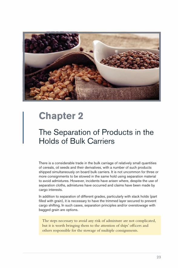
Chapter 2
The Separation of Products in the Holds of Bulk Carriers
There is a considerable trade in the bulk carriage of relatively small quantities of cereals, oil seeds and their derivatives, with a number of such products shipped simultaneously on board bulk carriers. It is not uncommon for three or more consignments to be stowed in the same hold using separation material to avoid admixtures. However, incidents have arisen where, despite the use of separation cloths, admixtures have occurred and claims have been made by cargo interests.
In addition to separation of different grades, particularly with slack holds (part filled with grain), it is necessary to have the trimmed layer secured to prevent cargo shifting. In such cases, separation principles and/or overstowage with bagged grain are options.
The steps necessary to avoid any risk of admixture are not complicated, but it is worth bringing them to the attention of ships’ officers and others responsible for the stowage of multiple consignments.
Carefully to Carry Consolidated Edition 2018
24
The following measures may be taken:
� Where it is intended to overstow one bulk parcel with another, the lower parcel should be trimmed as flat as possible. If the surface is left uneven, there is a risk that the separation material may be damaged, either as a result of uneven stresses during the sea passage or as a result of contact with the grab or elevator legs and bulldozers. Provided this procedure is followed, a single layer of separation material of good quality is considered adequate. Recommended materials include woven polypropylene, polythene sheets or burlap
� during loading operations, it is essential that the distance between the separation material and either the top of the weather deck hatch coamings or the deckhead of the hold is measured and recorded. This makes it possible to effectively locate the separations between the parcels during discharge and avoid tearing or damaging the separation material
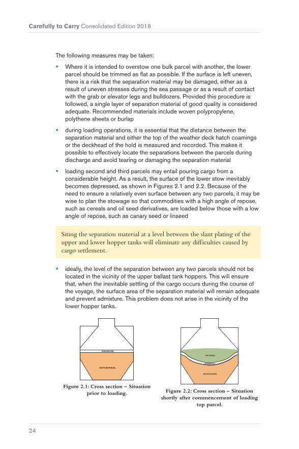
� loading second and third parcels may entail pouring cargo from a considerable height. As a result, the surface of the lower stow inevitably becomes depressed, as shown in Figures 2.1 and 2.2. Because of the need to ensure a relatively even surface between any two parcels, it may be wise to plan the stowage so that commodities with a high angle of repose, such as cereals and oil seed derivatives, are loaded below those with a low angle of repose, such as canary seed or linseed
Siting the separation material at a level between the slant plating of the upper and lower hopper tanks will eliminate any difficulties caused by cargo settlement.
� ideally, the level of the separation between any two parcels should not be located in the vicinity of the upper ballast tank hoppers. This will ensure that, when the inevitable settling of the cargo occurs during the course of the voyage, the surface area of the separation material will remain adequate and prevent admixture. This problem does not arise in the vicinity of the lower hopper tanks.
SEPARATION
BOTTOM PARCEL
Figure 2.1: Cross section – Situation prior to loading.
TOP PARCEL
SEPARATION
BOTTOM PARCEL
Figure 2.2: Cross section – Situation shortly after commencement of loading
top parcel.

25
Chapter 3
Moisture Migration and Surface Ventilation
This chapter explains how and why moisture migration takes place and discusses to what extent surface ventilation can reduce or eliminate the damage it can cause to bulk grain cargoes.
3.1 Movement of Moisture
The total amount of water held in a cargo may be the same at the end of a voyage as it was in the beginning but, as a result of moisture migration, the moisture content of some parts of the cargo may have changed considerably (both gains and losses being found). It is more usual, however, for part of the moisture that migrates to be either lost to the external atmosphere as a result of ventilation, or to be drained off into the bilges.
In countries such as India and China, grains and other agricultural products might come from a number of locations and so may have different moisture levels. It can be very difficult to obtain a representative sample to determine the correct pre-shipment moisture or to ascertain whether the moisture level is below the threshold that can trigger sweat/condensation.
Carefully to Carry Consolidated Edition 2018
26
In addition, cargo is often laid into open spaces for drying before it is moved to assembling places, which means that some lots will have higher moisture content than others.
3.2 Physical Considerations
3.2.1 Vapour Pressure (VP) and Relative Humidity (RH)
Vapour pressure (VP)
The earth’s atmosphere is a mixture of 78% nitrogen, 21% oxygen and approximately 1% of other gases, including water in the form of vapour. Pressure exerted by the atmosphere will partly depend on the pressure exerted by the water in vapour form, and this proportion of the total atmospheric pressure is known as the ‘water vapour pressure’ of the air at that time.
Saturation vapour pressure (SVP)
As the quantity of water in the atmosphere increases, the VP will increase proportionately. At a given temperature, the air can only hold a specific amount of water vapour and the pressure exerted in the atmosphere when this limiting point is reached is referred to as the ‘saturation vapour pressure’ (SVP) of the air at that particular temperature.
Super saturation
Any attempt to increase the water vapour in the air once it has reached its SVP will produce ‘super saturation’, where water is deposited from the air in liquid form, either as droplets to form a fog or cloud or in the form of water drops on suitable surfaces, eg as sweat in a ship’s hold.
Relative humidity (RH)
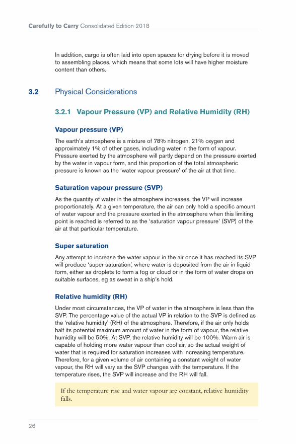
Under most circumstances, the VP of water in the atmosphere is less than the SVP. The percentage value of the actual VP in relation to the SVP is defined as the ‘relative humidity’ (RH) of the atmosphere. Therefore, if the air only holds half its potential maximum amount of water in the form of vapour, the relative humidity will be 50%. At SVP, the relative humidity will be 100%. Warm air is capable of holding more water vapour than cool air, so the actual weight of water that is required for saturation increases with increasing temperature. Therefore, for a given volume of air containing a constant weight of water vapour, the RH will vary as the SVP changes with the temperature. If the temperature rises, the SVP will increase and the RH will fall.
If the temperature rise and water vapour are constant, relative humidity falls.

Chapter 3 Moisture Migration and Surface Ventilation
27
Relationship at different temperatures
Figure 3.1 shows the relationship between VP and RH at different temperatures, eg 100% relative humidity at 10°C represents a water vapour pressure of 9.2 mm Hg and at 30°C of 32 mm Hg, ie an increase of 20°C has resulted in a more than three-fold increase in the water-holding capacity of the atmosphere.
5
0
15
10
25
20
35
30
40
5 1510 2520 35300-5
100% RH
75% RH
50% RH
Vapo
ur p
ress
ure
mm
Hg
Temperature °C
Figure 3.1: Relationship between vapour pressure and relative humidity at different temperatures.
Condensation
If air is cooled to the point where saturation (100% RH) is reached, moisture will begin to be deposited in the form of droplets or mist (ie condensation will occur).
Ship’s sweat
If the air in a ship’s hold is warm and it comes in contact with the deckhead, which has become cooled by the outside atmosphere, condensation will usually form on the deckhead in the form of sweat.
3.2.2 Equilibrium Relative Humidity (ERH) (Water Activity)
All biological materials normally contain a certain amount of water. The amount of moisture present at any given time is termed the moisture content. If the material is put in contact with dry air, it will tend to lose a small proportion of its water to the air in the form of water vapour. This process will continue until there is an ‘equilibrium’ of the air in contact with the material of that particular moisture content and at that particular temperature. Equilibrium relative

Carefully to Carry Consolidated Edition 2018
28
humidity (ERH) is sometimes referred to as ‘water activity’ and it is measured as a ratio rather than as a percentage, so an equilibrium relative humidity of 50% is equivalent to a water activity of 0.5.
In bulk grain cargoes, where air movement within the bulk is very restricted, the moisture content of the atmosphere within the cargo (which is also termed the ‘interstitial’ or ‘inter-particular’ air) is, under normal conditions, completely controlled by the temperature and moisture content of the cargo.
Experimental work with maize has made it possible to construct graphs that equate ERH with moisture content at various temperatures. Such graphs are known as ‘desorption isotherms’, since all the experiments were constructed so that, to achieve ERH, moisture was given up by the maize to the surrounding air. If the air around the maize is wetter than the ERH, the maize will absorb moisture from the air. Such a process is known as ‘adsorption’ and a similar series of curves or isotherms may be constructed, called ‘adsorption isotherms’. The relationship between adsorption and desorption isotherms is a complex one, but it may be stated that, under conditions of desorption, the ERH at any given moisture content is slightly lower than under conditions of adsorption.
Normally in the grain trade, from harvesting through to the discharge of cargo, there is a tendency for the grain to lose moisture to the surrounding atmosphere.
3.3 Moisture Migration
The mechanism by which moisture migration operates can be illustrated by considering a cargo of bulk maize, a commodity where migration is generally slow.
Change of temperature – change of ERH – change of vapour pressure
The interstitial air, which occupies some 40% of the cargo space in the case of bulk maize, will contain water vapour. The VP in this air will rapidly reach equilibrium with the moisture content of the maize. In maize with a moisture content of 14% and a temperature of 25°C, the RH of the interstitial air will rapidly reach 68% and the water vapour pressure in the air at that time will be 16.3 mm Hg. A change in the temperature of the maize will result in a change of the ERH and in the VP. Table 3.1 shows equilibrium temperatures for maize at 14% moisture content. The temperatures at which SVP occurs (ie 100% relative humidity) are included in the table, and these temperatures are known as the ‘dew points’.

Chapter 3 Moisture Migration and Surface Ventilation
29
Temp °CEquilibrium
RH %Vapour Pressure
mm HgDew Point
°C
15 60.0 7.1 7.4
20 64.4 11.2 13.0
25 68.0 16.3 18.7
30 71.5 22.9 24.3
35 75.0 31.5 30.0
Table 3.1: Temp/ERH/VP/DP – Relationship of maize at 14% moisture content.
Table 3.1 shows that air at 25°C and 68% ERH will have a VP of 16.3 mm Hg. If this air is reduced to a temperature of 18.7°C, moisture will be deposited because the SVP will have been reached. If a ship carrying maize of 14% moisture content with a temperature of 25°C passes into a region of colder water, the outside of the cargo will assume the temperature of the cold sides of the vessel. If we assume this to be 15°C, it can be seen that the maize will have an ERH of 60% and a VP of 7.1 mm Hg.
The cooling process of the colder sea will not noticeably affect the maize in the centre of the bulk, since maize is a poor conductor of heat. Therefore, the maize in the centre of the stow will still have a temperature of 25°C and the interstitial air in this region will still have a VP of 16.3 mm Hg.
Carefully to Carry Consolidated Edition 2018
30
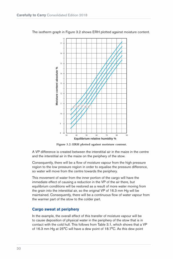
The isotherm graph in Figure 3.2 shows ERH plotted against moisture content.
10
9
12
11
14
13
16
15
17
830 40 50 60 70 80 90
Equilibrium relative humidity %
Moi
stur
e co
nten
t abs
olut
e %
15°C 20
°C25
°C30
°C
35°C
Figure 3.2: ERH plotted against moisture content.
A VP difference is created between the interstitial air in the maize in the centre and the interstitial air in the maize on the periphery of the stow.
Consequently, there will be a flow of moisture vapour from the high pressure region to the low pressure region in order to equalise the pressure difference, so water will move from the centre towards the periphery.
This movement of water from the inner portion of the cargo will have the immediate effect of causing a reduction in the VP of the air there, but equilibrium conditions will be restored as a result of more water moving from the grain into the interstitial air, so the original VP of 16.3 mm Hg will be maintained. Consequently, there will be a continuous flow of water vapour from the warmer part of the stow to the colder part.
Cargo sweat at periphery
In the example, the overall effect of this transfer of moisture vapour will be to cause deposition of physical water in the periphery of the stow that is in contact with the cold hull. This follows from Table 3.1, which shows that a VP of 16.3 mm Hg at 25°C will have a dew point of 18.7°C. As this dew point

Chapter 3 Moisture Migration and Surface Ventilation
31
is higher than the temperature of the cargo at the periphery, water will be deposited on the cargo and cargo sweat will be produced.
This example is an oversimplification of what happens in practice, as there is a tendency to set up a temperature gradient in the maize, along the route from the inside of the stow to the outside, and there will be a gradual drop in the temperature of the air that moves and the grain in contact with it. As water vapour will be absorbed en route, lowering the dew point of the air moving towards the periphery of the stow, it is not possible to make an exact prediction of the conditions that are necessary for cargo sweat to occur.
Heating up
If there is a temperature differential between the outside of the stow and the inside, moisture migration will result from the mechanism described. Such moisture migration will also occur when one part of the bulk heats up for any reason, eg insect infestation, microbiological activity or proximity to a hot bulkhead. In all these circumstances, moisture will migrate from the warmer region to colder parts of the stow.
Monitoring the cargo temperature on board, when it is safe to do so, can also provide valuable information regarding whether the cargo is self-heating. As an example, soya beans undergo discolouration at high temperatures. The colour of the beans will change from cream to brown, as a result of heating, over a period of time. At very high temperatures, soya beans appear totally blackened. The Master should refuse to load visually darkened portions of soya beans. Taking temperatures at regular intervals should indicate whether the cargo temperature is stable across the consignment or whether there are hotspots within some cargo parcels, and these should not be loaded. It is useful to monitor cargo temperatures at regular intervals during loading. The use of subsurface calibrated temperature probes will provide more reliable readings than an infrared thermometer.
Heated fuel oil tanks – soya beans example
Prolonged exposure to high temperatures from heated bunker tanks can also lead to direct heat-related discolouration of soya beans, with a direct impact on the oil and protein quality of the beans. The temperature gradient, established over time, between the tanks and cargo will drive moisture up through the cargo, resulting in further heating at some distance from the heated tanks.

Carefully to Carry Consolidated Edition 2018
32
Figure 3.3: Cargo damage associated with heated HFO tanks.
Figure 3.4: Cargo damage associated with heated HFO tanks.
Ideally, soya beans should not be loaded in holds adjacent to fuel oil tanks that are likely to be heated. Top side wing fuel oil tanks present a lower risk than those located in the double bottom as there is likely to be less cargo in direct contact with the steelwork of a top side wing fuel oil tank.
If it is unavoidable that the cargo has to be loaded into holds adjacent to heated fuel oil tanks, the Master should inform the Chief Engineer that a temperature sensitive cargo is to be loaded to allow for a suitable heating plan to be prepared.
The required levels of heat application to the fuel oil, to facilitate efficient transfer from the storage tanks to the settling tank, will depend on the properties of the fuel oil. As a matter of prudence, it is recommended that the fuel oil is heated to the minimum temperature that will allow for efficient transfer. Heat application to the fuel oil tanks in direct contact with the cargo should be performed in a manner that results in the smallest temperature differential between the cargo and the fuel oil tank.
The fuel oil temperatures should be recorded in the engine room logbook. Evidence that heating was applied in the most prudent manner will be the best defence against any claims that might arise in this regard.

Chapter 3 Moisture Migration and Surface Ventilation
33
Warmer to cooler
Figure 3.5: Bulk carrier arriving in a colder climate (ice on deck).
The problem of moisture migration is most evident with exports of biological materials from warmer climates to cooler climates. Moisture migration may occur for many reasons but, irrespective of the cause of the temperature differential, the result will always be (where the moisture content is uniform) a movement of moisture from the warmer to the cooler parts of the cargo.
Moisture migration is observed in cargoes where insect infestation occurs. Here, centres of heating arise from the respiratory heat from the insects and moisture migrates from these spots to form a wetter shell in the cooler cargo immediately surrounding the heated zone. As heating becomes progressive, the heating zone expands as the wetter shell moves outwards.
Another example is where ship’s heat causes a localised rise in the temperature of the cargo in contact with the heat source, for example an uninsulated engine room bulkhead. Here, moisture migrates from the warm cargo and forms a layer of increased moisture content in the cooler cargo adjacent to it.
Unfortunately, the straightforward pattern of moisture movement resulting from a VP differential is not the only phenomenon that results from temperature differential in a cargo. Where temperature differentials are present, convection currents are set up owing to the fact that warm air is less dense than cold air. Therefore, if heating occurs within a cargo, there will be a tendency for moisture to migrate in all directions from the heating zone. There will also be a tendency

Carefully to Carry Consolidated Edition 2018
34
for hot air to rise from the heating zone, to be replaced by cooler air coming in from the sides and underneath. The warm air will carry moisture with it, so the pattern of moisture movement will be distorted in a vertical direction.
Where a hot spot occurs in a cargo, moisture movement is greater in a vertical direction than either laterally or downwards because convection currents reinforce the upward movement of moisture.
Therefore, for grain loaded warm and subjected to peripheral cooling, the primary moisture movement will be in a vertical direction, so more water will pass towards the top of the cargo than towards the sides. If it is not possible to remove the water migrating to the top region of the cargo by ventilation, more damage may be anticipated in the top layers than at the sides.
3.3.1 The Rate of Moisture Migration
Difference in vapour pressure (VP)
The rate at which moisture moves from a warm to a cold region depends, to a large extent, on the difference in VP between the warmer and colder parts of the cargo. As shown in Table 3.1, the VP of interstitial air of a cargo of maize at 14% moisture content does not increase directly with temperature. Therefore, an increase in temperature from 15°C to 25°C will give a VP increase of 9.2 mm Hg, while a rise in temperature from 25°C to 35°C will give a VP increase of 15.2 mm Hg. It therefore follows that moisture migration will be greater, all other things being equal, when moisture is moving from cargo at 35°C to cargo at 25°C than when moisture is moving from cargo at 25°C to cargo at 15°C, although the temperature difference in both cases is the same.
When considering the rate of moisture movement within a cargo, the ‘actual temperatures’ are as important as the relative difference in temperatures.
Another factor is the differential in temperature in relation to distance, as moisture will move more rapidly from cargo at 25°C to cargo at 15°C if the distances are shorter, because the VP gradient is much greater. In this respect, the thermal conductivity of the cargo will be of considerable importance as the lower the conductivity, the slower any heat will move through the cargo.
Initial moisture content
The initial moisture content is also important. If we consider a cargo of maize at 14% moisture content loaded at 35°C, with its periphery cooled down to 25°C, the equilibrium VPs will be 31.5 mm Hg and 16.3 mm Hg respectively, giving a differential of 15.2 mm Hg. Under the same temperature conditions, but
Chapter 3 Moisture Migration and Surface Ventilation
35
with maize at moisture content of 11%, the equilibrium vapour pressures will be 22.4 mm Hg and 11.6 mm Hg, giving a lower differential of 10.8 mm Hg. In addition (and this is of considerable practical importance), a much greater quantity of water can be absorbed by the cooler grain before the moisture content is raised to a level at which spoilage will commence.
As an example, for soya beans, moisture content and temperature are two of the main factors that influence whether the cargo, or part of the cargo, may undergo self-heating. According to standards issued by the American Society of Agricultural and Biological Engineers (ASABE), it can be inferred that soya beans loaded with a moisture content above 12.4%, at temperatures above 25°C, may become unstable during a long voyage. While some commercial contracts allow a soya bean moisture content of up to 14%, this would be too high for the safe carriage of soya beans shipped over long distances. It should be noted that a Quality Certificate generally provides the average moisture content for a bulk cargo of soya beans. Some parcels of beans may, therefore, be loaded at above or below the average moisture content stated on a Quality Certificate.
Compactness
Because of the importance of convection currents in moving moisture, the more readily air can move through a cargo, the more rapidly moisture can be carried through.
This means that there will be more rapid moisture movement through a cargo that is less compact (eg pellets) than through a cargo that is powdered, where the movement of air will be very limited.
Relevance to grain
A cargo such as grain, which consists of seeds grown in a dry climate, has a comparatively low moisture content and the seed itself has a protective outer skin that is relatively impermeable to moisture. Therefore, moisture is released relatively slowly from seed products such as wheat and maize. In addition, whole grain will lose moisture much more slowly than grain that has been milled or pulverised in some way, as the natural protective coating will have been disrupted.
There is little quantitative data for the release of moisture from various products so direct comparisons are difficult. However, in a study of maize, it was found that, in 28 days, a zone of enhanced moisture had moved approximately 1 m in a vertical direction (ie with convection currents reinforcing the moisture movement) from a hot spot. The temperature differential in this experiment was from 40°C to 21°C over a distance of approximately 1.25 m. The actual quantities of water involved could not be accurately determined, but there was

Carefully to Carry Consolidated Edition 2018
36
no doubt that, for many other types of cargo, both the rate of movement and the quantities of water moved would have been many times greater.
Therefore, when considering the significance of potential moisture migration in a cargo, it is necessary to consider:
� The VP differential in relation to the distance between the hotter and colder zone
� the temperature of the hotter material and the temperature of the colder material to which moisture is migrating
� the initial moisture content
� the nature of the cargo
� the ease with which air may move through it.
Vessels that carry grain in bulk vary in their capability for ventilating the cargo. Considerable quantities of grain are carried in tankers with no ventilation whatsoever. Sometimes grain is carried in vessels fitted with a sophisticated Cargocaire system of surface ventilation, which also has facilities for preconditioning the ventilating air. Other vessels have fan-assisted surface ventilation and quite a large proportion have the normal type of surface ventilation through cowls, unassisted by any mechanical effort, the flow of air depending on the movement of the ship. Some bulk carriers that successfully carry many thousands of tonnes of grain have no means whatsoever of ventilating the surface of the cargo.
Vast quantities of grain are transported around the world and, in the great majority of cases, the cargoes outturn in a sound condition. This includes tanker shipments, which indicates that surface ventilation is not necessarily a prerequisite to successful carriage.
However, claimants frequently state that spoilage of grain in transit is a result of unsatisfactory ventilation or that lack of ventilation has exacerbated damage caused by other factors.
A bulk cargo of grain, if stowed in accordance with the International Code for the Safe Carriage of Grain in Bulk (International Grain Code) (Reference 3), cannot be significantly affected by surface ventilation or from a lack of it. T A Oxley in The Scientific Principles of Grain Storage, stated (Reference 4):
“... popular opinion greatly exaggerates the virtues of ventilation … gaseous diffusion and heat movement in grain are both exceedingly slow and, in the absence of mechanical means to force air through bulks, changes in the atmosphere at the surface have a negligible effect on the intergranular atmosphere and on the water content or temperature of the grain.”

Chapter 3 Moisture Migration and Surface Ventilation
37
Figure 3.6: Loading grain.
To reduce moisture movement and its effects within a grain cargo, it would be necessary to reduce the moisture content throughout the cargo or, alternatively, reduce the temperature differential by cooling the bulk of the grain.
A reduction in moisture content and a reduction in temperature could both be achieved by passing significant quantities of air through the cargo. However, through ventilation, while possible in some silos ashore, is not possible on board ship. In practice, only surface ventilation is available to attempt to control the damaging peripheral effects of moisture migration in bulk grain.
Example – considerations during the loading of soya beans
Soya bean cargoes can be loaded in a number of ways:
� Directly from barges
� from flat warehouses or silos
� from trucks.
In many cases, the cargo is transferred to the vessel by conveyor belt and loaded by pipe. If loading is conducted from barges, it is worth noting the numbers and/or names of the barges and the holds into which each barge loads. In all circumstances, sequence of hold loading should be recorded. Clear photographs of how the cargo is delivered to the vessel and how it is loaded will be invaluable in the event of a claim.
While a Master and crew will usually recognise the type of commodity being loaded, they are not cargo specialists and it can be difficult to recognise whether soya bean cargoes are or are not loaded “in apparent good order and

Carefully to Carry Consolidated Edition 2018
38
condition”, as described on the B/Ls. This is not helped by the high speed at which the cargo is loaded and the fact that the quality of soya beans can only be accurately assessed by laboratory analysis of representative samples.
It is unlikely that the Master will receive either a quality specification for the soya beans to be loaded or a Quality Certificate representing the average quality of the cargo loaded on board. A Quality Certificate is usually issued to the cargo buyer after the vessel has sailed, when the samples obtained by cargo superintendents/sampling attendants throughout loading, on behalf of shippers, have been analysed. While a Quality Certificate can be requested from shippers, the Master may not receive any analytical information regarding the quality of the cargo being loaded and so will have to rely on a visual assessment of condition during loading, which is challenging for non-specialists.
The Master and crew will have difficulty assessing the moisture content of bulk soya beans being loaded. While hand-held moisture meters are sometimes available, they do not always provide results as accurate as those obtained from analysis undertaken in a laboratory. However, an obvious sign that a consignment, or part of a consignment, has a high moisture content is when the soya beans are visually mouldy. This could indicate that they were not effectively dried after harvest or that they have been subject to poor handling and storage prior to shipment.
Figure 3.7: Sound soya beans.

Chapter 3 Moisture Migration and Surface Ventilation
39
Figure 3.8: Mouldy soya beans.
If the cargo on board a particular barge or truck is presented for loading with obvious clumps of white or green mouldy soya beans, or the beans are visibly wetted, then the Master should protest and refuse to load this cargo. Mouldy or wetted cargo will further deteriorate during the voyage and, potentially, initiate self-heating within surrounding soya beans.
The crew or cargo superintendent should enter the holds when safe to do so, ie during a loading break, and visually inspect the surface of the cargo for any odours or noticeable moist, heating or mouldy cargo and obtain numerous spot samples from each hold, which should be labelled clearly. The findings should be noted and photographs obtained.
3.4 Cargo Sweat
In the case of tankers, while there is general agreement that nothing can be done about ship’s sweat should it occur, it is suggested that, for vessels fitted with natural or mechanical ventilation, the moist air may be continuously removed from the headspace above the cargo to reduce or eliminate condensation occurring on the deckhead. However, it must be remembered that the air used for ventilation is at the same temperature as, or below, the temperature of the deckhead and hatch covers. If the ventilating air is cool, the immediate effect will be to take up moisture vapour by diffusion from the interstitial air in the surface layers of the cargo, because the vapour pressure of the interstitial air will be higher than the vapour pressure of the ventilating air. At the same time, the surface of the cargo will be cooled, both directly by contact with the cooler ventilating air and as a result of evaporation of moisture. The temperature of the surface layer of the cargo may, therefore, be reduced below the dew point of the warm moist air rising from within the bulk. Water will then condense in the cooler surface layers of the cargo, producing a wet cake just below the surface. Microbiological spoilage will eventually occur in this wet

Carefully to Carry Consolidated Edition 2018
40
cake. Even if no condensation occurs in the surface layer, the moisture content of these layers may rise as a result of absorption of moisture, to a level where microbiological activity can occur, although this damage does not arise strictly from cargo sweat.
Therefore, if the external ambient conditions are such that ship’s sweat would occur in the absence of ventilation, cargo sweat will frequently occur just below the surface if ventilation is employed. This means in fact that, under these circumstances, damage will result whether ventilation is used or not.
Surface ventilation is also claimed to be useful in cooling cargo that is heating, minimising the increase in temperature that might cause further deterioration. It is, however, generally agreed that heat transfer through bulk grain is a very slow process. Work carried out using a vertical heat transfer system with a temperature differential of 20°C indicated that about 32 days’ continuous heating was required before there was a rise in temperature of 3°C in maize one metre from the heat source. It is because of this fact that microbiological spoilage produces serious heating, and surface ventilation cannot significantly affect a heating process that is occurring more than about one metre below the surface.
Figure 3.9: Surface damage to cargo as a result of ship’s sweat.
What can occur when the surface of a heating cargo is continuously cooled by ventilation is that the VP differential between the interior of the cargo and the periphery is maintained and, consequently, the phenomenon of moisture migration is encouraged.

Chapter 3 Moisture Migration and Surface Ventilation
41
3.5 Stowage Regulations
The irrelevance of surface ventilation to the carriage of grain is apparent from the stowage regulations in force in all major grain exporting countries, which insist that the vessel is stowed so that shifting of the cargo is impossible. Under these regulations, a ship’s grain carrying compartments are classified as either partly filled or full. Grain in partly filled compartments must be levelled and topped off with bagged grain or other suitable cargo, tightly stowed and extending to a height of one to two metres above the bulk. The bagged grain or other suitable cargo must itself be supported by a platform made either of close boarded wood or strong separation cloths laid over the whole surface of the bulk cargo.
These regulations provide that, in compartments totally filled with grain, the grain must be trimmed to fill all the spaces between the beams, in the wings and ends.
Further, to ensure that the compartment is maintained fully filled during the voyage, the compartment must be equipped with a feeder from which grain can flow into the compartment if the cargo settles during the voyage. Alternatively, the grain in the area of the hatch may be trimmed hard up to the deckhead beyond the hatchway to form a saucer. This saucer and the hatchway above are then filled with bagged grain or other suitable cargo extending to a height of at least two metres in the centre of the saucer. The bagged grain or other suitable cargo must itself be stowed tightly against the deckhead as well as the longitudinal bulkheads, the hatch beams and hatch coamings.
The express purpose of the regulations is to reduce to a minimum, and if possible to eliminate, the headspace between the surface of the cargo and the overlying deck. With cargo stowed correctly in this way, there is no possibility of effective surface ventilation.


43
Chapter 4
Cargo Measurement
During the transportation of bulk cargo, some losses will unavoidably occur. However, when the shortages exceed a percentage regarded as customary in that trade, the carrier is often held responsible. One of the causes of shortage claims is that it is virtually impossible to precisely determine the weight of large quantities of dry bulk cargoes, either afloat or ashore. Chapter 16 describes the measurement of dry bulk cargoes using draught surveys, while this chapter refers to the specifics of bulk grain measurement.
4.1 Determination of Weight Ashore
Various methods are used to determine the weight of a grain cargo when it is still ashore. The common ones are:
� Weighbridges
� mechanical weighing
� fixed and mobile bag weighers
� automatic bulk grain weighers
� automatic load cell gross weighers
� conveyor belt weigh systems.

Carefully to Carry Consolidated Edition 2018
44
4.1.1 Weighbridges
These heavy-duty machines for the weighing of empty and fully loaded road vehicles are generally intended to operate in a wide range of temperature conditions, from minus 10°C (–10°C) to +50°C, depending on local regulations. In extreme conditions, where temperatures may be regularly outside these parameters, the manufacturers should be consulted.
Because of the manner in which weighbridge scales are graduated and operated, manufacturers can only guarantee an accuracy of half of one scale division or less.
Therefore, on a 20 t weighbridge, with 10 kg divisions, the error could be ±5 kg (±0.025%). An 80 t weighbridge will have an accuracy of ±10 kg (±0.0125%). Most weighbridge systems can account for any debris, water, ice or snow that may have accumulated between one lorry being weighed and the next.
4.1.2 Fixed and Mobile Bag Weighers
These include:
� Semi-automatic machines that are suitable for low output, low-cost bagging requirements
� portable automatic bag weighers that can deal with both sacks and bulk
� fully-automatic bag weighers that will record both gross and/or net weights and that are suitable for flow materials such as grain, granular fertiliser, seeds, pulses, pellets, plastic granules, rice, refined sugar and other similar products.
These machines may be accurate to within ±1% for bags weighing between 20 and 50 kg.
When weights increase to 100 and 250 kg, accuracy will improve to between 0.5 and 0.2%.
The degree of accuracy depends on:
� The index allowances set by the operator for the weight of an empty bag
� the degree of care exercised by the operator in maintaining the mechanical system.
4.1.3 Automatic Bulk Grain Weighers
These machines are suitable for weighing grain and free-flowing materials fed from elevators, conveyor belts, storage hoppers or silos. They are produced in various sizes and can record weight cycles from 30 kg up to 5 t. They can deliver at rates of up to 1,000 t per hour. When this machinery is correctly

Chapter 4 Cargo Measurement
45
installed and maintained by the manufacturers, and regularly inspected by a reliable local regulatory authority, an accuracy of ±0.1% is likely.
4.1.4 Automatic Load Cell Gross Weighers
These machines are designed to handle grain sizes not greater than 25 mm. They are used in continuous weighing cycles of 10 to 50 kg and their accuracy is better than 0.2% in most cases.
4.1.5 Conveyor Belt Weigh Systems
There are a number of conveyor weigh systems and, at best, their margin of error is likely to be within 0.5% of true weight for capacities of up to 6,000 t/hour, increasing to 1 to 2% of true weight for flow capacities of 2,000 t/hour.
Where an unexplained short-landing occurs at a discharge port, the conveyor belt weigh system may prove to be a worthwhile field of investigation. If the cargo has been loaded and weighed on a conveyor system, both the load port terminal and the discharge port terminal should be asked to produce the manufacturers’ full specification and brochures for the equipment utilised. If the guaranteed accuracy is not better than between 1 and 2% of true weight, considerable errors may arise. For a shipment of 100,000 t, for example, an indicated ‘loss’ of 2,000 t might be possible, where accurate weighing would have probably indicated a discrepancy of no more than 500 t (based on a ‘transport’ difference of 0.5%).
4.2 Determination of Weight on Board Ship
There are two methods of determining the weight of a dry bulk grain cargo loaded on board a ship:
� On the basis of the free space in a compartment (measurement and stowage factor)
� on the basis of draught surveys (see Chapter 16).
4.2.1 Measurement and Stowage Factor
On completion of loading, the free space in each cargo hold is measured and, from this, the volume occupied by the cargo is calculated. This volume, when divided by an assumed stowage factor, gives the approximate weight of the cargo. This method is no more than an estimation and the exact stowage factor is seldom known, so the assumed figure may be quite inaccurate. The stowage factor can only be ascertained correctly by laboratory analysis of samples from the cargo, which take into account the nature of the cargo, the moisture content, the percentage of foreign matter present and the age of the commodity.

Carefully to Carry Consolidated Edition 2018
46
The stowage figure may also vary considerably for other reasons. For example, in grain cargoes, ‘spout lines’ may develop because grain in a cargo hold tends to separate into heavier and lighter components. In addition, almost all bulk grain cargoes settle during transportation as the kernels and shells collapse. The result of this is an increase in weight per unit volume and a lower stowage factor. In such cases, and if the same assumed stowage factor was used, it would be unsurprising that the weight of cargo calculated on the basis of free space measurement after loading would indicate a greater quantity of cargo than that calculated before discharge.
It is probably reasonable to say that the accuracy of shore weighing of bagged and bulk commodities is unlikely to be better than within 0.2% and, in conveyor belt weigh systems, may be no better than ±2%. There are no technical means by which the exact weight of a dry bulk cargo on a ship may be accurately determined. The weights may be approximately determined by free space measurement or by draught survey, but neither of these methods is sufficiently accurate to verify the weight of a cargo as stated by shippers nor to determine any loss of cargo in transit.

47
Chapter 5
The Carriage of Genetically Modified (GM) Crops
The term GMO (genetically modified organism) refers to any organism whose genetic makeup has been altered using genetic engineering. In the instance of marine cargoes, they are usually seed from GM plant varieties that have characteristics that are different from those of varieties that have been developed through traditional plant breeding techniques. GM crops are not readily detectable by visual inspection.
Figure 5.1: GM cargoes are usually comprised of seed from GM plant varieties.

Carefully to Carry Consolidated Edition 2018
48
GM crop varieties have been developed to meet different breeding aims including:
� Herbicide resistance – crops that show minimum damage following herbicide spraying regimes that are designed to eliminate weeds
� disease – crops that are less prone to be damaged by fungal, bacterial or viral diseases
� pest resistance – crops that are less attractive to natural predators such as insects
� stress resistance – crops that are more tolerant to various environmental stresses such as drought, salinity and extreme temperatures
� varieties with altered composition – crops that show improved nutritional values, eg ‘golden rice’ with an increased level of vitamin A
� elimination of pollutants to be used in bioremediation – crops that have the ability to decontaminate land by assimilating hazardous pollutants and toxic compounds. These plants can then be harvested and forwarded for industrial use or incinerated
� pharming (biopharming/molecular farming for the production of pharmaceuticals, enzymes, etc) – crops that produce increased yields of desirable compounds for industrial and pharmaceutical use, eg starch, fuel, antibodies, hormones, etc.
The first GM seeds were planted for commercial use in the USA in 1996. By 2006, the total acreage had increased to 102 million hectares, and today it is estimated that 180 million hectares globally are being cultivated with GM crops (2014 figures). The USA is leading in the cultivation of GM crops with approximately half of the world acreage (73 million hectares in 2014), followed by Argentina, Brazil and Canada. China is rapidly expanding cultivation of GM crops.
Today, a total of 28 countries use genetic engineering commercially. Soya beans, maize, oilseed rape (canola) and cotton account for almost all commercial GM crop production. Other GM crops under cultivation include sugar beet, potatoes, rice and sugar cane. GM ornamental products include roses and carnations.

Chapter 5 The Carriage of Genetically Modified (GM) Crops
49
Figure 5.2: GM crops on board a vessel.
5.1 Hazard
GM crops present no greater hazard during shipping than that already identified for their conventional counterparts. Similarly, the loading, precautions during carriage, ventilation and discharge operations of GM crops do not differ from those of conventional crops.
Figure 5.3: The loading of GM crops.
5.2 Carriage of GM Crops
� Cargoes of soya beans, maize, oilseed rape and cotton that are loaded in the USA, Argentina, Paraguay, Uruguay, Brazil or Canada come with an increased likelihood of being genetically modified. It is therefore recommended that analysis of these specific cargoes from the above locations is carried out prior to loading. The GM or non-GM nature of the cargo should be certified based on the analysis carried out

Carefully to Carry Consolidated Edition 2018
50
� the B/L should clearly state the unique identifier, species and the variety, which, if the cargo is GM, should be on the list of GMOs authorised in the EU: https://tinyurl.com/3xnedx (Reference 5)
� it is recommended that any GMO qualitative and quantitative tests carried out at the load port follow the protocols set out by the National Reference Laboratory of the destination country. In this way, the danger of variable results due to laboratory discrepancies is minimised. A list of National Reference laboratories that can carry out analyses of GM material and work under the auspices of the European Central Reference Laboratory (CRL) can be found at: https://tinyurl.com/yayegyot (Reference 6)
� enquire whether the testing laboratory at the port of origin is accredited to carry out sampling specifically for GM material
� establish whether the import country is a party to the Cartagena Biosafety Protocol (CBP) through the BCH (http://bch.biodiv.org) (Reference 7). The EU is a party
� establish whether the import country has any additional regulations on GM shipments for FFP (food or feed, or for processing), as in the case of the EU Members who accept only previously EU-authorised GM crops
� the International Grade Trade Coalition recommends that the commercial invoice contains the contact information of the last exporter prior to the transboundary movement and the first importer after that movement.
5.3 Carriage of Non-GM Crops with Low Level Presence (LLP) of Adventitious/Chance Contaminants
In conventional cargoes that are found to contain low levels of chance contaminants of GM origin, the fate of the cargo depends on the nature of the GM contaminant and the sampling and testing procedures that are conducted.
5.3.1 Sampling
Correct sampling intensity and good sampling techniques are crucial to minimising the error and inaccurate measurement of LLP involved with sampling. GM contaminations in large shipments are not necessarily random and any sampling methods used should take this into account. Currently, there are two appropriate testing guidelines:
� European recommendation 2004/787/EC. This also specifies the ISO method that should be used for the collection of the material (see Table 5.1) (Reference 8)
� ISO DIS 21568 (Reference 9).

Chapter 5 The Carriage of Genetically Modified (GM) Crops
51
Commodity to be sampled ISO method to be used
Free-flowing commodities 6644/13690
Oilseeds 542
Pre-packaged food and feed products 2859
Material larger than grains (eg potatoes, fruits, rhizomes)
2859
Table 5.1: ISO methods used for the collection of material for the detection of GMOs.
Material for testing should be collected in intermittent sampling periods, which may be calculated by dividing the estimated total offloading time by the total number of increments. Table 5.2 shows the recommended number of increments, which varies according to the lot size.
Lot size in tonnes Size of bulk sample in kg Number of increments
≤50 5 10
100 10 20
250 25 50
≥500 50 100
Table 5.2: Size of bulk samples (kg) and number of increments to be collected for testing for GMOs in cargoes.
5.3.2 Testing
It is recommended that any qualitative and quantitative tests of GM crops that are carried out at the load port follow the protocols set out by the EU or national reference laboratory of the destination European country. In this way, the danger of variable results due to laboratory discrepancies is minimised. A list of national reference laboratories that can carry out analyses of GM material and that work under the auspices of the European Central Reference Laboratory (CRL) can be found at: https://tinyurl.com/yayegyot (Reference 6)
The analytical steps of cargo testing for the low level presence of GM material are shown in Figure 5.4.
Following a negative result of the screened material, the cargo will be released. However, a positive test to GM material will prompt further investigation for the identification of the exact GMO. If the identified GMO has been authorised to be used as food or feed in the European country of discharge, a quantitative test will be required to determine the level of contamination.
The maximum permitted amount of approved GMO in a non-GM cargo is 0.9%. Above this, the cargo will be labelled as GM cargo. If the GMO has not been

Carefully to Carry Consolidated Edition 2018
52
previously authorised under EU regulations, the cargo will be deemed illegal and it will be rejected irrespective of the level of contamination (there is zero threshold for non-approved GMOs in the EU).
Cargo screened for LLP of chance GMOs
Positive
IdentificationIs the GMO authorised?
>0.9%Labelling
REQUIRED
<0.9%Labelling
NOT REQUIRED
Yes No
Negative
Cargo release
ILLEGALRejection due to ‘zero-
tolerance’ policy
Figure 5.4: Cargo screening for the low level presence (LLP) of GM material.
Products that Require Labelling
Food that is a genetically modified organism (GMO) or that consists of GMOs(eg canned sweetcorn, approved but not available in the EU).
Food ingredients or additives that are produced from GMOs(eg oil from GM rapeseed or soya beans, starch from GM maize, and sugar from GM sugar beet).
Food ingredients or additives that contain genetically modified organisms(eg beer with GM yeast, blue cheese with GM moulds, yoghurt with GM lactobacilli).
NOTE: No GM yeast/bacteria/fungi have been approved for use in food in the EU.

Chapter 5 The Carriage of Genetically Modified (GM) Crops
53
Products that do not Require Labelling
Food containing GMOs up to a threshold of 0.9%� The producer/importer of a product needs to supply evidence that the presence
of such material is either adventitious or technically unavoidable and that every possible step to minimise the presence of such material has been taken
� the GMO in question has already been classified as safe and has received an EU authorisation.
NOTE: From April 2007, the threshold of unauthorised GMOs is 0% (zero tolerance).
Food that is produced with the aid of genetically modified organisms(eg meat, eggs or dairy products produced from animals fed on GM feed, also additives, flavours and vitamins produced with the help of GM microorganisms such as artificial sweeteners, flavour enhancers and thickening agents)
Substances that are not required to be declared on the list of ingredients� Enzymes used in food processing (eg chymosin used in cheese production and
pectinases used to degrade cell membranes in juice or wine)
� substrates (growth media) for microorganisms (eg baker’s yeast cultured on a medium containing GM corn, and vitamin C produced by microorganisms raised using glucose derived from GM corn starch)
� carrier substances; substances used to prolong shelf life, facilitate transportation, etc (eg starch/glucose/dextrin-derived).
Honey containing pollen or nectar from genetically modified plants
Table 5.3: Labelling requirements of GMO-related products.
5.4 The Legal Framework of GMO Importation
5.4.1 The European Regulations
Three laws govern the authorisation and release of genetically modified organisms in the EU:
Regulation 1829/2003 in effect since 19th April 2004 (Reference 10)
(Replaces directive 258/97)
This regulation defines the use of food and feed that has been produced from or contains GM plants. The regulation is set out in 49 Articles which give the detailed requirements for a GMO food or feed that need to be demonstrated in order for authorisation to be granted. It specifies the application for authorisation and the authorisation process, including modifications, revocations, suspensions and renewals of these.
Directive 2001/18/EC in effect since 17th April 2001 (Reference 11)
(Replaces directive 90/220/EC)
This directive contains 38 Articles which define the commercial use of genetically modified plants and their deliberate release into the environment.

Carefully to Carry Consolidated Edition 2018
54
These have been compiled with the objective of protecting human health and the environment by controlling the risk of the deliberate release of GMOs. It clarifies the obligations, including the notification procedure, consultation with the public, and exchange of information prior to the release, as well as the monitoring and handling of any modifications following the release.
In addition to these two main directives, there is a further regulation concerning the traceability and labelling of GMOs, and a recommendation that encourages the inclusion of GM crops in European farming.
Directive (EU) 2015/412 in effect since 11th March 2015 (Reference 12)
(Amends directive 2001/18/EC)
This directive is an amendment that allows for member states to restrict or prohibit the cultivation of GMOs in their territory or in specific geographical areas.
Regulation 1830/2003 (Reference 13)
This regulation (13 Articles) determines the stages involved in the traceability and labelling of approved GMOs and the traceability of food and feed products produced from these GMOs prior to being placed on the market. It covers the labelling provisions of all GM food or feed that consists of, contains or is produced from GMOs. For any products comprising mixtures of GMOs, a list of the unique identifiers of all GMO components should be made available. Labelling of pre-packaged and non-pre-packaged products consisting of or containing GMOs should include the following statement on the label:
“This product contains genetically modified organisms” or “This product contains genetically modified [name of organism(s)].”
Recommendation 2003/556/EC (Reference 14)
This recommendation states that no form of agriculture should be excluded in the EU and includes guidelines to be used by Member States for the development of measures for the coexistence of GMO crops and crops developed through conventional breeding. Any decision should not only be made on the basis of scientific evidence but should also assess the environmental and health aspects in addition to the economic aspects. The recommendation puts emphasis on the monitoring and evaluation of coexistence and encourages the improvement of the existing segregation measures.
5.4.2 The Cartagena Biosafety Protocol (CBP) and GMO Trade to the EU
In addition to the EU legal framework, there are regulations that have been agreed in the context of the Cartagena Biosafety Protocol (CBP), which came into force in 2003. The CBP was designed to promote transparency and

Chapter 5 The Carriage of Genetically Modified (GM) Crops
55
control in the international GMO trade, and up to the end of 2015 it had been signed by 170 countries, excluding the three main GMO producers – USA, Argentina and Canada.
The CBP is an international regulatory framework put in place to reconcile the safety of the biodiversity with the use of products of modern biotechnology. A major component of the CBP was the establishment of the Biosafety Clearing-House (BCH) which was set up to “facilitate the exchange of information on Living Modified Organisms (LMOs) and assist the Parties to better comply with their obligations under the Protocol”. (Reference 7).
The intentional and unintentional movements of products of modern biotechnology and their handling are described in Articles 6, 11, 17 and 18. It should be noted that the CBP refers to living modified organisms (LMOs). LMOs include genetically modified crops and other GMOs.
Under the protocol, exporters are obliged to provide more information on GM products before the shipment, and it is then up to the receiving country to decide whether or not to accept the shipment or to seek more information. Member States may reject such imports without quantitative justification or scientific evidence but must provide reasons, which may include (for example) potential danger to traditional crops, impacts on local culture or potential impacts on the value of biodiversity.
Figure 5.5: A shipment of GM goods.
CBP – Article 6 (Reference 15)
Transit and contained use
Article 6 of the CBP exempts contained material or material in transit from the provisions of the protocol.

Carefully to Carry Consolidated Edition 2018
56
CBP – Article 11 (Reference 15)
Procedure for living modified organisms intended for direct use as food or feed, or for processing (LMO-FFPs)
Article 11 of the CBP describes the procedures required for living modified organisms (LMOs) that are intended for direct use as food or feed, or for processing (FFP).
CBP – Article 17 (Reference 15)
Unintentional transboundary movements and emergency measures
The presence of GM material found in non-GM cargoes is covered in Article 17. According to this Article, the duties of parties involved in unintentional transboundary movements are:
� To notify affected states, the BCH and, where relevant, international organisations
� to provide the name, identity and details of the characteristics/traits of the LMO
� to provide information on the estimated quantities involved, the date of release, the use of the LMO at origin and any other relevant circumstances
� to inform on the possible adverse effects of the LMO on local biodiversity, including humans, and to provide possible risk management measures
� to provide a point of contact for further information and clarifications.
CBP – Article 18 (Reference 15)
Handling, transport, packaging and identification
Article 18 describes the requirements for handling, transport, packaging and identification of intentional transboundary movements of LMOs for direct use as FFP (Article 18.2a), for contained use (Article 18.2b) and for intentional introduction into the environment (Article 18.2c).
Central to the requirements of Article 18.2a is that the documentation that accompanies cargoes of LMO-FFPs clearly states that it ‘may contain’ LMOs. To this effect, the International Grain Trade Coalition (IGTC) recommends that the commercial invoice contains the following or a similar meaning declaration:
“Cartagena Protocol Provision: This shipment may contain living modified organisms intended for direct use as food or feed, or for processing, that are not intended for intentional introduction into the environment.”
The European Union goes beyond the Cartagena provisions, with tough rules on the importation of GMOs based on demanding but clearly set out principles. Following the cessation of the de facto moratorium on GMO imports in 2004, directive 1829/2003 came into force specifying the labelling provisions for food and feed produced from GMOs (as described under regulation 1830/2003).

57
Chapter 6
Karnal Bunt
Karnal bunt is a fungal disease that affects certain types of cereal grains such as wheat. The disease develops during the growth phase of the plant and not during post-harvest storage or transportation. However, it can cause potentially serious problems for shipowners and charterers. Many countries prohibit the importation of wheat that is known or, in some instances, is suspected to be affected by Karnal bunt. This can cause lengthy delays to ships while a solution is found for the disposal of the cargo. Definitive identification of the spores of the specific fungus that causes Karnal bunt in a consignment of grain requires specialised and time-consuming test procedures, which can take up to two weeks to complete.
Karnal bunt was first described in Karnal, India in 1931. It has now been identified in all of the major wheat producing regions of India, Pakistan, Iraq and Afghanistan and is also well established in north-western Mexico. More recently, it has also been found in durum wheat from Arizona. Following this discovery, a flurry of surveys and inspections was carried out, resulting in quarantine measures being imposed in the state of Arizona and in counties in New Mexico, Texas and California.
While the disease is not particularly damaging in terms of yield loss, it can cause significant reductions in grain quality. The spores of the infecting fungus

Carefully to Carry Consolidated Edition 2018
58
are believed to present no health risks to consumers through infected grain or grain products, but wheat containing more than 3% of ‘bunted’ kernels is commonly considered to be unfit for human consumption. This is because flour produced from wheat containing a significant number of bunted kernels may have a distinctive odour.
Karnal bunt is also known as partial bunt. The fungal organism responsible for the disease is Tilletia indica. Spread of the disease occurs by the microscopically small spores of the fungus being distributed by wind and then infecting the host plant during flowering and heading. Symptoms become visible only as the grain matures. Bunted kernels can be very difficult to detect in the field, particularly in cases of mild infection, because normally not all plants in the crop are affected. Bunted kernels, however, each contain millions of spores of the fungus, which means there is potential for further spread.
There are other types of bunt, such as common bunt (sometimes known as ‘stinking smut’), which is prevalent in parts of Europe and is caused by a related fungal organism. However, these other types of bunt differ in that infection is spread by spores in the soil, rather than by the wind. This means they can be controlled relatively easily by pre-treatment of the seed with suitable anti-fungal dressings. In EU countries, however, a ban has been imposed in recent years on the application of traditionally used seed dressings of proven effectiveness. This has been held responsible for some resurgence in the incidence of common bunt in certain parts of Europe.
Karnal bunt is much more difficult to control and there is no effective solution as yet.
A number of countries, particularly those in which wheat is a crop of major importance, look extremely critically upon the importation of wheat that is known or suspected to contain kernels affected by Karnal bunt and they regard the disease as a quarantine pest. By early 1997, some 50 countries had adopted phytosanitary measures to prevent the importation of wheat affected by Karnal bunt.
Some countries accept US wheat from quarantined areas if it is certified that the wheat has tested negative for Tilletia indica by laboratory analysis on both pre-harvest and pre-shipment samples. Other countries, for example Mexico, require methyl bromide fumigation prior to discharge of the cargo.
It is impossible for ships’ representatives to detect, by visual inspection at loading, whether a cereal grain cargo is contaminated with diseased kernels specifically affected by Karnal bunt. However, if during loading of a grain cargo any unusual odour is detected that may or may not be due to the presence of substantial amounts of grain severely infected with Karnal bunt, the bill of lading should be claused. Other than that, the only realistic course of action open to shipowners wishing to protect their interests as far as possible is to insist

Chapter 6 Karnal Bunt
59
on the provision of a certificate, from an authoritative source in the country of exportation, that unequivocally confirms that the cargo is free from Karnal bunt.
It may be advisable for shipowners to avoid carrying cargoes of wheat originating from countries where Karnal bunt is known to be prevalent. This applies particularly to cargoes destined for countries known to adopt a particularly severe approach to the importation of wheat from affected countries.
When a ship has discharged a cargo known to be affected by Karnal bunt, depending on future trading patterns, it may be necessary to carry out sterilisation treatment of the relevant holds to destroy the viability of any residual spores. The following sterilisation treatments are claimed to be effective:
� Wetting all surfaces to the point of run-off with a solution of 1.5% sodium hypochlorite and water and letting stand for 15 minutes. Thereafter, the surfaces should be thoroughly washed down to minimise corrosion
� applying steam to all surfaces until the point of run-off so that a critical temperature of about 80°C is reached at the point of contact
� cleaning with a solution of hot water and detergent under a pressure of at least 2 kg per sq cm (30 pounds per sq inch) at a minimum temperature of 80°C
� fumigating with methyl bromide at a dosage of 240 kg per 1,000 m³.


61
PART 2Ores and Minerals
Chapter 7 ..................................................63Coal Cargoes
Chapter 8 ..................................................71Bitumen – Natural and Rock
Chapter 9 ..................................................75Mineral Ore Concentrates and other Materials that may Liquefy
Chapter 10 ................................................79Sulphur Cargoes
Chapter 11 ................................................85Direct Reduced Iron (DRI)


63
Chapter 7
Coal Cargoes
This chapter, and all of the chapters in Part 2, should be read in conjunction with the booklet Carrying Solid Bulk Cargoes Safely (Reference 16), published by Lloyd’s Register/UK P&I Club/INTERCARGO, which can be found on the UK P&I website.
7.1 Properties and Characteristics
The International Maritime Solid Bulk Cargoes Code (IMSBC Code) (Reference 17) categorises coal as Group B (cargoes with a chemical hazard) and Group A (cargoes which may liquefy):
� Coals may emit methane, a flammable gas. A methane/air mixture containing between 5% and 16% methane constitutes an explosive atmosphere which can be ignited by sparks or naked flame, eg electrical or frictional sparks, a match or lighted cigarette. Methane is lighter than air and may, therefore, accumulate in the upper region of the cargo space or other enclosed spaces. If the cargo space boundaries are not tight, methane can seep through into spaces adjacent to the cargo space

Carefully to Carry Consolidated Edition 2018
64
� coals may be subject to oxidation, leading to depletion of oxygen and an increase in carbon dioxide or carbon monoxide concentrations in the cargo space. Carbon monoxide is an odourless gas, slightly lighter than air, and has flammable limits in air of 12% to 75% by volume. It is toxic by inhalation with an affinity for blood haemoglobin over 200 times that of oxygen
� some coals may heat spontaneously and spontaneous heating may lead to spontaneous combustion in the cargo space. Flammable and toxic gases, including carbon monoxide, may be produced
� some coals may be liable to react with water and produce acids which may cause corrosion. Flammable and toxic gases, including hydrogen, may be produced. Hydrogen is an odourless gas, much lighter than air, and has flammable limits in air of 4% to 75% by volume.
7.2 General Requirement for All Coals
The IMSBC Code states that, prior to loading, the shipper or his appointed agent should provide, in writing to the Master, the characteristics of the cargo and the recommended safe handling procedures. These details should include whether the cargo may be liable to emit methane or self-heat.
The Master should be satisfied that they have received this information prior to accepting the cargo. This is an essential requirement for safe shipment of the cargo as it decides the method of safe carriage.
� If the shipper has advised that the cargo is liable to self-heat, the Master should seek confirmation that the precautions intended to be taken and the procedures intended for monitoring the cargo during the voyage are adequate
� if the cargo is liable to self-heat or an analysis of the atmosphere in the cargo space indicates an increasing concentration of carbon monoxide, the following additional precautions should be taken:
� the hatches should be closed immediately after completion of loading in each cargo space. The hatch covers may also be additionally sealed with a suitable sealing tape. Surface ventilation should be limited to the absolute minimum time necessary to remove methane that may have accumulated. Forced ventilation should not be used. On no account should air be directed into the body of the coal as this could promote self-heating
� personnel should not be allowed to enter the cargo space unless they are wearing self-contained breathing apparatus (SCBA) and access is critical to the safety of the ship or safety of life. The SCBA should be worn only by personnel trained in its use

Chapter 7 Coal Cargoes
65
� when required by the competent authority (CA), the carbon monoxide concentration in each cargo space should be measured at regular time intervals to detect self-heating
� if, at the time of loading, when the hatches are open, the temperature of the coal exceeds 55°C, expert advice should be obtained.
If the carbon monoxide level is increasing steadily, self-heating may be developing. The cargo space should be completely closed down and all ventilation ceased. The Master should seek expert advice immediately. Water should not be used for cooling the material or for fighting coal cargo fires at sea, but may be used for cooling the boundaries of the cargo space.
Even if the shipper considers that the cargo is not liable to self-heat, the recommendations stated above should be closely followed. Monitoring the atmosphere of the cargo space is essential at least once daily, twice daily if rapid changes are detected.
7.3 Gas Monitoring of Coal Cargoes
All vessels engaged in the carriage of coal cargoes should have on board an instrument for measuring methane, carbon monoxide and oxygen, as per Chapter VI, Regulation 3 of the IMSBC Code, 2016 (Reference 17). SOLAS Chapter VI – Carriage of Cargoes confirms this statement (Reference 18):
Regulation 3
Oxygen analysis and gas detection equipment
1. When transporting a solid bulk cargo which is liable to emit a toxic or flammable gas, or cause oxygen depletion in the cargo space, an appropriate instrument for measuring the concentration of gas or oxygen in the air shall be provided together with detailed instructions for its use. Such an instrument shall be to the satisfaction of the Administration.
2. The Administration shall take steps to ensure that crews on ships are trained in the use of such instruments.
Appendix 1 of the IMSBC Code provides the individual schedules of solid bulk cargoes (Reference 17). This includes the schedule for coal. The schedule also contains as a separate appendix the procedures for gas monitoring of coal cargoes, equipment to be used, design and siting of sample points and measurement.

Carefully to Carry Consolidated Edition 2018
66
The Code details the requirements including the following:
3. The ship should be suitably fitted and carry on board appropriate instruments for measuring the following without requiring entry in the cargo space:
3.1 Concentration of methane in the atmosphere;
3.2 Concentration of oxygen in the atmosphere;
3.3 Concentration of carbon monoxide in the atmosphere; and
3.4 pH value of cargo space bilge samples.
4. These instruments shall be regularly serviced and calibrated. Ship personnel shall be trained in the use of such instruments. Details of gas measurement procedures are given at the end of this appendix.
8. The atmosphere in the space above the cargo in each space shall be regularly monitored for the concentration of methane, oxygen and carbon monoxide. Details of gas monitoring procedures are given at the end of this appendix. The results of monitoring shall be recorded. The frequency of the monitoring shall be determined based upon the information provided by the shipper and the information obtained through the analysis of the atmosphere in the cargo space.
9. Unless expressly provided otherwise, surface ventilation shall be conducted in all cargo spaces carrying this cargo for the first 24 hours after departure from the loading port. During this period, the atmosphere in the cargo spaces shall be monitored once from one sample point per cargo space and, for the purpose of the gas monitoring, the ventilation shall be stopped for an appropriate period prior to the gas monitoring.
10. When the methane concentrations monitored within 24 hours after departure are at an acceptably low level, the ventilation openings shall be closed and the atmosphere in the cargo spaces shall be monitored. When the methane concentrations monitored within 24 hours after departure are not at an acceptably low level, surface ventilation shall be maintained, except for an appropriate period for gas monitoring, and the atmosphere in the cargo spaces shall be monitored. This procedure shall be followed until the methane concentrations become acceptably low level. In any event, the atmosphere in the cargo spaces shall be monitored on a daily basis.
Other requirements relate to trimming the cargo, smoking and the use of naked lights etc.

Chapter 7 Coal Cargoes
67
7.4 Special Precautions
Special precautions apply to coals emitting methane and self-heating coals.
Coals emitting methane
Methane is a flammable gas which, within the range of 5 to 16% in air, can form a flammable mixture that can be readily ignited by a spark or naked light. The IMSBC Code advises that, if the shipper has advised
“that the cargo is liable to emit methane or analysis of the atmosphere in the cargo space indicates the presence of methane in excess of 20% of the Lower Explosion Limit (LEL), the following additional precautions shall be taken:
.1 Adequate surface ventilation shall be maintained, except for an appropriate period for the purpose of gas monitoring
.2 Care shall be taken to remove any accumulated gases prior to operation of the hatch covers or other openings for any reason, including discharging. Care shall be taken to operate hatch covers of the cargo spaces and other openings to avoid creating sparks. Smoking and the use of naked flame shall be prohibited
.3 Personnel shall not be permitted to enter the cargo space or enclosed adjacent spaces unless the space has been ventilated and the atmosphere tested and found to be gas-free and to have sufficient oxygen to support life. Notwithstanding these provisions, emergency entry into the cargo space may be permitted without ventilation, testing the atmosphere or both, provided that entry into the cargo space is undertaken only by trained personnel wearing self-contained breathing apparatus under the supervision of a responsible officer and special precautions are observed to ensure that no source of ignition is carried into the space
.4 The master shall ensure that enclosed working spaces such as storerooms, carpenter’s shops, passageways, tunnels, etc., are regularly monitored for the presence of methane. Such spaces shall be adequately ventilated and, in the case of mechanical ventilation, only equipment safe for use in an explosive atmosphere shall be used.” (Reference 17)
Self-heating coals
Low-rank coal types are more prone to oxidation than the high-rank anthracites and are therefore more liable to spontaneous heating. High inherent moisture contents, which can evaporate to create large internal surface areas susceptible to oxidation, will assist this heating process. Frequently, cargoes may consist of coals of different ages and from different mines, which can also lead to spontaneous heating problems.

Carefully to Carry Consolidated Edition 2018
68
The recommendations of the IMSBC Code are as follows:
.1 The cargo spaces shall be closed immediately after completion of loading in each cargo space. The hatch covers may also be additionally sealed with a suitable sealing tape. Only natural surface ventilation shall be permitted and ventilation shall be limited to the absolute minimum time necessary to remove methane which may have accumulated.
.2 Personnel shall not enter the cargo space during voyage, unless they are wearing self-contained breathing apparatus and access is critical to safety of life and safety of the ship.
.3 Prior to loading, temperature of this cargo shall be monitored. This cargo shall only be accepted for loading when the temperature of the cargo is not higher than 55°C.
.4 When the carbon monoxide level is increasing steadily, a potential self-heating may be developing. In such a case, the cargo space shall be completely closed and all ventilation ceased, and the master shall seek expert advice immediately. Water shall not be used for cooling material or fighting coal fires at sea, but may be used for cooling the boundaries of the cargo space.
.5 When the carbon monoxide level in any cargo space reaches 50 ppm or exhibits a steady rise over three consecutive days, a self-heating condition may be developing and the master shall inform the shipper and the company of, at least, the following information if an accurate assessment of the situation is to be achieved:
.5.1 identity of the cargo spaces involved; monitoring results covering carbon monoxide, methane and oxygen concentrations;
.5.2 if available, temperature of the cargo, location and method used to obtain results;
.5.3 time gas sample taken (monitoring routine);
.5.4 time ventilators opened/closed;
.5.5 quantity of coal in hold(s) involved;
.5.6 type of coal as per cargo information, and any special precautions indicated on information;
.5.7 date loaded, and ETA at intended discharge port (which shall be specified); and
.5.8 comments or observations from the ship’s master.
7.5 Acid Conditions
Many coals contain sulphur and if this is in soluble form it may react with moisture in the coal to form sulphurous and sulphuric acids. These acids will

Chapter 7 Coal Cargoes
69
attack steel, corroding bilge systems, tank top areas and, in some cases, bulkheads. It is, therefore, recommended that regular hold bilge testing should be conducted. If acid conditions are indicated, the bilges should be pumped regularly to minimise contact between the acids and the hold structure. This will also prevent the accumulation of water drained from the cargo collecting at lower hold levels and creating problems at discharge.
7.6 Entry to Cargo Spaces
Coal will oxidise, which is a process that removes oxygen from the surrounding atmosphere. The oxygen content of a normal atmosphere is 20.8%, but tests of the atmosphere in a sealed hold carrying a coal cargo have indicated oxygen content of less than 4%. It is, therefore, essential that suitable test procedures are followed prior to entry into a cargo space or a neighbouring confined space. Appropriate recommendations for the safety of personnel are detailed in Section 3 of the IMSBC Code 2016. In addition, Appendix 1 contains the specific risks associated with each cargo type (Reference 17).
The importance of this test procedure cannot be overemphasised. We still learn of loss of life through entry into cargo spaces and confined spaces without prior testing of the atmosphere. However, it is encouraging to note that at least one major exporting terminal will not commence loading a coal cargo until they are satisfied that the vessel is equipped with the relevant test apparatus and that personnel are trained in the use of the apparatus.
7.7 IMSBC Code 2016 Incorporating Amendment 03-15 and Supplement (the Code of Practice for the Safe Loading and Unloading of Bulk Carriers (BLU Code)) (Reference 17)
The IMSBC Code includes ‘brown coal (lignite) briquettes’, which are manufactured by pressing dried coal particles into compressed blocks. They are subject to oxidation, which leads to both oxygen depletion and carbon dioxide increase within the cargo space. They are also liable to self-heating and spontaneous combustion, which in turn may produce flammable and toxic gases.
Boundaries of cargo spaces in which briquettes are stowed should be fire and liquid resistant. The International Maritime Dangerous Goods Code (IMDG Code) should be consulted for particular stowage requirements (Reference 19). For full details of pre-loading, loading and post-loading operations and recommendations, the IMSBC Code Supplement (Reference 17) should be consulted.


71
Chapter 8
Bitumen – Natural and Rock
The terms bitumen and asphalt are interchangeable and both refer to black or dark-coloured solids or very thick liquids that have been distilled from crude oil. The distillation process may occur within a refinery, resulting in processed bitumen/asphalt. It may also happen naturally, either when crude oil is exposed to heating and/or biological activity within the deposit, or when it undergoes weathering at or near the earth’s surface. Either way, the distillation process separates the heavy molecular weight hydrocarbons, such as bitumen, from the lighter ones, such as methane and petroleum products.
Bitumen is extensively used in roadway construction as a ‘glue’ or binder in the production of asphalt concrete. To produce asphalt concrete, the sticky bitumen is heated and mixed with aggregates, such as rock chips, and it is then laid and rolled to form the road surface. Asphalt/bitumen may also be referred to as ‘tar’ or ‘pitch’. These liquid bitumens, or ‘natural’ bitumens, are carried in tankers.
8.1 Bitumen Rock
With the need to heat bitumen to enable mixing with aggregates during road construction, some companies have decided to exploit alternatives to refined

Carefully to Carry Consolidated Edition 2018
72
bitumen. One alternative is utilisation of natural asphalt/bitumen deposits where the ‘glue’ is already mixed into the rocks.
At Buton Island in South-East Sulawesi, Indonesia, natural bitumen/asphalt is found at the surface in association with limestone. These deposits are locally referred to as Aspal Buton or asbuton rock asphalt and can be utilised directly (or mixed with traditional roading materials but with much less processing). This avoids the need for excessive heating of the bitumen to enable its mixing with aggregates during road construction. While the Indonesian deposits have been known since 1920, and it is estimated there are 300 million tonnes available, it is only recently that they have been extensively exploited and offered for shipment.
The asbuton deposits consist of about 20 to 30% bitumen/asphalt integrated into about 70 to 80% limestone and can be divided into several types, based on their physical characteristics. The two main deposits currently being exploited are:
� Kabungka (since 1980) – these are hard deposits (the softening point is about 100°C) with relatively low asphalt content. They break easily when crushed but do not release the asphalt without extensive heating
� Lawele (since 2003) – these are soft deposits (the softening point is about 60°C) with relatively high asphalt content. They require slightly lower temperatures and readily deform during processing, such that the asphalt coats the grains of limestone. This makes the grains better able to stick to other aggregates during the production of asphalt concrete. This variety is the main variety being exported to date.
Figure 8.1: Bitumen rock.

Chapter 8 Bitumen – Natural and Rock
73
When asbuton rock asphalt is dried and crushed to form a granular material, it is referred to as Buton Rock Asphalt (BRA), and it is this name that may be included on cargo documents when the product is presented for ocean carriage in bulk. Shippers may also refer to the product using the name of the source and then add BRA, for example ‘Lawele BRA’. Alternatively, they may simply describe it by the general name ‘natural bitumen/asphalt’.
Figure 8.2: This cargo is often loaded from barges.
8.2 Application of the IMSBC Code (Reference 17)
Shippers tend to describe their cargo with respect to its intended use, so bitumen rock may be described as ‘natural bitumen’. This may cause shipowners, charterers of bulk carriers and P&I Clubs to query the nature of the cargo because natural bitumen is a product carried in a tanker. Even more confusing, it appears that this product is more than 50% ‘rock’, which means it would be a solid cargo. All this tends to ring alarm bells with owners and P&I Clubs.
Natural bitumen/asphalt or bitumen/asphalt rock is not listed in Appendix 1 (the individual schedules section) of the International Maritime Solid Bulk Cargoes Code (IMSBC Code), but advice is to treat this cargo like any other bulk cargo that is not listed in Appendix 1.
The IMSBC Code makes provision for the carriage of new and unlisted cargoes in Section 1.3. This section describes the processes shippers should undertake to gain certification from the load port competent authority (CA). IMO Circular MSC.1/Circ.1453/Rev.1 details guidelines for dealing

Carefully to Carry Consolidated Edition 2018
74
with cargoes not listed in the Code and assists with implementation of the requirements of the IMSBC Code. This circular may be found in the Supplement to the IMSBC Code, 2016 (Reference 17).
Section 1.3 of the IMSBC Code states that, for any bulk cargo not listed in Appendix 1, the shipper must provide the IMO CA of the load port with details of the cargo characteristics and properties prior to loading. Based on this information, the CA of the load port will assess the acceptability of the proposed cargo for safe shipment.
� If no specific hazards are identified, the load port CA can authorise shipment, and the flag state CA and disport state CA should be informed of this authorisation
� if hazards have been identified by the load port CA, the flag state CA and disport state CA should confer to agree the appropriate carriage conditions.
In either case, the load port CA should provide to the Master a certificate that states the cargo characteristics and required conditions for carriage and handling. Cargoes that are not listed in the IMSBC Code and non-IMSBC Code cargoes without a CA certificate should not be accepted.
To complete the procedures for dealing with unlisted cargoes, the IMO requires the CA of the load port to submit an application to the Organization, within one year from the issue of the certificate, to incorporate the new solid bulk cargo into Appendix 1 of the IMSBC Code. This mandatory requirement is detailed in Section 1.3.2 of the IMSBC Code, with the format covered in Section 1.3.3.
One of the major problems is that not every state that ships this type of product actually has a CA. Shipowners are advised not to carry insufficiently certified bulk cargoes.

75
Chapter 9
Mineral Ore Concentrates and other Materials that may Liquefy
Section 7 of the IMSBC Code contains general procedures for cargo that may liquefy. The recommended procedures for testing materials that may be subject to liquefaction are covered in Appendix 2 and Section 8 of the International Maritime Solid Bulk Cargoes Code (IMSBC Code). (Reference 17).
The following points should be borne in mind by shipowners and Masters when contemplating the carriage of concentrates.
Many minerals that are insoluble in water and that contain mainly finely divided material may liquefy on ocean voyages if they contain an excessive amount of water when loaded or if they subsequently become wetted. This applies even though they may appear to be in the form of dry powders or granular materials.
Liquefaction is due to energy being applied to the cargo as a result of vibration from the ship’s engine or due to motion in heavy seas. Liquefaction may become apparent at almost any stage of a voyage. Any cargo of finely divided material that starts to flatten and develop a putty-like surface during a voyage has begun to liquefy.

Carefully to Carry Consolidated Edition 2018
76
The presence of water on the surface of the cargo is also indicative of liquefaction. It must be stressed, however, that liquefaction can occur without liquid water being observed on the surface of the cargo. If flattening or a putty-like surface is observed, the ship should take urgent action and should proceed to the nearest port of refuge. It may be prudent to adjust course and speed to reduce the motion of the ship, even if this means having to steam further before reaching a suitable port.
Liquefaction is unlikely to occur if, when loaded, the cargo complies with the IMO requirement that the moisture content is relatively uniform and below the transportable moisture limit (TML) in each hold. There has been no case of liquefaction involving a cargo that in every respect complied with the IMO requirements.
Before loading any cargo with a potential to liquefy, Masters should carefully check all the documentation provided by the shippers or charterers. All cargoes known to liquefy are identified as such under the heading Hazards in Appendix 1 of the IMSBC Code, although total reliance cannot be placed solely on such information.
It is therefore recommended that, where a Master is concerned about possible liquefaction of a cargo of mineral in a finely divided form, he should insist on a written statement from the shippers or charterers confirming that the product will not liquefy if it contains an excess of moisture.
Alternatively, the Master should obtain the required documentation to satisfy his own suspicions. If the Master is not satisfied with the response obtained, it is recommended that he consults the P&I Club, either through the owners or ship managers.
9.1 Documentation
Before loading commences, the Master should receive a letter from the shippers indicating that the Master will be supplied with certificates stating the average moisture content of the cargo loaded into each separate hold. It will be appreciated that sampling before shipment, except in climates where there is no rainfall, is not satisfactory. Many of the larger shippers use an automatic sampling procedure during loading to obtain satisfactory samples for moisture content measurement. Under these circumstances, actual figures for the average moisture content of cargo loaded into each hold can only be given at the end of the loading period.
After completion of loading of materials known to liquefy, and before starting a voyage, the Master should be supplied with a certificate stating the TML for the

Chapter 9 Mineral Ore Concentrates and other Materials that may Liquefy
77
cargo. It is stipulated by the IMO that the testing necessary for the provision of such certificates should be carried out not more than every six months (see the IMSBC Code, Section 4.5) prior to loading. Masters should ensure that this certificate is dated within six months of loading and that it is issued by a laboratory on which reliance can be placed. It is reasonable to assume that certificates issued by major shippers of mineral ore concentrates, as listed in the IMSBC Code, are reliable. However, where there are shipments of less common materials, or where shipments are from newly developed sources, the certificates should be issued by a laboratory known to have the necessary equipment and expertise reliably to conduct the test. If there is any doubt about this matter, the Master should notify the shipowners. They should then contact the Association to obtain expert advice on how to check that the laboratory has the necessary equipment and expertise.
Sampling and testing of this cargo for moisture content should be conducted as near as possible to the time of loading.
The IMSBC Code stipulates as follows:
“A test to determine the TML of a solid bulk cargo shall be conducted within six months to the date of loading the cargo. Notwithstanding this provision, where the composition or characteristics of the cargo are variable for any reason, a test to determine the TML shall be conducted again after it is reasonably assumed that such variation has taken place.”
9.2 Careful Examination
Regardless of any evidence provided by the various certificates discussed above, Masters are strongly advised to examine the stockpiles of cargoes before loading. Water draining from stockpiles must be considered to indicate the probability that a part of the material in the stockpile has a moisture content above the TML. A watch should be kept on the condition of the cargo being loaded. Any obviously wet material should be rejected as such cargo might form a shear plane on which a basically sound cargo loaded subsequently might slide.
Masters should be aware of the risk of loading cargo at sub-zero temperatures, when it may contain ice crystals but not appear to be damp. It is recommended that, when cargo is loaded under such conditions, samples are drawn from various levels, including the bottoms of piles, and that these are warmed and then tested by the can test.
Under no circumstances should Masters agree to the erection of shifting boards or other temporary arrangements to carry cargoes loaded at moisture contents above the TML. If bulkheads are to be erected to facilitate the carriage of this type of cargo, they must be constructed strictly as required in Section 7.3.2 of the IMSBC Code (Reference 17).

Carefully to Carry Consolidated Edition 2018
78
It cannot be too strongly stressed that, when carrying cargoes of this nature, failure to ensure that they are accompanied by the correct reliable documentation and to ensure that they are in generally uniform condition at the time of loading can result in the loss of both a ship and its crew.
Figure 9.1: Liquef ied ore concentrate in ship’s hold.
9.3 Dangerous Reactions
There are two other dangers associated with concentrate cargoes. The first is that some concentrates may heat. Shippers should always be asked specifically about this possibility. Stows of such concentrates should be trimmed roughly flat using a tracked bulldozer or similar machine that also compacts the cargo. It is sometimes helpful to sheet such materials with heavy gauge polythene film, which further restricts the rate of air penetration into the cargo.
The second danger arises from the fact that, even if concentrate cargoes do not heat, they absorb oxygen such that the atmosphere above the cargo, in a hold that is inadequately or not at all ventilated, may become deficient in oxygen and enriched with nitrogen. Air contains roughly 76% nitrogen and 20.8% oxygen and, as the oxygen is absorbed by the cargo, the oxygen content may fall to as low as 4%.
The minimum concentration of oxygen required in the atmosphere to support life is 19.5%. It is vital to gauge the atmosphere before entering the hold. Fatal accidents have occurred where persons have entered fully closed holds loaded with concentrates where the oxygen content was too low.

79
Chapter 10
Sulphur Cargoes
Sulphur is a relatively cheap commodity that is used in the manufacture of fertiliser. It is both a by-product of the petrochemical industry and a naturally occurring mineral. After processing, it is often shipped in pelletised form, but it can also be shipped in lumps.
Substantial quantities of sulphur are produced in the Alberta province of Canada, most of which is shipped from Vancouver. It is also shipped from ports that include San Francisco, Long Beach, Aqaba, Jubail and Basra. Sulphur shipped from Vancouver is generally described as ‘Canadian bright yellow formed sulphur’. Sulphur suppliers warrant strict purity specifications to their customers and so are concerned with the risk of contamination.
Dry sulphur does not react with bare steel, but wet sulphur (sulphur containing free water) is potentially highly corrosive. Cargoes of sulphur in bulk are normally stored in the open and so are exposed to inclement weather and consequent moisture content. Stock will also include a percentage of sulphur dust particles. To prevent contaminated air emissions, it is normal practice, particularly in Canada and the USA, where loading wharves are situated in built-up areas and the dust is considered to be a pollutant, for the environmental authorities to insist upon the use of a water spray during handling to keep down the dust.

Carefully to Carry Consolidated Edition 2018
80
This practice, now widely adopted in other countries, may lead to difficulties during and after the period of ocean transportation. However, despite the fact that very large quantities of sulphur are carried annually by sea, the vast majority are carried without significant damage to the carrying vessels.
10.1 Corrosion
When sulphur is loaded, any retained free water filters to the bottom of the holds during the voyage. From there, it is pumped out via the bilges. Some water remains on the tank tops and, together with the fines, this produces a sulphurous mud. A great deal of research has been undertaken to understand and mitigate corrosion to vessel structures during the handling and transportation of sulphur.
There are two processes whereby a corrosion reaction can occur:
10.1.1 Acidic corrosion
This involves a reaction between an acid and elemental iron (steel). The acid involved is sulphuric acid (H2SO4). Corrosion does not become significant until the acidity of the solution decreases to or below pH 2.
10.1.2 Electrochemical corrosion
This involves a redox (reduction/oxidation) reaction between iron and sulphur. The specific requirements for this reaction to take place are that sulphur and iron must be in direct contact and that the sulphur must be wet.
Much of what we know about the electrochemical process is based on research carried out in the 1980s–90s, at the University of Calgary, by Professor J B Hyne and Dr N I Dowling (Reference 20). This work has established the characteristics of the reaction as follows:
� The reaction has a maximum rate at around neutral pH (which is 7)
� the reaction displays auto-catalytic behaviour under anaerobic conditions (existing without the presence of oxygen) and the reaction product promotes further reaction to occur
� the reaction proceeds to a greater extent and at a higher rate under anaerobic rather than aerobic conditions
� the initial by-product of the corrosion process is ferrous sulphide (FeS), otherwise known as mackinawite. This is a black/brown substance that is spontaneously combustible when in contact with oxygen (this is a pyrophoric reaction)
� the reaction is temperature dependent as the rate approximately doubles for every 10°C rise in temperature.

Chapter 10 Sulphur Cargoes
81
Experience has shown that it is electrochemical rather than acidic corrosion that is responsible for the largest proportion of damage occurring to a ship’s hold structures on passage.
The International Maritime Solid Bulk Cargoes Code (IMSBC Code) (Reference 17) states in Section 9.3.1.10:
“Materials which present corrosive hazards of such intensity as to affect either human tissue or the ship’s structure shall only be loaded after adequate precautions and protective measures have been taken.”
The following measures should be adopted to preclude risk of damage as a result of loading sulphur:
� Make good all damage to paint coatings on hopper tank plating, bulkheads, bulkhead stools, internal ship’s side plating, frames and internals to the height to which the cargo will be in contact. Loose rust and scale must be removed from the underside of hatch covers. Aluminium or epoxy resin based paints appear to be most effective
� while the current rules of Classification Societies do not require tank top plating to be coated, it is important and accepted that paint coatings serve to provide protection to the plates during the carriage of sulphur
� limewash as per the owner’s/shipper’s/charterer’s instructions and to the satisfaction of the pre-load surveyor
� cover the bilge strainer plates with hessian
� during the loaded voyage, maintain bilge levels below tank top level. Keep a careful bilge pumping record, which should also include estimates of the volumes of water ejected from the holds
� remove all residues of sulphur from the holds after completion of discharge and thoroughly wash down the holds with seawater and, finally, fresh water
� should corrosion have occurred, it must be removed by chipping or shot blasting before washing. The bare steel should be touched up with paint coatings.
The presence of chlorides, in the form of salts, such as sodium and potassium chlorides, can hasten the interaction between the moist sulphur and ship’s steel. Sodium chloride is a major constituent of both salt cake and dissolved materials found in seawater. Potassium chloride (potash) is regularly shipped from Vancouver. Any trace of these substances will lead to an accelerated corrosion effect, so hold cleanliness prior to loading is of the utmost importance.
To determine whether a vessel is likely to suffer from corrosion damage due to the carriage of wet sulphur, and to what degree, the following factors should be taken into account:
� Cargo-related factors and, in particular, residual cargo acidity
� length and duration of voyage

Carefully to Carry Consolidated Edition 2018
82
� temperatures encountered during the voyage
� effectiveness of lime washing and the condition of underlying paint coating
� proper bilge pumping to remove excess water.
10.2 Cleanliness
Prior to loading sulphur, it is recommended that the receiving holds are in a ‘grain clean’ condition, which requires:
� Removal of all residues of previous cargoes and hard and loose scale from the holds. Air wands should be used to dislodge residues of cargo from otherwise inaccessible areas
� thoroughly wash out the holds with seawater
� thoroughly wash out the holds with fresh water.
The IMSBC Code (Reference 17) states in Section 9.3.1.12:
“After discharge of cargoes, a close inspection shall be made for any residue, which shall be removed before the ship is presented for other cargoes.”
Figure 10.1: Pitting damage caused to tank top after 85 days’ sulphur/steel contact.
10.3 Lime Washing
Applying lime wash to cargo hold structures does not totally eliminate corrosive reaction, but only acts to slow or mitigate it. Ideally, the lime wash is, or should be, applied over existing sound paint coatings. The lime wash acts in two respects: as an additional physical barrier and as an alkaline neutralising barrier between the wet sulphur and the bare steel/painted surface. The lime wash’s neutralising action will eventually result in it being ‘consumed’ by the sulphur. Once this happens, and in the absence of an intact paint coating, the sulphur

Chapter 10 Sulphur Cargoes
83
is once again in direct contact with the ship’s structure and the electrochemical corrosion process will resume. Experience with Canadian sulphur has shown that the application of a single layer of lime wash can provide good protection to the steel for about 30 to 40 days, and in some cases even longer.
It is recommended that a mixture of approximately 60 kg of lime to 200 litres of fresh water should be used. The lime wash should also be allowed to dry before loading commences, otherwise the protective ‘glaze’ may not form properly.
10.4 Gas Emissions
Hydrogen sulphide (H2S)
During the passage and after discharge, bulk sulphur can emit small quantities of H2S gas. All areas where sulphur is stowed or used or which require the presence of personnel must, therefore, be thoroughly ventilated and tested before entry.
Sulphur dioxide (SO2)
SO2 may be generated during repairs involving heating/welding in spaces previously exposed to sulphur. Appropriate safety measures must be taken.
10.5 Flammability
A research report on the properties of formed sulphur was produced in 1989 by Alberta Sulphur Research Ltd, focussing on whether formed sulphur was a flammable solid within the meaning of the International Maritime Dangerous Goods Code (IMDG Code) (Reference 19) Class 4.1: Flammable Solids.
The IMDG Code defines flammable solids as:
“Solids which, under conditions encountered in transport, are readily combustible or may cause or contribute to fire through friction; self-reactive substances (solids and liquids) which are liable to undergo a strongly exothermic reaction; solid desensitized explosives which may explode if not diluted sufficiently.”
The result of tests included in the report led to the following declaration from the Canadian Coastguard on 7th August 1989:
“Based upon the results of the tests, as submitted, it is agreed that formed sulphur does not meet the criteria for classification in Class 4.1.”

Carefully to Carry Consolidated Edition 2018
84
However, Masters should be aware that fire might occur when dry sulphur is being loaded, as a result of static electricity building up on the loading pipes. These fires may be extinguished by dowsing with sulphur or by the use of a fresh water spray. Ferrous sulphide is pyrophoric (ie it may spontaneously combust on contact with air) and can cause fire near the tank top during discharge. Such fires may be controlled with the judicious use of a fine jet of fresh water.

85
Chapter 11
Direct Reduced Iron (DRI)
The world market for steel is expected to continue to increase. The volume of steel produced by the, now old-fashioned, blast furnace process is already very low and will continue to decline relative to the volume of steel produced by the electric arc process, for which DRI is the raw material. The world production of DRI is currently almost 72.5 million tonnes per year (2015) and over the last decade has enjoyed an average growth rate of nearly 10% per year.
Figure 11.1: Close-up of DRI pellets.

Carefully to Carry Consolidated Edition 2018
86
There are three types of DRI:
� Direct Reduced Iron (A) – Briquettes, hot-moulded. Located in Appendix 1, pages 166–169, of the IMSBC Code
� Direct Reduced Iron (B) – Briquettes, lumps, pellets, cold-moulded. Located in Appendix 1, pages 170–174 of the IMSBC Code, 2016
� Direct Reduced Iron (C) – By-product fines. Located in Appendix 1, pages 175–179 of the IMSBC Code, 2016.
Each is covered by a separate schedule in the International Maritime Solid Bulk Cargoes Code (IMSBC Code) (Reference 17).
Hot-moulded DRI is produced by compressing freshly produced cold-moulded DRI pellets into briquettes at high temperature. The additional processing involved in producing hot-moulded DRI briquettes means this type of DRI is more expensive than cold-moulded DRI, although hot-moulded DRI is a considerably less hazardous product in terms of self-heating. By-product fines are also known to overheat during transit.
11.1 Hot-Moulded DRI
All DRI products are internally porous, but hot-moulded DRI has a considerably lower ratio of surface area to mass than cold-moulded DRI. Consequently, hot-moulded DRI is substantially less reactive with water and so less hazardous than cold-moulded. There have been only isolated serious heating incidents with hot-moulded DRI during transportation.
Therefore, although the product can be hazardous, it is generally acceptable for ocean transportation provided the various requirements set out in Appendix 1 of the IMSBC Code are met. The Hazard section states:
“Temporary increase in temperature of about 30°C due to self-heating may be expected after material handling in bulk. The material may slowly evolve hydrogen after contact with water (notably saline water). Hydrogen is a flammable gas that can form an explosive mixture when mixed with air in concentration above 4% by volume. It is liable to cause oxygen depletion in cargo spaces. This cargo is non-combustible or has a low fire-risk.”
Figure 11.2: DRI can heat to extreme temperatures when exposed to seawater.

Chapter 11 Direct Reduced Iron (DRI)
87
11.2 Cold-Moulded DRI
Cold-moulded DRI is manufactured in the form of pellets (spheres) about 1 cm in diameter. These are produced from iron ore (principally iron oxide) which is crushed, partially freed from foreign material other than iron oxide and then compressed at normal ambient temperatures into iron oxide pellets. The pellets are passed down through a furnace, in which there is a counter-current flow of ‘reducing gas’, where they are heated to a temperature below the melting point of iron (1,538°C, but the furnace is usually heated to a temperature of between 800 and 1,050°C). The reaction between the iron ore pellets and hot gas removes the chemically-bound oxygen component from the iron oxide ore, leaving metallic iron pellets (cold-moulded DRI) with a sponge-like structure.
Once the pellets, consisting of approximately 90% metallic iron, have been produced and cooled, the product has a tendency to reoxidise (rust) back to iron oxide at normal temperatures if there is sufficient oxygen. This process is, however, extremely slow in dry conditions. The rate of oxidation is substantially increased by the presence of water and, if the water contains dissolved salts such as sodium chloride (as found in seawater), the rate of reaction is very substantially further increased.
The oxidation process is exothermic (heat is generated). All rusting processes are surface reactions and the reason why substantial heating can occur when wet DRI pellets react with atmospheric oxygen is that, because of their sponge-like structure, they have an extremely large surface area. It is important to appreciate that DRI is a poor heat conductor, so heat build-up occurs quite rapidly.
Another property that makes cold-moulded DRI very hazardous is that, although oxidation rates are insignificant in dry air at normal temperatures, the product will react with atmospheric oxygen at a rapid rate if heated to a temperature called the ‘autoxidation temperature’, which can be as low as 150°C. Therefore, if there is a focus of heating initiated in a cargo due to wetting, and this produces a rise in temperature of the cargo to above the autoxidation temperature, heating can spread to adjacent DRI cargo that would otherwise remain stable.
A final hazard associated with DRI pellets is that, if they become wetted and substantially increase in temperature, water may react with very hot iron to produce hydrogen, which is a potentially explosive gas. To retard or inhibit oxidation, the DRI pellets may receive during manufacture a special treatment called ‘passivation’. This is dealt with in both the schedule for cold-moulded DRI in the 2016 Edition of the IMSBC Code (Reference 17) and in a circular to Members on DRI that was issued by the International Group of P&I Clubs in July 1982. The relevant section in the schedule to the IMSBC Code reads:
“The ship shall be provided with the means to ensure that the requirement of this Code to maintain the oxygen concentration below 5% can be achieved throughout the voyage. The ship’s fixed CO2 fire-fighting system shall not be used for this purpose. Consideration shall be given to providing the vessel with the means to top up the cargo spaces with additional supplies of inert gas, taking into account the duration of the voyage.

Carefully to Carry Consolidated Edition 2018
88
The ship shall not sail until the master and a competent person recognized by the national administration of the port of loading are satisfied:
.1 that all loaded cargo spaces are correctly sealed and inerted;
.2 that the temperature of the cargo has stabilized at all measuring points and that the temperature does not exceed 65°C; and
.3 that, at the end of the inerting process, the concentration of hydrogen in the free space of the holds has stabilized and does not exceed 0.2% by volume.” (Reference 21)
With regard to the reference to ‘inert atmosphere’, it is important to stress that the inerting gas used must be nitrogen. If CO2 is used, it can be reduced by hot iron to carbon monoxide (CO), which is hazardous in terms of both severe toxicity and flammability.
In the International Group of P&I Clubs’ circular of 1982, there was particular comment on paragraphs A(2) and B from the schedule from the IMSBC Code as previously quoted. The relevant part of the circular reads:
“In relation to paragraph A(2), the major manufacturers in Germany have used a chemical ‘passivation’ process to inhibit oxidation/corrosion. However, there has recently been a serious fire on board a ship carrying this product and there must be serious doubts about whether such a passivation process renders the cargo safe for carriage by sea.
The undersigned Associations continue to believe that the only proven method of carrying this cargo safely is by maintaining the cargo hold in an inert atmosphere and believe the most effective method of providing an inert atmosphere is by injecting the inert gas at the bottom of the stow in order to force out the air within the stow. Therefore the detailed advice to shipowners and Managers on pages 2 and 3 of the circular of August 1981 stands.
On present information, it is not thought that the length or nature of the voyage contemplated (IMO paragraph B) can ever justify the waiver of the requirement of maintaining the cargo in an inert atmosphere.” (Reference 21)
In the 1980s, there was a lull in transocean shipments of cold-moulded DRI but trade stepped up again in the 1990s. During the 1990s, shipments in bulk carriers were made with no attempts at the outset or during the voyage to maintain the cargoes under an inert gas (nitrogen) atmosphere. Under more recent trading conditions, and with shipments made in ordinary bulk carriers, the practicality on long transocean voyages and the economics of shippers or shipowners providing and maintaining such inert conditions must be regarded as questionable. It is however understood that shipments of cold-moulded DRI not claimed to be passivated have been carried on relatively short voyages under inert gas with no reports of untoward incidents, although it is presumed that the costs of providing the inert conditions are borne by the shippers.

Chapter 11 Direct Reduced Iron (DRI)
89
Some shipments of cold-moulded DRI forwarded for ocean transport in certain regions have undergone a degree of passivation treatment and there are reasonable indications that this treatment does provide satisfactory protection against serious heat-generating oxidative reactions under circumstances where the product becomes wetted with up to a few percentage units of fresh water.
However, clear evidence has emerged that passivation treatment provides no effective protection against the occurrence of serious heating problems when the product is wetted by seawater. It has been estimated that the containment of a bulk stow of this type of cold-moulded DRI with as little as 60 litres of water would be sufficient to initiate very serious heating problems.
11.3 Characteristics of Burning DRI
� Hot spots propagate relatively slowly. It may take a day or more for propagation to occur through a stow, which allows the opportunity for action to be taken. Clearing DRI away from bulkheads and making a firebreak between heating DRI and adjacent cargo spaces are two of the few options available
� temperatures can become sufficiently elevated so that, if water is sprayed over DRI, it can evolve hydrogen through catalytic dissociation of the water by the hot metallic surface of the DRI. Sufficient concentration of hydrogen, coupled with a heat source, will result in the hydrogen igniting. A light spray of water, insufficient to quench combustion, can therefore create flames as the hydrogen burns
� neither the fuel, which is iron, nor the combustion products, iron oxides, are gaseous, so no flame appears. Burning DRI is similar in appearance to burning charcoal, glowing red hot but without flame. However, there may be a reaction between very hot DRI and moisture, possibly even atmospheric moisture, producing hydrogen, which burns with a blue flame. This flame often appears as a blue haze, best visible in low light conditions
� when fuel oil double-bottom tanks are below a hold containing burning DRI, an added safety measure would be to inert the fuel tanks. Dry ice or CO2 injected through sounding pipes/breathers is recommended. This does not conflict with earlier advice, as the CO2 will not be in contact with the burning DRI.


91
PART 3Steel and Other Metals
Chapter 12 ................................................93Steel
Chapter 13 ..............................................115Scrap Metal


93
Chapter 12
Steel
This chapter discusses the susceptibility of steel cargoes to damage, particularly pre-shipment. Where damaged cargo is presented for shipment, bills of lading (B/Ls) should be rigorously claused and any damage that is claimed on outturn should be properly surveyed.
In steel trading, profit margins are small and the competition is intense. This trading climate has produced an industry that is highly automated and where plant is very expensive and needs to be used to its utmost potential if it is to be worked economically. Anything that leads to delay on the production lines, or that requires extra manual handling, increases the cost of the product.
Therefore, any steel delivered damaged or blemished will almost certainly be the subject of a claim from the receivers. If the cargo is discharged in anything other than the condition described in the B/Ls, claims against the carrier may be expected.
Steel is often imported by merchants who are, in essence, ‘middlemen’ who work to very narrow profit margins and are, accordingly, extremely claims conscious. A merchant may, for example, order coils of say 1,120 mm width, knowing that he has buyers for coils of 510 mm and 610 mm widths, intending

Carefully to Carry Consolidated Edition 2018
94
to cut them to the required size. If, however, the coils arrive with their edges crimped or cut, this may not be possible. In the same way, while the bending of the flange at the extreme end of a beam may in itself seem unimportant, this beam may have been ordered in a 20 m length, with the merchant knowing that he has a market for 3 m and 6 m long beams. In both cases, the merchant may find that, after cutting to the width and length he needs, he is left with material of a width and length that is not readily marketable. Modern business methods do not encourage large stock holding and merchants do not want to keep capital tied up in goods that are deteriorating while they are in their custody.
Finally, the merchant is at the mercy of a steel market where rapid fluctuations in demand mean fluctuations in price, which may leave him with large quantities of steel for which he cannot get a profitable price. In these circumstances, an aggressive attitude may be expected towards carriers with regard to any damage for which they can possibly be held responsible.
The import of steel into the USA gives rise to more claims against ocean carriers than in any other part of the world.
This chapter describes the more common types of steel products transported and their susceptibility to damage. It emphasises the importance of accurately clausing the B/Ls and makes some recommendations on stowage and the way in which cargoes found damaged on outturn should be examined.
12.1 Types of Steel Products
Cou
rtes
y of
Dan
ny
Cor
nelis
sen/
port
pict
ures
.nl
Rolled steel. Sheet steel. Steel rods.
Figure 12.1: Steel products.
12.1.1 Sheet Steel
Sheet steel is mainly carried in the form of coils, although smaller quantities are often carried in packs.
Hot rolled coils
Coils are produced by heating and rolling steel ingots through reduction mills. As the thickness of the steel is reduced, its length increases and, for

Chapter 12 Steel
95
convenience in handling, the long narrow sheet is rolled into a coil. The coil is tightly strapped through the core and around the circumference and made ready for transportation to the load port. The coils are described as hot rolled coils or raw steel and they will require further processing at their country of destination.
Figure 12.2: Coils of hot rolled steel.
The coils are usually between 1.20 and 4.50 m in diameter and weigh between 5 and 15 t each.
Cold rolled coils
Rather than being prepared for shipment as hot rolled coils, the steel may be further processed in the country of manufacture to create cold rolled coils. The steel is passed through baths filled with a weak acid solution to remove rust and scale, a process known as pickling. The sheet is then washed, dried, oiled and re-coiled before being passed on to the cold reduction mill, where it will be cold rolled under tension. The end result is a product of better temper and improved finish.
Figure 12.3: Coils of cold rolled steel.

Carefully to Carry Consolidated Edition 2018
96
The higher quality surface finish of cold rolled steel makes it much more susceptible to rust damage, so it is usually packed in bituminous paper and kept away from moisture.
Cold rolled steel may be processed further by dipping the sheet into a bath of zinc to produce coils of galvanised steel sheeting. Alternatively, tin plate may be produced by covering one or both surfaces of the sheet with a thin layer of tin.
Cold rolled steel, galvanised steel sheet and tin plate are much more valuable than hot rolled sheet. They will be strapped in the same way as hot rolled coils but, before leaving the factory for transportation to the load port, will normally be wrapped in bituminous paper and then covered with fine gauge steel sheeting that is itself secured in place with metal strapping.
Packed sheets
Cold rolled sheets, galvanised sheets and tin plate may be carried in packs instead of coils. The bundle of cold rolled sheets that forms a pack is secured with steel strapping. It is then usually completely wrapped in bituminous paper and covered with a metal envelope. The package will be secured, by metal straps, to wooden skids.
12.1.2 Rolled Sections or Construction Steel
Rolled sections or construction steel are generally large sections in the form of ‘H’, ‘I’ or ‘U’ (channel) beams. They are produced by passing the steel ingots through a series of rollers.
12.1.3 Small Section Material, Rods and Wire
Small section material
This may be composed of special steel alloys or of steel that has been given a special finish at the factory. Small section material is usually destined for use in the manufacture of machine tools, for components for electrical machinery or for steel furniture. Other uses include the construction of ladders for fire escapes, racks in factories or warehouses, railings and numerous other appliances or fittings where a quality finish may be required. Small section material is shipped in bundles and may be wrapped.
Reinforcing bars
Reinforcing bars are often referred to as ‘rounds’, ‘concrete iron’, ‘deformed reinforcing bars’ or ‘re-bars’. The use of the word ‘deformed’ means that the bars have ridges introduced into their surface during production. The ridges improve the bond of the bar with the concrete and so increase the constructional strength of a finished structure.

Chapter 12 Steel
97
Wire rod
Wire rod is mainly produced by drawing larger bars through dies. It is prepared for shipment at the factory by being rolled into coils and, usually, 4 or 5 coils are strapped together to form a unitised coil bundle (see Figure 12.4).
Figure 12.4: Unitised coil – bundles of wire rods.
Bright basic wire
In the country of destination, the wire may be cold drawn through dies so that the gauge is reduced and the wire elongated and polished to form what is called bright basic wire.
Wire rod is used in the manufacture of numerous goods such as nails, wire mesh and galvanised wire. A large quantity of this wire is chromed and used in the manufacture of supermarket shopping baskets and trolleys.
12.2 Susceptibility to Damage
12.2.1 Rust
Cou
rtes
y of
D
anny
Cor
nelis
sen/
port
pict
ures
.nl
Figure 12.5: Coils showing external rust.

Carefully to Carry Consolidated Edition 2018
98
All steel is susceptible to damage by rusting, which is a continuous and progressive process. The longer it continues, the greater the damage to the product. Rust that appears insignificant at the time the consignment leaves the mill or is loaded on board the ocean-going ship may develop to a serious extent by the time the consignment reaches either the load port or the discharge port, even though there has been no failure on the part of the inland or ocean carrier to care properly for the cargo (see also Section 12.3.1).
Mill scale
When raw steel leaves the mill, it is covered by a thin layer of hard oxide known as mill scale. This will protect the steel from deterioration by rust as long as it remains an unbroken skin covering all surfaces of the product. Unfortunately, mill scale is very brittle and is easily shattered or splintered off the steel and, when this happens, rusting takes place. Rusting is accelerated in areas where bare steel and mill scale are in close proximity.
The ordinary shocks to which steel products are subjected in their transport to the carrying ship are sufficient to jar some of the scale off the surface of the steel. The scale will also gradually fall away if the steel is left exposed to the weather for any significant length of time.
Rust damage to coils
The coiling process is itself often sufficient to loosen the scale and expose the steel to rusting. With hot rolled coils, much of the rust will probably be removed in the normal course of further processing in the country of destination. However, if the rust has developed to the extent that the surface of the steel is damaged or pitted, the steel may be unfit for the purpose for which it was originally intended.
Rust damage to construction steel
Construction steel is not usually packed and will almost always be rusted to some extent. It is not unusual for steel producers to fill orders for constructional steel from stock that has been held on their premises for some time. It is usually transported from the factory to the load port by rail, either in open or covered wagons, or in lighters that are usually covered but may not be weathertight, so there is a danger of free water collecting in the bottom. Cargoes are frequently assembled a week or a fortnight before the ship arrives at the loading berth and, as this steel is usually stored unprotected in the open, it will be exposed not only to the weather but also to the atmosphere. Where the atmosphere contains salts and/or is polluted, the steel can be seriously attacked.

Chapter 12 Steel
99
Rust damage to small section material
Small section material may be wrapped, but should still be transported and stored under cover, protected from the elements. Unfortunately, this is not always done and frequently piles of small section steel rods are to be seen stored in the open, covered by very patched or old tarpaulins. Complaints may be expected if material of this type is received rusty since much of it is used in the production of furniture and fittings, where appearance is very important. This is particularly true of painted material, which is highly susceptible to rusting where the surface has been scratched.
Rust damage to reinforcing bars
Reinforcing bars are normally shipped unprotected in bundles, which can retain a lot of water if they have been exposed in open storage for any length of time. As the wetness on the outside of the bundles dries quickly, the interior of the bundle may be considerably rustier than is apparent from an examination of the outside. Unfortunately, the ‘purpose-built’ deformations on the bars are susceptible to erosion by rusting.
If the reinforcing bars are subject to strict specifications (as for example in any US federal project), erosion of the deformation may mean that the goods are off-specification.
Rust damage to wire rod
Wire rod is usually shipped unprotected and, in many cases, the pickling and other processing that the wire rod later undergoes will be sufficient to remove any rust that may have formed. However, if the surface of the wire has been damaged or pitted, it may be necessary to eliminate this by reducing the diameter of the wire, in which case the wire may be off-specification.
Figure 12.6: Typical small section steel.

Carefully to Carry Consolidated Edition 2018
100
12.2.2 Physical Damage
The nature of the steel industry is such that any physical damage, such as bending or denting, is likely to give rise to a claim.
Loose and deformed coils
Care should be taken not to displace or break the steel strapping. Where coils are brought forward in railway wagons, it is particularly important that they are well secured so that they do not come adrift with the motion of the train (which may be considerable if the wagons are shunted). If the strapping is displaced or broken, the coil will become loose and possibly deformed. An added danger with loose coils is that abrasive matter may get between the turns of the steel and chafe or scratch the surface. Any deterioration of the surface of either hot or cold rolled steel may be serious since, if pitting, scoring and chafing are not removed, the surface of the finished plate may be marred. Blemishes of this type cannot usually be eradicated without some waste of material.
Telescoping
Coils may also become telescoped, ie some laps may be projecting on one side of the coil. If the telescoping is excessive, it may be difficult to put the coil onto the de-coiling machine at the receiver’s premises.
Figure 12.7: Hot rolled coils that have telescoped.
Crimped edges
The edges of coils may be crimped by careless use of lifting equipment. The misuse of handling gear can lead to chafing damage even when the coils are

Chapter 12 Steel
101
wrapped. The edge of packaged sheets may be crimped, bent or cut if they overhang the wooden bearers.
Distortion
Constructional steel may be damaged if the flanges are bent by the careless use of lifting gear. If the bundle is incorrectly packed, the whole section may be distorted.
Kinked or bent smaller section material
If smaller section material is bent or wire rod is kinked, the value of the material will be reduced. If the rod is kinked or bent, it may damage the dies through which it is drawn and the finished product may have a score mark or nick that can only be removed by reducing the diameter of the wire, which involves the risk of putting it off-specification. Heavily twisted or nicked wire cannot be straightened satisfactorily and, therefore, it may be regarded as scrap.
12.3 Clausing Bills of Lading for Pre-shipment Damage
Before steel cargoes are loaded into the ship, they will have already been subject to considerable risk of damage, both by exposure to the elements and by the number of times they have been handled.
It is extremely important, therefore, that any pre-shipment damage is noted on the B/Ls. The services of a skilled and conscientious surveyor are usually necessary.
For steel shipments, some qualification of pre-existing damage does appear in the mate’s receipt or B/L, although this should not necessarily make the B/L a ‘foul’ B/L. Letters of credit need to be amended or there will be a tendency to issue a clean B/L against a Letter of Indemnity (LoI).
Masters and agents of ships stemmed to load steel cargoes should contact the local UK P&I Club correspondent, who can normally arrange for a surveyor to be instructed to attend the loading of cargo.
12.3.1 Rust Damage
Nowhere is the need to clause B/Ls greater than in the case of rust. Without exception, whenever a consignment is rusty, this should be stated in the B/L. Cargo interests may insist that the rust is normal or customary, or will not affect the value of the cargo, or will be removed in any event by further processing and that the B/L can be issued clean without any danger of prejudicing the interest of the carrier. However, representations of this type are to be ignored. The best way of protecting the carrier’s interests is to clause the B/L. If the rust is normal or customary, there should be no difficulty in the B/Ls being negotiated through the banks. The Master’s job is not to concern himself with

Carefully to Carry Consolidated Edition 2018
102
the marketability of the cargoes that he carries; he should simply describe the condition of the cargo as he sees it.
When clausing B/Ls against rust, it is essential not to qualify the word rusty in any way (eg by using words such as ‘atmospherically’ or ‘superficially’ or ‘slightly’). The reason for this is that rust that may appear, on loading, to be only slight may have worsened progressively during the voyage (without there being any fault on the part of the carrier in the care of the cargo) to such an extent that the cargo is pitted or otherwise seriously affected on discharge. If the damage on outturn is more severe than the damage noted on loading, a court may be tempted to attribute the deterioration in the condition of the cargo to some alleged fault of the carrier in the care of the cargo. This danger is minimised by simply describing the cargo as ‘rusty’.
In the 1960s, the London-based P&I Clubs issued circulars setting out clauses that were suitable for describing pre-shipment rust damage to steel. These included:
� Rusty
� rusty edge
� rusty end
� top sheets rusty
� rust on metal envelopes
� goods in rusty condition
� wet before shipment
� covered with snow.
12.3.2 Physical Damage
Any physical damage, such as denting or bending, should also be entered on the B/L. Where packaging is damaged, this should be noted as well, together with any obvious damage to the contents.

Chapter 12 Steel
103
12.4 Loading and StowageC
ourt
esy
of D
anny
Cor
nelis
sen/
port
pict
ures
.nl
Figure 12.8: Steel coils ready for loading.
The most suitable ships to be engaged in steel trade, from the point of view of loading and stowing, are bulk carriers with wide, large hatches and unobstructed holds. Residues of previous cargoes that may have an adverse effect on steel, particularly salt and fertilisers, should be very carefully removed.
Loading and stowage of steel cargoes calls for skilled and experienced stevedores. Steel can easily be damaged, or damage the ship, if not handled with care as each separate lift is likely to weigh in the region of 5 to 12 t.
Cranes used for loading and discharging containers are the best equipment for handling steel cargoes. Lifting gear such as wire slings, spring laid rope strops or chains should be adequately protected to avoid damaging the edges of coils. Winch drivers should be instructed to avoid violent acceleration or braking when lifting or lowering coils.
Forklift trucks should have the forks adequately protected with timber unless they are specially designed for use with steel cargoes. Crowbars should only be used when handling material not capable of being damaged by them.
Locking coils
Generally, coils should be given bottom stow. A method of stowing coils that has been used with success is stowing them in athwartships rows with their major axes horizontal and in the fore and aft line. The bottom tier of coils should stand on double lines of good dunnage, placed athwartships, so that any moisture that may collect on the tank top or ceiling of the hold can run to the bilges without damaging the cargo. This dunnage also helps to spread the

Carefully to Carry Consolidated Edition 2018
104
weight of the coils over the tank top plating. The first coils loaded are placed in the wings against the bulkhead and then the row is extended inwards towards the centreline of the ship. Invariably, a gap will be left on the centreline and the first coil of the second tier in that row will be placed in that gap. The next coils of the second tier will be placed in the wing above and outboard of the extreme wing coils of the first tier and these three coils, ie the one on the centreline and the one in each wing, will effectively jam and block off the first tier of that row (see Figure 12.9). These three coils are known as the locking coils. The remainder of the second tier in that row will be placed in the cantlines of the coils beneath them. The same procedure is followed for each further tier until the first row has been built up to the required number of tiers.
Coils of up to 10 or 12 t in weight may be stowed in 3 tiers, but over this weight it is better that a new row is started in the same way, ie loading the first 2 coils in the wings, against the first row loaded.
Locking coils
Figure 12.9: Locking coils.
Loading and stowing coils
It may be difficult to manipulate coils into positions out of the reach of the crane or derrick, and attempts to swing the coils into position in the wings or at the fore or aft ends of the hold may cause damage. The use of dedicated trucks and equipment has improved the means by which steel coils may be properly handled.

Chapter 12 Steel
105
It is better to stow coils at least 2 tiers high. A single tier of coils nearly always allows movement and, as result, the stow may work loose. If there are insufficient coils to make 2 complete tiers over the whole surface of the hold, the hold should be partially floored out with 2 tiers of coils so that the stow ends in a brow or wall across the hold. The face of the coils should be protected by a strong timber fence when other cargo, such as constructional steel, is stowed adjacent to them.
Each individual coil in the top tier of the stow should be secured by driving wedges between it and its adjacent coils on either side and fore and aft.
12.5 Securing Shipments of Steel Coils by Flexible Metal Bands
Steel coils may be successfully secured by using flexible flat metal banding secured by clips. Securing clips around the bands and tensioning the bands is undertaken using pneumatically-operated tools.
When utilising strapping bands, it is essential that the manufacturer’s instructions are strictly observed and that the correct procedures are closely followed at the time of loading. The following points should be carefully borne in mind when using bands:
� The strapping band system uses fewer personnel to secure the cargo as straps are easier to thread through the coils and rigging/bottle screws and bulldog clips are not required
� the straps can be rendered bar tight at the outset of the voyage (while wires may still not have reached the full limit of their elasticity and may subsequently slacken off during the voyage)
� when strapping bands are used, it is necessary to utilise an air compressor
Remember that such pneumatic tools need constant servicing and require trained operators.
� normal lashing wire of 16 mm diameter loses 30% of its strength in the area of the bulldog clips. The actual breaking strain may, therefore, be considered as 5.6 t. Metal strapping bands have, in general, a breaking strain of 4 t
� when a ‘key coil’ is secured with 16 mm wire lashings through the core and with additional cross lashings over the top, a breaking strain of 44.8 t can be achieved (8 lashings × 5.6 t = 44.8 t). This compares with a breaking strain of 32 t when single strapping bands are used. Such a lashing system would be considered adequate for coils weighing up to 15 t. Where very heavy coils are carried, double strapping bands should be applied.
When properly utilised, the strapping band securing system meets all the necessary requirements, ie it is of adequate strength and is acceptable for securing average steel cargoes.

Carefully to Carry Consolidated Edition 2018
106
Owners are advised to appoint a surveyor on their behalf in the load port to ensure that the securing system has been properly applied and that the manufacturer’s instructions are carefully followed.
Forward compartments
Particular attention should be paid to cargo in the forward compartment of a ship, where the effects of heavy pitching are more pronounced.
Coils of differing dimensions
When coils of differing dimensions and weights are being stowed, the lighter, smaller coils should be given a top position. Precautions should be taken to ensure that the smaller coils cannot work down too far into the cantlines of the rows of larger coils underneath, as this may cause them to become deformed. There is no objection to overstowing a coil cargo with wire rods, bales or other cargo. Whether a floor of dunnage over the stow of coils is necessary will depend on the nature of the overstowing cargo.
Sheet steel in packs
Sheet steel in packs should also be stowed on double lines of athwartships dunnage. The ordinary principles of cargo stowage may be applied to the stowage of these packs. They are less likely to shift than coils as they stow more compactly.
Dunnage for constructional steel
The recommended method of stowing constructional steel entails the use of considerable quantities of dunnage. Quantities of timber, amounting to between 75 and 100 t per 10,000 t, of cargo are quite common.
Dunnage, which is usually 6 in × 1 in (15 cm × 3 cm), should be laid in double lines athwartships at intervals along the length of the steel that is stowed fore and aft. The dunnage is inserted to assist in reslinging the steel for discharge and to help bind the steel into a solid block. As the steel is very heavy, it needs to be supported at intervals of about 10 ft (3 m) along its length.
Care should be taken to ensure that each line of athwartships dunnage is vertically over the line immediately beneath it (see Figure 12.10). If this precaution is not taken, the steel may become warped.

Chapter 12 Steel
107
Transversebulkheadcorrugations
SteelDunnage
Double-bottom tanks
Figure 12.10: Dunnaging constructional steel.
When stowing beams, it is important that the webs are kept vertical and that the flanges overlap in an ‘in and out’ manner (see Figure 12.11) as the beams can become severely distorted when all flanges are overlapping in the same direction. The stow should be kept level and complete. Efforts should be made to avoid mixing sizes as this may create gaps that can later lead to the whole stow collapsing. Athwartships stowage of steel beams should be avoided if at all possible. In particular, try to avoid the ends of beams stowed at the bottom of the hold in a bulk carrier resting against, or terminating adjacent to, the sides of the hopper tanks in the wings of the compartment. If the dunnage compresses during the voyage, the beams may settle, leaving the ends resting against the hopper tanks and the middle of the beams unsupported. As a result, the beams will probably be permanently bowed (and there is risk of damage to the tanks).
Figure 12.11: Constructional steel (‘I’ beams).Note that the beams are stacked correctly, with the f langes ‘in and out’.

Carefully to Carry Consolidated Edition 2018
108
12.6 Stowing and Securing Steel Slabs
The correct and safest method of carrying steel slabs, and heavy steel plates, is to stow with the longitudinal axis athwartships. This entails winging the stow out to the ship’s sides and results in overlapping of horizontal layer ends. In the case of slabs, this method of stowage entails handling each slab individually in the hatch, using a forklift truck. Similarly, steel plates, depending on their weight per unit, can only be handled a few at a time.
Figure 12.12 shows a satisfactory method of stowage. An acceptable variation that is useful when the complete tank top area is not to be utilised is for Slab 1 to be stowed athwartships and Slabs 2, 3 and 4 stowed longitudinally to prevent movement of the stow.
It is essential that wooden dunnage is placed between plates or slabs, in order to correct any tendency to shift. In some cases, consideration may be given to the lashing of such stows with steel wires, preferably attached to steel eye pads. This applies particularly in the upper decks of tween deck vessels.
Wooden dunnageplaced athwartships
Tank top
Double-bottom tank
Wooden dunnage F/A
Chockingbetween slabsShip’s side
12
34
Figure 12.12: Slabs stowed athwartships. Figure 12.13: Dunnage for steel slabs.

Chapter 12 Steel
109
Figure 12.14: Correct stowage of plate steel.
In recent years, other methods of stowage have been devised with the aim of speeding up the turnaround of ships and reducing expenses. One such system involves a series of heavy lifts into the ship, with each weighing up to 36 tonnes or more. Each lift is landed in a convenient position and succeeding lifts are landed adjacent to each other, in the square of the hatch, where all the cargo is stowed. No dunnage is used between the individual stacks and there is a gap between the cargo and the ship’s side, both to port and starboard. Sometimes timber framings are erected to fill these gaps (see Figure 12.15). Metal strapping bands are sometimes used to secure each stack but, due to the sinkage of whatever wooden dunnage may be placed between slabs, these are often slack before the ship sails.
The use of such strapping bands for steel slabs should not be encouraged as they can be dangerous. The main criticism concerns block stowage of bundles of steel slabs by direct loading into the hatch squares of bulk carriers leaving the space above the sloping lower wing tanks free of cargo. Whatever lashing or securing is used in these circumstances, there is still the potential for a shift of cargo. It is of paramount importance that the stowage extends out to the ship’s sides and that the top of the stowage is level. The only alternative would be to construct, and weld in position, substantial steel framing between the ship’s side and the cargo above the sloping lower wing tanks. There is no objection to using block stowage methods in ships with box-shaped holds as long as the stowage extends to the full width of the ship and again the top of the stowage is level.

Carefully to Carry Consolidated Edition 2018
110
Figure 12.15: Flimsy timber framing.
Masters should be on guard against situations where steel plates may be presented for shipment that are too large to fit the hatch opening dimensions. Attempts may be made to persuade the Master to carry such plates on hatch covers or weather decks. If steel plate is loaded on deck, care should be taken to ensure that the plates are individually stowed, dunnaged, chocked and lashed. There should be no plate-on-plate interfaces. It is also important, in such circumstances, to clause the mate’s receipts appropriately to ref lect stowage on deck.
Small section material
Small section material, particularly rods and bars, should, wherever possible, be given a top stowage position and also stowed in a fore and aft direction. The stow should be kept level to ensure that the material is adequately supported at frequent intervals along its length. Rods and bars should only be handled with rope slings, and crowbars should never be used in manipulating the bundles into their stowage positions.
Unitised bundles of wire rods are usually stowed in the ship with their axes in a fore and aft direction and in a manner similar to that described for coils. It is not recommended to stow the bundles of rod more than 6 tiers high as the weight on the lower bundles may be excessive, causing the lower bundles to become deformed and the stow to collapse. As with coils, a two tier stow in part of the hold is preferable to a single tier over the whole floor of the hold. The face or brow of the stow also needs to be fenced or secured in the same way. Loading slings should be made of composition fibre or of wire rope covered with rubber tubing. When forklift trucks are used, the forks should either be covered with timber or fitted with a specially constructed metal tube.

Chapter 12 Steel
111
One common fault with bundles of wire rod is that, if the strapping bands break or work round the coil to one particular point on the coil, the unsecured turns open out and become crushed, distorted and twisted in the stow.
Reinforcing bars
Reinforcing bar bundles should be given good, level stow and should be well supported throughout their length to avoid any bending or distortion that may make them unsuitable for the purpose for which they are intended.
Pipes
Figure 12.16: Steel pipes ready for loading.
Pipes are usually shipped in bundles unless the diameter is very large, when they are usually presented for shipment in single pieces. Special stowage is frequently called for, particularly in the case of lighter pipes where top stowage is preferred. Where top stowage is preferred, pipes should be stowed fore and aft in the hold. On occasions, where pipes have been stowed with some fore and aft and some athwartships, one or other tier has become deformed owing to the weight of the overstowed cargo. These goods are most vulnerable at their ends and great care should be taken where the ends are threaded to ensure that the threads are not nicked or otherwise damaged.

Carefully to Carry Consolidated Edition 2018
112
12.7 Care on Board
To avoid rust damage, effort should be made to avoid loading (or discharging) during wet weather and all the hatches should be covered during rain showers.
The shippers will frequently object and have been known to bring considerable pressure to bear on a ship’s staff to continue loading when they have wanted to stop during wet weather. Such pressure should be firmly resisted.
It is not advisable to continue loading in the rain even if the steel already inside the hatch has been covered with tarpaulins or plastic sheeting, since protection of this type has not been found to be of any great assistance in avoiding rust damage claims.
12.8 Fact Finding on Discharge
If damage is suspected on arrival at the discharge port, the Master should contact the P&I Club’s local correspondents directly and ask for the appointment of a competent surveyor to examine the hatches and the stowage of the cargo.
Contacting them direct is usually preferable to contacting the ship’s agents at the discharge port as these may be appointed by, and closely identified with, the cargo interests.
Photographs
The receivers of the cargo or the cargo underwriters often appoint surveyors who will want to board the ship and inspect the hatches and other openings into the holds. In the USA, cargo interests can obtain a court order granting them access to the ship for this purpose. When cargo interests’ surveyors are on board the ship, they should be accompanied by the shipowner’s surveyor wherever they go. Photographs taken by the cargo interests’ surveyor should, if possible, be countered with photographs taken by the shipowners’ surveyor. This will avoid selected images being used to support a claimant’s case by giving the impression that the whole cargo was damaged to the same extent as the cargo actually photographed. Colour photographs are recommended as black and white images often do not reveal the extent of damage.
Seawater entry or condensation?
Sometimes, on opening hatches, a pattern of rust extending right down through the stow and coinciding with the hatch coamings or hatch joints, is discovered. While this may indicate that the hatches have leaked during the voyage, it may

Chapter 12 Steel
113
also be indicative of heavy condensation. In any event, it is imperative that the pattern of damage in each compartment is accurately noted as only in this way will it be possible to distinguish between pre-shipment damage and damage incurred during the course of the voyage.
A careful examination should be made of any rust that is not pre-shipment in origin to establish whether it is caused by seawater or fresh water. An experienced surveyor should normally be able to say, fairly conclusively, which is which without resorting to silver nitrate tests, which can be quite misleading.
Stevedore damage
Any damage caused by the discharging stevedores should be noted so that recovery can be made from them for any claims lodged in relation to the damage.
12.9 Carriage of Steel in Containers
Special containers are available for the carriage of steel, which will reduce the risk of handling and water damage provided the steel is well secured within the container and the containers have been checked for holes prior to acceptance. However, unless precautions are taken and experts are involved in the securing of steel coils inside the container, there is a risk of damaging the coils as well as the container, with a risk of injury if the container breaks loose from the sling.


115
Chapter 13
Scrap Metal
13.1 Borings, Shavings, Cuttings and Turnings
Ferrous materials, in the form of iron swarf, steel swarf, borings, shavings or cuttings, are classified in the IMO International Maritime Solid Bulk Cargoes Code (IMSBC Code) as materials liable to self-heating and spontaneous ignition (Reference 17).
Turnings are produced by the machining, turning, milling, drilling, etc of steel. When produced, the turnings may be long and will form a tangled mass, but they may be passed through a crusher or chip breaker to form shorter lengths. Both forms of turnings are shipped and shipments are frequently a mixture of short and long chips. The density of short chips is approximately 60 pounds per cubic foot, twice the density of longer chips as they tend to compact more readily.
Borings are produced when iron castings are made. Because of the nature of the parent metal, borings break up more readily than turnings, tend to be finer and have a greater bulk density.

Carefully to Carry Consolidated Edition 2018
116
Turnings and borings may be contaminated with oils, such as the cutting oils used in the manufacturing processes. Oily rags and other combustible matter may also be found among the loads.
Iron will oxidise (rust), and in a finely divided form will oxidise rapidly. This oxidation is an exothermic reaction, ie it will release heat. In a shallow, level mass of turnings, this heat will be lost to the surrounding atmosphere. However, in large compact quantities, such as would be found in a cargo hold, this heat will be largely retained and, as a result, the temperature of the mass will increase. The oxidation process is accelerated if the material is wetted or damp or contaminated with cutting oils, oily rags or combustible matter.
The turnings may heat to high temperatures but will not necessarily produce flames. In one incident, temperatures in excess of 500°C were observed 6 feet below the surface of the cargo. Temperatures of this order may cause structural damage to the steelwork of the carrying vessel. Flames are frequently seen in cargoes of metal turnings, but they are usually the result of ignition of the cutting oils, rags, timber and other combustible materials that are mixed with the turnings.
Spontaneous heating of metal turnings has caused several major casualties. In one incident, the vessel was moved from port to port in attempts to agree discharge. After weeks of delay, all the holds were eventually flooded to reduce the heating for safe discharge of the cargo. Following discharge, the vessel loaded a cargo of conventional scrap. During the subsequent voyage, rough weather was encountered and cracks developed in the shell plating. The holds flooded and the vessel was lost with 29 lives.
In another incident, heated turnings formed a solid mass in the hold and had to be mechanically broken into pieces before discharge by grab. In a further incident, following a normal passage, it was not possible to discharge the cargo by grabs as the surface of the stow had crusted to a hard mass. Bulldozers were used to loosen the surface of the cargo and, several hours later, fire was observed in all of the holds.
The International Maritime Solid Bulk Cargoes Code (IMSBC Code) (Reference 17) has special requirements for the loading of turnings and borings, including:
� Prior to loading, the temperature of the material should not exceed 55°C. Wooden battens, dunnage and debris should be removed from the cargo space before the material is loaded
� the surface temperature of the material should be taken prior to, during and after loading and daily during the voyage. Temperature readings during the voyage should be taken in such a way that entry into the cargo space is not required, or alternatively, if entry is required for this purpose, sufficient breathing apparatus, additional to that required by the safety equipment regulations, should be provided.

Chapter 13 Scrap Metal
117
If the surface temperature exceeds 90°C during loading, further loading should cease and should not recommence until the temperature has fallen below 85°C. The ship should not depart unless the temperature is below 65°C and has shown a steady or downward trend in temperature for at least 8 hours. During loading and transport, the bilge of each cargo space in which the material is stowed should be as dry as practicable
� during loading, the material should be compacted in the cargo space as frequently as practicable with a bulldozer or other means. After loading, the material should be trimmed to eliminate peaks and should be compacted.
While at sea, any rise in surface temperature of the material indicates a self-heating reaction problem. If the temperature rises to 80°C, a potential fire is developing and the ship should make for the nearest port.
Water should not be used at sea. Early application of an inert gas to a smouldering fire may be effective. In port, copious quantities of water may be used but due consideration should be given to stability
� entry into cargo spaces containing this material should be made only with the main hatches open, after adequate ventilation and when using breathing apparatus.
Compacting the cargo by loading with a bulldozer is recommended as this creates a dense mass, pushing the short turnings into the bundles of long turnings and tending to exclude air from the stow. However, some authorities argue that compacting the stow tends to break up the long turnings, creating greater surface area for the oxidation process. Shorter turnings should compact more readily than the longer forms, reducing the area exposed to oxidation.
Trimming level ensures that there is less cargo surface exposed to the air than cargo in a peaked condition. In addition, while air will theoretically pass across the top of a level trim, it can pass through the stow if loaded in a peaked condition, creating a ‘chimney’ effect that accelerates the heating process.
The requirements for entry into cargo spaces are very important and many lives have been lost by officers and crew members entering a hold to inspect a heating problem without taking adequate precautions.
13.2 Metal Dross and Residues
Aluminium dross
Aluminium dross is formed during the recovery of aluminium from scrap and in the production of ingots. Dross may constitute about 5% of the metal where clean mill scrap is involved, but will constitute greater quantities where painted or litter scrap is recovered. The main components of dross are aluminium

Carefully to Carry Consolidated Edition 2018
118
oxide and entrained aluminium. Small amounts of magnesium oxide, aluminium carbide and nitride are also present.
The dross is recovered and re-melted under controlled conditions to provide aluminium metal, which is then treated to remove hydrogen and other impurities, including trace elements. Storage or transport of aluminium dross should be conducted under carefully controlled conditions.
Contact with water may cause heating and the evolution of f lammable and toxic gases, such as hydrogen, ammonia and acetylene. Hydrogen and acetylene have wide ranges of f lammability and are readily ignited.
Aluminium dross, aluminium salt slags, aluminium skimmings, spent cathodes and spent potliner (aluminium smelting by-products) are included in the IMSBC Code (Reference 17).
The Code recommends that hot or wet material should not be loaded and a relevant certificate should be provided by the shipper stating that the material was stored under cover, but exposed to the weather in the particle size in which it is to be shipped, for not less than 3 days prior to shipment. The material should only be loaded under dry conditions and should be kept dry during the voyage. The material should only be stowed in a mechanically ventilated space. The ventilation equipment should be intrinsically safe.
Zinc dross
Zinc dross, zinc skimmings, zinc ash and zinc residues are all materials obtained from the recovery of zinc. They may be recovered from galvanised sheets, batteries, car components, galvanising processes, etc. Zinc ashes are formed on the surface of molten zinc baths and, while primarily zinc oxide, particles of finely divided zinc will also adhere to the oxide. The different types of zinc are processed to produce pure zinc metal.
The ashes, dross, skimmings and residues are all reactive in the presence of moisture, liberating the f lammable gas hydrogen and various toxic gases.
The materials are also listed in the IMSBC Code (Reference 17), which states that any shipment of the material requires approval of the competent authorities of the countries of shipment and the flag State of the ship.
The Code recommends that any material that is wet, or is known to have been wetted, should not be accepted for carriage. Furthermore, the materials should only be handled and transported under dry conditions. Ventilation of the holds should be sufficient to prevent build-up of hydrogen in the cargo spaces. All sources of ignition should be eliminated, including naked light work such as cutting and welding, smoking, electrical fittings, etc.

Chapter 13 Scrap Metal
119
An incident where an explosion occurred in a hold containing zinc ashes was said to have been caused by a lamp used to warm the sealing tape to seal the hatch covers. The flame of the lamp ignited hydrogen gas leaking from the hold. The flame flashed back into the hold, igniting an explosive concentration of hydrogen/air. The explosion lifted the hatch covers and collapsed a deck crane. There was also loss of life.
The hydrogen had been generated by reaction of the zinc ashes with water as the zinc ashes had been loaded in a damp condition. They were discharged and later spread on the quayside in a thin layer to dry. Seven days later, hydrogen gas was still being detected.


121
PART 4Timber and Forestry Products
Chapter 14 ..............................................123Timber Deck Cargoes
Chapter 15 ..............................................135Forestry Products


123
Chapter 14
Timber Deck Cargoes
There is a steady incidence of timber deck cargoes being lost overboard, sometimes with catastrophic results for ship and crew. It is important to ensure that the carriage, stowage and securing of timber deck cargoes does not fall short of any currently accepted codes, rules, regulations or formal recommendations.
14.1 Regulations
The regulations that support the carriage of timber deck cargoes are contained within the following IMO codes and guidelines:
� Code of Safe Practice for Cargo Stowage and Securing (CSS Code) (Reference 22)
� Code of Safe Practice for Ships Carrying Timber Deck Cargoes, 2011 (Reference 23)
� Revised Guidelines for the Preparation of the Cargo Securing Manual (MSC.1/Circ.1353/Rev.1) (Reference 24)
� Regulation 44 of the International Convention on Load Lines, 1966 (Reference 25).
Cou
rtes
y of
the
MC
A

Carefully to Carry Consolidated Edition 2018
124
The provisions in these codes and guidelines are recommended for all vessels of 24 m or more engaged in the carriage of timber deck cargo (ie timber cargo carried on an uncovered part of a free board of superstructure deck). It includes logs and sawn timber, either loose or packaged.
This chapter should be read in conjunction with Chapter 54, Lashing and Securing Deck Cargoes.
14.2 Types of Timber Cargo
Figure 14.1: Ship preparing to load logs.
Timber cargoes come in many forms and sizes and may consist of logs, cants, ragged end packages, packages that are square (or flush) both ends, etc.
Packaged timber should not be stowed on deck if the bundles are ragged at both ends. Generally, only bundles square at both ends should be used for weather-deck stows, although the Asia trade usually requires stowage of a proportion of packages that are square at one end and ragged at the other. Wherever possible, care should be taken to ensure that ragged ends are kept to a minimum, are stowed inboard of the perimeter and that broken stowage is avoided.
As far as possible, timber should be stowed fore and aft. On some ships, it may be common practice for the ragged ends to face the aft direction. However, this is not a requirement. As such, all deck officers should consult their ship-specific cargo securing manual and the relevant provisions of the TDC Code when stowing timber cargoes.
The IMO Code of Safe Practice for Ships Carrying Timber Deck Cargoes (TDC Code) (Reference 23) does not allow the transverse stowage of packages to the outer sides of the deck and any packages stowed athwartships must be contained within a perimeter of square-ended packages that are stowed fore and aft.

Chapter 14 Timber Deck Cargoes
125
Logs come in a variety of lengths and may be of widely varying diameter. It is essential that uprights are used correctly, supported by transverse hog wires, with wiggle wires, securing wires or chains pitched at the correct distance apart.
Cants are logs that are ‘slab cut’, ie ripped lengthways so that the resulting thick pieces have two opposing parallel flat sides. In some cases, a third side is sawn flat as well. Cant cargoes require similar arrangements to those for logs.
Some timber cargoes are precut, for example a manufacturer of kitchen cupboards would import precut timber pieces in pallets in order to fix the pieces together to make cupboard carcasses. These pallets should be stowed under deck for protection. Generally, palletised timber cannot be treated as a timber deck cargo, as the pallets are too small to allow securing.
Any deviation from the lashing arrangements recommended in the IMO Code could lead to a loss of cargo.
14.3 Timber Load Lines
Many vessels are marked with timber load lines, in addition to the normal load lines, which are calculated on the premise that a full timber deck cargo will be carried. An entirely separate set of cross curves of stability is produced for this full timber deck cargo condition. The timber load lines allow the vessel to load to a deeper draught (and so a larger displacement) than would otherwise be the case.
Disputes have arisen between Masters and charterers about the strict application of timber load lines. The following guidelines should be applied:
� When a ship is assigned a timber load line, in order to load to this mark the vessel must be loaded with a timber deck cargo that is correctly stowed in accordance with the deck cargo regulations and the IMO Code of Safe Practice for Ships Carrying Timber Deck Cargoes, 2011 (TDC Code) (Reference 23)

Carefully to Carry Consolidated Edition 2018
126
Figure 14.2: A full timber deck cargo, compactly stowed, ends butted prior to securing with chain lashings 1.5 m apart.
� the International Convention on Load Lines, 1966 (Reference 25) requires that the timber is stowed as solidly as possible and to at least the standard height of the superstructure. For example, in ships of 125 m or more in length, this equates to a uniform height of not less than 2.3 m. In ships under 125 m in length, the stow should reach a uniform height of not less than the height of the break of the forecastle head
� if the timber is stowed to a lesser height, or is not correctly stowed in any other way, such as not the full length of the well or not from side to side, then the ship is not permitted to load to the timber line
� when timber is correctly stowed on deck, the ship may load to the timber load line, regardless of the quantity or type of cargo stowed below decks. The reduction in freeboard on a ship that is assigned timber load lines is permitted because of the buoyancy contribution of the timber deck cargo to the ship’s stability characteristics
� ships using a timber freeboard assignment should be aware of the load line changes that occur with seasonal zones, as specified in Regulation 6, Annex I of the Load Line Convention. These include Summer Timber Load Line (LS), Winter Timber Load Line (LW), Winter North Atlantic Timber Load Line (LWNA), Tropical Timber Load Line (LT), Fresh Water Timber Load Line (LF) and Tropical Fresh Water Timber Load Line (LTF). For example, it should be noted that the LWNA is the same as the standard Winter North Atlantic Load Line (WNA) for all ships, as this season warrants no additional allowance for timber cargoes.

Chapter 14 Timber Deck Cargoes
127
LTF
LFLT
LS
LW
LWNA
L R
TF
FT
S
WWNA
Figure 14.3: Typical timber load lines.
Figure 14.4: Cargo, poorly stowed and improperly secured and with widespread gaps. This led to total collapse of stowage, 50% of deck cargo bundles lost
overboard and widespread structural damage to the vessel.
When a full timber cargo is carried on deck and the ship is loaded to the timber load line, the static stability curve may be derived from the cross curves of stability, which have been computed taking into account the timber deck cargo. When the timber deck cargo is not correctly stowed, due to deficient height or other reason, the static stability curve must be derived from the cross curves that are computed for the ship without timber deck cargo.
14.4 Strength, Pitch and Tending of Lashings
It is important to remember that Regulation 44 of the International Convention on Load Lines, 1966 (Reference 25) still applies to the 2011 IMO Code of Safe Practice for Ships Carrying Timber Deck Cargoes, 2011 (TDC Code) (Reference 23), but that the spacing of the transverse lashings within the

Carefully to Carry Consolidated Edition 2018
128
Code, although still determined by height, does not permit an interpolation between cargo heights of 4 m and 6 m. The straightforward interpretation of such spacing applies to a compact stow of square-ended bundles (flush at both ends), or near square-ended bundles, in the following manner:
� Each package (along the sides) shall be secured by at least two transverse lashings spaced 3 m apart for heights not exceeding 4 m above the weather deck at sides
� for heights above 4 m, the spacing shall be 1.5 m above the weather deck at the sides
� when timber in the outboard stow is in lengths less than 3.6 m, the spacing of the lashings shall be reduced as necessary (to comply with the requirement for each package to be secured by at least two transverse lashings)
� the stowage of timber deck cargo should be tight and compact. Where packages are involved, they should be square-ended (flush) at both ends so far as this is possible. Broken stowage and unused spaces should be avoided. There is no absolute requirement for uprights to be used for packaged timber cargo, although some national administrations may insist on their use when lashing arrangements are not otherwise fully satisfactory. Bundles of regular form when stowed in ‘stepped-in’ truncated, pyramid fashion will not benefit from uprights, even if they are fitted. The TDC Code (Reference 23) does not allow uprights to be used instead of lashings. Where uprights are used, they are in addition to the full number of lashings, properly pitched and of full strength
� the use of uprights when carrying logs on deck is necessary and it is most important always to rig and attach hog wires between such uprights. The uprights’ strength relies upon the weight of logs above the hog wires. This rule applies whenever hog wires are rigged, even with packaged timber. Never use uprights without rigging hog wires
Transverse lashing wiresshackled to deck pad-eyes
Second level hog wiresshackled to uprights
First level hogwires shackledto uprights
Hatch coaming
Figure 14.5: Always rig hog wires when using the deck side uprights for logs, packages and loose timber.

Chapter 14 Timber Deck Cargoes
129
Figure 14.6: Rigging hog wires for deck-stowed log cargo, as required by the IMO TDC Code (Reference 23).
Figure 14.7: The correct use of wiggle wires through snatch blocks, which are used to bind and consolidate the log stow and are independent of the number and pitch of cross lashings required. Photo shows chain cross lashings pitched 3 m apart for a
stow not exceeding 4 m in height above the weather deck at the ship’s side.
� wires or chains used for lashings should have a break load of not less than 13.6 t force (133 kN). With wire and grips, the TDC Code (Reference 23) recommends that four grips per eye are used. If that recommendation is followed, with the eye made up around a thimble, the holding power of the eye will be not less than 90% MBL. Therefore, a 6 × 24 galvanised wire rope of 19 mm diameter will fully comply with the Code’s strength requirements (see Section 54.11)
� where thimbles are not used, the slip load of an eye properly made up will be about 70% of the wire’s nominal strain. More complex additional securing arrangements are required for cants and reference should be made to the drawings and illustrations given in Annex B of the TDC Code
� at sea, all lashing and securing arrangements should be tended daily, adjusting as necessary to take up any slack that may occur as the cargo settles. Where intermediate ports of discharge are involved, great care must be taken to ensure that the remaining deck cargo is levelled out and resecured in accordance with the Codes.

Carefully to Carry Consolidated Edition 2018
130
If necessary, to reach the focsle or to inspect the lashings, it may be possible to rig a walkway over the stow. This should be done carefully, with safety handlines either side in order to prevent injury in case of any cargo movement. Due regard should be made to the relevant chapters of the Code of Safe Working Practices for Merchant Seafarers (COSWP).
14.5 Weight and Height of Cargo – Stress and Stability Aspects
14.5.1 Weight
The weight of the deck cargo should not exceed the maximum permissible loading of weather decks and hatch covers. Everyone involved with the loading and safe carriage of timber deck cargoes should be fully conversant with the stability requirements, as set out in the IMO Code of Safe Practice for Ships Carrying Timber Deck Cargoes 2011 (Reference 23), and the ship’s ‘standard conditions’ stability book. The following additional comments may be of assistance.
It is important that the correct weight of the cargo is known and allowed for in the stability calculations. Instances have occurred where, because the standard stability booklet has indicated a given height of cargo as representing a given weight, the Master and charterers have assumed that any cargo of the same height will have the same weight. This assumption has proved to be incorrectly based and can have serious consequences.
Following losses of packaged timber deck cargoes from Brazil (see UK P&I Club ‘Packaged timber deck cargo – dangerous densities’ (Reference 26)), investigations revealed that the density of the timber involved was greater than 1,000 kg/m3. In other words, the timber as a whole and as loaded dry was heavier than fresh water. Samples cut from the cargo and scientifically analysed confirmed that 78% of the deck cargo, by weight, had specific gravities between 1.0 and 1.4, and that the remaining 22% had an average SG of 0.93. The overall average SG for this deck cargo was 1.080 (compared to SG 1.033 for oceanic salt water).
The average SG of packaged timber deck cargo is generally about 0.6. The data for timber conditions in most standard ship stability books indicates an SG of 0.4 where ‘condition volume’ is set against ‘condition weight’. This underlines the technical philosophy of the TDC Code (Reference 23), which is that a timber deck cargo should float and that, if it shifts and causes a severe transverse list, it will provide buoyancy to prevent the ship listing further towards capsize.

Chapter 14 Timber Deck Cargoes
131
It follows, therefore, that when timber of excessive density is involved, lashings approved for cargoes of x metres3 volume and y tonnes weight will be required to hold the same volume, but the weight may be as much as 2.7 y tonnes, an increase of 270% in weight. This would mean that the cargo itself could not be assumed to provide buoyancy.
The ship’s officers should conduct draught surveys at regular intervals to check the weights of cargo coming on board. This is particularly important when all the under-deck cargo has been loaded and before on-deck cargo loading commences. Such draught surveys will, if carefully carried out, provide acceptable information for stability purposes. To enable this, the Master needs to know the correct density (or correct SG) of the timber being loaded and, since July 1996, it has been a SOLAS requirement for such information to be supplied to the Master by the shipper.
Stability calculations should take into account the changes expected during the duration of the voyage. Annex C of the TDC Code contains instruction on calculation of the mass change of a timber deck cargo due to water absorption. This is done by a formula involving the planned duration of the voyage in days, and extracting the relevant figure from a table of daily wood mass change (depending on port area and wood type).
GM calculations
The calculation of the metacentric height (GM) of a ship provides some measure of transverse stability, but additional calculations need to be made to produce the curve of statical stability (the GZ graph). The ship’s dynamical stability characteristics can then be established for various angles of heel and can be compared with the minimum characteristics required by the load line rules and the vessel’s stability booklet.
There have been examples of written instructions, issued by some charterers or shippers, requiring that ‘the metacentric height (GM) should be maintained at 1.5% of the vessel’s beam and should never exceed 2 ft (61 cm)’. These instructions could be considered as poorly worded and incomplete, and potentially dangerous for vessels of less than 10 m beam, where 1.5% would produce a GM of less than 0.15 m when 0.15 m is the statutory minimum.

Carefully to Carry Consolidated Edition 2018
132
Masters should call for expert advice if they face instructions to the contrary, and follow the IMO International Code on Intact Stability (IS Code), which says:
“for ships loaded with timber deck cargoes, and provided that the cargo extends longitudinally between superstructures (...) transversely for the whole ship after due allowance for a rounded gunwale not exceeding 4% of the breadth of the ship ...” (Reference 27)
14.5.2 Height
If the timber deck cargo is to be carried through tropical or summer zones only, the following points should be observed:
� The height of the cargo must not restrict or impair visibility from the bridge
� for any given height of cargo, the weight should not exceed the designed maximum permissible loading on weather decks and hatch covers
� any forward facing profile of the timber deck stowage should not present overhanging shoulders to a head sea.
If a timber deck cargo is to be carried through a winter zone, or a seasonal winter zone in winter, the height of the cargo above the weather deck should not exceed one third of the extreme breadth of the ship. For example, if the extreme breadth of the vessel is 15 m, the height of the timber deck cargo should not exceed 5 m. Similarly, a vessel of extreme breadth 21 m could stow cargo to 7 m above the weather deck, providing this does not contravene any of the other requirements of the TDC Code.
It is important to appreciate that the ‘weather deck’ means the uppermost complete deck exposed to weather and sea. It is not permitted to commence the vertical measurement at hatch cover level.
14.6 Measures to Jettison Cargo
The present regulations for the jettison of cargo involve the use of senhouse slips or equivalent fittings and require personnel standing on top of the stow to release the individual lashings (see Figures 14.8 and 14.9). This is a risky undertaking and serves to emphasise the importance of ensuring, at the outset of the voyage, that the cargo will not shift. If, despite that care, the timber does shift to a dangerous degree, great caution must be exercised in any attempt made to jettison all or part of the cargo.

Chapter 14 Timber Deck Cargoes
133
Emergency release (option)
To nextchain winch
To emergencywinch
Guide wire
Figure 14.8: All the chain winches are connected by a rope system. In case of emergency, the guide wire has to be pulled by means of a rope winch or warping head. The slip hook will be released and the timber load will be set free at once.
Alternative system
Chain winch
Turnbuckle
Triangle
Figure 14.9: A turnbuckle f itting to a triangle plate allows ongoing tightening of lashing. Emergency remote release cannot operate with the turnbuckle
f itted as shown.
14.7 Sounding Pipes, Air Pipes and Ventilation
The safe working of a vessel, whether in port or at sea, depends to a large degree upon the ability to obtain quick and safe access to all sounding pipe caps and air pipes. With this in mind, it is imperative that any deck cargo is not stowed over such pipes nor should it interfere with safe access to them.

Carefully to Carry Consolidated Edition 2018
134
Numerous instances have arisen where ships and crew have been placed in danger because it is not possible to walk safely across the cargo to sound tanks or bilges or to effectively close off the upper apertures of air pipes, as is required by the Load Line Rules.
Care must also be taken to ensure that all ventilators, of whatever type, serving the cargo holds are kept clear and free for operation.
14.7.1 Hatchway Coaming Drainage Channels
Hatchways fitted with steel covers are generally provided with drain holes from the coaming channels that, in turn, exit through drainage pipes. The lower open ends of these pipes are sometimes provided with loose canvas socks that close off with the pressure of seas shipped on board, acting as simple (and effective) non-return valves so long as they remain supple and unpainted.
Drainpipes are also frequently fitted with patent non-return valves of one form or another, which are designed to exclude water on deck from working back into the hatchway coaming channels. Before loading timber deck cargoes, Masters should ensure that all such non-return facilities are in efficient working order so that they do not require maintenance or supervision during the course of the voyage.
14.8 Bills of Lading (B/Ls)
The trade in timber from tropical countries has resulted in more and more packages being offered for shipment as ‘kiln-dried’ and requiring under-deck stowage. Serious claims have arisen against some vessels where kiln-dried timber has been stowed on the weather deck. Masters must ensure that all such timber, even if wrapped, sheeted or otherwise covered, is afforded below-deck stowage.
Where shippers or charterers insist on the vessel carrying such timber on the weather deck, Masters should issue a clear note of protest, ensure that all mate’s receipts are claused accordingly, accept no letters of indemnity and instruct the local agents to clause the bills.
A switched B/L is resorted to when a trader does not want his buyers to know the identity of the actual seller. This means that logs are often loaded in ports of Malaysia with B/Ls showing the Malaysian seller as the ‘Shipper or Consignor’ and the Trader (say in Singapore) as the ‘Consignee’. Later, the B/Ls are ‘switched’ showing the Trader as the ‘Shipper’ and the ultimate buyer in various countries as the ‘Consignee’. Sometimes, such ‘switching’ of B/Ls causes disputes over the quantity loaded.

135
Chapter 15
Forestry Products
15.1 Softwood and Hardwood Timber, Plywood and Paper Products
Softwood timber
The main areas from which softwood timber is shipped are the Baltic and North America. Very few claims arise from the Baltic or the east coast of North America trades, but large claims have arisen on shipments of timber from the north west coast of North America, mainly due to the very wet climate in this area. Softwood timber is commonly shipped in bundles or packages of planks of various lengths and sizes and secured with flat metal strapping bands. The timber is usually unprotected unless it has been kiln-dried, when it is normally protected by a loose plastic wrapper or shroud.
Softwoods, and pinewoods in particular, carry a great deal of sap and are susceptible to fungal growth, known as sap staining, which is relevant only where strength or appearance is of prime importance as clean timber is always a more attractive product. Blue staining occurs mainly in hardwoods and may be prevented by chemical treatment. This must be done within one

Carefully to Carry Consolidated Edition 2018
136
day of sawing the timber into planks or it may not be effective and may not prevent blue staining. This timber is often stored in the open, exposed to inclement weather, and the water may destroy the effect of the chemicals. Fungal development is associated with the moisture content of the timber and, therefore, kiln-dried timber that has been properly dried is normally not affected by fungal growth.
There is so much rain in the British Colombia area of the north west coast of North America that timber is often loaded during pouring rain and may be wet before shipment. The problem is further exacerbated because the rain enters the ship’s hatchways and the tank tops can become partially flooded. Apart from the bottom packages of timber becoming thoroughly soaked, the water may stain the timber with rust marks picked up from the ship’s structure. It is, therefore, recommended that provision is made to keep the bilges pumped dry at all times when loading during rain. A further problem occurs when the metal strapping bands securing the bundles of timber become rusty and the rust runs into the timber, with resulting stain.
It is important to emphasise that many thousands of tonnes of softwood timber have been shipped over the years in a thoroughly wet condition on long voyages, with no ventilation between the planks or packages in the stow and with the timber remaining saturated for the entire voyage, without developing any defects as a result.
Invariably, B/Ls are signed ‘clean’, as it is well known that timber shipped from the British Colombia area is likely to be shipped in a wet condition. However, claims may arise as a result of blue staining, rust staining or, in some rare instances, rotting. Claims may also arise after discharge for drying the timber. It is, therefore, recommended that B/Ls are claused with appropriate remarks to reflect the condition of the timber as shipped, such as ‘timber rust stained’ or ‘wet before shipment’.
Hardwood timber
Hardwood and semi-hardwoods are shipped from many tropical and semi-tropical countries. Much of this timber, particularly from West Africa, is shipped as logs. Shipments of logs do not usually generate any cargo claims.
Hardwoods and semi-hardwoods shipped from South East Asia, particularly to Europe, are commonly shipped as boards in bundles or packages secured by metal bands. Most are unprotected. The following types of timber are often shipped from this part of the world.
Meranti
This is a relatively light semi-hardwood suitable for general construction, interior fittings and furniture. The subgroups include meranti bakau, dark red meranti,

Chapter 15 Forestry Products
137
light red meranti, white meranti and yellow meranti. This timber is not durable under tropical conditions and is difficult to treat with preservatives. However, it is easy to work and seasons without trouble. It is shipped into Europe in large quantities and used extensively for doors, window frames and other outside uses.
Merbau
This is a heavy, hard, fairly strong and durable wood used mainly for heavy construction. It is bronze or red/brown in colour, weathering to dark red brown.
Ramin
This is a moderately hard, moderately heavy utility wood, easily treated with preservatives. It seasons quickly but is very liable to blue stain and is usually dipped in anti-stain chemicals after sawing. The timber is white in colour and usually free from quality defects. It is used extensively in the furniture trade and is highly susceptible to claims.
15.2 Loading and Care of Timber Cargo
It is of paramount importance that cargo holds are thoroughly cleaned before any timber cargo is loaded. Any grease and oil should be removed from the vessel’s structure, as contact can stain the timber. All remnants of previous cargoes should be removed from the overhead beams and the underside beams of the hatch panels, as claims have arisen as a result of remnants of previous cargoes contaminating the timber. For example, iron ore dust, when made wet by condensation, can turn into a red liquid that may stain the timber. Ores or sand of an abrasive nature, such as ilmenite ore, can damage sawmill machinery if the timber has been contaminated.
If the steelwork in the hold is rusty, the timber should be protected from rust staining by the use of dunnage. Ship’s sweat developing during the voyage and dripping on the timber may also result in rust stains, so correct ventilation and dunnaging is of great importance.
Bad stowage often results in breakage of the bands securing the bundles. This is usually as a result of not keeping the stow level or crossing the bundles in stow, or a combination of the two. It is the practice for stevedores to work forklift trucks on top of the timber, in the square of the hatches in bulk carriers, when the stow has reached about half the height of the hold. The surface of the timber in contact with the trucks usually becomes damaged by scuffing and through oil dripping from the trucks. If this method of loading is to be used, protective steel plates should be carefully laid over the exposed timber.
Care should always be taken to use the correct equipment during loading and discharge. Wire slings tend to score the lower corner planks in the bundles, particularly when the slings are overloaded and so rope or webbing slings are

Carefully to Carry Consolidated Edition 2018
138
preferable. Forklift truck damage, caused by the forks of the truck being driven into the planks, is common. This results in deep score marks in the timber and, in many instances, splitting of the timber.
Careful supervision by the ship’s officers can prevent much of this type of damage.
15.3 Seasoning of Timber
Reduction of the moisture content of timber is achieved by either air or kiln drying. Timber is fully seasoned when the moisture content has been reduced to between 15 and 18%.
Air-dried timber
Air-dried timber is timber that has been allowed to dry naturally, usually by stick piling the sawn planks in covered storage and allowing natural air circulation between the planks. The time required for this process will depend on the type of timber and the climate. Once seasoned, the planks are secured in bundles with a number of flat metal strapping bands and are ready for shipment.
Often, these bundles are stored in the open and exposed to the elements, resulting in moisture infiltrating the individual planks. Although this may result in the planks on the outside of the bundles having a higher moisture level than expected, these planks will quickly dry naturally. The condition of the internal parts of the bundles will depend on how long free moisture has been trapped within the bundles and also the nature of the timber, ie its resilience to the effects of wetness. In the worst situation, the planks will be mouldy, still wet and severely black stained.
In general, high moisture contents for air-dried timber, without staining, do not provoke claims. However, if the moisture content is excessive, it is not unknown for receivers to claim the costs of stick piling to re-dry the timber. If such timber is not dried and remains in store, mould may develop and could lead to staining of the timber.
Air-dried timber is often carried on deck, with shipper’s approval, without protection.
Kiln-dried timber
Bundles of kiln-dried timber are generally protected by plastic wrappers and have a stencil on the outside of the bundle denoting the fact that the timber is kiln-dried.
Kiln-drying certificates usually specify to what degree the timber has been dried. The usual parameters are 8 to 12%, 14 to 16% or 16 to 18%. Provided

Chapter 15 Forestry Products
139
the timber has spent sufficient time in the kiln and has been properly treated, the moisture content at the heart of each plank should show the correct degree of drying to within 1 to 2%, even though the surface of the plank may show a higher level of moisture through natural absorption after the kiln-drying process. Sometimes, the moisture content reading to the heart of the plank shows a higher reading than the outside of the plank and much higher than the drying certificate. This is a clear indication that the timber has not been properly dried.
Claims for re-drying of kiln-dried timber represent a large proportion of claims on timber cargoes.
It is often alleged by cargo interests that, to stow kiln-dried timber in the same cargo hold as air-dried timber, is not caring properly for the cargo. However, provided the air-dried timber has not been exposed to rain before shipment and become saturated, allegations of this nature should be rejected. Whether timber is air-dried or kiln-dried, it will eventually adjust to the optimum moisture level compatible with its equilibrium relative humidity, developed in due course, through contact with the ambient air. Therefore, loading of air-dried and kiln-dried timber in the same ambient air will not affect the kiln-dried timber to any noticeable degree during the voyage.
If dry timber is stowed in the same hold as saturated timber, the moisture content of the outer planks of the dry timber will increase through absorption. Experience has proved that, in these circumstances, the inner planks within the bundles are not affected during the course of a normal sea voyage. It is also true that wet timber, or timber with too high a moisture content, will not dry, regardless of how well the bundles are ventilated in the stow. On a normal sea voyage, the timber will not deteriorate. However, if the timber is not dried when discharged, it will eventually decay.
If timber is kiln-dried too quickly or the moisture level reduced too far, this can result in the timber cracking. Usually, any damage of this nature will not be seen at the time of shipment. Claims for this type of damage should be rejected.
15.4 Plywood
Plywood is transported in large quantities throughout the world. It is highly susceptible to damage and often insufficiently packed for shipment.
The manufacture of plywood has been described as “the unrolling of logs of wood”. Very long thin sheets are shaved from the log and, after being cut to size, they are glued together to form plywood of various thicknesses. These thicknesses vary from around 4 mm to 25 mm and the sheets vary in size, the

Carefully to Carry Consolidated Edition 2018
140
most popular being 96 in × 48 in (244 cm × 122 cm). Moisture content of this manufactured product has been found to be about 9%.
The method of transporting plywood is to stack the sheets into bundles of about fifty sheets or more, depending on the thickness of the plywood, which are secured together with metal strapping bands across the width of the base of each bundle. It is not unusual for plywood to be transported in a completely unprotected condition. In some trades, the plywood is partly packed and, on rare occasions, it is completely packed and protected.
When packing is used, it is often deficient, failing adequately to protect areas that are vulnerable to handling damage, such as the corners of the bundles. One of the most common forms of packing is an arrangement where the stack of plywood is enfolded in a plastic sheet and placed on a wooden frame. The sides, ends and top are then covered with plywood sheets and strapped up with flat metal strapping bands. If carried out properly and with care, this packing can adequately protect the plywood from normal handling and stowage problems.
Figure 15.1: Plywood bundle showing torn plastic sheeting and loose and broken strapping bands.
Often, this packing is applied without sufficient care. Any deficiency or tear in the plastic sheeting can allow moisture penetration into the bundle of plywood. The strapping bands are sometimes of inadequate strength and the method of joining them is often unsatisfactory. This results in a lack of rigidity of the bundle, causing the plywood sheets to become misaligned during handling. In the worst cases, the bundle becomes loose, with the potential for considerable damage to the edges of the plywood. If the side, end and top packing is too short, corner damage may occur.
It is important, therefore, that bundles of plywood are examined by the ship’s crew before loading, paying particular attention to the packing of the plywood. Deficiencies in packing should be noted and suitable remarks inserted on the mate’s receipts and B/Ls.

Chapter 15 Forestry Products
141
Careful attention should be paid to stowage to prevent corner damage, both during the stowage and in securing of the stow. The stow should be properly secured to prevent movement of the bundles. Proper ventilation should be carried out during the voyage to minimise any possible staining from condensation. If possible, stowage should be away from the hatch square to prevent the possibility of moisture dripping down, particularly where the plywood is totally unprotected.
15.5 Paper Pulp (Wood Pulp)
Paper pulp comprises principally of cellulose fibres that are normally produced from timber, although certain other raw materials that have a high cellulose content, such as sugar cane residues, may be used.
Two basic procedures are used for separating cellulose fibres from timber. The first is a purely mechanical process, where logs are stripped of bark, knotted and ground, using water as a coolant and transport medium for the fibres produced. The slurry of fibres is passed through screens and strainers to remove oversized material, which is returned to the grinders. It then passes over a cylinder board machine to convert it into sheet form. The sheets then pass through hydraulic presses to remove excess water. The sheets of pulp may be baled at this stage but, for overseas trade, are normally further dried to a moisture content of about 10% before baling in hydraulic presses and banding.
Different grades of mechanical wood pulp are used for the manufacture of different types of paper or board.
The second process involves stripping and knotting, after which the timber is cut into wood chips. The wood chips are the raw materials for a chemical treatment process that produces pulp.
Figure 15.2: Discharging unitised wood pulp.

Carefully to Carry Consolidated Edition 2018
142
The pulp may be bleached to varying degrees to produce white pulps for paper or board manufacture. Ocean shipments of paper pulp usually involve the carriage of bleached material.
The bales are banded under compression using special equipment. If the bands are broken, it is not possible to restore the bales. This is of particular significance because modern paper/board-making processes rely on bales being in sound condition up to the time the pulp sheets are fed into a repulping machine.
For this reason, the same paper pulp that forms the sheets within the bales is used to form the protective outer wrapping. Shippers/receivers often claim that the outer protective wrappers form part of the contents.
Figure 15.3: Unitised wood pulp. Note the use of airbags to secure the stow.
Wetting
If bales become seriously wetted, the cellulose will absorb water, like blotting paper, and swell, breaking the bands, with consequent problems. Prolonged wetting, such as would occur if bales were partly immersed in water, can also affect the strength of cellulose fibres. High quality pulps that have been wetted are sometimes considered unsuitable for their original purpose and the pulp is sold for manufacturing a different product at a reduced price. Comparatively minor wetting can result in rusting of certain types of bands. Any resultant rust staining produces localised spots of discolouration on finished white papers, which is unacceptable. This type of wetting may be the result of inappropriate ventilation of cold cargoes. It must be remembered that much of the wood pulp traded around the world is shipped from countries that experience very cold winters, and Masters must, therefore, ventilate cargoes and record their adopted ventilation regime.
In theory, localised wetting of paper pulp can result in mould growth on the surface. However, there is normally sufficient moisture transfer through a bale to prevent this occurring, particularly as cellulose does not provide adequate nutrition for most mould species.
There have been occasions when the swelling of seriously wetted bales has resulted in structural damage to the ship. While this is only a remote possibility, the consequences can be catastrophic.

Chapter 15 Forestry Products
143
Soiling
Although paper machines are fitted with strainers, magnetic screens and similar devices, soiling of the outside of bales may result in particles of foreign material being incorporated in finished paper or board. Soiled bales, particularly where the soiling consists of particulate material such as grain or plastics granules, may be unacceptable to receivers. They can overcome the problem by tearing off the outer wrappers, but this not only results in loss of material but is also labour intensive. In an industry that is largely mechanised, providing suitable labour may be difficult and is costly.
Regenerated cellulose, which is used to produce viscose rayon textiles and cellophane film, is produced from very high quality bleached cellulose pulp. Because this process involves ejecting a solution of the cellulose through fine dies, any particulate matter in the solution can completely ruin the product. Pulp sold for this end use must be kept in scrupulously clean condition.
Taint
Cellulose will absorb odour and become tainted, although many taints can be removed in the paper-making operation. Because massive amounts of water are used in paper making, the water is recycled. Paper makers are particularly wary of introducing tainting materials into the water because, in some instances, the taint may be absorbed by the finished product. Such tainting would not be acceptable in products to be used in the food or other sensitive industries.
Fire
Paper pulp will burn. During handling, abrasion between bales can produce significant quantities of cellulose fluff, which is particularly flammable. If a fire in a paper product gains hold, a massive amount of heat is produced, which is sufficient to cause structural damage to a ship. Extinguishing a fire at this stage is a major operation, almost certainly requiring flooding of a hold.
Masters are advised that it is imperative that no smoking is allowed in or near a cargo of paper pulp and stringent precautions must be taken to avoid sparks from any source entering cargo holds.
Care must be taken to prevent bales of paper becoming contaminated with oil, particularly vegetable oil. Cellulose has a large surface area, so atmospheric oxidation of the contaminating oil can result in self-heating to the point of combustion.
Mechanical damage
Although this is less of a problem with paper pulp than with paper reels, bad handling may result in the breaking of bands or puncturing and contamination.

Carefully to Carry Consolidated Edition 2018
144
15.6 Reels of Paper and Board
Figure 15.4: Reels of paper ready for shipment.
Paper and board are manufactured from paper pulp. A large number of different types of paper may be produced by using different types of paper pulp and by various treatments during the paper-making operation, such as sizing, pacifying, treatment to produce wet strength, polishing (calendering), coating, etc. More complex papers are commercially more valuable than less complex papers. Paper products that are unacceptable for the intended purpose must either be sold for scrap or returned for repulping. The pulp produced will inevitably be used for low grade products.
Major uses of paper are for newsprint and the manufacture of corrugated fibre board. Newsprint reels are used on high-speed printing presses. Any interruption in the printing process, due to a fault in the paper, results in a substantial financial loss. Users take particular care to ensure that only sound reels, or reels that can easily be handled to make them sound, are accepted.
Although the users of kraft paper are not constrained by time in the same way as newspaper publishers, they also employ high-speed machinery of high capital cost and take the utmost care to prevent any interruption on a production line.
The two main forms of damage that cause problems with reels of newsprint and kraft paper are mechanical damage and wetting.
Mechanical damage
This may take the form of tears, cuts or snags. Where such damage occurs, the reels have to be unwound until completely sound paper is reached.
Another form of mechanical damage is distortion, which may result from unsatisfactory use of clamp trucks or any form of impact. Where distortion occurs, the paper web is subject to non-uniform tension during unreeling on a press or other machine. Because the web is under considerable tension, any non-uniformity can result in rupture.

Chapter 15 Forestry Products
145
Wetting
Newsprint reels are normally overwrapped with a wrapping system incorporating a waterproof barrier. Kraft reels are not so protected. However, significant wetting of newsprint can result in the reels themselves being damaged.
Wetted reels, even after drying, normally present the same problems as distorted reels and again must be stripped down to undamaged paper before they can be used. Due to swelling of the fibres, severely wetted reels are likely to split.
Figure 15.5: Reels of newsprint showing tears and cuts both in the wrappers and paper before shipment.
All reels should be examined at the time of loading for evidence of damage. As paper frequently originates from countries that are very cold in winter, they may sometimes be coated in a thin layer of ice, which is not detectable without careful checking. When found during loading, damaged reels should be rejected. If this proves impractical, mate’s receipts should be claused giving details of affected reels, including the nature of the damage. B/Ls should be claused in the same terms as the relevant mate’s receipts.
Figure 15.6: Reel of newsprint that has been standing in water before shipment.

Carefully to Carry Consolidated Edition 2018
146
Ship’s holds should be clean and dry before loading commences and, preferably, the tank tops should be covered with kraft paper or boards.
Great care should be taken to ensure reels, which are always stowed vertically, are not subject to uneven pressure from such fittings as horizontal cargo battens or dunnage. Any objects that can snag reels, such as projecting nails, should be removed. Other projections should be cased in dunnage. Rough sawn dunnage should not be used in contact with reels. The most suitable contact material is plywood sheets. Reels should never be secured in a way that results in direct contact with wires or chains.
Reels of different widths are often loaded in one hold and special care must be taken to ensure a stable stow. Care should also be taken to prevent wetting on board. Hatch covers must be closed when rain is threatened. The ship should be watertight and, if the ventilation system is used, ventilators should be closed whenever bad weather threatens. Paper reels originate from the same areas as wood pulp, ie often from ports where the temperature is very low in winter. Masters should either check the temperature of the reels, which is difficult to do as there may be significant variation through a reel, or assume the reels are at the same temperature as the ambient atmosphere and adopt a ventilation regime accordingly.
Ventilation should not be used after loading in ports where the temperatures are low and when proceeding through/to areas of higher ambient temperatures.
Conversely, there have been claims due to wetting of relatively warm reels by ship’s sweat when atmospheric temperatures are falling or when ventilation is interrupted during a period when the outside air temperature is lower than the dew point of the air in the cargo compartment, ie the ambient air surrounding the reels that is influenced to a degree by the peculiarities or characteristics of the actual cargo.
Another problem that may give rise to claims is taint. While this is discussed in relation to paper pulp (see Section 15.5), it is not always easy to detect taint to paper reels, particularly when it originates from residual odours from previous chemical cargoes.
A case arose where bleached board was used for the manufacture of milk cartons and no taint was detected until complaints were received from the public who consumed the milk. The taint was traced to an earlier cargo of herbicides.
Masters should check, or arrange for surveyors to check, that holds to be used for paper products are not only scrupulously clean but also odour free. Detection of odour is very difficult when the atmospheric temperature is low and, therefore, when loading takes place under such conditions, it is recommended that known properties of earlier cargoes are reviewed.

Chapter 15 Forestry Products
147
Wetting and mechanical damage may occur at the time of discharge. Masters should supervise discharging operations and, where damage is seen to arise as a result of mishandling by stevedores, the occurrence and nature of such damage should be reported in writing to the stevedoring company and recorded in the ship’s logbook.
15.7 Carriage of Wood Pellets
Figure 15.7: Wood pellets.
The manufacture and carriage of wood pellets has increased because of their use as a non-fossil heating fuel. The main areas of manufacture are North America and Scandinavia.
The pellets are produced from sawdust and wood shavings and do not contain any additives or binders. The sawdust and shavings are dried and then milled into particles of up to approximately 2 mm particle size. These are then compressed approximately 3.5 times into pellets that are typically 10 to 20 mm long and 3 to 12 mm in diameter. The compression leads to an increase in temperature. The pellets typically have a moisture content of 4 to 8% and vary in colour from blond to brown, depending on the types of wood used.
Due to transport movements and physical handling, some breakage of the pellets occurs and this means that the material loaded for transport consists of pellets, pieces of broken pellets and wood dust.
The wood pellets are combustible and may be ignited by a range of ignition sources. In addition, the dust associated with the pellets, when dispersed and ignited, may give rise to a dust explosion under certain conditions of

Carefully to Carry Consolidated Edition 2018
148
containment. Stored bulk piles of wood pellets can self-heat in parts with a high moisture content and it is reported that this process can lead to the spontaneous combustion of the material after a long period of time.
In addition to the combustion hazards, wood pellets also undergo oxidation to produce carbon monoxide (CO) and carbon dioxide (CO2). In a closed space, such as an unventilated ship’s hold, this can lead to a dangerous reduction in the oxygen concentration and the development of a dangerous concentration of CO, which is toxic and flammable.
Figure 15.8: The loading of wood pellets.
In a recent case, a CO concentration of approximately 1% was measured in the sealed cargo hold of a ship containing wood pellets some 18 days after the cargo was loaded. The oxygen concentration at this time was less than 1%. Emission rates for CO from wood pellets of up to 100 to 885 mg/ton/day have been reported.
It is well known that CO is produced when wood products are burned in reduced oxygen environments, but the low temperature emission of the gas from wood products may be unexpected. It has been suggested that the gas is generated by the autoxidation of fats and fatty acids in the wood, but the factors that promote the production have not been fully identified.
With respect to marine transportation of wood pellets, the commodity has sometimes been classed as ‘wood pulp pellets’, which appears in Appendix 1 of the IMSBC Code (Reference 17). However, wood pulp is not normally formed into pellets and wood pellets are not actually pulp. Furthermore, the entry for wood pulp pellets, while referring to oxygen depletion and the generation of CO2, does not refer to the formation of CO.
The CO hazard associated with wood pellets was referenced in the 2016 edition of the IMSBC Code (Reference 17). The hazard associated with oxygen depletion and the generation of CO is now recognised by stevedores, who routinely employ gas detectors to check spaces that contain or have contained wood pellets. It is a hazard that must be recognised by ships’ crews and others who may need to enter a cargo hold that has, or has recently, contained wood pellets.
149
PART 5Measurement Using Draught Surveys
Chapter 16 ..............................................151Draught Surveys


151
Chapter 16
Draught Surveys
If, during loading and discharging, no shifting of weights was to take place, other than the movement of cargo, then the calculation could be considered to be reasonably accurate. In practice, this seldom occurs.
The weight of the ship is determined both before and after loading and allowances made for differences in ballast water and other changeable items. The difference between these two weights is the weight of the cargo.
In order to do this, the depth that the ship is floating at is assessed from the draught marks, and the vessel’s stability book is consulted to obtain the hydrostatic particulars such as the displacement and other necessary data.
Several corrections are required and the quantities of ballast and other consumable items need to be assessed so as to obtain the net weights as follows.
The weight of an empty ship consists of three elements:
1. Empty ship Fixed item
2. Stores Considered fixed
3. Ballast, oil and fresh water Changeable
Empty net weight = Empty ship + Stores

Carefully to Carry Consolidated Edition 2018
152
The weight of a loaded ship consists of four elements:
1. Empty ship Fixed item
2. Stores Considered fixed
3. Ballast, oil and fresh water Changeable
4. Cargo Fixed item
Loaded net weight = Empty ship + Stores + Cargo
Therefore, the cargo weight is the difference between the net weights.
Although a draught survey is simple in principle, in practice it is frequently a complicated and time consuming way of attempting to ascertain the weight of cargo loaded on board a ship. Many factors are involved, few of which can be established with a complete degree of accuracy.
A draught survey starts with a reading of the ship’s draught, on both sides; forward, amidships and aft. There are a number of limiting factors:
� It is often difficult to accurately read the draught because of prevailing weather conditions and the presence of waves on the water surface. A vessel may have also developed a slight roll, leading to further inaccuracies
� the draught should be read from a position as close to the waterline as possible to avoid parallax, although this may not always be practicable
� a ship moored in a tidal stream or current will be affected by squat, particularly in shallow water, and this will have a further effect
� a draught can be affected when there is a large difference between the temperatures of the air and the water. This will cause a difference in the expansion of the submerged and emerged sections of the ship. There is currently no acceptable method of correcting for this
� when a ship is not on an even keel (as is always the case before loading and after discharge), the draught readings must be corrected for trim. It should be borne in mind that, at such times, the draught marks are not in line with the forward and after perpendiculars
� the draught must be corrected for the density of the water in which the vessel is floating. It is difficult to obtain a reliable average density because this will vary at different levels and locations around the ship
� the draught has to be corrected for hog and sag. This correction is generally calculated on the basis that a ship will bend parabolically, although this is not always the case.

Chapter 16 Draught Surveys
153
A mean draught figure is obtained (a double mean of means) which, by comparison with the ship’s displacement scale, provides the corresponding displacement. The ship’s displacement table may not, however, always be completely accurate. This is usually supplied by the shipbuilder and the methods used to make up the tables may not always be totally reliable. Similarly, the trim correction may be derived by the use of various formulae, not all of which are entirely accurate.
16.1 Draught Surveys – Practice
The Master of a vessel should be advised in adequate time that a draught survey will be taking place. If it is an initial light ship survey, he should be requested, subject to the safety of the vessel, to ensure that individual ballast tanks are either fully pressed up or empty and that the vessel is upright with a trim that is within the limits of the tank calibration tables.
When draught surveys are undertaken by independent surveyors, cooperation of the ship’s officers is essential. The survey sections should be undertaken with the vessel’s chief officer and chief engineer or their appointed deputies.
Before undertaking the survey, it is recommended that the surveyor makes time to inspect a general arrangement plan to confirm the number and position of the various ballast, fresh water and oil bunker tanks on the vessel.
Equipment used in the survey may include:
� Strong torch
� boat/ladders
� binoculars
� patent draught mark indicator or measuring devices (draught tubes, indicators, etc)
� calibrated inclinometer or manometer
� steel tape measure with plumb bob/stainless steel sounding tape with plumb bob (preferably calibrated)
� seawater sampling bucket or can of sufficient volume
� calibrated patent draught survey hydrometer
� calibrated salinity refractometer
� ballast water sampling device
� computer/calculator.

Carefully to Carry Consolidated Edition 2018
154
Reading the draught marks
At the time of reading the draught marks, the vessel should be upright and on an even keel, or with a minimum of trim. The trim at survey should never exceed the maximum trim for which corrections may be included in the vessel’s stability book.
To avoid errors when reading the draught marks, the vessel should, ideally, be lying in still, calm water. For example:
� For vessels lying at exposed berths or anchorages, where wave and swell surface disturbance is almost inevitable, even to the extent that the vessel may be rolling and pitching, it is usual to assess the actual mean water level over a number of readings to be at two-thirds of the distance between the lowest and highest levels of water as seen against the draught marks. Some experts advocate that, after studying wave patterns, a mean of the average highest and lowest draught readings should be used
� draught marks on vessels that are lying at a river berth or in tidal conditions when strong currents are running should, ideally, be read over periods of slack water (provided that at a low water slack there is sufficient UKC)
� currents of appreciable strengths are likely to cause the vessel to change trim or pitch slightly and/or sink bodily into the water from her static draught (‘squat’). This phenomenon becomes more pronounced in shallow waters (shallow water effect)
� strong currents will result in raised water levels against the leading edge of a stationary vessel lying in flowing water. This is especially true when the flow is in the direction of a vessel’s bulbous bow.
Draught marks must be read on both sides of the vessel, ie forward port and starboard, amidships port and starboard, and aft port and starboard. Alternatively, if additional marks are displayed on large vessels, they should be read at all the designated positions.
Should draught marks not be in place amidships, distances from the deck line to the waterline on both sides of the vessel must be measured. The amidships draughts can then be calculated from load line and freeboard data extracted from the vessel’s stability booklet.
Draught marks should be read with the observer as close to the waterline as is safe and reasonably possible to reduce parallax error.
Although it is common practice to read the offside draught marks from a rope ladder, a launch or small boat provides a more stable environment and brings the observer to a safer position closer to the waterline.
A vessel’s remote draught gauge should never be used for surveys due to lack of the necessary accuracy and the possibility of errors, which may accumulate over the working life of the instrument.

Chapter 16 Draught Surveys
155
When adverse weather conditions are being experienced, access to the offside draught marks may prove difficult or impossible. At these times, the draughts on the nearside can be read and the offside draughts calculated using a manometer.
This method should never be used when the offside draughts can be safely observed and accurately read. If, as a final resort, this method cannot be undertaken, the use of a fully calibrated inclinometer, graduated to minutes of arc, is strongly recommended. The type of inclinometer fitted to vessels is not usually of sufficient accuracy to be used.
Draught marks
Draught marks (the depth at which the ship is floating) are designed to make reading simple. Metric marks are 10 cm high and are placed 10 cm apart. The steel plate they are made from is 2 cm wide. On the few vessels that still use the imperial system, the numbers are 6 in high and located 6 in apart, with the numbers constructed from 1 in wide steel plate.
Figure 16.1: Draught marks.
Figure 16.1 shows depths from 8.49 m to 9.64 m. The water level is at 8.49 m as half the width of the top of the ‘4’ is visible above the water level. Some numbers are easier to assess than others. For example, in Figure 16.2, each pair of lines is 2 cm apart and it can be seen that the assessment of the depth is easy when the water level is across the ‘8’.
8Figure 16.2: Mid number marks.
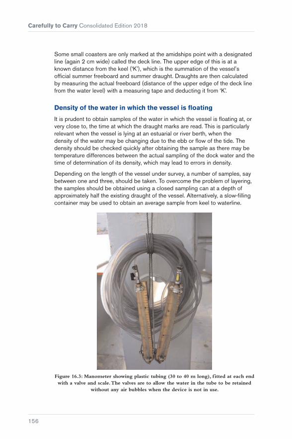
Carefully to Carry Consolidated Edition 2018
156
Some small coasters are only marked at the amidships point with a designated line (again 2 cm wide) called the deck line. The upper edge of this is at a known distance from the keel (‘K’), which is the summation of the vessel’s official summer freeboard and summer draught. Draughts are then calculated by measuring the actual freeboard (distance of the upper edge of the deck line from the water level) with a measuring tape and deducting it from ‘K’.
Density of the water in which the vessel is floating
It is prudent to obtain samples of the water in which the vessel is floating at, or very close to, the time at which the draught marks are read. This is particularly relevant when the vessel is lying at an estuarial or river berth, when the density of the water may be changing due to the ebb or flow of the tide. The density should be checked quickly after obtaining the sample as there may be temperature differences between the actual sampling of the dock water and the time of determination of its density, which may lead to errors in density.
Depending on the length of the vessel under survey, a number of samples, say between one and three, should be taken. To overcome the problem of layering, the samples should be obtained using a closed sampling can at a depth of approximately half the existing draught of the vessel. Alternatively, a slow-filling container may be used to obtain an average sample from keel to waterline.
Figure 16.3: Manometer showing plastic tubing (30 to 40 m long), f itted at each end with a valve and scale. The valves are to allow the water in the tube to be retained
without any air bubbles when the device is not in use.

Chapter 16 Draught Surveys
157
Figure 16.4: Manometer, showing scale and water level. When a scale is f itted and used for the reading, care must be taken that the scale is f ixed at the same height on
each side of the vessel.
When reading the hydrometer floating in the sample of water, the eye of the observer should be as close to the water level as possible to avoid parallax errors and errors due to the meniscus. The hydrometer should also be given a ‘twirl’ to free it of any air bubbles.
Ballast water tanks
Ballast water tanks, including peaks and those said to be empty, must be carefully sounded or proven to be full by pressing up and overflowing from all air pipes when local regulations permit. If the ballast hold contains ballast water, this compartment must not be fully pressed up but should be sounded and the weight of the water carefully calculated.
Spaces such as the duct keel and voids, particularly those of the lower stools situated at the base of transverse bulkheads, between cargo holds, must be checked when safe to do so and proved in the same condition at initial and final surveys.

Carefully to Carry Consolidated Edition 2018
158
These voids often contain the manhole access covers to the adjacent double-bottom tanks. If these covers are not totally watertight, the voids will flood, or partially flood, during ballasting or pressing up of the tanks, potentially resulting in huge errors in the lightship or ballast survey. Surveyors have been known to refuse to conduct draught surveys when it has been established that there is an unknown amount of water in such void spaces.
The calculation of the weight of ballast water is undoubtedly the main source of error in a draught survey and may result in very large, and unacceptable, inaccuracies in the quantity of cargo calculated.
Density of the ballast water
It should be established where the various ballast tanks were filled. If they were from a single source, a few random samples of the water will confirm the density. If from different sources, samples must be taken from tanks containing water from each of the various sources and relevant densities of the water in individual tanks established.
The ballast tanks may contain significant amounts of muck in the form of sand, silt, shingle, rust scale, etc. The density of these deposits will differ significantly from the ballast water. Also, it may not be possible to determine the amounts of these solids that are in the tanks. The results are usually assumed in the constant, but the value may be significantly inaccurate.
The tanks should not be overflowed substantially to obtain samples unless local regulations permit. Instead, sampling equipment that is suitable for tanks that are only partially filled should be used.
When small samples are obtained, a salinity refractometer should be used to establish density. When larger samples have been obtained, a draught survey hydrometer may be used.
Establishing the correct weight of oils on board
This can be established either by sounding or ullaging of the tanks or, in the case of the engine room daily service and settling tanks, by reading the gauges.
The volume of oils in each and every tank should be measured and recorded.
The relative densities of the most recently delivered oils on board can be obtained from the bunker delivery certificates. However, bunkers are almost inevitably mixed with oils already on board, the densities of which are likely to

Chapter 16 Draught Surveys
159
differ. The relative density of the contents may be calculated using the following formula:
RD of tank contents at survey =
(Old oil volume × Old RD) + (New bunker volume × New RD)
Total volume of oil in tank
After completion of the bunker survey, the totals of each oil found must be agreed with the Chief Engineer and the Master.
Water removed from hold bilges
Certain bulk cargoes, such as ores, concentrates and some types of coal, are sprayed with water during loading to keep the dust levels down. In addition, the stockpiles of cargo at the terminal are exposed to rain and other forms of moisture. During the passage, some or all of this water content settles to the bottom of the hold and accumulates in and around the bilges. For safety reasons, this water will be pumped out. A record of bilge pumping would usually be maintained on board, but the volumes pumped out are never known exactly. This volume of water is one of the sources of variation between load port and discharge port figures.
Calculation and corrections of vessel’s displacement from draught readings
Before extracting hydrostatic data from the vessel’s stability book, care should be taken by surveyors to familiarise themselves with the format and methods used to display the various particulars, especially the means of depicting positions of LCF (longitudinal centre of flotation) etc, relative to amidships or to the after perpendicular.
When using a recommended draught survey computer programme or when calculating directly from data extracted from the hydrostatic particulars contained within the vessel’s stability book, it is essential that the data is carefully and properly interpolated or, rarely, extrapolated.
One of the areas where significant errors often result is from the incorrect application of the sign in respect of the position of the LCF (in the first trim correction).
When undertaking initial and final displacement draught surveys to establish the weight(s) of cargo loaded, or alternatively unloaded, the difference between the net displacement weights provides the total cargo quantity. However, it is recommended for a cross check that, at the light ship/ballast survey, the vessel’s light ship weight is deducted from the net displacement found. The resultant then provides the vessel’s ‘constant’ at that time. These unknown weights might also be termed the vessel’s ‘stores variable’. Although variable,

Carefully to Carry Consolidated Edition 2018
160
for a number of reasons, it should serve as a guide to the accuracy of the light ship/ballast survey.
Comparison between ‘stores variable’ quantities, or mean thereof, established at previous surveys should be treated with caution unless the variable is a direct comparison that can be made. For example, all surveys include a check and a record of the engine lubricating oil held in storage tank(s) etc. Occasionally, surveyors report a negative stores variable, which is theoretically impossible unless, in extremely rare instances, the vessel has been subject to modification and large quantities of structural steel removed.
Charterparties often contain reference to an approximate quantity for the vessel’s constant, which may well create a discussion between the Master and the surveyor should the constant found by survey be substantially larger than that quoted by the owners. The surveyor, after relevant checks, should remain confident in the figure obtained, but always record on documents issued to the Master and clients any unusual factors or difficulties experienced during the survey. These include any differences between surveyors should owners, charterers or shippers each appoint separate survey companies to act on their behalf.
Documentation
At completion of the survey, a work sheet or computer printout should be placed on board the vessel recording the data and calculations used to obtain the cargo loaded/unloaded quantity. This document is usually produced by individual survey companies, or by shipping companies for use by their officers.
A formal survey report should be submitted to clients at a later date. Specific formal documentation has been drawn up by bodies such as the IMO and the various P&I Clubs.
The formal report document should include details of the survey as well as:
� Dates and times of surveys
� vessel particulars
� vessel location
� weather conditions (and whether these were within acceptable limits)
� sea conditions (and whether these were within acceptable limits)
� tidal/current conditions (and whether these were within acceptable limits)
� a record of any difficulties or defects in a ship’s documentation or equipment that might cause the calculated weight by draught displacement survey to be outside acceptable limits of normal draught survey measurement error.

Chapter 16 Draught Surveys
161
Cumulative errors
Errors can occur when reading and correcting the draughts. The final fully corrected 3/4 mean draught should be within ±10 mm of the true mean draught.
� Errors of calculation. The main error to be avoided in this section is incorrect positioning of the LCF relative to LBP/2, the amidships point
� error of the water density in which the vessel is floating. Always ensure that an average sample, or alternatively the average of a number of water samples, is obtained and that the correct type of certificated hydrometer is used to obtain the density
� sounding of tanks. Leaving aside documented tables which may not be accurate, the way of avoiding the main errors in this section of the survey is by ensuring, as best possible, that all volumes of liquids on board, particularly ballast water, are both correctly quantified and attributed with correct densities. These factors, particularly when applied to ballast water, undoubtedly contribute to the largest number and degree of errors likely to be encountered in draught surveying.
Bearing these reservations in mind, a well-conducted draught survey under reasonable prevailing conditions is capable of achieving an absolute accuracy of ±0.5%.
Worked example
From the following information, calculate the corrections to perpendiculars and the draughts at the perpendiculars. Also calculate the true trim.
Vessel LBP = 181.8 m Density at the time of draught reading = 1.0185 t/m3
port side stbd side distance marks from perp
Forward draughts 4.61 m 4.65 m Fd = 2.94 m aft
Midships draughts 4.93 m 5.10 m Md = 1.44 m aft
Aft draughts 5.58 m 5.60 m Ad = 7.30 m forward
Forward mean = (4.61 + 4.65)/2 = 4.63 m
Midships mean = (4.93 + 5.10)/2 = 5.015 m
Aft mean = (5.58 + 5.6)/2 = 5.59 m
So apparent trim is: 5.59 – 4.63 = 0.96 m
And LBM is: 181.8 – 2.94 – 7.30 = 171.56 m
Forward correction = Apparent Trim + Fd
LBM =
0.96 + –2.94171.56 = −0.0165 m
Midships correction = Apparent Trim + Md
LBM =
0.96 + –1.44171.56 = −0.0081 m

Carefully to Carry Consolidated Edition 2018
162
Aft correction = Apparent Trim + Ad
LBM =
0.96 + 7.3171.56 = +0.0408 m
Now:
Forward draught = 4.63 – 0.0165 m = 4.6135 m
Midships draught = 5.015 – 0.0081 m = 5.0069 m
Aft draught = 5.59 + 0.0408 m = 5.6308 m
True trim = 5.6308 – 4.6135 m = 1.0173 m = 101.73 cm
¾ mean draught = (6 × 5.0069) + 4.6135 + 5.6308
8 = 5.0357 m
From the original surveys, the following data was given in the vessel’s hydrostatic particulars:
Scale density of hydrostatic particulars 1.025 t/m3
Draught Displacement TPC LCF Draught MCTC Draught MCTC
5.00 19,743 42.32 −4.354 5.50 445.5 4.50 434.9
5.10 20,167 42.37 −4.289 5.60 446.6 4.60 435.9
The stability book stated that a negative (−) sign for LCF indicated forward of midships.
Interpolating the data from the table (it is easier to use centimetres in the interpolation rather than metres), the difference in the tabulated draughts is 10 cm and the draught we are looking for is 3.57 cm more than 5 m. Therefore:
Displacement for 5.0357 mdraught = 19,743 + (20,167 – 19,743)
10 × 3.57 = 19,894.37
TPC for 5.0357 m draught = 42.32 + (42.37 – 42.32)10
× 3.57 = 42.338
LCF for 5.0357 m draught = −4.354 + (4.354 – 4.289)
10 × 3.57 = −4.331 (ford of mid)
MCTC for 5.0357 + 50 cm = 445.5 + (446.6 – 445.5)
10 × 3.57 = 445.89
MCTC for 5.0357 – 50 cm = 434.9 + (435.9 – 434.9)
10 × 3.57 = 435.26
Therefore (dm ~ dz) = 10.63
The first trim correction is = 101.73 × −4.331 × 42.338
181.8 = −102.61 t
Second trim correction = 1.01732 × 50 × 10.63
181.8 = +3.03 t

Chapter 16 Draught Surveys
163
Then vessel’s displacement at a density of 1.025 t/m3 is calculated as follows:
Displacement for 5.0357 m = 19,894.37 t
First trim correction = −102.61 t
Second trim correction = +3.03 t
Corrected displacement in salt water = 19,794.79 t
This is the weight of the ship at the draught if it was in salt water of density 1.025 t/m3, which is the density of the ship’s hydrostatic scale.
However, it is floating in water of apparent density 1.0185 t/m3.
So true displacement = 19,794.79 × 1.0185
1.025 = 19,669.26 t
Draught surveying is based on Archimedes’ Principle, which states that anything that floats will displace an amount of the liquid it is floating in that is equal to its own weight.
16.2 Equipment
16.2.1 Manometer
In some circumstances, the wave and swell activity can be such that it is too rough to use a boat, or the wave damping tube may be difficult or even impossible to position on the hull. This situation can often be resolved by the use of a manometer to measure the list across the deck at midships, which is then added to, or subtracted from, the inboard draught reading to obtain the outboard draught.
It is not necessary for the manometer to be fitted with a scale at the ends as the height of the water in the tube is measured from the deck on each side using a tape measure. Where the list is large, the end of the manometer on the low side must be positioned higher than the end on the high side to avoid the water in the tube running out. However, when a scale is fitted and used for the reading, care must be taken that the scale is fixed at the same height on each side.
A simple manometer is constructed from a length of plastic tubing about 35 to 40 m long of 10 mm outside diameter, 6 mm inside diameter, filled with water. On each end is a valve connected to a short section of 19 mm tube. The valves allow the water in the tube to be retained without any air bubbles in it when the device is not in use. This is important, as any entrapped air will prevent the manometer working properly. The short sections of 19 mm tube provide a damping action to the movement of water in the system that is caused by ship movement.

Carefully to Carry Consolidated Edition 2018
164
Figure 16.5: Use of a manometer to measure list.
In Figure 16.5, the starboard draught is equal to the port draught plus the difference in port and starboard draughts from the manometer.
If the manometer is not long enough to reach the vessel’s sides, the true difference may be calculated from the measured difference by the use of similar triangles. In this case, the manometer is set to obtain readings at a known distance apart across the vessel.
Figure 16.6: Measurement of list using a manometer and similar triangles.
In Figure 16.6:
Difference in port/stbd draughts =
Difference in port/stbd readings Breadth d
Therefore:
Difference in port/stbd draughts = Breadth × Difference in readings
d
16.2.2 Marine Hydrometers
Two types of hydrometers are commonly used in the maritime industry:
Draught survey hydrometers
These instruments are designed to measure the apparent density of water.
For the purposes of draught surveys:
Apparent density (weight in air per unit volume) (t/m3) × Volume (m3) = Weight (t).

Chapter 16 Draught Surveys
165
Load line hydrometers
These instruments are designed to determine the relative density of water.
For the purposes of load line surveys in determination of a vessel’s displacement:
Relative density (specific gravity) × Volume (m3) = Displacement (m3).
Marine and draught surveyors should be familiar with the correct usage of both types of instrument so that neither confusion nor errors occur during draught survey or stability calculations.
Draught survey hydrometers
Modern hydrometers of glass manufacture are calibrated at standard temperature, 15°C (60°F), and measure the apparent density of the water sample in kilograms per litre in air. They are usually marked ‘for draught (or draft) survey’ and ‘medium ST’ (medium surface tension) and graduated in the range 0.990/1.040 kg/l.
These instruments are used to determine the weight in air (apparent weight) of a vessel, from which the weight of the cargo on board may be calculated.
When manufactured of glass and calibrated at standard temperature, a small error results if the hydrometer is not used at the designed standard temperature.
However, it is accepted that no temperature correction is necessary as it is compensated at survey by the change in volume of the steel vessel itself. The corrections due to the ‘coefficients of cubical expansion’ of glass and steel are very approximately the same, thus they cancel out.
The older types of hydrometer used for draught surveys and manufactured from brass, or some other metal, are still found on some vessels. These instruments should be accompanied with a table of corrections and the relevant temperature correction should always be applied.
The use of a glass hydrometer is always preferable and it should be kept clean and protected.
Draught survey hydrometers should not be used for load line survey purposes.
Load line hydrometers
Load line hydrometers are used to determine the relative density (specific gravity) of a water sample at a standard temperature (T1) against a sample of distilled water at a standard temperature (T2). The standard temperature used is usually 15°C (60°F). Relative density is a ratio, a number. Load line hydrometers are usually marked ‘RD’ or ‘Sp. Gr.’, together with the standard temperatures.

Carefully to Carry Consolidated Edition 2018
166
When the temperatures of the water and the distilled water samples have a huge variation, a temperature correction must be applied to allow for the expansion of the hydrometer. These instruments are used to determine the displacement of a vessel at any given waterline in order to comply with the requirements of the International Convention on Load Lines, 1966 (Reference 25).
Article 12 of the Convention permits a vessel to load to submerge the appropriate load line by an allowance made proportional to the difference between 1.025 and the actual density in which the vessel is floating. This then is relative density, ie the Convention refers to ‘density in vacuo’, ie mass per unit volume.
16.2.3 Differences Between Hydrometers
The displacement and apparent weight of a vessel have a relationship, as do the relative and apparent densities of the water in which the vessel is floating. The difference between the relative density (specific gravity) as determined by the load line hydrometer and the draught survey hydrometer is known as the ‘air buoyancy correction’, and can be accepted, at standard temperatures 15°C/15°C or 60°F/60°F, as 0.002 for marine surveys. The density of gases depends on temperature, pressure and moisture content.
The density of dry air at sea level is about 1/800th of the density of fresh water, ie 1.25 kg/m3 when under similar conditions of temperature and pressure. It should also be noted that the actual maximum density of fresh water is 999.972 kg/m3, which occurs at a temperature of 4.0°C. The density of fresh water at 100.0°C is 958.4 kg/m3.
A correction should be deducted from the relative density of a load line hydrometer to compare with an actual density of a draught survey hydrometer. For example, for a sample of seawater checked by a load line hydrometer reading relative density 1.025, a draught survey hydrometer would read an actual density of 1.023 kg/l in air.
All hydrometers should be calibrated regularly.
Surveyors should only use a hydrometer manufactured for the relevant type of survey being undertaken.
16.2.4 Salinity Refractometers
Salinity refractometers are used to check the salinity of water samples.
A refractometer uses the fact that light deflects as it passes through different substances. When passing through water, the degree of deflection (refraction) is directly related to the quantity of mineral salts dissolved in the water.
The refractive index of a substance is a measure of how far light is bent by that substance.

Chapter 16 Draught Surveys
167
For example, at 20°C, the refractive index of distilled water is 1.333 and the refractive index of seawater (relative density 1.025, salinity 35 parts per thousand) at the same temperature is 1.339.
When using a refractometer, a sample is placed on an optical prism in the sample window. As light passes through the sample, the rays are bent according to the salinity of the water, casting a shadow on the scale which is visible through the eyepiece.
A basic hand-held refractometer is used as follows:
� Ensure the refractometer is properly calibrated. If the refractometer scale reads zero, it is properly calibrated. If not, rotate the calibration screw until the shadow boundary lines up with the zero mark
� if necessary, clean the prism using a soft cloth
� rinse the equipment and the prism with part of the sample water to ensure that the sample remains unadulterated
� place several drops of the sample water on the prism, ensuring that the refractometer remains level so that none of the sample runs off the prism
� close the sample cover
� hold the instrument towards a strong light source
� adjust the focus ring until the scale is clearly visible
� read the scale at the shadow boundary
� rinse and clean the instrument before re-use.
Hand-held digital refractometers are also available.
Figure 16.7: Typical basic salinity refractometer.
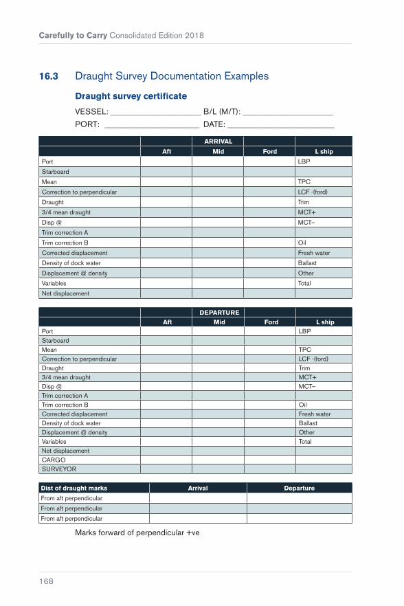
Carefully to Carry Consolidated Edition 2018
168
16.3 Draught Survey Documentation Examples
Draught survey certificate
VESSEL: ______________________ B/L (M/T): ______________________
PORT: _______________________ DATE: __________________________
ARRIVAL
Aft Mid Ford L ship
Port LBP
Starboard
Mean TPC
Correction to perpendicular LCF -(ford)
Draught Trim
3/4 mean draught MCT+
Disp @ MCT–
Trim correction A
Trim correction B Oil
Corrected displacement Fresh water
Density of dock water Ballast
Displacement @ density Other
Variables Total
Net displacement
DEPARTURE
Aft Mid Ford L shipPort LBPStarboardMean TPCCorrection to perpendicular LCF -(ford)Draught Trim3/4 mean draught MCT+Disp @ MCT–Trim correction ATrim correction B OilCorrected displacement Fresh waterDensity of dock water BallastDisplacement @ density OtherVariables TotalNet displacementCARGOSURVEYOR
Dist of draught marks Arrival Departure
From aft perpendicular
From aft perpendicular
From aft perpendicular
Marks forward of perpendicular +ve

Chapter 16 Draught Surveys
169
Draught survey spreadsheet
File Save Ref
Date B/Lading Tonnes
Ship Name Port
Port of Reg Draughts
Flag Arrival Departure
Owner Ford p
Capt Ford s
Cargo Officer Mid p
Berth Mid s
Agents Aft p
Cargo Aft s
Arrived DistFp
Commenced DistMidp
Completed DistAp
Year of Build App Trim 0.0000 0.0000
Gross True Trim Calculated Calculated
Net 3/4 mean Calculated Calculated
LOA Scale density
LBP Dock density
BreadthDisp @ 3/4 mean
Calculated Calculated
Depth TPC Calculated Calculated
Displacement 0.00 LCF (- if aft) Calculated Calculated
Deadweight MCT+ Calculated Calculated
Light Ship MCT– Calculated Calculated
Last Port Total Oil 0.00 0.00
Next Port Total F.Water 0.00 0.00
Surveyor Total Ballast 0.00 0.00
Other
Weather Conditions and Report
CARGO Wt Calculated
If the hydrostatics are from the top of the keel, enter keel correction in mm
Hydrostatic Data
Arrival
Below Above
Draught
Displacement
TPC
LCF
MCT+50cm
MCT-50cm
Departure
Draught
Displacement
TPC
LCF
MCT+50cm
MCT-50cm
Constant = (Disch) Calculated
Constant = (Load) Calculated

Carefully to Carry Consolidated Edition 2018
170
Sounding record
Vessel 0 Port 0 Date 0
BALLAST Trim Calculated Trim Calculated
Initial Survey Final Survey
Tank Capacity m3
Sounding Volume m3 Density Tonnes Sounding Volume m3 Density Tonnes
Total 0.00 Total 0.00 0.00 Total 0.00 0.00
FRESH WATER OIL
Tank Capacity m3
Initial Survey Final Survey
Initial Survey Final Survey
Sounding Tonnes Sounding Tonnes Tonnes Tonnes
Heavy Heavy
Diesel Diesel
Lub Oil Lub Oil
Slops Slops
Fecal Fecal
Total 0.00 Total 0.00 Total 0.00 Total 0.00 Total 0.00

Chapter 16 Draught Surveys
171
Draught survey certificate
VESSEL: 0 B/L (M/T):
PORT: 0 DATE: 0
Arrival
Aft Mid Ford L.Ship 0.00
Port 0.0000 0.0000 0.0000 LBP 0.00
Starboard 0.0000 0.0000 0.0000
Mean 0.0000 0.0000 0.0000 TPC Calculated
Corr’n to Perpendicular Calculated Calculated Calculated LCF (-Ford) Calculated
Draught Calculated Calculated Calculated Trim Calculated
3/4 Mean Draught Calculated MCT+ Calculated
Disp @ 0.0000 Calculated MCT– Calculated
Trim Correction A Calculated
Trim Correction B Calculated Oil 0.00
Corrected Displacement Calculated F.Water 0.00
Density of Dock Water 0.0000 Ballast 0.00
Displacement @ Density Calculated Other 0.00
Variables 0.00 Total 0.00
Net Displacement Calculated
Departure
Aft Mid Ford
Port 0.0000 0.0000 0.0000
Starboard 0.0000 0.0000 0.0000
Mean 0.0000 0.0000 0.0000 TPC Calculated
Corr’n to Perpendicular Calculated Calculated Calculated LCF (-Ford) Calculated
Draught Calculated Calculated Calculated Trim Calculated
3/4 Mean Draught Calculated MCT+ Calculated
Disp @ 0.0000 Calculated MCT– Calculated
Trim Correction A Calculated
Trim Correction B Calculated Oil 0.00
Corrected Displacement Calculated F. Water 0.00
Density of Dock Water 0.0000 Ballast 0.00
Displacement @ Density Calculated Other 0.00
Variables 0.00 Total 0.00
Net Displacement Calculated
CARGO Calculated
SURVEYOR 0
Dist of Draught Marks Arrival Departure
From Aft Perpendicular 0.000 0.000
From Mid Perpendicular 0.000 0.000 Marks forward of perpendicular +ive
From Ford Perpendicular 0.000 0.000 Marks aft of perpendicular -ive


173
PART 6Bulk Cargoes – Liquid
Chapter 17 ..............................................175Bulk Oil Cargoes – Shortage and Contamination Claims
Chapter 18 ..............................................195Samples and Sampling in the Carriage of Liquid Bulk Cargoes
Chapter 19 ..............................................205Flashpoint Contaminations of Diesel Oil and Gas Oil
Chapter 20 ............................................. 209Liquid Natural Oils, Fats and Fatty Products
Chapter 21 ..............................................215Biofuels: Marine Transport, Handling and Storage Issues


175
Chapter 17
Bulk Oil Cargoes – Shortage and Contamination Claims
Claims arising from the carriage of oil cargoes are often substantial and may allege either shortage or contamination or both. This chapter provides guidance on how tanker operators can minimise the risk of cargo loss or damage and defend themselves should claims arise.
17.1 Oil Shortages
In general, oil shortage claims are based upon a discrepancy between the quantity of cargo as stated in the B/L and the outturn quantity as calculated in the discharge port. Both these figures are frequently derived from shore tank calibration data. The most common arguments are that:
� The ship is bound by the figure stated in the B/L
� the shore tank calibrations are more accurate than the ship’s tank calibrations
� the oil has become contaminated by water after loading
� some oil remains on board the ship.

Carefully to Carry Consolidated Edition 2018
176
The carrier’s defence is commonly based upon the accuracy of the ship’s cargo figures and seeks to demonstrate that they were comparable with the B/L figure, that there was no significant in-transit loss, that any onboard quantity (OBQ) prior to loading has been taken into consideration and that all the cargo has been discharged with none remaining on board (ROB).
The following pages consider each phase of a typical tanker voyage and look at the likely causes of difficulty.
17.1.1 Before Arrival at the Load Port
The cargo officer should prepare a loading plan taking into account stability, trim and stress. Where draught restrictions permit, it may be advisable to plan to leave the load port with a trim that avoids the need for internal transfers of cargo during the loaded passage. The inert gas system, if fitted, should be fully operational in readiness for the forthcoming cargo operation. The oxygen content of the cargo tanks should be as low as possible before arrival and a record of all tank readings should be maintained.
17.1.2 On Arrival at the Berth
Figure 17.1: A berthed ship.
Once the ship is securely moored, it is important to liaise with representatives from the shore loading facility and to ensure continued good communications throughout the loading. All relevant information must be exchanged between ship and shore, including details of the ship’s loading plan, maximum loading rates, shutdown procedures, safety regulations and cargo data.

Chapter 17 Bulk Oil Cargoes – Shortage and Contamination Claims
177
17.1.3 Before Loading
The ship’s cargo valves and pipelines should be correctly set for the reception of cargo and the relevant tank valves opened. Before loading, it is customary for a joint inspection of the cargo tanks to be made by shore representatives and ship’s officers to confirm that the tanks are properly drained and in a suitable condition to load the designated cargo.
In general, the completion of such an inspection does not relieve the owner of his responsibility to ensure the correct condition of the cargo tanks.
In large tankers and where tanks are inerted, such inspections are difficult and it may be necessary to rely on the ship’s gauging equipment rather than any visual inspection. The measurement of any OBQ should be carefully undertaken, preferably jointly with the shore representatives. The depth of any residues should be measured at as many locations as possible, and at least at the forward and after ends of the tanks, with a wedge correction used, where applicable, to calculate liquid residues. Tank cleaning hatches should be utilised as appropriate.
It is never in the ship’s interest for the OBQ to be underestimated. This will result in an overstatement of the ship loaded figure, exposing the ship to an unwarranted short delivery claim.
17.1.4 During Loading
The tank loading sequence should be planned in advance with the ship’s stability and stress conditions in mind. It is customary to begin loading at a slow rate, with the rate increased to maximum once it is established that cargo is entering the correct tanks and that there are no leaks from hose connections or any other difficulties. It is recommended that, at an early stage, the cargo officer should satisfy himself that the correct grade of cargo is being loaded, either by checking the specific gravity of a sample or, at least, by visual means. The ship’s instrumentation may facilitate remote monitoring of temperatures during loading, but in any event it is essential to measure accurately and to record the temperature in each tank during loading. It is not advisable to use an average of the tank temperatures as this leads to inaccurate cargo figures.
The loading rate should be monitored and it is recommended that ullages and corresponding tank volumes, including those in idle tanks, are recorded in the deck log at least at hourly intervals.

Carefully to Carry Consolidated Edition 2018
178
The loading rate should be compared hourly with the shore tank discharge rates, where available, to help ensure that the cargo is not being misdirected in the loading terminal. Any changes in the loading rate or any stoppages must also be recorded. During the final stages of loading, the rate should be reduced to a minimum in order to permit measurement of the quantity of cargo so far loaded and to calculate the correct finishing ullage in the last cargo tank.
17.1.5 On Completion of Loading
Before the cargo hoses are disconnected, the ship’s figures must be calculated to check that the correct quantity of cargo has been loaded. While it is in the ship’s interests to measure the cargo on board ship, it is customary for various witnesses to attend this operation and, in some cases, to make independent calculations. These witnesses may include representatives from the loading terminal, the shippers and the charterers. It is of prime importance that the measurements of ullage, temperature and, where appropriate, water dips are agreed by all concerned, although it must be accepted that the methods of calculation employed thereafter may not always be consistent. It is generally accepted that the latest edition of the ASTM-IP-API Petroleum Measurement Tables (Reference 28) is more accurate than older tables, but it should be borne in mind that all tables are based on the average characteristics of a range of oils. Where a surveyor is attending on the ship’s behalf, he should collaborate with the ship’s officers to ensure that no inconsistencies arise in the calculations.
Ship’s tanks may be calibrated using imperial or metric units of volume and the quantity of cargo may be expressed in various units including long tons, tonnes or barrels. Whichever units are applied, it is essential to compare like with like. The use of standard volume may be considered preferable as it is less susceptible to misinterpretation by observers or laboratories. The glossary at the end of this chapter lists the common terms and abbreviations used in the measurement of liquid cargoes.
17.1.6 Ullaging
This is the measurement of the distance from the datum point at the top of a tank to the surface of the liquid cargo. In the past, this was usually carried out by means of a steel tape fitted with a weighted brass bob, but many tankers are now fitted with fixed gauging equipment in each tank. Electronic portable measuring devices are also available.
Ullaging is best carried out when the ship is on an even keel and with no list, otherwise inaccuracies may creep in despite the application of trim corrections.
A ship, whether afloat, alongside a jetty, at anchor or at sea, is a moving platform and even a slight movement will affect the accuracy of measurement.
Chapter 17 Bulk Oil Cargoes – Shortage and Contamination Claims
179
In any single tank, a difference of one inch in the ullage may involve a volume of several hundred barrels. Where a ship is pitching or rolling, it is recommended that five measurements are taken from each tank. The highest and lowest should be ignored and the middle three averaged. Weather and sea conditions at the time of the measurement survey should be logged.
Some factors may affect the calculation of OBQs, particularly residues on tank floors and structures, and these will vary with the age of the vessel and previous cargoes carried. It is not unusual for ullages to be recorded for the purpose of determining ROB and OBQ when the trim of the vessel, at the time of survey, is such that the ullaging tape or sounding rod is not perpendicular to the ship’s tank bottom on contact. In such cases, it follows that the depth of ullage obtained must be inaccurate. Clingage is a further consideration because, while crude oil washing (COW) reduces clingage for most crudes, there are a few types where the reverse is true.
17.1.7 Temperature
The temperature of liquid in a vessel’s tank is generally obtained by the use of a cup case thermometer, although some vessels are now equipped with electronic temperature sensing devices. Cup case thermometers are unreliable and errors of ±2 to 3°C are not unknown. Electronic temperature measurement devices have a greater accuracy, typically ±0.1°C. Great care should be taken when using a manual thermometer to ensure it is not affected by the environmental temperature after it has been removed from the oil.
The vertical positioning of the thermometer in a vessel’s tank, particularly at the discharge port, is critical because significant temperature variations can develop within the cargo tanks during the voyage. Cargo temperature may vary at different levels in the tank so, where possible, the temperature should be averaged from at least three readings (upper, middle and lower). Further, as temperatures vary from tank to tank, calculations of quantity must be calculated using individual temperature corrections for each tank.
The use of an arithmetical average for the whole ship is inaccurate and contributes to ‘paper losses’. An error of 1°C in temperature produces an inaccuracy in the volume at standard temperature of approximately 0.1%.
17.1.8 Water Dips
Free water beneath a crude oil cargo is normally measured with a sounding rod. Water finding paste or electronic interface tapes may also be used for the detection of free water. Unfortunately, neither of these methods can be used to distinguish accurately between an emulsion and free water. Each method involves the risk of inaccuracies that can only be determined by proper sampling and analysis techniques.

Carefully to Carry Consolidated Edition 2018
180
17.1.9 Sampling
When calculating cargo quantities, the ship has to rely upon certain data supplied from the shore, in particular the density of the cargo that is calculated after the analysis of samples. Shoreline samples may, however, contain inaccuracies and cannot always be accepted as being representative of the cargo loaded. It is recommended that, with crude oils, the standard sampling ‘thieves’ should not be used. Clean sample bottles should be used to acquire individual samples from each level (ie top, middle and bottom of each of the ship’s tanks) and clearly labelled.
During such an operation, volatile fractions may be lost to the atmosphere with the result that the density established from the final mix does not represent the true density of the cargo in each tank. This, in turn, may later have a significant effect upon the calculation of weight and bottom sediment and water. The importance of sampling as a measure to counter contamination claims is discussed further in Section 17.9.
17.1.10 Density
Despite practical difficulties, it is best practice to ensure that the density of the cargo on board is measured and compared with the figures supplied by the terminal. An error of 0.01 kg/l can alter the tonnage calculation on a VLCC by 3,000 t.
17.1.11 Measurement Errors
Studies by a major oil company revealed that a measurement error of ±0.21% may occur when calculating the measurement of volumes and an error of ±0.25% when calculating weights. Therefore, measurement errors may easily account for what has previously been termed a ‘measurement error loss’ or ‘measurement tolerance’.
17.2 Completion of Documentation
Once calculation of the ship’s figures has been completed, the shore installation will provide a shore figure. It is generally this figure that is used on the B/L. It is most unlikely that the two figures will precisely coincide, although in practice, and in the vast majority of cases, the discrepancy is small and of no great significance. The Master should have no difficulty in reconciling the figures nor in signing the B/Ls. In each case, the gross figures should be compared and the ship’s experience factor should also be taken into consideration.
Chapter 17 Bulk Oil Cargoes – Shortage and Contamination Claims
181
If there is an exceptional difference between the B/L figure and the ship’s figure, the Master should decline to sign the B/L. He should insist on a thorough check of all measurements and calculations, including those ashore, in order to ascertain the cause of the discrepancy.
When checking the shore figures, difficulties may arise because the measurements taken in the shore tanks before loading cannot be verified once the cargo has been transferred. Checking of the shore figures may, therefore, depend upon the accuracy of the records kept at the shore terminal. In the majority of cases, this investigation is likely to be successful and the figures will be corrected and easily reconciled.
The reasons for gross inaccuracies may include:
� Ullages incorrectly measured
� tanks filled but not taken into account
� the contents of pipelines not allowed for
� incorrect temperatures or densities
� cargo mistakenly loaded on top of ballast
� cargo lost in the shore installation
� incorrect meter proving.
On occasions, despite such exhaustive checks, it may be that the two calculations cannot be reconciled and the Master then finds himself in a dilemma. The Hague-Visby Rules provide:
“No Carrier, Master or Agent of the Carrier shall be bound to state or show in the bill of lading any marks, number, quantity or weight which he has reasonable ground for suspecting not accurately to represent the goods actually received for which he has had no reasonable means of checking.” (Reference 29)
However, the Master will be conscious of the commercial pressures, which dictate that the berth must be vacated and that the voyage must not be delayed. There is no inflexible rule to be followed that will apply in every case.
The Master should note protest, notifying the ship’s agents and instructing them to urgently inform the owners of the problem as well as the charterers, the shippers and any consignee or notify party named on the B/L. The Master should give full details of the available figures and ask the parties notified to inform any potential purchaser of the B/L of the discrepancy. It may be difficult for the Master to contact all the parties named, but the owner should do this at the earliest opportunity. Ideally, the Master should be able to clause the B/L, but in practice this creates many difficulties.

Carefully to Carry Consolidated Edition 2018
182
The Master should, therefore, decline to sign the B/L, or withhold authority for anyone else to sign, until the dispute has been resolved. In any event, the Master or owner should immediately contact their P&I Club or its correspondents.
17.3 Early Departure Procedures
Figure 17.2: The tanker MT ‘Orkim Harmony’.
In certain busy oil ports, it is the practice, in the interests of expediting the turnaround of tankers, to offer the Master the opportunity to utilise the early departure procedure. This system was devised in the light of many years’ experience of tanker operations and shore figures after loading. On arrival at the loading berth, the Master agrees that, on completion of loading, the loading hoses will be immediately disconnected and the ship will sail. As soon as the B/L figures are prepared, they are cabled to the Master who then, provided he is satisfied, authorises the agent to sign the B/L and other related documents on his behalf. On no account should the Master sign the B/L himself before sailing without the correct figures already being inserted.
17.4 Shipboard Records
It is essential for the defence of possible cargo claims that the ship maintains certain documentary records of cargo operations. Time charterers, particularly the oil majors, are likely to place their own documentation on board, which they

Chapter 17 Bulk Oil Cargoes – Shortage and Contamination Claims
183
will require to be returned promptly at the end of each voyage. Typical returns would include:
� A voyage abstract (deck and engine)
� notice of readiness (NOR)
� a port log
� pumping/loading records
� stowage plan
� loading and discharge port calculations
� details of any cargo transfers.
They may also include records of all oil transfers, whether loading, discharging or internal and including bunkering operations. Such records will assist not only with the defence of shortage and contamination claims, but also with the handling of other possible disputes including performance claims and demurrage and dispatch disputes.
The need to keep full records of bunker quantities and to properly maintain the oil record book cannot be overemphasised.
17.5 During the Voyage
Provided the ship’s fittings are properly maintained, the cargo will require little attention during the voyage unless heating is required. In such cases, it is important to follow the charterers’ instructions, particularly bearing in mind the specifications of the cargo carried. In some cases, failure to heat the cargo properly may lead to severe difficulties. When crudes that require heating are carried, particularly those with a high wax content, it is important that the charterers provide clear instructions for heating both on the voyage and throughout discharge. Often, heating instructions are not sufficiently precise, with the charterers relying on the experience of the Master. Usually, it is wise to heat early in the voyage to maintain the temperature rather than being obliged to raise the temperature of the cargo significantly at the end of the voyage. If there is doubt about the heating instructions, the Master should check with the charterers. The tank temperatures should be recorded twice daily.
Attention should be paid to the condition and operation of the pressure/vacuum (p/v) valves on the tank venting system to ensure that they are functioning correctly. Failure to operate these valves properly may lead to a significant loss of product during the voyage.

Carefully to Carry Consolidated Edition 2018
184
Finally, there should be no necessity to transfer cargo between cargo tanks during the voyage, which would create differences between ullages and soundings taken before and after the voyage and invariably lead to disputes when defending shortage claims. Ideally, the two sets of readings should not differ to any degree. Owners should discourage the practice and insist that any transfers that the Master considers urgent and essential be reported and properly recorded in the oil record book. Many charterparties require the Master to notify the charterers of any cargo transfers.
17.6 Arrival
17.6.1 Before Arrival at the Discharge Port
A proper discharging plan should be prepared, taking into account any restrictions or requirements. It must include a careful check of not only the trim condition during discharge, but also of the stress conditions. Care should be taken to ensure that the parameters laid down by the shipbuilders are adhered to. It is also important to take into account the required discharging temperature and the need to maintain this temperature throughout the discharge. When discharging in ports where low sea temperatures prevail, this may require considerable vigilance. In tankers fitted with inert gas and COW, it should be ensured in advance that the systems are fully operational in readiness for the forthcoming discharge.
17.6.2 On Arrival at the Discharge Port
Figure 17.3: Ship arriving at a discharge port, aided by a tug.

Chapter 17 Bulk Oil Cargoes – Shortage and Contamination Claims
185
On completion of the arrival formalities, the need to communicate with representatives of the discharging facility is no less important than at the load port. Full liaison should include the exchange of all relevant information about the cargo, including the maximum discharge rates, the discharge plan, safety procedures, shutdown procedures, scheduled shore stops and any local regulations.
If the ship is fitted with COW, it must be made clear whether COW is to be carried out, particularly bearing in mind any MARPOL requirements (Reference 30).
17.6.3 Before Discharge
As in the load port, the measurement of the cargo is undertaken in the presence of the cargo receivers and possibly other interested parties or their surveyors and including customs authorities. The remarks on cargo measurement apply equally in this instance. The utmost care should be taken in checking and double-checking the measurements. The measurement of temperature merits particular care, particularly where heated cargoes are concerned. Again, it is stressed that apparently small discrepancies in temperature can lead to significant differences in the final calculations and the temptation to ‘round off’ temperatures or to use convenient averages should be discouraged. It is essential to note the ship’s trim and list at the time of ullaging – the ideal trim is with the ship on an even keel and with no list. When sampling cargo before discharge, and particularly in the case of heated cargoes, samples should be taken from the top, middle and bottom of the cargo tank.
On completion of cargo measurement, a comparison should immediately be made with the loading ullages, tank by tank, to see whether there have been any appreciable changes since leaving the load port. Should any differences be noted, the reasons should be immediately investigated and fully recorded. The ship’s responsibility should begin and end at the fixed manifold and the owners have no liability for measurements taken once the cargo has entered the piping that forms the receiving terminal. Claims are frequently presented on the basis of shore figures that are inaccurate and the most effective and economical way of reducing liability may be to recalculate these figures correctly. It would be beneficial for a surveyor representing the shipowner to check the shore reception facility, where it may be possible to witness the taking of shore measurements. They may also be able to check the pipeline system to verify its size and length and the method by which its contents are ascertained before and after discharge, noting whether any valves that lead off the pipelines are in use. Some shore facilities are reluctant to allow ship’s representatives to make full checks in their terminals. If an inspection of the terminal or its operations is refused, this should be recorded.

Carefully to Carry Consolidated Edition 2018
186
Where shortage claims arise, they are usually based on the shore figures and the owner must defend himself not only on the basis of the accuracy of the ship’s figures, but also by challenging the accuracy of the shore figures. It will greatly assist if the owner’s surveyor has made a thorough inspection of the terminal at the time of the discharge.
17.6.4 During Discharge
Once the necessary preparations have been completed aboard the ship, and the shore installation has confirmed that the discharge can commence, the cargo pumps are started in sequence. Where one or more grades of cargo are carried, it may be possible to discharge each grade simultaneously, subject to stress and trim considerations and any other restricting factors such as the design of the ship’s pipeline system. Once it has been established that the cargo is flowing correctly, the discharge rate should be increased to the agreed maximum. The rate may be restricted either by back pressure or by the capacity of the ship’s pumps. The rate of discharge should be carefully monitored throughout and recorded at intervals of no more than one hour. These records should show not only the amount of cargo discharged by volume, but also the shore back pressure, the pressure at the ship’s manifold, the speed of the cargo pumps and steam pressure or, in the case of electrical pumps, the amperage. The unloading rate should be compared hourly with the shore tank reception rates, where available, to help ensure that the cargo is not being misdirected in the receiving terminal. If COW is being carried out, this operation must be closely monitored. Careful recording of the discharge in the ship’s logs is essential if claims are to be successfully defended.
Figure 17.4: Ship discharging its cargo.

Chapter 17 Bulk Oil Cargoes – Shortage and Contamination Claims
187
Effective stripping of the tanks is important since claims will undoubtedly be made against the owner for quantities of cargo remaining on board.
Provided the ship has a good stern trim, the tanks have been well cleaned and prepared prior to loading and the ship’s pumps and pipelines are in sound condition, it should be possible to ensure that only a negligible quantity is left on board. Light or clean products should present no problem, although where heavier or heated cargoes are concerned there will inevitably be some clingage and perhaps some sediment remaining. COW will help to reduce these quantities and care should be exercised when stripping heated cargoes to ensure that the tanks are drained quickly as, once the level of the cargo falls below the heating coils, heat will be lost quickly and difficulties may be encountered.
Whatever type of oil is carried, it will be necessary to be able to demonstrate that ship’s valves, lines and pumps were in good condition at the time of discharge because this has an impact on the question of ‘pumpability’. From the point of view of cargo claims, it must be considered whether, even if the cargo was liquid, it could be pumped by the vessel’s equipment. It is possible that small quantities of oil, particularly where high gas cargoes are concerned, cannot be picked up by the pumps without the pumps gassing up. It could be that, due to sediments from the cargo or shore restrictions on trim, the oil is liquid but cannot run to the suction (see Section 17.6.6). If pressure is applied to the ship to sail before the surveyor can attend, the Master should protest to the receivers and to the receivers’ surveyor. If the surveyors are not prepared to certify cargo remaining on board as unpumpable, they should be invited to inspect the ship’s pumps. The receivers should be informed that, if they consider the cargo to be pumpable, the ship is prepared to continue to attempt to pump it until the Club surveyor arrives. Owners should ensure that the maintenance records for the cargo pumps are carefully preserved and that they are available should such disputes arise. Surveyors who certify cargo as pumpable may be required to prove that they have tested the nature of the cargo and have ascertained that it can and does reach the suction in the cargo tank.
ROB claims may, therefore, arise in three different ways:
� By loss of heating or inadequate heating on board ships, sometimes coupled with low ambient temperatures at the time of discharge
� by the physical properties of the oil and the ability of the pumps to pump it. The possibility of pumps gassing up and loss of suction must be taken into consideration
� by cargo sediments or trim restrictions that prevent the free flow of oil to the tank suction.

Carefully to Carry Consolidated Edition 2018
188
In the case of a crude that does not require heating, or that has a high vapour pressure, good COW and a good stern trim will overcome most problems.
Frequently, the charterparty will call for COW ‘in accordance with MARPOL’ and will allow additional time for discharge when COW is performed. If the receiving installation will not allow satisfactory stern trim, or if they refuse COW either in whole or in part, the Master should protest to the terminal and to the charterers, stating that the vessel cannot be held responsible for any resulting cargo losses.
17.6.5 On Completion of Discharge
When the cargo has been completely discharged, with all tanks and pipelines well drained, the cargo system should be shut down and all tank valves closed. A final tank inspection is then carried out and, inevitably, particular attention will be paid by the shore representatives to any cargo remaining on board. All void spaces, including ballast tanks and cofferdams, should be checked to ensure that no leakage of cargo has occurred.
17.6.6 Dry Tank Certificate
After discharge, a dry tank certificate should be issued, signed by an appropriate shore representative, describing any remaining cargo as ‘unpumpable’ and carrying an endorsement that the ship’s equipment was in good working condition. In many places, shore cargo inspectors are reluctant to describe oil as ‘unpumpable’ and may prefer to use the terms ‘liquid/non-liquid’. This is not satisfactory and should be avoided if at all possible because it leaves cargo owners in a position to claim pumpability and to attempt to activate a charterparty retention clause, albeit unlawfully, if the clause requires the cargo to be pumpable.
It is strongly recommended that Masters contact their Club representative and the ship’s operators for advice if a dry tank certificate showing oil remaining on board as being unpumpable cannot be obtained.
17.7 In-transit Losses and their Potential Causes
The standard defence put forward by a shipowner to a cargo shortage claim used to be that the loss was below or equal to 0.5% of the total cargo. This figure, which originally stemmed from the cargo insurance deductible, was used by shipowners and cargo insurers as a yardstick for in-transit losses for many years. However, a number of courts, particularly in the United States, have rejected the concept of an automatic ‘loss allowance’.

Chapter 17 Bulk Oil Cargoes – Shortage and Contamination Claims
189
However, there is every indication that the same courts would allow a ±0.5% ‘measurement tolerance’. In-transit losses and their causes may be considered under four headings:
� The true in-transit losses during the voyage, where the ship’s gross volume at standard temperature on loading is compared with the ship’s gross volume at standard temperature prior to discharge
� theoretical in-transit losses, when the comparison of net volume on board at standard temperature on completion of loading is compared with the net volume on board prior to the commencement of discharge
� emptying and filling losses. This is particularly pertinent where a part discharge may take place into a lightering vessel or barge
� additional losses that may occur as a result of COW.
The third and the fourth items become apparent when accounting for volumetric losses on outturn.
The following factors may combine to cause a release of gases and an increase in pressure within the cargo tanks which, combined with the inert gas pressure, may cause venting through the pressure vent valves and consequent loss of product:
� Tanker design
� cargo density
� Reid vapour pressure
� cargo temperature
� ambient temperature and general weather conditions.
17.7.1 Losses During Discharge
The largest volumetric losses are likely to occur when there is transfer from one container to another. This means that quite large losses can occur when pumping the cargo from the ship to the shore. Where lightering is involved, there will, inevitably, be a greater risk of volumetric losses between the ocean-carrying ship and the shore tanks. Where COW is performed, the potential for volumetric losses is greater since the cargo is being formed into a high-pressure spray and partially atomised.
17.8 The Shore Installation
When assessing a claim for short delivery of an oil cargo, the ship’s calculation and figures are scrutinised. It is of equal importance to examine the shore calculations at both the loading and discharge ports. The carrier’s liability does not extend beyond the ship’s manifold, and claims for apparent oil losses can sometimes be resolved by recalculation of the shore figures. The cargo interests

Carefully to Carry Consolidated Edition 2018
190
should be asked to provide full details of the shore installation, including a plan showing all the storage tanks and the interconnecting pipelines as well as the position of isolating valves. They should be able to verify the maintenance of all their equipment and demonstrate that, for instance, all the isolating valves were tight and properly operating at the time of discharge. They should also be asked to demonstrate that the storage tanks were properly calibrated and show that the calibration was accurate. In some oil installations, the accuracy of the tank calibrations may be doubtful, particularly if they are of older construction or built on unstable sites. A small measurement inaccuracy may correspond to a substantial change in volume. Temperature measurements should also be closely considered as temperature gradients may exist when oil is stored in a large tank. In certain climatic conditions, there may be significant variations in the temperature within the tank. In a cold wind, there may be a horizontal temperature gradient as well as a vertical gradient. In many countries, the measurements taken at the time of custody transfer are witnessed by customs officials and, if appropriate, the official customs documents should be produced.
17.9 Oil Contamination Claims
Many oil shortage claims arise from the presence of excessive quantities of water that have settled out during the voyage and are found in crude oil cargoes at the discharge port. Oil contamination may occur in petroleum products, but a cross contamination between two grades of crude oil would, in most cases, not lead to a cargo claim. Crude oil cargoes are regularly blended before refining and, generally, for a cargo contamination to arise, a large cross contamination would need to take place.
This is not true of all grades of crude as there are some that have particular properties and must not be contaminated in any way.
Many refineries designed for the reception of cargoes carried by sea have desalination facilities to protect the distillation columns and refinery equipment from excessive corrosion. Such facilities, however, do not always exist. The presence of water in certain crude oil cargoes may also cause emulsions to form with the hydrocarbons. This in turn may cause ROB volumes to be excessive and possible sludging of land tanks if efficient water draining is not carried out.
It is quite possible that any alleged contamination could have taken place ashore before loading. A prudent owner is, therefore, recommended to protect his interest by ensuring that ship’s staff take cargo samples from each tank after loading and at the ship’s manifold during loading, as a matter of routine, so that hard evidence is at hand to refute claims of this kind. Contamination claims are more likely to occur in the white oil trades, where it is common for a number of grades to be carried simultaneously. As many as eight or ten grades may be carried simultaneously and, on a purpose-built product carrier fitted

Chapter 17 Bulk Oil Cargoes – Shortage and Contamination Claims
191
with deep well pumps and dedicated loading lines, it may be possible to carry a different grade in each tank with complete segregation.
Aside from leakage, which may occur between cargo pipelines or cargo tanks and may result in contamination, the most likely cause of a product being off-specification is failure to properly prepare the tank or associated pipelines after a previous incompatible grade.
17.9.1 Precautions Before Loading
Every care should be exercised to ensure that proper tank cleaning procedures are rigorously carried out and that tank coatings are in a suitable condition for the intended cargo. Particular care should be taken to ensure that all traces of the previous cargo are removed in the cleaning process.
When carrying multigrade cargoes, effective segregation is of prime importance. When preparing the loading plan, allowances must also be made for trim and draught restrictions. It is common for multigrade cargoes to be loaded in more than one port and for several discharge ports to be involved. In some cases, additional cargo may be loaded during the voyage after the discharge of other products. Careful planning is advisable, taking into consideration the quantity of cargo to be loaded and discharged, draught, trim and stress considerations, as well as the consumption of water and fuel.
Before loading, all concerned should have a clear knowledge of the intended loading plan, and the pipelines and valves must all be carefully set and double-checked. Because product cargoes generally have a low specific gravity, it is likely that the ship may not be loaded down to her marks even with all cargo tanks filled to the maximum permissible. When loading for a voyage that entails passing through areas where higher sea temperatures are expected to be encountered, it is advisable to take into account the expansion of the cargo that will occur as a result of those higher temperatures.
During the loading of sensitive products, it is common for ‘foot samples’ to be loaded and for samples to be taken and analysed before the rest of the product is taken on board. When carrying multigrades, it is good practice to take as many samples of the cargo as possible at various stages of the loading and discharge, including samples from the shorelines. If claims for contamination arise, the analysis of such samples will often identify the source of the problem and may assist the shipowner in rejecting liability.

Carefully to Carry Consolidated Edition 2018
192
If the following points are borne in mind by owners and Masters, there will be a much greater chance of success when defending oil cargo claims:
� Careful attention should be paid to all onboard surveys when loading and discharging with a view to avoiding ‘paper losses’
� after discharge, try to ensure that a dry tank certificate is issued showing all cargo remaining on board to be unpumpable and endorsed to confirm that the ship’s equipment was working correctly
� employ properly qualified surveyors and protest if it can be demonstrated that a surveyor employed by a cargo interest is not qualified or lacks experience.
17.10 Glossary of measurement terms
API = API GravityPetroleum industry expression for density of petroleum liquid expressed in API units. API gravity is obtained by means of simultaneous hydrometer/temperature readings, equated to and generally expressed at 15°C (60°F). The relative density to API gravity relation is:
141.5 – 131.5
Relative density 15°C (60°F).
Automatic samplerA device installed for indicating the level of product from a location remote to the manual gauge site.
BarrelPetroleum industry measurement unit equal to 42 US gallons.
Clingage The oil that remains adhered to the inner surface and structure of a tank after it has been emptied.
Crude Oil Washing (COW)The technique of washing cargo tanks of oil tankers during the discharge of crude oil cargoes, using the crude oil cargo itself.
DensityThe mass per unit volume at a specified temperature used to determine weight for a volume at a standard temperature.

Chapter 17 Bulk Oil Cargoes – Shortage and Contamination Claims
193
DipDepth of liquid. American expression: gauge.
Free waterWater within a container that is not entrained in the cargo.
Gauge reference heightThe distance from the tank’s strike point to the bench mark or reference point.
Gross Observed Volume (GOV)The total volume of all petroleum liquids, including sediment and water (S&W), but excluding free water, at observed temperature and pressure.
Gross Standard Volume (GSV)The total volume of all petroleum liquids and S&W, corrected by the appropriate temperature correction factor (Ct1) for the observed temperature and API gravity, relative density or density to a standard temperature such as 60°F or 15°C and also corrected by the applicable pressure correction factor.
Load on Top (LOT)The procedure of allowing hydrocarbon material recovered during tank washing to be commingled with the next cargo.
Net OBQOnboard quantity (OBQ) less free water in cargo, slop tanks and lines, and water in suspension in slop tanks.
Net Observed Volume (NOV)The total volume of all petroleum liquids, excluding S&W, and free water at observed temperature and pressure.
Onboard Quantity (OBQ)Cargo tank quantities of any material on board a ship after deballasting immediately prior to loading. Can include oil, oil/water emulsions, water, non-liquid hydrocarbons and slops.
Remaining On Board (ROB)Cargo or residues remaining on board the ship after discharge.
Sediment and Water (S&W)Non-hydrocarbon materials that are entrained in oil. Material may include sand, clay, rust, unidentified particulates and immiscible water.
Ship’s composite sampleA sample comprised of proportional portions from running samples drawn from each tank on the ship.
Ship figuresStated volume extracted from ship’s calibration tables based on measurements taken from cargo tanks.

Carefully to Carry Consolidated Edition 2018
194
Slop tankA tank into which the tank washings (slops) are collected for the separation of the hydrocarbon material and water, the recovery most often becoming LOT (load on top).
Total Calculated Volume (TCV)The total volume of the petroleum liquids and S&W, corrected by the appropriate temperature correction factor (Ct1) for the observed temperature and API gravity, relative density or density to a standard temperature such as 60°F or 15°C and also corrected by the applicable pressure factor and all free water measured at observed temperature and pressure (Gross Standard Volume plus free water).
Total delivered volume (ship)The Total Calculated Volume less ROB.
Total Observed Volume (TOV)The total measured volume of all petroleum liquids, S&W and free water at observed temperature and pressure.
Total received volume (ship)The Total Calculated Volume less OBQ.
Ullage (outage gauge)Measurement of the distance from the datum point at the top of a tank to the surface of the liquid cargo.
Volume Correction Factor (VCF)The coefficient of expansion for petroleum liquids at a given temperature and density. The product of the petroleum liquid volume and the volume correction factor equals the liquid volume at a standard temperature of either 60°F or 15°C.
Water (dip) gaugea) The depth of water found above the strike point, orb) To gauge for water.
Water finding pasteA paste applied to a bob or rule to indicate the water/product interface by a change in colour at the cut.
Wedge correctionAn adjustment made to the measurement of a wedge-shaped volume of oil, so as to allow for the vessel’s trim.
Weight Conversion Factor (WCF)A variable factor related to density for use when converting volume at standard temperature to weight.
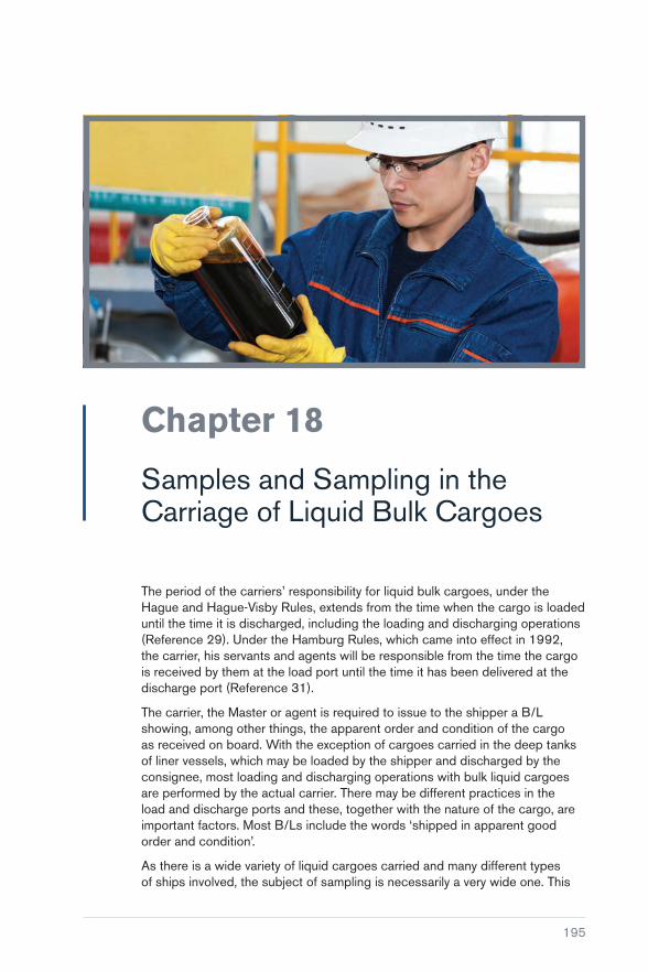
195
Chapter 18
Samples and Sampling in the Carriage of Liquid Bulk Cargoes
The period of the carriers’ responsibility for liquid bulk cargoes, under the Hague and Hague-Visby Rules, extends from the time when the cargo is loaded until the time it is discharged, including the loading and discharging operations (Reference 29). Under the Hamburg Rules, which came into effect in 1992, the carrier, his servants and agents will be responsible from the time the cargo is received by them at the load port until the time it has been delivered at the discharge port (Reference 31).
The carrier, the Master or agent is required to issue to the shipper a B/L showing, among other things, the apparent order and condition of the cargo as received on board. With the exception of cargoes carried in the deep tanks of liner vessels, which may be loaded by the shipper and discharged by the consignee, most loading and discharging operations with bulk liquid cargoes are performed by the actual carrier. There may be different practices in the load and discharge ports and these, together with the nature of the cargo, are important factors. Most B/Ls include the words ‘shipped in apparent good order and condition’.
As there is a wide variety of liquid cargoes carried and many different types of ships involved, the subject of sampling is necessarily a very wide one. This

Carefully to Carry Consolidated Edition 2018
196
chapter deals with the general principles of how to ascertain the apparent order and condition of goods when they are shipped and, just as importantly, how to preserve the evidence.
Many parcel tanker owners have issued instructions to their Masters to sample each type of cargo at the ship’s manifold on commencement of loading, after the first test-load (so called ‘first run’ sample) and from the ship’s tank after completion of loading. The samples are numbered and details entered in a sample logbook.
An advantage of this procedure is that the ship’s officers who attended the sampling, or who actually drew the samples, are available for questioning at the discharge port. It is sometimes the case that sampling by shippers at the load port is not witnessed by ship’s officers and samples allegedly drawn from ship’s tanks are handed to the ship’s staff just prior to departure, underlining the need for a joint sampling procedure between shippers and carriers and carriers and consignees.
Owners are strongly recommended to instruct their ship’s officers that, whenever they are in doubt as to the apparent good order and condition of a liquid bulk cargo, they should notify both the shipper and the P&I Club’s correspondents so that expert advice may be sought and samples analysed at the load port. In case of serious doubt about the condition of the cargo, B/Ls should not be signed until the results of the analysis are available.
It should be emphasised that, as with bulk or general cargo, the description on the B/L relates to the external and apparent condition of the goods. Claims on liquid bulk cargoes often involve the question of quality, which is not usually apparent, and these claims may be based on a detailed analysis that the carrier has no means of checking.
In most instances, the ship’s staff cannot question the condition of a product upon loading, unless they detect the presence of free water, haziness or dull appearance, a strong foreign odour or an obvious deviation in the colour of the product.
It is, therefore, important that samples taken at the time of loading and prior to discharge are truly representative of the condition of the cargo and are available in the event that any dispute arises. Where load port samples have been drawn and retained on board, any uncertainty about the quality of the cargo at the time of loading can be clarified at relatively low expense.
The shipper, however, is in quite a different position because, apart from the sampling and analysis that takes place prior to loading, he may consider it necessary to take first run samples from the ship’s tanks at the commencement of loading operations and suspend loading until analysis is available. The ship’s staff may not be involved or even informed about the results of this analysis. Bona fide shippers will usually provide this information, however, and will

Chapter 18 Samples and Sampling in the Carriage of Liquid Bulk Cargoes
197
require the ship to discharge the first run of cargo if this analysis shows it to be off-specification.
When loading operations are resumed, it should not be assumed that the first run of cargo will be in good order and condition as the shipper may have found the product to be only slightly off-specification and decided to blend the cargo during subsequent loading operations. Furthermore, water may be introduced into the product via the installation’s pipeline system without the ship’s staff being aware of it.
The importance of carefully cleaned tanks, compatible tank coatings and well-maintained pipelines, heating coils, valve systems, hoses and pumps cannot be too strongly stressed.
When cargo is loaded by shippers and discharged by consignees, it is their responsibility to ensure that the hoses and pumps supplied are suitable for the product concerned. Sampling after the first run of cargo has been loaded, after completion of loading and prior to discharge is important if analysis of whether or not any alleged damage or contamination could have been caused as a result of the use of unsuitable equipment supplied by the shipper or consignee, or by defects in the ship’s loading system.
It must also be emphasised that it is the duty of the ship’s crew to assist shippers and/or consignees with the proper connection of hoses and to ensure that, in the case of loading over the top, hoses are placed in the proper tanks. The crew should also ensure that, where the ship’s integral piping system is involved, the cargo is directed to the correct tank during loading and that the lines used during loading and discharging are properly isolated to avoid contamination with other products on board.
18.1 Sale Contracts
The condition of liquid bulk cargoes when shipped should be in accordance with either the specification in the contract of sale or the usual grade specifications used in the trade. The carrier is not a party to the contract of sale and cannot be expected to have knowledge of a specification that, in most cases, relates only to quality.
Certain limited quality descriptions such as ‘clear’, ‘colourless’, etc may be apparent upon visual inspection of samples and the presence of water can usually be detected by an experienced ship’s officer. However, the wide variety of products, frequently referred to only by trade names or codes, makes it difficult for ship’s officers to detect anything other than the most obvious deviations in the condition of the cargo.

Carefully to Carry Consolidated Edition 2018
198
Sale contracts, while regulating the relationship between seller and buyer, also have some bearing on the carrier’s position. They usually require certain sampling procedures to be carried out and the appointment of an independent surveyor to certify the fitness and cleanliness of the ship’s tank and pipelines. Many standard vegetable oil contracts require discharging samples to be drawn in the presence of both seller’s and buyer’s representatives and analysed by an independent chemist. Almost all oils and fats are sold subject to such sampling and analysis, but the contracts rarely provide for the carrier to be given such samples.
Evidence of the condition of a liquid bulk cargo on loading is, therefore, extremely important. Claims lodged at the discharge port have frequently been defeated as a result of analysis of loading samples.
Most sale contracts provide for the change of ownership of the cargo to take effect at the time of loading on board ship and for a B/L to be obtained from the carrier. It is, therefore, important for both seller and carrier to have evidence of the condition of the cargo at that time. The carrier’s responsibility may, however, commence at an earlier time, depending on the moment of taking charge of the cargo.
The sampling activities of shipper and buyer often lead ship’s officers to believe that nothing is required of them as the carrier’s position has been sufficiently protected. This, however, is not always the case.
The carrier must take an active part in the sampling procedures, particularly at the load port, and must see that his interests are properly protected.
18.2 Sampling
There are several other important reasons why samples should be taken during loading of bulk liquid cargoes:
� To enable protest to be made to the shipper if the product loaded is not in apparent good order
� to enable the loading operation to be followed in all its stages
� to provide evidence should the ship’s tank coatings be found damaged upon discharge
� to enable the carrier to provide evidence should local authorities lodge pollution claims against the ship
� to enable the specific gravity and temperature of the cargo to be established
� to investigate subsequent claims against the carrier for admixture or contamination.

Chapter 18 Samples and Sampling in the Carriage of Liquid Bulk Cargoes
199
18.2.1 Sampling Prior to Loading
Shippers of liquid bulk cargoes will not, in most cases, allow the carrier to take samples from shore tanks, road tankers, barges or tank wagons, particularly when the shippers are responsible for the loading of the cargo.
It should also be noted that there are many areas of the world where large consignments of vegetable oils are delivered alongside by a wide variety of road tankers, barges or rail tank wagons. With road tankers and rail tank wagons, the product is usually drained into the shore containers before being pumped on board. These tankers are generally used for a variety of commodities, including both vegetable and mineral oils, and their cleanliness should not always be assumed. It is also common practice, in this trade, for shippers to ‘borrow’ from each other to make up the total quantity loaded into a particular ship, so the cargo may consequently be of variable quality and condition. When loading is from tank barges, sampling takes place prior to loading into the ship. Even if the ship’s officers are provided with such samples, they have no control over how they were drawn and there is no certainty about when or from where they were taken.
18.2.2 Sampling During Loading
The first requirement is that, on commencement of loading, samples are taken from the ship’s manifold or first run from the ship’s tanks, even though the loading operation may have to be suspended while this is done. It is essential that shipper’s inspectors take part in this sampling procedure and that the samples are split between the parties. Whenever loading operations are interrupted and hoses, pumps or line systems are changed, sampling of the relevant ship’s tanks before and after the changeover will be necessary unless it is certain that the hoses, lines and pumps have been previously used for the same product.
On completion of loading, a representative sample from each tank should be taken. For a parcel tanker, each consignment should be similarly treated. Shipper’s inspectors frequently take first run samples on their own initiative and will usually make up composite samples of all tanks after completion of loading.
18.2.3 Load Port Samples other than those Taken by the Carrier
Samples are sometimes handed to the ship’s staff to be delivered to the consignees in accordance with the seller’s contractual obligations. In such cases, ship’s staff will be unaware of how or where such samples were obtained and it is rare for the ship to be provided with a duplicate set for its own use. The origin of such samples is uncertain and their labels often
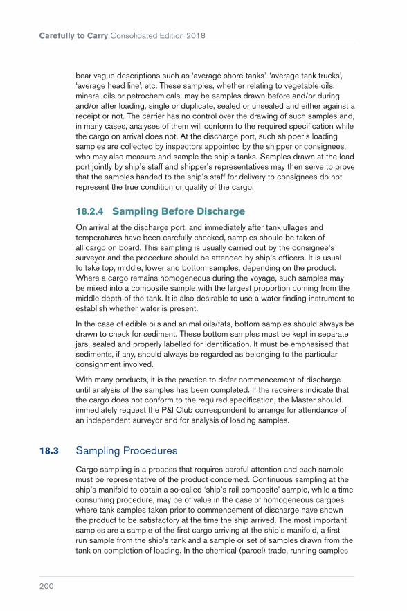
Carefully to Carry Consolidated Edition 2018
200
bear vague descriptions such as ‘average shore tanks’, ‘average tank trucks’, ‘average head line’, etc. These samples, whether relating to vegetable oils, mineral oils or petrochemicals, may be samples drawn before and/or during and/or after loading, single or duplicate, sealed or unsealed and either against a receipt or not. The carrier has no control over the drawing of such samples and, in many cases, analyses of them will conform to the required specification while the cargo on arrival does not. At the discharge port, such shipper’s loading samples are collected by inspectors appointed by the shipper or consignees, who may also measure and sample the ship’s tanks. Samples drawn at the load port jointly by ship’s staff and shipper’s representatives may then serve to prove that the samples handed to the ship’s staff for delivery to consignees do not represent the true condition or quality of the cargo.
18.2.4 Sampling Before Discharge
On arrival at the discharge port, and immediately after tank ullages and temperatures have been carefully checked, samples should be taken of all cargo on board. This sampling is usually carried out by the consignee’s surveyor and the procedure should be attended by ship’s officers. It is usual to take top, middle, lower and bottom samples, depending on the product. Where a cargo remains homogeneous during the voyage, such samples may be mixed into a composite sample with the largest proportion coming from the middle depth of the tank. It is also desirable to use a water finding instrument to establish whether water is present.
In the case of edible oils and animal oils/fats, bottom samples should always be drawn to check for sediment. These bottom samples must be kept in separate jars, sealed and properly labelled for identification. It must be emphasised that sediments, if any, should always be regarded as belonging to the particular consignment involved.
With many products, it is the practice to defer commencement of discharge until analysis of the samples has been completed. If the receivers indicate that the cargo does not conform to the required specification, the Master should immediately request the P&I Club correspondent to arrange for attendance of an independent surveyor and for analysis of loading samples.
18.3 Sampling Procedures
Cargo sampling is a process that requires careful attention and each sample must be representative of the product concerned. Continuous sampling at the ship’s manifold to obtain a so-called ‘ship’s rail composite’ sample, while a time consuming procedure, may be of value in the case of homogeneous cargoes where tank samples taken prior to commencement of discharge have shown the product to be satisfactory at the time the ship arrived. The most important samples are a sample of the first cargo arriving at the ship’s manifold, a first run sample from the ship’s tank and a sample or set of samples drawn from the tank on completion of loading. In the chemical (parcel) trade, running samples

Chapter 18 Samples and Sampling in the Carriage of Liquid Bulk Cargoes
201
during the first five minutes of loading are sometimes also drawn. The object of all these sampling operations is to obtain a manageable quantity of cargo, the condition and properties of which correspond as closely as possible to the average condition and properties of the parcel being sampled.
The importance of cleanliness cannot be too strongly stressed. All sampling work should be carried out with clean hands and, where protective clothing is necessary, such as in the case of toxic products, clean gloves of a suitable material should be worn. The apparatus used should be of a suitable material that does not react chemically with the cargo being sampled. Various types of sampling bottle can be used, particularly in large tanks, but if glass bottles are employed, care should be taken to avoid breakage.
With edible oils, where smell and flavour is important in quality assessment, scrupulous cleanliness is essential and the sampling devices should be thoroughly washed with hot water and soap and rinsed with hot water before use. All sampling equipment should be protected from the weather, rain, dust, rust, grease, etc, and, before the sample is divided into suitable glass jars, the outside of the sampling apparatus should be wiped clean.
When sampling from the manifold or pipeline, care should be taken to ensure that the sampling cock through which the product is drawn is absolutely clean. This method of sampling is most difficult and must be carefully supervised to ensure that both shipper and carrier obtain a part of the same representative sample. It is important that, when samples are being taken by this method, a constant rate of flow of the product is involved. If there is a variation in the flow rate, the sampling cock must be carefully regulated to ensure that the full sample is taken at a constant rate.
Certain products, such as corrosive liquids, liquefied gases and products that react dangerously with water and/or air cannot be sampled by normal means. It may also be dangerous to keep samples of some products for too long as they become unstable.
18.4 Labelling of Samples
All samples taken jointly should be properly labelled and sealed and identical sets should be kept by all parties. Should shippers refuse to seal the samples jointly, an appropriate entry should be made in the logbook. They should be unilaterally labelled and sealed by the ship’s staff and/or the independent surveyor representing the carrier. The samples themselves must be identical to those taken together with the shippers and the latter must be notified in writing

Carefully to Carry Consolidated Edition 2018
202
immediately to confirm the joint sampling and record any refusal to seal these identical samples jointly with the carrier.
In some ports, the chief officer may be asked to sign paper labels that bear the name of the ship, the shippers, the product, the ship’s tank, the date and place of sampling, a seal number (such as the one to appear later on the wax seal) and the signature of shippers’ inspectors before the loading operations have been completed or, sometimes, even before they have started. These labels are later attached to the sample containers after they have been filled and closed. This practice should be discouraged as the only way to be certain that the proper label is put on the proper sample container is for ship’s staff to participate in the whole procedure of sampling and sealing and to insist that the sealing and the labelling takes place on board the ship.
All labels should be properly dated and should indicate the local time when they were drawn, the name of the product and its destination, the name of the shippers and whether the sample was drawn jointly with them. The label should also record the quantity, tank number, the tank ullage and temperature, the B/L and voyage number and whether it is a manifold, pipeline, first run or average ship’s tank sample after completion of loading. Care must be taken that all these details will remain legible by using permanent washable ink. Having signed the labels, the ship is entitled to retain a set of the samples.
18.5 Storage of Samples
Samples should be stored in a dark, well-ventilated place where daylight cannot enter and away from sources of heat and from living quarters and foodstuff storerooms. Edible oils and chemicals should be stored separately. Samples should be contained in clean, dry and airtight containers, preferably of glass, tinned steel or a plastic material that will not become affected by the contents. They should be closed with corks or suitable plastic stoppers.
A sample logbook should be maintained recording the sample number, the sampling date and place, ship’s tank, quantity and kind of product, name of shipper and place of shipment, name of consignee and place of discharge, where stored on board and notes on disposal. Samples should be retained for a period of three months after the ship has discharged.
18.6 Sampling Instruments
Sampling instruments may be made of glass, stainless steel, aluminium, etc, and it is important to use an instrument made of a material that is compatible with the cargo being sampled. It is generally advisable to avoid instruments made of copper or copper-based alloys.
Sampling instruments should be simple, robust and easy to clean. Figures 18.1 to 18.4 illustrate sampling instruments for bulk oil shipments and some other liquid bulk cargoes. The Association is grateful to the British Standards

Chapter 18 Samples and Sampling in the Carriage of Liquid Bulk Cargoes
203
Institution for allowing material from BS EN 627:1996 to be reproduced (Reference 32).
Figure 18.1: Sampling bottle or can. Figure 18.2: Sampling tipping dipper.
The sampling bottle (Figure 18.1) is suitable for sampling large ships and tanks of liquid oil. It consists of a bottle or metal container, which may be weighted, attached to a handle long enough to reach the lowest part to be sampled. It has a removable stopper or top to which is attached a suitable chain, pole or cord. This device is lowered to the desired depth, where the stopper or top is removed and the container allowed to fill.
The tipping dipper (Figure 18.2) consists of a cylinder approximately 6 in (150 mm) long and 2 in (50 mm) in diameter, carrying an extension with a hole at its closed end and a stout wire handle at the open end. The handle carries a small metal catch and a rope. The cylinder is inverted in the position shown on the left, and maintained in that position by the insertion of the catch into the hole, and then sunk into the oil in the tank. At the required depth, the rope is twitched to release the catch, whereupon the cylinder rights itself and fills with oil.

Carefully to Carry Consolidated Edition 2018
204
Figure 18.3: ‘Go Devil’ sampling bottle. Figure 18.4: Bottom, or zone, sampler.
The ‘Go Devil’ (Figure 18.3) sampling bottle consists of a bottle, heavily weighted at the bottom, with a chain attached. When placed in oil in a tank, it drops so quickly that it does not begin to fill with oil until it reaches a fixed position.
The bottom sampler, or zone sampler, (Figure 18.4) is suitable for withdrawing bottom samples or zone samples at any level from tanks of liquid oil. To withdraw a bottom sample, the apparatus is attached to a cord or chain and lowered empty to the bottom of the tank. On contact with the bottom, the central spindle valve automatically opens and the container fills from the bottom. On withdrawal of the sampler, the valve automatically closes again. To withdraw samples at any level, the apparatus is lowered empty to the required level and then, by means of an additional cord attached to the top of the central valve spindle, the valve may be opened and the container filled. When the sampler has filled, the valve is allowed to close and the container is withdrawn.

205
Chapter 19
Flashpoint Contaminations of Diesel Oil and Gas Oil
The bulk liquid trade has a history of flashpoint contamination of high flashpoint cargo (eg diesel oil or gas oil) loaded into a tank that previously discharged a low flashpoint cargo, such as naphtha or gasoline. Such contamination can lead to significant delays and subsequent claims for flashpoint contamination of the ‘first-foots’ of the diesel oil or gas oil.
When first-foots are contaminated, there is an inevitable dispute as to whether the vessel can continue loading or whether the contaminated first-foots have to be discharged ashore.
If loading continues, after re-purging with inert gas, it will be hoped that the cargo can be blended back to within specification by dilution with sound cargo. This option is risky as, if the end result does not conform to the calculations undertaken, the vessel now has a full flashpoint contaminated cargo on board.
Alternatively, the first-foots may be discharged ashore and the tanks re-purged with inert gas before resumption of loading. This option may lead to significant delays and possibly substantial demurrage disputes between owners and charterers.

Carefully to Carry Consolidated Edition 2018
206
19.1 Common Industry Practice
Several options are available to avoid contamination when preparing cargo tanks to load high flashpoint cargo following a discharge of low flashpoint cargo:
1. Cargo tanks are hot water washed (this is not essential but it speeds up the subsequent gas-freeing operation) and gas-freed for entry.
This option avoids flashpoint contamination of the next cargo loaded and has the advantage of allowing entry for inspection of the cargo tanks.
This option may not be available because of commercial pressure to load the next cargo as quickly as possible.
2. Cargo tanks are cold water washed, ensuring that all liquid lines are flushed in the process, with recovery of the seawater/oil slops into the vessel’s slop tank(s).
The seawater can then be decanted overboard, from the bottom of the oil/water mixture, before recovering the oil part of the slops into the vessel’s oil retention tank, in compliance with Annex 1 of MARPOL 73/78 (Reference 30). All cargo tanks are then purged with further inert gas until the hydrocarbon content of the vapour phase is less than 2% by volume (ie the industry accepted standard).
3. The usual method is simply to purge each cargo tank with inert gas until the hydrocarbon content of the vapour phase is ‘less than 2% by volume’.
This option is popular because it is quicker and requires less manpower than options 1 and 2. However, if it is not carried out properly, it may result in subsequent claims for f lashpoint contamination of the next cargo first-foots.
19.2 Hydrocarbon Content of the Vapour Spaces
After discharge of a cargo such as naphtha or gasoline, the cargo tank vapour spaces will contain a mixture of inert gas and predominantly C5+ (with some C3 and C4 present) hydrocarbon vapours.
Such hydrocarbon vapours are approximately twice as heavy as the inert gas vapours (consisting mostly of nitrogen). Given this disparity in density, it is inevitable that the hydrocarbon vapours will settle towards the bottom of each cargo tank.
The industry accepted standard with regard to flashpoint contamination is to purge cargo tank vapour spaces with inert gas until the hydrocarbon content is less than 2% by volume. This corresponds approximately to 100% of the lower explosive limit (LEL) of the hydrocarbon vapours present, but concerns flashpoint contamination criteria only.

Chapter 19 Flashpoint Contaminations of Diesel Oil and Gas Oil
207
It is often assumed that the dilution method of purging the cargo tanks with inert gas (using inlets at the top of the tank and venting from the top of the tanks) is sufficient to reduce the entire vapour space hydrocarbon content to less than 2% by volume. Unfortunately, this is not always the case and a layer of heavier density hydrocarbon vapour may remain in the bottom of the cargo tank. This layer of hydrocarbon vapour is absorbed into the first-foots of the next cargo loaded, resulting in flashpoint contamination.
If option 3 is the preferred option, the following operational procedures are recommended to ensure that the cargo tank vapour spaces are clear of hydrocarbon vapours (ie lower than 2% by volume) before loading the next high flashpoint cargo:
1. Ensure that all cargo lines and cargo tank sumps are completely clear of the previous low flashpoint cargo.
2. Set the cargo lines so that inert gas is delivered to the top of the tank (as per normal) but the tanks are vented to atmosphere from the bottom of the tanks. This can usually be achieved by opening the liquid lines to the liquid cargo manifolds and, if possible, connecting this outlet to the vent riser(s).
3. Start inerting and venting the bottom of the tanks to atmosphere via the liquid manifolds. This layering method is considered to be more economical than the dilution method and will ensure that all hydrocarbons are removed from the bottom layers of each cargo tank. 1 to 1½ volume changes should be sufficient for each tank.
4. Continue to inert gas purge each pair of wing tanks in turn until the purging operation is complete.
5. Take hydrocarbon readings from the middle and bottom (ie bottom 1 m level) and confirm that hydrocarbon readings are below 2% by volume.
Great care should be taken when using multigas detectors in inert gas atmospheres (usually with oxygen content below 5% by volume). Gas detectors that use non-dispersive infrared (NDIR) detectors can be used safely in inert gas atmospheres to give direct gas concentrations in both the %Volume and the %LEL modes. Some types of gas detector, however, operate using dual catalytic sensors. In the %Volume mode, with correction factors applied, they will give the correct gas concentrations. In the %LEL mode, however, these sensors can only be used in inert gas atmospheres that contain at least 10% by volume oxygen. They cannot be used in normal inert gas atmospheres (ie less than 5% by volume oxygen) and, if used in such circumstances, will give unreliably erratic readings.


209
Chapter 20
Liquid Natural Oils, Fats and Fatty Products
This chapter includes crude vegetable, animal and marine oils as well as fats. Some of the oils are edible and others are used in the production of soap, paint, lacquer, cosmetics and medicines. When these products are transported by sea, a variety of difficulties may be encountered, the causes of which generally fall into two categories:
� Handling (usually temperature control)
� contamination.
20.1 Handling
Claims frequently arise that involve allegations of unsatisfactory handling by ships. It is sometimes necessary to apply heat to these cargoes as, during a sea passage, the temperatures encountered are likely to be lower than those recommended by the shippers. Many products of this type are adversely affected by heating, so some deterioration is inevitable. The extent of the damage depends on the nature of the product and the length of the voyage.

Carefully to Carry Consolidated Edition 2018
210
Unsatisfactory temperature control can cause additional deterioration, usually because the carrying temperature has been too high for all or part of the voyage. It is possible to estimate the level of unavoidable damage, so the extent of further damage caused by poor temperature control can be calculated.
Damage may also result if the carrying temperature is allowed to fall below that recommended by the shippers. The normal procedure for heating this type of product is through the use of heating coils at the tank bottoms and lower sides, with heat being transferred throughout the oil, mainly by convection current. The heat transfer becomes progressively less efficient as viscosity increases. The viscosity of liquid natural fatty products is greatly affected by temperature and a reduction of only a few degrees can have a serious effect. If the heating process is inadequate to maintain sufficient fluidity within the bulk of cargo, the liquid in the vicinity of the heating coils can become overheated.
During the discharge of cargo, if the environmental temperatures are very low, further problems may arise as a result of solidification, which most commonly occurs when a tank is almost empty and the liquid level has fallen below the level of the heating coils. Under such circumstances, the final residues may be removed by sweeping or by steam stripping, provided the receivers are able to accept the fat and water mixture that is produced. Ship’s officers responsible for discharging heated products in cold climates should ensure that the maximum pumping rate is maintained and that there are no interruptions during discharge.
20.2 Contamination
The most common contaminant resulting in claims is water, originating from shore or ship tanks, pumps or lines at the time of loading, or introduced by mistake or due to leakage. Some products contain a significant quantity of water when shipped, but the presence of excess water in others may accelerate deterioration.
Traders and governmental authorities also have concerns about the contamination of edible products by traces of chemical substances. Often, but not always, these contaminants have come from residues of previous cargoes.
It is normal practice for samples to be drawn by independent surveyors during loading, or immediately after loading, and at least one set of these samples will be given to the ship. It is important that the ship has a set of loading samples, since most claims are based upon differences in analytical parameters in samples drawn at loading and discharge. If the Master is instructed to deliver a set of samples to the receivers on arrival at the discharge port, it is recommended that he requests that the shippers provide a second set of samples for the use of the shipowners. Any such samples handed to the ship should be properly stored during the voyage, preferably in a refrigerated store.

Chapter 20 Liquid Natural Oils, Fats and Fatty Products
211
At the time of discharge, samples are always drawn by the receivers or their surveyors. Normal analyses conducted at both load ports and discharge ports are quite straightforward and the typical parameters determined are water, free fatty acid, unsaponifiable matter and odour. If there is evidence or suspicion that, on delivery, the cargo does not conform to either a specification or to the loading samples, more detailed chemical analysis may be performed. Contaminants can be identified and determined at levels as low as 10 parts per billion (ppb); contamination at this level will result from admixture of 10 g of contaminant with 1,000 t of cargo. Most chemical contaminant can be identified and determined at levels of 100 ppb, or 100 g per 1,000 t of cargo.
When cargo is loaded or transshipped, it is essential to consider the nature of previous cargoes. In some cases, it is virtually impossible during tank cleaning to remove all traces of previous cargo to a level that is not detectable by modern laboratory equipment. For this reason, restrictions are laid down in the contracts of sale regarding the immediate previous cargo carried in each of the ship’s tanks. Shippers and charterers should be notified in good time of the nature of the three previous cargoes carried in each individual tank. The restrictions are imposed by such bodies as FOSFA and NIOP and their rules should always be consulted. They are constantly under review and may change in the future.
It is important that, before loading, every care and attention is paid to the proper preparation of tanks, pumps and pipelines. It is very important that the tank coating is maintained to a high standard. The coating covering all sections of the tank must be sound because, where any breakdown of the coating takes place, particularly where epoxy and polyurethane coatings are concerned, there is a risk that the remains of previous cargoes may accumulate, creating a potential source of contamination. The breakdown of epoxy coating usually manifests itself in the form of open or closed blisters, forming pockets that cannot be reached by cleaning water. In these areas, there is also a risk that rust may form, which is again likely to trap cargo residues and lead to contamination.
It is not possible to properly clean tanks with damaged coatings and cases have been recorded where traces of the third previous cargo have been found when samples of damaged coatings were tested.
Another possible source of contamination is the penetration and softening of epoxy and polyurethane coating by a previous cargo, which may then find its way later into newly loaded products. Masters should always consult the cargo resistance list provided by the manufacturers of the tank coating, which will list cargoes to which the tank coating is resistant. For cargoes not included in the list, or for cargoes without resistance indicators, or when deviating from the maximum temperatures indicated on the list, the manufacturers should always be consulted.

Carefully to Carry Consolidated Edition 2018
212
Tank cleaning
The precise method of cleaning will depend on the previous cargo carried and the state of cleanliness required for the products to be loaded. The relevant tank cleaning guides should always be consulted. Generally, the most important part of the tank cleaning process is Butterworthing with hot or cold seawater at sufficient pressure and at the appropriate tank levels. This should be followed by fresh water washing to remove seawater residues. Tanks that may have contained monomer or drying oils should first be washed with sufficient quantities of cold water to avoid polymerisation of cargo residues. In some cases, it is necessary to employ tank cleaning chemicals, but their use is generally limited as it may be difficult to dispose of slops.
On completion, the tanks should be clean, dry and free from residual odours. It may also be desirable to take wall-wash samples and have them analysed for traces of previous cargoes, although this requires skilled inspectors. The presence of an odour in a tank that has been cleaned indicates the presence of cargo residues and also indicates the need for further cleaning. When checking for residual odours, it is advisable to conduct the test after the tank has been closed for a period. Testing should, in any case, be carried out by personnel who have not been working in or near the tanks for at least one hour.
When cargo with a high melting point has been carried, tanks should be washed with hot water. If possible, steam should be used to ensure the residues are effectively melted and cleared. The cleaning process must also include the tank lines, tank lids and vent lines, including pressure vacuum valves and risers. Examples of cargoes with high melting points include phenol and waxes.
Cargo pumps, usually of the hydraulic deep well type, should be dismantled and inspected as recommended by the manufacturer. The pumps should be purged to test the seals that separate the cargo and the hydraulic oil from the void space in the pump. This procedure should always be followed after tank cleaning, before loading and discharging, and after repairs. The results should always be properly recorded in the ship’s logbook or other formal records. Where defects to the seals are suspected, cargo should not be handled until corrective measures have been taken. When cleaning pumps, consideration must be paid to the trim of the ship to ensure that any contaminated product is properly drained away. Portable pumps should be tested before being lowered into the cargo tank.
If heating coils are not to be used, before loading commences they should be thoroughly purged and blanked both at the supply and the return ends. Even though coils may have been in use for some time, they should be pressure tested before loading to avoid the possibility of contamination through leaks that might have developed. Pumps not required for cargo handling should always be isolated.
Special attention should be paid to the cleanliness of vent lines, as they may contain residues of previous cargoes, both in a liquid and a solidified state.

Chapter 20 Liquid Natural Oils, Fats and Fatty Products
213
Vent lines, when not cleaned after discharge, may drain into a newly loaded tank when the vessel changes trim or when encountering heavy weather. Solidified cargo residues in a vent line may melt, due to the heat emitted from a heated cargo, and the melted product may drain back into the tank, causing contamination. The practice of steaming vent lines after the carriage of heated cargoes is recommended as blocked lines may result in overpressuring of cargo tanks.
Drain cocks fitted at the lowest parts of deck and manifold lines, as well as plugs at the bottom of cargo valves, should be opened and rinsed in order to remove any trapped cargo residues. These drain cocks may contain sufficient liquid to result in serious contamination. When clearing deck and drop lines, it is important to ensure that the dead ends of these lines and drop lines are not overlooked. They should be opened and thoroughly cleaned.
Mild steel tanks are sometimes used for the carriage of natural oils and fats but their use is in decline as cargo charterers more frequently stipulate the use of stainless steel or coated tanks. When used, mild steel tanks should be free from rust and scale, since remnants of previous cargoes are likely to be trapped and transferred into subsequently loaded cargoes. Where sensitive cargoes have been carried in mild steel tanks, contamination has been known to occur from the residues of hydrocarbon (petroleum products) cargoes.
The importance of proper tank cleaning procedures and the correct preparation of tanks and all related equipment prior to loading cannot be overemphasised. Masters may wish to consider appointing an independent surveyor to verify the condition of the tank coating, heating coils and hatch openings after the tank preparations have been completed.
On completion of loading, an ullage survey by an independent surveyor may be appropriate, and thereafter valves and hatches should be sealed. This process can be repeated at the discharge port. The practice of taking onboard samples at all stages of the loading and discharging operation is also highly recommended.
Should contamination occur at some stage in the course of transit, it may be possible, by analysis of such samples, to identify the source of contamination. By ensuring that the cargo is carried to the highest standards, the product should be well protected.


215
Chapter 21
Biofuels: Marine Transport, Handling and Storage Issues
The production and use of biofuels as transport fuels has increased dramatically in recent years. A number of legislative reforms have mandated the integration of fuels derived from renewable sources into fuel infrastructure. However, the introduction of biofuels has not been without problems and there is a large amount of research still ongoing into the properties of biofuels and how they behave when blended with conventional fossil fuels.
21.1 Legislative Targets
Biofuels were originally seen as an answer to the problems of increasing greenhouse gas (GHG) emissions and global warming. Biofuels are produced from renewable sources such as corn, wheat, rapeseed and soya beans, which can be quickly and easily replenished.

Carefully to Carry Consolidated Edition 2018
216
Figure 21.1: Potential sources of biofuel.
However, questions were soon raised with regard to the environmental credentials and overall sustainability of commercially available biofuels. Issues included the use of crops that would normally be used for food being put into biofuel production, the questionable CO2 emissions savings when considering the overall production process, deforestation to make way for biofuel crop plantations and the use of environmentally harmful fertilisers and pesticides employed in growing the crop feedstock. It was even suggested by some parties that biofuels could, in reality, be causing more harm than good to the environment.
Amid these growing concerns, the UK government has amended the targets set out in the Renewable Transport Fuel Obligation (RTFO), a directive aimed at reducing GHG emissions from road transport, and in December 2008 it was mandated that, by 2020, 10% of all automotive fuel consumption by energy content should be sourced from renewable energy sources (Reference 33). This was further clarified in 2015 when the European Parliament voted to approve new legislation that capped the contribution of biofuels produced from food crops to 7%.
Annual figures for the 2013/2014 period showed that 1,412 million litres of biofuels were imported to the UK transport market and it has been estimated that the global biodiesel and ethanol markets are likely to reach US$247 billion in sales by 2020, up from US$76 billion in 2010.
21.2 Current Types of Biofuel
There are currently two main classes of biofuels in widespread use; biodiesel (or, more correctly, FAME) and bioethanol. The two are very different in their properties and therefore have different issues to consider if they are to be safely shipped, handled, stored and used.

Chapter 21 Biofuels: Marine Transport, Handling and Storage Issues
217
21.2.1 FAME/Biodiesel
Biodiesel is a fuel derived from vegetable oils or animal fats, and is more correctly called fatty acid methyl esters (FAME). FAME is the product of reacting a vegetable oil or animal fat with an alcohol (methanol, a petrochemical that is generally derived from natural gas or coal) in a process known as transesterification. When compared to conventional diesel derived from crude oil, vegetable oils and animal fats generally have higher viscosities (which means they are more difficult to pump and store without heating) and are more unstable (which means they are more likely to degrade during storage, handling and end use). The transesterification process brings the properties of the raw materials closer to those of a conventional diesel, making the product more suitable for use as a road transport fuel. However, while the FAME produced can be used neat as a fuel, it is more commonly blended with conventional petroleum diesel for use in diesel engines.
The ASTM has described a system of nomenclature for naming FAME/diesel blends (see ASTM D6751) (Reference 34). Pure FAME is denoted B100, standing for 100% biodiesel. Other common blends include B5 (5% biodiesel and 95% conventional diesel), B7 (the EN 590 European diesel standard allows up to 7% by volume FAME in diesel) and B20 (20% biodiesel and 80% conventional diesel).
Raw materials for FAME production
Various raw materials may be used for the production of FAME, including palm oil, coconut oil, rapeseed oil, soya bean oil, tallow and used cooking oils. A general FAME cargo might be the product of processing any one of these raw materials or may be a mixture of FAMEs produced from different raw materials. Each raw material would produce FAME of a different chemical composition, with correspondingly different characteristics. For example, a FAME derived from palm oil (PME) is likely to be solidified at normal UK winter temperatures, whereas a FAME derived from rapeseed oil (RME) will be a liquid.
Figure 21.2: Examples of FAME.

Carefully to Carry Consolidated Edition 2018
218
One of the most important chemical characteristics of FAME is the structure and composition of the fatty acid methyl ester groups, which will be determined by the fatty acid components of the raw material used in the production process.
FAME types composed of a relatively high proportion of saturated fatty acid methyl esters, such as palm oil derived FAME (denoted PME), will generally be relatively stable to unwanted degradation reactions, but will have poorer cold temperature performance. FAME types composed of a relatively high proportion of unsaturated fatty acid methyl esters, such as soya bean oil derived FAME (denoted SME), will display markedly different behaviour, with better cold temperature properties in comparison to PME, but less stability to degradation reactions.
The presence and composition of other chemical constituents is also important. For example, FAMEs with high levels of vitamin E are thought to be more stable to unwanted oxidative degradation reactions.
21.2.2 FAME Problems
Water contamination
A major problem with regard to the carriage of FAME by sea is the issue of water contamination. FAME is a hygroscopic material, which means that it will absorb water from its surrounding environment, including the atmosphere. This renders FAME very sensitive to water contamination. The current maximum allowable water content in the European EN 14214 and American ASTM D6751 FAME standards is 500 mg/kg, although selling specifications are often lower (300 mg/kg being a typical maximum water content on a sales specification), reflecting the high potential for water pick-up in this material (Reference 35 and Reference 34).
Figure 21.3: FAME cargoes are extremely sensitive to water contamination, the source of which can be seawater taken in during a storm.

Chapter 21 Biofuels: Marine Transport, Handling and Storage Issues
219
Unlike most conventional diesels, in which any undissolved water present will generally settle out over a period of time, FAME can hold water in suspension up to relatively high levels (above 1,000 mg/kg). Apart from the fact this will render the cargo off-specification for water content, the presence of water can promote unwanted hydrolytic reactions, breaking down the FAME to form free fatty acids, which not only affect certain specification parameters for the material, but are also corrosive and may attack exposed metal surfaces. Additionally, once a certain threshold level of water content is reached, water can separate out from the FAME, forming a separate (and potentially corrosive) free water phase. The possibility of phase separation occurring is greater for blends of FAME and conventional diesel.
The presence of a FAME/water interface provides ideal conditions for the promotion of unwanted microbiological growth, which may in turn lead to filter blocking and corrosion problems.
Some publications have referenced the greater degree of biodegradability of FAME as a positive factor when dealing with environmental spillages. While this is correct, it also means that FAME is considerably more prone to microbiological attack than a conventional fossil fuel.
Possible sources of water contamination on board a vessel range from the obvious ones of seawater ingress or residues of tank washing operations to the less obvious ones of moisture in an inert gas blanket produced from a faulty flue gas generating system, or atmospheric humidity in tank ullage spaces that are not under a positive pressure of dry inert gas. Despite having relatively high flashpoints, FAME cargoes are generally carried under a (dry) nitrogen blanket to avoid the potential increase in water due to absorption of moisture from tank ullage spaces.
Stability problems
FAMEs are generally more prone to issues with regard to their stability than conventional petroleum diesel. FAME can degrade under the influence of air, heat, light and water, and this may occur during transport, storage or even during end use. FAME cargoes may display different levels of stability depending on their composition and the feedstock(s) used in their production.
Potential shipping problems include the promotion of degradation reactions by trace metals (copper heating coils or zinc-containing tank coatings have the potential to cause deterioration in quality) and thermal stability issues if the FAME cargoes are stored next to heated tanks, for example bunker settling tanks. Issues with the promotion of instability by the presence of trace metals are worse for B100 than for lower biodiesel blends such as B5 or B20. Degradation reactions can form insoluble sediments and gums, which may increase the viscosity of the FAME, leading to filter blocking, or they may potentially further decompose to other more corrosive species.
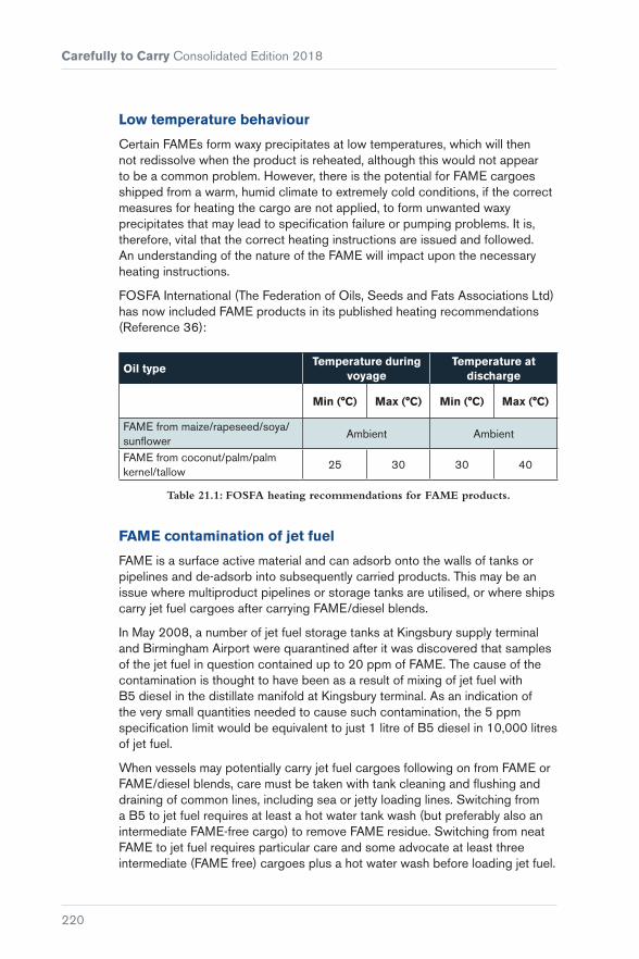
Carefully to Carry Consolidated Edition 2018
220
Low temperature behaviour
Certain FAMEs form waxy precipitates at low temperatures, which will then not redissolve when the product is reheated, although this would not appear to be a common problem. However, there is the potential for FAME cargoes shipped from a warm, humid climate to extremely cold conditions, if the correct measures for heating the cargo are not applied, to form unwanted waxy precipitates that may lead to specification failure or pumping problems. It is, therefore, vital that the correct heating instructions are issued and followed. An understanding of the nature of the FAME will impact upon the necessary heating instructions.
FOSFA International (The Federation of Oils, Seeds and Fats Associations Ltd) has now included FAME products in its published heating recommendations (Reference 36):
Oil typeTemperature during
voyageTemperature at
discharge
Min (°C) Max (°C) Min (°C) Max (°C)
FAME from maize/rapeseed/soya/sunflower
Ambient Ambient
FAME from coconut/palm/palm kernel/tallow
25 30 30 40
Table 21.1: FOSFA heating recommendations for FAME products.
FAME contamination of jet fuel
FAME is a surface active material and can adsorb onto the walls of tanks or pipelines and de-adsorb into subsequently carried products. This may be an issue where multiproduct pipelines or storage tanks are utilised, or where ships carry jet fuel cargoes after carrying FAME/diesel blends.
In May 2008, a number of jet fuel storage tanks at Kingsbury supply terminal and Birmingham Airport were quarantined after it was discovered that samples of the jet fuel in question contained up to 20 ppm of FAME. The cause of the contamination is thought to have been as a result of mixing of jet fuel with B5 diesel in the distillate manifold at Kingsbury terminal. As an indication of the very small quantities needed to cause such contamination, the 5 ppm specification limit would be equivalent to just 1 litre of B5 diesel in 10,000 litres of jet fuel.
When vessels may potentially carry jet fuel cargoes following on from FAME or FAME/diesel blends, care must be taken with tank cleaning and flushing and draining of common lines, including sea or jetty loading lines. Switching from a B5 to jet fuel requires at least a hot water tank wash (but preferably also an intermediate FAME-free cargo) to remove FAME residue. Switching from neat FAME to jet fuel requires particular care and some advocate at least three intermediate (FAME free) cargoes plus a hot water wash before loading jet fuel.

Chapter 21 Biofuels: Marine Transport, Handling and Storage Issues
221
Jet fuels from a marine terminal storage tank do not require testing for FAME contamination where it can be confirmed that there is no FAME in the marine supply system. Where there is direct knowledge that any diesel on board, or having any interface with the jet fuel, is B0 and the vessel has not carried biodiesel within the last three loads then the jet fuel may be exempted from testing.
The current industry guidelines for the prevention of FAME contamination of aviation jet fuel are as follows1:
I. Three intermediate cargoes with a no FAME content between a FAME B100 (100%) cargo or any cargo with a FAME content greater than 15% (above B15) and a subsequent aviation jet fuel cargo.
II. When following cargo with a FAME content of 5% or less (B5 or below), a hot water wash, including flushing of pumps and lines, followed by draining is recommended as a minimum.
III. When following cargo with a FAME content of 15% (B15) or less but above B5, a hot water wash, including flushing of pumps and lines, followed by draining is recommended as a minimum. Tanks must be in good condition and washing needs to be particularly stringent. A single intermediate cargo with no FAME content is suggested as an alternative, followed by a hot water wash, including flushing of pumps and lines, and by draining.
The Defence Standard 91-91 (Reference 37) suggests that the currently specified method of flushing sample containers three times for jet fuel samples may not be sufficient to remove traces of FAME, which may even be transferred from contaminated gloves. This could potentially lead to false positive detection of FAME in actually on-specification material, resulting in erroneous claims being made. It is therefore recommended that new sample containers and new gloves are used when sampling jet fuel cargoes.
For product tankers carrying multiple products, the danger of inadvertently contaminating a cargo of jet fuel with traces of FAME is a very real risk, even if it does not initially appear that there is any potential for cross contamination to occur. For example, ultra-low sulphur diesel meeting the EN 590 specification may appear in the shipping documents as ULSD, which would not immediately indicate that the product contained any FAME. However, the EN 590 diesel specification allows up to 7% by volume FAME content (Reference 38). If the ship’s tanks and lines are not completely stripped of all the ULSD prior to loading a cargo of jet fuel, the quantity of ULSD containing 7% FAME needed to render the jet fuel cargo off-specification would be very small.
1 Source: The Energy Institute Guidelines for the cleaning of tanks and lines for marine tank vessels carrying petroleum and refined products (HM 50) – Section 2.12.7 (Reference 39). While not a legal requirement, these guidelines are based on sensible practice and owners should give serious consideration to adopting such advice.

Carefully to Carry Consolidated Edition 2018
222
Figure 21.4: Chromatogram showing the components of a fuel cargo.
Solvent behaviour
FAME has the ability to act as a solvent, taking up any organic residue, dirt or scale that may have accumulated on the surfaces of tanks or pipelines. This may have the effect of cleaning out the dirty storage or pumping systems, but it will contaminate the FAME itself and may lead to subsequent fouling of filters or pump blockages.
FAME is known to attack and quicken the ageing process of certain materials, including elastomers (which may be used as seals, valves, gaskets, etc), and materials should be checked for compatibility with FAME and FAME/diesel blends by consultation with the equipment manufacturer.
Biodiesel in bunkers
In 2017, the sixth edition of the marine fuels international standard, ISO 8217:2012 (Reference 40), was issued. The third edition of the marine fuels standard, ISO 8217:2005, required under point 5.1 of Section 5 that the fuels to be classified in accordance with the standard should be “homogeneous blends of hydrocarbons derived from petroleum refining”. This was interpreted as precluding fuel from containing any bio-derived components. During preparation of the fourth edition of the standard, the working group committee considered the topic of biodiesel and the potential for the material to find its way into the marine fuel supply chain. It concluded that it was almost inevitable that, as a result of blending FAME into automotive diesel, some marine distillates and possibly even marine residual fuels may contain a proportion of FAME as a result of cross contamination within the distribution system.

Chapter 21 Biofuels: Marine Transport, Handling and Storage Issues
223
As such, ISO 8217:2012 required, under point 5.4 of Section 5, that “The fuel shall be free from bio-derived materials other than ‘de minimis’ levels of FAME (FAME shall be in accordance with the requirements of EN 14214 or ASTM D6751). In the context of this International Standard, ‘de minimis’ means an amount that does not render the fuel unacceptable for use in marine applications. The blending of FAME shall not be allowed.”
The current standard, ISO 8217:2017, retains this de minimis level requirement but with a wider tolerance to a level of approximately 0.5 volume % FAME and with additional specifications (DF grades) for distiliate marine fuels (Reference 40).
Figure 21.5: Bunkering vessel supplying fuel to a cruise ship.
Annex A of the current standard (Reference 40), considers the issue of bio-derived products and FAMEs finding their way into marine fuels in more detail. It states that, notwithstanding the fact that FAME has “good ignition and lubricity properties together with perceived environmental benefits there are potentially specific complications with respect to the storage and handling of distillates with a FAME component in a marine environment, such as:
� A tendency to oxidation and long-term storage issues
� affinity to water and risk of microbial growth
� degraded low-temperature flow properties, and
� FAME material deposition on exposed surfaces, including filter elements.”
It is recognised that there are a number of differently sourced FAME products, each with their own particular characteristics, which may impact upon storage, handling, treatment, engine operations and emissions.

Carefully to Carry Consolidated Edition 2018
224
The standard states that in “... those instances where the use of fuels containing FAME is being contemplated, it should be ensured that the ship’s storage, handling, treatment, service and machinery systems, together with any other machinery components (such as oily-water separator systems), are in terms of materials and operational performance compatible with such a product. Contact of materials such as bronze, brass, copper, lead, tin and zinc with FAME should be avoided as these may oxidize FAME thereby creating sediments.”
Figure 21.6: Ethanol biorefinery.
21.2.3 Bioethanol
Bioethanol is ethanol produced by the fermentation of renewable sources of sugar or starch crops. Unlike FAME, bioethanol is a single chemical compound, the properties of which are well documented and understood. It is a volatile, colourless liquid that is miscible with water and is hygroscopic. Ethanol is the alcohol found in alcoholic beverages and is also commonly used as a solvent in perfumes, medicines and paints. However, the most common use for ethanol is as a fuel or fuel-additive. Ethanol for use as a fuel is generally dosed with a ‘denaturant’ to render it unsuitable for human consumption.
There is significant experience worldwide in the use of ethanol as a fuel or fuel-additive. In the USA, there has been over ten years’ successful use of gasoline containing up to 10% ethanol (E10) and in Brazil blends containing up to 85% to 100% ethanol (E85 and E100) are commonly used in flexible-fuel vehicles. The current European gasoline specification, EN 228, allows up to 5% ethanol by volume (E5) (Reference 41).
Bioethanol can be produced from a number of raw materials, but they do not impart the same variation in the properties of the end product fuel as is the case with FAME. However, there are still a number of potential hazards for consideration.

Chapter 21 Biofuels: Marine Transport, Handling and Storage Issues
225
21.2.4 Bioethanol Problems
Water contamination
An issue during the carriage of bioethanol and bioethanol-gasoline blends is the potential for water contamination, because ethanol is hygroscopic and highly soluble in water. Small quantities of water can be dissolved in gasoline/bioethanol blends but, depending on temperature and the gasoline/bioethanol blend ratio, there is a critical threshold level of water that can be dissolved. Once this threshold level has been exceeded, irreversible phase separation will occur where the water causes the ethanol to separate from the gasoline, forming an alcohol rich water/ethanol aqueous phase and an alcohol poor gasoline phase. The alcohol rich aqueous phase will collect at the bottom of the ship’s tank or storage tank.
This phase is likely to be highly corrosive and it will not be able to be used as fuel. In addition, if such phase separation does occur, it is possible that the gasoline phase will be classed as Pollution Category Z, which means that it is considered to present a “minor hazard to either marine resources or human health” if discharged into the sea from tank cleaning or deballasting operations and therefore “justifies less stringent restrictions on the quality and quantity of the discharge into the marine environment” (Reference 30). While the regulations do not require ethanol to be carried on a chemical tanker, ethanol is generally shipped on chemical tankers to maintain the integrity of the product.
It should be noted that the terms biodiesel and bioethanol do not appear in the IBC Code (Reference 42). As it is a requirement that the proper shipping name is used to describe any product to be carried that appears in the IBC Code, these terms cannot be used to describe the products being carried.
The situation becomes more confusing when considering how blends of conventional fossil fuels and biofuels are shipped and the Annex of MARPOL they fall under. MARPOL Annex I covers the prevention of pollution by oil and MARPOL Annex II covers the control of pollution by noxious liquid substances carried in bulk (Reference 30). Blends of biofuels and conventional fuels are essentially mixtures of mineral oil based hydrocarbons and noxious liquid substances. The IMO has issued guidelines in MEPC.1/Circ.761/Rev.1 (Reference 43) in respect of blends of biofuels and conventional fossil fuels as follows:
Band 1: 75% or more petroleum oil (25% or less biofuel) – product is carried as an Annex I cargo. Oil discharge monitoring equipment (ODME) should be approved/certified for the mixture carried or tank residues and all tank washings should be pumped ashore.
Band 2: More than 1% but less than 75% petroleum oil (25% to 99% biofuel) – product is carried as an Annex II cargo. A list of existing blends and corresponding IMO IBC carriage requirements is provided in MEPC.1/Circ.761/Rev.1.

Carefully to Carry Consolidated Edition 2018
226
Carriage requirements for new blends of biofuels identified as falling under the scope of MARPOL Annex II will be incorporated into List 1 of the MEPC.2/Circular, as appropriate.
Band 3: 1% or less petroleum oil (greater than 99% FAME) – product is carried as an Annex II cargo and cargo treated as the Annex II product contained in the blend. Issues of concern include the potential effect that FAME and ethanol cargoes might have on ODME equipment. The varying blend levels also impact upon how the cargo is measured. Work is currently being undertaken on samples of FAME from various origins and at different blend levels to establish suitable volume correction factors (VCFs) to be used in cargo measurement.

227
PART 7The Carriage of Gas
Chapter 22 ..............................................229Liquefied Gases
Chapter 23 ..............................................241Liquefied Natural Gas


229
Chapter 22
Liquefied Gases
A liquefied gas is a gaseous substance at ambient temperature and pressure, that is liquefied by pressurisation or refrigeration and sometimes a combination of the two. Virtually all liquefied gases are hydrocarbons and flammable in nature. Liquefaction compresses the gas into volumes suited to international carriage. The principal gas cargoes are LNG (see Chapter 23), LPG and a variety of petrochemical gases, and all have their specific hazards. By regulation, all liquefied gases when transported in bulk must be carried on a gas carrier, as defined by the IMO. The IMO’s Gas Codes (see Sections 22.2 and 22.3) provide a list of safety precautions and design features required for each product.
22.1 LPG
The term LPG (liquefied petroleum gas) covers butane or propane or a mixture of the two. The main use for these products varies from country to country, but sizeable volumes are used as power station or refinery fuels. However, LPG is also sought after as a bottled cooking gas and it can form a feedstock at chemical plants. It is also used as an aerosol propellant and is added to gasoline as a vapour pressure enhancer. LPG may be carried in either a

Carefully to Carry Consolidated Edition 2018
230
pressurised or refrigerated state. Occasionally, it may be carried in a special type of carrier known as a semi-pressurised ship. When fully refrigerated, butane is carried at minus 5°C (–5°C) and propane at minus 42°C (–42°C). This low carriage temperature for propane introduces the need for special low temperature (LT) steels.
22.2 Chemical and Other Gases
Ammonia is one of the most common chemical gases and it is carried worldwide in large volumes, mainly for agricultural purposes. It has particularly toxic qualities and requires great care during handling and carriage.
Another important liquefied gas is ethylene. Very sophisticated ships are available for this product as carriage temperatures are minus 104°C (–104°C) and onboard systems require a high degree of expertise. Within this group, a subset of highly specialised ships is able to carry multigrades simultaneously.
The recent exploitation of shale gas has brought an increase in LPG and ethane production, as by-products. Ethane may be used as an alternative to naphtha or LPG as a feedstock for the chemical industry. Liquefied ethane, with a temperature close to minus 89°C (–89°C) at atmospheric pressure, has typically been shipped in small ethylene/ethane carriers, the design characteristics of the cargo containment system for the ships in this trade being in the region of 27,500 to 35,000 m3. The economies of scale needed for a profitable global trade typically require ethane to be shipped in large volumes. The first of the new class of dedicated very large ethane carriers (VLECs) were delivered at the end of 2016 and these have a capacity of 87,000 m3. These ships have a reinforced membrane cargo containment system similar to that fitted to LNG carriers.
Significant in the design and operation of all gas carriers is that methane (the main constituent of LNG) vapour is lighter than air, while LPG vapours are heavier than air. For this reason, the current gas carrier regulations allow only methane to be used as a propulsion fuel, with any minor gas seepage in engine spaces being naturally ventilated. With the adoption in January 2017 by the IMO of the International Code of Safety for Ships using Gases or other Low-flashpoint Fuels (IGF Code) (Reference 44), it may, in future, be possible to use ethane and LPG as propulsion fuel.
The principal hydrocarbon gases such as butane, propane and methane are non-toxic in nature. A comparison of the relative hazards of oils and gases is provided in Table 22.1.
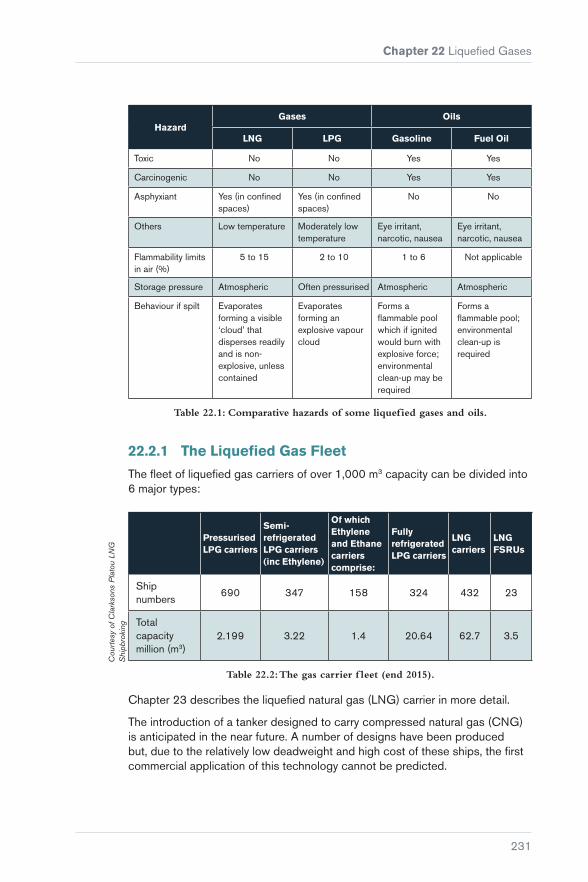
Chapter 22 Liquefied Gases
231
HazardGases Oils
LNG LPG Gasoline Fuel Oil
Toxic No No Yes Yes
Carcinogenic No No Yes Yes
Asphyxiant Yes (in confined spaces)
Yes (in confined spaces)
No No
Others Low temperature Moderately low temperature
Eye irritant, narcotic, nausea
Eye irritant, narcotic, nausea
Flammability limits in air (%)
5 to 15 2 to 10 1 to 6 Not applicable
Storage pressure Atmospheric Often pressurised Atmospheric Atmospheric
Behaviour if spilt Evaporates forming a visible ‘cloud’ that disperses readily and is non-explosive, unless contained
Evaporates forming an explosive vapour cloud
Forms a flammable pool which if ignited would burn with explosive force; environmental clean-up may be required
Forms a flammable pool; environmental clean-up is required
Table 22.1: Comparative hazards of some liquefied gases and oils.
22.2.1 The Liquefied Gas Fleet
The fleet of liquefied gas carriers of over 1,000 m3 capacity can be divided into 6 major types:
Pressurised LPG carriers
Semi-refrigerated LPG carriers (inc Ethylene)
Of which Ethylene and Ethane carriers comprise:
Fully refrigerated LPG carriers
LNG carriers
LNG FSRUs
Ship numbers
690 347 158 324 432 23
Total capacity million (m3)
2.199 3.22 1.4 20.64 62.7 3.5
Table 22.2: The gas carrier f leet (end 2015).
Chapter 23 describes the liquefied natural gas (LNG) carrier in more detail.
The introduction of a tanker designed to carry compressed natural gas (CNG) is anticipated in the near future. A number of designs have been produced but, due to the relatively low deadweight and high cost of these ships, the first commercial application of this technology cannot be predicted.
Cou
rtes
y of
Cla
rkso
ns P
lato
u LN
G
Shi
pbro
king

Carefully to Carry Consolidated Edition 2018
232
While the gas carrier is often portrayed negatively in the media as a potential floating bomb, accident statistics do not bear this out. The sealed nature of liquefied gas cargoes, in tanks completely segregated from oxygen or air, virtually excludes any possibility of a tank explosion. However, the image of the unsafe ship lingers, and some administrations and port state control organisations tend to target gas ships for special inspection whenever they enter harbour.
However, serious accidents related to gas carrier cargoes have been few and the gas carrier’s safety record is acknowledged as an industry leader. As an illustration of the robustness of gas carriers, when the ‘Gaz Fountain’ was hit by rockets during the Iran/Iraq War in the 1980s, despite penetration of the containment system with huge jet fires, the fires were successfully extinguished and the ship, together with most of the cargo, was salved.
The relative safety of the gas carrier is due to a number of features. One such, almost unique to the class, is that cargo tanks are always kept under positive pressure (sometimes just a small overpressure) and this prevents air entering the cargo system. This means that only liquid cargo or vapour can be present, so a flammable atmosphere cannot exist in the cargo system. In addition, all large gas carriers use a closed loading system with no venting to atmosphere, and a vapour return pipeline to the shore is often fitted and used where required.
22.3 Regulation of Gas Carrier Design
The regulations for the design and construction of gas carriers stem from practical ship designs codified by the IMO. However, all new ships (from June 1986) are built to the International Code for the Construction and Equipment of Ships Carrying Liquefied Gases in Bulk (the IGC Code) (Reference 45). This code also defines cargo properties and documentation provided to the ship (the Certificate of Fitness for the Carriage of Liquefied Gases in Bulk) and shows the cargo grades the ship can carry. In particular, this takes into account temperature limitations imposed by the metallurgical properties of the materials making up the containment and piping systems. It also considers the reactions between various gases and the elements of construction, not only on tanks but also related to pipeline and valve fittings. The IGC Code has recently been revised and the revised code, adopted by the IMO in 2014, applies to all new ships built (having their keel laid) after 1st July 2016.
When the IGC Code was produced, an intermediate code was also developed by the IMO – the Code for the Construction and Equipment of Ships Carrying Liquefied Gases in Bulk (the GC Code) (Reference 46). This covers ships built between 1977 and 1986.
Gas carriers were in existence before IMO codification and ships built before 1977 are defined as ‘existing ships’ within the meaning of the rules. To cover these ships, a voluntary code was devised, again by the IMO – the Code for Existing Ships Carrying Liquefied Gases in Bulk (the EGC Code)

Chapter 22 Liquefied Gases
233
(Reference 47). Despite its voluntary status, virtually all ships remaining in the fleet that are of this age, and because of longevity programmes there are still quite a number, have certification in accordance with the EGC Code.
22.4 Design of Gas Carriers
Cargo carriage in the pressurised fleet comprises double cargo containment. All other gas carriers are built with a double-hull structure and the distance of the inner hull from the outer is defined in the Gas Codes. This spacing introduces a vital safety feature to mitigate the consequences of collision and grounding.
A principal feature of gas carrier design is therefore double containment and an internal hold. The cargo tanks, more generally referred to as the cargo containment system, are installed in the hold, often as a completely separate entity from the ship, ie not part of the ship’s structure or its strength members. This is a distinctive difference between gas carriers and oil tankers or chemical carriers.
(a) 3,200 m3 coastal LPG carrier with cylindrical tanks
(b) 137,000 m3 LNG carrier with Type-B tanks (Kvaerner Moss system)
(c) 266,000 m3 LNG carrier with membrane tanks
(a) 135,000 m3 LNG carrier with membrane tanks
(b) 16,650 m3 semi-pressurised LPG carrier
(c) 78,000 m3 LPG carrier with Type-A tanks
Figure 22.1: Gas carrier types.
Cargo tanks may be of the independent self-supporting type or of a membrane design. Self-supporting tanks are defined in the IGC Code as being of Type-A, Type-B or Type-C. Type-A containment comprises box-shaped or prismatic tanks (ie shaped to fit the hold). Type-B comprises tanks where fatigue life and crack propagation analyses have shown improved characteristics. Such tanks are usually spherical but occasionally may be of prismatic types. Type-C tanks

Carefully to Carry Consolidated Edition 2018
234
are pure pressure vessels, often spherical or cylindrical, but sometimes bi-lobe in shape to minimise broken stowage.
The fitting of one system in preference to another tends towards particular trades. For example, Type-C tanks are suited to small volume carriage. They are therefore found most often on coastal or regional craft. Large international LPG carriers will normally be fitted with Type-A tanks.
Type-B tanks and tanks following membrane principles are found mainly within the LNG fleet and will be discussed in Chapter 23.
22.4.1 The Pressurised Fleet
Diagram (a) in Figure 22.1 shows a small fully pressurised LPG carrier. Regional and coastal cargoes are often carried in such craft, with the cargo fully pressurised at ambient temperature. The tanks are built as pure pressure vessels without the need for any extra metallurgical consideration appropriate to colder temperatures. Design pressures are usually for propane (about 20 bar) as this form of LPG has the highest vapour pressure at ambient temperature. The ship design comprises the outer hull and an inner hold containing the pressure vessels. These rest in saddles built into the ship’s structure. Double bottoms and other spaces act as water ballast tanks and, if problems are to develop with age, the ballast tanks are prime candidates. These ships are the most numerous class, comprising approximately 40% of the fleet. They are relatively simple in design but strong in construction. Cargo operations include cargo transfer by flexible hose and, in certain areas such as China, ship to ship transfer operations from larger refrigerated ships operating internationally are commonplace.
Figure 22.2: Pressurised LPG carrier with cylindrical tanks.
22.4.2 The Semi-pressurised Fleet
In these ships, sometimes referred to as semi-refrigerated, the cargo is carried in pressure vessels that are usually bi-lobe in cross section, designed for operating pressures of up to 7 bars. The tanks are constructed of special grade
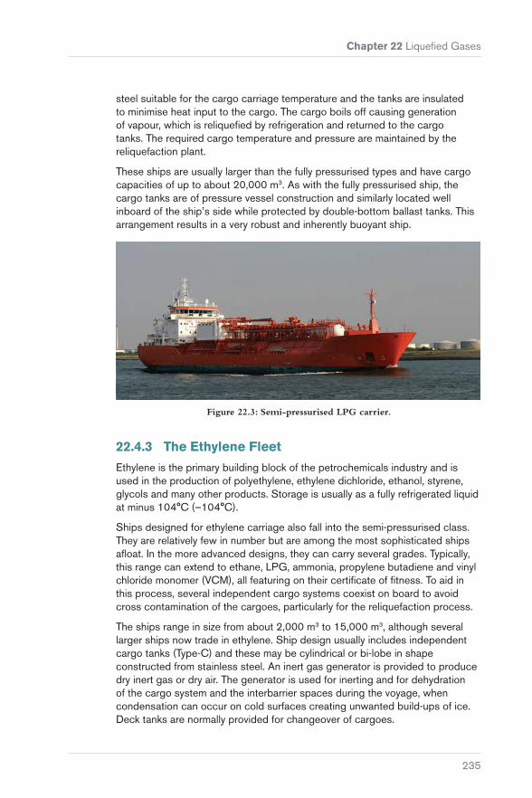
Chapter 22 Liquefied Gases
235
steel suitable for the cargo carriage temperature and the tanks are insulated to minimise heat input to the cargo. The cargo boils off causing generation of vapour, which is reliquefied by refrigeration and returned to the cargo tanks. The required cargo temperature and pressure are maintained by the reliquefaction plant.
These ships are usually larger than the fully pressurised types and have cargo capacities of up to about 20,000 m3. As with the fully pressurised ship, the cargo tanks are of pressure vessel construction and similarly located well inboard of the ship’s side while protected by double-bottom ballast tanks. This arrangement results in a very robust and inherently buoyant ship.
Figure 22.3: Semi-pressurised LPG carrier.
22.4.3 The Ethylene Fleet
Ethylene is the primary building block of the petrochemicals industry and is used in the production of polyethylene, ethylene dichloride, ethanol, styrene, glycols and many other products. Storage is usually as a fully refrigerated liquid at minus 104°C (–104°C).
Ships designed for ethylene carriage also fall into the semi-pressurised class. They are relatively few in number but are among the most sophisticated ships afloat. In the more advanced designs, they can carry several grades. Typically, this range can extend to ethane, LPG, ammonia, propylene butadiene and vinyl chloride monomer (VCM), all featuring on their certificate of fitness. To aid in this process, several independent cargo systems coexist on board to avoid cross contamination of the cargoes, particularly for the reliquefaction process.
The ships range in size from about 2,000 m3 to 15,000 m3, although several larger ships now trade in ethylene. Ship design usually includes independent cargo tanks (Type-C) and these may be cylindrical or bi-lobe in shape constructed from stainless steel. An inert gas generator is provided to produce dry inert gas or dry air. The generator is used for inerting and for dehydration of the cargo system and the interbarrier spaces during the voyage, when condensation can occur on cold surfaces creating unwanted build-ups of ice. Deck tanks are normally provided for changeover of cargoes.

Carefully to Carry Consolidated Edition 2018
236
The hazards associated with the cargoes involved are from the temperature, toxicity and flammability. The safety of ethane carriers is critical, requiring good management and rigorous personnel training.
Ethane carriers may be seen as a subset of the ethylene fleet and ethane can be carried by ships designed to carry ethylene. The new VLEC class (see Section 22.2) are constructed with a reinforced membrane cargo containment system, similar to that used in LNG carriers.
22.4.4 The Fully Refrigerated Fleet
Figure 22.4: Fully refrigerated LPG carrier.
These are generally large ships, up to about 85,000 m3 cargo capacity, with those above 70,000 m3 designated as VLGCs. Many in the intermediate range (30,000 m3 to 60,000 m3) are suitable for carrying the full range of hydrocarbon liquid gas, from butane to propylene, and may be equipped to carry chemical liquid gases such as ammonia. Cargoes are carried at near ambient pressure and at temperatures down to minus 48°C (–48°C). Reliquefaction plants are fitted (to manage boil-off) with a substantial reserve plant capacity provided. The cargo tanks do not have to withstand high pressures and are, therefore, generally of the freestanding prismatic type. The tanks are robustly stiffened internally and constructed of special low temperature resistant steel.
All ships have substantial double-bottom spaces and some have side ballast tanks. In all cases, the tanks are protectively located inboard. The ship’s structure surrounding or adjacent to the cargo tanks is also of special grade steel and this forms a secondary barrier to safely contain any cold cargo should it leak from the cargo tanks.

Chapter 22 Liquefied Gases
237
All cargo tanks, whether of the pressure vessel type or rectangular, are provided with safety relief valves amply sized to relieve boil-off in the absence of reliquefaction and even in conditions of surrounding fire.
Figure 22.5: LNG carrier with membrane tanks.
22.5 Crew Training and Numbers
The IMO has laid down a series of training standards for gas carrier crews that are additional to normal certification. These dangerous cargo endorsements are detailed in the STCW Convention (Reference 48). Courses are divided into the basic course for junior officers and the advanced course for senior officers. IMO rules require a certain amount of onboard gas experience, particularly at senior ranks, before taking on a responsible role or before progressing to the next rank.
In addition to the official certification for hazardous cargo endorsements, a number of colleges operate special courses for gas cargo handling. While this provides for a well-trained and highly knowledgeable environment, the continued growth in the fleet currently strains manpower resources and training schedules. To mitigate these pressures, in addition to the STCW requirements, the Society of International Gas Tanker and Terminal Operators (SIGTTO) provides guidance on competency standards and experience levels for officers serving on gas ships. While small gas carriers normally operate at minimum crew levels, on larger carriers it is normal to find increased crewing levels over and above the minimum required by the ship’s manning certificate.
22.6 Gas Carriers and Port Operations
As gas carriers have grown in size, so too has a concern over in-port safety. A higher degree of automation and instrumentation is often apparent, controlling the interface between ship and shore.

Carefully to Carry Consolidated Edition 2018
238
Terminals are also protected by careful risk analysis at the time of construction, helping to ensure that the location and size of maximum credible spill scenarios are identified and that suitable precautions, including appropriate safety distances, are established between operational areas and local populations.
Risk analysis of cargo transfer operations often identifies the cargo manifold as the area likely to produce the maximum credible spill. This is controlled by a number of measures. Primarily, as for all large oil tankers, gas carriers should be held firmly in position while handling cargo, and mooring management should be of a high calibre. Mooring ropes should be well managed throughout loading and discharging. Safe mooring is often the subject of computerised mooring analysis, particularly for new ships arriving at new ports, helping to ensure a sensible mooring array suited to the harshest conditions. An accident in the UK highlighted the consequences of a lack of such procedures when, in 1993, a 60,000 m3 LPG carrier broke out from her berth in storm conditions. This was the subject of an official MCA/HSE inquiry concluding that prior mooring analysis was vital to safe operations. The safe mooring principles attached to gas carriers are similar to those recommended for oil tankers (they are itemised in Mooring Equipment Guidelines, 3rd Edition (Reference 49).
The need for such ships to be held firmly in position during cargo handling is due in part to the use of marine loading arms (MLAs) (see Figure 22.6) for cargo transfer. Such equipment is of limited reach in comparison to hoses, yet it provides the ultimate in robustness and simplicity in connection at the cargo manifold.
Figure 22.6: Hard arms at cargo manifold (on an LNG carrier).
The use of MLAs for large gas carriers is common and is an industry recommendation. The use of hoses creates concerns over hose care and

Chapter 22 Liquefied Gases
239
maintenance, and their proper layout and support during operations to prevent kinking and abrasion. Further, accident statistics show that hoses have inferior qualities in comparison to MLAs. Perhaps the worst case of hose failure occurred in 1985 when a large LPG carrier was loading at Pajaritos, Mexico. Here, the hose burst and, in a short time, the resulting gas cloud ignited. The consequent fire and explosion impinged directly on three other ships in harbour and resulted in four deaths.
Figure 22.7: MLA quick connect/disconnect coupler (QC/DC).
Figure 22.8: MLA connection to manifold, showing double ball valve safety release.

Carefully to Carry Consolidated Edition 2018
240
As ships have grown in size, the installation of vapour return lines interconnecting ship and shore vapour systems has become more common for LPG carriers (and is an integral part of the LNG system – see Chapter 23).
A feature common to both ship and shore is an emergency shutdown system. It is common to inter connect such systems so that, for example, an emergency on the ship will stop shore-based loading pumps or, conversely, an emergency at an unloading terminal will stop the ship’s cargo pumps. It is common for hard arms to be fitted with automatic detection and alarm systems to guard the operating envelope and a further refinement at some larger LPG terminals is to have the loading arms fitted with emergency release devices that allow the hard arms to automatically release with minimal loss of product before they reach the limits of the operating envelope. These devices are commonly referred to as ERCs (emergency release couplings).
22.7 SIGTTO
Valuable assistance in the preparation of these chapters has come from the Society of International Gas Tanker and Terminal Operators (SIGTTO).
SIGTTO is the leading trade body in this field and has 190 members (January 2017) covering nearly 95% of the world’s LNG fleet and 60% of the LPG fleet. SIGTTO members also control most of the terminals that handle these products.
SIGTTO’s stated aim is to encourage the safe and responsible operation of liquefied gas tankers and marine terminals handling liquefied gas; to develop advice and guidance for best industry practice among its members and to promote criteria for best practice to all who have responsibilities for, or an interest in, the continuing safety of gas tankers and terminals.
SIGTTO operates from its London office at:17 St Helen’s PlaceLondon, EC3A 6DG.
Further details on activities and membership are available at www.sigtto.org

241
Chapter 23
Liquefied Natural Gas
In 1959, the ‘Methane Pioneer’ carried the first experimental LNG cargo and, in 1964, British Gas at Canvey Island received the inaugural cargo from Arzew on the ‘Methane Princess’. Together with the ‘Methane Progress’, these two ships formed the core of the Algeria to UK project and the project-based nature of LNG shipping continued until the end of the 1990s. Ships were built specifically for employment within the projects and acting as a floating pipeline between seller and buyer.
Due to commercial constraints, the need for precisely scheduled deliveries and limited shore tank capacities, spot loadings were not feasible and it is only in relatively recent years that projects now accept LNG carriers as cross traders, operating more like oil tankers.
The cooperative nature of the trade’s beginnings has given rise to operational features unique to LNG ships. LNG ships generally burn LNG cargo as fuel and retain LNG heel on completion of unloading for the ballast passage and, therefore, they are generally fixed on time charterparties where the charterer is responsible for the supply of bunkers. This applies even for single voyage ‘spot’ LNG charters as it avoids the complication of resolving the use of cargo as fuel, which would be the case if the ship were fixed on a single voyage charterparty commonly used in the oil tanker trade.

Carefully to Carry Consolidated Edition 2018
242
23.1 LNG Quality
LNG is sharply clear and colourless, comprising mainly of methane but with a percentage of constituents such as ethane, butane, propane and nitrogen. It is produced from either gas wells or oil wells and, at the point of production, the gas is processed to remove impurities. The degree to which this is achieved depends on the facilities available, but typically it results in LNG with between 80% and 97% methane content. The resulting LNG can, therefore, vary in quality from loading terminal to loading terminal or from day to day.
Other physical qualities that can change significantly are the specific gravity and the calorific value of the LNG, which depend on the characteristics of the gas field. The specific gravity affects the deadweight of cargo that can be carried in a given volume. LNG is typically bought and sold on the basis of the number of million British thermal units (MMBtu) transferred and, therefore, the calorific value affects both the monetary value of the cargo and the energy obtained from the boil-off gas fuel.
These factors have significance in commercial arrangements and gas quality is checked for each cargo, usually in a shore-based laboratory by means of gas chromatography.
Figure 23.1: LNG carrier with Type-B tanks (Kvaerner Moss system).
Gas quality is also significant from a shipboard perspective. LNGs that have a high nitrogen content naturally allow nitrogen to boil off preferentially, particularly at the beginning of the loaded passage (nitrogen having an atmospheric boiling point of minus 196°C (–196°C)). Methane also boils off preferentially to other heavier components of the LNG such as ethane and propane and this, combined with the boil-off of nitrogen, results in the boil-off gas being used as fuel having a lower calorific value than the bulk LNG cargo from which it originates. This has the reverse effect on the bulk LNG cargo, which increases in calorific value as the lighter components boil off

Chapter 23 Liquefied Natural Gas
243
preferentially over the course of laden voyage. Towards the end of a ballast passage, when the remaining heel has all but been consumed, the remaining liquids tend to be high on the heavier components such as the LPGs. This raises the boiling point of the remaining cargo and has a detrimental effect on the cooling capabilities of the LNG heel when used to spray-cool the cargo tanks in readiness for the next cargo.
LNG vapour is flammable in air and, in case of leakage, codes require an exclusion zone to allow natural dispersion and to limit the risk of ignition of a vapour cloud. Fire hazards are further limited by always handling the product within oxygen-free systems. Unlike oil tankers under inert gas, or in some cases air, LNG carriers operate with the vapour space at 100% methane. LNG vapour is non-toxic, although in sufficient concentration it can act as an asphyxiant.
The good combustion qualities of methane make it attractive as a fuel at electric power stations. It is also a ‘clean’ fuel. It burns producing little or no smoke, and nitrous oxide and sulphur oxide emissions produce figures far better than can be achieved when burning normal liquids such as low sulphur fuel oil. Natural gas has become attractive to industry and governments striving to meet environmental targets set under various international protocols such as the Rio Convention and the Kyoto Protocol. The practice of firing marine boilers on methane provides the further environmental advantage of lesser soot blowing operations and fewer carbon deposits (see Section 23.7).
23.2 The LNG Fleet
(a) 3,200 m3 coastal LPG carrier with cylindrical tanks
(b) 137,000 m3 LNG carrier with Type-B tanks (Kvaerner Moss system)
(c) 266,000 m3 LNG carrier with membrane tanks
(a) 135,000 m3 LNG carrier with membrane tanks
(b) 16,650 m3 semi-pressurised LPG carrier
(c) 78,000 m3 LPG carrier with Type-A tanks
Figure 23.2: Gas carrier types.

Carefully to Carry Consolidated Edition 2018
244
Early LNG carriers had carrying capacities of about 25,000 m3. This swiftly rose to about 75,000 m3 for the Brunei LNG project and later ships settled on 125,000 m3. For some years, this remained the norm, giving a loaded draught of about 11.5 m, thus stretching the port facilities of most discharge terminals to their limits. Since then, however, there has been a steady incremental increase in size, usually maintaining the loaded draught (although this has increased marginally to about 12.0 m) but increasing the beam, resulting in a standard ship size of about 175,000 m3. In the main, LNG ports and terminals have adapted accordingly. At the end of 2004, the first orders were placed for LNG carriers of more than 200,000 m3 for the Qatar LNG project and currently there are forty-five LNG carriers trading with a capacity in excess of 200,000 m3, with fourteen of these having a capacity of between 260,000 m3 and 266,000 m3 (known as Q-Max). At the other end of the scale is the relatively recent ‘Pioneer Knudsen’, trading at only 1,100 m3 capacity from a facility near Bergen to customers on the Norwegian west coast.
Large modern LNG carriers have dimensions approximately as follows:
Capacity (m3) 145,000 215,000 266,000
Length 295 m 315 m 345 m
Beam 48 m 50 m 54 m
Loaded draught 12 m 12 m 12.2 m
Table 23.1: LNG carrier dimensions.
LNG has a typical density of only 420 kg/m3 which allows ships, even when fully laden, to ride with a high freeboard. They never appear very low in the water as a fully laden oil tanker may do. Ballast draughts are maintained close to laden draughts and, for a ship having a laden draught of 12 m, a ballast draught of 10 m is likely. This means that, for manoeuvring in port in windy conditions, the ships are always susceptible to being blown to the leeward side of the channel, and restrictions on port manoeuvring usually apply with extra tug power commonly specified.
The cargo tanks of LNG ships are thermally insulated and the cargo is carried at or near atmospheric pressure. Cargo tanks may be free standing spherical, of the membrane type, or prismatic in design. In the case of membrane tanks, the cargo is contained within thin-walled tanks of Invar or stain less steel. The tanks are anchored to the inner hull in appropriate locations and the cargo load is transmitted to the inner hull through the intervening thermal insulation.
All LNG carriers have a watertight inner hull and most tank designs are required to have secondary containment capable of safely holding any leakage for a period of 15 days. Because of the simplicity and reliability of stress analysis of the spherical containment designs, a full secondary barrier is not required, but splash barriers and insulated drip trays protect the inner hull from any leakage that might occur in operation.

Chapter 23 Liquefied Natural Gas
245
No insulation system is 100% efficient and the heat from thermal leakage through the insulation is removed from the cargo by allowing the cargo to evaporate (boil-off). The boil-off gas must be removed from the cargo tanks to ensure that the tanks are maintained at or near atmospheric pressure. The majority of LNG carriers do not reliquefy boil-off gases, but use the boil-off gas as fuel in the ship’s propulsion system. However, a significant number of large LNG carriers have been delivered over the last decade that use slow-speed diesel engines for propulsion which burn conventional fuels and are not capable of using boil-off gas as fuel; these ships are fitted with full reliquefaction systems for managing boil-off (see Section 23.3).
The traditional propulsion system for LNG ships has been steam turbines supplied by high-pressure boilers. This provided a reliable, low maintenance propulsion system that was capable of burning any combination of gas and conventional fuel in the ship’s boilers. The low thermal efficiency of conventional steam turbines has led to the development of a number of alternative propulsion systems that include re-heat steam turbines, which have a higher thermal efficiency than conventional steam turbine systems, and also dual fuel diesel electric (DFDE) systems. LNG ships with DFDE propulsion are equipped with up to four medium-speed diesel generators that provide electrical power to large electric propulsion motors typically driving a single shaft and propeller through a reduction gearbox. The diesel generators are capable of running on either gas or marine gas oil and also, in some designs, heavy fuel oil, and are therefore able to utilise boil-off gas from the ship’s cargo tanks as fuel. The most recent development in propulsion systems for LNG ships is direct drive, gas-injected, slow-speed diesel engines that are claimed to be more fuel efficient than either steam or DFDE. Two designs are currently available, one working on the Otto process, using low-pressure fuel injection, and the other working on the Diesel process using high-pressure fuel injection. The latter requires a gas injection pressure of approximately 300 barg and, where boil-off gas is used as fuel, it is delivered to the engine(s) by a large multistage reciprocating compressor. The compressor also provides the gas pressure required for a partial reliquefaction system in circumstances where not all of the boil-off from the cargo tanks is required as fuel for propulsion. A number of LNG ships with direct drive, gas-injected, slow-speed diesel engine propulsion are under construction although, at the time of writing, there are none in operation. Designs for gas turbine propelled LNG ships have been available for several years but, to date, none have been ordered.

Carefully to Carry Consolidated Edition 2018
246
Figure 23.3: LNG carrier with Type-B tanks (Kvaerner Moss system).
23.3 Cargo Handling
The process of liquefaction is one of refrigeration and, once liquefied, the gas is stored at atmospheric pressure at its boiling point of minus 162°C (–162°C). At loading terminals, any boil-off from shore tanks can be reliquefied and returned to storage. However, on ships this is not usually the case and for the majority of LNG ships not fitted with reliquefaction systems it is the practice to burn boil-off gas in the ship’s boilers or engines to provide fuel for propulsion. Depending on the comparative cost of fuel oil, this may be supplemented by either fuel oil or additional natural gas produced by vaporising LNG using a heat exchanger, a process known as ‘forcing’, to meet the total fuel requirement of the passage.
Cargo volumes at the discharge port will not match those loaded and LNG carriers are outfitted with sophisticated means of cargo measurement, referred to as the ‘custody transfer system’, used in preference to shore tank measurements. These systems normally provide for highly accurate measurement of tank ullages, temperatures and pressures while the tanks themselves are specially calibrated by a Classification Society to a fine degree of accuracy. The system may automatically apply corrections for trim and list using equipment calibrated in dry dock. The resulting cargo volumes, corrected for the expansion and contraction of the tanks, are normally computed automatically by the system.
Cargo tank design requires carriage at atmospheric pressure and there is little to spare in tank design for over or underpressures. The extent to which pressure build-up can be contained in a ship’s tanks is very limited in the case of membrane cargo tanks, although this is normally not a problem as, at sea, the ship is burning boil-off as fuel. In port, the ship has its vapour header

Chapter 23 Liquefied Natural Gas
247
connected to the terminal vapour return system. However, there are short periods between these operations when pressure containment is necessary. This is managed by efficient shipboard operations that prevent all possible discharges to atmosphere, apart from minor escapes at pipe flanges, etc. This is part of the design criteria for the class as it is recognised that methane is not only flammable but is also a GHG that has over twenty times more impact on the atmosphere than the equivalent volume of CO2.
Boil-off gas (BOG) is limited by tank insulation and newbuilding contracts specify the efficiency required. Usually, this is stated in terms of a volume boil-off per day under set ambient conditions for sea and air temperature. The guaranteed maximum figure for boil-off would normally be about 0.15% of cargo volume per day, although more recent ships are capable of achieving closer to 0.10% per day.
While at sea, vapours bound for the boilers or engines must be boosted to the engine room by a low-duty compressor via a vapour heater. The heater raises the temperature of the boil-off to a level suited for combustion and to a point where cryogenic materials are no longer required in construction and where any gas leakage will be lighter than air and so cannot collect in the engine room bilges. LNG vessels with high-pressure gas-injected slow-speed diesel engines direct the boil-off gas to the engines via a multistage reciprocating compressor. The boil-off then enters the engine room suitably warmed, but first passes an automatically-controlled master gas valve before reaching an array of control and shutoff valves for direction to each burner or engine. As a safety feature, the gas pipeline through the engine room is of annular construction, with the outer pipe purged and constantly checked for methane ingress. In this area, operational safety is paramount and sensors cause shutdown of the master gas valve in alarm conditions. For steam ships, a vital procedure in the case of a boiler flameout is to purge all gas from the boilers before attempting re-ignition. Without such care, boiler explosions are possible and occasional accidents of this type have occurred.
23.4 Cargo Care
The majority of LNG shippers and receivers have a legitimate concern over foreign bodies getting into tanks and pipelines. The main concerns are the risk of valve blockage if (say) an old welding rod becomes lodged in a valve seat, damage to the cargo tanks on membrane ships or damage to the cargo pumps’ bearings. Such occurrences are not unknown with a ship discharging first cargoes after newbuilding or recently having come from dry dock. Accordingly, and despite discharge time diseconomies, it is common practice to fit filters at the ship’s liquid manifold connections to prevent any such material from entering the shore system. The ship normally supplies filters fitting neatly into the manifold piping.
Even small particulate matter can cause concerns and the carryover of silica gel dust from inert gas dryers is one such example. Another possible cause

Carefully to Carry Consolidated Edition 2018
248
of contamination is poor combustion at inert gas plants, with ships’ tanks becoming coated with soot and carbon deposits during gas-freeing and gassing-up operations. Subsequently, the contaminants may be washed into gas mains and cargoes may be rejected if unfit. Tank cleanliness is vital and, particularly after drydock, tanks must be thoroughly vacuumed and dusted.
Debris may also be loaded with an LNG cargo, particularly where a loading terminal is commissioning or has recently undergone maintenance. If in any doubt, strainers should also be fitted to the ship’s manifolds at a loading terminal to prevent damage to the ship’s equipment and avoid any subsequent cargo claims at the discharge port.
Figure 23.4: Debris recovered from the ship’s manifold strainers after loading a commissioning cargo at a new LNG export terminal.
A cargo was once rejected in Japan when, resulting from a misoperation, steam was accidentally applied to the main turbine with the ship secured alongside the berth. The ship broke out from the berth, but fortunately the MLAs had not been connected. This action was sufficient however for cargo receivers to reject the ship, and the cargo could only be delivered after a specialised STS transfer operation had been accomplished. At the time, STS transfer of LNG had only ever been carried out on a few occasions as the operation requires perfect weather, great care and specialist equipment.
Another case of cargo rejection, this time resulting in a distressed sale, involved a shipment to Cove Point in the USA, where the strict requirements that prevail on in-tank pressures on arrival at the berth were not adhered to. The ship had previously been ordered to reduce pressure for arrival.
Pressure reduction is a difficult job to perform satisfactorily and, if it is to be successful, the operation must progress with diligence throughout the loaded voyage by maintaining the cargo tanks at a minimal operational pressure using

Chapter 23 Liquefied Natural Gas
249
a compressor to encourage maximum cargo evaporation. This cools the cargo and reduces the saturated vapour pressure (SVP). The process of drawing vapour from the vapour space at the last moment is ineffective because such short-term action will have little effect on reducing the cargo temperature and associated SVP and, once gas burning stops, the vapour space will return to its high equilibrium pressure. The process of reducing the temperature of the cargo and its equivalent SVP on the loaded passage is known as ‘cargo conditioning’. In extreme conditions, particularly on short passages, where the amount of boil-off required to condition the cargo is more than that required as fuel, the ship may have to ‘dump’ excess gas either by steam dumping via the ship’s boilers or by use of the gas combustion unit (GCU) on DFDE and diesel-powered LNG carriers. Most LNG charterparties require the shipowner to warrant a daily loaded boil-off rate, which may not be achievable where the ship is required to condition the cargo on the loaded passage. In these instances, to avoid a subsequent claim for excess boil-off, the ship’s Master should request direct instructions from the charterer with regard to cargo conditioning requirements for the voyage.
A recent development is the back-loading of LNG cargoes from traditional import terminals where the quantity of LNG in storage from long-term supply contracts exceeds the current local pipeline or end user requirements. This presents the crew of an LNG ship with a number of challenges. The cargo may have come from a number of shore tanks and original sources and the final detailed composition and density of the LNG may not be known until after the cargo has been loaded. The cargo may also be significantly warmer and have a higher saturated vapour pressure than LNG typically loaded at a dedicated LNG export terminal. To ensure that the cargo temperature and associated tank pressures are capable of being maintained within safe limits, particularly during the early part of the loaded passage, it may be necessary to return significant volumes of gas back to the terminal to assist in conditioning the cargo during the loading period. This is typically assisted by the slow loading rate associated with this type of operation, but may be frustrated by the limited capacity of the terminal to receive vapour back from the ship. The key to a successful operation is detailed prior planning between the ship, the charterer, the supplier and the terminal and clear and documented agreement on operational procedures.
LNG ships engaged in a traded LNG market may occasionally be required to carry a number of ‘parcels’ of LNG loaded at different terminals. In addition to the standard stowage considerations in respect of draught, trim, hull stresses and sloshing limitations on intermediate tank filling levels, the crew of an LNG ship must also consider the risk of rollover where cargoes of different densities and compositions are loaded into the same tank. Shore tanks in LNG receiving terminals are typically provided with top and bottom filling lines and recirculation facilities to promote the mixing of batches of LNG with different compositions and densities loaded into the same tank. This is not the case with LNG ships, which are limited to bottom filling only. Stratification may occur where a heavier LNG, ie an LNG with a higher percentage of ethane and propane, is loaded under a lighter LNG with a higher methane content

Carefully to Carry Consolidated Edition 2018
250
in the same tank. When stratification occurs, the normal convection currents resulting from heat ingress through the tank insulation are restricted to the individual layers rather than throughout the full depth of the cargo as is the case where the tank contains a single, homogeneous LNG composition. The top, lighter layer evaporates to the vapour space and, due to the preferential evaporation of methane, becomes progressively denser. The lower, denser layer warms up though heat ingress through the cargo tank insulation, becoming progressively less dense. When the densities of the two layers become similar, the convection currents in the lower layer are able to break through the upper layer to the liquid surface, thus breaking down the stratification, referred to as rollover. The trapped heat in the lower layer may now be released, resulting in a sudden and massive increase in vapour generation and tank pressure causing the tank safety valves to lift and, in extreme cases, overpressure damage to the tank. The risk of rollover can be eradicated by ensuring that each parcel of LNG is loaded into a separate tank.
Where the LNG parcels are loaded into separate tanks but are discharged to a single receiving terminal, the receiver may require the cargo to be received into the terminal with a homogeneous composition. This is to ensure that sampling equipment on the terminal unloading line is able to gather an accurate sample of the average composition of the entire cargo throughout the course of the unloading operation. The composition of the cargo derived from sample analysis determines the price paid for the LNG received. This will require the cargo officer of the LNG carrier to plan and adjust the unloading rates from individual tanks to achieve a homogeneous blend at the ship’s manifolds throughout the unloading.
Rollover may also be a risk where a heavy cargo is loaded under significant quantities of lighter LNG heel. This is not normally an issue with LNG carriers on a liner trade and loading at a single export terminal as the heel will ‘weather’ on the ballast passage and will always be denser than the cargo to be loaded. It may be an important consideration for LNG ships engaged in an LNG trading market and it is recommended that the Liquefied Gas Handling Principles on Ships and in Terminals, published by the Society of International Gas Tanker and Terminal Operators (SIGTTO) (Reference 50) is consulted.
23.5 Ship Care
Most standard materials brought into contact with LNG become highly brittle and fracture. For this reason, pipelines and containment systems are built from the preferred materials of aluminium, Invar (a nickel-iron alloy) and stainless steel. However, these materials do not commonly feature over the ship’s weather decks, tank weather covers or hull and so care must be taken to ensure that LNG is not spilt. A spill of LNG will cause significant damage to the decks or hull, normally necessitating emergency dry-docking. Accidents of this nature have resulted in extended periods off-hire, but fortunately none have reported serious personal injury.

Chapter 23 Liquefied Natural Gas
251
Figure 23.5: Brittle fracture of a ship’s deck resulting from an LNG spill.
LNG carriers are double-hulled ships specially designed and insulated to prevent leakage and rupture in the event of an accident such as grounding or collision. Although sophisticated in control and expensive in materials, they are simple in concept. Mostly, they carry LNG in just four, five or six centreline tanks. Only a few have certification and equipment for cross trading in LPG and/or ethylene. LNG is carried at atmospheric pressure and, although there are four current methods of constructing seaborne LNG tanks, only two are in majority usage. These are the spherical tanks of Moss design and the membrane tanks from Gaztransport or Technigaz (two French companies, now amalgamated as GTT). A number of shipbuilders have their own licensed designs for cargo containment systems based on membrane, spherical or self-supporting prismatic tanks. In each design, the cargo tanks are contained within the double hull with the space between the inner and outer hull being used as ballast water tanks. In recent years, the number of orders for LNG carriers with spherical containment has declined, with approximately 25% of the current global fleet comprising ships of this type and the remaining 75% having membrane cargo containment systems.
Figure 23.6: Moss design.
Cou
rtes
y of
Mos
s M
ariti
me

Carefully to Carry Consolidated Edition 2018
252
Figure 23.7: Membrane design (GTT).
A small number of spherical tanks are constructed from 9% nickel steel but the majority are constructed from aluminium. A disadvantage of the spherical system is that the tanks do not fit the contours of a ship’s hull. LNG carriers with spherical containment systems also have a greater lightship displacement than an equivalent membrane ship of the same cargo capacity. In general terms, for two LNG ships of the same carrying capacity, a ship of Moss design will be about 10% longer. It will also have its navigating bridge set at a higher level to comply with SOLAS requirements for visibility from the navigation bridge. However, spherical tanks are robust and relatively simple to install in comparison to the membrane system, with its complication of twin barriers and complex construction requiring in excess of 70 km of precision welding.
The mass of a spherical LNG tank requires a longer cooldown time and a larger amount of LNG to cool down to be ready for loading than an equivalent size membrane tank. Spherical tanks do not, however, have the same restrictions on filling levels that apply to membrane tanks. The large free surface in partially filled membrane tanks may result in damaging overpressures on the membranes and supporting insulation from sloshing motions of the cargo when the LNG carrier is working in a seaway. The double containment requirements for membrane LNG carriers ensure that any damage to the primary membrane will be retained by the secondary membrane and will not prejudice the integrity of the inner hull. Any LNG carrier suffering damage to the primary membrane will however need to be taken out of service for repairs, resulting in lost availability, lost revenue and expensive repair costs. To avoid the risk of sloshing damage, membrane tanks have restrictions imposed by the respective

Chapter 23 Liquefied Natural Gas
253
Classification Society on filling levels in the cargo tanks when the LNG carrier is at sea. The sloshing restrictions typically require the cargo filling level to be either less than 10% of the height of the tank, or greater than 70% of the height of the tank when the LNG carrier is at sea, with guidance to avoid heavy rolling and pitching, where possible, when tank levels are close to these limits. This may require careful planning on the part of the cargo officer and the Master in circumstances where a long loaded voyage with slack tanks is contemplated or where a large heel is required for an extended ballast passage.
Figure 23.8: LNG carrier with Moss (spherical) tanks.
Figure 23.9: LNG carrier with membrane tanks.
LNG carriers fitted with slow-speed diesel propulsion and burning heavy fuel oil require reliquefaction plants on board to handle boil-off gas (see Section 23.3). All diesel systems require back-up gas disposal facilities – also known as gas combustion units (GCUs) – for occasions when either the reliquefaction plants are not available to process boil-off gas or, in the case of LNG carriers with DFDE and gas-injected direct drive diesel propulsion, where the ship’s fuel requirement is less than the boil-off generated by the cargo.

Carefully to Carry Consolidated Edition 2018
254
LNG ships are expensive to build, but are valuable assets with some hulls and containment systems built with a 40-year fatigue life. Shipowners and ship managers alike recognise this and, assisted by inspection regimes, the overall quality of LNG tonnage is maintained to a high standard. Some of the oldest LNG carriers have been in service for over 30 years and the oldest LNG carrier currently in service was built in 1972. Of the 487 LNG carriers built to date, only 31 have been scrapped. We are now seeing many of the older project ships as surplus to requirements as they reach the end of their original long-term charters and the original project either closes down or replaces them with newer ships. The older project ships that are laid off then have to find business in the global charter market competing with newer, larger and more fuel-efficient ships.
The increasing development of a spot market has allowed the shipowner to consider life extension programmes of considerable cost. These programmes are common with older ships which, in the right market conditions, can make handsome profits in the spot market. A number of these older project ships have also found a new lease of life by being converted to FSRUs. To ensure that the quality of older LNG tonnage is maintained, many charterers require a Condition Assessment Programme (CAP) rating of the hull and cargo system from a reputable Classification Society for LNG carriers older than 15 or 20 years.
23.6 Terminals, FSRU and STS
The cost and the time taken to construct LNG import terminals, exacerbated in some administrations by the time required to satisfy stringent permitting restrictions, has led to the development of floating storage and regasification units (FSRUs), which are, typically, conventional seagoing LNG carriers fitted with onboard regasification systems. An FSRU is designed to regas LNG from its cargo tanks and discharge the resultant high-pressure gas (80 to 100 barg) directly to an end receiver, typically a power plant, or into a gas distribution network. The FSRU enables natural gas to be delivered to a new end user in a shorter time frame and with less capital investment than would be the case with a conventional land-based regas terminal. An FSRU also requires a smaller footprint in a busy port area than a conventional land-based terminal and, when a particular contract has been completed, the FSRU can either be relocated to another project or returned, in the interim, to the LNG trade.
The regas capacity of a modern FSRU is similar to that of a medium size land-based regas terminal with throughput in the region of 3 million tonnes of LNG per annum. The gas is either discharged across a conventional jetty through a high-pressure hard arm or via a submerged turret mooring system into a subsea pipeline. Some FSRUs are converted from existing LNG carriers and are de-engined and maintained permanently on station while a significant number are capable of trading as standard LNG carriers in between regas contracts. In either case, when an FSRU is on station as a regas facility, it is kept supplied

Chapter 23 Liquefied Natural Gas
255
with LNG from standard LNG tankers via a double banked ship to ship transfer (STS) operation using either flexible hoses or conventional marine loading arms (MLAs). This may be accomplished with the FSRU on station at the jetty or on the turret mooring or at a transhipment location close to the regas station.
The facilities provided for LNG STS transfer are similar in principal to those provided on a conventional LNG jetty. The two ships maintain a common emergency shutdown (ESD) and communications link and the transfer system, whether MLAs or flexible hoses, is fitted with a quick release facility that, in turn, is linked to a position monitoring system. The position monitoring system ensures that the cargo transfer is automatically stopped and the hoses or hard arms disconnected before the relative movement of the two ships exceeds the operating limits of the transfer system.
Figure 23.10: Transhipment of LNG to an FSRU on a regas berth.
23.7 LNG as a Fuel
LNG carriers, terminals and commercial entities were initially all bound together in the same chain and advantages could be seen in limiting ‘unnecessary’ and energy consuming shipboard equipment, such as a reliquefaction plant, and allowing the boil-off to be burnt as fuel. With the introduction of Environmental Control Areas (ECAs), an added advantage of using boil-off gas as fuel is that natural gas provides a clean fuel solution with virtually zero sulphur content. Such is the appeal of natural gas as a clean fuel that LNG is now being increasingly considered as a fuel for ferries and other ships engaged in short sea trades in ECA areas. This concept was recognised in the IMO’s Gas Codes from the very earliest days and, with the appropriate safety equipment in place, the regulations allow methane to be burnt in ships’ boilers or engines. This is not the case for LPG, where reliquefaction equipment is a fitment, but specifically because LPGs are heavier than air gases and their use in engine rooms is disallowed. This situation may change with the IGF Code, which may eventually allow for the safe use of low flashpoint fuels other than natural gas.
Cou
rtes
y of
Exc
eler
ate
Ene
rgy

Carefully to Carry Consolidated Edition 2018
256
23.8 SIGTTO
Valuable assistance in the preparation of these chapters has come from the Society of International Gas Tanker and Terminal Operators (SIGTTO).
SIGTTO is the leading trade body in this field and has 190 members (January 2017) covering nearly 95% of the world’s LNG fleet and 60% of the LPG fleet. SIGTTO members also control most of the terminals that handle these products.
SIGTTO’s stated aim is to encourage the safe and responsible operation of liquefied gas tankers and marine terminals handling liquefied gas; to develop advice and guidance for best industry practice among its members and to promote criteria for best practice to all who have responsibilities for, or an interest in, the continuing safety of gas tankers and terminals.
SIGTTO operates from its London office at:17 St Helen’s PlaceLondon, EC3A 6DG.
Further details on activities and membership are available at www.sigtto.org

257
PART 8Packaged Cargoes, Including Bags, Drums and Flexitanks
Chapter 24 ............................................. 259Refined (Crystal) Sugar
Chapter 25 ..............................................263Potatoes
Chapter 26 ..............................................273Cocoa
Chapter 27 ..............................................279Coffee
Chapter 28 ..............................................283Bagged Rice
Chapter 29 ..............................................297Agricultural Products in Non-refrigerated Containers
Chapter 30 ............................................. 303Calcium Hypochlorite
Chapter 31 ..............................................307Thiourea Dioxide
Chapter 32 ............................................. 309Expandable Polymeric Beads
Chapter 33 ..............................................313Flexitanks


259
Chapter 24
Refined (Crystal) Sugar
Substantial claims have arisen on shipments of bagged refined sugar, where the complaint often relates to stickiness or caking of the product, sometimes wrongly attributed to conditions encountered during the voyage.
Unlike semi-refined or raw sugar, refined sugar is always carried in bags. In the past, jute outer bags were widely used with a polythene film inner bag, but the outer bags are now often made from woven polypropylene. The purpose of the plastic inner bag is to keep out moisture but, because the outer and inner bags are often stitched together, the seal is not always effective.
Refined sugar is normally a dry, free-flowing commodity with very low moisture content.
On delivery, if the sugar is not found to be free flowing, it is important to establish whether this is due to:
� Pressure compaction
� adhesiveness (stickiness)
� caking (agglomeration).
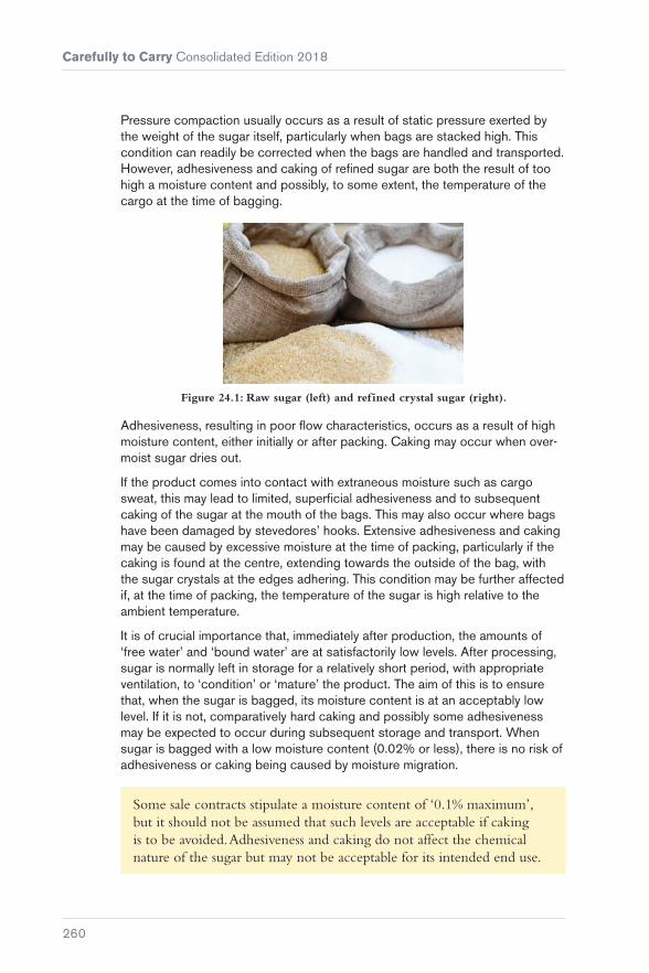
Carefully to Carry Consolidated Edition 2018
260
Pressure compaction usually occurs as a result of static pressure exerted by the weight of the sugar itself, particularly when bags are stacked high. This condition can readily be corrected when the bags are handled and transported. However, adhesiveness and caking of refined sugar are both the result of too high a moisture content and possibly, to some extent, the temperature of the cargo at the time of bagging.
Figure 24.1: Raw sugar (left) and refined crystal sugar (right).
Adhesiveness, resulting in poor flow characteristics, occurs as a result of high moisture content, either initially or after packing. Caking may occur when over-moist sugar dries out.
If the product comes into contact with extraneous moisture such as cargo sweat, this may lead to limited, superficial adhesiveness and to subsequent caking of the sugar at the mouth of the bags. This may also occur where bags have been damaged by stevedores’ hooks. Extensive adhesiveness and caking may be caused by excessive moisture at the time of packing, particularly if the caking is found at the centre, extending towards the outside of the bag, with the sugar crystals at the edges adhering. This condition may be further affected if, at the time of packing, the temperature of the sugar is high relative to the ambient temperature.
It is of crucial importance that, immediately after production, the amounts of ‘free water’ and ‘bound water’ are at satisfactorily low levels. After processing, sugar is normally left in storage for a relatively short period, with appropriate ventilation, to ‘condition’ or ‘mature’ the product. The aim of this is to ensure that, when the sugar is bagged, its moisture content is at an acceptably low level. If it is not, comparatively hard caking and possibly some adhesiveness may be expected to occur during subsequent storage and transport. When sugar is bagged with a low moisture content (0.02% or less), there is no risk of adhesiveness or caking being caused by moisture migration.
Some sale contracts stipulate a moisture content of ‘0.1% maximum’, but it should not be assumed that such levels are acceptable if caking is to be avoided. Adhesiveness and caking do not affect the chemical nature of the sugar but may not be acceptable for its intended end use.

Chapter 24 Refined (Crystal) Sugar
261
Because most marine reference books are silent on the carriage of refined sugar, it is often assumed that it is a relatively simple product to handle, subject only to the most general stowage and ventilation recommendations. Tight block stowage without height limitation is the customary and acceptable method, with the height of the stow limited only by the height of the cargo compartments. Cargo battens are not necessary as it is generally accepted that a separation of paper, cardboard sheets, polyethylene or polypropylene cloth between the ship’s structure and the bags is sufficient.
Ventilation of refined sugar is not necessary under any circumstances. The purpose of cargo ventilation is to prevent or restrict the formation of condensation or moisture on the ship’s internal structure. However, such condensation originates from within the cargo and will occur only when the cargo itself is moist. Because refined sugar has a low moisture content and is enclosed in plastic film, there is no risk of sweat.
Under certain circumstances, ventilation may even be detrimental, such as when holds loaded with cold cargo are ventilated with warm air, which can lead to the formation of sweat.
Sugar has low thermal conductivity, which means that during the voyage it tends to remain at the temperature at which it was loaded, at least in the interior of the stow. If the sugar is loaded cold and later discharged in a relatively hot area, there is a risk of condensation forming, during the discharge, on any bags having a temperature lower than the dew point of outside air. In such cases, rapid discharge is necessary to avoid any adverse consequences.
24.1 Issues with Regard to Shipments of Sugar Carried in Containers
As sugar is a seasonal trade, it is possible that smaller or older vessels are used at reduced freight rates. However, hatch covers are more likely to leak on an older vessel, so there is an increased risk of cargo damage.
A careful packing strategy should include control of stacking heights and temperature and moisture control at the producing mills, even before shipping, as this will minimise the chances of caking.
24.2 Loading Sugar
� The ship’s hold, before loading, should be clean, dry and free from any noticeable smell
� bags should be loaded only if outwardly dry and with no apparent lumpiness of the contents

Carefully to Carry Consolidated Edition 2018
262
� no bags should be loaded during any form of precipitation, including rain or snow
� cargo battens are not essential. Where no battens are fitted, measures should be taken to prevent damage from any protruding cargo batten hooks or fittings
� a separation of polyethylene, polypropylene cloth or paper sheeting between the ship’s structure and the bags is sufficient
� tight block stowage is the customary and acceptable method of stowage
� if additional cargo is to be carried in the same hold as refined sugar, it should be a dry cargo
� the hold should not be ventilated; all ventilators and other openings should be sealed
� bags loaded at substantially lower temperatures at the load port should be rapidly discharged to prevent or restrict unwanted condensation on the bags.

263
Chapter 25
Potatoes
Potatoes are grown throughout the world, except in humid tropical lowland areas. They are one of the world’s most important food crops and are traded as a commodity. This chapter refers to three basic types of potato, each of which has special considerations for stowage and carriage.
� Early/new or immature
� late/mature
� seed.
Figure 25.1: Three basic types of potato, left to right: early/new; late/mature; seed (notice fragile ‘eyes’ which produce new growth).

Carefully to Carry Consolidated Edition 2018
264
Early new potatoes have thin, relatively loose skins that are easily removed and damaged. Demand for this type of potato is significant and large quantities are shipped from Cyprus, Greece, Israel, Turkey and the Canary Islands during the northern winter and spring seasons.
Late/mature potatoes have firm skins and are, therefore, more resistant to damage and much easier to carry than immature potatoes.
Seed potatoes for shipment are small whole tubers, each with at least one eye to produce the new growth. Seed potatoes are grown under a regulated certification programme to ensure that they are as disease-free as possible.
25.1 Pre-shipment Considerations
Once potatoes have been harvested, they must be stored under optimal conditions until released for shipment.
High temperatures cause the tuber respiration rate to increase, using oxygen and food reserves, potentially resulting in excessive shrinkage. Freezing or chilling temperatures can damage and kill tuber cells. If the air surrounding the tubers has a low humidity, water will move from the tubers to the air, resulting in weight loss. Should the oxygen content of the air fall to a low level, cells within the tubers die and ‘blackheart’ forms.
Sprouting is a natural function of the tuber, but during shipment it is not desirable as quality and condition will suffer. Sprout suppressant chemicals or other methods may be used prior to shipment to prevent sprouting, but control in stowage can only be maintained by the correct temperature(s).
Potato tuber diseases may be the result of microorganisms, adverse pre-shipment storage conditions, or improper stowage and conditions of carriage. Potatoes are grown under the soil so, when harvested, will always contain spores of invading microorganisms on their surfaces. These will attack the tubers if the natural defence mechanism is ruptured. This can be as a result of mechanical damage, either during harvesting or subsequent handling, or may be the result of other forms of deterioration, such as sunscald. It may also happen if the tuber is subjected to wetting to a point that a film of water is present over its surface.
Figure 25.2: Signs of infestation by the potato tuber moth.

Chapter 25 Potatoes
265
Some of the principal diseases found at the time of harvesting include:
� Phytophthora infestans (potato blight)
� a dry mealy rot due to species of Fusarium (dry rot)
� a bacterial soft rot caused by Erwinia ssp. (black leg)
� brown rot caused by the bacterium Ralstonia solanacearum
� ring rot caused by the bacterium Clavibacter michiganensis subsp. sepedonicus.
These are notifiable diseases in many countries.
Post-harvest deterioration, ie storage/stowage deterioration, will normally result from the development of bacterial soft rot, usually the result of infection by Erwinia ssp. which causes collapse of the cells of the infected potatoes, exuding heavily infected fluid, and gives rise, by contact, to soft rot developing in adjacent tubers. Over a period of time, the contents of whole bags may collapse into an unpleasant smelling slime.
Another cause of deterioration is infestation by insects. The two most serious infestants of potato crops are the North American black and yellow striped beetle (Colorado beetle) and the potato tuber moth (Phthorimaea operculella).
It is necessary for shippers or charterers to provide phytosanitary certificates, attached to the B/Ls or other trade documents. These certificates are produced by the Authority of the country of origin and indicate that the specified consignment(s) have been inspected or treated according to the importing country’s requirements.
While the Master should be able to rely upon a valid phytosanitary certificate, he does have a continuing duty in relation to cargo in his charge. For example, if infestation is noticed during the voyage, the Master/owners must take reasonable steps to deal with the situation.
Fumigation prior to berthing at an arrived port or, alternatively, rejection of a cargo of potatoes as a result of infestation or infection by serious bacterial diseases may cause massive delays to a vessel and considerable additional problems for the shipowners.
Figure 25.3: Potato tubers infested with Colorado beetle.

Carefully to Carry Consolidated Edition 2018
266
Greening may occur in any part of a tuber exposed to light. Exposure to bright light during post-harvest handling, or longer periods (7 to 14 days) of low light, may result in the development of chlorophyll (greening) and bitter, toxic glycoalkaloids, such as solanine.
Experts advise that, while in cultivated varieties green discolouration of the flesh does not cause substantive harm to health, it will, depending upon extent, result in a loss of value of the consignment. Green flesh tastes bitter and must be cut away before cooking.
When consignments are presented for shipment, the external condition of the packaging should be inspected. Evidence of wet patch staining of the bags, or any associated odours, should alert crew members to likely problems and the vessel’s P&I Association should be requested to appoint an expert surveyor to investigate and ensure only healthy and undamaged potatoes are shipped.
Potatoes are often shipped in woven polypropylene bags of varying dark colours making it extremely difficult to recognise wet patches from superficial examination, so close inspection is recommended.
Mechanical damage, which is largely preventable, is one of the most significant factors affecting potato condition. Special care is essential during handling to and from the vessel, particularly when immature/new potatoes are being shipped. Bags of potatoes should not be walked over or handled roughly, with special care taken if palletised units of bags are overstowed by a second tier of pallets.
In light rain, snow or damp weather, cargo must be protected from moisture to preclude the onset of premature spoilage by bacterial soft rot. Potatoes should not be loaded or discharged during heavy rain.
25.2 Packaging
Figure 25.4: Potatoes packed in mesh bags.

Chapter 25 Potatoes
267
Potatoes may be packed in hessian bags, woven polypropylene bags, sacks lined with an internal perforated polyethylene bag or, sometimes, cartons or crates. Various sizes of bags are utilised and each will usually contain about 25 kg of tubers. A more recent innovation is to pack potatoes in large open-top lift bags weighing some 2 to 3 t.
Figure 25.5: Potatoes packed in large open-top lift bags.
New potatoes are frequently packed in moist or dry peat moss. The main purpose of the moss is to protect the new tubers and to preclude skin-set to maintain their value. However, excess free water or release of water from the moss during carriage can cause problems that lead to bacterial soft rot of the tubers.
25.3 Stowage
As for any product that may enter the human food chain, preparation of stowages will include ensuring that the cargo spaces are clean and dry. Potatoes are highly sensitive to odours and readily absorb foreign smells from chemicals, mineral oils and some fruits, etc. All compartments destined for stowage of potatoes must be free from odour and volatile substances.
Potato tubers are living organisms that consume oxygen and evolve carbon dioxide, water and heat. The principal problem as far as stowage and carriage are concerned is the heat produced and, therefore, good climate control is essential to maintain the condition of tubers.

Carefully to Carry Consolidated Edition 2018
268
Condensation in the form of ship or cargo sweat should not be allowed to develop during a voyage. Long voyages demand more critical control than short-term voyages.
Table 25.1 sets out the heat that may be produced by cargoes of potatoes From these figures, it is evident that new/immature potatoes produce considerably more heat per 1,000 kg than late/mature potatoes and so should be considered more difficult to carry.
Type of potatoes kcal per 1,000 kg per 24 hours
At °C 5° 10° 15° 20°
Immature 735 1,070 1,380 1,930
Mature 370 520 550 735
Table 25.1: Heat produced by potato cargoes.
When potatoes are presented for loading in bags, stow heights of up to eight tiers are preferable. To ensure adequate ventilation of cargo blocks, maximum stow heights of 12 to 13 bags should never be exceeded. The stowage must be arranged to ensure a free f low of air throughout the compartments.
Bags shipped on pallets are usually stacked to a height of 8 or 9 bags and are often secured to the pallet baseboards by nylon netting. Care must be taken (particularly when the bags are constructed of woven polyethylene) to ensure that the contents of pallets are fully and properly secured. The frictionless nature of this type of outer bag frequently results in the pallet loads becoming deformed and, in some cases, detached from the baseboards. This slippage may result in additional stevedoring costs for remaking the pallets.
Slippage of woven polyethylene bags from pallets, and also when loose stowed, into ventilation channels will cause restriction of airf low and must be prevented by the use of timber dunnage or dunnage nets.
25.4 Stowages in Refrigerated Cargo Vessels
Written instructions for the carriage temperature regime should always be obtained from the shippers and should be complied with throughout the voyage. Transport temperatures must be such that respiration and weight losses due to evaporation are kept to a minimum.

Chapter 25 Potatoes
269
The approximate lowest safe temperature for the carriage of potatoes is 4°C (39°F) and carriage is usually recommended at 4 to 5°C (39 to 41°F) at a relative humidity of 90 to 95%.
The exact stowage patterns adopted for potatoes will depend on the permanent air circulation systems incorporated in the vessel. Strict supervision of cargo stowage must ensure that airflow will be evenly distributed throughout the compartments for maintenance of optimal temperature control. Detailed records of cargo compartment/flesh temperatures should be maintained throughout the transit period.
When potatoes are discharged from refrigerated stowage, they should, ideally, be landed to stores at a similar temperature to that of carriage. If cold cargoes are discharged into ambient warm humid conditions, there is a risk of condensation forming on the tubers and bacterial soft rot will ensue.
Some shippers/consignees will request the vessel to undertake a dual temperature regime during transit and require the vessel to slowly raise the temperature of the cargo to above the anticipated ambient dew point at the discharge port, commencing some two to three days before discharge is due to commence.
25.5 Stowages in Mechanically Ventilated General Cargo Spaces
The usual system adopted is to use block stowage with air channels around each cargo block. This system relies on convection cooling. The cargo is stowed clear of the deck either by placing it on double dunnage or alternatively on pallet boards.
Cargo blocks should normally not exceed 3 m by 3 m square. Smaller blocks may be preferred under certain circumstances, but stability of each block is critical and, when loose stowed, bags must be key-stacked to construct a locking stow precluding slippage or collapse of bags into the air channels, potentially causing a breakdown in the air circulation.
High stows may not only cause compression damage/bruising to the potatoes (particularly new/immature tubers) but may also result in excessive heating due to metabolic processes. Bags should be stowed ideally to 8 tiers in height, but never more than 12 to 13. The width of the air channels around the cargo blocks should be approximately 20 to 30 cm, constructed using dunnage and/or the locking stow noted above.
Cargo should be stowed clear of transverse bulkheads and ship’s sides to promote air circulation, with exposed steelwork protected by paper mats or other sheeting to prevent condensation damage.

Carefully to Carry Consolidated Edition 2018
270
Potato cargoes should be kept well clear of engine room bulkheads and any other local heat sources situated on the vessel.
The stowage on any vessel should be designed to suit the type of permanent ventilation system fitted. Potato cargoes make heavy demands on ships’ ventilation systems and a capacity of at least 15 air changes per hour in each empty hold is required. At these rates, the ventilation system should be run continuously except when weather and climatic conditions prevent, eg if there is a risk of shipping water through the weather deck ventilators or condensation forming on the cargo or internal ship’s structures.
Figure 25.6: Blackheart is formed when the oxygen content of the air falls to a low level.
At higher rates of air changes per hour, consideration should be given, particularly on longer voyages, to either running the fans at lower power (reduction of speed) or for shorter times (ventilate intermittently) to maintain humidity and preclude water loss from the tubers (desiccation).
Details of ambient air wet and dry bulb temperatures, hold wet and dry bulb air temperatures/flesh temperatures and the ventilation regime undertaken must be recorded in a dedicated ventilation logbook or, alternatively, the deck logbook.
25.6 RoRo Vessels
Cargoes of new/immature potatoes are sometimes shipped from Eastern Mediterranean ports in the holds of RoRo vessels. Packed in woven polypropylene bags and shipped on pallet boards with bags secured by nylon nets, losses and/or additional costs have been experienced due to the displacement of bags from the pallet boards.

Chapter 25 Potatoes
271
The problem of tuber greening has also been experienced due to the practice of keeping the RoRo deck lights illuminated throughout the voyage. Attempts to prevent this have included covering stowages with polythene sheets, which unfortunately reduces the effectiveness of the hold ventilation system.
Hold lights should never remain continuously illuminated throughout a voyage, even of short duration.
Figure 25.7: Greening occurs when tubers are exposed to bright light or long periods of low light.
25.7 Transport of Potatoes in ISO Containers
Cargoes of potatoes may be carried in fan-assisted ventilated containers, open-sided containers, insulated refrigerated containers and ‘porthole’ insulated containers. For voyages of short duration, closed cargo containers may be used, but the doors should remain open whenever possible to promote ventilation. Stowage on deck must include provisions to protect the cargo from rain, sea spray and sunlight.
Flat racks are also used for below-deck stowage in well-ventilated compartments. Provisions should be made to afford exposed bags protection against rain and sunlight prior to loading and subsequent to discharge.
25.8 Seed Potatoes
Seed potatoes are usually shipped in smaller consignments than new or mature potatoes. The value of seed potatoes is much greater than potatoes destined for consumption and special care should be taken as any loss in quality or condition will potentially result in substantial claims. They may be carried in mechanically ventilated stowage, but for longer voyages involving

Carefully to Carry Consolidated Edition 2018
272
any prolonged period in warm climatic conditions, say in excess of 20°C, they should be carried under refrigeration at a temperature of 2 to 4°C.
25.9 Safety
Inadequate, or failure of, ventilation in spaces containing cargoes of potatoes can cause life-threatening concentrations of carbon dioxide (CO2) or oxygen (O2) depletion.
Before entry, the compartment(s) must be fully ventilated and a gas measurement conducted. The threshold limit value (TLV) for CO
2
concentrations is 0.49% by volume.

273
Chapter 26
Cocoa
26.1 Cocoa Beans
Cocoa beans are the dried seeds of the cocoa pod, which is the fruit of the cocoa tree. Cocoa trees are grown in tropical regions of the world.
Following harvesting the cocoa beans are fermented and dried.
The cocoa bean is generally of a grey to dark brown appearance (the external grey appearance not necessarily being indicative of inferior quality). The outer shell is brittle and it is the inner ‘nib’ that is the important part of the cocoa bean. Cocoa beans emit an acidic odour, which varies according to origin. The nib has an odour reminiscent of chocolate.
Cocoa beans are primarily used in the human food chain, with alternative uses in cosmetics and, to a limited extent, in pharmaceuticals. The shell is normally discarded, being more or less valueless. The inner nib is used to produce cocoa butter, cocoa liquor, cocoa cake and cocoa powder.
It is generally accepted that a maximum moisture content of 7.5% is indicative of stable cocoa beans.
Traditionally, cocoa beans are packed into jute bags of 60 to 70 kg per bag and are subject to sanitary certification prior to shipment. As cocoa beans and jute

Carefully to Carry Consolidated Edition 2018
274
(or hessian or sisal, or even polypropylene from Central South American origin) bags are an ideal medium for harbouring infestation, fumigation is frequently carried out prior to shipment.
Figure 26.1: Cocoa beans packed into jute bags.
Ideally, cocoa beans should be shipped in well-ventilated conditions, particularly for transportation from warm tropical producing areas to colder destinations.
When shipped in traditional breakbulk stowage, adequate ventilation should be allowed, with ample dunnage. In particular, bags should not be stowed directly in contact with the ship’s side or bare steelwork and they should be given adequate headspace for ventilation. It is imperative that vessels have ventilation capable of a sufficient number of air changes per hour within the cargo holds. The usual recommendation is between 10 to 20 changes per hour. Ventilation of a cocoa cargo requires that a proper regime, based on external air temperatures, cargo temperatures and relative humidities, is drawn up and implemented, with details recorded.
Respiration and post-fermentation factors result in cocoa beans evolving CO
2, so enclosed space entry procedures must be followed
before entering cargo spaces.
Figure 26.2: Container lined with kraft paper.

Chapter 26 Cocoa
275
When shipped in containers, it is preferable that fully ventilated/super ventilated containers are employed but few such containers exist these days.
The containers should be subject to careful inspection to confirm their integrity, cleanliness and freedom from taint. However, while neither shippers nor consignees can dictate to the carriers the stowage location of containers on board the carrying vessel, under-deck stowage within cargo holds that are well ventilated is the best that can be offered.
When cocoa beans are shipped in non-ventilated or dry van containers, there is no control over ventilation of the contents. Dry van containers are subject to condensation problems resulting from cargo being loaded in warm climates with temperatures of 25°C upwards and then shipped to colder climates in Northern Europe, USA, etc. The main cocoa shipping season is during the European winter. The mechanics of condensation forming in containers are well understood and various attempts have been made to reduce the effects, but with limited success.
The recommended dressing is for containers to be lined around the side and front walls and over the floor with a single layer of double-wall corrugated board, and then with a double layer of the same over the top of the stow of bags.
Bags of desiccant (known as dri-bags) are then employed (suspended from lashing points at the top of the side walls in the containers) to absorb moisture during the period of transit.
The most effective desiccants are those that contain more than 65% of calcium chloride.
When cocoa beans are shipped with a higher than desirable moisture content, the incidence of condensation with resultant wetting and deterioration (mostly by way of mould to the cocoa beans) increases considerably.
When bags of cocoa beans are offloaded, any bags exhibiting external wet stains and/or external contamination are usually segregated by the receivers. Bags that have become wet damaged may be externally stained and/or mouldy, and cocoa beans within wet bags may show signs of external bloom (white spotting) as well as subsequent mould growth development. In instances of heavy wetting, the beans will become blocked together.
If the bags are found to be contaminated with foreign substances, the contaminant should, wherever possible, be identified and/or analysed as to its likely properties, particularly as cocoa beans are generally destined for use in the human food chain.
Cocoa beans from wet damaged bags may be subjected to a reconditioning operation, but only if this is acceptable to the final receivers. If they are food manufacturers, they may be unwilling and/or unable to accept reconditioned cocoa skimmings, which have a lower value for use in alternative (normally non-food) outlets.

Carefully to Carry Consolidated Edition 2018
276
Cocoa beans may also be shipped in open or flat-rack containers, or bolsters, which are essentially containers without sidewalls or roof. The bags are stacked on the base of these containers and secured by lengths of timber, held in place by steel bands around the girth of the stow. Although not common practice, this is an effective method of shipping cocoa beans in bags provided that:
� The bags are well stowed on the flat-rack
� the securing timber is clean and dry
� the securing steel bands do not cut into the bags
� bags do not overhang the base section of the container
� tarpaulin covers are available at both the load port and the discharge port that may be used to cover the laden bolster or flat-rack container when rainfall is experienced.
Shipment of cocoa beans in bags on bolsters allows full all round ventilation and, therefore, allows for the dispersal of moisture from the cocoa.
Figure 26.3: Bags that have become wet damaged may be externally stained and/or mouldy and cocoa beans within wet bags may show signs of white
spotting and mould.
Cocoa beans are also shipped in bulk within the cargo holds of vessels/ containers. The reason for shipment in bulk is primarily economic, eg a standard 20 ft container can carry approximately 13 t of cocoa beans in bags but approximately 18 t in bulk.
In some instances, a crust of mouldy cocoa beans forms on parts or all of the surface of bulk cargo, which if possible should be removed and segregated to maintain the good overall quality of the bulk.
Figure 26.4: Bulk shipment of cocoa beans.

Chapter 26 Cocoa
277
A crust may also form when cocoa beans are shipped in bulk containers. These are standard 20 ft, non-ventilated containers that are often plywood lined. However, it is very difficult (more or less impossible) to separate the crust within the container and it may reduce the quality of the bulk overall when discharging.
Care must, therefore, be taken in discussing with consignees/receivers ways of solving the problem effectively. It is possible for some receivers to blend cocoa beans, so an allowance for depreciation can be negotiated in respect of bags that contain a percentage of damaged cocoa beans. If cocoa beans are destined for storage for sampling and sale to the LIFFE Terminal Market, reconditioning is not permitted, as reconditioned cocoa beans will not be accepted.
Damaged cocoa beans generally retain a good salvage value.
26.2 Cocoa Butter
Cocoa butter, in its pure prime pressed form, is produced by pressing the inner nib of the cocoa beans. Cocoa butter is the most valuable product of cocoa beans and usually has a distinctive chocolate-like odour. It is of a cream colour and is customarily packed into blocks of 25 kg and packed within polythene-lined fibreboard cartons. Cocoa butter is normally shipped within containers in such packaging.
Cocoa butter is susceptible to the effects of heating and will become soft and malleable at 30 to 32°C and will melt at 32 to 35°C. Having become warm or molten, it can retain the latent heat and remain in such a condition down to as low as 17°C. Depending on the structure of the constituent fats, the effect of heating cocoa butter is to raise the FFA (free fatty acid) level which, in turn, affects the fat structure and the shelf life of the cocoa butter, and any product that it is used to produce. If severe, it will cause rancidity of the cocoa butter. When heated, the cocoa butter will expand which may, in turn, cause it to burst the polyliner packaging of the cartons and seep out, staining adjacent cartons.
Cocoa butter retains its latent heat for a long period of time, aggravating the extent of any damage or stain.
Bacteria will develop on the fat-stained cartons and may well affect the cocoa butter, rendering it unacceptable to manufacturers of human food chain products. If wet damage is sustained to cartons of cocoa butter and if the water is able to ingress into the blocks of cocoa butter within the inner poly packaging, it will cause the cocoa butter to discolour. Wetting of cocoa butter cartons can also result in microbial contamination, rendering the product unfit for human consumption.

Carefully to Carry Consolidated Edition 2018
278
If cartons of cocoa butter are found to be infested, fumigation should not be carried out as the chemical residue will be absorbed by the butter and render it tainted and unfit for use in the human food chain. It is preferable to arrange for a careful stripping, examination and sorting of cartons and their contents according to the degree of infestation.
Other grades of cocoa butter are frequently carried in a molten condition in heated stainless steel tanks at a minimum temperature of 35°C, at which cocoa butter remains liquid, and a maximum temperature of 45°C.
Ships’ tanks have to be inspected carefully before shipment to confirm their cleanliness and suitability for carriage of cocoa butter. Details of the vessel’s previous three cargoes should be established.
Similarly, receiving shore tanks should be inspected.
26.3 Cocoa Liquor
Cocoa liquor is produced from roasted cocoa nibs ground to a paste. The heat of the process causes the cocoa butter in the nibs to melt, forming cocoa liquor. It is similar in all respects to cocoa butter, with the exception that it is a much harder product with a lower fat content than cocoa butter and, therefore, is lower in value. It is otherwise subject to the same difficulties.
26.4 Cocoa Powder
Cocoa liquor may be pressed to separate it into cocoa butter and cocoa cake. Cocoa powder is produced from ground cocoa cake. It is customarily packed in multi-ply paper bags, which must be handled carefully to avoid tearing/loss of contents. Cocoa powder is more or less inert, although, if it becomes hot, it may smoulder or burn owing to the residual fat content of the powder.
26.5 Issues with Regard to Shipments of Cocoa Carried in Containers
Cocoa products are prone to mildew damage if wet, so great care is required in handling. It is important to line the inside of ventilated containers to absorb moisture. Moisture, before stuffing or shipment, should be below a certain percentage (typically around 7.5% but advice should be sought from the charterer). During the beginning of the cocoa season, the moisture levels are very high and shipowners often ask for a letter of indemnity from shippers.

279
Chapter 27
Coffee
In recent years, there has been an increase in the import of containerised coffee, particularly from East and West Africa. As the trade has expanded, the methods of shipment have changed from loading coffee bags into containers to loading loose coffee directly into lined containers to save packaging costs and to increase carriage capacity (from 18 to 21 t in a 20 ft container (TEU)).
Figure 27.1: A liner bag fitted in a container for stowage of coffee.

Carefully to Carry Consolidated Edition 2018
280
As the low temperature air of the northern hemisphere enters a container loaded in tropical areas, the shipment of coffee suffers more condensation damage than coffee from other sources. The main risk of condensation damage to bagged coffee arises in containers shipped into Northern Europe, particularly if the containers remain on the wharf for long periods after discharge, often exposed to large variations in temperature. Containers on the outside of the stack suffer most damage, with those on the inside being partly protected by the outer containers. Rapid stripping of the containers after discharge, or storage of the containers in a warehouse, is the only solution to this problem.
Figure 27.2: Condensation from the container roof has dripped onto the bags.
Another cause of condensation damage is the practice of sealing the container ventilators with tape for fumigation purposes prior to shipment. After fumigation, the tapes are often not removed, preventing airflow and resulting in excessive condensation and mould growth. The volume of the air space at the top of the container should be carefully checked. When containers are loaded with 250 × 70 kg bags, a space of about 50 cm should be left between the top of the stow and the roof of the container.
Figure 27.3: Sealed ventilation openings.

Chapter 27 Coffee
281
When loaded with 300 × 60 kg bags, minimal space remains and in this case the cargo is more prone to condensation damage. There is no obvious scientific explanation for this phenomenon but it is well substantiated. Although ships’ crew cannot control the stuffing of containers, such damage may well be attributed to the ship, with allegations of incorrect ventilation during the passage.
Figure 27.4: Water has penetrated through all the openings.
It is recommended that containers are lined with heavy duty kraft paper/corrugated paper, which should also cover the floor and the top of the stow of bags used so as to effectively form an ‘envelope’ around the stow of bags. Bags should be stored in a brickwork fashion in order to minimise the effect of vertical changes between the bags and therefore minimise the rising of moist air towards the roof of the container. The floor of the container will have wooden boarding and this should be treated with wood preservative products. The preservative must be compatible with coffee to avoid contamination and resulting claims.
Shippers are recommended to check the history of containers prior to using them for transportation of coffee.


283
Chapter 28
Bagged Rice
Rice is a cereal grain and the staple food for many nations. It can be grown in anything from dry upland soils, to irrigated fields and along flooded river beds. There are over 85,000 varieties of rice in the research stocks of the International Rice Research Institute (IRRI), and over 120,000 cultivars are known to exist. The most common, Asian rice (Oryza sativa), is divided into Indica and Japonica varieties. Indica rice is longer and more slender, and generally remains separate when cooked. Japonica rice has shorter, rounder and more translucent grains, which quickly become slightly sticky.
When harvested, rice typically contains moisture in the range of 15 to 22% (US) or 19 to 25% (Asian) and must be dried to prevent spoilage (generally to between 12 and 14.5%). If well dried and protected, rice can be stored for many years.
After being dried and stored, rice undergoes a milling process to remove the tough outer husk and the inner layers of bran from the edible rice grain. Partial milling removes just the outer husk to produce brown rice. Complete milling also removes the bran layer and cereal germ to produce white rice.
Rice is traded as either paddy or milled rice, but most rice moving in world trade is fully milled and bagged in 20, 25 or 50 kg polypropylene bags.

Carefully to Carry Consolidated Edition 2018
284
A description of the product is required in cargo documentation, ie paddy/ brown/milled/parboiled, along with the grain type (long or short), origin and the percentage of broken rice (eg Thai white rice, long grain, 5% broken). Standards in most countries define the percentage of ‘brokens’ and other imperfections permitted in each grade of rice, and the basis on which such percentages are measured, which will have an impact on market value.
Traditionally, rice would have been carried as breakbulk on board general cargo ships designed to accommodate rice, with permanent wooden dunnage and spaces designed for proper ventilation to ensure the cargo arrived in the best condition possible. However, as global demand for staple foods has risen and the shipping industry has faced increasing pressure on freight rates, a large percentage of rice shipments are now transported in bagged form on board traditional bulk carriers, with smaller parcels carried more and more often as containerised cargo.
28.1 Hazards to the Cargo
The primary hazards to bagged rice are water damage, infestation, mishandling of cargo bags during loading, improper stowage in cargo holds and deficiencies in the ship’s condition affecting the cargo holds.
Bagged rice needs to be kept dry and well ventilated. Therefore, it is important to inspect the ship’s holds, hatch covers and ventilation system for potential defects as these will be critical to the safe carriage of the cargo on even short voyages.
The frequency and cost of claims associated with bagged rice is significant, with wet damage generally accounting for over one third of cargo claims and nearly half of the associated costs. Handling damages generally account for one fifth of the claims. It is also notable that cargo shortage, attributed to short-landings and pilferage, is one of the most costly types of claim.

Chapter 28 Bagged Rice
285
Seawater ingress Ingress through cargo hatch covers on passage, bilges, hull damage, pierced ballast tanks or sounding pipes in cargo holds.
Fresh water ingress Rain ingress during loading or discharging operations, or through leakage on passage. Damaged pipework within cargo hold. Ship/cargo sweat due to variations in climate temperature and humidity.
Condensation Fresh water condensation on the ship’s structure or cargo caused by temperature differences between the air in the hold and the ship’s steel structure (or cargo) from poorly managed ventilation.
Contamination Cargo holds can be contaminated by prior cargoes carried in the hold (residual odours, staining), by general condition (rust, chipped paint) or from fuel leakage.
Infestation Rice is particularly susceptible to infestation by storage pests if stored for over two months. Cargo can be exposed to granary and rice weevils; flour, drugstore and spider beetles; dried fruit and meal moths; rats and mice.
The chewing damage caused by cereal pests also brings about increased heat and moisture, which in turn provides favourable conditions for mould and (potentially) bacterial growth.
Heat As well as the danger of direct heating from halogen lamps that have not been isolated, heat may be generated from spaces adjacent to cargo holds, such as heated bunker tanks, the engine room or adjacent cargo.
Improper stowage Damage to bagged rice can occur due to improper stowage, causing shifting or collapse of cargo stacks during transit.
Table 28.1: Possible causes of damage to shipments of rice.

Carefully to Carry Consolidated Edition 2018
286
Caking, wet rice and mould
Seawater/fresh water ingress or condensation can cause bagged rice to become wet and permanently damaged through ‘caking’ and can also result in mould development. Affected bags have almost no salvage value.
Odour contamination
Wet rice, particularly rice damaged by seawater, spreads a penetrating odour that is absorbed by the adjacent rice and may spread through the entire hold. Rice is highly odour-sensitive. Brown rice is particularly sensitive to the absorption of foreign odours. Affected cargo has almost no salvage value.
Torn bags Bags used to carry rice are normally constructed from woven polypropylene, which is a relatively strong material but is still subject to tearing and damage during loading, transit or discharge. Rice from damaged bags can be restowed in spares, but this increases handling costs and can lead to shortage claims.
Stained bags Bags can be stained due to contact with dirty surfaces, or other factors. If the rice is undamaged, it may be re-bagged, but it will face devaluation and incur additional costs for handling.
Table 28.2: Types of damage associated with shipment of rice.
28.2 Avoidance of Damage: Preparation
28.2.1 Cleaning
A number of factors can affect the condition of the cargo holds, making them unsuitable for carrying bagged rice. Proper precautions should be taken in preparing the cargo hold before loading.
If there is any sign of previous insect or rodent infestation, holds should be sealed and fumigated using an approved method or, if appropriate, sprayed locally with insecticide or rodent repellant.
This operation should only be performed by approved professionals, with due regard to the safety of the crew and contractors.
Rust and scale that might contaminate the cargo should be removed. Paint and lime wash may be applied to avoid contact of the scaled ship side with the bagged rice and also to provide a sound and hygienic space to carry cargo.
Cargo holds should be properly cleaned and prepared. All tank tops/decks and bulkheads (including all difficult to reach areas and areas where dirt and water may become trapped) should be cleaned, swept, washed, rinsed with fresh water, mopped, well ventilated and dried.

Chapter 28 Bagged Rice
287
All residual odours from cleaning agents should be thoroughly ventilated from the space as they may taint the bagged rice.
The hold bilge wells should be clean and free from any cargo residue, bilge water or moisture. Hold bilge suctions and non-return arrangements should be tested and demonstrated as functional. Double burlap wrapping should be applied on the bilge cover plate and fixed with masking tape.
28.2.2 Hatches and Vents
Bagged rice needs to be kept dry and well ventilated. Therefore, it is important to inspect both the ship’s cargo hatch cover systems and ventilators for potential defects as their performance will be critical to the safe carriage of the rice cargo. Attention should be paid to the following areas:
� Hatch cover operation should be reliable, safe and timely, and the hatches should be closed if there is rainfall during loading/discharge in order to protect the cargo. Hydraulics should be free from leaks that may taint cargo
� cargo hatches should be free from piercing damage or deformation, correctly aligned and meet adjoining covers and coamings squarely. To operate correctly, the compression bar, dogs, clamps and cleats must be in line and free from deformation. Dogs should be clear of damage and set for the correct tension when applied
� hatch cover packing should be in good condition (ie not imprinted by more than 25%, hardened or with any sections missing). Replacement packing should be made in complete lengths only and preshaped corner sections used where necessary. Packing channels should be clear of corrosion and free from damage or deformation
� the full weight of the hatch cover should not be borne by the gaskets alone. Hatch cover landing pads should have minimal wear to avoid overcompression of the packings
� drainage channels should be clear of corrosion and free from damage or deformation and drain non-return valves should be checked and proven to be operational
� ventilator flaps should be inspected to ensure they are in good working condition and seal properly when closed
� the double-bottom ballast tanks and side tanks should be pressed up prior to loading to ensure their watertight integrity
� bilge suctions and tank top openings should be thoroughly examined, tested and proved fully operational and the strainer plate overcovered with burlap (as above). Any openings to the tank top should be examined and proven to be watertight and properly secured
� sounding pipes and other pipework should be examined and cleared of any debris. Any pipes within the holds, including ballast pipes or tank air

Carefully to Carry Consolidated Edition 2018
288
pipes, should also be closely examined to ensure they are in good working condition. Sounding pipe closures should be checked to ensure they are watertight.
It is the shipowner’s responsibility to maintain their cargo hatch covers in good operable condition and establish an adequate inspection/maintenance programme, so that due diligence may be proven in the event of any cargo claim. It is, therefore, also the shipowner’s burden to prove that their cargo hatch covers are in good operable condition (see Chapter 55 ‘Steel Hatch Covers’).
Hatch covers should be proven to be watertight by hose test or, preferably, ultrasonic testing carried out independently prior to loading of cargo. Holding valid Class and flag certificates alone will be no defence against a water ingress claim.
It is important to note that, if charterers ask to use Ram-Nek (sealing) tape, it does not relieve the shipowner from their duty under the charterparty to present their ship in seaworthy and cargoworthy condition.
28.2.3 Dunnage
To prevent damage from condensation, dunnage should be used on steel surfaces. Individual country or port authorities may have rules on the use of specific types of dunnage and local agents should be consulted in advance to determine whether there are any local restrictions. Generally, there are two primary types of dunnage used for bagged rice transported on bulk carriers – bamboo or timber – although combinations of Styrofoam, plastic/polythene sheet and kraft paper are also in use.
Bamboo dunnage
Dunnage usually consists of bamboo sticks laid in a crisscross fashion on the steel tank tops and side shells and then overlaid with bamboo mats.
While bamboo is lightweight, re-usable and relatively cheap and easy to access in load ports, it is commonly found that bamboo is not free from moisture and can retain and bleed moisture during passage. Bamboo sticks may appear dry on the outside but may have a moist pulpy interior. Bamboo mats overlaid with kraft paper should never be used as the fragile kraft paper will be destroyed and rendered useless.
When there is condensation or wetness on the tank top, bamboo mats tend to absorb the moisture and pass it on to adjacent bags that rest upon them. The greater the condensation, the more damage is transferred to more adjacent bags, so this method is not recommended.

Chapter 28 Bagged Rice
289
It is noteworthy that Peru does not allow cargo protected by bamboo mats and sticks to be discharged at their ports. A similar restriction applies in Chile, where disposal of protection materials such as bamboo mats and sticks is not permitted.
Timber dunnage
Timber dunnage (thick planks) should be placed in two layers on the tank top of each hold, with the lowest layer in a fore-aft direction, to provide drain channels, and the second layer at 90°. This will prevent the lower tiers of bags coming into contact with the tank top and avoid wet damage to the cargo. Timber dunnage should be well cured and dried, and the use of fresh sawn timber should be avoided. Kraft/lining paper or corrugated cardboard should be placed on top of the timber dunnage to protect the bags.
In tall or partial loads, timber dunnage should also be used within the stow to avoid stow collapse.
Synthetic materials
For bagged rice, the proper placement and combination of plastic/Styrofoam dunnage materials has proven to be effective in reducing condensation damage caused by direct contact with the ship’s steel structure.

Carefully to Carry Consolidated Edition 2018
290
Location Plastic sheet
Styrofoam Kraft paper
Optimal arrangement
Alternative arrangement
Side shellX X X Plastic and
StyrofoamPlastic and kraft paper
Forward bulkhead, cargo hold no. 1
X X X Plastic and Styrofoam
Plastic and kraft paper
Aft bulkhead adjacent to engine room
X X Plastic and Styrofoam
Plastic and kraft paper
All other transverse bulkheads
X X Plastic and kraft paper
Kraft paper
Hopper tanks
X X Plastic and kraft paper
Plastic or kraft paper
Hatchways X X X Plastic and
StyrofoamPlastic and kraft paper
Hatch coamings
X X Plastic and Styrofoam
Plastic or Styrofoam
Tank tops and tank top sloping plates
X X Plastic and kraft paper
Plastic or kraft paper
On top of cargo
X Kraft paper
Table 28.3: Placement and combination of dunnage materials.
In many ports, Styrofoam is not easy to obtain and it can be expensive. In addition, plastic and Styrofoam dunnage materials may be difficult to dispose of at some ports. Proper care is required to ensure that the stow does not become closed off by polythene sheeting material, reducing the ventilation capacity through the stow or blocking drainage of any condensation.
Caution should be taken when using Styrofoam near ventilation openings. It should be carefully cut and fitted so that it does not prohibit the f low of air through the ventilation openings.

Chapter 28 Bagged Rice
291
28.3 Avoidance of Damage: Stowage and Ventilation
Rice should not be stowed near any strong smelling cargo such as bagged cocoa, bulk copra or similar. The impact of any ventilation exhaust should also be considered.
Shipowners, in coordination with the ship’s Master and chief officer, should be made aware of the charterer’s stowage plan (in writing) in advance of cargo loading operations and all efforts must be made to ensure the cargo is stowed as per the agreed charterer’s/shipper’s instructions.
Construction of ventilation channels should be considered on a case-by-case basis, depending on the volume of cargo, dimensions and configuration of the cargo holds and the ventilation capabilities of the ship to allow the free flow of air. It is common practice that every five tiers of cargo being stowed should interlock and cross bags between adjacent stowage stacks. This practice allows for better stability of the stacks to prevent cargo stack slippage that could potentially block ventilation channels.
28.3.1 When to Ventilate
Bagged rice must be properly ventilated to prevent condensation during the voyage or at any point when the hatch covers are shut. The purpose of this is to remove the warm, moist air surrounding the cargo and replace it with drier air to minimise condensation on the colder steelwork in the hold (ship’s sweat). To do this, the ventilation method must be effective and the environmental conditions must be right.
Ship sweat occurs when a ship loads in a warm, moist atmosphere and then sails into cooler climates. As the ship’s steelwork cools below the dew point of the surrounding air, moisture will condense onto it.
Ship sweat appears as beads of moisture, typically on the sides of the hold when the sea temperature is low or on upper sides when the air temperature is cold.
If the dew point of the outside air (the air used for ventilation) is lower than that in the hold, it is appropriate to ventilate and, if not, ventilation should be withheld. However, it may be necessary to ventilate for other reasons, such as to comply with fumigators’ instructions when the cargo has been fumigated on board. External factors, such as sea spray across the ventilator openings, must also be taken into account to ensure that water does not enter the hold.
While the ship is on passage, the dew point should be regularly monitored to determine whether ventilation of the cargo holds is necessary. Comparison of dew points is usually made by taking readings from wet and dry bulb thermometers on deck and in the hold. Obtaining the ambient readings

Carefully to Carry Consolidated Edition 2018
292
is generally easy as most ships have a Stevenson screen fitted on each bridge wing. However, obtaining the same readings in a ship’s hold can be problematic and during the voyage it may not be safe for crew to enter the hold to obtain temperature readings. If thermometers are simply lowered into the hold from outside, there will be difficulty obtaining sufficient airflow across the wet thermometer.
Where it is possible to safely enter cargo holds to obtain meaningful readings, it may be necessary to stop ventilation to allow the in-hold atmosphere to stabilise. If this is not done, the crew will be measuring the ventilating air rather than the true in-hold atmosphere. If a reading is taken, it should be properly recorded in the cargo ventilation record book.
Where access to the holds is impossible or undesirable, and provided there is no significant airflow, the hold dew point can be determined from traditional wet and dry bulb thermometers placed inside the trunking of an exhaust ventilator or similar pipework leading from the compartment. Again, if this is done, it should be properly noted in the cargo ventilation record book.
Where the cargo has been fumigated, on no account should crew members enter the cargo holds until they have been appropriately ventilated and certified gas-free.
28.3.2 Ventilation Systems
There are three systems of cargo ventilation in general use – mechanical (airflow assisted by fans), natural (without fans) and controlled atmosphere (controlling a space’s temperature and carbon dioxide).
Most ships loading full cargoes of rice in the short sea trade in locations such as Thailand generally have only natural ventilation, sometimes assisted by portable fans. For voyages to colder climatic regions, natural ventilation is insufficient and any ships engaged on carriage of bagged rice on longer voyages should be equipped with a proper functioning mechanical ventilation system, with a capacity of 15 to 25 air changes per hour (calculated on the basis of empty hold space). All fans should be checked to ensure they run properly in the correct direction. The carriage of rice in a controlled atmosphere ship does not provide any advantage over a well-ventilated space.
28.4 Fumigation
Most rice cargoes are fumigated after completion of loading, which brings its own set of challenges as substances that kill insects may just as easily kill humans.

Chapter 28 Bagged Rice
293
Due regard should be paid to the IMO’s Recommendations on the Safe Use of Pesticides in Ships Applicable to the Fumigation of Cargo Holds (MSC.1/Circ.1264 and amendments) (Reference 51).
The fumigation process starts with a survey by the fumigator prior to loading. The surveyor will inspect the cargo holds looking for any area that will allow a fumigant to penetrate into spaces that will be inhabited by the ship’s crew. This is particularly important at the bulkheads between the accommodation spaces or machinery spaces and cargo holds. If any gaps are known or found, the surveyor will recommend that they are properly and effectively sealed off.
Before the fumigant is applied, the seals on the hatch covers and access trunkways must be marked with warning signs and sealed once completed.
The most common fumigant used is Phostoxin (aluminium phosphide), which creates phosphine gas when it reacts with moisture in the air. For it to activate, there has to be sufficient moisture in the air and the temperature of the cargo must be greater than 7°C.
Phostoxin tablets are often placed in sleeves that are laid across the surface of the cargo. The sleeves keep all of the phostoxin in a sock-like tube so that the residual ash can easily be removed at the discharge port. If the sleeves are not properly applied, there may be an incomplete reaction, with an insufficient dose applied to the cargo and the danger of production of phosphine gas when the sleeve is disturbed at the discharge port. A preferred (but more expensive) version is the prepack rope, which spreads the tablets out in a rope-like container across the top of the stow. This ensures greater exposure and thus better reactivity.
The recommended minimum dosage of phostoxin is 33 g per 1,000 ft3 of space. An effective dose is normally 45 g/1,000 ft3. In some instances, owners and/or P&I Clubs hire independent surveyors to witness the fumigation process.
For a charterer, fumigation is usually applied only because it is required in the sales contract and it can, therefore, be a temptation for the shipper to ask a fumigator for a ‘full certificate’ while only applying a cursory fumigation with less than the required dose for the size of hold. This should be monitored closely and the details of what is actually applied recorded.
28.5 Protection from Claims
Some damages can occur to bagged rice prior to arrival on board ship and it is important to recognise and document any pre-shipment irregularities prior to acceptance.
Cargo can be exposed to wetness damage during any barge leg of a voyage due to water ingress via the barge hull planking on older wooden barges or via the deck/hatch cover arrangements on both steel and wooden barges. This is a particular problem during inclement weather and must be watched for. As well

Carefully to Carry Consolidated Edition 2018
294
as the condition of the cargo, investigation of the condition of any barge should be well documented.
Bagged rice is normally brought on board ship from a barge or from ashore pre-bundled via crane. Bundles should be examined for any visible damage as much as possible before delivery into the hold and afterwards during stowage.
28.5.1 Cargo Quality and Moisture Content
The ship’s Master and chief officer should ensure that the cargo is tested for moisture content as it arrives on board. The maximum moisture content for rice to be shipped is 14.5%. If the cargo moisture is found to be in excess of that amount, there is a significantly higher risk of damage resulting from condensation.
It is important to acquire cargo quality certificates from the shippers. However, their results should not be solely relied upon and the Master should approach the Club correspondent to assist if there are any concerns.
28.5.2 During Loading and Discharge
When the cargo hatch covers are open, the cargo holds are exposed to potential adverse weather conditions. The Master should ensure that, during loading and discharge operations, there are crew members on station on the bridge who are constantly monitoring any changes in weather that may require closing of the cargo hatch covers (by visual observation, radar and from appropriate weather forecasts). Rain letters must not be accepted.
As well as ensuring hatch covers are in good working order, the crew should know the amount of time it takes to close each hatch cover prior to commencement of cargo operations. Adequately sized, placed and secured tarpaulins should be considered as an additional measure of cargo protection to cover closed or partially closed hatches in the event of adverse weather conditions.
While unlikely, the same applies if cargo hatches are opened during the voyage to ventilate the cargo.
28.5.3 Third Party Surveyors
To protect the ship from false claims, it might sometimes be useful to utilise qualified third party surveyors to properly corroborate and record the condition of the ship, cargo and conduct of the operations. The crew should regularly monitor and ensure that surveyors are performing their assigned survey tasks as required.

Chapter 28 Bagged Rice
295
An inspection should be made to document the condition of the cargo holds prior to loading to ensure that they are dry and clean, that bilges are in satisfactory condition, ventilation systems are in working order and the hatch covers are in satisfactory weathertight condition. If possible, an ultrasonic hatch test should be witnessed and reported by the attending surveyor.
Where a draught survey is required (and allowed), surveyors representing the shipowner and the shipper’s interests should jointly carry this out before and after loading to agree on the quantity of cargo loaded. It should be noted that the weight of cargo may decrease as a result of loss of moisture from the cargo during the voyage and so the moisture content of the rice should also be taken at load and discharge.
A tally surveyor should be positioned at each cargo hold to record the quantity of bags loaded and to liaise with tally clerks, representing the shipper’s interests, to agree on the quantity that will ultimately be noted on the mate’s receipt.
A cargo surveyor should monitor the cargo being loaded to ensure that it is properly stowed with due consideration to dunnaging and unobstructed ventilation, with sufficient and proper ventilation channels and with a stable stow. A cargo surveyor should also monitor the condition of the cargo as it comes on board and during its handling by stevedores, in order to reject on behalf of the shipowner any bags that are caked, mouldy, wet, torn, stained, discoloured or odour contaminated and reject/remark entire lots that appear to be infested by vermin.
28.5.4 Stevedore Monitoring
During loading and discharge operations, the crew should be aware of the particular risks associated with stevedores, which may include:
� Rough handling of cargo bags leading to tearing
� use of steel hooks for cargo handling (which should be strictly prohibited)
� careless loading of heavy slings of bagged rice. Damage may result if cargo is not properly lowered and lifted, and this may go undetected until discharge
� dragging cargo that is wedged in or overstowed by other cargo. This may be avoided by managing the load and discharge sequence
� improper stowage that prevents proper cargo ventilation
� theft/pilferage
� urination and defecation in cargo hold areas due to lack of sufficient sanitary facilities for stevedores while working on board the ship.

Carefully to Carry Consolidated Edition 2018
296
If cargo/tally surveyors are not available, as well as manning the gangway (and therefore monitoring any pilferage), the Master should consider stationing crew members above every cargo hold where cargo operations are underway to monitor the activities of all stevedores working in the cargo holds, and in any other locations where cargo is being brought on board or discharged from the ship.
28.5.5 Recording
In the event of damage or incident, the crew should:
� Notify the Master and/or officer on watch of any and all observed activities of concern by third parties on board the ship while loading or discharging cargo
� log the details of the specific incident in the ship’s cargo logbook
� collect all possible relevant evidence (video, photographs, statements from witnesses and physical evidence of the incident, if applicable) to be kept as a record of the incident.
The mate’s receipt should reflect details of the exact condition of the cargo, any pilferage/theft, receipt of damaged bagged rice upon loading (ie prior to arriving on board ship), improper stowage, etc. Any remarks concerning visual damage should be noted on the mate’s receipt, for example ‘2 torn bags’, ‘5 discoloured bags’, ‘3 mouldy bags’, ‘evidence of infestation’.
28.6 Case Study
A small hold fire occurred on a ship with a cargo of bagged rice. Investigation showed that only empty rice bags had combusted. It was found that, as is customary, a few thousand empty polypropylene bags had been loaded on top of the cargo on completion of loading to allow for rice from split or broken bags to be repackaged during discharge.
From the available evidence, it was deduced that the person doing the fumigation had triggered the solid fumigant capsules and thrown them onto the cargo from the hold access hatch. One or more of the capsules landed on top of the empty bags, which were determined to have been wet, and this additional moisture accelerated the chemical reaction, creating excess heat and causing the fire.
As the hold’s fire/smoke detection systems had been isolated as required prior to fumigation, the ship’s crew were unaware that there had been a fire in this hold for some days after departure.
To avoid a similar incident, empty bags should always be loaded in a clean and dry condition.
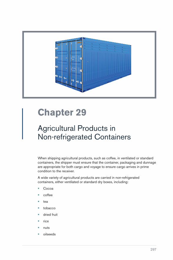
297
Chapter 29
Agricultural Products in Non-refrigerated Containers
When shipping agricultural products, such as coffee, in ventilated or standard containers, the shipper must ensure that the container, packaging and dunnage are appropriate for both cargo and voyage to ensure cargo arrives in prime condition to the receiver.
A wide variety of agricultural products are carried in non-refrigerated containers, either ventilated or standard dry boxes, including:
� Cocoa
� coffee
� tea
� tobacco
� dried fruit
� rice
� nuts
� oilseeds

Carefully to Carry Consolidated Edition 2018
298
� pulses
� spices.
Fresh fruit and vegetables are more commonly carried in refrigerated containers, although produce such as melons, oranges, potatoes, sweet potatoes, yams and onions are sometimes carried in ventilated or open containers.
Two frequent causes of major cargo damage are condensation and taint.
29.1 Condensation (Sweat)
Almost all agricultural products have a considerable intrinsic moisture content. They are hygroscopic cargoes which means they are in equilibrium with the air in the container and can emit as well as absorb moisture. The amount of water available within a container of such cargoes is much larger than for manufactured goods. Translocation of a comparatively small proportion of the total moisture available may cause substantial condensation problems.
Hygroscopic cargoes change temperature comparatively slowly. Therefore, when a container is shipped across climatic zones, the cargo adjusts to the changing ambient temperatures much more slowly than the container walls and the air. This delay can cause considerable temperature differences within the container and is the driving force for moisture translocation and condensation.
Ventilated containers
Ventilated containers include those with passive ventilation openings, open containers and mechanically ventilated containers. However, these are all comparatively rare and the vast majority of containers have no effective ventilation provision. Although the small air-expansion holes in the walls of standard dry boxes are sometimes called ‘ventilation holes’, the airflow through them is insufficient to provide significant protection against condensation.
The International Cocoa Organization recommends using ventilated containers for all containerised cocoa shipments. Some coffee and cocoa shippers use such containers, but this is not standard throughout the trade.
The air inside ventilated containers is largely common with the surrounding air, which may present additional problems, such as more ready transmission of taints. Therefore, the stowage location on board requires careful consideration.

Chapter 29 Agricultural Products in Non-refrigerated Containers
299
Desiccants
During carriage of hygroscopic cargoes in non-ventilated containers, condensation could be prevented if the relative humidity of the air inside the container is kept sufficiently low that its dew point is always below the ambient temperature. This ideal situation is often unrealistic, but the dew point may be lowered, and the risk of condensation reduced accordingly, by using desiccants.
Desiccants (such as silica gel, Møler clay or certain polymers) are water absorbent and remove moisture from the surrounding air. They may be supplied in bags, specially-lined sheets or as polymer-based paint. Once the maximum absorption capacity of such products is exhausted, they have no further beneficial effect, so their type and amount must be chosen carefully for the type of cargo and the voyage.
Because of their potential for significant moisture exchange with the air inside the container, hygroscopic cargoes place much greater demands on the capacity and sustained absorption rate of desiccants than non-hygroscopic cargoes. Desiccants alone are unlikely to prevent condensation in the event of rapid temperature changes of large magnitude.
Dunnage, sheets and linings
A basic precaution for cargoes sensitive to condensation damage is to apply suitable dunnage to separate the cargo from the container’s walls and floors. This cannot prevent the formation of condensation, but can greatly reduce its commercial implications. It is often recommended to use kraft paper or similar material to line the walls and floors of containers or as protective sheets on top of the cargo. Since these quickly become saturated, they cannot afford significant protection against severe sweat, but they can absorb small amounts of condensation and, in some circumstances, prevent or reduce staining and similar damage.
Sheets placed on top of the cargo must be readily permeable to air; plastic is unsuitable for this purpose as condensation could form between sheets and cargo.
29.2 Taint
Many foodstuffs can absorb chemicals and foreign odours from the air. This, typically, affects their taste and severely affects their commercial value, even when there are no significant toxicological implications.
Coffee, tea and cocoa are particularly susceptible to taint. They are traded primarily on their delicate flavour balances, with sophisticated tastings of every
Carefully to Carry Consolidated Edition 2018
300
consignment carried out at various stages. A comparatively minor off-flavour or odour causes commercial damage to these high-value cargoes.
Some basic considerations to protect against taint damage include:
� Prior to stuffing, inspect containers for odours, previous cargo residues and staining of floorboards. The container should be kept closed for some time until immediately before inspection
� containers that have recently been used for the carriage of odorous chemicals should not be used for foodstuffs, even if no detectable odour remains. More generally, operators should consider keeping separate pools of containers designated for chemicals and for foodstuffs
� stow containers containing foodstuffs away from strong odours on board. This is particularly relevant when using ventilated containers, where the air exchange rate, and so the potential for transmission of external taints, is much greater than for non-ventilated containers
� floorboards, pallets, crates, etc are often treated with fungicidal wood preservatives containing chlorophenols. These are also contained in mould inhibitors used on jute bags and in the adhesives in some fibreboard cartons. Chlorophenols are themselves a potential source of taint. Although the levels used are usually insufficient to cause commercial problems, they can be converted to chloroanisoles by certain microorganisms, particularly in the presence of excessive moisture such as may result from condensation. Chloroanisoles are an extremely potent source of taint, causing a characteristic musty odour and flavour, even in very minute proportions.
29.3 Production of Gases
Fresh produce continues to go through biological and chemical processes, including respiration, even when in storage. During this process, it will continue to generate heat when it absorbs oxygen (O2) and releases carbon dioxide (CO2) and ethylene (C2H4). The combination of heat and released gases can have an impact on the ‘health’ of the products being carried if the respiration process is not controlled.
The quantity of gases and associated heat produced varies between products. For example, pears and apples produce a significantly high quantity of ethylene, which can be controlled in two ways – by lowering the temperature or by increasing the CO2 concentration combined with reduction of O2. The latter option, however, is not desirable as it will have a negative impact on the quality of the cargo. The lowering of temperature, therefore, remains the only option to prolong the shelf life and maintain the quality of fresh produce. The atmosphere changed in this way is known as ‘Controlled Atmosphere (CA)’ or ‘Modified Atmosphere (MA)’.

Chapter 29 Agricultural Products in Non-refrigerated Containers
301
Due to variations in the level of oxygen (O2) absorption and release
of carbon dioxide (CO2) and ethylene (C
2H
4) even with the same
produce, there cannot be any single method of storage for a particular product. However, shippers may be able to provide some information for the required temperatures and levels of gases required on the basis of their experience. This information must always be complied with and specialist advice sought whenever there is any doubt.
29.4 Containerised Transport of Perishables without Refrigeration
Some perishable commodities are carried without refrigeration, possibly for very short duration journeys, or in ventilated equipment. In these cases, it is wise to consider which of the previous requirements may still apply.
Products with limited temperature sensitivity may be carried under refrigeration for certain journeys only. The following guidelines suggest when this may be appropriate:
� For any goods requiring close temperature control, refrigeration is essential. If temperatures need to be maintained within a band of 2°C or less, refrigeration should be virtually continuous
� at the other extreme, for less sensitive goods with a maximum temperature tolerance of 30°C or above, refrigeration is only necessary for storage on land at high ambient temperatures. For containerised shipments at sea, a protected stow may be requested
� if the maximum permitted temperature is 25°C or lower, refrigeration should be used for any journeys through the tropics and for any journeys anywhere in a summer season
� if cargo requirements are marginal, either in terms of temperature tolerance or in terms of possible delays at high ambient temperatures, the only safe option is to use refrigeration
� frozen foods may sometimes be carried without refrigeration for short journeys as long as the cargo is not subjected to more than the specified maximum temperature. This should only be done with the consent of the owner of the goods.


303
Chapter 30
Calcium Hypochlorite
Under the International Maritime Dangerous Goods Code (IMDG Code), (Reference 19), anhydrous (UN 1748), hydrated (UN 2880) and bleaching powder (UN 2208) forms of calcium hypochlorite (UN numbers 1748, 2208, 2880, 3485, 3486 and 3487) are to be stowed on deck only (Category ‘D’). They should be stowed out of direct sunlight and the use of bulk packages, IBCs, bags or sacks for transportation is not permitted. Packing the materials in drums facilitates airflow through a stow of such receptacles when they are stuffed into a freight container. This is important as airflow will assist in the dissipation of heat generated by these reactive materials.
30.1 Stowage Issues
The critical ambient temperature (CAT) for calcium hypochlorite depends on the package shape and size. The CAT is higher for smaller packages because they can dissipate heat in the atmosphere more quickly due to larger surface area for the amount of the contents. Therefore, the bigger the package, the lower the CAT and, therefore, the higher the risk of exothermic decomposition, ie release of chlorine and oxygen gases if exposed to temperatures of between 30° to 55°C or above due to stowage under direct sunlight or above bunker tanks.
Get
ty Im
ages

Carefully to Carry Consolidated Edition 2018
304
When released, oxygen will sustain any fire caused due to the decomposition reaction already taking place. As chlorine is toxic, the International Group of P&I Clubs (IG P&IC) recommends that stowage should be clear of living quarters. It also recommends a package limit of 45 kg with a limit of 14 t total mass per 20 ft container where a CAT of 40°C should still be expected (Reference 53). If cost is not an issue, carriage in reefer containers at controlled temperatures of 10°C should be considered. However, failure of refrigeration should be risk assessed as it may lead to disaster.
The IG P&IC recommendations are based on a better understanding of the properties of the hydrated form of the material UN 2880 than had been available when, in the late 1970s, the IMDG Code entry for this material was discussed. Research carried out in Australia by Professor B F Gray and Dr B W Haliburton highlighted the need to be more aware of the sensitivity of these materials to spontaneous decomposition, which may lead to explosion and fire and which could occur at temperatures as low as 30°C for freight containers stuffed with large drums (about 200 kg) of UN 2880 (Reference 54). Such temperatures are encountered in the holds of container vessels where there are heated fuel oil tanks. Therefore, the materials should not be stowed where their critical ambient temperature can be attained. If there is a risk with on-deck stowage that freight containers could be subjected to long periods of direct sunlight, steps should be taken to restow them. If this is not possible, they should be covered with tarpaulins to provide shade.
The ocean transportation history of calcium hypochlorite suggests that all forms pose special challenges concerning safe carriage. The safety issues are complex and are aggravated by a high degree of product variability.
The 2000 amendment to the IMDG Code (Amendment 30) (Reference 19), effective from 1st January 2001, states the following for calcium hypochlorite, UN numbers 1748, 2208 and 2880:
“Stowage and Segregation, Category D. Cargo transport units should be shaded from direct sunlight and stowed away from sources of heat. Packages in cargo transport units should be stowed so as to allow for adequate air circulation throughout the cargo. ‘Separated from’ powdered metals and their compounds, ammonium compounds, cyanides, hydrogen peroxides and liquid organic substances.”
30.2 Synonyms for Calcium Hypochlorite
� B-K powder
� bleaching powder
� bleaching powder, containing 39% or less chlorine

Chapter 30 Calcium Hypochlorite
305
� calcium chlorohydrochlorite
� calcium hypochloride
� calcium hypochlorite
� calcium oxychloride
� caporit
� Cch
� chloride of lime
� chlorinated lime
� Hth
� HY-chlor
� hypochlorous acid
� calcium salt
� lime chloride.
Some calcium hypochlorite shipped out of China is declared as:
� Prechloroisocyanoric acid (UN 2465)
� sodium di-isocyanorate (UN 2466).
It may also be shipped as water purification tablets and swimming pool cleanser.
30.3 Case Studies
‘Eugen Maersk’
In June 2013, the ‘Eugen Maersk’ container ship suffered a fire that broke out in one container and spread to several others nearby. The containers had all been declared as containing household goods and none should have held anything hazardous that might have caught fire in such a way. Containers with flammable contents are usually stored on deck to minimise the risks of fire but, if the contents are misdeclared, they may be stored in locations that cause serious hazards to the ship’s crew and cargo.
MSC ‘Flaminia’
In July 2012, the MSC ‘Flaminia’ suffered a severe fire that led to an explosion on board. Three crew members were killed in the incident and it again raised questions over whether the nature of the cargo had been correctly declared.


307
Chapter 31
Thiourea Dioxide
Thiourea dioxide, or formamidine sulfinic acid (UN 3341, Class 4.2), is a white to pale yellow, crystalline powder used as a reductive agent in the paper industry and a bleaching agent in the textile industry. It is produced by oxidation of thiourea with hydrogen peroxide.
During 1996–97, there were several incidents related to the decomposition of thiourea dioxide. In one incident in the Far East, 400 workers were evacuated from a marine terminal and several workers required hospitalisation. At that time, the chemical was not included in the IMDG Code.
When exposed to heat above 50°C and moisture, it is likely to decompose visibly and rapidly, a reaction that may be catalysed by metal salts. This decomposition is accompanied by the release of toxic and corrosive gases, including sulphur oxides, ammonia, carbon monoxide, nitrogen oxides, hydrogen sulphide, etc. Sulphur oxides can further react with moisture to form acidic conditions and the acid may then attack neighbouring cargo, leaving solid residue and causing contamination.
The IMDG Code (Reference 19) requires this cargo to be packed in hermetically-sealed drums. Stowage should be in cool dry areas at ambient temperatures. Stowage should be away from heat sources, such as steam pipes, heating coils, heated bunker tanks and main engine bulkheads.

Carefully to Carry Consolidated Edition 2018
308
Under-deck stowage is not recommended (IMDG Stowage and Segregation, Category D) because ships’ holds may reach 65°C in certain tropical zones. However, temperatures in containers carried on deck and exposed to sunlight at the edge of a container stow may also reach 65°C. Containers within the centre of a stow are protected from these high temperatures to some extent.
This cargo should not be accepted in bags.
31.1 Decomposition
Product information varies between manufacturers, with some stating that the material decomposes at 100°C, but will also decompose on lengthy heating above 50°C. Another indicates that the thermal stability is 80°C for two hours although the fate of the material after two hours under these conditions is not revealed. Some manufacturers have shipped this cargo under the names ‘Thiourea D’ or ‘Thiourea De’, claiming that it is less hazardous than thiourea dioxide, although this is not the case.
Figure 31.1: Decomposition.
Ships’ crew should be made fully aware of the possible hazards of the carriage of thiourea dioxide. Shipowners must ensure that, if any such cargo is offered for shipment, the relevant personnel are able to make qualified decisions, even if this requires them to reject the shipment.

309
Chapter 32
Expandable Polymeric Beads
Expandable polymeric beads, also known as expandable polystyrene (EPS) (UN 2211 Polymeric Beads, Expandable), are used to produce a moulding material in the form of granules or beads of approximately 3 mm in diameter. The beads or granules may contain 5 to 8% of a volatile hydrocarbon, chiefly pentane. During the moulding process, the beads are heated, causing expansion and fusion, forming the familiar polymeric packaging material. During storage or transport, the material will release a portion of the pentane. The rate of this release increases with a rise in temperature. Pentane vapours are heavier than air, so higher concentrations can be found closer to the deck level. To add more complexity, pentane is liable to ignition at relatively low concentrations, eg 1.3% by volume in the air, with the rate of gas release increasing with a rise in temperature.
The beads have been found to generate f lammable concentrations of gas in enclosed spaces and have been involved in several major explosions, one incident causing severe damage to a container ship.
Expandable beads are included in the IMDG Code (Reference 19), under Class 9 (miscellaneous dangerous substances and articles). Packaging

Carefully to Carry Consolidated Edition 2018
310
recommended in the IMDG Code includes outer drums and inner plastic packages. Intermediate bulk containers include composite fireboard or plastic materials. Under-deck stowage is permitted, but good ventilation must be ensured so that any ignitable concentrations can be avoided. Use of ventilation containers must be considered with caution as the level of ventilation provided may not necessarily be sufficient to rid any build-up of pentane. When ventilated containers are used, the ‘Criteria for the Selection of Ventilated Containers’ provided by the Expandable Polystyrene (EPS) Transport Group of PlasticsEurope in Guidelines for Transport and Storage of Expandable Polystyrene Raw Beads (Reference 55) must be complied with in addition to complying with other requirements of the IMDG Code for labelling, packaging and segregation. This requirement must include additional labelling for closed containers such as ‘keep away from all sources of ignition’, ‘no smoking or use of fire/naked lights’ and other cautions.
Transportation on ships in closed, non-ventilated containers is permitted, but the consignees must be advised about the risks associated with any accumulated pentane in high concentrations, including additional requirements for making an entry into the container, which should be treated as an enclosed space. This may require use of supplementary labels to warn workers of the hazards.
The Code of Federal Regulations 49 CFR, Chapter 1, Part 173 (Reference 56) describes various packaging materials but states that, except for transportation by highway and rail, the packaging must be capable of containing any evolving gases from the contents during normal conditions of transport.
The IMDG Code (Reference 19) states that storage and segregation is category ‘A’, on deck or under deck, but mechanical ventilation should be provided for under-deck stowage to prevent the formation of a flammable atmosphere. The Code advises that, during storage, a small proportion of the pentane may be released to the atmosphere and that this proportion is increased at elevated temperatures. There is also a cautionary note relating to the opening of doors if the material is carried in containers.
Reputable manufacturers of polymeric beads are well aware of the hazards of storage and transportation of the beads and provide detailed lists of precautions to be observed. They provide detailed warning labels to be fixed to drums and freight containers, labels in several different languages and graphic symbols.
The recommended storage is in a well-ventilated space and preferably below 20°C. Warehouse storage below 20°C may be a relatively simple operation. However, stowage in the holds of an ocean vessel may be more difficult and should, at least, be away from heated bunker tanks or engine room bulkheads. Temperatures in ships’ holds might be of the order of 65°C in some tropical areas. Adequate hold ventilation with ‘suitable equipment’ should be stressed

Chapter 32 Expandable Polymeric Beads
311
because the arcing of an electric fan motor may readily ignite a flammable concentration of pentane in air.
Deck temperatures in tropical climates can also exceed the recommended limits for safe stowage of the beads. However, if the cargo is containerised, the containers can be placed in a central area of the stow where they will be insulated from the effects of direct sunlight. This arrangement will create extra movement during loading and discharge, but can assist toward safe carriage. Pentane released from containers in deck stowage will be dispersed by wind and movement of the vessel and should not create flammable or explosive conditions outside the containers.
Manufacturers are well aware of the problems of release of pentane, which is heavier than air, into freight containers. Recommended ventilation periods are suggested prior to entry and unpacking the container. If opened in a container yard, containers should be sited away from drains so that pentane released when the doors are opened does not enter them, creating a potential fire hazard at some nearby location.


313
Chapter 33
Flexitanks
A flexitank is a bladder designed to fit inside a 20 ft general freight container, thereby converting the freight container into a non-hazardous bulk liquid transportation unit. As defined by the IMO/ILO/UNECE Code of Practice for Packing of Cargo Transport Units (CTU Code) (Reference 57), a flexitank is a ‘bladder used for the transport and/or storage of a non-regulated liquid inside a CTU’. Flexitanks are not an approved form of packaging for the carriage by sea of dangerous goods classified under the International Maritime Dangerous Goods Code (IMDG Code) (Reference 19).
Figure 33.1: Flexitank in a container.

Carefully to Carry Consolidated Edition 2018
314
There has been an expansion in the use of flexitanks since 2000, with the emergence of single-trip tanks.
In 2014, the demand for flexitanks was 800,000 units, expected to increase to 5.1 million by 2022.
A large number of claims have arisen relating to containers carrying flexitanks, where the pressure placed on the sidewall panels has resulted in them bulging beyond accepted ISO external dimensions and tolerances, leading to permanent deformation. The International Organization for Standardization (ISO)/Institute of International Container Lessors (IICL) deformation limit for sidewall panels is a maximum of 10 mm beyond the plane of the side surfaces of the corner casting fittings. This limit has been exceeded in many incidents, so some operators have imposed limits on the quantity of liquid that may be carried in a flexitank.
Figure 33.2: Bulging f lexitanks.
33.1 COA Code of Practice for Flexitanks
In 2011, the Container Owners Association (COA), Flexitank Division, published a Code of Practice to improve the quality and safety of flexitank operations. Compliance with this Code is not mandatory (Reference 58). The current version of the COA Code of Practice for Flexitanks was published in December 2015 and contains the guidance provided in the IMO/ILO/UNECE Code of Practice for Packing of Cargo Transport Units (CTU Code) published on 16th December 2014 (Reference 57).
The COA has also set up a dedicated website (http://www.flexitanks.org). Under the Code of Practice, the COA provides a mechanism for each COA flexitank manufacturer to obtain a COA Compliance Certificate showing their

Chapter 33 Flexitanks
315
compliance with the Code subsequent to audits for their quality management system, installation and training, material test and rail impact test. The certificate confirms that the manufacturer endorses the COA declaration and has undergone audit in all four areas. The COA also maintains a FQML (Flexitank Quality Management List) on this website to record the manufacturers who have received COA certification.
Alongside the Code of Practice, the British Standards Institution (BSI) has developed specification BSI PAS 1008 Specification for the performance and testing of a single-use flexitank (Reference 59). PAS 1008 is sponsored by COA and provides detailed specifications for testing materials, performance and labelling of all components in the flexitank system.
33.2 Perceived Advantages/Disadvantages
In the non-hazardous markets, single-use flexitanks are considered by some to be effective substitutes for ISO tank containers and drums. Some of the reasons for this include:
� Flexitanks are product dedicated and so there is no risk of cross contamination
� relatively low positioning costs (in some areas, 100 empty flexitanks can be positioned for the same cost as one tank container)
� positioning a flexitank with a capacity of up to 24,000 litres inside a 20 ft general freight container enables shippers to dispatch about 40% more cargo per container than a drummed consignment, about 50% more than a bottled consignment and about 15% additional payload when compared to a container filled with intermediate bulk containers (IBCs). No return loads are required
� loading rates are higher compared to drums and IBCs
� flexitank manufacturers obtain approvals from authorities such as the USA’s FDA (Food and Drug Administration), the EEC (Food Safety System Certification 22000 – FSSC) and the UK’s HACCP (Hazard Analysis and Critical Control Point) to ensure compliance with food products.
The disadvantages of flexitanks include:
� Products classified as dangerous goods under the IMDG Code (Reference 19) are not permitted to be carried in flexitanks
� pumps are required for unloading older flexitanks, although newer tanks are fitted with loading/unloading valves
� greater preparation is required for flexitanks than for ISO tank containers, although ISO tanks require substantial cleaning, particularly in food applications

Carefully to Carry Consolidated Edition 2018
316
� environmental issues arise in connection with the disposal of used single-trip flexitanks
� the risk of leakage of the full contents
� the potential for high costs to clean up spillages
� spillage resulting in the contamination of other cargo, depending upon stowage on board.
Figure 33.3: Flexitanks damage.
33.3 Types of Flexitanks
A range of products are carried in flexitanks, including wine, fruit concentrate, animal fat, fish oil, base oil, detergents, non-hazardous chemicals, drilling mud additives, paint, lubricants, printing ink, latex and potable water. The choice of flexitank is based on the cargo carried and factors such as the duration of the voyage and the temperature difference between load and discharge port.
Flexitanks can be either single layer or multilayer. Single layer flexitanks (SLFs) are generally manufactured from a single thick layer of polyethylene of 40 mm thickness. Multilayer flexitanks (MLFs) can consist of several layers (2, 3 or more), depending on the type of cargo being carried and the shipper’s requirements. Generally, the value of the cargo will determine the protection required in the carriage and, therefore, the number of layers required for the MLF being used. For example, cargoes that require a barrier against taint contamination will use 4 layers. Each layer of an MLF may be about 125 microns thick. The outer layer of an MLF is normally of a woven type plastic material. A problem with MLFs is that the different layers may, during loading, get caught up and trapped, resulting in a layer tearing.
The first flexitanks were designed on the basis that they would be for multi-trip use, which meant that cleaning and repositioning costs were incurred. However, these costs have been eliminated with the single trip/use flexitank, which is the type now most commonly in use, accounting for more than 95% of the global market.
Flexitanks are required to be marked with the performance test standard, manufacturer’s name and logo, unique serial number and capacity at the time of manufacture. These markings must be located on the f lexitank in such a way that they are visible when the right-hand door of the container is opened.

Chapter 33 Flexitanks
317
33.4 Free Surface Effect
A free surface effect can occur in liquids, or in masses of small solids, if they move about during transport in partly filled tanks, including ballast and fuel tanks. It also occurs in containers that are only partially full and when this happens it can alter the centre of gravity of the ship so that, instead of righting itself as it rolls on passage, the ship leans further over to one side and may capsize.
In October 2002, the container ship ‘Westwood Rainier’ began to list while in port in Seattle. The upper port ballast tank was seen to be pumping out water immediately prior to the 35 to 40° list developing. While a problem with the ballast water system seems to have been the cause of the list, it may have been exacerbated by a free surface effect in the tanks.
If a flexitank is not filled to near its nominal capacity, a marked free surface effect and hydraulic surging of the liquid may occur, often resulting in damage to the container. A flow meter should be used to ensure that a flexitank has been filled to its correct capacity (±500 litres of its nominal capacity) because a visual inspection alone is unlikely to be sufficient.
A large number of partially filled f lexitanks can have a significant adverse impact on ship’s stability. Masters must, therefore, be supplied with relevant information so that they can incorporate any loss of stability due to partially filled f lexitanks into their stability calculations.
The typical capacity of a flexitank is in the range of 10,000 to 24,000 litres and the weight carried will depend on the density of the commodity. The permitted gross weight of a container should never be exceeded. Current practice is not to load more than 24,000 kg of liquid in a 20 ft freight container, although even this is considered too high by some container operators.
33.5 Flexitank Container Characteristics
The 20 ft containers for carriage of flexitanks should be rated to a minimum 30,480 kg, irrespective of the size of the flexitank. The actual sidewall strength is a function of a container’s permitted payload, ie 0.6 × payload (ISO 1496-1 Series 1 freight containers – specification and testing (Reference 60)). Therefore, the sidewall panels of a 30 mt container will have been tested to a greater load bearing capability than, say, a 24 mt container.
The sidewall test requires a general freight container to be subjected to an internal loading uniformly distributed and arranged to allow free deflection of the sidewall and its longitudinal members. This test proves the ability of a container to withstand all forces that can result from the movement of a ship at sea. The ISO Standard requires that, upon completion of the test, the container exhibits neither permanent deformation that will render it unsuitable for use, nor

Carefully to Carry Consolidated Edition 2018
318
any abnormality that will render it unsuitable for use, and that the dimensional requirements governing handling, securing and interchange are satisfied. Therefore, for a 30 mt container, the test load will be of the order of 16.8 mt. However, a flexitank does not place a uniform loading over the full area of a sidewall and a gross liquid cargo weight of 24,000 kg is the recommended maximum by some flexitank operators, while some container operators consider that there should be a lower limit. Any general purpose container may be used as currently there is no specific classification of containers for the carriage of flexitanks.
To minimise the stress upon the sidewalls of a freight container, it is recommended that the height of the side of the flexitank in contact with the sidewall panel should be kept to a minimum. An optimum height of 1.3 m has been suggested.
It is also recommended by flexitank operators that the sidewall panels are fully corrugated from end to end and that a container with sidewall decal panels and flat logo panels is not acceptable.
Containers used for flexitanks are required to display a CSC plate and must be part of a valid PES (periodic examination scheme) or ACEP (approved continual examination programme). When used, the containers must be in a good state of repair in compliance with shipping line criteria such as UCIRC (Unified Container Inspection and Repair Criteria).
The container should be fitted with:
� Functioning dual locking bars for each door panel
� left-hand door handles that have a hole to accept a safety bolt seal
� door recesses for bulkhead fixings.
33.6 Inspection of Freight Container Prior to Use
Regardless of whether a single or multi-trip flexitank is being used, a freight container should be inspected to ensure the following:
� The container is structurally undamaged and free from sharp projections on internal side and end wall panels and floor
� the container is in a clean condition and free from the residue of all previous cargoes
� any joints in the welds are smooth, ie no rough edges or cracks in the welding or otherwise in the structure of the container
� there are no floor imperfections:
� floorboards and their retaining bolts are flush
� there are no nails in the floor (nails/screws/fastenings should not be hammered into the floor)

Chapter 33 Flexitanks
319
� the underside of the container floor should also be inspected to ensure that no nails are protruding and that all cross members are in place and firmly affixed to the floor and the side rails and do not show signs of excessive deformation and/or cracking
� internal weld joints are smooth; rough weld joints can result in a flexitank being abraded (placing tape over the weld joints can provide extra protection)
� cams on both doors position and lock correctly when the doors are closed
� handles position and lock fully in their hatches
� door recesses for bulkhead fixings are in good condition (note: containers are being built without door recess channels which makes them unable to accommodate bulkhead fittings)
� lashing fittings at bottom rails and corner posts should be undamaged to reduce the risk of punctures
� bolts affixing labels etc to the doors are not protruding through to the inside of panels. If they are, they must be covered with foam or cardboard
� any traces of oil found on the container walls or floor must be cleaned. If it cannot be cleaned, such as oil soaked into a timber floor, it must be reported to avoid subsequent claims on an incorrect party.
Some flexitank operators provide a standard practice checklist for container selection. If the container does not meet the criteria laid down, the flexitank operator’s technical department should be notified.
To protect the flexitank from abrasion against bare metal, the normal practice is to line the inside of the container. Materials often used include corrugated cardboard, Styrofoam sheets and kraft paper.
Figure 33.4: Use of kraft paper.
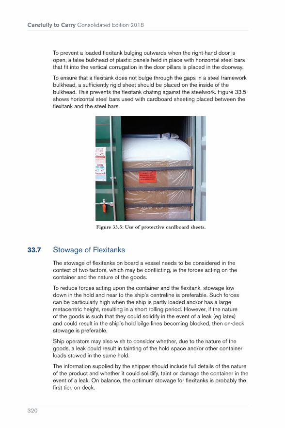
Carefully to Carry Consolidated Edition 2018
320
To prevent a loaded flexitank bulging outwards when the right-hand door is open, a false bulkhead of plastic panels held in place with horizontal steel bars that fit into the vertical corrugation in the door pillars is placed in the doorway.
To ensure that a flexitank does not bulge through the gaps in a steel framework bulkhead, a sufficiently rigid sheet should be placed on the inside of the bulkhead. This prevents the flexitank chafing against the steelwork. Figure 33.5 shows horizontal steel bars used with cardboard sheeting placed between the flexitank and the steel bars.
Figure 33.5: Use of protective cardboard sheets.
33.7 Stowage of Flexitanks
The stowage of flexitanks on board a vessel needs to be considered in the context of two factors, which may be conflicting, ie the forces acting on the container and the nature of the goods.
To reduce forces acting upon the container and the flexitank, stowage low down in the hold and near to the ship’s centreline is preferable. Such forces can be particularly high when the ship is partly loaded and/or has a large metacentric height, resulting in a short rolling period. However, if the nature of the goods is such that they could solidify in the event of a leak (eg latex) and could result in the ship’s hold bilge lines becoming blocked, then on-deck stowage is preferable.
Ship operators may also wish to consider whether, due to the nature of the goods, a leak could result in tainting of the hold space and/or other container loads stowed in the same hold.
The information supplied by the shipper should include full details of the nature of the product and whether it could solidify, taint or damage the container in the event of a leak. On balance, the optimum stowage for flexitanks is probably the first tier, on deck.
Chapter 33 Flexitanks
321
Even though the cargo carried in f lexitanks is considered to be non-dangerous and, therefore, does not necessarily require Safety Data Sheets (SDS), in order for the carrier to be aware of the risks associated with the cargo, the shipper must provide an SDS so that appropriate action can be taken in the event of spillage of cargo on the ship.
33.8 Labelling of Containers
It is normal practice to place a warning label on the left-hand door panel of the freight container to highlight the risk that the container is fitted with a flexitank. The label must be in English and at least one other language of the shipper or the consignee. This label should be printed on a placard of at least A4 size (210 × 297 mm) that is capable of withstanding the harshness of the sea for at least 90 days. It should advise:
� Caution bulk liquid
� flexitank container
� keep left-hand door shut, ie do not open the left-hand door until discharge is complete
� do not loose shunt
� no forklift truck
� emergency contact information.
The Code of Practice for Flexitanks recommends only one label, but this presupposes that this single label will be seen by the person handling the container, which may not be the case for the operator of the crane loading/discharging the vessel or the driver of the vehicle moving the container to/from the quayside to its storage location on the terminal (Reference 58). It also presupposes that the label is in a language understood by the person handling the container at any particular time in the transport chain.
Any markings on the container indicating carriage of a flexitank must be removed as soon as the flexitank is discharged.
33.9 Flexitank Safety
For ease of discharge, bottom fittings adjacent to the doorway are generally preferred. However, this can result in a static head of pressure between the flexible body of the tank and the valve construction. Leaks can occur due to the detachment of the double patch around the valve opening of either the top or bottom fittings.

Carefully to Carry Consolidated Edition 2018
322
Figure 33.6: Flexitank valve.
A damaged container does not automatically mean that a flexitank will leak. However, if a flexitank does leak and its full load is spilt then, depending on the commodity being carried, the clean-up costs may be considerable. Additionally, daily demurrage costs on quarantined leaking flexitanks may be charged by shipping lines if the shipper/consignee is unable to provide the emergency assistance required.
A flexitank can sustain severe trauma without leaking. Figure 33.7 shows a flexitank full of synthetic latex stowed at the bottom of a flooded hold. There was no leakage and the product was later sampled, approved and discharged for its intended use.
Figure 33.7: Flood-damaged f lexitanks containing undamaged latex.
However, problems do arise, such as with wine which expands excessively if it ferments in a flexitank, see Figure 33.8.

Chapter 33 Flexitanks
323
Figure 33.8: Damage caused by fermentation of wine.
In this case, while the sidewall and roof panels of the container were damaged, there was no leakage of the wine. This is one reason why relief valves are not used on some designs. While relief valves are suitable for the rigid design of tanktainers, there are complex problems in designing one suitable for a flexitank. The fitting of relief valves in the early flexitanks was one of the causes of criticism as there was frequently leakage of the contents during shipment.
However, to put the problem in perspective, the number of similar incidents involving wine, for one flexitank operator, has been three or four out of a total of 28,000 carried.
As the technology continues to develop, flexitank manufacturers are venturing into the use of 40 ft containers to transport liquid cargoes. It is estimated that these containers will be capable of carrying some 27,000 litres of liquid in one container. These flexitanks will also utilise heating pad systems to heat prior to discharging.
A number of underwriters have refused to insure flexitank shipments due to the risk of leakage, particularly where there is the potential for damage to the environment. It is therefore recommended that the following precautions are taken for all shipments involving flexitanks:
1. The shipper is to provide the carrier with:
a) details of the product being shipped
b) details of the manufacturer of the flexitanks to check whether they are on the COA approved list
c) serial number of the flexitank added on to the B/L.
2. If the flexitank manufacturer is not on the COA approved list, the carrier may still accept the shipment provided the shipper is able to provide the required information, such as for the criteria specified in the COA Code of Practice, and is certified by an independent auditing authority.
3. In all cases, the shipper must provide 24 hour emergency contact details.
Carefully to Carry Consolidated Edition 2018
324
4. The personnel operating the flexitank, ie installing it in the container, loading or unloading cargo, must be trained as required by the COA.
5. Depending on the nature of the cargo being carried, the flexitanks must be filled to their capacity, leaving only 5% space unfilled to allow for expansion. Shippers should establish additional requirements based on the temperature difference between load/discharge ports and transit areas and their impact on cargo expansion etc. If the flexitank is not full to capacity, the Master of the ship must be informed to allow for free surface effect calculations to take place.
6. Carriers must record the condition of the container loaded with a flexitank upon receipt on board, notifying any anomalies to the shipper immediately. The Master must exercise his right to refuse any cargo where a doubt exists as to the integrity of the container or its contents.
33.10 Charterparty Contracts
In charterparty contracts, owners and charterers should identify who will be responsible for costs and damages in the event of leakage from a f lexitanks while on board. In addition, when B/Ls are issued, they should be claused to identify the party responsible for positioning and loading the f lexitank in the container.

325
PART 9Refrigerated and Controlled Atmosphere Cargoes
Chapter 34 ..............................................327Refrigerated Container and Controlled Atmosphere Cargoes
Chapter 35 ..............................................335Carriage Instructions for Refrigerated Cargoes
Chapter 36 ............................................. 349Fresh Fruit and Vegetables
Chapter 37 ............................................. 361Table Grapes
Chapter 38 ............................................. 363Frozen Fish
Chapter 39 ............................................. 381Meat and Meat Products in Containers
Chapter 40 ............................................. 385Pharmaceuticals in Temperature Controlled Containers


327
Chapter 34
Refrigerated Container and Controlled Atmosphere Cargoes
The international transport of temperature controlled raw materials and final products is an essential link between producers and consumers. Most cargoes have properties that will determine their practical storage life (PSL), which is a key factor if they are to be carried by sea.
The container trade has seen changes in recent years:
� More countries are exporting by sea, with products including fruit, fish, flower bulbs and meat
� some shorter life products spend more than half their PSL in transit
� supermarkets demand all year round supplies, reducing seasonality
� lower stock holding has increased demand for just in time deliveries and inventory control.

Carefully to Carry Consolidated Edition 2018
328
34.1 Claims and Incidents
The majority of cargoes outturn well and claims represent a fraction of 1% of the containers carried.
The following list, while not exhaustive, contains occurrences often reported in cargo claims:
� Lack of container preparation for loading, causing issues such as tainting and lack of general cleanliness
� containers off-power and, therefore, off-refrigeration for extended times beyond allowed times for power-off
� wrong settings due to incorrect information supplied or interpreted
� failure to monitor properly leading to failure to correct faults or wrong settings
� poorly pre-cooled or overcooled cargo
� cargoes with insufficient PSL
� badly stowed containers impeding airflow, many with low quality packaging
� use of inappropriate packaging materials
� excess fresh air ventilation for live cargoes causing evaporators to ice up
� incorrect defrost interval where this has to be set manually
� incorrectly booked cargo leading to operational and commercial problems
� Fahrenheit and Celsius temperatures interchanged or wrongly converted.
Additional issues include physical damage, broken security seals, air probe temperature sensor failures, partial or complete loss of refrigerant and generator failure.
60% of claims can be attributed to human error, and negligence by one individual can have serious consequences. For example, mishandling by a gantry crane operator could damage the cooling plant or its controls, leading to incorrect readings on the Partlow charts or Cox recorders.
(See Section 35.3 on Specific Requirements for Reefer Ships.)
34.2 Patterns of Claims and Incidents
One of the main causes of damage to cargo carried in containers is poor stowage by the shipper, although as the number of claims is still small, the statistics are difficult to analyse. However, reports indicate a decline in the use of specialised reefer ships and an increase in demand for transport by refrigerated container. As the volume of refrigerated cargo increased, a shift from the use of 20 to 40 ft containers has become evident. Therefore, while the
Chapter 34 Refrigerated Container and Controlled Atmosphere Cargoes
329
ratio of claims in the trade may not change, the number and value of claims is likely to rise.
Most temperature controlled containers contain data loggers that record a variety of information. Some are fitted with data transmission capabilities for remote access for both control and readouts. Independent loggers are also available so that a wide variety of audits and checks can be made. When reviewing a claim/incident, containers equipped with this information download can show:
� Pre-trip inspection records
� set point plus supply and return air temperatures at preset intervals
� defrosts
� times off-power
� basic faults
� relative humidity.
This is a major improvement from just recorder chart details and, when such remotely managed containers are more widely implemented, ships’ crews involved in the cool chain will follow instructions directly from the reefer container operator.
34.3 Future Trends
The future trends are mainly positive and are likely to include:
� Integral containers:
� more reliable with improved airflow, calibrated air freshening vents, dehumidifiers and other programmable settings
� improved insulation with lower degradation over time
� reliable refrigeration machinery, controls and data loggers with some providing wireless/satellite data transmission and remote access to controls
� more use of 40 ft containers making it easy to care, carry and discharge
� new vessels providing faster transits
� increasing uniformity of regulations
� food standards agencies or equivalent developing in key countries
� majority of container ship operators providing information and guidance through their web-based systems.

Carefully to Carry Consolidated Edition 2018
330
34.4 Principles of Controlled Atmosphere (CA) Carriage
CA is a system whereby the gas concentrations to which a cargo is exposed are different from those of normal air.
The atmosphere naturally comprises about 78% nitrogen (N2), 21% oxygen (O2) and 0.04% carbon dioxide (CO2), the remainder consisting of noble gases (eg argon). The aim of CA is to change the ratio of these gases. For example, an atmosphere of 2 to 5% O2 and 2 to 5% CO2 can extend the storage life of bananas beyond that which can be achieved by refrigeration alone.
CA is extremely effective on apples and pears but less effective on some other fruit. In general, it can be said that it gives a 50% increase in storage life and, for bananas, their ‘green-life’ is more than doubled.
Lowering the O2 concentration results in a reduction of the respiration rate by up to 30%, thereby slowing ageing and also reducing sensitivity to the ripening hormone ethylene. Increasing CO2 is beneficial in suppressing the growth of moulds. Further, when dissolved in water, it produces carbonic acid which is antibacterial. CO2 also reduces production of ethylene and lessens its effect on produce.
Chilled produce is still alive and respiring during transport and storage, using O2 and its own carbohydrate reserves, as shown in Figure 34.1.
Oxygen(O2)
Heat
Carbon Dioxide +Water (CO2 + H2O)
Ethylene(C2H4)
Figure 34.1: Produce respiration.
Regardless of commodity, the strongest influence on the quality of the final cargo outturn is the initial quality of the produce.
As well as prolonging storage life, CA also maintains the firmness, texture, crispness, acidity and appearance of some products. It further opens possibilities for the produce to be harvested in a riper state.
The optimal temperature and gas composition for different perishable cargoes depends on variety, growing area and season. For this reason, the precise values must be defined by the shipper.
CA systems currently in use
The two current CA methods are:
� Nitrogen gas flushing
� fresh air replenishment with CO2 absorption.

Chapter 34 Refrigerated Container and Controlled Atmosphere Cargoes
331
Nitrogen gas flushing employs air and N2 injection to adjust the balance of O2 and CO2 inside a refrigerated hold or refrigerated container. Air separation units are used to obtain N2 from the outside atmosphere. It is injected to dilute the O2 in the refrigerated space. If (through respiration of the cargo) the concentration of O2 becomes too low or that of CO2 becomes too high, the system automatically adjusts the gas concentrations.
A fresh air exchange system with CO2 absorption relies on the respiration of the product to vary the gas concentrations. When the CO2 or O2 level reaches a preset point, the system activates, drawing in outside air to add O2 and flush excess CO2. As respiration consumes O2 and evolves CO2, it is not possible for this system simultaneously to achieve low O2 and low CO2 levels unless a CO2 absorption system is used.
Detrimental effects of CA
Generally, CA is beneficial to the long-term storage of produce, but there can be some less desirable consequences.
Inadequate O2 can result in anaerobic respiration, leading to the production of alcohol and giving the affected produce a characteristic off-taste. Excessive CO2 can produce tissue damage and ‘fizzy’ fruit. In apples, the final effect is a condition known as brown heart, where the core tissue turns brown.
Premature ripening of bananas during shipment under air-stored carriage will turn the fruit yellow, easily identified as ‘ship-ripes’. Under CA conditions, however, the raised CO2 concentration prevents de-greening of the peel and the bananas arrive with soft pulp, known as ‘green-soft’ or ‘green-ripes’. If CO2 levels are excessive, bananas may develop a black blotchy appearance. A combination of elevated temperature and CO2 levels above 5% can even kill the fruit.
34.5 Safety Issues with CA
Safety is an important consideration for carriers because low oxygen atmospheres are incapable of supporting life. Entering an area during CA operation will have fatal consequences, so all CA areas must be clearly indicated by warning signs. Stevedores, ships’ officers and crew should be adequately trained to understand the dangers of CA. Doors should be alarmed and adequate precautions taken against stowaways.
Enclosed space entry procedures must be followed before entering a space that has earlier been subject to CA, or an adjacent space where the O
2 concentration may have been depleted. Anyone entering such a
space should carry an O2 detector with a low-level alarm.

Carefully to Carry Consolidated Edition 2018
332
Symptoms of O2 deficiency are similar to drunkenness and the subject is unaware that they are being affected. Table 34.1 lists the effects at different concentrations.
Oxygen Content % Symptoms
21 Normal atmospheric concentration
15 to 19 Loss of coordination, impaired work ability12 to 15 Loss of judgement, confusion and elation
10 to 12Increased loss of judgement and coordination, general confusion
8 to 10 Mental incapacity, nausea and vomiting
5 to 8Death in 8 minutes, recovery possible providing exposure less than 5 minutes
<5 Rapid unconsciousness followed by death in under 1 minute
Table 34.1: Symptoms of O2 deficiency.
Increased CO2 levels also pose a danger, causing headaches, dizziness, confusion and ultimately loss of consciousness. Long-term exposure limits are 5,000 ppm (8 hour period) and short-term exposure limit 1,500 ppm (15 minutes).
The safety requirements extend to those unloading cargoes. It is essential that workers are adequately trained and that proper fresh air ventilation is applied prior to opening cargo spaces.
34.6 System Failure
Prompt action must be taken in the event of CA system failure. In most cases, the refrigeration system will continue to function and so complete cargo loss is not inevitable. CA failure can be caused by a variety of faults, such as mechanical breakdown, sensor malfunction, unexpected air leakage or even exhaustion of a chemical CO2 absorbent.
Without intervention, system failure may cause the O2 to fall too low, causing anaerobic respiration, and/or the CO2 may increase causing tissue damage.
The crew should be provided with clear guidance to identify those circumstances where it will be necessary to break the CA and introduce fresh air. The procedure should be documented in the CA cargo handling and carriage instructions.

Chapter 34 Refrigerated Container and Controlled Atmosphere Cargoes
333
Cutaway view
Container rear door view
Figure 34.2: Safety door lock in a CA reefer container.
WARNING
ADVERTENCIA
WARNUNG
HAZARDOUS ATMOSPHERE INSIDE.VENTILATE CONTAINER BEFORE ACCESS.
ATMOSFERA PELIGROSA EN EL INTERIOR. VENTILE EN CONTENEDOR ANTES DE ENTRAR.GEFÄHRLICHE ATMOSPHÄRE INNENSEITIG.OEN CONTAINER VOR BETRETEN BELÜFTEN.
Figure 34.3: Safety decal on a CA reefer container.
Figure 34.4: Rear door curtain in a CA reefer container.


335
Chapter 35
Carriage Instructions for Refrigerated Cargoes
Refrigerated cargoes are usually perishable and their safe carriage depends on maintaining suitable storage conditions during transportation.
Refrigerated cargoes include frozen products such as meat, fish and seafood, and chilled products such as fresh fruits and vegetables. Chilled products are also known as perishable products. Generally, frozen goods do not suffer if overcooled, but chilled goods can be damaged by temperatures that are too low. Much tropical and sub-tropical produce is liable to chilling injury if subjected to temperatures below those usually experienced in the growing area. Chilled products need to be maintained at temperatures very close to the required set point temperatures. Because they are living and respiring, these products generate heat of respiration, which unless extracted at a sufficient rate will cause an overall increase in temperature and result in damage. This is why the evaporator fans work at high speed for chilled cargoes while for frozen cargoes, since there is no respiration or heat generation, evaporator fans run at slower speed.

Carefully to Carry Consolidated Edition 2018
336
Figure 35.1: Transportation of refrigerated cargo.
Successful transportation depends on the carriage instructions, which define the conditions in which the goods are to be carried. If these instructions are incomplete, inadequate, contradictory or wrong, problems can be expected. For the shipper, there is the risk of loss of cargo. For the carrier, there is the risk of a claim even if the goods are undamaged.
Many shippers and carriers seem prepared to accept inadequate instructions, either through ignorance or acceptance of what has been accepted previously by themselves or others. Instructions may be based on goods of different origin, which may have different requirements. For example, there are a few hundred varieties of bananas, each variety requiring its own carriage conditions. It is not acceptable to assume the carriage conditions even if the carrier has carried similar cargo in the past.
35.1 General Requirements
The responsibility for specifying carriage instructions lies with the shipper of the goods and only they know the full nature of the goods, their prior history and their requirements. Frequently, this responsibility is passed to the carrier, but in this case the shipper should agree the acceptability of the specified conditions prior to shipment.
It should be explicitly understood that the responsibility of specifying carriage instructions lies solely with the shipper and not with the carrier.

Chapter 35 Carriage Instructions for Refrigerated Cargoes
337
The exact nature of the cargo needs to be known and, in the case of fruit, for example, carriage requirements may vary depending on type, variety, maturity, origin and growing season conditions.
� If mixed loads of different commodities are to be carried in a single cargo space, it is necessary to consider compatibility of temperature, atmosphere (particularly ethylene levels) and liability to taint. It is possible that gases liberated from one cargo may be detrimental to another. This will usually require specialist cargo care advice
� it may be necessary to ensure that carriage conditions are specified to all carriers in the transport chain, because an international journey may use different carriers at the start and end of the journey
� it is important to pass on the necessary carriage instructions to all carriers in the supply chain, particularly if multimodal transportation is involved
� factors such as relative humidity and maximum time without refrigeration should not be overspecified, but should meet the necessary requirements of the goods
� overspecification of requirements is to be avoided as it tends to lead to more, and sometimes spurious, claims regarding technicalities that have not actually affected cargo quality.
35.2 Requirements for Containerised Cargoes
Figure 35.2: Cargo in refrigerated container.

Carefully to Carry Consolidated Edition 2018
338
The parameters that may be included in carriage instructions for containerised refrigerated cargo are:
� Pre-trip inspection of containers Before stuffing the cargo, all refrigerated containers should be subject to pre-trip inspection in which the physical condition of the container is ascertained along with the proper running of the refrigeration equipment.
� pre-stuffing sanitation Containers to be used for refrigerated goods should be clean and odour free, and any special or particular needs should be identified.
� pre-cooling of containers Pre-cooling is only useful when loading from temperature controlled loading bays. In other conditions, it can result in excessive moisture ingress from the atmosphere and is not recommended.
� pre-cooling of the cargo Before loading the cargo into the container, the cargo should be pre-cooled to the required carriage temperature. It should be noted that the machinery of a reefer container is not designed to cool the cargo, but only to maintain the cargo temperature. It is not to be used as a cold storage where the temperature of the cargo is brought down rapidly using powerful heavy-duty refrigeration machinery.
� cooling during part-loaded conditions Part-loaded containers should be closed and the temperature maintained if there is a delay before complete loading.
� prohibition of loading of hot cargo Hot cargo should not be loaded into the container. Many insurance claims have been reported at the consignee’s end due to insufficient cooling of the cargo before loading into the container.
� prohibition of stuffing cargo at mixed temperatures Properly pre-cooled cargo and substantially warmer cargo should not be mixed.
� stowage requirements Any special stowage requirements, such as a protected or under-deck stow, should be stated.
� ventilation The rate of fresh air ventilation for fresh produce should be specified as an absolute figure in cubic metres per hour. The specification of a percentage rate of ventilation has meaning only if related to a specific container size and a specific model of refrigeration unit.
� carriage temperature It is not physically possible to provide refrigeration in the absence of temperature differences, both between air and goods and within the bulk of the goods. The only temperature that can be controlled is the set point,
Chapter 35 Carriage Instructions for Refrigerated Cargoes
339
which corresponds to the air delivery temperature for chilled goods and the air return temperature for frozen goods. The term ‘carriage temperature’ therefore has little meaning, and ‘set point temperature’ should be specified. If appropriate, this may be augmented by a maximum allowable temperature during periods without refrigeration.
Although degrees Celsius (°C) are the international standard, degrees Fahrenheit (°F) are still commonly used in the USA. As zero degrees C (0°C) is a common chilled goods temperature and zero degrees F (0°F) is a common frozen goods temperature, great care is needed to avoid possible confusion of units. In case of doubt, clarification should be obtained from the shipper.
For USDA (United States Department of Agriculture) and other cold treatment quarantine requirements, maximum pulp temperature may have to be maintained below a specified temperature throughout a continuous period of days or weeks and only approved equipment may be used.
� maximum time with refrigeration Sometimes, it may be necessary, for statutory or other reasons, to specify a maximum duration of time without refrigeration, either per event or in total for the journey. This should not be necessary if temperature limits are well defined.
� air circulation rate Some containers have a high air circulation rate for chilled goods and a lower rate for frozen goods. If a speed change switch is fitted, low-speed operation for chilled goods may be possible, but as this inevitably results in a wider range of cargo temperature, it is not recommended.
� relative humidity When equipment with humidity control is used, a range must be specified. It is difficult to measure humidity regularly to better than the nearest 2 to 3%, so an acceptable range of at least ±5% should be specified, albeit with a tighter target. Special equipment is available to maintain either high (90%) or low (50%) humidity. Without such equipment, relative humidity is not controllable and should not be specified.
� defrosting intervals The time interval between each consecutive defrost should be specified. Chilled cargoes generally need more frequent defrosting (6 to 8 hour interval) due to respiration and liberation of moisture, and frozen cargoes need less frequent defrosting (24 hour interval). When set as a parameter, the equipment automatically defrosts at the specified intervals.
� measurement and reporting requirements It is normal to record air temperature in refrigerated containers and some equipment also records delivery air temperature. Any specific shipper requirement for reporting temperatures should be stated. When the

Carefully to Carry Consolidated Edition 2018
340
refrigeration unit is not running, the recorded temperatures do not reflect cargo temperatures. Shippers may choose to put their own recording equipment within the cargo, in which case they should inform both carriers and receivers.
� special conditions for cold weather Sometimes, special requirements exist for exceptionally cold conditions. However, most transport refrigeration equipment will control temperature, using either cooling or heating as necessary, to maintain specified conditions.
� need to pass instructions to subsequent carrier If there is uncertainty at the start of a voyage as to who will be the final carrier, it may be necessary to request the initial carrier to pass on carriage instructions.
� need to notify and whom to notify if limits are exceeded Procedures for notification of out of specification conditions should be established prior to acceptance of cargo for shipment. This could apply to warm loading or equipment failures, for example. Standard procedures and safe limits should be available. The party to be contacted if parameters go beyond the limits should be clearly mentioned, with a second and third back-up for support.
35.3 Specific Requirements for Reefer Ships
The parameters for reefer ship carriage instructions may include:
� Pre-loading sanitation Compartments to be used for refrigerated goods should be clean and odour free and any special or particular needs should be identified.
� pre-cooling of cargo space The pre-cooling of cargo spaces removes heat from steelwork and provides a check on the operation of the refrigeration system. The required pre-cooling temperature may be a few degrees lower than required transport temperature.
� cooling during part-loaded conditions Part-loaded spaces should be closed and temperature maintained if there is a delay before completing loading. Care should be taken to ensure that, under these conditions, the temperature is not held at a pre-cooling temperature below the required transport temperature for long enough to damage the cargo.
� prohibition of loading cargo at mixed temperatures Properly pre-cooled cargo and substantially warmer cargo should not be mixed at loading.
� stowage requirements Any special stowage requirements should be stated.

Chapter 35 Carriage Instructions for Refrigerated Cargoes
341
� ventilation (or lack of) during cooling For most refrigerated cargoes, the cargo should be loaded at the required carriage temperature. For some cargoes, notably bananas and the less sensitive citrus varieties, cooling in transit is normal. In these cases, a period of 48 hours should be specified, during which fresh air ventilation is stopped to allow maximum refrigeration.
Reference is sometimes made to the ‘reduction period’, which is the time from hatch closure to the air return temperature reaching within minus 7°C (-7°C), or 18°F, of the requested air delivery temperature. This is a parameter that may usefully be measured and reported but should not be specified.
After cooling, or throughout in the absence of cooling, the rate of fresh air ventilation for fresh produce should be specified. This may be as an absolute figure in cubic metres per hour or as a rate in air changes per hour of the empty volume of cargo space. Alternatively, it may be linked to measured values of humidity, ethylene or carbon dioxide. Care is necessary to avoid requirements that conflict.
� carriage temperature It is not physically possible to provide refrigeration in the absence of temperature differences both between air and goods and within the bulk of the goods. Carriage temperature for chilled goods must therefore be specified as the air delivery temperature. Pulp temperatures may usefully be measured and reported.
It may be necessary to specify a lower temperature for a limited period to ensure rapid cooling of warm cargo, known as ‘shock treatment’. Dual-temperature regimes, in which the delivery air temperature is changed after a specified period of days, may also be stipulated.
For frozen cargo, it is usually sufficient to specify a maximum temperature that should not be exceeded. This may be subject to qualification for short periods. For example, the ICCT note:
“Cargo temperature shall not exceed –18°C, except for short periods during power disconnection or defrosting, when temperatures shall not exceed –15°C. A single specified ‘carriage temperature’ is a meaningless specification that should never be accepted.” (Reference 61)
Although degrees Celsius (°C) are the international standard, degrees Fahrenheit (°F) are still commonly used in the USA. As zero degrees C (0°C) is a common chilled goods temperature and zero degrees F (0°F) is a common frozen goods temperature, great care is needed to avoid possible confusion of units. In case of doubt, clarification should be obtained from the shipper.

Carefully to Carry Consolidated Edition 2018
342
For USDA and other cold treatment quarantine requirements, maximum pulp temperature may have to be maintained below a specified temperature throughout a continuous period of days or weeks and only approved equipment may be used.
� air circulation rate The rate of circulation of air around and through the cargo controls the range of temperature within the cargo, and also the rate of cargo cooling. Minimum rates may be specified, usually as multiples of the empty volume of the hold per hour. Often, these multiples are misleadingly referred to as ‘air changes per hour’, or ‘ACH’, a term best used for ventilation rather than circulation rates.
� relative humidity limits or target Relative humidity may not be specifically controllable in shipments. If there are critical requirements, either special equipment or special packaging or both will be required. A sensible specification is as follows:
“Relative humidity should be maintained at the maximum possible, after the delivery air temperature and fresh air ventilation requirements have been met.”
Overspecification of humidity requirements is likely to lead to conflicting instructions. When special equipment with humidity control is used, a range must be specified. It is difficult to measure humidity regularly to better than the nearest 2 to 3%, so an acceptable range of at least ±5% must be specified, albeit with a tighter target.
� carbon dioxide limits or target For many fruits, a maximum level of CO2 may be specified to be the overriding parameter for the ventilation rate control. Care is necessary to avoid conflicting ventilation requirements.
� ethylene limits The measurement or specification of ethylene levels is rare, as accurate measurement at very low concentrations requires specialised equipment. If limits are to be specified, the measurement and control regime must also be specified.
� measuring and reporting requirements It is normal for carriers to measure the temperature of the air in ships’ holds. Any specific shipper requirement should be stated, particularly if it involves cargo rather than air temperature. Shippers frequently choose to put their own recording equipment within the container/cargo, in which case they should inform both carriers and receivers.
� special conditions for cold weather Sometimes, special requirements exist for exceptionally cold conditions. However, most transport refrigeration equipment will control temperature, using either cooling or heating as necessary, to maintain specified conditions.

Chapter 35 Carriage Instructions for Refrigerated Cargoes
343
� need to pass instructions to subsequent carrier If there is uncertainty at the start of a voyage as to who will be the final carrier, it may be necessary to request the initial carrier to pass on carriage instructions.
� need to notify if limits exceeded Procedures for notification of out of specification conditions should be established prior to acceptance of cargo for shipment. For example, this could apply to warm loading or to equipment failures. Standard procedures and safe limits should be made available.
� USDA requirements, if any The USDA requires that all refrigerated cargoes entering the US should comply with special requirements of cold treatment and maintenance of cargo temperature during the voyage. This is to prevent entry of insects along with the goods into the US territory. The USDA requires special temperature probes to be inserted into the cargo at various locations within the cargo hold and continuous recording of the temperature. On arrival at US ports, cargo will be allowed to land only if the temperature of the cargo has been maintained continuously within the specified limits.
35.4 Documentation
The importance of documents
Documents are fundamentally important in the investigation of any claim involving damage to cargo. They will be examined by the technical surveyors and may be used as evidence in any subsequent legal proceedings. The following documents are likely to be important in the event of a claim:
� Ship’s log
� B/L
� mate’s receipts and attached record of the inspection of the cargo prior to and during loading
� stowage plan
� deck log of loading and unloading
� engine room log
� any documentation arising from disputes during unloading and/or receipt of cargo.
In addition, photographs and video recordings can provide important evidence in support of statements in the logs and inspection reports.

Carefully to Carry Consolidated Edition 2018
344
Mate’s receipts
The mate’s receipts should include the record of the pre-shipment inspection. This record should detail all observations on the cargo’s condition at the time of receipt, including results of at least a visual inspection of each part of the consignment. Records should also include temperature measurements, taken at sufficiently frequent intervals to provide a fair indication of the average temperature of the cargo.
Any observations that indicate that the cargo temperature is high or that cargo was delivered in a damaged or deteriorated condition should be supported as far as possible by further evidence. This evidence might include photographs taken during pre-shipment inspection or results of reports by cargo surveyors.
The mate’s receipt should include any information on the nature of the consignment supplementary to the B/L as well as details of any labels.
Stowage plan
A stowage plan should be drawn up for all cargoes – an accurate plan is a central piece of evidence in any damage claims arising against the vessel. The stowage plan should indicate the location of each consignment and part of consignment and should include the following information:
� Number of units (pallets, cartons or blocks) in each location
� gross and net weight
� origin of each part
� the corresponding B/L.
Deck log for loading
Loading
Many charterparty agreements specify a minimum rate of transhipment or loading. To demonstrate compliance with this, and to provide evidence in case of claims concerning damage to the cargo during loading, the timing and sequence of events during loading should be noted in the deck log. As a minimum, the log record should include the following:
� Time alongside
� where cargo was loaded from
� times of opening and closing of hatches
� arrival and departure times of stevedores on board
� times when the refrigeration system was turned on and off

Chapter 35 Carriage Instructions for Refrigerated Cargoes
345
� start and finish times of cargo stowage
� any breaks in loading
� weather conditions (sun, wind, rain, ambient temperature)
� any unusual or irregular events that might affect the condition of the cargo during stowage or subsequent carriage.
Deck log for unloading
Unloading
Normally, unloading is the responsibility of the receiver, and the Master of the vessel could consider that his responsibility for the cargo is over. However, the deck log should continue to record conditions during discharge, logging similar information as listed above for loading.
Engine room log
The engine room log is one of the most important documents, since it contributes evidence about the temperature of the ship’s cargo during stowage and carriage. The log should document at least the following:
� The locations of temperature sensors in the holds
� temperatures at the sensors in the holds
� times when compressors were turned on and off
� in air-cooled systems, the temperatures in the air streams entering and leaving the holds and compartments
� in pipe-cooled systems, the temperatures of refrigerant to and from the cooling pipes.
35.5 Actions in Case of Dispute
Action by the Master of the vessel
The Master must load the cargo in apparent good order and condition and act to maintain it in this state. This section describes actions to be taken when a potential problem is identified.
In the event of any concern or dispute over the condition of the cargo while loading or unloading, the Master should contact his owners or charterers or his P&I correspondent. Best practice would indicate that loading or unloading should cease until instructions have been received, although this may not always be possible.

Carefully to Carry Consolidated Edition 2018
346
As soon as any question is raised over the condition of the cargo, the Master should begin to document the events surrounding the discovery of defective material, and the nature and possible extent of the alleged defects.
If possible, loading or unloading of the vessel should be halted and the hatches closed until a cargo surveyor is present. Ideally, cargo should be inspected and sampled while still in the hold, or even during discharge, allowing the surveyor to determine whether the nature and extent of the damage is in any way related to the position in the hold.
Once the cargo has been discharged into store, relating damage to location in the hold is more difficult, or impossible, unless the cargo is adequately labelled. Therefore, if loading or unloading must continue, the Master should ensure that each cargo unit is labelled with the hatch number and deck as well as the location within the hatch and deck, as it leaves the hold. The deck log should also record the destination of the material and the agent responsible for handling it.
Records
The Master should ensure that all records and documents relevant to the dispute are secure and that they are only made available to parties representing the ship’s interests.
Services of surveyors
When a problem is identified during loading or unloading, for example if the temperature of the material is too high, loading or unloading should cease until the cargo has been inspected by a specialist surveyor.
If the dispute concerns the quality of the product, it will probably be necessary to call in at least one specialist surveyor to examine the cargo, establish its current quality and determine the nature and cause of any defects.
If it is suspected that defects result from maritime causes, for example physical damage from movement of cargo, or from contamination with seawater, fuel oil or bilge water, an expert in ship operations should be called in. However, if the defects could be attributed to the initial quality of the material when loaded or to the way the product was stowed and carried on the vessel, a specialist surveyor would be appropriate.
Many of the surveyors appointed by local shipping agents are general marine surveyors, often with a seagoing background; they are not necessarily skilled in the evaluation of the quality of refrigerated cargoes. Masters and agents are, therefore, advised to check the expertise and qualifications of surveyors carefully to ensure that their technical background and experience are appropriate for the particular job.

Chapter 35 Carriage Instructions for Refrigerated Cargoes
347
As a general rule, a single surveyor should not be commissioned for both a cargo survey and a survey of vessel condition. Since the skills required for each type of assessment are very different, it is unlikely that one person would have experience in both areas at the levels of expertise required. For example, a fish cargo surveyor should have a background in food science and the inspection of food products and, ideally, some experience in assessing the quality of frozen fishery products.
Official inspectors and sampling procedures
Where official inspectors are involved, the Master should document the authority under which the officers visited the vessel and the name and status of each officer.
The Master is also advised to record the nature and amounts of any samples taken by representatives of the owners or by officials. Such records should include the location of the samples within the hatch or deck, the authority under which the samples were taken and the destination of the samples.
If part of the sample is given to the Master, he should ensure that it is fully labelled and, if possible, that it is sealed in a container under the impress of the person taking the sample. The Master should store the sample in a secure place, under conditions such that the quality of the sample will not change.
If the cargo is in store, the surveyor should take into account the manner of discharge and delivery to the store, in case these operations could have affected the quality of the product or could in themselves be responsible for any damage.


349
Chapter 36
Fresh Fruit and Vegetables
The transport of fresh fruit and vegetables is complicated because each variety has widely differing requirements for safe preservation. The rate at which living fruits and vegetables age and are attacked by microorganisms depends upon the environment during storage and transit. During these periods, the quality and condition of fruits and vegetables are maintained by retention of their optimum temperatures. For safe carriage, this will usually require the commodities to be pre-cooled and maintained at that temperature prior to being loaded into the transport unit, whether that is a reefer or a refrigerated container.
Reefer containers are not designed to cool the cargo, but only to maintain the cargo temperature. They are not to be used as cold storage, where temperature of the cargo is brought down rapidly using powerful heavy-duty refrigeration machinery.
All fresh fruits and vegetables are living products and respire, which is a complicated sequence of chemical reactions involving conversion of starches to sugars and the change of those sugars into energy. Normal respiration results in the fruit and vegetables consuming oxygen and giving off carbon dioxide, water, ethylene and varying but large amounts of heat.

Carefully to Carry Consolidated Edition 2018
350
Figure 36.1: Fruit and vegetable warehouse.
Heat
+ Sugar
WatervapourCarbondioxide
Ethylene
Oxygen21%
Figure 36.2: Process of respiration in fruits.
The higher the ambient temperature surrounding the commodity, the greater the temperature of the commodity itself and consequently the higher its rate of respiration.
Fruits and vegetables also transpire, which is the loss of water by evaporation that occurs once the fruit or vegetable is removed from its tree or plant, which has been the source of water during its formative period. Therefore, the storage/carriage conditions should be such that excessive water loss does not ensue.
36.1 Temperature
It is essential to understand that published values of optimum temperatures for storage or transit of fruit and vegetables are not absolute and the accurate optimal requirements are dependent on the variety, climate and other details of the produce. The optimum and required transport temperature should be provided in writing by the shipper who will, or should, have full knowledge of the history of the produce and the temperature that must be maintained by the carrier throughout the period it is under his control.

Chapter 36 Fresh Fruit and Vegetables
351
Optimum temperatures promote low rates of respiration, extend storage life and, in addition, reduce the rate of development of microorganisms. In general, the higher the temperature, the faster the growth of moulds and bacterial infections.
36.2 Freezing Points
The lowest safe limit of temperature for each commodity is its highest freezing point. This temperature is invariably slightly below 0°C, the freezing point of pure water, as natural juices contain dissolved substances in solution that have the effect of lowering the freezing point. Therefore, in general, the sweeter the produce, the lower the freezing point. However, it must be remembered that stalks of fruit contain much less sugar and may freeze at a higher temperature than the fruit itself, resulting in death of the stalk tissue with possible consequences and a likely loss of market value when the fruit is restored to ambient temperatures.
36.3 Chill Damage
Chilling is another factor that affects the lower safe limit of carriage temperature of some produce. This is a reduction in temperature that does not reach the freezing point of the produce. Numerous commodities, particularly those grown in tropical climates from plants originating from the tropics, are easily affected by low temperatures and are inclined to injury to their tissues at temperatures well above their freezing point. Typical symptoms include pitting of surface tissues, discolouration of flesh and an increased susceptibility to decay.
36.4 Relative Humidity
Relative humidity is the ratio of the water vapour pressure present in air at an existing temperature to the water vapour pressure that would be present if the vapour were saturated at the same temperature. Relative humidity is usually expressed as a percentage.
A difference of vapour pressure may cause water vapour to move from or to the produce within the ambient air. The water retention capacity of air is directly proportional to the temperature of the air, ie an air mass at 90% relative humidity at 10°C contains a greater mass of water than a similar air mass at 90% relative humidity at a temperature of 0°C.
However, water is lost from produce at about double the rate when carried in a compartment whose air is at 10°C and 90% relative humidity than the same air at 0°C and 90% relative humidity.
The relative humidity of the air within a cargo compartment of a refrigerated vessel or insulated refrigerator container directly determines the retention of the

Carefully to Carry Consolidated Edition 2018
352
condition of the products carried. Over a period of time, the relative humidity inside a reefer chamber reduces, along with the moisture content in the cargo. The moisture in the air and the moisture released by the cargo due to respiration gets carried over onto the surface of the evaporator coil and settles as condensate. This condensate drips down to the drain pan and is led outside the chamber through a drain pipe. Sometimes, particularly in frozen conditions, when the refrigerant temperature is less than 0°C, the condensate may freeze on the surface of the evaporator tubes in the form of frost, creating a need for periodic defrosting. Frost formed over the evaporator coils has two detrimental effects: a) it blocks the airflow through the evaporator coils, affecting heat transfer and preventing the air from acquiring sufficient coldness from the refrigerant, and b) frost is an insulator and impedes heat transfer across the evaporator coils. Fruits and vegetables, being respiring cargoes, need frequent defrosting (every 4 to 8 hours).
Relative humidity below the optimum range will result in shrivelling or wilting in most produce. The maintenance of an optimum range of humidity can be difficult to resolve during the carriage of fresh produce.
Relative humidity of air of 85 to 95% is usually recommended for the carriage of most perishable produce in order to preclude/impede wilting or shrivelling caused by moisture loss. Exceptions to this include the carriage of onions, dates, coconuts, ginger rhizomes, yams, dried fruits and some horticultural produce. If the relative humidity increases to 100%, condensation may occur, which would increase the likelihood of mould growth within the compartment and on the produce itself.
36.5 Air Circulation
The circulation of cooling air within cargo compartments must be kept at an even required temperature throughout. Despite variable heat leakages, which may occur in various parts of the system, and the inevitable increase in the circulating air temperature at return compared with delivery, which is the result of the removal of respiratory heat from the produce, only a small increase should be acceptable.
The comparison of delivery air temperatures and return air temperatures is one of the critical monitoring requirements of carriage.
The majority of produce, exceptions include cargoes of bananas, carried should be presented to the vessel/container or trailer as pre-cooled with the field heat already removed. The circulating cooling air should, therefore, only be required to remove respiratory heat of the produce and the heat exchanged via exterior surfaces. A high velocity of circulating air should be unnecessary and is undesirable. Cooling air in refrigerated vessels and containers is usually

Chapter 36 Fresh Fruit and Vegetables
353
circulated vertically, from the deck/floor upwards. The system is designed to produce equal air pressures over the full area of the cargo space. However, any elaborate arrangement for air distribution may be rendered useless if incorrect stowage of the produce eliminates or reduces efficient airflow. The difficulties of properly and carefully stowing packages of fresh produce have become more complex with the use of palletised units and pallet boxes/bins.
36.6 Air Exchange
During the carriage of fresh fruits and vegetables under ordinary conditions of refrigeration, accumulations of gases such as carbon dioxide (CO2) and ethylene (C2H4) will occur. Undesirable odours, or volatiles, may also contribute to off-flavours and hasten deterioration of the produce. These problems can be prevented by repeatedly refreshing the circulating air within the holds by admitting atmospheric air into the system. The introduced air will enter at a point of lowest pressure within the circulation and the polluted air will exit at the point of highest pressure. Alternatively, an auxiliary air system driven by separate fans may be utilised.
36.7 Rates of Respiration and Heat Generation
The rate at which fruits and vegetables produce heat varies and some have high rates of respiration that require more refrigeration to maintain an optimum carriage temperature than those which respire more slowly. The rates of respiration are determined by temperature and for every 10°C rise in temperature the rates may be doubled or, in some instances, tripled.
The storage life of produce varies inversely with the rate of respiration, which means that produce with short storage expectancy will usually have higher rates of respiration, eg fresh broccoli, lettuce, peas and sweetcorn. Conversely, potatoes, onions and some cultivars of grapes with low respiration rates have longer storage lives. The rate of respiration for any given product will depend on its variety (cultivar), area of growth and the seasonal and climatic conditions experienced during periods of growth.

Carefully to Carry Consolidated Edition 2018
354
Figure 36.3: Fruit being prepared for bulk shipment.
Some varieties of fruit and vegetables have rates of respiration that do not decline during their ripening period but, instead, their respiration rates increase, a critical event or period known as their climacteric. Produce may, therefore, be categorised as climacteric or non-climacteric; the former continues to ripen post-harvest but the latter does not. The ripening processes include development of colour, texture (tissue softening) and flavour.
Many fruits are climacteric, such as peaches, apricots, bananas, mangos, papaya, avocados, plums, tomatoes and guavas, and tend to ripen rapidly during transit and storage. Examples of non-climacteric fruit and vegetables include cucumbers, grapes, lemons, limes, oranges, temple fruit (satsumas, tangerines, mandarins) and strawberries.
36.8 Weight Loss in Transit
Weight loss from harvested produce can be a major cause of deterioration during transit and storage. Most fruit and vegetables contain between 80 and 95% of water by weight, some of which may be lost by transpiration (water loss from living tissue).
To minimise loss of saleable produce weight and to preclude wilting and shrivelling, the produce must be maintained at the recommended humidity and temperature. While some weight loss will inevitably occur due to the loss of carbon during respiration, this should only be of relatively minor proportions.
However, the loss of water will not only result in weight reduction but also in produce of poor quality. Loss of moisture can often be minimised by the use of

Chapter 36 Fresh Fruit and Vegetables
355
protective packaging to complement carriage under optimum temperature and humidity.
36.9 Supplements to Refrigeration
Different mechanisms have been tried and tested to slow down ripening after harvest and thus extend the transit, storage and shelf life of fruit and vegetables, particularly those in the climacteric category. The most successful use controlled atmosphere (CA) storage and carriage, modified atmosphere packaging (MAP), modified atmosphere (MA) storage and carriage, and edible coatings.
In all cases, the atmosphere created is one of low oxygen (O2) and high carbon dioxide (CO2) when compared to atmospheric air. This depresses the production of ethylene (C2H4), which accelerates during the ripening process and in turn expedites the process itself in the form of a chain reaction, particularly in the case of bananas.
Modified and controlled atmospheres are non-life supporting. Proper ventilation procedures for compartments/containers under CA/MA must be followed prior to entry.
Edible coatings, which will have been tested and tailored for each product, are a simple, safe and relatively inexpensive means of extending the ultimate shelf life of fruit and vegetables provided there are good storage, shipping temperature and humidity controls.
Edible coatings can create a modified atmosphere, similar to that of modified atmosphere packaging (MAP), which can delay ripening of climacteric fruit, delay colour changes in non-climacteric fruit, reduce water loss, reduce decay and maintain quality appearance.
Under ideal conditions of temperature, humidity, atmosphere, packaging and stowing, apples can be preserved for as long as 6 years.
36.10 Carriage of Mixed Produce
Carriers are sometimes required to load and stow different produce in the same vessel, hold or cargo container. Should a mixture be necessary, it is essential that the produce is compatible in respect of:
� Temperature
� relative humidity
� odour production
� ethylene production.

Carefully to Carry Consolidated Edition 2018
356
Generally, deciduous fruits with the same temperature requirements can be stowed together.
Cross tainting, where strongly scented fruit and vegetables are stowed together, should be avoided.
Many products produce considerable quantities of ethylene naturally, including apples, avocados, bananas, pears, peaches, plums, melons and pineapples, and should not be stowed with or in adjacent compartments to kiwi fruit, watermelons, lettuce, carrots, etc, all of which can be seriously affected by ethylene.
Two commodities that have produced substantial cargo claims are pears and kiwi fruit.
Pears
Pears are shipped to Europe and North America from South Africa and Chile. They are also shipped in quantity from New Zealand and Australia. Although pears are considered to have a relatively long life, it is essential that they are picked at the right stage of maturity and pre-cooled if optimum life is to be achieved.
Pears are susceptible to various physiological disorders caused by chilling, excess atmospheric CO2 and skin contact (bruising). They are also subject to microbiological damage resulting from infection by various organisms prior to harvesting. The two most serious types of disease are Monilinia fructigena and Botrytis cinerea. The latter species can grow at temperatures as low as minus 4°C (–4°C) and therefore growth can only be controlled by low temperature storage. The rate of decay increases rapidly as the temperature rises. As invasion usually occurs through damaged tissue, the proper selection of fruit at the packing station is of paramount importance.
The prescribed temperature for the carriage of pears is between 0°C and minus 1.1°C (–1.1°C). Therefore, it is recommended that the carrying temperature should be 0°C, or marginally lower where ships have equipment that can control the delivery air temperature to plus or minus 0.2°C (–0.2°C) or better. The set points for the carriage of pears in containers should be between 0.6°C and 1.7°C.
Pears may suffer chilling injury at temperatures below minus 1.5°C (–1.5°C). Certain fruit can tolerate lower temperatures and, even if freezing occurs, very slow thawing at low temperatures can result in the fruit remaining undamaged. Therefore, claims for damage due to the delivery air temperature falling marginally below minus 1.5°C (–1.5°C) for short periods must be viewed with some scepticism.
Because of their comparatively large size and high thermal capacity, cooling of individual fruits through the whole tissue is a fairly slow process. When

Chapter 36 Fresh Fruit and Vegetables
357
checking a cargo shipped as pre-cooled, the ship’s representative should ensure that spear temperatures are taken at the centre of specimens selected for checking. Other points to be checked are the nature of the packaging and the general appearance of the fruit, particularly skin blemishes. Caution is required when attempting to assess the maturity of the fruit and a surveyor should be consulted if in doubt.
Pears are susceptible to damage if the CO2 concentration in the atmosphere rises much above about 1%, so it is necessary to maintain fresh air ventilation at regular intervals when carrying this cargo.
Where unsatisfactory outturn occurs, it is essential that expert advice is obtained as soon as possible.
Kiwi fruit
Kiwi fruit are mainly shipped from New Zealand and California and, increasingly, from Chile. They have a long storage life if picked at the right stage of maturity and stored at temperatures between minus 0.5°C (–0.5°C) and minus 1.0°C (–1.0°C). Storage at a temperature only slightly above this range (+3°C to +4°C) will substantially reduce the storage life.
Kiwi fruit are particularly sensitive to traces of ethylene in the atmosphere, which will prompt rapid ripening. Particular care must, therefore, be taken when kiwi fruit is loaded to ensure that the atmosphere in contact with the fruit cannot be contaminated with the atmosphere from other sources, eg from containers stuffed with cargoes such as apples which release considerable amounts of ethylene and even from exhaust fumes from certain types of forklift. As it is necessary for kiwi fruit to be carried using a fresh-air ventilation system, the possibility of cross contamination of the atmospheres from different cargoes must be considered carefully at the time of loading.
Kiwi fruit are also subject to microbiological deterioration, primarily due to invasion by Botrytis cinerea.
It is again of paramount importance to obtain expert advice as soon as possible where damage is feared.
Carriage of delicate fruits, exotic fruits and similar products
World trade in delicate products such as strawberries and certain tropical fruits has expanded, although the products concerned frequently have a short shelf life.
It has been known for many years that increasing the CO2 concentration in a cargo space will depress the metabolic rate of living natural products and this fact has been utilised when carrying apples from Australia to Northern

Carefully to Carry Consolidated Edition 2018
358
Europe and during storage worldwide. Recent research has developed more sophisticated gas mixtures, for use in containers or similar carrying units, which will not only slow the ripening rate of fruit but also render such products less susceptible to decay and damage caused by microorganisms, insects and physiological disorders.
Controlled or modified atmospheric systems involve original dosing to produce an atmosphere of the composition required and then monitoring the atmosphere with automatic analytical equipment which, coupled to recycling equipment, maintains the original composition of the atmosphere by removing the excess of some components and dosing to increase the concentration of others.
Figure 36.4: Prolonged exposure to high levels of carbon dioxide can cause bananas
to become ‘green ripe’ with soft ripe pulp and green skin.
It has also been established that:
� Ethylene gas, which promotes ripening of fruits, is less effective in atmospheres containing less than 1% carbon dioxide
� if the CO2 content of the atmosphere is too high, serious physiological damage may result
� at levels of CO2 in the range of 10 to 15%, botrytis rot of strawberries and some other fruit is substantially inhibited.
Storage in low oxygen levels (2%) can cause problems such as irregular ripening in bananas, pears, etc and development of black heart in potatoes and brown heart in pears and apples.
Table 36.1 lists some products that benefit from controlled atmosphere storage, showing the optimum conditions for such storage.
Commodity Temp °C % O2 % CO2
Apples 0.5 2 to 3 1 to 2
Kiwi fruit 0.5 2 5
Pears 0.5 2 to 3 0.1
Strawberries 0.5 10 15 to 20
Nuts/dried fruits 2.25 0.1 0.1
Bananas 12 to 15 2.5 2.5
Table 36.1: Products that benefit from controlled atmosphere storage.

Chapter 36 Fresh Fruit and Vegetables
359
The addition of carbon monoxide at levels of 1 to 5% in atmospheres containing 2 to 5% oxygen has been shown to reduce discolouration of damaged or cut lettuce tissue. At levels of 5 to 10%, it will inhibit the development of certain important plant pathogens. Use of this gas has been the subject of experimentation in some countries.
Table 36.2 lists optimum temperatures, maximum storage, transit and shelf life, etc for a wide range of commodities. This is for guidance only and the required details of temperature and humidity should be provided in writing by the shipper, who has full knowledge of the product’s history. The shipper’s instructions should be followed at all times.
CommodityApprox max
storage, transit and shelf life
Optimum transit temperature
Container temperature
set points
Highest freezing points
Relative humidity
Days °C °F °C °F °C °F %
Apples – chilling, sensitive
35 to 45 +1.5 to 4.5
34.7 to 40
+4.4 to +5.6
40 to 42 -1.5 29.3 90 to 95
Apples – non-chilling, sensitive
90 to 240 -1.1 to +1
30 to 33.8
+1.1 to +2.2
34 to 36 -1.5 29.3 90 to 95
Apricots 7 to 14 -0.5 to +1
31 to 33.8
+1.1 to +2.2
34 to 36 -1.1 30 90 to 95
Asparagus 14 to 21 +2.2 36 +2.2 36 -0.6 30.9 90 to 95
Avocados – fuerte and hass
21 to 28 +5 to +8
41 to 46.4
+5 to 12.8
41 to 55 -0.3 31.5 85 to 90
Bananas – green 14 to 21 13 to 14 56 to 58 13 to 14 56 to 58 -0.7 30.6 90 to 95
Blueberries 10 to 18 -0.5 31 1.1 to 2.2 34 to 36 -1.3 29.7 90 to 95
Carrots – topped 30 to 180 0 32 0.6 to 1.7 33 to 35 -1.4 29.5 95
Cherries – sweet 14 to 21 -1.1 30 1.1 to 2.2 34 to 36 -1.8 28.8 90 to 95
Clementines 14 to 28 4.4 40 3.3 to 4.4 38 to 40 -1 30.3 90 to 95
Coconut – flesh 30 to 60 0 32 1.1 to 2.2 34 to 36 -0.9 30.4 80 to 85
Corn – sweet 4 to 6 0 32 0.6 to 1.7 33 to 35 -0.6 30.9 90 to 95
Courgettes 14 to 21 7.2 45 7.2 to 10 45 to 50 -0.5 31.1 90 to 95
Cucumbers 10 to 14 10 50 10 to 11.1 50 to 52 -0.5 31.1 90 to 95
Dasheens 42 to 140 13.3 56 11.1 to 13.3 52 to 56 – – 85 to 90
Garlic 140 to 210 0 32 0.6 to 1.7 33 to 35 -0.8 30.5 65 to 70
Ginger rhizomes 90 to 180 13.3 56 12.8 to 13.3 55 to 56 – – 85 to 90
Grapefruit 28 to 42 13.3 56 14.4 to 15.6 58 to 60 -1.1 30 85 to 90
Grapes 56 to 180 -1.1 30 1.1 to 2.2 34 to 36 -2.2 28.1 90 to 95
Guavas 14 to 21 10 50 9 to 10 48 to 50 – – 85 to 90
Kiwi fruit 28 to 84 0 32 1.1 to 2.2 34 to 36 -0.9 30.4 90 to 95
Kumquats 14 to 28 4.4 40 4.4 40 – – 90 to 95
Lemons 30 to 180 12.2 54 10 to 12.8 50 to 55 -1.4 29.4 85 to 90
Lettuce – iceberg 10 to 18 0 32 1.1 to 2.2 34 to 36 – – 90 to 95
Limes 42 to 56 9 to 10 48 to 50 9 to 10 48 to 50 -1.6 29.1 85 to 90
Lychees 21 to 35 1.7 35 1.7 to 2.2 35 to 36 – – 90 to 95
Mandarins 14 to 28 7.2 45 7.2 45 -1.1 30 90 to 95
Mangoes 14 to 25 13.3 56 12.8 55 -0.9 30.4 85 to 90

Carefully to Carry Consolidated Edition 2018
360
Melons – honeydew 21 to 28 10 50 7.8 to 10 46 to 50 -1 30.3 85 to 90
Mineolas 21 to 35 3.3 38 3.9 to 6.7 39 to 44 -1 30.3 90 to 95
Nectarines 14 to 28 -0.5 31 -0.6 to ±1 31 to 32 -1 30.3 90 to 95
Onions – dry 30 to 180 0 32 0.6 to 1.7 33 to 35 -0.8 30.6 65 to 75
Oranges – blood 21 to 56 4.4 40 4.4 to 6.7 40 to 44 – – 90 to 95
Oranges – California and Arizona
21 to 56 6.7 44 6.7 to 7.8 44 to 45 -0.8 30.6 85 to 95
Oranges – Florida and Texas
56 to 84 1.7 35 1.1 to 2.2 34 to 36 -0.8 30.6 85 to 95
Oranges – Jaffa 56 to 84 7.8 46 7.8 to 10 46 to 50 -0.7 30.6 85 to 90
Oranges – Seville 90 10 50 11 52 – – 85 to 90
Parsnips 120 to 150 0 32 0.6 to 1.7 33 to 35 -0.9 30.4 95
Peaches 14 to 28 -0.5 31 0.6 to 1.7 33 to 35 -0.9 30.4 90 to 95
Pears – Anjou 120 to 180 -1.1 30 0.6 to 1.7 33 to 35 -1.6 29.2 90 to 94
Pears – Bartlett 70 to 90 -1.1 30 0.6 to 1.7 33 to 35 -1.6 29.2 90 to 94
Peppers – sweet 12 to 18 10 50 10 50 -0.7 30.7 90 to 95
Peppers – hot 14 to 21 10 50 10 50 -0.7 30.7 90 to 95
Pineapples 14 to 36 10 50 10 50 -1.1 30 85 to 90
Plantains 10 to 35 13 57.2 14 57.2 -0.8 30.6 85 to 90
Plums 14 to 28 -0.5 31 1.1 to 2.2 34 to 36 -0.8 30.6 90 to 95
Potatoes – seed 84 to 175 4.4 40 5 41 -0.8 30.5 90 to 95
Potatoes – table 56 to 140 6 42.8 7 44.6 -0.8 30.5 90 to 95
Satsumas 56 to 84 4 39 4 39 – – 85 to 90
Sweet potatoes 90 to 180 14 57 14 57 -1.3 29.7 85 to 90
Tangerines 14 to 28 7 42.5 7 42.5 -1.1 30.1 85 to 90
Tomatoes – green 21 to 28 13.3 56 13 to 14 56 to 58 -.5 31.1 90 to 95
Tomatoes – turning 10 to 14 9 48.2 10.6 51 -0.5 31.1 90 to 95
Ugli fruit 14 to 21 4.4 40 5 41 -1.1 30.1 90 to 95
Watermelons 14 to 21 10 50 8 to 10 46 to 50 -0.4 30.9 85 to 90
Yams – cured 49 to 112 16 61 16 61 -1.1 30.1 70 to 80
Table 36.2: Guidance for the transportation of fruit and vegetables.

361
Chapter 37
Table Grapes
Table grapes are a high value commodity that may be carried on pallets either in containers or in breakbulk refrigerated vessels.
As grapes do not continue to ripen once they have been cut from the vine, they must be harvested in fully mature condition. Grapes can easily be physically damaged and poor handling can result in a variety of physiological defects that make them more susceptible to microbiological invasion.
Even comparatively short periods of exposure at normal temperatures, say six hours at 20°C, can result in dehydration and browning of the stems which then often results in bunch ‘shattering’ during handling. It is, therefore, normal practice to cool grapes as soon as practicable after they have been harvested.
Weather conditions, particularly rain prior to and during the harvest period, can have a significant effect on the storage life of grapes, because wetted grapes are more susceptible to fungal invasion than grapes that have been harvested after a period of dry weather.
Various species of microorganisms will invade grapes and the most common found in transportation is Botrytis cinerea, which produces typical grey mould, white mould or some forms of berry rot. This organism can grow at a temperature as low as minus 4°C (–4°C). Fungal infection is more likely to arise if, during the growth period of the berries, the weather has been wet,

Carefully to Carry Consolidated Edition 2018
362
but Botrytis mould can develop on grapes that have not been exposed to wet conditions before harvesting. It is impossible to completely control or arrest the spread of fungal infection by this mould, as it will tolerate high levels of sulphur dioxide treatment. Other species of microorganisms that cause deterioration include Cladosporium herbarum, Alternaria, Penicillium and Aspergillus niger. Identification of the infecting microorganism can only be determined by laboratory examination of specimens of the grapes concerned.
Grapes are stowed in refrigerated containers in pre-cooled conditions. At the normal temperatures for loading, the rate of metabolic heat production is low so there should be no heat load problems. The carrying temperature, ie the air delivery temperature, must be as low as possible and container units are normally set to 0°C. Although grape berries will not freeze at temperatures above approximately minus 2°C (–2°C), the stalks will freeze at minus 1.5°C (–1.5°C) to minus 2°C (–2°C). On thawing, the stalks blacken, shrivel and become brittle, so there can be substantial shatter (ie individual grapes becoming detached from the bunches) with overcooled fruit, even if the berries themselves are unaffected.
The lugs in which the grapes are packed must be carefully stowed and this is normally the responsibility of the shipper. The key responsibility of the ship is to ensure the carrying temperature (0°C) is maintained and that there is a legible record to confirm this.
Grapes infected with Botrytis cinerea will continue to deteriorate, even at 0°C, but the rate of deterioration falls as the temperature is lowered, which is why carriers are advised to keep grapes at the lowest practical temperature, always ensuring it is above 1°C.
There are many types of physiological disorders that can result in commercial losses of grapes, although some of the causes arise during growing, harvesting and handling rather than during ocean voyage. If, therefore, damage to grapes is reported, the Master should ensure that a surveyor is called in.
Surveyors should be able to recognise the various conditions of infection or deterioration and take adequate samples to enable specialists to assess the nature of any damage. In cases of fungal infection, it is important that samples are drawn illustrating each particular type of fungal deterioration so that the causative organisms can be identified. This is because the types of infection involved can provide an indication of the underlying cause.
Experience has shown that claims for damage to cargoes of grapes frequently concern shipments made from the same source at about the same time, which could mean there were problems with a particular harvest. It is important for owners to advise their Association as soon as any allegations of damage are received so that the information can be collated and an investigation commenced to determine whether any particular pattern is involved.

363
Chapter 38
Frozen Fish
According to the UN’s Food and Agriculture Organization, there are more than 28 million people engaged in fishing operations worldwide. The annual world catch of fish exceeds 100 million tonnes, of which around 25% is processed into frozen fishery products. Each year, a high proportion of these frozen products enters international trade and is carried by sea.
Cargoes of frozen products are sometimes found to be damaged when they are unloaded from ships, leading to rejection and to claims against shipowners and agents alleging that the damage is due to negligence on the part of the Master and crew of the carrying vessel.
A vessel is not liable for damage that was sustained before loading, or during handling if due to the actions of third parties. However, it is often difficult to establish the precise cause and chain of events leading up to the damage and specialised knowledge is required to sample and inspect fishery products and relate their condition to the events of the voyage. However, vessel operators also need adequate technical knowledge to minimise the risk of problems occurring and to act in the event of a claim.

Carefully to Carry Consolidated Edition 2018
364
38.1 Frozen Fishery Products
A variety of frozen fishery products are carried by sea in reefer vessels and reefer containers. The main types, in approximately descending order of frequency, are:
Whole, gutted1 or dressed2 fish, individually frozen
Tuna intended for canning is a typical example.
Figure 38.1: Whole f ish individually frozen.
Whole, gutted or dressed fish in blocks
Figure 38.2: Fillets of f ish, frozen in a block, wrapped and packed in a carton.
This is a common form of presentation for small and medium-sized fish intended for further processing. Blocks are rarely more than 10 cm thick or more than 50 kg in weight. Common sizes are 25 kg and 50 kg. Blocks may be unwrapped, or wrapped in plastic film, and are sometimes packed in strapped cartons.
Fillets of fish, frozen in blocks
Fillets of fish are often frozen into geometrically-shaped blocks. Blocks are usually wrapped in plastic film and packed into inner display packs. The display packs are then usually packed in outer cartons.
1 Gutted fish are whole apart from removal of the viscera.2 Dressed fish have heads and guts, and perhaps tails and fins, removed.

Chapter 38 Frozen Fish
365
Fillets of fish, individually frozen
These are fillets frozen as separate pieces and sometimes coated with batter or breadcrumbs.
Fillets are either placed in packages for retail sale or loosely packed in plastic bags. Small display packs are packed in outer cartons while loosely packed fillets may be packed in bags within outer cartons.
Cephalopods, frozen in blocks or as packaged products
Figure 38.3: Cephalopods (squid) frozen in blocks.
Cephalopods include squid, cuttlefish and octopus. Both processed and unprocessed products are, typically, frozen in blocks weighing 10 or 25 kg. Blocks are occasionally individually packaged, but more usually are overwrapped in plastic, with several blocks packed together in a single outer carton.
Crustacean shellfish, frozen in blocks or as packaged products
These include lobster, crayfish, shrimp and crab. Smaller crustaceans and crustacean meats are often frozen in blocks weighing up to 1 kg. Blocks are packed individually in cartons or overwrapped in plastic film and then packed into outer cartons.
Crustacean shellfish, individually frozen
Large crustacea, such as lobsters and crayfish, are individually frozen, whole or as tails and then wrapped and packed in cartons.
38.2 Freezing and Storage of Fishery Products
The Master of a vessel carrying frozen fishery products does not generally need to be concerned with how the products have been frozen and stored before delivery to the vessel. However, the quality of the cargo discharged from the vessel is affected by freezing, storage and distribution practices before transfer to the vessel, as well as by the manner of loading, stowage and carriage on the vessel.

Carefully to Carry Consolidated Edition 2018
366
This section provides some background for Masters and crew about the technologies involved in freezing, storage of frozen fishery products, and the effects of freezing and storage on product quality.
38.2.1 The Freezing Process
When a fish product is cooled in a freezer, its temperature drops rapidly to about minus 1°C (–1°C), when ice begins to form. However, not all the water in the fish turns to ice at this point. As more heat is extracted, more ice forms, but the temperature of the product drops only slowly until about minus 3°C (–3°C). This period, when the product temperature changes very gradually, is known as the thermal arrest period.
The product’s temperature then begins to drop rapidly towards the operating temperature of the freezer (see Figure 38.4).
Prod
uct t
empe
ratu
re (C
elsi
us) THERMAL ARREST PERIOD
5
0
–5
–10
–15
–20
–250 1 2 3 4
Hours in freezer
THERMAL ARREST PERIOD
Figure 38.4: Freezing curve of f ish initially at 5°C.
To preserve the quality of the product, it is important that the thermal arrest period is as short as possible, preferably less than two hours. This rate of cooling can only be achieved in equipment designed for the purpose; merely placing fish in a cold store will not achieve a sufficiently high freezing rate.
The refrigerated holds of reefer ships are designed as cold stores to maintain the temperature of already frozen products and they do not have the refrigeration capacity to freeze products at the required rate.
When the product is allowed to thaw, the temperature will follow a curve similar to Figure 38.4, but in the reverse direction.
Brine freezing of individual fish
Brine freezing is used for larger, whole fish like salmon and tuna. The technique is used almost exclusively on board fishing vessels, particularly tuna catchers. The fishing vessel is fitted with one or more insulated tanks

Chapter 38 Frozen Fish
367
containing refrigeration coils. Before fishing starts, these tanks are filled with seawater, which is then cooled to around 0°C. As fish are caught, they are dropped into the tanks. When a tank is full, salt is added to lower the freezing point of the brine and the temperature is lowered so that the fish freeze. The temperature that can be achieved depends on the concentration of the brine, and the minimum, when the brine is saturated, is about minus 21°C (–21°C). In practice, fishing vessels aim for a solution giving a temperature of around minus 12 (–12°C). Once the fish are frozen, the brine is drained from the tank and the fish are held in dry condition with the refrigeration system on.
Temperature (°C)
0
0% salt100% water
Salt solution –
Solid salt + salt solutionIce + salt
solution
Solid salt + ice
23.3% salt
Increasing percentage by mass of salt
100% salt0% water
–21.1
Temperature (°C)
Figure 38.5: Lowering of freezing point of brine.
Freezing of blocks
Small products, including small fish, fish fillets, squid, octopus and shrimps, are often frozen in blocks. The product is laid in trays and frozen, either in a tunnel through which cold air is passed or between pairs of hollow plates through which refrigerant is circulated. The frozen block is knocked out of the tray, protected by some form of overwrapping and usually packed into cartons.
38.2.2 The Quality of Frozen Fishery Products
Complaints about defects in the quality of frozen fishery cargoes usually fall into one or both of two categories:
� Abnormal and offensive odours, flavours or texture, or any other defects that will influence the consumers’ perception of quality
� physical damage affecting the processability or merchantability of the product (this can occur during the freezing process, but more usually happens during handling of the frozen product).
Quality defects in both categories can arise during handling, processing and storage of the product before delivery to the vessel, during loading into the holds and while the product is stored on the vessel.

Carefully to Carry Consolidated Edition 2018
368
Loss of quality can occur both before and after freezing. However, the nature of the defects differs in the two circumstances and an experienced assessor should be able to distinguish between them.
38.2.3 Loss of Quality Before Freezing
Fish of all kinds are notorious for the speed at which they spoil (even when chilled) and for the unpleasant nature of the spoiled product. Spoilage affects the appearance, odour and flavour of the product. Freezing halts the spoilage process and fixes the quality as it was at the time of freezing. When frozen products are thawed, the quality can be no better than it was at the time of freezing. If defects in the quality of frozen fishery products at the time of delivery are shown to be a consequence of spoilage, no blame can be attached to the carrier of the frozen goods unless the product had thawed out during the voyage.
38.2.4 Loss of Quality During Frozen Storage
Frozen fishery products are not completely stable in the frozen state and will deteriorate over time, resulting in changes in texture, odour and flavour of the product. Changes in texture are similar in character across most fishery products – the product becomes dry, stringy and tough. Changes in odour and flavour depend on the type of fishery product. Lean fish with a low oil content (such as cod) develop the characteristic odours and flavours described as ‘musty’, ‘cardboard’ and ‘wet dog’, while fish with a high oil content (such as tuna, herring and mackerel) develop rancid odours and flavours reminiscent of new leather, linseed oil or old-fashioned oil paints. Changes in odour and flavour in frozen crustacean shellfish and cephalopods are similar to those in lean fish. Oily fish deteriorate faster and produce off-odours more quickly than lean fish during frozen storage.
The main factors influencing the rate at which fishery products deteriorate during frozen storage are temperature of storage and exposure to air. The lower the storage temperature, the slower the product deteriorates. The storage life of fishery products carried at minus 18°C (–18°C) ranges from 3 to 12 months. In general, storage life is halved for each 5°C rise in storage temperature. For example, a product with a storage life of 8 months at minus 18°C (–18°C) will have a storage life of 4 months at minus 13°C (–13°C).
Since ships’ refrigeration systems can maintain products at temperatures below minus 18°C (–18°C), and since voyages are generally less than a month long, there should be no significant loss of quality due to defects in frozen storage during a voyage.
Rate of deterioration is also affected by exposure to air. Block-frozen products are usually protected by close wrapping with plastic film or by coating with a water glaze. To maintain quality, it is important that this cover, film or glaze is not damaged or lost.

Chapter 38 Frozen Fish
369
Another defect arising during frozen storage is excessive loss of moisture from the product, which leads to general or localised dehydration known as a freezer burn. The dehydration is signified by white patches that appear where the glaze is lost or where there are tears or breaks in the protective wrapping. In unprotected material, dehydration occurs first in thin parts of the product, such as the fins of the whole fish and the tail-ends of fillets, or at the corners of blocks. These dried areas do not rehydrate when the product is thawed and are indicated by blemishes in the thawed product.
38.2.5 Physical Damage to Frozen Products
Physical damage takes a number of forms, but complaints about the quality of reefer cargoes are usually concerned with distortion or compression of the product. This kind of damage, which affects individually frozen fish or blocks of products, occurs when warm fishery products (ie warm relative to the recommended storage temperature) are subjected to pressure, for example in a stack of fish stored in the ship’s hold.
Fish typically contain 70 to 80% water, the exact percentage depending on the species. Water in fish tissues starts to freeze at about minus 1°C (–1°C), but at this point only a proportion of the water is converted to ice. Progressively, more water freezes as the temperature falls. At minus 18°C (–18°C), which is the lowest temperature usually specified for the carriage of frozen fish in reefers, around 90% of the water has turned to ice. It is very hard to deform frozen fish at this temperature and below, except under extremely high pressure.
If the product warms at all, some of the ice melts. The fish tissue holds an increasing proportion of liquid water and a decreasing proportion of ice as its temperature rises. As the proportion of ice decreases, the fish tissue, though still partly frozen, becomes softer and can be deformed by moderate pressure. At minus 3°C (–3°C), ‘frozen’ fishery products are soft enough to deform and to sag under their own weight. If the cargo in the hold of a reefer is stacked to a height of 4 or 5 m, as is often the case, there is sufficient pressure to distort fish to some extent at minus 7°C (–7°C), and to distort and compress fish considerably at minus 5°C (–5°C) or higher.
Individually frozen fish can be severely indented where they lie across each other and also tend to take up the shapes of the surfaces they are pressed against, such as ridged floor plates or edges of structures in the hold. In an extreme case, a stack of fish can be compressed together into a solid mass with almost no spaces between the fish. Blocks of products can be squeezed, flattened and distorted and will extrude into gaps between cartons and be indented by floor plates or pallet boards.

Carefully to Carry Consolidated Edition 2018
370
Figure 38.6: Indentations caused when warmed, soft tuna were pressed onto ridged f loor plates by the weight of the stack of f ish above them.
Frozen products at low temperatures are often brittle and prone to damage by rough handling. For example, tails are easily broken off whole fish and blocks can be shattered or chipped.
Products can also be damaged by contamination. If oil or chemicals are spilled, they may penetrate the wrappings and affect the contents. When cartons and wrappings are torn, the contents are more vulnerable to both contamination and dehydration.
38.3 Pre-shipment Inspection
The need for inspection
Loss of quality in fishery products can be caused by damage both before and after freezing. Carriage of frozen fish by sea is just one stage in a long sequence of processing, handling, distribution and storage operations, and products can be damaged or decline in quality at any stage. Receivers of damaged cargoes of frozen fishery products might allege that loss of quality occurred solely while the material was in the charge of the shipowner.
Pre-shipment inspection is, therefore, essential to determine as far as possible the condition and quality of the product at the time of loading and to note any circumstances that could lead to an exaggerated loss of quality during carriage in the vessel. Such information has an important bearing on any claim that loss of quality or damage occurred during carriage in the vessel. The inspection should take into account the nature of the material, its packaging and its presentation.
Pre-shipment inspection by the ship’s officers is generally confined to visual inspection of the cargo and to measurement of physical properties such as temperature. Officers are not expected to carry out detailed evaluations of the quality of the material, which would require examination of material after thawing and perhaps also after cooking.

Chapter 38 Frozen Fish
371
Nature of the consignment
The deck officer should check that the materials to be loaded are consistent with the B/L. However, information provided on a B/L is usually very brief and a cargo may be described as ‘fishery products’, which encompasses many different product types. Wherever possible, deck officers should record any additional information, for example, in the case of individually frozen fish, the species or variety, the presentation (whole or dressed) and the name of the fishing vessel.
It is also important to record the details of any labelling on wrapped or cartoned material, particularly production dates or batch codes. The absence of any labelling, particularly of batch or production codes, should also be noted.
Information on the nature of the consignment and all details of labelling should be recorded on the mate’s receipt. If labels are detachable, one can be removed and attached to the receipt.
Temperature of the consignment
It is essential to measure the temperature of frozen fish presented for loading. Since fishery products suffer damage if they are stowed at a high temperature, temperature records provide important evidence of the state of the product at the time of loading.
The terms of carriage normally stipulate the temperature, or at least the maximum temperature, at which the cargo should be carried. Holds of reefer vessels are intended for storage of frozen material loaded at the required temperature of carriage. Refrigeration systems have little spare capacity to lower the temperature of products that are put into the hold at above its operating temperature. Material that is above the operating temperature of the hold will take a long time to cool down and will lose quality as a result.
The terms of contract between the provider of the frozen products and the recipient sometimes specify the maximum temperature at which the products should be stored and delivered to the vessel and a temperature no warmer than minus 10°C (–10°C) would be typical for frozen tuna delivered from a tuna fishing vessel. Even if there is no specific requirement for the cargo’s temperature on delivery to the vessel, the Master may refuse to accept a product if he considers the temperature too high and the product at risk of damage during stowage and carriage.
The deck officer should ensure that sufficient measurements are taken to provide an adequate summary of the temperature of the cargo and that the measurements are accurately recorded. Guidelines for temperature measurement are provided in Section 38.5.

Carefully to Carry Consolidated Edition 2018
372
During loading, supervising officers should note any softening of the f lesh of fish during transfer to the vessel; this can be gauged by pressing the surface of the fish with a thumb nail or the point of a temperature probe. Even when the temperature measured at the core of a fish is low, the f lesh on the outside can be soft enough to be damaged by the pressure of a stack within the hold.
Condition of the material
It is not easy to assess the intrinsic quality of frozen products by visual examination but, with experience, one can get some indication of pre-freezing quality from the appearance of the eyes and skin in the case of whole fish, from the colour of the shell in the case of shell-on crustacean shellfish, and from the colour of the skin in the case of cephalopods. These indications of quality will not be visible in packaged products unless some of the cartons are opened. Whenever possible, photographs should be taken of any defects.
Visual indication of spoilage in individually frozen fish
The inspecting officer should examine frozen fish individually for signs of spoilage before freezing.
Good quality fish Stale fish
Colours Bright, demarcated Degraded and dull
Eyes Clear or slightly cloudy; flat to the head or even projecting slightly
Yellowish or reddish; sunken or missing
Skin Clean – no discoloured slime or coating
Abraded and covered with yellowish slime or blood-stained brine; head region of tuna takes on a diffuse pinkish hue
Tuna spoiled prior to freezing – note sunken, discoloured eyes, dull colours, pinkish discolouration of head, loss of skin and dirty, bloodstained slime
Table 38.1: Signs of spoilage in individually frozen fish.
Nature and integrity of packaging and wrapping
Packaging is intended to protect the product from physical damage. The inspecting officer should record any damage to outer wrappings, particularly if the damage has caused exposure of the contents. Sometimes, the packaging

Chapter 38 Frozen Fish
373
includes strapping, particularly where a carton contains individually wrapped, heavy products such as blocks of fillets. The nature and integrity of any strapping should be noted.
Wrapping, which may or may not be supplemented by further packaging in a carton, is intended to prevent contamination and dehydration. Wrapping is only effective in protecting against dehydration if it is sealed or closely applied to the product. The record should include details of the type and condition of any wrapping.
Figure 38.7: Damage to outer carton, although wrapping and contents appear unharmed.
The officer should note any staining of cartons and outer wrappings, including the character and nature of the stain – lubricating oil, fuel oil, water, fish juices, for example. Oils tend to be dark in colour and leave the wrappings soft, even when frozen. Fish-juice stains are yellowish or reddish. The officer should note whether the staining is extensive, covering all or most of the container or wrappings, or localised. When stains are localised, it should be noted whether they are predominantly on the corners or edges of the packages or on the sides.
Blemishes, stains and contamination of the product
When the surface of the product is visible, it should be inspected for blemishes and contamination. Blemishes include surface damage to whole fish, such as abrasions and tears to the skin or splits in the flesh, and surface damage to blocks, such as patches of freezer burn. An attempt should be made to assess the proportion of the consignment affected.
It is important to record any unusual discolouration or staining and, if possible, the nature of the defect, for example blood or bloody brine (particularly on brine-frozen tuna), oil or chemicals. The product should also be examined for contamination by dust, organic matter such as fish offal or vegetable debris, and any other foreign matter.
In all cases of blemishes or contamination, the inspecting officer should note the extent of the damage and estimate the proportion of the consignment affected.

Carefully to Carry Consolidated Edition 2018
374
Signs of thawing or partial thawing
Sometimes, claims are made against shipowners on the basis that a cargo has thawed or partially thawed during the voyage, and has then frozen again to the stipulated carriage temperature. It is, therefore, important to check that a potential cargo does not show signs that it has thawed and refrozen before being presented for shipment. Such thawing or near thawing is often indicated by distortion of product shape and release of liquids from the product.
Distortion
Distortion of whole or blocks of fish indicates that the material has thawed or partially thawed since freezing, or was distorted during the freezing process.
Individually frozen whole fish often have slight pressure marks formed during the freezing process. These minor distortions must be allowed for during examination of frozen products. The nature of the marks depends on the freezing process. For example, fish frozen in trays are slightly flattened or have indentations on one side where they have lain on the trays during freezing. Brine-frozen fish tend to float in the brine tanks and are restrained below the level of the brine by a grating. As a result, the fish may have slightly flattened sides where they have been compressed, or shallow cylindrical-shaped depressions where they lay across each other as they froze. Sometimes, the pressure on tuna during brine freezing results in splitting of the skin and flesh, usually on the dorsal surface at the base of the dorsal fin. Any other splitting should be noted by the officer.
Any distortions other than slight f lattening or the presence of minor depressions suggest that the product has warmed up, softened and refrozen in the distorted shape. The officer should note the nature and extent of any distortions.
Blocks of fish should reflect the sharp angles and regular, geometrical shape of the tray or former in which they were frozen. Blocks of fish that have thawed while stored on pallets or in stacks will show signs of slumping, bending or compression and material is often squeezed into the spaces between the blocks. Restraints such as strappings and the framing of pallets and shelf-supports cause indentations in blocks of fish. Again, the inspecting officer should note the nature and extent of distortions.
Release of liquid
Fish release liquid as they thaw. The cargo officers should check for pools of liquid collecting within wrappings, and for signs that liquid has been squeezed from the blocks and has refrozen on the sides of the stack or on shelves and pallets. Staining of cartons is sometimes an indication that the contents have thawed and released liquid.

Chapter 38 Frozen Fish
375
Figure 38.8: Oil-stained cartons. Figure 38.9: Carton that has been stained by f ish juices when the block partially thawed.
38.4 Transfer, Stowage and Carriage
Temperature control during loading
It is very important for maintaining quality that frozen fishery products are held at low temperatures at all times. Although it is inevitable that the product’s temperature will rise during loading into the hold, the loading operations must be conducted so as to keep this rise to a minimum. The product’s quality suffers not only due to the immediate rise in temperature as material is stowed in the hold, but also because of the time taken to bring the product back down to the required temperature after stowage.
As far as possible, the cargo should be loaded at, or below, the required temperature of carriage, typically around minus 18°C (–18°C). Officers and crew should attempt to minimise warming of the cargo while it is being loaded and stowed in the holds, preferably so that the temperature of the cargo is not above minus 10°C (–10°C) by the time it is stowed. Although the ship’s crew may have little control over loading operations, the Master should cooperate with the ship’s agent, and particularly with the stevedoring company, to ensure that good practices are adopted during loading and stowing.
Good practices during loading
� Ensure that delivery to the ship’s side is matched to loading onto the vessel to reduce the time that products are waiting on the quay
� products should be delivered in insulated containers or lorries, or at least in covered vehicles
� if the material must be unloaded onto the quay or held on the deck of the reefer, it should be placed on pallets or on an insulating base, packed as tightly as possible and covered with a tarpaulin or similar protection against sun and wind
� the cargo should be protected from exposure to wind, rain and sun until it is about to be transferred to the vessel
� in tropical climates, avoid loading for two or three hours either side of noon and consider loading the vessel at night.

Carefully to Carry Consolidated Edition 2018
376
Good practices during stowage
� Ensure that the hold is cooled to below the carriage temperature before loading begins
� during breaks in loading, cover holds or decks with at least the hatch covers, even if the thermal covers are not put in place
� refrigeration to the holds should be turned on during long breaks
� transfer cargo as rapidly as possible from the quay or discharging vessel to the hold
� once loaded, the cargo should be covered with tarpaulins
� where consistent with efficient loading, use only one hatch at a time to avoid through currents of air in the hold.
Maintaining low temperatures during carriage
There is usually an explicit or implicit requirement to hold the cargo below minus 18°C (–18°C) during carriage. The ship’s refrigeration system must be capable of delivering air to the holds at a temperature a few degrees below the target temperature to allow for heat leaks through the ship’s structures. Cargo spaces in reefers are usually cooled by recirculating air systems, which are only effective if the air can circulate freely through and around the stow.
Most heat leaks into the cargo hold occur through the sides and bulkheads and it is important to ensure that there is free circulation between the cargo and the structures to the hold. Sides and bulkheads should be fitted with vertical dunnage (without horizontal battens which could obstruct airflow) to keep the cargo away from the structures. There should be an even gap of at least 20 cm between the top of the stowed cargo and the lowest part of the deckhead.
Cartons should be stacked with gaps between them, while stows of individually frozen fish will inevitably have spaces unless the fish are deformable and have been compressed.
The ship’s engineer should ensure that refrigeration equipment is well maintained and can achieve the design temperatures. Evaporator coils must be defrosted as required to maintain the cooling capacity. Frequent need for defrosting is a sign of high temperatures in the cargo and should be noted in the engine room log. In addition, the engine room log should record temperatures at critical and meaningful positions in the refrigeration system, such as the outlet and return air streams in air-cooling systems and the outlet and return f luid temperatures in pipe-cooled systems.
It is vital to take and record temperature measurements in the hold. How meaningful these measurements are depends on the location of the temperature sensors. Material in the centre of the stow is the slowest to cool

Chapter 38 Frozen Fish
377
because the source of refrigeration is mainly around the sides of the stow. Refrigerated air percolates gaps between fish or between cartons and the cooling effect depends on the existence of uninterrupted spaces. Sensors attached to the sides or bulkheads of the hold are exposed to cold air circulating through the dunnage against the sides or bulkheads and, therefore, tend to indicate temperatures lower than the bulk of the cargo. Sensors should be attached to posts or other structural members running through the hold, where they are more likely to reflect accurately the temperature of the bulk of the cargo.
Protecting the cargo from contamination
Every effort must be made to protect the cargo from contamination. Good shipboard practices will prevent direct contamination by seawater, bilge water, fuel oil and the like, but it is important to be aware that fishery products are rapidly tainted by odours picked up from the ambient air. This is a vital consideration when using air-cooled refrigeration systems – the air must not become polluted by odoriferous materials such as fuel oil, paints or chemicals used on the ship.
A simple guideline is that, if the air circulating through the hold has an odour, then that odour will be picked up by the fish products.
Unloading
When a cargo is unloaded from the ship, similar precautions should be taken to those recommended during loading to minimise warming. Unloading should be completed as quickly as possible and the cargo should be protected from wind, rain and high temperatures.
38.5 Measuring the Temperature of Frozen Fishery Products
Equipment
The most convenient thermometer for measuring the temperature of frozen food products is a water-resistant, K-type thermometer with a digital display reading to 0.1°C. Typically, these thermometers have a measuring range down to minus 50°C (–50°C) and an accuracy of ±0.5°C in the range required when measuring the temperature of chilled or frozen foods. This accuracy is adequate for the purposes described in this chapter.
There are several types of probe available for plugging into the instrument. The best all-round probe for measuring the temperature of fishery products is a 100 mm long, 3 to 4 mm diameter, stainless steel penetration probe on a 1 m lead. There are also stouter, hammer-in probes for forcing into frozen fish (provided the temperature is not too low), but these have long response times. It is usually preferable to drill holes and use a thinner probe.

Carefully to Carry Consolidated Edition 2018
378
Measuring the temperature of frozen fish
It is not usually possible to push a probe into frozen products. Normal practice is to drill a hole, with an ordinary engineer’s hand or power drill, of such a diameter that the probe fits tightly. The bottom of the hole should be at the thermal centre of the object, ie at the position that will cool down or warm up most slowly. The thermal centre is usually at the backbone in the thickest part of a fish or at the centreline of a block of fillets. The hole should be around 100 mm deep, ie sufficiently long to take the whole length of the probe. This may mean that the hole must be drilled at an angle to the surface of a fish or along the centreline of a block from one of the smaller side faces.
Figure 38.10: Thermometer and probe.
Figure 38.11: Inserting temperature probe into frozen fish or block of f ish.

Chapter 38 Frozen Fish
379
Connectors
NB: Diagram not drawn to scale.
Probes
Figure 38.12: Location of thermometer probes.
Once the probe has been inserted, note the lowest temperature reading given in the next 2 to 4 minutes. While the hole is drilled and the temperature measurement taken, the product warms up, so measurements should be taken as quickly as possible, and preferably while the product is still in the hold.
Measuring the temperature of products in cartons
Products in cartons may be delivered in regular stacks or in random loads. In a regular stack of cartons, for example cartons on pallets, temperatures can be measured by inserting the probe between cartons. The warmest areas are the corners of the stack.
Temperature should be measured at diagonally opposed top and bottom corners and in the centre of a face. Insert the whole length of the probe between cartons, or between the flap and body of a carton, on the mid-line. Insert the probe between vertically stacked cartons rather than horizontally adjacent cartons as the weight of the cartons above ensures a good thermal contact with the probe. Record the minimum reading. Pushing the probe between cartons will result in some frictional heating, so 5 to 10 minutes may be required to reach equilibrium. When measuring temperatures of cartons, it is useful to have several probes, cover the stack to avoid heat loss, and allow 5 to 10 minutes before connecting the probes in turn to the thermometer.
Figure 38.13: Measuring temperature within a carton.
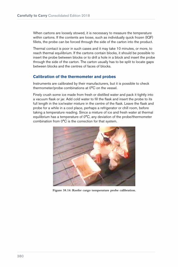
Carefully to Carry Consolidated Edition 2018
380
When cartons are loosely stowed, it is necessary to measure the temperature within cartons. If the contents are loose, such as individually quick frozen (IQF) fillets, the probe can be forced through the side of the carton into the product.
Thermal contact is poor in such cases and it may take 10 minutes, or more, to reach thermal equilibrium. If the cartons contain blocks, it should be possible to insert the probe between blocks or to drill a hole in a block and insert the probe through the side of the carton. The carton usually has to be split to locate gaps between blocks and the centres of faces of blocks.
Calibration of the thermometer and probes
Instruments are calibrated by their manufacturers, but it is possible to check thermometer/probe combinations at 0°C on the vessel.
Finely crush some ice made from fresh or distilled water and pack it tightly into a vacuum flask or jar. Add cold water to fill the flask and insert the probe to its full length in the ice/water mixture in the centre of the flask. Leave the flask and probe for a while in a cool place, perhaps a refrigerator or chill room, before taking a temperature reading. Since a mixture of ice and fresh water at thermal equilibrium has a temperature of 0°C, any deviation of the probe/thermometer combination from 0°C is the correction for that system.
Figure 38.14: Reefer cargo temperature probe calibration.

381
Chapter 39
Meat and Meat Products in Containers
39.1 Contamination by Odour
Meat is particularly vulnerable to foreign odours. Remedial treatment can be costly and substantial claims can result. If the intensity of the odour or its penetration of the meat surface is significant, the warehouse or cold store may reject it because of the risk of taint to other meat already in store. Modern cold stores usually have no facilities for carrying out remedial treatment for small quantities and it can be difficult and expensive to carry out the treatment at other premises.
39.2 Soft Condition
Damage may result from complete failure of the refrigeration plant, but is more usually brought about by incomplete closure of the vents at the connection point in controlled atmosphere containers, where the ship’s refrigeration has been disconnected. Damage can comprise blood-stained and misshapen

Carefully to Carry Consolidated Edition 2018
382
carcasses and the distortion and staining of meat in cartons in the area of the ambient airflow.
39.3 Chilled Beef
The shelf life of chilled beef is about 10 weeks from the time of slaughter and it may have been in store for some time before shipment. Occasionally, on arrival at destination, the amount of free blood in the vacuum pack is found to be in excess of normal. Provided there is no evidence of intramuscular icing at the time of discharge, any allegation that the transit temperatures were too low should be refuted. The cause could be that the meat has been kept below its freezing point of minus 2°C (–2°C) before shipment, in an effort to keep it as cool as possible and prolong its shelf life.
39.4 Vacuum-Packed Chilled Meat
The object of chilling is to provide meat that resembles, as closely as possible, fresh meat and to retain the maximum degree or flavour, texture, appearance and nutritive value. Chilled meat is often vacuum packed, a process used to reduce bacterial growth and surface dehydration activity and so prolong the storage life of chilled meat.
Meat is vacuum packed by first placing it in a gas impermeable plastic film bag at a temperature slightly above 0°C. The air is exhausted from the bag so that the film applies tightly to the meat surface. The temperature is then held at an appropriate level.
It should be noted that, because of the absence of air, chilled meat may show an abnormal discolouration and on removal of the vacuum packing can give off a distinctive odour. On exposure to air, the colour of the meat reverts to normal and the odour will disappear, so no immediate conclusions should be drawn as to the condition of the meat after removal of the packing.
In the past few years, a number of claims have been raised by receivers of chilled vacuum-packed meat, primarily in northern European ports citing that the meat had suffered a considerable depreciation as a result of the presence of ice crystals in the meat. The presence of ice crystals means that the meat can no longer be considered to be chilled (or fresh) meat but must be considered as ‘frozen chilled meat’. The claims are for the difference in market value between chilled and frozen meat at the time of delivery at the discharge port, which may be as much as 20 to 25%.
The usual carrying temperature will range from minus 1.4°C (-1.4°C) to +2°C, but on short voyages the shippers may require a carrying temperature as high as 0°C. The shippers should normally issue precise instructions on this point and, if they do not, Masters should press for instructions to be provided, preferably in writing.

Chapter 39 Meat and Meat Products in Containers
383
As the meat is vacuum packed, spike temperatures cannot be taken upon loading, but spot checks on individual cartons, placing thermometers between the layers, is recommended. Should there be any significant variation above or below the recommended carrying temperatures, it is suggested that a competent surveyor be called in.
For significant ice crystal formation to occur within the meat requires exposure to temperatures lower than minus 2°C (–2°C) for prolonged periods because the meat contains various salts that lower its freezing point. Minor quantities of crystal near the surface within the meat should not be taken to demonstrate a deterioration in condition or value. Crystals may also form on the meat at temperatures of 0°C (the freezing point of water) and below. These crystals between the meat and the vacuum packing result from moisture migration and are not indicative of any deterioration in the quality of the meat or any fault in the carriage. Any claim presented on the basis of the presence of such crystals should be strongly resisted.
39.5 Transhipment
There have been isolated instances where, as a result of damage to the original container during transit, restowage of the cargo into a sound container has been necessary. If such a transfer is carried out without veterinary control, in a country designated as a ‘disease pollution’ area, the consignees in some countries may reject the consignment on the grounds that there has been a breach of their own health regulations.
39.6 Insulated and Integral Refrigeration Containers
The shipment of chilled meat in units has been accomplished with great success with carriage temperatures as low as minus 1.4°C (–1.4°C). However, when similar carriage temperatures are attempted in containers fitted with integral refrigeration equipment, problems with intra-muscular icing have been encountered. It is recommended that chilled meat shipments are not carried in integral refrigeration containers with temperature settings lower than minus 0.5°C (–0.5°C).


385
Chapter 40
Pharmaceuticals in Temperature Controlled Containers
Many different pharmaceuticals are supplied worldwide, some requiring temperature controlled storage and distribution to maintain their efficacy and other properties.
Until fairly recently, long distance distribution of products was undertaken by air, but there has been a trend to move some of them by sea in refrigerated containers. Due to their sensitivity to the atmosphere and limited storage life, they are referred to as Time- and Temperature-Sensitive Pharmaceutical Products (TTSPP).
The carriage of pharmaceuticals and intermediaries is already established on many trade routes with different transit times. Two examples are Ventolin (an aid to breathing) carried at chilled temperatures and blood products moved as frozen cargoes.
Some cargoes create significant cold chain challenges if they are temperature sensitive or have a very high value. When both the sensitivity and high values of a pharmaceutical shipment combine, a careful and systematic approach to the planning and carriage must be undertaken, and the consequences of failure of this can be serious. The damage to cargo is one aspect leading, perhaps, to

Carefully to Carry Consolidated Edition 2018
386
P&I claims, but timely delivery of pharmaceuticals may also be required to avoid a pandemic.
40.1 Product Attributes and Challenges
Pharmaceutical product attributes have to be preserved through the cold chain to give the consignee the outturn expected after loading good quality product into the container. It is extremely helpful if shippers can explain the physical, chemical and biological attributes of sensitive products being carried. Products must have adequate storage lives for the transit and the next distribution chain to the patient or user.
Temperature control and times off refrigeration should be clearly specified and well controlled. Reefer containers are designed only to maintain the temperature and not cool down any cargo. Shippers therefore need to ensure that appropriate procedures are followed prior to and during stuffing containers.
In the event of problems or claims concerning products whose characteristics are unknown, or not fully known, carriers/shipping lines should contact their P&I Club to identify experts to provide assistance.
40.2 Carriage Challenges
For the successful carriage of pharmaceuticals on long sea routes, carriers should ensure that:
� Cold chain requirements are met, using equipment that operates correctly
� procedures, information flows and operations are compatible and coordinated
� due diligence actions for quality systems and security requirements are defined and followed
� careful work by trained personnel provides good quality control and assurance
� any ambiguities or the lack of information is resolved prior to accepting a consignment.
Pharmaceutical movement in reefer container shipping is still relatively unusual and there is less knowledge of its requirements. It may, therefore, be helpful to consider the features of an equivalent class of food product in transit.

Chapter 40 Pharmaceuticals in Temperature Controlled Containers
387
However, many pharmaceuticals have a very much higher value than the equivalent volume of food products. They are also regulated by national or state medicines agencies that have several similar roles to foods standards agencies.
The World Health Organization (WHO) supports member states through the publication of international standards to ensure delivery of quality finished products to the end user. Some examples are Good distribution practices for pharmaceutical products (Reference 62), Guide to good storage practices for pharmaceuticals (Reference 63) and technical supplements to WHO technical report series No. 961 Supplement 13: Qualification of shipping containers (Reference 64).
40.3 Management Issues
Carriers should define the extent to which they are prepared to carry cargoes of certain materials on different routes, as they can differ significantly in sensitivity, monetary values and the levels of control that are possible. The onus, however, remains with the shipper to declare the goods accurately and to specify any special carriage requirements. If the carrier discharges their duty of care as per the prescribed procedures and precautions, any losses may have to be picked up by the shipper and/or the consignee.
Pre-transit risk assessments should be made, to include discussions with the shippers (and consignees if necessary). Accepted cargoes should initially transit as trial shipments, with review after outturn. One approach is to limit risks by only accepting 20 ft container loads of particular products until the transits have been established. Corrective actions can be taken, if necessary, for further shipments and in extreme circumstances bookings may be refused.
40.4 Commercial Issues
Additional insurance premiums may be payable, depending on the risk limits and previous experience in carrying similar products. Special rates may be necessary to cover the additional work in carrying the cargoes successfully and the extra precautions taken against the risks. Careful wording on B/Ls is also required.
40.5 Operational Issues
Shippers define the set point temperatures required for the cargo. Other carriage requirements must also be agreed with the carriers when the containers are booked. There may be a need for additional instructions and checks in transit, depending on product sensitivities and the routes. Clearance by the appropriate authorities in importing countries may be specified, as well as compliance with consignees’ due diligence standards.

Carefully to Carry Consolidated Edition 2018
388
Shippers may include their own independent data loggers in the cargo space to measure product or air temperatures. A few logger types are able to calculate mean kinetic temperatures (a defined form of weighted average), while others record shocks and vibrations. Relative humidity is measurable, but the accuracy of the data must be considered carefully and large variations allowed.
Figure 40.1: Temperature/data recorder.
40.6 Temperature
Pharmaceuticals should be carried in integral containers with good refrigeration capacity, high internal airflow rates and an ability to provide the required temperature control. Following the stuffing of the cargoes into containers, they require the capability to deal with the heat loads to which they may be subjected.
Warm cargo must never be shipped for cooling on board. All cargo must be pre-cooled to its temperature for carriage prior to stowing in a container, keeping in mind that reefer containers are only designed to maintain the temperature at which they are set.
Pharmaceuticals are often transported in reefer containers in nominated temperature zones. Many require an environment in the +2°C to +8°C range. These products must not freeze or become too warm in transit because this may impair their potency, release potential, colloidal suspension or other properties. They vary in sensitivity, but the most sensitive could be considered somewhat similar to chilled meat for carriage. The container set point is normally in the above range, and +4°C or +5°C are often used.
Temperatures colder than minus 18°C (–18°C) are specified for some products. They are often sensitive to temperature fluctuations as well as needing a cold base temperature. A temperature set point of minus 25°C (–25°C) for containers is often requested. Serious thawing can often be observed by eye, but changes in protein structure, or other changes,

Chapter 40 Pharmaceuticals in Temperature Controlled Containers
389
caused by temperature fluctuations will require laboratory assessment. For example, frozen blood products could be compared to carrying a product with the combined properties of ice cream and individually quick frozen (IQF) prawns. Temperature fluctuations in ice cream can cause texture changes whilst prawns can incur protein denaturation and weld together. Both can generate ice crystals. Similarly, blood products can suffer protein damage and separation if not stored correctly.
Temperatures colder than +15°C or even +25°C are required for shelf stable products. Examples are powders, liquids and tablets. An equivalent food product is chocolate confectionery (usually carried with a set point of +10°C).
The shipper may specify individual container set points outside the above general ranges to meet a product requirement. If the carrier is uncertain as to the shipper’s requests, independent expert advice should be sought.
The shipper may request relatively dry air to be circulated in the containers. Many modern containers are fitted with a dehumidifier to reduce the relative humidity (RH). The RH is measured and controlled by a probe in the refrigeration unit. It does not represent the actual RH throughout the cargo space, which is difficult to measure accurately, and a tolerance of at least ±5% over the available range should be expected.
Fresh air ventilation is not expected for chilled pharmaceutical cargoes, but the need should be checked before bookings are accepted. Ventilation volumes should be kept as low as is essential.


391
PART 10General Container Operations Including Waste Shipments
Chapter 41 ............................................. 393Stuffing, Stacking and Lashing Containers
Chapter 42 ..............................................425Container Top Safety
Chapter 43 ..............................................429Container Crime
Chapter 44 ..............................................433Waste Shipments in Freight Containers

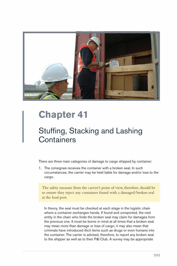
393
Chapter 41
Stuffing, Stacking and Lashing Containers
There are three main categories of damage to cargo shipped by container:
1. The consignee receives the container with a broken seal. In such circumstances, the carrier may be held liable for damage and/or loss to the cargo.
The safety measure from the carrier’s point of view, therefore, should be to ensure they reject any containers found with a damaged/broken seal at the load port.
In theory, the seal must be checked at each stage in the logistic chain where a container exchanges hands. If found and unreported, the next entity in the chain who finds the broken seal may claim for damages from the previous one. It must be borne in mind at all times that a broken seal may mean more than damage or loss of cargo; it may also mean that criminals have introduced illicit items such as drugs or even humans into the container. The carrier is advised, therefore, to report any broken seal to the shipper as well as to their P&I Club. A survey may be appropriate

Carefully to Carry Consolidated Edition 2018
394
to establish any pilferage, loss or damage to the cargo, after which the container may be allowed for shipment.
2. The container and the cargo is damaged. In such a case, a joint survey by the shipper or consignee and the carrier (P&I Club) will be carried out to establish the extent of damage. This survey report will define the liability for both parties.
Cou
rtes
y of
New
Zea
land
Def
ence
For
ce
Figure 41.1: The grounding of MV ‘Rena’ off New Zealand in 2011 overstressed many container twistlocks, resulting in a partial collapse of container stacks.
3. The consignee opens the container and finds the cargo damaged. In this case, the carrier may repudiate the claim on the basis that the container was packed by the shipper, provided that the ship did not suffer extreme weather damage during the voyage.
Reference should also be made to the guidance and publications provided by the shipping lines, which contain practical advice on container securing components and securing systems. A widely used publication is the Safe Transport of Containers by Sea: Industry Guidance for Shippers and Container Stuffers which is published by the International Chamber of Shipping and the World Shipping Council (Reference 65).

Chapter 41 Stuffing, Stacking and Lashing Containers
395
Front wall panel
LHS sidewall panel
Roof panel
Rear endDoor header
LHS top rear corner casting
Hinge
Rod guide
Cam end guide
Cam end
Door
Cam keeper
Door sealing gasket
Lever
Rear sill
RHS bottom rear corner casting
RHS door corner postor RHS rear corner post
Floor
Bottom cross member(floor supports)
Bottom side rail skirt
Bottom side rail
Front RHScorner post
Front sill
Top side rail
Front header
Front end
Cou
rtes
y of
Hap
ag L
loyd
Figure 41.2: Components of a container.
41.1 Stuffing
Containers are often packed at places that are distant from the marine loading terminal, sometimes several days’ journey. It is, therefore, important that everyone involved with the packing of containers, at whatever stage in transit, is fully aware of the stresses that can be generated in the structure of the container itself and in the cargo within it. It is essential that containers are in sound structural condition each time they are put into service and that they are suitable for the cargo to be carried.
It should always be borne in mind that the side panels, end panels and roof panels of an ISO container are not normally strength members.
Beneath the floor timbers, there are metal cross bearers and it is generally these bearers that provide the floor’s strength. Additionally, the corner posts, front and rear headers, and front and rear sills provide the internal strength members. Whenever bracing is to be used in vertical, horizontal or diagonal form, it must act against those members and the floor bearers and no others. Bracing and/or end chocking against side, end and roof panels will result in disaster.
Unlike breakbulk cargo, the ship’s Master and officers do not sight, or have any control over, the contents of containers or the methods by which the contents have been packed and secured.

Carefully to Carry Consolidated Edition 2018
396
If the contents of just one container are improperly packed, lack adequate securing arrangements or are inappropriate for container carriage, they may break adrift when the ship encounters heavy weather, risking the safety of the other containers, their contents and the ship itself.
In one example, round steel bars, inadequately secured, broke adrift within a container third in stack on deck, pierced and went through the container’s side panels and shattered a corner post of the adjacent container, creating a domino collapse of the other units. A single block of granite, lacking securing arrangements within the lower tier of a below-deck stack, broke through the container’s side panel and fell corner down, piercing the double-bottom fuel oil tank below. The consequential fuel oil flooding of the hold and lower level damage to base containers was a costly business.
Figure 41.3: Poorly stuffed container – note the damaged packages, the pallet on top of cartons and the apparent lack of securing arrangements.
Cou
rtes
y of
PO
2 P
rent
ice
Dan
ner,
DV
IDS
Figure 41.4: Inspection of goods in a container terminal.

Chapter 41 Stuffing, Stacking and Lashing Containers
397
Figure 41.5: Damage caused to a container by poorly secured coils.
Casualty investigation often reveals that horizontal spaces, ie fore-and-aft and longitudinally, are generally adequately chocked, but the vertical component is entirely neglected. When a ship is pitching and yawing in a seaway, vertical acceleration and deceleration forces acting on cargo components can attain values of 2 g, which means that, as the vessel goes up and comes down, the load on the securing arrangements will be equal to twice the static weight of the cargo item. If there is no arrangement to secure the cargo to the floor of the container, the cargo will lift, and once it lifts it will start to shift, and once it starts to shift it will go on shifting!
up to 1.0 g
up to 1.0 g
up to 1.0 g
up to 2.0 g
up to 0.5 g
up to 0.5 g
up to 0.4 g
up to 0.4 g
up to 0.8 g
up to 0.8 g
Figure 41.6: Potential accelerations at sea.
Where relatively lightweight cartons or good timber cases can be afforded tight block stowage, there will be little need for additional securing arrangements. However, where plastic jars, bottles, barrels or lightweight cartons with frail contents are to be stowed to the full internal height, it may be necessary to provide mid-height flooring so that the lowermost items do not suffer compression damage or collapse.

Carefully to Carry Consolidated Edition 2018
398
Figure 41.7: Flexible f looring arrangement.
Figure 41.8: Heavy machinery on a ‘f lat’.
Cou
rtes
y of
Sca
nDut
ch
Figure 41.9: Securing points.
Where bags, cartons or cases do not occupy the full internal space, chocking and bracing with timbers and/or air bags is necessary.
Where heavy items are involved, securing with downward leading wire lashings and/or strapping to ‘D’ rings attached to the upper parts of the floor bearers will be required.
It is important that the correct form of container is used, because not all have provision for mid-height flooring to be fitted, and not all are provided with ‘D’ rings.

Chapter 41 Stuffing, Stacking and Lashing Containers
399
Steel coils, steel pipes and bars, and heavy machinery items should be shipped on specially designed ‘flat racks’, ‘flats’ or ‘sledges’ (see Figure 41.7). These units are strengthened for such loads and adequate securing terminal points are provided (see Figures 41.8 and 41.9).
41.2 Container Stuffing Considerations
The packing and securing of goods inside a container plays a vital role in safe transportation of goods to their destination, but this is never in the control of the ship’s officers. In some ports, some carriers require container stuffing to be sample checked to ensure that the contents, particularly if there are any dangerous goods, have been secured properly.
Further inspections of the goods may also be made by the harbour or customs authorities to establish customs duties and export taxes, etc and, where this is done, the carriers can utilise the opportunity to check the stuffing of cargoes.
The ship’s officers must play their role in observing and reporting any abnormalities. Consideration should be given to the following.
1. Cargo may be containerised for a prolonged period, during which changes in temperature may lead to generation of mould, bacteria, fungus or other microorganisms, particularly where the cargoes are hygroscopic and there is a lack of proper ventilation. To avoid biological contamination, many countries require containers to be fumigated and then sealed prior to shipment.
2. When different commodities are stuffed together, the compatibility characteristics of each cargo should be noted. Some examples of non-compatible cargoes are:
a) cargoes that emit odours stowed with odour sensitive cargoes
b) hygroscopic cargoes stowed with cargoes that may absorb moisture. If unavoidable, hygroscopic cargoes should be loaded under other cargoes with a layer of dunnage and a protective cover such as a tarpaulin laid on top of the hygroscopic cargo.
3. Hygroscopic cargoes are likely to give off moisture during transportation leading to condensation, commonly referred to as ‘container sweat’ or ‘container rain’. Condensation may damage the cargo and may lead to biological contamination. Desiccants may be provided, but these are not a failsafe means of preventing condensation.
4. Certain sensitive cargoes, such as wet hides or salted skins, require containers to be lined with plastic sheeting or packing paper.

Carefully to Carry Consolidated Edition 2018
400
5. Containers are fitted with lashing/securing points with the longitudinal beams on the floor or roof and also with the corner posts. Each lashing point has a predetermined SWL (safe working load), which is generally 1 t but may vary for older containers. Container walls are not designed to be load bearing, so nothing should be attached to them.
6. When palletised cargo is loaded into a container, the space utilisation will depend on the size of the pallet in relation to the size of the container. Generally, there will be some void spaces between pallets and these must be filled in with air/inflatable bags or dunnage. Where pallets are stowed more than one high, their longitudinal movement within the container must also be blocked by the use of appropriate lashing or chocking.
7. Distribution of weight within a container should avoid:
a) Loading heavier items at one end or side of the container
b) Stowing heaver items above light items. Impact on the centre of gravity of the container with respect to weight distribution should also be considered.
8. Cargo items with sharp edges, protrusions or awkward shape must not be stowed next to soft packages, to avoid damage during even the smallest movement within the cargo.
9. Any cargo that is liable to leak should not be stowed on top of other cargo.
41.3 Containers in Stack
Most ISO containers are designed to allow nine-high stacking when empty. They should be placed and must stand on the four lower and four upper corner castings alone, with the appropriate stacking/locking components between. The bottom and top side rails, the front and rear sills and headers, and the underside floor bearers should remain free of vertical stacking contact at all times if transient wracking stresses are to be avoided.
There are many different securing systems and problems may arise if ships’ officers/charterers’ superintendents are unfamiliar with a specific system.
Container stack racking failures may occur in non-purpose-built vessels if charterers insist on stacking containers in the holds and on the weather deck in a manner that would not be approved even in a purpose-built ship. Unfortunately, stack collapses within the holds, and within weather-deck stacks, occur just as frequently in purpose-built vessels.

Chapter 41 Stuffing, Stacking and Lashing Containers
401
Container stack failures generally arise from three causes that involve unacceptable racking stresses in one form or another:
� Substandard components and seaworthiness
� weight management problems in stacks
� mixed unit sizes.
41.3.1 Substandard Components and Cargoworthiness
A vessel’s container stowage and securing arrangement can easily be undermined if substandard and/or incorrect components are utilised. Maintaining securing equipment in good order, both fixed and portable, requires considerable time and effort.
Whatever regulations, standards or codes of practice are issued, the integrity of a vessel’s container stowage and securing arrangement can only be ensured by regular inspection of the securing equipment. The securing arrangement can be undermined by one or more of the following:
� ‘Rogue’ securing equipment
� improperly maintained securing equipment
� complacency in inspection of the equipment and record keeping
� insufficient supply of correct securing equipment
� overloading of the securing equipment.
Portable securing equipment
If substandard equipment is used, it can fail at a lower load than its design rating, thereby resulting in failure of the overall securing system and possible collapse of the container stow.
The following aspects should be considered during periodic inspection of container securing equipment:
� Inspection of the twistlock complement to ensure that rogue twistlocks, ie ones with an opposite locking action to the ship’s standard complement, have not made their way on board. When left-hand and right-hand locking twistlocks are fitted with similar shaped handles, which can be the case, it is not always possible to differentiate between them once used in the same stow. Even if the stevedores are aware of the difference, any subsequent checks by other people could allow disengagement if the handles are all actuated in the same direction on the premise that some twistlocks had not been properly locked in the first instance.
ISO Standard 3874, Series 1 freight containers – handling and securing, includes the physical and functional requirements for various items of portable securing equipment as an appendix to the standard itself

Carefully to Carry Consolidated Edition 2018
402
(Reference 66). ISO Standard 1161, Series 1 freight containers – corner and intermediate fittings establishes the basic dimensions and the functional and strength requirements of corner and intermediate fittings for series 1 freight containers (Reference 67).
For manual twistlocks, it is proposed that the unified direction of handling will be clockwise when viewed from above, ie lefthand locking
� checks to ensure that the spring holding the twistlock in the closed position is in a resilient condition. If a spring loses its resiliency, the cone(s) will not be held in position in a positive manner. The moving and flexing of a vessel in a seaway has been found sufficient to allow twistlocks to unlock themselves if their spring action is failing or has failed
Figure 41.10: Uniform twistlocks.
� check to ensure there are no structural defects that would compromise the proper use of the equipment, for example:
� twistlocks with missing handles
� twistlocks with fractured housings
� double cones with fractured base plates
� seized/buckled turnbuckles, bridge fittings.
Figure 41.11: Fixed fittings.
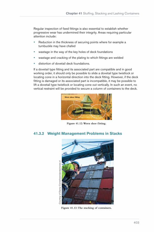
Chapter 41 Stuffing, Stacking and Lashing Containers
403
Regular inspection of fixed fittings is also essential to establish whether progressive wear has undermined their integrity. Areas requiring particular attention include:
� Reduction in the thickness of securing points where for example a turnbuckle may have chafed
� wastage in the way of the key holes of deck foundations
� wastage and cracking of the plating to which fittings are welded
� distortion of dovetail deck foundations.
If a dovetail type fitting and its associated part are compatible and in good working order, it should only be possible to slide a dovetail type twistlock or locating cone in a horizontal direction into the deck fitting. However, if the deck fitting is damaged or its associated part is incompatible, it may be possible to lift a dovetail type twistlock or locating cone out vertically. In such an event, no vertical restraint will be provided to secure a column of containers to the deck.
Figure 41.12: Worn shoe fitting.
41.3.2 Weight Management Problems in Stacks
Cou
rtes
y of
Dan
ny C
orne
lisse
n/po
rtpi
ctur
es.n
l
Figure 41.13: The stacking of containers.
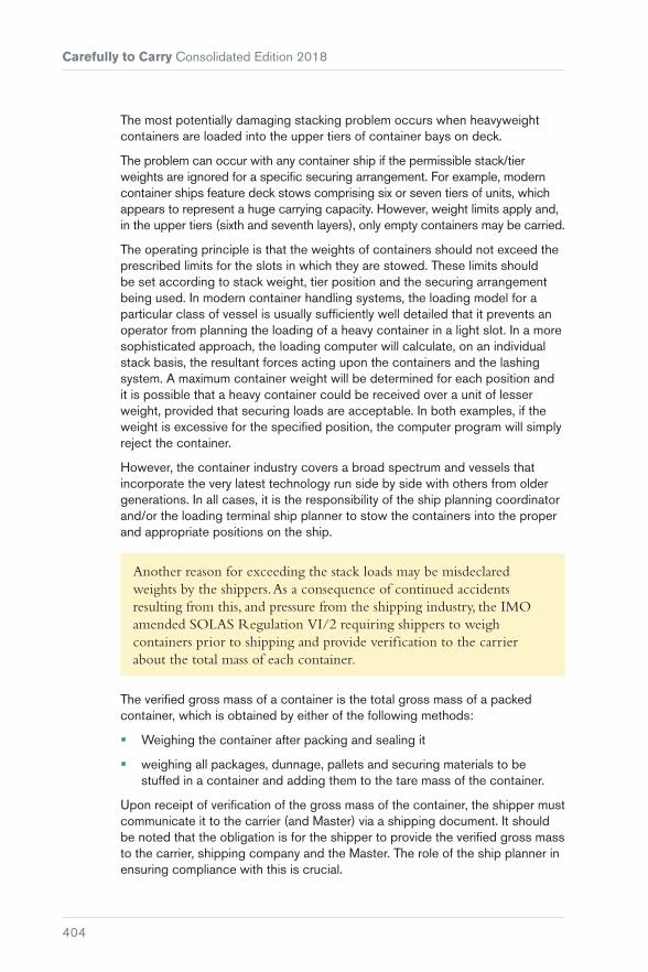
Carefully to Carry Consolidated Edition 2018
404
The most potentially damaging stacking problem occurs when heavyweight containers are loaded into the upper tiers of container bays on deck.
The problem can occur with any container ship if the permissible stack/tier weights are ignored for a specific securing arrangement. For example, modern container ships feature deck stows comprising six or seven tiers of units, which appears to represent a huge carrying capacity. However, weight limits apply and, in the upper tiers (sixth and seventh layers), only empty containers may be carried.
The operating principle is that the weights of containers should not exceed the prescribed limits for the slots in which they are stowed. These limits should be set according to stack weight, tier position and the securing arrangement being used. In modern container handling systems, the loading model for a particular class of vessel is usually sufficiently well detailed that it prevents an operator from planning the loading of a heavy container in a light slot. In a more sophisticated approach, the loading computer will calculate, on an individual stack basis, the resultant forces acting upon the containers and the lashing system. A maximum container weight will be determined for each position and it is possible that a heavy container could be received over a unit of lesser weight, provided that securing loads are acceptable. In both examples, if the weight is excessive for the specified position, the computer program will simply reject the container.
However, the container industry covers a broad spectrum and vessels that incorporate the very latest technology run side by side with others from older generations. In all cases, it is the responsibility of the ship planning coordinator and/or the loading terminal ship planner to stow the containers into the proper and appropriate positions on the ship.
Another reason for exceeding the stack loads may be misdeclared weights by the shippers. As a consequence of continued accidents resulting from this, and pressure from the shipping industry, the IMO amended SOLAS Regulation VI/2 requiring shippers to weigh containers prior to shipping and provide verification to the carrier about the total mass of each container.
The verified gross mass of a container is the total gross mass of a packed container, which is obtained by either of the following methods:
� Weighing the container after packing and sealing it
� weighing all packages, dunnage, pallets and securing materials to be stuffed in a container and adding them to the tare mass of the container.
Upon receipt of verification of the gross mass of the container, the shipper must communicate it to the carrier (and Master) via a shipping document. It should be noted that the obligation is for the shipper to provide the verified gross mass to the carrier, shipping company and the Master. The role of the ship planner in ensuring compliance with this is crucial.

Chapter 41 Stuffing, Stacking and Lashing Containers
405
Under legislation laid down by the United States Department of Labor’s Occupational Safety and Health Administration (29 CFR 1917.71 Marine Terminals: Terminals handling intermodal container or roll-on roll-off operations) (Reference 68), all cargo containers must be weighed before being hoisted for loading. Empty containers must be checked to ensure that they are indeed empty and marked or noted as such.
Figure 41.14: Collapsed container stacks as a result of bad stowage.
Bad stowage can occur as a result of a mistake, or it may be due to complacency. The following are the main reasons why heavy containers are sometimes placed in the wrong slots:
� Inexperience An inexperienced planner faced with a problem of container distribution might simply allocate stowage on the ‘best possible’ basis, ignoring good stowage principles and the vessel’s stowage and securing criteria.
� insufficient knowledge A planner who lacks specific knowledge of the tier limits for a particular vessel, or class of vessel, will not know whether a particular plan he has composed meets the criteria of the vessel’s lashing system. Lack of coordination between the planners and the lashing teams may not take into account the added complications resulting from the need for sufficient strength of lashing for heavy stows.
� late arrivals Errors often occur when containers are received late for shipment. The vessel may be part loaded and stevedores may have abandoned a scheduled loading plan in place of a hybrid because cargo was not available when the vessel arrived. When containers arrive late, it may be the case that only relatively high positions remain available.
� third party stowage. In almost all cases, loading, stowage and securing of containers is carried out by third party stevedores with the ship’s officers and crew only able to monitor their work. The quick operation of modern container gantries and the large number of containers being loaded/discharged in a short period of time mean that the ship’s crew is physically unable to pay the

Carefully to Carry Consolidated Edition 2018
406
same attention as they would otherwise on a smaller container with slower cargo operations. This situation has been historically complicated by lack of proper access to the top of container stacks to place, for example, the stacking cones or to properly lock the twistlocks. While some of these functions remain restricted due to the quick turnaround of container ships combined with the large volume of cargo being loaded, some of the issues can be overcome by the crew’s due diligence. MSC.1/Circ.1353, published in December 2014, requires that a cargo safe access plan (CSAP) is supplied within the cargo securing manual to ensure that persons engaged in securing and stowage of containers are provided with safe access during their work. This plan details guidance for hand rails, platforms, walkways, ladders, storage facilities, fittings for specialised containers such as reefer plugs, first aid locations and any other information that may be relevant to provision of safe access.
Addressing the issue on board ship
Ships’ staff should not allow loading operations to commence until they have received a copy of the proposed stowage plan. A relatively quick inspection should show whether heavy containers have been planned over light ones and whether the stack and tier weights are within the permissible limits.
Vigilance is the key and ships’ staff should be aware that mistakes are often accompanied by departures from the plan. Duty officers must not hesitate to report to the chief officer on any occasion when stevedores advise there is a change to the original plan and the chief officer should look carefully at what is proposed.
Ships’ staff should always check the pre-loading plan for heavy container stacks. These should be identified and, if possible, the container numbers in these stacks checked during loading. If a different container appears in the upper tier, it may be a heavy unit stowed by mistake and of sufficient weight to overload the stack and the lashing system.
Problems that may be created by incorrect stowage of this type include:
� The need for restowage of containers (and resulting delays and costs) if an overweight condition is ascertained
� collapsed container stacks
� containers lost overboard (both the overweights and containers that were not overweight)
� cargo liability claims
� chassis damage

Chapter 41 Stuffing, Stacking and Lashing Containers
407
� damage to the vessel
� stability and stress risks for the vessel
� risk of personal injury or death to seafarers and shoreside workers
� last minute shut-outs of confirmed, booked and available loads when the actual weight on board exceeds what is declared and the total cargo weight exceeds the vessel limit or port draught limit.
Container ship operators must instruct terminals to check weight against stowage slot before allowing a unit to be shipped late in a position other than that originally planned. In most cases, the plan will be sufficiently flexible to accommodate late loading, but in some instances it will not. Potential problems must be identified, and remedied, before sailing.
The most common method by which a stowage error of this type is discovered is when the chief officer updates his loading plan using the final plan, normally provided electronically. The update should tell him whether there are any changes from the pre-load plan. In more extreme cases, the discovery is made when the vessel encounters moderate weather and starts to roll and pitch. The safety margins in lashing systems are very small and an excessively heavy stack will soon begin to challenge the integrity of the securing arrangements. Container structures will be overloaded, causing fittings to fail and movement to occur.
On a modern vessel, the breakdown of the stowage usually commences in lower tiers, possibly at second tier level, where racking loads may cause failure of the door end structure. Alternatively, the compressive forces may cause buckling of a post. There may be excessive pull-out loads on twistlocks or base locks.
Once fittings have begun to fail, movement of the stack occurs and load is transferred to adjacent stacked containers and, in most cases, an entire bay of containers is at risk. Outcomes where heavy containers have been loaded in high positions have involved:
� The loss overboard and subsequent compulsory recovery of dangerous chemicals in 200 m water depths
� the capsize of ships alongside a berth
� the collapse of stacks and spillage of hazardous chemicals on deck.
Case studies
The loading of a container ship is a complex process. Weight must be evenly distributed at the same time as ensuring that hazardous cargoes are positioned appropriately and away from other cargoes with which they might react. There have been several instances where ships have capsized or heeled to severe angles during loading or unloading.

Carefully to Carry Consolidated Edition 2018
408
‘Deneb’
In June 2011, the container ship ‘Deneb’ capsized at the Port of Algeciras during loading operations. There had been modifications to the stowage plan during loading because of safety concerns and, during the first part of loading, a heel of 10° was seen. As the final containers were being loaded, the ship listed to approximately 45°, resulting in the ship lying on the pier. Further listing was in progress when tugs managed to push the ship further onto the pier to avoid a total capsize. It is believed that this accident was due to the weights of containers being incorrectly declared.
‘Repubblica di Genova’
In March 2007, the ‘Repubblica di Genova’ capsized as it was being loaded, while in berth at Antwerp. This ship was a RoRo vessel but was carrying a number of containers on deck. The cause was never determined, but a number of reports suggested that some of the containers on deck were heavier than had been declared and caused the ship to list to one side, eventually capsizing. The ship was partially under water for six months before salvage could be completed, at which point the ship underwent a total renovation and then returned to service.
41.3.3 Mixed Unit Sizes
Another cause of stack failure is where two 20 ft units are stowed on the weather deck in what would otherwise be a 40 ft unit position, making it very difficult, and sometimes impossible, to apply wires, chains or lashing bars to the adjacent end-butting corners. Their absence is not compensated for by using double or four-way inter-layer stackers (spades) or longitudinally positioned screw-bridge fittings, tie-wires or the like (see Figure 41.15).
Figure 41.15: Adjacent corner castings should never be loop-lashed.
The container stack as a whole, and particularly units in the base tier, will be subject to excessive racking stresses should the ship start rolling in heavy seas or pronounced swell conditions. Some compensation can be applied by the use of anti-rack bands (two tensioned metal straps fitted diagonally across the

Chapter 41 Stuffing, Stacking and Lashing Containers
409
corners of the ‘free’ ends of the base tier containers) but they suffer from the same inability to secure the ‘butting’ ends. Sometimes, anti-rack spacers are used (see Figure 41.16), but a full lashing system is preferred.
Figure 41.16: Anti-rack spacer.
41.4 Lashings
Cou
rtes
y of
Dan
ny C
orne
lisse
n/po
rtpi
ctur
es.n
l
Figure 41.17: The safe lashing of containers.
In the early years of containerisation, existing general cargo vessels were converted by the removal of tween decks and the addition of cell guides into the cargo holds. On deck, the hatch covers were strengthened and fittings added
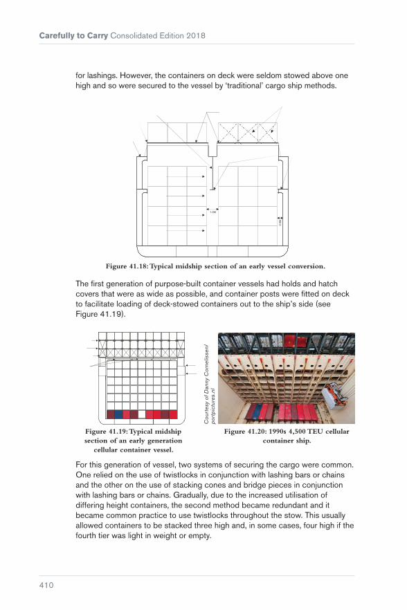
Carefully to Carry Consolidated Edition 2018
410
for lashings. However, the containers on deck were seldom stowed above one high and so were secured to the vessel by ‘traditional’ cargo ship methods.
Figure 41.18: Typical midship section of an early vessel conversion.
The first generation of purpose-built container vessels had holds and hatch covers that were as wide as possible, and container posts were fitted on deck to facilitate loading of deck-stowed containers out to the ship’s side (see Figure 41.19).
Figure 41.20: 1990s 4,500 TEU cellular container ship.
Figure 41.19: Typical midship section of an early generation
cellular container vessel.
Cou
rtes
y of
Dan
ny C
orne
lisse
n/po
rtpi
ctur
es.n
l
For this generation of vessel, two systems of securing the cargo were common. One relied on the use of twistlocks in conjunction with lashing bars or chains and the other on the use of stacking cones and bridge pieces in conjunction with lashing bars or chains. Gradually, due to the increased utilisation of differing height containers, the second method became redundant and it became common practice to use twistlocks throughout the stow. This usually allowed containers to be stacked three high and, in some cases, four high if the fourth tier was light in weight or empty.

Chapter 41 Stuffing, Stacking and Lashing Containers
411
For first generation vessels, computer technology was not available on board to speedily calculate dynamic loads acting on container lashings and frames. The shipboard computer was only used to calculate stresses and stability for the ship itself. Therefore, shipboard staff would ensure the vessel was lashed according to a lashing plan taken from the lashing equipment manufacturer’s manual, which tended to assume an ideal stow with respect to the distribution of weight in each stack.
With further development in the industry, the size of container ships continued to grow, with 9-high stowage in holds and 4-high stowage on deck becoming commonplace, and the industry began to realise that standards in lashing were required. Ships were at this stage still supplied with loading computers to calculate the ship’s stability, shear forces, bending and, occasionally, torsion moments. Very few had the capability to calculate dynamic loads on container frames and lashing systems caused by ship motions and wind forces, so the lashings were still applied throughout the stow in accordance with the manufacturer’s manual.
Following incidents such as the loss of the MOL ‘Comfort’, the question has been asked whether the sheer size of these ships constitutes a risk. If a fire broke out on one of these ships, potentially millions of pounds worth of cargo is at risk and there is a relatively small number of crew available to try to get any such situation under control.
While the economies of scale demand larger container ships, the lashing systems in use on all types of container vessels are very similar and based on the twistlock and lashing bar/turnbuckle system. Large hatch openings mean that containers are partly resting on hatch covers and partly on stanchions located adjacent to the hatchway, but unequal deformities in the hull structure may lead to misalignment of container seating points. Even though the Classification Society rules provide for certain allowance in any such misalignments, the extent of these will vary between ships and, in some cases, on the same ship between various stowage locations. This will have an impact on the stresses placed on lashings and, therefore, the resulting outcomes with respect to their ability to hold a container in position.
On post-Panamax vessels, where among other features the vessel’s large beam results in an unavoidable, relatively large GM (metacentric height), the practice is for the vessel to be fitted with a lashing bridge, which is a substantial steel structure running athwartships between each 40 ft container bay. This allows the second and third tiers of containers to be secured to the bridge using lashing rods and turnbuckles, while the whole stow is secured throughout with twistlocks (see Figure 41.25). The lashing bridge allows the anchoring points for each stack to be moved higher up the stack, which allows the lashings to be more effective in reducing the tipping moments acting on a stack when a vessel is rolling heavily. However, the practice of fitting the bridges between 40 ft bays means that the 20 ft containers can only take advantage of the lashing bridges at one end. So, in effect, the 20 ft stacks have to revert to the limits of a conventional lashing system. This is because the practice of estimating the

Carefully to Carry Consolidated Edition 2018
412
Cou
rtes
y of
Car
gote
c
Figure 41.21: Lashing bridges.
forces acting on a stack divides the container weight equally between each end of the container. Therefore, the weight in each 20 ft container is limited by the capacity of the lashing system at the container end, which does not have the advantage of being secured by a lashing bridge.
Cou
rtes
y of
Car
gote
c
Figure 41.22: Top lashing bridge system for up to 9-high containers.

Chapter 41 Stuffing, Stacking and Lashing Containers
413
On smaller vessels, the whole stow is also secured throughout with twistlocks, and the lowest three tiers are secured to the hatch cover or support post using the lashing bar/turnbuckle combination (see Figure 41.27).
Modern vessels may have up to 9-high stowage on deck, and the use of onboard computers to check the dynamics of the stow in all weather conditions is vitally important for the safe carriage of the cargo. Development of ultra-large container ships (ULCS) has required ultra-secure lashing systems. The safety of containers on board not only depends on the speed at which modern container ships operate but also their direction of movement in relation to the height and direction of waves to control the ship’s rolling and pitching motion, and so stresses on the container lashings. This type of development, combined with modification of lashing equipment such as lift-away hatch covers, fully automatic twistlocks (FATs) and the use of modern computerised systems to check loads on lashing points and equipment combined with full assessment of ship stability, can provide a complete solution.
‘Napoli’ case study
In January 2006, the 276 m, 4,734 TEU container ship MSC ‘Napoli’ was deliberately beached in the English Channel during a strong storm after parts of the ship became flooded. It was discovered that the hull had suffered severe fractures, although the vessel remained in one piece.
The investigation determined that the hull fractures occurred because the vessel had insufficient buckling strength. Whipping and hogging in the high waves caused heavier than usual loads.
Cou
rtes
y of
the
MC
A
Figure 41.23: MSC ‘Napoli’.

Carefully to Carry Consolidated Edition 2018
414
Cou
rtes
y of
the
MC
A
Stern is liftedout of thewater
BendingMoment
Wave crest at amidships creates buoyancy
ShearingForces
Weight
Weight
Figure 41.24: MSC ‘Napoli’ – simulation of forces leading to hull fracture.
The use of a computer lashing program, together with the IMO requirement for every vessel to carry on board an approved cargo securing manual, should theoretically mean a reduction in collapsed stows and losses overboard, provided the operators maintain the lashing equipment and comply with the requirements of the manual. The vigilance of ships’ staff is, therefore, vital to ensure that lashings are applied correctly.
Cou
rtes
y of
Dan
ny C
orne
lisse
n/po
rtpi
ctur
es.n
l
Figure 41.25: Typical post-panamax lashing bridge arrangement
(shown 4 high).
Figure 41.26: Lashing a container to the lashing bridge.

Chapter 41 Stuffing, Stacking and Lashing Containers
415
Figure 41.27: Typical container vessel’s hatch cover lashing arrangement.
Figure 41.28: Tightening the turnbuckle.
Cou
rtes
y of
Dan
ny C
orne
lisse
n/po
rtpi
ctur
es.n
l
41.4.1 Requirements of Lashing Systems
Figure 41.29: Typical ‘on lid’ loading.

Carefully to Carry Consolidated Edition 2018
416
The requirement to carry a cargo securing manual is specified in:
� MSC.1/Circ.1352 (and MSC.1/Circ.1352/Rev.1) – Amendments to the Code of Safe Practice for Cargo Stowage and Securing (CSS Code) (Reference 69) given in MSC/Circ.745(17) (Reference 70) which amends the CSS Code and provides Guidance on Providing Safe Working Conditions
� MSC.1/Circ.1353 – Revised guidelines for the preparation of the Cargo Securing Manual, which apply to container ships whose keels were laid on or which were at a similar stage of construction before 1st January 2015 (Reference 24).
SOLAS Chapter VI: Regulation 5, Stowage and Securing states:
“Cargo, cargo units and cargo transport units carried on or under deck shall be so loaded, stowed and secured as to prevent as far as is practicable, throughout the voyage, damage or hazard to the ship and the persons on board, and loss of cargo overboard.”
It goes on to say that:
“Freight containers shall not be loaded to more than the maximum gross weight indicated on the Safety Approval Plate under the International Convention for Safe Containers (CSC), as amended.
“All cargoes, other than solid and liquid bulk cargoes, cargo units and cargo transport units, shall be loaded, stowed and secured throughout the voyage in accordance with the Cargo Securing Manual approved by the Administration. ( ... ) The Cargo Securing Manual shall be drawn up to a standard at least equivalent to relevant guidelines developed by the Organization.” (Reference 18)
Therefore, following MSC/Circ.745(17) (Reference 70), any Classification Society that approves a cargo securing manual will need to ensure the following:
� The guidance given in the cargo securing manual does not replace the experience in stowage and securing and the principles of good seamanship
� the information in the manual is consistent with the requirements of the vessel’s trim/stability and hull strength manual, the International Convention on Load Lines, 1966 (Reference 25) requirements and the International Maritime Dangerous Goods Code (IMDG Code) (Reference 19), where applicable
� the manual specifies arrangements and cargo securing devices provided on board for the correct application to the containers, based on transverse, longitudinal and vertical forces that may arise during adverse weather and sea conditions
� such securing arrangements and devices shall be suitable and adapted to the nature of the cargo to be carried and used properly with appropriate securing points or fittings

Chapter 41 Stuffing, Stacking and Lashing Containers
417
� there is a sufficient quantity of reserve cargo securing devices on board the ship
� the manual contains information on the strength and instructions for the use and maintenance of each specific type of cargo securing device
� the manual should be updated when new or alternative types of securing devices are introduced
� the manual should consist of a comprehensive and understandable plan, providing an overview of the maximum stack weights and permissible vertical distribution of weight in stacks
� the manual should present the distribution of accelerations expected at various positions on board the ship based on a range of GM values. This information should be accompanied by a worked example showing the angles of roll and GM above which the forces acting on cargo exceed permissible limits for securing devices along with examples of calculations for number and strength of securing devices to counteract the exceeded limits
� the manual should provide information on the forces induced by wind and sea on deck cargo, and on the nominal increase of forces or accelerations with an increase in GM
� the manual should contain recommendations for reducing the risk of cargo losses from deck stows, by applying restrictions to stack weights or heights where high stability cannot be avoided
� the cargo safe access plan (CSAP) should provide detailed information for the safety of persons engaged in work connected with cargo stowage and securing.
IMO/Circ.745(17) also states that the cargo securing devices should be maintained in a satisfactory condition and that items worn or damaged to such an extent that their quality is impaired should be replaced. It is commonly accepted that obligatory survey of portable fittings is not generally pursued by the Classification Society, and so inspection and replacement should be the responsibility of the operators/Masters. Any inspections, maintenance, repair or rejection of cargo securing devices should be recorded and kept with the cargo securing manual. When replacement securing devices are placed on board, they should be provided with appropriate certification.
Portable fittings should be certified by some form of type-approval system, usually coming from the manufacturer (when approved), a Classification Society or other accepted testing body.
Ship managers may request a Classification Society to approve their particular lashing system and the lashing program software, in addition to the requirement of approving the cargo securing manual. However, until the cargo securing manual and the computer lashing program are produced and approved

Carefully to Carry Consolidated Edition 2018
418
Figure 41.30: The accelerations acting on a container in a seaway.
Figure 41.31: Excessive tipping moment or separation force on
corner f ittings.
together, in the same way as the ship stability loading computer and stability/loading manual are already used, there is bound to be confusion with respect to the safe capabilities of the on-deck container lashing system for each ship.
One note of caution: different Classification Societies have set their own standards for the minimum SWLs of lashing gear and maximum allowable forces acting on a container and the roll angle that any calculations should include.
Types of lashing failure
In general terms, whenever a vessel is working in a seaway, it will incur three main movements, described as rolling, pitching and heaving. These give rise to accelerations, and therefore forces, that act on the container frames and lashing system in use. Figure 41.30 illustrates the ship motions experienced by a container stack.
Of the forces acting on an individual container and its lashings as a result of these movements, the separation force is the tipping force that acts to pull out or separate the corner fittings or twistlocks. When the vessel is rolling heavily, if the separation force is excessive, it may pull the twistlocks out of the corner castings of the container, break the twistlocks at their weakest point or separate the corner castings from the main body of the container.
When the vessel is rolling heavily, and containers stowed on higher tiers are heavy, a racking force will be produced in the frame of the lowest containers. The larger the roll of the vessel, the larger the racking force will be.

Chapter 41 Stuffing, Stacking and Lashing Containers
419
Figure 41.32: Excessive racking force on a container.
A large GM, particularly when coupled with a short roll period, increases the dynamic loadings caused by rolling, and all of the loads previously mentioned will increase the compression and tension forces acting at the corner posts of the containers and at the twistlocks between them. If excessive, they may result in structural failure of one or more of the corner posts (see Figure 41.33).

Carefully to Carry Consolidated Edition 2018
420
Figure 41.33: Excessive compression force on container corner post, leading to failure of the post.
Application of computer software
Analysis of incidents involving loss of containers overboard, despite correct stowage and securing, revealed that there was much ignorance concerning the combined static and dynamic loads that were present in adverse weather. In such cases, the bad weather caused severe ship motions, in particular a rolling motion. Of all the ship’s motions, rolling is the most likely cause of overloading of the container frames and lashings.
It is interesting to note that the same difficulties with proper container securing and load distribution were being experienced in the mid 1980s. The solutions, in principle, are still similar but are exacerbated due to the larger size of container ships with higher stacks and increased loadings on lashings and securing points. Even though a number of computer programs are available to calculate the vessel’s stability and the forces experienced within a container stack, human error continues to play some part in their effective usage. Vessel planners need to be provided with two vital pieces of information, ie the discharge port and the weight of the container. Any inaccuracies in this information will result in erroneous output, leading to the same old problems.

Chapter 41 Stuffing, Stacking and Lashing Containers
421
The situation is complicated when the chief officer, on behalf of the Master, continues to hold the responsibility for correct stowage and carriage of cargo but may not have enough time to study the information supplied by the planner to question any inaccuracies.
To aggravate the situation further, many ports supply the chief officer with an electronic bay-plan file of the pre-load plan, which should include all the relevant container data. Again, the onus is on the chief officer to check that the correct information about the container height and weight has been entered, as this affects the vessel’s stability and any calculation of the forces experienced within the stack.
The benefits of using a program include assistance in achieving safer carriage of deck-stowed containers, saving on lashing requirements in terms of employment of lashing gangs, and the possibility of loading more cargo (depending on the voyage). Lashing equipment must be in good condition and certified as suitable because the calculations assume that all containers and lashing materials are in good condition and that all lashings are correctly applied, with equal tension on lashing bars, etc. These programs also calculate a theoretical angle of roll that a ship should not exceed.
Forces within a stack are affected by all ship motions, but the angle of roll is normally the most critical. Classification Society regulations assume values, which are generally the default values in loading programs. The natural period of roll can be determined using the rule of thumb formula:
Period (TR ) = 0.7 BeamGM
A detailed breakdown of the forces in each stack will be provided by loading programs, which include:
Racking force
This is the transverse force that tends to distort the container ends, primarily due to a rolling action. It should not exceed a maximum allowable force (MAF) of 15 t. If a lashing is applied, the force varies between the forward and aft ends of the container because of the different stiffness of the door and closed ends.
Corner shear
This is closely related to racking force, but is the force that tends to shear off the twistlocks. It should not exceed an SWL of 15 t for a standard twistlock.
Compressive force
This is the force acting on the container corner posts and fittings, which results from tilting of the stack and the vertical acceleration. It should not exceed 45 t

Carefully to Carry Consolidated Edition 2018
422
for a standard 20 ft container corner post or 67.5 t for a 40 ft container corner post. Larger compression forces are allowed for corner castings at the base of a stack (83.8 t).
Separation force
This is the tipping force that is acting to pull out or separate the corner fittings. It should not exceed 15 t for the top fitting and 20 t for the bottom. This force does not refer to the tensile loadings on the twistlocks.
Lashing tension
This is the tension in the applied lashings. Lashing rods should only ever be applied hand tight, not overtightened with large spanners, as this induces unnecessary tension in the lashing rod, reducing the angle of roll at which the SWL would be exceeded. The Germanischer Lloyd (GL) limit for lashing rods is 23 t SWL; turnbuckles are rated at 18 t.
If a container or item of lashing equipment exceeds its SWL/maximum allowable force, this does not automatically mean that the item will fail. SWLs are mostly set at 50% of the breaking load. The use of an SWL is to give a safety margin, allowing for occasional overstressing. A container that has been highlighted as having exceeded the Class limits will not automatically be lost if the vessel rolls to 24.9°. However, while many container stacks remain on board after having suffered greater loadings than some of those lost, calculations cannot allow for the domino effect of an inboard stack collapsing, falling against its neighbour and inducing far greater forces upon it, which in turn causes collapse.
Correct application of lashing equipment is also important and one example of incorrect application of semi-automatic base twistlocks occurs when there is an element of fore and aft movement of the container immediately prior to landing it on board so the base locks tend to be placed in the deck fitting rather than the base of the container prior to loading.
Any fore and aft movement of the container as it is aligned over the base lock risks the actuating wire being caught under the container, rendering the twistlock inoperable unless the container is lifted and landed correctly. This highlights the necessity of continual vigilance by the ship’s staff during the loading process.

Chapter 41 Stuffing, Stacking and Lashing Containers
423
Figure 41.34: Twistlock failure. Figure 41.35: Unlocked twistlock.
41.5 Containers in the Holds of Conventional Ships and Bulk Carriers
The ongoing problem of collapse of unsecured container stacks in non-purpose-built holds provides ample evidence that such stacks will not stay in place on the basis of their total weight alone.
Firm securing of the stacks to the ship’s structure as a block is essential. If slackness develops during adverse weather conditions, the containers will chafe and rack, leading to overall distortion and possible collapse, particularly if heavy units have been placed in upper tiers.
ISO containers are designed to be carried by stacking them one above the other in slots or cells below deck and on the weather decks in purpose-built ships, or ships converted for such carriage. The design of bulk carriers appears to provide large, unobstructed spaces for the safe stowage of containers. They are, however, prone to severe stresses arising in a heavy seaway and containers carried in block stowages below decks can create problems if adequate securing measures are not adopted. It is not infrequent that an entire stow of containers collapses, with serious damage to the boxes and to the cargo within them.
Generally, the cargo compartments of bulk carriers are not of the right dimensions to enable the container stow to be a perfect fit. In vessels fitted with sloping hopper side tanks, for example, there will be a large area of unusable space between a block of containers and the ship’s sides. Adequate measures must be adopted to ensure that the containers, as a result of rolling stresses, will not move or collapse into these spaces.
Whenever possible, the containers should be formed into one solid rigid block so that there will be no movement whatsoever. The bottom containers in the stacks should be secured to the ship’s tank top plating by twistlocks

Carefully to Carry Consolidated Edition 2018
424
or lockable locator cones and, in addition, twistlocks or lockable inter-layer stackers should be used between each container in the stack.
Not all the containers in a block will be loaded or discharged at a single port and, as a consequence, there may be parts of a voyage when the block will be irregular rather than cuboid in shape. The stow must be fully resecured as omissions of this nature have been the prime cause of a number of casualties. In the absence of such precautionary measures, the stacking of containers two high or more will produce racking stresses, which tend to distort containers laterally.
This problem will be aggravated during heavy weather, when the weight of the containers in the upper part of the stow may cause the corner posts of the lower containers to buckle, with the inevitable result that the stow collapses. This is more likely to happen in the forward holds, where the effects of pounding are more pronounced. Ideally, all ships converting to the carriage of containers in stacks two or more high should have the securing system and the strengthening requirements for the tank tops approved by the Classification Society.
In some systems, the spaces between the containers and the sides of the holds are taken up with portable or hinged steel girder chocks that insert precisely into the corner castings of the various heights of containers. Alternatively, and in addition to the provision of any form of inter-layer stackers or twistlocks, solid bar or wire lashings may be required, tautened on turnbuckles hooked into securing points at the tank top and at higher levels adjacent to the ship’s shell plating.

425
Chapter 42
Container Top Safety
Container top safety has been discussed in detail by various maritime organisations. The conclusions have brought about numerous changes in the applicable laws in a number of countries, most notably the USA and Japan. Both of these countries require all ships calling at their ports to comply with their legislation relating to the safety of dockworkers in the operation of loading and unloading containers. This includes the requirement that dockworkers are able to secure containers without going onto the top of containers that are stacked more than one high, whether on the quayside or on the ship. For ships to comply with the applicable law means that the equipment for fitting and securing containers on board the ship is operated from the deck, or possibly a safe walkway, level.
To ensure that containers are safely secured, automatic or semi-automatic twistlocks should be used and lashing rods need to be constructed such that they can be handled easily and safely, and secured properly without the dockworkers having to be raised above the deck, or safe walkway, level.
The top tier of a stack of containers should be secured at the top of the container and the positioning of bridge pieces normally achieves this. Dockworkers do need to be positioned on the top of containers on the top tier to fit these bridge pieces. The port or terminal normally has specialised cages fitted with fall-arrester systems to facilitate this operation.

Carefully to Carry Consolidated Edition 2018
426
The ILO’s Code of Practice on Safety and Health in Dock Work, Section 16 (Reference 71) specifies the guidance for ‘access to the top of a container’ and requires purpose-built container ships to carry a safe means of access consisting of a stowable gantry frame fitted with suitable ladders and guarded walkways and a means of locking the gantry against movement on deck. If such a frame is not carried by the ship, a similar arrangement should be available on the dock.
MSC.1/Circ.1263 (2008) Revised recommendations on safety of personnel during container securing operations (Reference 72) and amendments to the Code of Safe Practice for Cargo Stowing and Securing (CSS Code) through MSC.1/Circ.1352 (2010) (Reference 69) further enhance the safety of workers when accessing containers. These amendments specifically require an approved cargo safe access plan (CSAP) for purpose-built container ships. However, all of these arrangements for loading and unloading ships are based on the ship being alongside a pier, quay or wharf and properly secured against unwarranted movement.
These arrangements do not mean that the ship’s crew can be ignorant of these operations and the special nature of the equipment, as they will need to be able to operate these items of equipment in an emergency while the ship is at sea (SOLAS). Training in the safe operation of these pieces of equipment is an essential part of the management and running of the ship. Initial training can be carried out at shore-based facilities, provided that a sufficient mock-up of the arrangement for stacked containers on board can be arranged, but training in the ship environment is likely to be more instructive.
All training should be practised frequently, in a safe environment, and should be reviewed after each session. This is essential as the requirement for automatic and semi-automatic equipment becomes more widespread in ports and terminals throughout the world.
The ship’s crew should be wary of doing any part of the job that would normally be done by dockworkers. The correct fixing and lashing of containers, irrespective of whether they are on or under deck, is a specialised job and should always be left for the specialists. Ship’s personnel, who ultimately have the responsibility for the safe carriage of the cargo, should oversee the fixing and lashing on board.
Ship operators must follow the rules and regulations applicable to each port and should be aware that these are likely to vary between ports.

Chapter 42 Container Top Safety
427
Any ship that does not have the particular equipment in use for a specific country’s requirements should never consider trying to undertake releasing or lashing work whilst at sea, in coastal waters or manoeuvring in port limits as this would be very dangerous both for the crew and the cargo.
Despite various countries operating ‘safe dockworker’ principles, there should still be facilities to handle all ships that call at their ports. There should be other methods of ensuring that their dockworkers operate in a safe way, even if this means going on the tops of containers to release twistlocks (assuming that the ship does not have automatic or semi-automatic units). How they do this work is not the direct concern of the ship, as long as the ship is loaded or unloaded effectively.
Dockworkers are provided with appropriate safety equipment, such as fall-arrester harnesses and ancillary equipment, and similar safety equipment should be provided for ships’ crews, even though this may only need to be used in an emergency.

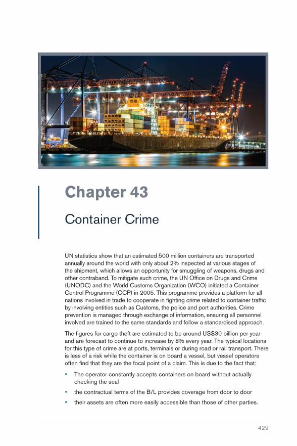
429
Chapter 43
Container Crime
UN statistics show that an estimated 500 million containers are transported annually around the world with only about 2% inspected at various stages of the shipment, which allows an opportunity for smuggling of weapons, drugs and other contraband. To mitigate such crime, the UN Office on Drugs and Crime (UNODC) and the World Customs Organization (WCO) initiated a Container Control Programme (CCP) in 2005. This programme provides a platform for all nations involved in trade to cooperate in fighting crime related to container traffic by involving entities such as Customs, the police and port authorities. Crime prevention is managed through exchange of information, ensuring all personnel involved are trained to the same standards and follow a standardised approach.
The figures for cargo theft are estimated to be around US$30 billion per year and are forecast to continue to increase by 8% every year. The typical locations for this type of crime are at ports, terminals or during road or rail transport. There is less of a risk while the container is on board a vessel, but vessel operators often find that they are the focal point of a claim. This is due to the fact that:
� The operator constantly accepts containers on board without actually checking the seal
� the contractual terms of the B/L provides coverage from door to door
� their assets are often more easily accessible than those of other parties.

Carefully to Carry Consolidated Edition 2018
430
Whatever type of container is used, its safety relies on its own security safeguards and those in place throughout its journey.
The introduction of containers was a technological advancement in the safe movement of cargo and it has had a major impact on the reduction of cargo pilferage. However, this type of transport has become a significant asset for organised crime, primarily due to the cargo involved, which offers substantial profits with minimal chance of detection.
Cargo in transit has always been the subject of crime. The distance involved in this type of movement, combined with the various handling procedures in place during the journey, presents a major obstacle to container security and it is extremely difficult to identify where a loss occurred and who carried it out. This is obviously very important when a B/L provides a door to door service.
If a container is correctly stuffed and its doors secured, there are only three ways in which unlawful entry can be gained:
� The removal of a section of the container’s body
� interference with the seals on the outer container door
� interference with the container doors. The weakest links tend to be the pivot rivet connecting the door handle to the handle hub, the rivet to the swivel seal bracket and the rivets on the door hinges.
The presence of a seal on a container may provide evidence that its cargo has remained secure throughout its journey, but it is not an anti-theft device. Fortunately, there have been significant advancements in the design of seals to increase deterrence against the loss of cargo from containers while in transit.
Figure 43.1: Main photo and inset show partly removed pin on sealed door handle.

Chapter 43 Container Crime
431
However, these improvements alone will not prevent an attack on a container because, if given the time, situation and the tools, a criminal can remove virtually any seal or section of a container’s door, so the extent to which a seal offers protection is only as good as the system into which it is introduced.
For this reason, it is important that B/L issuers are satisfied that the procedures in place throughout a container’s movement meet their requirements. Any discrepancies noted in the figures for container weight might be a good indication of loss of container contents, so the mandatory container weight verification requirement on shippers should be utilised. The IMO Guidelines categorically specify that the shipper named on the B/L is responsible for providing the container’s verified gross mass. This requirement is likely to make stealing the entire contents of a container impossible provided the requirements are complied with diligently, particularly if the mechanism implemented requires the container to be weighed immediately prior to being loaded on the ship.
It is not only weight but also contents that need to be correctly identified to enable the crew to deal with any potentially hazardous goods in a safe manner. It has long been considered a problem in the container ship industry that shippers make false declaration of contents to avoid paying the extra charges associated with the carriage of dangerous goods.
In many instances, improved security procedures have reduced the opportunity of a loss occurring at a port or terminal, but they have not prevented the criminal from identifying a suitable cargo to steal once it has left that location.
There is, therefore, a need to constantly review procedures:
� Have you received correct documentation that verifies a container’s correct weight as required by SOLAS?
� Are you satisfied that a container was correctly secured before departure from the shipper’s premises?
� Are you satisfied with the haulier contracted to move a laden container on your behalf?
� Do they use sub-contractors? If so, are they suitable to undertake this work?
� Are transport instructions issued to the haulier?
� How efficient is the checking procedure of a container on its arrival at a port?
� Is there a physical check prior to a container being loaded onto a vessel? (Weakness in the system, often due to operational or financial constraints, is constantly exploited by criminals, who remove cargo prior to loading.)
� Is the seal physically checked when the container is offloaded at the destination port?
� Is the seal checked when the container leaves the port?

Carefully to Carry Consolidated Edition 2018
432
� Is there a procedure in place should there be an alleged irregularity on delivery? It is important whenever there is a potential loss that:
� the seal sections are retained
� special attention is given to the container’s doors, in particular as to whether there are any different shaped rivet heads or signs of repainting.
Any irregularity should be noted, with consideration given to a surveyor’s examination. It is imperative that a carrier’s agent complies with the cargo release terms, which generally require presentation of the original B/L.
On occasions, agents show a lack of judgement in not complying with the release terms, but take an alternative approach without first obtaining the required authority. Such action usually relates to:
� A consignee’s letter of credit
� a consignee’s letter exonerating the agent from their action
� a bank guarantee confirming that sufficient funds exist in an account on a specific date
� agreement between agent and receiving party
� shipper’s extended credit facility, minus the authority to release the cargo.

433
Chapter 44
Waste Shipments in Freight Containers
A container operator may face the following perils associated with the carriage of waste:
� Structural damage to the freight container due to improper stowage practices at the loadout point
� tainting of the inside of the container due to the waste having odorous properties
� imbalanced load resulting in the vehicle rolling over during road transportation
� rejection at the discharge port due to incorrect and/or incomplete documentation
� rejection at the load and/or discharge ports due to ‘green waste’ being contaminated and recovery unable to be undertaken in an environmentally sound manner

Carefully to Carry Consolidated Edition 2018
434
� risk of non-payment of storage charges at the load and/or discharge ports because the shipper/receiver fails to take timely and appropriate measures to mitigate the problems that arise following one or other of the above incidents
� the shipper/receiver abandoning their waste and the container operator being left to arrange disposal and/or return to the point of origin with the associated costs.
With the significant amount of waste now shipped in freight containers on some trades, the potential for problems can be high. For example, a vessel loading in the UK for China may have up to 65% of its containers carrying various types of recyclable waste.
A major difficulty facing a container operator is that their client, the booking party, may not be the originator of the waste. The booking party will more often than not be a consolidator or NVOCC (non-vessel operating common carrier) and will themselves be dependent upon the quality and nature of the waste being supplied to them by a third party. Therefore, while a container operator may have a good relationship with their booking party, if that party then has a new supplier, problems may be experienced. Also, problems can be masked when, say, good bales of waste are stowed in the doorway of a container concealing poor quality/contaminated bales behind.
44.1 International Waste Disposal Legislation
In the late 1980s, a tightening of environmental regulations in industrialised countries resulted in a significant increase in the cost for disposal of hazardous waste, leading to unscrupulous practices such as shipping toxic waste to developing countries.
The Basel Convention was negotiated under the authority of the United Nations Environment Programme in the late 1980s, adopted in 1989 and entered into force in 1992. The Convention was originally designed to address the uncontrolled movement and dumping of hazardous wastes, including incidents of illegal dumping in developing nations by developed world industries.
Transboundary movements of waste have increased significantly over the last decades, primarily due to the international trade for recycling purposes.
The Convention has 176 member countries (parties) and regulates transboundary movement of hazardous and other wastes by applying the ‘prior informed consent’ procedure (shipments made without consent are illegal). Written consent must be obtained from the States of export, import and transit. The Convention also obliges parties to ensure that hazardous and other wastes are managed and disposed of in an environmentally sound manner. Parties are expected to minimise the quantities that are moved across borders, to

Chapter 44 Waste Shipments in Freight Containers
435
treat and dispose of waste as close as possible to their place of generation and to minimise the generation of waste at source. Article 8 of the Convention requires:
“When a transboundary movement of hazardous waste, or other waste to which the consent of the States concerned has been given, subject to the provisions of the Convention, cannot be completed in accordance with the terms of the contract, the State of export shall ensure that the wastes in question are taken back into the State of export, by the exporter, if alternative arrangements cannot be made for their disposal in an environmentally sound manner.”
The Convention currently addresses 27 specific categories of waste and 18 waste streams. Annex I identifies the categories of waste to be controlled. Annex II identifies categories of waste requiring special consideration. Annex III provides a list of hazardous characteristics. Annex VIII, otherwise known as List A, identifies waste characterised as hazardous under Article 1, Paragraph 1(a) of the Convention. Annex IX, otherwise known as List B, identifies wastes not covered by Article 1, Paragraph 1(a) unless they contain Annex I material to an extent causing them to exhibit an Annex III characteristic.
Annex IX (List B) includes paper, paperboard and paper product wastes, provided they are not mixed with hazardous wastes, and covers:
� Unbleached paper or paperboard or corrugated paper or paperboard
� other paper or paperboard, made mainly of bleached chemical pulp, not coloured in the mass
� paper or paperboard made mainly of mechanical pulp (for example, newspaper, journals and similar printed matter)
� other, including but not limited to, laminated paperboard and unsorted scrap.
Annex IX (List B) also details plastic or mixed plastic materials, provided they are not mixed with other wastes and are prepared to a specification, and electrical and electronic assemblies that are metals or alloys.
44.1.1 Illegal Traffic Under the Basel Convention
Statistics compiled by the Secretariat of the Basel Convention suggest that millions of tonnes of hazardous waste are shipped internationally each year.
For the purpose of the Convention, illegal traffic is deemed to be:
� Without notification pursuant to the provisions of the Convention to all States concerned; or
� Without the consent pursuant to the provisions of the Convention of a State concerned; or
� With consent obtained from States concerned through falsification, misrepresentation or fraud; or

Carefully to Carry Consolidated Edition 2018
436
� That [which] does not conform in a material way with the documents; or
� That [which] results in deliberate disposal (eg dumping) of hazardous wastes or other wastes in contravention of the Convention and of general principles of international law.
While many countries receive hazardous waste as a welcome source of business, others receive shipments for which there is no agreement and have difficulty in dealing with it properly.
Examples of ‘illegal trafficking’ incidents involving shipments in freight containers include:
� 60 freight containers containing 1,600 t of waste were seized by the Dutch port authorities. The waste was declared as recovered paper, on its way to China from the UK. However, it was found to contain bales of compacted household waste, food packaging and residues, plastic bags, waste wood and textiles. The waste was first transported to Dutch ports by lorry and ferry, where the bales were then transferred into the freight containers
� 95 containers of household rubbish were seized and the exporter involved was fined US$110,000
� a shipment of waste destined for India from the UK was declared to the customs authorities as containing paper. However, when opened by enforcement agents, it became clear, not only from the pervasive smell, that there was a mixture of wastes inside and, as well as paper, there were also plastics, wood, metals and textiles contaminated by food wastes. An attempt by the exporters to save fees payable under the correct procedure landed them with a fine of ten times as much
Figure 44.1: Compacted and tainted soft plastics.

Chapter 44 Waste Shipments in Freight Containers
437
� 89 containers were exported from England to Brazil with the cargo declared as ‘plastics for recycling’. However, upon investigation, the Brazilian authorities found the containers contained plastics, tin, paper, batteries, medical packaging and soiled nappies. The Brazilian government lodged an official complaint with the Basel Secretariat, leading to one of the UK Environment Agency’s largest investigations, the return of all 89 containers to England and the prosecution of three companies and five individuals.
The import of electronic waste is illegal into mainline China, but it is alleged that legislation in Hong Kong provides loopholes allowing e-waste to enter the country and make its way to scrap yards in China. The loopholes are said to include:
� No clear definition for ‘reuse’, ‘reprocessing’, ‘recycling’ and ‘recovery operations’
� loose definition of the term ‘contamination’
� not all types of electronic waste are under control and, while attention is given to old batteries and cathode ray tubes, printed circuit boards are given less attention.
Only about 50% of a computer can be recycled, comprising on average 32% ferrous metal, 23% plastic, 18% non-ferrous metal (lead, cadmium, antimony, beryllium and mercury), 15% glass and 12% electronic boards (gold, palladium, silver and platinum). The toxicity of the waste is mostly due to the lead, mercury and cadmium – the non-recyclable components of a single computer may contain almost 2 kg of lead. Much of the plastic used contains flame-retardant materials, which makes it difficult to recycle.
44.2 Area Information
44.2.1 China
Manufacturing activities in Southern China, and their increased demand for recovered scrap materials as secondary and inexpensive raw material, have resulted in a significant increase in the transboundary movement of waste for recycling purposes.
Their statistics show that between 2010 and 2014 the amount of waste imported and exported reduced from approximately 9 million tonnes to 6 million tonnes of plastics, and 1.3 million tonnes to 0.9 million tonnes of paper. However, figures from the International Solid Waste Association indicate that China’s import for plastic waste increased from 5.9 million tonnes in 2006 to 8.9 million tonnes in 2012 and the figures from Trading Economics show that China’s figures for import of solid waste consisting of plastics and paper reduced from US$250 million in January 2014 to 180 million in December 2015.

Carefully to Carry Consolidated Edition 2018
438
However, while the figures show a decline in Chinese import of waste, the trend is likely to change as the world economy fully recovers from recession.
44.2.2 Hong Kong
Regulatory control over the import and export of waste in Hong Kong comes under the Waste Disposal Ordinance (WDO), which is enforced by the Environmental Protection Department. The WDO provides for enhanced control on movements of wastes into and out of Hong Kong through a permit system, which corresponds with the Basel Convention.
Under the WDO, any import and export of prescribed hazardous, non-recyclable and contaminated waste for whatever purpose, and import and export of other waste for a purpose other than recycling, must be authorised by the EPD (Environmental Protection Department, Hong Kong Special Administrative Region) through a permit. A person who conducts controlled waste import/export activities without a permit or disposes of any imported waste listed in the Sixth Schedule, for which an authorisation is required, commits an offence that could be subject to a fine or prison term.
With the exception of the import or export of uncontaminated waste in Annex IX, List B, of the Basel Convention for the purpose of reprocessing, recycling, recovery or reuse, all other waste import and export activities require valid permits issued by the EPD. Waste movements between Hong Kong and mainland China are subject to the same control.
‘Green waste’ is commonly used to describe waste that can be readily recycled and is free from contamination. For the purposes of waste import and export, waste is contaminated if it is contaminated by a substance to an extent that:
� Significantly increases the risk to human health, property or the environment associated with the waste
� prevents the reprocessing, recycling, recovery or reuse of the waste in an environmentally sound manner.
The following procedure is used to decide whether a permit is required to import/export waste into/from Hong Kong:
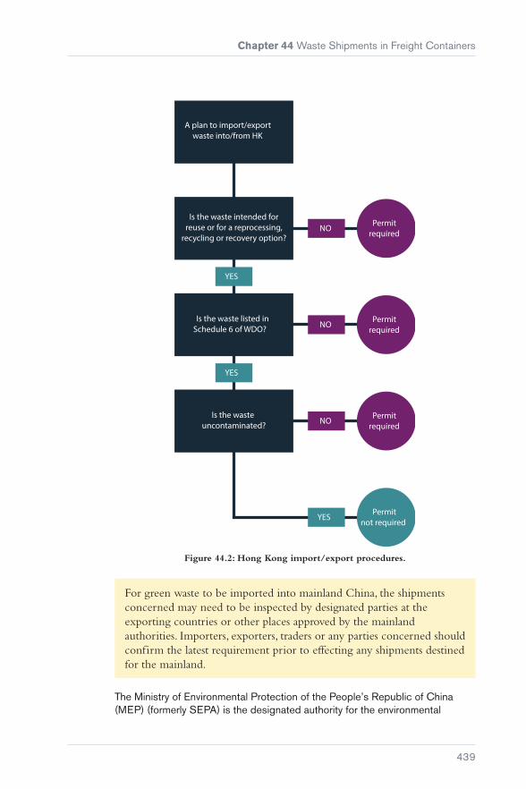
Chapter 44 Waste Shipments in Freight Containers
439
NO
A plan to import/export waste into/from HK
Is the waste intended for reuse or for a reprocessing,
recycling or recovery option?
Is the waste listed in Schedule 6 of WDO?
Is the waste uncontaminated?
Permitrequired
NO
NO
YES
Permitrequired
Permitrequired
Permitnot required
YES
YES
Figure 44.2: Hong Kong import/export procedures.
For green waste to be imported into mainland China, the shipments concerned may need to be inspected by designated parties at the exporting countries or other places approved by the mainland authorities. Importers, exporters, traders or any parties concerned should confirm the latest requirement prior to effecting any shipments destined for the mainland.
The Ministry of Environmental Protection of the People’s Republic of China (MEP) (formerly SEPA) is the designated authority for the environmental

Carefully to Carry Consolidated Edition 2018
440
management of solid waste imports and is responsible for issuing two kinds of import licence:
� Import licence of the People’s Republic of China (PRC) for automatic licensing of solid wastes that can be used as raw materials
� import licence of the People’s Republic of China (PRC) for restricted solid wastes that can be used as raw materials.
Imports should have:
� A Waste Import Licence issued by MEP – this is obtained by recyclers and/or utilisers of the imported waste in China prior to the waste import
� a License of Registration for Overseas Supplier Enterprise of Imported Scrap Materials issued by AQSIQ (AQSIQ Licence)
� a CCIC Pre-Shipment Certificate – Certificate for Pre-Shipment Inspection of Recycling Scraps to China (pre-shipment inspection certificate). More information may be obtained from http://www.ccic-europe.com or http://www.cciclondon.com.
CCIC is an inspection and certification company recognised by the General Administration for Quality Supervision, Inspection and Quarantine (AQSIQ) and accredited by the China National Accreditation Service for Conformity Assessment (CNAS). A number of CCIC offices have been set up around the world in countries that export waste materials to China. Container operators who accept waste product bookings to China should request the AQSIQ licence number at the time of booking, as it confirms that the shipper is approved by the Chinese Government authorities to ship waste products to China.
The Chinese Government continues to approve overseas scrap suppliers and at the same time monitors existing suppliers for the quality of waste supplies. During their inspections, if they find any anomalies, they may simply warn the suppliers and require them to rectify any issues. However, if these issues are not rectified or in the case of serious non-conformities, their licences may be cancelled. Container operators can check the AQSIQ website (www.ccc-us.com) for a list of warned/cancelled/suspended registration numbers. Container operators should not accept bookings from shippers whose registration numbers are on this ‘black list’.
It is good practice for the shipper to provide a copy of the documentation to the container operator as early as possible, but not later than the cut-off time for loading on the main line carrier. If a shipper has not submitted the export declaration, it is likely that they have not sold the cargo to a specific consignee. This increases the chances of cargo being abandoned at destination.
The list of solid wastes prohibited against import includes some 84 types, such as urban garbage, medical waste, waste organic solvent, waste clothes, waste tyres and tyre pieces, battery waste and scrap, used batteries, waste animal and plant products, waste rubber and leather, waste speciality paper, waste glass, as well as household appliances and waste electric motors including air-conditioners, televisions and computers (including their parts and accessories,
Chapter 44 Waste Shipments in Freight Containers
441
dismantled parts, broken parts and scraps unless stipulated otherwise by the state). The container operator’s booking department needs to be familiar with such prohibitions.
44.2.3 EU Regulations
Commission Regulation (EC) 660/2014 amended Regulation 1013/2006 that had applied since 12th July 2007 covering the shipment of waste (Reference 73). Commission Regulation (EC) 1379/2007 amended Annexes 1A, 1B, VII and VIII of Regulation (EC) 1013/2006 (Reference 74). Annexes III, IIIA and IIIB covered different types of non-hazardous waste, whilst annexes IV and IVA covered different types of hazardous waste. These regulations were supplemented by Regulation (EC) 1418/2007 concerning the export for recovery of certain waste listed in Annex III or IIIA to certain countries to which the OECD (Organisation for Economic Co-operation and Development) Decision on the control of transboundary movements of waste does not apply. Under these rules, stricter procedures must be followed (Reference 75).
Despite several EC regulations, gaps were identified in the enforcement and inspections carried out by EU member states. Regulation 660/2014 is designed to cover these gaps by strengthening Regulation 1013/2006 and providing a mechanism for planning of waste shipment inspections and to prevent illegal shipments. It also requires member states to make publicly available the outcomes of inspections and any measures taken, including penalties imposed on any parties.
It also clarified that the inspection of shipments must include verification of documents, confirmation of identity and physical checking of waste at any of the following stages of transport:
a) at the point of origin, carried out with the producer, holder or notifier;
b) at the point of destination, including interim and non-interim recovery or disposal, carried out with the consignee or the facility;
c) at the frontiers of the Union; and/or
d) during the shipment within the Union.
Under the present regulations (EC Regulation 1418/2007) (Reference 75), there are three options:
� Prohibition
� notification controls
� green list controls (lowest level of control).
Prohibition
Movements are not allowed under any circumstance, including almost all:
� Imports and exports for disposal
� exports of hazardous waste to developing countries, even if moving for recovery.
Carefully to Carry Consolidated Edition 2018
442
Notification controls
These apply to all allowed imports and exports of:
� Hazardous waste moving for recovery operations
� all types of waste moving for disposal
� some shipments of non-hazardous waste to non-OECD countries (includes Annex IIIB waste).
Green List controls
These controls contained in Article 18 of Regulation 1013/2006 (Reference 76) require that the exporters of waste must:
� Ensure that the Green List waste type can still be sent to that country under Green List controls
� know where the waste is going to be recovered in the destination country before shipping the waste
� ensure the waste is dealt with in an environmentally sound manner throughout its movement and recovery
� complete the Annex VII document specified in the rules with all the required information, including details of the producer or collector of the waste and the destination facility before shipping the waste (a copy of this document must be retained for 3 years)
� ensure that a copy of the above document accompanies the waste
� enter into a written contract containing specified provisions for the recovery of the waste with the person receiving the waste before the waste is shipped
� ensure that the person receiving the waste in the destination country signs the document that accompanies the waste to confirm receipt.
Waste being exported under Green List controls must be accompanied by a completed Annex VII form. The person who arranges the shipment of the waste must complete and sign this form. It is good practice for the shipper to provide a copy of this documentation to the container operator as early as possible, but not later than the cut-off time for loading on the main line carrier.
44.2.4 United States of America
The Resource Conservation and Recovery Act (RCRA) is the public law in the United States that creates the framework for the proper management of hazardous and non-hazardous solid waste.
Since the United States is not a party to the Basel Convention, it can export waste to those countries with which the US Government has negotiated a separate waste trade agreement.

Chapter 44 Waste Shipments in Freight Containers
443
44.3 Shipments of Waste at the Load Port
The first indication for a container operator that there is anything untoward with a container load of waste is when it is received by the loading terminal and the container is damaged. This is most likely to be the sidewall panels bulging outwards beyond their accepted envelope. Figure 44.3 is a series of pictures that show different problems with waste shipments.
Picture 1 shows the stow in the doorway when the container was opened. The container had been loaded with bales of waste plastics (eg bottles and packages). The bales were of rectangular shape with a long tack (right-hand bale) and a short tack (two left-hand bales).
Picture 2 shows the right-hand side bales stowed tight to the underside of the roof panel. This was because two bales had been stowed with their long tack upright. This resulted in the roof panel bowing upwards. The bales were also of non-uniform size.
Picture 3 is from an incident where the exporter had declared his shipment as being three container loads of electrical motors. However, these had been thrown into the containers with other rubbish that included plastic intermediate bulk containers (IBCs).
It is not always possible to identify the cause of damage to the structure of a container from a doorway inspection at the loading terminal. Identification of the cause may only be possible when the container is unpacked, which may take place some distance from the port.
1 2
3 4

Carefully to Carry Consolidated Edition 2018
444
Picture 5, shows an incident where it was found that the top right-hand bale of waste paper in the row (marked by the red arrow) was ‘canted’ at an angle on the horizontal plane. This resulted in pressure being applied during the course of loading to the left and right-hand sidewall panels, resulting in them bulging outwards and being permanently deformed by up to 100 mm.
Picture 6, shows another incident where the cause of damage became apparent during unloading. The bale of waste paper in the top left-hand row was not stowed with its side parallel to the fore and aft line of the container, but was ‘cocked’ at an angle thereby increasing its width in the stow. This bale was stowed adjacent to the maximum bowing outwards of the left-hand sidewall panel.
Poor stowage of bales within the container was not the only problem. The waste paper was contaminated with tin cans, some of which had sharp jagged edges, plastic bottles, plastic bags, pieces of wood and twigs, and a complete inflatable rubber mattress.
Waste paper contaminated with other such waste cannot be recovered in an environmentally sound manner. This type of waste should not be moved under Green List controls.
The container below was rejected by ship’s staff at the time of loading because liquid was leaking out from the door seal. When inspected at the terminal’s leaker bay, the front of the door sill was found to be heavily stained with a black oily substance.
5 6
7 8

Chapter 44 Waste Shipments in Freight Containers
445
When the container doors were opened, a distinct oily type odour was detected and emulsified oil was found on top of the door sill. Two solid plastic IBCs were stowed in the doorway, containing shredded plastic waste.
Behind these IBCs, shredded plastic waste had been stowed loose to approximately half the height of the container.
Other IBCs had been stowed on top of the loose shredded plastic waste. These IBCs were free to move, which would have made the container unstable during handling and transportation.
Figure 44.3: Different problems with waste shipments.
9 10
11


447
PART 11Miscellaneous Cargoes
Chapter 45 ............................................. 449Heavy-lift and Project Cargoes
Chapter 46 ............................................. 485Agricultural Produce – Insect Infestation and Fumigation
Chapter 47 ............................................. 501Fishmeal Cargoes – Self-Heating and Fires
Chapter 48 ............................................. 509Palletised Cargoes
Chapter 49 ..............................................513Radioactive Cargoes
Chapter 50 ..............................................515Radioactive Uranium Hexafluoride (UF6)


449
Chapter 45
Heavy-lift and Project Cargoes
Following a number of significant damage losses to ships and cargoes and a series of near-miss incidents in recent years, concerns have increased about the lack of expertise, skills and resources being deployed in this complex area of shipping.
The information in this publication is provided for guidance only and is not intended to replace, nor should it be used for, specific expert advice on the transportation of project/heavy-lift cargoes.

Carefully to Carry Consolidated Edition 2018
450
45.1 Project Cargo
Figure 45.1: Project cargo.
A wide range of cargoes fall within the definition of project cargo, from traditional breakbulk type cargoes to large single items such as cranes or oil and gas modules. It may be that large, heavy or out-of-gauge items require specialised stowage, lifting and handling, or there may be high value or critical items, or a quantity of goods connected to the same project, possibly loaded from different ports.
The cargo insurers will stipulate certain conditions (a warranty) for the purpose of insurance. If the cargo to be carried meets certain criteria (often referred to as ‘critical items’), certain procedures will have to be followed under the warranty.
Critical items may fall under one (or both) of two broad headings:
1. Those that are critical because of the cost and difficulty of replacement.
2. Those that may require unusual provisions for safe loading, stowage, lashing and discharge.
The criteria may include the replacement lead time, the value of the cargo (individually and/or in total), the size or footprint, weight, the centre of gravity and whether specialised transport, lifting and/or securing is required.
Cargo types that fall within the definition of a critical item may include:
� Oil and gas equipment for onshore and offshore infrastructure
� refinery and petrochemical plant equipment
� renewables equipment for onshore and offshore infrastructure
� modules and pre-assembled units

Chapter 45 Heavy-lift and Project Cargoes
451
� port handling equipment
� port construction
� floating cargo
� rolling stock
� heavy machinery
� power plants and power generation equipment.
Critical items require special attention during transportation and careful assessment and detailed planning is required for loading, stowage, securing and discharge.
Project cargo damages or loss can be very costly, often running into many millions of dollars. The risks involved can be largely mitigated with careful planning and attention, before the cargo is received for shipment.
The pressure to reduce costs is always high and, as the cost of shipment is essentially an overhead, there is a natural desire to reduce the shipping costs as far as possible. The use of unsuitable vessels for a cargo, poor quality or inadequate securing and dunnage, poorly trained crew and a lack of detailed planning can all lead to damage or loss.
Figure 45.2: Damage to project cargo during transportation.
Damage is likely to lead to a claim against the cargo and/or liability insurance and, potentially, delays to the project (eg delay in start-up). With many other parties involved and the consequential costs high, these claims are often complicated and may result in lengthy and costly litigation.
45.2 Relevant Regulations, Codes and Guidelines
It is the Master’s responsibility to ensure that all cargo is stowed, secured and handled (loaded/discharged) with care and in accordance with the requirements of the charterparty.

Carefully to Carry Consolidated Edition 2018
452
The charterparty may stipulate specific responsibilities of the vessel owner, charterer and shipper, such as the specific responsibility for stowage, lashing and securing of the cargo. There may be a requirement from the charterer and/or the cargo insurers for the appointment of an independent marine warranty surveyor (MWS) to review, approve and monitor all loading and sea-fastening operations. These responsibilities should be carefully assessed as they can greatly affect the liabilities if the cargo is damaged or lost during the loading, voyage or discharge. It is important that all relevant persons are aware of these requirements and their responsibilities.
The following regulations are applicable and should be adhered to:
Flag State and Classification Society rules
These are always mandatory and, in particular, SOLAS Chapter VI: Carriage of Cargoes is relevant and must be complied with. Regulations for lifting gear and operations will be found within the flag State or Classification Society rules.
The rules of a vessel’s Classification Society will also set out the requirements for maintenance of the vessel, including equipment required for the loading, stowage and securing of project cargoes. If these requirements are not followed, the vessel’s owners may be liable in the event of an incident.
Cargo Securing Manual (CSM)
The vessel’s cargo securing manual (CSM) is a key document in the shipment of project cargoes. The CSM is a required document under SOLAS Chapters VI and VII and sets out the types of cargo for which the vessel is properly suited to carry, as well as how it should be loaded, stowed and secured. It will also document the vessel’s cargo securing equipment (inventory) and its maintenance and inspection.
The CSS Code (IMO Code of Safe Practice for Cargo Stowage and Securing, 2003; Resolution A.714(17)) as amended by MSC circulars (Reference 22)
This Code sets out the general principles for the safe stowage and securing of a range of cargoes, including project cargoes and non-standard, heavy units that may require special attention. Annex 13 of the CSS Code (Reference 22) sets out the method of calculation of the required lashing forces for abnormal loads. The CSM will be based on the principles set out in the Code.

Chapter 45 Heavy-lift and Project Cargoes
453
One key aspect is that specialist knowledge and experience in the shipment of such cargoes is required to fully plan and engineer a safe project cargo shipment. The CSS Code sets this out in Section 1.8, Special Cargo Transport Units:
“The shipowner and the ship operator should, where necessary, make use of relevant expertise when considering the shipment of a cargo with unusual characteristics which may require special attention to be given to its location on board vis-a-vis the structural strength of the ship, its stowage and securing, and the weather conditions which may be expected during the intended voyage.”
In particular, the calculations involved often require specialist knowledge and appropriate expertise should be engaged.
Figure 45.3: The IMO CSS Code is the main standard to be applied for the stowage and securing of project cargoes.
Intact stability regulations (The International Code on Intact Stability, Resolution A.749(18)) (Reference 27)
This is a mandatory Code which sets out the minimum stability standards for all applicable vessels. Damaged stability standards should also be considered (SOLAS Chapter II-1).

Carefully to Carry Consolidated Edition 2018
454
CTU packing guidelines (IMO/ILO/UNECE Code of Practice for Packing of Cargo Transport Units (CTU Code), 2014) (Reference 57)
This Code provides guidance and measures for ensuring the safe packing of cargo in containers and other cargo transport units (CTUs).
Guidance on best practice for the loading, stowage, securing and discharge of project cargoes may be found in:
DNV Rules for Planning and Execution of Marine Operations (Reference 77)
The DNV Rules are mainly applicable to offshore operations, but there are sections on heavy lifts, lifting appliances, and loading and discharge operations that are relevant to project cargo shipments.
DNV-GL Noble Denton Guidelines (Reference 78)
The DNV-GL Noble Denton Guidelines provide the technical basis for marine operations, including the transportation of specialised cargoes. The guidelines include Marine Transportation Guidelines, Marine Lifting Guidelines, Mooring Guidelines and Load-out Operations.
All of these guidelines are specialist technical documents and appropriate expert advice on their requirements and implications should be sought before they are used.
45.3 Vessel Types and Suitability
Figure 45.4: Tweendecker.
A number of different vessel types are commonly used to carry project cargoes. These include:
� Tweendeckers: This old-style general or breakbulk cargo ship with multiple hatches, fixed tween decks and cargo handling via derricks or cranes has now largely disappeared
� general cargo ships: These carry a wide variety of cargoes, including industrial items, bagged cargoes, project cargoes, steel products, forest

Chapter 45 Heavy-lift and Project Cargoes
455
products, palletised cargoes, smaller breakbulk cargoes and containers. They are uncellular and have holds with movable/stackable tween deck pontoons
� multipurpose and heavy-lift vessels: These vessels usually have wall-sided (rectangular) holds and movable tween decks, providing efficient stowage for a range of cargoes using their own securing fittings. They are ideally suited to the carriage of project cargoes. Heavy-lift vessels are commonly defined as having cranes capable of a 100 t single lift. The cranes are usually sited to enable tandem working
� bulk carriers: These vessels have a number of holds designed to carry cargoes such as coal, grain, iron ore, etc. This type of vessel may vary in size from only a few hundred tonnes to around 200,000 t. The smaller sizes, up to around 50,000 t, may be fitted with cranes for self-discharge
Bulk carriers are sometimes chartered for project cargo transport, but are not well suited to this task as they do not have wall-sided holds, making safe and proper stowage difficult. The crews are often not familiar with the requirements for the stowage and securing of project cargoes.
Figure 45.5: General cargo ship.
Figure 45.6: Multipurpose vessel.

Carefully to Carry Consolidated Edition 2018
456
Figure 45.7: Bulk carrier holds are not designed for the carriage of project cargoes. The shape of the holds makes proper stowage and securing diff icult and will require
stacking and overstows. This can, and often does, result in cargo damage and sometimes damage to the vessel.
� module carriers and semi-submersible heavy-lift vessels: These vessels have all accommodation forward and a broad, flat deck, designed for the carriage of large modules. Loading and discharging is via self-propelled trailers, skidding or, if semi-submersible, by float-on/off methods. The vessels are usually fitted with sophisticated and highly responsive ballast systems (sometimes with stability pontoons) to allow fine adjustment of draught, list and trim as heavy modules are loaded
Figure 45.8: A purpose-built heavy-lift ship.
Figure 45.9: The tween deck of a purpose-built multipurpose vessel.
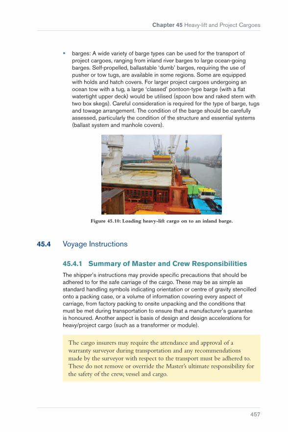
Chapter 45 Heavy-lift and Project Cargoes
457
� barges: A wide variety of barge types can be used for the transport of project cargoes, ranging from inland river barges to large ocean-going barges. Self-propelled, ballastable ‘dumb’ barges, requiring the use of pusher or tow tugs, are available in some regions. Some are equipped with holds and hatch covers. For larger project cargoes undergoing an ocean tow with a tug, a large ‘classed’ pontoon-type barge (with a flat watertight upper deck) would be utilised (spoon bow and raked stern with two box skegs). Careful consideration is required for the type of barge, tugs and towage arrangement. The condition of the barge should be carefully assessed, particularly the condition of the structure and essential systems (ballast system and manhole covers).
Figure 45.10: Loading heavy-lift cargo on to an inland barge.
45.4 Voyage Instructions
45.4.1 Summary of Master and Crew Responsibilities
The shipper’s instructions may provide specific precautions that should be adhered to for the safe carriage of the cargo. These may be as simple as standard handling symbols indicating orientation or centre of gravity stencilled onto a packing case, or a volume of information covering every aspect of carriage, from factory packing to onsite unpacking and the conditions that must be met during transportation to ensure that a manufacturer’s guarantee is honoured. Another aspect is basis of design and design accelerations for heavy/project cargo (such as a transformer or module).
The cargo insurers may require the attendance and approval of a warranty surveyor during transportation and any recommendations made by the surveyor with respect to the transport must be adhered to. These do not remove or override the Master’s ultimate responsibility for the safety of the crew, vessel and cargo.

Carefully to Carry Consolidated Edition 2018
458
Figure 45.11: A clear understanding of each party’s responsibilities and good teamwork is key to the success of project cargo transportation.
45.4.2 Shippers’ Instructions
The shippers may provide instructions for the safe and proper stowage and securing of the cargo. These instructions may refer to matters such as whether the cargo unit can be overstowed (ie whether other items may be stacked on top of it), the lashing and securing of the cargo (including the suitable lashing points on the cargo), the preferred stowage location (such as whether it can or cannot be stowed on deck) and the required packing to ensure the protection of any internal components and protection from the elements.
For more complicated shipments, particularly those for large, heavy items, a detailed transport manual or method statement should be provided. Owners should ensure that this is provided in a timely manner. It is normally provided by the shippers to all relevant parties and it should document all required procedures for the safe and proper shipment of the cargo, including:
� Management of the project, responsibilities and key contacts
� details of the cargo
� details of the vessel
� vessel strength and stability
� port details
� loading procedures, including any heavy lifts and, if necessary, any transportation to the loading berth
� stowage requirements
� lashing and securing requirements, including details of all lashing, securing and lifting gear
� voyage plan, including contingency procedures and ports of refuge
� discharge procedures.

Chapter 45 Heavy-lift and Project Cargoes
459
The transport manual, or method statement, should be complied with as this defines the procedures for the entire shipment. It will have been reviewed by personnel with the specialist knowledge required for critical shipments, such as a marine warranty surveyor (MWS) or cargo superintendent (‘supercargo’).
45.4.3 The Marine Warranty Surveyor (MWS)
The MWS is appointed on behalf of the cargo insurance underwriters, who insure the shipment of the cargo.
The MWS ensures that the terms of the warranty clause in the insurance policy are complied with and that the operations are carried out in accordance with the approved procedures, as defined in the transport manual or method statement.
Involvement of an MWS is common where shipment of the cargo forms a component of a larger project, including cargo comprising relatively small cases or cargo transport units (CTUs) through to complete modules for new infrastructure projects. In the latter case, the shipping operation will comprise a series of procedures, ie transport to point of shipment, lift plans and rigging calculations, sea-fastening and routeing of the ship or tow.
Subject to the approval of procedures and calculations, it is normal for the MWS to attend and observe loading, securing and possibly discharging operations to ensure that approved procedures are adhered to and to be on hand to evaluate and approve any changes to procedures necessitated by the actual onsite conditions.
Where smaller quantities of cargo are being shipped on breakbulk or container ‘liner’ vessels, the MWS would typically consult with the chief officer and/or client’s representative with respect to stowage position and method(s) of securing.
In cases where an MWS attends to approve loading and securing of cargo, it is usual for a certificate of approval (COA) or letter of approval (LOA) to be issued, on completion of operations, to confirm that the previously approved procedures have been adhered to or that the MWS is satisfied with onboard securing arrangements agreed with the vessel’s staff or client’s representative. The COA/LOA may have additional recommendations attached, such as specifying checks to be made on lashings, records to be noted in the vessel’s log, etc.

Carefully to Carry Consolidated Edition 2018
460
45.4.4 The Client’s Representative (Supercargo)
The supercargo, in many respects, plays a similar role to the MWS, but is usually appointed as the representative of one of the parties directly involved in the shipment such as the shipper, charterer or receivers.
45.5 The Cargo
Cargo group Examples Comments
Oil and gas equipment
Process modules, accommodation units, sub-sea equipment, topsides, decks, complete platforms/jack-ups
Can be very large units weighing thousands of tonnes
Refinery and petrochemical plant equipment
Cooling towers, flash towers, storage tanks, pipe-racks, reactors, towers and similar
May have large dimensions, often deck space intensive
Renewable energy equipment
Wind turbine blades (carried in racks), nacelles foundations, mono-piles, tidal turbines, power cables (on non-specialist vessels)
Wind turbine blades (usually carried in racks) can be affected by longitudinal bending of the vessel due to their length. Careful stowage and securing is required to avoid this
Modules and pre-assembled units
Often for oil and gas installations or refinery/petrochemical plants, such cargoes may include living quarters, pre-assembled machinery, generator sets, large pipe racks
Often pre-assembled into large structural framework for which careful lashing, securing and bracing is required to avoid distortion
Port handling equipment
Typically, cranes and material handling equipment such as large container gantry cranes, ship-loaders, mobile harbour cranes, rubber tyre gantry (RTG) cranes, reach stackers
May consist of a framework, requiring careful lashing, securing and bracing to avoid distortion. Some units may have low lift stability
Port construction
May include pre-assembled items such as link-spans, jetty platforms, cat-walks, dolphins, single buoy moorings
Floating cargo A wide variety of vessels and craft, such as tugs, small ferries, yachts and super-yachts, small naval craft
Careful lifting sling positioning and restraint required

Chapter 45 Heavy-lift and Project Cargoes
461
Rolling stock and heavy machinery
Locomotive engines and carriages, wheeled and tracked vehicles such as material handling lorries, excavators, trucked equipment such as mobile cranes, drilling rigs, etc. Mining equipment, factory equipment
Often included as breakbulk project cargo. Proper stowage and securing required
Power plants and power generation equipment
Large generators, conductors, transformers and similar
Table 45.1: Different types of project cargo.
Project cargoes come in many different shapes and sizes.
Heavy lift
There is no standard definition of a heavy lift in weight terms, although the cargo insurance policy may set a weight figure as part of the critical item criteria (typically 50 t, but this may vary).
A 500 t lift on a specialised vessel, loaded/discharged at a safe berth, may present less risk than a 50 t lift at the limits of a vessel’s safe handling capacity or loaded/discharged at a berth not suited to handling such items.
Breakbulk cargo
Breakbulk cargo is a much broader group of cargo types and refers to cargoes that are loaded and stowed individually and not in containers or palletised. This includes certain project cargoes that are small enough to fit inside a vessel’s holds, but which require individual loading, stowage and securing.
Problems often occur with breakbulk cargoes because there may not be a requirement for a surveyor to oversee and approve loading and securing. There has been a growing trend to use bulk carriers for such cargoes, which are ill-suited to the task and can result in extensive damage to the cargo.
Out-of-gauge
The term out-of-gauge refers to any cargo that has dimensions that exceed the normal dimensions of a standard shipping container.

Carefully to Carry Consolidated Edition 2018
462
Figure 45.12: Project cargoes require clear positioning and stowage. Care is required to ensure that all units in the stow can be properly secured.
45.5.1 Aspects to Consider for Project Cargoes
‘Footprint’ of the cargo
Where and how cargo will be stowed on the vessel must be considered to minimise the risk of damage and/or loss. The three-dimensional space and position must be considered in relation to the vessel structure and other cargo units; the stowage of project cargoes (particularly those in a breakbulk format) can often resemble a 3-D jigsaw and must be planned as such.
The stowage plan should consider the following:
� Is shoring required to hold the unit in position?
� Can enough lashings with sufficient scope be run to resist the forces that will be experienced?
� How should the cargo be orientated, with regard to any principal axes of strength in the cargo to the largest forces that will be applied to it?
� Can the cargo have other cargo stowed on top of it (overstow)? What is the weight limit for overstow?
� Does the cargo need to be carried on deck? Does the charterparty or fixture specify whose responsibility and risk this is (as often owners will not wish to carry the risk for deck cargoes)?
� If carried on deck, is there a risk of green seas affecting the cargo? Is forward on the deck the right position for the unit? Does it overhang the vessel’s sides (significantly increasing the risk of cargo damage)?

Chapter 45 Heavy-lift and Project Cargoes
463
Figure 45.13: Lifting and securing lugs (pad-eyes) should not be subjected to forces out of plane of the eye as this will damage the eye and may lead to failure of the lashing.
Lifting and securing points
The cargo must be supplied with appropriate lifting and securing points, particularly for large and heavy items. If the cargo unit is not supplied with adequate lifting/securing points, attempts may be made to lift and secure the cargo in the best manner possible. However, if this is felt to present any risk of damage to the cargo (itself or surrounding), a note of protest should be issued at the time of loading. If the risk is felt to be significant (to the cargo unit, cargo as a whole or to the vessel), the cargo should be rejected.
The cargo lifting/securing points should be assessed to confirm that they are strong points and not merely attached to a protective cover (are they intrinsically part of the unit?), that they are structurally sound and that they are in plane to the principal forces to which the cargo is going to be subjected (taking due account of the unit’s position and orientation in the stow).
Figure 45.14: Cargo being lifted.
Cargo condition
The cargo unit, whatever its size, must be adequately packed and covered for its voyage to protect it from damage. If contained within an outer casing or protective packaging (eg a wooden box), the casing must be secure, well fixed to the cargo unit so it does not come loose, and cover all required parts of the unit. The unit should be well secured and packed within the casing.

Carefully to Carry Consolidated Edition 2018
464
Figure 45.15: Cargoes should be well packed and properly secured inside CTUs. Failure to do so can lead to extensive damage to the CTU, surrounding cargo and
even the ship itself.
If shipped without an outer protective casing, careful packaging and covering of any vulnerable parts or components is necessary to prevent damage from impacts and corrosion.
Certain cargoes (such as coils, transformers, turbine components, etc) may be particularly liable to internal damage as they are sensitive to accelerations. These units must be properly packed, secured (including all internal components) and, if necessary, monitored during the voyage.
Advice from the manufacturer and/or relevant specialists should be sought.
Figure 45.16: Damage to the cargo observed on loading, even if only to packaging, should be noted and recorded.
Any project cargoes shipped inside containers or other cargo transport units (CTUs) should be adequately packed (stuffed), with appropriate shoring and internal securing, as with normal containerised transport (see Chapter 41).
The cargo should be inspected at loading and any damage recorded and noted.

Chapter 45 Heavy-lift and Project Cargoes
465
Cargo information
Heavy-lift and project cargoes tend to be more than averagely valuable and the consequence of their damage or loss proportionately more serious. Each cargo unit should be supplied with appropriate documentation that provides the necessary information to ensure safe transportation. The general standard for project cargo information should always be ‘comprehensive and accurate’.
The documentation must include the accurate weight of the cargo unit, the accurate location of its centre of gravity (particularly important for heavy lifts and possible off-centre units), its dimensions and details of the safe slinging, lifting and securing points, as well as the nature of the cargo.
The weight and centre of gravity should be marked on each side of the cargo unit such that it is immediately visible.
45.6 The Vessel
45.6.1 The Cargo Securing Manual (CSM)
All ships carrying cargoes other than solid or liquid bulk cargoes are required to carry and maintain a ship-specific cargo securing manual (CSM). This is a mandatory requirement of SOLAS (Reference 18) and the CSS Code (Reference 22). The CSM must be approved by the vessel’s flag State.
The purpose of the CSM is to set out the procedures and standards for the securing of cargo, taking into account the type of cargo, the characteristics of the vessel and the conditions that may be encountered. It is intended to provide relevant information and guidance to assist the crew in properly securing the cargo.
Guidelines for the production of the CSM have been published by the IMO and various Classification Societies. In general, the CSM should provide information on:
� The securing devices carried on board (number, strength, inspection regime and maintenance) and their arrangement
� the stowage and securing of non-standardised cargo, including evaluation of the forces and the appropriate calculation methods for determining the required cargo securing capacity
� the stowage and securing of standardised cargo units (such as containers), including securing devices, stowage requirements and evaluation of the forces acting upon the cargo units.

Carefully to Carry Consolidated Edition 2018
466
45.6.2 Vessel Stability
The vessel must comply with the International Code on Intact Stability 2008 (IS Code) (Reference 27) at all times, including during loading and discharge operations. For large, heavy cargoes, the vessel’s stability should be checked at all key stages of the proposed loading/discharge sequences. This will include any lifting operations (cargo unit at furthest extension and highest crane boom position), ‘drive-on’ (using self-propelled modular trailers for example) or floating operations (with semi-submersible vessels).
Where relevant, the effect of a stability pontoon should be included in the calculations.
For high value/long replacement time cargoes and/or if the voyage route is deemed to be high risk, additional stability checks will be required for a damaged state (eg a one compartment flooded condition). Although a vessel may meet the IMO intact stability criteria, it may still be considered that the vessel has too little (tender) or too much (stiff) stability.
Vessels with heavy deck cargoes may have a high centre of gravity (CG) and a small metacentric height (GM). This will result in a slow roll period (tender) and she will linger at the maximum angle. The extended roll period increases the gravitational forces on the cargo and the securing devices.
Figure 45.17: Rough weather combined with a high GM can result in violent motions, which if not properly planned can result in damage to or loss of the cargo.
Vessels with heavy cargo stowed low in the holds may have a low CG and a large GM. This results in a fast roll period (stiff) and she may roll violently. This violent motion increases the dynamic forces acting on the cargo and the securing devices due to the increased accelerations.
Project cargoes for the oil industry, loaded on conventional vessels, usually include a quantity of drill and casing pipe. This has to be bottom stowed in the holds and the result is always a high GM, with its associated short roll period, which in some cases is as low as 7 to 8 seconds, potentially resulting in violent rolling. High acceleration forces may be exerted on tween deck and deck cargo lashings and this should be taken into account during the planning and loading phase. Because project cargoes can be relatively light but have a high volume, there is seldom sufficient deadweight in the whole consignment to bring the vessel down to a reasonable draught that will provide full propeller and rudder immersion. Therefore, some bottom ballast will still be needed, which further increases the GM. Pumping out this bottom ballast will make little difference to

Chapter 45 Heavy-lift and Project Cargoes
467
the roll period and will make the vessel difficult to handle in adverse weather, with steering or maintenance of a certain heading more difficult.
With a lighter vessel, there is an added risk of main engine shutdown, as the governor will be working harder to avoid engine overspeed.
On conventional vessels, an ideal roll period would be in the region of 15 to 20 seconds. A longer roll period, resulting from a GM that is too low, will mean that the vessel will ‘hang’ at the maximum angle at the end of each roll and any shift of cargo could result in loss of GM and the vessel reaching angle of loll, with no prospect of recovery without resorting to ballasting bottom tanks.
The nature of the cargo will dictate the final GM, although consideration should be given during the planning phase to loading as many heavy units high up in the tween decks, or on deck if permitted, to counteract the effect of the drill and casing pipe consignments in the lower holds. This will not be possible in the case of bulk carriers being employed to load project cargoes, as the heaviest units will have to be stowed directly over the pipe stows, or on the remaining tank top areas in the holds, further increasing the GM.
Consideration should be given to the weather conditions that the vessel may experience on voyage. For exposed, open ocean voyages, where bad weather is a possibility, the effect of the vessel’s loading condition (GM and draughts) on her motions should be considered and any negative effects mitigated as much as possible. It is important to minimise the motions on the vessel (including possible wind heeling) as far as practically possible.
Figure 45.18: When sea-fastenings fail under excessive vessel motions, the violent motion of large, heavy project cargoes can cause extensive damage to the vessel structure. Side-shell plating (in way of cargo holds), deck structures and hatch
covers are particularly vulnerable to damage. The repairs can cause extensive delays.
45.6.3 Vessel Strength Considerations
The vessel will have defined weight limits for the tank top, tween deck and hatch covers (tonnes per square metre). It is important that these limits are adhered to, particularly with heavy cargoes, and they must be considered in the stowage planning.

Carefully to Carry Consolidated Edition 2018
468
Heavier cargo units should be placed over the frames of the vessel and additional load spreading may be required. Load spreading can range from dunnage or wooden mats, to steel grillages for heavier units that spread the load into the surrounding structure of the vessel. The grillage should be designed to take both the static weight of the cargo unit and the dynamic loads to which it will be subjected on voyage. In many cases, sophisticated software is used to determine ‘hot spots’ in structural members of the vessel while stowing heavy-lift cargo. This approach is usually used by naval architects or structural engineers, who are either employed in-house or outsourced.
Where structural reinforcements, grillages or any other welded modifications are required, the proximity to the vessel’s bunker tanks or any other f lammable source must be considered and the appropriate hot work procedures followed. All appropriate work permits should be in place.
The longitudinal strength of the vessel (shear forces and bending moments) must be checked at all key stages of the loading and discharge operations and for the voyage conditions. Project cargoes are typically limited by volume (rather than weight) and so the shear forces and bending moments are usually within the vessel’s permissible limits.
45.6.4 Securing Points
The securing points fitted to the vessel, and the surrounding structure to which they are fitted, must be strong enough to withstand the loads (static and dynamic) imposed by the cargo during the voyage. This is particularly important in the case of ‘hard’ sea-fastenings such as welded stoppers.
Figure 45.19: Adding securing points to the deck of a heavy-lift vessel.

Chapter 45 Heavy-lift and Project Cargoes
469
Figure 45.20: Load-spreading ‘mats’ to protect the structure of the vessel.
Figure 45.21: Lashing wires with suff icient scope and clear working space.
The securing points should be located such that there is adequate room for the securing device to operate effectively. For wire lashings, the lashing should have a clear line between the cargo unit and the securing points on the vessel and must not run around corners of the vessel structure or other cargo units.

Carefully to Carry Consolidated Edition 2018
470
Figure 45.22: Examples of D-rings properly welded to the deck (left) and poorly welded onto a bulkhead (right).
45.6.5 Cranes and Lifting Devices
The vessel’s cranes and lifting devices are of critical importance in the loading and discharge of project cargoes.
Maintenance of cranes and the operational procedures applied are critical to their safe operation. There are numerous examples of heavy lifts being dropped due to failures of cranes and/or poor operational practices. The manufacturer’s recommendations for maintenance should be followed and full records kept. Defective wires must be replaced as necessary. The Classification Society inspection history and maintenance records (eg ‘rocking’ test results) are often requested for review.
Figure 45.23: The vessel’s cranes are of critical importance to the safety of operations and all components should be thoroughly maintained and regularly
inspected. A crane failure during a heavy lift will be catastrophic.
The manufacturer’s recommended operating procedures should be followed and the crane operating limits adhered to rigidly.
A significant factor in incidents relating to cranes is the skill and experience of the operators. Heavy lifts, and in particular tandem lifts (using more than one crane at the same time to lift a unit), require experience and appropriate training.

Chapter 45 Heavy-lift and Project Cargoes
471
Figure 45.24: Cargo being unloaded by crane.
45.7 Loading and Discharge
The responsibilities of each party must be agreed and documented prior to commencement of operations and should set out the chain of responsibility, persons in charge and contact details for all relevant persons.
Instructions/information from shippers
The shipping note provides details of the contents of a cargo consignment to carriers, forwarders and receivers.
Industry guidelines and best practice
For any cargo movement, in particular for loading and discharge operations, a full and detailed plan must be produced and adhered to. The plan should take due account of the requirements and recommendations of industry best practice guidelines and rules.
Heavy-lift equipment and relevant requirements
Lifting gear may include wires, shackles, spreader beams and lifting blocks/hooks and should be documented on board the vessel or with the crane (if shore-side). All lifting equipment should be certified and its safe working load (SWL) or working load limit (WLL) and minimum breaking load (MBL) documented and marked visibly on the item itself.

Carefully to Carry Consolidated Edition 2018
472
Figure 45.25: Safe lifting equipment.
Lifting lugs/eyes on the cargo unit should be located so as to provide a stable lift, accounting for any offset of the unit’s centre of gravity. They must also be strong enough for the lift, including any dynamic lifting loads. All lifting gear and lifting points on the cargo should be inspected before commencing the lift.
Figure 45.26: Unsafe lifting equipment.

Chapter 45 Heavy-lift and Project Cargoes
473
Lifting and rigging plans
For any heavy lift, it is essential to properly develop and document a lifting plan, which should define the procedures for the lift and provide accurate information on the centre of gravity of the unit, the proposed lifting spread to be employed and the calculation of the rigging stability (the lifting triangle). It should document the loads expected to be experienced and the safety factors used in selecting the lifting gear. It should also assess the need for centre of gravity corrections (eg the use of water bags) and possible test lifts to ensure stability (insurance policy coverage should be checked in this case).
Case study: The lifting of units with a high centre of gravity (CG) can be challenging. In one case, the rigging arrangement was incorrect and allowed the crane to tip, which was initially caused by a strong gust of wind. Because the stability of the lift was marginal, once the crane had started to tip, there was no means to restore it to upright in the rigging plan and it fell onto the deck of the vessel and the quayside, causing significant damage.
All crane lifts should be carefully assessed to ensure adequate clearances between the cargo unit itself, the vessel and port infrastructure. Tandem crane lifts must be planned in detail to ensure the correct synchronous movement of the cranes.
Limiting conditions and external influences
The lift should have limiting conditions imposed on it to ensure that the design loads for which it is rated are not exceeded. These will include limiting wind conditions and vessel motions (which may differ for in-harbour and offshore operations) and, where positional accuracy is important, the lift may be limited to daytime hours only.
Significant crane slewing (rotation) and other horizontal motions should be assessed to ensure that the dynamic loads imposed are within the capacity of the lifting system. Similarly, lifting into and out of water imposes additional loads on the lift and must be assessed.
Reference should be made to the relevant industry guidelines for the determination of these loads.
Loading sequence and trim, ballasting
During loading and discharge operations, it is important to carefully manage the vessel’s draughts and trim. This is particularly important for drive-on/off and float-on/off operations. Careful ballasting is needed to ensure that the required draughts and trim are maintained during the course of the operation and this
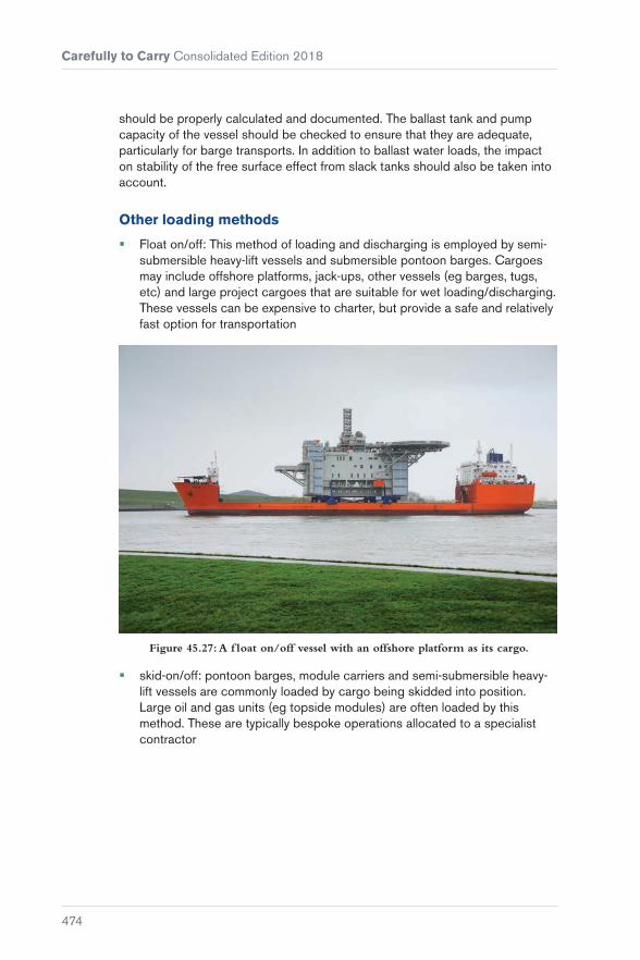
Carefully to Carry Consolidated Edition 2018
474
should be properly calculated and documented. The ballast tank and pump capacity of the vessel should be checked to ensure that they are adequate, particularly for barge transports. In addition to ballast water loads, the impact on stability of the free surface effect from slack tanks should also be taken into account.
Other loading methods
� Float on/off: This method of loading and discharging is employed by semi-submersible heavy-lift vessels and submersible pontoon barges. Cargoes may include offshore platforms, jack-ups, other vessels (eg barges, tugs, etc) and large project cargoes that are suitable for wet loading/discharging. These vessels can be expensive to charter, but provide a safe and relatively fast option for transportation
Figure 45.27: A f loat on/off vessel with an offshore platform as its cargo.
� skid-on/off: pontoon barges, module carriers and semi-submersible heavy-lift vessels are commonly loaded by cargo being skidded into position. Large oil and gas units (eg topside modules) are often loaded by this method. These are typically bespoke operations allocated to a specialist contractor

Chapter 45 Heavy-lift and Project Cargoes
475
Figure 45.28: Barge transports and loading/discharge by non-lifting methods require specialist expertise and knowledge.
� roll-on/off: Wheeled cargoes can be driven onto and off the vessel. Many project cargoes are loaded/discharged using self-propelled modular transporters (SPMTs). SPMTs provide a flexible loading/discharge method and are capable of dealing with inclined and uneven routes.
45.7.1 Other Operational Issues
Ground-bearing pressure
Consideration should be given to the ability of the load path (ashore) to withstand the weight passing over it without undue deformation, which might result in damage to the load path and/or a loss of stability of the load-transporting equipment. This can also be a factor with lifted loads, particularly where a high capacity mobile crane is utilised. The loading capacity of port facilities should be determined and account taken of any damaged or degraded areas. Repair and/or consolidation may be required to provide a usable load-path over which a heavy unit can be skidded or driven, or a crane safely located. The transport of the unit to the load port and onwards from the discharge port must also be considered. A route survey may be required.
Transhipments
Transhipment of cargo should, under ideal circumstances, be avoided as generally the cargo is at its most vulnerable when being handled. However, there are circumstances when it cannot be avoided. Transhipment operations (particularly vessel to vessel) require very detailed and careful planning.
Barge transport
While there are heavy-transport vessels capable of carrying modules of 2,000 to 3,000 t, towed barge transport is often the only reasonable solution to heavy-lift transport, particularly where large and heavy structures are concerned. These may include container cranes, large tanks, or jackets and decks for offshore installation. Barge transport is inevitably slower than the use of an equivalent vessel. It will also require the fixture of a suitable towing vessel

Carefully to Carry Consolidated Edition 2018
476
and may require more sophisticated voyage planning where a tow is lengthy or it transits known hazardous or adverse weather areas. Barge transports should be carefully planned as they are generally a higher risk method.
Management of operations
For any loading and discharge operation, the planning of the operation must include provision for hold points during the operation and toolbox talks. These help to ensure the safe progression of the operation and that all persons involved understand the next steps, responsibilities, etc.
Appropriate risk assessments, including HAZID/HAZOP meetings, should be carried out. These should involve all relevant parties and be approved by all. They should include management of changes (any deviations from agreed procedures) to be documented and agreed by all parties.
Relevant authorities (such as the local port authority) should be informed of the operation and involved in the planning. There may be a need to restrict vessel movements nearby during an operation, for example, which will require the support and assistance of the port.
45.8 Stowage Requirements
All vessels have their specific advantages and disadvantages, but while specialist heavy-lift vessels will be more expensive to charter, they are generally better suited to the cargo types typically shipped and so the overall shipment is safer. Cheaper vessels, such as bulk carriers or general cargo vessels, are often employed for economic reasons. However, they are not designed to carry these types of cargoes and their use often leads to increased costs, either due to cargo damage claims or the extra design and work required to make the cargo shipment as safe as possible, which tends to nullify the perceived cost benefit.
Figure 45.29: Large cargo units will need to be carried on deck, requiring special planning of the stowage, required sea-fastenings (to allow for the higher CG) and
protection from the elements. Stowage on forward hatch covers is not advised unless absolutely necessary as vessel motions (in particular, pitch motions) are greater in
this location and there is a higher risk of impact from seas shipped on deck.

Chapter 45 Heavy-lift and Project Cargoes
477
Very large cargo units will require sufficiently large amounts of deck space and this often dictates the choice of vessel. If the cargo can only be carried on deck and not in the holds, suitable protection from the elements is then required.
Deck cargoes will often be specified as being carried at the shipper’s risk and it is important to note this and take action accordingly.
45.9 Cargo Securing
Cargo securing equipment
Cargo securing gear may include lashing wires, web lashings, chains, D-rings, turnbuckles and shackles. In project cargo terms, these are often referred to as ‘soft’ lashings. As with lifting gear, all of the equipment for cargo securing should be certified and have its SWL and MBL documented and marked visibly on the item. If carried by the vessel, the CSM should provide a full inventory of these items.
Figure 45.30: Turnbuckles.
Also applicable are ‘hard’ sea-fastenings such as stoppers, braces, etc, which are often constructed from steel plating and/or beam sections and welded to the vessel. These are typically used for larger, heavier cargo units and are usually used only once.
Figure 45.31: ‘hard’ sea-fastenings.
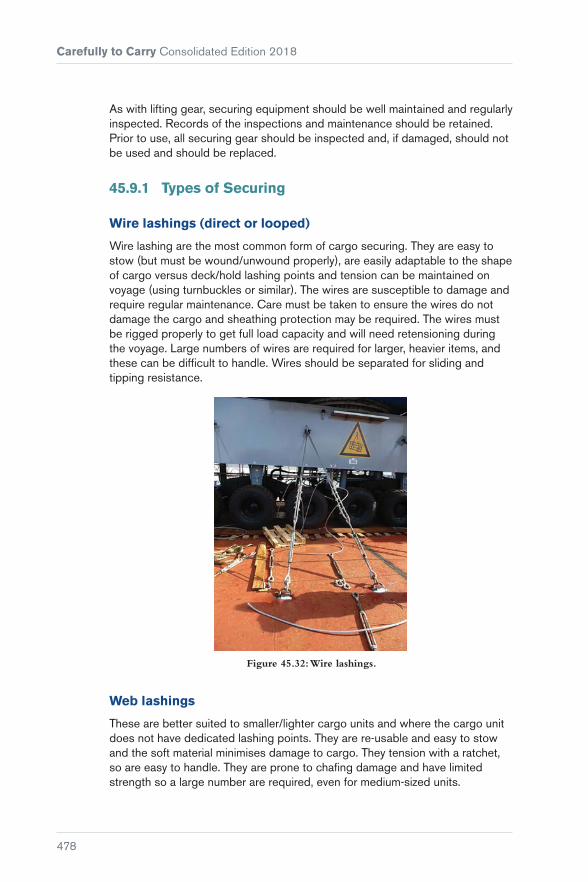
Carefully to Carry Consolidated Edition 2018
478
As with lifting gear, securing equipment should be well maintained and regularly inspected. Records of the inspections and maintenance should be retained. Prior to use, all securing gear should be inspected and, if damaged, should not be used and should be replaced.
45.9.1 Types of Securing
Wire lashings (direct or looped)
Wire lashing are the most common form of cargo securing. They are easy to stow (but must be wound/unwound properly), are easily adaptable to the shape of cargo versus deck/hold lashing points and tension can be maintained on voyage (using turnbuckles or similar). The wires are susceptible to damage and require regular maintenance. Care must be taken to ensure the wires do not damage the cargo and sheathing protection may be required. The wires must be rigged properly to get full load capacity and will need retensioning during the voyage. Large numbers of wires are required for larger, heavier items, and these can be difficult to handle. Wires should be separated for sliding and tipping resistance.
Figure 45.32: Wire lashings.
Web lashings
These are better suited to smaller/lighter cargo units and where the cargo unit does not have dedicated lashing points. They are re-usable and easy to stow and the soft material minimises damage to cargo. They tension with a ratchet, so are easy to handle. They are prone to chafing damage and have limited strength so a large number are required, even for medium-sized units.

Chapter 45 Heavy-lift and Project Cargoes
479
As a general rule, soft lashings will have their greatest effect if attached close to the plane of the centre of gravity of the item (subject to the structure of the item being able to withstand the motion forces expected) with the angle of the lashings as close as possible to 45° to the deck.
Figure 45.33: Web lashings may sometimes be used for smaller, lighter project cargoes, typically because they are cheaper than wires. However, they do not provide
the strength of wire lashings and are prone to chafing damage. Securing cargoes using web lashings as shown in the right-hand image will damage the webbing and
reduce its effectiveness.
Chains
These can provide higher strength capacity and require less maintenance than wires but are harder to handle and stow and difficult to keep taught. When using ratchet tensioners, the chain will loosen in steps (by link) rather than gradually, potentially resulting in loss of tension. They are suited to stronger securing points, with separate chains required for sliding and tipping resistance.
Figure 45.34: Lashing chains need to be properly tensioned and so need to be secured to appropriate securing points to enable the tension to be created. The
chains shown provide good tipping restraint but minimal sliding restraint, due to their high angle.

Carefully to Carry Consolidated Edition 2018
480
Sea-fastenings
These can include hard stoppers and braces, typically of steel construction and with welded connections to the decks. They can provide combined resistance to sliding and tipping and may be designed to resist very large forces. They are well suited to large, heavy units of non-uniform shape but require proper design and engineering. They will have a higher cost and time to construct and will need qualified welding contractors and non-destructive testing (NDT). Care is required to ensure that the vessel’s structure can withstand the imposed loads.
Figure 45.35: Sea-fastenings.
Dunnage, shoring
Wooden dunnage must be placed on the decks underneath the cargo to provide greater friction between the cargo and the deck and to assist load spreading. Dunnage is not used where the cargo unit sits on a grillage or similar, which is designed to spread the load, but may be used as shoring or bracing to help position and maintain the cargo unit.
The dunnage should be of good quality solid wood and not of plywood or similar. It should, ideally, be of horizontal grain (and not curved) to minimise the risk of splitting.
Figure 45.36: Wooden dunnage.
45.9.2 Securing Methods
The options for securing the cargo unit should be assessed and the most appropriate selected. This is typically undertaken by the charterers but is subject to the provisions of the charterparty. It is, therefore, important that each party understands their specific responsibilities. The Master should ensure

Chapter 45 Heavy-lift and Project Cargoes
481
that they are satisfied with the cargo securing and should note any defect or concern about the proposed arrangements.
Certain cargo types, particularly large heavy items or units that cannot absorb any stresses, will dictate that certain types of sea-fastenings are required and whether ‘hard’ or ‘soft’ sea-fastenings should be used.
Hard sea-fastenings include welded stoppers, braces, etc that are connected to the vessel’s decks and provide restraint of the cargo and spread loads into the surrounding structure of the vessel. Equally, if there is a direct connection (eg welded, pad-eye, etc) to the cargo unit, they may impart stresses on the vessel to the cargo unit. In particular, this can occur with cargo units of sufficient length that longitudinal bending and deflections of the vessel are imparted into the cargo unit. Careful design of the sea-fastenings is required to ensure that this is avoided or, if unavoidable, that the stresses imposed on the cargo are within the capacity of its own structure. Hard sea-fastenings will typically provide a greater restraining capacity and so are better suited to larger, heavier units.
Figure 45.37: Where cargo units may incur def lections due to the longitudinal bending of the vessel, the sea-fastenings must be carefully designed to minimise the loads imparted into the cargo unit. More complex sea-fastening designs are
required based on specialist expertise. It is, therefore, important that suff icient time is allowed in the project for the proper design process to be carried out.
Soft sea-fastenings include wires, straps, etc which provide some restraint, but also have some ‘give’. This ‘give’ is useful in avoiding the transfer of vessel stresses into the cargo unit, but also means that the tightness of the securing needs regular checking to ensure it does not come loose. Soft sea fastenings are generally cheaper and more convenient to use.
The design of the sea-fastenings must provide restraint against sliding and tipping in both transverse and longitudinal directions as well as against uplift. The design philosophy for the sea-fastenings should not mix hard and soft sea-fastenings in each mode of restraint, eg there should not be a mix for sliding or tipping restraint, although each can employ different methods such as hard for sliding and soft for tipping.
For soft restraints, the optimum angle for sliding restraint is about 25 degrees to the deck, while for tipping restraint, the optimum angle is about 45 to 60 degrees. Hard sea-fastenings should be designed considering all relevant forces and stresses (and not just one mode of force).

Carefully to Carry Consolidated Edition 2018
482
Bracing may need to be installed on the cargo unit to prevent distortion of the cargo unit under the loads experienced in a seaway. This is particular relevant for frameworks (eg modules for oil and gas installations) and large gantry cranes (eg container cranes, RTGs, etc).
Where welding is required to construct the sea-fastenings, it must be ensured that this is not over or against any fuel tanks and that hot work procedures are followed. The welding must be of a high standard and it is normally required that specialist, fully qualified welders are employed to complete the welding of sea-fastenings. The welds must be tested to ensure that there are no defects and non-destructive testing (NDT) inspectors are employed for this. The amount of NDT required varies, depending on the complexity and criticality of the project/cargo, but it is normally required that a minimum of 20% of all welds is required and, in some cases, 100% of all welds may be required. In addition to any NDT, there should always be a 100% visual inspection of all sea-fastening welds.
Figure 45.38: Examples of welds, showing very poor quality welding (top), a sea-fastening weld to the deck that failed the NDT inspection due to the presence of
weld cracks (middle) and a D-ring after NDT inspection that was passed (bottom).

Chapter 45 Heavy-lift and Project Cargoes
483
45.10 The Voyage
45.10.1 The Voyage Plan
The voyage plan should be critically assessed for the route, proximity to areas of navigation danger, exposure to weather conditions (duration and how open the area is and its effect on cargo stowage and securing) and areas of known piracy activity. Different criteria will apply for open ocean voyages, compared to sheltered voyages of limited duration. Consideration should be given to the use of weather routeing. Adequate fuel reserves should be maintained on board the vessel for the duration of the voyage. The usual recommended minimum reserve is 20% or 5 days’ fuel reserves.
The voyage route should include contingency plans in case of emergency events or forecasted weather exceeding the limits defined in the stowage and sea-fastening calculations. Ports and areas of refuge should be identified and should ideally be reachable within a reasonable accurate weather forecast time (usually 2 to 3 days’ sailing).
During the voyage, the stowage and securing of the cargo should be regularly checked (as far as safely possible) and any lashings tightened if they have loosened.
Where an MWS is involved, the vessel will be required to provide daily reports of voyage progress and a report on the condition of the cargo. This is usually a small addition to the normal reporting process for owners and charterers.
45.10.2 Voyage Reporting
An MWS may provide a certificate or letter of approval to confirm that the vessel can depart and that all procedures have been complied with. The certificate/letter may contain a number of recommendations that must also be complied with as a requirement of the warranty for the insurance policy. The recommendations will typically include limiting weather conditions for the voyage, the requirement to regularly check the sea-fastenings and reporting requirements.
A certificate or letter of approval may also be provided for critical operations such as heavy lifts or load-out/load-off.
It is important to keep records of the operations, both for log entries and future reference. It is recommended that the crew make notes of the operations as they progress and while on voyage. Handwritten notes (or crew’s notebooks) should be retained and, for more complicated cargoes, the notes should be extensive and represent a proactive approach.
Duty officers should be encouraged/instructed to take as many photos as possible, particularly during loading. Video clips of critical heavy-lift operations can also be taken. Photos and video clips are particularly helpful to investigators and experts in case of cargo loss or collapse, and could help protect interests in case of litigation.


485
Chapter 46
Agricultural Produce – Insect Infestation and Fumigation
Fumigant gases are poisonous to humans and should only be used by specialists, not by the ship’s crew.
Insects and mites of plant products may be found within cargo spaces as:
� Introduced infestation (carried on board with the produce)
� cross infestation (moved across from one product parcel to another)
� residual infestation (remaining on board from a prior infested cargo to attack subsequent cargo).
The principal method of treating cargo spaces or their contents for the control of insects is by fumigation, which is the application of an insecticidal chemical in its gas phase. The chemical can be applied as a gas, liquid or in solid formulation, but after vaporisation from liquids or reaction from solids, will always act in the gaseous phase. Fumigants act either as respiratory poisons, or as suffocants in the case of controlled or modified atmospheres. On release,

Carefully to Carry Consolidated Edition 2018
486
they mix with air at a molecular level and are capable of rapidly diffusing from one area to another and through commodities and buildings.
Fumigants should not be confused with smokes (which are solid particles in air) or with mists, aerosols or fogs (which are liquid droplets, of various sizes, in air). Smokes, mists, aerosols or fogs are not fumigants as they are unable to diffuse (ie they do not mix with air at a molecular level) and do not reach deep-seated infestations in commodities or structures.
The most common fumigant is phosphine (PH3), which is extremely toxic.
The effective and safe use of fumigants requires the space being treated to be rendered gastight for the period of exposure, which may vary from a few hours to several days, depending on the type of fumigant and concentration used, the pests, the commodities being treated and the ambient temperature.
The critical parameters that need to be considered for effective fumigation are:
� Nature of infestation (type of pest, eg rodent, insect or beetle, and stage of its life cycle)
� type of fumigant applied
� concentration and distribution of gas
� ambient temperature
� length of time fumigant must be applied
� method by which fumigant is administered
� containment of fumigant
� nature of commodity
� nature of commodity packaging
� monitoring system
� ventilation system.
46.1 Aim of Fumigation
The aim of fumigation is to create an environment that will contain an effective concentration of fumigant gas at a given temperature for a sufficient period of time to kill any live infestations. Both the time measured (hours or days) of exposure and the concentration of gas are critical to fumigation efficiency. Dosages applied are usually expressed as grams per cubic metre. Concentrations measured during the fumigation are usually expressed in parts per million (ppm) or grams per cubic metre, and total concentrations actually achieved as concentration time products (CTPs). The fumigation process is not completed until ventilation has been effectively carried out and removal of any residues is completed.

Chapter 46 Agricultural Produce – Insect Infestation and Fumigation
487
Evacuation of the space under gas treatment is essential and, in some cases, it will be necessary for the whole ship to be evacuated.
The Master will require the fumigator to provide written information on the type of fumigant to be used, to include the hazards involved, the threshold limit values (TLV) and the precautions to be taken.
The fumigation of cargoes with phosphine gas is by the use of tablets, pellets or solid preparations in other physical forms which are supplied by the manufacturers in hermetically-sealed containers. The active ingredient of these preparations is either aluminium phosphide or magnesium phosphide. These substances are highly reactive with water and, as the preparations are removed from their sealed containers, the active ingredient comes into contact with atmospheric water vapour and yields phosphine gas into the cargo space under fumigation. Phosphine is extremely toxic, so the crew evacuation procedures should apply. However, shippers or charterers frequently supply phosphine-releasing fumigants and request the Master to arrange for them to be applied to the cargo by the ship’s crew during the course (often towards the end) of the voyage. Such requests flagrantly contravene IMO recommendations.
As well as this serious issue (applying apparently different procedural standards to the fumigation of goods according to which fumigant is employed), two further important points should be made in relation to requests to fumigate the goods while on passage:
� To fulfil such a request, it would be necessary to open the weather-deck hatch covers while at sea to apply the fumigant and then to release and secure them. This may involve considerable risk and is contrary to good practice
� fumigation is incompatible with the need to ventilate the cargo as may be required by the prevailing climatic conditions. This will exacerbate ship’s sweat, if the prevailing conditions are conducive to its formation, and may lead to an adverse effect upon the cargo.
Reference should be made to the following IMO guidance:
� The IMDG Code (Reference 19)
� Revised Recommendations on the Safe Use of Pesticides in Ships (MSC.1/Circ.1358) (Reference 1)
� Recommendations on the Safe Use of Pesticides in Ships Applicable to the Fumigation of Cargo Holds (MSC.1/Circ.1264) (Reference 51)
� Recommendations on the Safe Use of Pesticides in Ships Applicable to the Fumigation of Cargo Transport Units (MSC.1/Circ.361) (Reference 52).
The relevant sections should be studied very carefully by Masters, always bearing in mind the following recommendations:
� Fumigation in transit should only be carried out at the discretion of the master

Carefully to Carry Consolidated Edition 2018
488
� In-ship in-transit fumigation with Methyl Bromide should not be carried out. Fumigation with Methyl Bromide should be permitted only when the ship is in the confines of a port (either at anchorage or alongside) ... once crew members have disembarked (Reference 51).
The IMO recommendations permit discretionary usage of phosphine in transit. It is possible that this has led to common misconception that phosphine gas is less toxic and that, consequently, non-specialists such as ships’ crew may apply phosphine-releasing preparations prior to or during a sea voyage. It must be clear that this belief is incorrect and potentially dangerous. Masters should never agree to requests for the ship’s crew to apply phosphine-releasing preparations in cargo spaces at any time, whether at sea or not.
46.2 Fumigation Continued in Transit
If fumigation that began in port is to be continued in transit, it is strongly recommended that the Master should possess, and familiarise himself with all relevant sections of, Recommendations on the Safe Use of Pesticides in Ships (Reference 1). This will enable him to make suitably informed decisions as to whether or not to allow fumigation to be continued in transit and, if such fumigation is allowed, to be aware of and to implement the appropriate safety precautions that should be taken before the ship leaves port and during the course of the voyage.
When specialists apply phosphine in port with a view to the fumigation being continued in transit, they usually install flexible pipework in stows to circulate the phosphine gas better throughout the stow. This provides more effective fumigation of deep stows than would be achieved by the fumigant being applied only to the surface of the stow with reliance being placed on diffusion alone to deliver the gas to the lower regions of the stow.
When the owners/charterers/Master agree to phosphine fumigation being carried out in transit, the Master should be clear as to the obligations of both the fumigator and the Master:
Fumigator
The fumigator provides written documentation in respect of the following:
� Pre-fumigation inspection certificate
� standard safety recommendations for vessels with fumigated grain cargoes
� gastightness statement
� statement of vessel suitability for fumigation and fumigant application compliance

Chapter 46 Agricultural Produce – Insect Infestation and Fumigation
489
� manufacturer’s information or safety data sheet
� first aid and medical treatment instructions
� fumigation certificate
� fumigation plan
� instructions for the use of the phosphine gas detecting equipment
� precautions and procedures during the voyage
� instructions for aeration and ventilation
� precautions and procedures during discharge.
Master
� Appoint a competent crew member to accompany the fumigator during the inspections/testing of empty holds prior to loading to determine whether they are gastight, or can be made gastight, and, if necessary, what work is to be carried out to ensure they are gastight
� ensure the crew is briefed on the fumigation process before fumigation takes place
� ensure the crew search the vessel thoroughly to ensure there are no stowaways or other unauthorised personnel on board before fumigation takes place
� appoint at least two members of the crew to be trained by the fumigator to act as representatives of the Master during the voyage to ensure safe conditions in respect of the fumigation are maintained on board during the voyage
� after the fumigant has been applied and appropriate tests have been completed, provide a representative to accompany the fumigator to check that all working spaces are free from harmful concentrations of gas
� when the fumigator has discharged his responsibilities, he should formally hand over in writing responsibility to the Master for maintaining safe conditions in all occupied areas, which the Master should accept
� it must be clearly understood by the Master that, even if no leakage of fumigant is detectable at the time of sailing, this does not mean that leakage will not occur at some point during the voyage due to the movement of the ship or due to other factors. This is why it is essential that the Master ensures that regular checks are carried out during the voyage
� during the voyage, the Master should ensure that regular checks for gas leakage are made throughout all occupied areas and the findings recorded in the ship’s log. If any leakage is detected, appropriate precautions to avoid any crew being exposed to harmful concentrations must be taken. If requested to do so by the fumigator, the Master may, prior to arrival at the first discharge port, start ventilation of the cargo spaces

Carefully to Carry Consolidated Edition 2018
490
� prior to arrival at the first discharge port, the Master should inform the authorities at the port that the cargo has been fumigated in transit
� on arrival at the discharge port, the Master should not allow discharge of the cargo to commence until he is satisfied that the cargo has been correctly ventilated, aluminium phosphide residues that can be removed have been removed and any other requirements of the discharge port have been met.
46.3 Compatibility between Fumigant and Cargo
It should be borne in mind that compatibility between the fumigant and the particular cargo being carried needs to be determined. Decisions on this point should be left to specialists. However, it should be noted that, while fumigants are suitable for many different cargoes, they are not suitable for all.
46.4 Charterparties
Charterparties may provide the charterer with an option to fumigate cargoes (usually cereal grains and oil seeds or similar agricultural produce) on board after loading has been completed. While it is convenient for the charterer or the shipper to fumigate cargoes on board instead of ashore, problems may well be experienced as a result of this practice. Before considering the most significant problems encountered, it is worth remembering that, although the goods may have been fumigated prior to loading, this will not mean they are free of all live insects. Insects in one or other of their metamorphic stages of development may still be present in the products because there is no permanence in any treatment against insects.
A standard sale contract usually requires cargoes such as cereal grains to be free from ‘live infestation’ at the time of shipment. However, rarely, if ever, will such a cargo be absolutely free from insects.
Although the terms of the contract of sale may only affect the relationship between the buyer and the seller, it makes little sense to expect a Master to adopt a standard that is at odds with the standards anticipated in standard forms of contract.
If the expectation of the standard contract of sale is that the goods should be ‘free’ of live infestation at the time of shipment but infestation is clearly apparent to the Master at that time, he is bound to conclude that the goods are not in apparent good order and condition.

Chapter 46 Agricultural Produce – Insect Infestation and Fumigation
491
If clearly infested goods are loaded on board, even though there is an intention to fumigate the goods upon completion of loading, it is advisable to clause the relevant mate’s receipts and B/Ls in terms similar to the following:
“Some live insects detected at the time of shipment on board; cargo to be fumigated by shippers/charterers at their risk and expense upon completion of loading.”
If the charterer intends to have the goods fumigated on board, it is also advisable to make a suitable provision in the charterparty in terms similar to the following:
“Charterers shall indemnify the owners in respect of any and all claims of whatsoever nature howsoever arising as a consequence of any infestation of the cargo at the time of shipment on board the vessel and/or the presence of dead insects in the cargo following the fumigation thereof.”
Regulations applying in some countries will only allow the presence of limited numbers of dead insects in imported goods. In such circumstances, sale contracts will be draughted to reflect these limitations. However, the fumigation of goods on board anticipates a residue of dead insects remaining within the cargo following the fumigation and it is, therefore, doubtful whether the issuance of clean B/Ls in such circumstances can be justified.
The Master may be told by a representative of the shipper or charterer that the presence of live insects in agricultural produce is quite normal, and that any insects present will be killed during the fumigation process on board after the completion of loading. This is usually the basis of the request for clean B/Ls, notwithstanding the visible presence of insects at the time of shipment. It is, therefore, important to consider this point further.
46.5 Recommendations on the Safe Use of Pesticides in Ships
IMO Circular MSC.1/Circ.1358 covers the use of insecticide sprays, smokes and gaseous fumigants, and it is recommended that it is carried on board all dry cargo ships (Reference 1). The former two treatments can be used effectively on clean empty holds. However, the eradication of either insect infestation or rodents in loaded holds can only be effected with fumigant gas treatment.
Owners’ and Masters’ attention is drawn specifically to the following sections:
3.1.1.2
“The success of chemical treatments does not tie wholly in the pesticidal activity of the agents used. In addition, an appreciation of the requirements and limitations of the different available methods is required. Crew members can carry out small-scale or ‘spot’ treatments if they adhere to the manufacturer’s instructions and take care to cover the whole area of infestation. However, extensive or hazardous treatments including fumigation and spraying near human and animal food should be placed in the hands of

Carefully to Carry Consolidated Edition 2018
492
professional operators, who should inform the master of the identity of the active ingredients used, the hazards involved and the precautions to be taken.”
When a cargo or empty vessel is to be treated with gaseous fumigation, the following requirement must be observed:
3.1.3.4
“A ‘fumigator-in-charge’ should be designated by the fumigation company, government agency or appropriate authority. He should be able to provide documentation to the master proving his competence and authorization. The master should be provided with written instructions by the fumigator-in-charge on the type of fumigant used, the hazards involved, and the precautions to be taken, and in view of the highly toxic nature of all commonly used fumigants these should be followed carefully. Such instructions should be written in a language readily understood by the master or his representative.”
Fumigation in port is covered in Section 3.1.4, and particularly important sections are:
3.1.4.1
“Fumigation and aeration (ventilation) of spaces on board a ship should always be carried out in port (alongside or at anchorage). Ships should not be permitted to leave port until gas-free certification has been received from the fumigator-in-charge.”
3.1.4.2
“Prior to the application of fumigants to spaces, the crew should be landed and remain ashore until the ship is certified ‘gas-free’, in writing, by the fumigator-in-charge or other authorized person. During this period a watchman should be posted to prevent unauthorized boarding or entry, and warning notices should be prominently displayed at gangways and at entrances to accommodation.”
3.1.4.3
“The fumigator-in-charge should be retained throughout the fumigation period and until such time as the ship is declared gas-free.”
3.1.4.5
“The fumigator-in-charge should notify the master in writing of any spaces determined to be safe for re-occupancy by essential crew members prior to the aeration of the ship.”
It is common practice to fumigate ships, both empty and loaded, with crew still on board and in some instances this requirement is incorporated in

Chapter 46 Agricultural Produce – Insect Infestation and Fumigation
493
charterparties. However, in some ports, the authorities will not allow fumigation with crew on board. While evacuation of crew provides the safest option, if a Master is prepared or required to allow fumigation with crew on board, it is imperative that he is satisfied that the fumigator-in-charge is equipped with proper gas detection and measuring equipment for the fumigant gas being employed. When Draeger tubes are used, the Master should ensure that adequate tubes are available, bearing in mind that each measurement requires the use of a separate tube. The Master should also insist that the fumigator-in-charge remains on board throughout the whole operation, ie from initial closing to completion of ventilation and the issue of a gas-free certificate. The Master should also be satisfied that the fumigator-in-charge regularly checks for gas leakages in areas where crew may be working or resting.
MSC.1/Circ.1264 covers in-transit fumigation, which is now a fairly common practice, particularly for bulk cargoes of agricultural products. With this type of operation, the Master is responsible for the safety of all on board his ship.
3.3.2
“Fumigation continued in transit”
3.3.2.1
“Fumigation in transit should only be carried out at the discretion of the master. This should be clearly understood by owners, charterers, and all other parties involved when considering the transport of cargoes that may be infested. Due consideration should be taken of this when assessing the options of fumigation. The master should be aware of the regulations of the flag State Administration with regard to in-transit fumigation. The application of the process should be with the agreement of the port State Administration. The process may be considered under two headings:
.1 fumigation in which treatment is intentionally continued in a sealed space during a voyage and in which no aeration has taken place before sailing; and
.2 in-port cargo fumigation where some aeration is carried out before sailing, but where a clearance certificate for the cargo hold(s) cannot be issued because of residual gas and the cargo hold(s) has been re-sealed before sailing.”
3.3.2.2
“Before a decision on sailing with a fumigated cargo hold(s) is made it should be taken into account that, due to operational conditions, the circumstances outlined in 3.3.2.1.2 may arise unintentionally, eg a ship may be required

Carefully to Carry Consolidated Edition 2018
494
to sail at a time earlier than anticipated when the fumigation was started. In such circumstances the potential hazards may be as great as with a planned in-transit fumigation and all the precautions in the following paragraphs should be observed.”
3.3.2.3
“Before a decision is made as to whether a fumigation treatment planned to be commenced in port and continued at sea should be carried out, special precautions are necessary. These include the following:
.1 at least two members of the crew (including one officer) who have received appropriate training (see 3.3.2.6) should be designated as the trained representatives of the master responsible for ensuring that safe conditions in accommodation, engine-room and other working spaces are maintained after the fumigator-in-charge has handed over that responsibility to the master (see 3.3.2.12); and
.2 the trained representatives of the master should brief the crew before a fumigation takes place and satisfy the fumigator-in-charge that this has been done.”
3.3.2.4
“Empty cargo holds are to be inspected and/or tested for leakage with instruments so that proper sealing can be done before or after loading. The fumigator-in-charge, accompanied by a trained representative of the master or a competent person, should determine whether the cargo holds to be treated are or can be made sufficiently gastight to prevent leakage of the fumigant to the accommodation, engine-rooms and other working spaces in the ship. Special attention should be paid to potential problem areas such as bilge and cargo line systems. On completion of such inspection and/or test, the fumigator-in-charge should supply to the master for his retention a signed statement that the inspection and/or test has been performed, what provisions have been made and that the cargo holds are or can be made satisfactory for fumigation. Whenever a cargo hold is found not to be sufficiently gastight, the fumigator-in-charge should issue a signed statement to the master and the other parties involved.”
3.3.2.5
“Accommodation, engine-rooms, areas designated for use in navigation of the ship, frequently visited working areas and stores, such as the forecastle head spaces, adjacent to cargo holds being subject to fumigation in transit should be treated in accordance with the provisions of 3.3.2.13. Special attention should be paid to gas concentration safety checks in problem areas referred to in 3.3.2.4.”

Chapter 46 Agricultural Produce – Insect Infestation and Fumigation
495
3.3.2.6
“The trained representatives of the master designated in 3.3.2.3 should be provided and be familiar with:
.1 the information in the relevant Safety Data Sheet; and
.2 the instructions for use, eg on the fumigant label or package itself, such as the recommendations of the fumigant manufacturer concerning methods of detection of the fumigant in air, its behaviour and hazardous properties, symptoms of poisoning, relevant first aid and special medical treatment and emergency procedures.”
3.3.2.7
“The ship should carry:
.1 gas-detection equipment and adequate fresh supplies of service items for the fumigant(s) concerned as required by 3.3.2.12, together with instructions for its use and the occupational exposure limit values set by the flag State regulations for safe working conditions;
.2 instructions on disposal of residual fumigant material;
.3 at least four sets of adequate respiratory protective equipment; and
.4 a copy of the latest version of the Medical First Aid Guide for Use in Accidents Involving Dangerous Goods (MFAG), including appropriate medicines and medical equipment.”
3.3.2.12
“Upon discharging his agreed responsibilities, the fumigator-in-charge should formally hand over to the master in writing responsibility for maintaining safe conditions in all occupied spaces. The fumigator-in-charge should ensure that gas-detection and respiratory protection equipment carried on the ship is in good order, and that adequate fresh supplies of consumable items are available to allow sampling as required in 3.3.2.13.”
3.3.2.13
“Gas concentration safety checks at all appropriate locations, which should at least include the spaces as indicated in 3.3.2.5, should be continued throughout the voyage at least at eight-hour intervals or more frequently if so advised by the fumigator-in-charge. These readings should be recorded in the ship’s log-book.”
It has been noted that some fumigations are unsatisfactory due to three basic causes:
� Excessively heavy infestation or infestation with fumigant-resistant strains of various insect species

Carefully to Carry Consolidated Edition 2018
496
� inadequate initial dosing
� insufficient time allowed for total penetration of the fumigant gas.
It is impossible for Masters to have sufficient expertise to be able to decide whether a proposed fumigation operation should prove satisfactory. Although it is possible to obtain expert advice on this matter, it is difficult for anyone to advise other than in general terms when they have not seen either the ship or the cargo. It is the fumigators’ duty to perform proper fumigation and, if they are employed by shippers or charterers, it is the latter’s duty to ensure that the fumigators are competent. However, to safeguard the shipowner’s position, the Master must insist on receiving a certificate of fumigation from the fumigators which states:
� The fumigant used
� the dose level in terms of weight of fumigant per volume of hold, eg lb/1,000 ft3
� the dates and times when fumigation commenced and ceased (ie when either ventilation fans were turned on or hatches were opened, whichever was the earlier).
If insects and/or mites are observed in or on any cargo, it is helpful to take specimens, transfer them to a small bottle with a secure closure, such as an aspirin bottle, and place it in a refrigerator. The specimens can be supplied to experts at a later date if there are complaints at the time of discharge.
If heavy infestation is observed, surveyors should be instructed to draw substantial samples of affected cargo (1 kg lots), which should be sealed and refrigerated pending expert examination to determine the level and nature of the infestation.
Shipowners are particularly warned that receivers in certain countries, particularly in the Middle East, may reject cargo, with the backing of their government authorities, if minimal live infestation is detected or even if the cargo is contaminated with a very small quantity of dead insect residues. It follows that, if a Master detects any insect infestation when cargoes are being loaded for Syria, Egypt and some other eastern Mediterranean countries, he should inform the shipowners immediately so they may seek advice from the Club.
46.6 Fumigation of Bulk and Bagged Cargo with Ventilation in Port
This procedure can be used either after loading and prior to sailing or on arrival at the discharge port prior to discharging.

Chapter 46 Agricultural Produce – Insect Infestation and Fumigation
497
After loading and prior to sailing
Phosphine fumigation and ventilation in port, prior to sailing, will normally take from 1 to 2 weeks to complete and therefore is only occasionally specified. All procedures as for in-transit fumigation should be followed to ensure safe and effective fumigation.
At discharge port prior to discharge
The crew should be landed and remain ashore until the ship is certified gas-free in writing by the fumigator-in-charge. The fumigator is responsible for the safety and efficiency of the fumigation, but crew members may remain in attendance to ensure the safety of the ship provided they adhere to safety instructions issued by the fumigator-in-charge.
The ventilation of fumigant from cargoes can be a very slow process if sufficiently powerful ventilation is not available. The Master (or his representative) should ensure that the fumigator has ensured that residues of gas are below the TLV (IMO Recommendations, Annex 2) throughout all parts of the cargo and holds. Phosphine fumigation and ventilation in port, prior to discharge, will normally take from 1 to 2 weeks to complete and therefore it is only occasionally specified. All procedures as for in-transit fumigation should be followed to ensure safe and effective fumigation.
46.7 In-transit Fumigation of Freight Containers
Fumigation of containers is normally undertaken to ensure that, when the goods arrive at the discharge port, they are free from live pests/insects.
Containers are normally fumigated and then ventilated prior to being loaded on board the ship. Containers that have been fumigated and ventilated, and where a ‘certificate of freedom from harmful concentration of gas’ has been issued, can be loaded on board ships as if they had not been fumigated.
Frequently, containers are fumigated but not ventilated prior to loading and these containers are therefore fumigated in-transit, as the ventilation process will not take place until after they have been discharged from the ship. The carriage of containers in-transit under fumigation is covered by the IMDG Code (Reference 19) whereby these containers are classified in Section 3.2, Dangerous Goods List as Fumigated Cargo Transport Unit Class 9 UN 3359. Reference should also be made to the IMDG Code Supplement Sections 3.5.1 and 3.5.2 of the chapter entitled Safe use of pesticides in ships.

Carefully to Carry Consolidated Edition 2018
498
WARNING – Containers are sometimes shipped under fumigation with no warning notices attached and no accompanying documentation stating they have been fumigated. This process is in direct contravention of the IMDG Code. There may be dangerous levels of fumigant gas inside the container when it arrives at its destination, which is both illegal and dangerous.
Obligations on the fumigator
� The fumigator must ensure that, as far as is practicable, the container is made gastight before the fumigant is applied
� the fumigator must ensure that the containers are clearly marked with appropriate warning signs stating the type of fumigant used and the date applied and all other details as required by the IMDG Code and IMO Recommendations in Annex 3
� the fumigator must ensure that the agreed formulation of fumigant is used at the correct dosage to comply with the contractual requirements.
Obligations on the exporter
� The exporter must ensure that the containers are clearly marked by the fumigator with appropriate warning signs stating the type of fumigant used and the date applied and all other details as required by the IMDG Code and IMO Recommendations in Annex 3
� the exporter must ensure that the Master is informed of the fumigation prior to the loading of the containers
� the exporter must ensure that shipping documents show the date of fumigation, the type of fumigant and the amount used all as required in the IMDG Code, Volume 1, page 35 and specifically Section 9.9.
Obligations on the Master
� The Master must ensure that he knows where containers under fumigation are stowed
� the Master must ensure availability of suitable gas detection equipment on board for the types of fumigant present, and that instructions for the use of the equipment have been received
� prior to arrival of the vessel at the discharge port, the Master should inform the authorities at the discharge point that the vessel is carrying containers under fumigation

Chapter 46 Agricultural Produce – Insect Infestation and Fumigation
499
� if the Master (or his representative) suspects that unmarked containers may have been fumigated and loaded on board, he should take suitable precautions and report his suspicions to the authorities prior to arrival at the discharge port.
Obligations on the receivers
� The receiver (or his agent) must ensure that any fumigant residues are removed and the container checked and certificated as being free from harmful concentrations of fumigant by a suitably qualified person before the cargo in the container is removed.
46.8 Phosphine Methodologies
The various methods of phosphine application that can be considered for in-transit fumigation of bulk or bagged cargoes in ships’ holds include the following. The actual method to be used will be specified by an expert.
1. Application of tablets or pellets to the cargo surface (or into the top half metre).
High concentrations of gas build up in the headspace, potentially resulting in a lot of leakage through the hatch covers unless these are very well sealed. There is very little penetration down into the cargo and powdery residues cannot be removed. This method produces a good kill of insects in the top part of the cargo but has negligible effect on eggs or juveniles or even adults in the lower part of the cargo.
2. Application of tablets or pellets by probing into the cargo a few metres.
There is less loss of gas through hatch covers than in method 1 and better penetration of gas than when applied on the surface only. However, it is unlikely to be fully effective unless holds are relatively shallow and voyage time relatively long. Powdery residues cannot be removed.
3. Application of tablets or pellets by deep probing into the full depth of the cargo.
This is difficult to achieve and currently practically impossible if the cargo is more than 10 metres deep. However, it ensures effective fumigation provided voyage time is long enough to allow gas to distribute. Powdery residues cannot be removed.
4. Application of aluminium phosphide in blankets, sachets or sleeves placed on the surface of the cargo (or into the top half metre).
All points are the same as for method 1, except that, with this method, powdery residues can be removed prior to discharge.
5. Application of tablets or pellets by probing into the cargo a few metres in retrievable sleeves.

Carefully to Carry Consolidated Edition 2018
500
All points are the same as for method 2, except that, with this method, powdery residues can be removed prior to discharge.
6. Fitting of an enclosed, powered recirculation system to the hold and application of aluminium phosphide tablets or pellets to the surface.
This method will ensure the gas is distributed throughout the cargo evenly and rapidly making maximum use of the fumigant in the shortest possible time. Powdery residues cannot be removed.
7. Fitting of an enclosed, powered recirculation system to the hold and application of aluminium phosphide in blankets, sachets or sleeves on the surface or probed into the top one or two metres.
All point are the same as for method 6, except that, with this method, powdery residues can be removed. Also, gaseous residues can be removed more easily than with other methods as, once the powdery residues have been removed, the recirculation system can be used to assist this to happen rapidly.
8. Deep probing into the full depth of the cargo (however deep) with tablets or pellets (in retrievable sleeves when required).
This method is being developed in Canada but is not yet available. Deep probing could also utilise pre-inserted pipes. It will enable good distribution of gas to be achieved without the requirement for a powered recirculation system, provided the voyage is long enough.
9. Use of powered recirculation system with phosphine from cylinders.
This method is not yet available but could be in the future and will enable phosphine fumigation to be carried out without using aluminium phosphide. This will mean no powdery residues to deal with and therefore residue and safety problems at the discharge port will be minimised. A powered recirculation system will be needed to enable this system to work with maximum efficacy.

501
Chapter 47
Fishmeal Cargoes – Self-Heating and Fires
If an insufficient quantity of antioxidant is added to fishmeal products at the time of production, oxidation will start at some stage. This can result in carbonisation and/or fire.
Fishmeal products manufactured from oily fish, which are principally anchovies and sardines, normally contain about 8–10% fish oil unless specially defatted. The standard products are classified as hazardous cargoes and are included in the IMDG Code (Reference 19) in Class 4.2 (Spontaneously Combustible) or Class 9 (Miscellaneous Dangerous Substances) UN numbers 1374 and 2216.
The original fishmeal trade involved products now falling into the Class 4.2 category. The basic requirements for the carriage of cargo of this type were that it was bagged and aged, for a period of not less than 28 days, between production and loading on the carrying ship. Stowage was by the double strip stow method, where the bags were stowed longitudinally in the cargo spaces with transverse channels every two bags. Cargo stowed in this way was to be ventilated throughout a voyage, weather permitting. There were also

Carefully to Carry Consolidated Edition 2018
502
requirements in terms of maximum oil content, maximum and minimum moisture contents and temperature at the time of loading. Strict adherence to these conditions permitted generally uneventful carriage of fishmeal over protracted voyages. However, the stowage requirements resulted in a high stowage factor and were expensive in both labour and materials (dunnage).
It has been known for many years that heating of fishmeal to the point of fire is due to aerial oxidation of reactive chemical sites on fish oil molecules. All oxidation reactions are associated with the production of heat, so in the double ship stow the most reactive material was oxidised during the aging process and the residual oxidisable material reacted with atmospheric oxygen at a rate at which the heat produced could be removed by ventilating air.
Certain shipowners approached the problem of reducing the rate of oxidation by using inert gas. Special ships were built, which were equipped with onboard inert gas producing equipment similar to that used on tankers and with hatch cover systems that were substantially airtight. This system works satisfactorily provided the number of load and discharge ports served on a single voyage is limited. However, each time a hatch cover is opened, part of the inert atmosphere is replaced by air and the inerting operation must be repeated when the hatches are closed.
The fishmeal industry sought to resolve the problem by modifying the product to render it inert or less susceptible to oxidation. This was achieved by the addition of antioxidant during the production of the meal. Fishmeal treated with antioxidant was included under Class 9 in the IMDG Code (Reference 19). Antioxidant-treated oily fishmeal, conforming to the requirements of the Code, can be carried either as a bulk cargo or in bags in block stow. This has permitted relaxation of both stowage and ventilation requirements during ocean carriage. Introduction of antioxidant-treated fishmeal on a large scale roughly coincided with drastic fall in the annual production of fishmeal on the west coast of South America. However, sufficient cargo was shipped for it to be apparent that the process could provide a stable product for carriage in bulk or block stow.
Fishmeal is produced by cooking the fish and extracting oil and aqueous fluids mechanically. The cake that is produced is then dried and milled. The milled meal is cooled and treated with antioxidant (ethoxyquin), usually by spraying the meal as it passes through a trough.
Heating of fishmeal is due to atmospheric oxidation, but the chemical process is complex and involves a series of reactions. The amount of heat produced by these reactions varies and those producing most energy are those towards the end of the series. Antioxidant stops the reaction chain before these later reactions can occur.
Antioxidant is used up as treated fishmeal ages. If an insufficient quantity is added at the time of production, it will be used up before the condition of the fishmeal has been stabilised. As a result, and at some stage after production, oxidation will start, producing substantial quantities of heat and the risk of

Chapter 47 Fishmeal Cargoes – Self-Heating and Fires
503
a serious rise in temperature in the affected meal. However, this will not be evident until some time after loading. This was the case in shipments from both Chile and Peru during the 1980s.
When serious heating occurs, it can result in carbonisation and/or fire. Many small isolated pockets of bags may be involved. Incident investigations have identified these pockets in regions of maximum ventilation and also in the interiors of large block stows, and it follows that the primary cause is the intrinsic reactivity of the contents of a few bags rather than unsuitable stowage or ventilation.
47.1 Bagged Fishmeal
Bagged fishmeal presents the majority of problems.
47.1.1 Documentation
The Master should have on board a copy of the latest edition of the IMDG Code (Reference 19), which includes entries for unstabilised fishmeal and for stabilised (ie antioxidant treated) fishmeal. The Master should also have a copy of the International Maritime Solid Bulk Cargoes Code (IMSBC Code) (Reference 17), where there is an entry for stabilised fishmeal.
The Master must obtain and retain certificates for antioxidant-treated fishmeal, as required by the Code, covering all the cargo loaded. These certificates should include all the information required and figures given should conform with the requirements set out in the special provisions in Volume 2 of the Code.
Since deregulation of the fishmeal trade in Peru, certificates may be issued by a person or company recognised by the Government of Peru, the competent authority. Certificates for Chilean fishmeal, which very rarely gives problems, are issued by the IFOP.
47.1.2 Action to be Taken by the Ship or Surveyors Acting for the Ship During Loading
The temperature of the contents of as many bags as possible should be measured. Where these do not comply with the requirements under the Code, the relevant bags must be rejected. If high temperatures are observed, it may be necessary to stop loading the relevant parcel to allow more extensive temperature checking. Any wet, water-stained or caked bags should be rejected. It may be difficult to detect staining when fishmeal cargoes are packed in black woven polypropylene bags, so it may be necessary when such staining is observed to slow or suspend loading to allow a proper examination. Torn bags should also be rejected.

Carefully to Carry Consolidated Edition 2018
504
47.1.3 Stowage
Standard stowage practice for bagged cargoes should be adopted, ie use of double dunnage on decks and tank tops and provision of a spar ceiling or adequate dunnage to prevent the cargo coming into contact with the ship’s sides, pipes and bulkheads, particularly those that are liable to become heated.
Details of stowage precautions for fishmeal can be found in the IMDG Code (Reference 19). For UN 1374 fishmeal, where loose bags are carried, double strip stowage is recommended provided there is good surface and through ventilation. For UN 2216 fishmeal, where loose bags are carried, no special ventilation is required for block stowages (IMDG Code). Flammable materials, such as paint, should be removed from store rooms immediately above or adjacent to cargo spaces loaded with bagged fishmeal.
47.2 Installation and Operation of Temperature Sensors
The IMSBC Code (Reference 17) requires that the temperature of cargo in each hold is monitored throughout the voyage. This can only be satisfactorily performed by the installation of remote reading sensors that are normally connected to a switch box that also has a connection for a read out meter. The installation is usually carried out by a specialist survey organisation employed by the shippers or charterers. The Committee specifically recommends that installation is not performed by the ship’s crew as they should be solely engaged in observing loading operations. It is common to install sensors at two or three levels in a lower hold and one or two levels on a tween deck, depending on the depths of the relevant spaces. Between four and eight sensors are distributed at each level, depending on the cross-sectional area of the cargo spaces.
The Master should obtain a drawing from the installation operator indicating the locations of sensors in each cargo space. At completion of loading, once all sensors have been installed, the Master or chief officer should check the temperature as indicated by each sensor, in the presence of the installation operator. This will ensure that the ship’s command is conversant with the equipment. It will also show whether each sensor is functioning correctly.
Abnormally high or low figures will indicate malfunction from the outset of the voyage. At this stage, it is impractical to replace sensors and such an operation should not be attempted. The installation operator should be asked to sign the entry covering the first set of recordings, which should be entered, as read, in a book. Subsequently, the figures for each sensor should be read and recorded in the book each watch for the first few days of the voyage. If they are more or less stable, they may subsequently be read at eight-hourly intervals, as required under Carriage in the IMSBC Code (Reference 17). If some temperatures in a space start to rise, temperature reading should revert to four-hourly intervals for all sensors in the space.

Chapter 47 Fishmeal Cargoes – Self-Heating and Fires
505
From experience, it is known that there can be some increase in temperature at the outset of a voyage (possibly up to 34°C) as recorded from some sensors, after which the temperature stabilises. This situation need not give rise to concern. If, however, the temperature of one or more sensors exceeds 40°C and continues to rise, the Master should take steps to seal the relevant hatch covers using sealing tape and, if necessary, plastic or foam sealant or cement. Consideration should be given at this stage to sealing ventilation openings. Owners and charterers should be informed of the temperature figures and their advice/instructions sought. Members of the Committee are, on occasions, requested to advise owners or charterers when this situation arises and advice is normally given on the temperature trends over a time period. Therefore, when a Master is forwarding information, he should ensure it is clear and the temperature figures for each cargo space are always reported in the same sequence.
In any event, the instructions under Ventilation in the IMSBC Code (Reference 17) should be followed, ie if any temperature sensors indicate a cargo temperature in excess of 55°C, the cargo space and any interconnecting cargo space should be sealed effectively and ventilation restricted. If self-heating continues, CO2 or inert gas should be injected as stipulated in the fire-fighting manual provided by the installers of the system. The injection should take place slowly over a 24-hour period. It is undesirable to inject less gas than is recommended in the manual, even though this means that only a few cargo spaces can be so treated.
It should be appreciated that any cargo heating results from an oxidation process. This means that the oxygen concentration in a hold is depleted and the concentration of nitrogen (an inert gas) increases. Therefore, in a sealed hold, cargo heating tends to be self-quenching.
It is of paramount importance that the Master has all necessary materials on board to allow very efficient sealing of cargo spaces to minimise atmospheric interchange. Efficient sealing may be a time-consuming operation, but should never be skimped.
Technically, provided that hold sealing is adequate, it would be possible for a ship with cargo heating in all her holds, to sail safely with her CO2 supply exhausted (assuming a sufficient reserve for the engine room). However, such an action would only be recommended if sealing efficiency could be guaranteed. Under normal circumstances, where there is obvious progressive heating, a ship would be recommended to go to a port of refuge to obtain adequate CO2 supplies. This often involves fitting a bulk tank containing several tonnes of CO2. If considered necessary, further sealing should be performed while the ship remains in port.
Unless special circumstances prevail, sealed hatch covers should not be opened until the first discharge port for that hold is reached.
Carefully to Carry Consolidated Edition 2018
506
An accurate assessment of the situation in any cargo space can be obtained by measuring the oxygen concentration via a pipe connected to an oxygen meter, which is introduced ideally via dedicated points of access or alternatively by slightly opening an access manhole. The manhole should be closed and secured immediately after measurements have been taken. Although some ships have oxygen meters on board and have crew conversant with their use, it is generally recommended that, where possible, measurements of oxygen levels are made by surveyors. If they are made by the ship, the instrument should be checked immediately before use by checking the oxygen concentration of the external atmosphere (20.8%). When oxygen levels are below 10%, heating is greatly restricted. Even without the use of CO2, this situation may be achieved in a few days where hatches are effectively sealed and there is a substantial quantity of cargo heating in a hold.
47.3 Discharge
Heating cargoes (if any) should be discharged first. However, where this is not practicable, the rate of spread of heating in a cargo space can be drastically reduced by maintaining a low oxygen concentration. This is preferably by the use of CO2 or, when supplies are not available, by keeping the holds sealed. It must be appreciated, however, that once the holds are opened for discharge and the oxygen concentration is allowed to rise to at least 20.8%, which is necessary for safe working in the hold, heating will resume at an accelerating rate. Therefore, attempts should be made to discharge pockets of heating cargo as soon as possible. On some occasions, this can be achieved without difficulty. However, on occasions, smoke generation becomes excessive, preventing manual operations. There are several options for dealing with this problem and the choice depends on the circumstances prevailing.
The first option is to reseal the hold and inject CO2, the minimum quantity injected being that recommended by the installers of the ship’s CO2 system. Again, this operation should take place over a 24-hour period. The hold should then be left sealed for at least four days. The oxygen concentration must again be allowed to rise to 20.8% before personnel are allowed into the space to resume discharge. This option, when successful, results in the minimum amount of cargo damage but extends the discharging period. It may be considered impractical if it has to be repeated several times.
The second option is to control smoke evolution by the use of water applied through a fine spray directly onto the smoking cargo, while discharge proceeds. This procedure, if properly used, results in limited water damage to part of the cargo. However, excessive water is often applied, particularly when the local fire service intervenes, and the amount of cargo wetted can then be substantial.
The third and last option, which should only be used when other methods have failed, is to use a water spray to control smoke evolution or fire and discharge heating pockets by grab. The procedure obviously results in more cargo damage.

Chapter 47 Fishmeal Cargoes – Self-Heating and Fires
507
If the cargo ignites, the f lames should be extinguished with a water spray. Fires in fishmeal may ignite f lammable cargo in adjacent spaces with disastrous results. It is reiterated that f lammable materials should not be stored in storerooms adjacent to or above holds loaded with fishmeal.
Damaged and apparently sound cargo should always be separated at the time of discharge. However, even badly heated cargo has feed value and can be incorporated in cattle feed. Therefore, cargo should never be left on board to be dumped at sea.
47.4 Bagged Fishmeal Carried in Containers
Bagged stabilised fishmeal (ie UN 2216, Class 9) may be carried in freight containers as indicated in Volume 1 of the IMDG Code (Reference 19). Containers will usually be delivered alongside already sealed. However, if the Master is in a position to see the containers being stuffed, he should ensure that they are clean and that the maximum quantity of bags are placed in each container. In any event, the Master should ensure that the container doors and other openings are properly tape-sealed to minimise possible air ingress.
On the voyage, the temperature of the outsides of containers, if stowed in accessible positions, should be checked regularly by feeling them, in any event as indicated in Volume 1 of the IMDG Code: “Temperature readings in the hold should be taken once a day early in the morning during the voyage and recorded”. If any container becomes hot, it should be cooled using water; “... consequent risk to the stability of the ship should be considered.” If smoke is seen issuing from a container, a hole should be punched in the side at the top of the container, a hose nozzle fitted and the container flooded.
Masters must ensure there is reasonable access to any containers stowed under deck.


509
Chapter 48
Palletised Cargoes
Wooden pallets are used extensively for the transportation of cargo, both in containers and in conventional breakbulk seagoing ships. Palletising of cargo helps to speed up cargo handling operations by consolidating merchandise into units that can be easily and rapidly handled. Both the efficiency and the reliability of the system depend upon the quality of the construction of the pallet and on the measures taken to protect the goods and to secure them in place.
Care should be taken not to stow pallets of inadequate construction as this is likely to lead to widespread collapse of the stow and damage to the cargo.
When pallets were first introduced into the trade, they were generally of robust construction. As experience was gained, it was found necessary to secure the goods adequately to the pallet by means of metal strapping bands and to protect them by providing a covering.
Nearly all palletised cargoes are received directly from the producers/manufacturers of the goods, and shippers and shipowners should appreciate that, while pallets may appear to be adequate when stacked ashore in a warehouse, they must be strong enough to be transported to the docks, unloaded, picked up by forklift trucks, carried over uneven surfaces and finally loaded on board ship.

Carefully to Carry Consolidated Edition 2018
510
There are formal recommendations covering the design, construction and strength of pallets. These are set out in ISO 6780:2003 (Reference 79). Some freight conferences specify the standards they require to ensure that a pallet will be capable of handling its proper load adequately and supporting four tiers of similar pallets.
Flimsy pallets, constructed from soft wood and designed for storage of lightweight cargo in warehouses, are sometimes presented for loading onto ships. They may be dangerously overloaded and unable to withstand the rigours of an ocean voyage or stevedoring operations. In some cases, where the design is adequate, the materials used and the standards of workmanship are poor.
Experience shows that little consideration is given to whether the strength of the pallet matches the weight of the goods it is to carry. Often, the dimensions do not match, with the result that bags or cartons project beyond the edges of the platform. Frequently, the merchandise is badly stacked or badly secured and is in danger of shifting.
Other inadequacies relate to the methods of securing goods to the pallets. One mechanism is the shrink plastic cover, which is applied by placing a large piece of plastic over the stack of cartons or bags on the pallet and then applying heat at the folds to shrink the plastic onto the load. Many shippers mistakenly consider that this affords adequate packing and protection and frequently, when a shrink plastic cover has been applied and extended downwards to embrace the pallet, a load of substantial weight may be mistakenly considered to be secured. If the load is secured to the pallet by any other means, this is often in the form of weak, flimsy plastic strapping that stretches easily. Subsequently, during the various stages of transportation and as a result of the jolts, jars and tilting that are experienced, pallets quite commonly break or even fall to pieces, or loads become lopsided and unstable and sometimes fall off, ending as damaged breakbulk cargo.
The method of handling pallets within dock areas may also leave something to be desired. Where forklift trucks are utilised, the forks may be misdirected, penetrating the goods rather than passing beneath the platform. If the cargo is in bags or containers and consists of a liquid or some form of granular material that sifts or runs easily, the entire stability of the load then becomes endangered to such an extent that it may in due course disintegrate. When bagged cargo bulges through the gaps of the planks forming the platform, or where in weak pallets the planks in the platform break, damage can occur when the pallet is picked up. If the forks pierce the bulging part of the sack, the contents will pour out and the stack or load is rendered unstable.
48.1 Handling of Pallets
� Where slings are utilised, particularly wire slings, they should be of adequate strength. At the very least, wide nylon belts and spreaders should be utilised

Chapter 48 Palletised Cargoes
511
� where forklift trucks are utilised in handling pallets, care should be taken to ensure that the forks are not pointing parallel to the base boards of the pallets, otherwise there is a danger of tearing from below
� where it is necessary to load pallets in twos, this should be by utilising special lifting equipment
Photos 1 and 2: Note the platforms that have to be used in order to load damaged pallets on board the ship.
In Photo 1, it can be seen that the pallet is already breaking up. The stack, even though cross-tier stowed, consists of polypropylene woven sacks that slide easily upon each other, with the result that the stack becomes unstable and leans over.
Photos 3 and 4: This shows goods in stow, with leaning stacks and pallets that are broken, bending or bulging.
Photo 4 shows a method of slinging that causes extensive damage to such pallets.
� where pallets are handled singly, perhaps because of the low safe working load (SWL) of the crane, they should be handled on solid pallets with suitable pallet-lifting gear attached
� the use of C-hooks, originally developed for the handling of fruit cargoes, is now widespread on palletised goods and has proved very successful
� where holds are completely filled with pallets, the incorporation of ‘key pallets’ in the stowage will assist at the time of discharge. This may be achieved by pre-slinging the pallets with strops or other similar suitable appliances to gain access to the remainder of the stow.
48.2 Stacking of Pallets
When stacking goods on pallets, a number of steps can be taken to prevent or reduce some of the more obvious problems:
� The platform of the pallet should be covered with a sheet of cardboard to prevent bulging bags or damage by contact with the sharp edges of the timber platform

Carefully to Carry Consolidated Edition 2018
512
� to prevent stacks of polypropylene or paper bags sliding, a square of strong kraft paper can be inserted between each horizontal tier to bind the layers of bags together
� where multiple paper bags are concerned, the bags can be attached to each other by a patch of glue on the centre surface of each bag
� to prevent the secure strapping from damaging the bags when tightened, a thin square plywood sheet or a sheet of strong cardboard should be placed on the outer perimeter edge of the pallet platform and inserted between the securing bands and the bags. This will also provide protection against the fork ends of the lifting trucks.

513
Chapter 49
Radioactive Cargoes
If a radioactive cargo is not ‘excepted matter’, the consignment is not covered by P&I Club Rules and the consignor must arrange nuclear liability insurance and produce a certificate of financial security.
Transport of radioactive materials is a well-regulated international activity and it may be surprising to many people to know that over 10,000,000 radioactive packages are transported around the world each year, with up to 4,000,000 of these by sea. Records show that radioactive material transport is a highly safe activity in terms of people and the environment because of the regulatory standards to which the carriage is subject internationally and the careful application of them by industry and transporters. As with the transport of all hazardous materials, the carrier places great reliance on the consignor to declare the materials correctly. In the case of liability insurance, there is an additional question of whether or not the consignment is ‘excepted matter’. If it is not ‘excepted matter’, the consignment is not covered by P&I Club Rules and the consignor must arrange nuclear liability insurance and produce a certificate of financial security from their government before the consignment can be moved.
Cou
rtes
y of
Dan
ny C
orne
lisse
n/po
rtpi
ctur
es.n
l

Carefully to Carry Consolidated Edition 2018
514
The following case involving an international shipment highlights the fact that, while Members may think they know that a certain shipment is probably ‘excepted matter’, they should always consult the Club for their nuclear consultant’s confirmation.
Two consignments of uranium – one of uranium trioxide and one of uranium metal ingots – were shown on the dangerous goods note as being Radioactive Material, Low Specific Activity (LSA-11), N.O.S. and as being ‘fissile excepted’. However, the dangerous goods note also showed that, from the weights of uranium and of the U235 fissile isotope, the uranium trioxide was 5.55% fissile and the uranium ingots were 1.23% fissile. In each case, the limit for the quantity involved to be fissile excepted was 1.0%. When the Member refused these consignments, the consignor reverted with revised weights for the U235 fissile isotope that brought both consignments within the 1.0% limit. The Club’s nuclear consultant was able to confirm that the revised figures were correct by obtaining the relevant data independently from the consignee (who he knew) by asking them what they were expecting to receive.
In this case, the outcome was satisfactory, but if the U235 fissile isotope weights in the first dangerous goods note had been correct and the packages had been stowed on a vessel in the proximity of other fissile material, there would have been a real risk of a ‘criticality excursion’ (chain reaction).
The Association’s Rule 5, Exclusion of Nuclear Risks, applies.

515
Chapter 50
Radioactive Uranium Hexafluoride (UF6)
50.1 Production, Processing and Use of UF6
The raw material to make fuel for nuclear power stations is uranium ore, the main sources of which are South Africa, North America, Australia and the former Soviet Bloc countries of Eastern Europe. The ore is first ground and purified at the mining site using chemical and physical processes to produce a dry powder of natural uranium oxide, known as uranium ore concentrate (UOC).
This material contains 0.72% of the uranium 235 isotope (U235), which is fissionable. The rest consists of non-fissionable uranium 238 and small traces of other naturally occurring isotopes such as thorium.
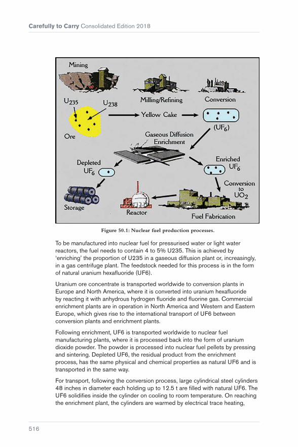
Carefully to Carry Consolidated Edition 2018
516
Figure 50.1: Nuclear fuel production processes.
To be manufactured into nuclear fuel for pressurised water or light water reactors, the fuel needs to contain 4 to 5% U235. This is achieved by ‘enriching’ the proportion of U235 in a gaseous diffusion plant or, increasingly, in a gas centrifuge plant. The feedstock needed for this process is in the form of natural uranium hexafluoride (UF6).
Uranium ore concentrate is transported worldwide to conversion plants in Europe and North America, where it is converted into uranium hexafluoride by reacting it with anhydrous hydrogen fluoride and fluorine gas. Commercial enrichment plants are in operation in North America and Western and Eastern Europe, which gives rise to the international transport of UF6 between conversion plants and enrichment plants.
Following enrichment, UF6 is transported worldwide to nuclear fuel manufacturing plants, where it is processed back into the form of uranium dioxide powder. The powder is processed into nuclear fuel pellets by pressing and sintering. Depleted UF6, the residual product from the enrichment process, has the same physical and chemical properties as natural UF6 and is transported in the same way.
For transport, following the conversion process, large cylindrical steel cylinders 48 inches in diameter each holding up to 12.5 t are filled with natural UF6. The UF6 solidifies inside the cylinder on cooling to room temperature. On reaching the enrichment plant, the cylinders are warmed by electrical trace heating,

Chapter 50 Radioactive Uranium Hexafluoride (UF6)
517
which turns the solid into the gaseous form needed for the enrichment process. After enrichment, the enriched UF6 is transported in 30 inch steel cylinders inside an overpack to prevent a criticality excursion (an unwanted nuclear chain reaction).
50.2 The Hazards of UF6
UF6 presents both radioactive and chemical hazards but, for the purposes of transport regulation under the IMDG Code (Reference 19), the radioactive nature of the material takes precedence and it is therefore categorised as radioactive Class 7.
Radioactive effects
UF6 poses potential health risks due to the radioactive nature of the uranium and the other radioactive elements it decays into. For natural UF6, the radiological hazard is low and the main hazard is due to the chemical effects of a release. Enriched UF6 poses a hazard with respect to the possibility of a criticality excursion, which would result in very large pulses of gamma radiation within tens of metres of the packages.
Chemical effects
If UF6 is released to the atmosphere, the uranium compounds that are formed by reaction with moisture in the air are chemically hazardous. Uranium is a heavy metal that, in addition to being radioactive, can have chemical effects, principally on the kidneys, if it enters the bloodstream by ingestion or inhalation. When UF6 comes into contact with water vapour in the air, it reacts to form hydrogen fluoride and uranyl fluoride, which are intensely corrosive to the skin and toxic if inhaled.
Figure 50.2: UF6 cylinder being loaded onto a f lat-rack container.

Carefully to Carry Consolidated Edition 2018
518
Figure 50.3: 48 inch cylinder for natural UF6.
50.3 IAEA/IMDG Code Regulations for the Transport of UF6
UF6 transport is subject to comprehensive and strict regulation. The International Atomic Energy Agency (IAEA) has developed and continuously revises these regulations, which are used as the basis for relevant sections of the IMDG Code (Reference 19). The IAEA approach is that the safety of radioactive material transport is defined by the design, construction and operation of the packages used and that the level of package safety is proportional to the hazard of the material it contains. UF6 packages have to be able to withstand normal and accident conditions during transport. They are designed in accordance with ISO Standard 7195 (Reference 80), which is specific to UF6 packages. They are tested to withstand hydraulic tests to 2.76 MPa, a drop test onto the most vulnerable part of the package and a thermal test consisting of immersion in a fire at 800°C for 30 minutes.
In addition, cylinders designed to carry enriched UF6 must be able to withstand a drop test from a height of 9 m without rupture or degradation of criticality safety. The packages must be approved by the Competent Authority, and this includes quality assurance during construction and operation and periodic testing during use.
50.4 Current and Future Levels of UF6 Transport
There are no official figures, but the current annual level of uranium ore transport worldwide is believed to be about 30,000 to 40,000 t from the source to the plants that convert it to UF6. As these conversion plants are in Europe and North America, this means that most of this material is transported by sea. When converted to UF6, about 10,000 to 15,000 t are believed to be transported by sea to enrichment plants. This represents up

Chapter 50 Radioactive Uranium Hexafluoride (UF6)
519
to 2,000 packages. After enrichment, about 3,000 t of enriched UF6 are transported from enrichment plants to the fuel fabricators, many of which are located overseas. Cylinders returning from these transports often contain residues of UF6, known as ‘heels’, and some cylinders are returned slightly contaminated after washing. In future years, it is known that some conversion facilities will close and it is anticipated that this will result in a 10% increase in sea transport of UF6 between Europe and the USA. In addition, it is impossible to anticipate variations in monetary exchange rates and, because uranium enrichment costs are largely based on the cost of electricity, this may also cause a significant variation in transport levels.
50.5 Accidents Involving UF6
Two significant accidents have occurred during sea transport of UF6.
On 25th August 1987, a French cargo ship, the ‘Mont Louis’, sank in the English Channel after a collision with a car ferry. The ‘Mont Louis’ was carrying 30 cylinders of UF6 containing 12 t of material each. Although there was damage to some of the cylinders, no significant release of UF6 occurred. The recovery campaign was complex and lengthy because of the sea conditions and the need to carry out extensive checks to the cylinders before their onward transport. In addition, there was a very large programme of environmental testing carried out by the French and UK Authorities.
Figure 50.4: Nuclear fuel assembly being loaded into nuclear power plant.
On 23rd May 1989, a container vessel carrying nine cylinders of UF6 residues was involved in an incident while on passage from Rotterdam to Montreal. During a mid-Atlantic storm, three cylinders, which were inadequately secured inside a closed 40 ft freight container, broke loose, damaging the freight container and two adjacent containers. The valves of two of the cylinders were broken off and UF6 residue escaped, contaminating the deck of the ship, other

Carefully to Carry Consolidated Edition 2018
520
equipment and cargo in the adjacent containers. A section of the dock area was also contaminated when the freight containers were unloaded in Montreal.
The accident was caused by improper stowage of the UF6 cylinders inside the freight containers. Each of the cylinders had been tied to straps on the wall of the freight container using half inch thick polypropylene rope, which snapped during the storm. Although there was no significant radiological risk to the crew, workers or the public, there was a very large insurance claim for the subsequent monitoring and clean-up operation.
50.6 Club Cover and the ‘Excepted Matter’ Regulations
UF6 transport presents particular difficulties in assessing whether it is ‘excepted matter’ under the Nuclear Installations (Excepted Matter) Regulations 1978. If it is ‘excepted matter’, it is covered by the Club, but if it is not then the consignor, or in some cases the consignee, is required to arrange nuclear liability insurance in place of Club cover and provide the carrier with a certificate of financial security to demonstrate this. This certificate must be countersigned by the government of the country concerned.
UF6 is transported in a variety of quantities, enrichments and activities and, unlike chemical products, which have a single UN number for each material, UF6 may be UN 2978, 2977, 2919, 3331, 2910 or 2908. Natural UF6, ie non-enriched, is transported as UN 2978 and, although this should always be ‘excepted matter’, it is necessary to check since it is not unusual to find consignments that are misdeclared.
Enriched UF6 is transported in full, partially full, empty or contaminated cylinders. It is, therefore, always necessary to check the total quantity of U235 in a consignment to determine whether it is more or less than the limit of 600 gms and so whether it is covered for ‘excepted matter’ by the Club. This is achieved by converting the net quantity of UF6 to the weight of uranium and then, knowing the % enrichment, calculating the weight of U235.
Members should contact the Club for advice if there is any doubt as to whether or not the cargo is ‘excepted matter’.

521
PART 12Cargo Planning and Securing (Including Hatch Covers)
Chapter 51 ..............................................523Preparing Cargo Plans – Structural Limitations
Chapter 52 ..............................................531Cargo Pre-loading Surveys
Chapter 53 ..............................................535Stowage of Breakbulk Cargo (General Cargo)
Chapter 54 ............................................. 543Lashing and Securing Deck Cargoes
Chapter 55 ..............................................571Steel Hatch Covers


523
Chapter 51
Preparing Cargo Plans – Structural Limitations
51.1 Strength of Tank Tops, Tween Decks, Hatch Covers and Weather Decks
When preparing cargo loading plans, it is important that the ship is loaded as close as possible to its maximum deadweight or capacity, but it is equally important to consider the implications of loading any high density cargo. In the early stages of planning, it is essential that not only should the physical dimensions of the cargo be established but also the maximum permissible weight that can be loaded into any compartment. The Committee believes that there is a common failure to fully understand the strength limits of tank tops, tween decks, hatch covers and even weather decks and that the knowledge of many Masters in this matter is often superficial.
The strength limits that are to be applied to tank tops are calculated and approved by the Classification Societies. The maximum limits are expressed in tonnes per square metre and are included in the ship’s technical manuals and capacity plans. To calculate the number of tonnes that can be loaded on the

Carefully to Carry Consolidated Edition 2018
524
tank top without exceeding the limit, the area of the tank top in square metres is multiplied by the permissible number of tonnes per square metre. To ensure that the limits are not exceeded, the cargo must be spread evenly over the area of the tank top. The volume of the space above the lower hopper tanks should also then be calculated and the figure obtained included in the total quantity to be loaded. A typical calculation might be as follows:
Maximum tonnage to be loaded:
(L)ength × (B)readth × PL (permissible load) = 27 × 21 × 12 t/m2 = 6,804 t
(where L and B represent the dimensions of the tank top excluding the hopper tanks)
Maximum volume to load:
6,804 t @ 3 t/cubic metre = 2,268 cubic metres
Height of stow:
2,268/567 = 4.0 m (567 = 27 × 21)
When discrete items are to be loaded, such as billets, steel coils, slabs, etc, the Committee recommends that the load should not exceed the equivalent tonnage shown above.
When other homogeneous cargoes are loaded, which may safely be stowed over the hopper tanks, additional weight may be carried but always with the proviso that the overall height of stow should never exceed the original figure as arrived at in the example.
In such cases, the amount of weight that can be safely added can be calculated by using the formula:
0.5 (L × B × PL) t, where L = the length of hopper tank and B = the horizontal width of tank and PL = permissible load.
Thus, if L = 27 m and B = 4 m then 0.5 (27 × 4 × 12) = 648 t at each side. At 3 t/m3, 648 t would occupy 216 m3. Over a base area of 108 m2 (27 × 4), this would take the height to 2 m (216/108) or, allowing for the wedge of a 45 degree hopper tank, to 4 m height. Thus, the final result of the calculation would be that the total weight of cargo to load would be 8,100 t at an overall height of 4 m.
In any case, the Committee recommends that, when making these calculations, Masters should consult the IMSBC Code (Reference 17) Section 2.1, Cargo Distribution.
When bulk cargo is poured into a ship’s hold, it tends to form a heap, thereby increasing the load on the tank top towards the centre of the hold. The result is

Chapter 51 Preparing Cargo Plans – Structural Limitations
525
a tendency for the double bottom to sag and for the ship’s sides to be drawn in, as indicated in Figure 51.1.
Such stresses can seriously weaken the ship’s structure. It is possible that the effects of such stowage procedures over a number of years may have contributed to the losses of loaded bulk carriers. During loading, the aim should be to maintain an even distribution of weight both transversely and longitudinally so that the specified tank top limits are not exceeded.
The procedures outlined above are simple, but more complicated situations may arise if breakbulk cargoes are to be loaded where large, heavy pieces of cargo may be offered for shipment.
Take, for instance, a 200 t transformer with base dimensions of 5 m × 3 m (15 square metres) to be loaded into the hold illustrated in Figure 51.1. The spot load on the tank top would be 200/15 = 13.3 t per square metre. This load would be excessive if the limit were 12 t per square metre. To spread the load and reduce the pressure to within the specified limits, it is customary to build a grid-like timber frame on the tank top. The timber selected should have its grain running the length of the timber and be of uniform quality. The area over which to apply the timber can be calculated by dividing the weight of the transformer by the tank top limitation, ie 200 t/12 t per square metre = 16.7 square metres. This would be the minimum area to be covered by the frame. 2 in × 2 in and 3 in × 3 in timber is commonly used with the loading of many cargoes, particularly steel. Square timber of greater cross section is extensively used for supporting heavy lifts.
Total cargo: 8,100 t
Cargo of iron orestowing at 3 t/m2
Width of tank top 21.0 m
Length of hold 27.0 m
Peak of hopper tanksabove tank top level 4.0 m
Base width of hopper tanksabove tank top level 4.0 m
Classification Societypermissible load 12 t/m2
Figure 51.1: X = level of surface of stow before trimming, Y = level of surface of stow after trimming.

Carefully to Carry Consolidated Edition 2018
526
Ideally, a complete floor should be constructed, with baulks of timber placed next to the steel surface of the tank top and with no spaces between the timbers. In practice, this would be costly and uneconomical. Any procedure is likely to involve compromise, but it is in any case recommended that, with heavy lifts, the baulks used should be of substantial sized timber with cross-sectional dimensions of not less than 9 in (23 cm) square. The timber may compress under the applied weight and, as an alternative, a steel frame may be used. Before deciding the exact stowage position for a heavy lift, it is advisable to check the nature of the hull construction. A heavy lift should be placed with reference to the longitudinal reinforced structure (longitudinal girders.) The placement of timber baulks should be considered with reference to the internal double-bottom structure, always bearing in mind that an important function of dunnage is to spread the load to the primary structure of the hull.
Other complications are likely to arise when loading steel cargoes. When loading steel coils, it is usual to load not more than three tiers high with individual coils weighing up to 10 t. If the unit weight is more than 10 t, only two tiers are loaded and, if more than 15 t, only one tier is loaded. Usually, two lines of double dunnage measuring 6 in × 1 in are laid athwartships between the coil and the tank top. Applying the formula above, the pressure exerted over the small bearing surface of the lowest coil is about 30 t. Without due care, the customary dunnage may not be sufficient to effectively spread this weight and there is a risk that the tank top will be overloaded beneath each unit.
Every possible precaution should be taken to ensure that the spot load does not exceed the limit, bearing in mind that the load spread is improved if the pitch of dunnage is reduced and that the dunnage must be laid across primary structures and must not terminate in between members (ie between double-bottom longitudinal girders).
The stowage of steel slabs poses similar problems. A typical slab may measure 6 m × 1.25 m × 0.25 m and weigh 14.75 t. The area of such a slab is 7.5 m and, when stacked 7 high, there would be 103 t bearing down on the tank top. Assuming the slabs were stowed flat, this would indicate a load of 13.74 t per square metre, ie 14.5% in excess of a 12 t permissible limit. However, the lowest slab is likely to be supported by three or four baulks of timber in order to facilitate handling by forklift truck. This means that the entire stack is supported on a maximum of four points, resulting in a tremendous concentration of weight on a small area. Unless larger dunnage is utilised, thereby spreading the load to within satisfactory limits, the tank top is likely to be overloaded when such cargo is loaded in the manner described. Bearing in mind the manner in which steel billets and slabs are usually dunnaged and stowed, it should be realised that little or no weight of that stowage will be distributed to the sloping tank sides unless special dunnaging arrangements are constructed to do so. It is more likely that the flat tank top area alone will be supporting the entire cargo weight, even though billet/slab ends/sides may be touching the plating of the sloping tanks.

Chapter 51 Preparing Cargo Plans – Structural Limitations
527
Masters are again encouraged to consult the IMSBC Code, (Reference 17) with particular reference to Section 2.1.2 which states:
“A general cargo ship is normally constructed to carry cargoes in the range of 1.39 to 1.67 cubic meters per tonne when loaded to full bale and deadweight capacities. When loading a high-density solid bulk cargo, particular attention shall be paid to the distribution of weights to avoid excessive stresses, taking into account that the loading conditions may be different from those found normally and that improper distribution of such cargo may be capable of stressing either the structure under the load or the entire hull. To set out exact rules for the distribution of loading is not practicable for all ships because the structural arrangements of each vessel may vary greatly. The information on proper distribution of cargo may be provided in the ship’s stability information booklet or may be obtained by the use of loading calculators, if available.”
Within the data provided in that section of the Code, the very densest iron ore has a stowage factor of 0.29 m3/t, which is considerably lower than the guiding upper limit of 0.80 m3/t. Using reported dimensions for billets, their stowage factor may be not greater than 0.25 m3/t (allowing for dunnage, margin plate areas, interstitial spacing, etc), on the basis that a mild steel billet will have an inherent density of 7.86 t/m3. If it were possible to stow billets without any interstitial spaces, the stowage factor would be 0.127 m3/t, demonstrating that billets constitute a very heavy cargo which stows denser than the densest iron ore.
In purpose-built container ships, the tank tops and double-bottom structures are specially strengthened where container corner castings are to be positioned. Here, the guiding principle is the stack weight, where 4, 6 or even 9 units per stack are involved. When containers are carried in the holds of non-purpose-built vessels, such as general cargo ships and bulk carriers, great care must be taken to use adequate dunnage to spread the point loading at the corner castings, generated by the stack load. For instance, a single stack of 2 × 20 ft × 20 t units will exert a down loading of 40 t. Beneath each corner casting, the point loading will be about 345 t/m2. Failure to appreciate the magnitude of such stresses has sometimes resulted in tank tops becoming pierced, followed by flooding of the hold by fuel oil or ballast water.
Figure 51.2: A collapsed tween deck.

Carefully to Carry Consolidated Edition 2018
528
51.2 Summary
When loading high density cargoes, there is a risk of overloading tank tops and proper precautions must be taken. Provided that the tank top is not overloaded, the pressure on the hopper tanks should be within acceptable limits, but in any case, if the density of the cargo is sufficiently high, the surface level of the stow will be below the upper limits of the sloping sides and no problems should arise. When high density bulk cargoes are loaded, the cargo should be levelled to ensure an even pressure over the tank top. Heavy lifts require plenty of strong, good quality dunnage, laying as much dunnage as feasible on the tank top in order to spread the load evenly. The tank top limitations are laid down when the ship is built and, provided that the structure remains within class specifications, remain unchanged throughout the life of the ship. If, through damage or wastage, the structure is reduced, reduced limitations may well have been imposed as a condition of class.
Masters should be aware that tween decks can collapse even when overloading is marginal. There are no safety factors and all cargo must be carefully trimmed. Where ships are fitted with twin hatchways (port and starboard), the cargo should be loaded in equal quantities on each side, unless there are specific instructions in shipyard plans that dictate otherwise.
51.3 Weather Decks and Hatch Covers
Similar caution should be exercised when loading heavy cargo and containers on weather decks and hatch covers.
Unless the weather deck has been specially strengthened, it is unlikely to have a loading limit in excess of 3 t per square metre. Similarly, unless hatch covers have been specially strengthened, it is unlikely that they would have a limit greater than 1.8 t per square metre, and maybe half that value in vessels less than 100 m in length. Hence, it is of great importance to consult and confirm the relevant data from the ship’s documentation. When exceptionally heavy cargoes are to be carried, it may be necessary to shore up the weather deck from below, but in such cases care should be taken to ensure that the load on the tween deck plating is properly spread.
It is always prudent not to load up to the maximum permissible limit on weather decks but to err on the safe side, given that heavy seas may be shipped in these areas. It is good practice to add 5% to the weight to be loaded before calculating the dunnage area.
The Committee is of the general view that containers should be stowed on deck two or more high only on those ships that have securing arrangements specially provided. At no time should the deck-loaded containers overstress

Chapter 51 Preparing Cargo Plans – Structural Limitations
529
the hatch cover or the hatchway structure. In cases of doubt, details of stress limitations should be obtained from the Classification Society. As mentioned above, where bulk carriers or dry cargo ships are used for the carriage of containers on the weather deck and/or the hatch covers, it should be borne in mind that it is the stack weight and the resultant point loading beneath the corner castings that must be taken into consideration. This criterion addresses not only structural capability but also the ability of the lower tiers of containers to support the superincumbent weight.
Where containers are to be stacked two or more tiers high on the hatch covers or weather deck, the base tier should be provided with permanent footlocks for the lower corner castings. The containers should be secured one above the other by means of twistlocks and/or lockable inter-layer stackers and the upper corner castings of a block of units should be locked into each other transversely by means of screw-bridge fittings and/or tension clamps. Containers so carried must be treated as deck cargo and secured in accordance with the deck cargo rules and recommendations. In other words, the total holding power of the lashing arrangements, properly disposed and attached to appropriate terminal points, should be not less than three times the static gross weight of the containers and contents.
If circumstances demand a twin tier stack in the absence of footlocks or welded restraints, properly rigged foot lashings should be used. The units must be twist locked together and lashed as indicated above. In such instances, the correct use of dunnage, both as to size and application, beneath the base corner castings is of paramount importance, as illustrated in Figure 51.3 (see also Section 53.2).
Good dunnage boards nailed together tosupport corner castings
Foot lashings well secured to, andtautened at, each corner casting inequal balanced manner
Figure 51.3: Dunnaging and lashing at base corner casting.


531
Chapter 52
Cargo Pre-loading Surveys
Instructing a surveyor to ‘carry out a pre-loading survey’ is inadequate and leaves the surveyor in doubt as to how far his duties extend.
In most contracts of carriage, the shipowner’s responsibilities begin at the time of loading and it is, therefore, important to inspect the cargo at this stage. Pre-shipment inspection of cargo is undertaken to determine and document the condition of the cargo at this time. This inspection is commonly referred to as the pre-loading survey. This survey can be carried out by the ship’s Master and officers, owner’s representatives or surveyors instructed by the owner depending on the trade and nature of the cargo. If the cargo is not as described in the shipping documentation, a decision will have to be made whether to reject the cargo or accept the cargo and adequately describe any differences on the mate’s receipts and bills of lading. Early notification of any deficiencies to the shippers is desirable together with owner’s intentions on rejection of the cargo or clausing the mate’s receipts and B/Ls. This notification can be given direct to the shippers but is more commonly given to the agents, stevedores or charterers, depending on the owner’s contractual relations.
Masters and deck officers employed by owners who trade their ships in liner services are usually trained to take care of pre-shipment inspections.
Cou
rtes
y of
Dan
ny C
orne
lisse
n/po
rtpi
ctur
es.n
l

Carefully to Carry Consolidated Edition 2018
532
Liner companies usually employ cargo superintendents, who can be called upon to assist if there is a problem. They may also have their own network of contracted surveyors who can be called upon quickly if an unusual cargo is to be loaded. Ships employed in the main bulk trades, (oil, grain, ore, etc) or specialised ships such as gas carriers and RoRo vessels usually have sufficient and adequately trained Masters and officers on board to take care of any pre-shipment inspections that are necessary. However, problems may arise if a tramp operator is chartered to carry, for example, steel products, paper products or breakbulk cargoes but the Master and the ship’s officers have little or no experience of these products. In many instances, loading operations commence immediately upon the ship’s arrival and there is little time for the ship’s personnel to inspect the cargo.
The ship’s personnel may be unfamiliar with the port and the system of loading, they may not know the agents, who almost always will be the charterer’s agents, and they will be put under pressure by the charterers and possibly a cargo superintendent employed by the charterer to load their ship as quickly as possible. In these circumstances, employment of a competent local surveyor can be most useful and cost effective.
If owners decide they require a surveyor to attend their ship to carry out a pre-loading survey, the instructions given should be comprehensive, precise and given as early as possible to allow sufficient time for the surveyor to conduct an efficient survey. This will avoid confusion and disagreement at a later date when the surveyor presents his report and invoice. An instruction that the surveyor should ‘carry out a pre-loading survey’ is inadequate and leaves the surveyor in doubt as to how far his duties extend. In these circumstances, the surveyor would simply inspect the cargo on the quay, possibly prior to the ship’s arrival if all the cargo had been delivered, and report to the Master on its condition and present the written report. Most surveyors would take their duties a little further and advise the Master on the clausing of the mate’s receipts and give advice on loading and stowage, if requested by the Master, but more precise instructions would avoid confusion. Instructing and informing the surveyor should therefore include the following:
Relevant details in the contracts of carriage (charterparties)
These include:
� Clauses relating to damaged cargo, eg sometimes clauses state that damaged cargo should not be loaded or that specific clausing only is permitted on the B/Ls
� clauses relating to the responsibility for loading and stowage
� clauses relating to the issue of the mate’s receipts and B/Ls.

Chapter 52 Cargo Pre-loading Surveys
533
Precise instructions on the survey
� The surveyor should be instructed whether the cargo is to be inspected on the quay just before loading or in the transit shed or elsewhere prior to the ship’s arrival, etc. The nature of the cargo and time factor will probably determine this. In many cases, the owners, charterer or ship’s agent will not know where the cargo is stored in the port or when it is to be delivered, so the surveyor should be instructed to survey all cargo to be loaded as near to the time of shipment as possible
� instruction is also required on the information to be given to the Master before the signing of the mate’s receipts and whether the surveyor should formulate suitable clauses relating to any damage. Usually, the surveyor should be instructed to be present when the Master signs the shipping documents. At this time, the surveyor can assist with any language problems and any disputes with shippers, agents or charterers in the clausing of mate’s receipts and/or B/L.
Other additional services connected with loading
� Inspection of ship’s hatch covers and ventilation system. (The findings of this inspection should be provided in a separate report or confidential side letter. This is to avoid any adverse information being disclosed if the pre-loading report is used in a cargo dispute)
� advising the Master on loading, stowage and securing
� monitoring the loading, stowage and securing
� advising and reporting on handling damage caused by stevedores
� advising on the tallying of the cargo and the issue of cargo documentation
� advising whether the cargo can be loaded in rain.
If early instructions are given, the surveyor will have time to contact the agents and stevedores to find out the exact nature of the cargo, when it is arriving at the loading berth and the proposed stowage on the ship.
Most shipowners will be aware that the employment of a competent surveyor for a ‘precautionary’ pre-loading survey in certain circumstances can eliminate or reduce problems and claims and the money spent is well worthwhile. The UK P&I Club and correspondents can assist and advise owners in arranging these surveys and in some exceptional circumstances will pay for the survey. This is particularly the case with finished or semi-finished steel products when the Club will always pay for a pre-loading survey if notified by the owners but not any associated services.


535
Chapter 53
Stowage of Breakbulk Cargo (General Cargo)
In recent years, there has been a general decline of standards in the stowage of breakbulk cargo, resulting in cargo damage and claims.
The Committee considers there are various reasons for the decline of standards, namely:
� Use of bulk carriers for the carriage of breakbulk cargo
� improper dunnaging
� inadequate packing
� inadequate stowage skills of ships’ officers.

Carefully to Carry Consolidated Edition 2018
536
53.1 Bulk Carriers
Figure 53.1: Medium-sized bulk carriers often replace tweendeckers on trades that have not been containerised or where, because of the type of cargo, it is impossible
to use containers.
A ship fitted with tween decks is ideal for the carriage of breakbulk cargo. The many compartments facilitate the carriage of different commodities and make port rotation easier, usually avoiding overstows. Provided care is taken over the stowage, cargo damage, particularly crushing damage, should be avoided. Unfortunately, tweendeckers are in short supply and cannot compete economically with the medium-sized bulk carrier. Medium-sized bulk carriers have, therefore, replaced, or are replacing, tweendeckers on trades that have not been containerised or where, because of the type of cargo, it is impossible to use containers.
The bulk carrier’s two main disadvantages, as compared with the tweendecker, are the height of the holds (about 12 m as compared with 6 m for the lower hold of a tweendecker) and the sloping lower wing ballast tanks. Most breakbulk cargo is stowed using forklift trucks, but the sloping lower wing ballast tanks prevent the forklift trucks manoeuvring close to the side of the holds, making stowage difficult. The height of the holds also prevents stowage from the tank top to the deckhead using forklift trucks. These problems are usually overcome by loading the cargo in horizontal tiers on top of which are placed steel plates on which forklift trucks can manoeuvre to load the next tier. It can readily be seen that crushing damage may occur, not just because of the height of the stow, but due to the use of the steel plates and forklifts.

Chapter 53 Stowage of Breakbulk Cargo (General Cargo)
537
53.2 Dunnaging
It is of paramount importance to use proper and adequate dunnaging materials during the stowage of breakbulk cargo, and this is particularly true in the case of bulk carriers.
Timber and timber products, such as plywood, are the main types of dunnage materials in use, even though timber products have risen in price over the past few years. Other cheaper materials are sometimes used as a substitute, but are generally found to be inadequate. Because of the price of timber, charterers, or whoever is paying for the dunnage, are often reluctant to provide dunnage that is adequate both in quality and quantity.
Dunnage is used for the following reasons:
� To spread the load over the surface area of the tank top, tween deck or deck and also between horizontal tiers of cargo
� to increase friction between steel surfaces (tank top and cargo, etc)
� to tie the cargo together to prevent any movement in the stow
� to keep the cargo away from the tank top or deck and away from the steel structure at the ship’s sides, thereby preventing contact with moisture formed on or running down or across steel surfaces and permitting the water to flow to the bilges
� to block void spaces, brace and support cargo, and block cargo to prevent movement
� to create a divide, an auxiliary deck or level surface.
Dunnage is an absolute necessity for proper stowage of breakbulk cargo and, when cargo damage occurs, the failure to use adequate or good quality dunnage may result in allegations of bad stowage by cargo interests and liability for cargo claims being difficult to refute. Because of the difficulties in the stowage of breakbulk cargo in bulk carriers, proper and adequate use of dunnage is vital and, although cost is a consideration, this is usually minor in proportion to potential claims.
When timber dunnage is supplied, the Master and the ship’s officers should check that the timber is properly seasoned. Green or wet timber contains up to 35% water. Shrinkage of green timber results in the loosening of nails and could mean that any blocking or bracing structure collapses. Timber should also be without dry rot, without infestation, without splits (split timbers cannot be fastened properly and lack strength) and of adequate scantling.
Poor quality timber should be rejected and, as the ship’s officers will probably have to sign for the timber supplied, they should check that the amount supplied corresponds to the receipt they sign.

Carefully to Carry Consolidated Edition 2018
538
53.3 Packing
One of the main causes of damage to breakbulk cargo is inadequate packing. Pallets, boxes, crates and other forms of packing are usually designed for a single transit. During the course of this transit, the unit must survive initial storage, loading onto a road or rail vehicle, transit to a port, handling at the port into temporary storage, loading onto the ship, stowage, static and dynamic forces related to the ocean passage, breaking out of stow and unloading, handling into temporary storage, handling onto a road or rail vehicle, transit to the receiver’s premises and handling at the receiver’s premises. There are probably at least 10 handling operations involved with every transit, but by far the most arduous is the sea voyage. It is therefore very important that packaging is taken into account when planning the stowage of breakbulk cargo, particularly when a stow could be as high as 12 m on a bulk carrier. Packaging should be inspected prior to loading and, if inadequate, the cargo should either be rejected or the B/Ls properly claused with regard to the inadequacy of the packing. It is difficult to generalise on what should be considered as inadequate packing, but some examples are:
� Flimsy pallets that bend and break when lifted
� the cargo on the pallets is laterally greater than the surface area of the pallet platform, which results in the cargo projecting over the sides and becoming torn or split on the pallet edges, causing the load to become unstable
� the load on the pallet is only secured with shrink-wrapped plastic sheeting, which is not acceptable as a securing material and leads to instability of the cargo on the pallets
� some of the bottom bags of the pallets lose their contents due to being pierced by the forks of forklift trucks, which impairs the stability of the stow on the pallet
� packages on pallets are not interlocked making the whole unit unstable, particularly the case if the goods are slippery
� bundles of pipes secured with wire are wrongly arranged in the bundles, causing slackness in the bundles resulting in bending and end damage
� heavy drums loaded on pallets that are only secured with flat metal strapping bands which eventually become slack and the load becomes loose

Chapter 53 Stowage of Breakbulk Cargo (General Cargo)
539
Figure 53.2: Heavy drums that have broken loose from inadequate strapping.
� wooden cases that have a strong base but with weak covers that lack rigidity because they are not fitted with a frame. This can result in the cases collapsing in a stow and the stow collapsing. It is difficult to see this weakness at the time of shipment
� plywood bundles that are packed in such a manner that the packing is too light for the weight of the bundle and the bearers.
Figure 53.3: Plywood bundles that have broken out of packing that is insufficient for the weight of the bundles and bearers.
If the packing is inadequate and incapable of withstanding the rigours of an ocean voyage, good stowage may not prevent the cargo from sustaining damage. Furthermore, inadequate or weak packing can undermine the stability of a stow and in extreme cases lead to its eventual collapse. Without proper supervision during loading, inadequate or weak packing is very often only discovered at the discharge port when the cargo is unIoaded in a damaged condition. It is difficult to determine at the discharge port whether the cargo was damaged due to bad stowage or as a result of inadequate packing. Cargo claims will eventually be directed to the shipowner and may prove costly and impossible to defend.

Carefully to Carry Consolidated Edition 2018
540
It is far more difficult to cater for stowage of cargo with weak or inadequate packing on a bulk carrier than ships with tween decks. On a tweendecker, top stowage either in the lower hold or tween deck can be arranged for suspect or weak packing. However, top stowage on a bulk carrier is far more limited, particularly when there are many loading or discharge ports.
Figure 53.4: Wooden cases that lack structural rigidity.
Even if packing is adequate, it is only designed to withstand certain pressures, and usually these pressures are determined for static conditions. Packing crates and cases of medium size should be able to withstand the superincumbent load of five similar items stowed above. Properly designed palletised units of 1,500 kg should be capable of supporting a 6,000 kg load under static conditions, which would result in a five-tier pallet stow of about six metres in height. Steel drums are designed to survive under a static load of a three metre height of units of the same weight. Proper stowage of these types of commodities can be arranged on a tweendecker, but the problem is far more difficult on a bulk carrier, even if vast quantities of dunnage are used to spread the loads evenly.
Various international and national organisations issue guidance stipulating the strength and construction of packing. These include the IMDG Code, British Standard, USA Packing Standard and the German Industry Standard (DIN) (Reference 19, Reference 81, Reference 82, Reference 83). For example, under German Standard (DIN), cases have to withstand a static vertical pressure of 1.0 mt/m2 during sea transit. Ships’ officers cannot be expected to test packaging to see whether it complies with these standards, but they should be aware that standards do exist and that shippers are under an obligation to comply with the rules and regulations of national and international organisations. Also, packaging has to be properly marked, particularly if there are special requirements for lifting or stowage. It is important to comply with wording or markings on packages such as:
� Stow away from heat
� top stowage only
� position of weight point
� marks for lifting points

Chapter 53 Stowage of Breakbulk Cargo (General Cargo)
541
� marks for forklift handling
� this way up arrows.
If it is impossible to comply with the instructions on the package, particularly with regard to stowage, that particular package or parcel of cargo should not be loaded.
53.4 Stowage Skills
The huge increase in containerisation has brought about a gradual decline in the traditional seafaring skills of loading and proper stowage. The result is that a Master or chief officer on a medium-sized bulk carrier may have never seen a general cargo loaded or stowed, and he may also have never received any tuition or training in a shore-based establishment. If a bulk carrier is chartered to load general cargo, the Master and chief officer will probably rely on the charterer’s supercargo, if any, to advise on stowage, or on the stevedores’ expertise. The result may be a series of expensive cargo claims.
53.5 Recommendations
The Committee recommends that, when owners know that their Masters or deck officers do not have the necessary expertise to properly load and stow general cargo, particularly on bulk carriers, expert advice should be obtained. Club correspondents have the local knowledge to advise Members on experts and surveyors in their area. Even if the Master and deck officers have some skill in the loading of breakbulk cargoes, expert advice should be sought if it is suspected that the packaging of any commodity is inadequate.


543
Chapter 54
Lashing and Securing Deck Cargoes
For the purposes of this chapter, reference should be made to the IMO Code of Safe Practice for Cargo Stowage and Securing (Reference 22) and the requirements under SOLAS for a cargo securing manual (Reference 18).
54.1 Cargo Securing Manual
Regulations VI/5 and VII/5 of the 1974 SOLAS Convention require cargo units and cargo transport units to be loaded, stowed and secured throughout the voyage in accordance with the cargo securing manual (CSM) approved by the administration and drawn up to a standard at least equivalent to the guidelines developed by the International Maritime Organization (IMO) (Reference 18).
The guidelines have been expanded to take into account the provisions of the Code of Safe Practice for Cargo Stowage and Securing (the CSS Code) (Reference 22), the amendments to that Code, the Code of Safe Practice for Ships Carrying Timber Deck Cargoes (Reference 23) and the codes and guidelines for RoRo vessels, grain cargoes, containers and container vessels, and ships carrying nuclear waste and similar radioactive products. Such
Cou
rtes
y of
Dan
ny C
orne
lisse
n/po
rtpi
ctur
es.n
l

Carefully to Carry Consolidated Edition 2018
544
individual publications are subject to amendments that need to be carried into the appropriate section of the CSM as they occur.
As from 1st January 1998, it is a mandatory regulation for all vessels, other than exempted vessels such as dedicated bulk solid, bulk liquid and liquefied gas-carrying vessels, to have on board an approved and up-to-date CSM. Some administrations may exempt certain cargo-carrying ships of less than 500 gross tons and certain very specialised ships, but such exemption should not be assumed in the absence of a formal exemption certificate.
It is a mandatory requirement for Masters and ships’ officers to be conversant with the CSS Code and the CSM guidelines to understand their applications for the vessel in which they are serving and to be capable of deploying correctly the hardware that goes with them. The CSM and its associated hardware are subject to port state control inspection. Violation of the CSM guidelines may give rise to vessel detention and/or prosecution of the Master and owners.
The CSS Code and the CSM guidelines and their amendments contain much sound and well-tried advice and should not be treated lightly. There are, however, a number of anomalies and in some instances the applied text is difficult to reconcile with safe practice and sound seamanship. It is hoped that these shortcomings may be rectified by future amendments. In the meantime, the following suggestions may be of use to ships’ officers, loading superintendents, supercargoes, surveyors, etc.
54.2 Deck Cargo
The term ‘deck cargo’ refers to items and/or commodities carried on the weather deck and/or hatch covers of a ship and thereon exposed to sun, wind, rain, snow, ice and sea, so that the packaging must be fully resistant to, or the commodities themselves not be denatured by, such exposure. Even in RoRo vessels, many areas above the actual hold space can reasonably be considered as ‘on deck’ even though they are not fully exposed to the onslaught of wind and sea. The combined effects of wind, sea and swell can be disastrous. Where damage and loss occur to cargo shipped on deck at anyone’s risk and expense, the shipowners, the Master and his officers, and the charterers must be in a position to demonstrate there was no negligence or lack of due diligence on their part.
Deck cargoes, because of their very location and the means by which they are secured, will be subjected to velocity and acceleration stresses greater, in most instances, than cargo stowed below deck. When two or more wave forms add up algebraically, a high wave preceded by a deep trough may occur. This may be referred to as an ‘episodic wave’, ie a random large wave, noticeably of greater height than its precursors or successors, which occurs when one or more wave trains fall into phase with another so that a wave or waves of large amplitude is/are produced giving rise to sudden steep and violent rolling and/or pitching of the ship. These are popularly, and incorrectly, referred to as ‘freak’
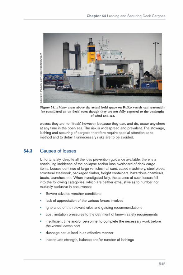
Chapter 54 Lashing and Securing Deck Cargoes
545
Cou
rtes
y of
Dan
ny C
orne
lisse
n/po
rtpi
ctur
es.n
l
Figure 54.1: Many areas above the actual hold space on RoRo vessels can reasonably be considered as ‘on deck’ even though they are not fully exposed to the onslaught
of wind and sea.
waves; they are not ‘freak’, however, because they can, and do, occur anywhere at any time in the open sea. The risk is widespread and prevalent. The stowage, lashing and securing of cargoes therefore require special attention as to method and to detail if unnecessary risks are to be avoided.
54.3 Causes of losses
Unfortunately, despite all the loss prevention guidance available, there is a continuing incidence of the collapse and/or loss overboard of deck cargo items. Losses continue of large vehicles, rail cars, cased machinery, steel pipes, structural steelwork, packaged timber, freight containers, hazardous chemicals, boats, launches, etc. When investigated fully, the causes of such losses fall into the following categories, which are neither exhaustive as to number nor mutually exclusive in occurrence:
� Severe adverse weather conditions
� lack of appreciation of the various forces involved
� ignorance of the relevant rules and guiding recommendations
� cost limitation pressures to the detriment of known safety requirements
� insufficient time and/or personnel to complete the necessary work before the vessel leaves port
� dunnage not utilised in an effective manner
� inadequate strength, balance and/or number of lashings

Carefully to Carry Consolidated Edition 2018
546
� wire attachment eyes and loops made up wrongly, including incorrect methods of using bulldog grips
� lack of strength continuity between the various securing components
� taking lashing materials around unprotected sharp edges
� incorrect/unbalanced stowage and inadequate weight distribution
� the perversity of shore-based labour when required to do the job properly
� securing arrangements, both supplied and approved, not fully utilised on the voyage under consideration.
This last point is particularly true of ISO freight containers and timber cargoes carried on the weather deck, and of large commercial vehicles carried in RoRo vessels.
All interests involved in the lashing and securing of deck cargoes should bear in mind that high expense in the purchase of lashing materials is no substitute for a simple design and a few basic calculations before lashing operations commence.
Other than in RoRo and purpose-built container operations where standardisation of gear and rapid loading and turnaround times pose different problems, Masters should be encouraged, on completion of lashing operations, to make notes of the materials used, to produce a representative sketch of the lashing system, to insist upon being provided with the test/proof certificates of all lashing components involved and to take illustrative photographs of the entire operation. These, at least, will be of great assistance to the vessel’s interest in the event of related future litigation.
54.4 General Guidelines
The Merchant Shipping (Load Lines) (Deck Cargo) Regulations, 1968 (United Kingdom Statutory Instrument No 1089 of 1968) (Reference 84) set out some of the general ideas to be followed when securing deck cargoes. The list of requirements is not exhaustive but provides a realistic base from which to work, and reads:
“2. Deck cargo shall be so distributed and stowed:
1) as to avoid excessive loading having regard to the strength of the deck and integral supporting structure of the ship;
2) as to ensure that the ship will retain adequate stability at all stages of the voyage having regard in particular to:
a) the vertical distribution of the deck cargo;
b) wind moments which may normally be expected on the voyage;

Chapter 54 Lashing and Securing Deck Cargoes
547
c) losses of weight in the ship, including in particular those due to the consumption of fuel and stores; and
d) possible increases of weight of the ship or deck cargo, including in particular those due to the absorption of water and to icing;
3) as not to impair the weathertight or watertight integrity of any part of the ship or its fittings or appliances, and as to ensure the proper protection of ventilators and air pipes;
4) that its height above the deck or any other part of the ship on which it stands will not interfere with the navigation or working of the ship;
5) that it will not interfere with or obstruct access to the ship’s steering arrangements, including emergency steering arrangements;
6) that it will not interfere with or obstruct safe and efficient access by the crew to or between their quarters and any machinery space or other part of the ship used in the working of the ship, and will not in particular obstruct any opening giving access to those positions or impede its being readily secured weathertight.”
54.5 Dunnage
If all deck cargo items could be structurally welded to the weather deck using components of acceptable strength, this would remove the necessity to consider coefficients of friction between the base of the cargo and the deck or dunnage on which it rests. Such is the large range of deck cargoes that do not lend themselves to such securing, however, that an appreciation of the sliding effect naturally raises the subject of coefficients of friction.
The values given for the coefficient of friction between dry timber and dry steel vary from 0.3 (17°) to 0.7 (35°), and sliding between steel and steel can occur at angles of inclination as small as 6°. Until some years ago, there appeared to be no published data relating to the coefficient of friction between timber dunnage and the painted surface of steel decks or steel hatch covers. Carefully controlled experiments were carried out in Liverpool, under the author’s supervision, using 9 in × 3 in × 8 ft sawn pine deals, some of which had earlier been allowed to float in water; others had been stored in covered conditions so as to conform to normal atmospheric moisture content. The experiments were carried out on hinge-opening hydraulic-powered steel MacGregor hatch covers in clean, painted condition, free of any unusual roughness and/or obstruction.
The tests used dry timber on dry covers; wet timber on dry covers; dry timber on wet covers; and, lastly, wet timber on wet covers. The lowest value, 0.51 (27°), occurred with wet timbers on wet covers; the highest value occurred with wet timber on dry covers, 0.645 (33°).
On the basis of such results, the lowest value of 0.51 (27°) should be accepted as relating to the most common condition likely to be found on the weather

Carefully to Carry Consolidated Edition 2018
548
deck of a seagoing ship, ie wet timber on wet decks. Hence, with inclination, and without any effects likely to be introduced by velocity and/or acceleration stresses due to rolling and pitching, timber dunnage alone will start to slide of its own accord at angles of inclination of 27°. Thereafter, sliding will continue at progressively smaller angles. It follows that, when the vessel is rolling and pitching and timber dunnage is unsecured, it will begin to slide at angles of inclination considerably less than 27°.
From such results, it follows that the normal practice of utilising timber dunnage and of keeping downward-leading lashings as short and as tight as possible should be continued and encouraged. A near vertical lashing is of great benefit in resisting the cargo item’s tendency to tip; a near horizontal lashing will greatly resist sliding forces.
It is important not to overload lashing terminals and/or shackles, and consideration should be given to the ‘effective strength’ of a lashing – its ‘holding power’. The ‘slip load’ of an eye in a wire should be balanced with the strengths of a shackle, a bottle-screw and a chain. A lashing is no stronger than its weakest part.
54.6 Spread the Load
Point loading and uneven distribution of cargo weight can, and frequently does, cause unnecessary damage to decks and hatch covers. Unless the weather deck has been specially strengthened, it is unlikely to have a maximum permissible weight-loading of more than 3 t/m2. Similarly, unless hatch covers have been specially strengthened, it is unlikely they will have a maximum permissible weight-loading of more than 1.8 t/m2. The ship’s capacity plan and/or general arrangement plan should always be consulted. If the information is not there, try the ship’s stability booklet. If the specific values are not available on board, allow no more than 2.5 t/m2 for weather-deck areas; and no more than 0.75 t/m2 for hatch covers in small vessels; and 1.30 t/m2 in vessels over 100 m in length.
The adverse effects of point loading are not always fully appreciated. For example, a 6 t machine with a flat-bed area of 3 m2 will exert a down load of 2 t/m2 (see Figure 54.2a).

Chapter 54 Lashing and Securing Deck Cargoes
549
6 t
2m
1.5m
Figure 54.2a: The 6 t weight is exerting a down loading of 2 t/m2.
Contrast this with a woman of 60 kg weight wearing high heels. The heel areas of 50 mm2 (0.00005 m2) will exert a point loading of 1,200 t/m2 if she stands on your toe with all her weight on one heel (see Figure 54.2b).
Figure 54.2b: The heel of the shoe is exerting a point loading of 1,200 t/m2.
When exceptionally heavy weights are to be carried, it may be necessary to shore up the weather deck from below, but care must be taken to spread the load on the tween deck so as not to overload that plating. In the not so dense range of cargoes, units of 20 to 40 t weight are common and stacking of unit weights is widespread. If a piece of machinery weighing, say, 30 t with a base area of 6 m2 is placed direct on the weather deck, the point loading will be 30/6 = 5 t/m2. If, however, the deck plating has a maximum permissible loading of 2.5 t/m2, the minimum area over which that 30 t load must be spread is 30/2.5 = 12 m2.
Good dunnage must be used to spread the load, and it is always good practice to add 5% to the weight to be loaded before working out the dunnage area. For the 30 t weight, for instance, 31.5 t would be used and the dunnage area would go from 12 m2 to 12.6 m2.
Dunnage timber is often no more than 6 in × 1 in (150 mm × 25 mm) rough planking but, where weighty cargo items are involved, dunnage should be not less than 2 in (50 mm) thickness × 6 in (150 mm) width, and preferably 3 in (75 mm) × 9 in (225 mm). Thicker pieces of dunnage are frequently referred

Carefully to Carry Consolidated Edition 2018
550
to as ‘bearers’. A dunnage width greater than 150 mm is always acceptable, eg 9 in (225 mm) to 12 in (305 mm), but where the thickness goes to 3 in (75 mm), care must be taken to choose straight-grained timbers of as great a width as possible and to ensure that they are laid with the grain horizontal and parallel with the deck. There have been incidents where what appeared to have been a soundly dunnaged and well-secured item of deck cargo broke adrift and was lost overboard due to a sequence of events commencing with the collapse of 3 in × 3 in dunnage timbers along the curved grain used on its edge, followed by consequential slackness in otherwise adequate lashing arrangements, followed by increasingly accelerated cargo movement and finally breakage of the lashings.
Because of the random nature of grain configurations in the thicker dunnage timbers, it is acceptable to achieve thicknesses by nailing planks together. A 2 in thick dunnage timber can be made up using 1 in thick planks, and a 3 in thick dunnage timber can be made up using 2 in and 1 in thick timber planks, all securely nailed together. To a large degree, this will correct the tendency for separation in timber with a badly-aligned grain.
If load-spreading dunnage is to remain fully effective, it will be as important to install good lower-level foot lashings as it will be to install downward-leading lashings.
Good dunnage boards nailed together tosupport corner castings
Foot lashings well secured to, andtautened at, each corner casting inequal balanced manner
Figure 54.3: The use of foot lashings with a twin-tier stack.
54.7 Rolling Periods
It is not the purpose of this chapter to deal with ship stability aspects, so far as those aspects may be avoided. However, it is worth repeating a few established and relevant stability facts. For instance, the roll period of a ship is the time taken to make one complete transverse oscillation, ie from the upright

Chapter 54 Lashing and Securing Deck Cargoes
551
position to starboard inclination, from starboard inclination back to upright and through to port inclination, then back to upright. Hence, if the roll period is 15 seconds and if the roll to starboard is 10° and the roll to port is 11°, the total ‘sweep’ within the 15 second roll period will be 10° + 10° + 11° + 11° = 42°.
When a ship rolls, the axis about which the rolling takes place cannot generally be accurately determined, but it is accepted as being near to the longitudinal axis passing through the ship’s centre of gravity. The time period of the roll is generally independent of the roll angle, provided that the roll angle is not large. Thus, a vessel with a 15 second roll period will take 15 seconds to make one full transverse oscillation when the roll angle (to port and to starboard) is anything from, say, 2° to 30°. The crux, from a cargo lashing viewpoint, lies in realising that a roll angle of 2° and a roll period of 15 seconds involves a sweep of no more than 8°, whereas a roll angle of 20° and a roll period of 15 seconds involves a sweep of 80° (ten times the arc) in the same time. The first will be barely noticeable, but the second will be violent and will involve large transverse acceleration stresses, particularly when returning to the upright.
Equally important is consideration of vertical acceleration as the ship pitches and ascends. Calculation of this force is not so simple, but measured values give results varying from 0.5 g amidships to 2 g at the far forward end of the ship.
A ‘stiff’ ship is one with a large GM (metacentric height) that is difficult to incline and returns rapidly to the upright and beyond, sometimes with whiplash effect. This imposes excessive acceleration stresses on cargo lashings. A ‘tender’ ship is one with a small GM that is easy to incline and returns slowly to the upright, sometimes even sluggishly. Although acceleration stresses are small, the inclined angles may attain 30°, and the simple gravitational effects of such angles and slow returns may impose equally excessive stresses on cargo lashings. Extremes of either condition should be avoided. It is worth working on the assumption that, if deck cargo is to remain safely in place during severe adverse weather conditions, the lashing arrangements should be sufficient to sustain 30° roll angles associated with 13 second roll periods, and 5° pitch angles associated with not less than 1 g vertical acceleration.
54.8 Rule of Thumb for Lashing Strength
The basic rule of thumb for securing cargoes with a tendency to move during a moderate weather voyage is simply that the sum of the minimum breaking loads (MBLs) of all the lashings should be not less than twice the static weight of the item of cargo to be secured. That is, a single item of 10 t weight requires the lashings to have a total breaking load of not less than 20 t, on the positive assumption that the lashings are all positioned in a balanced, efficient and non-abrasive manner. This rule may be adequate, or even too much, below decks – though not necessarily so in all instances – but it will not be adequate on the weather deck in instances where calm seas and a fair weather passage cannot be guaranteed.

Carefully to Carry Consolidated Edition 2018
552
Where winds of Force 6 and upwards together with associated wave heights are likely to be encountered during a voyage, the increased stresses arising are those considered here, allowing for 30° roll angles with not less than 13 second roll periods (also see Tables 54.3 and 54.4, taken from the CSS Code and the CSM guidelines).
In such cases, the rule of thumb – the ‘3-times rule’ – tends to be that the sum of the safe working load of all the lashings shall equal the static weight of the cargo item to be secured; the safe working load is arrived at by dividing by 3 the minimum breaking load/slip load/holding power of the lashings. In other words, if the breaking load/slip load/holding power of all the lashings is 30 t, they can safely hold an item whose static weight is 10 t, again on the assumption that all securing arrangements are deployed in a balanced, efficient and non-abrasive manner. The author is not aware of any failures of lashings/securing arrangements or loss of deck cargo where this 3-times rule has been applied in a sensible manner.
It is not arbitrary, however, because it is derived from the International Convention on Load Lines, 1966 within which framework the UK Department for Transport, in earlier instructions to surveyors, gave the following guidance, inter alia:
“When severe weather conditions (ie sea state conditions equal to or worse than those associated with Beaufort Scale 6) are likely to be experienced in service the following principles should be observed in the design of the deck cargo securing arrangements:
(iv) Lashings used to secure cargo or vehicles should have a breaking load of at least 3 times the design load, the design load being the total weight of the cargo or cargo plus vehicle subjected to acceleration of:
0.7 ‘g’ athwartships,1.0 ‘g’ vertically and0.3 ‘g’ longitudinally,relative to the principal axis of the ship.
When sea state conditions worse than those associated with Beaufort Scale 6 are unlikely to be experienced in service, a lesser standard of securing such items of cargo might be acceptable to approval by the Chief Ship Surveyor.
The equipment and fittings used to secure the deck cargoes should be regularly maintained and inspected.”
Put into practical and approximate terms, and using the term ‘holding power’ to indicate ‘breaking load/slip load/holding power’, this means:
� The total holding power, in tonnes, of all lashings holding the cargo item vertically downward to the deck should be equivalent to three times the ordinary static weight of the cargo item in tonnes, ie a 10 t cargo item requires total lashings having a holding-down potential of 30 t
� the holding power, in tonnes, of all lashings preventing the cargo item moving to port and to starboard should be equivalent to seven-tenths of the

Chapter 54 Lashing and Securing Deck Cargoes
553
holding-down potential of item 1 above, ie a 10 t item requires lashings with holding power preventing transverse movement of 21 t
� the holding power, in tonnes, of all lashings preventing the cargo moving forward or aft should be equivalent to three-tenths of the holding-down potential of item 1 above, ie a 10 t item requires lashings with holding power preventing longitudinal movement of 9 t.
The IMO 1994/1995 amendments to the CSS Code (Reference 22) (now carried forward into the requirements for the preparation of the CSM) change the emphasis of the above as follows.
The CSM rule of thumb varies with the maximum securing load (MSL) of the different lashing components, as listed in Table 54.1, giving rise to five different answers to one problem. For the most part, vertical acceleration is replaced by a 1 g transverse acceleration, and vertical and longitudinal accelerations are not quantified except in the instance of containers of radioactive wastes etc, when accelerations shall be considered to be 1.5 g longitudinally, 1.5 g transversely, 1.0 g vertically up and 2.0 g vertically down. To date, the IMO have not offered an explanation as to why a tonne of radioactive waste should be considered to ‘weigh’ twice as much as, say, a tonne of tetraethyl lead or some other equally noxious substance.
The rule of thumb method given in Section 6 of the current CSS Code amendments indicates that the MSL values of the securing devices on each side of a cargo unit (port as well as starboard) should equal the weight of the unit, and a proposed amendment to the table in Section 4 of the Code now provides MSLs as follows:
Material MSL
Shackles, rings, deckeyes, turnbuckles of mild steel
50% of breaking strength
Fibre rope 33% of breaking strength
Wire rope (single use) 80% of breaking strength
Web lashing 50% of breaking strength (was 70%)
Wire rope (re-usable) 30% of breaking strength
Steel band (single use) 70% of breaking strength
Chains 50% of breaking strength
“For particular securing devices (eg fibre straps with tensioners or special equipment for securing containers), a permissible working load may be prescribed and marked by authority. This should be taken as the MSL. When the components of a lashing device are connected in series (for example, a wire to a shackle to a deckeye), the minimum MSL in the series shall apply to that device.”
Table 54.1: Determination of MSL from breaking strength.

Carefully to Carry Consolidated Edition 2018
554
Consider a cargo unit of 18 t mass which is to be secured using only shackles, web lashings, chains and turnbuckles – all MSLs of 50% breaking strength (BS). The unit will require 18 tonne-force MSL on each side, namely 36 tonne-force total MSL (72 tonne-force BS for these items), representing a total lashing breaking strength to cargo mass ratio of 72/18 = 4.
Secure the same cargo unit with steel band only. The total MSL required will still be 36 tonne-force (72 tonne-force BS) but the MSL of steel band is nominated as 70% of its breaking strength, so this gives a total lashing breaking strength of (36 × 100)/70 = 51.42 tonne-force, representing a total lashing breaking strength to cargo mass ratio of 51.42/18 = 2.86.
Do the calculation using wire rope, re-usable, and the answer is (36 × 100)/30 = 120 tonne-force: ratio 120/18 = 6.67. For wire rope, single use, the answer is (36 × 100)/80 = 45 tonne-force: ratio 45/18 = 2.5, and for fibre rope the ratio is 6. These ratios (or multipliers) remain constant for equal cargo mass. If you do the same calculations using, say, 27 t and 264 t cargo mass, you will finish up with the same 4, 2.86, 6.67, 2.5 and 6 ratios (or multipliers). If a component was assigned a 66.67% MSL, the result would be a ratio of 3 – the three-times rule multiplier.
The CSS Code changes the commonly-held understanding of the term ‘rule of thumb’ – a single multiplier easy to use and general in application – by inserting the MSL percentages to produce a range of rule of thumb multipliers.
Just to labour the point, if the cargo mass to be secured was 18 t and we use the five results obtained by using Sections 4 and 6 of the Code, the total lashing breaking strength required in each instance would be 72 tonne-force, or 51.48 tonne-force, or 120.06 tonne-force, or 45 tonne-force, or 108 tonne-force! One way of partly rationalising this problem is to create an additional column in Table 54.1, as follows:
Material MSL ROT multiplier
Shackles, rings, deckeyes, turnbuckles of mild steel
50% of breaking strength 4.00
Fibre rope 33% of breaking strength 6.06
Wire rope (single use) 80% of breaking strength 2.50
Web lashing 50% of breaking strength (was 70%)
4.00
Wire rope (re-usable) 30% of breaking strength 6.67
Steel band (single use) 70% of breaking strength 2.86
Chains 50% of breaking strength 4.00
(Compare with overall general component)
(60.67% of breaking strength)
(3.00)
Table 54.2: Determination of MSL from breaking strength, including rule of thumb multipliers.

Chapter 54 Lashing and Securing Deck Cargoes
555
By looking at Table 54.2, and in respect of any cargo mass, you can use the multipliers without going through all the calculations required by Sections 4 and 6 and, more importantly, you will be able to see clearly the extent to which the MSL multipliers degrade or upgrade the generally accepted three-times rule.
In the instance of the 18 t cargo unit given above, the lashings’ total breaking strength would be 54 tonne-force when the three-times rule is applied. Simply, 18 × 3 = 54 tonne-force total BS, that is:
Cargo mass × Rule number = Lashings’ total breaking strength
54.9 Correction Factors
While the three-times rule may be considered adequate for the general conditions considered above, Section 7 of the CSS Code Amendments provides Tables 3 and 4 where GMs are large and roll periods are less than 13 seconds. These Tables, reproduced in this section, provide a measured way of applying that extra strength.
Length (m)
50 60 70 80 90 100 120 140 160 180 200
Speed (kn)
9 1.20 1.09 1.00 0.92 0.85 0.79 0.70 0.63 0.57 0.53 0.49
12 1.34 1.22 1.12 1.03 0.96 0.90 0.79 0.72 0.65 0.60 0.56
15 1.49 1.36 1.24 1.15 1.07 1.00 0.89 0.80 0.73 0.68 0.63
18 1.64 1.49 1.37 1.27 1.18 1.10 0.98 0.89 0.82 0.76 0.71
21 1.78 1.62 1.49 1.38 1.29 1.21 1.08 0.98 0.90 0.83 0.78
24 1.93 1.76 1.62 1.50 1.40 1.31 1.17 1.07 0.98 0.91 0.85
Table 54.3: Correction factors for length and speed.
B/GM 7 8 9 10 11 12 13 or above
on deck, high 1.56 1.40 1.27 1.19 1.11 1.05 1.00
on deck, low 1.42 1.30 1.21 1.14 1.09 1.04 1.00
tween deck 1.26 1.19 1.14 1.09 1.06 1.03 1.00
lower hold 1.15 1.12 1.09 1.06 1.04 1.02 1.00
Note: The datum point in Table 54.3 is length of ship 100 m, speed of ship 15 knots and, in Table 54.4, B/GM <13.
Table 54.4: Correction factors for B/GM <13.

Carefully to Carry Consolidated Edition 2018
556
A word of caution. Some officers may choose to ignore in Table 54.3 any correction factor less than 1. For all those values less than 1, let the rule-of-thumb calculation stand on its own and only apply the Table 54.3 factors when the values are greater than 1. This way, the safety of the three-times rule or any other rule of thumb you may care to use will not be compromised.
Section 5 of the current CSS Code Amendments says:
“5 Safety Factor
Within the assessment of a securing arrangement by a calculated balance of forces and moments, the calculated strength (CS) of securing devices should be reduced against MSL, using a safety factor of 1.5, as follows:
CS = MSL
1.5
The reasons for this reduction are the possibility of uneven distribution of forces among the devices, strength reduction due to poor assembly and others. Notwithstanding the introduction of such safety factor, care should be taken to use securing elements of similar material and length in order to provide a uniform elastic behaviour within the arrangement.”
Many people were puzzled by the expression CS = MSL/1.5 appearing where it did in the text, because the term ‘calculated strength’ appeared to have no direct relationship to Sections 1, 2, 3 and 4 preceding it, nor did it sit easily with any attempt to apply it to Section 6 which followed it. It can now be stated with some authority that Section 5 (other than the third paragraph thereof) and its CS = MSL/1.5 expression does not relate to, nor should any attempt ever be made to apply it to, Section 6 or any other rule of thumb, other than the admonition in the third paragraph relating to securing elements of similar material and length.
Section 5 and its CS = MSL/1.5 are wrongly placed in the text. They relate to the Advanced Calculation Method illustrated in Section 7. To make sense of Section 5, there is currently a proposed amendment to Annex 13 indicating that the expression should be re-sited under paragraph 7.2.1. In Section 7, calculated strength is used within a set calculation method, and it is in that sense and in that context that calculated strength (CS) should be applied. So, unless you are involved with a full advanced calculation method, just ignore CS = MSL/1.5; also note that the advanced calculation method itself is also under review.
54.10 Breaking Strengths
The term ‘breaking strength’ is not defined in the CSS Code and the CSM guidelines, but within the context of those two documents, it could reasonably be taken to mean the point at which the component, material or element can no longer support or sustain the load, pending some possible amendments by the IMO.

Chapter 54 Lashing and Securing Deck Cargoes
557
The CSS Code (Reference 22) defines the values of MSLs of mild steel components for securing purposes as 50% of breaking strength (see Table 54.1). The 1997 amendments to the CSM require such components inter alia to have identification marking, strength test result or ultimate tensile strength result, and MSL* all to be supplied by the manufacturer/supplier with information as to individual uses and with strengths/MSL values to be given in kilonewtons (kN). (To convert kN to tonnes force (tonne-force), multiply by 0.1019761 or, for a rough value, divide by 10.)
This latter definition is included in the proposed amendment to Annex 13 of the CSS Code (Reference 22).
This mix of terms is likely to raise questions about the validity of the CSMs issued and/or approved to date. If the components are not identifiable by at least their MSLs, they are not compliant with the CSM guidelines. To overcome this problem, it has been suggested that all aspects could be safely met by attaching, with suitable wire, small coloured metal tags stamped with the MSL of the component, such as used for securing components for timber deck cargoes. Responses received from the industry support this proposal.
The Committee’s advice to ships’ officers and others trying to apply the requirements of the CSM/CSS Code is this: if the chains, shackles, rings, etc available to you are not clearly identified as to their MSLs, use the stamped SWL of a lifting shackle as required by the CSM/CSS Code, thereby using a component that may have a breaking strength two-times greater than is needed but ensures you are compliant with the Regulations. Alternatively, multiply the stamped SWL value by 4 to obtain the breaking strength and apply the percentages given in Table 54.1 to obtain the MSL; then remove that component from any possibility of use for lifting purposes by tagging it. This fulfils the spirit of the regulations without resorting to the use of massively oversized lashing components.
54.11 Wire Rope
For efficient lashing purposes, wire ropes should be round-stranded, flexible and not so great in diameter as to make their use cumbersome. The most commonly used general purpose wire is 16 mm diameter (2 in circumference) of 6 × 12 construction galvanised round strand with 7 fibre cores having a certificated MBL of 7.74 tonne-force. This is the cheapest wire for its size and it will turn easily around thimbles and lashing points, can be spliced or bulldog gripped without difficulty and is easily handled.
* The CSS Code 1994/95 amendments say: “Maximum securing load is to securing devices as safe working load is to lifting tackle.” Appendix 1 of the 1997 amendments to the CSM says: “Maximum securing load (MSL) is a term used to define the allowable load capacity for a device used to secure cargo to a ship. Safe working load (SWL) may be substituted for MSL for securing purposes, provided this is equal to or exceeds the strength defined by MSL.”

Carefully to Carry Consolidated Edition 2018
558
Other wires of different construction and of varying sizes or strength may be needed for particular lashing purposes and the certificated MBL should always be verified before taking such wires into use.
1 2 3 4 5 6 7 8 9
DHA
Uncoiling: correct method
Unreeling: incorrect method
Correct method by which to measure the diameter of wire rope
Figure 54.4: Wire rope.
Wires intended for use as lashings may be supplied pre-cut to a precise length and with eyes or attachment devices already formed in one or both ends. Such purpose-made items are usually sold with certificates stating the test load and minimum break load applicable. If test certificates are not supplied, they should be requested. More commonly, the wire is supplied in coils and must be cut to length on board ship with eyes and attachment devices formed and fitted as required. Where this is the case, eyes formed by bulldog grips must be made up in accordance with the manufacturer’s instructions as otherwise the eye terminations will tend to slip under loads very much smaller than the certificated breaking load of the wire.

Chapter 54 Lashing and Securing Deck Cargoes
559
Bulldog grip
Full-formed tucked splice
Bulldog grips applied correctly
The WRONG WAY to apply bulldog grips
Crosby clip
Figure 54.5: Grips and clips.
54.12 Bulldog Grips
The most common cause of lashing failure is incorrect application of bulldog grips. Where an eye is formed around a thimble in the correct manner, the lashing arrangement will hold secure with loads up to or even in excess of 90% of the nominal break-load (NBL) of the wire before slipping or fracturing, although it is usual and recommended to allow not more than 80%. Without a thimble, the eye, when made up correctly, can be expected to slip at loads of about 70% of the NBL. Where the correct procedures are not followed, slippage is likely to occur at much reduced loads.
Under strictly controlled conditions, more than 100 tests were applied on a licensed test bed on 16 mm and 18 mm wire rope lashing configurations (see Figure 54.6 a, b and c). As a result of such tests, the following recommendations are made:
It should be stressed that these recommendations relate to cargo lashings only. Lifting gear and other statutory applications require a minimum of 4, 5 and 6 grips for 16 mm diameter wire and upwards, respectively. It is also most important to ensure that the bulldog grips are of the correct size in order to correspond with the diameter of the lashing wire.

Carefully to Carry Consolidated Edition 2018
560
Diameter of wire rope (mm) Wire rope grips
Up to and including 19 3
Over 19, up to and including 32 4
Over 32, up to and including 38 5
Over 38, up to and including 44 6
Over 44, up to and including 56 7
Table 54.5: Recommended minimum number of bulldog grips for each eye – lashing purposes only.
An allowance of 150 mm should be made between the last bulldog grip and the end of the ‘dead’ wire. It is important to ensure that the lashing wires are not cut short immediately next to the bulldog grips. The end of the dead wire should be tightly taped.
54.6aSingle eye at
each end
54.6bSingle loop
54.6cHalf-double
grommet
Figure 54.6: Configurations tested.
� Bulldog grips have a grooved surface in the bridge piece which is suitable for a standard wire of right-hand lay having six strands. The grips should not be used with ropes of left-hand lay or of different construction. Crosby grips have a smooth surface in the bridge piece. The first grip should be applied close to the thimble or at the neck of the eye if a thimble is not used. Other grips should be placed at intervals of approximately six rope diameters apart (ie 96 mm with a 16 mm diameter wire, 108 mm with an 18 mm diameter wire)

Chapter 54 Lashing and Securing Deck Cargoes
561
� the grips must all face in the same direction and must be fitted with the saddle or bridge applied to the working or hauling part of the rope. The U-bolt must be applied to the tail or dead-end of the rope. If the grips are not applied as indicated, the effectiveness of the eye can be seriously affected
� ideally, all the nuts on the grips should be tightened using a torque wrench so that they may be set in accordance with the manufacturer’s instructions. In practice, it may be sufficient to use a ring spanner, although thereafter all the nuts should be checked periodically and adjusted as necessary
Slip load =NBL × 0.70
Slip load =NBL × 0.70 Slip load =
NBL × 1.50
54.7aSoft eyes
54.7bHalf-doublegrommets
Slip load = NBL × 1.40
54.7cSingle loops
Galvanised marine wire rope16 mm – 6 × 12 construction
and 16 mm – 6 × 24 construction
54.8aSlip load =NBL × 0.50
54.8dSlip load =NBL × 0.50
54.8cSlip load =NBL × 0.50
54.8bSlip load =NBL × 0.50
Galvanised marine wire rope16 mm – 6 × 12 construction
and 16 mm – 6 × 24 construction
Figure 54.8: Soft eyes – some other representative slip loads.
Figure 54.7: Correct application of Bulldog grips.
� should a connection slip under load, it is likely that initially the rate of slip will be accelerated. The rate may then decrease but, until the load is removed, the slip will not be completely arrested
� if three grips are applied in the correct manner and with an eye formed around a thimble (a hard eye), the eye will not fail or slip at loads of less than 80 to 90% of the NBL. Without a thimble, the eye (a soft eye) made up correctly can be expected to slip at loads in excess of about 70% of the NBL (see Figure 54.7a). This is referred to in this section as the ‘slip load’ or ‘holding power’ of the eye

Carefully to Carry Consolidated Edition 2018
562
54.9aSlip load = NBL × 0.25
54.9bSlip load = NBL × 0.18
Galvanised marine wire rope16 mm – 6 × 12 construction
and 16 mm – 6 × 24 construction
Figure 54.9: Soft eyes – UNSAFE application of Bulldog clips.
� the use of half-double grommets is widespread and it is sometimes wrongly assumed that the holding power will be twice the NBL of the wire. In fact, tests show that the slip load will be only 1.5 times the NBL (see Figure 54.7b). The holding power also decreases as the number of grips is reduced (see Figure 54.11)
� the use of bulldog grips to join two ends of wire rope is to be avoided, and again it is sometimes wrongly assumed that this will provide a holding power of twice the NBL. In a single loop with six grips being used (see Figure 54.7), the slip load will be about 1.4 times the NBL. The holding power decreases as the number of grips is reduced (see Figures 54.10 and 54.11)
� in a soft eye, with 2 grips, and with one or both used in the reverse manner (see Figure 54.8), the eye can be expected to slip at loads of about 50% NBL. These configurations are the least efficient and, as indicated, the holding power is at most half the nominal break load of the wire

Chapter 54 Lashing and Securing Deck Cargoes
563
54.10aSlip load = NBL × 1.00
54.10bSlip load = NBL × 1.00
54.10cSlip load = NBL × 1.00
54.10dSlip load = NBL × 0.70
54.10eSlip load = NBL × 0.70
Figure 54.10: Half-double grommets – some other representative slip loads.
� with a soft eye, using only one grip, the slip load was found to be 0.25 NBL with the grip positioned correctly (see Figure 54.9a) and 0.18 NBL with the grip reversed (see Figure 54.9b)
54.12aSingle loops
Slip load = NBL × 0.40
54.12bHalf-double grommets
Figure 54.12: NOT recommended.Figure 54.11: Single loops – some other representative slip loads.

Carefully to Carry Consolidated Edition 2018
564
� a turnbuckle with a thread diameter of 24 mm or more can be adjusted to set up a pre-tension of about 2 t. If such a turnbuckle were attached to an eye made up in 16 mm wire, full tension in the wire would not be attained and the eye would slip at the grip under the pull of the turnbuckle alone.
Before deciding to use half-double grommets (at NBL × 1.5) and single loops (at NBL × 1.4) as opposed to single eyes (at NBL × 0.7), it must be remembered that, at one terminal end in the instance of a half-double grommet, and at each terminal end in the instance of a single loop, there is no more material than at the terminal end of a soft eye.
If a properly made up single loop breaks adrift, you have immediately lost twice the holding power allowable for a soft eye, and if a properly made up half-double grommet breaks adrift, you have lost more than twice the holding power allowable for a soft eye. Therefore, it is most important to ensure that the terminal ends are connected by shackles or some other form of smooth, non-sharp-edged component.
For example, instead of 25 single eyes, for convenience and time saving you use 12 half-double grommets of 16 mm 6 × 12 wire to secure a 46 t item of deck cargo. If one of the half-double grommets fractures at a poor terminal connection, you lose 8.3% of the total holding power; if a soft eye had failed, you would have lost only 4% of the total holding power. Lashing and securing of deck cargoes is not an exact science; it is frequently a case of a balanced trade-off, but the trade-off should be based on information and a few quick calculations, as discussed in this chapter.
Eyes and similar terminal ends in wire lashings should never be formed by the use of round turns and half hitches. Initial slackness is seldom taken up sufficiently and, even when it is, the turns and hitches tend to slip and create sharp nips leading to failure of the wire at loads well below those to be expected for eyes properly formed by the use of bulldog grips.
When attaching wires to lashing terminals on the ship’s structure or the cargo itself, every means should be taken to avoid hard edges, rough chafing points and sharp nips at the eye. Even where thimbles are not used, the attachment of the eyes of the wire to lashing terminals may best be accomplished by using shackles of the appropriate size and break load.
It must be ensured that the lashing points on the ship are sufficient in number and adequate in strength for the lashings they will hold.
54.13 Plastic-coated Wires
Plastic (PVC) coated galvanised standard marine wire of 18 mm diameter and 6 × 24 construction is commonly used for various purposes where there is a need to avoid the risk of cutting or chafing. Such wire should be used with caution because, if plastic-covered wire is used in conjunction with grips,

Chapter 54 Lashing and Securing Deck Cargoes
565
slippage is likely to occur at much reduced loads than would be the case for unprotected wire of the same size and characteristics. The plastic coating should be stripped from the wire where the bulldog grips are to be applied and from the surface of any wires coming into contact with each other.
54.14 Fire and Explosion Hazards
Great care should be exercised if lashing terminals are to be welded while or after loading cargo. Before undertaking any hot work, it is important to obtain a hot work certificate from the local port authority. The authority should also be in possession of all relevant information relating to the ship and cargo. The welders themselves should be properly qualified and competent and, if welding is taking place either on deck or under deck, a proper fire watch should be mounted both at and below the welding site. Adequate fireproof sheeting should be spread below welding points. On deck, fire hoses should be rigged with full pressure on the fire line.
A watchman should be posted for at least four hours after the completion of welding and a ship’s officer should examine all spaces before they are finally battened down. These precautions should never be neglected and, if there is any doubt about safety, the welding must not go ahead.
54.15 Positive Action
It is important to be vigilant at all stages of the operation. If you see something being done badly or incorrectly, you should stop the work and have it re-done correctly. When rigging foremen, stevedore superintendents and charterers’ supercargoes insist on doing things wrongly and say they have always done it that way successfully, tell them they’ve just been lucky! Then make them do it correctly.
54.16 Chain
Chain is widely used in the securing of freight containers, timber cargoes and vehicle trailers.
The use of chain alone for the securing of general deck cargoes is not widespread. Where chain lashings are used, they tend to be supplied in precise lengths already fitted with terminal points and tightening devices.
The advantage of using chain is that, under the normal load for which the chain is designed, it will not stretch. Therefore, if all chain lashings are set tight before the voyage and the cargo neither settles nor moves, nothing should cause the chain to lose its tautness.

Carefully to Carry Consolidated Edition 2018
566
In general, chain for non-specific uses is awkward to handle, tiresome to rig, difficult to cut to length and does not render easily. For general purposes, it is most effectively used in relatively short lengths in conjunction with or as a part of lashings otherwise composed of wire or webbing.
54.17 Webbing
The use of webbing slings and webbing lashings for cargo securing purposes has steadily increased over the past years, but operational results differ widely. There are instances where webbing is ideal for securing deck cargoes and there are other instances where it should be used with caution.
Special large bore pipes made of reinforced plastic or provided with contact-sensitive outer coatings make webbing an ideal securing medium because its relatively broad flat surfaces and reduced cutting nature allow it to be turned around and tightened against the pipes with short spans, producing a most acceptable stowage. Large, heavy, crated items or high standing heavy machinery where relatively long spans may be involved require wire or chain lashings, because sufficient unsupported tension is difficult to apply with webbing alone, although some of the ‘superlash’ systems can overcome this problem effectively.
One method of using webbing andchain lashings
Webbing lashing with handratchet tensioner: chainattachments each end
Figure 54.13: Webbing.
Webbing is usually manufactured from impregnated woven polyester fibre and therefore will stretch more than wire rope. It is supplied in reels and may be easily cut and fashioned to any required length.
Webbing should not be used without first confirming from the manufacturer’s literature its nature, breaking load and application. Tension on a hand ratchet

Chapter 54 Lashing and Securing Deck Cargoes
567
can be obtained easily up to 0.54 t and then with increasing difficulty up to a maximum of 0.60 t. A spanner or bar must never be used to tighten a hand tension ratchet since recoil could cause serious injury.
Webbing should be kept away from acid and alkalis and care taken to ensure that it is never used to secure drums or packages of corrosive materials or chemicals because any leakage may damage and weaken the webbing. All webbing should be inspected frequently and, if re-used, care taken to ensure that all lengths are free from defects.
Protective sleeves should be used between webbing and abrasion points or areas. ISO freight containers should only be secured using webbing systems designed for such purpose.
54.18 Fibre Rope
Ropes of up to 24 mm in diameter are handy to use but are more likely to be found on cargoes that are stowed below deck. The use of fibre ropes for weather-deck cargoes should be restricted to light loads of limited volume in areas that are partly sheltered by the ship’s structure. Where such ropes are used on deck, difficulty is likely to be encountered in maintaining the tautness of the lashings when they are subjected to load stresses and the effects of wetting and drying out in exposed situations. The use of turnbuckles should be avoided as they may quite easily overload the rope lashing and create the very failure conditions they are designed to avoid. The tautening of rope lashings is best achieved by the use of bowsing ropes and frappings. At 24 mm diameter, a sisal rope has a breaking strain of 7.5 t and a polyester rope of 9 t.
Composite rope, frequently referred to as ‘lashing rope’, is made up of interwoven wire fibres and sisal or polypropylene fibres. It is most frequently supplied in coils of 10 mm diameter. The breaking strain of composite ropes should be considered as about 0.8 t for sisal-based and 1.8 t for polypropylene-based ropes.
Nylon fibre absorbs water and when under load this can reduce its effective strength by about 15%. Premature failure of nylon rope occurs under limited cyclic loading of up to 70% of its effective strength. Therefore, nylon rope is not recommended for deck cargo securing purposes.
The figures for breaking strain quoted refer to new material and not to rope that has been in use for any length of time.
54.19 Shackles
Shackles are supplied in several shapes, sizes and strengths. The two shapes most commonly used in general cargo lashing are the D shackle and the bow shackle, each with an eyed screw pin. When using shackles, it is correct to define their strength in terms of the safe working load although, as indicated
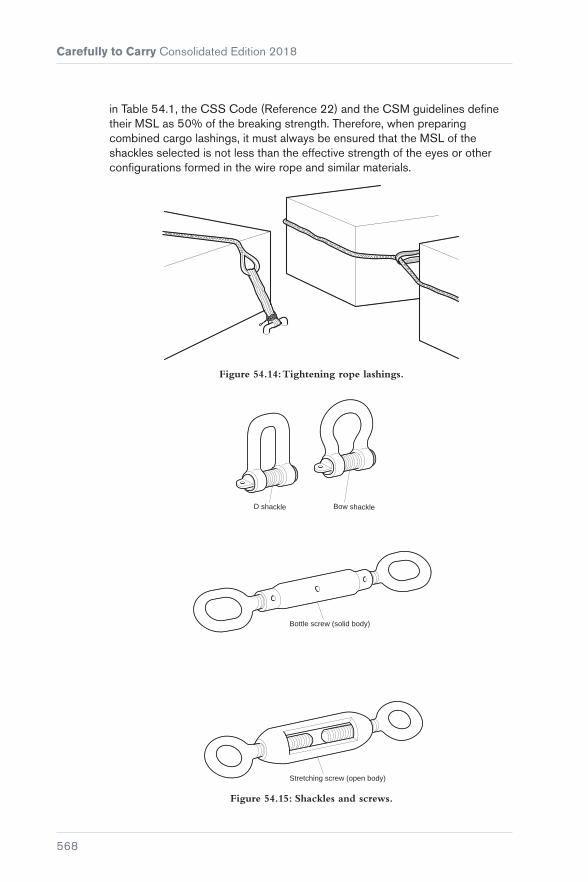
Carefully to Carry Consolidated Edition 2018
568
in Table 54.1, the CSS Code (Reference 22) and the CSM guidelines define their MSL as 50% of the breaking strength. Therefore, when preparing combined cargo lashings, it must always be ensured that the MSL of the shackles selected is not less than the effective strength of the eyes or other configurations formed in the wire rope and similar materials.
Figure 54.14: Tightening rope lashings.
Stretching screw (open body)
Bottle screw (solid body)
D shackle Bow shackle
Figure 54.15: Shackles and screws.
Chapter 54 Lashing and Securing Deck Cargoes
569
54.20 Turnbuckles
The precautions for shackles also apply to the use of turnbuckles. The word ‘turnbuckle’ is used collectively to include solid-cased bottle screws and open-sided rigging screws or straining screws. These are most commonly used for general cargo lashing and are supplied in a range of sizes and strengths with a closed eye at each end. Open-sided rigging screws and straining screws tend to have noticeably lower strengths than solid bottle screws of the same size. The suppliers or manufacturers should be asked to provide the relevant test data so that the correct MSL or SWL can be ascertained before commencing lashing.
Solid bottle screws are typically sold by size of screw pin diameter. Those of 24 mm diameter have a proof-load of 4 t and those of 38 mm have a proof-load of 10 t. Special-purpose turnbuckles are available with much greater strengths than those given above. These may have particular fittings and modifications, such as those used in the container trade. Again, it is important to consult the manufacturers’ literature before such equipment is brought into use.
Turnbuckles should always be used with the pulling forces acting in one straight line. They should never be allowed to become the fulcrum of angled forces, no matter how slight.
Care should always be taken to ensure that the screws are at adequate extension when the cargo is finally secured. In this way, scope is provided for further tightening if this should prove necessary during the voyage as the cargo and lashing arrangements settle. Where high torque upon a main lashing is involved, the eyes of the turnbuckle should be seized or stopped against its own body in order to prevent the screws working back under load during the voyage.


571
Chapter 55
Steel Hatch Covers
The steady increase in the size of ships, and particularly bulk carriers, has been accompanied by a steady increase in the cost of manning and running them.
Figure 55.1: Steel hatch covers.

Carefully to Carry Consolidated Edition 2018
572
As a partial counter to this escalation in costs, equipment such as steel hatch covers was developed and introduced on board ship, shortening the turnaround time in port and enabling larger ships to be manned by smaller crews.
This chapter is from a UK P&I Club report that considered steel hatch covers in general and the MacGregor-Navire hatch covers in particular. It looks at claims for seawater damage to cargo carried in ships fitted with steel hatch covers to analyse the causes of leakage and to suggest solutions.
The fitting of steel hatch covers on the weather deck of seagoing ships is now the rule rather than the exception, and so it is essential to eliminate the underlying causes of cargo damage from ingress of seawater through these hatch covers. The additional weight of seawater in the tanks may also overload the ship and threaten stability.
55.1 Advantages of Steel Hatches
The advantages of steel hatch covers include:
� Greater strength than traditional hatch covers, which contributes to the safety of the vessel
� easier and quicker to open and close
� fewer crew are required to operate them compared to traditional hatch covers.
Against these advantages must be placed the high costs of initial purchase and routine maintenance.
55.2 Development of Automatic Steel Hatch Covers
The hatch openings of ships were traditionally covered with beams, wooden boards and tarpaulins. Metal was used for slab-type pontoons, but the MacGregor-Navire Organisation had the idea of using an eccentric wheel to lower and raise these pontoons and, in the raised position, to move them to one end of the coamings, lifting them at that point into a vertical position. In the lowered position, they would rest on a rubber gasket and, by the use of cleats, become weathertight. This revolutionary but simple modification was still in operation in the mid 1940s.
Subsequently, these simple individually moved panels were linked together and counterbalanced in such a way that one wire could be used to move them to one end of the hatch, where they would automatically assume a vertical position and stow in a small area. This principle became internationally known as the ‘single pull hatch cover’ and, on the weather deck, it is still the most widely used means of cargo protection. Refinements and modifications have been incorporated to include automation and folding hatch covers motivated by hydraulic or electrical means, piggy back covers, stacking covers, coiling

Chapter 55 Steel Hatch Covers
573
covers and sequential or non-sequential multi-panel covers. However, for illustrative purposes, this chapter covers just the single pull type of operation.
55.2.1 Coamings
The sealing round the edge of the hatch, to prevent the ingress of water, consists of a hard rubber gasket strip retained on three sides in a channel bar within the hatch cover framework and resting on the compression bar, which is a square section steel bar welded onto the coaming bars (see Figures 55.2 to 55.4). A double drainage trough is designed inboard of this compression bar to safeguard against minor localised sealing problems.
Figure 55.2: Section through side or end of hatch cover.
Figure 55.3: Section through cross joint.
Figure 55.4: Details of cross joint rubber inserts.

Carefully to Carry Consolidated Edition 2018
574
Should anything be trapped on the coaming during the closing operation or a local deformation in the compression bar be caused by, for example, a derrick runner wire then in this local area there is a small opening for the possible entry of water which, while not being dangerous, could damage a fairly large amount of cargo.
55.2.2 Moving Parts
Maintenance for the continuance of original weathertightness is essential and correct maintenance of moving parts, such as wheels, chains, gypsies, etc, will alleviate the possibility of the assembly being subjected unnecessarily to rough treatment because of undue wear on these parts.
55.3 Weakness in Hatch Covers
55.3.1 Strength
Each automated steel hatch cover panel, consisting of steel plate, sections, beams, etc, is designed and assembled to the strict requirements of a Classification Society and is expected to be immensely strong. However, this can be a disadvantage under certain circumstances, particularly when the vessel is labouring in a seaway. Although ships give the impression of great strength, when the weather is adverse any ship that does not yield to the force of the waves would quickly founder. In fact, the ship must ride those blows that cannot be avoided to absorb the greater part of the energy directed at it. In so doing, the ship ‘works’ along its length and across its width.
In these conditions, the strength and rigidity of the steel hatch covers can cause the weathertight joints between the vessel’s structure (hatch) and the covers to move as the ship works in a seaway.
With the average freeboard of ships considered as being approximately 2.75 m, and with a combination of wave heights, a deadweight cargo and strong winds on passage, most ships will have the decks and hatches awash at frequent intervals.
In an analysis of claims for cargo damage when hatch covers had failed, bad weather had been experienced on every voyage, but in no case was it of such severity as to offer certain defence of ‘perils of the sea’ under the Hague-Visby Rules, neither was it severe enough to justify penetrations of the rubber seals of the hatch joints, provided that the seals were in good condition. However, in many cases, survey reports from the discharge port criticised the condition of the hatch covers and coamings, indicating a poor standard of maintenance.

Chapter 55 Steel Hatch Covers
575
The results on analysis of claims showed:
� Usually, the only vessels involved were those carrying bulk and deadweight cargoes
� their freeboard was not very large
� all voyages included a period of heavy weather
� hatch survey reports indicated that some hatches and coamings were in poor condition.
55.4 Suggested Remedies
55.4.1 Proper Securing
When hatches were secured with boards and tarpaulins, the need for care in their securing was very obvious. The ships were also much smaller and there were more seafarers to perform the tasks connected with leaving port, such as the lowering and securing of derricks and the battening down of hatches. The crew had to work as a team because the various jobs could not be done by one or two seafarers alone and, with teamwork, there is less risk that the job will be improperly done. Lastly, a poorly secured hatch was immediately apparent to the ship’s officers and steps could be taken to remedy the situation.
However, on modern bulk carriers, there are fewer crew members. For the one or two seafarers concerned, the prospect of securing a long line of hatch covers stretching away along the weather deck is not an inviting one, and when there are added discomforts of wind and rain it is not surprising if the securing is not always carried out as conscientiously as it ought to be. Steel cleats and wedges are not as interesting as canvas tarpaulins and wooden wedges, even if they are stronger and more efficient and, therefore, safer. There are also a great many of them; hatches of say 40 ft × 30 ft will probably have 6 panels secured around the edges by about 40 cleats and further secured by about 50 cross-seam wedges.
When securing hatch covers, the joints cannot be effective if insufficient pressure is applied and the pressure must be evenly distributed along the whole length of the joint.
Type of cargo stresses
The type and distribution of cargo carried can affect the stresses experienced by a ship in a seaway and the degree of bending and twisting she suffers. In this respect, homogeneous cargoes of low density, such as bulk grain, are better than high density cargoes, such as ore concentrates or steel products. Bulk carriers are designed as single-deck vessels, which means that high

Carefully to Carry Consolidated Edition 2018
576
density cargoes will be stowed at the bottom of the holds, causing severe racking strains of hogging and sagging.
These racking strains may well cause the hatch covers to leak if the cleats and wedges are not secured properly. In these conditions, it is important to ensure that the cleats remain tight.
Leakage despite proper securing – case study
In severe weather, leakages can and will occur through steel hatch covers even if they are properly secured. This was illustrated by the decision of the US Court of Appeal in the case of the ‘Sabine Howaldt’, 1971 AMC539.
The ‘Sabine Howaldt’ was a vessel of 2,300 gross tons, 306 ft in length, a beam of 40 ft, her bridge amidships and her engines aft. The four cargo holds were served by two hatches only, one forward and one abaft the bridge. The fore deck hatch was about 60 ft × 18 ft and had the protection of solid bulwarks at the ship’s side, while the after deck with open rails at the ship’s side was 3 ft higher than the fore deck and had a hatch of about 68 ft × 18 ft. The holds were separated by bulkheads with the forward hatch serving Nos 1 and 2 and the after hatch serving Nos 3 and 4.
At the time, the ‘Sabine Howaldt’ was 7 years old and her classification, which was the highest in Germanischer Lloyd, had been maintained at her annual survey in April 1965. The charter voyage during the following December was from Europe to the USA with a full cargo of steel products, which were loaded in good condition but were rusted and pitted from contact with seawater when discharged from No 4 hold and also, but to a lesser extent, from No 1 hold.
Before completion of loading, the surveyor for the charterer inspected the hatch covers and found them in good condition with no dents, bending or other damage and no staining on the inside of the coamings to indicate previous leakage. His report found the ship seaworthy. After the hatches had been closed and tightened down, they were inspected by the chief officer together with another officer and a log entry was made by the chief officer that the MacGregor-Navire hatch covers were ‘closed and wedged’.
The ‘Sabine Howaldt’ sailed from Antwerp on 15th December at a draught less than permitted as she was not down to her winter marks. By midnight on the third day, the wind had risen to force 9 on the Beaufort Scale. It increased to force 10 by 09.00 on the 18th, blew with that force until about 17.00 and then began to ease. During the whole of this period, the ship pitched and rolled heavily in the high seas and waves were continually breaking across the decks.
On the 20th, the wind reached force 9/10, but it abated the following day and did not exceed force 7/8. On the 23rd, the ship was hove-to for twelve hours trying to reduce the battering from hurricane force winds, heavy confused

Chapter 55 Steel Hatch Covers
577
swells and huge seas breaking over her forecastle deck hatches and upper works, bending, twisting and vibrating her continuously.
The violence of the weather was severe enough to cause structural damage. After the worst of the storm was over, it was discovered that the pedestal holding the master switch control for the capstan had been torn loose leaving a hole in the deck, a galley port hole was smashed and the catwalk gangway from amidships to poop was torn loose and destroyed, denting a ventilator at the same time. Several parts of the ship’s superstructure and fixtures were dented and the covers from two winches had been ripped off and lost.
When the weather first deteriorated at the beginning of the voyage, the chief officer, in the company of another officer, made a second inspection of the hatches from inside the cargo holds. He found no leakage through the hatchway although waves were washing across the covers. He also examined the covers on arrival in the USA on 3rd January and found hatches, covers and gaskets all in good condition, as did the surveyors for both the owners and the charterers. Nevertheless, seawater had entered the hold and it was decided that the severe stresses to which the ship had been subjected had momentarily deformed the rectangular opening of the hatch, thereby disturbing the seal between the gasket and the compression bar on the coaming, allowing seawater, which was pouring over the decks and hatches, to enter the hold.
After considering all the circumstances, including the fact that on both the previous and following voyages the hatch covers had not leaked in spite of heavy weather, the Court of Appeal decided that the violence of the wind and the confused cross swells that had wrenched and twisted the ship during the voyage were a ‘peril of the sea’ and that the owners were not liable for the damage to cargo resulting from the leaking of the hatch covers.
Had the ‘Sabine Howaldt’ been equipped with wooden hatch boards and tarpaulins, the situation would have been far more dangerous. The collapsing of the amidships catwalk would undoubtedly have torn the tarpaulins covering the hatch over Nos 3 and 4 holds, allowing a much larger volume of seawater to enter those holds to the certain detriment of the cargo and possibly to the ultimate danger of the ship itself.
55.4.2 Proper Maintenance
It is absolutely crucial for hatch covers to be maintained at the highest standard if cargo damage is to be avoided.
It is not easy to achieve this standard because the modern bulk carrier has a smaller crew for its size than the older type general cargo ship and spends little time in port. Adequate maintenance is difficult to carry out in port because of cargo being worked, or at sea because the hatches are then secured for the passage.

Carefully to Carry Consolidated Edition 2018
578
Figure 55.5: Folding hatch cover.
Systematic and well-documented inspection is an essential part of onboard maintenance and will aid identification of defects at an early stage. The ship’s planned maintenance system should include ship/hatch-specific checklists that have been drawn up in accordance with the equipment manuals.
Working parts
The marine environment is extremely corrosive and every opportunity must be taken to minimise its effect, particularly in respect of the cleats that secure the pontoons. It is the shipowner’s/operator’s responsibility to undertake the required maintenance.
Cou
rtes
y of
Dan
ny C
orne
lisse
n/po
rtpi
ctur
es.n
l
Figure 55.6: Hatch coaming and cleat arrangement on a container ship
f itted with pontoons.

Chapter 55 Steel Hatch Covers
579
Hatch panels
Regular inspection and maintenance of hatch panels is essential because any defects, cracks, holes or corrosion will invariably lead to water leaking into the hold. Properly painted hatch top plating contributes only to cosmetic appearance and should not be taken as proof that the panels are in good condition.
Cracks and holes may be repaired with doublers, but these should be considered as a temporary repair and never a substitute to a proper insert repair. Doublers will cover the damage and prevent water ingress, but will not restore the original strength or stop corrosion. Welding on hatch covers should be carried out by trained and qualified personnel as excessive heat may cause distortion of the panel structure, which is very difficult to correct.
Figure 55.7: Multiple doubler plates on hatch top plating.
Care must be taken if sealing tape has been applied to the hatch cover. This adheres strongly to the surface and may lift off the paint when removed. This leaves the surface unprotected and exposed to the elements, with corrosive action setting in if not dealt with quickly and in the proper manner.
Hatch covers are type-approved equipment and repairs involving modifications or changes to the design can only be made with the approval of the Classification Society or the f lag State.
Hatch cover repairs should be properly and promptly reported to the Classification Society or f lag State. As well as being a Class requirement, this enables the ship to obtain correct repair information that is in line with Class rules.
Rubber seals
The most important factors determining the ability of the hatches to remain weathertight are the rubber seals on the underside of the panels and the compression bars with which the seals make contact when the hatches are in a closed and secured position.

Carefully to Carry Consolidated Edition 2018
580
The effectiveness of the rubber seals can be reduced in several ways. Accidents while the hatches are being worked and during the opening and closing of the hatches can physically deform the seals. Careless painting of channels can cause hard spots on the seals locally reducing their resilience. Rust scale can form underneath the seals in an uneven thickness causing high spots and resulting in non-uniform compression of the rubber. Particles of cargoes, such as grain or ore, can become compressed between the seals and the compression bars. Overcompression of the rubber will result in permanent damage in the form of a groove where the rubber meets the compression bar. Finally, although every care and attention is given to the seals, age will cause them to perish or harden, with a tendency for them to crack and break. Any of the above can result in the covers leaking when under stress.
Figure 55.8: Permanent groove in packing rubber caused by overcompression.
Good management, careful inspection and routine maintenance at every opportunity will help to prevent all but the last. The ageing of the rubber cannot be prevented but it can and ought to be recognised and remedied before it has progressed too far. The only remedy is the replacement of the old seals with new, and the opportunity should be taken at the time of renewal to remove all traces of rust scale from the channels before preparing them and reseating the new seals.
Any seals more than two years old should be inspected regularly for signs of deterioration due to ageing.
Whenever packing is to be renewed, whether because of damage or old age, it is essential that the whole strip is replaced, or there will be different compression strengths between the new and existing rubber. In hatch cover tightness, compression is the governing factor not contact.
Last minute repairs should be avoided, particularly if they focus on passing a tightness test rather than quality of repair. Improper repairs are unlikely to withstand ocean passage and overlook the important issue of due diligence.

Chapter 55 Steel Hatch Covers
581
Under the due diligence principle, owners are required to carry out a reasonable inspection to ensure that hatch covers are in good condition. If a defect is found during this inspection, repairs should be carried out in line with good industry practice to restore the condition of the hatch covers and their sealing and securing arrangements.
If a claim for wetting damage is filed against the ship, a well-prepared maintenance file will be of great value in defending the owner’s interest and proving that due diigence was exercised.
Improperly maintained or adjusted hatch covers will generally cause accelerated wear and deep permanent imprint to the rubber seal. Replacing the rubber seal alone will not solve the problem and identifying the root cause of the problem is necessary to ensure that repairs will be efficient.
Compression bars
The compression bars along the top of the hatch coamings are solid steel and there is a tendency to assume that no harm can come to them and that they need no maintenance.
The most common cause of damage to these bars is impact from cargo moving into or out of the hold. This is particularly the case if the ship carries cargoes of constructional steel, when each lift will be awkward to handle and probably heavy as well. A load of this type striking the compression bar can easily dent, score or bend the bar.
The bars may also become damaged over a period of time by cargo wires continually passing across the same area, with the result that the original right-angled edge of the bar becomes rounded. If care is not taken to combat corrosion, the top surface of the bar will, in time, develop high and low spots that will prevent the proper seating of the rubbers.
This corrosion is particularly likely to affect the compression bars of the cross joints. Close attention should be paid to the cross joints between the panels as, in many instances, leakage has occurred at these joints or at some other position as a result of them being defective in some way. The cross joints must be pressed firmly and evenly together, and the cross wedges, whether manually or automatically operated, are of paramount importance as the tightness of the joint mainly depends on them. If the cross wedges do not provide an effective seal, either the seals have become too heavily compressed and require renewal, the compression bar on the adjacent panel has become bent or worn down, or there is a combination of both these defects. The situation is often rectified by welding a small plate onto the adjacent panel edge at a position where the manual wedge end rides up and over the panels to put pressure on the cross joint. If the wedges become strained or bent, new wedges should be fitted.
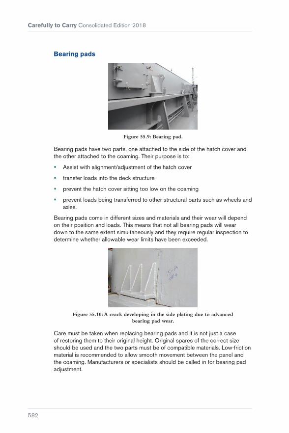
Carefully to Carry Consolidated Edition 2018
582
Bearing pads
Figure 55.9: Bearing pad.
Bearing pads have two parts, one attached to the side of the hatch cover and the other attached to the coaming. Their purpose is to:
� Assist with alignment/adjustment of the hatch cover
� transfer loads into the deck structure
� prevent the hatch cover sitting too low on the coaming
� prevent loads being transferred to other structural parts such as wheels and axles.
Bearing pads come in different sizes and materials and their wear will depend on their position and loads. This means that not all bearing pads will wear down to the same extent simultaneously and they require regular inspection to determine whether allowable wear limits have been exceeded.
Figure 55.10: A crack developing in the side plating due to advanced bearing pad wear.
Care must be taken when replacing bearing pads and it is not just a case of restoring them to their original height. Original spares of the correct size should be used and the two parts must be of compatible materials. Low-friction material is recommended to allow smooth movement between the panel and the coaming. Manufacturers or specialists should be called in for bearing pad adjustment.

Chapter 55 Steel Hatch Covers
583
Figure 55.11: Improper repair to a bearing pad.
Hatch covers fitted with bearing pads usually have an operational clearance of 10 to 15 mm between the panel side lower edge and the coaming. The exact distance should be checked in the manual and noted on inspection sheets as it is one of the first indicators of bearing pad wear.
Locators
Figure 55.12: Properly maintained and adjusted locator.
Locators guide the panel into its correct closing position and ensure the panels are kept properly positioned during the voyage.
Locator wear should be regularly monitored because slight wear on the locators in one place may result in significant loss of compression or improper positioning at another place.
Some locators have replaceable mating surfaces and allow for the use of shim plates to facilitate installation and adjustment in case of wear down.
Figure 55.13: Excessive wear on the locator.

Carefully to Carry Consolidated Edition 2018
584
Stoppers
Hatch panels may be subjected to heavy loads and accelerations when the ship is rolling and pitching in a seaway. Stoppers (restraints) are fitted to keep the panel in its correct position. Stopper wear must be closely monitored and the manual should be consulted for advice on allowable wear limits.
Figure 55.14: Stopper.
Draining system
The coamings and covers of steel hatches are designed to clear away moisture, but general cleanliness of drain holes, waterways and coamings is important because any accumulation of cargo residues or dirt may trap condensation and rainwater. This could result in sweat damage to the cargo and steady deterioration of the covers by corrosion.
Maintenance of the draining system should include regular cleaning of the drainage channels, drain holes, drain pipes and drain valves, particularly following cargo operations.
A wooden bung may be placed in the drainage system to prevent blockage during cargo operations. This is fine as long as removal of the bung is not overlooked on completion of operations.
Figure 55.15: Blocked drainage systems.
Securing mechanism
The primary function of the securing mechanism (cleats) is to hold the panels down when the ship is at sea. Whatever cleating system is used (eg manual, hydraulically operated), it is vital that it is structurally sound. This includes

Chapter 55 Steel Hatch Covers
585
not only the cleat itself, but also the component parts to which the cleats are engaged (eg coaming table, crutches, snugs/panel side plating). The system should be checked regularly for wear and corrosion.
Figure 55.16: Corrosion of quick acting cleat crutch (left), thinned down snugs (right).
The cleats should never be overtightened to obtain a tighter seal. This would make the system too rigid and eventually result in damage to the cleats. In addition, steel to steel contact between the panels and the coaming would make it impossible to compress the rubber seal to achieve an adequate seal.
After completion of securing operations, a final check should be made to ensure that the cleats are all in place and correctly positioned. Crooked or poorly fitting cleats may be an indication of improper closing or alignment of the panel. This should be investigated and corrected before commencement of the voyage since faulty securing will affect the holding power of the system.
Figure 55.17: Improper vertical alignment of quick acting cleat.
Tape or foam
Sometimes, additional safeguards against leakage are applied. The usual method is the covering of cross joints with heavy adhesive tape. A more recent procedure is to use expanding foam, which when sprayed onto the joints produces a hardened barrier to water. The use of additional safeguards does not negate the need for hatch cover testing and inspection.

Carefully to Carry Consolidated Edition 2018
586
Some charterers, particularly in the steel trades, require the Master to apply tape to the hatch cover joints and may even supply the tape. However, the use of temporary sealants allows claimants to assume that the Master/shipowner was aware of the tightness problem, but disregarded due diligence by opting for the cheapest and quickest repair.
Maintenance manuals
Vessels fitted with steel hatch covers should carry manufacturer’s manuals that provide detailed information relating to the construction, operation and maintenance of the covers, together with lists of spare parts that should be carried on board for remedial repairs. In addition, leading manufacturers may have representatives in major sea ports available both to advise and also to carry out repairs and maintenance as required.
It is strongly recommended that major overhauls and inspections are carried out by manufacturers’ representatives, at the very least each time the vessel dry-docks, in order that the high original standard of the covers is maintained throughout the life of the ship. As the trend is for ships to spend less time in port and to carry a relatively small crew, it is reasonable to say that shore maintenance must be the standard, with crew maintenance being used as remedial as and when necessary. In this way, claims on the shipowner for damage to cargo should be reduced to a minimum.
55.5 Testing Weathertight Integrity of Dry Cargo Vessels’ Hatch Covers
Regulation 3.12 of the International Convention on Load Lines, 1966 states:
“Weathertight. Weathertight means that in any sea conditions water will not penetrate into the ship”.
Regulation 16 of the Convention concerns “hatches closed by weathertight covers”. The “means for securing weathertightness” is defined in Regulation 16.4 of the Convention, which states:
“The means for securing and maintaining weathertightness shall be to the satisfaction of the Administration. The arrangements shall ensure that the tightness can be maintained in any sea conditions, and for this purpose tests for tightness shall be required at the initial survey, and may be required at periodical surveys and at annual inspections or at more frequent intervals.”

Chapter 55 Steel Hatch Covers
587
55.5.1 Traditional Methods
The chalk test
Chalk is applied to the compression bars of the coamings and the individual panel cross seams. The hatches are then battened down fully and in the proper manner, after which they are immediately re-opened and the rubber packing (joints) carefully examined. Where a clean regular chalk mark is observed on the packaging, it is assumed that sufficient pressure exists between the joint and the adjacent compression bar. If the chalk mark is found to be intermittent or less pronounced at some points than at others, it is assumed that weathertight integrity does not exist over those areas. This method can only be considered as indicative of a possible problem, with likely inconclusive results even after rectification of possible defects that may have been exposed by the test. IACS Recommendation No 14 advises:
“Upon completion of installation of hatch covers, a chalk test is to be carried out. This is to be followed by a hose test with a pressure of water not less than 200 kN/m2.”
The light test
This is the simplest means of establishing whether a defect exists and its location. The hatches are battened down fully and properly for seagoing, the surveyor/observer entering the hold and viewing the underside of the covers from below. In strong sunlight, defects should be readily visible, with daylight shining through any gaps in the packaging. If the test is undertaken during poor light conditions, strong torchlight properly directed from above will serve the same purpose.
The hose test
In this test, a strong jet of pressurised water is directed at the seams and joints of the hatch covers. Hatch covers are battened down fully in the proper manner and with the surveyor stationed in the hold. A survey assistant must be stationed on deck/on top of the hatch covers to ensure that the water, usually supplied from the vessel’s fire main, is directed at a constant and sufficient pressure in the proper direction. Ideally, the hose should be held at a distance of no more than one metre from the joint under test with a pressure of not less than 200 Kn/m2. The disadvantages of this method include:
� It is time consuming
� it is difficult to ensure adequate water pressure
� excessive water may drain from the decks when the vessel may be alongside a wharf, pier or jetty
� the test cannot be safely carried out when the vessel is laden for fear of wet damage to the cargo

Carefully to Carry Consolidated Edition 2018
588
� two surveyors are required to conduct the test
� the test cannot be carried out if weather conditions/air temperatures are at or below 0°C.
A high-pressure jet of water may break apart on top of the panel rather than entering the interpanel void space, thus producing an unreliable test result. A second method would be to close the panel’s side guttering and fill up the cross joint interpanel void space with water from a low-pressure hose. This allows hydrostatic pressure to build up on top of the packing rubber/compression bar interface. Any water that passes through the seal will be expelled on deck through the drain valve (note that perimeter joints will still require water jet testing). As a lot of water is generated during the test, it is recommended that a plastic bag is placed at the discharge end of the drain valve to collect water expelled during the test.
Ultrasonic test
There has been debate concerning the efficiency and acceptability of ultrasonic testing equipment but the technique is widely used throughout the industry to test and prove the weathertightness of hatch covers.
The advantages of this method include:
� The test identifies the exact location and extent of leakage
� it indicates the compression status of the rubber seal; if compression is good, the rubber will be able to compensate for movements at sea and maintain a tight seal
� the equipment is quick and easy to operate. One person operation is possible
� the test may be carried out in loaded or empty holds
Figure 55.18: Ultrasonic testing of hatch cover.

Chapter 55 Steel Hatch Covers
589
� there are no weather/temperature limitations and the test may be carried out during the day or night
� there is no pollution risk.
The procedure comprises placing a transmitter in the cargo hold, switching it on, and properly closing and securing the hatch covers or access equipment to seaworthy requirements. The ultrasonic waves emitted by the transmitter within the enclosed space will leak through the smallest of apertures. Any leakage of sound may be detected by a receiver or detector between frequencies of 36.7 and 40.7 kHz and converted into aural frequencies or into digitally reproduced information. The location of leaks can be precisely detected from outside the hold by moving a hand-held detector along the periphery and cross seams of the covers. Evaluation of the extent of leakage can be established from reading a digital scale.
Class type approval and operator training is undertaken by some manufacturers of ultrasonic equipment used in the testing of hatch covers. The training courses include:
� Principles of the technique
� the ultrasonic equipment
� hatch cover types
� typical defects identified
� testing and reporting procedures.
It is impossible to say that hatch covers are weathertight merely by testing the seal. Although the condition of the seal plays a major part, it is also necessary to visually inspect all parts of the cover.
Records
A record should be kept of the location and extent of any leakages detected during testing. The hatches should then be opened, the causes of leakages, if any, identified, the defects rectified, covers resecured and further weathertight testing undertaken.
Hatch cover safety
Hatch covers are heavy, moving pieces of machinery and crew must be trained in their safe operation and maintenance.
Chapter 16 of the Code of Safe Working Practices for Merchant Seafarers (2015 Edition) identifies areas of operation that need particular attention to protect the health and safety of operators.

Carefully to Carry Consolidated Edition 2018
590
As there are many different types of hatch cover, shipowners should draft ship-specific operating guidelines based on the manufacturer’s manuals. This should include the operational limits due to trim, heel, and transversal and longitudinal coaming deflection. The OOW/cargo officer should monitor these operational limitations closely because failure to do so may cause the hatch covers to derail.
Evidence to produce in the event of a claim
If a claim for wetting damage is filed against the ship, the following documentation should be produced as evidence of due diligence:
� Work schedules
� maintenance logs and test reports
� work specifications
� accounts
� standing instructions
� reports and correspondence
� logbook entries
� hatch patentee manual
� relevant certificates
� evidence of voyage planning and weather reports
� proof that the ship was operated in a seamanlike manner during the voyage.
A sea protest should also be prepared. A local P&I surveyor will be able to assist with further survey and test requirements.

591
References
References ............................................ 591


593
References
1. IMO. Recommendations on the Safe Use of Pesticides in Ships.
2. Isbester, Captain J. Bulk Carrier Practice: A Practical Guide.
3. IMO. International Code for the Safe Carriage of Grain in Bulk (International Grain Code).
4. Oxley, T A. The Scientific Principles of Grain Storage.
5. European Commission. EU Register of authorised GMOs.
6. European Union Reference Laboratory for GM Food and Feed. ENGL Members.
7. Biosafety Clearing-House. Welcome to the BCH Central Portal.
8. European Commission. 2004/787/EC: Commission Recommendation of 4 October 2004 on technical guidance for sampling and detection of genetically modified organisms and material produced from genetically modified organisms as or in products in the context of Regulation (EC) No 1830/2003Text with EEA relevance.
9. International Organization for Standardization (ISO). ISO DIS 21568: FOODSTUFFS - METHODS OF ANALYSIS FOR THE DETECTION OF GENETICALLY MODIFIED ORGANISMS AND DERIVED PRODUCTS – SAMPLING.
10. European Parliament, Council of the European Union. Regulation (EC) No 1829/2003 of the European Parliament and of the Council of 22 September 2003 on genetically modified food and feed.
11. European Parliament, Council of the European Union. Directive 2001/18/EC of the European Parliament and of the Council of 12 March 2001 on the deliberate release into the environment of genetically modified organisms and repealing Council Directive 90/220/EEC - Commission Declaration.
12. European Parliament, Council of the European Union. Directive (EU) 2015/412 of the European Parliament and of the Council of 11 March 2015 amending Directive 2001/18/EC as regards the possibility for the Member States to restrict or prohibit the cultivation of genetically modified organisms (GMOs) in their territory.
13. European Parliament, Council of the European Union. Regulation (EC) No 1830/2003 of the European Parliament and of the Council of 22 September 2003 concerning the traceability and labelling of genetically modified organisms and the traceability of food and feed products produced from genetically modified organisms and amending Directive 2001/18/EC.

Carefully to Carry Consolidated Edition 2018
594
14. European Commission. Commission Recommendation of 23 July 2003 on guidelines for the development of national strategies and best practices to ensure the coexistence of genetically modified crops with conventional and organic farming (notified under document number C(2003) 2624).
15. Biosafety Clearing-House, Convention on Biological Diversity. The Cartagena Protocol on Biosafety.
16. INTERCARGO/Lloyd’s Register/UK P&I Club. Carrying Solid Bulk Cargoes Safely.
17. IMO. International Maritime Solid Bulk Cargoes Code (IMSBC Code).
18. IMO. International Convention for the Safety of Life at Sea (SOLAS).
19. IMO. International Maritime Dangerous Goods Code (IMDG Code).
20. N I Dowling and J B Hyne. ‘Controlling Corrosion of Steel by Wet Elemental Sulphur.’ NACE Canadian Region Western Conference, 1987.
21. International Group of P&I Clubs. Circular: Direct Reduced Iron. 1982.
22. IMO. Code of Safe Practice for Cargo Stowage and Securing (CSS Code).
23. IMO. Code of Safe Practice for Ships Carrying Timber Deck Cargoes, 2011 (TDC Code).
24. IMO. Revised Guidelines for the Preparation of the Cargo Securing Manual (MSC.1/Circ.1353/Rev.1).
25. IMO. International Convention on Load Lines, 1966.
26. UK P&I Club. Carefully to Carry: Packaged timber deck cargo – dangerous densities.
27. IMO. International Code on Intact Stability, 2008 (IS Code).
28. ASTM-IP-API. Petroleum Measurement Tables.
29. IMO. International Convention for the Unification of Certain Rules of Law relating to Bills of Lading (1924)/First Protocol (1968)/Second Protocol (1979) (The Hague-Visby Rules).
30. IMO. International Convention for the Prevention of Pollution from Ships (MARPOL).
31. IMO. United Nations Convention on the Carriage of Goods by Sea (The Hamburg Rules).
32. British Standards Institution. BS EN 627:1996 Specification for data logging and monitoring of lifts, escalators and passenger conveyors.
33. Department for Transport. Renewable Transport Fuels Obligation.
34. ASTM. ASTM D6751 – Standard Specification for Biodiesel Fuel Blend Stock (B100) for Middle Distillate Fuels.
35. European Committee for Standardization. EN 14214.

595
References
36. The Federation of Oils, Seeds and Fats Associations Ltd. Carriage of Oils and Fats.
37. Ministry of Defence. Defence Standard 91-91.
38. European Committee for Standardization. EN 590.
39. The Energy Institute. HM 50. Guidelines for the cleaning of tanks and lines for marine tank vessels carrying petroleum and refined products.
40. International Organization for Standardization (ISO). ISO 8217:2017: Petroleum products – Fuels (class F) – Specifications of marine fuels.
41. European Committee for Standardization. EN 228 - Automotive fuels - Unleaded petrol - Requirements and test methods.
42. IMO. International Code for the Construction and Equipment of Ships Carrying Dangerous Chemicals in Bulk (IBC Code).
43. IMO. 2011 Guidelines for the Carriage of Blends of Petroleum Oil and Biofuels, as Amended (MEPC.1/Circ.761/Rev.1).
44. IMO. International Code of Safety for Ships Using Gases or Other Low-Flashpoint Fuels (IGF Code).
45. IMO. International Code for the Constructions and Equipment of Ships Carrying Liquefied Gases in Bulk (IGC Code).
46. IMO. Code for the Construction and Equipment of Ships Carrying Liquefied Gases in Bulk (GC Code).
47. IMO. Code for Existing Ships Carrying Liquefied Gases in Bulk (EGC Code).
48. IMO. International Convention on Standards of Training, Certification and Watchkeeping (STCW Convention).
49. OCIMF. Mooring Equipment Guidelines, 3rd Edition (MEG3).
50. SIGTTO. Liquefied Gas Handling Principles on Ships and in Terminals, 4th Edition. (LGHP4).
51. IMO. Recommendations on the Safe Use of Pesticides in Ships Applicable to the Fumigation of Cargo Holds (MSC.1/Circ.1264 and Amendments).
52. IMO. Recommendations on the Safe Use of Pesticides in Ships Applicable to the Fumigation of Cargo Transport Units (MSC.1/Circ.361).
53. The International Group of P&I Clubs. Carriage of calcium hypochlorite.
54. Gray, B F and Halliburton, B W. The thermal decomposition of hydrated calcium hypochlorite (UN 2880). Fire Saf. J. 2000, 35.3, 223–39.
55. The Expandable Polystyrene (EPS) Transport Group of PlasticsEurope. Guidelines for Transport and Storage of Expandable Polystyrene Raw Beads.
56. The Office of the Federal Register. ‘Title 49: Transportation.’ The Code of Federal Regulations.

Carefully to Carry Consolidated Edition 2018
596
57. IMO/ILO/UNECE. Code of Practice for Packing of Cargo Transport Units (CTU Code).
58. Container Owners Association (COA). Code of Practice for Flexitanks.
59. British Standards Institution (BSI). PAS 1008 – Specification for the performance and testing of a single-use flexitank.
60. International Organization for Standardization (ISO). ISO 1496-1 Series 1 freight containers – specification and testing.
61. ICCT. Recommendations Regarding Carriage Instructions for Refrigerated Cargoes.
62. World Health Organisation (WHO). Good Distribution Practices for Pharmaceutical Products.
63. World Health Organisation (WHO). Guide to Good Storage Practices for Pharmaceuticals.
64. World Health Organisation (WHO). Supplement 13: Qualification of Shipping Containers. (Technical Supplement to WHO Technical Report Series, No. 961, 2011).
65. International Chamber of Shipping (ICS) and The World Shipping Council (WSC). Safe Transport of Containers by Sea: Industry Guidance for Shippers and Container Stuffers.
66. International Organization for Standardization (ISO). ISO/DIS 3874 – Series 1 freight containers – Handling and securing.
67. International Organization for Standardization (ISO). ISO 1161:2016 – Series 1 freight containers – Corner and intermediate fittings – Specifications.
68. United States Department of Labor, Occupational Safety and Health Administration. ‘Title 29: Labor.’ The Code of Federal Regulations.
69. IMO. Amendments to the Code of Safe Practice for Cargo Stowage and Securing (CSS Code). MSC.1/Circ.1352/Rev.1.
70. IMO. Guidelines for the Preparation of the Cargo Securing Manual. MSC/Circ.745.
71. International Labour Organization (ILO). Code of Safe Practice on Safety and Health in Dock Work.
72. IMO. MSC.1/Circ.1263 (2008). Revised recommendations on safety of personnel during container securing operations.
73. European Parliament, Council of the European Union. Regulation (EU) No 660/2014 of the European Parliament and of the Council of 15 May 2014 amending Regulation (EC) No 1013/2006 on shipments of waste.
74. European Commission. Commission Regulation (EC) No 1379/2007 of 26 November 2007 amending Annexes IA, IB, VII and VIII of Regulation (EC) No 1013/2006 of the European Parliament and of the Council on shipments

597
of waste, for the purposes of taking account of technical progress and changes agreed under the Basel Convention (Text with EEA relevance).
75. European Commission. Commission Regulation (EC) No 1418/2007 of 29 November 2007 concerning the export for recovery of certain waste listed in Annex III or IIIA to Regulation (EC) No 1013/2006 of the European Parliament and of the Council to certain countries to which the OECD Decision on the control of transboundary movements of wastes does not apply (Text with EEA relevance).
76. European Parliament, Council of the European Union. Regulation (EC) No 1013/2006 of the European Parliament and of the Council of 14 June 2006 on shipments of waste.
77. DNV. Rules for Planning and Execution of Marine Operations.
78. DNV-GL. Noble Denton Guidelines.
79. International Standards Organization (ISO). ISO 6780:2003. Flat pallets for intercontinental materials handling – Principal dimensions and tolerances.
80. International Organization for Standardization (ISO). ISO/DIS 7195 – Nuclear Energy – Packagings for the transport of uranium hexafluoride (UF6).
81. British Standards Institution. BSI Homepage.
82. ANSI. American National Standards Institute Homepage.
83. DIN. German Institute for Standardization Homepage.
84. UK Gov. Merchant Shipping (Load Lines) (Deck Cargo) Regulations 1968 S.I. 1968/1089.
References