
Capacitance - Chapter 2
58
Chapter 25 Capacitance 1
-
Upload
khangminh22 -
Category
Documents
-
view
0 -
download
0
Transcript of Capacitance - Chapter 2

Chapter 25Capacitance
1
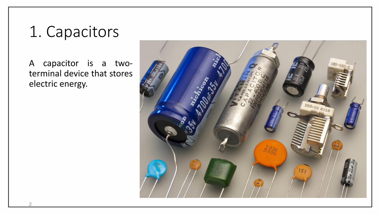
1. Capacitors
A capacitor is a two-terminal device that storeselectric energy.
2
2. Capacitance
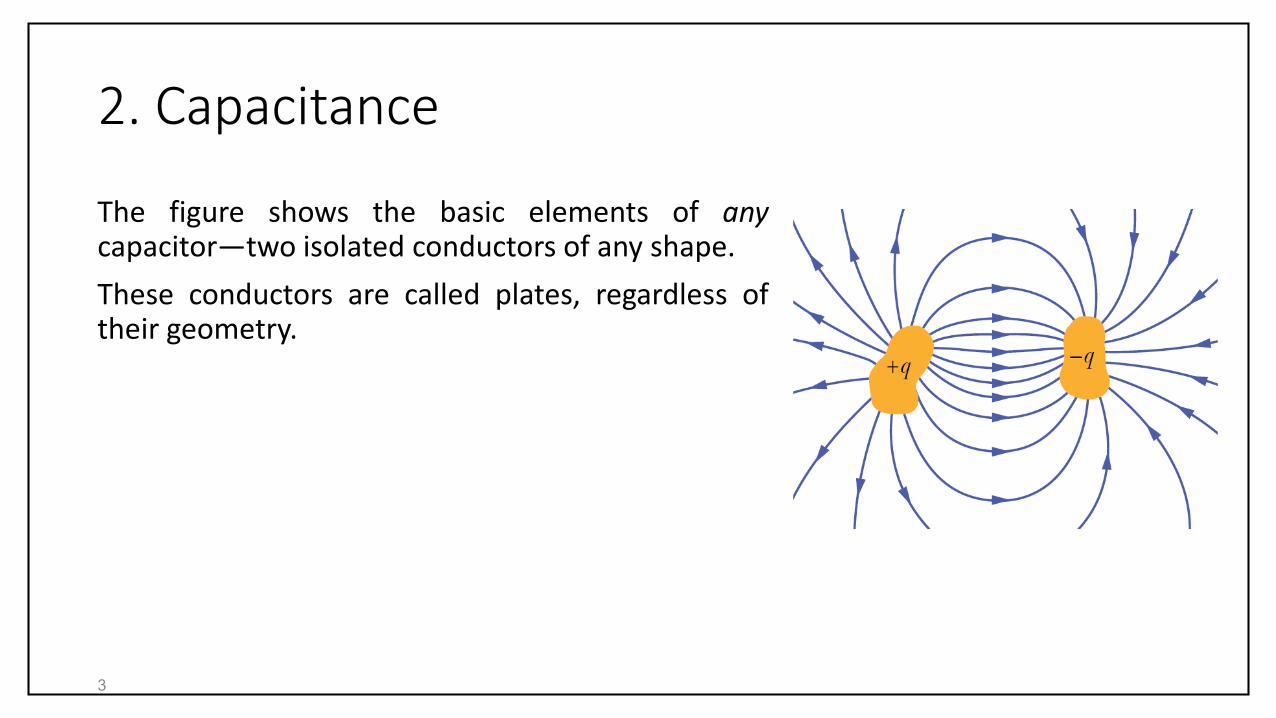
The figure shows the basic elements of anycapacitor—two isolated conductors of any shape.
These conductors are called plates, regardless oftheir geometry.
3

2. Capacitance
The figure shows a less general but more conventional arrangement, called aparallel-plate capacitor, consisting of two parallel conducting plates of area 𝐴separated by a distance 𝑑.
4

2. Capacitance
When a capacitor is charged, its plates have charges of equal magnitudes butopposite signs: +𝑞 and −𝑞. However, we refer to the charge of a capacitor as being𝑞, the absolute value of these charges on the plates.
The plates are equipotential surfaces. Moreover, there is a potential differencebetween the two plates. For historical reasons, we represent the absolute value ofthis potential difference with 𝑉 rather than with the ∆𝑉.
The charge 𝑞 and the potential difference 𝑉 are related by
𝑞 = 𝐶𝑉,
where 𝐶 is called the capacitance of the capacitor. The capacitance is a measure ofhow much charge must be put on the plates to produce a certain potentialdifference between them: The greater the capacitance, the more charge isrequired. The capacitance depends only on the geometry of a capacitor.5
2. Capacitance
The SI unit of capacitance is the coulomb per volt and has the special name farad(𝐹):
1 farad = 1 F = 1 coulomb per volt = 1 C/V.
6

2. Capacitance
Charging a Capacitor
To charge a capacitor we place it in an electric circuit with a battery. An electriccircuit is a path through which charge can flow. A battery is a device that maintainsa potential difference between its terminals by means of internal electrochemicalreactions in which electric force can move internal charge. Terminals are points atwhich charge can enter or leave the battery.
7
2. Capacitance
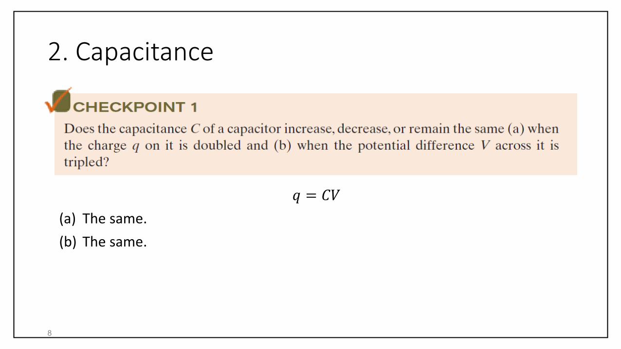
𝑞 = 𝐶𝑉
(a) The same.
(b) The same.
8
3. Calculating the Capacitance
We want here to calculate the capacitance of a capacitor once we know itsgeometry. To do that, we will
(1) assume a charge of magnitude 𝑞 lies on the plates,
(2) calculate the electric field 𝐸 between the plates in terms of 𝑞 using Gauss’ law,
(3) calculate the potential difference 𝑉 between the plates and
(4) calculate 𝐶 using 𝑞 = 𝐶𝑉.
9

3. Calculating the Capacitance
Calculating the Electric Field
To evaluate the electric field between the plates of a capacitor, we will take aGaussian surface enclosing the positive charge 𝑞. Additionally, we will approximatethe electric field 𝐸 to be constant over the Gaussian surface. The charge 𝑞 and theelectric field 𝐸 are then related by
𝐸𝐴 =𝑞
𝜀0,
where 𝐴 here is the area of the Gaussian surface.
10
3. Calculating the Capacitance
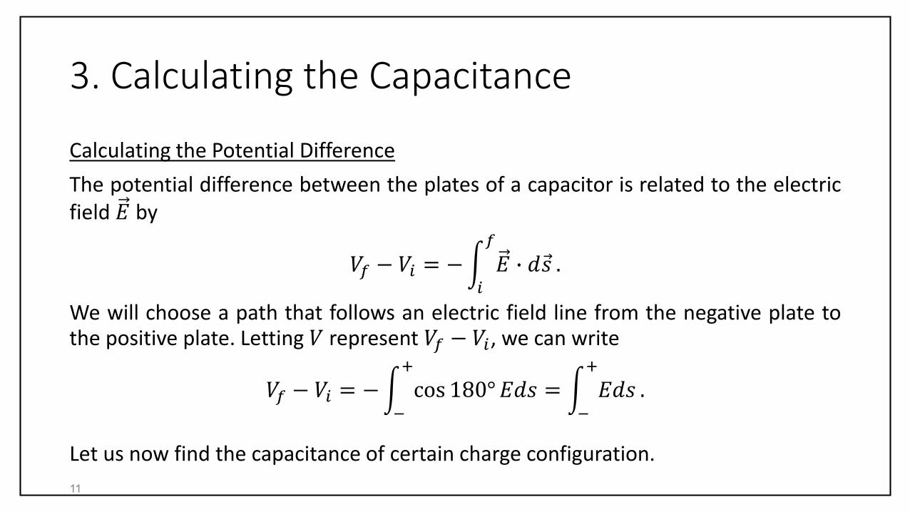
Calculating the Potential Difference
The potential difference between the plates of a capacitor is related to the electricfield 𝐸 by
𝑉𝑓 − 𝑉𝑖 = − 𝑖
𝑓
𝐸 ∙ 𝑑 𝑠 .
We will choose a path that follows an electric field line from the negative plate tothe positive plate. Letting 𝑉 represent 𝑉𝑓 − 𝑉𝑖, we can write
𝑉𝑓 − 𝑉𝑖 = − −
+
cos 180° 𝐸𝑑𝑠 = −
+
𝐸𝑑𝑠 .
Let us now find the capacitance of certain charge configuration.
11
3. Calculating the Capacitance
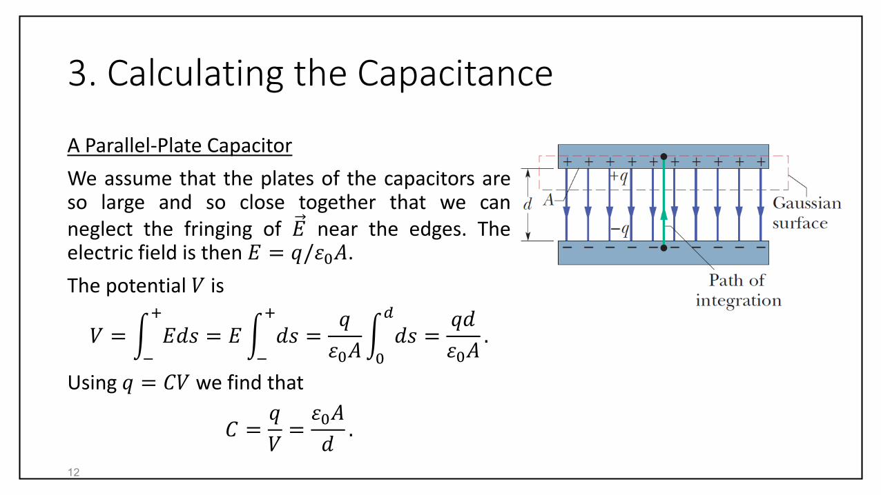
A Parallel-Plate Capacitor
We assume that the plates of the capacitors areso large and so close together that we canneglect the fringing of 𝐸 near the edges. Theelectric field is then 𝐸 = 𝑞/𝜀0𝐴.
The potential 𝑉 is
𝑉 = −
+
𝐸𝑑𝑠 = 𝐸 −
+
𝑑𝑠 =𝑞
𝜀0𝐴 0
𝑑
𝑑𝑠 =𝑞𝑑
𝜀0𝐴.
Using 𝑞 = 𝐶𝑉 we find that
𝐶 =𝑞
𝑉=𝜀0𝐴
𝑑.
12

3. Calculating the Capacitance
A Parallel-Plate Capacitor
𝐶 =𝜀0𝐴
𝑑.
A here is the area of the either plate.
Note that the capacitance 𝐶 depends only on thegeometry of the capacitor.
We can express the permittivity constant 𝜀0 in aunit more appropriate for problems involvingcapacitors:
𝜀0 = 8.85 × 10⁻¹²𝐹
𝑚= 8.85
𝑝𝐹
𝑚.
13
3. Calculating the Capacitance
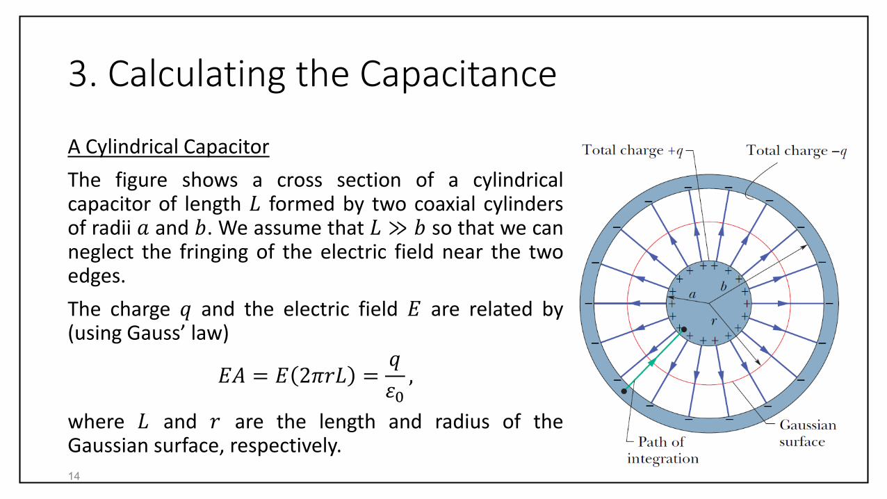
A Cylindrical Capacitor
The figure shows a cross section of a cylindricalcapacitor of length 𝐿 formed by two coaxial cylindersof radii 𝑎 and 𝑏. We assume that 𝐿 ≫ 𝑏 so that we canneglect the fringing of the electric field near the twoedges.
The charge 𝑞 and the electric field 𝐸 are related by(using Gauss’ law)
𝐸𝐴 = 𝐸 2𝜋𝑟𝐿 =𝑞
𝜀0,
where 𝐿 and 𝑟 are the length and radius of theGaussian surface, respectively.
14

3. Calculating the Capacitance
A Cylindrical Capacitor
Solving for 𝐸 we find that
𝐸 =𝑞
2𝜋𝜀0𝐿𝑟.
The potential difference becomes
𝑉 = −
+
𝐸𝑑𝑠 = 𝑏
𝑎
𝐸(−𝑑𝑟) =−𝑞
2𝜋𝜀0𝐿 𝑏
𝑎 𝑑𝑟
𝑟
=𝑞
2𝜋𝜀0𝐿ln𝑏
𝑎.
We used that 𝑑𝑠 = −𝑑𝑟.
15

3. Calculating the Capacitance
A Cylindrical Capacitor
Using 𝑞 = 𝐶𝑉 we find that
𝐶 =𝑞
𝑉= 2𝜋𝜀0
𝐿
ln 𝑏/𝑎.
16
3. Calculating the Capacitance
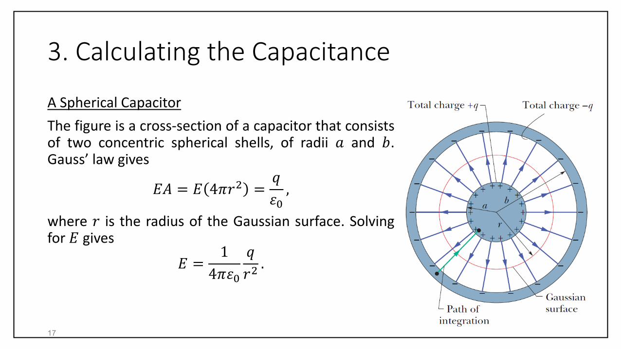
A Spherical Capacitor
The figure is a cross-section of a capacitor that consistsof two concentric spherical shells, of radii 𝑎 and 𝑏.Gauss’ law gives
𝐸𝐴 = 𝐸 4𝜋𝑟2 =𝑞
𝜀0,
where 𝑟 is the radius of the Gaussian surface. Solvingfor 𝐸 gives
𝐸 =1
4𝜋𝜀0
𝑞
𝑟2.
17
3. Calculating the Capacitance
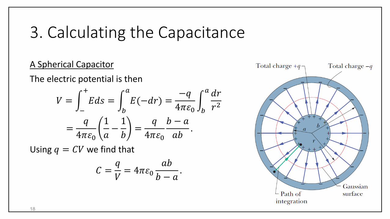
A Spherical Capacitor
The electric potential is then
𝑉 = −
+
𝐸𝑑𝑠 = 𝑏
𝑎
𝐸(−𝑑𝑟) =−𝑞
4𝜋𝜀0 𝑏
𝑎 𝑑𝑟
𝑟2
=𝑞
4𝜋𝜀0
1
𝑎−1
𝑏=𝑞
4𝜋𝜀0
𝑏 − 𝑎
𝑎𝑏.
Using 𝑞 = 𝐶𝑉 we find that
𝐶 =𝑞
𝑉= 4𝜋𝜀0
𝑎𝑏
𝑏 − 𝑎.
18
3. Calculating the Capacitance
An Isolated Sphere
We can assign capacitance to a single isolated sphere of radius 𝑅 by assuming thatthe “missing plate” is a conducting sphere of infinite radius.
To find an expression for the capacitance we rewrite the capacitance of a sphericalcapacitor as
𝐶 = 4𝜋𝜀0𝑎
1 − 𝑎/𝑏.
Replacing 𝑎 with 𝑅 and taking the limit that 𝑏 → ∞ gives that
𝐶 = 4𝜋𝜀0𝑅.
19

3. Calculating the Capacitance
(a) Decreases.
(b) Increases.
(c) Decreases.
20
𝑞 = 𝐶𝑉
𝐶 =𝜀0𝐴
𝑑
𝐶 = 2𝜋𝜀0𝐿
ln 𝑏/𝑎
𝐶 = 4𝜋𝜀0𝑎𝑏
𝑏 − 𝑎

4. Capacitors in Parallel and in Series
When there are several capacitors in a circuit, wecan sometimes replace them with a singleequivalent capacitor. Such a replacement cansimplify circuit analysis. There are two basic waysin which capacitors are combined:
Capacitors in Parallel
When a potential difference 𝑉 is applied acrossseveral capacitors connected in parallel, thatpotential difference 𝑉 is applied across eachcapacitor. The total charge 𝑞 stored on thecapacitors is the sum of the charges stored on allthe capacitors.
21
4. Capacitors in Parallel and in Series
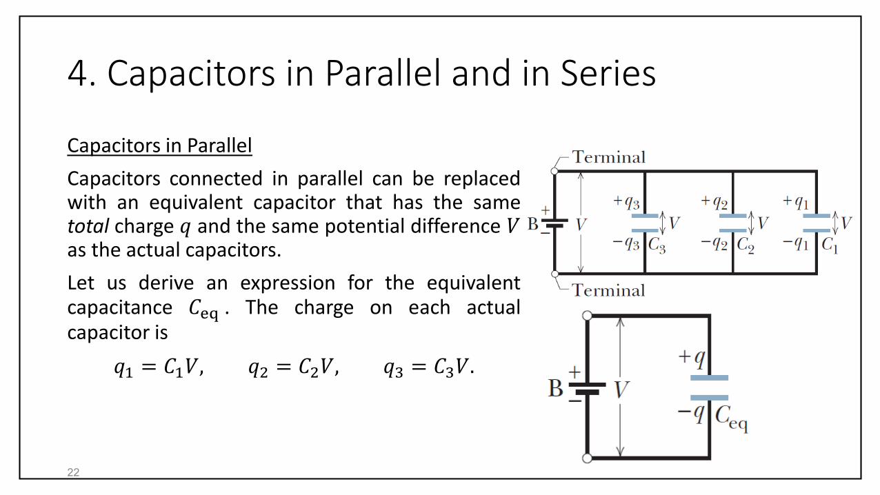
Capacitors in Parallel
Capacitors connected in parallel can be replacedwith an equivalent capacitor that has the sametotal charge 𝑞 and the same potential difference 𝑉as the actual capacitors.
Let us derive an expression for the equivalentcapacitance 𝐶eq . The charge on each actualcapacitor is
𝑞1 = 𝐶1𝑉, 𝑞2 = 𝐶2𝑉, 𝑞3 = 𝐶3𝑉.
22

4. Capacitors in Parallel and in Series
Capacitors in Parallel
The total charge 𝑞 on the parallel combination isthen
𝑞 = 𝑞1 + 𝑞2 + 𝑞3 = 𝐶1 + 𝐶2 + 𝐶3 𝑉.
Thus,
𝐶eq =𝑞
𝑉= 𝐶1 + 𝐶2 + 𝐶3.
Generally, for 𝑛 capacitors connected in parallel
𝐶eq = 𝑖=1
𝑛
𝐶𝑖 .
23

4. Capacitors in Parallel and in Series
Capacitors in Series
When a potential difference 𝑉 is applied across severalcapacitors connected in series, the capacitors have identicalcharge 𝑞. The sum of the potential differences across all thecapacitors is equal to the applied potential difference 𝑉.
Capacitors that are connected in series can be replaced withan equivalent capacitor that has the same charge 𝑞 and thesame total potential difference 𝑉 as the actual seriescapacitors.
Let us derive an expression for the equivalent capacitance𝐶eq
24
4. Capacitors in Parallel and in Series
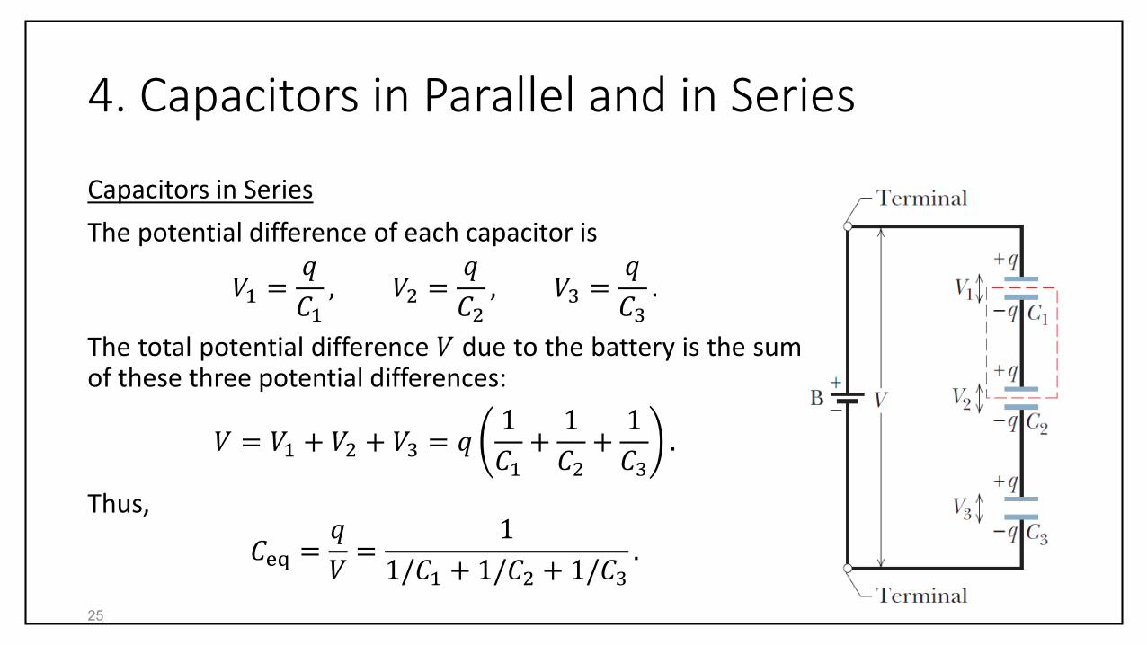
Capacitors in Series
The potential difference of each capacitor is
𝑉1 =𝑞
𝐶1, 𝑉2 =
𝑞
𝐶2, 𝑉3 =
𝑞
𝐶3.
The total potential difference 𝑉 due to the battery is the sumof these three potential differences:
𝑉 = 𝑉1 + 𝑉2 + 𝑉3 = 𝑞1
𝐶1+1
𝐶2+1
𝐶3.
Thus,
𝐶eq =𝑞
𝑉=
1
1/𝐶1 + 1/𝐶2 + 1/𝐶3.
25
4. Capacitors in Parallel and in Series
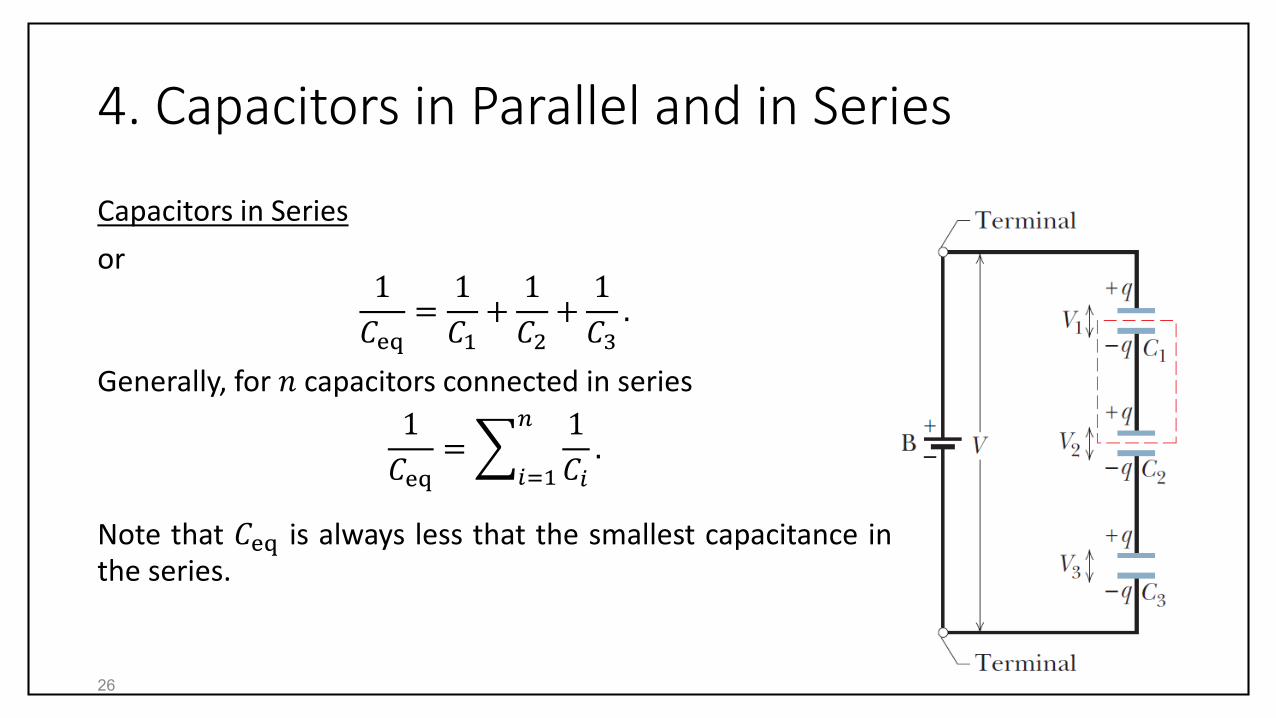
Capacitors in Series
or1
𝐶eq=1
𝐶1+1
𝐶2+1
𝐶3.
Generally, for 𝑛 capacitors connected in series
1
𝐶eq=
𝑖=1
𝑛 1
𝐶𝑖.
Note that 𝐶eq is always less that the smallest capacitance inthe series.
26

4. Capacitors in Parallel and in Series
(a) 𝑞/2, 𝑉.
(b) 𝑞, 𝑉/2.
27
4. Capacitors in Parallel and in Series
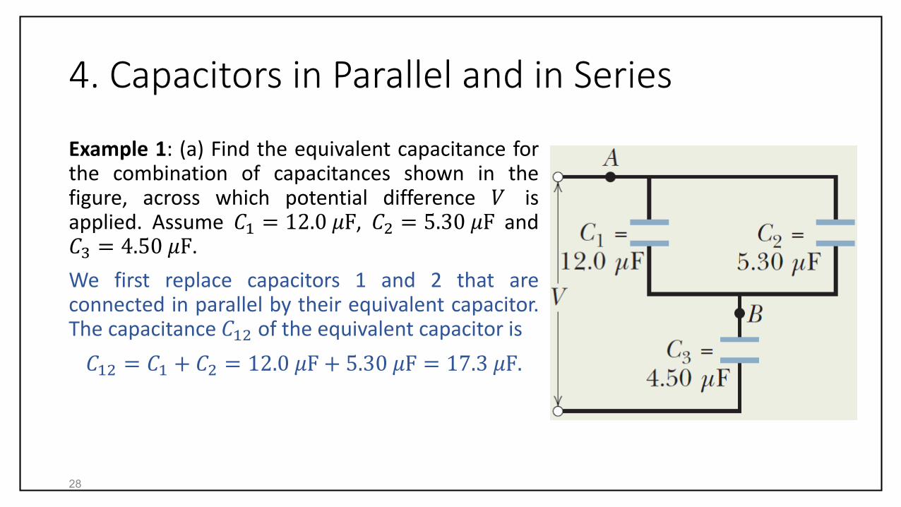
Example 1: (a) Find the equivalent capacitance forthe combination of capacitances shown in thefigure, across which potential difference 𝑉 isapplied. Assume 𝐶1 = 12.0 𝜇F, 𝐶2 = 5.30 𝜇F and𝐶3 = 4.50 𝜇F.
We first replace capacitors 1 and 2 that areconnected in parallel by their equivalent capacitor.The capacitance 𝐶12 of the equivalent capacitor is
𝐶12 = 𝐶1 + 𝐶2 = 12.0 𝜇F + 5.30 𝜇F = 17.3 𝜇F.
28

4. Capacitors in Parallel and in Series
Now capacitors 𝐶12 and 𝐶3 are in series.Their equivalent capacitance 𝐶123 is
1
𝐶123=1
𝐶12+1
𝐶3=1
17.3 𝜇F+1
4.50 𝜇F
= 0.280 1/𝜇F.
Therefore,𝐶123 = 3.57 𝜇F.
29
4. Capacitors in Parallel and in Series
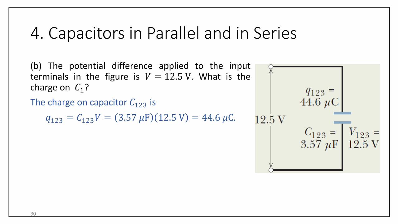
(b) The potential difference applied to the inputterminals in the figure is 𝑉 = 12.5 V. What is thecharge on 𝐶1?
The charge on capacitor 𝐶123 is
𝑞123 = 𝐶123𝑉 = 3.57 𝜇F 12.5 V = 44.6 𝜇C.
30
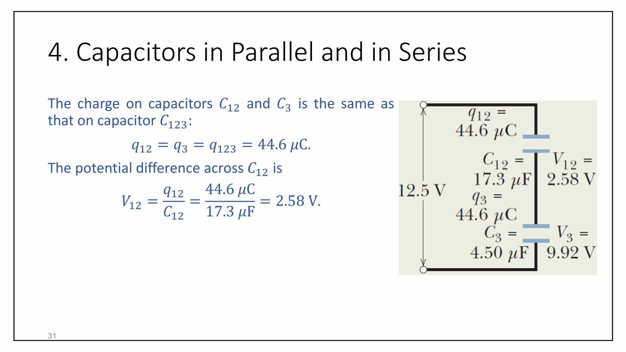
4. Capacitors in Parallel and in Series
The charge on capacitors 𝐶12 and 𝐶3 is the same asthat on capacitor 𝐶123:
𝑞12 = 𝑞3 = 𝑞123 = 44.6 𝜇C.
The potential difference across 𝐶12 is
𝑉12 =𝑞12𝐶12=44.6 𝜇C
17.3 𝜇F= 2.58 V.
31

4. Capacitors in Parallel and in Series
The potential difference across 𝐶1 is thesame as that across 𝐶12. Thus,
𝑉1 = 𝑉2 = 𝑉12 = 2.58 V.
Thus,
𝑞1 = 𝐶1𝑉1 = 12.0 𝜇F 2.58 V
= 31.0 𝜇C.
32

4. Capacitors in Parallel and in Series
Example 2: Capacitor 1, with 𝐶1 = 3.55 𝜇F, ischarged to a potential difference 𝑉0 = 6.30 V,using a 6.30 V battery. The battery is thenremoved, and the capacitor is connected as inthe figure to an uncharged capacitor 2, with 𝐶2= 8.95 𝜇F. When switch S is closed, chargeflows between the capacitors. Find the chargeon each capacitor when equilibrium isreached.
At equilibrium, capacitor 2 is charged until thepotentials 𝑉1 and 𝑉2 across the two capacitorsbecome equal.
33

4. Capacitors in Parallel and in Series
Thus,
𝑉1 = 𝑉2,
implies that𝑞1𝐶1=𝑞2𝐶2.
Charge conservation requires that
𝑞1 + 𝑞2 = 𝑞0 = 𝑉0𝐶1.
34
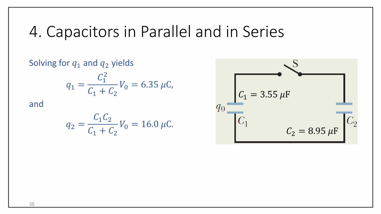
4. Capacitors in Parallel and in Series
Solving for 𝑞1 and 𝑞2 yields
𝑞1 =𝐶12
𝐶1 + 𝐶2𝑉0 = 6.35 𝜇C,
and
𝑞2 =𝐶1𝐶2𝐶1 + 𝐶2
𝑉0 = 16.0 𝜇C.
35
𝐶1 = 3.55 𝜇F
𝐶2 = 8.95 𝜇F

5. Energy Stored in an Electric Field
To charge a capacitor, work must be done by an external agent. Starting with anuncharged capacitor, work must be done to transfer electrons from one plate toanother. This work is practically done by a battery.
We visualize the work required to charge a capacitor as being stored in the form ofelectric potential energy 𝑈 in the electric field between the plates. We recover thisenergy by discharging the capacitor.
Suppose that a charge 𝑞′ has been transferred from one plate to the other. Thepotential difference between the plates at that instant will be 𝑞′/𝐶. If an extraincrement of charge 𝑑𝑞′ is then transferred, the increment of work required will be
𝑑𝑊 = 𝑉′𝑑𝑞′ =𝑞′
𝐶𝑑𝑞′.
36

5. Energy Stored in an Electric Field
The work required to charge up the capacitor to a final charge 𝑞 is
𝑊 = 𝑑𝑊 =1
𝐶 0
𝑞
𝑞′𝑑𝑞′ =𝑞2
2𝐶.
This work is stored as potential energy 𝑈 in the capacitor. Thus,
𝑈 =𝑞2
2𝐶.
Using 𝑞 = 𝐶𝑉, we can rewrite 𝑈 as
𝑈 =1
2𝐶𝑉2.
37

5. Energy Stored in an Electric Field
Consider a parallel-plate capacitor of charge 𝑞 and plate separation 𝑑. The volumeof the space between the plates is Vol = 𝐴𝑑. The stored potential energy in thecapacitor is 𝑈 = 𝑞2/2𝐶.
If the plate separation is doubled (𝑑2 = 2𝑑) the space volume is doubled too.Because the capacitance is halved (𝐶2 = 𝐶/2), the stored potential energy in thecapacitor is doubled: 𝑈2 = 2𝑈.
This argument is a demonstration of our earlier assumption; the potential energy ofa charged capacitor may be viewed as being stored in the electric field between itsplates.
38
5. Energy Stored in an Electric Field
Energy Density:
The energy density 𝑢, or the potential energy per unit volume between the platesof a parallel-plate capacitor, where the field is uniform, is given by
𝑢 =𝑈
𝑉=𝑈
𝐴𝑑=𝐶𝑉2
2𝐴𝑑.
Using 𝐶 = 𝜀0𝐴/𝑑, 𝑢 become
𝑢 =1
2𝜀0𝐸2.
Although we have here derived this result for the electric field between the platesof a parallel-plate capacitor, it holds for any electric field.
39

5. Energy Stored in an Electric Field
Example 3: An isolated conducting sphere whose radius 𝑅 = 6.85 cm has a charge𝑞 = 1.25 𝑛C.
(a) How much potential energy is stored in the electric field of this chargedconductor?
𝑈 =𝑞2
2𝐶=𝑞2
2 4𝜋𝜀0𝑅=
1.25 𝑛C 2
8𝜋 8.85𝑝Fm0.0685 m
= 103 𝑛J.
(b) What is the energy density at the surface of the sphere?
The electric field at the surface of the sphere is
𝐸 =1
4𝜋𝜀0
𝑞
𝑅240

5. Energy Stored in an Electric Field
The energy density is
𝑢 =1
2𝜀0𝐸2 =1
2𝜀01
4𝜋𝜀0
𝑞
𝑅2
2
=𝑞2
32𝜋2𝜀0𝑅4=
1.25 𝑛C 2
32𝜋2 8.85𝑝Fm0.0685 m 4
= 25.4𝜇J
m3.
41
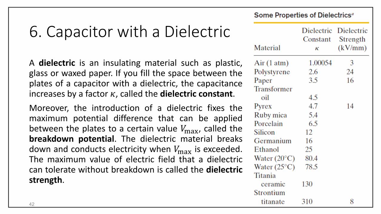
6. Capacitor with a Dielectric
A dielectric is an insulating material such as plastic,glass or waxed paper. If you fill the space between theplates of a capacitor with a dielectric, the capacitanceincreases by a factor 𝜅, called the dielectric constant.
Moreover, the introduction of a dielectric fixes themaximum potential difference that can be appliedbetween the plates to a certain value 𝑉max, called thebreakdown potential. The dielectric material breaksdown and conducts electricity when 𝑉max is exceeded.The maximum value of electric field that a dielectriccan tolerate without breakdown is called the dielectricstrength.
42
6. Capacitor with a Dielectric
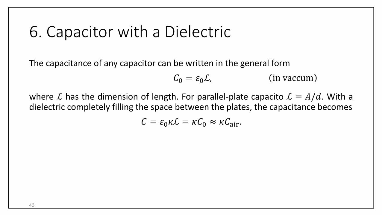
The capacitance of any capacitor can be written in the general form
𝐶0 = 𝜀0ℒ, in vaccum
where ℒ has the dimension of length. For parallel-plate capacito ℒ = 𝐴/𝑑. With adielectric completely filling the space between the plates, the capacitance becomes
𝐶 = 𝜀0𝜅ℒ = 𝜅𝐶0 ≈ 𝜅𝐶air.
43
6. Capacitor with a Dielectric
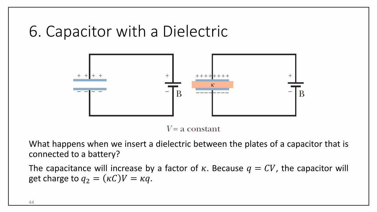
What happens when we insert a dielectric between the plates of a capacitor that isconnected to a battery?
The capacitance will increase by a factor of 𝜅. Because 𝑞 = 𝐶𝑉, the capacitor willget charge to 𝑞2 = 𝜅𝐶 𝑉 = 𝜅𝑞.
44

6. Capacitor with a Dielectric
What happens when we insert a dielectric between the plates of a chargedcapacitor?
The capacitance will increase by a factor of 𝜅. Because 𝑉 = 𝑞/𝐶, the potentialacross the capacitor will drop to 𝑉2 = 𝑞/ 𝜅𝐶 = 𝑉/𝜅.
45

6. Capacitor with a Dielectric
In a region completely filled by a dielectric material of dielectric constant 𝜅, allelectrostatic equations containing the permittivity constant 𝜀0 are to be modifiedby replacing 𝜀0 with 𝜅𝜀0.
For example, the magnitude of the electric field due to a point charge inside adielectric is
𝐸 =1
4𝜋𝜀0𝜅
𝑞
𝑟2.
Also, the expression for the electric field just outside an isolated conductorimmersed in a dielectric becomes
𝐸 =𝜎
𝜀0𝜅.
Since 𝜅 > 1, the effect of a dielectric is to weaken the electric field that would beotherwise present.46
6. Capacitor with a Dielectric
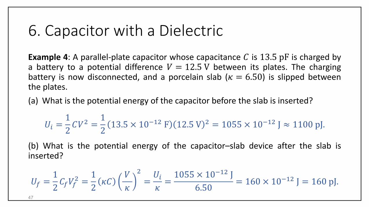
Example 4: A parallel-plate capacitor whose capacitance 𝐶 is 13.5 pF is charged bya battery to a potential difference 𝑉 = 12.5 V between its plates. The chargingbattery is now disconnected, and a porcelain slab (𝜅 = 6.50) is slipped betweenthe plates.
(a) What is the potential energy of the capacitor before the slab is inserted?
𝑈𝑖 =1
2𝐶𝑉2 =
1
213.5 × 10⁻¹² F 12.5 V 2 = 1055 × 10−12 J ≈ 1100 pJ.
(b) What is the potential energy of the capacitor–slab device after the slab isinserted?
𝑈𝑓 =1
2𝐶𝑓𝑉𝑓2 =1
2𝜅𝐶𝑉
𝜅
2
=𝑈𝑖𝜅=1055 × 10−12 J
6.50= 160 × 10−12 J = 160 pJ.
47
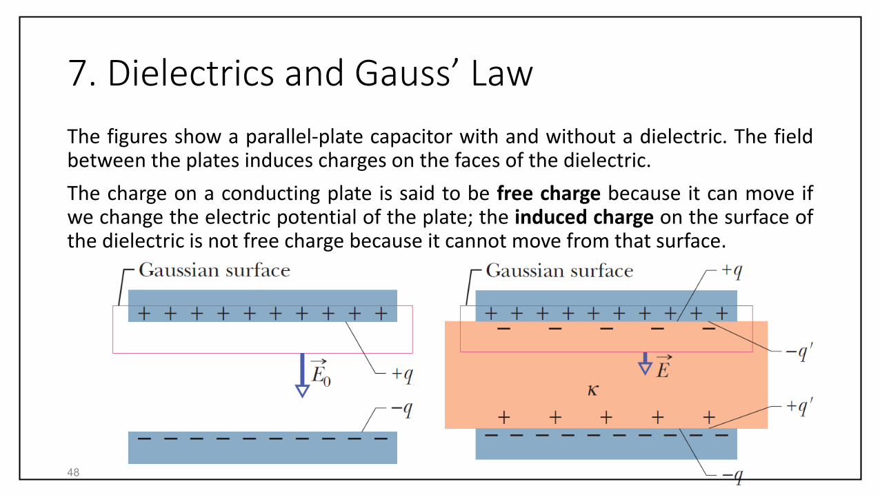
7. Dielectrics and Gauss’ Law
The figures show a parallel-plate capacitor with and without a dielectric. The fieldbetween the plates induces charges on the faces of the dielectric.
The charge on a conducting plate is said to be free charge because it can move ifwe change the electric potential of the plate; the induced charge on the surface ofthe dielectric is not free charge because it cannot move from that surface.
48

7. Dielectrics and Gauss’ Law
To find the electric field 𝐸0 between the plates,without the dielectric, we enclose the charge +𝑞on the top plate with a Gaussian surface and applyGauss’ law:
𝐸 ∙ 𝑑 𝐴 = 𝐴𝐸0 =𝑞
𝜀0,
or
𝐸0 =𝑞
𝜀0𝐴.
49

7. Dielectrics and Gauss’ Law
With the dielectric present, the Gaussian surfaceencloses charge +𝑞 on the top plate as well as theinduced charge −𝑞′ on the top face of thedielectric.
Gauss’ law now reads
𝐸 ∙ 𝑑 𝐴 = 𝐴𝐸 =𝑞 − 𝑞′
𝜀0,
or
𝐸 =𝑞 − 𝑞′
𝜀0𝐴.
50

7. Dielectrics and Gauss’ Law
𝐸 =𝑞 − 𝑞′
𝜀0𝐴.
The effect of the dielectric is to weaken theoriginal field 𝐸0 by a factor of 𝜅. Thus,
𝐸 =𝐸0𝜅=𝑞
𝜅𝜀0𝐴.
We can conclude that
𝑞 − 𝑞′ =𝑞
𝜅.
The magnitude of the induced charge 𝑞′ is lessthan that of the free charge 𝑞 and is zero when nodielectric is present.51
𝑞′ = 𝑞 1 −1
𝜅
7. Dielectrics and Gauss’ Law
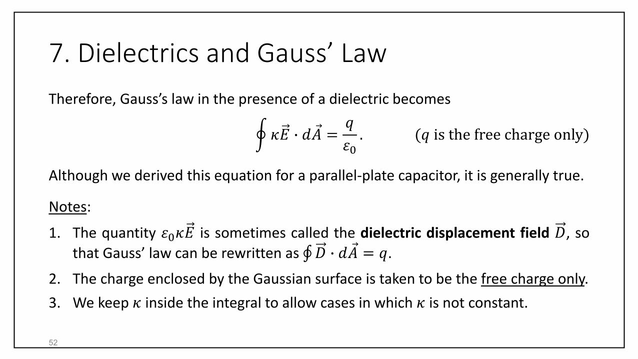
Therefore, Gauss’s law in the presence of a dielectric becomes
𝜅𝐸 ∙ 𝑑 𝐴 =𝑞
𝜀0. (𝑞 is the free charge only)
Although we derived this equation for a parallel-plate capacitor, it is generally true.
Notes:
1. The quantity 𝜀0𝜅𝐸 is sometimes called the dielectric displacement field 𝐷, so
that Gauss’ law can be rewritten as 𝐷 ∙ 𝑑 𝐴 = 𝑞.
2. The charge enclosed by the Gaussian surface is taken to be the free charge only.
3. We keep 𝜅 inside the integral to allow cases in which 𝜅 is not constant.
52

7. Dielectrics and Gauss’ Law
Example 6: The figure shows a parallel-platecapacitor of plate area 𝐴 and plate separation 𝑑.A potential difference 𝑉0 is applied between theplates by connecting a battery between them. Thebattery is then disconnected, and a dielectric slabof thickness 𝑏 and dielectric constant 𝜅 is placedbetween the plates as shown. Assume 𝐴= 115 cm2 , 𝑑 = 1.24 cm , 𝑉0 = 85.5 V , 𝑏= 0.780 cm, and 𝜅 = 2.61.
53

7. Dielectrics and Gauss’ Law
(a) What is the capacitance 𝐶0 before thedielectric slab is inserted?
𝐶0 =𝜀0𝐴
𝑑=8.85 pF 0.0115 m2
0.0124 m= 8.21 pF.
(b) What free charge appears on the plates?
𝑞 = 𝐶0𝑉0 = 8.21 pF 85.5 V = 702 pC.
The free charge is not changed by inserting theslab because the battery was disconnected.
54

7. Dielectrics and Gauss’ Law
(c) What is the electric field 𝐸0 in the gapsbetween the plates and the dielectric slab?
Applying Gauss’ law to Gaussian surface I yields
𝜅𝐸 ∙ 𝑑 𝐴 = 𝜅𝐸0𝐴 = 1 𝐸0𝐴 =𝑞
𝜀0,
or
𝐸0 =𝑞
𝜀0𝐴=
702 pC
8.85 pF 0.0115 m2= 6.90
kV
m.
Note that 𝐸0 is note affected by inserting the slab.because the charge enclosed by the Gaussiansurface is not affected.55
7. Dielectrics and Gauss’ Law
(d) What is the electric field 𝐸1 in the dielectricslab?
Applying Gauss’ law to Gaussian surface II yields
𝜅𝐸 ∙ 𝑑 𝐴 = −𝜅𝐸1𝐴 = −𝑞
𝜀0,
or
𝐸1 =𝑞
𝜅𝜀0𝐴=𝐸0𝜅=6.90 kV/m
2.61= 2.64 kV/m.
Recall that we take the free charge only (here −𝑞)as the enclosed charge.
56

7. Dielectrics and Gauss’ Law
(e) What is the potential difference 𝑉 betweenthe plates after the slab has been introduced?
We integrate along a line from the bottom plateto the top plate
𝑉 = −
+
𝐸𝑑𝑠 = 𝐸0 𝑑 − 𝑏 + 𝐸1𝑏
= 6.90 kVm 0.0124 m − 0.00780 m
+2.64 kVm 0.00780 m = 52.3 V.
57

7. Dielectrics and Gauss’ Law
(f) What is the capacitance with the slab in placebetween the plates of the capacitor?
From parts (c) and (e)
𝐶 =𝑞
𝑉=702 pC
52.3 V= 13.2 pF.
58