CANON ANELVA COrpOrAtiON
268
VACUUM COMPONENTS Catalog CANON ANELVA CORPORATION http://www.canon-anelva.co.jp
-
Upload
khangminh22 -
Category
Documents
-
view
0 -
download
0
Transcript of CANON ANELVA COrpOrAtiON

VACUUMCOMPONENTS
Catalog
CANON ANELVA COrpOrAtiONhttp://www.canon-anelva.co.jp


Accompanying the advance of vacuum application technology,
vacuum equipment/components and materials are being utilized in
a variety of fields, with new types of equipment and components ap-
pearing increasingly each year.
In order to provide our customers with an overall understanding of
the wide variety of products (Vacuum Components) that CANON
ANELVA has developed and manufactures, we have combined the
individual product catalogs into a single comprehensive catalog.
We are pleased to present it to you here as the CANON ANELVA
Vacuum Components Catalog.
We hope you will keep this catalog at your side for quick reference
whenever you need to order any of our products.
CANON ANELVA COrpOrAtION
Preface

Information ................................................................................................6
1. Vacuum Pumps ................................................................................11
Ion Pump/Noble Pump ................................................................................................ 12Excel Pump ................................................................................................................. 30Ion Pump/Noble Pump Controller ................................................................................ 38Titanium Sublimation Pump/Ti-Vac Pump ................................................................... 42Combination Pump ...................................................................................................... 46Cryopump POWER/POWEREco Series ........................................................................ 52
Cryopump POWER Series ...................................................................................... 53Cryopump POWEREco Series .................................................................................. 62
Foreline Trap ............................................................................................................... 80
2. Measurement Instruments & Controllers ..........................................85
Quadrupole Mass Spectrometer (Transducer Type) ................................................... 86Quadrupole Mass Spectrometer (High-speed /High-sensitivity Measurement) .......... 90QUADVISION .............................................................................................................. 92QUADVISION 3 Mobile ............................................................................................... 93Gas Analysis System
Compact Gas Analysis System C Series ................................................................ 94Compact Gas Analysis System D Series .............................................................. 100
Vacuum GaugesTransducer Vacuum Gauge Series ....................................................................... 102Vacuum Gauge Series........................................................................................... 118
Leak DetectorsHelium Leak Detectors .......................................................................................... 140
Film Thickness MeterCrystal Oscillator for Film Thickness Sensor ......................................................... 148
■ Contents
VacuumComponents

3. Vacuum Components .....................................................................149
Piping PartsUltra-High Vacuum Flanges ................................................................................... 150Connecting Components with ICF ......................................................................... 162Quick-release Couplings ....................................................................................... 166Vacuum Switches .................................................................................................. 174Ancillary Materials ................................................................................................. 176
ValvesUltra-High Vacuum Type-L All-metal Valves .......................................................... 178Ultra-High Vacuum Type-L Polyimide Valves ........................................................ 182"V Series" Roughing Pump Valves ........................................................................ 186"V Series" Type-L Valves ....................................................................................... 190Ultra-High Vacuum Variable Leak Valves .............................................................. 196Gas Inlet Valves..................................................................................................... 198Isolate Valves ........................................................................................................ 202
Ultra-High Vacuum Gate ValveMSB series ............................................................................................................ 204STD series ............................................................................................................. 208
FeedthroughsRotary Feedthroughs ............................................................................................. 214Linear Feedthroughs ............................................................................................. 220R/L Feedthroughs .................................................................................................. 222Current Terminals .................................................................................................. 224Ultra-high Vacuum Viewing Ports .......................................................................... 244
E-type Electron Guns ................................................................................................ 248
● Information
● Pumps
● Measurements
● Components
6 Canon anELVa Corporation Vacuum Components Catalog
Info
rmat
ion
(1) How to use this catalog
this catalog covers all vacuum pumps, gauges, and vacuum components offered by Canon Anelva (these product's are hereafter referred to as Components).the catalog is divided into the following chapters: Vacuum pumps, Gauges, and Vacuum Components. A table of Contents is included at the beginning of each chapter.the catalog is organized so that you can easily find the desired component.refer to the table of Contents for the specific page.the dimensions in the figures are in millimeters (mm) un-less specified otherwise.
(2) Contact information
At the end of each product description, a table listing the parts numbers, types, product names, and product codes of the described products and related components is provided as ordering information.Select the required components from this list, and order by specifying the parts numbers, types, product names, and product codes.
(3) Others
please note that the specifications of the products in this catalog may change due to performance improvements without prior notice.please contact our sales department (head office, local branch) or vendor for questions or inquiries regarding the order or delivery of your product.
(4) Maintenance service
Our components are manufactured and sold upon close scrutiny and careful testing at all stages, from development to marketing, in order to deliver "reliable and easy-to-use" products.Nevertheless, even highly reliable components can fail, or reach their end of life due to wear and tear after long use.periodic maintenance and repair are therefore essential.Accordingly, we provide periodic maintenance of pumps and repair/adjustment of gauges, and offer service parts that are indispensable for creating vacuum systems.If you have any suggestions or questions concerning our products, please feel free to contact us.
information
VacuumComponents-- Read Before Using This Catalog --
7Canon anELVa Corporation Vacuum Components Catalog
Info
rmat
ion
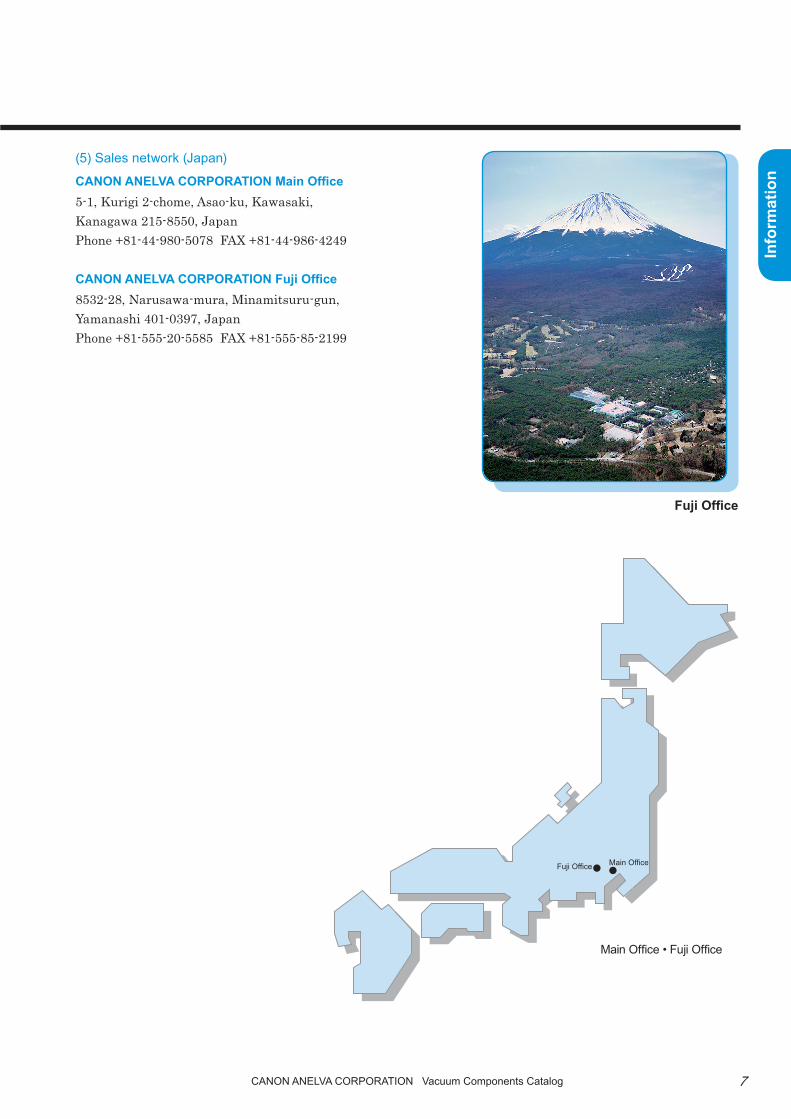
(5) Sales network (Japan)
CANON ANELVA CORPORATION Main Office5-1, Kurigi 2-chome, Asao-ku, Kawasaki, Kanagawa 215-8550, Japanphone +81-44-980-5078 FAX +81-44-986-4249
CANON ANELVA COrpOrAtiON Fuji Office8532-28, Narusawa-mura, Minamitsuru-gun, Yamanashi 401-0397, Japanphone +81-555-20-5585 FAX +81-555-85-2199
Fuji Office
Main OfficeFuji Office
Main Office • Fuji Office

8 Canon anELVa Corporation Vacuum Components Catalog
Info
rmat
ion (6) Sales network (Overseas)
Canon Anelva Corporation German Service
Phone FAX Address
+49-0-351-892-5207 +49-0-351-892-5209Manfred-von-Ardenne-Ring 20, 01099 Dresden, Germany
Canon Anelva Corporation UK Service
Phone FAX Address
+44-28-7136-1697 N/AUnit 4, 1st Floor, Phase 2 18 Balliniska Road Springtown Industrial Estate Londonderry BT48 0NA United Kingdom
Canon U.S.A., inc.
Phone FAXE-Mail(About Components Only)
Address
+1-408-468-2000 +1-408-468-2343 [email protected] North First StreetSan Jose, CA 95134 U.S.A.
Canon Semiconductor Engineering Korea, inc.
Phone FAX Address
+82-31-677-6182 +82-31-677-6187Bong Bldg., 5F #1014-15Youngtong-Dong,Youngtong-Gu,Suwon-City,Gyeonggi-Do,443-470Korea
Canon Semiconductor Equipment taiwan, inc.
Phone FAX Address+886-3-668-6600 +886-3-668-6969 9F-2, No.25, Pu-Ding Road, Hsinchu, 300, Taiwan

9Canon anELVa Corporation Vacuum Components Catalog
Info
rmat
ionCanon Singapore pte. Ltd.
Phone FAX Address
+65-6799-8888 +65-6721-42261 HarbourFront Avenue #4-01 Keppel Bay TowerSingapore 098632
Canon Optical Industrial Equipment Service (Shanghai), Inc.
Phone FAX Address+86-21-2316-3200 +86-21-2316-3222 18F,Urban City Center, No.45 Nanchang Road Shanghai

10 Canon anELVa Corporation Vacuum Components Catalog
Info
rmat
ion
Memorandum
11
Pum
ps
Canon anELVa Corporation Vacuum Components Catalog
Vacuum Pumps
Ion Pump/Noble PumpExcel PumpIon Pump/Noble Pump ControllerTitanium Sublimation Pump/Ti-Vac PumpCombination PumpCryopump POWER/POWEREco SeriesCryopump POWER SeriesCryopump POWEREco SeriesForeline Trap

12
Pum
ps
Canon anELVa Corporation Vacuum Components Catalog
■ SummaryThe ion, noble, and excel pumps are ultra-high vacuum pumps which utilize the gas adsorption properties of the cathode material sputtered by cold cathode discharge within a magnetic field and the continuous formation of ac-tive getter film by sputtering cathode material (Ti) during collision with the cathode.Since no organic materials such as oil are used, a completely oil free, ultra-high vacuum can be obtained. Opera-tion requires only electrical power and there is no vibration or noise because there are no moving parts. In addi-tion, the pumps can be used safely for unattended operation at night because there is no need to worry about the pumped system becoming contaminated in case of an accident such as a sudden power failure or vacuum leak. The noble and excel pumps are tripolar type ion pumps with improved inert gas pumping speed. They have all the features of an ion pump, but are capable of stable pumping of inert gas.Furthermore, the excel pump has improved discharge characteristics at the extreme high vacuum region due to optimized discharge conditions.
ion pump/Noble pump
P-500 Series Controller

13
Pum
ps
Canon anELVa Corporation Vacuum Components Catalog
Magnet
Link line
Pump element
Pump element
Inlet flangeCurrent input terminal
915-9520 Noble Pump element
915-9510 Ion Pump element
Fig. 2 Pump elementsFig. 1 Ion Pump/Noble Pump external
(Example: 140L/s Ion Pump, 110L/s Noble Pump)
■ Features1. Completely oil free
A clean vacuum can be obtained without contami-nating the system because no organic materials such as oil are used. In addition, there is no need to close the valve even in case of a power failure.
Fig. 3 Comparison of ion pump and oil diffusion pump residual gas(M/e = 44 or more hydrocarbon is hardly ever observed in the ion pump system.)
M/e 1–2 M/e 1–2
1×10–13A
1×10–12A
18 28 18 28 44 57 80 91
Residual gas analysis of ion pump system vacuum equipmentFull pressure: 9.3×10⁻⁷Pa
Residual gas analysis of diffusion pump system vacuum equipmentFull pressure: 1.6×10⁻⁵Pa
14
Pum
ps
Canon anELVa Corporation Vacuum Components Catalog
Power consumption (W)
600
500
400
300
200
100
010−6 10−5 10−4 10−3 10−2 10−1
PressurePa
Pressure
20
×10−9Pa
18
16
14
12
10
8
64
2
50sec 100sec 150sec Time
OFF
OFF
OFFO
N
ON
ON
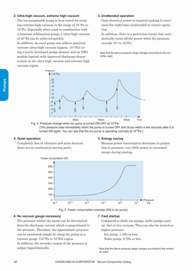
2. Ultra-high vacuum, extreme high vacuumthe ion pump/noble pump is best suited for creat-ing extreme high vacuum in the range of 10-1pa to 10-9pa. Especially when used in combination with a titanium sublimation pump, a ultra-high vacuum of 10-9pa can be achieved quickly.In addition, an excel pump can achieve practical extreme ultra-high vacuum (approx. 10-10pa) us-ing a newly developed pump element and an NEG module (option) with improved discharge charac-teristic at the ultra-high vacuum and extreme high vacuum region.
3. Unattended operationOnly electrical power is required making it conve-nient for night-time unattended or remote opera-tion.In addition, there is a protection circuit that auto-matically turns off the power when the pressure exceeds 10-3 to 10-2pa*.
* Note that the above pressure range changes according to the con-troller used.
Fig. 4 Pressure change when ion pump is turned ON-OFF at 10-9Pa(The pressure rises immediately when the pump is turned OFF and drops within a few seconds after it is turned ON again. You can see that the ion pump is operating normally at 10-9Pa.)
4. Quiet operationCompletely free of vibration and noise because there are no mechanical moving parts.
5. Energy savingBecause power consumption decreases in propor-tion to pressure, very little power is consumed except during startup.
Fig. 5 Power consumption example (60L/s ion pump)
6. No vacuum gauge necessarythe pressure within the pump can be determined from the discharge current which is proportional to the pressure. therefore, the approximate pressure can be monitored simply by using the pump as a vacuum gauge. [10-3pa to 10-6pa] region.In addition, the recorder output of the pressure is output logarithmically.
7. Fast startupCompared to diode ion pumps, noble pumps start up fast at low vacuum. they can also be started at higher pressure.
Ion pump 1.3pa or lessNoble pump 6.7pa or less
* Note that the above pressure range changes according to the control-ler used.

15
Pum
ps
Canon anELVa Corporation Vacuum Components Catalog
Anode
Mag
netic
fiel
d
Mag
netic
fiel
d
Anode Titanium atomCathode Cathode
Pump shellTrapped gas molecules
Trapped gas molecules
Adsorbed inert gas molecules
Ion pumpNoble pump/Excel pump
Gas ionTitanium atom Gas ion
+V −V
Pump shell
8. Inert gas pumping (Noble Pump/Excel Pump)
Improved inert gas pumping speed compared to diode ion pumps. (Approximately 21% of air with argon)In addition, argon instability is less likely to occur compared to ion pumps. table 1 shows the pump-ing speed ratio of ion pumps and noble/excel pumps for each gas.
9. Free mounting directionthere is no restriction on the mounting direction; up, down, horizontal or diagonal.
10. Low leakage magnetic fieldA ferrite magnet is used for 20L/s or more pumps. the leakage magnetic field decays close to geomag-netism at 30cm from the flange.
(See Fig. 10 for details)
Table 1 Pumping speed ratio of various gases against nitrogen (%)
Ionpump
Noblepump
Excelpump
Hydrogen[10-4Pa or less]
200 to 270* 200 to 270* 200 to 270*
Nitrogen 100 100 100Vapor 100 100 100Carbon monoxide
100 100 100
Carbon dioxide
[10-3Pa or less]100 100 100
Various hy-drocarbon
90 to 160 90 to 160 90 to 160
Oxygen 57 57 57Helium 10 30 30Argon 1 21 21
■ Principle
■ Applications• Completely oil free ultra-high vacuum and extreme vacuum pumping systems• Ultra-high vacuum and extreme high vacuum experimental equipment• pumping systems such as electron microscopes, surface and other analyzers• pumping systems such as particle accelerators, nuclear fusion experimental devices, and space environ-
mental testing equipment• Vacuum retention pump for electron tubes, etc.• Heating pumping equipment such as electron tubes
etc.
Fig. 6 Ion Pump/Noble Pump/Excel Pump pumping mechanism
* 100 to 110 for ion, noble, and excel pumps at pressures equal to or more than 10-3Pa.

16
Pum
ps
Canon anELVa Corporation Vacuum Components Catalog
216±1.5
154±1.5
133±
1.5
187±
2
(67)
(20)
(121
)
(100
)(1
1)
(13)
(65) (105)
(194)(214)
(20)
M32PI
4-M6Depth 36±1
φ70 ICF
■ 20L/s Ion Pump/Noble Pump● Specifications
● Standard configuration
Pum
p
Name 20L/s Ion Pump 20L/s Noble PumpType 912-7125 912-7120Pumping speed (N2 gas) 20L/sOperating range(Note 1) 10-1 to 10-9Pa 1 to 10-9PaReady to start pressure(Note 1) 2x10⁻²Pa or lessCapacity 1.4LMaximum heating temperature 250°CInlet φ70ICFCurrent input terminal Non-replaceableElement (replaceable) Non-replaceableMagnet 912-7121 (x1) includedWeight 10.5kg
Note 1: Note that the value in the table will change depending on the controller used.
Pum
p
Name and TypeComponents
20L/s Ion Pump 20L/s Noble Pump912-7125 912-7120
Pump body x1Attachment gasket for φ70ICF x2
Fig. 7 (a) 20L/s Ion Pump (912-7125) 20L/s Noble Pump (912-7120)

17
Pum
ps
Canon anELVa Corporation Vacuum Components Catalog
● Standard configuration
Note 1: Note that the value in the table will change depending on the controller used.
■ 30L/s Ion Pump/Noble Pump● Specifications
Pum
p
Name 30L/s Ion Pump 30L/s Noble PumpType 912-7135 912-7130Pumping speed (N2 gas) 30L/sOperating range(Note 1) 10-1 to 10-9Pa 1 to 10-9PaReady to start pressure(Note 1) 2x10⁻²Pa or lessCapacity 2.2LMaximum heating temperature 250°CInlet φ114ICFCurrent input terminal 954-7281Element (replaceable) Non-replaceableMagnet 912-7121 (x1) includedWeight 12.5kg
Pum
p
Name and TypeComponents
30L/s Ion Pump 30L/s Noble Pump912-7135 912-7130
Pump body x1Attachment gasket for φ114ICF x2
154±1.5(20)
228±
213
3±1.
5
216±1.5
(214)
(194)
(105
)
(22)
(40)
(13)
(100
) (150
)
168±3
φ114 ICF
M32PI
4-M6Depth 36±1
Fig. 7 (b) 30L/s Ion Pump (912-7135) 30L/s Noble Pump (912-7130)

18
Pum
ps
Canon anELVa Corporation Vacuum Components Catalog
■ 60L/s Ion Pump/Noble Pump● Specifications
● Standard configuration
Pum
p
Name 60L/s Ion Pump 60L/s Noble PumpType 912-7165 912-7160Pumping speed (N2 gas) 60L/sOperating range(Note 1) 10-1 to 10-9Pa 1 to 10-9PaReady to start pressure(Note 1) 2x10⁻²Pa or lessCapacity 6.2LMaximum heating temperature 250°CInlet φ152ICFCurrent input terminal 954-7281Element (replaceable) 915-7027 (1 set) 915-9527 (1 set)Magnet 912-7121 (x2) includedWeight 25.6kg
Pum
p
Name and TypeComponents
60L/s Ion Pump 60L/s Noble Pump912-7165 912-7160
Pump body x1Attachment gasket for φ152ICF x2
Fig. 7 (c) 60L/s Ion Pump (912-7165) 60L/s Noble Pump (912-7160)
293±
2
133±
1.5
(67)
(28.
5)(2
14)
(3.5
)
(9.5
)(1
95)
356±1.5
188±4
108±1
φ152 ICF
M32PI
(10) (100) (100)
(110) (126) (110)
4-M6Depth 108±1
Note 1: Note that the value in the table will change depending on the controller used.

19
Pum
ps
Canon anELVa Corporation Vacuum Components Catalog
Note 1: Note that the value in the table will change depending on the controller used.
● Standard configuration
Pum
p
Name 110L/s Noble Pump 140L/s Ion PumpType 912-7020 912-7010Pumping speed (N2 gas) 110L/s 140L/sOperating range(Note 1) 1 to 10-9Pa 10-1 to 10-9PaReady to start pressure(Note 1) 1x10⁻²Pa or lessCapacity 18LMaximum heating temperature 250°CInlet φ203ICFCurrent input terminal 954-7281Element (replaceable) 915-9520 (x1) 915-9510 (x1)Magnet 912-7001 (x1) includedWeight 48kg
■ 110L/s Noble Pump•140L/s Ion Pump● Specifications
Pum
p
Name and TypeComponents
110L/s Noble Pump 140L/s Ion Pump912-7020 912-7010
Pump body x1Attachment gasket for φ203ICF x2
Fig. 7 (d) 110L/s Noble Pump (912-7020) 140L/s Ion Pump (912-7010)
20
Pum
ps
Canon anELVa Corporation Vacuum Components Catalog
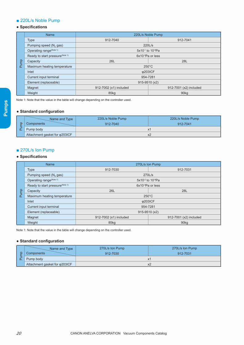
■ 220L/s Noble Pump● Specifications
Note 1: Note that the value in the table will change depending on the controller used.
● Standard configuration
Pum
p
Name 220L/s Noble PumpType 912-7040 912-7041Pumping speed (N2 gas) 220L/sOperating range(Note 1) 5x10⁻¹ to 10-9PaReady to start pressure(Note 1) 6x10⁻³Pa or lessCapacity 26L 28LMaximum heating temperature 250°CInlet φ203ICFCurrent input terminal 954-7281Element (replaceable) 915-9510 (x2)Magnet 912-7002 (x1) included 912-7001 (x2) includedWeight 85kg 90kg
Pum
p
Name and TypeComponents
220L/s Noble Pump 220L/s Noble Pump912-7040 912-7041
Pump body x1Attachment gasket for φ203ICF x2
■ 270L/s Ion Pump● Specifications
Note 1: Note that the value in the table will change depending on the controller used.
● Standard configuration
Pum
p
Name 270L/s Ion PumpType 912-7030 912-7031Pumping speed (N2 gas) 270L/sOperating range(Note 1) 5x10⁻² to 10-9PaReady to start pressure(Note 1) 6x10⁻³Pa or lessCapacity 26L 28LMaximum heating temperature 250°CInlet φ203ICFCurrent input terminal 954-7281Element (replaceable) 915-9510 (x2)Magnet 912-7002 (x1) included 912-7001 (x2) includedWeight 85kg 90kg
Pum
p
Name and TypeComponents
270L/s Ion Pump 270L/s Ion Pump912-7030 912-7031
Pump body x1Attachment gasket for φ203ICF x2
21
Pum
ps
Canon anELVa Corporation Vacuum Components Catalog
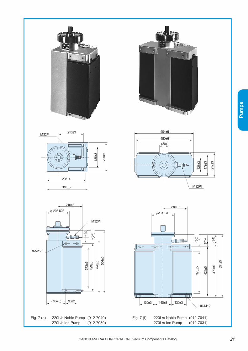
Fig. 7 (f) 220L/s Noble Pump (912-7041) 270L/s Ion Pump (912-7031)
Fig. 7 (e) 220L/s Noble Pump (912-7040) 270L/s Ion Pump (912-7030)
186±
3
250±
3
210±3
210±3
298±4
310±5
96±2 130±3 130±3140±3
373±
542
9±5
470±
555
4±5
373±
5
429±
5
470±
5 554±
5
217±
3
179±
3
128±
3
φ 203 ICF
M32PI
M32PI
M32PI
8-M12
16-M12
(30)
(164.5)
(25)
(25) (84)
210±3
504±6
480±6(80)
φ203 ICF
(30)

22
Pum
ps
Canon anELVa Corporation Vacuum Components Catalog
■ 400L/s Noble Pump•500L/s Ion Pump● Specifications
● Standard configuration
Note 1: Note that the value in the table will change depending on the controller used.
Pum
p
Name 400L/s Noble Pump 500L/s Ion PumpType 912-7060 912-7050Pumping speed (N2 gas) 400L/s 500L/sOperating range(Note 1) 1 to 10-9Pa 10-1 to 10-9PaReady to start pressure(Note 1) 3x10⁻³Pa or lessCapacity 38LMaximum heating temperature 250°CInlet φ203ICFCurrent input terminal 954-7281Element (replaceable) 915-9520 (x4) 915-9510 (x4)Magnet 912-7002 (x2) includedWeight 120kg
Pum
p
Name and TypeComponents
400L/s Noble Pump 500L/s Ion Pump912-7060 912-7050
Pump body x1Attachment gasket for φ203ICF x2
Fig. 7 (g) 400L/s Noble Pump (912-7060) 500L/s Ion Pump (912-7050)
186±
3
250±
3
210±3
483±5
507±6
M32PI
96±2 96±2216±4
373±
542
9±5
470±
5 554±
5
16-M12
(25.
4)
φ203 ICF
(30)

23
Pum
ps
Canon anELVa Corporation Vacuum Components Catalog
■ 800L/s Noble Pump•1000L/s Ion Pump● Specifications
● Standard configuration
Note 1: Note that the value in the table will change depending on the controller used.
Pum
p
Name 800L/s Noble Pump 1000L/s Ion PumpType 912-9110 912-7190 912-9100 912-7195Pumping speed (N2 gas) 800L/s 1000L/sOperating range(Note 1) 10-2 to 10-9Pa 10-3 to 10-9PaReady to start pressure(Note 1) 2x10⁻³Pa or lessCapacity 106LMaximum heating temperature 250°CInlet φ326CS flange φ356ICF φ326CS flange φ356ICFCurrent input terminal 954-7281Element (replaceable) 912-9520 (x8) 915-9510 (x8)Magnet 912-7003 (x2) includedWeight 257kg
Pum
p
Name and TypeComponents
800L/s Noble Pump 800L/s Noble Pump 1000L/s Ion Pump 1000L/s Ion Pump912-9110 912-7190 912-9100 912-7195
Pump body x1
Attachment gasketx3 (gasket for φ326CS
flange)x3 (gasket for
φ356ICF)x3 (gasket for φ326CS
flange)x3 (gasket for
φ356ICF)
Fig. 7 (h) 800L/s Noble Pump (912-9110) 800L/s Noble Pump (912-7190) 1000L/s Ion Pump (912-9100) 1000L/s Ion Pump (912-7195)
24
Pum
ps
Canon anELVa Corporation Vacuum Components Catalog
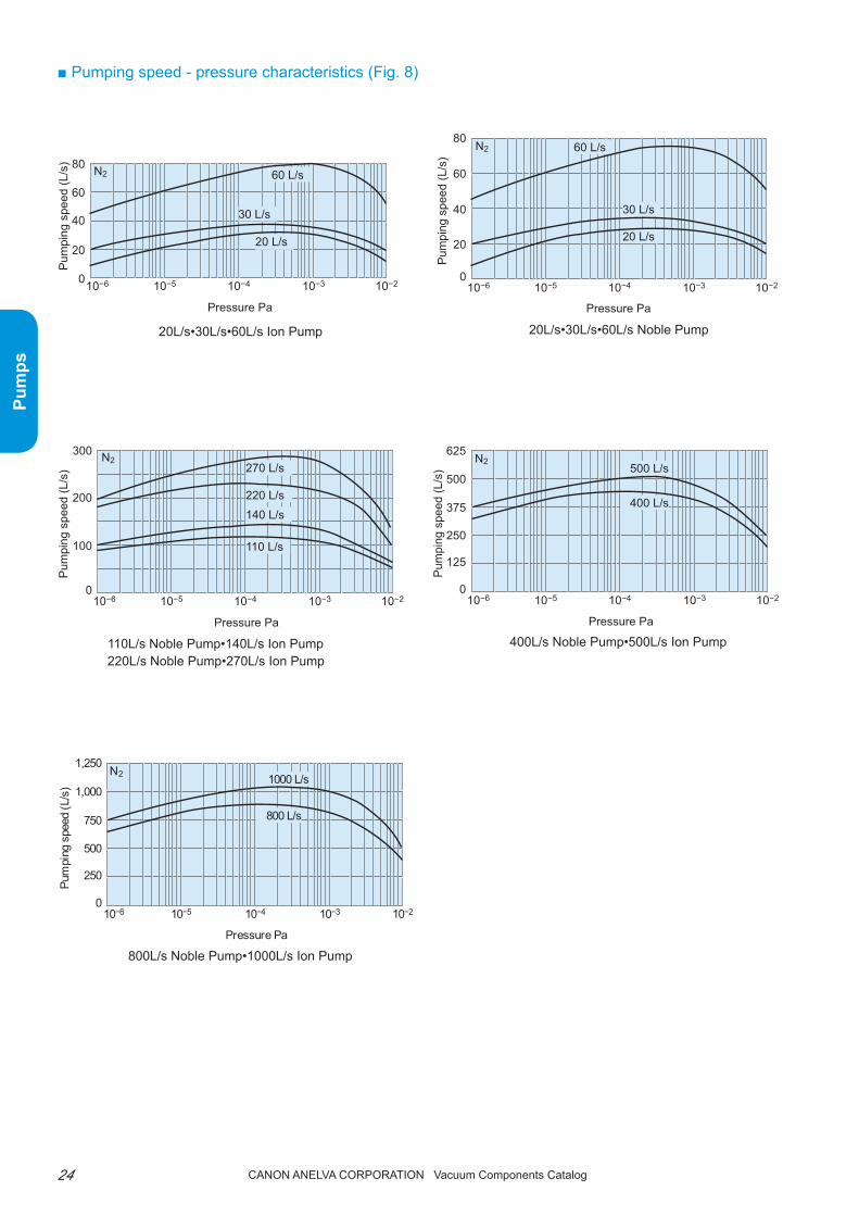
■ Pumping speed - pressure characteristics (Fig. 8)
20L/s•30L/s•60L/s Ion Pump 20L/s•30L/s•60L/s Noble Pump
110L/s Noble Pump•140L/s Ion Pump220L/s Noble Pump•270L/s Ion Pump
400L/s Noble Pump•500L/s Ion Pump
800L/s Noble Pump•1000L/s Ion Pump
10−6 10−5 10−4 10−3 10−20
20
40
60
80
Pressure Pa
Pum
ping
spe
ed (L
/s)
N2 60 L/s
30 L/s
20 L/s
10−6 10−5 10−4 10−3 10−20
20
40
80
60
60 L/s
30 L/s
20 L/s
N2
Pressure Pa
Pum
ping
spe
ed (L
/s)
10−6 10−5 10−4 10−3 10−20
100
200
300
Pressure Pa
Pum
ping
spe
ed (L
/s) 270 L/s
220 L/s140 L/s
110 L/s
N2
10−6 10−5 10−4 10−3 10−20
125
250
625
500
375
Pressure Pa
Pum
ping
spe
ed (L
/s) 500 L/s
400 L/s
N2
10−6 10−5 10−4 10−3 10−20
250
500
1,250
1,000
750
Pressure Pa
Pum
ping
spe
ed (L
/s) 1000 L/s
800 L/s
N2

25
Pum
ps
Canon anELVa Corporation Vacuum Components Catalog
■ Pressure - pump current characteristics (Fig. 9)
20L/s•30L/s•60L/s Ion Pump 20L/s•30L/s•60L/s Noble Pump
110L/s•220L/s•400L/s•800L/s Noble Pump 140L/s•270L/s•500L/s•1000L/s Ion Pump
10μA 100μA 1mA 10mA 100mA10−6
10−5
10−4
10−3
10−2
Pump current
Pre
ssur
e P
a
20L/s • 30L/s
60L/s
10μA 100μA 1mA 10mA 100mA10−6
10−5
10−4
10−3
10−2
Pump current
Pres
sure
Pa
20L/s • 30L/s
60L/s
100μA 1mA 10mA 100mA 1A10−6
10−5
10−4
10−3
10−2
Pump current
Pre
ssur
e P
a 110L/s
800L/s
220L/s
400L/s
10μA 100μA 1mA 10mA 100mA 1A10−6
10−5
10−4
10−3
10−2
Pump current
Pre
ssur
e P
a
140L/s
270L/s500L/s
1000L/s

26
Pum
ps
Canon anELVa Corporation Vacuum Components Catalog
■ Leakage magnetic flux characteristics (Fig. 10)
20L/s Noble Pump20L/s Ion Pump
60L/s Noble Pump60L/s Ion Pump
110L/s Noble Pump140L/s Ion Pump
400L/s Noble Pump500L/s Ion Pump
800L/s Noble Pump1000L/s Ion Pump
0 20 cm 40 cm 60 cm1×10−5
1×10⁻⁴
1×10⁻³
1×10⁻²
Distance
Leak
age
mag
netic
flux
den
sity
(Tes
la)
C B
A
ABC
0 20 cm 40 cm 60 cm
1×10⁻⁵
1×10⁻⁴
1×10⁻³
1×10⁻²
Distance
Leak
age
mag
netic
flux
den
sity
(Tes
la)
B C
A
A
C B
0 20 cm 40 cm 60 cm1×10−5
1×10⁻⁴
1×10⁻³
1×10⁻²
Distance
Leak
age
mag
netic
flux
den
sity
(Tes
la)
A B CC
A
B
0 20 cm 40 cm 60 cm1×10−5
1×10⁻³
1×10⁻⁴
1×10⁻²
Distance
Leak
age
mag
netic
flux
den
sity
(Tes
la)
A B C
A
C B
0 20 cm 40 cm 60 cm1×10−5
1×10⁻³
1×10⁻⁴
A
B
C
1×10⁻²
Distance
Leak
age
mag
netic
flux
den
sity
(Tes
la)
A
C B

27
Pum
ps
Canon anELVa Corporation Vacuum Components Catalog
■ Options● Output cable assemblythe following options are available as an output cable assembly in addition to the standard 3m. please spec-ify when ordering controllers. refer to the following notes when ordering. B type output plug is included.
954-7403, 7405, 7407, 7409 output cable assembly
Length Type Applicable pump Applicable controller
3m 954-7403
20L/s to 1,000L/sIon Pump andNoble Pump125L/s Excel Pump
P-500 series Ion Pump controllerNoble Pump controller
5m 954-7405
7m 954-7407
9m 954-7409

28
Pum
ps
Canon anELVa Corporation Vacuum Components Catalog
● Maintenance/consumable partsreplacement elementFor ion and noble pumps of 60L/s or more, the ele-ment must be replaced at the end of its product life.refer to the ordering information for the element type and quantity.Depending on the degree of contamination of the pump, simply replacing the element may not be enough to sufficiently restore the characteristics.In this case, the container must be cleaned and heat pumped. please contact us for details. (refer to the section on application.) For pumps of 30L/s or less, the entire pump unit excluding the magnet must be replaced because it cannot be renewed.
■ ApplicationWhen using an ion pump to create an ultra-high vacuum, the selection of the components of the vac-uum system and internal processing of the vacuum chamber are also very important in addition to the ion
Current input terminalthe current input terminal can be replaced for 30L/s or more pumps. refer to the section on current input terminal.
Precautions before ordering
If you already have a controller and are only order-ing a pump or you already have a pump and are only ordering a controller, check the compatibility of the pump side current input terminal with the controller
side output plug. When newly purchasing, the con-troller comes with B type output plug and the pump comes with B type current input terminal.
B type
A type
B type
A type
Output plugApplicabilityCurrent input terminal
Applicable
Applicable
M32 special screws requiredM32
Spring
• the B type current input terminal does not match the A type output plug. If you have an old controller with A type output plug and are ordering a pump with B type current input terminal, be sure to also order an output cable assembly with B type output plug.
• the A type current input terminal can be made compatible with the B type output plug by using an M32 special screw. If you have a pump with A type current input terminal and are ordering a controller with B type output plug, be sure to also order an M32 special screw. (please specify according to the pump type.)
3-M3 set screw5
A
M32
M32 special screw
Type Name Applicable Dimension A915-7020 M32 special screw (1) 110L/s, 140L/s, 220L/s, 270L/s, 400L/s, 500L/s, 800L/s, 1000L/s pump φ20.2915-7019 M32 special screw (2) 1L/s, 8L/s, 20L/s, 60L/s, pump φ19.3
pump selection. If the appropriate components and pump are not selected carefully, the intended perfor-mance of the ion pump may not be able to be achieved. please contact us when designing the vacuum system.Generally, the following pumping system configura-tions are recommended

29
Pum
ps
Canon anELVa Corporation Vacuum Components Catalog
● Usage example
Ion pump
Leak valve
Turbo molecular pump
Oil rotary pump
Valve
Valve
Sublimation pump
Vacuum chamberTi
Fig. 11 Combining the roughing system with turbo molecular pump and oil rotary pump
Note) The pump may not start depending on the roughing system's ultimate pressure. Refer to page 40 for the ready to start pressure.
● To activate the ion/noble pumproughing must be performed with other pumps at at-mosphere to 6.7pa or at 1.1×10⁻⁴pa or less depending on the pump and the controller. the following system is recommended as the roughing pump.• System combining the turbo molecular pump and oil
rotary pump (Fig. 11)Currently, this is the most common method. Any ion pump/noble pump and controller can be used because the ultimate pressure of the roughing system is favorable. this is well suited for rough-ing of large capacity systems or ultra-high vacuum systems when low ultimate pressure is necessary because oil free roughing is possible.
● When there is a large amount of gas emissionUse in combination with our titanium sublimation pump (956-7015) is recommended. Even when there is a large amount of gas emission, quick and safe pump-ing is possible and ultra-high vacuum can be obtained quicker than with an ion pump alone. It is also oil-free.● To obtain ultra-high vacuumUse in combination with our titanium sublimation pump (956-7015) or use of an excel pump with the NEG module is recommended. (refer to the excel pump application for details)
● Overhaulthe life of the ion pump and noble pump varies greatly with the condition of use. Normally, however, it is about 30,000 to 40,000 hours at 1×10⁻⁴pa. the life will decrease in inverse proportion to the working pressure. In general, the end of product life should be assumed when the ultimate pressure drops or when the startup time increases. the following overhaul methods are available when the end of product life is reached.• Replace or restore the element
the most simple restoration method is sufficient to restore the characteristics if the required ulti-mate pressure is not so high. In addition, clean the pump container with acetone.please contact us for details on restoring the ele-ment.
• replace the element and current terminal, clean and heat pump the pump container.please specify under the name overhaul A. We will pick up the pump set and perform the above-mentioned overhaul. the pump characteristics will be restored to as good as new. periodic inspection of the power supply is recommended as well.
[Notes on use]If you pump special gas specified in the "Ordinance on prevention of Hazards Due to Specified Chemical Sub-stances", the pump may cease to operate or overhaul may not be possible. please contact us in advance.

30 Canon anELVa Corporation Vacuum Components Catalog
Pum
ps
Excel pumpExtreme high vacuum compatible ion pump
■ Features1. High pumping performance in the UHV and XHV
rangeFor practical use, approximately 10-10pa is realized using a newly developed pump element with im-proved discharge characteristics in the low pressure range and an NEG module (option).
2. Compact and light weightCompared to conventional 110L/s noble pumps, the size is reduced by 40% (125L/s excel pump).the intake flange is also reduced to φ152ICF (φ4″).
■ SummaryIn recent years, there has been an increasing de-mand for compact ion pumps with high pumping per-formance in the extreme high vacuum (XHV) range in the state-of-the-art fields such as accelerators, quan-tum effect devices for semiconductors, and single atom manipulation.The excel pump is an ion pump that can achieve XHV using a newly developed noble element with im-proved discharge characteristics in the low pressure range, a built-in heater (option) for efficient baking, and an integrated NEG pump module (option).
3. Highly efficient bakingthe built-in baking heater (option) and standard cover with thermal insulation function enables ef-ficient baking with low power requirements.
4. Support for clean roomSmooth surface heat-resistant paint is used for the cover and magnet.

31Canon anELVa Corporation Vacuum Components Catalog
Pum
ps
■ 125L/s Excel Pump● Specifications
Note 1: Note that the value in the table will change depending on the controller used.This specification shows the case using the P-521NP controller.
● Standard configuration
Pum
p
Name 125L/s Excel PumpType 912-7100Pumping speed (N2 gas) 125L/sOperating range(Note 1) 10-3 to *10-10Pa *NEG module installedReady to start pressure(Note 1) 1x10⁻²Pa or lessCapacity Approx. 10L
Maximum heating temperature250°C (pump shell with magnet removed
may be baked up to 400°C)Inlet φ152ICFCurrent input terminal 954-7281Element (replaceable) 915-7070 excel element (x2)Magnet 912-7005 (x1) included in main unitWeight Approx. 48kg
Pum
p
Name and TypeComponents
912-7100 125L/s Excel Pump
Pump body x1Magnet 1 setCover 1 setAttachment gasket for φ152ICF x2
Fig. 1 912-7100 125L/s Excel Pump

32 Canon anELVa Corporation Vacuum Components Catalog
Pum
ps
■ Pumping speed - pressure characteristics (Fig. 2)
■ Leakage magnetic flux characteristics (Fig. 4)
■ Pressure - pump current characteristics (Fig. 3)
125L/s Excel Pump
125L/s Excel Pump(without NEG)
125L/s Excel Pump
10−7
Pressure pa
Pum
ping
spe
ed (L
/s)
10−6 10−5 10−4 10−3
50
100
150N2 (without NEG)
10μA 100μA 1mA 10mA 100mA10−7
10−6
10−5
10−4
10−3
10−2
10−1
Discharge current
Pres
sure
Pa
0 20 cm 40 cm 60 cm1×10−5
1×10⁻⁴A
B
C
1×10⁻³
1×10⁻²
Distance
Leak
age
mag
netic
flux
den
sity
(Tes
la)
A
C B
Measurement point

33Canon anELVa Corporation Vacuum Components Catalog
Pum
ps
■NEG modulethis is an optional module that is integrated with the excel pump to increase the pumping speed of active gas, especially hydrogen in the ultra-high vacuum (UHV) to extreme high vacuum (XHV) range to easily obtain XHV.It is attached inside the excel pump container and functions as a pump through activating by baking. Indirect heating using a plate heater attached to the outside of the excel pump container enables easy acti-vation along with baking of the excel pump.
Features• High pumping performance at UHV and XHV range
the pumping speed of hydrogen, which is the main residual component in the UHV to XHV range, is high. this increases the hydrogen pumping speed by several factors enabling XHV to be obtained easily.
• Small, light weight, and easy to mountIt can be easily attached inside the excel pump with a single fixing bolt.
• Easy reactivation1) the built-in baking heater (option) and the
standard cover with thermal insulation func-tion enable efficient activation with low power consumption.
2) the heater capacity is optimized and only rated voltage is necessary to bake at optimum tem-perature without special temperature control.
■ Options● Excel Pump heater kitIn order to obtain an ultra-high vacuum or extreme high vacuum with the ion pump, baking of the vacu-um container as well as the pump body is essential. Since this heater kit has a structure incorporating a heater between the magnet and excel pump body, highly efficient baking is possible compared to conven-tional sheath heaters.In addition, the NEG module (option) can be activated easily while baking the excel pump because it is also used as an activation heater for the NEG module (op-tion).
● Specifications
Note) This heater kit does not have a temperature control function. It is designed to obtain the optimum temperature distribution ap-proximately four hours after the heater is turned on.
Type 915-7130
Name Heater kit for 125L/s Excel PumpPower require-ments
920W
Input voltage 1φ 100V AC
ContentsPlate heater (400W) 1 setRubber heater (260W) 2 setsHeater mount 1 set
Temperature distribution
At approx. 4 hours after turning on heaterTemperature near NEG 350°CTemperature near element 260°CMagnet surface temperature 150°C
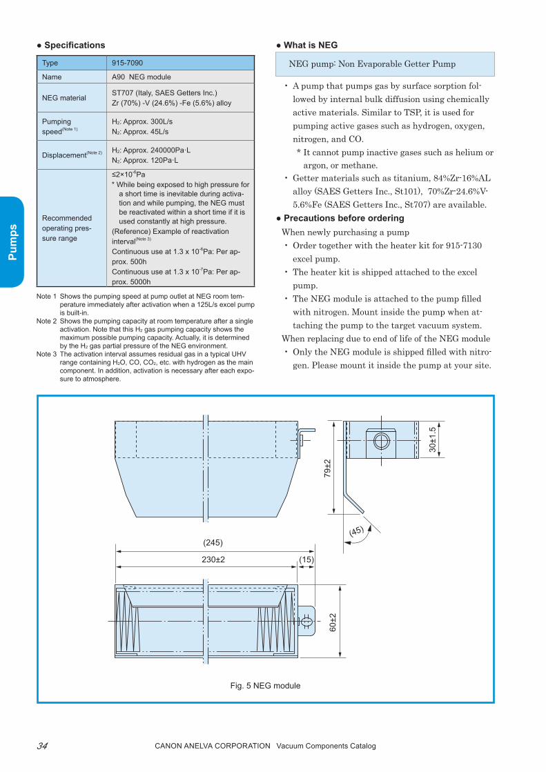
34 Canon anELVa Corporation Vacuum Components Catalog
Pum
ps
Note 1 Shows the pumping speed at pump outlet at NEG room tem-perature immediately after activation when a 125L/s excel pump is built-in.
Note 2 Shows the pumping capacity at room temperature after a single activation. Note that this H2 gas pumping capacity shows the maximum possible pumping capacity. Actually, it is determined by the H2 gas partial pressure of the NEG environment.
Note 3 The activation interval assumes residual gas in a typical UHV range containing H2O, CO, CO2, etc. with hydrogen as the main component. In addition, activation is necessary after each expo-sure to atmosphere.
● What is NEG
NEG pump: Non Evaporable Getter pump
• A pump that pumps gas by surface sorption fol-lowed by internal bulk diffusion using chemically active materials. Similar to tSp, it is used for pumping active gases such as hydrogen, oxygen, nitrogen, and CO. * It cannot pump inactive gases such as helium or
argon, or methane.• Getter materials such as titanium, 84%Zr-16%AL
alloy (SAES Getters Inc., St101), 70%Zr-24.6%V-5.6%Fe (SAES Getters Inc., St707) are available.
● Precautions before orderingWhen newly purchasing a pump• Order together with the heater kit for 915-7130
excel pump.• the heater kit is shipped attached to the excel
pump.• the NEG module is attached to the pump filled
with nitrogen. Mount inside the pump when at-taching the pump to the target vacuum system.
When replacing due to end of life of the NEG module• Only the NEG module is shipped filled with nitro-
gen. please mount it inside the pump at your site.
Fig. 5 NEG module
● Specifications
(15)
(45)(245)
230±2
60±2
79±2
30±1
.5
Type 915-7090
Name A90 NEG module
NEG materialST707 (Italy, SAES Getters Inc.)Zr (70%) -V (24.6%) -Fe (5.6%) alloy
Pumping speed(Note 1)
H2: Approx. 300L/sN2: Approx. 45L/s
Displacement(Note 2) H2: Approx. 240000Pa·LN2: Approx. 120Pa·L
Recommended operating pres-sure range
≤2×10⁻⁶Pa* While being exposed to high pressure for
a short time is inevitable during activa-tion and while pumping, the NEG must be reactivated within a short time if it is used constantly at high pressure.
(Reference) Example of reactivation interval(Note 3)
Continuous use at 1.3 x 10⁻⁶Pa: Per ap-prox. 500hContinuous use at 1.3 x 10⁻⁷Pa: Per ap-prox. 5000h

35Canon anELVa Corporation Vacuum Components Catalog
Pum
ps
■ Application
―― Pumping system and connection method ――the above pumping system is recommended as an extreme high vacuum system using the excel pump. In addition, you can use an oil rotary pump and a foreline trap combination instead of the dry pump.―― pumping method――(1) pump the vacuum chamber and excel pump to ap-
proximately 10-5pa with a turbo molecular pump.(2) Activate the NEG module and bake the excel pump
and vacuum chamber. Note that the NEG module can be activated by baking it together with the excel pump main unit using the 915-7130 heater kit (option).
(3) After baking, start the excel pump, close the turbo molecular pump side valve and pump to extreme high vacuum range with the excel pump and the activated NEG module.
―― Activation method ――• Activation is possible simply by baking together
with the excel pump main unit using a dedicated heater kit (915-7130 125L/s heater kit for excel pump).
• Baking conditions (activation conditions)○ pump pressure during baking: 1×10⁻³pa or less○ Baking time: 8hr or more (including warm-up
time)• Baking while pumping
Baking while pumping with a high vacuum pump such as tMp is ideal. If the gas load is small, how-ever, baking while self-pumping with the excel pump is also possible. In this case, the following conditions is recommended.○ pump pressure during baking: 1×10⁻⁵pa or less
● Life expectancy• replacement of the NEG module is recommended
after 30 atmospheric exposures or equivalent load.• performance for hydrogen drops to approximately
40% of initial pumping speed after 30 atmospheric exposures. However, if nitrogen purge is performed, the drop in performance can be reduced to approxi-mately 90% of the initial pumping speed even after 30 exposures.
● Maintenance/consumable parts• replacement element NEG module
the excel pump element and NEG module can be replaced at the end of their product life. refer to the ordering information for the type and quantity.Depending on how contaminated the pump is, simply replacing the element may not be enough to sufficiently restore its characteristics. In this case, the container must be cleaned and heat pumped. please contact us for details.
• Current input terminalthe current input terminal can be replaced. refer to the ordering information for the type.
• Output cable assemblythe following output cable assemblies are available. please specify when ordering the controller. Note that the output cable assembly is the same as the p-500 series.
Length Type
3m 954-7403
5m 954-7405
7m 954-7407
9m 954-7409
● Usage example
Fig. 6 Extreme high vacuum system combining excel pump with oil-free roughing system
Dry pump
Leak valveTurbo
molecular pumpValves
Heater input100V AC
Valves
Vacuum chamber
P-521NP Noble pump controller
912-7100 125L/s Excel pump
Options ○ 915-7090 A90 NEG module○ 915-7130 heater kit

36 Canon anELVa Corporation Vacuum Components Catalog
Pum
ps
■ Ordering information
Parts Number Model Description Remarks Code
2-110015 912-7125 20L/s Ion Pump With φ70ICF 10020
0111-19171 912-7127 20L/s Ion pump With φ70ICF without magnet 10021
0111-19553 912-7135 30L/s Ion Pump With φ114ICF 10022
0111-79286M 912-7137 30L/s Ion Pump With φ114ICF without magnet 10023
2-110016 912-7165 60L/s Ion Pump With φ152ICF 10030
0111-24443M 912-7010 140L/s Ion Pump With φ203ICF 10040
0111-24841 912-7030 270L/s Ion Pump With φ203ICF 10042
0111-19545M 912-7031 270L/s Ion Pump With φ203ICF, left-right symmetric 10043
1-110008 912-7050 500L/s Ion Pump With φ203ICF 10050
P21-04273 912-9100 1000L/s Ion Pump With φ326CS flange 10060
P21-03919 912-7195 1000L/s Ion Pump With φ356ICF 10062
2-310186 912-7120 20L/s Noble Pump With φ70ICF 10120
0111-17909 912-7122 20L/s Noble Pump With φ70ICF without magnet 10121
0111-15664 912-7130 30L/s Noble Pump With φ114ICF 10122
0111-55957 912-7132 30L/s Noble Pump With φ114ICF without magnet 10123
2-310167 912-7160 60L/s Noble Pump With φ152ICF 10130
1-110006 912-7020 110L/s Noble Pump With φ203ICF 10140
0111-24566 912-7040 220L/s Noble Pump With φ203ICF 10142
0111-24809 912-7041 220L/s Noble Pump With φ203ICF, left-right symmetric 10143
1-110007 912-7060 400L/s Noble Pump With φ203ICF 10150
VMT-580 912-9110 800L/s Noble Pump With φ326CS flange 10160
P25-03037 912-7190 800L/s Noble Pump With φ356ICF 10162
P25-04001 912-7100 125L/s Excel Pump φ152ICF, with cover, with heater kit 10651
833-4448 954-7403 Output Cable assembly(3m) For 20L/s-1000L/s IP/NP (3m) 10548
VMT-4784 954-7405 Output Cable assembly(5m) For 20L/s-1000L/s IP/NP (5m) 10549
0111-14422 954-7407 Output Cable assembly(7m) For 20L/s-1000L/s IP/NP (7m) 10550
0111-14430 954-7409 Output Cable assembly(9m) For 20L/s-1000L/s IP/NP (9m) 10551
Note) Contact us for more information about CE (RoHS).

37Canon anELVa Corporation Vacuum Components Catalog
Pum
ps
Memorandum

38 Canon anELVa Corporation Vacuum Components Catalog
Pum
ps
■ SummaryThese controllers control the ion pump or noble pump from high vacuum of 10−2Pa to 10−4Pa or less. A large green LED display is used for improved visibility from a distance.The controllers provide enhanced functions and CE, RoHS compatibility while maintaining compatibility with con-ventional models. Supporting RS232C communications with the addition of an option board as well as abundant I/O functions, the controllers are ideal for automated equipment/remote operation equipment.An ultra-high vacuum type and a high-power type are available for both the ion and noble pumps with the oper-able pressure range and ready to start pressure depending on the connected pump.
New design with improved visibility and function!
ion pump/Noble pump ControllerP-500 series
■ Features1. High performance
Achieves basic functions necessary for high voltage power supply with improved minimum displayable values when monitoring current/voltage, addition of pressure display, and various protective functions
2. Rich functionsSupports external control with various standard equipped I/Os such as two set points, and auto re-covery from power failure (selectable)
3. High compatibilityMaintains remote connector, input cable, and output cable compatibility with conventional models
4. Communication supportrS232C (optionally built-in)
5. Applicable standardsCE marking, roHS directive compliance
■ Applications• Electron microscopes, electron beam lithography
equipment• Ion beam equipment, mask repair equipment• Accelerator-related systems such as storage rings,
beam lines, etc.• Ultra-high vacuum equipment and various ana-
lyzers such as MBE, surface analysis equipment, etc.
CE RoHS

39Canon anELVa Corporation Vacuum Components Catalog
Pum
ps
■ Specifications
Type P-511 IP P-521 IP P-511 NP P-521 NP
Name Ion Pump Controller Noble Pump Controller
Compatible pump All ion pumpsAll noble pumps, excel pumps,
combination pumps
Maximum output voltageDC+5.2kV±10% / DC+7.5kV±10% / DC+3.5kV±10%
Switched in program modeDC-5.2kV±10% / DC-7.0kV±10%
Switched in program mode
Maximum output current43mA or more 170mA or more
43mA or more 170mA or moreLimited to approx. 20mA in the case of 8L/s and 1L/s
Input voltage 90 to 240V AC 50/60Hz single phase (multi-voltage input)
Power consumption Approx. 500VA maximum
Dimensions W209xH99xD370mm (1/2 rack size)
Weight Approx. 6kg (without option board)
Operating temperature/humidity 0 to 40°C/85% RH or less (no condensation)
Usage environment Indoor use/altitude 2000m or less/pollution level: 2/Installation category: II
Display range
Output voltage 0.1x10³V (0.1kV) to 8.0x10³V (8.0kV)
Output current 0.1x10⁻⁷A (10nA) to 5.0x10⁻¹A (500mA)
Pressure
1.1×10⁻⁹ to 1.0×10⁻³Pa (The display range varies depending
on the connected pump) No display function in the case of 8L/s and 1L/s
1.1×10⁻⁹ to 1.0×10⁻³Pa (The display range varies depending
on the connected pump)
Protection functionVarious protective functions available
Errors and error numbers are displayed on the display unit when the protective function is activated
Pressure contact Two points can be set between 1μA and 99mA
REMOTE mode REMOTE/LOCAL switchable with the REMOTE switch on the front panel
Applicable standard CE, RoHS
■ Specifications

40 Canon anELVa Corporation Vacuum Components Catalog
Pum
ps
■ Selection guideAn ultra-high vacuum type and high-power type are available for both the p-500 series ion pump controller and noble pump controller with different ready to start pressures when operating the same pump.Use the following table to select the controller that meets your requirements.
Applicable Pump Type/Name Ready to Start Pressure Remarks
<Ion Pump>P-511 IP Ion Pump controller (ultra-high vacuum type)
P-521 IP Ion Pump controller (high-power type)
Set to +5.0kV output voltage at shipment
912-7125 20L/s ion pump 1x10⁻²Pa or less 2x10⁻²Pa or less
912-7135 30L/s ion pump 1x10⁻²Pa or less 2x10⁻²Pa or less
912-7165 60L/s ion pump 5x10⁻³Pa or less 2x10⁻²Pa or less
912-7010 140L/s ion pump 2x10⁻³Pa or less 1x10⁻²Pa or less
Output voltage must be changed to +7.5kV
912-7030 270L/s ion pump 912-7031 270L/s ion pump
1x10⁻³Pa or less 6x10⁻³Pa or less
912-7050 500L/s ion pump 5x10⁻⁴Pa or less 3x10⁻³Pa or less
912-9100 1000L/s ion pump 912-7195 1000L/s ion pump
3x10⁻⁴Pa or less 2x10⁻³Pa or less
913-0007 1L/s ion pump 913-0008 1L/s ion pump
1x10⁻²Pa or less - Output voltage must be changed to +3.5kV
911-7000 8L/s ion pump 1x10⁻²Pa or less -
<Noble Pump>P-511NP Noble Pumpcontroller (ultra-high vacuum type)
P-521NP Noble Pumpcontroller (high-power type)
Set to -5.0kV output voltage at shipment
912-7120 20L/s noble pump 1x10⁻²Pa or less 2x10⁻²Pa or less
912-7130 30L/s noble pump 1x10⁻²Pa or less 2x10⁻²Pa or less
912-7160 60L/s noble pump 5x10⁻³Pa or less 2x10⁻²Pa or less
912-7020 110L/s noble pump 2x10⁻³Pa or less 1x10⁻²Pa or less
912-7040 220L/s noble pump 912-7041 220L/s noble pump
1x10⁻³Pa or less 6x10⁻³Pa or less
912-7060 400L/s noble pump 5x10⁻⁴Pa or less 3x10⁻³Pa or less
912-9110 800L/s noble pump 912-7190 800L/s noble pump
3x10⁻⁴Pa or less 2x10⁻³Pa or less
912-7100 125L/s Excel Pump 3x10⁻³Pa or less 2x10⁻²Pa or lessChange settings to output volt-age -7kV
913-7000 400L/s combination pump 1x10⁻²Pa or less 2x10⁻²Pa or less
913-7001 800L/s combination pump 1x10⁻²Pa or less 2x10⁻²Pa or less
913-7002 1600L/s combination pump
5x10⁻³Pa or less 2x10⁻²Pa or less
Note) Note that the values depend on conditions such as the pumping history, pumping system configuration, and capacity.

41Canon anELVa Corporation Vacuum Components Catalog
Pum
psNote) * marked indicates CE (RoHS) compliant. Contact us for other products.
■ Output cablethe main unit of the p-500 series ion pump/noble pump controller is CE compliant.therefore, CE compliant output cables are newly included.Conventional type cables (CE non-compliant) can also be used.
■ Ordering information
A current terminal adapter is necessary to connect the CE-compliant output cable to the ion pump/noble pump.
Output cable assemblyL=139mm
CE-compliant output cable assembly L=185mm
Current terminal adapter
Current terminal equipped with adapter
* The current terminal adapter is included with the CE-compliant output cable.
Parts Number Model Description Remarks Code
0110-08011 P-511IP Ion Pump Control Unit (UHV) For ultra-high vacuum 10261*
0110-08029 P-521IP Ion Pump Control Unit (HP) High output type 10262*
0110-08037 P-511NP Noble Pump Control Unit (UHV) For ultra-high vacuum 10361*
0110-08045 P-521NP Noble Pump Control Unit (HP) High output type 10362*
0112-21546 P-511IP-RS Ion Pump Control Unit (UHV) w RS232C For ultra-high vacuum, RS232C built-in 10263*
0112-21554 P-521IP-RS Ion Pump Control Unit (HP) w RS232C High output, RS232C built-in 10264*
0112-21562 P-511NP-RS Noble Pump Control Unit (UHV) w RS232C For ultra-high vacuum, RS232C built-in 10363*
0112-25702 P-521NP-RS Noble Pump Control Unit (HP) w RS232C High output, RS232C built-in 10364*
0110-08087 501-003 CE- Output Cable assembly(3m) For both 20L/s-1000L/s IP/NP 10561*
0110-08095 501-005 CE- Output Cable assembly(5m) For both 20L/s-1000L/s IP/NP 10562*
0110-08100 501-007 CE- Output Cable assembly(7m) For both 20L/s-1000L/s IP/NP 10563*
0110-08118 501-009 CE- Output Cable assembly(9m) For both 20L/s-1000L/s IP/NP 10564*
833-4448 954-7403 Output Cable assembly(3m) For both 20L/s-1000L/s IP/NP 10548
VMT-4784 954-7405 Output Cable assembly(5m) For both 20L/s-1000L/s IP/NP 10549
0111-14422 954-7407 Output Cable assembly(7m) For both 20L/s-1000L/s IP/NP 10550
0111-14430 954-7409 Output Cable assembly(9m) For both 20L/s-1000L/s IP/NP 10551

42 Canon anELVa Corporation Vacuum Components Catalog
Pum
ps
■ Features1. Oil-free ultra-high vacuum
An oil-free ultra-high vacuum can be achieved when used together with an ion pump.
2. EconomicalWhen used together with an ion pump, turbo molec-ular pump, or cryopump, the pumping rate and ulti-mate pressure can be improved significantly making it extremely economical compared to a single large pump.
3. Compact designthe compact light weight design makes it possible to install the pump anywhere.
4. Excellent control functionthe controller uses a unique control method that prevents the filament life from being reduced due to frequent ON-OFF.
5. Simple attachment and removalthe controller is connected to the pump with a con-nector to facilitate attachment and removal.
6. Easy replacementthe evaporation sources (titanium filament, ti-Vac head) can be replaced easily.
■ ApplicationsEffective in reducing the pumping time and increasing the ultimate pressure and pumping capacity of your current vacuum pump systems (ion pump, cryopump, turbo molecular pump).Effective when there is a large amount of gas emis-sion while processing using equipment requiring an ultra-high vacuum such as deposition, annealing, or tube pumping equipment.
titanium Sublimation pump/ti-Vac pump
■ SummaryThe titanium sublimation pump and ti-Vac pump are getter pumps that heat and sublimate titanium within a vacuum to form a titanium evaporated film (getter surface) on the surrounding walls and use the getter effect of metal to absorb and discharge gas.
■ Specifications● Pump body
● Controller
Name Titanium Sublimation Pump Ti-Vac Pump
Type 956-7015 956-7040
Operating pressure 3 Pa or lessEffective amount of titanium Approx. 1g/pump Approx. 15g
Number of fila-ments ×3 -
Amount of titanium evaporation
Approx. 0.07g/h (per pump) at 45A power
Average 0.35g/hat 48A power
Used flange φ70ICF flange
Weight Approx. 580g Approx. 680g
Dimensions See Fig. 1 See Fig. 2
Name Sublimation controller
Type 922-9119
Input 200V AC±20V 1φ 2A 50/60Hz
Output Voltage: 2.8 to 10.8V AC (with output open)Variable with slider
Current: Up to 50APower: Up to 430W
Control method
Evaporation - preheating control with two inde-pendent timers
Output voltage during evaporation: Variable with slider
Output voltage during preheating: Fixed at approx. 3.8V
Timer setting: Both evaporation and preheating time can be set to 0 or from 1 to 10 minutes
Operation: Evaporation > preheating > OFF(not repeated)
Weight Approx. 20.5kg
Input cable Length outside equipment Approx. 2m
Output Cable Length 2m
Dimensions See figure

43Canon anELVa Corporation Vacuum Components Catalog
Pum
ps
Sublimation pump controller
● Standard configurationTitanium sublimation pump (TSP)
ti-Vac pump
Controller (for both TSP and Ti-Vac pump)
Note) Cable connector heat-resistant temperature 125°C
Fig. 2 Ti-Vac pump
Sublimation pump controller
228±570±3 33±1
φ34±
1.5
26.5±0.5
Insulation stone
Leak groove (rear)
Key
Ti-Vac head
Ti-Vac holderInsulating spacer
Support fitting
50±1.5
(φ47
.5)
φ70 ICF
271±4
φ34±
1.5
146±2 Insulation stone
Leak groove (rear)Key
Titanium filament TSP cartridge
50±1.5
(φ47
.5)
φ70 ICF
12
3C
12
3C
Name Configuration
956-7015TSP cartridge(Titanium filament not attached)
x1
Atta
chm
ents
956-0010 titanium filament x12 (1 pack)
953-5014 gasket for φ70ICF flange x5 (1 pack)
10x10 combination wrench x1
7x8 both opening spanner x1
Dimension 2 hexagonal wrench x1
Moly paste (lubricant) x1 (tube)
M4x4 set screws (spare) x4
Name Configuration
Controller body x1
4P plug with output cable (2m) x1
Atta
chm
ents Outlet for 200V x1
5A fuse x2
50A fuse with tab x1
Name Configuration
956-7030 Ti-Vac holder x1956-7035 Ti-Vac head x1
Atta
chm
ents
Support fitting (included with ti-Vac holder)
x1
Insulation spacer (included with ti-Vac head)
x1
953-5014 gasket for φ70ICF flange x5 (1 pack)
10x10 combination wrench x1
Dimension 2 hexagonal wrench x2
Moly paste (lubricant) x1 (tube)
M4x4 set screws (spare) x6
S1DX
ON UP
S1DX
ON UP
0
1
2
3
45
6
7
8
9
10
A0
10 20 30 4050
922-9119SUBLIMATION PUMP CONTROLLER
FILAMENT CURRENT
FILAMENT SELECT
POWER
HEAT TIME
SUB HEAT
EVA HEAT
START
STOP1 2 3
POWER ADJ0
1
2
3
45
6
7
8
9
10
3A TLF2
3A TLF1
OUTPUTTB1
AC200V IN
HAZARDOUS VOLTAGE INSIDEWARNING
0164-14974DTrained service personnel only.Do not open covers.Can shock,burn or cause death.
JAPAN Kawasaki
Canon ANELVA Co.
InputVAφFrequencyHz
Max. outputV
A C
1
2
3
460 ±1.510 ±0.5
305
±1.5
MAX
48
142
±1.5
5.5
±1
(14)
480 ±2
(8.5
)10
0 ±1
24.5
±0.5
149
±1.5
6M
AX 3
0
removable
430 ±1.5
Input cable
Rubber feet
Canon ANELVA Co.
Fig. 1 Titanium sublimation pump
44 Canon anELVa Corporation Vacuum Components Catalog
Pum
ps
↓
Conductance limited area
Titanium sublimation speed limited areas
10−5−10−3Pa
High→Pressure
Hig
hPu
mpi
ng s
peed
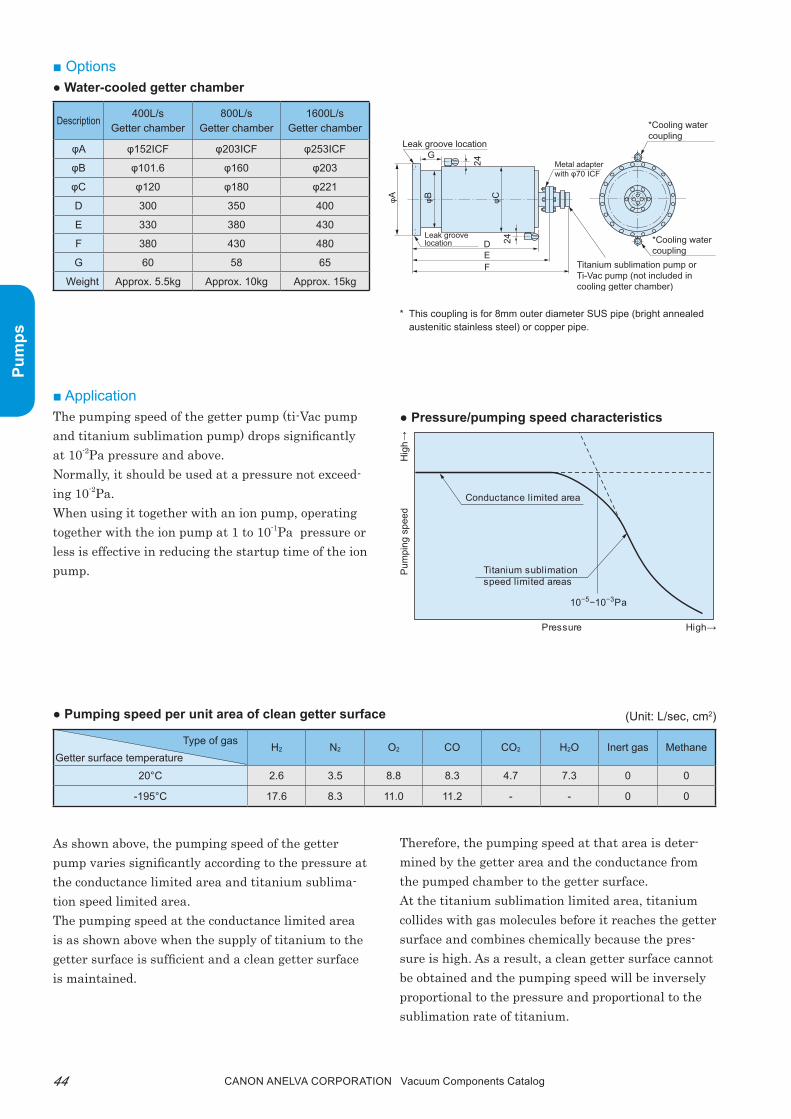
■ Options● Water-cooled getter chamber
therefore, the pumping speed at that area is deter-mined by the getter area and the conductance from the pumped chamber to the getter surface.At the titanium sublimation limited area, titanium collides with gas molecules before it reaches the getter surface and combines chemically because the pres-sure is high. As a result, a clean getter surface cannot be obtained and the pumping speed will be inversely proportional to the pressure and proportional to the sublimation rate of titanium.
■ Applicationthe pumping speed of the getter pump (ti-Vac pump and titanium sublimation pump) drops significantly at 10-2pa pressure and above.Normally, it should be used at a pressure not exceed-ing 10-2pa.When using it together with an ion pump, operating together with the ion pump at 1 to 10-1pa pressure or less is effective in reducing the startup time of the ion pump.
* This coupling is for 8mm outer diameter SUS pipe (bright annealed austenitic stainless steel) or copper pipe.
● Pressure/pumping speed characteristics
● Pumping speed per unit area of clean getter surface
As shown above, the pumping speed of the getter pump varies significantly according to the pressure at the conductance limited area and titanium sublima-tion speed limited area.the pumping speed at the conductance limited area is as shown above when the supply of titanium to the getter surface is sufficient and a clean getter surface is maintained.
Leak groove location
*Cooling water coupling
*Cooling water coupling
Titanium sublimation pump or Ti-Vac pump (not included in cooling getter chamber)
Metal adapter with φ70 ICF
Leak groove location
G
DEF
24
24
φA φB φC
Description 400L/sGetter chamber
800L/sGetter chamber
1600L/sGetter chamber
φA φ152ICF φ203ICF φ253ICF
φB φ101.6 φ160 φ203
φC φ120 φ180 φ221
D 300 350 400
E 330 380 430
F 380 430 480
G 60 58 65
Weight Approx. 5.5kg Approx. 10kg Approx. 15kg
Type of gasGetter surface temperature
H2 N2 O2 CO CO2 H2O Inert gas Methane
20°C 2.6 3.5 8.8 8.3 4.7 7.3 0 0
-195°C 17.6 8.3 11.0 11.2 - - 0 0
(Unit: L/sec, cm2)

45Canon anELVa Corporation Vacuum Components Catalog
Pum
ps
the following methods are available when using the getter pump.1. Using the inside wall of the pumped chamber as the
getter surface(In order to obtain high pumping speed)
2. Creating a dedicated getter surface inside the pumped chamber(Effective when pumping hydrogen to obtain an ultra-high vacuum)
3. Installing a dedicated getter chamber inside the pumped chamber(Effective when pumping without contaminating the pumped chamber)three types of water cooled getter chambers are available when using this method.
■ Ordering information
Water cooling
Water cooling
Pumped chamber
Shield plate
LiqN2 cooling
Getter surface mounting flange
Pumped chamber
Shield plate
Water cooling
Chamber connection flange
Dedicated getter chamber
Pumped chamber
Shield plate
Parts Number Model Description Remarks Code
0111-16547 956-7040 Ti-Vac Pump With φ70ICF, ti-Vac head x1 10720
H23-01049 956-7035 Ti-Vac Head TI Head 10730
743-1277 956-7015 TSP Cartridge With φ70ICF, with filament/gasket/attachment tool 10700
MOD-41604 956-0010 TSP Filament x12 10711
VMT-8089 956-7030 Ti-Vac Holder 10731
0112-10901 922-9119 Sublimation Pump Control Unit 200V AC/1φ, for both TSP and ti-Vac pump 10772
VMT-7107 TSP Output Cable (2m) 2m 10780
VMT-6485 TSP Output Cable (3m) 3m 10781
A23-08968 TSP Output Cable (5m) 5m 10782
VMT-6487 TSP Output Cable (7m) 7m 10783
VMT-8093 941-7104 400L/s Getter Chamber With φ152ICF 10752
VMT-8095 941-7108 800L/s Getter Chamber With φ203ICF 10753
FMT-9017 941-7116 1600L/s Getter Chamber With φ253ICF 10754
Note) Contact us for more information about CE (RoHS).

46 Canon anELVa Corporation Vacuum Components Catalog
Pum
ps
■ Features1. Increased pumping speed
Compared to ion pumps, the cost (including the cost of the control equipment) per pumping speed of 1L/s is approximately 1/2 to 1/3.
2. Light weight and compactCompared to ion pumps with the same pumping speed, the volume and weight are reduced to 1/5 to 1/10. therefore, it can be easily attached/removed to/from the pumped system to achieve a fast pump-ing speed with minimum space.
3. Safety designA connector is used to connect the power supply for the sublimation pump to enable simple and secure connection. Flareless fitting is used for the cooling water inlet/outlet so that the metal tube can be con-nected easily without having to worry about water leaking.
Combination pump
■ SummaryThe combination pump combines a titanium subli-mation pump and triode ion pump (noble pump) to achieve a fast pumping speed at very low cost, tak-ing advantage of the ion pump features that enable a clean ultra-high vacuum to be achieved easily.
4. Clean ultra-high vacuumAn oil-free clean ultra-high vacuum can be obtained because no organic materials are used.
5. No liquid nitrogen requiredNo trap is used. runs on cooling water and AC power.
6. Easy operation and maintenanceSimple operation enabling unattended operation even during a power failure.
7. pump element replaceableAll models use a replaceable titanium evaporation source and noble pump element.
■ ApplicationsDeposition equipment, electron microscopes, mass spectrometers, vacuum furnaces, various analysis equipment, experimental equipment, pumping equip-ment and other ultra-high vacuum systems with large gas emission.
Fig. 1 Price to pumping speed ratio(Assuming 400L/s noble pump is 100%)
[1600L/s Combination Pump]
(%)
Pumping speed (L/s)
100
50
1500 1000 1500 2000
Combination pump
Noble pump

47Canon anELVa Corporation Vacuum Components Catalog
Pum
ps
■ 400L/s Combination Pump
● Specifications
Fig. 2 Pumping speed/pumping flow - pressure characteristics
Fig. 3 Dimensions diagram
* This coupling is for 8mm outer diameter SUS pipe (bright an-nealed austenitic stainless steel) or copper pipe.
Pumping speed
Pumping speed
Pumping flow
Pumping flowL/s
1000
100
10
Pam3/s
1×10⁻³
1×10⁻⁵ 1×10⁻⁴ 1×10⁻³ 1×10⁻²
1×10⁻⁴
Pressure Pa
Pumping rate/Pumping flow
See Fig. 2
Operating pressure range
10-1Pa to 10-9 Pa
Baking temperature MAX 250°C
Weight Approx. 15kg
Intake flange φ152ICF flange
Capacity Approx. 4.5L
Dimensions See Fig. 3
Applicable control-ler
922-9119 Sublimation Pump Controller and P-511NP or P-521NP Noble Pump Controller
133±2(52) 214±3
290±3
372±4
φ136±2
201±
3(7
6)
Intake flange
Current input terminal
*Water cooling coupling
Sublimation pump cartridge
Magnet
Water-cooling jacket
φ152
ICF

48 Canon anELVa Corporation Vacuum Components Catalog
Pum
ps
Fig. 4 Pumping speed/pumping flow - pressure characteristics
Fig. 5 Dimensions diagram
* This coupling is for 8mm outer diameter SUS pipe (bright an-nealed austenitic stainless steel) or copper pipe.
● Specifications
■ 800L/s Combination Pump
133±2(53) 214±3
216±363±2
406±5
236±
3
φ203
ICF
124±
2
114±2
Intake flange
Drainage opening
Current input terminal
*Water cooling coupling
Mounting foot
Sublimation pump cartridge4-φ13
Magnet
Water-cooling jacket
φ174±2
Pumping speed
Pumping speed
Pumping flow
Pumping flowL/s
1000
100
10
Pam3/s
1×10⁻³
1×10⁻⁵ 1×10⁻⁴ 1×10⁻³ 1×10⁻²
1×10⁻⁴
Pressure Pa
Pumping rate/Pumping flow
See Fig. 4
Operating pressure range
10-1Pa to 10-9 Pa
Baking temperature MAX 250°C
Weight Approx. 25kg
Intake flange φ203ICF flange
Capacity Approx. 7.5L
Dimensions See Fig. 5
Applicable control-ler
922-9119 Sublimation Pump Controller and P-511NP or P-521NP Noble Pump Controller

49Canon anELVa Corporation Vacuum Components Catalog
Pum
ps
■ 1600L/s Combination Pump
● Specifications
Fig. 6 Pumping speed/pumping flow - pressure characteristics
* This coupling is for 8mm outer diameter SUS pipe (bright annealed austenitic stainless steel) or copper pipe.
133±2
250±3(129) 214±3
170±2
240±3
429±5
φ253
ICF
Intake flange
Current input
terminal
*Water cooling coupling
Magnet
Water-cooling jacket
Magnet
430±
5
φ70
110±
2
φ230
±3
Internal heater for baking : 200V×900W
Internal heater
Sublimation pump cartridge
Pumping speed
Pumping speed
Pumping flow
Pumping flowL/s
1000
100
10
Pam3/s
1×10⁻³
1×10⁻⁵ 1×10⁻⁴ 1×10⁻³ 1×10⁻²
1×10⁻⁴
Pressure Pa
Pumping rate/Pumping flow
See Fig. 6
Operating pressure range
10-1Pa to 10-9 Pa
Baking temperature MAX 250°C
Weight Approx. 35kg
Intake flange φ253ICF flange
Capacity Approx. 15.5L
Dimensions See Fig. 7
Applicable control-ler
922-9119 Sublimation Pump Controller and P-511NP or P-521NP Noble Pump Controller
Fig. 7 Dimensions diagram

50 Canon anELVa Corporation Vacuum Components Catalog
Pum
ps
■ Options (maintenance and consumable parts)
● Pumping system and connection methodA pumping system similar to the one shown above is recommended. An oil rotary pump and foreline trap combination can also be used instead of the adsorp-tion pump. A turbo molecular pump and oil rotary pump combination is also popular.the cutout valve may be omitted on systems not fre-quently exposed to atmosphere.Connect the cooling water by inserting a φ8mm metal tube (bright annealed austenitic stainless steel or copper) into the cooling water inlet and turning it 5/4 turns with a wrench.
● Pump element replacementthe sublimation pump filament can be replaced with-out removing the pump from the pumping system. remove just the cartridge.the noble pump element can be removed simply by removing the pump from the pumping system.
■ Application
Fig. 8 Pumping system
Combination pump
Cooling water outletP-511NP, P-521NPnoble pump controller
922-9119sublimation pump controller
Cut-out valve
Roughing valve
Roughing system such as TMP
High vacuum valve
Vacuum chamber
Description Type Configuration Remarks
Set filament 956-0010 1 set For titanium sublimation pump, x12
Combination pump element400L/s800L/s1600L/s
913-7000913-7001913-7002
1 set1 set1 set
Connecting lines included
Current input terminal 954-7281 x1 With φ34 mini flange, for ion pump
Ti-Vac pump 956-7040 1 set Can be combined with a ti-Vac pump as an option.

51Canon anELVa Corporation Vacuum Components Catalog
Pum
ps
■ Ordering information
Parts Number Model Description Remarks Code
0111-21039 913-7000 400L/s Combination Pump With φ152ICF, with TSP•NP 10600
0111-17721 913-7001 800L/s Combination Pump With φ203ICF, with TSP•NP 10610
0111-26071 913-7002 1600L/s Combination Pump With φ253ICF, with TSP•NP 10620
MOD-41604 956-0010 TSP Filament x12 10711
0111-16547 956-7040 Ti-Vac Pump With φ70ICF, ti-Vac head x1 10720
Note) Contact us for more information about CE (RoHS).

52 Canon anELVa Corporation Vacuum Components Catalog
Pum
ps
■ Selection guide● Selection by various characteristics
taking into consideration the size and use of the vacuum equipment, select the model in terms of performance such as pumping speed (nitrogen, ar-gon, hydrogen), gas load (maximum pumping flow), regeneration cycle (pumping capacity), and start operation pressure (maximum gas instantaneous tolerance).In general, the higher pump type names have, greater pumping speed and capacity (see the indi-vidual specifications).
● Selection of the intake flange typeFormer JIS flange, ISO (new JIS) flange, ASA flange, and ICF flange are available as intake flanges.products with other flanges are also available upon order.
Cryopump POWER/POWEREco Series
■ About the POWER/POWERECO series cryopump modelA product configuration example is shown.
P−080CL−AHNPump intake diameter(08 to 20)
Specification No.
C: Cryopump (vertical)CL Cryopump (horizontal)
Intake flange specificationsJ: Form JIS flangeA: ASA flangeS: ISO (new JIS) flangeU: ICF flange specificationX: All metal seal specification
HN: With heater N: Without heater
● Selection by installation conditionIf a vertical cryopump cannot be installed, a hori-zontal cryopump is available.
Note) there are gases that are not appropriate for pumping with a cryopump or require certain precautions. refer to the instruction manual for details.

53Canon anELVa Corporation Vacuum Components Catalog
Pum
ps
■ Features1. Enables safe, high speed regeneration without
a heater• the self-heating function enables regeneration at
high-speed equaling pumps with heaters.• there is no fear of sparks, electrical discharge, or
leakage because no heater is used.2. POWER startup and stability (excellent startup
characteristic and temperature stability)• No significant increase in the start-up time when
using only a single pump during multi-operation.• Change in the startup time due to the cryopump
operating environment is kept to a minimum.• resistance to unbalanced thermal load penetra-
tion into multi-operation pump is improved sig-nificantly.
• Fluctuation in temperature between pumps is kept to a minimum.
■ SummaryGas turns into a liquid when cooled and then into a solid (ice) when cooled further. Cryopumps are vacuum pumps that use this phenomenon to pump vacuum and store gas as a solid (ice) by freezing the gas onto the internal cryogenic surface (pumping surface).Cryopumps have excellent features such as fast pumping speed and clean vacuum.However, since cryopumps store the vacuum pumped gas internally, the pumping performance will drop after a certain amount of gas has been pumped and must be restored.This operation is called regeneration. Specifically, the temperature of the cryogenic surface (pumping surface) is increased to normal temperature and the gas stored as a solid (ice) is re-vaporized and pumped out of the cryopump.Since vacuum pumping is not possible during regeneration, the speed of regeneration and the amount of gas that can be stored to reduce the frequency of regeneration greatly affects the productivity and utilization of semi-conductor or electronic component manufacturing equipment and other vacuum equipment.The POWER series cryopump solves the above problem by using the world's first self-heating function and our unique pumping panel structure. Furthermore, it provides excellent pumping performance and improved temper-ature stability during multi-operation.
POWER series
CryopumpHigh performance cryopumpIntake diameter 8 to 12 inches (small)
3. Low vibrationAverage vibration acceleration is less than 1/10 com-pared to our previous product.
4. POWER pumping capacity (pumping character-istics)the argon pumping capacity based on convention-ally used standards was far outside the range where a cryopump can be used in actual production equip-ment because these calculation standards were not at a practical level.the argon pumping capacity shown in our catalog is evaluated based on our own standards, which are much more rigorous than the above conventional standards. It accurately shows the range in which a cryopump can be installed and used in actual pro-duction equipment.Although the pumping performance of a cryopump changes together with the gas storage capacity, the

54 Canon anELVa Corporation Vacuum Components Catalog
Pum
ps
pOWEr series keeps that change to a minimum with our unique panel design and maintains excel-lent pumping performance all the way to the pump-ing capacity limit.
• Maintains excellent pumping performance all the way to the argon pumping capacity limit.
5. POWER refrigeration (with sufficient cooling performance)
• Significantly increased cooling performance en-ables long-lasting, stable hydrogen pumping per-formance
• Capable of withstanding thermal load enabling more stable operation
• triple operation is also possible with the 12 inch cryopump.
■ What is the self-heating function? (POWER regeneration)
the normal refrigeration cycle cools the stage by re-peating adiabatic expansion of high pressure He gas introduced from the outside within the cooling stage.the self-heating function heats the cooling stage by switching the movement of the piston (displacer) cre-ating this space and the He gas introduction timing to perform adiabatic compression of He gas in the space where adiabatic expansion is normally performed.this enables high-speed regeneration without using a heater.
Cooling stage
(Displacer)
He Gas
Adiabatic expansion
Cooling stage
He Gas
Adiabatic compression
(Displacer)
Cooling cycle Heating cycle
■ About the cryopump startup characteristicsthe cryopump used in a multi-chamber system is normally used in multi-operation mode where multiple cryopumps are operated with a single compressor.If cryopumps running in multi-operation mode are all regenerated/started at the same time, the startup time will be as specified in the catalog. However, if only a single cryopump is regenerated while running other cryopumps, it will take longer to start. this is because a cryopump operates on the principle where the cooling performance increases as the temperature decreases. therefore, the cooling performance of higher temperature pumps tends to decrease.this characteristic may be a problem not only during startup, but also during normal use. this is because when a large thermal load is applied to only one of the cryopumps running in multi-operation mode, the temperature of that pump is more likely to increase further while the other pumps are more likely to cool. As a result, the varia-tion in temperature among the pumps running in multi-operation mode will increase causing imbalanced cooling performance among the pumps.the pOWEr series cryopump is significantly improved with respect to these phenomenon.

55Canon anELVa Corporation Vacuum Components Catalog
Pum
ps
Time
Conventional type
POWER
Warm-up time 150 min
Triple operation Three unit simultaneous regeneration
(during Ar500L storage)
Startup time 70 minRoughing
40 min 50 min
0 60 120 180 240 (Minute)
Conventional type
POWER50 min
0 20 40 60 80 100 (Minute)
Three units started simultaneously
Startup time when regenerating only one unit
Three units started simultaneously
Startup time when regenerating only one unit
70 min
98 min
56 min
if p-081C cryopump
Cryopump triple operationStartup time comparison by startup method
Cryopump regeneration time comparison
0 200
Acc
eler
atio
n st
reng
th
0
10
20
30
400 600
Conventional cryopump
POWER series cryopump
1000(Hz)
800
Cryopump vibration spectrum
01E-7
1E-6
1E-5
1E-4
1E-3 Argon gas storage capacity
890L
800L
780L or less
(Minute)
Pres
sure
(Pa)
10
Time
20 30 01E-7
1E-6
1E-5
1E-4
1E-3 Argon gas storage capacity
4400L
4000L3000L or less
(Minute)
Pres
sure
(Pa)
10
Time
20 30
P-081C Ar pumping capacity 800L P-122C Ar pumping capacity 4000L
Argon gas storage capacity and pressure drop characteristics
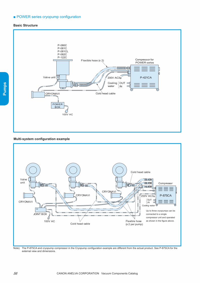
56 Canon anELVa Corporation Vacuum Components Catalog
Pum
ps
■ POWER series cryopump configuration
Basic Structure
Multi-system configuration example
P-080CP-081CP-081CLP-082CP-122C
Compressor for POWER series
CRYONAVI
Valve unit
Flexible hose (x 2)
Cold head cable
200V AC3φ
Cooling water
OUTIN
100V AC
P-421CA
POWERBOX
Cooling water
OUTIN
Flexible hose (x 2 per pump)Cold head cable
Cold head cable
CRYONAVI
JOINT BOX
Valve unit
CRYONAVICRYONAVI
100V AC
Compressor
P-875CA200V AC3φ
Up to three cryopumps can be connected to a single compressor unit and operated as shown in the figure above.
Note) The P-875CA and cryopump compressor in the Cryopump configuration example are different from the actual product. See P-875CA for the external view and dimensions.

57Canon anELVa Corporation Vacuum Components Catalog
Pum
ps
*1) If the POWER series dedicated control power supply CRYONAVI is not used, the time required for cryopump regeneration such as the warm-up time will increase because the self-heating function cannot be used. Similar to normal type cryopumps, the above regeneration (warm-up) time assumes the use of the self-heating function and no gas such as argon is stored inside the pump. +α is the time required to rough pump the cryopump. (This changes according to the roughing pump type and the amount of moisture in the cryopump.)
*2) The pumping capacity is calculated using our unique calculation method and is similar to the value obtained when the cryopump is actually used mounted on the equipment.
*3) Depending on the gas/thermal load conditions of the cryopump of the vacuum equipment, it may not be possible to run this number of units.
■ POWER series cryopump performance specifications
Pump Type P-080C P-081C P-081CL P-082C P-083C P-100C P-100CLRemarks
Diameter 8 inch 8 inch 8 inch 8 inch 8 inch 10 inch 10 inch
Shape Vertical Vertical Horizontal Vertical Vertical Vertical Horizontal
Pumping speed (L/s)
Nitrogen 1,500 1,500 1,500 1,500 1,500 2,400 2,400Argon 1,300 1,300 1,300 1,300 1,300 2,000 2,000Hydrogen 1,000 2,500 2,200 1,000 1,000 3,000 3,000Vapor 4,000 4,000 4,000 4,000 4,000 6,400 6,400
Maximum pumping flow (Pa•m3/s) 1.5 1.2 1.2 1.5 1.5 1.0 1.0Maximum gas instantaneous toler-ance (Pa•m3)
18.0 18.0 18.0 18.0 18.0 18.0 18.0
Startup time (min) 45 50 65 45 50 70 80 *1Regeneration (warm-up) time (min) 30 30 30 30 35 35 40 *1Startup regeneration time (min) 75+α 80+α 95+α 75+α 85+α 105+α 120+α *1
Pumping capacity(Pa•m3)
Argon 80,000 80,000 80,000 150,000 190,000 160,000 140,000 *2Hydrogen 1,300 1,800 1,600 1,300 1,300 1,600 1,300
Ultimate temperature (K) 15 or lessUltimate pressure (Pa) Approx. 10-7
Maximum heating temperature (°C)
70
Ambient temperature range (°C) 10 to 35Recommended maintenance hour (h)
Within 16,000h
Weight (kg) 20 21 22 23 24 25 27
Operating unitsP-421CA 1 1 1 1 1 1 1 *3P-875CA 2 to 3 2 to 3 2 to 3 2 to 3 2 to 3 2 to 3 2 to 3 *3
Pump Type P-101C P-101CL P-120C P-120CL P-121C P-121CL P-122CRemarks
Diameter 10 inch 10 inch 12 inch 12 inch 12 inch 12 inch 12 inch
Shape Vertical Horizontal Vertical Horizontal Vertical Horizontal Vertical
Pumping speed (L/s)
Nitrogen 2,400 2,400 4,000 4,000 4,000 4,000 4,000Argon 2,000 2,000 3,200 3,200 3,200 3,200 3,200Hydrogen 3,800 3,700 3,600 3,000 6,000 5,000 3,000Vapor 6,400 6,400 9,000 9,000 9,000 9,000 9,000
Maximum pumping flow (Pa•m3/s) 1.0 1.0 1.0 1.0 1.0 1.0 1.0Maximum gas instantaneous toler-ance (Pa•m3)
18.0 18.0 18.0 18.0 18.0 18.0 18.0
Startup time (min) 70 80 60 90 70 100 60 *1Regeneration (warm-up) time (min) 35 45 35 40 40 50 30 *1Startup regeneration time (min) 105+α 125+α 95+α 130+α 110+α 150+α 90+α *1
Pumping capacity(Pa•m3)
Argon 160,000 140,000 260,000 200,000 260,000 200,000 400,000 *2Hydrogen 2,000 1,800 1,600 1,400 2,400 2,200 1,600
Ultimate temperature (K) 15 or lessUltimate pressure (Pa) Approx. 10-7
Maximum heating temperature (°C)
70
Ambient temperature range (°C) 10 to 35Recommended maintenance hour (h)
Within 16,000h
Weight (kg) 25 27 29 30 29 30 30
Operating unitsP-421CA 1 1 1 1 1 1 1 *3P-875CA 2 to 3 2 to 3 2 to 3 2 to 3 2 to 3 2 to 3 2 to 3 *3

58 Canon anELVa Corporation Vacuum Components Catalog
Pum
ps
● Dimensions diagram P-080C/P-081C
● Dimensions diagram P-081CL
● Dimensions diagram P-082C

59Canon anELVa Corporation Vacuum Components Catalog
Pum
ps
● Dimensions diagram P-100CL/P-101CL
● Dimensions diagram P-101C

60 Canon anELVa Corporation Vacuum Components Catalog
Pum
ps
● Dimensions diagram P-122C
● Dimensions diagram P-120C/P-121C
● Dimensions diagram P-120CL/P-121CL
61Canon anELVa Corporation Vacuum Components Catalog
Pum
ps
Memorandum

62 Canon anELVa Corporation Vacuum Components Catalog
Pum
ps
■ SummaryThe POWER series cryopump reduces regenera-tion/startup time to help increase vacuum equipment productivity and utilization, and provides high pump-ing capacity, excellent pumping performance and improved temperature stability during multi-operation.In addition to the features of the POWER series cryopump, the POWEREco series cryopump is a high performance energy saving cryopump designed to reduce power consumption and cooling water flow.Using the same compressor as the POWER series, but with increased refrigerator efficiency, and by using multi-wave control (patent pending), the number of cryopumps that can be operated using a single com-pressor has been increased resulting in significantly reduced power consumption and cooling water flow per cryopump. For example, a single P-875CA large compressor can accommodate up to five eight inch diameter cryopumps with 1.0 to 1.2kW power con-sumption per cryopump.With the POWEREco series cryopump, medium and large-sized cryopumps are also available in addition to the small-sized pumps, with significant perfor-mance and energy saving advantages compared to conventional medium to large-sized cryopumps.
POWEREco series
CryopumpHigh-performance energy-efficient cryopumpIntake diameter 8 to 20 inches
■ Features1. Energy and resource saving
power consumption and cooling water: Can be re-duced by 15% to 70%
2. Reduced regeneration/startup timeLess than half that of our previous products.
3. improved pumping performanceArgon pumping capacity substantially increased 1.5 to 4 times that of our previous products.
4. Low vibrationApproximately 1/10 or less compared to convention-al models.
■ Applications• Semiconductor manufacturing equipment (sput-
tering equipment, ion implantation equipment)• Electronic component manufacturing equipment• Vacuum evaporation systems• Vacuum furnaces, space chambers• Accelerators• Various high vacuum equipment

63Canon anELVa Corporation Vacuum Components Catalog
Pum
ps
■ Small POWEREco series cryopump performance specifications
*1) If the POWER series dedicated control power supply CRYONAVI is not used, the time required for cryopump regeneration such as the warm-up time will increase because the self-heating function cannot be used. Similar to normal type cryopumps, the above regeneration (warm-up) time assumes the use of the self-heating function and no gas such as argon is stored inside the pump. The +α is the time required to rough pump the cryopump. (This changes according to the roughing pump type and the amount of moisture in the cryopump.)
*2) The pumping capacity is calculated using our unique calculation method and is similar to the value obtained when the cryopump is actually used mounted on the equipment.
*3) Depending on the gas/thermal load conditions of the cryopump of the vacuum equipment, it may not be possible to run this number of units.*4) A separate Eco unit is required.
Pump Type P-085C P-086C P-086CL P-087C P-105C P-105CL P-106C P-106CL P-107C Re-marksDiameter 8 inch 8 inch 8 inch 8 inch 10 inch 10 inch 10 inch 10 inch 10 inch
Shape Vertical Vertical Horizontal Vertical Vertical Horizontal Vertical Horizontal Vertical
Pumping speed (L/s)
Nitrogen 1,500 1,500 1,500 1,500 2,400 2,400 2,400 2,400 2,200
Argon 1,300 1,300 1,300 1,300 2,000 2,000 2,000 2,000 1,600
Hydrogen 1,000 2,500 2,200 1,000 3,000 3,000 3,800 3,700 2,600
Vapor 4,000 4,000 4,000 4,000 6,400 6,400 6,400 6,400 6,400
Maximum pumping flow (Pa•m3/s) 1.2 1.2 1.1 1.2 1.0 1.0 1.0 1.0 1.0Maximum gas instantaneous toler-ance (Pa•m3) 18.0 18.0 18.0 18.0 18.0 18.0 18.0 18.0 18.0
Startup time (min) 60 65 80 60 75 90 85 100 120 *1Regeneration (heat-up) time (min) 40 40 45 40 45 50 45 50 50 *1
Startup regeneration time (min) 100+α 105+α 125+α 100+α 120+α 140+α 130+α 150+α 170+α *1
Pumping capacity(Pa•m3)
Argon 80,000 80,000 80,000 150,000 160,000 140,000 160,000 140,000 300,000 *2
Hydrogen 1,300 1,800 1,600 1,300 1,600 1,300 2,000 1,800 1,600
Ultimate temperature (K) 15 or less
Ultimate pressure (Pa) Approx. 10-7
Maximum heating temperature (°C) 70
Ambient temperature range (°C) 10 to 35Recommended maintenance hour (h) Within 16,000hr
Weight (kg) 22 22 22 23 25 27 24 30 25
Operating unitsP-421CA 2 2 2 2 2 2 2 2 2 *3, *4
P-875CA 4 to 5 4 to 5 4 to 5 4 to 5 3 to 4 3 to 4 3 to 4 3 to 4 3 to 4 *3
Pump Type P-124C P-124CL P-126C P-126CL P-127C Re-marksDiameter 12 inch 12 inch 12 inch 12 inch 12 inch
Shape Vertical Horizontal Vertical Horizontal Vertical
Pumping speed (L/s)
Nitrogen 4,000 4,000 4,000 4,000 4,000
Argon 3,200 3,200 3,200 3,200 3,200
Hydrogen 3,600 3,600 6,000 6,000 3,000
Vapor 9,000 9,000 9,000 9,000 9,000
Maximum pumping flow (Pa•m3/s) 0.8 0.8 0.8 0.8 0.8Maximum gas instantaneous toler-ance (Pa•m3) 18.0 18.0 18.0 18.0 18.0
Startup time (min) 95 105 95 105 70 *1Regeneration (heat-up) time (min) 45 50 45 50 40 *1
Startup regeneration time (min) 130+α 155+α 140+α 155+α 110+α *1
Pumping capacity(Pa•m3)
Argon 260,000 200,000 260,000 200,000 400,000 *2
Hydrogen 1,600 1,400 2,400 2,000 1,600
Ultimate temperature (K) 15 or less
Ultimate pressure (Pa) Approx. 10-7
Maximum heating temperature (°C) 70
Ambient temperature range (°C) 10 to 35Recommended maintenance hour (h) Within 16,000hr
Weight (kg) 29 30 29 31 29
Operating unitsP-421CA 2 2 2 2 2 *3, *4
P-875CA 3 to 4 3 to 4 3 to 4 3 to 4 3 to 4 *3

64 Canon anELVa Corporation Vacuum Components Catalog
Pum
ps
■ Medium/large POWEREco series cryopump performance specifications
Pump Type P-128C P-128CL P-160C P-160CL P-161C P-161CL P-201C P-206CRemarks
Diameter 12 inch 12 inch 16 inch 16 inch 16 inch 16 inch 20 inch 20 inch
Shape Vertical Horizontal Vertical Horizontal Vertical Horizontal Vertical Vertical
Pumping speed (L/s)
Nitrogen 4,000 4,000 8,000 7,400 8,000 7,400 13,000 13,000Argon 3,200 3,200 5,500 5,500 5,500 5,000 9,000 9,000Hydrogen 6,000 5,000 5,500 5,500 11,000 10,000 17,000 17,000Water 9,000 9,000 17,000 17,000 17,000 17,000 28,000 28,000
Maximum pumping flow (Pa•m3/s)
2.2 2.2 2.2 2,2 2.0 2.2 3.0 3.0
Maximum gas instantaneous tolerance (Pa•m3)
40 40 50 50 50 50 80 80
Startup time (min) 110 115 70 95 90 120 100 100 *1Regeneration (heat-up) time (min)
70 70 40 60 60 60 70 80 *1
Startup regeneration time (min)
180+α 185+α 110+α 155+α 150+α 180+α 170+α 180+α *1
Pumping capacity(Pa•m3)
Argon 270,000 200,000 400,000 200,000 400,000 200,000 800,000 800,000 *2Hydrogen 4,000 3,500 1,600 1,400 3,400 3,000 4,500 7,500
Ultimate temperature (K) 15 or lessUltimate pressure (Pa) Approx. 10-7
Maximum heating tempera-ture (°C)
70
Ambient temperature range (°C)
10 to 35
Recommended maintenance hour (h)
Minimum every 16,000h
Weight (kg) 37 39 50 62 50 62 66 66
Operating unitsP-421CA 1 1 1 1 1 1 - - *3, *4P-875CA 2 2 1 to 2 1 to 2 1 to 2 1 to 2 1 1 *3
*1) If the POWER series dedicated control power supply CRYONAVI is not used, the time required for cryopump regeneration such as the warm-up time will increase because the self-heating function cannot be used. Similar to normal type cryopumps, the above regeneration (warm-up) time assumes the use of the self-heating function and no gas such as argon is stored inside the pump. The +α is the time required to rough pump the cryopump. (This changes according to the roughing pump type and the amount of moisture in the cryopump.)
*2) The pumping capacity is calculated using our unique calculation method and is similar to the value obtained when the cryopump is actually used mounted on the equipment.
*3) Depending on the gas/thermal load conditions of the cryopump of the vacuum equipment, it may not be possible to run this number of units.*4) A separate Eco unit is required.

65Canon anELVa Corporation Vacuum Components Catalog
Pum
ps
■ Utility comparison (energy-saving effect)When using five 8 inch cryopumps
When using two small 12 inch cryopumps
Approx. 33% reduction of power consumption is possible!
Power requirements: 4.8/6.1kW (50/60Hz steady state)
Cooling water flow: 420L/h
Power requirements: 4.8/6.1kW (50/60Hz steady state)
Cooling water flow: 420L/h
Power requirements: 2.4/3.0kW (50/60Hz steady state)
Cooling water flow: 180L/h
Approx. 50% reduction of power consumption is possible!
Conventional type POWEREco
P-086C x 5
P-421CA P-875CA P-875CA
series
Power requirements: 7.2/9.1kW (50/60Hz steady state)
Cooling water flow: 600L/h
Conventional type POWER seriesEco
P-875CA P-421CA
Eco unit
P-126 x 2

66 Canon anELVa Corporation Vacuum Components Catalog
Pum
ps
When using four 12 inch cryopumps
Approx. 33% reduction of power is possible!
Conventional type POWER seriesEco
P-126C x 4
P-875CAP-421CA
P-875CA
○ Energy efficiency and productivity are improved significantly by switching to the "pOWErEco Series" cryopump. Operating costs can also be reduced significantly.
The energy saving performance depends on the configuration of the pump used in the equipment. Please contact our sales offices for details.
When using two medium 12 inch cryopumps
Conventional type POWER seriesEco
P-875CA P-875CA P-875CA
P-128C x 2
Power requirements: 9.6/12.2kW (50/60Hz steady state)
Cooling water flow: 840L/h
Power requirements: 4.8/6.1kW (50/60Hz steady state)
Cooling water flow: 420L/h
Approx. 50% reduction of power is possible!
Power requirements: 7.2/9.1kW (50/60Hz steady state)
Cooling water flow: 600L/h
Power requirements: 4.8/6.1kW (50/60Hz steady state)
Cooling water flow: 420L/h

67Canon anELVa Corporation Vacuum Components Catalog
Pum
ps
■ Dimensions diagramsp-085C/p-086C
p-086CL

68 Canon anELVa Corporation Vacuum Components Catalog
Pum
ps
p-087C
p-105CL/p-106CL
p-105C/p-106C

69Canon anELVa Corporation Vacuum Components Catalog
Pum
ps
■ Dimensions diagramsp-124C/p-126C
p-124CL/p-126CL
p-127C

70 Canon anELVa Corporation Vacuum Components Catalog
Pum
ps
p-128C
p-128CL
p-161C
12-φ25.4PCD.362
4-M8 PCD.363
flange10"ASA
PCD.37012-φ15
flangeφ400 former JIS
13
14
344.5
125
φ295
125125
15
42
64
185.
786
386
511
597
387.5
PCD.37012-φ15
φ400 former JIS
10"ASAflange
12-φ25.4PCD.362
4-M8PCD.363
flange
64
14
15
42
8618
5.7
164
φ18
0
13
164
284
φ298
175 100
436.5522.5
12-φ19PCD.480PCD.473
4-M8
flangeFormer JIS-VG400
20
125
φ406
185.
715
42
64
φ280
86
355
397
521
398
607
p-161CL

71Canon anELVa Corporation Vacuum Components Catalog
Pum
ps
■ Dimensions diagramsp-201C
p-206C
4-M8PCD.585PCD.578 16-φ19
flangeFormer JIS • VG500
428
22
385
122
426.9
φ506
1518
5.7
42
64
86
φ320
553
639
4-M8PCD.585PCD.578 16-φ19
flangeFormer JIS • VG500
428
22
385
122
426.9
φ506
1518
5.7
42
64
86
φ320
553
639

72 Canon anELVa Corporation Vacuum Components Catalog
Pum
ps
c
470
41
421
88
186 428
109
■ Dimensions diagramp-421CA
Compressor unit for P-421CA POWER series cryopump
Type P-421CA
Helium gas pres-sure(MPa)
Not operating 1.60 to 1.65Operating (starting) 2.0 to 2.2Operating (running) 1.8 to 2.0
Compressor cool-ing water
Flow rate(L/H) 180 or moreInlet/outlet pressure difference (MPa)
0.13
Maximum water pressure (MPa)
0.69
Input temperature (°C)
30 or less
Input power supply/voltage (50/60Hz) 200V AC±10% 3φ
Power consump-tion (kW)
Steady-state (50Hz) 2.4Steady-state (60Hz) 2.8
Ambient tempera-ture range (°C)
Operating 10 to 35Storage -15 to 55
Maintenance interval (h) (adsorber re-placement)
Every 30,000h
Dimensions (mm) WxDxH 400x450x470Weight (kg) 75
■ Specifications
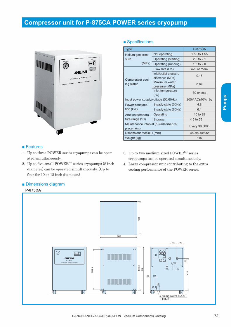
73Canon anELVa Corporation Vacuum Components Catalog
Pum
ps
Compressor unit for P-875CA POWER series cryopump
■ Features1. Up to three pOWEr series cryopumps can be oper-
ated simultaneously.2. Up to five small pOWErEco series cryopumps (8 inch
diameter) can be operated simultaneously. (Up to four for 10 or 12 inch diameter.)
P-875CACRYOPUMP COMPRESSORUNT
500
32
5040
55
100 90
58
45
42555
4.3
584.
363
245
0
■ Specifications
■ Dimensions diagramp-875CA
3. Up to two medium-sized pOWErEco series cryopumps can be operated simultaneously.
4. Large compressor unit contributing to the extra cooling performance of the pOWEr series.
Type P-875CA
Helium gas pres-sure
(MPa)
Not operating 1.50 to 1.55Operating (starting) 2.0 to 2.1Operating (running) 1.8 to 2.0
Compressor cool-ing water
Flow rate (L/h) 420 or moreInlet/outlet pressure difference (MPa)
0.15
Maximum water pressure (MPa)
0.69
Inlet temperature (°C)
30 or less
Input power supply/voltage (50/60Hz) 200V AC±10% 3φ
Power consump-tion (kW)
Steady-state (50Hz) 4.8Steady-state (60Hz) 6.1
Ambient tempera-ture range (°C)
Operating 10 to 35Storage -15 to 55
Maintenance interval (h) (adsorber re-placement)
Every 30,000h
Dimensions WxDxH (mm) 450x500x632Weight (kg) 115

74 Canon anELVa Corporation Vacuum Components Catalog
Pum
ps
p-450CM cryo-temperature monitor
■ Specifications
N:Number of unitsMounted close together
Panel cutting dimensions
Mounting conditions• Panel: t1 to 10 mm steel plate• Mounting angle: Front/back angle within 10˚, left/right angle within 15˚
P-450CM
KSV
PV
MODE
SV4
MANOUT
SV32ND1ST
HIGHLOW
SEL/ENTUPDOWN
K
Mounted individually
910+0.8
92
0+248×N-3
44
96116
70
0+0.8
92
0+0.645
120
748 100
■ Dimensions diagramsp-450CM cryo-temperature monitor
■ Summarythe p-450CM cryo-temperature monitor monitors the status and temperature of the pOWEr/pOWErECO series cryopump and cryo trap and controls them by event output.the pt-Co resistance temperature sensor of the cryopump second stage or the pt100 resistance tem-perature sensor of the cryopump first stage and cryo trap can be used by changing the setting.
Item Specifications
Temperature sensor
Pt-Co resistance temperature sensorPt100 resistance temperature sensor
Output eventNon-voltage contact output 3-points
Rated supply voltage100 to 240V AC50/60Hz (free power)
Transmission signal output(Option)
0 to 5V DC

75Canon anELVa Corporation Vacuum Components Catalog
Pum
ps
Cold head driver p-021CD
UL standard compliant products are also available for the compressor unit and cold head driver.
JRJC
JP
V iew on arrow A
A
COL D HEADMAIN POW ER
ON
INT
OFF
4-φ4.6
EXT
12
9
190
3.2
(342)
300
105
13
9
14
9
209.5

76 Canon anELVa Corporation Vacuum Components Catalog
Pum
ps
● Ordering Information
Parts Number Model Description Remarks Code0112-28831 P-080C-AN POWER Cryopump (ASA Flange) Resistance temperature sensor 11380
0112-28849 P-080C-JN POWER Cryopump(Old JIS Flange) Resistance temperature sensor 11381
0112-28857 P-080C-UN POWER Cryopump (ICF Flange) Resistance temperature sensor 11382
0112-28865 P-081C-AN POWER Cryopump (ASA Flange) Resistance temperature sensor 11383
0112-28873 P-081C-JN POWER Cryopump(Old JIS Flange) Resistance temperature sensor 11384
0112-28792 P-081C-UN POWER Cryopump (ICF Flange) Resistance temperature sensor 11385
0112-28881 P-081CL-AN POWER Cryopump (ASA Flange) Resistance temperature sensor 11386
0112-28899 P-081CL-JN POWER Cryopump(Old JIS Flange) Resistance temperature sensor 11387
0112-28904 P-081CL-UN POWER Cryopump (ICF Flange) Resistance temperature sensor 11388
0112-28912 P-082C-AN POWER Cryopump (ASA Flange) Resistance temperature sensor 11389
0112-28920 P-082C-JN POWER Cryopump(Old JIS Flange) Resistance temperature sensor 11390
0112-28938 P-082C-UN POWER Cryopump (ICF Flange) Resistance temperature sensor 11391
0112-28946 P-101C-JN POWER Cryopump(Old JIS Flange) Resistance temperature sensor 11395
0112-28954 P-122C-AN POWER Cryopump (ASA Flange) Resistance temperature sensor 11392
0112-28962 P-122C-JN POWER Cryopump(Old JIS Flange) Resistance temperature sensor 11393
0112-28970 P-122C-UN POWER Cryopump (ICF Flange) Resistance temperature sensor 11394
0112-28988 P-085C-AN POWER Cryopump (ASA Flange) Resistance temperature sensor 11850
0112-28996 P-085C-JN POWER Cryopump(Old JIS Flange) Resistance temperature sensor 11851
0112-29007 P-085C-UN POWER Cryopump (ICF Flange) Resistance temperature sensor 11852
0112-28807 P-086C-AN POWER Cryopump (ASA Flange) Resistance temperature sensor 11853
0112-29015 P-086C-JN POWER Cryopump(Old JIS Flange) Resistance temperature sensor 11854
0112-29023 P-086C-UN POWER Cryopump (ICF Flange) Resistance temperature sensor 11855
0112-29031 P-086CL-AN POWER Cryopump (ASA Flange) Resistance temperature sensor 11856
0112-29049 P-086CL-JN POWER Cryopump(Old JIS Flange) Resistance temperature sensor 11857
0112-29057 P-086CL-UN POWER Cryopump (ICF Flange) Resistance temperature sensor 11858
0112-29065 P-087C-AN POWER Cryopump (ASA Flange) Resistance temperature sensor 11859
0112-29073 P-087C-JN POWER Cryopump(Old JIS Flange) Resistance temperature sensor 11860
0112-29081 P-087C-UN POWER Cryopump (ICF Flange) Resistance temperature sensor 11861
0112-29099 P-106C-JN POWER Cryopump(Old JIS Flange) Resistance temperature sensor 11862
0112-29104 P-106C-UN POWER Cryopump (ICF Flange) Resistance temperature sensor 11863
0112-29112 P-106CL-JN POWER Cryopump(Old JIS Flange) Resistance temperature sensor 11864
0112-29120 P-106CL-UN POWER Cryopump (ICF Flange) Resistance temperature sensor 11865
0112-29138 P-126C-AN POWER Cryopump (ASA Flange) Resistance temperature sensor 11866
0112-29146 P-126C-JN POWER Cryopump(Old JIS Flange) Resistance temperature sensor 11867
0112-29154 P-126C-UN POWER Cryopump (ICF Flange) Resistance temperature sensor 11868
0112-29162 P-126CL-AN POWER Cryopump (ASA Flange) Resistance temperature sensor 11869
0112-29170 P-126CL-JN POWER Cryopump(Old JIS Flange) Resistance temperature sensor 11870
0112-29188 P-126CL-UN POWER Cryopump (ICF Flange) Resistance temperature sensor 11871
0112-29196 P-127C-AN POWER Cryopump (ASA Flange) Resistance temperature sensor 11872
0112-29201 P-127C-JN POWER Cryopump(Old JIS Flange) Resistance temperature sensor 11873
0112-29219 P-127C-UN POWER Cryopump (ICF Flange) Resistance temperature sensor 11874
0111-03196M P-128C-A POWER Cryopump (ASA Flange) Resistance temperature sensor 11775
0111-26291M P-128C-J POWER Cryopump(Old JIS Flange) Resistance temperature sensor 11776
0112-29227 P-128C-U POWER Cryopump (ICF Flange) Resistance temperature sensor 11777
0111-03879M P-128CL-A POWER Cryopump (ASA Flange) Resistance temperature sensor 11778
0111-53010M P-128CL-J POWER Cryopump (Old JIS Flange) Resistance temperature sensor 11779
0112-28784 P-128CL-U POWER Cryopump (ICF Flange) Resistance temperature sensor 11780
0111-13840M P-161C-J POWER Cryopump(Old JIS Flange) Resistance temperature sensor 11781
0111-03073M P-201C-J POWER Cryopump(Old JIS Flange) Resistance temperature sensor 11783
0111-02962M P-206C-J POWER Cryopump(Old JIS Flange) Resistance temperature sensor 11784
Note) Contact us for more information about CE (RoHS).

77Canon anELVa Corporation Vacuum Components Catalog
Pum
ps
● Ordering Information
Parts Number Model Description Remarks Code9009-11488 P-875CA Compressor Unit 200V AC/3φ water-cooled 11418
9009-11470 P-421CA Compressor Unit 200V AC/3φ water-cooled 11419
9009-11747 P-021CD-1 Cold Head Driver 200V AC/3φ, with 6M input cable 11786
9005-07328B P-450CM Cryo Temperature Monitor100V AC, for both 1st and 2nd, without power supply or sensor cable
11792
9004-88914B P-450CM-ALCryo Temperature Monitor (Analog output)
100V AC, for both 1st and 2nd, without power supply or sensor cable
11793
A22-02069 He Manifold L-2Two port assignment type for direct compressor attachment
11524
A22-02070 He Manifold L-3Three port assignment type for direct compressor attachment
11525
0111-55834,0111-55826 He Manifold L-4For branch between flexi-hoses, 4 port assignment, R/S
11790
0111-55850,0111-00842 He Manifold L-5For branch between flexi-hoses, 5 port assignment, R/S
11791
0114-01748D Eco Unit (5L) T type branch pipe, with 8Ax1M flexi-hose 11787
A23-00449,A23-00450 15Ax3m Flexible Hose Set For P-080 to 127, one return/supply set 11550
A23-00648,A23-00649 15Ax6m Flexible Hose Set For P-080 to 127, one return/supply set 11551
A23-01272,A23-01273 15Ax9m Flexible Hose Set For P-080 to 127, one return/supply set 11552
A23-10531,A23-10532 15Ax12m Flexible Hose Set For P-080 to 127, one return/supply set 11556
A23-00451,A23-00452 20Ax3m Flexible Hose Set For P-128 to 206, one return/supply set 11553
A23-00944,A23-00945 20Ax6m Flexible Hose Set For P-128 to 206, one return/supply set 11554
A23-01275,A23-01274 20Ax9M Flexible Hose Set For P-128 to 206, one return/supply set 11555
A23-10533,A23-10534 20Ax12m Flexible Hose Set For P-128 to 206, one return/supply set 11557
Note) Contact us for more information about CE (RoHS).

78 Canon anELVa Corporation Vacuum Components Catalog
Pum
ps
4˚ 20˚ 78˚B
alan
ced
vapo
r pre
ssur
e (P
a)102
10
10−1
10−2
10−3
10−4
10−5
10−6
10−7
10−8
Temperature (k)1 2 5 10 20 50 100 200
He
H2
Ne
N2
Ar
O2
CH4
CO2
H2O
He gas
(4)
(3)
(2)
(1)
(6)
(5)
(7)
(8)■ Technical notes● Cryopump structure and pumping principlethe name of each part of the cryopump is shown.(1) refrigerator(2) refrigerator first thermal load stage(3) refrigerator second thermal load stage(4) pump container(5) radiation shield(6) Cryosorption panel(7) Cryo-condensation panel(8) Louverthe cryopump cooling unit has two stages with panels that condense and adsorb gas.the first thermal load stage (2) has a radiation shield (5) that blocks the heat from the outside and a lou-ver (8) that condenses and traps mainly H2O (water vapor) at the pump inlet. It runs at approximately 50 to 80K.the second thermal load stage (3) runs at approxi-mately 10 to 20K and consists of a cryo-condensation panel which freezes and condenses gases such as N2 (nitrogen), O2 (oxygen), and Ar (argon) and a cryosorp-tion panel that adsorbs H2 (hydrogen), Ne (neon), and He (helium) that do not condense at 10 to 20K.As described above, the cryopump pumps the gas by(1) Cryo-condensation(2) Cryosorptionand at 20K or less, it can be seen in the vapor pres-sure line chart shown at right that all gases except H2, Ne, and He will be at 10-8pa or less vapor pres-sure.For H2, Ne, and He, the example of H2 in the equal temperature adsorption line chart at right shows that when the temperature decreases and the adsorption volume increases, the balanced pressure becomes suf-ficiently low. therefore, it is possible to pump practi-cally any gas.
Cryopump structure
Vapor pressure line charts
Activated carbon isothermal adsorption line charts (Example)
Bal
ance
d pr
essu
re (P
a)
106
102
10−2
10−6
10−10
10−14
10−18
Adsorbed H2 amount (L/g)0 0.1 0.2 0.3 0.4
12K
10K15K
20K
30K

79Canon anELVa Corporation Vacuum Components Catalog
Pum
ps
P2
P2
TL, Q
TL, Q
P2
Exhaust valve
DisplacerRegenerator
P1
P1
P1
Intake valve
He compressor
Room temperature space
Low temperature space
A
B
D
C
A. When the exhaust valve closes and the intake valve opens, the high pressure gas from the compressor fills the room temperature space at the top of the cylinder.
B. When the displacer moves to the highest point while the intake valve is open, the high pressure gas at the room temperature space is cooled as it passes through the regenerator and moves to the low tem-perature space at the bottom of the cylinder. Dur-ing this process, fresh high pressure gas is supplied through the intake valve since the volume of the moving high pressure gas decreases as the tempera-ture drops.
● Structure and principle of cryopump refrigerator Cooling of the cryopump refrigerator using the G-M refrigeration cycle consists of four cycles.
G-M cycle principle of operation
C. When the intake valve closes and the exhaust valve opens, the high pressure gas in the low temperature space is released, goes through adiabatic expansion, and creates a cold environment (low-temperature low-pressure gas). the low-temperature low-pres-sure gas cools the regenerator and returns to the intake side of the compressor after it adsorbs the refrigeration load.
D. When the displacer moves to the lowest point with the exhaust valve open, the low temperature gas in the low temperature space cools the regenerator (the gas itself is heated) and moves to the room tempera-ture space while some gas returns to the compres-sor.
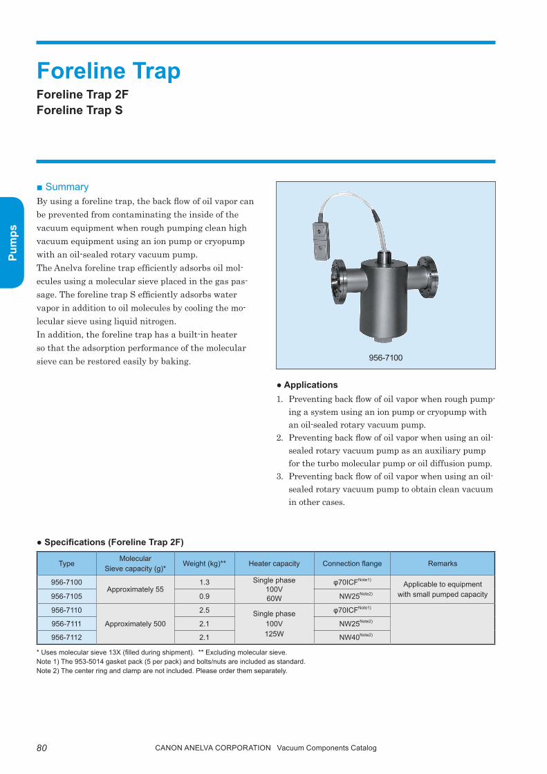
80 Canon anELVa Corporation Vacuum Components Catalog
Pum
ps
● Specifications (Foreline Trap 2F)
* Uses molecular sieve 13X (filled during shipment). ** Excluding molecular sieve.Note 1) The 953-5014 gasket pack (5 per pack) and bolts/nuts are included as standard.Note 2) The center ring and clamp are not included. Please order them separately.
■ SummaryBy using a foreline trap, the back flow of oil vapor can be prevented from contaminating the inside of the vacuum equipment when rough pumping clean high vacuum equipment using an ion pump or cryopump with an oil-sealed rotary vacuum pump.the Anelva foreline trap efficiently adsorbs oil mol-ecules using a molecular sieve placed in the gas pas-sage. the foreline trap S efficiently adsorbs water vapor in addition to oil molecules by cooling the mo-lecular sieve using liquid nitrogen.In addition, the foreline trap has a built-in heater so that the adsorption performance of the molecular sieve can be restored easily by baking.
Foreline trapForeline trap 2FForeline trap S
● Applications1. preventing back flow of oil vapor when rough pump-
ing a system using an ion pump or cryopump with an oil-sealed rotary vacuum pump.
2. preventing back flow of oil vapor when using an oil-sealed rotary vacuum pump as an auxiliary pump for the turbo molecular pump or oil diffusion pump.
3. preventing back flow of oil vapor when using an oil-sealed rotary vacuum pump to obtain clean vacuum in other cases.
956-7100
TypeMolecular
Sieve capacity (g)*Weight (kg)** Heater capacity Connection flange Remarks
956-7100Approximately 55
1.3 Single phase100V60W
φ70ICFNote1)Applicable to equipment
with small pumped capacity956-7105 0.9 NW25Note2)
956-7110
Approximately 500
2.5 Single phase100V125W
φ70ICFNote1)
956-7111 2.1 NW25Note2)
956-7112 2.1 NW40Note2)
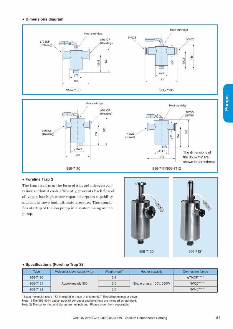
81Canon anELVa Corporation Vacuum Components Catalog
Pum
ps
● Dimensions diagram
● Specifications (Foreline Trap S)
● Foreline Trap Sthe trap itself is in the form of a liquid nitrogen con-tainer so that it cools efficiently, prevents back flow of oil vapor, has high water vapor adsorption capability and can achieve high ultimate pressure. this simpli-fies startup of the ion pump in a system using an ion pump.
* Uses molecular sieve 13X (included in a can at shipment).** Excluding molecular sieve.Note 1) The 953-5014 gasket pack (5 per pack) and bolts/nuts are included as standard.Note 2) The center ring and clamp are not included. Please order them separately.
Type Molecular sieve capacity (g)* Weight (kg)** Heater capacity Connection flange
956-7130
Approximately 500
2.4
Single phase, 100V, 380W
φ70ICFNote 1)
956-7131 2.0 NW25Note 2)
956-7132 2.0 NW40Note 2)
956-7130 956-7131
146
100.
5
φ76
164
φ70 ICF(Rotating)φ70 ICF
(Rotating)
Heat cartridge
146
100.
5
φ76
φ38
177
NW25NW25
Heat cartridge
203
150
φ114.3
200
φ70 ICF(Rotating)
φ70 ICF(Rotating)
Heat cartridge
203
150
φ114.3
210
NW25(NW40)
NW25(NW40)
Heat cartridge
φ38
956-7110 956-7111/956-7112
The dimensions of the 956-7112 are shown in parenthesis
956-7100 956-7105

82 Canon anELVa Corporation Vacuum Components Catalog
Pum
ps
● Maintenance and consumable partsReplacement molecular sieve (13X)type: 956-7101Contents: 500g (in can)
replacement heater
● Dimensions diagram
● Usagethe foreline trap is assembled in the vacuum pipe between the vacuum chamber (or main pump) and the oil-sealed rotary pump, as shown in the figure below.
360
φ113
9116
0
167
φ70 ICF(Rotating)
φ70 ICF(Fixed)
Sheathed heater
367
φ113
98Sheathed heater
NW25(NW40)
NW25(NW40)
φ38
φ38
956-7130 956-7131/956-7132
The dimensions of the 956-7132 are shown in parenthesis.
Leak valve*Leak valve
Foreline trap
* This can be omi tted if the foreline trap vacuum is not needed.
Oil rotary vacuum pump
Valves*Valves
DuctVacuum chamber
or main pump
Type Applicable trap type Remarks
956-9100956-7100956-7105
100V, 60WCartridge heater
956-7114956-7110956-7111956-7112
100V, 125WCartridge heater
944-9150956-7130956-7131956-7132
100V, 380WSheathed heater

83Canon anELVa Corporation Vacuum Components Catalog
Pum
ps
■ Ordering informationParts Number Model Description Remarks Code
P21-03509 956-7100 Fore-Line Trap 2F Straight type, with φ70ICF, with 100V AC/60W heater 13800
A23-00512 956-7105 Fore-Line Trap 2F Straight type, with NW25 flange, with 100V AC/60W heater 13802
P25-00554 956-7110 Fore-Line Trap 2F Straight type, with φ70ICF, with 100V AC/125W heater 13803
P21-05520 956-7111 Fore-Line Trap 2F(w NW25) Straight type, with NW25 flange, with 100V AC/125W heater 13804
P21-05172 956-7112 Fore-Line Trap 2F(w NW40) Straight type, with NW40 flange, with 100V AC/125W heater 13805
P21-03776 956-7130 Fore-Line Trap S(w PY70 ICF) Angle type, with φ70ICF, with 100V AC/380W heater 13801
A22-00091 956-7131 Fore-Line Trap S(w NW25) Angle type, with NW25 flange, with 100V AC/380W heater 13806
P21-01075 956-7132 Fore-Line Trap S(w NW40) Angle type, with NW40 flange, with 100V AC/380W heater 13807
825-4619 956-7101 Molecularsieve 500 gram 13810
MOD-41514 956-9100 Cartridge Heater 100V AC/60W for 956-7100/7105 13811
P25-02238 956-7114 Cartridge Heater 100V AC/125W for 956-7110/7111/7112 13813
Note) Contact us for more information about CE (RoHS).

84 Canon anELVa Corporation Vacuum Components Catalog
Pum
ps
Memorandum

85Canon anELVa Corporation Vacuum Components Catalog
Mea
sure
men
ts
Mea
sure
men
ts
Quadrupole Mass Spectrometer (Transducer Type)
Quadrupole Mass Spectrometer (High-speed /High-sensitivity Measure-ment)
QUADVISION
QUADVISION 3 Mobile
Gas Analysis SystemCompact Gas Analysis System C SeriesCompact Gas Analysis System D Series
Vacuum GaugesTransducer Vacuum Gauge SeriesVacuum Gauge Series
Leak DetectorsHelium Leak Detectors
Film Thickness MeterCrystal Oscillator for Film Thickness Sensor
Measurement Instruments & Controllers

Canon anELVa Corporation Vacuum Components Catalog86
Mea
sure
men
ts
Mea
sure
men
ts
■ Features1. High sensitivity
• Uses a secondary-emission electron multiplier tube for the detector (M-101/201QA-tDM)
2. Low gas emission analyzer tube• Uses a low gas emission ion source• provides a degassing function (*1)
3. Excellent basic performance- Support for advanced analysis -• Enables detailed setting of ionization voltage and
emission current (*1)• Wide dynamic range
*1: Excluding M-070QA-tDF.
4. QUADViSiON- Easy to use Japanese/English control software -• Multicontroller control
(Can control up to eight units at the same time)• Measured data can be converted to CSV
5. Standard equipped with a variety of i/O func-tions
• Auto measurement signal• Analog signal input• Set point output
Quadrupole mass spectrometer designed exclusively to be controlled from a PC, meeting the demands for high sensitivity analysis and low emission
Quadrupole Mass Spectrometer (Transducer Type)M-070QA-tDF, M-101QA-tDF, M-101/201QA-tDM
■ SummaryQuadrupole Mass Spectrometer are used for a wide range of applications from gas analysis for thin film manufacturing equipment to furnace gas analysis and accelerator gas analysis.Quadrupole Mass Spectrometer must have low gas emission and high sensitivity in order to support such applications. The M-101QA-TDF and M-101/201QA-TDM are highly sensitive/functional, low gas emission quadrupole mass spectrometers suitable for such applications, and are designed exclusively to be controlled from a PC.The M-070QA-TDF is a low-cost quadrupole mass spectrometer ideally suited for residual gas monitoring of various vacuum equipment.Adequate performance is ensured from management of production equipment vacuum quality to gas analysis for research and development.
CE RoHS

87Canon anELVa Corporation Vacuum Components Catalog
Mea
sure
men
ts
Mea
sure
men
ts
1×10 -2Pa or less
Valve
Vacuum chamber
Vacuum pump
Filament
Electronic repeller
Ionization chamber
Ion focus
Electro-suppressor
U+Vcosωt
–U–Vcosωt
Ion deflector
Secondary electron multiplier(M-101/201QA-TDM)
Ion source
Quadrupole electrode
Ion detector
Application Area M-070QA-TDF M-101QA-TDF M-101QA-TDM M-201QA-TDM
PVD equipment residual gas monitor
CVD equipment residual gas monitor
Etching equipment residual gas monitor
Vacuum equipment residual gas monitor
Ultra-high vacuum equipment residual gas analysis
Accelerator vacuum gas monitor
Inorganic gas analysis
Thermobalance emission gas analysis
Thermal desorption gas analysis
Trace gas analysis
PFC gas analysis
R&D
■ Selection guide
: Optimum : Applicable : Contact us for details.The table above lists the recommended quadrupole mass spectrometers for general use. If you are considering use in applications other than the above, please contact our sales department.
■ Analyzer tube principle diagram ■ Mass filter connection diagram
Ionizes the neutral gas molecules with thermal electrons emitted from the filament.
Filters the ions by applying high-frequency voltage and DC voltage.
Detects ions as current value signals. ● When installing to a process chamber, installing a
valve to protect the analysis tube is recommended.
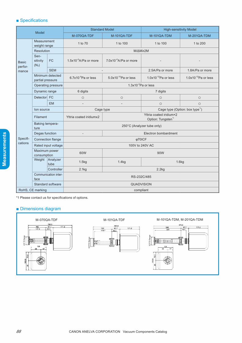
Canon anELVa Corporation Vacuum Components Catalog88
Mea
sure
men
ts
Mea
sure
men
ts
■ Dimensions diagram
■ Specifications
ModelStandard Model High-sensitivity Model
M-070QA-TDF M-101QA-TDF M-101QA-TDM M-201QA-TDM
Basic perfor-mance
Measurement weight range
1 to 70 1 to 100 1 to 100 1 to 200
Resolution M/ΔM≥2MSen-sitivity (N2)
FC 1.5x10⁻⁶A/Pa or more 7.0x10⁻⁶A/Pa or more - -
SEM - 2.5A/Pa or more 1.8A/Pa or moreMinimum detected partial pressure
6.7x10⁻⁹Pa or less 5.0x10⁻¹⁰Pa or less 1.0x10⁻¹²Pa or less 1.0x10⁻¹²Pa or less
Operating pressure 1.3x10⁻²Pa or less
Dynamic range 6 digits 7 digits
Specifi-cations
Detector FC ○ ○ ○ ○EM - - ○ ○
Ion source Cage type Cage type (Option: box type*1)
Filament Yttria coated iridiumx2Yttria coated iridium×2
Option: Tungsten*1
Baking tempera-ture
250°C (Analyzer tube only)
Degas function - Electron bombardment
Connection flange φ70ICF
Rated input voltage 100V to 240V ACMaximum power consumption
60W 90W
Weight Analyzer tube
1.5kg 1.4kg 1.6kg
Controller 2.1kg 2.2kgCommunication inter-face
RS-232C/485
Standard software QUADVISION
RoHS, CE marking compliant
*1 Please contact us for specifications of options.
M-101QA-TDFM-070QA-TDF
ICF7
0 fla
nge
ICF7
0 fla
nge
M-101QA-TDM, M-201QA-TDM
ICF
70 fla
nge

89Canon anELVa Corporation Vacuum Components Catalog
Mea
sure
men
ts
Mea
sure
men
ts
■ Ordering information
Notes *1 The quadrupole mass spectrometer includes dedicated software QUADVISION (CD version). *2 Indicates CE (RoHS) compliant. Contact us for other products.
Parts Number Model Description remarks Code
0161-44854 M-201QA-TDM(W) Quadrupole Mass Spectrometer200amu, M type, W-FIL, AC adapter in-cluded, no communication cable*1 20090*2
0161-44846 M-201QA-TDM(Y) Quadrupole Mass Spectrometer200amu, M type, Y-FIL, AC adapter includ-ed, no communication cable*1 20091*2
0161-44901 M-101QA-TDM(W) Quadrupole Mass Spectrometer100amu, M type, W-FIL, AC adapter in-cluded, no communication cable*1 20092*2
0161-44896 M-101QA-TDM(Y) Quadrupole Mass Spectrometer100amu, M type, Y-FIL, AC adapter includ-ed, no communication cable*1 20093*2
0161-46466 M-101QA-TDF(W) Quadrupole Mass Spectrometer100amu, F type, W-FIL, AC adapter includ-ed, no communication cable*1 20094*2
0161-46474 M-101QA-TDF(Y) Quadrupole Mass Spectrometer100amu, F type, Y-FIL, AC adapter includ-ed, no communication cable*1 20095*2
0160-09509 M-070QA-TDF Quadrupole Mass Spectrometer70amu, F type, Y-FIL, AC adapter included, no communication cable*1 20096*2
0160-06438 M-201QA-TDM(Re)Quadrupole Mass Spectrometer (box type ion source)
200amu, M type, Re-FIL, box type ion source, AC adapter included, no communi-cation cable*1
20190*2
0160-06446 M-101QA-TDM(Re)Quadrupole Mass Spectrometer (box type ion source)
100amu, M type, Re-FIL, box type ion source, AC adapter included, no communi-cation cable*1
20191*2
N20069218RS232C Cable (1.5m) for Quadrupole Mass Spectrometer
Cross cable 20290
N20069220RS232C Cable (3m) for Quadrupole Mass Spectrometer
Cross cable 20291
N20069232RS232C Cable (5m) for Quadrupole Mass Spectrometer
Cross cable 20292
N20069244RS232C Cable (10m) for Quadrupole Mass Spectrometer
Cross cable 20293
N20096390 COM-1 (USB) H USB-RS232C Converter 20430
0161-47690 RS485 Y Cable Set (5m) RS-485 cable 5m + Y cable (0.3m) 20296
0161-47750 RS485 Y Cable Set (10m) RS-485 cable 10m + Y cable (0.3m) 20297
0161-47713 RS485 Y Cable Set (15m) RS-485 cable 15m + Y cable (0.3m) 20298
0161-47721 RS485 Y Cable Set (20m) RS-485 cable 20m + Y cable (0.3m) 20299
N20097497 COM-1D(PM) RS-485 Card 20390
N20097928 COM-2PD(PC1)H RS-485 Board 20391
N20097980 COM-1PD (USB)H USB-RS485 Converter 20392
N20073881 PARANI-SD1000 Blue Tooth Serial Conversion Adapter For QV mobile 20431
0161-48036 AC Adapter Extension Cable (5m) For M-010/101/201QA 20395
0161-48044 AC Adapter Extension Cable (10m) For M-010/101/201QA 20396
0161-48052 AC Adapter Extension Cable (15m) For M-010/101/201QA 20397
H11-27574 NIST Library Data Conversion Software For QUADVISION-WIN7 20422
0161-42909 TD-W-FIL W Filament for TD-MASS 20490
0161-41822 TD-Y-FIL Y Filament for TD-MASS 20491
0161-75504 Ion Source for M-070 20493
P15-58845 TD-Re-FILRe Filament for TD-MASS (Box type Ion source)
For M-101/201 20492
0190-00512 V-040LV-MMI DN40 Manual L Type Valve MSB Protection valve for M-101/201 30111

Canon anELVa Corporation Vacuum Components Catalog90
Mea
sure
men
ts
Mea
sure
men
ts
■ Features1. High-speed measurement support (M-401QA-
MGSY/MUSY)Obtains m/Z=1 to 410 data at 1-second intervals
2. Two types of ion sourceSelectable between UHV type (cage type) and gas feedthrough type (box type)
3. High-sensitivity (M-401QA-MGHY/ MUHY)8-digits dynamic range
Quadrupole Mass Spectrometer (High-speed /High-sensitivity Measurement)M-401QA-MU/G
■ SummaryThe M-401QA-MU/G is a high-performance/high-functionality quadrupole mass spectrometer capable of measuring weight up to 410amu.As a general purpose mass spectrometer, the M-401QA-MGSY/ MUSY has increased measurement speed of up to 10 times that of our previous product.
Application AreaHigh-speed Type High-sensitivity Type
M-401QA-MGSY M-401QA-MUSY M-401QA-MGHY M-401QA-MUHYUltra-high vacuum equipment residual gas analysisInorganic gas analysis
Thermobalance emission gas analysis
Thermal desorption gas analysis
Trace gas analysis
PFC gas analysis
R&D
■ Selection guide
: Optimum : Applicable : Contact us for details.The table above lists the recommended quadrupole mass spectrometers for general use. If you are considering use in applications other than the above, please contact our sales department.
4. Low gas emission analyzer tubeUses a low gas emission ion sourceprovides a degassing function
CE RoHS
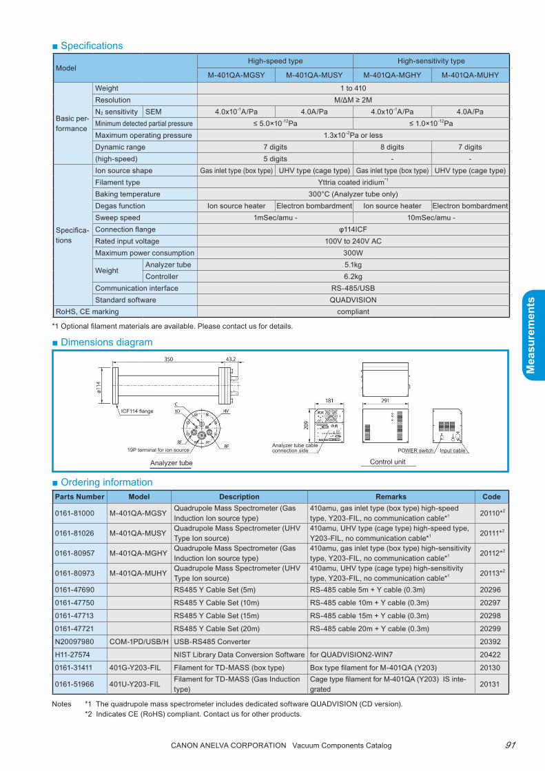
91Canon anELVa Corporation Vacuum Components Catalog
Mea
sure
men
ts
Mea
sure
men
ts
■ Dimensions diagram
■ Specifications
*1 Optional filament materials are available. Please contact us for details.
Notes *1 The quadrupole mass spectrometer includes dedicated software QUADVISION (CD version). *2 Indicates CE (RoHS) compliant. Contact us for other products.
■ Ordering information
ModelHigh-speed type High-sensitivity type
M-401QA-MGSY M-401QA-MUSY M-401QA-MGHY M-401QA-MUHY
Basic per-formance
Weight 1 to 410Resolution M/ΔM ≥ 2MN2 sensitivity SEM 4.0x10⁻¹A/Pa 4.0A/Pa 4.0x10⁻¹A/Pa 4.0A/PaMinimum detected partial pressure ≤ 5.0×10⁻¹²Pa ≤ 1.0×10⁻¹²PaMaximum operating pressure 1.3x10⁻²Pa or lessDynamic range 7 digits 8 digits 7 digits(high-speed) 5 digits - -
Specifica-tions
Ion source shape Gas inlet type (box type) UHV type (cage type) Gas inlet type (box type) UHV type (cage type)Filament type Yttria coated iridium*1
Baking temperature 300°C (Analyzer tube only)Degas function Ion source heater Electron bombardment Ion source heater Electron bombardmentSweep speed 1mSec/amu - 10mSec/amu -Connection flange φ114ICFRated input voltage 100V to 240V ACMaximum power consumption 300W
WeightAnalyzer tube 5.1kgController 6.2kg
Communication interface RS-485/USBStandard software QUADVISION
RoHS, CE marking compliant
Analyzer tube Control unit
19P terminal for ion source
ICF114 flange
Analyzer tube cable connection side POWER switch Input cable
Parts Number Model Description Remarks Code
0161-81000 M-401QA-MGSYQuadrupole Mass Spectrometer (Gas Induction Ion source type)
410amu, gas inlet type (box type) high-speed type, Y203-FIL, no communication cable*1 20110*2
0161-81026 M-401QA-MUSYQuadrupole Mass Spectrometer (UHV Type Ion source)
410amu, UHV type (cage type) high-speed type, Y203-FIL, no communication cable*1 20111*2
0161-80957 M-401QA-MGHYQuadrupole Mass Spectrometer (Gas Induction Ion source type)
410amu, gas inlet type (box type) high-sensitivity type, Y203-FIL, no communication cable*1 20112*2
0161-80973 M-401QA-MUHYQuadrupole Mass Spectrometer (UHV Type Ion source)
410amu, UHV type (cage type) high-sensitivity type, Y203-FIL, no communication cable*1 20113*2
0161-47690 RS485 Y Cable Set (5m) RS-485 cable 5m + Y cable (0.3m) 20296
0161-47750 RS485 Y Cable Set (10m) RS-485 cable 10m + Y cable (0.3m) 20297
0161-47713 RS485 Y Cable Set (15m) RS-485 cable 15m + Y cable (0.3m) 20298
0161-47721 RS485 Y Cable Set (20m) RS-485 cable 20m + Y cable (0.3m) 20299
N20097980 COM-1PD/USB/H USB-RS485 Converter 20392
H11-27574 NIST Library Data Conversion Software for QUADVISION2-WIN7 20422
0161-31411 401G-Y203-FIL Filament for TD-MASS (box type) Box type filament for M-401QA (Y203) 20130
0161-51966 401U-Y203-FILFilament for TD-MASS (Gas Induction type)
Cage type filament for M-401QA (Y203) IS inte-grated
20131

Canon anELVa Corporation Vacuum Components Catalog92
Mea
sure
men
ts
Mea
sure
men
ts
■ QUADVISION specifications
Quadrupole mass spectrometer support software
QUADViSiONEasy measurement with simple operation
Multiple ion detection
Leak test
Partial pressure measurement
Recipe/sequence measurement
Mass peak analog/bar
Compatible quadrupole mass spectrometer
M-070QA-TDFM-101/201QA series
RS-232C/485 communication
M-401QA series USB/RS-485 communication
Measurement modes
Multiple ion detection (SIM) Weight trend monitor with up to 16 channelsMass peak monitor (MPM) Continuous mass spectrum measurement of specified rangeLeak test (LT) Leak test at specified weight
Partial pressure measurement (PPM)
Fixed 10 componentsPartial pressure measurement (H2, He, CH4, H2O, CO, N2, O2, Ar, CO2, HC, + total pressure)
Other features
Recipe functionArea calculationAdjustment mode (weight calibration, waveform adjustment)CSV conversion of stored dataStatus checkAutomatic measurement, analog input (0 to 10V), set point output
Pressure readingPressure values can be loaded into QUADVISION by RS-232C communication*1
OptionsTemperature reading
Temperature values can be loaded into QUADVISION by RS-232C communication*2
NIST conversion Saved data may be converted to format searchable in NIST library
Personal computer specifi-cations
OS Windows 7Interface RS-232C (9P)/485 port/USB
Note *1 A Canon ANELVA specified vacuum gauge and cable must be used when reading pressure. *2 A Canon ANELVA specified temperature control module and cable must be used when reading temperature.

93Canon anELVa Corporation Vacuum Components Catalog
Mea
sure
men
ts
Mea
sure
men
ts
■ QUADVISION 3 Mobile details
*1 Set point output is performed from the quadrupole mass spectrometer controller.*2) Saved data can be reproduced and modified using the QUADVISION software.*3) There is no adjustment mode. Use the separate QUADVISION software.
Quadrupole mass spectrometer support mobile software
QUADViSiON 3 MobileSimplified mobile software for QUADVISION.Easy operation and measurement with touch panel support
• Easy partial pressure management and leak test• Touch panel support• Capable of wireless (Bluetooth) measurement
Menu screen Measurement screen
Trend screen
Parameters screen
Chart screen
Numeric value screen
Switch screens as needed.
Compatible quadrupole mass spectrometer
M-070QA-TDF, M-101/201TDM series
Communication specificationsWireless specification: BluetoothWired specification: RS-232C
Measurement modes
Multiple ion detection (SIM)Mass peak monitor (MPM)Leak test (LT)Partial pressure measurement (PPM)
Other features*3)
Touch panel support1 set point output*1
Status check functionData save function*2
PC specificationOS: Windows 7Interface: RS-232C, Bluetooth

Canon anELVa Corporation Vacuum Components Catalog94
Mea
sure
men
ts
Mea
sure
men
ts
Compact Gas Analysis System C SeriesM-070/101/201GA-C series
■ SummaryThe C Series is a compact gas analysis system of-fering a high degree of freedom using a quadrupole mass spectrometer. Select the system configuration that meets your measurement needs.
■ Features1. Flexible customization
Options tailored to individual applications are available in addition to the basic configuration to meet your mea-surement needs.
2. Space savingSmall installation space of only W480mm × D500mm.
3. Easy operationpumping controlled with a single switch. Interlock functions available for pumping/measurement.
■ Combination exampleSelect the configuration that meets your needs.
Category Measurement ApplicationBasic Structure recommended Option
Otherstype Feedthrough System Se-lection
Vacuum equ ipment gas analysis
Residual gas measurement/process measurement
M-070GA-CRFY Gas inlet system 1 or 2 Vacuum gauge
R&Dgas analysis
High-sensitivityprocess measurement
M-101GA-CDMY Gas inlet system 1 or 3Vacuum gauge
heaterAtmospheric pressure thermal
desorption gas analysisM-201GA-CRMY Gas inlet system 5 or 6
Vacuum gaugeheater
Atmospheric pressure thermal desorption gas analysis
M-201GA-CRMW Gas inlet system 3 or 4Vacuum gauge
heater
Exhaust gas analysis M-201GA-CRMY Gas inlet system 6Vacuum gauge
heaterAtmospheric pressure furnace
gas analysisM-101GA-CRMY Gas inlet system 5 or 6
Vacuum gaugeheater
Vacuum furnace gas analysis M-101GA-CRMW Gas inlet system 3 or 4Vacuum gauge
heaterVacuum equipment gas analysis M-101GA-CDFY Gas inlet system 2 or 3 Vacuum gauge
Catalytic reaction gas analysis M-101GA-CRMW Gas inlet system 5 or 6Vacuum gauge
heater
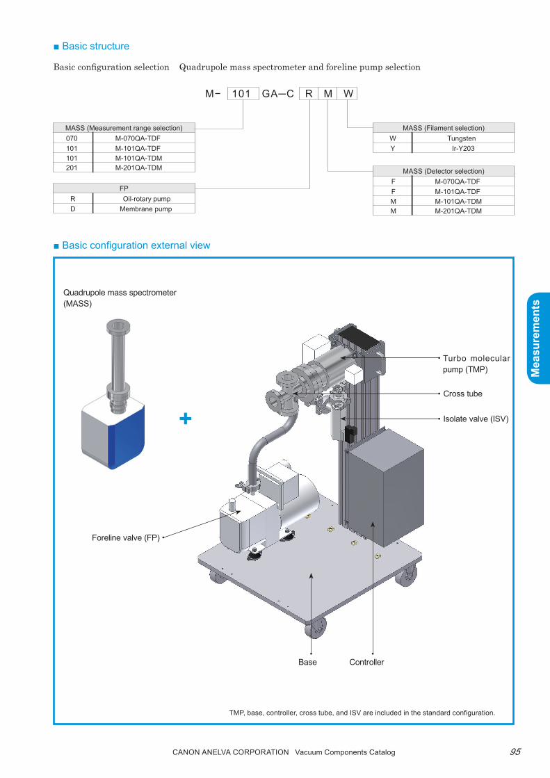
95Canon anELVa Corporation Vacuum Components Catalog
Mea
sure
men
ts
Mea
sure
men
ts
■ Basic configuration external view
+
Quadrupole mass spectrometer (MASS)
Foreline valve (FP)
TMP, base, controller, cross tube, and ISV are included in the standard configuration.
Turbo molecular pump (TMP)
Cross tube
Isolate valve (ISV)
ControllerBase
■ Basic structure
Basic configuration selection Quadrupole mass spectrometer and foreline pump selection
MASS (Measurement range selection)M-070QA-TDFM-101QA-TDFM-101QA-TDMM-201QA-TDM
070101101201
M− 101 GA─C R M W
FPOil-rotary pump
Membrane pumpRD
MASS (Detector selection)M-070QA-TDFM-101QA-TDFM-101QA-TDMM-201QA-TDM
FFMM
MASS (Filament selection)Tungsten
Ir-Y203WY

Canon anELVa Corporation Vacuum Components Catalog96
Mea
sure
men
ts
Mea
sure
men
ts
■ Specifications
Type M-070GA-CRFY M-101GA-CRFY M-101GA-CRMY M-201GA-CRMYAnalyzer M-070QA-TDF M-101QA-TDF M-101QA-TDM M-201QA-TDM
Weight range 1 to 70 1 to 100 1 to 200Sensitivity 100PPM 10PPM
Vacuum pumping system Turbo molecular pump (70L/s) + oil-sealed rotary pump (25L/min) [membrane pump (20L/min)]Ultimate pressure 1x10⁻⁵Pa or lessSoftware function QUADVISION2 Win7
Power supply 100V AC 1.0kVA
* The quadrupole mass spectrometers and options are installed by the customer.
■ Option selection 1 (selection of gas inlet system)Gas introduction system relation table
Name Main Use E-6 E-5 E-4 E-3 E-2 E-1 E0 E+1 E+2 E+3 E+4 E+5
Gas inlet system 1
Process gas mea-surement
General gas mea-surement
Gas inlet system 2
General gas mea-surement
Gas inlet system 3
Process gas mea-surement
Gas inlet system 4
General gas mea-surement
Gas inlet system 5
General gas mea-surement
Real-time gas mea-surement
Gas inlet system 6
Atmospheric pressure gas analysis
Thermal desorption gas analysis
Furnace gas analysis
BG measurement7.1E-5Pa to 2.0E-2Pa
7.1E-5Pa to 2.0Pa
8.0E-6Pa to 2.0Pa
1.3E-2Pa to atmospheric pressure
1.3E-2Pa to atmospheric pressure
0.05Mpa to 0.25Mpa
1Pa 10Pa
100Pa*1
500Pa*1
*1: Special order
Vacuum gauge set
-1Ionization vacuum gauge set
M-431HG + MG-2F + mount + interlock cable Analysis chamber pressure
measurement
-2 M-350PG Pirani gaugeTurbo molecular pump back
pressure measurement
-3Pirani gauge set
M-350PG + M-601GC (display unit) + mount + Interlock cable
Turbo molecular pump back pressure measurement
Heater kit
-12ch heater unit + ribbon heater (1.5m) + thermocouple +
interlock cableFor analyzer tube + analysis
chamber
-2 Ribbon heater (1.5m) + thermocouple For gas inlet system
-3 Ribbon heater (2.5m) + thermocouple For capillary gas inlet system
Notebook pC arm type mount 3 joint free-arm type, mountable dimension (390x300), load capacity 7kg
Notebook PC mount
Tipping prevention fixture Four sets of dedicated metal fittingsFor pumping system mount
tipping prevention
■ Option selection 2 (other options)Improved measurement accuracy and operability with additional options
Atmospher-ic pressure

97Canon anELVa Corporation Vacuum Components Catalog
Mea
sure
men
ts
Mea
sure
men
ts
(PC fixed image)
(Frame rear view)
Tipping prevention fixture
Vacuum gauge
Input receptacle
Free space
PC fixing arm
Fixed to vacuum gauge
Can be arranged freely
Gas inlet system 1, 2(For process measurement)
Gas inlet system 4
Gas inlet system 6
(For general measurement)
(For atmospheric pressure measurement)
(Frame side view)

Canon anELVa Corporation Vacuum Components Catalog98
Mea
sure
men
ts
Mea
sure
men
ts
■ Ordering information
Parts Number Model Description Remarks Code
0371-59482 M-070GA-CRFY Compact Gas Analysis System 46700
0371-59490 M-070GA-CDFY Compact Gas Analysis System 46701
0371-59505 M-101GA-CRFY Compact Gas Analysis System 46702
0371-59513 M-101GA-CDFY Compact Gas Analysis System 46703
0371-59521 M-101GA-CRMY Compact Gas Analysis System 46704
0371-59539 M-101GA-CDMY Compact Gas Analysis System 46705
0371-59547 M-201GA-CRMY Compact Gas Analysis System 46706
0371-59555 M-201GA-CDMY Compact Gas Analysis System 46707
0371-60742 M-101GA-CRFW Compact Gas Analysis System 46742
0371-60776 M-101GA-CDFW Compact Gas Analysis System 46743
0371-60750 M-101GA-CRMW Compact Gas Analysis System 46744
0371-60784 M-101GA-CDMW Compact Gas Analysis System 46745
0371-60768 M-201-CRMW Compact Gas Analysis System 46746
0371-60792 M-201GA-CDMW Compact Gas Analysis System 46747
0371-59393 M-001GA-CR Pumping System for Gas Analysis with RVP 46708
0371-59424 M-001GA-CD Pumping System for Gas Analysis with DRY 46709
0371-57472 SS-1CO Gas Introduction System-1Valve with orifice (for 1Pa, 10Pa attached)
46714
0371-57480 SS-1CR Gas Introduction System-2 Flow control valve 46710
VMT-8368 SS-1M Gas Introduction System-3 Combination valve inlet system 46711
0190-04867 951-7172 Gas Introduction System-4 Variable leak valve 31001
VMT-9693 Gas Introduction System-5 3-way variable leak valve 46712
0371-60700 Gas Introduction System-6 (Capillary Model) For capillary gas inlet system 46713
0371-60140 Vacuum Gauge Set-1 (M-431HG set) M-431HG vacuum gauge set 46731
0371-60514 Vacuum Gauge Set-2 (M-350PG-SP) M-350PG Pirani gauge 46732
0371-60522 Vacuum Gauge Set-3 (M-350PG-SD+M-601GC) M-350PG Pirani gauge set 46733
0371-60564 Heater Kit-1 (2CH Heater Unit Plus 1 Heater Set)2ch heater unit + heater (1.5m) + thermocouple
46736
0371-60530 Heater Kit-2 (Heater(1.5m) 1 Heater Set) Heater (1.5m) + thermocouple 46737
0371-60548 Heater Kit-3 (Heater(2.5m) 1 Heater Set) Heater (2.5m) + thermocouple 46738
0371-59458 Arm Set for PC 3 joint free arm PC mount 46720
0371-59872 Fall-Prevention Hardware Crank type dedicated bracket x 4 sets 46722
Note) Contact us for more information about CE (RoHS).

99Canon anELVa Corporation Vacuum Components Catalog
Mea
sure
men
ts
Mea
sure
men
ts
■ Dimensions diagram

Canon anELVa Corporation Vacuum Components Catalog100
Mea
sure
men
ts
Mea
sure
men
ts
Compact Gas Analysis System D SeriesM-101/201/401GA-D series
■ SummaryThe M-101/201/401GA-D series is a compact, low-cost gas analysis system ideally suited for quadrupole mass spectrometer application technology products, vacuum equipment residual gas analysis, inorganic gas analysis, thermal desorption analysis (TDS, etc.), emission gas analysis, and research and develop-ment gas analysis.This system can be flexibly configured to meet spe-cific, individual applications by optionally combining the quadrupole mass spectrometer analyzer with the TMP pumping system.The system can be used for a wide range of gas analysis applications in research and development.
■ Features1. Customizable system
• Systems that combine a quadrupole mass spec-trometer, gas feedthrough system and other op-tions can be easily set up to meet your specific needs.
• the quadrupole mass spectrometer can be selected from six different models: M-070QA-tDF, M-101QA-tDF, M-101/201QA-tDF, and M-401QA-M (high sensitivity/high speed).
2. Space-saving, compact design• the compact quadrupole mass spectrometer and
tMp pumping system can be mounted on a small rack.
3. Simple operation• Measurement operations can be easily controlled
using a pC.4. Windows compatible software
QUADViSiON
■ Applications• Vacuum equipment residual gas analysis• thermobalance emission gas analysis• thermal desorption gas analysis• Furnace gas analysis• Sealed gas analysis
QUADVISION

101Canon anELVa Corporation Vacuum Components Catalog
Mea
sure
men
ts
Mea
sure
men
ts
■ SpecificationsM-101GA-DF M-101GA-DM M-201GA-DM M-401GA-DM
Analyzer M-101QA-TDF M-101QA-TDM M-201QA-TDM M-401QA-M
Measured weight 1 to 100 1 to 200 1 to 410
Sensitivity 100 10 10ppm 10ppm
Ultimate pressure 5x10⁻⁶Pa or less
Inducible gas pressureSample gas pressure
VLV < Atmospheric pressure
SS-1M < 3Pa
Capillary inlet system Atmospheric pressure -
Software function Multi-ion detection mode, partial pressure measurement mode, mass peak mode, leak test mode
Operating environment Inquire for details
UtilityPower supply 100V AC 2.0kVA
N2 gas 0.5MPa (supply when N2 purge is necessary)
Connection flange φ70ICF φ114ICF
■ Dimensions diagram
Example of M-201GA-DM gas analysis system
(100)530
746
(991
)
Main unit
M-431HG
START/STOP SW
TG70F
Controller
Analysis chamberMG-2F
Gas inlet valve
■ Block diagram
Ionization vacuum gauge
(optional)
Select analyzerM-101QA-TDFM-101/201QA-TDMM-401QA-M
G1
Analysis chamber
TMP
RPOther optional• data system
Gas inlet system (optional)
VLV
SS-1M
3-way VLV

Canon anELVa Corporation Vacuum Components Catalog102
Mea
sure
men
ts
Mea
sure
men
ts
Transducer Vacuum Gauge Series
■ SummaryCompact wire-saving, RoHS/CE marking compliant environment-friendly products.These Transducer type vacuum gauges are capable of handling a wide range from atmospheric pressure to 10-8Pa. The vacuum gauges include capacitance gauges, Pirani gauges, cold cathode Pirani gauge, crystal ion gauge, and ion gauge display units (1ch, 3ch). They are ideally suited for all types of industries such as state-of-the-art semiconductor manufacturing equipment and flat panel manufacturing equipment.
■ Selection guide
Seamless coverage from atmosphere to ultra-high vacuum
● Features• transducer type→ Wire saving→ Space saving• Energy saving with low power consumption• Analog type, communication type supported• Gauge auto recognition (display unit)• Series with uniform external design• Lead-free solder used• CE marking compliant
● Applications• Vacuum thin film equipment, deposition
equipment• Semiconductor manufacturing equipment,
electronic component manufacturing equip-ment
• Electron microscopes, electron beam equip-ment
• Mass spectrometers, various analyzers• Vacuum furnaces, freeze drying equipment• Various industrial equipment• Various pumping equipment• r&D equipment
Gauge nameRecommended measurement pressure range
Pa 10-8 10-6 10-4 10-2 1 102 104
Capacitance gaugeM-342DG
133kPa
13.3kPa
1.33 kPa
Capacitance gaugeM-341DG 133Pa
Pirani gaugeM-350PGM-351PG
Cold cathode Pirani gaugeM-360CP
Ion gaugeM-311HG
Crystal ion gaugeM-336MX

103Canon anELVa Corporation Vacuum Components Catalog
Mea
sure
men
ts
Mea
sure
men
ts
Gauge nameRecommended measurement pressure range
Pa 10-8 10-6 10-4 10-2 1 102 104
Capacitance gaugeM-342DG
133kPa
13.3kPa
1.33 kPa
Capacitance gaugeM-341DG 133Pa
Pirani gaugeM-350PGM-351PG
Cold cathode Pirani gaugeM-360CP
Ion gaugeM-311HG
Crystal ion gaugeM-336MX
* This table lists the recommended pressure measurement range, which is different from the measurable pressure range.
CE RoHS

Canon anELVa Corporation Vacuum Components Catalog104
Mea
sure
men
ts
Mea
sure
men
ts
Capacitance Gauge
■ Dimensions diagram
M-341DG■ Summarythese capacitance gauges (diaphragm gauge) are complied with roHS. they offer push button zero adjustment, LED status display, and low power consumption for improved usability and precision.■ Features• Static capacitance diaphragm gauge using micro machine
technology• Single crystal silicon diaphragm used for the sensor• Compact, light weight, low cost, and low power consump-
tion• High precision and repeatability■ ApplicationsSputtering systems, ashing systemsLoad lock chambersGas analysis/pumping system pressure measurement
Type M-341DG-01
Full scale pressure (Pa) 133
Precision (% of reading) 0.25 (at 25°C)
Zero temperature drift coefficient (% of F.S./°C) 0.015Span temperature drift coefficient (% of reading/°C) 0.01
Maximum operating pressure (Pa)200kPa (However, the internal pressure of NW16 and NW25 with φ15 tube coupler
must not become positive.)Input voltage (V DC) +13.5 to 26.4
Power consumption (W) 0.5 or less
Analog output (V DC) 0 to 10
Response speed (ms) 40
Operating temperature (°C) 5 to 50
Storage temperature (°C) -20 to 70°C (not operating)
Maximum cable length (m) 20 (0.13mm2)
I/O connector D-sub 9 pin male
Gas contacting part material SUS304, SUS316, Si, Tempax float®, Viton®
Flange shape and weight NW16 (210g), NW25 (220g), φ70ICF (540g), 8-VCR female (250g), φ15 tube (220g)
Applicable standards and regulations CE, IP40, RoHS
Security trade regulations Not applicable
Compatible display unit M-601GC (1ch), M-603GC (3ch)
Main unit shape (Coupler: NW25)
NW16 type φ70ICF type
8-VCR type φ15 tube type
CE RoHS
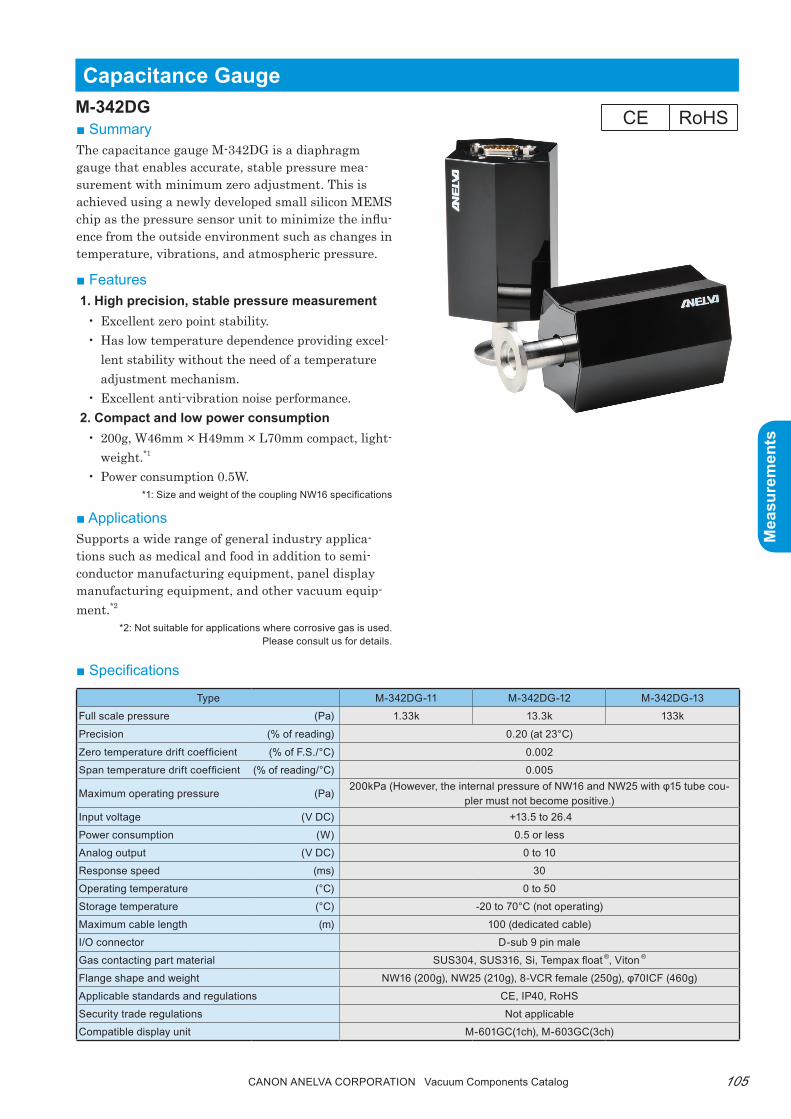
105Canon anELVa Corporation Vacuum Components Catalog
Mea
sure
men
ts
Mea
sure
men
ts
Capacitance GaugeM-342DG■ Summarythe capacitance gauge M-342DG is a diaphragm gauge that enables accurate, stable pressure mea-surement with minimum zero adjustment. this is achieved using a newly developed small silicon MEMS chip as the pressure sensor unit to minimize the influ-ence from the outside environment such as changes in temperature, vibrations, and atmospheric pressure.
■ Features1. High precision, stable pressure measurement
• Excellent zero point stability.• Has low temperature dependence providing excel-
lent stability without the need of a temperature adjustment mechanism.
• Excellent anti-vibration noise performance.2. Compact and low power consumption
• 200g, W46mm × H49mm × L70mm compact, light-weight.*1
• power consumption 0.5W.*1: Size and weight of the coupling NW16 specifications
■ ApplicationsSupports a wide range of general industry applica-tions such as medical and food in addition to semi-conductor manufacturing equipment, panel display manufacturing equipment, and other vacuum equip-ment.*2
*2: Not suitable for applications where corrosive gas is used.Please consult us for details.
■ Specifications
Type M-342DG-11 M-342DG-12 M-342DG-13
Full scale pressure (Pa) 1.33k 13.3k 133k
Precision (% of reading) 0.20 (at 23°C)
Zero temperature drift coefficient (% of F.S./°C) 0.002Span temperature drift coefficient (% of reading/°C) 0.005
Maximum operating pressure (Pa)200kPa (However, the internal pressure of NW16 and NW25 with φ15 tube cou-
pler must not become positive.)Input voltage (V DC) +13.5 to 26.4
Power consumption (W) 0.5 or less
Analog output (V DC) 0 to 10
Response speed (ms) 30
Operating temperature (°C) 0 to 50
Storage temperature (°C) -20 to 70°C (not operating)
Maximum cable length (m) 100 (dedicated cable)
I/O connector D-sub 9 pin male
Gas contacting part material SUS304, SUS316, Si, Tempax float ®, Viton ®
Flange shape and weight NW16 (200g), NW25 (210g), 8-VCR female (250g), φ70ICF (460g)
Applicable standards and regulations CE, IP40, RoHS
Security trade regulations Not applicable
Compatible display unit M-601GC(1ch), M-603GC(3ch)
CE RoHS

Canon anELVa Corporation Vacuum Components Catalog106
Mea
sure
men
ts
Mea
sure
men
ts
■ Ordering information
■ Dimensions diagram
Φ30
Φ70
Φ40
Φ12.7
Φ12.7
12.7
Φ12.7
Φ12.7
2530
25
48.978.6
105.8
25
46NW16 NW25φ70ICF 8-VCR® (female)
ZERO
Parts Number Model Description Remarks Code
0161-65656 M-341DG-01/N16 Capacitance Diaphragum Gauge (133Pa) Coupling: NW16 22645*
0161-65672 M-341DG-01/N25 Capacitance Diaphragum Gauge (133Pa) Coupling: NW25 22646*
0161-65680 M-341DG-01/C70 Capacitance Diaphragum Gauge (133Pa) Coupling: Ф70ICF 22647*
0161-65664 M-341DG-01/VCR Capacitance Diaphragum Gauge (133Pa) Coupling: 8-VCR female 22648*
0161-65698 M-341DG-01/P15 Capacitance Diaphragum Gauge (133Pa) Coupling: Ф15 tube 22649*
0160-11459 M-342DG-11-N16 Capacitance Diaphragum Gauge (1.33kPa) Coupling: NW16 22715*
0160-11467 M-342DG-11-N25 Capacitance Diaphragum Gauge (1.33kPa) Coupling: NW25 22716*
0160-11475 M-342DG-11-C70 Capacitance Diaphragum Gauge (1.33kPa) Coupling: Ф70ICF 22717*
0160-11483 M-342DG-11-VC8 Capacitance Diaphragum Gauge (1.33kPa) Coupling: 8-VCR female 22718*
0160-11140 M-342DG-12-N16 Capacitance Diaphragum Gauge (13.3kPa) Coupling: NW16 22720*
0160-11158 M-342DG-12-N25 Capacitance Diaphragum Gauge (13.3kPa) Coupling: NW25 22721*
0160-11077 M-342DG-12-C70 Capacitance Diaphragum Gauge (13.3kPa) Coupling: Ф70ICF 22722*
0160-11166 M-342DG-12-VC8 Capacitance Diaphragum Gauge (13.3kPa) Coupling: 8-VCR female 22723*
0160-11093 M-342DG-13-N16 Capacitance Diaphragum Gauge (133kPa) Coupling: NW16 22725*
0160-11108 M-342DG-13-N25 Capacitance Diaphragum Gauge (133kPa) Coupling: NW25 22726*
0160-11116 M-342DG-13-C70 Capacitance Diaphragum Gauge (133kPa) Coupling: Ф70ICF 22727*
0160-11124 M-342DG-13-VC8 Capacitance Diaphragum Gauge (133kPa) Coupling: 8-VCR female 22728*
Note) * marked indicates CE (RoHS) compliant.

107Canon anELVa Corporation Vacuum Components Catalog
Mea
sure
men
ts
Mea
sure
men
ts
pirani Gauge
■ Summarythis pirani vacuum gauge can handle a wide range of applications. It offers convenient measurement capability from atmospheric pressure with high cost performance. the gauge can be mounted on various systems for low to medium vacuum measurements in a variety of industries such as food, automobile, and pharmaceutical.
■ Features• Good repeatability and low cost• From 5×10⁻²pa to atmospheric pressure• Suitable for low to medium vacuum range mea-
surements
■ Applicationsroughing pump system pressure measurement, pumping system pressure monitoring and control
TypePirani Gauge
M-350PG-SDStandard type
M-350PG-SPType with set point
M-350PG-RSRS485 type
Set pressure range*1 5x10⁻² to 1x10⁻⁵(Pa)
Accuracy (Pa) ±50%: 5x10⁻² to 1x10⁻¹
±15%: 1x10⁻¹ to 1x10⁴
±50%: 1x10⁴ to 1x10⁵
Repeatability ±2%: 1x10⁻¹ to 1x10⁴PaInput voltage +14 to 30V DCPower consumption 1WAnalog output 0 to 10VGauge identification resistance 13KΩ (between D-sub 5 and 9 pin)Set point - 2 contact output (1A 30V, DC)Interface - RS485I/O connector D-sub 9 pinMaximum cable length 200m (0.34mm2) supported*1
Operating temperature range 5 to 60°CStorage temperature range -20 to 70°C (not operating)
Baking temperature<+150°C (O-ring specification, gauge head only)
<+300°C (metal seal specification, gauge head only)
Allowed overload pressure1MPa (limited to coupler shape NPT and inert gas,
absolute temperature)Applicable Pirani sensor type MP-1Flange shape NW16, NW25, φ34ICF, 1/8NPT, φ15 adapter, φ18 adapter
Sensor material(Main component)
Pirani filament: TungstenSensor tube: Stainless steel
Inlet terminal insulator: Kovar glassProtection standard IP40RoHS, CE marking compliant
M-350pG
■ Dimensions diagram
■ Specifications
*1 The maximum length of the gauge cable is 100m when connecting an M-601/603GC display unit.
CE RoHS

Canon anELVa Corporation Vacuum Components Catalog108
Mea
sure
men
ts
Mea
sure
men
ts
Parts Number Model Description Remarks Code
0160-06608 M-350PG-SD/N16 Pirani Gauge With NW16 flange 22500*
0160-06616 M-350PG-SD/N25 Pirani Gauge With NW25 flange 22501*
0160-06624 M-350PG-SD/P15 Pirani Gauge For φ15 gauge port 22502*
0160-06632 M-350PG-SD/P18 Pirani Gauge For φ18 gauge port 22503*
0160-07133 M-350PG-SD/C34 Pirani Gauge With φ34ICF flange 22504*
0160-07125 M-350PG-SD/NPT Pirani Gauge With 1/8" NPT (male) 22505*
0160-06658 M-350PG-SP/N16 Pirani Gauge (w Setpoints) With NW16 flange 22506*
0160-06666 M-350PG-SP/N25 Pirani Gauge (w Setpoints) With NW25 flange 22507*
0160-06674 M-350PG-SP/P15 Pirani Gauge (w Setpoints) For φ15 gauge port 22508*
0160-06682 M-350PG-SP/P18 Pirani Gauge (w Setpoints) For φ18 gauge port 22509*
0160-08286 M-350PG-SP/C34 Pirani Gauge (w Setpoints) With φ34ICF flange 22510*
0160-07531 M-350PG-SP/NPT Pirani Gauge (w Setpoints) With 1/8" NPT (male) 22511*
0160-06690 M-350PG-RS/N16 Pirani Gauge (RS485) With NW16 flange 22512*
0160-06705 M-350PG-RS/N25 Pirani Gauge (RS485) With NW25 flange 22513*
0160-06713 M-350PG-RS/P15 Pirani Gauge (RS485) For φ15 gauge port 22514*
0160-06721 M-350PG-RS/P18 Pirani Gauge (RS485) For φ18 gauge port 22515*
0160-11205 M-350PG-RS/C34 Pirani Gauge (RS485) With φ34ICF flange 22516*
0160-09575 M-350PG-RS/NPT Pirani Gauge (RS485) With 1/8" NPT (male) 22517*
0161-51275 MP1/NW16 Pirani Gauge Head With NW16 flange 22527*
0161-51479 MP1/NW25 Pirani Gauge Head With NW25 flange 22528*
0161-51982 MP1/C34 Pirani Gauge Head With φ34ICF flange 22529*
0161-56788 MP1/NPT Pirani Gauge Head With 1/8"NPT (male) 22530*
0161-55986 MP1/PY15 Pirani Gauge Head For φ15 gauge port 22531*
0161-55994 MP1/PY18 Pirani Gauge Head For φ18 gauge port 22532*
■ Ordering information
Note) * marked indicates CE (RoHS) compliant.

109Canon anELVa Corporation Vacuum Components Catalog
Mea
sure
men
ts
Mea
sure
men
ts
■ Dimensions diagram
Pirani Gauge (Corrosion-resistant Type)
■ Summarythis model uses an Ni filament to increase corrosion resistance. It supports hard process equipment such as rIE and CVD.
■ Features• Improved corrosion resistance Uses Ni filament.• Good repeatability and low cost. From 5×10⁻²pa to
atmospheric pressure.• Can be mounted in any direction.
■ Applications• Semiconductor and electronic device manufacturing
equipmentDry etching equipment, plasma CVD equipment, LD-CVD equipment
• Food and drug manufacturing equipmentVacuum-freeze drying, reduced-pressure distillation, sterilization equipment
■ Ordering information
M-351pG
Type M-351PG-SP (Ni filament) (Set point equipped type)Measurement pressure range 5x10⁻² to 1x10⁵(Pa)
Accuracy (Pa)±50%: 5×10⁻² to 1×10⁻¹
±15%: 1×10⁻¹ to 1×10⁴
±50%: 1×10⁴ to 1×10⁵
Repeatability ± 2%: 1×10⁻¹ to 1×10⁴PaInput voltage +14 to 30V DCPower consumption 2WAnalog output 0 to 10VGauge identification resistance 13KΩ (between D-sub 5 and 9 pin)Set point 2 contact output (1A 30V, DC)Interface -I/O connector D-sub 9 pinMaximum cable length 200m (0.34mm2) supported *1
Operating temperature range 5 to 60°CStorage temperature range -20 to 70°C (not operating)
Baking temperature <+150°C (O-ring specification, gauge head only)<+300°C (metal seal specification, gauge head only)
Allowed overload pressure 1MPa (limited to coupler shape NPT and inert gas, absolute temperature)Applicable Pirani sensor type MP-2Flange shape NW16, NW25, 1/8NPT
Sensor material(Main component)
Pirani filament: NickelSensor tube: Stainless steel
Inlet terminal insulator: Kovar glass+Al2O3 coatProtection standard IP40RoHS, CE marking compliant
■ Specifications
*1 The maximum length of the gauge cable is 100m when connecting an M-601/603GC display unit.
Parts Number Model Description Remarks Code0160-08359 M-351PG-SP/N16 Pirani Gauge With NW16 flange 22665*0160-08854 M-351PG-SP/N25 Pirani Gauge With NW25 flange 22666*0161-62080 MP-2/NW16 Pirani Gauge Head With NW16 flange 22668*0161-70368 MP-2/NW25 Pirani Gauge Head With NW25 flange 22669*
CE RoHS
Note) * marked indicates CE (RoHS) compliant.
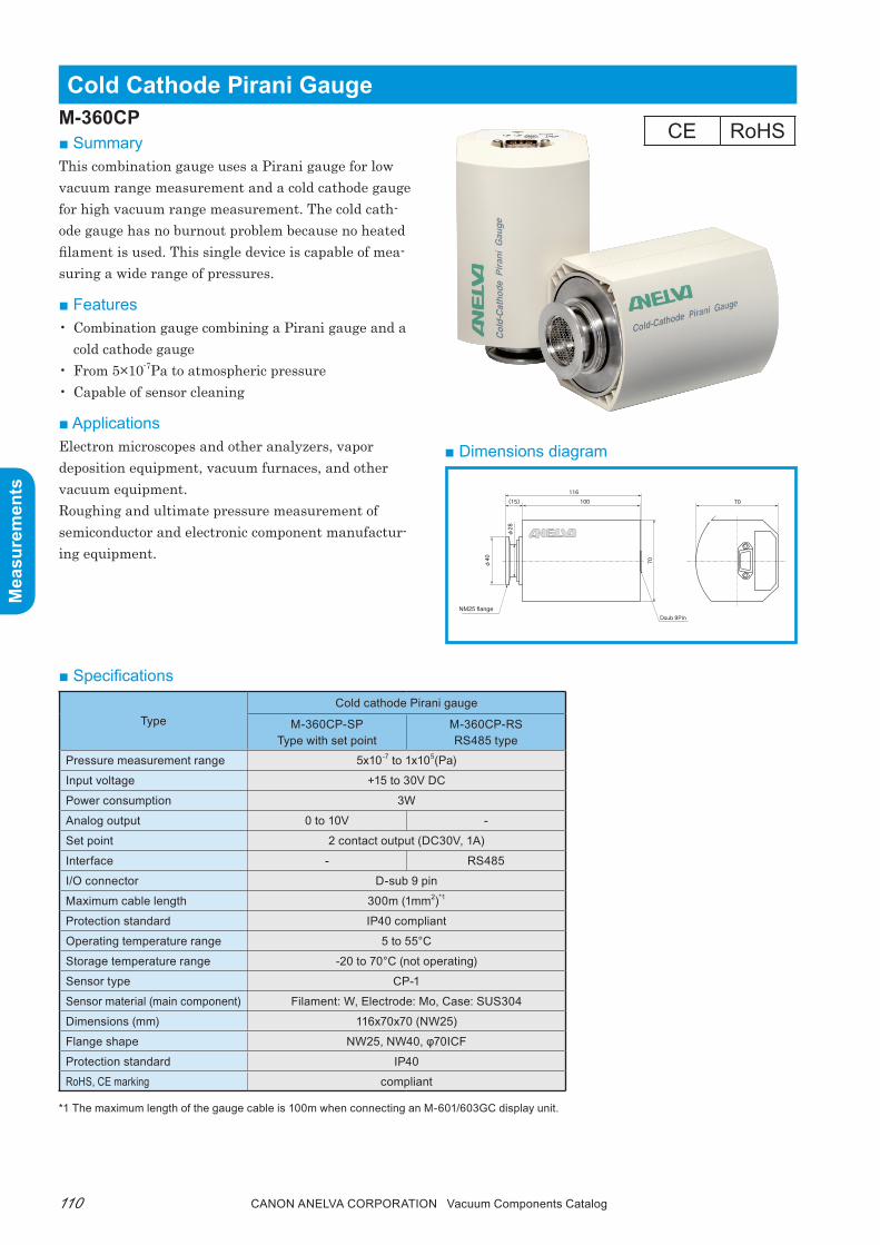
Canon anELVa Corporation Vacuum Components Catalog110
Mea
sure
men
ts
Mea
sure
men
ts
■ Dimensions diagram
Cold Cathode pirani Gauge
■ Summarythis combination gauge uses a pirani gauge for low vacuum range measurement and a cold cathode gauge for high vacuum range measurement. the cold cath-ode gauge has no burnout problem because no heated filament is used. this single device is capable of mea-suring a wide range of pressures.
■ Features• Combination gauge combining a pirani gauge and a
cold cathode gauge• From 5×10⁻⁷pa to atmospheric pressure• Capable of sensor cleaning
■ ApplicationsElectron microscopes and other analyzers, vapor deposition equipment, vacuum furnaces, and other vacuum equipment.roughing and ultimate pressure measurement of semiconductor and electronic component manufactur-ing equipment.
TypeCold cathode Pirani gauge
M-360CP-SPType with set point
M-360CP-RSRS485 type
Pressure measurement range 5x10⁻⁷ to 1x10⁵(Pa)
Input voltage +15 to 30V DC
Power consumption 3W
Analog output 0 to 10V -
Set point 2 contact output (DC30V, 1A)
Interface - RS485
I/O connector D-sub 9 pin
Maximum cable length 300m (1mm2)*1
Protection standard IP40 compliant
Operating temperature range 5 to 55°C
Storage temperature range -20 to 70°C (not operating)
Sensor type CP-1
Sensor material (main component) Filament: W, Electrode: Mo, Case: SUS304
Dimensions (mm) 116x70x70 (NW25)
Flange shape NW25, NW40, φ70ICF
Protection standard IP40
RoHS, CE marking compliant
M-360Cp
■ Specifications
*1 The maximum length of the gauge cable is 100m when connecting an M-601/603GC display unit.
CE RoHS

111Canon anELVa Corporation Vacuum Components Catalog
Mea
sure
men
ts
Mea
sure
men
ts
■ Ordering informationParts Number Model Description Remarks Code
0161-92962 M-360CP-SP/N25 Cold Cathode Pirani Gauge With NW25 flange 22700*
0161-54142 M-360CP-SP/N40 Cold Cathode Pirani Gauge With NW40 flange 22701*
0161-93007 M-360CP-SP/C70 Cold Cathode Pirani Gauge With φ70ICF flange 22702*
0161-54184 M-360CP-RS/N25 Cold Cathode Pirani Gauge (RS485) With NW25 flange 22703*
0161-54207 M-360CP-RS/N40 Cold Cathode Pirani Gauge (RS485) With NW40 flange 22704*
0161-54223 M-360CP-RS/C70 Cold Cathode Pirani Gauge (RS485) With φ70ICF flange 22705*
Note) * marked indicates CE (RoHS) compliant.

Canon anELVa Corporation Vacuum Components Catalog112
Mea
sure
men
ts
Mea
sure
men
ts
■ Dimensions diagram
Crystal Ion Gauge
■ Summarythis combination gauge uses a crystal gauge with excellent repeatability and response for measurement in the low vacuum range and a miniature B-A gauge proven over many years for measurement in the high vacuum range. this single device is capable of mea-suring a wide range of pressures from atmospheric pressure to ultra-high vacuum.
■ Features• Combination gauge combining a crystal gauge and a
miniature B-A gauge• From ultra-high vacuum to atmospheric pressure• High precision with excellent repeatability in the
low vacuum range
■ Applicationsroughing pump and ultimate pressure measurement of vacuum equipment, semiconductor and electronic component manufacturing equipment pressure mea-surement.
TypeCrystal Ion Gauge
M-336MX-SPType with set point
M-336MX-RSRS485 type
Pressure measurement range*1 4x10⁻⁸ to 1x10⁵(Pa)
Input voltage +20 to 28V DC
Power consumption 12W
Analog output 0 to 10V -
Set point 2 contact output
Interface - RS485
I/O connector D-sub 9 pin
Maximum cable length 300m (1mm2)**
Protection standard IP40 compliant
Operating temperature range*2 5 to 50°C
Storage temperature range*2 -20 to 70°C (not operating)
Sensor type MX-1
Sensor material (main component) Filament: Y2O3/Ir, Case: SUS304
Dimensions (mm) 149x70x50 (NW25)
Flange shape NW16, NW25, NW40, φ70ICF
Protection standard IP40
RoHS, CE marking compliant
M-336MX
■ Specifications
*1. The minimum pressure measurement shows the soft X-ray limit of B-A gauge.Minimum pressure measurement ICF: Approx. 10-7Pa
NW: Approx. 10-6Pa*2. Use or storage under high temperatures may reduce the product life.
** The maximum length of the gauge cable is 100m when connecting an M-601/603GC display unit.
CE RoHS

113Canon anELVa Corporation Vacuum Components Catalog
Mea
sure
men
ts
Mea
sure
men
ts
■ Ordering informationParts Number Model Description Remarks Code
0161-14825 MX-1/N16 Crystal Ion Gauge Head(336MX) With NW16 flange 22559*
0161-14752 MX-1/N25 Crystal Ion Gauge Head(336MX) With NW25 flange 22560*
0161-14689 MX-1/N40 Crystal Ion Gauge Head(336MX) With NW40 flange 22561*
0161-14647 MX-1/C70 Crystal Ion Gauge Head(336MX) With φ70ICF flange 22562*
0160-06797 M-336MX-SP/N16 Crystal Ion Gauge With NW16 flange 22545*
0160-06810 M-336MX-SP/N25 Crystal Ion Gauge With NW25 flange 22546*
0160-07206 M-336MX-SP/N40 Crystal Ion Gauge With NW40 flange 22547*
0160-06828 M-336MX-SP/C70 Crystal Ion Gauge With φ70ICF flange 22548*
0160-06836 M-336MX-RS/N16 Crystal Ion Gauge (RS485) With NW16 flange 22549*
0160-06844 M-336MX-RS/N25 Crystal Ion Gauge (RS485) With NW25 flange 22550*
0160-07963 M-336MX-RS/N40 Crystal Ion Gauge (RS485) With NW40 flange 22551*
0160-06852 M-336MX-RS/C70 Crystal Ion Gauge (RS485) With φ70ICF flange 22552*
Note) * marked indicates CE (RoHS) compliant.
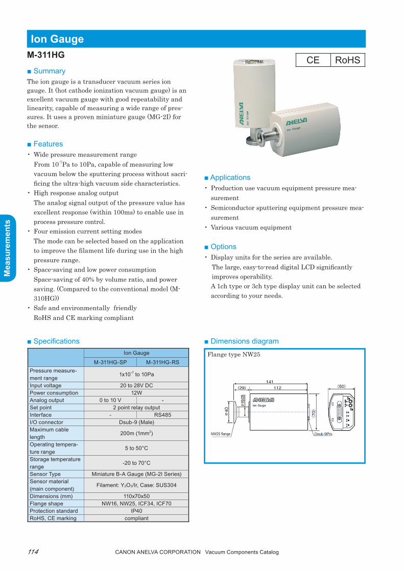
Canon anELVa Corporation Vacuum Components Catalog114
Mea
sure
men
ts
Mea
sure
men
ts
■ Dimensions diagram
ion Gauge
■ Summarythe ion gauge is a transducer vacuum series ion gauge. It (hot cathode ionization vacuum gauge) is an excellent vacuum gauge with good repeatability and linearity, capable of measuring a wide range of pres-sures. It uses a proven miniature gauge (MG-2I) for the sensor.
■ Features• Wide pressure measurement range
From 10-7pa to 10pa, capable of measuring low vacuum below the sputtering process without sacri-ficing the ultra-high vacuum side characteristics.
• High response analog outputthe analog signal output of the pressure value has excellent response (within 100ms) to enable use in process pressure control.
• Four emission current setting modesthe mode can be selected based on the application to improve the filament life during use in the high pressure range.
• Space-saving and low power consumptionSpace-saving of 40% by volume ratio, and power saving. (Compared to the conventional model (M-310HG))
• Safe and environmentally friendlyroHS and CE marking compliant
■ Applications• production use vacuum equipment pressure mea-
surement• Semiconductor sputtering equipment pressure mea-
surement• Various vacuum equipment
■ Options• Display units for the series are available.
the large, easy-to-read digital LCD significantly improves operability. A 1ch type or 3ch type display unit can be selected according to your needs.
■ Specifications
M-311HG
Ion Gauge
M-311HG-SP M-311HG-RSPressure measure-ment range
1x10⁻⁷ to 10Pa
Input voltage 20 to 28V DCPower consumption 12WAnalog output 0 to 10 V -Set point 2 point relay outputInterface - RS485I/O connector Dsub-9 (Male)Maximum cable length
200m (1mm2)
Operating tempera-ture range
5 to 50°C
Storage temperature range
-20 to 70°C
Sensor Type Miniature B-A Gauge (MG-2I Series)Sensor material (main component)
Filament: Y2O3/Ir, Case: SUS304
Dimensions (mm) 110x70x50Flange shape NW16, NW25, ICF34, ICF70Protection standard IP40RoHS, CE marking compliant
Flange type NW25
NW25 flange
CE RoHS
115Canon anELVa Corporation Vacuum Components Catalog
Mea
sure
men
ts
Mea
sure
men
ts
■ Ordering informationParts Number Model Description Remarks Code
0161-78390 M-311HG-SP/N16 Ion Gauge With NW16 flange 22670*
0161-78405 M-311HG-SP/N25 Ion Gauge With NW25 flange 22671*
0161-78413 M-311HG-SP/C70 Ion Gauge With φ70ICF flange 22672*
0161-78421 M-311HG-SP/C34 Ion Gauge With φ34ICF flange 22673*
0161-78439 M-311HG-RS/N16 Ion Gauge (RS485) With NW16 flange 22674*
0161-78447 M-311HG-RS/N25 Ion Gauge (RS485) With NW25 flange 22675*
0161-78455 M-311HG-RS/C70 Ion Gauge (RS485) With φ70ICF flange 22676*
0161-78463 M-311HG-RS/C34 Ion Gauge (RS485) With φ34ICF flange 22677*
Note) * marked indicates CE (RoHS) compliant.

Canon anELVa Corporation Vacuum Components Catalog116
Mea
sure
men
ts
Mea
sure
men
ts
■ Dimensions diagram
Display Unit (1 ch/3 ch)
■ Summarythese display units support the transducer type vacuum gauge series.the large, easy-to-read digital LCD significantly im-proves operability. the units offer numerous features to improve on-site usability. A 1ch type or 3ch type display unit can be selected according to your needs.
■ Features• Gauge auto recognition• Large digital LCD• rS232C interface equipped as standard• Excellent operability• Capable of simultaneous display (3ch)• Easy-to-read 3-type display (3ch) Digital display trend graph (up to 18H) Analog meter
TypeM-601GC
(1 ch connection type)
M-603GC(3 ch connection
type)Input voltage 90 to 250V AC 50/60HzPower consump-tion
50VA 100VA
Operating tem-perature
5 to 50°C 5 to 40°C
Storage tempera-ture
-20 to 60°C
Gauge recogni-tion
Auto
Number of con-nected channels
1Ch3Ch (Simultane-
ously displayable)Connected gauge
Ion gauge (M-311HG) Pirani, Capacitance,Crystal ion, CC Pirani
Set point 2 points 2/ChProtection stan-dard
IP30 compliant
Analog output 1 1/Ch
Recorder output 1 1/ChCommunication function
RS232C
Dimensions (mm) 84×106.3×212 128.5×106.3×212
Display Back lit LCD Color TFT LCDProtection stan-dard
IP30
RoHS, CE marking compliant
M-601GC/603GC
■ Specifications
Digital
3ch display unit
Analog meterTrend graph
3ch display unit Display mode
1ch display unit
WARNING
The power cord protective grounding conductor must beconnected to ground. No user serviceable parts inside.
POWER
50VA
GAUGE
REMOTE
RS232C
50/60Hz100-240VAC
Refer servicing to qualified personnel.
IO
106.3
7884
(2.5) (204.5) (5)
(67.5
)
(103)
4-Ø3.5
3
(8.3)91.4
106.3
122.
5
128.
5
3
4-Ø3.5
(110)
(103)
(9.3
)(204.5) (5)(2.5)91.4
M-603GC
WARNING
The power cord protective grounding conductor
No user serviceable parts inside.
POWER
100VA50/60Hz
100-240VAC
Refer servicing to qualified personnel.
must be connected to ground.
CH1 CH2 CH2
GAUGE
GAUGE
GAUGE
REMOTE
REMOTE
REMOTE
RS232C
IO
CE RoHS

117Canon anELVa Corporation Vacuum Components Catalog
Mea
sure
men
ts
Mea
sure
men
ts
■ Ordering informationParts Number Model Description Remarks Code
0161-56738 M-601GC Display Unit (1CH) No external control connector, AC cable 22563*
0161-56746 M-603GC Display Unit (3CH) No external control connector, AC cable 22564*
0161-52946 601-005 Gauge Cable for M-601/603GC (5m) 22567
0161-52954 601-010 Gauge Cable for M-601/603GC (10m) 22568
0161-52962 601-015 Gauge Cable for M-601/603GC (15m) 22569
9007-83851 Connector for Gauge (D-Sub9P) 22570
9007-83835 Power Cable for M601/603GC 3m 22571
0164-29767 SCREWDRIVER(PLASTICS) Ordering unit 10E 22572
9007-83869 I/O Connector for M-601/603GC (D-Sub15P) 22573
Note) * marked indicates CE (RoHS) compliant. Contact us for other products.
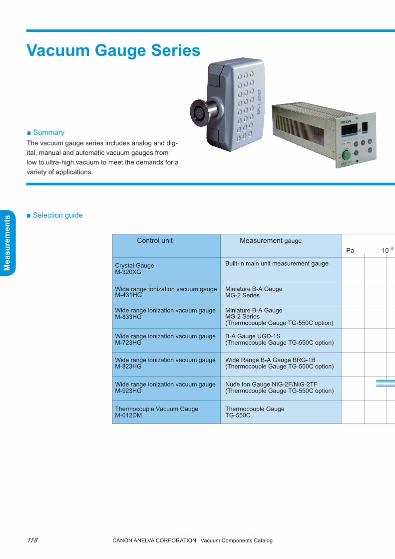
Canon anELVa Corporation Vacuum Components Catalog118
Mea
sure
men
ts
Mea
sure
men
ts
Vacuum Gauge Series
■ Selection guide
Control unit Measurement gauge Recommended measurement pressure range *Pa 10−8 10−6 10−4 10−2 1 102 104
Crystal GaugeM-320XG
Wide range ionization vacuum gaugeM-431HG
Wide range ionization vacuum gaugeM-833HG
Wide range ionization vacuum gaugeM-723HG
Wide range ionization vacuum gaugeM-823HG
Wide range ionization vacuum gaugeM-923HG
Thermocouple Vacuum GaugeM-012DM
Built-in main unit measurement gauge
Miniature B-A GaugeMG-2 Series
Miniature B-A GaugeMG-2 Series(Thermocouple Gauge TG-550C option)
B-A Gauge UGD-1S(Thermocouple Gauge TG-550C option)
Wide Range B-A Gauge BRG-1B(Thermocouple Gauge TG-550C option)
Nude Ion Gauge NIG-2F/NIG-2TF(Thermocouple Gauge TG-550C option)
Thermocouple GaugeTG-550C
■ SummaryThe vacuum gauge series includes analog and dig-ital, manual and automatic vacuum gauges from low to ultra-high vacuum to meet the demands for a variety of applications.

119Canon anELVa Corporation Vacuum Components Catalog
Mea
sure
men
ts
Mea
sure
men
ts
Control unit Measurement gauge Recommended measurement pressure range *Pa 10−8 10−6 10−4 10−2 1 102 104
Crystal GaugeM-320XG
Wide range ionization vacuum gaugeM-431HG
Wide range ionization vacuum gaugeM-833HG
Wide range ionization vacuum gaugeM-723HG
Wide range ionization vacuum gaugeM-823HG
Wide range ionization vacuum gaugeM-923HG
Thermocouple Vacuum GaugeM-012DM
Built-in main unit measurement gauge
Miniature B-A GaugeMG-2 Series
Miniature B-A GaugeMG-2 Series(Thermocouple Gauge TG-550C option)
B-A Gauge UGD-1S(Thermocouple Gauge TG-550C option)
Wide Range B-A Gauge BRG-1B(Thermocouple Gauge TG-550C option)
Nude Ion Gauge NIG-2F/NIG-2TF(Thermocouple Gauge TG-550C option)
Thermocouple GaugeTG-550C
* This table lists the recommended measurement pressure range, which is different from the measureable pressure range.

Canon anELVa Corporation Vacuum Components Catalog120
Mea
sure
men
ts
Mea
sure
men
ts
■ Dimensions diagram
Crystal GaugeHigher precision, better reproducibility, next generation roughing vacuum gauge replacing the Pirani gauge
M-320XG
■ SummaryCrystal gauges are capable of performing a wide range of highly reliable measurements from atmospheric pressure to 10-2pa.Instead of the unstable thermal phenomenon used by conventional roughing gauges such as pirani and thermocouple gauges, crystal gauges utilize the phenomenon where the crystal oscillator’s resonant impedance changes according to pressure; thereby ensuring excellent repeatability and stable measure-ment near atmospheric pressure.In addition to roughing gauges, a crystal gauge can be used as a pressure switch to detect chamber at-mospheric pressure vent or for process pressure mea-surement.
■ Features1. Wide measurement range
Enables measurement with excellent repeatability from atmospheric pressure to 10-2pa.
2. High stabilityCrystal gauges are vacuum gauges without a heat source (filament).Enables safe handling without affecting the process gas.
3. Compact and ultra-light weightWeighing only 200g, the controller can fit in the palm of your hand.
4. 2W low power consumptionLow power consumption that is friendly to the envi-ronment.
■ Applications• roughing pump pressure measurement of various
vacuum equipment• Various process pressure measurement• pressure switch for detection of chamber vent, etc.• Other pressure measurements from atmospheric
pressure to 10-2pa
If you are considering process gas (especially corro-sive gases) pressure measurement, please contact our sales office. the sensor life may be reduced depending on the type of gas and usage environment.
M-320XG CRYSTAL GAUGE
ATM
ZERO
19 0
87
23
0 1 2
534
D/A46 58 7 6
0 19
MANT
238
7
SP25 46
EDBC
0F
EXP
1 235
09
87
MANT
1 23
SP1
A 89 7 6
5 46
4
POWER/ALM
E F
EXP
DBC A 9
REMOTE I/O
102
44.5
A72
.5
SensorA dimension
NW16, NW25 : 23φ34 ICF : 36φ70 ICF, VG70 : 30

121Canon anELVa Corporation Vacuum Components Catalog
Mea
sure
men
ts
Mea
sure
men
ts
■ Specifications
■ Ordering information
Type M-320XGMeasurement gauge XG-1 Crystal Gauge Head (exclusive for crystal gauge)Measurement pressure range 10-2 to atmospheric pressureGas type selections N2, Ar, H2, Air
Analog output (pressure signal)
0 to 10V DC: Use the digit switch to set the output format of the following items:(1) Log output(2) Multiple output(3) Linear output Full scale pressure range selectable (1x101, 1x10², 1x10³, 1x10⁴, 1x10⁵ Pa)
Remote I/O
INPUT: (1) Gas type setting Switch with 2 bit signal (2) Zero adjustment (3) ATM settingOUTPUT: 2 set point outputs
Set point2 points (photocoupler output, fixed hysteresis)Set using the digit switch (SP1, SP2 mantissa, exponent)
Operating environment5°C to 50°C (including controller)Gauge head only withstand temperature 150°C MAX
Zero adjustment PUSH switch or software adjustment by remote I/OFull scale adjustment Adjustment by trimmerI/O connector Dsub 15PDisplay LED x3 (PWR/ALM (Green/Red), SP1-Status (Green), SP2-Status (Green))Power requirements 22V to 33V DC, (maximum power consumption 2W)Dimensions (mm) 72.5Hx102Wx44.5D (excluding gauge head)Weight 200g (excluding gauge head)Sensor attaching flange NW16, NW25, φ34ICF, φ70ICF, etc.
Parts Number Model Description Remarks Code
0160-01331 M-320XG/N16 A-NET Crystal Gauge Controller + Crystal gauge head (with NW16) 21561
0160-01349 M-320XG/N25 A-NET Crystal Gauge Controller + Crystal gauge head (with NW25) 21562
0160-01365 M-320XG/C34 A-NET Crystal Gauge Controller + Crystal gauge head (with PY34ICF) 21580
0160-01373 M-320XG/C70 A-NET Crystal Gauge Controller + Crystal gauge head (with PY70ICF) 21581
0160-01357 M-320XG/VG70 A-NET Crystal Gauge Controller + Crystal gauge head (with PY70VG) 21582
H21-03280 XG-1/NW16 Crystal Gauge Head with NW16 21575
H21-03281 XG-1/NW25 Crystal Gauge Head with NW25 21576
0161-17920 XG-1/ICF34 Crystal Gauge Head with PY34ICF 21577
0161-17938 XG-1/ICF70 Crystal Gauge Head with PY70ICF 21578
0161-44888 XG-1/VG70 Crystal Gauge Head with PY70VG 21579
Note) Contact us for more information about CE (RoHS).

Canon anELVa Corporation Vacuum Components Catalog122
Mea
sure
men
ts
Mea
sure
men
ts
A-NET Display UnitM-390•M-391■ Summarythe M-390 and M-391 are dedicated display units for the A-NEt series (M-310HG, M-320XG,M-330MX, IKr-251/261, and pKr-251/261).they are single channel support models. (One display unit per gauge is required.)
■ Specifications
51.5 M-390
M-391
99
253
77
48
48
44.8
61.6
44.8
100(1)
9.2
8.2
■ Dimensions diagram
Type M-390 M-391
Supported gauge
M-330MX (crystal ion gauge)*1
M-310HG (ion gauge)*1
M-320XG (crystal gauge)IKR-251/261 (cold cathode gauge)*1
PKR-251/261 (full range gauge)*1
Front panel size 1/8JIS rack size DIN size
Display digits2 mantissa digits + 1 exponent digit
2 mantissa digits + 1 exponent digit
Set point
2 pointsContact capacity 24V DC0.5A
4 pointsContact capacity 250V AC1A
External outputAnalog output(Through OUT)Status output
None
External input 2 points (1 spare) NoneA-NET gauge supply power
24V DC None
Power requirements85 to 132V AC70W MAX
21.6 to 26.4V AC160mA MAX
Dimensions (mm) 99Hx51.5Wx253D 48Hx48Wx100DWeight 1300g 340gCommunication func-tion
None None
AC input cable 2m NoneBetween each gauge and displayConnection cable
Option, standard 5m
None
* 1 Discontinued

123Canon anELVa Corporation Vacuum Components Catalog
Mea
sure
men
ts
Mea
sure
men
ts
■ Ordering informationParts Number Model Description Remarks Code
P23-04307 M-390 A-NET Display Unit A-NET series dedicated display unit, no cable
21563
H21-03614 M-391 A-NET Display UnitA-NET series dedicated display unit, no cable
21583*
0161-37475 390-03BA A-NET Cable for Display Unit (for Ion Gauge 3m) For ion gauge 3m 21567
0161-37483 390-05BA A-NET Cable for Display Unit (for Ion Gauge 5m) For ion gauge 5m 21564
0161-37491 390-10BA A-NET Cable for Display Unit (for Ion Gauge 10m) For ion gauge 10m 21568
0161-37506 390-15BA A-NET Cable for Display Unit (for Ion Gauge 15m) For ion gauge 15m 21569
0161-37514 390-20BA A-NET Cable for Display Unit (for Ion Gage 20m) For ion gauge 20m 21570
0161-37409 390-03CR A-NET Cable for Display Unit (for Crystal Gauge 3m)For crystal ion gauge, crystal gauge 3m
21571
0161-37417 390-05CR A-NET Cable for Display Unit (for Crystal Gauge 5m)For crystal ion gauge, crystal gauge 5m
21565
0161-37425 390-10CR A-NET Cable for Display Unit (for Crystal Gauge 10m)For crystal ion gauge, crystal gauge 10m
21572
0161-37433 390-15CR A-NET Cable for Display Unit (for Crystal Gauge 15m)For crystal ion gauge, crystal gauge 15m
21573
0161-37441 390-20CR A-NET Cable for Display Unit (for Crystal Gauge 20m)For crystal ion gauge, crystal gauge 20m
21574
0161-37344 390-05CCA-NET Cable for Display Unit (CC, for Full Range Gauge 5m)
CC, for full-range gauge 5m 21566
0161-37360 390-010CCA-NET Cable for Display Unit (CC, for Full Range Gauge 10m)
CC, for full-range gauge 10m 21587
0161-37378 390-015CCA-NET Cable for Display Unit (CC, for Full Range Gauge 15m)
CC, for full-range gauge 15m 21588
0161-37386 390-020CCA-NET Cable for Display Unit (CC, for Full Range Gauge 20m)
CC, for full-range gauge 20m 21589
Note) * marked indicates CE (RoHS) compliant. Contact us for other products.

Canon anELVa Corporation Vacuum Components Catalog124
Mea
sure
men
ts
Mea
sure
men
ts
Wide Range Ionization Vacuum GaugeComplies with European and US safety standards.
M-431HG
■ Summarythe miniature gauge exclusive M-431HG vacuum gauge control power inherits the basic performance, space-saving, and lightweight features of the conven-tional model (M-430HG). In addition, the gauge now supports the safety standards in Europe and the Unit-ed States.
■ Features1. CE marking compliant2. External I/O and rS-232C communication func-
tions equipped as standard3. Wide input voltage (M-431 HG)4. Low power consumption/24V DC input
■ Applications• Automated vacuum equipment pressure measure-
ment• Sputtering process pressure measurement and
control• Multi-chamber system pressure measurement• General vacuum equipment pressure measure-
ment
■ SpecificationsType M-431HG
Pressure display range 0.01x10⁻⁷ to 13.2x100Pa
Pressure display Digital, measurement range auto switch
Set point Standard equipped with 2 points (with hysteresis)
D/A output Switch between LOG or combined output (0 to 10V)
Analog output 0 to 10V (APC compatible output)
External control function(Remote operation)
INPUT: Filament ON/OFF, parameter LOCK, filament switching, degas ON/OFF, range holdOUTPUT: Set points 1, 2, Filament ON/OFF status degas status, filament 1/2 status
Communication functionRS232C standard equipped
(9600, 4800, 2400, 1200 bps)Dimensions (mm), Weight
104Wx99Hx296D 1.2kg
Power consumption 50VA 90 to 240V AC 50/60Hz
Emission current 10μA, 100μA, 1mA (auto switched, or fixed)
Degas Grid electrical heating method, 3 min timer
Filament switching Key and remote I/O control
Filament protection Filament OFF at 13.3x100Pa
Standard configuration Vacuum gauge main unit (measurement gauge and cables not included)
RoHS, CE marking compliant
M-431 HG
* The cable included with the M-431HG is for use at 100V. Please contact us when using at 200V.
CE RoHS

125Canon anELVa Corporation Vacuum Components Catalog
Mea
sure
men
ts
Mea
sure
men
ts
■ Dimensions diagram
■ Ordering information
■ AccessoriesCables
• Dedicated gauge cable (60°C heat-resistant temperature)Standard length 5m, 10m, 15m, 20m
• Bakable cable also available (250°C heat-resistant temperature).Standard length 5m, 10m, 15m, 20m
Measurement gaugerefer to the miniature gauge in the measurement gauge section.
Parts Number Model Description Remarks Code
H21-03430 430-901 Cable for Miniature B-A Gauge (5m) For MG-2/2F 21672
H21-03432 430-902 Cable for Miniature B-A Gauge (10m) For MG-2/2F 21673
H21-03433 430-903 Cable for Miniature B-A Gauge (15m) For MG-2/2F 21674
0161-24189 430-904 Cable for Miniature B-A Gauge (20m) For MG-2/2F 21675
0161-44820 430-911 Bakable Cable for MG-2 (5m) Maximum operating temperature range 250°C 21676
0161-44838 430-912 Balable Cable for MG-2 (10m) Maximum operating temperature range 250°C 21677
0161-36966 430-913 Balable Cable for MG-2 (15m) Maximum operating temperature range 250°C 21678
0161-36974 430-914 Bakable Cable for MG-2 (20m) Maximum operating temperature range 250°C 21679
0161-55554 M-431HG Wide Range Ion Gauge For MG-2 21685*
Note) * marked indicates CE (RoHS) compliant. Contact us for other products.

Canon anELVa Corporation Vacuum Components Catalog126
Mea
sure
men
ts
Mea
sure
men
ts
Wide Range Ionization Vacuum GaugeThe ultimate ionization gauge (RoHS, CE compliant)
M-833HG■ Summarythe M-833HG is a control unit made exclusively for miniature B-A gauges. Optional expansion boards supporting versatile gauge and data output are avail-able. the combination of a miniature B-A gauge and tC gauge (option) and the use of an auto filament for auto gauge switching enables highly accurate vacuum measurement from atmospheric pressure to ultra-high vacuum. the M-833HG is ideally suited for installation on high to ultra-high vacuum equipment.
■ Features1. Easy-to-read liquid crystal display. pressure val-
ues and messages are displayed on the LCD.2. Automatically switched pressure range.3. Variety of external control functions enabling fully
remote operation.4. two set points equipped as standard.5. Highly expandable supporting up to four option
boards. (Note: Gp-IB option not supported.)6. Compliant with roHS and CE marking.
■ SpecificationsType M-833HG
Measurement gauge Miniature gauge MG-2 Series
Pressure display range 0.1x10⁻⁷ to 9.9x100 Pa
Pressure display Measurement range auto switch
Set point Two set points equipped as standard (open collector)
D/A output0 to 10V: Mantissa output0 to 11V: Combined output or LOG output
Analog output(Electron meter output)
When set to APC mode (0.1 to 2.5V)When set to normal mode (0.1 to 1.6V)
External control function(Remote operation)
INPUT: Filament ON/OFF Six types of external control functions such as degas ON/OFF etc. OUTPUT: Six types of status signal output
Special functionAPC compatible: Range hold function Electron meter output function
Dimensions and Weight H99xW209xD330, 1.9kg
Power requirements100 to 240V AC100VA or less, 50/60Hz
Emission current 10μA, 100μA, 1mA auto switched or fixed
Degas Grid electrical heating method
Filament switching Key and remote I/O control
Filament protection Over range setting or emission current ±50% variation
Standard configuration Vacuum gauge main unit (measurement gauge and cables not included)
RoHS, CE marking compliant
■ Applications• Automated vacuum equipment pressure measure-
ment• Sputtering process pressure measurement and
control• Multi-chamber system pressure measurement• General vacuum equipment pressure measure-
ment
CE RoHS

127Canon anELVa Corporation Vacuum Components Catalog
Mea
sure
men
ts
Mea
sure
men
ts
■ Dimensions diagram
■ Ordering information
■ AccessoriesCables
• Dedicated gauge cable (60°C heat-resistant temperature)Standard length 5m, 10m, 15m, 20m
• Bakable cable also available (250°C heat-resistant temperature).Standard length 5m, 10m, 15m, 20m
TC gauge board
Combination of thermocouple gauge and B-A gauge enables measurement from roughing pressure to ultra-high vacuum.Two TG-550Cs can be measured with one board. However, the standard configuration is one TG-550C1 and one cable.
BCD output board Enables BCD output of pressure values.
CM gauge boardEnables measurement of atmospheric pressure to ultra-high vacuum in combination with a capacitance manometer.
Set point output Expansion and relay output of pressure set points are possible.
RS232C board For external control (600, 1200, 2400, 4800, 9600, 19200 bps)
Gauge selector box Capable of connecting and selecting between two miniature B-A gauges.
■ Expansion function options* Refer to the section on the M-723HG, M-823HG, and M-932HG accessories for the option board combinations
Parts Number Model Description Remarks Code
0161-63816 M-833HG Wide Range Ion GaugeMiniature gauge dedicated power supply, cable/no measurement gauge
21734*
0161-68604 722-TC TC Gauge BoardTG-550C for M-723HG, 823HG, 833HG, 923HG with 5m cable
21487
0161-70465 722-BCD BCD Output Board With connector for M-723HG, 823HG, 833HG, 923HG 21483
0161-70423 722-CM CM.XTL Gauge Board With connector for M-723HG, 823HG, 833HG, 923HG 21481
P23-04131 722-SPB Set Points Board With connector for M-723HG, 823HG, 833HG, 923HG 21480
P23-04132 722-232C RS-232C Board With connector for M-723HG, 823HG, 833HG, 923HG 21485
0161-70499 831-331 Gauge Selector Box for M-833HG No cable, for MG-2 21776
P23-01064 831-323 Gauge Selector Box for MG-2For M-833HG, including cable (5m between main unit, 2m between gauge)
21775
H21-03430 430-901 Cable for Miniature B-A Gauge (5m) For MG-2/2F 21672
H21-03432 430-902 Cable for Miniature B-A Gauge (10m) For MG-2/2F 21673
H21-03433 430-903 Cable for Miniature B-A Gauge (15m) For MG-2/2F 21674
0161-24189 430-904 Cable for Miniature B-A Gauge (20m) For MG-2/2F 21675
0161-44820 430-911 Bakable Cable for MG-2 (5m) Maximum operating temperature range 250°C 21676
0161-44838 430-912 Balable Cable for MG-2 (10m) Maximum operating temperature range 250°C 21677
0161-36966 430-913 Balable Cable for MG-2 (15m) Maximum operating temperature range 250°C 21678
0161-36974 430-914 Bakable Cable for MG-2 (20m) Maximum operating temperature range 250°C 21679
Note) * marked indicates CE (RoHS) compliant. Contact us for other products.

Canon anELVa Corporation Vacuum Components Catalog128
Mea
sure
men
ts
Mea
sure
men
ts
Ionization Vacuum GaugeRenewed through further aging
M-723HG, M-823HG, M-923HG
■ Summarythis series includes the most common B-A ionization vacuum gauges, with abundant expansion board se-lection supporting a variety of gauges.A remote control function necessary for process con-trol of vacuum equipment and a range hold function effective for ApC (auto pressure control) are equipped as standard.Combining a wide range B-A gauge and a thermo-couple gauge and the use of an auto filament for auto gauge switching, the M-823HG enables highly accu-rate vacuum measurement from atmospheric pressure to ultra-high vacuum.
■ Features1. Automatically switched pressure range.2. pressure values and messages are displayed on the
LCD.3. Variety of external control functions enabling fully
remote operation.4. two set points equipped as standard.5. D/A output equipped as standard (four outputs:
mantissa, exponent, composite, and LOG) for re-corder output.
6. Convenient range hold function for ApC (auto pressure control) equipped as standard.this feature enables fixing/releasing to/from the set pressure range. In addition, a high response analog output (electrometer output) separate from the D/A output is provided as a signal for ApC.
7. the M-823HG is equipped with an auto filament function that automatically switches from rough-ing gauges such as tC and CM to a B-A gauge.
8. the relative sensitivity can be set by gas type.9. In addition to 100V AC, power supply voltages of
115V AC, 200V AC, and 230V AC are also available by special order.
10. Functions can be enhanced using a variety of op-tions.
■ Applications• Automated vacuum equipment pressure measure-
ment• Sputtering process pressure measurement and
control• Multi-chamber system pressure measurement• General vacuum equipment pressure measure-
ment

129Canon anELVa Corporation Vacuum Components Catalog
Mea
sure
men
ts
Mea
sure
men
ts
■ Specifications
■ Dimensions diagram
Type M-723HG M-823HG M-923HG
Measurement gauge
UGD-1S B-A gauge BRG-1B wide range B-A gaugeNIG-2F/NIG-2TF
Nude Ion Gauge
Pressure measure-ment range
5 range auto switch 7 range auto switch 8 range auto switch
10-2, 10-3, 10-4, 10-5,10-6Pa10-0, 10-1, 10-2, 10-3,
10-4, 10-5,10-6 Pa10-2, 10-3, 10-4, 10-5,10-6,
10-7, 10-8, 10-9 PaMeasurement range switching
Auto switching (range hold possible)
Degas Grid electrical heating method Electron bombardment method
Filament switching Can be switched from the front panel or by external control input (M822HG excluded).
Filament protectionTurns off automatically if there is a problem in the fluctuation range of pressure,
ion current, or emission current.
Analog outputD/A output (mantissa D/A output, exponent D/A output, combined D/A output)
analog raw output (electrometer output)
I/O remote
INPUT: Filament ON/OFF input, degas ON/OFF input, filament inhibit input, range hold 1 input,
range hold 2 input, filament switch input, gauge 1/2 switch input (when using the gauge select option)
OUTPUT: Filament ON/OFF output, degas ON/OFF output, remote/local output, set point output (2 points),
gauge 1/2 select output (when using the gauge selector option), power ON/OFF output,
filament 1/2 output, alarm output
Set point Two set points set as standard (open collector)
Dimensions (mm) H99 x W209 x D330Power require-ments
100V AC±10%2A, 50/60Hz (also supports 115/200/230V AC)
Weight 5.4kgStandard configu-ration
Vacuum gauge main unit (measurement gauge and cables not included)

Canon anELVa Corporation Vacuum Components Catalog130
Mea
sure
men
ts
Mea
sure
men
ts
<Option board>
Gauge selector box <optional>
See Table 1 for the combination
■ Accessories
Option board combinationsFunctions can be enhanced using an option board.
M-723HG, 823HG, 833HG, 923HG main unit
CablesStandard length 5m, 10m, 15m, 20m and bakable ca-bles are available. refer to the ordering information.
Measurement gaugerefer to the section on measurement gauge for de-tails. (refer to the control unit specifications for the available gauge.)
Set pointboard
CM gauge board
TC gaugeboard
BCD outputboard
GP-IBboard
RS-232Cboard
Gauge selec-torbox
Set pointboard
CM gauge board
TC gaugeboard
BCD outputboard
GP-IB board
RS-232C board
Gauge selectorbox
: Combination allowed: Combination not allowed
Set point output Expansion and relay output of pressure set points are possible. 4 points 100V AC 1A, 30V DC 1A
CM gauge boardEnables measurement of atmospheric pressure to ultra-high vacuum in combination with a capacitance manometer.
TC gauge boardEnables measurement from roughing pressure to ultra-high vacuum by combining a thermocouple gauge with a B-A gauge. Two units can be measured with one board. However, the standard configuration is one TG550C1 and one cable.
BCD output board Enables BCD output of pressure values.
GB-IB board For external control
RS-232C board For external control (600, 1200, 2400, 4800, 9600, 19200 bps)
Gauge selector box Capable of connecting and selecting between two B-A gauges.
(
131Canon anELVa Corporation Vacuum Components Catalog
Mea
sure
men
ts
Mea
sure
men
ts
Note) Contact us for more information about CE (RoHS).
■ Ordering informationParts Number Model Description Remarks Code
0161-80355 M-723HG Ion Gauge JIS rack type 21704
0161-80486 M-823HG Wide Range Ion Gauge JIS rack type 21728
0161-71445 M-923HG UHV Vacuum Gauge JIS rack type 21747
P13-06804 921-303 Gauge Selector Box (for M-922HG)For M-923HG, including cable (5m between main unit, 2m between gauge)
21745
P13-08435 721-303Gauge Selector Box (for M-722HG/M-822HG)
For M-723HG/M-823HG, including cable (5m between main unit, 2m between gauge)
21764
0161-68604 722-TC TC Gauge BoardTG-550C for M-723HG/823HG/833H-G/923HG, with cable 5m
21487
0161-70423 722-CM CM.XTL Gauge BoardFor M-723HG/823HG/833HG/923HG with connector
21481
0161-70465 722-BCD BCD Output BoardFor M-723HG/823HG/833HG/923HG with connector
21483
P23-04131 722-SPB Set Points Board For M-723HG/823HG/833HG/923HG with connector
21480
P23-04132 722-232C RS-232C BoardFor M-723HG/823HG/833HG/923HG with connector
21485
P13-14960 820-901 Cable for B-A Gauge (5m) M-723HG/823HG, standard 5m 21645
P13-14965 820-902 Cable for B-A Gauge (10m) M-723HG/823HG, standard 10m 21646
P13-14966 820-903 Cable for B-A Gauge (15m) M-723HG/823HG, standard 15m 21647
P13-14967 820-904 Cable for B-A Gauge (20m) M-723HG/823HG, standard 20m 21648
P13-14123 921-901 Cable for Nude Ion Gauge (5m) For M-923HG, 5m 21750
P13-14128 921-902 Cable for Nude Ion Gauge (10m) For M-923HG, 10m 21751
P13-14129 921-903 Cable for Nude Ion Gauge (15m) For M-923HG, 15m 21752
P13-14130 921-904 Cable for Nude Ion Gauge (20m) For M-923HG, 20m 21753
0161-36411 921-911 Bakable Cable for Nude Ion Gauge (5m) For M-923HG, 5m 21754
P13-22893 921-912 Extension Cable for Nude Ion Gauge (5m) For 921-911 extension, 5m 21755
0161-36932 921-913 Extension Cable for Nude Ion Gauge (10m) For 921-911 extension, 10m 21756
0161-36940 921-914 Extension Cable for Nude Ion Gauge (15m) For 921-911 extension, 15m 21757
P13-15424 921-801 Rack Mount Panel For M-723HG/823HG/833HG/923HG 21765

Canon anELVa Corporation Vacuum Components Catalog132
Mea
sure
men
ts
Mea
sure
men
ts
Ionization Vacuum GaugeCC-Link equipped ionization vacuum gauge
M-723HG-CC, M-823HG-CC, M-833HG-CC, M-923HG-CC
■ Ordering information
TC gaugeboard
CM gauge boardbox
Gauge selectorboard
Set pointboard
BCD outputboard
RS-232Cboard
: Communication with CC-Link allowed : Combination allowed : Combination not allowed
Note) * marked indicates CE (RoHS) compliant. Contact us for other products.
■ AccessoriesCombination with other option boardsOnly one option board can be added.
I / O unit
CC-Link unit
MFC
PLC
CC-Link connection schematic
Parts Number Model Description Remarks Code
9009-13579 M-723HG-CC Ion Gauge (CC-Link) For UGD-1S 21708
0162-08381 M-823HG-CC Wide Range Ion Gauge (CC-Link) For BRG-1B 21729
0161-68777 M-833HG-CC Wide Range Ion Gauge (CC-Link) For MG-2 series 21735*
0161-82129 M-923HG-CC UHV Vacuum Gauge (CC-Link) For NIG-2F series 21748
■ Summarythe popular ionization vacuum gauges M-723-HG, M-823HG, M-833HG, and M-923HG support CC-Link communication control.
CC-Link is a field network recommended by the CC-Link Association for efficient wired FA control. CC-Link enables multiple connections with a single unit.

133Canon anELVa Corporation Vacuum Components Catalog
Mea
sure
men
ts
Mea
sure
men
ts
Note) Contact us for more information about CE (RoHS).
thermocouple Vacuum GaugeStandard for roughing region
M-012DM■ Summarythe M-012DM vacuum gauge uses two types of crossed precious metal wires, using one pair as a thermocouple and the other pair as a heater. the gauge measures the temperature at the center contact point, which changes as the pressure of the gas changes. this small panel meter has a large, easy-to-read LED. It also has a control unit installed at the rear. In addition, its two set points can be easily set using the switches on the front panel.
■ Features1. LED bar graph display
Easy-to-read LED bar graph display. Set points can be easily set using the switches on the front panel.
2. Constant measurementCapable of measuring pressure from 200pa to 5 × 10⁻¹pa, stable measurement across a wide range of power supply voltages and changes in ambient tem-perature is assured.
3. Atmospheric pressure operationprecious metal resistance wires are used to enable operation under atmospheric pressure.
■ Applications• roughing pump system pressure measurement• roughing pump system automatic control
■ Specifications
■ AccessoriesCable: 5m cable equipped as standard.
10m and 15m cables are available as options. refer to the ordering information.
Measurement gauge: refer to the section on measure-ment gauge tG-550C for details.
■ Dimensions diagram
M-012DM
80 12.2 81
16
19Terminal cover
Vents
2
80 φ65
Pa
■ Ordering information
Type M-012DMMeasurement gauge
TG-550C Thermocouple Gauge
Pressure mea-surement range
5x10⁻¹ to 200Pa
Pressure displayBar graph(LED, pseudo analog display format)
Operable pres-sure
Operable from atmospheric pressure
Analog outputDC0 to 10mV (non-linear with respect to pressure)
Set point2 points (each point NO, NC)30V DC 2A, 250V AC 2A
Power require-ments
90 to 200V AC 50/60Hz 5W
Weight 0.25kg
Standard config-uration
M-012DM (main unit) : x1Input cable (1.8m) : x1TG-550C : x1Gauge cable (5m) : x1
Parts Number Model Description Remarks Code
0161-68573 M-012DM Thermo-Couple Gauge (w TG-550B) TG-550C, with 5m cable 21539
H21-03124 M-012DM Thermo-Couple Gauge TG-550C, no cable 21537
B26-01832 012DM-05 Cable for M-012DM (5m) 21526
B26-01834 012DM-10 Cable for M-012DM (10m) 21527
B26-01835 012DM-15 Cable for M-012DM (15m) 21528

Canon anELVa Corporation Vacuum Components Catalog134
Mea
sure
men
ts
Mea
sure
men
ts
Measurement gauge
■ Specifications
Note 1) Linearity limitNote 2) Lowest practical pressure that can be measured. Use of MG-2F is recommended for measurement of 10-7Pa.Note 3) Inert gases such as nitrogen and argon can be measured up to 13Pa.Note 4) The lowest measureable value of MG-2W/F is one order of magnitude higher than the standard MG-2.
■ Dimensions diagram
MG-2 • MG-2/WFφ15
φ26
2463
.5
MG-2M
MG-2Fφ18
φ70
φ70ICF
φ26 φ26
30
38.569
.5
MG-2 MG-2M MG-2F
Miniature Gaugethe miniature B-A gauge MG-2/MG-2M/MG-2F (patent pending) is a small metal gauge designed to replace the large, breakable glass gauge of previous gauges. the small size enables the mounting location to be easily selected. Moreover, the reduced size (ap-prox. 1/20 that of previous products) does not sacrifice any sensitivity or measurement range. pressure from ultimate pressure to process pressure (measureable to 1pa range), such as for sputtering, can be measured with a single gauge. the MG-2 and MG-2M are con-
■ Flange examples
φ34ICF
φ34
70.2
NW16
φ3067 NW25
φ40
67
φ70ICF
φ70
65.5
Type MG-2 MG-2M MG-2I/NW16, 25 MG-2I/φ34ICF, φ70ICF MG-2F MG-2/WFBody material SUS304Maximum pressure measurement(Note 1) 13Pa 1.3x10⁻¹(Note 3)Pa
Minimum pressure measurement(Note 2) Approx. 10-6Pa Approx. 10-7Pa Approx. 1.0x10⁻⁵(Note 4)Pa
Sensitivity 0.045Pa-1
FilamentTwo filaments built-in
Filament material: Yttria coated iridium wireTwo filaments built-in
Filament material: TungstenMeasurement gauge capacity
Approx. 12cc
Power require-ments
FilamentGrid degas
2.3W1.0W
2.5W1.0W
Degassing method Grid electrical heating
Attachment meth-od
Can be weld-ed to φ15
gauge adapt-er or various
flanges
φ18 gauge adapter NW25, NW16 φ34ICF, φ70ICF
φ70ICFConnected to flange
Can be welded to φ15 gauge adapter or vari-
ous flanges
nected to a gauge adapter (O-ring insertion type). the MG-2 is for φ15mm and the MG-2M is for φ18mm. With its em-phasis on measuring ultimate pressure, the MG-2F is mounted di-rectly to the φ70ICF.
MG-2/MG-2M/MG-2F MG-2/WF
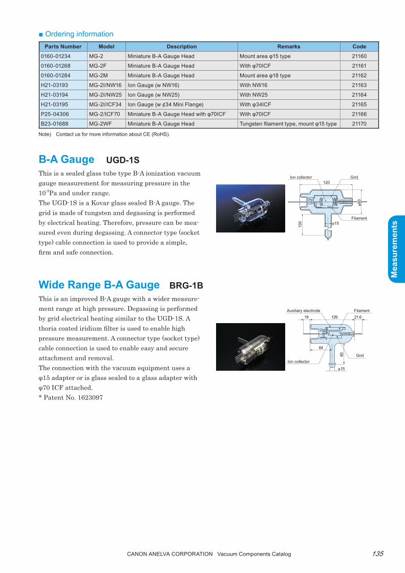
135Canon anELVa Corporation Vacuum Components Catalog
Mea
sure
men
ts
Mea
sure
men
ts
■ Ordering informationParts Number Model Description Remarks Code
0160-01234 MG-2 Miniature B-A Gauge Head Mount area φ15 type 21160
0160-01268 MG-2F Miniature B-A Gauge Head With φ70ICF 21161
0160-01284 MG-2M Miniature B-A Gauge Head Mount area φ18 type 21162
H21-03193 MG-2I/NW16 Ion Gauge (w NW16) With NW16 21163
H21-03194 MG-2I/NW25 Ion Gauge (w NW25) With NW25 21164
H21-03195 MG-2I/ICF34 Ion Gauge (w ¢34 Mini Flange) With φ34ICF 21165
P25-04306 MG-2/ICF70 Miniature B-A Gauge Head with φ70ICF With φ70ICF 21166
B23-01688 MG-2WF Miniature B-A Gauge Head Tungsten filament type, mount φ15 type 21170
B-A Gaugethis is a sealed glass tube type B-A ionization vacuum gauge measurement for measuring pressure in the 10-2pa and under range.the UGD-1S is a Kovar glass sealed B-A gauge. the grid is made of tungsten and degassing is performed by electrical heating. therefore, pressure can be mea-sured even during degassing. A connector type (socket type) cable connection is used to provide a simple, firm and safe connection.
Wide Range B-A Gaugethis is an improved B-A gauge with a wider measure-ment range at high pressure. Degassing is performed by grid electrical heating similar to the UGD-1S. A thoria coated iridium filter is used to enable high pressure measurement. A connector type (socket type) cable connection is used to enable easy and secure attachment and removal.the connection with the vacuum equipment uses a φ15 adapter or is glass sealed to a glass adapter with φ70 ICF attached.* patent No. 1623097
120Grid
Filament
Ion collector
φ15
100
φ60
UGD-1S Dimensions Diagram
12919
64
60
21.6
φ15
Auxiliary electrode Filament
GridIon collector
UGD-1S
BrG-1B
Note) Contact us for more information about CE (RoHS).

Canon anELVa Corporation Vacuum Components Catalog136
Mea
sure
men
ts
Mea
sure
men
ts
■ OptionsGlass gauge (UGD-1S, BrG-1B, LG-11S) with a glass adapter with φ70ICF attached (welded) are also available. We can customize the connection direction and length according to your specifications.
Type UGD-1S BRG-1B
Gauge Type B-A Gauge Wide Range B-A Gauge
Shape Glass tubeConnection with measured vacuum chamber
φ15 gauge port (O ring)
Recommended measurement range 10-6 to 0.1Pa 10-6 to 10Pa
Standard sensitivity 0.075Pa-1with respect to N2
X ray limit Approx. 1.3 x 10⁻⁸Pa
Baking temperature 400°C (150°C or less with O-ring seal)
Mate-rial
Filament Tungsten (x2) Thoria coated iridium (x1)
Body Kovar glass (vacuum sealed) Tungsten glass (open)Supported vacuum gauge power supply
M-723HG M-823HG
Applications General vacuum useB-A gauge, sputter etc. measurable up to
high pressure (10Pa)B-A gauge, sputter, etc.
■ Specifications
2-18UNS
(φ70
)
40 75±2
69±2
NIG-2F/2TF Dimensions Diagram
■ Ordering informationParts Number Model Description Remarks Code
P25-05688 BRG-1B Wide Range B-A Gauge Head Mount area φ15 type 21225
P25-02463 952-7860 BRG-1 Vertical Type Wide Range B-A Gauge Head With φ70ICF glass adapter 21133
P21-02260 952-7861BRG-1 Horizontal Type Wide Range B-A Gauge Head
With φ70ICF glass adapter 21132
783-5285 UGD-1S B-A Gauge Head Socket type 21121
VMT-9304 952-7850 UGD-1S Vertical Type B-A Gauge Head With φ70ICF glass adapter 21130
VMT-9305 952-7851 UGD-1S Horizontal Type B-A Gauge Head With φ70ICF glass adapter 21131
Nude ion Gaugethis gauge directly mounts a B-A type electrode on a flange. this is directly attached to the equipment making it ideally suited for ultra-high vacuum mea-surement without any errors due to feedthrough. plat-inum-clad molybdenum wires are used for the grid to minimize errors due to gas contamination.A connector type (Canon plug type) cable connection is used to provide a simple, firm and safe connection. the NIG-2F uses a tungsten filament. In addition, the NIG-2tF uses a yttria coated filament, which lowers the operating temperature, suppresses degassing, and improves ultra-high vacuum measurement.
NiG-2F/NiG-2tF
Note) Contact us for more information about CE (RoHS).
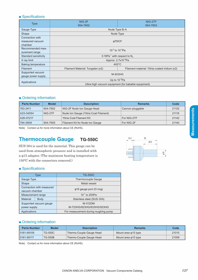
137Canon anELVa Corporation Vacuum Components Catalog
Mea
sure
men
ts
Mea
sure
men
ts
TypeNIG-2F
954-7902NIG-2TF954-7903
Gauge Type Nude Type B-AShape Nude TypeConnection with measured vacuum chamber
φ70ICF
Recommended mea-surement range
10-9 to 10-2Pa
Standard sensitivity 0.19Pa-1 with respect to N2
X ray limit Approx. 2.7x10⁻⁹PaBaking temperature 400°CFilament Filament Material: Tungsten (x2) Filament material: Yttria-coated iridium (x2)Supported vacuum gauge power supply
M-923HG
ApplicationsUp to 10-9Pa
Ultra-high vacuum equipment (for bakable equipment)
■ Specifications
■ Ordering informationParts Number Model Description Remarks Code
783-2411 954-7902 NIG-2F Nude Ion Gauge Head Cannon pluggable 21120
A23-04054 NIG-2TF Nude Ion Gauge (Yttria Coat Filament) 21119
A26-07217 Yttria Coat Filament Kit For NIG-2TF 21142
794-0609 954-7905 Filament Kit for Nude Ion Gauge For NIG-2F 21140
14.2 52
29.5
φ15
thermocouple GaugeSUS-304 is used for the material. this gauge can be used from atmospheric pressure and is installed with a φ15 adapter. (the maximum heating temperature is 150°C with the connectors removed.)
tG-550C
Type TG-550CGauge Type Thermocouple GaugeShape Metal vesselConnection with measured vacuum chamber
φ15 gauge port (O ring)
Measurement range 10-1 to 200PaMaterial Body Stainless steel (SUS-304)Supported vacuum gauge power supply
M-012DMM-723HG/823HG/833HG/923HG
Applications For measurement during roughing pump
■ Specifications
Note) Contact us for more information about CE (RoHS).
■ Ordering informationParts Number Model Description Remarks Code
0161-68109 TG-550C Thermo-Couple Gauge Head Mount area φ15 type 21015
0161-68117 TG-550B Thermo-Couple Gauge Head Mount area φ15 type 21009
Note) Contact us for more information about CE (RoHS).
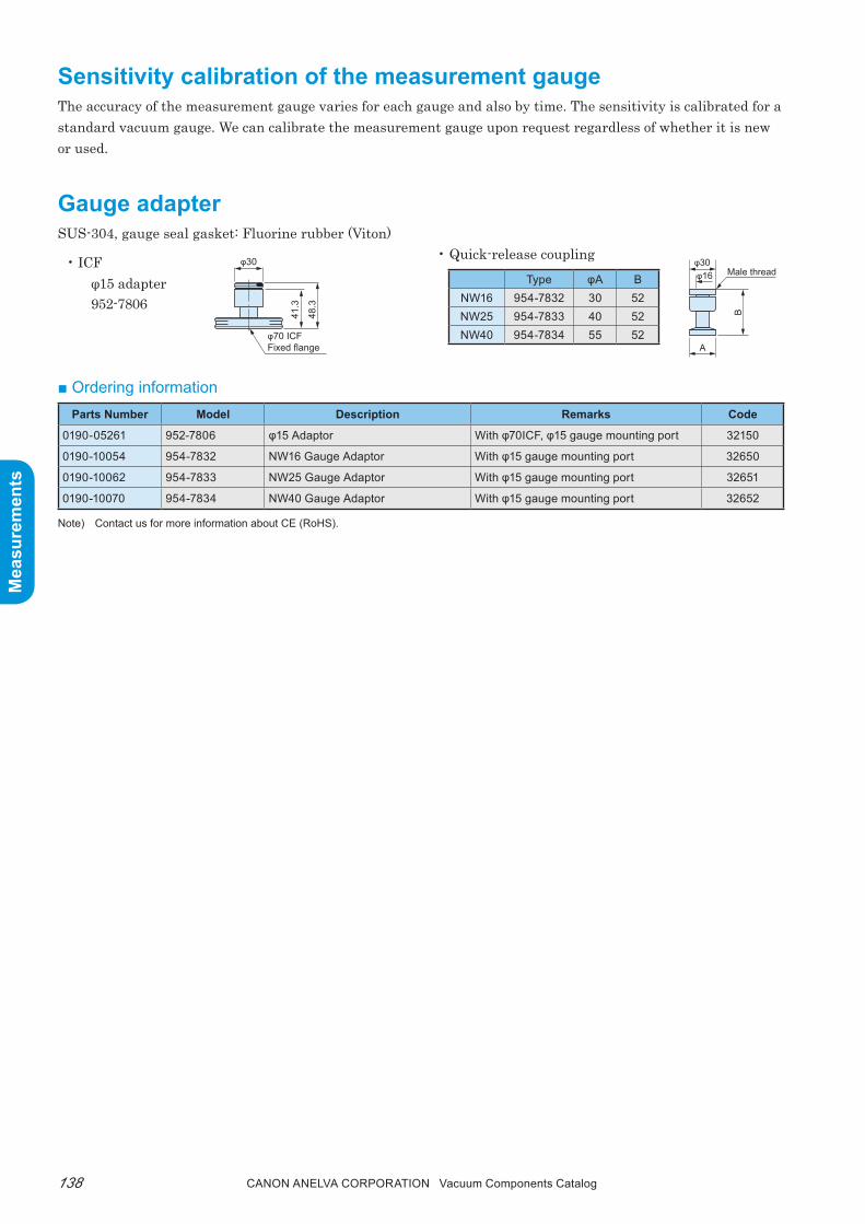
Canon anELVa Corporation Vacuum Components Catalog138
Mea
sure
men
ts
Mea
sure
men
ts
Gauge adapterSUS-304, gauge seal gasket: Fluorine rubber (Viton)
• ICFφ15 adapter952-7806
Sensitivity calibration of the measurement gaugethe accuracy of the measurement gauge varies for each gauge and also by time. the sensitivity is calibrated for a standard vacuum gauge. We can calibrate the measurement gauge upon request regardless of whether it is new or used.
φ30φ16
A
B
Male threadType φA B
NW16 954-7832 30 52NW25 954-7833 40 52NW40 954-7834 55 52
φ30
φ70 ICFFixed flange
41.3
48.3
■ Ordering information
• Quick-release coupling
Parts Number Model Description Remarks Code
0190-05261 952-7806 φ15 Adaptor With φ70ICF, φ15 gauge mounting port 32150
0190-10054 954-7832 NW16 Gauge Adaptor With φ15 gauge mounting port 32650
0190-10062 954-7833 NW25 Gauge Adaptor With φ15 gauge mounting port 32651
0190-10070 954-7834 NW40 Gauge Adaptor With φ15 gauge mounting port 32652
Note) Contact us for more information about CE (RoHS).

139Canon anELVa Corporation Vacuum Components Catalog
Mea
sure
men
ts
Mea
sure
men
ts
Memorandum
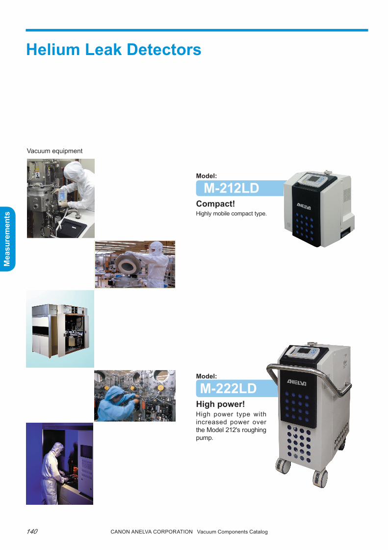
Canon anELVa Corporation Vacuum Components Catalog140
Mea
sure
men
ts
Mea
sure
men
ts
Helium Leak Detectors
Model:
M-222LDHigh power!High power type with increased power over the Model 212's roughing pump.
Vacuum equipment
Model:
M-212LDCompact!Highly mobile compact type.
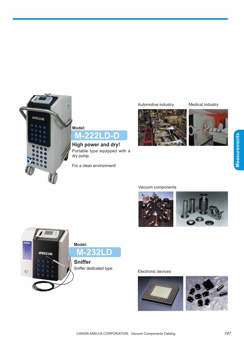
141Canon anELVa Corporation Vacuum Components Catalog
Mea
sure
men
ts
Mea
sure
men
ts
Model:
M-232LDSnifferSniffer dedicated type
Model:
M-222LD-DHigh power and dry!Portable type equipped with a dry pump.
For a clean environment!
Automotive industry
Vacuum components
Electronic devices
Medical industry

Canon anELVa Corporation Vacuum Components Catalog142
Mea
sure
men
ts
Mea
sure
men
ts
Portable series M-212LD/M-222LD(-D)/M-232LD
Portable
■ Summarythe portable series products have been conceptually developed with emphasis on compactness, lightness, and portability.the M-212LD is a lightweight, general-purpose model that has been specifically designed for use in the field.the M-222LD is equipped with a large roughing pump. It can perform leak tests of large vacuum con-tainers by itself without the need of the equipment's pump. A high sensitivity type M-222LD-H is also available. Furthermore, the M-222LD-D uses a dry pump pumping system to keep the vacuum equipment (vacuum components) free of oil contamination.the M-232LD is a dedicated machine focusing on the sniffer method. It is ideally suited for use in gas pipes and pressurization components.Select the best model for the intended application from the variety of models provided in this series.
M-212LD ........................................Compact! • Suitable for inspection and field maintenance of
various vacuum equipment• Compact leak detector for various vacuum compo-
nents
M-222LD ................................... High Power!• Maintenance of various vacuum equipment• Leak test of various large-scale vacuum containers
such as accelerators• Leak system analyzer
M-222LD-D .............. High Power! and DRY!• Supports clean room• Enables oil-free leak tests• Maintenance of various vacuum equipment
M-232LD ............................................Sniffer!• Leak test of gas supply systems, vacuum compo-
nents, and piping components• Leak test of automotive parts and air conditioning
freezers• Leak test of food and pharmaceutical packages• Leak test of water and various gas pipes

143Canon anELVa Corporation Vacuum Components Catalog
Mea
sure
men
ts
Mea
sure
men
ts
■ Features1. Simple operationFrom equipment startup to measurement with just a touch of a button. Anyone can easily perform leak tests. Simply set the conditions appropriate for the test specimen. Sensitivity calibration is performed automatically.
2. Industry leading sensitivity, stability, and re-sponse
In addition to using a 180° mag-netic deflection mass spectrometer tube, an MCp (Micro-Channel plate with a secondary-electron multi-plier) is installed for amplifying he-lium ions. As a result, even the standard models can achieve a sensitivity as high as 10-12pa•m3/s. this is also coupled with high stability throughout the long-term service period.
3. portablethe large casters and han-dle make the units ideal for field maintenance use.
Analyzer tube
■ Hand controller
4. Durable robust designthe units are equipped with a variety of safety fea-tures. they respond immediately to operator errors and abnormal environmental conditions.A long life tungsten filament is used to enable long term high-sensitivity measurement. the robust de-sign enables the units to be installed in systems that operate 24/7.
5. Wide range of functionsJust like the simple operation of the conventional sys-tem, measurements can be performed using the start/stop button. Even those customers requiring compli-cated configurations to satisfy their specific needs can be easily supported. A 3.8 inch color LCD (320×240) is used for the display unit. A color LCD has been adopt-ed in order to increase legibility. the standard, status, and trend screens are shown below. As an example of other functions, reading the internal temperature variations and compensating for tem-perature drift of the preamplifier have improved the measurement accuracy.Portable
Standard screen Status screen Trend screen
Hand controller Analog screen
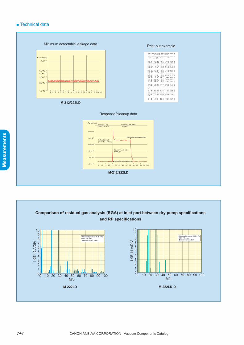
Canon anELVa Corporation Vacuum Components Catalog144
Mea
sure
men
ts
Mea
sure
men
ts
■ Technical data
55
(Pa • m3/sec)
1.0×10⁻⁷
1.0×10⁻⁸
1.0×10⁻⁹
1.0×10⁻¹⁰
1.0×10⁻¹¹
1.0×10-125 10 15 20 25 30 35 40 45 50 60 65 70 (sec)
Calibration leak valve open
Calibration leak(5×10⁻⁹Pa • m3/sec)
Calibration leak valve open
Standard Leak Valve**OPEN**
Standard Leak Valve**CLOSE**
Standard Leak5×10-9Pa • m3/s
1 2 3 4 5 6 8 9 10 11 12 13 14 15 16 17 18 197 (min)1.0×10⁻¹²
2.0×10⁻¹²
3.0×10⁻¹²
4.0×10⁻¹²
5.0×10⁻¹²
1.0×10⁻¹¹
(Pa • m3/sec)
00 10 20 30 40 50
M/e
1.0E
-12
A/D
IV
60 70 80 90 100
123456789
10
• Measured pressure : 6.7E-5 Pa• AQA-100 mass Emission current : 5mA
00 10 20 30 40 50
M/e
1.0E
-11
A/D
IV
60 70 80 90 100
123456789
10
• Measured pressure : 5.8E-5 Pa• AQA-100 mass Emission current : 5mA
Minimum detectable leakage data
Response/cleanup data
Comparison of residual gas analysis (RGA) at inlet port between dry pump specifications and RP specifications
M-222LD M-222LD-D
Print-out example
M-212/222LD
M-212/222LD

145Canon anELVa Corporation Vacuum Components Catalog
Mea
sure
men
ts
Mea
sure
men
ts
■ Dimensions diagram
■ Specifications sheet
Type M-212LD (-H)*3 M-222LD (-H)*3 M-222LD-D (-H)*3 M-232LDVersion Compact High power High power & dry SnifferQuantitative measurement range (Pa•m3/s)
10-12 to 10-3
(-H: 10-13 to 10-3)10-12 to 10-3
(-H: 10-13 to 10-3)10-12 to 10-3
(-H: 10-13 to 10-3)10-8 to 10-1
(10-2 to 105ppm)
Inlet port exhaust speed (He)
(L/s)
0.5 (Gross Mode) 1.8 (Gross Mode) 2.0 (Gross Mode) Probe suction speed2.0 (Middle Mode) 2.0 (Middle Mode) 2.0 (Middle Mode) 0.3Pa•m3/s
(5.0 (-H: Fine Mode)) (5.0 (-H: Fine Mode)) (5.0 (-H: Fine Mode))
Inlet port shape NW25 (ISO) NW25 (ISO) NW25 (ISO) -Main pump TMP 50L/s
Roughing pump RP 30L/min RP 142L/min*1 Dry pump250L/min
RP30L/min+Diaphragm pump
External interfaceRS-232C
Analog output (2 points) - Standard I/O
Display Color LCDSniffer probe Options StandardPower requirements*2 100V AC 8A 100V to 115V AC, 15A 100V to 115V AC, 10A 100V AC 8ADimensions (WxHxD) (mm) 435x487x364 462x867x715 435x470x363Weight (kg) 42 75 42
*1: Optionally changeable to RP up to 275L/min. *2: Supports 115V, 200V, and 230V according to your order specification.*3: (-H) is a high sensitivity specification equipment.
M-232LDM-212LD (H) M-222LDM-222LD-D (H)
364
435
487
11
715
462
867
Helium Leak DetectorM-232LD
1136
347
0
435
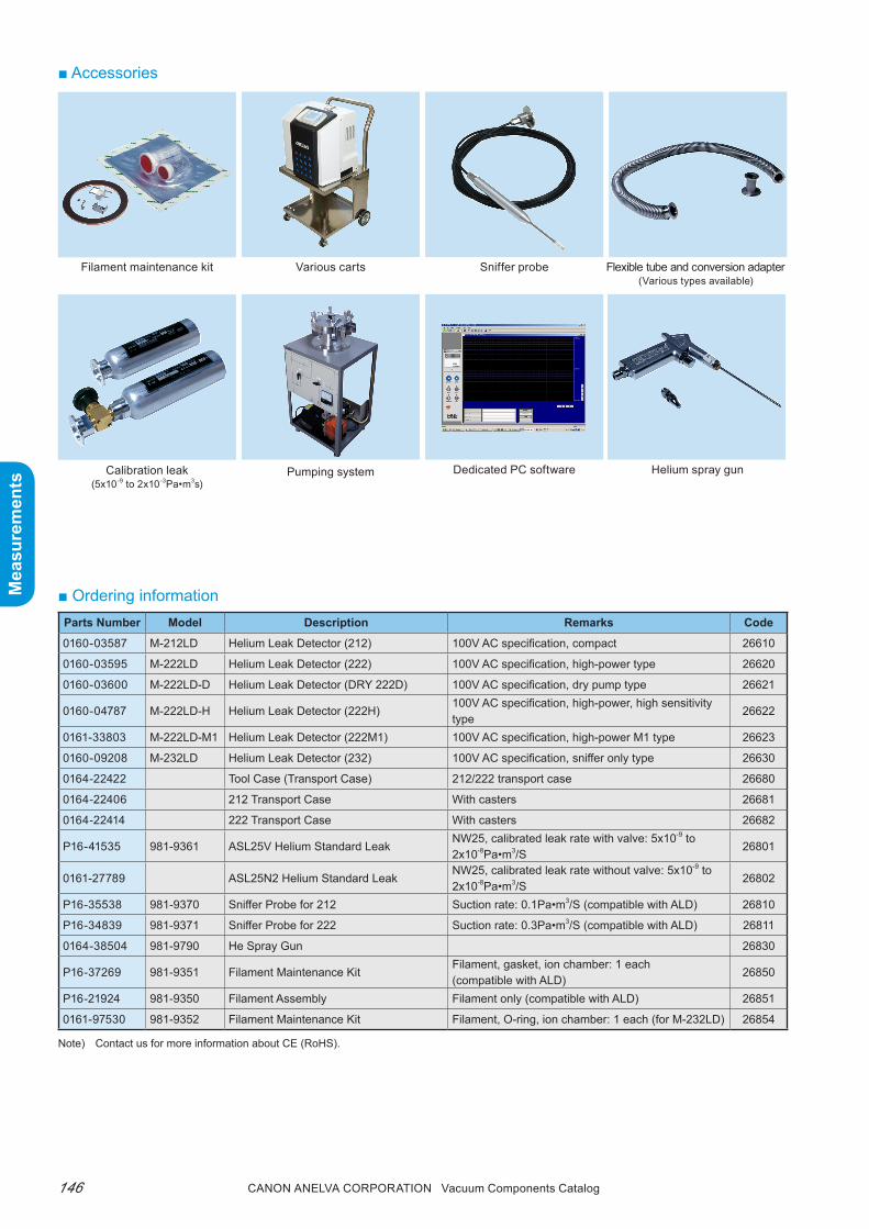
Canon anELVa Corporation Vacuum Components Catalog146
Mea
sure
men
ts
Mea
sure
men
ts
■ Ordering information
Filament maintenance kit
Helium spray gun
Flexible tube and conversion adapter(Various types available)
Calibration leak(5x10⁻⁹ to 2x10⁻³Pa•m3s)
Pumping system
Sniffer probe
■ Accessories
Various carts
Dedicated PC software
Parts Number Model Description Remarks Code
0160-03587 M-212LD Helium Leak Detector (212) 100V AC specification, compact 26610
0160-03595 M-222LD Helium Leak Detector (222) 100V AC specification, high-power type 26620
0160-03600 M-222LD-D Helium Leak Detector (DRY 222D) 100V AC specification, dry pump type 26621
0160-04787 M-222LD-H Helium Leak Detector (222H)100V AC specification, high-power, high sensitivity type
26622
0161-33803 M-222LD-M1 Helium Leak Detector (222M1) 100V AC specification, high-power M1 type 26623
0160-09208 M-232LD Helium Leak Detector (232) 100V AC specification, sniffer only type 26630
0164-22422 Tool Case (Transport Case) 212/222 transport case 26680
0164-22406 212 Transport Case With casters 26681
0164-22414 222 Transport Case With casters 26682
P16-41535 981-9361 ASL25V Helium Standard LeakNW25, calibrated leak rate with valve: 5x10⁻⁹ to 2x10⁻⁸Pa•m3/S
26801
0161-27789 ASL25N2 Helium Standard LeakNW25, calibrated leak rate without valve: 5x10⁻⁹ to 2x10⁻⁸Pa•m3/S
26802
P16-35538 981-9370 Sniffer Probe for 212 Suction rate: 0.1Pa•m3/S (compatible with ALD) 26810
P16-34839 981-9371 Sniffer Probe for 222 Suction rate: 0.3Pa•m3/S (compatible with ALD) 26811
0164-38504 981-9790 He Spray Gun 26830
P16-37269 981-9351 Filament Maintenance KitFilament, gasket, ion chamber: 1 each (compatible with ALD)
26850
P16-21924 981-9350 Filament Assembly Filament only (compatible with ALD) 26851
0161-97530 981-9352 Filament Maintenance Kit Filament, O-ring, ion chamber: 1 each (for M-232LD) 26854
Note) Contact us for more information about CE (RoHS).

tHiN FiLM DEpOSitiONCONtrOLLEr and MONitOr
Film Thickness Meter
Crystal Oscillator
147Canon anELVa Corporation Vacuum Components Catalog
Mea
sure
men
ts
Mea
sure
men
ts

■ Features1. Initial oscillation frequency with minimum toler-
anceFor applications that use a narrow range from the initial oscillation frequency such as optical film deposition, this product, which has a small initial oscillation frequency tolerance (5990kHz ± 5kHz), can be used for strictly controlling the crystal oscil-lator replacement interval.
2. More stable lifethe oscillation strength of crystal film thickness meters will always decay (although dependent on the deposition conditions), as the film deposits on the crystal oscillator and the oscillating frequency shifts toward lower frequency.Under the same deposition conditions, decrease in the oscillation strength at the resonant frequency of the crystal oscillator is considered to be one of the factors determining the life of the crystal oscillator.to prolong the life of the crystal oscillator, it is im-portant to keep the resonance resistance of the crys-tal oscillator at a small, strong oscillation strength.this product has succeeded in keeping the resonance resistance small by using high quality crystal mate-rial and high processing technology.
Crystal Oscillator for Film Thickness Sensor6MHz CRYSTALM-600Cr
■ SummaryA new crystal oscillator is used for the crys-tal film thickness sensor of vacuum deposi-tion equipment. This crystal oscillator offers high-grade performance and high quality, where you can actually feel the difference.
■ Specifications
Item Specifications
Crystal cut direction AT cutInitial oscillation fre-quency
5990kHz ± 5kHz
Electrode
Deposition surface: Gold electrode (fully round surface)Electrode surface: Gold electrode (patterned)
Outer diameter φ14mm
Cross-section shape Plano-convex
Quantity/1 pack Contains 10
Case outer dimensions W30 x H20 x D40mm
Case Material ABS resin
Electrode surfaceDeposition surface
■ Ordering Information
Parts Number Model Description Remarks Code
9007-67148 M-600CR 6MHz Quartz Crystal 10 per set 22071
Canon anELVa Corporation Vacuum Components Catalog148
Mea
sure
men
ts
Mea
sure
men
ts
Note) Contact us for more information about CE (RoHS).

com
pone
nts
com
pone
nts
149Canon anELVa Corporation Vacuum Components Catalog
CONStrUCtiON COMpONENtS & EB GUNS
Vacuum Components
Piping PartsUltra-High Vacuum FlangesConnecting Components with ICFQuick-release CouplingsVacuum SwitchesAncillary Materials
ValvesUltra-High Vacuum Type-L All-metal ValvesUltra-High Vacuum Type-L Polyimide Valves“V Series” Roughing Pump Valves“V Series” Type-L ValvesUltra-High Vacuum Variable Leak ValvesGas Inlet ValvesIsolate Valves
Ultra-High Vacuum Gate ValveMSB seriesSTD series
FeedthroughsRotary FeedthroughsLinear FeedthroughsR/L FeedthroughsCurrent TerminalsUltra-high Vacuum Viewing Ports
E-type Electron Guns
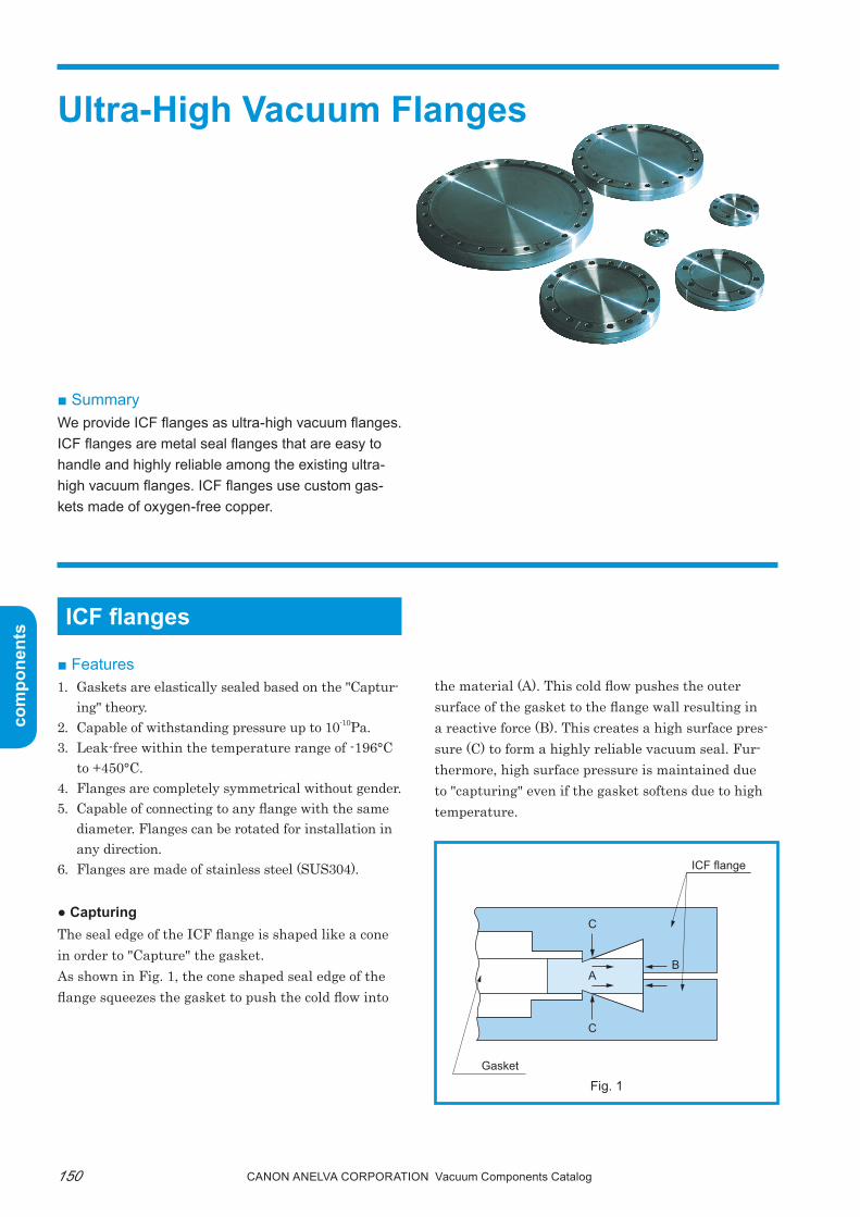
com
pone
nts
com
pone
nts
Canon anELVa Corporation Vacuum Components Catalog150
Ultra-High Vacuum Flanges
■ SummaryWe provide ICF flanges as ultra-high vacuum flanges.ICF flanges are metal seal flanges that are easy to handle and highly reliable among the existing ultra-high vacuum flanges. ICF flanges use custom gas-kets made of oxygen-free copper.
ICF flanges
■ Features1. Gaskets are elastically sealed based on the "Captur-
ing" theory.2. Capable of withstanding pressure up to 10-10pa.3. Leak-free within the temperature range of -196°C
to +450°C.4. Flanges are completely symmetrical without gender.5. Capable of connecting to any flange with the same
diameter. Flanges can be rotated for installation in any direction.
6. Flanges are made of stainless steel (SUS304).
● Capturingthe seal edge of the ICF flange is shaped like a cone in order to "Capture" the gasket.As shown in Fig. 1, the cone shaped seal edge of the flange squeezes the gasket to push the cold flow into
the material (A). this cold flow pushes the outer surface of the gasket to the flange wall resulting in a reactive force (B). this creates a high surface pres-sure (C) to form a highly reliable vacuum seal. Fur-thermore, high surface pressure is maintained due to "capturing" even if the gasket softens due to high temperature.
Fig. 1
ICF flange
Gasket
AB
C
C

com
pone
nts
com
pone
nts
151Canon anELVa Corporation Vacuum Components Catalog
Fig. 3
Flange typeSeal line load
(N/cm)
ICF 3528
Step 3675
Knife-edge 4381
Flange Bolt usedTightening torque
per bolt (N•m)
φ34 ICF M4 2 to 3
φ70 ICF M6 6.9 to 9.8
φ114 ICF M8 9.8 to 14.7
φ152 ICF M8 9.8 to 14.7
φ203 ICF M8 9.8 to 14.7
φ253 ICF M8 9.8 to 14.7
φ305 ICF M8 9.8 to 14.7
φ356 ICF M10 19.6 to 24.5
φ406 ICF M10 19.6 to 24.5
● Test data1. Heat cycle test
No leakage occurs after tightening the φ70ICF flange with a torque of 7.8 to 9.8N•m (bolts and washers coated with molybdenum disulfide paste) and repeating 60 or more heat cycles under the con-ditions shown in Fig. 2.
2. Low-temperature cycle testNo leakage occurs after tightening the φ70ICF flange with a torque of approximately 7.8N•m (bolts and washers coated with molybdenum disulfide paste) and repeating 30 or more low temperature cycles under the conditions shown in Fig. 3.
3. Continuous heating testNo leakage occurs after tightening the φ70ICF flange with a torque of approximately 9.8N•m (bolts and washers coated with molybdenum disulfide paste) and heating at 450°C several hours every day for a total of 150 hours.
4. Comparison with metal gasket seal flangestable 1 compares the sealing line load per unit cir-cumferential length of the gasket.
5. tightening torque (reference value)table 2 lists the tightening torque of the flange for each size.
Fig. 2
Table 2Table 1
Note) Torque when bolts and washers are coated with molybdenum disulfide paste.
400˚C
30 minutes
60 minutes
100˚C
Tem
pera
ture
Time
150˚C
30 minutes
5 minutes
Room temperature
−196˚C
Temperature
Time

com
pone
nts
com
pone
nts
Canon anELVa Corporation Vacuum Components Catalog152
■ ICF flange standardsthe standard dimensions are divided into six types based on the external diameter. pipes up to φ203mm can be connected.A standard flange modified to fit the compatible pipe is available for each size of flange. (table 3)
Table 3 ICF fixed flanges
No.Flange
typeShape A B B1 C T T1 φH n P.C.D.
Applicable bolt
Applicable gasket pack
Applicablepipe
1 954-9401 a
34
Blank
-
- 7.5
-4.5
6 27M4x20L
953-9210
-
2 954-9402
b
6 φ6xφ4
3 954-9403 8 φ8xφ5.6
4 954-9404 10 φ10xφ8
5 954-9405 12.8 φ12.7xφ10.7
6 954-9427c 16 19.2 13.2 φ19.1xφ16.7
7 954-1091 M4 M4x16
8 954-7051 d
70
Blank
-
-
12.7
-
6.76 58.9
M6x35L953-5014
-
9 954-1101
e
20 17
5.3
φ19.1xφ16.7
10 954-1102 26.5 23.5 φ25.4xφ23
11 954-1103 33 30 φ32xφ29.6
12 954-1104 39 35.5 φ38xφ35
13 954-110542 38.5 φ41xφ38
14 954-1191 M6 M6x22L
15 954-7052 d
114
Blank
-
-
17.5
-8.4
8 92.2M8x45L
953-5015
-
16 954-1201e 64.5 61 9.5 φ63.5xφ60.2
17 954-1291 M8 M8x30L
18 954-7053 d
152
Blank
-
-
20
-8.4
16 130.3M8x50L
953-5016
-
19 954-1301e 103 97 11 φ101.6xφ95.6
20 954-1391 M8 M8x40L
21 954-7054 d
203
Blank
-
-
22
-8.4
20 181.1M8x55L
953-5017
-
22 954-1401e 155.5 148.5 12.5 φ153xφ147
23 954-1491 M8 M8x40L
24 954-7055 d
253
Blank
-
-
25
-8.4
24 231.9M8x60L
953-5048
-
25 954-1501e 205.5 198.5 12.5 φ203xφ197
26 954-1591 M8 M8x45L

com
pone
nts
com
pone
nts
153Canon anELVa Corporation Vacuum Components Catalog

com
pone
nts
com
pone
nts
Canon anELVa Corporation Vacuum Components Catalog154
No.Flange
typeShape A B B1 C T T1 H n P.C.D.
Applicablepipe
1 954-9420 a
34 16 19.2
Blank
7.514
4.5 6 27
-
2 954-1052 b 6 φ6xφ4
3 954-1053 b 8.2 φ8xφ5.6
4 954-1051 c - 13.2 φ19.1xφ16.7
5 954-1150 d
70
Blank
-
-
12.7
-
6.7 6 58.7
-
6 954-1151 e 20 17
5.3
φ19.1xφ16.7
7 954-1152 e 26.5 23.5 φ25.4xφ23
8 954-1153 e 33 30 φ32xφ29.6
9 954-1154 e 39 35.5 φ38xφ35
10 954-1250 d114
Blank-
-19
-8.4 8 92.2
-
11 954-1251 e 64.5 61 9.5 φ63.5xφ60.2
12 954-1350 d152
Blank-
-21
-8.4 16 130.3
-
13 954-1351 e 103 97 11 φ101.6xφ95.6
14 954-1450 d203
Blank-
-24
-8.4 20 181.1
-
15 954-1451 e 155.5 148.5 12.5 φ153xφ147
16 954-1550 d253
Blank-
-25
-8.4 24 231.9
-
17 954-1551 e 205.5 198.5 12.5 φ203xφ197
Table 4 ICF rotatable flanges

com
pone
nts
com
pone
nts
155Canon anELVa Corporation Vacuum Components Catalog
No.Flange
typeShape φA φB
(Note 2)
θ(Angle)
T T1
(Note 3)
φH n P.C.D
Applicable bolt/nut/washer
Applicablegaskettype
(Note 5)
Applicable pipeOutside diam-eter x Inside
diameterType Dimensions1
(Note 1) 954-1611 a 305 Blank 11°15′ 28 - 8.4 32 284 953-7801 M8x70L 953-7131 -2
(Note 2) 954-1612 b 305 250 11°15′ 28 150 8.4 32 284 953-7801 M8x70L 953-7131 φ250xφ2443
(Note 3) 954-1622 c 305 250 11°15′ 28 150 M8(Note 4) 32 284 953-7811 M8x50L 953-7131 φ250xφ244
4 954-1701 a 356 Blank 12° 28.5 - 10.5 30 325.4 953-7802 M10x70L 953-7132 -5 954-1712 b 356 295 12° 28.5 150 10.5 30 325.4 953-7802 M10x70L 953-7132 φ295xφ2896 954-1722 c 356 295 12° 28.5 150 M10
(Note 4) 30 325.4 953-7812 M10x50L 953-7132 φ295xφ2897 954-1801 a 406 Blank 12° 28.5 - 10.5 30 381 953-7802 M10x70L 953-7133 -8 954-1812 b 406 350 12° 28.5 150 10.5 30 381 953-7802 M10x70L 953-7133 φ350xφ3449 954-1822 c 406 350 12° 28.5 150 M10
(Note 4) 30 381 953-7812 M10x50L 953-7133 φ350xφ344
Fig 7 Large-diameter ICF fixed flange shape
■ Large-diameter ICF flangesthe dimensions of the large-diameter ICF flanges are divided into three types based on the external diam-eter as shown in table 6. pipes up to φ350mm can be connected. A blank flange and a flange with a short
Table 6 Large diameter ICF fixed flange list
pipe are available as standard products (table 6, Fig. 7). Contact us if you need to connect pipes with spe-cific dimensions. See table 7 and Fig. 8 for the rotary flanges.
Note 1. No.1 to No.3 are flanges that conform to the shapes and dimensions of bakable flanges for vacuum equipment (JVIS 003). 2. Winding pipes are used for the pipes. The φB dimensional tolerance is circumference tolerance πD−3
0 mm and the radial thickness is 3mm. 3. The standard T1 dimension is 150mm. However, special orders can be accepted. 4. Thread size of tapped flange. 5. The thickness of the large-diameter ICF flange gasket is 3mm. 6. The allowable heating temperature of large-diameter ICF flanges is 250°C.
14 T T
T1 T1
T
n-φH
n-φH n-φH2-M8 equal spaced screw depth 10
θθ
θ2
θ 2
2-M8 equal spaced(removal tap)
P.C.D.
2.0
φA φA φAφB3 3
φBP.C
.D.
P.C
.D.
P.C
.D.
Pipe Pipe
a b c
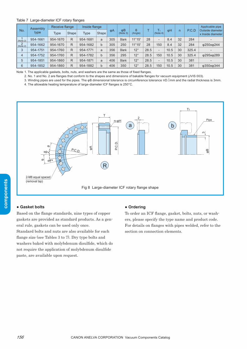
com
pone
nts
com
pone
nts
Canon anELVa Corporation Vacuum Components Catalog156
No. Assemblytype
Receive flange Inside flangeφA φB
(Note 3)θ
(Angle)T T1
(Note 4)φH n P.C.D
Applicable pipeOutside diameter x Inside diameterType Shape Type Shape
1(Note 2) 954-1661 954-1670 R 954-1681 a 305 Blank 11°15′ 28 - 8.4 32 284 -
2(Note 2) 954-1662 954-1670 R 954-1682 b 305 250 11°15′ 28 150 8.4 32 284 φ250xφ244
3 954-1751 954-1760 R 954-1771 a 356 Blank 12° 28.5 - 10.5 30 325.4 -4 954-1752 954-1760 R 954-1782 b 356 295 12° 28.5 150 10.5 30 325.4 φ295xφ2895 954-1851 954-1860 R 954-1871 a 406 Blank 12° 28.5 - 10.5 30 381 -6 954-1852 954-1860 R 954-1882 b 406 350 12° 28.5 150 10.5 30 381 φ350xφ344
● Gasket boltsBased on the flange standards, nine types of copper gaskets are provided as standard products. As a gen-eral rule, gaskets can be used only once.Standard bolts and nuts are also available for each flange size (see tables 3 to 7). Dry type bolts and washers baked with molybdenum disulfide, which do not require the application of molybdenum disulfide paste, are available upon request.
● Orderingto order an ICF flange, gasket, bolts, nuts, or wash-ers, please specify the type name and product code. For details on flanges with pipes welded, refer to the section on connection elements.
Table 7 Large-diameter ICF rotary flanges
Note 1. The applicable gaskets, bolts, nuts, and washers are the same as those of fixed flanges. 2. No. 1 and No. 2 are flanges that conform to the shapes and dimensions of bakable flanges for vacuum equipment (JVIS 003). 3. Winding pipes are used for the pipes. The φB dimensional tolerance is circumference tolerance πD−3
0 mm and the radial thickness is 3mm. 4. The allowable heating temperature of large-diameter ICF flanges is 250°C.
T
T1
n-φH
θ
θθ 2
θ 2
2-M8 equal spaced(removal tap)
P.C.D.
φA
3
2
φB
P.C
.D.Pipe
a
R
b
Fig 8 Large-diameter ICF rotary flange shape

com
pone
nts
com
pone
nts
157Canon anELVa Corporation Vacuum Components Catalog
■ 953-7601 gasket clipA gasket clip is used to ensure the gasket remains at-tached to the ICF flange when joining flanges. Fig. 9 shows an example of its use and dimensions. When flanges are joined vertically, the gasket clip can
prevent the gasket from dropping and improve opera-tion.the gasket clip can be used on all ICF flanges except for the φ34ICF.
Note) • After joining the flanges, remove the gasket clip before tightening the bolts.• The gasket clip is inserted in the leak groove (leak finding groove) of the ICF flange. Therefore, it cannot be used on conflat flanges without
a leak groove.• Gasket clips are not provided as a set of two. Therefore, specify the necessary quantity when ordering.
Fig 9 953-7601 gasket clip

com
pone
nts
com
pone
nts
Canon anELVa Corporation Vacuum Components Catalog158
No.Conversion
ICF type
I flange II flangeφA φB T M
ICF sizeApplicable
gasketApplicable
bolt*ICF size
Applicable gasket
Applicable bolt
1 952-7010 φ70ICF 953-5014 M6x35L φ34ICF 953-9210 M4x12L 70 17 12.7 6-M4 (Depth 6)2 952-7020 φ114ICF 953-5015 M8x45L φ34ICF 953-9210 M4x14L 114 17 17.5 6-M4 (Depth 9)3 952-7021 φ114ICF 953-5015 M8x45L φ70ICF 953-5014 M6x22L 114 38 17.5 6-M6 (Depth 10)4 952-7030 φ152ICF 953-5016 M8x50L φ34ICF 953-9210 M4x14L 152 17 20 6-M4 (Depth 9)5 952-7031 φ152ICF 953-5016 M8x50L φ70ICF 953-5014 M6x22L 152 38 20 6-M6 (Depth 10)6 952-7032 φ152ICF 953-5016 M8x50L φ114ICF 953-5015 M8x25L 152 65 20 8-M8 (Depth 10)7 952-7040 φ203ICF 953-5017 M8x55L φ34ICF 953-9210 M4x14L 203 17 22 6-M4 (Depth 9)8 952-7041 φ203ICF 953-5017 M8x55L φ70ICF 953-5014 M6x22L 203 38 22 6-M6 (Depth 10)9 952-7042 φ203ICF 953-5017 M8x55L φ114ICF 953-5015 M8x25L 203 65 22 8-M8 (Depth 10)10 952-7043 φ203ICF 953-5017 M8x55L φ152ICF 953-5016 M8x30L 203 103 22 16-M8 (Depth 10)11 952-7050 φ253ICF 953-5048 M8x60L φ34ICF 953-9210 M4x14L 253 17 25 6-M4 (Depth 9)12 952-7051 φ253ICF 953-5048 M8x60L φ70ICF 953-5014 M6x22L 253 38 25 6-M6 (Depth 10)13 952-7052 φ253ICF 954-5048 M8x60L φ114ICF 953-5015 M8x25L 253 65 25 8-M8 (Depth 12)14 952-7053 φ253ICF 953-5048 M8x60L φ152ICF 953-5016 M8x30L 253 103 25 16-M8 (Depth 12)15 952-7054 φ253ICF 953-5048 M8x60L φ203ICF 953-5017 M8x30L 253 154 25 20-M8 (Depth 12)
■ Conversion ICF flangesUse a conversion ICF flange when joining ICF flanges with different diameters.A standard series of 15 types is available (see Fig. 11 and table 8).For copper gaskets, standard gaskets can be used.the locations of the screws for joining the II flange (M) are arranged with the leak groove at the center.
Fig. 11
Table 8 ICF rotatable flanges
* The I flange side bolt hole is a through-hole.
■ ICF flange weldingtIG welding used to weld the ICF flange (see Fig. 12).the flange and pipe must be degreased before weld-ing.When additionally working on a blank flange to weld a pipe, keep the weld location away from the seal edge
as much as possible. In addition, avoid welding pipes larger than the applicable pipe diameter. Note that when welding by additionally working on a large-diameter ICF blank flange, the flange may become deformed, preventing the gasket from being attached.
Fig. 12 Flange welding example
a) The compatible pipe only needs to be cut because it is butt welded
b) Keep the clearance between the compatible pipe and flange to a minimum
Leak grooveM
T
φA
I flange
II flange
φB
ICF flange
φ34 ICF flange φ34 ICF flangeTIG
TIG
Applicable pipe
ICF flange
Applicable pipeApplicable pipe
Applicable pipe
TIGTIG
a) Applicable pipe only needs to be cut because it is butt welded
b) Keep the clearance between the applicable pipe and flange to a minimum

com
pone
nts
com
pone
nts
159Canon anELVa Corporation Vacuum Components Catalog
■ Ordering information
Parts Number Model Description Remarks Code
4-368029 954-9401 φ34 Mini ICF Flange Blank 34000
4-368030 954-9402 φ34 Mini ICF Flange (Applicable pipe) φ6xφ4 34001
4-368031 954-9403 φ34 Mini ICF Flange (Applicable pipe) φ8xφ5.6 34002
4-368032 954-9404 φ34 Mini ICF Flange (Applicable pipe) φ10xφ8 34003
4-368033 954-9405 φ34 Mini ICF Flange (Applicable pipe) φ12.7xφ10.7 34004
4-368171 954-9427 φ34 Mini ICF Flange (Applicable pipe) φ19.1xφ16.7 34005
804-3850 954-1091 φ34 Mini ICF Flange (Applicable pipe) φ19.1xφ16.7 with M4 tap 34020
A26-20341 954-9420 φ34 Mini ICF Rotatable Flange Blank 34040
B26-00882 954-1051 φ34 Mini ICF Rotatable Flange (Applicable pipe) φ19.1xφ16.7 34041
P21-03183 954-1052 φ34 Mini ICF Rotatable Flange (Applicable pipe) φ6xφ4 34042
P21-03184 954-1053 φ34 Mini ICF Rotatable Flange (Applicable pipe) φ8xφ5.6 34043
803-0156 954-7051 φ70 ICF Flange Blank 34100
804-3853 954-1103 φ70 ICF Flange (Applicable pipe) φ32xφ29.6 34101
804-3854 954-1104 φ70 ICF Flange (Applicable pipe) φ38xφ35 34102
804-3855 954-1105 φ70 ICF Flange (Applicable pipe) φ41xφ38 34103
804-3851 954-1101 φ70 ICF Flange (Applicable pipe) φ19.1xφ16.7 34106
804-3852 954-1102 φ70 ICF Flange (Applicable pipe) φ25.4xφ23 34107
804-3856 954-1191 φ70 ICF Flange (Applicable pipe) φ41xφ38, with M6 tap 34110
0190-03285 954-1150 φ70 ICF Rotatable Flange Blank 34140
P21-03188 954-1153 φ70 ICF Rotatable Flange (Applicable pipe) φ32xφ29.6 34143
B26-00883 954-1154 φ70 ICF Rotatable Flange (Applicable pipe) φ38xφ35 34144
P25-05139 954-1151 φ70 ICF Rotatable Flange (Applicable pipe) φ19.1xφ16.7 34145
P25-05619 954-1152 φ70 ICF Rotatable Flange (Applicable pipe) φ25.4xφ23 34146
P25-06545 954-7052 φ114 ICF Flange Blank 34200
803-1721 954-1201 φ114 ICF Flange (Applicable pipe) φ63.5xφ60.2 34201
803-1722 954-1291 φ114 ICF Flange (Applicable pipe) φ63.5xφ60.2, with M8 tap 34210
0190-03366 954-1250 φ114 ICF Rotatable Flange Blank 34240
A26-20338 954-1251 φ114 ICF Rotatable Flange (Applicable pipe) φ63.5xφ60.2 34241
803-0158 954-7053 φ152 ICF Flange Blank 34300
803-1723 954-1301 φ152 ICF Flange (Applicable pipe) φ101.6xφ95.6 34301
803-1724 954-1391 φ152 ICF Flange (Applicable pipe) φ101.6xφ95.6, with M8 tap 34310
P21-03192 954-1350 φ152 ICF Rotatable Flange Blank 34340
A26-20339 954-1351 φ152 ICF Rotatable Flange (Applicable pipe) φ101.6xφ95.6 34341
803-0159 954-7054 φ203 ICF Flange Blank 34400
803-1725 954-1401 φ203 ICF Flange (Applicable pipe) φ153xφ147 34401
803-1726 954-1491 φ203 ICF Flange (Applicable pipe) φ153xφ147, with M8 tap 34410
P21-03195 954-1450 φ203 ICF Rotatable Flange Blank 34440
A26-20340 954-1451 φ203 ICF Rotatable Flange (Applicable pipe) φ153xφ147 34441
803-0160 954-7055 φ253 ICF Flange Blank 34500
803-1727 954-1501 φ253 ICF Flange (Applicable pipe) φ203xφ197 34501
803-1728 954-1591 φ253 ICF Flange (Applicable pipe) φ203xφ197, with M8 tap 34510
Note) Contact us for more information about CE (RoHS).

com
pone
nts
com
pone
nts
Canon anELVa Corporation Vacuum Components Catalog160
Parts Number Model Description Remarks Code
P21-03197 954-1550 φ253 ICF Rotatable Flange Blank 34540
P21-03198 954-1551 φ253 ICF Rotatable Flange (Applicable pipe) φ203xφ197 34541
P21-04187 954-1611 φ305 ICF Flange Blank 34602
P21-04188 954-1612 φ305 ICF Flange (Applicable pipe) φ250xφ244 34603
P21-04189 954-1622 φ305 ICF Flange (Applicable pipe) φ250xφ244, with M8 tap 34604
P21-04190 954-1661 φ305 ICF Rotatable Flange Blank 34612
M21-01140 954-1662 φ305 ICF Rotatable Flange (Applicable pipe) φ250xφ244 34613
P25-06074 954-1701 φ356 ICF Flange Blank 34620
P21-04192 954-1712 φ356 ICF Flange (Applicable pipe) φ295xφ289 34622
P21-04193 954-1722 φ356 ICF Flange (Applicable pipe) φ295xφ289, with M10 tap 34623
P21-04194 954-1751 φ356 ICF Rotatable Flange Blank 34630
0190-08772 954-1752 φ356 ICF Rotatable Flange (Applicable pipe) φ295xφ289 34631
P25-06416 954-1801 φ406 ICF Flange Blank 34640
P21-04196 954-1812 φ406 ICF Flange (Applicable pipe) φ350xφ344 34642
P21-04197 954-1822 φ406 ICF Flange (Applicable pipe) φ350xφ344, with M10 tap 34643
P21-04198 954-1851 φ406 ICF Rotatable Flange Blank 34650
0190-08780 954-1852 φ406 ICF Rotatable Flange (Applicable pipe) φ350xφ344 34651
A26-13554 952-7010 Conversion ICF Flange φ34 ICF-φ70 ICF 34900
A23-06496 952-7020 Conversion ICF Flange φ34 ICF-φ114 ICF 34901
A23-06497 952-7021 Conversion ICF Flange φ70 ICF-φ114 ICF 34902
A23-06498 952-7030 Conversion ICF Flange φ34 ICF-φ152 ICF 34903
793-5893 952-7031 Conversion ICF Flange φ70 ICF-φ152 ICF 34904
793-5894 952-7032 Conversion ICF Flange φ114 ICF-φ152 ICF 34905
0191-14921 952-7040 Conversion ICF Flange φ34 ICF-φ203 ICF 34906
A23-06502 952-7041 Conversion ICF Flange φ70 ICF-φ203 ICF 34907
A23-06503 952-7042 Conversion ICF Flange φ114 ICF-φ203 ICF 34908
803-0887 952-7043 Conversion ICF Flange φ152 ICF-φ203 ICF 34909
0191-14955 952-7050 Conversion ICF Flange φ34 ICF-φ253 ICF 34910
A23-06506 952-7051 Conversion ICF Flange φ70 ICF-φ253 ICF 34911
P25-02740 952-7052 Conversion ICF Flange φ114 ICF-φ253 ICF 34912
P25-04860 952-7053 Conversion ICF Flange φ152 ICF-φ253 ICF 34913
0191-14963 952-7054 Conversion ICF Flange φ203 ICF-φ253 ICF 34914
0190-03748 953-9210 Gasket Pack For mini φ34 ICF, 5 per set 38000
0190-03756 953-5014 Gasket Pack For mini φ70 ICF, 5 per set 38002
0190-03764 953-5015 Gasket Pack For mini φ114 ICF, 5 per set 38003
0190-03772 953-5016 Gasket Pack For mini φ152 ICF, 5 per set 38004
0190-03829 953-5017 Gasket Pack For mini φ203 ICF, 5 per set 38005
0190-03837 953-5048 Gasket Pack For mini φ253 ICF, 5 per set 38006
A26-13403 953-7131 Gasket Pack for PY305 · 3T For mini φ305 ICF, 1 per set 38024
A26-13406 953-7132 Gasket Pack for PY356 · 3T For mini φ356 ICF, 1 per set 38025
A26-13409 953-7133 Gasket Pack for PY406 · 3T For mini φ406 ICF, 1 per set 38026
A26-04805 953-7601 Gasket Clip For φ70 ICF to φ406 ICF gasket fixture (x1) 38029
Note) Contact us for more information about CE (RoHS).

com
pone
nts
com
pone
nts
161Canon anELVa Corporation Vacuum Components Catalog
Memorandum

com
pone
nts
com
pone
nts
Canon anELVa Corporation Vacuum Components Catalog162
Connecting Components with ICF
■ Features1. Several types are available to satisfy any need.2. ICF flanges ensure use up to ultra-high vacuum.
■ Fittingthe fitting is an all-stainless steel (SUS-304) connec-tion element using an ICF flange. It is nonmagnetic and can be baked up to 450°C, making it ideal for con-nection pipes for ultra-high vacuum equipment and the like.We also manufacture flexible tubes with ICF flanges. please ask us.
● SpecificationsAllowable heating temperature: 450°CLeak: 1.33×10⁻¹¹pa•m3/sec or less
● Nipples (Material: SUS-304)
Type A B C D
952-7100 φ70 φ38 φ35 120
952-7104 φ70 φ38 φ35 210
952-7103 φ34 φ19 φ16 76
● Bellows nipples (Material: SUS-304)
Type A B C DExtension/shrinkage
952-7200 φ70 φ48 φ32 94Expansion 2, shrinkage 3
952-7201 φ34 φ22 φ15 76Expansion 4, shrinkage 6
● Elbows (Material: SUS-304)
Type A B C D E952-7305 φ70 φ38 φ35 54.2 54.2952-7306 φ70 φ38 φ35 54.2 189
*952-7307 φ34 φ21.7 φ17.5 51.3 51.3
(Note) * indicates a bulge product.
FittingMetal adapterGlass adapter
■ SummaryA wide variety of elements are used to connect the pipes when the equipment is being assembled. The series of connection elements listed here utilize ICF flanges for connecting the pipes. They are used in the main body of the ultra-high vacuum equipment and its roughing pump system.
A B C
D
ICF fixed flange
ICF rotatable flange
A B C
D (free length)
ICF rotatable flange
ICF rotatable flange
ICF fixed flange
A
C
D
B
E
ICF fixed flange
B

com
pone
nts
com
pone
nts
163Canon anELVa Corporation Vacuum Components Catalog
● Tees (Material: SUS-304)
● Crosses (Material: SUS-304)
* Ask for availability of fittings with shapes and sizes other than the above.
■ Metal adaptersthe metal adapter is an all-stainless steel (SUS-304) adapter using an ICF flange. It is nonmagnetic and can be baked up to 450°C. It can be welded onto the vacuum container for instance.
● SpecificationsAllowable heating temperature: 450°CLeak: 1.33×10⁻¹¹pa•m3/sec or less
● Metal adapters (Material: SUS-304)
Type A B C D952-7800 φ70 φ38 φ35 114.8952-7801 φ70 φ41 φ38 33952-7802 φ114 φ50.8 φ46.8 49.5952-7825 φ114 φ60.5 φ54.9 49.5952-7803 φ152 φ101.6 φ95.6 61952-7804 φ203 φ153 φ147 60
Dimensions
(Note) The ICF flange for the 952-7801 metal adapter is with M6tap.* Ask for availability of metal adapters with shapes and sizes other
than the above.
A
BC
D
D D
A
ICF fixed flangeICF rotatable flange
B
C
A
B
BC
DD
DD
ICF fixed flange
ICF rotatable flange
Type A B C D
952-7605 φ70 φ38 φ35 54.2
952-7606 φ34 φ19 φ16 38.6
Type A B C D
952-7500 φ70 φ38 φ35 60
952-7501 φ34 φ19 φ16 38

com
pone
nts
com
pone
nts
Canon anELVa Corporation Vacuum Components Catalog164
■ Glass adaptersthe glass adapter is Kovar glass sealed with Kovar alloy and welded onto an ICF flange. two types are available: all Kovar glass and Kovar glass sealed with pyrex glass. You can select either type to match the glass material of the other side.
● SpecificationsAllowable heating temperature: 300°Ctemperature change: 25°C/min or lessLeak: 7×10-11pa•m3/sec or lessWithstand pressure: 0.1Mpa (inside vacuum, outside atmosphere)
● Glass adapters (Material: Kovar glass)
● Glass adapters (Material: Pyrex glass)
Dimensions
Pyrex glassKovar glass
Pyrex glass
Kovar glass
Kovar glass Pyrex glass
Middle glass
Kovar glass
ICF fixed flange
Kovar
Dimensions Diagram
Type A B C tMinimum
inner diameter
952-7810 φ70 φ32 155 1.5 φ27952-7822 φ34 φ19 145 1.2 φ15.5952-7823 φ34 φ7 51.5 0.8 φ4.4
Type A B C t D
Mini-mumInner diam-eter
952-7811 φ70 φ32 155 1.8 43 φ27952-7824 φ34 φ20 145 1.2 53.2 φ15.5

com
pone
nts
com
pone
nts
165Canon anELVa Corporation Vacuum Components Catalog
■952-7806, φ15 adapter(Material: SUS-304, gauge seal gasket is fluorine rubber (Viton))this adapter is used exclusively for vacuum gauges such as B-A, Shultz, or thermo couple (applicable gauge diameter φ15).
● SpecificationsAllowable heating temperature: 125°CLeak: 6.7×10⁻¹¹pa•m3/sec or less
(Excluding gas permeation of the fluoro rubber (Viton))
φ15 adapter
48.3
41.3
φ30
■ Ordering informationParts Number Model Description Remarks Code
B26-00777 952-7100 φ70 Nipple With φ70 ICF 32000
4-340142 952-7104 φ70 Nipple With φ70 ICF 32001
B26-00779 952-7103 Mini Nipple With φ34 ICF 32002
B26-00862 952-7200 φ70 Bellows Nipple With φ70 ICF 32010
B26-00863 952-7201 Mini Bellows Nipple With φ34 ICF 32011
B26-00763 952-7305 φ70 Elbow With φ70 ICF 32030
B23-00777 952-7306 φ70 Elbow Different Length Elbow With φ70 ICF 32031
B26-00761 952-7307 Mini Elbow With φ34 ICF 32032
B23-00778 952-7605 φ70 Tee With φ70 ICF 32040
B26-00762 952-7606 Mini Tee With φ34 ICF 32041
B23-00846 952-7500 Cross With φ70 ICF 32050
B26-00792 952-7501 Mini Cross With φ34 ICF 32051
0190-04079 952-7810 φ32 Glass Adapter With φ70 ICF, Kovar glass 32100
0190-04100 952-7811 φ32 Glass Adapter With φ70 ICF, Pyrex® glass 32101
VMT-236 952-7820 φ60 Glass Adapter With φ114 ICF, Kovar glass 32102
VMT-237 952-7821 φ60 Glass Adapter With φ114 ICF, Pyrex® glass 32103
VMT-238 952-7840 φ110 Glass Adapter With φ152 ICF, Kovar glass 32104
VMT-239 952-7841 φ110 Glass Adapter With φ152 ICF, Pyrex® glass 32105
0190-04087 952-7822 φ19 Mini Glass Adapter With φ34 ICF, Kovar glass 32106
0190-04095 952-7823 φ7 Mini Glass Adapter With φ34 ICF, Kovar glass 32107
0190-04118 952-7824 φ20 Mini Glass Adapter With φ34 ICF, Pyrex® glass 32108
0190-04053 952-7800 φ38 Metal Adapter With φ70 ICF 32120
P25-12482 952-7801 φ41 Metal Adapter With φ70 ICF, M6 tap 32121
VMT-287 952-7802 φ50 Metal Adapter With φ114 ICF 32122
VMT-9040 952-7825 φ60 Metal Adapter With φ114 ICF 32123
VMT-288 952-7803 φ102 Metal Adapter With φ152 ICF 32124
VMT-289 952-7804 φ153 Metal Adapter With φ203 ICF 32125
0190-05261 952-7806 φ15 AdapterWith φ70 ICF, φ15 gauge mounting port
32150
Note) Contact us for more information about CE (RoHS).

com
pone
nts
com
pone
nts
Canon anELVa Corporation Vacuum Components Catalog166
■ SummaryWe also offer easy-to-use ISO compliant vacuum flanges.These flanges are referred to as Quick-release Cou-plings by ISO. We offer five types of small flanges with standardized diameters of 10, 16, 25, 40, and 50.These coupling are functional quick release flanges with clamps. No bolts are used. A wide variety of con-nection elements using these flanges are also avail-able.
Quick-release Couplings
Wing nut
Clamp
Center ring
O-ring
Flange
■ Features1. Easy attachment and removal. No bolts or nuts are
used.2. Completely symmetrical flange without gender.3. Can be installed in any direction (functions the same
as a rotatable flange).4. the entire circumference of the flange can be con-
tinuously and uniformly tightened.5. Al alloy coated with Ni makes the clamp highly
corrosion-resistant.6. the O-ring can be swapped depending on the heat-
ing temperature. (Neoprene: 70°C, Viton:150°C)7. Leakage is 1.3×10⁻⁹pa•m3/sec or less.
(Except gas permeation of the O-ring)
■ Principlethe quick-release coupling method is the most sim-plest type of coupling.the flange seal is flat and the other side is tapered for both.By inserting a clamp in this tapered area and tight-ening the thumbscrew, a force is created toward the center of the flange, crushing the O-ring to create a seal. the center ring guides the O-ring at this time.this quick-release coupling is superior to any other coupling method because only a single thumbscrew needs to be tightened, reducing the assembly time and simplifying handling.

com
pone
nts
com
pone
nts
167Canon anELVa Corporation Vacuum Components Catalog
A flange
B flange
D
C
50
A
D
CB
B
C
A
D
C
B
10
A
■ Specifications
● Flanges (Material: SUS-304)
● Blank flanges (Material: SUS-304)
● Nipples (Material: SUS-304)
● NW-ICF conversion nipples (Material: SUS-304)
● NW conversion nipples (Material: SUS-304)
Applicable pipe NW10: φ13.0xφ11.0 NW16: φ19.1xφ16.7 NW25: φ28.0xφ25.0 NW40: φ42.7xφ39.4 NW50: φ51.0xφ47.0
A flange
B flange
DC 50
Type φA φB φC φDNW10 954-7731 30 12.2 10 13.0NW16 954-7732 30 17.2 16 19.1NW25 954-7733 40 26.2 24 28.0NW40 954-7734 55 41.2 38.5 42.7NW50 954-7895 75 52.2 47 51.0
Type φA φB CNW10 954-7741 30 12.2 6NW16 954-7742 30 17.2 6NW25 954-7743 40 26.2 6NW40 954-7744 55 41.2 6NW50 954-7745 75 52.2 6
Type φA φB φC DNW10 954-7781 30 13.8 10.5 60NW16 954-7782 30 20 16 80NW25 954-7783 40 27.2 23 100NW40 954-7784 55 42.7 37.1 130
Type A flange B flange φC φDNW10-φ34ICF 954-7461 NW10 φ34ICF 12.7 9.7NW10-φ70ICF 954-7462 NW10 φ70ICF 13.8 10.5NW16-φ34ICF 954-7463 NW16 φ34ICF 19 16NW16-φ70ICF 954-7464 NW16 φ70ICF 19 16NW25-φ70ICF 954-7465 NW25 φ70ICF 27.2 24NW40-φ70 ICF 954-7466 NW40 φ70ICF 38 35
Type A flange B flange φC φDNW10-16 954-7451 NW10 NW16 13.8 10.5NW10-25 954-7452 NW10 NW25 13.8 10.5NW10-40 954-7453 NW10 NW40 13.8 10.5NW10-50 954-7454 NW10 NW50 13.8 10.5NW16-25 954-7455 NW16 NW25 20 16NW16-40 954-7456 NW16 NW40 20 16NW16-50 954-7457 NW16 NW50 20 16NW25-40 954-7458 NW25 NW40 27.2 23NW25-50 954-7459 NW25 NW50 27.2 23NW40-50 954-7460 NW40 NW50 42.7 37.1

com
pone
nts
com
pone
nts
Canon anELVa Corporation Vacuum Components Catalog168
B
DA E
C
B
C
C
DA
CB
A
D
● Bellows nipples (Material: SUS-304)
● Elbows (Material: SUS-304)
● Tees (Material: SUS-304)
● Crosses (Material: SUS-304)
● Metal adapters (Material: SUS-304)
● Rubber tube adapters (Material: SUS-304)
D
A
C
B
E
B
C
A
D
B
D
A
C
Type φA φB φCD Minimum
inner diameter
Free length
MAX MIN
NW10 954-7771 30 24±2 15.5±2 60 64 54 10NW16 954-7772 30 22±2 15±2 80 84 76 15NW25 954-7773 40 48±2 32.0±2 100 102 97 24NW40 954-7774 55 48±2 32.0±2 130 132 127 32
Type φA φB C φD
NW10 954-7791 30 13.8 30 10.5NW16 954-7792 30 20 40 16NW25 954-7793 40 27.2 50 23
*NW40 954-7794 55 42.7 65 37.1
Type φA φB C D φE
NW10 954-7811 30 13.8 30 30 10.5NW16 954-7812 30 20 40 40 16NW25 954-7813 40 27.2 50 50 23NW40 954-7814 55 42.7 65 65 37.1
Type φA φB C D φE
NW10 954-7821 30 13.8 30 30 10.5NW16 954-7822 30 20 40 40 16NW25 954-7823 40 27.2 50 50 23NW40 954-7824 55 42.7 65 65 37.1
Type φA φB φC D
NW10 954-7761 30 13.8 10.5 70NW16 954-7762 30 20 16 70NW25 954-7763 40 27.2 23 70NW40 954-7764 55 42.7 37.1 70
Type φA φB C φD
NW10 954-7751 30 19 60 19NW16 954-7752 30 19 60 19NW25 954-7753 40 22 80 24NW40 954-7754 55 38.0 80 38
Note) * indicates a bulge product.

com
pone
nts
com
pone
nts
169Canon anELVa Corporation Vacuum Components Catalog
φ30
φ16 Male screw
A
B
● Gauge adapters (Material: SUS-304 (male screw Ni-plated copper alloy), Gauge seal gas-
ket fluoro rubber (Viton)
● Flexible tubes (Material: SUS-316)
● Center rings (Material: AL for neoprene O-ring, SUS-304 for fluoro rubber (Viton) O-ring)
● Clamps (Material: AL, Niplated)
Usage: Installation of B-A gauge, Shultz gauge. (Applicable gauge glass tube Outside diameter φ15)
C
B
A
D
AB
8
3.9
B C
A
D
Type φA B
NW16 954-7832 30 52NW25 954-7833 40 52NW40 954-7834 55 52
Type
D=500 D=1000 D=1500 D=2000NW10 954-7475 954-7476 954-7477 954-7478NW16 954-7480 954-7481 954-7482 954-7483NW25 954-7485 954-7486 954-7487 954-7488NW40 954-7490 954-7491 954-7492 954-7493
φA φB φCMinimum
bend radius
Repeated bending radius
NW10 30 19.4±2 15±2 30 80NW16 30 24.8±2 20±2 35 115NW25 40 31.5±2 25.4±2 60 125NW40 55 48.2±2 40±2 90 150
TypeφA φBWith neoprene
O-ringWith fluoro rubber
(Viton) O-ring
NW10 954-7871 954-7841 12 10NW16 954-7872 954-7842 17 16NW25 954-7873 954-7843 26 24NW40 954-7874 954-7844 41 39NW50 954-7717 954-7847 52 50
Size Type A B C D
NW10/16 954-7885 42.5 63.0 16.0 22.0NW20/25 954-7886 54.0 72.0 16.0 33.0NW32/40 954-7887 70.0 90.0 16.0 46.0NW50 954-7888 90.0 114.0 20.0 62.0

com
pone
nts
com
pone
nts
Canon anELVa Corporation Vacuum Components Catalog170
■ Options1. Note during design that the mounting dimensions
are as shown at right.
■ Usage notes1. tighten the clamp by hand. Do not use any tool to
tighten the clamp.2. Do not use the clamp to support the load when pip-
ing. (Make sure no moment is applied). When forced to apply a load, distribute it over the
bellows nipple and flexible tube.
■ Ordering information
3.9 Clamp
FlangeO-ring
Center ring
Parts Number Model Description Remarks Code
764-8152 954-7741 NW10 Blank Flange SUS product 35000
764-8148 954-7731 NW10 Flange SUS product 35001
764-8153 954-7742 NW16 Blank Flange SUS product 35010
764-8149 954-7732 NW16 Flange SUS product 35011
764-8154 954-7743 NW25 Blank Flange SUS product 35020
764-8150 954-7733 NW25 Flange SUS product 35021
764-8155 954-7744 NW40 Blank Flange SUS product 35030
764-8151 954-7734 NW40 Flange SUS product 35031
804-4658 954-7745 NW50 Blank Flange SUS product 35040
A26-00414 954-7895 NW50 Flange SUS product 35041
B26-00820 954-7781 NW10 Nipple SUS product 32500
B26-00822 954-7782 NW16 Nipple SUS product 32501
B26-00823 954-7783 NW25 Nipple SUS product 32502
B26-00824 954-7784 NW40 Nipple SUS product 32503
A26-14921 954-7461 NW10-φ34 Conversion Nipple SUS product 32470
B26-00851 954-7462 NW10-φ70 Conversion Nipple SUS product 32471
B26-00852 954-7463 NW16-φ34 Conversion Nipple SUS product 32472
B26-00853 954-7464 NW16-φ70 Conversion Nipple SUS product 32473
B26-00854 954-7465 NW25-φ70 Conversion Nipple SUS product 32474
B26-00855 954-7466 NW40-φ70 Conversion Nipple SUS product 32475
A26-12825 954-7451 NW10-16 Conversion Nipple SUS product 32483
A26-12826 954-7452 NW10-25 Conversion Nipple SUS product 32484
A26-12827 954-7453 NW10-40 Conversion Nipple SUS product 32485
A26-12828 954-7454 NW10-50 Conversion Nipple SUS product 32486
B26-00839 954-7455 NW16-25 Conversion Nipple SUS product 32487
Note) Contact us for more information about CE (RoHS).

com
pone
nts
com
pone
nts
171Canon anELVa Corporation Vacuum Components Catalog
Parts Number Model Description Remarks Code
B26-00840 954-7456 NW16-40 Conversion Nipple SUS product 32488
B26-00841 954-7457 NW16-50 Conversion Nipple SUS product 32489
B26-00842 954-7458 NW25-40 Conversion Nipple SUS product 32490
B26-00843 954-7459 NW25-50 Conversion Nipple SUS product 32491
B26-00844 954-7460 NW40-50 Conversion Nipple SUS product 32492
764-8171 954-7771 NW10 Bellows Nipple SUS product 32510
B26-00717 954-7772 NW16 Bellows Nipple SUS product 32511
B26-00860 954-7773 NW25 Bellows Nipple SUS product 32512
B26-00861 954-7774 NW40 Bellows Nipple SUS product 32513
764-8187 954-7791 NW10 Elbow SUS product 32530
B26-00829 954-7792 NW16 Elbow SUS product 32531
B26-00830 954-7793 NW25 Elbow SUS product 32532
B26-00791 954-7794 NW40 Elbow SUS product 32533
774-0004 954-7811 NW10 Tee SUS product 32540
B26-00832 954-7812 NW16 Tee SUS product 32541
B26-00833 954-7813 NW25 Tee SUS product 32542
B26-00834 954-7814 NW40 Tee SUS product 32543
774-0014 954-7821 NW10 Cross SUS product 32550
P25-11753 954-7822 NW16 Cross SUS product 32551
B26-00814 954-7823 NW25 Cross SUS product 32552
B26-00819 954-7824 NW40 Cross SUS product 32553
B26-00846 954-7761 NW10 Metal Adapter SUS product 32620
B26-00847 954-7762 NW16 Metal Adapter SUS product 32621
B26-00848 954-7763 NW25 Metal Adapter SUS product 32622
B26-00849 954-7764 NW40 Metal Adapter SUS product 32623
B26-00787 954-7751 NW10 Rubber Hose Adapter SUS product 32640
B26-00788 954-7752 NW16 Rubber Hose Adapter SUS product 32641
B26-00789 954-7753 NW25 Rubber Hose Adapter SUS product 32642
B26-00790 954-7754 NW40 Rubber Hose Adapter SUS product 32643
0190-10054 954-7832 NW16 Gauge Adapter SUS product, φ15 gauge mounting port 32650
0190-10062 954-7833 NW25 Gauge Adapter SUS product, φ15 gauge mounting port 32651
0190-10070 954-7834 NW40 Gauge Adapter SUS product, φ15 gauge mounting port 32652
594-3457 954-7475 NW10 Flexible Tube (D=500mm) D=500mm 32660
594-3458 954-7476 NW10 Flexible Tube (D=1000mm) D=1000mm 32661
594-3459 954-7477 NW10 Flexible Tube (D=1500mm) D=1500mm 32662
594-3460 954-7478 NW10 Flexible Tube (D=2000mm) D=2000mm 32663
594-3461 954-7480 NW16 Flexible Tube (D=500mm) D=500mm 32664
594-3462 954-7481 NW16 Flexible Tube (D=1000mm) D=1000mm 32665
594-3463 954-7482 NW16 Flexible Tube (D=1500mm) D=1500mm 32666
594-3464 954-7483 NW16 Flexible Tube (D=2000mm) D=2000mm 32667
594-3465 954-7485 NW25 Flexible Tube (D=500mm) D=500mm 32668
594-3466 954-7486 NW25 Flexible Tube (D=1000mm) D=1000mm 32669
594-3467 954-7487 NW25 Flexible Tube (D=1500mm) D=1500mm 32670
Note) Contact us for more information about CE (RoHS).
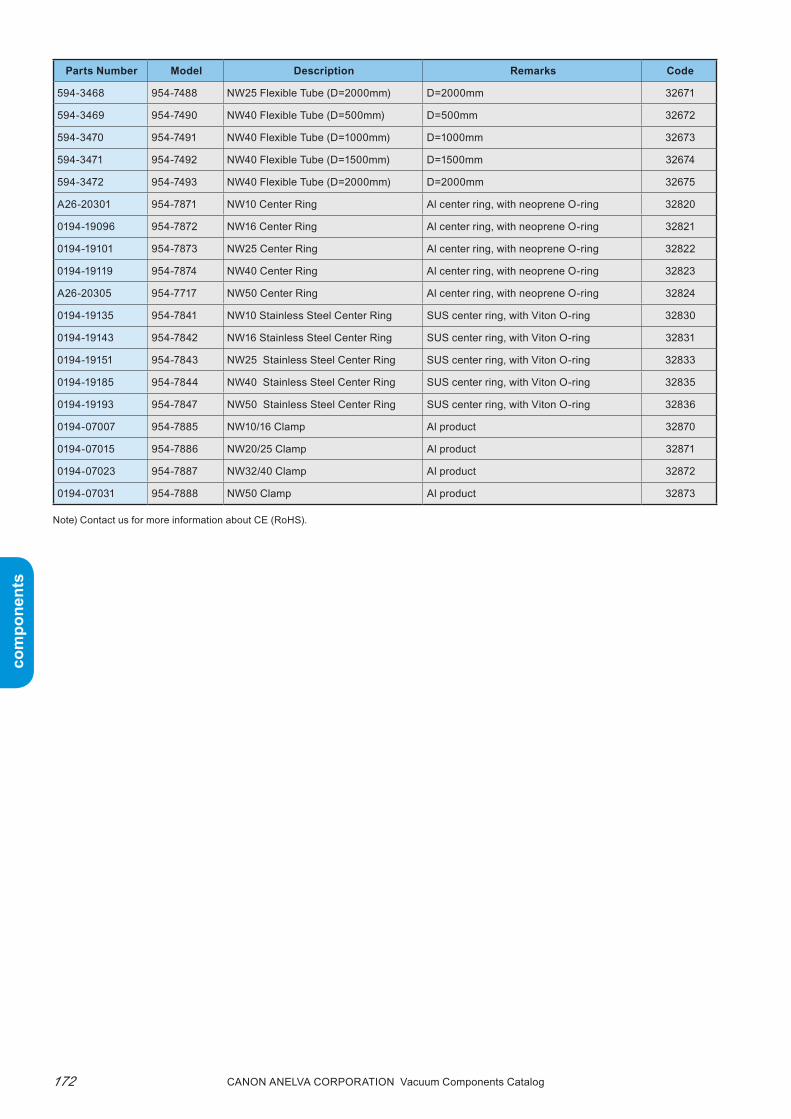
com
pone
nts
com
pone
nts
Canon anELVa Corporation Vacuum Components Catalog172
Parts Number Model Description Remarks Code
594-3468 954-7488 NW25 Flexible Tube (D=2000mm) D=2000mm 32671
594-3469 954-7490 NW40 Flexible Tube (D=500mm) D=500mm 32672
594-3470 954-7491 NW40 Flexible Tube (D=1000mm) D=1000mm 32673
594-3471 954-7492 NW40 Flexible Tube (D=1500mm) D=1500mm 32674
594-3472 954-7493 NW40 Flexible Tube (D=2000mm) D=2000mm 32675
A26-20301 954-7871 NW10 Center Ring Al center ring, with neoprene O-ring 32820
0194-19096 954-7872 NW16 Center Ring Al center ring, with neoprene O-ring 32821
0194-19101 954-7873 NW25 Center Ring Al center ring, with neoprene O-ring 32822
0194-19119 954-7874 NW40 Center Ring Al center ring, with neoprene O-ring 32823
A26-20305 954-7717 NW50 Center Ring Al center ring, with neoprene O-ring 32824
0194-19135 954-7841 NW10 Stainless Steel Center Ring SUS center ring, with Viton O-ring 32830
0194-19143 954-7842 NW16 Stainless Steel Center Ring SUS center ring, with Viton O-ring 32831
0194-19151 954-7843 NW25 Stainless Steel Center Ring SUS center ring, with Viton O-ring 32833
0194-19185 954-7844 NW40 Stainless Steel Center Ring SUS center ring, with Viton O-ring 32835
0194-19193 954-7847 NW50 Stainless Steel Center Ring SUS center ring, with Viton O-ring 32836
0194-07007 954-7885 NW10/16 Clamp Al product 32870
0194-07015 954-7886 NW20/25 Clamp Al product 32871
0194-07023 954-7887 NW32/40 Clamp Al product 32872
0194-07031 954-7888 NW50 Clamp Al product 32873
Note) Contact us for more information about CE (RoHS).

com
pone
nts
com
pone
nts
173Canon anELVa Corporation Vacuum Components Catalog
Memorandum

com
pone
nts
com
pone
nts
Canon anELVa Corporation Vacuum Components Catalog174
■ Features1. With a single-pole double-throw contact, ON and
OFF point control signals can be simultaneously received at the maximum or minimum operating pressure.
2. Additionally, the entire vacuum side is made of SUS-304, and the welded air seal allows connection to high vacuum.
3. Has a long life of over 10,000 times, while keeping the change in operating pressure very small.
4. Can be used up to 0.2Mpa even when the inside of
Vacuum Switches
the vacuum switch is pressurized.5. the 954-7720 vacuum switch is a quick-release type
with a φ15 gauge adapter.6. the 954-7730 vacuum switch can be heated up to
250°C, allowing it to be used in ultra-high vacuum equipment.
■ Applicationsprotection of automated vacuum equipment and as a switch for safety circuits. retrieval of control signals for various vacuum systems.
Type 954-7700 954-7720 954-7730
Operating pressure(At black - yellow lead wire)
OFFAtmospheric pressure minus 2.7±2.7x10³PaONAtmospheric pressure minus 16±2.7x10³Pa
OFFAtmospheric pressure minus 2.7±2.7x10³PaONAtmospheric pressure minus 14±2.7x10³Pa
Operating degree of vacuum
Approx. 10-7Pa Approx. 10-8Pa
Leak 1.33x10⁻¹¹Pa•m3/sec or lessFluid air, gas (excluding corrosive gases affecting SUS-304)Withstand pressure * 0.2MPaAllowable heating tem-perature
40°C 250°C
Operating environment temperature
-10°C to +40°C
Material Vacuum side all SUS-304Life 10,000 times or more
Connection flange φ70ICF
954-7806φ15 adapter954-7832 gauge adapter954-7833 gauge adapter954-7834 gauge adapter
φ70ICF
Weight 510g 220g 580g
* When you add pressure inside the vacuum switch, take measures to prevent it from venting out of the φ15 adapter.
■ SummaryWith a single-pole double-throw contact, these vacu-um switches enable ON and OFF point control sig-nals to be simultaneously received at the maximum or minimum operating pressure, while keeping the change in operating pressure very small.Additionally, the entire vacuum side is made of SUS-304, and the welded air seal allows connection to high vacuum. Thus, these vacuum switches can also be used as protection for automated vacuum equip-ment and as a switch for safety circuits.

com
pone
nts
com
pone
nts
175Canon anELVa Corporation Vacuum Components Catalog
N.O(Red line)
N.C(Yellow line)
COM(Black line)
N.O(Red line)
N.C(Yellow line)
COM(Black line)
N.O(Red line)
N.O(Red line) COM
(Black line)COM
(Black line) N.C(Yellow line)
N.C(Yellow line)
Load
Load
Load
Load
N.O(Red line)
N.C(Yellow line)
N.C(Yellow line)
N.O(Red line)
N.O(Red line)
N.O(Red line)
COM(Black line)
COM(Black line)
Load
Load
COM(Black line)
COM(Black line)
Load
Load
N.C(Yellow line)
N.C(Yellow line)
N.O(Red line)
N.C(Yellow line)
N.C(Yellow line)
N.O(Red line)
N.O(Red line)
N.O(Red line)
COM(Black line)
COM(Black line)
Load
Load
COM(Black line)
COM(Black line)
Load
Load
N.C(Yellow line)
N.C(Yellow line)
12
1212
Length outside equipment 100 ± 5
Black (COM)Red (N.O)Yellow (N.C)
(Crimp terminal inside diameter φ4)
Length outside equipment 100 ± 5
Black (COM)Red (N.O)Yellow (N.C)
(Crimp terminal inside diameter φ4)
φ46±1
φ41±0.5
(φ70)
50±1
69.5
±3
119.
5±3
Length outside equipment 100 ± 5
Black (COM)Red (N.O)Yellow (N.C)
(Crimp terminal inside diameter φ4)
φ72.1±1
φ41±0.5
(18.
8)(1
2.7)
61.5
±2
93±2
φ46±1
φ41±0.5
18.5
±112
.747
±1
78.2
±2
φ70 ICF (φ70) φ70 ICF
φ15±0.1(ID12)
■ Specifications● Electrical ratings
954-7700, 7720 Vacuum switch
The inductive load shall be greater than or equal to power factor 0.5 (AC), and greater than or equal to time constant 7msec (DC).
The lamp load has x10 inrush current.The motor load has x6 inrush current.
954-7730 Vacuum switch
Fig. 1 954-7700 dimensions Fig. 2 954-7720 dimensions Fig. 3 954-7730 dimensions
■ Ordering information
● Contact structure954-7700, 7720, 7730 Vacuum switchAtmospheric pressure minus 5.4x10³Pa or more (At-mospheric pressure state)
954-7700, 7720 Vacuum switchAtmospheric pressure minus 13.3x10³Pa or lower (vacuum state)
954-7730 Vacuum switch Atmospheric pressure minus 11.3x10³Pa or lower (vacuum state)
If AC If DC● Wiring method
Rated volt-age(V)
Non-inductive current (A) Inductive load (A)Resistance
loadLamp load
Inductive load
Motor load
DC125 0.6 0.1 0.6 0.1DC250 0.3 0.05 0.3 0.05AC125 15 3 10 4AC250 15 2 10 3
N.O(Red line)
N.C(Yellow line)
N.C(Yellow line)
N.O(Red line)
N.O(Red line)
N.O(Red line)
COM(Black line)
COM(Black line)
Load
Load
COM(Black line)
COM(Black line)
Load
Load
N.C(Yellow line)
N.C(Yellow line)
■ Usage notesBe sure to read the included "Usage notes" before using.
Rated volt-age(V)
Non-inductive current (A) Inductive load (A)Resistance
loadLamp load
Inductive load
Motor load
DC125 0.4 0.05 0.4 0.05AC125 1 0.45 1 0.75AC250 1 0.3 1 0.3
Parts Number Model Description Remarks Code
753-0387 954-7700 Vacuum Switch With φ70ICF 29200
A23-05138 954-7720 Vacuum Switch For φ15 gauge port 29201
P25-02873 954-7730 Vacuum Switch With φ70ICF Bakable to 250°C 29202
Note) Contact us for more information about CE (RoHS).

com
pone
nts
com
pone
nts
Canon anELVa Corporation Vacuum Components Catalog176
Ancillary MaterialsBolts, Nuts, Washers
Bolts, Nuts, Washers
Note) Bolts and washers baked with molybdenum disulfide are avail-able as a special order.
*1) A set contains 1 bolt and 2 washers .*2) A set contains 1 bolt and 1 washer.*3) Size M4 is a hexagon socket bolt.
Bolts, and washers (Material: SUS304)
TypeBolt
RemarksSize L S
953-9120 M4 *3) 20 14953-0085 M6 32 18953-9107 M6 35 18953-0088 M6 45 18
Each set of 25*1)
1 bag
953-0091 M6 55 18953-9100 M8 40 22953-9101 M8 45 22953-9106 M8 50 22953-9102 M8 55 22953-9103 M8 60 22 Each set of
35*1)
1 bag953-7801 M8 70 35953-7802 M10 70 35
TypeBolt
RemarksSize L S
953-9104 M6 18 18953-9105 M6 22 18953-9110 M8 25 22953-9111 M8 30 22953-9122 M4 * 3) 16 16953-7811 M8 50 35953-7812 M10 50 35
Each set of 25*2)
1 bag
Each set of 35 *2) 1 bag
Bolts, nuts, and washers (Material: SUS304)
Note) Bolt dimensions are based on JIS B1180.

com
pone
nts
com
pone
nts
177Canon anELVa Corporation Vacuum Components Catalog
■ Ordering information
Parts Number Model Description Remarks Code
4-365017 953-9120 M4x20 Bolt · Nut · Washer M4x20 (25 sets), for φ34 ICF, hexagon socket bolt 38700
MOD-41480 953-0085 M6x32 Bolt · Nut · Washer M6x32 (25 sets) 38701
794-0509 953-9107 M6x35 Bolt · Nut · Washer M6x35 (25 sets), for φ70 ICF 38703
MOD-41481 953-0088 M6x45 Bolt · Nut · Washer M6x45 (25 sets) 38704
MOD-41482 953-0091 M6x55 Bolt · Nut · Washer M6x55 (25 sets) 38705
MOD-41483 953-9100 M8x40 Bolt · Nut · Washer M8x40 (25 sets), for tapped φ152 ICF 38706
MOD-41484 953-9101 M8x45 Bolt · Nut · Washer M8x45 (25 sets), for φ114 ICF 38707
4-365020 953-9106 M8x50 Bolt · Nut · Washer M8x50 (25 sets) 38708
MOD-41485 953-9102 M8x55 Bolt · Nut · Washer M8x55 (25 sets), for φ203 ICF 38709
4-365021 953-9103 M8x60 Bolt · Nut · Washer M8x60 (25 sets), for φ253 ICF 38710
A26-06376 953-7801 M8x70 Bolt · Nut · Washer M8x70 (35 sets), for φ305 ICF 38716
P21-04823 953-7802 M10x70 Bolt · Nut · Washer M10x70 (35 sets), for φ356 ICF · φ406 ICF 38717
MOD-41594 953-9104 M6x18 Bolt · Washer M6x18 (25 sets) 38711
MOD-41486 953-9105 M6x22 Bolt · Washer M6x22 (25 sets), for tapped φ70 ICF 38712
MOD-41592 953-9110 M8x25 Bolt · Washer M8x25 (25 sets) 38713
MOD-41593 953-9111 M8x30 Bolt · Washer M8x30 (25 sets) 38714
A26-02723 953-9122 M4x16 Bolt · WasherM4x16 (25 sets), for tapped φ34 ICF, hexagon socket bolt
38715
P25-02830 953-7811 M8x50 Bolt · Washer M10x50 (35 sets), with tapped φ305 ICF 38718
P25-02831 953-7812 M10x50 Bolt · Washer M10x50 (35 sets), for tapped φ356 ICF and φ406 ICF 38719
Note) Contact us for more information about CE (RoHS).

com
pone
nts
com
pone
nts
Canon anELVa Corporation Vacuum Components Catalog178
■ Features1. Ultra-high vacuum range
the all-metal valve can be used in an ultra-high vacuum range of up to 10-8pa or lower.
2. Capturing seal structureFor the valve seal, a highly reliable capturing seal structure similar to the flange, is adopted (see Fig. 1).
3. High heat tolerancethe valve can be baked out up to 400°C or 450°C.
Ultra-High Vacuum Type-L All-metal Valves
951-7148
■ SummaryThese all-metal ultra-high vacuum type-L valves can be used up to 10-8Pa or lower. The valve body is made of austenitic stainless steel and the shaft seals are made of austenitic stainless steel bellows. These valves have an all-welded structure and the parts that are exposed to vacuum are oil-free and clean. Fur-
thermore, the valve sealing has a highly reliable cap-turing seal structure similar to the ICF flange. These valves can be baked out up to 400°C or 450°C, mak-ing them ideal for ultra-high vacuum equipment sub-ject to hard baking.
4. Quick, easy gasket replacementthe valve sealing copper alloy gasket can be re-placed using the included handle or gasket remover.
5. Parallel pipes can be connected (excluding the 951-7148 mini metal valve)
Because the valve a 3-port type valve, pipes can con-nected with the side port side parallel.
6. Simple, easy maintenanceMaintenance such as replacing the gasket or reap-plying the atmosphere side lubricant is simple and easy.
951-7152951-7150
Seal edge
Copper alloy gasket
Fig. 1 Valve sealing structure

com
pone
nts
com
pone
nts
179Canon anELVa Corporation Vacuum Components Catalog
■ Specifications
Type 951-7148
Operating vacuum range Atmospheric to 10-8Pa or lessLeak 6.7x10⁻¹¹Pa•m3/sec or lessConductance when fully opened
4L/sec
Allowable heating tem-perature
400°C
Initial sealing torque Approx. 15.7N•mMaximum sealing torque 23.5N•m
Main component material
Body: SUS-304Bellows: SUS-304Valve sealing gasket: Copper alloyBonnet gasket: SUS-321 silver plated metal
Hollow O-ring
Connection flange φ34ICF flange
Weight 0.7kg
Dimensions See Fig. 2Applicable torque wrench(Option)
460F (Angular drive dimension□9.53mm)(JIS B4650 plate type nominal 450 equivalent)
Attachments
Gasket remover: 1SHandle: x1Nominal 2.5 hexagonal wrench: x1Nominal 4 hexagonal wrench: x1Wire brush: x1Spare washer: Large x1, small x1, 2 totalSpare gasket: x1
* All values are based on a valve with the inside replaced with a vacuum or inert gas such as Ar gas.
■ Dimensions diagram
Fig. 2 951-7148 mini metal valve
38±1
38±1 Fu
lly o
pene
d 12
6 ±
3Fu
lly c
lose
d 11
0 ±
3
φ34 ICF Rotatable flange
φ34 ICF Rotatable flange
(φ19.2)
(φ19
.2)
(φ36)
(□ 9.7)
(φ46)(φ16)

com
pone
nts
com
pone
nts
Canon anELVa Corporation Vacuum Components Catalog180
■ Specifications
Type 951-7150 951-7152
Operating vacuum range Atmospheric to 10-8Pa or less
Leak 6.7x10⁻¹¹Pa•m3/sec or lessConductance when fully opened
30L/sec 100L/sec
Allowable heating tem-perature*
450°C
Initial sealing torque 29.4 to 34.3N•m 78.4 to 127.4N•m
Maximum sealing torque 127.4N•m 225.4N•m
Main component materialBody: SUS-304Bellows: SUS-304Valve sealing gasket: Copper alloy
Connection flange φ70ICF flange φ114ICF flange
Weight 1.6kg 7kg
Dimensions See Fig. 3 See Fig. 4
Applicable torque wrench1300F (Angular drive dimension□12.7mm) 2800F (Angular drive dimension□19.05mm)
(JIS B4650 plate type nominal 1300 equivalent) (JIS B4650 plate type nominal 2800 equivalent)
Attachments
Handle: x1Nominal 2.5 hexagonal wrench: x1Nominal 6 hexagonal wrench: x1Wire brush: x1Spare washer: Large x1, small x1, 2 totalSpare gasket: x1
Handle: x1Nominal 10 hexagonal wrench: x1BS ball point driver: x1Wire brush: x1Spare washer: Large x1, small x1, 2 totalSpare gasket: x1
* All values are based on a valve with the inside replaced with a vacuum or inert gas such as Ar gas.
■ Dimensions diagram
φ70 ICF Rotatable flange
62±1 62±1
62±1
Fully
ope
ned
167±
3Fu
lly c
lose
d 14
2± 3
φ70 ICF Rotatable flangeφ70 ICF Fixed flange
( □ 12.9)
(φ23)
(φ50)
(φ38
)
(φ38
)
(φ38)
Leak groove location
Fig. 3 951-7150 φ38 metal valve
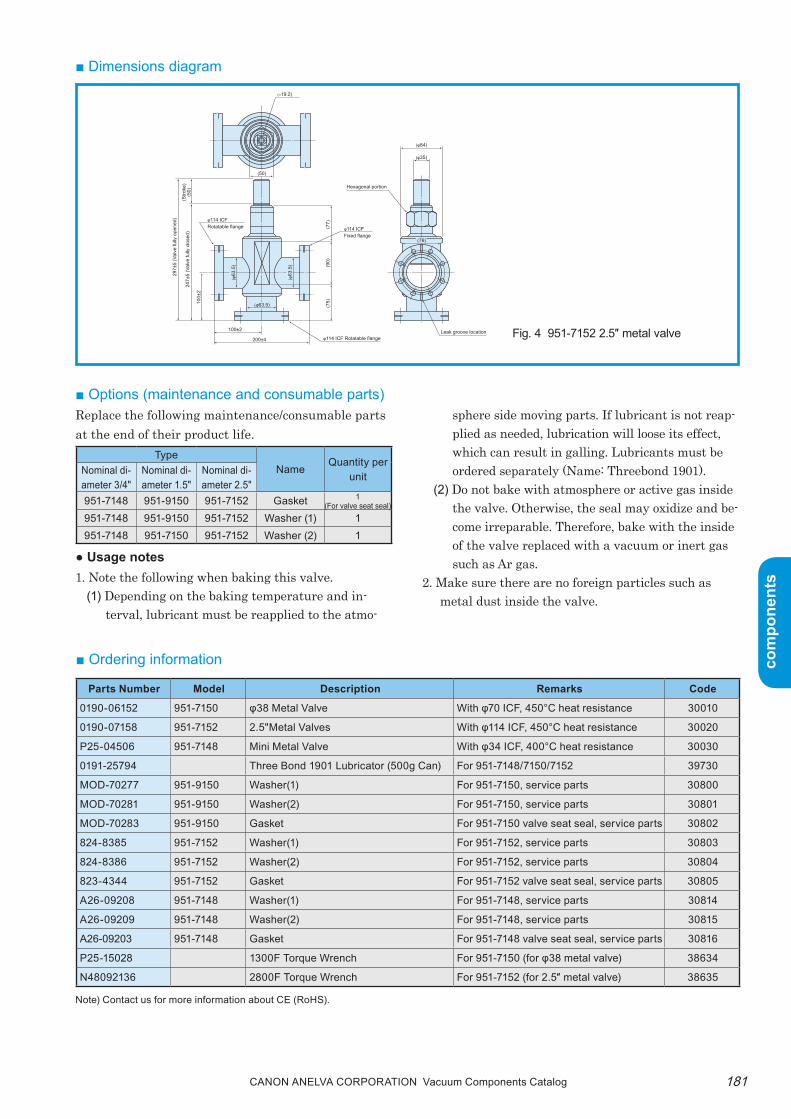
com
pone
nts
com
pone
nts
181Canon anELVa Corporation Vacuum Components Catalog
■ Dimensions diagram
■ Options (maintenance and consumable parts)replace the following maintenance/consumable parts at the end of their product life.
● Usage notes1. Note the following when baking this valve.
(1) Depending on the baking temperature and in-terval, lubricant must be reapplied to the atmo-
Fig. 4 951-7152 2.5″ metal valve
sphere side moving parts. If lubricant is not reap-plied as needed, lubrication will loose its effect, which can result in galling. Lubricants must be ordered separately (Name: threebond 1901).
(2) Do not bake with atmosphere or active gas inside the valve. Otherwise, the seal may oxidize and be-come irreparable. therefore, bake with the inside of the valve replaced with a vacuum or inert gas such as Ar gas.
2. Make sure there are no foreign particles such as metal dust inside the valve.
■ Ordering information
TypeName
Quantity per unitNominal di-
ameter 3/4"Nominal di-ameter 1.5"
Nominal di-ameter 2.5"
951-7148 951-9150 951-7152 Gasket 1(For valve seat seal)
951-7148 951-9150 951-7152 Washer (1) 1951-7148 951-7150 951-7152 Washer (2) 1
(□19.2)
(50)29
7±5
(Val
ve fu
lly o
pene
d)
247±
5 (V
alve
fully
clo
sed)
(Stro
ke)
(50)
(75)
(90)
(77)
100±
2
φ114 ICFRotatable flange φ114 ICF
Fixed flange
φ114 ICF Rotatable flangeLeak groove location100±2
200±4
Hexagonal portion
(φ35)
(φ84)
(φ63
.5)
(φ63
.5)
(φ63.5)
(76)
Parts Number Model Description Remarks Code
0190-06152 951-7150 φ38 Metal Valve With φ70 ICF, 450°C heat resistance 30010
0190-07158 951-7152 2.5"Metal Valves With φ114 ICF, 450°C heat resistance 30020
P25-04506 951-7148 Mini Metal Valve With φ34 ICF, 400°C heat resistance 30030
0191-25794 Three Bond 1901 Lubricator (500g Can) For 951-7148/7150/7152 39730
MOD-70277 951-9150 Washer(1) For 951-7150, service parts 30800
MOD-70281 951-9150 Washer(2) For 951-7150, service parts 30801
MOD-70283 951-9150 Gasket For 951-7150 valve seat seal, service parts 30802
824-8385 951-7152 Washer(1) For 951-7152, service parts 30803
824-8386 951-7152 Washer(2) For 951-7152, service parts 30804
823-4344 951-7152 Gasket For 951-7152 valve seat seal, service parts 30805
A26-09208 951-7148 Washer(1) For 951-7148, service parts 30814
A26-09209 951-7148 Washer(2) For 951-7148, service parts 30815
A26-09203 951-7148 Gasket For 951-7148 valve seat seal, service parts 30816
P25-15028 1300F Torque Wrench For 951-7150 (for φ38 metal valve) 38634
N48092136 2800F Torque Wrench For 951-7152 (for 2.5″ metal valve) 38635
Note) Contact us for more information about CE (RoHS).

com
pone
nts
com
pone
nts
Canon anELVa Corporation Vacuum Components Catalog182
Ultra-High Vacuum Type-L Polyimide Valves
■ SummaryThese type-L valves can be used at an ultra-high vacuum range of up to 10-8Pa. The valve body is made of austenitic stainless steel and the shaft seals are made of austenitic stainless steel bellows. The vacuum seal is made of polyimide resin, which has high heat tolerance and low gas emission. These valves are ideal for ultra high-vacuum equipment with a bake-out temperature of 150°C or more.
951-7145
■ Features1. High heat tolerance
Whether opened or closed, the polyimide seal can endure repeated baking from room temperature to a maximum of 300°C.
2. Seal material with low gas emissionSince the gas emission of polyimide resin is lower
than fluoro rubber (Viton), it can easily achieve ultra-high vacuum of about 10-8pa. (See Fig. 1, 2)
3. Low tightening torquepolyimide seals do not require as much tightening torque as metal seals.
951-7120
810
64
2
8642×1
0P
RE
SS
UR
E (P
a)−1
0×1
0−9
×10
−8×1
0−7
×10
−6×1
0−5
8642
8642
8642
8642
8642
0 100 200 300 100 200 300 400 500 6000
−11
810
64
2
−10
810
64
2
−9
810
64
2
−8
10−12
OU
TGA
SS
ING
RAT
E (P
a m
/sec
-cm
)3
2
TEMPERATURE (°C) TIME (Minutes)
VITON (Unbaked)VITON (Baked)POLYIMIDE (Unbaked)POLYIMIDE (Baked)EMPTYCHAMBERCOPPER GASKETS (Baked)
Bakeout Off
POLYIMIDE
VITON
Fig. 1 Gas emissions Fig. 2 Seal material comparison (ultimate pressure)

com
pone
nts
com
pone
nts
183Canon anELVa Corporation Vacuum Components Catalog
38±1 62±1
105±
2(B
oth
fully
ope
ned
and
fully
clo
sed)
(112
.5)
(24)
(30)
38±1
62±1
Fully
ope
ned
165±
4Fu
lly c
lose
d 14
0±4
φ70 ICF Fixed flange
Leak groove location
φ70 ICF Rotatable flangeφ34 ICF Rotatable flange
φ34 ICFFixed flange
(φ51)
(φ38)
(φ28)
(φ12.8)
(φ51)
(φ64)
(φ12
.8)
(φ38
)■ Dimensions diagram
951-7145 mini polyimide valve
■ Specifications
*1. All values are based on a valve with the inside replaced with a vacuum or inert gas such as Ar gas.*2. 260°C if heated continuously.*3. Gas permeation of polyimide resin is not within specifications.*4. Please consult with us about upgrading the bonnet seal to a metal seal (SUS321 silver plated O-ring).*5. The tightening torque is a reference value only because baking increases the friction coefficient of the
driving screws and changes the balance between the tightening torque and tightening seal force.
Type 951-7145 951-7120Operating vacuum range Atmospheric to approx. 10-8PaAllowable heating tempera-ture*1,2 300°C 300°C
Seal material (gasket) Polyimide resin Polyimide resin*4
Recommended sealing force (sample tightening torque*5)
1225 to 1921N (2 to 3.4N•m) 3920 to 4900N (4.9 to 5.9N•m)
Maximum sealing force (sample tightening torque*5)
2626N (5.9N•m) 7840N (14.7N•m)
Operation ManualIf baked several timesuse adjustable pin face wrench
Conductance 1L/sec 30L/secLeak*3 6.7x10⁻¹¹Pa•m3/sec or less 6.7x10⁻¹¹Pa•m3/sec or lessDimensions Fig. 3 Fig. 3
Material usedMain body: SUS-304Bellows: SUS-304LHandle: AL alloy (black alumite)
Main body: SUS-304Bellows: SUS-304LHandle: AL alloy (black alumite)
Connection flange φ34ICF flange φ70ICF flangeWeight 0.41kg 1.6kgAttachments - Adjustable pin face wrench, hexagonal wrench
( )
951-7120 φ38 polyimide valve
Fig. 3
Manual
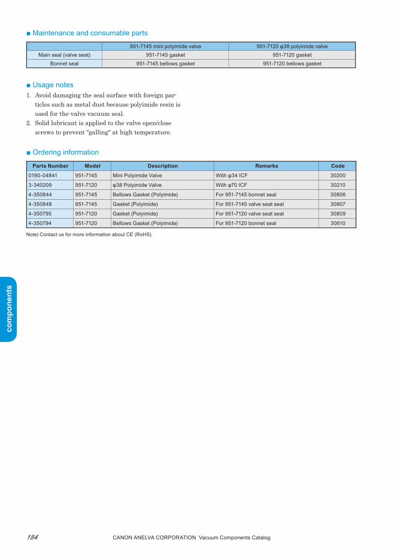
com
pone
nts
com
pone
nts
Canon anELVa Corporation Vacuum Components Catalog184
■ Maintenance and consumable parts
■ Usage notes1. Avoid damaging the seal surface with foreign par-
ticles such as metal dust because polyimide resin is used for the valve vacuum seal.
2. Solid lubricant is applied to the valve open/close screws to prevent "galling" at high temperature.
■ Ordering information
951-7145 mini polyimide valve 951-7120 φ38 polyimide valveMain seal (valve seat) 951-7145 gasket 951-7120 gasket
Bonnet seal 951-7145 bellows gasket 951-7120 bellows gasket
Parts Number Model Description Remarks Code
0190-04841 951-7145 Mini Polyimide Valve With φ34 ICF 30200
3-340209 951-7120 φ38 Polyimide Valve With φ70 ICF 30210
4-350844 951-7145 Bellows Gasket (Polyimide) For 951-7145 bonnet seal 30806
4-350848 951-7145 Gasket (Polyimide) For 951-7145 valve seat seal 30807
4-350795 951-7120 Gasket (Polyimide) For 951-7120 valve seat seal 30809
4-350794 951-7120 Bellows Gasket (Polyimide) For 951-7120 bonnet seal 30810
Note) Contact us for more information about CE (RoHS).

com
pone
nts
com
pone
nts
185Canon anELVa Corporation Vacuum Components Catalog
Memorandum

com
pone
nts
com
pone
nts
Canon anELVa Corporation Vacuum Components Catalog186
■ Features1. High vacuum range supported
A high vacuum range up to approximately 10-4pa is supported. (Fluorine grease is used only on the shaft seal.)
2. Open/Close position sensor switchthe air cylinder used in the compressed air driven valves has a position sensor switch for opening and closing.
■ SummaryThese type-L valves can be used in a high vacuum range of up to 10-4Pa. These valves use a fluoro rubber (Viton) O-ring for the vacuum seal and shaft seal, making them ideal for high vacuum equipment or as a roughing pump valve for ultra-high vacuum equipment.
Display example
V-025rV-□N roughing pump valve
Small size and low price!
"V Series" Roughing Pump ValvesV-025rV
Valve drive system
CCompressed air driven+open/close sensor x2
M Manual
■ Type and name notation

com
pone
nts
com
pone
nts
187Canon anELVa Corporation Vacuum Components Catalog
Drive system Air pressure ManualType V-025RV-CN V-025RV-MN
Pressure range Atmospheric pressure to approx. 10-4Pa
He leak*1 Stationary 6.7x10⁻¹¹Pa�m3/sec or lessOpen/close Up to 10-5Pa�m3/sec
Conductance 7L/secAllowable heating temperature 60°C
Main compo-nent material
Main unit SUS-304Moving part AL alloy (air cylinder) Nylon 66, polypropylene (handle)
Vacuum seal material
Fluoro rubber (Viton) O ring (main seal, shaft seal, bonnet seal)Shaft seal lubricant: Perfluoropolyether grease
Operating air pressure 0.4 to 0.6 MPa ---Air consumption (L /cycle)*2 0.024 ---Air supply inlet M5 ---Open/close sensor See the ■ Sensor switch specifications ---Used fluid Atmosphere or gas (excluding corrosive gas)Dimensions See the ■ Dimensions diagramWeight 0.63kg 0.58kgConnection flange*3 NW25 flange
■ Roughing valve specifications
*1. Gas permeation of the fluoro rubber (Viton) O-ring is not within specifications.*2. Air consumption for one cycle (open-close) at an air pressure of 0.5MPa.*3. The NW25 flange is a clamp flange for vacuum equipment. It uses an elastomer gasket (mainly fluoro rubber). For details, refer to the Quick
Coupling section in our Vacuum Components Piping Parts Catalog.
■ Sensor switch specificationsItem SpecificationsApplications Program controller (sequencer), for relayType, wiring method Contact, 2-wireLoad voltage 12/24V DC 100V ACLoad current 5 to 50mA 7 to 20mAInternal voltage drop 2.4 V or lessLamp LED (lit when ON)Leak current 0mAInternal circuit See figure at rightLead wire length 1m (Oil resistant vinyl cabtire cord 2-core 0.22)Maximum collision 294m/s2 (30G)Insulating resistance 20MΩ or more with 500V DC ohmmeterWithstand voltage 1000V AC for 1 minuteEnvironment tem-perature
-10 to +60°C
Protection structureIEC standard IP67, JIS C0920 (watertight), oil
proof
Brown line (+)(White line)
Blue line (-)(Black line)
▲
Sensor switch internal circuit
Note 1. The sensor switch is sensitive to magnetic fields. Therefore, avoid using the switch near strong external magnetic fields or high-current power lines.
2. Do not connect the sensor switch directly to the power supply. Be sure to connect the load in series and use within the specified load cur-rent.
3. When connecting an inductive load (such as an electromagnetic relay), be sure to provide a contact protection circuit because surge volt-age (inductive surge) will occur when the sensor switch is turned OFF.DC: Normal rectifier diode, AC: CR (0.033 to 0.1μF capacitor, 1 to 3KΩ resistor)
4. When using with DC, connect so that the brown wire (white wire) is the positive side and the blue wire (black wire) is the negative side.
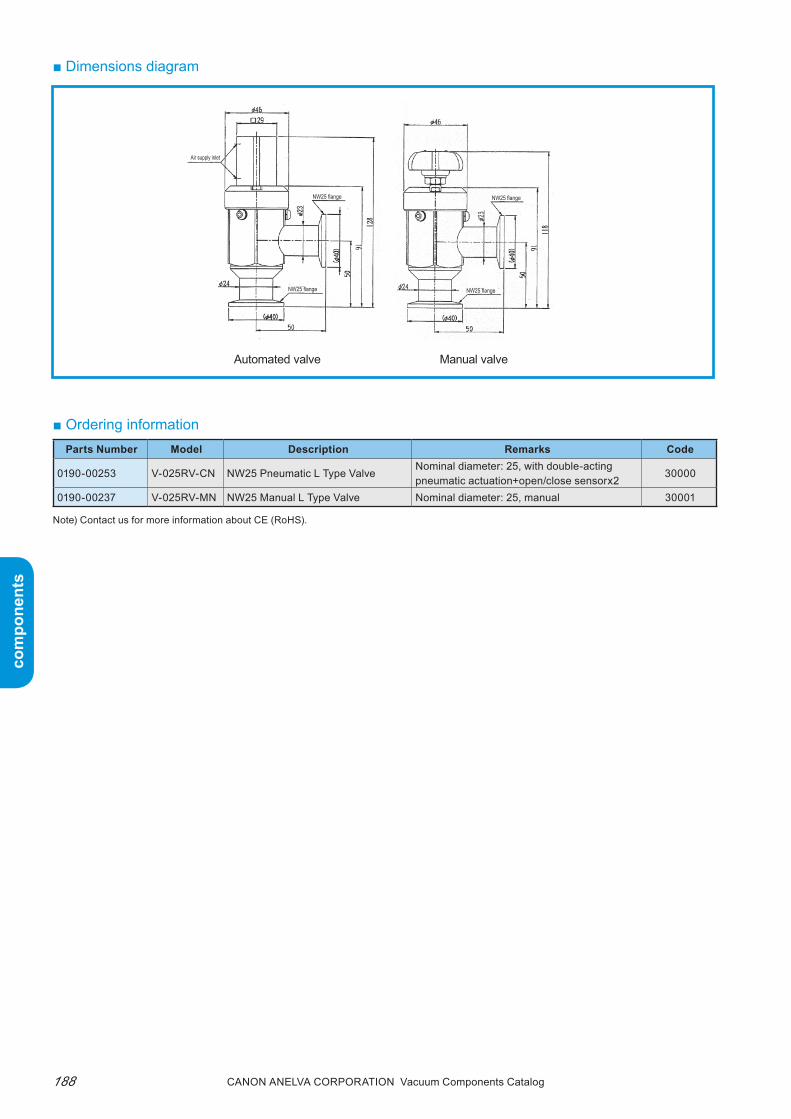
com
pone
nts
com
pone
nts
Canon anELVa Corporation Vacuum Components Catalog188
NW25 flange
Air supply inlet
NW25 flange
NW25 flangeNW25 flange
■ Dimensions diagram
Automated valve
■ Ordering informationParts Number Model Description Remarks Code
0190-00253 V-025RV-CN NW25 Pneumatic L Type ValveNominal diameter: 25, with double-acting pneumatic actuation+open/close sensorx2
30000
0190-00237 V-025RV-MN NW25 Manual L Type Valve Nominal diameter: 25, manual 30001
Manual valve
Note) Contact us for more information about CE (RoHS).

com
pone
nts
com
pone
nts
189Canon anELVa Corporation Vacuum Components Catalog
Memorandum

com
pone
nts
com
pone
nts
Canon anELVa Corporation Vacuum Components Catalog190
■ Features1. Ultra-high vacuum supported
the StD series*2 can be used in an ultra-high vac-uum range up to approximately 10-7pa*3. the MSB series*4 can be used up to approximately 10-8pa*3. In addition, if after purchasing the StD series, only a few parts need to be replaced to upgrade to the ultra-high vacuum compatible MSD series.
2. Long-life valvethe built-in bellows is a molded bellows. It is made of hastelloy alloy considering cost and product life*5.
3. Open/Close position sensor switchEach standard air cylinder used in the valves has a position sensor switch (magnetic sensor) for opening and closing.
4. High heat tolerancethe air cylinder for compressed air powered valves is heat-resistant up to 120°C. therefore, bake-outs are possible with the valve body heating up to 150°C for the StD series and 200°C for the MSB series when the valves are opened. (However, please en-sure that the air cylinder does not exceed 120°C and the sensor switch does not exceed 60°C.)
■ SummaryThese type-L valves have been designed to have a longer lifespan and improved ease of maintenance. Because hastelloy alloy is used, the bellows inside the valve has a longer lifespan (compared with our existing product *1). In addition, the MSB series uses a metal hollow O-ring for the bonnet, which prevents gas permeation of the air, making it ideal for gas analysis vacuum equipment. A large assortment of sizes and connection flanges are available for both manual and compressed air powered valves.
Super long life and improved maintenance!
"V Series" Type-L ValvesV-040LV/V-065LV/V-100LV
5. Variety of connection flangesthe valve body is made of stainless steel so that even a special connection flange can be welded eas-ily to the body.
6. Simple, easy maintenanceNo special tools are needed. Since the bellows can be easily removed from the valve drive, the parts inside the valve can be quickly cleaned and the maintenance parts easily replaced.
*1: Bellows product life comparison with our 951 series type-L valve (about 5 times longer).
*2: Standard specification using a fluoro rubber O-ring for the bon net flange.
*3: the vacuum rate is only a reference value because there is emission of gas such as moisture from inside the valve at the beginning of usage.
Also note that the ultimate pressure varies depending on the pump to be used.
*4: Metal seal specification using a metal hollow O-ring for the bon-net flange seal. (the part that separates the passage is made using a fluoro rubber O-ring.)
*5: the bellows product life varies depending on the condition of use. Check the maintenance timing of the actual equipment.

com
pone
nts
com
pone
nts
191Canon anELVa Corporation Vacuum Components Catalog
SizeSTD series MSB series
40 65 100 40 65 100Type See ■ Type name notationPressure range Atmospheric to approximately 10-7Pa*1 Atmospheric to approximately 10-8Pa*1
He leakValve seat 6.7x10⁻¹¹Pa•m3/sec or less*2
External 6.7x10⁻¹¹Pa•m3/sec or less*2 1.3x10⁻¹¹Pa•m3/sec or less*2
Allowable heating tem-perature
Valve opened
150°C*3 200°C*3
Valve closed 125°C*3
Main compo-nent material
Valve body SUS-304Bellows Hastelloy C-22
Moving partAir cylinder (pneumatic drive valve): Aluminum alloy, fluoro rubber
Handle (manual valve): Aluminum alloy
Vacuum seal material
Fluoro rubber O-ringFluoro rubber O-ring (main seal)
SUS321 silver plated metal tube O-ring(Bonnet seal)
Operating air pressure 0.4 to 0.6MPaAir consumption (L/cycle)*4 0.12 0.47 1.22 0.12 0.47 1.22Air supply inlet Rc1/8 Rc1/4 Rc1/8 Rc1/4Used fluid Atmosphere or gas (excluding corrosive gas)Dimensions See ■ Dimensions diagramWeight See ■ Dimensions table
Connection flange*5
Size 40 65 100ICF flange φ70ICF rotation φ114ICF rotation φ152ICF rotationNW flange NW40 NW63 NW80
Former JIS flange Former JIS 40A Former JIS 65A Former JIS 100A
■ Valve specifications
■ Type and name notation
*1: The vacuum rate is only a reference value, because there is emission of gas such as moisture from inside the valve at the beginning of usage. Also note that the ultimate pressure varies depending on the pump to be used.
*2 Gas permeation of the fluoro rubber (Viton) O-ring is not within specifications.*3. The maximum withstand temperature of the sensor switch is 60°C. Please remove the sensor switch when heating up to 120°C. If heating of the
air cylinder can be kept under 120°C, the valve body can be heated up to 150°C for the STD (with the valve open) and 200°C for the MSB (con-tinuously for four hours with the valve open).
*4. Air consumption for one cycle (open-close) at an air pressure of 0.5MPa. About half the value of NC valves.*5. For details of the connection flanges, see ■ Dimensions diagram, ■ Dimensions table, and ■ Connection flange.
Display example V-040LV-SCNValve size: 40BonnetGasket: STD series (fluorine rubber)Valve drive system: Double-acting com-
pressed air drivenConnection flange: NW40 flangeOpen/close sensor: two included
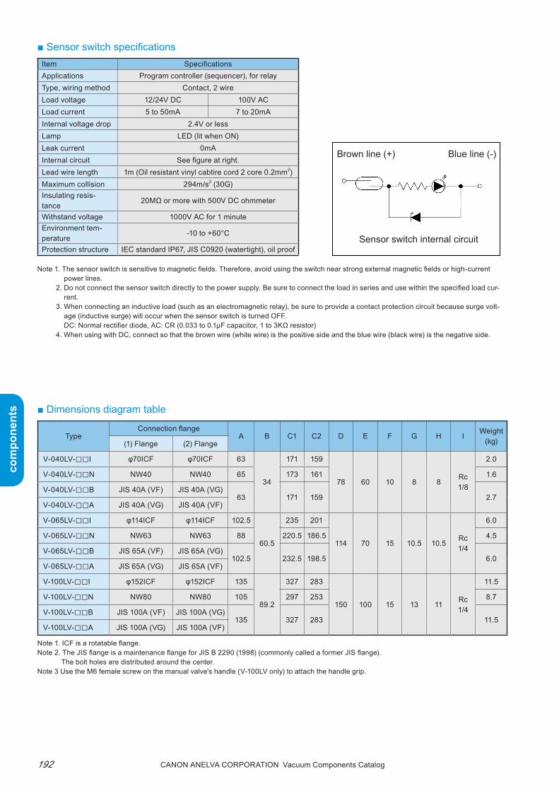
com
pone
nts
com
pone
nts
Canon anELVa Corporation Vacuum Components Catalog192
TypeConnection flange
A B C1 C2 D E F G H IWeight
(kg)(1) Flange (2) Flange
V-040LV-□□I φ70ICF φ70ICF 63
34
171 159
78 60 10 8 8Rc1/8
2.0
V-040LV-□□N NW40 NW40 65 173 161 1.6
V-040LV-□□B JIS 40A (VF) JIS 40A (VG)63 171 159 2.7
V-040LV-□□A JIS 40A (VG) JIS 40A (VF)
V-065LV-□□I φ114ICF φ114ICF 102.5
60.5
235 201
114 70 15 10.5 10.5Rc1/4
6.0
V-065LV-□□N NW63 NW63 88 220.5 186.5 4.5
V-065LV-□□B JIS 65A (VF) JIS 65A (VG)102.5 232.5 198.5 6.0
V-065LV-□□A JIS 65A (VG) JIS 65A (VF)
V-100LV-□□I φ152ICF φ152ICF 135
89.2
327 283
150 100 15 13 11Rc1/4
11.5
V-100LV-□□N NW80 NW80 105 297 253 8.7
V-100LV-□□B JIS 100A (VF) JIS 100A (VG)135 327 283 11.5
V-100LV-□□A JIS 100A (VG) JIS 100A (VF)
■ Sensor switch specificationsItem SpecificationsApplications Program controller (sequencer), for relayType, wiring method Contact, 2 wireLoad voltage 12/24V DC 100V ACLoad current 5 to 50mA 7 to 20mAInternal voltage drop 2.4V or lessLamp LED (lit when ON)Leak current 0mAInternal circuit See figure at right.Lead wire length 1m (Oil resistant vinyl cabtire cord 2 core 0.2mm2)Maximum collision 294m/s2 (30G)Insulating resis-tance
20MΩ or more with 500V DC ohmmeter
Withstand voltage 1000V AC for 1 minuteEnvironment tem-perature
-10 to +60°C
Protection structure IEC standard IP67, JIS C0920 (watertight), oil proof
Note 1. The sensor switch is sensitive to magnetic fields. Therefore, avoid using the switch near strong external magnetic fields or high-current power lines.
2. Do not connect the sensor switch directly to the power supply. Be sure to connect the load in series and use within the specified load cur-rent.
3. When connecting an inductive load (such as an electromagnetic relay), be sure to provide a contact protection circuit because surge volt-age (inductive surge) will occur when the sensor switch is turned OFF.DC: Normal rectifier diode, AC: CR (0.033 to 0.1μF capacitor, 1 to 3KΩ resistor)
4. When using with DC, connect so that the brown wire (white wire) is the positive side and the blue wire (black wire) is the negative side.
■ Dimensions diagram table
Note 1. ICF is a rotatable flange.Note 2. The JIS flange is a maintenance flange for JIS B 2290 (1998) (commonly called a former JIS flange).
The bolt holes are distributed around the center.Note 3 Use the M6 female screw on the manual valve's handle (V-100LV only) to attach the handle grip.
Brown line (+)
Sensor switch internal circuit
Blue line (-)
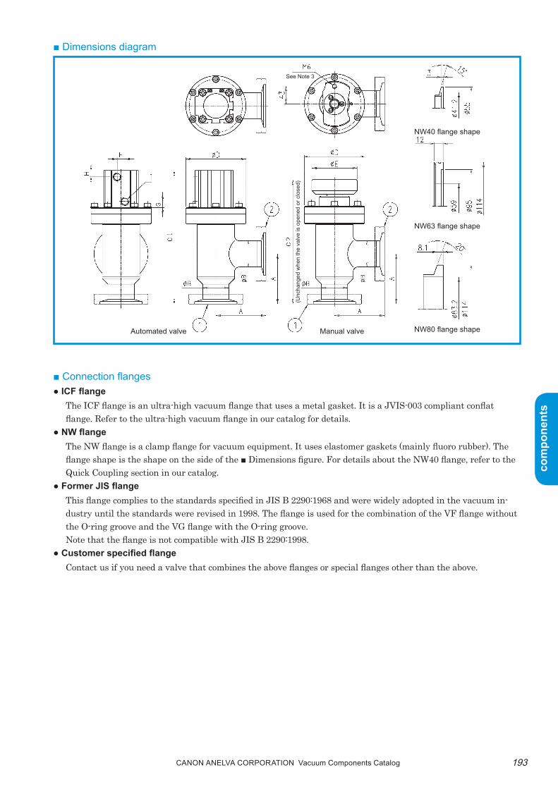
com
pone
nts
com
pone
nts
193Canon anELVa Corporation Vacuum Components Catalog
■ Dimensions diagram
■ Connection flanges● ICF flange
the ICF flange is an ultra-high vacuum flange that uses a metal gasket. It is a JVIS-003 compliant conflat flange. refer to the ultra-high vacuum flange in our catalog for details.
● NW flangethe NW flange is a clamp flange for vacuum equipment. It uses elastomer gaskets (mainly fluoro rubber). the flange shape is the shape on the side of the ■ Dimensions figure. For details about the NW40 flange, refer to the Quick Coupling section in our catalog.
● Former JIS flangethis flange complies to the standards specified in JIS B 2290:1968 and were widely adopted in the vacuum in-dustry until the standards were revised in 1998. the flange is used for the combination of the VF flange without the O-ring groove and the VG flange with the O-ring groove.Note that the flange is not compatible with JIS B 2290:1998.
● Customer specified flangeContact us if you need a valve that combines the above flanges or special flanges other than the above.
See Note 3
NW40 flange shape
NW63 flange shape
NW80 flange shapeAutomated valve Manual valve
(Unc
hang
ed w
hen
the
valv
e is
ope
ned
or c
lose
d)
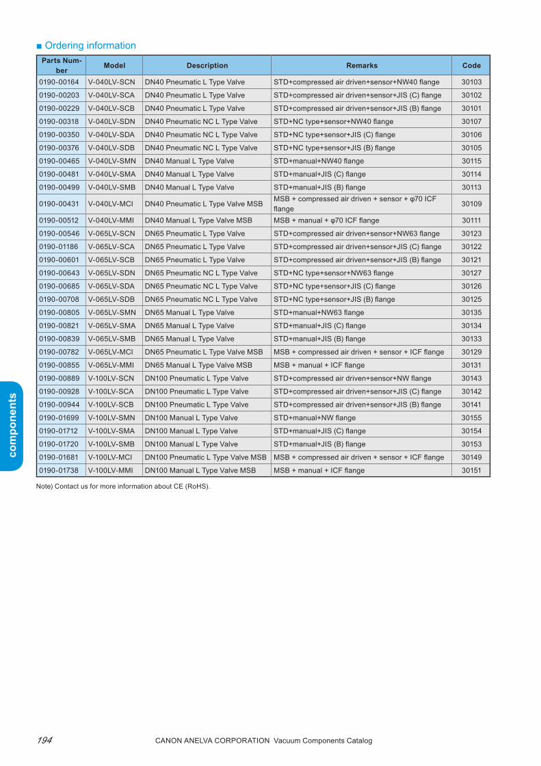
com
pone
nts
com
pone
nts
Canon anELVa Corporation Vacuum Components Catalog194
■ Ordering informationParts Num-
ber Model Description Remarks Code
0190-00164 V-040LV-SCN DN40 Pneumatic L Type Valve STD+compressed air driven+sensor+NW40 flange 30103
0190-00203 V-040LV-SCA DN40 Pneumatic L Type Valve STD+compressed air driven+sensor+JIS (C) flange 30102
0190-00229 V-040LV-SCB DN40 Pneumatic L Type Valve STD+compressed air driven+sensor+JIS (B) flange 30101
0190-00318 V-040LV-SDN DN40 Pneumatic NC L Type Valve STD+NC type+sensor+NW40 flange 30107
0190-00350 V-040LV-SDA DN40 Pneumatic NC L Type Valve STD+NC type+sensor+JIS (C) flange 30106
0190-00376 V-040LV-SDB DN40 Pneumatic NC L Type Valve STD+NC type+sensor+JIS (B) flange 30105
0190-00465 V-040LV-SMN DN40 Manual L Type Valve STD+manual+NW40 flange 30115
0190-00481 V-040LV-SMA DN40 Manual L Type Valve STD+manual+JIS (C) flange 30114
0190-00499 V-040LV-SMB DN40 Manual L Type Valve STD+manual+JIS (B) flange 30113
0190-00431 V-040LV-MCI DN40 Pneumatic L Type Valve MSBMSB + compressed air driven + sensor + φ70 ICF flange
30109
0190-00512 V-040LV-MMI DN40 Manual L Type Valve MSB MSB + manual + φ70 ICF flange 30111
0190-00546 V-065LV-SCN DN65 Pneumatic L Type Valve STD+compressed air driven+sensor+NW63 flange 30123
0190-01186 V-065LV-SCA DN65 Pneumatic L Type Valve STD+compressed air driven+sensor+JIS (C) flange 30122
0190-00601 V-065LV-SCB DN65 Pneumatic L Type Valve STD+compressed air driven+sensor+JIS (B) flange 30121
0190-00643 V-065LV-SDN DN65 Pneumatic NC L Type Valve STD+NC type+sensor+NW63 flange 30127
0190-00685 V-065LV-SDA DN65 Pneumatic NC L Type Valve STD+NC type+sensor+JIS (C) flange 30126
0190-00708 V-065LV-SDB DN65 Pneumatic NC L Type Valve STD+NC type+sensor+JIS (B) flange 30125
0190-00805 V-065LV-SMN DN65 Manual L Type Valve STD+manual+NW63 flange 30135
0190-00821 V-065LV-SMA DN65 Manual L Type Valve STD+manual+JIS (C) flange 30134
0190-00839 V-065LV-SMB DN65 Manual L Type Valve STD+manual+JIS (B) flange 30133
0190-00782 V-065LV-MCI DN65 Pneumatic L Type Valve MSB MSB + compressed air driven + sensor + ICF flange 30129
0190-00855 V-065LV-MMI DN65 Manual L Type Valve MSB MSB + manual + ICF flange 30131
0190-00889 V-100LV-SCN DN100 Pneumatic L Type Valve STD+compressed air driven+sensor+NW flange 30143
0190-00928 V-100LV-SCA DN100 Pneumatic L Type Valve STD+compressed air driven+sensor+JIS (C) flange 30142
0190-00944 V-100LV-SCB DN100 Pneumatic L Type Valve STD+compressed air driven+sensor+JIS (B) flange 30141
0190-01699 V-100LV-SMN DN100 Manual L Type Valve STD+manual+NW flange 30155
0190-01712 V-100LV-SMA DN100 Manual L Type Valve STD+manual+JIS (C) flange 30154
0190-01720 V-100LV-SMB DN100 Manual L Type Valve STD+manual+JIS (B) flange 30153
0190-01681 V-100LV-MCI DN100 Pneumatic L Type Valve MSB MSB + compressed air driven + sensor + ICF flange 30149
0190-01738 V-100LV-MMI DN100 Manual L Type Valve MSB MSB + manual + ICF flange 30151
Note) Contact us for more information about CE (RoHS).

com
pone
nts
com
pone
nts
195Canon anELVa Corporation Vacuum Components Catalog
Memorandum
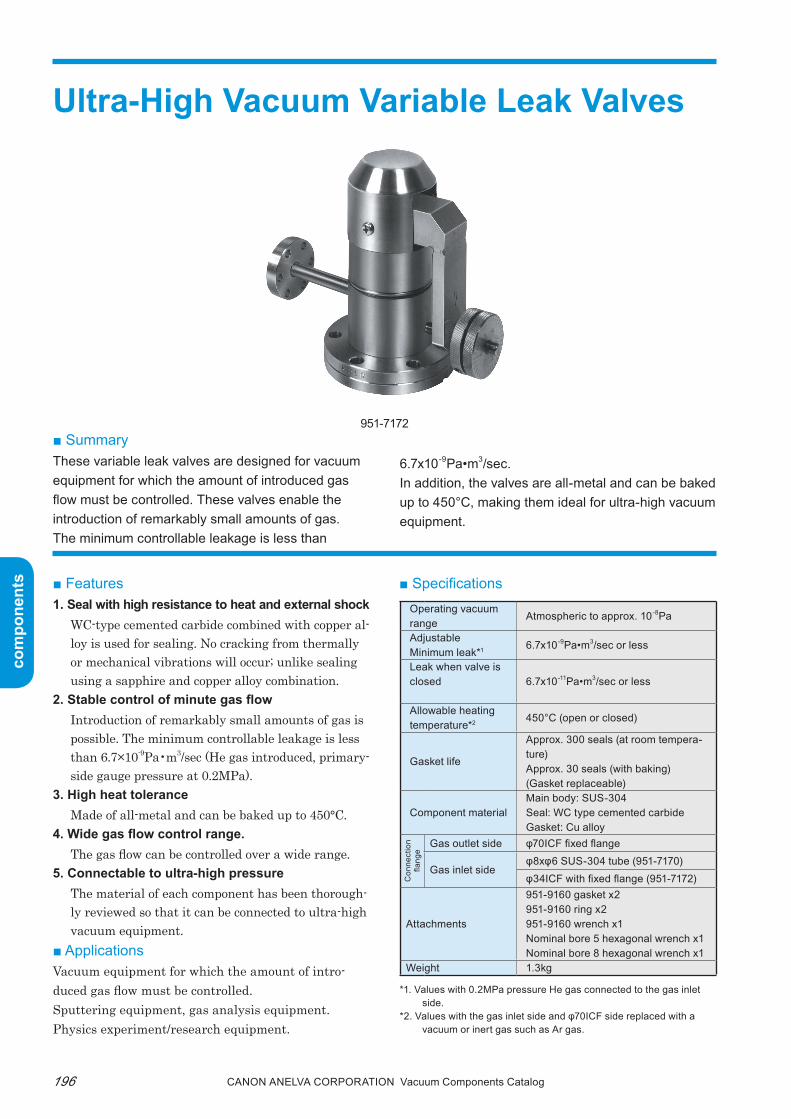
com
pone
nts
com
pone
nts
Canon anELVa Corporation Vacuum Components Catalog196
■ SummaryThese variable leak valves are designed for vacuum equipment for which the amount of introduced gas flow must be controlled. These valves enable the introduction of remarkably small amounts of gas. The minimum controllable leakage is less than
Ultra-High Vacuum Variable Leak Valves
951-7172
■ Features1. Seal with high resistance to heat and external shock
WC-type cemented carbide combined with copper al-loy is used for sealing. No cracking from thermally or mechanical vibrations will occur; unlike sealing using a sapphire and copper alloy combination.
2. Stable control of minute gas flowIntroduction of remarkably small amounts of gas is possible. the minimum controllable leakage is less than 6.7×10⁻⁹pa•m3/sec (He gas introduced, primary-side gauge pressure at 0.2Mpa).
3. High heat toleranceMade of all-metal and can be baked up to 450°C.
4. Wide gas flow control range.the gas flow can be controlled over a wide range.
5. Connectable to ultra-high pressurethe material of each component has been thorough-ly reviewed so that it can be connected to ultra-high vacuum equipment.
■ ApplicationsVacuum equipment for which the amount of intro-duced gas flow must be controlled.Sputtering equipment, gas analysis equipment.physics experiment/research equipment.
6.7x10⁻⁹Pa•m3/sec.In addition, the valves are all-metal and can be baked up to 450°C, making them ideal for ultra-high vacuum equipment.
■ Specifications
*1. Values with 0.2MPa pressure He gas connected to the gas inlet side.
*2. Values with the gas inlet side and φ70ICF side replaced with a vacuum or inert gas such as Ar gas.
Operating vacuum range
Atmospheric to approx. 10-8Pa
AdjustableMinimum leak*1 6.7x10⁻⁹Pa•m3/sec or less
Leak when valve is closed 6.7x10⁻¹¹Pa•m3/sec or less
Allowable heating temperature*2 450°C (open or closed)
Gasket life
Approx. 300 seals (at room tempera-ture)Approx. 30 seals (with baking)(Gasket replaceable)
Component materialMain body: SUS-304Seal: WC type cemented carbideGasket: Cu alloy
Con
nect
ion
flang
e
Gas outlet side φ70ICF fixed flange
Gas inlet sideφ8xφ6 SUS-304 tube (951-7170)φ34ICF with fixed flange (951-7172)
Attachments
951-9160 gasket x2951-9160 ring x2951-9160 wrench x1Nominal bore 5 hexagonal wrench x1Nominal bore 8 hexagonal wrench x1
Weight 1.3kg

com
pone
nts
com
pone
nts
197Canon anELVa Corporation Vacuum Components Catalog
● Dimensions diagram ■ Maintenance and consumable partsreplace the following maintenance/consumable parts at the end of their product life.
■ Usage notes1. Note the following when baking this variable leak
valve.● Depending on the baking temperature and in-
terval, lubricant must be reapplied to the atmo-sphere side moving parts. If lubricant is not reap-plied as needed, lubrication will loose its effect, which can result in galling. Lubricants must be orderd separately (Name: threebond 1901).
● Do not bake with atmosphere or active gas inside the valve (including the gas inlet side). Otherwise, the seal may oxidize and become irreparable.
therefore, bake with the gas inlet side and φ70ICF side replaced with a vacuum or inert gas such as Ar gas.
2. Make sure there are no foreign particles such as metal dust inside the valve.
In addition, if there is such risk in the gas intro-duced from the primary side, a filter should be placed in the piping.
3. Be careful of the thermal effects of the valve. thermal effects of the valve appear significantly
when introducing a small gas flow and the flow rate changes as the temperature changes. therefore, maintain the valve at a constant temperature in order to perform precise control of the gas flow.
4. this variable leak valve cannot be used to introduce corrosive gas.
■ Ordering information
Type Name Quantity per unit951-9160 Gasket 1951-9160 Ring 1951-9160 Spring washer 5
Type951-7170: With φ8 SUS tube on inlet side951-7172: with φ34 ICF flange on inlet side
51 ± 3(951-7172)
Leak groove location
φ34 ICF Fixed flangeφ70 ICF Fixed flange
33 ±
3
25 ±
5
112
± 5
(φ8)
(12.
7)
(7.5)
50 ± 2(951-7170)
(φ34
)φ44.5 ± 0.5
(φ70)
44 ± 2
Parts Number Model Description Remarks Code
753-0378 951-7170 Variable Leak Valve With φ70ICF, inlet side φ8SUS tube 31000
803-0666 951-7172 Variable Leak Valve With φ70ICF, inlet side φ34ICF tube 31001
MOD-70344 951-9160 Gasket For 951-7170/7172 30824
MOD-70345 951-9160 Ring For 951-7170/7172 30825
MOD-70333 951-9160 Spring Washer For 951-7170/7172 31802
0191-25794 Three Bond 1901 Lubricator (500g Can) For 951-7170/7172 39730
Note) Contact us for more information about CE (RoHS).

com
pone
nts
com
pone
nts
Canon anELVa Corporation Vacuum Components Catalog198
■ 951-7179 Inlet Valvethis leak valve is used for introducing specified gases into vacuum equipment. the shaft seal is made of an austentic stainless steel bellows. the vacuum seal is made of fluoro rubber (Viton).this valve is ideal as a gas introduction valve for leak-ing high vacuum or ultra-high vacuum equipment.● Features1. Ultra-high vacuum range
An ultra-high vacuum range of up to approximately 10-7pa is supported.
2. No atmospheric air mixingthe shaft seal uses a bellows to prevent atmospheric air from being mixed into the gas being introduced.
3. High heat tolerancethe valve can be baked up to 150°C.
4. Simple, easy maintenance
Gas Inlet Valves951-7179 inlet Valve951-7180 inlet Valve951-7177 Leak Valve951-7178 Leak Valve951-7190 Leak Valve951-7192 Leak Valve
● Specifications
*1. Gas permeation of the fluoro rubber (Viton) is not with specifica-tions.
*2. Remove the handles before baking.*3. The main seal and bonnet seal.
Item Specifications
Type 951-7179, 951-7180Operating vacuum range
Atmospheric to approx. 10-7Pa
Leak when valve is closed
6.7x10⁻¹¹Pa•m3/sec or less*1
Orifice diameter φ8.5mmAllowable heating temperature*2
150°C when valve opened, 125°C when valve closed
Main component material
Vacuum seal: Fluoro rubber (Viton)*3
Valve body: SUS304Bellows: SUS304LHandle: Phenol resin
Connection flange φ70ICF, NW25 flangeWeight 0.5kgDimensions See Fig. 1, 2
951-7179
951-7179
Fig. 1
Fig. 2
Fully
ope
ned
86 ±
4Fu
lly c
lose
d 81
± 4
61±2
(φ10
)
25.3
±3
(φ30)
(φ38)
(φ38)
(φ30)
61±2
(φ10
)
30±3
Fully
ope
ned
91 ±
4Fu
lly c
lose
d 86
± 4
951-7180
● Dimensions diagram

com
pone
nts
com
pone
nts
199Canon anELVa Corporation Vacuum Components Catalog
(φ22)
57±2
(φ10
)
32±3
(φ38)
NW25 flange
Fully
ope
ned
91.5
± 4
Fully
clo
sed
84.5
± 4
■ 951-7177 Leak Valve■ 951-7178 Leak Valvethese leak valves are used for introducing specified gases into vacuum equipment. the vacuum seal and shaft seal are made of fluoro rubber (Viton).these valves are ideal as an atmospheric air/speci-fied gas introduction valve for leaking high vacuum or ultra-high vacuum equipment.
● Features1. Ultra-high vacuum range
An ultra-high vacuum range of up to approximately 10-7pa is supported.
2. High heat tolerancethe valve can be baked up to 125°C.
3. Simple, easy maintenance4. Specific gases can be introduced
● Specifications
*1. Gas permeation of the fluoro rubber (Viton) is not within specifica-tions.
*2. Remove the handles before baking.
● Dimensions diagram
951-7177
Fig. 3
Fig. 4
951-7177
57±2(φ
10)
27.3
±3
(φ38)
(φ22)
φ70ICF Fixed flange
Fully
ope
ned
87 ±
4Fu
lly c
lose
d 80
± 4
Item Specifications
Type 951-7177, 951-7178Operating vacuum range
Atmospheric to approx. 10-7Pa
Leak when valve is closed
6.7x10⁻¹¹Pa•m3/sec or less*1
Orifice diameter φ3.5mmAllowable heating temperature
125°C*2
Main component material
Vacuum sealing material: Fluorine rubber (Viton)Shaft sealing material: Fluorine rubber (Viton) O-ringShaft seal lubricant: For high vacuum Silicone greaseValve bodyShaft: SUS304Valve body: Brass (Ni-plated)Handle: Phenol resin
Connection flange φ70ICF, NW25 flangeWeight 0.4kgDimensions See Fig. 3, 4
951-7178

com
pone
nts
com
pone
nts
Canon anELVa Corporation Vacuum Components Catalog200
■ 951-7190 Leak Valve■ 951-7192 Leak Valvethese grip-type leak valves are used for introducing atmospheric air into the vacuum equipment. A fluoro rubber (Viton) O-ring is used for the vacuum seal.these valves are ideal as an atmosphere feed through valve for leaking high vacuum or ultra-high vacuum equipment.
● Features1. Ultra-high vacuum range
An ultra-high vacuum range of up to approximately 10-7pa is supported.
2. High heat tolerancethe valve can be baked up to 125°C.
3. Simple, easy maintenance
● Specifications
* Gas permeation of the fluoro rubber (Viton) O-ring is not within specifications.
951-7190
● Dimensions diagram
951-7192
951-7190
Fig. 5
Fig. 6
■ Ordering information
63 ±
3 (F
ully
clo
sed)
(φ38)
(φ25.4)
φ70 ICF Fixed flange
951-7190
67.7
± 3
(Ful
ly c
lose
d)
(φ38)
(φ25.4)
NW25 flange
951-7192
Item Specifications
Type 951-7190, 951-7192Operating vacuum range
Atmospheric to approx. 10-7Pa
Leak when valve is closed
6.7x10⁻¹¹Pa•m3/sec or less
Orifice diameter φ10mmAllowable heating temperature
125°C
Main component material
Vacuum seal material: Fluoro rubber (Viton) O-ringValve body: SUS304Valve element: SS34 (Ni-plated)
Connection flange φ70ICF, NW25 flangeWeight 0.5kgDimensions See Fig. 5, 6
Parts Number Model Description Remarks Code
0190-06097 951-7190 Air Leak Valve φ70 ICF, O-ring seal grip type 31030
0190-09396 951-7177 Leak Valve With φ70 ICF, O-ring shaft seal 31010
0190-09388 951-7179 Inlet Valve With φ70 ICF, bellows shaft seal 31020
Note) Contact us for more information about CE (RoHS).

com
pone
nts
com
pone
nts
201Canon anELVa Corporation Vacuum Components Catalog
■ Ordering information
Parts Number Model Description Remarks Code
A26-05986 951-7192 Air Leak Valve NW25 with flange, O-ring seal grip type 31031
0190-09362 951-7178 Leak Valve NW25 with flange, O-ring shaft seal 31011
0190-09370 951-7180 Inlet Valve NW25 with flange, bellows shaft seal 31021
Note) Contact us for more information about CE (RoHS).

com
pone
nts
com
pone
nts
Canon anELVa Corporation Vacuum Components Catalog202
Isolate ValvesV -025SV
■ SummaryThese valves are connected to the inlet of the oil-sealed rotary vacuum pump. The valves are automated valves that do not use compressed air to move the valve. The valves have two functions: vacuum locking the pumped system when the pump is stopped, and then venting the pump side.These valves prevent backflow of pump oil due to a power outage or improper operation of the automated or manual exhaust systems.
■ Features1. When the oil-sealed rotary pump stops, the pumped
system is automatically cut off (vacuum locked). the pump side is then vented to prevent the pump oil from flowing back into the pumped system.
2. Since the valve uses the vacuum created by the pump as the drive source, it does not require com-pressed air or pipes like conventional automated valves. (the valve does not open when the pump is not operating.)
3. this valve does not require any dedicated control circuit. It can be controlled by interlocking the power supply for the attached solenoid valve with the motor for the pump.
■ Flow of operation(When linked to the oil-rotary vacuum pump in the pumping configuration example)
Serves both as cut valve and vent valve!
Note) Vent valve is built into an isolate valve.
Start pump(Energize the valve
solenoid valve)
Close vent valve
Open isolate valve
Vacuum pump the pumped system
Stop pump(Turn off power to the valve solenoid valve)
Close isolate valve(Vacuum seal the pumped system)
Open vent valve(Air vent only pump side)
■ Pumping system configuration example
Note 1) Wire so that the solenoid valve to the valve is energized only when the pump is running.
2) The above diagram is an example of the connection contain-ing a protection circuit.

com
pone
nts
com
pone
nts
203Canon anELVa Corporation Vacuum Components Catalog
■ Specifications
■ Dimensions diagram
Note) This may be mounted in any direction. However, the connection port to the pumped system and pump is fixed.(It cannot be used with the connection port reversed.)
* 1. Values are for 20°C air in molecular flow range.* 2. Main seal, bonnet seal, and shaft seal* 3. Piston and screw seal
■ Ordering information
Type V-025SV-100 V-025SV-200Pressure range Atmospheric to approx. 10-2Pa
Leak <10-6Pa•m3/sec
Conductance 420 L/min*1
Maintenance interval 10,000 cycles or 1 year
Main component material
Vacuum seal material: Fluoro rubber O-ring*2
Nitryl rubber*3
Body, valve, spring: SUS304Shaft seal lubricant: Silicon grease
Connection flange NW25 flangeFluid used Atmosphere or gas (excluding corrosive gas)Usage environment Ambient temperature 10°C to 40°C
SolenoidRated voltage (V) 100V AC (50/60Hz) 200V AC (50/60Hz)Starting current (A) 0.032/0.027 0.016/0.014Holding current (A) 0.028/0.022 0.014/0.011
Dimensions See ■ Dimensions diagram.Weight 1kg
Parts Number Model Description remark Code
0190-06160 V-025SV-100 Isolate Valve With NW25 flange, 100V AC 31092
0190-06178 V-025SV-200 Isolate Valve With NW25 flange, 200V AC 31093
Note) Contact us for more information about CE (RoHS).
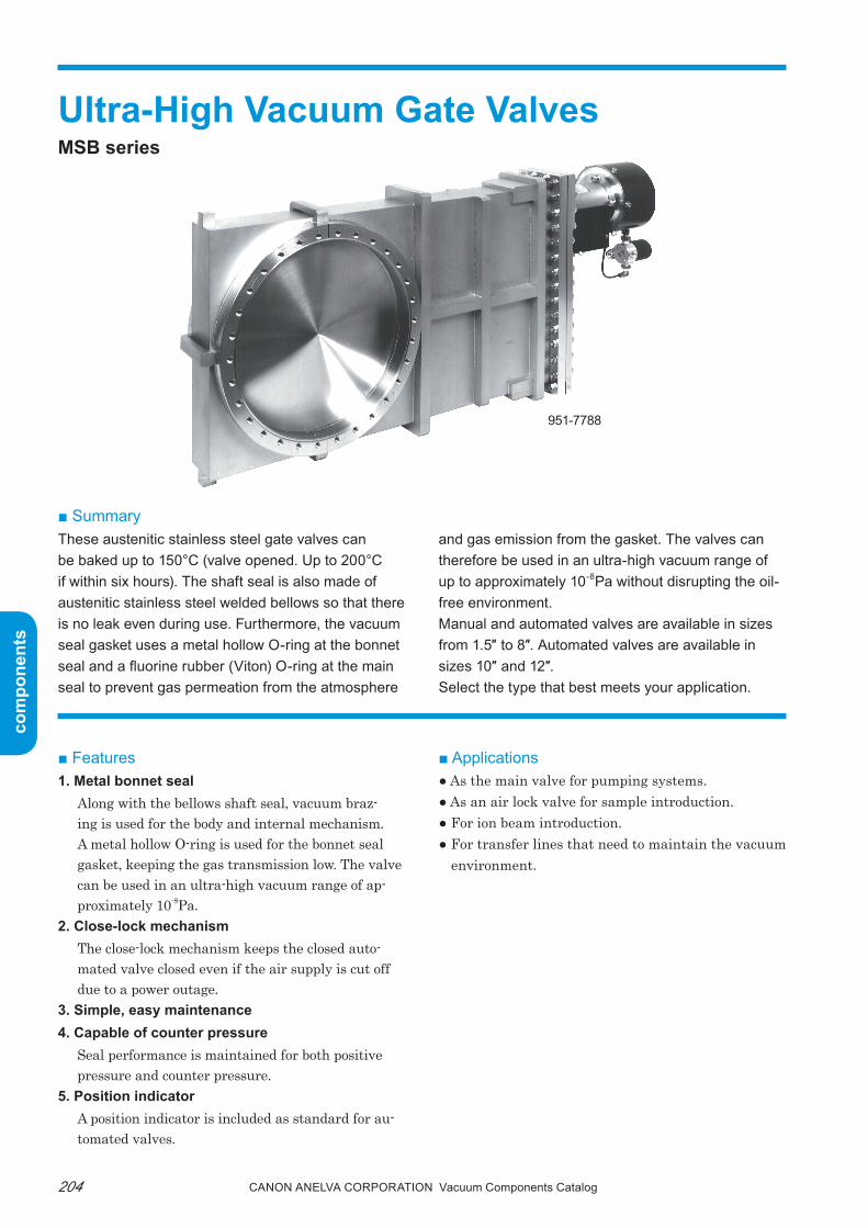
com
pone
nts
com
pone
nts
Canon anELVa Corporation Vacuum Components Catalog204
Ultra-High Vacuum Gate ValvesMSB series
■ SummaryThese austenitic stainless steel gate valves can be baked up to 150°C (valve opened. Up to 200°C if within six hours). The shaft seal is also made of austenitic stainless steel welded bellows so that there is no leak even during use. Furthermore, the vacuum seal gasket uses a metal hollow O-ring at the bonnet seal and a fluorine rubber (Viton) O-ring at the main seal to prevent gas permeation from the atmosphere
and gas emission from the gasket. The valves can therefore be used in an ultra-high vacuum range of up to approximately 10-8Pa without disrupting the oil-free environment.Manual and automated valves are available in sizes from 1.5″ to 8″. Automated valves are available in sizes 10″ and 12″.Select the type that best meets your application.
■ Features1. Metal bonnet seal
Along with the bellows shaft seal, vacuum braz-ing is used for the body and internal mechanism. A metal hollow O-ring is used for the bonnet seal gasket, keeping the gas transmission low. the valve can be used in an ultra-high vacuum range of ap-proximately 10-8pa.
2. Close-lock mechanismthe close-lock mechanism keeps the closed auto-mated valve closed even if the air supply is cut off due to a power outage.
3. Simple, easy maintenance4. Capable of counter pressure
Seal performance is maintained for both positive pressure and counter pressure.
5. Position indicatorA position indicator is included as standard for au-tomated valves.
■ Applications● As the main valve for pumping systems.● As an air lock valve for sample introduction.● For ion beam introduction.● For transfer lines that need to maintain the vacuum
environment.
951-7788

com
pone
nts
com
pone
nts
205Canon anELVa Corporation Vacuum Components Catalog
Manual type Auto typeDrive system Manual drive Automatically driven by air pressureOperating vacuum range Atmospheric to approx. 10-8PaLeak 6.7x10⁻¹¹Pa•m3/sec or less*1
Allowable heating temperature 150°C valve open, 125°C valve closed*2, 3
Allowable maximum differen-tial pressure
Valve at rest: ±1 atm., Valve operating: ±133Pa
Life Bellows: 10,000 cycles, Maintenance time: 5,000 cycles or 1 year
Material used
Seal material: Main seal ..... Fluoro rubber (Viton) O-ring Bonnet seal ..... SUS321 silver plated metal tube O ringMain body: SUS304Bellows: SUS304 welded bellows
Connection flange ICF flangeOperating air pressure range - 1.5" to 4" 0.3 to 0.5MPa, 6" to 12" 0.4 to 0.5MPa
SolenoidType - 4-way solenoid (200V AC 50/60Hz)*4
Connection port - Rc1/4 (former PT1/4)Position indicator*5 Option: For retrieving valve open/close signal Standard: For retrieving valve open/close signal
■ Specifications
(Note) *1. Gas permeation of the fluoro rubber (Viton) O-ring is not within specifications.*2. The actuator and solenoid valve of the automated gate valves are not heat resistant. The allowable ambient temperature is 50°C.*3. Can be heated up to 200°C with the valve open, if the heating time is less than six hours.*4. If you need to use 100V AC 50/60Hz or 24V DC, please specify when ordering.*5. For the relay contact output and contact capacity, refer to the section on the Position indicator.
● Weight
ValveNominal diameter
Manual type Auto type
1.5″ 3kg 3.5kg2.5″ 7.9kg 8.4kg4″ 12.6kg 13kg6″ 19.8kg 20.6kg8″ 30.8kg 31.8kg
10″ - 54kg12″ - 74kg
● Fully opened conductance
ValveNominal diameter
Conductance
1.5″ 65L/sec2.5″ 203L/sec4″ 600L/sec6″ 1,450L/sec8″ 2,730L/sec
10″ 4,350L/sec12″ 6,420L/sec

com
pone
nts
com
pone
nts
Canon anELVa Corporation Vacuum Components Catalog206
● Dimensions diagram
* No hand grip for 1.5". ** The screw location of the ICF flange are arranged at the center relative to the 0 center line.
ModelNominal diameter
Flange dimensions
Outer diameter Inner diameter Thickness Screw
951-7723951-7728
1.5″ φ70 φ38 12.7 6-M6 Depth 8
951-7733951-7738
2.5″ φ114 φ64 17.5 8-M8 Depth 12
951-7743951-7748
4″ φ152 φ102 20.0 16-M8 Depth 15
951-7753951-7758
6″ φ203 φ152 22.0 20-M8 Depth 15
951-7763951-7768
8″ φ253 φ203 25.0 24-M8 Depth 17
951-7778 10″ φ305 φ254 28.0 32-M8 Depth 19
951-7788 12″ φ356 φ305 28.5 30-M10 Depth 19
With ICF flange
Note) The number 3 at the end of the type name indicates a manual valve and 8 indicates an automated valve.
A A F L
B B
I I H
KM
G
C C
N D N D
J
H
G
E
O center line** O center line** Position indicator
Handle Hand grip*
Leak groove location Leak groove location
Air inlet (Rc1/4)
Main seal Main seal Actuator
200V AC50/60Hz4-way solenoid valve
High vacuum side High vacuum side
Low vacuum side Low vacuum side
Bonnet seal flange
ModelNominal diameter
Valve dimension
A B C D E F G H I J K L M N
951-7723951-7728
1.5″ 138 103 51.4 62 105 105 108 18 70 φ51 φ53 48.5 103 -
951-7733951-7738
2.5″ 216 159 71 78 206 156 156 27 114 φ64 φ64 47.5 103 -
951-7743951-7748
4″ 284 208 78 80 225 180.5 190 39 148 φ74 φ74 46.5 103 70
951-7753951-7758
6″ 380 278 90 88 225 184 246 67 204 φ74 φ90 41.5 103 84
951-7763951-7768
8″ 485 358 100 92 258 224.5 296 83 254 φ86 φ100 44.5 103 100
951-7778 10″ 601 443 116 102 - 227 358 113 316 - φ110 44 103 100
951-7788 12″ 700 518 127 114 - 241 414 138 370 - φ137 40.5 103 110
Manual type Auto type

com
pone
nts
com
pone
nts
207Canon anELVa Corporation Vacuum Components Catalog
● Position indicator
AC rating125V AC
Resistance load
Current (A) 5
DC rating8V DC 14V DC 30V DC 115V DC
Resistance load
Resistance load
Resistance load
Resistance load
Current (A) 5 5 5 0.3
(Note) Lead wire color (length 300mm): For open signal/red (COM), white For open signal/blue (COM), green
● Automated gate valve air piping example
● The solenoid valve switches the introduction of compressed air.
● The gate valve is designed to open when the sole-noid valve is energized.Compressed air flows from P (IN) to A (OUT2). The pushed air flows from B (OUT1) to R (EXH) and is pumped out.
● Replace the solenoid connections B (OUT1) and A (OUT2) in order to close the valve by energizing the solenoid valve.
■ Ordering information
Actuator
Open valveClose valve
Gate valve
FilterRegulatorLubricator
Compressed air
Solenoid valve operation switch
200V AC, 50/60Hz
A (OUT 2)
B (OUT 1) P (IN)
R (EXH)Sol
enoi
d
Parts Number Model Description remark Code
P21-02210 951-7723 1.5"Manual Gate Valve (MSB) With φ70 ICF, bellows shaft seal 31212
P21-02212 951-7733 2.5"Manual Gate Valve (MSB) With φ114 ICF, bellows shaft seal 31222
P21-02355 951-7743 4"Manual Gate Valve (MSB) With φ152 ICF, bellows shaft seal 31232
P21-02362 951-7753 6"Manual Gate Valve (MSB) With φ203 ICF, bellows shaft seal 31242
P21-02369 951-7763 8"Manual Gate Valve (MSB) With φ253 ICF, bellows shaft seal 31252
P21-01899 951-7728 1.5" Automatic Gate Valve (MSB) With φ70 ICF, bellows shaft seal 31312
0190-08358 951-7738 2.5" Automatic Gate Valve (MSB) With φ114 ICF, bellows shaft seal 31322
P21-02360 951-7748 4" Automatic Gate Valve (MSB) With φ152 ICF, bellows shaft seal 31332
U11-15642 951-7758 6" Automatic Gate Valve (MSB) With φ203 ICF, bellows shaft seal 31342
P21-02374 951-7768 8" Automatic Gate Valve (MSB) With φ253 ICF, bellows shaft seal 31352
P21-02376 951-7778 10" Automatic Gate Valve (MSB) With φ305 ICF, bellows shaft seal 31362
P21-02563 951-7788 12" Automatic Gate Valve (MSB) With φ356 ICF, bellows shaft seal 31372
Note) Contact us for more information about CE (RoHS).

com
pone
nts
com
pone
nts
Canon anELVa Corporation Vacuum Components Catalog208
Ultra-High Vacuum Gate ValvesSTD series
■ SummaryThese austenitic stainless steel gate valves can be baked up to 150°C (valve opened). The shaft seal is also made of austenitic stainless steel welded bel-lows. The valves can therefore be used in an ultra-high vacuum range of up to approximately 10-7Pa
without disrupting the oil-free environment.Manual and automated valves are available in sizes from 1.5" to 8". Automated valves are available in sizes 10" and 12". Select the type that best meets your application.
■ Features1. Vacuum brazing
Along with the bellows shaft seal, vacuum brazing is used for the body and the internal mechanism, keeping the gas transmission low. the valve can be used in an ultra-high vacuum range of approxi-mately 10-7pa.
2. Close-lock mechanismthe close-lock mechanism keeps the closed auto-mated valve closed even if the air supply is cut off due to a power outage.
3. Simple, easy maintenancethe simple structure enable the bellows to be easily replaced.
4. Capable of counter pressureSeal performance is maintained for both positive pressure and counter pressure.
5. Position indicatorA position indicator is included as standard for au-tomated valves.
■ Applications● As the main valve for pumping systems.● As an air lock valve for sample introduction.● For ion beam introduction● For transfer lines that need to maintain the vacuum
environment.
951-7755Auto Type
951-7750Manual type

com
pone
nts
com
pone
nts
209Canon anELVa Corporation Vacuum Components Catalog
Manual type Auto typeDrive system Manual drive Automatically driven by air pressureOperating vacuum range Atmospheric to approx. 10-7PaLeak 6.7x10⁻¹¹Pa•m3/sec or less*1
Allowable heating tempera-ture
150°C valve open, 125°C valve closed*2
Allowable maximum differen-tial pressure
Valve at rest: ±1 atm., Valve operating: ±133Pa
Life Bellows: 10,000 cycles, Maintenance time: 5,000 cycles or 1 year
Material usedSeal material: Fluoro rubber (Viton) O ring (main seal, bonnet seal, bellows seal)Main body: SUS304Bellows: SUS304 welded bellows
Connection flange ICF flange, JIS flangeOperating air pressure range - 1.5" to 4" 0.3 to 0.5MPa, 6" to 12" 0.4 to 0.5MPa
SolenoidType - 4-way solenoid (200V AC 50/60Hz)*3
Connection port - Rc1/4 (former PT1/4)Position indicator*4 Option: For retrieving valve open/close signal Standard: For retrieving valve open/close signal
■ Specifications
(Note) *1. Gas permeation of the fluoro rubber (Viton) O-ring is not within specifications.*2. The actuator and solenoid valve of the automated gate valves are not heat resistant. The allowable ambient temperature is 50°C.*3. If you need to use 100V AC 50/60Hz or 24V DC, please specify when ordering.*4. For the relay contact output and contact capacity, refer to the section on the Position indicator.
● Weight
● Fully opened conductance
ValveNominal diameter
Manual type Auto typeWith ICF flange With JIS flange With ICF flange With JIS flange
1.5″ 2.3kg 3.0kg 2.8kg 3.5kg2.5″ 6.4kg 6.6kg 6.9kg 7.1kg4″ 10.3kg 10.8kg 10.7kg 11.2kg6″ 17.8kg 18.3kg 18.6kg 19.1kg8″ 28.6kg 31.8kg 29.6kg 32.8kg
10″ - - 50.0kg 52.0kg12″ - - 70.0kg 72.0kg
ValveNominal diameter
With ICF flange With JIS flange
1.5″ 65L/sec 69L/sec2.5″ 203L/sec 225L/sec4″ 600L/sec 649L/sec6″ 1,450L/sec 1,560L/sec8″ 2,730L/sec 2,870L/sec
10″ 4,350L/sec 4,610L/sec12″ 6,420L/sec 6,740L/sec

com
pone
nts
com
pone
nts
Canon anELVa Corporation Vacuum Components Catalog210
● Dimensions diagram (The figure shows the ICF flange).
*1 No hand grip for 1.5". *2 The screw locations of the ICF flange are arranged at the center relative to the 0 center line.
With ICF flange
Note) The number 0 at the end of the type name indicates a manual valve and 5 indicates an automated valve.
A A F L
B B
I I H
KM
G
C C
N D N D
J
H
G
E
O center line*2 O center line*2 Position indicator
Handle Hand grip*1
Leak groove location Leak groove location Air inlet (Rc1/4)
Main seal Main seal Actuator
200V AC50/60Hz4-way solenoid valve
High vacuum side High vacuum side
Low vacuum side Low vacuum side
Bonnet seal flange
ModelNominal diameter
Flange dimensions
Outer diameter Inner diameter Thickness Screw951-7720951-7725
1.5″ φ70 φ38 12.7 6-M6 Depth 8
951-7730951-7735
2.5″ φ114 φ64 17.5 8-M8 Depth 12
951-7740951-7745
4″ φ152 φ102 20.0 16-M8 Depth 15
951-7750951-7755
6″ φ203 φ152 22.0 20-M8 Depth 15
951-7760951-7765
8″ φ253 φ203 25.0 24-M8 Depth 17
951-7775 10″ φ305 φ254 28.0 32-M8 Depth 19
951-7785 12″ φ356 φ305 28.5 30-M10 Depth 19
ModelNominal diameter
Valve dimension
A B C D E F G H I J K L M N951-7720951-7725
1.5″ 138 103 51.4 51 105 105 96 18 70 φ51 φ53 48.5 103 -
951-7730951-7735
2.5″ 216 159 71 64 206 156 144 27 114 φ64 φ64 47.5 103 -
951-7740951-7745
4″ 284 208 78 74 225 180.5 182 39 148 φ74 φ74 46.5 103 70
951-7750951-7755
6″ 380 278 90 82 225 184 240 67 204 φ74 φ90 41.5 103 84
951-7760951-7765
8″ 485 358 100 86 258 224.5 295 83 254 φ86 φ100 44.5 103 100
951-7775 10″ 601 443 116 97 - 227 354 113 316 - φ110 44 103 100
951-7785 12″ 700 518 127 107 - 241 407 138 370 - φ137 40.5 103 110
Manual type Auto type

com
pone
nts
com
pone
nts
211Canon anELVa Corporation Vacuum Components Catalog
Rated voltage(V)
Non-inductive current (A) Inductive load (A)Resistance load Lamp load Inductive load Motor load
Always closed Always opened Always closed Always opened Always closed Always opened Always closed Always openedAC125 5 1.5 0.7 4 2.5 1.3
250 5 1 0.5 4 1.5 0.8DC 8 5 3 4 3
14 5 3 4 330 5 3 4 3
125 0.4 0.05 0.4 0.05250 0.2 0.03 0.2 0.03
● Position indicator
(Note) Lead wire color (length 300mm): For open signal/red (COM), white; For closed signal/blue (COM), green.
● Automated gate valve air piping example
● The solenoid valve switches the introduc-tion of compressed air.
● The gate valve is designed to open when the solenoid valve is energized.Compressed air flows from P (IN) to A (OUT2). The pushed air flows from B (OUT1) to R (EXH) and is pumped out.
● Replace the solenoid connections B (OUT1) and A (OUT2) in order to close the valve by energiz-ing the solenoid valve.
Actuator
Open valveClose valve
Gate valve
FilterRegulatorLubricator
Compressed air
Solenoid valve operation switch
200V AC, 50/60Hz
A (OUT 2)
B (OUT 1) P (IN)
R (EXH)Sole
noid

com
pone
nts
com
pone
nts
Canon anELVa Corporation Vacuum Components Catalog212
■ Ordering information
Parts Number Model Description Remarks Code
Manual type with ICF flange
0190-04906 951-7720 1.5"Manual Gate Valve With φ70 ICF, bellows shaft seal 31210
0190-04922 951-7730 2.5"Manual Gate Valve With φ114 ICF, bellows shaft seal 31220
0190-04948 951-7740 4"Manual Gate Valve With φ152 ICF, bellows shaft seal 31230
P21-02317 951-7750 6"Manual Gate Valve With φ203 ICF, bellows shaft seal 31240
FMT-9118 951-7760 8"Manual Gate Valve With φ253 ICF, bellows shaft seal 31250
Automated type with ICF flange
P21-02053 951-7725 1.5" Automatic Gate Valve With φ70 ICF, bellows shaft seal 31310
VMT-9652 951-7735 2.5"Automatic Gate Valve With φ114 ICF, bellows shaft seal 31320
0190-04956 951-7745 4" Automatic Gate Valve With φ152 ICF, bellows shaft seal 31330
P21-02319 951-7755 6" Automatic Gate Valve With φ203 ICF, bellows shaft seal 31340
FMT-9132 951-7765 8" Automatic Gate Valve With φ253 ICF, bellows shaft seal 31350
FMT-9166 951-7775 10" Automatic Gate Valve With φ305 ICF, bellows shaft seal 31360
P21-02952 951-7785 12" Automatic Gate Valve With φ356 ICF, bellows shaft seal 31370
Note) Contact us for more information about CE (RoHS).
com
pone
nts
com
pone
nts
213Canon anELVa Corporation Vacuum Components Catalog
Memorandum

com
pone
nts
com
pone
nts
Canon anELVa Corporation Vacuum Components Catalog214
Rotary FeedthroughsMagnetic Coupling Type, Bellows Type
■ SummaryThese rotary feedthroughs are used for introducing rotary motion into equipment installed in a vacuum. They can be used in an ultra-high vacuum range of
■ Features1. High transfer torque
A side variety of models are available to best meet your application, from 3kg•cm up to a high torque type of 100kg•cm.
2. Long lifeDry lubricant ball bearings are used for the vacu-um side bearings (excluding the 954-7640 rotary feedthrough). this ensures a long product life, mak-ing the rotary feedthrough ideal for semiconductor manufacturing equipment.
3. Capable of bake-outsVacuum brazing joints that do not require elastomer seals are used, making the rotary feedthrough ideal for ultra-high vacuum systems.
4. Outer rotor stopperAn outer rotor stopper (fixed screw) enables holding at any rotating position.
5. Capable of motor drivetwo types of drive systems are available: Manual and motor.(the 954-7630 is manual drive only.)
■ Magnetic coupling type rotary feedthroughs(954-7603, 7604, 7605, 7606, 7607)
the magnetic coupling type rotary feedthroughs use strong magnet. they have a simple structure and can withstand continuous rotation at high speed. the rotary feedthroughs can be used semi-permanently simply by replacing the bearings. there is no reduc-tion in the transmission torque because there is al-most no demagnetization of the magnet. Leakage flux is comparable to the geomagnetic field. (See the Leak-age flux table.)the motor driven rotary feedthroughs can be used at a higher rotation speed (500rpm) compared to the bel-lows type. In addition, if excessive load is applied to the rotor, the rotor will rotate freely to prevent dam-age to the motor.
954-7620(Bellows)
954-7605(Magnetic coupling)
Magnetic coupling drive system
Magnet
Rotor (magnetic material)
up to 10-8Pa. Two types of rotary feedthroughs are available: Magnetic coupling type rotary feedthrough and bellows type rotary feedthrough.
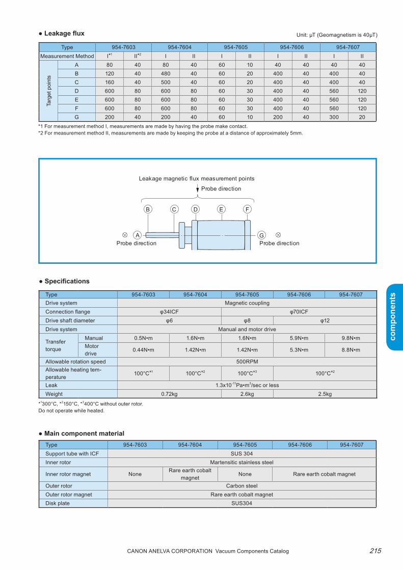
com
pone
nts
com
pone
nts
215Canon anELVa Corporation Vacuum Components Catalog
● Leakage flux Unit: μT (Geomagnetism is 40μT)
Type 954-7603 954-7604 954-7605 954-7606 954-7607Measurement Method I*1 II*2 I II I II I II I II
Targ
et p
oint
s
A 80 40 80 40 60 10 40 40 40 40B 120 40 480 40 60 20 400 40 400 40C 160 40 500 40 60 20 400 40 400 40D 600 80 600 80 60 30 400 40 560 120E 600 80 600 80 60 30 400 40 560 120F 600 80 600 80 60 30 400 40 560 120G 200 40 200 40 60 10 200 40 300 20
*1 For measurement method I, measurements are made by having the probe make contact.*2 For measurement method II, measurements are made by keeping the probe at a distance of approximately 5mm.
● Main component material
*1300°C, *2150°C, *3400°C without outer rotor.Do not operate while heated.
● Specifications
Type 954-7603 954-7604 954-7605 954-7606 954-7607Drive system Magnetic couplingConnection flange φ34ICF φ70ICFDrive shaft diameter φ6 φ8 φ12Drive system Manual and motor drive
Transfer torque
Manual 0.5N•m 1.6N•m 1.6N•m 5.9N•m 9.8N•mMotor drive
0.44N•m 1.42N•m 1.42N•m 5.3N•m 8.8N•m
Allowable rotation speed 500RPMAllowable heating tem-perature
100°C*1 100°C*2 100°C*3 100°C*2
Leak 1.3x10⁻¹¹Pa•m3/sec or lessWeight 0.72kg 2.6kg 2.5kg
Type 954-7603 954-7604 954-7605 954-7606 954-7607Support tube with ICF SUS 304Inner rotor Martensitic stainless steel
Inner rotor magnet NoneRare earth cobalt
magnetNone Rare earth cobalt magnet
Outer rotor Carbon steelOuter rotor magnet Rare earth cobalt magnetDisk plate SUS304
A
B C D E F
G
Leakage magnetic flux measurement points
Probe direction
Probe directionProbe direction

com
pone
nts
com
pone
nts
Canon anELVa Corporation Vacuum Components Catalog216
*Do not operate while heated.
■ Bellows type rotary feedthroughs(954-7620, 954-7630, 954-7640)
these bellows type rotary feedthroughs use a welded bellows to completely separate the vacuum side and air side. Because no O-ring is used at the shaft seal, there is no fear of leakage from the rotating shaft seal during operation. In addition, a scale is provided on the handle so that the rotating angle of the drive shaft inside the vacuum system can be read directly.
Type 954-7620 954-7630 954-7640Drive system BellowsConnection flange φ70ICF φ34ICFDrive shaft diameter φ8 φ6Drive method Manual Motor drive Manual Manual Motor driveTransfer torque 2N•m 1.2N•m 0.3N•m 1N•m 0.6N•mAllowable heating temperature* 200°CAllowable rotation speed - 100rpm - - 200rpmLeak 1.3x10⁻¹¹Pa•m3/sec or less 1.3x10⁻¹¹Pa•m3/sec or less
Material usedMain body SUS-304
Bellows SUS-304
Weight 1.15kg 0.33kg 0.74kg
ApplicationsFor simple rotating inlets such as shutters.
For simple rotating inlets such as shutters.
For motor drive or high-pre-cision, high-torque rotating inlets using mini ICF ports.
■ Dimensions diagram
954-7603, 7604 rotary feedthrough (magnetic coupling)
Bellows
Bellows drive system
● Specifications
Support tube with φ34ICF
Outer rotor (with magnet)
Inner rotor shaft
Outer rotor stopper
Disk plate
(When the outer rotor is fixed)Side A

com
pone
nts
com
pone
nts
217Canon anELVa Corporation Vacuum Components Catalog
954-7606, 7607 rotary feedthrough (magnetic coupling type/high torque)
954-7620 rotary feedthrough (bellows)
50±2 125
70 6 6(20) (10)
93
20
2
50
340
102.4R
Handle fixing stopper
φ70 ICF fixed flange
φ8–0.05–0.1
φ38
φ55.
2φ6
0
φ47
03
2
φ 32
Support tube with φ70 ICF
φ12
φ14
–0.02–0.05
Inner rotor shaft
50±1.5 157±2
φ62
±0.5
207
20±1
4 30
20.5 136.5 10 (When the outer rotor is fixed)
Side A
Disk plate
Outer rotor (with magnet)
Outer rotor stopper
φ36
φ58
Support tube with φ70 ICF
φ32
φ8–0
.05
–0.1
a
a20
3
Cross-section a-a
29 3.5135
155 (9)(When the outer rotor is fixed)
Disk plate
Outer rotor stopper
R2.4 (O-ring groove belt)
57±1
φ57.
2
φ58
φ62
954-7605 rotary feedthrough (magnetic coupling)

com
pone
nts
com
pone
nts
Canon anELVa Corporation Vacuum Components Catalog218
■ Maintenance and consumable partsthe bearings are maintenance parts. they should be replaced when worn.
■ Applications● Magnetic coupling rotary feedthroughs (954-7603 , 7604, 7605, 7606, 7607)
954-7630 mini rotary feedthrough (bellows)
● Bellows type motor driven rotary feedthroughs (954-7620 , 954-7640)
When using a small motor to drive a bellows type ro-tary feedthrough, use an O-ring belt or chain. please contact us if a drive motor that operates at 50rpm or more is to be used.
O-ring belt drive Timing belt drive Direct drive Internal gear drive
● Usage notesrefer to the assembly design to prevent direct radial load or thrust load on the rotary feedthrough shaft.
954-7640 mini rotary feedthrough (bellows/high torque)
φ5.9
φ15
φ34 ICF fixed flange
0–0.1
2
10
15 35
00
24
32Handle fixing stopper
(7)
6150±2 91
φ16
φ32
φ40
60°
3
19.5
2
0.5
φ15
φ19.
2
φ38
φ34 ICF fixed flange
φ6 0−0.1
10
18.8 56.5
50±2 104.5
(154.5)
(7)
Handle fixing stopper
φ22
φ42
200
600
O-ring Timing belt Internal gear
Pulley
PulleyStandard part acceptable Attach boss (φ6) to disk plate
Attach the internal gear in place of the disk plate
Ball joint (or flexible coupling)
M M
MM

com
pone
nts
com
pone
nts
219Canon anELVa Corporation Vacuum Components Catalog
■ Options1. Head shaft (Material: SUS304)
the head shaft is used to connect a magnetic cou-pling type rotary feedthrough with the drive source such as a motor. the following head shafts are avail-able as standard. When ordering, append an H at the end of the type name and specify together with the rotary feedthrough. Ask us for the availability of shafts with shapes other than the following or about rotary feedthroughs with motors.
● Example of motor drive application
● Dimensions diagram
Note) When the head shaft is attached, side A shown in the rotary feedthrough dimensions diagram and side B shown in the head shaft dimensions diagram match.
2. Vacuum side bearingsBall bearings coated with MoS2 solid lubricant are provided as standard (excluding the 954-7640 rotary feedthrough).
Timing belt drive Direct drive
■ Ordering information
Timing belt
Pulley
Ball joint (or flexible coupling)
M
M
Head shaft (2)For 954-7606•7607 rotary feedthrough
Head shaft (1)For 954-7603•7604 rotary feedthrough
Head shaft954-7605 rotary feedthrough
B-side
B-side
B-side
Parts Number Model Description remark Code
763-1401 954-7630 Mni Rotary Motion Feedthrough With φ34 ICF Bellows 36500
803-3549 954-7640 Mni Rotary Motion Feedthrough (High Torque) With φ34 ICF Bellows 36501
0190-04215 954-7620 Rotary Motion Feedthrough With φ70 ICF Bellows 36520
P21-03020 954-7603 Mni Rotary Motion Feedthrough With φ34 ICF Magnetic coupling 36502
A23-01600 954-7604 Mni Rotary Motion Feedthrough With φ34 ICF Magnetic coupling 36503
753-0001 954-7605 Rotary Motion Feedthrough With φ70 ICF Magnetic coupling 36521
P21-03025 954-7606 Rotary Motion Feedthrough With φ70 ICF Magnetic coupling 36522
P21-03028 954-7607 Rotary Motion Feedthrough With φ70 ICF Magnetic coupling 36523
Note) Contact us for more information about CE (RoHS).
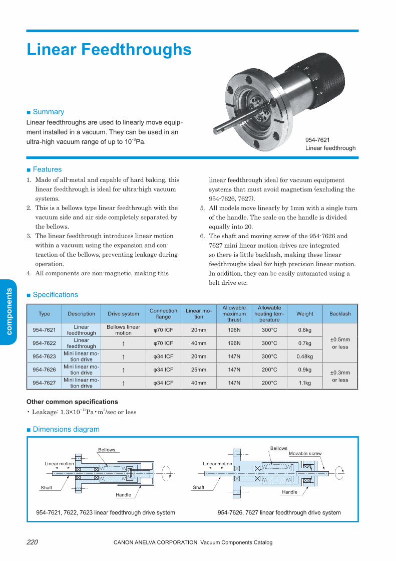
Canon anELVa Corporation Vacuum Components Catalog220
com
pone
nts
com
pone
nts
■ Features1. Made of all-metal and capable of hard baking, this
linear feedthrough is ideal for ultra-high vacuum systems.
2. this is a bellows type linear feedthrough with the vacuum side and air side completely separated by the bellows.
3. the linear feedthrough introduces linear motion within a vacuum using the expansion and con-traction of the bellows, preventing leakage during operation.
4. All components are non-magnetic, making this
linear feedthrough ideal for vacuum equipment systems that must avoid magnetism (excluding the 954-7626, 7627).
5. All models move linearly by 1mm with a single turn of the handle. the scale on the handle is divided equally into 20.
6. the shaft and moving screw of the 954-7626 and 7627 mini linear motion drives are integrated so there is little backlash, making these linear feedthroughs ideal for high precision linear motion. In addition, they can be easily automated using a belt drive etc.
Other common specifications• Leakage: 1.3×10⁻¹¹pa•m3/sec or less
■ Dimensions diagram
■ Specifications
Type Description Drive system Connection flange
Linear mo-tion
Allowable maximum
thrust
Allowable heating tem-
peratureWeight Backlash
954-7621 Linear feedthrough
Bellows linear motion φ70 ICF 20mm 196N 300°C 0.6kg
±0.5mmor less
954-7622 Linear feedthrough ↑ φ70 ICF 40mm 196N 300°C 0.7kg
954-7623 Mini linear mo-tion drive ↑ φ34 ICF 20mm 147N 300°C 0.48kg
954-7626 Mini linear mo-tion drive ↑ φ34 ICF 25mm 147N 200°C 0.9kg ±0.3mm
or less954-7627 Mini linear mo-tion drive ↑ φ34 ICF 40mm 147N 200°C 1.1kg
954-7621, 7622, 7623 linear feedthrough drive system 954-7626, 7627 linear feedthrough drive system
Bellows BellowsMovable screw
Handle HandleShaft Shaft
Linear motion Linear motion
954-7621Linear feedthrough
■ SummaryLinear feedthroughs are used to linearly move equip-ment installed in a vacuum. They can be used in an ultra-high vacuum range of up to 10-8Pa.
Linear Feedthroughs
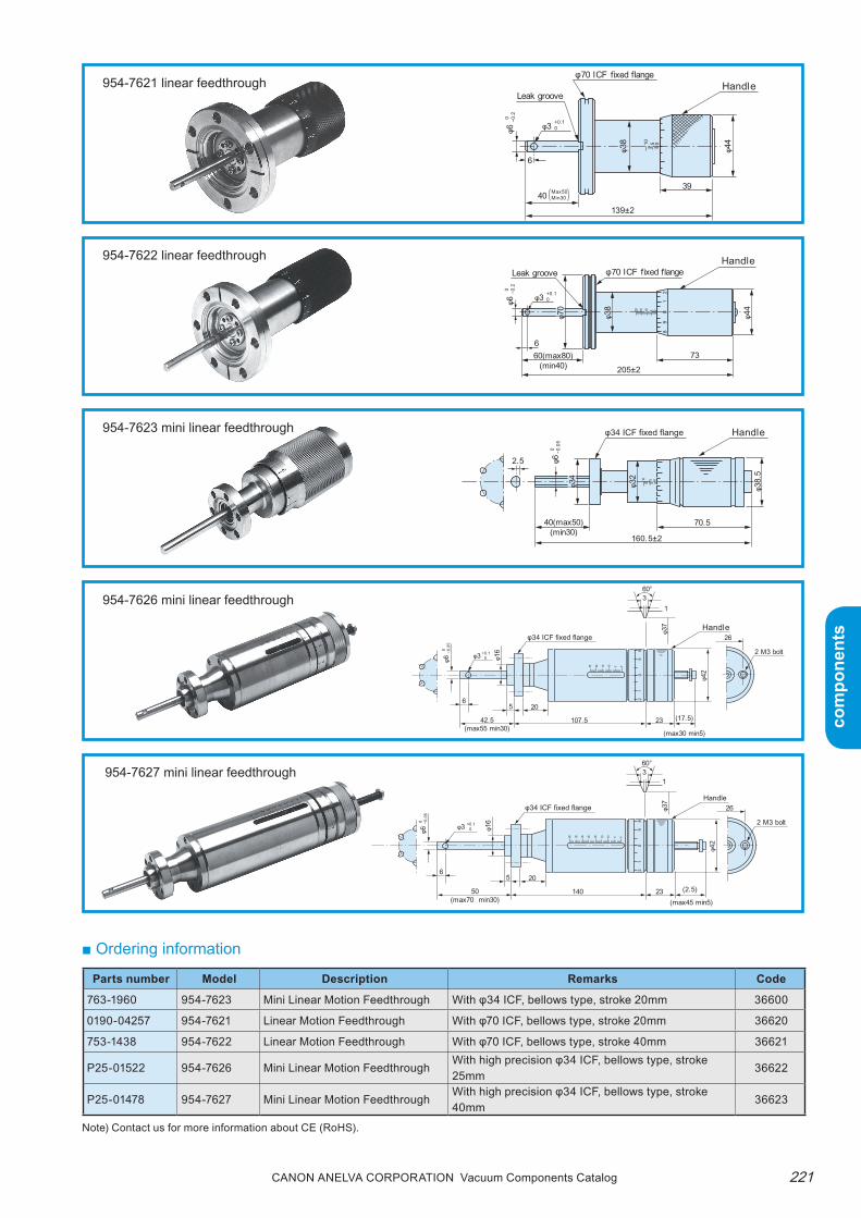
221Canon anELVa Corporation Vacuum Components Catalog
com
pone
nts
com
pone
nts
954-7627 mini linear feedthrough
■ Ordering information
954-7621 linear feedthrough
954-7622 linear feedthrough
954-7623 mini linear feedthrough
954-7626 mini linear feedthrough
φ6 0 −0
.05
φ3 +0.1 0
65 20
140 23
26
2 M3 bolt
31
60°
(2.5)
(max45 min5)50
(max70 min30)
φ34 ICF fixed flange
φ42
φ16
φ37
10 0
89
12
2025303540 15 5
0
Handle
φ6 0 −0
.05
φ3 +0.1 0
65 20
107.5 23
26
2 M3 bolt
31
60°
(17.5)
(max30 min5)
42.5(max55 min30)
φ34 ICF fixed flange
φ42
φ16
φ37
10 0
89
12
2025 15 5
0
Handle
2.5 φ6 0 −0
.05
160.5±2
70.540(max50)(min30)
φ34
φ32
φ38.
5
φ34 ICF fixed flange Handle
0510
φ6 0 −0
.2
φ3 +0.10
205±2
73660(max80)
(min40)
φ70 ICF fixed flange
φ44
Leak grooveHandle
φ38
φ70
21
05101520 09
8
φ70 ICF fixed flange
φ4410 5 0
φ6
Leak grooveHandle
139±2
3940
6
Max50Min30
0 −0.2
φ3 +0.10
φ38
Parts number Model Description Remarks Code
763-1960 954-7623 Mini Linear Motion Feedthrough With φ34 ICF, bellows type, stroke 20mm 36600
0190-04257 954-7621 Linear Motion Feedthrough With φ70 ICF, bellows type, stroke 20mm 36620
753-1438 954-7622 Linear Motion Feedthrough With φ70 ICF, bellows type, stroke 40mm 36621
P25-01522 954-7626 Mini Linear Motion FeedthroughWith high precision φ34 ICF, bellows type, stroke 25mm
36622
P25-01478 954-7627 Mini Linear Motion FeedthroughWith high precision φ34 ICF, bellows type, stroke 40mm
36623
Note) Contact us for more information about CE (RoHS).
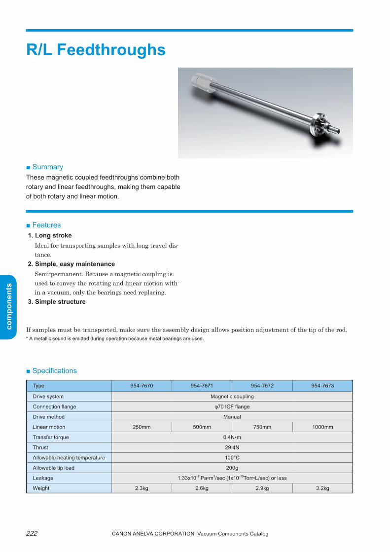
Canon anELVa Corporation Vacuum Components Catalog222
com
pone
nts
com
pone
nts
R/L Feedthroughs
■ SummaryThese magnetic coupled feedthroughs combine both rotary and linear feedthroughs, making them capable of both rotary and linear motion.
■ Features1. Long stroke
Ideal for transporting samples with long travel dis-tance.
2. Simple, easy maintenanceSemi-permanent. Because a magnetic coupling is used to convey the rotating and linear motion with-in a vacuum, only the bearings need replacing.
3. Simple structure
■ Specifications
Type 954-7670 954-7671 954-7672 954-7673
Drive system Magnetic coupling
Connection flange φ70 ICF flange
Drive method Manual
Linear motion 250mm 500mm 750mm 1000mm
Transfer torque 0.4N•m
Thrust 29.4N
Allowable heating temperature 100°C
Allowable tip load 200g
Leakage 1.33x10⁻¹¹Pa•m3/sec (1x10⁻¹⁰Torr•L/sec) or less
Weight 2.3kg 2.6kg 2.9kg 3.2kg
If samples must be transported, make sure the assembly design allows position adjustment of the tip of the rod.* A metallic sound is emitted during operation because metal bearings are used.

223Canon anELVa Corporation Vacuum Components Catalog
com
pone
nts
com
pone
nts
■ Dimensions diagram
■ Ordering information
Supports any linear stroke.Also supports ones with a rotary/linear stopper.
Type Dimension A
954-7670 250
954-7671 500
954-7672 750
954-7673 1000
An M6 screw is attached to the vacuum side tip.
■ External drawings with rotating•linear stopper
φ70 ICF fixed flange Handle M4 screw
152+stroke32~32+stroke
stroke
Note) Contact us for more information about CE (RoHS).
Parts number Model Description Remarks Code
0191-01075 954-7670 R/L Motion Feedthrough Rotary linear motion feedthrough Stroke 250mm 36640
0191-01106 954-7671 R/L Motion Feedthrough Rotary linear motion feedthrough Stroke 500mm 36641
0191-01130 954-7672 R/L Motion Feedthrough Rotary linear motion feedthrough Stroke 750mm 36642
0191-01164 954-7673 R/L Motion Feedthrough Rotary linear motion feedthrough Stroke 1000mm 36643
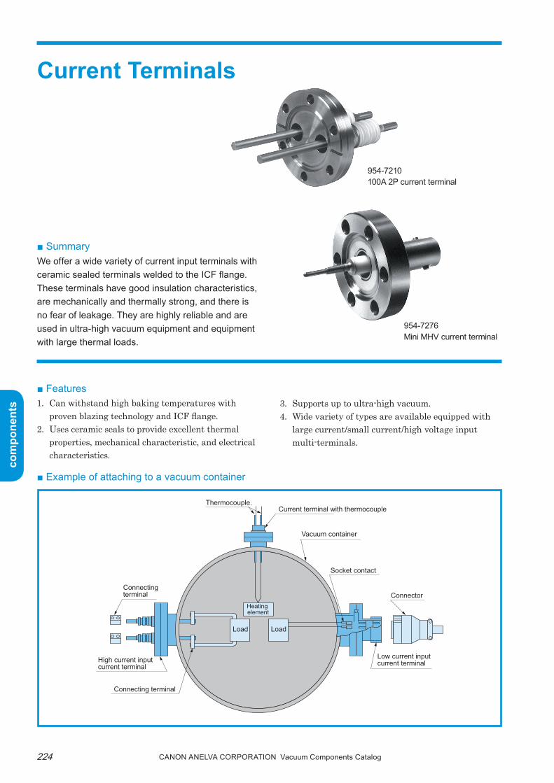
Canon anELVa Corporation Vacuum Components Catalog224
com
pone
nts
com
pone
nts
Current Terminals
■ SummaryWe offer a wide variety of current input terminals with ceramic sealed terminals welded to the ICF flange.These terminals have good insulation characteristics, are mechanically and thermally strong, and there is no fear of leakage. They are highly reliable and are used in ultra-high vacuum equipment and equipment with large thermal loads.
■ Features1. Can withstand high baking temperatures with
proven blazing technology and ICF flange.2. Uses ceramic seals to provide excellent thermal
properties, mechanical characteristic, and electrical characteristics.
954-7276Mini MHV current terminal
3. Supports up to ultra-high vacuum.4. Wide variety of types are available equipped with
large current/small current/high voltage input multi-terminals.
954-7210100A 2P current terminal
■ Example of attaching to a vacuum container
Current terminal with thermocoupleThermocouple.
Connecting terminal
Connecting terminal
Heating element
Load Load
Vacuum container
Socket contact
Connector
Low current input current terminalHigh current input
current terminal

225Canon anELVa Corporation Vacuum Components Catalog
com
pone
nts
com
pone
nts
■ Specifications
• See the separate page for MS type multi-pin current terminals.• Kovar is an alloy with iron, nickel and cobalt as the main ingredients.• The withstand voltage may drop and discharge may occur at 1x10⁻²Pa or more pressure.
Allowable heating temperature 300°CAllowable temperature change 25°C/min or less for all models
Insulating resistance1000MΩ or more for 954-7276MHV current terminal and 954-7238 mini HF current terminal, 5000MΩ or more for others
Leakage 1.3x10⁻¹¹Pa•m3/sec or less
● Other common specifications
Description
Electrodes
WeightApplicable
flange
Compatible connectorExternal diameter x Internal diameter x
LengthMaterial
Quan-tity
Current capacity
With-stand
voltage
Atmosphere side
Vacuum side
954-7209Mini 100A current terminal
φ6x130(Atmosphere side φ6.2)
Oxygen-free copper(Ni-plated)
1 100A 7kV DC 93g
φ34ICF
953-9910100A connect-ing terminal
953-9900•953-9901100A connecting terminal100AL connector
954-7245Mini 5A current terminal
φ1.5x91 Kovar 1 5A 1kV DC 50g954-7326#16 socket contact
954-7238Mini HF current terminal
φ3x7Nonmag-netic Monel
1 5A1.5kV AC (r.m.s)
60gN-P-3-ASHF connector
954-7276Mini MHV current terminal
φ1.57φ2.4xφ5.5x19.5
Kovar 1 3A 5kV DC 50gUG-932/UMHV connector
954-7326 #16Socket contact
954-7227Mini 2W2T current terminal
φ1.2x115x2φ1.2xφ0.9x115x2
NickelWire
2tubes
2
5A/line(wire only)
1kV DC 50g
954-7203100A current terminal
φ6x130(Atmosphere side φ6.2)
Oxygen-free copper(Ni-plated)
1 100A 7kV DC 330g
φ70ICF
953-9910100A connect-ing terminal
953-9900•953-9901•100A connect-ing terminal953-9916100AL connector
954-7210100A2P current terminal
φ6x130(Atmosphere side φ6.2)
Oxygen-free copper(Ni-plated)
2 100A/line 7kV DC 380g953-9910100A connecting terminal
953-9900•953-9901•100A connect-ing terminal953-9916100AL connector
954-72604P current terminal
φ6.1x125 Nickel 4 50A/line 1kV DC 510g954-72614P plug(MS connector)
954-7207400A current terminal
φ15.8x140Oxygen-free copper(Ni-plated)
1 400A 3kV DC 540g
953-9907400A F connect-ing Terminal 953-9917400A L connector
954-72906P current terminal
φ1.6x64.5x4φ1.6x68x2
Kovar 6 5A/line 1kV DC 235g954-72916P plug(MS connector)
954-7326 #16Socket contact
954-72218W current terminal
φ1.2x250 Nickel Wire 8 5A/line 1kV DC 270g
954-72258T current terminal
φ1.2xφ0.9x250 Nickel Tube 8 - 1kV DC 270g
954-72234W4T current terminal
φ1.2x250x4φ1.2xφ0.9x250x4
NickelWire
4tubes
4
5A/line(wire only)
1kV DC 270g
954-725213P current terminal
φ1x24 Kovar 12 5A/line 1.5kV DC 300g954-925413P connector(MS connector)
954-7256 #20Socket contact
Current Terminal Series

Canon anELVa Corporation Vacuum Components Catalog226
com
pone
nts
com
pone
nts
In the figure, the vacuum side is on the left.
● Dimensions diagrams
954-7209Mini 100A current terminal
954-7245Mini 5A current terminal
954-7238Mini HF current terminal
954-7276Mini MHV current terminal
φ34 ICF fixed flange
φ6
φ6.
2
4
(80.2)49.8±2
130
φ19
91
(51)40±1
φ1.
5
φ8
φ34 ICF fixed flange
φ34 ICF fixed flange27.5
7.53.5
8
19.5±2
φ1.
57
φ2.
4
φ9.
6
φ5.
5
φ34 ICF fixed flange
(Flat surface available on the electrode)
φ13
.5
φ34
φ3
5/8″-24-NEF-2Aφ
1.65
8
33.57.52.5
2
M2
7±2
φ15
.9

227Canon anELVa Corporation Vacuum Components Catalog
com
pone
nts
com
pone
nts
In the figure, the vacuum side is on the left.
954-72272W2T current terminal
954-7203100A current terminal
954-7210100A2P current terminal
954-72604P current terminal
φ70 ICF fixed flange
φ1
φ6
φ6.
2
4
57.7±2 (72.3)130
φ19
φ19
φ6.
2
φ6
φ6
φ6.
2
φ19
φ70 ICF fixed flange
4φ1Leak groove
26
52.3±2 (77.7)130
φ34 mini ICF fixed flange
φ1.2×φ0.9Nickel feedthrough tube
φ10
φ1.2 nickel feedthrough wire
CeramicInclusion dish
Brazed part (feedthrough tube only)
115±170±2 (45)
15±1
φ19.
1±1
125±1
Insulation stone(Ceramic)
50
Leak groove
45°(Key location)
2-18UNS-2A
2112.7
3.5
φ70 ICF fixed flange
φ6.1
φ45
φ5.7
1
φ34
φ47.
5
φ3.2Depth 10
14.514.5

Canon anELVa Corporation Vacuum Components Catalog228
com
pone
nts
com
pone
nts
In the figure, the vacuum side is on the left.
954-725213P current terminal
φ70 ICF fixed flange
φ42.
5
12−φ1
Screw 1 3/4-18NS-2A
Leak groove
Key locationAtmosphere side
41.7
7.1
5.6
9.35
φ20
In the figure, the vacuum side is on the left.
954-7207400A current terminal
954-72906P current terminal
954-72218W current terminal
954-72234W4T current terminal
954-72258T current terminal
(Note) The inner diameter of the mounting φ70ICF port is φ38 or more.
φ70 ICF fixed flange
140
69.4±2 (70.6)
φ15.
8
φ15.
8
φ33
2-18UNS-2A
MA
X D
IA
Leak groove
Long pin
Key locationAtmosphere side
φ70 ICF fixed flange
5
φ36.
5
40±1(30)
70±2
26.5±2
φ70 ICF fixed flange
Brazed part (feedthrough tube only)
Leak groove
φ17.
45φ31.
3
250
2026.8(203.2)
φ1.2
xφ0.
9

229Canon anELVa Corporation Vacuum Components Catalog
com
pone
nts
com
pone
nts
954-7326#16 socket contact
■ Options● Vacuum side connector
Type Description Applicable modelCompatible
wire sizeAllowable
currentMaterial
Allowable heating tem-
peratureTool Weight
954-7326#16 socket
Contact
954-7276Mini MHV current terminal954-7245Mini 5A current terminal954-72906P current terminalMS connectorMulti-pin current terminal
AWG16-18 5ABe-Cu(gold plated)Stainless steel
250°CMain unit: M22520/1-01Turret: M22520/1-02
(Made by Daniel)0.8g
954-7256#20 socket
Contact
954-725213P current termi-nal
AWG20-24 5ACopper alloy (gold plated) stainless steel
250°CMain unit: M22520/1-01Turret: M22520/1-04
(Made by Daniel)0.15g
21.44
6.35 8.3
Electrode
Pressure bonded section
φ1.7
3
φ2.5
9
φ2.8
7
φ3.7
In the figure, the terminal connection side is on the right.
954-7256#20 socket contact 13.3
Pressure bonded section
6.7φ2φ1
.2
φ1.8
φ2.3

Canon anELVa Corporation Vacuum Components Catalog230
com
pone
nts
com
pone
nts
N-P-3-ASHF connector
43
φ6.2
3
φ21
Socket (female) built in.
UG-932/UMHV connector
BNCH-CSshort cap
● Atmosphere side connector
Type Description Applicable modelRated
voltageRated current
Allowable tem-perature range
Remarks
UG-932/U MHV connector954-7276 mini MHV current terminal
-20°C to 160°C
Applied code: RG-59, 62/UTest voltage:
5000V AC/for 1 minuteWeight 25g (soldered)
BNCH-CS Short cap954-7276 mini MHV current terminal
- Ground connector
N-P-3-AS HF connector954-7238 mini HF current terminal
-20°C to 160°CCompatible wire material:
3C2V, 3D2V (soldered)
951-7261 4P Plug 954-7260 4P current terminal 900V AC 1250V DC 80A -50°C to 125°C MS connector, contact size #4
solder
951-7291 6P Plug 954-7290 6P current terminal 500V AC 700V DC 13A -50°C to 125°C MS connector, contact size
#16-18 solder
951-9254 13P connector 954-7252 13P current terminal 500V AC700V DC 13A -50°C to 125°C MS connector, contact size
#16-18 solder
10.338.5
12.7
(Fla
t-to-
flat d
ista
nce
of h
exag
on)
φ6.6φ1
4.5
18
57
φ14.
5
φ4.5
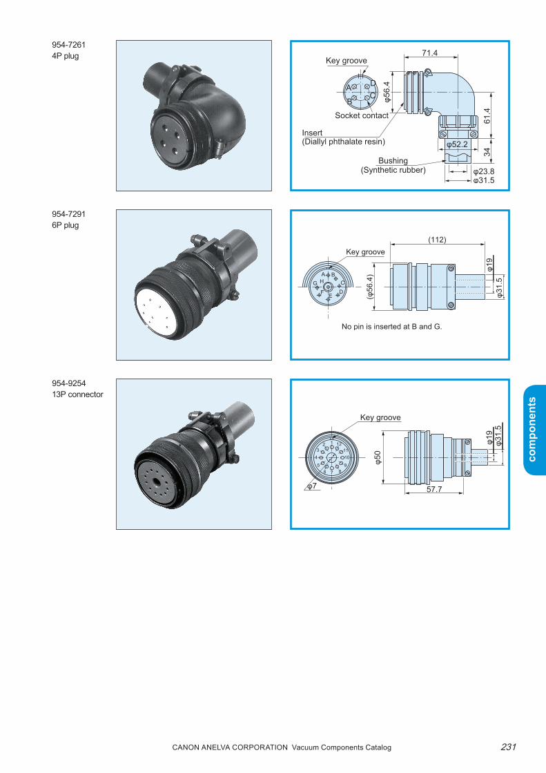
231Canon anELVa Corporation Vacuum Components Catalog
com
pone
nts
com
pone
nts
954-72614P plug
954-72916P plug
954-925413P connector
71.4
61.4
34
Key groove
AC
Socket contact
Bushing(Synthetic rubber)
Insert(Diallyl phthalate resin)
φ56.
4
φ31.5φ23.8
φ52.2
B
D
(112)Key groove
No pin is inserted at B and G.
(φ56
.4)A
HGF E
DC
B
φ19
φ31.
557.7
Key groove
φ50
φ7
23
56 8
9
1
7
4 1011
12 φ19
φ31.
5

Canon anELVa Corporation Vacuum Components Catalog232
com
pone
nts
com
pone
nts
● Connecting terminal
Type Description Material Applicable model Remarks953-9900 100A connecting terminal Copper (nickel plated)
954-7209 Mini 100A current terminal954-7203 100A current terminal954-7210 100A2P current terminal
Vacuum side953-9901 100A connecting terminal Copper (nickel plated) Vacuum side953-9910 100A connecting terminal Copper (nickel plated) Atmosphere side953-9916 100AL connecting terminal Copper (nickel plated) Vacuum side953-9903 400A connecting terminal Copper (nickel plated) 954-7207 400A current terminal Vacuum side
953-9917 400AL connecting terminal Copper (nickel plated)954-7241 400A water-cooled current terminal
Vacuum side
Connecting terminals other than the above are also available upon request. Contact us for details.
953-9900100A connecting terminal
953-9901100A connecting terminal
953-9910100A connecting terminal
The photo shows an example of attaching to a current terminal.The mounting bolts in the figure are not included.
3523
175 1.5
9
5
φ6
φ6.2
M6
7
10
4520 10
2-φ6.5
Inner diameter φ612
1.5
Inner diameter φ6.2
1.5
30
15
206
2-φ6.5

233Canon anELVa Corporation Vacuum Components Catalog
com
pone
nts
com
pone
nts
The photo shows an example of attaching to a current terminal.The mounting bolts in the figure are not included.
953-9916100AL connect-ing terminal
2317
10 9
35
1.5
45
17 23
7
510
5 1.5
7
2-φ6.2
2-φ6
● Connector usage example
953-9903400A connecting terminal
953-9917400A L connecting terminal
φ10 φ16
45
36
20
22
1.6
φ6.5
7.5
8
15
φ16.2
1020
2
4325
φ16.2
102
5840
15 7.5
157.5
37
52
Washer Bolt 953-9900 100A connecting terminal
954-7209 Mini 100A current terminalNut

Canon anELVa Corporation Vacuum Components Catalog234
com
pone
nts
com
pone
nts
* Note that the rated voltage is different from the optional atmosphere side connector.
MS Connector Type Multi-pin Current Terminals
■ Specifications
Type DescriptionNumber of elec-trodes
Weight Compatibleflange Compatible connectors (atmosphere side)
954-79113P current terminal 3
70g φ34ICF954-7915 3P connector
954-7912 340g φ70ICF954-7921
4P current terminal 470g φ34ICF
954-7925 4P connector954-7922 340g φ70ICF954-7931
6P current terminal 670g φ34ICF
954-7935 6P connector954-7932 340g φ70ICF954-7942 10P current terminal 10 340g φ70ICF 954-7945 10P connector954-7952 14P current terminal 14 340g φ70ICF 954-7955 14P connector954-7962 19P current terminal 19 340g φ70ICF 954-7965 19P connector954-7972 24P current terminal 24 320g φ70ICF 954-7975 24P connector954-7982 37P current terminal 37 330g φ70ICF 954-7985 37P connector954-7993 48P current terminal 48 1140g φ114ICF 954-7995 48P connector
Current capacity 3A/lineWithstand voltage* 350V AC [r.m.s], 500V DCInsulating resistance 1000MΩ or moreAllowable heating temperature 350°CTemperature change 15°C/min or lessLeakage 1.3x10⁻¹¹Pa•m3/sec or lessVacuum side connector 954-7326, 954-7327 #16 socket connectorElectrode material KovarElectrode diameter φ1.57
● Other common specifications
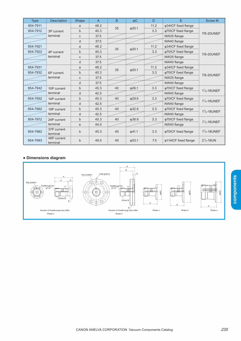
235Canon anELVa Corporation Vacuum Components Catalog
com
pone
nts
com
pone
nts
Type Description Shape A B φC D E Screw M954-7911
3P current terminal
a 48.235 φ20.1
11.2 φ34ICF fixed flange
7/8-20UNEF954-7912 b 40.3 3.3 φ70ICF fixed flange
c 37.5 NW25 flanged 37.5 NW40 flange
954-7921
4P current terminal
a 48.235 φ20.1
11.2 φ34ICF fixed flange
7/8-20UNEF954-7922 b 40.3 3.3 φ70ICF fixed flange
c 37.5 NW25 flanged 37.5 NW40 flange
954-7931
6P current terminal
a 48.235 φ20.1
11.2 φ34ICF fixed flange
7/8-20UNEF954-7932 b 40.3 3.3 φ70ICF fixed flange
c 37.5 NW25 flanged 37.5 NW40 flange
954-7942 10P current terminal
b 45.3 40 φ26.1 3.3 φ70ICF fixed flange11/8-18UNEF
d 42.5 NW40 flange954-7952 14P current
terminalb 45.3 40 φ29.6 3.3 φ70ICF fixed flange
11/4-18UNEFd 42.5 NW40 flange
954-7962 19P current terminal
b 45.3 40 φ32.6 3.3 φ70ICF fixed flange13/8-18UNEF
d 42.5 NW40 flange954-7972 24P current
terminalb 45.3 40 φ36.6 3.3 φ70ICF fixed flange
11/2-18UNEFe 44.0 NW40 flange
954-798237P current terminal
b 45.3 40 φ41.1 3.3 φ70ICF fixed flange 13/4-18UNEF
954-799348P current terminal
b 49.5 40 φ53.1 7.5 φ114ICF fixed flange 21/4-16UN
● Dimensions diagram

Canon anELVa Corporation Vacuum Components Catalog236
com
pone
nts
com
pone
nts
● Pin layout ( : key location, viewed from the vacuum side)
* There are no pin numbers on the current terminals. (The above pin numbers are matched with the connectors.)
24P current terminal ( • 954-7972)
37P current terminal ( • 954-7982)
48P current terminal ( • 954-7993)
10P current terminal (• 954-7942)
14P current terminal ( • 954-7952)
19P current terminal ( • 954-7962)
( ) 6P current terminal • 954-7931 • 954-7932( )
4P current terminal • 954-7921 • 954-7922( )
3P current terminal • 954-7911 • 954-7912
T
g
ELJ H F P MN
GG
V U
Z Y
Q NP
T S R
X W
EM L K X
mf
RZ
e d bc
ks r
hjnq
W UV
D C B A JD C
HAB
FTK U RS PQ O
z
jaS
ks
c b
z y
X
nh fg
qrw
p
v u
Za Y
de
m
t
VW
G
N J
B A
L
F
ME D
KC
H
BI GB
EF
D
JC
HA
L HN
FEG
MD
JI
A
K
B
CA
CB
DA
B
D
CC JVP T
H
FE G
R S
MAN
L
U K
B
C ED
FA
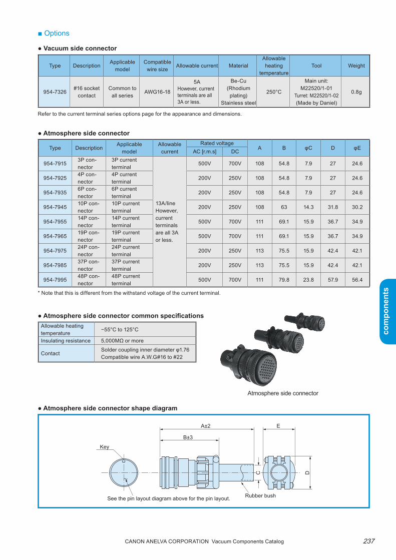
237Canon anELVa Corporation Vacuum Components Catalog
com
pone
nts
com
pone
nts
■ Options
Type DescriptionApplicable
modelCompatible
wire sizeAllowable current Material
Allowable heating
temperatureTool Weight
954-7326#16 socket
contactCommon to
all seriesAWG16-18
5AHowever, current terminals are all 3A or less.
Be-Cu(Rhodium plating)
Stainless steel
250°C
Main unit: M22520/1-01
Turret: M22520/1-02(Made by Daniel)
0.8g
Refer to the current terminal series options page for the appearance and dimensions.
● Atmosphere side connector
● Vacuum side connector
Type DescriptionApplicable
modelAllowable
currentRated voltage
A B φC D φEAC [r.m.s] DC
954-79153P con-nector
3P current terminal
13A/line However, current terminals are all 3A or less.
500V 700V 108 54.8 7.9 27 24.6
954-79254P con-nector
4P current terminal
200V 250V 108 54.8 7.9 27 24.6
954-79356P con-nector
6P current terminal
200V 250V 108 54.8 7.9 27 24.6
954-794510P con-nector
10P current terminal
200V 250V 108 63 14.3 31.8 30.2
954-795514P con-nector
14P current terminal
500V 700V 111 69.1 15.9 36.7 34.9
954-796519P con-nector
19P current terminal
500V 700V 111 69.1 15.9 36.7 34.9
954-797524P con-nector
24P current terminal
200V 250V 113 75.5 15.9 42.4 42.1
954-798537P con-nector
37P current terminal
200V 250V 113 75.5 15.9 42.4 42.1
954-799548P con-nector
48P current terminal
500V 700V 111 79.8 23.8 57.9 56.4
● Atmosphere side connector shape diagram
● Atmosphere side connector common specificationsAllowable heating temperature
−55°C to 125°C
Insulating resistance 5,000MΩ or more
ContactSolder coupling inner diameter φ1.76Compatible wire A.W.G#16 to #22
* Note that this is different from the withstand voltage of the current terminal.
A±2
B±3
E
Key
Rubber bushSee the pin layout diagram above for the pin layout.
C D
Atmosphere side connector

Canon anELVa Corporation Vacuum Components Catalog238
com
pone
nts
com
pone
nts
Description Mounting adapter RemarksAllowable heating
temperature
Sheathed thermo-couple
952-7806, φ15 adapter954-7832, gauge adapter954-7833, gauge adapter954-7834, gauge adapter
Select the thermocouple type andA and B dimensions from the following when ordering:A: 100, 200, 300, 400, 500B: 1000, 2000Other dimensions are available upon request.
60°C
● Sheathed thermocoupleAn insulated thermocouple (insulated type) is con-tained in a metal protective tube with a φ1.6 sheath diameter.
Sheathed thermocouple
Use a φ15 adapter similar to the vacuum measure-ment gauge when mounting.
B
2
Compensating lead wire(Red: + pole, White: - pole)
For M3
A
Blazed
40
Seal
φ1.6
φ20
φ15±
0.1
• An insulation type is standard for a hot junction. However, a grounded type can also be used.• One pair is the standard number of thermocouples. However, a multi-pair type can also be used. Contact us for details.

239Canon anELVa Corporation Vacuum Components Catalog
com
pone
nts
com
pone
nts
● Other common specifications
● MS connector type temperature measurement terminals
these temperature measurement terminals with ther-mocouples can be easily attached/removed from the vacuum side or atmosphere side.the K thermocouple is the standard. the same mate-rial as the chromel/alumel thermocouples is used for
Type DescriptionElectrodes
WeightCompatible
FlangeCompatible connector
Quantity Pair Vacuum side Atmosphere side954-7917 2 pair temperature
measurement terminal4 2
70g φ34ICF
954-7328Alumel socket contact954-7329Chromel socket contact
954-7914, 2 pair connector954-7918 340g φ70ICF
954-79285 pair temperature measurement terminal
10 5 340g φ70ICF954-7924, 5 pair connector
954-79387 pair temperature measurement terminal
14 7 340g φ70ICF954-7934, 7 pair connector
954-794812 pair temperature measurement terminal
24 12 320g φ70ICF954-7944, 12 pair connector
Withstand voltage 350V AC [r.m.s], 500V DC
Insulating resistance 1000MΩ or more
Allowable heating temperature 350°C
Temperature change 15°C/min or less
Leakage 1.3x10⁻¹¹Pa•m3/sec or less
Vacuum side connector954-7328 # 16 alumel socket contact954-7329 # 16 chromel socket contact
Feedthrough bar material Chromel, alumelFeedthrough bar thickness φ1.57
the temperature measurement terminal's feedthrough bar/vacuum side socket contact and atmosphere side connection socket contact.
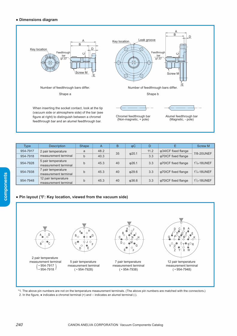
Canon anELVa Corporation Vacuum Components Catalog240
com
pone
nts
com
pone
nts
● Dimensions diagram
Type Description Shape A B φC D E Screw M954-7917 2 pair temperature
measurement terminala 48.2
35 φ20.111.2 φ34ICF fixed flange
7/8-20UNEF954-7918 b 40.3 3.3 φ70ICF fixed flange
954-79285 pair temperature measurement terminal
b 45.3 40 φ26.1 3.3 φ70ICF fixed flange 11/8-18UNEF
954-79387 pair temperature measurement terminal
b 45.3 40 φ29.6 3.3 φ70ICF fixed flange 11/4-18UNEF
954-794812 pair temperature measurement terminal
b 45.3 40 φ36.6 3.3 φ70ICF fixed flange 11/2-18UNEF
● Pin layout ( : Key location, viewed from the vacuum side)
Chromel feedthrough bar(Non-magnetic, + pole)
Alumel feedthrough bar(Magnetic, - pole)
Key location
Key location Leak groove
Feedthrough bar
φ1.57
Screw ME
AB
D
C Feedthrough bar
φ1.57
Screw M
E
AB
D
C
Number of feedthrough bars differ.
Shape a
Number of feedthrough bars differ.
Shape b
*1. The above pin numbers are not on the temperature measurement terminals. (The above pin numbers are matched with the connectors.)2. In the figure, ● indicates a chromel terminal (+) and ○ indicates an alumel terminal (-).
( )
2 pair temperature
measurement terminal • 954-7917 • 954-7918
5 pair temperature measurement terminal
( • 954-7928)
7 pair temperature measurement terminal
( • 954-7938)
12 pair temperature measurement terminal
( • 954-7948)
J H FG
V UZ Y
Q NP
T S R
X W
EM L K
D C B AB
L HN
FEG
MD
JI
AK
CI GB
EF
D
JC
HA
CB
DA
When inserting the socket contact, look at the tip (vacuum side or atmosphere side) of the bar (see figure at right) to distinguish between a chromel feedthrough bar and an alumel feedthrough bar.
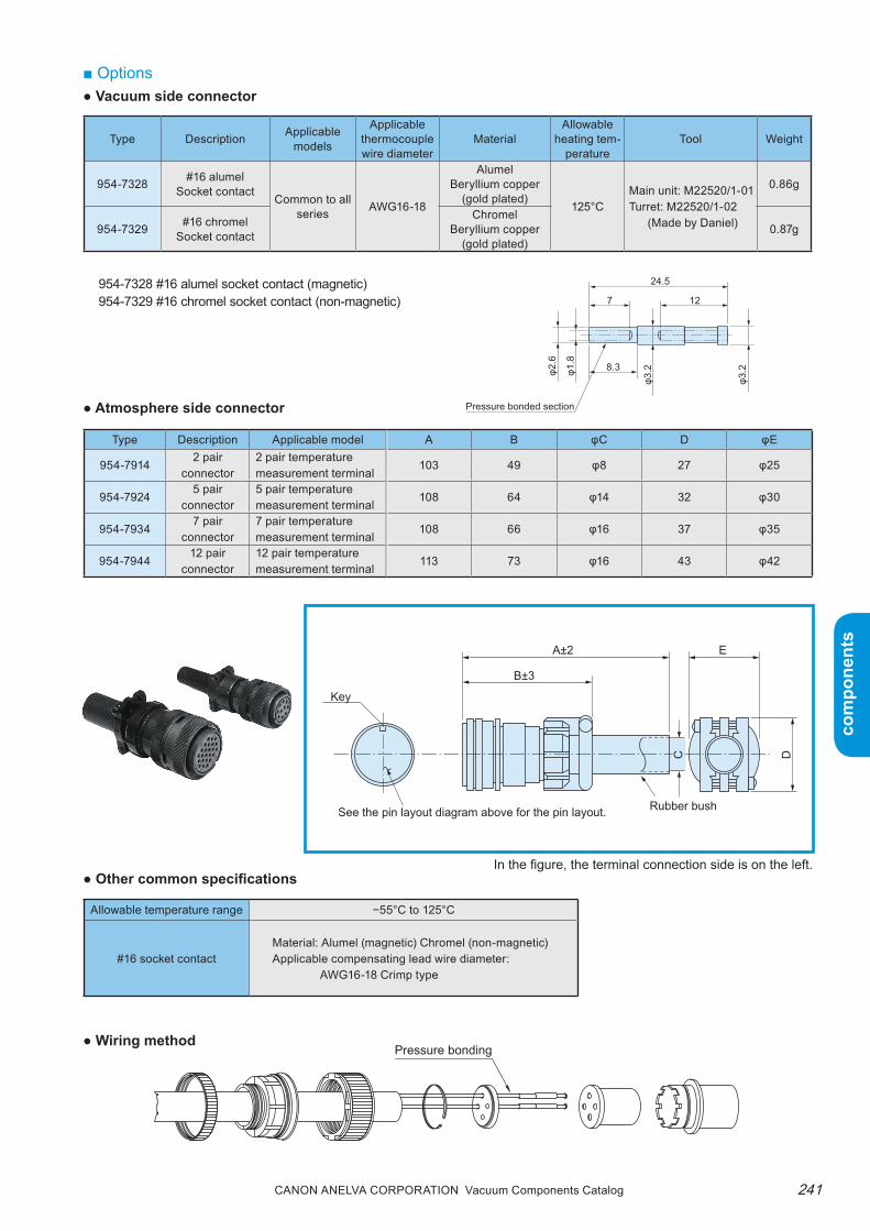
241Canon anELVa Corporation Vacuum Components Catalog
com
pone
nts
com
pone
nts
24.5
127
8.3
Pressure bonded section
φ2.6
φ1.8
φ3.2
φ3.2
■ Options● Vacuum side connector
Type Description Applicable models
Applicable thermocouple wire diameter
MaterialAllowable
heating tem-perature
Tool Weight
954-7328 #16 alumelSocket contact
Common to all series AWG16-18
AlumelBeryllium copper
(gold plated)125°C
Main unit: M22520/1-01Turret: M22520/1-02
(Made by Daniel)
0.86g
954-7329 #16 chromelSocket contact
ChromelBeryllium copper
(gold plated)0.87g
954-7328 #16 alumel socket contact (magnetic)954-7329 #16 chromel socket contact (non-magnetic)
Type Description Applicable model A B φC D φE
954-79142 pair
connector2 pair temperature measurement terminal
103 49 φ8 27 φ25
954-79245 pair
connector5 pair temperature measurement terminal
108 64 φ14 32 φ30
954-79347 pair
connector7 pair temperature measurement terminal
108 66 φ16 37 φ35
954-794412 pair
connector12 pair temperature measurement terminal
113 73 φ16 43 φ42
In the figure, the terminal connection side is on the left.● Other common specifications
Allowable temperature range −55°C to 125°C
#16 socket contactMaterial: Alumel (magnetic) Chromel (non-magnetic)Applicable compensating lead wire diameter:
AWG16-18 Crimp type
● Atmosphere side connector
A±2
B±3
E
Key
Rubber bushSee the pin layout diagram above for the pin layout.
C D
● Wiring method

Canon anELVa Corporation Vacuum Components Catalog242
com
pone
nts
com
pone
nts
■ Selection guide● Select the current terminal that matches the intended application.
For high frequency feedthrough
954-7209Mini 100A current terminal
954-7245Mini 5A current terminal
954-7238Mini HF current terminal
954-7276MHV current terminal
954-72272W2T current terminal
954-7203100A current terminal
954-7210100A2P current terminal
954-72604P current terminal
954-7207400A current terminal
954-72906P current terminal
954-72218W current terminal
954-72258T current terminal
954-72234W4T current terminal
954-725213P current terminal
954-7911 (3P), 954-7921 (4P), 954-7931 (6P)MS connector type multi-pin current terminal
954-7912(3P), 954-7922 (4P), 954-7932 (6P), 954-7942 (10P), 954-7952 (14P), 954-7962 (19P), 954-7972 (24P), 954-7982 (37P)MS connector type multi-pin current terminal
954-799348P current terminal
For thermocouple inclusion
Connector type
● Applicable flange
For small current feedthrough
For large current feedthrough
φ70 ICF
φ34 ICF
φ114 ICF
■ Ordering informationParts number Model Description Remarks Code
A26-13706 954-7917 2 Pair Feedthrough for Thermocouples φ34ICF, K (CA) thermocouple 36400
P25-02875 954-7918 2 Pair Feedthrough for Thermocouples φ70ICF, K (CA) thermocouple 36405
A26-13707 954-7928 5 Pair Feedthrough for Thermocouples φ70ICF, K (CA) thermocouple 36410
P25-02877 954-7938 7 Pair Feedthrough for Thermocouples φ70ICF, K (CA) thermocouple 36415
P25-02878 954-7948 12 Pair Feedthrough for Thermocouples φ70ICF, K (CA) thermocouple 36420
0194-12777 954-7914 2 Pair Contacts PlugFor 2 pair temperature measurement terminal, K (CA) thermocouple
36235
0194-13210 954-7924 5 Pair Contacts PlugFor 5 pair temperature measurement terminal, K (CA) thermocouple
36237
Note) Contact us for more information about CE (RoHS).
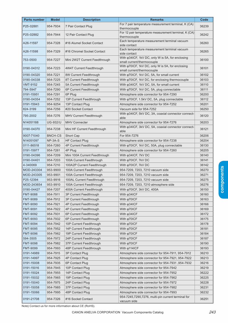
243Canon anELVa Corporation Vacuum Components Catalog
com
pone
nts
com
pone
nts
Parts number Model Description Remarks Code
P25-02881 954-7934 7 Pair Contact PlugFor 7 pair temperature measurement terminal, K (CA) thermocouple
36239
P25-02882 954-7944 12 Pair Contact PlugFor 12 pair temperature measurement terminal, K (CA) thermocouple
36242
A26-11597 954-7328 #16 Alumel Socket ContactEach temperature measurement terminal vacuum side contact
36260
A26-11598 954-7329 #16 Chromel Socket ContactEach temperature measurement terminal vacuum side contact
36265
753-0500 954-7227 Mini 2W2T Current FeedthroughWith φ34ICF, 1kV DC, only W is 5A, for enclosing small current/thermocouple
36100
0190-04312 954-7223 4W4T Current FeedthroughWith φ70ICF, 1kV DC, only W is 5A, for enclosing small current/thermocouple
36101
0190-04320 954-7221 8W Current Feedthrough With φ70ICF, 1kV DC, 5A, for small current 361020190-04338 954-7225 8T Current Feedthrough With φ70ICF, 1kV DC, for enclosing thermocouple 36103VMT-9152 954-7245 5A Current Feedthrough With φ34ICF, 1kV DC, 5A, for small current 36110794-5947 954-7290 6P Current Feedthrough With φ70ICF, 1kV DC, 5A, plug connectable 361110191-15951 954-7291 6P Plug Atmosphere side connector for 954-7290 362000190-04354 954-7252 13P Current Feedthrough With φ70ICF, 1.5kV DC, 5A, plug connectable 361120191-15943 954-9254 13P Contact Plug Atmosphere side connector for 954-7252 36201824-3199 954-7256 #20 Socket Contact Vacuum side for 954-7252 36250
795-2002 954-7276 MHV Current FeedthroughWith φ34ICF, 5kV DC, 3A, coaxial connector connect-able
36120
N14051188 UG-932/U MHV Connecter Atmosphere side connector for 954-7276 36203
0190-04370 954-7238 Mini HF Current FeedthroughWith φ34ICF, 3kV DC, 5A, coaxial connector connect-able
36121
9007-71040 BNCH-CS Short Cap For 954-7276 36206N14051097 NP-3A-S HF Contact Plug Atmosphere side connector for 954-7238 362040111-86518 954-7260 4P Current Feedthrough With φ70ICF, 1kV DC, 50A, plug connectable 361300191-15977 954-7261 4P Plug Atmosphere side connector for 954-7260 362050190-04396 954-7209 Mini 100A Current Feedthrough With φ34ICF, 7kV DC 361400190-04401 954-7203 100A Current Feedthrough With φ70ICF, 7kV DC 361414-340069 954-7210 100A2P Current Feedthrough With φ70ICF, 7kV DC 36142MOD-243304 953-9900 100A Current Feedthrough 954-7209, 7203, 7210 vacuum side 36270MOD-243305 953-9901 100A Current Feedthrough 954-7209, 7203, 7210 vacuum side 36271P25-12394 953-9916 100AL Current Feedthrough 954-7209, 7203, 7210 vacuum side 36275MOD-243654 953-9910 100A Current Feedthrough 954-7209, 7203, 7210 atmosphere side 362760190-04427 954-7207 400A Current Feedthrough With φ70ICF, 3kV DC, 400A 36150FMT-9088 954-7911 3P Current Feedthrough With φ34ICF 36160FMT-9089 954-7912 3P Current Feedthrough With φ70ICF 36163FMT-9090 954-7921 4P Current Feedthrough With φ34ICF 36166FMT-9091 954-7922 4P Current Feedthrough With φ70ICF 36169FMT-9092 954-7931 6P Current Feedthrough With φ34ICF 36172FMT-9093 954-7932 6P Current Feedthrough With φ70ICF 36175FMT-9094 954-7942 10P Current Feedthrough With φ70ICF 36178FMT-9095 954-7952 14P Current Feedthrough With φ70ICF 36181FMT-9096 954-7962 19P Current Feedthrough With φ70ICF 36184594-3505 954-7972 24P Current Feedthrough With φ70ICF 36187FMT-9098 954-7982 37P Current Feedthrough With φ70ICF 36190FMT-9099 954-7993 48P Current Feedthrough With φ114ICF 361930191-14989 954-7915 3P Contact Plug Atmosphere side connector for 954-7911, 954-7912 362100191-14997 954-7925 4P Contact Plug Atmosphere side connector for 954-7921, 954-7922 362130191-15008 954-7935 6P Contact Plug Atmosphere side connector for 954-7931 ,954-7932 362160191-15016 954-7945 10P Contact Plug Atmosphere side connector for 954-7942 362190191-15024 954-7955 14P Contact Plug Atmosphere side connector for 954-7952 362220191-15032 954-7965 19P Contact Plug Atmosphere side connector for 954-7962 362250191-15040 954-7975 24P Contact Plug Atmosphere side connector for 954-7972 362280191-15058 954-7985 37P Contact Plug Atmosphere side connector for 954-7982 362310191-15066 954-7995 48P Contact Plug Atmosphere side connector for 954-7993 36232
0191-21708 954-7326 #16 Socket Contact954-7245,7290,7276, multi-pin current terminal for vacuum side
36251
Note) Contact us for more information about CE (RoHS).

Canon anELVa Corporation Vacuum Components Catalog244
com
pone
nts
com
pone
nts
Ultra-high Vacuum Viewing Ports
■ SummaryA viewing port is a window for looking inside a vacu-um container. These viewing ports use Kovar glass or synthesized sapphire sealed with Kovar welded onto an ICF flange, enabling them to be used under ultra-high pressure of up to 10-8Pa. In particular, the sap-phire viewing ports have stable transmission charac-teristics with respect to irradiation of electromagnetic waves and particle beams in the UV range (short wavelength).
■ Features1. Wide, clear effective field of view
the thin viewing port provides a wide effective field of view. the strain-free glass and sapphire allow for a clear view.
2. Ultra-high vacuumthe use of ICF flanges enable the viewing port to be used under ultra-high vacuum.
3. High heat toleranceCapable of withstanding 350°C heat cycle.
4. Stable transmission of wide wavelength rangethe sapphire viewing ports offer more stable trans-mission characteristics over a wider range of wave-lengths in the UV to Ir range when compared to Kovar glass viewing ports and longer wavelengths in the Ir range compared to quartz viewing ports.(952-7042, 7043, sapphire viewing ports)
5. Excellent radiation resistancethe synthetic sapphire is a single crystal of AL2O3. It has excellent radiation resistance against irra-diation of high energy electromagnetic waves and particle beams with little discoloration or change in transmittance. (954-7042, 7043, sapphire viewing ports)
Withstand pressure
0.1MPa (inside vacuum, outside atmo-sphere)
Allowable heat-ing temperature
350°C
Temperature change
25°C/min or less
Leakage 1.3x10⁻¹¹Pa•m3/sec or less
Relationship between the wavelength and transmittance of glass material (reference value)
■ Specifications
Kovar glass SapphireQuartz glass
Visible lightUV Infrared light
0.1 0.15 0.2 0.3 0.4 0.7 2.01.0 4.0 6.0 8.0
20
40
60
80
100
Wavelengths (μm)
Tran
smitt
ance
(%)
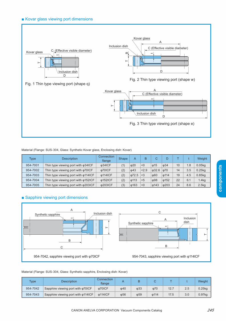
245Canon anELVa Corporation Vacuum Components Catalog
com
pone
nts
com
pone
nts
■ Kovar glass viewing port dimensions
Material (Flange: SUS-304, Glass: Synthetic sapphire, Enclosing dish: Kovar)
954-7042, sapphire viewing port with φ70ICF 954-7043, sapphire viewing port with φ114ICF
■ Sapphire viewing port dimensions
Type DescriptionConnection
flangeShape A B C D T t Weight
954-7001 Thin type viewing port with φ34ICF φ34ICF (1) φ20 <0 φ15 φ34 10 1.8 0.05kg954-7002 Thin type viewing port with φ70ICF φ70ICF (2) φ43 <2.9 φ32.6 φ70 14 3.5 0.25kg954-7003 Thin type viewing port with φ114ICF φ114ICF (2) φ72.5 <3 φ60 φ114 19 4.5 0.85kg954-7004 Thin type viewing port with φ152ICF φ152ICF (2) φ113 <5 φ98 φ152 22 6.1 1.4kg954-7005 Thin type viewing port with φ203ICF φ203ICF (3) φ163 <0 φ143 φ203 24 8.6 2.5kg
Material (Flange: SUS-304, Glass: Synthetic Kovar glass, Enclosing dish: Kovar)
C
D
A
A
D
D
t tt
T T
T
B
(Effective visible diameter)C (Effective visible diameter)
C (Effective visible diameter)
Kovar glass
Kovar glass
Kovar glass
Inclusion dish
Inclusion dish
Inclusion dish
A
A
B
BC
C
t
tT
T
Inclusion dishInclusion dish
Synthetic sapphire
Synthetic sapphire
Type DescriptionConnection
flangeA B C T t Weight
954-7042 Sapphire viewing port with φ70ICF φ70ICF φ40 φ33 φ70 12.7 2.5 0.25kg
954-7043 Sapphire viewing port with φ114ICF φ114ICF φ56 φ59 φ114 17.5 3.0 0.97kg
Fig. 1 Thin type viewing port (shape q)Fig. 2 Thin type viewing port (shape w)
Fig. 3 Thin type viewing port (shape e)

Canon anELVa Corporation Vacuum Components Catalog246
com
pone
nts
com
pone
nts
■ Optionsthe following options are available to protect the viewing port.
Protective covers● Features1. protects the bolted glass surface of the viewing port
from damage due to external force.2. Can be easily installed on the viewing port. Fig. 4
shows the protective cover.
TypeApplicable viewing
portA B t
954-7012954-7002, 7042Thin type with φ70ICFViewing port
φ72.7 20 0.4
954-7013954-7003, 7043Thin type with φ114ICFViewing port
φ116.7 25 0.4
954-7014
954-7004,Thin type with φ152ICFViewing port
φ154.7 29 0.6
954-7015
954-7005,Thin type with φ203ICFViewing port
φ205.7 32 0.6
Fig. 5
Shields● Features1. the vaporized material generated inside the vacu-
um chamber adheres to the shield glass to ensure a clear view through the viewing port.
2. the shield glass is easy to replace. the shield as-sembly holds the glass shield and can be fixed to the inner diameter of the vacuum chamber side port with a single action.
Type Applicable shield assemblyGlass
diameterThick-ness
954-7032 954-7022 φ35 2954-7033 954-7023 φ51 2954-7036 954-7026 φ56 2954-7035 954-7025 φ142 2954-7034 954-7024 φ91 2
Protective covers (Material: SUS-304)
Fig. 4
Shield assembly (Material: SUS-304)
Type Applicable attachment port inner diameter954-7022 φ38954-7023 φ54.9954-7026 φ60.2954-7025 φ147
Shield glass (Material: Soda glass)
Vacuum container Viewing port
Glass B
A
t
Protective cover
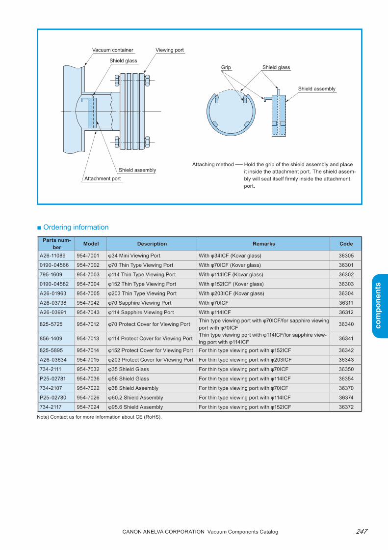
247Canon anELVa Corporation Vacuum Components Catalog
com
pone
nts
com
pone
nts
■ Ordering information
Vacuum container
Shield glassShield glass
Viewing port
Attachment portShield assembly
Grip
Shield assembly
Attaching method ─ Hold the grip of the shield assembly and place it inside the attachment port. The shield assem-bly will seat itself firmly inside the attachment port.
Parts num-ber Model Description Remarks Code
A26-11089 954-7001 φ34 Mini Viewing Port With φ34ICF (Kovar glass) 36305
0190-04566 954-7002 φ70 Thin Type Viewing Port With φ70ICF (Kovar glass) 36301
795-1609 954-7003 φ114 Thin Type Viewing Port With φ114ICF (Kovar glass) 36302
0190-04582 954-7004 φ152 Thin Type Viewing Port With φ152ICF (Kovar glass) 36303
A26-01963 954-7005 φ203 Thin Type Viewing Port With φ203ICF (Kovar glass) 36304
A26-03738 954-7042 φ70 Sapphire Viewing Port With φ70ICF 36311
A26-03991 954-7043 φ114 Sapphire Viewing Port With φ114ICF 36312
825-5725 954-7012 φ70 Protect Cover for Viewing PortThin type viewing port with φ70ICF/for sapphire viewing port with φ70ICF
36340
856-1409 954-7013 φ114 Protect Cover for Viewing PortThin type viewing port with φ114ICF/for sapphire view-ing port with φ114ICF
36341
825-5895 954-7014 φ152 Protect Cover for Viewing Port For thin type viewing port with φ152ICF 36342
A26-03634 954-7015 φ203 Protect Cover for Viewing Port For thin type viewing port with φ203ICF 36343
734-2111 954-7032 φ35 Shield Glass For thin type viewing port with φ70ICF 36350
P25-02781 954-7036 φ56 Shield Glass For thin type viewing port with φ114ICF 36354
734-2107 954-7022 φ38 Shield Assembly For thin type viewing port with φ70ICF 36370
P25-02780 954-7026 φ60.2 Shield Assembly For thin type viewing port with φ114ICF 36374
734-2117 954-7024 φ95.6 Shield Assembly For thin type viewing port with φ152ICF 36372
Note) Contact us for more information about CE (RoHS).

Canon anELVa Corporation Vacuum Components Catalog248
com
pone
nts
com
pone
nts
■ Features of electron beam depositionIn electron beam deposition, electrons emitted from a hot filament are accelerated in a vacuum, and de-flected by a magnetic or electric field to bombards an evaporated substance to cause thermal evaporation and form a thin film on a substrate. this method has the following advantages over the resistance heating method.1. Deposition of most metal and oxide from AL to
refractory metals such as W, ta, and Mo is possible with its high power density.
2. the water-cooled copper crucible maintains the pu-rity of the deposition specimen, providing deposited films with few impurities.
3. parts wear out slower compared to resistance heat-ing type evaporation sources.
■ Features of the ANELVA E-type electron gun and power supply1. Excellent deposition
Because the primary electron beam is deflected by a magnetic field, the secondary electrons and reflected electrons generated from the surface of the evapo-rated sample are also deflected and are less likely to adversely a effect the deposited film.
2. Excellent controlA raster scan method and circle sweep method are used as the electron beam sweep methods. the am-plitude, scanning frequency, and waveform pattern in the X and Y directions are compensated to enable fine control of the power density over the crucible.
For electron beam deposition
E-type Electron Guns
■ SummaryOur E-type Electron Guns have a proven sales record since their introduction in 1964 as electron guns used for vapor deposition experiments. Through constant, continuous product development and improvement from that time, today they have evolved into a more operable, reliable, and safer electron beam deposition source used in the electronics industry and optics industry laboratories. We are confident that our E-type electron guns can satisfy the performance requirements of any field.
3. Beam sweep capableElectron guns capable of beam sweep, able to with-stand baking up to 200°C, and usable in an ultra-high vacuum of up to approximately 10−8pa are available (980-7100 and 980-7300)Ultra-high vacuum electron guns without beam sweep, and capable of withstanding baking up to 250°C are also available (980-7102, 980-7104, and 980-7302).
4. Sustained discharge preventionthe electron gun power has a circuit to prevent sus-tained discharge.

249Canon anELVa Corporation Vacuum Components Catalog
com
pone
nts
com
pone
nts
Sweepable ultra-high
vacuum deposition
use
For multi-layer
ultra-high vacuum
deposition
Equipped with a sweep coil
and increased power for
ultra-high vacuum deposition.
Ideal for superconducting film
creation and experimenting.
Capable of 4 source
simultaneous deposition.
Ideal for superconducting film
creation and experimenting.
980-7100(980-7102) 2kW single-shot
980-71042kW triple-shot
980-7300(980-7302) 3kW single-shot
980-74013kW 4 source
1
3
1
4
1
1
2.5
3.8
200°C
(250°C)
250°C
200°C
(250°C)
200°C
220°
220°
220°
220°
○(×)
×
3kW
×4
○(×)
○
2kW
2kW
3kW
○
○
○
×
×
×
×
E-type electron gun
Flange mount type
Maximum input
powerBeam sweep
Beam deflection
angleBaking
temperature
(MAX)Crucible capacity
(mL)Number of
cruciblesFeatures
Product
ion lin
e
equip
ment
R&D
Name Specifications
Ultra-hig
h vacu
um
equipm
ent su
pport
Applications
■ E-type electron gun series line-upWe offer a full line-up of E-type electron guns so that you can select the best gun for your application, based on the input power, crucible capacity, number of cru-cibles (single-shot or multi-barrel), and beam sweep capability.For conventional vacuum equipment, a high-pressure
input terminal and shutter mechanism had to be at-tached from a separate port. As a result, it was dif-ficult to install an EB gun because of the small work space. to solve this problem, flange mount type prod-ucts with these components integrated into the elec-tron gun itself are also included.
Optimum Compatible Acceptable Not acceptable or compatible
Note: 980-7102, 7302, 7311 in parentheses do not have a sweep coil (sweep function).

Canon anELVa Corporation Vacuum Components Catalog250
com
pone
nts
com
pone
nts
E-type Electron Guns■ 980-7100/980-7102 2kW single-shot E-type
electron gun● Features1. Capable of beam sweep. (980-7100 only)2. Compact and lightweight.3. Can be easily attached to the equipment.4. Can withstand baking and can be used in ultra-high
vacuum of 10-8pa range.5. Flange mount type available.
● ApplicationsDeposition of high temperature superconductive ma-terialDeposition of various metals including refractory met-alsDeposition of insulator or semiconductorMelting of refractory metalsIdeal for creating Josephson devices
(Note) 980-7100 shown (with sweep coil)
● Specifications
Type 980-7100 980-7102
Beam accelerator voltage 4kV 4kV
Emission current 0 to 500mA 0 to 500mA
Filament power 10Vx25A (max) 10Vx25A (max)
Coil current ±1A (max) -
Electron beam scanning Available -Electron beam scanning range
±8mm -
Crucibles
Quantity x1 x1
Size φ18xφ12xDepth 6 (mm) φ18xφ12xDepth 6 (mm)
Capacity 1mL 1mL
Beam deflection angle 220° 220°
Cooling water flow 2L/min* 2L/min*
Operating pressure 6.7x10⁻³Pa or less 6.7x10⁻³Pa or less
Baking temperature 200°C (max) 250°C (max)
Weight 1.3kg 1kg
Attachments Filament (x10) tool attachment fixture Same as left
Applicable controller922-9203 2kW E-type electron gun controlleror EGP-230 electron controller,EGP-212S-C sweep controller
922-9203 2kW E-type electron gun controlleror EGP-230 electron gun controller
Typical evaporation rate ex-ample
See item in technical memorandum Same as left
* If necessary, the customer must install a boost pump to ensure a sufficient flow of cooling water.
● Water-cooled pipe dimensions
(Experimental)
A (D)+B≤320, B-C≥76 Dimensions
A 0 or 50 to 180 (upward)
D 0 or 50 to 180 (downward)
B 119 to 329/69 to 329 (when A = D = 0)
C 43 to 260

251Canon anELVa Corporation Vacuum Components Catalog
com
pone
nts
com
pone
nts
● Dimensions diagram
● Attachment method
980-7100 2kW single-shot E-type electron gun
The above mounting parts are all included in the attachments for the 980-7100E-type electron gun (sold separately).
A HEX SUS304 N×6
954-7922 4P current terminal
S SUS304 WA×6
HEX SUS304 MS6×22
H SUS304 MS6×30
Coil power supply line (L = 500 x 4 lines)
Filament power supply lines (L=2M)
922-9203 connector
S SUS304 WA×6
954-7210 100A2P current terminal
953-9904 100A connecting terminal
953-5014 gasket
953-9230 gasket
R1/8
952-9830 nut
Rc1/8
954-7830 flange
954-5110 receive flange
S SUS304 WA×6
H SUS304 MS6×22
φ12±0.5
φ18±0.5
6±0.
3
D
(48.
1)
197±5B
A
C
(13)
(8.5
)
(19.
5)
(48)(7
0)
(29)
(98.
1)
(46)
(φ6)
(φ7.
8)
(22)
111±5
(φ34
)
(φ6)
φ2.3 Oxygen-free copper wire mounting holes
N
Crucible shape
980-7301Sweep coil Crucible center
φ70ICF
This figure shows the dimensions diagram of the 980-7100E-type electron gun. This gun is a 980-7102E-type electron gun fitted with a 980-7301 sweep coil unit.

Canon anELVa Corporation Vacuum Components Catalog252
com
pone
nts
com
pone
nts
● Features1. Multi-barrel electron gun that can withstand bak-
ing and can be used in ultra-high vacuum of 10-8pa range.
2. Can accommodate up to three samples.3. Can be easily attached to the equipment.
● ApplicationsDeposition of high temperature superconductive ma-terial.Deposition of various metals including refractory metals.Deposition of insulator or semiconductor.Melting of refractory metals.Ideal for creating Josephson devices.
■ 980-7104 2kW triple barrel E-type electron gun (for laboratory use)
For φ400 chamber
● Dimensions diagram
● Specifications
* If necessary, the customer must install a boost pump to ensure a sufficient flow of cooling water.
Type 980-7104
Beam accelerator voltage 4kV
Emission current 0 to 500mA
Filament power 10Vx25A (max)
Coil current -
Electron beam scanning -Electron beam scanning range
-
Crucibles
Quantity x3
Size φ18xφ12xDepth 6 (mm)
Capacity 1mL
Beam deflection angle 220°
Cooling water flow 2L/min*
Operating pressure 6.7x10⁻³Pa or less
Baking temperature 250°C (max)
Weight 4.4kg
AttachmentsFilament (x10) tool attachment fixture
Applicable controller922-9203 2kW E-type electron gun controller or EGP-230 elec-tron gun controller
Typical evaporation rate example
See item in technical memoran-dum
392±5 stroke±38
342±5 stroke±38 251±3 stroke±38
178±3
178±3
192.5±1
Filament center location
146.5±2 39.9±2
9±2 7.
5±1
96±2
67.5
±2 112.
5±2
94±1
30.5
±2
34.1
±2
6±1
80±2
31.5±1
(φ6)
φ34±
1
φ45±
1
φ34.
5±1
φ18±1
φ12±1
38±138±1
146±2
Crucible shape
N
This figure shows the demensions dia-gram of the 980-7104E-type electron gun (for φ300 chamber).
Right side view
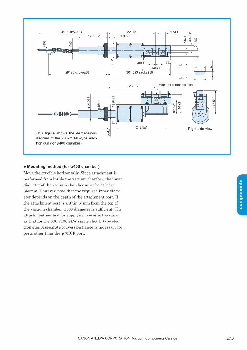
253Canon anELVa Corporation Vacuum Components Catalog
com
pone
nts
com
pone
nts
● Mounting method (for φ400 chamber)Move the crucible horizontally. Since attachment is performed from inside the vacuum chamber, the inner diameter of the vacuum chamber must be at least 350mm. However, note that the required inner diam-eter depends on the depth of the attachment port. If the attachment port is within 67mm from the top of the vacuum chamber, φ300 diameter is sufficient. the attachment method for supplying power is the same as that for the 980-7100 2kW single-shot E-type elec-tron gun. A separate conversion flange is necessary for ports other than the φ70ICF port.
341±5 stroke±38
291±5 stroke±38 301.5±3 stroke±38
228±3
228±3
242.5±1
Filament center location
146.5±2 39.9±2
9±2 7.
5±1
80±2
96±2
67.5
±2 112.
5±2
94±1
30.5
±2
34.1
±2
6±1
31.5±1
(φ6)
φ34±
1
φ45±
1
φ34.
5±1
φ18±1
φ12±1
38±138±1
146±2
N
This figure shows the demensions diagram of the 980-7104E-type elec-tron gun (for φ400 chamber).
Right side view

Canon anELVa Corporation Vacuum Components Catalog254
com
pone
nts
com
pone
nts
■ 980-7300/7302 3kW single shot E-type elec-tron gun (for laboratory use)
(Note) 980-7300 shown (with sweep coil)
● Features1. Capable of beam sweep (980-7300).2. Compact, lightweight, and bigger capacity crucible
than the 2kW electron gun. (2.5mL)3. Can be easily attached to the equipment.4. Can withstand baking and can be used in ultra-high
vacuum of 10-8pa range.5. Flange mount type available.
Flange mount type product: 980-7001 deposition unit (mounts a 980-7300E gun)
● ApplicationsDeposition of high temperature superconductive ma-terial.Deposition of various metals including refractory met-als.Deposition of insulator or semiconductor.Melting of refractory metals.Ideal for creating Josephson devices.
● Specifications
*1 Normally shipped with 5kV specification.*2 If necessary, the customer must install a boost pump to ensure a sufficient flow of cooling water.
Type 980-7300 980-7302
Beam accelerator voltage 5kV or 4kV*1 5kV or 4kV*1
Emission current 0 to 500mA (4kV), 0 to 600mA (5kV) 0 to 500mA, 0 to 600mA (5kV)
Filament power 10Vx25A (max) 10Vx25A (max)
Coil current ±1A (max) -
Electron beam scanning Available -
Electron beam scanning range ±8mm -
Crucibles
Quantity x1 x1
Size φ22xφ18xDepth 8 (mm) φ22xφ18xDepth 8 (mm)
Capacity 2.5mL 2.5mL
Beam deflection angle 220° 220°
Cooling water flow 3L/min*2 3L/min*2
Operating pressure 6.7x10⁻³Pa or less Same as left
Baking temperature 200°C (max) 250°C (max)
Weight 1.3kg 1kg
Attachments Filament (x10) tool attachment fixture Same as left
Applicable controllerEGP-230 electron gun controllerEGP-212S-C sweep controller
EGP-230 electron gun controller
Typical evaporation rate example See item in technical memorandum Same as left
● Water-cooled pipe dimensions
A (D)+B≤320, B-C≥76 Dimensions
A 0 or 50 to 180 (upward)
D 0 or 50 to 180 (downward)
B 119 to 329/69 to 329 (when A = D = 0)
C 43 to 260

255Canon anELVa Corporation Vacuum Components Catalog
com
pone
nts
com
pone
nts ● Attachment method
● Dimensions diagram
φ18±0.5
φ22±0.5
8±0.
3
D
(48.
1)
197±5B
A
C
(13)
(10.
5)
(19.
5)
(50)(7
0)
(31)
(98.
1)
(44)
(φ6)
(φ7.
8)
(20)
111±5
(φ34
)
(φ6)
φ2.3 Oxygen-free copper wire mounting holes
N
Crucible shape
980-7301 Sweep coil Crucible center
φ70ICF
980-7300 3kW single-shot E-type electron gun
A HEX SUS304 N×6
954-7922 4P current terminal
S SUS304 WA×6
HEX SUS304 MS6×22
H SUS304 MS6×30
Coil power supply line (L = 500 x 4 lines)
Filament power supply lines (L=2M)
922-9203 connector
S SUS304 WA×6
954-7210 100A2P current terminal
953-9904 100A connecting terminal
953-5014 gasket
953-9230 gasket
R1/8
952-9830 nut
Rc1/8
954-7830 flange
954-5110 receive flange
S SUS304 WA×6
H SUS304 MS6×22
This figure shows the demensions diagram of the 980-7300E-type electron gun. This gun is a 980-7302E-type electron gun fitted with a 980-7301 sweep coil unit.
The above mounting parts are all included in the attachments for the 980-7300E-type electron gun (sold separately).
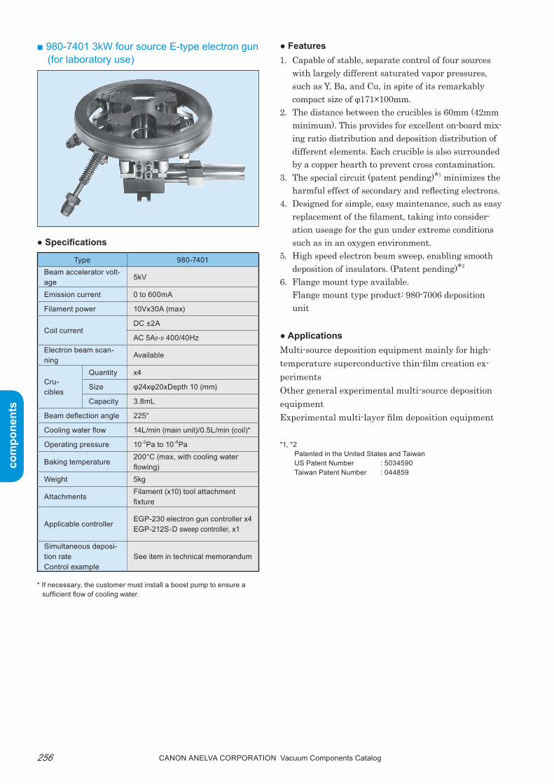
Canon anELVa Corporation Vacuum Components Catalog256
com
pone
nts
com
pone
nts
● Features1. Capable of stable, separate control of four sources
with largely different saturated vapor pressures, such as Y, Ba, and Cu, in spite of its remarkably compact size of φ171×100mm.
2. the distance between the crucibles is 60mm (42mm minimum). this provides for excellent on-board mix-ing ratio distribution and deposition distribution of different elements. Each crucible is also surrounded by a copper hearth to prevent cross contamination.
3. the special circuit (patent pending)*1 minimizes the harmful effect of secondary and reflecting electrons.
4. Designed for simple, easy maintenance, such as easy replacement of the filament, taking into consider-ation useage for the gun under extreme conditions such as in an oxygen environment.
5. High speed electron beam sweep, enabling smooth deposition of insulators. (patent pending)*2
6. Flange mount type available.Flange mount type product: 980-7006 deposition unit
● ApplicationsMulti-source deposition equipment mainly for high-temperature superconductive thin-film creation ex-perimentsOther general experimental multi-source deposition equipmentExperimental multi-layer film deposition equipment
*1, *2Patented in the United States and TaiwanUS Patent Number : 5034590Taiwan Patent Number : 044859
■ 980-7401 3kW four source E-type electron gun (for laboratory use)
● Specifications
Type 980-7401Beam accelerator volt-age
5kV
Emission current 0 to 600mA
Filament power 10Vx30A (max)
Coil currentDC ±2A
AC 5Ap-p 400/40HzElectron beam scan-ning
Available
Cru-cibles
Quantity x4
Size φ24xφ20xDepth 10 (mm)
Capacity 3.8mL
Beam deflection angle 225°
Cooling water flow 14L/min (main unit)/0.5L/min (coil)*
Operating pressure 10-2Pa to 10-8Pa
Baking temperature200°C (max, with cooling water flowing)
Weight 5kg
AttachmentsFilament (x10) tool attachment fixture
Applicable controllerEGP-230 electron gun controller x4EGP-212S-D sweep controller, x1
Simultaneous deposi-tion rateControl example
See item in technical memorandum
* If necessary, the customer must install a boost pump to ensure a sufficient flow of cooling water.
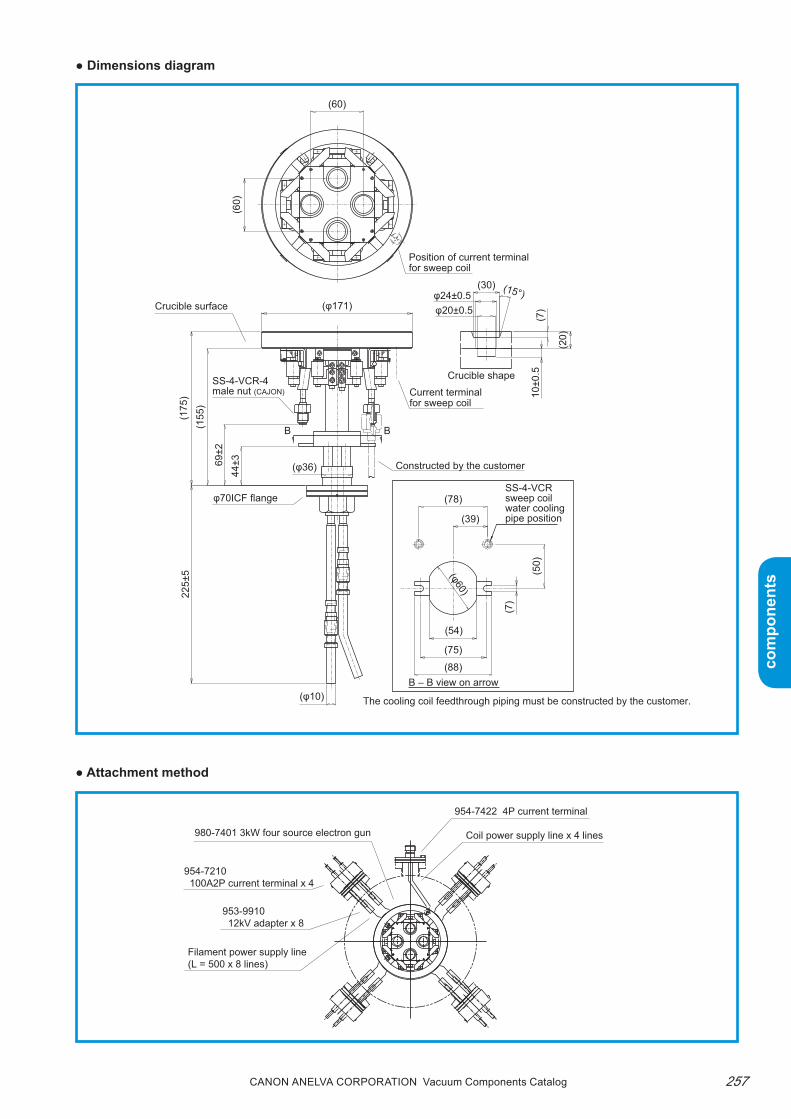
257Canon anELVa Corporation Vacuum Components Catalog
com
pone
nts
com
pone
nts
● Dimensions diagram
● Attachment method
Crucible shape
(88)
(φ10)
Crucible surface
(15°)
10±0
.5
(20)
(7)
(30)φ24±0.5φ20±0.5
Position of current terminal for sweep coil
Current terminal for sweep coil
φ70ICF flange
SS-4-VCR-4male nut (CAJON)
Constructed by the customer
(39)
(φ36)
(175
)
69±2
(155
)22
5±5
44±3
(50)
(7)
(φ60)
(54)
(75)
(78)
(φ171)
(60)
(60)
The cooling coil feedthrough piping must be constructed by the customer.
B B
B – B view on arrow
SS-4-VCRsweep coil water cooling pipe position
Filament power supply line (L = 500 x 8 lines)
Coil power supply line x 4 lines
953-9910 12kV adapter x 8
954-7422 4P current terminal
954-7210 100A2P current terminal x 4
980-7401 3kW four source electron gun

Canon anELVa Corporation Vacuum Components Catalog258
com
pone
nts
com
pone
nts
Electron Gun Controllers
■922-9203 2kW E-type electron gun controllerthis high-voltage DC power source is designed for E-type electron guns.
● Features1. Compact, affordable high-voltage DC power source
that is easy to handle.2. Built-in circuits prevent discharge and water short-
age of the electron gun.
● SpecificationsDC output voltage −3.5kV DC to −4.6kV
DC output current DC0 to 500mA
Filament output 10V ACx30A
Input requirement 200V ACx15A 1φ50/60Hz A ground
Dimensions W500xD500xH1200
Weight 130kg
OperationManual operation from front panel only(No external control function)
Applicable electron gun
980-7100, 980-7102980-7104
● Dimensions diagram
Input code (5m) x1
Output cable assembly (3m) x1
Protection cord (3m) x1
Ground cord (5m) x1
Fuse (5A) x3
Return cable (5m) x1
500 500
1000
95
(Note) Use the EGP-230 or EGP-210RS if deposition rate control in combination with the deposition controller is required. This is necessary because emission cannot be changed by external control.
● Attachments
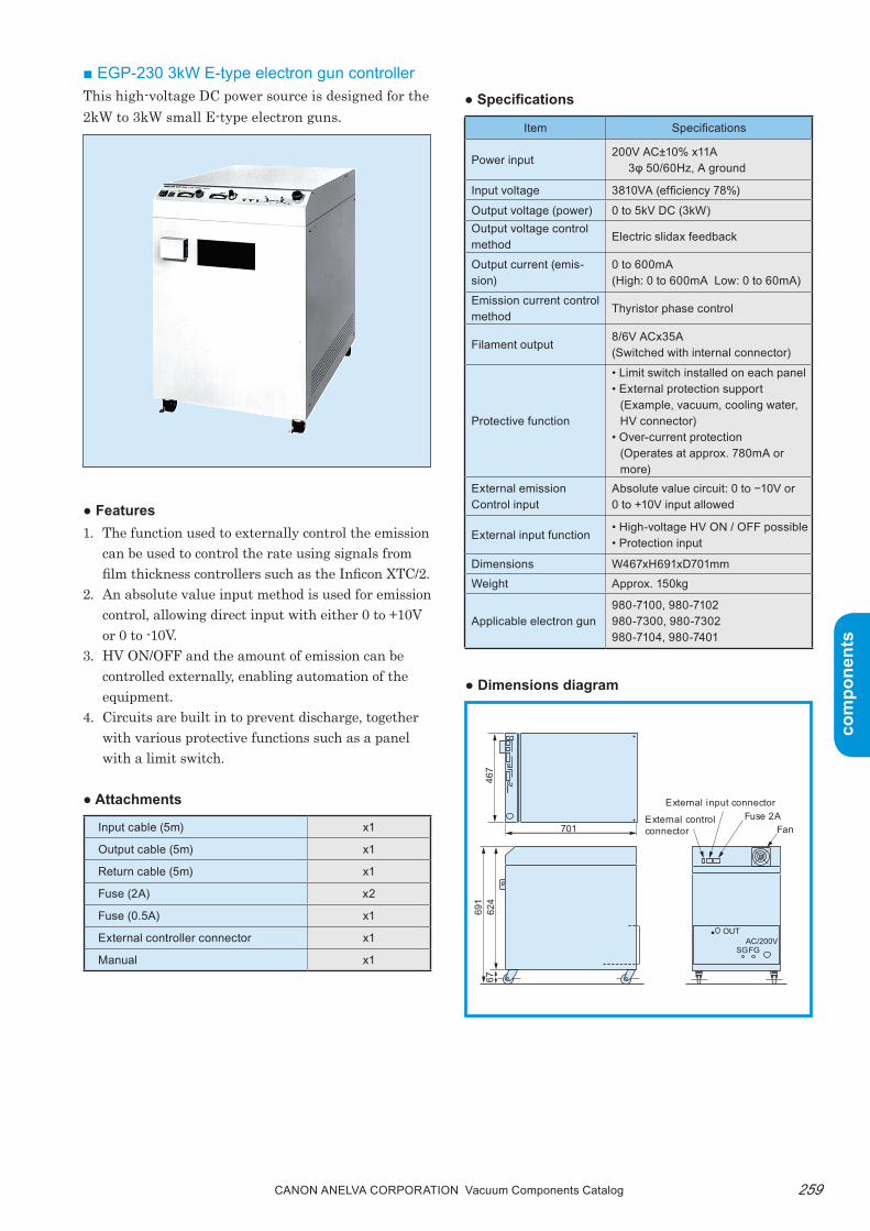
259Canon anELVa Corporation Vacuum Components Catalog
com
pone
nts
com
pone
nts
● Features1. the function used to externally control the emission
can be used to control the rate using signals from film thickness controllers such as the Inficon XtC/2.
2. An absolute value input method is used for emission control, allowing direct input with either 0 to +10V or 0 to -10V.
3. HV ON/OFF and the amount of emission can be controlled externally, enabling automation of the equipment.
4. Circuits are built in to prevent discharge, together with various protective functions such as a panel with a limit switch.
● Attachments
■ EGP-230 3kW E-type electron gun controllerthis high-voltage DC power source is designed for the 2kW to 3kW small E-type electron guns.
● Specifications
Item Specifications
Power input200V AC±10% x11A
3φ 50/60Hz, A ground
Input voltage 3810VA (efficiency 78%)
Output voltage (power) 0 to 5kV DC (3kW)Output voltage control method
Electric slidax feedback
Output current (emis-sion)
0 to 600mA(High: 0 to 600mA Low: 0 to 60mA)
Emission current control method
Thyristor phase control
Filament output8/6V ACx35A(Switched with internal connector)
Protective function
• Limit switch installed on each panel• External protection support
(Example, vacuum, cooling water, HV connector)
• Over-current protection(Operates at approx. 780mA or more)
External emissionControl input
Absolute value circuit: 0 to −10V or0 to +10V input allowed
External input function• High-voltage HV ON / OFF possible• Protection input
Dimensions W467xH691xD701mm
Weight Approx. 150kg
Applicable electron gun980-7100, 980-7102980-7300, 980-7302980-7104, 980-7401
Input cable (5m) x1
Output cable (5m) x1
Return cable (5m) x1
Fuse (2A) x2
Fuse (0.5A) x1
External controller connector x1
Manual x1
● Dimensions diagram
701
467
624
6769
1
External control connector
External input connectorFuse 2A
Fan
OUT
SGFGAC/200V

Canon anELVa Corporation Vacuum Components Catalog260
com
pone
nts
com
pone
nts
■ Notes on attaching the output cableWhen using an E-type electron gun, space for con-necting the output cable from the controller must be provided.One 922-9203 output cable (2p connector ×1) (up to four for the 3kW source E-type electron gun) is used for the 2kW and 3kW E-type electron guns.
● Example of attaching the output cable (for the 980-7100 2kW E-type electron gun)
922-9203 output cable
11724
φ85
φ70
φ2.3 Oxygen-free copper
953-9904100A connecting terminal
Space with output cable attached MIN200
(φ70 ICF port)
922-9203output cable
954-7210100A2Pcurrent terminal
M6bolt
954-79224P current terminal
♯16 socket contact
Coil lead wire (4 wires)
980-71002kW E-type electron Gun
953-9230gasket
953-5014gasket
952-9830gasket
954-5110flange
954-7830flange
M6 bolt
(φ70 ICF port)(Vacuum container)
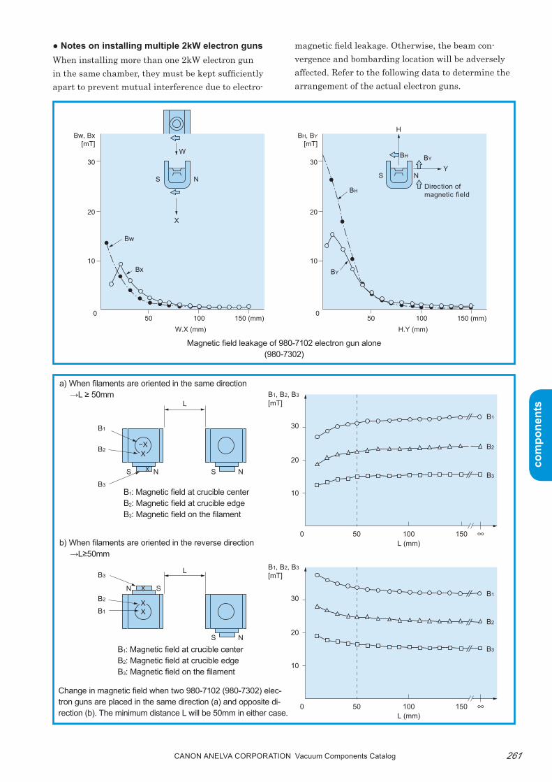
261Canon anELVa Corporation Vacuum Components Catalog
com
pone
nts
com
pone
nts L
−X
L
NS
SN
NS
NS
X
XX
X
X
B1
B2
B3
B3
B2
B1
B1
B2
B3
B1
B2
B3
B1, B2, B3
[mT]
30
20
10
0 50 100L (mm)
L (mm)
150
B1, B2, B3
[mT]
30
20
10
0 50 100 150
● Notes on installing multiple 2kW electron gunsWhen installing more than one 2kW electron gun in the same chamber, they must be kept sufficiently apart to prevent mutual interference due to electro-
magnetic field leakage. Otherwise, the beam con-vergence and bombarding location will be adversely affected. refer to the following data to determine the arrangement of the actual electron guns.
Magnetic field leakage of 980-7102 electron gun alone(980-7302)
a) When filaments are oriented in the same direction →L ≥ 50mm
B1: Magnetic field at crucible centerB2: Magnetic field at crucible edgeB3: Magnetic field on the filament
b) When filaments are oriented in the reverse direction →L≥50mm
B1: Magnetic field at crucible centerB2: Magnetic field at crucible edgeB3: Magnetic field on the filament
Change in magnetic field when two 980-7102 (980-7302) elec-tron guns are placed in the same direction (a) and opposite di-rection (b). The minimum distance L will be 50mm in either case.
0
10
20
30
Bw, Bx[mT]
50 100 150 (mm)W.X (mm)
0
10
20
30
BH, BY
[mT]
50 100 150 (mm)H.Y (mm)
W
NS
X
Bw
Bx BY
BY
BH
H
BH
YNS
Direction of magnetic field

Canon anELVa Corporation Vacuum Components Catalog262
com
pone
nts
com
pone
nts
Relationship of the distance (L) and magnetic field between the 980-7104 2kW triple-barrel electron gun and 980-7102 (980-7302) electron gun. Minimum dimensions L=60mm.
0 50 100 150
10
20
30
B1
[mT]
R=60mm
R (mm)
N S
N
S N
S
B
R
120°
120°
B1 : Magnetic field on the filament← : Direction of magnetic field
0 50 100 150
10
20
30
B1
[mT]
L (mm)
: Magnetic field of single-shot EB gun: Magnetic field of triple-shot EB gun
L=60mm980-7104
980-7102(980-7302) B1
B1
S2
N1
L
N2
S1
B1 : Magnetic field at crucible center← : Direction of magnetic field
Relationship between the radius (R) and magnetic field when the 980-7102 (980-7302) electron gun is placed on the same circumference. Minimum radius R=60mm.

263Canon anELVa Corporation Vacuum Components Catalog
com
pone
nts
com
pone
nts
10,000
1,000
100
100 0.5 1 21.5
Power (kW)
Deposition rate
(Å / min)
Ti(7g)
Mo(11g)
Au(13.7g)
Substrate
250mm
E-GUN
■ Technical Notes ● Typical deposition rate example
Deposition rate of 2kW E-type electron gunElectron gun: 980-7102 E-type electron gunSample volume: Shown in parentheses
(The data in this section is the average of the typical deposi-tion rates measured with a crystal thin film meter 250mm above a crucible using our E-type electron guns.)

Canon anELVa Corporation Vacuum Components Catalog264
com
pone
nts
com
pone
nts
250mm
250mm250mm
Power (kW)0 1 2 3
10
100
1000
10000
0 1 2 310
100
1000
10000
Superconductive material
Ba
Y
Bi (Sweep)
Y2O3
Cu
La
Substrate
E-GUN
Power (kW)
Magnetic film material, refractory material, insulating material
Substrate
E-GUN
0 1 2 310
100
1000
10000
Power (kW)
Wiring material
Substrate
E-GUN
SiO2
(Sweep)
Cr (Sweep)
Ni (Sweep)Al (Sweep)
Mo (Sweep)
Si
Al
Si(Sweep)
(Å/min)
Deposition rate
(Å/min)
Deposition rate
(Å/min)
Deposition rate
980-7300 Deposition rate of 3kW single-shot E-type electron gun with sweepElectron Gun : 980-7300Sample volume : 2.5mLSweep : Those that are indicated as sweep (Bi, AL, Si, Cr, Mo, SiO2).
Others are stationary.The deposition rate described here is just a measurement example. The deposition rate characteristic depends on fac-tors such as the sample volume, surface condition, degree of vacuum, and sweep status.

265Canon anELVa Corporation Vacuum Components Catalog
com
pone
nts
com
pone
nts
Rate control example with 3kW four source E-type electron gun (Tetra gun)Electron gun: 980-7401 E-type electron gunControl: With crystal film thickness controller
Four source simultaneous deposition rateControl example (Si, Zr, Cu, Al)
Y, Ba simultaneous rate control example
(Time)
Aℓ
Cu
Zr
ZrSi
Dep
ositi
on ra
te (Å
/S)
0
0
0
0
1MIN
1Å/S
1Å/S
1Å/S
1Å/SBa
Y
(Time)
Dep
ositi
on ra
te (Å
/S)
1MIN
0
5
10
0
5
10
● Precautions on installing the electron gunFor E-type electron guns, the electron beam is de-flected by the magnetic field of the gun. therefore, if a magnetic structure is in the vicinity of the electron gun, the magnetic field of the gun will be affected and the bombarding location of the electron beam changed. In extreme cases, the electron beam may miss the crucible and damage the electron gun.For iron vacuum chambers, in particular, the electron gun must be at least 15cm away from the base plate of the chamber. In addition, when using a mount, use non-magnetic material such as SUS.
● On-site adjustment of the electron gunAfter the E-type electron gun is delivered and instal-lation, protective wiring, and plumbing of the water pipes have been completed, we will perform on-site adjustment of the electron gun to confirm that it is safe to use.
Magnetic material structure
Minimum of 15cm
Minimum of 15cm
Electron gun
Electron gun Mount (non-magnetic)Steel chamber
Minimum of 15cm

Canon anELVa Corporation Vacuum Components Catalog266
com
pone
nts
com
pone
nts
■ Ordering informationParts number Model Description Remarks Code
Electron gun
VMT-9119 980-7102 2kW Electron Beam Gun Crucible capacity 1mL 40000
P25-05870 980-7100 2kW Electron Beam Gun980-7102+980-7301 electron beam sweepable, crucible capacity 1mL
40001
VSM-0302 980-7104 2kW 3 Series Electron Beam Gun For φ300, crucible capacity 1mLx3 40010
VSM-0303 980-7104 2kW 3 Series Electron Beam Gun For φ400, crucible capacity 1mLx3 40011
P25-05919 980-7302 3kW Electron Beam Gun Crucible capacity 2.5mL 40030
P25-05920 980-7300 3kW Electron Beam Gun980-7302+980-7301 electron beam sweepable, crucible capacity 2.5mL
40031
A21-01279 980-7401 3kW Electron Beam Gun (four source)Four source simultaneous deposition capable, 3.8mL
40040
Power supply
752-0178 922-9203 Electron Beam Gun Controller 2kW single-shot, triple-barrel power supply 40500
U13-00400 EGP-230 Electron Beam Gun Controller 3kW power supply 40503
Options
A26-04817 980-7301 Sweep Unit For 2kW single-shot, 3kW single-shot 40320
594-3481 954-7912 3P Current Feedthrough for φ70 ICF 36163
753-0001 954-7605 Rotary Motion Feedthrough for crucible rotation 36521
Note) Contact us for more information about CE (RoHS).
Vacuum Components Catalog
CANON ANELVA COrpOrAtiON5-1 Kurigi 2-chome, Asao-ku, Kawasaki-shi, Kanagawa
phone+81-44-980-3503 (DIAL IN)
Engligh: 1st Edition Issue 1 issued September 2014(Based on Japanese 9th Edition Issue 1 issued May 2014)
* Notes on export, transfer and disposal When exporting a product listed in this catalog outside Japan, please inform our sales division in advance because decisions must be made
based on the terms of the Foreign Exchange and Foreign Trade Act. Also note the transfer and disposal destination when transferring or disposing domestically.
* The design, specifications, or dimensions published in this catalog are subject to change without prior notice.* Due to printing, photos may differ from the color of the actual product.* Unauthorized reproduction or copying prohibited