
Canal Irrigation System - Civil.PDDC.2013
30
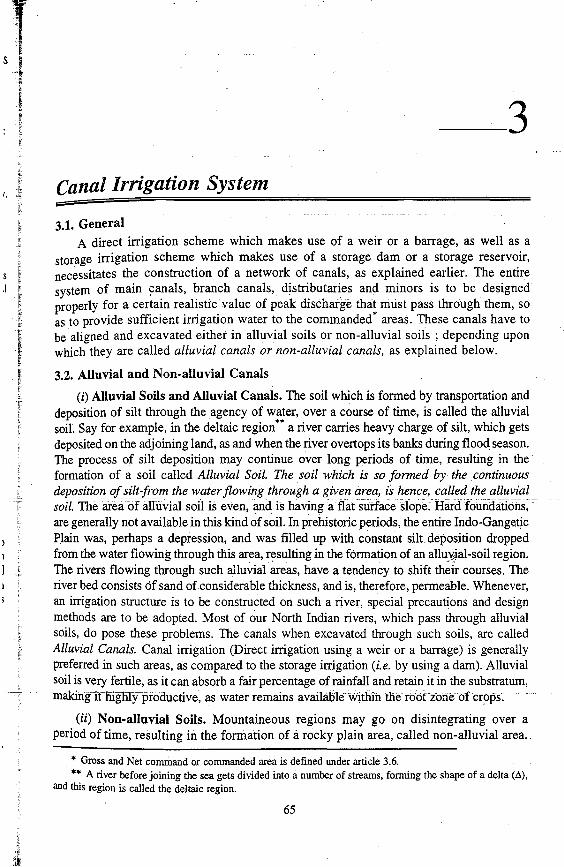
_3 Canal Irrigation System 3.1. General A direct irrigation scheme which makes use of a weir or a barrage, as well as a storage irrigation scheme which makes use of a storage dam or a storage reservoir, necessitates the construction of a network of canals, as explained earlier. The entire system of main branch canals, distributaries and minors is to be designed properly for a certain realistic value of peak discharge that must pass through them, so as to provide sufficient irrigation water to the commanded* areas. These canals have to be aligned and excavated either in alluvial soils or non-alluvial soils ; depending upon which they are called alluvial canals or non-alluvial canals, as explained below. 3.2. Alluvial and Non-alluvial Canals (i) Alluvial Soils and Alluvial Canals. The soil which is formed by transportation and deposition of silt through the agency of water, over a course of time, is called the alluvial soiL Say for example, in the deltaic region** a river carries heavy charge of silt, which gets deposited on the adjoining land, as and when the river overtops its banks during flood season. The process of silt deposition may continue over long periods of time, resulting in the formation of a soil called Alluvial Soil. The soii which is so formed by the .continuous deposition of silt-from the water flowing through a given area, {s hence, called the alluvial soil. The area of aiIUVlat so11 is even, and ls havi.ng a flat sllrface sfripe. are generally not available in this kind of soil. In prehistoric periods, the entire Indo-Gangetjc Plain was, perhaps a depression, and was filled up with constant silt. deposition dropped from the water flowing through this area, resulting in the formation of an allU\jal-soil region. The rivers flowing through such alluvial areas, have a tendency to shift courses. The river bed consists cif sand of considerable thickness, and is, therefore, permeable. Whenever, an irrigation structure is to be constructed on such a river, special precautions and design methods are to be adopted. Most of our North Indian rivers, which pass through alluvial soils, do pose these problems. The canals when excavated through such soils, are called Alluvial Canals. Canal irrigation (Direct irrigation using a weir or a barrage) is generally preferred in such areas, as compared to the storage irrigation (i.e. by using a dam). Alluvial soil is very fertile, as it can absorb a fair percentage of rainfall and retain it in the substratum, makingifiiigfilfprodudive, as water remains availableWitl:iin the (ii) Non-alluvial Soils. Mountaineous regions may go on disintegrating over a period of time, resulting in the formation of a rocky plain area, called non-alluvial area.. * Gross and Net command or commanded area is defined under article 3.6. ** A river before joining the sea gets divided into a number of streams, forming the shape of a delta (Ll), and this region is called the deltaic region. 65
-
Upload
khangminh22 -
Category
Documents
-
view
1 -
download
0
Transcript of Canal Irrigation System - Civil.PDDC.2013
_3 Canal Irrigation System
3.1. General A direct irrigation scheme which makes use of a weir or a barrage, as well as a
storage irrigation scheme which makes use of a storage dam or a storage reservoir, necessitates the construction of a network of canals, as explained earlier. The entire system of main ~anals, branch canals, distributaries and minors is to be designed properly for a certain realistic value of peak discharge that must pass through them, so as to provide sufficient irrigation water to the commanded* areas. These canals have to be aligned and excavated either in alluvial soils or non-alluvial soils ; depending upon which they are called alluvial canals or non-alluvial canals, as explained below.
3.2. Alluvial and Non-alluvial Canals
(i) Alluvial Soils and Alluvial Canals. The soil which is formed by transportation and deposition of silt through the agency of water, over a course of time, is called the alluvial soiL Say for example, in the deltaic region** a river carries heavy charge of silt, which gets deposited on the adjoining land, as and when the river overtops its banks during flood season. The process of silt deposition may continue over long periods of time, resulting in the formation of a soil called Alluvial Soil. The soii which is so formed by the .continuous deposition of silt-from the water flowing through a given area, {s hence, called the alluvial soil. The area of aiIUVlat so11 is even, and ls havi.ng a flat sllrface sfripe. Hardfoundaiions~~ are generally not available in this kind of soil. In prehistoric periods, the entire Indo-Gangetjc Plain was, perhaps a depression, and was filled up with constant silt. deposition dropped from the water flowing through this area, resulting in the formation of an allU\jal-soil region. The rivers flowing through such alluvial areas, have a tendency to shift th~ir courses. The river bed consists cif sand of considerable thickness, and is, therefore, permeable. Whenever, an irrigation structure is to be constructed on such a river, special precautions and design methods are to be adopted. Most of our North Indian rivers, which pass through alluvial soils, do pose these problems. The canals when excavated through such soils, are called Alluvial Canals. Canal irrigation (Direct irrigation using a weir or a barrage) is generally preferred in such areas, as compared to the storage irrigation (i.e. by using a dam). Alluvial soil is very fertile, as it can absorb a fair percentage of rainfall and retain it in the substratum, makingifiiigfilfprodudive, as water remains availableWitl:iin the rooczcineofcr~ps.
(ii) Non-alluvial Soils. Mountaineous regions may go on disintegrating over a period of time, resulting in the formation of a rocky plain area, called non-alluvial area ..
* Gross and Net command or commanded area is defined under article 3.6. ** A river before joining the sea gets divided into a number of streams, forming the shape of a delta (Ll),
and this region is called the deltaic region.
65

I
! 1 •. !
j.l,1
I I '1
. i ..
! 1·1
: 'I I: I
I
I·.··· .. l'.1111'! 1!11,:
66 IRRIGATION ENGINEERING AND HYDRAULIC STRUCTURES
It has an uneven topography, and hard foundations are generally available. The rivers, passing through such areas, have no tendency to shift their courses, and they do not pose much problems for designing irrigation structures on them. Canals, passing through such areas are called Non-alluvial Canals. Major portion of Maharashtra State is non-alluvial. Storage irrigation is preferred to canal irrigation in this type of soil. Non-alluvial soils may be permeable or impermeable, but generally, they are non-perm~able .
3.3. Alignment of Canals
Irrigation canals can be aligned in any of the following three ways : (i) as watershed canal or ridge canal .
. (ii) as contour canal ; and (iii) as side-slope canal. These three types of canals are discussed below :
(i) Watershad Canal or Ridge Canal. The dividing ridge line between the catch-. ment areas• of two streams (drains) is called the water-shed, or the. ridge. Thus, between
two major streams, there is the main watershed (ridge line), which divides the drainage area of the two streams, as shown in Fig. 3.1. Similarly, between a main stream and any of its tributary, there are subsidiary watersheds (ridge lines), dividing the drainage between the two streams on either side.
· /y I
v 12
l I
.l. I
I
Fig. 3.1. Alignment of a Ridge or Watershed canal (Head reach of a main canal in plains)
* The area from which rain water flows into a drain or a stream, is known as its catchment area.

CANAL IRRIGATION SYSTEM 67
For a canal system in plain areas, where land slopes are relatively flat and uniform, it is often necessary and advantageous to align canals on the watersheds (ridge lines) of the areas to be irrigated. The canal which is aligned along any natural watershed (ridge line) is called a watershed canal, or a ridge canal. The natural limits of the command area of such irrigation channels would be the drainage area on either side of the channel. Aligning a canal (main canal or branch canal or distributary) on the ridge, ensures gravity irrigation on both sides /Of the canal. Moreover, since the drainage flows away from the ridge, no drainage can cross a canal aligned on the ridge. Thus, a canal aligned on the watershed saves the cost of construction of cross-drainage works.
However, the main canal has to be taken off from a river, which is the lowest point in the cross-secti~n, and this canal must mount the watershed (ridge) in as short a distance as possible. Since the available ground slope in the head reaches of a canal is usually much higher than the required canal bed slope, the canal generally needs only a short distance to reach the ridge line. This is illustrated in Fig. 3.1, in which the main canal takes off from a river at point A, and mounts the watershed at point B. Let the canal bed level at A be 200 m and the elevation of the highest point Q along the section PQA be 210 m. Assuming that the ground slope is l m per km, the distance of the point B (RL 195 m) from Q (RL 210 m) on the watershed would be 15 km. If the designed canal bed slope is I in 4000 (i.e. 0.25 m per km), then the length AB of the canal would be 20 km. In this length AB, the canal would cross small streams, and hence, construction of cross-drainage structures would be necessary for this length. As a matter of fact, the alignment AB is influenced considerably by the need of providing suitable locations for the cross-drainage structures. The exact location of B would be determined by trial, so that the alignment AB results in an economic as well as an efficient canal system. It can also be seen that on the watershed side of the canal AB, the ground (i.e. area AQB) is higher than the ground area on valley side (i.e. river side). Therefore, th.is canal portion AB can irrigate only on one side (i.e. on left side) of the canal.
· When once the canal has reached the watershed (ridge line), it is generally kept on the watershed, except where : (i) localities are settled on the watershed ; or (ii) where the wate~shed is fooping and not running straight, as shown by L1L2L3 in Fig. 3.1. In a situation of a looping ridge line, the canal alignment may be taken straight along L1L3 by leaving the ridge line. The area between the canal and the watershed in the region L (Fig. 3.1) can be irrigated by a distributary which takes off at L1 and follows the watershed alignment along L1LzL3• In the region L, the main canal may also have to cross some small streams, and hence some cross-drainage structures may have to be . constructed.
If the watershed is passing through villages or towns, the canal may have to leave the watershed (ridge line) for some distance.
The depressions in the ridge line may also necessitate construction of viaducts or -- syphons to maintain the canal FSL. -·· · - -- --'···- -- -·--- ----- ·· -·-· - -·-·--·
(ii) Contour Canals. The above arrangement of providing the canal along the ridge line are, however, not found economical in hill areas, since the conditions in hills are vastly different compared to those of plains. In hills, the river flows in the valley well below the watershed. lnfact, the ridge line (watershed) may be hundred of metres abov~ the river. It therefore becomes virtually impossible to take the canal on top of such a higher ridge line. In such conditions, contour canals (Fig. 3;2) are usually constructed.

I"' :1,:j',l I',, t'i' I
I :1
,I'
, I
I,: !
68 IRRIGATION ENGINEERING AND HYDRAULIC STRUCTURES
Fig. 3.2. Alignment of a Contour canal. (Head reach of main canal in hills)
Contour channels follow a contour, except for giving the required longitudinal slope to the canal.
Since the river slope is much steepter than the canal bed slope, the canal encompasses more and more area between itself and the river. It may be noted that more fertile areas in the hills are located at lower levels only.
A contour canal irrigates only on one side because the area on the other side is higher, as can be seen in Fig. 3.2. ,
-As tfiedraillage:tlow is always- at fight anglesto-thegrouncic6-ntoiid;·sudiT2hannel would definitely have tci cross natural drains and streams, necessitating construction of cross-drainage structures.
(iii) Side slope canal. A side slope canal is that which is aligned at right angles to the contours ; i.e. along the side slopes, as shown in Fig. 3.3. Since such a canal runs parallel to the natural drainage flow, it usually does not intercept drainage channels, thus, ·avoiding the construction of cross-drainage structures.
In order to finalise the canal networks for an irrigation project, trial alignment of canals are initially marked on the
' ' i I · ~ap prepared during the detailed survey. A large-scale map I Ir is required to work out the details of individual canals. How-
l'!"' __ _:--___ ever;·-a-smaJ-lo.-sca-lemap-showing the entire command-area of
' 1
1 the irrigation project is also desirable. The alignents of canals : , , , i,: marked on the map are transferred on the field, and adjust-
-SIDE SLOP£ CHANN L
1000 --~----.J -- - - ---sso ____ 9CiT
1 [!1 ments and changes are made, wherever found necessary. These adjustments are transferred on the map as well. The
I alignment on the field is marked by small masonry pillars GROUND CONTOURS
erected at every 200 metres distance or so. The centre line Fig. 3.3. Alignment of a Side on top of these pillars coincides with the exact alighment of Slope canal.

CANAL IRRIGATION SYSTEM 69
the given canal. In between the adjacent pillars, a small trench may be excavated in the ground, to mark the canal alignment.
3.4. Distribution System for Canal Irrigation
It has been emphasized earlier that the direct irrigation scheine using a weir or a barrage, as well as the storage irrigation scheme using a dam or a reservoir, require a network of irrigation canals of different sizes and capacities. The entire network of irrigation channels (Fig. 3.4) is called the Canal System. The canal system, as explained earlier in Chapter 2, consists of :
(i) Main canal ;
(ii) Branch canals ;
(iii) Distributaries, also called major distributaries ;
(iv) Minors, also called minor distributaries,
(v) Watercourses.
In case of direct irrigation scheme, a weir or a barrage is constructed across the river, and water is headed up on the upstream side. The arrangement is known as Head
. .
8-Branches D - Distrubutaries M-Minors
Fig. 3.4. Layout of an Irrigation canal network.
'I, , 11 I
,·1.1
I'
70 IRRIGATION ENGINEERING AND HYDRAULIC STRUCTURES
Works or Diversion Head Works. It will be explained in details in Chapter 9. Water is diverted into the main canal by means of a diversion weir. A head regulator is provided at the head of the main canal, so as to regulate the flow of water into the main canal.
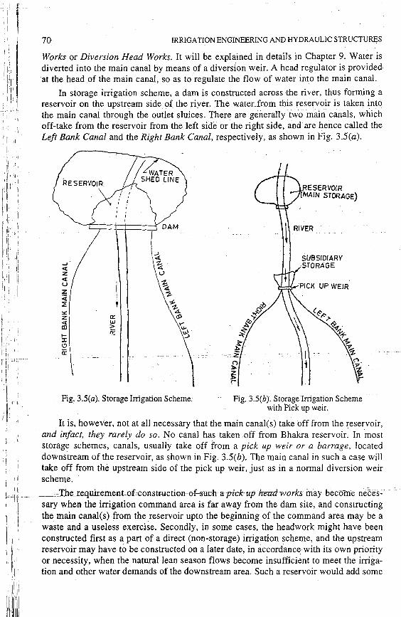
In storage irrigation scheme, a dam is constructed across the river, thus forming a reservoir on the upstream side of_ the river. The_water from this reservoir is taken into the main canal through the outlet sluices. There are generally two ·main canals, which off-take from the reservoir from the left side or the right side, and are hence called the Left Bank Canal and the Right Bank Canal, respectively, as shown in Fig. 3.5(a).
a:: UJ > ;:;:
Fig. 3.S(a). Storage Irrigation Scheme.
RESERVOIR (MAIN STORAGE)
i RIVER
SUBSIDIARY -STORAGE
Fig. 3.5(b). Storage Irrigation Scheme with Pick up weir.
It is, however, not at all necessary that the main canal(s) take off from the reservoir, and infact, they rarely do so. No canal has taken off from Bhakra reservoir: In most storage schemes, canals, usually take off from a pick up weir or a barrage, located downstream of the reservoir, as shown in Fig. 3.S(b). The main canal in such a case will take off from the upstream side of the pick up weir, just as in a normal diversion weir scheme. II
[ . :J _____ The_requirement-ofccconstmcti0n-0f-such-a-pick- up-head-works may become rieces- · ·1·· '
11
j sary when the irrigation command area is far away from the dam site, and constructing
11 'I the main canal(s) from the reservoir upto the beginning of the command area may be a
'i·j'' ,1 waste and a useless exercise. Secondly, in some cases, the headwork might have been 1
, constructed first as a part of a direct (non-storage) irrigation scheme, and the upstream I, 1 reservoir may have to be constructed on a later date, in accordance with its own priority I'
'1, or necessity, when the natural lean season flows become insufficient to meet the irriga-il1, tion and other water demands of the downstream area. Such a reservoir would add some
,: 11 11
~Iii
I ~ i
CANAL IRRIGATION SYSTEM 71
new irrigation command and firm up the irrigation in the existing command. That is what happened in the case of Bhakra dam, where canal system was already in existence as a part of a nop storage scheme, purely based on perennial river supplies. Similar constructions are expected in case of Yamuna river, where Western Yamuna Canql (WYC) and Eastern Yamuna Canal (EYC) taking off from the Tajewala headworks • have been in existence for the last more than 100 years, but without the backing of any upstream reservoir. Such a direct irrigation scheme proved satisfactory in olden times, when population was less and the river used to get sufficient snowmelt throughout the Jean season. However, with the increasing population and consequently increasing water demand along with dwindling snowmelt due to extension of habitat in upper hills and green house effects of urbanisation, the available natural flows in lean season have become insufficient, necessitating construction of reservoir(s) upstream. That is why, there are plans to construct three reservoirs at Renuka, Kishau and Lakhwar-Vyasi in the Yamuna catchment upstream. When these dame are constructed, there will be very little addition to irrigation command area, but they will mostly firm up the irrigation in the already existing WYC and EYC command, and make available water for other needs. The (Hathnikund) headworks constructed as a part of direct irrigation scheme will then; become a part of a storage irrigation scheme. ·
It can be easily understood that a reservoir redistribute the water in time (storing water in rainy season and releasing it in lean season) ; while the barrage and the canal system will redistribute it in space, taking it upto the fields.
In both these 'irrigation schemes, when once the water reaches into the main canal, the problem left is to distribute this water upto the fields. The purpose is achieved through a network of channels, as described below : -
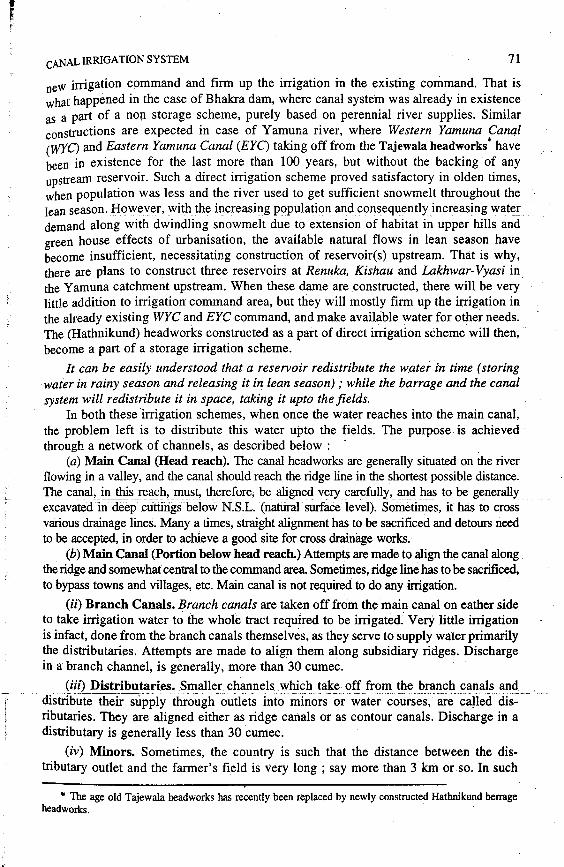
(a) Main Canal (Head reach). The canal headworks are generally situated on the river flowing in a valley, and the canal should reach the ridge line in the shortest possible distance. The canal, in this reach, must, therefore, be aligned very carefully, and has to be generally excavated-I.ii deep cuttlngs below N.S.L. {natui-ai. sUrface level). Sometimes, it has to cross various drainage lines. Many a times, straight alignment has to be sacrificed and detours need to be accepted, in order to achieve a good site for cross drainage works.
(b) Main Canal (Portion below head reach.) Attempts are made to align the canal along the ridge and somewhat central to the command area. Sometimes, ridge line has to be sacrificed, to bypass towns and villages, etc. Main canal is not required to do any irrigation.
(ii) Branch Canals. Branch canals are taken off from the main canal on eather side to take irrigation water to the whole tract required to be irrigated. Very little irrigation is infact, done from the branch canals themselves, as they serve to supply water primarily the distributaries. Attempts are made to align them along subsidiary ridges. Discharge in a branch channel, is generally, more than 30 cumec.
(iii) Distributaries. Smaller chanJtels which take off from the branch canals and distribute theTrsupply through-outlets into minors-or water courses, are ca!ieci dis::-ributaries. They are aligned either as ridge canals or as contour canals. Discharge in a distributary is generally less than 30 cumec.
(iv) Minors. Sometimes, the country is such that the distance between the distributary outlet and the farmer's field is very long ; say more than 3 km or .so. In such.
* The age old Tajewala headworks has recently been replaced by newly constructed Hathnikund berrage head works.

i'' I 'ii\1 : :1
72 IRRIGATION.ENGINEERING AND HYDRAULIC STRUCTURES
a case, small channels called minors, are taken off from the distributaries, so as to supply water to the cultivators at the point nearer to their fields. Discharge in a minor, is generally, less than 2.5 cumec.
(v) Watercourses. These are not the government channels and belong to the cultivators. They are small channels, which are excavated and maintained by the cultivators at their own costs, to take water from the government-owned outlet points, provided_ in ~he distributary or the minor. -
3.5. Curves in Channels
Attempts are made to align the channels Slfaight as far as possible. But many a times, the curves become inescapable. Whenever, a curve is proposed, while aligning unlined channels, it should be as gentle as possible. A curve causes disturbance of flow and results in silting on the inside (i.e. convex side) and scouring on the outside (i.e. concave side).
Pitching is, tqerefore, sometimes proposed on the Fig. 3.6. concave side, so as to avoid scouring. If the discharge
CONCAVE SIDE
is more, the curve should be more gentle and should, therefore, have more radius. The g~erally adopted minimum values of radii for different discharges are tabulated below in Table 3.1. .
Discharging Capacity of Channels (in cumecs)
Over JOO
3Ch-IOO
15-3.0
3-15
0.5-3
Less than 0.5
3.6. Certain Important Definitions
Table 3.1
Minimum recommended curve Radius lin metres) ·
1500
900
600.
300
150
100
i :1
'I , Before we discuss the techniques, which are employed to determine the 'design ' 1 .. , J\ . discharge~-~~~-~-~an~l_,_l~t _ _ll_~ __ f}!st _of_ all, define certain important. t~rms, which often .. ~ .· j-f
1
_____ coiiieacross in the design of irrigation canal systems. · ·. .
11 ·: 3.6.1. Gross Command Area (G.C.A.). It is the total (!rea, bounded within the _ 1, 11
11 I' ·irrigation boundary of a project, which ca.n be economically irrigated without consider-
11,: ·. ing the limitation of the quantity of available water. It includes the cultivable as well as \' j \\
1
the un-cultivable area. For example, ponds, residential areqs, roads, reserved forests,
1,.1!
1. etc. are the uncultivable areas of the gross command area.
1,,1.::i
·. :ilill ' ~lli:1

I r
CANAL IRRIGATION SYSTEM 73
A given irrigation canal system lies in a doab (i.e. the area between two drainages), and can economically irrigate the doab. It is, obviously, uneconomical to use the irrigation system to irrigate across the two drainages. Thus, the boundaries of gross command of a carial system is, fixed by the drainages on both sides of the main irrigation canal, as shown in Fig. 3.4. The gross command area, evidently represents the geographical area of the doab.
3.6.2. Culturable or Cultivable Command Area (CCA). Culturable area is the cultivable part of the gross command area, and includes all land of GCA on which cultivation is possible. It will, thus, include pastures and fallow lands, which can ·be made cultivable. Obviously, it does not include uncultivable part of the gross command, like.populated areas, ponds, roads, reserved forests, ushar land, etc.
At any given time, however, all the cultivable land may not be actually under cultivation. Therefore, sometimes, the CCA is divided into two categories ; i.e. (i) cultivated portion of CCA ; and (ii) Cultivable but not cultivated portion of CCA. In the absence of detailed data, CCA may be assumed to be equal to 80% of GCA.
3.6.3. Intensity of Irrigation (Seasonal and Annual). The entire cultivated por~ tion of the culturable. command area (CCA) is not proposed to be irrigated at one time (in one season) to avoid intensive irrigation of a particular area, which may cause harmful effects like water logging*,. salinity and malaria, etc. Moreover, due to shortage of irrigation water, larger area of the command is usually covered with partial coverage of the fields of different sub-areas or pockets. Some land of a particular sub area is thus, either allowed to take rest; or is shown with crops which do not require irrigation water. Fields left unirrigated in one season will be supplied water in the next season, when some other fields will be left unirrigated. The fields are thus, supplied water in rotation over different crop seasons, thereby irrigating only about 40 to 60% of the fields of various sub areas over a season. The irrigation water is, thus, usually supplied extenstively, covering a larger area. Such as extensive irrigation, covering a larger portion of the cultivable command, is preferred to the intensive irrigation of the smaller portion of the command, to avoid general famine conditions over some area (which would be totally left unirrigated, if the entire water is used in intensive irrigation of some other portion). Extensive irrigation also helps fo avoiding harmful effects of over-irrigation (like salinity and water-logging), which is caused by intensive irrigation.
Due to these reasons, only a small percentage of CCA is brought under irrigation over a given season. This percentage of CCA proposed to be irrigated in a given season is called the intensity of irrigation of that season, or seasonal intensity of irrigation. Say for example, the sanctioned intensity of irrigation under Bhakra canal system is only 27.6% for Kharif season, and 34.4% for Rabi season.
Sometimes, the intensity of irrigation is worked out over the entire year (inclusive of two-ormore-'-ct~rp-ieasons}; Wfieii'i{i:s c-a1Ted The annual irrigation 'intensity or annual intensity of irrigation (All), which may be defined as the percentage of CCA which may be irrigated annually. All is, thus, obtained by dividing the gross irrigated area (i.e. total area irrigated once in the year+ the area irrigated more than once in that year) by the CCA. The annual intensity of irrigation is the sum total of intensities of irrigation of all the seasons of t~e year. The annual intensity of irrigation for Bhakra canal system
* Explained in details in chapter 6.

! I
! ! I
11 I' I 1
I , 1 I
1· .,,
,,r
II
lili,):j 1'
74 IRRIGATION ENGINEERING AND HYDRAULIC STRUCTURES
is thus, computed by adding the intensity of irrigation for kharif season and that for the Rabi season, giving combined annual irrigation intensity of 27.6 + 34.4 = 62%.
The annual irrigation intensity is usually found to be in the range of 40 to 60%, but needs to be raised to the range of 100 to 180% by cultivating larger parts of CCA with more than one crop in a year, and through improved management and economica,1 utilisation of the available irrigation water. From the perusal of col. (7) of table IV under the first chapter on "Introduction to the subject", it can be seen that in India, U.P. and Punjab, States have already exceeded this figure of AU beyond 100%, to 139.6% and 133.4%, respecti','.ely, with Haryana (902%) and West Bengal (73.3%) following these two best irrigated States. Other States are far behind to such an extent that the overall annual intensity of irrigation in the country is only 45.9%.
3.6.4. Net and Gross Sown Areas. Sometimes, two crops in two seasons are grown during a particular year on the same area. Hence, such an area will be sown more than once during a given year. If this area is added to the area which is sown only once (and called the net shown area), then we get what is known as· the gross sown q,rea, or the gross cropped area. Hence,
Gross cropped or Gross sown area (during a year)
= Net cropped area, i.e. area sown once in a year + Area shown more than once during the same year
... (3.1)
3.6.5. Net and Gross Irrigated Areas. Based on the above analogy, the area which is irrigated once during a year is called· the net irrigated area, and when to this is added the area irrigated more than once, we obtain the gross irrigated area.
:. Gross irrigated area (in a given year)
= Netirri.gated area {i.e: area irrigated oncecin a year) + Area irrigated more than once during the same year .
... (3.2)
3.6.6. Area to be Irrigated. The area proposed to be irrigated in any one crop season or over any given year, is called the area to be irrigated in that season or the year, respectively. It is obtained by multiplying CCA by the seasonal or annual intensity of, irrigation, as the case may be. The areas. to be irrigated are usually worked out separately for each crop season, because the water requirement of the crops of two seasons are quite different.
.L
'I 3.6.7. Time Factor. To check the dangers of over irrigation, leading to water-log-! ging and salinity, no distributary is allowed to operate on all the days during any crop
.,J., .· seaso~. The t:!J..tio_ gf_tb~_actual operating per:iod of-adistl'ibutary- to the-crop period-is- -~ j-------c~Tz;d. the time factor of the distributary. For the Bhakra canal system, for example, the
11
'.1·.l1 ,.1.1
,,'I
time factors for Kharif and Rabi seasons are fixed at 0.80 and 0.72, respectively, which means that each distributary would receive its full SJ.!.pply for a period of 0.80 x 180 = 144 days, and 0.72 x 180 = 129 days, respectively, in each crop season of 180 days.
For computing the design capacity of a distributary, therefore, the computed water requirement (for the crops proposed to be grown and irrigated by that distributary) should be divided' by the time factor, since this factor is less than 1.

r j
CANAL IRRIGATION SYSTEM 75
3.6.8. Capacity Factor. The capacity factor for a canal is the ratio of the mean supply discharge in a canal during a period to its designed foll capacity. Since canals have to run almost to their full designed capacities during Kharif (summer) season, this value usuaJly varies from 0.9 to 0.95 for Kharif season. However, since water require-
ment during Rabi (winter) .season reduces to about ~rd times* the full supply, the
capacity factor usually varies from 0.60 to 0. 70 for Rabi season. To improve this factor during Rabi season, the cropped area in Rabi season is, hence, usually increased.
3.6.9. Full supply coefficient. Full supply coefficient is the design duty at the head of the canal. In other words, the number of hectares irrigable per cumec of the canal capacity at its head, is known as the full supply coefficient of the canal. It can hence, be represented by the equation :
FuII supply coefficient
= Area estimated to be irrigated during base period .Design fuJI supply discharge at the head of the canal
This factor is also called the Duty on capacity.
... (3.3)
3.6.10. Nominal Duty. It is the ratio of the area actually irrigated by the cultivators to the mean supply discharge Jet out from the outlet of the distributary over the crop period.
For example, let x cumec of water is released daily from the outlet of a distributary · for 100 days (says) in a total crop period of 125 days (say). Then, the mean supply
discharge over the crop period will be x 7;5oo = 0.8x (cumec).
If the area of crop irrigated by this discharge is A hectares, then the nominal duty wili be givel} as :
. A(ha) A Nommal duty =
0 0 _ ( ) = 1.25 - ha/cumec. · .<M cumec x
3.7. Computing the Design Capacity of an Irrigation Canal
Whenever one plans for supplying irrigation water, one has to think of the likely crops that would be sown in any one season. The peak rate of water requirement of all the crops in each season of a year is also needed to be worked out. The capacity of the canal should be sufficient to fulfil the maximum of the peak demand of all the crops that are required to be irrigated at any one time amongst all the seasons. It is explained below in details:
The most important Rabi crop is wheat, which requires water from December to March, durin-g-rne-Rli1:5i season. Simifady; Pai:ldy -(RiCe)-is -the-most important :Kharif crop, requiring water from June to November. So it .can be presumed that when Rabi crops require water, Kharif crops do not, and vice-versa. Sugarcane and garden crops are perennial crops, requiring water throughout the year. Hence, the canal may be designed for a capacity equal to the greater of the water requirement of Rabi and Sugar
* The winter (Rabi) crops usually mature on about 52% of the supply required by crops in summer ; but due to lower winter discharges in canals, the percentage of losses enroute becomes higher in winter season_ The actual water supply at the head of canal is, therefore, found to be about 66% of full supply.

I
! .I
I
76 IRRIGATION ENGINEERING AND HYDRAULIC STRUCTURES
cane (plus garden crops if any) ; or Kharif and Sugarcane (and garden crops, if any). This is a very simple method for fixing the capacity of the channel. The entire Rabi area is supposed to be sown with wheat and entire Kharif area with Paddy ; Sugarcane area (including garden· crop area, if any) is excluded from both. Their water requirements in
-GumeG are wor:ked out-for both seasons; separately. The water requirement of sugarcane and garden crops are separately worked out each, in cumec. The sum of cumec required by the Rabi plus Sugarcane (including garden crop, if any) and Kharif plus Sugarcane (including garden crop if any), are separately worked out. The canal capacity may then be fixed for the maximum of the two values ..
The most important point which must be kept in mind while fixing the channel capacity is that, we must take into account the keenest demand of the crop and not the average demand. For example, let Rice require 120 cm of water during 120 days, thus giving an average outlet factor of 864 hectares/cumec
(. D= 864B = 864x 120 864) i.e. ~ 120
But a canal designed on this average outlet factor will prove to be very inadequate, as it will fail to supply the required water to the crop at its peak demand, i.e. at the time of kor-watering, as explained below :
The kor depth for Rice is about 19 cm and the kor period is about 2 weeks (i.e. 14 days). It means that 19 cm of water depth must be supplied in about 14 days. The outlet factor for this, works out to be 637 hectares/cumec as
D= 864B = 864x 14 = 637 t. 19
Now, discharge required to mature A hectares of land for an outlet factor of 864 is
8~4 cumecs ; while that for an outlet factor of 637 is 6~7 cumecs. Out of these twQ
values, the second value (i.e. 6~7) is more, and hence, the -discharge required for
fulfilling the kor demand o~ the crop is more than that for the av~rage demand.
Similarly, wheat requires about 40 cm of water in a total base period of about 160 days; thus giving an average outlet factor of 3464 hectares/cumec. But the kor water depth required by wheat is about 14 cm in about four weeks, giving an outlet factor of 1728 hectares/cumec. _Applying the previous reasoning; we can say that the discharge required to fulfil kor-demand is much more than that for the average-demand (almost double of average). Hence, it follows that the peak demand, i.e. kor-demand of the crop should be taken into account while fixing the capacity of a canal. Moreover, the provision for canal losses should also be made, while deciding the final capacity of the canal.
-------- -=-=:.:.=-c-"Tnemernoa·,'-'cfescfibea'ao-6ve; Tor determiniffgtfie·c'anal ·capacity ;·ifl1 Simplified approximate process. To be more precise, we can find out the monthly or fortnightly water requirements of various crops (as was explained in Chapter 2). The water depth required in this interval is multiplied by the crop area, so as to give the volume of water required in this interval. Dividing the volume by interval, we can find out the discharge required in each interval, by various crops. The summation of which for all the crops will give us the discharge required by all the crops in each interval. The canal may then be designed for maximum of these values.

,, r l
CANAL IRRIGATION SYSTEM 77
It is evident that in order to be more precise, the interval should be as small as possible. Generally, monthly water requirement studies are conducted, and the canal capacity is increased by 20 to 25% to cater for the peak demand in the month.
Example 3.1. The gross commanded area for a distributary is 6000 hectares, 80% of which is culturable irrigable. The intensity of irrigation for Rabi season is 50% and that for Kharif season is 25%. If the average duty at the head of the distributary is 2000 hectares!cumec for Rabi season and 900 hectareslcumec for Kharif season, find out the discharge required at the head of the dis tributary from average demand considerations.
Solution. G.C.A. = 6000 hectares
80 C.C.A. = 6000 x
100 = 4800 hectares.
* Area to be irrigated in Rabi season
= C.C.A. x Intensity oflrrigation 50
= 4800 x 100
= 2400 hectares.
Area to be irrigated in Kharif season
25 = 4800 x 100
= 1200 hectares.
Water required at the head of the distributary to irrigate Rabi area
2400 = 2000
cumecs = 1.20 cumec. . .. (i)
Water required at the head of the distributary to irrigate Kharif area
1200 . =
900 cumecs = 1.33 cumec. . .. (ii)
Thus~ the requirement in Kh'adf season IS 1.33 cumec and that in Rabi season is 1.20 cumecs. The required discharge is maximum of the two, i.e. 1.33 cumec. Ans.
Hence, the distributary should be designed for 1.33 cumec discharge at its head, from average demand considerations. The· head regulator should be sufficient to carry 1.33 cumec ; and in Rabi season, only 1.20 cumec will be released.
Example 3.2. Determine the discharge required at the head of the distributary in Example 3.1 given above, for fulfilling maximum crop requirement. Assume suitable values of kor depth and kor period.
Solution. Let us assume a kor period of 4 weeks for Rabi (wheat) and 2.5 weeks for Kharif crop (rice). Also assume, Kor depth of 13.5 cm for Rabi (wheat) and 19 cm for ~JlnL(riG_~)SLQQ.,.:__ -~'. - -- - occ-:_ __ . ________ _
. 864 x B 864 x ( 4 x 7) Now, outlet factor for rab1 = b.
13.5
= 1792 hectares/cumec.
864 x (2.5 x 7) Outlet factor for Kharif =
19 · = 796 hectares/cumec.
Area to be irrigated in Rabi season (worked out in previous example)
= 2400 hectares

I !I/ .1'
: : J
78 IRRIGATION ENGINEERING AND HYDRAULIC STRUCTURES
Area to be in:igated in Kharif season (worked out in previous example)
= 1200hectares.
Water reqd. at the head of the distributary to irrigate Rabi area
2400 =
1792 = 1.34 cumec ... (i)
Water required at the head of the distributary to irrigate Kharif area
1200 =
796 = 1.51 cumec. ...(ii)
The required d,ischarge is maximum of the two, i.e. 1.51 cumec. Ans.
Note : The required discharge from kor demand considerations have gone up to 1.51 . . . '$'
cumec from 1.33 cumec (worked out in the previous Example), i.e. an increase of about 14%.
Example 3.3. The culturable commanded area ofa watercourse is 1200 hectares. Intensities of sugarcane and wheat crops are 20% and 40% respectively. The duties for the crops at the head of the watercourse. are 730 hectares!cumec and 1800 hectareslcumec, respectively. Find (a) the discharge required· at the head of the watercourse (b) determine the design discharge at the outlet, assuming a time factor equal to 0.8.
and
Solution. C.C.A. = 1200 hectares
Intensity of irrigation for sugarcane = 20%
: . Area to be irrigated under sugarcane = 1200 x :io = 240 hectares
Intensity of irrigation for wheat = 40%
,'., Area to be irrigated under wheat= 1200 x ~O;, 480 hectares
Duty for sugarcane = 730 hectares/cumec Duty for wheat.= 1800 hectares/cumec.
. . Discharge required for sugarcane = ~:~ cumec = b.329 cumec
Discharge required for wheat 480
= l .800
cumec = 0.271 cumec.
Now, sugarcane requires water for all the 12 months and wheat requires water for only rabi season. Hence, the water requirement at the head of the watercourse at any time of the year will be the summation of the two, i.e. equal to 0.329+0.271 =0.6 · cuniec.
(a) Hence, the discharg_e__r~q!lj_reci ~t tb~Jl~~Q_Qf_ tb_~ __ w;lJ~L:CQJJis.~.ifi 0,6 c_um.e_c.~.Ans. _
Note : The discharge during rabi season will be 0.6 cumec and for the rest of the year, it will be 0.329 cumec.
(b) Time factor= 0.8 ; since the channel runs for fewer days than the crop days, therefore, the actual design discharge at the outlet
0.6 . = 0.
8 = 0.75 cumec. Ans.

'·
CANAL IRRIGATION SYSTEM 79
Example 3.4. The culturable commanded area for a distributary is 15,000 hectares. The intensity of irrigation (/./.)for Rabi (wheat) is 40% and for Kharif (rice) is 15%. If the total water requirement ofthe two crops are 37.5 cm and 120 cm and their periods of growth are 160 days and UO days respectively; (a) Determine the outlet discharge from average demand considerations; (b) Also determine the peak demand discharge, assuming that the kor water depth for two crops are 13.5 cm. and 19 cm. and their kor periods are 4 weeks and 2 weeks respectively.
Solution. C.C.A. = 15,000 hectares.
I.I. For wheat (Rabi) . . = 40%
I.I. For rice (Kharif)
Wheat (Rabi) area
Rice (Kharif) area
= 15%
= 15,000 x 0.40 = 6000 hectares
= 15,000 x 0.15 = 2250 hectares
Now
.1 for wheat= 37.5 cm . .1 for rice= 120 cm.
B for wheat = 160 days B for rice = 140 days
D= 864B .1
864 x 160 Average duty (D) for wheat=
375 = 3686 hectares/cumec
. 864xl40 Average duty (D) for nee=
120 1008 hectares/cumec
. . Area 6000 Outlet discharge reqmred for wheat = Duty =
3686 = 1.63 cumec
·· OiiilefaiSdiarge required for rice = ~~~~,;,, i.i3 cu~~c ....
.. T
The required design discharge at outlet (from average demand considerations) is maximum of the two values, i.e. 2.23 cumec. Ans. ·
(b) Kor water depth for wheat= 13.5 cm.
Kor period fcir wheat
Kor water depth for rice
= 4 weeks= 4 x 7 = 28 days
=19cm.
Kor period for rice = 2 weeks= 2 x 7 = 14 days.
864xB Duty for wheat (for kor demand)= .1
_ 864 x Kor period for wheat 864 x 28 , Fl9lha/cumec . ·------= Koi water depth for whe.ai ·· 13 .5
Duty for rice (for Kor demand)
= 864 x Kor period for ~ice = 864 x 14 = 636 ha./cumec Kor water depth for nee . 19
Outlet discharge required for wheat (for kor demand)
Area 6000 =Duty= 1792 =3.35cumec. ... (i)
I
'.I
I' I 'I
,,
11
' I
•I
11 !
I
11
i.1 :1 I'
.11i
80 IRRIGATION ENGINEERING AND HYDRAULIC STRUCTURES
Outlet discharge required for rice (for kor demand)
= 2250 = 3.54 cumec 636
... (ii)
The required design discharge at the outlet, from peak demand considerations, is maximum of these two values, i.e. = 3.§4 cumec~ Ans.
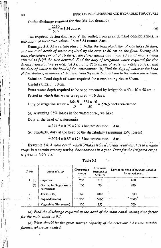
Example 3.5. At a certain place in India, the transplantation of rice takes I 6 days, and the total depth of water required by the crop is 60 cm on the field. During this transplantation period of 16 days, rain starts falling and about JO cm of rain is being utilised to fulfil the rice demand. Find the duty of irrigation water required for rice during transplanting period. (a) Assuming 25% losses of wate.r in water courses, find the duty of water at the head of the watercourse. ( b) Find the duty of water at the head of distributary, assuming 15% losses from.the distributary head to the watercourse head.
Solution. Total depth of water required for transplanting rice = 60 cm.
Useful rainfall = 10 cm.
. Extra water depth required to be supplemented by irrigatio·n = 60 - 10 = 50 cm.
Period in which this water is required= 16 days.
D f . . . 864 B 864 x 16 276 Sh s/ uty o irr1gat10n water = ----n- = 50
· = . · ectare cumec
(a) Assuming 25% losses in the watercourse, we have
Duty at the head of watercourse
= 277.5 x 0.75 = 207.4 hectares/Cumec. Ans.
(b) Similarly, duty at the head of the distributary (assuming 15% losses)
,;,, 207.4 x 0.85 = 176.3 hectares/cumec. Ans.
Example 3.6. A main canal, which offtakes from a storage reservoir, has to irrigate crops in a certain country having three seasons in a year, Data for the irrigated crops, is given in table 3.2:
Table 3.2
Crop period Area to be Duty at the head of the main canal in
S. No. Name of crop irrigated in in days hectares hectareslcumec
I. (a) Sugarcane 280 315 630
(b) Overlap for Sugarcane in 100 70 630 hot weather
2. Jowar (Rabi) 120 4800 1600 -- ·-- ·- -·--··-·
3. Bajri (Morisooiif .. -120 - 5600 --2800
4. Vegetables (Hot season) 120 350 700
(a) Find the discharge required at the head of the main canal, taking time factor for the main cana.l as 0.7.
(b) What should be the gross storage capacity of the reservoir ? Assume suitable factors, wherever needed.

CANAL JRRIGA TION SYSTEM 81
Solution. Water required by various crops, is as follows (figures taken from Table
3.2).
(i) Water required for sugarcane (whole year)
(ii) Water required for overlap sugarcane (Hot season)
(iii) Water required for jowar (Rabi season)
(iv) Water required for bajri (Monsoon season)
(v) Water required for vegetables (Hot season)
Total water required in each season is as follows :
315 . =
630 = 0.5 cumec.
70 =
630 = 0.11 cumec.
4800 =
1600 ::;: 3 .0 cumecs
·- 5600 . =
2800 = 2.0 cumecs.
350- . =
700 = 0.5 cumec.
(a) in hot season = 0.5 + 0.11 + 0.5 = 1.11 c'umec ;
(b) in monsoon season = 0.5 + 2.0 = 2.5 cumec;
(c) in Rabi season = 0.5 + 3.0 = 3.5 cumec.
It is evident that the maximum water is required in Rabi season, i.e. equal so 3.5 cumec.
Now, Time factor= 0.7 ;
Therefore, full supply discharge (based on average demand or duty) 3.5 . = 0
_7
= 5.0 cumec.
Assuming the peak demand discharge to be 25% more than the average, the full supply discharge on peak demand 5 x 1.25 cumec = 6.25 cumec.
(afHence the F:S.Q. at the bead oflhe main can-al (assiimirig negligibfo-seepage losses from the head of the main canal to the fields)
= 6.25 cumec Ans. (b) To.find out the gross storage capacity of the reservoir, let us work out the volume
of water required by various crops as follows :
1. Water required by sugarcane = 0.5 x 280 x 24 x 60 x 60 m3
(i.e. discharge x days x secs in one day)
Water required by overlap sugarcane= 0.11 x 100 x 24 x 60 x 60 m3
Water required by jowar = 3.0 x 120 x 24 x 60 x 60 m3
Water required by bajri = 2.0 x 120 x 24 x 60 x 60 m3
\Yater r~quired by "~ge!ables ::::: 0.5 ><J~9_>sJ-1 ~_60 x QQ lll3
Total water required
= l: = 24 x 60 x 60 [0.5 x 280 + 0.11 x 100 + 3.0 x 120 + 2.0 x 120 + 0.5 x 120)
= 24 x. 60 x 60 [140 + 11+660) cubic metres
= (24 x 60 x 60 x 811) cubic metres = 70.07 x 10⁶ cubic metres
= 70.07 million cubic metres = 70.07 M.m3

: I
82 IRRIGATIONENGINEERING AND HYDRAULIC STRUCTURES
·Assume reservoir losses due to absorption and evaporation as 10% of 70;07, i.e. == 7.01 M.m3.
To allow for late and irregular monsoon, let us assume a carry over storage, equal tci 5% of 70.07 M.m3, i~e. 3.35 M.m3.
or
/ or
:. J'heJive storage of reservoir =70.07 +-7.01+3.35=80.43 mcm . '
Now, Gross sforage =Live storage+ Dead storage.
Assuming dead storage at 10% of gross storage, we get gross storage
=G= 80.43+0.l x Gross storage G,;,, 80.43 + 0.1 G . . 0.9 G= 80.43
G = 80.43 = 89 4 M 3 0.9 · .m ·
Hence, the Gross storage of the reservoir is 89.4 million cubic metres. Ans.
Example 3.7. Apump is installed on a well to lift water and to irrigate rice crop, sown over 3 hectares of land. If duty for rice is 864 hectares/cumec on the field and pump efficiency is 48% ; determine the minimum required input (H.P.) of the pump, if the lowest well water level is .8 metres below the highest portion of the field. Assume negligible field channel losses. · - .
Solution. Area of rice to be irrigated = 3 hectares.
Duty of water for rice = 864 hectares/cumec.
Discharge required for rice for fulfilling its· duty demand
3 1 =
864 cumec. =
288 cumec.
. . . . 1 -·· .. __ :. Volume o~ water lifted per second=
288 m3
. :. Weighfo~water lifted per second= 2~8 m3 x 9.81 kN/m3 =.0.0341 kN/sec.
( ·: unit wt. of water= 9 .81 kN/m3)
Minimum static lift of pump = 8 metres
:. Work done by the pump in lifting this water
= 0.0341kN/sec.x8m=0.273 kN.m/sec. = 0.273 kWatt.
The output _ofth~_puni_?(H.PJ,'.'." ~~~~~:=_0.37 L_.;-"~-~e_!!j~_!'LJ~. _ _:::_0.735 .k.watt) . ··--- - - ------ -~-- -- -~~-·-- . .
. Output 0.37 : .. Input H.P. of the pump = rt = 0.4
8 = 0,77 ; say 0.8 H;P. Ans.
Example 3.8. Monthly water requirement studies as shown in Table 3.3 were conducted on various crops that are required to be grown. ·

r f CANAL IRRIGATION SYSTEM '~
83 . !~: Table 3.3
- Field irrigation requirement in cm (FIR) Month
Paddy Groundnut Maize Cotton Sugarci1ne Chillies
(I) (2) (3) (4) (5) (6) (7) -
June J-30 19.3 25.9
July 1-31 "6.0 7.6
Aug. I-31 7.4 6.8
Sept. J-30 7.9 6.0 1.7
Oct. 1-:31 29.9 3.4 4.0 34.7 23.5
Nov. J-30 20.7 6.3 15.I 8.0 42.3 22.4
Dec. 1-31 16.2 23.8 20.6 18.0 16.6
Jan. I-31 21.6 20.5 22.8 22.0 10.8
Feb. J-28 13.4 14.3 25.0
March 1-31 36.5
Aprill-30 40.8
May 1-31 50.0
A reservoir is proposed to be constructed to command an area equal to 1,20,000 hectares. The various crops are : Paddy, Groundnut, Maize, Catton, Sugarcane and Chillies. The areas under irrigation of these crops are going to be: 20%, 5%, 5%, 10%, 10%, 3% of commaful respectively. Detennine .the .annual storage required for the reservoir, assuming canal losses as 25% of head discharge, and reservoir evaporation and dead storage losses as 20% of gross capacity.
Solution. Th{( areas to be irrigated for Paddy, groundnut, Maize, Cotton, Sugarcane and Chillies respectively are : 24,000, 6,000, 6,000, 12,000, 12000, and 3,600 hectares. The water required at field i.e. at outlet point is worked out for eac~ r;r2p~@o11Jl:rwis.~) as shownTn-Ta:5le T4:-Tne ta5Te is,-self expian-itory·.--- -- ----- - . . . . - - -
. Table 3.4
Water required in hectare-metre (i.e. Areax Depth in metres given in question)
Month Paddy Groundnut · Maize Cotton Sugarcane Chillies
24000 6000 ·' 6000 12000 12000 3600 hectares hectares .hectares hecta"res hectares · hectares
(1) (2) (3) (4) (5) (6) (7)
June 1-30 4632 3081, July 1-31 1440 912, Aug. l-31 1776 816, Sept 1-30 1896 720 61.2 Oct. 1-31 7176 -- ··---- -·-·--·- _2_04_ . _ _480_ . 4164 846,0· Nov.1-30 4968 378 906 960 5076. 806.4 bec. l-31 972 1428 2472 2160 597.6 Jan.1-31 1296 1230 2736 2640 388.8
Feb.1-28 804 1716 3000,
Mar. l-31 4380,
April 1-30 4896,
May 1-31 6000, r 21888 3450 3768 8364 37845 2700
I': ',
I
84
Grand total
IRRIGATION ENGINEERING AND HYDRAULIC STRUCTUR~S
= 78,015 hectare metres Water required at outlet = 78,015 ha.m
Water required at canal head 78015 .
= 0
_75
= l,04,020ha.m
Gross storage required 1•04
•020
_- ·130025h == 0.80 ' ' a.m
= 1,30,025 x l 04 m3 "" 1300 M.m3
Example 3.9. Fix the channel capacity for the crop pattern of example 3.8. Assume any suitable data you ne~{i.
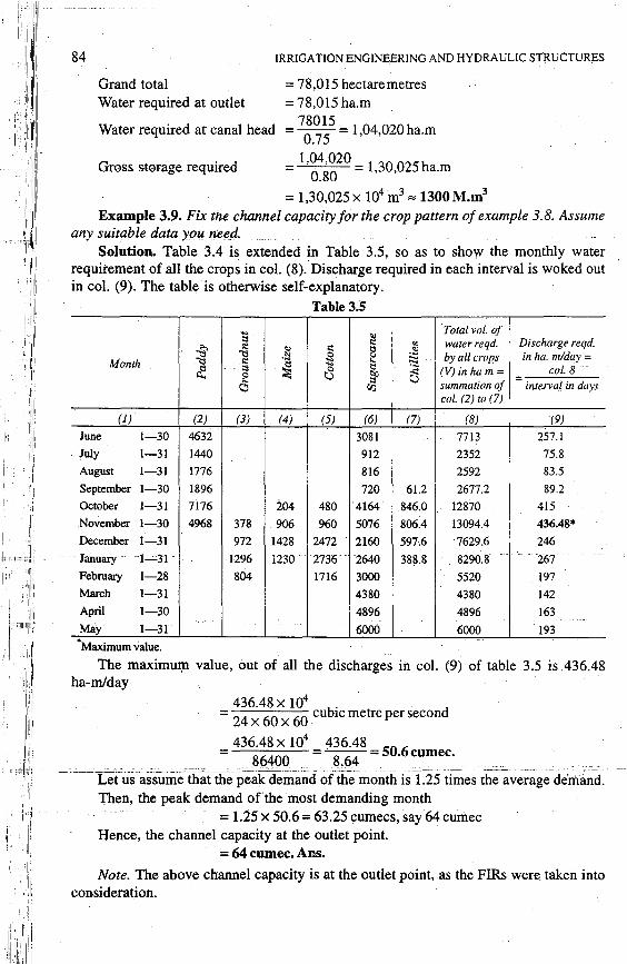
Solution. Table 3.4 is extended in Table 3.5, so as to show the monthly water requirement of all the crops in col. (8). Discharge required in each interval is woked out in col. (9). The table is otherwise self-explanatory.
Table3.5
:; ., Total vol. of s::e "' waterreqd. Discharge reqd. :g s::e ., s::e ~ -~ ~ .!;l .s ~ by all crops in lw. mlday =
Month s::e ::::l
~ :; ~
.... ~
~ col. 8
~ 8 ~ (V) in ham= = C'l".J summation <!f interval in days
col. (2) to (7)
(1) (2) (3) (4) (5) (6) (7) (8) (9)
June 1-30 4632 3081 7713 257.1 July 1-31 1440 912 2352 75.8 August 1-31 1776 816 2592 83.5 September 1-30 1896 720 61.2 2677.2 89.2 October 1-31 7176 204 480 4164 846.0 12870 415 .November l-30 4968 378 906 960 5076 806.4 13094.4 436.48*
December 1-31 972 1428 2472 2160 597.6 "7629.6 246 January 1-Jl 1296 ·1230 2736 2640 388.8 8290.8 201 February 1-28 804 1716 3000 5520 197 March 1-31 4380 4380 142 April 1-30 4896 4896 163 May 1-31 6000 6000 193 •Maximum value.
The maximui:µ value, out of all the discharges in col. (9) of table 3.5 is .436.48 ha-ml day
436.48 x 10⁴ .
= 24
x 60
x 60
~cubic metre per second
= 436.48 x 10⁴
- 436.48 - 50 6 · . , 86400 - 8.64 - · cumec. . .
c: ''':"11 :-- ···- .. : ..... L~tus ··as~siime -th~:.(ihepeak -demand of the .month. is-1~25 ti~es th;ave~~g~-de·~~~d~ .I : Then, the peak demand ofthe most demanding month i , = 1.25 x 50.6 = 63.25 cumecs, say 64 curil.ec
Hence, the channel capacity at the outlet point. = 64 cumec. Ar.s.
Note. The above channel capacity is at the outlet point, as the FIRs were taken into consideration.

.
CANAL IRRIGATION SYSTEM 85
Example .3.10. A reservoir is proposed to be constructed to command an area of J,20,000 hectares. It is anticipated that ultimately sugar and paddy would both be irrigated equal to 20% of the command and Rabi equal to 50% of the command, making a total annual irrigation equal to 90% of the commanded area.
(a) Work out the storage required for the reservoir, assuming water requirement as prevailing in any area you are familiar with. Assume canal losses at 25% of the head discharge, and reservoir evaporation and dead storage losses at 20% of gross capacity.
(b) For the above crop pattern, fix the channel capacity in the head reaches.
Solution. Total commanded area= 1,20,000 hectares
Area under Sugar= 0.20 x 1,20,000= 24,000 hectares
Area under Paddy= 0.20 x 1,20,000 = 24,000 hectares
Area under Rabi = 0.50 x 1,20,000 = 60,000 hectares
Let us assumy water depth requirements, average duties, on capacity duties, etc. for the three crops, as shown in Table 3.6 .
: Table 3.6 F ~~ f E·
t l'
Total water depth reqd. in Av. Duty in Duty on capacity, i.e. max
Crop cm hectareslcumec
demand duty in hecwreslcumec
(I) (2) (3) (4)
Sugar 90 2600 600
Paddy 120 864 637
Rabi 40 3464 1728
The quantity of water required for all crops is worked out as shown in Table 3.7. Table3;7 · -~ - --
Crop !Ji. in cm (assumed) Hectares under cultivation
(I) (2) (3)
Sugar 90 24000
Paddy 120 24000
Rabi 40 60000
Total volume of water required at outlet
• = 7 4400 hectare metres = 7 4400 x IQ4 cubic metres
= 7 44 million cubic metres (M.m3)
Canal losses = 25% of head discharge (given)
Water reqd. in hf!ctare-metres =
col. (2)xcol. (3VIOO
(4)
21600
28800
24000
1:=74400
:. Total volume of water required at the head of the canal system
744. 3 3 = 0.75 M.m =992M.m
or Net Reservoir Storage= 992 M.m3

86 IRRIGATION ENGINEERING AND HYDRAULIC STRUCTURES
Reservoir evaporation and dead storage loss = 20% of Gross storage
(a) Gross Storage of the required reservoir= ~~~ = 1240 M.m3 Ans.
(given)
(b) Channel capacity. Channel capacity can be fixed on the basis of 'on capacity outlet factors' assumed in col. (4) Table 3.6. Let us work out the capacity discharge required for each crop as shown in col (4) of Table 3.8.
Table 3.8
'Capacity.Duty' Hectares under i:ultivaillin
Crop hectareslcumec (given)
(assumed)
(1) (i) (3)
Sugar 600 24000
Paddy 637 . 24000
Rabi 1728 60000
Cumecs reqd. for Sugar and Paddy= 40 + 37;7::::: 77.7 cumec
Cumecs reqd. for Sugar and Rabi = 40+ 34.7 = 74.7 cumec.
Capacity in cumecs =col. (3)
col. (2)
(4)
40
37.7
34.7
Assuming that the Paddy does not require water when Rabi requires, and Sugar may require its peak demand at a time when eith_er Rabi or Paddy is in full demand ; we can fix the capacity of the channel as maximum cif these two, i.e. 77.7 cumec. (It is very hypothetical). In practice, however, demand of sugar may arise only when Rabi or Paddy are in very.small demand. In such a hypothetical case, assuming that the peak demands of Sugai and Rabi or Paddy (one of them) rriay arise at the same time, we may fix channel capacity as : .
Channel capacity at the outlet= 77.7 cumec
:. Channel c~pacity in ;he he~d re::h:: ~ -~~7~ curriec = 103.6 cumec. Ans.
3.8. Losses of water "in canals
During the passage of water from the main canal to the outlet at the head of the watercourse, water may be lost either by evaporation from .the surface or by seepage through the peripheries of the channels. These losses are someti.111es very high; of the order of25 to 50% of the waterdivertedinto the main canal. In determining the designed channel capacity, a provision for these water losses must be made. The provision for the water lost in the watercourses and in the fields is however, already made in the outlet discharge factor, and hence, no extra provision is made on that account. Evaporation _and seepage losses of channels are discussed below :
. ( l). EvaporatiOD';-'fhe--watedost by 'eva:potafioif ls. generaify ~ery small, as compared to the water lost by seepage in certain channels. Evaporation losses are generally of the order of 2 .to 3 per cent of the total losses. They depend upon all those factors*, on which the evaporation depends, such as temperature, wind velocity, humidity, etc. In summer season; these losses may be more but seldom exceed about 7% of the total water diverted into the main canal.
* Discussed in article 7.34.2.3.

CANAL JRRIGA TION SYSTEM
(ii) Absorption. In absorption, a small. saturated soil zone ex~ ists round the canal section, and is sur
Fig. 3.7. Percolation.
WATER TABLE LEVEL
87
rounded by zone of decreasing saturation. A certain zone just above the water-table is saturated by capillarity. Thus, there exists an unsaturated soil zone. betVl:'een the two saturated zones, as shown in Fig. 3.8. ·
In this case, the rate of loss is independent of seepage head (H) but depends only upcm the water. head h (i.e. distance between water surface level of canal and the bottom of the saturated zone) plus the capillary head he,
as shown in Fig. 3.8 ..
WT.
Fig. 3.8. Absorption.
The seepage losses depend upon the following factors :
(i) Type of seepage, i.e. whether 'percolation' br 'absorption'.
(ii) Soil permeability.
(iii)The conifition o[Jhe canal; the seepage throughasilte~ c~n::tl isJess.thaJ1 t_~at - . from a n'ew canal. - -------- ---- --- ... ---- -- .. _ ----- --- ---- - - ------- -------
. . . . .
(iv) Amount of silt carried by the canal ; the more the silt .• lesser are .the losses ..
(v) Velocity of canal water; the more the velocity, the lesser will be the losses.
(vi) Cross-section of the canal and its wetted perimeter.
For designs, a combined figure for seepage losses as well as for evaporation losses, expressed as cumec per million sq. m of wetted perimeter, may be taken, as tabulated in Table 3.9.

88 IRRIGATION ENGINEERING AND HYDRAULIC STRUCTURES
Table 3.9. Channel Losses
S.No. Type of soil through which channel is ·
excavated ' Total loss in cumec!million sq. 111 if wetted area
I.
2.
3.
4.
5.
Rocks
Black cotton soil
Alluvial red soil
Decayed ro.ck, gravel, etc.
Loose sandy soil
0.9
1.6
2.5
3.0
5.5
3.8.1. Empirical formulas for channel losses. The channel losses can be determined by using certain empirical formulas, such as
(a) .1.Q = 2~0 (B + D)213 ... (3.4)
where .1.Q = Channel losses in cumecs per km length of channel,
B = Bed width of the channel in metres. D = Depth of water in the channel in metres.
This formula is generally used in U.P.
(b) .1.Q = 1.9. Q116 ••• (3.5)
where .1.Q = Losses in cumecs per million sq. m. of wetted perimeter.
Q = Discharge in cumecs.
The above formula is commonly used in Punjab.
3.9. Canal Regulation -- ----- - -- - - -:::------- ----:----
The amount of water which can be diverted from the river into the main canal depends upon : .
(i) The water available in the river ;
(ii) The capacity of the main canal ; and
(iii) the share of other canals taking off from the river.
The flow from the main canal is further diverted to the branch canals ; and from the branch canals to the distributaries. The distribution of water (flow) depends upon the water demand of various canals. The method of distribution of available supplies into various canals of a canal system is called the canal regulation.
l t
' ~
I f:
Obviously, when there exists a significant demand of water anywhere in the com- t. __ .:niancLarea-of-a-canal,-the-said-Ganal-has:·to'-be-kept-flowin~-The·canal can, however, be'-- 1
closed, if the water demand falls below a specified quantity. The canal shall be reopened ' again when the water demand exceeds the specified minimum quantity. Normally, there always exists a demand in some part of the command area of any major canal. Such major canals can, hence, be closed only for a very small period (say hardly for three to four weeks in a year). These canals, thus run almost continuously. They may, however, carry discharges much less than their full capacity, either when there is less demand, or when the available supplies are insufficient.

CANAL IRRIGATION SYSTEM 89
When the demand in less, only the distributaries which need water are kept running, while others (including those which have very little demand) are closed. In case of higher demand but insufficient supplies, either all the smaller channels are made to run simultaneously and continuously with reduced supplies ; or some channels are closed. turn by turn and the remaining ones are made to run to their full or near-full capacities. The first alternative of simultaneously running all the distributaries with reduced supplies is generally not preferred, as it causes channel siltation, weed growth, increased seepage, water-logging and low heads on the outlets. The second alternative of running the distributaries turn by .tum. with full supplies is, hence, generally preferred, since it does not have these disadvantages, and allows sufficient time for inspections and repairs of the channels.
A roster is, therefore, usually prepared for indicating the allotted supplies to different channels, showing the schedule of their closure and operation.
A flexible regulation is always preferred, so that the supplies are allocated in accordance with the anticipated demand. The allocation of supplies should hence be varied on the basis of the information provided by the canal revenue staff, who is supposed to keep a close watch on the crop condition and irrigation water demand of their respective distributaries and outlets.
The discharge in a canal is usually regulated at its head regulator', which is generally designed as a meter, as to indicate the discharge being let out from it. However, when a head regulator cannot be used as a discharge meter, a depth guage is provided at about 200 m distance downstream of the head regulator. The gauge-discharge curve of the canal is kept ready, as to indicate the discharge for the observed gauge reading. By manipulating the opening through the regulator gates, the desired discharge can be obtained in the given canal.
3.10. Distri!n1tion of Water into the Fields-Tln:ough-Water-Courses--- _c-- - ., -
The water from a distributary or a minor is allowed to flow into the water course, through an opening, called module or outlet*. When once the water reaches the water course, the problem of its equitable distributfon among the various farmers or fields arises. The release of water into the water course and its sharing by farmers with different field holdings, largely depends upon the available supply. Since the water supply is usually limited, the following two possible alternatives for its distribution become available·:
(1) The canal irrigation is restricted to a limited area, which can be fully supported with the lowest available supply. This does not lead to optimum utilisation of available water and may cause intensive irrigation and its ill effects. ·
Agricultural production ahd protectjon ag.l'linst fo.wine wo_uld_also.nothe optimum.- -The production may be maximum per unit of land covered (if the farmers donot overirrigate), though it would certainly not be per unit of water available. This approach would, however, not require a precise or sophisticated method for distribution of irrigation water amongst the field owners. The delivery system for this alternative can be either continuous or demand-based, depending upon the availability of water. A continuous delivery system can be effectively used for large farms and continuous terraced
* Discussed in details in chapter 13.

90 IRRIGATION ENGINEERING AND HYDRAULIC STRUCTURES
rice fields. Though ideal, a demand-based delivery system is not. practical on large irrigation systems.
(2) In the second and usually adopted alternative, irrigation is extended to a much larger area than what could be supported by the lowest available supply. This extensive irrigation often creates perpetual scarcity of irrigation water but ensures that a comparatively much less quantity of water remains unutilised. Agricultural production and protection again famine will be at optimum levels. The crop production would be maximum per unit of available water, though it may not be optimum per unit of land covered. Since this method of delivering water is in~ the interest of a larger section of farmers, it is usually adopted in our country, inspite of the fact that this method of distribution requires elaborate control and monitoring on the release of water from the different outlets into the different water courses, and to further ensure that the farmers in possession of different land holdings (land areas) do share water as per their decided shares and utilise it on the decided days, rather than permitting the upstream farmers to utilise larger amounts of irrigation water and thereby leaving very little or no water for farmers at the tail end of the conveyance system. Such a system of distributing irrigation water among the farmers is popularly known as the Warawandi, and is explained below:
3.10.1. Warabandi. Warabandi (Fig. 3.9) Is an integral management system for conveying and distributing irrigation water from the source.(river or reservoir) down to the farm gates (i.e. nakkas) of various land holders, so as to ensure supplies upto the tail end of the command area. The entire water conveyance .system is divided into the following three categories :
(i) Primary distribution system ;
(ii) Secondary distribution system ; and
(iii) Tertiary distribution system.
Conveyance of water from the source into the main canal, feeding two or more -, branch canals (which may operate by rotation) and may not carry the total required supply, constitute what is known as the primary distribution system: This primary distribution system runs throughout the irrigation season with varying supply.
The secondary distribution system consists ()f a large number of disti;ibutaries which run by rotation but usually carry full supply. They are fed by the branc.h canals of the primary distribution system. The water is finally released from the distributary into the water courses through the outlets (modules). The secondary distribution system ends at
1
, 11 this outlet point.
The water flowing into the water course or it branches, from an outlet of a dis~ ·. tributary, is finally allocated to various fields situated along the water course by a time
Iii ! I roster. This is the tertiary distribution system. · I I' . -·
:, f i '1i111[::":--' ~~·~·t:~;;:a~~i~~j~~a~? ~:~~g!~c:;a;~P-~!~!:~::~o~h:Y:!~~=r;~i~~~1~~:n:g;:st:~ -
I :' ', 'i'[ (downstream .of the outlet) is managed. by the farmers, in a classic exam pk of the joint . I , iij state-farmer management of the irrigation system.
i ,1
11
.In this warabandi system, each unit of cultu. rable cammand area (CCA) is allocated
1
1 a certain rate of flow, called water allowance, whose value is generally a comprise 1
, 1
1
between the likely demand and the supply for a gwen project. The carrying capacities of the watercourses and the dis tributaries are designed on the basis of this decide.d value

' , f·
CANAL IRRIGATION SYSTEM
Legend
C8:I
-
Distributary
Outlet
. Water course and its branches
--"'"'"'==;---:Nakka-'-' -c'-- -
I -x-x--· x Chak boundary
r:::::::J Holding boundary
Distributary
Head works (Barrage)
Left Bank Main Canal
91
Primary system (Main + Branch canal
Sr,,, ~ Secondary system "'Ile;-,
(Major & Minor Cq'1q/ ~ Distributaries)
Outlet
Branch of watercour:
Fig. 3.9. Typical warabandi distributien system.

r: 'I
92 IRRIGATION ENGINEERING AND HYDRAULIC STRUCTURES
of water allowance. Say for example, under the Bhakra canal system, covering Punjab, Haryana and Rajasthan, the value of water allowance at the head of water courses is fixed @ 0.017 cumec per 100 hectares of culturable command area.
Whenever distributaries run, they are expected to carry their full supply. The outlets to water courses are so planned and constructed that all the water courses on a distributary withdraw their authorised shares of water simultaneously. The design capacities of distributaries and water courses in this warabandi system are, thus, based on the hectares of culturable command area (which is fixed), rather than on the basis of water demand of variable cropping pattern adopted by the different farmers. The warabandi system, thus, does not provide greater amount of water to the farmers, who are growing more water consuming crops in their fields. Tpe system, therefore, does not provide any undue benefits to some particular farmers, as it imposes equal water scarcity on every user. Such distribution of water, ii:). 'proportion to the land holdings of different farmers, by relating the design capacities 9f watercourses and distributaries to the CCA rather than to the cropping pattern, is 9bviously advantageous, as it offers equitable distribution of water, avoiding unneces!!lary rivalary and ill will among the farmers.
Under the warabandi system, the distributaries are operated at full capacities*, usually on eight-day periods. The number of these periods would depend on the availability of water and crop requirements. In a normal year, it is possible to run the distributaries of the Bhakra project for 18 periods during Kharif season and 16 periods during Rabi season.
The distribution of water from the water course, being managed by the farmers, is done on seven-day rotation basis, with the help of an agreed roster (called roster of turns), which divides 24 x 7 = 168 hours of seven days in the ratio of the land holdings of various farmers. The eight day running period of distributary ensures a minimum of seven days running for each water course, including those which are at the tail end of the distri-butaey-. . =--:· ____ ;:__._-_-_ - _ _ -- - - ---- -- --
Each cultivator's right to share water in.a water course is guaranted by law, as the canal Act empowers the canal officers (AE's, EE's and SE~s) to ensure this right for everyone.
Whenever a distributary is running, a water course receives its sh.are of water at a constant rate round the clock and water distribution proceeds from head to tail. Each cultivator on the watercourse is entitled to receiving the entire water in a water course only on specific week day and at a specific time (including night time). There is no provision in the system to compensate a defaulting farmer, who has failed to utilise his turn for any reason.
Roster of Turn. The cycle of turns on a water course or its branch starts from its head, proceeds downstream and ends at the tail. Before a farmer re~eives his s_~-l!!'~Ql
---water;--sometime''is--spenrin-fflling-the water~course length betweentfle point of histaking over and the beginning of his holding. This time is called bharai (i.e. the filling time), which is debited to a common pool time of 168 hours and credited to the account of the concerned farmer. The supply in the water course has to be stopped when the tail end farmer is having his turn, since the water filled in the water-course during the entire bharai period can be discharged only into the field of the tail-end farme_r ; and hence,
* Running the distributaries and water courses at full capacities; reduces their running time, thereby reducing conveyance losses, besides checking siltation, weed growth, etc.
I
CANAL IRRIGATION SYSTEM 93
normally, the total time spent on filling the entire length of the water course should be recovered from him in lieu of this ; but then, he does not receive this water (flowing after closure of outlet) at a constant rate .. Since such a supply, beyond a limit, is not effiCient for field applications, the tail end farmer is compensated for it, and is allowed a certain discount on the recovery of the bharai time. This value of bharai is called Jharai (i.e. emptying time). Evidently, precise determination of Jharai time is not f~asible, and its present values are favourable to the tail-end farmers. After allowing for bharai and jharai timings, the flow time (FT) for a unit area of land holding of an individual farmer is given as :
Flow time (FT) for unit area in hours (h)
= __ l 6_8_h.,_-__._[T_o_t_a_l b_h_a_r_ai_t_im_e_in_h_-_T_o_ta_l..._j_ha_r_a_i t_im_e_in_h]._ Total area to be irrigated by the given outlet or watercourse
Flow time in hour for an individual farmer
... (3.6)
= [FT for unit area x area of farmer's fields + (his bharai - his jharai)] ... (3.7)
Obviously, bharai is usually zero in the case of last farmer (at tail) and jharai is zero for all except the last farmer. It may also be noted that the losses in the watercourse are not reflected anywhere in the above equations.
PROBLEMS 1. (a) Differentiate between "Alluvial" and "Non-alluvial" canals.
· (b) What are the different ways in which the irrigation canals can be aligned?
(c) Name the ~arious types of canals which are required to be constructed while planning a canal irrigation system.
2. Give an account of the investigations and surveys required while planning an irrigation canal project in a given tract of land. Discuss the factors governing the selection of alignment of the main canal and its branches.
3. (a). "T'he·construction and design of canals 'incTamilNadu·is ·easieccompared-'to tlia:Fin 'U.P.'' Discuss critically the above statement with reference to the type of soils available in these two States of India.
(b) State how will you filf.. up the following in an irrigation canal :
(i) Alignment ; (ii) Full supply level ; (iii) Full supply discharge.
4. (a) Discuss the factors that are considered in fixing the alignment of a main canal in a Deltaic area.
s.
( b) The left bank canal of a storage irrigation scheme carries a discharge of 10 cumecs and has a culturable commanded area of 8000 hectares. The intensity of Rabi crop is 70% and base period is 110 days. The right bank canal of the scheme on the other hand, carries ·a di~charge of 24 cumecs and commands a culturable area of 15000 hectares. The intensity of rabi crops is 80% and the base period is 110 days. Coinpare the efficiencies of the two canal systems.
(a) Define and explain the following terms :
(i) Culturable commanded area. --~iii)-Nominal-duty------ - -"-' -
(v) Time factor
(ii) Intensity of irrigation
(iv )-Fi!IJ- supply-coefficient
(vi) Capacity factor.
(b) The discharge available from a tubewell is 136 cubic metres per hour. Assuming 3000 hours of working for this tubewell in a year, estimate the culturable area that this tubewell can command. The intensity of irrigation is 50% and the average water depth required for the rabi and kharif crops is 51 cm
[
. 136 x 3000 1 1 _ Hmt. CCA =
0 · -
5 · 4 hectares= 160 hectares .
. 51 0. 10 Ans-]

94 IRRIGATION ENGINEERING AND HYDRAULIC STRUCTURES
6. Write short notes on :
(i) Alluvial and Non-alluvial soils.
(ii) Water-shed canals and contour canals
(iii) Distribution system for canal irrigation
(iv) Water losses in irrigation canals.
(v) Curves. in irrigation channels.
7. (a) Explain in details, as to how will you proceed for determining the approximate value of design discharge of an irrigation canal. What procedure are required for its precise computations ?
(b) Discuss the precautions which you· would adopt while designing irrigation channels aligned on curvilinear path,s, .
8. (a) How is the capacity of an irrigation channel decided for Indian irrigation conditions? Also discuss, as to why the kor demand ofcourse should be considered in place of average demand while computing this capacity. · ··
(b) A field channel ha5 a culturable commanded area of 2000 hectares. The.intensity of.irrigation for gram is 30% and for wheat is 50%. Gram has a crop periOd of IS days and kor depth of 12 cm, while wheat has a kor period of 15 days and a kor depth of 15 cm. Calculate the discharge of ihe . field channel. ·
[ 864x 18
Hint. Duty for gram= 12
. 1296 ha/curnec
864x 15 Duty for wheat=
15 = 864 ha/cumec
Area of gram irrigated = 2000 x 0.30 = 600 ha: .. 600
Discharge for gram= 1296
cumec = 0.46 cumec
Area of wheat irrigated = 50% x 2000 = 1000 ha . . 1000
Discharge for wheat = 864
= 1.16 cumecs
Total discharge required = 0.46+ 1.16 = 1.62 cumecs. Ans.]
9. A watercourse commands an irrigation area of 800 hectares. The intensity of irrigation of rice.in -~-cthis areais:50%: Thelransplan:tatiorF oflice'ctop takes l5~daysaiid.toliilaeptlf0Twaterrequlred by_
the crop is 60 cm on the field during the transplantation period, give_ri that the rain. falling. on the field during this period is 15 cm. (i) Find the duty of irrigation water for the crop on the field during transplantation ; (ii) at the head of the distributary, a~surning losses of water to. be 20% in the water courses (iii) Calculate the discharge required in the watercourse. .
[Ans. (i) 216 hectare/cumec (ii): 172.8 hectare/cumec, (iii) 2.32 cumecs.]
· 10. How is the water lost while flowing through irrigation canals ? What are the factors affectiilg these losses, and how will you estimate these losses ? How do these losses .. affect the duty.of water and what precautions will you undertake in order to minimise them ? ·
11. What are the possible causes of water losses in a· canal ? What are the methods adopted for redudng . such losses ? ·