CAN WE POWER FUTURE MARS MISSIONS?
16
IAC–06–A5.2.06 CAN WE POWER FUTURE MARS MISSIONS? by Tibor S. Balint, Erick J. Sturm II, Ryan C. Woolley & James F. Jordan Jet Propulsion Laboratory, California Institute of Technology 4800 Oak Grove Drive, M/S 301–170U Pasadena, CA 91109–8099 e-mail: [email protected] ABSTRACT The Vision for Space Exploration identified the exploration of Mars as one of the key pathways. In response, NASAs Mars Program Office is developing a detailed mission lineup for the next decade that would lead to future explorations. Mission architectures for the next decade include both orbiters and landers. Existing power technologies, which could include solar panels, batteries, ra- dioisotope power systems, and in the future fission power, could support these missions. Second and third decade explorations could target human precursor and human in–situ missions, building on increasingly complex architectures. Some of these could use potential feed forward from earlier Constellation missions to the Moon, discussed in the ESAS study. From a potential Mars Sample Return mission to human missions the complexity of the architectures increases, and with it the delivered mass and power requirements also amplify. The delivered mass at Mars mostly depends on the launch vehicle, while the landed mass might be further limited by EDL technologies, in- cluding the aeroshell, parachutes, landing platform, and pinpoint landing. The resulting in–situ mass could be further divided into payload elements and suitable supporting power systems. These power systems can range from tens of watts to multi–kilowatts, influenced by mission type, mission configuration, landing location, mission duration, and season. Regardless, the power system design should match the power needs of these surface assets within a given architecture. Consequently, in this paper we will identify potential needs and bounds of delivered mass and architecture dependant power requirements to surface assets that would enable future in–situ exploration of Mars. INTRODUCTION Mars exploration represents one of the main pathways in the Vision for Space Exploration [1]. Mission lineup for the next two decades is identified within NASA’s Mars Exploration Program, with additional input from advisory groups, such as the NASA Advisory Council (NAC), and the Mars Exploration Program Analysis Group (MEPAG) [2]. Interdependen- cies between NASA’s Mars Exploration Program and Solar System Exploration Program are dis- cussed in NASA’s SSE Roadmap [3]. In general, potential mission architectures for Mars exploration may include orbiters and in– situ robotic platforms, eventually leading to hu- man exploration [1]. In this paper we exam- ine key power system trades and options, that could enable these proposed missions. We also link power system options to programmatics (namely to the various planned Mars mission architectures); and to other technologies, such as launch vehicle options, and entry, descent, and landing (EDL) technologies. MISSION ARCHITECTURES FOR MARS EXPLORATION NASA pathway missions are primarily driven by science, although the pathway could also include technology driven missions. The former would address science objectives, outlined in the Solar System Exploration Decadal Survey [4], and in MEPAG documents [2]. The latter would focus on technology demonstrations that could enable 1
Transcript of CAN WE POWER FUTURE MARS MISSIONS?
IAC–06–A5.2.06
CAN WE POWER FUTURE MARS MISSIONS?
by Tibor S. Balint, Erick J. Sturm II, Ryan C. Woolley & James F. JordanJet Propulsion Laboratory, California Institute of Technology
4800 Oak Grove Drive, M/S 301–170UPasadena, CA 91109–8099
e-mail: [email protected]
ABSTRACT
The Vision for Space Exploration identified the exploration of Mars as one of the key pathways. Inresponse, NASAs Mars Program Office is developing a detailed mission lineup for the next decadethat would lead to future explorations. Mission architectures for the next decade include bothorbiters and landers. Existing power technologies, which could include solar panels, batteries, ra-dioisotope power systems, and in the future fission power, could support these missions. Secondand third decade explorations could target human precursor and human in–situ missions, buildingon increasingly complex architectures. Some of these could use potential feed forward from earlierConstellation missions to the Moon, discussed in the ESAS study. From a potential Mars SampleReturn mission to human missions the complexity of the architectures increases, and with it thedelivered mass and power requirements also amplify. The delivered mass at Mars mostly dependson the launch vehicle, while the landed mass might be further limited by EDL technologies, in-cluding the aeroshell, parachutes, landing platform, and pinpoint landing. The resulting in–situmass could be further divided into payload elements and suitable supporting power systems. Thesepower systems can range from tens of watts to multi–kilowatts, influenced by mission type, missionconfiguration, landing location, mission duration, and season. Regardless, the power system designshould match the power needs of these surface assets within a given architecture. Consequently, inthis paper we will identify potential needs and bounds of delivered mass and architecture dependantpower requirements to surface assets that would enable future in–situ exploration of Mars.
INTRODUCTION
Mars exploration represents one of the mainpathways in the Vision for Space Exploration[1]. Mission lineup for the next two decadesis identified within NASA’s Mars ExplorationProgram, with additional input from advisorygroups, such as the NASA Advisory Council(NAC), and the Mars Exploration ProgramAnalysis Group (MEPAG) [2]. Interdependen-cies between NASA’s Mars Exploration Programand Solar System Exploration Program are dis-cussed in NASA’s SSE Roadmap [3].
In general, potential mission architectures forMars exploration may include orbiters and in–situ robotic platforms, eventually leading to hu-man exploration [1]. In this paper we exam-
ine key power system trades and options, thatcould enable these proposed missions. We alsolink power system options to programmatics(namely to the various planned Mars missionarchitectures); and to other technologies, suchas launch vehicle options, and entry, descent,and landing (EDL) technologies.
MISSION ARCHITECTURESFOR MARS EXPLORATION
NASA pathway missions are primarily driven byscience, although the pathway could also includetechnology driven missions. The former wouldaddress science objectives, outlined in the SolarSystem Exploration Decadal Survey [4], and inMEPAG documents [2]. The latter would focuson technology demonstrations that could enable
1
future missions. At present, several in–situ andorbiter missions are in their operational phase,namely the Mars Exploration Rovers (MER),a number of orbiters by NASA (i.e., the MarsGlobal Surveyor, the Mars Odyssey, and theMars Reconnaissance Orbiter) and the MarsExpress orbiter by ESA. Missions under devel-opment or in planning include the Scout classPhoenix lander (2007), and the large Mars Sci-ence Laboratory (MSL) rover (2009). Final se-lection for the next Scout mission — targetingthe 2011 opportunity — is expected within afew months.
Potential next decade missions (between 2011and 2020) could include Scout missions in 2011and 2018; the Mars Science Orbiter (MSO) in2013; an in–situ mission in 2016 in the formof medium or large rovers; and a Mars Multi–Lander Network mission with multiple (∼4 ormore) small landers. One of the options forthe 2016 opportunity could be an AstrobiologyField Laboratory (AFL) rover, as a follow onto MSL, addressing astrobiology related scienceobjectives.
Over the past years additional concepts were alsoconsidered, including a deep drill for subsurfaceaccess to ∼50–100 m, and sub–MER class fetchrovers. Second decade technology demonstrationmissions (between 2021 and 2030) could includean In–Situ Resource Utilization (ISRU) landers,and other large human precursor missions. Todate, these second decade missions are in anearly formulation phase, thus the final missionconcepts could be significantly influenced by thefuture direction of the Mars exploration path-way. [5]
Second and third decade explorations could tar-get human precursor missions and eventuallylead to manned in–situ missions, building onincreasingly complex architectures.
Selected missions for this decade, and potentialmissions for the next decade and beyond aresummarized in Table 1.
These listed missions are categorized as Scout,Moderate, Large and Flagship, where the classes
correspond to assigned mission costs of ∼$500M,∼$750M, ∼$1B and multi–$B, respectively. Themission lineup is strongly driven by budget al-location for the Mars Exploration Program, andcould change based on Agency priorities.
Past mission studies, performed under NASA’sMars Exploration Program Division, sized someof these proposed missions, in order to under-stand the science and technology drivers, thecorresponding mission costs, and to ultimatelysupport NASA in the process of identifying fu-ture pathway missions. Table 2 identifies landedmass values for these mission concepts. It shouldbe noted that the landed mass is strongly influ-enced by all elements of a mission architecture,including the chosen launch vehicle, landing con-figuration, subsystem options, science, opera-tional scenarios (e.g., mission duration), landingsite, and assumed mission cost cap. Therefore,these reported landed mass values should beconsidered notional and used only in the frame-work of the current discussion.
It is evident from Table 2 that future proposedrobotic missions over the next two decades couldbe achieved with less than 2 metric tons oflanded mass. At the same time, a proposedhuman mission would require a landed mass of20 to 40 times more [6].
Implications of delivering the required mass tothe surface of Mars, and to support these mis-sions with suitable power system configurationswill be discussed in the second half of this paper.
MASS TRACKING RESULTS
The payload masses that could be landedon the surface of Mars were generated withMassTracker, a Microsoft Excel–based tool, de-veloped at JPL. MassTracker uses worksheets ina single Excel workbook to collect inputs for amission architecture, specifically spacecraft drymasses, maneuver ΔV’s and “rules–of–thumb”.The tool then uses macros to build a worksheet,which calculates the spacecraft wet mass beforeand after each maneuver in the architecture. [7]
2
Selected & Potential Missions Year Class Potential Power System Option(s)
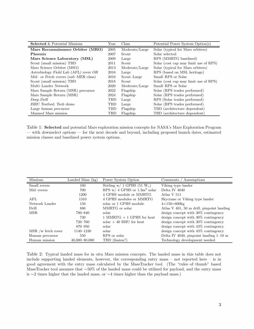
Mars Reconnaissance Orbiter (MRO) 2005 Moderate/Large Solar (typical for Mars orbiters)Phoenix 2007 Scout Solar selectedMars Science Laboratory (MSL) 2009 Large RPS (MMRTG baselined)Scout (small mission) TBD 2011 Scout Solar (cost cap may limit use of RPS)Mars Science Orbiter (MSO) 2013 Moderate/Large Solar (typical for Mars orbiters)Astrobiology Field Lab (AFL) rover OR 2016 Large RPS (based on MSL heritage)Mid– or Fetch–rovers (sub–MER class) 2016 Scout–Large Small–RPS or SolarScout (small mission) TBD 2018 Scout Solar (cost cap may limit use of RPS)Multi–Lander Network 2020 Moderate/Large Small–RPS or SolarMars Sample Return (MSR) precursor 2022 Flagship Solar (RPS trades performed)Mars Sample Return (MSR) 2024 Flagship Solar (RPS trades performed)Deep Drill TBD Large RPS (Solar trades performed)ISRU Testbed, Tech demo TBD Large Solar (RPS trades performed)Large human precursor TBD Flagship TBD (architecture dependent)Manned Mars mission TBD Flagship TBD (architecture dependent)
Table 1: Selected and potential Mars exploration mission concepts for NASA’s Mars Exploration Program— with downselect options — for the next decade and beyond, including proposed launch dates, estimatedmission classes and baselined power system options.
Missions Landed Mass (kg) Power System Option Comments / Assumptions
Small rovers 160 Stirling w/ 1 GPHS (51 We) Viking type landerMid–rovers 700 RPS w/ 4 GPHS or 1.3m2 solar Delta IV 4040
1200 4 GPHS module or MMRTG Atlas V 511AFL 1310 4 GPHS modules or MMRTG Skycrane or Viking type landerNetwork Lander 150 solar or 1 GPHS module 4×150=600kgDrill 886 MMRTG or solar Atlas V 401, 50 m drill, pinpoint landingMSR 780–840 solar design concept with 30% contingency
730 1 MMRTG + 1 GPHS for heat design concept with 30% contingency720–760 solar + 40 RHU for heat design concept with 30% contingency870–950 solar design concept with 43% contingency
MSR /w fetch rover 1140–1230 solar design concept with 43% contingencyHuman precursor 550 RPS or solar Delta IV 4040, pinpoint landing 1–10 mHuman mission 40,000–80,000 TBD (fission?) Technology development needed
Table 2: Typical landed mass for in–situ Mars mission concepts. The landed mass in this table does notinclude supporting landed elements, however, the corresponding entry mass – not reported here – is ingood agreement with the entry mass calculated by the MassTracker tool. (The “rules–of–thumb” basedMassTracker tool assumes that ∼50% of the landed mass could be utilized for payload, and the entry massis ∼2 times higher that the landed mass, or ∼4 times higher than the payload mass.)
3
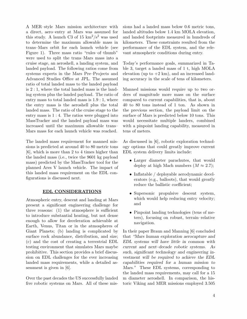
A MER–style Mars mission architecture witha direct, aero–entry at Mars was assumed forthis study. A launch C3 of 15 km2/s2 was usedto determine the maximum allowable mass intrans–Mars orbit for each launch vehicle (seeFigure 1). Three mass ratio “rules–of–thumb”were used to split the trans–Mars mass into acruise stage, an aeroshell, a landing system, andlanded payload. The following ratios come fromsystems experts in the Mars Pre–Projects andAdvanced Studies Office at JPL. The assumedratio of total landed mass to the landed payloadis 2 : 1, where the total landed mass is the land-ing system plus the landed payload. The ratio ofentry mass to total landed mass is 1.9 : 1, wherethe entry mass is the aeroshell plus the totallanded mass. The ratio of the cruise stage to theentry mass is 1 : 4. The ratios were plugged intoMassTracker and the landed payload mass wasincreased until the maximum allowable trans–Mars mass for each launch vehicle was reached.
The landed mass requirement for manned mis-sions is predicted at around 40 to 80 metric tons[6], which is more than 2 to 4 times higher thanthe landed mass (i.e., twice the 9601 kg payloadmass) predicted by the MassTracker tool for theplanned Ares V launch vehicle. The impact ofthis landed mass requirement on the EDL con-figurations is discussed next.
EDL CONSIDERATIONS
Atmospheric entry, descent and landing at Marspresent a significant engineering challenge forthree reasons: (1) the atmosphere is sufficientto introduce substantial heating, but not denseenough to allow for deceleration achievable atEarth, Venus, Titan or in the atmospheres ofGiant Planets; (b) landing is complicated bysurface rock abundance, distribution, and size;(c) and the cost of creating a terrestrial EDLtesting environment that simulates Mars maybeprohibitive. This section provides a brief discus-sion on EDL challenges for the ever increasinglanded mass requirements, while a detailed as-sessment is given in [6].
Over the past decades the US successfully landedfive robotic systems on Mars. All of these mis-
sions had a landed mass below 0.6 metric tons,landed altitudes below 1.4 km MOLA elevation,and landed footprints measured in hundreds ofkilometers. These constraints resulted from theperformance of the EDL system, and the rele-vant atmospheric conditions during entry.
Today’s performance goals, summarized in Ta-ble 3, target a landed mass of 1 t, high MOLAelevation (up to +2 km), and an increased land-ing accuracy in the scale of tens of kilometers.
Manned missions would require up to two or-ders of magnitude more mass on the surfacecompared to current capabilities, that is, about40 to 80 tons instead of 1 ton. As shown inthe previous section, the payload limit on thesurface of Mars is predicted below 10 tons. Thiswould necessitate multiple landers, combinedwith a pinpoint landing capability, measured intens of meters.
As discussed in [6], robotic exploration technol-ogy options that could greatly improve currentEDL system delivery limits include:
• Larger diameter parachutes, that woulddeploy at high Mach numbers (M ≈ 2.7);
• Inflatable / deployable aerodynamic decel-erators (e.g., balloots), that would greatlyreduce the ballistic coefficient;
• Supersonic propulsive descent system,which would help reducing entry velocity;and
• Pinpoint landing technologies (tens of me-ters), focusing on robust, terrain–relativenavigation.
In their paper Braun and Manning [6] concludedthat “Mars human exploration aerocapture andEDL systems will have little in common withcurrent and next–decade robotic systems. Assuch, significant technology and engineering in-vestment will be required to achieve the EDLcapabilities required for a human mission toMars.” These EDL systems, corresponding tothe landed mass requirements, may call for a 15m diameter aeroshell. In comparison, the his-toric Viking and MER missions employed 3.505
4
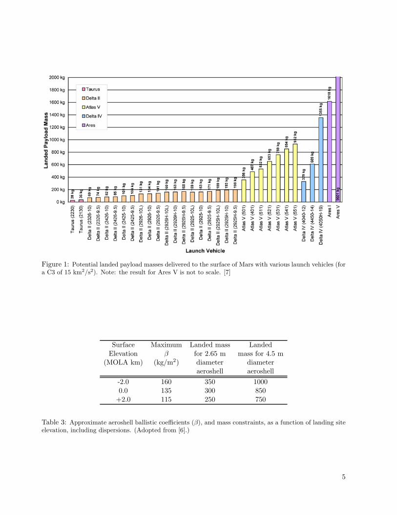
Figure 1: Potential landed payload masses delivered to the surface of Mars with various launch vehicles (fora C3 of 15 km2/s2). Note: the result for Ares V is not to scale. [7]
Surface Maximum Landed mass LandedElevation β for 2.65 m mass for 4.5 m
(MOLA km) (kg/m2) diameter diameteraeroshell aeroshell
-2.0 160 350 10000.0 135 300 850
+2.0 115 250 750
Table 3: Approximate aeroshell ballistic coefficients (β), and mass constraints, as a function of landing siteelevation, including dispersions. (Adopted from [6].)
5

m and 2.65 m diameter aeroshells, respectively,while the MSL mission would use a 4.6 m di-ameter aeroshell. Furthermore, a 15 m diameteraeroshell would introduce technology challengesfor the launch vehicles as well, since the currentlaunch vehicle fairing diameters are limited toabout a third of the one required for mannedmissions.
Therefore, human exploration missions willlikely require further performance improve-ments, such as:
• Improved aerocapture / entry ThermalProtection System (TPS) configurationoptions;
• Improved method for an efficient transi-tion from the entry to landing configura-tion at supersonic conditions, that wouldfit within the EDL timeline constraints;(note that this transition would likely tooccur at Mach 3 or 4)
• Improved parachute system, by moving toaerodynamic decelerator systems in thehypersonic flow regime; or in the super-sonic flow regime while combining it witha propulsive descent system.
POWER SYSTEM OPTIONS
Following the discussions on missions architec-tures, launch vehicle trades and EDL limits, thissection provides a brief overview of potentialpower system options that could enable pro-posed future Mars missions. These space powertechnologies include power sources (both exter-nal and internal), and power storage devices. Amore comprehensive Mars relevant summary ofthese power systems can be found in [5], [8], and[9]. Additional details on Radioisotope PowerSystems (RPS) are provided in [10], [11], [12],and [13], while energy storage technologies arediscussed in [14], and solar power generation in[15].
RPS Options for Mars Missions
NASA and DoE — with their industry partners— are currently developing two types of RPSs,
which are considered internal power sources.The first is called a Multi–Mission Radioiso-tope Thermoelectric Generator (MMRTG) andit uses static power conversion. (This type RPSis baselined for the 2009 MSL mission.) Thesecond is called a Stirling Radioisotope Gen-erator (SRG), and it employs dynamic powerconversion (i.e., a Stirling converter). Both sys-tems are designed to generate at least 110 We atBOL. Concepts of these two systems are shownin Figure 2, while their projected performancesare summarized in Table 4.
The first proposed RPS is the MMRTG, whichwould use 8 General Purpose Heat Source(GPHS) modules. Its specific power is ∼2.9W/kg, with a corresponding current best esti-mate (CBE) mass of ∼44 kg. It would generate∼125 We at BOL. This RPS design is multi–mission capable, that is, an MMRTG can oper-ate both in atmospheres and in vacuum. Thealmost 2 kWt of excess heat — following thepower conversion — could be utilized for space-craft temperature management. In contrastto these advantages, thermoelectrics have lowpower conversion efficiencies (∼6.2%), and theoverall power system degradation is estimated at∼1.6%, half of it is due to natural radioisotopicdecay and the other half is to the degradationof the thermoelectrics. At the same power out-put, it uses about 4 times more Plutonium–238(Pu238) fuel, and it is also heavier than the Stir-ling Radioisotope Generator. [10] [5]
An upgraded MMRTG design is also under con-sideration, with a higher power conversion ef-ficiency of ∼8%, using improved or new ther-moelectrics. These advanced MMRTGs wouldtarget a specific power level of 5 W/kg andabove.
The second proposed RPS is the Stirling Ra-dioisotope Generator (SRG). It would use 2GPHS modules, generating 500 Wt. Two dy-namic Stirling generators would convert someof this heat into ∼116 We at BOL. The powersystem degradation is assumed at ∼0.8% peryear, due to radioisotopic decay. Degradation ofthe dynamic power conversion system was notassessed and was considered negligible. SRGs
6
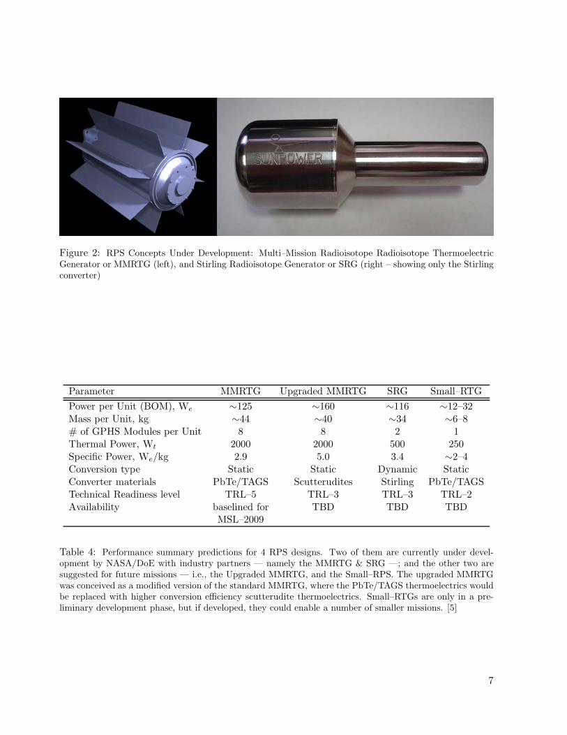
Figure 2: RPS Concepts Under Development: Multi–Mission Radioisotope Radioisotope ThermoelectricGenerator or MMRTG (left), and Stirling Radioisotope Generator or SRG (right – showing only the Stirlingconverter)
Parameter MMRTG Upgraded MMRTG SRG Small–RTGPower per Unit (BOM), We ∼125 ∼160 ∼116 ∼12–32Mass per Unit, kg ∼44 ∼40 ∼34 ∼6–8# of GPHS Modules per Unit 8 8 2 1Thermal Power, Wt 2000 2000 500 250Specific Power, We/kg 2.9 5.0 3.4 ∼2–4Conversion type Static Static Dynamic StaticConverter materials PbTe/TAGS Scutterudites Stirling PbTe/TAGSTechnical Readiness level TRL–5 TRL–3 TRL–3 TRL–2Availability baselined for TBD TBD TBD
MSL–2009
Table 4: Performance summary predictions for 4 RPS designs. Two of them are currently under devel-opment by NASA/DoE with industry partners — namely the MMRTG & SRG —; and the other two aresuggested for future missions — i.e., the Upgraded MMRTG, and the Small–RPS. The upgraded MMRTGwas conceived as a modified version of the standard MMRTG, where the PbTe/TAGS thermoelectrics wouldbe replaced with higher conversion efficiency scutterudite thermoelectrics. Small–RTGs are only in a pre-liminary development phase, but if developed, they could enable a number of smaller missions. [5]
7
offer a few distinct advantages over static con-verter based systems. SRGs have significantlyhigher conversion efficiencies, in the range oftoday’s ∼22% to the next generation of ∼32%.For the present system the conversion efficiencyis about 4 times higher than that of the staticconversion. Consequently, for the same poweroutput SRGs require about 75% less Pu238 fuel,which can be an important consideration. Thislower fuel requirement (∼1 kg vs. ∼4 kg perunit) could also significantly reduce the fuel costper RPS, by as much as ∼$6M based on anassumed fuel cost of $2000 per gram of Pu238
[13]. Because of its lower mass (∼34 kg), thespecific power of an SRG is about 3.4 W/kg,compared to 2.9 W/kg for the MMRTG. TheSRG design is also multi–mission capable. Inshort, the SRG design is more efficient; requiresless plutonium; and is lighter. The lower Pu238
requirement also results in 75% less heat gener-ation, which may simplify cruise–phase thermalmanagement for missions, where a lander is en-capsulated in an aeroshell until the completionof atmospheric entry. Beside these advantages,SRGs also have both real and perceived limi-tations. SRGs are not yet space qualified, andthe lifetime for dynamic converters is not yetproven. The SRG g–load tolerance requirementis currently 30g, somewhat lower than that foran MMRTG (40g). This can tolerate the launchenvironment, but limits landing to soft landingonly. In case of failing one of the two Stirlingconverters, the whole unit could become unbal-anced, resulting in the failure of the other con-verter side. EMI radiation could interfere withsensitive science measurements, and while EMIshielding could somewhat mitigate this effect,it would increase system mass and complexity.Finally, it is required to provide redundancy forthese dynamic power systems. This means thateach SRG enabled mission must carry a redun-dant unit, which lessens the power system massgains against other RPS configurations. NASAand DoE are currently in the process of substi-tuting SRG development from the one reportedin Table 4 to an advanced SRG, for which theconverter is shown in Figure 2.
NASA’s RPS development plans may also con-sider small–RPSs [11] [8], generating power in
the ranges of 10s to 100s of milliwatts or 10s ofwatts. The former would use multiple Radioiso-tope Heater Units (RHU: 1 Wt each), whilethe latter would employ a single GPHS module.Both configurations would utilize thermoelec-tric (or potentially dynamic) power conversion.Mission concept examples for Mars exploration,enabled by small–RPSs, are given in [16] and[8]. Small–RPS concepts could employ individ-ual units, stacked as needed, or could follow amodular RTG (Mod–RTG) design, where theGPHS modules would be stacked and housedtogether. Both approaches could provide scal-ability to the power system, as required by themission. These systems should be multi–missioncapable and high g–load tolerant, in order toenable the largest number of missions.
Batteries
Batteries are energy storage devices, which uti-lize internal chemical power. They are scalableand highly reliable, but scaled up batteries couldhave a significant impact on total system mass.A battery’s life cycle is influenced by the tem-perature of the environment; depth and rage ofdischarge; and degree of overcharge.
Primary batteries are not rechargeable, andtypically used for short operations, such asduring launch, EDL, and on planetary probesduring descent. Examples include Lithium–Thionyl Chloride (Li–SOCl2) and Lithium–Carbon Monofluoride (LiCFx) cells. The specificenergy for today’s Lithium based primary bat-teries, at 0◦C, is ∼250 Wh/kg, which is expectedto increase to ∼400 Wh/kg and ∼600 Wh/kgin 5 and 10 years, respectively. Since batteryperformance is temperature dependent, it candegrade significantly at low temperatures.
Secondary batteries include Lithium–Ion,Lithium Polymer Electrolyte, Lithium Solid–State Inorganic Electrolyte and advancedLithium–Sulfur (Li–S) batteries. They arerechargeable, and are only used for energy stor-age. During peak load operations, these bat-teries can complement the main power source,and could provide power during overnight oper-ations. Their performance is lower than those
8
for primary batteries. The State of Practice(SoP) specific energy for these batteries at 0◦Cis ∼100 Wh/kg, which is expected to grow to∼120 Wh/kg and ∼200 Wh/kg within 5 and 10years. The battery lifetime is also expected toincrease from today’s 5 years to 10 and 15 years,respectively. [14]
Solar Power Generation
Solar panels convert solar flux, and externalpower source, into electricity. (Solar flux de-creases with the inverse square of distance fromthe Sun.) For Mars surface missions, there itfurther decreases due to the atmosphere andpotential dust storms. Landing latitude, sea-sonal and diurnal changes could also impactsolar availability and intensity. For example,the solar constant (S) at 1 AU from the Sun is1367 W/m2. At the orbit of Mars — at 1.5 AU— it drops to ∼43%, while on the surface it canbe as low as ∼13% to 6.5% to that at Earth [8].Solar panel size and mass scales linearly withpower.
Multi–junction or multi–layer photovoltaic ar-rays — e.g., Gallium Indium Phosphide / Gal-lium Arsenide (GaInP/GaAs) cells — use dif-ferent spectrums of sunlight, resulting in typicalconversion efficiencies of ∼22–26.8% [15]. Thesesolar panels degrade at a rate of ∼0.5% per year[17]. Important characteristics of solar cells in-clude: high efficiency; good radiation, UV andatomic oxygen tolerance; long life; robustnessfor mechanical stress tolerance; high reliabilityand low cost. Similarly, the arrays can be char-acterized by their specific power; stowed volume;cost; and reliability. The main solar array cate-gories include body mounted; rigid; and flexibleor deployable configurations. Others includeconcentrator, electrostatically clean and hightemperature arrays. The SoP for body mountedarray areal power is ∼350 W/m2. For rigid ar-rays the specific power is 30–60 W/kg, with acorresponding specific volume of 5–10 kW/m3.For flexible or deployable arrays these are 40–80W/kg and 10–15 kW/m3, respectively, but thearrays may require complex deployment. [15]
Fission Power
The power technologies discussed above are notconsidered sufficient to support future mannedmissions, which would require significantlyhigher power levels. For these, nuclear fissionpower could be considered. Fissions reactorsbelong to the internal power source category.
Nuclear fission reactors are well established onEarth, with many decades of operational experi-ence (e.g., research & commercial reactors; sub-marines; carriers). Space reactors are differentin many aspects from their terrestrial counter-parts. The specific mass is lower, due to trans-port and EDL limitations, and to high systemintegration. Reliability and long mission life-time require autonomous operation, diagnosticsand maintenance. The operating environment isharsh both in space and on a planetary surface.Space reactors must endure extreme (cryogenic)environments, lack of gravity, and dynamic loadsduring launch and EDL. Yet they could providecontinuous power, without reliance on an ex-ternal power source, such as the Sun. An im-portant distinction between fission reactors andRPSs is that uranium fuel for the former is es-sentially non–radioactive before reactor startup,while RPSs are active throughout the mission,due to radioisotopic decay of the plutonium fuel.
Theoretically, reactors are scalable up to thekWe to MWe power levels. For example, theradioactive material (usually Uranium — U233
or U235) in a fast spectrum, beryllium–reflected,ex–core controlled design (which is one of many)is contained in fuel pins and arranged inside thereactor core. The power level of a reactor in-creases with the number of fuel pins. While a20 kWe reactor may use ∼150 fuel pins, similar150 kWe and 1 MWe designs employ ∼300 and600 pins, respectively.
The reactor core would be cooled using one ofthree methods:
• Liquid metal (lithium–coolant);
• Heatpipe (liquid sodium (Na) coolant);
• Direct gas (He/Xe coolant)
9

Liquid metal systems provide a flexible powerconversion interface and have the lowest mass.This configuration is unproven, it is difficult totest, and system freeze/thaw could introducea single–point failure to the reactor and conse-quently to the mission. Heatpipes are flexible,easy to test, and more reliable, and the multi-ple pipes provide redundancy, although lifetimeand reliability data are not readily available andintegration with the power converter/heat ex-changer may introduce difficulties. Direct gascooled systems are simple and easy to test, butdifficult to integrate with power converters andcan present a single point failure.
Increased operating temperatures supporthigher reactor powers. Reactors in space canemploy refractory metals that can tolerate hightemperatures, but are highly susceptible to cor-rosion in a planetary atmosphere. Thus high–temperature in–space reactors may not be suit-able for Mars surface applications. The self–sustained fission reaction is controlled withsafety/control rods/drums and neutron reflec-tors in and around the core. Power conversion isachieved through static or dynamic methods, asexplained earlier for RPSs. In space, excess heatis rejected through large radiators. On the sur-face, convection and conduction complement ra-diation heat transfer; thus these radiators/heatexchangers are designed differently and are moreefficient. Shielding configurations are also dif-ferent between in–space and surface–based reac-tors. Recent in–space spacecraft designs placethe radioactive reactor, the radiator, the pay-load, and the propulsion system in series. Ashield plate is placed between the reactor andthe radiators. The conical shadow of the shieldprovides a radiation–free area, which results inthe familiar triangular shaped radiator design.On the surface, shielding may be required allaround the reactor to protect not only the in-struments but also the surface below and theenvironment around. Furthermore, a mannedmission would require additional shielding toprotect humans from the reactor’s radiation ef-fects. This will likely result in a significantsystem mass increase.
A more detailed overview of nuclear systems for
Mars exploration is given in [9].
MISSION IMPACT OFPOWER SYSTEM OPTIONS
Power system options, especially the use of nu-clear systems, could significantly impact all mis-sion phases, mission architectures and designs.
Impact on Mission Phases
RPSs generate heat continuously, which shouldbe mitigated for all RPS enabled missions duringEarth storage, launch, cruise and EDL phases,in addition to the in–situ operating phase [18].RPSs are fueled and stored at a US Depart-ment of Energy (DoE) facility and integratedwith the spacecraft on the launch pad prior tolaunch. (The storage phase can be as long as2 years.) RPS integration with the spacecraftis overseen by the DoE. It requires a spacecraftdesign with easy accessibility, which could intro-duce an ever–increasing challenge as the numberof RPSs may increase for human precursor andmanned missions. The ambient temperaturesand heat transfer mechanisms also vary through-out the mission phases. On Earth, during thestorage and launch phases, the temperatures andpressures are terrestrial. Here the heat transfermechanisms include convection, conduction andradiation. During the cruise phase in space (vac-uum), radiation is the dominant heat transfermode, while conduction through the RPS hous-ing and along the cooling fins also plays a role.EDL on Mars requires an aeroshell for atmo-spheric entry. Thus, during the cruise phase theRPS is enclosed inside an aeroshell. The gener-ated excess heat must be removed through a sec-ondary cooling system. A typical configurationwould use a fluid loop and external radiators.This adds mass to the spacecraft and complex-ity to the mission. In the Martian atmosphereheat is again removed through convection, con-duction and radiation, although convection isless effective due to the lower atmospheric den-sity.In comparison, integration of other types ofpower systems, such as solar panels and bat-teries, do not represent integration challenges.
10
Impact on Mission Architectures
At 1.5 AU, Mars is relatively close to the Sun.Therefore, solar availability could point to theuse of solar panels. However, solar power maynot be suitable for all of the missions listed inTable 1. For Mars in–situ missions, seasonalchanges at the polar regions could result in in-sufficient solar flux that could shut down themission for up to 6 months [8], and potentiallycould cause “thermal death”. Therefore, thepower source selection strategies should be dis-cussed on a destination related basis.
Mars orbiter missions historically used solarpower generation, combined with secondarybatteries to mitigate eclipses and other non–nominal operating conditions. It is expectedthat future Mars orbiters will continue to usesolar power generation.
On the surface, longer missions to partiallyor permanently shadowed areas must addressspacecraft thermal management issues. Thethermal environment could be maintained byresistance heating or through utilization of theexcess heat from RPSs or RHUs. In the firstcase, resistance heating would require secondarybatteries, which would be charged from the solarpanels during the Martian sol. This method issuitable for near equatorial regions, or for shortmissions at hight latitudes during polar sum-mers (e.g., Phoenix, MSR). However, it wouldnot be sufficient for long–lived polar missions, inwhich case the excess heat from a radioisotopesource could be utilized to keep componentswarm. RHUs could augment resistance heating,or keep external components warm, reducing theneed for oversized batteries, thus saving mass.
All of the in–situ Mars exploration robotic mis-sion concepts discussed in this paper requirepower up to the multi hundred watts level.Among these architectures, the RPS enabledmissions consider only a single MMRTG. Con-sequently, for these smaller missions the use ofa dynamic conversion technology based SRGis not advantageous, since design principles re-quire a redundant power system for a missionutilizing SRGs. When a single MMRTG based
configuration is compared against two SRGs, itis evident that the savings in fuel would be only50%, but the additional mass and cost impactfrom the second SRG unit would make this sec-ond mission architecture less desirable and moreexpensive.
On the Mars Sample Return mission — rec-ommended in [4] — one of the key technologyobjectives is to keep the propellant on the MarsAscent Vehicle (MAV) from freezing. This putsa significant demand on the thermal manage-ment system. For a solar powered architecturethe propellant could be kept above freezing byresistance heating, RHUs or the combination ofthe two. For an RPS enabled option the excessheat from the power source or from RHUs couldbe utilized, while in an alternative configura-tion a single GHPS module could be employedspecifically to provide 250 Wt for MAV thermalmanagement.
The Multi–Lander Network mission [4] was stud-ied through three mission architectures. Al-though it is baselined with solar panels, it hasbeen demonstrated that if a single GPHS mod-ule based small–RPS would be made available,it could enable the mission beyond the capabil-ities of the solar option. This mission, however,was conceived with a hard landing aeroshell —using crushable materials — that would result inhigh g–loads up to ∼2000g. This would requiresignificant RPS technology development, sinceRPSs are currently designed to tolerate g–loadsup to 40g only. [18]
Mobility concepts could include rovers at varioussizes and mission classes. The largest, the As-trobiology Field Laboratory rover, would likelyutilize MSL heritage, including the baselinedMMRTG power source. (RPS enabled missionstypically employ a hybrid power system, whereduring peak power modes power is drawn fromthe RPS and the batteries, while during lowpower modes the batteries are recharged [19].)Potentially, the rover could utilize the proposedupdated MMRTG. The additional power wouldincrease traversing capability, and high volumedata collection & transfer (e.g, high definitionstreaming video from the surface). Smaller rover
11
concepts could be based on MER heritage, andcould use either solar power or small–RPSs [20].Single GPHS module based small–RPSs couldbe stacked to provide the required power levels.For example, both MER rovers used 1.3 m2 so-lar panels, generating about ∼1000 Wh/sol atBOL, which is predicted to drop to ∼600 Wh/sat the end of life (EOL). The same amount ofpower could be generated with two single GPHSmodule based small–RPSs. The smallest sub–MER class rovers are referred to as fetch rovers.In NASA studies these were also considered withtwo small–RPSs, and were designed to supportthe MSR mission, or to perform independentprospecting for future ISRU missions.Large scale prospecting on the surface wouldlikely necessitate larger RPS enabled rovers,long mission durations, and significant travers-ing capabilities. These rovers should cover 10sof square kilometers to map in–situ resources.Traversing capabilities at this scale may needMSL class rover configurations or possibly more.
The Deep Drill concept was considered withpinpoint landing, MSL landing heritage, anda subsurface access to ∼50 m, although mis-sion trade studies extended the depth to ∼100m. The mission architecture assumed either so-lar or RPS based power generation. With anoptimized design, drilling to 50 m could be sup-ported with 4 small–RPSs, generating about halfthe power of a standard MMRTG. For the 100 mexcess more power would be needed, which couldbe provided by an MMRTG, while an updatedMMRTG could further enhance this mission.
ISRU testbed mission concepts were studiedwith power requirements around 1 to 2 kWe,using solar panels. Ultimately, RPSs could beemployed maybe up to 5 kWe, requiring Pu238
fuel at the Cassini–Huygens mission level, andcombined with dynamic power conversion. Notethat the corresponding ∼27 kg plutonium fuelwould generate 13.5 kWt thermal power, whichmust be rejected throughout the cruise phase.The required radiator size would be ∼7 timeslarger than the one designed for the MSL rover’sexternal radiators during cruise phase. Thiswould have a significant mass impact on themission. In addition, during EDL this excess
heat could be removed using phase change ma-terials (PCM), further increasing the overallsystem mass. Solar panels and a near equato-rial landing location could solve this problem.However, if the mission is required to access theMartian poles, then a hybrid system with solarpanels, RPSs, and secondary batteries could beused. During polar summers the RPSs couldsupplement solar power generation. During po-lar winters the operation could be scaled backand the power and heat generated with the RPSscould keep the system above survival tempera-tures. Ultimately, a small fission reactor couldbe also considered, but this technology is notyet available.
Manned Mars missions are expected to powerhabitats, ISRU plants, surface mobility plat-forms, a mining apparatus, and science instru-ments, resulting in a power requirement above100 kWe. Obviously this is outside of the ca-pabilities of today’s space power systems. Evena proposed multi–kilowatt level HOMER typesurface fission reactor would not be sufficient tomeet these needs, and technology developmentwould come at a significant cost, as demon-strated through the now canceled JIMO mission.
Power Sizing Limits Based on Payload Mass
An alternative way to assess power availabilityfor in–situ Mars missions is by looking at thedeliverable mass to the surface, and from thatdetermine the available power levels, based on a“rules–of–thumb” mass fraction allocation to thepower system. Using this methodology, Table 5summarizes the landed payload mass for selectedlaunch vehicles, generated with the MassTrackertool (see Figure 1). From these mass values atypical 10% was assumed for the power systemmass fraction, and the power levels were calcu-lated for RPSs at three specific power levels (i.e.,2.9 W/kg, 5 W/kg and 6 W/kg, representing anMMRTG and future performance goals, respec-tively). These calculations indicate that thelisted launch vehicles would be able to deliversufficient mass to the surface to support the pro-posed missions, and to power them. However,manned missions would require power at the 100kWe level, which is beyond current capabilities.
12
Similarly, based on the projected performanceof an Ares V launch vehicle, the power systemmass allocation would translate to an RPS basedconfiguration, that could generate around 3 to6 kWe. This would also correspond to either 21MMRTGs or 28 SRGs, with RPS fuel require-ments of 28 kg to 84 kg, making this architecturenot credible, due considerations related to plu-tonium availability, mission cost, mission risk,and other technology challenges.
A simple scaling calculation was also performedto assess the the potential available power us-ing solar panels. As discussed earlier, mannedmissions would require landed mass in the 40to 80 metric tons range. (This would neces-sitate ∼4 to 8 pinpoint landings for a Ares Vbased architecture.) Since solar panel mass andpower scales linearly, it is possible to scale upthe 1.3 m2 solar panel of the 180 kg MER roversby 400 fold, resulting in a solar panel size of520 m2 and payload mass of 72000 kg (in linewith the requirements for a manned mission).A 520 m2 solar panel translates to a size of 26m × 20 m. Since the MER panels generated∼1000 Wh/sol (or ∼40 We on average), thescaled up panels could provide ∼400 kWh/sol(or ∼16 kWe on average). This is significantlylower than the required 100 kWe. Solar panelsgenerate power from sunrise to sunset, resultingin significantly higher peak powers than the av-erage power stated above. Excess power mustbe stored and used overnight by a scaled upsecondary battery bank, that could store powerat the multi-kilowatt level. This would have asignificant mass impact on the mission. Deploy-ment, degradation, structural support, dusting,and seasonal variations could further reduce thesolar panel performance during its expected longmission duration. Note that this “back of theenvelope” assessment for solar power generationwas presented for illustration purposes only.
CONCLUSIONS
In this paper we discussed power system op-tions for proposed future Mars missions un-der NASA’s Mars Exploration Program. In abroader framework, these power system options
were examined together with other mission ar-chitecture elements, namely launch vehicles andEDL limits.
The main focus was placed on RadioisotopePower System options, since these may introducemore complexity to long–lived in–situ roboticmissions and related mission architectures, thanother power system options.
Power system options for in–situ Mars missionsup to the multi–hundred watts level are wellunderstood, and multiple choices are available.For large human precursor, and particularly formanned missions, power systems in the tens tohundreds of kilowatts range represent only oneof the many technology challenges that needs tobe solved through a dedicated technology devel-opment effort.
The Mars Program also identified a potentialneed for small–RPSs in the 12 to 20 We range. Ifthis power system becomes available, a numberof additional missions could be enabled by singleGPHS module based small–RPSs. Small–RPSscould reduce plutonium requirements and mis-sion cost, when compared to MMRTGs; whileextending mission capabilities and mission du-ration when compared to solar panels.
Historically, for orbiting spacecraft solar powergeneration was and is found to be the best suitedoption, due to simplicity; low mass; high relia-bility; and high solar flux availability.
In summary, future robotic missions over thenext two decades are expected to utilize existingpower technologies, such as solar panels, batter-ies and RPSs. Because of the number of RPSsand the mission requirements, these proposedMars missions are not key drivers for future RPSdevelopment. At the same time, manned mis-sions will require about an orders of magnitudemore mass and about two orders higher powerthan that for robotic missions. Thus mannedmissions would likely need a nuclear fission re-actor to provide power at the 100 kWe level.
Power system options represent only one ele-ment of complex mission architectures, there-
13

Landed Power SystemLaunch Vehicle Payload Mass Power† Power‡ Power§
kg kg We We We
Atlas V (501) 356 36 103 178 213Atlas V (401) 487 49 141 244 292Atlas V (511) 532 53 154 266 319Atlas V (521) 653 65 189 326 392Atlas V (531) 759 76 220 379 455Atlas V (541) 854 85 248 427 512Atlas V (551) 932 93 270 466 559Delta IV (4040–12) 329 33 96 165 198Delta IV (4450–14) 609 61 177 305 366Delta IV (4050H–19) 1355 135 393 677 813Ares I 1618 162 469 809 971Ares V 9601 960 2784 4801 5761
Table 5: Notional continuous power generation as a function of payload mass, and specific power levels of† 2.9 W/kg, ‡ 5 W/kg, and § 6 W/kg. Note that the power system mass is assumed at 10% of the landedpayload mass, while the specific power levels are typical for current and future RPS concepts. The actualpower system mass, and the resulting power levels would also be influence by the discrete unit mass valuesor the RPSs. Therefore, these values are provided for illustration purposes only.
fore, in future missions studies these should beaddressed together with other technology chal-lenges, including launch vehicle and EDL limits,technologies for in–situ resource utilization, hu-man habitats, and improved instrumentation.
ACKNOWLEDGMENTS
The authors of this paper wish to thank mem-bers of the Pre–Projects and Advances StudiesOffice (610) at JPL’s Mars Exploration Pro-gram Directorate. A special thanks is extendedto Sylvia Miller and Gregory Wilson for the for-mulation support, to Kirsten Badaracco for theaccount management and to Judy Greenberg forthe administrative support.
This work was performed at the Jet PropulsionLaboratory, California Institute of Technology,under contract to NASA. Any opinions, findings,and conclusions or recommendations expressedin this paper are those of the authors and donot necessarily reflect the views of the NationalAeronautics and Space Administration.
REFERENCES
[1] The White House. A Renewed Spiritof Discovery, The President’s Vi-sion for U.S. Space Exploration.http://www.whitehouse.gov/space/renewedspirit.html, January 2004.
[2] MEPAG. Mars Exploration Program Anal-ysis Group. http://mepag.jpl.nasa.gov,2005.
[3] SSE Roadmap Team. Solar System Explo-ration – This is the Solar System Explo-ration Roadmap for NASA’s Science Mis-sion Directorate. Technical Report JPLD-35618, National Aeronautics and SpaceAdministration, Washington, D.C., August2006.
[4] NRC. New Frontiers in the Solar System,an integrated exploration strategy. Techni-cal report, Space Studies Board, NationalResearch Council, Washington, D.C., 2003.
[5] T.S. Balint and J.F. Jordan. RPS Strategiesto Enable NASA’s Next Decade Robotic
14
Mars Missions. In 2005 International Astro-nautical Congress, number IAC-05-A5.2.03,Fukuoka, Japan, October 2005.
[6] R.D. Braun and R.M. Manning. Mars Ex-ploration Entry, Descent and Landing Chal-lenges. In IEEE Aerospace Conference, BigSky, MN, March 2006.
[7] D. Oh, R. Easter, C. Heeg, E. Sturm,T. Wilson, R. Woolley, and D. Rapp. AnAnalytical Tool for Tracking and Visualiz-ing the Transfer of Mass at Each Stage ofComplex Missions. In AIAA Space 2006Conference, Santa Jose, CA, September2006.
[8] T.S. Balint. Small Power System TradeOptions for Advanced Mars Mission Stud-ies. In Proc. 55th International Astronauti-cal Congress of the International Astronau-tical Federation, the International Academyof Astronautics, and the International In-stitute of Space Law, (IAC-2004), numberIAC-04-Q.3.b.08, Vancouver, Canada, Oc-tober 2004.
[9] T.S. Balint. Nuclear Systems for Mars Ex-ploration. In Proc. 2004 IEEE AerospaceConference, Track 8.09 Spacecraft &Launch Vehicle Systems & Technologies;Nuclear Systems for Space Science, 8th -13th March, number IEEEAC Paper #1118/ Catalog Number: 04TH8720C / ISBN:0-7803-8156-4, Big Sky, Montana, USA,2004.
[10] R.D. Abelson, T.S. Balint, K. Coste, J.O.Elliott, J.E. Randolph, G.R. Schmidt,T. Schriener, J.H. Shirley, and T.R. Spilker.Expanding Frontiers with Standard Ra-dioisotope Power Systems. Technical Re-port JPL D-28902, PP-266 0332, Na-tional Aeronautics and Space Administra-tion, Washington, D.C., December 2004.
[11] R.D. Abelson, T.S. Balint, K.E. Marshall,H. Noravian, J.E. Randolph, C.M. Satter,G.R. Schmidt, and J.H. Shirley. EnablingExploration with Small Radioisotope PowerSystems. Technical Report JPL Pub 04-10, National Aeronautical and Space Ad-
ministration, Washington, D.C., September2004.
[12] R.D. Abelson, T.S. Balint, M. Evans,T. Schriener, J.H. Shirley, and T.R. Spilker.Extending Exploration with Advanced Ra-dioisotope Power Systems. Technical Re-port JPL D-28903, PP-266 0333, Na-tional Aeronautics and Space Administra-tion, Washington, D.C., November 2005.
[13] R. Surampudi, R. Carpenter, M. El-Genk,L. Herrera, L. Mason, J. Mondt, B. Ne-smith, D. Rapp, and R. Wiley. AdvancedRadioisotope Power Systems Report. Tech-nical Report JPL D-20757 6/01, Report toNASA Code S, March 2001.
[14] J. Mondt, K. Burke, B. Bragg, G. Rao, andS. Vukson. Energy storage technology forfuture space science missions. Technical Re-port JPL D-30268, Rev.A, Jet PropulsionLaboratory, California Institute of Technol-ogy, Pasadena, CA, November 2004.
[15] J. Cutts, S. Prusha, and et al. Solar Celland Array Technology for Future SpaceMissions. Technical Report JPL D-24454,Rev. A, Jet Propulsion Laboratory, Califor-nia Institute of Technology, Pasadena, CA,December 2003.
[16] T.S. Balint and J.F. Jordan. Overview ofNASA’s Mars Exploration Program for theNext Decade. In SAE World Aviation Con-ference, Aerospace Control & Guidance Sys-tems Committee Meeting No. 94, November2-4, Reno, NV, 2004.
[17] J.R. Wertz and W.J. Larson, editors.Space Mission Analysis and Design. SpaceTechnology Library. Microcosm Press andKluwer Academic Publishers, El Segundo,CA, USA, third edition, 1999.
[18] T.S. Balint and N. Emis. Thermal Analysisof a Small-RPS Concept for the Mars Net-Lander Network Mission. In M.S. El-Genk,editor, AIP Conference Proceedings #746,Space Technology and Applications Interna-tional Forum (STAIF-2005), Melville, NewYork, 2005.
15

[19] T.S. Balint. Radioisotope Power SystemCandidates for Unmanned Exploration Mis-sions. In SAE Aerospace Control & Guid-ance Systems Committee Meeting No.95,March 2-4, Salt Lake City, UT, 2005.
[20] T.S. Balint. Small-RPS Enabled MarsRover Concept. In M.S. El-Genk, editor,AIP Conference Proceedings #746, SpaceTechnology and Applications InternationalForum (STAIF-2005), Melville, New York,2005.
16