
Cambridge Fire Department Cambridge, ON Heavy Rescue
626
OWNER/OPERATORS MANUAL FOR: Cambridge Fire Department Cambridge, ON Heavy Rescue DELIVERY DATE: May 11, 2015 SVI TRUCKS PRODUCTION NO: SVI #909 SVI SERVICE/WARRANTY REPAIRS: 888-SVI-1112 SVI TRUCKS FIRE & RESCUE SOLD BY: Safetek Emergency Veh. Ltd. SVI TRUCKS - Super Vacuum Mfg. Co., Inc. 3842 Redman Drive - Fort Collins, Colorado, USA 80524 PHONE: (970) 297-7100 - FAX: (970) 297-7099 - TOLL FREE: (888) SVI-1112 WEB PAGE: www.svitrucks.com
-
Upload
khangminh22 -
Category
Documents
-
view
0 -
download
0
Transcript of Cambridge Fire Department Cambridge, ON Heavy Rescue

OWNER/OPERATORS MANUAL FOR:
Cambridge Fire Department
Cambridge, ON
Heavy Rescue
DELIVERY DATE: May 11, 2015
SVI TRUCKS PRODUCTION NO: SVI #909
SVI SERVICE/WARRANTY REPAIRS: 888-SVI-1112
SVI TRUCKS FIRE & RESCUE
SOLD BY: Safetek Emergency Veh. Ltd.
SVI TRUCKS - Super Vacuum Mfg. Co., Inc.3842 Redman Drive - Fort Collins, Colorado, USA 80524
PHONE: (970) 297-7100 - FAX: (970) 297-7099 - TOLL FREE: (888) SVI-1112WEB PAGE: www.svitrucks.com

04/30/15 1
Cambridge Fire DepartmentCambridge, ON
Heavy RescueSVI Trucks Production Number: SVI #909
Apparatus Owner Cambridge Fire Department1625 Bishop Street NorthCambridge, ON N1R 7J4
Manufactured By SVI Trucks3842 Redman DriveFort Collins, CO 80524Phone: 888-SVI-1112, Fax: 970-297-7099
Delivery Date May 11, 2015
Air Compressor Make/ Model: Cummings WabcoSerial Number: 5301100
Alternator Output Rating: 270 Amp
Battery CCA Capacity: 1185Make/Model: Meritor MFS20133ANK6
Chassis Make/Model: Spartan Metro Star LFD, 20"Serial Number: 4S7CT2D9XFC079465
Decibel Rating in Cab 72 DB
Selling Dealer: Safetek Emergency Veh. Ltd.
Engine Bore/Stroke: 4.49/5.69Compression Ratio: 16.6:1Displacement: 538/8.8Make/Model: Cummins ISLNumber Cylinders: 6Rated HP @ RPM: 450 GHP @ 2,100 RPMSerial Number: 73791520Torque @ RPM: 1,200 GT @ 1300 RPM
Fuel Type/Capacity: Diesel / 68 Gallons
Generator Make/Model: Onan 15YD CRPhase: 1 - PhasePTO Make/Model: Chelsea 280GMFJP-B5XVPTO Ratio: 129%Serial Number: 50060159Voltage: 120/240
Cambridge Fire DepartmentCambridge, ON
Heavy Rescue

04/30/15 2
SVI Trucks Production Number: SVI #909
Mileage at SVI Trucks: 2009
Camera or Antenna Mast
Make/Model: Will-Burt 7-42
Paint Brand: PPGNumber(s): 71528 CNDYAPLRED
Front Tires Size: 425/65R22.5Tire Pressure (PSI/KPI): 120 / 828Tire Capacity (Lbs./Kg.): 11400 / 5171Wheel Size: 22.5 x 8.25
Rear Tires Size: 11R22.5Tire Pressure (PSI/KPI): 120 / 828Tire Capacity (Lbs./Kg.): 13460 / 6105Wheel Size: 22.5 x 8.25

04/30/15 3
Cambridge Fire DepartmentCambridge, ON
Heavy RescueSVI Trucks Production Number: SVI #909
GAWR Front (Lbs./Kg.): 20000 / 9072Rear (Lbs./Kg.): 24000 / 10866
Transmission Make/ Model: Allison 3000 EVPSerial Number: 6511284616
Warranty Period(Body/Electrical/Paint/Structural)Company name and signature of responsible company representative:
SVI Trucks, a division of Super Vacuum Mfg. Co. Inc.,
Bob Sorensen
All of the above information was certified to be correct by: Ken Riggins, e-mail: [email protected]

04/30/15 4
Cambridge Fire DepartmentCambridge, ON
Heavy RescueSVI Trucks Production Number: SVI #909
SVI TRUCKS warrants each new apparatus manufactured by SVI TRUCKS for a period of two (2) years or 36,000 miles (57,936 kilometers), whichever occurs first to be free from defects in materials and workmanship under normal use and service. The obligation of SVI TRUCKS under this warranty is limited to repairing or replacing, at its option, any part or parts thereof which shall be returned with transportation charges pre-paid to SVI TRUCKS or an authorized SVI distributor or dealer, and which upon examination shall disclose to have been defective, except as herein after provided. The following items are excluded from the SVI warranty:
- Chassis or items supplied by chassis manufacturer.- Normal lubrication, maintenance, and proper adjustment of main functional operating components.- Tires, tubes, tire balancing, or wheel alignments.- Electrical lamps, and other devices subject to deterioration.- Separate manufactured items installed by SVI including, but not limited to: batteries, sirens, battery chargers,
light bars, and similar equipment. These are covered by warranties supplied by the manufacturer of those components.
- Normal wear, abuse, accident, negligence, or unapproved alteration of original parts.
SVI TRUCKS will be the single source coordinator of all warranties on the vehicle.
Should repairs become necessary under the terms of this warranty, the extent of that repair shall be determined solely by SVI TRUCKS and shall be performed solely by SVI TRUCKS or a repair facility designated by SVI TRUCKS. The expense of any transportation to or from such repair facility shall be that of the purchaser and is not an item covered by this warranty.
SVI TRUCKS reserves the unrestricted right at any time to make changes in design of and/or improvements on its products without thereby imposing any obligation on itself to make corresponding changes or improvements in or on its products theretofore manufactured.
EXCLUSIONS AND LIMITATIONS: This manufacturer's warranty is provided in place of any and all other representations of express or implied warranties of merchantability and fitness for a particular purpose. No person is authorized to make any representation or warranty on behalf of SVI TRUCKS or any of its distributors other than set forth in this manufacturer's warranty. Your right to service and replacement of parts on the terms expressly set forth herein are your exclusive remedies and neither the manufacturer nor any of its distributors shall be liable for damages whether ordinary, incidental or consequential. The vehicle chassis, chassis components, and applicable body of cab will be warranted in accordance with the standard chassis warranty policy by the manufacturer, normal or extended.
Requesting Service or Warranty must be authorized by the Administrator before any work is started bycontacting SVI Trucks at the numbers below;
Hours are Monday - Friday, 7:00 AM - 3:30 PM MST.
Service/Warranty Administrator Parts DepartmentKen Riggins Eric Davide-mail: [email protected] e-mail: [email protected]: 970-297-7042 Phone: 970-297-7041Fax: 970-297-7098 Fax: 970-297-7098Toll Free: 888-SVI-1112 Toll Free: 888-SVI-1112
Parts should be returned to the address below:
Shipping AddressSVI TrucksATTN: Warranty/Service Department3842 Redman DriveFort Collins, CO 80524

04/30/15 5
__________________________________________________________________________SVI Trucks
Pre-Service Warranty Form________________________________________________________________________________________________________________
Fax To: SVI Trucks
ATTN: Service/Warranty Administrator970-297-7099
Warranty Authorization (WA) Number _________ Date Customer Called: ________________
Customer: Cambridge Fire Department
SVI Truck No: SVI #909
Selling Dealer: Safetek Emergency Veh. Ltd._________________________________________________________________________Service Center:
Name: ____________________________________________________________________
Address: __________________________________________________________________
City: _________________________________ State: __________ Zip: _________________
Contact: ____________________ Phone ________________ Fax: _____________________________________________________________________________________________
Description of Problem:__________________________________________________________________________
__________________________________________________________________________
__________________________________________________________________________
__________________________________________________________________________
__________________________________________________________________________
__________________________________________________________________________
__________________________________________________________________________
__________________________________________________________________________
Estimated Total Labor: ______ Hrs. @ $______ / Hour = $______
Estimated Total Materials: ______
Estimated Total Price: ______
When work is completed, send invoice to SVI Trucks, Service/Warranty Administrator, referencing the warranty authorization number and the customer name

04/30/15 6
SVI TrucksDelivered Weights Chart
_______________________________________________________________________________________________________________
Customer Name: Cambridge Fire Department Date: April 30, 2015
Truck No: SVI #909 Truck Type: Heavy Rescue
Cab/Chassis: Spartan Metro Star LFD, 20" Body Material: Aluminum
Delivered Weights without Water or Equipt.
Front Axle Rear AxleLeft: 7,340 lbs. Left: 6,920 lbs.Right: 8,300 lbs. Right: 6,540 lbs.Total: 15640 lbs. Total: 13460 lbs.
Front GAWR: 20000 lbs. / 9072 kg. Rear GAWR: 24000 lbs. / 10866 kg.
GVWR: 44000 lbs. / 19958 kg.
Over All Dimensions (Delivered):
Over All Height (OAH): 11'-2"Over All Length (OAL): 34'-2"Over All Width (OAW): 9'-7"

Operation
1
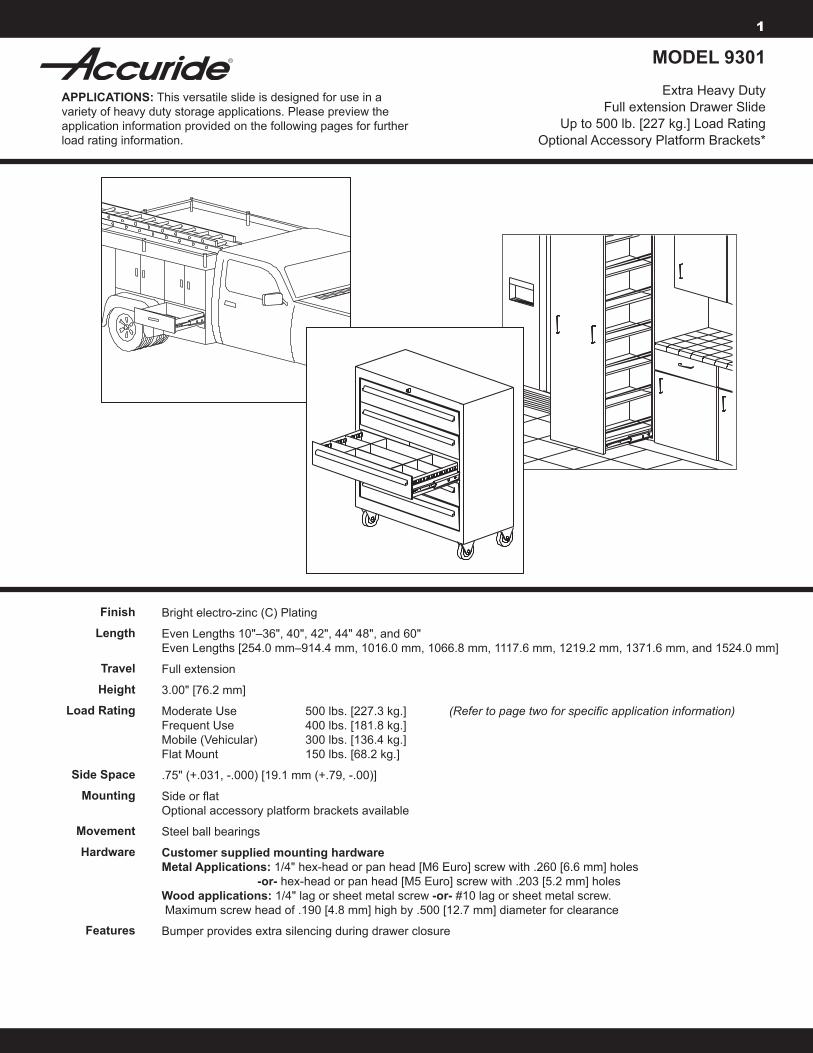
MODEL 9301
Extra Heavy Duty Full extension Drawer Slide
Up to 500 lb. [227 kg.] Load Rating Optional Accessory Platform Brackets*
APPLICATIONS: This versatile slide is designed for use in a variety of heavy duty storage applications. Please preview the application information provided on the following pages for further load rating information.
Bright electro-zinc (C) Plating
Even Lengths 10"–36", 40", 42", 44" 48", and 60" Even Lengths [254.0 mm–914.4 mm, 1016.0 mm, 1066.8 mm, 1117.6 mm, 1219.2 mm, 1371.6 mm, and 1524.0 mm]
Full extension
3.00" [76.2 mm]
Moderate Use 500 lbs. [227.3 kg.] (Refer to page two for specific application information) Frequent Use 400 lbs. [181.8 kg.] Mobile (Vehicular) 300 lbs. [136.4 kg.] Flat Mount 150 lbs. [68.2 kg.]
.75" (+.031, -.000) [19.1 mm (+.79, -.00)]
Side or flat Optional accessory platform brackets available
Steel ball bearings
Customer supplied mounting hardware Metal Applications: 1/4" hex-head or pan head [M6 Euro] screw with .260 [6.6 mm] holes -or- hex-head or pan head [M5 Euro] screw with .203 [5.2 mm] holes Wood applications: 1/4" lag or sheet metal screw -or- #10 lag or sheet metal screw. Maximum screw head of .190 [4.8 mm] high by .500 [12.7 mm] diameter for clearance
Bumper provides extra silencing during drawer closure
Finish
Length
Travel
Height
Load Rating
Side Space
Mounting
Movement
Hardware
Features

The Accuride load ratings shown below represent a wide range of typical applications and take into consideration factors which can adversely affect the performance of a slide.
In general, slides installed in drawers that are wider than they are deep, are subject to lateral (side) stresses that reduce their load carrying capacity. Likewise, slides in applications that are cycled frequently also carry a lower load rating.
Please use the following information to determine the load rating of model 9301 as it pertains to its intended application.
500lb.[227kg.]loadrating Load rating is based on an 18" [457.2 mm] slide in an 18" [457.2 mm] wide drawer, cycled 10,000 times. A computer server storage unit may be cycled once per month for servicing. Electronic instrumentation may be cycled a few times each week.
Computer server storage access Electronic instrumentation chassis
400lb.[182kg.]loadrating Load rating is based on an 18" [457.2 mm] slide in a 42" [1066.8 mm] wide drawer, cycled 75,000 times. A storage drawer opened and closed an average of three times per hour during each eight-hour work day would undergo a total of 60,000 cycles in 10 years. Heavy duty storage drawers Large pantry pull-outs Toolboxes Modular storage cabinets
300lb.[136kg.]loadrating Load rating is based on an 18" [457.2 mm] slide in a 32" [812.8 mm] wide drawer, cycled 10,000 times. Use for any application associated with transportation, or any application exposed to vibration and rough usage.
RV storage drawers Vehicle battery trays Service truck tool drawers
150lb.[68kg.]loadrating Load rating is based on an 18" [457.2 mm] slide in a 32" [812.8 mm] wide drawer, cycled 10,000 times. Use anywhere side space is limited.
Flight status monitor cabinets
This slide must never be used as a pull-out step, platform or any other application supporting human weight as injury may result.
Application Classification/Performance Standard 2
Moderate Use Applications
Typical Applications
Frequent Use Applications
Typical Applications
Mobile (Vehicular) Applications
Typical Applications
Flat Mount Applications
Typical Applications
CAUTION:
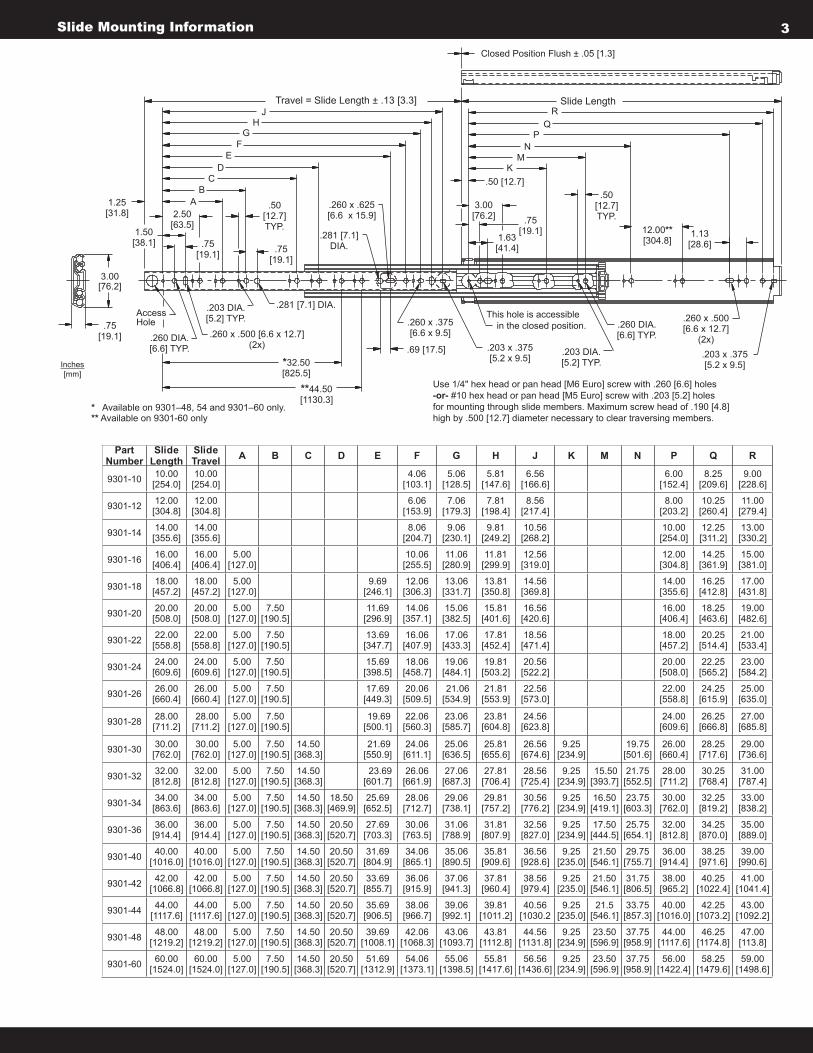
Slide Mounting Information 3
AccessHole
.260 DIA.[6.6] TYP.
.260 x .500 [6.6 x 12.7](2x)
.203 DIA.[5.2] TYP.
.281 [7.1] DIA.
*32.50[825.5]
**44.50[1130.3]
1.25[31.8]
1.50[38.1]
2.50[63.5]
.75[19.1]
.50[12.7]TYP.
JTravel = Slide Length ± .13 [3.3]
.260 x .625[6.6 x 15.9]
.281 [7.1]DIA.
.260 x .375[6.6 x 9.5]
.69 [17.5]
This hole is accessible in the closed position.
.203 x .375[5.2 x 9.5]
.260 DIA.[6.6] TYP.
.203 DIA.[5.2] TYP.
.260 x .500[6.6 x 12.7]
(2x).203 x .375[5.2 x 9.5]
.50 [12.7]
.75[19.1]
3.00[76.2]
.50[12.7]TYP.
12.00**[304.8]
1.13[28.6]
Slide Length
Closed Position Flush ± .05 [1.3]
* Available on 9301–48, 54 and 9301–60 only.** Available on 9301-60 only
.75[19.1]
3.00[76.2]
AB
CD
EF
GH
KM
NP
RQ
Use 1/4" hex head or pan head [M6 Euro] screw with .260 [6.6] holes -or- #10 hex head or pan head [M5 Euro] screw with .203 [5.2] holes for mounting through slide members. Maximum screw head of .190 [4.8] high by .500 [12.7] diameter necessary to clear traversing members.
1.63[41.4].75
[19.1]
Inches[mm]
Part Number
Slide Length
Slide Travel A B C D E F G H J K M N P Q R
9301-10 10.00 [254.0]
10.00 [254.0]
4.06 [103.1]
5.06 [128.5]
5.81 [147.6]
6.56 [166.6]
6.00 [152.4]
8.25 [209.6]
9.00 [228.6]
9301-12 12.00 [304.8]
12.00 [304.8]
6.06 [153.9]
7.06 [179.3]
7.81 [198.4]
8.56 [217.4]
8.00 [203.2]
10.25 [260.4]
11.00 [279.4]
9301-14 14.00 [355.6]
14.00 [355.6]
8.06 [204.7]
9.06 [230.1]
9.81 [249.2]
10.56 [268.2]
10.00 [254.0]
12.25 [311.2]
13.00 [330.2]
9301-16 16.00 [406.4]
16.00 [406.4]
5.00[127.0]
10.06 [255.5]
11.06 [280.9]
11.81 [299.9]
12.56 [319.0]
12.00 [304.8]
14.25 [361.9]
15.00 [381.0]
9301-18 18.00 [457.2]
18.00 [457.2]
5.00[127.0]
9.69 [246.1]
12.06 [306.3]
13.06 [331.7]
13.81 [350.8]
14.56 [369.8]
14.00 [355.6]
16.25 [412.8]
17.00 [431.8]
9301-20 20.00 [508.0]
20.00 [508.0]
5.00[127.0]
7.50 [190.5]
11.69 [296.9]
14.06 [357.1]
15.06 [382.5]
15.81 [401.6]
16.56 [420.6]
16.00 [406.4]
18.25 [463.6]
19.00 [482.6]
9301-22 22.00 [558.8]
22.00 [558.8]
5.00[127.0]
7.50 [190.5]
13.69 [347.7]
16.06 [407.9]
17.06 [433.3]
17.81 [452.4]
18.56 [471.4]
18.00 [457.2]
20.25 [514.4]
21.00 [533.4]
9301-24 24.00 [609.6]
24.00 [609.6]
5.00[127.0]
7.50 [190.5]
15.69 [398.5]
18.06 [458.7]
19.06 [484.1]
19.81 [503.2]
20.56 [522.2]
20.00 [508.0]
22.25 [565.2]
23.00 [584.2]
9301-26 26.00 [660.4]
26.00 [660.4]
5.00[127.0]
7.50 [190.5]
17.69 [449.3]
20.06 [509.5]
21.06 [534.9]
21.81 [553.9]
22.56 [573.0]
22.00 [558.8]
24.25 [615.9]
25.00 [635.0]
9301-28 28.00 [711.2]
28.00 [711.2]
5.00[127.0]
7.50 [190.5]
19.69 [500.1]
22.06 [560.3]
23.06 [585.7]
23.81 [604.8]
24.56 [623.8]
24.00 [609.6]
26.25 [666.8]
27.00 [685.8]
9301-30 30.00 [762.0]
30.00 [762.0]
5.00[127.0]
7.50 [190.5]
14.50 [368.3]
21.69 [550.9]
24.06 [611.1]
25.06 [636.5]
25.81 [655.6]
26.56 [674.6]
9.25 [234.9]
19.75 [501.6]
26.00 [660.4]
28.25 [717.6]
29.00 [736.6]
9301-32 32.00 [812.8]
32.00 [812.8]
5.00[127.0]
7.50 [190.5]
14.50 [368.3]
23.69 [601.7]
26.06 [661.9]
27.06 [687.3]
27.81 [706.4]
28.56 [725.4]
9.25 [234.9]
15.50 [393.7]
21.75 [552.5]
28.00 [711.2]
30.25 [768.4]
31.00 [787.4]
9301-34 34.00 [863.6]
34.00 [863.6]
5.00[127.0]
7.50 [190.5]
14.50 [368.3]
18.50 [469.9]
25.69 [652.5]
28.06 [712.7]
29.06 [738.1]
29.81 [757.2]
30.56 [776.2]
9.25 [234.9]
16.50 [419.1]
23.75 [603.3]
30.00 [762.0]
32.25 [819.2]
33.00 [838.2]
9301-36 36.00 [914.4]
36.00 [914.4]
5.00[127.0]
7.50 [190.5]
14.50 [368.3]
20.50 [520.7]
27.69 [703.3]
30.06 [763.5]
31.06 [788.9]
31.81 [807.9]
32.56 [827.0]
9.25 [234.9]
17.50 [444.5]
25.75 [654.1]
32.00 [812.8]
34.25 [870.0]
35.00 [889.0]
9301-40 40.00[1016.0]
40.00[1016.0]
5.00[127.0]
7.50 [190.5]
14.50 [368.3]
20.50 [520.7]
31.69[804.9]
34.06[865.1]
35.06[890.5]
35.81[909.6]
36.56[928.6]
9.25[235.0]
21.50[546.1]
29.75[755.7]
36.00[914.4]
38.25[971.6]
39.00[990.6]
9301-42 42.00[1066.8]
42.00[1066.8]
5.00[127.0]
7.50 [190.5]
14.50 [368.3]
20.50 [520.7]
33.69[855.7]
36.06[915.9]
37.06[941.3]
37.81[960.4]
38.56[979.4]
9.25[235.0]
21.50[546.1]
31.75[806.5]
38.00[965.2]
40.25[1022.4]
41.00[1041.4]
9301-44 44.00 [1117.6]
44.00[1117.6]
5.00 [127.0]
7.50 [190.5]
14.50 [368.3]
20.50[520.7]
35.69 [906.5]
38.06 [966.7]
39.06 [992.1]
39.81 [1011.2]
40.56 [1030.2
9.25 [235.0]
21.5 [546.1]
33.75 [857.3]
40.00 [1016.0]
42.25 [1073.2]
43.00 [1092.2]
9301-48 48.00 [1219.2]
48.00 [1219.2]
5.00[127.0]
7.50 [190.5]
14.50 [368.3]
20.50 [520.7]
39.69 [1008.1]
42.06 [1068.3]
43.06 [1093.7]
43.81 [1112.8]
44.56 [1131.8]
9.25 [234.9]
23.50 [596.9]
37.75 [958.9]
44.00 [1117.6]
46.25 [1174.8]
47.00 [113.8]
9301-60 60.00 [1524.0]
60.00 [1524.0]
5.00[127.0]
7.50 [190.5]
14.50 [368.3]
20.50 [520.7]
51.69 [1312.9]
54.06 [1373.1]
55.06 [1398.5]
55.81[1417.6]
56.56 [1436.6]
9.25 [234.9]
23.50 [596.9]
37.75 [958.9]
56.00 [1422.4]
58.25 [1479.6]
59.00 [1498.6]
Copyright © 2007 Accuride International Inc. 3700-9407(1066)-MK056-R9-0507 Copyright © 2007 Accuride International Inc. 3700-1066(9407)-MK554-R9-0507
Figure 1See
Tabulated
Data
2.00 [50.8] Min.
*2.13[54.1]
‡
‡
‡
‡
For Overlay Drawer
*1/4" Hex-Head or Pan Head [M6 Euro] Screw
‡
1/4" Hex-Head or Pan Head[M6 Euro] Screws
See
Tabulated
Data
For Overlay Drawer
*
Figure 2 ‡
‡
‡
‡
‡2.13[54.1]
*
1.50 Min. [38.1]
Figure 3
Platform/Shelf
Inner Member Bracket
9301 Slide
Outer MemberBracket
Bracket mounts to top or bottom of cabinet
Bottom-Mount
Platform/Shelf
9301 Slide
Inner Member BracketSlide mounts to side of cabinet
Side-Mount
Examples of mounting brackets. Six configurations available. Refer to bracket data sheet for details.
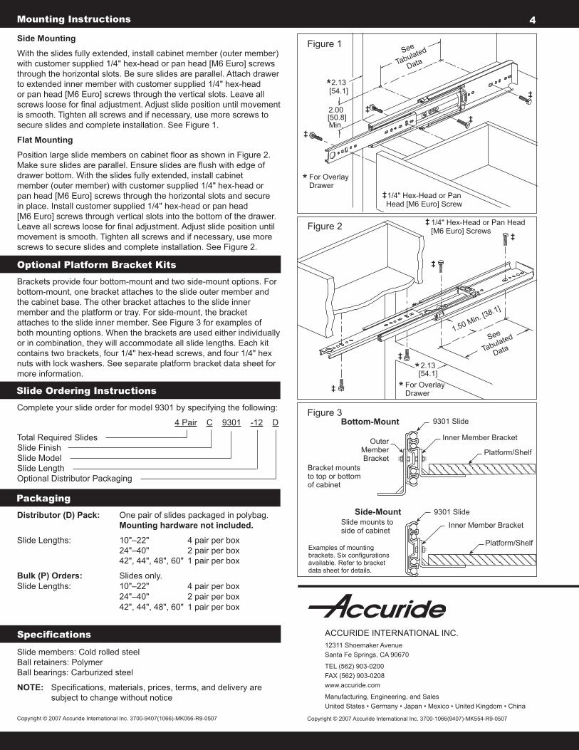
Side Mounting
With the slides fully extended, install cabinet member (outer member) with customer supplied 1/4" hex-head or pan head [M6 Euro] screws through the horizontal slots. Be sure slides are parallel. Attach drawer to extended inner member with customer supplied 1/4" hex-head or pan head [M6 Euro] screws through the vertical slots. Leave all screws loose for final adjustment. Adjust slide position until movement is smooth. Tighten all screws and if necessary, use more screws to secure slides and complete installation. See Figure 1.
Flat Mounting
Position large slide members on cabinet floor as shown in Figure 2. Make sure slides are parallel. Ensure slides are flush with edge of drawer bottom. With the slides fully extended, install cabinet member (outer member) with customer supplied 1/4" hex-head or pan head [M6 Euro] screws through the horizontal slots and secure in place. Install customer supplied 1/4" hex-head or pan head [M6 Euro] screws through vertical slots into the bottom of the drawer. Leave all screws loose for final adjustment. Adjust slide position until movement is smooth. Tighten all screws and if necessary, use more screws to secure slides and complete installation. See Figure 2.
Mounting Instructions 4
Optional Platform Bracket Kits
Brackets provide four bottom-mount and two side-mount options. For bottom-mount, one bracket attaches to the slide outer member and the cabinet base. The other bracket attaches to the slide inner member and the platform or tray. For side-mount, the bracket attaches to the slide inner member. See Figure 3 for examples of both mounting options. When the brackets are used either individually or in combination, they will accommodate all slide lengths. Each kit contains two brackets, four 1/4" hex-head screws, and four 1/4" hex nuts with lock washers. See separate platform bracket data sheet for more information.
Slide Ordering Instructions
Complete your slide order for model 9301 by specifying the following:
4 Pair C 9301 -12 D
Total Required Slides Slide Finish Slide Model Slide Length Optional Distributor Packaging
PackagingDistributor (D) Pack: One pair of slides packaged in polybag. Mounting hardware not included.
Slide Lengths: 10"–22" 4 pair per box 24"–40" 2 pair per box 42", 44", 48", 60" 1 pair per box
Bulk (P) Orders: Slides only. Slide Lengths: 10"–22" 4 pair per box 24"–40" 2 pair per box 42", 44", 48", 60" 1 pair per box
Slide members: Cold rolled steel Ball retainers: Polymer Ball bearings: Carburized steel
NOTE: Specifications, materials, prices, terms, and delivery are subject to change without notice
Specifications ACCURIDE INTERNATIONAL INC.12311 Shoemaker Avenue Santa Fe Springs, CA 90670
TEL (562) 903-0200FAX (562) 903-0208www.accuride.com
Manufacturing, Engineering, and SalesUnited States • Germany • Japan • Mexico • United Kingdom • China

InPower LLC3555 Africa Road
Galena, Ohio 43021 USA740-548-0965
www.InPowerDirect.com© Copyright 2009 InPower LLC
The InPower SSC20 Series is a family of high current solid state DC contactors. These contactors are avail-able in current ratings of 100, 150 and 200 amps, and are packaged in a sealed metal case. As they have extremely low current draw when in the off state they are ideally suited for use as battery disconnect switches. A key feature is the contactor’s highly efficent, low on-resistance DC power switch. This results in superior performance by producing a low voltage drop and generating only a small amount if internal heat.
A status LED indicator is lit when the contactor is on, and flashes to indicate a fault shutdown condition. Auto-matic fault shutdown is provided for over current, loss of ground and low battery voltage. Under a fault condi-tion the contactor is latched in the off state. To reset the unit the fault must be cleared; then the control input voltage must be removed, then re-applied. Removing the +BAT cable will also reset the unit.
The control input utilizes a ¼ inch male faston blade terminal. Connections for the high current DC cables utilize 3/8” - 16 stainless steel threaded studs with brass contact pads for low contact resistance. The terminal design allows the use of an optional rubber terminal protection boot for added protection from the environment, as well as accidental shorting. Four mounting contact pads allow for the required connection to ground.
SSC20 Series Owners ManualDocument: OM-105 Version Code: BDate: February 11, 2010 Date: August 31, 2011
OWNERS MANUALSolid State Contactors
Models:SSC20-100 (100 Amps)SSC20-150 (150 Amps)SSC20-200 (200 Amps)
InPower Solid State Contactor
Page1 of 4
Introduction
Ground
LOADBATTERY
Battery+
+12 Volt Loads
Ground+12 Volts
Control SwitchGround
Solid State Contactor
Model SSC20-200200 Amp Contactor
GroundStatus LED
ControllerControl Input
Electronic Switch LOAD+BAT

InPower LLC3555 Africa Road
Galena, Ohio 43021 USA740-548-0965
www.InPowerDirect.com© Copyright 2009 InPower LLC
SSC20 Series Owners Manual
System OperationThe solid state contactor is controlled by a positive DC voltage on its control terminal. The must operate voltage is +8.0 Vdc. The must release voltage is +4.0 Vdc. Note that the input voltage must drop to under +4.0 volts, then increase to +8.0 volts to turn on again.
Certain fault conditions will cause the power switch to turn off and remain latched off until the fault is cleared and the control input voltage is removed, then re-applied. The status LED will flash to indicate a fault. These fault conditions include: 1. An over current condition for greater than 500 milliseconds. 2. Loss of ground 3. Low battery voltage
SpecificationsCurrent Rating: SSC20-100 SSC20-150 SSC20-200 Maximum current at 43º C (110º F)* Type A Mounting** 100 Amps 150 Amps 200 Amps Type B Mounting** 75 Amps 100 Amps 125 AmpsOn-resistance at maximum current and temperature: 2.2 milliohms 1.1 milliohms 0.75 milliohm * Mounting surface temperature. Note - The maximum current rating will be derated above 43º C (110º F). ** Mounting surface types: Type A - Mounting surface such as an aluminum plate 0.125 x 16 x 16 inches. Type B - Mounting surface such as wood, plastic or free air.
Operating Voltage Range: +7.5 to +20.0 voltsCase Maximum Temperature: +185º F (85º C)Low Battery Voltage Trip: +7.25 to +7.50 Vdc for 250 millisecondsLoss of Ground Trip: 250 millisecondsOver-Current Trip: 100% to 110% of rated amperage for 500 millisecondsLogic Power Current Draw With Status LED Off: 80 milliwatts With Status LED On: 150 milliwatts Turn-On Delay: 25 millisecondsTurn-Off Delay: 25 millisecondsControl Connector Type: 0.25 inch male Faston blade terminalControl Input Voltage: >+8.0 Vdc to activate, <+4.0 Vdc to deactivateControl Input Resistance: 120 K Ohm to groundBAT+ to LOAD Terminal Leakage Current: 75 microamps maximumWeight: 0.40 lbs (0.181 kg)Dimensions: 2.85 (72.29 mm) x 4.35 (110.49) x 1.10 inches (27.94 mm)Power Terminals: Two (2) 3/8’ - 16 threaded stainless steel studs, with locking nuts. Optional rubber terminal boots are available. Power Terminal Torque: 10 Foot Pound Minimum, 15 Foot Pounds MaximumCase Mounting Screw Torque: 5 Inch Pounds
Page2 of 4
Installation Procedure
WARNING!
Do not weld on the vehicle with the solid state contactor installed as damage to the product may result. If electric welding is necessary, disconnect the control terminal and the cables attached to the LOAD and BAT+ terminals. Damage due to electric welding while the unit is installed will void InPower’s warranty.
Document: OM-105 Version Code: BDate: February 11, 2010 Date: August 31, 2011

InPower LLC3555 Africa Road
Galena, Ohio 43021 USA740-548-0965
www.InPowerDirect.com© Copyright 2009 InPower LLC
SSC20 Series Owners ManualPage3 of 4
IntroductionThis manual provides instructions for installing InPower SSC20 Series Solid State Contactors. It is impor-tant that you follow these instructions carefully and contact InPower if you need assistance or more informa-tion. You can reach InPower at:
InPower LLCCustomer Support
740-548-0965
Safety PrecautionsThis product requires the installer to be trained for installation and work on vehicle electrical systems. We recommend that all wiring meet the SAE and applicable vehicle manufacturer’s wiring specifications. In-spect the product and all other components for damage before starting the installation. Do not perform the installation if any problems exist.
Make sure that the vehicle battery power is disconnected during installation of the solid state contactor. Reconnect the battery when the installation is complete. Wear appropriate safety equipment such as eyeglasses, face shield and clothing when installing the equipment and handling the battery. Be careful when working near a battery. Make sure the area is well ventilated and that there are no flames near the battery. Never lay objects on the battery that can short the terminals together or to ground. If battery acid gets in your eyes immediately seek first aid. If acid gets on your skin immediately wash it off with soap and water.
Mounting LocationFirst determine where the contractor will be mounted. We recommend mounting it to a flat metal surface that can absorb heat produced by the contactor. Also take into consideration the maximum current needed and the maximum mounting surface temperature (See Specification Section). The contactor should not be mounted in the engine compartment or any location near the engine’s heat. For maximum thermal efficiency the mounting surface should be a thick metal surface such as an aluminum plate 1/8 x 16 x 16 inches or larger. To facilitate heat transfer a square piece of thermal transfer material is supplied with each contactor. Remove the clear plastic protective coating and insert the heat transfer material between the contactor and the mounting surface. Secure the contactor to the flat metal surface using four screws and tighten to a torque setting of 5 inch pounds. Do not drill out the contactor’s four mounting pad holes to use a larger bolt size. If the mounting surface is a good quality ground (low resistance to battery negative terminal) the mounting screws will provide a good ground connection. If the mounting surface is not a good ground, or you are not sure, you must install a ground wire with a ring terminal under one of the four mounting screws.
Connect the Power CablesFirst, make sure that the battery is disconnected. Prepare the cable to the battery using a suitable size cable for the current required and install a crimped lug terminal on the end. Be sure that you have installed a protection device (fuse, fuse link or circuit breaker) at the battery end of the cable. If the optional rubber terminal boot is used install the boot over the cable and lug, then install the cable as shown in the diagram on page 4. Torque the nut to the torque specification shown in the diagram. Slide the boot over the lug and onto the power terminal. Prepare the cable to the loads and install the cable as you did with the battery cable.
Control CircuitThe control wire must provide a positive DC voltage of at least +8.0 volts to activate the power switch. This could be, for example, a toggle switch wired to the +12 volt battery. Crimp a female 1/4 inch Faston terminal on the control wire and attach it to the male control input terminal.
Installation Procedure, Continued
Document: OM-105 Version Code: BDate: February 11, 2010 Date: August 31, 2011
InPower LLC3555 Africa Road
Galena, Ohio 43021 USA740-548-0965
www.InPowerDirect.com© Copyright 2009 InPower LLC
Page4 of 4
SSC20 Series Owners Manual
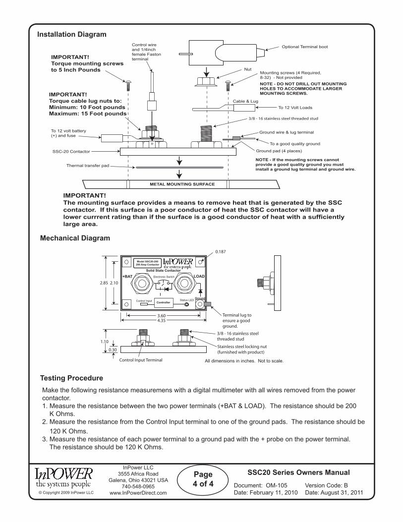
Installation Diagram
Mechanical Diagram
Make the following resistance measuremens with a digital multimeter with all wires removed from the power contactor.1. Measure the resistance between the two power terminals (+BAT & LOAD). The resistance should be 200 K Ohms.2. Measure the resistance from the Control Input terminal to one of the ground pads. The resistance should be 120 K Ohms.3. Measure the resistance of each power terminal to a ground pad with the + probe on the power terminal. The resistance should be 120 K Ohms.
Testing Procedure
+BAT
Solid State Contactor
Model SSC20-200200 Amp Contactor
GroundStatus LED
ControllerControl Input
Electronic Switch LOAD+BAT2.85 2.10
3.604.35
1.10
0.30
Terminal lug toensure a goodground.
0.187
Stainless steel locking nut(furnished with product)
3/8 - 16 stainless steel threaded stud
All dimensions in inches. Not to scale.Control Input Terminal
3/8 - 16 stainless steel threaded stud
Cable & Lug
Nut
Optional Terminal boot
Mounting screws (4 Required,8-32) - Not provided
To 12 Volt Loads
Ground wire & lug terminal
To a good quality ground
Ground pad (4 places)
Thermal transfer pad
IMPORTANT!Torque mounting screwsto 5 Inch Pounds
IMPORTANT!Torque cable lug nuts to:Minimum: 10 Foot poundsMaximum: 15 Foot pounds
Control wireand 1/4inchfemale Fastonterminal
SSC-20 Contactor
To 12 volt battery (+) and fuse
METAL MOUNTING SURFACE
NOTE - If the mounting screws cannotprovide a good quality ground you mustinstall a ground lug terminal and ground wire.
IMPORTANT!The mounting surface provides a means to remove heat that is generated by the SSCcontactor. If this surface is a poor conductor of heat the SSC contactor will have alower currrent rating than if the surface is a good conductor of heat with a sufficientlylarge area.
NOTE - DO NOT DRILL OUT MOUNTINGHOLES TO ACCOMMODATE LARGERMOUNTING SCREWS.
Document: OM-105 Version Code: BDate: February 11, 2010 Date: August 31, 2011

Operator's Manual
Printed in U.S.A. 929-0101 09�2001
Model YD PTOProtec Series
Redistribution or publication of this documentby any means, is strictly prohibited.Redistribution or publication of this documentby any means, is strictly prohibited.
Table of Contents
i
SECTION TITLE PAGE
SAFETY PRECAUTIONS ii, iii. . . . . . . . . . . . . . . . . . . . . . . . . . . . . . . . . . . . . . . . .
1 INTRODUCTION 1-1. . . . . . . . . . . . . . . . . . . . . . . . . . . . . . . . . . . . . . . . . . . . . . . . . .
About This Manual 1-1. . . . . . . . . . . . . . . . . . . . . . . . . . . . . . . . . . . . . . . . . . . . . . . How to Obtain Service 1-1. . . . . . . . . . . . . . . . . . . . . . . . . . . . . . . . . . . . . . . . . . . Generator 1-1. . . . . . . . . . . . . . . . . . . . . . . . . . . . . . . . . . . . . . . . . . . . . . . . . . . . . . Voltage Regulator 1-1. . . . . . . . . . . . . . . . . . . . . . . . . . . . . . . . . . . . . . . . . . . . . . . Meter/Breaker Box 1-1. . . . . . . . . . . . . . . . . . . . . . . . . . . . . . . . . . . . . . . . . . . . . . . Operation 1-1. . . . . . . . . . . . . . . . . . . . . . . . . . . . . . . . . . . . . . . . . . . . . . . . . . . . . . .
2 SPECIFICATIONS 2-1. . . . . . . . . . . . . . . . . . . . . . . . . . . . . . . . . . . . . . . . . . . . . . . . .
3 OPERATION 3-1. . . . . . . . . . . . . . . . . . . . . . . . . . . . . . . . . . . . . . . . . . . . . . . . . . . . . .
Startup Considerations 3-1. . . . . . . . . . . . . . . . . . . . . . . . . . . . . . . . . . . . . . . . . . . Typical Startup Procedure 3-1. . . . . . . . . . . . . . . . . . . . . . . . . . . . . . . . . . . . . . . . Applying Electrical Load 3-2. . . . . . . . . . . . . . . . . . . . . . . . . . . . . . . . . . . . . . . . . .
4 MAINTENANCE/TROUBLESHOOTING 4-1. . . . . . . . . . . . . . . . . . . . . . . . . . . . . .
Maintenance 4-1. . . . . . . . . . . . . . . . . . . . . . . . . . . . . . . . . . . . . . . . . . . . . . . . . . . . Troubleshooting 4-1. . . . . . . . . . . . . . . . . . . . . . . . . . . . . . . . . . . . . . . . . . . . . . . . . Cleaning the Generator 4-1. . . . . . . . . . . . . . . . . . . . . . . . . . . . . . . . . . . . . . . . . .
Redistribution or publication of this documentby any means, is strictly prohibited.Redistribution or publication of this documentby any means, is strictly prohibited.

Safety Precautions
ii
Before operating the generator, read the Operator’s Manual and become familiar with it and the equipment.Safe and efficient operation can be achieved only if the unit is properly operated and maintained.Many accidents are caused by failure to follow fundamental rules and precautions.
The following symbols, found throughout this manual, alert you to potentially dangerous conditions to the op-erator, service personnel, or the equipment.
This symbol warns of immediate hazards which will result in severe personal injury ordeath.
WARNING This symbol refers to a hazard or unsafe practice which can result in severe personal inju-ry or death.
CAUTION This symbol refers to a hazard or unsafe practice which can result in personal injury orproduct or property damage.
GASOLINE AND LPG FUEL MAY BE ACCIDENTALLY IGNITED BY ELECTRICAL SPARKS, presentingthe hazard of fire or explosion, which can result in severe personal injury or death. When installing thegenerator set:• Do not tie electrical wiring to fuel lines.• Do not run electrical lines and fuel lines through the same compartment openings.• Keep electrical and fuel lines as far apart as possible.• Place a physical barrier between fuel lines and electrical lines wherever possible.• If electrical and fuel lines must pass through the same compartment opening, make certain that they are
physically separated by running them through individual channels, or by passing each line through a sepa-rate piece of tubing.
• DO NOT SMOKE while servicing batteries. Lead acid batteries emit a highly explosive hydrogen gas thatcan be ignited by electrical arcing or by smoking.
Redistribution or publication of this documentby any means, is strictly prohibited.Redistribution or publication of this documentby any means, is strictly prohibited.

Safety Precautions
iii
GEN-2
MOVING PARTS CAN CAUSE SEVERE PERSONAL INJURY OR DEATH• Before starting work on the generator, disconnect batteries, negative (-) cable first. This will prevent acci-
dental arcing.• Keep hands, clothing, hair and jewelry away from moving parts.• Make sure that fasteners on the generator are secure. Tighten supports and clamps, keep guards in position
over fans, drive belts, etc.• Do not wear loose clothing or jewelry while working on generators. Loose clothing and jewelry can become
caught in moving parts. Jewelry can short out electrical contacts and cause shock or burning.• If adjustment must be made while the unit is running, use extreme caution around hot manifolds, moving
parts, etc.
ELECTRICAL SHOCK CAN CAUSE SEVERE PERSONAL INJURY OR DEATH• Disconnect starting battery before removing protective shields or touching electrical equipment. Use rubber
insulative mats placed on dry wood platforms over floors that are metal or concrete when around electricalequipment. Do not wear damp clothing (particularly wet shoes) or allow skin surfaces to be damp when han-dling electrical equipment.
• Use extreme caution when working on electrical components. High voltages can cause injury or death.• Follow all state and local electrical codes. Have all electrical installations performed by a qualified licensed
electrician. Tag open switches to avoid accidental closure.• DO NOT CONNECT GENERATOR DIRECTLY TO ANY BUILDING ELECTRICAL SYSTEM. Hazardous
voltages can flow from the generator set into the utility line. This creates a potential for electrocution or prop-erty damage. Connect only through an approved device and after building main switch is open. Consult anelectrician in regard to emergency power use.
GENERAL SAFETY PRECAUTIONS• Have a fire extinguisher nearby. Maintain extinguisher properly and become familiar with its use. Extinguish-
ers rated ABC by the NFPA are appropriate for all applications. Consult the local fire department for thecorrect type of extinguisher for various applications.
• Remove all unnecessary grease and oil from the unit. Accumulated grease and oil can cause overheatingand generator damage, which presents a potential fire hazard.
• DO NOT store anything in the generator compartment such as oil or gas cans, oily rags, chains, woodenblocks, portable propane cylinders, etc. A fire could result or the generator set operation (cooling, noise andvibration) may be adversely affected. Keep the compartment floor clean and dry.
• Do not work on this equipment when mentally or physically fatigued, or after consuming any alcohol or drugthat makes the operation of equipment unsafe.
Redistribution or publication of this documentby any means, is strictly prohibited.Redistribution or publication of this documentby any means, is strictly prohibited.

Section 1. Introduction
1-1
ABOUT THIS MANUAL
This manual covers the operation and maintenanceof the Onan PROTEC YD AC PTO generator. Formore information, see these publications:
• PROTEC AC PTO Installation Manual(publication # 929-0601)
• YD Generator Service Manual(publication # 900-0184)
Read this manual carefully, and follow all warningsand cautions. Using the generator properly and fol-lowing a regular maintenance schedule can resultin longer unit life, better performance, and safer op-eration. The generator must be installed properly tooperate safely.
HOW TO OBTAIN SERVICE
When the unit needs service, call an authorized ser-vice center and give them the complete model num-ber and serial number listed on the generator name-plate.
Factory-trained parts and service centers can han-dle your service needs. The Parts and Service Cen-ter Directory (publication F-118, included) lists thenearest center.
GENERATOR
The Onan YD series AC generators are two-bear-ing, 1500 or 1800 rpm, 50 or 60 hertz units designedfor direct drive from a power takeoff unit connectedto a vehicle engine.
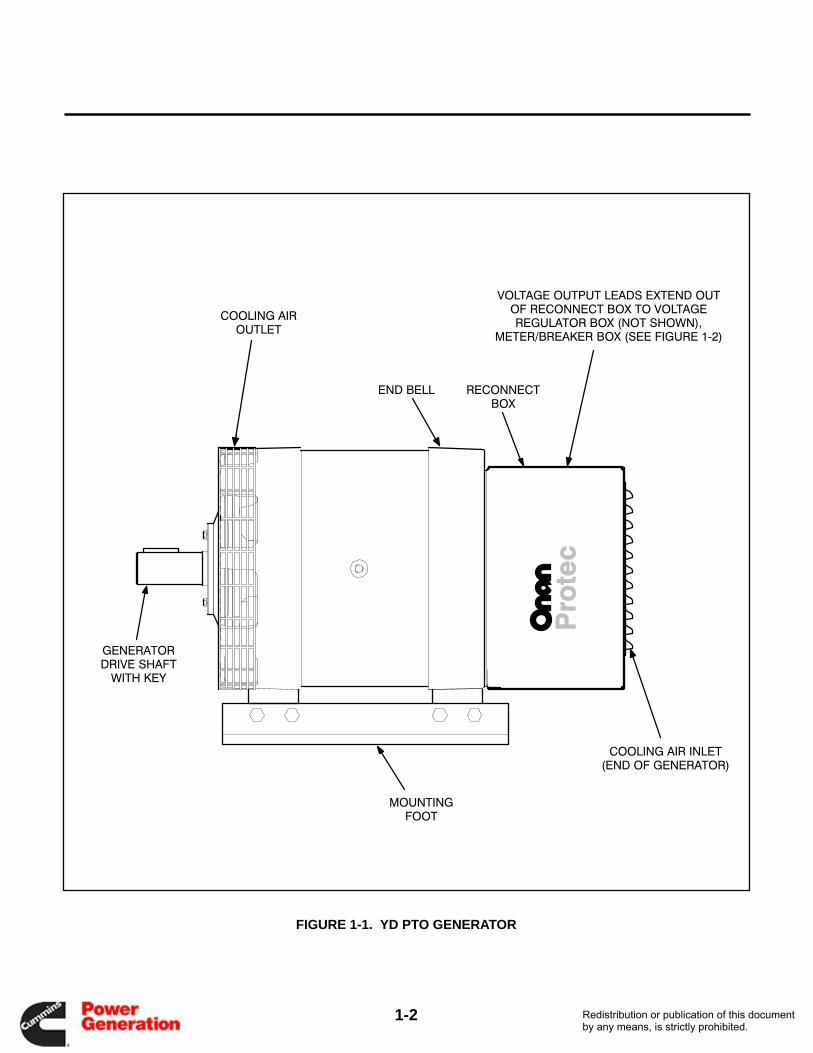
A centrifugal blower, on the front end of the rotorshaft, circulates the generator cooling air which isdrawn in through the reconnection box, over the ro-tor, and discharged through the outlet at the blowerend. See Figure 1-1.
A ball bearing at each end of the generator supportsthe rotor shaft. The reconnect box, end bell and sta-tor housing are attached by four through-studswhich pass through the stator assembly. Thebrushless exciter stator mounts in the end bell whilethe exciter rotor and its rotating rectifier assembliesmount on the rotor shaft.
VOLTAGE REGULATOR
The voltage regulator assembly includes the follow-ing components:
• Printed circuit board
• Voltage reference transformer
• Commutating reactor assembly
• Field circuit breaker
The AC PTO voltage regulator is housed in a re-mote box which may be mounted in any convenientlocation within a short range of the generator.
METER/BREAKER BOX
The meter/breaker box contains the following com-ponents:
• Voltmeter
• Ammeters
• Line circuit breakers
• Marked output terminals
• Conduit connector and hardware
• Current transformers
These components are used to indicate alternatorvoltage, load current and voltage regulation with avarying load.
Figure 1-2 illustrates the control box and its face-plate.
OPERATION
Residual magnetism in the generator rotor and apermanent magnet embedded in one exciter fieldpole begin the voltage buildup process as the gen-erator starts running. Single-phase AC voltage,taken from one of the stator windings, is fed to thevoltage regulator as a reference voltage for main-taining the generator output voltage. The AC refer-ence voltage is converted to DC by a silicon con-trolled rectifier bridge on the voltage regulatorprinted circuit board and fed into the exciter fieldwindings. The exciter armature produces three-phase AC voltage that is converted to DC by the ro-tating rectifier assembly. The resulting DC voltageexcites the generator rotor winding to produce thestator output voltage for the AC load.
Figure 1-1 illustrates the YD AC PTO generator.Figure 1-2 illustrates the PTO generator meter/cir-cuit breaker box.
Redistribution or publication of this documentby any means, is strictly prohibited.Redistribution or publication of this documentby any means, is strictly prohibited.
1-2
FIGURE 1-1. YD PTO GENERATOR
VOLTAGE OUTPUT LEADS EXTEND OUTOF RECONNECT BOX TO VOLTAGEREGULATOR BOX (NOT SHOWN),
METER/BREAKER BOX (SEE FIGURE 1�2)
RECONNECTBOX
GENERATORDRIVE SHAFT
WITH KEY
COOLING AIR INLET(END OF GENERATOR)
COOLING AIROUTLET
MOUNTINGFOOT
END BELL
Redistribution or publication of this documentby any means, is strictly prohibited.Redistribution or publication of this documentby any means, is strictly prohibited.

1-3
FIGURE 1-2. YD PTO GENERATOR METER/BREAKER BOX (20 kW UNIT SHOWN)
AMMETER VOLTMETER HOUR METER
TWO�POLECIRCUIT
BREAKER
FREQUENCYMETER
(45�65 HZ)
AMMETER
NOTE: AMMETER RATINGSVARY DEPENDING ON MODEL
Redistribution or publication of this documentby any means, is strictly prohibited.Redistribution or publication of this documentby any means, is strictly prohibited.
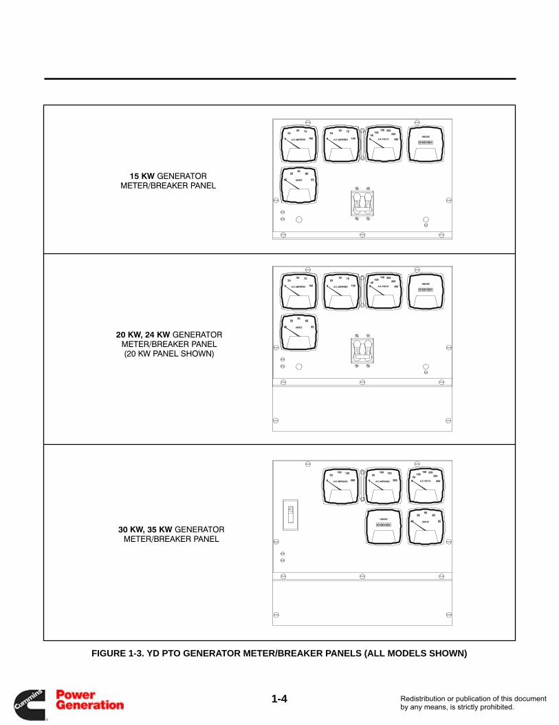
1-4
30 KW, 35 KW GENERATORMETER/BREAKER PANEL
20 KW, 24 KW GENERATORMETER/BREAKER PANEL(20 KW PANEL SHOWN)
15 KW GENERATORMETER/BREAKER PANEL
FIGURE 1-3. YD PTO GENERATOR METER/BREAKER PANELS (ALL MODELS SHOWN)
Redistribution or publication of this documentby any means, is strictly prohibited.Redistribution or publication of this documentby any means, is strictly prohibited.

Section 2. Specifications
2-1
Design: Revolving field: 4 pole. Drip-proofconstruction. Skewed stator minimizes field heat-ing and voltage harmonics. Stator laminationswelded in heavy steel frame. Dynamically balancedrotor. Windings epoxy impregnated and over-coated for environmental protection and improvedcooling.
Bearings: 2, double sealed, prelubricated ballbearings.
Cooling: Direct-drive centrifugal blower.
Reconnect Box: End mounted. Houses output ter-minals and conduit connectors.
Exciter System: Brushless, with 8-pole statormounted in end bell. Rectifier assemblies encapsu-lated for environmental protection. Permanentmagnet in stator field provides reliable voltagebuildup.
Voltage Regulator: Components include printedcircuit board, voltage reference transformer, com-mutating reactor, field circuit breaker, voltage adjustrheostat.Voltage Regulator Dimensions: 8” x 7.75” x 2.75”(203.2 mm x 196.85 mm x 69.85 mm)
Insulation System: Class F, per NEMA MG1-1.65definition. Insulating varnish conforms withMIL-I-24092, Grade CB, Class 155° C.
Electromagnetic Interference Attenuation:Meets requirements of most industrial and commer-cial applications.
Configuration: Platform-mounted or side-mounted.
Rating 50/60 (kW) Circuit Breaker L x W x H, in. (mm)
12/15 70 A, 2-pole 16.4 (418) x 4.5 (114) x 10.9 (278)
16 70 A, 2-pole 16.4 (418) x 4.5 (114) x 10.9 (278)20 85 A, 2-pole 16.5 (419) x 10 (254) x 15 (381)
20/25 100 A, 2-pole 16.5 (419) x 10 (254) x 15 (381)
24/30 150 A, 2-pole 16.5 (419) x 10 (254) x 15 (381)
30/35 175 A, 2-pole 16.5 (419) x 10 (254) x 15 (381)
(Optional) Meter/Breaker Box Dimensions, Circuit Breaker Ratings
Redistribution or publication of this documentby any means, is strictly prohibited.Redistribution or publication of this documentby any means, is strictly prohibited.
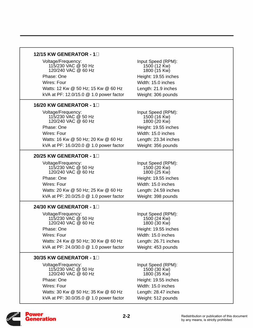
2-2
12/15 KW GENERATOR - 1 ∅Voltage/Frequency:
115/230 VAC @ 50 Hz120/240 VAC @ 60 Hz
Phase: OneWires: FourWatts: 12 Kw @ 50 Hz; 15 Kw @ 60 HzkVA at PF: 12.0/15.0 @ 1.0 power factor
Input Speed (RPM):1500 (12 Kw)1800 (15 Kw)
Height: 19.55 inchesWidth: 15.0 inchesLength: 21.9 inchesWeight: 306 pounds
16/20 KW GENERATOR - 1 ∅Voltage/Frequency:
115/230 VAC @ 50 Hz120/240 VAC @ 60 Hz
Phase: OneWires: FourWatts: 16 Kw @ 50 Hz; 20 Kw @ 60 HzkVA at PF: 16.0/20.0 @ 1.0 power factor
Input Speed (RPM):1500 (16 Kw)1800 (20 Kw)
Height: 19.55 inchesWidth: 15.0 inchesLength: 23.34 inchesWeight: 356 pounds
20/25 KW GENERATOR - 1 ∅Voltage/Frequency:
115/230 VAC @ 50 Hz120/240 VAC @ 60 Hz
Phase: OneWires: FourWatts: 20 Kw @ 50 Hz; 25 Kw @ 60 HzkVA at PF: 20.0/25.0 @ 1.0 power factor
Input Speed (RPM):1500 (20 Kw)1800 (25 Kw)
Height: 19.55 inchesWidth: 15.0 inchesLength: 24.59 inchesWeight: 398 pounds
24/30 KW GENERATOR - 1 ∅Voltage/Frequency:
115/230 VAC @ 50 Hz120/240 VAC @ 60 Hz
Phase: OneWires: FourWatts: 24 Kw @ 50 Hz; 30 Kw @ 60 HzkVA at PF: 24.0/30.0 @ 1.0 power factor
Input Speed (RPM):1500 (24 Kw)1800 (30 Kw)
Height: 19.55 inchesWidth: 15.0 inchesLength: 26.71 inchesWeight: 453 pounds
30/35 KW GENERATOR - 1 ∅Voltage/Frequency:
115/230 VAC @ 50 Hz120/240 VAC @ 60 Hz
Phase: OneWires: FourWatts: 30 Kw @ 50 Hz; 35 Kw @ 60 HzkVA at PF: 30.0/35.0 @ 1.0 power factor
Input Speed (RPM):1500 (30 Kw)1800 (35 Kw)
Height: 19.55 inchesWidth: 15.0 inchesLength: 28.47 inchesWeight: 512 pounds
Redistribution or publication of this documentby any means, is strictly prohibited.Redistribution or publication of this documentby any means, is strictly prohibited.
2-3
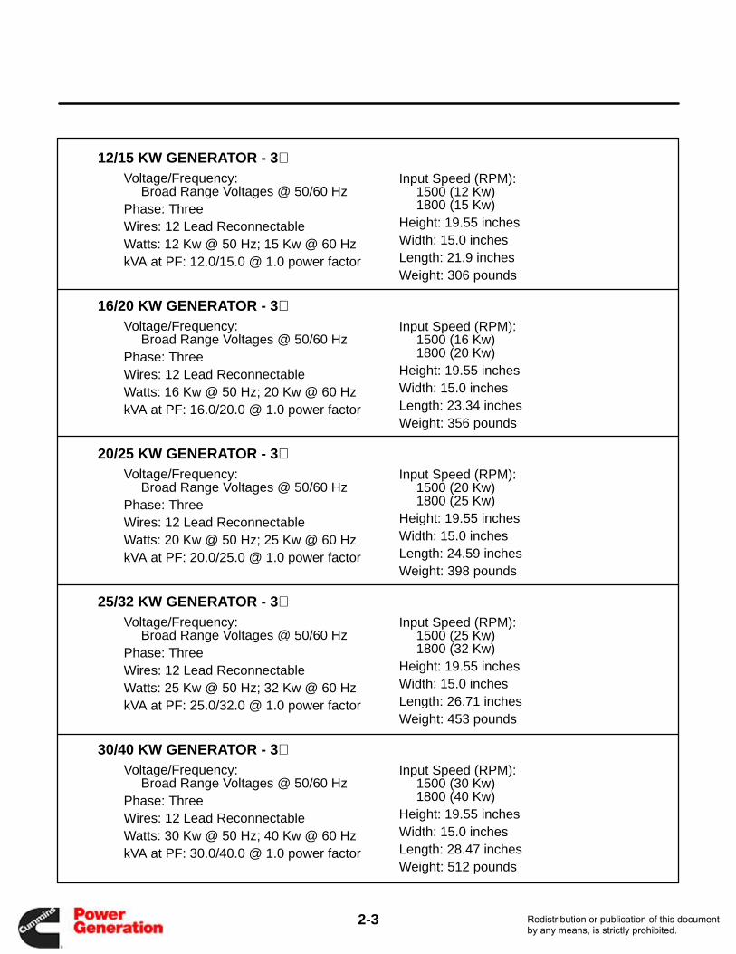
12/15 KW GENERATOR - 3 ∅Voltage/Frequency:
Broad Range Voltages @ 50/60 HzPhase: ThreeWires: 12 Lead ReconnectableWatts: 12 Kw @ 50 Hz; 15 Kw @ 60 HzkVA at PF: 12.0/15.0 @ 1.0 power factor
Input Speed (RPM):1500 (12 Kw)1800 (15 Kw)
Height: 19.55 inchesWidth: 15.0 inchesLength: 21.9 inchesWeight: 306 pounds
16/20 KW GENERATOR - 3 ∅Voltage/Frequency:
Broad Range Voltages @ 50/60 HzPhase: ThreeWires: 12 Lead ReconnectableWatts: 16 Kw @ 50 Hz; 20 Kw @ 60 HzkVA at PF: 16.0/20.0 @ 1.0 power factor
Input Speed (RPM):1500 (16 Kw)1800 (20 Kw)
Height: 19.55 inchesWidth: 15.0 inchesLength: 23.34 inchesWeight: 356 pounds
20/25 KW GENERATOR - 3 ∅Voltage/Frequency:
Broad Range Voltages @ 50/60 HzPhase: ThreeWires: 12 Lead ReconnectableWatts: 20 Kw @ 50 Hz; 25 Kw @ 60 HzkVA at PF: 20.0/25.0 @ 1.0 power factor
Input Speed (RPM):1500 (20 Kw)1800 (25 Kw)
Height: 19.55 inchesWidth: 15.0 inchesLength: 24.59 inchesWeight: 398 pounds
25/32 KW GENERATOR - 3 ∅Voltage/Frequency:
Broad Range Voltages @ 50/60 HzPhase: ThreeWires: 12 Lead ReconnectableWatts: 25 Kw @ 50 Hz; 32 Kw @ 60 HzkVA at PF: 25.0/32.0 @ 1.0 power factor
Input Speed (RPM):1500 (25 Kw)1800 (32 Kw)
Height: 19.55 inchesWidth: 15.0 inchesLength: 26.71 inchesWeight: 453 pounds
30/40 KW GENERATOR - 3 ∅Voltage/Frequency:
Broad Range Voltages @ 50/60 HzPhase: ThreeWires: 12 Lead ReconnectableWatts: 30 Kw @ 50 Hz; 40 Kw @ 60 HzkVA at PF: 30.0/40.0 @ 1.0 power factor
Input Speed (RPM):1500 (30 Kw)1800 (40 Kw)
Height: 19.55 inchesWidth: 15.0 inchesLength: 28.47 inchesWeight: 512 pounds
Redistribution or publication of this documentby any means, is strictly prohibited.Redistribution or publication of this documentby any means, is strictly prohibited.

Section 3. Operation
3-1
STARTUP CONSIDERATIONS
Components of the Onan YD AC PTO generator in-clude:
• YD generator with mounting hardware
• Voltage regulator in box
• Meter/breaker box with ampere and voltmetersand circuit breakers
These components are not supplied by Onan:
• Driving source (normally the vehicle propulsionengine)
• External governor unit, dedicated to maintain-ing 1500 or 1800 rpm from the driving source
• Dedicated power takeoff unit with clutch ortransmission to engage the generator
• Remote control unit for the power takeoff unit
• Interlock systems to keep the PTO from beingstarted in the wrong circumstances (vehicle ingear, brakes off, etc.).
TYPICAL STARTUP PROCEDURE
WARNING If the PTO generator is accessible tothe operator or other personnel, guards must beinstalled around rotating parts to prevent injuryor death.
Although most installations vary, a typical startupprocedure follows. These steps depend on the pro-cedures recommended by the manufacturers of thenon-Onan components of the system: the engine,governor, power takeoff unit and remote controlunit. Consult their instruction manuals beforestarting the PTO system.
1. Engage the vehicle emergency brake. Mostinstallations will have an interlock that keepsthe PTO system from being started unless thebrake is engaged and the vehicle is motionless.
2. Verify that the vehicle transmission is in theNEUTRAL position. Most installations willhave an interlock that prevents the PTO sys-tem from being started unless the transmissionis in neutral.
WARNING Emergency brake and/or trans-mission interlocks must be provided to pre-vent PTO operation while vehicle is in mo-tion. Do NOT operate generator while ve-hicle is moving or in gear. Severe equip-ment damage and personal injury may re-sult.
3. Start the vehicle propulsion engine (if not al-ready running).
4. Verify that the engine is running at low RPM.On most installations, the PTO output will begeared up to provide the 1800 rpm (1500 rpm,50 Hz units) and 30 horsepower or less that theYD AC generator requires. A typical engine/PTO output ratio might be 1:1.29. This meansthat the vehicle engine will be running at 1400rpm to provide 1800 rpm to the generator. Mostinstallations will have an interlock to keep thePTO from being started at high RPM.
5. Actuate the governor/PTO system. The en-gine governor and the geared PTO are actu-ated, beginning rotation of the Onan YD gener-ator. The engine governor system maintainsPTO output speed at 1800 rpm (1500 rpm for50 Hz system), adjusting engine speed to com-pensate for the generator’s electrical load.
6. Verify the output voltage and frequency onthe Onan switch/meter panel. The Onan me-ter panel provides verification of output voltageand frequency: these should quickly stabilize at120/240 VAC and 60 Hz (or other voltage/fre-quency, depending on model).
7. Close the circuit breakers on the Onan pan-el (if not already closed). The breakers on theOnan panel provide system protection fromelectrical shorts or overloads. Ampere rating ofthe breakers depends on the size of the gener-ator.
8. Apply power to the load. External switches orplug connections may be used to apply powerto the load, depending on the application.Note: depending on the configuration, theload may be powered by closing the break-ers on the Onan panel.
Redistribution or publication of this documentby any means, is strictly prohibited.Redistribution or publication of this documentby any means, is strictly prohibited.
3-2
WARNING Exhaust gas presents the hazard ofsevere personal injury or death. Inspect the ve-hicle exhaust system audibly and visually be-fore operating the PTO. Have any leaks repairedimmediately.
APPLYING ELECTRICAL LOAD
• Allow the driving source to warm up before con-necting a heavy load. Continuous generatoroverloading may cause high operating temper-atures that can damage the windings. Al-though the generator can handle a 20% over-load for ten minutes, the breakers supplied byOnan will not permit it. For normal operation,keep the load within nameplate rating.
• Connect the electrical load after the generatoroperates correctly at no load. When applyingload to electric motors, connect one at a time,allowing each to reach running speed beforeconnecting the next one. Motors require muchmore current for starting than when running atnormal speed. Therefore, if several motorswere connected at the same time, the genera-tor could be so overloaded that none of the mo-tors would start.
• If the engine governor does not provide effec-tive regulation, or if the engine is operating atmaximum capacity, it may be necessary tomanually adjust the engine throttle control inaccordance with changes in generator load.
Redistribution or publication of this documentby any means, is strictly prohibited.Redistribution or publication of this documentby any means, is strictly prohibited.
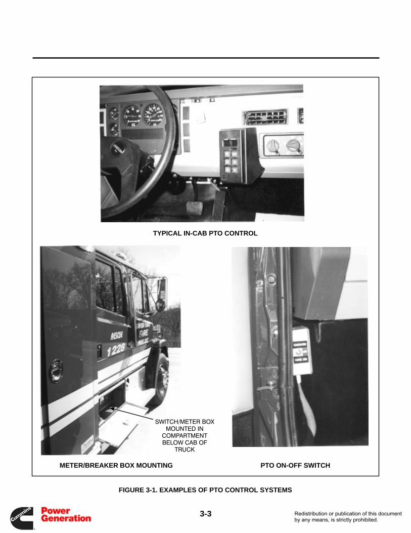
3-3
TYPICAL IN-CAB PTO CONTROL
SWITCH/METER BOXMOUNTED IN
COMPARTMENTBELOW CAB OF
TRUCK
METER/BREAKER BOX MOUNTING PTO ON-OFF SWITCH
FIGURE 3-1. EXAMPLES OF PTO CONTROL SYSTEMS
Redistribution or publication of this documentby any means, is strictly prohibited.Redistribution or publication of this documentby any means, is strictly prohibited.

Section 4. Maintenance/Troubleshooting
4-1
MAINTENANCE
The Onan YD PTO AC generator is a low-mainte-nance unit: only a few principles need to be kept inmind to keep the generator running correctly:
• Keep the generator clean: remove dirt, oil,grease and other foreign substances on a reg-ular basis
• Make certain that the air inlet and outlet to thegenerator are unobstructed, so that it may becooled properly
• Inspect the generator regularly. Make a goodvisual check before, during, and after the gen-erator is operating; look for loose or brokenleads and bad connections.
• Check the torque on the generator holddownbolts and retighten if necessary (see Installa-tion Manual for rating).
TROUBLESHOOTING
A few simple checks and a proper troubleshootingprocedure can locate the probable source of troubleand cut down troubleshooting time.
• Check all modifications, repairs, and replace-ments performed since last satisfactory opera-tion of the generator, to be sure that connectionof the generator leads are correct. A loose wire
connection, overlooked when installing a re-placement part, could cause problems. An in-correct connection, an opened circuit breaker,or a loose printed circuit board are all potentialmalfunction areas to be eliminated by a visualcheck.
• Unless absolutely sure that the panel instru-ments are accurate, use portable test metersfor troubleshooting.
• Visually inspect components inside the voltageregulator box. Look for dirt, dust, moisture,burned resistors, arcing tracks and cracks inthe printed circuit conductors.
• Coupling direct drive units have the driving unitand generator shafts in line with each other. Ifeither the driving unit or the generator is loos-ened from the base, the loosened unit must beproperly realigned when reinstalled.
CLEANING THE GENERATOR
Clean the generator every six months, or moreoften in severe conditions. Remove dust with adamp cloth. Use steam to remove tar or other resi-due (do not steam-clean the generator while it isrunning). Protect the generator, voltage regulator,and meter/breaker box from cleaning solutions. Donot clean with solvents; they may damage electricalconnectors.
Redistribution or publication of this documentby any means, is strictly prohibited.Redistribution or publication of this documentby any means, is strictly prohibited.
4-2
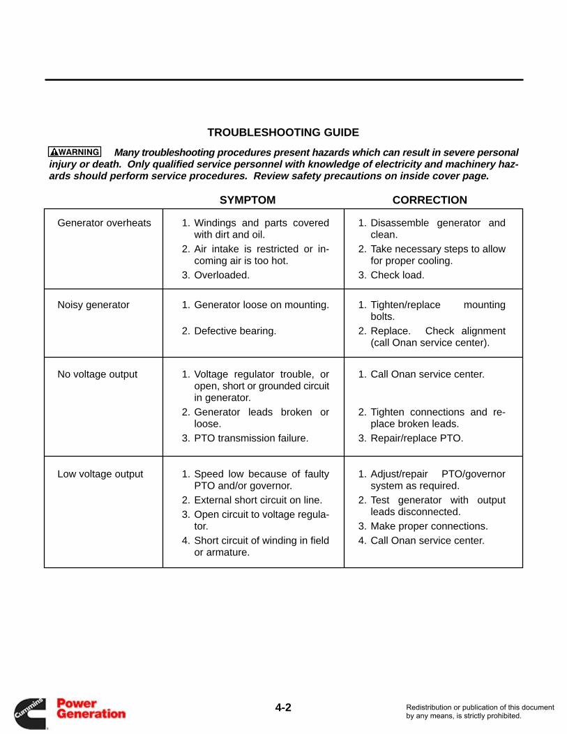
Generator overheats 1. Windings and parts coveredwith dirt and oil.
2. Air intake is restricted or in-coming air is too hot.
3. Overloaded.
1. Disassemble generator andclean.
2. Take necessary steps to allowfor proper cooling.
3. Check load.
Noisy generator 1. Generator loose on mounting.
2. Defective bearing.
1. Tighten/replace mountingbolts.
2. Replace. Check alignment(call Onan service center).
No voltage output 1. Voltage regulator trouble, oropen, short or grounded circuitin generator.
2. Generator leads broken orloose.
3. PTO transmission failure.
1. Call Onan service center.
2. Tighten connections and re-place broken leads.
3. Repair/replace PTO.
Low voltage output 1. Speed low because of faultyPTO and/or governor.
2. External short circuit on line.3. Open circuit to voltage regula-
tor.4. Short circuit of winding in field
or armature.
1. Adjust/repair PTO/governorsystem as required.
2. Test generator with outputleads disconnected.
3. Make proper connections.4. Call Onan service center.
TROUBLESHOOTING GUIDE
Many troubleshooting procedures present hazards which can result in severe personalinjury or death. Only qualified service personnel with knowledge of electricity and machinery haz-ards should perform service procedures. Review safety precautions on inside cover page.
WARNING
SYMPTOM CORRECTION
Redistribution or publication of this documentby any means, is strictly prohibited.Redistribution or publication of this documentby any means, is strictly prohibited.

Cummins Power Generation1400 73rd Avenue N.E.Minneapolis, MN 55432763-574-5000Fax: 763-528-7229
Cummins and Onan are registered trademarks of Cummins Inc.
Redistribution or publication of this documentby any means, is strictly prohibited.Redistribution or publication of this documentby any means, is strictly prohibited.
3842 Redman Drive 1-800-797-7974 Fort Collins, CO 80524 www.CommandLight.com
MODELS COVERED:
CL602A
CL602D
CL605
CL607
CL609
CL610
CL611
CL615
Effective July 1, 2013
This guide supersedes all previous versions
Models represented beginning
with serial number: CL5967

COMMAND LIGHT
JULY 2013 2
THANK YOU
Please allow us to express a simple thank you for investing in a COMMAND LIGHT product.
As a company we are dedicated to producing the very best and most versatile flood lighting
package available. We take great pride in the quality of our work and hope that you will find
many years of satisfaction from the use of this equipment.
Should you have any problems with your product please do not hesitate to contact us.
COMMAND LIGHT__ 3842 Redman Drive Fort Collins, CO 80524 PHONE: 1-800-797-7974 FAX: 1-970-297-7099 WEB: www.CommandLight.com

USER GUIDE
3

COMMAND LIGHT
JULY 2013 4
Please take the time to read this manual before installing or operating the COMMAND LIGHT.
Save this guide for future reference.
Contents Breakage or Damage During Shipment .................................................................................................... 7
Product Safety Precautions ........................................................................................................................ 8
General Description and Specifications .................................................................................................... 9
Operation ................................................................................................................................................... 10
Raising the light from the nested position .............................................................................................. 10
Returning the light to the nested position ............................................................................................... 11
Installation ................................................................................................................................................. 11
Installation Kit ........................................................................................................................................ 11
Tools Required ........................................................................................................................................ 12
Installation Notes .................................................................................................................................... 12
Location Requirements ........................................................................................................................... 13
Mounting ................................................................................................................................................. 14
Electrical Wiring ....................................................................................................................................... 15
120 VAC Wiring Diagram ...................................................................................................................... 15
240 VAC Wiring Diagram ...................................................................................................................... 16
220 VAC European ................................................................................................................................. 16
12 VDC ................................................................................................................................................... 16
Warning Device Installation .................................................................................................................... 17
Maintenance .............................................................................................................................................. 18
Bulb Replacement ................................................................................................................................... 18
Cleaning .................................................................................................................................................. 19
Rotation Motor Replacement .................................................................................................................. 20

USER GUIDE
5
Center Switch Adjustment ...................................................................................................................... 22
Light Tower is Not Finding Center ......................................................................................................... 22
Troubleshooting ........................................................................................................................................ 24
Technical Specifications – Standard AC Models (602A/605/607/609/610/611/615) ............................ 25
Specifications ............................................................................................................................................. 26
Parts Lists - Exploded Views ................................................................................................................... 29
Exploded View (Lower Stage A) ............................................................................................................ 30
Exploded View (Lower Stage B) ............................................................................................................ 32
Exploded View (Upper Stage A) ............................................................................................................ 34
Exploded View (Upper Stage B) ............................................................................................................ 36
Exploded View (Upper Stage C) ............................................................................................................ 38
Wiring Schematics .................................................................................................................................... 39
Entrance Box (120VAC) ......................................................................................................................... 40
Entrance Box (220VAC) ......................................................................................................................... 41
Entrance Box (240VAC) ......................................................................................................................... 42
Holster Box ............................................................................................................................................. 43
Lamp Tree (Metal Halide X 2) Backlight ............................................................................................... 44
Lamp Tree (Metal Halide x 2) Strobe ..................................................................................................... 45
Lamp Tree (Metal Halide X 4) ............................................................................................................... 46
Lamp Tree (Backlight) ............................................................................................................................ 47
Lamp Tree (Strobe) ................................................................................................................................. 48
Midplate .................................................................................................................................................. 49
Relaybox ................................................................................................................................................. 50

COMMAND LIGHT
JULY 2013 6
Command Light PHONE: 1-800-797-7974
3842 Redman Drive FAX: 1-970-297-7099
Fort Collins, CO 80524 WEB: www.CommandLight.com
LIMITED WARRANTY Five Year
COMMAND LIGHT warrants that the equipment is free from defects in materials and workmanship
when used and operated for a period of five years. The responsibility of COMMAND LIGHT under this
limited warranty is limited to the repair and replacement of any parts found defective. Parts must be
returned to COMMAND LIGHT at 3842 Redman Drive, Ft Collins, Colorado 80524 with transportation
charges prepaid (C.O.D. shipments will not be accepted).
Prior to returning defective parts to COMMAND LIGHT, the original purchaser shall make a claim in
writing to COMMAND LIGHT at the above address indicating the model number, serial number and
type of defect. No parts or equipment will be received by COMMAND LIGHT for repair or replacement
under this warranty without specific written authority from it in advance.
Any parts damaged by improper installation, overloading, abuse or accident of any type or cause are not
covered by this warranty.
All equipment manufactured by us is tested before leaving our plant, and is shipped in good working
order and condition. We therefore extend to the original purchasers the following Limited Warranty for
the period of five years from the original date of purchase:
1. This warranty does not apply to defects caused by accident, misuse, neglect, or wear and tear, nor
can we be held responsible for incidental and consequential expense and loss, nor does this
warranty apply to equipment where alterations have been executed without our knowledge or
consent. These conditions are readily discernable when the equipment is returned to us for
inspection.
2. On all component parts not manufactured by COMMAND LIGHT, their warranty is to the extent
that the manufacturer of such component warrants them to COMMAND LIGHT, if at all. Look in
your local business telephone directory for the nearest repair station for the brand of parts you
have or write to us for the address.
3. If equipment received has been damaged in transit, a claim should be made against the carrier
within three days, as we assume no responsibility for such damage.
4. Any service other than our Authorized Service voids this warranty.
5. This warranty is in lieu of and is intended to exclude all other warranties, express or implied, oral
or written, including any warranties of MERCHANTIBILITY or FITNESS for a particular
purpose.

USER GUIDE
7
Breakage or Damage During Shipment
The transportation company is fully responsible for all shipping damage and will resolve
problems promptly if you handle it correctly. Please read these instructions carefully.
Examine the contents of all shipping cases. If you find any damage, call your transportation
agent at once and have them make a description on the freight or express bill describing the
damage and the number of pieces. Then contact us and we will send you the original bill of
lading. Also promptly contact the transportation company and follow their procedure for
filing a claim. Each company will have a unique procedure to follow.
Please note, we cannot and will not enter claims for damages. If we filed claim here, it
would be sent to your local freight agent for verification and investigation. This time can be
saved by you filing the claim directly. Every consignee is on the ground floor, in contact
with the local agent who inspects the damaged goods, and thus, each claim can be given
individual attention.
Since our goods are packed to comply with the regulations of all railroad, truck, and express
companies, we cannot allow deduction from any invoice because of any damage, however,
be sure to file your claim promptly. Our goods are sold F.O.B. factory. We take receipt from
the transportation company certifying that the goods were delivered to them in good order
and our responsibility ceases.
It is seldom that any breakage or damage occurs in any of our shipments and in no case will
the customer be out any expense if they follow the above instructions.
Be sure to keep all damaged goods subject to examination of the truck or express company
inspector, who may call on you some time later. These damaged goods, of course, will
belong to them, and they will inform you what to do with them. If you dispose of these
damaged goods, your claim may not be paid.

COMMAND LIGHT
JULY 2013 8
Product Safety Precautions
Never operate the COMMAND
LIGHT near overhead high
voltage power lines. The
COMMAND LIGHT is
manufactured from electrically
conductive materials.
Do not use the COMMAND
LIGHT for uses other than its
intended purpose.
Do not move emergency vehicle with the light extended. Visually verify that
the light is completely nested before moving vehicle.
Do not change light position while people are located within its operating
envelope. There are numerous pinch points that can cause serious bodily injury.
Do not use a high-pressure washer or subject the light to high volumes of water
when cleaning.
Never use the COMMAND LIGHT as a lifting device or mobile arm.
Do not use a COMMAND LIGHT that has been damaged or is not fully
functional, including non-working indicator lamps.
Never hold any part of the COMMAND LIGHT with a hand or foot while it is
in motion.
The COMMAND LIGHT has numerous pinch points. Keep loose clothing,
hands and feet clear of moving parts.
USER GUIDE
9
General Description and Specifications
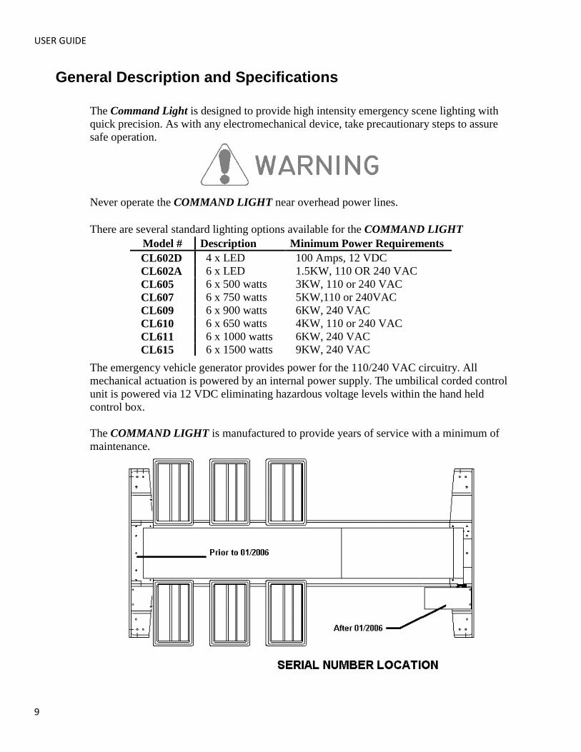
The Command Light is designed to provide high intensity emergency scene lighting with
quick precision. As with any electromechanical device, take precautionary steps to assure
safe operation.
Never operate the COMMAND LIGHT near overhead power lines.
There are several standard lighting options available for the COMMAND LIGHT
The emergency vehicle generator provides power for the 110/240 VAC circuitry. All
mechanical actuation is powered by an internal power supply. The umbilical corded control
unit is powered via 12 VDC eliminating hazardous voltage levels within the hand held
control box.
The COMMAND LIGHT is manufactured to provide years of service with a minimum of
maintenance.
Model # Description Minimum Power Requirements
CL602D 4 x LED 100 Amps, 12 VDC
CL602A 6 x LED 1.5KW, 110 OR 240 VAC
CL605 6 x 500 watts 3KW, 110 or 240 VAC
CL607 6 x 750 watts 5KW,110 or 240VAC
CL609 6 x 900 watts 6KW, 240 VAC
CL610 6 x 650 watts 4KW, 110 or 240 VAC
CL611 6 x 1000 watts 6KW, 240 VAC
CL615 6 x 1500 watts 9KW, 240 VAC

COMMAND LIGHT
JULY 2013 10
Operation
Raising the light from the nested position
Using the control box, raise the lower or upper stage. You may also activate both stages
simultaneously. Control switches are of momentary action style and must be held in the
“on” position to actuate the stages.
The COMMAND LIGHT has an override system that precludes rotation of the upper stage
until the lower stage has elevated approximately 16” from the nested position. When the
lower stage is below 16” the following conditions exist:
Upper stage is prevented from rotating.
All lights are turned off, including strobe light if equipped, regardless of light switch
positions.
Prevents the upper stage from moving down if upper stage is not centered.
If the supply from the generator is marginal, position the COMMAND LIGHT before
turning on lights.
Upper Lights
Middle Lights
Lower Lights
Rotation
Upper Stage
Emergency Stop
Strobe
Backlight Rotation
Lower Stage
Autopark
Elevated Indicator Center Indicator

USER GUIDE
11
Returning the light to the nested position
The COMMAND LIGHT is equipped with an Autopark function as a standard feature. The
green button on the control box initiates the Autopark sequence. Once initiated, the
“Emergency Stop” red button indicator is illuminated. Pressing the “Emergency Stop”
button will cancel the Autopark sequence.
Autopark Sequence
Press green button on the controller once. It does not need to be held in position. The
Autopark sequence begins:
1. “Emergency Stop” light is illuminated.
2. Lamps are extinguished.
3. Upper stage begins rotation to the center position. If equipped with back light option,
back light begins rotation and returns to the home position.
4. Once upper stage is centered, rotation stops, lower stage begins retracting.
5. After lower stage has fully retracted, upper stage begins retracting. Upon upper stage
retracting fully, “Emergency Stop” light turns off.
Installation
The COMMAND LIGHT must be installed by a designated installation facility by qualified
personnel only. All safety precautions must be thoroughly understood before installation.
Please consult the factory for additional installation information assistance.
Installation Kit
Included with the COMMAND LIGHT is an installation kit. Verify that the kit contains the
following items:
(1) 50 feet of 8GA-4 Conductor power cable (1) 50 feet of 22GA-20 conductor cable
(1) Pre-wired HOLSTER BOX w/cover (1) Handheld Controller
(1) Lifting sling
(1) Small hardware parts bag with:
(4) mounting spacers (4) 3∕8-16 X 2 ½” bolts
(4) 3∕8-16 nylon lock nuts (8)
3∕8” flat washers
(4) large diameter flat washers (2) ¼-20 X 5∕8” Phillips pan head machine screws
(4) ¼” flat washers (2) ¼-20 nylon lock nuts
(1) ½” 90° sealing connector w/nut (1) 1” 90° sealing connector w/nut
(4) screw pin clevis

COMMAND LIGHT
JULY 2013 12
Tools Required
Lifting device (crane, forklift, block and tackle, etc.)
Sling for lifting (included with light)
Drill 13
/32”,
17/64
” drill bits
Hole punch for metal with 7/8
” and 1
5/16
” diameter capacity
Phillips head screwdriver, #2
Command Light flat blade screwdriver (included with light) 9/16
” and
1/2
” combination wrenches and/or ratchet and
9/16
” and
1/2
” sockets
8” adjustable wrench
Tongue and Groove Pliers
Wire stripper or razor blade knife
Solder-less wire connector crimp tool
Silicone based gasket sealer, RTV™ recommended
Installation Notes
The COMMAND LIGHT weighs approximately 300 pounds. Use mechanical assistance to
lift the light into installation position such as a forklift or crane.
Use the provided sling to grasp the light.
Use the provided fender washers under the mounting surface to distribute the weight load
evenly.
When routing the connecting electrical wires take care to avoid sharp bends, hot
components or other hazards to the wire.
The COMMAND LIGHT is not designed to be operated in a raised position while the
vehicle is in motion. The COMMAND LIGHT includes warning circuit wiring to enable a
warning device.
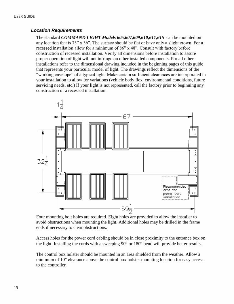
USER GUIDE
13
Location Requirements
The standard COMMAND LIGHT Models 605,607,609,610,611,615 can be mounted on
any location that is 73” x 36”. The surface should be flat or have only a slight crown. For a
recessed installation allow for a minimum of 86” x 48”. Consult with factory before
construction of recessed installation. Verify all dimensions before installation to assure
proper operation of light will not infringe on other installed components. For all other
installations refer to the dimensional drawing included in the beginning pages of this guide
that represents your particular model of light. The drawings reflect the dimensions of the
“working envelope” of a typical light. Make certain sufficient clearances are incorporated in
your installation to allow for variations (vehicle body flex, environmental conditions, future
servicing needs, etc.) If your light is not represented, call the factory prior to beginning any
construction of a recessed installation.
Four mounting bolt holes are required. Eight holes are provided to allow the installer to
avoid obstructions when mounting the light. Additional holes may be drilled in the frame
ends if necessary to clear obstructions.
Access holes for the power cord cabling should be in close proximity to the entrance box on
the light. Installing the cords with a sweeping 90 or 180 bend will provide better results.
The control box holster should be mounted in an area shielded from the weather. Allow a
minimum of 10” clearance above the control box holster mounting location for easy access
to the controller.

COMMAND LIGHT
JULY 2013 14
Mounting
Place the provided spacers in the location of the light mounting holes. The spacers may be
modified to conform to the contour of the mounting location.
Remove any obstructions below the mounting surface such as headliners.
Attach any necessary lifting attachments to the COMMAND LIGHT. The center of gravity
(balance point) is slightly behind the lower bank of lights.
Slowly lift the COMMAND LIGHT and check for balanced lifting. Lower and make any
necessary adjustments to the lift points.
Lift and place the
COMMAND LIGHT into position above the
spacers. Before placing
the full weight of the unit
on the spacers align
spacers with the holes in
the end frame castings.
Drill 13
/32” holes in the
mounting surface using
the end casting holes as a
template.
Fasten the light using the
provided hardware. To
assure a weather-tight
installation apply a thin
bead of silicone based
gasket sealer to the base
of the spacer and
underside of bolt head.
Remove any lifting straps and devices from the COMMAND LIGHT.
Locate and drill the wire feed holes.
Control Box Holster Mounting
Using the holster as a template, mark hole locations.
Drill 17
/64” mounting holes.
Drill any holes required to route the control wire from the control box to the COMMAND
LIGHT unit. Mount holster box with provided hardware.

USER GUIDE
15
Electrical Wiring
Please Note: Detailed internal wiring schematic for the light is found in the supplement
pages found at the end of this document.
Run the control wire from the control box holster to the COMMAND LIGHT.
Run the power wire from the breaker box or generator to the COMMAND LIGHT. A 40
Amp breaker is recommended on AC models. A 100 Amp breaker is recommended on DC
models.
Make the control connections in the COMMAND LIGHT entrance box. To simplify
installation remove the connector hold down screws and pull the connector out of the box
slightly.
The Model 602A/605/607/610 series COMMAND LIGHT comes pre-wired to connect to
120 VAC.
The Model 609/611/615 series COMMAND LIGHT comes pre-wired to connect to 240
VAC.
The Model 602D series COMMAND LIGHT comes pre-wired to connect to 12 VDC.
120 VAC Wiring Diagram
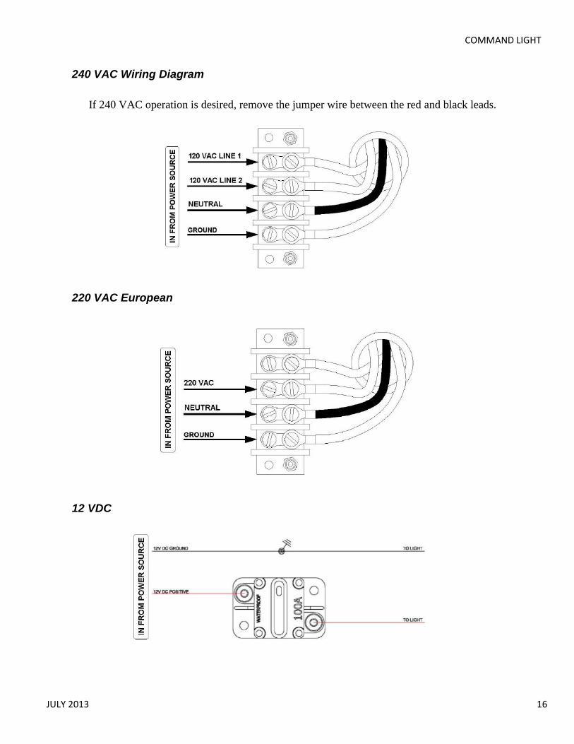
COMMAND LIGHT
JULY 2013 16
240 VAC Wiring Diagram
If 240 VAC operation is desired, remove the jumper wire between the red and black leads.
220 VAC European
12 VDC
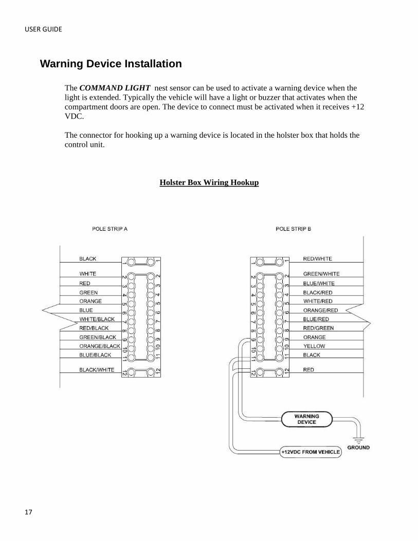
USER GUIDE
17
Warning Device Installation
The COMMAND LIGHT nest sensor can be used to activate a warning device when the
light is extended. Typically the vehicle will have a light or buzzer that activates when the
compartment doors are open. The device to connect must be activated when it receives +12
VDC.
The connector for hooking up a warning device is located in the holster box that holds the
control unit.
Holster Box Wiring Hookup
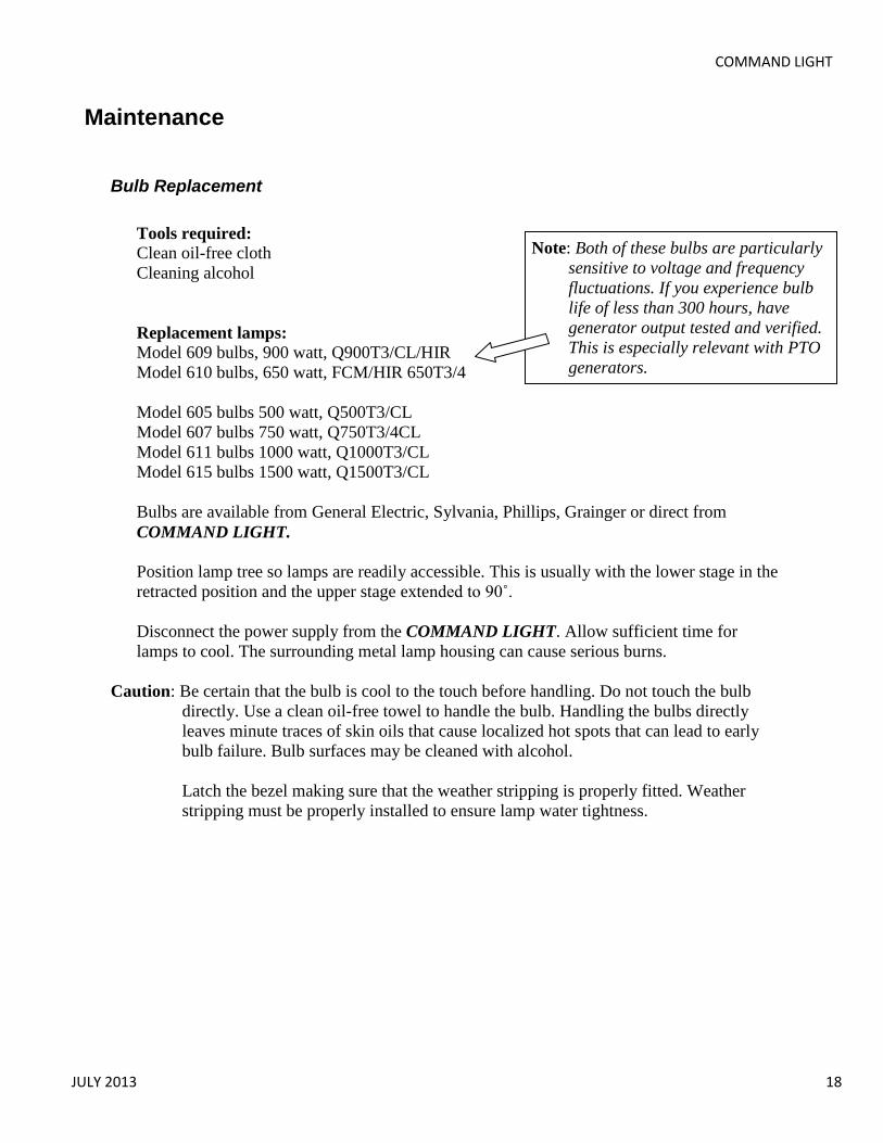
COMMAND LIGHT
JULY 2013 18
Note: Both of these bulbs are particularly
sensitive to voltage and frequency
fluctuations. If you experience bulb
life of less than 300 hours, have
generator output tested and verified.
This is especially relevant with PTO
generators.
Maintenance
Bulb Replacement
Tools required:
Clean oil-free cloth
Cleaning alcohol
Replacement lamps:
Model 609 bulbs, 900 watt, Q900T3/CL/HIR
Model 610 bulbs, 650 watt, FCM/HIR 650T3/4
Model 605 bulbs 500 watt, Q500T3/CL
Model 607 bulbs 750 watt, Q750T3/4CL
Model 611 bulbs 1000 watt, Q1000T3/CL
Model 615 bulbs 1500 watt, Q1500T3/CL
Bulbs are available from General Electric, Sylvania, Phillips, Grainger or direct from
COMMAND LIGHT.
Position lamp tree so lamps are readily accessible. This is usually with the lower stage in the
retracted position and the upper stage extended to 90˚.
Disconnect the power supply from the COMMAND LIGHT. Allow sufficient time for
lamps to cool. The surrounding metal lamp housing can cause serious burns.
Caution: Be certain that the bulb is cool to the touch before handling. Do not touch the bulb
directly. Use a clean oil-free towel to handle the bulb. Handling the bulbs directly
leaves minute traces of skin oils that cause localized hot spots that can lead to early
bulb failure. Bulb surfaces may be cleaned with alcohol.
Latch the bezel making sure that the weather stripping is properly fitted. Weather
stripping must be properly installed to ensure lamp water tightness.

USER GUIDE
19
Cleaning
The COMMAND LIGHT is constructed with corrosion resistant aluminum and stainless
steel fasteners. To further enhance corrosion resistance all exposed surfaces receive a
powder coated paint finish. To assure years of trouble free service periodically clean all
external surfaces with a mild detergent solution and a gentle spray of water. DO NOT USE
A HIGH-PRESSURE WASHER, which will force water into sensitive electric circuitry.
Lamp lenses may be cleaned with any commercially available glass cleaner.
Upper and lower stage actuators are sealed units and do not require adjustment or
lubrication. The actuators have slip-clutches to compensate for minor stroke tolerances at
the limits of its travel as well as internal limit switches. The actuator may produce a
ratcheting sound at each end of the stroke which is normal. The actuators should not be
made to ratchet excessively, this can lead to premature actuator clutch failure.
All pivot points on the COMMAND LIGHT are self-lubricating thermal polymere.
Periodic cleaning with a moisture displacing cleaner and soft bristle brush, without
disassembly, to remove accumulated dirt and debris will minimize wear.
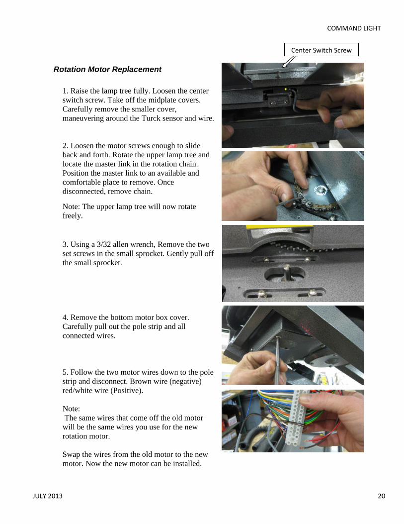
COMMAND LIGHT
JULY 2013 20
Rotation Motor Replacement
1. Raise the lamp tree fully. Loosen the center
switch screw. Take off the midplate covers.
Carefully remove the smaller cover,
maneuvering around the Turck sensor and wire.
2. Loosen the motor screws enough to slide
back and forth. Rotate the upper lamp tree and
locate the master link in the rotation chain.
Position the master link to an available and
comfortable place to remove. Once
disconnected, remove chain.
Note: The upper lamp tree will now rotate
freely.
3. Using a 3/32 allen wrench, Remove the two
set screws in the small sprocket. Gently pull off
the small sprocket.
4. Remove the bottom motor box cover.
Carefully pull out the pole strip and all
connected wires.
5. Follow the two motor wires down to the pole
strip and disconnect. Brown wire (negative)
red/white wire (Positive).
Note:
The same wires that come off the old motor
will be the same wires you use for the new
rotation motor.
Swap the wires from the old motor to the new
motor. Now the new motor can be installed.
Center Switch Screw

USER GUIDE
21
6. Attach the wires to the new motor (the brown is negative and the red/white is positive)
and connect them to the pole strip. Place the motor back into the housing and screw in all
four screws. Rotate the motor so the key stock slot is facing you.
7. Place the small sprocket back on the motor
and put in the keystock. Use blue Loctite on
the set screws tightening them as much as
possible.
8. If not already, loosen up the four motor
screws to let the motor slip for adjustment.
Wrap the chain back around the sprockets
bringing the ends together.
Note:
Be sure the half-link is on the right hand side
with the small cotter pin facing upwards.
9. Using a small pry bar or a screw driver, put
pressure on the small sprocket pushing it away
and tightening the chain. Tighten down the
four motor screws.
10. Now the bottom box cover can be put back
on after placing all the wires back in place.
The mid plate covers can now be put back on
also.
Note:
After motor replacement is completed, the
center switch and the safety switch will need
to be adjusted.

COMMAND LIGHT
JULY 2013 22
Center Switch Adjustment
Exercise caution when performing the following procedure. There are numerous pinch
points that can cause severe injury. Adjustment should be performed by qualified personnel.
1. Raise lamp tree fully. Raise lower stage enough to comfortably work on. Verify lower
stage is above the safety limit, lamps can be illuminated.
2. Visually inspect the screw on the rotation platform to be sure it is activating the Turck
sensor. The green light on the sensor indicates it has power. The orange light indicates
the sensor is activated.
3. Rotate off center. Activate Autopark and let light tower proceed through sequence until
the lamp tree is a couple inches above the nested position, hit Emergency Stop.
4. Visually determine which side the lamp tree will be hitting the nest pad.
5. Raise lower section above safety limit and to comfortable working height.
6. Loosen screws on center switch bracket slightly.
7. Tap center switch bracket slightly toward the side that the lamp tree is hitting on.
8. Fully tighten the screws holding the center switch bracket.
9. Raise lamp tree all the way up, rotate off center.
10. Press the Autopark button and let light tower proceed through sequence until the lamp
tree is a couple inches above the nested position, hit Emergency Stop.
11. If it looks like center is now adjusted properly, raise light tower all the way up one last
time and press Autopark and let it go through the entire sequence.
12. If it is still hitting off center, repeat steps 3-11. If problems adjusting center still persist
you may need to adjust the height on the set screw, or call Command Light at 1-800-
797-7974 to order a new switch part number 065-12884.
Light Tower is Not Finding Center
1. Visually check to see if the orange indicator light is activating with metal in proximity
and that the green light is on constantly.
2. Check continuity of white/black wire in relay box to the connection point in the box
below the mid plate. White/black should connect to the black wire from the Turck
sensor.

USER GUIDE
23
Power Failure
The COMMAND LIGHT can be retracted manually if power to the unit is lost. If power
loss is temporary, reestablishing power may be easier than manually retracting the light.
Disconnect power source from the COMMAND LIGHT .
Rotate to center
Slowly apply pressure to the rotation platform to manually rotate to the centered position.
Trying to rotate the platform too quickly or with too much pressure can break the rotation
motor shaft. Be certain that you rotate the platform in the proper direction. The upper stage
can rotate a full 360˚. Generally you need to rotate the platform in the direction that requires
the least amount of travel in order to center the platform.
Retract The Lower Stage First
Locate the silver plug located on lower actuator below the lower actuator’s motor. Use the
provided hex tool to remove silver plug. Be sure to not lose this plug. Use the same hex tool
inserted into the opening to drive the internal gears of the actuator. Be sure to replace the
silver plug after this actuator is fully retracted
Retract The Upper Stage
To access the upper actuator mechanism it is necessary to remove the main cover. Remove
the 16 screws using a #2 Phillips head screwdriver. There are 12 screws on top and 2 on
either end of the main cover. Use the same hex bit and method as above in “Retract The
Lower Stage First” to retract the upper actuator.

COMMAND LIGHT
JULY 2013 24
Troubleshooting
Problem Possible Cause Solution
Unit will not extend No power to the unit Check power input
connections.
Incorrect installation Refer to installation
instructions.
Upper stage will not rotate Lower stage not raised
above 16”
Raise lower stage higher.
Rotation motor failure. Consult with factory.
Lights will not illuminate. Lower stage not raised
above 16”
Raise lower stage higher.
Circuit breaker tripped. Check circuit breaker at
power supply.
No power to the unit. Check power supply
operation/output.
Lamp filament broken. Replace lamp.
Rotation coasts after
switch is released
Drive chain out of
adjustment
Adjust chain to provide no
more than ¼” slack
Unit will not nest Upper stage not centered Raise lower stage higher
than 16”. Center upper stage
(green light illuminated)
Unit being operated on a
slope >15°
Lower upper stage to
horizontal. Using a pike
pole, hold unit level while
lowering to nest position.
Autopark button must be
held in to park unit
Improper or faulty ground Check nest switch ground
and operation. Test
red/green wire for 12VDC.
Water in electronics Remove moisture from
ground points and
electronics. Do not use a
pressure washer to clean
unit.
Upper Act. & Rotation
Start at the same time
Check down limit sensor. Contact factory for
replacement part.
Wires on back light
catching
Check for 90 degree sealing
connector on lamp tree.
Contact factory for
replacement part.
No lights or rotation Check safety limit sensor,
bad, etc.
Contact factory for
replacement part.
Autoparking off Center Center switch out of
adjustment
Refer to instructions on
page
Popping noise coming
from back light
Drive belt loose, switch
hoods stuck, faulty rotation
relay.
Adjust belt for minimal
play. Replace switch hoods.

USER GUIDE
25
Technical Specifications – Standard AC Models (602A/605/607/609/610/611/615)
Dimensions (with strobe and ½” mounting spacers) – May vary by model:
Height(Depth) Length Width
Retracted 12.75” 74” 40”
Extended 10’-7” 80” 40”
Recessed installation 12.75” 86” 48” Minimum
Weight:
306 pounds
Wiring:
Main Power VAC 8/4 SO cord 50’ provided
Control wiring 22/20 PVC Jacketed 50’ provided
Relay protection:
Lights Cole-Hersey 3055 40 amp
Other electrical Cole-Hersey 3055 40 amp
Current Draw / Power Requirements:
Average Generator Requirement
150 Watt LED 110 VAC/8 amps 1 kW minimum
220 Watt LED 110 VAC/11 amps 1.5 kW minimum
500 Watt bulbs 110 VAC/25 amps 4 kW minimum
650 Watt bulbs 110 VAC/33 amps 6 kW minimum
750 Watt bulbs 110 VAC/41 amps 5.5 kW minimum
900 Watt bulbs 220 VAC/25 amps 6.5 kW minimum
1000 Watt bulbs 220 VAC/28 amps 6 kW minimum
1500 Watt bulbs 220 VAC/40 amps 10 kW minimum Lift actuators and rotation motor will cause higher current draw during use.
Motor Duty Cycle:
(All motors thermally protected, specifications are to thermal relay trip):
Lower stage 1:3 (90 seconds maximum per 5 minute)
Upper stage 1:3 (90 seconds maximum per 5 minute)
Rotation 5-6 Revolutions
Motor Speed:
Lower stage 1.0 inches per minute 12 seconds to full extension
Upper stage 0.5 inches per minute 12 seconds to full extension
Rotation 2.75 RPM at lamp tree
Operation:
Angle of vehicle 15˚ maximum incline
Wind load:
Design maximum 60 mph
Maximum tested 55 mph

COMMAND LIGHT
JULY 2013 26
Specifications

USER GUIDE
27
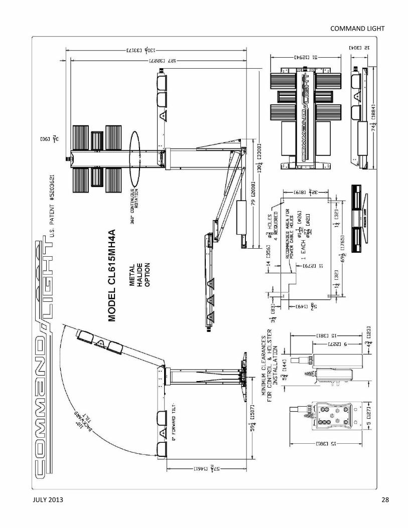
COMMAND LIGHT
JULY 2013 28

USER GUIDE
29
Parts Lists - Exploded Views

COMMAND LIGHT
JULY 2013 30
Exploded View (Lower Stage A)

USER GUIDE
31
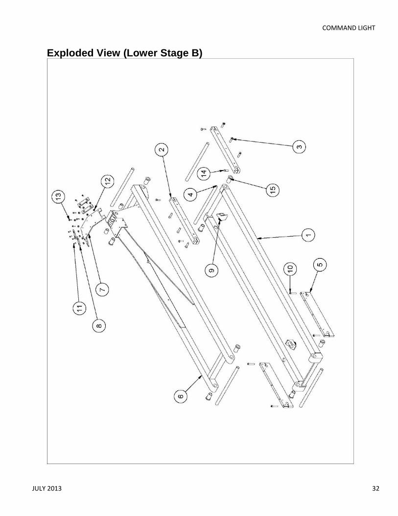
COMMAND LIGHT
JULY 2013 32
Exploded View (Lower Stage B)

USER GUIDE
33
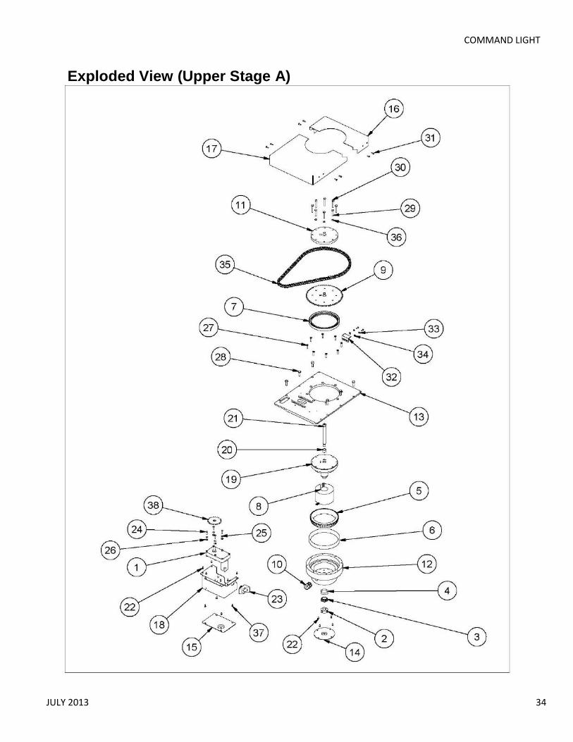
COMMAND LIGHT
JULY 2013 34
Exploded View (Upper Stage A)

USER GUIDE
35
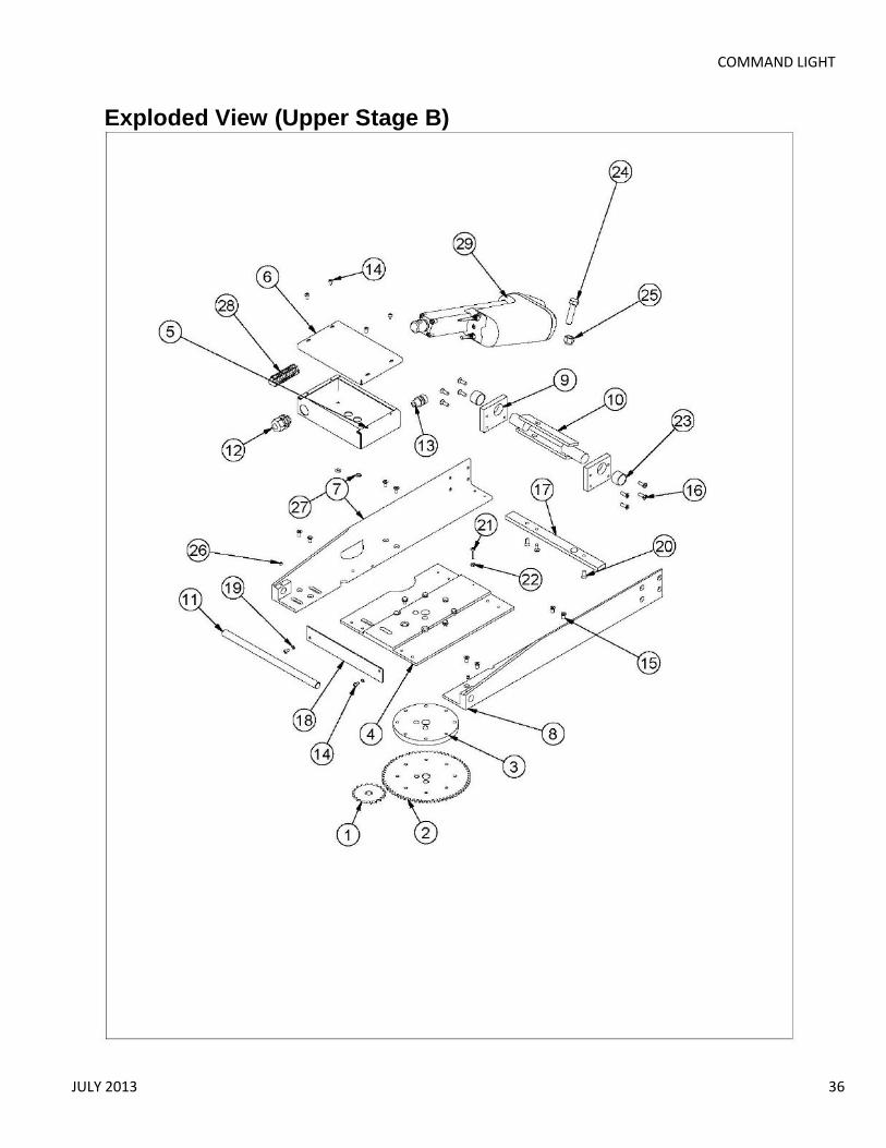
COMMAND LIGHT
JULY 2013 36
Exploded View (Upper Stage B)

USER GUIDE
37

COMMAND LIGHT
JULY 2013 38
Exploded View (Upper Stage C)
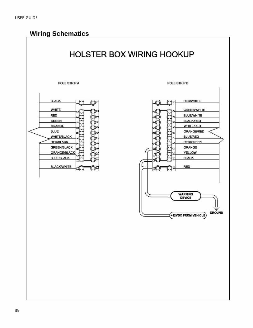
USER GUIDE
39
Wiring Schematics
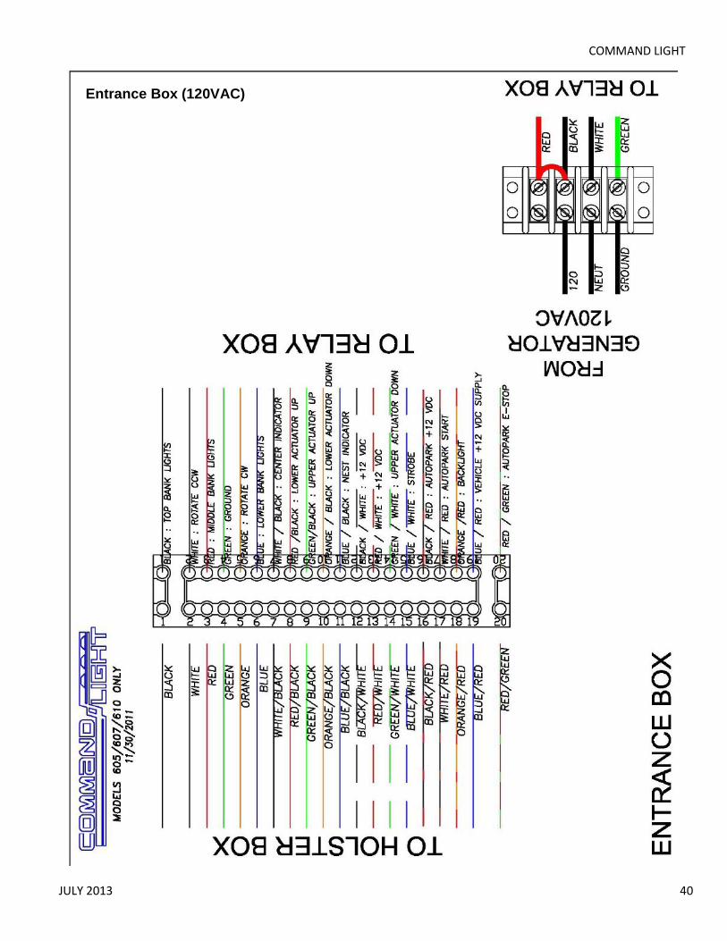
COMMAND LIGHT
JULY 2013 40
Entrance Box (120VAC)
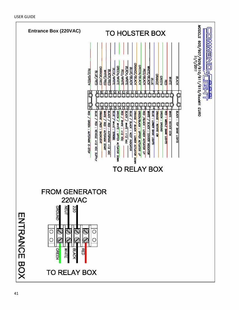
USER GUIDE
41
Entrance Box (220VAC)
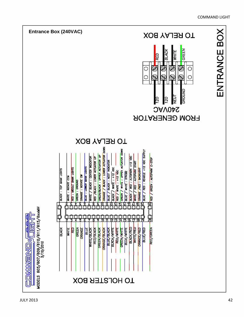
COMMAND LIGHT
JULY 2013 42
Entrance Box (240VAC)
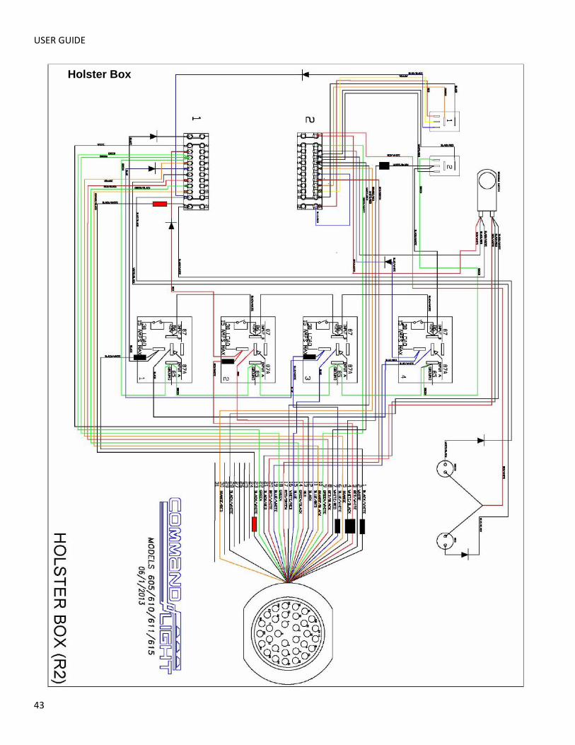
USER GUIDE
43
Holster Box
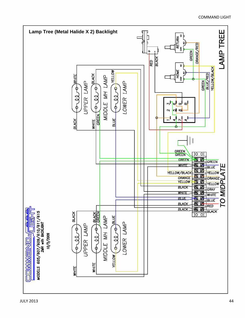
COMMAND LIGHT
JULY 2013 44
Lamp Tree (Metal Halide X 2) Backlight
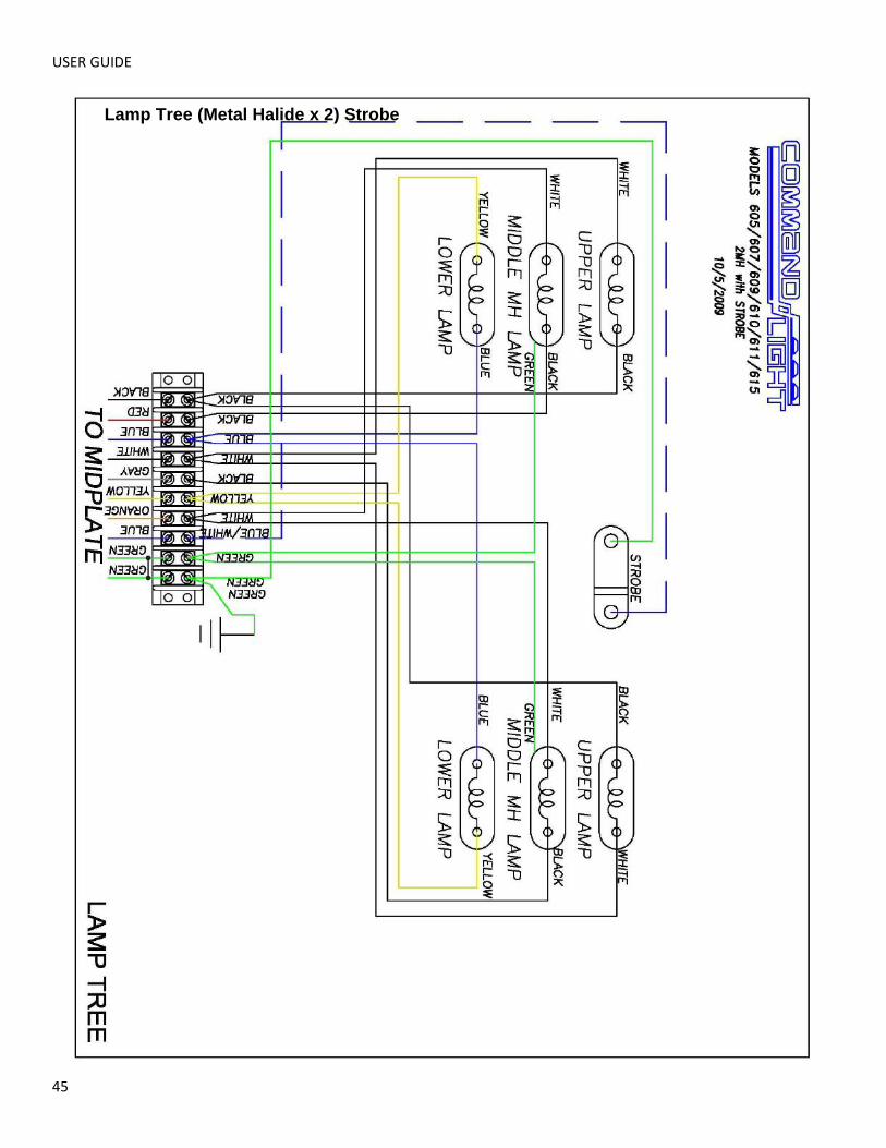
USER GUIDE
45
Lamp Tree (Metal Halide x 2) Strobe

COMMAND LIGHT
JULY 2013 46
Lamp Tree (Metal Halide X 4)

USER GUIDE
47
Lamp Tree (Backlight)
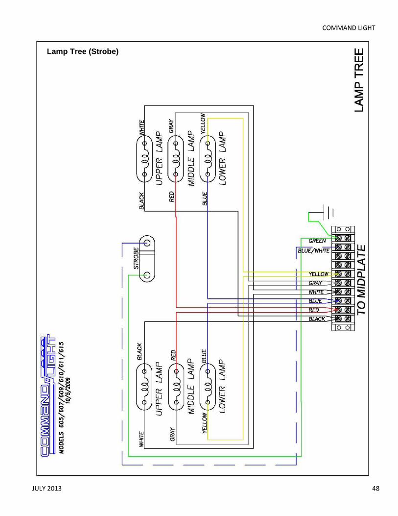
COMMAND LIGHT
JULY 2013 48
Lamp Tree (Strobe)

USER GUIDE
49
Midplate
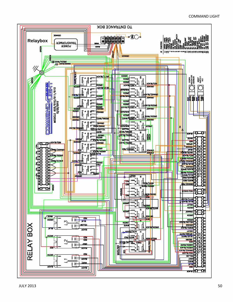
COMMAND LIGHT
JULY 2013 50
Relaybox

Figures and illustrations in this User Manual are provided for reference only and may differ from actual product appearance. Product design and specifications may be changed without notice.
Important Warranty Information Regarding Television Format Viewing
✎ See the warranty card for more information on warranty terms.
Wide screen format LED Displays (16:9, the aspect ratio of the screen width to height) are primarily designed to view wide screen format full-motion video. The images displayed on them should primarily be in the wide screen 16:9 ratio format, or expanded to fill the screen if your model offers this feature and the images are constantly moving. Displaying stationary graphics and images on screen, such as the dark sidebars on non- expanded standard format television video and programming, should be limited to no more than 5% of the total television viewing per week. Additionally, viewing other stationary images and text such as stock market reports, video game displays, station logos, web sites or computer graphics and patterns, should be limited as described above for all televisions. Displaying stationary images that exceed the above guidelines can cause uneven aging of LED Displays that leave subtle, but permanent burned-in ghost images in the LED picture. To avoid this, vary the programming and images, and primarily display full screen moving images, not stationary patterns or dark bars. On LED models that offer picture sizing features, use these controls to view different formats as a full screen picture. Be careful in the selection and duration of television formats you use for viewing. Uneven LED aging as a result of format selection and use, as well as burned-in images, are not covered by your Samsung limited warranty.
• SAMSUNG ELECTRONICS NORTH AMERICAN LIMITED WARRANTY STATEMENT
Subject to the requirements, conditions, exclusions and limitations of the original Limited Warranty supplied with Samsung Electronics (SAMSUNG) products, and the requirements, conditions, exclusions and limitations contained herein, SAMSUNG will additionally provide Warranty Repair Service in the United States on SAMSUNG products purchased in Canada, and in Canada on SAMSUNG products purchased in the United States, for the warranty period originally specified, and to the Original Purchaser only.
The above described warranty repairs must be performed by a SAMSUNG Authorized Service Center. Along with this Statement, the Original Limited Warranty Statement and a dated Bill of Sale as Proof of Purchase must be presented to the Service Center.
Transportation to and from the Service Center is the responsibility of the purchaser. Conditions covered are limited only to manufacturing defects in material or workmanship, and only those encountered in normal use of the product. Excluded, but not limited to, are any originally specified provisions for, in-home or on-site services, minimum or maximum repair times, exchanges or replacements, accessories, options, upgrades, or consumables.For the location of a SAMSUNG Authorized Service Center, please call toll-free:–– In the United States : 1-800-SAMSUNG (1-800-726-7864)–– In Canada : 1-800-SAMSUNG
Still image warningAvoid displaying still images (such as jpeg picture files) or still image elements (such as TV channel logos, TV shows or movies in panorama or 4:3 format, stock or news scroll bars, etc.) on the screen. The constant display of still pictures can cause ghosting or image burn-in (image retention) on the LED screen, which will affect image quality. To reduce the risk of this effect, please follow the recommendations below:• Avoid displaying the same TV channel for long periods.• Always try to display any image in full screen mode. Use the TV's
Picture Options menu to select the optimal screen size.• Reduce brightness and contrast values to the minimum required
to achieve the desired picture quality. Values that exceed the minimum may speed up the burn-in process.
• Frequently use all TV features designed to reduce image retention and screen burn-in. Refer to proper user manual section for details.
Contact SAMSUNG WORLDWIDE
If you have any questions or comments relating to Samsung products, please contact the SAMSUNG customer care center.
Country CANADA U.S.A.
Address
Samsung Electronics Canada Inc., Customer Service 55 Standish Court Mississauga, Ontario L5R 4B2 Canada
Samsung Electronics America, Inc. 85 Challenger Road Ridgefield Park, NJ 07660-2112
Customer Care Center
1-800-SAMSUNG(726-7864)
Web Site www.samsung.com
LED TVuser manual
© 2012 Samsung Electronics Co., Ltd. All rights reserved.
BN68-04499A
BN68-04499A-00
- 1 - - 1 -

The On Screen MenusYour TV has two kinds of menus, the Main menu and the various Tools menus. The Main menu gives you access to most or all of the menu options available on your TV. The Tools menus display a selected number of frequently used menu options that change depending on the screen you are viewing. A Tools menu symbol (T) in the lower right side of the screen indicates that a Tools menu is available.
The Main menu has seven primary categories:
y Picture y Input
y Sound y Application
y Channel y Support
y Setup
To view the Main menu, press the MENU button on your remote. To view a Tools menu, press the TOOLS button on your remote.
✎ The menu options that appear in the Main menu depend on the Source you have selected. For example, if you have selected the HDMI source, the Channel category will not appear. To see the Channel category, you must first select TV in the Source List.
The Menu options are presented below, arranged by Main menu categories. A Tools button symbol (t) next to an option name indicates the option is also available in one of the Tools menus.
Picture Menu
Mode tSelect your preferred picture mode.
✎ When your TV is connected to a PC, you can only select Entertain and Standard.
■■ Dynamic: Brightens the screen. Suitable for a bright room.■■ Standard: Suitable for a normal.■■ Movie: Darkens the screen, making it less glary. Suitable for watching movies in a darkened room.■■ Entertain: Sharpens the picture. Suitable for games.
✎ Only available when the TV is connected to a PC.
Backlight / Contrast / Brightness / Sharpness / Color / Tint (G/R) ■■ Backlight: Adjusts the brightness of the screen by adjusting the brightness of the individual pixels.■■ Contrast: Increases or decreases the contrast between dark and light areas of the picture.■■ Brightness: Adjusts the brightness of the screen. Not as effective as Backlight.■■ Sharpness: Sharpens or dulls the edges of objects.■■ Color: Adjusts the color saturation. The higher the Color setting, the more intense the color. Low settings remove color and the picture becomes black, white and gray.■■ Tint: Adjusts the amount of green and red in the picture. As you increase the amount of green, the amount of red decreases and vice versa. ✎ When the TV is connected to a PC, you can only make changes to Backlight, Contrast, Brightness, and Sharpness.
Advanced SettingsAvailable in Standard and Movie mode only.
Compared to previous models, new Samsung TVs offer a more precise picture with more precise controls.
✎ When your TV is connected to a PC, you can only make changes to Gamma and White Balance.
■■ Color Space (Auto / Native): Auto automatically matches the range of colors available to create pictures to the color range of the video source. Native provides a color range wider than the color range of the video source.■■ White Balance: Adjusts the color temperature of the picture so that white objects look white (instead of, for example, slightly pink or slightly yellow) and the overall color of the picture looks natural.
R-Offset / G-Offset / B-Offset: Adjusts each color’s (red, green, blue) darkness.R-Gain / G-Gain / B-Gain: Adjusts each color’s (red, green, blue) brightness.Reset: Resets the White Balance to it’s default settings.
■■ Gamma: Adjusts the primary color intensity.■■ Dynamic Contrast (Off / Low / Medium / High): Adjusts the screen contrast. ■■ Black Tone (Off / Dark / Darker / Darkest): Selects the black level to adjust the screen depth. Darker settings make blacks look darker.■■ Flesh Tone: Adjusts the amount of red in skin tones.■■ Motion Lighting (Off / On): When on, the TV automatically adjusts the brightness of the screen in response to the brightness of the room. In bright light, the screen brightens. In dim light, the screen dims.
✎ Available in Standard mode only.
Picture Options ✎ When the TV is connected to a PC, you can only make changes to the Color Tone, Size and HDMI Black Level.
■■ Color Tone (Cool / Standard / Warm1 / Warm2): Cool makes the picture bluer (cooler). Warm 1 and Warm 2 make the picture redder (warmer).
✎ Warm1 and Warm2 are deactivated when the picture mode is set to Dynamic.
■■ Size: Set the size and aspect ratio of the picture on the screen.Your cable box or satellite receiver may have its own set of screen sizes as well. However, we highly recommend you use the TVs 16:9 mode most of the time.16:9: Sets the picture to the 16:9 wide screen format.Zoom1: Provides moderate magnification of the picture. Sides, top, and bottom are cut off.Zoom2: Provides larger magnification of the picture. Sides, top, and bottom are cut off.Wide Fit: Enlarges the aspect ratio of the picture so the picture fits the entire screen.4:3: Sets the picture to the old, 4:3 format and puts black or gray borders on the right and left of the picture.
✎ Do not watch your TV in the 4:3 format for a long time. Traces of borders displayed on the left, right and center of the screen may cause image retention (screen burn) which is not covered by the warranty.
Screen Fit: Displays the full image without any cut-off when your TV is inputting HDMI (720p / 1080i / 1080p) or Component (1080i / 1080p) HD signals. ✎ HD (High Definition) has a 16:9 aspect ratio and 1080i/1080p (1920x1080) or 720p (1280x720) resolution.
✎ You can adjust and store settings for each external device you have connected to an input on the TV. Picture Sizes available by Input Source are listed below:
- 2 - - 2 -

Input Source Picture Size
ATV, AV, Component (480i, 480p) 16:9, Zoom1, Zoom2, 4:3
DTV (1080i, 1080p), Component (1080i, 1080p), HDMI (720p, 1080i, 1080p)
16:9, Wide Fit, 4:3, Screen Fit
■■ Digital Noise Filter (Off / Low / Medium / High / Auto) : If the broadcast signal received by your TV is weak, you can activate the Digital Noise Filter feature to reduce any static and ghosting that may appear on the screen.
✎ When the signal is weak, try all the Digital Noise Filter options until the TV displays the best picture.
■■ HDMI Black Level (Normal / Low) : For HDMI signals, select the black level to adjust the screen depth. Low make blacks look darker.
✎ Available only in HDMI mode (RGB signals).■■ Film Mode (Off / Auto) : Sets the TV to automatically sense and process film signals from all sources and adjusts the picture for optimum quality.
✎ Available in ATV, DTV (interlace), AV, COMPONENT (480i / 1080i) and HDMI (480i / 1080i).
■■ LED Motion Plus (Off / On): Removes drag from fast scenes with a lot of movement to provide a clear picture.
Picture Reset■■ Picture Reset (Reset Picture Mode/Cancel): Resets the picture settings to their factory defaults.
Sound Menu
Mode t■■ Standard: Selects the normal sound mode.■■ Music: Emphasizes music over voices.■■ Movie: Provides the best sound for movies.■■ Clear Voice: Emphasizes voices over other sounds.■■ Amplify: Increase the intensity of high-frequency sounds to allow a better listening experience for the hearing impaired.
EqualizerAvailable in Standard sound mode only.
■■ Balance L/R: Adjusts the balance between the right and left speaker.■■ 100Hz / 300Hz / 1KHz / 3KHz / 10KHz (Bandwidth Adjustment): Adjusts the loudness of specific bandwidth frequencies.■■ Reset: Resets the equalizer to its default settings.
SRS TruSurround HD (On/Off)Available in Standard sound mode only.
SRS TruSurround HD is a patented SRS technology that solves the problem of playing 5.1 multichannel content through two speakers. TruSurround delivers a compelling, virtual surround sound experience through any two-speaker playback system, including internal television speakers. It is fully compatible with all multichannel formats.
Preferred LanguageDigital channels only.
Digital-TV broadcasts can transmit many audio tracks simultaneously (for example, simultaneous translations of a program into foreign languages).
✎ You can only select a language from among the ones being broadcast.
Multi-Track Sound (MTS)Analog channels only.
■■ Mono: Select for channels that are broadcasting in mono or if you are having difficulty receiving a stereo signal.■■ Stereo: Select for channels that are broadcasting in stereo.■■ SAP: Select to listen to the Separate Audio Program, which is usually a foreign-language translation. ✎ Depending on the program being broadcast, you can listen to Mono, Stereo or SAP.
Auto VolumeBecause each station has its own broadcasting conditions, the volume may fluctuate each time you change the channel. This feature automatically adjusts the volume of a channel by lowering the sound output when the modulation signal is high or by raising the sound output when the modulation signal is low.
SPDIF OutputThe SPDIF (Sony Philips Digital InterFace) outputs an uncompressed digital audio signal when you connect the digital audio jack on the back of the TV to a digital audio in jack on a receiver or home theater.
■■ Audio Format (PCM/Dolby Digital): You can select the Digital Audio output (SPDIF) format. The available Digital Audio output format may differ depending on the input source.
✎ By connecting the TV to a receiver or home theater with Dolby Digital and 5.1ch speakers and selecting Dolby Digital, you can maximize your interactive 3D sound experience.
■■ Audio Delay: Lets you correct timing mismatches between the audio track and the video when you are watching the TV and listening to digital audio output from the TV through an external device such as an AV receiver. When you select Audio Delay, a slider appears. Use the left and right arrow buttons to adjust the slider. Press ENTERE when done (0ms ~ 250ms).
Speaker Settings■■ Speaker Select (External Speaker / TV Speaker)If you are listening to the sound track of a broadcast or movie through an external receiver, you may hear a sound echo caused by the difference in decoding speed between the TV’s speakers and the speakers attached to your audio receiver. If this occurs, set the TV to External Speaker.
✎ When you set Speaker Select to External Speaker, the TV’s speakers are turned off. You will hear sound through the external speakers only. When you set Speaker Select to TV Speaker both the TV’s speakers and the external speakers are on. You will hear sound through both.
✎ When Speaker Select is set to External Speaker, the VOLUME and MUTE buttons will not operate and the sound settings will be limited.
✎ If there is no video signal, both the TV’s speakers and the external speakers will be mute.
Sound Reset■■ Reset All: Resets all sound settings to the factory defaults.
- 3 - - 3 -

Channel Menu
❑ Memorizing ChannelsWhen you first set up your TV using Plug & Play, the TV memorized the channels that were available over the air or through your cable system and added them to the Channel List. The Antenna and Auto program functions described below let you re-run the channel memorization function without having to re-run the Plug & Play procedure.
Antenna (Air / Cable) Before your television can memorize the available channels, you must select your TV's signal source, Air (using an antenna) or Cable. Select Menu >Channel > Antenna > Air or Cable. After you have selected the signal source, go on to the Auto Program function.
✎ Selecting the signal source using the Antenna function also determines the signal source the TV is tuned to. For example, if you receive your TV signal over the air, and you select Cable, you will see only snow. You must select Air to see a picture.
Auto Program The Auto Program function memorizes all channels that are available over the air or through your cable system and adds them to the Channel List.
To start Auto Program, follow these steps:
1. Push MENUm → Channel → Auto Program → ENTERE on your remote. The Antenna Source screen appears.
2. On the Antenna Source screen, select the source of your TV signal.
AirIf your TV is connected to an antenna choose Air, and then press ENTERE. The TV will automatically start memorizing channels.
CableIf your TV is connected to a cable outlet, choose Cable, and then press ENTERE. Go to Step 3.
AutoIf you choose Auto, and then press ENTERE, the TV will automatically select the correct Antenna source. Go to Step 3.
3. On the Cable Type screen, use the ◄/►/▲/▼ buttons to select the type of digital and analog cable systems you have: STD, HRC, or IRC. Most systems are STD (Standard). When done, select Start, and then press ENTERE. The TV will start memorizing channels.
✎ Channel memorization can take up to 45 minutes, depending on your cable system.
✎ Memorized channels are added to the Added Channels list. These are the channels you will see when you use the Channel buttons on your remote.
Clear Scrambled ChannelThis function filters out scrambled channels after Auto Program is completed. This process may take up to 20~30 minutes.
✎ Press the ENTERE button to stop the Clear Scrambled Channel.
✎ This function is only available in Cable mode.
❑ Managing Channels
Channel ListSee your list of Added channels, Favorite channels, or channels you've scheduled for viewing. Add or delete Favorite channels, add or delete channels from the Added Channels list, schedule channels or programs for viewing. Watch a channel by selecting the channel in the All Channels, Added Channels, or Favorite screen, pressing the ▲ / ▼ buttons, and then pressing the ENTERE button.
Added Channels
6 Air6-1 ♥ TV #6
7-1 ♥ TV #7
8 Air9 Air9-1 ♥ TV #910 Air10-1 ♥ TV #1011-1 ♥ TV #11
Air ' Zoom ' Select T Tools ► Next Program
Channel List Screens icons are listed on the left side. Select an icon using the ▲/▼ buttons to view each list.
■■ All Channels: Shows all currently available channels including those you deleted from the Added Channels list.
■■ Added Channels: Shows all Added Channels. These are the channels that appear when you press the CH button.■■* Favorite: Shows all favorite channels.■■ Programmed: Shows all channels and programs currently
scheduled using Timer Viewing.
✎ Remote control buttons active on the Channel List screen. x Green (Zoom): Enlarges or shrinks a channel number. x Yellow (Select): Move the cursor to a channel. Press the Yellow button to select the channel. A c mark appears. Repeat to select additional channels. Then, open the Tools menu and apply a function to the channels you selected.
x T (Tools): Displays the Channel List Tools menu. (The Tools menus may differ depending on the situation.)
Display Icons Used in the Channel List Screens
Icons Meaning
c A selected channel.
* A Favorite channel.
) A reserved program.
( A program currently being broadcast.
❑ The Channel List Tools Menu tThe Channel List Tools menu contains most of the functions you can use on the All Channel, Added Channels, and Favorite List screens. To view, select a list screen, select a channel, and then press the TOOLS button.
■■ Add / Delete: Delete a channel from or add a channel to the Added Channels list.
To delete channels from the Added Channels list, follow these steps:
1. Select one or more channels in the Added Channels list using the ▲/▼ buttons and the Yellow Select button on your remote.
2. Press the TOOLS button on your remote. The Tools menu appears.
3. Select Delete in the Tools menu, and then press the ENTERE button.
- 4 - - 4 -

To add channels to the Added Channels list, follow these steps:
1. Select one or more channels in the All Channels list using the ▲/▼ buttons and the Yellow Select button on your remote.
2. Press the TOOLS button on your remote. The Tools menu appears.
3. Select Add in the Tools menu, and then press the ENTERE button.
✎ All deleted channels will be shown on the All Channels list. You add channels back to the Added Channels list on the All Channels list.
✎ A gray-colored channel indicates the channel has been deleted from the Added Channels list.
✎ The Add menu option only appears for deleted channels.■■ Add to Favorite/Delete from Favorite: Lets you add channels to and delete channels from your Favorites list.
To add channels to the Favorites list, follow these steps:
1. Select one or more channels in the All Channels list using the ▲/▼ buttons and the Yellow Select button on your remote.
2. Press the TOOLS button on your remote. The Tools menu appears.
3. Select Add to Favorite in the Tools menu, and then press the ENTERE button.
To delete channels from the Favorites list, follow these steps:
1. Select one or more channels in the Favorite Channels list using the ▲/▼ buttons and the Yellow Select button on your remote.
2. Press the TOOLS button on your remote. The Tools menu appears.
3. Select Delete from Favorite in the Tools menu, and then press the ENTERE button.
■■ Timer Viewing: You can schedule a channel to be displayed automatically at a set time, even when you are watching another channel. You must set the current time first in the Time > Clock function to use Time Viewing.
To schedule a channel, follow these steps:
1. Select a channel in the Added Channels list using the ▲/▼ buttons and the Yellow Select button on your remote.
2. Press the TOOLS button on your remote. The Tools menu appears.
3. Select Time Viewing in the Tools menu, and then press the ENTERE button. The Time Viewing screen appears.
Antenna Channel Repeat▲
DTV Air 6-1 Once▼
L Move U Adjust EEnter RReturn
Timer Viewing
Date Start Time
01-01-2012 12 : 01 am
4. Use the ◄/► buttons to move from entry field to entry field and the ▲/▼ buttons to change the entries. Where numbers are displayed, you can also enter numbers directly using the number keypad on your remote.
✎ If you select Everyday or Every Week, the date you select in the Date field becomes the start date for your scheduled viewing. For Everyday, the TV will turn on every day, at the time you selected, starting from that date. For Everyweek, the TV will turn on every week, on the same day of the week as the start date you selected, at the time you selected, from that day on. If you select Once, the TV will turn on once, on the date and time you selected.
5. Press the ENTERE button on your remote when done.
✎ Only Added Channels can be scheduled.
✎ Scheduled programs and channels are displayed in the Programmed List.
✎ When you select a digital channel, press the ► button to view the digital program list. If you highlight a program in the list, and then press the ENTERE(Schedule) button, you set Timer Viewing for that program directly.
■■ Select All: Select all the channels in the displayed channel list.■■ Deselect All: Deselect all the selected displayed channels.
✎ You can only select Deselect All when one or more channels are selected.
■■ Channel Name Edit: Analog channels only. Lets you assign a name of up to five characters to an analog channel. For example, Hist, Food, Golf, etc. This makes it easier to find and select a channel .■■ Auto Program: See Auto Program under Memorizing Channels.
Programmed List (on the Channel List Screen)The Programmed list displays the channels and programs you have scheduled for viewing using the Time Viewing function. You can view, modify, or delete a show you have scheduled using the functions on the Programmed List screen Tools menu.
Programmed List Screen Tools Menu t■■ Change Info: Change the scheduling information for a show or channel you have scheduled.
To change the information, follow these steps:
1. Select the Programmed List icon on the left side of the Channel List screen, and then press the ENTERE button.
2. On the Programmed List screen, select the show or channel entry you want to change, and then press the TOOLS button. The Tools Menu appears.
3. Select Change Info, and then press the ENTERE button. The Time Viewing screen appears.
4. Use the ◄/► buttons to move from entry field to entry field and the ▲/▼ buttons to change the entries. Where numbers are displayed, you can also enter numbers directly using the number keypad on your remote.
5. Press the ENTERE button when done.
■■ Cancel Schedules: Cancel a show or channel you have scheduled.
To cancel a scheduled show or channel, follow these steps:
1. Select the Programmed List icon on the left side of the Channel List screen, and then press the ENTERE button.
2. On the Programmed List screen, select the show or channel entry you want to cancel, and then press the TOOLS button. The Tools Menu appears.
3. Select Cancel Schedules, and then press the ENTERE button. The Cancel Schedule screen appears.
4. Select OK, and then press the ENTERE button.
- 5 - - 5 -

■■ Information: Display the information for a show or channel you have scheduled. You can also change the schedule Information.1. Select the Programmed List icon on the left side of the
Channel List screen, and then press the ENTERE button.
2. On the Programmed List screen, select the show or channel entry you want information for, and then press the TOOLS button. The Tools Menu appears.
3. Select Information, and then press the ENTERE button. The Time Viewing Information screen appears.
4. Select Change Info and press the ENTERE button to change information, or select Close and press the ENTERE button to close the Information screen.
■■ Select All / Deselect All: You can select or deselect all channels in the channel list.
❑ Other Channel Menu Functions
Channel Mode (Added Channels/Favorite Channels)Lets you select the channel list displayed when you press the <CH> (Channel) button on your remote. For example, if you select Favorite Channels, you will only see Favorite channels when you press the <CH> button.
Fine Tune Analog channels only.
If the reception is clear, you do not have to fine tune the channel, as this is done automatically during the search and store operation. If the signal is weak or distorted, fine tune the channel manually.
✎ Select the channel, and then select Fine Tune.
✎ Fine tuned channels that have been saved are marked with an asterisk “*” on the right-hand side of the channel number in the channel banner.
✎To reset fine-tuning, select the channel, select Fine Tune, and then select Reset on the Fine Tune screen.
Setup Menu
Plug & PlayLets you re-run the Plug & Play initial setup procedure. For instructions, see your Quick Start Guide.
LanguageSet the menu language.
✎ Choose between English, Español, and Français.
❑ Setting the TimeTime
✎ The time you set will appear when you press the INFO button.
■■ Clock: Set the clock so you can use the various timer features of the TV.
✎ If you disconnect the power cord, you have to set the clock again.
To set the clock, follow these steps:
1. Select Setup >Time > Clock.
2. Press ENTERE and select Auto or Manual, and then press ENTERE again.
If you selected Auto:
The TV will automatically download the correct time from a digital channel.
• Select Time Zone, and then press the ENTERE button. Use the▲/▼ buttons to select your Time Zone, and then press ENTERE.
• Select DST (Daylight Savings Time), and then press ENTERE. Select On if you want to turn the DST adjustment on and off manually. Select Off to turn off the DST adjustment. Select Auto if you want the TV to adjust to DST automatically. Press ENTERE when done.
✎ DST and Time Zone function are only available when the Clock Mode is set to Auto.
If you selected Manual:
The Clock Set screen appears. Use the ▲/▼ buttons to change the values in each field or use the number buttons to enter the values directly. Use the ◄/► buttons to move from field to field. When done with all the fields, press ENTERE.
✎ Available only when Clock Mode is set to Manual.
■■ Sleep Timer tAutomatically shuts off the TV after a preset period of time. (30, 60, 90, 120, 150 and 180 minutes).
✎ To cancel the Sleep Timer, select Off.
Timer 1 / Timer 2 / Timer 3Turns the TV on and off automatically at times and days you select. You can set three different on/off timer settings.
✎ You must set the clock first.
■■ On Time / Off Time: Set the hour, minute, am/pm, and Activate/Inactivate fields for the On Time and Off Time. Use the ◄/► buttons to move from field to field. Use the ▲/▼ buttons to change the values in each field. To activate the timer with the setting you have chosen, set the Activate/Inactivate field to Activate. ■■ Volume: Set the desired loudness.■■ Contents: To select what will be turned on when the timer setting is activated. You can set the TV to turn on a specific channel or play back contents such as photo or audio files.Use the ◄/► buttons to move to move to the Contents field, and then press the ENTERE button. The Contents screen appears. Use the ◄/► buttons to move from field to field. Use the ▲/▼ buttons to change the values in each field.
- TV/USB: Select TV or USB. The USB device must be connected to your TV before you can select USB.
- Antenna: Displays the current antenna source, Air or Cable.
- Channel: If you have selected TV, select the desired channel.
- Music/Photo: If you have selected USB, follow these steps to select a folder containing MP3 (Music) or JPEG (Photo) files on the USB device: ✎ The maximum displayed number of files, including sub folders, in one folder of USB storage device is 2000.
✎ The media may not be playing smoothly when using the device lower than USB 2.0.
1. Use the ◄/► buttons to move to the field under Music or the field under Photo, and then press the ENTERE button. The TV displays a single folder (the Root folder) and the type or name of the device.
- 6 - - 6 -

1. Press the ENTERE button. A list of folders on the device appears.
✎ If there are no folders on your device, press the Yellow select button to select the Root folder, and then press the RETURN button. The Timer screen re-appears.
2. Use the ▲/▼ buttons to highlight a folder that contains music or photos, and then press the Yellow select button to select the folder.
3. Press the RETURN button. The Timer screen re-appears.
■■ Repeat: Select Once, Everyday, Mon~Fri, Mon~Sat, Sat~Sun or Manual. If you select Manual, you can select the days you want to activate the timer by using the ◄/► buttons to highlight the day, and then pressing the ENTERE button. To unselect a day, highlight it, and then press the ENTERE button.
When you finished making all your selections on the Timer screen, press either the ENTERE or RETURN button.
❑ Other Features
Program Rating LockThe Program Rating Lock feature lets you block programs you've determined are inappropriate for your children based on the program's ratings. To access the Program Rating Lock feature and make any changes, you must enter a PIN (personal identification number). To watch a blocked program, you must also enter the same PIN.
✎ Program Rating Lock is not available in HDMI or Component mode.
✎ The default PIN number of a new TV set is “0-0-0-0”. You can set your own PIN using the Change PIN function.
How It WorksWhen you access the Program Rating Lock Menu functions for the first time, the PIN input screen appears. Enter 0-0-0-0. The PIN screen closes and the Program Rating Lock Menu appears. Every time you access the Program Rating Lock functions, the PIN screen will appear and you must enter a PIN.
When the Rating Lock screen appears, select Program Rating Lock, and then press ENTERE. Select On, and then press the ENTERE key again. Depending on what type of programs or movies you want to block, select one of the options on the screen, and then press the ENTERE button. The options are listed below:
■■ TV Parental Guidelines: You can block TV programs based on their ratings. This function allows you to control what your children are watching.■■ MPAA Rating: You can block movies based on their MPAA ratings. The Motion Picture Association of America (MPAA) has implemented a rating system that provides parents or guardians with advanced information on which films are appropriate for children.■■ Canadian English: You can block TV programs based on their Anglophone Canadian ratings.■■ Canadian French: You can block TV programs based on their French Canadian ratings.■■ Downloadable U.S. Rating: Parental restriction information can be used while watching DTV channels.
Locking/Blocking Programs or MoviesYou lock or block programs and/or movies in essentially the same way for each option. Each option displays a grid or table. All the tables have ratings listed on the left. The TV Parental Guidelines option also has kinds of content listed across the top: ALL: Lock all TV ratings. / FV: Fantasy violence / V: Violence / S: Sexual situation / L: Adult Language / D: Sexually Suggestive Dialog.
To lock/block movies or shows with certain ratings and/or kinds of content, click the square next to the rating and/or under the kind of content. A lock appears. To unlock/unblock, click the square again. When you click a low rating, all the ratings above it will also display locks. You can also Allow All or Lock All. When done, press the RETURN button on your remote.
■■ Change PIN: The Change PIN screen will appear. Choose any 4 digits for your PIN and enter them in Enter New PIN fields. Re-enter the same 4 digits in Confirm New PIN fields. When the Change PIN screen disappears, press the OK button. The TV has memorized your new PIN.
✎ If you forget the PIN, press the remote-control buttons in the following sequence, which resets the pin to “0-0-0-0” : POWER (off) → MUTE → 8 → 2 → 4 → POWER (on)
Game Mode (On/Off)When you connect a game console such as a PlayStation™ or Xbox™ to your TV, you can enjoy a more realistic gaming experience by turning on the Game Mode function.
✎ Precautions and limitations for game mode: x Before you disconnect the game console and connect another external device, set Game Mode to Off in the setup menu.
x If you display the TV menu in Game Mode, the screen shakes slightly.
✎ Game Mode is not available when the input source is set to TV.
✎ After connecting the game console, set Game Mode to On. You may notice slightly reduced picture quality.
Caption(On-Screen Text Dialogue)■■ Caption: You can switch the caption function on or off. If captions are not available, they will not be displayed on the screen.
✎ The Caption feature does not work in Component or HDMI mode.
■■ Caption Mode: You can select the desired caption mode.
Default / CC1~CC4 / Text1~Text4: (analog channels only) The Analog Caption function operates in either analog TV channel mode or when a signal is supplied from an external device to the TV. (Depending on the broadcasting signal, the Analog Caption function may or may not work with digital channels.)
Default / Service1~Service6 / CC1~CC4 / Text1~Text4: (Digital channels only) The Digital Captions function works with digital channels.
✎ Service1~6 may not be available in digital caption mode depending on the broadcast.
■■ Digital Caption Options: (Digital channels only)Size: Options include Default, Small, Standard and Large. The default is Standard.Font Style: Options include Default and Styles 0 to 7. The default is Style 0.Foreground Color: Options include Default, White, Black, Red, Green, Blue, Yellow, Magenta and Cyan. You can change the color of the letters. The default is White.
- 7 - - 7 -
Background Color: Options include Default, White, Black, Red, Green, Blue, Yellow, Magenta and Cyan. You can change the background color of the captions. The default is Black.Foreground Opacity: This adjusts the opacity of text. Options include Default, Transparent, Translucent, Solid and Flashing.Background Opacity: This adjusts the opacity of the caption background. Options include Default, Transparent, Translucent, Solid and Flashing.Return to Default: This option sets each Size, Font Style, Foreground Color, Background Color, Foreground Opacity and Background Opacity to its default.
✎ Digital Caption Options are available only when you can select Default and Service1 ~ Service6 in Caption Mode.
✎ The Foreground and Background cannot be set to the same color.
MelodySet so that a melody plays when the TV is turned on or off.
✎ The Melody does not play: x When no sound is output from the TV because the MUTE button has been pressed.
x When no sound is output from the TV because the volume has been reduced to minimum with the VOL – button.
x When the TV is turned off by Sleep Timer function.
Auto Protection Time ■■ Auto Protection Time (Off / 2 hours / 4 hours / 8 hours / 10 hours): If the screen remains idle with a still image for a certain period of time you define, the screen saver is activated to prevent the formation of ghost images on the screen.
Eco Solution
■■ Energy Saving (Off / Low / Medium / High / Picture Off) : This adjust the brightness of the TV in order to reduce power consumption. If you select Picture Off, the screen is turned off, but the sound remains on. Press any button except volume button to turn on the screen. ■■ Eco Sensor (Off / On) for LED 5000 series : To enhance your power savings; the picture settings will automatically adapt to the light in the room.
✎ If you adjust the Backlight, the Eco Sensor will be set to Off.
Min. Backlight: When Eco Sensor is On, the minimum screen brightness can be adjusted manually.
✎ If Eco Sensor is On, the display brightness may change (become slightly darker in most cases) depending on the surrounding light intensity.
■■ No Signal Power Off (Off / 15 min. / 30 min. / 60 min.): Sets how quickly the TV switches to standby mode, if no picture is being received.
✎ Disabled when the PC is in power saving mode.■■ Auto Power Off (Off / On): The TV will be automatically turned off when no user operation is received for 4 hours.
Support Menu
Self Diagnosis■■ Picture Test: Use to check for picture problems. If the problem appears in the test picture, select Yes and follow the directions on the screen.■■ Sound Test: Use the built-in melody sound to check for sound problems. If the problem occurs during the test, select Yes and follow the directions on the screen.■■ Signal Strength: (Digital channels only) An HD channel’s reception quality is either perfect or the channels are unavailable. Adjust your antenna to increase signal strength.
■■ Reset: Reset all settings to the factory defaults. ✎ The PIN input screen appears before the setup screen. ✎ Enter your 4-digit PIN. Change the PIN using the Change PIN option.
Software UpgradeSoftware Upgrade can be performed by downloading the latest firmware from samsung.com to a USB memory device.
HD Connection GuideRefer to this information when connecting external devices to the TV.
Contact SamsungView this information when your TV does not work properly or when you want to upgrade the software. You can find information regarding our call centers and how to download products and software.
Media PlayEnjoy photos, music and/or movie files saved on a USB Mass Storage Class (MSC) device.
PPOWER
MEDIA.P
❑ Connecting a USB Device1. Turn on your TV.
2. Connect a USB device containing photo, music, and/or movie files to the USB jack on the back of the TV. A pop up window appears.
3. Press the MEDIA.P button on your remote. The Media Play menu appears.
❑ Using the Media Play Menu
SUM ■ Change Device E Enter R Return
Media Play
Videos
To open Media Play in the Menu, follow these steps:
1. Press the MENU button. Then, press the ▲ or ▼ button to select Application on the left, and then press the ENTERE button.
2. Press the ▲ or ▼ button to select Media Play (USB), and then press the ENTERE button.
3. Press the ◄ or ► button to select an icon (Videos, Music, Photos, Settings), and then press the ENTERE button. ✎ Media Play might not work properly with unlicensed multimedia files.
✎ Need-to-Know List before using Media Play (USB) x The file system supports FAT16, FAT32 and NTFS. x Certain types of USB Digital camera and audio devices may not be compatible with this TV.
x Media Play only supports USB Mass Storage Class (MSC) devices. MSC is a Mass Storage Class Bulk-Only Transport device. Examples of MSC are Thumb drives and Flash Card Readers. Devices should be connected directly to the TV’s USB port. USB HDD is not supported.
- 8 - - 8 -
x Before connecting your device to the TV, please back up your files to prevent them from damage or loss of data. SAMSUNG is not responsible for any data file damage or data loss.
x A USB device that requires high power (more than 0.5A) may not be supported.
x Do not disconnect the USB device while it is loading. x The higher the resolution of the image, the longer it takes to display on the screen.
x The maximum supported JPEG resolution is 15360 x 8640 pixels. x If a file is corrupted or the TV does not support the file type, the “Not Supported File Format” message appears.
x The TV cannot play MP3 files with DRM that have been downloaded from a for-pay site. Digital Rights Management (DRM) is a technology that supports the creation, distribution, and management of digital content in an integrated and comprehensive way, including protecting the rights and interests of content providers, preventing illegal copying of contents, and managing billing and settlements.
x PTP devices are not supported. x If an over-power warning message is displayed while you are connecting or using a USB device, the device may not be recognized or may malfunction.
x If the TV has no input during the time period set in Auto Protection Time, the Screensaver will run.
x The power-saving mode of some external hard disk drives may be released automatically when your connect them to the TV.
x If you use a USB extension cable, the TV may not recognize the USB device or may not be able to read the files on the device.
x If a USB device connected to the TV is not recognized, the list of files on the device is corrupted, or a file in the list is not played, connect the USB device to a PC, format the device, and check the connection.
x If a file you deleted from the PC is still found when you run Media Play, use the “Empty the Recycle Bin” function on the PC to permanently delete the file.
x Photos only supports the sequential jpeg format. x The Videos option does not support the scene search and thumbnail functions.
x If the number of files and folders saved on a USB storage device is over approximately 4000, the files and folders may not appear and some folders may not open.
x The maximum displayed number of files, including sub folders, in one folder of USB storage device is 2000.
x The media may not be playing smoothly when using the device lower than USB 2.0.
Videos
SUM
00:04:03 / 00:07:38► 1/1Movie 01.avi
E Pause L Jump T Tools R Return
1. In the Media Play menu, press the ◄ or ► button to select Videos, and then press the ENTERE button.
2. Press the ◄/►/▲/▼ buttons to select a video in the file list.
3. Press the ENTERE button or � (Play) button. - The file name is displayed on the top of the screen with the
playing time.
- If video time information is unknown, playing time and the progress bar are not displayed.
- During video playback, you can search using the ◄ and ► buttons.
✎ In this mode, you can play movie clips contained in a game, but you cannot play the game itself.
y Supported Subtitle Formats
- ExternalName File extension
MPEG-4 timed text .ttxt
SAMI .smi
SubRip .srt
SubViewer .sub
Micro DVD .sub or .txt
SubStation Alpha .ssa
Advanced SubStation Alpha .ass
- InternalName Container Format
Xsub AVI Picture Format
SubStation Alpha MKV Text Format
Advanced SubStation Alpha MKV Text Format
SubRip MKV Text Format
MPEG-4 Timed text MP4 Text Format
y Supported Video Formats
File Extension Container Video Codec Resolution Frame
rate(fps)Bit
rate(Mbps)Audio Codec
*.mp4 MP4
DivX 3.11/4.x/5.1
/6.01920x1080 6~30 30Mbps
MP3 / ADPCM /
AACH264 1920x1080 6~30 30Mbps
AVC 1920x1080 6~30 30Mbps
MJPEG 640x480 6~30 10Mbps
*.avi *.mkv
AVI, MKV
DivX 3.11/4.x/5.1
/6.01920x1080 6~30 30Mbps MP3 /
AC3 / LPCM / ADPCM / DTS Core
MPEG4 SP / ASP
1920x1080 6~30 30Mbps
H264 1920x1080 6~30 30Mbps
MJPEG 640x480 6~30 10Mbps
*.asf *.wmv
ASF
DivX 3.11 / 4.x /5.1
/ 6.01920x1080 6~30 30Mbps
MP3 / AC3 /
LPCM /ADPCM / WMA / WMA
Pro
MPEG4 SP / ASP
1920x1080 6~30 30Mbps
H.264 1920x1080 6~30 30Mbps
*.ts *.trp *.tp
*.m2ts
TS
MPEG2 1920x1080 6~30 30Mbps AC3 / AAC / MP3 / DD+ /
HE-AAC
H. 264 BP / MP / HP
1920x1080 6~30 30Mbps
*.dat *.mpg *.mpeg *.vob
PS
MPEG1 1920x1080 24/25/30 30MbpsAC3 /
MPEG / LPCM /
AAC
MPEG2 1920x1080 24/25/30 30Mbps
H. 264 BP / MP / HP
1920x1080 6~30 30Mbps
*.3gp 3GPP
MPEG4 SP / ASP
1920x1080 6~30 30MbpsMP3
H.264 1920x1080 6~30 30Mbps
*.flv *.swf
flash formats
H.264 1920x1080 6~30 30Mbps
MP3Sorenson H.263
1920x1080 6~30 30Mbps
- 9 - - 9 -

Other Restrictions y Video content will not play, or not play correctly, if there is an error in the content or the container.
y Sound or video may not work if the contents have a standard bit rate/ frame rate above the compatible Frame/sec listed in the Supported Video Formats table.
y If the Index Table erroneous, the Seek (Jump) function is not supported.
y The menu may take longer to appear if the video’s bit rate exceeds 10Mbps.
y Video content can not be played if there are many contents in one file.
Video Decoder
Supports up to H.264, Level 4.1
H.264 FMO / ASO / RS, VC1 SP / MP / AP L4 and AVCHD are not supported.
MPEG4 SP, ASP :
– Below 1280 x 720: 60 frame max
– Above 1280 x 720: 30 frame max
H.263 is not supported.
GMC is not support.
Audio Decoder
Supports up to WMA7, 8, 9 STD, 9 PRO, 10 PRO
WMA 9 PRO and WMA 10 PRO support 5.1 channel. (LBR mode of WMA Pro is not supported)
WMA Lossless is not supported.
Music
3/15
I Love youJhonMusic 1No SingerMusic 2No Singer
Music 3No SingerMusic 4No Singer
Music 5No Singer
I Love YouJhon
1st AlbumPop20104.2MB
01:10 / 04:02
SUM E Pause L Jump T Tools R Return
Playlist
1. In the Media Play menu, press the ◄ or ► button to select Music, and then press the ENTERE button.
2. Press the ◄/►/▲/▼ buttons to select the desired Music in the file list.
3. Press the ENTERE button or � (Play) button. ✎ During music playback, you can search using the ◄ and ► button.
✎ �■(REW) and μ (FF) buttons do not function during play.
✎ Media Play only displays files with MP3 and PCM file extension. Other file extensions are not displayed, even if they are saved on the same USB device.
✎ If the sound is abnormal when playing MP3 files, adjust the Equalizer in the Sound menu. (An over-modulated MP3 file may cause a sound problem.)
PhotosImage1024.jpg 1024x768 2010/2/1 3/15
SUM
E Pause L Previous/Next T Tools R Return
Normal
1. In the Media Play menu, press the ◄ or ► button to select Photos, then press the ENTERE button.
2. Press the ◄/►/▲/▼ buttons to select a photo in the file list.
3. Press the ENTERE button or � (Play) button. ✎ NOTE
x While a photo list is displayed, press the � (Play) / ENTERE button on the remote control to start a slide show.
x All files in the file list section will be displayed in the slide show. x During the slide show, files are displayed in order. x During the slide show, you can adjust the slide show speed using (π) (REW) or (µ) (FF) button.
x You can move to other files using ◄ or ► button. ✎ Media Play can play Music files automatically during a Slide Show if Background Music is set to On.
✎ You cannot change the Mode in Background Music until the Background Music file has finished loading.
y Supported Photo Formats
Image Photo Resolution
JPEGBase-line 15360 x 8704
Progressive 1024 x 768
Other Restrictions y CMYK, YCCK Color space JPEG are not supported.
Playing Multiple Files ■■ Playing selected video/music/photo files
1. On the File List screen, highlight a file, and then press the Yellow button on your remote.
2. Repeat Step 1 to select multiple files. ✎ NOTE
x A c mark appears to the left of the selected files. x To cancel a selection, press the Yellow button again. x To deselect all selected files, press the TOOLS button, select Deselect All, and then the ENTERE button.
3. Press the TOOLS button, select Play Selected Contents, and then press the ENTERE button.■■ Playing a video/music/photo folder
1. With the folders on your USB device displayed, use the ◄/►/▲/▼ buttons to highlight a folder.
2. Press the TOOLS button, select Play Folder, and then press the ENTERE button.
- 10 - - 10 -
Media Play - Additional Functions■■ Videos/Music/Photos Play Option menus
When playing a file, press the TOOLS button.
Category Operation Videos Music Photos
Title You can select another video file to play directly. c
Repeat Mode You can play movie and music files repeatedly. c c
Picture Size You can adjust the picture size to your preference. c
Picture Mode You can adjust the picture setting. c c
Sound Mode You can adjust the sound setting. c c c
Subtitle Setting
You can play the video with Subtitles. This function only works if the subtitles have the same file name as the video.
c
Audio Format You can select the digital audio output format. c
Audio Language
You can change the audio language if the video has more than one language.
c
Stop Slide Show / Start Slide Show
You can start or stop a Slide Show. c
Slide Show Speed
You can select the slide show speed during the slide show. c
Background Music
You can set and select background music when watching a Slide Show.
c
Zoom You can zoom into images in full screen mode. c
Rotate You can rotate images in full screen mode. c
Information You can see detailed information about the played file. c c c
Settings
Using the Setup Menu■■ DivX® Video On Demand : Shows the registration code authorized for the TV. If you connect to the DivX web site and register with the 10-digit registration code, you can download the VOD activation file. Once you play it using Media Play, the registration is completed.
✎ For more information on DivX® VOD, visit “http://vod.divx.com”.
■■ Information: Select to view information about the connected USB device.
Other InformationInstalling the Wall Mount KitThe wall mount kit (sold separately) allows you to mount the TV on the wall.
For detailed information about installing the wall mount, see the instructions provided with the wall mount items. Contact a technician for assistance when installing the wall mount bracket. Samsung Electronics is not responsible for any damage to the product or injury to yourself or others if you elect to install the wall mount on your own.
Wall Mount Kit Specifications (VESA) ✎ The wall mount kit is not supplied, but sold separately.
Install your wall mount on a solid wall perpendicular to the floor. When attaching to other building materials, please contact your nearest dealer. If you install the TV on a ceiling or slanted wall, it may fall and result in severe personal injury.
✎ NOTE x Standard dimensions for wall mount kits are shown in the table below.
x When purchasing our wall mount kit, a detailed installation manual and all parts necessary for assembly are provided.
x Do not use screws that do not comply with the VESA standard screw specifications.
x Do not use screws that are longer than the standard dimension or do not comply with the VESA standard screw specifications. Screws that are too long may cause damage to the inside of the TV set.
x For wall mounts that do not comply with the VESA standard screw specifications, the length of the screws may differ depending on the wall mount specifications.
x Do not fasten the screws too firmly. This may damage the product or cause the product to fall, leading to personal injury. Samsung is not liable for these kinds of accidents.
x Samsung is not liable for product damage or personal injury when a non-VESA or non-specified wall mount is used or the consumer fails to follow the product installation instructions.
x Do not mount the TV at more than a 15 degree tilt. x Always have two people mount the TV on a wall.
Product Family
TV size in inches
VESA screw hole specs (A * B) in millimeters
Standard Screw Quantity
LED-TV
19~22 75 X 75M4
426 100 X 100
32~40 200 X 200 M6
46~60 400 X 400 M8
Do not install your Wall Mount Kit while your TV is turned on. It may result in personal injury due to electric shock.
Securing the TV to the Wall
Caution: Pulling, pushing, or climbing onto the TV may cause the TV to fall. In particular, ensure that your children do not hang over or destabilize the TV; doing so may cause the TV to tip over, resulting in serious injuries or death. Follow all safety precautions provided on the included Safety Flyer. For added stability, install the anti-fall device for safety purposes, as follows.
To prevent the TV from falling ✎ Since the necessary brackets, screws, and string or cable are not supplied, please purchase these separately.
1. Insert the screws into the wall brackets and firmly fasten them to the wall. Make sure the screws are firmly fixed to the wall. ✎ We strongly recommend you drive the screws into a stud.
2. Using screws, insert the screws through the TV brackets, and then fasten the screws to the top VESA screw holes on the back of the TV.
3. Connect the brackets on the TV and the brackets on the wall with a strong string or cable, and then tie the string or cable tightly to the brackets. ✎ Verify all connections are properly secured. Periodically check the connections for any sign of fatigue or failure. If you have any doubt about the security of your connections, contact a professional installer.
✎ Install the TV close to the wall so that it does not fall. ✎ Connect the string or cable so that the brackets on the wall are at the same height or lower than the brackets on the TV. Untie the string or cable before moving the TV.
✎ To purchase a TV Holder kit, contact Samsung customer care.- 11 - - 11 -

TroubleshootingIf the TV seems to have a problem, first review this list of possible problems and solution. If none of these troubleshooting tips apply, visit samsung.com, then click on Support, or call Samsung customer service at 1-800-SAMSUNG.
Problem Possible Solution
Flickering and Dimming If your Samsung Television is flickering or dimming sporadically, you may need to disable some of its energy efficient features like the Eco Sensor or the Energy Saving feature. Follow the steps below with your remote to turn these features off or on. y Energy saving : Menu → Setup → Eco Solution → Energy Saving →Select Settings y Eco Sensor : Menu → Setup → Eco Solution → Eco Sensor →Select Settings
Component Connections /Screen Color
If you find that the color on your Samsung television’s screen is not correct or black and white, first run a Self Diagnosis Test on the TV to make sure there are no device issues. y Self Diagnosis : User Menu → Support → Self Diagnosis → Picture Test
y If the test is ok, try making sure ;
y Your connections are all consistent. For example, if you’ve used the AV In jack on your TV, make sure you have used the AV Out jack on your video source.
y Try making sure you have connected to the correct jacks. For example, if you use the Component jacks, labeled Pb, Pr, and Y, to connect your TV and video source, make sure you have connected the blue Pb jack on the video source to the blue Pb jack on the TV, the red Pr jack on the source to the red Pr jack on the TV.
Screen Brightness If you find that the colors on your Samsung TV are correct but just a little too dark or bright, there are some settings you should check before calling for a repair. y Backlight, Contrast, Brightness, Sharpness, Color, Tint and so on. Go to “Picture” in the Menu, and then try adjusting these options.
Unwanted Powering off If your Samsung TV appears to turn off by itself, there may be an issue with either your Timer settings or your Eco friendly No Signal Power Off feature.
First make sure the Sleep Timer is not accidentally set. The Sleep Timer lets you fall asleep with the TV still on knowing that it will turn off after a certain period of time and not waste energy.
y Sleep Timer : User Menu → Setup → Time → Sleep Timer
If the Sleep Timer is not activated, you may have engaged the No Signal Power Off or Auto Power Off feature.
y No Signal Power Off : User Menu → Setup → Eco Solution → No Signal Power
y Auto Power Off : User Menu → Setup → Eco Solution → Auto Power Off
Kensington LockThe Kensington Lock is not supplied by Samsung. It is a device used to physically fix the system when using it in a public place. Refer to the manual provided with the Kensington Lock for additional information on proper use.
✎ Please find a “K” icon on the rear of the TV. The Kensington slot is beside the “K” icon.
✎ The position and color may differ depending on the model.
Assembling the Wire Holder stand
Display Modes (HDMI/DVI Input)Optimal resolution4000 series:1366 x 768@60Hz / 5000 series: 1920 x 1080@60Hz
Mode ResolutionHorizontal Frequency
(KHz)
Vertical Frequency
(Hz)
Pixel Clock Frequency
(MHz)
Sync Polarity (H / V)
1366 x 768
1920 x 1080
IBM 640 x 350 31.469 70.086 25.175 +/- c c 720 x 400 31.469 70.087 28.322 -/+ c c
MAC 640 x 480 35.000 66.667 30.240 -/- c c832 x 624 49.726 74.551 57.284 -/- c c
1152 x 870 68.681 75.062 100.000 -/- c
VESA DMT
640 x 480 31.469 59.940 25.175 -/- c c 640 x 480 37.861 72.809 31.500 -/- c c 640 x 480 37.500 75.000 31.500 -/- c c 800 x 600 37.879 60.317 40.000 +/+ c c800 x 600 48.077 72.188 50.000 +/+ c c800 x 600 46.875 75.000 49.500 +/+ c c
1024 x 768 48.363 60.004 65.000 -/- c c1024 x 768 56.476 70.069 75.000 -/- c c1024 x 768 60.023 75.029 78.750 +/+ c c1152 x 864 67.500 75.000 108.000 +/+ c 1280 x 720 45.000 60.000 74.250 +/+ c c1280 x 800 49.702 59.810 83.500 -/+ c1280 x 1024 63.981 60.020 108.000 +/+ c1280 x 1024 79.976 75.025 135.000 +/+ c1366 x 768 47.712 59.790 85.500 +/+ c c1440 x 900 55.935 59.887 106.500 -/+ c
1600 x 900RB 60.000 60.000 108.000 +/+ c1680 x 1050 65.290 59.954 146.250 -/+ c1920 x 1080 67.500 60.000 148.500 +/+ c
- 12 - - 12 -

Trouble Powering On Before you turn the TV on, find the red light on the right or left bottom of your TV. Press the power on button on the TV or remote and the light should blink about 5 times before the TV turns on.If you find that you are having trouble powering on your Samsung television, there are a number of things to check it before making a call to the service department. y If you happen to be using the TV as a monitor and the stand-by light only blinks for a few seconds when you press the power button, your PC is in sleep mode. To take your PC out of sleep mode, press a key on your keyboard or move the mouse. Then try turning your TV on.
If you’re sure your power cord, remote control, and PC are functioning properly, you may be having a cable issue. If you have a cable or satellite box, your TV may appear to be off because the cable or satellite box is not outputting a signal. To test the signal output of your cable or satellite box, press the guide or info button on the cable or satellite box remote control. If the screen displays the guide or info data, the problem is caused by the box.
Stand Assembly • If you have any trouble assembling the stand, refer to “Install the Stand” in the Start Up or Stand Installation Guide.
Cannot find a channel • Re-run Plug & Play or run Auto Program. (go to MENU - Channel - Auto Program)
Poor Picture First, perform the Picture Test and to see if your TV is displaying the test image properly.Go to MENU - Support - Self Diagnosis - Picture TestIf the test image is properly displayed, the poor picture may be caused by the source or signal.
The TV image does not look as good as it did in the store.
• If you have an analog cable/satellite box, upgrade to a digital set top box. Use HDMI or Component cables to deliver HD (high definition) picture quality.
• Cable/Satellite subscribers: Try HD channels from the channel line up.• Air/Cable Antenna connection: Try HD channels after running Auto Program.
✎ Many HD channels broadcast up scaled SD (Standard Definition) content. The picture quality of up scaled SD content is low.
• Adjust the Cable/Set top box video output resolution to 1080i or 720p.
The picture is distorted: macroblock error, small block, dots, pixelization.
• Compression of video contents may cause picture distortion, especially on fast moving pictures such as those in sports and action movies.
• A weak signal can cause picture distortion. This is not a TV problem.• Mobile phones used close to the TV (within 3.3ft) may cause noise in the picture on analog and digital channels.
Color is wrong or missing. • If you’re using a component connection, make sure the component cables are connected to the correct jacks. Incorrect or loose connections may cause color problems or a blank screen.
There is poor color or brightness. • Adjust the Picture options in the TV menu. (go to Picture Mode / Color / Brightness / Sharpness)• Adjust the Energy Saving option in the TV menu. (go to MENU - Setup - Eco Solution - Energy Saving )• Try resetting the picture to the default picture settings. (go to MENU - Picture - Picture Reset)
There is a dotted line on the edge of the screen.
• If the picture size is set to Screen Fit, change it to 16:9.• Change the cable/satellite box resolution.
The picture is black and white. • If you are using an AV composite input, connect the video cable (yellow) to the Green jack of Component Input 1 on the TV.
When changing channels, the picture freezes or is distorted or delayed.
• If connected to a cable box, please try to reset it. (Reconnect the AC cord and wait until the cable box reboots. It may take up to 20 minutes)
• Set the output resolution of the cable box to 1080i or 720p.
Sound Problems Perform the Sound Test to confirm that your TV audio is properly operating.(go to MENU - Support - Self Diagnosis - Sound Test)If the audio is OK, the sound problem may be caused by the source or signal.
There is no sound or the sound is too low at maximum volume.
• Check the volume of the device (Cable/Sat Box, DVD, Blu-ray, etc.) connected to your TV.
The picture is good, but there is no sound.
• If you are using an external device, check the device’s audio output option Ex. you may need to change your cable box’s audio option to HDMI if the box is connected to your TV using an HDMI cable.
• Reboot the connected device by reconnecting the device’s power cable.
The speakers are making an inappropriate noise.
• Check the cable connections. Make sure a video cable is not connected to an audio input.• For Antenna or Cable connections, check the signal information. A weak signal may cause sound distortion.• Perform the Sound Test as explained above.
No Picture, No Video
The TV will not turn on. • Make sure the AC power cord is securely plugged into the wall outlet and the TV.• Make sure the wall outlet is working.• Try pressing the POWER button on the TV to make sure the problem is not the remote.
If the TV turns on, refer to ‘Remote control does not work’ below.
The TV turns off automatically. • Ensure the Sleep Timer is set to Off in the Time menu.• If your PC is connected to the TV, check your PC power settings.• Make sure the AC power cord is plugged securely into the wall outlet and the TV.• When you are watching TV connected to an antenna or cable connection, the TV will turn off after 10 - 15 minutes
if there is no signal.
- 13 - - 13 -

There is no picture/video. • Check the cable connections. (Remove and reconnect all cables connected to the TV and external devices).• Set your external device’s (Cable/Sat Box, DVD, Blu-ray etc) video outputs to match the connections to the TV
input. For example, if an external device’s output is HDMI, it should be connected to an HDMI input on the TV.• Make sure your connected devices are powered on.• Be sure to select the correct input source by pressing the SOURCE button on the remote control.• Reboot the connected device by reconnecting the device’s power cable.
RF (Cable/Antenna) Connection
The TV is not receiving all channels. • Make sure the coaxial cable is connected securely.• Run Auto Program to add available channels to the channel list.
go to MENU - Channel - Auto program then select Auto and make sure the correct Cable TV signal type is set in the menu. There are 3 options. (STD, HRC and IRC)
• Verify the antenna is positioned correctly.
No Caption on digital channels. • Check the Caption Setup menu. Try changing Caption Mode Service 1 to CC1.• Some channels may not have caption data.
The picture is distorted: macroblock, error, small block, dots, pixelization.
• Compression of video contents may cause picture distortion, especially on fast moving pictures such as those in sports and action movies.
• A weak signal can cause picture distortion. This is not a TV problem.
Others
Purple/green rolling horizontal bars and buzzing noise from the TV speakers with Component cable connection.
• Remove the left and right audio connections from the set-top-box. If the buzzing stops, this indicates that the set-top-box has a grounding issue. Replace the Component video cables with an HDMI connection.
The picture will not display in full screen. • HD channels will have black bars on either side of the screen when displaying up scaled SD (4:3) contents.• Black bars on the top and bottom appear when movies that have aspect ratios different from your TV play on the
TV.• Adjust the picture size option on your external device or change the TV to full screen.
The remote control does not work. • Replace the remote control's batteries. Make sure you insert them with the polarity (+/–) correct .• Clean the transmission window located on the top of the remote control.• Try pointing the remote directly at the TV from 5~6 feet away.
The cable/set top box remote control does not turn the TV on or off, or adjust the volume.
• Program the Cable/Set top box remote control to operate the TV. Refer to the Cable/Set top box user manual for the SAMSUNG TV code.
A “Mode Not Supported” message appears.
• Check the supported resolution of the TV and adjust the external device’s output resolution accordingly. Refer to resolution settings in this manual.
Caption on the TV menu is greyed out. • You cannot select Caption in the TV menu when watching content from a device connected via HDMI or Component.
• Caption must be activated on the external device.
There is a plastic smell from the TV. • This smell is normal and will dissipate in a few days.
TV Signal Strength is unavailable in the Self Diagnosis Test menu.
• This function is only available for digital channels received through an Antenna / RF/Coax connection.
TV is tilted to the right or left side. • Remove the stand base from the TV and reassemble it.
The Channel menu is grey out (unavailable).
• The Channel menu is only available when you select the TV source.
Your settings are lost after 30 minutes or every time the TV is turned off.
• If TV is in the Store Demo mode, it will reset audio and picture settings every 30 minutes. Please change from Store Demo mode to Home Use mode using the Plug & Play procedure. Press the SOURCE button to select TV mode, go to MENU → Setup → Plug & Play → ENTERE.
You have intermittent loss of audio or video.
• Check the cable connections and reconnect them.• Loss of audio or video can be caused by using overly rigid or thick cables. Make sure the cables are flexible
enough for long term use. If mounting the TV to the wall, we recommend using cables with 90 degree connectors.
You see small particles when you look closely at the edge of the frame of the TV.
• This is part of the product’s design and is not a defect.
POP (TV’s internal banner ad) appears on the screen.
• Select Home Use under Plug & Play mode. For details, refer to Plug & Play (Initial Setup).
✎ This TFT LED panel uses a panel consisting of sub pixels which require sophisticated technology to produce. However, there may be a few bright or dark pixels on the screen. These pixels will have no impact on the performance of the product.
✎ Watch these troubleshooting on video at www.samsung.com/spsn.
✎ Some functions and pictures shown in this manual are available on specific models only.
✎ You can keep your TV in optimum condition by upgrading it with the latest firmware from the Samsung web site (samsung.com → Support → Downloads). To upgrade, download the firmware to your computer, copy the firmware file to a USB memory stick, insert the USB memory stick into the TV's USB slot, and then select Support > Software Upgrade in the TV's menu.
- 14 - - 14 -

Storage and Maintenance
✎ If a sticker was attached to the TV screen, some debris can remain after you remove the sticker. Please clean it before watching the TV.
✎ The exterior and screen of the product can get scratched during cleaning. Be sure to wipe the exterior and screen carefully using a soft cloth to prevent scratches.
Do not spray water directly onto the product. Any liquid that goes into the product may cause a failure, fire, or electric shock.
Clean the product with a soft cloth dampened with in a small amount of water. Do not use a flammable liquid (e.g. benzene, thinners) or a cleaning agent.
License
TheaterSound, SRS and the symbol are trademarks of SRS Labs, Inc.
TheaterSound technology is incorporated under licence from SRS Labs, Inc.
SRS TheaterSound™ provides the most immersive surround sound experience from the TV's built-in speakers, while maintaining steady volume and delivering rich bass and clear dialog.
DivX Certified® to play DivX® video up to HD 1080p, including premium content.
ABOUT DIVX VIDEO: DivX® is a digital video format created by DivX, LLC, a subsidiary of Rovi Corporation. This is an official DivX Certified® device that plays DivX video. Visit divx. com for more information and software tools to convert your files into DivX videos. ABOUT DIVX VIDEO-ON-DEMAND: This DivX Certified® device must be registered in order to play purchased DivX Video-on-Demand (VOD) movies. To obtain your registration code, locate the DivX VOD section in your device setup menu. Go to vod. divx.com for more information on how to complete your registration. Covered by one or more of the following U.S. patents : 7,295,673; 7,460,668; 7,515,710; 7,519,274 DivX®, DivX Certified® and associated logos are trademarks of Rovi Corporation or its subsidiaries and are used under license.
Manufactured under license from Dolby Laboratories. Dolby and the double-D symbol are trademarks of Dolby Laboratories.
Manufactured under license under U.S. Patent Nos: 5,956,674; 5,974,380; 6,487,535 & other U.S. and worldwide patents issued & pending. DTS, the Symbol, & DTS and the Symbol together are registered trademarks & DTS 2.0+Digital Out is a trademark of DTS, Inc. Product includes software. © DTS, Inc. All Rights Reserved.
The terms HDMI and HDMI High-Definition Multimedia Interface, and the HDMI Logo are trademarks or registered trademarks of HDMI Licensing LLC in the United States and other countries.
Open Source License Notice
Open Source used in this product can be found on the following webpage. (http://opensource.samsung.com) Open Source License Notice is written only English.
To send inquiries and requests for questions regarding open sources, contact Samsung via Email ([email protected]).
■■ This product uses some software programs which are distributed under the Independent JPEG Group.ICU License - ICU 1.8.1 and later
COPYRIGHT AND PERMISSION NOTICE
Copyright (c) 1995-2008 International Business Machines Corporation and others All rights reserved.
Permission is hereby granted, free of charge, to any person obtaining a copy of this software and associated documentation files (the "Software"), to deal in the Software without restriction, including without limitation the rights to use, copy, modify, merge, publish, distribute, and/or sell copies of the Software, and to permit persons to whom the Software is furnished to do so, provided that the above copyright notice(s) and this permission notice appear in all copies of the Software and that both the above copyright notice(s) and this permission notice appear in supporting documentation.
THE SOFTWARE IS PROVIDED "AS IS", WITHOUT WARRANTY OF ANY KIND, EXPRESS OR IMPLIED, INCLUDING BUT NOT LIMITED TO THE WARRANTIES OF MERCHANTABILITY, FITNESS FOR A PARTICULAR PURPOSE AND NONINFRINGEMENT OF THIRD PARTY RIGHTS. IN NO EVENT SHALL THE COPYRIGHT HOLDER OR HOLDERS INCLUDED IN THIS NOTICE BE LIABLE FOR ANY CLAIM, OR ANY SPECIAL INDIRECT OR CONSEQUENTIAL DAMAGES, OR ANY DAMAGES WHATSOEVER RESULTING FROM LOSS OF USE, DATA OR PROFITS, WHETHER IN AN ACTION OF CONTRACT, NEGLIGENCE OR OTHER TORTIOUS ACTION, ARISING OUT OF OR IN CONNECTION WITH THE USE OR PERFORMANCE OF THIS SOFTWARE.
Except as contained in this notice, the name of a copyright holder shall not be used in advertising or otherwise to promote the sale, use or other dealings in this Software without prior written authorization of the copyright holder.
All trademarks and registered trademarks mentioned herein are the property of their respective owners.
- 15 - - 15 -

Specifications
Environmental ConsiderationsOperating TemperatureOperating HumidityStorage TemperatureStorage Humidity
50°F to 104°F (10°C to 40°C)10% to 80%, non-condensing-4°F to 113°F (-20°C to 45°C )5% to 95%, non-condensing
Model Name UN26EH4000 / UN26EH4050 UN32EH4000 / UN32EH4050 UN32EH5000 / UN32EH5050
Display Resolution 1366 x 768 1366 x 768 1920 x 1080
Screen Size (Diagonal)
26" Class(26.0" measured diagonally)
32" Class(31.5" measured diagonally)
32" Class(31.5" measured diagonally)
SoundOutput 5W x 2 10W x 2
Dimensions (W x D x H)Body With stand
24.2 X 3.6 X 14.3 inches (615.1 X 93.3 X 365.6 (mm))
24.2 X 7.1 X 16.5 inches (615.1 X 180.7 X 419.2 (mm))
29.0 X 3.6 X 17.1 inches (738.8 X 93.3 X 436.7 (mm))
29.0 X 7.5 X 19.4 inches (738.8 X 191.7 X 493.3 (mm))
29.0 X 3.6 X 17.5 inches (738.3 X 93.2 X 444.9 (mm))
29.0 X 7.5 X 19.6 inches (738.3 X 191.7 X 498.2 (mm))
WeightWithout StandWith Stand
9.2 Ibs (4.2 kg)10.3 Ibs (4.7 kg)
12.5 Ibs (5.7 kg)13.8 Ibs (6.3 kg)
13.0 Ibs (5.9 kg)14.5 Ibs (6.6 kg)
Model Name UN40EH5000 / UN40EH5050 UN46EH5000 / UN46EH5050 UN50EH5000 / UN50EH5050 / UN50EH5070
Display Resolution 1920 x 1080
Screen Size (Diagonal)
40” Class(40.0" measured diagonally)
46" Class(45.9" measured diagonally)
50" Class(49.5" measured diagonally)
SoundOutput 10W x 2
Dimensions (W x D x H)Body
With stand
36.5 X 3.6 X 21.6 inches (927.6 X 93.0 X 551.0 (mm))
36.5 X 8.9 X 23.8 inches (927.6 X 227.6 X 606.5 (mm))
41.7 X 3.7 X 24.6 inches (1059.8 X 94.3 X 625.6 (mm))
41.7 X 8.9 X 26.7 inches (1059.8 X 227.6 X 680.7 (mm))
44.7 X 3.7 X 26.3 inches (1137.6 X 94.5 X 669.4 (mm))
44.7 X 8.9 X 28.5 inches (1137.6 X 227.6 X 725.0 (mm))
WeightWithout StandWith Stand
19.8 Ibs (9.0 kg)24.2 Ibs (11.0 kg)
27.5 Ibs (12.5 kg)31.9 Ibs (14.5 kg)
34.6 Ibs (15.7 kg)40.3 Ibs (18.3 kg)
✎ Design and specifications are subject to change without prior notice.
✎ This device is a Class B digital apparatus.
✎ For information about the power required and more about power consumption, refer to the label attached to the product.
✎ Typical power consumption is measured according to Energy Star Program requirements for televisions.
✎ Dispose unwanted electronics through an approved recycler. To find the nearest recycling location, go to our website: www.samsung.com/recyclingdirect or call, (877) 278-0799.
■■ JACK PANEL DETAIL / REAR VIEW
(Unit: inches)
Model name 1 2 3 4 5 6
UN26EH4000 / UN26EH4050 5.4 3.6 2.8 13.9 3.9 3.9
UN32EH4000 / UN32EH4050 7.4 3.4 1.9 18.9 7.8 7.8
UN32EH5000 / UN32EH5050 7.4 3.4 4.2 19.0 7.8 7.8
UN40EH5000 / UN40EH5050 9.6 5.8 6.2 24.1 7.8 7.8
UN46EH5000 / UN46EH5050 11.6 5.2 7.7 29.8 15.7 15.7
UN50EH5000 / UN50EH5050 / UN50EH5070 12.5 6.7 8.5 31.3 15.7 15.7
NOTE: All drawings are not necessarily to scale. Some dimensions are subject to change without prior notice. Refer to the dimensions prior to performing installation of your TV. Not responsible for typographical or printed errors. © 2012 Samsung Electronics America, Inc
1
2
3
4
5
6
- 16 - - 16 -

USER’S MANUAL
AXIS Q7401 Video Encoder

AXIS Q7401 - User’s Manual
Notices
This manual is intended for administrators and users of the AXIS Q7401 Video Encoder, and is applicable for firmware release 5.20 and later. It includes instructions for using and managing the encoder on your network. Previous experience of networking will be of use when using this product. Some knowledge of UNIX or Linux-based systems may also be beneficial, for developing shell scripts and applications. Later versions of this document will be posted to the Axis Website, as required. See also the product’s online help, available via the Web-based interface. AXIS Q7401 supports ONVIF v1.0. For more information about ONVIF go to www.onvif.org For more information about enabling ONVIF go to the developers page at www.axis.com
LiabilityEvery care has been taken in the preparation of this manual. Please inform your local Axis office of any inaccuracies or omissions. Axis Communications AB cannot be held responsible for any technical or typographical errors and reserves the right to make changes to the product and manuals without prior notice. Axis Communications AB makes no warranty of any kind with regard to the material contained within this document, including, but not limited to, the implied warranties of merchantability and fitness for a particular purpose. Axis Communications AB shall not be liable nor responsible for incidental or consequential damages in connection with the furnishing, performance or use of this material.
Intellectual Property RightsAxis AB has intellectual property rights relating to technology embodied in the product described in this document. In particular, and without limitation, these intellectual property rights may include one or more of the patents listed at http://www.axis.com/patent.htm and one or more additional patents or pending patent applications in the US and other countries.
This product contains licensed third-party software. See the menu item “About” in the product’s user interface for more information.
This product contains source code copyright Apple Computer, Inc., under the terms of Apple Public Source License 2.0 (see http://www.opensource.apple.com/apsl/). The source code is available from: http://developer.apple.com/darwin/projects/bonjour/
Equipment Modifications This equipment must be installed and used in strict accordance with the instructions given in the user documentation. This equipment contains no user-serviceable components. Unauthorized equipment changes or modifications will invalidate all applicable regulatory certifications and approvals.
Trademark AcknowledgmentsApple, Boa, Bonjour, Ethernet, Internet Explorer, Linux, Microsoft, Mozilla, Netscape Navigator, OS/2, Real, QuickTime, UNIX, Windows, WWW are registered trademarks of the respective holders. Java and all Java-based trademarks and logos are trademarks or registered trademarks of Sun Microsystems, Inc. in the United States and other countries. Axis Communications AB is independent of Sun Microsystems Inc. UPnPTM is a certification mark of the UPnPTM Implementers Corporation.
SupportShould you require any technical assistance, please contact your Axis reseller. If your questions cannot be answered immediately, your reseller will forward your queries through the appropriate channels to ensure a rapid response. If you are connected to the Internet, you can:• download user documentation and firmware updates• find answers to resolved problems in the FAQ database. Search by
product, category, or phrases• report problems to Axis support by logging in to your private support
area• visit Axis Support at www.axis.com/techsup
AXIS Q7401 Video Encoder User’s ManualRev. 2.1
Copyright© Axis Communications AB, 2008 - 2012 April 2012 Part no. 47342
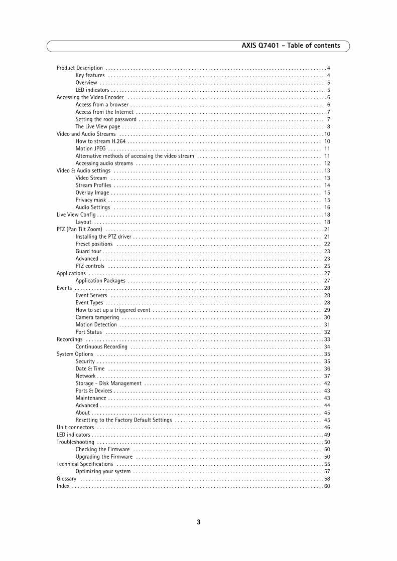
3
AXIS Q7401 - Table of contents
Product Description . . . . . . . . . . . . . . . . . . . . . . . . . . . . . . . . . . . . . . . . . . . . . . . . . . . . . . . . . . . . . . . . . . . . . . . . . . . . . . . . 4Key features . . . . . . . . . . . . . . . . . . . . . . . . . . . . . . . . . . . . . . . . . . . . . . . . . . . . . . . . . . . . . . . . . . . . . . . . . . . . . . 4Overview . . . . . . . . . . . . . . . . . . . . . . . . . . . . . . . . . . . . . . . . . . . . . . . . . . . . . . . . . . . . . . . . . . . . . . . . . . . . . . . . . 5LED indicators . . . . . . . . . . . . . . . . . . . . . . . . . . . . . . . . . . . . . . . . . . . . . . . . . . . . . . . . . . . . . . . . . . . . . . . . . . . . . 5
Accessing the Video Encoder . . . . . . . . . . . . . . . . . . . . . . . . . . . . . . . . . . . . . . . . . . . . . . . . . . . . . . . . . . . . . . . . . . . . . . . . 6Access from a browser . . . . . . . . . . . . . . . . . . . . . . . . . . . . . . . . . . . . . . . . . . . . . . . . . . . . . . . . . . . . . . . . . . . . . . 6Access from the Internet . . . . . . . . . . . . . . . . . . . . . . . . . . . . . . . . . . . . . . . . . . . . . . . . . . . . . . . . . . . . . . . . . . . . 7Setting the root password . . . . . . . . . . . . . . . . . . . . . . . . . . . . . . . . . . . . . . . . . . . . . . . . . . . . . . . . . . . . . . . . . . . 7The Live View page . . . . . . . . . . . . . . . . . . . . . . . . . . . . . . . . . . . . . . . . . . . . . . . . . . . . . . . . . . . . . . . . . . . . . . . . . 8
Video and Audio Streams . . . . . . . . . . . . . . . . . . . . . . . . . . . . . . . . . . . . . . . . . . . . . . . . . . . . . . . . . . . . . . . . . . . . . . . . . . 10How to stream H.264 . . . . . . . . . . . . . . . . . . . . . . . . . . . . . . . . . . . . . . . . . . . . . . . . . . . . . . . . . . . . . . . . . . . . . . 10Motion JPEG . . . . . . . . . . . . . . . . . . . . . . . . . . . . . . . . . . . . . . . . . . . . . . . . . . . . . . . . . . . . . . . . . . . . . . . . . . . . . 11Alternative methods of accessing the video stream . . . . . . . . . . . . . . . . . . . . . . . . . . . . . . . . . . . . . . . . . . . . . 11Accessing audio streams . . . . . . . . . . . . . . . . . . . . . . . . . . . . . . . . . . . . . . . . . . . . . . . . . . . . . . . . . . . . . . . . . . . 12
Video & Audio settings . . . . . . . . . . . . . . . . . . . . . . . . . . . . . . . . . . . . . . . . . . . . . . . . . . . . . . . . . . . . . . . . . . . . . . . . . . . . 13Video Stream . . . . . . . . . . . . . . . . . . . . . . . . . . . . . . . . . . . . . . . . . . . . . . . . . . . . . . . . . . . . . . . . . . . . . . . . . . . . 13Stream Profiles . . . . . . . . . . . . . . . . . . . . . . . . . . . . . . . . . . . . . . . . . . . . . . . . . . . . . . . . . . . . . . . . . . . . . . . . . . . 14Overlay Image . . . . . . . . . . . . . . . . . . . . . . . . . . . . . . . . . . . . . . . . . . . . . . . . . . . . . . . . . . . . . . . . . . . . . . . . . . . . 15Privacy mask . . . . . . . . . . . . . . . . . . . . . . . . . . . . . . . . . . . . . . . . . . . . . . . . . . . . . . . . . . . . . . . . . . . . . . . . . . . . . 15Audio Settings . . . . . . . . . . . . . . . . . . . . . . . . . . . . . . . . . . . . . . . . . . . . . . . . . . . . . . . . . . . . . . . . . . . . . . . . . . . 16
Live View Config . . . . . . . . . . . . . . . . . . . . . . . . . . . . . . . . . . . . . . . . . . . . . . . . . . . . . . . . . . . . . . . . . . . . . . . . . . . . . . . . . . 18Layout . . . . . . . . . . . . . . . . . . . . . . . . . . . . . . . . . . . . . . . . . . . . . . . . . . . . . . . . . . . . . . . . . . . . . . . . . . . . . . . . . . 18
PTZ (Pan Tilt Zoom) . . . . . . . . . . . . . . . . . . . . . . . . . . . . . . . . . . . . . . . . . . . . . . . . . . . . . . . . . . . . . . . . . . . . . . . . . . . . . . . 21Installing the PTZ driver . . . . . . . . . . . . . . . . . . . . . . . . . . . . . . . . . . . . . . . . . . . . . . . . . . . . . . . . . . . . . . . . . . . . 21Preset positions . . . . . . . . . . . . . . . . . . . . . . . . . . . . . . . . . . . . . . . . . . . . . . . . . . . . . . . . . . . . . . . . . . . . . . . . . . 22Guard tour . . . . . . . . . . . . . . . . . . . . . . . . . . . . . . . . . . . . . . . . . . . . . . . . . . . . . . . . . . . . . . . . . . . . . . . . . . . . . . . 23Advanced . . . . . . . . . . . . . . . . . . . . . . . . . . . . . . . . . . . . . . . . . . . . . . . . . . . . . . . . . . . . . . . . . . . . . . . . . . . . . . . . 23PTZ controls . . . . . . . . . . . . . . . . . . . . . . . . . . . . . . . . . . . . . . . . . . . . . . . . . . . . . . . . . . . . . . . . . . . . . . . . . . . . . 25
Applications . . . . . . . . . . . . . . . . . . . . . . . . . . . . . . . . . . . . . . . . . . . . . . . . . . . . . . . . . . . . . . . . . . . . . . . . . . . . . . . . . . . . . 27Application Packages . . . . . . . . . . . . . . . . . . . . . . . . . . . . . . . . . . . . . . . . . . . . . . . . . . . . . . . . . . . . . . . . . . . . . . 27
Events . . . . . . . . . . . . . . . . . . . . . . . . . . . . . . . . . . . . . . . . . . . . . . . . . . . . . . . . . . . . . . . . . . . . . . . . . . . . . . . . . . . . . . . . . . 28Event Servers . . . . . . . . . . . . . . . . . . . . . . . . . . . . . . . . . . . . . . . . . . . . . . . . . . . . . . . . . . . . . . . . . . . . . . . . . . . . 28Event Types . . . . . . . . . . . . . . . . . . . . . . . . . . . . . . . . . . . . . . . . . . . . . . . . . . . . . . . . . . . . . . . . . . . . . . . . . . . . . . 28How to set up a triggered event . . . . . . . . . . . . . . . . . . . . . . . . . . . . . . . . . . . . . . . . . . . . . . . . . . . . . . . . . . . . . 29Camera tampering . . . . . . . . . . . . . . . . . . . . . . . . . . . . . . . . . . . . . . . . . . . . . . . . . . . . . . . . . . . . . . . . . . . . . . . . 30Motion Detection . . . . . . . . . . . . . . . . . . . . . . . . . . . . . . . . . . . . . . . . . . . . . . . . . . . . . . . . . . . . . . . . . . . . . . . . . 31Port Status . . . . . . . . . . . . . . . . . . . . . . . . . . . . . . . . . . . . . . . . . . . . . . . . . . . . . . . . . . . . . . . . . . . . . . . . . . . . . . 32
Recordings . . . . . . . . . . . . . . . . . . . . . . . . . . . . . . . . . . . . . . . . . . . . . . . . . . . . . . . . . . . . . . . . . . . . . . . . . . . . . . . . . . . . . . 33Continuous Recording . . . . . . . . . . . . . . . . . . . . . . . . . . . . . . . . . . . . . . . . . . . . . . . . . . . . . . . . . . . . . . . . . . . . . 34
System Options . . . . . . . . . . . . . . . . . . . . . . . . . . . . . . . . . . . . . . . . . . . . . . . . . . . . . . . . . . . . . . . . . . . . . . . . . . . . . . . . . . 35Security . . . . . . . . . . . . . . . . . . . . . . . . . . . . . . . . . . . . . . . . . . . . . . . . . . . . . . . . . . . . . . . . . . . . . . . . . . . . . . . . . 35Date & Time . . . . . . . . . . . . . . . . . . . . . . . . . . . . . . . . . . . . . . . . . . . . . . . . . . . . . . . . . . . . . . . . . . . . . . . . . . . . . 36Network . . . . . . . . . . . . . . . . . . . . . . . . . . . . . . . . . . . . . . . . . . . . . . . . . . . . . . . . . . . . . . . . . . . . . . . . . . . . . . . . . 37Storage - Disk Management . . . . . . . . . . . . . . . . . . . . . . . . . . . . . . . . . . . . . . . . . . . . . . . . . . . . . . . . . . . . . . . . 42Ports & Devices . . . . . . . . . . . . . . . . . . . . . . . . . . . . . . . . . . . . . . . . . . . . . . . . . . . . . . . . . . . . . . . . . . . . . . . . . . . 43Maintenance . . . . . . . . . . . . . . . . . . . . . . . . . . . . . . . . . . . . . . . . . . . . . . . . . . . . . . . . . . . . . . . . . . . . . . . . . . . . . 43Advanced . . . . . . . . . . . . . . . . . . . . . . . . . . . . . . . . . . . . . . . . . . . . . . . . . . . . . . . . . . . . . . . . . . . . . . . . . . . . . . . . 44About . . . . . . . . . . . . . . . . . . . . . . . . . . . . . . . . . . . . . . . . . . . . . . . . . . . . . . . . . . . . . . . . . . . . . . . . . . . . . . . . . . . 45Resetting to the Factory Default Settings . . . . . . . . . . . . . . . . . . . . . . . . . . . . . . . . . . . . . . . . . . . . . . . . . . . . . 45
Unit connectors . . . . . . . . . . . . . . . . . . . . . . . . . . . . . . . . . . . . . . . . . . . . . . . . . . . . . . . . . . . . . . . . . . . . . . . . . . . . . . . . . . 46LED indicators . . . . . . . . . . . . . . . . . . . . . . . . . . . . . . . . . . . . . . . . . . . . . . . . . . . . . . . . . . . . . . . . . . . . . . . . . . . . . . . . . . . . 49Troubleshooting . . . . . . . . . . . . . . . . . . . . . . . . . . . . . . . . . . . . . . . . . . . . . . . . . . . . . . . . . . . . . . . . . . . . . . . . . . . . . . . . . . 50
Checking the Firmware . . . . . . . . . . . . . . . . . . . . . . . . . . . . . . . . . . . . . . . . . . . . . . . . . . . . . . . . . . . . . . . . . . . . 50Upgrading the Firmware . . . . . . . . . . . . . . . . . . . . . . . . . . . . . . . . . . . . . . . . . . . . . . . . . . . . . . . . . . . . . . . . . . . 50
Technical Specifications . . . . . . . . . . . . . . . . . . . . . . . . . . . . . . . . . . . . . . . . . . . . . . . . . . . . . . . . . . . . . . . . . . . . . . . . . . . 55Optimizing your system . . . . . . . . . . . . . . . . . . . . . . . . . . . . . . . . . . . . . . . . . . . . . . . . . . . . . . . . . . . . . . . . . . . . 57
Glossary . . . . . . . . . . . . . . . . . . . . . . . . . . . . . . . . . . . . . . . . . . . . . . . . . . . . . . . . . . . . . . . . . . . . . . . . . . . . . . . . . . . . . . . . 58Index . . . . . . . . . . . . . . . . . . . . . . . . . . . . . . . . . . . . . . . . . . . . . . . . . . . . . . . . . . . . . . . . . . . . . . . . . . . . . . . . . . . . . . . . . . . 60

AXIS Q7401 - Product Description
Product Description
This manual applies to the AXIS Q7401 Video Encoder.
Key features
• Superb video quality AXIS Q7401 offers the highly efficient H.264 video compression, which drastically reduces bandwidth and storage requirements without compromising image quality. Motion JPEG is also supported for increased flexibility.
• Multiple H.264 streams AXIS Q7401 can deliver multiple, individually configurable video streams simultaneously at full frame rate in all resolutions up to D1 (720x480 in NTSC, 720x576 in PAL). This means that several video streams can be configured with different compression formats, resolutions and frame rates for different needs.
• Image setting adjustment The video encoder also enables users to adjust image settings such as contrast, brightness and saturation to improve images before encoding takes place.
• Intelligent video capabilities AXIS Q7401 includes intelligent capabilities such as enhanced video motion detection, active tampering alarm and audio detection. The encoder’s external inputs and outputs can be connected to devices such as sensors and relays, enabling the system to react to alarms and activate lights or open/close doors.
• Power over Ethernet Support for Power over Ethernet (IEEE802.3af) enables the unit, as well as the analog camera that is connected to it, to receive power through the same cable as for data transmission. This makes for easy installation since no power outlet is needed.
• Audio support and Local storage AXIS Q7401 also supports two-way audio and has an SD/SDHC memory card slot for local storage.
• ONVIF This is a global interface standard that makes it easier for end users, integrators, consultants, and manufacturers to take advantage of the possibilities offered by network video technology. ONVIF enables interoperability between different vendor products, increased flexibility, reduced cost, and future-proof systems.
4
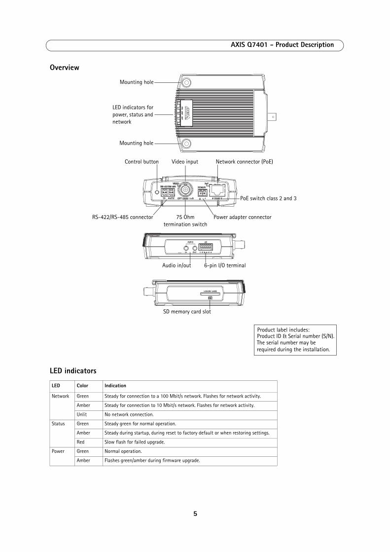
AXIS Q7401 - Product Description
Overview
LED indicators
LED Color Indication
Network Green Steady for connection to a 100 Mbit/s network. Flashes for network activity.
Amber Steady for connection to 10 Mbit/s network. Flashes for network activity.
Unlit No network connection.
Status Green Steady green for normal operation.
Amber Steady during startup, during reset to factory default or when restoring settings.
Red Slow flash for failed upgrade.
Power Green Normal operation.
Amber Flashes green/amber during firmware upgrade.
Mounting hole
Mounting hole
LED indicators for power, status and network
Control button
Power adapter connectorRS-422/RS-485 connector
Video input Network connector (PoE)
PoE switch class 2 and 3
75 Ohmtermination switch
Audio in/out 6-pin I/O terminal
SD memory card slot
Product ID & Serial number (S/N). The serial number may be required during the installation.
Product label includes:
5

AXIS Q7401 - Accessing the Video Encoder
Accessing the Video Encoder
Refer to the installation guide supplied with your product in order to install the AXIS Q7401 Video Encoder.
The AXIS Q7401 can be used with most standard operating systems and browsers.
Notes:• To view streaming video in Microsoft Internet Explorer, set your browser to allow ActiveX controls and install AXIS
Media Control (AMC) on your workstation.
• QuickTimeTM is also supported for viewing streaming H.264 video and audio.• If your workstation restricts the use of additional software components, the video encoder can be configured to
use a Java applet for viewing Motion JPEG.• The video encoder includes one (1) decoder license for viewing H.264 video streams. This is automatically installed
with AMC. The administrator can disable the installation of the H.264 decoder, to prevent installation of unlicensed copies.
Access from a browser
1. Start a browser (Internet Explorer, Firefox, Safari).
2. Enter the IP address or host name of the encoder in the Location/Address field of your browser. To access the video encoder from a Macintosh computer (Mac OSX), click on the Bonjour tab and select the AXIS Q7401 from the drop-down list.
3. If this is the first time you are accessing the AXIS Q7401, see Access from the Internet, on page 7. Otherwise enter your user name and password, set by the administrator.
4. The encoder’s Live View page appears in your browser.
Note:The layout of the Live View page may have been customized to specific requirements. Consequently, some of the examples and functions featured here may differ from those displayed on your own Live View page.
6

AXIS Q7401 - Accessing the Video Encoder
Access from the Internet
Once connected, the video encoder is accessible on your local network (LAN). To access the video encoder from the Internet you must configure your broadband router to allow incoming data traffic to the video encoder. To do this, enable the NAT-traversal feature, which will attempt to automatically configure the router to allow access to the video encoder. This is enabled from Setup > System Options > Network > TCP/IP Advanced.
For more information, please see NAT traversal (port mapping) for IPv4, on page 38. See also the AXIS Internet Dynamic DNS Service at www.axiscam.net For Technical notes on this and other topics, visit the Axis Support web at www.axis.com/techsup
Setting the root password
To gain access to the product, the password for the default administrator user root must be set. This is done in the ‘Configure Root Password’ dialog, which is displayed when the video encoder is accessed for the first time.
To prevent network eavesdropping when setting the root password, this can be done via an encrypted HTTPS connection, which requires an HTTPS certificate (see note below).
To set the password via a standard HTTP connection, enter it directly in the first dialog shown below.
To set the password via an encrypted HTTPS connection, follow these steps:
1. Click the Create self-signed certificate button.
2. Provide the requested information and click OK. The certificate is created and the password can now be set securely. All traffic to and from the video encoder is encrypted from this point on.
3. Enter a password and then re-enter it to confirm the spelling. Click OK. The password has now been configured.
Notes:
• The default administrator user name ‘root’ is permanent and cannot be deleted.• If the password for root is lost, the camera must be reset to the factory default settings. See page 45.• If prompted, click Yes to install AXIS Media Control, which allows viewing of the video stream in Internet Explorer.
You will need administrator rights on the computer to do this. If using Windows 7 or Windows Vista, you must also run Internet Explorer as administrator; right-click the Internet Explorer icon and select Run as administrator.
To configure the password directly via an unencrypted connection, enter the password here.
To create an HTTPS connection, start by clicking this button.
7
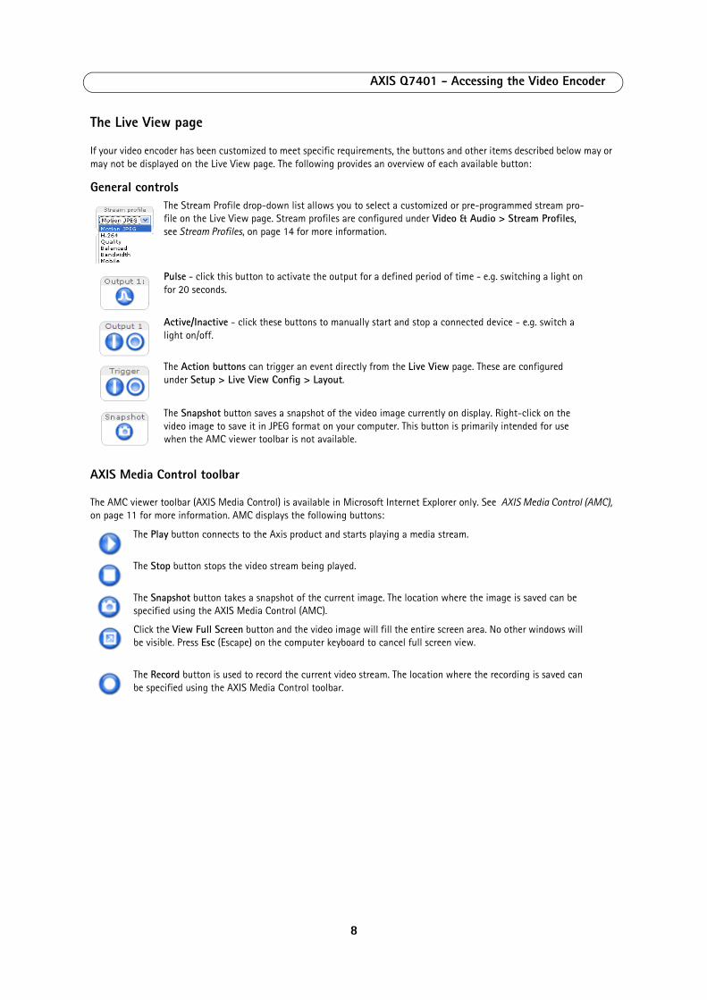
AXIS Q7401 - Accessing the Video Encoder
The Live View page
If your video encoder has been customized to meet specific requirements, the buttons and other items described below may or may not be displayed on the Live View page. The following provides an overview of each available button:
General controls
AXIS Media Control toolbar
The AMC viewer toolbar (AXIS Media Control) is available in Microsoft Internet Explorer only. See AXIS Media Control (AMC), on page 11 for more information. AMC displays the following buttons:
The Stream Profile drop-down list allows you to select a customized or pre-programmed stream pro-file on the Live View page. Stream profiles are configured under Video & Audio > Stream Profiles, see Stream Profiles, on page 14 for more information.
Pulse - click this button to activate the output for a defined period of time - e.g. switching a light on for 20 seconds.
Active/Inactive - click these buttons to manually start and stop a connected device - e.g. switch a light on/off.
The Action buttons can trigger an event directly from the Live View page. These are configured under Setup > Live View Config > Layout.
The Snapshot button saves a snapshot of the video image currently on display. Right-click on the video image to save it in JPEG format on your computer. This button is primarily intended for use when the AMC viewer toolbar is not available.
The Play button connects to the Axis product and starts playing a media stream.
The Stop button stops the video stream being played.
The Snapshot button takes a snapshot of the current image. The location where the image is saved can be specified using the AXIS Media Control (AMC).
Click the View Full Screen button and the video image will fill the entire screen area. No other windows will be visible. Press Esc (Escape) on the computer keyboard to cancel full screen view.
The Record button is used to record the current video stream. The location where the recording is saved can be specified using the AXIS Media Control toolbar.
8

AXIS Q7401 - Accessing the Video Encoder
AMC Audio controls
AMC audio buttons control the speakers and microphone connected to the client computer. The buttons are only visible when audio is enabled.
Pan/Tilt/Zoom controls
Speaker button – Click to switch the sound on or off.
Microphone button – Click to switch the sound on or off. In Simplex - Network Camera speaker only mode, click this button to stop sending audio to the network camera.
Use the slider to control the volume of the speakers and the microphone.
Half-duplex mode The Talk/Listen button is used to switch between sending and receiving audio. The button can be config-ured from the Audio tab in the AMC Control panel:• Push-To-Talk mode: Click and hold the button to talk/send, release the button to listen.• Toggle mode: Click once to switch between talking and listening.Simplex – Network Camera speaker only modeTo send audio, the Talk and Microphone buttons must both be enabled. Click either button to stop audio transmission.
When in Center Mode, click on any part of the image other than its exact center and the video encoder will move so that the point you clicked on becomes the new center of the image.
If you select Emulate Joystick Mode, the video encoder moves in the direction of the mouse pointer. If you click and hold down on the left mouse button, and then point your cursor at the lower left hand corner of the image, the video encoder continues to move left and down until you release the mouse button.
9

AXIS Q7401 - Video and Audio Streams
Video and Audio Streams
The video encoder provides several image and video stream formats. Your requirements and the properties of your network will determine the type you use.
The Live View page in the video encoder provides access to H.264 and Motion JPEG video streams, and to the list of available stream profiles. Other applications and clients can also access these video streams/images directly, without going via the Live View page.
How to stream H.264
This video compression standard makes good use of bandwidth, and can provide high quality video streams at less than 1 Mbit/s.
Deciding which combination of protocols and methods to use depends on your viewing requirements, and on the properties of your network. The available options in AMC are:
AMC negotiates with the video encoder to determine the transport protocol to use in the order listed above. This order can be changed and the options disabled, to suit specific requirements.
Important!
H.264 is licensed technology. The video encoder includes one viewing client license. Installing additional unlicensed copies of the viewing client is prohibited. To purchase additional licenses, contact your Axis reseller.
Unicast RTP This unicast method (RTP over UDP) should be your first consideration for live unicast video, especially when it is important to always have an up-to-date video stream, even if some images are dropped. Unicasting is used for video-on-demand broadcasting,
so that there is no video traffic on the network until a client connects and requests the stream.
Note that there are a maximum of 20 simultaneous unicast connections.
RTP over RTSP This unicast method (RTP tunneled over RTSP) is useful as it is relatively simple to configure firewalls to allow RTSP traffic.
RTP over RTSP over HTTP
This unicast method can be used to traverse firewalls. Firewalls are commonly configured to allow the HTTP protocol, thus allowing RTP to be tunneled.
Multicast RTP This method (RTP over UDP) should be used for live multicast video. The video stream is always up-to-date, even if some images are dropped.
Multicasting provides the most efficient usage of bandwidth when there are large numbers of cli-ents viewing simultaneously. A multicast broadcast cannot however, pass a network router unless the router is configured to allow this. It is not possible to multicast over the Internet, for example.
Note also that all multicast viewers count as one unicast viewer in the maximum total of 20 simultaneous connections.
10
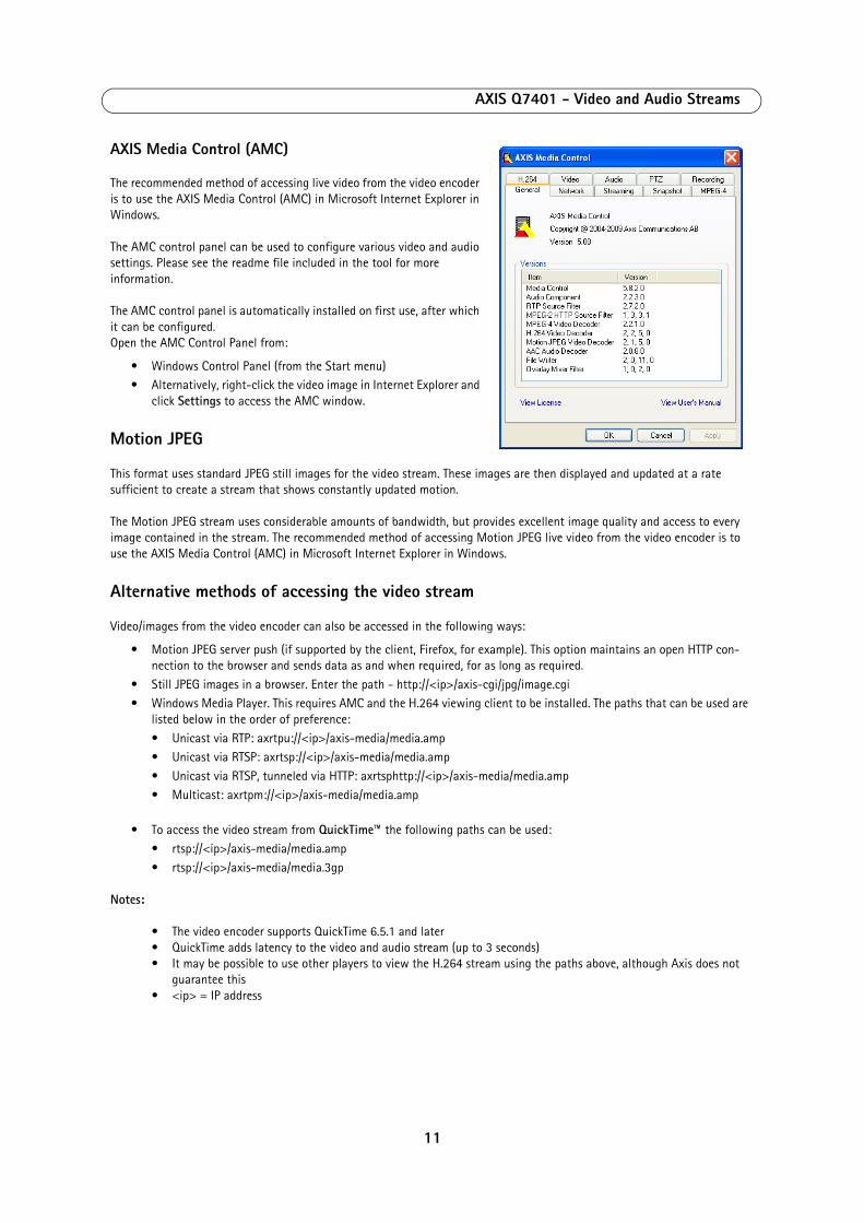
AXIS Q7401 - Video and Audio Streams
AXIS Media Control (AMC)
The recommended method of accessing live video from the video encoder is to use the AXIS Media Control (AMC) in Microsoft Internet Explorer in Windows.
The AMC control panel can be used to configure various video and audio settings. Please see the readme file included in the tool for more information.
The AMC control panel is automatically installed on first use, after which it can be configured. Open the AMC Control Panel from:
• Windows Control Panel (from the Start menu)• Alternatively, right-click the video image in Internet Explorer and
click Settings to access the AMC window.
Motion JPEG
This format uses standard JPEG still images for the video stream. These images are then displayed and updated at a rate sufficient to create a stream that shows constantly updated motion.
The Motion JPEG stream uses considerable amounts of bandwidth, but provides excellent image quality and access to every image contained in the stream. The recommended method of accessing Motion JPEG live video from the video encoder is to use the AXIS Media Control (AMC) in Microsoft Internet Explorer in Windows.
Alternative methods of accessing the video stream
Video/images from the video encoder can also be accessed in the following ways:
• Motion JPEG server push (if supported by the client, Firefox, for example). This option maintains an open HTTP con-nection to the browser and sends data as and when required, for as long as required.
• Still JPEG images in a browser. Enter the path - http://<ip>/axis-cgi/jpg/image.cgi• Windows Media Player. This requires AMC and the H.264 viewing client to be installed. The paths that can be used are
listed below in the order of preference:
• Unicast via RTP: axrtpu://<ip>/axis-media/media.amp• Unicast via RTSP: axrtsp://<ip>/axis-media/media.amp
• Unicast via RTSP, tunneled via HTTP: axrtsphttp://<ip>/axis-media/media.amp
• Multicast: axrtpm://<ip>/axis-media/media.amp
• To access the video stream from QuickTime™ the following paths can be used:• rtsp://<ip>/axis-media/media.amp
• rtsp://<ip>/axis-media/media.3gp
Notes:
• The video encoder supports QuickTime 6.5.1 and later• QuickTime adds latency to the video and audio stream (up to 3 seconds)• It may be possible to use other players to view the H.264 stream using the paths above, although Axis does not
guarantee this• <ip> = IP address
11

AXIS Q7401 - Video and Audio Streams
Accessing audio streamsThe Live View page provides access to audio through AXIS Media Control; in addition audio can be accessed in the following ways:
VAPIX®
Audio can be accessed through the VAPIX® Application Programming Interface (API). For more information visit http://www.axis.com/techsup
QuickTime and Windows Media Player
Simplex audio can be accessed via QuickTime and Windows Media Player by using the same paths as for video streams (see above). QuickTime supports G.711 and AAC audio encoding.
Java applet
The Java applet supports simplex audio with G.711 encoding.
12
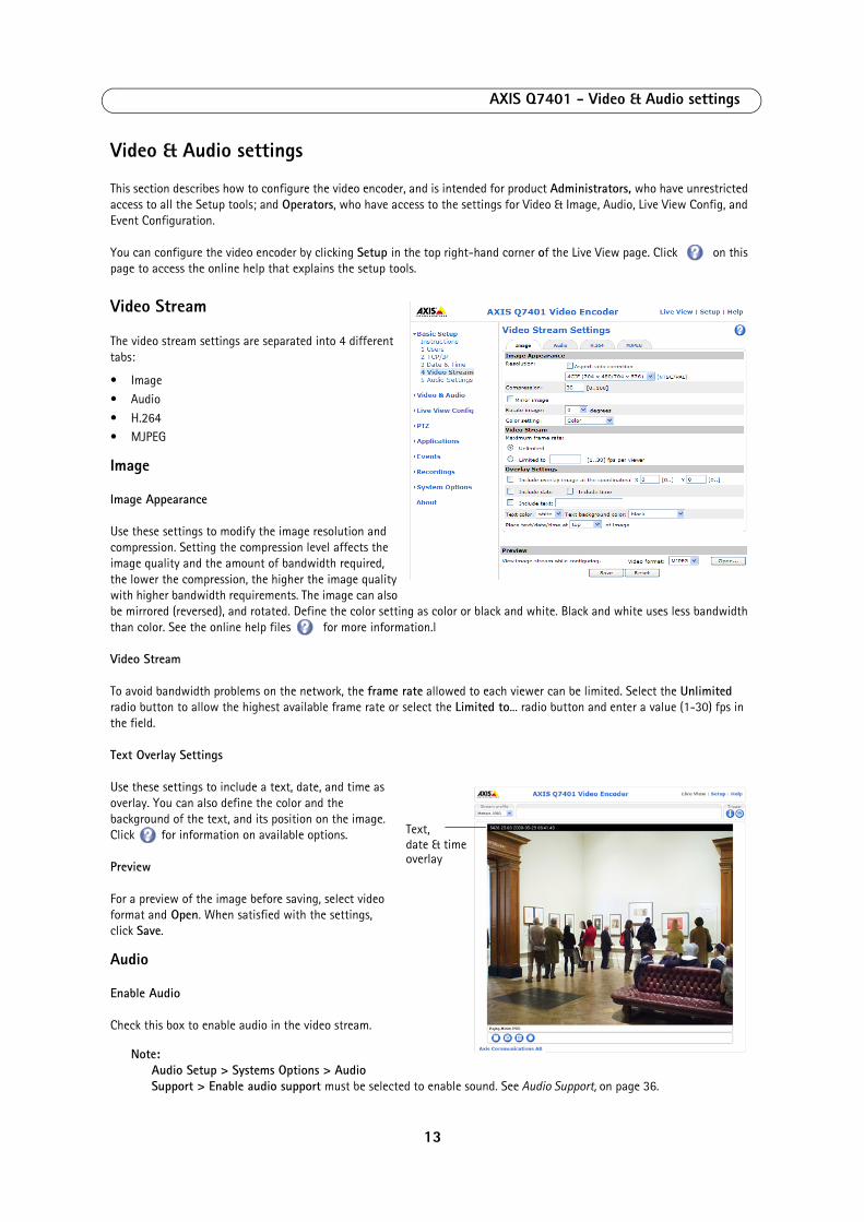
AXIS Q7401 - Video & Audio settings
Video & Audio settings
This section describes how to configure the video encoder, and is intended for product Administrators, who have unrestricted access to all the Setup tools; and Operators, who have access to the settings for Video & Image, Audio, Live View Config, and Event Configuration.
You can configure the video encoder by clicking Setup in the top right-hand corner of the Live View page. Click on this page to access the online help that explains the setup tools.
Video Stream
The video stream settings are separated into 4 different tabs:
• Image
• Audio
• H.264 • MJPEG
Image
Image Appearance
Use these settings to modify the image resolution and compression. Setting the compression level affects the image quality and the amount of bandwidth required, the lower the compression, the higher the image quality with higher bandwidth requirements. The image can also be mirrored (reversed), and rotated. Define the color setting as color or black and white. Black and white uses less bandwidth than color. See the online help files for more information.l
Video Stream
To avoid bandwidth problems on the network, the frame rate allowed to each viewer can be limited. Select the Unlimited radio button to allow the highest available frame rate or select the Limited to... radio button and enter a value (1-30) fps in the field.
Text Overlay Settings
Use these settings to include a text, date, and time as overlay. You can also define the color and the background of the text, and its position on the image. Click for information on available options.
Preview
For a preview of the image before saving, select video format and Open. When satisfied with the settings, click Save.
Audio
Enable Audio
Check this box to enable audio in the video stream.
Note:Audio Setup > Systems Options > Audio Support > Enable audio support must be selected to enable sound. See Audio Support, on page 36.
Text,
overlaydate & time
13
AXIS Q7401 - Video & Audio settings
Current Audio Settings: Configuration under Video & Audio > Audio Settings will be shown here. See Audio Settings, on page 16 for more information on the audio settings.
H.264
GOV Settings
The GOV structure describes the composition of the video stream and setting the GOV-length to a higher value saves considerably on bandwidth.
Bit Rate Control
The bit rate can be set as Variable Bit Rate (VBR) or Constant Bit Rate (CBR).
VBR adjusts the bit rate according to the image complexity, using up bandwidth for increased activity in the image, and less for lower activity in the monitored area.
When using CBR you can set a fixed Target bit rate, which will ensure that the level of bandwidth consumed is predictable.
Priority - As the bit rate would usually need to increase for increased image activity, but cannot when CBR is selected, the frame rate and image quality will both be affected negatively. To go some of the way towards compensating for this, it is possible to prioritize either the frame rate or the image quality whenever the bit rate would normally need to be increased. Not setting a priority means the frame rate and image quality will be affected approximately equally.
MJPEG
Sometimes the image size is large due to low light or complex scenery. Adjusting the maximum frame size helps to control the bandwidth and storage used by the Motion JPEG video stream in these situations. Defining the frame size as Unlimited provides consistently good image quality at the expense of increased bandwidth and storage usage during low light. Limiting the frame size optimizes bandwidth and storage usage, but may give poor image quality. To prevent increased bandwidth and storage usage, the maximum frame size should be set to an optimal value.
Stream Profiles
There are 4 pre-programmed stream profiles available for quick set-up. These settings can be adjusted and new customized profiles can be created. Each profile has a descriptive name, describing its usage and/or purpose. The profiles can be accessed from the Live View page.
• To add a new stream profile, click Add to bring up the Stream Profile Settings panel. • Choose a descriptive name and enter a description for your profile.
• Choose the form of Video encoding you wish to use from the drop-down list:
H.264 - Also known as MPEG-4 Part 10. This is the new generation compression standard for digital video. This function offers higher video resolution than Motion JPEG or MPEG-4 at the same bit rate and bandwidth, or the same quality video at a lower bit rate.
Motion JPEG - Delivers a high quality video stream, from which individual images can be extracted and saved.• Copy an existing stream profile to your system and rename the copy
• Modify an existing stream profile based on the light situation and motion to be captured by your video encoder. See Stream Profile Settings for more information.
• Highlight the stream profile you wish to remove, then click Remove to remove it from the list.
14

AXIS Q7401 - Video & Audio settings
Camera Settings
This page provides access to the advanced image settings for the AXIS Q7401.
Image Appearance
Color level - Select an appropriate level by entering a value in the range 0-100. Lower values mean less color saturation, whilst the value 100 gives maximum color saturation.
Brightness - The image brightness can be adjusted in the range 0-100, where a higher value produces a brighter image.
Contrast - Adjust the image's contrast by raising or lowering the value in this field.
Rotate image - The image can be rotated to the correct orientation. Select the appropriate value from the drop-down list.
Video Input
To eliminate a black border surrounding the image, change the horizontal and vertical synchronization for the image.
Note: Be careful to only use low values, no more than 1-3, as higher values may put the image out of sync.
To improve image quality from analog devices, select Adaptive Interpolation from the 4CIF de-interlacing drop down list for best image quality or select Blending for improved image quality. If de-interlacing is not necessary select None.
Once satisfied, click Save. Click View to view the video stream with the current configuration.
Overlay Image
An overlay image is a static image superimposed over the video image. An overlay can be used to e.g. provide extra information, or to mask a part of the video image.
Selecting and Uploading Overlay Images
To use an overlay image in the AXIS Q7401 Video Encoder, it must be selected from the drop-down list of available images. The overlay (e.g. a logo) is then displayed in the video image.
To use your own image, first upload it to the AXIS Q7401 Video Encoder by entering the name of the file in the field provided, or by clicking the Browse button and locating it. Then click the Upload button.
Once your own image has been uploaded it will be available for selection from the drop-down list.
Image Overlay Placement
To place the overlay image at specific coordinates in the live view image, check Include overlay image at the coordinates and enter the X and Y coordinates.
View Image Settings
To test the overlay and it's placement click Save and View. A popup window appears with the camera's live view image.
For more information, please see the online help .
Privacy mask
Privacy masks are up to 3 configurable areas of solid color that allow concealment of parts of the image that are not to be viewable. Privacy masks cannot be bypassed via the AXIS VAPIX HTTP API.
15

AXIS Q7401 - Video & Audio settings
Privacy Mask List
The Privacy Mask List shows all the masks that are currently configured in the AXIS Q7401 Video Encoder and if they are enabled.
Add/Edit Mask
To define a new mask:
1. Click Add and place the box over the desired area to conceal.
2. Choose a color, black, white, gray or red for the box from the drop-down list Privacy mask color
3. Enter a descriptive name in Mask name.
4. Click Save.
To edit a privacy mask, select it and reshape, move or change color as needed.
Audio Settings
This section describes how to configure the basic audio settings for the video encoder.
The audio functionality for all streams is enabled under Video & Audio > Video Stream > Audio.
Audio Channels
Audio mode - The Half duplex mode transmits and receives audio in both directions, but only in one direction at a time. To speak, press and hold the button (check that the microphone is not muted). To receive audio, release the button.
Note:The push-to-talk button is configured from AMC (see AXIS Media Control toolbar, on page 8). It is possible to configure the push-to-talk button so that it toggles between the speaking and listening modes.
When selecting the Simplex - Network Video Encoder speaker only mode, the speaker connected to the video encoder plays audio, but no audio is transmitted from the video encoder to other web clients. This could be used to provide spoken instructions to a person seen in the camera. This mode requires you to use the push-to-talk button.
The Simplex - Network Video Encoder microphone only mode transmits audio only from the video encoder to web clients. It does not receive audio from other web clients. This can be used in remote monitoring, and web attractions, to provide live audio and video, of a monitored situation.
Audio Input
Audio from an external microphone or a line source can be connected to the Audio in the connector of the video encoder. The audio source must be set to Microphone or Line depending on the connected device.
The Enable microphone power option provides DC power for an external microphone. If using a small electret condenser microphone such as a clip-on microphone or a PC microphone, enable this option.
Note:To use a high impedance dynamic microphone, do not enable microphone power. Microphone power will not harm the microphone; if you are uncertain, try switching it off and on. The default value is microphone power enabled. To use a professional microphone requiring 48V phantom power, you need an external power supply and a balanced-unbalanced converter (audio transformer) in between.
If the sound input is too low or too high, adjust the input gain for the microphone attached to the video encoder.
Select the desired audio Encoding format: AAC, G.711 μ-law or G.726.
Select the required Sample rate (number of times per second the sound is sampled). The higher the sample rate, the better the audio quality and the greater the bandwidth required.
16

AXIS Q7401 - Video & Audio settings
Depending on the selected encoding, set the desired audio quality (Bit rate). The settings affect the available bandwidth and the required audio quality.
The video encoder can be set to trigger an event if the incoming sound level rises above, falls below, or passes the set value. The Alarm level is set between 0-100%.
Audio Output
If the sound from the speaker is too low or too high, adjust the output gain for the active speaker attached to the video encoder.
When satisfied with the settings, click Save, or click Reset to revert to previously saved settings.
17
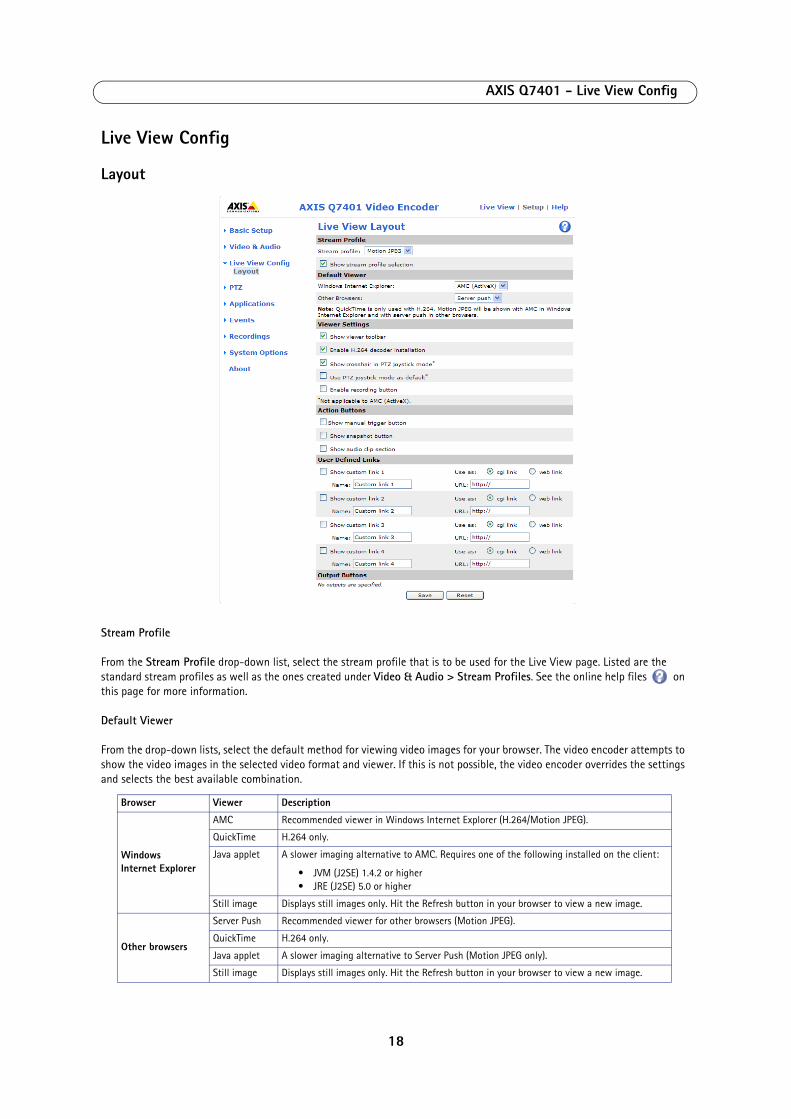
AXIS Q7401 - Live View Config
Live View Config
Layout
Stream Profile
From the Stream Profile drop-down list, select the stream profile that is to be used for the Live View page. Listed are the standard stream profiles as well as the ones created under Video & Audio > Stream Profiles. See the online help files on this page for more information.
Default Viewer
From the drop-down lists, select the default method for viewing video images for your browser. The video encoder attempts to show the video images in the selected video format and viewer. If this is not possible, the video encoder overrides the settings and selects the best available combination.
Browser Viewer Description
Windows Internet Explorer
AMC Recommended viewer in Windows Internet Explorer (H.264/Motion JPEG).
QuickTime H.264 only.
Java applet A slower imaging alternative to AMC. Requires one of the following installed on the client:
• JVM (J2SE) 1.4.2 or higher• JRE (J2SE) 5.0 or higher
Still image Displays still images only. Hit the Refresh button in your browser to view a new image.
Other browsers
Server Push Recommended viewer for other browsers (Motion JPEG).
QuickTime H.264 only.
Java applet A slower imaging alternative to Server Push (Motion JPEG only).
Still image Displays still images only. Hit the Refresh button in your browser to view a new image.
18
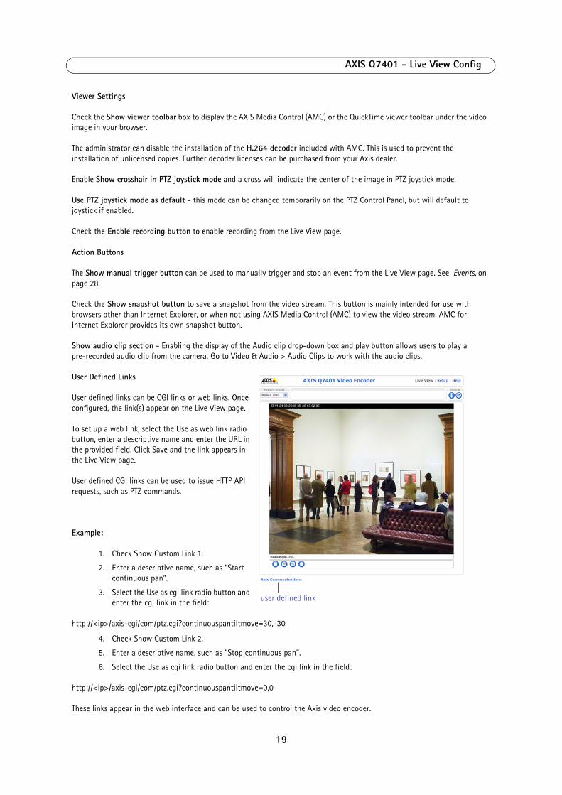
AXIS Q7401 - Live View Config
Viewer Settings
Check the Show viewer toolbar box to display the AXIS Media Control (AMC) or the QuickTime viewer toolbar under the video image in your browser.
The administrator can disable the installation of the H.264 decoder included with AMC. This is used to prevent the installation of unlicensed copies. Further decoder licenses can be purchased from your Axis dealer.
Enable Show crosshair in PTZ joystick mode and a cross will indicate the center of the image in PTZ joystick mode.
Use PTZ joystick mode as default - this mode can be changed temporarily on the PTZ Control Panel, but will default to joystick if enabled.
Check the Enable recording button to enable recording from the Live View page.
Action Buttons
The Show manual trigger button can be used to manually trigger and stop an event from the Live View page. See Events, on page 28.
Check the Show snapshot button to save a snapshot from the video stream. This button is mainly intended for use with browsers other than Internet Explorer, or when not using AXIS Media Control (AMC) to view the video stream. AMC for Internet Explorer provides its own snapshot button.
Show audio clip section - Enabling the display of the Audio clip drop-down box and play button allows users to play a pre-recorded audio clip from the camera. Go to Video & Audio > Audio Clips to work with the audio clips.
User Defined Links
User defined links can be CGI links or web links. Once configured, the link(s) appear on the Live View page.
To set up a web link, select the Use as web link radio button, enter a descriptive name and enter the URL in the provided field. Click Save and the link appears in the Live View page.
User defined CGI links can be used to issue HTTP API requests, such as PTZ commands.
Example:
1. Check Show Custom Link 1.
2. Enter a descriptive name, such as “Start continuous pan”.
3. Select the Use as cgi link radio button and enter the cgi link in the field:
http://<ip>/axis-cgi/com/ptz.cgi?continuouspantiltmove=30,-30
4. Check Show Custom Link 2.
5. Enter a descriptive name, such as “Stop continuous pan”.
6. Select the Use as cgi link radio button and enter the cgi link in the field:
http://<ip>/axis-cgi/com/ptz.cgi?continuouspantiltmove=0,0
These links appear in the web interface and can be used to control the Axis video encoder.
user defined link
19

AXIS Q7401 - Live View Config
For more information on the Axis HTTP API, see the Support/Developer pages on the Axis Web site at http://www.axis.com
Please use the online help files for more information.
Output Buttons
The output buttons are used to manually activate the output from the Live View page, for example, switching a light on and off. There are two options to activate the output:
• Pulse button - activates the output for a defined period
• Active/Inactive - displays two buttons (on/off)
20
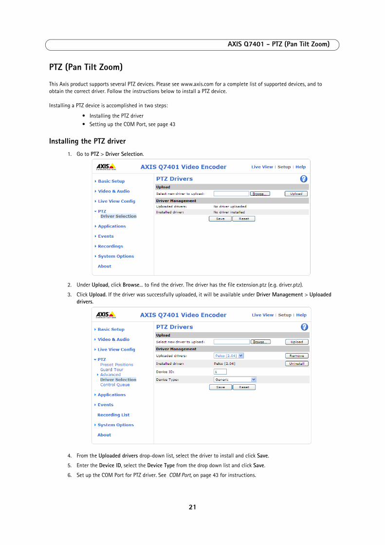
AXIS Q7401 - PTZ (Pan Tilt Zoom)
PTZ (Pan Tilt Zoom)
This Axis product supports several PTZ devices. Please see www.axis.com for a complete list of supported devices, and to obtain the correct driver. Follow the instructions below to install a PTZ device.
Installing a PTZ device is accomplished in two steps:
• Installing the PTZ driver
• Setting up the COM Port, see page 43
Installing the PTZ driver
1. Go to PTZ > Driver Selection.
2. Under Upload, click Browse... to find the driver. The driver has the file extension.ptz (e.g. driver.ptz).
3. Click Upload. If the driver was successfully uploaded, it will be available under Driver Management > Uploaded drivers.
4. From the Uploaded drivers drop-down list, select the driver to install and click Save.
5. Enter the Device ID, select the Device Type from the drop down list and click Save.
6. Set up the COM Port for PTZ driver. See COM Port, on page 43 for instructions.
21

AXIS Q7401 - PTZ (Pan Tilt Zoom)
Notes:• After a PTZ driver has been installed, PTZ > Advanced > Device will contain additional driver specific settings that
can be configured for the PTZ device.• Advanced users and application developers can also use the Axis Application Programming Interface and HTTP
specification for generic control of PTZ devices using CGI commands or a TCP/IP client. Refer to the Axis website at www.axis.com for further information.
Uninstalling a PTZ driver1. Go to PTZ > Driver Selection
2. Click Uninstall
For more information see the online help .
Preset positions
A preset position is a pre-defined camera view than can be used to quickly move the camera to a specific location.
From Preset Position Setup, use the Pan, Tilt and Zoom (PTZ) controls to steer the camera to the required position. When satisfied with the camera's position, enter a descriptive name. The camera position, iris and focus settings are then saved as a preset position.
The position can be assumed at any time, by selecting the preset's name from the Preset positions drop-down list. Preset positions can be selected in the Live View page; they can be selected as an action when an event is triggered as a part of a Guard Tour.
One position can be set as the Home position, which is readily accessible by clicking the box beside Use current position as Home. The position's name will then have (H) added to the end, for example, Office Entrance (H).
22
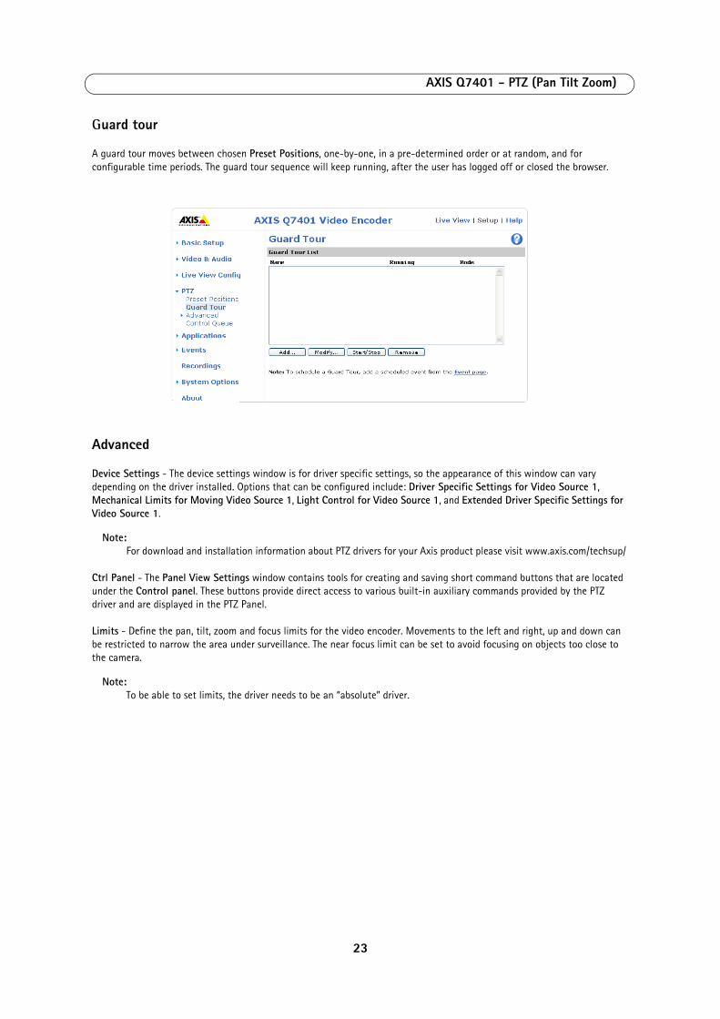
AXIS Q7401 - PTZ (Pan Tilt Zoom)
Guard tour
A guard tour moves between chosen Preset Positions, one-by-one, in a pre-determined order or at random, and for configurable time periods. The guard tour sequence will keep running, after the user has logged off or closed the browser.
Advanced
Device Settings - The device settings window is for driver specific settings, so the appearance of this window can vary depending on the driver installed. Options that can be configured include: Driver Specific Settings for Video Source 1, Mechanical Limits for Moving Video Source 1, Light Control for Video Source 1, and Extended Driver Specific Settings for Video Source 1.
Note:For download and installation information about PTZ drivers for your Axis product please visit www.axis.com/techsup/
Ctrl Panel - The Panel View Settings window contains tools for creating and saving short command buttons that are located under the Control panel. These buttons provide direct access to various built-in auxiliary commands provided by the PTZ driver and are displayed in the PTZ Panel.
Limits - Define the pan, tilt, zoom and focus limits for the video encoder. Movements to the left and right, up and down can be restricted to narrow the area under surveillance. The near focus limit can be set to avoid focusing on objects too close to the camera.
Note:To be able to set limits, the driver needs to be an “absolute” driver.
23
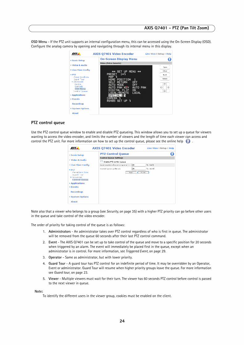
AXIS Q7401 - PTZ (Pan Tilt Zoom)
OSD Menu - If the PTZ unit supports an internal configuration menu, this can be accessed using the On-Screen Display (OSD). Configure the analog camera by opening and navigating through its internal menu in this display.
PTZ control queue
Use the PTZ control queue window to enable and disable PTZ queueing. This window allows you to set up a queue for viewers wanting to access the video encoder, and limits the number of viewers and the length of time each viewer can access and control the PTZ unit. For more information on how to set up the control queue, please see the online help .
Note also that a viewer who belongs to a group (see Security, on page 35) with a higher PTZ priority can go before other users in the queue and take control of the video encoder.
The order of priority for taking control of the queue is as follows:
1. Administrators - An administrator takes over PTZ control regardless of who is first in queue. The administrator will be removed from the queue 60 seconds after their last PTZ control command.
2. Event - The AXIS Q7401 can be set up to take control of the queue and move to a specific position for 20 seconds when triggered by an alarm. The event will immediately be placed first in the queue, except when an administrator is in control. For more information, see Triggered Event, on page 29.
3. Operator - Same as administrator, but with lower priority.
4. Guard Tour - A guard tour has PTZ control for an indefinite period of time. It may be overridden by an Operator, Event or administrator. Guard Tour will resume when higher priority groups leave the queue. For more information see Guard tour, on page 23.
5. Viewer - Multiple viewers must wait for their turn. The viewer has 60 seconds PTZ control before control is passed to the next viewer in queue.
Note:To identify the different users in the viewer group, cookies must be enabled on the client.
24

AXIS Q7401 - PTZ (Pan Tilt Zoom)
PTZ controls
If the video encoder has been appropriately configured, the Live View page displays the controls available for the installed Pan Tilt Zoom (PTZ) device. The administrator can enable/disable the controls for specified users.
The controls shown depends on the make and model of PTZ device. The most common controls are:
• the Pan bar - moves the camera to the right and left • the Tilt bar - tips the camera up and down
• the Zoom bar - zooms the view in and out. Note that this is only available if the camera is fitted with a zoom lens
• the Iris bar - adjusts the brightness of the image
Clicking on the bars themselves or on the arrows at the end of the bars moves the camera to a new position. The type of movement and the location of this new position depends on the type of PTZ driver.
When controlling the camera using a relative PTZ driver (see the bars in the illustration above) the new position is relative to the previous position, for example, left of, below, or above. Clicking the bar further from the center results in a larger movement.
In contrast, when using an absolute driver, each position on the bar (see right) represents a defined position in the device’s range of movement, with the center of the bar representing the point midway between the two extremes of movement.
Clicking a position directly on the bar moves the camera directly to the new position in one smooth movement. Clicking on the arrows at the ends of a bar causes an incremental change.
25

AXIS Q7401 - PTZ (Pan Tilt Zoom)
Using CGI links to control PTZ devices
User-defined CGI links on the Live View page can be used to issue HTTP API requests, such as PTZ commands. These links are configured in the Live View Layout settings, see Live View Config, on page 18.
PTZ control modes
The PTZ device can also be controlled using click-in-image movement, which has two different types of navigation - Center and Joystick.
Center mode means that when clicking in the image, the camera view centers on the absolute position that was clicked.
Joystick mode moves the camera in the direction of the mouse pointer. By clicking and holding the mouse button down in the image, the PTZ device moves the camera in that direction, relative to the center of the image. The farther from the center the image is clicked, the greater the movement. The camera stops moving when the button is released.
Note:There is also joystick support in AXIS Media Control (AMC).
Control panel
The focus and iris (image brightness) can be adjusted manually by using the control bars, or they can be set for automatic adjustment, by clicking the Auto iris and Auto focus buttons.
Note:These buttons appear only if the PTZ driver installed supports them.
To access the Auto iris and Auto focus buttons, click on the Control panel button. The menu to the right will then appear in the upper left hand corner of the screen.
There are also driver specific shortcuts that can appear in the Control Panel. In the screen to the right, a driver has been installed that brings up the Wiper shortcut button, which allows the user to configure and use a windshield wiping action with the video encoder.
26

AXIS Q7401 - Applications
Applications
Application Packages
The Applications feature allows you to upload third party applications for use on this device. Listed under Applications > Packages are the applications that have already been installed. Click on the name to view the menu options - Settings, License and About.
Settings - This depends on the application.
License - Once uploaded some applications need a license to run, and a license code is required for the uploaded application. If there is an Internet connection Automatic Installation appears in the web page. If there is no Internet connection to the camera, go to www.axis.com to acquire a License key file. You will need a license code and the device's serial number to receive a license key.
About - Details support for this application. To upload an application, browse to the package and click Upload Package.
Installed Applications - A list of installed applications with information about the version, and the vendor; the status of the application (running or not running), and information about the license (if installed).
Start/Stop - Start or stop the application.
Remove - To delete an application, select it and click Remove.
Log - To generate a log of the application happenings, select an application and click Log. This log is helpful when requesting support from the application’s vendor.
Note:
It is recommended that you do not run more than one application at a time. Also do not run an application when the motion detection feature is active.
27

AXIS Q7401 - Events
EventsPre-defined parameters, known as an event or Event Type can trigger certain actions in the camera. A common event type is an alarm that causes the camera to upload images. Many event types use an Event Server, to receive uploaded images.
An event that is triggered by a signal, such as a door switch, motion detection, or system event, is called a triggered event, see page 29.
A scheduled event runs at pre-programmed times.
An Action refers to what happens when the event occurs.
This section describes how to configure the camera to perform certain actions when events occur.
Event Servers
Event Servers are used to receive uploaded image files and/or notification messages. To set up Event Server connections in your video encoder, go to Setup > Event Configuration > Event Servers and enter the required information for the required server type.
For details on each setting, see the online help available from each web page.
When the setup is complete, the connection can be tested by clicking the Test button (the connection test takes approximately 10 seconds).
Event Types
An Event Type describes how and when the video encoder performs certain actions.
Example: If somebody passes in front of a video encoder and an event has been configured to detect and respond to motion, the video encoder can record and saves images to an FTP server, and can send a notification e-mail to an e-mail address. Images can be sent as e-mail attachments.
Server type Purpose Information required
FTP Server • Receives uploaded images • Descriptive name • Network address and Upload path• User Name and password
HTTP Server • Receives notification messages• Receives uploaded images
• Descriptive name • URL (IP address or host name)• User Name and password
TCP Server • Receives notification messages • Descriptive name• Network address (IP address or host name)• Port number
28

AXIS Q7401 - Events
Triggered Event
A triggered event could be activated by:
• a push button connected to the video encoder’s input port
• a manually activated action, such as from an action button in the web interface
• an application that has been uploaded to the video encoder.• detected movement in a configured motion detection window
• on restart (reboot), after power loss
• camera tampering• disk full
• video loss
• sound at a certain decibel level
How to set up a triggered event
The following example describes how to set up the video encoder to upload images when the main door is opened.
1. Click Add triggered... on the Event Types page. The Triggered Event Type Setup page appears.
2. Enter a descriptive Name for the event, such as Main door open.
3. Set the Priority - High, Normal or Low (see the online help).
4. Set the Respond to Trigger... parameters to define when the event is active, for example, after office hours.
5. Select the trigger alternative from the Triggered by... drop-down list. For example, select Input ports, for a sensor connected to the door.
6. Set the When Triggered... parameters, that is, define what the video encoder will do if the main door is opened - upload images to an FTP server or send an e-mail notification.
7. Click OK to save the event in the Event Types list.
Please see the online help for descriptions of each available option.
Notes:• Up to 10 event types can be configured in the video encoder, and up to four of these can be configured to upload
images. • File names can be formatted according to specific requirements. See File Naming & Date/Time Formats online
help.
Pre-trigger and Post-trigger buffers
This function is very useful when checking to see what happened immediately before and/or after a trigger, for example, 30 seconds before and/or after a door was opened. Check the Save stream checkbox under Event Types > Add Triggered... > When Triggered... to view the options. All uploaded images are JPEG images.
Include pre-trigger buffer - contains images from the time immediately preceding the trigger. Check the box to enable the pre-trigger buffer, enter the desired length of time and specify the required image frequency.
Include post-trigger buffer - contains images from the time immediately after the trigger. Configure as for pre-trigger.
Notes:• Pre-trigger and Post-trigger buffers will be lost if the connection to the event server fails.• The maximum length of the pre-/post-buffer depends on the video image size and selected frame rate.• If the pre- or post-buffer is too large for the video encoder’s internal memory, the buffer size is reduced so that
the recorded time is less than expected. If this occurs, an entry is created in the unit's log file.
Continue image upload (unbuffered) - enables the upload of video images for a fixed length of time. Specify the length of time for the uploaded recording, in seconds, minutes or hours, or for as long as the trigger is active. Finally, set the desired image frequency to the maximum (the maximum available) or to a specified frame rate. The frame rate will be the best possible, but might not be as high as specified, especially if uploading via a slow connection.
29

AXIS Q7401 - Events
Scheduled Event
A Scheduled event can be activated at preset times, in a repeating pattern on selected weekdays.
Configuration example: 1. Click Add scheduled... on the Event Types page.
2. Enter a descriptive Name for the event, such as Scheduled e-mail upload.
3. Set the Priority (High, Normal or Low).
4. Set the Activation Time parameters (24h clock) for the event - start on Sundays at 13.00 with a duration of 12 hours.
5. Set the When Activated... parameters, (what the video encoder would do at the specified time) for example, send uploaded images to an e-mail address.
6. Click OK to save the Event in the Event Types list.
Please see the online help for descriptions of each available option.
Camera tampering
The camera tampering application generates an alarm whenever the camera is repositioned, or when the lens is covered, sprayed, or severely defocused.
First, you must create an event, see How to set up a triggered event, on page 29, for the video encoder to send an alarm.
Settings
The Minimum duration parameter sets the minimum tampering period, that is an alarm will not be triggered until this period has elapsed, even if the tampering conditions are otherwise met. This can help prevent false alarms for known conditions that affect the image.
If the camera lens is sprayed or covered so that the camera live view becomes dark, it will not be possible to distinguish this situation from other situations where the same effect is seen, such as when lighting conditions change.
When the Alarm for dark images parameter is enabled, alarms are generated for all cases where the lights are either dimmed or turned off, or if the lens is sprayed, covered, or rendered severely out of focus. If not enabled, no alarm will be sent.
After you define these settings, click Save.
30
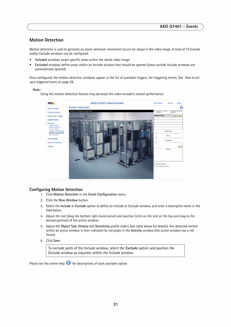
AXIS Q7401 - Events
Motion Detection
Motion detection is used to generate an alarm whenever movement occurs (or stops) in the video image. A total of 10 Include and/or Exclude windows can be configured.
• Included windows target specific areas within the whole video image
• Excluded windows define areas within an Include window that should be ignored (areas outside Include windows are automatically ignored)
Once configured, the motion detection windows appear in the list of available triggers, for triggering events. See How to set up a triggered event, on page 29.
Note:Using the motion detection feature may decrease the video encoder’s overall performance.
Configuring Motion Detection1. Click Motion Detection in the Event Configuration menu.
2. Click the New Window button.
3. Select the Include or Exclude option to define an Include or Exclude window, and enter a descriptive name in the field below.
4. Adjust the size (drag the bottom right-hand corner) and position (click on the text at the top and drag to the desired position) of the active window.
5. Adjust the Object Size, History and Sensitivity profile sliders (see table below for details). Any detected motion within an active window is then indicated by red peaks in the Activity window (the active window has a red frame).
6. Click Save.
Please see the online help for descriptions of each available option.
To exclude parts of the Include window, select the Exclude option and position the Exclude window as required, within the Include window.
31

AXIS Q7401 - Events
Examples: • Avoid triggering on small objects in the video image by setting the object size level to high.• To reduce the number of triggers if there is a lot of movement during a short period of time, select a high history
level.• To only detect flashing light, select low sensitivity. In other cases, a high sensitivity level is recommended.
Port Status
Under Event Configuration > Port Status there is a list showing the status for the video encoder’s input and output. This is for the benefit of Operators who have no access to the System Options section.
Example: If the Normal state for a push button connected to an input is set to Open circuit - as long as the button is not pushed, the state is inactive. If the button is pushed, the state of the input changes to active.
Object Size History Sensitivity
High level Only very large objects trigger motion detec-tion
An object that appears in the region will trigger the motion detection for a long period
Ordinary colored objects on ordinary backgrounds will trigger the motion detection
Low level Even very small objects trigger motion detec-tion
An object that appears in the region will trigger motion detection for only a very short period
Only very bright objects on a dark background trigger motion detection
Default value Low High High
32

AXIS Q7401 - Recordings
Recordings
The AXIS Q7401 Video Encoder can be set to record continuously or as result of a triggered or scheduled event. See Continuous Recording, on page 34 and Event Types, on page 28 for more information. The Recording List window contains a list of recordings made to the local storage. It shows each recording's start time, length, the event type used to start the recording, and if the recording is locked so that it can neither be deleted nor recorded over.
To view a recording, select it from the list and click the Play button.
For detailed recording and video information, select an individual recording from the list and click the Properties button.
Use the Lock/Unlock button to control whether a recording can either be removed. If the recording is important and needs to be saved for future use, locking the recording can help prevent its accidental removal.
Recordings can be downloaded by selecting one or more recordings and clicking Download. The package downloaded is a zip file containing a minimum of 3 files, of which the .mkv or Matroska file is the actual recording.
NoteTo play recordings in Windows Media Player download and install AXIS Matroska File Splitter from
www.axis.com/techsup/software/ For more information on Matroska files see the online help .
The Remove button is used to delete unlocked recordings.
Filter - Use the filter to narrow down the list according to certain criteria such as a particular time frame. Note that certain filters, may take a long time to complete.
For more information on filters see the online help .
33

AXIS Q7401 - Recordings
Continuous Recording
The AXIS Q7401 video encoder can be configured to continuously save video to local storage. Automatic Disk Cleanup should be enabled when using Continuous Recording to prevent the local storage from becoming full. See Storage - Disk Management, on page 42.
Recording Settings
Enabled - Must be checked to record continuously.
Disk - Shows as SD Card for this product.
Stream Profile - Select a stream profile to use for recordings. For more information, see Stream Profiles, on page 14.
Note: The recording will be restarted and all previous continuous recordings will be removed if Stream profile is changed.
Click Save to activate these settings.
Recording
Start time - Shows the time the current continuous recording began. If no continuous recording is taking place the status will display as Not started.
Duration - Shows the length of the current continuous recording.
Restart - Click to start a new recording.
Note: All previous continuous recording data will be removed.
From - To play or download the recording from a point in time, enter the year, month, day and the time in hours and minutes.
Duration - Enter the amount of the recording to play or download in hours, minutes and seconds.
Play... - Click this button to open a window to play the selected amount of the continuous recording.
Download - Click this button to download the recorded video to a storage disk. The package downloaded is a zip file containing a minimum of 3 files, of which the .mkv or Matroska file is the actual recording. The zip file is named after the time set in the From field.
Notes:• The zip file will contain at least the time period selected. The first matroska file contains the start time, and the
last matroska contains at least the stop time• To play recordings in Windows Media Player download and install AXIS Matroska File Splitter from
www.axis.com/techsup/software/
34
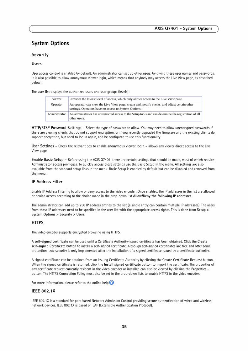
AXIS Q7401 - System Options
System Options
Security
Users
User access control is enabled by default. An administrator can set up other users, by giving these user names and passwords. It is also possible to allow anonymous viewer login, which means that anybody may access the Live View page, as described below:
The user list displays the authorized users and user groups (levels):
HTTP/RTSP Password Settings - Select the type of password to allow. You may need to allow unencrypted passwords if there are viewing clients that do not support encryption, or if you recently upgraded the firmware and the existing clients do support encryption, but need to log in again, and be configured to use this functionality.
User Settings - Check the relevant box to enable anonymous viewer login - allows any viewer direct access to the Live View page.
Enable Basic Setup - Before using the AXIS Q7401, there are certain settings that should be made, most of which require Administrator access privileges. To quickly access these settings use the Basic Setup in the menu. All settings are also available from the standard setup links in the menu. Basic Setup is enabled by default but can be disabled and removed from the menu.
IP Address Filter
Enable IP Address Filtering to allow or deny access to the video encoder. Once enabled, the IP addresses in the list are allowed or denied access according to the choice made in the drop-down list Allow/Deny the following IP addresses.
The administrator can add up to 256 IP address entries to the list (a single entry can contain multiple IP addresses). The users from these IP addresses need to be specified in the user list with the appropriate access rights. This is done from Setup > System Options > Security > Users.
HTTPS
The video encoder supports encrypted browsing using HTTPS.
A self-signed certificate can be used until a Certificate Authority-issued certificate has been obtained. Click the Create self-signed Certificate button to install a self-signed certificate. Although self-signed certificates are free and offer some protection, true security is only implemented after the installation of a signed certificate issued by a certificate authority.
A signed certificate can be obtained from an issuing Certificate Authority by clicking the Create Certificate Request button. When the signed certificate is returned, click the Install signed certificate button to import the certificate. The properties of any certificate request currently resident in the video encoder or installed can also be viewed by clicking the Properties... button. The HTTPS Connection Policy must also be set in the drop-down lists to enable HTTPS in the video encoder.
For more information, please refer to the online help .
IEEE 802.1X
IEEE 802.1X is a standard for port-based Network Admission Control providing secure authentication of wired and wireless network devices. IEEE 802.1X is based on EAP (Extensible Authentication Protocol).
Viewer Provides the lowest level of access, which only allows access to the Live View page.Operator An operator can view the Live View page, create and modify events, and adjust certain other
settings. Operators have no access to System Options.Administrator An administrator has unrestricted access to the Setup tools and can determine the registration of all
other users.
35
AXIS Q7401 - System Options
To access a network protected by IEEE 802.1X, devices must authenticate themselves. The authentication is performed by a third-party entity called an authentication server, typically a RADIUS server, examples of which are FreeRADIUS and Microsoft Internet Authentication Service. In Axis implementation, the network device and the authentication server authenticate themselves with the help of digital certificates using EAP-TLS (Extensible Authentication Protocol - Transport Layer Security). The certificates are provided by an Certification Authority (CA). You need:
•a CA certificate to validate the identity of the authentication server•a CA-signed client certificate and a private key to authenticate the network device.
To allow the network device to access a network protected by IEEE 802.1X:
1. Obtain a CA certificate, a client certificate and a client private key (contact your network administrator).
2. Go to Setup > System Options > Security > IEEE 802.1X and upload the CA certificate, the client certificate and the client private key.
3. Under SETTINGS, select the EAPOL version, provide your EAP identity and private key password.
4. Check the box to enable IEEE 802.1X and click Save.
Certificates
CA Certificate - The CA certificate is used to validate the identity of the authentication server. Enter the path to the certificate directly, or locate the file using the Browse button. Then click Upload. To remove a certificate, click Remove.
Client Certificate/Client private key - The client certificate and private key are used to authenticate the network device. They can be uploaded as separate files or in one combined file (e.g. a PFX file or a PEM file). Use the Client private key field if uploading one combined file. For each file, enter the path to the file, or locate the file using the Browse button. Then click Upload. To remove a file, click Remove.
Settings
Eapol version - Select the EAPOL version (1 or 2) as used in your network switch.
Eap identity - Enter the user identity (maximum 16 characters) associated with your certificate.
Private key password - Enter the password (maximum 16 characters) for the private key.
Enable IEEE 802.1X - 5.Check the box to enable the IEEE 802.1X protocol.
Audio Support
Enable audio support - Allow clients to retrieve audio streams from the AXIS Q7401, and is used to totally enable or disable the sound source. See also Audio Settings, on page 16 for information on how to configure the audio settings.
Date & Time
Current Server Time - displays the current date and time (24h clock). The time can be displayed in 12h clock format in the overlay (see below).
New Server Time - select your time zone from the drop-down list. If you want the server clock to automatically adjust for daylight savings time, select the Automatically adjust for daylight saving time changes.
From the Time Mode section, select the preferred method to use for setting the time:
• Synchronize with computer time - sets the time from the clock on your computer. • Synchronize with NTP Server - the video encoder will obtain the time from an NTP server on a regular basis.
• Set manually - this option allows you to manually set the time and date.
36
AXIS Q7401 - System Options
Note:If using a host name for the NTP server, a DNS server must be configured under TCP/IP settings. See Network > Basic TCP/IP Settings below.
Date & Time Format Used in Images - specify the formats for the date and time (12h or 24h) displayed in the video streams.
Use the predefined formats or use your own custom date and time formats. See Advanced File Naming & Date/Time Formats in the online help for information on how to create your own date and time formats.
Network
Basic TCP/IP Settings
Q7401 support both IP version 4 and IP version 6. Both versions may be enabled simultaneously, and at least one version must always be enabled. When using IPv4, the IP address for the video encoder can be set automatically via DHCP, or a static IP address can be set manually. If IPv6 is enabled, the video encoders receive an IP address according to the configuration in the network router. There is also the option of using the AXIS Internet Dynamic DNS Service. For more information on setting the IP address, please see the Installation Guide supplied with the product.
Network Settings - Click the View button for an overview of the IP configuration of the video encoder.
IPv4 Address Configuration - Check this box to enable IPv4.
Obtain IP address via DHCP - Dynamic Host Configuration Protocol (DHCP) is a protocol that lets network administrators centrally manage and automate the assignment of IP addresses on a network. DHCP is enabled by default. Although a DHCP server is mostly used to set an IP address dynamically, it is also possible to use it to set a static, known IP address for a particular MAC address.
Note:DHCP should only be enabled if using dynamic IP address notification (see below), or if your DHCP server can update a DNS server, which then allows you to access the AXIS Q7401 by name (host name). If DHCP is enabled and you cannot access the unit, you may have to reset it to the factory default settings and then perform the installation again.
Use the following IP address - To use a static IP address for the AXIS Q7401, check the radio button and then make the following settings:
•IP address - Specify a unique IP address for your AXIS Q7401. (To check if the IP address you intend to use is available or not, click the Test button)
•Subnet mask - Specify the mask for the subnet the AXIS Q7401 is located on •Default router - Specify the IP address of the default router (gateway) used for connecting devices attached to different
networks and network segments.
IPv6 Address Configuration - Check the box to enable IPv6. Other settings for IPv6 are configured in the network router.
Services
Enable ARP/Ping setting of IP address - The IP address can be set using the ARP/Ping method, which associates the unit's MAC address with an IP address. Check this box to enable the service. Leave disabled to prevent unintentional resetting of the IP address.
Note:
• The ARP/Ping service is automatically disabled two minutes after the unit is started, or as soon as an IP address is set.
• Pinging the unit is still possible when this service is disabled.
37
AXIS Q7401 - System Options
Enable AVHS - AXIS Video Hosting System (AVHS) in conjunction with an AVHS service provides easy and secure Internet access to live and recorded video accessible from any location. For more information and help to find a local AVHS Service Provider please go to www.axis.com If AVHS is not to be used this option can be disabled.
•One-Click enabled - Press the camera’s control button (see Hardware overview, on page 6) to connect to an AVHS service over the Internet. Once registered the camera stays connected to the AVHS service. If the camera is not registered within 24 hours after the button is pressed, the camera will disconnect from the AVHS service.
•Always - The camera will constantly attempt to connect to the AVHS service over the Internet. Once registered the cam-era will stay connected to the service. This option can be used when the camera is already installed and it is not con-venient to use the one-click installation.
AXIS Internet Dynamic DNS Service - Use the AXIS Internet Dynamic DNS service to assign a host name for easy access to your video encoder (requires Internet access).
Click Settings... to register the video encoder with the Axis Internet Dynamic DNS service, or to modify the existing settings (requires access to the Internet). The domain name currently registered at the Axis Internet Dynamic DNS service for your product can at any time be removed.
For more information, please refer to the online help.
Advanced TCP/IP Settings
DNS Configuration - DNS (Domain Name Service) provides the translation of host names to IP addresses on your network.
Obtain DNS server address via DHCP - automatically use the DNS server settings provided by the DHCP server. Click the View button to see the current settings.
Use the following DNS server address - enter the desired DNS server by specifying the following:
Domain name - enter the domain(s) to search for the host name used by the video encoders. Multiple domains can be separated by semicolons (;). The host name is always the first part of a Fully Qualified Domain Name, for example, myserver is the host name in the Fully Qualified Domain Name myserver.mycompany.com where mycompany.com is the Domain name.
DNS servers - enter the IP addresses of the primary, and secondary DNS servers.
Note:This is not mandatory with regard to secondary DNS servers.
NTP Configuration - Obtain NTP server address via DHCP - check this radio button to automatically look up and use the NTP server settings as provided by DHCP. Click the View button to see the current settings.
Use the following NTP server address - to create manual settings, check this radio button and enter the host name or IP address of the NTP server.
Host Name Configuration - The video encoders can be accessed using a host name, instead of an IP address. The host name is usually the same as the assigned DNS Name.
For more information, please see Security, on page 35.
Link-Local IPv4 Address - This is enabled by default and assigns the video encoders an additional IP address for use with UPnP™. The video encoder can have both a Link-Local IP and a static/DHCP-supplied IP address at the same time - these will not affect each other.
HTTP and HTTPS - The default HTTP/HTTPS port numbers (80 and 443 respectively) can be changed to any port within the range 1024-65535. This is useful for simple security port mapping, for example.
NAT traversal (port mapping) for IPv4 - A broadband router allows devices on a private network (LAN) to share a single connection to the Internet. This is done by forwarding network traffic from the private network to the “outside”, that is, the Internet. Security on the private network (LAN) is increased since most broadband routers are pre-configured to stop attempts to access the private network (LAN) from the public network/Internet.
38
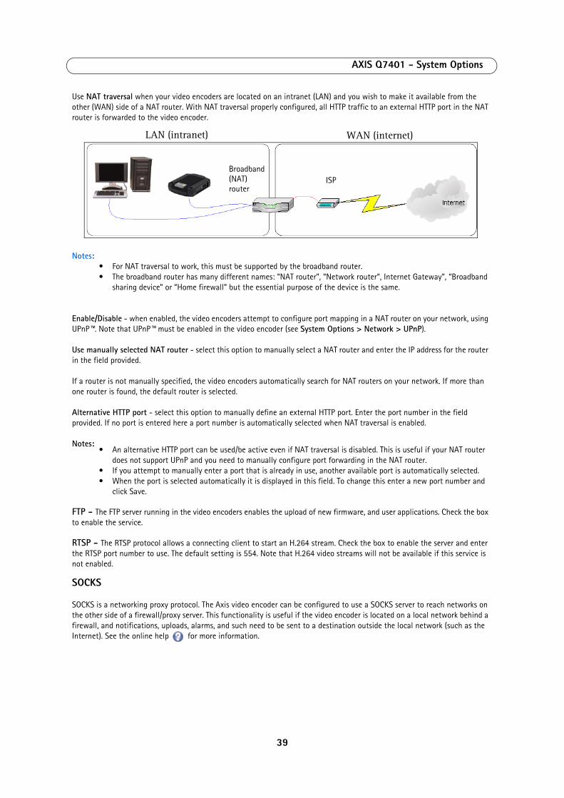
AXIS Q7401 - System Options
Use NAT traversal when your video encoders are located on an intranet (LAN) and you wish to make it available from the other (WAN) side of a NAT router. With NAT traversal properly configured, all HTTP traffic to an external HTTP port in the NAT router is forwarded to the video encoder.
Notes:• For NAT traversal to work, this must be supported by the broadband router.• The broadband router has many different names: “NAT router”, “Network router“, Internet Gateway”, “Broadband
sharing device” or “Home firewall” but the essential purpose of the device is the same.
Enable/Disable - when enabled, the video encoders attempt to configure port mapping in a NAT router on your network, using UPnP™. Note that UPnP™ must be enabled in the video encoder (see System Options > Network > UPnP).
Use manually selected NAT router - select this option to manually select a NAT router and enter the IP address for the router in the field provided.
If a router is not manually specified, the video encoders automatically search for NAT routers on your network. If more than one router is found, the default router is selected.
Alternative HTTP port - select this option to manually define an external HTTP port. Enter the port number in the field provided. If no port is entered here a port number is automatically selected when NAT traversal is enabled.
Notes:• An alternative HTTP port can be used/be active even if NAT traversal is disabled. This is useful if your NAT router
does not support UPnP and you need to manually configure port forwarding in the NAT router.• If you attempt to manually enter a port that is already in use, another available port is automatically selected.• When the port is selected automatically it is displayed in this field. To change this enter a new port number and
click Save.
FTP - The FTP server running in the video encoders enables the upload of new firmware, and user applications. Check the box to enable the service.
RTSP - The RTSP protocol allows a connecting client to start an H.264 stream. Check the box to enable the server and enter the RTSP port number to use. The default setting is 554. Note that H.264 video streams will not be available if this service is not enabled.
SOCKS
SOCKS is a networking proxy protocol. The Axis video encoder can be configured to use a SOCKS server to reach networks on the other side of a firewall/proxy server. This functionality is useful if the video encoder is located on a local network behind a firewall, and notifications, uploads, alarms, and such need to be sent to a destination outside the local network (such as the Internet). See the online help for more information.
LAN (intranet) WAN (internet)
Broadband (NAT)router
ISP
39

AXIS Q7401 - System Options
QoS (Quality of Service)
Quality of Service (QoS) guarantees a certain level of a specified resource to selected traffic on a network. Quality can be defined as a maintained level of bandwidth, low latency, and no packet losses. The main benefits of a QoS-aware network can be summarized as:
•The ability to prioritize traffic and thus allow critical flows to be served before flows with lesser priority.
•Greater reliability in the network, thanks to the control of the amount of bandwidth an application may use, and thus control over bandwidth races between applications.
The QoS in Axis network video products marks the data packets for various types of network traffic originating from the product. This makes it possible for network routers and switches to reserve a fixed amount of bandwidth for these types of traffic. The video encoders mark the following types of traffic:
•video
•audio•event/alarm
•management network traffic
QoS Settings - For each type of network traffic supported by your Axis network video product, enter a DSCP (Differentiated Services Codepoint) value. This value is used to mark the traffic’s IP header. When the marked traffic reaches a network router or switch, the DSCP value in the IP header tells the router or switch the type of treatment to apply to this type of traffic, for example, how much bandwidth to reserve for it. Note that DSCP values can be entered in decimal or hex form, but saved values are always shown in decimal.
For more information on Quality of Service, please see the Axis support web at www.axis.com/techsup
SMTP (email)
Enter the host names (or IP addresses) and port numbers for your primary and secondary mail servers in the fields provided, to enable the sending of notifications and image email messages from the video encoder to predefined addresses via SMTP.
If your mail server requires authentication, check the box for Use authentication to log in to this server and enter the necessary information. See the online help for more information.
SNMP
The Simple Network Management Protocol (SNMP) allows remote management of network devices. Depending on the level of security required, select the version of SNMP to use. The three levels of security are:
•SNMP v1 - includes no security.
•SNMP v2c - uses very simple security. The community name can be specified as a password for read or read/write access to all supported SNMP objects. The community is the the group of network devices using SNMP.
•SNMP v3 - provides encryption and secure passwords. HTTPS must be enabled.
Traps for SNMP v1/v2 - Traps are used by the camera to send messages to a management system for important events or status changes. These settings are used with SNMP v1/v2.
Enable traps - Check this box to activate trap reporting.
Trap address - Enter the IP address of the management server.
Trap community - Community to use when sending a trap message to the management system.
Available traps are:
•Cold start - Sends a trap message when SNMP has started and the configuration as well as the MIB (Management Infor-mation Base) may have changed
•Warm start - Sends a trap message when SNMP has started and the configure file has changed, but not the MIB.
•Link up - Sends a trap message when a link changes from down to up•Authentication failed - Sends a trap message when an authentication attempt fails
40

AXIS Q7401 - System Options
SNMP v3 - provides encryption and secure passwords. HTTPS must be enabled. To use traps with SNMP v3 an SNMP v3 management application is required.
If the Enable SNMP v3 option is enabled, provide the Initial user password. Note that the initial password is activated only when HTTPS is enabled and can only be set once.
If HTTPS is enabled, SNMP v1 and SNMP v2c should be disabled.
When SNMP configuration is ready, click Save to use the new settings or Reset to return to the default values.
UPnP™
The video encoder includes support for UPnP™. UPnP™ is enabled by default, and the video encoder then is automatically detected by operating systems and clients that support this protocol.
RTP/H.264
These settings are the port range, IP address, port number (video and audio), and Time-To-Live value to use for the video stream(s) in multicast H.264 format. Only certain IP addresses and port numbers should be used for multicast streams. For more information, please see the online help.
Bonjour
The video encoders include support for Bonjour. When enabled, the video encoder is automatically detected by operating systems and clients that support this.
41
AXIS Q7401 - System Options
Storage - Disk Management
Disk Management is used to setup and manage local storage devices. Local storage can be used to save video streams from triggered, scheduled or continuous recordings. For information on how to use the local storage with Triggered and Scheduled Event Type Setup and Continuous Recordings see the online help .
Storage Device
Once a formatted SD card has been inserted in the SD memory card slot, it is automatically mounted and information such as the available space and the size of the storage device is shown. The disk is full when there is less than 10 MB of space left on the memory card.
Disks are normally preformatted when purchased, if a SD Card needs to be formatted click the Format button to format the disk. Any previous data stored on the disk will be lost. Mounting is done automatically when a new memory card is inserted, or when the system boots. The only time you need to do a manual mount, is when you have executed an unmount command and the memory card has not been ejected and reinserted.
Status shows as follows:
• OK - The storage device is mounted and working correctly
• connected - The storage device is present but not mounted
• disconnected - The storage device is not present. • failed - A problem has been discovered.
If the status shows as failed, click Check disk to see if the problem can be found and then try Repair. As a final measure the storage device might need to be reformatted. If there is important data on the storage device, see Troubleshooting, on page 50.
Read only shows the status of write-protect tab on the memory card. The status no means the tab is in the write-enabled mode and recordings can be saved to the memory card. The status yes means the memory card's tab is in the write-protected/read-only position, or there is a system error and recordings cannot be saved to the memory card.
Important!To prevent loss of data, click Unmount before removing a storage device.
Storage Device Settings
Storage Device Settings is used to configure removal of recorded video.
Automatic disk cleanup
To avoid filling up local storage, Automatic disk cleanup can be set to continually remove older recordings to create more space.
Once enabled, automatic disk cleanup can be set to remove recordings that are older than a set number of days or weeks and when a percentage of the disk is full. For longer or continuous recordings, the oldest part of the recording is removed, it is recommended to have a time and date overlay in the video for proper tracking of recordings. See Text Overlay Settings, on page 14.
Note:For continuous recording to work properly, do not set the limit to more than 95% full.
Interrupted recordings with an Unknown status, partial recordings and any other recording that has not been removed by disk cleanup can be removed manually from the Recording List using the Remove button.
Check Lock disk to stop writing to the disk and protect recordings from being removed. A locked disk cannot be formatted.
42

AXIS Q7401 - System Options
Ports & Devices
I/O Ports - the pinout, interface support and the control and monitoring functions provided by this connector are described in Unit connectors, on page 46.
COM Port
The COM port and serial connector allow you to connect legacy and auxiliary equipment to the Q7401. After consulting the auxiliary device's user documentation, select the appropriate settings for connecting to the Q7401. The COM port can enable the video encoder to receive status/data and send commands via either generic HTTP or IP/TCP applications, or control a PTZ device.
The serial port can be selected as either RS422 2/4 wire, RS485 2-wire or RS485 4-wire. For more information about the serial connector see RS-422/RS-485 connector, on page 47.
Setting up COM Port for a PTZ device
A PTZ driver needs to have been uploaded and installed before setting up the COM port. If this step has not been completed click the link Upload and select driver and complete this step before continuing.
1. Using an appropriate cable, connect the device to your selected port (RS-422 or RS-485). These ports are available via the RS-422/RS-485 connector. See RS-422/RS-485 connector, on page 46.
2. Go to Port Settings, check Enable port and Pan Tilt Zoom.
3. In Serial Port Settings > Port mode, select either port RS-485 2 wire, RS-485 4 wire, or RS-422 2/4 wire.
4. For any additional settings that might be necessary, consult the driver’s user documentation. Click the link Specify advanced device settings to gain access to driver specific settings for the PTZ device.
5. Click Save activate settings.
Maintenance
•Restart - the video encoder is restarted without changing any setting.•Restore - the unit is restarted and most current settings are reset to factory default values. The settings that do not reset
are:• the boot protocol (DHCP or static)
• the static IP address
• the default router• the subnet mask
• the system time
• 802.1X settings•Default - the default button should be used with caution. Pressing this returns the video encoder's settings to the fac-
tory default values (including the IP address).
Upgrade Server - See Upgrading the Firmware, on page 50.
43
AXIS Q7401 - System Options
Support
The Support Overview page provides valuable information on troubleshooting and contact information, should you require technical assistance.
System Overview - is an overview of the video encoder’s status and settings. Information that can be found here includes the video encoder’s firmware version, IP address, security, event and image settings and recent log items. Many of the captions are also links to the proper Setup page to conveniently make adjustments in the video encoder’s settings.
Logs & Reports - when contacting Axis support, please be sure to provide a valid Server Report with your query. The Access Log is automatically included in the server report.
Information
The Logs, the Server Report and the Parameter List may prove useful when troubleshooting a problem or when contacting the Axis support web.
System Log - Provides information about system events.
Access Log - The Access Log may be used for various purposes:
• Security - Tracking all access to your the video encoder. The access log lists the IP addresses, users and networking protocols used to access the video encoder.
• Simple web attraction tracker.
• System analysis and trouble shooting.
Server Report - Provides information about the server status and should always be included when requesting support.
Parameter List - Shows the unit's parameters and their current settings.
Connection List - Lists all clients that are currently accessing video and audio. It is also used for system analysis and trouble shooting.
Configuration
From the drop-down lists, select the size and level of information to be added to the System and Access Log files.
The default information level for the Access Log is set to Critical & Warnings. However, in an error situation and when requesting support, set it to the lowest information level Critical & Warnings & Info.
For the Log Level for Email, select from the drop-down list the level of information to send as email and enter the destination email address.
Advanced
Scripting is an advanced function that enables you to customize and use scripts. This function is a very powerful tool.
Caution!Improper use may cause unexpected behavior or even cause loss of contact with the unit. If a script does cause problems, reset the unit to its factory default settings.
Axis strongly recommends that you do not use this function unless you understand the consequences. Note that Axis support does not provide assistance for problems with customized scripts.
For more information, visit the Developer pages at www.axis.com/developer
Upload/Remove Own Web Files - To use your own files (e.g. web pages and images) as custom settings, they must first be uploaded to the Q7401 Video Encoder.
44
AXIS Q7401 - System Options
To do this, enter the name and path to the file to upload in the field provided. The file might be on e.g. your workstation. As an alternative to entering the path directly, click the Browse button and then select the correct file.
Now select the user level for the uploaded file. Setting the user access level means that you have complete control over which files can be viewed by which users. When the file is shown correctly in the text field, click the Upload button.
All uploaded files are shown in the list in the lower section of the page. To remove a file, check the box provided next to it and then click the Remove button.
Plain Config - this function is for the advanced user with experience of Axis video encoder configuration. All parameters can be set and modified from this page. Help is available from the standard help pages.
About
Here you can find basic information about your video encoder. You can also view third party software licenses.
Resetting to the Factory Default Settings
To reset the video encoder to the original factory default settings, go to the System Options > Maintenance web page (as described in Maintenance, on page 43) or use the Control button on the side of the video encoder (see Overview, on page 5) as described below:
Using the Control Button
To reset the video encoder to the factory default settings using the Control Button:
1. Disconnect the power adapter.
2. Press and hold the Control button while reconnecting the power.
3. Keep the Control button pressed until the Status Indicator color changes to amber (this may take up to 15 seconds).
4. Release the Control button.
5. When the Status Indicator changes to green (which may take up to 1 minute), the process is complete and the video encoder has been reset. The unit now has the default IP address 192.168.0.90
Note:For other methods of setting the IP address, please refer to the product’s Installation Guide that accompanies the product, or download a copy from www.axis.com
45
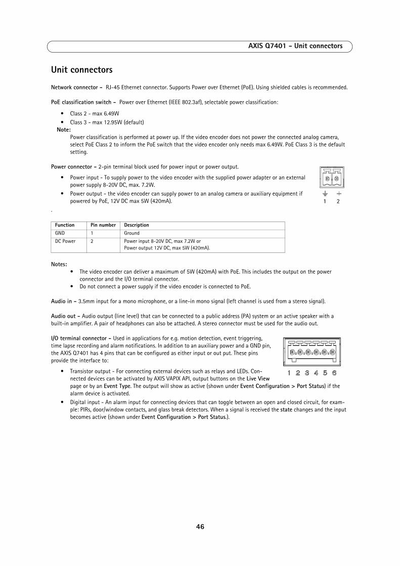
AXIS Q7401 - Unit connectors
Unit connectors
Network connector - RJ-45 Ethernet connector. Supports Power over Ethernet (PoE). Using shielded cables is recommended.
PoE classification switch - Power over Ethernet (IEEE 802.3af), selectable power classification:
• Class 2 - max 6.49W
• Class 3 - max 12.95W (default)Note:
Power classification is performed at power up. If the video encoder does not power the connected analog camera, select PoE Class 2 to inform the PoE switch that the video encoder only needs max 6.49W. PoE Class 3 is the default setting.
Power connector - 2-pin terminal block used for power input or power output.
• Power input - To supply power to the video encoder with the supplied power adapter or an external power supply 8-20V DC, max. 7.2W.
• Power output - the video encoder can supply power to an analog camera or auxiliary equipment if powered by PoE, 12V DC max 5W (420mA).
.
Notes:• The video encoder can deliver a maximum of 5W (420mA) with PoE. This includes the output on the power
connector and the I/O terminal connector.• Do not connect a power supply if the video encoder is connected to PoE.
Audio in - 3.5mm input for a mono microphone, or a line-in mono signal (left channel is used from a stereo signal).
Audio out - Audio output (line level) that can be connected to a public address (PA) system or an active speaker with a built-in amplifier. A pair of headphones can also be attached. A stereo connector must be used for the audio out.
I/O terminal connector - Used in applications for e.g. motion detection, event triggering, time lapse recording and alarm notifications. In addition to an auxiliary power and a GND pin, the AXIS Q7401 has 4 pins that can be configured as either input or out put. These pins provide the interface to:
• Transistor output - For connecting external devices such as relays and LEDs. Con-nected devices can be activated by AXIS VAPIX API, output buttons on the Live View page or by an Event Type. The output will show as active (shown under Event Configuration > Port Status) if the alarm device is activated.
• Digital input - An alarm input for connecting devices that can toggle between an open and closed circuit, for exam-ple: PIRs, door/window contacts, and glass break detectors. When a signal is received the state changes and the input becomes active (shown under Event Configuration > Port Status.).
Function Pin number DescriptionGND 1 Ground
DC Power 2 Power input 8-20V DC, max 7.2W or Power output 12V DC, max 5W (420mA).
1 2
46
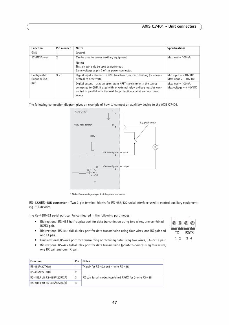
AXIS Q7401 - Unit connectors
The following connection diagram gives an example of how to connect an auxiliary device to the AXIS Q7401.
RS-422/RS-485 connector - Two 2-pin terminal blocks for RS-485/422 serial interface used to control auxiliary equipment, e.g. PTZ devices.
The RS-485/422 serial port can be configured in the following port modes:
• Bidirectional RS-485 half-duplex port for data transmission using two wires, one combined RX/TX pair.
• Bidirectional RS-485 full-duplex port for data transmission using four wires, one RX pair and one TX pair.
• Unidirectional RS-422 port for transmitting or receiving data using two wires, RX- or TX pair.
• Bidirectional RS-422 full-duplex port for data transmission (point-to-point) using four wires, one RX pair and one TX pair.
Function Pin number Notes SpecificationsGND 1 Ground
12VDC Power 2 Can be used to power auxiliary equipment.
Notes: This pin can only be used as power out. Same voltage as pin 2 of the power connector.
Max load = 100mA
Configurable (Input or Out-put)
3 - 6 Digital input - Connect to GND to activate, or leave floating (or uncon-nected) to deactivate.
Min input = - 40V DC Max input = + 40V DC
Digital output - Uses an open-drain NFET transistor with the source connected to GND. If used with an external relay, a diode must be con-nected in parallel with the load, for protection against voltage tran-sients.
Max load = 100mA Max voltage = + 40V DC
Function Pin Notes
RS 485/422TX(A) 1 TX pair for RS-422 and 4-wire RS-485
RS 485/422TX(B) 2
RS-485A alt RS-485/422RX(A) 3 RX pair for all modes (combined RX/TX for 2-wire RS-485)
RS-485B alt RS-485/422RX(B) 4
1
2E.g. push button
I/O 3 configured as input
I/O 4 configured as output
* Note: Same voltage as pin 2 of the power connector
AXIS Q7401
3.3V
*12V max 100mA
D
S
G
1 2 3 4
TX RX/TX
47

AXIS Q7401 - Unit connectors
SDHC memory card slot - The high capacity SD memory card can be used for local recording with removable storage.
BNC connector - Connect a 75 ohm coaxial video cable (max. length 800 feet (250 meters).
Note:If the video source is to be connected in parallel with other equipment using a BNC T adaptor, disable the input termi-nation by setting the 75 ohm termination switch to OFF. Failure to do so may cause reduced image quality.
48

AXIS Q7401 - LED indicators
LED indicators
LED Color Indication
Network Green Steady for connection to a 100 Mbit/s network. Flashes for network activity.
Amber Steady for connection to 10 Mbit/s network. Flashes for network activity.
Unlit No network connection.
Status Green Steady green for normal operation.
Amber Steady during startup, during reset to factory default or when restoring settings.
Red Slow flash for failed upgrade.
Power Green Normal operation.
Amber Flashes green/amber during firmware upgrade.
49
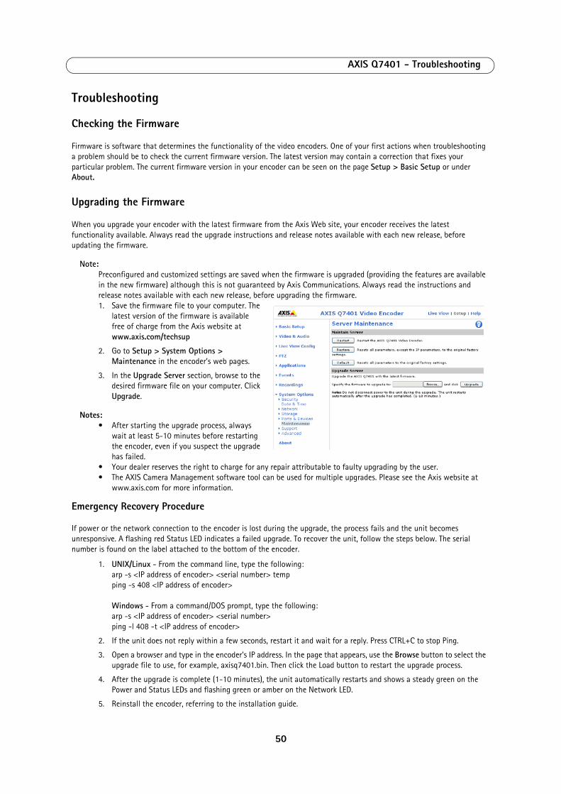
AXIS Q7401 - Troubleshooting
Troubleshooting
Checking the Firmware
Firmware is software that determines the functionality of the video encoders. One of your first actions when troubleshooting a problem should be to check the current firmware version. The latest version may contain a correction that fixes your particular problem. The current firmware version in your encoder can be seen on the page Setup > Basic Setup or under About.
Upgrading the Firmware
When you upgrade your encoder with the latest firmware from the Axis Web site, your encoder receives the latest functionality available. Always read the upgrade instructions and release notes available with each new release, before updating the firmware.
Note:Preconfigured and customized settings are saved when the firmware is upgraded (providing the features are available in the new firmware) although this is not guaranteed by Axis Communications. Always read the instructions and release notes available with each new release, before upgrading the firmware.1. Save the firmware file to your computer. The
latest version of the firmware is available free of charge from the Axis website at www.axis.com/techsup
2. Go to Setup > System Options > Maintenance in the encoder’s web pages.
3. In the Upgrade Server section, browse to the desired firmware file on your computer. Click Upgrade.
Notes: • After starting the upgrade process, always
wait at least 5-10 minutes before restarting the encoder, even if you suspect the upgrade has failed.
• Your dealer reserves the right to charge for any repair attributable to faulty upgrading by the user.• The AXIS Camera Management software tool can be used for multiple upgrades. Please see the Axis website at
www.axis.com for more information.
Emergency Recovery Procedure
If power or the network connection to the encoder is lost during the upgrade, the process fails and the unit becomes unresponsive. A flashing red Status LED indicates a failed upgrade. To recover the unit, follow the steps below. The serial number is found on the label attached to the bottom of the encoder.
1. UNIX/Linux - From the command line, type the following: arp -s <IP address of encoder> <serial number> temp ping -s 408 <IP address of encoder> Windows - From a command/DOS prompt, type the following: arp -s <IP address of encoder> <serial number> ping -l 408 -t <IP address of encoder>
2. If the unit does not reply within a few seconds, restart it and wait for a reply. Press CTRL+C to stop Ping.
3. Open a browser and type in the encoder’s IP address. In the page that appears, use the Browse button to select the upgrade file to use, for example, axisq7401.bin. Then click the Load button to restart the upgrade process.
4. After the upgrade is complete (1-10 minutes), the unit automatically restarts and shows a steady green on the Power and Status LEDs and flashing green or amber on the Network LED.
5. Reinstall the encoder, referring to the installation guide.
50

AXIS Q7401 - Troubleshooting
If the emergency recovery procedure does not get the encoder up and running again, please contact Axis support at www.axis.com/techsup/
Axis Support
If you contact Axis support, please help us to help you solve your problems by providing the server report, the log file and a detailed description of the problem.
Server Report - go to Setup > System Options > Support > Support Overview. The server report contains important information about the server and its software, as well as a list of the current parameters.
The Log file is available from Setup > System Options > Support > Logs & Reports. The Log file records events in the unit since the last system restart and can be a useful diagnostic tool when troubleshooting.
51

AXIS Q7401 - Troubleshooting
Symptoms, Possible Causes, and Remedial ActionProblems setting the IP address
When using ARP/Ping Try the installation again. The IP address must be set within two minutes after power has been applied to the encoder. Ensure the Ping length is set to 408. See the Installation Guide.
The encoder is located on a different subnet
If the IP address intended for the encoder and the IP address of your computer are located on different subnets, you will not be able to set the IP address. Contact your network administrator to obtain an appropriate IP address.
The IP address is being used by another device
Disconnect the encoder from the network. Run the Ping command. (In a Command/DOS win-dow, type ping and the IP address of the unit).
If you receive: Reply from <IP address>: bytes = 32; time = 10 ms..... - this means that the IP address may already be in use by another device on your network. You must obtain a new IP address and reinstall the unit.
If you see: Request timed out - this means that the IP address is available for use with your encoder. In this case, check all cabling and reinstall the unit.
Possible IP address conflict with another device on the same subnet
The static IP address in the encoder is used before the DHCP server sets a a dynamic address. This means that if the same default static IP address is also used by another device, there may be problems accessing the encoder. To avoid this, set the static IP address to 0.0.0.0.
The encoder cannot be accessed from a browserProblems with ONVIF If ONVIF is not working as expected, it may be that for security reasons ONVIF was disabled
when the camera was accessed over VAPIX. To enable ONVIF, reset the product to Factory default settings (see page 45).
The IP address has been changed by DHCP
If the encoder and client are on the same network, Run AXIS IP Utility to locate the encoder. Identify the encoder using its model or serial number
Alternatively: 1) Move the encoder to an isolated network or to one with no DHCP or BOOTP server. Set the IP address again, using the AXIS IP Utility (see the Installation Guide) or the ARP/Ping commands. 2) Access the unit and disable DHCP in the TCP/IP settings. Return the unit to the main network. The unit now has a fixed IP address that will not change. 3) As an alternative to 2), if dynamic IP address via DHCP or BOOTP is required, select the required service and then configure IP address change notification from the network settings. Return the unit to the main network. The unit now has a dynamic IP address, but will notify you if the address changes.
Other networking problems Test the network cable by connecting it to another network device, then Ping that device from your workstation. See instructions above.
Encoder is accessible locally, but not externallyBroadband router configuration To configure your broadband router to allow incoming data traffic to the encoder, enable the
NAT-traversal feature which will attempt to automatically configure the router to allow access to the encoder. This is enabled from Setup > System Options > Network > TCP/IP Advanced.
Firewall protection Check the Internet firewall with your system administrator.
Default routers required Check if you need to configure the default router settings.
Problems with the H.264 formatNo H.264 displayed in the client
Check that the relevant H.264 connection methods are enabled in the AMC control panel applet (network tab).
In the AMC control applet, select the H.264 tab and click the button Set to default H.264 decoder.
No multicast H.264 displayed in the cli-ent
Check that the correct network interface is selected in the AMC control panel applet (network tab).
Check with your network administrator that the multicast addresses used by the encoder are valid for your network.
Check with your network administrator to see if there is a firewall preventing viewing.
Multicast H.264 only accessible by local clients
Check if your router supports multicasting, or if the router settings between the client and the server need to be configured. The TTL (Time To Live) value may need to be increased.
Poor rendering of H.264 images Color depth set incorrectly on clients. Set to 16-bit or 32-bit color.
If text overlays are blurred, or if there are other rendering problems, you may need to enable Advanced Video Rendering from the H.264 tab in the AMC control panel applet.
Ensure that your graphics card is using the latest device driver. The latest drivers can usually be downloaded from the manufacturer's web site.
52

AXIS Q7401 - Troubleshooting
Color saturation is different in H.264 and Motion JPEG
Modify the settings for your graphics adapter. Please see the adapter's documentation for more information.
Lower frame rate than expected Reduce number of applications running on the client computer.
Limit the number of simultaneous viewers.
Check with the system administrator that there is enough bandwidth available. See also the online help.
Check in the AMC control panel applet (H.264 tab) that video processing is set to Decode all frames possible.
Lower the image resolution.
Why do I not get 30 frames per second? See the section Optimizing your system, on page 57.
Image degeneration Decrease the GOV length, see the online help for more information.
The Power indicator is not constantly litFaulty power supply Check that you are using the correct power supply.
The Status and Network indicator LEDs are flashing red rapidlyHardware failure Contact your Axis dealer.
The Status indicator LED is flashing red and the encoder is inaccessibleA firmware upgrade has been inter-rupted or the firmware has otherwise been damaged
See the Emergency Recovery Procedure above.
No images displayed on web pageProblem with AMC. (Internet Explorer only)
To enable the updating of video images in Microsoft Internet Explorer, set your browser to allow ActiveX controls. Also, make sure that AXIS Media Control (AMC) component is installed on your workstation.
Installation of additional ActiveX com-ponent restricted or prohibited
Configure your encoder to use a Java applet for updating the video images under Live View Config > Layout > Default Viewer for Internet Explorer. See the online help for more information.
Video/Image problems, generalImage too dark or too light Check the video image settings. See the online help on Video and Image Settings.
Missing images in uploads This can occur when trying to use a larger image buffer than is actually available. Try lowering the frame rate or the upload period.
Slow image update Configuring pre-buffers, motion detection, high-resolution images, or high frame rates, will affect the performance of the encoder.
Poor performance Poor performance may be caused by heavy network traffic, multiple users accessing the unit, low performance clients, use of features such as Motion Detection, Event handling, Image rota-tion other than 180 degrees.
Poor quality snapshot imagesScreen incorrectly configured on your workstation
In Display Properties, configure your screen to show at least 65000 colors, that is, at least 16-bit. Using only 16 or 256 colors will produce dithering artifacts in the image.
Overlay/Privacy mask is not displayedIncorrect size or location of overlay or privacy mask.
The overlay or privacy mask may have been positioned incorrectly or wrong resolution may have been used while positioning. Refer to the online help for information on the limitations when using image overlays and privacy masks.
Browser freezesMozilla/Firefox 1.4 (or later) can some-times freeze on a slow computer
Lower the image resolution.
Problems uploading filesLimited space There is only limited space available for the upload of your own files. Try deleting existing files
to free up space.
Motion Detection triggers unexpectedlyChanges in luminance Motion detection is based on changes in luminance in the image. This means that if there are
sudden changes in the lighting, motion detection may be triggered mistakenly. Lower the sensi-tivity setting to avoid problems with luminance.
No audio Incorrect setup Check the sound card in the PC. Ensure that the mute button is not pressed and the volume set-
tings are correct.
No audio or very poor audio quality
Check that the correct Audio Input source is selected under Setup > Video & Audio > Audio Settings. Select Microphone for a connected external microphone. Select Line for a connected line in source.
53

AXIS Q7401 - Troubleshooting
For further assistance, please contact your reseller or see the support pages on the Axis website at www.axis.com/techsup
Audio volume too low/highVolume settings incorrect The volume of the microphone is either too high or too low. Change the volume for the micro-
phone in the toolbar on the Live View page.
Poor audio qualityCPU overloaded Reduce the number of listeners and viewers and decrease the image resolution and compres-
sion.
Unsynchronized audio and video It is recommended that the encoder's time setting is synchronized with an NTP Server. This is enabled under System Options > Date & Time.
Distorted audio Check that the correct Audio Input source is selected under Setup > Video & Audio > Audio Settings. Select Microphone for a connected external microphone. Select Line for a connected line in source.
Local Storage problemSD Card has critical data on it but shows as needing to be reformatted.
Critical data might be accessed and saved by placing the SD card in a card reader.
54

AXIS Q7401 - Technical Specifications
Technical Specifications
Item Specification
Video compression • H.264• Motion JPEG
Resolutions • 176x120 to 720x576
Frame rate H.264 • 30/25 (NTSC/PAL) fps in all resolutions
Frame rate Motion JPEG
• 30/25 (NTSC/PAL) fps in all resolutions
Video streaming • Multi-stream H.264 and Motion JPEG• Controllable frame rate and bandwidth• VBR/CBR H.264
Image settings • Compression, color, brightness, contrast, saturation• Rotation: 90°, 180°, 270°• Aspect ratio correction• Mirroring of images• Text and image overlay• Privacy mask• Enhanced deinterlace filter
Pan/Tilt/Zoom • Wide range of analog PTZ cameras supported (drivers available for download at www.axis.com)• 100 presets/camera, guard tour, PTZ control queue• Supports Windows compatible joysticks
Users • 20 simultaneous viewers
Audio streaming • Two way, half-duplex
Audio compression • AAC-LC 8 kHz 32 kbit/s, 16 kHz 64 kbit/s• G.711 μ-law PCM 64 kbit/s• G.726 ADPCM 32 or 24 kbit/s
Audio input/output • External microphone input or line input• Line level output
Security Password protection, IP address filtering, HTTPS encryption, IEEE 802.1X network access control, digest authentication, user access log
Supported protocols • IPv4/v6, HTTP, HTTPS, QoS layer 3 DiffServ, FTP, SMTP, Bonjour, UPnP, SNMPv1/v2c/v3(MIB-II), DNS, DynDNS, NTP, RTSP, RTP, TCP, UDP, IGMP, RTCP, ICMP, DHCP, ARP, SOCKS, etc.
• SSL/TLS*• *This product includes software developed by the Open SSL Project for use in the Open SSL Tool
kit (www.openssl.org)
Application Programming Interface
• Open API for software integration, including VAPIX® from Axis Communications*, AXIS Media Control SDK*, event trigger data in video stream, the ONVIF specification available at www.onvif.org
• Quality of Service (QoS) layer 3, DiffServ Model• Embedded Linux operating system• Support for AXIS Video Hosting System (AVHS) with One-Click Camera connection
*Available at www.axis.com
Intelligent video Video motion detection, active tampering alarm, audio detection
Alarm triggers Intelligent video, external inputs, video loss, disk full
Alarm events • File upload via FTP, HTTP and email• Notification via email, HTTP and TCP• External output activation• Local storage
Video buffer 64 MB pre- and post-alarm
55
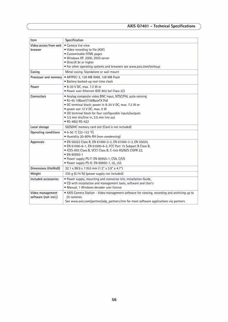
AXIS Q7401 - Technical Specifications
Video access from web browser
• Camera live view• Video recording to file (ASF)• Customizable HTML pages• Windows XP, 2000, 2003 server• DirectX 9c or higher• For other operating systems and browsers see www.axis.com/techsup
Casing Metal casing. Standalone or wall mount
Processor and memory • ARTPEC-3, 128 MB RAM, 128 MB Flash• Battery backed-up real-time clock
Power • 8-20 V DC, max. 7.2 W or• Power over Ethernet IEEE 802.3af Class 2/3
Connectors • Analog composite video BNC input, NTSC/PAL auto-sensing• RJ-45 10BaseT/100BaseTX PoE• DC terminal block: power in 8-20 V DC, max. 7.2 W or• power out 12 V DC, max. 5 W• I/O terminal block for four configurable inputs/outputs• 3.5 mm mic/line in, 3.5 mm line out• RS-485/ RS-422
Local storage SD/SDHC memory card slot (Card is not included)
Operating conditions • 0-50 °C (32-122 °F)• Humidity 20-80% RH (non-condensing)
Approvals • EN 55022 Class B, EN 61000-3-2, EN 61000-3-3, EN 55024,• EN 61000-6-1, EN 61000-6-2, FCC Part 15 Subpart B Class B,• ICES-003 Class B, VCCI Class B, C-tick AS/NZS CISPR 22,• EN 60950-1• Power supply PS-T: EN 60950-1, CSA, C/US• Power supply PS-K: EN 60950-1, UL, cUL
Dimensions (HxWxD) 32.1 x 98.9 x 118.0 mm (1.3" x 3.9" x 4.7")
Weight 335 g (0.74 lb) (power supply not included)
Included accessories • Power supply, mounting and connector kits, Installation Guide,• CD with installation and management tools, software and User’s• Manual, 1 Windows decoder user license
Video management software (not incl.)
• AXIS Camera Station - Video management software for viewing, recording and archiving up to 25 cameras
See www.axis.com/partner/adp_partners.htm for more software applications via partners
Item Specification
56

AXIS Q7401 - Technical Specifications
General performance considerations
When setting up your system, it is important to consider how various settings and situations will affect performance. Some factors affect the amount of bandwidth (the bit rate) required, others can affect the frame rate, and some will affect both. If the load on the CPU reaches its maximum, this will also affect the frame rate.
The following factors are among the most important to consider:
• High image resolutions and/or lower compression levels result in larger images. Bandwidth affected.
• Access by large numbers of Motion JPEG and/or unicast H.264 clients. Bandwidth affected.
• Simultaneous viewing of different streams (resolution, compression, etc.) by different clients. Bandwidth affected.• Heavy usage of event settings affects the CPU load. Frame rate affected.
• Heavy network utilization due to poor infrastructure. Bandwidth affected
• Viewing on poorly performing client PC lowers perceived performance. Frame rate affected.
Optimizing your system
To see the bandwidth and frame rate currently required by the video stream, the video encoder provides a tool that can be used to display these values directly in the video image.
To do this, special format strings are added as part of a text overlay. Simply add #r (average frame rate in fps) and/or #b (average bandwidth in Kbps) to the overlay.
For detailed instructions, please see the online help for Video & Image > Text Overlay Settings, and the help for File Naming & Date/Time Formats.
Important!• The figures displayed here are the values as delivered by the server. If other restrictions are
currently in force, (e.g. bandwidth limitation) these values might not correspond to those actually received by the client.
• For Motion JPEG, these values will only be accurate as long as no frame rate limit has been specified.
57

AXIS Q7401 - Glossary
Glossary Active Speaker - a speaker with a built-in power amplifier.
ActiveX - A control (or set of rules) used by a browser. ActiveX controls are often downloaded and installed automatically as required.
Advanced Audio Coding (AAC) - is an audio codec that is at the core of the MPEG-4, 3GPP and 3GPP2 specifications, and is used for Internet, wireless and digital broadcast audio. AAC combines high quality audio encoding with a small file size.
AMC - AXIS Media Control. The control required for viewing video images in Internet Explorer. Installs automatically on first use.
API - Application Programming Interface. The Axis API can be used for integrating Axis products into other applications.
ARP - Address Resolution Protocol. Used to associate an IP address to a hardware MAC address. A request is broadcast on the local network to find out what the MAC address is for the IP address.
ARTPEC - Axis Real Time Picture Encoder - used for image compression.
Aspect ratio - A ratio of width to height in images. A common aspect ratio used for television screens and computer monitors is 4:3. High-definition television (HDTV) uses an aspect ratio of 9:16.
BOOTP - A protocol that can automatically configure a network device (give it an IP address).
Bonjour - Also known as zero-configuration networking, Bonjour enables automatic discovery of computers, devices, and services on IP networks. Bonjour allows devices to automatically discover each other without the need to enter IP addresses or configure DNS servers. Bonjour is developed by Apple Computer Inc.
CGI - Common Gateway Interface. A set of rules (or a program) that allows a Web Server to communicate with other programs.
Client/Server - Describes the network relationship between two computer programs, in which one, the client, makes a service request from another - the server.
DC-Iris - This special type of iris is electrically controlled by the Axis camera, to automatically regulate the amount of light allowed to enter.
dB (Decibels) - A unit to measure sound level changes. A 3dB change is the smallest level change we can hear. A 3dB change is actually twice or half the audio power level. A gain of 0dB will leave the signal level unchanged.
De-interlacing - De-interlacing is the process taking a stream of interlaced frames and converting it to a stream of progressive frames.
DSL - Digital Subscriber Line. A means of transferring data via standard phone lines.
Ethernet - A widely used networking standard.
ETRAX - Axis' own microprocessor.
Firewall - A virtual barrier between a LAN (Local Area Network) and other networks, e.g. the Internet.
FTP - File Transfer Protocol. Used for the simple transfer of files to and from an FTP-server.
Full-duplex - Transmission of data, e.g. audio, in two directions
simultaneously.
G.711 - G.711 is the international standard for encoding telephone audio on 64 kbps channel. It is a pulse code modulation (PCM) scheme operating at 8 kHz sample rate.
G.726 - Frequently used speech-compression algorithm in telecommunications due to its high perceived speech quality and low resource requirements.
H.264 - Also known as MPEG-4 Part 10. This is the new generation compression standard for digital video. H.264 offers higher video resolution than Motion JPEG or MPEG-4 at the same bit rate and bandwidth, or the same quality video at a lower bit rate.
Half-duplex- A half-duplex link communicates in one direction at a time only, much like a walkie-talkie. Two way communication is possible, but not simultaneously.
HTTP - Hypertext Transfer Protocol. The set of rules for exchanging files (text, images, sound, video, and other files) on the World Wide Web.
HTTPS - An extension to the HTTP protocol to support sending data securely over the World Wide Web.
Intranet - A private network limited to an organization or corporation. Usually closed to external traffic.
IP - Internet Protocol. See TCP/IP.
IP address - A unique number used by a computer on the network to allow it to be identified and found.
ISMA - Internet Streaming Media Alliance.
JPEG - A standard image format, used widely for photographs. Also known as JPG.
LAN - A local area network (LAN) is a group of computers and associated devices that typically share common resources within a limited geographical area.
Linux - A popular operating system that is “open source” and practically free of charge.
Local storage - If a camera or video encoder supports local storage, an SD card can be inserted into the SD card slot to locally record and store a video stream.
Lux - A standard unit for light measurement.
Mbit/s - Megabits per second. A unit for measuring speeds in networks. A LAN might run at 10 or 100 Mbit/s.
Motion JPEG - Delivers a high quality video stream, from which individual images can be extracted and saved.
MPEG-4 - A video compression standard that makes good use of bandwidth, and which can provide DVD-quality video streams at less than 1 Mbit/s.
Multicast - A bandwidth-conserving technology that reduces bandwidth usage by simultaneously delivering a single stream of information to multiple network recipients.
PEM - Privacy Enhanced Mail. An early standard for securing electronic mail. The PEM-format is often used for representing an HTTPS certificate or certificate request.
Ping - A small utility used for sending data packets to network resources to check that they are working and that the network is intact.
Pre/post alarm image - The images from immediately before and after an alarm.
Protocol - A special set of rules governing how two entities will communicate. Protocols are found at many levels of
58

AXIS Q7401 - Glossary
communication, and there are hardware protocols and software protocols.
(QoS) Quality of Service - QoS provides the means to guarantee a certain level of a specified resource to selected traffic on a network. Quality can be defined as e.g. a maintained level of bandwidth, low latency, and no packet losses.
Router - A device that determines the next network point to which a packet should be forwarded on its way to its final destination. A router is often included as part of a network switch (see below).
RTP- Real-Time Transfer Protocol. A transfer protocol designed for the delivery of live content, e.g. MPEG-4.
RTSP (Real Time Streaming Protocol) - RTSP is a control protocol, and a starting point for negotiating transports such as RTP, multicast and Unicast, and for negotiating codecs. RTSP can be considered a “remote control” for controlling the media stream delivered by a media server. RTSP servers typically use RTP as the protocol for the actual transport of audio/video data.
Simplex - In simplex operation, a network cable or communications channel can only send information in one direction; it's a “one-way street”.
SMTP - Simple Mail Transfer Protocol is the protocol used to send e-mail across the Internet. SMTP authentication is a way of allowing people outside of a domain to use an SMTP server when sending e-mail.
SNMP - Simple Network Management Protocol. An application layer protocol that facilitates the exchange of management information between network devices. It is part of the Transmission Control Protocol/Internet Protocol (TCP/IP) protocol suite.
Subnet Mask - An IP address consists of two components: the network address and the host address. “Subnetting’ enables a network administrator to further divide the host part of the address into two or more subnets. The subnet mask identifies the subnet to which an IP address belongs.
Switch - Whilst a simple hub transmits all data to all devices connected to it, a switch only transmits the data to the device it is specifically intended for.
TCP/IP - Transmission Control Protocol/Internet Protocol. A suite of network protocols that determine how data is transmitted. TCP/IP is used on many networks, including the Internet. TCP keeps track of the individual packets of information and IP contains the rules for how the packets are actually sent and received.
UDP - The User Datagram Protocol is a communications protocol that offers a limited amount of service when messages are exchanged between computers in a network that uses the Internet Protocol (IP). UDP is an alternative to the Transmission Control Protocol (TCP) and, together with IP, is also known as UDP/IP.
Unicast - Communication between a single sender and a single receiver over a network. A new connection is established for each new user.
URL - Uniform Resource Locator. An “address" on the network.
Varifocal - A varifocal lens provides a wide range of focal lengths, as opposed to a lens with a fixed focal length, which only provides one.
WAN - Wide-Area-Network. Similar to a LAN, but on a larger geographical scale.
Web server - A program on a computer that delivers the
resources (usually web pages) requested by the web user (the client).
59

AXIS Q7401 - Index
Index
AAction Buttons 8, 19Active/Inactive 20Administrator 13Alarm 31, 46AMC 6Applications 27ARP/Ping 37Audio 13Audio input 16Audio output 17AVHS 38, 55AXIS Media Control 16
BBit Rate 14Bonjour 6Buffer Size 29Buffers 29
CCGI links 26Click-in-image 26Continuous Recording 34Control Button 45
DDate & Time 36Default Viewer 18Disk Management 42DNS Configuration 38DNS Server 38Domain Name 38
EEmergency Recovery 50Enable ARP/Ping 37Event Servers 28Events 28
FFactory Default Settings 45Frame Rate 13FTP Server 28
GGOV Settings 14
HH.264 6, 10, 13Half duplex 16Host Name 38HTTP API 26HTTP Server 28HTTPS 7, 35
II/O Ports 43Installing PTZ devices 21IP Address Filtering 35
LLive View Config 18Local storage 4, 58Logs & Reports 44
MMotion Detection 31, 46Motion JPEG 6, 10
NNAT traversal 7, 38, 39Network Settings 37NTP Server 36
OOutput Buttons 20
PPan/Tilt/Zoom 25Port Status 32Ports & Devices 43Post-trigger Buffer 29Preset positions 22Pre-trigger Buffer 29PTZ commands 26PTZ control queue 24Pulse 20
QQuickTime 11, 18
60

AXIS Q7401 - Index
RRecordings 33Recovery 50Referrals 35Relative and absolute PTZ drivers 25Restore 43
SScheduled Event 30Security 35Server Time 36SNMP 40Specifications 55Support 44System Options 35
TTCP Server 28TCP/IP Settings 37Time Mode 36Troubleshooting 50
UUpgrade Server 43UPnP 38, 41Users 35
VVideo Stream 10, 13
61

Installation

Marine Electrical Products
ST Blade Fuse Block6 Circuits with Negative Bus
PN 5025 / PN 5030
425 Sequoia Drive Bellingham, WA 98226 USAp 360.738.8230p 800.222.7617 USA and Canada Customer Service f [email protected]

Helmet Mount System 92510Adjustment and Mounting Instructions
PATENT PENDING
www.onscenesolutions.com

Nomenclature
Sliding Toe Clamp
Toe Clamp
Base Plate
Mounting Bracket
2
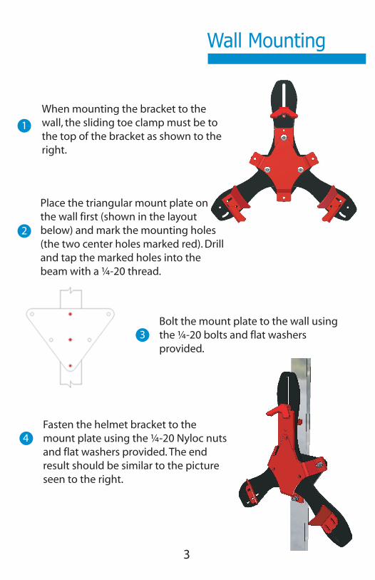
Helmet Mount SystemWall Mounting
3
When mounting the bracket to the
wall, the sliding toe clamp must be to
the top of the bracket as shown to the
right.
1
2
3
Place the triangular mount plate on
the wall first (shown in the layout
below) and mark the mounting holes
(the two center holes marked red). Drill
and tap the marked holes into the
beam with a ¼-20 thread.
Bolt the mount plate to the wall using
the ¼-20 bolts and flat washers
provided.
4
Fasten the helmet bracket to the
mount plate using the ¼-20 Nyloc nuts
and flat washers provided. The end
result should be similar to the picture
seen to the right.
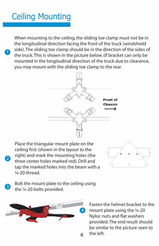
Ceiling Mounting
4
1
When mounting to the ceiling, the sliding toe clamp must not be in
the longitudinal direction facing the front of the truck (windshield
side). The sliding toe clamp should be in the direction of the sides of
the truck. This is shown in the picture below. (If bracket can only be
mounted in the longitudinal direction of the truck due to clearance,
you may mount with the sliding toe clamp to the rear.
2
Place the triangular mount plate on the
ceiling first (shown in the layout to the
right) and mark the mounting holes (the
three center holes marked red). Drill and
tap the marked holes into the beam with a
¼-20 thread.
3Bolt the mount plate to the ceiling using
the ¼-20 bolts provided.
4
Fasten the helmet bracket to the
mount plate using the ¼-20
Nyloc nuts and flat washers
provided. The end result should
be similar to the picture seen to
the left.

Helmet Mount SystemAdjustments
5
Roughly center your helmet with the Talon
Helmet Bracket as shown to the right. 1
2
3
After helmet is centered, note the mount-
ing holes on the two “wings” of the
bracket. Remove your helmet and place
the toe clamps over the proper mounting
holes. This is shown below. Be sure to not
tighten the bolts all the way.
Once the toe clamps are in place,
mount the helmet by sliding the top
toe clamp up with the brim of the
helmet, and setting the bottom brim of
the helmet into the “loose” toe clamps
that you just mounted to the bracket.
4
Orient the bottom toe clamps so they
are parallel to the brim of your helmet
then tighten the bolts completely on
the toe clamps.
5
Make sure that the spring loaded toe clamp at the top of the
bracket has tension and that the helmet can be removed from
the bracket. (If the top toe clamp will not slide up enough to
allow the helmet to be removed, adjust the bottom toe clamps
down on the bracket to allow more movement in the top sliding
toe clamp.)
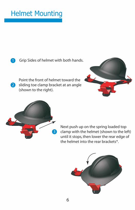
Helmet Mounting
6
Grip Sides of helmet with both hands.1
2
Point the front of helmet toward the
sliding toe clamp bracket at an angle
(shown to the right).
3
Next push up on the spring loaded top
clamp with the helmet (shown to the left)
until it stops, then lower the rear edge of
the helmet into the rear brackets*.

Helmet Mount System
7
2
*Depending on your helmet style, the helmet may rest in the lower part
of the toe clamp (non-traditional) or the upper part (tradional). See
images below.
Other mounting configurations are possible. For more examples, please
visit our website at www.onscenesolutions.com
)

1
INSTALLATION INSTRUCTIONS FRONT ROLL CONFIGURATION
AMDOR® Roll-Up Doors are shipped complete for your application. Depending on the features ordered each door is equipped with the following items:
AMDOR® Roll-Up Door Pretensioned balancer assembly Balancer mounting plates (2) with cotter pins Side frame and track with side seals (2) Nylon Strikers for Lift Bar (2) with SS fasteners (4) Top gutter with top seal and top bumper installed Sill Plate (Optional) Trim strips to cover fastener locations in top gutter and sill plate Template for locating fastening holes.
NOTE: Care should be taken when handling roll-up doors to avoid scratching the anodized surface.
1. Prior to beginning the installation check all the doors and hardware enclosed. The hardware (ie. Balancer Plates, Track/Side Frames, Top Gutters and Sill Plates) should be marked with the Job Number or Door Serial No.
2. Position the Template provided, so that the diagram is face up, against the inside
front compartment wall. (The Template will be placed against the Left wall as viewed from outside the compartment looking in.) Position so as to ensure that the alignment tab is flush with the exterior edge of the body, as indicated. Also ensure that the top of the Template is positioned against the ceiling of the compartment. When fastened, the extreme front and top edges of the plate will be 1/4" from the exterior edge of the body and 1/4" from the underside of the compartment ceiling. Some installations with large headers (6 inches or more) may require positioning the plates down from the ceiling slightly - check for any special instructions. Mark and drill only two of the slotted fastener locations. This will ensure adjustment for final positioning. Mount the Balancer Plate using the two drilled holes. It will be necessary to use a fastener in the debossed hole location, shown as a circle, and at least one of the additional slotted fastener locations. The debossed location is necessary to remove any warping caused by welding on the plate.

2
NOTE: The location of the Idler Wheel and the Balancer Bracket are determined by the header size and door height. Ensure that the correct Balancer Plates are installed in each compartment or the door may not operate properly. The number marked on the Balancer Plate should coincide with the Job Number or Serial No. on the door.
3. Repeat Step 2 for the other side of the compartment except with the Template
diagram face down. 4. Orient the Pretensioned Balancer Assembly above the brackets on the Balancer
Plate and so that the end with the removable charge pin is on the Right hand side. Lower the Balancer Assembly into the brackets - it may be a tight fit. Align the hole in the Left hand end of the balancer shaft with the lower hole in the balancer bracket and insert the 3/16" cotter pin provided. Insert the 3/32" cotter pin in the small hole of the balancer bracket on the Right hand plate.
5. Pick up the door and position it in the opening with the top edge of the door
aligned with the Idler Wheels on the Balancer Plate. Guide the door up over the top of the Idler Wheels. Wrap the Balancer Strap around the balancer case and align the loop of the Balancer Strap with the Hinge Leaf connector on the top of the door. Install the Clevis Pin through the Hinge Leaf and Balancer Strap and secure with the Cotter Pin provided. Inspect the straps and ensure that they are aligned and straight with no twists etc.
6. Grasp the bottom of the door and pull firmly downward to take the tension off the
charge pin inserted through the nylon bushing at the right hand end of the balancer. Remove the charge pin and gently let the door roll up into the compartment. It will not roll-up beyond the header.
7. If a Sill Plate was ordered, it is to be installed at this point. Position the
prenotched plate against the body exterior, extending into the compartment. Drill through the recessed front of the Sill Plate. Fastener locations should be countersunk to ensure complete hiding of the fastener heads.
8. Pivot the Bottom Rail of the door forward and slide the two Side Frame/Track
pieces up over the bottom of the door. With the Side frames pushed up as far as possible, pivot the Bottom Rail and Side Frame pieces in toward the body. The Side Frames should be flush against the side of the body. Slide the Side Frames down so they sit firmly on the compartment sill.
For optimum security, it is recommended that the Side sections be secured through the track rather than the rear flange. Fastening in this position prevents the section from being twisted away from the body. The Track Section has been designed to prevent interference between fasteners and the door however it is recommended that all fasteners be countersunk. For extra security, additional fasteners may be secured through the rear flange.

3
9. Close the door and press down firmly on the Bottom Rail making contact with good pressure between the door bottom seal and the compartment sill. The bottom seal should be compressed approximately 50 percent. Ensure that there is a good seal across the entire width of the door. Locate the Nylon Strikers 1/8" in from the inside edge of the Track/Side Frame (closest to the door opening).
The strikers should be positioned with the upper hole exposed and the stainless steel bar engaged in the detent area. Mark the upper hole location for each striker. Remove the strikers and roll the door up. Drill through the Side Frame sections, as marked, and tap the hole to suit the SS 1/4-28 Machine Screws provided. Roll the door down and GENTLY engage the SS Lift Bar in the strikers. Align striker with lift bar tube. Roll the door up again. Now drill, tap and install the fasteners in the lower holes of the strikers. If the Key Locking feature has been ordered two holes must be drilled for the deadbolt to engage. Drill 3/8 inch diameter holes through the center of the track (both sides) 1-3/16 inches up from the sill. Be sure to drill thru the body as well as the door track.
10. Position the Top Gutter section along the top edges of the Side Frame sections.
The side edges of the Top Gutter and the Side Frame sections should line up. Fasten the Top Gutter in the same manner as the Sill Plate (Step 7).
Care should be taken to use a short fastener (3/8" is recommended) to prevent damaging the door. Before drilling close the door all the way. This will prevent marking the door surface if the drill should poke through too far when drilling through the header panel.
For adjacent doors supplied with "Continuous Top Gutter", the Top Seal(s) are not installed. Position the gutter and mark the location of each door opening on the back of the gutter section. Mark at the inside edge of the Track/Side Frame. Remove the marked gutter section, install the top seal, to extend across the marked opening, by pressing the spine of the seal into the retainer groove with the fin pointed towards the bottom of the gutter. Install the gutter section and fasten as detailed above.
11. Insert the Trim Strips into the fastener recesses of the Sill Plate (if ordered) and
the Top Gutter sections. Install the Trim Strips by starting to insert the flexible extrusion into the fastener recess at the center and working toward each end. Avoid stretching the trim strip during installation. Leave approximately 1/8" at each end to allow the Trim Strips to relax after insertion. It is recommended that the Trim Section be allowed to relax for at least 8 hours, 24 would be preferred, before final trimming. Lubrication will help reduce stretching during insertion. The Trim Strips are a tight fit but a drop of adhesive may be used for extra security.

4
12. Open the door gently and check to ensure that all fasteners are tight and do not interfere with the door movement.
13. Run the door up and down a few times to ensure the action is smooth and that
the latch points are properly aligned.
If you have any questions or would like additional information please call your
local AMDOR® representative or our customer service team at 1-877-462-6367 / [email protected]
Page 1
Installation Guide:600 Series LED Lighthead
©2001 Whelen Engineering Company Inc.Form No.13650R (052011)
®
ENGINEERING COMPANY INC.51 Winthrop RoadChester, Connecticut 06412-0684Phone: (860) 526-9504Fax: (860) 526-4078Internet: www.whelen.comSales e-mail: [email protected] Sales e-mail: [email protected] Service e-mail: [email protected]
Aut
omot
ive:
Lig
hthe
ads
Safety First
This document provides all the necessary information to allow your Whelen product to be properly and safely installed.Before beginning the installation and/or operation of your new product, the installation technician and operator mustread this manual completely. Important information is contained herein that could prevent serious injury or damage.
• Proper installation of this product requires the installer to have a good understanding of automotive electronics, systems and procedures.
• If mounting this product requires drilling holes, the installer MUST be sure that no vehicle components or other vital parts could be damaged by the drilling process. Check both sides of the mounting surface before drilling begins. Also de-burr any holes and remove any metal shards or remnants. Install grommets into all wire passage holes.
• If this manual states that this product may be mounted with suction cups, magnets, tape or Velcro®, clean the mounting surface with a 50/50 mix of isopropyl alcohol and water and dry thoroughly.
• Do not install this product or route any wires in the deployment area of your air bag. Equipment mounted or located in the air bag deployment area will damage or reduce the effectiveness of the air bag, or become a projectile that could cause serious personal injury or death. Refer to your vehicle owner’s manual for the air bag deployment area. The User/Installer assumes full responsibility to determine proper mounting location, based on providing ultimate safety to all passengers inside the vehicle.
• For this product to operate at optimum efficiency, a good electrical connection to chassis ground must be made. The recommended procedure requires the product ground wire to be connected directly to the NEGATIVE (-) battery post.
• If this product uses a remote device to activate or control this product, make sure that this control is located in an area that allows both the vehicle and the control to be operated safely in any driving condition.
• Do not attempt to activate or control this device in a hazardous driving situation.
• This product contains either strobe light(s), halogen light(s), high-intensity LEDs or a combination of these lights. Do not stare directly into these lights. Momentary blindness and/or eye damage could result.
• Use only soap and water to clean the outer lens. Use of other chemicals could result in premature lens cracking (crazing) and discoloration. Lenses in this condition have significantly reduced effectiveness and should be replaced immediately. Inspect and operate this product regularly to confirm its proper operation and mounting condition. Do not use a pressure washer to clean this product.
• It is recommended that these instructions be stored in a safe place and referred to when performing maintenance and/or reinstallation of this product.
• FAILURE TO FOLLOW THESE SAFETY PRECAUTIONS AND INSTRUCTIONS COULD RESULT IN DAMAGE TO THE PRODUCT OR VEHICLE AND/OR SERIOUS INJURY TO YOU AND YOUR PASSENGERS!
For warranty information regarding this product, visit www.whelen.com/warranty
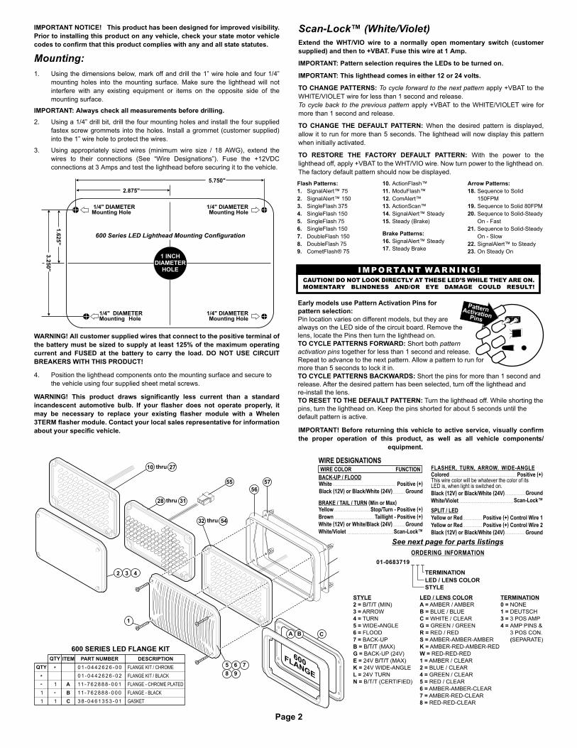
Page 2
AMBER / AMBER
BLUE / BLUE
WHITE / CLEAR
GREEN / GREEN
RED / RED
AMBER-AMBER-AMBER
AMBER-RED-AMBER-RED
RED-RED-RED
AMBER / CLEAR
BLUE / CLEAR
GREEN / CLEAR
RED / CLEAR
AMBER-AMBER-CLEAR
AMBER-RED-CLEAR
RED-RED-CLEAR
LED / LENS COLOR
A =
B =
C =
G =
R =
S =
K =
W =
1 =
2 =
4 =
5 =
6 =
7 =
8 =
NONE
DEUTSCH
3 POS AMP
AMP PINS &
3 POS CON.
SEPARATE)
TERMINATION
0 =
1 =
3 =
4 =
(
4 =
4 =
STYLE
B T T (MIN)
ARROW
TURN
WIDE ANGLE
FLOOD
BACK-UP
B T T (MAX)
BACK-UP (24V)
24V B T T (MAX)
24V WIDE-ANGLE
24V TURN
B T T
2 = / /
3 =
4 =
5 = -
6 =
7 =
B = / /
G =
E = / /
K =
L =
N = / / (CERTIFIED)
1
2 3 4
57
10
28
32
27
31
54
55
WIRE DESIGNATIONS
Yellow
Brown
White (12V) or (24V)
White/Violet
White/Black
Stop Turn
Positive (+)
Scan-Lock™
/ - Positive (+)
Taillight -
Ground
BRAKE / TAIL / TURN (Min or Max)
FLASHER, TURN, ARROW, WIDE-ANGLEColoredThis wire color will be whatever the color of itsLED is, when light is switched on.
Black (12V) or Black/White (24V)
White/Violet
Positive (+)
Ground
Scan-Lock™
Yellow or Red
Yellow or Red
Black (12V) or Black/White (24V)
Positive (+)
Positive (+)
Control Wire 1
Control Wire 2
Ground
SPLIT / LED
WIRE COLOR FUNCTION
White
Black (12V) or Black/White (24V)
Positive (+)
Ground
BACK-UP / FLOOD
600 SERIES LED FLANGE KIT
FLANGE KIT / BLACK0 1 - 0 4 4 2 6 2 6 - 0 2
1
1
QTY
1 C 3 8 - 0 4 6 1 3 5 3 - 0 1 GASKET
B 11 - 7 6 2 8 8 8 - 0 0 0 FLANGE - BLACK
1 A 11 - 7 6 2 8 8 8 - 0 0 1 FLANGE - CHROME PLATED
DESCRIPTION
FLANGE KIT / CHROME
PART NUMBER
0 1 - 0 4 4 2 6 2 6 - 0 0
ITEMQTY
01-0683719 _ _ _
TERMINATION
LED / LENS COLOR
STYLE
ORDERING INFORMATION
See next age for arts listin sp p g
C
600FLANGE
A B
5 6 7
8 9
56
thru
thru
thru
2.875"
5.750"
1.6
25
"
3.2
50
"
"1/4 DIAMETERMounting Hole
1/4 DIAMETERMounting Hole
"
1 INCHDIAMETER
HOLE
600 Series LED Lighthead Mounting Configuration
"1/4 DIAMETERMounting Hole
"1/4 DIAMETERMounting Hole
IMPORTANT NOTICE! This product has been designed for improved visibility.Prior to installing this product on any vehicle, check your state motor vehiclecodes to confirm that this product complies with any and all state statutes.
Mounting: 1. Using the dimensions below, mark off and drill the 1” wire hole and four 1/4”
mounting holes into the mounting surface. Make sure the lighthead will notinterfere with any existing equipment or items on the opposite side of themounting surface.
IMPORTANT: Always check all measurements before drilling. 2. Using a 1/4” drill bit, drill the four mounting holes and install the four supplied
fastex screw grommets into the holes. Install a grommet (customer supplied)into the 1” wire hole to protect the wires.
3. Using appropriately sized wires (minimum wire size / 18 AWG), extend thewires to their connections (See “Wire Designations”). Fuse the +12VDCconnections at 3 Amps and test the lighthead before securing it to the vehicle.
WARNING! All customer supplied wires that connect to the positive terminal ofthe battery must be sized to supply at least 125% of the maximum operatingcurrent and FUSED at the battery to carry the load. DO NOT USE CIRCUITBREAKERS WITH THIS PRODUCT!
4. Position the lighthead components onto the mounting surface and secure tothe vehicle using four supplied sheet metal screws.
WARNING! This product draws significantly less current than a standardincandescent automotive bulb. If your flasher does not operate properly, itmay be necessary to replace your existing flasher module with a Whelen3TERM flasher module. Contact your local sales representative for informationabout your specific vehicle.
Scan-Lock™ (White/Violet)Extend the WHT/VIO wire to a normally open momentary switch (customersupplied) and then to +VBAT. Fuse this wire at 1 Amp.
IMPORTANT: Pattern selection requires the LEDs to be turned on.
IMPORTANT: This lighthead comes in either 12 or 24 volts.
TO CHANGE PATTERNS: To cycle forward to the next pattern apply +VBAT to theWHITE/VIOLET wire for less than 1 second and release.To cycle back to the previous pattern apply +VBAT to the WHITE/VIOLET wire formore than 1 second and release.
TO CHANGE THE DEFAULT PATTERN: When the desired pattern is displayed,allow it to run for more than 5 seconds. The lighthead will now display this patternwhen initially activated.
TO RESTORE THE FACTORY DEFAULT PATTERN: With the power to thelighthead off, apply +VBAT to the WHT/VIO wire. Now turn power to the lighthead on.The factory default pattern should now be displayed.
IMPORTANT! Before returning this vehicle to active service, visually confirmthe proper operation of this product, as well as all vehicle components/
equipment.
PatternActivationPins
Early models use Pattern Activation Pins for
pattern selection:
TO CYCLE PATTERNS FORWARD:
TO CYCLE PATTERNS BACKWARDS:
TO RESET TO THE DEFAULT PATTERN:
Pin location varies on different models, but they are
always on the LED side of the circuit board. Remove the
lens, locate the Pins then turn the lighthead on.
Short both
together for less than 1 second and release.
Repeat to advance to the next pattern. Allow a pattern to run for
more than 5 seconds to lock it in.
Short the pins for more than 1 second and
release. After the desired pattern has been selected, turn off the lighthead and
re-install the lens.
Turn the lighthead off. While shorting the
pins, turn the lighthead on. Keep the pins shorted for about 5 seconds until the
default pattern is active.
pattern
activation pins
CAUTION! DO NOT LOOK DIRECTLY AT THESE LED’S WHILE THEY ARE ON.
MOMENTARY BLINDNESS AND/OR EYE DAMAGE COULD RESULT!
IMPORTANT WARNING !
Flash Patterns:1. SignalAlert™ 752. SignalAlert™ 1503. SingleFlash 3754. SingleFlash 1505. SingleFlash 756. SingleFlash 1507. DoubleFlash 1508. DoubleFlash 759. CometFlash® 75
10. ActionFlash™11. ModuFlash™12. ComAlert™13. ActionScan™14. SignalAlert™ Steady15. Steady (Brake)
Brake Patterns:16. SignalAlert™ Steady17. Steady Brake
Arrow Patterns:18. Sequence to Solid
150FPM19. Sequence to Solid 80FPM20. Sequence to Solid-Steady
On - Fast21. Sequence to Solid-Steady
On - Slow22. SignalAlert™ to Steady 23. On Steady On

Page 3
01 -06837195 ( )4
01 -0683719L ( )0
01 -0683719K( )0
01 -0683719G C ( )
01 -06837195 ( )0
0 1 - 0 6 8 3 7 1 9 7 C ( )
01 -06837195 ( )0
01 -06837194 ( )0
01 -06837193 ( )0
LT HD FLUSH MT 600 LED BACK-UP - WHT
LT HD FLUSH MT 600 LED FLOOD - WHT
LT HD FLUSH MT 600 LED WIDE ANGLE
LT HD FLUSH MT 600 LED TURN
LT HD FLUSH MT 600 LED ARROW
LT HD FLUSH MT 600 LED B/T/T (MIN)0 1 - 0 6 8 3 7 1 9 2 R 0
0 1 - 0 6 8 3 7 1 9 6 C 0
FLUSH MT 600 LED (CERTIFIED)LT HD B/T/T
LT HD FLUSH MT 600 LED WIDE ANGLE 24V
LT HD FLUSH MT 600 LED B/T/T (MAX) 24V
LT HD FLUSH MT 600 LED BACK-UP (24V)-WHT
LT HD FLUSH MT 600 LED B/T/T (MAX) DEUTSCH
LT HD FLUSH MT 600 LED TURN-AMB/DEUTSCH
LT HD FLUSH MT 600 LED WIDE ANGLE-RED/3 POS AMP
LT HD FLUSH MT 600 LED WIDE ANGLE-DEUTSCH
LT HD 600 LED TURN, AMP PINS
LT HD 600 LED ARROW, AMP PINS
LT HD 600 LED WIDE ANGLE, AMP PINS
LT HD FLUSH MT 600 LED TURN 24V
LT HD FLUSH MT 600 LED SPLIT
LT HD FLUSH MT 600 LED B/T/T (MAX)
0 1 - 0 6 8 3 7 1 9 4 A 1
0 1 - 0 6 8 3 7 1 9 5 R 3
01 -06837195 ( )1
0 1 - 0 6 8 3 7 1 9 B R 0
0 1 - 0 6 8 3 7 1 9 E R 0
0 1 - 0 6 8 3 7 1 9 B R 1
0 1 - 0 6 8 3 7 1 9 4 A 4
0 1 - 0 6 8 3 7 1 9 3 A 4
0 1 - 0 6 8 3 7 1 9 N R 0
ITEM PART NUMBER DESCRIPTIONQTY QTY QTY QTYQTYQTYQTYQTYQTYQTYQTYQTYQTYQTYQTYQTYQTYQTYQTY QTY QTY QTYQTYQTYQTYQTYQTYQTYQTYQTYQTY
A/R1
4 4
A/R
4
1
A/R 11
4 4 4 4 4 4
A/R
1
1 1
01 -06837193 ( )3
01 -0683719B( )3
44 4
1
44
1
4
11
A/R
A/R
A/R
1
A/R
A/R
A/R
4 4 4 4 4 4
1
A/R
A/R 1
A/R
1
1
1
4 4 4 4 4 4
A/R
A/R
A/R
A/R
A/R
1
1
1
1
4
A/R
4 4
A/R
4
A/R
A/R
A/R
A/R
A/R
A/R
A/R
1
LT HD FLUSH MT 600 LED B/T/T MAX/AMP
LT HD B/T/TFLUSH MT 600 LED AMB
LT HD 600 LED WIDE ANGLE RED/RED/AMP PINS
LT HD 600 LED WIDE ANGLE AMB/RED/AMP PINS
LT HD 600 LED BACK UP - WHT, AMP PINS
LT HD B/T/T600 LED (MIN) AMP PINS
LT HD B/T/T600 LED (MAX) AMP PINS
LT HD 600 LED FLOOD - WHT, AMP PINS
0 1 - 0 6 8 3 7 1 9 5 7 4
0 1 - 0 6 8 3 7 1 9 6 C 4
0 1 - 0 6 8 3 7 1 9 7 C 4
0 1 - 0 6 8 3 7 1 9 2 R 4
0 1 - 0 6 8 3 7 1 9 B R 4
LT HD 600 LED BACK UP - WHT/AMP
LT HD 600 LED FLOOD - WHT/AMP
LT HD 600 LED ARROW, AMP
LENS, GREEN OPTIC
LENS, CLEAR OPTIC
LENS, BLUE OPTIC
LENS, AMBER OPTIC
SCREW, #6 X 1-1/2" PPHSMS
LENS, CLEAR6 8 - 3 1 8 3 5 8 7 - 3 0
0 1 - 0 6 8 3 7 1 9 6 C 3
01 -0683719EA0
0 1 - 0 6 8 3 7 1 9 5 8 4
0 1 - 0 6 8 3 7 1 9 7 C 3
6 8 - 3 1 8 3 5 8 7 - 1 0
1 5 - 0 6 1 4 1 6 - 2 4 0
LENS, AMBER
6 8 - 11 8 3 5 8 1 - 3 0
6 8 - 11 8 3 5 8 1 - 2 0
6 8 - 11 8 3 5 8 1 - 1 0
6 8 - 3 1 8 3 5 8 7 - 5 0
A/R
A/R
SUB ASSY, LED ARROW - RED
SUB ASSY, LED ARROW - AMB
0 1 - 0 2 8 3 4 6 0 - 5 3
0 1 - 0 2 8 3 4 6 0 - 1 3
6 8 - 11 8 3 5 8 1 - 5 0
6 8 - 11 8 3 5 8 1 - 4 0
LENS, RED
LENS, RED OPTIC
A/R
A/R
A/R
A/R
A/R
SUB ASSY, LED WIDE ANGLE - RED
SUB ASSY, LED WIDE ANGLE - GRN
SUB ASSY, LED WIDE ANGLE - WHT
SUB ASSY, LED WIDE ANGLE - BLU
SUB ASSY, LED WIDE ANGLE - AMB
0 1 - 0 2 8 3 4 6 0 - 5 5
0 1 - 0 2 8 3 4 6 0 - 4 5
0 1 - 0 2 8 3 4 6 0 - 3 5
0 1 - 0 2 8 3 4 6 0 - 2 5
0 1 - 0 2 8 3 4 6 0 - 1 5
1 1 1 1 1 1 1 1 1 11 1 1 1 1 1 1 1 1 1 1 1 1 1 1 1 1 1 1 1 1 GASKET, 600 SERIES W/O FLANGE3 8 - 0 4 6 4 2 5 3 - 0 0
1 1 1 1 1 1 1 1 1 11 1 1 1 1 1 1 1 1 1 1 1 1 1 1 1 1 1 1 1 1
A/R
A/R
1 SUB ASSY, LED WIDE ANGLE - RED/3 POS AMP
SUB ASSY, LED WIDE ANGLE - RED/DEUTSCH
SUB ASSY, LED BACK-UP - WHT0 1 - 0 2 8 3 4 6 0 - 3 7
0 2 - 0 3 8 3 4 6 0 3 5 5
0 2 - 0 3 8 3 4 6 0 2 5 5
SCREW GROMMET FLANGE11 - 7 6 D 2 5 8 - 0 0 0
A/R
A/R
A/R
SUB ASSY, LED SPLIT - RED/RED
SUB ASSY, LED SPLIT - AMB/RED
SUB ASSY, LED SPLIT - AMB/AMB
0 1 - 0 2 8 3 4 6 0 - R 5
01 -0283460 -K5
01 -0283460 -A5
A/R SUB ASSY, LED BACK-UP - WHT/DEUTSCH0 2 - 0 3 8 3 4 6 0 2 3 7
A/R
A/R
SUB ASSY, LED WIDE ANGLE - AMB/DEUTSCH0 2 - 0 3 8 3 4 6 0 2 1 5
SUB ASSY, LED WIDE ANGLE - BLU/DEUTSCH0 2 - 0 3 8 3 4 6 0 2 2 5
A/R
A/R
SUB ASSY, LED WIDE ANGLE - RED 24V
SUB ASSY, LED WIDE ANGLE - AMB 24V
0 1 - 0 2 8 3 4 6 0 - 5 K
0 1 - 0 2 8 3 4 6 0 - 1 K
A/R
A/R SUB ASSY, LED BACK-UP (24V) - WHT/DEUT
SUB ASSY, LED BACK-UP (24V) - WHT0 1 - 0 2 8 3 4 6 0 - 3 G
0 2 - 0 3 8 3 4 6 0 2 3 G
1 SUB ASSY, LED BACK UP WHT - AMP PINS0 2 - 0 3 8 3 4 6 0 6 3 7
1 1 1 1 11 1 1 1 HOUSING, 3 POS PIN AMP3 9 - 0 4 0 3 0 1 3 - 0 4
1
1
SUB ASSY, LED WIDE ANGLE RED/RED-AMP PINS
SUB ASSY, LED WIDE ANGLE AMB/RED-AMP PINS
0 2 - 0 3 8 3 4 6 0 6 R 5
0 2 - 0 3 8 3 4 6 0 6 K 5
1 SUB ASSY, LED ARROW AMB - AMP & TAIL0 2 - 0 3 8 3 4 6 0 7 1 3
1 SUB ASSY, LED BACK UP WHT - AMP0 2 - 0 3 8 3 4 6 0 3 3 7
2
3
11
12
13
14
15
16
17
18
19
20
4
5
6
7
8
9
10
1
21
22
30
31
32
33
34
35
36
37
38
39
23
24
25
26
27
28
29
40
41
49
50
51
52
53
54
55
56
57
42
43
44
45
46
47
48
1 SUB ASSY, LED B/T/T (MIN)0 1 - 0 2 8 3 4 6 0 - 5 2
1 SUB ASSY, LED FLOOD WHITE - AMP PINS0 2 - 0 3 8 3 4 6 0 6 3 6
1
1
A/R
A/R
SUB ASSY, LED FLOOD - WHT
SUB ASSY, LED TURN - RED
SUB ASSY, LED TURN - AMB
SUB ASSY, LED (MAX)B/T/T
0 1 - 0 2 8 3 4 6 0 - 3 6
0 1 - 0 2 8 3 4 6 0 - 5 4
0 1 - 0 2 8 3 4 6 0 - 1 4
0 1 - 0 2 8 3 4 6 0 - 5 B
1 SUB ASSY, LED (MAX) DEUTB/T/T0 2 - 0 3 8 3 4 6 0 2 5 B
1 SUB ASSY, LED TURN - AMB/DEUTSCH0 2 - 0 3 8 3 4 6 0 2 1 4
1 SUB ASSY, LED (MAX) 24VB/T/T0 1 - 0 2 8 3 4 6 0 - 5 E
1
1
1
SUB ASSY, LED B/T/T (MIN) AMP PINS
SUB ASSY, LED (MAX) AMP PINSB/T/T
SUB ASSY, LED TURN AMBER - AMP PINS
0 2 - 0 3 8 3 4 6 0 6 5 2
0 2 - 0 3 8 3 4 6 0 6 5 B
0 2 - 0 3 8 3 4 6 0 6 1 4
1
1
SUB ASSY, LED (MAX) AMP & TAILB/T/T
SUB ASSY, LED B/T/T 24V AMBER
0 2 - 0 3 8 3 4 6 0 7 5 B
0 1 - 0 2 8 3 4 6 0 - 1 E
1 SUB ASSY, LED FLOOD WHT - AMP0 2 - 0 3 8 3 4 6 0 3 3 6
A/R
A/R
SUB ASSY, LED B/T/T CERTIFIED - RED
SUB ASSY, LED TURN - RED 24V
SUB ASSY, LED TURN - AMB 24V
0 1 - 0 2 8 3 4 6 0 - 5 N
0 1 - 0 2 8 3 4 6 0 - 5 L
0 1 - 0 2 8 3 4 6 0 - 1 L
1
SUB ASSY, LED ARROW AMB - AMP PINS0 2 - 0 3 8 3 4 6 0 6 1 31
SUB ASSY, LED WIDE ANGLE - AMP PINS0 2 - 0 3 8 3 4 6 0 6 * 51

Page 1
Installation Guide:2” Round LED Lighthead
©2002 Whelen Engineering Company Inc.Form No.13678C (061207)
®
ENGINEERING COMPANY INC.51 Winthrop RoadChester, Connecticut 06412-0684Phone: (860) 526-9504Fax: (860) 526-4078Internet: www.whelen.comSales e-mail: [email protected] Sales e-mail: [email protected] Service e-mail: [email protected]
Aut
omot
ive:
Lig
hthe
ads
Safety First
This document provides all the necessary information to allow your Whelen product to be properly and safely installed.Before beginning the installation and/or operation of your new product, the installation technician and operator mustread this manual completely. Important information is contained herein that could prevent serious injury or damage.
• Proper installation of this product requires the installer to have a good understanding of automotive electronics, systems and procedures.
• If mounting this product requires drilling holes, the installer MUST be sure that no vehicle components or other vital parts could be damaged by the drilling process. Check both sides of the mounting surface before drilling begins. Also de-burr any holes and remove any metal shards or remnants. Install grommets into all wire passage holes.
• If this manual states that this product may be mounted with suction cups, magnets, tape or Velcro®, clean the mounting surface with a 50/50 mix of isopropyl alcohol and water and dry thoroughly.
• Do not install this product or route any wires in the deployment area of your air bag. Equipment mounted or located in the air bag deployment area will damage or reduce the effectiveness of the air bag, or become a projectile that could cause serious personal injury or death. Refer to your vehicle owner’s manual for the air bag deployment area. The User/Installer assumes full responsibility to determine proper mounting location, based on providing ultimate safety to all passengers inside the vehicle.
• For this product to operate at optimum efficiency, a good electrical connection to chassis ground must be made. The recommended procedure requires the product ground wire to be connected directly to the NEGATIVE (-) battery post.
• If this product uses a remote device to activate or control this product, make sure that this control is located in an area that allows both the vehicle and the control to be operated safely in any driving condition.
• Do not attempt to activate or control this device in a hazardous driving situation.
• This product contains either strobe light(s), halogen light(s), high-intensity LEDs or a combination of these lights. Do not stare directly into these lights. Momentary blindness and/or eye damage could result.
• Use only soap and water to clean the outer lens. Use of other chemicals could result in premature lens cracking (crazing) and discoloration. Lenses in this condition have significantly reduced effectiveness and should be replaced immediately. Inspect and operate this product regularly to confirm its proper operation and mounting condition. Do not use a pressure washer to clean this product.
• It is recommended that these instructions be stored in a safe place and referred to when performing maintenance and/or reinstallation of this product.
• FAILURE TO FOLLOW THESE SAFETY PRECAUTIONS AND INSTRUCTIONS COULD RESULT IN DAMAGE TO THE PRODUCT OR VEHICLE AND/OR SERIOUS INJURY TO YOU AND YOUR PASSENGERS!
For warranty information regarding this product, visit www.whelen.com/warranty
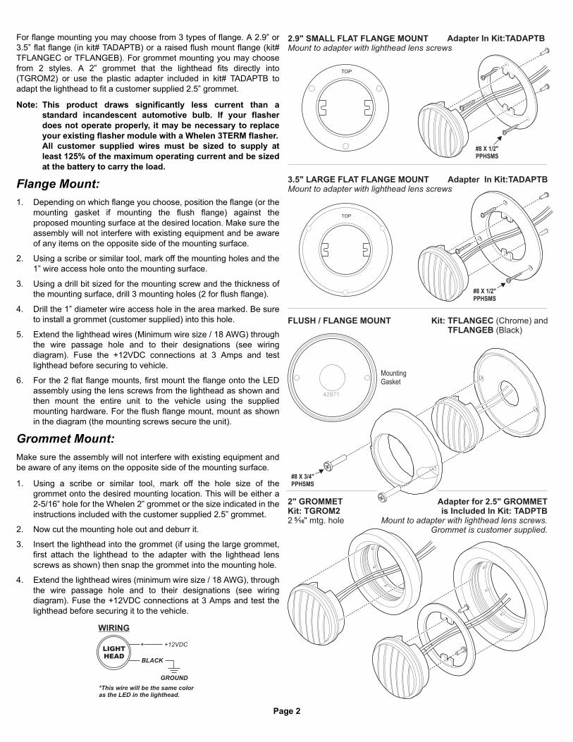
Page 2
TOP
2.9" SMALL FLAT FLANGE MOUNTMount to adapter with lighthead lens screws
Adapter In Kit:TADAPTB
Adapter for 2.5" GROMMETis Included In Kit: TADPTB
Mount to adapter with lighthead lens screws.Grommet is customer supplied.
3.5" LARGE FLAT FLANGE MOUNTMount to adapter with lighthead lens screws
Adapter In Kit:TADAPTB
FLUSH / FLANGE MOUNT Kit: TFLANGECTFLANGEB
(Chrome) and(Black)Kit:
TOP
516
MountingGasket
#8 X 1/2"
PPHSMS
#8 X 1/2"
PPHSMS
#8 X 3/4"
PPHSMS
42871
2" GROMMETKit: TGROM22 " mtg. hole
GROUND
+12VDC*
*This wire will be the same coloras the LED in the lighthead.
BLACK
WIRING
LIGHT
HEAD
For flange mounting you may choose from 3 types of flange. A 2.9” or3.5” flat flange (in kit# TADAPTB) or a raised flush mount flange (kit#TFLANGEC or TFLANGEB). For grommet mounting you may choosefrom 2 styles. A 2” grommet that the lighthead fits directly into(TGROM2) or use the plastic adapter included in kit# TADAPTB toadapt the lighthead to fit a customer supplied 2.5” grommet.
Note: This product draws significantly less current than astandard incandescent automotive bulb. If your flasherdoes not operate properly, it may be necessary to replaceyour existing flasher module with a Whelen 3TERM flasher.All customer supplied wires must be sized to supply atleast 125% of the maximum operating current and be sizedat the battery to carry the load.
Flange Mount:1. Depending on which flange you choose, position the flange (or the
mounting gasket if mounting the flush flange) against theproposed mounting surface at the desired location. Make sure theassembly will not interfere with existing equipment and be awareof any items on the opposite side of the mounting surface.
2. Using a scribe or similar tool, mark off the mounting holes and the1” wire access hole onto the mounting surface.
3. Using a drill bit sized for the mounting screw and the thickness ofthe mounting surface, drill 3 mounting holes (2 for flush flange).
4. Drill the 1” diameter wire access hole in the area marked. Be sureto install a grommet (customer supplied) into this hole.
5. Extend the lighthead wires (Minimum wire size / 18 AWG) throughthe wire passage hole and to their designations (see wiringdiagram). Fuse the +12VDC connections at 3 Amps and testlighthead before securing to vehicle.
6. For the 2 flat flange mounts, first mount the flange onto the LEDassembly using the lens screws from the lighthead as shown andthen mount the entire unit to the vehicle using the suppliedmounting hardware. For the flush flange mount, mount as shownin the diagram (the mounting screws secure the unit).
Grommet Mount:Make sure the assembly will not interfere with existing equipment andbe aware of any items on the opposite side of the mounting surface.
1. Using a scribe or similar tool, mark off the hole size of thegrommet onto the desired mounting location. This will be either a2-5/16” hole for the Whelen 2” grommet or the size indicated in theinstructions included with the customer supplied 2.5” grommet.
2. Now cut the mounting hole out and deburr it.
3. Insert the lighthead into the grommet (if using the large grommet,first attach the lighthead to the adapter with the lighthead lensscrews as shown) then snap the grommet into the mounting hole.
4. Extend the lighthead wires (minimum wire size / 18 AWG), throughthe wire passage hole and to their designations (see wiringdiagram). Fuse the +12VDC connections at 3 Amps and test thelighthead before securing it to the vehicle.
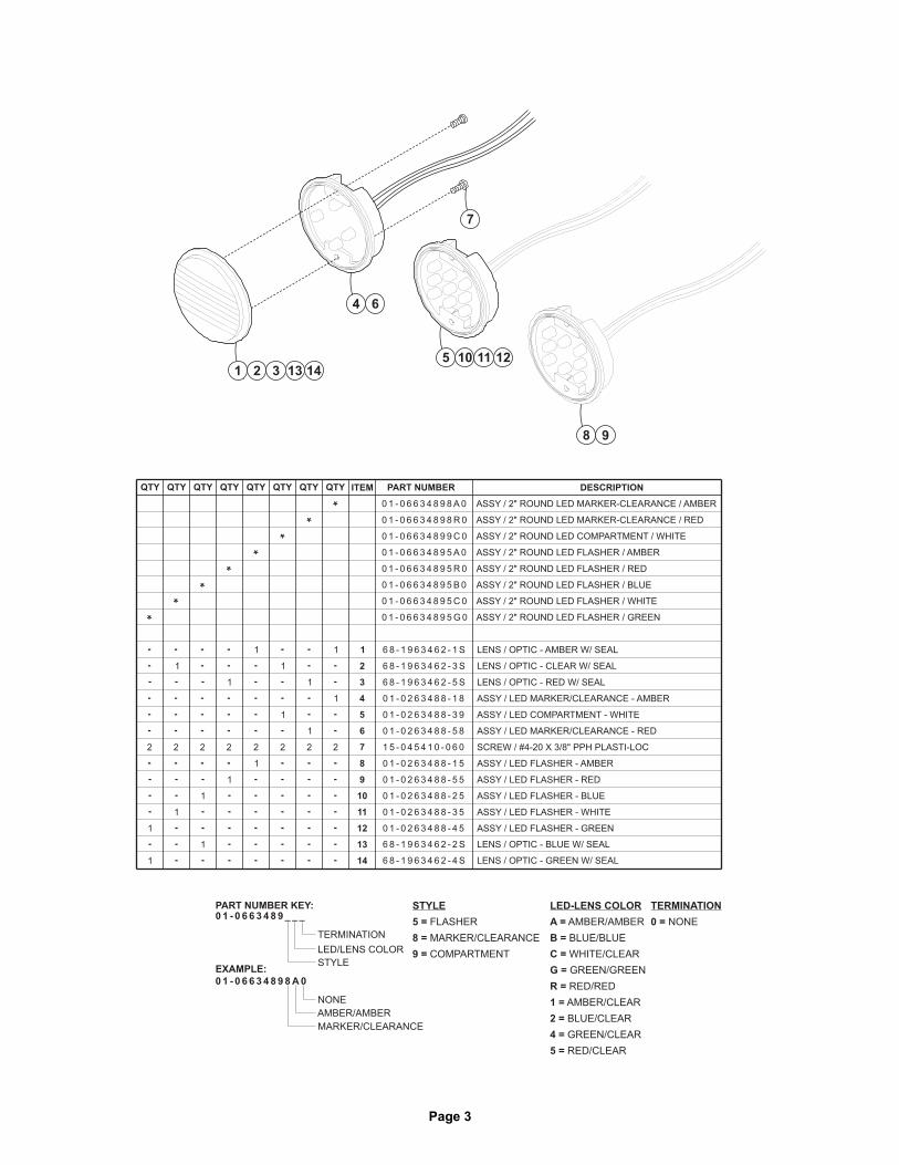
Page 3
5
4
7
1
6
2 3 13 14
8
121110
9
TERMINATION
NONE0 =
STYLE
PART NUMBER KEY:
EXAMPLE:
0 1 - 0 6 6 3 4 8 9 _ _ _
TERMINATION
LED/LENS COLOR
MARKER/CLEARANCE
AMBER/AMBER
NONE
0 1 - 0 6 6 3 4 8 9 8 A 0
STYLE
FLASHER
MARKER/CLEARANCE
COMPARTMENT
5 =
8 =
9 =
LED-LENS COLOR
AMBER/AMBER
BLUE/BLUE
WHITE/CLEAR
GREEN/GREEN
RED/RED
AMBER/CLEAR
BLUE/CLEAR
GREEN/CLEAR
RED/CLEAR
A =
B =
C =
G =
R =
1 =
2 =
4 =
5 =
QTYQTYQTYQTYQTYQTYQTYQTY ITEM PART NUMBER DESCRIPTION
0 1 - 0 6 6 3 4 8 9 8 A 0
0 1 - 0 6 6 3 4 8 9 8 R 0
ASSY 2" ROUND LED MARKER-CLEARANCE AMBER/ /
ASSY 2" ROUND LED MARKER-CLEARANCE RED/ /
1 1 6 8 - 1 9 6 3 4 6 2 - 1 S LENS OPTIC - AMBER W/ SEAL/
LENS OPTIC - RED W/ SEAL/
LENS OPTIC - BLUE W/ SEAL/
LENS OPTIC - GREEN W/ SEAL/
6 8 - 1 9 6 3 4 6 2 - 5 S
2
SCREW #4-20 X 3/8" PPH PLASTI-LOC/1 5 - 0 4 5 4 1 0 - 0 6 0
3
22
ASSY LED MARKER/CLEARANCE - AMBER/0 1 - 0 2 6 3 4 8 8 - 1 841
ASSY LED MARKER/CLEARANCE - RED/0 1 - 0 2 6 3 4 8 8 - 5 8
5
6
0 1 - 0 6 6 3 4 8 9 9 C 0 ASSY 2" ROUND LED COMPARTMENT WHITE/ /
7
11 LENS OPTIC - CLEAR W/ SEAL/6 8 - 1 9 6 3 4 6 2 - 3 S
6 8 - 1 9 6 3 4 6 2 - 2 S
6 8 - 1 9 6 3 4 6 2 - 4 S
1 ASSY LED COMPARTMENT - WHITE/0 1 - 0 2 6 3 4 8 8 - 3 9
1
2
1
0 1 - 0 6 6 3 4 8 9 5 A 0
0 1 - 0 6 6 3 4 8 9 5 R 0
0 1 - 0 6 6 3 4 8 9 5 B 0
0 1 - 0 6 6 3 4 8 9 5 C 0
0 1 - 0 6 6 3 4 8 9 5 G 0
ASSY 2" ROUND LED FLASHER AMBER/ /
ASSY 2" ROUND LED FLASHER RED/ /
ASSY 2" ROUND LED FLASHER/ / BLUE
ASSY 2" ROUND LED FLASHER/ / WHITE
ASSY 2" ROUND LED FLASHER/ / GREEN
1
1
2222 2
ASSY LED FLASHER - AMBER/
ASSY / LED FLASHER - RED
ASSY / LED FLASHER - BLUE
ASSY / LED FLASHER - WHITE
ASSY / LED FLASHER - GREEN
0 1 - 0 2 6 3 4 8 8 - 1 5
0 1 - 0 2 6 3 4 8 8 - 5 5
0 1 - 0 2 6 3 4 8 8 - 2 5
0 1 - 0 2 6 3 4 8 8 - 3 5
0 1 - 0 2 6 3 4 8 8 - 4 5
1
1
1
1
1
1
1 8
9
10
11
12
13
14

®
ENGINEERING COMPANY INC.
51 Winthrop RoadChester, Connecticut 06412-0684Phone: (860) 526-9504Fax: (860) 526-4078Sales Email:[email protected] Sales:[email protected] Service:[email protected]
www. .com900 Series Surface Mount LED Scenelight
For warranty information regarding this product, visit www.whelen.com/warranty©2010 Whelen Engineering Company Inc.Form No. 14411A (050311)
Mounting:
1. Using the mounting diagram shown, mark the locations for the mounting holes andthe wire passage hole. Drill 4 mounting holes with
sing a 1" drill bit .
2. Insert the round hole screw grommets (included) into the mounting holes. Using asmall rod (approx .062 dia.), press on the starting pin so that it is just below the faceof the grommet (about .050"). This will spread the grommet prongs and lock thegrommet in place. Do NOT press the starting pin out of the grommet! If the pin ispressed out, remove that grommet and install a new one.
a .250" drill bit. Drill and de-burrthe wire passage hole u
Safety FirstThis document provides all the necessary information to allow your Whelen product to be properly and safely installed. Before beginningthe installation and/or operation of your new product, the installation technician and operator must read this manual completely. Importantinformation is contained herein that could prevent serious injury or damage.
�
�
�
�
�
Proper installation of this product requires the installer to have agood understanding of automotive electronics, systems andprocedures.
If mounting this product requires drilling holes, the installer MUSTbe sure that no vehicle components or other vital parts could bedamaged by the drilling process. Check both sides of the mountingsurface before drilling begins. Also de-burr any holes and removeany metal shards or remnants.
For this product to operate at optimum efficiency, a good electricalconnection to chassis ground must be made. The recommendedprocedure requires the product ground wire to be connecteddirectly to the NEGATIVE (-) battery post.
If this product uses a remote device to activate or control thisproduct, make sure that this control is located in an area thatallows both the vehicle and the control to be operated safely in anydriving condition.
Do not attempt to activate or control this device in a hazardousdriving situation.
�
�
�
�
This product contains either strobe light(s), halogen light(s), high-intensity LEDs or a combination of these lights. Do not look directlyinto these lights. Momentary blindness and/or eye damage couldresult.
Use only soap and water to clean the outer lens. Use of otherchemicals could result in premature lens cracking (crazing) anddiscoloration. Lenses in this condition have significantly reducedeffectiveness and should be replaced immediately. Inspect andoperate this product regularly to confirm its proper operation andmounting condition. Do not use a pressure washer to clean thisproduct.
It is recommended that these instructions be stored in a safe placeand referred to when performing maintenance and/or reinstallationof this product.
FAILURE TO FOLLOW THESE SAFETY PRECAUTIONS ANDINSTRUCTIONS COULD RESULT IN DAMAGE TO THE PRODUCTOR VEHICLE AND/OR SERIOUS INJURY TO YOU AND YOURPASSENGERS!
Pos. -Pos. -Pos. -
1 WHITE2 N/C3 BLACK
orBLACK/WHITE
A
(rear)
B C
Wiring Diagram3-pos. Socket Conn.
Pos. -Pos. -Pos. -
A WHITEB Sealing PlugC BLACK
orBLACK/WHITE
Wiring Diagram3-pos. Pin Housing
3 2 1
3.625
2.625
MOUNTING DIMENSIONS
.250 Dia.Mounting Hole (4) Places
5.250
CL
CL
7.250
1" Dia. WirePassage Hole
4.Apply a soap and water solution to the face of the silicone wire exit seal.
5. Place the flange (if present) and the gasket onto the lighthead as shown. Refer tothe of both the gasket and the lighthead.
6. place the lighthead assembly ontothe mounting surface.
7. Hold the lighthead against the mounting surface and install the mounting screws.Make sure the screw tips are in the center of the grommet before tightening.
IMPORTANT! When placing the assembly onto themounting surface, it must NOT be moved or slid into its proper position Itmust be placed directly into its proper position on the mounting surface.
IMPORTANT! Before returning the vehicle to active service, visually confirmthe proper operation of this product, as well as all vehiclecomponents/equipment.
illustration for proper orientation
While holding all these components together,
3. Route the wires through the flange (if present) and gasket, Extend the wiresthrough the wire passage hole, make the appropriate connections and confirmproper operation of the light.
Screw
Round HoleScrew Grommet
Gasket(Orient with openingat bottom as shown)
Flange(optional)
900 SeriesScenelight
CAUTION! DO NOT LOOK DIRECTLY AT THESE LEDS WHILE THEY ARE ON.
MOMENTARY BLINDNESS AND/OR EYE DAMAGE COULD RESULT!
IMPORTANT WARNING!
WARNING! All customer supplied wires that connect to the positive (+)terminal of the battery must be sized to supply at least 125% of themaximum operating current and “at the battery” to carry thatload. DO NOT USE CIRCUIT BREAKERS WITH THIS PRODUCT!
FUSED
Wire Color (12V)
Wire Color (24V)
White
White
Black
Black/White
Function
Function
(+)VBAT (Fuse@10A)
(+)VBAT (Fuse@5A)
(-) Ground
(-) Ground

Page 1
Installation Guide:500 Series TIR6™
Super-LED® Lighthead
©2002 Whelen Engineering Company Inc.Form No.13733N (020111)
®
ENGINEERING COMPANY INC.51 Winthrop RoadChester, Connecticut 06412-0684Phone: (860) 526-9504Fax: (860) 526-4078Internet: www.whelen.comSales e-mail: [email protected] Sales e-mail: [email protected] Service e-mail: [email protected]
Aut
omot
ive:
Lig
hthe
ads
Safety First
This document provides all the necessary information to allow your Whelen product to be properly and safely installed.Before beginning the installation and/or operation of your new product, the installation technician and operator mustread this manual completely. Important information is contained herein that could prevent serious injury or damage.
• Proper installation of this product requires the installer to have a good understanding of automotive electronics, systems and procedures.
• If mounting this product requires drilling holes, the installer MUST be sure that no vehicle components or other vital parts could be damaged by the drilling process. Check both sides of the mounting surface before drilling begins. Also de-burr any holes and remove any metal shards or remnants. Install grommets into all wire passage holes.
• If this manual states that this product may be mounted with suction cups, magnets, tape or Velcro®, clean the mounting surface with a 50/50 mix of isopropyl alcohol and water and dry thoroughly.
• Do not install this product or route any wires in the deployment area of your air bag. Equipment mounted or located in the air bag deployment area will damage or reduce the effectiveness of the air bag, or become a projectile that could cause serious personal injury or death. Refer to your vehicle owner’s manual for the air bag deployment area. The User/Installer assumes full responsibility to determine proper mounting location, based on providing ultimate safety to all passengers inside the vehicle.
• For this product to operate at optimum efficiency, a good electrical connection to chassis ground must be made. The recommended procedure requires the product ground wire to be connected directly to the NEGATIVE (-) battery post.
• If this product uses a remote device to activate or control this product, make sure that this control is located in an area that allows both the vehicle and the control to be operated safely in any driving condition.
• Do not attempt to activate or control this device in a hazardous driving situation.
• This product contains either strobe light(s), halogen light(s), high-intensity LEDs or a combination of these lights. Do not stare directly into these lights. Momentary blindness and/or eye damage could result.
• Use only soap and water to clean the outer lens. Use of other chemicals could result in premature lens cracking (crazing) and discoloration. Lenses in this condition have significantly reduced effectiveness and should be replaced immediately. Inspect and operate this product regularly to confirm its proper operation and mounting condition. Do not use a pressure washer to clean this product.
• It is recommended that these instructions be stored in a safe place and referred to when performing maintenance and/or reinstallation of this product.
• FAILURE TO FOLLOW THESE SAFETY PRECAUTIONS AND INSTRUCTIONS COULD RESULT IN DAMAGE TO THE PRODUCT OR VEHICLE AND/OR SERIOUS INJURY TO YOU AND YOUR PASSENGERS!
For warranty information regarding this product, visit www.whelen.com/warranty
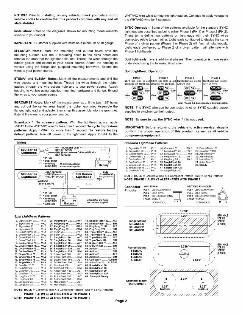
Page 2
PHASE 1
LEFT
RIGHT
side lights up and
with side.alternates
PHASE 2
RIGHT
LEFT
side lights up and
with side.alternates
PHASE 3
BOTH sides flash together
(ON-OFF-ON).
PHASE 4
BOTH sides flash together
(OFF-ON-OFF).
Note: Phases 3 & 4 are visually indistinguishable.
then
then
ON OFF
ONOFF
ON OFFthen
thenON OFF
ONOFF
ONOFF
then
then
ON ON
ON ON
OFFOFF
then
thenON ON
OFFOFF
OFFOFF
All switches and fusesare customer supplied
All switches and fusesare customer supplied
Cut & cap GRY wireGRY (Sync)BLK (Ground)
RED (+12VDC)
GRY (Sync)BLK (Ground)
RED (+12VDC)
WHT/VIO (Scan-Lock™)
WHT/VIO(Scan-Lock™)
(+)Battery
(-)
(-)Battery
(+)
500 Series
Lighthead
= 3A Fuse
= Momentary
Switch (N.O.)
= SP/ST Switch
= 3A Fuse
= Momentary
Switch (N.O.)
= Butt Splice
= SP/ST Switch
GRY
BLKWHT/VIO
RED
500 Series
Lighthead
500 Series
Lighthead
Wiring
1.74"
MTG. HOLEFOR #10SCREW(2 PLCS.)
MTG. HOLEFOR #10SCREW(2 PLCS.)
CUT-OUT
5.20"
5.750"
5.750"
2.875"
1” DIA.Wire Hole
4.25"
1.25”Radius
1.25”Radius
Flange Mount5FLANGEC5FLANGEP5FLANGEB
Flange Mount5TSMAC5TSMAB5LSMAB5LSMAC
Grommet(5GROMMET)
Mount
A
CB
DEUTSCH 3 POS SOCKET
POS A
POS B
POS C
LOOSE -
- LED COLOR (+VBAT)
- GREY (SYNC)
- BLK or BLK/WHT (GND)
WHT/VIO
(SCAN-LOCK™)LOOSE -123
AMP 3 POS PIN
POS 1 -
POS 2 -
POS 3 -
LOOSE -
LED COLOR (+VBAT)
GREY (SYNC)
BLK or BLK/WHT (GND)
WHT/VIO
(SCAN-LOCK™)LOOSE -
ConnectorPinouts
NOTICE! Prior to installing on any vehicle, check your state motorvehicle codes to confirm that this product complies with any and allstate statutes.
Installation: Refer to the diagrams shown for mounting measurementsspecific to your model.
IMPORTANT: Customer supplied wire must be a minimum of 18 gauge.
5FLANGE* Notes: Mark the mounting and cut-out holes onto themounting surface. Drill the 2 mounting holes to the sizes noted andremove the area that the lighthead fits into. Thread the wires through therubber gasket and extend to your power source. Attach the housing tovehicle using the flange and supplied mounting hardware. Extend thewires to your power source.
5TSMA* and 5LSMA* Notes: Mark off the measurements and drill thewire access and mounting holes. Thread the wires through the rubbergasket, through the wire access hole and to your power source. Attachhousing to vehicle using supplied mounting hardware and flange. Extendthe wires to your power source.
5GROMMET Notes: Mark off the measurements, drill the two 1.25” holesand cut out the center area. Install the rubber grommet. Assemble theflange, lighthead and adapter then snap this assembly into the grommet.Extend the wires to your power source.
Scan-Lock™: To advance pattern: With the lighthead active, apply+VBAT to the WHT/VIO wire for less than 1 second. To cycle to previouspatterns: Apply +VBAT for more than 1 second. To restore factorydefault pattern: Turn off power to the lighthead. Apply +VBAT to the
Standard Lighthead Patterns
Split Lighthead Patterns
NOTE: BOLD = California Title XIII Compliant Pattern Italic = SYNC PatternsNOTE: PHASE 1 ALWAYS ALTERNATES WITH PHASE 2
NOTE: PHASE 1 ALWAYS ALTERNATES WITH PHASE 2PHASE 3 ALWAYS ALTERNATES WITH PHASE 4
1. SignalAlert™ 75 ...... PH.12. SignalAlert 75 .......... PH.23. SignalAlert 75 .......... PH.34. SignalAlert 75 .......... PH.45. CometFlash® 75 ..... PH.16. CometFlash 75 ........ PH.27. CometFlash 75 ........ PH.38. CometFlash 75 ........ PH.49. DoubleFlash 75...... PH.1
10. DoubleFlash 75...... PH.211. DoubleFlash 75...... PH.312. DoubleFlash 75...... PH.413. SingleFlash 75 ....... PH.114. SingleFlash 75 ....... PH.215. SingleFlash 75 ....... PH.316. SingleFlash 75 ....... PH.417. ComAlert™ 75......... PH.118. ComAlert 75 ............ PH.219. ComAlert 75 ............ PH.320. ComAlert 75 ............ PH.421. LongBurst™ 75 ....... PH.122. LongBurst 75 ........... PH.223. LongBurst 75 ........... PH.324. LongBurst 75 ........... PH.4
25. PingPong™ 75 ....... PH.126. PingPong 75 ........... PH.227. PingPong 75 ........... PH.328. PingPong 75 ........... PH.429. SSNF 75 .................. PH.130. SSNF 75 .................. PH.231. SingleFlash 60......... ALT32. SingleFlash 60..........SIM33. SingleFlash 90......... ALT34. SingleFlash 90..........SIM35. SingleFlash 120....... ALT36. SingleFlash 120........SIM37. SingleFlash 300 .........ALT38. SingleFlash 300 .........SIM39. DoubleFlash 150........ALT40. DoubleFlash 150........SIM41. ComAlert 150.............ALT42. ComAlert 150.............SIM43. ActionFlash™50 ........ALT44. ActionFlash 50 ...........SIM45. ActionFlash 150 .........ALT46. ActionFlash 150 .........SIM47. ModuFlash™ .............ALT48. ModuFlash .................SIM
49. DoubleFlash 120...... ALT50. DoubleFlash 120...... SIM51. PingPong™ 120....... ALT52. PingPong 120 .......... SIM53. TripleFlash™ 75....... ALT54. TripleFlash 75 .......... SIM55. TripleFlash 120 ........ALT56. TripleFlash 120 ........ SIM57. SigAlert Cal.™ ......... ALT58. SigAlert Cal.............. SIM59. Action 1 .................... ALT60. Action 1 .................... SIM61. Action 2 .................... ALT62. Action 2 .................... SIM63. CalScan™ .........ALT/SIM64. ActionScan™ ..... ALT/SIM65. SteadyFlash 6066. SteadyFlash 7567. SteadyFlash 9068. SteadyFlash 12069. Steady & Steady
1. SignalAlert™ 75....... PH.12. SignalAlert 75 .......... PH.23. CometFlash® 75...... PH.14. CometFlash 75 ........ PH.25. DoubleFlash 75 ....... PH.16. DoubleFlash 75 ....... PH.27. SingleFlash 75......... PH.18. SingleFlash 75......... PH.29. ComAlert™ 75 ......... PH.1
10. ComAlert 75 .............PH.211. LongBurst™ 75 ........PH.112. LongBurst 75............PH.213. PingPong™ 75.........PH.114. PingPong 75 ............PH.215. SingleFlash 6016. SingleFlash 9017. SingleFlash 12018. SingleFlash 300
19. DoubleFlash 15020. ComAlert™15021. ActionFlash™122. ActionFlash223. ModuFlash™24. ActionScan™25. Steady
WHT/VIO wire while turning the lighthead on. Continue to apply voltage tothe WHT/VIO wire for 5 seconds.
SYNC Operation: Some of the patterns available for the standard SYNClighthead are described as being either Phase 1 (PH.1) or Phase 2 (PH.2).These terms define how patterns on lightheads with their SYNC wiresconnected relate to each other. Lightheads configured to display the samePhase of a given pattern (Phase 1 or Phase 2) will flash simultaneously.Lightheads configured to Phase 2 of a given pattern will alternate withPhase 1 lightheads.
Split lightheads have 2 additional phases. Their operation is more easilyunderstood using the following illustration:
Split Lighthead Operation
NOTE: The SYNC wire can be connected to other SYNC-capable powersupplies to synchronize their output.
NOTE: Be sure to cap the SYNC wire if it is not used.
IMPORTANT! Before returning the vehicle to active service, visuallyconfirm the proper operation of this product, as well as all vehiclecomponents/equipment.
NOTE: BOLD = California Title XIII Compliant Pattern Italic = SYNC Patterns
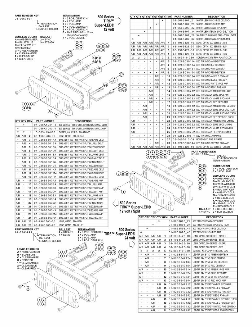
Page 3
6 8 - 1 9 6 3 5 8 3 - 2 0 LENS, OPTIC LED - BLUE
LENS/LED COLOR
0 1 - 0 6 6 3 5 0 7 _ _ _
BALLASTTERMINATION
PART NUMBER KEY:
LENS/LED COLORA =B =C =R =G1 =2 =5 =
AMBER/AMBERBLUE/BLUECLEAR/WHITERED/RED
= GREEN/GREENCLEAR/AMBERCLEAR/BLUECLEAR/RED
LENS/LED COLOR
0 1 - 0 6 6 3 8 9 8 _ _ _
BALLASTTERMINATION
PART NUMBER KEY:
LENS/LED COLORA =B =C =R =1 =2 =5 =
AMBER/AMBERBLUE/BLUECLEAR/WHITERED/REDCLEAR/AMBERCLEAR/BLUECLEAR/RED
TERMINATION1 =2 =3 =4 =
3 POS. DEUTSCH2 POS. AMP3 POS. AMP2 POS. DEUTSCH
BALLAST2 =4 =
STEADYSYNC
500 SeriesTIR6™
Super-LED12 volt
®
500 SeriesTIR6™ Super-LED
24 volt®
TERMINATION1 =2 =3 =4 =5 =6 =
3 POS. DEUTSCH2 POS. AMP3 POS. AMP2 POS. DEUTSCH4 POS. DEUTSCHAMP PINS 3 Pos. Conn.shipped seperately
7 = 2 POS. UMMNLBALLASTSYNCSTEADY
2 =3 =
2
3
ITEM PART NUMBER DESCRIPTION
11
12
13
14
15
16
17
18
19
20
4
5
6
7
8
9
10
1
QTY QTY QTY QTYQTYQTY
21
22
23
24
25
26
27
28
29
A/R LED TIR STEADY RED 2 POS AMP0 1 - 0 2 6 B 0 3 0 2 5 2
0 1 - 0 6 6 3 5 0 7 _ 3 7
0 1 - 0 6 6 3 5 0 7 _ 2 6
0 1 - 0 6 6 3 5 0 7 _ 3 4
0 1 - 0 6 6 3 5 0 7 _ 3 2
0 1 - 0 6 6 3 5 0 7 _ 2 3
0 1 - 0 6 6 3 5 0 7 _ 2 1
2 2
A/R A/R
A/RA/R
A/R
A/RA/R
A/R
2 2 2 1 5 - 0 6 5 4 1 9 - 0 8 02
A/R
A/R
A/R
A/R
A/R
A/R
A/R
A/R
A/R A/R
A/R A/R
A/R
A/R A/R
A/R
6 8 - 1 9 6 3 4 2 8 - 1 0
6 8 - 1 9 6 3 4 2 8 - 2 0
6 8 - 1 9 6 3 4 2 8 - 3 0
6 8 - 1 9 6 3 4 2 8 - 5 0
A/R
A/R
A/R
A/R
A/R
A/R
A/R
A/R
A/R
A/R
A/R
0 1 - 0 2 6 B 0 3 0 3 2 4
0 1 - 0 2 6 B 0 3 0 1 5 4
0 1 - 0 2 6 B 0 3 0 3 1 4
0 1 - 0 2 6 B 0 3 0 11 4
0 1 - 0 2 6 B 0 3 0 1 2 4
0 1 - 0 2 6 B 0 3 0 1 3 4
0 1 - 0 2 6 B 0 3 0 2 3 2
0 1 - 0 2 6 B 0 3 0 2 1 2
0 1 - 0 2 6 B 0 3 0 3 3 4
0 1 - 0 2 6 B 0 3 0 3 5 4
0 1 - 0 2 6 B 0 3 0 2 2 2
500 TIR LED SYNC-3 POS DEUTSCH
500 TIR LED SYNC-AMP PINS / CONN. LOOSE
500 TIR LED STEADY-2 POS DEUTSCH
500 TIR LED STEADY-2 POS AMP
LED TIR STEADY WHITE 2 POS AMP
LED TIR STEADY BLUE 2 POS AMP
LED TIR STEADY AMBER 2 POS AMP
LED TIR SYNC AMBER 3 POS AMP
500 TIR LED STEADY-2 POS MUMNL
500 TIR LED SYNC-3 POS AMP
LED TIR SYNC RED 3 POS AMP
LED TIR SYNC WHITE 3 POS AMP
LED TIR SYNC BLUE 3 POS AMP
3 9 - 0 4 0 3 0 1 3 - 0 4
0 1 - 0 2 6 B 0 3 0 6 _ 4
A/R
A/R
A/R
A/R
1
1
A/RA/R
0 1 - 0 2 6 B 0 3 0 3 4 4A/R
A/R
A/R
A/R
A/R
0 1 - 0 2 6 B 0 3 0 7 1 2
0 1 - 0 2 6 B 0 3 0 4 5 2
0 1 - 0 2 6 B 0 3 0 4 3 2
0 1 - 0 2 6 B 0 3 0 4 2 2
0 1 - 0 2 6 B 0 3 0 4 1 2
0 1 - 0 2 6 B 0 3 0 7 5 2
0 1 - 0 2 6 B 0 3 0 7 3 2
0 1 - 0 2 6 B 0 3 0 7 2 2
A/RA/R A/R A/R 6 8 - 1 9 6 3 4 2 8 - 4 0
LED TIR SYNC GREEN 3 POS AMP
LED TIR STEADY RED 2 POS UMMNL
LED TIR STEADY WHITE 2 POS UMMNL
LED TIR STEADY AMBER 2 POS UMMNL
LED TIR STEADY BLUE 2 POS UMMNL
LED TIR STEADY RED 2 POS DEUTSCH
LED TIR STEADY WHITE 2 POS DEUTSCH
LED TIR STEADY BLUE 2 POS DEUTSCH
LED TIR STEADY AMBER 2 POS DEUTSCH
HOUSING 3 POS. PIN AMP/
LED TIR SYNC / AMP PINS
LENS GREEN, OPTIC, 500 SERIES -
SCREW #6 X 1/2" PPH PLASTIC-LOC/
LENS OPTIC - AMB, , 500 SERIES
LENS BLU, OPTIC, 500 SERIES -
LENS CLR, OPTIC, 500 SERIES -
LENS RED, OPTIC, 500 SERIES -
LED TIR SYNC RED DEUTSCH
LED TIR SYNC WHT DEUTSCH
LED TIR SYNC BLU DEUTSCH
LED TIR SYNC AMB DEUTSCH
2
3
ITEM PART NUMBER DESCRIPTIONQTY QTY QTY QTY
11
12
13
14
15
16
17
18
19
20
4
5
6
7
8
9
10
1
21
500 TIR 24V SYNC-3 POS AMP
500 TIR 24V SYNC-3 POS DEUTSCH
500 TIR 24V STEADY-2 POS DEUTSCH
LED TIR 24V SYNC RED 3 POS AMP
LED TIR 24V SYNC WHITE 3 POS AMP
LED TIR 24V SYNC BLUE 3 POS AMP
LED TIR 24V SYNC AMBER 3 POS AMP
LED TIR 24V SYNC RED DEUTSCH
LED TIR 24V SYNC WHITE DEUTSCH
LED TIR 24V SYNC BLUE DEUTSCH
LED TIR 24V SYNC AMBER DEUTSCH
500 TIR 24V STEADY-2 POS AMP
LENS AMBER, OPTIC, 500 SERIES -
LENS BLUE, OPTIC, 500 SERIES -
LENS CLEAR, OPTIC, 500 SERIES -
LENS RED, OPTIC, 500 SERIES -
SCREW / #6 X 1/2" PPH PLASTIC-LOC
A/R
A/R
A/R
A/R
A/R
A/R
A/R
A/RA/R
A/R
A/R
A/R
A/R
A/R
A/R
A/R
A/R
A/R
A/R
A/R
2
A/R
A/R
A/R
2
A/R
2 2
0 1 - 0 6 6 3 8 9 8 _ 4 3
0 1 - 0 6 6 3 8 9 8 _ 4 1
0 1 - 0 6 6 3 8 9 8 _ 2 4
0 1 - 0 6 6 3 8 9 8 _ 2 2
6 8 - 1 9 6 3 4 2 8 - 1 0
6 8 - 1 9 6 3 4 2 8 - 2 0
6 8 - 1 9 6 3 4 2 8 - 3 0
6 8 - 1 9 6 3 4 2 8 - 5 0
0 1 - 0 2 6 B 6 4 7 1 5 4
0 1 - 0 2 6 B 6 4 7 3 1 4
0 1 - 0 2 6 B 6 4 7 3 2 4
0 1 - 0 2 6 B 6 4 7 3 3 4
0 1 - 0 2 6 B 6 4 7 3 5 4
0 1 - 0 2 6 B 6 4 7 11 4
0 1 - 0 2 6 B 6 4 7 1 2 4
0 1 - 0 2 6 B 6 4 7 1 3 4
1 5 - 0 6 5 4 1 9 - 0 8 0
LED TIR 24V STEADY RED 2 POS DEUTSCH
LED TIR 24V STEADY WHITE 2 POS DEUTSCH
LED TIR 24V STEADY BLUE 2 POS DEUTSCH
LED TIR 24V STEADY AMBER 2 POS DEUTSCH
LED TIR 24V STEADY RED 2 POS AMP
LED TIR 24V STEADY WHITE 2 POS AMP
LED TIR 24V STEADY BLUE 2 POS AMP
LED TIR 24V STEADY AMBER 2 POS AMP
A/R
A/R
A/R
A/R
A/R
A/R
A/R
A/R
0 1 - 0 2 6 B 6 4 7 4 5 2
0 1 - 0 2 6 B 6 4 7 4 3 2
0 1 - 0 2 6 B 6 4 7 4 2 2
0 1 - 0 2 6 B 6 4 7 4 1 2
0 1 - 0 2 6 B 6 4 7 2 5 2
0 1 - 0 2 6 B 6 4 7 2 3 2
0 1 - 0 2 6 B 6 4 7 2 1 2
0 1 - 0 2 6 B 6 4 7 2 2 2
BALLAST
TERMINATION
PART NUMBER KEY:0 1 - 0 6 6 A 1 0 4 _ _ _
LED/LENS COLOR
TERMINATION3 POS. DEUTSCH3 POS. AMP
1 =3 =
LED/LENS COLORA =B =C =D =E =F =G =J =K =M =R52 =
AMB-AMB-CLRBLU-BLU-CLRWHT-WHT-CLRRED-WHT-CLRBLU-WHT-CLRAMB-WHT-CLRGRN-GRN-CLRRED-BLU-CLRRED-AMB-CLRAMB-BLU-CLR
= RED-RED-CLR= RED-RED-RED
BLU-BLU/BLUBALLAST4 = SYNC
252
14 15
22
16 17
23
18 19
24
20 21
1
500 SeriesTIR6™ Super-LED12 volt / Split
®
10
14
1
11
15
2
12
16
3
13
17
4
3 4 5 6 7 8
9 10
5
1211 13
5
21 3
610
14
711
15
812
16
2813
17
19
23
20
24
21
25
18
22
27
26
9
6 7
8 9
18 19
20 21
4 29
SUB ASSY, 500 TIR SYNC SPLIT WHT/WHT AMP
SUB ASSY, 500 TIR SYNC SPLIT BLU/BLU AMP
SUB ASSY, 500 TIR SYNC SPLIT AMB/AMB AMP
SUB ASSY, 500 TIR SYNC SPLIT RED/RED DEUT
SUB ASSY, 500 TIR SYNC SPLIT AMB/BLU DEUT
SUB ASSY, 500 TIR SYNC SPLIT RED/AMB DEUT
SUB ASSY, 500 TIR SYNC SPLIT RED/BLU DEUT
SUB ASSY, 500 TIR SYNC SPLIT GRN/GRN DEUT
SUB ASSY, 500 TIR SYNC SPLIT AMB/WHT DEUT
SUB ASSY, 500 TIR SYNC SPLIT BLU/WHT DEUT
SUB ASSY, 500 TIR SYNC SPLIT RED/WHT DEUT
SUB ASSY, 500 TIR SYNC SPLIT WHT/WHT DEUT
SUB ASSY, 500 TIR SYNC SPLIT BLU/BLU DEUT
SUB ASSY, 500 TIR SYNC SPLIT AMB/AMB DEUT
LENS, OPTIC LED - CLEAR
SCREW, 6 X 1/2 PPH PLASTI-LOC
A/R
A/R
2
A/R
2
A/R
A/R
A/R
A/R
A/R
A/R
A/R
A/R
A/R
A/R
A/R
A/R
0 1 - 0 2 6 B 6 6 6 1 E 4
0 1 - 0 2 6 B 6 6 6 1 D 4
0 1 - 0 2 6 B 6 6 6 1 C 4
0 1 - 0 2 6 B 6 6 6 1 B 4
0 1 - 0 2 6 B 6 6 6 1 A 4
6 8 - 1 9 6 3 5 8 3 - 3 0
1 5 - 0 6 5 4 1 9 - 0 8 0
0 1 - 0 2 6 B 6 6 6 3 B 4
0 1 - 0 2 6 B 6 6 6 3 A 4
0 1 - 0 2 6 B 6 6 6 1 R 4
0 1 - 0 2 6 B 6 6 6 1 M 4
0 1 - 0 2 6 B 6 6 6 1 K 4
0 1 - 0 2 6 B 6 6 6 1 J 4
0 1 - 0 2 6 B 6 6 6 1 G 4
0 1 - 0 2 6 B 6 6 6 1 F 4
LENS, OPTIC LED - RED
SUB ASSY, 500 TIR SYNC SPLIT RED/RED AMP
SUB ASSY, 500 TIR SYNC SPLIT AMB/BLU AMP
SUB ASSY, 500 TIR SYNC SPLIT RED/AMB AMP
SUB ASSY, 500 TIR SYNC SPLIT RED/BLU AMP
SUB ASSY, 500 TIR SYNC SPLIT GRN/GRN AMP
SUB ASSY, 500 TIR SYNC SPLIT AMB/WHT AMP
SUB ASSY, 500 TIR SYNC SPLIT BLU/WHT AMP
SUB ASSY, 500 TIR SYNC SPLIT RED/WHT AMP
A/R
A/R
A/R
A/R
A/R
A/R
A/R
A/R
A/R
A/R A/R
0 1 - 0 2 6 B 6 6 6 3 R 4
0 1 - 0 2 6 B 6 6 6 3 M 4
0 1 - 0 2 6 B 6 6 6 3 K 4
0 1 - 0 2 6 B 6 6 6 3 J 4
0 1 - 0 2 6 B 6 6 6 3 G 4
0 1 - 0 2 6 B 6 6 6 3 F 4
0 1 - 0 2 6 B 6 6 6 3 E 4
0 1 - 0 2 6 B 6 6 6 3 D 4
0 1 - 0 2 6 B 6 6 6 3 C 4
6 8 - 1 9 6 3 5 8 3 - 5 0
26
2
3
ITEM PART NUMBER DESCRIPTIONQTY QTY
11
12
13
14
15
16
17
18
19
20
4
5
6
7
8
9
10
1
21
22
23
24
25
500 SERIES TIR SPLIT LIGHTHEAD SYNC AMP/ / /
500 SERIES TIR SPLIT LIGHTHEAD SYNC DEUT/ / /0 1 - 0 6 6 A 1 0 4 1 _ 4
0 1 - 0 6 6 A 1 0 4 3 _ 4
26A/R A/R
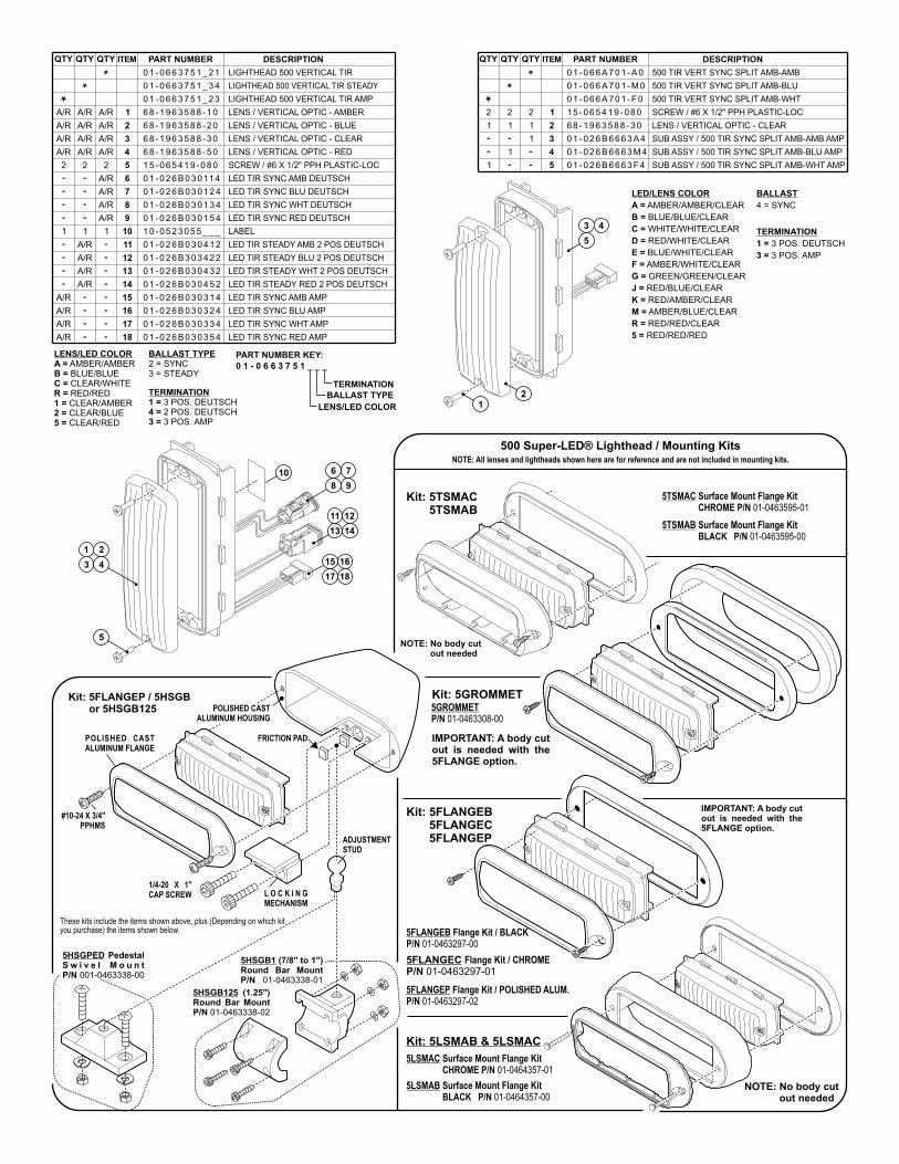
Page 4
5TSMAC Surface Mount Flange KitCHROME P/N 01-0463595-015TSMAC
5LSMAC Surface Mount Flange KitCHROME P/N 01-0464357-015LSMAC
01-0463297-015FLANGECP/N
Flange Kit / CHROME
#10-24 X 3/4"PPHMS
POLISHED CASTALUMINUM FLANGE
ADJUSTMENTSTUD
L O C K I N GMECHANISM
1/4-20 X 1"CAP SCREW
Kit: 5GROMMET5GROMMETP/N 01-0463308-00
Kit: 5FLANGEB5FLANGEC5FLANGEP
Kit:Kit:
Kit: 5TSMAC5TSMABKit:
Kit: 5LSMAB & 5LSMAC
5HSGB1 (7/8" to 1")Round Bar MountP/N 01-0463338-01
01-0463338-02
5HSGB125 (1.25")Round Bar MountP/N
FRICTION PAD
Kit: 5FLANGEP / 5HSGBor 5HSGB125Kit:
These kits (Depending on which kityou purchase)
include the items shown above, plusthe items shown below.
NOTE: All lenses and lightheads shown here are for reference and are not included in mounting kits.
IMPORTANT: A body cutout is needed with the5FLANGE option.
NOTE: No body cutout neededNOTE:
NOTE: No body cutout neededNOTE:
5TSMAB Surface Mount Flange KitBLACK P/N 01-0463595-005TSMAB
5LSMAB Surface Mount Flange KitBLACK P/N 01-0464357-005LSMAB
500 Super-LED® Lighthead / Mounting Kits
BALLAST
4 = SYNC
TERMINATION
1 =
3 =
3 POS. DEUTSCH
3 POS. AMP
LED/LENS COLOR
A =
B =
C =
D =
E =
F =
G =
J =
K =
M =
R =
5 =
AMBER/AMBER/CLEAR
BLUE/BLUE/CLEAR
WHITE/WHITE/CLEAR
RED/WHITE/CLEAR
BLUE/WHITE/CLEAR
AMBER/WHITE/CLEAR
GREEN/GREEN/CLEAR
RED/BLUE/CLEAR
RED/AMBER/CLEAR
AMBER/BLUE/CLEAR
RED/RED/CLEAR
RED/RED/RED
TERMINATION
BALLAST TYPE
LENS/LED COLOR
PART NUMBER KEY:
0 1 - 0 6 6 3 7 5 1 _ _ _
LENS/LED COLORA =B =C =R =1 =2 =5 =
AMBER/AMBERBLUE/BLUECLEAR/WHITERED/REDCLEAR/AMBERCLEAR/BLUECLEAR/RED
2 = SYNC3 = STEADY
BALLAST TYPE
3 POS. DEUTSCH2 POS. DEUTSCH3 POS. AMP
TERMINATION1 =4 =3 =
LIGHTHEAD 500 VERTICAL TIR AMP
LIGHTHEAD 500 VERTICAL TIR STEADY
LED TIR STEADY AMB 2 POS DEUTSCH
LED TIR STEADY BLU 2 POS DEUTSCH
LED TIR STEADY WHT 2 POS DEUTSCH
LED TIR STEADY RED 2 POS DEUTSCH
LIGHTHEAD 500 VERTICAL TIR
LED TIR SYNC RED DEUTSCH
LED TIR SYNC WHT DEUTSCH
LED TIR SYNC BLU DEUTSCH
LED TIR SYNC AMB DEUTSCH
LENS VERTICAL OPTIC - AMBER/
LENS VERTICAL OPTIC - BLUE/
LENS VERTICAL OPTIC - CLEAR/
LENS VERTICAL OPTIC - RED/
SCREW / #6 X 1/2" PPH PLASTIC-LOC
A/R A/R A/R
2
A/R
A/R
A/R
A/R
A/R
A/R
2
A/R
A/R
A/R
2
1 1 1
A/R
A/R
A/R
A/R
A/R
A/R
A/R
A/R
0 1 - 0 6 6 3 7 5 1 _ 2 3
0 1 - 0 6 6 3 7 5 1 _ 3 4
0 1 - 0 6 6 3 7 5 1 _ 2 1
6 8 - 1 9 6 3 5 8 8 - 1 0
6 8 - 1 9 6 3 5 8 8 - 2 0
6 8 - 1 9 6 3 5 8 8 - 3 0
6 8 - 1 9 6 3 5 8 8 - 5 0
1 5 - 0 6 5 4 1 9 - 0 8 0
0 1 - 0 2 6 B 0 3 0 4 3 2
0 1 - 0 2 6 B 0 3 0 4 5 2
0 1 - 0 2 6 B 3 0 3 4 2 2
0 1 - 0 2 6 B 0 3 0 4 1 2
1 0 - 0 5 2 3 0 5 5 _ _ _
0 1 - 0 2 6 B 0 3 0 1 5 4
0 1 - 0 2 6 B 0 3 0 11 4
0 1 - 0 2 6 B 0 3 0 1 2 4
0 1 - 0 2 6 B 0 3 0 1 3 4
LABEL
LED TIR SYNC RED AMP
LED TIR SYNC WHT AMP
LED TIR SYNC BLU AMP
LED TIR SYNC AMB AMP
A/R
A/R
A/R
A/R
0 1 - 0 2 6 B 0 3 0 3 1 4
0 1 - 0 2 6 B 0 3 0 3 5 4
0 1 - 0 2 6 B 0 3 0 3 2 4
0 1 - 0 2 6 B 0 3 0 3 3 4
2
3
ITEM PART NUMBER DESCRIPTIONQTY QTY QTY
11
12
13
14
15
16
17
18
4
5
6
7
8
9
10
1
500 TIR VERT SYNC SPLIT AMB-WHT
500 TIR VERT SYNC SPLIT AMB-BLU
SUB ASSY / 500 TIR SYNC SPLIT AMB-WHT AMP
SUB ASSY 500 TIR SYNC SPLIT AMB BLU AMP/ -
SUB ASSY 500 TIR SYNC SPLIT AMB AMB AMP/ -
500 TIR VERT SYNC SPLIT AMB-AMB
LENS VERTICAL OPTIC - CLEAR/
SCREW #6 X 1/2" PPH PLASTIC-LOC/2 2 2
1 1
1
1
1
1
01 -066A701 -F 0
01 -066A701 -M0
0 1 - 0 2 6 B 6 6 6 3 A 4
0 1 - 0 2 6 B 6 6 6 3 M 4
0 1 - 0 2 6 B 6 6 6 3 F 4
01 -066A701 -A0
6 8 - 1 9 6 3 5 8 8 - 3 0
1 5 - 0 6 5 4 1 9 - 0 8 0
ITEM PART NUMBER DESCRIPTIONQTY QTY QTY
2
3
4
5
1
5
2
3 4
10 76
8 9
12
16
14
18
11
15
13
17
5FLANGEB Flange Kit / BLACKP/N 01-0463297-00
01-0463297-025FLANGEP Flange Kit / POLISHED ALUM.P/N
IMPORTANT: A body cutout is needed with the5FLANGE option.
5HSGPED PedestalS w i v e l M o u n tP/N 001-0463338-00
POLISHED CASTALUMINUM HOUSING
1
12
3 4
5

Page 1
Installation GuideFreedom™ NFPA Lightbar
©2003 Whelen Engineering Company Inc.Form No.13762K (052410)
®
ENGINEERING COMPANY INC.51 Winthrop RoadChester, Connecticut 06412-0684Phone: (860) 526-9504Fax: (860) 526-4078Internet: www.whelen.comSales e-mail: [email protected] Sales e-mail: [email protected] Service e-mail: [email protected]
Aut
omot
ive:
Lig
htba
rs
Safety FirstThis document provides all the necessary information to allow your Whelen product to be properly and safely installed.Before beginning the installation and/or operation of your new product, the installation technician and operator mustread this manual completely. Important information is contained herein that could prevent serious injury or damage.
• Proper installation of this product requires the installer to have a good understanding of automotive electronics, systems and procedures.
• If mounting this product requires drilling holes, the installer MUST be sure that no vehicle components or other vital parts could be damaged by the drilling process. Check both sides of the mounting surface before drilling begins. Also de-burr any holes and remove any metal shards or remnants. Install grommets into all wire passage holes.
• If this manual states that this product may be mounted with suction cups, magnets, tape or Velcro®, clean the mounting surface with a 50/50 mix of isopropyl alcohol and water and dry thoroughly.
• Do not install this product or route any wires in the deployment area of your air bag. Equipment mounted or located in the air bag deployment area will damage or reduce the effectiveness of the air bag, or become a projectile that could cause serious personal injury or death. Refer to your vehicle owner’s manual for the air bag deployment area. The User/Installer assumes full responsibility to determine proper mounting location, based on providing ultimate safety to all passengers inside the vehicle.
• For this product to operate at optimum efficiency, a good electrical connection to chassis ground must be made. The recommended procedure requires the product ground wire to be connected directly to the NEGATIVE (-) battery post.
• If this product uses a remote device to activate or control this product, make sure that this control is located in an area that allows both the vehicle and the control to be operated safely in any driving condition.
• Do not attempt to activate or control this device in a hazardous driving situation.
• This product contains either strobe light(s), halogen light(s), high-intensity LEDs or a combination of these lights. Do not stare directly into these lights. Momentary blindness and/or eye damage could result.
• Use only soap and water to clean the outer lens. Use of other chemicals could result in premature lens cracking (crazing) and discoloration. Lenses in this condition have significantly reduced effectiveness and should be replaced immediately. Inspect and operate this product regularly to confirm its proper operation and mounting condition. Do not use a pressure washer to clean this product.
• It is recommended that these instructions be stored in a safe place and referred to when performing maintenance and/or reinstallation of this product.
• FAILURE TO FOLLOW THESE SAFETY PRECAUTIONS AND INSTRUCTIONS COULD RESULT IN DAMAGE TO THE PRODUCT OR VEHICLE AND/OR SERIOUS INJURY TO YOU AND YOUR PASSENGERS!
For warranty information regarding this product, visit www.whelen.com/warranty

Page 2
Strap Mounting:1. Locate the mounting foot, mounting plate and tinnerman plate
included with your lightbar. If not already present, install the mountingplate onto the mounting foot. When properly positioned, this plate iscentered from side to side on the mounting foot.
2. Flip the lightbar upside-down to expose the bottom of the extrusionand place the mounting foot onto the extrusion.
3. Rotate the mounting foot 90° in a counter-clockwise direction. Makesure that the edges of the mounting foot swing into position under theextrusion mounting lip. Install a tinnerman plate onto the extrusion inthe same manner.
Strap Mounting:1. Locate the mounting foot, mounting plate and tinnerman plate
included with your lightbar. If not already present, install the mountingplate onto the mounting foot. When properly positioned, this plate iscentered from side-to-side on the mounting foot.
2. Flip the lightbar upside-down to expose the bottom of the extrusionand place the mounting foot onto the extrusion.
3. Rotate the mounting foot 90° in a counter-clockwise direction. Makesure that the edges of the mounting foot swing into position under theextrusion mounting lip. Install a tinnerman plate onto the extrusion inthe same manner.
MountingPad
AdjustableMountingFoot
WasherNut
MountingPlate
StandardMountingFoot
MountingPad
Washer
Nut
MountingPlate
BoltBolt
IMPORTANT! The lightbar should be located a minimum of16" from any radio antennas!
Permanent Mounting:1. Locate the mounting foot and mounting plate included with your
lightbar. If not already present, install the mounting plate onto themounting foot. When properly positioned, this plate is centered fromside to side on the mounting foot.
2. Flip the lightbar upside-down to expose the bottom of the extrusionand place the mounting foot onto the extrusion.
3. Rotate the mounting foot 90° in a counter-clockwise direction. Makesure that the edges of the mounting foot swing into position under theextrusion mounting lip.
4. Repeat this procedure for the remaining mounting foot and return thelightbar to its right side-up position.
5. Position the lightbar onto the vehicle roof in the desired mountinglocation. One often selected location is directly above the B-pillars.This area is the strongest part of the roof. Refer to your lightbarmanual for cable exit location, to be sure that the lightbar is facing theproper direction.
6. Adjust the two mounting feet outwards so that they are as close tothe edge of the roof as possible. Make sure that both mounting feetare in full contact with the roof. Be sure that there is no less than 1/2”clearance between the roof and the lightbar at their closest point.When the mounting feet are in their proper position, lightly tighten themounting foot allen head set screws.
7. Turn the lightbar upside down and firmly tighten all of the set screwsfrom step 6 (2 or 4 per side).
8. Note that on the adjustable foot, use the hole in the pad as a guide todrill the two holes into the mounting foot at the locations shown.
9. Place the lightbar in its final mounting position on the vehicle, markthe mounting hole locations off onto the mounting surface, removethe lightbar and drill the mounting holes.
10. Place the lightbar back onto the vehicle lined up with the mountingholes and secure the mounting feet to the vehicle using the suppliedhardware as shown.

Page 3
TinnermanPlate
LockingPlate
MountingPlate
MountingFoot
Nut
MountingPad
Adjustmentscrews
LockWasher
MountingFoot
MountingPad
TinnermanPlate
MountingStrap
MountingScrew
TensionBolt
Adjustable Mounting Foot / Model MKAJStandard Mounting Foot / Model MKEZ
Tighten screws
with torque wrench
set at 35 to 40 in/lbs
MountingStrap
MountingScrew
TensionBolt
4. Repeat this procedure for the remaining mounting foot and tinnermanplate and return the lightbar to its right side-up position.
5. Position the lightbar onto the vehicle roof in the desired mounting location.One often selected location is directly above the B-pillars. This area is thestrongest part of the roof. Refer to your lightbar manual for cable exitlocation, to be sure that the lightbar is facing the proper direction.
6. Adjust the two mounting feet outwards so that they are as close to theedge of the roof as possible. Both mounting feet must be in full contactwith the roof. Be sure that there is no less than 1/2” clearance betweenthe roof and the lightbar at their closest point. When the mounting feet arein their proper position, lightly tighten the mounting foot allen head setscrews.
7. Return the lightbar to an upside-down position. Slide each tinnermanplate outwards until it is fully engaged with its corresponding mountingfoot. With the mounting feet and tinnerman plates in their proper positionsfirmly tighten all of the set screws (2 or 4 per side). Flip the lightbar rightside-up and return it to its mounting position.
8. Open both drivers side doors. In the area directly below the mountingfoot, carefully pull the drivers side weatherstrip away from the vehicle.
Remove enough so that the area where the mounting strap will besecured to the vehicle is exposed. Repeat procedure for passenger side.
9. Insert the mounting strap through the mounting foot. Be sure that thestrap fits flush against the area where it will be secured onto the vehicle.Insert the tension bolt through the mounting strap and into the tinnermannut on the tinnerman plate. Tighten slightly with a long shafted, Phillipsscrewdriver. Repeat procedure for passenger side.
10. If your mounting strap has mounting holes in the end of the strap, usethese holes as a template to drill appropriately sized pilot holes throughthe strap and into the vehicle. Repeat for passenger side of the vehicle.
11. Firmly tighten the tension bolts to secure the lightbar to the vehicle.
NOTE: Model MKAJ is an adjustable mounting foot. On this model youmay loosen the screws on the rear of the foot and adjust the angle of thelightbar. This feature can be used if the angle of the roof is not level withthe road.
IMPORTANT: To adjust the leveling screws you must use a torque wrenchset at 35 to 40 in./lbs.
MOUNTING FOOT
TINNERMANNUT
FOOTANCHOR
PLATE
SETSCREW
Plate slides intolightbar extrusion
5" Mounting Foot
NUTBOLT
SPLIT LOCKWASHER
METAL SCREW
NOTE: The mounting straps are made to fit the contours of individualvehicles. The strap
may look different.shown here is for example only. The strap
for your vehicleNOTE:NOTE:
STRAP
S H E E TM E T A LSCREWS
EXTENSION
VEHICLE ROOF
1/2" MIN. CLEARANCE
NOTE: Unless otherwise specified, the lightbar mounting feet must be sitting as close to the edge of the roof as possible. They must also bein full contact with the roof and not be hanging off the edge.
IMPORTANT: For strap mounted bars, be sure you have the right sizedlightbar for your vehicle. The lightbar should be approximately the samewidth as the vehicle roof. If too large or small it will not mount properlyto the vehicle and may come loose during driving.
If your lightbar has a 5” mounting foot, it will assembledifferently than the standard mounting foot. It alsouses an extension to compensate for the extra height.Follow these illustrations for assembly. Mounting to thelightbar is the same.
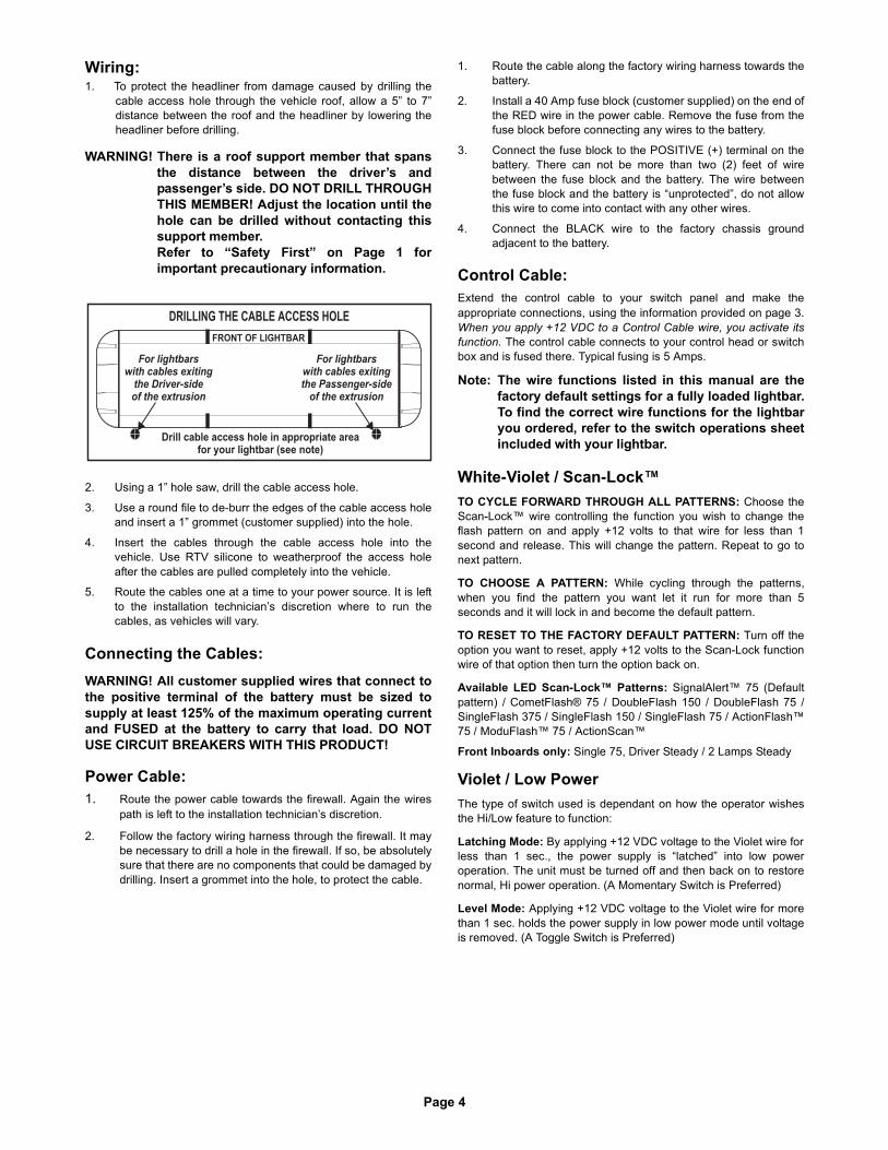
Page 4
Wiring:1. To protect the headliner from damage caused by drilling the
cable access hole through the vehicle roof, allow a 5” to 7”distance between the roof and the headliner by lowering theheadliner before drilling.
WARNING! There is a roof support member that spansthe distance between the driver’s andpassenger’s side. DO NOT DRILL THROUGHTHIS MEMBER! Adjust the location until thehole can be drilled without contacting thissupport member.Refer to “Safety First” on Page 1 forimportant precautionary information.
2. Using a 1” hole saw, drill the cable access hole.
3. Use a round file to de-burr the edges of the cable access holeand insert a 1” grommet (customer supplied) into the hole.
4. Insert the cables through the cable access hole into thevehicle. Use RTV silicone to weatherproof the access holeafter the cables are pulled completely into the vehicle.
5. Route the cables one at a time to your power source. It is leftto the installation technician’s discretion where to run thecables, as vehicles will vary.
Connecting the Cables: WARNING! All customer supplied wires that connect tothe positive terminal of the battery must be sized tosupply at least 125% of the maximum operating currentand FUSED at the battery to carry that load. DO NOTUSE CIRCUIT BREAKERS WITH THIS PRODUCT!
Power Cable:1. Route the power cable towards the firewall. Again the wires
path is left to the installation technician’s discretion.
2. Follow the factory wiring harness through the firewall. It maybe necessary to drill a hole in the firewall. If so, be absolutelysure that there are no components that could be damaged bydrilling. Insert a grommet into the hole, to protect the cable.
1. Route the cable along the factory wiring harness towards thebattery.
2. Install a 40 Amp fuse block (customer supplied) on the end ofthe RED wire in the power cable. Remove the fuse from thefuse block before connecting any wires to the battery.
3. Connect the fuse block to the POSITIVE (+) terminal on thebattery. There can not be more than two (2) feet of wirebetween the fuse block and the battery. The wire betweenthe fuse block and the battery is “unprotected”, do not allowthis wire to come into contact with any other wires.
4. Connect the BLACK wire to the factory chassis groundadjacent to the battery.
Control Cable:Extend the control cable to your switch panel and make theappropriate connections, using the information provided on page 3.When you apply +12 VDC to a Control Cable wire, you activate itsfunction. The control cable connects to your control head or switchbox and is fused there. Typical fusing is 5 Amps.
Note: The wire functions listed in this manual are thefactory default settings for a fully loaded lightbar.To find the correct wire functions for the lightbaryou ordered, refer to the switch operations sheetincluded with your lightbar.
White-Violet / Scan-Lock™TO CYCLE FORWARD THROUGH ALL PATTERNS: Choose theScan-Lock™ wire controlling the function you wish to change theflash pattern on and apply +12 volts to that wire for less than 1second and release. This will change the pattern. Repeat to go tonext pattern.
TO CHOOSE A PATTERN: While cycling through the patterns,when you find the pattern you want let it run for more than 5seconds and it will lock in and become the default pattern.
TO RESET TO THE FACTORY DEFAULT PATTERN: Turn off theoption you want to reset, apply +12 volts to the Scan-Lock functionwire of that option then turn the option back on.
Available LED Scan-Lock™ Patterns: SignalAlert™ 75 (Defaultpattern) / CometFlash® 75 / DoubleFlash 150 / DoubleFlash 75 /SingleFlash 375 / SingleFlash 150 / SingleFlash 75 / ActionFlash™75 / ModuFlash™ 75 / ActionScan™
Front Inboards only: Single 75, Driver Steady / 2 Lamps Steady
Violet / Low PowerThe type of switch used is dependant on how the operator wishesthe Hi/Low feature to function:
Latching Mode: By applying +12 VDC voltage to the Violet wire forless than 1 sec., the power supply is “latched” into low poweroperation. The unit must be turned off and then back on to restorenormal, Hi power operation. (A Momentary Switch is Preferred)
Level Mode: Applying +12 VDC voltage to the Violet wire for morethan 1 sec. holds the power supply in low power mode until voltageis removed. (A Toggle Switch is Preferred)
DRILLING THE CABLE ACCESS HOLE
Drill cable access hole in appropriate areafor your lightbar (see note)
FRONT OF LIGHTBAR
Forcables exiting
the Driver-sideof the extrusion
lightbarswith
Forcables exiting
the Passenger-sideof the extrusion
lightbarswith
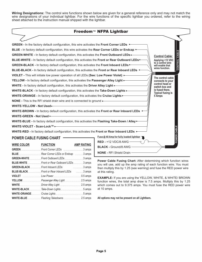
Page 5
NONE - RFI Shield Drain
BLACK - Ground/8 AWG
RED - +12 VDC/8 AWG
GREEN -
BLUE -
GREEN-WHITE - Front Outboard LEDs
BLUE-WHITE - LEDs
- Inboard LEDs
- Front or Rear Inboard LEDs
VIOLET - (See: Low Power Violet)
YELLOW -
WHITE -
WHITE-BLACK -
WHITE-ORANGE - Cruise Lights
NONE -
WHITE-YELLOW - Not Used
WHITE-BROWN - Front or Rear Inboard LEDs
WHITE-GREEN - Not Used
WHITE-BLUE - Flashing Take-Down / Alley
WHITE-VIOLET - Scan-Lock™
WHITE-RED - Front or Rear Inboard LEDs
the
T
In factory default configuration, this activates the
In factory default configuration, this activates the
In factory default configuration, this activates the
In factory default configuration, this activates the
This is the RFI shield drain wire and is connected to ground
In factory default configuration, this activates the
In factory default configuration, this activates the
In factory default configuration, this activates the
In the factory default configuration, this wire activates the
In factory default configuration, this wire activates the
In factory default configuration, this activates
In factory default configuration, this activates the
In factory default configuration, this activates the
In factory default configuration, this activates the
his will initiate low power operation of all LEDs
Front Corner LEDs
Rear Corner LEDs or Endcap
Front or Rear Outboard
GREEN-BLACK Front
BLUE-BLACK
Passenger Alley Light
Driver Alley Light
Take-Down Lights
Control Cable:
Applying +12 VDCto a control wirewill enable thatwires function.
The control cableconnects to yourcontrol head orswitch box andis fused there.Typical fusing is5 Amps
Fuse @ 40 Amp for fully loaded lightbar
GREEN
BLUE
GREEN-WHITE
BLUE-WHITE
GREEN-BLACK
BLUE-BLACK
YELLOW
WHITE
WHITE-BLACK
VIOLET
WHITE-ORANGE
WHITE-BLUE
Front Corner LEDs
Rear Corner
Front or Rear Outboard
Front Inboard
Front or Rear In
Passenger Alley Light
Driver Alley Light
Take-Down Lights
Cruise Lights
LEDs or Endcap
Front Outboard LEDs
LEDs
LEDs
board LEDs
Low Power
Flashing Takedowns
POWER CABLE FUSING CHART
WIRE COLOR FUNCTION
3 amps
3 amps
3 amps
3 amps
3 amps
3 amps
0.5 amps
2.5 amps
2.5 amps
5 amps
5 amps
2.5 amps
AMP RATING
CO
NT
RO
LC
AB
LE
PO
WE
RC
AB
LE
Freedom Lightbar™ NFPA
All options may not be present on all Lightbars.
EXAMPLE: If you are using the YELLOW, WHITE, & WHITE/ BROWN
function wires, the total amp draw is
ou
7.5 amps. Multiply this by 1.25
which comes out to 9.375 amps. Y must fuse the RED power wire
at 10 amps.
Power Cable Fusing Chart: After determining which function wires
you will use, add up the amp rating of each function wire. You must
then multiply this by 1.25 (see warning) and fuse the RED power wire
at this rating.
Wiring Designations: The control wire functions shown below are given for a general reference only and may not match thewire designations of your individual lightbar. For the wire functions of the specific lightbar you ordered, refer to the wiringsheet attached to the instruction manual shipped with the lightbar.
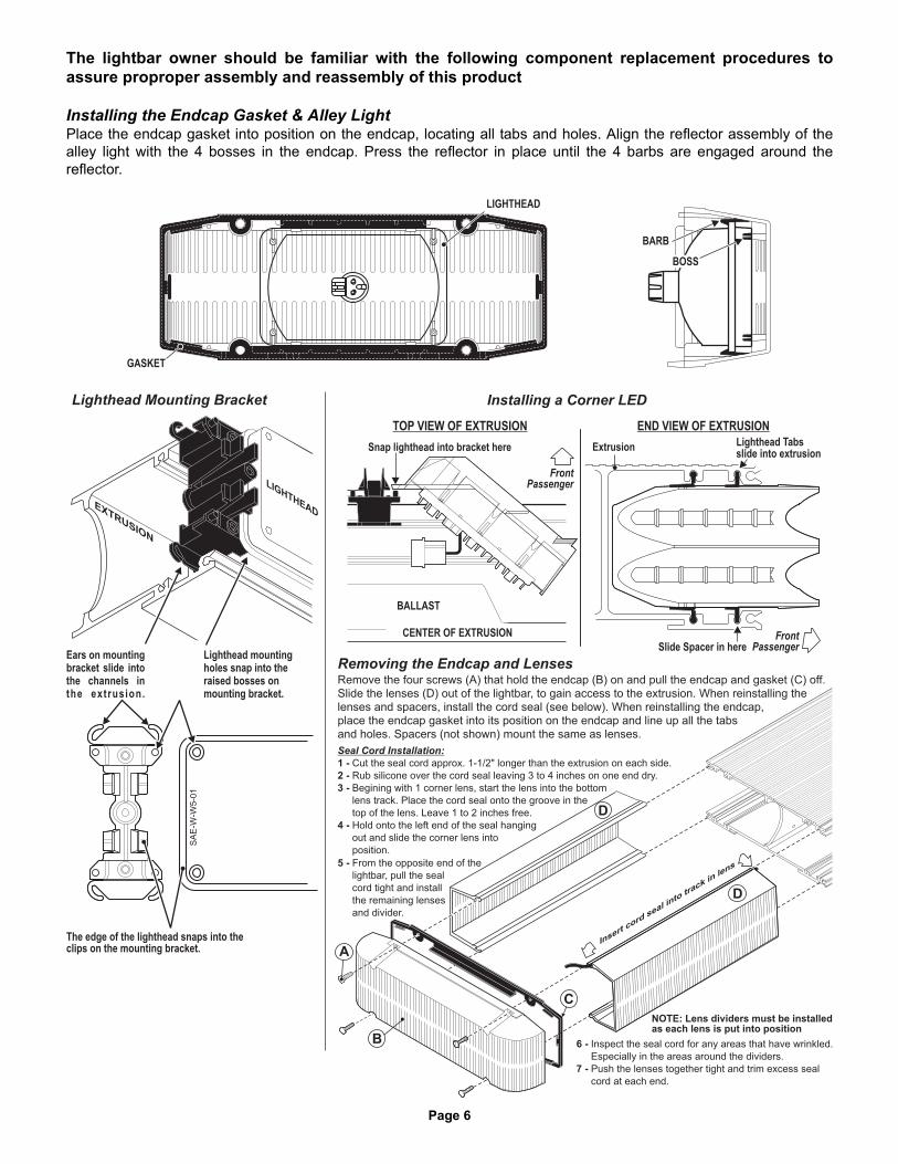
Page 6
GASKET
LIGHTHEAD
BARB
BOSS
Lighthead Mounting Bracket
Ears on mountingbracket slide intothe channels inthe extrusion.
Remove the four screws (A) that hold the endcap on and pull the endcap and gasket (C) off.(B)Slide the lenses (D) out of the lightbar, to gain access to the extrusion. When reinstalling thelenses and spacers, install the cord seal (see below). When reinstalling the endcap,place the endcap gasket into its position on the endcap and line up all the tabsand holes. Spacers (not shown) mount the same as lenses.
Removing the Endcap and Lenses
D
D
C
TOP VIEW OF EXTRUSION END VIEW OF EXTRUSION
Installing a Corner LED
Slide Spacer in here
Snap lighthead into bracket here
BALLAST
Extrusion
CENTER OF EXTRUSION
LIGHTHEADEXTRUSION
FrontPassenger
FrontPassenger
Lighthead Tabsslide into extrusion
The edge of the lighthead snaps into theclips on the mounting bracket.
Lighthead mountingholes snap into theraised bosses onmounting bracket.
CO
RNER
LED
Insert
cordseal in
totra
ckin
lens
A
B
Seal Cord Installation:
Cut the seal cord approx. 1-1/2" longer than the extrusion on each side.
Rub silicone over the cord seal leaving 3 to 4 inches on one end dry.
Begining with 1 corner lens, start the lens into the bottom
lens track. Place the cord seal onto the groove in the
top of the lens eav 1 to 2 inches
Hold onto the left end of the seal hanging
out and slide the corner lens into
position.
1 -
2 -
3 -
4 -
3 -
3 -
4 -
4 -
. L e free.
Inspect the seal cord for any areas that have wrinkled.
Especially in the areas around the dividers.
Push the lenses together tight and trim excess seal
cord at each end.
6 -
7 -
6 -
7 -
From the opposite end of the
lightbar, pull the seal
cord tight and install
the remaining lenses
and divider.
5 -
5 -
5 -
5 -
5 -
NOTE: Lens dividers must be installedas each lens is put into position
The lightbar owner should be familiar with the following component replacement procedures toassure proproper assembly and reassembly of this product
Installing the Endcap Gasket & Alley LightPlace the endcap gasket into position on the endcap, locating all tabs and holes. Align the reflector assembly of thealley light with the 4 bosses in the endcap. Press the reflector in place until the 4 barbs are engaged around thereflector.

Page 1
®
ENGINEERING COMPANY INC.Route 145, Winthrop Road,Chester, Connecticut 06412Phone: (860) 526-9504Fax: (860) 526-4078Internet: www.whelen.comSales e-mail: [email protected] Sales e-mail: [email protected] Service e-mail: [email protected]
Aut
omot
ive:
Lig
hthe
ads
Installation Guide:900-series
Dual Super-LED® Lighthead
Safety First
This document provides all the necessary information to allow your Whelen product to be properly and safely installed.Before beginning the installation and/or operation of your new product, the installation technician and operator mustread this manual completely. Important information is contained herein that could prevent serious injury or damage.
• Proper installation of this product requires the installer to have a good understanding of automotive electronics, systems and procedures.
• If mounting this product requires drilling holes, the installer MUST be sure that no vehicle components or other vital parts could be damaged by the drilling process. Check both sides of the mounting surface before drilling begins. Also de-burr any holes and remove any metal shards or remnants. Install grommets into all wire passage holes.
• If this manual states that this product may be mounted with tape or Velcro™, clean the mounting surface with a 50/50 mix of isopropyl alcohol and water and dry thoroughly.
• Do not install this product or route any wires in the deployment area of your air bag. Equipment mounted or located in the air bag deployment area will damage or reduce the effectiveness of the air bag, or become a projectile that could cause serious personal injury or death. Refer to your vehicle owners manual for the air bag deployment area. The User/Installer assumes full responsibility to determine proper mounting location, based on providing ultimate safety to all passengers inside the vehicle.
• For this product to operate at optimum efficiency, a good electrical connection to chassis ground must be made. The recommended procedure requires the product ground wire to be connected directly to the NEGATIVE (-) battery post.
• If this product uses a remote device to activate or control this product, make sure that this control is located in an area that allows both the vehicle and the control to be operated safely in any driving condition.
• Do not attempt to activate or control this device in a hazardous driving situation.
• This product contains either strobe light(s), halogen light(s), high-intensity LEDs or a combination of these lights. Do not stare directly into these lights. Momentary blindness and/or eye damage could result.
• Use only soap and water to clean the outer lens. Use of other chemicals could result in premature lens cracking (crazing) and discoloration. Lenses in this condition have significantly reduced effectiveness and should be replaced immediately. Inspect and operate this product regularly to confirm its proper operation and mounting condition. Do not use a pressure washer to clean this product.
• It is recommended that these instructions be stored in a safe place and referred to when performing maintenance and/or reinstallation of this product.
• FAILURE TO FOLLOW THESE SAFETY PRECAUTIONS AND INSTRUCTIONS COULD RESULT IN DAMAGE TO THE PRODUCT OR VEHICLE AND/OR SERIOUS INJURY TO YOU AND YOUR PASSENGERS!
©2004 Whelen Engineering Company Inc.Form No.13902B (111804)

Page 2
3.62"
7.26"
5.2
4"
2.6
2"
3"
1.5
0"
1" diameter hole
1" diameter hole
1/4" diameterhole (4 places)
Installation:WARNING! The LED models designated “external flasher” must beconnected to an electronic flasher. Allowing the LED to steady burn willdamage the lighthead and void the warranty.
External Flasher Models: This product draws significantly less current than astandard incandescent automotive bulb. If your flasher does not operateproperly, it may be necessary to replace your existing flasher module with aWhelen 3TERM flasher module. Contact your sales representative for specificvehicle application.
Note: Make sure lighthead will not interfere with existing equipment orany items on the opposite side of the mounting surface.1. Using the dimensions shown, mark off and drill the four 1/4 inch
diameter mounting holes and two 1 inch wire holes into the mountingsurface. Check measurements before drilling.
2. Install the 4 supplied plastic grommets into the mounting holes then installrubber grommets (customer supplied) into the wire holes.
3. Using appropriately sized wires (Minimum wire size / 18 AWG), extendthe lighthead wires to their connections. Fuse the positive connections at3 Amps and test operation of lighthead before securing it to vehicle.
4. Position the lighthead onto the mounting surface and secure to thevehicle using the four #8 x 1-1/2” sheet metal screws.
Flasher Models:Scan-Lock™: White-Violet Wire / This feature allows the user to select from several available flash patternsTO CYCLE THROUGH ALL PATTERNS: Apply positive voltage to the WHITE-VIOLET wire for less than 1 second and release to cycle forward. Applypositive voltage to the WHITE-VIOLET wire for more than 1 second andrelease to cycle backward.TO SET A PATTERN AS DEFAULT: Allow the desired pattern to run for morethan 5 seconds. The lighthead will now display this pattern when active.
TO RESET TO THE FACTORY DEFAULT PATTERN: Turn off power, applypositive voltage to the WHITE-VIOLET wire, then turn power on.
Available Flash Patterns: SignalAlert™75 / SignalAlert™150 / SingleFlash 375 / SingleFlash 150 / SingleFlash 75 / DoubleFlash 150 / DoubleFlash 75 CometFlash®75 / ActionFlash™ / ModuFlash™ / ComAlert™ / ActionScan™ / SignalAlert™ Steady / Steady (Brake)
Hi-Lo Intensity: Violet Wire / This feature allows the user to step theunit down to low power operation for nighttime use.Apply positive voltage to the VIOLET wire to put the lighthead into low power.Remove the voltage from the VIOLET wire to restore high power operation.
PART NUMBER KEY:
0 1 - 0 6 8 4 1 3 7 _ _ _
Upper / Lower LED ColorsLens ColorFlasher / Connector / Voltage
LED COLORS
A =
B =
W =
R =
M =
AMBER-AMBER
BLUE-BLUE
WHITE-WHITE
RED-RED
AMBER-BLUE
AMBER-WHITE
AMBER-RED
BLUE-WHITE
BLUE-RED
WHITE-RED
F =
K =
E =
J =
D =
LENS COLOR
A =
B =
C =
R =
AMBER
BLUE
CLEAR
RED
FLASHER-CONNECTOR-VOLTAGE
6 =
8 =
1 =
3 =
EXTERNAL / NONE / 12V
ON BOARD / NONE / 12V
EXTERNAL / NONE / 24V
ON-BOARD / NONE / 24V
2 1 - 1 7 0 8 0 8 0 6 0 3
3 8 - 0 4 8 1 6 9 0 - 0 0
6 8 - 1 9 8 4 1 0 0 - 5 0
6 8 - 1 9 8 4 1 0 0 - 3 0
6 8 - 1 9 8 4 1 0 0 - 2 0
6 8 - 1 9 8 4 1 0 0 - 1 0
1 5 - 0 8 1 4 1 6 - 2 4 0
1 0 - 0 5 2 3 11 5 _ _ _
0 2 - 0 3 8 4 1 2 3 6 11
0 2 - 0 3 8 4 1 2 3 6 2 2
0 2 - 0 3 8 4 1 2 3 6 3 3
0 2 - 0 3 8 4 1 2 3 6 5 5
0 1 - 0 6 8 4 1 3 7 6 _ _
1
LENS OPTIC - AMBER/
LIGHTHEAD 900 DUAL LINEAR - EXTERNAL FLASHER
SCREW #8 X 1-1/2" PPHSMS SS/
LENS OPTIC RED/ /
LENS OPTIC - CLEAR/
LENS OPTIC - BLUE/
SUB ASSY 900 LINEAR - 2 WIRE/ AMBER-AMBER /
SUB ASSY 900 LINEAR - 2 WIRE/ BLUE-BLUE /
SUB ASSY 900 LINEAR - 2 WIRE/ WHITE-WHITE /
SCREW GROMMET ROUND HOLE/
GASKET
LABEL / Not shown1
0 1 - 0 6 8 4 1 3 7 8 _ _ LIGHTHEAD 900 DUAL LINEAR - ON-BOARD FLASHER
0 2 - 0 3 8 4 1 2 3 6 2 3
0 2 - 0 3 8 4 1 2 3 6 1 5
0 2 - 0 3 8 4 1 2 3 6 1 3
0 2 - 0 3 8 4 1 2 3 6 1 2
SUB ASSY 900 LINEAR - 2 WIRE/ BLUE-WHITE /
SUB ASSY 900 LINEAR - 2 WIRE/ AMBER-RED /
SUB ASSY 900 LINEAR - 2 WIRE/ AMBER-WHITE /
SUB ASSY 900 LINEAR - RED RED 2 WIRE/ - /
0 2 - 0 3 8 4 1 2 3 6 3 5
0 2 - 0 3 8 4 1 2 3 6 2 5
SUB ASSY 900 LINEAR - 2 WIRE/ WHITE-RED /
SUB ASSY 900 LINEAR - 2 WIRE/ BLUE-RED /
SUB ASSY 900 LINEAR - 2 WIRE/ AMBER-BLUE /
0 2 - 0 3 8 4 1 2 3 8 3 5
0 2 - 0 3 8 4 1 2 3 8 2 5
0 2 - 0 3 8 4 1 2 3 8 2 3
0 2 - 0 3 8 4 1 2 3 8 1 5
0 2 - 0 3 8 4 1 2 3 8 1 3
0 2 - 0 3 8 4 1 2 3 8 1 2
0 2 - 0 3 8 4 1 2 3 8 5 5
0 2 - 0 3 8 4 1 2 3 8 3 3
0 2 - 0 3 8 4 1 2 3 8 2 2
0 2 - 0 3 8 4 1 2 3 8 11
SUB ASSY 900 LINEAR 4 WIRE/ / WHITE-RED /
SUB ASSY 900 LINEAR 4 WIRE/ / BLUE-RED /
SUB ASSY 900 LINEAR BLU WH T 4 WIRE/ / E- I E /
SUB ASSY 900 LINEAR - 4 WIRE/ AMBER-RED /
SUB ASSY 900 LINEAR - 4 WIRE/ AMBER-WHITE /
SUB ASSY 900 LINEAR - 4 WIRE/ AMBER-BLUE /
SUB ASSY 900 LINEAR - RED RED 4 WIRE/ - /
SUB ASSY 900 LINEAR - 4 WIRE/ WHITE-WHITE /
SUB ASSY 900 LINEAR - 4 WIRE/ BLUE-BLUE /
SUB ASSY 900 LINEAR - 4 WIRE/ AMBER-AMBER /
0 1 - 0 6 8 4 1 3 7 1 _ _
0 1 - 0 6 8 4 1 3 7 3 _ _
LIGHTHEAD 900 DUAL LINEAR 24V - EXTERNAL FLASHER
LIGHTHEAD 900 DUAL LINEAR 24V - ON-BOARD FLASHER
1 1
SUB ASSY 900 LINEAR 24V - AMBER-RED 4 WIRE/ /0 2 - 0 3 8 4 1 2 3 3 1 5
0 2 - 0 3 8 4 1 2 3 111
0 2 - 0 3 8 4 1 2 3 1 2 2
0 2 - 0 3 8 4 1 2 3 1 3 3
0 2 - 0 3 8 4 1 2 3 1 5 5
0 2 - 0 3 8 4 1 2 3 1 2 3
0 2 - 0 3 8 4 1 2 3 11 5
0 2 - 0 3 8 4 1 2 3 11 3
0 2 - 0 3 8 4 1 2 3 11 2
0 2 - 0 3 8 4 1 2 3 1 3 5
0 2 - 0 3 8 4 1 2 3 1 2 5
0 2 - 0 3 8 4 1 2 3 3 1 3
0 2 - 0 3 8 4 1 2 3 3 1 2
0 2 - 0 3 8 4 1 2 3 3 5 5
0 2 - 0 3 8 4 1 2 3 3 3 3
0 2 - 0 3 8 4 1 2 3 3 2 2
0 2 - 0 3 8 4 1 2 3 3 11
SUB ASSY 900 LINEAR 24V - AMBER-AMBER 2 WIRE/ /
SUB ASSY 900 LINEAR 24V - BLUE-BLUE 2 WIRE/ /
SUB ASSY 900 LINEAR 24V - WHITE-WHITE 2 WIRE/ /
SUB ASSY 900 LINEAR 24V - AMBER-WHITE 2 WIRE/ /
SUB ASSY 900 LINEAR 24V - RED-RED 2 WIRE/ /
SUB ASSY 900 LINEAR 24V - AMBER-BLUE 2 WIRE/ /
SUB ASSY 900 LINEAR 24V - BLUE-WHITE 2 WIRE/ /
SUB ASSY 900 LINEAR 24V - WHITE-RED 2 WIRE/ /
SUB ASSY 900 LINEAR 24V - BLUE-RED 2 WIRE/ /
SUB ASSY 900 LINEAR 24V - AMBER-WHITE 4 WIRE/ /
SUB ASSY 900 LINEAR 24V - AMBER-BLUE 4 WIRE/ /
SUB ASSY 900 LINEAR 24V - RED-RED 4 WIRE/ /
SUB ASSY 900 LINEAR 24V - WHITE-WHITE 4 WIRE/ /
SUB ASSY 900 LINEAR 24V - BLUE-BLUE 4 WIRE/ /
SUB ASSY 900 LINEAR 24V - AMBER-AMBER 4 WIRE/ /
SUB ASSY 900 LINEAR 24V - AMBER-RED 2 WIRE/ /
0 2 - 0 3 8 4 1 2 3 3 3 5
0 2 - 0 3 8 4 1 2 3 3 2 3
0 2 - 0 3 8 4 1 2 3 3 2 5
SUB ASSY / 900 LINEAR 24V - WHITE-RED / 4 WIRE
SUB ASSY 900 LINEAR 24V - 4 WIRE/ BLUE-WHITE /
SUB ASSY / 900 LINEAR 24V - BLUE-RED / 4 WIRE
A/R
A/R
A/R
4
A/R
A/R
A/R
A/R
A/R
A/R
A/R
4
A/R
A/R
A/R
2
3
11
12
13
14
15
16
17
18
19
20
21
22
23
4
5
6
7
8
9
10
1
24
25
26
27
28
29
30
31
32
33
ITEM PART NUMBER DESCRIPTIONQTY QTY
4
A/R
A/R
A/R
A/R
A/R
4
A/R
A/R
A/R
QTY QTY
A/R
A/R
34
35
36
37
38
39
40
41
42
43
44
45
46
47
48
A/R
A/R
A/R
A/R
A/R
A/R
A/R
A/R
A/R
A/R
A/R
A/R
A/R
A/R
A/R
444 4
444 4
A/R
A/R
A/R
A/R
A/R
A/R
A/R
A/R
A/R
A/R
A/R
A/R
A/R
A/R
A/R
A/R
A/R
A/R
PowerGround
HI/LO PowerScan-Lock™
Wire Functions / On-Board Flasher / 12VLED COLORBLACKVIOLETWHITE-VIOLET
PowerGround
HI/LO PowerScan-Lock™
Wire Functions / On-Board Flasher / 24VLED COLORBLACK-WHITEVIOLETWHITE-VIOLET
HI/LO PowerScan-Lock™
PowerGround
Wire Functions / External Flasher / 12VLED COLORBLACKVIOLETWHITE-VIOLET
HI/LO PowerScan-Lock™
PowerGround
Wire Functions / External Flasher / 24VLED COLORBLACK-WHITEVIOLETWHITE-VIOLET
2
27
28
3 4
16 19 22 2517 20 2318 21 24
5
6 9 12 157 10 138 11 14
39 42 45 4840 43 4641 44 47
29 32 35 3830 33 3631 34 371
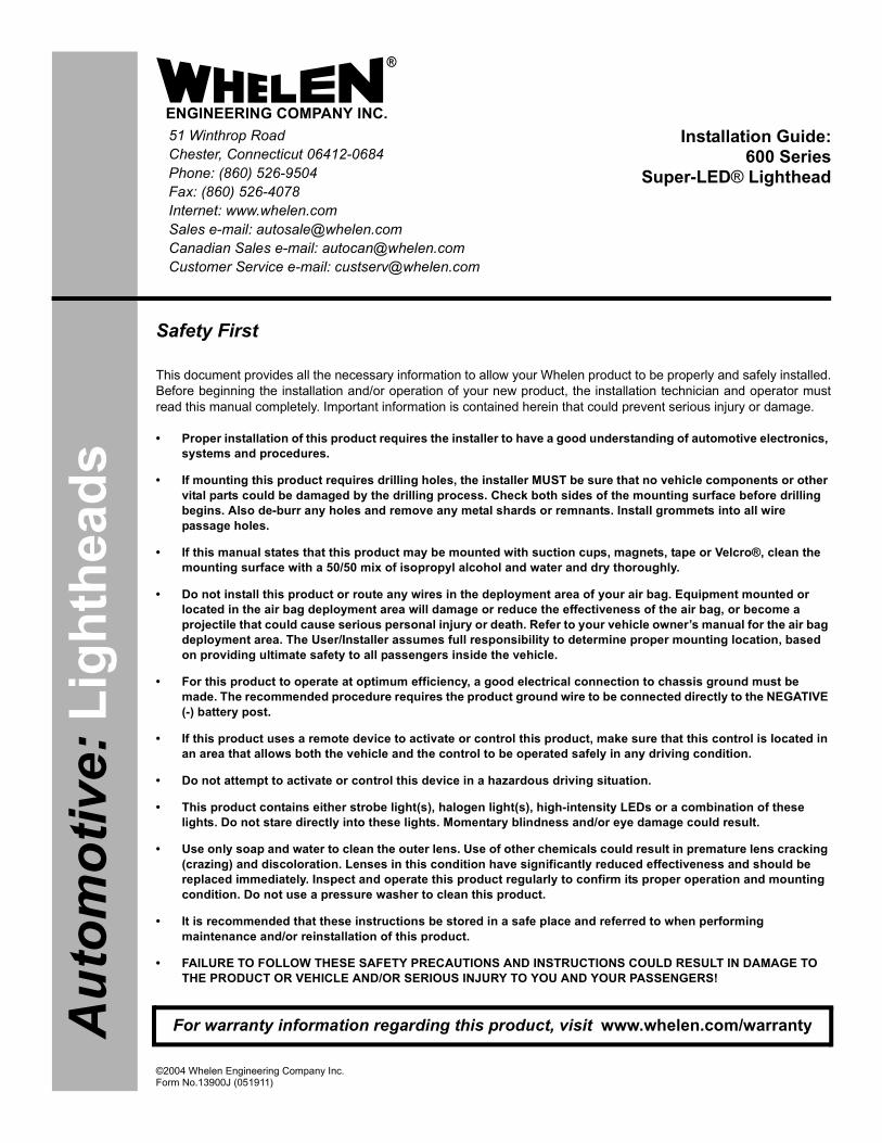
Page 1
Installation Guide:600 Series
Super-LED® Lighthead
©2004 Whelen Engineering Company Inc.Form No.13900J (051911)
®
ENGINEERING COMPANY INC.51 Winthrop RoadChester, Connecticut 06412-0684Phone: (860) 526-9504Fax: (860) 526-4078Internet: www.whelen.comSales e-mail: [email protected] Sales e-mail: [email protected] Service e-mail: [email protected]
Aut
omot
ive:
Lig
hthe
ads
Safety First
This document provides all the necessary information to allow your Whelen product to be properly and safely installed.Before beginning the installation and/or operation of your new product, the installation technician and operator mustread this manual completely. Important information is contained herein that could prevent serious injury or damage.
• Proper installation of this product requires the installer to have a good understanding of automotive electronics, systems and procedures.
• If mounting this product requires drilling holes, the installer MUST be sure that no vehicle components or other vital parts could be damaged by the drilling process. Check both sides of the mounting surface before drilling begins. Also de-burr any holes and remove any metal shards or remnants. Install grommets into all wire passage holes.
• If this manual states that this product may be mounted with suction cups, magnets, tape or Velcro®, clean the mounting surface with a 50/50 mix of isopropyl alcohol and water and dry thoroughly.
• Do not install this product or route any wires in the deployment area of your air bag. Equipment mounted or located in the air bag deployment area will damage or reduce the effectiveness of the air bag, or become a projectile that could cause serious personal injury or death. Refer to your vehicle owner’s manual for the air bag deployment area. The User/Installer assumes full responsibility to determine proper mounting location, based on providing ultimate safety to all passengers inside the vehicle.
• For this product to operate at optimum efficiency, a good electrical connection to chassis ground must be made. The recommended procedure requires the product ground wire to be connected directly to the NEGATIVE (-) battery post.
• If this product uses a remote device to activate or control this product, make sure that this control is located in an area that allows both the vehicle and the control to be operated safely in any driving condition.
• Do not attempt to activate or control this device in a hazardous driving situation.
• This product contains either strobe light(s), halogen light(s), high-intensity LEDs or a combination of these lights. Do not stare directly into these lights. Momentary blindness and/or eye damage could result.
• Use only soap and water to clean the outer lens. Use of other chemicals could result in premature lens cracking (crazing) and discoloration. Lenses in this condition have significantly reduced effectiveness and should be replaced immediately. Inspect and operate this product regularly to confirm its proper operation and mounting condition. Do not use a pressure washer to clean this product.
• It is recommended that these instructions be stored in a safe place and referred to when performing maintenance and/or reinstallation of this product.
• FAILURE TO FOLLOW THESE SAFETY PRECAUTIONS AND INSTRUCTIONS COULD RESULT IN DAMAGE TO THE PRODUCT OR VEHICLE AND/OR SERIOUS INJURY TO YOU AND YOUR PASSENGERS!
For warranty information regarding this product, visit www.whelen.com/warranty

Page 2
Installation:IMPORTANT! It is the responsibility of the installation technician to make surethat the installation and operation of this product will not interfere with orcompromise the operation or efficiency of any vehicle equipment!
Caution: Permanent mounting of this product will require drilling. It isabsolutely necessary to make sure that no other vehicle components could bedamaged by this process. Check both sides of the mounting surface beforestarting. If damage is likely, select a different mounting location.
Hi/Low Intensity (Violet) - This feature allows the user to step the unit down to lowpower operation for nighttime use. Apply positive voltage to the VIOLET wire to putthe lighthead into low power. Remove the voltage from the VIOLET wire to restorenormal high power operation.
The table below provides wiring information for the 600 Series lighthead. Refer to theappropriate Flash Pattern list as determined by the lighthead style:
WARNING! The LED models designated “Steady” must be connected to anelectronic flasher. Allowing the LED to steady burn will damage the lightheadand void the warranty. This product draws significantly less current than astandard incandescent automotive bulb. If your flasher does not operateproperly, it may be necessary to replace your existing flasher module with aWhelen 3TERM flasher module. Contact your sales representative for specificvehicle application.
3.2
50"
1.6
25"
2.875"5.750"
1" diameter hole
1/4" diameterhole (4 places)
CAUTION! DO NOT LOOK DIRECTLY AT THESE LED’S WHILE THEY ARE ON.
MOMENTARY BLINDNESS AND/OR EYE DAMAGE COULD RESULT!
IMPORTANT WARNING !
IMPORTANT! Before returning the vehicle to active service, visuallyconfirm the proper operation of this product, as well as all vehiclecomponents/equipment.
1. SignalAlert 75 - Alt.2. SignalAlert 75 - Sim.3. CometFlash - Alt.4. CometFlash - Sim.5. DoubleFlash150 - Alt.6. DoubleFlash150 - Sim.7. DoubleFlash75 - Alt.
8. DoubleFlash75 - Sim.9. SingleFlash375 - Alt.10. SingleFlash375 - Sim.11. SingleFlash150 - Alt.12. SingleFlash150 - Sim.13. SingleFlash75 - Alt.14. SingleFlash75 - Sim.
15. ActionFlash - Alt.16. ActionFlash - Sim.17. ModuFlash - Alt18. ModuFlash - Sim.19. ActionScan - Alt.20. SSNF
1. SignalAlert™752. SignalAlert1503. SingleFlash 3754. SingleFlash 1505. SingleFlash 75
6. DoubleFlash 1507. DoubleFlash 758. CometFlash®759. ActionFlash10. ModuFlash
11. ComAlert12. ActionScan13. SignalAlert14. Steady
Sync-Capable Flash Patterns:1. SignalAlert™ 75 - Phase 12. SignalAlert 75 - Phase 23. CometFlash® 75 - Phase 14. CometFlash 75 - Phase 25. DoubleFlash 75 - Phase 16. DoubleFlash 75 - Phase 27. SingleFlash 75 - Phase 18. SingleFlash 75 - Phase 29. ComAlert™ 75 - Phase 110. ComAlert 75 - Phase 211. LongBurst™ 75 - Phase 112. LongBurst 75 - Phase 213. PingPong™ 75 - Phase 114. PingPong 75 - Phase 2
Non-Sync Flash Patterns:15. SingleFlash 60*16. SingleFlash 90*17. SingleFlash 120*18. SingleFlash 30019. DoubleFlash 15020. ComAlert 15021. ActionFlash™ 5022. ActionFlash 15023. ModuFlash™24. ActionScan™25. Steady
* = California Title XIII compliant
Split Pattern Table:
Standard Pattern Table:
1. Using the dimensions shown, mark off and drill the four 1/4” diameter mountingholes and the 1” wire hole into the mounting surface. Check measurementsbefore drilling.
2. Install the screw grommet flange into the mounting holes then install a rubbergrommet (customer supplied) into the wire hole.
3. Using appropriately sized wires (minimum 18 AWG wire), extend the lightheadwires to their appropriate connections. Fuse the positive connections at 3Amps and test operation of lighthead before securing it to vehicle.
4. Position the lighthead onto the mounting surface and secure to the vehicleusing the four #6 x 1-1/2” sheet metal screws.
Wiring:WARNING! All customer supplied wires that connect to the positive terminalof the battery must be sized to supply at least 125% of the maximum operatingcurrent and FUSED at the battery to carry that load. DO NOT USE CIRCUITBREAKERS WITH THIS PRODUCT!
The 600 Series lighthead offers the user various features depending on the model.These features and their usage are as follows:
Scan-Lock™ (White/Violet):Note that the lighthead must be on to use the ScanLock feature except wherenoted.
To advance to the next flash pattern - Apply +12VDC to the WHT/VIO wire for lessthan 1 second and release.
To cycle backwards through the flash patterns - Apply +12VDC to the WHT/VIOwire for more than 1 second and release.
To reset to the factory default flash pattern - Turn off power to the lighthead. Whileapplying +12VDC to the WHT/VIO wire, turn power to the lighthead on. Continue toapply voltage to the WHT/VIO wire for 5 seconds. The default pattern will now beactive.
NOTE: A Normally Open momentary switch is suggested to activate the Scan-Lock™ wire.
SYNC (Grey) - To SYNC two lightheads, configure both lightheads to display thesame Phase 1 pattern. With the power off, connect the Grey wires from eachlighthead. When the lightheads are activated, their patterns will be synchronized. Toconfigure the two lightheads to alternate their patterns, advance the pattern of eitherlighthead to the Phase 2 mode of the current pattern. Remember, Phase 1 patternsALWAYS alternate with Phase 2 patterns!
SYNC Pattern Table:
600 Series Lighthead WiringStyle Wiring Pattern TableSteady (12V) - LED Color (Power) . . . . . . . N/A (see “WARNING” above)
- BLK (Ground)
Steady (24V) - LED Color (Power) . . . . . . . N/A (see “WARNING” above)- BLK/WHT (Ground)
SYNC - LED Color (Power) . . . . . . . SYNC Pattern Table- BLK (Ground)- GRY (SYNC)- WHT/VIO (Scan-Lock™)
Split - LED-1 Color (Power) . . . . . Split Pattern Table- LED-2 Color (Power)- BLK (Ground)- WHT/VIO (Scan-Lock)
Hi/Low (12V) - LED Color (Power) . . . . . . . Standard Pattern Table)- BLK (Ground)- VIO (Hi/Low Power)- WHT/VIO (Scan-Lock)
Hi/Low (24V) - LED Color (Power) . . . . . . . Standard Pattern Table)- BLK/WHT (Ground)- VIO (Hi/Low Power)- WHT/VIO (Scan-Lock)

Page 3
A/R 0 2 - 0 3 6 3 8 8 7 4 D 0
0 1 - 0 6 8 6 _ 06 4 11
0 1 - 0 6 8 4 _ 26 4 11
0 1 - 0 6 8 2 _ 26 4 11
0 1 - 0 6 8 4 _ 16 4 11
0 1 - 0 6 8 2 _ 16 4 11
0 1 - 0 6 8 3 _ 06 4 11
0 1 - 0 6 8 1 _ 06 4 11
0 2 - 0 3 6 3 8 8 7 2 4 0
6 8 - 11 8 3 5 8 1 - 4 0
0 2 - 0 3 6 3 8 8 7 4 2 0
0 2 - 0 3 6 3 8 8 7 4 3 0
0 2 - 0 3 6 3 8 8 7 4 5 0
0 2 - 0 3 6 3 8 8 7 4 1 0
0 1 - 0 6 8 4 _ 06 4 11
3 8 - 0 4 6 4 2 5 3 - 0 0
11 - 7 6 D 2 5 8 - 0 0 0
0 2 - 0 3 6 3 8 8 7 2 2 0
0 2 - 0 3 6 3 8 8 7 2 3 0
0 2 - 0 3 6 3 8 8 7 2 5 0
6 8 - 11 8 3 5 8 1 - 5 0
6 8 - 11 8 3 5 8 1 - 3 0
6 8 - 11 8 3 5 8 1 - 2 0
6 8 - 11 8 3 5 8 1 - 1 0
1 5 - 0 6 1 4 1 6 - 2 4 0
0 2 - 0 3 6 3 8 8 7 2 1 0
0 1 - 0 6 8 6 4 11 2 _ 0
A/R
A/R
A/R
A/R
A/R
A/R
A/R
4
A/R
4
A/R
A/R
A/R A/R
A/R
A/R
A/R
4 4
A/R
4
A/R
A/R
A/R A/R
A/R
A/R
4
A/RA/R
4
A/R
A/R
4
A/R
A/R
A/RA/R
A/R
A/R
A/R
A/R
4
A/R
A/R
A/R
A/R
1
1
1
1
A/R
1
1
1
1
1
1
A/R
A/R
A/R
A/R
A/R
A/R
A/R
1
1
1
1
1
1
A/RA/R
1
1
A/R
A/R
0 2 - 0 3 6 3 8 8 7 6 5 0
0 2 - 0 3 6 3 8 8 7 6 4 0
0 2 - 0 3 6 3 8 8 7 6 3 0
0 2 - 0 3 6 3 8 8 7 6 2 0
0 2 - 0 3 6 3 8 8 7 6 1 0
0 2 - 0 3 6 3 8 8 7 4 B 0
0 2 - 0 3 6 3 8 8 7 4 R 0
3 9 - 0 4 0 3 0 1 3 - 0 4
0 2 - 0 3 6 3 8 8 7 4 _ 8
0 2 - 0 3 6 3 8 8 7 2 _ 7
0 2 - 0 3 6 3 8 8 7 2 _ 4
0 2 - 0 3 6 3 8 8 7 4 _ 5
0 2 - 0 3 6 3 8 8 7 4 4 0
0 2 - 0 3 6 3 8 8 7 3 4 0
0 2 - 0 3 6 3 8 8 7 1 4 0
0 2 - 0 3 6 3 8 8 7 3 2 0
0 2 - 0 3 6 3 8 8 7 3 3 0
0 2 - 0 3 6 3 8 8 7 3 5 0
0 2 - 0 3 6 3 8 8 7 3 1 0
0 2 - 0 3 6 3 8 8 7 1 2 0
0 2 - 0 3 6 3 8 8 7 1 3 0
0 2 - 0 3 6 3 8 8 7 1 5 0
0 2 - 0 3 6 3 8 8 7 11 0
0 2 - 0 3 6 3 8 8 7 4 M 0
0 2 - 0 3 6 3 8 8 7 4 K 0
0 2 - 0 3 6 3 8 8 7 4 J 0
0 2 - 0 3 6 3 8 8 7 4 F 0
0 2 - 0 3 6 3 8 8 7 4 E 0
A/R
A/R
A/R
A/R
A/R
A/R
A/R
A/R
A/R
A/R
A/R
A/R
A/R
A/R
A/R
A/R
A/R
1
A/R
1
A/R
A/R
A/R
A/R
A/R
A/R
A/R
A/R
A/R
SUB ASSY 600 LINEAR TIR - AMBER 12V SYNC/
SUB ASSY 600 LINEAR TIR - 4 WIRE AMP PINS/ /
SUB ASSY 600 LINEAR TIR - 2 WIRE AMP PINS/ /
SUB ASSY 600 LINEAR TIR 24V - GRN 4 WIRE/ /
SUB ASSY 600 LINEAR TIR 24V - WH 4 WIRE/ T /
SUB ASSY 600 LINEAR TIR 24V - BLU 4 WIRE/ /
SUB ASSY 600 LINEAR TIR - GREEN 12V SYNC/
SUB ASSY 600 LINEAR TIR 24V - GRN 2 WIRE/ /
SUB ASSY 600 LINEAR TIR 24V - AMB 4 WIRE/ /
SUB ASSY 600 LINEAR TIR 24V - AMB 2 WIRE/ /
SUB ASSY 600 LINEAR TIR 24V - BLU 2 WIRE/ /
SUB ASSY 600 LINEAR TIR 24V - WH 2 WIRE/ T /
SUB ASSY 600 LINEAR TIR - WHT RED SPLIT/ -
600 LINEAR TIR LO/PWR 24V
600 LINEAR TIR STEADY 24V
600 LINEAR TIR LO/PWR FLASHER
600 LINEAR TIR STEADY
SUB ASSY 600 LINEAR TIR - BLUE 2 WIRE/ /
600 LINEAR TIR SYNC 12V
600 LINEAR TIR LO/PWR
600 LINEAR TIR STEADY FLASHER
600 LINEAR TIR Lo/Power DEUTSCH
600 LINEAR TIR STEADY DEUTSCH
SUB ASSY 600 LINEAR TIR - AMBER 2 WIRE/ /
LENS OPTIC RED/ /
LENS OPTIC CLEAR/ /
LENS OPTIC BLUE/ /
LENS OPTIC AMBER/ /
SCREW / #6 X 1-1/2" PPHSMS
SUB ASSY 600 LINEAR TIR - GRN 2 WIRE/ /
LENS OPTIC GREEN/ /
SUB ASSY 600 LINEAR TIR - RED 4 WIRE/ /
SUB ASSY 600 LINEAR TIR - WHITE 4 WIRE/ /
SUB ASSY 600 LINEAR TIR - BLUE 4 WIRE/ /
SUB ASSY 600 LINEAR TIR - AMBER 4 WIRE/ /
SCREW GROMMET FLANGE
SUB ASSY 600 LINEAR TIR - WHITE 2 WIRE/ /
SUB ASSY 600 LINEAR TIR - RED 2 WIRE/ /
GASKET 600 SERIES FLANGE/ without
SUB ASSY 600 LINEAR TIR - BLUE 12V SYNC/
SUB ASSY 600 LINEAR TIR - BLU BLU SPLIT/ /
SUB ASSY 600 LINEAR TIR - RED RED SPLIT/ /
SUB ASSY 600 LINEAR TIR - 2 WIRE DEUTSCH/
SUB ASSY 600 LINEAR TIR - 4 WIRE DEUTSCH/
SUB ASSY 600 LINEAR TIR 24V - RED 4 WIRE/ /
SUB ASSY 600 LINEAR TIR 24V - RED 2 WIRE/ /
SUB ASSY 600 LINEAR TIR - AMB BLU SPLIT/ -
SUB ASSY 600 LINEAR TIR - AMB RED SPLIT/ -
SUB ASSY 600 LINEAR TIR - BLU RED SPLIT/ -
SUB ASSY 600 LINEAR TIR - AMB WHT SPLIT/ -
SUB ASSY 600 LINEAR TIR - BLU WHT SPLIT/ -
HOUSING 3 POS. PIN AMP/
SUB ASSY 600 LINEAR TIR - GREEN 4 WIRE/ /
SUB ASSY 600 LINEAR TIR - WHITE 12V SYNC/
SUB ASSY / 600 LINEAR TIR - RED 12V SYNC
ITEM PART NUMBER DESCRIPTIONQTY QTY QTY QTYQTYQTYQTYQTYQTY
2
3
11
12
13
14
15
16
17
18
19
20
4
5
6
7
8
9
10
1
21
22
30
31
32
33
34
35
36
37
38
39
23
24
25
26
27
28
29
40
41
42
43
44
45
46
CONNECTOR
STYLE/VOLTAGE
LED/LENS COLOR
PART NUMBER KEY:
0 1 - 0 6 8 6 4 1 1 _ _ _
A =
B =
G =
R =
AMBER/AMBER
BLUE/BLUE
GREEN/GREEN
RED/RED
STYLE/VOLTAGE
2 =
4 =
1 =
3 =
6 =
STEADY/12V
LO-PWR/12V
STEADY/24V
LO-PWR/24V
W/SYNC 12V
LED/LENS COLOR
1 =
2 =
3 =
4 =
5 =
6 =
D =
AMBER/CLEAR
BLUE/CLEAR
WHITE/CLEAR
GREEN/CLEAR
RED/CLEAR
BLU/BLU/CLEAR
WHT/RED/CLEAR
E =
F =
J =
K =
M =
W =
V =
BLU/WHT/CLEAR
AMB/WHT/CLEAR
BLU/RED/CLEAR
AMB/RED/CLEAR
AMB/BLU/CLEAR
RED/RED/RED
RED/RED/CLEAR
CONNECTOR0 =1 =2 =
NONEDEUTSCHAMP Pins with 3Position Connectorshipped separate
2 =2 =
Replacement Parts:
1
44 45 46
437 thru
62 thru

LGT100 Rev0309
1
FIRE RESEARCH CORPORATIONwww.fireresearch.com
26 Southern Blvd., Nesconset, NY11767TEL ( 631 ) 724-8888 FAX ( 631 ) 360-9727 TOLL FREE 1-800-645-0074
GENERAL LIGHTING
Document Number:XM-LGT1PM-R0A
OPTIMUM
FOCUS
NIGHTMASTER

LGT100 Rev0309
2
CONTENTS
Table of Contents
CONTENTS ................................................................................................................ 2INTRODUCTION ...................................................................................................... 4
Overview ................................................................................................................ 4Features .................................................................................................................. 4Specifications ......................................................................................................... 5
SAFETY SUMMARY ................................................................................................ 6INSTALLATION INSTRUCTIONS .......................................................................... 8
Install Lamphead on Telescopic Pole .................................................................... 8Install Recessed Mount Models 200, 230, 250 .................................................... 10Install Aerial Mount Models 300 ......................................................................... 12Install Top Mount Telescopic Pole Models 510, 512 ........................................... 14Install Side Mount Telescopic Pole Models 530, 540, 542.................................. 16Install Pedestal Mount Models 570, 580 ............................................................. 18Install Quick Release Bracket Set for Tripod Models 600, 642, 656 ................. 20Install Quick Release Bracket for Portable Model 700 ....................................... 22Install Brow Mount Models 800, 850 .................................................................. 24
MAINTENANCE ..................................................................................................... 26Bulb Replacement Optimum and Focus .............................................................. 26Cleaning ............................................................................................................... 26Bulb Replacement NightMaster........................................................................... 28Bulb Replacement Triple Cluster ......................................................................... 28
NO-SCRATCH FOR MODEL 530 TELESCOPIC POLE ....................................... 30Install No-Scratch Guide Collar and Guide Rail ................................................. 30Install No-Scratch Rubber Bumpers (Focus Lamphead Only) ............................ 30
RAISED POLE WARNING SWITCH AND INDICATOR ..................................... 32Overview .............................................................................................................. 32Description ........................................................................................................... 33Parts List .............................................................................................................. 34

LGT100 Rev0309
3
List of Tables
Table 1. Lamphead Guide .......................................................................................... 5Table 2. Recessed Mount Dimensions .................................................................... 11
List of Figures
Figure 1. Assemble Lamphead and Telescopic Pole .................................................. 9Figure 2. Install Recessed Mount ............................................................................ 11Figure 3. Install Under Aerial Mount ....................................................................... 13Figure 4. Install Top Mount Telescopic Pole ........................................................... 15Figure 5. Install Side Mount Telescopic Pole .......................................................... 17Figure 6. Install Pedestal Mount .............................................................................. 19Figure 7. Install Tripod Quick Release Bracket Set ................................................. 21Figure 8. Install Portable Light Quick Release Bracket .......................................... 23Figure 9. Install Contour and Flat Brow Mounts ..................................................... 25Figure 10. Bulb Replacement Optimum and Focus ................................................. 27Figure 11. Bulb Replacement NightMaster ............................................................. 29Figure 12. No-Scratch ............................................................................................. 31Figure 13. Raised Pole Warning Switch Housing Locations ................................... 33Figure 14. Raised Pole Warning Switch Parts List .................................................. 34

LGT100 Rev0309
4
INTRODUCTION
OverviewOPTIMUM Lampheads utilize a super-efficient design to offer a maximum transfer
of light from bulb to scene. The newest addition to the FRC lighting series includes HIR and HID bulb options not available on classic Focus lights.
FOCUS Low Profile Lampheads introduced the concept of re-directing light with 50 parabolic curved and aimed surfaces. The innovative design directs light where it is needed. The low profile of the classic FOCUS offers mounting options that many other lights cannot.
NIGHTMASTER Lampheads are affordable scene lights that have a proven track record on emergency apparatus. Simple, functional, and available in multiple styles and mounting configurations.
FeaturesEFFICIENCY The brightest and best designed lights in the industry. A unique reflector design transfers more light from the bulb to the scene.
NO WASTED LIGHT Focus 100% of the light directly where it is needed.
RELIABLE and PROVEN Manufactured from heavy duty, thick extruded aluminum for long life and many hours of dependable performance. Proven under actual emergency situations.
COMPACT Focus lights will not take up valuable space on your vehicle.
ATTRACTIVE Modern design and stylish look of all our lights enhances the appearance of emergency apparatus.
VERSATILE Choose from 70W to 1500W and from 12V to 240V capabilities.
MOUNTING CHOICES FRC lampheads can be mounted virtually anywhere as telescopic poles, portable, fixed, brow mounted, recessed, or under aerial.
OPTIONS Include multiple size mounting brackets, costum length poles, wire guard, on/off power switch, raised pole indicator,and no scratch for Focus.
SAFETY TWIST LOCK Easy to use and standard on all FRC telescopic poles, the locking mechanism has no metal to metal contact, it can not jam or be over tightened.

LGT100 Rev0309
5
SeriesO=OptiumF=FocusL=NightMaster
Lapmhead Style
Bulb Type Watts Volts Amps
O, F H70 HID 70 12 6.0O, F H15 HID 150 12 12.5
O E70 HID 70 24 3.0O E15 HID 150 24 6.25F D15 Quartz Halogen 150 12 12.5F D30* Quartz Halogen 300 12 25.0F H30 Quartz Halogen 300 24 12.5L DT0 Quartz Halogen 250 12 20.0L TC0 Quartz Halogen 300 12 25.0
O, F, L S30 Quartz Halogen 300 120 2.5O, F, L S50 Quartz Halogen 500 120 4.2
L P50 Quartz Halogen 500 120 4.2O, F S75 Quartz Halogen 750 120 6.3
O, F, L M10 Quartz Halogen 1000 120 8.3O, F S72 Quartz Halogen 750 240 3.1
O R90 HIR 900 240 3.75O, F, L M12 Quartz Halogen 1000 240 4.2O, F, L M15 Quartz Halogen 1500 240 6.25
* Two 150 watt bulbs are installed.
RESTRICTION NOTES
12/24 VDC lampheads are not available on 600 and 700 type mounts.
240 VAC lampheads are not available on 700 type mounts.
LT series lampheads are not available on 200, 230, 250, 300, 800, and 850 type mounts.
FOCUS HID lamphead is only available on 800 and 850 type mounts.
.
Table 1. Lamphead Guide
SpecificationsNote: All Optimum, Focus, and NightMaster lampheads are available
seperately or as part of a lighting assembly.

LGT100 Rev0309
6
SAFETY SUMMARYFRC lighting products are engineered and manufactured with safety in mind. It is
critical that FRC scene lights are installed, maintained, and operated correctly. Read and understand all instructions before installing, performing maintenance, or operating.
All components, equipment, and installation procedures shall conform to NFPA 1901, Standard for Automotive Fire Apparatus and NFPA 70 National Electrical Code.
The following safety precautions shall be observed while performing procedures in this manual.
General Safety PrecautionsEnsure power is off prior to connecting or disconnecting wires and plugs or performing maintenance.
Scene lighting lampheads are designed for outdoor use and will be extremely hot when operating. Do not use in areas of limited ventilation.
Installation Safety PrecautionsEnsure power is off prior to connecting wires or cable to the power source.
Connect only to the type of power source as indicated on the lamphead identification label.
Ensure an appropriate sized circuit protection device is installed (circuit breaker or fuse).
Use a minimum of 16 AWG wire to connect AC lights and 12 AWG to connect DC lights.
FRC lights are intended for mounting to a noncombustible surface only. Do not install insulation within 76 mm (3 in) of any part of the light, lighting fixture, or its components.
Install approved rubber or plastic grommets or bushings where wires or cable will pass through a surface.
Ensure all wire connectors or terminals provide a positive mechanical and electrical connection.
Electrical connections not enclosed in a box must be covered with an insulation equivalent to that on the conductors.
Lampheads will be extremely hot when operating, do not mount such that personnel or equipment could inadvertently come in contact with the lamphead.
Recessed lights require a minimum of 3 inch clearance between wall insulation and the light housing.

LGT100 Rev0309
7
Operation Safety PrecautionsOperate portable lighting products only from the type of power source indicated on the identification label.
During operation use the handle to move the light, the housing will be extremely hot.
Ensure that all lighting components are clear of obstructions when raising telescopic poles.
Ensure that telescopic poles are lowered and stowed before moving the vehicle.
Maintenance Safety PrecautionsEnsure power is off prior to removing the front glass or opening covers.
Do not operate the light with the front glass removed or cover opened.
Ensure replacement bulbs have the same voltage and wattage.
When handling a new quartz halogen, HIR, or HID bulb avoid touching it except on the flat seal at either end.
Use a clean soft cloth to wipe the reflector clean if necessary, do not use liquid or aerosol cleaners.

LGT100 Rev0309
8
INSTALLATION INSTRUCTIONS
Install Lamphead on Telescopic PoleLampheads and telescopic poles are shipped apart and need to be assembled
Note: The 512 telescopic pole must be installed before the lamphead is attached if the small diameter hole is used. Refer to Install Models 510, 512 Top Mount Telescopic Poles.
1. Place the lamphead and the pole on a flat surface.
2. Connect the lamphead wires to the pole wires. (Refer to Figure 1.)
a. Ensure that 3/8 inch of bare conductor shows at the end of each wire.
b. Insert the wires in the butt connectors and crimp.
For DC lights:
Connect black to black, white to red.
For AC lights:
Connect black to black, white to white, silver braid to green.
3. Ensure the crimps are tight. (Test by lightly tugging on the wires.)
4. Loop the excess wire in a zig-zag fashion to take up the slack.
Note: Ensure that the wires are not caught and squeezed by the lip of the pole. If this happens the wire insulation may be cut and short the wires to the pole.
5. Slide the lamphead onto the pole tucking the wires into the pole.
6. Apply thread lock and tighten the set screws to secure the lamphead on the pole. (A medium strength locking compound like Loctite blue is recommended.)
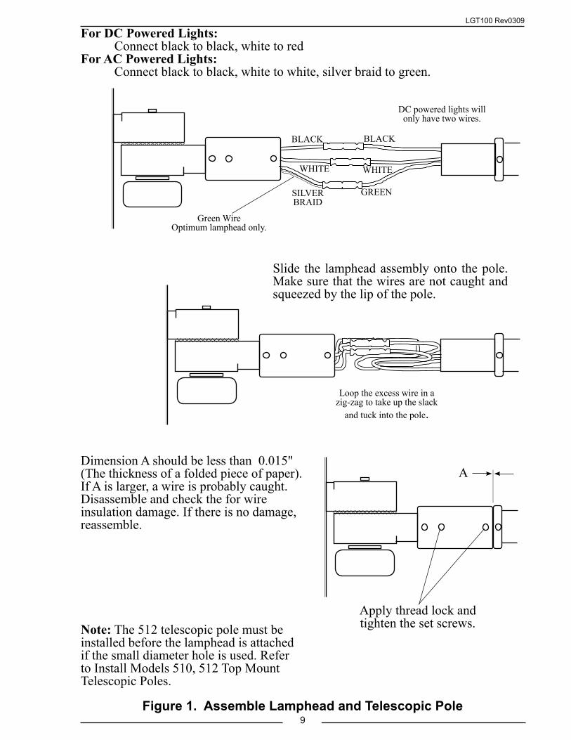
LGT100 Rev0309
9
For DC Powered Lights: Connect black to black, white to red For AC Powered Lights: Connect black to black, white to white, silver braid to green.
Figure 1. Assemble Lamphead and Telescopic Pole
Dimension A should be less than 0.015"(The thickness of a folded piece of paper).If A is larger, a wire is probably caught. Disassemble and check the for wire insulation damage. If there is no damage, reassemble.
Loop the excess wire in a zig-zag to take up the slack
and tuck into the pole.
Slide the lamphead assembly onto the pole. Make sure that the wires are not caught and squeezed by the lip of the pole.
Note: The 512 telescopic pole must be installed before the lamphead is attached if the small diameter hole is used. Refer to Install Models 510, 512 Top Mount Telescopic Poles.
Apply thread lock and tighten the set screws.
A
BLACK
WHITE
SILVER BRAID
BLACK
WHITE
GREEN
DC powered lights will only have two wires.
Green WireOptimum lamphead only.

LGT100 Rev0309
10
Install Recessed Mount Models 200, 230, 2501. Measure and mark mounting location for cutout.
2. Cut out mounting hole.
3. Place the light in position to check for fit and mark mounting screw locations.
4. Double check the clearance around and behind the light housing. Recessed lights require a minimum of 3 inch clearance between wall insulation and the light housing.
5. Drill mounting screw holes.
Note: Wires may need to be connected before installing the recessed light.
6. Ensure that approved strain relief for the wiring is installed.
7. Secure the housing with mounting screws.
Wiring12/24 VDCConnect the BLACK wire to GROUND.Connect the RED (or WHITE) wire to POWER.120/240 VACConnect the SILVER BRAID or GREEN wire to chassis GROUND.Connect the WHITE wire to RETURN.Connect the BLACK wire to POWER.
FCA200
OPA200, OPA230
OPA250

LGT100 Rev0309
11Figure 2. Install Recessed Mount
Model W D H W2 H2
FCA200-D15, H30, S30, S50, S72, S75 11 2 5 5/8 9 3/4 4 1/4D30, M10, M12, M15 17 1/2 2 5 5/8 16 1/8 4 1/4OPA200-S30, S50, S72, S75 11 2 5 5/8 9 3/4 4 1/4M10, M12, M15, R90 17 1/2 2 5 5/8 16 1/8 4 1/4OPA230-E15, E70, H15, H70 10 3/16 3 1/4 4 3/4 8 3/4 3 7/8OPA250-S30, S50, S72, S75 11 3/16 4 1/8 7 1/2 9 9/16 5 3/4M10, M12, M15, R90 16 9/16 3 1/4 7 1/2 15 5 3/4
Note: W2 and H2 will be the cutout dimensions.
OPA250
FCA200
OPA200
OPA230
OPA230 is the only recessed light available with HID bulb.
Table 2. Recessed Mount Dimensions
Hardware RecommendationsFor 200 mounts:
10-32 SS
Hardware RecommendationsFor 230 mounts:
1/4-20 SS
Hardware RecommendationsFor 250 mounts:
10-32 SSH
WW2
H2
D 1 1/4"
WW2
H H2
D 3 3/4"
W
H2
W2
H
D 3 1/8"
WW2
H
D
H2
1 3/4"

LGT100 Rev0309
12
Install Aerial Mount Models 300Before mounting check the identification label on the lamphead for specific voltage
and current requirements. Check that the length of the power cord is correct.
Note: Before drilling holes place the light in position to check for fit. Ensure that the lamphead will clear all obstructions.
1. Place the light in position.
2. Mark the mounting hole locations and through hole for the wiring. Use the lamphead and attached brackets as a template.
3. Drill mounting holes.
4. Secure the mounting bracket(s). Use 5/16-18 SS hardware.
5. Ensure that approved strain relief for the wiring is installed.
6. Adjust the lamphead angle by loosing the nuts at the bracket pivot point, set at desired position and tighten nuts.
Wiring12/24 VDCConnect the BLACK wire to GROUND.Connect the RED (or WHITE) wire to POWER.120/240 VACConnect the GREEN wire to chassis GROUND.Connect the WHITE wire to RETURN.Connect the BLACK wire to POWER.
FCA300
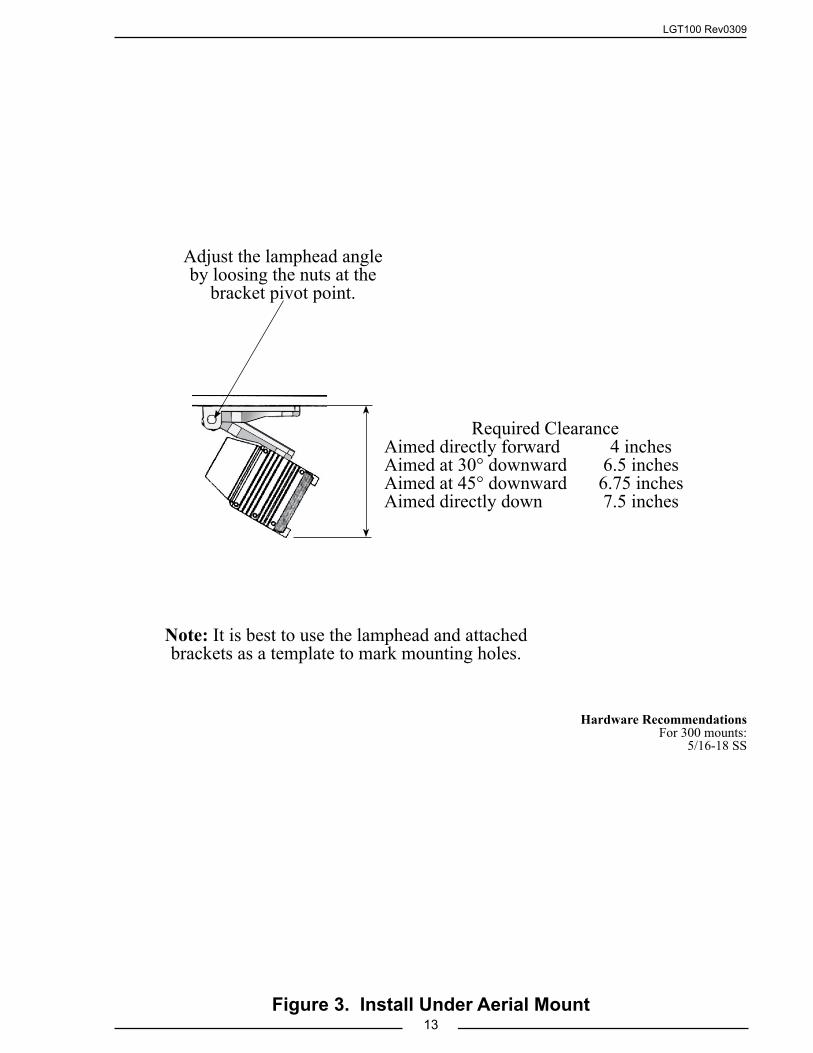
LGT100 Rev0309
13Figure 3. Install Under Aerial Mount
Note: It is best to use the lamphead and attached brackets as a template to mark mounting holes.
Adjust the lamphead angle by loosing the nuts at the
bracket pivot point.
Required ClearanceAimed directly forward 4 inchesAimed at 30° downward 6.5 inchesAimed at 45° downward 6.75 inchesAimed directly down 7.5 inches
Hardware RecommendationsFor 300 mounts:
5/16-18 SS

LGT100 Rev0309
14
Install Top Mount Telescopic Pole Models 510, 512When positioning a telescopic pole ensure that the lamphead will clear all
obstructions and the twist lock will be accessible.
Note: The 512 telescopic pole should be installed before the lamphead is attached. Two set screws allow the flange to be removed and the pole will fit up through a 1 5/8" hole. To install a fully assembled 512 pole down through the roof, a 2 1/2" hole will be needed so the handle and twist lock will fit through.
1. Check the light position for fit and freedom of operation
2. Mark the footprint of the mounting flange.
3. Drill mounting holes.
Note: The 512 requires a bead of RTV or similar sealant be applied between the mounting surface and the bottom outer edge of the flange.
4. For 512 apply a bead of sealant around the bottom outer edge of the flange.
5. Secure the mounting flange. Use 1/4-20 SS hardware. Install a backing plate if necessary for a sturdy mounting.
6. Ensure that approved strain relief for the wiring is installed.
Wiring12/24 VDCConnect the BLACK wire to GROUND.Connect the RED wire to POWER.120/240 VACConnect the GREEN wire to chassis GROUND.Connect the WHITE wire to RETURN.Connect the BLACK wire to POWER.
510Top Mount
Pull Up
512Thru-The-Roof
Push Up
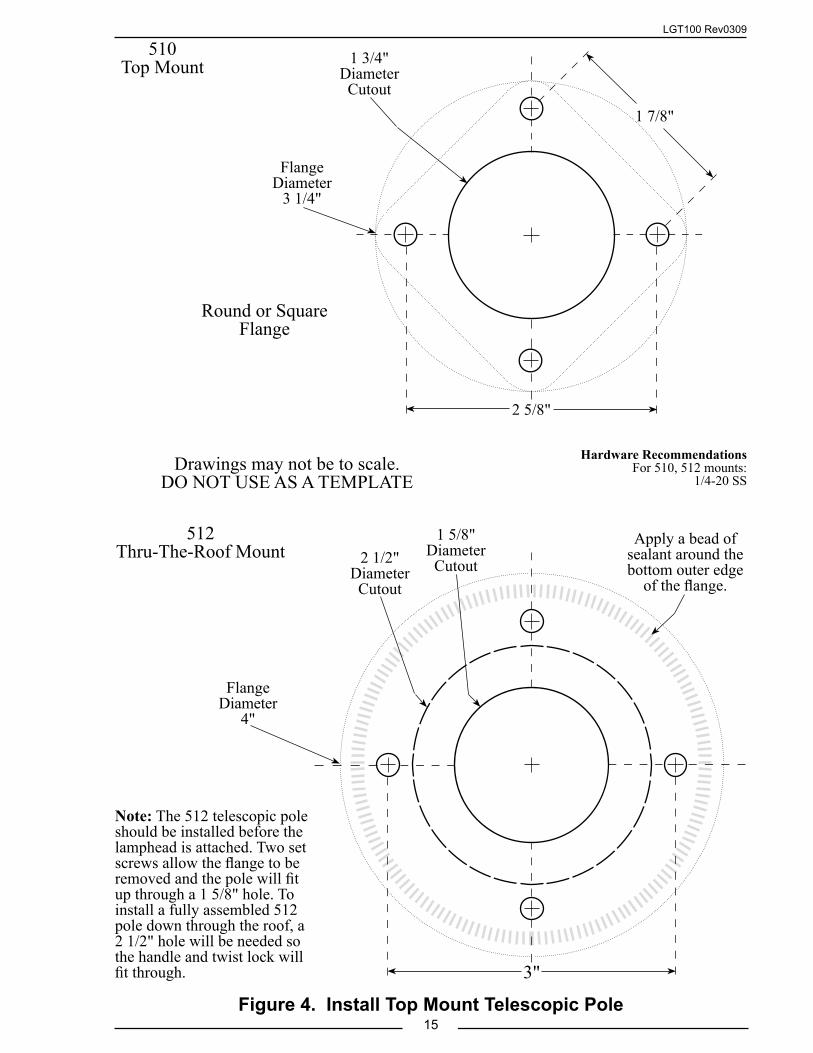
LGT100 Rev0309
15Figure 4. Install Top Mount Telescopic Pole
Drawings may not be to scale.DO NOT USE AS A TEMPLATE
Round or Square Flange
1 3/4"Diameter Cutout
2 5/8"
1 7/8"
Flange Diameter
3 1/4"
510Top Mount
Note: The 512 telescopic pole should be installed before the lamphead is attached. Two set screws allow the flange to be removed and the pole will fit up through a 1 5/8" hole. To install a fully assembled 512 pole down through the roof, a 2 1/2" hole will be needed so the handle and twist lock will fit through.
512Thru-The-Roof Mount
1 5/8"Diameter Cutout2 1/2"
Diameter Cutout
Apply a bead of sealant around the bottom outer edge
of the flange.
3"
Flange Diameter
4"
Hardware RecommendationsFor 510, 512 mounts:
1/4-20 SS

LGT100 Rev0309
16
Install Side Mount Telescopic Pole Models 530, 540, 542
When positioning a telescopic pole ensure that the lamphead will clear all obstructions and the twist lock will be accessible.
1. Place the light in position to check for fit and freedom of operation.
2. Slide the brackets up or down into required position. The set screws may need to be loosened.
3. Tighten set screws.
4. Mark the footprint of the mounting bracket(s).
5. Drill mounting holes.
6. Secure the mounting bracket(s). Use 5/16-18 SS hardware. Install a backing plate if necessary for a sturdy mounting.
7. Ensure that approved strain relief for the wiring is installed.
Wiring12/24 VDCConnect the BLACK wire to GROUND.Connect the RED wire to POWER.120/240 VACConnect the GREEN wire to chassis GROUND.Connect the WHITE wire to RETURN.Connect the BLACK wire to POWER
530Side Mount
Push Up
540Side Mount
Pull Up
542Side Mount
Pull Up
Typical Bracket
Slide bracket up or down into required position and tighten
set screws.

LGT100 Rev0309
17Figure 5. Install Side Mount Telescopic Pole
Drawings may not be to scale.DO NOT USE AS A TEMPLATE
3 13/16"
1"
2"
3"
Side Mount Bracket FootprintThe footprint is the same for all side mount and steady rest
brackets.
3"
1 1/2"
3"
2 1/8"
530, 540, 542Side Mount Brackets
530, 540, 542Flush Mount Brackets
Hardware RecommendationsFor 530, 540, 542 mounts:
5/16-18 SS

LGT100 Rev0309
18
Install Pedestal Mount Models 570, 580When positioning a pedestal mount light ensure that the lamphead will clear all
obstructions.
1. Place the light in position to check for fit and freedom of operation.
2. Mark the footprint of the mounting flange/bracket.
3. Drill mounting holes.
4. Ensure that approved strain relief for the wiring is installed.
5. Secure the mounting flange/bracket. Use 5/16-18 or 1/4-20 SS hardware. Install a backing plate if necessary for a sturdy mounting.
Wiring12/24 VDCConnect the BLACK wire to GROUND.Connect the RED (or WHITE) wire to POWER.120/240 VACConnect the SILVER BRAID or GREEN wire to chassis GROUND.Connect the WHITE wire to RETURN.Connect the BLACK wire to POWER.
OPA570
FCA580
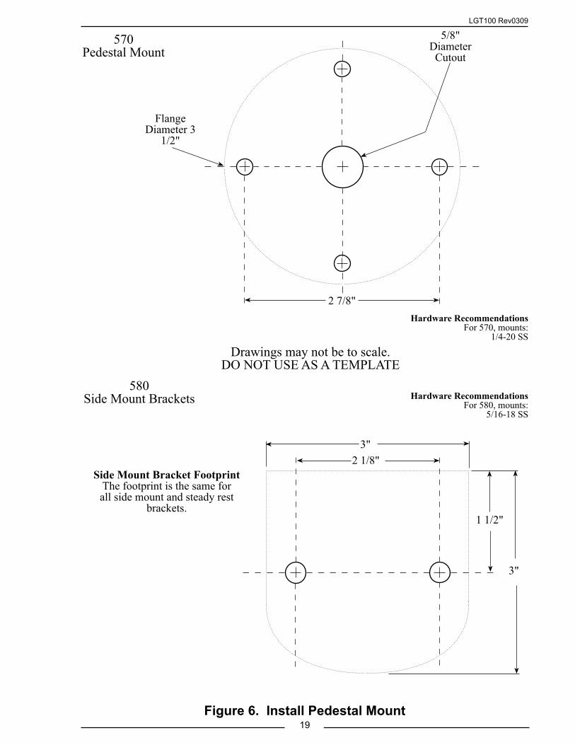
LGT100 Rev0309
19Figure 6. Install Pedestal Mount
Drawings may not be to scale.DO NOT USE AS A TEMPLATE
Side Mount Bracket FootprintThe footprint is the same for all side mount and steady rest
brackets.
3"
1 1/2"
3"
2 1/8"
580Side Mount Brackets
570Pedestal Mount
5/8" Diameter Cutout
2 7/8"
Flange Diameter 3
1/2"
Hardware RecommendationsFor 570, mounts:
1/4-20 SS
Hardware RecommendationsFor 580, mounts:
5/16-18 SS

LGT100 Rev0309
20
Install Quick Release Bracket Set for Tripod Models 600, 642, 656
The quick release mounting bracket set will hold an FRC tripod securely on the vehicle. The mounting bracket set consists of a lower base into which the bottom of the tripod legs rest, and an upper locking bracket, which has a quick release knob on the right side.
1. Place the tripod in position to check for fit.
Note: The mounting brackets are aligned left and not centered on each other.
2. Mark the mounting hole locations.
a. Align the left sides of the brackets and the left side mounting holes for the tripod to fit correctly.
b. The upper bracket is mounted with the pull knob to the right side.
c. Use the brackets as templates.
Helpful Hint: Mount the bottom bracket first. Attach the quick release bracket to the hole on the upper slide casting of the tripod. Rest the tripod legs in the base, and push the upper bracket in position flush to the mounting surface. Mark the top bracket hole locations.
3. Dill the mounting holes. The mounting brackets are predrilled for 1/4-20 hardware.
Note: Tripods with Focus lampheads require that 3/4" spacers be installed between the mounting surface and the brackets so the back of the lamphead will clear the mounting surface.
4. Install the mounting brackets (and spacers with Focus lamphead).
642Tripod
w/Focus LampheadQuick Release Bracket Set
(Shown with Focus lamphead spacers.)
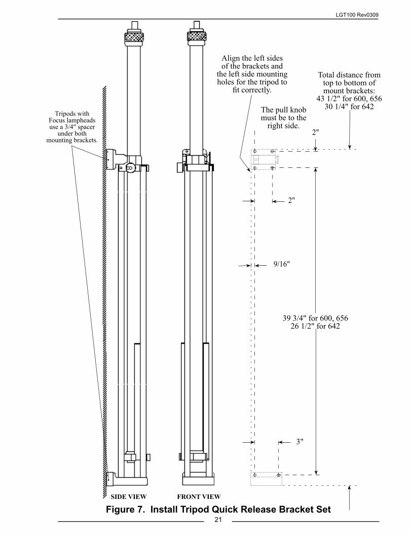
LGT100 Rev0309
21Figure 7. Install Tripod Quick Release Bracket Set
SIDE VIEW FRONT VIEW
Tripods with Focus lampheads use a 3/4" spacer
under both mounting brackets.
2"
3"
39 3/4" for 600, 65626 1/2" for 642
2"
Total distance from top to bottom of mount brackets:
43 1/2" for 600, 65630 1/4" for 642
Align the left sides of the brackets and
the left side mounting holes for the tripod to
fit correctly.
9/16"
The pull knob must be to the
right side.

LGT100 Rev0309
22
Install Quick Release Bracket for Portable Model 700The quick release brackets will hold an FRC portable lamphead securely to the
vehicle or a telescopic pole. Pull the quick release knob to install or remove the portable light.
703 Quick Release Bracket for Flat Surface Mounting1. Place the 703 bracket in position to check for lamphead fit.
2. Mark the mounting hole locations. Use the bracket as template.
3. Dill the mounting holes. The mounting bracket is predrilled for 5/16 hardware.
4. Pull the quick release knob to install the portable light on the bracket.
705 Quick Release Bracket for Pole MountingNote: If the 705 quick release is to be retrofit onto an existing pole the
lamphead to pole adapter P/N LT100 must be removed and replaced with the 705 adapter P/N X-LT214-705.
1. Place adapter on top of pole and tighten two set crews.
2. Place the 705 into the adapter and tighten the set screw.
3. Pull the quick release knob to install the portable light on the bracket.
703 Quick Release Bracket for Flat Surface Mounting
705 Quick Release Bracket for Pole Mounting
OptimumOPA700
FocusFCA700
NightMasterLTA700

LGT100 Rev0309
23Figure 8. Install Portable Light Quick Release Bracket
3 1/8"
2 1/4"
2"
3 3/8"
703Quick Release Bracket for
Flat Surface Mountingt
Drawings may not be to scale.DO NOT USE AS A TEMPLATE
Base (lamphead not shown) shown on a telescopic pole with a
705 quick release bracket.
703 Quick
Release
Note: For a retrofit the lamphead to pole adapter P/N LT100 must be removed and replaced with the
705 adapter P/N X-LT214-705.
705 Quick
Release
705 Pole
Mount Adapter
Base with Focus lamphead shown on a 703 quick
release bracket.
Hardware RecommendationsFor 703 mounts:
5/16-18 SS

LGT100 Rev0309
24
Install Brow Mount Models 800, 850Before mounting check the identification label on the lamphead for specific voltage
and current requirements. Check that the length of the power cord is correct.
Note: Before drilling holes place the light in position to check for fit. Ensure that the lamphead will clear all obstructions.
1. Place the light in position.
2. Mark the mounting hole locations and through hole for the wiring. Use the lamphead and attached brackets as a template.
3. Dill the mounting holes. The mounting brackets are predrilled for 1/4-20 or 5/16-18 hardware.
4. Place the four rubber washers in position at each mounting hole.
5. Secure the light.
6. Ensure that approved strain relief for the wiring is installed.
Wiring12/24 VDCConnect the BLACK wire to GROUND.Connect the RED (or WHITE) wire to POWER.120/240 VACConnect the GREEN wire to chassis GROUND.Connect the WHITE wire to RETURN.Connect the BLACK wire to POWER.
FCA850 Flat
Mount
OPA800 Contour Mount
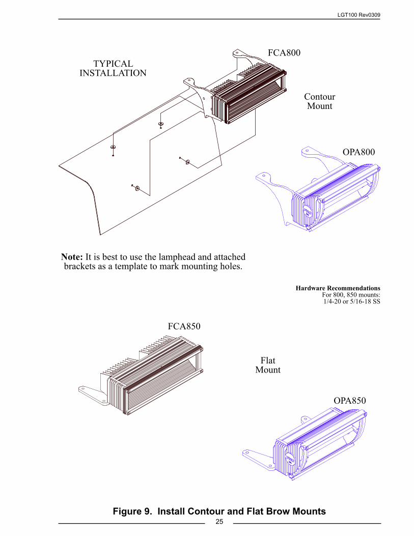
LGT100 Rev0309
25Figure 9. Install Contour and Flat Brow Mounts
Note: It is best to use the lamphead and attached brackets as a template to mark mounting holes.
TYPICAL INSTALLATION
OPA800
FCA850
OPA850
FCA800
Contour Mount
Flat Mount
Hardware RecommendationsFor 800, 850 mounts:1/4-20 or 5/16-18 SS

LGT100 Rev0309
26
MAINTENANCE
Bulb Replacement Optimum and Focus1. Ensure power is OFF and the lamphead is cool to the touch prior to replacing
the bulb.
2. Ensure the replacement bulb has the same voltage and wattage rating. (If there are two bulbs installed, each bulb will be half the listed wattage.)
3. Hold the glass in place while removing the bezels. Remove the four cap head screws and remove the bezels. Remove the glass.
Note: Optimum gasket is attached, the Focus gasket may come off.
4. Slide the bulb sideways into the spring contact and lift it out from the opposite side.
Note: When handling the new bulb avoid touching it except on the flat seal at either end. (Grease or oily fingerprints can cause damage the quartz bulb.) If the bulb is accidently touched, gently wipe it clean with alcohol.
5. Check both lamp base contacts to be sure they are perfectly clean.
6. Push one end of the bulb into the spring contact until the other end can be placed into the opposite contact. Rotate the lamp back and forth about its axis to ensure adequate seating of contacts.
Caution: Do not operate the light with the front glass removed.
7. Insert the Focus gasket in the groove with the splice positioned down.
8. Hold the glass in position. Ensure the glass is inside the lip on all four sides.
9. Install the bezels and secure with the four screws.
Note: Bulb life is extended when the lamphead is mounted so the bulb is in a horizontal position.
CleaningHigh intensity lights may, over time, develop a powdery white film on the reflector.
If this happens remove the glass (see bulb replacement procedure) and gently wipe the refelctor clean with a soft cloth.

LGT100 Rev0309
27Figure 10. Bulb Replacement Optimum and Focus
OPTIMUM LAMPHEAD
FOCUS LAMPHEAD
CAUTIONPosition the glass inside the housing lip on all four sides. Failure to do so may result in racking the glass when
the screws are tightened.
GlassBulb
ScrewBezel
Glass
ScrewBezel
Gasket Bulb
Splice in gasket should be down.
Lip
Glass
Housing
LipHousing

LGT100 Rev0309
28
Bulb Replacement NightMaster1. Ensure power is OFF and the lamphead is cool to the touch prior to replacing
the bulb.
2. Ensure the replacement bulb has the same voltage and wattage rating.
3. Loosen the two screws on each side of the lamphead. Open the glass cover (the gasket may also come off).
4. Slide the bulb sideways into the spring contact and lift it out from the opposite side.
Note: When handling the new bulb avoid touching it except on the flat seal at either end. (Grease or oily fingerprints can cause damage the quartz bulb.) If the bulb is accidently touched, gently wipe it clean with alcohol.
5. Check both lamp base contacts to be sure they are perfectly clean.
6. Push one end of the bulb into the spring contact until the other end can be placed into the opposite contact. Rotate the lamp back and forth about its axis to ensure adequate seating of contacts.
Caution: Do not operate the light with the front glass removed.
7. Ensure the gasket is in place. Close the glass cover and tighten the two screws. Do not over tighten the screws.
Note: Bulb life is extended when the bulb is mounted in a horizontal position.
Bulb Replacement Triple Cluster
12 Volt, 100 Watt, PAR 46 Bulb1. Ensure power is OFF and the lamphead is cool to the touch prior to replacing
the bulb.
2. Ensure the replacement bulb has the same voltage and wattage rating.
3. Remove the three screws (newer installations have one screw) and the collar that hold the bulb in place.
4. Remove the three wires one at a time from the bulb and connect them to the same terminal on the new bulb.
5. Put the new bulb in position and set the collar in place.
6. Install and tighten the screw(s).
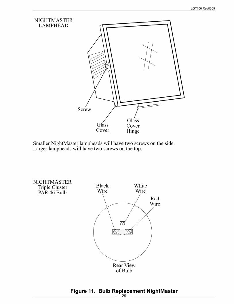
LGT100 Rev0309
29Figure 11. Bulb Replacement NightMaster
Black Wire
White Wire
Red Wire
NIGHTMASTER Triple Cluster PAR 46 Bulb
Smaller NightMaster lampheads will have two screws on the side. Larger lampheads will have two screws on the top.
Glass Cover
Screw
Glass Cover Hinge
Rear View of Bulb
NIGHTMASTER LAMPHEAD

LGT100 Rev0309
30
NO-SCRATCH FOR MODEL 530 TELESCOPIC POLE
Install No-Scratch Guide Collar and Guide Rail1. Install the telescopic pole according to instructions for side mouint telescopoic
pole.
Note: It is recommended that the Steady Rest Bracket be installed with the No-Scratch option.
2. Use the guide rail as a template and mark the mounting holes.
Note: The slot in the guide collar has to engage the guide rail when the pole is in the down position. The collar mounts on the handle of the pole, ensure the guide rail will be in the correct position before drilling mounting holes.
3. Drill holes and secure the guide rail.
4. Place the guide collar in position on the pole handle. Before tighting the two screws ensure that when the slot engages the rail the lamphead is in the correct position.
5. Tighten the screws.
Install No-Scratch Rubber Bumpers (Focus Lamphead Only)
The rubber bumpers help prevent scratching and denting by eliminating any metal-to-metal contact between the rear of the lamphead and the apparatus body surfaces when the pole is lowerd.
1. Place the rubber bumper in position on the bottom of the end cooling fin.
2. Using the bumper as a guide, drill a hole through the cooling fin with a number 30 bit.
3. Place the backing plate on the rivet and insert the rivet thru the bumper and mounting hole.
4. Secure the bumper with the rivet.No-Scratch Guide Rail and Guide Collar for 530 Telescopic Poles
Shown with a Steady Rest Bracket Installed
No-Scratch Rubber Bumpers
for Focus Lampheads
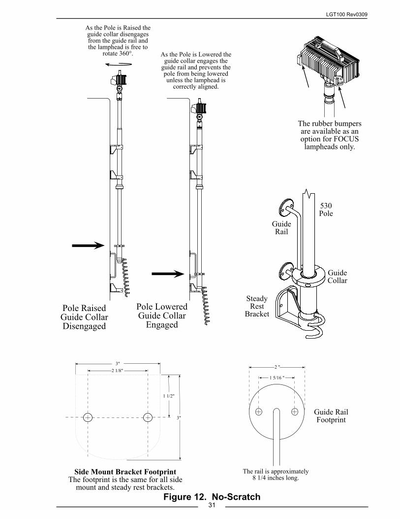
LGT100 Rev0309
31Figure 12. No-Scratch
3"
1 1/2"
3"
2 1/8"2 "
1 5/16 "
As the Pole is Raised the guide collar disengages from the guide rail and the lamphead is free to
rotate 360°. As the Pole is Lowered the guide collar engages the
guide rail and prevents the pole from being lowered unless the lamphead is
correctly aligned.
The rail is approximately 8 1/4 inches long.
Pole Raised Guide Collar Disengaged
Pole Lowered Guide Collar
Engaged
Side Mount Bracket FootprintThe footprint is the same for all side
mount and steady rest brackets.
Guide Rail Footprint
Guide Rail
Guide Collar
Steady Rest
Bracket
530 Pole
The rubber bumpers are available as an option for FOCUS lampheads only.
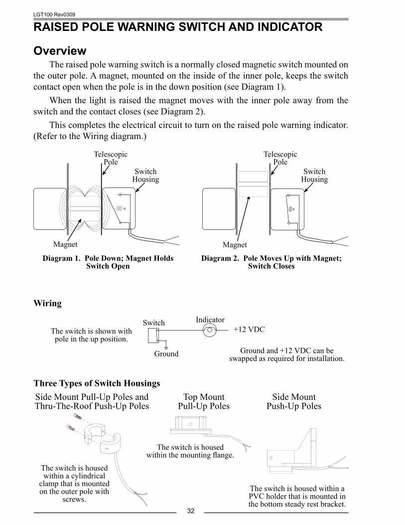
LGT100 Rev0309
32
RAISED POLE WARNING SWITCH AND INDICATOR
OverviewThe raised pole warning switch is a normally closed magnetic switch mounted on
the outer pole. A magnet, mounted on the inside of the inner pole, keeps the switch contact open when the pole is in the down position (see Diagram 1).
When the light is raised the magnet moves with the inner pole away from the switch and the contact closes (see Diagram 2).
This completes the electrical circuit to turn on the raised pole warning indicator. (Refer to the Wiring diagram.)
Magnet
Telescopic Pole
Switch Housing
Diagram 1. Pole Down; Magnet Holds Switch Open
Diagram 2. Pole Moves Up with Magnet; Switch Closes
Three Types of Switch HousingsSide Mount Pull-Up Poles andThru-The-Roof Push-Up Poles
Top MountPull-Up Poles
Side MountPush-Up Poles
The switch is housed within a cylindrical
clamp that is mounted on the outer pole with
screws.
The switch is housed within the mounting flange.
The switch is housed within a PVC holder that is mounted in the bottom steady rest bracket.
Wiring
Indicator
Ground
+12 VDCThe switch is shown with pole in the up position.
Switch
Ground and +12 VDC can be swapped as required for installation.
Switch Housing
Telescopic Pole
Magnet
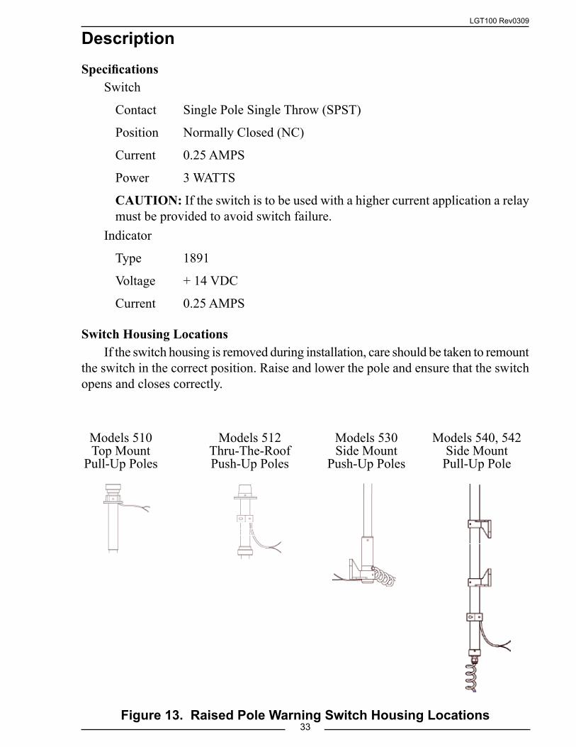
LGT100 Rev0309
33Figure 13. Raised Pole Warning Switch Housing Locations
Description
SpecificationsSwitch
Contact Single Pole Single Throw (SPST)
Position Normally Closed (NC)
Current 0.25 AMPS
Power 3 WATTS
CAUTION: If the switch is to be used with a higher current application a relay must be provided to avoid switch failure.
Indicator
Type 1891
Voltage + 14 VDC
Current 0.25 AMPS
Switch Housing LocationsIf the switch housing is removed during installation, care should be taken to remount
the switch in the correct position. Raise and lower the pole and ensure that the switch opens and closes correctly.
Models 540, 542Side MountPull-Up Pole
Models 510Top Mount
Pull-Up Poles
Models 530Side Mount
Push-Up Poles
Models 512Thru-The-Roof Push-Up Poles

LGT100 Rev0309
34
Parts ListPart Number DescriptionLT-S100 Kit, Raised Pole Warning, 510 Poles
1 . LT-S347SW . Switch Assembly, Top Flange, Magnetic, NC . LT-S347C-SW . Switch Assembly, Top Flange C/E, Magnetic, NC
2 . LT-S337 . Magnet, Inner Pole3 . LT-SZL606 . Indicator Assembly
LT-S101 Kit, Raised Pole Warning, 512, 540, 542 Poles4 . LT-S336SW . Switch Assembly, Donut, Magnetic, NC2 . LT-S337 . Magnet, Inner Pole3 . LT-SZL606 . Indicator Assembly
LT-S102 Kit, Raised Pole Warning, 530 Poles-LT-S102-B Kit, Raised Pole Warning, 530 Poles, 5" Bracket-LT-S102-C Kit, Raised Pole Warning, 530 Poles, 7" Bracket
5 . LT-S304SW . Switch Assembly, Steady Rest,-5 . LT-S305SW . Switch Assembly, Steady Rest 5"-5 . LT-S306SW . Switch Assembly, Steady Rest 7"6 . . LT350C . . Switch Holder, PVC7 . . LT-808-2000 . . Switch, Magnetic, NC8 . LT-S318C . Magnet, Pole End w/Strain Relief 3 . LT-SZL606 . Indicator Assembly
4
2
3
1
85
6
7
Figure 14. Raised Pole Warning Switch Parts List

LGT100 Rev0309
35
This page intentionally left blank.

ENGLISH
DEUTSCHITALIAN
OESPAÑ
OL
INSTALLATION GUIDEFRAN
ÇAIS
AXIS Q7401 Video Encoder

About this DocumentThis document includes instructions for installing the AXIS Q7401 on your network. Previous experience of networking will be beneficial when installing the product.
Legal ConsiderationsVideo and audio surveillance can be prohibited by laws that vary from country to country. Check the laws in your local region before using this product for surveillance purposes.This product includes one (1) H.264 decoder license. To purchase further licenses, contact your reseller.
Electromagnetic Compatibility (EMC)This equipment generates, uses and can radiate radio frequency energy and, if not installed and used in accordance with the instructions, may cause harmful interference to radio communications. However, there is no guarantee that interference will not occur in a particular installation.
If this equipment does cause harmful interference to radio or television reception, which can be determined by turning the equipment off and on, the user is encouraged to try to correct the interference by one or more of the following measures: Re-orient or relocate the receiving antenna. Increase the separation between the equipment and receiver. Connect the equipment to an outlet on a different circuit to the receiver. Consult your dealer or an experienced radio/TV technician for help. Shielded (STP) network cables must be used with this unit to ensure compliance with EMC standards.
USA - This equipment has been tested and found to comply with the limits for a Class B computing device pursuant to Subpart B of Part 15 of FCC rules, which are designed to provide reasonable protection against such interference when operated in a commercial environment. Operation of this equipment in a residential area is likely to cause interference, in which case the user at his/her own expense will be required to take whatever measures may be required to correct the interference.
Canada - This Class B digital apparatus complies with Canadian ICES-003.
Europe - This digital equipment fulfills the requirements for radiated emission according to limit B of EN55022, and the requirements for immunity according to EN55024 residential and commercial industry.
Japan - This is a class B product based on the standard of the Voluntary Control Council for Interference from Information Technology Equipment (VCCI). If this is used near a radio or television receiver in a domestic environment, it may cause radio interference. Install and use the equipment according to the instruction manual.
Australia - This electronic device meets the requirements of the Radio communications (Electromagnetic Compatibility) Standard AS/NZS CISPR22.
Equipment Modifications This equipment must be installed and used in strict accordance with the instructions given in the user documentation. This equipment contains no user-serviceable components. Unauthorized equipment changes or modifications will invalidate all applicable regulatory certifications and approvals.
LiabilityEvery care has been taken in the preparation of this document. Please inform your local Axis office of any inaccuracies or omissions. Axis Communications AB cannot be held responsible for any technical or typographical errors and reserves the right to make changes to the product and documentation without prior notice. Axis Communications AB makes no warranty of any kind with regard to the material contained within this document, including, but not limited to, the implied warranties of merchantability and fitness for a particular purpose. Axis Communications AB shall not be liable nor responsible for incidental or consequential damages in connection with the furnishing, performance or use of this material.
RoHSThis product complies with both the European RoHS directive, 2002/95/EC, and the Chinese RoHS regulations, ACPEIP.
WEEE DirectiveThe European Union has enacted a Directive 2002/96/EC on Waste Electrical and Electronic Equipment (WEEE Directive). This directive is applicable in the European Union member states.The WEEE marking on this product (see right) or its documentation indicates that the product must not be disposed of together with household waste. To prevent possible harm to human health and/or the environment, the product must be disposed of in an approved and environmentally safe recycling process. For further information on how to dispose of this product correctly, contact the product supplier, or the local authority responsible for waste disposal in your area. Business users should contact the product supplier for information on how to dispose of this product correctly. This product should not be mixed with other commercial waste. For more information, visit www.axis.com/techsup/commercial waste.
SupportShould you require any technical assistance, please contact your Axis reseller. If your questions cannot be answered immediately, your reseller will forward your queries through the appropriate channels to ensure a rapid response. If you are connected to the Internet, you can:• download user documentation and firmware updates• find answers to resolved problems in the FAQ database.
Search by product, category, or phrases• report problems to Axis support by logging in to your
private support area.
The AXIS Q7401 uses a 3.0V CR2032 Lithium battery, for more information please see page 81.

AXIS Q7401 Installation Guide Page 3
ENGLISH
AXIS Q7401 Video EncoderInstallation Guide
This installation guide provides instructions for installing a AXIS Q7401 Video Encoder on your network. For all other aspects of using the product, please see the product User’s Manual, available on the CD included in this package, or from www.axis.com
Installation stepsFollow these steps to install the AXIS Q7401 Video Encoder on your local network (LAN):
1. Check the package contents against the list below.
2. Hardware overview. See page page 4.
3. Install the hardware. See page 5.4. Assign an IP address. See page 6.
5. Set the password. See page 9.
Package contentsItem Models/variants/notes
Axis video encoder models AXIS Q7401
Power adapter models Type PS-K or PS-T
Mounting kit • 2 screws and plugs to mount the encoder to a concrete wall
• 4 Surface protection pads
• Terminal block connectors (I/O: 6-pin connector, RS-485/422: 2x 2-pin connector, Power: 2-pin connector)
CD AXIS Network Video Product CD, including product documentation, installation tools and other software
Printed Materials AXIS Q7401 Installation Guide (this document)Axis Warranty Document
Important! This product must be used in compliance with local laws and regulations.
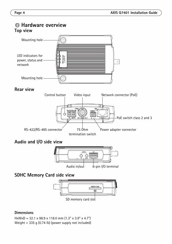
Page 4 AXIS Q7401 Installation Guide
Hardware overviewTop view
Rear view
Audio and I/O side view
SDHC Memory Card side view
DimensionsHxWxD = 32.1 x 98.9 x 118.0 mm (1.3" x 3.9" x 4.7")Weight = 335 g (0.74 lb) (power supply not included)
Mounting hole
Mounting hole
LED indicators forpower, status and network
Control button
Power adapter connectorRS-422/RS-485 connector
Video input Network connector (PoE)
PoE switch class 2 and 3
75 Ohmtermination switch
Audio in/out 6-pin I/O terminal
SD memory card slot

AXIS Q7401 Installation Guide Page 5
ENGLISH
Install the hardware
Mount the video encoderThe video encoder is supplied with a mounting kit containing screws, plugs, and protective pads for mounting the video encoder to a concrete wall:
1. Place the video encoder against the wall, and mark the location of the two mounting holes (see page 4) through which the video encoder will be attached.
2. Remove the video encoder and drill the two mounting holes.
3. Punch out the four protective pads and apply them to the underside of the video encoder.
4. Insert the wall plugs into the wall, position the video encoder, and attach it to the wall using the screws provided.
Connect the cables1. Connect the encoder to the network using a shielded network cable.
2. Optionally connect external input/output devices, e.g. alarm devices. See page 12 for information on the terminal connector pins.
3. Optionally connect an active speaker and/or external microphone.4. Connect the camera.
5. Connect power, using one of the methods listed below:
• PoE (Power over Ethernet). If available, this is automatically detected when the network cable is connected (see above).
• Connect the supplied indoor power supply to the power connector on the encoder. 6. Check that the indicator LED:s indicate the correct conditions. See the table on page 15 for
further details.
! IMPORTANT! - The casing of the AXIS Q7401 is not approved for outdoor use - the product may only be installed in indoor environments.

Page 6 AXIS Q7401 Installation Guide
Assign an IP addressMost networks today have a DHCP server that automatically assigns IP addresses to connected devices. If your network does not have a DHCP server the AXIS Q7401 will use 192.168.0.90 as the default IP address.
AXIS IP Utility and AXIS Camera Management are recommended methods for setting an IP address in Windows. These free applications are available on the Axis Network Video Product CD supplied with this product, or they can be downloaded from www.axis.com/techsup. Depending on the number of cameras you wish to install, use the method that suits you best.
Notes:• If assigning the IP address fails, check that there is no firewall blocking the operation.• For other methods of assigning or discovering the IP address of the AXIS Q7401, e.g. in other operating
systems, see page 11.
Method Recommended for Operating system
AXIS IP Utility See page 7
Single video encoderSmall installations
Windows
AXIS Camera ManagementSee page 8
Multiple video encodersLarge installationsInstallation on a different subnet
Windows 2000Windows XP ProWindows 2003 ServerWindows Vista

AXIS Q7401 Installation Guide Page 7
ENGLISH
AXIS IP Utility - single camera/small installationAXIS IP Utility automatically discovers and displays Axis devices on your network. The application can also be used to manually assign a static IP address.
Note that the computer running AXIS IP Utility must be on the same network segment (physical subnet) as the AXIS Q7401.
Automatic discovery1. Check that the AXIS Q7401 is connected to the network and that power has been applied.2. Start AXIS IP Utility.
3. When the AXIS Q7401 appears in the window, double-click it to open its home page.
4. See page 9 for instructions on how to assign the password.
Set the IP address manually (optional)1. Acquire an unused IP address on the same network segment as your computer.
2. Select the AXIS Q7401 in the list.
3. Click the button Assign new IP address to selected device and enter the IP address.
4. Click the Assign button and follow the instructions.5. Click the Home Page button to access the video encoder’s web pages.
6. See page 9 for instructions on how to set the password.
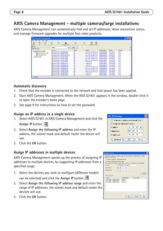
Page 8 AXIS Q7401 Installation Guide
AXIS Camera Management - multiple cameras/large installationsAXIS Camera Management can automatically find and set IP addresses, show connection status, and manage firmware upgrades for multiple Axis video products.
Automatic discovery1. Check that the encoder is connected to the network and that power has been applied.2. Start AXIS Camera Management. When the AXIS Q7401 appears in the window, double-click it
to open the encoder’s home page. 3. See page 9 for instructions on how to set the password.
Assign an IP address in a single device1. Select AXIS Q7401 in AXIS Camera Management and click the
Assign IP button.
2. Select Assign the following IP address and enter the IP address, the subnet mask and default router the device will use.
3. Click the OK button.
Assign IP addresses in multiple devicesAXIS Camera Management speeds up the process of assigning IP addresses to multiple devices, by suggesting IP addresses from a specified range.
1. Select the devices you wish to configure (different models
can be selected) and click the Assign IP button.
2. Select Assign the following IP address range and enter the range of IP addresses, the subnet mask and default router the devices will use.
3. Click the OK button.
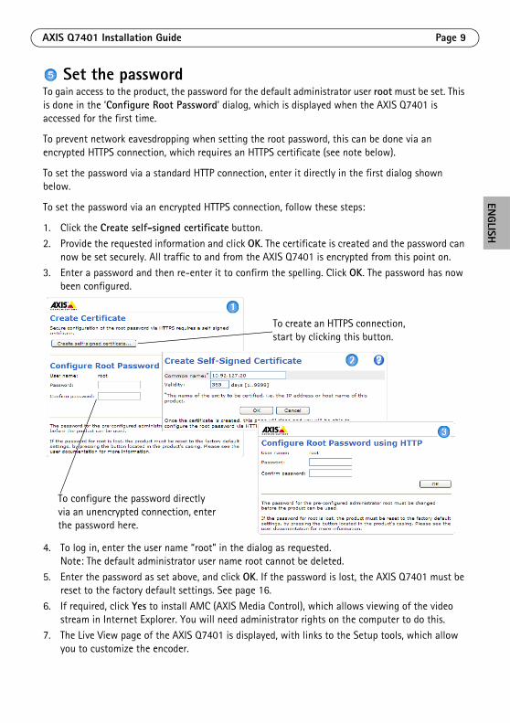
AXIS Q7401 Installation Guide Page 9
ENGLISH
Set the passwordTo gain access to the product, the password for the default administrator user root must be set. This is done in the ‘Configure Root Password’ dialog, which is displayed when the AXIS Q7401 is accessed for the first time.
To prevent network eavesdropping when setting the root password, this can be done via an encrypted HTTPS connection, which requires an HTTPS certificate (see note below).
To set the password via a standard HTTP connection, enter it directly in the first dialog shown below.
To set the password via an encrypted HTTPS connection, follow these steps:
1. Click the Create self-signed certificate button.
2. Provide the requested information and click OK. The certificate is created and the password can now be set securely. All traffic to and from the AXIS Q7401 is encrypted from this point on.
3. Enter a password and then re-enter it to confirm the spelling. Click OK. The password has now been configured.
4. To log in, enter the user name “root” in the dialog as requested. Note: The default administrator user name root cannot be deleted.
5. Enter the password as set above, and click OK. If the password is lost, the AXIS Q7401 must be reset to the factory default settings. See page 16.
6. If required, click Yes to install AMC (AXIS Media Control), which allows viewing of the video stream in Internet Explorer. You will need administrator rights on the computer to do this.
7. The Live View page of the AXIS Q7401 is displayed, with links to the Setup tools, which allow you to customize the encoder.
To configure the password directly via an unencrypted connection, enter the password here.
To create an HTTPS connection, start by clicking this button.
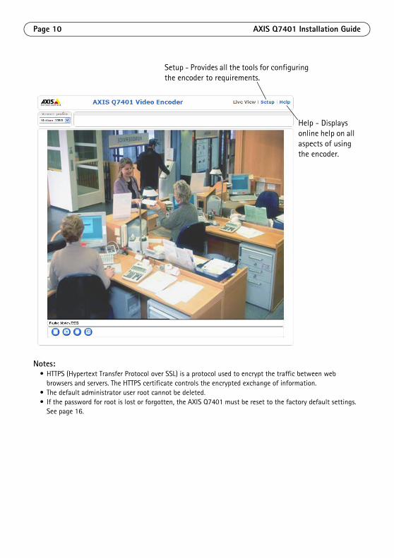
Page 10 AXIS Q7401 Installation Guide
Notes:• HTTPS (Hypertext Transfer Protocol over SSL) is a protocol used to encrypt the traffic between web
browsers and servers. The HTTPS certificate controls the encrypted exchange of information.• The default administrator user root cannot be deleted.• If the password for root is lost or forgotten, the AXIS Q7401 must be reset to the factory default settings.
See page 16.
Setup - Provides all the tools for configuring the encoder to requirements.
Help - Displays online help on all aspects of using the encoder.

AXIS Q7401 Installation Guide Page 11
ENGLISH
Other methods of setting the IP addressThe table below shows the other methods available for setting or discovering the IP address. All methods are enabled by default, and all can be disabled.
Set the IP address with ARP/Ping1. Acquire a free static IP address on the same network segment your computer is connected to.
2. Locate the serial number (S/N) on the AXIS Q7401 label.
3. Open a command prompt on your computer and enter the following commands:
4. Check that the network cable is connected to the AXIS Q7401 and then start/restart the AXIS Q7401, by disconnecting and reconnecting power. If PoE is used, start/restart the AXIS Q7401 by disconnecting and then reconnecting the network cable.
5. Close the command prompt when you see ‘Reply from 192.168.0.125:...’ or similar.
6. In your browser, type in http://<IP address> in the Location/Address field and press Enter on your keyboard.
Notes:• To open a command prompt in Windows: from the Start menu, select Run... and type cmd. Click OK.• To use the ARP command on a Mac OS X, use the Terminal utility in Application > Utilities.
Use in operating system
Notes
UPnP™
Windows When enabled on your computer, the video encoder is automatically detected and added to “My Network Places.”
Bonjour MAC OSX (10.4 or later)
Applicable to browsers with support for Bonjour. Navigate to the Bonjour bookmark in your browser (e.g. Safari) and click on the link to access the video encoder’s web pages.
AXIS Dynamic DNS Service
All A free service from Axis that allows you to quickly and simply install your video encoder. Requires an Internet connection with no HTTP proxy. See www.axiscam.net for more information.
ARP/Ping All See below. The command must be issued within 2 minutes of connecting power to the video encoder.
View DHCP server admin pages
All To view the admin pages for the network DHCP server, see the server’s own documentation.
Windows syntax Windows example
arp -s <IP Address> <Serial Number>ping -l 408 -t <IP Address>
arp -s 192.168.0.125 00-40-8c-18-10-00ping -l 408 -t 192.168.0.125
UNIX/Linux/Mac syntax UNIX/Linux/Mac example
arp -s <IP Address> <Serial Number> tempping -s 408 <IP Address>
arp -s 192.168.0.125 00:40:8c:18:10:00 tempping -s 408 192.168.0.125

Page 12 AXIS Q7401 Installation Guide
Unit connectorsNetwork connector - RJ-45 Ethernet connector. Supports Power over Ethernet (PoE). Using shielded cables is recommended.
PoE classification switch - Power over Ethernet (IEEE 802.3af), selectable power classification:
• Class 2 - max 6.49W• Class 3 - max 12.95W (default)
Note: Power classification is performed at power up. If the video encoder does not power the connected analog camera, select PoE Class 2 to inform the PoE switch that the video encoder only needs max 6.49W. PoE Class 3 is the default setting.
Power connector - 2-pin terminal block used for power input or power output.
• Power input - To supply power to the video encoder with the supplied power adapter or an external power supply 8-20V DC, max. 7.2W.
• Power output - the video encoder can supply power to an analog camera or auxiliary equipment if powered by PoE, 12V DC max 5W (420mA).
Notes:• The video encoder can deliver a maximum of 5W (420mA) with PoE. This includes the output on the power
connector and the I/O terminal connector.• Do not connect a power supply if the video encoder is connected to PoE.
Audio in - 3.5mm input for a mono microphone, or a line-in mono signal (left channel is used from a stereo signal).
Audio out - Audio output (line level) that can be connected to a public address (PA) system or an active speaker with a built-in amplifier. A pair of headphones can also be attached. A stereo connector must be used for the audio out.
Function Pin number Description
GND 1 Ground
DC Power 2 Power input 8-20V DC, max 7.2W or Power output 12V DC, max 5W (420mA).
1 2

AXIS Q7401 Installation Guide Page 13
ENGLISH
I/O terminal connector - Used in applications for e.g. motion detection, event triggering, time lapse recording and alarm notifications. In addition to an auxiliary power and a GND pin, the AXIS Q7401 has 4 pins that can be configured as either input or out put. These pins provide the interface to:
• Transistor output - For connecting external devices such as relays and LEDs. Connected devices can be activated by AXIS VAPIX API, output buttons on the Live View page or by an Event Type. The output will show as active (shown under Event Configuration > Port Status) if the alarm device is activated.
• Digital input - An alarm input for connecting devices that can toggle between an open and closed circuit, for example: PIRs, door/window contacts, glass break detectors, etc. When a signal is received the state changes and the input becomes active (shown under Event Configuration > Port Status.).
Function Pin number Notes Specifications
GND 1 Ground
12VDC Power
2 Can be used to power auxiliary equipment.Notes:
• This pin can only be used as power out.
• Same voltage as pin 2 of the power connector.
Max load = 100mA
Configurable (Input or Output)
3 - 6 Digital input - Connect to GND to activate, or leave floating (or unconnected) to deactivate.
Min input = - 40V DCMax input = + 40V DC
Digital output - Uses an open-drain NFET transistor with the source connected to GND. If used with an external relay, a diode must be connected in parallel with the load, for protection against voltage transients.
Max load = 100mAMax voltage = + 40V DC

Page 14 AXIS Q7401 Installation Guide
The following connection diagram gives an example of how to connect an auxiliary device to the AXIS Q7401.
1
2E.g. push button
I/O 3 configured as input
I/O 4 configured as output
* Note: Same voltage as pin 2 of the power connector
AXIS Q7401
3.3V
*12V max 100mA
D
S
G
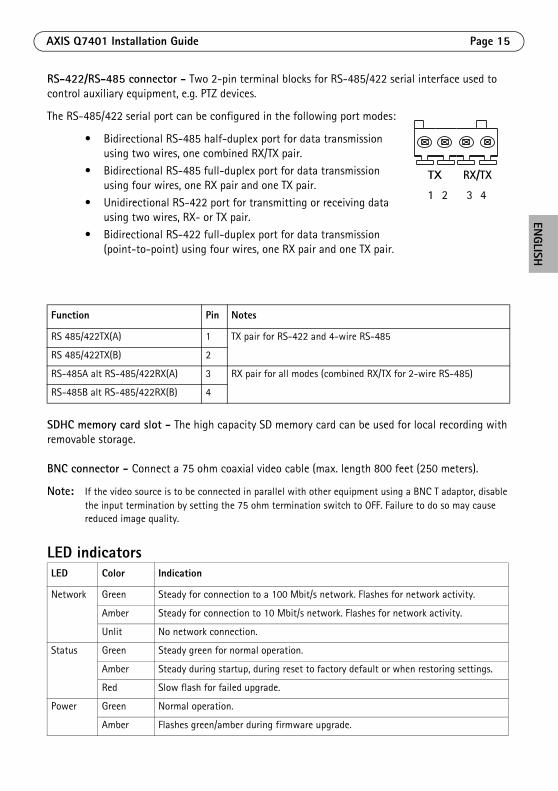
AXIS Q7401 Installation Guide Page 15
ENGLISH
RS-422/RS-485 connector - Two 2-pin terminal blocks for RS-485/422 serial interface used to control auxiliary equipment, e.g. PTZ devices.
The RS-485/422 serial port can be configured in the following port modes:
• Bidirectional RS-485 half-duplex port for data transmission using two wires, one combined RX/TX pair.
• Bidirectional RS-485 full-duplex port for data transmission using four wires, one RX pair and one TX pair.
• Unidirectional RS-422 port for transmitting or receiving data using two wires, RX- or TX pair.
• Bidirectional RS-422 full-duplex port for data transmission (point-to-point) using four wires, one RX pair and one TX pair.
SDHC memory card slot - The high capacity SD memory card can be used for local recording with removable storage.
BNC connector - Connect a 75 ohm coaxial video cable (max. length 800 feet (250 meters).
Note: If the video source is to be connected in parallel with other equipment using a BNC T adaptor, disable the input termination by setting the 75 ohm termination switch to OFF. Failure to do so may cause reduced image quality.
LED indicators
Function Pin Notes
RS 485/422TX(A) 1 TX pair for RS-422 and 4-wire RS-485
RS 485/422TX(B) 2
RS-485A alt RS-485/422RX(A) 3 RX pair for all modes (combined RX/TX for 2-wire RS-485)
RS-485B alt RS-485/422RX(B) 4
LED Color Indication
Network Green Steady for connection to a 100 Mbit/s network. Flashes for network activity.
Amber Steady for connection to 10 Mbit/s network. Flashes for network activity.
Unlit No network connection.
Status Green Steady green for normal operation.
Amber Steady during startup, during reset to factory default or when restoring settings.
Red Slow flash for failed upgrade.
Power Green Normal operation.
Amber Flashes green/amber during firmware upgrade.
1 2 3 4
TX RX/TX
Page 16 AXIS Q7401 Installation Guide
Resetting to the factory default settingsThis will reset all parameters, including the IP address, to the Factory Default settings:
1. Disconnect the power from the AXIS Q7401, or if PoE is used disconnect the network cable.2. Press and hold the Control button and reconnect power or the network cable if PoE is used.
3. Keep the Control button pressed until the Status indicator displays amber (this may take up to 15 seconds).
4. Release the Control button. When the Status indicator displays green (which can take up to 1 minute) the process is complete and the video encoder has been reset.
5. Re-assign the IP address, using one of the methods described in this document.
It is also possible to reset parameters to the original factory default settings via the web interface. For more information, please see the online help or the user’s manual.
Accessing the AXIS Q7401 from the InternetOnce installed, your AXIS Q7401 is accessible on your local network (LAN). To access the video encoder from the Internet, network routers must be configured to allow incoming traffic, which is usually done on a specific port.
• HTTP port (default port 80) for viewing and configuration
• RTSP port (default port 554) for viewing H.264 video streams
Please refer to the documentation for your router for further instructions. For more information on this and other topics, visit the Axis Support Web at www.axis.com/techsup
Further informationThe user’s manual is available from the Axis Web site at www.axis.com or from the Axis Network Video Product CD supplied with this product.
Tip! Visit www.axis.com/techsup to check if there is updated firmware available for your AXIS Q7401. To see the currently installed firmware version, see the About web page in the product’s Setup tools.

AXIS Q7401 Guide d'installation Page 17
FRANÇAIS
Encodeur vidéo AXIS Q7401 Guide d'installation
Ce guide d’installation vous explique comment installer un Encodeur vidéo AXIS Q7401 sur votre réseau. Pour toute autre question concernant l’utilisation du produit, reportez-vous au Manuel de l’utilisateur du produit, que vous trouverez sur le CD joint ou sur le site www.axis.com
Étapes de l'installationProcédez comme suit pour installer l’Encodeur vidéo AXIS Q7401 sur votre réseau local (LAN) :
1. Vérifiez le contenu de la livraison à l'aide de la liste ci-dessous.
2. Présentation du matériel. Reportez-vous à la page page 18.
3. Installation du matériel. Reportez-vous à la page 19.4. Attribution d’une adresse IP. Reportez-vous à la
page 20.5. Configuration du mot de passe. Reportez-vous à la
page 23.
Contenu de l'emballageArticle Modèles/variantes/remarques
Modèles d’encodeur vidéo Axis
AXIS Q7401
Modèles d'adaptateur secteur
Type PS-K ou PS-T
Kit de montage • 2 vis et chevilles pour fixer l’encodeur sur un mur en béton
• 4 patins de protection de surface
• Connecteurs pour terminaux (E/S : connecteur à 6 broches, RS-485/422 : connecteur 2x 2 broches, alimentation : connecteur à 2 broches)
CD CD du produit de vidéo sur IP AXIS comprenant les outils d'installation, les autres logiciels et la documentation
Documentation AXIS Q7401 Guide d'installation (le présent document)Document de garantie d'Axis
Important ! Ce produit doit être utilisé conformément aux lois et dispositions locales en vigueur.

Page 18 AXIS Q7401 Guide d’installation
Présentation du matérielVue de dessus
Vue de derrière
Vue de côté E/S et audio terminal E/S à 6 broches
Vue de côté carte mémoire SDHC logement de carte mémoire SD
DimensionsH x L x P = 32,1 x 98,9 x 118,0 mmPoids = 335 g (alimentation exclue)
Trou de fixation
Trou de fixation
Témoins DELd'alimentation,
d’état et de réseau
Bouton de commande
Connecteur d’adaptateur secteurConnecteur RS-422/RS-485
Entrée vidéo Connecteur réseau (PoE)
Commutateur PoEclasse 2 et 3
75 ohmscommutateur de terminaison
Entrée/sortie audio 6 broches terminal d´E/S
Emplacement de la carte mémoire SD

AXIS Q7401 Guide d'installation Page 19
FRANÇAIS
Installation du matériel
Montage de l’encodeur vidéoL’encodeur vidéo est fourni avec un kit de montage contenant des vis, des chevilles et des patins de protection pour la fixation de l’encodeur vidéo sur un mur en béton :
1. Placez l’encodeur contre le mur et marquez l’emplacement des deux trous de fixation (cf. page 18) qui seront utilisés pour la fixation de l’encodeur vidéo.
2. Retirez l’encodeur vidéo et percez les deux trous.
3. Sortez les quatre patins de protection de leur emballage et posez sur le dessous de l’encodeur vidéo.
4. Insérez les chevilles dans le mur, positionnez l’encodeur vidéo et fixez-le au mur à l’aide des vis fournies.
Branchement des câbles1. Branchez l’encodeur sur le réseau à l'aide d'un câble réseau blindé.
2. Si vous le souhaitez, connectez des dispositifs d’entrée/sortie externes, par exemple des systèmes d'alarme. Reportez-vous à la page 27 pour plus d'informations sur les broches du connecteur pour terminaux.
3. Si vous le souhaitez, branchez un haut-parleur actif et/ou un micro externe.
4. Branchez la caméra.
5. Branchez l'alimentation en suivant une des méthodes décrites ci-dessous :• PoE (alimentation par Ethernet). Si la PoE est disponible, elle est automatiquement
détectée lorsque le câble réseau est connecté (voir ci-dessus).• Branchez le bloc d’alimentation intérieure fourni sur le connecteur d’alimentation de
l’encodeur. 6. Vérifiez que les témoins DEL indiquent les conditions correctes. Pour plus d'informations,
reportez-vous au tableau de la page 31.
! IMPORTANT ! - Le boîtier de votre AXIS Q7401 n'est pas approuvé pour une utilisation extérieure. Le produit doit être uniquement installé en intérieur.
Page 20 AXIS Q7401 Guide d’installation
Attribution d'une adresse IPAujourd'hui, la plupart des réseaux sont équipés d’un serveur DHCP qui affecte automatiquement des adresses IP aux périphériques connectés. Si votre réseau en est dépourvu, votre AXIS Q7401 utilisera 192.168.0.90 comme adresse IP par défaut.
Il est conseillé d’utiliser AXIS IP Utility et AXIS Camera Management pour configurer une adresse IP sous Windows. Ces deux applications gratuites sont disponibles sur le CD du produit de vidéo sur IP Axis joint. Vous pouvez également les télécharger à partir du site www.axis.com/techsup. Choisissez la méthode qui vous convient le mieux, selon le nombre de caméras à installer.
Remarques :• En cas d'échec de l'attribution d'adresse IP, vérifiez qu'aucun pare-feu ne bloque l'opération.• Pour connaître les autres méthodes d’attribution ou de détection de l'adresse IP de votre AXIS Q7401, par
exemple sur d'autres systèmes d'exploitation, reportez-vous à la page 25.
Méthode Recommandée pour Système d'exploitation
AXIS IP Utility Voir page 21
Un seul encodeur vidéoPetites installations
Windows
AXIS Camera ManagementVoir page 22
Plusieurs encodeurs vidéoGrandes installationsInstallation sur un autre sous-réseau
Windows 2000Windows XP ProWindows 2003 ServerWindows Vista
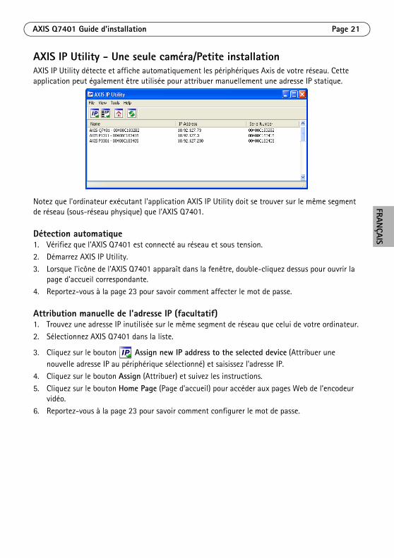
AXIS Q7401 Guide d'installation Page 21
FRANÇAIS
AXIS IP Utility - Une seule caméra/Petite installationAXIS IP Utility détecte et affiche automatiquement les périphériques Axis de votre réseau. Cette application peut également être utilisée pour attribuer manuellement une adresse IP statique.
Notez que l'ordinateur exécutant l'application AXIS IP Utility doit se trouver sur le même segment de réseau (sous-réseau physique) que l’AXIS Q7401.
Détection automatique1. Vérifiez que l’AXIS Q7401 est connecté au réseau et sous tension.2. Démarrez AXIS IP Utility.
3. Lorsque l'icône de l’AXIS Q7401 apparaît dans la fenêtre, double-cliquez dessus pour ouvrir la page d'accueil correspondante.
4. Reportez-vous à la page 23 pour savoir comment affecter le mot de passe.
Attribution manuelle de l'adresse IP (facultatif)1. Trouvez une adresse IP inutilisée sur le même segment de réseau que celui de votre ordinateur.
2. Sélectionnez AXIS Q7401 dans la liste.
3. Cliquez sur le bouton Assign new IP address to the selected device (Attribuer une nouvelle adresse IP au périphérique sélectionné) et saisissez l'adresse IP.
4. Cliquez sur le bouton Assign (Attribuer) et suivez les instructions.
5. Cliquez sur le bouton Home Page (Page d'accueil) pour accéder aux pages Web de l’encodeur vidéo.
6. Reportez-vous à la page 23 pour savoir comment configurer le mot de passe.
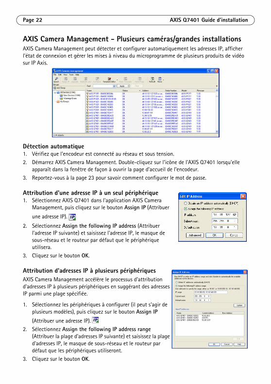
Page 22 AXIS Q7401 Guide d’installation
AXIS Camera Management - Plusieurs caméras/grandes installationsAXIS Camera Management peut détecter et configurer automatiquement les adresses IP, afficher l’état de connexion et gérer les mises à niveau du microprogramme de plusieurs produits de vidéo sur IP Axis.
Détection automatique1. Vérifiez que l’encodeur est connecté au réseau et sous tension.
2. Démarrez AXIS Camera Management. Double-cliquez sur l'icône de l'AXIS Q7401 lorsqu'elle apparaît dans la fenêtre de façon à ouvrir la page d'accueil de l’encodeur.
3. Reportez-vous à la page 23 pour savoir comment configurer le mot de passe.
Attribution d'une adresse IP à un seul périphérique1. Sélectionnez AXIS Q7401 dans l'application AXIS Camera
Management, puis cliquez sur le bouton Assign IP (Attribuer
une adresse IP).
2. Sélectionnez Assign the following IP address (Attribuer l’adresse IP suivante) et saisissez l’adresse IP, le masque de sous-réseau et le routeur par défaut que le périphérique utilisera.
3. Cliquez sur le bouton OK.
Attribution d'adresses IP à plusieurs périphériquesAXIS Camera Management accélère le processus d’attribution d'adresses IP à plusieurs périphériques en suggérant des adresses IP parmi une plage spécifiée.
1. Sélectionnez les périphériques à configurer (il peut s'agir de plusieurs modèles), puis cliquez sur le bouton Assign IP
(Attribuer une adresse IP).
2. Sélectionnez Assign the following IP address range (Attribuer la plage d'adresses IP suivante) et saisissez la plage d'adresses IP, le masque de sous-réseau et le routeur par défaut que les périphériques utiliseront.
3. Cliquez sur le bouton OK.
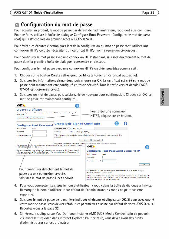
AXIS Q7401 Guide d'installation Page 23
FRANÇAIS
Configuration du mot de passePour accéder au produit, le mot de passe par défaut de l’administrateur, root, doit être configuré. Pour ce faire, utilisez la boîte de dialogue Configure Root Password (Configurer le mot de passe root) qui s'affiche lors du premier accès à l’AXIS Q7401.
Pour éviter les écoutes électroniques lors de la configuration du mot de passe root, utilisez une connexion HTTPS cryptée nécessitant un certificat HTTPS (voir la remarque ci-dessous).
Pour configurer le mot passe avec une connexion HTTP standard, saisissez directement le mot de passe dans la première boîte de dialogue représentée ci-dessous.
Pour configurer le mot passe avec une connexion HTTPS cryptée, procédez comme suit :
1. Cliquez sur le bouton Create self-signed certificate (Créer un certificat autosigné).
2. Saisissez les informations demandées, puis cliquez sur OK. Le certificat est créé et le mot de passe peut maintenant être configuré en toute sécurité. Tout le trafic vers et depuis l’AXIS Q7401 est désormais crypté.
3. Saisissez un mot de passe, puis saisissez-le de nouveau pour confirmation. Cliquez sur OK. Le mot de passe est maintenant configuré.
4. Pour vous connecter, saisissez le nom d’utilisateur « root » dans la boîte de dialogue à l’invite. Remarque : le nom d’utilisateur par défaut de l'administrateur « root » ne peut pas être supprimé.
5. Saisissez le mot de passe de la manière indiquée ci-dessus et cliquez sur OK. Si vous avez oublié votre mot de passe, vous devrez rétablir les paramètres d'usine par défaut de votre AXIS Q7401. Reportez-vous à la page 32.
6. Si nécessaire, cliquez sur Yes (Oui) pour installer AMC (AXIS Media Control) afin de pouvoir visualiser le flux vidéo dans Internet Explorer. Pour ce faire, vous devez avoir des droits d'administrateur sur cet ordinateur.
Pour configurer directement le mot de passe via une connexion cryptée, saisissez le mot de passe à cet endroit.
Pour créer une connexion HTTPS, cliquez sur ce bouton.

Page 24 AXIS Q7401 Guide d’installation
7. La page Live View (Vidéo en direct) de l’ AXIS Q7401 s'affiche, avec des liens vers les outils de configuration, lesquels vous permettent d’adapter l’encodeur à vos besoins.
Remarques :• Le protocole HTTPS (Hypertext Transfer Protocol over Secure Socket Layer) est utilisé pour crypter le trafic
entre les navigateurs Web et les serveurs. Le certificat HTTPS contrôle l'échange crypté des informations.• Le nom d’utilisateur par défaut de l'administrateur « root » ne peut pas être supprimé.• Si vous perdez ou oubliez le mot de passe du nom d’utilisateur « root », les paramètres par défaut définis en
usine de l’AXIS Q7401 devront être rétablis. Reportez-vous à la page 32.
Setup (Configuration) : contient tous les outils nécessaires pour configurer l’encodeur à vos besoins.
Help (Aide) : affiche l’aide en ligne sur tous les aspects de l'utilisation de l’encodeur.
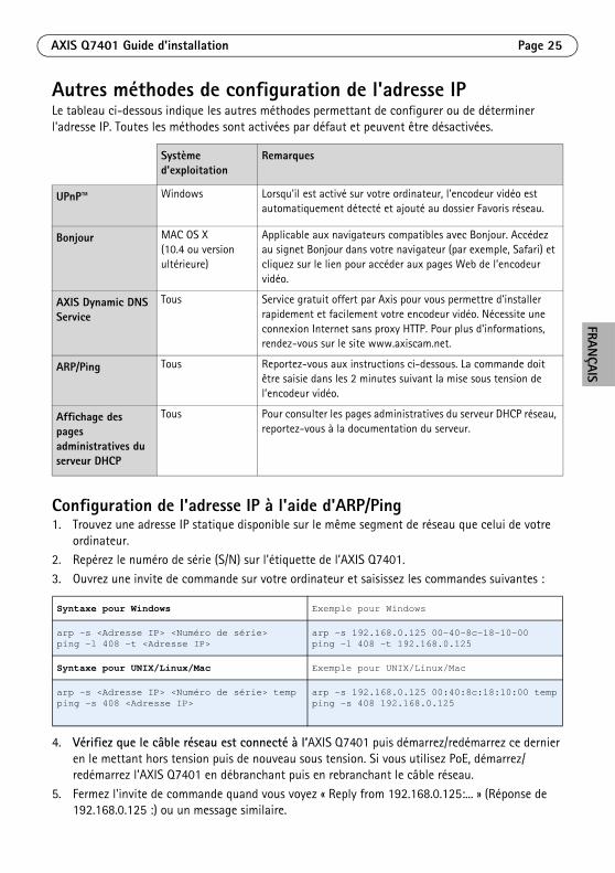
AXIS Q7401 Guide d'installation Page 25
FRANÇAIS
Autres méthodes de configuration de l'adresse IPLe tableau ci-dessous indique les autres méthodes permettant de configurer ou de déterminer l'adresse IP. Toutes les méthodes sont activées par défaut et peuvent être désactivées.
Configuration de l'adresse IP à l'aide d'ARP/Ping1. Trouvez une adresse IP statique disponible sur le même segment de réseau que celui de votre
ordinateur. 2. Repérez le numéro de série (S/N) sur l'étiquette de l’AXIS Q7401.
3. Ouvrez une invite de commande sur votre ordinateur et saisissez les commandes suivantes :
4. Vérifiez que le câble réseau est connecté à l’AXIS Q7401 puis démarrez/redémarrez ce dernier en le mettant hors tension puis de nouveau sous tension. Si vous utilisez PoE, démarrez/redémarrez l’AXIS Q7401 en débranchant puis en rebranchant le câble réseau.
5. Fermez l'invite de commande quand vous voyez « Reply from 192.168.0.125:... » (Réponse de 192.168.0.125 :) ou un message similaire.
Système d'exploitation
Remarques
UPnP™
Windows Lorsqu’il est activé sur votre ordinateur, l’encodeur vidéo est automatiquement détecté et ajouté au dossier Favoris réseau.
Bonjour MAC OS X(10.4 ou version ultérieure)
Applicable aux navigateurs compatibles avec Bonjour. Accédez au signet Bonjour dans votre navigateur (par exemple, Safari) et cliquez sur le lien pour accéder aux pages Web de l’encodeur vidéo.
AXIS Dynamic DNS Service
Tous Service gratuit offert par Axis pour vous permettre d'installer rapidement et facilement votre encodeur vidéo. Nécessite une connexion Internet sans proxy HTTP. Pour plus d'informations, rendez-vous sur le site www.axiscam.net.
ARP/Ping Tous Reportez-vous aux instructions ci-dessous. La commande doit être saisie dans les 2 minutes suivant la mise sous tension de l’encodeur vidéo.
Affichage des pages administratives du serveur DHCP
Tous Pour consulter les pages administratives du serveur DHCP réseau, reportez-vous à la documentation du serveur.
Syntaxe pour Windows Exemple pour Windows
arp -s <Adresse IP> <Numéro de série>ping -l 408 -t <Adresse IP>
arp -s 192.168.0.125 00-40-8c-18-10-00ping -l 408 -t 192.168.0.125
Syntaxe pour UNIX/Linux/Mac Exemple pour UNIX/Linux/Mac
arp -s <Adresse IP> <Numéro de série> tempping -s 408 <Adresse IP>
arp -s 192.168.0.125 00:40:8c:18:10:00 tempping -s 408 192.168.0.125

Page 26 AXIS Q7401 Guide d’installation
6. Dans votre navigateur, tapez http://<Adresse IP> dans le champ Emplacement/Adresse, puis appuyez sur la touche Entrée de votre clavier.
Remarques :• Pour ouvrir une invite de commande sous Windows : dans le menu Démarrer, sélectionnez Exécuter… et
tapez cmd. Cliquez sur OK.• Pour utiliser la commande ARP sous Mac OS X, utilisez l'utilitaire Terminal dans Application > Utilitaires.

AXIS Q7401 Guide d'installation Page 27
FRANÇAIS
Connecteurs de l’appareilConnecteur réseau - Connecteur Ethernet RJ-45. Prend en charge l'alimentation par Ethernet (PoE). Il est recommandé d'utiliser des câbles blindés.
Commutateur de classification PoE - Power over Ethernet (IEEE 802.3af), classification d’alimentation sélectionnable :
• Classe 2 – Max. 6,49 W
• Classe 3 – Max. 12,95 W (par défaut)Remarque :
La classification d’alimentation a lieu lors de la mise sous tension. Si l’encodeur vidéo n’alimente pas la caméra analogique connectée, sélectionnez PoE Classe 2 pour informer le commutateur PoE que l’encodeur vidéo n’a besoin que de 6,49 W. PoE Classe 3 est le paramètre par défaut.
Connecteur d’alimentation - Bornier de connexion à 2 broches utilisé pour la puissance d’entrée et de sortie.
• Puissance d’entrée – Pour alimenter l’encodeur vidéo avec l’adaptateur secteur fourni ou un bloc d’alimentation externe 8-20 V CC, max. 7,2 W.
• Puissance de sortie – L’encodeur vidéo peut alimenter une caméra analogique ou un appareil auxiliaire en cas d’alimentation par Ethernet, 12 V CC max. 5 W (420 mA).
Remarques :• L’encodeur vidéo peut fournir un maximum de 5 W (420 mA) avec PoE. Ceci inclut la sortie sur le
connecteur d’alimentation et le connecteur pour terminaux E/S.• Ne branchez pas d’alimentation si l’encodeur vidéo est branché sur PoE.
Entrée audio - Entrée de 3,5 mm pour microphone mono ou signal mono avec entrée de haut niveau (le canal de gauche est utilisé pour le signal stéréo).
Sortie audio - Sortie audio (niveau de ligne) pouvant être connectée à un système de diffusion publique ou à un haut parleur actif avec amplificateur intégré. Une paire d'écouteurs peut être aussi connectée. Un connecteur stéréo doit être utilisé pour la sortie audio.
Fonction Numéro de broche
Description
GND 1 Terre
Alimentation CC
2 Puissance d’entrée 8-20 V CC, max. 7,2 W ouPuissance de sortie 12 V CC, max. 5 W (420 mA).
1 2

Page 28 AXIS Q7401 Guide d’installation
Connecteur pour terminaux E/S - Utilisé dans des applications telles que la détection de mouvement, le déclenchement d'événements, l'enregistrement à intervalles et les notifications d'alarme. En plus d’une alimentation auxiliaire et d’une broche GND, l’AXIS Q7401 possède 4 broches qui peuvent être configurées comme entrées ou sorties. Ces broches assurent l’interface avec :
• Sortie transistor : permet de connecter des dispositifs externes, comme des relais ou des DEL. Les dispositifs connectés peuvent être activés par l’AXIS VAPIX API, des boutons de sortie sur la page Live View (Vidéo en direct) ou un type d'événement. La sortie est considérée comme étant active (dans Event Configuration > Port Status(Configuration d'événement - État du port)) si le dispositif d'alarme est activé.
• Entrée numérique : entrée d'alarme utilisée pour connecter des dispositifs pouvant passer d'un circuit ouvert à un circuit fermé, par exemple : détecteurs infrarouge passifs, contacts de porte/fenêtre, détecteurs de bris de verre, etc. Lorsqu'un signal est reçu, l'état change et l'entrée devient active (sous Event Configuration > Port Status (Configuration d'événement - État du port)).
Fonction Numéro de broche
Remarques Caractéristiques techniques
GND 1 Terre
Alimentation 12 V CC
2 Cette broche peut également servir à alimenter l’appareil auxiliaire.Remarques :
• Cette broche ne peut être utilisée que comme sortie d'alimentation.
• Même tension que la broche 2 du connecteur d’alimentation.
Charge maximale = 100 mA
Configurable (entrée ou sortie)
3 - 6 Entrée numérique - Connectez-la au GND pour l'activer ou laissez-la flotter (ou déconnectée) pour la désactiver.
Entrée minimum = - 40 V CCEntrée maximum = + 40 V CC
Sortie numérique - Utilise un transistor NFET à drain ouvert avec la source connectée à GND. En cas d'utilisation avec un relais externe, une diode doit être connectée en parallèle avec la charge, en guise de protection contre les tensions transitoires.
Charge maximale = 100 mATension maximale = + 40 V CC
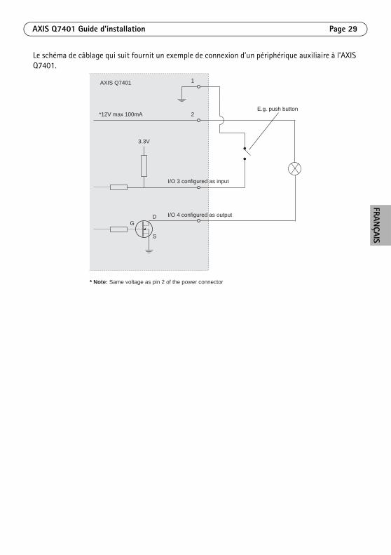
AXIS Q7401 Guide d'installation Page 29
FRANÇAIS
Le schéma de câblage qui suit fournit un exemple de connexion d’un périphérique auxiliaire à l’AXIS Q7401.
1
2E.g. push button
I/O 3 configured as input
I/O 4 configured as output
* Note: Same voltage as pin 2 of the power connector
AXIS Q7401
3.3V
*12V max 100mA
D
S
G

Page 30 AXIS Q7401 Guide d’installation
Connecteur RS-422/RS-485 - Deux borniers à 2 broches pour l’interface série RS-485/422 utilisée pour contrôler les périphériques auxiliaires (appareils PTZ, par ex.).
Le port série RS-485/422 peut être configuré dans les modes de port suivants :
• Port semi-duplex RS-485 bidirectionnel pour la transmission de données à l’aide de deux fils, une paire RX/TX combinée.
• Port duplex RS-485 bidirectionnel pour la transmission de données à l’aide de quatre fils, une paire RX et une paire TX.
• Port RS-422 unidirectionnel pour la transmission ou la réception de données à l’aide de deux fils, une paire RX ou TX.
• Port duplex RS-422 bidirectionnel pour la transmission de données (point à point) à l’aide de quatre fils, une paire RX et une paire TX.
Logement de carte mémoire SDHC - La carte mémoire SD haute capacité peut être utilisée pour l’enregistrement local avec stockage amovible.
Connecteur BNC - Branchez un câble vidéo coaxial de 75 ohms (d’une longueur maximale de 250 mètres).
Remarque :Si la source vidéo doit être connectée parallèlement à d’autres équipements à l’aide d’un adaptateur en T BNC, désactivez la terminaison d’entrée en configurant le commutateur de terminaison de 75 ohms sur OFF. Sinon, la qualité d’image risque d’être réduite.
Fonction Broche
Remarques
RS 485/422TX(A) 1 Paire TX pour RS-422 et RS-485 à 4 fils
RS 485/422TX(B) 2
RS-485A alt RS-485/422RX(A) 3 Paire RX pour tous les modes (RX/TX combiné pour RS-485 à 2 fils)
RS-485B alt RS-485/422RX(B) 4
1 2 3 4
TX RX/TX

AXIS Q7401 Guide d'installation Page 31
FRANÇAIS
Témoins DELDEL Couleur Indication
Réseau Vert Continu en cas de connexion à un réseau 100 Mbit/s. Clignote en cas d'activité réseau.
Orange Continu en cas de connexion à un réseau 10 Mbit/s. Clignote en cas d'activité réseau.
Éteint Pas de connexion réseau.
État Vert Vert continu en cas de fonctionnement normal.
Orange Continu pendant le démarrage, la réinitialisation des valeurs d'usine par défaut ou la restauration des paramètres.
Rouge Clignote lentement en cas d'échec de la mise à niveau.
Alimentation Vert Fonctionnement normal.
Orange Clignote en vert/orange pendant la mise à niveau du microprogramme.
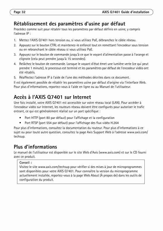
Page 32 AXIS Q7401 Guide d’installation
Rétablissement des paramètres d'usine par défautProcédez comme suit pour rétablir tous les paramètres par défaut définis en usine, y compris l'adresse IP :
1. Mettez l’AXIS Q7401 hors tension ou, si vous utilisez PoE, débranchez le câble réseau.
2. Appuyez sur le bouton CTRL et maintenez-le enfoncé tout en remettant l’encodeur sous tension ou en rebranchant le câble réseau si vous utilisez PoE.
3. Appuyez sur le bouton de commande jusqu'à ce que le voyant d'alimentation passe à l'orange et clignote (cela peut prendre jusqu'à 15 secondes).
4. Relâchez le bouton de commande. Lorsque le voyant d'état émet une lumière verte (ce qui peut prendre 1 minute), le processus est terminé et les paramètres par défaut de l’encodeur vidéo ont été rétablis.
5. Réaffectez l'adresse IP à l'aide de l'une des méthodes décrites dans ce document.
Il est également possible de rétablir les paramètres usine par défaut d'origine via l'interface Web. Pour plus d'informations, reportez-vous à l'aide en ligne ou au Manuel de l'utilisateur.
Accès à l’AXIS Q7401 sur InternetUne fois installé, votre AXIS Q7401 est accessible sur votre réseau local (LAN). Pour accéder à l’encodeur vidéo sur Internet, les routeurs réseau doivent être configurés pour autoriser le trafic entrant, ce qui est généralement réalisé sur un port spécifique :
• Port HTTP (port 80 par défaut) pour l'affichage et la configuration
• Port RTSP (port 554 par défaut) pour l’affichage des flux vidéo H.264
Pour plus d'informations, consultez la documentation du routeur. Pour plus d'informations à ce sujet ou pour toute autre question, consultez la page Axis Support Web à l'adresse www.axis.com/techsup.
Plus d'informationsLe manuel de l'utilisateur est disponible sur le site Web d'Axis (www.axis.com) et sur le CD fourni avec ce produit.
Conseil : Visitez le site www.axis.com/techsup pour vérifier si des mises à jour de microprogrammes sont disponibles pour votre AXIS Q7401. Pour connaître la version du microprogramme actuellement installée, reportez-vous à la page Web About (À propos de) dans les outils de configuration du produit.

AXIS Q7401 Installationsanleitung Seite 33
DEUTSCH
AXIS Q7401 Video-EncoderInstallationsanleitung
In dieser Anleitung wird die Installation des AXIS Q7401 Video-Encoder in einem Netzwerk beschrieben. Alle weiteren Hinweise zur Verwendung des Produkts finden Sie im Benutzerhandbuch, das auf der mitgelieferten CD oder auf unserer Website unter www.axis.com zur Verfügung steht.
InstallationsschritteBefolgen Sie diese Schritte, um den AXIS Q7401 Video-Encoder in Ihrem lokalen Netzwerk (LAN) zu installieren:
1. Prüfen Sie, ob alle in der nachfolgenden Liste aufgeführten Komponenten vorhanden sind.2. Hardwareübersicht. Siehe Seite Seite 34.
3. Installieren der Hardware. Siehe Seite 35.
4. Zuweisen einer IP-Adresse. Siehe Seite 36.5. Festlegen des Kennworts. Siehe Seite 39.
LieferumfangKomponente Modell/Variante/Anmerkung
Axis Video-Encoder-Modell AXIS Q7401
Netzteilmodell Typ PS-K oder PS-T
Montagesatz • 2 Schrauben und Dübel zur Montage des Encoders an einer Betonwand
• 4 Klebeschutzfüße
• Anschlussblöcke (E/A: 6-polige Klemmleiste, RS-485/422: 2x 2-polige Klemmleiste, Netz: 2-polige Klemmleiste)
CD CD für Axis-Netzwerkvideoprodukte einschließlich Installationswerkzeugen und anderer Software sowie Produktdokumentation
Gedruckte Dokumente AXIS Q7401 Installationsanleitung (dieses Dokument)Axis-Garantieerklärung
Wichtiger Hinweis! Verwenden Sie dieses Produkt unter Beachtung der geltenden rechtlichen Bestimmungen.

Seite 34 AXIS Q7401 Installationsanleitung
HardwareübersichtDraufsicht
Rückansicht
Audio und E/A – Seiten ansicht
SDHC-Speicherkarte – Seiten ansicht
AbmessungenH × B × T = 32,1 x 98,9 x 118,0 mmGewicht = 335 g (ohne Netzteil)
Montagebohrung
Montagebohrung
LED-Anzeigen fürStrom, Status und
Netzwerk
Steuertaste
NetzteilanschlussRS-422/RS-485-Anschluss
Videoeingang Netzwerkanschluss (PoE)
PoE-Switch Klasse 2 und 3
75 OhmDIP-Schalter
Audio-Ein-/Ausgang 6-polige E/A-Anschlussleiste
SD-Speicherkarteneinschub

AXIS Q7401 Installationsanleitung Seite 35
DEUTSCH
Installieren der Hardware
Befestigen des Video-EncodersDer Video-Encoder wird mit einem Montagesatz mit Schrauben, Dübeln und Schutzfüßen geliefert, um den Video-Encoder an einer Betonwand zu befestigen:
1. Halten Sie den Video-Encoder an die Wand und markieren Sie die Stelle der beiden Montagebohrungen (siehe Seite 34), über die der Video-Encoder befestigt wird.
2. Nehmen Sie den Video-Encoder ab und bohren Sie die Montagelöcher in die Wand.
3. Drücken Sie die vier Schutzfüße heraus und kleben Sie sie auf die Unterseite des Video-Encoders.
4. Drücken Sie die Dübel in die Wand, positionieren Sie den Video-Encoder und befestigen Sie ihn mit den mitgelieferten Schrauben an der Wand.
Anschließen der Kabel1. Verbinden Sie den Encoder über ein abgeschirmtes Netzwerkkabel (CAT5) mit dem Netzwerk.
2. Sie können zusätzlich externe Geräte, wie z. B. Alarmanlagen, anschließen. Informationen zur Anschlussbelegung finden Sie auf Seite 43.
3. Für eine bidirektionale Audioverbindung können Sie zusätzlich einen Aktivlautsprecher und/oder ein externes Mikrofon anschließen.
4. Schließen Sie die Kamera an.
5. Schließen Sie den Video-Encoder auf eine der folgenden Arten an die Stromversorgung an:• PoE-Anschluss (Power over Ethernet). Wenn PoE vorhanden ist, wird der Anschluss
automatisch bei Anschluss des Netzwerkkabels (siehe oben) erkannt.• Schließen Sie das mitgelieferte Netzteil für Innenräume an den Netzanschluss des
Encoders an. 6. Überprüfen Sie, ob die LED-Anzeigen die Betriebszustände korrekt angeben. Weitere
Informationen finden Sie in der Tabelle auf Seite 46.
! WICHTIG! - Das Gehäuse des AXIS Q7401 ist nicht für den Einsatz im Außenbereich geeignet; das Gerät darf nur in Innenräumen installiert werden.

Seite 36 AXIS Q7401 Installationsanleitung
Zuweisen einer IP-AdresseIn den meisten Netzwerken ist heutzutage ein DHCP-Server eingebunden, der angeschlossenen Geräten automatisch IP-Adressen zuweist. Wenn Ihr Netzwerk über keinen DHCP-Server verfügt, wird für den AXIS Q7401 die Standard-IP-Adresse 192.168.0.90 verwendet.
AXIS IP Utility und AXIS Camera Management sind die empfohlenen Methoden zur Festlegung einer IP-Adresse unter Windows. Beide Anwendungen stehen kostenlos auf der mitgelieferten CD für Axis-Netzwerkvideoprodukte zur Verfügung oder können unter www.axis.com/techsup heruntergeladen werden. Verwenden Sie die Methode, die für die gewünschte Anzahl der zu installierenden Kameras geeignet ist.
Hinweise:• Falls Sie die IP-Adresse nicht zuweisen können, müssen ggf. die Einstellungen der Firewall überprüft
werden.• Weitere Informationen zu alternativen Methoden zum Festlegen der IP-Adresse des AXIS Q7401 (z. B. in
anderen Betriebssystemen) finden Sie auf Seite 41.
Methode Empfohlen für Betriebssystem
AXIS IP Utility Siehe Seite 37
Einzelner Video-EncoderKleine Installationen
Windows
AXIS Camera ManagementSiehe Seite 38
Mehrere Video-EncoderGroße InstallationenInstallation in einem anderen Subnetz
Windows 2000Windows XP ProWindows 2003 ServerWindows Vista

AXIS Q7401 Installationsanleitung Seite 37
DEUTSCH
AXIS IP Utility – einzelne Kamera/kleine InstallationenAXIS IP Utility erkennt automatisch im Netzwerk vorhandene Axis-Geräte und zeigt diese an. Die Anwendung kann außerdem zur manuellen Zuweisung einer statischen IP-Adresse verwendet werden.
Beachten Sie, dass sich der AXIS Q7401 und der Computer, auf dem AXIS IP Utility ausgeführt wird, im gleichen Netzwerksegment (d. h. physischen Subnetz) befinden müssen.
Automatische Erkennung1. Stellen Sie sicher, dass der AXIS Q7401 an das Netzwerk und die Stromversorgung
angeschlossen ist.
2. Starten Sie AXIS IP Utility.
3. Doppelklicken Sie auf das Symbol des AXIS Q7401, um die entsprechende Startseite zu öffnen. 4. Anweisungen zum Festlegen des Kennworts finden Sie auf Seite 39.
Manuelle Zuweisung der IP-Adresse (optional)1. Wählen Sie eine nicht zugewiesene IP-Adresse im selben Netzwerksegment, in dem sich Ihr
Computer befindet.
2. Wählen Sie den AXIS Q7401 aus der Liste aus.
3. Klicken Sie auf die Schaltfläche Assign new IP address to the selected device (Ausgewähltem Gerät neue IP-Adresse zuweisen) und geben Sie die IP Adresse ein.
4. Klicken Sie auf die Schaltfläche Assign (Zuweisen) und folgen Sie den Anweisungen.
5. Klicken Sie auf die Schaltfläche Home Page (Startseite), um auf die Webseiten des Video-Encoders zuzugreifen.
6. Anweisungen zum Festlegen des Kennworts finden Sie auf Seite 39.
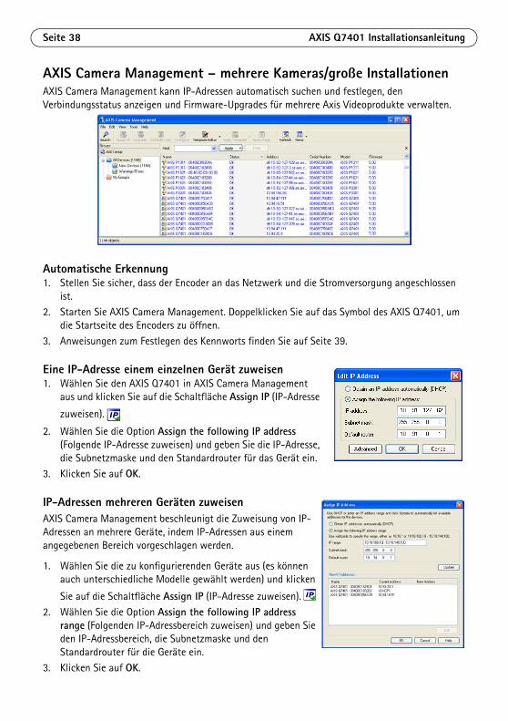
Seite 38 AXIS Q7401 Installationsanleitung
AXIS Camera Management – mehrere Kameras/große InstallationenAXIS Camera Management kann IP-Adressen automatisch suchen und festlegen, den Verbindungsstatus anzeigen und Firmware-Upgrades für mehrere Axis Videoprodukte verwalten.
Automatische Erkennung1. Stellen Sie sicher, dass der Encoder an das Netzwerk und die Stromversorgung angeschlossen
ist.
2. Starten Sie AXIS Camera Management. Doppelklicken Sie auf das Symbol des AXIS Q7401, um die Startseite des Encoders zu öffnen.
3. Anweisungen zum Festlegen des Kennworts finden Sie auf Seite 39.
Eine IP-Adresse einem einzelnen Gerät zuweisen 1. Wählen Sie den AXIS Q7401 in AXIS Camera Management
aus und klicken Sie auf die Schaltfläche Assign IP (IP-Adresse
zuweisen).
2. Wählen Sie die Option Assign the following IP address (Folgende IP-Adresse zuweisen) und geben Sie die IP-Adresse, die Subnetzmaske und den Standardrouter für das Gerät ein.
3. Klicken Sie auf OK.
IP-Adressen mehreren Geräten zuweisenAXIS Camera Management beschleunigt die Zuweisung von IP-Adressen an mehrere Geräte, indem IP-Adressen aus einem angegebenen Bereich vorgeschlagen werden.
1. Wählen Sie die zu konfigurierenden Geräte aus (es können auch unterschiedliche Modelle gewählt werden) und klicken
Sie auf die Schaltfläche Assign IP (IP-Adresse zuweisen).
2. Wählen Sie die Option Assign the following IP address range (Folgenden IP-Adressbereich zuweisen) und geben Sie den IP-Adressbereich, die Subnetzmaske und den Standardrouter für die Geräte ein.
3. Klicken Sie auf OK.

AXIS Q7401 Installationsanleitung Seite 39
DEUTSCH
Festlegen des KennwortsUm Zugriff auf das Produkt zu erhalten, muss das Kennwort für den standardmäßigen Administrator-Benutzer root festgelegt werden. Beim erstmaligen Zugriff auf den AXIS Q7401 wird das Dialogfeld Configure Root Password (Root-Kennwort konfigurieren) angezeigt . Dort kann das Kennwort festgelegt werden.
Um ein Abhören der Netzwerkkommunikation während der Festlegung des Root-Kennworts zu vermeiden, können Sie diesen Vorgang über eine verschlüsselte HTTPS-Verbindung durchführen, die ein HTTPS-Zertifikat erfordert (siehe folgenden Hinweis).
Um das Kennwort über eine standardmäßige HTTP-Verbindung festzulegen, geben Sie es direkt in das erste unten abgebildete Dialogfeld ein.
Um das Kennwort über eine verschlüsselte HTTPS-Verbindung festzulegen, gehen Sie wie folgt vor:
1. Klicken Sie auf die Schaltfläche Create self-signed certificate (Selbstsigniertes Zertifikat erstellen).
2. Geben Sie die angeforderten Informationen ein und klicken Sie auf OK. Das Zertifikat wird erstellt, und das Kennwort kann jetzt sicher festgelegt werden. Der gesamte Datenverkehr des AXIS Q7401 wird ab diesem Zeitpunkt verschlüsselt.
3. Geben Sie ein Kennwort ein, und wiederholen Sie die Eingabe, um die korrekte Schreibweise zu bestätigen. Klicken Sie auf OK. Damit ist das Kennwort konfiguriert.
4. Geben Sie den Benutzernamen „root“ wie erforderlich ein. Hinweis: Der standardmäßige Administrator-Benutzername „root“ kann nicht gelöscht werden.
5. Geben Sie das zuvor festgelegte Kennwort ein und klicken Sie auf OK. Wenn Sie das Kennwort vergessen haben, muss der AXIS Q7401 auf die Werkseinstellungen zurückgesetzt werden. Siehe Seite 47.
Um das Kennwort direkt über eine unverschlüsselte Verbindung zu konfigurieren, geben Sie es hier ein.
Um eine HTTPS-Verbindung herzustellen, klicken Sie zunächst auf diese Schaltfläche.

Seite 40 AXIS Q7401 Installationsanleitung
6. Klicken Sie auf Yes (Ja), um AMC (AXIS Media Control) zu installieren. Nach Abschluss der Installation können Sie Videoströme in Microsoft Internet Explorer anzeigen. Hierzu müssen Sie über Administratorrechte für den Computer verfügen.
7. Die Seite „Live-View“ (Live-Ansicht) des AXIS Q7401 wird angezeigt. Sie enthält Links zu Setup-Tools, mit denen Sie die Kamera Ihren Bedürfnissen entsprechend anpassen können
Hinweise:• Das Protokoll HTTPS (Hypertext Transfer Protocol over SSL) wird verwendet, um den Datenverkehr zwischen
Webbrowsern und Servern zu verschlüsseln. Das HTTPS-Zertifikat steuert den verschlüsselten Informationsaustausch.
• Der standardmäßige Administrator-Benutzer „root“ kann nicht gelöscht werden.• Wenn Sie das Kennwort für den AXIS Q7401 vergessen haben, muss er auf die Werkseinstellungen
zurückgesetzt werden. Siehe Seite 47.
Setup: Alle zur benutzerspezifischen Konfiguration des Encoders notwendigen Werkzeuge
Help (Hilfe): Zum Aufrufen der Online-Hilfe für den Encoder
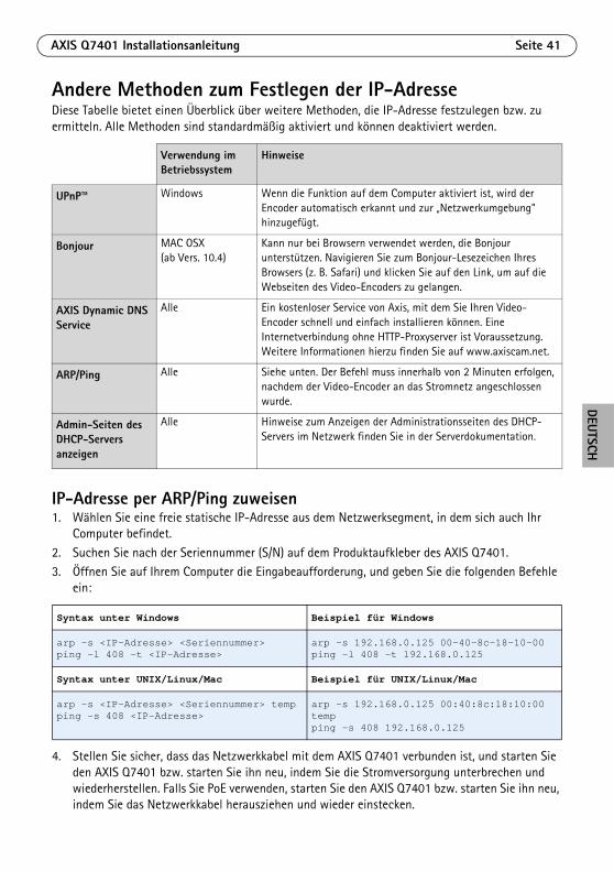
AXIS Q7401 Installationsanleitung Seite 41
DEUTSCH
Andere Methoden zum Festlegen der IP-AdresseDiese Tabelle bietet einen Überblick über weitere Methoden, die IP-Adresse festzulegen bzw. zu ermitteln. Alle Methoden sind standardmäßig aktiviert und können deaktiviert werden.
IP-Adresse per ARP/Ping zuweisen1. Wählen Sie eine freie statische IP-Adresse aus dem Netzwerksegment, in dem sich auch Ihr
Computer befindet.
2. Suchen Sie nach der Seriennummer (S/N) auf dem Produktaufkleber des AXIS Q7401.3. Öffnen Sie auf Ihrem Computer die Eingabeaufforderung, und geben Sie die folgenden Befehle
ein:
4. Stellen Sie sicher, dass das Netzwerkkabel mit dem AXIS Q7401 verbunden ist, und starten Sie den AXIS Q7401 bzw. starten Sie ihn neu, indem Sie die Stromversorgung unterbrechen und wiederherstellen. Falls Sie PoE verwenden, starten Sie den AXIS Q7401 bzw. starten Sie ihn neu, indem Sie das Netzwerkkabel herausziehen und wieder einstecken.
Verwendung im Betriebssystem
Hinweise
UPnP™
Windows Wenn die Funktion auf dem Computer aktiviert ist, wird der Encoder automatisch erkannt und zur „Netzwerkumgebung" hinzugefügt.
Bonjour MAC OSX (ab Vers. 10.4)
Kann nur bei Browsern verwendet werden, die Bonjour unterstützen. Navigieren Sie zum Bonjour-Lesezeichen Ihres Browsers (z. B. Safari) und klicken Sie auf den Link, um auf die Webseiten des Video-Encoders zu gelangen.
AXIS Dynamic DNS Service
Alle Ein kostenloser Service von Axis, mit dem Sie Ihren Video-Encoder schnell und einfach installieren können. Eine Internetverbindung ohne HTTP-Proxyserver ist Voraussetzung. Weitere Informationen hierzu finden Sie auf www.axiscam.net.
ARP/Ping Alle Siehe unten. Der Befehl muss innerhalb von 2 Minuten erfolgen, nachdem der Video-Encoder an das Stromnetz angeschlossen wurde.
Admin-Seiten des DHCP-Servers anzeigen
Alle Hinweise zum Anzeigen der Administrationsseiten des DHCP-Servers im Netzwerk finden Sie in der Serverdokumentation.
Syntax unter Windows Beispiel für Windows
arp -s <IP-Adresse> <Seriennummer>ping -l 408 -t <IP-Adresse>
arp -s 192.168.0.125 00-40-8c-18-10-00ping -l 408 -t 192.168.0.125
Syntax unter UNIX/Linux/Mac Beispiel für UNIX/Linux/Mac
arp -s <IP-Adresse> <Seriennummer> tempping -s 408 <IP-Adresse>
arp -s 192.168.0.125 00:40:8c:18:10:00 tempping -s 408 192.168.0.125

Seite 42 AXIS Q7401 Installationsanleitung
5. Schließen Sie die Befehlszeile, sobald „Reply from 192.168.0.125:...“ (Antwort von 192.168.0.125:...) oder eine ähnliche Meldung angezeigt wird.
6. Starten Sie einen Browser, geben Sie im Adressfeld „http://<IP-Adresse>“ ein, und drücken Sie die Eingabetaste auf der Tastatur.
Hinweise:• So öffnen Sie die Eingabeaufforderung unter Windows: Wählen Sie im Startmenü die Option „Ausführen...“,
und geben Sie „cmd“ ein. Klicken Sie auf OK.• Verwenden Sie zum Eingeben des Befehls „ARP“ unter Mac OS X das Dienstprogramm „Terminal“, das Sie
unter „Anwendung > Dienstprogramme“ finden.
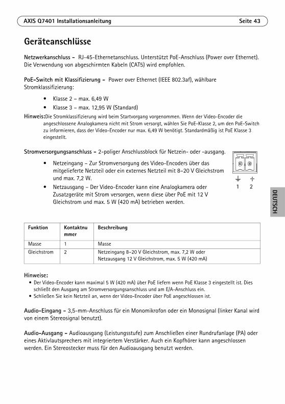
AXIS Q7401 Installationsanleitung Seite 43
DEUTSCH
GeräteanschlüsseNetzwerkanschluss - RJ-45-Ethernetanschluss. Unterstützt PoE-Anschluss (Power over Ethernet). Die Verwendung von abgeschirmten Kabeln (CAT5) wird empfohlen.
PoE-Switch mit Klassifizierung - Power over Ethernet (IEEE 802.3af), wählbare Stromklassifizierung:
• Klasse 2 – max. 6,49 W
• Klasse 3 – max. 12,95 W (Standard)Hinweis:Die Stromklassifizierung wird beim Startvorgang vorgenommen. Wenn der Video-Encoder die
angeschlossene Analogkamera nicht mit Strom versorgt, wählen Sie PoE-Klasse 2, um den PoE-Switch zu informieren, dass der Video-Encoder nur max. 6,49 W benötigt. Standardmäßig ist PoE Klasse 3 eingestellt.
Stromversorgungsanschluss - 2-poliger Anschlussblock für Netzein- oder -ausgang.
• Netzeingang – Zur Stromversorgung des Video-Encoders über das mitgelieferte Netzteil oder ein externes Netzteil mit 8–20 V Gleichstrom und max. 7,2 W.
• Netzausgang – Der Video-Encoder kann eine Analogkamera oder Zusatzgeräte mit Strom versorgen, wenn diese über PoE mit 12 V Gleichstrom und max. 5 W (420 mA) betrieben werden.
Hinweise:• Der Video-Encoder kann maximal 5 W (420 mA) über PoE liefern wenn PoE Klasse 3 eingestellt ist. Dies
schließt den Ausgang am Stromversorgungsanschluss und am E/A-Anschluss ein.• Schließen Sie kein Netzteil an, wenn der Video-Encoder über PoE angeschlossen ist.
Audio-Eingang - 3,5-mm-Anschluss für ein Monomikrofon oder ein Monosignal (linker Kanal wird von einem Stereosignal benutzt).
Audio-Ausgang - Audioausgang (Leistungsstufe) zum Anschließen einer Rundrufanlage (PA) oder eines Aktivlautsprechers mit integriertem Verstärker. Auch ein Kopfhörer kann angeschlossen werden. Ein Stereostecker muss für den Audioausgang benutzt werden.
Funktion Kontaktnummer
Beschreibung
Masse 1 Masse
Gleichstrom 2 Netzeingang 8–20 V Gleichstrom, max. 7,2 W oder Netzausgang 12 V Gleichstrom, max. 5 W (420 mA)
1 2
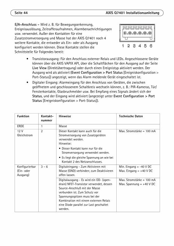
Seite 44 AXIS Q7401 Installationsanleitung
E/A-Anschluss - Wird z. B. für Bewegungserkennung, Ereignisauslösung, Zeitrafferaufnahmen, Alarmbenachrichtigungen usw. verwendet. Außer den Kontakten für eine Zusatzstromversorgung und Masse hat der AXIS Q7401 noch 4 weitere Kontakte, die entweder als Ein- oder als Ausgang konfiguriert werden können. Diese Kontakte stellen die Schnittstelle für Folgendes bereit:
• Transistorausgang: Für den Anschluss externer Relais und LEDs. Angeschlossene Geräte können über die AXIS VAPIX API, über die Schaltflächen für den Ausgang auf der Seite Live View (Direktübertragung) oder durch einen Ereignistyp aktiviert werden. Der Ausgang wird als aktiviert (Event Configuration > Port Status [Ereigniskonfiguration > Port-Status]) angezeigt, wenn das Alarm meldende Gerät eingeschaltet ist.
• Digitaler Eingang: Alarmeingang für den Anschluss von Geräten, die zwischen geöffnetem und geschlossenem Schaltkreis wechseln können, z. B.: PIR-Kameras, Tür/Fensterkontakte, Glasbruchmelder usw. Bei Empfang eines Signals ändert sich der Status, und der Eingang wird aktiviert (angezeigt unter Event Configuration > Port Status [Ereigniskonfiguration > Port-Status]).
Funktion Kontakt-nummer
Hinweise Technische Daten
ERDE 1 Masse
12 V Gleichstrom
2 Dieser Kontakt kann auch für die Stromversorgung von Zusatzgeräten verwendet werden.Hinweise:
• Dieser Kontakt kann nur für die Stromversorgung verwendet werden.
• Es liegt die gleiche Spannung an wie bei Kontakt 2 des Netzanschlusses.
Max. Stromstärke = 100 mA
Konfigurierbar (Ein- oder Ausgang)
3 – 6 Digitaleingang - Zum Aktivieren mit Masse (GND) verbinden; zum Deaktivieren offen lassen.
Min. Eingang = -40 V DCMax. Eingang = +40 V DC
Digitalausgang - Es wird ein OD- (open-drain) NFET-Transistor verwendet, dessen Source-Anschluß mit der Masse verbunden ist. Zum Schutz vor Spannungsspitzen muss bei der Kombination mit einem externen Relais eine Diode parallel zur Last geschaltet werden.
Max. Stromstärke = 100 mAMax. Spannung = +40 V DC

AXIS Q7401 Installationsanleitung Seite 45
DEUTSCH
Das folgende Anschlussschaltbild zeigt ein Beispiel für den Anschluss eines Zusatzgeräts an den AXIS Q7401.
RS-422/RS-485-Buchse - Zwei 2-polige Anschlussblöcke für serielle Schnittstellen vom Typ RS-485/422 zur Steuerung von Zusatzgeräten, wie z. B. PTZ-Geräten.
Der serielle RS-485/422-Anschluss kann in den folgenden Anschlussmodi konfiguriert werden:
• Bidirektionaler RS-485-Halbduplex-Anschluss für die Datenübertragung über zwei Leiter, ein kombiniertes RX/TX-Paar
• Bidirektionaler RS-485-Vollduplex-Anschluss für die Datenübertragung über vier Leiter, ein RX-Paar und ein TX-Paar
• Unidirektionaler RS-422-Anschluss für die Datenübertragung bzw. den Datenempfang über zwei Leiter, RX- oder TX-Paar
• Bidirektionaler RS-422-Vollduplex-Anschluss für die Datenübertragung (Punkt-zu-Punkt) über vier Leiter, ein RX-Paar und ein TX-Paar
Funktion Kontakt Hinweise
RS 485/422TX(A) 1 TX-Paar für RS-422 und RS-485 mit 4 Leitern
RS 485/422TX(B) 2
RS-485A alt RS-485/422RX(A) 3 RX-Paar für alle Modi (kombinierter RX/TX für RS-485 mit 2 Leitern)RS-485B alt RS-485/422RX(B) 4
1
2E.g. push button
I/O 3 configured as input
I/O 4 configured as output
* Note: Same voltage as pin 2 of the power connector
AXIS Q7401
3.3V
*12V max 100mA
D
S
G
1 2 3 4
TX RX/TX

Seite 46 AXIS Q7401 Installationsanleitung
SDHC-Speicherkarteneinschub - Die SDHC-Speicherkarte kann zur lokalen Aufzeichnung mit Wechselmedien verwendet werden.
BNC-Anschluss - Zum Anschluss eines 75-Ohm-Koaxialvideokabels (max. Länge 250 Meter).
Hinweis:Wenn die Videoquelle parallel zu anderen Geräten mit einem BNC T-Adapter angeschlossen werden soll, deaktivieren Sie den Eingangsabschluss, indem Sie den 75-Ohm-DIP-schalter auf OFF stellen. Andernfalls kann die Bildqualität beeinträchtigt werden.
LED-AnzeigenLED Farbe Bedeutung
Netzwerk Grün Leuchtet konstant bei Verbindung mit einem 100-MBit/s-Netzwerk. Blinkt bei Netzwerkaktivität.
Gelb Leuchtet konstant bei Verbindung mit einem 10-MBit/s-Netzwerk. Blinkt bei Netzwerkaktivität.
Leuchtet nicht
Keine Netzwerkverbindung vorhanden.
Status Grün Leuchtet bei Normalbetrieb konstant grün.
Gelb Leuchtet dauerhaft beim Start und beim Wiederherstellen der Werkseinstellungen bzw. von vorherigen Einstellungen.
Rot Blinkt langsam bei Aktualisierungsfehler.
Betrieb Grün Normalbetrieb
Gelb Blinkt grün/gelb während Firmware-Aktualisierung.

AXIS Q7401 Installationsanleitung Seite 47
DEUTSCH
Wiederherstellen der werkseitigen StandardeinstellungenGehen Sie wie folgt vor, um sämtliche Parameter einschließlich der IP-Adresse auf die werkseitigen Standardeinstellungen zurückzusetzen:
1. Trennen Sie den AXIS Q7401 von der Stromversorgung oder ziehen Sie, falls PoE verwendet wird, das Netzwerkkabel ab.
2. Halten Sie die Steuertaste gedrückt und schließen Sie das Netzkabel oder bei Verwendung von PoE das Netzwerkkabel wieder an.
3. Halten Sie die Steuertaste so lange gedrückt, bis die Statusanzeige gelb aufleuchtet (dies kann bis zu 15 Sekunden dauern).
4. Lassen Sie die Steuertaste los. Sobald die Statusanzeige grün leuchtet (dies kann bis zu einer Minute dauern), ist der Video-Encoder auf die werkseitigen Standardeinstellungen zurückgesetzt.
5. Legen Sie die IP-Adresse erneut fest. Wenden Sie dabei eines der in diesem Handbuch beschriebenen Verfahren an.
Die Parameter können auch über die Weboberfläche auf die werkseitigen Einstellungen zurückgesetzt werden. Weitere Informationen dazu finden Sie in der Online-Hilfe und im Benutzerhandbuch.
Über das Internet auf den AXIS Q7401 zugreifenNach der Installation können Sie auf den AXIS Q7401 über Ihr lokales Netzwerk (LAN) zugreifen. Um auch über das Internet auf den Video-Encoder zugreifen zu können, müssen Sie die Netzwerk-Router so konfigurieren, dass diese den entsprechenden eingehenden Datenverkehr zulassen, was üblicherweise durch Zuweisung eines bestimmten Ports geschieht.
• HTTP-Port (standardmäßig Port 80) für die Anzeige und Konfiguration• RTSP-Port (standardmäßig Port 554) für die Anzeige von H.264-Videoströmen
Ausführliche Informationen zu diesem Thema finden Sie in der Dokumentation des Routers. Weitere Informationen zu diesem und zu anderen Themen erhalten Sie auf der Axis Support-Website unter www.axis.com/techsup.
Weitere InformationenDas Benutzerhandbuch ist auf der Axis Website unter http://www.axis.com erhältlich und befindet sich auch auf der mitgelieferten CD für Axis-Netzwerkvideoprodukte.
Tipp! Unter www.axis.com/techsup finden Sie Firmware-Aktualisierungen für Ihren AXIS Q7401. Gehen Sie unter „Setup“ auf die Seite „About“ (Info), um die aktuell installierte Firmware-Version anzuzeigen.


Guida all'installazione di AXIS Q7401 Pagina 49
ITALIANO
AXIS Q7401 Video EncoderGuida all'installazione
Questo documento fornisce le istruzioni necessarie per installare il codificatore video AXIS Q7401 Video Encoder nella rete in uso. Per ulteriori informazioni sull’utilizzo del prodotto, consultare la Guida per l'utente disponibile sul CD incluso nella confezione oppure visitare il sito Web all’indirizzo www.axis.com.
Procedura di installazioneAttenersi alla seguente procedura per installare AXIS Q7401 Video Encoder nella rete locale (LAN):
1. Controllare il contenuto della confezione utilizzando l'elenco fornito di seguito.2. Panoramica dell’hardware. Vedere la pagina 50.
3. Installazione dell'hardware. Vedere la pagina 51.
4. Assegnazione di un indirizzo IP. Vedere la pagina 52.5. Impostazione della password. Vedere la pagina 55.
Contenuto della confezioneArticolo Modelli/varianti/note
Modelli di codificatori video Axis
AXIS Q7401
Modelli di adattatori Tipo PS-K o PS-T
Kit di montaggio • 2 viti e tasselli per montare il codificatore alla parete
• 4 cuscinetti di protezione
• Connettori per la morsettiera (I/O: connettore a 6 pin , RS-485/422: 2 connettori a 2 pin, alimentazione: connettore a 2 pin)
CD CD del prodotto, che comprende le utility di installazione e altro software nonché la documentazione del prodotto.
Documentazione cartacea AXIS Q7401 Guida all'installazione (questo documento)Certificato di garanzia Axis
Importante! Il prodotto deve essere utilizzato in conformità alle leggi e alle disposizioni locali.
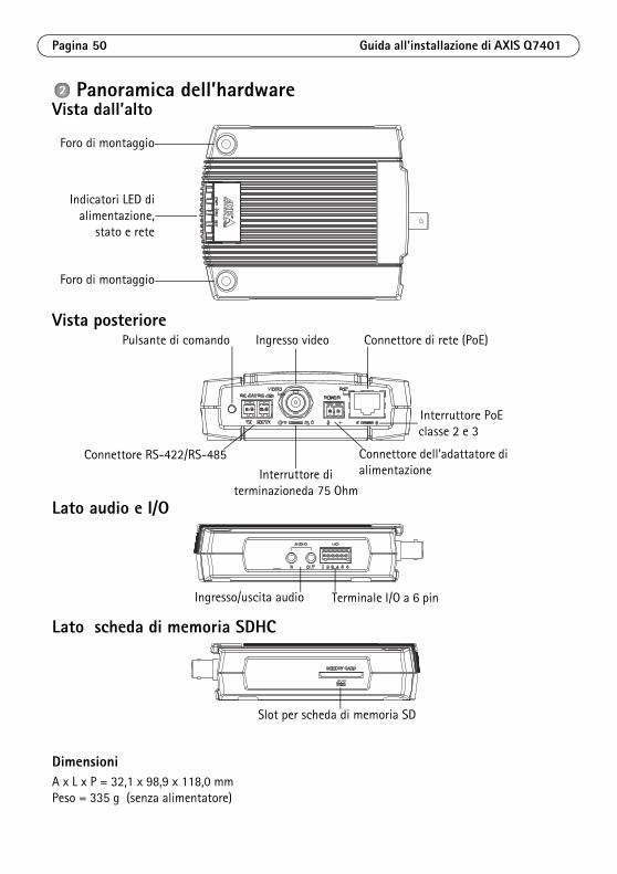
Pagina 50 Guida all'installazione di AXIS Q7401
Panoramica dell’hardwareVista dall’alto
Vista posteriore
Lato audio e I/O
Lato scheda di memoria SDHC
DimensioniA x L x P = 32,1 x 98,9 x 118,0 mmPeso = 335 g (senza alimentatore)
Foro di montaggio
Foro di montaggio
Indicatori LED dialimentazione,
stato e rete
Pulsante di comando
Connettore dell'adattatore di alimentazione
Connettore RS-422/RS-485
Ingresso video Connettore di rete (PoE)
Interruttore PoEclasse 2 e 3
Interruttore diterminazioneda 75 Ohm
Ingresso/uscita audio Terminale I/O a 6 pin
Slot per scheda di memoria SD

Guida all'installazione di AXIS Q7401 Pagina 51
ITALIANO
Installazione dell'hardware
Montaggio del codificatore videoIl codificatore video viene fornito con un kit di montaggio contenente viti, tasselli e cuscinetti di protezione per il montaggio a parete:
1. Posizionare il codificatore video sulla parete e contrassegnare la posizione dei fori di montaggio (vedere la pagina 50) da usare per il fissaggio del codificatore.
2. Rimuovere il codificatore video e trapanare i due fori di montaggio.
3. Punzonare i quattro cuscinetti di protezione e applicarli alla base del codificatore video.4. Inserire i tasselli nella parete, posizionare il codificatore video e fissarlo alla parete con le viti.
Collegamento dei cavi1. Collegare il codificatore alla rete mediante un cavo di rete schermato.
2. Collegare le altre periferiche esterne (facoltativo) come eventuali sistemi di allarme. Per informazioni sui pin della morsettiera di alimentazione, vedere la pagina 59
3. Collegare, facoltativamente, l'altoparlante e/o il microfono esterno.
4. Collegare la videocamera.5. Collegare l'alimentazione mediante uno dei metodi elencati di seguito:
• PoE (Power over Ethernet): se disponibile, questo tipo di alimentazione viene automaticamente rilevato al momento della connessione del cavo di rete (vedere la sezione precedente).
• Collegare l’alimentatore per uso interno al connettore di alimentazione sul codificatore.
6. Verificare che i LED indichino le condizioni di funzionamento corrette. Per ulteriori dettagli, vedere la tabella a pagina 62.
! IMPORTANTE! L'alloggiamento del codificatore video AXIS Q7401 non è approvato per l'utilizzo in ambienti esterni. Il prodotto può essere installato soltanto in ambienti interni.

Pagina 52 Guida all'installazione di AXIS Q7401
Assegnazione di un indirizzo IPLa maggior parte delle reti dispone di un server DHCP che automaticamente assegna gli indirizzi IP alle periferiche connesse. Se la rete non dispone di un server DHCP, per il codificatore video AXIS Q7401 viene utilizzato l'indirizzo IP predefinito 192.168.0.90.
AXIS IP Utility e AXIS Camera Management sono i metodi consigliati per impostare un indirizzo IP in Windows. Queste applicazioni sono disponibili gratuitamente sul CD del prodotto oppure possono essere scaricate dal sito Web all’indirizzo www.axis.com/techsup. Utilizzare il metodo che meglio si adatta alle proprie esigenze, in base al numero di videocamere da installare.
Note• Se l'assegnazione dell'indirizzo IP non è riuscita correttamente, verificare che non ci siano firewall che
blocchino l’operazione.• Per altri metodi di assegnazione o di rilevazione dell’indirizzo IP per il codificatore video AXIS Q7401, ad
esempio in altri sistemi operativi, vedere la pagina 57.
Metodo Consigliato per… Sistema operativo
AXIS IP Utility Vedere la pagina 53
Codificatore video singoloPiccole installazioni
Windows
AXIS Camera ManagementVedere la pagina 54
Più codificatori videoGrandi installazioniInstallazione in una diversa subnet
Windows 2000Windows XP ProWindows 2003 ServerWindows Vista

Guida all'installazione di AXIS Q7401 Pagina 53
ITALIANO
AXIS IP Utility - Videocamera singola/piccola installazioneAXIS IP Utility rileva e visualizza automaticamente le periferiche Axis collegate alla rete. L’applicazione inoltre può essere utilizzata per assegnare manualmente un indirizzo IP statico.
Si tenga presente che il codificatore video AXIS Q7401 deve essere installato sullo stesso segmento di rete (subnet fisica) del computer sul quale è in esecuzione AXIS IP Utility.
Rilevamento automatico1. Verificare che il codificatore video AXIS Q7401 sia collegato alla rete e alimentato
correttamente.
2. Avviare AXIS IP Utility. 3. Appena viene visualizzato il codificatore video AXIS Q7401, selezionarlo con un doppio clic per
aprire la home page. 4. Vedere la pagina 55 per istruzioni su come assegnare la password.
Impostazione manuale dell'indirizzo IP (facoltativo)1. Acquisire un indirizzo IP non utilizzato sullo stesso segmento di rete del computer. 2. Selezionare AXIS Q7401 dall'elenco.
3. Fare clic sul pulsante Assign new IP address to selected device (Assegna nuovo indirizzo IP alla periferica selezionata) e inserire l'indirizzo IP.
4. Fare clic sul pulsante Assign (Assegna) e seguire le istruzioni visualizzate.5. Fare clic sul pulsante Home Page (Pagina home) per accedere alle pagine Web del codificatore
video.6. Vedere la pagina 55 per istruzioni su come impostare la password.

Pagina 54 Guida all'installazione di AXIS Q7401
AXIS Camera Management -Più videocamere/grandi installazioniAXIS Camera Management è in grado di rilevare e impostare automaticamente gli indirizzi IP, visualizzare lo stato di connessione e gestire gli aggiornamenti del firmware per numerosi prodotti video Axis.
Rilevamento automatico1. Verificare che il codificatore sia collegato alla rete e alimentato correttamente.
2. Avviare AXIS Camera Management. Appena viene visualizzato il codificatore video AXIS Q7401, selezionarlo con un doppio clic del mouse per aprire la home page del codificatore.
3. Vedere la pagina 55 per istruzioni su come impostare la password.
Assegnazione di un indirizzo IP a un singolo codificatore video 1. Selezionare AXIS Q7401 in AXIS Camera Management e fare
clic sul pulsante Assign IP (Assegna IP) .
2. Selezionare Assign the following IP address (Assegna il seguente indirizzo IP) e inserire l'indirizzo IP, la subnet mask e il router predefinito utilizzato dal codificatore.
3. Fare clic sul pulsante OK.
Assegnazione degli indirizzi IP a più codificatori videoAXIS Camera Management facilita il processo di assegnazione degli indirizzi IP di più periferiche, suggerendo gli indirizzi IP in base a un intervallo specifico.
1. Selezionare i codificatori video da configurare (è possibile selezionare più modelli) e fare clic sul pulsante Assign IP
(Assegna IP).2. Selezionare Assign the following IP address range (Assegna
il seguente intervallo di indirizzi IP) e inserire l'intervallo di indirizzi IP, la subnet mask e il router predefinito utilizzati dai codificatori video.
3. Fare clic sul pulsante OK.
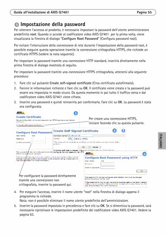
Guida all'installazione di AXIS Q7401 Pagina 55
ITALIANO
Impostazione della passwordPer ottenere l'accesso al prodotto, è necessario impostare la password dell'utente amministratore predefinito root. Quando si accede al codificatore video AXIS Q7401 per la prima volta, viene visualizzata la finestra di dialogo "Configure Root Password" (Configura password root).
Per evitare l'interruzione della connessione di rete durante l'impostazione della password root, è possibile eseguire questa operazione tramite la connessione crittografata HTTPS, che richiede un certificato HTTPS (vedere la nota seguente).
Per impostare la password tramite una connessione HTTP standard, inserirla direttamente nella prima finestra di dialogo mostrata di seguito.
Per impostare la password tramite una connessione HTTPS crittografata, attenersi alla seguente procedura:
1. Fare clic sul pulsante Create self-signed certificate (Crea certificato autofirmato).2. Fornire le informazioni richieste e fare clic su OK. Il certificato viene creato e la password può
essere ora impostata in modo sicuro. Da questo momento in poi tutto il traffico verso e dal codificatore video AXIS Q7401 viene cifrato.
3. Inserire una password e quindi reinserirla per confermarla. Fare clic su OK. La password è stata ora configurata.
4. Per eseguire l’accesso, inserire il nome utente “root” nella finestra di dialogo appena il programma lo richiede. Nota: non è possibile eliminare il nome utente predefinito dell'amministratore.
5. Inserire la password impostata in precedenza e fare clic su OK. Se si dimentica la password, sarà necessario ripristinare le impostazioni predefinite del codificatore video AXIS Q7401. Vedere la pagina 63.
Per configurare la password direttamente tramite una connessione non crittografata, inserire la password qui.
Per creare una connessione HTTPS, iniziare facendo clic su questo pulsante.
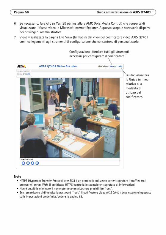
Pagina 56 Guida all'installazione di AXIS Q7401
6. Se necessario, fare clic su Yes (Sì) per installare AMC (Axis Media Control) che consente di visualizzare il flusso video in Microsoft Internet Explorer. A questo scopo è necessario disporre dei privilegi di amministratore.
7. Viene visualizzata la pagina Live View (Immagini dal vivo) del codificatore video AXIS Q7401 con i collegamenti agli strumenti di configurazione che consentono di personalizzarlo.
Note• HTTPS (Hypertext Transfer Protocol over SSL) è un protocollo utilizzato per crittografare il traffico tra i
browser e i server Web. Il certificato HTTPS controlla lo scambio crittografato di informazioni.• Non è possibile eliminare il nome utente amministratore predefinito “root”.• Se si smarrisce o si dimentica la password “root”, il codificatore video AXIS Q7401 deve essere reimpostato
sulle impostazioni predefinite. Vedere la pagina 63.
Configurazione: fornisce tutti gli strumenti necessari per configurare il codificatore.
Guida: visualizza la Guida in linea relativa alla modalità di utilizzo del codificatore.
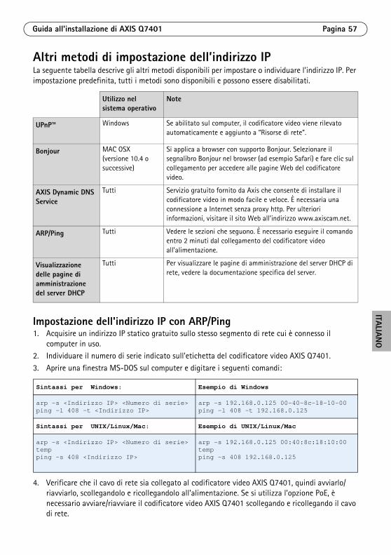
Guida all'installazione di AXIS Q7401 Pagina 57
ITALIANO
Altri metodi di impostazione dell’indirizzo IPLa seguente tabella descrive gli altri metodi disponibili per impostare o individuare l'indirizzo IP. Per impostazione predefinita, tutti i metodi sono disponibili e possono essere disabilitati.
Impostazione dell'indirizzo IP con ARP/Ping1. Acquisire un indirizzo IP statico gratuito sullo stesso segmento di rete cui è connesso il
computer in uso. 2. Individuare il numero di serie indicato sull'etichetta del codificatore video AXIS Q7401.
3. Aprire una finestra MS-DOS sul computer e digitare i seguenti comandi:
4. Verificare che il cavo di rete sia collegato al codificatore video AXIS Q7401, quindi avviarlo/riavviarlo, scollegandolo e ricollegandolo all'alimentazione. Se si utilizza l’opzione PoE, è necessario avviare/riavviare il codificatore video AXIS Q7401 scollegando e ricollegando il cavo di rete.
Utilizzo nel sistema operativo
Note
UPnP™
Windows Se abilitato sul computer, il codificatore video viene rilevato automaticamente e aggiunto a “Risorse di rete”.
Bonjour MAC OSX (versione 10.4 o successive)
Si applica a browser con supporto Bonjour. Selezionare il segnalibro Bonjour nel browser (ad esempio Safari) e fare clic sul collegamento per accedere alle pagine Web del codificatore video.
AXIS Dynamic DNS Service
Tutti Servizio gratuito fornito da Axis che consente di installare il codificatore video in modo facile e veloce. È necessaria una connessione a Internet senza proxy http. Per ulteriori informazioni, visitare il sito Web all’indirizzo www.axiscam.net.
ARP/Ping Tutti Vedere le sezioni che seguono. È necessario eseguire il comando entro 2 minuti dal collegamento del codificatore video all'alimentazione.
Visualizzazione delle pagine di amministrazione del server DHCP
Tutti Per visualizzare le pagine di amministrazione del server DHCP di rete, vedere la documentazione specifica del server.
Sintassi per Windows: Esempio di Windows
arp -s <Indirizzo IP> <Numero di serie>ping -l 408 -t <Indirizzo IP>
arp -s 192.168.0.125 00-40-8c-18-10-00ping -l 408 -t 192.168.0.125
Sintassi per UNIX/Linux/Mac: Esempio di UNIX/Linux/Mac
arp -s <Indirizzo IP> <Numero di serie> tempping -s 408 <Indirizzo IP>
arp -s 192.168.0.125 00:40:8c:18:10:00 tempping -s 408 192.168.0.125

Pagina 58 Guida all'installazione di AXIS Q7401
5. Chiudere la finestra MS-DOS appena viene visualizzato il messaggio "Reply from 192.168.0.125:…" (Risposta da 192.168.0.125) o altro messaggio equivalente.
6. Nel browser immettere http://<indirizzo IP> nel campo dell’indirizzo e premere Invio sulla tastiera.
Note• Per aprire una finestra MS-DOS in Windows: dal menu Start, scegliere Esegui... e digitare cmd. Fare clic su
OK.• Per utilizzare il comando ARP in un sistema operativo Mac OS X, usare l'utility Terminal, in Applicazioni >
Utilità.

Guida all'installazione di AXIS Q7401 Pagina 59
ITALIANO
ConnettoriConnettore di rete - Connettore Ethernet RJ-45. Supporto per Power over Ethernet (PoE). Si consiglia l’uso di cavi schermati.
Interruttore PoE - Power over Ethernet (IEEE 802.3af) con selettore di alimentazione:
• Classe 2 – Max. 6,49 W• Classe 3 – Max. 12,95 W (impostazione predefinita)
Nota Il tipo di alimentazione viene selezionato all’accensione. Se il codificatore video non è usato per alimentare la videocamera analogica collegata, selezionare PoE Classe 2 per segnalare all’interruttore PoE che il codificatore necessita soltanto di max. 6,49 W. PoE Classe 3 è l’impostazione predefinita.
Connettore di alimentazione - Morsettiera a 2 pin utilizzata per l’ingresso e l’uscita dell’alimentazione.
• Ingresso alimentazione: per fornire alimentazione al codificatore video con l’adattatore in dotazione o un alimentatore esterno da 8-20 V CC, max. 7,2 W.
• Uscita alimentazione: il codificatore video può alimentare una videocamera o una periferica ausiliaria se è alimentato tramite PoE, 12 V CC max. 5 W (420 mA).
Note• Il codificatore video è in grado di fornire una potenza massima di 5 W (420 mA) tramite l’opzione PoE,
compresa l’uscita sul connettore di alimentazione e il connettore del morsetto I/O.• Non collegare l’alimentazione se il codificatore video è collegato a PoE.
Ingresso audio - 3,5 mm per microfono in mono o segnale mono line-in (il canale sinistro è usato da un segnale in stereo).
Uscita audio - Uscita audio che può essere connessa a un sistema di indirizzo pubblico (PA), oppure a un altoparlante con amplificatore integrato. Si possono collegare anche un paio di cuffie. Per l'uscita audio è necessario usare un connettore stereo.
Funzione Numero pin
Descrizione
GND 1 Terra
Alimentazione CC
2 Ingresso alimentazione a 8-20 V CC, max. 7,2 W o Uscita alimentazione 12 V CC, max. 5 W (420 mA)
1 2
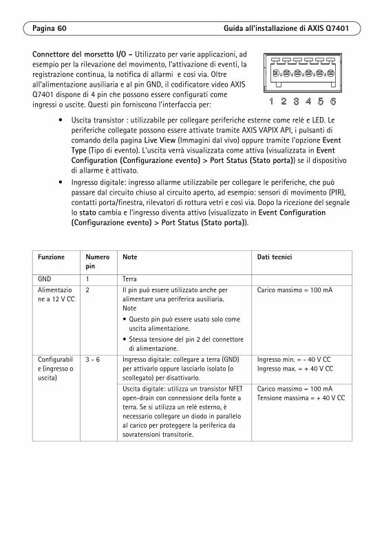
Pagina 60 Guida all'installazione di AXIS Q7401
Connettore del morsetto I/O - Utilizzato per varie applicazioni, ad esempio per la rilevazione del movimento, l’attivazione di eventi, la registrazione continua, la notifica di allarmi e così via. Oltre all’alimentazione ausiliaria e al pin GND, il codificatore video AXIS Q7401 dispone di 4 pin che possono essere configurati come ingressi o uscite. Questi pin forniscono l’interfaccia per:
• Uscita transistor : utilizzabile per collegare periferiche esterne come relè e LED. Le periferiche collegate possono essere attivate tramite AXIS VAPIX API, i pulsanti di comando della pagina Live View (Immagini dal vivo) oppure tramite l'opzione Event Type (Tipo di evento). L’uscita verrà visualizzata come attiva (visualizzata in Event Configuration (Configurazione evento) > Port Status (Stato porta)) se il dispositivo di allarme è attivato.
• Ingresso digitale: ingresso allarme utilizzabile per collegare le periferiche, che può passare dal circuito chiuso al circuito aperto, ad esempio: sensori di movimento (PIR), contatti porta/finestra, rilevatori di rottura vetri e così via. Dopo la ricezione del segnale lo stato cambia e l’ingresso diventa attivo (visualizzato in Event Configuration (Configurazione evento) > Port Status (Stato porta)).
Funzione Numero pin
Note Dati tecnici
GND 1 Terra
Alimentazione a 12 V CC
2 Il pin può essere utilizzato anche per alimentare una periferica ausiliaria.Note
• Questo pin può essere usato solo come uscita alimentazione.
• Stessa tensione del pin 2 del connettore di alimentazione.
Carico massimo = 100 mA
Configurabile (ingresso o uscita)
3 - 6 Ingresso digitale: collegare a terra (GND) per attivarlo oppure lasciarlo isolato (o scollegato) per disattivarlo.
Ingresso min. = - 40 V CCIngresso max. = + 40 V CC
Uscita digitale: utilizza un transistor NFET open-drain con connessione della fonte a terra. Se si utilizza un relè esterno, è necessario collegare un diodo in parallelo al carico per proteggere la periferica da sovratensioni transitorie.
Carico massimo = 100 mATensione massima = + 40 V CC
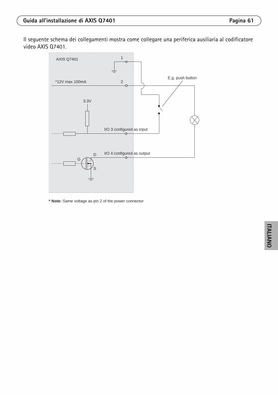
Guida all'installazione di AXIS Q7401 Pagina 61
ITALIANO
Il seguente schema dei collegamenti mostra come collegare una periferica ausiliaria al codificatore video AXIS Q7401.
1
2E.g. push button
I/O 3 configured as input
I/O 4 configured as output
* Note: Same voltage as pin 2 of the power connector
AXIS Q7401
3.3V
*12V max 100mA
D
S
G

Pagina 62 Guida all'installazione di AXIS Q7401
Connettore RS-422/RS-485 - Due morsettiere da 2 pin per l'interfaccia seriale RS-485/422, utilizzate per il controllo di periferiche ausiliarie come le videocamere PTZ.
La porta seriale RS-485/422 può essere configurata su una delle seguenti modalità porta:
• Porta bidirezionale RS-485 half-duplex per la trasmissione di dati con due cavi e una coppia RX/TX combinata.
• Porta bidirezionale RS-485 half-duplex per la trasmissione di dati con quattro cavi, una coppia RX e una coppia TX.
• Porta unidirezionale RS-422 per la trasmissione e la ricezione di dati con due cavi e una coppia RX o TX.
• Porta bidirezionale RS-422 half-duplex per la trasmissione di dati (point-to-point) con quattro cavi, una coppia RX e una coppia TX.
Slot per scheda di memoria SDHC - Grazie alla sua elevata capacità, la scheda di memoria SD può essere utilizzata come unità di memorizzazione rimovibile per la registrazione locale.
Connettore BNC - Può essere collegato a un cavo video coassiale da 75 Ohm (della lunghezza massima di 250 metri).
Nota Per collegare la sorgente video in parallelo con un’altra periferica tramite un adattatore BNC T, disattivare la terminazione dell’uscita impostando l’interruttore di terminazione a 75 Ohm su OFF. Il mancato rispetto di queste istruzioni può compromettere la qualità delle immagini.
Indicatori LED
Funzione Pin Note
RS 485/422TX(A) 1 Coppia TX per RS-422 e RS-485 con quattro cavi
RS 485/422TX(B) 2
RS-485A alt RS-485/422RX(A) 3 Coppia RX per tutte le modalità (RX/TX combinata per RS-485 con due cavi)RS-485B alt RS-485/422RX(B) 4
LED Colore Indicazione
Rete Verde Luce fissa: connessione di rete a 100 Mbit/s. Luce lampeggiante: attività di rete.
Giallo Luce fissa: connessione di rete a 10 Mbit/s. Luce lampeggiante: attività di rete.
Spento Assenza di connessione..
Stato Verde Luce verde fissa: condizioni di normale utilizzo.
Giallo Luce fissa: durante l’avvio o il ripristino delle impostazioni predefinite o della configurazione.
Rosso Luce lampeggiante lenta: aggiornamento non riuscito.
Alimentazione Verde Normale utilizzo.
Giallo Luce lampeggiante verde/gialla: aggiornamento firmware.
1 2 3 4
TX RX/TX

Guida all'installazione di AXIS Q7401 Pagina 63
ITALIANO
Ripristino delle impostazioni predefiniteQuesta procedura consente di ripristinare le impostazioni predefinite per tutti i parametri, incluso l'indirizzo IP.
1. Scollegare il codificatore video AXIS Q7401 dall'alimentazione oppure scollegare il cavo di rete se si utilizza PoE.
2. Premere e tenere premuto il pulsante di comando e ricollegare l’alimentazione o il cavo di rete se si utilizza PoE.
3. Tenere premuto il pulsante di comando fino a quando l'indicatore di stato non inizia a lampeggiare in giallo (l'operazione può richiedere fino a 15 secondi).
4. Rilasciare il pulsante di comando. Appena l'indicatore di stato diventa verde (l'operazione può richiedere fino a 1 minuto), significa che la procedura è terminata e che il codificatore video è stato reimpostato.
5. Riassegnare l'indirizzo IP utilizzando uno dei metodi descritti in questo documento.
È possibile inoltre ripristinare le impostazioni predefinite mediante l’interfaccia Web. Per ulteriori informazioni, consultare la Guida in linea o la Guida per l'utente.

Pagina 64 Guida all'installazione di AXIS Q7401
Accesso al codificatore video AXIS Q7401 da InternetDopo l'installazione, il codificatore AXIS Q7401 è accessibile nella rete locale (LAN). Per accedere al codificatore video da Internet, è necessario configurare i router di rete per consentire il traffico in entrata, che di norma avviene su una porta specifica:
• Porta HTTP (porta predefinita 80) per la visualizzazione e la configurazione
• Porta RTSP (porta predefinita 554) per la visualizzazione di flussi video in formato H.264
Per ulteriori istruzioni, consultare la documentazione del router. Per maggiori informazioni su questo e altri argomenti, visitare il sito Web per il supporto Axis all'indirizzo www.axis.com/techsup.
Ulteriori informazioniLa Guida per l’utente è disponibile sul sito Web di Axis all’indirizzo www.axis.com oppure sul CD fornito con il prodotto.
Suggerimento Visitare il sito di Axis all’indirizzo www.axis.com/techsup per verificare se sono stati pubblicati aggiornamenti del firmware per il codificatore video AXIS Q7401. Per sapere quale versione del firmware è stata installata, vedere la pagina Web About (Informazioni su) nella sezione degli strumenti di configurazione.

AXIS Q7401 Guía de instalación Página 65
ESPAÑO
L
Codificador de vídeo AXIS Q7401 Guía de instalación
Esta guía de instalación incluye las instrucciones necesarias para instalar el Codificador de vídeo AXIS Q7401 en su red. Para obtener información sobre el uso del producto, consulte el Manual del usuario, disponible en el CD que se incluye en este paquete, o la página www.axis.com.
Pasos para la instalaciónSiga estos pasos para instalar el Codificador de vídeo AXIS Q7401 en su red local (LAN):
1. Verifique el contenido del paquete con la lista que aparece más abajo.
2. Presentación del hardware. Consulte la página 66.
3. Instalación del hardware. Consulte la página 67.4. Asignación de la dirección IP. Consulte la página 68.
5. Configuración de la contraseña. Consulte la página 71.
Contenido del paqueteArtículo Modelos/variantes/notas
Modelos de codificador de vídeo Axis
AXIS Q7401
Modelos de adaptador de corriente
Tipo PS-K o PS-T
Kit de montaje • 2 tornillos y tacos para instalar el codificador en una pared de hormigón
• 4 protectores superficiales
• Conectores para el bloque de terminales (E/S: conector de 6 pines; RS-485/422: 2 conectores de 2 pines ; alimentación eléctrica: conector de 2 pines)
CD CD de Productos de vídeo en red de AXIS, que incluye documentación de productos, herramientas de instalación y otro software
Documentación AXIS Q7401 Guía de instalación (este documento)Documento de garantía de Axis
¡Importante! Este producto debe utilizarse de acuerdo a la legislación y normativas locales.
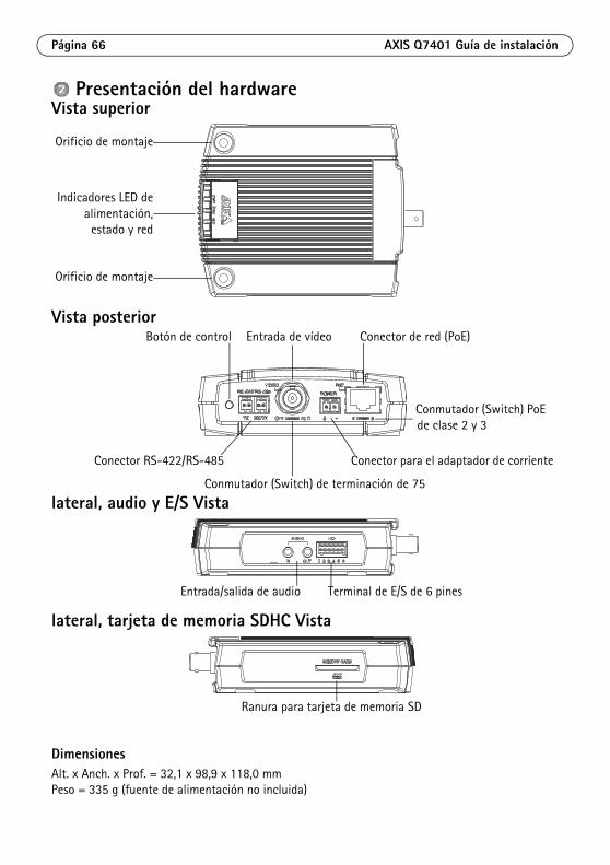
Página 66 AXIS Q7401 Guía de instalación
Presentación del hardwareVista superior
Vista posterior
lateral, audio y E/S Vista
lateral, tarjeta de memoria SDHC Vista
DimensionesAlt. x Anch. x Prof. = 32,1 x 98,9 x 118,0 mmPeso = 335 g (fuente de alimentación no incluida)
Orificio de montaje
Orificio de montaje
Indicadores LED dealimentación,
estado y red
Botón de control
Conector para el adaptador de corrienteConector RS-422/RS-485
Entrada de vídeo Conector de red (PoE)
Conmutador (Switch) PoE de clase 2 y 3
Conmutador (Switch) de terminación de 75
Entrada/salida de audio Terminal de E/S de 6 pines
Ranura para tarjeta de memoria SD
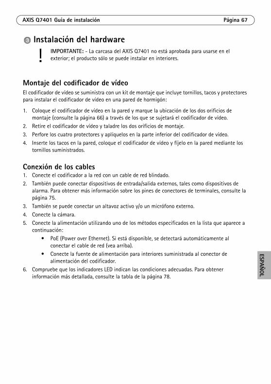
AXIS Q7401 Guía de instalación Página 67
ESPAÑO
L
Instalación del hardware
Montaje del codificador de vídeoEl codificador de vídeo se suministra con un kit de montaje que incluye tornillos, tacos y protectores para instalar el codificador de vídeo en una pared de hormigón:
1. Coloque el codificador de vídeo en la pared y marque la ubicación de los dos orificios de montaje (consulte la página 66) a través de los que se sujetará el codificador de vídeo.
2. Retire el codificador de vídeo y taladre los dos orificios de montaje.
3. Perfore los cuatro protectores y aplíquelos en la parte inferior del codificador de vídeo.
4. Inserte los tacos en la pared, coloque el codificador de vídeo y fíjelo en la pared mediante los tornillos suministrados.
Conexión de los cables1. Conecte el codificador a la red con un cable de red blindado.
2. También puede conectar dispositivos de entrada/salida externos, tales como dispositivos de alarma. Para obtener más información sobre los pines de conectores de terminales, consulte la página 75.
3. También se puede conectar un altavoz activo y/o un micrófono externo.
4. Conecte la cámara.5. Conecte la alimentación utilizando uno de los métodos especificados en la lista que aparece a
continuación:• PoE (Power over Ethernet). Si está disponible, se detectará automáticamente al
conectar el cable de red (vea arriba).• Conecte la fuente de alimentación para interiores suministrada al conector de
alimentación del codificador. 6. Compruebe que los indicadores LED indican las condiciones adecuadas. Para obtener
información más detallada, consulte la tabla de la página 78.
! IMPORTANTE: - La carcasa del AXIS Q7401 no está aprobada para usarse en el exterior; el producto sólo se puede instalar en interiores.

Página 68 AXIS Q7401 Guía de instalación
Asignación de la dirección IPActualmente, la mayoría de redes disponen de un servidor DHCP que asigna direcciones IP a los dispositivos conectados de forma automática. Si su red no dispone de un servidor DHCP, el AXIS Q7401 utilizará 192.168.0.90 como dirección IP predeterminada.
AXIS IP Utility y AXIS Camera Management son métodos recomendados para configurar una dirección IP en Windows. Estas aplicaciones son gratuitas y están disponibles en el CD de productos de vídeo en red de Axis suministrado con este producto o pueden descargarse de www.axis.com/techsup. En función del número de cámaras que desee instalar, deberá utilizar el método que mejor se adapte a sus necesidades.
Notas:• Si no puede asignar la dirección IP, compruebe que no haya ningún cortafuegos (firewall) que bloquee la
operación.• Consulte la página 73 para conocer otros métodos para asignar o detectar la dirección IP del AXIS Q7401,
por ejemplo, en otros sistemas operativos.
Método Recomendado para Sistema operativo
AXIS IP Utility Consulte la página 69
Codificador de vídeo individualInstalaciones pequeñas
Windows
AXIS Camera ManagementConsulte la página 70
Varios codificadores de vídeoInstalaciones grandesInstalación en una subred diferente
Windows 2000Windows XP ProWindows 2003 ServerWindows Vista
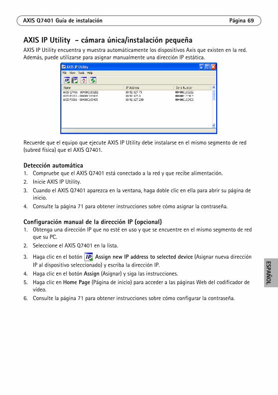
AXIS Q7401 Guía de instalación Página 69
ESPAÑO
L
AXIS IP Utility - cámara única/instalación pequeñaAXIS IP Utility encuentra y muestra automáticamente los dispositivos Axis que existen en la red. Además, puede utilizarse para asignar manualmente una dirección IP estática.
Recuerde que el equipo que ejecute AXIS IP Utility debe instalarse en el mismo segmento de red (subred física) que el AXIS Q7401.
Detección automática1. Compruebe que el AXIS Q7401 está conectado a la red y que recibe alimentación.2. Inicie AXIS IP Utility.
3. Cuando el AXIS Q7401 aparezca en la ventana, haga doble clic en ella para abrir su página de inicio.
4. Consulte la página 71 para obtener instrucciones sobre cómo asignar la contraseña.
Configuración manual de la dirección IP (opcional)1. Obtenga una dirección IP que no esté en uso y que se encuentre en el mismo segmento de red
que su PC. 2. Seleccione el AXIS Q7401 en la lista.
3. Haga clic en el botón Assign new IP address to selected device (Asignar nueva dirección IP al dispositivo seleccionado) y escriba la dirección IP.
4. Haga clic en el botón Assign (Asignar) y siga las instrucciones.5. Haga clic en Home Page (Página de inicio) para acceder a las páginas Web del codificador de
vídeo.6. Consulte la página 71 para obtener instrucciones sobre cómo configurar la contraseña.
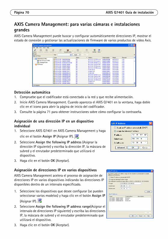
Página 70 AXIS Q7401 Guía de instalación
AXIS Camera Management: para varias cámaras e instalaciones grandesAXIS Camera Management puede buscar y configurar automáticamente direcciones IP, mostrar el estado de conexión y gestionar las actualizaciones de firmware de varios productos de vídeo Axis.
Detección automática1. Compruebe que el codificador está conectado a la red y que recibe alimentación.
2. Inicie AXIS Camera Management. Cuando aparezca el AXIS Q7401 en la ventana, haga doble clic en el icono para abrir la página de inicio del codificador.
3. Consulte la página 71 para obtener instrucciones sobre cómo configurar la contraseña.
Asignación de una dirección IP en un dispositivo individual1. Seleccione AXIS Q7401 en AXIS Camera Management y haga
clic en el botón Assign IP (Asignar IP).
2. Seleccione Assign the following IP address (Asignar la dirección IP siguiente) y escriba la dirección IP, la máscara de subred y el enrutador predeterminado que utilizará el dispositivo.
3. Haga clic en el botón OK (Aceptar).
Asignación de direcciones IP en varios dispositivosAXIS Camera Management acelera el proceso de asignación de direcciones IP en varios dispositivos indicando las direcciones IP disponibles dentro de un intervalo especificado.
1. Seleccione los dispositivos que desee configurar (se pueden seleccionar varios modelos) y haga clic en el botón Assign IP
(Asignar IP).
2. Seleccione Assign the following IP address range(Asignar el intervalo de direcciones IP siguiente) y escriba las direcciones IP, la máscara de subred y el enrutador predeterminado que utilizará el dispositivo.
3. Haga clic en el botón OK (Aceptar).

AXIS Q7401 Guía de instalación Página 71
ESPAÑO
L
Configuración de la contraseñaPara poder acceder al producto, hay que configurar la contraseña del usuario predeterminado para el administrador root. Al acceder por primera vez al AXIS Q7401, aparecerá el cuadro de diálogo ‘Configure Root Password’ (Configurar contraseña de root).
Para evitar la intercepción de la contraseña de root cuando se configura, este proceso se puede realizar a través de una conexión HTTPS cifrada, que precisa un certificado HTTPS (ver nota más abajo).
Para configurar la contraseña a través de una conexión HTTP estándar, escríbala directamente en el primer cuadro de diálogo que se muestra a continuación.
Para configurar la contraseña a través de una conexión HTTPS cifrada, siga estos pasos:
1. Haga clic en el botón Create self-signed certificate (Crear certificado autofirmado).
2. Proporcione la información requerida y haga clic en OK (Aceptar). Se creará el certificado y se podrá configurar la contraseña con seguridad. Todo el tráfico hacia y desde el AXIS Q7401 se cifrará a partir de este punto.
3. A continuación, escriba una contraseña y vuelva a escribirla para confirmarla. Haga clic en OK (Aceptar). La contraseña ya se ha configurado.
4. Para iniciar sesión, escriba el nombre de usuario 'root' en el cuadro de diálogo. Nota: El nombre de usuario predeterminado para el administrador root no se puede borrar.
5. Escriba la contraseña que introdujo anteriormente y haga clic en OK (Aceptar). Si extravió u olvidó la contraseña, debe restablecer el AXIS Q7401 a los valores de fábrica. Consulte la página 79.
6. En caso necesario, haga clic en Yes (Sí) para instalar el AMC (AXIS Media Control) y así permitir la visualización de vídeo continuo en Internet Explorer. Para ello, debe tener derechos de administrador en su equipo.
Para configurar directamente la contraseña a través de una conexión sin cifrar, escriba aquí la contraseña.
Para crear una conexión HTTPS, empiece haciendo clic en este botón.
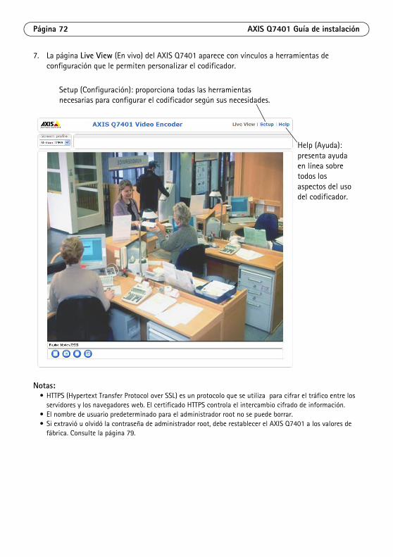
Página 72 AXIS Q7401 Guía de instalación
7. La página Live View (En vivo) del AXIS Q7401 aparece con vínculos a herramientas de configuración que le permiten personalizar el codificador.
Notas:• HTTPS (Hypertext Transfer Protocol over SSL) es un protocolo que se utiliza para cifrar el tráfico entre los
servidores y los navegadores web. El certificado HTTPS controla el intercambio cifrado de información.• El nombre de usuario predeterminado para el administrador root no se puede borrar.• Si extravió u olvidó la contraseña de administrador root, debe restablecer el AXIS Q7401 a los valores de
fábrica. Consulte la página 79.
Setup (Configuración): proporciona todas las herramientas necesarias para configurar el codificador según sus necesidades.
Help (Ayuda): presenta ayuda en línea sobre todos los aspectos del uso del codificador.

AXIS Q7401 Guía de instalación Página 73
ESPAÑO
L
Otros métodos para configurar la dirección IPEsta tabla presenta otros métodos disponibles para configurar o detectar la dirección IP. Todos los métodos están habilitados de forma predeterminada y es posible deshabilitarlos.
Configuración de la dirección IP con ARP/Ping1. Adquiera una dirección IP estática libre en el mismo segmento de red en el que está conectado
su equipo.
2. Localice el número de serie (S/N) en la etiqueta del AXIS Q7401.
3. Abra una línea de comando en su equipo y escriba los comandos siguientes:
4. Compruebe que el cable de red está conectado al codificador AXIS Q7401 y desconecte y vuelva a conectar la corriente para iniciarlo o reiniciarlo. Si se usa PoE, inicie/reinicie el AXIS Q7401 desconectando y volviendo a conectar el cable de red.
5. Cierre la línea de comando cuando vea “Reply from 192.168.0.125:…” (Respuesta de 192.168.0.125:…) o similar.
Uso en sistema operativo
Notas
UPnP™
Windows El codificador de vídeo se detecta y añade a “Mis sitios de red” automáticamente, siempre que esta opción esté habilitada en el equipo.
Bonjour MAC OSX (10.4 o posterior)
Aplicable a navegadores compatibles con Bonjour. Navegue hasta el favorito Bonjour del explorador (p. ej., Safari) y haga clic en el vínculo para acceder a las páginas Web del codificador de vídeo.
Servicio de DNS dinámico de AXIS
Todos Servicio gratuito suministrado por Axis que permite instalar el codificador de forma rápida y sencilla. Es necesario disponer de conexión a Internet sin proxy HTTP. Para más información, consulte www.axiscam.net.
ARP/Ping Todos Véase más adelante. El comando debe emitirse en los dos minutos posteriores al encendido del codificador de vídeo.
Acceso a las páginas admin. del servidor DHCP
Todos Para acceder a las páginas admin. del servidor DHCP en red, consulte la documentación del servidor.
Sintaxis en Windows Ejemplo en Windows
arp -s <Dirección IP> <Número de serie>ping -l 408 -t <Dirección IP>
arp -s 192.168.0.125 00-40-8c-18-10-00ping -l 408 -t 192.168.0.125
Sintaxis en UNIX/Linux/Mac Ejemplo en UNIX/Linux/Mac
arp -s <Dirección IP> <Número de serie> tempping -s 408 <Dirección IP>
arp -s 192.168.0.125 00:40:8c:18:10:00 tempping -s 408 192.168.0.125

Página 74 AXIS Q7401 Guía de instalación
6. En el explorador, escriba http://<dirección IP> en el campo Ubicación/Dirección y pulse Intro en el teclado.
Notas:• Para abrir una línea de comando en Windows: desde el menú Inicio, seleccione Ejecutar... y escriba cmd.
Haga clic en Aceptar.• Para utilizar el comando ARP en un sistema operativo Mac OS X, utilice la herramienta Terminal, que se
encuentra en Aplicaciones > Utilidades.

AXIS Q7401 Guía de instalación Página 75
ESPAÑO
L
Conectores de unidadConector de red - Conector Ethernet RJ-45. Compatible con PoE (Power over Ethernet). Se recomienda emplear cables blindados.
Conmutador (Switch) PoE con clasificación de potencia - Power over Ethernet (IEEE 802.3af), clasificación de potencia seleccionable:
• Clase 2: 6,49 W máx.
• Clase 3: 12,95 W máx. (predeterminado)Nota: La clasificación de potencia se realiza en el encendido. Si el codificador de vídeo no alimenta a la
cámara analógica conectada, seleccione PoE Clase 2 para informar al conmutador (Switch) PoE que el codificador de vídeo necesita sólo 6,49 W máx. PoE Clase 3 es el ajuste predeterminado.
Conector de alimentación - Bloque de terminales de 2 pines que se utiliza para entrada o salida de energía.
• Entrada de alimentación: para suministrar energía al codificador de vídeo con el adaptador de corriente suministrado o una fuente de alimentación externa de 8-20 V CC, 7,2 W máx..
• Salida de alimentación: el codificador de vídeo puede suministrar energía a una cámara analógica o equipo auxiliar si se alimenta a través de PoE, 12 V CC, 5W máx. (420 mA).
Notas:• El codificador de vídeo puede suministrar un máximo de 5W (420 mA) con PoE. Esto incluye la salida en el
conector de alimentación y el conector del terminal de E/S.• No conecte una fuente de alimentación si el codificador de vídeo está conectado a PoE.
Entrada de audio - Conector de 3,5 mm para micrófono mono, o entrada de línea de señal mono (se usa el canal izquierdo de una señal estéreo).
Salida de audio - Salida de audio (nivel línea) que puede ser conectada a un sistema de megafonía pública o a un altavoz con amplificador incorporado. También puede conectarse a unos auriculares. Debe utilizarse un conector estéreo para la salida de audio.
Función Número de pin
Descripción
GND 1 Toma de tierra
DC Power 2 Entrada de alimentación: 8-20 V CC, 7,2W máx. o salida de alimentación: 12 V CC, 5 W máx. (420mA).
1 2
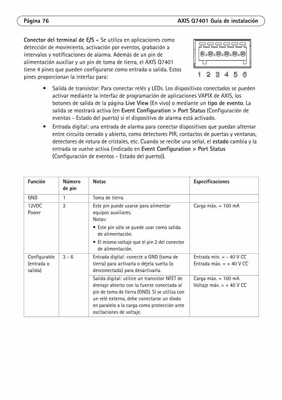
Página 76 AXIS Q7401 Guía de instalación
Conector del terminal de E/S - Se utiliza en aplicaciones como detección de movimiento, activación por eventos, grabación a intervalos y notificaciones de alarma. Además de un pin de alimentación auxiliar y un pin de toma de tierra, el AXIS Q7401 tiene 4 pines que pueden configurarse como entrada o salida. Estos pines proporcionan la interfaz para:
• Salida de transistor: Para conectar relés y LEDs. Los dispositivos conectados se pueden activar mediante la interfaz de programación de aplicaciones VAPIX de AXIS, los botones de salida de la página Live View (En vivo) o mediante un tipo de evento. La salida se mostrará activa (en Event Configuration > Port Status (Configuración de eventos - Estado del puerto) si el dispositivo de alarma está activado.
• Entrada digital: una entrada de alarma para conectar dispositivos que puedan alternar entre circuito cerrado y abierto, como detectores PIR, contactos de puertas y ventanas, detectores de rotura de cristales, etc. Cuando se recibe una señal, el estado cambia y la entrada se vuelve activa (indicado en Event Configuration > Port Status (Configuración de eventos - Estado del puerto)).
Función Número de pin
Notas Especificaciones
GND 1 Toma de tierra
12VDC Power
2 Este pin puede usarse para alimentar equipos auxiliares.Notas:
• Este pin sólo se puede usar como salida de alimentación.
• El mismo voltaje que el pin 2 del conector de alimentación.
Carga máx. = 100 mA
Configurable (entrada o salida)
3 - 6 Entrada digital: conecte a GND (toma de tierra) para activarla o déjela suelta (o desconectada) para desactivarla.
Entrada mín. = - 40 V CCEntrada máx. = + 40 V CC
Salida digital: utilice un transistor NFET de drenaje abierto con la fuente conectada al pin de toma de tierra (GND). Si se utiliza con un relé externo, debe conectarse un diodo en paralelo a la carga como protección ante oscilaciones de voltaje.
Carga máx. = 100 mAVoltaje máx. = + 40 V CC
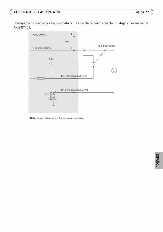
AXIS Q7401 Guía de instalación Página 77
ESPAÑO
L
El diagrama de conexiones siguiente ofrece un ejemplo de cómo conectar un dispositivo auxiliar al AXIS Q7401.
1
2E.g. push button
I/O 3 configured as input
I/O 4 configured as output
* Note: Same voltage as pin 2 of the power connector
AXIS Q7401
3.3V
*12V max 100mA
D
S
G
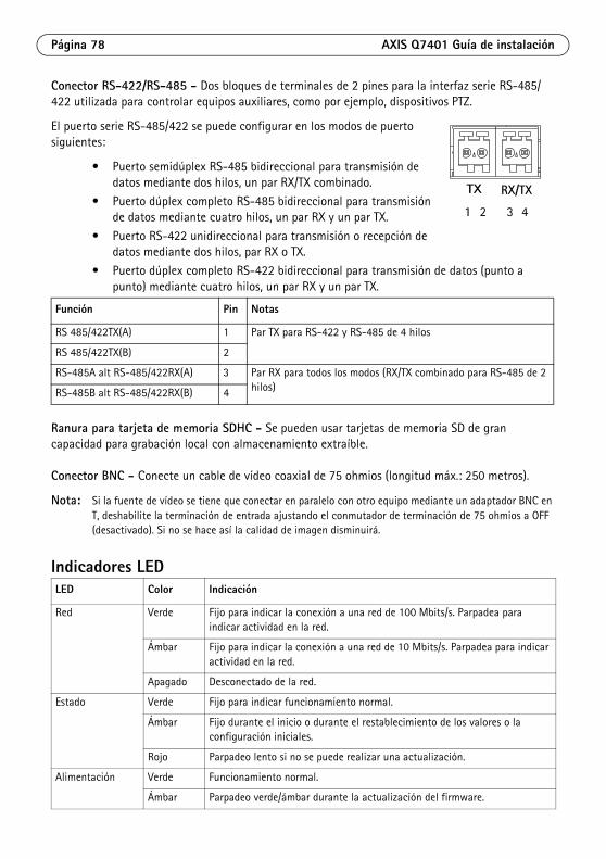
Página 78 AXIS Q7401 Guía de instalación
Conector RS-422/RS-485 - Dos bloques de terminales de 2 pines para la interfaz serie RS-485/422 utilizada para controlar equipos auxiliares, como por ejemplo, dispositivos PTZ.
El puerto serie RS-485/422 se puede configurar en los modos de puerto siguientes:
• Puerto semidúplex RS-485 bidireccional para transmisión de datos mediante dos hilos, un par RX/TX combinado.
• Puerto dúplex completo RS-485 bidireccional para transmisión de datos mediante cuatro hilos, un par RX y un par TX.
• Puerto RS-422 unidireccional para transmisión o recepción de datos mediante dos hilos, par RX o TX.
• Puerto dúplex completo RS-422 bidireccional para transmisión de datos (punto a punto) mediante cuatro hilos, un par RX y un par TX.
Ranura para tarjeta de memoria SDHC - Se pueden usar tarjetas de memoria SD de gran capacidad para grabación local con almacenamiento extraíble.
Conector BNC - Conecte un cable de vídeo coaxial de 75 ohmios (longitud máx.: 250 metros).
Nota: Si la fuente de vídeo se tiene que conectar en paralelo con otro equipo mediante un adaptador BNC en T, deshabilite la terminación de entrada ajustando el conmutador de terminación de 75 ohmios a OFF (desactivado). Si no se hace así la calidad de imagen disminuirá.
Indicadores LED
Función Pin Notas
RS 485/422TX(A) 1 Par TX para RS-422 y RS-485 de 4 hilos
RS 485/422TX(B) 2
RS-485A alt RS-485/422RX(A) 3 Par RX para todos los modos (RX/TX combinado para RS-485 de 2 hilos)RS-485B alt RS-485/422RX(B) 4
LED Color Indicación
Red Verde Fijo para indicar la conexión a una red de 100 Mbits/s. Parpadea para indicar actividad en la red.
Ámbar Fijo para indicar la conexión a una red de 10 Mbits/s. Parpadea para indicar actividad en la red.
Apagado Desconectado de la red.
Estado Verde Fijo para indicar funcionamiento normal.
Ámbar Fijo durante el inicio o durante el restablecimiento de los valores o la configuración iniciales.
Rojo Parpadeo lento si no se puede realizar una actualización.
Alimentación Verde Funcionamiento normal.
Ámbar Parpadeo verde/ámbar durante la actualización del firmware.
1 2 3 4
TX RX/TX
AXIS Q7401 Guía de instalación Página 79
ESPAÑO
L
Restablecimiento de los valores de fábricaEsta operación restaurará todos los parámetros, incluida la dirección IP, a los valores de fábrica:
1. Desconecte la alimentación del AXIS Q7401 o, si se usa PoE, desconecte el cable de red.2. Mantenga pulsado el botón de control y vuelva a conectar la alimentación o el cable de red si
se utiliza PoE.3. Mantenga pulsado el botón de control hasta que el indicador de estado emita una luz ámbar
(puede tardar hasta 15 segundos en encenderse).4. Suelte el botón de control. Cuando el indicador de estado emita una luz verde (lo que puede
tardar hasta 1 minuto), ha finalizado el proceso y se han restablecido los valores iniciales del codificador de vídeo.
5. Vuelva a asignar la dirección IP utilizando uno de los métodos descritos en este documento.También es posible restablecer los valores predeterminados originales mediante la interfaz Web. Si desea más información, consulte la ayuda en línea o el manual del usuario.

Página 80 AXIS Q7401 Guía de instalación
Acceso al AXIS Q7401 desde InternetUna vez instalado, el AXIS Q7401 será accesible en su red local (LAN). Para acceder al codificador de vídeo desde Internet, los enrutadores (Routers) de red deben configurarse para permitir tráfico entrante, que normalmente se realiza en un puerto específico.
• Puerto HTTP (puerto 80 predeterminado) para visualización y configuración
• Puerto RTSP (puerto 554 predeterminado) para visualización de secuencias de vídeo H.264
Consulte la documentación del enrutador (Router) para obtener instrucciones. Si desea más información sobre éste y otros temas, visite la página Web de soporte de Axis en www.axis.com/techsup
Más informaciónEl manual del usuario está disponible en el sitio Web de Axis, www.axis.com, o en el CD de productos de vídeo en red de Axis suministrado con este producto.
Consejo: Visite www.axis.com/techsup para comprobar si hay disponible firmware actualizado para el AXIS Q7401. Para saber la versión de firmware que hay instalada actualmente, consulte la página Web About (Acerca de) en las herramientas de configuración del producto.

AXIS Q7401 Installation Guide Page 81
ENGLISH
DEUTSCHITALIAN
OESPAÑ
OL
FRANÇAIS
Safety Notice - Battery Replacement
The AXIS Q7401 uses a 3.0V CR2032 Lithium battery as the power supply for its internal real-time clock (RTC). Under normal conditions this battery will last for a minimum of 5 years. Low battery power affects the operation of the RTC, causing it to reset at every power-up. A log message will appear when the battery needs replacing. The battery should not be replaced unless required!
• If the battery does need replacing, please observe the following:• Danger of Explosion if battery is incorrectly replaced• Replace only with the same or equivalent battery, as recommended by the manufacturer.• Dispose of used batteries according to the manufacturer's instructions.
Consignes de sécurité - Remplacement de la pileL'AXIS Q7401 utilise une pile au lithium CR2032 (3 V) pour l'alimentation de son horloge temps réel (HTR) interne. Dans des conditions d'utilisation normales, la durée de vie de cette pile est d'au moins 5 ans. Si la pile est faible, le fonctionnement de l'horloge temps réel est affecté et celle-ci se réinitialise à chaque mise en marche. Un message de journal apparaît lorsqu'il est nécessaire de remplacer la pile. La pile ne doit être remplacée que si cela s'avère nécessaire!Si c'est le cas, observez les consignes suivantes:
• Danger d'explosion si la pile n'est pas remplacée correctement• Ne remplacez la pile que par le même modèle ou un modèle équivalent recommandé par le fabricant.• Débarrassez-vous des piles usagées conformément aux instructions du fabricant.
Sicherheitshinweis zum BatterieaustauschDie AXIS Q7401 benötigt eine Lithium-Batterie CR2032 3,0 V, um die interne Echtzeituhr (RTC) zu versorgen. Die Lebensdauer dieser Batterie beträgt unter normalen Betriebsbedingungen mindestens 5 Jahre. Bei niedrigem Batteriestand muss die RTC bei jedem Einschalten nachgestellt werden. Es wird eine Protokollnachricht angezeigt, wenn die Batterie ausgetauscht werden muss. Die Batterie sollte nur wenn unbedingt erforderlich ausgetauscht werden.Wenn die Batterie ausgetauscht werden muss, beachten Sie diese Hinweise:
• Es besteht Explosionsgefahr, wenn die Batterie nicht ordnungsgemäß eingesetzt wurde.• Nur gegen vom Hersteller empfohlene Batterien desselben oder eines ähnlichen Typs austauschen.• Entsorgen benutzter Batterien gemäß den Herstellervorgaben.
Informazioni sulla sicurezza - Sostituzione della batteriaPer il dispositivo AXIS Q7401 viene utilizzata una batteria al litio CR2032 3.0 V per l'alimentazione dell'orologio interno in tempo reale (RTC). In condizioni di normale utilizzo, questa batteria ha una durata minima di 5 anni. Se la carica della batteria non è sufficiente, il dispositivo RTC non funziona correttamente causando il ripristino delle impostazioni ad ogni accensione. Viene visualizzato un messaggio di registro quando è necessario sostituire la batteria. Sostituire la batteria solo quando richiesto.Qualora sia necessario sostituire la batteria, attenersi alle seguenti indicazioni:
• Pericolo di esplosione se la batteria viene sostituita in modo errato.• Sostituire la batteria solo con una dello stesso tipo o equivalente, come consigliato dal produttore.• Smaltire le batterie usate secondo quanto stabilito dal produttore.
Aviso de seguridad - Sustitución de la pilaLa AXIS Q7401 utiliza una pila de litio CR2032 de 3,0 V como fuente de alimentación para el reloj en tiempo real interno (RTC). En condiciones normales, esta pila dura 5 años como mínimo. Si la alimentación de la pila es baja, el funcionamiento del RTC se ve afectado y se restablece después de cada arranque. Aparecerá un mensaje de registro cuando sea necesario cambiar la pila. La pila no debe reemplazarse a menos que sea necesario.Tenga en cuenta las indicaciones siguientes al cambiar la pila:
• Existe peligro de explosión si la pila no se cambia de forma correcta• Sustitúyala sólo con una pila del mismo tipo o equivalente, según la recomendación del fabricante.• Deseche las pilas usadas de acuerdo con las instrucciones del fabricante.

Installation Guide Ver.1.1
AXIS Q7401 Video Encoder Printed: May 2011
©2008-2011 Axis Communications AB Part No. 42790

I N S T A L L A T I O N / O P E R A T I O N
C307M-L (3/10)
ES30C/ES31CES30PC/ES31PC
ES30/ES31 SeriesEsprit® with IOC/IOP

Contents
Important Safety Instructions . . . . . . . . . . . . . . . . . . . . . . . . . . . . . . . . . . . . . . . . . . . . . . . . . . . . . . . . . . . . . . . . . . . . . . . . . . . . . . . . . . . . . . . . . . . . 4
Important Notices . . . . . . . . . . . . . . . . . . . . . . . . . . . . . . . . . . . . . . . . . . . . . . . . . . . . . . . . . . . . . . . . . . . . . . . . . . . . . . . . . . . . . . . . . . . . . . . . . . . . . 5Regulatory Notice . . . . . . . . . . . . . . . . . . . . . . . . . . . . . . . . . . . . . . . . . . . . . . . . . . . . . . . . . . . . . . . . . . . . . . . . . . . . . . . . . . . . . . . . . . . . . . . . . 5
Description. . . . . . . . . . . . . . . . . . . . . . . . . . . . . . . . . . . . . . . . . . . . . . . . . . . . . . . . . . . . . . . . . . . . . . . . . . . . . . . . . . . . . . . . . . . . . . . . . . . . . . . . . . . 6ES30C/ES31C Series Esprit with IOP . . . . . . . . . . . . . . . . . . . . . . . . . . . . . . . . . . . . . . . . . . . . . . . . . . . . . . . . . . . . . . . . . . . . . . . . . . . . . . . . . . 6
Models . . . . . . . . . . . . . . . . . . . . . . . . . . . . . . . . . . . . . . . . . . . . . . . . . . . . . . . . . . . . . . . . . . . . . . . . . . . . . . . . . . . . . . . . . . . . . . . . . . . . . 6ES30PC/ES31PC Esprit with Pressurized IOC . . . . . . . . . . . . . . . . . . . . . . . . . . . . . . . . . . . . . . . . . . . . . . . . . . . . . . . . . . . . . . . . . . . . . . . . . . . . 7
Models . . . . . . . . . . . . . . . . . . . . . . . . . . . . . . . . . . . . . . . . . . . . . . . . . . . . . . . . . . . . . . . . . . . . . . . . . . . . . . . . . . . . . . . . . . . . . . . . . . . . . 7
Installation . . . . . . . . . . . . . . . . . . . . . . . . . . . . . . . . . . . . . . . . . . . . . . . . . . . . . . . . . . . . . . . . . . . . . . . . . . . . . . . . . . . . . . . . . . . . . . . . . . . . . . . . . . . 8
Optional TXB Series Translator Board Installation . . . . . . . . . . . . . . . . . . . . . . . . . . . . . . . . . . . . . . . . . . . . . . . . . . . . . . . . . . . . . . . . . . . . . . . . . . . 12How to Remove the Pan/Tilt Cover . . . . . . . . . . . . . . . . . . . . . . . . . . . . . . . . . . . . . . . . . . . . . . . . . . . . . . . . . . . . . . . . . . . . . . . . . . . . . . . . . . 12How to Reinstall the Pan/Tilt Cover. . . . . . . . . . . . . . . . . . . . . . . . . . . . . . . . . . . . . . . . . . . . . . . . . . . . . . . . . . . . . . . . . . . . . . . . . . . . . . . . . . 12
Operation . . . . . . . . . . . . . . . . . . . . . . . . . . . . . . . . . . . . . . . . . . . . . . . . . . . . . . . . . . . . . . . . . . . . . . . . . . . . . . . . . . . . . . . . . . . . . . . . . . . . . . . . . . . 14Power-Up Display . . . . . . . . . . . . . . . . . . . . . . . . . . . . . . . . . . . . . . . . . . . . . . . . . . . . . . . . . . . . . . . . . . . . . . . . . . . . . . . . . . . . . . . . . . . . . . . . 14How to Operate Your System . . . . . . . . . . . . . . . . . . . . . . . . . . . . . . . . . . . . . . . . . . . . . . . . . . . . . . . . . . . . . . . . . . . . . . . . . . . . . . . . . . . . . . . 14Preset 95: Accessing Main Menu. . . . . . . . . . . . . . . . . . . . . . . . . . . . . . . . . . . . . . . . . . . . . . . . . . . . . . . . . . . . . . . . . . . . . . . . . . . . . . . . . . . . 14
CM6700/CM6800 . . . . . . . . . . . . . . . . . . . . . . . . . . . . . . . . . . . . . . . . . . . . . . . . . . . . . . . . . . . . . . . . . . . . . . . . . . . . . . . . . . . . . . . . . . . 14KBD200A/KBD300A: Direct Mode Only . . . . . . . . . . . . . . . . . . . . . . . . . . . . . . . . . . . . . . . . . . . . . . . . . . . . . . . . . . . . . . . . . . . . . . . . . . 15CM9500 . . . . . . . . . . . . . . . . . . . . . . . . . . . . . . . . . . . . . . . . . . . . . . . . . . . . . . . . . . . . . . . . . . . . . . . . . . . . . . . . . . . . . . . . . . . . . . . . . . . 15CM9740/CM9760/CM9770/CM9780 . . . . . . . . . . . . . . . . . . . . . . . . . . . . . . . . . . . . . . . . . . . . . . . . . . . . . . . . . . . . . . . . . . . . . . . . . . . . 15KBD4000/KBD4002/KBD4000V . . . . . . . . . . . . . . . . . . . . . . . . . . . . . . . . . . . . . . . . . . . . . . . . . . . . . . . . . . . . . . . . . . . . . . . . . . . . . . . . . 15MPT9500 . . . . . . . . . . . . . . . . . . . . . . . . . . . . . . . . . . . . . . . . . . . . . . . . . . . . . . . . . . . . . . . . . . . . . . . . . . . . . . . . . . . . . . . . . . . . . . . . . . 15Endura Systems . . . . . . . . . . . . . . . . . . . . . . . . . . . . . . . . . . . . . . . . . . . . . . . . . . . . . . . . . . . . . . . . . . . . . . . . . . . . . . . . . . . . . . . . . . . . . 15
Operating Notes . . . . . . . . . . . . . . . . . . . . . . . . . . . . . . . . . . . . . . . . . . . . . . . . . . . . . . . . . . . . . . . . . . . . . . . . . . . . . . . . . . . . . . . . . . . . . . . . . 16Environmental Range. . . . . . . . . . . . . . . . . . . . . . . . . . . . . . . . . . . . . . . . . . . . . . . . . . . . . . . . . . . . . . . . . . . . . . . . . . . . . . . . . . . . . . . . . 16Pan/Tilt Functions . . . . . . . . . . . . . . . . . . . . . . . . . . . . . . . . . . . . . . . . . . . . . . . . . . . . . . . . . . . . . . . . . . . . . . . . . . . . . . . . . . . . . . . . . . . 16Scan Speed . . . . . . . . . . . . . . . . . . . . . . . . . . . . . . . . . . . . . . . . . . . . . . . . . . . . . . . . . . . . . . . . . . . . . . . . . . . . . . . . . . . . . . . . . . . . . . . . 16Preset Functions. . . . . . . . . . . . . . . . . . . . . . . . . . . . . . . . . . . . . . . . . . . . . . . . . . . . . . . . . . . . . . . . . . . . . . . . . . . . . . . . . . . . . . . . . . . . . 16Random, Frame, and Auto Scanning . . . . . . . . . . . . . . . . . . . . . . . . . . . . . . . . . . . . . . . . . . . . . . . . . . . . . . . . . . . . . . . . . . . . . . . . . . . . . 16Zones . . . . . . . . . . . . . . . . . . . . . . . . . . . . . . . . . . . . . . . . . . . . . . . . . . . . . . . . . . . . . . . . . . . . . . . . . . . . . . . . . . . . . . . . . . . . . . . . . . . . . 16Patterns . . . . . . . . . . . . . . . . . . . . . . . . . . . . . . . . . . . . . . . . . . . . . . . . . . . . . . . . . . . . . . . . . . . . . . . . . . . . . . . . . . . . . . . . . . . . . . . . . . . 17Park . . . . . . . . . . . . . . . . . . . . . . . . . . . . . . . . . . . . . . . . . . . . . . . . . . . . . . . . . . . . . . . . . . . . . . . . . . . . . . . . . . . . . . . . . . . . . . . . . . . . . . 17IR Filter. . . . . . . . . . . . . . . . . . . . . . . . . . . . . . . . . . . . . . . . . . . . . . . . . . . . . . . . . . . . . . . . . . . . . . . . . . . . . . . . . . . . . . . . . . . . . . . . . . . . 17Auto Iris . . . . . . . . . . . . . . . . . . . . . . . . . . . . . . . . . . . . . . . . . . . . . . . . . . . . . . . . . . . . . . . . . . . . . . . . . . . . . . . . . . . . . . . . . . . . . . . . . . . 17Wiper . . . . . . . . . . . . . . . . . . . . . . . . . . . . . . . . . . . . . . . . . . . . . . . . . . . . . . . . . . . . . . . . . . . . . . . . . . . . . . . . . . . . . . . . . . . . . . . . . . . . . 17Open Collector Auxiliary Output . . . . . . . . . . . . . . . . . . . . . . . . . . . . . . . . . . . . . . . . . . . . . . . . . . . . . . . . . . . . . . . . . . . . . . . . . . . . . . . . 17
Operating Notes: Pressurized Models only . . . . . . . . . . . . . . . . . . . . . . . . . . . . . . . . . . . . . . . . . . . . . . . . . . . . . . . . . . . . . . . . . . . . . . . . . . . . 18Pressurized Integrated Optics Cartridge . . . . . . . . . . . . . . . . . . . . . . . . . . . . . . . . . . . . . . . . . . . . . . . . . . . . . . . . . . . . . . . . . . . . . . . . . . 18Alert Label Cycle . . . . . . . . . . . . . . . . . . . . . . . . . . . . . . . . . . . . . . . . . . . . . . . . . . . . . . . . . . . . . . . . . . . . . . . . . . . . . . . . . . . . . . . . . . . . 18Alert Reset . . . . . . . . . . . . . . . . . . . . . . . . . . . . . . . . . . . . . . . . . . . . . . . . . . . . . . . . . . . . . . . . . . . . . . . . . . . . . . . . . . . . . . . . . . . . . . . . . 19Current Reading Menu. . . . . . . . . . . . . . . . . . . . . . . . . . . . . . . . . . . . . . . . . . . . . . . . . . . . . . . . . . . . . . . . . . . . . . . . . . . . . . . . . . . . . . . . 19
ES30C22/ES31C22 Menu Tree . . . . . . . . . . . . . . . . . . . . . . . . . . . . . . . . . . . . . . . . . . . . . . . . . . . . . . . . . . . . . . . . . . . . . . . . . . . . . . . . . . . . . . . . . . 20
ES30CBW24/ES31CBW24 Menu Tree . . . . . . . . . . . . . . . . . . . . . . . . . . . . . . . . . . . . . . . . . . . . . . . . . . . . . . . . . . . . . . . . . . . . . . . . . . . . . . . . . . . . 21
ES30CBW35/ES31CBW35 Menu Tree . . . . . . . . . . . . . . . . . . . . . . . . . . . . . . . . . . . . . . . . . . . . . . . . . . . . . . . . . . . . . . . . . . . . . . . . . . . . . . . . . . . . 22
ES30PC22/ES31PC22 Menu Tree . . . . . . . . . . . . . . . . . . . . . . . . . . . . . . . . . . . . . . . . . . . . . . . . . . . . . . . . . . . . . . . . . . . . . . . . . . . . . . . . . . . . . . . . 23
ES30PCBW24/ES31PCBW24 Menu Tree . . . . . . . . . . . . . . . . . . . . . . . . . . . . . . . . . . . . . . . . . . . . . . . . . . . . . . . . . . . . . . . . . . . . . . . . . . . . . . . . . . 24
ES30PCBW35/ES31PCBW35 Menu Tree . . . . . . . . . . . . . . . . . . . . . . . . . . . . . . . . . . . . . . . . . . . . . . . . . . . . . . . . . . . . . . . . . . . . . . . . . . . . . . . . . . 25
Configuration . . . . . . . . . . . . . . . . . . . . . . . . . . . . . . . . . . . . . . . . . . . . . . . . . . . . . . . . . . . . . . . . . . . . . . . . . . . . . . . . . . . . . . . . . . . . . . . . . . . . . . . . 26
2 C307M-L (3/10)

ACK Act. . . . . . . . . . . . . . . . . . . . . . . . . . . . . . . . . . . . . . . . . . . . . . . . . . . . . . . . . . . . . . . . . . . . . . . . . . . . . . . . . . . . . . . . . . . . . . . . . . . . . . . . 26Alert Display Position . . . . . . . . . . . . . . . . . . . . . . . . . . . . . . . . . . . . . . . . . . . . . . . . . . . . . . . . . . . . . . . . . . . . . . . . . . . . . . . . . . . . . . . . . . . . . 27Alert Display Row . . . . . . . . . . . . . . . . . . . . . . . . . . . . . . . . . . . . . . . . . . . . . . . . . . . . . . . . . . . . . . . . . . . . . . . . . . . . . . . . . . . . . . . . . . . . . . . . 28Alert Repeat . . . . . . . . . . . . . . . . . . . . . . . . . . . . . . . . . . . . . . . . . . . . . . . . . . . . . . . . . . . . . . . . . . . . . . . . . . . . . . . . . . . . . . . . . . . . . . . . . . . . 29Auto Focus Mode . . . . . . . . . . . . . . . . . . . . . . . . . . . . . . . . . . . . . . . . . . . . . . . . . . . . . . . . . . . . . . . . . . . . . . . . . . . . . . . . . . . . . . . . . . . . . . . . 30Auto Iris. . . . . . . . . . . . . . . . . . . . . . . . . . . . . . . . . . . . . . . . . . . . . . . . . . . . . . . . . . . . . . . . . . . . . . . . . . . . . . . . . . . . . . . . . . . . . . . . . . . . . . . . 31Auto IR Level. . . . . . . . . . . . . . . . . . . . . . . . . . . . . . . . . . . . . . . . . . . . . . . . . . . . . . . . . . . . . . . . . . . . . . . . . . . . . . . . . . . . . . . . . . . . . . . . . . . . 32Auto Sharpness. . . . . . . . . . . . . . . . . . . . . . . . . . . . . . . . . . . . . . . . . . . . . . . . . . . . . . . . . . . . . . . . . . . . . . . . . . . . . . . . . . . . . . . . . . . . . . . . . . 33Az/El . . . . . . . . . . . . . . . . . . . . . . . . . . . . . . . . . . . . . . . . . . . . . . . . . . . . . . . . . . . . . . . . . . . . . . . . . . . . . . . . . . . . . . . . . . . . . . . . . . . . . . . . . . 34Az/El Line . . . . . . . . . . . . . . . . . . . . . . . . . . . . . . . . . . . . . . . . . . . . . . . . . . . . . . . . . . . . . . . . . . . . . . . . . . . . . . . . . . . . . . . . . . . . . . . . . . . . . . 35Azimuth Zero. . . . . . . . . . . . . . . . . . . . . . . . . . . . . . . . . . . . . . . . . . . . . . . . . . . . . . . . . . . . . . . . . . . . . . . . . . . . . . . . . . . . . . . . . . . . . . . . . . . . 36Backlight Compensation . . . . . . . . . . . . . . . . . . . . . . . . . . . . . . . . . . . . . . . . . . . . . . . . . . . . . . . . . . . . . . . . . . . . . . . . . . . . . . . . . . . . . . . . . . . 37Direction . . . . . . . . . . . . . . . . . . . . . . . . . . . . . . . . . . . . . . . . . . . . . . . . . . . . . . . . . . . . . . . . . . . . . . . . . . . . . . . . . . . . . . . . . . . . . . . . . . . . . . . 38Direction Line . . . . . . . . . . . . . . . . . . . . . . . . . . . . . . . . . . . . . . . . . . . . . . . . . . . . . . . . . . . . . . . . . . . . . . . . . . . . . . . . . . . . . . . . . . . . . . . . . . . 39Display Duration . . . . . . . . . . . . . . . . . . . . . . . . . . . . . . . . . . . . . . . . . . . . . . . . . . . . . . . . . . . . . . . . . . . . . . . . . . . . . . . . . . . . . . . . . . . . . . . . . 40Field Alignment. . . . . . . . . . . . . . . . . . . . . . . . . . . . . . . . . . . . . . . . . . . . . . . . . . . . . . . . . . . . . . . . . . . . . . . . . . . . . . . . . . . . . . . . . . . . . . . . . . 41Gain Limit . . . . . . . . . . . . . . . . . . . . . . . . . . . . . . . . . . . . . . . . . . . . . . . . . . . . . . . . . . . . . . . . . . . . . . . . . . . . . . . . . . . . . . . . . . . . . . . . . . . . . . 42Image Stabilizer . . . . . . . . . . . . . . . . . . . . . . . . . . . . . . . . . . . . . . . . . . . . . . . . . . . . . . . . . . . . . . . . . . . . . . . . . . . . . . . . . . . . . . . . . . . . . . . . . 43IR Filter Mode . . . . . . . . . . . . . . . . . . . . . . . . . . . . . . . . . . . . . . . . . . . . . . . . . . . . . . . . . . . . . . . . . . . . . . . . . . . . . . . . . . . . . . . . . . . . . . . . . . . 44Limit Stops . . . . . . . . . . . . . . . . . . . . . . . . . . . . . . . . . . . . . . . . . . . . . . . . . . . . . . . . . . . . . . . . . . . . . . . . . . . . . . . . . . . . . . . . . . . . . . . . . . . . . 45
Turning Limit Stops On or Off . . . . . . . . . . . . . . . . . . . . . . . . . . . . . . . . . . . . . . . . . . . . . . . . . . . . . . . . . . . . . . . . . . . . . . . . . . . . . . . . . . 45Programming Limit Stops. . . . . . . . . . . . . . . . . . . . . . . . . . . . . . . . . . . . . . . . . . . . . . . . . . . . . . . . . . . . . . . . . . . . . . . . . . . . . . . . . . . . . . 45
Line Synchronization. . . . . . . . . . . . . . . . . . . . . . . . . . . . . . . . . . . . . . . . . . . . . . . . . . . . . . . . . . . . . . . . . . . . . . . . . . . . . . . . . . . . . . . . . . . . . . 47LowLight Focus . . . . . . . . . . . . . . . . . . . . . . . . . . . . . . . . . . . . . . . . . . . . . . . . . . . . . . . . . . . . . . . . . . . . . . . . . . . . . . . . . . . . . . . . . . . . . . . . . . 48LowLight Limit. . . . . . . . . . . . . . . . . . . . . . . . . . . . . . . . . . . . . . . . . . . . . . . . . . . . . . . . . . . . . . . . . . . . . . . . . . . . . . . . . . . . . . . . . . . . . . . . . . . 49Low Lux Noise Reduction . . . . . . . . . . . . . . . . . . . . . . . . . . . . . . . . . . . . . . . . . . . . . . . . . . . . . . . . . . . . . . . . . . . . . . . . . . . . . . . . . . . . . . . . . . 50Park Time Minutes . . . . . . . . . . . . . . . . . . . . . . . . . . . . . . . . . . . . . . . . . . . . . . . . . . . . . . . . . . . . . . . . . . . . . . . . . . . . . . . . . . . . . . . . . . . . . . . 51Pattern Length. . . . . . . . . . . . . . . . . . . . . . . . . . . . . . . . . . . . . . . . . . . . . . . . . . . . . . . . . . . . . . . . . . . . . . . . . . . . . . . . . . . . . . . . . . . . . . . . . . . 52Picture Mode. . . . . . . . . . . . . . . . . . . . . . . . . . . . . . . . . . . . . . . . . . . . . . . . . . . . . . . . . . . . . . . . . . . . . . . . . . . . . . . . . . . . . . . . . . . . . . . . . . . . 53Power-Up Mode . . . . . . . . . . . . . . . . . . . . . . . . . . . . . . . . . . . . . . . . . . . . . . . . . . . . . . . . . . . . . . . . . . . . . . . . . . . . . . . . . . . . . . . . . . . . . . . . . 54Proportional Pan . . . . . . . . . . . . . . . . . . . . . . . . . . . . . . . . . . . . . . . . . . . . . . . . . . . . . . . . . . . . . . . . . . . . . . . . . . . . . . . . . . . . . . . . . . . . . . . . . 55Reset Camera . . . . . . . . . . . . . . . . . . . . . . . . . . . . . . . . . . . . . . . . . . . . . . . . . . . . . . . . . . . . . . . . . . . . . . . . . . . . . . . . . . . . . . . . . . . . . . . . . . . 56Scan Speed . . . . . . . . . . . . . . . . . . . . . . . . . . . . . . . . . . . . . . . . . . . . . . . . . . . . . . . . . . . . . . . . . . . . . . . . . . . . . . . . . . . . . . . . . . . . . . . . . . . . . 57Sharpness . . . . . . . . . . . . . . . . . . . . . . . . . . . . . . . . . . . . . . . . . . . . . . . . . . . . . . . . . . . . . . . . . . . . . . . . . . . . . . . . . . . . . . . . . . . . . . . . . . . . . . 58Shutter Speed . . . . . . . . . . . . . . . . . . . . . . . . . . . . . . . . . . . . . . . . . . . . . . . . . . . . . . . . . . . . . . . . . . . . . . . . . . . . . . . . . . . . . . . . . . . . . . . . . . . 59Speed Profile. . . . . . . . . . . . . . . . . . . . . . . . . . . . . . . . . . . . . . . . . . . . . . . . . . . . . . . . . . . . . . . . . . . . . . . . . . . . . . . . . . . . . . . . . . . . . . . . . . . . 60Sure Focus. . . . . . . . . . . . . . . . . . . . . . . . . . . . . . . . . . . . . . . . . . . . . . . . . . . . . . . . . . . . . . . . . . . . . . . . . . . . . . . . . . . . . . . . . . . . . . . . . . . . . . 61System Information. . . . . . . . . . . . . . . . . . . . . . . . . . . . . . . . . . . . . . . . . . . . . . . . . . . . . . . . . . . . . . . . . . . . . . . . . . . . . . . . . . . . . . . . . . . . . . . 61Text Display . . . . . . . . . . . . . . . . . . . . . . . . . . . . . . . . . . . . . . . . . . . . . . . . . . . . . . . . . . . . . . . . . . . . . . . . . . . . . . . . . . . . . . . . . . . . . . . . . . . . 62
Editing the Title Text . . . . . . . . . . . . . . . . . . . . . . . . . . . . . . . . . . . . . . . . . . . . . . . . . . . . . . . . . . . . . . . . . . . . . . . . . . . . . . . . . . . . . . . . . 62Displaying title text . . . . . . . . . . . . . . . . . . . . . . . . . . . . . . . . . . . . . . . . . . . . . . . . . . . . . . . . . . . . . . . . . . . . . . . . . . . . . . . . . . . . . . . . . . 62Setting Title Text Row . . . . . . . . . . . . . . . . . . . . . . . . . . . . . . . . . . . . . . . . . . . . . . . . . . . . . . . . . . . . . . . . . . . . . . . . . . . . . . . . . . . . . . . . 62Setting Zone Text Row . . . . . . . . . . . . . . . . . . . . . . . . . . . . . . . . . . . . . . . . . . . . . . . . . . . . . . . . . . . . . . . . . . . . . . . . . . . . . . . . . . . . . . . 63Setting Preset Text Row . . . . . . . . . . . . . . . . . . . . . . . . . . . . . . . . . . . . . . . . . . . . . . . . . . . . . . . . . . . . . . . . . . . . . . . . . . . . . . . . . . . . . . 63
Type of Lighting . . . . . . . . . . . . . . . . . . . . . . . . . . . . . . . . . . . . . . . . . . . . . . . . . . . . . . . . . . . . . . . . . . . . . . . . . . . . . . . . . . . . . . . . . . . . . . . . . 64White Balance . . . . . . . . . . . . . . . . . . . . . . . . . . . . . . . . . . . . . . . . . . . . . . . . . . . . . . . . . . . . . . . . . . . . . . . . . . . . . . . . . . . . . . . . . . . . . . . . . . 65Wide Dynamic Range . . . . . . . . . . . . . . . . . . . . . . . . . . . . . . . . . . . . . . . . . . . . . . . . . . . . . . . . . . . . . . . . . . . . . . . . . . . . . . . . . . . . . . . . . . . . . 66Wiper . . . . . . . . . . . . . . . . . . . . . . . . . . . . . . . . . . . . . . . . . . . . . . . . . . . . . . . . . . . . . . . . . . . . . . . . . . . . . . . . . . . . . . . . . . . . . . . . . . . . . . . . . 67Zones. . . . . . . . . . . . . . . . . . . . . . . . . . . . . . . . . . . . . . . . . . . . . . . . . . . . . . . . . . . . . . . . . . . . . . . . . . . . . . . . . . . . . . . . . . . . . . . . . . . . . . . . . . 68Zone Blank . . . . . . . . . . . . . . . . . . . . . . . . . . . . . . . . . . . . . . . . . . . . . . . . . . . . . . . . . . . . . . . . . . . . . . . . . . . . . . . . . . . . . . . . . . . . . . . . . . . . . 68Zoom . . . . . . . . . . . . . . . . . . . . . . . . . . . . . . . . . . . . . . . . . . . . . . . . . . . . . . . . . . . . . . . . . . . . . . . . . . . . . . . . . . . . . . . . . . . . . . . . . . . . . . . . . . 69Zoom Limit . . . . . . . . . . . . . . . . . . . . . . . . . . . . . . . . . . . . . . . . . . . . . . . . . . . . . . . . . . . . . . . . . . . . . . . . . . . . . . . . . . . . . . . . . . . . . . . . . . . . . 70Zoom Line . . . . . . . . . . . . . . . . . . . . . . . . . . . . . . . . . . . . . . . . . . . . . . . . . . . . . . . . . . . . . . . . . . . . . . . . . . . . . . . . . . . . . . . . . . . . . . . . . . . . . . 71
Troubleshooting . . . . . . . . . . . . . . . . . . . . . . . . . . . . . . . . . . . . . . . . . . . . . . . . . . . . . . . . . . . . . . . . . . . . . . . . . . . . . . . . . . . . . . . . . . . . . . . . . . . . . . 72Maintenance. . . . . . . . . . . . . . . . . . . . . . . . . . . . . . . . . . . . . . . . . . . . . . . . . . . . . . . . . . . . . . . . . . . . . . . . . . . . . . . . . . . . . . . . . . . . . . . . . . . . 73
Appendix . . . . . . . . . . . . . . . . . . . . . . . . . . . . . . . . . . . . . . . . . . . . . . . . . . . . . . . . . . . . . . . . . . . . . . . . . . . . . . . . . . . . . . . . . . . . . . . . . . . . . . . . . . . 74
Specifications . . . . . . . . . . . . . . . . . . . . . . . . . . . . . . . . . . . . . . . . . . . . . . . . . . . . . . . . . . . . . . . . . . . . . . . . . . . . . . . . . . . . . . . . . . . . . . . . . . . . . . . 81
C307M-L (3/10) 3
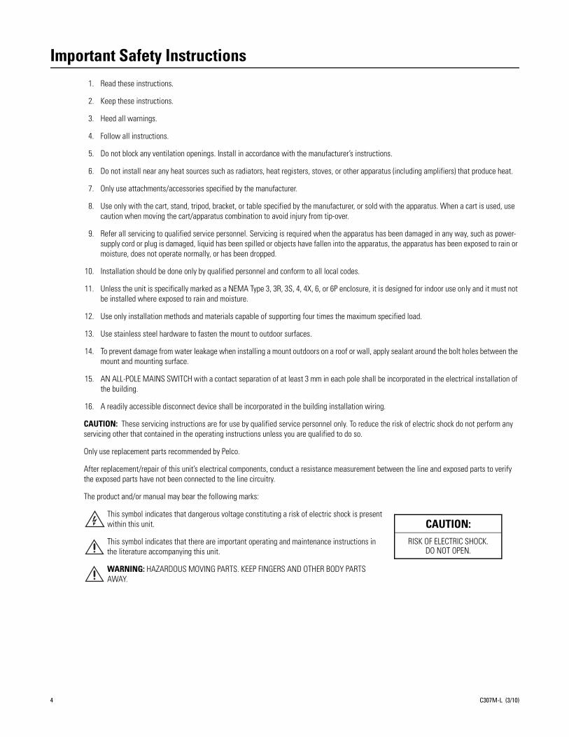
Important Safety Instructions1. Read these instructions.
2. Keep these instructions.
3. Heed all warnings.
4. Follow all instructions.
5. Do not block any ventilation openings. Install in accordance with the manufacturer’s instructions.
6. Do not install near any heat sources such as radiators, heat registers, stoves, or other apparatus (including amplifiers) that produce heat.
7. Only use attachments/accessories specified by the manufacturer.
8. Use only with the cart, stand, tripod, bracket, or table specified by the manufacturer, or sold with the apparatus. When a cart is used, use caution when moving the cart/apparatus combination to avoid injury from tip-over.
9. Refer all servicing to qualified service personnel. Servicing is required when the apparatus has been damaged in any way, such as power-supply cord or plug is damaged, liquid has been spilled or objects have fallen into the apparatus, the apparatus has been exposed to rain or moisture, does not operate normally, or has been dropped.
10. Installation should be done only by qualified personnel and conform to all local codes.
11. Unless the unit is specifically marked as a NEMA Type 3, 3R, 3S, 4, 4X, 6, or 6P enclosure, it is designed for indoor use only and it must not be installed where exposed to rain and moisture.
12. Use only installation methods and materials capable of supporting four times the maximum specified load.
13. Use stainless steel hardware to fasten the mount to outdoor surfaces.
14. To prevent damage from water leakage when installing a mount outdoors on a roof or wall, apply sealant around the bolt holes between the mount and mounting surface.
15. AN ALL-POLE MAINS SWITCH with a contact separation of at least 3 mm in each pole shall be incorporated in the electrical installation of the building.
16. A readily accessible disconnect device shall be incorporated in the building installation wiring.
CAUTION: These servicing instructions are for use by qualified service personnel only. To reduce the risk of electric shock do not perform any servicing other that contained in the operating instructions unless you are qualified to do so.
Only use replacement parts recommended by Pelco.
After replacement/repair of this unit’s electrical components, conduct a resistance measurement between the line and exposed parts to verify the exposed parts have not been connected to the line circuitry.
The product and/or manual may bear the following marks:
This symbol indicates that dangerous voltage constituting a risk of electric shock is present within this unit.
This symbol indicates that there are important operating and maintenance instructions in the literature accompanying this unit.
WARNING: HAZARDOUS MOVING PARTS. KEEP FINGERS AND OTHER BODY PARTS AWAY.
CAUTION:RISK OF ELECTRIC SHOCK.
DO NOT OPEN.
4 C307M-L (3/10)

Important Notices
REGULATORY NOTICEThis device complies with Part 15 of the FCC Rules. Operation is subject to the following two conditions: (1) this device may not cause harmful interference, and (2) this device must accept any interference received, including interference that may cause undesired operation.
RADIO AND TELEVISION INTERFERENCEThis equipment has been tested and found to comply with the limits of a Class B digital device, pursuant to Part 15 of the FCC Rules. These limits are designed to provide reasonable protection against harmful interference in a residential installation. This equipment generates, uses, and can radiate radio frequency energy and, if not installed and used in accordance with the instructions, may cause harmful interference to radio communications. However there is no guarantee that the interference will not occur in a particular installation. If this equipment does cause harmful interference to radio or television reception, which can be determined by turning the equipment off and on, the user is encouraged to try to correct the interference by one or more of the following measures:
• Reorient or relocate the receiving antenna.
• Increase the separation between the equipment and the receiver.
• Connect the equipment into an outlet on a circuit different from that to which the receiver is connected.
• Consult the dealer or an experienced radio/TV technician for help.
You may also find helpful the following booklet, prepared by the FCC: “How to Identify and Resolve Radio-TV Interference Problems.” This booklet is available from the U.S. Government Printing Office, Washington D.C. 20402.
Changes and modifications not expressly approved by the manufacturer or registrant of this equipment can void your authority to operate this equipment under Federal Communications Commission’s rules.
This Class B digital apparatus complies with Canadian ICES-003.
Cet appareil numérique de la classe B est conforme à la norme NMB-003 du Canada.
C307M-L (3/10) 5

Description
ES30C/ES31C SERIES ESPRIT WITH IOPThe ES30C and ES31C Series combine a receiver, pan/tilt, enclosure, and integrated optics package (IOP) in a single, easy-to-install system. The integrated optics package contains an auto-focus camera and lens module with programmable features.
The ES30C and ES31C systems are available with an input voltage of 24 VAC or with a selectable power source of 120/230 VAC. The systems are constructed of lightweight aluminum and have a heater, window defroster, sun shroud, and insulation blanket.
MODELS ES30C22 High resolution, color camera with LowLight™ technology, 220X zoom (22X optical zoom and 10X digital
zoom)
ES31C22 Same as ES30C22, except supplied with window wiper
ES30CBW24 Low-light, high resolution, color/black-white camera with infrared cut filter, 240X zoom (24X optical zoom and 10X digital zoom)
ES31CBW24 Same as ES30CBW24, except supplied with window wiper
ES30CBW35 High resolution, color/black-white camera with infrared cut filter, electronic image stabilization, and 420X zoom (35X optical zoom and 12X digital zoom)
ES31CBW35 Same as ES30CBW35, except supplied with window wiper
Model Numbers
Model FormatPedestal Mount Wall Mount
24 VAC 120/230 VAC 24 VAC 120/230 VAC
22X Color
Standard NTSCPAL
ES30C22-2NES30C22-2N-X
ES30C22-5NES30C22-5N-X
ES30C22-2WES30C22-2W-X
ES30C22-5WES30C22-5W-X
With Wiper NTSCPAL
ES31C22-2NES31C22-2N-X
ES31C22-5NES31C22-5N-X
ES31C22-2WES31C22-2W-X
ES31C22-5WES31C22-5W-X
24X Color/B-W
Standard NTSCPAL
ES30CBW24-2NES30CBW24-2N-X
ES30CBW24-5NES30CBW24-5N-X
ES30CBW24-2WES30CBW24-2W-X
ES30CBW24-5WES30CBW24-5W-X
With Wiper NTSCPAL
ES31CBW24-2NES31CBW24-2N-X
ES31CBW25-5NES31CBW24-5N-X
ES31CBW24-2WES31CBW24-2W-X
ES31CBW24-5WES31CBW24-5W-X
35X Color/B-W
Standard NTSCPAL
ES30CBW35-2NES30CBW35-2N-X
ES30CBW35-5NES30CBW35-5N-X
ES30CBW35-2WES30CBW35-2W-X
ES30CBW35-5WES30CBW35-5W-X
With Wiper NTSCPAL
ES31CBW35-2NES31CBW35-2N-X
ES31CBW35-5NES31CBW35-5N-X
ES31CBW35-2WES31CBW35-2W-X
ES31CBW35-5WES31CBW35-5W-X
6 C307M-L (3/10)
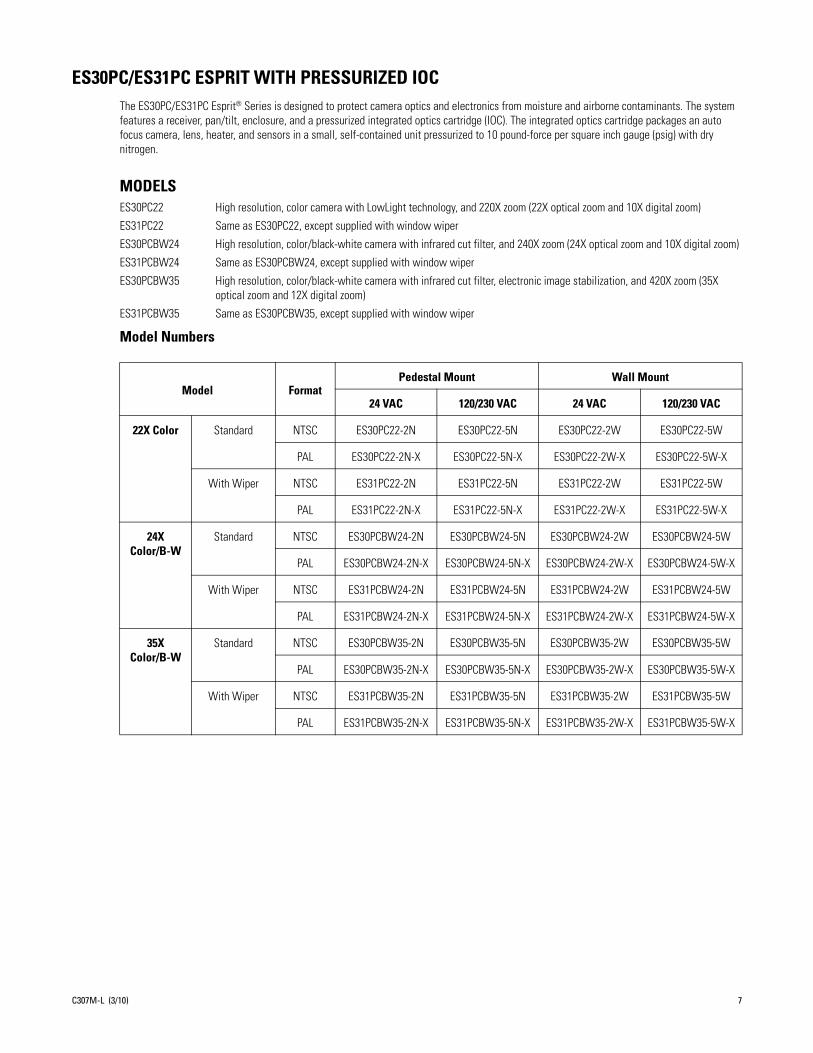
ES30PC/ES31PC ESPRIT WITH PRESSURIZED IOCThe ES30PC/ES31PC Esprit® Series is designed to protect camera optics and electronics from moisture and airborne contaminants. The system features a receiver, pan/tilt, enclosure, and a pressurized integrated optics cartridge (IOC). The integrated optics cartridge packages an auto focus camera, lens, heater, and sensors in a small, self-contained unit pressurized to 10 pound-force per square inch gauge (psig) with dry nitrogen.
MODELSES30PC22 High resolution, color camera with LowLight technology, and 220X zoom (22X optical zoom and 10X digital zoom)
ES31PC22 Same as ES30PC22, except supplied with window wiper
ES30PCBW24 High resolution, color/black-white camera with infrared cut filter, and 240X zoom (24X optical zoom and 10X digital zoom)
ES31PCBW24 Same as ES30PCBW24, except supplied with window wiper
ES30PCBW35 High resolution, color/black-white camera with infrared cut filter, electronic image stabilization, and 420X zoom (35X optical zoom and 12X digital zoom)
ES31PCBW35 Same as ES30PCBW35, except supplied with window wiper
Model Numbers
Model FormatPedestal Mount Wall Mount
24 VAC 120/230 VAC 24 VAC 120/230 VAC
22X Color Standard NTSC ES30PC22-2N ES30PC22-5N ES30PC22-2W ES30PC22-5W
PAL ES30PC22-2N-X ES30PC22-5N-X ES30PC22-2W-X ES30PC22-5W-X
With Wiper NTSC ES31PC22-2N ES31PC22-5N ES31PC22-2W ES31PC22-5W
PAL ES31PC22-2N-X ES31PC22-5N-X ES31PC22-2W-X ES31PC22-5W-X
24X Color/B-W
Standard NTSC ES30PCBW24-2N ES30PCBW24-5N ES30PCBW24-2W ES30PCBW24-5W
PAL ES30PCBW24-2N-X ES30PCBW24-5N-X ES30PCBW24-2W-X ES30PCBW24-5W-X
With Wiper NTSC ES31PCBW24-2N ES31PCBW24-5N ES31PCBW24-2W ES31PCBW24-5W
PAL ES31PCBW24-2N-X ES31PCBW24-5N-X ES31PCBW24-2W-X ES31PCBW24-5W-X
35X Color/B-W
Standard NTSC ES30PCBW35-2N ES30PCBW35-5N ES30PCBW35-2W ES30PCBW35-5W
PAL ES30PCBW35-2N-X ES30PCBW35-5N-X ES30PCBW35-2W-X ES30PCBW35-5W-X
With Wiper NTSC ES31PCBW35-2N ES31PCBW35-5N ES31PCBW35-2W ES31PCBW35-5W
PAL ES31PCBW35-2N-X ES31PCBW35-5N-X ES31PCBW35-2W-X ES31PCBW35-5W-X
C307M-L (3/10) 7

Installation1. When installing the ES30C/ES31C or ES30PC/ES31PC Esprit system, allow for sufficient clearance between the top of the unit and
overhead obstructions. This will prevent interference when the enclosure is driven to its maximum elevation of 33 degrees.
2. Remove the transformer module from the base of the system by loosening the four Phillips screws and lifting the module.
Figure 1. Removing the Transformer Module
3. Attach the base of the system to an Esprit mount (EWM or EPA):a. Apply a drop of Loctite® thread compound (supplied) to each of the three mounting holes and 10-32 x 1/2-inch flathead screws
(supplied).
WARNING: Applying the Loctite thread compound is an important step in the installation process. Failure to apply Loctite to the mounting holes may increase the risk of damage to the unit.
A33.0°
B
CD
Model ES30 ES31
A 16.6(42.5)
16.9(42.9)
B 9.4(23.9)
9.7(24.6)
C 7.1(18.1)
7.6(19.2)
D 4.2(10.7)
4.6(11.7)
NOTE: VALUES IN PARENTHESES ARE CENTIMETERS; ALL OTHERS ARE INCHES.
BASE
LOOSENPHILLIPSSCREWS
TRANSFORMERMODULE
8 C307M-L (3/10)

b. Attach the base of the system to the mount using the three screws and washers.
Figure 2. Attaching the Base to a Mount
4. Route the wires and cables through the center of the Esprit mount. Reinstall the transformer module into the base. The transformer module can be positioned in the mount base in only one orientation.
Figure 3. Reinstalling the Transformer Module
5. Models with 120/230 VAC only: Set the 120/230 voltage selector switch on the transformer to the appropriate voltage.
6. Connect wires and cables.a. Connect to power. Use the two supplied clamp connectors to connect the AC line and neutral.
b. Connect the video coaxial cable to the BNC connector.
c. Connect the wiring for a two-wire or four-wire control system. This step does not apply to Coaxitron® control systems.
120/230 VAC 24 VAC
Black wire Input (AC Line) White wire Input (AC Line)
White wire AC Neutral White wire AC Neutral
Green wire Ground Green wire Ground
Green wire RX–
Red wire RX+
Black wire TX–
White wire TX+
MOUNT
MOUNTING HOLES
BASE
MOUNTINGSCREWS
120/230 VOLTAGE SELECTOR SWITCH
C307M-L (3/10) 9
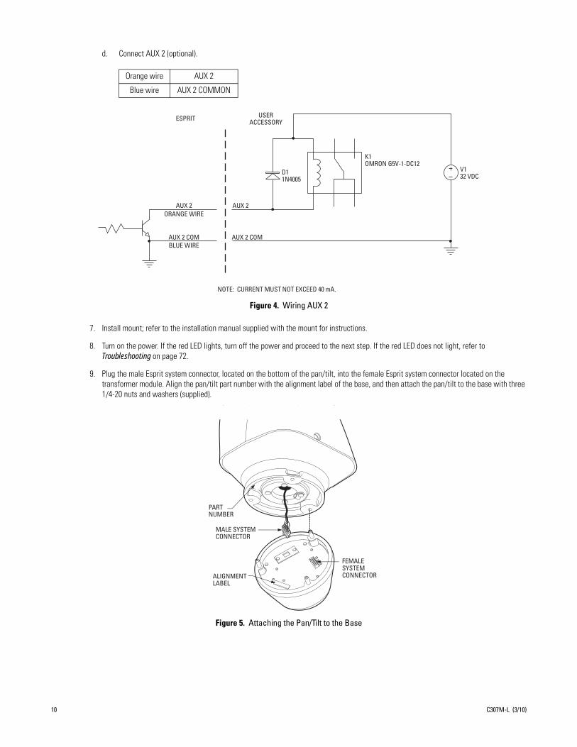
d. Connect AUX 2 (optional).
Figure 4. Wiring AUX 2
7. Install mount; refer to the installation manual supplied with the mount for instructions.
8. Turn on the power. If the red LED lights, turn off the power and proceed to the next step. If the red LED does not light, refer to Troubleshooting on page 72.
9. Plug the male Esprit system connector, located on the bottom of the pan/tilt, into the female Esprit system connector located on the transformer module. Align the pan/tilt part number with the alignment label of the base, and then attach the pan/tilt to the base with three 1/4-20 nuts and washers (supplied).
Figure 5. Attaching the Pan/Tilt to the Base
Orange wire AUX 2
Blue wire AUX 2 COMMON
AUX 2
AUX 2 COM
AUX 2
AUX 2 COM
ESPRIT
NOTE: CURRENT MUST NOT EXCEED 40 mA.
ORANGE WIRE
BLUE WIRE
USER ACCESSORY
D1 1N4005
K1 OMRON G5V-1-DC12
V1 32 VDC
PART NUMBER
MALE SYSTEM CONNECTOR
ALIGNMENT LABEL
FEMALE SYSTEM CONNECTOR
10 C307M-L (3/10)
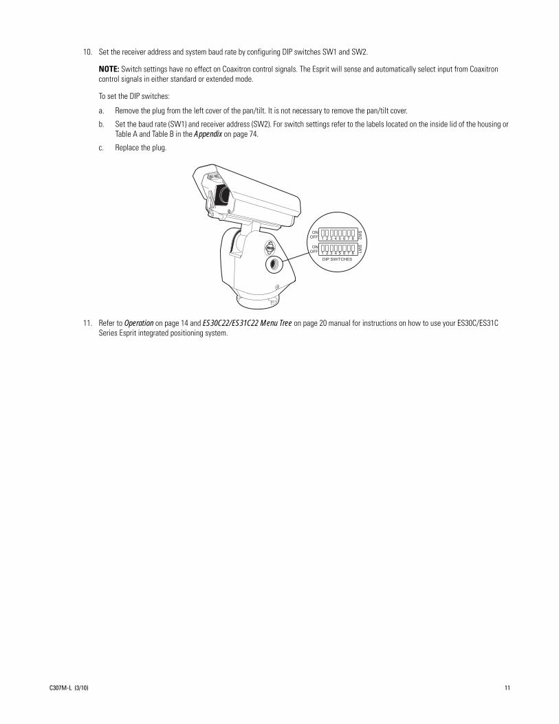
10. Set the receiver address and system baud rate by configuring DIP switches SW1 and SW2.
NOTE: Switch settings have no effect on Coaxitron control signals. The Esprit will sense and automatically select input from Coaxitron control signals in either standard or extended mode.
To set the DIP switches:
a. Remove the plug from the left cover of the pan/tilt. It is not necessary to remove the pan/tilt cover.
b. Set the baud rate (SW1) and receiver address (SW2). For switch settings refer to the labels located on the inside lid of the housing or Table A and Table B in the Appendix on page 74.
c. Replace the plug.
11. Refer to Operation on page 14 and ES30C22/ES31C22 Menu Tree on page 20 manual for instructions on how to use your ES30C/ES31C Series Esprit integrated positioning system.
C307M-L (3/10) 11
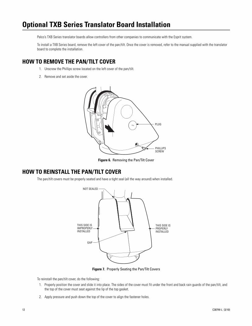
Optional TXB Series Translator Board InstallationPelco’s TXB Series translator boards allow controllers from other companies to communicate with the Esprit system.
To install a TXB Series board, remove the left cover of the pan/tilt. Once the cover is removed, refer to the manual supplied with the translator board to complete the installation.
HOW TO REMOVE THE PAN/TILT COVER1. Unscrew the Phillips screw located on the left cover of the pan/tilt.
2. Remove and set aside the cover.
Figure 6. Removing the Pan/Tilt Cover
HOW TO REINSTALL THE PAN/TILT COVERThe pan/tilt covers must be properly seated and have a tight seal (all the way around) when installed.
Figure 7. Properly Seating the Pan/Tilt Covers
To reinstall the pan/tilt cover, do the following:
1. Properly position the cover and slide it into place. The sides of the cover must fit under the front and back rain guards of the pan/tilt, and the top of the cover must seat against the lip of the top gasket.
2. Apply pressure and push down the top of the cover to align the fastener holes.
PHILLIPS SCREW
PLUG
THIS SIDE IS IMPROPERLY INSTALLED
THIS SIDE IS PROPERLY INSTALLED
NOT SEALED
GAP
12 C307M-L (3/10)
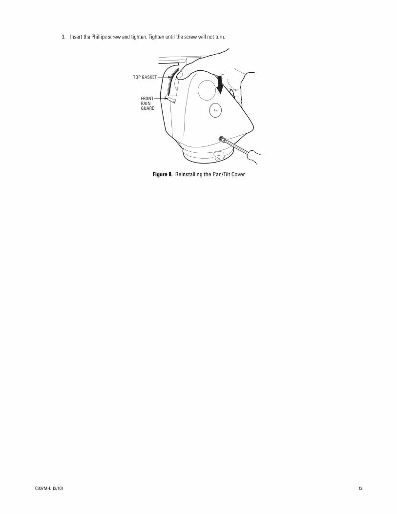
3. Insert the Phillips screw and tighten. Tighten until the screw will not turn.
Figure 8. Reinstalling the Pan/Tilt Cover
TOP GASKET
FRONTRAINGUARD
C307M-L (3/10) 13

Operation
POWER-UP DISPLAYWhen the system is powered up, the selected protocol, revision number, and other information is displayed on the monitor. For example, the screen might show the following information:
The information remains on the monitor until the system receives a command.
HOW TO OPERATE YOUR SYSTEM
*Optical zoom magnifies the image and the picture remains clear. Resolution is constant.†Digital zoom magnifies the image and the picture may appear pixelated. The larger the zoom limit, the greater the reduction in resolution.
PRESET 95: ACCESSING MAIN MENUYou can call up the main menu on your monitor by programming (setting or creating) preset 95 (28 if in 32-preset mode).
Programming preset 95 for Pelco’s controllers varies according to the type of controller you are using. Instructions for programming preset 95 are given below for various Pelco controllers.
CM6700/CM68001. Enter the number of the camera and press the CAM key.
2. Enter 95 and hold the PRESET key for two seconds.
3. In the Edit Preset menu, arrow to SET, and then press the ACK key. The main menu appears.
Operation How to Control
Pan and Tilt Move joystick left/right and up/down.
ScanningStop scanRandom scanFrame scanAuto scan
Call preset 96.Call preset 97.Call preset 98.Call preset 99.
Zoom Far
To zoom far, do the following:1.Press the Zoom Tele button or turn the joystick clockwise until zoom stops at the optical zoom* limit.2.Release the button or joystick.3.To continue zooming (digitally), immediately press the button or turn the joystick clockwise again until you have the picture you want or reach the digital zoom† limit.
Zoom Wide Press the Zoom Wide button or turn the joystick counterclockwise.
Presets Refer to the documentation supplied with the controller.
Patterns Refer to the documentation supplied with the controller.
ESPRIT 35X IOP X.XXCONFIGURE DONE
D Address 1P Address 2Comm 2400, N, 8, 1
CAMERA XXXX-XXXX
14 C307M-L (3/10)

KBD200A/KBD300A: DIRECT MODE ONLY1. Enter 95.
2. Hold the PRESET key (approximately 5 seconds) until the main menu appears on the screen.
CM95001. Enter the number of the camera and press the CAM key. The main menu appears.
2. Highlight SETUP in the main menu and press the SELECT key.
3. Highlight CAM in the Setup menu and press the SELECT key.
4. Highlight PRESET in the Camera menu and press the SELECT key.
5. Enter 95 and press the F1 key. The main menu appears.
CM9740/CM9760/CM9770/CM97801. Press the ESCAPE key to open the main menu, and then select DEF. The Define Menu appears.
2. Enter your four-digit PIN if this is your first time entering this mode.
3. Enter 95 and select PRST. The main menu appears.
4. Select the Quit icon to return to the default menu.
KBD4000/KBD4002/KBD4000V1. Press the SPOT MONITOR key.
2. Enter 95, and then hold the PRESET key (approximately five seconds) until the main menu appears on the screen.
MPT9500
Standard Coaxitron® Mode1. Enter 95 and press the PRESET SET key.
2. Position the asterisk in the YES row and press the F1 key. The main menu appears.
Extended Coaxitron or RS-485 Mode1. Enter 95 and press the PRESET SET key.
2. Press the F2 key. The main menu appears.
ENDURA SYSTEMSIf your Esprit positioning system is connected to an Endura® system, you can access the main menu directly from the Endura workstation or the VCD5000. Note that access to the main menu is controlled through user permissions.
Endura Workstation1. Right-click in the video pane that is displaying video from an Esprit positioning system.
2. Click Preset, and then click Select Preset.
3. Enter 95, and the click OK.
VCD50001. Select a video pane that is displaying video from an Esprit positioning system.
2. Enter 95 on the KBD5000 keyboard. A shortcuts menu appears.
3. Press the Preset button on the keyboard.
C307M-L (3/10) 15
OPERATING NOTES
ENVIRONMENTAL RANGEThe operating temperature ranges from a minimum of -50°F (-45°C) to a maximum of 122°F (50°C) for sustained system operation or 140°F (60°C) absolute maximum. The entire unit can de-ice and be operational in two hours from a temperature of -13°F (-25°C). The thermostatically controlled heater consumes 10 W and cycles on at 70°F (21°C) and off at 85°F (29°C), while the window defroster runs continuously and consumes 2.5 W.
PAN/TILT FUNCTIONS
*50 mph wind-speed profile.†If manual limit stops are set, “Pan Limit” appears on your monitor when a limit stop is reached (except when you are programming or running a pattern). This does not apply to scan limit stops.
‡When the system reaches the upper limit, “Tilt Limit” appears on your monitor (except when you are programming or running a pattern).
If the proportional pan mode is enabled (refer to Proportional Pan on page 55), the pan/tilt speeds will depend on the amount of zoom. At telephoto zoom settings, the pan/tilt speeds will be slower for a given amount of joystick deflection than at wide zoom settings. This keeps the image from moving too fast on the monitor when there is a large amount of zoom. This slowing does not happen when going to a preset but does occur in Turbo mode when high zoom is selected. The minimum pan/tilt speeds are 0.1 degree per second at full zoom.
SCAN SPEEDScan speed is adjustable from 1 to 40 degrees per second through the programming menu.
PRESET FUNCTIONSThe Esprit system is capable of going to 80 preset locations, each with a 20-character label. The presets are numbered 1 to 32 and 35 to 82. Refer to the documentation for your control system for programming presets.
If you command the pan/tilt to go to an undefined preset, erratic operation may result.
Presets 33 and 34 are fixed commands, meaning that you cannot program them. Preset 33 is the “flip” command, which will pan the system 180 degrees. Preset 34 is the “pan zero” command, which will pan the system to the factory-determined zero reference point.
RANDOM, FRAME, AND AUTO SCANNINGSelect preset 97 (30) to start random scanning. Select preset 98 (31) to activate frame scanning (three seconds of scanning followed by a three-second pause). Select preset 99 (32) to start auto (continuous) scanning. Scan limit stops are controlled by software. Refer to Limit Stops on page 45 to program the scan limit stops.
When the pan/tilt reaches a scan limit stop, it reverses direction. Select preset 96 (29) to stop a scan. Any pan/tilt or lens command also will stop a scan.
ZONESA zone is a programmed pan area with set boundaries and identifying label. The Esprit system has a maximum of eight zones, each with a 20-character label. Zones can be programmed to blank video when the camera pans into the zone area. If a zone is blanked, the system displays the message, VIDEO BLANK. (Refer to Zone Blank on page 68 for instructions.)
ControllerType
Pan(Capability: 360° Continuous Pan Rotation)†
Tilt(Viewing Range: +33° to -83°)‡
Fixed speed Speed determined by controller Speed determined by controller
*Variable speed
*Turbo Mode*Preset Mode
0.1 to 40° per second, depending on joystick and zoom positions100° per second100° per second
0.1 to 20° per second, depending on joystick and zoom positionsDoes not affect the tilt speed30° per second
16 C307M-L (3/10)

PATTERNSThe Esprit system can do either one full pattern (1.5, 3, or 6 minutes long) or two half patterns (.75, 1.5, or 3 minutes long). This pattern can consist of any standard pan/tilt or lens command. Presets, flip, digital zoom, proportional pan, and Turbo are not allowed in a pattern. Zones can be enabled while running a pattern. Refer to the documentation for your control system to program and run patterns.
PARKIf the system does not receive any commands for a specified period of time (refer to Park Time Minutes on page 51), the system goes to preset 1 and parks. If the time specified is zero, or if preset 1 has not been programmed, the pan/tilt will not park.
IR FILTER(Applies only to 24X and 35X models.)
The 24X and 35X models have an IR (infrared) lens filter that can switch in and out, automatically or manually, depending on how the system is programmed. When the filter is IN, the camera produces a color picture. When the IR filter switches OUT, the picture changes to black-white, increasing visibility in low light conditions.
The Auto IR Level setting controls automatic operation of the filter. To manually override automatic operation, use presets 88 (filter IN) and 89 (filter OUT). The unit will remain in manual control until it is panned or tilted more than 15 degrees.
NOTE: Low light does not mean no light. Some type of illumination is required (street light, IR light, and so forth).
AUTO IRISIf auto iris is in the auto mode, it remains that way until you manually open or close the iris. The system will return to auto iris when it is panned or tilted more than 15 degrees.
WIPERThe ES31C Series features a window wiper to clear moisture from the enclosure glass. There are two modes of operation for the wiper, momentary and continuous. The wiper mode is easily set up through on-screen programming (refer to Wiper on page 67).
To operate the wiper do the following:
Momentary mode: To operate the wiper one full cycle, press the AUX 1 button on your controller. Each press of the button operates the wiper one full cycle, even if the AUX 1 button is latching. If AUX 1 is latching, the first press will activate the wiper (open the latch). Pressing AUX 1 a second time closes the latch, but will not cycle the wiper. Press the AUX 1 key again to cycle the wiper.
Continuous mode: To operate the wiper press the AUX 1 button on your controller. The wiper will continue to operate until the AUX 1 button is pressed again or until the programmed cycle is completed.
NOTE: (CM9740 and CM9760 matrix systems only) For the wiper to operate in continuous mode, the AUX 1 function in the camera file must be set to latching. If the AUX 1 camera file is not latching, the wiper will only operate in momentary mode, even if the Esprit wiper is programmed for continuous operation. Refer to the operation manual supplied with the CM9740 or CM9760 matrix system for instructions.
OPEN COLLECTOR AUXILIARY OUTPUTAn AUX 2 command from the controller will activate a device, such as a relay. The output will remain active for two seconds and then deactivate, even if the controller is set to latching mode.
Examples of devices that can be used with AUX 2 are a washer assembly (not supplied by Pelco) or a latching relay (not supplied by Pelco) attached to control a gate, lights, and so forth.
If a relay is used it must require less than 32 VDC and 40 mA to trigger the relay coil. The relay must be placed within 100 feet (30 m) of the Esprit unit.
C307M-L (3/10) 17
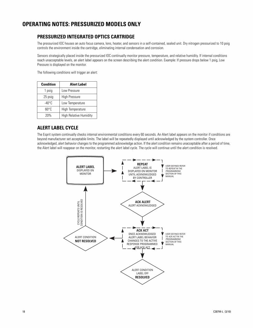
OPERATING NOTES: PRESSURIZED MODELS ONLY
PRESSURIZED INTEGRATED OPTICS CARTRIDGEThe pressurized IOC houses an auto focus camera, lens, heater, and sensors in a self-contained, sealed unit. Dry nitrogen pressurized to 10 psig controls the environment inside the cartridge, eliminating internal condensation and corrosion.
Sensors strategically placed inside the pressurized IOC continually monitor pressure, temperature, and relative humidity. If internal conditions reach unacceptable levels, an alert label appears on the screen describing the alert condition. Example: If pressure drops below 1 psig, Low Pressure is displayed on the monitor.
The following conditions will trigger an alert:
ALERT LABEL CYCLEThe Esprit system continually checks internal environmental conditions every 60 seconds. An Alert label appears on the monitor if conditions are beyond manufacturer set acceptable limits. The label will be repeatedly displayed until acknowledged by the system controller. Once acknowledged, alert behavior changes to the programmed acknowledge action. If the alert condition remains unacceptable after a period of time, the Alert label will reappear on the monitor, restarting the alert label cycle. The cycle will continue until the alert condition is resolved.
Condition Alert Label
1 psig Low Pressure
25 psig High Pressure
-40°C Low Temperature
60°C High Temperature
20% High Relative Humidity
USER DEFINED REFER TO REPEAT IN THE PROGRAMMING SECTION OF THIS MANUAL
USER DEFINED REFER TO ACK ACT IN THE PROGRAMMING SECTION OF THIS MANUAL
ALERT LABELDISPLAYED ON
MONITOR
REPEATALERT LABEL IS
DISPLAYED ON MONITOR UNTIL ACKNOWLEDGED
BY CONTROLLER
ACK ALERTALERT ACKNOWLEDGED
CYCL
E RE
PEAT
S UN
TIL
CON
DITI
ON IS
RES
OLVE
D
ALERT CONDITIONNOT RESOLVED
ACK ACTONCE ACKNOWLEDGED ALERT LABEL BEHAVIOR
CHANGES TO THE ACTIVE RESPONSE PROGRAMMED
FOR ACK ACT
ALERT CONDITIONLABEL OFF
RESOLVED
18 C307M-L (3/10)
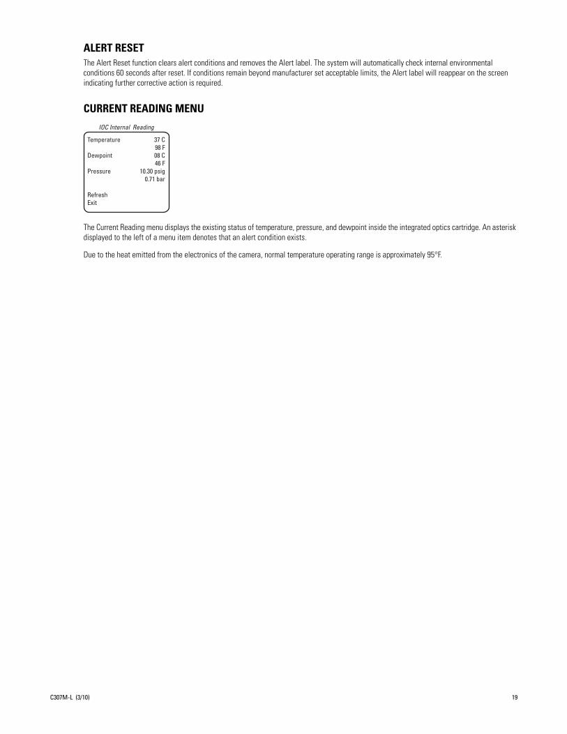
C307M-L (3/10) 19
ALERT RESETThe Alert Reset function clears alert conditions and removes the Alert label. The system will automatically check internal environmental conditions 60 seconds after reset. If conditions remain beyond manufacturer set acceptable limits, the Alert label will reappear on the screen indicating further corrective action is required.
CURRENT READING MENU
The Current Reading menu displays the existing status of temperature, pressure, and dewpoint inside the integrated optics cartridge. An asterisk displayed to the left of a menu item denotes that an alert condition exists.
Due to the heat emitted from the electronics of the camera, normal temperature operating range is approximately 95°F.
Temperature 37 C 98 FDewpoint 08 C 46 FPressure 10.30 psig 0.71 bar
RefreshExit
IOC Internal Reading

20 C307M-L (3/10)
ES30C22/ES31C22 Menu Tree
For detailed instructions,refer to the following sections.
Menu items are listed alphabetically.
ES30CBWProduction CodePG53-0094-0387Nov 20 2009 13:35:187202-01040 6 15:15
BackExit
System Information Menu
Set Azimuth ZeroAz/ElAz/El LineDirectionDirection LineZoomZoom LineDisp DurationBackExit
Az/El/Direction
Video Blanking Zone1 Off 2 Off3 Off 4 Off5 Off 6 Off7 Off 8 Off
BackExit
Zone Blank Menu
Auto Sharpness SharpnessAuto White Bal R Gain B Gain
BackExit
Sharp/Wht Bal Menu
Low Light LimitShutter SpeedAuto Focus ModeSure Focus
<Sharp/Wht Bal>NextBackExit
Next Menu
Gain LimitAuto Iris Mode Auto Iris Level Auto Iris Peak
BackExit
Gain/AGC/Auto Iris Menu
Proportional PanPark Time MinutesScan Speed Deg/SPattern LengthSpd Profile<Zone Blank><Az/El/Direction><System Information>
BackExit
Other Menu
<Edit Title Text>Disp Title TextTitle Text RowZone Text RowPreset Text Row
BackExit
Text Display Menu
Limit StopsSet Man LimitsClear Man LimitsSet Scan LimitsClear Scan Limits
BackExit
Limit Stops Menu
Wiper ModeWiper Dwell <s>Wiper Time <m>
BackExit
*Wiper Menu
Power Up
BackExit
Power-Up Menu
Line SyncLine Sync Phase
BackExit
Line Sync Menu
Backlight CompZoom LimitReset Camera
<Gain/AGC/Auto Iris>NextBackExit
Camera Menu
If the limit stops are turned off(refer to the Limit Stops section),presets 23-26 can be used asregular presets.
99 becomes 3298 becomes 3197 becomes 3096 becomes 2995 becomes 2894 becomes 2793 becomes 2692 becomes 2591 becomes 2490 becomes 2389 becomes 2288 becomes 21
*ES31C only
NOTE: For American Dynamicscontrollers with only 32 presets,set Esprit DIP switch SW1-5 tothe ON position. When SW1-5is ON, preset
FunctionParkFlip commandPan zero commandManual limit stopsAuto limit stopsSelect cameraprogramming menuStop a scanRandom scanningFrame scanningAuto scanning
Preset1
3334
90-9192-93
95
96979899
PRESETSThe following presets arereserved for special functions.
<Camera><Line Sync><Power Up Mode>*<Wiper><Limit Stops><Text Display><Other>
Exit
MAIN MENU
1. Access main menu (preset 95).2. Make main menu selections. Joystick: Move up or down to position cursor or to toggle between selections. Iris Open: Enter. Iris Close: Cancel.

ES30CBW24/ES31CBW24 Menu Tree
For detailed instructions,refer to the following sections.
Menu items are listed alphabetically.
IR Filt/Sharp/Wht Bal Menu
Auto Sharpness SharpnessAuto White Bal R Gain B GainIR Filter Mode Auto IR Level
BackExit
System Information Menu
ES30CBWProduction CodePG53-0094-0387Nov 20 2009 13:35:187202-01040 6 15:15
BackExit
Az/El/Direction
Set Azimuth ZeroAz/ElAz/El LineDirectionDirection LineZoomZoom LineDisp DurationBackExit
Zone Blank Menu
Video Blanking Zone1 Off 2 Off3 Off 4 Off5 Off 6 Off7 Off 8 Off
BackExit
Next Menu
Low Light LimitShutter SpeedAuto Focus ModeSure FocusLowLight Focus<IR Filt/Sharp/Wht Bal>
BackExit
AGC/Auto Iris/ToL Menu
Gain LimitAuto Iris Mode Auto Iris Level Auto Iris Peak
BackExit
Other Menu
Proportional PanPark Time MinutesScan Speed Deg/SPattern LengthSpd Profile<Zone Blank><Az/El/Direction><System Information>
BackExit
Text Display Menu
<Edit Title Text>Disp Title TextTitle Text RowZone Text RowPreset Text Row
BackExit
Limit Stops Menu
Limit StopsSet Man LimitsClear Man LimitsSet Scan LimitsClear Scan Limits
BackExit
*Wiper Menu
Wiper ModeWiper Dwell <s>Wiper Time <m>
BackExit
Power Up
BackExit
Power-Up Menu
Line Sync Menu
Line SyncLine Sync Phase
BackExit
Camera Menu
Backlight CompZoom LimitReset CameraWDRField Alignment
<AGC/Auto Iris/ToL>NextBackExit
If the limit stops are turned off(refer to the Limit Stops section),presets 23-26 can be used asregular presets.
99 becomes 3298 becomes 3197 becomes 3096 becomes 2995 becomes 2894 becomes 2793 becomes 2692 becomes 2591 becomes 2490 becomes 2389 becomes 2288 becomes 21
NOTE: For American Dynamicscontrollers with only 32 presets,set Esprit DIP switch SW1-5 tothe ON position. When SW1-5is ON, preset
*ES31C only
FunctionParkFlip commandPan zero commandIR filter INIR filter OUTManual limit stopsAuto limit stopsSelect cameraprogramming menuStop a scanRandom scanningFrame scanningAuto scanning
Preset1
33348889
90-9192-93
95
96979899
PRESETSThe following presets arereserved for special functions.
<Camera><Line Sync><Power Up Mode>*<Wiper><Limit Stops><Text Display><Other>
Exit
MAIN MENU
1. Access main menu (preset 95).2. Make main menu selections.
Joystick: Move up or down to position cursor or to toggle between selections.Iris Open: Enter.Iris Close: Cancel.
C307M-L (3/10) 21

ES30CBW35/ES31CBW35 Menu Tree
For detailed instructions,refer to the following sections.
Menu items are listed alphabetically.
ES31CBW35aProduction CodePG53-0094-0400Nov 20 2009 13:35:187202-01040 6 15:15
BackExit
System Information Menu
Set Azimuth ZeroAz/ElAz/El LineDirectionDirection LineZoomZoom LineDisp DurationBackExit
Az/El/Direction
Video Blanking Zone1 Off 2 Off3 Off 4 Off5 Off 6 Off7 Off 8 Off
BackExit
Zone Blank Menu
Picture ModeLow Lux NR
BackExit
Next Menu
Auto Sharpness SharpnessAuto White Bal R Gain B GainIR Filter Mode Auto IR Level
BackExit
IR Filt/Sharp/Wht Bal Menu
Low Light LimitShutter SpeedAuto Focus ModeSure FocusLow Light FocusImg Stabilizer<IR Filt/Sharp/Wht Bal>
NextBackExit
Next Menu
Gain LimitAuto Iris Mode Auto Iris Level Auto Iris PeakType of Lighting
BackExit
AGC/Auto Iris/ToL Menu
Proportional PanPark Time MinutesScan Speed deg/sPattern LengthSpd Profile<Zone Blank><Az/El/Direction><System Information>
BackExit
Other Menu
<Edit Title Text>Disp Title TextTitle Text RowZone Text RowPreset Text Row
BackExit
Text Display Menu
Limit StopsSet Man LimitsClear Man LimitsSet Scan LimitsClear Scan Limits
BackExit
Limit Stops Menu
Wiper ModeWiper Dwell <s>Wiper Time <m>
BackExit
*Wiper Menu
Power Up
BackExit
Power-Up Menu
Line SyncLine Sync Phase
BackExit
Line Sync Menu
Backlight CompZoom LimitReset CameraWDRField Alignment
<AGC/Auto Iris/ToL>NextBackExit
Camera Menu
If the limit stops are turned off(refer to the Limit Stops section),presets 23-26 can be used asregular presets.
99 becomes 3298 becomes 3197 becomes 3096 becomes 2995 becomes 2894 becomes 2793 becomes 2692 becomes 2591 becomes 2490 becomes 2389 becomes 2288 becomes 21
*ES31C only
NOTE: For American Dynamicscontrollers with only 32 presets,set Esprit DIP switch SW1-5 tothe ON position. When SW1-5is ON, preset
FunctionParkFlip commandPan zero commandIR filter INIR filter OUTManual limit stopsAuto limit stopsSelect cameraprogramming menuStop a scanRandom scanningFrame scanningAuto scanning
Preset133348889
90-9192-93
95
96979899
PRESETSThe following presets arereserved for special functions.
<Camera><Line Sync><Power Up Mode>*<Wiper><Limit Stops><Text Display><Other>
Exit
MAIN MENU
1. Access main menu (preset 95).2. Make main menu selections. Joystick: Move up or down to position cursor or to toggle between selections. Iris Open: Enter. Iris Close: Cancel.
22 C307M-L (3/10)
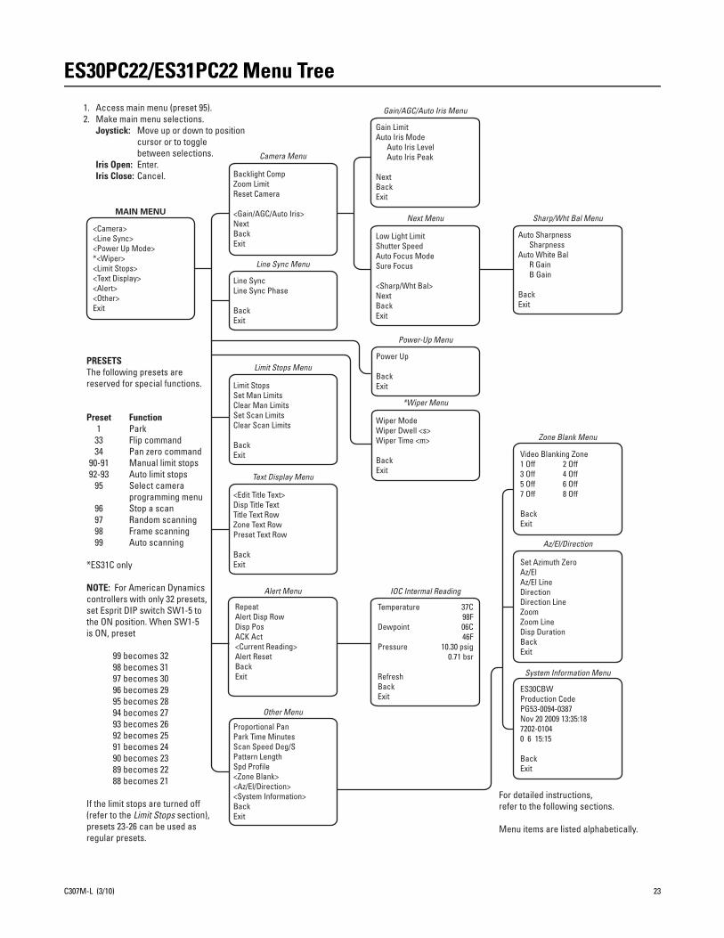
ES30PC22/ES31PC22 Menu Tree
For detailed instructions,refer to the following sections.
Menu items are listed alphabetically.
System Information Menu
ES30CBWProduction CodePG53-0094-0387Nov 20 2009 13:35:187202-01040 6 15:15
BackExit
Az/El/Direction
Set Azimuth ZeroAz/ElAz/El LineDirectionDirection LineZoomZoom LineDisp DurationBackExit
Zone Blank Menu
Video Blanking Zone1 Off 2 Off3 Off 4 Off5 Off 6 Off7 Off 8 Off
BackExit
Sharp/Wht Bal Menu
Auto Sharpness SharpnessAuto White Bal R Gain B Gain
BackExit
RepeatAlert Disp RowDisp PosACK Act<Current Reading>Alert ResetBackExit
Alert Menu
37C98F06C46F
10.30 psig0.71 bsr
Temperature
Dewpoint
Pressure
RefreshBackExit
IOC Intermal Reading
Low Light LimitShutter SpeedAuto Focus ModeSure Focus
<Sharp/Wht Bal>NextBackExit
Next Menu
Gain/AGC/Auto Iris Menu
Gain LimitAuto Iris Mode Auto Iris Level Auto Iris Peak
NextBackExit
Proportional PanPark Time MinutesScan Speed Deg/SPattern LengthSpd Profile<Zone Blank><Az/El/Direction><System Information>BackExit
Other Menu
<Edit Title Text>Disp Title TextTitle Text RowZone Text RowPreset Text Row
BackExit
Text Display Menu
Limit StopsSet Man LimitsClear Man LimitsSet Scan LimitsClear Scan Limits
BackExit
Limit Stops Menu
Wiper ModeWiper Dwell <s>Wiper Time <m>
BackExit
*Wiper Menu
Power Up
BackExit
Power-Up Menu
Line SyncLine Sync Phase
BackExit
Line Sync Menu
Backlight CompZoom LimitReset Camera
<Gain/AGC/Auto Iris>NextBackExit
Camera Menu
If the limit stops are turned off(refer to the Limit Stops section),presets 23-26 can be used asregular presets.
99 becomes 3298 becomes 3197 becomes 3096 becomes 2995 becomes 2894 becomes 2793 becomes 2692 becomes 2591 becomes 2490 becomes 2389 becomes 2288 becomes 21
*ES31C only
NOTE: For American Dynamicscontrollers with only 32 presets,set Esprit DIP switch SW1-5 tothe ON position. When SW1-5is ON, preset
FunctionParkFlip commandPan zero commandManual limit stopsAuto limit stopsSelect cameraprogramming menuStop a scanRandom scanningFrame scanningAuto scanning
Preset1
3334
90-9192-93
95
96979899
PRESETSThe following presets arereserved for special functions.
MAIN MENU
<Camera><Line Sync><Power Up Mode>*<Wiper><Limit Stops><Text Display><Alert><Other>Exit
1. Access main menu (preset 95).2. Make main menu selections. Joystick: Move up or down to position cursor or to toggle between selections. Iris Open: Enter. Iris Close: Cancel.
C307M-L (3/10) 23
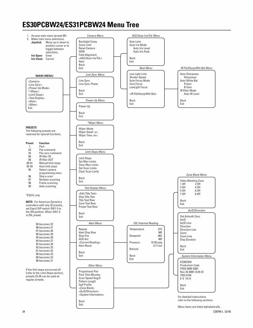
24 C307M-L (3/10)
ES30PCBW24/ES31PCBW24 Menu Tree
For detailed instructions,refer to the following sections.
Menu items are listed alphabetically.
ES30CBWProduction CodePG53-0094-0387Nov 20 2009 13:35:187202-01040 6 15:15
BackExit
System Information Menu
Set Azimuth ZeroAz/ElAz/El LineDirectionDirection LineZoomZoom LineDisp Duration
BackExit
Az/El/Direction
Video Blanking Zone1 Off 2 Off3 Off 4 Off5 Off 6 Off7 Off 8 Off
BackExit
Zone Blank Menu
Auto Sharpness SharpnessAuto White Bal R Gain B GainIR Filter Mode Auto IR Level
BackExit
IR Filt/Sharp/Wht Bal Menu
RepeatAlert Disp RowDisp PosACK Act<Current Reading>Alert Reset
BackExit
Alert Menu
Low Light LimitShutter SpeedAuto Focus ModeSure FocusLowLight Focus
<IR Filt/Sharp/Wht Bal>
BackExit
Next Menu
Gain LimitAuto Iris Mode Auto Iris Level Auto Iris Peak
BackExit
AGC/Auto Iris/ToL Menu
Proportional PanPark Time MinutesScan Speed Deg/SPattern LengthSpd Profile<Zone Blank><Az/El/Direction><System Information>
BackExit
Other Menu
37C98F06C46F
10.30 psig0.71 bsr
Temperature
Dewpoint
Pressure
Refresh
BackExit
IOC Intermal Reading
<Edit Title Text>Disp Title TextTitle Text RowZone Text RowPreset Text Row
BackExit
Text Display Menu
Limit StopsSet Man LimitsClear Man LimitsSet Scan LimitsClear Scan Limits
BackExit
Limit Stops Menu
Wiper ModeWiper Dwell <s>Wiper Time <m>
BackExit
*Wiper Menu
Power Up
BackExit
Power-Up Menu
Line SyncLine Sync Phase
BackExit
Line Sync Menu
Backlight CompZoom LimitReset CameraWDRField Alignment<AGC/Auto Iris/ToL>NextBackExit
Camera Menu
If the limit stops are turned off(refer to the Limit Stops section),presets 23-26 can be used asregular presets.
99 becomes 3298 becomes 3197 becomes 3096 becomes 2995 becomes 2894 becomes 2793 becomes 2692 becomes 2591 becomes 2490 becomes 2389 becomes 2288 becomes 21
*ES31C only
NOTE: For American Dynamicscontrollers with only 32 presets,set Esprit DIP switch SW1-5 tothe ON position. When SW1-5is ON, preset
FunctionParkFlip commandPan zero commandIR filter INIR filter OUTManual limit stopsAuto limit stopsSelect cameraprogramming menuStop a scanRandom scanningFrame scanningAuto scanning
Preset1
33348889
90-9192-93
95
96979899
PRESETSThe following presets arereserved for special functions.
<Camera><Line Sync><Power Up Mode>*<Wiper><Limit Stops><Text Display><Alert><Other>Exit
MAIN MENU
1. Access main menu (preset 95).2. Make main menu selections. Joystick: Move up or down to position cursor or to toggle between selections. Iris Open: Enter. Iris Close: Cancel.
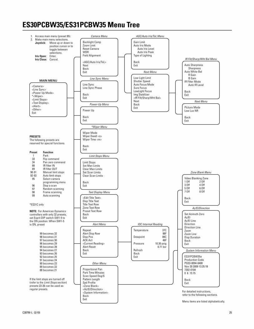
C307M-L (3/10) 25
ES30PCBW35/ES31PCBW35 Menu Tree
For detailed instructions,refer to the following sections.
Menu items are listed alphabetically.
ES31PCBW35aProduction CodePG53-0094-0400Nov 20 2009 13:35:187202-01040 6 15:15
BackExit
System Information Menu
Set Azimuth ZeroAz/ElAz/El LineDirectionDirection LineZoomZoom LineDisp DurationBackExit
Az/El/Direction
Video Blanking Zone1 Off 2 Off3 Off 4 Off5 Off 6 Off7 Off 8 Off
BackExit
Zone Blank Menu
Picture ModeLow Lux NR
BackExit
Next Menu
Auto Sharpness SharpnessAuto White Bal R Gain B GainIR Filter Mode Auto IR Level
BackExit
IR Filt/Sharp/Wht Bal Menu
RepeatAlert Disp RowDisp PosACK Act<Current Reading>Alert ResetBackExit
Alert Menu
Low Light LimitShutter SpeedAuto Focus ModeSure FocusLowLight FocusImg Stabilizer<IR Filt/Sharp/Wht Bal>NextBackExit
Next Menu
Gain LimitAuto Iris Mode Auto Iris Level Auto Iris PeakType of Lighting
BackExit
AGC/Auto Iris/ToL Menu
Proportional PanPark Time MinutesScan Speed Deg/SPattern LengthSpd Profile<Zone Blank><Az/El/Direction><System Information>BackExit
Other Menu
37C98F06C46F
10.30 psig0.71 bsr
Temperature
Dewpoint
Pressure
RefreshBackExit
IOC Intermal Reading
<Edit Title Text>Disp Title TextTitle Text RowZone Text RowPreset Text RowBackExit
Text Display Menu
Limit StopsSet Man LimitsClear Man LimitsSet Scan LimitsClear Scan Limits
BackExit
Limit Stops Menu
Wiper ModeWiper Dwell <s>Wiper Time <m>
BackExit
*Wiper Menu
Power Up
BackExit
Power-Up Menu
Line SyncLine Sync Phase
BackExit
Line Sync Menu
Backlight CompZoom LimitReset CameraWDRField Alignment
<AGC/Auto Iris/ToL>NextBackExit
Camera Menu
If the limit stops are turned off(refer to the Limit Stops section)presets 23-26 can be used asregular presets.
99 becomes 3298 becomes 3197 becomes 3096 becomes 2995 becomes 2894 becomes 2793 becomes 2692 becomes 2591 becomes 2490 becomes 2389 becomes 2288 becomes 21
*ES31C only
NOTE: For American Dynamicscontrollers with only 32 presets,set Esprit DIP switch SW1-5 tothe ON position. When SW1-5is ON, preset
FunctionParkFlip commandPan zero commandIR filter INIR filter OUTManual limit stopsAuto limit stopsSelect cameraprogramming menuStop a scanRandom scanningFrame scanningAuto scanning
Preset1
33348889
90-9192-93
95
96979899
PRESETSThe following presets arereserved for special functions.
<Camera><Line Sync><Power Up Mode>*<Wiper><Limit Stops><Text Display><Alert><Other>Exit
MAIN MENU
1. Access main menu (preset 95).2. Make main menu selections. Joystick: Move up or down to position cursor or to toggle between selections. Iris Open: Enter. Iris Close: Cancel.
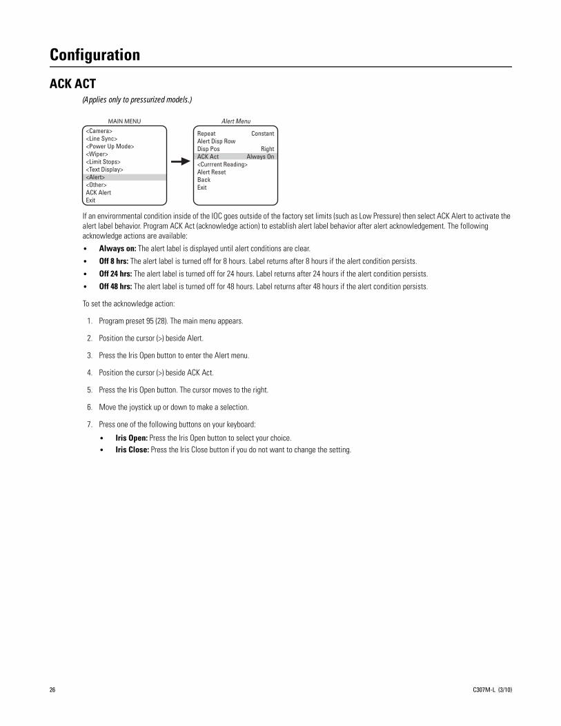
Configuration
ACK ACT(Applies only to pressurized models.)
If an envirornmental condition inside of the IOC goes outside of the factory set limits (such as Low Pressure) then select ACK Alert to activate the alert label behavior. Program ACK Act (acknowledge action) to establish alert label behavior after alert acknowledgement. The following acknowledge actions are available:
• Always on: The alert label is displayed until alert conditions are clear.
• Off 8 hrs: The alert label is turned off for 8 hours. Label returns after 8 hours if the alert condition persists.
• Off 24 hrs: The alert label is turned off for 24 hours. Label returns after 24 hours if the alert condition persists.
• Off 48 hrs: The alert label is turned off for 48 hours. Label returns after 48 hours if the alert condition persists.
To set the acknowledge action:
1. Program preset 95 (28). The main menu appears.
2. Position the cursor (>) beside Alert.
3. Press the Iris Open button to enter the Alert menu.
4. Position the cursor (>) beside ACK Act.
5. Press the Iris Open button. The cursor moves to the right.
6. Move the joystick up or down to make a selection.
7. Press one of the following buttons on your keyboard:
• Iris Open: Press the Iris Open button to select your choice.• Iris Close: Press the Iris Close button if you do not want to change the setting.
MAIN MENU<Camera><Line Sync><Power Up Mode><Wiper><Limit Stops><Text Display><Alert><Other>ACK AlertExit
Repeat ConstantAlert Disp RowDisp Pos RightACK Act Always On<Currrent Reading>Alert ResetBackExit
Alert Menu
26 C307M-L (3/10)
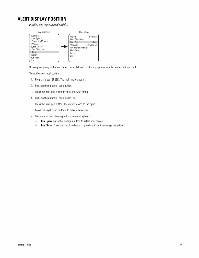
ALERT DISPLAY POSITION(Applies only to pressurized models.)
Screen positioning of the alert label is user-defined. Positioning options include Center, Left, and Right.
To set the alert label position:
1. Program preset 95 (28). The main menu appears.
2. Position the cursor (>) beside Alert.
3. Press the Iris Open button to enter the Alert menu.
4. Position the cursor (>) beside Disp Pos.
5. Press the Iris Open button. The cursor moves to the right.
6. Move the joystick up or down to make a selection.
7. Press one of the following buttons on your keyboard:
• Iris Open: Press the Iris Open button to select your choice.• Iris Close: Press the Iris Close button if you do not want to change the setting.
MAIN MENU<Camera><Line Sync><Power Up Mode><Wiper><Limit Stops><Text Display><Alert><Other>ACK AlertExit
Repeat ConstantAlert Disp RowDisp Pos RightACK Act Always On<Currrent Reading>Alert ResetBackExit
Alert Menu
C307M-L (3/10) 27

ALERT DISPLAY ROW(Applies only to pressurized models.)
The row on which the alert label is displayed is user-defined. Display row options include rows 1 through 12.
To set the alert display row:
1. Program preset 95 (28). The main menu appears.
2. Position the cursor (>) beside Alert.
3. Press the Iris Open button to enter the Alert menu.
4. Position the cursor (>) beside Alert Disp Row.
5. Press the Iris Open button. The cursor moves to the right.
6. Move the joystick up or down to make a selection.
7. Press one of the following buttons on your keyboard:
• Iris Open: Press the Iris Open button to select your choice.• Iris Close: Press the Iris Close button if you do not want to change the setting.
MAIN MENU<Camera><Line Sync><Power Up Mode><Wiper><Limit Stops><Text Display><Alert><Other>ACK AlertExit
Repeat ConstantAlert Disp RowDisp Pos RightACK Act Always On<Currrent Reading>Alert ResetBackExit
Alert Menu
28 C307M-L (3/10)
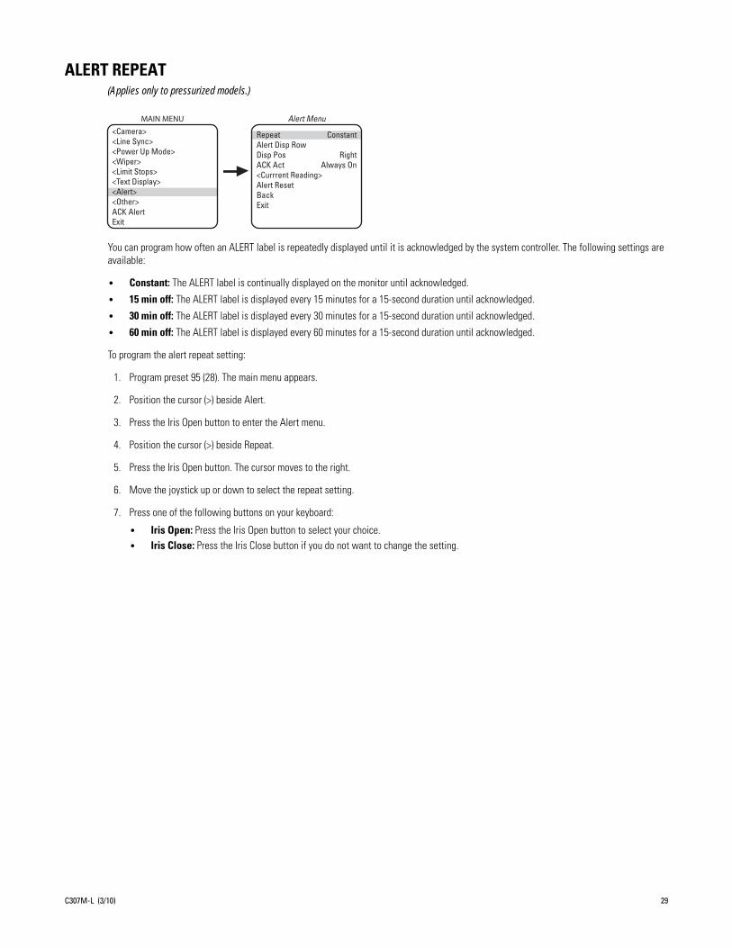
ALERT REPEAT(Applies only to pressurized models.)
You can program how often an ALERT label is repeatedly displayed until it is acknowledged by the system controller. The following settings are available:
• Constant: The ALERT label is continually displayed on the monitor until acknowledged.
• 15 min off: The ALERT label is displayed every 15 minutes for a 15-second duration until acknowledged.
• 30 min off: The ALERT label is displayed every 30 minutes for a 15-second duration until acknowledged.
• 60 min off: The ALERT label is displayed every 60 minutes for a 15-second duration until acknowledged.
To program the alert repeat setting:
1. Program preset 95 (28). The main menu appears.
2. Position the cursor (>) beside Alert.
3. Press the Iris Open button to enter the Alert menu.
4. Position the cursor (>) beside Repeat.
5. Press the Iris Open button. The cursor moves to the right.
6. Move the joystick up or down to select the repeat setting.
7. Press one of the following buttons on your keyboard:
• Iris Open: Press the Iris Open button to select your choice.• Iris Close: Press the Iris Close button if you do not want to change the setting.
MAIN MENU<Camera><Line Sync><Power Up Mode><Wiper><Limit Stops><Text Display><Alert><Other>ACK AlertExit
Repeat ConstantAlert Disp RowDisp Pos RightACK Act Always On<Currrent Reading>Alert ResetBackExit
Alert Menu
C307M-L (3/10) 29

AUTO FOCUS MODE
There are two auto focus modes:
• Auto: If auto focus is in the auto mode, pressing the Focus Far or Focus Near button will place the focus in the manual mode. The system will return to auto focus if you pan or tilt the unit or do a zoom function.
• Off: If the mode is set to Off, the system will operate in the manual mode.
NOTE: Auto focus does not operate at shutter speeds longer than 1/8 of a second.
To change the mode:
1. Program preset 95 (28). The main menu appears.
2. Position the cursor (>) beside Camera.
3. Press the Iris Open button to enter the Camera menu.
4. Position the cursor (>) beside Next.
5. Press the Iris Open button to go to the Next menu.
6. Position the cursor (>) beside Auto Focus Mode.
7. Press the Iris Open button. The cursor moves to the right, beside Auto or Off.
8. Move the joystick up or down to toggle between Auto and Off.
9. Press one of the following buttons on your keyboard:
• Iris Open: Press the Iris Open button to select your choice.
• Iris Close: Press the Iris Close button if you do not want to change the setting.
Backlight CompZoom LimitReset CameraWDRField Alignment
<AGC/Auto Iris/ToL>NextBackExit
Camera MenuMAIN MENU
<Camera><Line Sync><Power Up Mode><Wiper><Limit Stops><Text Display><Other>Exit
LowLight LimitShutter Speed
Auto Focus ModeSure Focus LowLight Focus Img Stabilizer <IR Filt/Sharp/Wht Bal>NextBackExit
Next Menu
30 C307M-L (3/10)

AUTO IRIS
The available settings for auto iris are Mode, Level, and Peak.
To change the settings for auto iris:
1. Program preset 95 (28). The main menu appears.
2. Position the cursor (>) beside Camera.
3. Press the Iris Open button to enter the Camera menu.
4. Position the cursor (>) beside AGC/Auto Iris/ToL.
5. Press the Iris Open button. The AGC/Auto Iris/ToL menu appears.
6. Position the cursor (>) and select one of the following settings:
• Mode: The cursor moves to one of two choices: – Auto: The iris is automatically adjusted to produce a constant video output as determined by the Level setting.– Off: Auto iris is disabled, and control is always manual.
• Level: The cursor moves to a numeric value, which the system uses to try to maintain a certain light level. Changing the value of the Level setting will change the video level to which the auto iris adjusts. This setting should be adjusted if the video level in the auto iris mode is too bright or too dark.
• Peak: The cursor moves to a numeric value. Increasing this value will cause the auto iris circuit to react more to highlights or “peaks” in the picture. Decreasing this value will cause it to use the average video level to adjust the iris.
7. Move the joystick up or down to toggle between the available settings.
8. Press one of the following buttons on your keyboard:
• Iris Open: Press the Iris Open button to select your choice.
• Iris Close: Press the Iris Close button if you do not want to change the setting.
Backlight CompZoom Limit
Reset CameraWDRField Alignment
<AGC/Auto Iris/ToL>NextBackExit
Camera Menu AGC/Auto Iris/ToL Menu
Gain LimitAuto-Iris ModeAuto-Iris LevelAuto-Iris PeakType of Lighting
BackExit
MAIN MENU
<Camera><Line Sync><Power Up Mode><Wiper><Limit Stops><Text Display><Other>Exit
C307M-L (3/10) 31
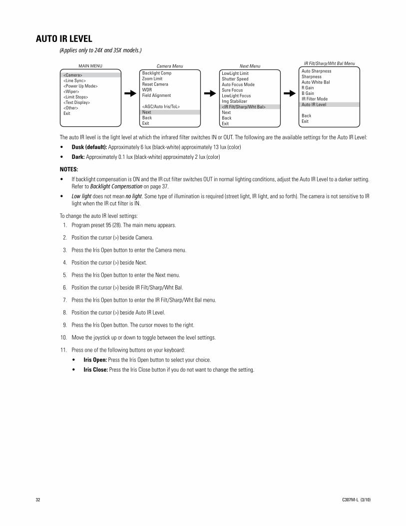
AUTO IR LEVEL(Applies only to 24X and 35X models.)
The auto IR level is the light level at which the infrared filter switches IN or OUT. The following are the available settings for the Auto IR Level:
• Dusk (default): Approximately 6 lux (black-white) approximately 13 lux (color)
• Dark: Approximately 0.1 lux (black-white) approximately 2 lux (color)
NOTES:
• If backlight compensation is ON and the IR cut filter switches OUT in normal lighting conditions, adjust the Auto IR Level to a darker setting. Refer to Backlight Compensation on page 37.
• Low light does not mean no light. Some type of illumination is required (street light, IR light, and so forth). The camera is not sensitive to IR light when the IR cut filter is IN.
To change the auto lR level settings:
1. Program preset 95 (28). The main menu appears.
2. Position the cursor (>) beside Camera.
3. Press the Iris Open button to enter the Camera menu.
4. Position the cursor (>) beside Next.
5. Press the Iris Open button to enter the Next menu.
6. Position the cursor (>) beside IR Filt/Sharp/Wht Bal.
7. Press the Iris Open button to enter the IR Filt/Sharp/Wht Bal menu.
8. Position the cursor (>) beside Auto IR Level.
9. Press the Iris Open button. The cursor moves to the right.
10. Move the joystick up or down to toggle between the level settings.
11. Press one of the following buttons on your keyboard:
• Iris Open: Press the Iris Open button to select your choice.
• Iris Close: Press the Iris Close button if you do not want to change the setting.
Backlight CompZoom LimitReset CameraWDRField Alignment
<AGC/Auto Iris/ToL>NextBackExit
Camera Menu
LowLight LimitShutter SpeedAuto Focus ModeSure FocusLowLight FocusImg Stabilizer<IR Filt/Sharp/Wht Bal>NextBackExit
Next Menu IR Filt/Sharp/Wht Bal Menu
Auto SharpnessSharpnessAuto White BalR GainB GainIR Filter ModeAuto IR Level
BackExit
MAIN MENU
<Camera><Line Sync><Power Up Mode><Wiper><Limit Stops><Text Display><Other>Exit
32 C307M-L (3/10)

AUTO SHARPNESS
The following settings are available for auto sharpness:
• On: Automatically sets the sharpness of the camera.
• Off: The sharpness of the camera needs to be manually set (refer to Sharpness).
To change the mode:
1. Program preset 95 (28). The main menu appears.
2. Position the cursor (>) beside Camera.
3. Press the Iris Open button to enter the Camera menu.
4. Position the cursor (>) beside Next.
5. Press the Iris Open button to enter the Next menu.
6. Position the cursor (>) beside IR Filt/Sharp/Wht Bal.
7. Press the Iris Open button to enter the IR Filt/Sharp/Wht Bal menu.
8. Position the cursor (>) beside Auto Sharpness.
9. Press the Iris Open button. The cursor moves to the right.
10. Move the joystick up or down to toggle between On and Off.
11. Press one of the following buttons on your keyboard:
• Iris Open: Press the Iris Open button to select your choice.
• Iris Close: Press the Iris Close button if you do not want to change the setting.
Backlight CompZoom LimitReset CameraWDRField Alignment
<AGC/Auto Iris/ToL>NextBackExit
Camera MenuLowLight LimitShutter SpeedAuto Focus ModeSure FocusLowLight FocusImg Stabilizer<IR Filt/Sharp/Wht Bal>NextBackExit
Next MenuAuto SharpnessSharpnessAuto White BalR GainB GainIR Filter ModeAuto IR Level
BackExit
IR Filt/Sharp/Wht Bal MenuMAIN MENU
<Camera><Line Sync><Power Up Mode><Wiper><Limit Stops><Text Display><Other>Exit
C307M-L (3/10) 33
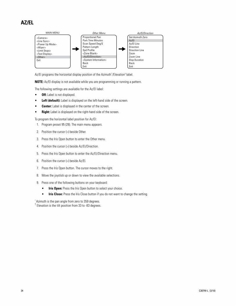
AZ/EL
Az/El programs the horizontal display position of the Azimuth*/Elevation† label.
NOTE: Az/El display is not available while you are programming or running a pattern.
The following settings are available for the Az/El label:
• Off: Label is not displayed.
• Left (default): Label is displayed on the left-hand side of the screen.
• Center: Label is displayed in the center of the screen.
• Right: Label is displayed on the right-hand side of the screen.
To program the horizontal label position for Az/El:
1. Program preset 95 (28). The main menu appears.
2. Position the cursor (>) beside Other.
3. Press the Iris Open button to enter the Other menu.
4. Position the cursor (>) beside Az/El/Direction.
5. Press the Iris Open button to enter the Az/El/Direction menu.
6. Position the cursor (>) beside Az/El.
7. Press the Iris Open button. The cursor moves to the right.
8. Move the joystick up or down to view the available selections.
9. Press one of the following buttons on your keyboard:
• Iris Open: Press the Iris Open button to select your choice.
• Iris Close: Press the Iris Close button if you do not want to change the setting.
* Azimuth is the pan angle from zero to 359 degrees.† Elevation is the tilt position from 33 to -83 degrees.
Proportional Pan Park Time Minutes Scan Speed Deg/S Pattern Length Spd Profile<Zone Blank><Az/El/Direction><System Information>BackExit
Other Menu Az/El/DirectionSet Azimuth ZeroAz/ElAz/El LineDirectionDirection LineZoomZoom LineDisp DurationBackExit
MAIN MENU
<Camera><Line Sync><Power Up Mode><Wiper><Limit Stops><Text Display><Other>Exit
34 C307M-L (3/10)
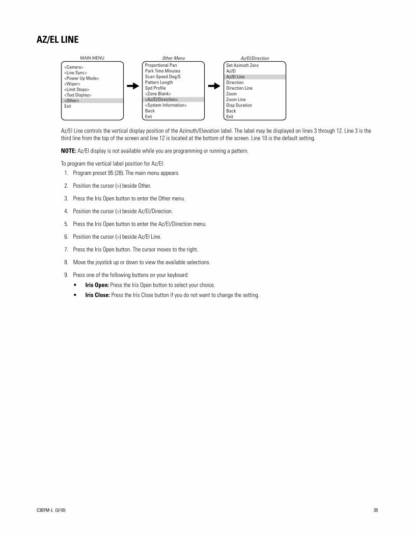
AZ/EL LINE
Az/El Line controls the vertical display position of the Azimuth/Elevation label. The label may be displayed on lines 3 through 12. Line 3 is the third line from the top of the screen and line 12 is located at the bottom of the screen. Line 10 is the default setting.
NOTE: Az/El display is not available while you are programming or running a pattern.
To program the vertical label position for Az/El:
1. Program preset 95 (28). The main menu appears.
2. Position the cursor (>) beside Other.
3. Press the Iris Open button to enter the Other menu.
4. Position the cursor (>) beside Az/El/Direction.
5. Press the Iris Open button to enter the Az/El/Direction menu.
6. Position the cursor (>) beside Az/El Line.
7. Press the Iris Open button. The cursor moves to the right.
8. Move the joystick up or down to view the available selections.
9. Press one of the following buttons on your keyboard:
• Iris Open: Press the Iris Open button to select your choice.
• Iris Close: Press the Iris Close button if you do not want to change the setting.
Proportional Pan Park Time Minutes Scan Speed Deg/S Pattern Length Spd Profile<Zone Blank><Az/El/Direction><System Information>BackExit
Other MenuSet Azimuth ZeroAz/ElAz/El LineDirectionDirection LineZoomZoom LineDisp DurationBackExit
Az/El/DirectionMAIN MENU
<Camera><Line Sync><Power Up Mode><Wiper><Limit Stops><Text Display><Other>Exit
C307M-L (3/10) 35

AZIMUTH ZERO
Azimuth is the pan angle from zero to 359 degrees. Azimuth zero is the programmed 0° point that is normally set to magnetic north. Once programmed, on-screen pan position (azimuth) and compass readings are based on the set azimuth zero point.
To set azimuth zero:
1. Program preset 95 (28). The main menu appears.
2. Position the cursor (>) beside Other.
3. Press the Iris Open button to enter the Other menu.
4. Position the cursor (>) beside Az/El/Direction.
5. Press the Iris Open button to enter the Az/El/Direction menu.
6. Position the cursor (>) beside Set Azimuth Zero.
7. Press the Iris Open button. The programming menu for Set Azimuth Zero appears on the monitor.
8. Use the joystick to pan the Esprit unit to the desired azimuth zero (zero degree point) position.
9. Press the Iris Open button to set the azimuth zero position.
Proportional Pan Park Time Minutes Scan Speed Deg/S Pattern Length Spd Profile<Zone Blank><Az/El/Direction><System Information>BackExit
Other Menu Az/El/Direction
Set Azimuth ZeroAz/ElAz/El LineDirectionDirection LineZoomZoom LineDisp DurationBackExit
MAIN MENU
<Camera><Line Sync><Power Up Mode><Wiper><Limit Stops><Text Display><Other>Exit
36 C307M-L (3/10)

BACKLIGHT COMPENSATION
There are two backlight compensation modes:
• On: The system uses the center 10 percent of the picture to adjust the iris. If there is a bright light source outside of this area, it will wash out to white. The camera will adjust the iris so that the object in the sensitive area is properly exposed.
NOTE: Applies only to 24X and 35X models.) If backlight compensation is ON and the IR cut filter switches OUT (black-white mode) in normal lighting conditions, adjust the Auto IR Level to a darker setting. Refer to Auto IR Level on page 32.
• Off: Backlight compensation is not activated.
To change the backlight compensation mode:
1. Program preset 95 (28). The main menu appears.
2. Position the cursor (>) beside Camera.
3. Press the Iris Open button to enter the Camera menu.
4. Position the cursor (>) beside Backlight Comp.
5. Press the Iris Open button. The cursor moves to the right, beside On or Off.
6. Move the joystick up or down to toggle between On and Off.
7. Press one of the following buttons on your keyboard:
• Iris Open: Press the Iris Open button to select your choice.
• Iris Close: Press the Iris Close button if you do not want to change the setting.
Backlight Comp Zoom Limit Reset CameraWDRField Alignment
<AGC/Auto Iris/ToL>NextBackExit
Camera MenuMAIN MENU
<Camera><Line Sync><Power Up Mode><Wiper><Limit Stops><Text Display><Other>Exit
NON-SENSITIVE AREA
SENSITIVE AREA
C307M-L (3/10) 37

DIRECTION
Direction programs the horizontal display position of the Direction label (N, NW, NE, …).
NOTES:
• For direction to be accurate, the azimuth zero must be set to magnetic north.
• Direction display is not available while you are programming or running a pattern.
The following settings are available for the Direction label:
• Off: Label is not displayed.
• Left: Label is displayed on the left-hand side of the screen.
• Center: Label is displayed in the center of the screen.
• Right (default): Label is displayed on the right-hand side of the screen.
To program the horizontal label position for Direction:
1. Program preset 95 (28). The main menu appears.
2. Position the cursor (>) beside Other.
3. Press the Iris Open button to enter the Other menu.
4. Position the cursor (>) beside Az/El/Direction.
5. Press the Iris Open button to enter the Az/El/Direction menu.
6. Position the cursor (>) beside Direction.
7. Press the Iris Open button. The cursor moves to the right.
8. Move the joystick up or down to view the available selections.
9. Press one of the following buttons on your keyboard:
• Iris Open: Press the Iris Open button to select your choice.
• Iris Close: Press the Iris Close button if you do not want to change the setting.
Proportional Pan Park Time Minutes Scan Speed Deg/S Pattern Length Spd Profile<Zone Blank><Az/El/Direction><System Information>BackExit
Other Menu Az/El/DirectionSet Azimuth ZeroAz/ElAz/El LineDirectionDirection LineZoomZoom LineDisp DurationBackExit
MAIN MENU
<Camera><Line Sync><Power Up Mode><Wiper><Limit Stops><Text Display><Other>Exit
38 C307M-L (3/10)

DIRECTION LINE
Direction Line controls the vertical display position of the Direction label. The label may be displayed on lines 3 through 12. Line 3 is the third line from the top of the screen and line 12 is located at the bottom of the screen. Line 10 is the default setting.
NOTE: Direction display is not available while you are programming or running a pattern.
To program the vertical label position for Direction:
1. Program preset 95 (28). The main menu appears.
2. Position the cursor (>) beside Other.
3. Press the Iris Open button to enter the Other menu.
4. Position the cursor (>) beside Az/El/Direction.
5. Press the Iris Open button to enter the Az/El/Direction menu.
6. Position the cursor (>) beside Direction Line.
7. Press the Iris Open button. The cursor moves to the right.
8. Move the joystick up or down to view the available selections.
9. Press one of the following buttons on your keyboard:
• Iris Open: Press the Iris Open button to select your choice.
• Iris Close: Press the Iris Close button if you do not want to change the setting.
Proportional Pan Park Time Minutes Scan Speed Deg/S Pattern Length Spd Profile<Zone Blank><Az/El/Direction><System Information>BackExit
Other Menu Az/El/DirectionSet Azimuth ZeroAz/ElAz/El LineDirectionDirection LineZoomZoom LineDisp DurationBackExit
MAIN MENU
<Camera><Line Sync><Power Up Mode><Wiper><Limit Stops><Text Display><Other>Exit
C307M-L (3/10) 39

DISPLAY DURATION
Display Duration programs the duration the Az/El, Direction, and Zoom labels are displayed on the monitor. The available settings for display duration include the following:
• Constant: The label is displayed continuously.
• 2 Seconds (default): The label is displayed for 2 seconds after PTZ functions end.
• 5 Seconds: The label is displayed for 5 seconds after PTZ functions end.
• 10 Seconds: The label is displayed for 10 seconds after PTZ functions end.
To program the display duration for the Az/El, Direction, and Zoom labels:
1. Program preset 95 (28). The main menu appears.
2. Position the cursor (>) beside Other.
3. Press the Iris Open button to enter the Other menu.
4. Position the cursor (>) beside Az/El/Direction.
5. Press the Iris Open button to enter the Az/El/Direction menu.
6. Position the cursor (>) beside Disp Duration.
7. Press the Iris Open button. The cursor moves to the right.
8. Move the joystick up or down to view the available selections.
9. Press one of the following buttons on your keyboard:
• Iris Open: Press the Iris Open button to select your choice.
• Iris Close: Press the Iris Close button if you do not want to change the setting.
Proportional Pan Park Time Minutes Scan Speed Deg/S Pattern Length Spd Profile<Zone Blank><Az/El/Direction><System Information>BackExit
Other Menu Az/El/DirectionSet Azimuth ZeroAz/ElAz/El LineDirectionDirection LineZoomZoom LineDisp DurationBackExit
MAIN MENU
<Camera><Line Sync><Power Up Mode><Wiper><Limit Stops><Text Display><Other>Exit
40 C307M-L (3/10)
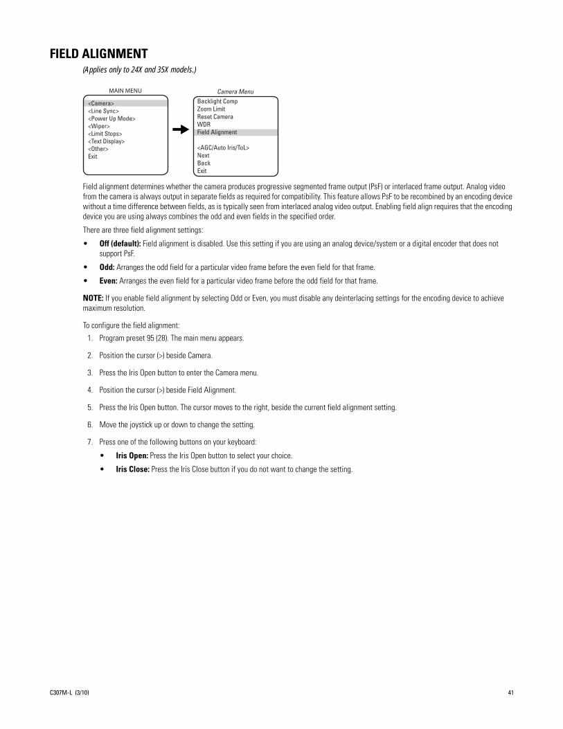
FIELD ALIGNMENT(Applies only to 24X and 35X models.)
Field alignment determines whether the camera produces progressive segmented frame output (PsF) or interlaced frame output. Analog video from the camera is always output in separate fields as required for compatibility. This feature allows PsF to be recombined by an encoding device without a time difference between fields, as is typically seen from interlaced analog video output. Enabling field align requires that the encoding device you are using always combines the odd and even fields in the specified order.
There are three field alignment settings:
• Off (default): Field alignment is disabled. Use this setting if you are using an analog device/system or a digital encoder that does not support PsF.
• Odd: Arranges the odd field for a particular video frame before the even field for that frame.
• Even: Arranges the even field for a particular video frame before the odd field for that frame.
NOTE: If you enable field alignment by selecting Odd or Even, you must disable any deinterlacing settings for the encoding device to achieve maximum resolution.
To configure the field alignment:
1. Program preset 95 (28). The main menu appears.
2. Position the cursor (>) beside Camera.
3. Press the Iris Open button to enter the Camera menu.
4. Position the cursor (>) beside Field Alignment.
5. Press the Iris Open button. The cursor moves to the right, beside the current field alignment setting.
6. Move the joystick up or down to change the setting.
7. Press one of the following buttons on your keyboard:
• Iris Open: Press the Iris Open button to select your choice.
• Iris Close: Press the Iris Close button if you do not want to change the setting.
Backlight CompZoom LimitReset CameraWDRField Alignment
<AGC/Auto Iris/ToL>NextBackExit
Camera MenuMAIN MENU
<Camera><Line Sync><Power Up Mode><Wiper><Limit Stops><Text Display><Other>Exit
C307M-L (3/10) 41

GAIN LIMIT
The gain limit sets the maximum level for the automatic gain control. Increasing the level will increase the signal level and increase the noise level of the picture.
To change the gain:
1. Program preset 95 (28). The main menu appears.
2. Position the cursor (>) beside Camera.
3. Press the Iris Open button to enter the Camera menu.
4. Position the cursor (>) beside AGC/Auto Iris/ToL.
5. Press the Iris Open button to enter the AGC/Auto Iris/ToL menu.
6. Position the cursor (>) beside Gain Limit.
7. Press the Iris Open button. The cursor moves to the right, beside the current gain level setting (a numeric value).
8. Move the joystick up or down to change the level.
9. Press one of the following buttons on your keyboard:
• Iris Open: Press the Iris Open button to select your choice.
• Iris Close: Press the Iris Close button if you do not want to change the setting.
Backlight CompZoom Limit
Reset CameraWDRField Alignment
<AGC/Auto Iris/ToL>NextBackExit
Camera Menu
Gain LimitAuto-Iris ModeAuto-Iris LevelAuto-Iris PeakType of Lighting
BackExit
AGC/Auto Iris/ToL MenuMAIN MENU
<Camera><Line Sync><Power Up Mode><Wiper><Limit Stops><Text Display><Other>Exit
42 C307M-L (3/10)
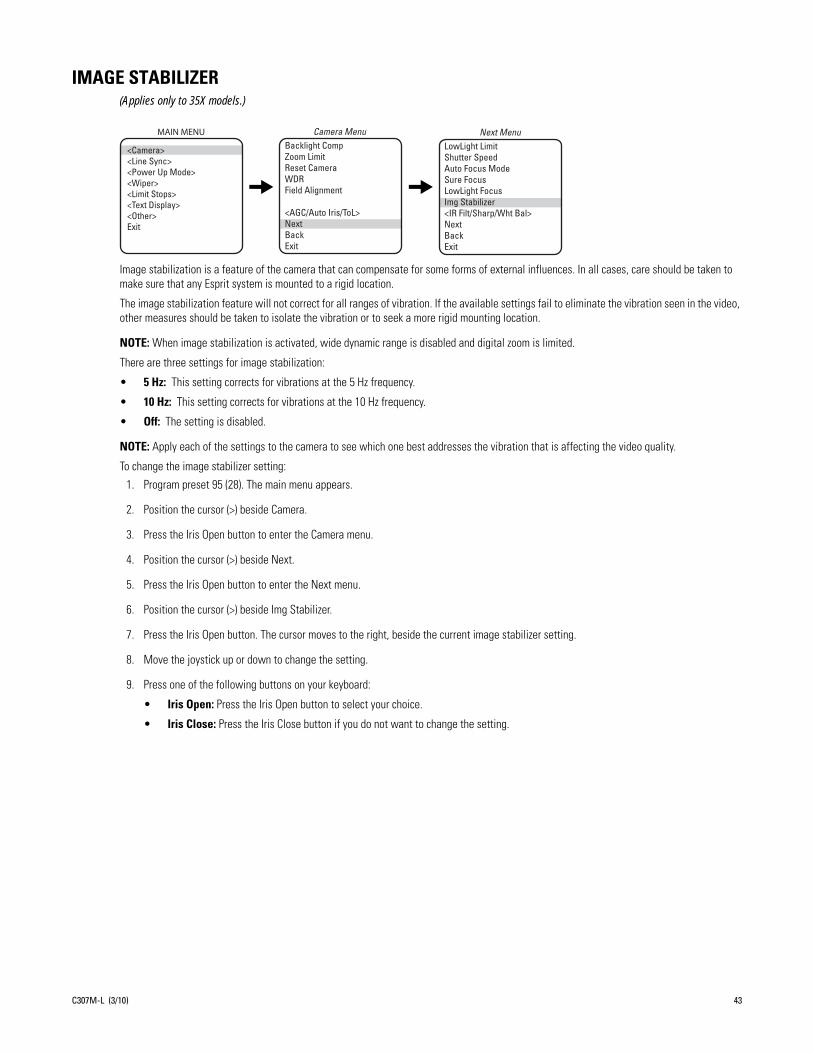
IMAGE STABILIZER(Applies only to 35X models.)
Image stabilization is a feature of the camera that can compensate for some forms of external influences. In all cases, care should be taken to make sure that any Esprit system is mounted to a rigid location.
The image stabilization feature will not correct for all ranges of vibration. If the available settings fail to eliminate the vibration seen in the video, other measures should be taken to isolate the vibration or to seek a more rigid mounting location.
NOTE: When image stabilization is activated, wide dynamic range is disabled and digital zoom is limited.
There are three settings for image stabilization:
• 5 Hz: This setting corrects for vibrations at the 5 Hz frequency.
• 10 Hz: This setting corrects for vibrations at the 10 Hz frequency.
• Off: The setting is disabled.
NOTE: Apply each of the settings to the camera to see which one best addresses the vibration that is affecting the video quality.
To change the image stabilizer setting:
1. Program preset 95 (28). The main menu appears.
2. Position the cursor (>) beside Camera.
3. Press the Iris Open button to enter the Camera menu.
4. Position the cursor (>) beside Next.
5. Press the Iris Open button to enter the Next menu.
6. Position the cursor (>) beside Img Stabilizer.
7. Press the Iris Open button. The cursor moves to the right, beside the current image stabilizer setting.
8. Move the joystick up or down to change the setting.
9. Press one of the following buttons on your keyboard:
• Iris Open: Press the Iris Open button to select your choice.
• Iris Close: Press the Iris Close button if you do not want to change the setting.
Backlight CompZoom LimitReset CameraWDRField Alignment
<AGC/Auto Iris/ToL>NextBackExit
Camera Menu
LowLight LimitShutter SpeedAuto Focus ModeSure FocusLowLight Focus Img Stabilizer <IR Filt/Sharp/Wht Bal>NextBackExit
Next MenuMAIN MENU
<Camera><Line Sync><Power Up Mode><Wiper><Limit Stops><Text Display><Other>Exit
C307M-L (3/10) 43
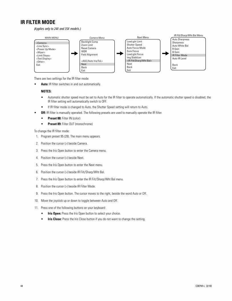
IR FILTER MODE(Applies only to 24X and 35X models.)
There are two settings for the IR filter mode:
• Auto: IR filter switches in and out automatically.
NOTES:
• Automatic shutter speed must be set to Auto for the IR filter to operate automatically. If the automatic shutter speed is disabled, the IR filter setting will automatically switch to OFF.
• If IR filter mode is changed to Auto, the Shutter Speed setting will return to Auto.
• Off: IR filter is manually operated. The following presets are used to manually operate the IR filter.
• Preset 88: Filter IN (color)
• Preset 89: Filter OUT (monochrome)
To change the lR filter mode:
1. Program preset 95 (28). The main menu appears.
2. Position the cursor (>) beside Camera.
3. Press the Iris Open button to enter the Camera menu.
4. Position the cursor (>) beside Next.
5. Press the Iris Open button to enter the Next menu.
6. Position the cursor (>) beside IR Filt/Sharp/Wht Bal.
7. Press the Iris Open button to enter the IR Filt/Sharp/Wht Bal menu.
8. Position the cursor (>) beside IR Filter Mode.
9. Press the Iris Open button. The cursor moves to the right, beside the word Auto or Off.
10. Move the joystick up or down to toggle between Auto and Off.
11. Press one of the following buttons on your keyboard:
• Iris Open: Press the Iris Open button to select your choice.
• Iris Close: Press the Iris Close button if you do not want to change the setting.
Backlight CompZoom LimitReset CameraWDRField Alignment
<AGC/Auto Iris/ToL>NextBackExit
Camera Menu Auto SharpnessSharpnessAuto White BalR GainB GainIR Filter ModeAuto IR Level
BackExit
IR Filt/Sharp/Wht Bal MenuMAIN MENU
<Camera><Line Sync><Power Up Mode><Wiper><Limit Stops><Text Display><Other>Exit
LowLight LimitShutter SpeedAuto Focus ModeSure FocusLowLight FocusImg Stabilizer<IR Filt/Sharp/Wht Bal>NextBackExit
Next Menu
44 C307M-L (3/10)

LIMIT STOPS
NOTE: Limit stops are inactive while setting items in the program menu (e.g. azimuth zero, scan limits, manual pan limits).
TURNING LIMIT STOPS ON OR OFF
To change the limit stop mode:
1. Program preset 95 (28). The main menu appears.
2. Position the cursor (>) beside Limit Stop.
3. Press the Iris Open button to enter the Limit Stop menu.
4. Position the cursor (>) beside Limit Stops.
5. Press the Iris Open button. The cursor moves to the right, beside On or Off.
6. Move the joystick up or down to toggle between On and Off.
7. Press one of the following buttons on your keyboard:
• Iris Open: Press the Iris Open button to select your choice.
• Iris Close: Press the Iris Close button if you do not want to change the setting.
PROGRAMMING LIMIT STOPS
Manual Limit StopsWhen manual limit stops are set, pan operation (using a joystick or pan/tilt keys) stops when a limit stop is reached. The manual limit stops can be set in one of two ways:
• At the controller by programming presets 90 (23) and 91 (24)
• At the controller by programming the Limit Stops menu
PresetsRefer to the documentation for your control system for programming presets, and then do the following:
1. Make sure limit stops are turned ON, then exit the menu.
2. Push the joystick left until you reach the limit you want the camera to go to on the left.
3. Program preset 90 (23).
4. Push the joystick right to the limit you want the camera to go to on the right.
5. Program preset 91 (24).
Setting presets 90 (23) and 91 (24) to the same point disables manual limit stops.
NOTE: Programming preset 90 (23) disables the manual limit stops until preset 91 (24) is set. Preset 90 (23) is the left manual limit and preset 91 (24) is the right manual limit.
Limit Stops Set Man LimitsClear Man LimitsSet Scan LimitsClear Scan LimitsBackExit
Limit Stop MenuMAIN MENU
<Camera><Line Sync><Power Up Mode><Wiper><Limit Stops><Text Display><Other>Exit
C307M-L (3/10) 45

Limit Stops MenuThe manual pan limit stops can be set at the controller using the Limit Stops menu:
1. Program preset 95 (28). The main menu appears.
2. Position the cursor (>) beside Limit Stop.
3. Press the Iris Open button to enter the Limit Stop menu.
4. Move the cursor to Set Man Limits and press the Iris Open button. PRESS IRIS OPEN TO SET LEFT LIMIT appears.
5. Move the pan/tilt to the desired left limit position and press the Iris Open button to set the left manual limit. PRESS IRIS OPEN TO SET RIGHT LIMIT appears.
6. Move the pan/tilt to the desired right limit position and press the Iris Open button to set the right manual limit.
7. Exit the Limit Stop menu.
Clear Manual StopsTo clear the manual limit stops:
1. Program preset 95 (28). The main menu appears.
2. Position the cursor (>) beside Limit Stop.
3. Press the Iris Open button to enter the Limit Stop menu.
4. Move the cursor to Clear Man Limits and press the Iris Open button. The cursor will flash to an asterisk (*) briefly to indicate the limits have been disabled.
Scan Limit StopsWhen scan limit stops are set, the pan/tilt reverses direction during random, frame, or autoscanning when a limit stop is reached. The manual scan limit stops can be set in one of two ways:
• At the controller by programming presets 92 and 93
• At the controller by programming the Limit Stops menu
Limit Stops MenuThe manual pan limit stops can be set at the controller using the Limit Stops menu:
1. Program preset 95 (28). The main menu appears.
2. Position the cursor (>) beside Limit Stop.
3. Press the Iris Open button to enter the Limit Stop menu.
4. Move the cursor to Set Scan Limits and press the Iris Open button. PRESS IRIS OPEN TO SET LEFT LIMIT appears.
5. Move the pan/tilt to the desired left limit position and press the Iris Open button to set the left manual limit. PRESS IRIS OPEN TO SET RIGHT LIMIT appears.
6. Move the pan/tilt to the desired right limit position and press the Iris Open button to set the right scan limit.
7. Exit the Limit Stop menu.
Clear Scan Limit StopsTo clear the scan limit stops, move the cursor to Clear Scan Limits and press the Iris Open button. The cursor will flash to an asterisk (*) briefly to indicate the limits have been disabled.
46 C307M-L (3/10)
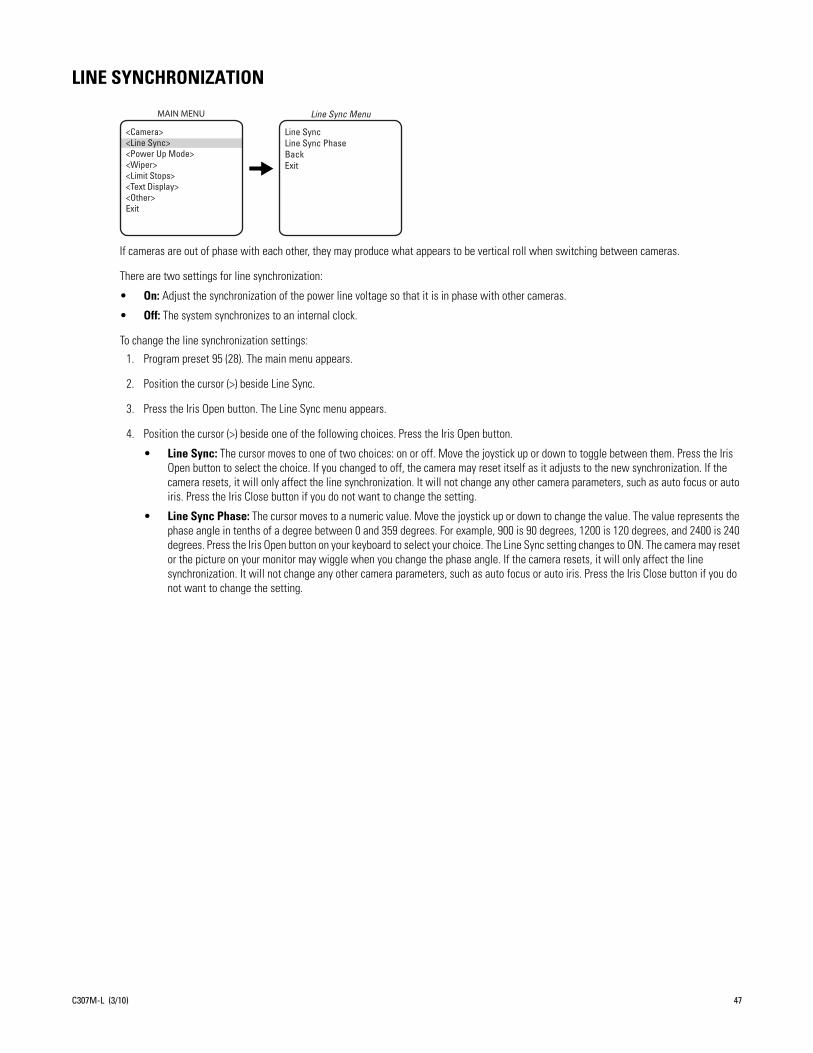
LINE SYNCHRONIZATION
If cameras are out of phase with each other, they may produce what appears to be vertical roll when switching between cameras.
There are two settings for line synchronization:
• On: Adjust the synchronization of the power line voltage so that it is in phase with other cameras.
• Off: The system synchronizes to an internal clock.
To change the line synchronization settings:
1. Program preset 95 (28). The main menu appears.
2. Position the cursor (>) beside Line Sync.
3. Press the Iris Open button. The Line Sync menu appears.
4. Position the cursor (>) beside one of the following choices. Press the Iris Open button.
• Line Sync: The cursor moves to one of two choices: on or off. Move the joystick up or down to toggle between them. Press the Iris Open button to select the choice. If you changed to off, the camera may reset itself as it adjusts to the new synchronization. If the camera resets, it will only affect the line synchronization. It will not change any other camera parameters, such as auto focus or auto iris. Press the Iris Close button if you do not want to change the setting.
• Line Sync Phase: The cursor moves to a numeric value. Move the joystick up or down to change the value. The value represents the phase angle in tenths of a degree between 0 and 359 degrees. For example, 900 is 90 degrees, 1200 is 120 degrees, and 2400 is 240 degrees. Press the Iris Open button on your keyboard to select your choice. The Line Sync setting changes to ON. The camera may reset or the picture on your monitor may wiggle when you change the phase angle. If the camera resets, it will only affect the line synchronization. It will not change any other camera parameters, such as auto focus or auto iris. Press the Iris Close button if you do not want to change the setting.
Line Sync Line Sync PhaseBackExit
Line Sync MenuMAIN MENU
<Camera><Line Sync><Power Up Mode><Wiper><Limit Stops><Text Display><Other>Exit
C307M-L (3/10) 47

LOWLIGHT FOCUS
This setting allows the camera to focus better in infrared lighting. The available settings are Def (default), 850nm, or 950nm
NOTE: Low light does not mean no light. Some type of illumination is required.
To change the LowLight focus:
1. On the main menu, move the joystick up or down to position the cursor (>) beside Camera.
2. Press the Iris Open button to enter the Camera menu.
3. Position the cursor (>) beside Next.
4. Press the Iris Open button to go to the Next menu.
5. Position the cursor (>) beside LowLight focus.
6. Press the Iris Open button. The cursor moves to the right, beside the current LowLight focus.
7. Move the joystick up or down to choose the LowLight focus.
8. Press one of the following buttons on your keyboard:
• Iris Open: Press the Iris Open button to select your choice.
• Iris Close: Press the Iris Close button if you do not want to change the setting.
Backlight CompZoom LimitReset CameraWDRField Alignment
<AGC/Auto Iris/ToL>NextBackExit
Camera MenuMAIN MENU
<Camera><Line Sync><Power Up Mode><Wiper><Limit Stops><Text Display><Other>Exit
LowLight LimitShutter SpeedAuto Focus ModeLow Light Focus Img Stabilizer <IR Filt/Sharp/Wht Bal>NextBackExit
Next Menu
48 C307M-L (3/10)

LOWLIGHT LIMIT
This setting determines the maximum length of time the shutter will remain open automatically in low light conditions. There are six choices:
2 = 1/2 second 8 = 1/8 second 30 = 1/30 second
4 = 1/4 second 15 = 1/15 second 60 = 1/60 second
NOTES:
• Low light does not mean no light. Some type of illumination is required.
• Auto focus is automatically turned off when the shutter speed is longer than 1/8 of a second.
To change the LowLight limit:
1. On the main menu, move the joystick up or down to position the cursor (>) beside Camera.
2. Press the Iris Open button to enter the Camera menu.
3. Position the cursor (>) beside Next.
4. Press the Iris Open button to go to the Next menu.
5. Position the cursor (>) beside LowLight Limit.
6. Press the Iris Open button. The cursor moves to the right, beside the current LowLight Limit.
7. Move the joystick up or down to choose the LowLight Limit.
8. Press one of the following buttons on your keyboard:
• Iris Open: Press the Iris Open button to select your choice.
• Iris Close: Press the Iris Close button if you do not want to change the setting.
Backlight CompZoom LimitReset CameraWDRField Alignment
<AGC/Auto Iris/ToL>NextBackExit
Camera MenuMAIN MENU
<Camera><Line Sync><Power Up Mode><Wiper><Limit Stops><Text Display><Other>Exit
LowLight LimitShutter SpeedAuto Focus ModeSure FocusLowLight FocusImg Stabilizer<IR Filt/Sharp/Wht Bal>NextBackExit
Next Menu
C307M-L (3/10) 49
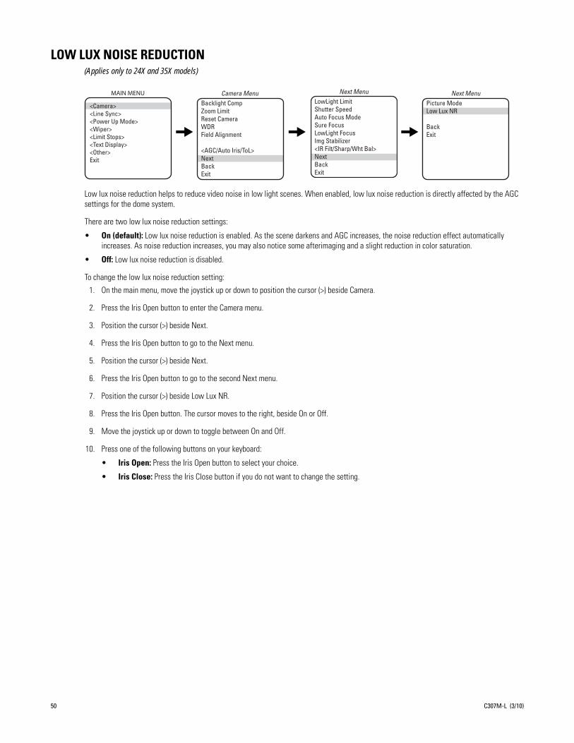
LOW LUX NOISE REDUCTION(Applies only to 24X and 35X models)
Low lux noise reduction helps to reduce video noise in low light scenes. When enabled, low lux noise reduction is directly affected by the AGC settings for the dome system.
There are two low lux noise reduction settings:
• On (default): Low lux noise reduction is enabled. As the scene darkens and AGC increases, the noise reduction effect automatically increases. As noise reduction increases, you may also notice some afterimaging and a slight reduction in color saturation.
• Off: Low lux noise reduction is disabled.
To change the low lux noise reduction setting:
1. On the main menu, move the joystick up or down to position the cursor (>) beside Camera.
2. Press the Iris Open button to enter the Camera menu.
3. Position the cursor (>) beside Next.
4. Press the Iris Open button to go to the Next menu.
5. Position the cursor (>) beside Next.
6. Press the Iris Open button to go to the second Next menu.
7. Position the cursor (>) beside Low Lux NR.
8. Press the Iris Open button. The cursor moves to the right, beside On or Off.
9. Move the joystick up or down to toggle between On and Off.
10. Press one of the following buttons on your keyboard:
• Iris Open: Press the Iris Open button to select your choice.
• Iris Close: Press the Iris Close button if you do not want to change the setting.
Backlight CompZoom LimitReset CameraWDRField Alignment
<AGC/Auto Iris/ToL>NextBackExit
Camera MenuPicture ModeLow Lux NR
BackExit
Next MenuMAIN MENU
<Camera><Line Sync><Power Up Mode><Wiper><Limit Stops><Text Display><Other>Exit
LowLight LimitShutter SpeedAuto Focus ModeSure FocusLowLight Focus Img Stabilizer <IR Filt/Sharp/Wht Bal>NextBackExit
Next Menu
50 C307M-L (3/10)

PARK TIME MINUTES
This feature causes the system to park at preset 1 after a programmed number of minutes of control inactivity. The time can be set from 1 minute to 720 minutes (12 hours), or it can be set to zero, which disables this feature.
NOTE: Preset 1 must be programmed for the dome to park.
To change the park time:
1. Program preset 95 (28). The main menu appears.
2. Position the cursor (>) beside Other.
3. Press the Iris Open button to enter the Other menu.
4. Position the cursor (>) beside Park Time Minutes.
5. Press the Iris Open button. The cursor moves to the right, beside the current park time.
6. Move the joystick up or down to change the park time.
7. Press one of the following buttons on your keyboard:
• Iris Open: Press the Iris Open button to select your choice.
• Iris Close: Press the Iris Close button if you do not want to change the setting.
Proportional Pan Park Time Minutes Scan Speed Deg/S Pattern Length Spd Profile<Zone Blank><Az/El/Direction><System Information>BackExit
Other MenuMAIN MENU
<Camera><Line Sync><Power Up Mode><Wiper><Limit Stops><Text Display><Other>Exit
C307M-L (3/10) 51
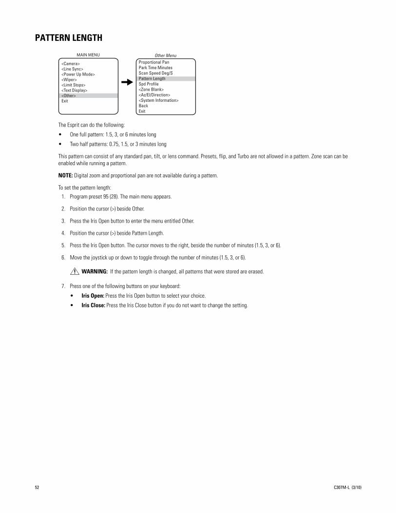
PATTERN LENGTH
The Esprit can do the following:
• One full pattern: 1.5, 3, or 6 minutes long
• Two half patterns: 0.75, 1.5, or 3 minutes long
This pattern can consist of any standard pan, tilt, or lens command. Presets, flip, and Turbo are not allowed in a pattern. Zone scan can be enabled while running a pattern.
NOTE: Digital zoom and proportional pan are not available during a pattern.
To set the pattern length:
1. Program preset 95 (28). The main menu appears.
2. Position the cursor (>) beside Other.
3. Press the Iris Open button to enter the menu entitled Other.
4. Position the cursor (>) beside Pattern Length.
5. Press the Iris Open button. The cursor moves to the right, beside the number of minutes (1.5, 3, or 6).
6. Move the joystick up or down to toggle through the number of minutes (1.5, 3, or 6).
7. Press one of the following buttons on your keyboard:
• Iris Open: Press the Iris Open button to select your choice.
• Iris Close: Press the Iris Close button if you do not want to change the setting.
WARNING: If the pattern length is changed, all patterns that were stored are erased.
Proportional Pan Park Time Minutes Scan Speed Deg/S Pattern Length Spd Profile<Zone Blank><Az/El/Direction><System Information>BackExit
Other MenuMAIN MENU
<Camera><Line Sync><Power Up Mode><Wiper><Limit Stops><Text Display><Other>Exit
52 C307M-L (3/10)
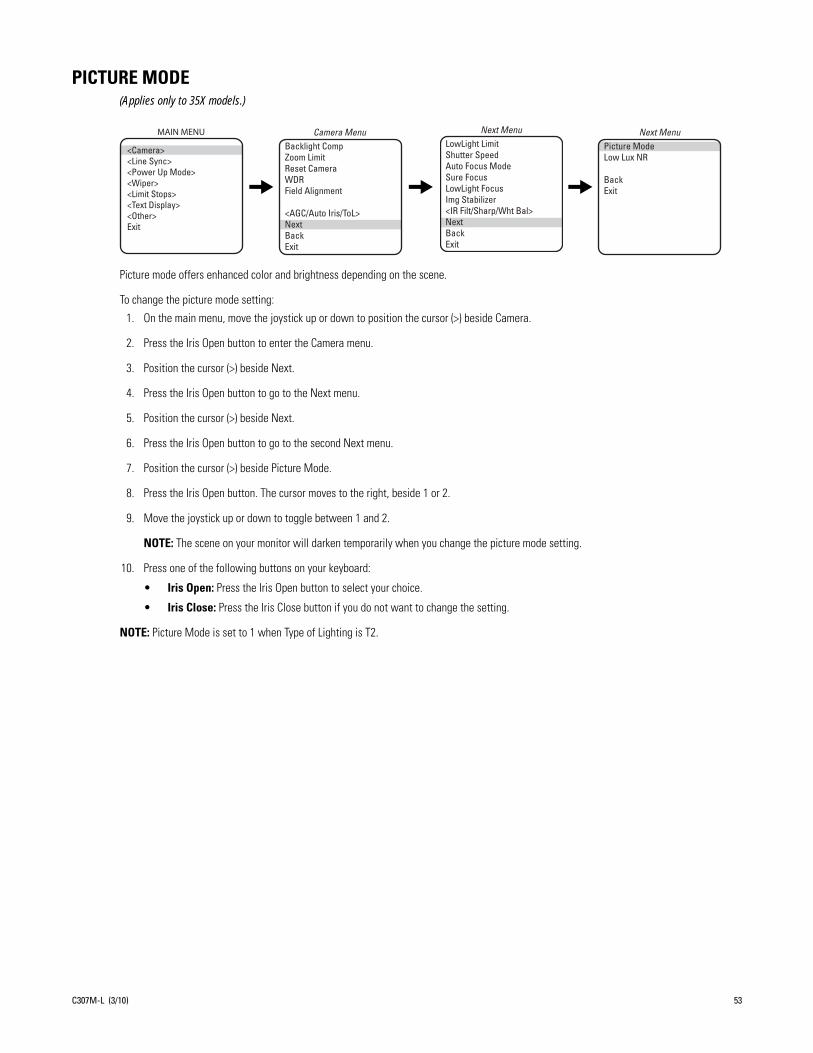
PICTURE MODE(Applies only to 35X models.)
Picture mode offers enhanced color and brightness depending on the scene.
To change the picture mode setting:
1. On the main menu, move the joystick up or down to position the cursor (>) beside Camera.
2. Press the Iris Open button to enter the Camera menu.
3. Position the cursor (>) beside Next.
4. Press the Iris Open button to go to the Next menu.
5. Position the cursor (>) beside Next.
6. Press the Iris Open button to go to the second Next menu.
7. Position the cursor (>) beside Picture Mode.
8. Press the Iris Open button. The cursor moves to the right, beside 1 or 2.
9. Move the joystick up or down to toggle between 1 and 2.
NOTE: The scene on your monitor will darken temporarily when you change the picture mode setting.
10. Press one of the following buttons on your keyboard:
• Iris Open: Press the Iris Open button to select your choice.
• Iris Close: Press the Iris Close button if you do not want to change the setting.
NOTE: Picture Mode is set to 1 when Type of Lighting is T2.
Backlight CompZoom LimitReset CameraWDRField Alignment
<AGC/Auto Iris/ToL>NextBackExit
Camera MenuPicture ModeLow Lux NR
BackExit
Next MenuMAIN MENU
<Camera><Line Sync><Power Up Mode><Wiper><Limit Stops><Text Display><Other>Exit
LowLight LimitShutter SpeedAuto Focus ModeSure FocusLowLight Focus Img Stabilizer <IR Filt/Sharp/Wht Bal>NextBackExit
Next Menu
C307M-L (3/10) 53
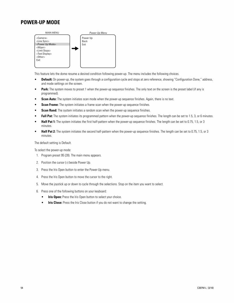
POWER-UP MODE
This feature lets the dome resume a desired condition following power-up. The menu includes the following choices.
• Default: On power-up, the system goes through a configuration cycle and stops at zero reference, showing “Configuration Done,” address, and mode settings on the screen.
• Park: The system moves to preset 1 when the power-up sequence finishes. The only text on the screen is the preset label (if any is programmed).
• Scan Auto: The system initiates scan mode when the power-up sequence finishes. Again, there is no text.
• Scan Frame: The system initiates a frame scan when the power-up sequence finishes.
• Scan Rand: The system initiates a random scan when the power-up sequence finishes.
• Full Pat: The system initiates its programmed pattern when the power-up sequence finishes. The length can be set to 1.5, 3, or 6 minutes.
• Half Pat 1: The system initiates the first half-pattern when the power-up sequence finishes. The length can be set to 0.75, 1.5, or 3 minutes.
• Half Pat 2: The system initiates the second half-pattern when the power-up sequence finishes. The length can be set to 0.75, 1.5, or 3 minutes.
The default setting is Default.
To select the power-up mode:
1. Program preset 95 (28). The main menu appears.
2. Position the cursor (>) beside Power Up.
3. Press the Iris Open button to enter the Power-Up menu.
4. Press the Iris Open button to move the cursor to the right.
5. Move the joystick up or down to cycle through the selections. Stop on the item you want to select.
6. Press one of the following buttons on your keyboard:
• Iris Open: Press the Iris Open button to select your choice.
• Iris Close: Press the Iris Close button if you do not want to change the setting.
Power UpBackExit
Power-Up MenuMAIN MENU
<Camera><Line Sync><Power Up Mode><Wiper><Limit Stops><Text Display><Other>Exit
54 C307M-L (3/10)

PROPORTIONAL PAN
There are two proportional pan modes:
• On: Enables the proportional pan mode. The amount of zoom controls the pan/tilt. At telephoto zoom settings, the pan/tilt speeds will be slower for a given amount of joystick deflection than at wide zoom settings. This keeps the image from moving too fast on the monitor when there is a large amount of zoom.
• Off: Disables proportional pan mode. The pan speed will not depend on the amount of zoom.
NOTE: Proportional pan is not available during a pattern.
To change the proportional pan mode:
1. Program preset 95 (28). The main menu appears.
2. Position the cursor (>) beside Other.
3. Press the Iris Open button to enter the Other menu.
4. Position the cursor (>) beside Proportional Pan.
5. Press the Iris Open button. The cursor moves to the right, beside the word On or Off.
6. Move the joystick up or down to toggle between On and Off.
7. Press one of the following buttons on your keyboard:
• Iris Open: Press the Iris Open button to select your choice.
• Iris Close: Press the Iris Close button if you do not want to change the setting.
Proportional Pan Park Time Minutes Scan Speed Deg/S Pattern Length Spd Profile<Zone Blank><Az/El/Direction><System Information>BackExit
Other MenuMAIN MENU
<Camera><Line Sync><Power Up Mode><Wiper><Limit Stops><Text Display><Other>Exit
C307M-L (3/10) 55

RESET CAMERA
Resetting the camera returns the settings to their defaults.
NOTE: The values in the following table for Gain Limit, Auto Iris, Level, and Peak are typical.
Turning off power does not reset the camera. Camera settings are retained in memory. When the power is turned back on, the settings will be the same as they were when the power was turned off.
To reset the camera:
1. Program preset 95 (28). The main menu appears.
2. Position the cursor (>) beside Camera.
3. Press the Iris Open button to enter the Camera menu.
4. Position the cursor (>) beside Reset Camera.
5. Press the Iris Open button to reset the camera.
35X Models 24X Models 22X Models
Defa
ult S
ettin
g
Backlight Comp Off Off Off
Zoom Limit No default No default No default
Gain/AGCGain Limit 23 25 25
Auto IrisModeLevelPeak
NTSCAuto11616
PALAuto488
NTSCAuto10616
PALAuto9616
Auto6616
Low Light Limit 8 2 2
Shutter Speed Auto Auto Auto
Auto Focus Mode Auto Auto Auto
IR FilterIR Filter ModeAuto IR Level
AutoDusk
OffDusk
N/AN/A
SharpnessAuto SharpnessSharpness
OnNo defaults
OnNo default
OnNo default
White BalanceAuto White BalR GainB Gain
OnNo defaultNo default
OnNo defaultNo default
OnNo defaultNo default
Backlight CompZoom LimitReset CameraWDRField Alignment
<AGC/Auto Iris/ToL>NextBackExit
Camera MenuMAIN MENU
<Camera><Line Sync><Power Up Mode><Wiper><Limit Stops><Text Display><Other>Exit
56 C307M-L (3/10)

SCAN SPEED
The scan speed is adjustable from 1-40 degrees per second. This occurs in three scan modes: auto, random, and frame scan.
To change the scan speed:
1. Program preset 95 (28). The main menu appears.
2. Position the cursor (>) beside Other.
3. Press the Iris Open button to enter the menu entitled Other.
4. Position the cursor (>) beside Scan Speed deg/s.
5. Press the Iris Open button. The cursor moves to the right, beside the number of degrees.
6. Move the joystick up or down to toggle through the number of degrees (1-40) until you reach the number you want. (If set on a low number, the scan will appear to barely move but is still functioning.)
7. Press one of the following buttons on your keyboard:
• Iris Open: Press the Iris Open button to select your choice.
• Iris Close: Press the Iris Close button if you do not want to change the setting.
Proportional Pan Park Time Minutes Scan Speed Deg/S Pattern Length Spd Profile<Zone Blank><Az/El/Direction><System Information>Back Exit
Other MenuMAIN MENU
<Camera><Line Sync><Power Up Mode><Wiper><Limit Stops><Text Display><Other>Exit
C307M-L (3/10) 57

SHARPNESS
Use the Sharpness setting to manually set the sharpness of the camera.
To manually set the sharpness of the camera:
1. Program preset 95 (28). The main menu appears.
2. Position the cursor (>) beside Camera.
3. Press the Iris Open button to enter the Camera menu.
4. Position the cursor (>) beside Next.
5. Press the Iris Open button to enter the Next menu.
6. Position the cursor (>) beside IR Filt/Sharp/Wht Bal.
7. Press the Iris Open button to enter the IR Filt/Sharp/Wht Bal menu.
8. Position the cursor (>) beside Sharpness.
9. Press the Iris Open button. The cursor moves to the right, beside the numeric value.
10. Move the joystick up or down to toggle through the sharpness settings.
NOTE: As you change the value, you will see the sharpness change.
11. Press one of the following buttons on your keyboard:
• Iris Open: Press the Iris Open button to select your choice.
• Iris Close: Press the Iris Close button if you do not want to change the setting.
NOTE: If the Auto Sharpness setting is On, it will change to Off when you select a Sharpness value.
Backlight CompZoom LimitReset CameraWDRField Alignment
<AGC/Auto Iris/ToL>NextBackExit
Camera MenuAuto SharpnessSharpnessAuto White BalR GainB GainIR Filter ModeAuto IR Level
BackExit
IR Filt/Sharp/Wht Bal MenuMAIN MENU
<Camera><Line Sync><Power Up Mode><Wiper><Limit Stops><Text Display><Other>Exit
LowLight LimitShutter SpeedAuto Focus ModeSure FocusLowLight FocusImg Stabilizer<IR Filt/Sharp/Wht Bal>NextBackExit
Next Menu
58 C307M-L (3/10)

SHUTTER SPEED
There are several electronic shutter speed settings:
Auto1/21/41/81/151/301/601/1001/1201/1801/2501/5001/10001/20001/40001/10,0001/30,000
In the Auto setting the camera controls the shutter speed automatically. Increasing the shutter speed lowers the light sensitivity, but rapidly moving objects will be less blurred.
NOTE: (Applies only to 24X and 35X.) If the IR Filter Mode is set to Auto, the Shutter Speed setting will default automatically to the Auto setting.
To change the electronic shutter speed settings:
1. Program preset 95 (28). The main menu appears.
2. Position the cursor (>) beside Camera.
3. Press the Iris Open button to enter the Camera menu.
4. Position the cursor (>) beside Next.
5. Press the Iris Open button to go to the Next menu.
6. Position the cursor (>) beside Shutter Speed.
7. Press the Iris Open button.
8. The cursor moves to the right, beside the current shutter speed.
9. Move the joystick up or down to choose the shutter speed.
10. Press one of the following buttons on your keyboard:
• Iris Open: Press the Iris Open button to select your choice.
• Iris Close: Press the Iris Close button if you do not want to change the setting.
Backlight CompZoom LimitReset CameraWDRField Alignment
<AGC/Auto Iris/ToL>NextBackExit
Camera MenuMAIN MENU
<Camera><Line Sync><Power Up Mode><Wiper><Limit Stops><Text Display><Other>Exit
LowLight Limit Shutter SpeedAuto Focus ModeSure FocusLowLight FocusImg Stabilizer<IR Filt/Sharp/Wht Bal>NextBackExit
Next Menu
C307M-L (3/10) 59
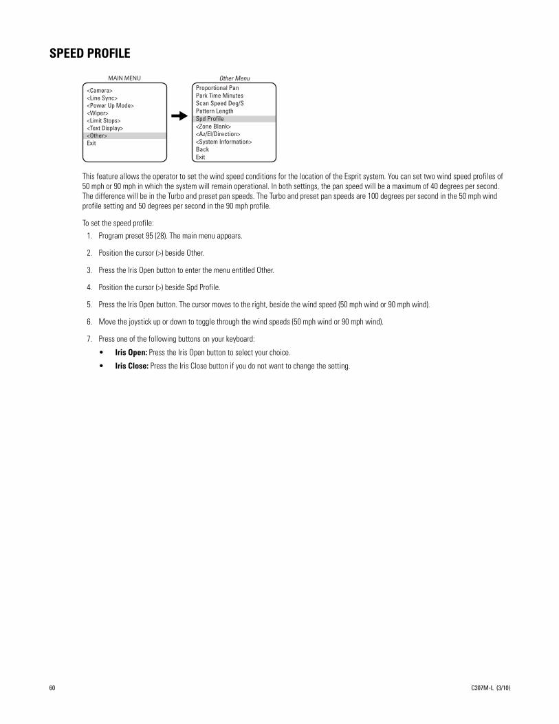
SPEED PROFILE
This feature allows the operator to set the wind speed conditions for the location of the Esprit system. You can set two wind speed profiles of 50 mph or 90 mph in which the system will remain operational. In both settings, the pan speed will be a maximum of 40 degrees per second. The difference will be in the Turbo and preset pan speeds. The Turbo and preset pan speeds are 100 degrees per second in the 50 mph wind profile setting and 50 degrees per second in the 90 mph profile.
To set the speed profile:
1. Program preset 95 (28). The main menu appears.
2. Position the cursor (>) beside Other.
3. Press the Iris Open button to enter the menu entitled Other.
4. Position the cursor (>) beside Spd Profile.
5. Press the Iris Open button. The cursor moves to the right, beside the wind speed (50 mph wind or 90 mph wind).
6. Move the joystick up or down to toggle through the wind speeds (50 mph wind or 90 mph wind).
7. Press one of the following buttons on your keyboard:
• Iris Open: Press the Iris Open button to select your choice.
• Iris Close: Press the Iris Close button if you do not want to change the setting.
Proportional Pan Park Time Minutes Scan Speed Deg/S Pattern Length Spd Profile<Zone Blank><Az/El/Direction><System Information>BackExit
Other MenuMAIN MENU
<Camera><Line Sync><Power Up Mode><Wiper><Limit Stops><Text Display><Other>Exit
60 C307M-L (3/10)

SURE FOCUS
When sure focus is enabled and all PTZ motions are stopped, the camera will attempt to find a fixed focus position and lock to an object in the scene. If a focus lock is acquired or a specific amount of time has expired with no focus lock, the focus position remains fixed until PTZ is resumed. Sure focus can be set to On or Off.
To change the sure focus setting:
1. On the main menu, move the joystick up or down to position the cursor (>) beside Camera.
2. Press the Iris Open button to enter the Camera menu.
3. Position the cursor (>) beside Next.
4. Press the Iris Open button to go to the Next menu.
5. Position the cursor (>) beside Sure Focus.
6. Press the Iris Open button. The cursor moves to the right, beside On or Off.
7. Move the joystick up or down to toggle between On and Off.
8. Press one of the following buttons on your keyboard:
• Iris Open: Press the Iris Open button to select your choice.
• Iris Close: Press the Iris Close button if you do not want to change the setting.
SYSTEM INFORMATION
The System Information menu displays the model number, software version, and other diagnostic information.
System settings cannot be changed using this menu; this information is for reference only.
To display the System Information menu:
1. Program preset 95 (28). The main menu appears.
2. Position the cursor (>) beside Other.
3. Press the Iris Open button to enter the Other menu.
4. Position the cursor (>) beside System Information.
5. Press the Iris Open button to enter the System Information menu.
Backlight CompZoom LimitReset CameraWDRField Alignment
<AGC/Auto Iris/ToL>NextBackExit
Camera MenuMAIN MENU
<Camera><Line Sync><Power Up Mode><Wiper><Limit Stops><Text Display><Other>Exit
LowLight LimitShutter SpeedAuto Focus ModeSure FocusLowLight Focus Img Stabilizer <IR Filt/Sharp/Wht Bal>NextBackExit
Next Menu
MAIN MENU
<Camera><Line Sync><Power Up Mode><Wiper><Limit Stops><Text Display><Other>Exit
C307M-L (3/10) 61

TEXT DISPLAY
NOTE: When displaying more than one type of text, be sure that each type of text is set to display on a different row. If more than one type of text is set to display on the same row, text overlap may occur.
EDITING THE TITLE TEXTTo edit the title text:
1. Program preset 95 (28). The main menu appears.
2. Position the cursor (>) beside Text Display.
3. Press the Iris Open button to enter the Text Display menu.
4. Position the cursor (>) beside Edit Title Text.
5. Press the Iris Open button. The cursor moves to the top of the screen.
6. Move the joystick left or right to position the cursor in the desired location.
7. Move the joystick up or down to scroll through uppercase and lowercase letters and numbers.
8. Press one of the following buttons on your keyboard:
• Iris Open: Press the Iris Open button to select your choice.
• Iris Close: Press the Iris Close button if you do not want to change the setting.
DISPLAYING TITLE TEXTTo activate or deactivate the title text:
1. Program preset 95 (28). The main menu appears.
2. Position the cursor (>) beside Text Display.
3. Press the Iris Open button to enter the Text Display menu.
4. Position the cursor (>) beside Disp Title Text.
5. Press the Iris Open button. The cursor moves to the right.
6. Move the joystick up or down to toggle between Off and On.
7. Press one of the following buttons on your keyboard:
• Iris Open: Press the Iris Open button to select your choice.
• Iris Close: Press the Iris Close button if you do not want to change the setting.
SETTING TITLE TEXT ROWThe title text row is the line on the screen on which the title text is displayed. The available settings for the Title Text Row are rows 1 through 12.
To change the settings for title text row:
1. Program preset 95 (28). The main menu appears.
2. Position the cursor (>) beside Text Display.
MAIN MENU
<Edit Title Text>Disp Title TextTitle Text RowZone Text RowPreset Text RowBackExit
Text Display Menu
<Camera><Line Sync><Power Up Mode>*<Wiper><Limit Stops><Text Display><Other>Exit
62 C307M-L (3/10)

3. Press the Iris Open button to enter the Text Display menu.
4. Position the cursor (>) beside Title Text Row.
5. Press the Iris Open button. The cursor moves to the right.
6. Move the joystick up or down to toggle between available rows.
7. Press one of the following buttons on your keyboard:
• Iris Open: Press the Iris Open button to select your choice.
• Iris Close: Press the Iris Close button if you do not want to change the setting.
SETTING ZONE TEXT ROWThe zone text row is the line on the screen on which the zone text is displayed. The available settings for the Zone Text Row are rows 1 through 12.
To change the settings for zone text row:
1. Program preset 95 (28). The main menu appears.
2. Position the cursor (>) beside Text Display.
3. Press the Iris Open button to enter the Text Display menu.
4. Position the cursor (>) beside Zone Text Row.
5. Press the Iris Open button. The cursor moves to the right.
6. Move the joystick up or down to toggle between available rows
7. Press one of the following buttons on your keyboard:
• Iris Open: Press the Iris Open button to select your choice.
• Iris Close: Press the Iris Close button if you do not want to change the setting.
SETTING PRESET TEXT ROWThe preset text row is the line on the screen on which the preset text is displayed. The available settings for the Preset Text Row are rows 1 through 12.
To change the settings for preset text row:
1. Program preset 95 (28). The main menu appears.
2. Position the cursor (>) beside Text Display.
3. Press the Iris Open button to enter the Text Display menu.
4. Position the cursor (>) beside Preset Text Row.
5. Press the Iris Open button. The cursor moves to the right.
6. Move the joystick up or down to toggle between available rows.
7. Press one of the following buttons on your keyboard:
• Iris Open: Press the Iris Open button to select your choice.
• Iris Close: Press the Iris Close button if you do not want to change the setting.
C307M-L (3/10) 63
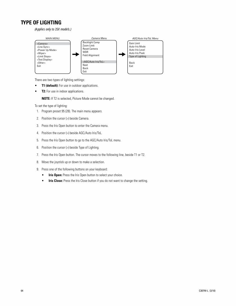
TYPE OF LIGHTING(Applies only to 35X models.)
There are two types of lighting settings:
• T1 (default): For use in outdoor applications.
• T2: For use in indoor applications.
NOTE: If T2 is selected, Picture Mode cannot be changed.
To set the type of lighting:
1. Program preset 95 (28). The main menu appears.
2. Position the cursor (>) beside Camera.
3. Press the Iris Open button to enter the Camera menu.
4. Position the cursor (>) beside AGC/Auto Iris/ToL.
5. Press the Iris Open button to go to the AGC/Auto Iris/ToL menu.
6. Position the cursor (>) beside Type of Lighting.
7. Press the Iris Open button. The cursor moves to the following line, beside T1 or T2.
8. Move the joystick up or down to make a selection.
9. Press one of the following buttons on your keyboard:
• Iris Open: Press the Iris Open button to select your choice.
• Iris Close: Press the Iris Close button if you do not want to change the setting.
Backlight CompZoom Limit
Reset CameraWDRField Alignment
<AGC/Auto Iris/ToL>NextBackExit
Camera Menu AGC/Auto Iris/ToL Menu
Gain LimitAuto-Iris ModeAuto-Iris LevelAuto-Iris PeakType of Lighting
BackExit
MAIN MENU
<Camera><Line Sync><Power Up Mode><Wiper><Limit Stops><Text Display><Other>Exit
64 C307M-L (3/10)
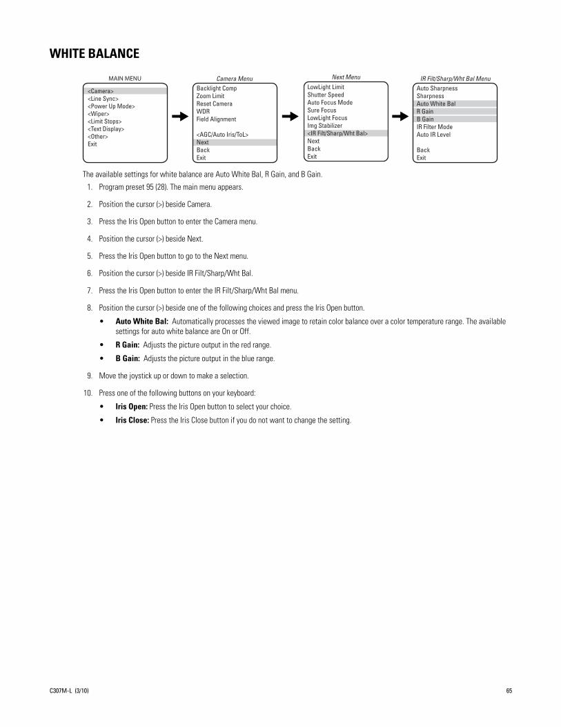
WHITE BALANCE
The available settings for white balance are Auto White Bal, R Gain, and B Gain.
1. Program preset 95 (28). The main menu appears.
2. Position the cursor (>) beside Camera.
3. Press the Iris Open button to enter the Camera menu.
4. Position the cursor (>) beside Next.
5. Press the Iris Open button to go to the Next menu.
6. Position the cursor (>) beside IR Filt/Sharp/Wht Bal.
7. Press the Iris Open button to enter the IR Filt/Sharp/Wht Bal menu.
8. Position the cursor (>) beside one of the following choices and press the Iris Open button.
• Auto White Bal: Automatically processes the viewed image to retain color balance over a color temperature range. The available settings for auto white balance are On or Off.
• R Gain: Adjusts the picture output in the red range.
• B Gain: Adjusts the picture output in the blue range.
9. Move the joystick up or down to make a selection.
10. Press one of the following buttons on your keyboard:
• Iris Open: Press the Iris Open button to select your choice.
• Iris Close: Press the Iris Close button if you do not want to change the setting.
Backlight CompZoom LimitReset CameraWDRField Alignment
<AGC/Auto Iris/ToL>NextBackExit
Camera MenuAuto SharpnessSharpnessAuto White BalR GainB GainIR Filter ModeAuto IR Level
BackExit
IR Filt/Sharp/Wht Bal MenuMAIN MENU
<Camera><Line Sync><Power Up Mode><Wiper><Limit Stops><Text Display><Other>Exit
LowLight LimitShutter SpeedAuto Focus ModeSure FocusLowLight FocusImg Stabilizer<IR Filt/Sharp/Wht Bal>NextBackExit
Next Menu
C307M-L (3/10) 65

WIDE DYNAMIC RANGE(Applies only to 24X and 35X models.)
Wide dynamic range (WDR) balances the brightest and darkest sections of a scene to produce a picture that is better balanced in lighting and provides more detail. WDR can be set to Off or On.
NOTE: When WDR is set to On, the iris will not close completely even in manual mode. Also, when WDR is set to On, backlight compensation is disabled.
To change the WDR:
1. On the main menu, move the joystick up or down to position the cursor (>) beside Camera.
2. Press the Iris Open button to enter the Camera menu.
3. Position the cursor (>) beside WDR.
4. Press the Iris Open button. The cursor moves to the right, beside On or Off.
5. Move the joystick up or down to toggle between On and Off.
6. Press one of the following buttons on your keyboard:
• Iris Open: Press the Iris Open button to select your choice.
• Iris Close: Press the Iris Close button if you do not want to change the setting.
Backlight CompZoom LimitReset CameraWDRField Alignment
<AGC/Auto Iris/ToL>NextBackExit
Camera MenuMAIN MENU
<Camera><Line Sync><Power Up Mode><Wiper><Limit Stops><Text Display><Other>Exit
66 C307M-L (3/10)

WIPER
The available settings for wiper mode are Wiper Mode, Wiper Dwell, and Wiper Time.
To change the wiper settings:
1. Program preset 95 (28). The main menu appears.
2. Position the cursor (>) beside Wiper.
3. Press the Iris Open button to enter the Wiper menu.
4. Move the joystick up or down to position the cursor next to one of the wiper settings.
5. Press the Iris Open button. The cursor moves to the right.
6. Move the joystick up or down to toggle through the choices.
• Momentary Mode: To operate the wiper one full cycle, press the AUX 1 button on your controller. Each press of the button operates the wiper one full cycle, even if the AUX 1 button is latching. If AUX 1 is latching, the first press will activate the wiper (open the latch). Pressing AUX 1 a second time closes the latch, but will not cycle the wiper. Press the AUX 1 key again to cycle the wiper.
• Continuous Mode: To operate the wiper press the AUX 1 button on your controller. The wiper will continue to operate until the AUX 1 button is pressed again or until the programmed cycle is completed.
NOTE: CM9740 and CM9760 matrix systems only: For the wiper to operate in continuous mode, the AUX 1 function in the camera file must be set to latching. If the AUX 1 camera file is not latching, the wiper will only operate in momentary mode, even if the Esprit wiper is programmed for continuous operation. Refer to the operation manual supplied with the CM9740 or CM9760 matrix system for instructions.
• Wiper Dwell: The time between wiper cycles. The dwell time can be programmed from 2 to 255 seconds.
• Wiper Time: The length of the wiper cycle. Wiper time can be programmed from 2 to 1,440 minutes (2 minutes to 24 hours).
7. Press one of the following buttons on your keyboard:
• Iris Open: Press the Iris Open button to select your choice.
• Iris Close: Press the Iris Close button if you do not want to change the setting.
Wiper Mode Wiper Dwell <s> Wiper Time <m>BackExit
Wiper MenuMAIN MENU
<Camera><Line Sync><Power Up Mode><Wiper><Limit Stops><Text Display><Other>Exit
C307M-L (3/10) 67

ZONESBasic rules for setting zones:
1. Refer to the documentation for your control system to program zones.
2. Establish zones using the controller, prior to programming ZONE BLANK with the Esprit on-screen menu.
3. To accurately set zone areas, zoom wide to the maximum field of view.
4. Set zones moving the joystick left to right. The left position is always the start position.
ZONE BLANK
The Esprit system features on-screen programmable zone blanking. This feature lets you define any zone as blanked for video (viewing/recording).
Zones can be programmed to overlap each other, although this is not recommended. If you program two zones to overlap, the title of the zone with the highest priority (zone 8 is the highest, zone 1 is the lowest) will be displayed on the monitor. This rule also applies to blanked zones that overlap. The blanking status of the zone with the highest priority will determine if the area is blanked or not. Example: Zone 1 is blanked but a portion of the zone overlaps zone 8 which is not blanked. The overlapped portion of zone 1 will be displayed on the monitor with the zone 8 label.
There are two video zone blank settings:
• On: Enables video blanking.
• Off: Disables video blanking.
To change the video blank zone setting:
1. Program preset 95 (28). The main menu appears.
2. Position the cursor (>) beside Other.
3. Press the Iris Open button to enter the Other menu.
4. Position the cursor (>) beside Zone Blank.
5. Press the Iris Open button to enter the Zone Blank menu.
6. Position the cursor (>) beside the number of the zone for which you want to set the blank option.
7. Press the Iris Open button. The cursor moves to the right, beside the word On or Off.
8. Move the joystick up or down to toggle between the words On and Off.
9. Press one of the following buttons on your keyboard:
• Iris Open: Press the Iris Open button to select your choice.
• Iris Close: Press the Iris Close button if you do not want to change the setting.
Proportional Pan Park Time Minutes Scan Speed Deg/S Pattern LengthSpd Profile <Zone Blank><Az/El/Direction><System Information>BackExit
Other MenuVideo Blanking Zones1 Off 2 Off3 Off 4 Off5 Off 6 Off7 Off 8 Off
BackExit
Zone Blank MenuMAIN MENU
<Camera><Line Sync><Power Up Mode><Wiper><Limit Stops><Text Display><Other>Exit
68 C307M-L (3/10)
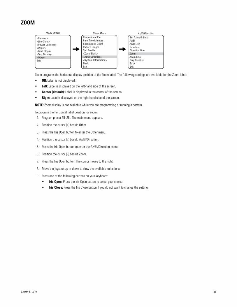
ZOOM
Zoom programs the horizontal display position of the Zoom label. The following settings are available for the Zoom label:
• Off: Label is not displayed.
• Left: Label is displayed on the left-hand side of the screen.
• Center (default): Label is displayed in the center of the screen.
• Right: Label is displayed on the right-hand side of the screen.
NOTE: Zoom display is not available while you are programming or running a pattern.
To program the horizontal label position for Zoom:
1. Program preset 95 (28). The main menu appears.
2. Position the cursor (>) beside Other.
3. Press the Iris Open button to enter the Other menu.
4. Position the cursor (>) beside Az/El/Direction.
5. Press the Iris Open button to enter the Az/El/Direction menu.
6. Position the cursor (>) beside Zoom.
7. Press the Iris Open button. The cursor moves to the right.
8. Move the joystick up or down to view the available selections.
9. Press one of the following buttons on your keyboard:
• Iris Open: Press the Iris Open button to select your choice.
• Iris Close: Press the Iris Close button if you do not want to change the setting.
Proportional Pan Park Time Minutes Scan Speed Deg/S Pattern Length Spd Profile<Zone Blank><Az/El/Direction><System Information>BackExit
Other MenuSet Azimuth ZeroAz/ElAz/El LineDirectionDirection LineZoomZoom LineDisp DurationBackExit
Az/El/DirectionMAIN MENU
<Camera><Line Sync><Power Up Mode><Wiper><Limit Stops><Text Display><Other>Exit
C307M-L (3/10) 69

ZOOM LIMIT
ES30C22/ES31C22 or ES30PC22/ES31PC22: 22X optical zoom and 12X digital zoom; can be set for 22X, 32X, 88X, 176X, 220X, or 264X
ES30CBW24/ES31CBW24 or EC30PCBW224/ES31PCBW24: 24X optical zoom and 12X digital zoom; can be set for 24X, 32X, 96X, 192X, 240X, or 288X
ES30CBW35/ES31CBW35 or ES30PCBW35/ES31PCBW35: 35X optical zoom and 12X digital zoom; can be set for 35X, 70X, 140X, 280X, 350X, or 420X
To change the zoom limit:
1. Program preset 95 (28). The main menu appears.
2. Position the cursor (>) beside Camera.
3. Press the Iris Open button to enter the Camera menu.
4. Position the cursor (>) beside Zoom Limit.
5. Press the Iris Open button. The cursor moves to the right, beside the current zoom limit.
6. Move the joystick up or down to choose the zoom limit.
7. Press one of the following buttons on your keyboard:
• Iris Open: Press the Iris Open button to select your choice.
• Iris Close: Press the Iris Close button if you do not want to change the setting.
Backlight CompZoom LimitReset CameraWDRField Alignment
<AGC/Auto Iris/ToL>NextBackExit
Camera MenuMAIN MENU
<Camera><Line Sync><Power Up Mode><Wiper><Limit Stops><Text Display><Other>Exit
70 C307M-L (3/10)

ZOOM LINE
Zoom Line controls the vertical display position of the Zoom label. The label may be displayed on lines 3 through 12. Line 3 is the third line from the top of the screen and line 12 is located at the bottom of the screen. Line 10 is the default setting.
NOTE: Zoom display is not available while you are programming or running a pattern.
To program the vertical label position for Zoom:
1. Program preset 95 (28). The main menu appears.
2. Position the cursor (>) beside Other.
3. Press the Iris Open button to enter the Other menu.
4. Position the cursor (>) beside Az/El/Direction.
5. Press the Iris Open button to enter the Az/El/Direction menu.
6. Position the cursor (>) beside Zoom Line.
7. Press the Iris Open button. The cursor moves to the right.
8. Move the joystick up or down to view the available selections.
9. Press one of the following buttons on your keyboard:
• Iris Open: Press the Iris Open button to select your choice.
• Iris Close: Press the Iris Close button if you do not want to change the setting.
Proportional Pan Park Time Minutes Scan Speed Deg/S Pattern Length Spd Profile<Zone Blank><Az/El/Direction><System Information>BackExit
Other MenuSet Azimuth ZeroAz/ElAz/El LineDirectionDirection LineZoomZoom LineDisp DurationBackExit
Az/El/DirectionMAIN MENU
<Camera><Line Sync><Power Up Mode><Wiper><Limit Stops><Text Display><Other>Exit
C307M-L (3/10) 71
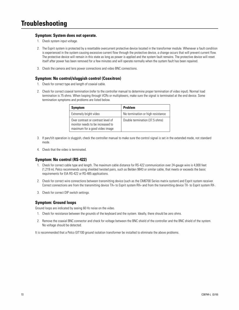
Troubleshooting
Symptom: System does not operate.1. Check system input voltage.
2. The Esprit system is protected by a resettable overcurrent protective device located in the transformer module. Whenever a fault condition is experienced in the system causing excessive current flow through the protective device, a change occurs that will prevent current flow. The protective device will remain in this state as long as power is applied and the system fault remains. The protective device will reset itself after power has been removed for a few minutes and will operate normally when the system fault has been repaired.
3. Check the camera and lens power connections and video BNC connections.
Symptom: No control/sluggish control (Coaxitron)1. Check for correct type and length of coaxial cable.
2. Check for correct coaxial termination (refer to the controller manual to determine proper termination of video input). Normal load termination is 75 ohms. When looping through VCRs or multiplexers, make sure the signal is terminated at the end device. Some termination symptoms and problems are listed below.
3. If pan/tilt operation is sluggish, check the controller manual to make sure the control signal is set in the extended mode, not standard mode.
4. Check that the video is terminated.
Symptom: No control (RS-422)1. Check for correct cable type and length. The maximum cable distance for RS-422 communication over 24-gauge wire is 4,000 feet
(1,219 m). Pelco recommends using shielded twisted pairs, such as Belden 9843 or similar cable, that meets or exceeds the basic requirements for EIA RS-422 or RS-485 applications.
2. Check for correct wire connections between transmitting device (such as the CM6700 Series matrix system) and Esprit system receiver. Correct connections are from the transmitting device TX+ to Esprit system RX+ and from the transmitting device TX- to Esprit system RX-.
3. Check for correct DIP switch settings.
Symptom: Ground loopsGround loops are indicated by seeing 60 Hz noise on the video.
1. Check for resistance between the grounds of the keyboard and the system. Ideally, there should be zero ohms.
2. Remove the coaxial BNC connector and check for voltage between the BNC shield of the controller and the BNC shield of the system. No voltage should be detected.
It is recommended that a Pelco GIT100 ground isolation transformer be installed to eliminate the above problems.
Symptom Problem
Extremely bright video No termination or high resistance
Over contrast or contrast level of monitor needs to be increased to maximum for a good video image
Double termination (37.5 ohms)
72 C307M-L (3/10)
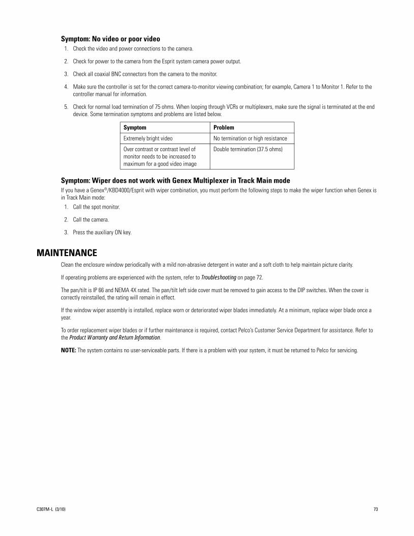
Symptom: No video or poor video1. Check the video and power connections to the camera.
2. Check for power to the camera from the Esprit system camera power output.
3. Check all coaxial BNC connectors from the camera to the monitor.
4. Make sure the controller is set for the correct camera-to-monitor viewing combination; for example, Camera 1 to Monitor 1. Refer to the controller manual for information.
5. Check for normal load termination of 75 ohms. When looping through VCRs or multiplexers, make sure the signal is terminated at the end device. Some termination symptoms and problems are listed below.
Symptom: Wiper does not work with Genex Multiplexer in Track Main modeIf you have a Genex®/KBD4000/Esprit with wiper combination, you must perform the following steps to make the wiper function when Genex is in Track Main mode:
1. Call the spot monitor.
2. Call the camera.
3. Press the auxiliary ON key.
MAINTENANCEClean the enclosure window periodically with a mild non-abrasive detergent in water and a soft cloth to help maintain picture clarity.
If operating problems are experienced with the system, refer to Troubleshooting on page 72.
The pan/tilt is IP 66 and NEMA 4X rated. The pan/tilt left side cover must be removed to gain access to the DIP switches. When the cover is correctly reinstalled, the rating will remain in effect.
If the window wiper assembly is installed, replace worn or deteriorated wiper blades immediately. At a minimum, replace wiper blade once a year.
To order replacement wiper blades or if further maintenance is required, contact Pelco’s Customer Service Department for assistance. Refer to the Product Warranty and Return Information.
NOTE: The system contains no user-serviceable parts. If there is a problem with your system, it must be returned to Pelco for servicing.
Symptom Problem
Extremely bright video No termination or high resistance
Over contrast or contrast level of monitor needs to be increased to maximum for a good video image
Double termination (37.5 ohms)
C307M-L (3/10) 73

AppendixNOTE: Esprit will sense and automatically select input from Coaxitron control signals in either the standard or extended mode. Therefore, the DIP switches settings have no effect on Coaxitron control signals.
*SW1-3 is not used; set it to the OFF position.
*SW1-4 is not used; set it to the OFF position.
Table A. Switch Settings for SW1
Baud RateSwitch Setting
SW1-1 SW1-2 SW1-3
2400 OFF OFF OFF*
4800 ON OFF OFF*
9600 OFF ON OFF*
2400 ON ON OFF*
Switch Setting
SW1-4 SW1-5 SW1-6 SW1-7 SW1-8
OFF* Note (1) Note (2) Note (3) Note (4)
NOTES:
(1) SW1-5 OFF For controllers that have more than 32 presets.ON For American Dynamics™ controllers (32 presets).
(2) SW1-6 OFF For all control systems except CM9502 with variable speed keyboards. For CM9502 with fixed speed keyboards, set switch
to OFF.ON For CM9502 with variable speed keyboards to get smoother joystick control.
(3) SW1-7 OFF RS-422 transmitter is not terminated.ON RS-422 transmitter is terminated.
(4) SW1-8 OFF 1.2 Vp-p video level.ON 1 Vp-p video level.
74 C307M-L (3/10)

NOTE: The Esprit will sense and automatically select input from Coaxitron control signals in either the standard or extended mode. Therefore, the DIP switches settings have no effect on Coaxitron control signals.
Table B. Switch Settings for SW2 (Pelco P-Type Control)
Table C. Switch Settings for SW2 (Pelco D-Type Control) (1 of 6)
ESPRITADDRESS
SWITCH SETTING
SW2-1 SW2-2 SW2-3 SW2-4 SW2-5 SW2-6 SW2-7 SW2-8
1 ON OFF OFF OFF OFF OFF OFF OFF
2 OFF ON OFF OFF OFF OFF OFF OFF
3 ON ON OFF OFF OFF OFF OFF OFF
4 OFF OFF ON OFF OFF OFF OFF OFF
5 ON OFF ON OFF OFF OFF OFF OFF
6 OFF ON ON OFF OFF OFF OFF OFF
7 ON ON ON OFF OFF OFF OFF OFF
8 OFF OFF OFF ON OFF OFF OFF OFF
9 ON OFF OFF ON OFF OFF OFF OFF
10 OFF ON OFF ON OFF OFF OFF OFF
11 ON ON OFF ON OFF OFF OFF OFF
12 OFF OFF ON ON OFF OFF OFF OFF
13 ON OFF ON ON OFF OFF OFF OFF
14 OFF ON ON ON OFF OFF OFF OFF
15 ON ON ON ON OFF OFF OFF OFF
16 OFF OFF OFF OFF ON OFF OFF OFF
17 ON OFF OFF OFF ON OFF OFF OFF
18 OFF ON OFF OFF ON OFF OFF OFF
19 ON ON OFF OFF ON OFF OFF OFF
20 OFF OFF ON OFF ON OFF OFF OFF
21 ON OFF ON OFF ON OFF OFF OFF
22 OFF ON ON OFF ON OFF OFF OFF
23 ON ON ON OFF ON OFF OFF OFF
24 OFF OFF OFF ON ON OFF OFF OFF
ESPRITADDRESS
SWITCH SETTING
SW2-1 SW2-2 SW2-3 SW2-4 SW2-5 SW2-6 SW2-7 SW2-8
1 OFF OFF OFF OFF OFF OFF OFF OFF
2 ON OFF OFF OFF OFF OFF OFF OFF
3 OFF ON OFF OFF OFF OFF OFF OFF
4 ON ON OFF OFF OFF OFF OFF OFF
5 OFF OFF ON OFF OFF OFF OFF OFF
6 ON OFF ON OFF OFF OFF OFF OFF
7 OFF ON ON OFF OFF OFF OFF OFF
8 ON ON ON OFF OFF OFF OFF OFF
9 OFF OFF OFF ON OFF OFF OFF OFF
10 ON OFF OFF ON OFF OFF OFF OFF
11 OFF ON OFF ON OFF OFF OFF OFF
12 ON ON OFF ON OFF OFF OFF OFF
13 OFF OFF ON ON OFF OFF OFF OFF
14 ON OFF ON ON OFF OFF OFF OFF
15 OFF ON ON ON OFF OFF OFF OFF
16 ON ON ON ON OFF OFF OFF OFF
ESPRITADDRESS
SWITCH SETTING
SW2-1 SW2-2 SW2-3 SW2-4 SW2-5 SW2-6 SW2-7 SW2-8
17 OFF OFF OFF OFF ON OFF OFF OFF
18 ON OFF OFF OFF ON OFF OFF OFF
19 OFF ON OFF OFF ON OFF OFF OFF
20 ON ON OFF OFF ON OFF OFF OFF
21 OFF OFF ON OFF ON OFF OFF OFF
22 ON OFF ON OFF ON OFF OFF OFF
23 OFF ON ON OFF ON OFF OFF OFF
24 ON ON ON OFF ON OFF OFF OFF
25 OFF OFF OFF ON ON OFF OFF OFF
26 ON OFF OFF ON ON OFF OFF OFF
27 OFF ON OFF ON ON OFF OFF OFF
28 ON ON OFF ON ON OFF OFF OFF
29 OFF OFF ON ON ON OFF OFF OFF
30 ON OFF ON ON ON OFF OFF OFF
31 OFF ON ON ON ON OFF OFF OFF
32 ON ON ON ON ON OFF OFF OFF
C307M-L (3/10) 75

25 ON OFF OFF ON ON OFF OFF OFF
26 OFF ON OFF ON ON OFF OFF OFF
27 ON ON OFF ON ON OFF OFF OFF
28 OFF OFF ON ON ON OFF OFF OFF
29 ON OFF ON ON ON OFF OFF OFF
30 OFF ON ON ON ON OFF OFF OFF
31 ON ON ON ON ON OFF OFF OFF
32 OFF OFF OFF OFF OFF ON OFF OFF
33 ON OFF OFF OFF OFF ON OFF OFF
34 OFF ON OFF OFF OFF ON OFF OFF
35 ON ON OFF OFF OFF ON OFF OFF
36 OFF OFF ON OFF OFF ON OFF OFF
37 ON OFF ON OFF OFF ON OFF OFF
38 OFF ON ON OFF OFF ON OFF OFF
39 ON ON ON OFF OFF ON OFF OFF
40 OFF OFF OFF ON OFF ON OFF OFF
41 ON OFF OFF ON OFF ON OFF OFF
42 OFF ON OFF ON OFF ON OFF OFF
43 ON ON OFF ON OFF ON OFF OFF
44 OFF OFF ON ON OFF ON OFF OFF
45 ON OFF ON ON OFF ON OFF OFF
46 OFF ON ON ON OFF ON OFF OFF
47 ON ON ON ON OFF ON OFF OFF
48 OFF OFF OFF OFF ON ON OFF OFF
49 ON OFF OFF OFF ON ON OFF OFF
50 OFF ON OFF OFF ON ON OFF OFF
51 ON ON OFF OFF ON ON OFF OFF
52 OFF OFF ON OFF ON ON OFF OFF
53 ON OFF ON OFF ON ON OFF OFF
54 OFF ON ON OFF ON ON OFF OFF
55 ON ON ON OFF ON ON OFF OFF
56 OFF OFF OFF ON ON ON OFF OFF
57 ON OFF OFF ON ON ON OFF OFF
58 OFF ON OFF ON ON ON OFF OFF
59 ON ON OFF ON ON ON OFF OFF
60 OFF OFF ON ON ON ON OFF OFF
61 ON OFF ON ON ON ON OFF OFF
62 OFF ON ON ON ON ON OFF OFF
63 ON ON ON ON ON ON OFF OFF
64 OFF OFF OFF OFF OFF OFF ON OFF
65 ON OFF OFF OFF OFF OFF ON OFF
66 OFF ON OFF OFF OFF OFF ON OFF
67 ON ON OFF OFF OFF OFF ON OFF
68 OFF OFF ON OFF OFF OFF ON OFF
69 ON OFF ON OFF OFF OFF ON OFF
70 OFF ON ON OFF OFF OFF ON OFF
71 ON ON ON OFF OFF OFF ON OFF
72 OFF OFF OFF ON OFF OFF ON OFF
73 ON OFF OFF ON OFF OFF ON OFF
Table C. Switch Settings for SW2 (Pelco D-Type Control) (2 of 6)
ESPRITADDRESS
SWITCH SETTING
SW2-1 SW2-2 SW2-3 SW2-4 SW2-5 SW2-6 SW2-7 SW2-8
76 C307M-L (3/10)

74 OFF ON OFF ON OFF OFF ON OFF
75 ON ON OFF ON OFF OFF ON OFF
76 OFF OFF ON ON OFF OFF ON OFF
77 ON OFF ON ON OFF OFF ON OFF
78 OFF ON ON ON OFF OFF ON OFF
79 ON ON ON ON OFF OFF ON OFF
80 OFF OFF OFF OFF ON OFF ON OFF
81 ON OFF OFF OFF ON OFF ON OFF
82 OFF ON OFF OFF ON OFF ON OFF
83 ON ON OFF OFF ON OFF ON OFF
84 OFF OFF ON OFF ON OFF ON OFF
85 ON OFF ON OFF ON OFF ON OFF
86 OFF ON ON OFF ON OFF ON OFF
87 ON ON ON OFF ON OFF ON OFF
88 OFF OFF OFF ON ON OFF ON OFF
89 ON OFF OFF ON ON OFF ON OFF
90 OFF ON OFF ON ON OFF ON OFF
91 ON ON OFF ON ON OFF ON OFF
92 OFF OFF ON ON ON OFF ON OFF
93 ON OFF ON ON ON OFF ON OFF
94 OFF ON ON ON ON OFF ON OFF
95 ON ON ON ON ON OFF ON OFF
96 OFF OFF OFF OFF OFF ON ON OFF
97 ON OFF OFF OFF OFF ON ON OFF
98 OFF ON OFF OFF OFF ON ON OFF
99 ON ON OFF OFF OFF ON ON OFF
100 OFF OFF ON OFF OFF ON ON OFF
101 ON OFF ON OFF OFF ON ON OFF
102 OFF ON ON OFF OFF ON ON OFF
103 ON ON ON OFF OFF ON ON OFF
104 OFF OFF OFF ON OFF ON ON OFF
105 ON OFF OFF ON OFF ON ON OFF
106 OFF ON OFF ON OFF ON ON OFF
107 ON ON OFF ON OFF ON ON OFF
108 OFF OFF ON ON OFF ON ON OFF
109 ON OFF ON ON OFF ON ON OFF
110 OFF ON ON ON OFF ON ON OFF
111 ON ON ON ON OFF ON ON OFF
112 OFF OFF OFF OFF ON ON ON OFF
113 ON OFF OFF OFF ON ON ON OFF
114 OFF ON OFF OFF ON ON ON OFF
115 ON ON OFF OFF ON ON ON OFF
116 OFF OFF ON OFF ON ON ON OFF
117 ON OFF ON OFF ON ON ON OFF
118 OFF ON ON OFF ON ON ON OFF
119 ON ON ON OFF ON ON ON OFF
120 OFF OFF OFF ON ON ON ON OFF
121 ON OFF OFF ON ON ON ON OFF
122 OFF ON OFF ON ON ON ON OFF
Table C. Switch Settings for SW2 (Pelco D-Type Control) (3 of 6)
ESPRITADDRESS
SWITCH SETTING
SW2-1 SW2-2 SW2-3 SW2-4 SW2-5 SW2-6 SW2-7 SW2-8
C307M-L (3/10) 77

123 ON ON OFF ON ON ON ON OFF
124 OFF OFF ON ON ON ON ON OFF
125 ON OFF ON ON ON ON ON OFF
126 OFF ON ON ON ON ON ON OFF
127 ON ON ON ON ON ON ON OFF
128 OFF OFF OFF OFF OFF OFF OFF ON
129 ON OFF OFF OFF OFF OFF OFF ON
130 OFF ON OFF OFF OFF OFF OFF ON
131 ON ON OFF OFF OFF OFF OFF ON
132 OFF OFF ON OFF OFF OFF OFF ON
133 ON OFF ON OFF OFF OFF OFF ON
134 OFF ON ON OFF OFF OFF OFF ON
135 ON ON ON OFF OFF OFF OFF ON
136 OFF OFF OFF ON OFF OFF OFF ON
137 ON OFF OFF ON OFF OFF OFF ON
138 OFF ON OFF ON OFF OFF OFF ON
139 ON ON OFF ON OFF OFF OFF ON
140 OFF OFF ON ON OFF OFF OFF ON
141 ON OFF ON ON OFF OFF OFF ON
142 OFF ON ON ON OFF OFF OFF ON
143 ON ON ON ON OFF OFF OFF ON
144 OFF OFF OFF OFF ON OFF OFF ON
145 ON OFF OFF OFF ON OFF OFF ON
146 OFF ON OFF OFF ON OFF OFF ON
147 ON ON OFF OFF ON OFF OFF ON
148 OFF OFF ON OFF ON OFF OFF ON
149 ON OFF ON OFF ON OFF OFF ON
150 OFF ON ON OFF ON OFF OFF ON
151 ON ON ON OFF ON OFF OFF ON
152 OFF OFF OFF ON ON OFF OFF ON
153 ON OFF OFF ON ON OFF OFF ON
154 OFF ON OFF ON ON OFF OFF ON
155 ON ON OFF ON ON OFF OFF ON
156 OFF OFF ON ON ON OFF OFF ON
157 ON OFF ON ON ON OFF OFF ON
158 OFF ON ON ON ON OFF OFF ON
159 ON ON ON ON ON OFF OFF ON
160 OFF OFF OFF OFF OFF ON OFF ON
161 ON OFF OFF OFF OFF ON OFF ON
162 OFF ON OFF OFF OFF ON OFF ON
163 ON ON OFF OFF OFF ON OFF ON
164 OFF OFF ON OFF OFF ON OFF ON
165 ON OFF ON OFF OFF ON OFF ON
166 OFF ON ON OFF OFF ON OFF ON
167 ON ON ON OFF OFF ON OFF ON
168 OFF OFF OFF ON OFF ON OFF ON
169 ON OFF OFF ON OFF ON OFF ON
170 OFF ON OFF ON OFF ON OFF ON
171 ON ON OFF ON OFF ON OFF ON
Table C. Switch Settings for SW2 (Pelco D-Type Control) (4 of 6)
ESPRITADDRESS
SWITCH SETTING
SW2-1 SW2-2 SW2-3 SW2-4 SW2-5 SW2-6 SW2-7 SW2-8
78 C307M-L (3/10)

172 OFF OFF ON ON OFF ON OFF ON
173 ON OFF ON ON OFF ON OFF ON
174 OFF ON ON ON OFF ON OFF ON
175 ON ON ON ON OFF ON OFF ON
176 OFF OFF OFF OFF ON ON OFF ON
177 ON OFF OFF OFF ON ON OFF ON
178 OFF ON OFF OFF ON ON OFF ON
179 ON ON OFF OFF ON ON OFF ON
180 OFF OFF ON OFF ON ON OFF ON
181 ON OFF ON OFF ON ON OFF ON
182 OFF ON ON OFF ON ON OFF ON
183 ON ON ON OFF ON ON OFF ON
184 OFF OFF OFF ON ON ON OFF ON
185 ON OFF OFF ON ON ON OFF ON
186 OFF ON OFF ON ON ON OFF ON
187 ON ON OFF ON ON ON OFF ON
188 OFF OFF ON ON ON ON OFF ON
189 ON OFF ON ON ON ON OFF ON
190 OFF ON ON ON ON ON OFF ON
191 ON ON ON ON ON ON OFF ON
192 OFF OFF OFF OFF OFF OFF ON ON
193 ON OFF OFF OFF OFF OFF ON ON
194 OFF ON OFF OFF OFF OFF ON ON
195 ON ON OFF OFF OFF OFF ON ON
196 OFF OFF ON OFF OFF OFF ON ON
197 ON OFF ON OFF OFF OFF ON ON
198 OFF ON ON OFF OFF OFF ON ON
199 ON ON ON OFF OFF OFF ON ON
200 OFF OFF OFF ON OFF OFF ON ON
201 ON OFF OFF ON OFF OFF ON ON
202 OFF ON OFF ON OFF OFF ON ON
203 ON ON OFF ON OFF OFF ON ON
204 OFF OFF ON ON OFF OFF ON ON
205 ON OFF ON ON OFF OFF ON ON
206 OFF ON ON ON OFF OFF ON ON
207 ON ON ON ON OFF OFF ON ON
208 OFF OFF OFF OFF ON OFF ON ON
209 ON OFF OFF OFF ON OFF ON ON
210 OFF ON OFF OFF ON OFF ON ON
211 ON ON OFF OFF ON OFF ON ON
212 OFF OFF ON OFF ON OFF ON ON
213 ON OFF ON OFF ON OFF ON ON
214 OFF ON ON OFF ON OFF ON ON
215 ON ON ON OFF ON OFF ON ON
216 OFF OFF OFF ON ON OFF ON ON
217 ON OFF OFF ON ON OFF ON ON
218 OFF ON OFF ON ON OFF ON ON
219 ON ON OFF ON ON OFF ON ON
220 OFF OFF ON ON ON OFF ON ON
Table C. Switch Settings for SW2 (Pelco D-Type Control) (5 of 6)
ESPRITADDRESS
SWITCH SETTING
SW2-1 SW2-2 SW2-3 SW2-4 SW2-5 SW2-6 SW2-7 SW2-8
C307M-L (3/10) 79

221 ON OFF ON ON ON OFF ON ON
222 OFF ON ON ON ON OFF ON ON
223 ON ON ON ON ON OFF ON ON
224 OFF OFF OFF OFF OFF ON ON ON
225 ON OFF OFF OFF OFF ON ON ON
226 OFF ON OFF OFF OFF ON ON ON
227 ON ON OFF OFF OFF ON ON ON
228 OFF OFF ON OFF OFF ON ON ON
229 ON OFF ON OFF OFF ON ON ON
230 OFF ON ON OFF OFF ON ON ON
231 ON ON ON OFF OFF ON ON ON
232 OFF OFF OFF ON OFF ON ON ON
233 ON OFF OFF ON OFF ON ON ON
234 OFF ON OFF ON OFF ON ON ON
235 ON ON OFF ON OFF ON ON ON
236 OFF OFF ON ON OFF ON ON ON
237 ON OFF ON ON OFF ON ON ON
238 OFF ON ON ON OFF ON ON ON
239 ON ON ON ON OFF ON ON ON
240 OFF OFF OFF OFF ON ON ON ON
241 ON OFF OFF OFF ON ON ON ON
242 OFF ON OFF OFF ON ON ON ON
243 ON ON OFF OFF ON ON ON ON
244 OFF OFF ON OFF ON ON ON ON
245 ON OFF ON OFF ON ON ON ON
246 OFF ON ON OFF ON ON ON ON
247 ON ON ON OFF ON ON ON ON
248 OFF OFF OFF ON ON ON ON ON
249 ON OFF OFF ON ON ON ON ON
250 OFF ON OFF ON ON ON ON ON
251 ON ON OFF ON ON ON ON ON
252 OFF OFF ON ON ON ON ON ON
253 ON OFF ON ON ON ON ON ON
254 OFF ON ON ON ON ON ON ON
Table C. Switch Settings for SW2 (Pelco D-Type Control) (6 of 6)
ESPRITADDRESS
SWITCH SETTING
SW2-1 SW2-2 SW2-3 SW2-4 SW2-5 SW2-6 SW2-7 SW2-8
80 C307M-L (3/10)

Specifications
ELECTRICALInput Voltage 24, 120, or 230 VAC, 50/60 Hz; switch selectable for 120/230 VAC inputs; reset feature enables when
power becomes unstable or interrupted
Power Requirements Maximum power consumption is 70 VA per system
Heater and Defroster Thermostatically controlled heater consumes 10 W; cycles on at 40°F (5°C) and off at 60°F (16°C)
Defogger The window defogger consumes 3 W; cycles on at 70°F (21°C) and off at 85°F (29°C)
Electrical Connections 2 power source connections made at mount location with wire splices and 1 ground wire splice; 1 BNC receptacle and 4 wire splices at mount location for RS-422 D and P protocols; 2 wire splices for open collector auxiliary output
Aux 2 Open collector output with 2-second activation; connected relay must require no more than 32 VDC and 40 mA to energize relay coil; wire length between Esprit and relay must be less than 100 ft (30 m)
MECHANICALPan Movement 360° continuous pan rotation
Vertical Tilt Unobstructed +33° to -83°
Variable Pan/Tilt SpeedPan 0.1° to 40°/sec variable-speed operation, 100°/sec TurboTilt 0.1° to 20°/sec variable-speed operation
Preset SpeedsPan 100°/secTilt 30°/sec
Camera Mounting Integrated camera sled assembly
Latches 1 link-lock, No. 3 stainless-steel latch; can be secured with padlock (not supplied)
CAMERASScanning System 2:1 interlace
Image Sensor 1/4-inch
Effective Pixels NTSC PALES30C22/ES31C22 768 (H) x 494 (V) 752 (H) x 582 (V)ES30CBW24/ES31CBW24 768 (H) x 494 (V) 752 (H) x 582 (V)ES30CBW35/ES31CBW35 768 (H) x 494 (V) 752 (H) x 582 (V)ES30PC22/ES31PC22 768 (H) x 494 (V) 752 (H) x 582 (V)ES30PCBW24/ES31PCBW24 768 (H) x 494 (V) 752 (H) x 582 (V)ES30PCBW35/ES31PCBW35 768 (H) x 494 (V) 752 (H) x 582 (V)
Horizontal Resolution NTSC PALES30C22/ES31C22 >470 TV lines >460 TV linesES30CBW24/ES31CBW24 >520 TV lines >520 TV linesES30CBW35/ES31CBW35 >540 TV lines >540 TV linesES30PC22/ES31PC22 >470 TV lines >460 TV linesES30PCBW24/ES31PCBW24 >520 TV lines >520 TV linesES30PCBW35/ES31PCBW35 >540 TV lines >540 TV lines
C307M-L (3/10) 81

Focal LengthES30C22/ES31C22 4 ~ 88 mm opticalES30CBW24/ES31CBW24 3.8 ~ 91.2 mm opticalES30CBW35/ES31CBW35 3.4 ~ 119 mm optical
ES30PC22/ES31PC22 4 ~ 88 mm opticalES30PCBW24/ES31PCBW24 3.8 ~ 91.2 mm opticalES30PCBW35/ES31PCBW35 3.4 ~ 119 mm optical
Zoom RatioES30C22/ES31C22 22X optical zoom, 10X digital zoomES30CBW24/ES31CBW24 24X optical zoom, 10X digital zoomES30CBW35/ES31CBW35 35X optical zoom, 12X digital zoom
ES30PC22/ES31PC22 22X optical zoom, 10X digital zoomES30PCBW24/ES31PCBW24 24X optical zoom, 10X digital zoomES30PCBW35/ES31PCBW35 35X optical zoom, 12X digital zoom
Digital Slow Shutter Auto/manual speed selection
Horizontal Angle of ViewES30C22/ES31C22 47° at 4 mm wide zoom; 2° at 88 mm telephoto zoomES30CBW24/ES31CBW24 50.7° at 3.8 mm wide zoom; 2.3° at 91.2 mm telephoto zoomES30CBW35/ES31CBW35 55.8° at 3.4 mm wide zoom; 1.7° at 119 mm telephoto zoom
ES30PC22/ES31PC22 47° at 4 mm wide zoom; 2° at 88 mm telephoto zoomES30PCBW24/ES31PCBW24 50.7° at 3.8 mm wide zoom; 2.3° at 91.2 mm telephoto zoomES30PCBW35/ES31PCBW35 55.8° at 3.4 mm wide zoom; 1.7° at 119 mm telephoto zoom
Focus Automatic and manual override
SensitivityES30C22/ES31C22 0.02 lux at 1/2-second shutter speed (NTSC)
0.02 lux at 1/1.5-second shutter speed (PAL)ES30CBW24/ES31CBW24 0.005 lux at 1/2-second shutter speed (color, NTSC/PAL)
0.015 lux at 1/60-second shutter speed (B-W, NTSC/PAL)0.0005 lux at 1/2-second shutter speed (B-W, NTSC/PAL)
ES30CBW35/ES31CBW35 0.55 lux at 1/60-second shutter speed (color, NTSC)0.063 lux at 1/4-second shutter speed (color, NTSC)0.00018 lux at 1/2-second shutter speed (B-W, NTSC)0.50 lux at 1/50-second shutter speed (color, PAL)0.062 lux at 1/3-second shutter speed (color, PAL)0.00014 lux at 1/1.5-second shutter speed (B-W, NTSC)
ES30PC22/ES31PC22 0.02 lux at 1/2-second shutter speed (NTSC)0.02 lux at 1/1.5-second shutter speed (PAL)
ES30PCBW24/ES31PCBW24 0.005 lux at 1/2-second shutter speed (color, NTSC/PAL)0.015 lux at 1/60-second shutter speed (B-W, NTSC/PAL)0.0005 lux at 1/2-second shutter speed (B-W, NTSC/PAL)
ES30PCBW35/ES31PCBW35 0.55 lux at 1/60-second shutter speed (color, NTSC)0.063 lux at 1/4-second shutter speed (color, NTSC)0.00018 lux at 1/2-second shutter speed (B-W, NTSC)0.50 lux at 1/50-second shutter speed (color, PAL)0.062 lux at 1/3-second shutter speed (color, PAL)0.00014 lux at 1/1.5-second shutter speed (B-W, NTSC)
Synchronization System AC line lock, phase adjustable through remote control*
White Balance Automatic with manual override*
Shutter Speed 1/2 to 1/30,000 (NTSC)1/1.5 to 1/30,000 (PAL)
Iris Control Automatic with manual override*
82 C307M-L (3/10)
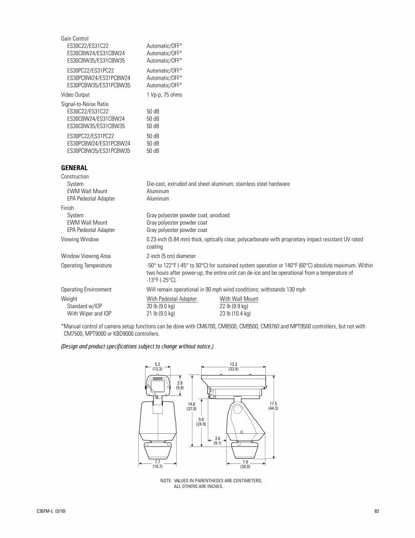
Gain ControlES30C22/ES31C22 Automatic/OFF*ES30CBW24/ES31CBW24 Automatic/OFF*ES30CBW35/ES31CBW35 Automatic/OFF*
ES30PC22/ES31PC22 Automatic/OFF*ES30PCBW24/ES31PCBW24 Automatic/OFF*ES30PCBW35/ES31PCBW35 Automatic/OFF*
Video Output 1 Vp-p, 75 ohms
Signal-to-Noise RatioES30C22/ES31C22 50 dBES30CBW24/ES31CBW24 50 dBES30CBW35/ES31CBW35 50 dB
ES30PC22/ES31PC22 50 dBES30PCBW24/ES31PCBW24 50 dBES30PCBW35/ES31PCBW35 50 dB
GENERALConstruction
System Die-cast, extruded and sheet aluminum; stainless steel hardwareEWM Wall Mount AluminumEPA Pedestal Adapter Aluminum
FinishSystem Gray polyester powder coat, anodizedEWM Wall Mount Gray polyester powder coatEPA Pedestal Adapter Gray polyester powder coat
Viewing Window 0.23-inch (5.84 mm) thick, optically clear, polycarbonate with proprietary impact resistant UV rated coating
Window Viewing Area 2-inch (5 cm) diameter
Operating Temperature -50° to 122°F (-45° to 50°C) for sustained system operation or 140°F (60°C) absolute maximum. Within two hours after power-up, the entire unit can de-ice and be operational from a temperature of -13°F (-25°C).
Operating Environment Will remain operational in 90 mph wind conditions; withstands 130 mph
Weight With Pedestal Adapter With Wall MountStandard w/IOP 20 lb (9.0 kg) 22 lb (9.9 kg)With Wiper and IOP 21 lb (9.5 kg) 23 lb (10.4 kg)
*Manual control of camera setup functions can be done with CM6700, CM8500, CM9500, CM9760 and MPT9500 controllers, but not with CM7500, MPT9000 or KBD9000 controllers.
(Design and product specifications subject to change without notice.)
NOTE: VALUES IN PARENTHESES ARE CENTIMETERS;ALL OTHERS ARE INCHES.
5.2(13.3)
13.3(33.9)
3.9(9.9)
14.6(37.0)
9.8(24.9)
3.6(9.1)
17.5(44.3)
7.9(20.0)
7.7(19.7)
C307M-L (3/10) 83

REVISION HISTORY
Manual # Date CommentsC307M 9/00 Original version.C307M-A 3/01 Added RS-422 and wiper functions material to the Troubleshooting section.C307M-B 8/02 Revised per ECO 02-8063.C307M-C 9/02 Revised model descriptions and specifications.C307M-D 11/02 Revised installation instructions for addition of alignment label.C307M-E 6/03 Added 24 VAC wire chart.C307M-F 8/03 Revised per ECO 03-9210 for new camera design.C307M-G 2/04 Referenced wire clamps per ECO 04-9710. Revised signal to noise ratio for the ES30C22/ES31C22.C307M-H 1/05 DIP switch SW1-8 functionality changed to video level per ECO 02-8186.C307M-I 11/05 Added operation and programming information. Added information on ES30CBW24/ES31CBW24. Updated layout. C307M-J 5/06 Removed information on ES30CBW18/ES31CBW18. Updated layout. C307M-K 11/07 Added information on ES30CBW35/ES31CBW35.C307M-L 3/10 Removed information on ES30CBW16/ES31CBW16. Added information on new settings including field alignment, low lux noise reduction, picture mode, sure focus,
system information, and wide dynamic range. Applied new template and merged C311M-O information with C307M-L.
Pelco, the Pelco logo, Camclosure, Coaxitron, Digital Sentry, Endura, Esprit, ExSite, Genex, Intelli-M, Legacy, and Spectra are registered trademarks of Pelco, Inc. © Copyright 2010, Pelco, Inc. All rights reserved.Spectra III and Sarix are trademarks of Pelco, Inc.DLP is a registered trademark of Texas Instruments Incorporated.All product names and services identified throughout this document are trademarks or registered trademarks of their respective companies. The absence of a trademark or registered trademark from this document does not constitute a waiver of intellectual property rights.
84 C307M-L (3/10)
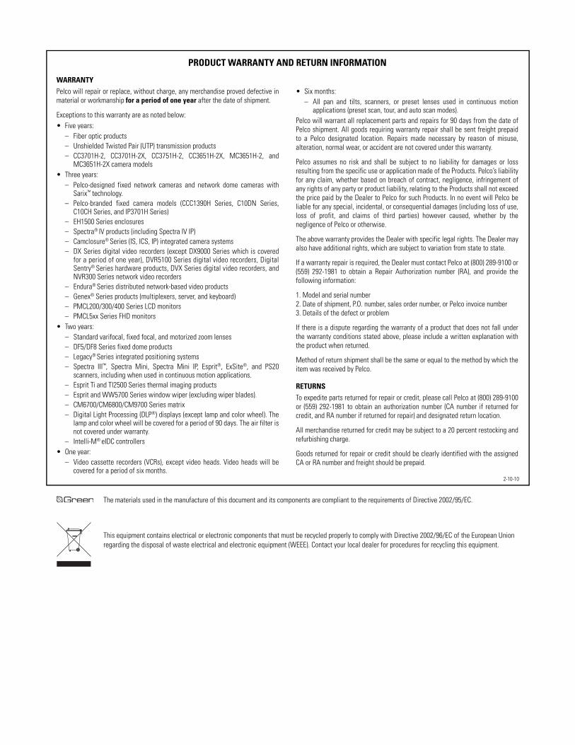
The materials used in the manufacture of this document and its components are compliant to the requirements of Directive 2002/95/EC.
This equipment contains electrical or electronic components that must be recycled properly to comply with Directive 2002/96/EC of the European Union regarding the disposal of waste electrical and electronic equipment (WEEE). Contact your local dealer for procedures for recycling this equipment.
PRODUCT WARRANTY AND RETURN INFORMATION
WARRANTYPelco will repair or replace, without charge, any merchandise proved defective inmaterial or workmanship for a period of one year after the date of shipment.
Exceptions to this warranty are as noted below:• Five years:
– Fiber optic products– Unshielded Twisted Pair (UTP) transmission products– CC3701H-2, CC3701H-2X, CC3751H-2, CC3651H-2X, MC3651H-2, and
MC3651H-2X camera models• Three years:
– Pelco-designed fixed network cameras and network dome cameras withSarix™ technology.
– Pelco-branded fixed camera models (CCC1390H Series, C10DN Series,C10CH Series, and IP3701H Series)
– EH1500 Series enclosures– Spectra® IV products (including Spectra IV IP)– Camclosure® Series (IS, ICS, IP) integrated camera systems– DX Series digital video recorders (except DX9000 Series which is covered
for a period of one year), DVR5100 Series digital video recorders, DigitalSentry® Series hardware products, DVX Series digital video recorders, andNVR300 Series network video recorders
– Endura® Series distributed network-based video products– Genex® Series products (multiplexers, server, and keyboard)– PMCL200/300/400 Series LCD monitors– PMCL5xx Series FHD monitors
• Two years:– Standard varifocal, fixed focal, and motorized zoom lenses– DF5/DF8 Series fixed dome products– Legacy® Series integrated positioning systems– Spectra III™, Spectra Mini, Spectra Mini IP, Esprit®, ExSite®, and PS20
scanners, including when used in continuous motion applications.– Esprit Ti and TI2500 Series thermal imaging products– Esprit and WW5700 Series window wiper (excluding wiper blades).– CM6700/CM6800/CM9700 Series matrix– Digital Light Processing (DLP®) displays (except lamp and color wheel). The
lamp and color wheel will be covered for a period of 90 days. The air filter isnot covered under warranty.
– Intelli-M® eIDC controllers• One year:
– Video cassette recorders (VCRs), except video heads. Video heads will becovered for a period of six months.
• Six months:– All pan and tilts, scanners, or preset lenses used in continuous motion
applications (preset scan, tour, and auto scan modes).Pelco will warrant all replacement parts and repairs for 90 days from the date ofPelco shipment. All goods requiring warranty repair shall be sent freight prepaidto a Pelco designated location. Repairs made necessary by reason of misuse,alteration, normal wear, or accident are not covered under this warranty.
Pelco assumes no risk and shall be subject to no liability for damages or lossresulting from the specific use or application made of the Products. Pelco’s liabilityfor any claim, whether based on breach of contract, negligence, infringement ofany rights of any party or product liability, relating to the Products shall not exceedthe price paid by the Dealer to Pelco for such Products. In no event will Pelco beliable for any special, incidental, or consequential damages (including loss of use,loss of profit, and claims of third parties) however caused, whether by thenegligence of Pelco or otherwise.
The above warranty provides the Dealer with specific legal rights. The Dealer mayalso have additional rights, which are subject to variation from state to state.
If a warranty repair is required, the Dealer must contact Pelco at (800) 289-9100 or(559) 292-1981 to obtain a Repair Authorization number (RA), and provide thefollowing information:
1. Model and serial number2. Date of shipment, P.O. number, sales order number, or Pelco invoice number3. Details of the defect or problem
If there is a dispute regarding the warranty of a product that does not fall underthe warranty conditions stated above, please include a written explanation withthe product when returned.
Method of return shipment shall be the same or equal to the method by which theitem was received by Pelco.
RETURNSTo expedite parts returned for repair or credit, please call Pelco at (800) 289-9100or (559) 292-1981 to obtain an authorization number (CA number if returned forcredit, and RA number if returned for repair) and designated return location.
All merchandise returned for credit may be subject to a 20 percent restocking andrefurbishing charge.
Goods returned for repair or credit should be clearly identified with the assignedCA or RA number and freight should be prepaid.
2-10-10

Pelco, Inc. Worldwide Headquarters 3500 Pelco Way Clovis, California 93612 USAUSA & Canada Tel (800) 289-9100 Fax (800) 289-9150
International Tel +1 (559) 292-1981 Fax +1 (559) 348-1120
www.pelco.com

PNEUMATIC MAST OPERATOR’S MANUAL
The Will-Burt Company 169 S. Main Street
Orrville, OH 44667 Ph.: 330-682-7015 Fax: 330-684-1190 www.willburt.com
ISO Registered Quality System Revision 13, October 2012

WARRANTY
The Manufacturer warrants its products to be free from defects in material and workmanship for a period of one year from the date of shipment from the factory. The Manufacturer shall not be re-sponsible for any damage resulting to or caused by its products by reason of improper installation, improper storage, unauthorized service, alteration of products, neglect or abuse, or use of the product in a manner inconsistent with its design, accident, acts of God, or failure to properly main-tain this product. This warranty does not extend to any component parts not manufactured by Manufacturer, however, Manufacturer's warranty herein shall not limit any warranties made by manufacturers of component parts which may extend to Buyer.
THE FOREGOING WARRANTY IS IN LIEU OF ALL OTHER WARRANTIES, AND NO REPRESENTATIONS, GUARANTEES OR WARRANTIES, EXPRESS OR IMPLIED, (IN-CLUDING, BUT NOT LIMITED, TO A WARRANTY OF MERCHANTABILITY OR FIT-NESS FOR A PARTICULAR PURPOSE) ARE MADE BY MANUFACTURER IN CONNEC-TION WITH THE MANUFACTURE OR SALE OF ITS PRODUCTS. NO EMPLOYEE, DISTRIBUTOR, OR REPRESENTATIVE IS AUTHORIZED TO CHANGE THIS WARRAN-TY IN ANY WAY OR GRANT ANY OTHER WARRANTY ON BEHALF OF MANUFAC-TURER.
Claims for defects in material and workmanship shall be made in writing to Manufacturer within thirty (30) days of the discovery of defect. Failure to provide notice as required hereby shall be conclusive evidence that the product was in conformity with the warranty, and the Manufacturer shall be released from any and all liability relating to the product. Manufacturer may either send a service representative or have the product returned to its factory at Buyer's expense for inspection. If judged by Manufacturer to be defective in material or workmanship, the product will be re-placed or repaired at the option of Manufacturer, free from all charges except authorized transpor-tation.
THE REMEDIES OF BUYER SET FORTH HEREIN ARE EXCLUSIVE AND ARE IN LIEU OF ALL OTHER REMEDIES. THE LIABILITY OF MANUFACTURER WHETHER IN CONTRACT, TORT, UNDER ANY WARRANTY, OR OTHERWISE, SHALL NOT EXTEND BEYOND ITS OBLIGATION TO REPAIR OR REPLACE, AT ITS OPTION, ANY PRODUCT OR PART FOUND BY MANUFACTURER TO BE DEFECTIVE IN MATERIAL OR WORK-MANSHIP. MANUFACTURER SHALL NOT BE LIABLE FOR COST OF INSTALLATION AND/OR REMOVAL, OR BE RESPONSIBLE FOR DIRECT, INDIRECT, SPECIAL OR CONSEQUENTIAL DAMAGES OF ANY NATURE.

iii
Document History
Manual Version Date Remarks Pneumatic Mast Op. Man. Rev. 13 October 2012 Revised Tables, Section 1.4

TABLE OF CONTENTS
1. INTRODUCTION 1-1
1.1 Safety Precautions ................................................................................................................................................. 1-1 1.2 Introduction ........................................................................................................................................................... 1-1 1.3 Description ............................................................................................................................................................ 1-1 1.4 Reference Data ...................................................................................................................................................... 1-4
2. INSTALLATION 2-1
2.1 Introduction ........................................................................................................................................................... 2-1 2.2 Tools and Materials required for Installation ........................................................................................................ 2-1 2.3 Unpacking ............................................................................................................................................................. 2-2 2.4 Installation ............................................................................................................................................................. 2-3
3. OPERATING INSTRUCTIONS 3-1
3.1 Introduction ........................................................................................................................................................... 3-2 3.2 Operation – Non-locking Masts ............................................................................................................................ 3-2 3.3 Operation – Locking Masts ................................................................................................................................... 3-3
4. MAINTENANCE AND SERVICE INSTRUCTIONS 4-1
4.1 Introduction ........................................................................................................................................................... 4-1 4.2 Tools & Materials Recommedned/Required ......................................................................................................... 4-1 4.3 Reference dimensional information ...................................................................................................................... 4-2 4.4 Scheduled Maintenance ........................................................................................................................................ 4-4 4.5 Corrective Maintenance ........................................................................................................................................ 4-5 4.6 Trouble Shooting................................................................................................................................................. 4-14
5. MAST DRAWING 5-1
5.1 Mast Drawing ........................................................................................................................................................ 5-1
6. REFERENCE DRAWINGS 6-1
6.1 Introduction ........................................................................................................................................................... 6-1 6.2 Reference Drawings .............................................................................................................................................. 6-1

v
LIST OF ILLUSTRATIONS Figure 2-1 Shipping Crate................................................................................................................................................. 2-2 Figure 2-2 Installation Dimensions – Mast ....................................................................................................................... 2-4 Figure 2-3 Non-Rotating Base Plate ................................................................................................................................. 2-5 Figure 2-4 Rotating Base Plate ......................................................................................................................................... 2-6 Figure 2-5 Turning Handle Assembly .............................................................................................................................. 2-7 Figure 2-6 Internal Mounting Kit Hardware ..................................................................................................................... 2-8 Figure 2-7 Support Bracket Assembly – Standard & Heavy Duty ................................................................................... 2-9 Figure 2-8 Support Bracket Assembly – Super Heavy Duty .......................................................................................... 2-10 Figure 2-9 External Shelf Bracket Assembly ................................................................................................................. 2-11 Figure 2-10 Mast Installation - Internal Mounting ......................................................................................................... 2-13 Figure 2-11 Mast Installation - External Mounting ........................................................................................................ 2-15 Figure 2-12 Weep Hole Drain Kit .................................................................................................................................. 2-16 Figure 2-13 Pneumatic System ....................................................................................................................................... 2-18 Figure 2-14 Magnetic Warning Kit ................................................................................................................................. 2-20 Figure 2-15 Switch & Relay Assembly .......................................................................................................................... 2-20 Figure 2-16 Magnetic Warning Kit ................................................................................................................................. 2-20 Figure 3-1 T-Handle & Trip Line Yoke Assemblies ........................................................................................................ 3-4 Figure 4-1 Tube Diameters ............................................................................................................................................... 4-2 Figure 4-2 Collar Information ........................................................................................................................................... 4-3 Figure 4-3 Seal Replacement - Standard Duty .................................................................................................................. 4-6 Figure 4-4 Seal Area - Heavy Duty & Super Heavy Duty ................................................................................................ 4-8 Figure 4-5 Locking Collar Assembly ............................................................................................................................... 4-8 Figure 4-6 Replacing Collar Bearing Strips ...................................................................................................................... 4-9 Figure 4-7 Replacing Wear Rings................................................................................................................................... 4-10 Figure 4-8 Replacing Collar Inserts ................................................................................................................................ 4-11 Figure 4-9 Replacing Internal Bumpers .......................................................................................................................... 4-12 Figure 4-10 Replacing External Bumpers ....................................................................................................................... 4-13 Figure 6-1 Identification Plates ......................................................................................................................................... 6-1 Figure 6-2 Hardware Bag Items ........................................................................................................................................ 6-2 Figure 6-3 Drain Kit Fittings ............................................................................................................................................ 6-3 Figure 6-4 Magnetic Warning Kit ..................................................................................................................................... 6-4 Figure 6-5 Magnetic Warning Kit ..................................................................................................................................... 6-5

LIST OF TABLES Table 1-1 Part & Model Numbers – Standard Duty Non-locking Mast ........................................................................... 1-4 Table 1-2 Reference Data – Standard Duty Non-locking Mast ........................................................................................ 1-4 Table 1-3 Part & Model Numbers – Heavy Duty Non-locking Mast ............................................................................... 1-5 Table 1-4 Reference Data – Heavy Duty Non-Locking Mast ........................................................................................... 1-5 Table 1-5 Part & Model Numbers – Heavy Duty Locking Mast ...................................................................................... 1-6 Table 1-6 Reference Data – Heavy Duty Locking Mast ................................................................................................... 1-6 Table 1-7 Part & Model Numbers – Super Heavy Duty Non-locking Mast ..................................................................... 1-7 Table 1-8 Reference Data – Super Heavy Duty Non-locking Mast .................................................................................. 1-7 Table 1-9 Part & Model Numbers – Super Heavy Duty Locking Mast ............................................................................ 1-8 Table 1-10 Reference Data – Super Heavy Duty Locking Mast ....................................................................................... 1-8 Table 2-1 Tools and Materials Required for Installation .................................................................................................. 2-1 Table 2-2 Installation Dimensions - Mast ......................................................................................................................... 2-3 Table 2-3 Non-Rotating Base Plate Dimensions .............................................................................................................. 2-5 Table 2-4 Rotating Base Plate Dimensions....................................................................................................................... 2-6 Table 2-5 Turning Handle Assembly ................................................................................................................................ 2-7 Table 2-6 Internal Mounting Kit Information ................................................................................................................... 2-8 Table 2-7 Support Bracket Assembly – Standard & Heavy Duty ..................................................................................... 2-9 Table 2-8 Support Bracket Assembly – Super Heavy Duty............................................................................................ 2-10 Table 2-9 External Shelf Bracket Assembly ................................................................................................................... 2-11 Table 4-1 Tube Diameters ................................................................................................................................................ 4-2 Table 4-2 Collar Information ............................................................................................................................................ 4-3 Table 6-1 Identification Plate Abbreviations .................................................................................................................... 6-1 Table 6-2 Hardware Bag Parts List ................................................................................................................................... 6-2 Table 6-3 Drain Kit ........................................................................................................................................................... 6-3 Table 6-4 Magnetic Warning Kit ...................................................................................................................................... 6-4 Table 6-5 Magnetic Warning Kit ...................................................................................................................................... 6-5

vii
SAFETY SUMMARY
SIGNAL WORD DEFINITION
Per the ANSI Z535.4 standard, the following signal words and definitions are used to indicate hazardous situations:
DANGER indicates an imminently hazardous situation that, if not avoided, will result in death or serious injury.
WARNING indicates a potentially hazardous situation that, if not avoided, could result in death or serious injury.
CAUTION indicates a potentially hazardous situation that, if not avoided, may result in minor or moderate injury. It is also used to alert against unsafe practices.
GENERAL SAFETY PRECAUTIONS
The following are general safety precautions that are not related to any specific procedures and therefore do not appear else-where in this publication. These are recommended precautions that personnel must understand and apply during many phases of operation and maintenance.
Electrocution Hazard! Contact with high voltage will result in death or serious injury. Observe general safety precautions for handling equipment using high voltage. Do not locate or operate mast near electrical lines, cables or other unwanted
sources of electricity. Do not operate mast in lightning. Be certain electrical cables are undamaged and properly terminated. Always disconnect power before performing service, repair or test operations.
Safety Instruction - Read Manual! Failure to follow operating instructions could result in death or serious injury. Read and understand the operator’s manual before using the mast.
Tip Over Hazard! Mast tip over could result in death or serious injury. Do not operate in high winds. Operate on level ground only. Stand clear of mast and mast payload during operation. Be certain mast is level and secure before and during
installation, operation and maintenance.
Safety Instruction - Trained Personnel Only! Death or serious injury could result if proper inspection, installation, opera-tion and maintenance procedures are not observed. Installation, operation and maintenance to be performed by trained and
authorized personnel only. Proper eye protection should be worn when servicing the mast.
Health and Safety Hazard! Solvent used to clean parts is potentially dangerous. Avoid inhalation of fumes and also pro-longed contact to skin.
Safety Instruction – Resuscitation Alert! Personnel working with or near high voltages should be familiar with modern methods of resuscitation. Such information may be obtained from the Bureau of Medicine and Surgery.

SPECIFIC SAFETY PRECAUTIONS
The following are safety precautions that are related to specific procedures and therefore appear elsewhere in this publication for emphasis. These are recommended precautions that personnel must understand and apply during specific phases of instal-lation, operation and maintenance.
Pinch Point Hazard! Moving parts can crush and cut resulting in death or serious injury. Keep clear of moving parts while operating mast.
Crush Hazard! Death or serious injury could result if mast fails suddenly. Do not stand directly beneath the mast or its payload. Be certain payload is properly installed and secured.
Burst Hazard! Over pressurizing mast will trip safety valve and could result in death or serious injury. Do not exceed max-imum operating pressure of 35 psi (241 kPa) for Heavy and Super Heavy Duty masts. Do not exceed maximum operating
pressure of 20 psi (138 kPa) for Standard Duty masts. Keep personnel clear of safety valve exhaust direction.
Fire Hazard! Cleaning solvent, used for maintenance, is flammable and can be explosive resulting in death or serious inju-ry. Do not smoke. Use cleaning solvent in a well-ventilated area. Keep cleaning solvent away from ignition sources. Al-
ways store cleaning solvent in the proper marked container.
Relocation Hazard! Relocating the mast during operation or after extension could result in death or serious injury. Do not relocate the mast during operation or while extended. This applies especially to masts mounted to vehicles. Operate the mast
only if the vehicle is stationary and the vehicle engine is off.
Lifting Hazard! The mast is intended to lift a specific payload for lighting, surveillance or communication use only. Any other use without written consent is prohibited and could cause death or serious injury. Do not use mast to lift personnel. Do
not exceed specified payload capacity.
Mast Extension Hazard! Extending mast into obstructions could result in death or serious injury and could render the mast inoperable and partially extended. Before applying power and operating the mast, be certain there is sufficient clearance above and to all sides of the expected location of the fully extended mast and payload. Keep all persons clear of mast and
mast extension. Do not lean directly over the mast.
Mounting Structure Hazard! Mounting mast into a structure unable to resist the forces generated from customer-specific loading scenario could result in death or serious injury and could damage the mast. Before operation, be certain mounting
structure is capable of resisting forces generated from all loading and environmental conditions, including, but not limited to, mast size and weight, payload size and weight, sail size, wind speed, guy line arrangement, support bracket or roof line loca-
tion and base plate assembly.

ix
Safety Instruction – Operation! At all times prior to mast operation, insure that:
1.) The mast area is free of personnel and mechanical obstruction; 2.) All electrical cables are undamaged and properly terminated; 3.) The operator must have full view of the mast during use; 4.) Any transit tie-downs on the payload have been removed; 5.) The vehicle is not moving; 6.) The area above the mast is free of mechanical obstructions.
Pressurized Device Hazard! Mast disassembly prior to depressurization may release pressurized air jet. Completely lower the mast, depressurize and shut down power before disassembly.
Safety Instruction – Roof Access! If mast will be mounted to a vehicle, user must provide safe means to access the roof of the vehicle during installation and maintenance.
Entanglement Hazard! Tangled cables can cause equipment damage. Ensure control cables are not tangled and are free to pay out as mast is extended.
Safety Instruction – Installation! At all times while using pipe and hose during installation, recognize that:
1.) Pipe and hose should be routed, mounted and restrained to protect from damage; 2.) Do not use second hand piping for installation; 3.) Do not bend air pipe and hose at a radius less than specified by the manufacturer; 4.) Pipes should be marked to avoid hazards from incorrect connection; 5.) The exhaust should be fitted with a silencer and be directed away from personnel; 6.) When routing piping, install in such a way as to minimize torsion on the joints; 7.) Mounting air pipe and hose shall be accomplished only by the use of tools to
prevent readily disconnecting air pipe and hose from mast.
Safety Instruction – Control Valve! Improper positioning and operation of Control Valve can result in moderate injury or equipment damage. Control valve must be mounted in a location such that the operator has full view of the mast, but does
not make contact with the mast during operation. Use only a Hold-To-Run type control valve.
Lifting Hazard! Manually lifting over 55 lb (25kg) is prohibited. In the UK, all lifting equipment must be thoroughly ex-amined annually by a competent person according to the Lifting Operations and Lift Equipment Regulations 1998. Equiva-
lent regulations exist in other EU states.
Safety Instruction – Follow Procedure! Failure to follow drain kit installation instructions could damage the mast and ren-der the mast inoperable. Read and understand the installation instructions before installing the drain kit.
Frozen Water Hazard! Water freezing inside mast or air fittings may render mast inoperable and cause major equipment damage. Open drain, when mast is not in operation, in temperatures near or below freezing.


Pneumatic Mast
1-1
CHAPTER 1 INTRODUCTION
1.1 SAFETY PRECAUTIONS
Refer to the Safety Summary for precautions to be observed while installing, operating or maintaining this equipment.
1.2 INTRODUCTION
This manual covers the installation, operation, and maintenance for The Will-Burt Co. pneumatic masts. Mast models covered include standard duty non-locking, heavy duty non-locking, heavy duty locking, super heavy duty non-locking and super heavy duty locking models. The pneumatic mast comprises a non-locking or locking telescoping mast, a hardware bag, a drain kit, a mast extension magnetic warning kit and mast lubricant. A non-rotating base plate, a rotat-ing hardware kit, a support bracket assembly, an internal mounting kit, an external shelf bracket assembly, a pneumatic system, a mast top cover or a guy line kit may also be included.
1.3 DESCRIPTION 1.3.1 TELESCOPING MAST The telescoping mast is the structure used to raise the payload to an operational level. It consists of several concentric, nesting mast sections, fabricated from aluminum tube, that extend and retract pneumatically. The telescoping mast can be non-locking or locking. The non-locking telescoping mast must remain pressurized to support the payload at an ex-tended height. The locking telescoping mast can be depressurized once the desired sections are raised and locked into position. The base mast section is constructed from the tube with the largest diameter and the top mast section is con-structed from the tube with the smallest diameter. The intermediate mast sections are any mast section in between the base and top mast sections. Aluminum collars are fitted to the top end of each mast section, except for the top mast sec-tion that is fitted with a top tube stop. When the telescoping mast is completely retracted, the collars nest on top of each other. The collars on a locking mast are fitted with a locking mechanism including a yoke assembly. There are two types of yoke assemblies, a T-handle and a trip line. Refer to Figure 3-1 for illustrations of the two yoke assembly types. Where guying is required, lugs or holes used to attach the guy lines are integral to the locking mast’s fabricated collar. Each mast section, except the base mast section, has two rectangular keys along the length of the tube. The keys match with keyways on the larger, adjacent mast section’s collar. The keys and keyways are used to establish azimuth (rota-tional) integrity between the sections. Identification plates are secured to the collar on the base mast section. Standard duty masts use both the 902852 and 914098 identification plates. Heavy and super heavy duty masts use the 902851 identification plate. The plates are engraved with information pertaining to the mast. Refer to Table 6-1 and Figure 6-1 for identification plate abbreviation explanation and illustration. Refer to CHAPTER 5 for a mast drawing and bill of materials. 1.3.2 HARDWARE BAG The hardware bag is a 4 x 6” plain cloth bag that includes screws for fastening a non-rotating base plate to the base mast section, and bolts, washers and nuts that may be used for securing the mast to a mounting structure. The hardware bag also contains a safety valve, for protection from over pressurization, and brass fittings for water drainage and connecting the mast to the air supply line. Do not operate the mast until the safety valve has been properly installed. Refer to Table 6-2 for a hardware bag parts list and to Figure 6-2 for an illustration of the hardware bag contents and installation sche-matic.

Pneumatic Mast
1-2
1.3.3 WEEP HOLE DRAIN KIT The drain kit, sealed in a clear plastic bag, includes installation instructions, a length of clear plastic tube and fittings to outfit the telescoping mast with a means to drain water that has entered the top and intermediate mast sections and may cause damage. Use the drain cock from the hardware bag to drain water from the base mast section. The fittings are used to attach one end of the plastic tube to the weep hole in the base mast section and to route the other end of the tube outside the mounting structure or vehicle to drain water. Refer to 2.4.2.1 for installation instructions and Figure 6-3 for an illustration of the fittings. 1.3.4 MAST EXTENSION MAGNETIC WARNING KIT The warning kit, packaged in a brown cardboard box, includes items to install a system for warning against moving a vehicle while the telescoping mast is partially or completely extended. The clamp is a thin strip of coiled metal used to brace the switch assembly against the mast base tube. The magnet is cylindrical and covered with a wax-like coating. The switch assembly is attached to a small, rectangular aluminum casing. The labels are gray. The flasher has a cylin-drical metal casing and is packaged in a rectangular box. The (2) plastic lights are red. The relay (not included or neces-sary in kits for the 6-25 or 7-30 models) has a transparent, rectangular casing. Refer to 2.4.2.3 for installation instruc-tions. Refer to Table 6-4 and Figure 6-4 for a mast extension magnetic warning kit parts list and illustration for the 5-20, 6-27, 7-34, 8-30, 6-25, & 7-30 models. Refer to Table 6-5 and Figure 6-5 for a mast extension magnetic warning kit parts list for the 7-42, 8.5-48, 8.5-52, 9.5-56, 9-58, 10-60, 9-50, 10.3-60, & 10.8-76 models. 1.3.5 MAST LUBRICANT The mast lubricant is a blue-colored mineral oil specifically designed for telescoping masts and their operating environ-ment that is contained in a 16 oz capped plastic bottle. The mast lubricant is to be used on regular basis to insure smooth operation and prolong useful life of the mast. Refer to 4.3.1 Mast Cleaning and Lubrication for recommended use. 1.3.6 NON-ROTATING BASE PLATE The non-rotating (NR) base plate is a square aluminum plate used to stabilize the mast and to provide a means of secur-ing the mast to a mounting structure. Countersunk holes in the NR base plate match threaded holes on the base mast section. Screws included in the hardware bag can be used to attach the NR base plate to the base mast section. Bolts, nuts and washers included in the hardware bag are sized for the through-holes in the corners of the NR base plate so the mast can be secured to a mounting structure. A larger in the center of the plate allows the option of routing air to the bottom of the base mast section. Refer to and Figure 2-3 for dimensions and illustration. 1.3.7 ROTATING HARDWARE KIT The rotating hardware kit is used to stabilize the mast and to provide a means of, not only securing the mast to a mount-ing structure, but also enabling the mast to be rotated. The kit includes a rotating base plate assembly, a turning handle assembly, bolts, nuts and an instruction sheet. The rotating (R) base plate assembly consists of a painted weldment, a bearing, bolts and nuts. The weldment, typically painted white, is made of a steel ring welded to a square steel plate with (4) thru holes in the corners of the plate. Bolts, nuts and washers included in the hardware bag are sized for the thru holes in the corners of the weldment plate so the base plate assembly can be secured to a mounting structure. The mast is to be positioned inside the ring on the weldment. Bolts (2), threaded into the weldment ring, can be tightened once the mast is in place to restrict mast rotational movement. A hole in the center of the plate allows the option of routing air to the bottom of the base mast section. Refer to Table 2-4 and Figure 2-4 for dimensions and illustration. The turning han-dle assembly wraps around, and is secured to, the base mast section with the bolts and nuts included in the kit. Once the turning handle assembly is fitted to the base section, the operator can grip the handles and rotate the mast into position. Refer to point 9 in 2.4.1.1, Table 2-5 and Figure 2-5 for installation instructions and illustration.

Pneumatic Mast
1-3
1.3.8 SUPPORT BRACKET ASSEMBLY The support bracket assembly, used to brace standard and heavy duty masts against a mounting structure, is constructed from a steel stand-off, (2) aluminum support brackets, a plastic bearing and fasteners to secure the assembly together. The stand-off is a formed sheet metal piece that positions the support brackets away from the mounting structure. The C-shaped support brackets close around the base mast section and are bolted together to hold the mast against the mount-ing structure. The plastic bearing, attached to the inside of the support brackets, protects the base mast section from be-ing scraped by the support brackets and allows the mast to be rotated. A similar assembly is used to brace super heavy duty masts. Refer to Table 2-7, Table 2-8, Figure 2-7 and Figure 2-8 for dimensions and illustration. 1.3.9 INTERNAL MOUNTING KIT The internal mounting kit contains the hardware used to position and support an internally mounted mast. Kits for standard and heavy duty masts include a weather bonnet, (2) gaskets, a ceiling plate, a roof flange and an o-ring. Kits for super heavy duty masts include a roof ring, (2) gaskets, a ceiling plate, a retaining ring and an o-ring. Bolts, lock wash-ers and hex nuts, ¼” or M6, not provided, can be used as fasteners. Bolt length will depend on the specific application and is to be determined by the installer. Refer to 2.4.1.1 for installation instructions and Figure 2-10 for illustration. See Table 2-6 and Figure 2-6 for roof flange, roof ring and stack-up dimensions. 1.3.10 EXTERNAL SHELF BRACKET ASSEMBLY The external shelf bracket assembly is a painted, steel weldment that can be bolted into a mounting structure and used to position and support an externally mounted mast. Refer to Table 2-9 and Figure 2-9 for dimensions and illustration. See 2.4.1.2 for installation instructions. 1.3.11 MAST TOP COVER The mast top cover is a large canvas bag with drawstrings. The mast top cover is drawn over the collars of a fully re-tracted locking mast to protect the locking mechanism from dust, debris and other foreign material when the mast is not being operated. It may be used on a non-locking mast. 1.3.12 PNEUMATIC SYSTEM The pneumatic system refers to a means of safely controlling the pressurization and depressurization of the telescoping mast. Components in the hardware bag and a port near the bottom of the base mast section are provided to connect an air supply to the telescoping mast. See 2.4.2.2 for additional information on a pneumatic system. 1.3.13 GUY LINE KIT The guy line kit includes guy lines, guy stakes or anchors and a ground anchor location drawing. The kit components are used to further stabilize the telescoping mast by resisting environmental conditions that may cause tip over and horizon-tal payload movement. Specific installation instructions will be provided with any guyed mast.
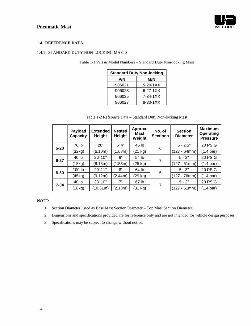
Pneumatic Mast
1-4
1.4 REFERENCE DATA
1.4.1 STANDARD DUTY NON-LOCKING MASTS
Table 1-1 Part & Model Numbers – Standard Duty Non-locking Mast
Standard Duty Non-locking P/N M/N
906021 5-20-1XX 906023 6-27-1XX 906025 7-34-1XX 906027 8-30-1XX
Table 1-2 Reference Data – Standard Duty Non-locking Mast
Payload Capacity
Extended Height
Nested Height
Approx. Mast
Weight
No. of Sections
Section Diameter
Maximum Operating Pressure
5-20 70 lb 20' 5' 4" 45 lb
6 5 - 2.5" 20 PSIG
(32kg) (6.10m) (1.63m) (21 kg) (127 - 64mm) (1.4 bar)
6-27 40 lb 26' 10" 6' 54 lb
7 5 - 2" 20 PSIG
(18kg) (8.18m) (1.83m) (25 kg) (127 - 51mm) (1.4 bar)
8-30 100 lb 29' 11" 8' 64 lb
5 5 - 3" 20 PSIG
(45kg) (9.12m) (2.44m) (29 kg) (127 - 76mm) (1.4 bar)
7-34 40 lb 33' 10" 7' 67 lb
7 5 - 2" 20 PSIG
(18kg) (10.31m) (2.13m) (31 kg) (127 - 51mm) (1.4 bar)
NOTE:
1. Section Diameter listed as Base Mast Section Diameter – Top Mast Section Diameter.
2. Dimensions and specifications provided are for reference only and are not intended for vehicle design purposes.
3. Specifications may be subject to change without notice.
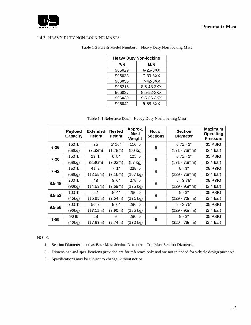
Pneumatic Mast
1-5
1.4.2 HEAVY DUTY NON-LOCKING MASTS
Table 1-3 Part & Model Numbers – Heavy Duty Non-locking Mast
Heavy Duty Non-locking P/N M/N
906029 6-25-3XX 906033 7-30-3XX 906035 7-42-3XX 906215 8.5-48-3XX 906037 8.5-52-3XX 906039 9.5-56-3XX 906041 9-58-3XX
Table 1-4 Reference Data – Heavy Duty Non-Locking Mast
Payload Capacity
Extended Height
Nested Height
Approx. Mast
Weight
No. of Sections
Section Diameter
Maximum Operating Pressure
6-25 150 lb 25' 5' 10" 110 lb
6 6.75 - 3" 35 PSIG
(68kg) (7.62m) (1.78m) (50 kg) (171 - 76mm) (2.4 bar)
7-30 150 lb 29' 1" 6' 8" 125 lb
6 6.75 - 3" 35 PSIG
(68kg) (8.86m) (2.03m) (57 kg) (171 - 76mm) (2.4 bar)
7-42 150 lb 41' 2" 7' 1" 235 lb
9 9 - 3" 35 PSIG
(68kg) (12.55m) (2.16m) (107 kg) (229 - 76mm) (2.4 bar)
8.5-48 200 lb 48' 8' 6" 275 lb
8 9 - 3.75" 35 PSIG
(90kg) (14.63m) (2.59m) (125 kg) (229 - 95mm) (2.4 bar)
8.5-52 100 lb 52' 8' 4" 266 lb
9 9 - 3" 35 PSIG
(45kg) (15.85m) (2.54m) (121 kg) (229 - 76mm) (2.4 bar)
9.5-56 200 lb 56' 2" 9' 6" 296 lb
8 9 - 3.75" 35 PSIG
(90kg) (17.12m) (2.90m) (135 kg) (229 - 95mm) (2.4 bar)
9-58 90 lb 58' 9' 290 lb
9 9 - 3" 35 PSIG
(40kg) (17.68m) (2.74m) (132 kg) (229 - 76mm) (2.4 bar)
NOTE:
1. Section Diameter listed as Base Mast Section Diameter – Top Mast Section Diameter.
2. Dimensions and specifications provided are for reference only and are not intended for vehicle design purposes.
3. Specifications may be subject to change without notice.

Pneumatic Mast
1-6
1.4.3 HEAVY DUTY LOCKING MASTS
Table 1-5 Part & Model Numbers – Heavy Duty Locking Mast
Heavy Duty Locking P/N M/N
906043 7-30-4XX 906045 7-42-4XX 906051 10-60-4XX 906053 14.5-80-4XX 906055 17-100-4XX 906057 20-134-4XX
Table 1-6 Reference Data – Heavy Duty Locking Mast
Payload Capacity
Extended Height
Nested Height
Approx. Mast
Weight
No. of Sections
Section Diameter
Maximum Operating Pressure
Collar Type
Guying Required
7-30 150 lb 29' 1" 7' 125 lb
6 6.75 - 3" 35 PSIG Locking T
Handles Not Req. (68kg) (8.86m) (2.13m) (57 kg) (171 - 76mm) (2.4 bar)
7-42 150 lb 41' 3" 7' 9" 235 lb
9 9 - 3" 35 PSIG Locking T
Handles Not Req. (68kg) (12.57m) (2.36m) (107 kg) (229 - 76mm) (2.4 bar)
10-60 200 lb 59' 9" 10' 1" 330 lb
8 9 - 3.75" 35 PSIG Locking T
Handles Not Req. (91kg) (18.21m) (3.07m) (150 kg) (229 - 95mm) (2.4 bar)
14.5-80 225 lb 79' 9" 14' 3" 416 lb
7 9 - 4.5" 35 PSIG Locking
Triplines 4 Way
(102kg) (24.31m) (4.34m) (189 kg) (229 - 114mm) (2.4 bar) 4 Level
17-100 200 lb 99' 9" 17' 2" 480 lb
7 9 - 4.5" 35 PSIG Locking
Triplines 4 Way
(90kg) (30.40m) (5.23m) (218 kg) (229 - 114mm) (2.4 bar) 4 Level
20-134 150 lb 133' 9" 20' 2" 600 lb
8 9 - 3.75" 35 PSIG Locking
Triplines 4 Way
(68kg) (40.77m) (6.15m) (273 kg) (229 - 95mm) (2.4 bar) 5 Level
NOTE:
1. Section Diameter listed as Base Mast Section Diameter – Top Mast Section Diameter.
2. Dimensions and specifications provided are for reference only and are not intended for vehicle design purposes.
3. Specifications may be subject to change without notice.

Pneumatic Mast
1-7
1.4.4 SUPER HEAVY DUTY NON-LOCKING MASTS
Table 1-7 Part & Model Numbers – Super Heavy Duty Non-locking Mast
Super Heavy Duty Non-locking P/N M/N
915507 10-38-5XX 710904800 12-48-5XX
TBD 13.6-45-5XX TBD 14-67-5XX
Table 1-8 Reference Data – Super Heavy Duty Non-locking Mast
Payload Capacity
Extended Height
Nested Height
Approx. Mast
Weight No. of
Sections Section
Diameter Maximum Operating Pressure
10-38 1000 lb 38' 10' 400 lb
5 11.25 - 7.5" 35 PSIG
(453kg) (11.58m) (3.05m) (181 kg) (285 - 192mm) (2.4 bar)
12-48 1000 lb 47' 11” 12' 475 lb
5 11.25 - 7.5" 35 PSIG
(453kg) (14.61m) (3.66m) (215 kg) (285 - 192mm) (2.4 bar)
13.6-45 1200 lb 44' 10" 13' 8" 475 lb
4 11.25 - 8.25" 35 PSIG
(545kg) (13.67m) (4.1m) (215 kg) (285 - 211mm) (2.4 bar)
14-67 800 lb 67' 13' 11" 575 lb
6 11.25 - 6.75" 35 PSIG
(363kg) (20.42m) (4.17m) (261 kg) (285 - 173mm) (2.4 bar)
NOTE:
1. Section Diameter listed as Base Mast Section Diameter – Top Mast Section Diameter.
2. Dimensions and specifications provided are for reference only and are not intended for vehicle design purposes.
3. Specifications may be subject to change without notice.

Pneumatic Mast
1-8
1.4.5 SUPER HEAVY DUTY LOCKING MASTS
Table 1-9 Part & Model Numbers – Super Heavy Duty Locking Mast
Super Heavy Duty Locking P/N M/N
909959 9-50-6XX 909426 10.3-60-6XX 910916 10.8-76-6XX 912970 15.7-100-6XX
Table 1-10 Reference Data – Super Heavy Duty Locking Mast
Payload Capacity
Extended Height
Nested Height
Approx. Mast
Weight No. of
Sections Section
Diameter Maximum Operating Pressure
Collar Type
Guying Required
9-50 450 lb 50' 5" 9' 2" 500 lb
8 11.25 - 5.25" 35 PSIG Locking T
Handles Not Req. (205kg) (15.37m) (2.79m) (227 kg) (286 - 134mm) (2.4 bar)
10.3-60 450 lb 60' 6" 10' 5" 500 lb
8 11.25 - 5.25" 35 PSIG Locking T
Handles Not Req. (205kg) (18.44m) (3.18m) (227 kg) (286 - 134mm) (2.4 bar)
10.8-76 200 lb 76' 2" 10' 9" 536 lb
10 11.25 - 3.75" 35 PSIG Locking T
Handles 4 Way
(91kg) (23.22m) (3.28m) (245 kg) (286 - 96mm) (2.4 bar) 1 Level
15.7-100 450 lb 100' 15' 8" 790 lb
8 11.25 - 5.25" 35 PSIG Locking T
Handles Trip Lines
4 Way
(205kg) (30.48m) (4.78m) (361 kg) (286 - 134mm) (2.4 bar) 4 Level
NOTE:
1. Section Diameter listed as Base Mast Section Diameter – Top Mast Section Diameter.
2. Dimensions and specifications provided are for reference only and are not intended for vehicle design purposes.
3. Specifications may be subject to change without notice.

Pneumatic Mast
2-1
CHAPTER 2 INSTALLATION
2.1 INTRODUCTION
The chapter provides instructions for installing a Pneumatic Mast.
2.2 TOOLS AND MATERIALS REQUIRED FOR INSTALLATION
Table 2-1 Tools and Materials Required for Installation
Wrenches Hoist
Screwdrivers Torque Wrench
Thread Tape Safety Glasses
Safety Gloves Hammer
Sling / Strap Level
Measuring Tape Saw
Silicone Sealant Drill
String or Thin Wire Air Supply
Plumb-bob Sockets
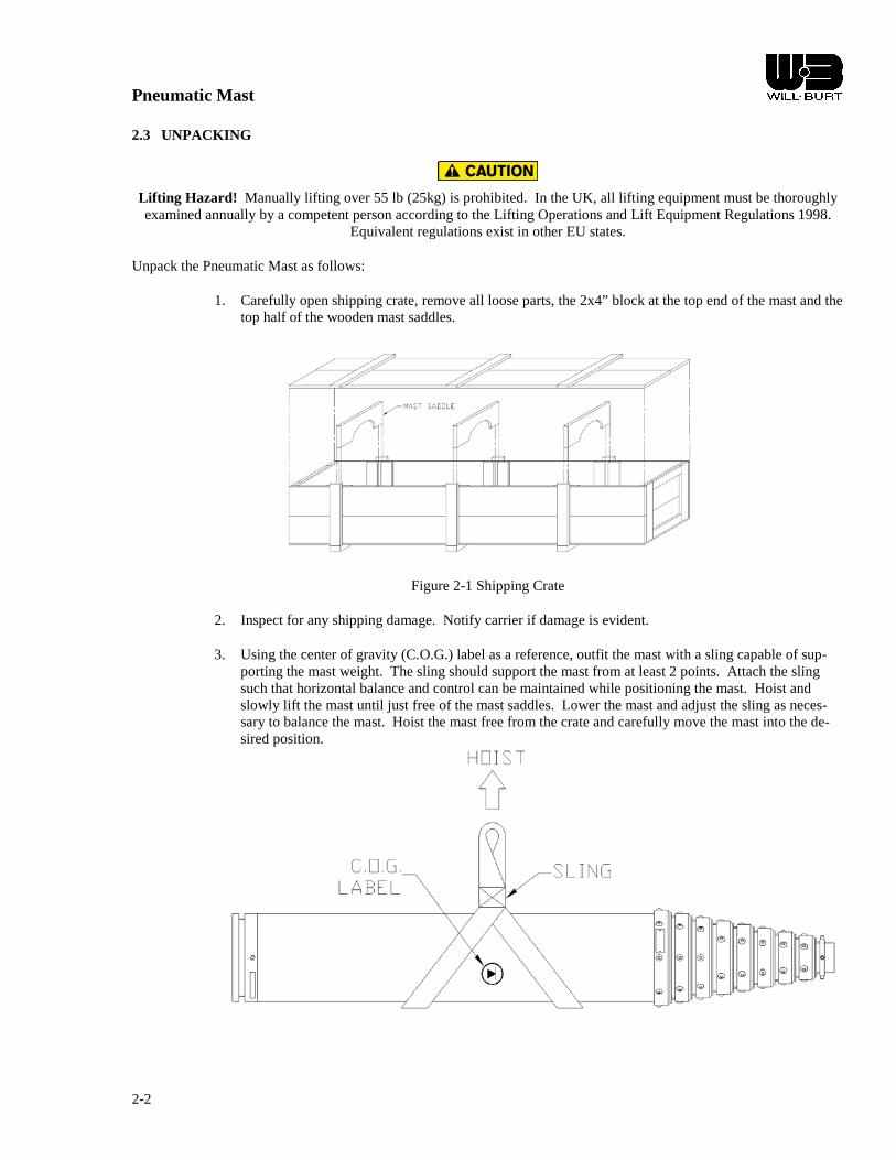
Pneumatic Mast
2-2
2.3 UNPACKING
Lifting Hazard! Manually lifting over 55 lb (25kg) is prohibited. In the UK, all lifting equipment must be thoroughly examined annually by a competent person according to the Lifting Operations and Lift Equipment Regulations 1998.
Equivalent regulations exist in other EU states.
Unpack the Pneumatic Mast as follows:
1. Carefully open shipping crate, remove all loose parts, the 2x4” block at the top end of the mast and the top half of the wooden mast saddles.
Figure 2-1 Shipping Crate
2. Inspect for any shipping damage. Notify carrier if damage is evident.
3. Using the center of gravity (C.O.G.) label as a reference, outfit the mast with a sling capable of sup-porting the mast weight. The sling should support the mast from at least 2 points. Attach the sling such that horizontal balance and control can be maintained while positioning the mast. Hoist and slowly lift the mast until just free of the mast saddles. Lower the mast and adjust the sling as neces-sary to balance the mast. Hoist the mast free from the crate and carefully move the mast into the de-sired position.

Pneumatic Mast
2-3
2.4 INSTALLATION
2.4.1 Mast Table 2-2 Installation Dimensions - Mast
P/N MODEL A B C in mm in mm in mm
906021 5-20-1XX 64 1626 51.8 1316 41.8 1062 906023 6-27-1XX 72 1829 58.4 1483 48.3 1227 906025 7-34-1XX 84 2134 70.4 1788 60.3 1532 906027 8-30-1XX 96 2438 88.4 2245 71.6 1819 906029 6-25-3XX 70 1778 59.8 1519 47.6 1209 906033 7-30-3XX 79 2007 69.1 1755 55.3 1405 906035 7-42-3XX 85 2159 69.1 1755 49.6 1260 906215 8.5-48-3XX 103 2616 89.0 2261 73.6 1869 906037 8.5-52-3XX 99 2515 83.5 2121 64.0 1626 906039 9.5-56-3XX 113 2870 99.0 2515 79.5 2019 906041 9-58-3XX 107 2718 91.5 2324 72.0 1829 906043 7-30-4XX 84 2134 68.3 1735 55.3 1405 906045 7-42-4XX 92 2337 68.4 1737 49.6 1260 906051 10-60-4XX 122 3099 101.1 2568 82.4 2093 906053 14.5-80-4XX 171 4343 152.5 3874 129.7 3294 906055 17-100-4XX 208 5283 186.6 4740 163.8 4161 906057 20-134-4XX 245 6223 221.0 5613 189.9 4823 915507 10-38-5XX 119 3023 110.1 2797 86.3 2192
710904800 12-48-5XX 144 3658 133.9 3401 110.2 2799 TBD 13.6-45-5XX 164 4166 156.4 3973 127.7 3244 TBD 14-67-5XX 167 4242 156.4 3973 127.7 3244
909959 9-50-6XX 110 2794 89.6 2276 66.5 1689 909426 10.3-60-6XX 125 3175 104.6 2657 81.5 2070 910916 10.8-76-6XX 131 3327 104.6 2657 81.5 2070 912970 15.7-100-6XX 187 4750 166.6 4232 143.5 3645
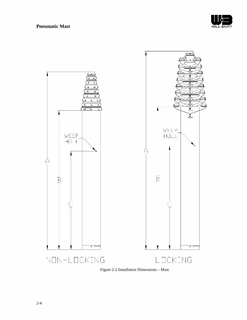
Pneumatic Mast
2-4
Figure 2-2 Installation Dimensions – Mast

Pneumatic Mast
2-5
Table 2-3 Non-Rotating Base Plate Dimensions
NON-ROTATING BASE PLATE ASSEMBLY A B ØC
BASE TUBE in mm in mm in mm 11 1/4 12 305 11 279 9/16 14
9 9 229 8 203 7/16 11 6 3/4 6 3/4 171 5 3/4 146 7/16 11
5 5 127 4 102 7/16 11
Figure 2-3 Non-Rotating Base Plate
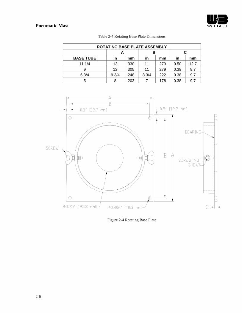
Pneumatic Mast
2-6
Table 2-4 Rotating Base Plate Dimensions
ROTATING BASE PLATE ASSEMBLY A B C
BASE TUBE in mm in mm in mm 11 1/4 13 330 11 279 0.50 12.7
9 12 305 11 279 0.38 9.7 6 3/4 9 3/4 248 8 3/4 222 0.38 9.7
5 8 203 7 178 0.38 9.7
Figure 2-4 Rotating Base Plate

Pneumatic Mast
2-7
Table 2-5 Turning Handle Assembly
BASE TUBE A
in mm 9 18 457
6 3/4 16 406 5 14 356
Figure 2-5 Turning Handle Assembly
NOTES FOR TURNING HANDLE ASSEMBLY:
1.) When assembling the mast turning handles to the base mast section, do not over tighten the ¼-20 bolts. Over tight-ening the bolts may distort the base mast sections, causing the next largest mast section to stick when extended or lowered.
2.) For Masts with Ø 9.00” Base Mast Section: Torque ¼-20 bolts to 120 in-lbs MAX. 3.) For Masts with Ø 6.75” Base Mast Section: Torque ¼-20 bolts to 100 in-lbs MAX. 4.) For Masts with Ø 5.00” Base Mast Section: Torque ¼-20 bolts to 60 in-lbs MAX. 5.) See point 9 in 2.4.1.1 Mast Installation – Internal Mounting for more information on turning handle installation.

Pneumatic Mast
2-8
Table 2-6 Internal Mounting Kit Information
ROOF FLANGE & RING
BASE TUBE A B C in mm in mm
11 1/4 14 356 8 13 330 9 11 7/8 301 8 11 279
6 3/4 9 3/4 248 8 8 3/4 222 5 9 229 6 8 203
Figure 2-6 Internal Mounting Kit Hardware
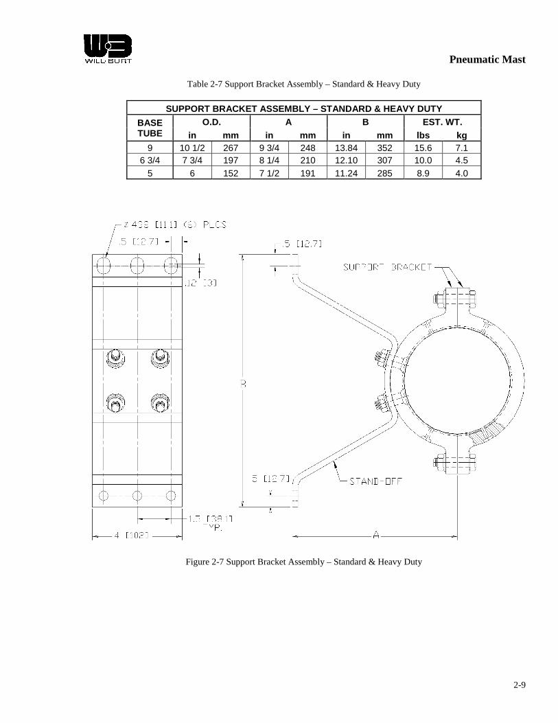
Pneumatic Mast
2-9
Table 2-7 Support Bracket Assembly – Standard & Heavy Duty
SUPPORT BRACKET ASSEMBLY – STANDARD & HEAVY DUTY BASE TUBE
O.D. A B EST. WT. in mm in mm in mm lbs kg
9 10 1/2 267 9 3/4 248 13.84 352 15.6 7.1 6 3/4 7 3/4 197 8 1/4 210 12.10 307 10.0 4.5
5 6 152 7 1/2 191 11.24 285 8.9 4.0
Figure 2-7 Support Bracket Assembly – Standard & Heavy Duty

Pneumatic Mast
2-10
Table 2-8 Support Bracket Assembly – Super Heavy Duty
SUPPORT BRACKET – SUPER HEAVY DUTY A B C D E F
in mm in mm in mm in mm in mm in mm 8.00 203 16.34 415 19.75 502 13.75 349 1.50 38 3.00 76
G H J K L
in mm in mm in mm in mm in mm 6.00 152 0.56 14 2.50 64 6.00 152 2.00 51
Figure 2-8 Support Bracket Assembly – Super Heavy Duty
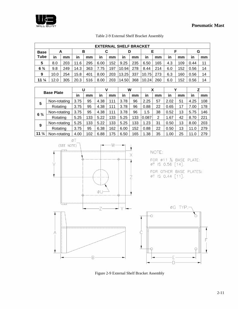
Pneumatic Mast
2-11
Table 2-9 External Shelf Bracket Assembly
EXTERNAL SHELF BRACKET Base Tube
A B C D E F G in mm in mm in mm in mm in mm in mm in mm
5 8.0 203 11.6 295 6.00 152 9.25 235 6.50 165 4.3 109 0.44 11 6 ¾ 9.8 249 14.3 363 7.75 197 10.94 278 8.44 214 6.0 152 0.56 14 9 10.0 254 15.8 401 8.00 203 13.25 337 10.75 273 6.3 160 0.56 14
11 ¼ 12.0 305 20.3 516 8.00 203 14.50 368 10.24 260 6.0 152 0.56 14
Base Plate U V W X Y Z
in mm in mm in mm in mm in mm in mm
5 Non-rotating 3.75 95 4.38 111 3.78 96 2.25 57 2.02 51 4.25 108 Rotating 3.75 95 4.38 111 3.78 96 0.88 22 0.65 17 7.00 178
6 ¾ Non-rotating 3.75 95 4.38 111 3.78 96 1.5 38 0.52 13 5.75 146 Rotating 5.25 133 5.22 133 5.25 133 0.087 2 1.67 42 8.70 221
9 Non-rotating 5.25 133 5.22 133 5.25 133 1.23 31 0.50 13 8.00 203 Rotating 3.75 95 6.38 162 6.00 152 0.88 22 0.50 13 11.0 279
11 ¼ Non-rotating 4.00 102 6.88 175 6.50 165 1.38 35 1.00 25 11.0 279
Figure 2-9 External Shelf Bracket Assembly
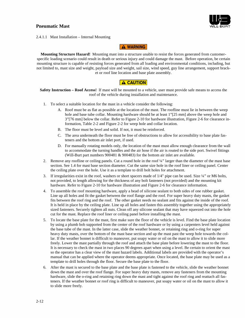
Pneumatic Mast
2-12
2.4.1.1 Mast Installation – Internal Mounting
Mounting Structure Hazard! Mounting mast into a structure unable to resist the forces generated from customer-specific loading scenario could result in death or serious injury and could damage the mast. Before operation, be certain mounting structure is capable of resisting forces generated from all loading and environmental conditions, including, but not limited to, mast size and weight, payload size and weight, sail size, wind speed, guy line arrangement, support brack-
et or roof line location and base plate assembly.
Safety Instruction – Roof Access! If mast will be mounted to a vehicle, user must provide safe means to access the roof of the vehicle during installation and maintenance.
1. To select a suitable location for the mast in a vehicle consider the following:
A. Roof must be as flat as possible at the location of the mast. The roofline must lie in between the weep hole and base tube collar. Mounting hardware should be at least 1”[25 mm] above the weep hole and 3”[76 mm] below the collar. Refer to Figure 2-10 for hardware illustration, Figure 2-6 for clearance in-formation, Table 2-2 and Figure 2-2 for weep hole and collar location.
B. The floor must be level and solid. If not, it must be reinforced.
C. The area underneath the floor must be free of obstructions to allow for accessibility to base plate fas-teners and the bottom air inlet port, if used.
D. For manually rotating models only, the location of the mast must allow enough clearance from the wall to accommodate the turning handles and the air hose if the air is routed to the side port. Swivel fittings (Will-Burt part numbers 900481 & 900483) for the bottom air inlet are available.
2. Remove any roofline or ceiling panels. Cut a round hole in the roof ¼” larger than the diameter of the mast base section. See 1.4 for mast base section diameter. Cut the same size hole in the roof liner or ceiling panel. Center the ceiling plate over the hole. Use it as a template to drill bolt holes for attachment.
3. If irregularities exist in the roof, washers or short spacers made of 1/4" pipe can be used. Size ¼” or M6 bolts, not provided, to length allowing for the thickness of any bolt fasteners (not provided) and the mounting kit hardware. Refer to Figure 2-10 for hardware illustration and Figure 2-6 for clearance information.
4. To assemble the roof mounting hardware, apply a bead of silicone sealant to both sides of one rubber gasket. Line up all holes and fit the gasket between the roof flange and the roof. For super heavy duty masts, the gasket fits between the roof ring and the roof. The other gasket needs no sealant and fits against the inside of the roof. It is held in place by the ceiling plate. Line up all holes and fasten this assembly together using the appropriately sized fasteners. Securely tighten all nuts. Clean off any silicone sealant that may have squeezed out into the hole cut for the mast. Replace the roof liner or ceiling panel before installing the mast.
5. To locate the base plate for the mast, first make sure the floor of the vehicle is level. Find the base plate location by using a plumb bob supported from the center of the roof hardware or by using a carpenters level held against the base tube of the mast. In the latter case, slide the weather bonnet, or retaining ring and o-ring for super heavy duty masts, over the bottom of the mast base section and up the mast past the weep hole towards the col-lar. If the weather bonnet is difficult to maneuver, put soapy water or oil on the mast to allow it to slide more freely. Lower the mast partially through the roof and attach the base plate before lowering the mast to the floor. It is necessary to check the mast in two places 90 degrees apart when using a level. Be certain to orient the mast so the operator has a clear view of the mast hazard labels. Additional labels are provided with the operator’s manual that can be applied where the operator deems appropriate. Once located, the base plate may be used as a template to drill holes through the floor. Secure the base plate to the floor.
6. After the mast is secured to the base plate and the base plate is fastened to the vehicle, slide the weather bonnet down the mast and over the roof flange. For super heavy duty masts, remove any fasteners from the mounting hardware, slide the o-ring and retaining ring down the mast and tight against the roof ring and reattach all fas-teners. If the weather bonnet or roof ring is difficult to maneuver, put soapy water or oil on the mast to allow it to slide more freely.

Pneumatic Mast
2-13
7. Air to operate the mast may be provided by an air compressor or other source of clean dry air. The air system should be regulated to not exceed the maximum operating pressure of the mast being used. Refer to tables in 1.4 for maximum operating pressures. Refer to 2.4.2.2 for installation instructions of the pneumatic system.
8. Install the weep hole drain kit provided with the mast. Refer to 2.4.2.1 for instructions.
9. For rotating masts, locate the turning handles at the desired height. Tighten the turning handle bolts just enough to allow the turning handles to rotate the mast without slipping. Tightening the turning bolts too much can de-form the base tube and impede the movement of the next internal mast section. Lock the mast in place by tight-ening the locking screws located on the base plate assembly at all times unless the mast is to be rotated. See Chapter 3 for instructions on rotating the mast. Refer to Figure 2-4 and Figure 2-5 for illustrations of the rotat-ing base plate and turning handles.
Figure 2-10 Mast Installation - Internal Mounting
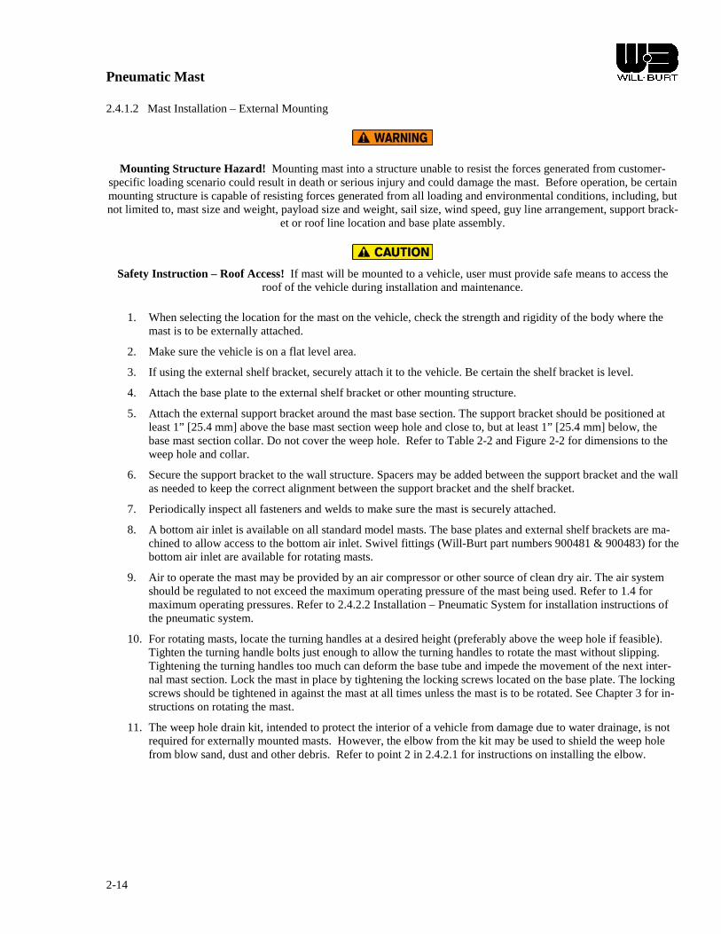
Pneumatic Mast
2-14
2.4.1.2 Mast Installation – External Mounting
Mounting Structure Hazard! Mounting mast into a structure unable to resist the forces generated from customer-specific loading scenario could result in death or serious injury and could damage the mast. Before operation, be certain mounting structure is capable of resisting forces generated from all loading and environmental conditions, including, but not limited to, mast size and weight, payload size and weight, sail size, wind speed, guy line arrangement, support brack-
et or roof line location and base plate assembly.
Safety Instruction – Roof Access! If mast will be mounted to a vehicle, user must provide safe means to access the roof of the vehicle during installation and maintenance.
1. When selecting the location for the mast on the vehicle, check the strength and rigidity of the body where the mast is to be externally attached.
2. Make sure the vehicle is on a flat level area.
3. If using the external shelf bracket, securely attach it to the vehicle. Be certain the shelf bracket is level.
4. Attach the base plate to the external shelf bracket or other mounting structure.
5. Attach the external support bracket around the mast base section. The support bracket should be positioned at least 1” [25.4 mm] above the base mast section weep hole and close to, but at least 1” [25.4 mm] below, the base mast section collar. Do not cover the weep hole. Refer to Table 2-2 and Figure 2-2 for dimensions to the weep hole and collar.
6. Secure the support bracket to the wall structure. Spacers may be added between the support bracket and the wall as needed to keep the correct alignment between the support bracket and the shelf bracket.
7. Periodically inspect all fasteners and welds to make sure the mast is securely attached.
8. A bottom air inlet is available on all standard model masts. The base plates and external shelf brackets are ma-chined to allow access to the bottom air inlet. Swivel fittings (Will-Burt part numbers 900481 & 900483) for the bottom air inlet are available for rotating masts.
9. Air to operate the mast may be provided by an air compressor or other source of clean dry air. The air system should be regulated to not exceed the maximum operating pressure of the mast being used. Refer to 1.4 for maximum operating pressures. Refer to 2.4.2.2 Installation – Pneumatic System for installation instructions of the pneumatic system.
10. For rotating masts, locate the turning handles at a desired height (preferably above the weep hole if feasible). Tighten the turning handle bolts just enough to allow the turning handles to rotate the mast without slipping. Tightening the turning handles too much can deform the base tube and impede the movement of the next inter-nal mast section. Lock the mast in place by tightening the locking screws located on the base plate. The locking screws should be tightened in against the mast at all times unless the mast is to be rotated. See Chapter 3 for in-structions on rotating the mast.
11. The weep hole drain kit, intended to protect the interior of a vehicle from damage due to water drainage, is not required for externally mounted masts. However, the elbow from the kit may be used to shield the weep hole from blow sand, dust and other debris. Refer to point 2 in 2.4.2.1 for instructions on installing the elbow.
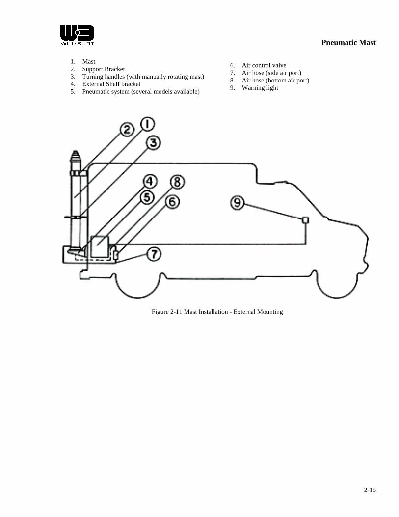
Pneumatic Mast
2-15
1. Mast 2. Support Bracket 3. Turning handles (with manually rotating mast) 4. External Shelf bracket 5. Pneumatic system (several models available)
6. Air control valve 7. Air hose (side air port) 8. Air hose (bottom air port) 9. Warning light
Figure 2-11 Mast Installation - External Mounting

Pneumatic Mast
2-16
2.4.2 Controls
2.4.2.1 Installation – Weep Hole Drain Kit
The intended use of the weep hole drain kit is to route water, from inside the mast, outside a vehicle or enclosure. The weep holes on each mast section are located to facilitate the drainage of water during periods of extension. Water can enter the mast through condensation in the air supply or by rain running down the mast sections and entering at the col-lars. Water can freeze in or on the mast causing it to work erratically or not at all. Keeping water out of the mast is very important to avoid damage to the mast and possible delays in operation.
A drain cock, provided in the hardware bag, should also be connected to the air inlet near the base of the mast. The drain cock should be used, periodically, to empty water that may have accumulated inside the base mast section, particularly after the mast has been exposed to rain.
Safety Instruction – Follow Procedure! Failure to follow drain kit installation instructions could damage the mast and render the mast inoperable. Read and understand the installation instructions before installing the drain kit.
NOTE: Complete internal mast installation before installing the weep hole drain kit.
1. Be certain the locknut and washer are threaded over the end of ¼” hose adapter. 2. Fasten hose adapter to base mast section weep hole. Turn the hose adapter in ONLY 1 1/2 to 2 turns after initial
engagement of threads. Further turning will damage mast. Tighten the locknut to secure in place. 3. Drill hole in vehicle or enclosure to route water outside. Fasten bulkhead fitting to hole. 4. Attach drain tube to hose adapter and bulkhead fitting.
See Figure 2-12 below and refer to Table 6-3 and Figure 6-3 for illustrations of the weep hole drain kit.
Figure 2-12 Weep Hole Drain Kit

Pneumatic Mast
2-17
2.4.2.2 Installation – Pneumatic System
Safety Instruction – Installation! At all times while using pipe and hose during installation, recognize that:
1.) Pipe and hose should be routed, mounted and restrained to protect from damage; 2.) Do not use second hand piping for installation; 3.) Do not bend air pipe and hose at a radius less than specified by the manufacturer; 4.) Pipes should be marked to avoid hazards from incorrect connection; 5.) The exhaust should be fitted with a silencer and be directed away from personnel; 6.) When routing piping, install in such a way as to minimize torsion on the joints; 7.) Mounting air pipe and hose shall be accomplished only by the use of tools to
prevent readily disconnecting air pipe and hose from mast.
Safety Instruction – Control Valve! Improper positioning and operation of Control Valve can result in moderate injury or equipment damage. Control valve must be mounted in a location such that the operator has full view of the mast, but
does not make contact with the mast during operation. Use only a Hold-To-Run type control valve.
1. MOUNTING – When mounting the pneumatic system, leave enough space around the unit for ventilation and for access to make initial installation, periodic adjustments, and future maintenance procedures as easy as pos-sible. To reduce vibration in the system place rubber washers or grommets on the bolts between the mounting pads and the mounting surface. To reduce noise, separate the system from the inside workspace of the vehicle.
2. ELECTRICAL – In accordance with applicable electrical codes, select the proper wiring size, circuit breakers,
or fuse size according to the maximum current draw of the pneumatic system being installed. Refer to rating in-formation plate on the compressor motor. Be sure to properly ground the compressor motor and all other elec-trical components. Operation of the compressor may cause interference unless proper isolation or shielding is used. NOTE: A qualified electrician should perform installation and adjustments.
3. AIR SUPPLY – The compressor should have adequate ventilation to provide at least 10 SCFM of clean dry air
at the air intake at all times. The recommended temperature range for inlet air is 32° F (0° C) to 95° F (35° C), so it works best when located in a heated compartment. The compressor should not be operated without the air filters in place.
4. CONTROL VALVE – A control valve should be installed to direct airflow in and out of the mast. The control
valve should be positioned to avoid unintentional operation. Mast movement should stop when the controller is released (hold-to-run type). If the controller is not a hold-to-run type, an emergency stop must be provided. The control valve should be operable by a person wearing gloves and mounted so it can be used with the mast in full view. The control valve should be suitable for outdoor use and marked “Up”, “Down” or similar. A check valve or similar device should be installed directly to the mast through rigid piping that would prevent an extended mast from exhausting uncontrollably if there is a pneumatic failure, such as a hose burst.
5. DRAIN & RELIEF FITTINGS – A drain cock and a safety valve should be installed at the air inlet at the base
of the mast. The drain cock empties water that may have accumulated inside the mast. The drain cock should be opened periodically to drain the mast, particularly after the mast has been operated in the rain. The drain cock on any mast should be left open once the mast is fully retracted and once a locking mast is completely ex-tended and locked into position. The safety valve prevents the mast from being over pressurized. Refer to Table 6-2 and Figure 6-2 for illustrations and installation schematics for the drain cock and safety valve.
6. PLUMBING – A length of 3/8" airline hose plus additional loose fittings are supplied with a Will-Burt pneu-
matic system, if purchased. The hose can be cut to the required length at installation. A drain hose should be at-tached to the exhaust port of the control valve to drain condensation or oil mist that may exhaust from the mast.

Pneumatic Mast
2-18
Do not remove any hose or piping without first completely exhausting all air from the mast and then disconnect-ing the power supply.
Figure 2-13 Pneumatic System

Pneumatic Mast
2-19
2.4.2.3 Installation – Mast Extension Magnetic Warning Kit
The vehicle should be equipped with a mast extension warning system. The mast extension magnetic warning kit in-cludes items to install a system for warning against moving a vehicle while the telescoping mast is partially or complete-ly extended. Test and ensure magnetic warning kit functions properly before operating the mast. A magnetic sensitive switch is attached to the base mast section. Magnets inside the top mast section activate the switch when the mast has nested. When correctly installed, flashing lights will indicate partial or full extension of the mast when the ignition is on. When the mast is lowered and completely nested or the ignition is off the lights will cease to illuminate. The lead to the positive battery terminal should be connected to the ignition switch such that the lights will only illuminate when the mast is extended and the ignition is on. Vehicle operator should always visually confirm that the mast is entirely retracted before moving the vehicle. The system should be installed per the diagrams shown below. One flashing light should be mounted to the vehicle dash in full view of the driver. The mast extension magnetic warning kit will not operate unless it is installed properly. Refer to Figure 2-14, Table 6-4 and Figure 6-4 for mast models 5-20, 6-27, 7-34, 8-30, 6-25, & 7-30 and refer to Figure 2-15 and Figure 2-16, Table 6-5 and Figure 6-5 for mast models 7-42, 8.5-48, 8.5-52, 9.5-56, 9-58, 10-60, 9-50, 10.3-60, & 10.8-76.
INSTALLATION INSTRUCTIONS:
1. Loop one end of a length of string or wire securely around the set of magnets. Carefully insert the magnets into the top of the top mast section positioned so the side with (3) screws enters the tube first. Using the string or wire, lower the magnets to the bottom. It is important that the magnets rest on the bottom of the top mast sec-tion. Remove any excess string or wire.
2. Assemble the magnetic switch assembly and the stainless steel clamp as shown. Attach the switch assembly loosely around the mast base tube, approximately 6 to 20” [15 to 51 cm] above the base plate.
3. Use 16 AWG stranded wire (not included) to connect the flasher, lights and relay (not included or necessary in kits for the 5-20, 6-27, 7-34, 8-30, 6-25, & 7-30 models) to the wires exiting the switch assembly. Connect the wires according to the diagram and schematic as shown. Be certain to observe any local codes or regulations.
4. With the ignition on, have the mast fully nested and the flasher/light installed and connected through the igni-tion to the battery. The lights should be flashing unless the switch is in proximity with the magnet assembly. Slide the magnetic switch assembly up and down along the lower two feet of the mast base tube to locate the magnet assembly inside the tube. When the magnet is located, the lights will stop flashing. The vertical sensing range should be about 1 to 3” [2.5 to 7.5 cm]. Tighten the band to clamp the switch assembly in the sensing range, but not lower than 1” [2.5 cm] above the lower limit. The switch can be located anywhere around the pe-rimeter of the base tube.
5. Pressurize the mast to extend it 1 to 2’ [31 to 61 cm] several times to test the mast extension magnetic warning kit.
6. Attach the "NOTICE" label in a visible area on the mast base tube. NOTE: Do not mount the relay any closer than 6” [0.15 m] from the switch assembly that is clamped to the mast. When energized, the relay produces an electromagnetic field that could affect the performance of the reed switch if the relay is mounted closer than 6” [15 cm].
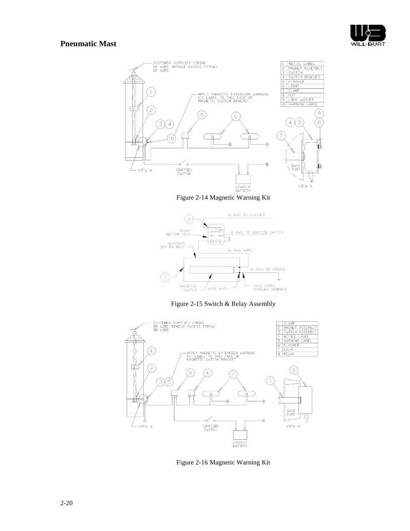
Pneumatic Mast
2-20
Figure 2-14 Magnetic Warning Kit
Figure 2-15 Switch & Relay Assembly
Figure 2-16 Magnetic Warning Kit

Pneumatic Mast
3-1
CHAPTER 3 OPERATING INSTRUCTIONS
Safety Instruction – Operation! At all times prior to mast operation, insure that:
1.) The mast area is free of personnel and mechanical obstruction; 2.) All electrical cables are undamaged and properly terminated; 3.) The operator must have full view of the mast during use; 4.) Any transit tie-downs on the payload have been removed; 5.) The vehicle is not moving; 6.) The area above the mast is free of mechanical obstructions.
Relocation Hazard! Relocating the mast during operation or after extension could result in death or serious injury. Do not relocate the mast during operation or while extended. This applies especially to masts mounted to vehicles. Operate
the mast only if the vehicle is stationary and the vehicle engine is off.
Mast Extension Hazard! Extending mast into obstructions could result in death or serious injury and could render the mast inoperable and partially extended. Before applying power and operating the mast, be certain there is sufficient
clearance above and to all sides of the expected location of the fully extended mast and payload. Keep all persons clear of mast and mast extension. Do not lean directly over the mast.
Lifting Hazard! The mast is intended to lift a specific payload for lighting, surveillance or communication use only. Any other use without written consent is prohibited and could cause death or serious injury. Do not use mast to lift per-
sonnel. Do not exceed specified payload capacity.
Pinch Point Hazard! Moving parts can crush and cut resulting in death or serious injury. Keep clear of moving parts while operating mast.
Crush Hazard! Death or serious injury could result if mast fails suddenly. Do not stand directly beneath the mast or its payload. Be certain payload is properly installed and secured.
Burst Hazard! Over pressurizing mast will trip safety valve and could result in death or serious injury. Do not exceed maximum operating pressure of 35 psi (241 kPa) for Heavy and Super Heavy Duty masts. Do not exceed maximum
operating pressure of 20 psi (138 kPa) for Standard Duty masts. Keep personnel clear of safety valve exhaust direction.
Entanglement Hazard! Tangled cables can cause equipment damage. Ensure control cables are not tangled and are free to pay out as mast is extended.
Frozen Water Hazard! Water freezing inside mast or air fittings may render mast inoperable and cause major equip-ment damage. Open drain, when mast is not in operation, in temperatures near or below freezing.
Pneumatic Mast
3-2
3.1 INTRODUCTION
The chapter provides instructions for operating the Pneumatic Mast.
3.2 OPERATION – NON-LOCKING MASTS
3.2.1 EXTENDING THE MAST
1. Select an area free of power lines or other overhead obstructions. Mast location should be no closer than a hori-zontal distance equal to the extended height of the mast away from any overhead power lines.
2. The mast should be located on level terrain. 3. Remove the canvas top cover (if used) and secure the payload and any required cables to the mast. 4. Attach the pneumatic system to the mast. Using the control valve, pressurize the mast to extend it. Do not ex-
ceed the maximum recommended operating pressure of the mast at any time. (20 PSIG for Standard Duty Masts and 35 PSIG for Heavy Duty Masts.) Maintain visual contact with the mast throughout extension to avoid cable entanglements or overhead obstructions.
3.2.2 ROTATING THE MAST
1. If the mast is a manually rotating model, loosen the locking screws on the base plate approximately one turn. Using its turning handles, rotate the mast to the desired direction. Re-tighten the locking screws to hold the po-sition. Refer to Figure 2-4 and Figure 2-5 for illustrations of the rotating base plate and turning handles.
3.2.3 LOWERING THE MAST
1. Before lowering the mast, rotate the mast or top load to allow for enough clearance in the stowed position. 2. Using the control valve, exhaust air from the mast. The mast will retract by its own weight and the weight of the
payload. Maintain visual contact with the mast during retraction to avoid cable and/or payload hang-ups.
Pinch Point Hazard! Moving parts can crush and cut resulting in death or serious injury. Keep clear of moving parts while operating mast.
3. Periodically open the drain cock when exhausting the mast to drain off any accumulated water. 4. To eliminate the possibility of inadvertent mast extension, disconnect the air supply or open the drain cock
while the mast is not in use. 5. Securely tie the canvas top cover (if used) over the mast. 6. Always visually confirm that the mast is fully retracted before moving the mast.
Frozen Water Hazard! Water freezing inside mast or air fittings may render mast inoperable and cause major equip-ment damage. Open drain, when mast is not in operation, in temperatures near or below freezing.

Pneumatic Mast
3-3
3.3 OPERATION – LOCKING MASTS
3.3.1 MASTS WITH T-HANDLE YOKE ASSEMBLIES (Refer to Figure 3-1)
EXTENDING THE MAST
1. Select an area free of power lines or other overhead obstructions. Mast should be no closer than a horizontal dis-tance equal to the extended height of the mast away from any overhead power lines.
2. The mast should be located on level terrain.
3. Remove the canvas top cover (if used) and secure the payload to the mast. If guy lines are used, attach the lines to the color-coded lugs on the collars.
4. Attach the pneumatic system to the mast.
5. Make sure all persons and obstructions are clear of the extension path of the mast. Before tripping any yoke as-semblies make sure the mast is not pressurized.
6. For masts with T handle yokes extend the mast sections from the smallest to largest. Pull down firmly on the top T handle attached to the smallest collar. While holding down the T handle, pressurize the mast using the air control valve to extend the first internal mast section. Continue holding down on the T handle while the section is extending. When the section is fully extended, release the T handle and stop pressurizing the mast. The spring loaded latch pins will lock this section in the extended position. Exhaust all air from the mast to confirm that the section is locked. If the section comes down, repeat this step.
7. Follow the same procedure for each subsequent mast section going from smallest to largest. Watch carefully that none of the cables become tangled or snag on anything as each mast section is extended.
8. Any combination of sections can be extended if the full height of the mast is not required.
ROTATING THE MAST
1. If the mast is a manually rotating model, loosen the locking screws on the base plate approximately one turn. Using its turning handles, rotate the mast to the desired direction. Re-tighten the locking screws to hold the po-sition. Refer to Figure 2-4 and Figure 2-5 for illustrations of the rotating base plate and turning handles.
LOWERING THE MAST
1. Before lowering the mast, rotate the mast or payload to allow for enough clearance in the stowed position.
2. For masts with T handles, pressurize the mast to lift the load until the base section yoke assembly latch pins can be disengaged by pulling the bottom T handle. Once the latch pins are disengaged, exhaust the air from the mast while firmly holding down the T handle. Continue holding down the T handle while the first internal mast sec-tion above is retracting. When this section is fully retracted, stop exhausting air pressure and release the T han-dle, locking the retracted section into position. Keep hands clear of retracting mast sections and collars.
Pinch Point Hazard! Moving parts can crush and cut resulting in death or serious injury. Keep clear of moving parts while operating mast.
3. Follow the same procedure for each subsequent mast section, working from largest to smallest.
4. Periodically, open the drain cock when exhausting the mast to drain off any accumulated water.
5. Once all sections are nested remove the payload and fit the mast top cover (if used) over the mast.
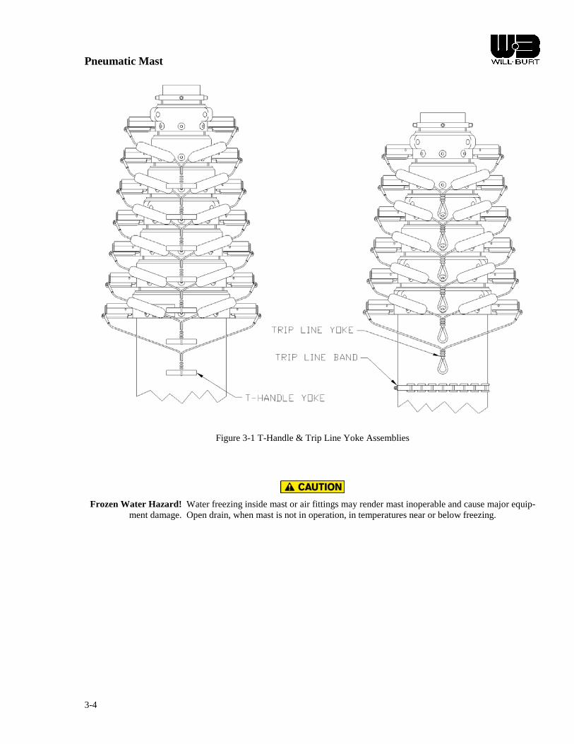
Pneumatic Mast
3-4
Figure 3-1 T-Handle & Trip Line Yoke Assemblies
Frozen Water Hazard! Water freezing inside mast or air fittings may render mast inoperable and cause major equip-ment damage. Open drain, when mast is not in operation, in temperatures near or below freezing.

Pneumatic Mast
3-5
3.3.2 MASTS WITH TRIP LINES (Refer to Figure 3-1)
EXTENDING THE MAST
1. Select an area free of power lines or other overhead obstructions. The Mast should be no closer than a horizon-tal distance equal to the extended height of the mast away from any overhead power lines.
2. The mast should be located on level terrain.
3. Remove the canvas top cover (if used) and secure the payload to the mast. If guy lines are used, attach the lines to the color-coded lugs on the collars.
4. For masts with trip lines, attach color-coded trip lines to the matching colored yoke assemblies. Feed the trip lines under the cable guides on all collars up to the collar where they are to be attached.
5. Attach the pneumatic system to the mast.
6. Make sure all persons and obstructions are clear of the extension path of the mast. Before tripping any yoke as-semblies make sure the mast is not pressurized.
7. For masts with trip lines, pull down firmly on the bottom trip line attached to the largest collar. While holding down the trip line, pressurize the mast using the air control valve to extend the first internal mast section. Con-tinue holding down on the trip line when the section is extending. When the section is fully extended, release the trip line and stop pressurizing the mast. The spring loaded latch pins will lock this section in the extended position. Exhaust all air from the mast to confirm that the section is locked. If the section comes down, repeat this step.
8. Pull the trip line on the next smaller collar to release the next section. Pressurize the mast to extend that section. Continue holding down on the trip line while the section is extending.
9. Follow the same procedure for each subsequent mast section going from largest to smallest. The color code se-quence for the trip lines from largest to smallest tube diameter is white (11.25), blue (10), black (9), brown (8.25), red (7.5), orange (6.75), yellow (6), green (5.25), blue (4.5) and white (3.75). Maintain visual contact with the mast throughout extension to avoid trip line or cable entanglements and to watch for overhead obstruc-tions.
ROTATING THE MAST
1. If the mast is a manually rotating model, loosen the locking screws on the base plate approximately one turn. Using its turning handles, rotate the mast to the desired direction. Re-tighten the locking screws to hold the po-sition. Refer to Figure 2-4 and Figure 2-5 for illustrations of the rotating base plate and turning handles.
LOWERING THE MAST
1. Before lowering the mast, rotate the mast or payload to allow for enough clearance in the stowed position.
2. For masts with trip lines, pressurize the mast until pulling the trip line can disengage the top yoke assembly latch pins. Sufficient pressure to disengage the top latch pins is obtained when this mast section is supported by air pressure. Once latch pins are retracted, exhaust air from the mast while firmly holding down the trip line. The top mast section will begin to retract. Continue holding down on the trip line while the section above is re-tracting. As soon as this section is fully retracted, stop exhausting air and release the trip line, locking the re-tracted section into position.
Pinch Point Hazard! Moving parts can crush and cut resulting in death or serious injury. Keep clear of moving parts while operating mast.
3. Follow the same procedure for each subsequent mast section working from smallest to largest.

Pneumatic Mast
3-6
4. Once all sections are nested, remove trip lines and payload and fit the mast top cover (if used) over the mast.

Pneumatic Mast
4-1
CHAPTER 4 MAINTENANCE AND SERVICE INSTRUCTIONS
Fire Hazard! Cleaning solvent, used for maintenance, is flammable and can be explosive resulting in death or serious injury. Do not smoke. Use cleaning solvent in a well-ventilated area. Keep cleaning solvent away from ignition
sources. Always store cleaning solvent in the proper marked container.
Pressurized Device Hazard! Mast disassembly prior to depressurization may release pressurized air jet. Completely lower the mast, depressurize and shut down power before disassembly.
Safety Instruction – Roof Access! If mast will be mounted to a vehicle, user must provide safe means to access the roof of the vehicle during installation and maintenance.
Lifting Hazard! Manually lifting over 55 lb (25kg) is prohibited. In the UK, all lifting equipment must be thoroughly examined annually by a competent person according to the Lifting Operations and Lift Equipment Regulations 1998.
Equivalent regulations exist in other EU states.
4.1 INTRODUCTION
The chapter provides instructions for maintaining and servicing a Pneumatic Mast.
To order spare or replacement parts, always refer to the mast model number and serial number. This information is in-cluded in the operator’s manual supplied with each mast. The mast serial number is stamped at the bottom of the base mast section. Model number, serial number and additional information is also engraved on the mast identification plate(s). The plate(s) are fixed to the base mast section’s collar. Refer to Table 6-1 and Figure 6-1 for identification plate abbreviation explanation and illustration.
4.2 TOOLS & MATERIALS RECOMMEDNED/REQUIRED
Safety Glasses Safety Gloves Thread Tape Level
Rags, Clean & Dry Non-abrasive cleanser Utility Knife Acetone (or other solvent)
Mast Lubricant Sling Locktite 380 or equal File
Hoist Ratchet Straps Allen Wrenches Chisel
Screwdrivers Wrenches Flat Punch Saw Horses
Sockets Measuring Tape Hammer Torque Wrench Air Supply
Silicone Sealant Drill String or Thin Wire

Pneumatic Mast
4-2
4.3 REFERENCE DIMENSIONAL INFORMATION
Table 4-1 Tube Diameters
STANDARD DUTY TUBE SUPER HEAVY & HEAVY
DUTY TUBE Tube A Tube A in mm in mm 2 2.00 51 3 3.00 76 2 1/2 2.50 64 3 3/4 3.75 95 3 3.00 76 4 1/2 4.50 114 3 1/2 3.50 89 5 1/4 5.25 133 4 4.00 102 6 6.00 152 4 1/2 4.50 114 B 6 3/4 6.75 171 B 5 5.00 127 6 3/4 6.75 171
7 1/2 7.50 191 8 1/4 8.25 210 B 9 9.00 229 9 1/8 9.14 232 10 10.00 254 11 1/4 11.25 286
NOTE: “B” Designates a base tube section.
Figure 4-1 Tube Diameters
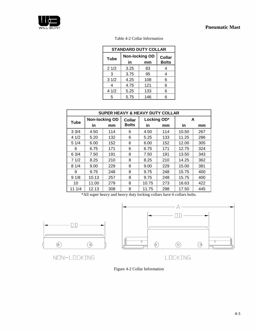
Pneumatic Mast
4-3
Table 4-2 Collar Information
STANDARD DUTY COLLAR
Tube Non-locking OD Collar Bolts in mm
2 1/2 3.25 83 4 3 3.75 95 4
3 1/2 4.25 108 6 4 4.75 121 6
4 1/2 5.25 133 6 5 5.75 146 6
SUPER HEAVY & HEAVY DUTY COLLAR
Tube Non-locking OD Collar
Bolts Locking OD* A
in mm in mm in mm 3 3/4 4.50 114 6 4.50 114 10.50 267 4 1/2 5.20 132 6 5.25 133 11.25 286 5 1/4 6.00 152 6 6.00 152 12.00 305
6 6.75 171 6 6.75 171 12.75 324 6 3/4 7.50 191 8 7.50 191 13.50 343 7 1/2 8.25 210 8 8.25 210 14.25 362 8 1/4 9.00 229 8 9.00 229 15.00 381
9 9.75 248 8 9.75 248 15.75 400 9 1/8 10.13 257 8 9.75 248 15.75 400 10 11.00 279 8 10.75 273 16.63 422
11 1/4 12.13 308 8 11.75 298 17.50 445 *All super heavy and heavy duty locking collars have 6 collars bolts.
Figure 4-2 Collar Information

Pneumatic Mast
4-4
4.4 SCHEDULED MAINTENANCE
4.4.1 Mast Cleaning and Lubrication
Will-Burt pneumatic telescoping masts should be cleaned and lubricated on a regular basis to insure smooth operation and to prolong useful life. This maintenance should be performed typically once a month depending upon local environ-mental conditions and frequency of use. Signs that cleaning and lubrication are needed can be:
• A noticeable gritty film on the exterior surfaces of the mast sections • Erratic extension or retraction of the mast • Noisy operation of the mast • Sticking of one or more mast sections when mast is extending or retracting
PROCEDURE:
1. Remove top load from the mast. This will allow the sections of a non-locking mast to more easily be extended from smallest to largest. See Step 3. On locking masts, the sequence of extension can be controlled by the lock-ing collars.
2. When a regulator exists in the pneumatic system, reduce its pressure to between 5 and 10 PSIG.
NOTE: 10 PSIG should be sufficient pressure to extend all sections of the mast without a top load. If any section will not extend with 10 PSIG the mast may require overhaul. Consult the factory.
3. One person operating the air control valve should slowly pressurize the mast just enough to extend the top mast section. Another person may need to hold down the larger mast section collars to assure the proper sequence of extension. Close the air control valve as soon as the mast section is up.
4. Dampen a rag with a non-abrasive cleanser or solvent such as lacquer thinner to wipe down the extended mast section. Do not allow the cleaning fluid or solvent to run down inside the collar.
5. Repeat steps 3 and 4 for the next larger mast section. 6. Inject approximately 1/2 oz. of Mast Lubricant* or a lightweight machine oil into the weep hole (drain) of the
exposed mast section. The weep holes are located between one and three feet below the collar on each tube ex-cept the top one.
7. Repeat steps 3, 4 and 6 for each of the remaining mast sections. The larger diameter sections should be injected with approximately 1 oz. of lubricant.
8. Lower the mast completely. Allow several minutes for the lubricant to settle and spread around the wear ring and seal at the bottom of each mast section.
Pinch Point Hazard! Moving parts can crush and cut resulting in death or serious injury. Keep clear of moving parts while operating mast.
9. Extend the mast again one section at a time in the same sequence (smallest to largest). Wipe off any excess lub-ricant that flows out of the weep holes. NOTE: Do not lubricate the exterior of the mast. This will attract dust and contaminants from the air.
* Mast Lubricant is specifically formulated for cold weather use, but is suitable for year around use. Regular winter maintenance and the frequent use of Mast Lubricant should significantly reduce the potential for mast freeze ups. Mast Lubricant is also intended for use in air in-line lubricators.

Pneumatic Mast
4-5
4.5 CORRECTIVE MAINTENANCE
4.5.1 REPLACING SEALS – STANDARD DUTY
1. Place the mast horizontally on a pair of sawhorses or similar supports. Secure the mast base tube to the supports so that the mast does not roll off. To disassemble the mast, start with the top section and work toward the base section. Remove any plugs from air inlet ports. Refer to the drawing in Chapter 5 for identifying parts.
2. To remove the top mast section pull it out several inches away from the collar and remove the top tube stop. On locking collar models, it is necessary to retract the latch pins to allow the mast section to be pulled out. Remove the collar bolts on the top collar and slide the collar over the end of the mast section. On locking collar models, retract the latch pins fully to allow the collar to slide off the end of the mast section. Slide the top section out. Do not drop the mast section as it comes out.
3. Remove the wear ring from the butt plate and wipe it clean. Remove the old seal and clean the seal groove. The mast section should be cleaned inside and outside with a solvent such as lacquer thinner. Do not use anything that might scratch the inside surface of the mast section. Repeat this procedure for each subsequent mast sec-tion.
4. Refer to 4.5.3 for replacement of collar bearing strips; 4.5.4 for replacement of wear rings; 4.5.5 for replace-ment of collar inserts; 4.5.6 for replacement of internal bumpers; and 4.5.7 for replacement of external bumpers.
5. Apply a coat of Mast Lubricant or lightweight machine oil such as SAE 10 to the inside surface of all mast sec-tions except the top section. Oil the new seal. With the lip edge of the seal toward the bottom end of the mast section, slide it on the butt plate and into the seal groove. Replace the wear ring on the butt plate. Repeat this procedure for each mast section.
6. When reassembling the mast, start with the base section and work toward the top section.
7. Secure the base mast section of the mast horizontally on saw horses or similar supports. Using a second person or using some other brace to support the top end, hold the next mast section so that the top end of the section is at a lower elevation than the seal end. Next, rest the lip of the seal on the inside of the receiving section. Refer to Figure 4-3. Slowly raise the lower end of the mast section to horizontal while carefully pressing the lip of the seal into the receiving section. Use your thumbs and forefingers on both sides of the seal to simultaneously press both sides of the seal in an upward motion. Work this way until your fingers meet at the top. Make sure that the seal is in correctly. If not, the mast will eventually leak air. If the seal has not been inserted into the re-ceiving tube correctly, remove the mast section and try again. Once the seal is inserted, guide the wear ring into position within its groove, and slide in the mast section. Be careful not to damage the seal as it slides past the collar bolt holes that are located near the insertion end of the receiving section.
8. Slide the section in leaving several inches protruding. Rotate the section so that the match mark "0" stamped on one of the keys at the end of the section is in line with the "O" stamped on the end of the base section.
9. Replace the collar on the mast section. Line up the match mark "O" on the collar with the "O" on the mast sec-tion. On locking collar masts, retract the latch pins to allow the collar to slide onto the end of the mast section. Make certain that all the bolt holes in the collar align exactly with the holes in the mast section. Install and hand tighten the collar bolts and lock washers. Torque the collar bolts to 80 lbs-in maximum.
10. Repeat steps 6 through 9 for each subsequent mast section.

Pneumatic Mast
4-6
Figure 4-3 Seal Replacement - Standard Duty

Pneumatic Mast
4-7
4.5.2 REPLACING SEALS, EXPANDERS AND YOKE ASSEMBLIES – HEAVY DUTY & SUPER HEAVY DUTY
1. Place the mast horizontally on a pair of sawhorses or similar supports. Secure the mast base tube to the supports so that the mast does not roll off. To disassemble the mast, start with the top section and work toward the base section.
2. To remove the top mast section, pull firmly on the yoke assembly of the top collar while pulling the top section out. Pull the top section out several inches away from the collar. Remove the set screw from the end of each latch pin lug (ears on each side of the collar). Refer to Figure 4-5. Slide out the latch pin spring from the end of each lug. Using a hammer and a punch, drive out the roll pin on each lug just far enough to remove the yoke as-sembly. Slide the latch pin out of the latch pin lug using a small screwdriver inserted into the slot located on the underside of each lug. Remove the collar bolts and slide the collar over the end of the mast section. Slide the top mast section out. Be careful not to drop it as it comes out.
3. Remove the orifice bolt, lock washer, back-up washer, expander and seal from the bottom of the mast section. Note orifice bolt ID and corresponding mast section for use when reassembling. Thoroughly clean and inspect all parts. The mast section should be cleaned inside and outside with a solvent such as lacquer thinner. Do not use anything that might scratch the honed inside surface of the mast section. The mast sections may need cleaned repeatedly before reassembly to remove all debris. Repeat this procedure for each subsequent mast sec-tion.
4. Refer to 4.5.3 for replacement of collar bearing strips; 4.5.4 for replacement of wear rings; 4.5.5 for replace-ment of collar inserts; 4.5.6 for replacement of internal bumpers; and 4.5.7 for replacement of external bumpers.
5. Reassemble the orifice bolt, lock washer, back-up washer, new expander and new seal on the bottom of the mast section. Match orifice bolts with the correct mast section by using the orifice bolt ID and the mast section tube OD. The ID of the orifice bolts should increase as the tube OD decreases. For example, the top mast sec-tion will have the smallest tube diameter and the orifice bolt with the largest ID. Refer to the illustration. As the orifice bolt is being tightened, center the seal, expander and back-up washer on the butt plate. Torque the orifice bolt to 16 lbs-ft. Repeat this procedure for each mast section.
6. Before reassembling the mast, lightly oil the lip of the seal and the inside honed surface of each mast section with Mast Lubricant or lightweight machine oil such as SAE 10. When reassembling the mast, begin with the base section and work toward the top section.
7. Secure the base section of the mast horizontally on saw horses. Using a second person or using some other brace to support the top end, hold the next mast section so that the top end of the section is at a lower elevation than the seal end. Next, rest the lip of the seal on the inside of the receiving section. Refer to the Figure 4-3. Slowly raise the lower end of the mast section to horizontal while carefully pressing the lip of the seal into the receiving section. Use your thumbs and forefingers on both sides of the seal to simultaneously press both sides of the seal in an upward motion. Use caution, pressing too hard will bend the expander. Work this way until your fingers meet at the top. Make sure that the seal is in correctly. If not, the mast will eventually leak air. If the seal has not been inserted into the receiving tube correctly, remove the mast section and try again. Once the seal is inserted, guide the wear ring into position within its groove, and slide in the mast section. Be careful not to damage the seal as it slides past the collar bolt holes that are located near the insertion end of the receiving section.
8. Slide the section in leaving several inches protruding. Rotate the section so that the match mark "0" stamped on one of the keys at the end of the section is in line with the "O" stamped on the end of the base section.
9. Replace the collar on the mast section. Line up the match mark "O" on the collar with the "O" on the mast sec-tion. On locking collar masts, retract the latch pins to allow the collar to slide onto the end of the mast section. Make certain that all the bolt holes in the collar align exactly with the holes in the mast section. Install and hand tighten the collar bolts and lock washers. Torque the collar bolts to 80 lbs-in maximum.

Pneumatic Mast
4-8
10. Replace the latch pins with the flats on the ends perpendicular to the key on the mast section. Replace the yoke assembly. Make sure that the hole in the lever lines up with the hole in the latch ear. Drive in the roll pin while holding it in place with a punch. Make sure that the lever does not get jammed. Install the latch pin spring and set screw. Turn the set screw all the way in until it stops. Then, back out the screw approximately 1/4 to 1/2 turn. Repeat this procedure for the other latch ear. Check the yoke assembly for smooth operation. It may be necessary to readjust the set screw as much as one full turn. If the set screw is too tight, it may not allow the latch pin to retract fully when the yoke assembly is pulled. If the set screw is too loose, spring tension may not adequately load the latch pin.
11. While pulling the yoke assembly, slide the mast section through the collar several times. Check for smooth op-eration. Observe the flat surface on the keys of the mast section for wear marks. If wear marks exist, the latch pin is causing friction and the set screw must be loosened.
12. Repeat steps 6 through 11 for each subsequent mast section.
Figure 4-4 Seal Area - Heavy Duty & Super Heavy Duty
Figure 4-5 Locking Collar Assembly
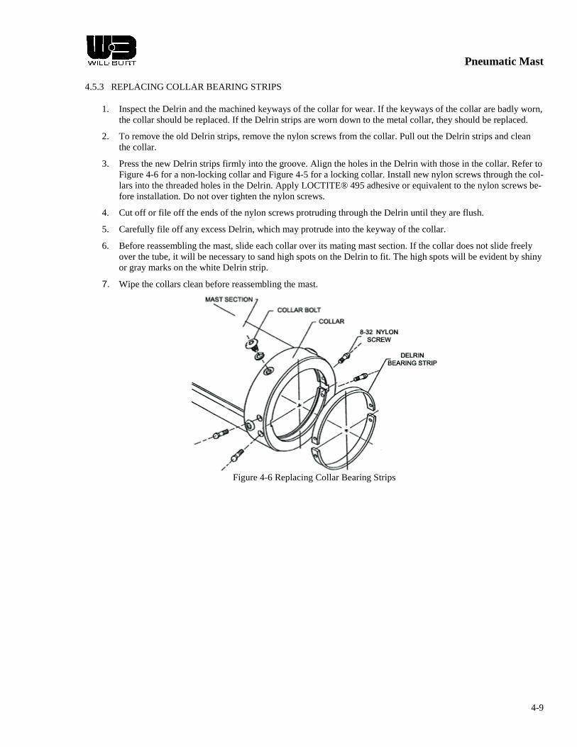
Pneumatic Mast
4-9
4.5.3 REPLACING COLLAR BEARING STRIPS
1. Inspect the Delrin and the machined keyways of the collar for wear. If the keyways of the collar are badly worn, the collar should be replaced. If the Delrin strips are worn down to the metal collar, they should be replaced.
2. To remove the old Delrin strips, remove the nylon screws from the collar. Pull out the Delrin strips and clean the collar.
3. Press the new Delrin strips firmly into the groove. Align the holes in the Delrin with those in the collar. Refer to Figure 4-6 for a non-locking collar and Figure 4-5 for a locking collar. Install new nylon screws through the col-lars into the threaded holes in the Delrin. Apply LOCTITE® 495 adhesive or equivalent to the nylon screws be-fore installation. Do not over tighten the nylon screws.
4. Cut off or file off the ends of the nylon screws protruding through the Delrin until they are flush.
5. Carefully file off any excess Delrin, which may protrude into the keyway of the collar.
6. Before reassembling the mast, slide each collar over its mating mast section. If the collar does not slide freely over the tube, it will be necessary to sand high spots on the Delrin to fit. The high spots will be evident by shiny or gray marks on the white Delrin strip.
7. Wipe the collars clean before reassembling the mast.
Figure 4-6 Replacing Collar Bearing Strips
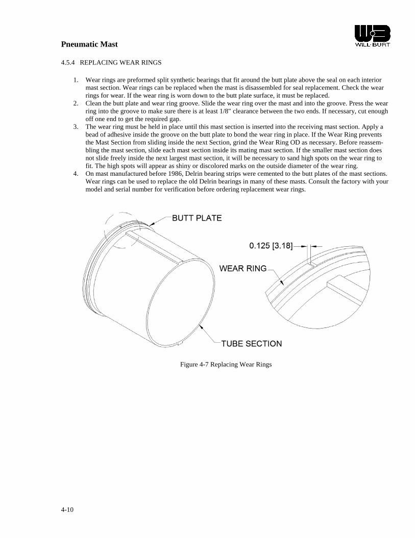
Pneumatic Mast
4-10
4.5.4 REPLACING WEAR RINGS
1. Wear rings are preformed split synthetic bearings that fit around the butt plate above the seal on each interior mast section. Wear rings can be replaced when the mast is disassembled for seal replacement. Check the wear rings for wear. If the wear ring is worn down to the butt plate surface, it must be replaced.
2. Clean the butt plate and wear ring groove. Slide the wear ring over the mast and into the groove. Press the wear ring into the groove to make sure there is at least 1/8" clearance between the two ends. If necessary, cut enough off one end to get the required gap.
3. The wear ring must be held in place until this mast section is inserted into the receiving mast section. Apply a bead of adhesive inside the groove on the butt plate to bond the wear ring in place. If the Wear Ring prevents the Mast Section from sliding inside the next Section, grind the Wear Ring OD as necessary. Before reassem-bling the mast section, slide each mast section inside its mating mast section. If the smaller mast section does not slide freely inside the next largest mast section, it will be necessary to sand high spots on the wear ring to fit. The high spots will appear as shiny or discolored marks on the outside diameter of the wear ring.
4. On mast manufactured before 1986, Delrin bearing strips were cemented to the butt plates of the mast sections. Wear rings can be used to replace the old Delrin bearings in many of these masts. Consult the factory with your model and serial number for verification before ordering replacement wear rings.
Figure 4-7 Replacing Wear Rings
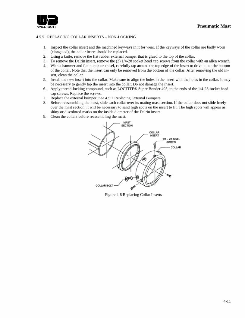
Pneumatic Mast
4-11
4.5.5 REPLACING COLLAR INSERTS – NON-LOCKING
1. Inspect the collar insert and the machined keyways in it for wear. If the keyways of the collar are badly worn (elongated), the collar insert should be replaced.
2. Using a knife, remove the flat rubber external bumper that is glued to the top of the collar. 3. To remove the Delrin insert, remove the (3) 1/4-28 socket head cap screws from the collar with an allen wrench. 4. With a hammer and flat punch or chisel, carefully tap around the top edge of the insert to drive it out the bottom
of the collar. Note that the insert can only be removed from the bottom of the collar. After removing the old in-sert, clean the collar.
5. Install the new insert into the collar. Make sure to align the holes in the insert with the holes in the collar. It may be necessary to gently tap the insert into the collar. Do not damage the insert.
6. Apply thread-locking compound, such as LOCTITE® Super Bonder 495, to the ends of the 1/4-28 socket head cap screws. Replace the screws.
7. Replace the external bumper. See 4.5.7 Replacing External Bumpers. 8. Before reassembling the mast, slide each collar over its mating mast section. If the collar does not slide freely
over the mast section, it will be necessary to sand high spots on the insert to fit. The high spots will appear as shiny or discolored marks on the inside diameter of the Delrin insert.
9. Clean the collars before reassembling the mast.
Figure 4-8 Replacing Collar Inserts

Pneumatic Mast
4-12
4.5.6 REPLACING INTERNAL BUMPERS
1. The internal bumper, which looks like an O ring, is located on the top edge of the stop panel on each internal mast section. When the mast is disassembled, check the condition of the internal bumper. If the internal bumper has deteriorated, it should be replaced.
2. Remove the old bumper and carefully stretch the new bumper over the end of the mast section and insert it into the groove machined in the keys. The bumper should fit tightly against the mast section immediately above the stop panel.
Figure 4-9 Replacing Internal Bumpers

Pneumatic Mast
4-13
4.5.7 REPLACING EXTERNAL BUMPERS
1. The external bumper is a flat rubber ring cemented to the top of each mast collar. Check the condition and the adhesion of each external bumper. If the external bumpers become loose they can usually be reused unless they have been damaged.
2. Remove the old bumper. Use acetone to clean off any old adhesive from the collar. Clean the replacement bumper with acetone. Allow it to dry thoroughly.
3. At room temperature, apply a light bead of LOCTITE® Black Max Adhesive 380 or equivalent around the top of the collar. Follow the manufacturer's instructions.
4. Place the external bumper on the collar and align the inside diameter edges. Hold pressure on the bumper and collar using a uniform weight for at least 90 seconds.
5. Using a razor knife, notch out keyways in the external bumper to match those in the collar.
Figure 4-10 Replacing External Bumpers

Pneumatic Mast
4-14
4.6 TROUBLE SHOOTING
PROBLEM POSSIBLE CAUSE(S) POSSIBLE SOLUTION(S) Mast frozen in ex-tended position.
1) Mast Base Section not drained routinely. Typically freezes around collar area.
1) Wrap warming blankets around collar until ice melts. Use heat gun or 500W quartz light.
2) Depressurize Mast. Inject 1 oz. Anti-
freeze, suited for aluminum engines, where top of collar and Intermediate tube meet.
Mast frozen in nested position.
1) Mast Base Section not drained routinely. Typically damages Tubes.
1) Send to manufacturer for repair or re-placement.
Mast will not lower without rocking.
1) Mast not oiled routinely. 1) See 4.4.1 Mast Cleaning & Lubrication. 2) Not enough weight. 2) Add weight to platform or stub adapter.
*Typ. Standard Duty* 3) Check tube trueness. Order replacement if bent. 3) Bent Tube.
4) Broken internal bumper. 4) Depressurize. Remove collar & lift tube to check Internal bumper. Order replace-ment. See 4.5.6.
5) Inserts tight. *Typ. Heavy & Super Heavy Duty* 5) Depressurize. Disassemble. File & grind
to prefit collar inserts as necessary. Largest Intermediate Tube Section stuck
1) Turning Handles tight. 1) Remove Turning Handles and cycle. *Typ. Standard Duty* Cycles properly: Reinstall Handles per
point 9 in 2.4.1.1 Internal Mounting. 2) Support bracket tight. Does not cycle: Tubes damaged; Order
replacement. 2) Loosen bolts. Shim as necessary between
clamp halves. Rotational movement in Mast Sections
1) Bearing Strips or Inserts worn. 1) Locking Strip Collar: Order Insert Collar.* 2) Non-locking Insert Collar: Order Insert.*
* Customer must prefit. Cannot slide Weather Bonnet over Base Section.
1) Bonnets are designed tight. 1) Use soapy water per point 6 in 2.4.1.1 In-ternal Mounting.
2) Oil O-ring and use mallet to tap evenly around diameter of Bonnet.
For additional information, please contact The Customer Service at 330-684-5298.

Pneumatic Mast
5-1
CHAPTER 5 MAST DRAWING & INSTALLATION INSTRUCTIONS
5.1 MAST DRAWING
This chapter includes the mast drawing with the bill of materials and may also include additional installation instructions specific to the mast model. Refer to the following pages for the drawing and any additional information included.


Pneumatic Mast
6-1
CHAPTER 6 REFERENCE DRAWINGS
6.1 INTRODUCTION
The chapter provides reference drawings related to the Heavy Duty Non-locking Pneumatic Mast.
6.2 REFERENCE DRAWINGS
Table 6-1 Identification Plate Abbreviations
DATE Date of Assembly or Year of Manufacture M/N Model Number P/N Part Number S/N Serial Number C.C. The Will-Burt Co. Cage Code
MAST WT. Approximate Mast Weight MAX PAYLOAD Mast Maximum Payload Capacity
(Box in top, right corner of 902851 used for Date or Year)
Figure 6-1 Identification Plates
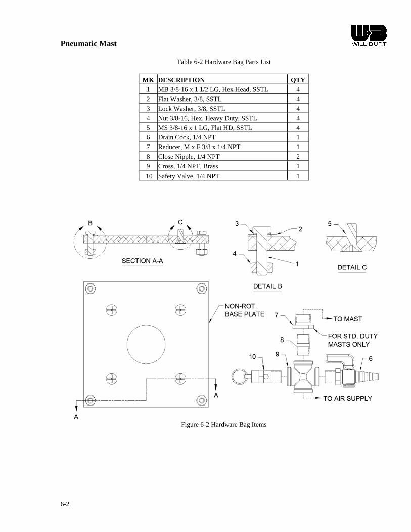
Pneumatic Mast
6-2
Table 6-2 Hardware Bag Parts List
MK DESCRIPTION QTY
1 MB 3/8-16 x 1 1/2 LG, Hex Head, SSTL 4
2 Flat Washer, 3/8, SSTL 4
3 Lock Washer, 3/8, SSTL 4
4 Nut 3/8-16, Hex, Heavy Duty, SSTL 4
5 MS 3/8-16 x 1 LG, Flat HD, SSTL 4
6 Drain Cock, 1/4 NPT 1
7 Reducer, M x F 3/8 x 1/4 NPT 1
8 Close Nipple, 1/4 NPT 2
9 Cross, 1/4 NPT, Brass 1
10 Safety Valve, 1/4 NPT 1
Figure 6-2 Hardware Bag Items

Pneumatic Mast
6-3
Table 6-3 Drain Kit
DRAIN KIT P/N: 902982 - D/N: C-9571
PARTS LIST MK P/N QTY DESCRIPTION
1 900555 1 Washer, 1/16 Thk. x 3/8 ID x 3/4 OD 2 900556 1 Locknut, 1/8 NPT x 3/16 Thk. 3 900564 1 Male Elbow, 1/8 NPT - 1/4 Hose 4 900565 1 Bulkhead Fitting, 1/4 NPT-1/4 Hose 5 900566 8' Plastic Tube, 1/4 OD (Not Shown)
Figure 6-3 Drain Kit Fittings

Pneumatic Mast
6-4
Table 6-4 Magnetic Warning Kit
MAGNETIC WARNING KIT PARTS LIST
MK QTY DESCRIPTION 1 1 Notice Label 2 1 Magnet Assembly 3 1 Switch 4 1 Switch Bracket 5 1 Flasher 6 2 Light 7 1 Clamp 8 2 Nut 9 2 Lock washer
10 1 Warning Label 11 1 Carton (Not Shown)
***FOR MAST MODELS 5-20, 6-27, 7-34, 8-30, 6-25 & 7-30***
Figure 6-4 Magnetic Warning Kit
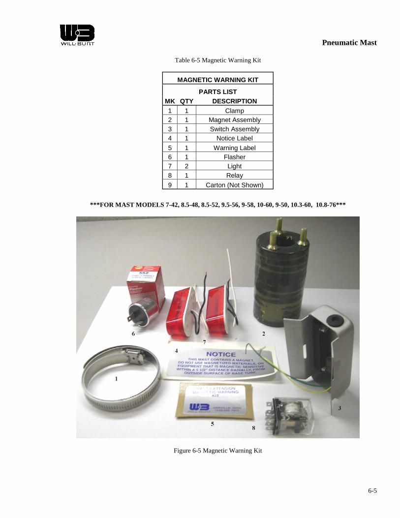
Pneumatic Mast
6-5
Table 6-5 Magnetic Warning Kit
MAGNETIC WARNING KIT PARTS LIST
MK QTY DESCRIPTION 1 1 Clamp 2 1 Magnet Assembly 3 1 Switch Assembly 4 1 Notice Label 5 1 Warning Label 6 1 Flasher 7 2 Light 8 1 Relay 9 1 Carton (Not Shown)
***FOR MAST MODELS 7-42, 8.5-48, 8.5-52, 9.5-56, 9-58, 10-60, 9-50, 10.3-60, 10.8-76***
Figure 6-5 Magnetic Warning Kit

Mast Cleaning and Lubrication
Will-Burt pneumatic telescoping masts should be cleaned and lubricated on a regular basis to insure smooth operation and to prolong useful life. This maintenance should be performed typically about once a month depending upon local environmental conditions and frequency of use. Signs that cleaning and lubrication are needed can be:
• A noticeable gritty film on the exterior surfaces of the mast sections • Erratic extension or retraction of the mast • Noisy operation of the mast • Sticking of one or more mast sections when mast is extending or retracting
WARNING: A pneumatic telescoping mast is a pressure vessel. Caution must be exercised to stay clear when the mast is being extended. Do not lean directly over the mast. Proper eye protection should be worn when working on the mast.
PROCEDURE:
1. Remove top load from the mast. This will allow the sections of a non-locking mast to more easily be extended from smallest to largest. See Step 3. On locking masts, the sequence of extension can be controlled by the locking collars.
2. When a regulator exists in the pneumatic system, reduce its pressure to between 5 and 10 PSIG. WARNING: 10 PSIG should be sufficient pressure to extend all sections of the mast without a top load. If any section will not extend with 10 PSIG the mast may require overhaul. Consult the factory.
3. One person operating the air control valve should slowly pressurize the mast just enough to extend the top mast section. Another person may need to hold down the larger mast section collars to assure the proper sequence of extension. Close the air control valve as soon as the mast section is up.
4. Wipe down the extended mast section using a non=abrasive cleanser or solvent such as lacquer thinner. Do not allow the cleaning fluid or solvent to run down inside the collar.
5. Repeat steps 3 and 4 for the next larger mast section.
6. Inject approximately 1/2 oz. of TMD Mast Lubricant* or a light weight machine oil into the weep hole (drain) of the exposed mast section. The weep holes are located between on and three feet below the collar on each tube except the top one.
7. Repeat steps 3, 4 and 6 for each of the remaining mast sections. The larger diameter sections should be injected with approximately 1 oz. of lubricant.
8. Lower the mast completely. Allow several minutes for the lubricant to settle and spread around the wear ring and seal at the bottom of each mast section.

WARNING: Keep hands clear of the descending collars while the mast is being lowered to avoid pinching.
9. Extend the mast again one section at a time in the same sequence (smallest to largest). Wipe off any excess lubricant which flows out of the weep holes. NOTE: Do not lubricate the exterior of the mast as this will cause it to attract dust and contaminants from the air.
* TMD Mast Lubricant is specifically formulated for cold weather use, but is suitable for year around use. Regular winter maintenance and the frequent use of TMD Mast Lubricant should significantly reduce the potential for mast freeze ups. TMD Mast Lubricant is also intended for use in air in-line lubricators.
SHEET 403
The Will-Burt Company 169 S. Main St. P.O. Box 900
Orville, Ohio 44667-0900 330.682.7015
www.willburt.com

Maintenance

FINISH CARE RECOMMENDATIONS
PPG recommends the following precautions must be followed to insure proper care of the new finish on your new vehicle. If these recommendations are not followed your paint warranty may be null and void.
The first 30 days… o Avoid parking under trees – sap and bird dropping may damage the new finish.
(Rinse them off as soon as possible) o Avoid driving on gravel roads – rock chips may occur on the fresh new finish. o Never let gasoline, antifreeze and transmission fluid or windshield solvent stand
on painted surface. (Rinse them off as soon as possible)
The first 90 days… o Do not wax or polish the vehicle – this will allow the finish to dry and harden
completely. (Do not use any silicone-containing waxes or polishes) o After 90 days the vehicle should be polished with a premium quality product.
o Consult the following manufacture for there recommendations. � 3M � Meguiars
Long term care… o Never use ice scraper to remover ice or snow – this will cause scratches the
finish. o Never use abrasive cleaner, chemicals, steel wool or scuff pads directly on the
finish - this will cause damage the finish. o Remove road salt within 1 week by washing or rinsing vehicle with clean water o Remove road tar by washing with finger nail polish remover or lighter fluid and a
clean cotton cloth. Wipe off excess cleaner ASAP.
Proper washing recommendations… o Do not use any commercial wash. Stiff brushes could mar the finish and damage
the surface. Wash vehicle by hand with cold water and a very mild disk wash soap. Be sure to use a soft cloth or sponge.
o Wash the vehicle in shade – never in direct sun. o Allow to air dry or wipe dry using clean cotton rags. o Do not “dry wire” the vehicle – dry wiping could scratch the finish. o If vehicle is washed in doors, vehicle MUST BE thoroughly air-dried.
Proper add-ons recommendations… o If any mounting of additional equipment (light, handles, etc.) are needed use the
following steps. o When drilling is required, mark holes to be drilled using a marker. Drill
holes using a sharp drill bit. After drilling remove ALL metal shaving. Prior to mounting equipment, apply a compound (ECK® Electrolysis Corrosion Control or Dolphin) to all screws. This will help prevent corrosion blistering from dissimilar metal electrolysis.
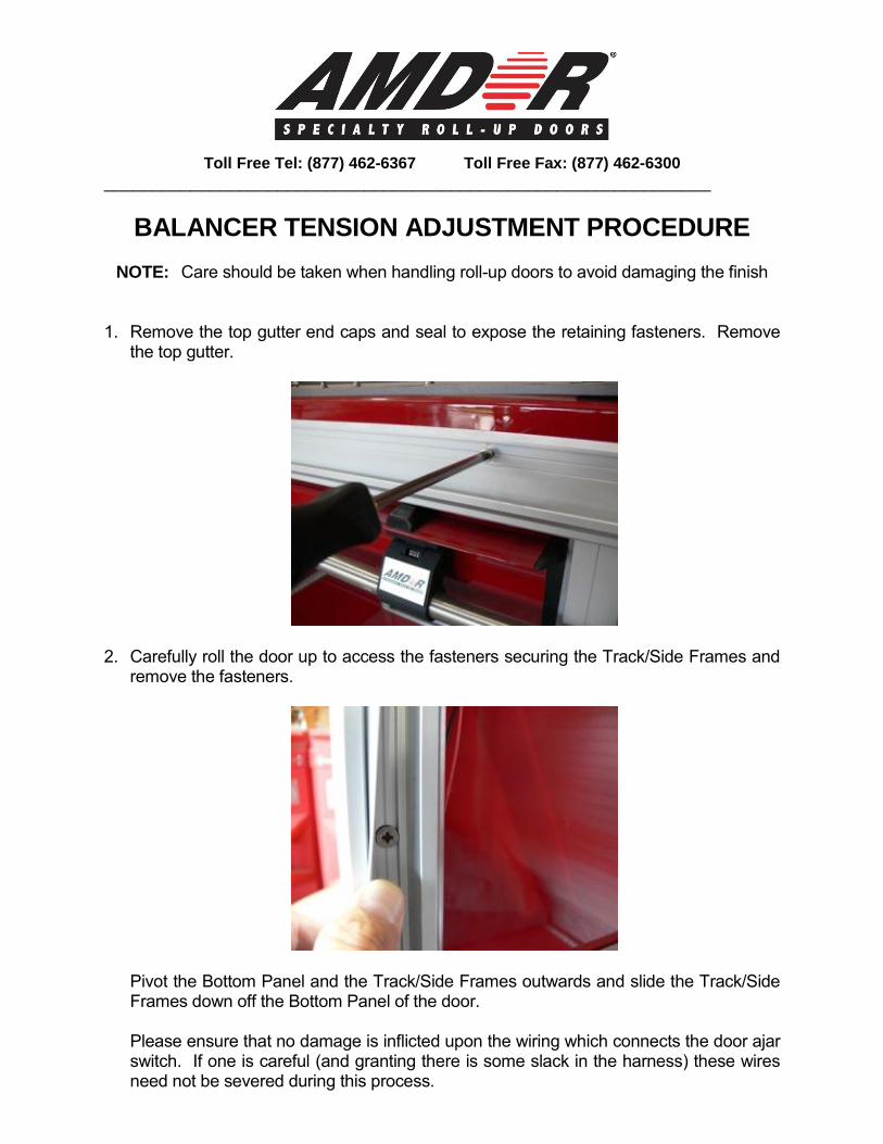
Toll Free Tel: (877) 462-6367 Toll Free Fax: (877) 462-6300
_______________________________________________________________
BALANCER TENSION ADJUSTMENT PROCEDURE
NOTE: Care should be taken when handling roll-up doors to avoid damaging the finish 1. Remove the top gutter end caps and seal to expose the retaining fasteners. Remove
the top gutter.
2. Carefully roll the door up to access the fasteners securing the Track/Side Frames and remove the fasteners.
Pivot the Bottom Panel and the Track/Side Frames outwards and slide the Track/Side Frames down off the Bottom Panel of the door. Please ensure that no damage is inflicted upon the wiring which connects the door ajar switch. If one is careful (and granting there is some slack in the harness) these wires need not be severed during this process.

3. Being careful not to scratch the door, pull the door down firmly to the closed position.
Swing the door away from the opening to access the Balancer Assembly. Insert a pin into the hole in the nylon bushing at the right-hand end of the Balancer in order to maintain tension while you remove the door curtain.
It may be necessary to rotate the Balancer slightly toward you until the hole in the nylon bushing is aligned with the hole in the shaft. Remove the clevis pins connecting the strap to the top of the door and remove the door. Holding the Balancer firmly, remove the pin locking the balancer spring and turn the balancer one full revolution. Turn the balancer against the tension (towards you) to increase tension and the opposite direction (away from you) to reduce tension. Insert the pin in the Balancer to lock the spring again. Please note that the balancer may be tensioned in ½ turn increments.
4. Pick up the door and guide the top slat of the door over the white nylon idler wheels on
both of the Balancer Mounting Plates. Ensure that the balancer straps are wrapped up and over the rear of the balancer and lie at the front of the balancer. If the straps are permitted to hanging freely without being wrapped then the initial rotation of the balancer will be used to wrap the straps around the balancer case resulting in insufficient tension.
Correct Incorrect
Install the clevis pins to connect the straps to the top of the door.

5. Grasp the bottom of the door and pull firmly downward to take the tension off the charge pin inserted through the nylon bushing at the right hand end of the Balancer. Remove the charge pin and gently let the door roll up into the compartment.
6. Pivot the Bottom Panel of the door out slightly and slide the two Track/Side Frames
over the Bottom Panel of the door. With the Track/Side Frames pushed up as far as possible, pivot the Bottom Rail and Side sections in toward the body. The Track/Side Frames should be flush against the side of the body. Slide the Track sections down so they sit firmly on the compartment sill.
For optimum security, it is recommended that the Side Frame sections be secured through the track rather than the rear flange. Fastening in this position prevents the section from being twisted away from the body. The Track Section has been designed to prevent interference between fasteners and the door however it is recommended that all fasteners be countersunk. For extra security, additional fasteners may be secured through the rear flange.
7. Open the door gently and check to ensure that all fasteners are tight and do not interfere with the door movement.
IF YOU HAVE ANY ADDITIONAL QUESTIONS,
PLEASE DON’T HESITATE TO GIVE US A CALL
1-800-GO-AMDOR (1-800-462-6367)
www.AMDOR.com

Mast Cleaning and Lubrication
Will-Burt pneumatic telescoping masts should be cleaned and lubricated on a regular basis to insure smooth operation and to prolong useful life. This maintenance should be performed typically about once a month depending upon local environmental conditions and frequency of use. Signs that cleaning and lubrication are needed can be:
• A noticeable gritty film on the exterior surfaces of the mast sections • Erratic extension or retraction of the mast • Noisy operation of the mast • Sticking of one or more mast sections when mast is extending or retracting
WARNING: A pneumatic telescoping mast is a pressure vessel. Caution must be exercised to stay clear when the mast is being extended. Do not lean directly over the mast. Proper eye protection should be worn when working on the mast.
PROCEDURE:
1. Remove top load from the mast. This will allow the sections of a non-locking mast to more easily be extended from smallest to largest. See Step 3. On locking masts, the sequence of extension can be controlled by the locking collars.
2. When a regulator exists in the pneumatic system, reduce its pressure to between 5 and 10 PSIG. WARNING: 10 PSIG should be sufficient pressure to extend all sections of the mast without a top load. If any section will not extend with 10 PSIG the mast may require overhaul. Consult the factory.
3. One person operating the air control valve should slowly pressurize the mast just enough to extend the top mast section. Another person may need to hold down the larger mast section collars to assure the proper sequence of extension. Close the air control valve as soon as the mast section is up.
4. Wipe down the extended mast section using a non=abrasive cleanser or solvent such as lacquer thinner. Do not allow the cleaning fluid or solvent to run down inside the collar.
5. Repeat steps 3 and 4 for the next larger mast section.
6. Inject approximately 1/2 oz. of TMD Mast Lubricant* or a light weight machine oil into the weep hole (drain) of the exposed mast section. The weep holes are located between on and three feet below the collar on each tube except the top one.
7. Repeat steps 3, 4 and 6 for each of the remaining mast sections. The larger diameter sections should be injected with approximately 1 oz. of lubricant.
8. Lower the mast completely. Allow several minutes for the lubricant to settle and spread around the wear ring and seal at the bottom of each mast section.

WARNING: Keep hands clear of the descending collars while the mast is being lowered to avoid pinching.
9. Extend the mast again one section at a time in the same sequence (smallest to largest). Wipe off any excess lubricant which flows out of the weep holes. NOTE: Do not lubricate the exterior of the mast as this will cause it to attract dust and contaminants from the air.
* TMD Mast Lubricant is specifically formulated for cold weather use, but is suitable for year around use. Regular winter maintenance and the frequent use of TMD Mast Lubricant should significantly reduce the potential for mast freeze ups. TMD Mast Lubricant is also intended for use in air in-line lubricators.
SHEET 403
The Will-Burt Company 169 S. Main St. P.O. Box 900
Orville, Ohio 44667-0900 330.682.7015
www.willburt.com

Warranty

OVERVIEW OF SVI TRUCKS STANDARD WARRANTIES
GENERAL - TWO (2) YEAR LIMITED WARRANTY
The entire apparatus and equipment produced by SVI TRUCKS shall be warranted, including materials costs and labor costs for a period of at least two (2) years, or 36,000 miles (or 57,936 kilometers), whichever occurs
first. SVI TRUCKS will be the single source coordinator of all warranties on the vehicle.
LOW VOLTAGE ELECTRICAL SYSTEM - FIVE (5) YEAR LIMITED WARRANTY
SVI TRUCKS warrants each new vehicle low voltage electrical system for a period of five (5) years, or 60,000 miles (or 96,561 kilometers), whichever occurs first. Warranty includes workmanship, wire harness, printed circuit boards, load management system, and switch panels installed by SVI. Components are covered by
their respective manufacturers.
BODY STRUCTURAL - TEN (10) YEAR LIMITED WARRANTY
SVI TRUCKS warrants each new vehicle to be free from structural defects for at least ten (10) years or 100,000 miles (or 160,934 kilometers), whichever occurs first including:
Body Frame Exterior Skin Structural Integrity of Interior cabinets/Exterior Compartments
PAINT - TEN (10) YEAR LIMITED WARRANTY
This limited warranty covers the areas of the vehicle painted by SVI TRUCKS for a period of at least ten (10) years or 100,000 miles (or 160,934 kilometers), whichever occurs first.
Peeling or delamination on the top coat and/or
other layers of paint Cracking or checking
Loss of gloss caused by cracking, checking or hazing
GENERAL INFORMATION
Warranty transferable; subject to inspection by SVI TRUCKS. Vehicle Chassis; Chassis components and cab body warranted by original manufacturer. Components manufactured by others and installed by SVI TRUCKS shall be covered by representative
warranties. EXCLUSIONS
Any paint not applied by SVI. Damage by fire, misuse,
negligence, or accident. Damage from corrosive
agents. Damage caused by theft,
vandalism, riot or explosion. Damage caused by lightning,
earthquake, storms, flood, or acidic environment.
Any repairs, modifications, or alterations made without SVI’s authorization.
Damage resulting from compromising the painted surface in any way, such as drilling holes.
Damage from lack of maintenance and cleaning.
Gold leaf, decals, or striping, except that affected by repair.
Loss of time, use of product, inconvenience
UV Paint fade Abnormal wear & tear
SVI TRUCKS - A Division of Super Vacuum Mfg. Co., Inc.
3842 Redman Drive, Fort Collins, CO USA 80524 Phone: 888.SVI.1112, Fax: 970.297.7099
Website: www.svitrucks.com, Email: [email protected] 05/12

SVI TRUCKS 3842 Redman Drive, Fort Collins, CO USA 80524
Phone: 888.SVI.1112, Fax: 970.297.7099, www.svitrucks.com
GENERAL - TWO (2) YEAR OR 36,000 MILE LIMITED WARRANTY 1. SVI TRUCKS (SVI) warrants to each original purchaser only that the SVI apparatus is free from defects in material and workmanship for a period of two (2) years or 36,000 miles (or 57,936 kilometers), whichever occurs first, starting thirty (30) days after the original invoice date. 2. SVI’s sole obligation under this warranty is limited to the repair or replacement, as determined by SVI, without charge to the original purchaser, which repairs shall be performed solely by SVI at its principal place of business or at a repair facility selected by SVI. This warranty covers only labor for repair or replacement which is reasonably necessary, as determined by SVI, to make the repair or replacement deemed necessary by SVI. Any labor, time, or amounts that are in excess of those reasonably necessary or deemed to be excessive by SVI are not covered under this warranty. All repairs must be expressly approved in writing by SVI’s warranty department. The failure to obtain approval for repairs from SVI or to have the apparatus or item repaired or replaced at SVI or a place designated by SVI shall void this warranty. Any repair or replacement performed by SVI pursuant to this warranty shall be warranted under this warranty only for the duration of the original warranty. 3. This warranty is nontransferable and terminates upon transfer of ownership, lease, or disposition of the apparatus from the original purchaser to any other person or entity. 4. SVI’s obligation to render any performance under this warranty is subject to the following conditions: a) The claimed defect must manifest itself during the warranty period; b) The original purchaser must notify SVI in writing of the claimed defect within thirty (30), days after the claimed defect manifests itself
to the original purchaser; and c) The claimed defective item or items must be returned to SVI or SVI’s designee immediately after notification of SVI with
transportation charges prepaid, unless otherwise directed by SVI. SVI shall have the unconditional right to thoroughly examine the claimed defects, including the apparatus and any part thereof, prior to conducting or approving any repair or replacement to determine whether the claimed defect is covered by this warranty. The failure of SVI to conduct any such examination shall not be deemed to be a waiver of its right to deny warranty coverage.
d) Any paint or corrosion defect that is covered by this warranty shall be limited in cost and manner of repair as set forth above, and this warranty is limited to the exterior surface of the apparatus.
5. This warranty is effective only under normal use and conditions. In addition, this warranty does not cover: a) Damage or corrosion due to improper use, improper maintenance, unauthorized alterations to the apparatus or repairs, chemical
deterioration, accidents, or acts of God, or operation beyond rated capacity; or b) Any liability for direct or indirect damages or delays resulting from any defects, including but not limited to, special, incidental or
consequential damages, loss of use, and loss of profits; or c) The cost of transporting original purchaser’s apparatus or item to or from any repair facility, including, but not limited to, the costs of
unloading or reloading any apparatus or any item; or d) Ordinary maintenance services or adjustments; or e) Replacement of any ordinary maintenance items, including but not limited to, filters, screens, lubricants, and light bulbs; or f) Any item which is manufactured by any person or entity other than SVI that is separately warranted in any manner by said person or
entity. 6. This warranty is absolutely void if SVI determines that the apparatus or any item has been misused, neglected, altered, overloaded, loaded beyond specified compartment weight limits, loaded to a state of excessive imbalance, or damaged. In addition this warranty is void if SVI determines that the original purchaser has misrepresented or concealed any material fact in connection with this warranty claim or that the apparatus or item has been damaged in any accident or by act of God, or that the defect is attributable to any use by the original customer of the product which is contrary to the intended use for which the product was manufactured or designed by SVI. Also, any disturbance of a painted surface due to mounting of any type of equipment by anyone other than SVI Trucks. 7. THIS WARRANTY IS EXPRESSLY IN LIEU OF ALL OTHER WARRANTIES, EXPRESS OR IMPLIED, INCLUDING WARRANTIES OF MERCHANTABILITY AND FITNESS FOR USE FOR A PARTICULAR PURPOSE AND ALSO INCLUDES, BUT NOT LIMITED TO, WARRANTIES IS FURTHER IN LIEU OF ALL OTHER REPRESENTATIONS TO THE ORIGINAL PURCHASER AND ANY OTHER OBLIGATIONS OR LIABILITIES WHATSOEVER, INCLUDING, BUT NOT LIMITED TO, ANY OBLIGATION OR LIABILITY FOR SPECIAL, INCIDENTAL, OR CONSEQUENTIAL DAMAGES, SVI NEITHER GIVES, ASSUMES NOR AUTHORIZES ANY OTHER PERSON TO GIVE OR ASSUME ANY OTHER WARRANTY, OBLIGATION OR LIABILITY ON SVI’S BEHALF, UNLESS EXPRESSLY GIVEN OR ASSUMED IN WRITING BY SVI. 8. PERFORMANCE OF REPAIRS OR REPLACEMENT OF PARTS UNDER THE TERMS SET FORTH HEREIN ARE THE EXCLUSIVE REMEDIES AFFORDED TO THE BUYER AND NEITHER SVI NOR ANY OF ITS DISTRIBUTORS OR AGENTS SHALL BE LIABLE FOR ANY BREACH OF WARRANTY IN AN AMOUNT EXCEEDING THE PURCHASE PRICE OF THE DEFECTIVE APPARATUS EQUIPMENT OR ITEM. THIS WARRANTY SHALL NOT BE EXTENDED, ALTERED, OR VARIED EXCEPT BY WRITTEN AGREEMENT SIGNED BY SVI AND THE ORIGINAL PURCHASER. 9. SVI reserves the right to make changes in design of and/or improvements on its products or to change specifications on materials as it may deem desirable at any time without imposing any obligations on itself to make corresponding changes or improvements in or on its products theretofore manufactured. Only the SVI apparatus and its components manufactured by SVI are bound by this warranty. Components of other manufacturers are covered only by such warranties set forth by the component manufacturer. Any surety bond, if required, shall apply only to the basic one (1) year warranty and not to any other extended warranty or warranties made by SVI or any of SVI’s suppliers. SVI TRUCKS will be the single source coordinator of all warranties on the vehicle. 05/12

SVI TRUCKS 3842 Redman Drive, Fort Collins, CO USA 80524
Phone: 888.SVI.1112, Fax: 970.297.7099, www.svitrucks.com
LOW VOLTAGE ELECTRICAL SYSTEM - FIVE (5) YEAR OR 60,000 MILE LIMITED WARRANTY
SVI TRUCKS (SVI) warrants to each original purchaser only that the SVI apparatus electrical system is free from defects in material and workmanship for a period of five (5) years or 60,000 miles (or 96,561 kilometers), whichever occurs first, starting thirty (30) days after the original invoice date. SVI’s sole obligation under this warranty is limited to the repair or replacement, as determined by SVI, without charge to the original purchaser, which repairs shall be performed solely by SVI at its principal place of business or at a repair facility selected by SVI. This warranty covers only labor for repair or replacement which is reasonably necessary, as determined by SVI, to make the repair or replacement deemed necessary by SVI. Any labor, time, or amounts that are in excess of those reasonably necessary or deemed to be excessive by SVI are not covered under this warranty. All repairs must be expressly approved in writing by SVI’s warranty department. The failure to obtain approval for repairs from SVI or to have the apparatus or item repaired or replaced at SVI or a place designated by SVI shall void this warranty. Any repair or replacement performed by SVI pursuant to this warranty shall be warranted under this warranty only for the duration of the original warranty. This warranty is nontransferable and terminates upon transfer of ownership, lease, or disposition of the apparatus from the original purchaser to any other person or entity. Items specifically covered are: Electrical harness and harness installation Printed circuit boards Load management system Warning light control panel switches that are provided and installed by SVI Items excluded are: Chassis electrical systems and components installed by chassis manufacturer including, but not limited to:
printed circuit boards, switches, relays, fuses, and similar equipment. Separately manufactured items installed by SVI including, but not limited to: batteries, sirens, battery
chargers, inverters, light bars and similar equipment. These are covered by warranties supplied by the manufacturer of the components.
Periodic tightening and cleaning of connection terminals as this is considered routine maintenance. Normal wear, abuse, accident, negligence or unapproved alteration of original parts. THIS WARRANTY IS EXPRESSLY IN LIEU OF ALL OTHER WARRANTIES, EXPRESS OR IMPLIED, INCLUDING WARRANTIES OF MERCHANTABILITY AND FITNESS FOR USE FOR A PARTICULAR PURPOSE AND ALSO INCLUDES, BUT NOT LIMITED TO, WARRANTIES IS FURTHER IN LIEU OF ALL OTHER REPRESENTATIONS TO THE ORIGINAL PURCHASER AND ANY OTHER OBLIGATIONS OR LIABILITIES WHATSOEVER, INCLUDING, BUT NOT LIMITED TO, ANY OBLIGATION OR LIABILITY FOR SPECIAL, INCIDENTAL, OR CONSEQUENTIAL DAMAGES, SVI NEITHER GIVES, ASSUMES NOR AUTHORIZES ANY OTHER PERSON TO GIVE OR ASSUME ANY OTHER WARRANTY, OBLIGATION OR LIABILITY ON SVI’S BEHALF, UNLESS EXPRESSLY GIVEN OR ASSUMED IN WRITING BY SVI. PERFORMANCE OF REPAIRS OR REPLACEMENT OF PARTS UNDER THE TERMS SET FORTH HEREIN ARE THE EXCLUSIVE REMEDIES AFFORDED TO THE BUYER AND NEITHER SVI NOR ANY OF ITS DISTRIBUTORS OR AGENTS SHALL BE LIABLE FOR ANY BREACH OF WARRANTY IN AN AMOUNT EXCEEDING THE PURCHASE PRICE OF THE DEFECTIVE APPARATUS EQUIPMENT OR ITEM. THIS WARRANTY SHALL NOT BE EXTENDED, ALTERED, OR VARIED EXCEPT BY WRITTEN AGREEMENT SIGNED BY SVI AND THE ORIGINAL PURCHASER. SVI reserves the right to make changes in design of and/or improvements on its products or to change specifications on materials as it may deem desirable at any time without imposing any obligations on itself to make corresponding changes or improvements in or on its products theretofore manufactured. Only the SVI apparatus and its components manufactured by SVI are bound by this warranty. Components of other manufacturers are covered only by such warranties set forth by the component manufacturer. 05/12

SVI TRUCKS 3842 Redman Drive, Fort Collins, CO USA 80524
Phone: 888.SVI.1112, Fax: 970.297.7099, www.svitrucks.com
BODY STRUCTURAL - TEN (10) YEAR OR 100,000 MILE LIMITED WARRANTY
SVI TRUCKS (SVI) warrants to each original purchaser only that the SVI apparatus body (exclusive of paint, finish, hardware, moldings, windows, and other appointments and accessories) is structurally sound and free from structural defects in material and workmanship for a period of ten (10) years or 100,000 miles (or 160,934 kilometers), whichever occurs first, starting thirty (30) days after the original invoice date. In the event of a chassis remount, this structural warranty shall remain in effect providing that the re-chassis work is completed by SVI or a facility approved by SVI. Should repairs become necessary under the terms of this warranty, the extent of that repair shall be determined solely by SVI and shall be performed solely by SVI or a repair facility designated by SVI. The expense of any transportation to or from such repair facility shall be that of the purchaser and is not an item covered by this warranty. This warranty is conditioned upon normal use and proper maintenance of such apparatus body; prompt written notice of all defects submitted to SVI, or one of its authorized distributors or dealers in the area; no repair or additions thereto except by SVI or authorized by SVI. This warranty is absolutely void if SVI determines that the apparatus or any item has been misused, neglected, altered, overloaded, loaded beyond specified compartment weight limits, loaded to a state of excessive imbalance, or damaged. In addition this warranty is void if SVI determines that the original purchaser has misrepresented or concealed any material fact in connection with this warranty claim or that the apparatus or item has been damaged in any accident or by act of God, or that the defect is attributable to any use by the original customer of the product which is contrary to the intended use for which the product was manufactured or designed by SVI. Also, any disturbance of a painted surface due to mounting of any type of equipment by anyone other than SVI Trucks. THIS WARRANTY IS EXPRESSLY IN LIEU OF ALL OTHER WARRANTIES, EXPRESS OR IMPLIED, INCLUDING WARRANTIES OF MERCHANTABILITY AND FITNESS FOR USE FOR A PARTICULAR PURPOSE AND ALSO INCLUDES, BUT NOT LIMITED TO, WARRANTIES IS FURTHER IN LIEU OF ALL OTHER REPRESENTATIONS TO THE ORIGINAL PURCHASER AND ANY OTHER OBLIGATIONS OR LIABILITIES WHATSOEVER, INCLUDING, BUT NOT LIMITED TO, ANY OBLIGATION OR LIABILITY FOR SPECIAL, INCIDENTAL, OR CONSEQUENTIAL DAMAGES, SVI NEITHER GIVES, ASSUMES NOR AUTHORIZES ANY OTHER PERSON TO GIVE OR ASSUME ANY OTHER WARRANTY, OBLIGATION OR LIABILITY ON SVI’S BEHALF, UNLESS EXPRESSLY GIVEN OR ASSUMED IN WRITING BY SVI. PERFORMANCE OF REPAIRS OR REPLACEMENT OF PARTS UNDER THE TERMS SET FORTH HEREIN ARE THE EXCLUSIVE REMEDIES AFFORDED TO THE BUYER AND NEITHER SVI NOR ANY OF ITS DISTRIBUTORS OR AGENTS SHALL BE LIABLE FOR ANY BREACH OF WARRANTY IN AN AMOUNT EXCEEDING THE PURCHASE PRICE OF THE DEFECTIVE APPARATUS EQUIPMENT OR ITEM. THIS WARRANTY SHALL NOT BE EXTENDED, ALTERED, OR VARIED EXCEPT BY WRITTEN AGREEMENT SIGNED BY SVI AND THE ORIGINAL PURCHASER. SVI reserves the right to make changes in design of and/or improvements on its products or to change specifications on materials as it may deem desirable at any time without imposing any obligations on itself to make corresponding changes or improvements in or on its products theretofore manufactured. Only the SVI apparatus and its components manufactured by SVI are bound by this warranty. Components of other manufacturers are covered only by such warranties set forth by the component manufacturer. 05/12

SVI TRUCKS 3842 Redman Drive, Fort Collins, CO USA 80524
Phone: 888.SVI.1112, Fax: 970.297.7099, www.svitrucks.com
PPG PAINT - TEN (10) YEAR OR 100,000 MILE LIMITED WARRANTY
SVI TRUCKS (SVI) warrants to each original purchaser that the SVI applied PPG paint finish is free from defects in material and workmanship for a period of ten (10) years or 100,000 miles (or 160,934 kilometers), whichever occurs first, starting thirty (30) days after the original invoice date. REPAIR OR REPLACEMENT OF PAINT IS THE EXCLUSIVE REMEDY UNDER THIS LIMITED WARRANTY.
ADVANTAGES With the ten (10) year warranty, you are assured that the finish on your vehicle is applied by highly trained professionals, using the highest quality products on the market today. You also have the satisfaction of knowing your vehicles finish will stand up to the rigorous demands put upon them in daily use.
THE WARRANTY This warranty covers repair or replacement, at the sole option of SVI, of the PPG paint on your new vehicle if a defect in materials or workmanship appears under normal use, where maintenance has been performed as stated in the owner’s manual, or during servicing of the vehicle operated in the United States and/or Canada within the limited warranty period. It provides for the following: Peeling or delamination on the top coat and/or other layers of paint Cracking or checking Loss of gloss caused by cracking, checking or hazing
EXCLUSION FROM THE WARRANTY
This warranty covers only repair or replacement of paint in which a defect in materials or workmanship appears. SVI will not replace the vehicle or repurchase the vehicle from you. ITEMS NOT COVERED include: Any paint not applied by SVI. Paint deterioration caused by blisters or other film degradation due to rust or corrosion originating from
the substrate. Common causes of substrate corrosion can consist of (but not limited to) dissimilar metals interaction at attachment points, welds, inserted fasteners, lap joints, etc.
Hazing, chalking, or loss of gloss due to improper care, abrasive polishes, cleaning agents, heavy-duty high-pressure washing or aggressive mechanical washing system.
Paint deterioration caused by abuse, scratches, chips, gloss reduction, accident, acid rain, chemical fallout or acts of nature.
Any repairs, modifications, or alterations made without SVI’s authorization. Not following “PPG Finish Care Recommendations” included in manuals with delivered vehicle. Application of, or removal of, stickers or decals.
CLAIM PROCEDURE
Should a vehicle show evidence of a covered paint failure, the owner will contact SVI at 1-888-SVI-1112, or www.svitrucks.com. SVI will contact authorized PPG personnel to inspect the vehicle. After the inspection, SVI will contact the owner. No repairs will be completed or paid until an estimate is approved by PPG personnel.
GUARANTEE REMEDY
In the event of a claim, SVI will complete all necessary repairs at SVI’s facility, or will pay a local PPG paint finishing center to complete the repairs. REPAIR OR REPLACEMENT OF PAINT IS THE EXCLUSIVE REMEDY UNDER THIS LIMITED WARRANTY. 05/12

SVIG Products & Installation Warranty Warranty Effective Date – January 1st, 2009
Definitions ‐
1) SVIG – acronym for Super Vacuum Incorporate Graphics
100.1.1 ‐ 2 Year SVIG Limited Vehicle Graphics Installation Warranty
All SVI Graphics vehicle graphic preparations, techniques, and installations are preformed according to the 3M Instruction Bulletin 5.36 guidelines or the most current 3M Instruction Bulletin at the time of install, and in accordance with the applicable 3M Product Bulletins (see section 100.1.2).
The 2 Year SVIG Limited Vehicle Graphics Installation Warranty applies exclusively to products manufactured and installed by SVI Graphics (a division of Super Vacuum Mfg.). This warranty covers all defects in vehicle graphics determined to be the result of improper installation by certified SVI Graphics installers. Damage determined to be the result of improper graphics maintenance (see section 100.1.4 for graphics care instructions) will not be considered a warrantable failure.
All claims must be made within the 2 year warranty time frame and are subject to approval by an authorized SVI Graphics representative.
In case of a warrantable failure, SVI Graphics’ responsibility is limited solely to, at its option, repairing or replacing the defective graphic parts. Customer option for repair of warrantable failures is strictly limited to repair at an SVI Graphics facility unless arranged with an authorized SVI Graphics representative prior to initial warranted installation date.
100.1.2 ‐ SVI Graphics Product and Film Warrantees
Definitions ‐
1) Finished Graphics ‐ finished products that have been manufactured using approved printers, films, inks, and over laminate combinations.
2) Graphics ‐ SVIG manufactured products. 3) Films – SVIG products that do not require printing or finishing.
All SVI Graphics products are manufactured exclusively using 3M materials and are warranted for material failures and defects as described in the applicable 3M Product Bulletins, and our SVIG Limited Graphics Durability Warranty.
Page 1 of 5

100.1.2 (Continued)
For your reference, our standard 3M films are listed below with their appropriate 3M Product Bulletins ‐
SVIG Solvent Printable Products
1) 3M IJ680CR Printable Reflective (3M Product Bulletin PIJ680CR) 2) 3M IJ180C Non‐Reflective (3M Product Bulletin PIJ180/180C) 3) 3M IJ8171 Printable “Window Vision” Film (3M Product Bulletin PIJ8171)
SVIG Plotter Cut Products
1) 3M 680CR Reflective Films (3M Product Bulletin 680CR)(All Colors) 2) 3M 180C Non‐Reflective HP Films (3M Product Bulletin 180/180C)(All Colors) 3) 3M Scotchcal 220 Electro‐Cut Films (3M Product Bulletin 220)(All Colors) 4) 3M 1170 Transparent Films (3M Product Bulletin 1170)
SVIG Finishing Laminates
1) 3M 8519 Luster Laminate (3M Product Bulletin GP‐1) 2) 3M 8914 Optically Clear Laminate (3M Product Bulletin GP‐1)
SVIG Diamond Grade Chevron Materials
1) 3M 983 Conspicuity Films (3M Product Bulletin 983)(All Colors)
Warranted Durability
A graphics Warranted Durability period is offered for the graphic constructions manufactured solely by SVI Graphics, and/or installed by certified SVI Graphics Installers. The durability period extends only to the performance of the SVI Graphics products used in the construction in accordance with the most current 3M Product and 3M Application Bulletin’s approved end uses.
See Table 100.1.2‐A below for the warranted durability, in years, of the performance of SVIG Films, Products, and graphic protection.
Page 2 of 5
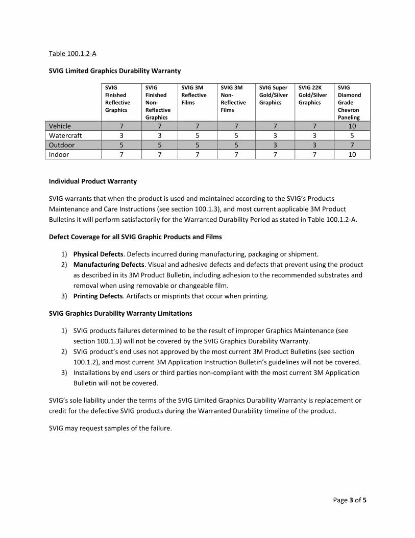
Table 100.1.2‐A
SVIG Limited Graphics Durability Warranty
SVIG Finished Reflective Graphics
SVIG Finished Non‐Reflective Graphics
SVIG 3M Reflective Films
SVIG 3M Non‐Reflective Films
SVIG Super Gold/Silver Graphics
SVIG 22K Gold/Silver Graphics
SVIG Diamond Grade Chevron Paneling
Vehicle 7 7 7 7 7 7 10 Watercraft 3 3 5 5 3 3 5 Outdoor 5 5 5 5 3 3 7 Indoor 7 7 7 7 7 7 10
Individual Product Warranty
SVIG warrants that when the product is used and maintained according to the SVIG’s Products Maintenance and Care Instructions (see section 100.1.3), and most current applicable 3M Product Bulletins it will perform satisfactorily for the Warranted Durability Period as stated in Table 100.1.2‐A.
Defect Coverage for all SVIG Graphic Products and Films
1) Physical Defects. Defects incurred during manufacturing, packaging or shipment. 2) Manufacturing Defects. Visual and adhesive defects and defects that prevent using the product
as described in its 3M Product Bulletin, including adhesion to the recommended substrates and removal when using removable or changeable film.
3) Printing Defects. Artifacts or misprints that occur when printing.
SVIG Graphics Durability Warranty Limitations
1) SVIG products failures determined to be the result of improper Graphics Maintenance (see section 100.1.3) will not be covered by the SVIG Graphics Durability Warranty.
2) SVIG product’s end uses not approved by the most current 3M Product Bulletins (see section 100.1.2), and most current 3M Application Instruction Bulletin’s guidelines will not be covered.
3) Installations by end users or third parties non‐compliant with the most current 3M Application Bulletin will not be covered.
SVIG’s sole liability under the terms of the SVIG Limited Graphics Durability Warranty is replacement or credit for the defective SVIG products during the Warranted Durability timeline of the product.
SVIG may request samples of the failure.
Page 3 of 5

100.1.3 ‐ SVI Graphics Product Maintenance and Care Instructions
Page 4 of 5

100.1.3 – (Continued)
Page 5 of 5

On Scene Solutions Quick Release Cargo Strap
Warranty
On Scene Solutions LLC warrants products of its manufacture against defects in materials and workmanship for a period of 2 years from the date of purchase. This warranty coverage is valid only if the product has been installed and used in accordance with the manufacturers recommended installation. During the duration of the warranty period, coverage is extended to the first purchaser, in the event of a direct purchase from On Scene Solutions. In the event the product is purchased by an OEM manufacturer of vehicles or an On Scene Solutions approved dealer/distributor with intent to re-sell, the warranty may be extended to the first “end” purchaser of said product. During the warranty coverage period, any product that falls within the warranty coverage guidelines, will be replaced in its entirety, by an On Scene Solutions warranty center, or an authorized dealer/agent of On Scene Solutions. The defective product must be returned complete (all components) including two buckle connectors, (receptacle and insertion) and straps with a complete description of the failure, to be considered for warranty coverage. This warranty is not applicable to any On Scene Solutions Cargo Strap product that has failed due to abuse, misuse, improper installation, excessive tension or alterations to the product that affects, in the manufacturer’s judgment, intended use and service. This warranty covers the complete buckle and any segment of the strap webbing, sewn by On Scene Solutions. Straps that are worn due to improper tensioning or positioning are NOT covered by warranty. On Scene Solutions will not be held liable for any incidental or consequential damages, and assumes no responsibility or liability for expenses incurred in the removal and or re-installation of products requiring service and or repair. On Scene Solutions will not be responsible for the packaging, handling and shipping of products to the warranty repair center or authorized warranty agent/dealer. On Scene Solutions will cover all costs of return postage to warranty covered customers. There are no warranties, expressed or implied, including, but not limited to, any implied merchantability or fitness for a particular use. On Scene Solutions reserves the right to modify this warranty statement at any time; or discontinue, modify or upgrade any products of its manufacture with design improvements without prior notice. This warranty gives you specific rights, and you may also have other rights which vary from state to state.
Warranty Return Procedures 1) On Scene Solutions products are to be returned freight prepaid to On Scene Solutions, 231 N.
Chimney Park Dr., Windsor, CO 80550 or an authorized On Scene Solutions distributor. 2) A copy of the sales receipt must accompany the returned product to qualify for coverage. 3) Include the complete product with a description of the problem. 4) Include all contact information (i.e. Name, address, day and evening phone and email address). 5) On Scene Solutions will return all replacement units via Fed Ex (no cost to the customer) usually
within one week of verifying coverage.

Effective July 1, 2008
TERMS OF BUSINESS AND GENERAL INFORMATION
Establishing Credit: All prospective AMDOR Inc. accounts must complete a "Credit Information Request" form. This application must be signed by a company officer. Accounts: All approved accounts are strictly net 30 days. Interest of 2% per month will be charged on all unpaid invoices beginning 60 days after the invoice date. Pricing: The possession of a particular price list by a Company or individual must not be construed as an offer to provide goods or services at the prices shown. Published price lists are subject to change without notice. Shipping: F.O.B. Lewiston, New York or Burlington, Ontario. AMDOR Inc. reserves the right to use the carrier of our choice on all pre-paid shipments. Shortages: Claims for shortages on shipments must be made within 14 days of the shipping date as shown on your packing slip. Return Policy: AMDOR Inc. manufactures high quality roll-up doors to the exacting specifications of our customers. Due to the custom nature of this product signed purchase orders are considered non-cancelable binding agreements.
WARRANTY INFORMATION AMDOR
® Roll-Up Doors
All AMDOR Inc. roll-up door products are warranted for a period of 36 months from the date of delivery (with the exception of wet paint adhesion - please see below). AMDOR Inc. liability covers the replacement or repair of any component that fails due to defects in material and / or workmanship during the coverage period. We accept no liability for claims made for damages to any part (or parts) of a vehicle and / or machine (of any type) or injury claims by a person or persons assumed or alleged to have been brought about by the use or misuse of any product supplied by AMDOR Inc. Warranty coverage does not extend to door attachments including (but not limited to) decals, emblems, stripes and adhesives.

In order to initiate the claims process please contact your authorized representative of AMDOR Inc. Warranty claims must be accompanied by a written description providing full and reasonable details as to the nature of the defect. Upon receipt of your claim arrangements will be made to inspect the defective product (if necessary). Justified warranty claims will be repaired, exchanged, or credited to the customer's account at AMDOR Inc.'s discretion. All warranty claims must be approved in writing by the Customer Service Manager for AMDOR Inc. There are no exceptions to this clause. Limited warranty coverage includes the labor associated with the disassembly and assembly of products deemed to be defective by AMDOR Inc. Labor allowances are based on a set time schedule as determined by AMDOR Inc. The maximum allowable hourly labor rate is $ 50. All warranty labor claims must be approved in writing by an authorized representative of AMDOR Inc. prior to commencement of work. Allowances for removal and installation:
Curtain replacement: 3/4 hour Balancer replacement: 1 hour Door ajar switch 3/4 hour Bottom Panel Assembly: 1/2 hour Slat replacement: 3/4 hour Door removal and replacement 1 1/2 hours Items authorized for return must be accompanied by a Return Goods Authorization (RGA) number. We will accept collect shipments of items deemed to be defective provided that they are returned via the most economical carrier. Should items be returned by means other than the most economical carrier the difference will be charged back to the sender. AMDOR Inc. reserves the right to reject any claim when a product has been opened, interfered with or modified. Claims may also be rejected when damage to the product (or any sub-assembly) has been brought about by accident, misuse, abuse, vandalism, incorrect installation, temperature extremes, chemical exposure or any factor other than regular operating conditions. Luma Bar
™ LED Lighting Products
All Luma Bar LED Lighting products are warranted for a period of 36 months from the date of delivery to the original purchaser. AMDOR Inc. liability covers the replacement or repair of any component that fails due to defects in material and / or workmanship during the coverage period. We accept no liability for claims made for damages to any part (or parts) of a vehicle and / or machine (of any type) or injury claims by a person or persons assumed or alleged to have been brought about by the use or misuse of any Luma Bar product supplied by AMDOR Inc. In order to initiate the claims process please contact your authorized representative of AMDOR Inc. Warranty claims must be accompanied by a written description providing full and reasonable details as to the nature of the defect. Upon receipt of your claim arrangements will be made to inspect the defective product (if necessary). Justified warranty claims will be repaired, exchanged, or credited to the original customer's account at AMDOR Inc.'s discretion. All warranty claims must be approved in writing by the Customer Service Manager for AMDOR Inc. There are no exceptions to this clause. Limited warranty coverage includes the labor associated with the disassembly and assembly of products deemed to be defective by AMDOR Inc. Labor allowances are based on a set time schedule as determined by AMDOR Inc. The maximum allowable hourly labor rate is $ 50. All warranty labor claims must be approved in writing by an authorized representative of AMDOR Inc. prior to commencement of work. Items authorized for return must be accompanied by a Return Goods Authorization (RGA) number. We will accept collect shipments of items deemed to be defective provided that they are returned via the most economical carrier. Should items be returned by means other than the most economical carrier the difference will be charged back to the sender. The carrier and level of service utilized for the returned goods must be approved by the Customer Service Manager for AMDOR Inc. AMDOR Inc. reserves the right to reject any claim when a product has been opened, interfered with or modified. Claims may also be rejected when damage to the product (or any sub-assembly) has been brought about by accident, misuse, abuse, vandalism, incorrect installation, temperature extremes, voltage spikes, chemical exposure or any factor other than regular operating conditions.

Limited Wet Paint Match Adhesion Warranty AMDOR Inc. warrants wet paint finishes applied by AMDOR utilizing our approved factory paint specification. All wet paint match colors must be approved in writing by an authorized OEM representative; AMDOR Inc. will provide a color spray out for this purpose. The time required for shipping and consideration of initial color spray outs will be considered over and above stated lead times. Warranty coverage will extend for a period of not less than 7 years from the date of delivery as determined by AMDOR Inc.'s Packing Slip. AMDOR reserves the right to determine whether individual units will be replaced and / or repaired by an AMDOR approved vendor. An allowance will be made for labor associated with the disassembly and assembly of individual units at the prescribed hourly rate of $50 per hour. Compensation for labor will not exceed the maximum time allowance permitted for door removal and replacement. Written approval including specified allowance for time must be obtained from AMDOR prior to initiating work. Warranty coverage will extend to the following visible paint system defects:
1. Loss of mechanical adhesion as evidenced by peeling, cracking or blistering which exposes the substrate material.
2. Corrosion of the substrate due to paint system failure. 3. Fading which results in a substantial departure from the primary AMDOR approved body color. Wet paint adhesion limited warranty coverage will be excluded when damages to the system are determined by AMDOR Inc. to be a result of the following:
1. Damage caused through the use of attachments including (but not limited to) decals, labels, adhesives, non factory approved coatings.
2. Loss of gloss, discoloration or damage due to improper maintenance (including but not limited to) mechanical wash systems, pressure washers, steam cleaners, non approved wash or polishing agents. 3. Abuse, acts of nature, excessive heat / cold, chemical exposure, vandalism and / or accidents. 4. Scratches, chips, abrasions, or dents from any source.
This document supercedes all previous written and / or verbal warranties provided by AMDOR Inc. and / or its affiliates.
If you have any additional questions, comments, or concerns please feel free to call your local AMDOR representative or our customer service team.
1-800-462-6367 www.AMDOR.com

1
On Scene Solutions, LLC “Ground Illuminating Rub Rail”
Warranty Certificate & Procedures On Scene Solutions, LLC provides a limited lifetime warranty for rub rail product(s) of its manufacture against defects in materials and workmanship as defined in this certificate of warranty. This warranty coverage is only valid if the product has been installed, used, and maintained in accordance with manufacturer’s guidelines and limits. Limited Lifetime Warranty Definition:
• Limited lifetime warranty coverage for rub rail product shall cover the aluminum extrusion(s), machined aluminum end caps, colored LED clearance marker lamp(s) and assembly hardware for a “Lifetime Period” against defects in materials or workmanship which affect the function of said product. This “Lifetime Period” shall not cover defects in materials or workmanship of a finish coating(s) or other wear to surface(s)/component(s).
• Finish coating(s) on rub rail components shall be covered for a period of ninety (90) days from
date of original purchase. Warranty coverage of finish coating(s) shall be limited too defects in materials or workmanship, created during manufacture of above said product. On Scene Solutions, LLC may not be held responsible for defects in finish coating(s) caused by installation/shipping of said product (i.e. scratches from tooling used to install rail) or from normal use of said product (i.e. deterioration from chemicals either stored on or used in the maintenance/care of said product).
• There shall be a warranty coverage period of not less than one (1) year from the original date of
purchase on the component(s) of said product which are/or can be defined as adhered component(s) including but not limited to conspicuity (reflective) tape or other reflective devices.
• Any component used in the manufacture of said product(s), but not of manufacture by On Scene
Solutions, shall be warranted according to the respective manufacture’s coverage and guidelines through On Scene Solutions.
• Warranty repair(s)/service(s) may be performed by On Scene Solutions, On Scene Solutions
authorized repair center, or repair facilities approved by On Scene Solutions prior to repair.
• On Scene Solutions, LLC may not be held liable for incidental or consequential damages/expenses incurred in the failure/repair of said product(s).
• On Scene Solutions, LLC does not assume responsibility for expenses for, but not limited too,
transportation/shipping of said product(s) to an authorized warranty center for needed repairs and needed removal of equipment or other obstacle(s) to perform repairs.
• All components needed to perform necessary warranty repairs of said product(s)s shall be
supplied or replaced by On Scene Solutions at its expense, On Scene Solutions will not pay/reimburse the repair facility/person for components purchased from other than On Scene Solutions. All components replaced under warranty must be returned to On Scene Solutions, unless other wise stated on the “Warranty Authorization”, at On Scene Solution’s expense.

2
• The above mentioned warranty period(s) is set to begin on the date of purchase either by end user or dealer/distributor. In the event the product(s) are purchased by an original equipment manufacturer (OEM) or dealer/distributor with the intent to re-sell, the warranty is transferable to “the first end user” of said product.
The “Lifetime Period” is defined as the period of which the product is in use by the original purchaser or in the event of re-sell by an OEM/Dealer/Distributor “the first end user”. All warranty(s) expressed or implied above are applicable to “original purchaser” or “the first end user” as defined within this certificate of warranty and are non transferable. There are no warranties, expressed or implied, including, but not limited to, any implied merchantability or fitness for a particular use. On Scene Solutions reserves the right to modify this warranty statement at any time; or discontinue, modify or upgrade any products of its manufacture with design improvements without prior notice. This warranty gives you specific rights, and you may also have other rights which vary from state to state.
Warranty Authorization and Repair Procedures • Warranty repairs shall only be performed by persons/facilities authorized to do so by On Scene
Solutions, LLC. • Prior to repairs being performed on said product, authorized persons/facilities must obtain a
“Warranty Authorization Form” from a representative of On Scene Solutions, LLC. • In order to receive a “Warranty Authorization” the requestor must be able to provide information
pertaining to the customer and above said product(s). (i.e. Full customer contact information, product(s) serial numbers, full description of complaint/problem, and etc.)
• On Scene Solutions, LLC will provide repair persons/facilities with a copy of the “Warranty Authorization” form.
• Upon completion of repair of said product, the repair persons/facilities must complete the “Warranty Authorization” form (steps and procedures taken to complete repair) and return to On Scene Solutions within 90 days, for prompt payment of labor charges. If warranty claim and defective components are not received within 90 days of repair, On Scene Solutions reserves the right to deny the claim in it’s entirety.

Warranty
The Manufacturer warrants its products to be free from defects in material and workmanship for a period of one year from the date of shipment from the factory. The Manufacturer shall not be responsible for any damage resulting to or caused by its products by reason of improper installation, improper storage, unauthorized service, alteration of products, neglect or abuse, or use of the product in a manner inconsistent with its design, accident, acts of God, or failure to properly maintain this product. This warranty does not extend to any component parts not manufactured by Manufacturer, however, Manufacturer's warranty herein shall not limit any warranties made by manufacturers of component parts which may extend to Buyer.
THE FOREGOING WARRANTY IS IN LIEU OF ALL OTHER WARRANTIES, AND NO REPRESENTATIONS, GUARANTEES OR WARRANTIES, EXPRESS OR IMPLIED, (INCLUDING, BUT NOT LIMITED, TO A WARRANTY OF MERCHANTABILITY OR FITNESS FOR A PARTICULAR PURPOSE) ARE MADE BY MANUFACTURER IN CONNECTION WITH THE MANUFACTURE OR SALE OF ITS PRODUCTS. NO EMPLOYEE, DISTRIBUTOR, OR REPRESENTATIVE IS AUTHORIZED TO CHANGE THIS WARRANTY IN ANY WAY OR GRANT ANY OTHER WARRANTY ON BEHALF OF MANUFACTURER.
Claims for defects in material and workmanship shall be made in writing to Manufacturer within thirty (30) days of the discovery of defect. Failure to provide notice as required hereby shall be conclusive evidence that the product was in conformity with the warranty, and the Manufacturer shall be release from any and all liability relating to the product. Manufacturer may either send a service representative or have the product returned to its factory at Buyer's expense for inspection. If judged by Manufacturer to be defective in material or workmanship, the product will be replaced or repaired at the option of Manufacturer, free from all charges except authorized transportation.
THE REMEDIES OF BUYER SET FORTH HEREIN ARE EXCLUSIVE AND ARE IN LIEU OF ALL OTHER REMEDIES. THE LIABILITY OF MANUFACTURER WHETHER IN CONTRACT, TORT, UNDER ANY WARRANTY, OR OTHERWISE, SHALL NOT EXTEND BEYOND ITS OBLIGATION TO REPAIR OR REPLACE, AT ITS OPTION, ANY PRODUCT OR PART FOUND BY MANUFACTURER TO BE DEFECTIVE IN MATERIAL OR WORKMANSHIP. MANUFACTURER SHALL NOT BE LIABLE FOR COST OF INSTALLATION AND/OR REMOVAL, OR BE RESPONSIBLE FOR DIRECT, INDIRECT, SPECIAL OR CONSEQUENTIAL DAMAGES OF ANY NATURE.
SHEET 450
The Will-Burt Company 169 S. Main St. P.O. Box 900
Orville, Ohio 44667-0900 330.682.7015
www.willburt.com

Parts &Accessories
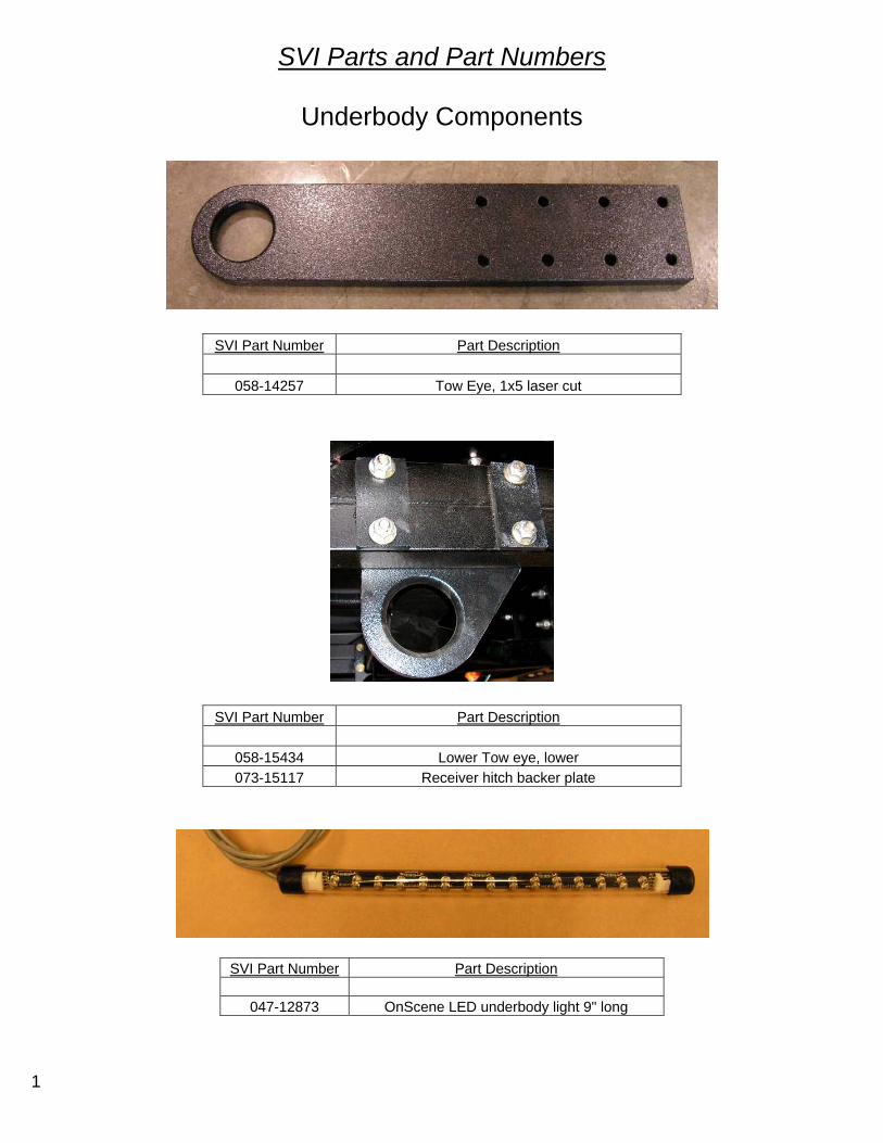
1
SVI Parts and Part Numbers
Underbody Components
SVI Part Number Part Description
058-14257 Tow Eye, 1x5 laser cut
SVI Part Number Part Description
058-15434 Lower Tow eye, lower 073-15117 Receiver hitch backer plate
SVI Part Number Part Description
047-12873 OnScene LED underbody light 9" long
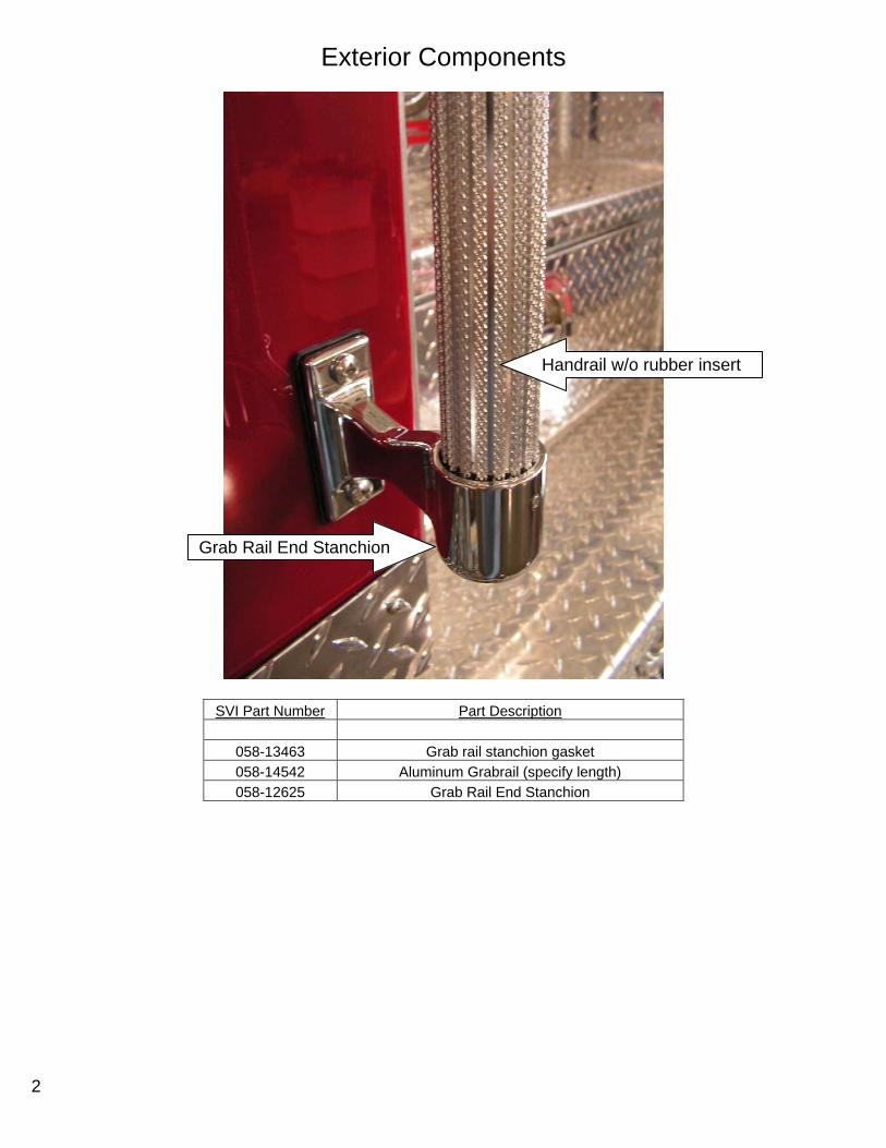
2
Exterior Components
SVI Part Number Part Description
058-13463 Grab rail stanchion gasket 058-14542 Aluminum Grabrail (specify length) 058-12625 Grab Rail End Stanchion
Grab Rail End Stanchion
Handrail w/o rubber insert
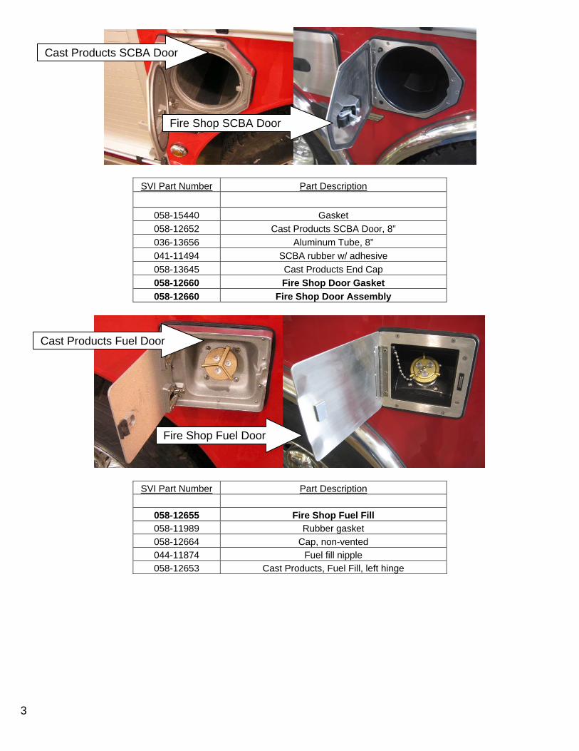
3
SVI Part Number Part Description
058-15440 Gasket 058-12652 Cast Products SCBA Door, 8” 036-13656 Aluminum Tube, 8” 041-11494 SCBA rubber w/ adhesive 058-13645 Cast Products End Cap 058-12660 Fire Shop Door Gasket 058-12660 Fire Shop Door Assembly
SVI Part Number Part Description
058-12655 Fire Shop Fuel Fill 058-11989 Rubber gasket 058-12664 Cap, non-vented 044-11874 Fuel fill nipple 058-12653 Cast Products, Fuel Fill, left hinge
Cast Products SCBA Door
Fire Shop SCBA Door
Cast Products Fuel Door
Fire Shop Fuel Door

4
SVI Part Number Part Description
058-15459 Stainless Steel Fenderettes
SVI Part Number Part Description
066-12301 Fender Liners, HDPE, Black, 1/8" x 32" x 100"
SVI Part Number Part Description
060-15300 Receiver Tube, Steel 24" 058-15438 Rope Tie-off 059-14883 Hitch pin
Receiver Tube
Hitch Pin
Rope Tie-off

5
Upper Body Compartment parts
SVI Part Number Part Description 058-12600 Grab Handle, Chrome, Roof Comp.058-11988 Grab Handle, gasket
SVI Part Number Part Description
(See page 11) Gas shock (See page 11) 058-12675 Walkway door plate
(See page 19) Night Stik (specify length) 047-12879 OSS Light Clip
SVI Part Number Part Description
047-15470 Night Stik LED Aluminum Mounting Bezel
SVI Part Number Part Description
054-12293 Tilt switch for Upper Body compartments
SVI Part Number Part Description 073-00271 Bracket, Door Latch 058-13453 Rotary Latch 058-13454 Paddle Latch
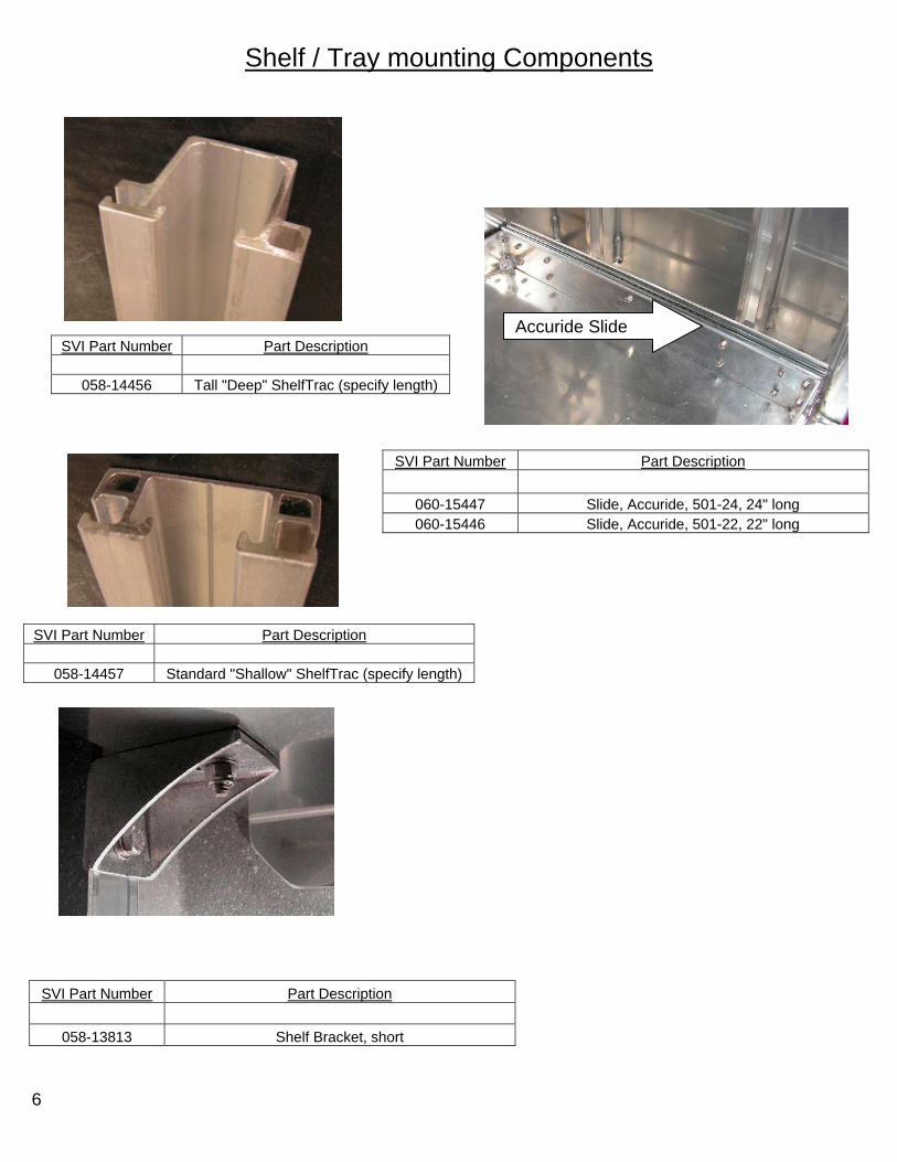
6
Shelf / Tray mounting Components
SVI Part Number Part Description
058-14456 Tall "Deep" ShelfTrac (specify length)
SVI Part Number Part Description
058-14457 Standard "Shallow" ShelfTrac (specify length)
SVI Part Number Part Description
058-13813 Shelf Bracket, short
SVI Part Number Part Description
060-15447 Slide, Accuride, 501-24, 24" long 060-15446 Slide, Accuride, 501-22, 22" long
Accuride Slide
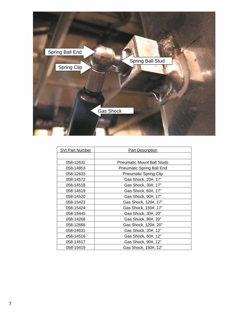
7
SVI Part Number Part Description
058-12632 Pneumatic Mount Ball Studs 058-14853 Pneumatic Spring Ball End 058-12633 Pneumatic Spring Clip 058-14572 Gas Shock, 20#, 17” 058-14518 Gas Shock, 30#, 17” 058-14519 Gas Shock, 60#, 17” 058-14520 Gas Shock, 90#, 17” 058-15423 Gas Shock, 120#, 17” 058-15424 Gas Shock, 150#, 17” 058-15445 Gas Shock, 30#, 20” 058-14268 Gas Shock, 90#, 20” 058-12666 Gas Shock, 120#, 20” 058-14631 Gas Shock, 20#, 12” 058-14516 Gas Shock, 60#, 12” 058-14517 Gas Shock, 90#, 12” 058-15419 Gas Shock, 150#, 12”
Spring Ball End
Spring Clip Spring Ball Stud
Gas Shock
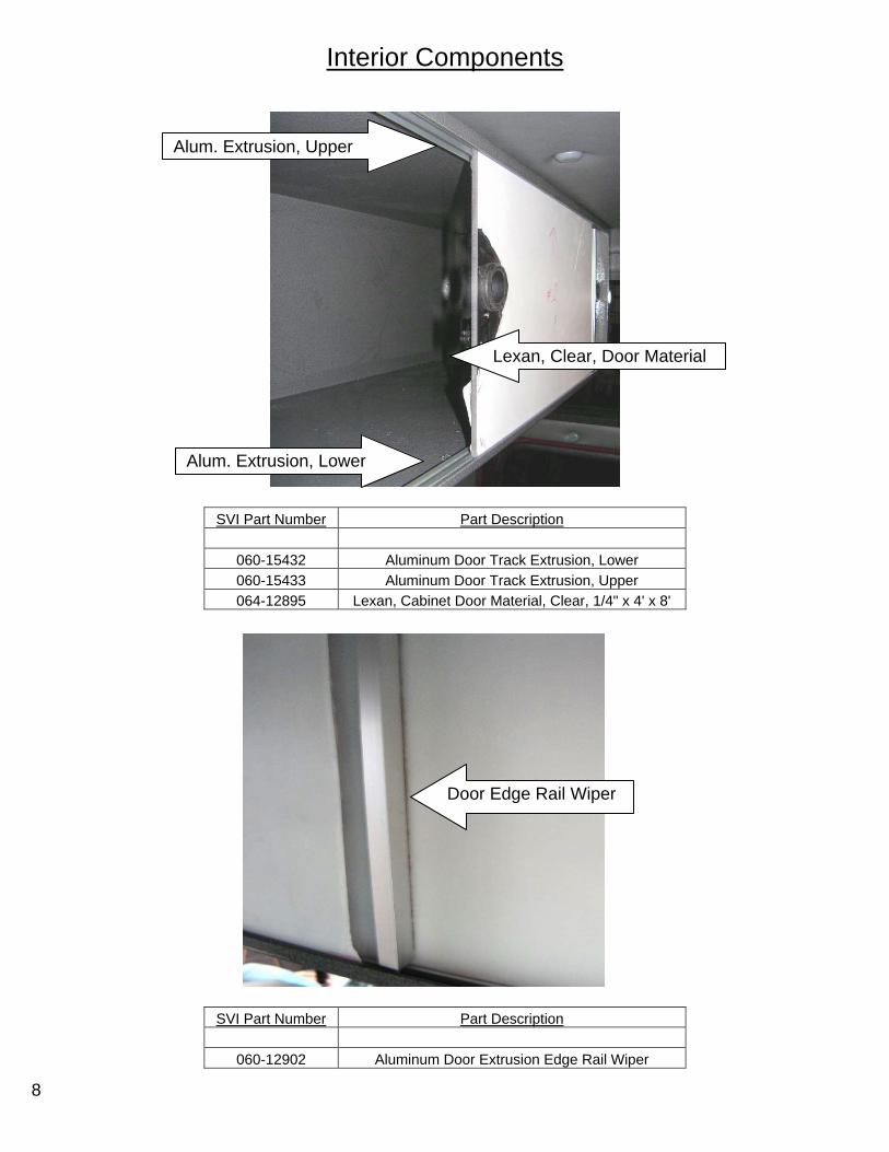
8
Interior Components
SVI Part Number Part Description
060-15432 Aluminum Door Track Extrusion, Lower 060-15433 Aluminum Door Track Extrusion, Upper 064-12895 Lexan, Cabinet Door Material, Clear, 1/4" x 4' x 8'
SVI Part Number Part Description
060-12902 Aluminum Door Extrusion Edge Rail Wiper
Alum. Extrusion, Upper
Alum. Extrusion, Lower
Lexan, Clear, Door Material
Door Edge Rail Wiper
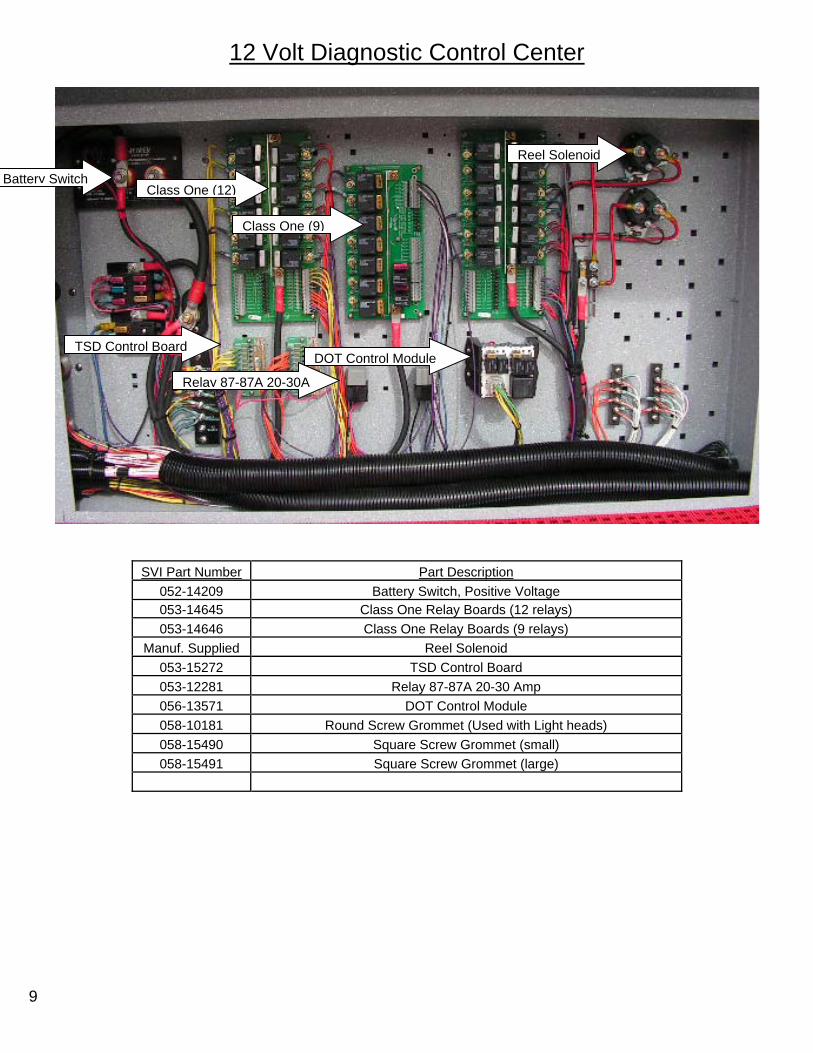
9
12 Volt Diagnostic Control Center
SVI Part Number Part Description 052-14209 Battery Switch, Positive Voltage 053-14645 Class One Relay Boards (12 relays) 053-14646 Class One Relay Boards (9 relays)
Manuf. Supplied Reel Solenoid 053-15272 TSD Control Board 053-12281 Relay 87-87A 20-30 Amp 056-13571 DOT Control Module 058-10181 Round Screw Grommet (Used with Light heads) 058-15490 Square Screw Grommet (small) 058-15491 Square Screw Grommet (large)
Battery Switch Class One (12)
Class One (9)
Reel Solenoid
TSD Control Board
Relay 87-87A 20-30A
DOT Control Module
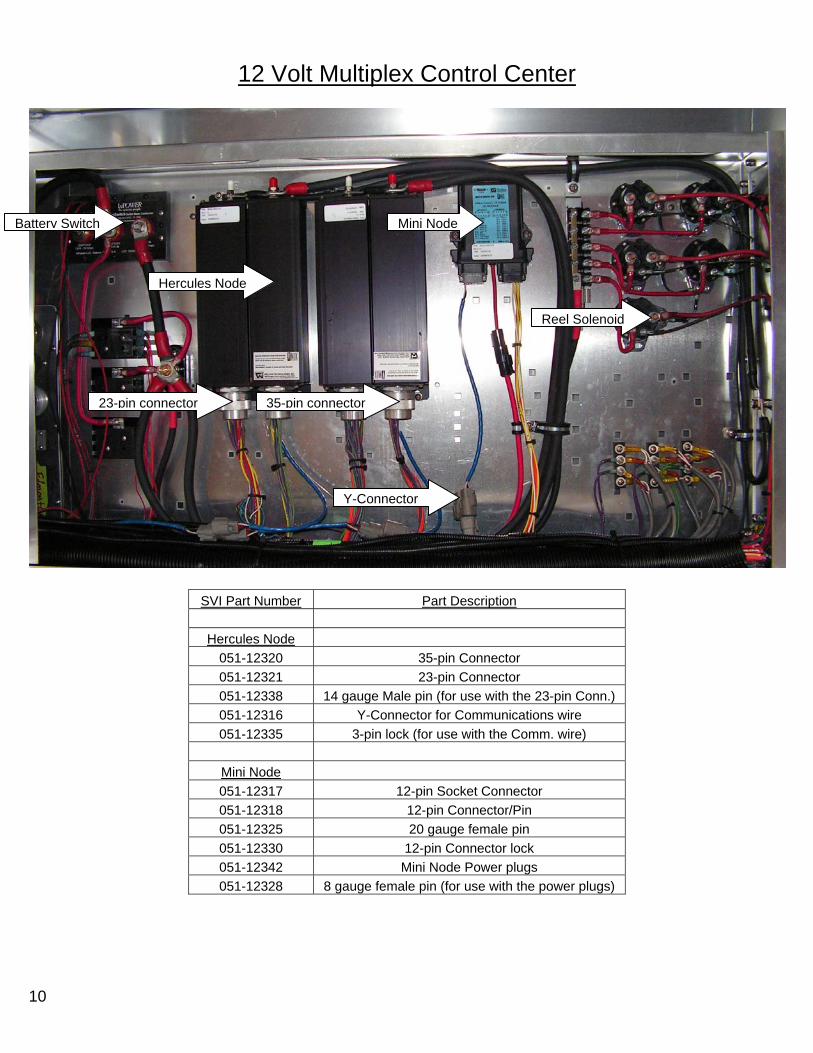
10
12 Volt Multiplex Control Center
SVI Part Number Part Description
Hercules Node 051-12320 35-pin Connector 051-12321 23-pin Connector 051-12338 14 gauge Male pin (for use with the 23-pin Conn.) 051-12316 Y-Connector for Communications wire 051-12335 3-pin lock (for use with the Comm. wire)
Mini Node 051-12317 12-pin Socket Connector 051-12318 12-pin Connector/Pin 051-12325 20 gauge female pin 051-12330 12-pin Connector lock 051-12342 Mini Node Power plugs 051-12328 8 gauge female pin (for use with the power plugs)
Battery Switch
Reel Solenoid
Hercules Node
Mini Node
Y-Connector
35-pin connector23-pin connector

11
120 / 240 Volt Components
SVI Part Number Part Description
053-14917 Floodlight relay
SVI Part Number Part Description
051-14397 Cab Junction box
SVI Part Number Part Description
065-13513 120 Volt Circuit breaker (20 Amp shown)
SVI Part Number Part Description
065-13516 240 Volt Circuit breaker (20 Amp shown)
SVI Part Number Part Description
065-13510 100 Amp 3-phase Circuit breaker
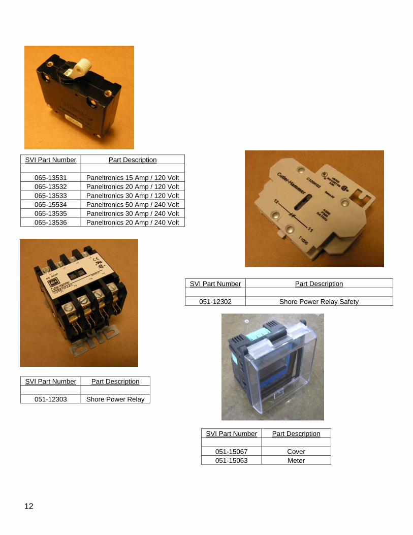
12
SVI Part Number Part Description
065-13531 Paneltronics 15 Amp / 120 Volt 065-13532 Paneltronics 20 Amp / 120 Volt 065-13533 Paneltronics 30 Amp / 120 Volt 065-15534 Paneltronics 50 Amp / 240 Volt 065-13535 Paneltronics 30 Amp / 240 Volt 065-13536 Paneltronics 20 Amp / 240 Volt
SVI Part Number Part Description
051-12302 Shore Power Relay Safety
SVI Part Number Part Description
051-12303 Shore Power Relay
SVI Part Number Part Description
051-15067 Cover 051-15063 Meter

13
Compartment Lights
SVI Part Number Part Description
Mounting Parts 034-10534 8-32 Track nut OSS 047-12879 OSS Light Clip 034-10535 8-32 Button head Socket OSS NightStick
LED NightStick
047-12873 9" NightStick 047-15466 18" NightStick 047-12874 27" NightStick 047-15467 36" NightStick 047-12875 54” Night Stick
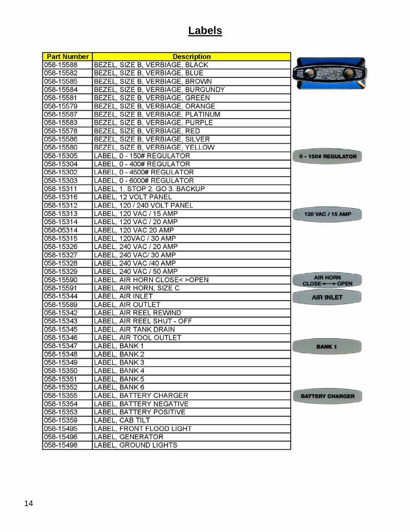
14
Labels

15
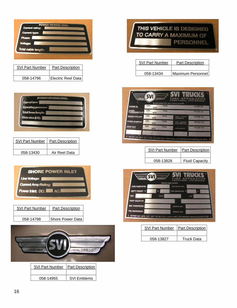
16
SVI Part Number Part Description
058-14796 Electric Reel Data
SVI Part Number Part Description
058-13430 Air Reel Data
SVI Part Number Part Description
058-14798 Shore Power Data
SVI Part Number Part Description
058-13434 Maximum Personnel
SVI Part Number Part Description
058-13828 Fluid Capacity
SVI Part Number Part Description
058-13827 Truck Data
SVI Part Number Part Description
058-14955 SVI Emblems

17
Miscellaneous Parts
SVI Part Number Part Description
047-11942 Arrow License Plate Light
SVI Part Number Part Description
058-13507 Latch, Push Release
SVI Part Number Part Description
058-10182 Drain intake adapter 058-10178 Hose, Vac-U-flex, 1" x 1/4"
Clamp, hose, 3/4" to 1 3/4" hose
Drain Intake Adapter
Clamp, hose, ¾” to 1 ¾” hose
Hose, Vac-U-flex, 1” x 25’

Part # Qty Description UnitsAKRON BRASS CO
060-14558 2 JUNCTION BOX, AKRON BRASS EA 060-14565 2 JUNCTION BOX BRACKET EA
ALLCABLE 051-13621 64 CONDUIT POLYTUFF TUBING 1/2in 1721/12 LF 051-13622 20 CONDUIT POLYTUFF TUBING 1in B2100 LF 052-12210 16 WELDING CABLE, 2/0, NEOPRENE LF 052-13955 6 BATT.TERM PROTECTOR,2 GAUGE,BLACK 5737B EA 052-13956 10 BATTERY TERM PROTECTOR,2 GAUGE,RED 5737R EA 055-12328 80 WIRE, 4 GA, THHN LF 055-12356 400 CABLE, 10-3 SEOW, NEOPRENE, BLACK LF 055-13786 220 CABLE, LMR 195 COAXIAL CABLE LF
ALLEGIS CORP 041-15272 85 GASKET, D-SHAPE, W ADHESIV, X-109HT, MED LF 047-15200 2 LIGHT, BRITAX, RUBBER BUMPER EA 058-10186 8 VENT, PLASTIC, BLACK, 3-1/2 x 3-1/2 EA 058-12632 28 PNEUMATIC MOUNT BALL STUD AC 98 SS EA 058-12636 2 PNEUMATIC MOUNT GS MB-3 EA 058-13507 2 LATCH, PUSH RELEASE, SC2-32-11-3,SOUTHCO EA 060-15397 0.8 HINGE, SS, 1/4P x 1K x 4F x 96 EA 060-15447 6 SLIDE, NON LOCK, 24 IN, ACCURIDE, 9301 PR
ALLIED ELECTRONICS INC 056-14030 3 CRIMP, MINI, UHF for LMR-195, ALLIED EA 056-14035 1 LABEL, 24mm 1 IN, BLACK ON WHITE EA 056-14065 1 LABEL, 12mm 1/2 IN, BLACK ON WHITE EA
AMDOR INC. 054-14460 4 ROLL-UP DOOR, AMDOR, (See Drawing) EA 054-14460 2 ROLL-UP DOOR, AMDOR, (See Drawing) EA 054-14460 2 ROLL-UP DOOR, AMDOR, (See Drawing) EA 054-14461 8 SWITCH, DOOR AJAR, AMDOR EA
APPLIED INDUSTRIAL 041-11471 2.66 MUD FLAP RUBBER, 1/4 x 36 LF
AUSTIN HARDWARE & SUPPLY 054-12279 5 SWITCH, GAS PISTON, EZ ASSEMBLY EA 058-11988 10 GASKET, CHROME GRAB HANDLE, G 3200 EA 058-12600 5 HANDLE, GRAB, DIE CAST, CHROME EA 058-13498 2 HANDLE, D-RING, EG3-SEFL-BCW-1250 EA 058-14515 1 GAS SPRING, 7.50 IN, 61 LB EA 058-14517 10 GAS SPRING, 12.09 IN, 94 LB EA 058-14518 5 GAS SPRING, 17.20 IN, 34 LB EA
2 GAS SPRING, 15 IN, 18 LB EA
AUVECO PRODUCTS 034-14905 2 FASTENER, NYLON, #6 EA 058-15490 66 SCREW GROMMET, SQUARE, MEDIUM EA 058-15491 20 SCREW GROMMET, SQUARE, LARGE EA 064-12790 2 WEATHERSTRIP, AUVECO 4530 TEE RUBBER EA
B & G EQUIPMENT INC. 040-11436 4 RUSTPROOFING, KROWN GL
BADGER RUBBER CO

041-11475 11 GROMMET, FLOOR DRAIN, 5436 EA 041-15258 1 GROMMET, RUBBER, 2.125ID X 2.875OD EA
BARKER ENTERPRISES, INC 047-13709 1 LIGHT, LOOK UP, 35W,12VDC, BLACK, 88113B EA
BREY-KRAUSE MFG. CO. 058-14096 1 GRAB RAIL, STAIRCASE LH BS KNURL STT STR EA 058-14097 1 GRAB RAIL, STAIRCASE RH BS KNURL CURB EA 058-14098 2 GRAB RAIL, 24CL BS KNURL 304 FLG EA
CAST PRODUCTS INC 058-12675 10 BRACKET, UPPER COMP DOOR, CAST, PRO 286 EA
CDW1546164 1 AXIS Q7401 VIDEO ENCODER EA
COAST RV PRODUCTS INC 058-14370 1 REFRIG, 120V/12V, NORCOLD,DE-0751, COAST EA 058-14366 1 CORD, POWER, NORCOLD,NR751BB EA
COLORADO SCREW MACHINE 058-10182 16 DRAIN TUBE ADAPTER EA
CONSOLIDATED ELECTRIC DISTRIBUTORS051-14400 1 ENCLOSURE, ELECTRIC, HOFFMAN, WATERPROOF EA
CONTROL PRODUCTS INC 054-12274 4 SWITCH, CPI, BRACKET LONG PLUNGER EA 054-12276 1 SWITCH, CPI, RIGHT HAND EA 054-12277 1 SWITCH, CPI, CMPT DOOR LH EA
CUMMINS ROCKY MTN LLC 051-15419 1 GEN ONAN PROTEC 15KW 15YDCR621C EA
DELL, INCA6805337 1 SAMSUNG 32" LED TV EA
FIRE RESEARCH CORP 047-15546 2 TRIPOD, VAC, FRC, FCA656-S50-ON-6F3P2 EA
FIRE SPEC 058-14955 3 LOGO, SVI TRUCKS, NEW STYLE ,1998 EA
FLEET OIL & TRUCK SUPPLY 058-12664 1 FUEL FILL CAP, NON VENTED, 2 INCH,FEMALE EA
FLEXIBLE TECHNOLOGIES 058-10178 76 HOSE 1 IN VAC-U-FLEX DRAIN HOSE LF
GRAINGER INC 051-12304 2 RECEPTACLE, DUPLEX, 20AMP, 125VOLT,WHITE EA 051-15168 1 CONN STRAIN RELIEF FOR 8-3 CABLE 5D736 EA 067-15336 1 AIR QC MALE X MPT SPEEDAIRE 2X169 EA
HANNAY REELS 061-12724 4 REEL HANNAY HS-3 HOSE STOPS SMALL EA 061-12815 1 REEL HANNAY ECR1618-17-18 TR RT, ASSY C EA 061-12731 1 REEL HANNAY ECR1618-17-18 TR LT, ASSY C EA

061-12703 1 REEL HANNAY EF2016-17-18 VR LEFT HYDRAUL EA 061-12704 1 REEL HANNAY EF2016-17-18 VR RIGHT HYDRAU EA
HURST JAWS OF LIFE 051-12985 2 HOSE, STREAMLINE, 100 FT EA 051-12988 2 PIGTAIL, STREAMLINE, 16 FT EA
1 Hurst SC357E E-Draulic Combi tool complete with two (2) batteries and one (1) AC adaptor EA 1 Hurst JL500 hydraulic cutte EA 1 Hurst ML28 Defender spreader tool EA 1 Hurst T59 telescopic ram tool EA 1 Hurst JL-SG Power Unit EA
HUTTON COMMUNICATIONS 056-04969 3 NMO MOUNT, SOLDER ON, LAR-NM0-B EA 056-14027 3 RAIN CAP, for NMO BASE, ANTENNX # QWRC EA 056-14029 3 GASKET,SEAL,for NMO MOUNTS,ANTENNX#MOGSK EA
IEWC CORP. 055-00019 64 WIRE, 10 GA, GXL, BLUE, 01 OUTLET LF 055-00027 64 WIRE, 10 GA, GXL, GREEN, BOND LF 055-00032 64 WIRE, 10 GA, GXL, WHITE, NEUTRAL LF 055-00151 16 WIRE, 12 GA, GXL, WHITE, NEUTRAL LF
INNOVATIVE CONTROLS, INC 058-15314 2 LABEL, 120 VAC/20 AMP EA 058-15316 1 LABEL, 12 VOLT PANEL EA 058-15372 1 LABEL, DIESEL FUEL ONLY EA 058-15375 1 LABEL, DOOR AJAR EA 058-15378 2 LABEL, ELECTRIC REEL REWIND EA 058-15504 2 LABEL, HYDRAULIC REEL REWIND EA 058-15549 2 LABEL, RIDING WARNING, WHITE / BLACK EA 058-15562 1 LABEL, KIT, GAUGE BEZEL, BLACK EA 058-15578 1 LABEL, BEZEL, VERBIAGE, RED EA 058-15579 1 LABEL, BEZEL, VERBIAGE, ORANGE EA 058-15581 1 LABEL, BEZEL, VERBIAGE, GREEN EA 058-15586 2 LABEL, BEZEL, VERBIAGE, SILVER EA 058-15588 2 LABEL, BEZEL, VERBIAGE, BLACK EA 058-15596 5 LABEL, NOT A STEP WARNING, SMALL EA 058-15602 1 LABEL, HIGH VOLTAGE POWER DISTRIBUTION P EA 058-15962 1 LABEL, DEATH OR SERIOUS INJURY MAY EA 058-15963 2 LABEL, WARNING DO NOT WEAR HELMET EA 058-15970 1 BEZEL, SIZE B, DUAL, 3001804 EA 058-15971 1 OVERLAY, SIZE B, TRUCK DATA CHART EA 058-15972 1 BEZEL, SIZE D, SINGLE, 3001917 EA 058-15973 1 OVERLAY, SIZE D, VEHICLE SPECS. WARNING EA 058-15981 1 BEZEL, SIZE E, DUAL, 3001923 EA 058-15982 1 OVERLAY, SIZE E, FLUID DATA EA 058-15983 1 LABELS, SHEET, 18 PER SHEET, 3001805 ST
INNOVATIVE INDUSTRIES INC 060-14223 1 SLIDE, SLIDEMASTER, SM2P-SP, 61-72x41 (See Drawing) EA 060-14227 2 SLIDE, SLIDEMASTER, SM2-D, 85-96x41 (See Drawing) EA 060-14228 1 SLIDE, SLIDEMASTER, SM2-D, 85-96x51 (See Drawing) EA
INPOWER 052-14206 2 BATTERY SWITCH, INPOWER, SSC20-200 EA
INTERNET 056-14075 2 FLASH DRIVE, CUSTOM LOGO, 1GB EA

058-11998 12 GASKET, NEOPRENE, SS GRAB HANDLE EA
KELLY SUPPLY CO 044-11868 1 PIPE NIPPLE, BLACK, 2 x CLOSE EA 044-11869 1 PIPE ELBOW,BLK,2 X 90 DEG EA 044-11874 1 FUEL FILL, NIPPLE, BARBED FITTING, DIXON EA 044-14794 1 PIPE ELBOW,BLK, 2 X 45 DEG EA
KEMPER PRODUCTS, INC. 033-14881 8 NUTSERT, 1/4-20, LONG EA
LADD DISTRIBUTION 051-12352 12 NUT, PANEL, AL, SIZE 24, BAYONET EA 051-12353 12 WASHER, LOCK SIZE 24 BAYONET 112264 EA 056-12465 2 DUST CAP, DEUTSCH, WITH CHAIN EA 056-12572 1 WASHER, LOCK, #18 EA 056-12573 1 PANEL, NUT, METAL, # 18 EA 056-12606 2 CONNECTOR, DEUTSCH, DT04-12PA-P021, CAP EA
LANE SUPPLY CO 040-14501 1 GLUE, SCOTCH WELD EPOXY, CHASSIS FRAME EA
McCOY SALES CORP 044-14839 80 TUBING, PLASTIC, DOOR GUARD DRIP PAN LF 056-12402 2 CLAMP, FUEL FILL, T BOLT, DIXON EA 057-12561 3 HOSE, FUEL FILL, 2 INCH ID, McCOY, BLACK LF 057-12572 4 HOSE, FUEL VENT, 1/2, PUSHLOK, 300 PSI LF
MCMASTER CARR SUPPLY CO. 032-12901 32 NUT, THUMB, AL, 1/4-20 SCREW, 3/4 HEAD EA 032-12902 32 BOLT, ELEVATOR, SS, .25-20, .75, 18-8 EA 058-15489 1.2 SPACER, PLASTIC, 1 x .510 x 1 PKG
MINITMAN SUPPLY INC.032-10823 12 BOLT, HEX, GR8, 1/2-13 x 3 EA 032-10825 8 BOLT, HEX, GR8, 1/2-13 x 4-1/2 EA 032-10827 24 BOLT, HEX, GR8, 1/2-13 x 3-1/2 EA 032-10828 44 NUT, STOVER, 1/2-13 EA 032-10829 76 WASHER, FLAT, GR8, SAE, 1/2 EA 032-10849 12 BOLT, HEX, GR8, 3/4-10 x 2 EA 032-10856 12 BOLT, HEX, GR8, 3/4-10 x 6 EA 032-10859 12 WASHER, FLAT, GR8, USS, 3/4 EA 032-10861 24 NUT, STOVER, 3/4-10 EA 032-10862 36 WASHER, FLAT, GR8, 3/4 EA 032-10886 36 NUT, HEX, NYLOK, SS, 5/16 THIN EA 032-10888 36 WASHER, FLAT, SS, 5/16 EA 034-10462 6 SCREW, PHIL, PH, SS, 8-32 x 1 EA 034-10463 4 SCREW, PHIL, FH, SS, 10-24 x 1/2 EA 034-10476 24 NUT, HEX, NYLOK, SS, 10-24, THIN EA 034-10509 16 WASHER, FLAT, SS, 1/4 EA 034-10531 36 WASHER, LOCK, SS, 5/16 EA 034-10545 72 WASHER, SHOULDER, NYLON, 1/4 SHORT EA 034-10550 36 RIVET, PLASTIC, BLACK EA 034-10552 4 TURNBUCKLE, 3/16 x 5-1/2, N221-820 EA 034-10560 8 SCREW, ALLEN, PH, 8/32 x 1/4 EA 034-10917 2 SCREW, PHIL, PH, SS, 6-32 x 1/2 EA 034-10943 12 SCREW, PHIL, PH, SS, 8-32 x 1-1/4 EA 034-10964 2 SCREW, PHIL, PH, SS, 10-24 x 5/8 EA 034-10967 36 SCREW, 10-24 x 7/8, PPMS, SS EA

034-10983 4 NUT, HEX, NYLOK, SS, 10-24 EA 034-10994 20 SCREW, PHIL, FH, SS, 1/4-20 x 1/2 EA 034-11003 8 SCREW, PHIL, PH, SS, 1/4-20 x 3/4 EA 034-11005 6 SCREW, PHIL, PH, SS, 1/4-20 x 1-1/4 EA 034-11043 72 BOLT, HEX, SS, 5/16-18 x 1-1/4 EA 034-11054 36 WASHER, FENDER, SS, 5/16 EA 034-11078 4 BOLT, HEX, SS, 7/16-14 x 1-1/2 EA 034-11089 4 NUT, HEX, NYLOK, SS, 7/16-14 EA 034-13940 36 WASHER, FENDER, SS, 3/8 X 1-1/4 EA 034-15008 30 SCREW, PHIL, TRUSS, SS, 10-24 x 1/2 EA 034-15010 6 SCREW, PHIL, TRUSS, SS, 10-24 x 1 EA 034-15036 16 SCREW, PHIL, TRUSS, SS, 8-32 x 3/8 EA 034-15077 96 SCREW, PHIL, PH, SMS, SS, #8 x 1-1/2 EA 043-11661 1 WEATHERHEAD, BUSHING, 3220 x 8 x 4 EA 043-13894 1 WEATHERHEAD, MALE ELBOW, 90, 1469x8x4 EA 046-11933 1 VALVE, BENDIX, CHECK, BW800375 EA 052-13951 12 BATTERYCABLE END 2/0 X3/8IN RING PLATED EA 052-14335 5 BATTERY STUD SINGLE TERMINAL S240-7000 EA 056-12343 16 HOSE CLAMP,DRIP PAN TUBE,.4375 ODx .3125 EA 056-12351 6 CLAMP, HOSE, #12 EA 056-12365 4 CLAMP, LOOM, #6 EA 056-12369 2 CLAMP, LOOM, #20 EA 056-12533 4 TERMINAL, FEM, DELPHI, #31077, IN POWER EA 056-13763 4 TERMINAL, FEMALE, 22-18, SHRINK EA 056-13764 20 TERMINAL, MALE, 16-14, SHRINK EA 056-13766 20 TERMINAL, MALE, 12-10, SHRINK EA 058-14459 12 NUT, UNISTRUT, 1/4-20 EA 060-15421 2 WELDED RING,3/8X2,PLAIN,SAFETYCHAIN LOOP EA 065-15300 3 HEAT SHRINK, 4GA x 2 O x 1.5 IN, BLK,ADH EA 065-15323 9 HEAT SHRINK, 4GA x 2 O x 1.5 IN, RED,ADH EA
MSC INDUSTRIAL SUPPLY 058-12645 12 SPRING, 4IN BODY MOUNT, MH 200-400 (DATO EA
NATALE MACHINE & TOOL CO 047-15374 5 LIGHT, SURVIVOR, DIV2, 12VDC, FAST, ORNG EA
1 5 Bank DC Charger 90401 EA
NEWCO 034-15021 1 LOCKNUT, CONDUIT, STEEL, 1/2 IN EA 034-15023 1 LOCKNUT, CONDUIT, STEEL, 1 IN EA 051-12142 1 ELEC COVER, POLY, HBL5221HU, DUPLEX EA 051-12372 1 CONTACTOR, DEFINITE PURPOSE, 2 POLE, CH EA 051-12370 1 AUX CONTACT EA 051-12371 1 CONTACTOR, DEFINITE PURPOSE, 4 POLE, CH EA 051-13629 3 ELEC MULBERRY 30209 2 X 4 W/P BOX 4-KO EA 051-15401 2 HBL DUPLEX WALL PLATES SS MUL 93101 EA 058-12642 32 NUT, UNISTRUT, 5/16 x 1/4 in EA
NORTHERN COLO DRIVELINE 066-16162 1 YOKE, FLANGE (SEE DRAWING) EA 066-16164 1 DRIVESHAFT (SEE DRAWING) EA
ON SCENE SOLUTIONS00*-OSS RUBRAIL 1 ONSCENE - RUBRAIL ( See Drawing ) EA034-10534 24 NUT, TRACK, 8-32 EA 047-12871 8 LIGHT, ONSCENE, 8 IN, ACCESS EA 047-12884 4 LIGHT, ONSCENE, 28 IN, ACCESS EA 73046-WH 8 LIGHT, ONSCENE, 46 IN, ACCESS EA

047-12886 4 LIGHT, ONSCENE, 54 IN, ACCESS EA 047-15274 4 LIGHT HOUSING KIT, ROUGH SERVICE, 9 IN EA 047-15466 5 LIGHT, ONSCENE, 18 INCH, NIGHT AXE EA 047-12874 2 LIGHT, ONSCENE, 27 IN, NIGHT AXE EA058-11990 5 STRAP ASSEMBLY, 3 INCH ALUMINUM BUCKLE EA 058-11992 1 STRAP ASSEMBLY, 18 INCH STRAP, ONSCENE EA 058-11993 4 STRAP ASSEMBLY, 36 INCH STRAP, ONSCENE EA 058-12001 4 HELMET MOUNT, TALON EA 058-13710 8 FOOTMAN LOOP, ON SCENE EA
PDM STEEL SERVICE 037-11286 3.1 ST, TUBE, 11GA x 2 x 4 LF
PIEDMONT PLASTICS 065-15173 36 UHMW, FRAME, ISOLATOR, BLACK LF 066-12301 2 FENDER LINER, 1/8 x 32 x 96 EA
PORT SUPPLY 053-12227 1 OUTLET, 12 VOLT, ACCESORY, DOUBLE GANG EA 053-15308 3 FUSE BLOCK, 6 CIRCUIT, with COVER EA 054-12282 1 BUSS BAR, GROUND, CHROME PLATED BRASS EA
PROCESS MEASUREMENT CO 051-15063 1 METER, #CI3 EA 051-15064 2 CURRENT TRANSFORMER, 200/5, #2RL201 EA 051-15065 1 HOUR METER, #3410-2000 EA 051-15066 1 GASKET, #3C34501 EA 051-15067 1 COVER, #3G36502 EA 051-15068 3 INLINE .5A FUSE AND HOLDER, #PMCD-M1934 EA
PUTNAM HITCH PRODUCTS 1 HITCH, RECEIVER, 48 INCH EA
REXEL INC 051-12147 1 ELEC COVER, 20 AND 30 AMP POLY, GREY EA 051-13623 6 CONDUIT POLYTUF FIT 1/2 P050N-BK-A EA 051-13624 1 CONDUIT POLYTUFF FIT 1/2in X 90 PS0509NB EA 051-13625 2 CONDUIT POLYTUFF FIT 1in P100N-BK-A EA 051-14637 1 HUBBELL, 2620, 30A, 250V, RECEPT EA 051-14910 1 ELEC MULBERRY 2X4 BOX W/3/4in HOLES EA 051-14921 2 HUBBELL, 2613, 30A, 125V, FEMALE PLUG EA 051-14995 1 CONDUIT HUB NHC1042CR 1in 90 DEG. EA 056-12549 1 CONNECTOR, 45 DEGREE, 1 IN, LIQUID TITE EA 056-12551 1 BUSHING, REDUCING,.75 x.5 IN x.55 TALL EA 065-13518 1 BREAKER,45A,120/240V,2 POLE, BR245CT, CH EA 065-13522 1 BREAKER,125A,120/240V,2 POLE,BR2125CT,CH EA 065-13513 2 BREAKER, 20A, 120/240V, 1 POLE, BR120CT, EA 065-13519 1 BREAKER,70A,120/240V,2 POLE, BR270CT, CH EA 069-14548 1 BREAKER,BOX,CPL130,CUTTLER HAMMER EA 065-13514 2 BREAKER,30A,120/240V,1 POLE, BR130CT, CH EA 065-13517 2 BREAKER,30A,120/240V,2 POLE, BR230CT, CH EA
RYERSON DENVER 036-11129 0 AL, BAR, 1/2 x 2, 6061 LF 036-11156 0 AL, TUBE, 1/8 x 1 x 2, 6063 LF 036-11172 35 AL, ANGLE, 1/8 x 2 x 2, 6061 LF 036-11178 10 AL, ANGLE, 1/4 x 2 x 2 x 25 ft, 6061 LF 036-11180 0 AL, ANGLE, 1/4 x 2 x 3 , 6061 LF

036-11227 1 AL, ROUND, 3/4, 6061 LF 036-11232 0 SS, SHEET, 20GA x 48 x 120, #4 NITTO SF 036-11384 50 AL, TUBE, 1/8 x 2 x 3, 6063 LF 037-11369 0 ST, BAR, 3/8 x 5, CR LF 058-14456 125 AL, SHELF TRACK, DEEP LF 058-14457 100 AL, SHELF TRACK, SHALLOW LF 060-14805 53 AL, CHANNEL, 1/4 x 2 x 2, 6063 LF 060-14806 20 AL, DOOR THRESHOLD, 2 x 1/2 x .062 LF 036-13914 5 AL, GRIPSTRUT, 1-1/2 x 4-3/4 LF 037-11286 3 ST, TUBE, 11GA x 2 x 4 LF 036-11137 0 AL, SHT, TREAD, .190 x 48 x 144 SF036-11144 0 AL, SHT, .125 x 48 x 144, 3003, NITTO SF036-11145 0 AL, SHT, .190 x 48 x 144, 3003, NITTO SF036-11159 125 AL, TUBE, 1/4 x 2 x 2, 6061 LF036-11162 15 AL, TUBE, 1/4 x 2 x 4, 6061 LF036-11163 105 AL, TUBE, 1/4 x 2 x 6, 6063 LF036-13621 380 AL, SHT, .190 x 60 x 144, 3003, NITTO SF036-13889 50 AL, SHT, .125 x 60 x 144, 3003, NITTO SF036-15315 95 AL, SHT, TREAD, NFPA, .190 x 60 x 144 SF036-15364 9 SS, SHT, 14GA x 60 x 144, 4B, NITTO SF 036-15331 0.2 SS, SHT, 12GA x 60 x 144, 2B, NITTO SF 036-15328 3 SS, SHT, 10GA x 48 x 120, 2B, NITTO SF 036-15313 260 AL, SHT, TREAD, .190 x 60 x 144 SF 036-13620 1000 AL, SHT, .190 x 60 x 144, 3003, NON NITTO036-13619 360 AL, SHT, .125 x 60 x 144, 3003, NON NITTO036-11151 24 AL, SHT, .090 x 60 x 144, 3003, NITTO SF
S & S HINGE COMPANY 060-15438 16 HINGE, SS, 1/4P x 1K x 2F x 16 EA
SEALCON 066-15006 1 FITTING, 90 DEGREE, .5 INCH, SEALCON EA
SEALEZE 3.3 BRUSH for BRUSH TRACK, 10 FOOT PIECES EA
058-12685 33 AL, BRUSH TRACK LF
SIGNATURE FIRESHOPP INC 058-12655 1 FUEL, FILL ACCESS DOOR SS FIRE SHOP EA
SOUTHERN ALUMINUM 036-15327 0.5 AL, PIPE, 4 OD x 1/4 WALL, 6061 LF
SPECIALTY PRODUCTS CO. 058-15434 2 TOW EYE LOWER EA
STURGEON ELECTRICES31C22-5N 1 PELCO PTZ CAMERA EA075-03422 1 PELCO KEYBOARD / JOYSTICK EA075-03423 1 KEYBOARD KIT EA
SUPER VAC (COMM LITE)
047-16001 1 COMMAND LIGHT, 6x1000 WATT LIGHTS, CL611 EA
SUPER VAC FOUNDRY 058-13813 24 CAST SHELF BRACKETS SVI EA
SVI TRUCKS034-14903 1 FASTENER KIT, ASSORTED, TRUCKS EA

057-12571 1 FUEL FILL, WELDED ASSY, ALUM, SVI EA 060-14960 1 SHROUD, ONAN GENERATOR, 20 GAGE CR STEEL EA 073-00277 12 BACKING PLATE, BODY MOUNT, 6 IN EA 073-00292 2 BRACKET, MOUNT, CUTTER/SPREADER, SVI EA 073-00295 4 BRACKET, REEL REWIND 1 EA 073-00319 2 MOUNTING PLATE, SHORE GEN PWR EA 073-00501 1 FACEPLATE, 120 V, DUPLEX EA 073-15168 8 ROLL UP DOOR PROTECTOR, 50 INCH EA 073-15320 1 ANTENNA BOX, 3 FT EA 073-15401 6 MOUNT, BODY LOWER EA 073-15405 6 MOUNT, BODY UPPER, 6IN AL EA 073-15421 2 BUSS BAR, IN POWER, COPPER EA 073-15422 1 JUMPER, FUSE BLOCK, 6 TERM EA 073-15437 1 MOUNT, ONAN GEN EA 080-33001 1 RECEIVER, MOUNT, BRACKET 3/8 HOT ROLLED EA 080-33002 1 MOUNTING PLATE, RECEIVER SHORT EA
THE LIGHTHOUSE INC 047-11942 1 LIGHT, LICENSE, ARROW, LED, 437-52-332 EA 047-15390 1 LIGHT, UNDER STEP, LED BAR LAMP EA 047-15462 2 LIGHT, CLEARANCE, LED, RED, 18011R EA 052-13793 2 BATTERY ISOLAT COLE HERSE 46211-01 STUD EA 052-15401 1 FUSE, HOLDER, TIE WRAP MOUNT HMEG-111 EA 052-15403 1 FUSE, AMG, 200 AMP EA 052-15414 1 TRAILER SCKT, 7WAY BLADE TYPE, OEM EA 052-15418 1 TRAILER SCKT, 7WAY PIN TYPE, ISO3731, OE EA 053-12256 5 BREAKER, COLE HERSEE, 30056-40A EA 053-12259 1 BREAKER HLDR, COLE HERSEE, 30090-2 GANG EA 053-12260 1 BREAKER HLDR, COLE HERSEE, 30090-4 GANG EA 053-12261 3 BREAKER HLDR, COLE HERSEE, 30090-6 GANG EA 053-12322 2 FUSE, HOLDER, MAXI, BLADE TYPE EA 053-12333 2 FUSE, MAXI BLADE, 40 AMP EA 053-12334 2 FUSE, MAXI BLADE, 60AMP EA 053-13701 3 FUSE, BLOCK, CH 46377-6 TERM EA 053-14525 18 BRKR CH THERMAL RESET 10 AMP 30409-10 EA
TIES 4 LESS LLC00*-LOOM MB(LT) 1 WIRE LOOM, MAIN BODY, LEFT EA00*-LOOM MB(RT) 1 WIRE LOOM, MAIN BODY, RIGHT EA00*-LOOM MECH 1 WIRE LOOM, MECHANICAL EA00*-LOOM PANEL 1 WIRE LOOM, 12V PANEL-INTERNAL EA00*-LOOM TRAILER 1 WIRE LOOM, TRAILER BRAKE EA00*-LOOM UP CMPT L 1 WIRE LOOM, UPPER COMPARTMENT, LEFT EA00*-LOOM UP CMPT R 1 WIRE LOOM, UPPER COMPARTMENT, RIGHT EA00*-LOOM WRN(LT) 1 WIRE LOOM, WARNING, LEFT EA00*-LOOM WRN(RT) 1 WIRE LOOM, WARNING, RIGHT EA052-14915 2 BATTERY GROUND STRAP 16in X 2GA. EA 056-12359 13 LOOM 014NPB 1/4 inch HIGH TEMP SPLIT LF 056-12360 9 LOOM, 038NPB 3/8 SPLIT 300 DEG. LF 056-13571 1 DILL BLOCK, DOT, LED, MIDSHIP MODULE EA
TIMBERLINE PLASTICS 057-12549 2 DRAIN TEE 1 IN HOSE BARB EA
TRUCK PARTS SPECIALISTS 1 PTO, CHELSEA, 280GMFJP-B5XV 126% RATIO EA
TTI, INC. 053-13481 4 SW, RCKR, DPST (ON)-OFF, BLK EA

053-13513 4 SW ACT, RCKR, CONTURA III, NO LNS, BK EA
TURTLE PLASTICS 041-12224 360 FLOOR, TURTLE TILE, 12 x 12, BLACK EA 041-12225 54 FLOOR, TURTLE TILE, MALE EDGE, BLACK EA
VISIONMARK INC 058-13432 2 DATA PLATE V1-5901 SEATED & BELTED EA
WELDON TECHNOLOGIES033-14001 2 NODE, HERCULES, WELDON EA
WHELEN ENGINEERING CO 047-12894 2 LIGHT, WHELEN, MARKER, AMBER, T0A00MAR EA 047-12895 2 FLANGE, WHELEN, CHROME, TFLANGEC EA 047-13731 8 LIGHT, WHELEN, AMBER/AMBER, 50A03ZAR EA 047-15422 8 FLANGE, WHELEN, CHROME, 5FLANGEC EA 047-12799 2 LIGHT, WHELEN, BRAKE/TAIL, 60BTT EA 047-13537 2 LIGHT, WHELEN, BACK-UP, 60C00WCR EA 047-15433 2 LIGHT, WHELEN, ARROW, AMBER, 60A00TAR EA 047-15492 4 LIGHT, WHELEN, RED/CLEAR, 60R02FCR EA 047-13716 2 LIGHT, WHELEN, RED/RED, 60R02FRR EA 047-15384 12 FLANGE, WHELEN, CHROME, 6EFLANGE EA 047-13712 2 LIGHT, WHELEN, RED/RED, 90RR5FRR EA 047-15469 4 LIGHT, WHELEN, RED/CLEAR, 90RR5FCR EA 047-13465 6 FLANGE, WHELEN, CHROME, 90FLANGC EA 047-13729 6 LIGHT, WHELEN, GRADIENT, 9SC0ENZR EA 047-15356 1 LIGHTBAR, WHELEN, FREEDOM, FN72QLED EA
WILL-BURT CO. 047-14902 1 MAST, WILL-BURT, 7-42 EA 047-14903 1 SOLENOID VALVE KIT, MAST, WILL-BURT EA 047-14904 1 MAST, WILL-BURT, FILTER LUB EA 047-14905 70 NYCOIL, 1IN, GRAY LF 047-14908 1 MAST, WILL-BURT, D-TEC II, AIR VALVE KIT EA 054-14909 1 SWITCH, PROX, WILL BURT MAST UP and DOWN EA
YORK CORRUGATING CO. 058-15459 2 FENDERETTE, 14 GA., LONG EA ADDITIONAL ITEMS 4 Windshield Wiper Blades EA 047-15595 1 LED Dome Light, Red/Clear lens, Rear Command Desk EA
1 Cab Tilt Safety Bar EA 1 Blow Hard rechargeable PPV fan EA 2 Kore Kooler rehab chairs EA
TECH EQUIPMENT
1 Pepwave MAX 700/HD2 Cellular, Wi-Fi, WAN Router EA 1 Video Monitor, Wall Mount, Fixed EA
CUSTOMER SUPPLIED 1 Advance Tec Multi Unit Charger EA 1 Stokes Basket EA 1 Electric Hydraulic Power Unit EA 1 Hydraulic Ram EA 1 Hydraulic Cutter EA 1 Hydraulic Spreader EA

SAFETYGUIDELINES
READ THIS FIRST.
These guidelines provide general safety recom-mendations for using hose and cable reels. However, theemployer should assess and determine if any additionalsafety measures are required for its particular applica-tion and operation, and fully instruct employees onthose safety measures.
Additionally, the employer should make a copy ofthis safety manual available to all employees workingwith reels. Additional copies of this safety manual maybe obtained upon request. No warranty of the correct-ness or sufficiency of the information in this manual ismade by Hannay Reels.
Read all relevant manuals and safety instructionsprior to unpackaging reels. If there is ANYTHING you donot understand about the safe installation and use ofyour Hannay reel, please contact Hannay Reels (Attn:Customer Service). We are always glad to help.
NOTICE
Hannay Reels will not assume any liability for any alter-ations and/or modifications to Hannay Reels or prod-ucts supplied by Hannay Reels nor for uses other thanfor which these products are intended. All warrantiesexpressed or implied will become null and void.
Hannay Reels553 State Route 143Westerlo, NY 12193-0159(518) 797-3791USA Toll Free 1-877-GO REELS (467-3357)FAX: 1-800-REELING (733-5464)Int’l. Fax: (518) 797-3259
50M HP 11-04 H-9602-ISG
REV 4
WARNING: PINCH POINT AREASUSE CAUTION WHEN OPERATING NEAR CHAIN AND
SPROCKETS.
Where chain guards are furnished, the reels should not be operated with them removed.
NOTE:
OSHA indicates the appropriate guarding of chains and sprockets isat least partly the responsibility of the final installer of equipment,based on the fact that equipment can be installed in so many differ-ent positions and so many different degrees of accessibility to theoperator.
Please make sure that you have thoroughly reviewed this issue whenmaking the installation of the reel.
USE CAUTION WHEN GUIDING HOSE ORCABLE BACK ONTO POWER REELS.
Keep the hand guiding the hose back onto the reel several inches away from the drum so thatthere is no possibility of trapped or pinched fingers. Use proper personal protectionequipment.
KEEP HANDS AWAY FROM SPOKED DISCS WHEN TURNING.
INSTRUCTIONS FOR SAFE FLUID HANDLINGUSE A HOSE REEL AND HOSE PROPERLY
RATED FOR THE JOB.Never exceed the pressure rating (psi) specified for a particular reel and hose. Also, make surethat the size and material of both the reel and hose are designed for the intended use.
USE A FLEXIBLE CONNECTOR BETWEEN ASWIVEL JOINT AND INLET PIPING.
CHECK FOR POSSIBLE LEAKS AT FLUIDCONNECTIONS PRIOR TO USE.
RELEASE PRESSURE IN HOSE BEFORE REMOVINGFITTINGS OR PERFORMING ANY MAINTENANCE.
BEFORE WINDING COLLAPSIBLE HOSE ONTO ALIVE REEL, HOSE MUST BE EVACUATED OF ALL FLUID.
POWER REWIND REELSUSE CIRCUIT BREAKERS FOR ELECTRIC REWIND
MOTORS.
Make sure that the circuit breaker is properly sized for the motor. Also, check all electricalconnections for proper installation prior to use.
REMOVE AUXILIARY CRANK REWIND HANDLEBEFORE USING POWER REWIND.
DISCONNECT POWER SOURCE BEFOREPERFORMING MAINTENANCE.
This applies to both electric and air-powered reels. Also, disconnect electrical power before
removing junction box covers or collector ring housings.
SPRING REWIND REELS
USE CAUTION WHEN SPRING REEL RATCHETASSEMBLY LOCK IS DISENGAGED.
When the lock is disengaged, always holdonto the hose or cable and guide it onto the reelas it rewinds.
ON SPRING REELS, NEVER REMOVE THE COVERCONTAINING THE SPRING.
Coiled springs are under tension and removal of cover can result in severe personal injury.
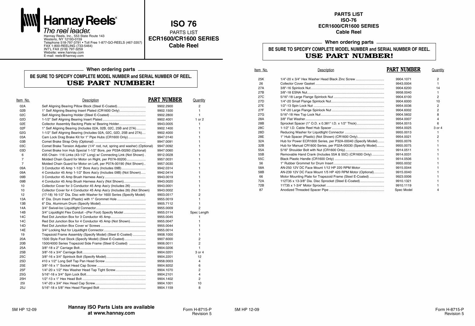
5M HP 12-09 Form H-8715-PRevision 5
5M HP 12-09 Form H-8715-PRevision 5
Item No. Description PART NUMBER Quantity02A Self Aligning Bearing Pillow Block (Steel E-Coated)............................... 9902.2900 202B 1" Self Aligning Bearing Insert Plated (CR1600 Only) ............................ 9902.1500 102C Self Aligning Bearing Holder (Steel E-Coated) ....................................... 9902.2800 102D 1-1/2" Self Aligning Bearing Insert Plated ............................................... 9902.4001 1 or 202E Collector Assembly Backing Plate w/ Bearing Holder............................. 9943.0005 102F 1" Self Aligning Bearing (Includes 02A, 02B, 02C, 25B and 27A) .......... 9902.1400 102G 1-1/2" Self Aligning Bearing (Includes 02A, 02C, 02D, 25B and 27A).... 9902.4000 103A Cam Lock Drag Brake Kit for 1" Pipe Hubs (CR1600 Only) ................... 9947.0140 103B Comet Brake Strap Only (Optional) ........................................................ 9947.0091 103C Comet Brake Tension Adjuster (1/4" rod, nut, spring and washer) (Optional) 9947.0092 103D Comet Brake Iron Hub Special 1-1/2" Bore, per P03A-00260 (Optional) 9947.0060 1
6 #35 Chain- 116 Links (43-1/2" Long) w/ Connecting Link (Not Shown) . 9912.0028 17 Molded Chain Guard for Motor on Right, per P07A-00200..................... 9957.0031 17 Molded Chain Guard for Motor on Left, per P07A-00190 (Not Shown).. 9957.0030 1
09A 3 Conductor 45 Amp 1-1/2" Bore Ass'y (Includes 09B) .......................... 9942.0314 109A 4 Conductor 45 Amp 1-1/2" Bore Ass'y (Includes 09B) (Not Shown)..... 9942.0414 109B 3 Conductor 45 Amp Brush Harness Ass'y............................................. 9943.0019 109B 4 Conductor 45 Amp Brush Harness Ass'y (Not Shown)........................ 9943.0020 110 Collector Cover for 3 Conductor 45 Amp Ass'y (Includes 26) ................ 9943.0001 110 Collector Cover for 4 Conductor 45 Amp Ass'y (Includes 26) (Not Shown) 9943.0002 112 (17-18) 16-1/2" Dia. Disc with Washer for 1600 Series (Specify Model) 9903.0517 2
13A 6" Dia. Drum Insert (Plastic) with 1" Grommet Hole ............................... 9955.0019 113B 6" Dia. Aluminum Drum (Specify Model)................................................. 9905.7112 114A 3/4" Swivel-loc Liquidtight Connector...................................................... 9955.0009 214B 3/4" Liquidtight Flex Conduit ~(Per Foot) Specify Model ........................ 9955.0114 Spec Length14C Red Dot Junction Box for 3 Conductor 45 Amp...................................... 9955.0045 114C Red Dot Junction Box for 4 Conductor 45 Amp (Not Shown)................. 9955.0047 114D Red Dot Junction Box Cover w/ Screws ................................................. 9955.0044 114E 3/4" Locking Nut for Liquidtight Connector.............................................. 9955.0014 119 Trapezoid Frame Assembly (Specify Model) (Steel E-Coated) .............. 9908.1000 1
20A 1500 Style Foot Stock (Specify Model) (Steel E-Coated) ....................... 9907.6000 220B 1500/4000 Series Trapezoid Side Frame (Steel E-Coated) .................. 9906.0011 225A 3/8"-18 x 2" Carriage Bolt........................................................................ 9904.0206 125B 3/8"-16 x 3/4" Carriage Bolt..................................................................... 9904.0201 3 or 425C 3/8"-16 x 3/4" Spinlock Bolt (Specify Model)........................................... 9904.2201 1225D #10 x 1/2" Long Self Tap Pan Head Screw ............................................ 9958.0003 425E 3/8"-16 x 1" Socket Head Cap Screw ..................................................... 9904.9202 625F 1/4"-20 x 1/2" Hex Washer Head Tap Tight Screw................................. 9904.1070 225G 5/16"-18 x 3/4" Spin Lock Bolt................................................................. 9904.2101 425H 1/2"-13 x 1" Hex Head Bolt ..................................................................... 9904.1402 225I 1/4"-20 x 3/4" Hex Head Cap Screw....................................................... 9904.1001 1025J 5/16"-18 x 5/8" Hex Head Flanged Bolt .................................................. 9904.1159 8
BE SURE TO SPECIFY COMPLETE MODEL NUMBER and SERIAL NUMBER OF REEL.USE PART NUMBER!
When ordering parts
BE SURE TO SPECIFY COMPLETE MODEL NUMBER and SERIAL NUMBER OF REEL.USE PART NUMBER!
When ordering parts
Item No. Description PART NUMBER Quantity
25K 1/4"-20 x 3/4" Hex Washer Head Black Zinc Screw ............................... 9904.1071 226 Collector Cover Gasket ........................................................................... 9943.0004 1
27A 3/8"-16 Spinlock Nut................................................................................ 9904.6200 1427B 3/8"-18 ESNA Nut.................................................................................... 9958.0040 127C 5/16"-18 Large Flange Spinlock Nut ....................................................... 9904.6100 227D 1/4"-20 Small Flange Spinlock Nut.......................................................... 9904.6000 1027E 1/2"-13 Spin Lock Nut ............................................................................. 9954.0036 227F 1/4"-20 Large Flange Spinlock Nut ......................................................... 9904.6002 227G 5/16"-18 Hex Top Lock Nut ..................................................................... 9904.5602 828A 3/8" Flat Washer...................................................................................... 9954.0007 428B Sprocket Spacer (1" O.D. x 0.381" I.D. x 1/2" Thick).............................. 9954.0015 628C 1-1/2" I.D. Cable Reel Hub Spacer ......................................................... 9954.0025 3 or 428D Reducing Washer for Liquidtight Connector ........................................... 9955.0013 128E 1" Hub Spacer (Plastic) (Not Shown) (CR1600 Only)............................. 9954.0021 232A Hub for Power ECR1600 Series, per P32A-00040 (Specify Model)....... 9955.0076 132B Hub for Manual CR1600 Series, per P32A-00030 (Specify Model)........ 9955.0075 155A 5/16" Shoulder Bolt with Nut (CR1600 Only) .......................................... 9914.0511 155B Removable Hand Crank (Includes 55A & 55C) (CR1600 Only) ............. 9914.0031 155C Black Plastic Handle (CR1600 Only) ...................................................... 9914.0506 156 1" Rubber Grommet for Drum Insert ....................................................... 9955.0032 1
58A AN-250 12V DC Face Mount 1/12 HP 220 RPM Motor.......................... 9915.0044 158B AN-239 12V DC Face Mount 1/5 HP 420 RPM Motor (Optional) ........... 9915.0040 166 Motor Mounting Plate for Trapezoid Frame (Steel E-Coated) ................ 9923.0006 1
72A 112T35 x 13-3/8" Dia. Disc Sprocket (Steel E-Coated) .......................... 9910.1321 172B 11T35 x 1-3/4" Motor Sprocket ............................................................... 9910.1119 187 Anodized Threaded Spacer Pipe ............................................................ Spec Model 4
ISO 76PARTS LIST
ECR1600/CR1600 SERIESCable Reel
Hannay Reels, Inc., 553 State Route 143Westerlo, NY 12193-0159Telephone 518-797-3791 • Toll Free 1-877-GO-REELS (467-3357)FAX 1-800-REELING (733-5464)INT’L FAX (518) 797-3259Website: www.hannay.comE-mail: [email protected]
Hannay ISO Parts Lists are availableat www.hannay.com
PARTS LISTISO-76
ECR1600/CR1600 SERIESCable Reel
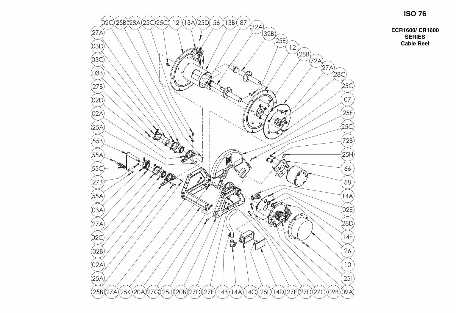
ISO 76
ECR1600/ CR1600SERIES
Cable Reel
Bulletin HY25-2277-M1/US
Parts List277/278 Series
Effective: February 15, 2002Supersedes: HY25-2277-M1/US December, 2001

Parker Hannifin CorporationChelsea Products DivisionOlive Branch, MS 38654 USA
FAILURE OR IMPROPER SELECTION OR IMPROPER USE OF THE PRODUCTS AND/OR SYSTEMS DESCRIBED HEREIN OR RELATED ITEMS CAN CAUSE DEATH,PERSONAL INJURY AND PROPERTY DAMAGE.
This document and other information from Parker Hannifin Corporation, its subsidiaries and authorized distributors provide product and/or system options for further investigationby users having technical expertise. It is important that you analyze all aspects of your application and review the information concerning the product or system in the currentproduct catalog. Due to the variety of operating conditions and applications for these products or systems, the user, through its own analysis and testing, is solely responsible formaking the final selection of the products and systems and assuring that all performance, safety and warning requirements of the application are met.
The products described herein, including without limitation, product features, specifications, designs, availability and pricing, are subject to change by Parker Hannifin Corporationand its subsidiaries at any time without notice.
WARNING
The items described in this document are hereby offered for sale by Parker Hannifin Corporation, its subsidiaries or its authorized distributors. This offer and its acceptance aregoverned by the provisions stated in the "Offer of Sale".
Offer of Sale
© Copyright 2002, Parker Hannifin Corporation, All Rights Reserved
II
Parker Hannifin CorporationChelsea Products DivisionOlive Branch, MS 38654 USA
Bulletin HY25-2277-M1/US
Contents
III
Parts List277/278 Series
277 Exploded View.................................................................................................................. 1
277 Bill of Materials .............................................................................................................. 2-4
277 Gear Chart ....................................................................................................................... 4
277 Output Shaft Chart ........................................................................................................... 4
277 Model Number Designation.............................................................................................. 5
277 Shift Installation Kits ...................................................................................................... 6-8
277 Pump Conversion ............................................................................................................. 9
278 Exploded View................................................................................................................ 11
278 Bill of Materials .......................................................................................................... 12-14
278 Gear Chart ..................................................................................................................... 14
278 Output Shaft Chart ......................................................................................................... 14
278 Model Designation ......................................................................................................... 15
278 Shift Installation Kits .................................................................................................. 16-18
278 Pump Conversion ........................................................................................................... 19
277/278 Pump Flange & Shaft Dimensions .......................................................................... 20
Offer of Sale .......................................................................................................................... 24

Parker Hannifin CorporationChelsea Products DivisionOlive Branch, MS 38654 USA
Bulletin HY25-2277-M1/US
277 Exploded View
1
Parts List277/278 Series

Parker Hannifin CorporationChelsea Products DivisionOlive Branch, MS 38654 USA
Bulletin HY25-2277-M1/US
277 Bill of Materials
Item Part Number Description Quantity
1 1-P-554X Housing Ass’y 5, includes item 11 .......................................................................... 12 560972 Needle Bearing ........................................................................................................ 13 550439 Tapered Bearing Cone ............................................................................................ 24 See Chart Pg. 4 Input Gear ................................................................................................................ 15 14-P-74-1 Spacers (.112 - .114) ............................................................................................... A.R.
14-P-74-2 Spacers (.115 - .117) ............................................................................................... A.R.14-P-74-3 Spacers (.118 - .120) ............................................................................................... A.R.14-P-74-4 Spacers (.121 - .123) ............................................................................................... A.R.14-P-74-5 Spacers (.124 - .126) ............................................................................................... A.R.
6 28-P-191 O-Ring ..................................................................................................................... 17 9-P-91 Idler Shaft, Pressure Lube ...................................................................................... 1
8 379672 NWD Plug ................................................................................................................ 19 9-P-102 Thrust Washer ......................................................................................................... 1
11 500597-16 Slotted Pin ............................................................................................................... 1
329145-12X Valve And Valve Cap Assembly (12 Volt) ................................................................ 1329145-24X Valve And Valve Cap Assembly (24 Volt) ................................................................ 1
Assemblies include items 12 thru 1912 28-P-193 Block Ring ................................................................................................................ 113 329144X Valve Cap Assembly (12 Volt) ................................................................................. 1
329144-1X Valve Cap Assembly (24 Volt) ................................................................................. 114 379604-1 Solenoid Valve (12 Volt) ........................................................................................... 1
379604-2 Solenoid Valve (24 Volt) ...........................................................................................15 34-P-123 Valve Cap ................................................................................................................ 116 379565 Hex Capscrew (.250"-20 x .750") ............................................................................ 417 28-P-119 Oil Seal .................................................................................................................... 118 378811 Washer ..................................................................................................................... 119 378849 Retaining Ring ......................................................................................................... 120 22-P-112 Gasket, Valve Cap ................................................................................................... 121 378447-6 Socket Head Capscrew (.312"-18 x 1.000") ........................................................... 3
See Chart Pg. 4 Output Shaft & Clutch Assembly(Includes items 22 thru 34)
22 14-P-49 Spacer ..................................................................................................................... 123 379746 Retaining Ring ......................................................................................................... 124 See Chart Pg. 4 Output Shaft ............................................................................................................ 125 2-P-458 Clutch Gear ............................................................................................................. 126 379485 Friction Disc ............................................................................................................. 827 379595 Clutch Plate ............................................................................................................. 728 28-P-244 O-Ring ..................................................................................................................... 229 37-P-39 Return Spring .......................................................................................................... 1
328895X Piston & Cylinder Assembly (Includes items 30-32)30 28-P-121 Block Vee Ring......................................................................................................... 1
328676X Piston Assembly (Includes items 31 and 32)31 379133 Piston ....................................................................................................................... 132 378856 Wiggler Wire ............................................................................................................ 133 378760 Clutch Back Up Cylinder ......................................................................................... 134 378576 Retaining Ring ......................................................................................................... 1
Output Gear Assembly (Includes items 35 and 36)329005-1X / 6X “B” Ratio / “B” Ratio Super Torque329005-2X / 7X “D” Ratio / “D” Ratio Super Torque329005-3X / 8X “G” Ratio / “G” Ratio Super Torque329005-4X / 9X “M” Ratio / “M” Ratio Super Torque329005-5X / 10X “S” Ratio / “S” Ratio Super Torque
35 See Chart Pg. 4 Output Gear ........................................................................................................... 136 560972 Needle Bearing ...................................................................................................... 137 31-P-70 Thrust Washer ......................................................................................................... 138 379746 Retaining Ring ......................................................................................................... 139 4-P-147 Spacer, Drive Shaft ................................................................................................. 140 550010 Ball Bearing ............................................................................................................. 1
A.R.—As Required
2
Parts List277/278 Series
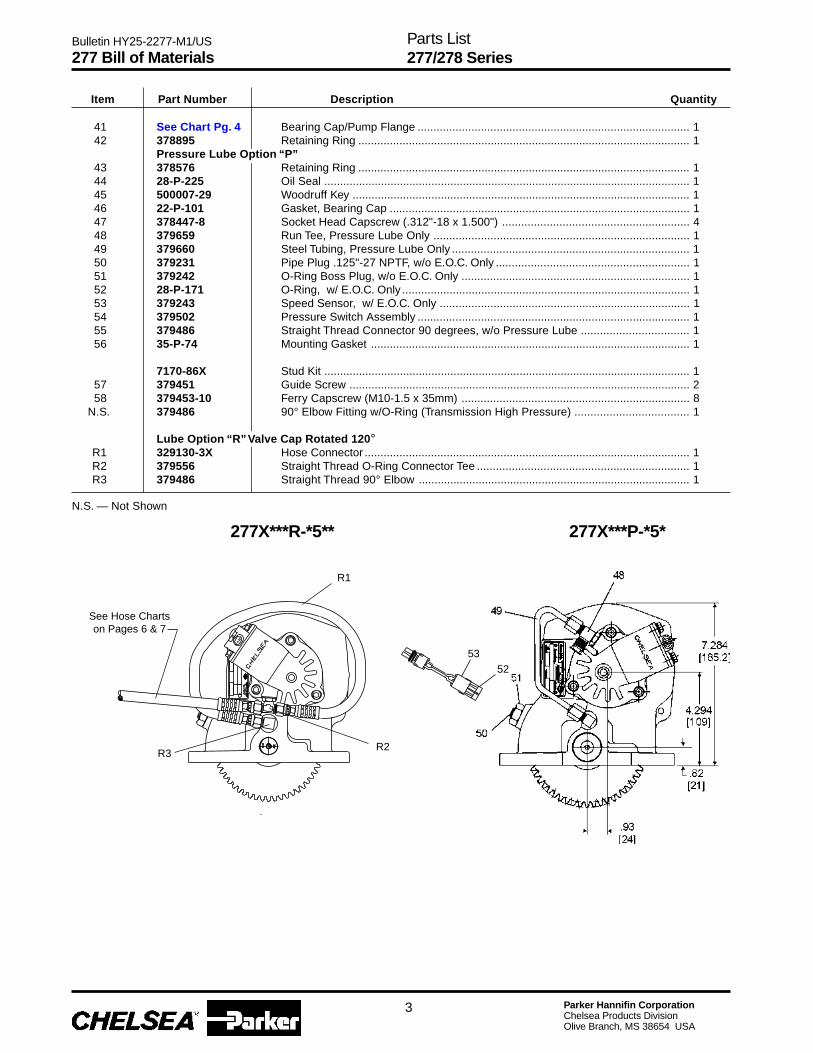
Parker Hannifin CorporationChelsea Products DivisionOlive Branch, MS 38654 USA
Bulletin HY25-2277-M1/US
277X***R-*5** 277X***P-*5*
Item Part Number Description Quantity
See Hose Chartson Pages 6 & 7
R1
R2R3
53
52
277 Bill of Materials
3
41 See Chart Pg. 4 Bearing Cap/Pump Flange ...................................................................................... 142 378895 Retaining Ring ......................................................................................................... 1
Pressure Lube Option “P”43 378576 Retaining Ring ......................................................................................................... 144 28-P-225 Oil Seal .................................................................................................................... 145 500007-29 Woodruff Key ........................................................................................................... 146 22-P-101 Gasket, Bearing Cap ............................................................................................... 147 378447-8 Socket Head Capscrew (.312"-18 x 1.500") ........................................................... 448 379659 Run Tee, Pressure Lube Only ................................................................................. 149 379660 Steel Tubing, Pressure Lube Only ........................................................................... 150 379231 Pipe Plug .125"-27 NPTF, w/o E.O.C. Only ............................................................. 151 379242 O-Ring Boss Plug, w/o E.O.C. Only ........................................................................ 152 28-P-171 O-Ring, w/ E.O.C. Only ........................................................................................... 153 379243 Speed Sensor, w/ E.O.C. Only ............................................................................... 154 379502 Pressure Switch Assembly ...................................................................................... 155 379486 Straight Thread Connector 90 degrees, w/o Pressure Lube .................................. 156 35-P-74 Mounting Gasket ..................................................................................................... 1
7170-86X Stud Kit .................................................................................................................... 157 379451 Guide Screw ............................................................................................................ 258 379453-10 Ferry Capscrew (M10-1.5 x 35mm) ........................................................................ 8
N.S. 379486 90° Elbow Fitting w/O-Ring (Transmission High Pressure) .................................... 1
Lube Option “R” Valve Cap Rotated 120°R1 329130-3X Hose Connector ....................................................................................................... 1R2 379556 Straight Thread O-Ring Connector Tee ................................................................... 1R3 379486 Straight Thread 90° Elbow ...................................................................................... 1
N.S. — Not Shown
Parts List277/278 Series
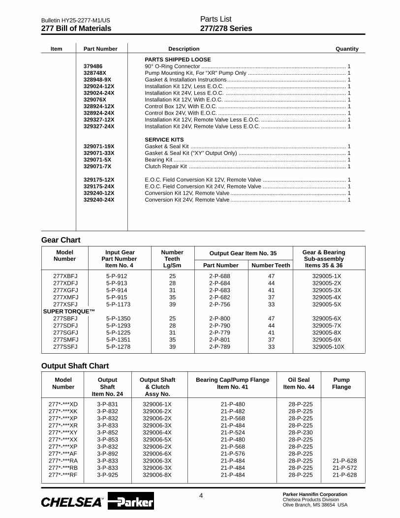
Parker Hannifin CorporationChelsea Products DivisionOlive Branch, MS 38654 USA
Bulletin HY25-2277-M1/US
PARTS SHIPPED LOOSE379486 90° O-Ring Connector ............................................................................................. 1328748X Pump Mounting Kit, For “XR” Pump Only ............................................................... 1328948-9X Gasket & Installation Instructions ............................................................................ 1329024-12X Installation Kit 12V, Less E.O.C. ............................................................................. 1329024-24X Installation Kit 24V, Less E.O.C. ............................................................................. 1329076X Installation Kit 12V, With E.O.C. .............................................................................. 1328924-12X Control Box 12V, With E.O.C. .................................................................................. 1328924-24X Control Box 24V, With E.O.C. .................................................................................. 1329327-12X Installation Kit 12V, Remote Valve Less E.O.C. ...................................................... 1329327-24X Installation Kit 24V, Remote Valve Less E.O.C. ...................................................... 1
SERVICE KITS329071-19X Gasket & Seal Kit .................................................................................................... 1329071-33X Gasket & Seal Kit (“XY” Output Only) ..................................................................... 1329071-5X Bearing Kit ............................................................................................................... 1329071-7X Clutch Repair Kit ..................................................................................................... 1
329175-12X E.O.C. Field Conversion Kit 12V, Remote Valve ..................................................... 1329175-24X E.O.C. Field Conversion Kit 24V, Remote Valve ..................................................... 1329240-12X Conversion Kit 12V, Remote Valve .......................................................................... 1329240-24X Conversion Kit 24V, Remote Valve .......................................................................... 1
Item Part Number Description Quantity
277 Bill of Materials
Output Shaft Chart
Model Output Output Shaft Bearing Cap/Pump Flange Oil Seal PumpNumber Shaft & Clutch Item No. 41 Item No. 44 Flange
Item No. 24 Assy No.
277*-***XD 3-P-831 329006-1X 21-P-480 28-P-225277*-***XK 3-P-832 329006-2X 21-P-482 28-P-225277*-***XP 3-P-832 329006-2X 21-P-568 28-P-225277*-***XR 3-P-833 329006-3X 21-P-484 28-P-225277*-***XY 3-P-852 329006-4X 21-P-524 28-P-230277*-***XX 3-P-853 329006-5X 21-P-480 28-P-225277*-***XP 3-P-832 329006-2X 21-P-568 28-P-225277*-***AF 3-P-892 329006-6X 21-P-576 28-P-225277*-***RA 3-P-833 329006-3X 21-P-484 28-P-225 21-P-628277*-***RB 3-P-833 329006-3X 21-P-484 28-P-225 21-P-572277*-***RF 3-P-925 329006-8X 21-P-484 28-P-225 21-P-628
4
Gear Chart
Model Input Gear Number Gear & BearingNumber Part Number Teeth Sub-assembly
Item No. 4 Lg/Sm Part Number Number Teeth Items 35 & 36
Output Gear Item No. 35
277XBFJ 5-P-912 25 2-P-688 47 329005-1X277XDFJ 5-P-913 28 2-P-684 44 329005-2X277XGFJ 5-P-914 31 2-P-683 41 329005-3X277XMFJ 5-P-915 35 2-P-682 37 329005-4X277XSFJ 5-P-1173 39 2-P-756 33 329005-5X
SUPER TORQUE™277SBFJ 5-P-1350 25 2-P-800 47 329005-6X277SDFJ 5-P-1293 28 2-P-790 44 329005-7X277SGFJ 5-P-1225 31 2-P-779 41 329005-8X277SMFJ 5-P-1351 35 2-P-801 37 329005-9X277SSFJ 5-P-1278 39 2-P-789 33 329005-10X
Parts List277/278 Series

Parker Hannifin CorporationChelsea Products DivisionOlive Branch, MS 38654 USA
Bulletin HY25-2277-M1/US
Model Number Designation
277 X G XP P - B 5 XD
BASIC MODEL277
MOUNTING TYPEX = Standard MountingS = Super Torque™
GEAR RATIOB = 25/47 D = 28/44G = 31/41 M = 35/37S = 39/33
INPUT GEAR DESIGNATOR
LUBRICATIONP = Pressure LubeR = Valve Cap Rotated 120°
P.T.O. Housing Dimensions
277 Model Number Designation
5
Parts List277/278 Series
OUTPUT TYPEXD = 1.250" RD Std. ShaftXK = S.A.E. “B” 2 or 4 BoltXP = S.A.E. “A” 2 BoltXR = CHELSEA SpecialAF = S.A.E. “BB” 2 or 4 BoltRA = Rotatable S.A.E. “B” 2 BoltRB = Rotatable S.A.E. “B” 4 BoltXY = DIN 5462XX = DIN 100RF = Rotatable S.A.E. “BB” 2 BoltRG = Rotatable S.A.E. “BB” 4 Bolt
ASSEMBLY ARRANGEMENT*5* Gear forward, shaft rear, bulge up right side,bulge down left side
SHIFTER TYPEB = 12V Hydraulic ValveD = 24V Hydraulic ValveG = 12V Remote Hydraulic Valve w/o E.O.C.H = 24V Remote Hydraulic Valve w/o E.O.C.K = 12V Hydraulic Valve with E.O.C.L = 24V Hydraulic Valve with E.O.C.M = 12V without Installation Kit - 329024-12XN = 24V without Installation Kit - 329024-24X
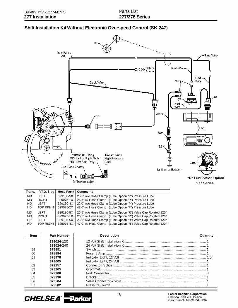
Parker Hannifin CorporationChelsea Products DivisionOlive Branch, MS 38654 USA
Bulletin HY25-2277-M1/US
Trans. P.T.O. Side Hose Part# CommentsMD LEFT 329130-5X 26.5" w/o Hose Clamp (Lube Option “P”) Pressure LubeMD RIGHT 329075-1X 26.5" w/ Hose Clamp (Lube Option “P”) Pressure LubeHD LEFT 329130-4X 22.0" w/o Hose Clamp (Lube Option “P”) Pressure LubeHD TOP RIGHT 329075-2X 42.0" w/ Hose Clamp (Lube Option “P”) Pressure Lube
MD LEFT 329130-5X 26.5" w/o Hose Clamp (Lube Option “R”) Valve Cap Rotated 120°MD RIGHT 329075-1X 26.5" w/ Hose Clamp (Lube Option “R”) Valve Cap Rotated 120°HD LEFT 329130-5X 26.5" w/o Hose Clamp (Lube Option “R”) Valve Cap Rotated 120°HD TOP RIGHT 329075-4X 47.0" w/ Hose Clamp (Lube Option “R”) Valve Cap Rotated 120°
329024-12X 12 Volt Shift Installation Kit ...................................................................................... 1329024-24X 24 Volt Shift Installation Kit ...................................................................................... 1
59 378881 Switch ...................................................................................................................... 160 378884 Fuse, 9 Amp ............................................................................................................ 161 378978 Indicator Light, 12 Volt ............................................................................................. 1 or
379005 Indicator Light, 24 Volt ............................................................................................. 162 379257 Connector, Splice .................................................................................................... 163 379265 Grommet .................................................................................................................. 164 379306 Fork Connector ........................................................................................................ 365 379336 Bracket ..................................................................................................................... 166 379504 Valve Connector & Wire .......................................................................................... 167 379502 Pressure Switch ....................................................................................................... 1
Item Part Number Description Quantity
277 Installation
Shift Installation Kit Without Electronic Overspeed Control (SK-247)
6
277 Series
Parts List277/278 Series
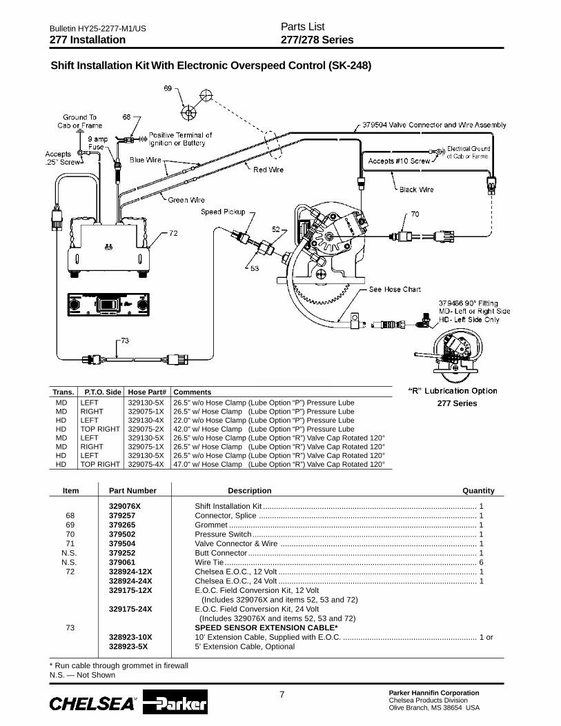
Parker Hannifin CorporationChelsea Products DivisionOlive Branch, MS 38654 USA
Bulletin HY25-2277-M1/US
Item Part Number Description Quantity
329076X Shift Installation Kit .................................................................................................. 168 379257 Connector, Splice .................................................................................................... 169 379265 Grommet .................................................................................................................. 170 379502 Pressure Switch ....................................................................................................... 171 379504 Valve Connector & Wire .......................................................................................... 1
N.S. 379252 Butt Connector ......................................................................................................... 1N.S. 379061 Wire Tie .................................................................................................................... 672 328924-12X Chelsea E.O.C., 12 Volt ........................................................................................... 1
328924-24X Chelsea E.O.C., 24 Volt ........................................................................................... 1329175-12X E.O.C. Field Conversion Kit, 12 Volt
(Includes 329076X and items 52, 53 and 72)329175-24X E.O.C. Field Conversion Kit, 24 Volt
(Includes 329076X and items 52, 53 and 72)73 SPEED SENSOR EXTENSION CABLE*
328923-10X 10' Extension Cable, Supplied with E.O.C. ............................................................. 1 or328923-5X 5' Extension Cable, Optional
277 Installation
Trans. P.T.O. Side Hose Part# CommentsMD LEFT 329130-5X 26.5" w/o Hose Clamp (Lube Option “P”) Pressure LubeMD RIGHT 329075-1X 26.5" w/ Hose Clamp (Lube Option “P”) Pressure LubeHD LEFT 329130-4X 22.0" w/o Hose Clamp (Lube Option “P”) Pressure LubeHD TOP RIGHT 329075-2X 42.0" w/ Hose Clamp (Lube Option “P”) Pressure LubeMD LEFT 329130-5X 26.5" w/o Hose Clamp (Lube Option “R”) Valve Cap Rotated 120°MD RIGHT 329075-1X 26.5" w/ Hose Clamp (Lube Option “R”) Valve Cap Rotated 120°HD LEFT 329130-5X 26.5" w/o Hose Clamp (Lube Option “R”) Valve Cap Rotated 120°HD TOP RIGHT 329075-4X 47.0" w/ Hose Clamp (Lube Option “R”) Valve Cap Rotated 120°
Shift Installation Kit With Electronic Overspeed Control (SK-248)
7
* Run cable through grommet in firewallN.S. — Not Shown
Parts List277/278 Series
277 Series

Parker Hannifin CorporationChelsea Products DivisionOlive Branch, MS 38654 USA
Bulletin HY25-2277-M1/US
Item Part Number Description Quantity
277 Installation
Trans. P.T.O. Side Hose Part# CommentsMD LEFT 329130-5X 26.5" w/o Hose Clamp (Shifter “Options G & H”) 12V & 24V Remote Hydraulic Valve w/o E.O.C.MD RIGHT 329075-1X 26.5" w/ Hose Clamp (Shifter “Options G & H”) 12V & 24V Remote Hydraulic Valve w/o E.O.C.HD LEFT 329130-5X 26.5" w/o Hose Clamp (Shifter “Options G & H”) 12V & 24V Remote Hydraulic Valve w/o E.O.C.HD TOP RIGHT 329075-4X 47.0" w/ Hose Clamp (Shifter “Options G & H”) 12V & 24V Remote Hydraulic Valve w/o E.O.C.
8
329237-12X 12 Volt Shift Installation Kit329237-24X 24 Volt Shift Installation Kit
74 329230X Connector Wire ........................................................................................................ 175 329231X Valve Connector & Wire .......................................................................................... 176 378881 Switch ...................................................................................................................... 177 378884 Fuse Holder, 9 AMP ................................................................................................ 178 378978 Indicator Light, 12 Volt ............................................................................................. 1 or
379005 Indicator Light, 24 Volt ............................................................................................. 179 379252 Butt Connector ......................................................................................................... 280 379257 Splice Connector .................................................................................................... 181 379258 Mounting Bracket, Solenoid .................................................................................... 182 379265 Grommet .................................................................................................................. 183 379306 Fork Connector ........................................................................................................ 384 379336 Name & Plate Bracket ............................................................................................. 185 379449 Male Connector ....................................................................................................... 286 379502 Pressure Switch ....................................................................................................... 187 379686-1 Solenoid Valve, 12 Volt ............................................................................................ 1 or
379686-2 Solenoid Valve, 24 Volt ............................................................................................ 188 500357-7 Lockwasher .............................................................................................................. 289 500457-6 Mounting Screw (.790"-32x.438") ........................................................................... 2
Parts List277/278 Series
Remote Mount Valve Conversion Kits (SK-316)

Parker Hannifin CorporationChelsea Products DivisionOlive Branch, MS 38654 USA
Bulletin HY25-2277-M1/US
Item Part Number Description Quantity
329160-21X “XK” Output329160-22X “XR” Output329160-23X “XP” Output329160-25X “AF” Output329160-37X “RA” Output329160-38X “RB” Output329160-39X “RF” Output329160-45X “RG” Output
17 28-P-119 Oil Seal, High Pressure ........................................................................................... 119 378849 Retaining Ring ......................................................................................................... 120 22-P-112 Gasket, Valve Cap ................................................................................................... 123 379746 Retaining Ring ......................................................................................................... 124 3-P-832 Output Shaft, XK & XP Outputs .............................................................................. 1 or
3-P-833 Output Shaft, XR, RA, & RB Outputs ...................................................................... 13-P-925 Output Shaft, RF Output ......................................................................................... 13-P-892 Output Shaft, AF Output .......................................................................................... 1
28 28-P-244 O-Ring ..................................................................................................................... 230 28-P-121 Block -V- Ring .......................................................................................................... 134 378576 Retaining Ring ......................................................................................................... 138 379746 Retaining Ring ......................................................................................................... 141 21-P-482 Bearing Cap, XK Output .......................................................................................... 1 or
21-P-484 Bearing Cap, XR Output .......................................................................................... 121-P-568 Bearing Cap, XP Output .......................................................................................... 121-P-576 Bearing Cap, AF Output .......................................................................................... 1
N.S. 21-P-572 Pump Flange, RB & RG Output & 21-P-484 Brg. Cap ........................................... 1N.S. 21-P-628 Pump Flange, RA & RF Outputs & 21-P-484 Brg. Cap .......................................... 143 378576 Retaining Ring ......................................................................................................... 144 28-P-225 Oil Seal .................................................................................................................... 146 22-P-101 Gasket, Bearing Cap ............................................................................................... 147 378447-8 Socket Head Capscrew (.3125"-18 x 1.500") ......................................................... 4
N.S. 378447-6 Socket Head Capscrew (.3125"-18 x 1.000")(Rotatable Flange) ........................... 4N.S. 328748X Pump Mounting Kit, XR Output ............................................................................... 1
277 Pump Conversion Kits
9
Parts List277/278 Series

Parker Hannifin CorporationChelsea Products DivisionOlive Branch, MS 38654 USA
Bulletin HY25-2277-M1/US
Notes
10
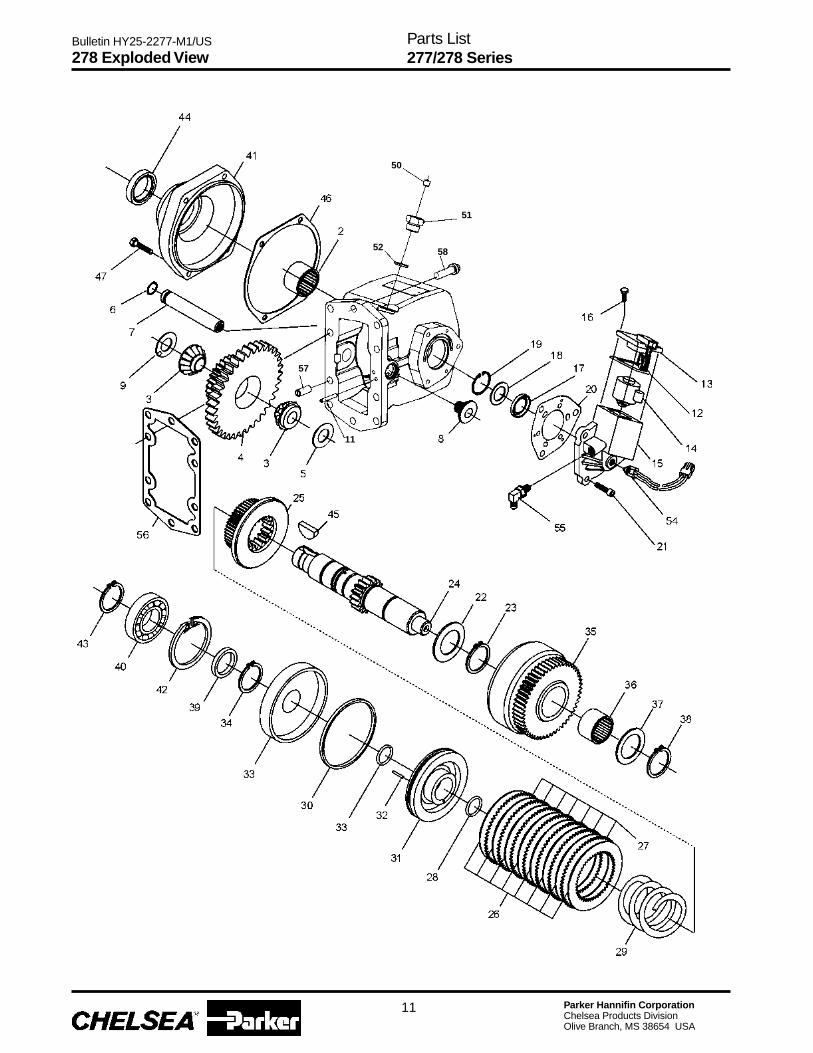
Parker Hannifin CorporationChelsea Products DivisionOlive Branch, MS 38654 USA
Bulletin HY25-2277-M1/US
278 Exploded View
11
Parts List277/278 Series
11
57
58
51
50
52
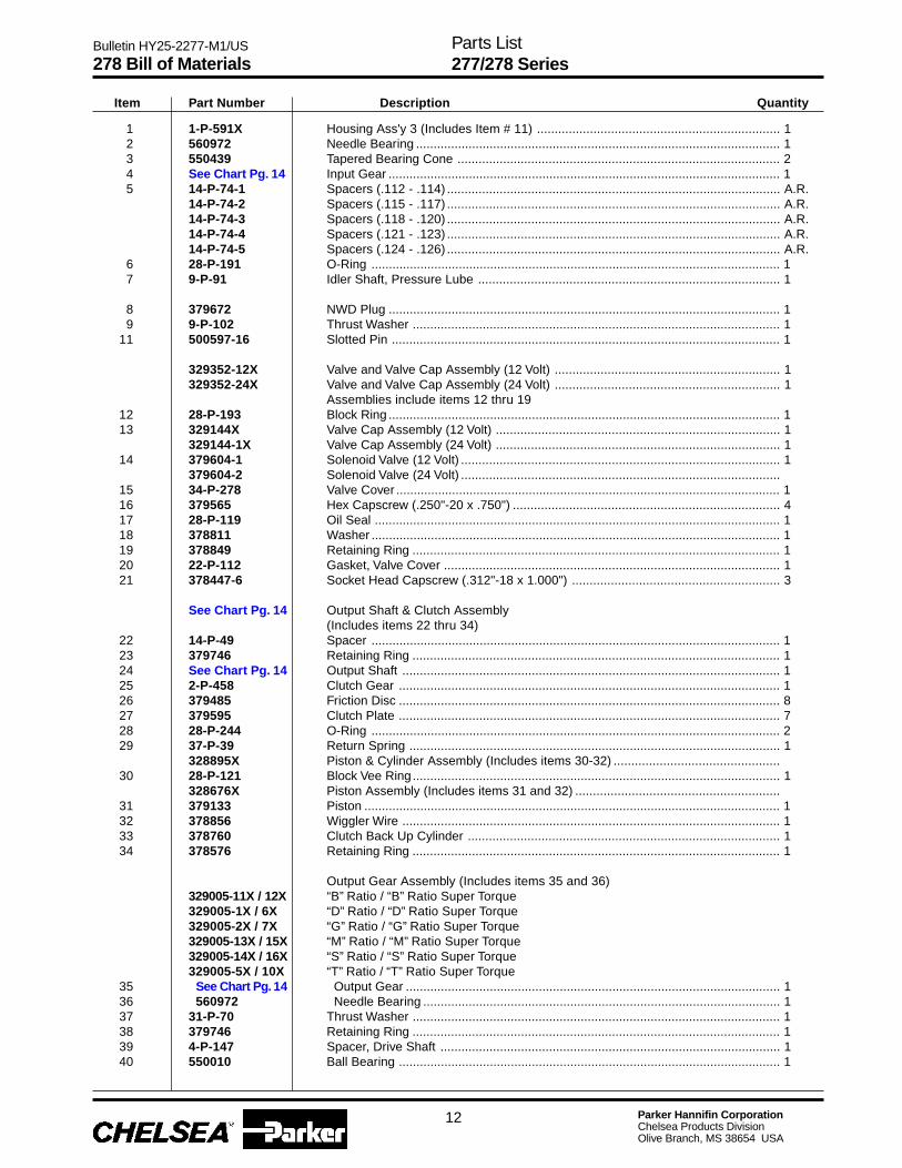
Parker Hannifin CorporationChelsea Products DivisionOlive Branch, MS 38654 USA
Bulletin HY25-2277-M1/US
Item Part Number Description Quantity
1 1-P-591X Housing Ass'y 3 (Includes Item # 11) ..................................................................... 12 560972 Needle Bearing ........................................................................................................ 13 550439 Tapered Bearing Cone ............................................................................................ 24 See Chart Pg. 14 Input Gear ................................................................................................................ 15 14-P-74-1 Spacers (.112 - .114) ............................................................................................... A.R.
14-P-74-2 Spacers (.115 - .117) ............................................................................................... A.R.14-P-74-3 Spacers (.118 - .120) ............................................................................................... A.R.14-P-74-4 Spacers (.121 - .123) ............................................................................................... A.R.14-P-74-5 Spacers (.124 - .126) ............................................................................................... A.R.
6 28-P-191 O-Ring ..................................................................................................................... 17 9-P-91 Idler Shaft, Pressure Lube ...................................................................................... 1
8 379672 NWD Plug ................................................................................................................ 19 9-P-102 Thrust Washer ......................................................................................................... 1
11 500597-16 Slotted Pin ............................................................................................................... 1
329352-12X Valve and Valve Cap Assembly (12 Volt) ................................................................ 1329352-24X Valve and Valve Cap Assembly (24 Volt) ................................................................ 1
Assemblies include items 12 thru 1912 28-P-193 Block Ring ................................................................................................................ 113 329144X Valve Cap Assembly (12 Volt) ................................................................................. 1
329144-1X Valve Cap Assembly (24 Volt) ................................................................................. 114 379604-1 Solenoid Valve (12 Volt) ........................................................................................... 1
379604-2 Solenoid Valve (24 Volt) ...........................................................................................15 34-P-278 Valve Cover .............................................................................................................. 116 379565 Hex Capscrew (.250"-20 x .750") ............................................................................ 417 28-P-119 Oil Seal .................................................................................................................... 118 378811 Washer ..................................................................................................................... 119 378849 Retaining Ring ......................................................................................................... 120 22-P-112 Gasket, Valve Cover ................................................................................................ 121 378447-6 Socket Head Capscrew (.312"-18 x 1.000") ........................................................... 3
See Chart Pg. 14 Output Shaft & Clutch Assembly(Includes items 22 thru 34)
22 14-P-49 Spacer ..................................................................................................................... 123 379746 Retaining Ring ......................................................................................................... 124 See Chart Pg. 14 Output Shaft ............................................................................................................ 125 2-P-458 Clutch Gear ............................................................................................................. 126 379485 Friction Disc ............................................................................................................. 827 379595 Clutch Plate ............................................................................................................. 728 28-P-244 O-Ring ..................................................................................................................... 229 37-P-39 Return Spring .......................................................................................................... 1
328895X Piston & Cylinder Assembly (Includes items 30-32) ...............................................30 28-P-121 Block Vee Ring......................................................................................................... 1
328676X Piston Assembly (Includes items 31 and 32) ..........................................................31 379133 Piston ....................................................................................................................... 132 378856 Wiggler Wire ............................................................................................................ 133 378760 Clutch Back Up Cylinder ......................................................................................... 134 378576 Retaining Ring ......................................................................................................... 1
Output Gear Assembly (Includes items 35 and 36)329005-11X / 12X “B” Ratio / “B” Ratio Super Torque329005-1X / 6X “D” Ratio / “D” Ratio Super Torque329005-2X / 7X “G” Ratio / “G” Ratio Super Torque329005-13X / 15X “M” Ratio / “M” Ratio Super Torque329005-14X / 16X “S” Ratio / “S” Ratio Super Torque329005-5X / 10X “T” Ratio / “T” Ratio Super Torque
35 See Chart Pg. 14 Output Gear ........................................................................................................... 136 560972 Needle Bearing ...................................................................................................... 137 31-P-70 Thrust Washer ......................................................................................................... 138 379746 Retaining Ring ......................................................................................................... 139 4-P-147 Spacer, Drive Shaft ................................................................................................. 140 550010 Ball Bearing ............................................................................................................. 1
278 Bill of Materials
12
Parts List277/278 Series
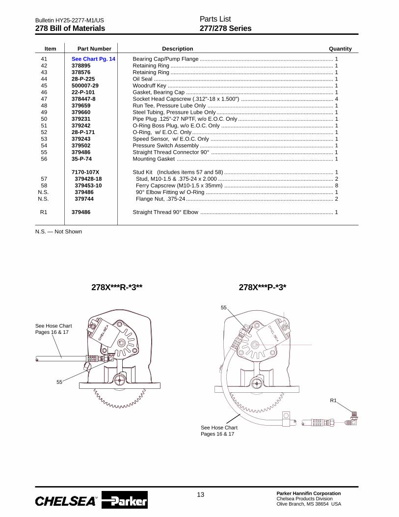
Parker Hannifin CorporationChelsea Products DivisionOlive Branch, MS 38654 USA
Bulletin HY25-2277-M1/US
41 See Chart Pg. 14 Bearing Cap/Pump Flange ...................................................................................... 142 378895 Retaining Ring ......................................................................................................... 143 378576 Retaining Ring ......................................................................................................... 144 28-P-225 Oil Seal .................................................................................................................... 145 500007-29 Woodruff Key ........................................................................................................... 146 22-P-101 Gasket, Bearing Cap ............................................................................................... 147 378447-8 Socket Head Capscrew (.312"-18 x 1.500") ........................................................... 448 379659 Run Tee, Pressure Lube Only ................................................................................. 149 379660 Steel Tubing, Pressure Lube Only ........................................................................... 150 379231 Pipe Plug .125"-27 NPTF, w/o E.O.C. Only ............................................................. 151 379242 O-Ring Boss Plug, w/o E.O.C. Only ........................................................................ 152 28-P-171 O-Ring, w/ E.O.C. Only ........................................................................................... 153 379243 Speed Sensor, w/ E.O.C. Only ............................................................................... 154 379502 Pressure Switch Assembly ...................................................................................... 155 379486 Straight Thread Connector 90° ............................................................................... 156 35-P-74 Mounting Gasket ..................................................................................................... 1
7170-107X Stud Kit (Includes items 57 and 58) ...................................................................... 157 379428-18 Stud, M10-1.5 & .375-24 x 2.000 .......................................................................... 258 379453-10 Ferry Capscrew (M10-1.5 x 35mm) ...................................................................... 8
N.S. 379486 90° Elbow Fitting w/ O-Ring .................................................................................. 1N.S. 379744 Flange Nut, .375-24 ............................................................................................... 2
R1 379486 Straight Thread 90° Elbow ...................................................................................... 1
278X***R-*3** 278X***P-*3*
Item Part Number Description Quantity
278 Bill of Materials
13
Parts List277/278 Series
N.S. — Not Shown
See Hose ChartPages 16 & 17
See Hose ChartPages 16 & 17
55
55
R1
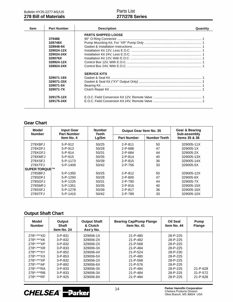
Parker Hannifin CorporationChelsea Products DivisionOlive Branch, MS 38654 USA
Bulletin HY25-2277-M1/US
278 Bill of Materials
14
Item Part Number Description Quantity
Output Shaft Chart
Model Output Output Shaft Bearing Cap/Pump Flange Oil Seal PumpNumber Shaft & Clutch Item No. 41 Item No. 44 Flange
Item No. 24 Ass’y No.
278*-***XD 3-P-831 329006-1X 21-P-480 28-P-225278*-***XK 3-P-832 329006-2X 21-P-482 28-P-225278*-***XP 3-P-832 329006-2X 21-P-568 28-P-225278*-***XR 3-P-833 329006-3X 21-P-484 28-P-225278*-***XY 3-P-852 329006-4X 21-P-524 28-P-230278*-***XX 3-P-853 329006-5X 21-P-480 28-P-225278*-***XP 3-P-832 329006-2X 21-P-568 28-P-225278*-***AF 3-P-892 329006-6X 21-P-576 28-P-225278*-***RA 3-P-833 329006-3X 21-P-484 28-P-225 21-P-628278*-***RB 3-P-833 329006-3X 21-P-484 28-P-225 21-P-572278*-***RF 3-P-925 329006-8X 21-P-484 28-P-225 21-P-628
PARTS SHIPPED LOOSE379486 90° O-Ring Connector ............................................................................................. 1328748X Pump Mounting Kit, For “XR” Pump Only ............................................................... 1328948-9X Gasket & Installation Instructions ............................................................................ 1329024-12X Installation Kit 12V, Less E.O.C. ............................................................................. 1329024-24X Installation Kit 24V, Less E.O.C. ............................................................................. 1329076X Installation Kit 12V, With E.O.C. .............................................................................. 1328924-12X Control Box 12V, With E.O.C. .................................................................................. 1328924-24X Control Box 24V, With E.O.C. .................................................................................. 1
SERVICE KITS329071-19X Gasket & Seal Kit .................................................................................................... 1329071-33X Gasket & Seal Kit (“XY” Output Only) ..................................................................... 1329071-5X Bearing Kit ............................................................................................................... 1329071-7X Clutch Repair Kit ..................................................................................................... 1
329175-12X E.O.C. Field Conversion Kit 12V, Remote Valve ..................................................... 1329175-24X E.O.C. Field Conversion Kit 24V, Remote Valve ..................................................... 1
Gear Chart
Model Input Gear Number Gear & BearingNumber Part Number Teeth Sub-assembly
Item No. 4 Lg/Sm Part Number Number Teeth Items 35 & 36
Output Gear Item No. 35
278XBFJ 5-P-912 50/25 2-P-811 50 329005-11X278XDFJ 5-P-913 50/28 2-P-688 47 329005-1X278XGFJ 5-P-914 50/31 2-P-684 44 329005-2X278XMFJ 5-P-915 50/35 2-P-814 40 329005-13X278XSFJ 5-P-1173 50/39 2-P-815 36 329005-14X278XTFJ 5-P-1409 50/42 2-P-756 33 329005-5X
SUPER TORQUE™278SBFJ 5-P-1350 50/25 2-P-812 50 329005-12X278SDFJ 5-P-1293 50/28 2-P-800 47 329005-6X278SGFJ 5-P-1225 50/31 2-P-790 44 329005-7X278SMFJ 5-P-1351 50/35 2-P-816 40 329005-15X278SSFJ 5-P-1278 50/39 2-P-817 36 329005-16X278STFJ 5-P-1410 50/42 2-P-789 33 329005-10X
Parts List277/278 Series

Parker Hannifin CorporationChelsea Products DivisionOlive Branch, MS 38654 USA
Bulletin HY25-2277-M1/US
BASIC MODEL278
MOUNTING TYPEX = Standard MountingS = Super Torque™
GEAR RATIOB = 25/50 D = 38/47G = 31/44 M = 35/41S = 39/37T = 42/33
INPUT GEAR DESIGNATOR
LUBRICATIONP = Pressure LubeR = Valve Cap Rotated 120°
278 Model Designation
15
Model Number Designation
278 X G FJ P - B 3 XD
OUTPUT TYPEXD = 1.250" RD Std. ShaftXK = S.A.E. “B” 2 or 4 BoltXP = S.A.E. “A” 2 BoltXR = CHELSEA SpecialAF = S.A.E. “BB” 2 or 4 BoltRA = Rotatable S.A.E. “B” 2 BoltRB = Rotatable S.A.E. “B” 4 BoltXY = DIN 5462XX = DIN 100RF = Rotatable S.A.E. “BB” 2 BoltRG = Rotatable S.A.E. “BB” 4 Bolt
ASSEMBLY ARRANGEMENT*3* - Gear Forward, Shaft Rear, Bulge Straight Up
Both Sides
SHIFTER TYPEB = 12V Hydraulic ValveD = 24V Hydraulic ValveG = 12V Remote Valve without E.O.C.H = 24V Remote Valve without E.O.C.K = 12V Hydraulic Valve with E.O.C.L = 24V Hydraulic Valve with E.O.C.M = 12 Volt without Installation Kit - 329024-12XN = 24 Volt without Installation Kit - 329024-24X
P.T.O. Housing Dimensions
▲▼ 5.136"[130.45]
▲▼ 7.04"[179]
1.451"[36.86]
▲▼
.82"[21]
▲
▼
7.70"[196]
▲
▼
4.57"[116]
▼
▲
Parts List277/278 Series
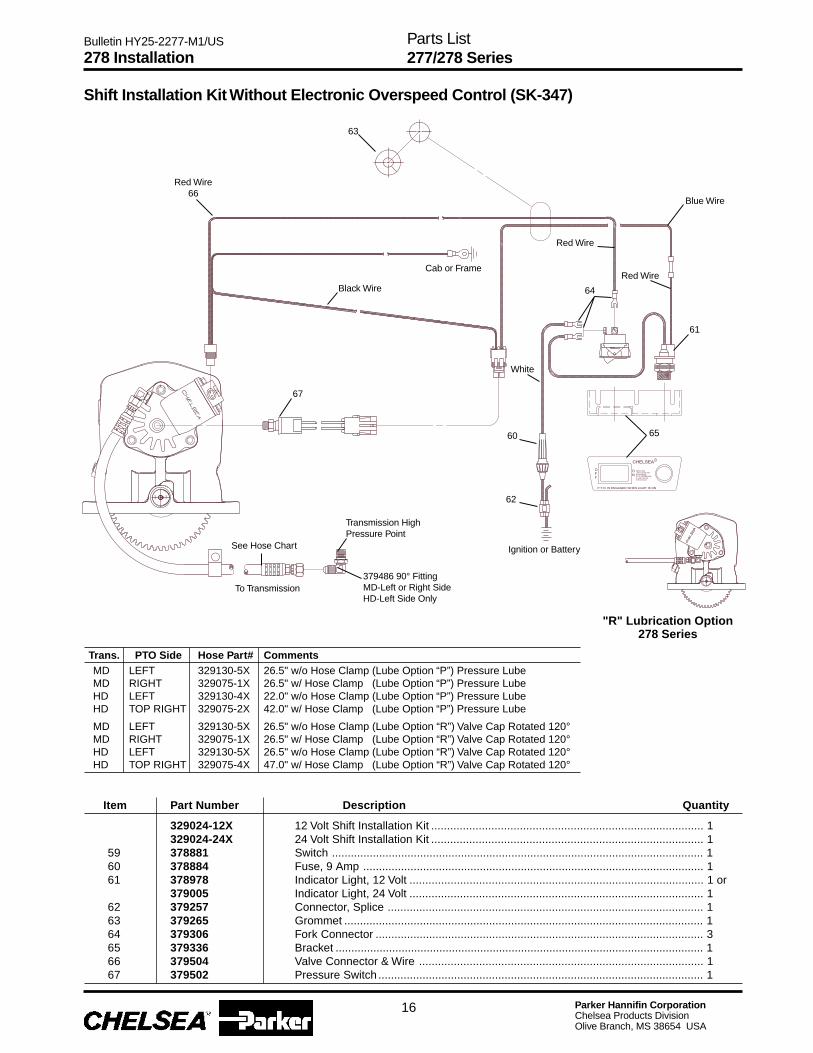
Parker Hannifin CorporationChelsea Products DivisionOlive Branch, MS 38654 USA
Bulletin HY25-2277-M1/US
Trans. PTO Side Hose Part# CommentsMD LEFT 329130-5X 26.5" w/o Hose Clamp (Lube Option “P”) Pressure LubeMD RIGHT 329075-1X 26.5" w/ Hose Clamp (Lube Option “P”) Pressure LubeHD LEFT 329130-4X 22.0" w/o Hose Clamp (Lube Option “P”) Pressure LubeHD TOP RIGHT 329075-2X 42.0" w/ Hose Clamp (Lube Option “P”) Pressure Lube
MD LEFT 329130-5X 26.5" w/o Hose Clamp (Lube Option “R”) Valve Cap Rotated 120°MD RIGHT 329075-1X 26.5" w/ Hose Clamp (Lube Option “R”) Valve Cap Rotated 120°HD LEFT 329130-5X 26.5" w/o Hose Clamp (Lube Option “R”) Valve Cap Rotated 120°HD TOP RIGHT 329075-4X 47.0" w/ Hose Clamp (Lube Option “R”) Valve Cap Rotated 120°
329024-12X 12 Volt Shift Installation Kit ...................................................................................... 1329024-24X 24 Volt Shift Installation Kit ...................................................................................... 1
59 378881 Switch ...................................................................................................................... 160 378884 Fuse, 9 Amp ............................................................................................................ 161 378978 Indicator Light, 12 Volt ............................................................................................. 1 or
379005 Indicator Light, 24 Volt ............................................................................................. 162 379257 Connector, Splice .................................................................................................... 163 379265 Grommet .................................................................................................................. 164 379306 Fork Connector ........................................................................................................ 365 379336 Bracket ..................................................................................................................... 166 379504 Valve Connector & Wire .......................................................................................... 167 379502 Pressure Switch ....................................................................................................... 1
Item Part Number Description Quantity
16
278 InstallationParts List277/278 Series
Red Wire66
Blue Wire
Shift Installation Kit Without Electronic Overspeed Control (SK-347)
"R" Lubrication Option278 Series
63
Black Wire
Red Wire
67
See Hose Chart
Transmission HighPressure Point
379486 90° FittingMD-Left or Right SideHD-Left Side Only
62
60
White
64
Red Wire
65
61
Ignition or Battery
Cab or Frame
To Transmission

Parker Hannifin CorporationChelsea Products DivisionOlive Branch, MS 38654 USA
Bulletin HY25-2277-M1/US
Item Part Number Description Quantity
329076X Shift Installation Kit .................................................................................................. 168 379257 Connector, Splice .................................................................................................... 169 379265 Grommet .................................................................................................................. 170 379502 Pressure Switch ....................................................................................................... 171 379504 Valve Connector & Wire .......................................................................................... 1
N.S. 379252 Butt Connector ......................................................................................................... 1N.S. 379061 Wire Tie .................................................................................................................... 672 328924-12X Chelsea E.O.C., 12 Volt ........................................................................................... 1
328924-24X Chelsea E.O.C., 24 Volt ........................................................................................... 1329175-12X E.O.C. Field Conversion Kit, 12 Volt
(Includes 329076X and items 52, 53 and 72)329175-24X E.O.C. Field Conversion Kit, 24 Volt
(Includes 329076X and items 52, 53 and 72)73 SPEED SENSOR EXTENSION CABLE*
328923-10X 10' Extension Cable, Supplied with E.O.C. ............................................................. 1 or328923-5X 5' Extension Cable, Optional
Trans. P.T.O. Side Hose Part# CommentsMD LEFT 329130-5X 26.5" w/o Hose Clamp (Lube Option “P”) Pressure LubeMD RIGHT 329075-1X 26.5" w/ Hose Clamp (Lube Option “P”) Pressure LubeHD LEFT 329130-4X 22.0" w/o Hose Clamp (Lube Option “P”) Pressure LubeHD TOP RIGHT 329075-2X 42.0" w/ Hose Clamp (Lube Option “P”) Pressure LubeMD LEFT 329130-5X 26.5" w/o Hose Clamp (Lube Option “R”) Valve Cap Rotated 120°MD RIGHT 329075-1X 26.5" w/ Hose Clamp (Lube Option “R”) Valve Cap Rotated 120°HD LEFT 329130-5X 26.5" w/o Hose Clamp (Lube Option “R”) Valve Cap Rotated 120°HD TOP RIGHT 329075-4X 47.0" w/ Hose Clamp (Lube Option “R”) Valve Cap Rotated 120°
Shift Installation Kit With Electronic Overspeed Control (SK-348)
17
* Run cable through grommet in firewallN.S. — Not Shown
278 InstallationParts List277/278 Series
"R" Lubrication Option278 Series
69
68
Accepts .25"Screw
Ground toCab or Frame
Positive Terminal ofIgnition or Battery
73
Green Wire
9 Amp Fuse
Blue Wire
Red Wire
379504 ValveConnector andWire Assembly
ElectricalGround ofCab or FrameAccepts #10 Screw
Black Wire
70SpeedPick Up
52
53
See HoseChart
379486 90° FittingMD-Left or Right SideHD-Left Side Only
72
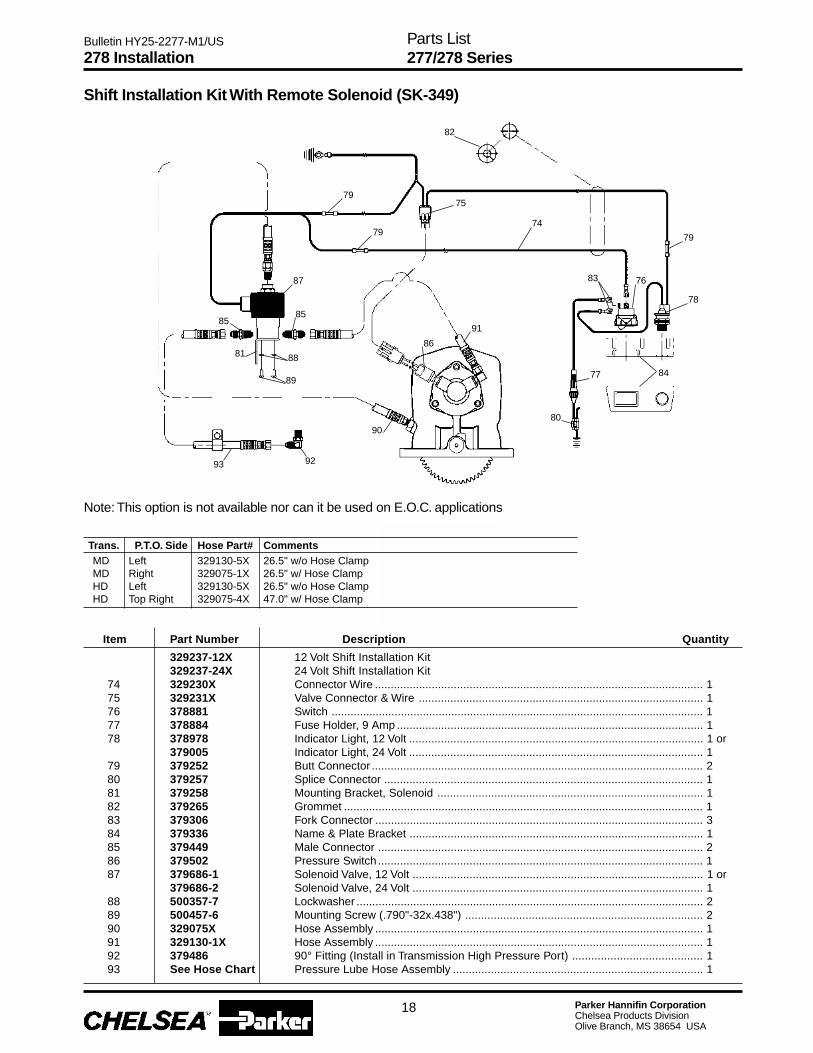
Parker Hannifin CorporationChelsea Products DivisionOlive Branch, MS 38654 USA
Bulletin HY25-2277-M1/US
Shift Installation Kit With Remote Solenoid (SK-349)
278 InstallationParts List277/278 Series
18
329237-12X 12 Volt Shift Installation Kit329237-24X 24 Volt Shift Installation Kit
74 329230X Connector Wire ........................................................................................................ 175 329231X Valve Connector & Wire .......................................................................................... 176 378881 Switch ...................................................................................................................... 177 378884 Fuse Holder, 9 Amp ................................................................................................. 178 378978 Indicator Light, 12 Volt ............................................................................................. 1 or
379005 Indicator Light, 24 Volt ............................................................................................. 179 379252 Butt Connector ......................................................................................................... 280 379257 Splice Connector ..................................................................................................... 181 379258 Mounting Bracket, Solenoid .................................................................................... 182 379265 Grommet .................................................................................................................. 183 379306 Fork Connector ........................................................................................................ 384 379336 Name & Plate Bracket ............................................................................................. 185 379449 Male Connector ....................................................................................................... 286 379502 Pressure Switch ....................................................................................................... 187 379686-1 Solenoid Valve, 12 Volt ............................................................................................ 1 or
379686-2 Solenoid Valve, 24 Volt ............................................................................................ 188 500357-7 Lockwasher .............................................................................................................. 289 500457-6 Mounting Screw (.790"-32x.438") ........................................................................... 290 329075X Hose Assembly ........................................................................................................ 191 329130-1X Hose Assembly ........................................................................................................ 192 379486 90° Fitting (Install in Transmission High Pressure Port) ......................................... 193 See Hose Chart Pressure Lube Hose Assembly ............................................................................... 1
Item Part Number Description Quantity
Trans. P.T.O. Side Hose Part# CommentsMD Left 329130-5X 26.5" w/o Hose ClampMD Right 329075-1X 26.5" w/ Hose ClampHD Left 329130-5X 26.5" w/o Hose ClampHD Top Right 329075-4X 47.0" w/ Hose Clamp
Note: This option is not available nor can it be used on E.O.C. applications
82
75
74
79
78
7683
8477
80
91
86
90
79
79
87
85
88
89
81
85
93 92
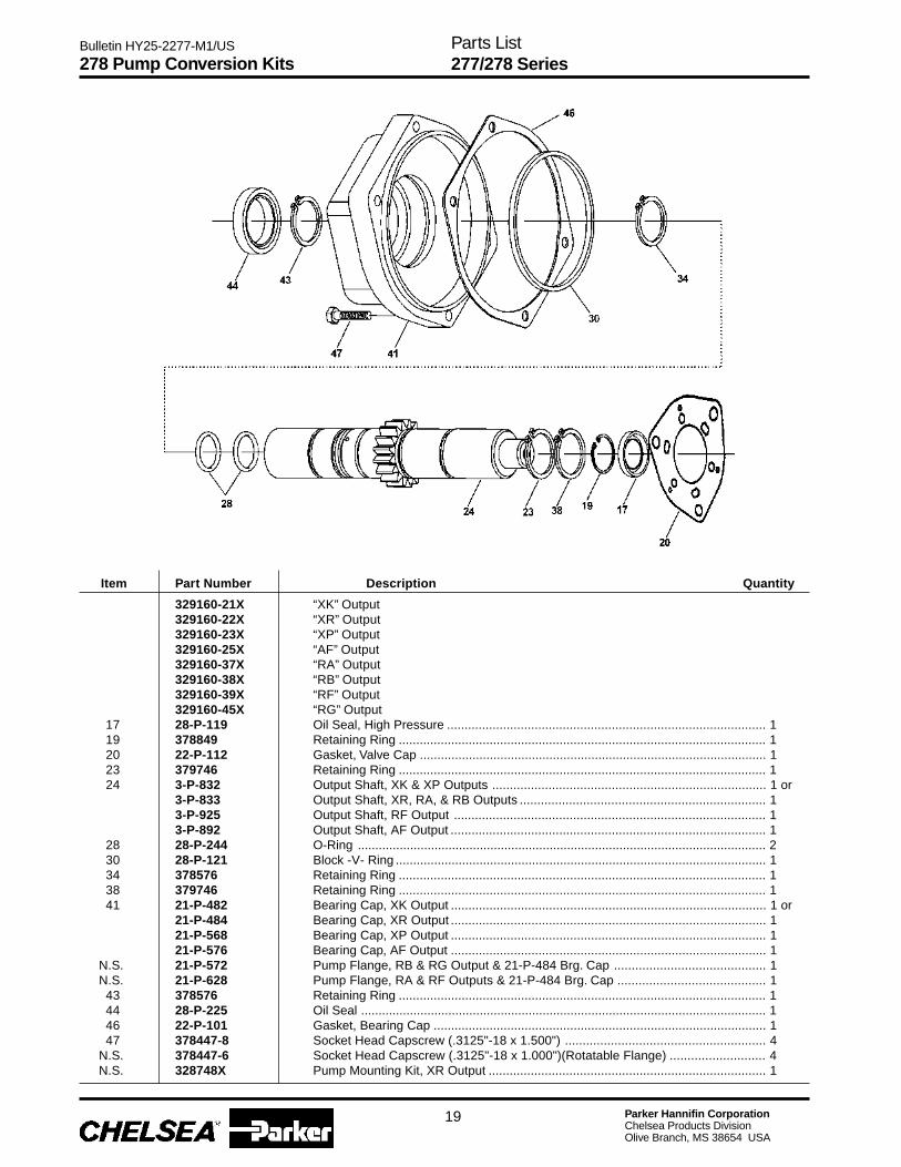
Parker Hannifin CorporationChelsea Products DivisionOlive Branch, MS 38654 USA
Bulletin HY25-2277-M1/US
Item Part Number Description Quantity
329160-21X “XK” Output329160-22X “XR” Output329160-23X “XP” Output329160-25X “AF” Output329160-37X “RA” Output329160-38X “RB” Output329160-39X “RF” Output329160-45X “RG” Output
17 28-P-119 Oil Seal, High Pressure ........................................................................................... 119 378849 Retaining Ring ......................................................................................................... 120 22-P-112 Gasket, Valve Cap ................................................................................................... 123 379746 Retaining Ring ......................................................................................................... 124 3-P-832 Output Shaft, XK & XP Outputs .............................................................................. 1 or
3-P-833 Output Shaft, XR, RA, & RB Outputs ...................................................................... 13-P-925 Output Shaft, RF Output ......................................................................................... 13-P-892 Output Shaft, AF Output .......................................................................................... 1
28 28-P-244 O-Ring ..................................................................................................................... 230 28-P-121 Block -V- Ring .......................................................................................................... 134 378576 Retaining Ring ......................................................................................................... 138 379746 Retaining Ring ......................................................................................................... 141 21-P-482 Bearing Cap, XK Output .......................................................................................... 1 or
21-P-484 Bearing Cap, XR Output .......................................................................................... 121-P-568 Bearing Cap, XP Output .......................................................................................... 121-P-576 Bearing Cap, AF Output .......................................................................................... 1
N.S. 21-P-572 Pump Flange, RB & RG Output & 21-P-484 Brg. Cap ........................................... 1N.S. 21-P-628 Pump Flange, RA & RF Outputs & 21-P-484 Brg. Cap .......................................... 143 378576 Retaining Ring ......................................................................................................... 144 28-P-225 Oil Seal .................................................................................................................... 146 22-P-101 Gasket, Bearing Cap ............................................................................................... 147 378447-8 Socket Head Capscrew (.3125"-18 x 1.500") ......................................................... 4
N.S. 378447-6 Socket Head Capscrew (.3125"-18 x 1.000")(Rotatable Flange) ........................... 4N.S. 328748X Pump Mounting Kit, XR Output ............................................................................... 1
278 Pump Conversion Kits
19
Parts List277/278 Series

Parker Hannifin CorporationChelsea Products DivisionOlive Branch, MS 38654 USA
Bulletin HY25-2277-M1/US
Pump Flange & Shaft Dimensions
BoltCircle
Diameter
PumpFlangeSuffix
AF 5.000 .500-13 4 4.003 0.406 2.060 7.304 1.000-15 Spline5.750 .500-13 2
XK 5.000 .500-13 4 4.003 0.406 0.562 1.940 6.410 .875-13 Spline -5.750 .500-13 2
XP 4.188 .375-16✦ 2 3.253 0.344 0.562 1.940 6.410 .875-13 Spline -XR 3.710 .312-18✦ 4 2.752 0.281 N/A N/A 5.860 .875-13 Spline
XY 3.150 M12x1.75 4 3.152 0.394 0.55 2.250 9.030 1.420-8 SplineXX* N/A N/A N/A N/A N/A N/A N/A N/A 1.250 SAE Taper 0.3125RA ◆ 5.750 4 x .500-13 4 4.003 0.406 0.574 2.056 7.605 .875-13 SplineRF ◆ 5.750 4 x .500-13 2● 4.003 0.406 0.574 2.056 7.605 1.000-15 SplineRG ◆ 3.552 4 x .500-13 4 4.003 0.406 0.574 2.060 7.610 1.000-15 SplineRB ◆ 3.552 4 x .500-13 4 4.003 0.406 0.574 2.060 7.610 .875-13 Spline
* Requires customer supplied companion flange, Spicer part number 3-1-604.◆ Rotatable Flange Rotates in 30° Increments● Flange has two sets of holes offset 14°✦ Hole tapped .750" deep
CAUTION: All pump mounting dimensions shown are compiled to conform to S.A.E. standards; however it shall be theresponsibility of the user to determine the correct fit at the time the pump is mounted to the P.T.O. Therefore carefullycheck the shaft and key or spline engagement.
NOTE: Apply a generous amount of spline lubricant part number 379688 to the inside of shaft. Must cover tooth space.
Bolt Holes FC FD FE FF FH Output ShaftKeywayWidth
HoleDiameter
Face toCenter
FaceThru
Face toEnd
of P.T.O.
PilotDepthHole
FemalePilot
of Shaft
No.EquallySpaced
TaperedHole
Diameter
20
Parts List277/278 Series

Parker Hannifin CorporationChelsea Products DivisionOlive Branch, MS 38654 USA
Bulletin HY25-2277-M1/US
21
Notes

Parker Hannifin CorporationChelsea Products DivisionOlive Branch, MS 38654 USA
Bulletin HY25-2277-M1/US
22
Notes

Parker Hannifin CorporationChelsea Products DivisionOlive Branch, MS 38654 USA
Bulletin HY25-2277-M1/US
Notes
23
Parker Hannifin CorporationChelsea Products DivisionOlive Branch, MS 38654 USA
Bulletin HY25-2277-M1/US
24
Offer of Sale
The items described in this document and other documents or descriptions provided by Parker Hannifin Corporation, its subsidiaries and its authorizeddistributors are hereby offered for sale at prices to be established by Parker Hannifin Corporation, its subsidiaries and its authorized distributors. Thisoffer and its acceptance by any customer ("Buyer") shall be governed by all of the following Terms and Conditions. Buyer’s order for any such items,when communicated to Parker Hannifin Corporation, its subsidiary or an authorized distributor ("Seller") verbally or in writing, shall constituteacceptance of this offer.
discretion at any time.8. Buyer’s Property: Any designs, tools, patterns, materials, drawings,confidential information or equipment furnished by Buyer or any otheritems which become Buyer’s property, may be considered obsolete andmay be destroyed by Seller after two (2) consecutive years have elapsedwithout Buyer placing an order for the items which are manufacturedusing such property, Seller shall not be responsible for any loss ordamage to such property while it is in Seller’s possession or control.9. Taxes: Unless otherwise indicated on the face hereof, all prices andcharges are exclusive of excise, sales, use, property, occupational or liketaxes which may be imposed by any taxing authority upon the manufac-ture, sale or delivery of the items sold hereunder. If any such taxes mustbe paid by Seller or if Seller is liable for the collection of such tax, theamount thereof shall be in addition to the amounts for the items sold.Buyer agrees to pay all such taxes or to reimburse Seller therefore uponreceipt of its invoice. If Buyer claims exemption from any sales, use orother tax imposed by any taxing authority, Buyer shall save Sellerharmless from and against any such tax, together with any interest orpenalties thereon which may be assessed if the items are held to betaxable.10. Indemnity For Infringement of Intellectual Property Rights:Seller shall have no liability for infringement of any patents, trademarks,copyrights, trade dress, trade secrets or similar rights except as providedin this Part 10. Seller will defend and indemnify Buyer against allegationsof infringement of U.S. Patents, U.S. Trademarks, copyrights, tradedress and trade secrets (hereinafter ‘Intellectual Property Rights’). Sellerwill defend at its expense and will pay the cost of any settlement ordamages awarded in an action brought against Buyer based on anallegation that an item sold pursuant to this contract infringes theIntellectual Property Rights of a third party. Seller’s obligation to defendand indemnify Buyer is contingent on Buyer notifying Seller within ten(10) days after Buyer becomes aware of such allegations of infringe-ment, and Seller having sole control over the defense of any allegationsor actions including all negotiations for settlement or compromise. If anitem sold hereunder is subject to a claim that it infringes the IntellectualProperty Rights of a third party, Seller may, at its sole expense andoption, procure for Buyer the right to continue using said item, replace ormodify said item so as to make it noninfringing, or offer to accept returnof said item and return the purchase price less a reasonable allowancefor depreciation. Notwithstanding the foregoing, Seller shall have noliability for claims of infringement based on information provided byBuyer, or directed to items delivered hereunder for which the designs arespecified in whole or part by Buyer, or infringements resulting from themodification, combination or use in a system of any item sold hereunder.The foregoing provisions of this Part 10 shall constitute Seller’s sole andexclusive liability and Buyer’s sole and exclusive remedy for infringe-ment of Intellectual Property Rights.If a claim is based on information provided by Buyer or if the design foran item delivered hereunder is specified in whole or in part by Buyer,Buyer shall defend and indemnify Seller for all costs, expenses orjudgments resulting from any claim that such item infringes any patent,trademark, copyright, trade dress, trade secret or any similar right.11. Force Majeure: Seller does not assume the risk of and shall not beliable for delay or failure to perform any of Seller’s obligations by reasonof circumstances beyond the reasonable control of Seller (hereinafter‘Events of Force Majeure’). Events of Force Majeure shall includewithout limitation, accidents, acts of God, strikes or labor disputes, acts,laws, rules or regulations of any government or government agency,fires, floods, delays or failures in delivery of carriers or suppliers,shortages of materials and any other cause beyond Seller’s control.12. Entire Agreement/Governing Law: The terms and conditions setforth herein, together with any amendments, modifications and anydifferent terms or conditions expressly accepted by Seller in writing, shallconstitute the entire Agreement concerning the items sold, and there areno oral or other representations or agreements which pertain there/to.This Agreement shall be governed in all respects by the law of the Stateof Ohio. No actions arising out of the sale of the items sold hereunder orthis Agreement may be brought by either party more than two (2) yearsafter the cause of action accrues.
9/01-P
1. Terms and Conditions of Sale: All descriptions, quotations, proposals,offers, acknowledgments, acceptances and sales of Seller’s products aresubject to and shall be governed exclusively by the terms and conditionsstated herein. Buyer’s acceptance of any offer to sell is limited to theseterms and conditions. Any terms or conditions in addition to, or inconsistentwith those stated herein, proposed by Buyer in any acceptance of an offerby Seller, are hereby objected to. No such additional, different or inconsis-tent terms and conditions shall become part of the contract between Buyerand Seller unless expressly accepted in writing by Seller. Seller’s accep-tance of any offer to purchase by Buyer is expressly conditional uponBuyer’s assent to all the terms and conditions stated herein, including anyterms in addition to, or inconsistent with those contained in Buyer’s offer,Acceptance of Seller’s products shall in all events constitute such assent.2. Payment: Payment shall be made by Buyer net 30 days from the date ofdelivery of the items purchased hereunder. Amounts not timely paid shallbear interest at the maximum rate permitted by law for each month or portionthereof that the Buyer is late in making payment. Any claims by Buyer foromissions or shortages in a shipment shall be waived unless Seller receivesnotice thereof within 30 days after Buyer’s receipt of the shipment.3. Delivery: Unless otherwise provided on the face hereof, delivery shallbe made F.O.B. Seller’s plant. Regardless of the method of delivery,however, risk of loss shall pass to Buyer upon Seller’s delivery to a carrier.Any delivery dates shown are approximate only and Seller shall have noliability for any delays in delivery.4. Warranty: Seller warrants that the items sold hereunder shall be freefrom defects in material or workmanship for a period of:(A) All Power Take-Off units one (1) year from date of installation.(B) Except 267, 277, 278, 242, 244, 250, 251 and 859 series two (2) yearsfrom date of installation. THIS WARRANTY COMPRISES THE SOLEAND ENTIRE WARRANTY PERTAINING TO ITEMS PROVIDED HERE-UNDER. SELLER MAKES NO OTHER WARRANTY, GUARANTEE, ORREPRESENTATION OF ANY KIND WHATSOEVER. ALL OTHER WAR-RANTIES, INCLUDING BUT NOT LIMITED TO, MERCHANTABILITYAND FITNESS FOR PURPOSE, WHETHER EXPRESS, IMPLIED, ORARISING BY OPERATION OF LAW, TRADE USAGE, OR COURSE OFDEALING ARE HEREBY DISCLAIMED. NOTWITHSTANDING THEFOREGOING, THERE ARE NO WARRANTIES WHATSOEVER ONITEMS BUILT OR ACQUIRED WHOLLY OR PARTIALLY, TO BUYER’SDESIGNS OR SPECIFICATIONS.5. Limitation Of Remedy: SELLER’S LIABILITY ARISING FROM OR INANY WAY CONNECTED WITH THE ITEMS SOLD OR THIS CON-TRACT SHALL BE LIMITED EXCLUSIVELY TO REPAIR OR RE-PLACEMENT OF THE ITEMS SOLD OR REFUND OF THE PURCHASEPRICE PAID BY BUYER, AT SELLER’S SOLE OPTION. IN NO EVENTSHALL SELLER BE LIABLE FOR ANY INCIDENTAL, CONSEQUEN-TIAL OR SPECIAL DAMAGES OF ANY KIND OR NATURE WHATSO-EVER, INCLUDING BUT NOT LIMITED TO LOST PROFITS ARISINGFROM OR IN ANY WAY CONNECTED WITH THIS AGREEMENT ORITEMS SOLD HEREUNDER, WHETHER ALLEGED TO ARISE FROMBREACH OF CONTRACT, EXPRESS OR IMPLIED WARRANTY, OR INTORT, INCLUDING WITHOUT LIMITATION, NEGLIGENCE, FAILURETO WARN OR STRICT LIABILITY.6. Changes, Reschedules and Cancellations: Buyer may request tomodify the designs or specifications for the items sold hereunder as wellas the quantities and delivery dates thereof, or may request to cancel allor part of this order, however, no such requested modification or cancel-lation shall become part of the contract between Buyer and Seller unlessaccepted by Seller in a written amendment to this Agreement. Acceptanceof any such requested modification or cancellation shall be at Seller’sdiscretion, and shall be upon such terms and conditions as Seller mayrequire.7. Special Tooling: A tooling charge may be imposed for any specialtooling, including without limitation, dies, fixtures, molds and patterns,acquired to manufacture items sold pursuant to this contract. Such specialtooling shall be and remain Seller’s property notwithstanding payment ofany charges by Buyer. In no event will Buyer acquire any interest inapparatus belonging to Seller which is utilized in the manufacture of theitems sold hereunder, even if such apparatus has been specially convertedor adapted for such manufacture and notwithstanding any charges paid byBuyer. Unless otherwise agreed, Seller shall have the right to alter, discardor otherwise dispose of any special tooling or other property in its sole

Parker Hannifin CorporationChelsea Products Division8225 Hacks Cross RoadOlive Branch, Mississippi 38654 USATel: (662) 895-1011Fax: (662) 895-1019www.parker.com/chelsea
FP 02/02 5M
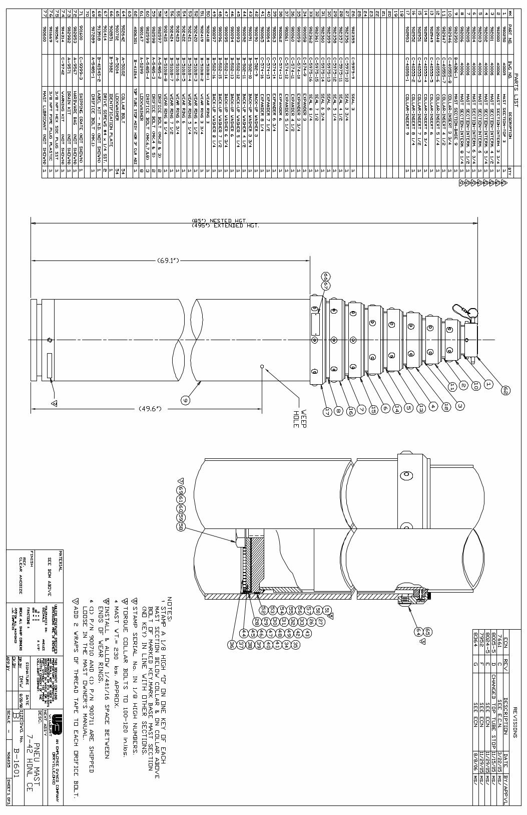

MSDS

MATERIAL SAFETY DATA SHEET
ECP Incorporated 4700 South Central Avenue Chicago, It. 60638 TELEPHONE 708-496-7350
EMERGENCY 800-424-9300
HMI S HAZARD RATING
HEALTH 1 FIRE 2
REACTIVITY 0 PERSONAL PROTECTION C
DATE OF PREPARATION 30 APRIL 1998
BY R. REMIASZ
SECTION 1- PRODUCT IDENTIFICATION
ITEM NUMBER - 1335
ITEM DESCRIPTION - R-477-139 SOUND SHIELD PRODUCT NAME - AA 477-139 SOUND SHIELD
PRODUCT CLASS - UNDERCOATING
SECTION 2 - HAZARDOUS INGREDIENTS INGREDIENT MAX. % BY WT TLV1 PEL2
CAS NUMBER ALIPHATIC HYDROCARBON 35 100ppm 100ppm
64742-88-7, 64742-47-8, 8052-41-3
PETROLEUM ASPHALT 37 5mg/m3 5mg/m3 8052-42-4 HYDROUS ALUMINUM 32 10mg/m3 15mg/m3 SILICATE 1332-58-7 Listed as IARC, NTP, or OSHA Carcinogen: (IARC, ASPHALT SOLUTIONS)

SECTION 3 - PHYSICAL CHARACTERISTICS BOILING POINT: >300F VAPOR PRESSURE (mmHg @ 68F) 3.4 VAPOR DENSITY (AIR=l) >1 SOLUBILITY IN WATER: NONE SPECIFIC GRAVITY: 1.11+/-0.05 % VOLATILE (VOLUME) 50+/-0.2 MELTING POINT: N/A EVAPORATION RATE (ether=l) <1 APPEARANCE AND ODOR: BLACK LIQUID,
SOLVENT ODOR
SECTION 4 - FIRE AND EXPLOSION HAZARD DATA FLASH POINT / METHOD: 105 F I TCC FLAMMABLE LIMITS: LEL: O. 6 UEL: 7.0 EXTINGUISHING MEDIA: Water fog, dry chemicals or carbon dioxide. SPECIAL FIRE FIGHTING PROCEDURES: Full protective equipment including self contained breathing apparatus for confined areas. UNUSUAL FIRE AND EXPLOSION HAZARDS: Vapors are heavier than air. Treat as petroleum fire. SECTION 5 - HEALTH HAZARD DATA SYMPTOMS OF OVEREXPOSURE: EYES: Can cause irritation, redness, and blurred vision. SKIN: Prolonged or repeated contact can cause moderate irritation, defatting dermatitis and burns. INHALATION: Excessive breathing of vapors can cause nasal and respiratory
irritation, dizziness, weakness, fatigue, nausea, headache, possible unconsciousness and even death.
INGESTION: Can cause gastrointestinal irritation, nausea, vomiting and diarrhea. Aspiration into the lungs can cause chemical pneumonitis, which can be fatal.

CONDITIONS AGGRAVATED BY EXPOSURE: Some asphalt solutions have caused skin cancer in laboratory animals. Activity is weak. Intermittent or occasional skin contact with asphalt is not expected to have serious health effects as long as good personal hygiene practices are followed. Heart and respiratory disorders. Alcohol consumption. Dermatitis.
EMERGENCY AND FIRST AID PROCEDURES: INHALATION Remove exposure. Restore breathing. Keep warm and quite. SKIN Wash affected area with soap and water. Remove
contaminated clothing and launder before reuse. EYES Flush with large amounts of water. Get medical attention. IF SWALLOWED never give anything by mouth to an unconscious person.
DO NOT INDUCE VOMITING. Seek medical attention.
SECTION 6 - REACTIVITY DATA STABILITY: Stable INCOMPATIBILITY: Strong oxidizers HAZARDOUS DECOMPOSITION PRODUCTS: Various hydrocarbons of
incomplete combustion HAZARDOUS POLYMERIZATION: Will not occur
SECTION 7 - SPILL OR LEAK PROCEDORES STEPS TO BE TAKEN IF MATERIAL IS SPILLED OR LEAKED: Remove all sources of ignition. Contain spill. Ventilate and remove with inert
absorbent. WASTE DISPOSAL METHOD: Waste from this product may be hazardous (DOO1) as defined by the Resource
Conservation and Recovery Act (RCRA) 40 CFR 261. Dispose of in accordance with federal, state and local regulations.
SECTION 8 - SPECIAL PROTECTION INFORMATION
VENTILATION: Use only with adequate ventilation. Avoid breathing vapor or mist. Local exhaust
preferred.

RESPIRATORY PROTECTION: If required a properly fitted NIOSH/MSHA approved respirator rated for the hazardous ingredients found in (SECTION 2) .
SKIN PROTECTION: Gloves rated for protection against ingredients in (SECTION 2). EYE PROTECTION: Safety glasses with side shields or chemical goggles.
SECTION 9 - PRECAUTIONARY INFORMATION PRECAUTIONS TO BE TAKEN IN STORING AND HANDLING:
Contents may burn. Keep away from any heat or spark source. Do not smoke. Empty containers can contain explosive vapors. Never use a torch to cut or weld on or near container. Never wear oil soaked clothing. Launder or dry-clean before wearing. Discard oil soaked shoes. Affix proper warning labels on containers in accordance with 29CFR 1010.1200.
SECTION 10 - REGULATORY INFORMATION
D.O.T. REQUIREMENTS (49CFR 172.101)
The following is not required by D.O.T. when shipped in containers less than 119 gallons, except when shipped by vessel or aircraft. A flammable classification is required when shipped by vessel or aircraft. (See CFR29 173.150)
COMBUSTIBLE LIQUID N.O.S., COMBUSTIBLE LIQUID, NA1993, III RQ (REPORTABLE QUANTITY) 49CFR 172.101 COMPONENT RQ (lb.) FOR THIS PRODUCT None TSCA (Toxic Substances Control Act) Status - The intentional ingredients of
this product are listed. CERCLA RQ - 40CFR 302.4 - None SARA 302 COMPONENTS - 40CFR 355 Appendix A - None

SECTION 311/312 HAZARD CLASS - 40CFR 370.2 Immediate (X) Reactive ( ) Delayed (X) Sudden Release of Pressure ( ) Fire ( ) SARA 313 COMPONENTS - 40CF<R 372.65 COMPONENT CAS NUMBER MAXIMUM PERCENT None WORKPLACE HAZARDOUS INFORMATION SYSTEM (WHMIS) INGREDIENT MAX. % BY WI. LD50 LC50 PETROLEUM DISTILLATES 35 unknown 3400ppm/4hr
inhl-rat The information contained herein is based on data we believe to be correct. Any use of the product which is not in conformance with this MSDS or which involves using the product in combination with any other product or any process is the responsibility of the user.

Certificates

Copyright © 2012 UL LLC. Unauthorized reproduction, alteration, or recompila tion of this certificate constitutes fraud.
A U T O M O T I V E F I R E A P P A R A T U S C E R T I F I C A T E O F I N S P E C T I O N F O R
L I N E V O L T A G E E L E C T R I C A L S Y S T E M S
FIRE EQUIPMENT SERVICES
This is to certify that UL inspected and tested the below apparatus to the certification requirements in Section 22.15.7 of NFPA 1901, Standard for Automotive Fire Apparatus, 2009 Edition. Certificate No.: G20150326909 Date of Issue: 26 March 2015 Test Date: 26 March 2015 Owner/Destination: Cambridge/Bill Chesney Manufacturer of Unit: SVI Trucks, Inc. Year of Mfg.: 2015 Mfr. Model: Heavy Rescue Mfr. Serial No.: 909
Chassis Manufacturer Model Number Serial Number Spartan Motors LA42L-2142 4S7CT2D9XFC079465 Engine Manufacturer Model Number Serial Number Cummins ISL 73791520 Transmission Manufacturer Model Number Serial Number Allison 3000EVP 6511284616 Generator Manufacturer Model Number Serial Number Onan 15YD CR M15B066328
Remarks: Certified to 15 KW
For additional details regarding the scope of UL’s inspection, go to www.UL.com/fes
For annual in-service testing of your aerial device , ground ladders and pumps, please contact UL at 1-877-UL HELPS (877-854-3577)
Not Valid Unless Signed
Thomas Hillenbrand N
UL

425 Sequoia Drive ● Bellingham, WA 98226 USA ● 001.360.738.8230 ● Fax: 001.360.734.4195 ● www.bluesea.com
Certificate of Compliance
to
European Directive 2002/95/EC - RoHS
ST Blade Fuse Blocks5025, 5026, 5028, 5029, 5030, 5031, 5033,
5034
Product DescriptionBlue Sea Systems’ Model Number(s)
Statement of Compliance
Blue Sea Systems Inc. certifies that, to its knowledge as of the date of this document, the above
referenced model number(s) comply with the maximum concentration values issued as part of the European Union Directive 2002/95/EC (RoHS Directive). The maximum concentration values
issued by the European Union Technical Adaptation Committee (TAC) are shown below:
<0.1%0.1%Polybrominated diphenyl ethers - PBDE
<0.1%0.1%Polybrominated biphenyls – PBB
<0.1%0.1%Hexavalent Chromium – Cr (VI)
<0.01%0.01%Cadmium – Cd
<0.1%0.1%Mercury – Hg
<0.1%0.1%Lead – Pb
Actual
Concentration
Maximum Allowable
Concentration
Substance
Sources for Additional Information
Product technical information, application notes, and model information may be found on the Blue
Sea System’s web site: www.bluesea.com
The test of the EU Directive 2002/95/EC may be found at the following website:
http://europa.eu.int/eur-lex/pri/en/oj/dat/2003/l_037/l_03720030213en00190023.pdf
Disclaimers
This certification applies only the Blue Sea System’s model numbers referenced above and is
made based on Blue Sea system’s understanding of the European Union directive 2002/95/EC and a diligent review of the known and recognized substances contained in each homogenous
material used to manufacture the referenced products
Signature:
Name / Title: Eric Graham / Engineering Manager
Date: March 5, 2008

130 MINERS DRIVE • LAFAYETTE, COLORADO 80026-2951 • 303-666-8112 • FAX: 303-666-4169 www.ponderosa-assoc.com
June 12, 2009 Clay Horst On Scene Solutions P.O. Box 270 Windsor, CO 80550 RE: Talon Helmet Bracket Dear Mr. Horst: This letter is to certify that Ponderosa Associates has performed engineering testing on your Talon helmet bracket device. Our testing was done in accordance with the requirements for the National Fire Protection Associations (NFPA) 1901 Standard for Automotive Fire Apparatus. This standard requires that the helmet bracket adequately contain a helmet when subjected to a 9G acceleration in the longitudinal direction (direction of travel), or a 3G acceleration in the lateral or vertical directions. Our tests indicate that your Talon device complies fully with the requirements set forth in the NFPA 1901 standard when properly mounted per your guidelines for mounting and set up.
If you or any of your associates has any questions regarding the above, please do not hesitate to ask. Respectfully submitted, PONDEROSA ASSOCIATES, LTD.
Carl Finocchiaro, P.E.
ROBERT J. CALDWELL, P.E
JOSEPH H. ROMIG, PH.D.
WILLIAM J. HANNA, P.E. SETH W. BAYER, P.E.
THOMAS FEIEREISEN, M.S., P.E.
MICHAEL J. MCCORT, M.S., P.E.
CARL V. FINOCCHIARO, M.S., P.E.
JOHN W. DAILY, PH.D.
LUCAS W. BARNES
ROBERT S. HOIT, B.S.
JAMIE M. LAROCQUE, B.S.
JODIE E. WHITEHEAD, B.S.
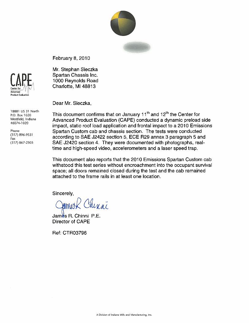

FORM# M/N0510REVISED 053010
������������ �� �������
�������������������������������������� ��
������������ ���������������
��������
®
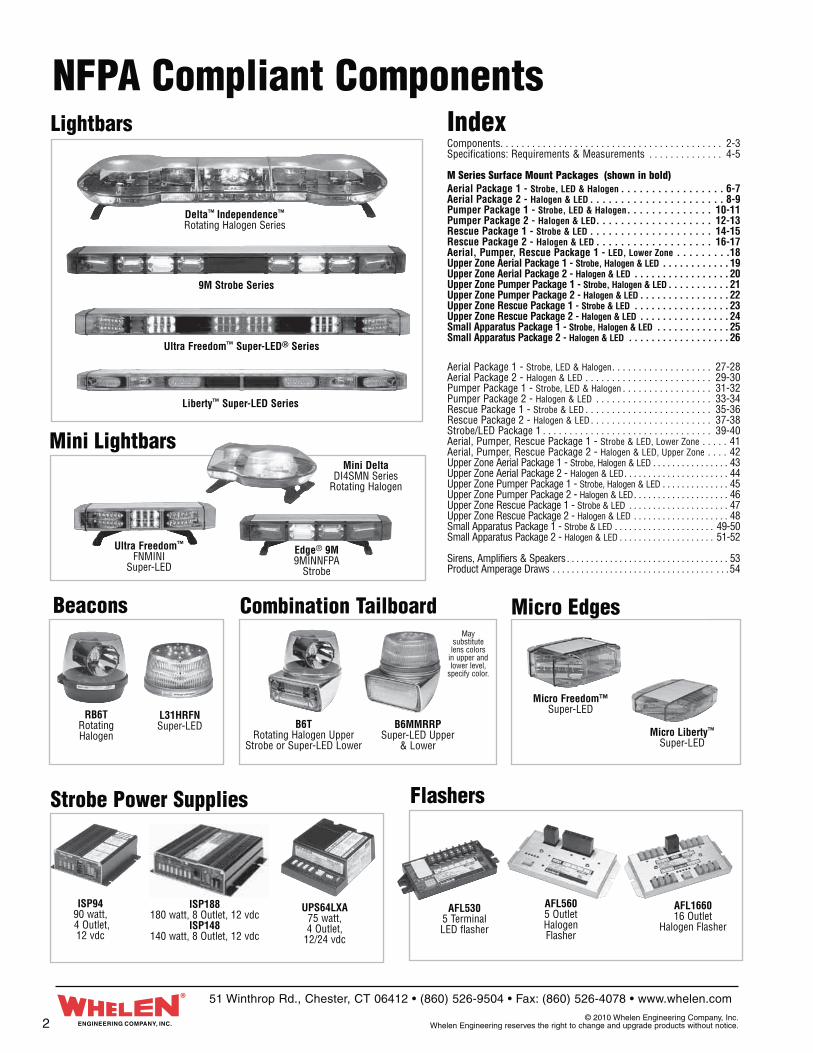
NFPA Compliant ComponentsLightbars Index
Components . . . . . . . . . . . . . . . . . . . . . . . . . . . . . . . . . . . . . . . . . . 2-3Specifications: Requirements & Measurements . . . . . . . . . . . . . . 4-5
M Series Surface Mount Packages (shown in bold)Aerial Package 1 - Strobe, LED & Halogen . . . . . . . . . . . . . . . . . 6-7Aerial Package 2 - Halogen & LED . . . . . . . . . . . . . . . . . . . . . . 8-9Pumper Package 1 - Strobe, LED & Halogen . . . . . . . . . . . . . . 10-11Pumper Package 2 - Halogen & LED . . . . . . . . . . . . . . . . . . . 12-13Rescue Package 1 - Strobe & LED . . . . . . . . . . . . . . . . . . . . 14-15Rescue Package 2 - Halogen & LED . . . . . . . . . . . . . . . . . . . 16-17Aerial, Pumper, Rescue Package 1 - LED, Lower Zone . . . . . . . . .18Upper Zone Aerial Package 1 - Strobe, Halogen & LED . . . . . . . . . . . . 19Upper Zone Aerial Package 2 - Halogen & LED . . . . . . . . . . . . . . . . . 20Upper Zone Pumper Package 1 - Strobe, Halogen & LED . . . . . . . . . . . 21Upper Zone Pumper Package 2 - Halogen & LED . . . . . . . . . . . . . . . . 22Upper Zone Rescue Package 1 - Strobe & LED . . . . . . . . . . . . . . . . . 23Upper Zone Rescue Package 2 - Halogen & LED . . . . . . . . . . . . . . . . 24Small Apparatus Package 1 - Strobe, Halogen & LED . . . . . . . . . . . . . 25Small Apparatus Package 2 - Halogen & LED . . . . . . . . . . . . . . . . . . 26
Aerial Package 1 - Strobe, LED & Halogen . . . . . . . . . . . . . . . . . . . 27-28Aerial Package 2 - Halogen & LED . . . . . . . . . . . . . . . . . . . . . . . . 29-30Pumper Package 1 - Strobe, LED & Halogen . . . . . . . . . . . . . . . . . 31-32Pumper Package 2 - Halogen & LED . . . . . . . . . . . . . . . . . . . . . . 33-34Rescue Package 1 - Strobe & LED . . . . . . . . . . . . . . . . . . . . . . . . 35-36Rescue Package 2 - Halogen & LED . . . . . . . . . . . . . . . . . . . . . . . 37-38Strobe/LED Package 1 . . . . . . . . . . . . . . . . . . . . . . . . . . . . . . . . 39-40Aerial, Pumper, Rescue Package 1 - Strobe & LED, Lower Zone . . . . . 41Aerial, Pumper, Rescue Package 2 - Halogen & LED, Upper Zone . . . . 42 Upper Zone Aerial Package 1 - Strobe, Halogen & LED . . . . . . . . . . . . . . . . 43Upper Zone Aerial Package 2 - Halogen & LED . . . . . . . . . . . . . . . . . . . . . . 44Upper Zone Pumper Package 1 - Strobe, Halogen & LED . . . . . . . . . . . . . . 45Upper Zone Pumper Package 2 - Halogen & LED . . . . . . . . . . . . . . . . . . . . 46Upper Zone Rescue Package 1 - Strobe & LED . . . . . . . . . . . . . . . . . . . . . 47Upper Zone Rescue Package 2 - Halogen & LED . . . . . . . . . . . . . . . . . . . . 48Small Apparatus Package 1 - Strobe & LED . . . . . . . . . . . . . . . . . . . . . 49-50Small Apparatus Package 2 - Halogen & LED . . . . . . . . . . . . . . . . . . . . 51-52
Sirens, Amplifiers & Speakers . . . . . . . . . . . . . . . . . . . . . . . . . . . . . . . . . . 53Product Amperage Draws . . . . . . . . . . . . . . . . . . . . . . . . . . . . . . . . . . . . .54
9M Strobe Series
Ultra Freedom™ Super-LED® Series
Liberty™ Super-LED Series
Micro Edges
Mini Lightbars
Micro Freedom™Super-LED
Micro Liberty™ Super-LED
Mini DeltaDI4SMN Series
Rotating Halogen
Ultra Freedom™
FNMINI Super-LED
Edge® 9M9MINNFPA
Strobe
Delta™ Independence™
Rotating Halogen Series
Strobe Power Supplies Flashers
UPS64LXA75 watt, 4 Outlet,
12/24 vdc
ISP9490 watt, 4 Outlet,12 vdc
AFL166016 Outlet
Halogen Flasher
AFL5305 Terminal LED flasher
AFL5605 Outlet Halogen Flasher
ISP188180 watt, 8 Outlet, 12 vdc
ISP148140 watt, 8 Outlet, 12 vdc
RB6TRotating Halogen
Beacons Combination Tailboard
L31HRFNSuper-LED B6MMRRP
Super-LED Upper & Lower
B6TRotating Halogen Upper
Strobe or Super-LED Lower
May substitute lens colors
in upper and lower level,
specify color.
ENGINEERING COMPANY, INC.
51 Winthrop Rd., Chester, CT 06412 • (860) 526-9504 • Fax: (860) 526-4078 • www.whelen.com
© 2010 Whelen Engineering Company, Inc. Whelen Engineering reserves the right to change and upgrade products without notice.
®
2
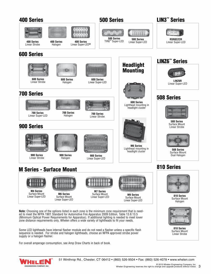
500 Series LIN3™ Series
LINZ6™ Series600 Series
Headlight Mounting
400 Series
M4 SeriesSurface Mount
Linear Super-LEDM6 Series
Surface MountLinear Super-LED
M7 SeriesSurface Mount
Linear Super-LEDM9 Series
Surface MountLinear Super-LED
400 Series Halogen
400 Series Linear Strobe
400 Series Linear Super-LED®
900 Series
900 Series Linear Strobe
900 Series Halogen
900 Series Linear Super-LED
810 Series Surface Mount Linear Strobe
500 SeriesTIR6™ Super-LED
500 Series Linear Super-LED
RSR02ZCRLinear Super-LED
LINZ6RLinear Super-LED
810 Series
810 Series Surface Mount
Halogen
508 Series
508 Series Surface Mount Dual Halogen
508 Series Surface Mount Linear Strobe
600 Series Linear Strobe
600 Series Halogen
600 SeriesLighthead mounting in
headlight cluster
M6 SeriesLighthead mounting in
headlight cluster
600 Series Linear Super-LED
M Series - Surface Mount
700 Series
700 Series Linear Strobe
700 Series Linear Super-LED
700 Series Halogen
ENGINEERING COMPANY, INC.
51 Winthrop Rd., Chester, CT 06412 • (860) 526-9504 • Fax: (860) 526-4078 • www.whelen.com
© 2010 Whelen Engineering Company, Inc. Whelen Engineering reserves the right to change and upgrade products without notice.
®
Some LED lightheads have internal flasher module and do not need a flasher unless a specific flash sequence is needed. For strobe and halogen lightheads, choose an NFPA approved strobe power supply or a halogen flasher.
For overall amperage consumption, see Amp Draw Charts in back of book.
Note: Choosing one of the options listed in each zone is the minimum zone requirement that is need-ed to meet the NFPA 1901 Standard for Automotive Fire Apparatus 2009 Edition, Table 13.8.13.5 (Minimum Optical Power Requirements for Apparatus). If additional lighting is needed to meet lower zone distance requirements only, Whelen offers a wide variety of lightheads to fit your needs.
3

NFPA 1901 Lighting Specifications Measurements Summary Sheet
How to Measure Lighting SpecificationsEXAMPLE: Zone A Upper, Clearing the Right of Way Measurements.
1. Test all modules distributing light 45° right and 45° left at 5° increments (19 test points, total).
2. Add all 19 test points together for each module and add these modules together. For example: A rotating lamp has the same reading at all 19 points (i.e. 120 candela seconds in red) 19 x 120 = 2280. There are four of these identical rotators in Zone A 4 x 2280 = 9120. There is also one clear rotator in Zone A that produces 600 candela. 19 x 600 x 1 = 11400. Add 11400 to the four identical rotators (9120) for a total of 20520. To convert to candela-second/minutes, multiply 20520 x 1.25 (Hz) x 60 (seconds). The total is 1,539,000 candela-second/minutes.
3. There is a minimum requirement in Zone A for each of the 19 test points (10,000 candela-sec./min.). For example: 20° left: Four red rotators produce 220 candela seconds at 20° and one clear rotator produces 600 candela seconds at 20° for a total of 1080 candela seconds. Multiply 1080 by 1.25 (Hz) and multiply by 60 (seconds) for a total of 81,000 candela-second/minutes.
4. The final test requirement for this zone is to check 5° up and 5° down at all 19 test points. The minimum requirement for these areas is 3500 candela-second/minutes. For example: at 35° left, 5° down: All four identical red rotators get 40 candela seconds. One clear rotator gets 200 candela seconds. 40 x 4 + 200 x 1.25 (Hz) x 60 (seconds) equals 27,000 candela-second/minutes.
5. Other requirements to keep in mind: For large & small apparatus photometric requirements & color requirements by zones see charts.
6. Load Management (refer to NFPA 1901 Standards Section 13.3.6). Often the electrical requirements of all appliances operating at the same time exceed the output capacity of the alternator. To prevent deep discharge of the vehicles batteries, appliance malfunction, or possible engine shut down, it is required to automatically disconnect non-critical loads in order to equalize the alternator output capacity. The purchaser and apparatus manufacturer must work together to determine the load management priority assigned to each piece of equipment on the apparatus. Certain equipment including the emergency lighting required to meet the minimum photometric zone requirements cannot be load managed, additional emergency lighting equipment can be installed on the apparatus, however this equipment should be connected to an automatic load manager.
50’
25’ 25’
How to determine the quantity of mid-ship lights needed to adequately light the lower B&D zones of Large Apparatus. Additional mid-ship lights must be added so that you always maintain a horizontal distance of 25 feet or less between all centers of the lower level warning lights.
For example: You have a piece of apparatus 50 feet long. In Zone B lower you are using 3 warning lights. (1 front bumper area, 1 rear of the apparatus, and 1 mid-ship light in the center of the apparatus).
The distance from the mid-ship light to the front light or the rear light must not exceed a distance of 25 feet. As you can see, you will not exceed the 25 foot requirement from the mid-ship light to the front bumper light. If you exceed 25 feet, you must add an additional mid-ship light, for a total of four lower level lights.
Mid-Ship Light
4 ENGINEERING COMPANY, INC.
®51 Winthrop Rd., Chester, CT 06412 • (860) 526-9504 • Fax: (860) 526-4078 • www.whelen.com
© 2010 Whelen Engineering Company, Inc. Whelen Engineering reserves the right to change and upgrade products without notice.
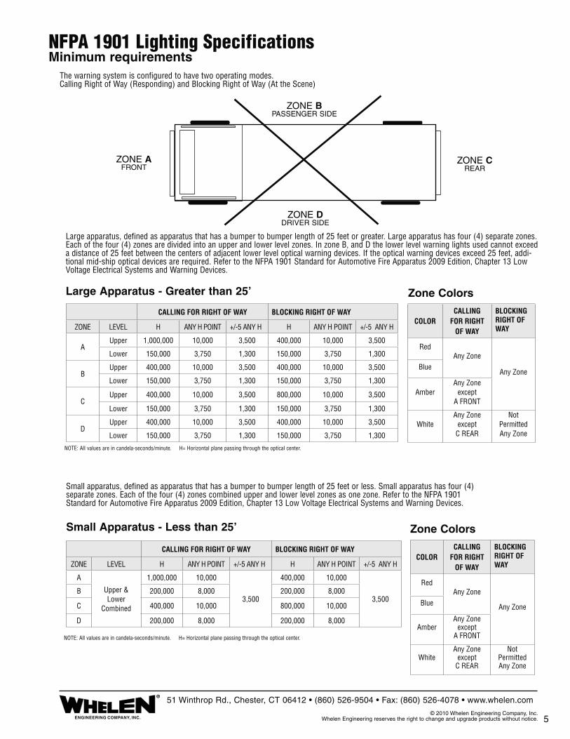
5
NOTE: All values are in candela-seconds/minute. H= Horizontal plane passing through the optical center.
NOTE: All values are in candela-seconds/minute. H= Horizontal plane passing through the optical center.
Zone Colors
Zone Colors
ZONE CREAR
ZONE B PASSENGER SIDE
ZONE D DRIVER SIDE
NFPA 1901 Lighting SpecificationsMinimum requirements
Large Apparatus - Greater than 25’
Small Apparatus - Less than 25’
The warning system is configured to have two operating modes. Calling Right of Way (Responding) and Blocking Right of Way (At the Scene)
ZONE AFRONT
Large apparatus, defined as apparatus that has a bumper to bumper length of 25 feet or greater. Large apparatus has four (4) separate zones. Each of the four (4) zones are divided into an upper and lower level zones. In zone B, and D the lower level warning lights used cannot exceed a distance of 25 feet between the centers of adjacent lower level optical warning devices. If the optical warning devices exceed 25 feet, addi-tional mid-ship optical devices are required. Refer to the NFPA 1901 Standard for Automotive Fire Apparatus 2009 Edition, Chapter 13 Low Voltage Electrical Systems and Warning Devices.
Small apparatus, defined as apparatus that has a bumper to bumper length of 25 feet or less. Small apparatus has four (4) separate zones. Each of the four (4) zones combined upper and lower level zones as one zone. Refer to the NFPA 1901 Standard for Automotive Fire Apparatus 2009 Edition, Chapter 13 Low Voltage Electrical Systems and Warning Devices.
ENGINEERING COMPANY, INC.
®51 Winthrop Rd., Chester, CT 06412 • (860) 526-9504 • Fax: (860) 526-4078 • www.whelen.com
© 2010 Whelen Engineering Company, Inc. Whelen Engineering reserves the right to change and upgrade products without notice.
CALLING FOR RIGHT OF WAY BLOCKING RIGHT OF WAY
ZONE LEVEL H ANY H POINT +/-5 ANY H H ANY H POINT +/-5 ANY H
AUpper 1,000,000 10,000 3,500 400,000 10,000 3,500
Lower 150,000 3,750 1,300 150,000 3,750 1,300
BUpper 400,000 10,000 3,500 400,000 10,000 3,500
Lower 150,000 3,750 1,300 150,000 3,750 1,300
CUpper 400,000 10,000 3,500 800,000 10,000 3,500
Lower 150,000 3,750 1,300 150,000 3,750 1,300
DUpper 400,000 10,000 3,500 400,000 10,000 3,500
Lower 150,000 3,750 1,300 150,000 3,750 1,300
CALLING FOR RIGHT OF WAY BLOCKING RIGHT OF WAY
ZONE LEVEL H ANY H POINT +/-5 ANY H H ANY H POINT +/-5 ANY H
A
Upper & Lower
Combined
1,000,000 10,000
3,500
400,000 10,000
3,500B 200,000 8,000 200,000 8,000
C 400,000 10,000 800,000 10,000
D 200,000 8,000 200,000 8,000
COLORCALLING
FOR RIGHT OF WAY
BLOCKING RIGHT OF WAY
RedAny Zone
Any ZoneBlue
AmberAny Zone
exceptA FRONT
WhiteAny Zone
exceptC REAR
Not PermittedAny Zone
COLORCALLING
FOR RIGHT OF WAY
BLOCKING RIGHT OF WAY
RedAny Zone
Any ZoneBlue
AmberAny Zone
exceptA FRONT
WhiteAny Zone
exceptC REAR
Not PermittedAny Zone
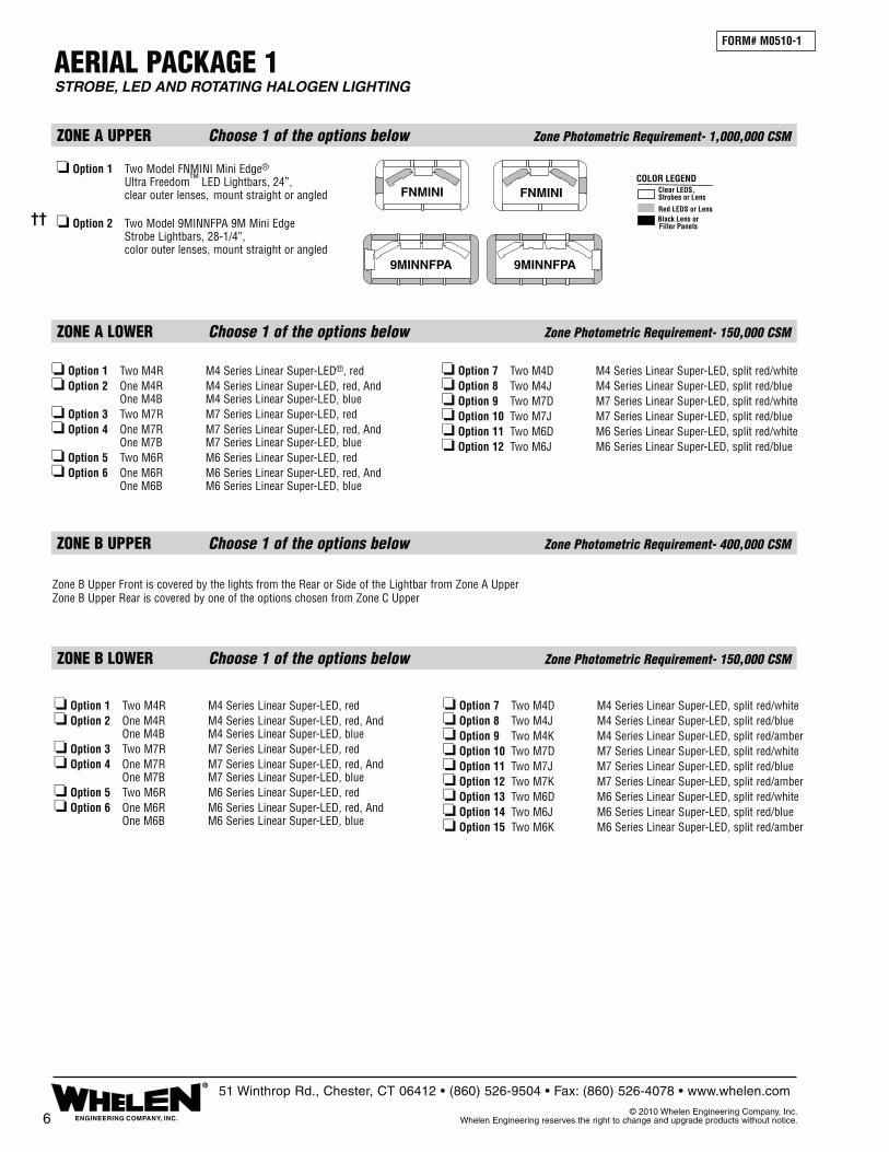
FORM# M0510-1
AERIAL PACKAGE 1STROBE, LED AND ROTATING HALOGEN LIGHTING
ZONE B UPPER Choose 1 of the options below Zone Photometric Requirement- 400,000 CSM
ZONE A LOWER Choose 1 of the options below Zone Photometric Requirement- 150,000 CSM
ZONE B LOWER Choose 1 of the options below Zone Photometric Requirement- 150,000 CSM
9MINNFPA 9MINNFPA
FNMINI FNMINI
❏ Option 1 Two Model FNMINI Mini Edge® Ultra Freedom™ LED Lightbars, 24”, clear outer lenses, mount straight or angled ❏ Option 2 Two Model 9MINNFPA 9M Mini Edge Strobe Lightbars, 28-1/4”, color outer lenses, mount straight or angled
❏ Option 1 Two M4R M4 Series Linear Super-LED®, red❏ Option 2 One M4R M4 Series Linear Super-LED, red, And One M4B M4 Series Linear Super-LED, blue❏ Option 3 Two M7R M7 Series Linear Super-LED, red❏ Option 4 One M7R M7 Series Linear Super-LED, red, And One M7B M7 Series Linear Super-LED, blue❏ Option 5 Two M6R M6 Series Linear Super-LED, red❏ Option 6 One M6R M6 Series Linear Super-LED, red, And One M6B M6 Series Linear Super-LED, blue
❏ Option 7 Two M4D M4 Series Linear Super-LED, split red/white❏ Option 8 Two M4J M4 Series Linear Super-LED, split red/blue❏ Option 9 Two M7D M7 Series Linear Super-LED, split red/white❏ Option 10 Two M7J M7 Series Linear Super-LED, split red/blue❏ Option 11 Two M6D M6 Series Linear Super-LED, split red/white❏ Option 12 Two M6J M6 Series Linear Super-LED, split red/blue
❏ Option 1 Two M4R M4 Series Linear Super-LED, red❏ Option 2 One M4R M4 Series Linear Super-LED, red, And One M4B M4 Series Linear Super-LED, blue❏ Option 3 Two M7R M7 Series Linear Super-LED, red❏ Option 4 One M7R M7 Series Linear Super-LED, red, And One M7B M7 Series Linear Super-LED, blue❏ Option 5 Two M6R M6 Series Linear Super-LED, red❏ Option 6 One M6R M6 Series Linear Super-LED, red, And One M6B M6 Series Linear Super-LED, blue
❏ Option 7 Two M4D M4 Series Linear Super-LED, split red/white❏ Option 8 Two M4J M4 Series Linear Super-LED, split red/blue❏ Option 9 Two M4K M4 Series Linear Super-LED, split red/amber❏ Option 10 Two M7D M7 Series Linear Super-LED, split red/white❏ Option 11 Two M7J M7 Series Linear Super-LED, split red/blue ❏ Option 12 Two M7K M7 Series Linear Super-LED, split red/amber❏ Option 13 Two M6D M6 Series Linear Super-LED, split red/white❏ Option 14 Two M6J M6 Series Linear Super-LED, split red/blue❏ Option 15 Two M6K M6 Series Linear Super-LED, split red/amber
Zone B Upper Front is covered by the lights from the Rear or Side of the Lightbar from Zone A UpperZone B Upper Rear is covered by one of the options chosen from Zone C Upper
ZONE A UPPER Choose 1 of the options below Zone Photometric Requirement- 1,000,000 CSM
6 ENGINEERING COMPANY, INC.
®51 Winthrop Rd., Chester, CT 06412 • (860) 526-9504 • Fax: (860) 526-4078 • www.whelen.com
© 2010 Whelen Engineering Company, Inc. Whelen Engineering reserves the right to change and upgrade products without notice.
Clear LEDS,Strobes or Lens
Red LEDS or LensBlack Lens orFiller Panels
COLOR LEGEND
��

7
ZONE D UPPER Choose 1 of the options below Zone Photometric Requirement- 400,000 CSM
ZONE D LOWER Choose 1 of the options below Zone Photometric Requirement- 150,000 CSM
AERIAL PACKAGE 1 (cont.)STROBE, LED AND ROTATING HALOGEN LIGHTING
FORM# M0510-1
ZONE C LOWER Choose 1 of the options below Zone Photometric Requirement- 150,000 CSM
ENGINEERING COMPANY, INC.
®51 Winthrop Rd., Chester, CT 06412 • (860) 526-9504 • Fax: (860) 526-4078 • www.whelen.com
© 2010 Whelen Engineering Company, Inc. Whelen Engineering reserves the right to change and upgrade products without notice.
CERTIFICATE OF COMPLIANCE WITH NFPA 1901To Meet Certification, Check Box for the Option Chosen in Each Appropriate Zone
Note: This system is tested and certified by Whelen Engineering Company, Inc. to meet all require-ments for the NFPA 1901 Standards for Automotive Fire Apparatus (2010 Edition). See Chapter 13 titled: Low Voltage Electrical Systems & Warning Devices. This System is Certified only if all optical and electrical warning devices are installed and wired in accordance to the 1901 Standard and Specifications; and also in accordance to the device manufacturers mounting and wiring specifications.
FIRE DEPARTMENT
TRUCK NUMBER
ZONE C UPPER Choose 1 of the options below Zone Photometric Requirement- 800,000 CSM
❏ Option 1 One RB6TAP RB6 Series Rotating Beacon, amber, And One RB6TRP RB6 Series Rotating Beacon, red❏ Option 2 Two RB6TRP RB6 Series Rotating Beacons, red❏ Option 3 Two B6TMRR1P RBT Series Upper Rotator, Lower Level, Linear Super-LED® flasher, red❏ Option 4 Two B6TSRR1P RBT Series Upper Rotator, Lower Level, Strobe, red❏ Option 5 Two MCFLED2R Ultra Freedom Micro Edge® LED, red❏ Option 6 Two MCSLED2R LFL Liberty Micro Edge LED, red❏ Option 7 Two L31HRFN L31 Series Super-LED Beacons, red❏ Option 8 Two B6MMRRP Super-LED Beacons Upper Section, Lower Level Linear Super-LED flasher, red
❏ Option 9 Two M7R M7 Series Linear Super-LED, red❏ Option 10 Two M6R M6 Series Linear Super-LED, red❏ Option 11 Two M9R M9 Series Linear Super-LED, red❏ Option 12 One M9R M9 Series Linear Super-LED, red, And One M9A M9 Series Linear Super-LED, amber❏ Option 13 One M9R M9 Series Linear Super-LED, red, And One M9B M9 Series Linear Super-LED, blue❏ Option 14 One M6A M6 Series Linear Super-LED, amber, And One M6R M6 Series Linear Super-LED, red❏ Option 15 One M6R M6 Series Linear Super-LED, red, And One M6B M6 Series Linear Super-LED, blue
❏ Option 1 Two M4R M4 Series Linear Super-LED, red❏ Option 2 One M4R M4 Series Linear Super-LED, red, And One M4B M4 Series Linear Super-LED, blue❏ Option 3 Two M7R M7 Series Linear Super-LED, red❏ Option 4 One M7R M7 Series Linear Super-LED, red, And One M7B M7 Series Linear Super-LED, blue❏ Option 5 Two M6R M6 Series Linear Super-LED, red❏ Option 6 One M6R M6 Series Linear Super-LED, red, And One M6B M6 Series Linear Super-LED, blue
❏ Option 7 Two M4D M4 Series Linear Super-LED, split red/white❏ Option 8 Two M4J M4 Series Linear Super-LED, split red/blue❏ Option 9 Two M4K M4 Series Linear Super-LED, split red/amber❏ Option 10 Two M7D M7 Series Linear Super-LED, split red/white❏ Option 11 Two M7J M7 Series Linear Super-LED, split red/blue❏ Option 12 Two M7K M7 Series Linear Super-LED, split red/amber❏ Option 13 Two M6D M6 Series Linear Super-LED, split red/white❏ Option 14 Two M6J M6 Series Linear Super-LED, split red/blue❏ Option 15 Two M6K M6 Series Linear Super-LED, split red/amber
❏ Option 1 Two M4R M4 Series Linear Super-LED, red❏ Option 2 One M4R M4 Series Linear Super-LED, red, And One M4B M4 Series Linear Super-LED, blue❏ Option 3 Two M7R M7 Series Linear Super-LED, red❏ Option 4 One M7R M7 Series Linear Super-LED, red, And One M7B M7 Series Linear Super-LED, blue❏ Option 5 Two M6R M6 Series Linear Super-LED, red❏ Option 6 One M6R M6 Series Linear Super-LED, red, And One M6B M6 Series Linear Super-LED, blue
❏ Option 7 Two M4J M4 Series Linear Super-LED, split red/blue❏ Option 8 Two M4K M4 Series Linear Super-LED, split red/amber❏ Option 9 Two M7J M7 Series Linear Super-LED, split red/blue❏ Option 10 Two M7K M7 Series Linear Super-LED, split red/amber❏ Option 11 Two M6J M6 Series Linear Super-LED, split red/blue❏ Option 12 Two M6K M6 Series Linear Super-LED, split red/amber
This package meets all zone requirements of NFPA 1901 specifications.
M Series Lightheads are Surface Mount
Zone D Upper Front is covered by the lights from the Rear or Side of the Lightbar from Zone A UpperZone D Upper Rear is covered by one of the options chosen from Zone C Upper
†† = special order, check availability, non-returnable
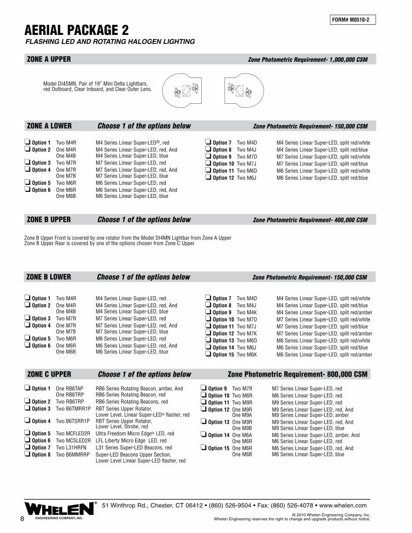
ZONE C UPPER Choose 1 of the options below Zone Photometric Requirement- 800,000 CSM
FORM# M0510-2
FLASHING LED AND ROTATING HALOGEN LIGHTING AERIAL PACKAGE 2
ZONE A UPPER Zone Photometric Requirement- 1,000,000 CSM
ZONE B UPPER Choose 1 of the options below Zone Photometric Requirement- 400,000 CSM
ZONE A LOWER Choose 1 of the options below Zone Photometric Requirement- 150,000 CSM
ZONE B LOWER Choose 1 of the options below Zone Photometric Requirement- 150,000 CSM
Model DI4SMN, Pair of 19” Mini Delta Lightbars, red Outboard, Clear Inboard, and Clear Outer Lens.
8 ENGINEERING COMPANY, INC.
®51 Winthrop Rd., Chester, CT 06412 • (860) 526-9504 • Fax: (860) 526-4078 • www.whelen.com
© 2010 Whelen Engineering Company, Inc. Whelen Engineering reserves the right to change and upgrade products without notice.
❏ Option 1 Two M4R M4 Series Linear Super-LED®, red❏ Option 2 One M4R M4 Series Linear Super-LED, red, And One M4B M4 Series Linear Super-LED, blue❏ Option 3 Two M7R M7 Series Linear Super-LED, red❏ Option 4 One M7R M7 Series Linear Super-LED, red, And One M7B M7 Series Linear Super-LED, blue❏ Option 5 Two M6R M6 Series Linear Super-LED, red❏ Option 6 One M6R M6 Series Linear Super-LED, red, And One M6B M6 Series Linear Super-LED, blue
❏ Option 7 Two M4D M4 Series Linear Super-LED, split red/white❏ Option 8 Two M4J M4 Series Linear Super-LED, split red/blue❏ Option 9 Two M7D M7 Series Linear Super-LED, split red/white❏ Option 10 Two M7J M7 Series Linear Super-LED, split red/blue❏ Option 11 Two M6D M6 Series Linear Super-LED, split red/white❏ Option 12 Two M6J M6 Series Linear Super-LED, split red/blue
❏ Option 1 Two M4R M4 Series Linear Super-LED, red❏ Option 2 One M4R M4 Series Linear Super-LED, red, And One M4B M4 Series Linear Super-LED, blue❏ Option 3 Two M7R M7 Series Linear Super-LED, red❏ Option 4 One M7R M7 Series Linear Super-LED, red, And One M7B M7 Series Linear Super-LED, blue❏ Option 5 Two M6R M6 Series Linear Super-LED, red❏ Option 6 One M6R M6 Series Linear Super-LED, red, And One M6B M6 Series Linear Super-LED, blue
❏ Option 7 Two M4D M4 Series Linear Super-LED, split red/white❏ Option 8 Two M4J M4 Series Linear Super-LED, split red/blue❏ Option 9 Two M4K M4 Series Linear Super-LED, split red/amber❏ Option 10 Two M7D M7 Series Linear Super-LED, split red/white❏ Option 11 Two M7J M7 Series Linear Super-LED, split red/blue❏ Option 12 Two M7K M7 Series Linear Super-LED, split red/amber❏ Option 13 Two M6D M6 Series Linear Super-LED, split red/white❏ Option 14 Two M6J M6 Series Linear Super-LED, split red/blue❏ Option 15 Two M6K M6 Series Linear Super-LED, split red/amber
❏ Option 1 One RB6TAP RB6 Series Rotating Beacon, amber, And One RB6TRP RB6 Series Rotating Beacon, red❏ Option 2 Two RB6TRP RB6 Series Rotating Beacons, red❏ Option 3 Two B6TMRR1P RBT Series Upper Rotator, Lower Level, Linear Super-LED® flasher, red❏ Option 4 Two B6TSRR1P RBT Series Upper Rotator, Lower Level, Strobe, red❏ Option 5 Two MCFLED2R Ultra Freedom Micro Edge® LED, red❏ Option 6 Two MCSLED2R LFL Liberty Micro Edge LED, red❏ Option 7 Two L31HRFN L31 Series Super-LED Beacons, red❏ Option 8 Two B6MMRRP Super-LED Beacons Upper Section, Lower Level Linear Super-LED flasher, red
❏ Option 9 Two M7R M7 Series Linear Super-LED, red❏ Option 10 Two M6R M6 Series Linear Super-LED, red❏ Option 11 Two M9R M9 Series Linear Super-LED, red❏ Option 12 One M9R M9 Series Linear Super-LED, red, And One M9A M9 Series Linear Super-LED, amber❏ Option 13 One M9R M9 Series Linear Super-LED, red, And One M9B M9 Series Linear Super-LED, blue❏ Option 14 One M6A M6 Series Linear Super-LED, amber, And One M6R M6 Series Linear Super-LED, red❏ Option 15 One M6R M6 Series Linear Super-LED, red, And One M6B M6 Series Linear Super-LED, blue
Zone B Upper Front is covered by one rotator from the Model DI4MN Lightbar from Zone A UpperZone B Upper Rear is covered by one of the options chosen from Zone C Upper
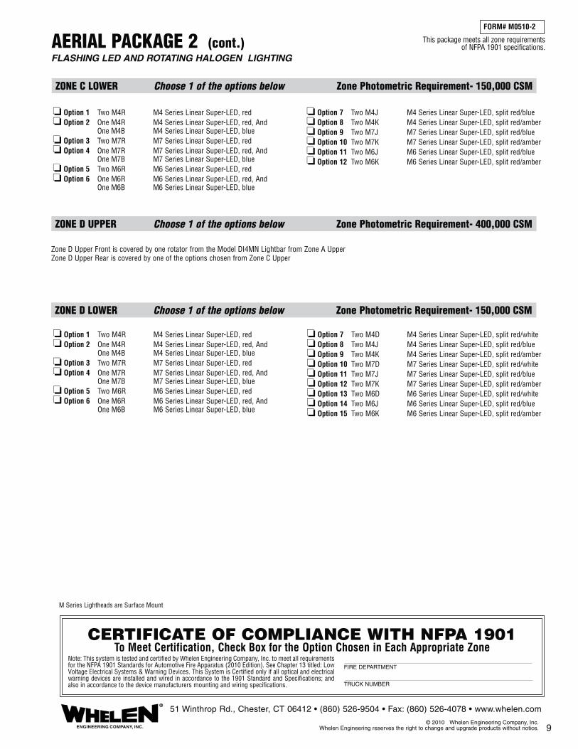
9
FLASHING LED AND ROTATING HALOGEN LIGHTING AERIAL PACKAGE 2 (cont.)
ZONE D UPPER Choose 1 of the options below Zone Photometric Requirement- 400,000 CSM
ZONE D LOWER Choose 1 of the options below Zone Photometric Requirement- 150,000 CSM
FORM# M0510-2
ZONE C LOWER Choose 1 of the options below Zone Photometric Requirement- 150,000 CSM
ENGINEERING COMPANY, INC.
®51 Winthrop Rd., Chester, CT 06412 • (860) 526-9504 • Fax: (860) 526-4078 • www.whelen.com
© 2010 Whelen Engineering Company, Inc. Whelen Engineering reserves the right to change and upgrade products without notice.
CERTIFICATE OF COMPLIANCE WITH NFPA 1901To Meet Certification, Check Box for the Option Chosen in Each Appropriate Zone
Note: This system is tested and certified by Whelen Engineering Company, Inc. to meet all requirements for the NFPA 1901 Standards for Automotive Fire Apparatus (2010 Edition). See Chapter 13 titled: Low Voltage Electrical Systems & Warning Devices. This System is Certified only if all optical and electrical warning devices are installed and wired in accordance to the 1901 Standard and Specifications; and also in accordance to the device manufacturers mounting and wiring specifications.
FIRE DEPARTMENT
TRUCK NUMBER
This package meets all zone requirements of NFPA 1901 specifications.
❏ Option 1 Two M4R M4 Series Linear Super-LED, red❏ Option 2 One M4R M4 Series Linear Super-LED, red, And One M4B M4 Series Linear Super-LED, blue❏ Option 3 Two M7R M7 Series Linear Super-LED, red❏ Option 4 One M7R M7 Series Linear Super-LED, red, And One M7B M7 Series Linear Super-LED, blue❏ Option 5 Two M6R M6 Series Linear Super-LED, red❏ Option 6 One M6R M6 Series Linear Super-LED, red, And One M6B M6 Series Linear Super-LED, blue
❏ Option 7 Two M4J M4 Series Linear Super-LED, split red/blue❏ Option 8 Two M4K M4 Series Linear Super-LED, split red/amber❏ Option 9 Two M7J M7 Series Linear Super-LED, split red/blue❏ Option 10 Two M7K M7 Series Linear Super-LED, split red/amber❏ Option 11 Two M6J M6 Series Linear Super-LED, split red/blue❏ Option 12 Two M6K M6 Series Linear Super-LED, split red/amber
❏ Option 1 Two M4R M4 Series Linear Super-LED, red❏ Option 2 One M4R M4 Series Linear Super-LED, red, And One M4B M4 Series Linear Super-LED, blue❏ Option 3 Two M7R M7 Series Linear Super-LED, red❏ Option 4 One M7R M7 Series Linear Super-LED, red, And One M7B M7 Series Linear Super-LED, blue❏ Option 5 Two M6R M6 Series Linear Super-LED, red❏ Option 6 One M6R M6 Series Linear Super-LED, red, And One M6B M6 Series Linear Super-LED, blue
❏ Option 7 Two M4D M4 Series Linear Super-LED, split red/white❏ Option 8 Two M4J M4 Series Linear Super-LED, split red/blue❏ Option 9 Two M4K M4 Series Linear Super-LED, split red/amber❏ Option 10 Two M7D M7 Series Linear Super-LED, split red/white❏ Option 11 Two M7J M7 Series Linear Super-LED, split red/blue❏ Option 12 Two M7K M7 Series Linear Super-LED, split red/amber❏ Option 13 Two M6D M6 Series Linear Super-LED, split red/white❏ Option 14 Two M6J M6 Series Linear Super-LED, split red/blue❏ Option 15 Two M6K M6 Series Linear Super-LED, split red/amber
M Series Lightheads are Surface Mount
Zone D Upper Front is covered by one rotator from the Model DI4MN Lightbar from Zone A UpperZone D Upper Rear is covered by one of the options chosen from Zone C Upper

PUMPER PACKAGE 1
ZONE A UPPER Choose 1 of the options below Zone Photometric Requirement- 1,000,000 CSM
ZONE B UPPER Choose 1 of the options below Zone Photometric Requirement- 400,000 CSM
ZONE A LOWER Choose 1 of the options below Zone Photometric Requirement- 150,000 CSM
ZONE B LOWER Choose 1 of the options below Zone Photometric Requirement- 150,000 CSM
FORM# M0510-3
STROBE, LED AND ROTATING HALOGEN LIGHTING
10 ENGINEERING COMPANY, INC.
®51 Winthrop Rd., Chester, CT 06412 • (860) 526-9504 • Fax: (860) 526-4078 • www.whelen.com
© 2010 Whelen Engineering Company, Inc. Whelen Engineering reserves the right to change and upgrade products without notice.
FRONTFN55QLED
SLN2QLED
FN55VLED
SLN2VLED
FN60QLED FN60VLED
FN72VLEDFN72QLED
9M380NQ 9M380NV
9M382NQ 9M382NV
9M387NV9M387NQ
Clear LEDS,Strobes or Lens
Red LEDS or LensBlack Lens orFiller Panels
COLOR LEGEND
❏ Option 1 Two M4R M4 Series Linear Super-LED, red❏ Option 2 One M4R M4 Series Linear Super-LED, red, And One M4B M4 Series Linear Super-LED, blue❏ Option 3 Two M7R M7 Series Linear Super-LED, red❏ Option 4 One M7R M7 Series Linear Super-LED, red, And One M7B M7 Series Linear Super-LED, blue❏ Option 5 Two M6R M6 Series Linear Super-LED, red❏ Option 6 One M6R M6 Series Linear Super-LED, red, And One M6B M6 Series Linear Super-LED, blue
❏ Option 7 Two M4D M4 Series Linear Super-LED, split red/white❏ Option 8 Two M4J M4 Series Linear Super-LED, split red/blue❏ Option 9 Two M4K M4 Series Linear Super-LED, split red/amber❏ Option 10 Two M7D M7 Series Linear Super-LED, split red/white❏ Option 11 Two M7J M7 Series Linear Super-LED, split red/blue❏ Option 12 Two M7K M7 Series Linear Super-LED, split red/amber❏ Option 13 Two M6D M6 Series Linear Super-LED, split red/white❏ Option 14 Two M6J M6 Series Linear Super-LED, split red/blue❏ Option 15 Two M6K M6 Series Linear Super-LED, split red/amber
❏ Option 1 Two M4R M4 Series Linear Super-LED®, red❏ Option 2 One M4R M4 Series Linear Super-LED, red, And One M4B M4 Series Linear Super-LED, blue❏ Option 3 Two M7R M7 Series Linear Super-LED, red❏ Option 4 One M7R M7 Series Linear Super-LED, red, And One M7B M7 Series Linear Super-LED, blue❏ Option 5 Two M6R M6 Series Linear Super-LED, red❏ Option 6 One M6R M6 Series Linear Super-LED, red, And One M6B M6 Series Linear Super-LED, blue
❏ Option 7 Two M4D M4 Series Linear Super-LED, split red/white❏ Option 8 Two M4J M4 Series Linear Super-LED, split red/blue❏ Option 9 Two M7D M7 Series Linear Super-LED, split red/white❏ Option 10 Two M7J M7 Series Linear Super-LED, split red/blue❏ Option 11 Two M6D M6 Series Linear Super-LED, split red/white❏ Option 12 Two M6J M6 Series Linear Super-LED, split red/blue
Zone B Upper Front is covered by the lights from the Rear or Side of the Lightbar from Zone A UpperZone B Upper Rear is covered by one of the options chosen from Zone C Upper
������
������
❏ Option 1 One SLN2VLED NFPA LFL Liberty™ LED Lightbar, clear outer lenses, std. 54” only❏ Option 2 One SLN2QLED NFPA LFL Liberty LED Lightbar, clear outer lenses, std. 54” only❏ Option 3 One FN55QLED NFPA Edge® Ultra Freedom™ LED Lightbar, clear outer lenses, std. 55"❏ Option 4 One FN60QLED NFPA Edge Ultra Freedom LED Lightbar, clear outer lenses, std. 60"❏ Option 5 One FN72QLED NFPA Edge Ultra Freedom LED Lightbar, clear outer lenses, std. 72"❏ Option 6 One FN55VLED NFPA Edge Ultra Freedom LED Lightbar, clear outer lenses, std. 55"❏ Option 7 One FN60VLED NFPA Edge Ultra Freedom LED Lightbar, clear outer lenses, std. 60"❏ Option 8 One FN72VLED NFPA Edge Ultra Freedom LED Lightbar, clear outer lenses, std. 72"❏ Option 9 One 9M382NQ NFPA Edge 9M Strobe Lightbar, color outer lenses, std. 55"❏ Option 10 One 9M380NQ NFPA Edge 9M Strobe Lightbar, color outer lenses, std. 60"❏ Option 11 One 9M387NQ NFPA Edge 9M Strobe Lightbar, color outer lenses, std. 72"❏ Option 12 One 9M382NV NFPA Edge 9M Strobe Lightbar, color outer lenses, std. 55"❏ Option 13 One 9M380NV NFPA Edge 9M Strobe Lightbar, color outer lenses, std. 60"
❏ Option 14 One 9M387NV NFPA Edge 9M Strobe Lightbar, color outer lenses, std. 72"

PUMPER PACKAGE 1 (cont.)STROBE, LED AND ROTATING HALOGEN LIGHTING
ZONE D UPPER Choose 1 of the options below Zone Photometric Requirement- 400,000 CSM
ZONE D LOWER Choose 1 of the options below Zone Photometric Requirement- 150,000 CSM
FORM# M0510-3
11
ZONE C UPPER Choose 1 of the options below Zone Photometric Requirement- 800,000 CSM
ZONE C LOWER Choose 1 of the options below Zone Photometric Requirement- 150,000 CSM
ENGINEERING COMPANY, INC.
®51 Winthrop Rd., Chester, CT 06412 • (860) 526-9504 • Fax: (860) 526-4078 • www.whelen.com
© 2010 Whelen Engineering Company, Inc. Whelen Engineering reserves the right to change and upgrade products without notice.
CERTIFICATE OF COMPLIANCE WITH NFPA 1901To Meet Certification, Check Box for the Option Chosen in Each Appropriate Zone
Note: This system is tested and certified by Whelen Engineering Company, Inc. to meet all requirements for the NFPA 1901 Standards for Automotive Fire Apparatus (2010 Edition). See Chapter 13 titled: Low Voltage Electrical Systems & Warning Devices. This System is Certified only if all optical and electrical warning devices are installed and wired in accordance to the 1901 Standard and Specifications; and also in accordance to the device manufacturers mounting and wiring specifications.
FIRE DEPARTMENT
TRUCK NUMBER
This package meets all zone requirements of NFPA 1901 specifications.
❏ Option 1 Two M4R M4 Series Linear Super-LED, red❏ Option 2 One M4R M4 Series Linear Super-LED, red, And One M4B M4 Series Linear Super-LED, blue❏ Option 3 Two M7R M7 Series Linear Super-LED, red❏ Option 4 One M7R M7 Series Linear Super-LED, red, And One M7B M7 Series Linear Super-LED, blue❏ Option 5 Two M6R M6 Series Linear Super-LED, red❏ Option 6 One M6R M6 Series Linear Super-LED, red, And One M6B M6 Series Linear Super-LED, blue
❏ Option 7 Two M4D M4 Series Linear Super-LED, split red/white❏ Option 8 Two M4J M4 Series Linear Super-LED, split red/blue❏ Option 9 Two M4K M4 Series Linear Super-LED, split red/amber❏ Option 10 Two M7D M7 Series Linear Super-LED, split red/white❏ Option 11 Two M7J M7 Series Linear Super-LED, split red/blue❏ Option 12 Two M7K M7 Series Linear Super-LED, split red/amber❏ Option 13 Two M6D M6 Series Linear Super-LED, split red/white❏ Option 14 Two M6J M6 Series Linear Super-LED, split red/blue❏ Option 15 Two M6K M6 Series Linear Super-LED, split red/amber
❏ Option 1 Two M4R M4 Series Linear Super-LED, red❏ Option 2 One M4R M4 Series Linear Super-LED, red, And One M4B M4 Series Linear Super-LED, blue❏ Option 3 Two M7R M7 Series Linear Super-LED, red❏ Option 4 One M7R M7 Series Linear Super-LED, red, And One M7B M7 Series Linear Super-LED, blue❏ Option 5 Two M6R M6 Series Linear Super-LED, red❏ Option 6 One M6R M6 Series Linear Super-LED, red, And One M6B M6 Series Linear Super-LED, blue
❏ Option 7 Two M4J M4 Series Linear Super-LED, split red/blue❏ Option 8 Two M4K M4 Series Linear Super-LED, split red/amber❏ Option 9 Two M7J M7 Series Linear Super-LED, split red/blue❏ Option 10 Two M7K M7 Series Linear Super-LED, split red/amber❏ Option 11 Two M6J M6 Series Linear Super-LED, split red/blue❏ Option 12 Two M6K M6 Series Linear Super-LED, split red/amber
❏ Option 1 One RB6TAP RB6 Series Rotating Beacon, amber, And One RB6TRP RB6 Series Rotating Beacon, red❏ Option 2 Two RB6TRP RB6 Series Rotating Beacons, red❏ Option 3 Two B6TMRR1P RBT Series Upper Rotator, Lower Level, Linear Super-LED® flasher, red❏ Option 4 Two B6TSRR1P RBT Series Upper Rotator, Lower Level, Strobe, red❏ Option 5 Two MCFLED2R Ultra Freedom Micro Edge® LED, red❏ Option 6 Two MCSLED2R LFL Liberty Micro Edge LED, red❏ Option 7 Two L31HRFN L31 Series Super-LED Beacons, red❏ Option 8 Two B6MMRRP Super-LED Beacons Upper Section, Lower Level Linear Super-LED flasher, red
❏ Option 9 Two M7R M7 Series Linear Super-LED, red❏ Option 10 Two M6R M6 Series Linear Super-LED, red❏ Option 11 Two M9R M9 Series Linear Super-LED, red❏ Option 12 One M9R M9 Series Linear Super-LED, red, And One M9A M9 Series Linear Super-LED, amber❏ Option 13 One M9R M9 Series Linear Super-LED, red, And One M9B M9 Series Linear Super-LED, blue❏ Option 14 One M6A M6 Series Linear Super-LED, amber, And One M6R M6 Series Linear Super-LED, red❏ Option 15 One M6R M6 Series Linear Super-LED, red, And One M6B M6 Series Linear Super-LED, blue
M Series Lightheads are Surface Mount
Zone D Upper Front is covered by the lights from the Rear or Side of the Lightbar from Zone A UpperZone D Upper Rear is covered by one of the options chosen from Zone C Upper
†† = special order, check availability, non-returnable
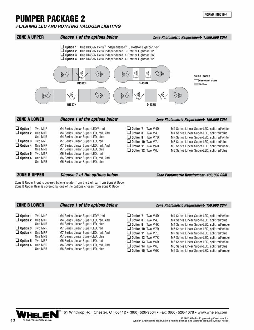
PUMPER PACKAGE 2
❏ Option 1 One DI3S2N Delta™ Independence™ 3 Rotator Lightbar, 56”❏ Option 2 One DI3S7N Delta Independence 3 Rotator Lightbar, 72”❏ Option 3 One DI4S2N Delta Independence 4 Rotator Lightbar, 56”❏ Option 4 One DI4S7N Delta Independence 4 Rotator Lightbar, 72”
ZONE A UPPER Choose 1 of the options below Zone Photometric Requirement- 1,000,000 CSM
ZONE B UPPER Choose 1 of the options below Zone Photometric Requirement- 400,000 CSM
ZONE A LOWER Choose 1 of the options below Zone Photometric Requirement- 150,000 CSM
ZONE B LOWER Choose 1 of the options below Zone Photometric Requirement- 150,000 CSM
FORM# M0510-4
FLASHING LED AND ROTATING HALOGEN LIGHTING
12 ENGINEERING COMPANY, INC.
®51 Winthrop Rd., Chester, CT 06412 • (860) 526-9504 • Fax: (860) 526-4078 • www.whelen.com
© 2010 Whelen Engineering Company, Inc. Whelen Engineering reserves the right to change and upgrade products without notice.
Clear rotators or Lens
Red Lens
COLOR LEGEND
DI3S7N
DI3S2N DI4S2N
DI4S7N
❏ Option 1 Two M4R M4 Series Linear Super-LED®, red❏ Option 2 One M4R M4 Series Linear Super-LED, red, And One M4B M4 Series Linear Super-LED, blue❏ Option 3 Two M7R M7 Series Linear Super-LED, red❏ Option 4 One M7R M7 Series Linear Super-LED, red, And One M7B M7 Series Linear Super-LED, blue❏ Option 5 Two M6R M6 Series Linear Super-LED, red❏ Option 6 One M6R M6 Series Linear Super-LED, red, And One M6B M6 Series Linear Super-LED, blue
❏ Option 7 Two M4D M4 Series Linear Super-LED, split red/white❏ Option 8 Two M4J M4 Series Linear Super-LED, split red/blue❏ Option 9 Two M4K M4 Series Linear Super-LED, split red/amber❏ Option 10 Two M7D M7 Series Linear Super-LED, split red/white❏ Option 11 Two M7J M7 Series Linear Super-LED, split red/blue❏ Option 12 Two M7K M7 Series Linear Super-LED, split red/amber❏ Option 13 Two M6D M6 Series Linear Super-LED, split red/white❏ Option 14 Two M6J M6 Series Linear Super-LED, split red/blue❏ Option 15 Two M6K M6 Series Linear Super-LED, split red/amber
❏ Option 1 Two M4R M4 Series Linear Super-LED®, red❏ Option 2 One M4R M4 Series Linear Super-LED, red, And One M4B M4 Series Linear Super-LED, blue❏ Option 3 Two M7R M7 Series Linear Super-LED, red❏ Option 4 One M7R M7 Series Linear Super-LED, red, And One M7B M7 Series Linear Super-LED, blue❏ Option 5 Two M6R M6 Series Linear Super-LED, red❏ Option 6 One M6R M6 Series Linear Super-LED, red, And One M6B M6 Series Linear Super-LED, blue
❏ Option 7 Two M4D M4 Series Linear Super-LED, split red/white❏ Option 8 Two M4J M4 Series Linear Super-LED, split red/blue❏ Option 9 Two M7D M7 Series Linear Super-LED, split red/white❏ Option 10 Two M7J M7 Series Linear Super-LED, split red/blue❏ Option 11 Two M6D M6 Series Linear Super-LED, split red/white❏ Option 12 Two M6J M6 Series Linear Super-LED, split red/blue
Zone B Upper Front is covered by one rotator from the Lightbar from Zone A UpperZone B Upper Rear is covered by one of the options chosen from Zone C Upper

13
PUMPER PACKAGE 2 (cont.)FLASHING LED AND ROTATING HALOGEN LIGHTING
FORM# M0510-4
ZONE D UPPER Choose 1 of the options below Zone Photometric Requirement- 400,000 CSM
ZONE D LOWER Choose 1 of the options below Zone Photometric Requirement- 150,000 CSM
ZONE C LOWER Choose 1 of the options below Zone Photometric Requirement- 150,000 CSM
ZONE C UPPER Choose 1 of the options below Zone Photometric Requirement- 800,000 CSM
ENGINEERING COMPANY, INC.
®51 Winthrop Rd., Chester, CT 06412 • (860) 526-9504 • Fax: (860) 526-4078 • www.whelen.com
© 2010 Whelen Engineering Company, Inc. Whelen Engineering reserves the right to change and upgrade products without notice.
CERTIFICATE OF COMPLIANCE WITH NFPA 1901To Meet Certification, Check Box for the Option Chosen in Each Appropriate Zone
Note: This system is tested and certified by Whelen Engineering Company, Inc. to meet all require-ments for the NFPA 1901 Standards for Automotive Fire Apparatus (2010 Edition). See Chapter 13 titled: Low Voltage Electrical Systems & Warning Devices. This System is Certified only if all optical and electrical warning devices are installed and wired in accordance to the 1901 Standard and Specifications; and also in accordance to the device manufacturers mounting and wiring specifications.
FIRE DEPARTMENT
TRUCK NUMBER
This package meets all zone requirements of NFPA 1901 specifications.
❏ Option 1 Two M4R M4 Series Linear Super-LED, red❏ Option 2 One M4R M4 Series Linear Super-LED, red, And One M4B M4 Series Linear Super-LED, blue❏ Option 3 Two M7R M7 Series Linear Super-LED, red❏ Option 4 One M7R M7 Series Linear Super-LED, red, And One M7B M7 Series Linear Super-LED, blue❏ Option 5 Two M6R M6 Series Linear Super-LED, red❏ Option 6 One M6R M6 Series Linear Super-LED, red, And One M6B M6 Series Linear Super-LED, blue
❏ Option 7 Two M4D M4 Series Linear Super-LED, split red/white❏ Option 8 Two M4J M4 Series Linear Super-LED, split red/blue❏ Option 9 Two M4K M4 Series Linear Super-LED, split red/amber❏ Option 10 Two M7D M7 Series Linear Super-LED, split red/white❏ Option 11 Two M7J M7 Series Linear Super-LED, split red/blue❏ Option 12 Two M7K M7 Series Linear Super-LED, split red/amber❏ Option 13 Two M6D M6 Series Linear Super-LED, split red/white❏ Option 14 Two M6J M6 Series Linear Super-LED, split red/blue❏ Option 15 Two M6K M6 Series Linear Super-LED, split red/amber
❏ Option 1 Two M4R M4 Series Linear Super-LED, red❏ Option 2 One M4R M4 Series Linear Super-LED, red, And One M4B M4 Series Linear Super-LED, blue❏ Option 3 Two M7R M7 Series Linear Super-LED, red❏ Option 4 One M7R M7 Series Linear Super-LED, red, And One M7B M7 Series Linear Super-LED, blue❏ Option 5 Two M6R M6 Series Linear Super-LED, red❏ Option 6 One M6R M6 Series Linear Super-LED, red, And One M6B M6 Series Linear Super-LED, blue
❏ Option 7 Two M4J M4 Series Linear Super-LED, split red/blue❏ Option 8 Two M4K M4 Series Linear Super-LED, split red/amber❏ Option 9 Two M7J M7 Series Linear Super-LED, split red/blue❏ Option 10 Two M7K M7 Series Linear Super-LED, split red/amber❏ Option 11 Two M6J M6 Series Linear Super-LED, split red/blue❏ Option 12 Two M6K M6 Series Linear Super-LED, split red/amber
❏ Option 1 One RB6TAP RB6 Series Rotating Beacon, amber, And One RB6TRP RB6 Series Rotating Beacon, red❏ Option 2 Two RB6TRP RB6 Series Rotating Beacons, red❏ Option 3 Two B6TMRR1P RBT Series Upper Rotator, Lower Level, Linear Super-LED® flasher, red❏ Option 4 Two B6TSRR1P RBT Series Upper Rotator, Lower Level, Strobe, red❏ Option 5 Two MCFLED2R Ultra Freedom Micro Edge® LED, red❏ Option 6 Two MCSLED2R LFL Liberty Micro Edge LED, red❏ Option 7 Two L31HRFN L31 Series Super-LED Beacons, red❏ Option 8 Two B6MMRRP Super-LED Beacons Upper Section, Lower Level Linear Super-LED flasher, red
❏ Option 9 Two M7R M7 Series Linear Super-LED, red❏ Option 10 Two M6R M6 Series Linear Super-LED, red❏ Option 11 Two M9R M9 Series Linear Super-LED, red❏ Option 12 One M9R M9 Series Linear Super-LED, red, And One M9A M9 Series Linear Super-LED, amber❏ Option 13 One M9R M9 Series Linear Super-LED, red, And One M9B M9 Series Linear Super-LED, blue❏ Option 14 One M6A M6 Series Linear Super-LED, amber, And One M6R M6 Series Linear Super-LED, red❏ Option 15 One M6R M6 Series Linear Super-LED, red, And One M6B M6 Series Linear Super-LED, blue
M Series Lightheads are Surface Mount
Zone D Upper Front is covered by one rotator from the Lightbar from Zone A UpperZone D Upper Rear is covered by one of the options chosen from Zone C Upper

RESCUE PACKAGE 1
ZONE A UPPER Choose 1 of the options below Zone Photometric Requirement- 1,000,000 CSM
ZONE A LOWER Choose 1 of the options below Zone Photometric Requirement- 150,000 CSM
ZONE B UPPER Choose 1 of the options below Zone Photometric Requirement- 400,000 CSM
ZONE B LOWER Choose 1 of the options below Zone Photometric Requirement- 150,000 CSM
FORM# M0510-5
STROBE AND LED LIGHTING
14 ENGINEERING COMPANY, INC.
®51 Winthrop Rd., Chester, CT 06412 • (860) 526-9504 • Fax: (860) 526-4078 • www.whelen.com
© 2010 Whelen Engineering Company, Inc. Whelen Engineering reserves the right to change and upgrade products without notice.
FRONTFN55QLED
SLN2QLED
FN55VLED
SLN2VLED
FN60QLED FN60VLED
FN72VLEDFN72QLED
9M380NQ 9M380NV
9M382NQ 9M382NV
9M387NV9M387NQ
❏ Option 1 One SLN2VLED NFPA LFL Liberty™ LED Lightbar, clear outer lenses, std. 54” only❏ Option 2 One SLN2QLED NFPA LFL Liberty LED Lightbar, clear outer lenses, std. 54” only❏ Option 3 One FN55QLED NFPA Edge® Ultra Freedom™ LED Lightbar, clear outer lenses, std. 55”❏ Option 4 One FN60QLED NFPA Edge Ultra Freedom LED Lightbar, clear outer lenses, std. 60”❏ Option 5 One FN72QLED NFPA Edge Ultra Freedom LED Lightbar, clear outer lenses, std. 72”❏ Option 6 One FN55VLED NFPA Edge Ultra Freedom LED Lightbar, clear outer lenses, std. 55”❏ Option 7 One FN60VLED NFPA Edge Ultra Freedom LED Lightbar, clear outer lenses, std. 60”❏ Option 8 One FN72VLED NFPA Edge Ultra Freedom LED Lightbar, clear outer lenses, std. 72”
❏ Option 9 One 9M382NQ NFPA Edge 9M Strobe Lightbar, color outer lenses, std. 55”
❏ Option 10 One 9M380NQ NFPA Edge 9M Strobe Lightbar, color outer lenses, std. 60”
❏ Option 11 One 9M387NQ NFPA Edge 9M Strobe Lightbar, color outer lenses, std. 72”
❏ Option 12 One 9M382NV NFPA Edge 9M Strobe Lightbar, color outer lenses, std. 55”
❏ Option 13 One 9M380NV NFPA Edge 9M Strobe Lightbar, color outer lenses, std. 60”❏ Option 14 One 9M387NV NFPA Edge 9M Strobe Lightbar, color outer lenses, std. 72”
Clear LEDS,Strobes or Lens
Red LEDS or LensBlack Lens orFiller Panels
COLOR LEGEND
❏ Option 1 Two M4R M4 Series Linear Super-LED®, red❏ Option 2 One M4R M4 Series Linear Super-LED, red, And One M4B M4 Series Linear Super-LED, blue❏ Option 3 Two M7R M7 Series Linear Super-LED, red❏ Option 4 One M7R M7 Series Linear Super-LED, red, And One M7B M7 Series Linear Super-LED, blue❏ Option 5 Two M6R M6 Series Linear Super-LED, red❏ Option 6 One M6R M6 Series Linear Super-LED, red, And One M6B M6 Series Linear Super-LED, blue
❏ Option 7 Two M4D M4 Series Linear Super-LED, split red/white❏ Option 8 Two M4J M4 Series Linear Super-LED, split red/blue❏ Option 9 Two M4K M4 Series Linear Super-LED, split red/amber❏ Option 10 Two M7D M7 Series Linear Super-LED, split red/white❏ Option 11 Two M7J M7 Series Linear Super-LED, split red/blue❏ Option 12 Two M7K M7 Series Linear Super-LED, split red/amber❏ Option 13 Two M6D M6 Series Linear Super-LED, split red/white❏ Option 14 Two M6J M6 Series Linear Super-LED, split red/blue❏ Option 15 Two M6K M6 Series Linear Super-LED, split red/amber
❏ Option 1 Two M4R M4 Series Linear Super-LED®, red❏ Option 2 One M4R M4 Series Linear Super-LED, red, And One M4B M4 Series Linear Super-LED, blue❏ Option 3 Two M7R M7 Series Linear Super-LED, red❏ Option 4 One M7R M7 Series Linear Super-LED, red, And One M7B M7 Series Linear Super-LED, blue❏ Option 5 Two M6R M6 Series Linear Super-LED, red❏ Option 6 One M6R M6 Series Linear Super-LED, red, And One M6B M6 Series Linear Super-LED, blue
❏ Option 7 Two M4D M4 Series Linear Super-LED, split red/white❏ Option 8 Two M4J M4 Series Linear Super-LED, split red/blue❏ Option 9 Two M7D M7 Series Linear Super-LED, split red/white❏ Option 10 Two M7J M7 Series Linear Super-LED, split red/blue❏ Option 11 Two M6D M6 Series Linear Super-LED, split red/white❏ Option 12 Two M6J M6 Series Linear Super-LED, split red/blue
❏ Option 1 Two M7R M7 Series Linear Super-LED, red❏ Option 2 Two M6R M6 Series Linear Super-LED, red❏ Option 3 Two M9R M9 Series Linear Super-LED, red❏ Option 4 One M9R M9 Series Linear Super-LED, red, And One M9A M9 Series Linear Super-LED, amber❏ Option 5 One M9R M9 Series Linear Super-LED, red, And One M9B M9 Series Linear Super-LED, blue
❏ Option 6 One M6A M6 Series Linear Super-LED, amber, And One M6R M6 Series Linear Super-LED, red❏ Option 7 One M6R M6 Series Linear Super-LED, red, And One M6B M6 Series Linear Super-LED, blue❏ Option 8 Two M9B M9 Series Linear Super-LED, blue❏ Option 9 Two M6B M6 Series Linear Super-LED, blue
������
������
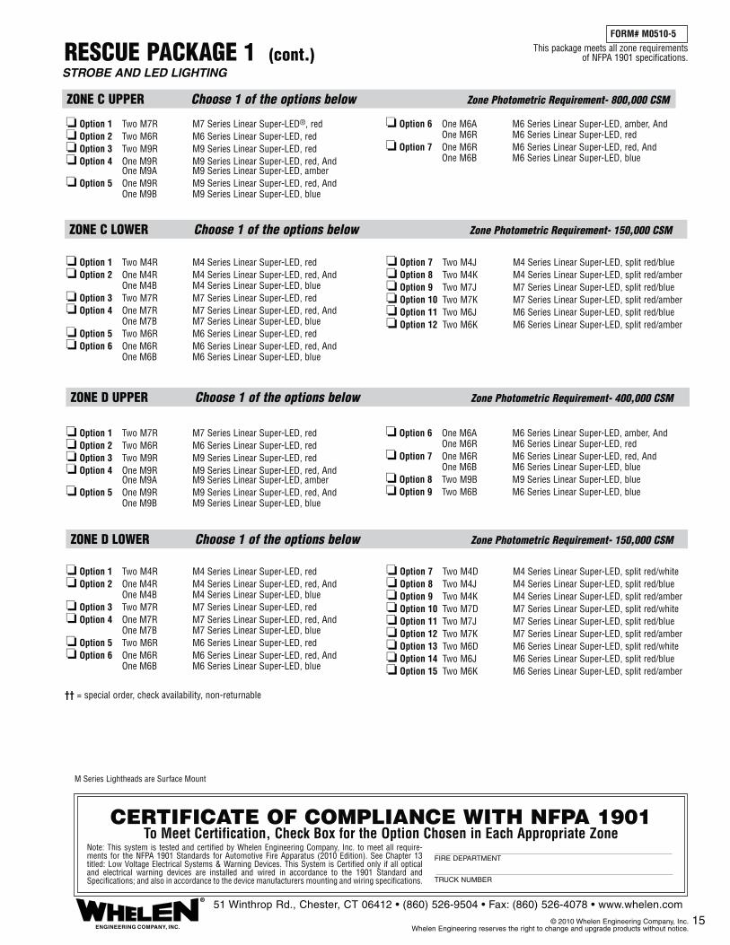
15
RESCUE PACKAGE 1 (cont.)FORM# M0510-5
STROBE AND LED LIGHTING
ZONE D UPPER Choose 1 of the options below Zone Photometric Requirement- 400,000 CSM
ZONE D LOWER Choose 1 of the options below Zone Photometric Requirement- 150,000 CSM
ZONE C UPPER Choose 1 of the options below Zone Photometric Requirement- 800,000 CSM
ZONE C LOWER Choose 1 of the options below Zone Photometric Requirement- 150,000 CSM
ENGINEERING COMPANY, INC.
®51 Winthrop Rd., Chester, CT 06412 • (860) 526-9504 • Fax: (860) 526-4078 • www.whelen.com
© 2010 Whelen Engineering Company, Inc. Whelen Engineering reserves the right to change and upgrade products without notice.
CERTIFICATE OF COMPLIANCE WITH NFPA 1901To Meet Certification, Check Box for the Option Chosen in Each Appropriate Zone
Note: This system is tested and certified by Whelen Engineering Company, Inc. to meet all require-ments for the NFPA 1901 Standards for Automotive Fire Apparatus (2010 Edition). See Chapter 13 titled: Low Voltage Electrical Systems & Warning Devices. This System is Certified only if all optical and electrical warning devices are installed and wired in accordance to the 1901 Standard and Specifications; and also in accordance to the device manufacturers mounting and wiring specifications.
FIRE DEPARTMENT
TRUCK NUMBER
This package meets all zone requirements of NFPA 1901 specifications.
❏ Option 1 Two M4R M4 Series Linear Super-LED, red❏ Option 2 One M4R M4 Series Linear Super-LED, red, And One M4B M4 Series Linear Super-LED, blue❏ Option 3 Two M7R M7 Series Linear Super-LED, red❏ Option 4 One M7R M7 Series Linear Super-LED, red, And One M7B M7 Series Linear Super-LED, blue❏ Option 5 Two M6R M6 Series Linear Super-LED, red❏ Option 6 One M6R M6 Series Linear Super-LED, red, And One M6B M6 Series Linear Super-LED, blue
❏ Option 7 Two M4D M4 Series Linear Super-LED, split red/white❏ Option 8 Two M4J M4 Series Linear Super-LED, split red/blue❏ Option 9 Two M4K M4 Series Linear Super-LED, split red/amber❏ Option 10 Two M7D M7 Series Linear Super-LED, split red/white❏ Option 11 Two M7J M7 Series Linear Super-LED, split red/blue❏ Option 12 Two M7K M7 Series Linear Super-LED, split red/amber❏ Option 13 Two M6D M6 Series Linear Super-LED, split red/white❏ Option 14 Two M6J M6 Series Linear Super-LED, split red/blue❏ Option 15 Two M6K M6 Series Linear Super-LED, split red/amber
❏ Option 1 Two M4R M4 Series Linear Super-LED, red❏ Option 2 One M4R M4 Series Linear Super-LED, red, And One M4B M4 Series Linear Super-LED, blue❏ Option 3 Two M7R M7 Series Linear Super-LED, red❏ Option 4 One M7R M7 Series Linear Super-LED, red, And One M7B M7 Series Linear Super-LED, blue❏ Option 5 Two M6R M6 Series Linear Super-LED, red❏ Option 6 One M6R M6 Series Linear Super-LED, red, And One M6B M6 Series Linear Super-LED, blue
❏ Option 7 Two M4J M4 Series Linear Super-LED, split red/blue❏ Option 8 Two M4K M4 Series Linear Super-LED, split red/amber❏ Option 9 Two M7J M7 Series Linear Super-LED, split red/blue❏ Option 10 Two M7K M7 Series Linear Super-LED, split red/amber❏ Option 11 Two M6J M6 Series Linear Super-LED, split red/blue❏ Option 12 Two M6K M6 Series Linear Super-LED, split red/amber
❏ Option 1 Two M7R M7 Series Linear Super-LED, red❏ Option 2 Two M6R M6 Series Linear Super-LED, red❏ Option 3 Two M9R M9 Series Linear Super-LED, red❏ Option 4 One M9R M9 Series Linear Super-LED, red, And One M9A M9 Series Linear Super-LED, amber❏ Option 5 One M9R M9 Series Linear Super-LED, red, And One M9B M9 Series Linear Super-LED, blue
❏ Option 6 One M6A M6 Series Linear Super-LED, amber, And One M6R M6 Series Linear Super-LED, red❏ Option 7 One M6R M6 Series Linear Super-LED, red, And One M6B M6 Series Linear Super-LED, blue❏ Option 8 Two M9B M9 Series Linear Super-LED, blue❏ Option 9 Two M6B M6 Series Linear Super-LED, blue
❏ Option 1 Two M7R M7 Series Linear Super-LED®, red❏ Option 2 Two M6R M6 Series Linear Super-LED, red❏ Option 3 Two M9R M9 Series Linear Super-LED, red❏ Option 4 One M9R M9 Series Linear Super-LED, red, And One M9A M9 Series Linear Super-LED, amber❏ Option 5 One M9R M9 Series Linear Super-LED, red, And One M9B M9 Series Linear Super-LED, blue
❏ Option 6 One M6A M6 Series Linear Super-LED, amber, And One M6R M6 Series Linear Super-LED, red❏ Option 7 One M6R M6 Series Linear Super-LED, red, And One M6B M6 Series Linear Super-LED, blue
M Series Lightheads are Surface Mount
†† = special order, check availability, non-returnable
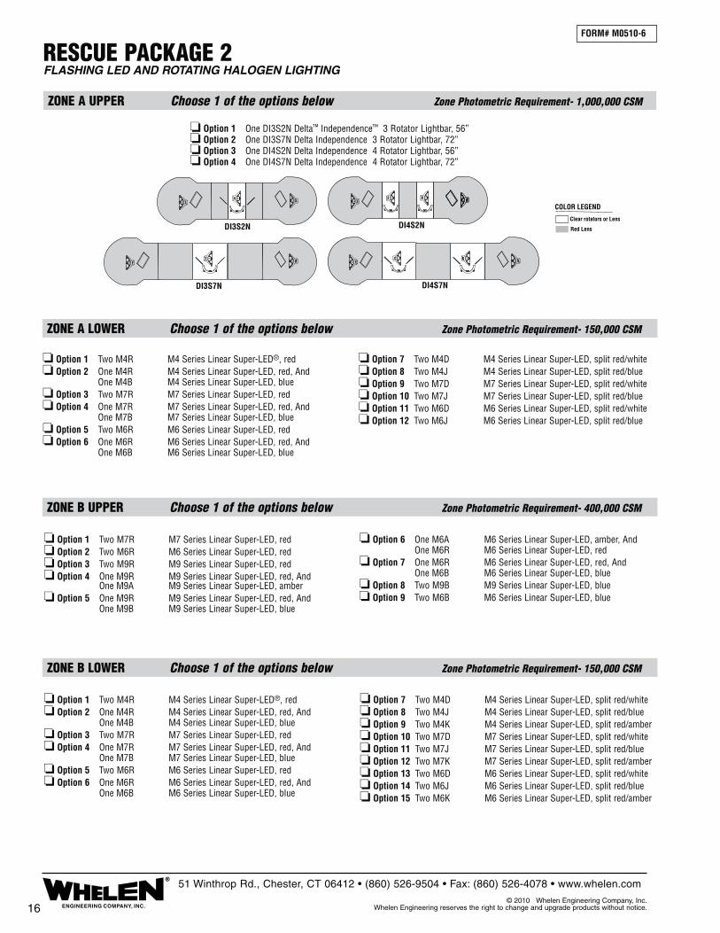
RESCUE PACKAGE 2
ZONE A UPPER Choose 1 of the options below Zone Photometric Requirement- 1,000,000 CSM
ZONE A LOWER Choose 1 of the options below Zone Photometric Requirement- 150,000 CSM
ZONE B UPPER Choose 1 of the options below Zone Photometric Requirement- 400,000 CSM
ZONE B LOWER Choose 1 of the options below Zone Photometric Requirement- 150,000 CSM
FORM# M0510-6
FLASHING LED AND ROTATING HALOGEN LIGHTING
16 ENGINEERING COMPANY, INC.
®51 Winthrop Rd., Chester, CT 06412 • (860) 526-9504 • Fax: (860) 526-4078 • www.whelen.com
© 2010 Whelen Engineering Company, Inc. Whelen Engineering reserves the right to change and upgrade products without notice.
❏ Option 1 One DI3S2N Delta™ Independence™ 3 Rotator Lightbar, 56”❏ Option 2 One DI3S7N Delta Independence 3 Rotator Lightbar, 72”❏ Option 3 One DI4S2N Delta Independence 4 Rotator Lightbar, 56”❏ Option 4 One DI4S7N Delta Independence 4 Rotator Lightbar, 72”
Clear rotators or Lens
Red Lens
COLOR LEGEND
DI3S7N
DI3S2N DI4S2N
DI4S7N
❏ Option 1 Two M4R M4 Series Linear Super-LED®, red❏ Option 2 One M4R M4 Series Linear Super-LED, red, And One M4B M4 Series Linear Super-LED, blue❏ Option 3 Two M7R M7 Series Linear Super-LED, red❏ Option 4 One M7R M7 Series Linear Super-LED, red, And One M7B M7 Series Linear Super-LED, blue❏ Option 5 Two M6R M6 Series Linear Super-LED, red❏ Option 6 One M6R M6 Series Linear Super-LED, red, And One M6B M6 Series Linear Super-LED, blue
❏ Option 7 Two M4D M4 Series Linear Super-LED, split red/white❏ Option 8 Two M4J M4 Series Linear Super-LED, split red/blue❏ Option 9 Two M7D M7 Series Linear Super-LED, split red/white❏ Option 10 Two M7J M7 Series Linear Super-LED, split red/blue❏ Option 11 Two M6D M6 Series Linear Super-LED, split red/white❏ Option 12 Two M6J M6 Series Linear Super-LED, split red/blue
❏ Option 1 Two M4R M4 Series Linear Super-LED®, red❏ Option 2 One M4R M4 Series Linear Super-LED, red, And One M4B M4 Series Linear Super-LED, blue❏ Option 3 Two M7R M7 Series Linear Super-LED, red❏ Option 4 One M7R M7 Series Linear Super-LED, red, And One M7B M7 Series Linear Super-LED, blue❏ Option 5 Two M6R M6 Series Linear Super-LED, red❏ Option 6 One M6R M6 Series Linear Super-LED, red, And One M6B M6 Series Linear Super-LED, blue
❏ Option 7 Two M4D M4 Series Linear Super-LED, split red/white❏ Option 8 Two M4J M4 Series Linear Super-LED, split red/blue❏ Option 9 Two M4K M4 Series Linear Super-LED, split red/amber❏ Option 10 Two M7D M7 Series Linear Super-LED, split red/white❏ Option 11 Two M7J M7 Series Linear Super-LED, split red/blue❏ Option 12 Two M7K M7 Series Linear Super-LED, split red/amber❏ Option 13 Two M6D M6 Series Linear Super-LED, split red/white❏ Option 14 Two M6J M6 Series Linear Super-LED, split red/blue❏ Option 15 Two M6K M6 Series Linear Super-LED, split red/amber
❏ Option 1 Two M7R M7 Series Linear Super-LED, red❏ Option 2 Two M6R M6 Series Linear Super-LED, red❏ Option 3 Two M9R M9 Series Linear Super-LED, red❏ Option 4 One M9R M9 Series Linear Super-LED, red, And One M9A M9 Series Linear Super-LED, amber❏ Option 5 One M9R M9 Series Linear Super-LED, red, And One M9B M9 Series Linear Super-LED, blue
❏ Option 6 One M6A M6 Series Linear Super-LED, amber, And One M6R M6 Series Linear Super-LED, red❏ Option 7 One M6R M6 Series Linear Super-LED, red, And One M6B M6 Series Linear Super-LED, blue❏ Option 8 Two M9B M9 Series Linear Super-LED, blue❏ Option 9 Two M6B M6 Series Linear Super-LED, blue

17
RESCUE PACKAGE 2 (cont.)FORM# M0510-6
FLASHING LED AND ROTATING HALOGEN LIGHTING
ZONE D UPPER Choose 1 of the options below Zone Photometric Requirement- 400,000 CSM
ZONE D LOWER Choose 1 of the options below Zone Photometric Requirement- 150,000 CSM
ZONE C UPPER Choose 1 of the options below Zone Photometric Requirement- 800,000 CSM
ZONE C LOWER Choose 1 of the options below Zone Photometric Requirement- 150,000 CSM
ENGINEERING COMPANY, INC.
®51 Winthrop Rd., Chester, CT 06412 • (860) 526-9504 • Fax: (860) 526-4078 • www.whelen.com
© 2010 Whelen Engineering Company, Inc. Whelen Engineering reserves the right to change and upgrade products without notice.
CERTIFICATE OF COMPLIANCE WITH NFPA 1901To Meet Certification, Check Box for the Option Chosen in Each Appropriate Zone
Note: This system is tested and certified by Whelen Engineering Company, Inc. to meet all require-ments for the NFPA 1901 Standards for Automotive Fire Apparatus (2010 Edition). See Chapter 13 titled: Low Voltage Electrical Systems & Warning Devices. This System is Certified only if all optical and electrical warning devices are installed and wired in accordance to the 1901 Standard and Specifications; and also in accordance to the device manufacturers mounting and wiring specifications.
FIRE DEPARTMENT
TRUCK NUMBER
This package meets all zone requirements of NFPA 1901 specifications.
❏ Option 1 Two M4R M4 Series Linear Super-LED, red❏ Option 2 One M4R M4 Series Linear Super-LED, red, And One M4B M4 Series Linear Super-LED, blue❏ Option 3 Two M7R M7 Series Linear Super-LED, red❏ Option 4 One M7R M7 Series Linear Super-LED, red, And One M7B M7 Series Linear Super-LED, blue❏ Option 5 Two M6R M6 Series Linear Super-LED, red❏ Option 6 One M6R M6 Series Linear Super-LED, red, And One M6B M6 Series Linear Super-LED, blue
❏ Option 7 Two M4D M4 Series Linear Super-LED, split red/white❏ Option 8 Two M4J M4 Series Linear Super-LED, split red/blue❏ Option 9 Two M4K M4 Series Linear Super-LED, split red/amber❏ Option 10 Two M7D M7 Series Linear Super-LED, split red/white❏ Option 11 Two M7J M7 Series Linear Super-LED, split red/blue❏ Option 12 Two M7K M7 Series Linear Super-LED, split red/amber❏ Option 13 Two M6D M6 Series Linear Super-LED, split red/white❏ Option 14 Two M6J M6 Series Linear Super-LED, split red/blue❏ Option 15 Two M6K M6 Series Linear Super-LED, split red/amber
❏ Option 1 Two M4R M4 Series Linear Super-LED, red❏ Option 2 One M4R M4 Series Linear Super-LED, red, And One M4B M4 Series Linear Super-LED, blue❏ Option 3 Two M7R M7 Series Linear Super-LED, red❏ Option 4 One M7R M7 Series Linear Super-LED, red, And One M7B M7 Series Linear Super-LED, blue❏ Option 5 Two M6R M6 Series Linear Super-LED, red❏ Option 6 One M6R M6 Series Linear Super-LED, red, And One M6B M6 Series Linear Super-LED, blue
❏ Option 7 Two M4J M4 Series Linear Super-LED, split red/blue❏ Option 8 Two M4K M4 Series Linear Super-LED, split red/amber❏ Option 9 Two M7J M7 Series Linear Super-LED, split red/blue❏ Option 10 Two M7K M7 Series Linear Super-LED, split red/amber❏ Option 11 Two M6J M6 Series Linear Super-LED, split red/blue❏ Option 12 Two M6K M6 Series Linear Super-LED, split red/amber
❏ Option 1 Two M7R M7 Series Linear Super-LED, red❏ Option 2 Two M6R M6 Series Linear Super-LED, red❏ Option 3 Two M9R M9 Series Linear Super-LED, red❏ Option 4 One M9R M9 Series Linear Super-LED, red, And One M9A M9 Series Linear Super-LED, amber❏ Option 5 One M9R M9 Series Linear Super-LED, red, And One M9B M9 Series Linear Super-LED, blue
❏ Option 6 One M6A M6 Series Linear Super-LED, amber, And One M6R M6 Series Linear Super-LED, red❏ Option 7 One M6R M6 Series Linear Super-LED, red, And One M6B M6 Series Linear Super-LED, blue❏ Option 8 Two M9B M9 Series Linear Super-LED, blue❏ Option 9 Two M6B M6 Series Linear Super-LED, blue
❏ Option 1 Two M7R M7 Series Linear Super-LED®, red❏ Option 2 Two M6R M6 Series Linear Super-LED, red❏ Option 3 Two M9R M9 Series Linear Super-LED, red❏ Option 4 One M9R M9 Series Linear Super-LED, red, And One M9A M9 Series Linear Super-LED, amber❏ Option 5 One M9R M9 Series Linear Super-LED, red, And One M9B M9 Series Linear Super-LED, blue
❏ Option 6 One M6A M6 Series Linear Super-LED, amber, And One M6R M6 Series Linear Super-LED, red❏ Option 7 One M6R M6 Series Linear Super-LED, red, And One M6B M6 Series Linear Super-LED, blue
M Series Lightheads are Surface Mount

ZONE D LOWER Choose 1 of the options below Zone Photometric Requirement- 150,000 CSM
This package meets all lower zone requirements of NFPA 1901 specifications.
CERTIFICATE OF COMPLIANCE WITH NFPA 1901To Meet Certification, Check Box for the Option Chosen in Each Appropriate Zone
Note: This system is tested and certified by Whelen Engineering Company, Inc. to meet all require-ments for the NFPA 1901 Standards for Automotive Fire Apparatus (2010 Edition). See Chapter 13 titled: Low Voltage Electrical Systems & Warning Devices. This System is Certified only if all optical and electrical warning devices are installed and wired in accordance to the 1901 Standard and Specifications; and also in accordance to the device manufacturers mounting and wiring specifications.
FIRE DEPARTMENT
TRUCK NUMBER
ZONE A LOWER Choose 1 of the options below Zone Photometric Requirement- 150,000 CSM
ZONE B LOWER Choose 1 of the options below Zone Photometric Requirement- 150,000 CSM
ZONE C LOWER Choose 1 of the options below Zone Photometric Requirement- 150,000 CSM
AERIAL, PUMPER, RESCUE PACKAGE 1FORM# M0510-7
LED LIGHTING, LOWER ZONE ONLY
18 ENGINEERING COMPANY, INC.
®51 Winthrop Rd., Chester, CT 06412 • (860) 526-9504 • Fax: (860) 526-4078 • www.whelen.com
© 2010 Whelen Engineering Company, Inc. Whelen Engineering reserves the right to change and upgrade products without notice.
❏ Option 1 Two M4R M4 Series Linear Super-LED®, red❏ Option 2 One M4R M4 Series Linear Super-LED, red, And One M4B M4 Series Linear Super-LED, blue❏ Option 3 Two M7R M7 Series Linear Super-LED, red❏ Option 4 One M7R M7 Series Linear Super-LED, red, And One M7B M7 Series Linear Super-LED, blue❏ Option 5 Two M6R M6 Series Linear Super-LED, red❏ Option 6 One M6R M6 Series Linear Super-LED, red, And One M6B M6 Series Linear Super-LED, blue
❏ Option 7 Two M4D M4 Series Linear Super-LED, split red/white❏ Option 8 Two M4J M4 Series Linear Super-LED, split red/blue❏ Option 9 Two M7D M7 Series Linear Super-LED, split red/white❏ Option 10 Two M7J M7 Series Linear Super-LED, split red/blue❏ Option 11 Two M6D M6 Series Linear Super-LED, split red/white❏ Option 12 Two M6J M6 Series Linear Super-LED, split red/blue
❏ Option 1 Two M4R M4 Series Linear Super-LED®, red❏ Option 2 One M4R M4 Series Linear Super-LED, red, And One M4B M4 Series Linear Super-LED, blue❏ Option 3 Two M7R M7 Series Linear Super-LED, red❏ Option 4 One M7R M7 Series Linear Super-LED, red, And One M7B M7 Series Linear Super-LED, blue❏ Option 5 Two M6R M6 Series Linear Super-LED, red❏ Option 6 One M6R M6 Series Linear Super-LED, red, And One M6B M6 Series Linear Super-LED, blue
❏ Option 7 Two M4D M4 Series Linear Super-LED, split red/white❏ Option 8 Two M4J M4 Series Linear Super-LED, split red/blue❏ Option 9 Two M4K M4 Series Linear Super-LED, split red/amber❏ Option 10 Two M7D M7 Series Linear Super-LED, split red/white❏ Option 11 Two M7J M7 Series Linear Super-LED, split red/blue❏ Option 12 Two M7K M7 Series Linear Super-LED, split red/amber❏ Option 13 Two M6D M6 Series Linear Super-LED, split red/white❏ Option 14 Two M6J M6 Series Linear Super-LED, split red/blue❏ Option 15 Two M6K M6 Series Linear Super-LED, split red/amber
❏ Option 1 Two M4R M4 Series Linear Super-LED®, red❏ Option 2 One M4R M4 Series Linear Super-LED, red, And One M4B M4 Series Linear Super-LED, blue❏ Option 3 Two M7R M7 Series Linear Super-LED, red❏ Option 4 One M7R M7 Series Linear Super-LED, red, And One M7B M7 Series Linear Super-LED, blue❏ Option 5 Two M6R M6 Series Linear Super-LED, red❏ Option 6 One M6R M6 Series Linear Super-LED, red, And One M6B M6 Series Linear Super-LED, blue
❏ Option 7 Two M4J M4 Series Linear Super-LED, split red/blue❏ Option 8 Two M4K M4 Series Linear Super-LED, split red/amber❏ Option 9 Two M7J M7 Series Linear Super-LED, split red/blue❏ Option 10 Two M7K M7 Series Linear Super-LED, split red/amber❏ Option 11 Two M6J M6 Series Linear Super-LED, split red/blue❏ Option 12 Two M6K M6 Series Linear Super-LED, split red/amber
❏ Option 1 Two M4R M4 Series Linear Super-LED®, red❏ Option 2 One M4R M4 Series Linear Super-LED, red, And One M4B M4 Series Linear Super-LED, blue❏ Option 3 Two M7R M7 Series Linear Super-LED, red❏ Option 4 One M7R M7 Series Linear Super-LED, red, And One M7B M7 Series Linear Super-LED, blue❏ Option 5 Two M6R M6 Series Linear Super-LED, red❏ Option 6 One M6R M6 Series Linear Super-LED, red, And One M6B M6 Series Linear Super-LED, blue
❏ Option 7 Two M4D M4 Series Linear Super-LED, split red/white❏ Option 8 Two M4J M4 Series Linear Super-LED, split red/blue❏ Option 9 Two M4K M4 Series Linear Super-LED, split red/amber❏ Option 10 Two M7D M7 Series Linear Super-LED, split red/white❏ Option 11 Two M7J M7 Series Linear Super-LED, split red/blue❏ Option 12 Two M7K M7 Series Linear Super-LED, split red/amber❏ Option 13 Two M6D M6 Series Linear Super-LED, split red/white❏ Option 14 Two M6J M6 Series Linear Super-LED, split red/blue❏ Option 15 Two M6K M6 Series Linear Super-LED, split red/amber
M Series Lightheads are Surface Mount

FORM# M0510-8
UPPER ZONE AERIAL PACKAGE 1LED, STROBE AND ROTATING HALOGEN LIGHTING
ZONE C UPPER Choose 1 of the options below Zone Photometric Requirement- 800,000 CSM
ZONE D UPPER Choose 1 of the options below Zone Photometric Requirement- 400,000 CSM
ZONE B UPPER Choose 1 of the options below Zone Photometric Requirement- 400,000 CSM
ZONE A UPPER Choose 1 of the options below Zone Photometric Requirement- 1,000,000 CSM
This package meets all upper zone requirements of NFPA 1901 specifications.
9MINNFPA 9MINNFPA
❏ Option 1 Two Model FNMINI NFPA Mini Ultra Freedom LED Lightbars, clear outer lenses, std. 24
❏ Option 2 Two Model 9MINNFPA NFPA 9M Mini Freedom Strobe Lightbars, color outer lenses, std. 28-1/4
19ENGINEERING COMPANY, INC.
®51 Winthrop Rd., Chester, CT 06412 • (860) 526-9504 • Fax: (860) 526-4078 • www.whelen.com
© 2010 Whelen Engineering Company, Inc. Whelen Engineering reserves the right to change and upgrade products without notice.
CERTIFICATE OF COMPLIANCE WITH NFPA 1901To Meet Certification, Check Box for the Option Chosen in Each Appropriate Zone
Note: This system is tested and certified by Whelen Engineering Company, Inc. to meet all require-ments for the NFPA 1901 Standards for Automotive Fire Apparatus (2010 Edition). See Chapter 13 titled: Low Voltage Electrical Systems & Warning Devices. This System is Certified only if all optical and electrical warning devices are installed and wired in accordance to the 1901 Standard and Specifications; and also in accordance to the device manufacturers mounting and wiring specifications.
FIRE DEPARTMENT
TRUCK NUMBER
FNMINI FNMINI
Clear LEDS,Strobes or Lens
Red LEDS or LensBlack Lens orFiller Panels
COLOR LEGEND
❏ Option 1 One RB6TAP RB6 Series Rotating Beacon, amber, And One RB6TRP RB6 Series Rotating Beacon, red❏ Option 2 Two RB6TRP RB6 Series Rotating Beacons, red❏ Option 3 Two B6TMRR1P RBT Series Upper Rotator, Lower Level, Linear Super-LED flasher, red❏ Option 4 Two B6TSRR1P RBT Series Upper Rotator, Lower Level, Strobe, red❏ Option 5 Two MCFLED2R Ultra Freedom Micro Edge® LED, red❏ Option 6 Two MCSLED2R LFL Liberty Micro Edge LED, red❏ Option 7 Two L31HRFN L31 Series Super-LED Beacons, red❏ Option 8 Two B6MMRRP Super-LED Beacons Upper Section, Lower Level Linear Super-LED flasher, red❏ Option 9 Two M7R M7 Series Linear Super-LED, red
❏ Option 10 Two M6R M6 Series Linear Super-LED, red❏ Option 11 Two M9R M9 Series Linear Super-LED, red❏ Option 12 One M9R M9 Series Linear Super-LED, red, And One M9A M9 Series Linear Super-LED, amber❏ Option 13 One M9R M9 Series Linear Super-LED, red, And One M9B M9 Series Linear Super-LED, blue❏ Option 14 One M6A M6 Series Linear Super-LED, amber, And One M6R M6 Series Linear Super-LED, red❏ Option 15 One M6R M6 Series Linear Super-LED, red, And One M6B M6 Series Linear Super-LED, blue
M Series Lightheads are Surface Mount
Zone B Upper Front is covered by the lights from the Rear or Side of the Lightbar from Zone A UpperZone B Upper Rear is covered by one of the options chosen from Zone C Upper
Zone D Upper Front is covered by the lights from the Rear or Side of the Lightbar from Zone A UpperZone D Upper Rear is covered by one of the options chosen from Zone C Upper
†† = special order, check availability, non-returnable
��
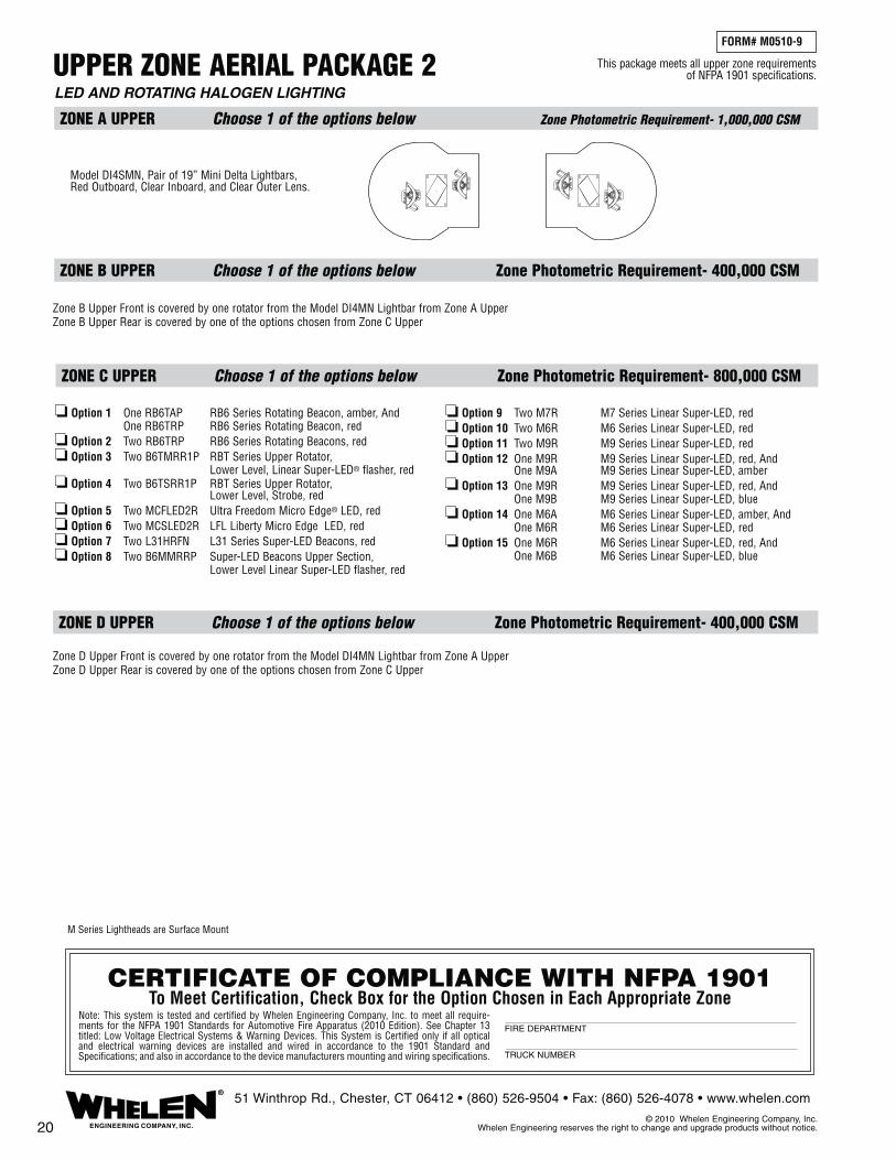
FORM# M0510-9
LED AND ROTATING HALOGEN LIGHTING
UPPER ZONE AERIAL PACKAGE 2
ZONE A UPPER Choose 1 of the options below Zone Photometric Requirement- 1,000,000 CSM
ZONE C UPPER Choose 1 of the options below Zone Photometric Requirement- 800,000 CSM
ZONE D UPPER Choose 1 of the options below Zone Photometric Requirement- 400,000 CSM
ZONE B UPPER Choose 1 of the options below Zone Photometric Requirement- 400,000 CSM
This package meets all upper zone requirements of NFPA 1901 specifications.
Model DI4SMN, Pair of 19” Mini Delta Lightbars, Red Outboard, Clear Inboard, and Clear Outer Lens.
20 ENGINEERING COMPANY, INC.
®51 Winthrop Rd., Chester, CT 06412 • (860) 526-9504 • Fax: (860) 526-4078 • www.whelen.com
© 2010 Whelen Engineering Company, Inc. Whelen Engineering reserves the right to change and upgrade products without notice.
CERTIFICATE OF COMPLIANCE WITH NFPA 1901To Meet Certification, Check Box for the Option Chosen in Each Appropriate Zone
Note: This system is tested and certified by Whelen Engineering Company, Inc. to meet all require-ments for the NFPA 1901 Standards for Automotive Fire Apparatus (2010 Edition). See Chapter 13 titled: Low Voltage Electrical Systems & Warning Devices. This System is Certified only if all optical and electrical warning devices are installed and wired in accordance to the 1901 Standard and Specifications; and also in accordance to the device manufacturers mounting and wiring specifications.
FIRE DEPARTMENT
TRUCK NUMBER
❏ Option 1 One RB6TAP RB6 Series Rotating Beacon, amber, And One RB6TRP RB6 Series Rotating Beacon, red ❏ Option 2 Two RB6TRP RB6 Series Rotating Beacons, red❏ Option 3 Two B6TMRR1P RBT Series Upper Rotator, Lower Level, Linear Super-LED® flasher, red❏ Option 4 Two B6TSRR1P RBT Series Upper Rotator, Lower Level, Strobe, red❏ Option 5 Two MCFLED2R Ultra Freedom Micro Edge® LED, red❏ Option 6 Two MCSLED2R LFL Liberty Micro Edge LED, red❏ Option 7 Two L31HRFN L31 Series Super-LED Beacons, red❏ Option 8 Two B6MMRRP Super-LED Beacons Upper Section, Lower Level Linear Super-LED flasher, red
❏ Option 9 Two M7R M7 Series Linear Super-LED, red❏ Option 10 Two M6R M6 Series Linear Super-LED, red❏ Option 11 Two M9R M9 Series Linear Super-LED, red❏ Option 12 One M9R M9 Series Linear Super-LED, red, And One M9A M9 Series Linear Super-LED, amber❏ Option 13 One M9R M9 Series Linear Super-LED, red, And One M9B M9 Series Linear Super-LED, blue❏ Option 14 One M6A M6 Series Linear Super-LED, amber, And One M6R M6 Series Linear Super-LED, red❏ Option 15 One M6R M6 Series Linear Super-LED, red, And One M6B M6 Series Linear Super-LED, blue
M Series Lightheads are Surface Mount
Zone D Upper Front is covered by one rotator from the Model DI4MN Lightbar from Zone A UpperZone D Upper Rear is covered by one of the options chosen from Zone C Upper
Zone B Upper Front is covered by one rotator from the Model DI4MN Lightbar from Zone A UpperZone B Upper Rear is covered by one of the options chosen from Zone C Upper
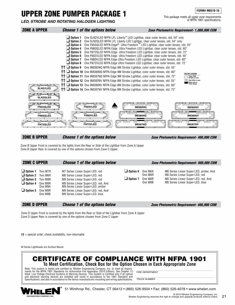
UPPER ZONE PUMPER PACKAGE 1
ZONE A UPPER Choose 1 of the options below Zone Photometric Requirement- 1,000,000 CSM
ZONE C UPPER Choose 1 of the options below Zone Photometric Requirement- 800,000 CSM
ZONE D UPPER Choose 1 of the options below Zone Photometric Requirement- 400,000 CSM
ZONE B UPPER Choose 1 of the options below Zone Photometric Requirement- 400,000 CSM
FORM# M0510-10
LED, STROBE AND ROTATING HALOGEN LIGHTING This package meets all upper zone requirements
of NFPA 1901 specifications.
21 ENGINEERING COMPANY, INC.
®51 Winthrop Rd., Chester, CT 06412 • (860) 526-9504 • Fax: (860) 526-4078 • www.whelen.com
© 2010 Whelen Engineering Company, Inc. Whelen Engineering reserves the right to change and upgrade products without notice.
❏ Option 1 One SLN2VLED NFPA LFL Liberty™ LED Lightbar, clear outer lenses, std. 54” only❏ Option 2 One SLN2QLED NFPA LFL Liberty LED Lightbar, clear outer lenses, std. 54” only❏ Option 3 One FN55QLED NFPA Edge® Ultra Freedom™ LED Lightbar, clear outer lenses, std. 55”❏ Option 4 One FN60QLED NFPA Edge Ultra Freedom LED Lightbar, clear outer lenses, std. 60”❏ Option 5 One FN72QLED NFPA Edge Ultra Freedom LED Lightbar, clear outer lenses, std. 72”❏ Option 6 One FN55VLED NFPA Edge Ultra Freedom LED Lightbar, clear outer lenses, std. 55”❏ Option 7 One FN60VLED NFPA Edge Ultra Freedom LED Lightbar, clear outer lenses, std. 60”❏ Option 8 One FN72VLED NFPA Edge Ultra Freedom LED Lightbar, clear outer lenses, std. 72”❏ Option 9 One 9M382NQ NFPA Edge 9M Strobe Lightbar, color outer lenses, std. 55”❏ Option 10 One 9M380NQ NFPA Edge 9M Strobe Lightbar, color outer lenses, std. 60”❏ Option 11 One 9M387NQ NFPA Edge 9M Strobe Lightbar, color outer lenses, std. 72”❏ Option 12 One 9M382NV NFPA Edge 9M Strobe Lightbar, color outer lenses, std. 55”❏ Option 13 One 9M380NV NFPA Edge 9M Strobe Lightbar, color outer lenses, std. 60”❏ Option 14 One 9M387NV NFPA Edge 9M Strobe Lightbar, color outer lenses, std. 72”
CERTIFICATE OF COMPLIANCE WITH NFPA 1901To Meet Certification, Check Box for the Option Chosen in Each Appropriate Zone
Note: This system is tested and certified by Whelen Engineering Company, Inc. to meet all require-ments for the NFPA 1901 Standards for Automotive Fire Apparatus (2010 Edition). See Chapter 13 titled: Low Voltage Electrical Systems & Warning Devices. This System is Certified only if all optical and electrical warning devices are installed and wired in accordance to the 1901 Standard and Specifications; and also in accordance to the device manufacturers mounting and wiring specifications.
FIRE DEPARTMENT
TRUCK NUMBER
FRONTFN55QLED
SLN2QLED
FN55VLED
SLN2VLED
FN60QLED FN60VLED
FN72VLEDFN72QLED
9M380NQ 9M380NV
9M382NQ 9M382NV
9M387NV9M387NQ
Clear LEDS,Strobes or Lens
Red LEDS or LensBlack Lens orFiller Panels
COLOR LEGEND
❏ Option 1 Two M7R M7 Series Linear Super-LED, red❏ Option 2 Two M6R M6 Series Linear Super-LED, red❏ Option 3 Two M9R M9 Series Linear Super-LED, red❏ Option 4 One M9R M9 Series Linear Super-LED, red, And One M9A M9 Series Linear Super-LED, amber❏ Option 5 One M9R M9 Series Linear Super-LED, red, And One M9B M9 Series Linear Super-LED, blue
❏ Option 6 One M6A M6 Series Linear Super-LED, amber, And One M6R M6 Series Linear Super-LED, red❏ Option 7 One M6R M6 Series Linear Super-LED, red, And One M6B M6 Series Linear Super-LED, blue
M Series Lightheads are Surface Mount
Zone B Upper Front is covered by the lights from the Rear or Side of the Lightbar from Zone A UpperZone B Upper Rear is covered by one of the options chosen from Zone C Upper
Zone D Upper Front is covered by the lights from the Rear or Side of the Lightbar from Zone A UpperZone D Upper Rear is covered by one of the options chosen from Zone C Upper
†† = special order, check availability, non-returnable
������������
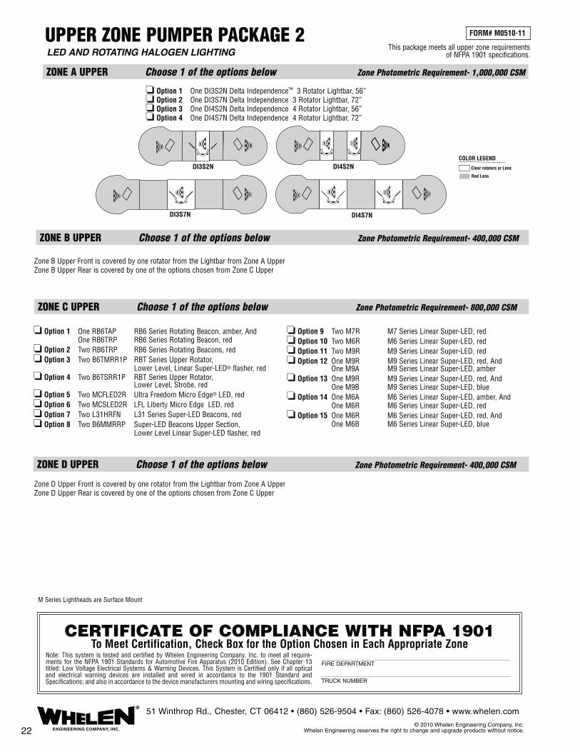
UPPER ZONE PUMPER PACKAGE 2
ZONE A UPPER Choose 1 of the options below Zone Photometric Requirement- 1,000,000 CSM
ZONE C UPPER Choose 1 of the options below Zone Photometric Requirement- 800,000 CSM
ZONE D UPPER Choose 1 of the options below Zone Photometric Requirement- 400,000 CSM
ZONE B UPPER Choose 1 of the options below Zone Photometric Requirement- 400,000 CSM
LED AND ROTATING HALOGEN LIGHTING
22 ENGINEERING COMPANY, INC.
®51 Winthrop Rd., Chester, CT 06412 • (860) 526-9504 • Fax: (860) 526-4078 • www.whelen.com
© 2010 Whelen Engineering Company, Inc. Whelen Engineering reserves the right to change and upgrade products without notice.
FORM# M0510-11
This package meets all upper zone requirements of NFPA 1901 specifications.
CERTIFICATE OF COMPLIANCE WITH NFPA 1901To Meet Certification, Check Box for the Option Chosen in Each Appropriate Zone
Note: This system is tested and certified by Whelen Engineering Company, Inc. to meet all require-ments for the NFPA 1901 Standards for Automotive Fire Apparatus (2010 Edition). See Chapter 13 titled: Low Voltage Electrical Systems & Warning Devices. This System is Certified only if all optical and electrical warning devices are installed and wired in accordance to the 1901 Standard and Specifications; and also in accordance to the device manufacturers mounting and wiring specifications.
FIRE DEPARTMENT
TRUCK NUMBER
❏ Option 1 One DI3S2N Delta Independence™ 3 Rotator Lightbar, 56”❏ Option 2 One DI3S7N Delta Independence 3 Rotator Lightbar, 72”❏ Option 3 One DI4S2N Delta Independence 4 Rotator Lightbar, 56”❏ Option 4 One DI4S7N Delta Independence 4 Rotator Lightbar, 72”
Clear rotators or Lens
Red Lens
COLOR LEGEND
DI3S7N
DI3S2N DI4S2N
DI4S7N
❏ Option 1 One RB6TAP RB6 Series Rotating Beacon, amber, And One RB6TRP RB6 Series Rotating Beacon, red❏ Option 2 Two RB6TRP RB6 Series Rotating Beacons, red❏ Option 3 Two B6TMRR1P RBT Series Upper Rotator, Lower Level, Linear Super-LED® flasher, red❏ Option 4 Two B6TSRR1P RBT Series Upper Rotator, Lower Level, Strobe, red❏ Option 5 Two MCFLED2R Ultra Freedom Micro Edge® LED, red❏ Option 6 Two MCSLED2R LFL Liberty Micro Edge LED, red❏ Option 7 Two L31HRFN L31 Series Super-LED Beacons, red❏ Option 8 Two B6MMRRP Super-LED Beacons Upper Section, Lower Level Linear Super-LED flasher, red
❏ Option 9 Two M7R M7 Series Linear Super-LED, red❏ Option 10 Two M6R M6 Series Linear Super-LED, red❏ Option 11 Two M9R M9 Series Linear Super-LED, red❏ Option 12 One M9R M9 Series Linear Super-LED, red, And One M9A M9 Series Linear Super-LED, amber❏ Option 13 One M9R M9 Series Linear Super-LED, red, And One M9B M9 Series Linear Super-LED, blue❏ Option 14 One M6A M6 Series Linear Super-LED, amber, And One M6R M6 Series Linear Super-LED, red❏ Option 15 One M6R M6 Series Linear Super-LED, red, And One M6B M6 Series Linear Super-LED, blue
M Series Lightheads are Surface Mount
Zone D Upper Front is covered by one rotator from the Lightbar from Zone A UpperZone D Upper Rear is covered by one of the options chosen from Zone C Upper
Zone B Upper Front is covered by one rotator from the Lightbar from Zone A UpperZone B Upper Rear is covered by one of the options chosen from Zone C Upper

UPPER ZONE RESCUE PACKAGE 1
ZONE A UPPER Choose 1 of the options below Zone Photometric Requirement- 1,000,000 CSM
ZONE B UPPER Choose 1 of the options below Zone Photometric Requirement- 400,000 CSM
ZONE C UPPER Choose 1 of the options below Zone Photometric Requirement- 800,000 CSM
ZONE D UPPER Choose 1 of the options below Zone Photometric Requirement- 400,000 CSM
FORM# M0510-12
STROBE AND LED LIGHTING
This package meets all upper zone requirements of NFPA 1901 specifications.
23ENGINEERING COMPANY, INC.
®51 Winthrop Rd., Chester, CT 06412 • (860) 526-9504 • Fax: (860) 526-4078 • www.whelen.com
© 2010 Whelen Engineering Company, Inc. Whelen Engineering reserves the right to change and upgrade products without notice.
❏ Option 1 One SLN2VLED NFPA LFL Liberty™ LED Lightbar, clear outer lenses, std. 54” only❏ Option 2 One SLN2QLED NFPA LFL Liberty LED Lightbar, clear outer lenses, std. 54” only❏ Option 3 One FN55QLED NFPA Edge® Ultra Freedom™ LED Lightbar, clear outer lenses, std. 55”❏ Option 4 One FN60QLED NFPA Edge Ultra Freedom LED Lightbar, clear outer lenses, std. 60”❏ Option 5 One FN72QLED NFPA Edge Ultra Freedom LED Lightbar, clear outer lenses, std. 72”❏ Option 6 One FN55VLED NFPA Edge Ultra Freedom LED Lightbar, clear outer lenses, std. 55”❏ Option 7 One FN60VLED NFPA Edge Ultra Freedom LED Lightbar, clear outer lenses, std. 60”❏ Option 8 One FN72VLED NFPA Edge Ultra Freedom LED Lightbar, clear outer lenses, std. 72”❏ Option 9 One 9M382NQ NFPA Edge 9M Strobe Lightbar, color outer lenses, std. 55”❏ Option 10 One 9M380NQ NFPA Edge 9M Strobe Lightbar, color outer lenses, std. 60”❏ Option 11 One 9M387NQ NFPA Edge 9M Strobe Lightbar, color outer lenses, std. 72”❏ Option 12 One 9M382NV NFPA Edge 9M Strobe Lightbar, color outer lenses, std. 55”❏ Option 13 One 9M380NV NFPA Edge 9M Strobe Lightbar, color outer lenses, std. 60”❏ Option 14 One 9M387NV NFPA Edge 9M Strobe Lightbar, color outer lenses, std. 72”
CERTIFICATE OF COMPLIANCE WITH NFPA 1901To Meet Certification, Check Box for the Option Chosen in Each Appropriate Zone
Note: This system is tested and certified by Whelen Engineering Company, Inc. to meet all requirements for the NFPA 1901 Standards for Automotive Fire Apparatus (2010 Edition). See Chapter 13 titled: Low Voltage Electrical Systems & Warning Devices. This System is Certified only if all optical and electrical warning devices are installed and wired in accordance to the 1901 Standard and Specifications; and also in accordance to the device manufacturers mounting and wiring specifications.
FIRE DEPARTMENT
TRUCK NUMBER
FRONTFN55QLED
SLN2QLED
FN55VLED
SLN2VLED
FN60QLED FN60VLED
FN72VLEDFN72QLED
9M380NQ 9M380NV
9M382NQ 9M382NV
9M387NV9M387NQ
Clear LEDS,Strobes or Lens
Red LEDS or LensBlack Lens orFiller Panels
COLOR LEGEND
❏ Option 1 Two M7R M7 Series Linear Super-LED®, red❏ Option 2 Two M6R M6 Series Linear Super-LED, red❏ Option 3 Two M9R M9 Series Linear Super-LED, red❏ Option 4 One M9R M9 Series Linear Super-LED, red, And One M9A M9 Series Linear Super-LED, amber❏ Option 5 One M9R M9 Series Linear Super-LED, red, And One M9B M9 Series Linear Super-LED, blue
❏ Option 6 One M6A M6 Series Linear Super-LED, amber, And One M6R M6 Series Linear Super-LED, red❏ Option 7 One M6R M6 Series Linear Super-LED, red, And One M6B M6 Series Linear Super-LED, blue❏ Option 8 Two M9B M9 Series Linear Super-LED, blue❏ Option 9 Two M6B M6 Series Linear Super-LED, blue
❏ Option 1 Two M7R M7 Series Linear Super-LED, red❏ Option 2 Two M6R M6 Series Linear Super-LED, red❏ Option 3 Two M9R M9 Series Linear Super-LED, red❏ Option 4 One M9R M9 Series Linear Super-LED, red, And One M9A M9 Series Linear Super-LED, amber❏ Option 5 One M9R M9 Series Linear Super-LED, red, And One M9B M9 Series Linear Super-LED, blue
❏ Option 6 One M6A M6 Series Linear Super-LED, amber, And One M6R M6 Series Linear Super-LED, red❏ Option 7 One M6R M6 Series Linear Super-LED, red, And One M6B M6 Series Linear Super-LED, blue
M Series Lightheads are Surface Mount
†† = special order, check availability, non-returnable
������������

UPPER ZONE RESCUE PACKAGE 2
ZONE C UPPER Choose 1 of the options below Zone Photometric Requirement- 800,000 CSM
ZONE A UPPER Choose 1 of the options below Zone Photometric Requirement- 1,000,000 CSM
ZONE B UPPER Choose 1 of the options below Zone Photometric Requirement- 400,000 CSM
ZONE D UPPER Choose 1 of the options below Zone Photometric Requirement- 400,000 CSM
This package meets all upper zone requirements of NFPA 1901 specifications.
FORM# M0510-13
FLASHING LED AND ROTATING HALOGEN LIGHTING
24 ENGINEERING COMPANY, INC.
®51 Winthrop Rd., Chester, CT 06412 • (860) 526-9504 • Fax: (860) 526-4078 • www.whelen.com
© 2010 Whelen Engineering Company, Inc. Whelen Engineering reserves the right to change and upgrade products without notice.
CERTIFICATE OF COMPLIANCE WITH NFPA 1901To Meet Certification, Check Box for the Option Chosen in Each Appropriate Zone
Note: This system is tested and certified by Whelen Engineering Company, Inc. to meet all requirements for the NFPA 1901 Standards for Automotive Fire Apparatus (2010 Edition). See Chapter 13 titled: Low Voltage Electrical Systems & Warning Devices. This System is Certified only if all optical and electrical warning devices are installed and wired in accordance to the 1901 Standard and Specifications; and also in accordance to the device manufacturers mounting and wiring specifications.
FIRE DEPARTMENT
TRUCK NUMBER
❏ Option 1 One DI3S2N Delta Independence™ 3 Rotator Lightbar, 56”❏ Option 2 One DI3S7N Delta Independence 3 Rotator Lightbar, 72”❏ Option 3 One DI4S2N Delta Independence 4 Rotator Lightbar, 56”❏ Option 4 One DI4S7N Delta Independence 4 Rotator Lightbar, 72”
Clear rotators or Lens
Red Lens
COLOR LEGEND
DI3S7N
DI3S2N DI4S2N
DI4S7N
❏ Option 1 Two M7R M7 Series Linear Super-LED, red❏ Option 2 Two M6R M6 Series Linear Super-LED, red❏ Option 3 Two M9R M9 Series Linear Super-LED, red❏ Option 4 One M9R M9 Series Linear Super-LED, red, And One M9A M9 Series Linear Super-LED, amber❏ Option 5 One M9R M9 Series Linear Super-LED, red, And One M9B M9 Series Linear Super-LED, blue
❏ Option 6 One M6A M6 Series Linear Super-LED, amber, And One M6R M6 Series Linear Super-LED, red❏ Option 7 One M6R M6 Series Linear Super-LED, red, And One M6B M6 Series Linear Super-LED, blue❏ Option 8 Two M9B M9 Series Linear Super-LED, blue❏ Option 9 Two M6B M6 Series Linear Super-LED, blue
❏ Option 1 Two M7R M7 Series Linear Super-LED, red❏ Option 2 Two M6R M6 Series Linear Super-LED, red❏ Option 3 Two M9R M9 Series Linear Super-LED, red❏ Option 4 One M9R M9 Series Linear Super-LED, red, And One M9A M9 Series Linear Super-LED, amber❏ Option 5 One M9R M9 Series Linear Super-LED, red, And One M9B M9 Series Linear Super-LED, blue
❏ Option 6 One M6A M6 Series Linear Super-LED, amber, And One M6R M6 Series Linear Super-LED, red❏ Option 7 One M6R M6 Series Linear Super-LED, red, And One M6B M6 Series Linear Super-LED, blue
M Series Lightheads are Surface Mount

Zone D UPPER and LOWER Combined Zone Photometric Requirement- 200,000 CSM
CERTIFICATE OF COMPLIANCE WITH NFPA 1901To Meet Certification, Check Box for the Option Chosen in Each Appropriate Zone
Note: This system is tested and certified by Whelen Engineering Company, Inc. to meet all require-ments for the NFPA 1901 Standards for Automotive Fire Apparatus (2010 Edition). See Chapter 13 titled: Low Voltage Electrical Systems & Warning Devices. This System is Certified only if all optical and electrical warning devices are installed and wired in accordance to the 1901 Standard and Specifications; and also in accordance to the device manufacturers mounting and wiring specifications.
FIRE DEPARTMENT
TRUCK NUMBER
Choose 1 of the options for the Upper or Lower Zone
SMALL APPARATUS (25’or Less) PACKAGE 1
Zone A UPPER and LOWER Combined Zone Photometric Requirement- 1,000,000 CSM
Choose 1 of the options for the Upper Zone
❏ Option 1 One SLN2VLED NFPA LFL Liberty™ LED Lightbar, std. 54” only❏ Option 2 One SLN2QLED NFPA LFL Liberty LED Lightbar, std. 54” only❏ Option 3 One FN55VLED NFPA Edge® Ultra Freedom™ LED Lightbar, std. 55”❏ Option 4 One FN55QLED NFPA Edge Ultra Freedom LED Lightbar, std. 55”❏ Option 5 One 9M380NV NFPA Edge 9M Strobe Lightbar, std. 60”❏ Option 6 One 9M380NQ NFPA Edge 9M Strobe Lightbar, std. 60”
Choose 1 of the options for the Lower Zone
❏ Option 1 Two M4R M4 Series Linear Super-LED®, red❏ Option 2 One M4R M4 Series Linear Super-LED, red, And One M4B M4 Series Linear Super-LED, blue❏ Option 3 Two M7R M7 Series Linear Super-LED, red❏ Option 4 One M7R M7 Series Linear Super-LED, red, And One M7B M7 Series Linear Super-LED, blue
❏ Option 5 Two M4D M4 Series Linear Super-LED, split red/white❏ Option 6 Two M4J M4 Series Linear Super-LED, split red/blue❏ Option 7 Two M7D M7 Series Linear Super-LED, split red/white❏ Option 8 Two M7J M7 Series Linear Super-LED, split red/blue
❏ Option 1 Two M4R M4 Series Linear Super-LED, red❏ Option 2 One M4R M4 Series Linear Super-LED, red, And One M4B M4 Series Linear Super-LED, blue❏ Option 3 Two M7R M7 Series Linear Super-LED, red❏ Option 4 One M7R M7 Series Linear Super-LED, red, And One M7B M7 Series Linear Super-LED, blue
❏ Option 5 Two M4D M4 Series Linear Super-LED, split red/white❏ Option 6 Two M4J M4 Series Linear Super-LED, split red/blue❏ Option 7 Two M4K M4 Series Linear Super-LED, split red/amber❏ Option 8 Two M7D M7 Series Linear Super-LED, split red/white❏ Option 9 Two M7J M7 Series Linear Super-LED, split red/blue❏ Option 10 Two M7K M7 Series Linear Super-LED, split red/amber
Zone B UPPER and LOWER Combined Zone Photometric Requirement- 200,000 CSM
Choose 1 of the options for the Upper or Lower Zone
❏ Option 1 Two M4R M4 Series Linear Super-LED, red❏ Option 2 One M4R M4 Series Linear Super-LED, red, And One M4B M4 Series Linear Super-LED, blue❏ Option 3 Two M7R M7 Series Linear Super-LED, red❏ Option 4 One M7R M7 Series Linear Super-LED, red, And One M7B M7 Series Linear Super-LED, blue
❏ Option 5 Two M4D M4 Series Linear Super-LED, split red/white❏ Option 6 Two M4J M4 Series Linear Super-LED, split red/blue❏ Option 7 Two M4K M4 Series Linear Super-LED, split red/amber❏ Option 8 Two M7D M7 Series Linear Super-LED, split red/white❏ Option 9 Two M7J M7 Series Linear Super-LED, split red/blue❏ Option 10 Two M7K M7 Series Linear Super-LED, split red/amber
Choose 1 of the options for the Upper or Lower Zone
ZONE C UPPER and LOWER Combined Zone Photometric Requirement- 800,000 CSM
❏ Option 1 One RB6TAP RB6 Series Rotating Beacon, amber, And One RB6TRP RB6 Series Rotating Beacon, red❏ Option 2 Two RB6TRP RB6 Series Rotating Beacons, red❏ Option 3 Two MCFLED2R Ultra Freedom Micro Edge® LED, red❏ Option 4 Two MCSLED2R LFL Liberty Micro Edge LED, red❏ Option 5 Two L31HRFN L31 Series Super-LED Beacons, red❏ Option 6 Two M7R M7 Series Linear Super-LED, red❏ Option 7 Two M6R M6 Series Linear Super-LED, red
❏ Option 8 Two M9R M9 Series Linear Super-LED, red❏ Option 9 One M9R M9 Series Linear Super-LED, red, And One M9A M9 Series Linear Super-LED, amber❏ Option 10 One M6A M6 Series Linear Super-LED, amber, And One M6R M6 Series Linear Super-LED, red❏ Option 11 One M6R M6 Series Linear Super-LED, red, And One M6B M6 Series Linear Super-LED, blue
FORM# M0510-14
STROBE, LED AND ROTATING HALOGEN LIGHTING
This package meets all zone requirements of NFPA 1901 specifications.
SLN2VLED
SLN2QLED
FN55VLED
FN55QLED
9M382NQ
9M382NV
25ENGINEERING COMPANY, INC.
®51 Winthrop Rd., Chester, CT 06412 • (860) 526-9504 • Fax: (860) 526-4078 • www.whelen.com
© 2010 Whelen Engineering Company, Inc. Whelen Engineering reserves the right to change and upgrade products without notice.
Clear LEDS,Strobes or Lens
Red LEDS or LensBlack Lens orFiller Panels
COLOR LEGEND
M Series Lightheads are Surface Mount†† = special order, check availability, non-returnable
����

M Series Lightheads are Surface Mount
CERTIFICATE OF COMPLIANCE WITH NFPA 1901To Meet Certification, Check Box for the Option Chosen in Each Appropriate Zone
Note: This system is tested and certified by Whelen Engineering Company, Inc. to meet all requirements for the NFPA 1901 Standards for Automotive Fire Apparatus (2010 Edition). See Chapter 13 titled: Low Voltage Electrical Systems & Warning Devices. This System is Certified only if all optical and electrical warning devices are installed and wired in accordance to the 1901 Standard and Specifications; and also in accordance to the device manufacturers mounting and wiring specifications.
FIRE DEPARTMENT
TRUCK NUMBER
Choose 1 of the options for the Upper or Lower Zone
Choose 1 of the options for the Upper Zone or Lower Zone
ZONE C UPPER and LOWER Combined Zone Photometric Requirement- 800,000 CSM
ZONE D UPPER and LOWER Combined Zone Photometric Requirement- 200,000 CSM
SMALL APPARATUS (25’ or Less) PACKAGE 2
ZONE A UPPER and LOWER Combined Zone Photometric Requirement- 1,000,000 CSM
Choose 1 of the options for the Upper Zone
Choose 1 of the options for the Upper Zone
ZONE B UPPER and LOWER Combined Zone Photometric Requirement- 200,000 CSM
Choose 1 of the options for the Upper or Lower Zone
This package meets all zone requirements of NFPA 1901 specifications.
FORM# M0510-15
FLASHING LED / HALOGEN AND ROTATING HALOGEN LIGHTING
26 ENGINEERING COMPANY, INC.
®51 Winthrop Rd., Chester, CT 06412 • (860) 526-9504 • Fax: (860) 526-4078 • www.whelen.com
© 2010 Whelen Engineering Company, Inc. Whelen Engineering reserves the right to change and upgrade products without notice.
❏ Option 1 One DI3S2N Delta™ Independence™ 3 Rotator Lightbar, 56”❏ Option 2 One DI4S2N Delta Independence 4 Rotator Lightbar, 56”
Clear rotators or Lens
Red Lens
COLOR LEGEND
DI3S2N DI4S2N
❏ Option 1 Two M4R M4 Series Linear Super-LED, red❏ Option 2 One M4R M4 Series Linear Super-LED, red, And One M4B M4 Series Linear Super-LED, blue❏ Option 3 Two M7R M7 Series Linear Super-LED, red❏ Option 4 One M7R M7 Series Linear Super-LED, red, And One M7B M7 Series Linear Super-LED, blue
❏ Option 5 Two M4D M4 Series Linear Super-LED, split red/white❏ Option 6 Two M4J M4 Series Linear Super-LED, split red/blue❏ Option 7 Two M4K M4 Series Linear Super-LED, split red/amber❏ Option 8 Two M7D M7 Series Linear Super-LED, split red/white❏ Option 9 Two M7J M7 Series Linear Super-LED, split red/blue❏ Option 10 Two M7K M7 Series Linear Super-LED, split red/amber
❏ Option 1 Two M4R M4 Series Linear Super-LED®, red❏ Option 2 One M4R M4 Series Linear Super-LED, red, And One M4B M4 Series Linear Super-LED, blue❏ Option 3 Two M7R M7 Series Linear Super-LED, red❏ Option 4 One M7R M7 Series Linear Super-LED, red, And One M7B M7 Series Linear Super-LED, blue
❏ Option 5 Two M4D M4 Series Linear Super-LED, split red/white❏ Option 6 Two M4J M4 Series Linear Super-LED, split red/blue❏ Option 7 Two M7D M7 Series Linear Super-LED, split red/white❏ Option 8 Two M7J M7 Series Linear Super-LED, split red/blue
❏ Option 1 One RB6TAP RB6 Series Rotating Beacon, amber, And One RB6TRP RB6 Series Rotating Beacon, red❏ Option 2 Two RB6TRP RB6 Series Rotating Beacons, red❏ Option 3 Two MCFLED2R Ultra Freedom Micro Edge® LED, red❏ Option 4 Two MCSLED2R LFL Liberty Micro Edge LED, red❏ Option 5 Two L31HRFN L31 Series Super-LED Beacons, red❏ Option 6 Two M7R M7 Series Linear Super-LED, red❏ Option 7 Two M6R M6 Series Linear Super-LED, red
❏ Option 8 Two M9R M9 Series Linear Super-LED, red❏ Option 9 One M9R M9 Series Linear Super-LED, red, And One M9A M9 Series Linear Super-LED, amber❏ Option 10 One M6A M6 Series Linear Super-LED, amber, And One M6R M6 Series Linear Super-LED, red❏ Option 11 One M6R M6 Series Linear Super-LED, red, And One M6B M6 Series Linear Super-LED, blue

ZONE C LOWER Choose 1 of the options below Zone Photometric Requirement- 150,000 CSM
❏ Option 1 Two 40RR5SRR* 400 Series Linear Super-LED Surface Mount Lightheads, red❏ Option 2 Two 402000RU* 400 Series Linear Strobe Lightheads, red❏ Option 3 Two 50R03ZRR* 500 Series TIR6 Super-LED Surface Mount Lightheads, red❏ Option 4 Two 50R02ZRR* 500 Series Linear Super-LED Surface Mount Lightheads, red❏ Option 5 Two 60R02FRR 600 Series Linear Super-LED Flashers Surface Mount, red
❏ Option 6 Two 602000RU* 600 Series Linear Strobe Lightheads, red❏ Option 7 Two 702000RU 700 Series Linear Strobe Lightheads, red❏ Option 8 Two LINZ6R LINZ6 Series Linear Super-LED Surface Mount, red❏ Option 9 Two RSR02ZCR LIN3 Series Super-LED Surface Mount, red
ZONE C UPPER Choose 1 of the options below Zone Photometric Requirement- 800,000 CSM
❏ Option 1 One RB6TAP RB6 Series Rotating Beacon, amber, And One RB6TRP RB6 Series Rotating Beacon, red❏ Option 2 Two RB6TRP RB6 Series Rotating Beacons, red❏ Option 3 Two B6TMRR1P RBT Series Upper Rotator, Lower Level, Linear Super-LED with flasher, red❏ Option 4 Two B6TSRR1P RBT Series Upper Rotator, Lower Level,Strobe, red❏ Option 5 Two 40RR5SRR* 400 Series Linear Super-LED Surface Mount Lightheads, red
❏ Option 6 Two 90RR5FRR 900 Series Linear Super-LED Surface Mount Lightheads, red❏ Option 7 Two MCFLED2R Ultra Freedom Micro Edge® LED Lightheads, red❏ Option 8 Two MCSLED2R LFL Liberty Micro Edge LED Lightheads, red❏ Option 9 Two L31HRFN L31 Series Super-LED Beacons, red❏ Option 10 Two B6MMRRP Super-LED Beacons Upper Section, Lower Level Linear Super-LED with flasher, red
FORM# N0510-1
AERIAL PACKAGE 1STROBE, LED AND ROTATING HALOGEN LIGHTING
ZONE B UPPER Zone Photometric Requirement- 400,000 CSM
ZONE A LOWER Choose 1 of the options below Zone Photometric Requirement- 150,000 CSM
ZONE B LOWER Choose 1 of the options below Zone Photometric Requirement- 150,000 CSM
9MINNFPA 9MINNFPA
FNMINI FNMINI
❏ Option 1 Two Model FNMINI Mini Edge® Ultra Freedom™ LED Lightbars, 24”, clear outer lenses, mount straight or angled ❏ Option 2 Two Model 9MINNFPA 9M Mini Edge Strobe Lightbars, 28-1/4”, color outer lenses, mount straight or angled
❏ Option 1 Two 40RR5SRR* 400 Series Linear Super-LED® Surface Mount Lightheads, red❏ Option 2 Two 402000RU* 400 Series Linear Strobe Lightheads, red❏ Option 3 Two 50R03ZRR* 500 Series TIR6™ Super-LED Surface Mount Lightheads, red❏ Option 4 Two 50R02ZRR* 500 Series Linear Super-LED Surface Mount Lightheads, red❏ Option 5 Two 60R02FRR 600 Series Linear Super-LED Flashers Surface Mount, red
❏ Option 6 Two 602000RU* 600 Series Linear Strobe Lightheads, red❏ Option 7 Two 70R02FRR 700 Series Linear Super-LED Flashers Surface Mount, red❏ Option 8 Two 702000RU 700 Series Linear Strobe Lightheads, red❏ Option 9 Two LINZ6R LINZ6™ Series Linear Super-LED Surface Mount, red❏ Option 10 Two RSR02ZCR LIN3™ Series Super-LED Surface Mount, red
Zone B Upper Front is covered by the lights from the Rear or Side of the Lightbar from Zone A upperZone B Upper Rear is covered by One of the options chosen from Zone C Upper
❏ Option 1 Two 40RR5SRR* 400 Series Linear Super-LED Surface Mount Lightheads, red❏ Option 2 Two 402000RU* 400 Series Linear Strobe Lightheads, red❏ Option 3 Two 50R03ZRR* 500 Series TIR6 Super-LED Surface Mount Lightheads, red❏ Option 4 Two 50R02ZRR* 500 Series Linear Super-LED Surface Mount Lightheads, red❏ Option 5 Three 58EC20RU 508 Series Linear Strobe Surface Mount Strobe Lightheads, red
❏ Option 6 Two 60R02FRR 600 Series Linear-LED Flashers Surface Mount, red❏ Option 7 Two 602000RU* 600 Series Linear Strobe Lightheads, red❏ Option 8 Two 70RC6FCR 700 Series Linear-LED Flashers Surface Mount (split red/white) ❏ Option 9 Two 70R02FRR 700 Series Linear-LED Flashers Surface Mount, red❏ Option 10 Two 702000RU 700 Series Linear Strobe Lightheads, red❏ Option 11 Two LINZ6R LINZ6 Series Linear Super-LED Surface Mount, red❏ Option 12 Two RSR02ZCR LIN3 Series Super-LED Surface Mount, red
ZONE A UPPER Choose 1 of the options below Zone Photometric Requirement- 1,000,000 CSM
27ENGINEERING COMPANY, INC.
®51 Winthrop Rd., Chester, CT 06412 • (860) 526-9504 • Fax: (860) 526-4078 • www.whelen.com
© 2010 Whelen Engineering Company, Inc. Whelen Engineering reserves the right to change and upgrade products without notice.
* Requires optional flange purchased separately
Clear LEDS,Strobes or Lens
Red LEDS or LensBlack Lens orFiller Panels
COLOR LEGEND
CONTINUED ON NEXT PAGE†† = special order, check availability, non-returnable
��

28
ZONE D UPPER Zone Photometric Requirement- 400,000 CSM
ZONE D LOWER Choose 1 of the options below Zone Photometric Requirement- 150,000 CSM
AERIAL PACKAGE 1 (cont.)STROBE, LED AND ROTATING HALOGEN LIGHTING
FORM# N0510-1
*Requires optional flange purchased separately
ENGINEERING COMPANY, INC.
®51 Winthrop Rd., Chester, CT 06412 • (860) 526-9504 • Fax: (860) 526-4078 • www.whelen.com
© 2010 Whelen Engineering Company, Inc. Whelen Engineering reserves the right to change and upgrade products without notice.
CERTIFICATE OF COMPLIANCE WITH NFPA 1901To Meet Certification, Check Box for the Option Chosen in Each Appropriate Zone
Note: This system is tested and certified by Whelen Engineering Company, Inc. to meet all require-ments for the NFPA 1901 Standards for Automotive Fire Apparatus (2009 Edition). See Chapter 13 titled: Low Voltage Electrical Systems & Warning Devices. This System is Certified only if all optical and electrical warning devices are installed and wired in accordance to the 1901 Standard and Specifications; and also in accordance to the device manufacturers mounting and wiring specifications.
FIRE DEPARTMENT
TRUCK NUMBER
❏ Option 1 Two 40RR5SRR* 400 Series Linear Super-LED Surface Mount Lightheads, red❏ Option 2 Two 402000RU* 400 Series Linear Strobe Lightheads, red❏ Option 3 Two 50R03ZRR* 500 Series TIR6 Super-LED Surface Mount Lightheads, red❏ Option 4 Two 50R02FRR* 500 Series Linear Super-LED Surface Mount Lightheads, red❏ Option 5 Three 58EC20RU 508E Series Linear Strobe Surface Mount Strobe Lightheads, red❏ Option 6 Two 60R02FRR 600 Series Linear Super-LED Flashers Surface Mount, red
❏ Option 7 Two 602000RU* 600 Series Linear Strobe Lightheads, red❏ Option 8 Two 70R02FRR 700 Series Linear Super-LED Flashers Surface Mount, red❏ Option 9 Two 70RC6FCR 700 Series Linear Super-LED Flashers Surface Mount (split red/white)❏ Option 10 Two 702000RU 700 Series Linear Strobe Lightheads, red❏ Option 11 Two LINZ6R LINZ6 Series Linear Super-LED Surface Mount, red❏ Option 12 Two RSR02ZCR LIN3 Series Super-LED Surface Mount, red
Zone D Upper Front is covered by the lights from the Rear or Side of the Lightbar from Zone A upperZone D Upper Rear is covered by One of the options chosen from Zone C Upper
This package meets all zone requirements of NFPA 1901 specifications.
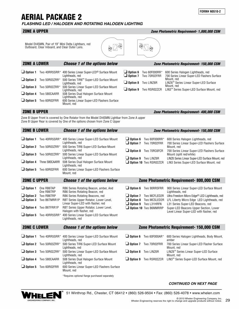
ZONE C LOWER Choose 1 of the options below Zone Photometric Requirement- 150,000 CSM
❏ Option 1 Two 40RR5SRR* 400 Series Linear Super-LED Surface Mount Lightheads, red❏ Option 2 Two 50R03ZRR* 500 Series TIR6 Super-LED Surface Mount Lightheads, red❏ Option 3 Two 50R02ZRR* 500 Series Linear Super-LED Surface Mount Lightheads, red❏ Option 4 Two 580CAARR 508 Series Dual Halogen Surface Mount Lightheads, red❏ Option 5 Two 60R02FRR 600 Series Linear Super-LED Flashers Surface Mount, red
❏ Option 6 Two 60F000AR* 600 Series Halogen Lightheads, Body Mount, amber❏ Option 7 Two 70R02FRR 700 Series Linear Super-LED Flasher Surface Mount, red❏ Option 8 Two LINZ6R LINZ6™ Series Linear Super-LED Surface Mount, red❏ Option 9 Two RSR02ZCR LIN3™ Series Super-LED Surface Mount, red
ZONE C UPPER Choose 1 of the options below Zone Photometric Requirement- 800,000 CSM
❏ Option 1 One RB6TAP RB6 Series Rotating Beacon, amber, And One RB6TRP RB6 Series Rotating Beacon, red❏ Option 2 Two RB6TRP RB6 Series Rotating Beacons, red❏ Option 3 Two B6TMRR1P RBT Series Upper Rotator, Lower Level, Linear Super-LED with flasher, red❏ Option 4 Two B6TFRR1P RBT Series Upper Rotator, Lower Level, Halogen with flasher, red❏ Option 5 Two 40RR5SRR* 400 Series Linear Super-LED Surface Mount Lightheads, red
❏ Option 6 Two 90RR5FRR 900 Series Linear Super-LED Surface Mount Lightheads, red❏ Option 7 Two MCFLED2R Ultra Freedom Micro Edge® LED Lightheads, red❏ Option 8 Two MCSLED2R LFL Liberty Micro Edge LED Lightheads, red❏ Option 9 Two L31HRFN L31 Series Super-LED Beacons, red❏ Option 10 Two B6MMRRP Super-LED Beacons Upper Section, Lower Level Linear Super-LED with flasher, red
FORM# N0510-2
FLASHING LED / HALOGEN AND ROTATING HALOGEN LIGHTING AERIAL PACKAGE 2
ZONE A UPPER Zone Photometric Requirement- 1,000,000 CSM
ZONE B UPPER Zone Photometric Requirement- 400,000 CSM
ZONE A LOWER Choose 1 of the options below Zone Photometric Requirement- 150,000 CSM
ZONE B LOWER Choose 1 of the options below Zone Photometric Requirement- 150,000 CSM
Model DI4SMN, Pair of 19” Mini Delta Lightbars, red Outboard, Clear Inboard, and Clear Outer Lens.
❏ Option 1 Two 40RR5SRR* 400 Series Linear Super-LED® Surface Mount Lightheads, red❏ Option 2 Two 50R03ZRR* 500 Series TIR6™ Super-LED Surface Mount Lightheads, red❏ Option 3 Two 50R02ZRR* 500 Series Linear Super-LED Surface Mount Lightheads, red❏ Option 4 Two 580CAARR 508 Series Dual Halogen Surface Mount Lightheads, red❏ Option 5 Two 60R02FRR 600 Series Linear Super-LED Flashers Surface Mount, red
❏ Option 6 Two 60F000RR* 600 Series Halogen Lightheads, red❏ Option 7 Two 70R02FRR 700 Series Linear Super-LED Flashers Surface Mount, red❏ Option 8 Two LINZ6R LINZ6™ Series Linear Super-LED Surface Mount, red❏ Option 9 Two RSR02ZCR LIN3™ Series Super-LED Surface Mount, red
❏ Option 1 Two 40RR5SRR* 400 Series Linear Super-LED Surface Mount Lightheads, red❏ Option 2 Two 50R03ZRR* 500 Series TIR6 Super-LED Surface Mount Lightheads, red ❏ Option 3 Two 50R02ZRR* 500 Series Linear Super-LED Surface Mount Lightheads, red❏ Option 4 Three 580CAARR 508 Series Dual Halogen Surface Mount Lightheads, red❏ Option 5 Two 60R02FRR 600 Series Linear Super-LED Flashers Surface Mount, red
❏ Option 6 Two 60F000RR* 600 Series Halogen Lightheads, red❏ Option 7 Two 70R02FRR 700 Series Linear Super-LED Flashers Surface Mount, red❏ Option 8 Two 70RC6FCR 700 Series Linear Super-LED Flashers Surface Mount (split red/white)❏ Option 9 Two LINZ6R LINZ6 Series Linear Super-LED Surface Mount, red❏ Option 10 Two RSR02ZCR LIN3 Series Super-LED Surface Mount, red
Zone B Upper Front is covered by One Rotator from the Model DI4SMN Lightbar from Zone A upperZone B Upper Rear is covered by One of the options chosen from Zone C Upper
29ENGINEERING COMPANY, INC.
®51 Winthrop Rd., Chester, CT 06412 • (860) 526-9504 • Fax: (860) 526-4078 • www.whelen.com
© 2010 Whelen Engineering Company, Inc. Whelen Engineering reserves the right to change and upgrade products without notice.
*Requires optional flange purchased separately
CONTINUED ON NEXT PAGE

30
FLASHING LED / HALOGEN AND ROTATING HALOGEN LIGHTING AERIAL PACKAGE 2 (cont.)
ZONE D UPPER Zone Photometric Requirement- 400,000 CSM
ZONE D LOWER Choose 1 of the options below Zone Photometric Requirement- 150,000 CSM
Zone D Upper Front is covered by One Rotator from the Model DI48MN Lightbar from Zone A upperZone D Upper Rear is covered by One of the options chosen from Zone C Upper
FORM# N0510-2
*Requires optional flange purchased separately
ENGINEERING COMPANY, INC.
®51 Winthrop Rd., Chester, CT 06412 • (860) 526-9504 • Fax: (860) 526-4078 • www.whelen.com
© 2010 Whelen Engineering Company, Inc. Whelen Engineering reserves the right to change and upgrade products without notice.
CERTIFICATE OF COMPLIANCE WITH NFPA 1901To Meet Certification, Check Box for the Option Chosen in Each Appropriate Zone
Note: This system is tested and certified by Whelen Engineering Company, Inc. to meet all requirements for the NFPA 1901 Standards for Automotive Fire Apparatus (2009 Edition). See Chapter 13 titled: Low Voltage Electrical Systems & Warning Devices. This System is Certified only if all optical and electrical warning devices are installed and wired in accordance to the 1901 Standard and Specifications; and also in accordance to the device manufacturers mounting and wiring specifications.
FIRE DEPARTMENT
TRUCK NUMBER
❏ Option 1 Two 40RR5SRR* 400 Series Linear Super-LED Surface Mount Lightheads, red❏ Option 2 Two 50R03ZRR* 500 Series TIR6 Super-LED Surface Mount Lightheads, red❏ Option 3 Two 50R02ZRR* 500 Series Linear Super-LED Surface Mount Lightheads, red❏ Option 4 Three 580CAARR 508 Series Dual Halogen Surface Mount Lightheads, red❏ Option 5 Two 60R02FRR 600 Series Linear Super-LED Flashers Surface Mount, red
❏ Option 6 Two 60F000AR* 600 Series Halogen Lightheads, amber❏ Option 7 Two 70R02FRR 700 Series Linear Super-LED Flashers Surface Mount, red❏ Option 8 Two 70RC6FCR 700 Series Linear Super-LED Flashers Surface Mount (split red/white) ❏ Option 9 Two LINZ6R LINZ6 Series Linear Super-LED Surface Mount, red❏ Option 10 Two RSR02ZCR LIN3 Series Super-LED Surface Mount, red
This package meets all zone requirements of NFPA 1901 specifications.
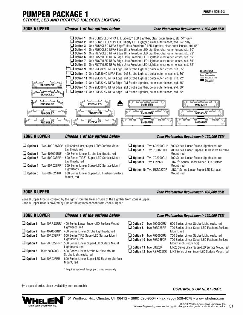
PUMPER PACKAGE 1
ZONE A UPPER Choose 1 of the options below Zone Photometric Requirement- 1,000,000 CSM
ZONE B UPPER Zone Photometric Requirement- 400,000 CSM
ZONE A LOWER Choose 1 of the options below Zone Photometric Requirement- 150,000 CSM
ZONE B LOWER Choose 1 of the options below Zone Photometric Requirement- 150,000 CSM
❏ Option 1 Two 40RR5SRR* 400 Series Linear Super-LED® Surface Mount Lightheads, red❏ Option 2 Two 402000RU* 400 Series Linear Strobe Lightheads, red❏ Option 3 Two 50R03ZRR* 500 Series TIR6™ Super-LED Surface Mount Lightheads, red❏ Option 4 Two 50R02ZRR* 500 Series Linear Super-LED Surface Mount Lightheads, red❏ Option 5 Two 60R02FRR 600 Series Linear Super-LED Flashers Surface Mount, red
❏ Option 6 Two 602000RU* 600 Series Linear Strobe Lightheads, red❏ Option 7 Two 70R02FRR 700 Series Linear Super-LED Flashers Surface Mount, red❏ Option 8 Two 702000RU 700 Series Linear Strobe Lightheads, red❏ Option 9 Two LINZ6R LINZ6™ Series Linear Super-LED Surface Mount, red❏ Option 10 Two RSR02ZCR LIN3™ Series Linear Super-LED Surface Mount, red
Zone B Upper Front is covered by the lights from the Rear or Side of the Lightbar from Zone A upperZone B Upper Rear is covered by One of the options chosen from Zone C Upper
❏ Option 1 Two 40RR5SRR* 400 Series Linear Super-LED Surface Mount Lightheads, red❏ Option 2 Two 402000RU* 400 Series Linear Strobe Lightheads, red❏ Option 3 Two 50R03ZRR* 500 Series TIR6 Super-LED Surface Mount Lightheads, red❏ Option 4 Two 50R02ZRR* 500 Series Linear Super-LED Surface Mount Lightheads, red❏ Option 5 Three 58EC20RU 508 Series Linear Strobe Surface Mount Strobe Lightheads, red❏ Option 6 Two 60R02FRR 600 Series Linear Super-LED Flashers Surface Mount, red
❏ Option 7 Two 602000RU* 600 Series Linear Strobe Lightheads, red❏ Option 8 Two 70R02FRR 700 Series Linear Super-LED Flashers Surface Mount, red❏ Option 9 Two 702000RU 700 Series Linear Strobe Lightheads, red❏ Option 10 Two 70RC6FCR 700 Series Linear Super-LED Flashers Surface Mount (split red/white)❏ Option 11 Two LINZ6R LINZ6 Series Linear Super-LED Surface Mount, red❏ Option 12 Two RSR02ZCR LIN3 Series Linear Super-LED Surface Mount, red
FORM# N0510-3
STROBE, LED AND ROTATING HALOGEN LIGHTING
❏ Option 1 One SLN2VLED NFPA LFL Liberty™ LED Lightbar, clear outer lenses, std. 54” only❏ Option 2 One SLN2QLED NFPA LFL Liberty LED Lightbar, clear outer lenses, std. 54” only❏ Option 3 One FN55QLED NFPA Edge® Ultra Freedom™ LED Lightbar, clear outer lenses, std. 55”❏ Option 4 One FN60QLED NFPA Edge Ultra Freedom LED Lightbar, clear outer lenses, std. 60”❏ Option 5 One FN72QLED NFPA Edge Ultra Freedom LED Lightbar, clear outer lenses, std. 72”❏ Option 6 One FN55VLED NFPA Edge Ultra Freedom LED Lightbar, clear outer lenses, std. 55”❏ Option 7 One FN60VLED NFPA Edge Ultra Freedom LED Lightbar, clear outer lenses, std. 60”❏ Option 8 One FN72VLED NFPA Edge Ultra Freedom LED Lightbar, clear outer lenses, std. 72”❏ Option 9 One 9M382NQ NFPA Edge 9M Strobe Lightbar, color outer lenses, std. 55”❏ Option 10 One 9M380NQ NFPA Edge 9M Strobe Lightbar, color outer lenses, std. 60”❏ Option 11 One 9M387NQ NFPA Edge 9M Strobe Lightbar, color outer lenses, std. 72”❏ Option 12 One 9M382NV NFPA Edge 9M Strobe Lightbar, color outer lenses, std. 55”❏ Option 13 One 9M380NV NFPA Edge 9M Strobe Lightbar, color outer lenses, std. 60”❏ Option 14 One 9M387NV NFPA Edge 9M Strobe Lightbar, color outer lenses, std. 72”
31ENGINEERING COMPANY, INC.
®51 Winthrop Rd., Chester, CT 06412 • (860) 526-9504 • Fax: (860) 526-4078 • www.whelen.com
© 2010 Whelen Engineering Company, Inc. Whelen Engineering reserves the right to change and upgrade products without notice.
*Requires optional flange purchased separately
FRONTFN55QLED
SLN2QLED
FN55VLED
SLN2VLED
FN60QLED FN60VLED
FN72VLEDFN72QLED
9M380NQ 9M380NV
9M382NQ 9M382NV
9M387NV9M387NQ
Clear LEDS,Strobes or Lens
Red LEDS or LensBlack Lens orFiller Panels
COLOR LEGEND
CONTINUED ON NEXT PAGE†† = special order, check availability, non-returnable
������������

PUMPER PACKAGE 1 (cont.)STROBE, LED AND ROTATING HALOGEN LIGHTING
ZONE D UPPER Zone Photometric Requirement- 400,000 CSM
ZONE D LOWER Choose 1 of the options below Zone Photometric Requirement- 150,000 CSM
Zone D Upper Front is covered by the Light from the Rear or Side of Lightbar from Zone A upper Zone D Upper Rear is covered by One of the options chosen from Zone C upper
FORM# N0510-3
*Requires optional flange purchased separately
32
ZONE C UPPER Choose 1 of the options below Zone Photometric Requirement- 800,000 CSM
ZONE C LOWER Choose 1 of the options below Zone Photometric Requirement- 150,000 CSM
❏ Option 1 Two 40RR5SRR* 400 Series Linear Super-LED Surface Mount Lightheads, red❏ Option 2 Two 402000RU* 400 Series Linear Strobe Lightheads, red❏ Option 3 Two 50R03ZRR* 500 Series TIR6™ Super-LED Surface Mount Lightheads, red❏ Option 4 Two 50R02ZRR* 500 Series Linear Super-LED Surface Mount Lightheads, red❏ Option 5 Two 60R02FRR 600 Series Linear Super-LED Flashers Surface Mount, red
❏ Option 6 Two 602000RU* 600 Series Linear Strobe Lightheads, red❏ Option 7 Two 702000RU 700 Series Linear Strobe Lightheads, red❏ Option 8 Two 70R02FRR 700 Series Linear Super-LED Flashers Surface Mount, red❏ Option 9 Two LINZ6R LINZ6™ Series Linear Super-LED Surface Mount, red❏ Option 10 Two RSR02ZCR LIN3 Series Linear Super-LED Surface Mount, red
❏ Option 1 One RB6TAP RB6 Series Rotating Beacon, amber, And One RB6TRP RB6 Series Rotating Beacon, red❏ Option 2 Two RB6TRP RB6 Series Rotating Beacons, red❏ Option 3 Two B6TMRR1P RBT Series Upper Rotator, Lower Level, Linear Super-LED® with flasher, red❏ Option 4 Two B6TSRR1P RBT Series Upper Rotator, Lower Level, Strobe, red❏ Option 5 Two 40RR5SRR* 400 Series Linear Super-LED Surface Mount Lightheads, red
❏ Option 6 Two 90RR5FRR 900 Series Linear Super-LED Surface Mount Lightheads, red❏ Option 7 Two MCFLED2R Ultra Freedom Micro Edge® LED Lightheads, red❏ Option 8 Two MCSLED2R LFL Liberty Micro Edge LED Lightheads, red❏ Option 9 Two L31HRFN L31 Series Super-LED Beacons, red❏ Option 10 Two B6MMRRP Super-LED Beacons Upper Section, Lower Level Linear Super-LED with flasher, red
ENGINEERING COMPANY, INC.
®51 Winthrop Rd., Chester, CT 06412 • (860) 526-9504 • Fax: (860) 526-4078 • www.whelen.com
© 2010 Whelen Engineering Company, Inc. Whelen Engineering reserves the right to change and upgrade products without notice.
CERTIFICATE OF COMPLIANCE WITH NFPA 1901To Meet Certification, Check Box for the Option Chosen in Each Appropriate Zone
Note: This system is tested and certified by Whelen Engineering Company, Inc. to meet all requirements for the NFPA 1901 Standards for Automotive Fire Apparatus (2009 Edition). See Chapter 13 titled: Low Voltage Electrical Systems & Warning Devices. This System is Certified only if all optical and electrical warning devices are installed and wired in accordance to the 1901 Standard and Specifications; and also in accordance to the device manufacturers mounting and wiring specifications.
FIRE DEPARTMENT
TRUCK NUMBER
❏ Option 1 Two 40RR5SRR* 400 Series Linear Super-LED Surface Mount Lightheads, red❏ Option 2 Two 402000RU* 400 Series Linear Strobe Lightheads, red❏ Option 3 Two 50R03ZRR* 500 Series TIR6 Super-LED Surface Mount Lightheads, red❏ Option 4 Two 50R02ZRR* 500 Series Linear Super-LED Surface Mount Lightheads, red❏ Option 5 Three 58EC20RU 508 Series Linear Strobe Surface Mount Strobe Lightheads, red❏ Option 6 Two 60R02FRR 600 Series Linear Super-LED Flashers Surface Mount, red
❏ Option 7 Two 602000RU* 600 Series Linear Strobe Lightheads, red❏ Option 8 Two 70R02FRR 700 Series Linear Super-LED Flashers Surface Mount, red❏ Option 9 Two 702000RU 700 Series Linear Strobe Lightheads, red❏ Option 10 Two 70RC6FCR 700 Series Linear Super-LED Flashers Surface Mount (split red/white)❏ Option 11 Two LINZ6R LINZ6 Series Linear Super-LED Surface Mount, red❏ Option 12 Two RSR02ZCR LIN3 Series Linear Super-LED Surface Mount, red
This package meets all zone requirements of NFPA 1901 specifications.
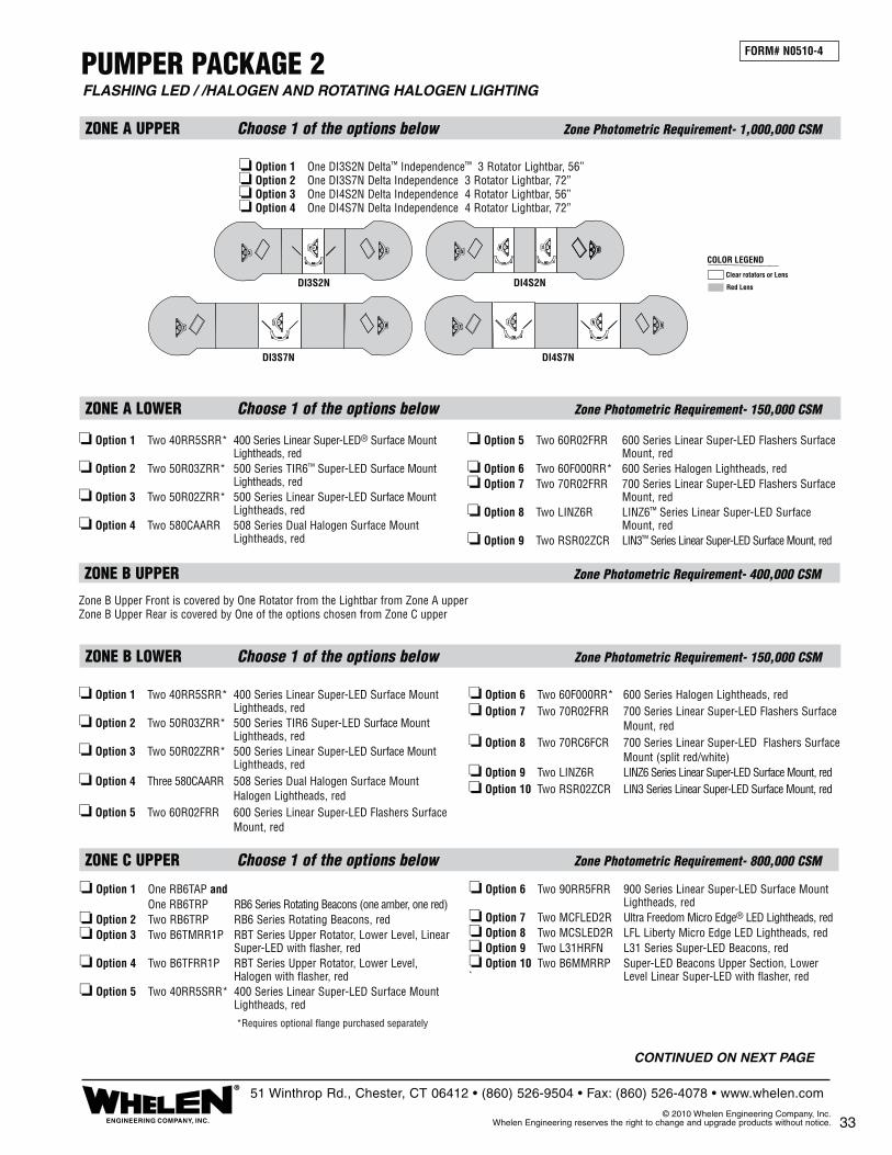
ZONE C UPPER Choose 1 of the options below Zone Photometric Requirement- 800,000 CSM
❏ Option 1 One RB6TAP and One RB6TRP RB6 Series Rotating Beacons (one amber, one red)❏ Option 2 Two RB6TRP RB6 Series Rotating Beacons, red❏ Option 3 Two B6TMRR1P RBT Series Upper Rotator, Lower Level, Linear Super-LED with flasher, red❏ Option 4 Two B6TFRR1P RBT Series Upper Rotator, Lower Level, Halogen with flasher, red❏ Option 5 Two 40RR5SRR* 400 Series Linear Super-LED Surface Mount Lightheads, red
❏ Option 6 Two 90RR5FRR 900 Series Linear Super-LED Surface Mount Lightheads, red❏ Option 7 Two MCFLED2R Ultra Freedom Micro Edge® LED Lightheads, red❏ Option 8 Two MCSLED2R LFL Liberty Micro Edge LED Lightheads, red❏ Option 9 Two L31HRFN L31 Series Super-LED Beacons, red❏ Option 10 Two B6MMRRP Super-LED Beacons Upper Section, Lower ` Level Linear Super-LED with flasher, red
PUMPER PACKAGE 2
❏ Option 1 One DI3S2N Delta™ Independence™ 3 Rotator Lightbar, 56”❏ Option 2 One DI3S7N Delta Independence 3 Rotator Lightbar, 72”❏ Option 3 One DI4S2N Delta Independence 4 Rotator Lightbar, 56”❏ Option 4 One DI4S7N Delta Independence 4 Rotator Lightbar, 72”
ZONE A UPPER Choose 1 of the options below Zone Photometric Requirement- 1,000,000 CSM
ZONE B UPPER Zone Photometric Requirement- 400,000 CSM
ZONE A LOWER Choose 1 of the options below Zone Photometric Requirement- 150,000 CSM
ZONE B LOWER Choose 1 of the options below Zone Photometric Requirement- 150,000 CSM
❏ Option 1 Two 40RR5SRR* 400 Series Linear Super-LED® Surface Mount Lightheads, red❏ Option 2 Two 50R03ZRR* 500 Series TIR6™ Super-LED Surface Mount Lightheads, red❏ Option 3 Two 50R02ZRR* 500 Series Linear Super-LED Surface Mount Lightheads, red❏ Option 4 Two 580CAARR 508 Series Dual Halogen Surface Mount Lightheads, red
❏ Option 5 Two 60R02FRR 600 Series Linear Super-LED Flashers Surface Mount, red❏ Option 6 Two 60F000RR* 600 Series Halogen Lightheads, red❏ Option 7 Two 70R02FRR 700 Series Linear Super-LED Flashers Surface Mount, red❏ Option 8 Two LINZ6R LINZ6™ Series Linear Super-LED Surface Mount, red❏ Option 9 Two RSR02ZCR LIN3™ Series Linear Super-LED Surface Mount, red
❏ Option 1 Two 40RR5SRR* 400 Series Linear Super-LED Surface Mount Lightheads, red❏ Option 2 Two 50R03ZRR* 500 Series TIR6 Super-LED Surface Mount Lightheads, red❏ Option 3 Two 50R02ZRR* 500 Series Linear Super-LED Surface Mount Lightheads, red❏ Option 4 Three 580CAARR 508 Series Dual Halogen Surface Mount Halogen Lightheads, red❏ Option 5 Two 60R02FRR 600 Series Linear Super-LED Flashers Surface Mount, red
❏ Option 6 Two 60F000RR* 600 Series Halogen Lightheads, red❏ Option 7 Two 70R02FRR 700 Series Linear Super-LED Flashers Surface Mount, red❏ Option 8 Two 70RC6FCR 700 Series Linear Super-LED Flashers Surface Mount (split red/white) ❏ Option 9 Two LINZ6R LINZ6 Series Linear Super-LED Surface Mount, red❏ Option 10 Two RSR02ZCR LIN3 Series Linear Super-LED Surface Mount, red
FORM# N0510-4
FLASHING LED / /HALOGEN AND ROTATING HALOGEN LIGHTING
Zone B Upper Front is covered by One Rotator from the Lightbar from Zone A upperZone B Upper Rear is covered by One of the options chosen from Zone C upper
33ENGINEERING COMPANY, INC.
®51 Winthrop Rd., Chester, CT 06412 • (860) 526-9504 • Fax: (860) 526-4078 • www.whelen.com
© 2010 Whelen Engineering Company, Inc. Whelen Engineering reserves the right to change and upgrade products without notice.
*Requires optional flange purchased separately
Clear rotators or Lens
Red Lens
COLOR LEGEND
DI3S7N
DI3S2N DI4S2N
DI4S7N
CONTINUED ON NEXT PAGE

34
PUMPER PACKAGE 2 (cont.)FLASHING LED / HALOGEN AND ROTATING HALOGEN LIGHTING
FORM# N0510-4
ZONE D UPPER Zone Photometric Requirement- 400,000 CSM
ZONE D LOWER Choose 1 of the options below Zone Photometric Requirement- 150,000 CSM
Zone D Upper Front is covered by One Rotator from the Lightbar from Zone A upperZone D Upper Rear is covered by One of the options chosen from Zone C upper
*Requires optional flange purchased separately
ZONE C LOWER Choose 1 of the options below Zone Photometric Requirement- 150,000 CSM
❏ Option 1 Two 40RR5SRR* 400 Series Linear Super-LED Surface Mount Lightheads, red❏ Option 2 Two 50R03ZRR* 500 Series TIR6™ Super-LED Surface Mount Lightheads, red❏ Option 3 Two 50R02ZRR* 500 Series Linear Super-LED Surface Mount Lightheads, red❏ Option 4 Two 580CAARR 508 Series Dual Halogen Surface Mount Lightheads, red
❏ Option 5 Two 60R02FRR 600 Series Linear Super-LED Flashers Surface Mount, red❏ Option 6 Two 60F000RR* 600 Series Halogen Lightheads, red❏ Option 7 Two 70R02FRR 700 Series Linear Super-LED Flashers Surface Mount, red❏ Option 8 Two LINZ6R LINZ6™ Series Linear Super-LED Surface Mount, red❏ Option 9 Two RSR02ZCR LIN3™ Series Linear Super-LED Surface Mount, red
ENGINEERING COMPANY, INC.
®51 Winthrop Rd., Chester, CT 06412 • (860) 526-9504 • Fax: (860) 526-4078 • www.whelen.com
© 2010 Whelen Engineering Company, Inc. Whelen Engineering reserves the right to change and upgrade products without notice.
CERTIFICATE OF COMPLIANCE WITH NFPA 1901To Meet Certification, Check Box for the Option Chosen in Each Appropriate Zone
Note: This system is tested and certified by Whelen Engineering Company, Inc. to meet all require-ments for the NFPA 1901 Standards for Automotive Fire Apparatus (2009 Edition). See Chapter 13 titled: Low Voltage Electrical Systems & Warning Devices. This System is Certified only if all optical and electrical warning devices are installed and wired in accordance to the 1901 Standard and Specifications; and also in accordance to the device manufacturers mounting and wiring specifications.
FIRE DEPARTMENT
TRUCK NUMBER
❏ Option 1 Two 40RR5SRR* 400 Series Linear Super-LED Surface Mount Lightheads, red❏ Option 2 Two 50R03ZRR* 500 Series TIR6 Super-LED Surface Mount Lightheads, red❏ Option 3 Two 50R02ZRR* 500 Series Linear Super-LED Surface Mount Lightheads, red❏ Option 4 Three 580CAARR 508 Series Dual Halogen Surface Mount Halogen Lightheads, red❏ Option 5 Two 60R02FRR 600 Series Linear Super-LED Flashers Surface Mount, red
❏ Option 6 Two 60F000RR* 600 Series Halogen Lightheads, red❏ Option 7 Two 70R02FRR 700 Series Linear Super-LED Flashers Surface Mount, red❏ Option 8 Two 70RC6FCR 700 Series Linear Super-LED Flashers Surface Mount (split red/white)❏ Option 9 Two LINZ6R LINZ6 Series Linear Super-LED Surface Mount, red❏ Option 10 Two RSR02ZCR LIN3 Series Linear Super-LED Surface Mount, red
This package meets all zone requirements of NFPA 1901 specifications.

RESCUE PACKAGE 1
ZONE A UPPER Choose 1 of the options below Zone Photometric Requirement- 1,000,000 CSM
ZONE A LOWER Choose 1 of the options below Zone Photometric Requirement- 150,000 CSM
❏ Option 1 Two 40RR5SRR* 400 Series Linear Super-LED® Surface Mount Lightheads, red❏ Option 2 Two 402000RU* 400 Series Linear Strobe Lightheads, red❏ Option 3 Two 50R03ZRR* 500 Series TIR6™ Super-LED Surface Mount Lightheads, red❏ Option 4 Two 50R02ZRR* 500 Series Linear Super-LED Surface Mount Lightheads, red❏ Option 5 Two 60R02FRR 600 Series Linear Super-LED Flashers Surface Mount, red
❏ Option 6 Two 602000RU* 600 Series Linear Strobe Lightheads, red❏ Option 7 Two 70R02FRR 700 Series Linear Super-LED Flashers Surface Mount, red❏ Option 8 Two 702000RU 700 Series Linear Strobe Lightheads, red❏ Option 9 Two LINZ6R LINZ6™ Series Linear Super-LED Surface Mount, red❏ Option 10 Two RSR02ZCR LIN3™ Series Linear Super-LED Surface Mount, red
ZONE B UPPER Choose 1 of the options below Zone Photometric Requirement- 400,000 CSM
Zone B Upper Front is covered by the lights from the Rear or Side of the Lightbar from Zone A upperZone B Upper Rear is covered by One of the options chosen from Zone C Upper plus Two Lightheads from the options below:
❏ Option 1 Two 58EC20RU 508 Series Linear Strobe Surface Mount Lighthead, red) ❏ Option 2 Two 602000RU* 600 Series Linear Strobe Lighthead, red
❏ Option 3 Two 81EC20RU 810 Series Linear Strobe Surface Mount Lighthead, red❏ Option 4 Two 90RR5FRR 900 Series Linear Super-LED Flasher Surface Mount, red❏ Option 5 Two 902000RU 900 Series Linear Strobe Lighthead, red
ZONE B LOWER Choose 1 of the options below Zone Photometric Requirement- 150,000 CSM
❏ Option 1 Two 40RR5SRR* 400 Series Linear Super-LED Surface Mount Lightheads, red❏ Option 2 Two 402000RU* 400 Series Linear Strobe Lightheads, red❏ Option 3 Two 50R03ZRR* 500 Series TIR6 Super-LED Surface Mount Lightheads, red❏ Option 4 Two 50R02ZRR* 500 Series Linear Super-LED Surface Mount Lightheads, red❏ Option 5 Three 58EC20RU 508E Series Linear Strobe Surface Mount Lightheads, red❏ Option 6 Two 60R02FRR 600 Series Linear Super-LED Flashers Surface Mount, red
❏ Option 7 Two 602000RU* 600 Series Linear Strobe Lightheads, red❏ Option 8 Two 70R02FRR 700 Series Linear Super-LED Flashers Surface Mount, red❏ Option 9 Two 702000RU 700 Series Linear Strobe Lightheads, red❏ Option 10 Two 70RC6FCR 700 Series Linear Super-LED Flashers Surface Mount (split red/white)❏ Option 11 Two LINZ6R LINZ6 Series Linear Super-LED Surface Mount, red❏ Option 12 Two RSR02ZCR LIN3 Series Linear Super-LED Surface Mount, red
FORM# N0510-5
STROBE AND LED LIGHTING
35ENGINEERING COMPANY, INC.
®51 Winthrop Rd., Chester, CT 06412 • (860) 526-9504 • Fax: (860) 526-4078 • www.whelen.com
© 2010 Whelen Engineering Company, Inc. Whelen Engineering reserves the right to change and upgrade products without notice.
*Requires optional flange purchased separately
FRONTFN55QLED
SLN2QLED
FN55VLED
SLN2VLED
FN60QLED FN60VLED
FN72VLEDFN72QLED
9M380NQ 9M380NV
9M382NQ 9M382NV
9M387NV9M387NQ
❏ Option 1 One SLN2VLED NFPA LFL Liberty™ LED Lightbar, clear outer lenses, std. 54” only❏ Option 2 One SLN2QLED NFPA LFL Liberty LED Lightbar, clear outer lenses, std. 54” only❏ Option 3 One FN55QLED NFPA Edge® Ultra Freedom™ LED Lightbar, clear outer lenses, std. 55”❏ Option 4 One FN60QLED NFPA Edge Ultra Freedom LED Lightbar, clear outer lenses, std. 60”❏ Option 5 One FN72QLED NFPA Edge Ultra Freedom LED Lightbar, clear outer lenses, std. 72”❏ Option 6 One FN55VLED NFPA Edge Ultra Freedom LED Lightbar, clear outer lenses, std. 55”❏ Option 7 One FN60VLED NFPA Edge Ultra Freedom LED Lightbar, clear outer lenses, std. 60”❏ Option 8 One FN72VLED NFPA Edge Ultra Freedom LED Lightbar, clear outer lenses, std. 72”❏ Option 9 One 9M382NQ NFPA Edge 9M Strobe Lightbar, color outer lenses, std. 55”❏ Option 10 One 9M380NQ NFPA Edge 9M Strobe Lightbar, color outer lenses, std. 60”❏ Option 11 One 9M387NQ NFPA Edge 9M Strobe Lightbar, color outer lenses, std. 72”❏ Option 12 One 9M382NV NFPA Edge 9M Strobe Lightbar, color outer lenses, std. 55”❏ Option 13 One 9M380NV NFPA Edge 9M Strobe Lightbar, color outer lenses, std. 60”❏ Option 14 One 9M387NV NFPA Edge 9M Strobe Lightbar, color outer lenses, std. 72”
Clear LEDS,Strobes or Lens
Red LEDS or LensBlack Lens orFiller Panels
COLOR LEGEND
CONTINUED ON NEXT PAGE†† = special order, check availability, non-returnable
������������

36
RESCUE PACKAGE 1 (cont.)FORM# N0510-5
STROBE AND LED LIGHTING
ZONE D UPPER Choose 1 of the options below Zone Photometric Requirement- 400,000 CSM
ZONE D LOWER Choose 1 of the options below Zone Photometric Requirement- 150,000 CSM
*Requires optional flange purchased separately
ZONE C UPPER Choose 1 of the options below Zone Photometric Requirement- 800,000 CSM
❏ Option 1 Two 40RR5SRR* 400 Series Linear Super-LED® Surface Mount Lightheads, red❏ Option 2 Two 90RR5FRR 900 Series Linear Super-LED Surface Mount Lightheads, red
❏ Option 3 Two 81EC20AU 810 Series Linear Strobe Surface Mount Lightheads, amber❏ Option 4 Two 902000AU 900 Series Linear Strobe Lightheads, amber
ZONE C LOWER Choose 1 of the options below Zone Photometric Requirement- 150,000 CSM
❏ Option 1 Two 40RR5SRR* 400 Series Linear Super-LED Surface Mount Lightheads, red❏ Option 2 Two 402000RU* 400 Series Linear Strobe Lightheads, red❏ Option 3 Two 50R03ZRR* 500 Series TIR6™ Super-LED Surface Mount Lightheads, red❏ Option 4 Two 50R02ZRR* 500 Series Linear Super-LED Surface Mount Lightheads, red❏ Option 5 Two 60R02FRR 600 Series Linear Super-LED Flashers Surface Mount Lightheads, red
❏ Option 6 Two 602000RU* 600 Series Linear Strobe Lightheads, red❏ Option 7 Two 70R02FRR 700 Series Linear Super-LED Flashers Surface Mount Lightheads, red❏ Option 8 Two 702000RU 700 Series Linear Strobe Lightheads, red❏ Option 9 Two LINZ6R LINZ6™ Series Linear Super-LED Surface Mount Lightheads, red❏ Option 10 Two RSR02ZCR LIN3™ Series Linear Super-LED Surface Mount Lightheads, red
ENGINEERING COMPANY, INC.
®51 Winthrop Rd., Chester, CT 06412 • (860) 526-9504 • Fax: (860) 526-4078 • www.whelen.com
© 2010 Whelen Engineering Company, Inc. Whelen Engineering reserves the right to change and upgrade products without notice.
CERTIFICATE OF COMPLIANCE WITH NFPA 1901To Meet Certification, Check Box for the Option Chosen in Each Appropriate Zone
Note: This system is tested and certified by Whelen Engineering Company, Inc. to meet all require-ments for the NFPA 1901 Standards for Automotive Fire Apparatus (2009 Edition). See Chapter 13 titled: Low Voltage Electrical Systems & Warning Devices. This System is Certified only if all optical and electrical warning devices are installed and wired in accordance to the 1901 Standard and Specifications; and also in accordance to the device manufacturers mounting and wiring specifications.
FIRE DEPARTMENT
TRUCK NUMBER
Zone D Upper Front is covered by Light from the Rear or Side of Lightbar from Zone A upperZone D Upper Rear is covered by One of the options chosen from Zone C Upper Plus Two Lightheads from the options below:
❏ Option 1 Two 58EC20RU 508 Series Linear Strobe Surface Mount Lighthead, red ❏ Option 2 Two 602000RU* 600 Series Linear Strobe Lighthead, red
❏ Option 3 Two 81EC20RU 810 Series Linear Strobe Surface Mount Lighthead, red❏ Option 4 Two 902000RU 900 Series Linear Strobe Lighthead, red❏ Option 5 Two 90RR5FRR 900 Series Linear Super-LED Flasher Surface Mount, red
❏ Option 1 Two 40RR5SRR* 400 Series Linear Super-LED Surface Mount Lightheads, red❏ Option 2 Two 402000RU* 400 Series Linear Strobe Lightheads, red❏ Option 3 Two 50R03ZRR* 500 Series TIR6 Super-LED Surface Mount Lightheads, red❏ Option 4 Two 50R02ZRR* 500 Series Linear Super-LED Surface Mount Lightheads, red❏ Option 5 Three 58EC20RU 508 Series Linear Strobe Surface Mount Lightheads, red❏ Option 6 Two 60R02FRR 600 Series Linear Super-LED Flashers Surface Mount, red
❏ Option 7 Two 602000RU* 600 Series Linear Strobe Lightheads, red❏ Option 8 Two 70R02FRR 700 Series Linear Super-LED Flashers Surface Mount, red❏ Option 9 Two 702000RU 700 Series Linear Strobe Lightheads, red❏ Option 10 Two 70RC6FCR 700 Series Linear Super-LED Flashers Surface Mount Lightheads (split red/white)❏ Option 11 Two LINZ6R LINZ6 Series Linear Super-LED Surface Mount, red❏ Option 12 Two RSR02ZCR LIN3 Series Linear Super-LED Surface Mount, red
This package meets all zone requirements of NFPA 1901 specifications.

RESCUE PACKAGE 2
ZONE A UPPER Choose 1 of the options below Zone Photometric Requirement- 1,000,000 CSM
ZONE A LOWER Choose 1 of the options below Zone Photometric Requirement- 150,000 CSM
❏ Option 1 Two 40RR5SRR* 400 Series Linear Super-LED® Surface Mount Lightheads, red❏ Option 2 Two 50R03ZRR* 500 Series TIR6™ Super-LED Surface Mount Lightheads, red❏ Option 3 Two 50R02ZRR* 500 Series Linear Super-LED Surface Mount Lightheads, red❏ Option 4 Two 580CAARR 508 Series Dual Halogen Surface Mount Lightheads, red
❏ Option 5 Two 60R02FRR 600 Series Linear Super-LED Flashers Surface Mount, red❏ Option 6 Two 60F000RR* 600 Series Halogen Lightheads, red❏ Option 7 Two 70R02FRR 700 Series Linear Super-LED Flashers Surface Mount, red❏ Option 8 Two LINZ6R LINZ6™ Series Linear Super-LED Surface Mount, red❏ Option 9 Two RSR02ZCR LIN3™ Series Linear Super-LED Surface Mount, red
One Rotator from the Lightbar from Zone A upper; Plus Two Lightheads from the options below:
❏ Option 1 Two 580CAARR 508 Series Dual Halogen Surface Mount Lighthead, red❏ Option 2 Two 60F000RR* 600 Series Halogen Lighthead, red
❏ Option 3 Two 810CAARR 810 Series Dual Halogen Surface Mount Lighthead, red❏ Option 4 Two 90RR5FRR 900 Series Linear Super-LED Flasher Surface Mount, red❏ Option 5 Two 90F000RR 900 Series Halogen Lighthead, red
ZONE B UPPER Choose 1 of the options below Zone Photometric Requirement- 400,000 CSM
ZONE B LOWER Choose 1 of the options below Zone Photometric Requirement- 150,000 CSM
❏ Option 1 Two 40RR5SRR* 400 Series Linear Super-LED Surface Mount Lightheads, red ❏ Option 2 Two 50R03ZRR 500 Series TIR6 Super-LED Surface Mount Lightheads, red❏ Option 3 Two 50R02ZRR* 500 Series Linear Super-LED Surface Mount Lightheads, red ❏ Option 4 Three 580CAARR 508 Series Dual Halogen Surface Mount Lightheads, red❏ Option 5 Two 60R02FRR 600 Series Linear Super-LED Flasher Surface Mount, red
❏ Option 6 Two 60F000RR* 600 Series Halogen Lightheads, red❏ Option 7 Two 70R02FRR 700 Series Linear Super-LED Flasher Surface Mount, red❏ Option 8 Two 70RC6FCR 700 Series Linear Super-LED Flasher Surface Mount (split red/white) ❏ Option 9 Two LINZ6R LINZ6 Series Linear Super-LED Surface Mount, red❏ Option 10 Two RSR02ZCR LIN3 Series Linear Super-LED Surface Mount, red
FORM# N0510-6
FLASHING LED / HALOGEN AND ROTATING HALOGEN LIGHTING
37ENGINEERING COMPANY, INC.
®51 Winthrop Rd., Chester, CT 06412 • (860) 526-9504 • Fax: (860) 526-4078 • www.whelen.com
© 2010 Whelen Engineering Company, Inc. Whelen Engineering reserves the right to change and upgrade products without notice.
*Requires optional flange purchased separately
❏ Option 1 One DI3S2N Delta™ Independence™ 3 Rotator Lightbar, 56”❏ Option 2 One DI3S7N Delta Independence 3 Rotator Lightbar, 72”❏ Option 3 One DI4S2N Delta Independence 4 Rotator Lightbar, 56”❏ Option 4 One DI4S7N Delta Independence 4 Rotator Lightbar, 72”
Clear rotators or Lens
Red Lens
COLOR LEGEND
DI3S7N
DI3S2N DI4S2N
DI4S7N
CONTINUED ON NEXT PAGE

38
RESCUE PACKAGE 2 (cont.)FORM# N0510-6
FLASHING LED / HALOGEN AND ROTATING HALOGEN LIGHTING
ZONE D UPPER Choose 1 of the options below Zone Photometric Requirement- 400,000 CSM
ZONE D LOWER Choose 1 of the options below Zone Photometric Requirement- 150,000 CSM
*Requires optional flange purchased separately
ZONE C UPPER Choose 1 of the options below Zone Photometric Requirement- 800,000 CSM
❏ Option 1 Two 40RR5SRR* 400 Series Linear Super-LED® Surface Mount Lightheads, red❏ Option 2 Two 90RR5FRR 900 Series Linear Super-LED Surface Mount Lightheads, red❏ Option 3 Two 810CAAAR 810 Series Halogen Surface Mount Lightheads, amber
❏ Option 4 Two 90F000AR 900 Series Halogen Lightheads, amber❏ Option 5 Two 90RR5FRR 900 Series Linear Super-LED Flashing Lighthead Surface Mount, red AND Two 70R02FRR 700 Series Linear Super-LED Flashing Surface Mount Lightheads, red
ZONE C LOWER Choose 1 of the options below Zone Photometric Requirement- 150,000 CSM
❏ Option 1 Two 40RR5SRR* 400 Series Linear Super-LED Surface Mount Lightheads, red❏ Option 2 Two 50R03ZRR* 500 Series TIR6™ Super-LED Surface Mount Lightheads, red❏ Option 3 Two 50R02ZRR* 500 Series Linear Super-LED Surface Mount Lightheads, red❏ Option 4 Two 580CAARR 508 Series Dual Halogen Surface Mount Lightheads, red
❏ Option 5 Two 60R02FRR 600 Series Linear Super-LED Flashers Surface Mount, red❏ Option 6 Two 60F000AR* 600 Series Halogen Lightheads, red❏ Option 7 Two 70R02FRR 700 Series Linear Super-LED Flashers Surface Mount, red❏ Option 8 Two LINZ6R LINZ6™ Series Linear Super-LED Surface Mount, red❏ Option 9 Two RSR02ZCR LIN3™ Series Linear Super-LED Surface Mount, red
ENGINEERING COMPANY, INC.
®51 Winthrop Rd., Chester, CT 06412 • (860) 526-9504 • Fax: (860) 526-4078 • www.whelen.com
© 2010 Whelen Engineering Company, Inc. Whelen Engineering reserves the right to change and upgrade products without notice.
CERTIFICATE OF COMPLIANCE WITH NFPA 1901To Meet Certification, Check Box for the Option Chosen in Each Appropriate Zone
Note: This system is tested and certified by Whelen Engineering Company, Inc. to meet all require-ments for the NFPA 1901 Standards for Automotive Fire Apparatus (2009 Edition). See Chapter 13 titled: Low Voltage Electrical Systems & Warning Devices. This System is Certified only if all optical and electrical warning devices are installed and wired in accordance to the 1901 Standard and Specifications; and also in accordance to the device manufacturers mounting and wiring specifications.
FIRE DEPARTMENT
TRUCK NUMBER
One Rotator from the Lightbar from Zone A upper; Plus Two Lightheads from the options below:
❏ Option 1 Two 580CAARR 508 Series Dual Halogen Surface Mount Lighthead, red❏ Option 2 Two 60F000RR* 600 Series Halogen Lighthead, red
❏ Option 3 Two 810CAARR 810 Series Dual Halogen Surface Mount Lighthead, red❏ Option 4 Two 90RR5FRR 900 Series Linear Super-LED Flasher Surface Mount, red❏ Option 5 Two 90F000RR 900 Series Halogen Lighthead, red
❏ Option 1 Two 40RR5SRR* 400 Series Linear Super-LED Surface Mount Lightheads, red❏ Option 2 Two 50R03ZRR* 500 Series TIR6 Super-LED Surface Mount Lightheads, red❏ Option 3 Two 50R02ZRR* 500 Series Linear Super-LED Surface Mount Lightheads, red❏ Option 4 Three 580CAARR 508 Series Dual Halogen Surface Mount Lightheads, red❏ Option 5 Two 60R02FRR 600 Series Linear Super-LED Flashers Surface Mount, red
❏ Option 6 Two 60F000RR* 600 Series Halogen Lightheads, red❏ Option 7 Two 70R02FRR 700 Series Linear Super-LED Flashers Surface Mount, red❏ Option 8 Two 70RC6FCR 700 Series Linear Super-LED Flashers Surface Mount (split red/white) ❏ Option 9 Two LINZ6R LINZ6 Series Linear Super-LED Surface Mount, red❏ Option 10 Two RSR02ZCR LIN3 Series Linear Super-LED Surface Mount, red
This package meets all zone requirements of NFPA 1901 specifications.
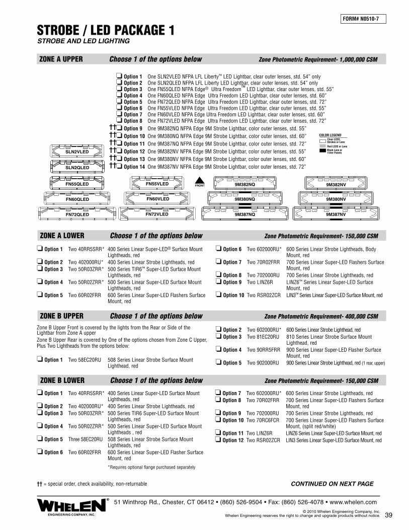
STROBE / LED PACKAGE 1
ZONE A UPPER Choose 1 of the options below Zone Photometric Requirement- 1,000,000 CSM
ZONE A LOWER Choose 1 of the options below Zone Photometric Requirement- 150,000 CSM
❏ Option 1 Two 40RR5SRR* 400 Series Linear Super-LED® Surface Mount Lightheads, red❏ Option 2 Two 402000RU* 400 Series Linear Strobe Lightheads, red❏ Option 3 Two 50R03ZRR* 500 Series TIR6™ Super-LED Surface Mount Lightheads, red❏ Option 4 Two 50R02ZRR* 500 Series Linear Super-LED Surface Mount Lightheads, red❏ Option 5 Two 60R02FRR 600 Series Linear Super-LED Flashers Surface Mount, red
❏ Option 6 Two 602000RU* 600 Series Linear Strobe Lightheads, Body Mount, red❏ Option 7 Two 70R02FRR 700 Series Linear Super-LED Flashers Surface Mount, red❏ Option 8 Two 702000RU 700 Series Linear Strobe Lightheads, red❏ Option 9 Two LINZ6R LINZ6™ Series Linear Super-LED Surface Mount, red❏ Option 10 Two RSR02ZCR LIN3™ Series Linear Super-LED Surface Mount, red
ZONE B UPPER Choose 1 of the options below Zone Photometric Requirement- 400,000 CSM
ZONE B LOWER Choose 1 of the options below Zone Photometric Requirement- 150,000 CSM
❏ Option 1 Two 40RR5SRR* 400 Series Linear Super-LED Surface Mount Lightheads, red❏ Option 2 Two 402000RU* 400 Series Linear Strobe Lightheads, red❏ Option 3 Two 50R03ZRR* 500 Series TIR6 Super-LED Surface Mount Lightheads, red❏ Option 4 Two 50R02ZRR* 500 Series Linear Super-LED Surface Mount Lightheads , red❏ Option 5 Three 58EC20RU 508 Series Linear Strobe Surface Mount Lightheads, red❏ Option 6 Two 60R02FRR 600 Series Linear Super-LED Flasher Surface Mount, red
❏ Option 7 Two 602000RU* 600 Series Linear Strobe Lightheads, red❏ Option 8 Two 70R02FRR 700 Series Linear Super-LED Flashers Surface Mount, red❏ Option 9 Two 702000RU 700 Series Linear Strobe Lightheads, red❏ Option 10 Two 70RC6FCR 700 Series Linear Super-LED Flashers Surface Mount, (split red/white) ❏ Option 11 Two LINZ6R LINZ6 Series Linear Super-LED Surface Mount, red❏ Option 12 Two RSR02ZCR LIN3 Series Linear Super-LED Surface Mount, red
FORM# N0510-7
STROBE AND LED LIGHTING
39ENGINEERING COMPANY, INC.
®51 Winthrop Rd., Chester, CT 06412 • (860) 526-9504 • Fax: (860) 526-4078 • www.whelen.com
© 2010 Whelen Engineering Company, Inc. Whelen Engineering reserves the right to change and upgrade products without notice.
*Requires optional flange purchased separately
Zone B Upper Front is covered by the lights from the Rear or Side of the Lightbar from Zone A upperZone B Upper Rear is covered by One of the options chosen from Zone C Upper, Plus Two Lightheads from the options below:
❏ Option 1 Two 58EC20RU 508 Series Linear Strobe Surface Mount Lighthead, red
❏ Option 2 Two 602000RU* 600 Series Linear Strobe Lighthead, red❏ Option 3 Two 81EC20RU 810 Series Linear Strobe Surface Mount Lighthead, red❏ Option 4 Two 90RR5FRR 900 Series Linear Super-LED Flasher Surface Mount, red ❏ Option 5 Two 902000RU 900 Series Linear Strobe Lighthead, red (1 rear, upper)
FRONTFN55QLED
SLN2QLED
FN55VLED
SLN2VLED
FN60QLED FN60VLED
FN72VLEDFN72QLED
9M380NQ 9M380NV
9M382NQ 9M382NV
9M387NV9M387NQ
❏ Option 1 One SLN2VLED NFPA LFL Liberty™ LED Lightbar, clear outer lenses, std. 54” only❏ Option 2 One SLN2QLED NFPA LFL Liberty LED Lightbar, clear outer lenses, std. 54” only❏ Option 3 One FN55QLED NFPA Edge® Ultra Freedom™ LED Lightbar, clear outer lenses, std. 55”❏ Option 4 One FN60QLED NFPA Edge Ultra Freedom LED Lightbar, clear outer lenses, std. 60”❏ Option 5 One FN72QLED NFPA Edge Ultra Freedom LED Lightbar, clear outer lenses, std. 72”❏ Option 6 One FN55VLED NFPA Edge Ultra Freedom LED Lightbar, clear outer lenses, std. 55”❏ Option 7 One FN60VLED NFPA Edge Ultra Freedom LED Lightbar, clear outer lenses, std. 60”❏ Option 8 One FN72VLED NFPA Edge Ultra Freedom LED Lightbar, clear outer lenses, std. 72”❏ Option 9 One 9M382NQ NFPA Edge 9M Strobe Lightbar, color outer lenses, std. 55”❏ Option 10 One 9M380NQ NFPA Edge 9M Strobe Lightbar, color outer lenses, std. 60”❏ Option 11 One 9M387NQ NFPA Edge 9M Strobe Lightbar, color outer lenses, std. 72”❏ Option 12 One 9M382NV NFPA Edge 9M Strobe Lightbar, color outer lenses, std. 55”❏ Option 13 One 9M380NV NFPA Edge 9M Strobe Lightbar, color outer lenses, std. 60”❏ Option 14 One 9M387NV NFPA Edge 9M Strobe Lightbar, color outer lenses, std. 72”
Clear LEDS,Strobes or Lens
Red LEDS or LensBlack Lens orFiller Panels
COLOR LEGEND
CONTINUED ON NEXT PAGE†† = special order, check availability, non-returnable
������������

40
ZONE D UPPER Choose 1 of the options below Zone Photometric Requirement- 400,000 CSM
ZONE D LOWER Choose 1 of the options below Zone Photometric Requirement- 150,000 CSM
STROBE / LED PACKAGE 1 (cont.)FORM# N0510-7
STROBE AND LED LIGHTING
*Requires optional flange purchased separately
ZONE C UPPER Choose 1 of the options below Zone Photometric Requirement- 800,000 CSM
❏ Option 1 Two 40RR5SRR* 400 Series Linear Super-LED® Surface Mount Lightheads, red❏ Option 2 Two 90RR5FRR 900 Series Linear Super-LED Surface Mount Lightheads, red❏ Option 3 Two 81EC20AU 810 Series Linear Strobe Surface Mount Lightheads, amber
❏ Option 4 Two 902000AU 900 Series Linear Strobe Lightheads, amber❏ Option 5 Two 90RR5FRR 900 Series Linear Super-LED Flashing Lighthead Surface Mount, red❏ Option 6 Two MCFLED2R Micro Edge® Ultra Freedom LED Lightheads, red❏ Option 7 Two MCSLED2R Micro Edge LFL Liberty LED Lightheads, red
ZONE C LOWER Choose 1 of the options below Zone Photometric Requirement- 150,000 CSM
❏ Option 1 Two 40RR5SRR* 400 Series Linear Super-LED Surface Mount Lightheads, red❏ Option 2 Two 402000RU* 400 Series Linear Strobe, red❏ Option 3 Two 50R03ZRR* 500 Series TIR6™ Super-LED Surface Mount Lightheads, red❏ Option 4 Two 50R02ZRR* 500 Series Linear Super-LED Surface Mount Lightheads, red❏ Option 5 Two 60R02FRR 600 Series Linear Super-LED Flashers Surface Mount, red
❏ Option 6 Two 602000RU* 600 Series Linear Strobe Lightheads, red❏ Option 7 Two 70R02FRR 700 Series Linear Super-LED Flashers Surface Mount, red❏ Option 8 Two 702000RU 700 Series Linear Strobe Lightheads, red❏ Option 9 Two LINZ6R LINZ6™ Series Linear Super-LED Surface Mount, red❏ Option 10 Two RSR02ZCR LIN3™ Series Linear Super-LED Surface Mount, red
ENGINEERING COMPANY, INC.
®51 Winthrop Rd., Chester, CT 06412 • (860) 526-9504 • Fax: (860) 526-4078 • www.whelen.com
© 2010 Whelen Engineering Company, Inc. Whelen Engineering reserves the right to change and upgrade products without notice.
CERTIFICATE OF COMPLIANCE WITH NFPA 1901To Meet Certification, Check Box for the Option Chosen in Each Appropriate Zone
Note: This system is tested and certified by Whelen Engineering Company, Inc. to meet all requirements for the NFPA 1901 Standards for Automotive Fire Apparatus (2009 Edition). See Chapter 13 titled: Low Voltage Electrical Systems & Warning Devices. This System is Certified only if all optical and electrical warning devices are installed and wired in accordance to the 1901 Standard and Specifications; and also in accordance to the device manufacturers mounting and wiring specifications.
FIRE DEPARTMENT
TRUCK NUMBER
❏ Option 1 Two 40RR5SRR* 400 Series Linear Super-LED Surface Mount Lightheads, red❏ Option 2 Two 402000RU* 400 Series Linear Strobe Lightheads, red❏ Option 3 Two 50R03ZRR* 500 Series TIR6 Super-LED Surface Mount Lightheads, red❏ Option 4 Two 50R02ZRR* 500 Series Linear Super-LED Surface Mount Lightheads, red❏ Option 5 Three 58EC20RU 508 Series Linear Strobe Surface Mount Lightheads, red❏ Option 6 Two 60R02FRR 600 Series Linear Super-LED Flashers Surface Mount, red
❏ Option 7 Two 602000RU* 600 Series Linear Strobe Lightheads, red❏ Option 8 Two 70R02FRR 700 Series Linear Super-LED Flashers Surface Mount, red❏ Option 9 Two 702000RU 700 Series Linear Strobe Lightheads, red❏ Option 10 Two 70RC6FCR 700 Series Linear Super-LED Flashers Surface Mount (split red/white)❏ Option 11 Two LINZ6R LINZ6 Series Linear Super-LED Surface Mount, red❏ Option 12 Two RSR02ZCR LIN3 Series Linear Super-LED Surface Mount, red
Zone D Upper Front is covered by Light from the Rear or Side of Lightbar from Zone A upperZone D Upper Rear is covered by One of the options chosen from Zone C Upper Plus Two Lightheads from the options below:
❏ Option 1 Two 58EC20RU 508 Series Linear Strobe Surface Mount Lighthead, red ❏ Option 2 Two 602000RU* 600 Series Linear Strobe Lighthead, red
❏ Option 3 Two 81EC20RU 810 Series Linear Surface Mount Strobe Lighthead, red❏ Option 4 Two 902000RU 900 Series Linear Strobe Lighthead, red ❏ Option 5 Two 90RR5FRR 900 Series Linear Super-LED Flasher Surface Mount, red
This package meets all zone requirements of NFPA 1901 specifications.

41ENGINEERING COMPANY, INC.
®51 Winthrop Rd., Chester, CT 06412 • (860) 526-9504 • Fax: (860) 526-4078 • www.whelen.com
© 2010 Whelen Engineering Company, Inc. Whelen Engineering reserves the right to change and upgrade products without notice.
ZONE D LOWER Choose 1 of the options below Zone Photometric Requirement- 150,000 CSM
This package meets all lower zone requirements of NFPA 1901 specifications.
CERTIFICATE OF COMPLIANCE WITH NFPA 1901To Meet Certification, Check Box for the Option Chosen in Each Appropriate Zone
Note: This system is tested and certified by Whelen Engineering Company, Inc. to meet all require-ments for the NFPA 1901 Standards for Automotive Fire Apparatus (2009 Edition). See Chapter 13 titled: Low Voltage Electrical Systems & Warning Devices. This System is Certified only if all optical and electrical warning devices are installed and wired in accordance to the 1901 Standard and Specifications; and also in accordance to the device manufacturers mounting and wiring specifications.
FIRE DEPARTMENT
TRUCK NUMBER
❏ Option 1 Two 40RR5SRR* 400 Series Linear Super-LED Surface Mount Lightheads, red❏ Option 2 Two 402000RU* 400 Series Linear Strobe Lightheads, red❏ Option 3 Two 50R03ZRR* 500 Series TIR6 Super-LED Surface Mount Lightheads, red❏ Option 4 Two 50R02ZRR* 500 Series Linear Super-LED Surface Mount Lightheads, red❏ Option 5 Three 58EC20RU 508 Series Linear Strobe Surface Mount Lightheads, red❏ Option 6 Two 60R02FRR 600 Series Linear Super-LED Flashers Surface Mount, red
❏ Option 7 Two 602000RU* 600 Series Linear Strobe Lightheads, red❏ Option 8 Two 70R02FRR 700 Series Linear Super-LED Flashers Surface Mount, red❏ Option 9 Two 702000RU 700 Series Linear Strobe Lightheads, red❏ Option 10 Two 70RC6FCR 700 Series Linear Super-LED Flashers Surface Mount (split red/white) ❏ Option 11 Two LINZ6R LINZ6 Series Linear Super-LED Surface Mount, red❏ Option 12 Two RSR02ZCR LIN3 Series Linear Super-LED Surface Mount, red
❏ Option 1 Two 40RR5SRR* 400 Series Linear Super-LED Surface Mount Lightheads, red❏ Option 2 Two 402000RU* 400 Series Linear Strobe Lightheads, red❏ Option 3 Two 50R03ZRR* 500 Series TIR6 Super-LED Surface Mount Lightheads, red❏ Option 4 Two 50R02ZRR* 500 Series Linear Super-LED Surface Mount Lightheads, red❏ Option 5 Three 58EC20RU 508 Series Linear Strobe Surface Mount Lightheads, red❏ Option 6 Two 60R02FRR 600 Series Linear Super-LED Flashers Surface Mount, red
❏ Option 7 Two 602000RU* 600 Series Linear Strobe Lightheads, red❏ Option 8 Two 70R02FRR 700 Series Linear Super-LED Flashers Surface Mount, red❏ Option 9 Two 702000RU 700 Series Linear Strobe Lightheads, red❏ Option 10 Two 70RC6FCR 700 Series Linear Super-LED Flashers Surface Mount (split red/white)❏ Option 11 Two LINZ6R LINZ6 Series Linear Super-LED Surface Mount, red❏ Option 12 Two RSR02ZCR LIN3 Series Linear Super-LED Surface Mount, red
❏ Option 1 Two 40RR5SRR* 400 Series Linear Super-LED Surface Mount Lightheads, red❏ Option 2 Two 402000RU* 400 Series Linear Strobe Lightheads, red❏ Option 3 Two 50R03ZRR* 500 Series TIR6 Super-LED Surface Mount Lightheads, red❏ Option 4 Two 50R02ZRR* 500 Series Linear Super-LED Surface Mount Lightheads, red❏ Option 5 Two 60R02FRR 600 Series Linear Super-LED Flashers Surface Mount, red
❏ Option 6 Two 602000RU* 600 Series Linear Strobe Lightheads, red❏ Option 7 Two 70R02FRR 700 Series Linear Super-LED Flashers Surface Mount, red❏ Option 8 Two 702000RU 700 Series Linear Strobe Lightheads, red❏ Option 9 Two LINZ6R LINZ6 Series Linear Super-LED Surface Mount, red❏ Option 10 Two RSR02ZCR LIN3 Series Linear Super-LED Surface Mount, red
ZONE A LOWER Choose 1 of the options below Zone Photometric Requirement- 150,000 CSM
ZONE B LOWER Choose 1 of the options below Zone Photometric Requirement- 150,000 CSM
ZONE C LOWER Choose 1 of the options below Zone Photometric Requirement- 150,000 CSM
AERIAL, PUMPER, RESCUE PACKAGE 1
❏ Option 1 Two 40RR5SRR* 400 Series Linear Super-LED® Surface Mount Lightheads, red❏ Option 2 Two 402000RU* 400 Series Linear Strobe Lightheads, red❏ Option 3 Two 50R03ZRR* 500 Series TIR6™ Super-LED Surface Mount Lightheads, red❏ Option 4 Two 50R02ZRR* 500 Series Linear Super-LED Surface Mount ` Lightheads, red❏ Option 5 Two 60R02FRR 600 Series Linear Super-LED Flashers Surface Mount, red
❏ Option 6 Two 602000RU* 600 Series Linear Strobe Lightheads, Body Mount,, red❏ Option 7 Two 70R02FRR 700 Series Linear Super-LED Flashers Surface Mount, red❏ Option 8 Two 702000RU 700 Series Linear Strobe Lightheads, red❏ Option 9 Two LINZ6R LINZ6™ Series Linear Super-LED Surface Mount, red❏ Option 10 Two RSR02ZCR LIN3™ Series Linear Super-LED Surface Mount, red
FORM# N0510-8
STROBE AND LED LIGHTING, LOWER ZONE ONLY
*Requires optional flange purchased separately

42 ENGINEERING COMPANY, INC.
®51 Winthrop Rd., Chester, CT 06412 • (860) 526-9504 • Fax: (860) 526-4078 • www.whelen.com
© 2010 Whelen Engineering Company, Inc. Whelen Engineering reserves the right to change and upgrade products without notice.
This package meets all lower zone requirements of NFPA 1901 specifications.
ZONE D LOWER Choose 1 of the options below Zone Photometric Requirement- 150,000 CSM
CERTIFICATE OF COMPLIANCE WITH NFPA 1901To Meet Certification, Check Box for the Option Chosen in Each Appropriate Zone
Note: This system is tested and certified by Whelen Engineering Company, Inc. to meet all require-ments for the NFPA 1901 Standards for Automotive Fire Apparatus (2009 Edition). See Chapter 13 titled: Low Voltage Electrical Systems & Warning Devices. This System is Certified only if all optical and electrical warning devices are installed and wired in accordance to the 1901 Standard and Specifications; and also in accordance to the device manufacturers mounting and wiring specifications.
FIRE DEPARTMENT
TRUCK NUMBER
❏ Option 1 Two 40RR5SRR* 400 Series Linear Super-LED Surface Mount Lightheads, red❏ Option 2 Two 50R03ZRR* 500 Series TIR6™ Super-LED Surface Mount Lightheads, red❏ Option 3 Two 50R02ZRR* 500 Series Linear Super-LED Surface Mount Lightheads, red❏ Option 4 Three 580CAARR 508 Series Dual Halogen Surface Mount Lightheads, red❏ Option 5 Two 60R02FRR 600 Series Linear Super-LED Flashers Surface Mount, red
❏ Option 6 Two 60F000RR* 600 Series Halogen Lightheads, red❏ Option 7 Two 70R02FRR 700 Series Linear Super-LED Flashers Surface Mount, red❏ Option 8 Two 70RC6FCR 700 Series Linear Super-LED Flashers Surface Mount (split red/white) ❏ Option 9 Two LINZ6R LINZ6 Series Linear Super-LED Surface Mount, red❏ Option 10 Two RSR02ZCR LIN3 Series Linear Super-LED Surface Mount, red
AERIAL, PUMPER, RESCUE PACKAGE 2
ZONE B LOWER Choose 1 of the options below Zone Photometric Requirement- 150,000 CSM
❏ Option 1 Two 40RR5SRR* 400 Series Linear Super-LED Surface Mount Lightheads, red❏ Option 2 Two 50R03ZRR* 500 Series TIR6 Super-LED Surface Mount Lightheads, red❏ Option 3 Two 50R02ZRR* 500 Series Linear Super-LED Surface Mount Lightheads, red❏ Option 4 Three 580CAARR 508 Series Dual Halogen Surface Mount Lightheads, red❏ Option 5 Two 60R02FRR 600 Series Linear Super-LED Flashers Surface Mount, red
❏ Option 6 Two 60F000RR* 600 Series Halogen Lightheads, red❏ Option 7 Two 70R02FRR 700 Series Linear Super-LED Flashers Surface Mount, red❏ Option 8 Two 70RC6FCR 700 Series Linear Super-LED Flashers Surface Mount (split red/white)❏ Option 9 Two LINZ6R LINZ6 Series Linear Super-LED Surface Mount, red❏ Option 10 Two RSR02ZCR LIN3 Series Linear Super-LED Surface Mount, red
❏ Option 1 Two 40RR5SRR* 400 Series Linear Super-LED Surface Mount Lightheads, red❏ Option 2 Two 50R03ZRR* 500 Series TIR6 Super-LED Surface Mount Lightheads, red❏ Option 3 Two 50R02ZRR* 500 Series Linear Super-LED Surface Mount Lightheads, red❏ Option 4 Two 580CAARR 508 Series Dual Halogen Surface Mount Lightheads, red
❏ Option 5 Two 60R02FRR 600 Series Linear Super-LED Flashers Surface Mount, red❏ Option 6 Two 70R02FRR 700 Series Linear Super-LED Flashers Surface Mount, red❏ Option 7 Two 70F000RR* 700 Series Halogen Lightheads, red❏ Option 8 Two LINZ6R LINZ6 Series Linear Super-LED Surface Mount, red❏ Option 9 Two RSR02ZCR LIN3 Series Linear Super-LED Surface Mount, red
ZONE C LOWER Choose 1 of the options below Zone Photometric Requirement- 150,000 CSM
❏ Option 1 Two 40RR5SRR* 400 Series Linear Super-LED® Surface Mount Lightheads, red❏ Option 2 Two 50R03ZRR* 500 Series TIR6™ Super-LED Surface Mount Lightheads, red❏ Option 3 Two 50R02ZRR* 500 Series Linear Super-LED Surface Mount Lightheads, red❏ Option 4 Two 580CAARR 508 Series Dual Halogen Surface Mount Lightheads, red
❏ Option 5 Two 60R02FRR 600 Series Linear Super-LED Flashers Surface Mount, red❏ Option 6 Two 60F000RR* 600 Series Halogen Lightheads, red❏ Option 7 Two 70R02FRR 700 Series Linear Super-LED Flashers Surface Mount, red❏ Option 8 Two LINZ6R LINZ6™ Series Linear Super-LED Surface Mount, red❏ Option 9 Two RSR02ZCR LIN3™ Series Linear Super-LED Surface Mount, red
ZONE A LOWER Choose 1 of the options below Zone Photometric Requirement- 150,000 CSM
FORM# N0510-9
HALOGEN AND/OR LED LIGHTING, LOWER ZONE ONLY
*Requires optional flange purchased separately

*Requires optional flange purchased separately
FORM# N0510-10
UPPER ZONE AERIAL PACKAGE 1LED, STROBE AND ROTATING HALOGEN LIGHTING
ZONE C UPPER Choose 1 of the options below Zone Photometric Requirement- 800,000 CSM
ZONE D UPPER Zone Photometric Requirement- 400,000 CSM
ZONE B UPPER Zone Photometric Requirement- 400,000 CSM
❏ Option 1 One RB6TAP RB6 Series Rotating Beacon, amber, And One RB6TRP RB6 Series Rotating Beacon, red❏ Option 2 Two RB6TRP RB6 Series Rotating Beacons, red❏ Option 3 Two B6TMRR1P RBT Series Upper Rotator, Lower Level, Linear Super-LED® with flasher, red❏ Option 4 Two B6TSRR1P RBT Series Upper Rotator, Lower Level, Strobe, red❏ Option 5 Two 40RR5SRR* 400 Series Linear Super-LED Surface Mount Lightheads, red
❏ Option 6 Two 90RR5FRR 900 Series Linear Super-LED Surface Mount Lightheads, red❏ Option 7 Two MCFLED2R Ultra Freedom Micro Edge® LED Lightheads, red❏ Option 8 Two MCSLED2R LFL Liberty Micro Edge LED Lightheads, red❏ Option 9 Two L31HRFN L31 Series Super-LED Beacons, red❏ Option 10 Two B6MMRRP Super-LED Beacons Upper Section, Lower Level Linear Super-LED with flasher, red
ZONE A UPPER Choose 1 of the options below Zone Photometric Requirement- 1,000,000 CSM
This package meets all upper zone requirements of NFPA 1901 specifications.
9MINNFPA 9MINNFPA
❏ Option 1 Two Model FNMINI NFPA Mini Ultra Freedom LED Lightbars, clear outer lenses, std. 24"
❏ Option 2 Two Model 9MINNFPA NFPA 9M Mini Freedom Strobe Lightbars, color outer lenses, std. 28-1/4"
Zone B Upper Front is covered by the lights from the Rear or Side of the Lightbar from Zone A upperZone B Upper Rear is covered by One of the options chosen from Zone C Upper
Zone D Upper Front is covered by Light from the Rear or Side of Lightbar from Zone A upperZone D Upper Rear is covered by One of the options chosen from Zone C Upper
43ENGINEERING COMPANY, INC.
®51 Winthrop Rd., Chester, CT 06412 • (860) 526-9504 • Fax: (860) 526-4078 • www.whelen.com
© 2010 Whelen Engineering Company, Inc. Whelen Engineering reserves the right to change and upgrade products without notice.
CERTIFICATE OF COMPLIANCE WITH NFPA 1901To Meet Certification, Check Box for the Option Chosen in Each Appropriate Zone
Note: This system is tested and certified by Whelen Engineering Company, Inc. to meet all require-ments for the NFPA 1901 Standards for Automotive Fire Apparatus (2009 Edition). See Chapter 13 titled: Low Voltage Electrical Systems & Warning Devices. This System is Certified only if all optical and electrical warning devices are installed and wired in accordance to the 1901 Standard and Specifications; and also in accordance to the device manufacturers mounting and wiring specifications.
FIRE DEPARTMENT
TRUCK NUMBER
FNMINI FNMINI
Clear LEDS,Strobes or Lens
Red LEDS or LensBlack Lens orFiller Panels
COLOR LEGEND
†† = special order, check availability, non-returnable
��

FORM# N0510-11
LED, ROTATING AND FLASHING HALOGEN LIGHTING
UPPER ZONE AERIAL PACKAGE 2
ZONE A UPPER Zone Photometric Requirement- 1,000,000 CSM
ZONE C UPPER Choose 1 of the options below Zone Photometric Requirement- 800,000 CSM
ZONE D UPPER Zone Photometric Requirement- 400,000 CSM
ZONE B UPPER Zone Photometric Requirement- 400,000 CSM
❏ Option 1 One RB6TAP RB6 Series Rotating Beacon, amber, And One RB6TRP RB6 Series Rotating Beacons, red❏ Option 2 Two RB6TRP RB6 Series Rotating Beacons, red❏ Option 3 Two B6TMRR1P RBT Series Upper Rotator,Lower Level, Linear Super-LED® with flasher, red❏ Option 4 Two B6TFRR1P RBT Series Upper Rotator, Lower Level, Halogen with flasher, red❏ Option 5 Two 40RR5SRR* 400 Series Linear Super-LED Surface Mount Lightheads, red
❏ Option 6 Two 90RR5FRR 900 Series Linear Super-LED Surface Mount Lightheads, red❏ Option 7 Two MCFLED2R Ultra Freedom Micro Edge® Lightheads, red❏ Option 8 Two MCSLED2R LFL Liberty Micro Edge LED Lightheads, red ❏ Option 9 Two L31HRFN L31 Series Super-LED Beacons, red❏ Option 10 Two B6MMRRP Super-LED Beacons Upper Section, Lower Level Linear Super-LED with flasher, red
This package meets all upper zone requirements of NFPA 1901 specifications.
Model DI4SMN, Pair of 19” Mini Delta Lightbars, Red Outboard, Clear Inboard, and Clear Outer Lens.
Zone B Upper Front is covered by the Rotator from the Model DI4SMN Lightbar from Zone A upperZone B Upper Rear is covered by One of the options chosen from Zone C Upper
Zone D Upper Front is covered by the Rotator from the Model DI4SMN Lightbar from Zone A upperZone D Upper Rear is covered by One of the options chosen from Zone C Upper
44 ENGINEERING COMPANY, INC.
®51 Winthrop Rd., Chester, CT 06412 • (860) 526-9504 • Fax: (860) 526-4078 • www.whelen.com
© 2010 Whelen Engineering Company, Inc. Whelen Engineering reserves the right to change and upgrade products without notice.
*Requires optional flange purchased separately
CERTIFICATE OF COMPLIANCE WITH NFPA 1901To Meet Certification, Check Box for the Option Chosen in Each Appropriate Zone
Note: This system is tested and certified by Whelen Engineering Company, Inc. to meet all require-ments for the NFPA 1901 Standards for Automotive Fire Apparatus (2009 Edition). See Chapter 13 titled: Low Voltage Electrical Systems & Warning Devices. This System is Certified only if all optical and electrical warning devices are installed and wired in accordance to the 1901 Standard and Specifications; and also in accordance to the device manufacturers mounting and wiring specifications.
FIRE DEPARTMENT
TRUCK NUMBER
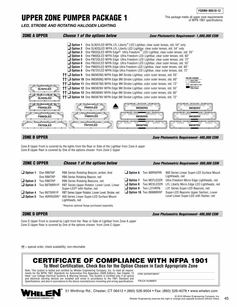
UPPER ZONE PUMPER PACKAGE 1
ZONE A UPPER Choose 1 of the options below Zone Photometric Requirement- 1,000,000 CSM
ZONE C UPPER Choose 1 of the options below Zone Photometric Requirement- 800,000 CSM
ZONE D UPPER Zone Photometric Requirement- 400,000 CSM
ZONE B UPPER Zone Photometric Requirement- 400,000 CSM
Zone B Upper Front is covered by the lights from the Rear or Side of the Lightbar from Zone A upperZone B Upper Rear is covered by One of the options chosen from Zone C Upper
Zone D Upper Front is covered by Light from the Rear or Side of Lightbar from Zone A upperZone D Upper Rear is covered by One of the options chosen from Zone C Upper
❏ Option 1 One RB6TAP RB6 Series Rotating Beacon, amber, And One RB6TRP RB6 Series Rotating Beacon, red❏ Option 2 Two RB6TRP RB6 Series Rotating Beacons, red❏ Option 3 Two B6TMRR1P RBT Series Upper Rotator, Lower Level, Linear Super-LED® with flasher, red❏ Option 4 Two B6TSRR1P RBT Series Upper Rotator, Lower Level, Strobe, red❏ Option 5 Two 40RR5SRR* 400 Series Linear Super-LED Surface Mount Lightheads, red
❏ Option 6 Two 90RR5FRR 900 Series Linear Super-LED Surface Mount Lightheads, red❏ Option 7 Two MCFLED2R Ultra Freedom Micro Edge Lightheads, red❏ Option 8 Two MCSLED2R LFL Liberty Micro Edge LED Lightheads, red❏ Option 9 Two L31HRFN L31 Series Super-LED Beacons, red❏ Option 10 Two B6MMRRP Super-LED Beacons Upper Section, Lower Level Linear Super-LED with flasher, red
FORM# N0510-12
LED, STROBE AND ROTATING HALOGEN LIGHTING
This package meets all upper zone requirements of NFPA 1901 specifications.
45ENGINEERING COMPANY, INC.
®51 Winthrop Rd., Chester, CT 06412 • (860) 526-9504 • Fax: (860) 526-4078 • www.whelen.com
© 2010 Whelen Engineering Company, Inc. Whelen Engineering reserves the right to change and upgrade products without notice.
*Requires optional flange purchased separately
❏ Option 1 One SLN2VLED NFPA LFL Liberty™ LED Lightbar, clear outer lenses, std. 54” only❏ Option 2 One SLN2QLED NFPA LFL Liberty LED Lightbar, clear outer lenses, std. 54” only❏ Option 3 One FN55QLED NFPA Edge® Ultra Freedom™ LED Lightbar, clear outer lenses, std. 55”❏ Option 4 One FN60QLED NFPA Edge Ultra Freedom LED Lightbar, clear outer lenses, std. 60”❏ Option 5 One FN72QLED NFPA Edge Ultra Freedom LED Lightbar, clear outer lenses, std. 72”❏ Option 6 One FN55VLED NFPA Edge Ultra Freedom LED Lightbar, clear outer lenses, std. 55”❏ Option 7 One FN60VLED NFPA Edge Ultra Freedom LED Lightbar, clear outer lenses, std. 60”❏ Option 8 One FN72VLED NFPA Edge Ultra Freedom LED Lightbar, clear outer lenses, std. 72”❏ Option 9 One 9M382NQ NFPA Edge 9M Strobe Lightbar, color outer lenses, std. 55”❏ Option 10 One 9M380NQ NFPA Edge 9M Strobe Lightbar, color outer lenses, std. 60”❏ Option 11 One 9M387NQ NFPA Edge 9M Strobe Lightbar, color outer lenses, std. 72”❏ Option 12 One 9M382NV NFPA Edge 9M Strobe Lightbar, color outer lenses, std. 55”❏ Option 13 One 9M380NV NFPA Edge 9M Strobe Lightbar, color outer lenses, std. 60”❏ Option 14 One 9M387NV NFPA Edge 9M Strobe Lightbar, color outer lenses, std. 72”
CERTIFICATE OF COMPLIANCE WITH NFPA 1901To Meet Certification, Check Box for the Option Chosen in Each Appropriate Zone
Note: This system is tested and certified by Whelen Engineering Company, Inc. to meet all require-ments for the NFPA 1901 Standards for Automotive Fire Apparatus (2009 Edition). See Chapter 13 titled: Low Voltage Electrical Systems & Warning Devices. This System is Certified only if all optical and electrical warning devices are installed and wired in accordance to the 1901 Standard and Specifications; and also in accordance to the device manufacturers mounting and wiring specifications.
FIRE DEPARTMENT
TRUCK NUMBER
FRONTFN55QLED
SLN2QLED
FN55VLED
SLN2VLED
FN60QLED FN60VLED
FN72VLEDFN72QLED
9M380NQ 9M380NV
9M382NQ 9M382NV
9M387NV9M387NQ
Clear LEDS,Strobes or Lens
Red LEDS or LensBlack Lens orFiller Panels
COLOR LEGEND
†† = special order, check availability, non-returnable
������������
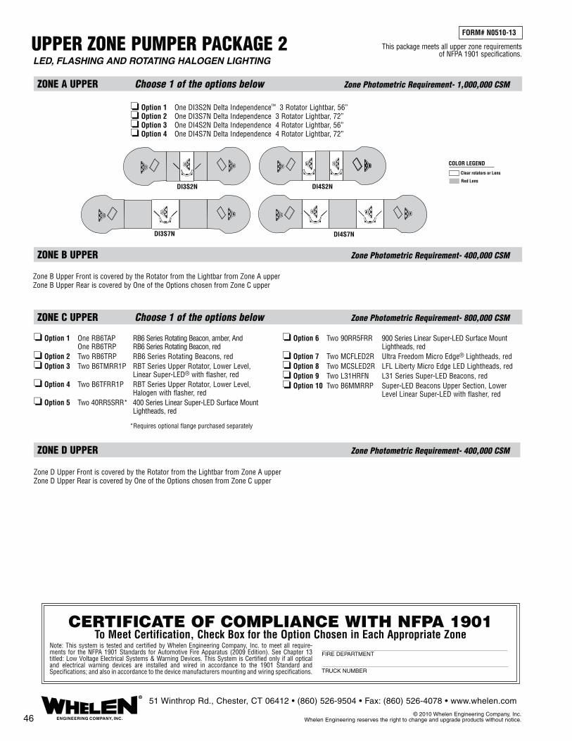
UPPER ZONE PUMPER PACKAGE 2
ZONE A UPPER Choose 1 of the options below Zone Photometric Requirement- 1,000,000 CSM
ZONE C UPPER Choose 1 of the options below Zone Photometric Requirement- 800,000 CSM
ZONE D UPPER Zone Photometric Requirement- 400,000 CSM
ZONE B UPPER Zone Photometric Requirement- 400,000 CSM
❏ Option 1 One RB6TAP RB6 Series Rotating Beacon, amber, And One RB6TRP RB6 Series Rotating Beacon, red❏ Option 2 Two RB6TRP RB6 Series Rotating Beacons, red❏ Option 3 Two B6TMRR1P RBT Series Upper Rotator, Lower Level, Linear Super-LED® with flasher, red❏ Option 4 Two B6TFRR1P RBT Series Upper Rotator, Lower Level, Halogen with flasher, red❏ Option 5 Two 40RR5SRR* 400 Series Linear Super-LED Surface Mount Lightheads, red
❏ Option 6 Two 90RR5FRR 900 Series Linear Super-LED Surface Mount Lightheads, red❏ Option 7 Two MCFLED2R Ultra Freedom Micro Edge® Lightheads, red❏ Option 8 Two MCSLED2R LFL Liberty Micro Edge LED Lightheads, red❏ Option 9 Two L31HRFN L31 Series Super-LED Beacons, red❏ Option 10 Two B6MMRRP Super-LED Beacons Upper Section, Lower Level Linear Super-LED with flasher, red
LED, FLASHING AND ROTATING HALOGEN LIGHTING
Zone B Upper Front is covered by the Rotator from the Lightbar from Zone A upperZone B Upper Rear is covered by One of the Options chosen from Zone C upper
Zone D Upper Front is covered by the Rotator from the Lightbar from Zone A upperZone D Upper Rear is covered by One of the Options chosen from Zone C upper
46 ENGINEERING COMPANY, INC.
®51 Winthrop Rd., Chester, CT 06412 • (860) 526-9504 • Fax: (860) 526-4078 • www.whelen.com
© 2010 Whelen Engineering Company, Inc. Whelen Engineering reserves the right to change and upgrade products without notice.
*Requires optional flange purchased separately
FORM# N0510-13
This package meets all upper zone requirements of NFPA 1901 specifications.
CERTIFICATE OF COMPLIANCE WITH NFPA 1901To Meet Certification, Check Box for the Option Chosen in Each Appropriate Zone
Note: This system is tested and certified by Whelen Engineering Company, Inc. to meet all require-ments for the NFPA 1901 Standards for Automotive Fire Apparatus (2009 Edition). See Chapter 13 titled: Low Voltage Electrical Systems & Warning Devices. This System is Certified only if all optical and electrical warning devices are installed and wired in accordance to the 1901 Standard and Specifications; and also in accordance to the device manufacturers mounting and wiring specifications.
FIRE DEPARTMENT
TRUCK NUMBER
❏ Option 1 One DI3S2N Delta Independence™ 3 Rotator Lightbar, 56”❏ Option 2 One DI3S7N Delta Independence 3 Rotator Lightbar, 72”❏ Option 3 One DI4S2N Delta Independence 4 Rotator Lightbar, 56”❏ Option 4 One DI4S7N Delta Independence 4 Rotator Lightbar, 72”
Clear rotators or Lens
Red Lens
COLOR LEGEND
DI3S7N
DI3S2N DI4S2N
DI4S7N

UPPER ZONE RESCUE PACKAGE 1
ZONE A UPPER Choose 1 of the options below Zone Photometric Requirement- 1,000,000 CSM
ZONE B UPPER Choose 1 of the options below Zone Photometric Requirement- 400,000 CSM
Zone B Upper Front is covered by the lights from the Rear or Side of the Lightbar from Zone A upper; Plus Two Lightheads from the options below:
❏ Option 1 Two 58EC20RU 508 Series Linear Strobe Surface Mount Lighthead, red ❏ Option 2 Two 602000RU* 600 Series Linear Strobe Lighthead, red
❏ Option 3 Two 81EC20RU 810 Series Linear Strobe Surface Mount Lighthead, red❏ Option 4 Two 90RR5FRR 900 Series Linear Super-LED® Flasher Surface Mount, red❏ Option 5 Two 902000RU 900 Series Linear Strobe Lighthead, red
Zone D Upper Front is covered by Light from the Rear or Side of Lightbar from Zone A upper; Plus Two Lightheads from the options below:
❏ Option 1 Two 58EC20RU 508 Series Linear Strobe Surface Mount Lighthead, red ❏ Option 2 Two 602000RU* 600 Series Linear Strobe Lighthead, red ❏ Option 3 Two 81EC20RU 81E Series Linear Strobe Surface Mount Lighthead, red
❏ Option 4 Two 90RR5FRR 900 Series Linear Super-LED Flasher Surface Mount, red❏ Option 5 Two 902000RU 900 Series Linear Strobe Lighthead, red
ZONE C UPPER Choose 1 of the options below Zone Photometric Requirement- 800,000 CSM
❏ Option 1 Two 40RR5SRR* 400 Series Linear Super-LED Surface Mount Lightheads, red❏ Option 2 Two 90RR5FRR 900 Series Linear Super-LED Surface Mount Lightheads, red
❏ Option 3 Two 81EC20AU 81E Series Linear Strobe Surface Mount Lightheads, amber❏ Option 4 Two 902000AU 900 Series Linear Strobe Lightheads, amber
ZONE D UPPER Choose 1 of the options below Zone Photometric Requirement- 400,000 CSM
FORM# N0510-14
STROBE AND LED LIGHTING
This package meets all upper zone requirements of NFPA 1901 specifications.
47ENGINEERING COMPANY, INC.
®51 Winthrop Rd., Chester, CT 06412 • (860) 526-9504 • Fax: (860) 526-4078 • www.whelen.com
© 2010 Whelen Engineering Company, Inc. Whelen Engineering reserves the right to change and upgrade products without notice.
*Requires optional flange purchased separately
CERTIFICATE OF COMPLIANCE WITH NFPA 1901To Meet Certification, Check Box for the Option Chosen in Each Appropriate Zone
Note: This system is tested and certified by Whelen Engineering Company, Inc. to meet all requirements for the NFPA 1901 Standards for Automotive Fire Apparatus (2009 Edition). See Chapter 13 titled: Low Voltage Electrical Systems & Warning Devices. This System is Certified only if all optical and electrical warning devices are installed and wired in accordance to the 1901 Standard and Specifications; and also in accordance to the device manufacturers mounting and wiring specifications.
FIRE DEPARTMENT
TRUCK NUMBER
FRONTFN55QLED
SLN2QLED
FN55VLED
SLN2VLED
FN60QLED FN60VLED
FN72VLEDFN72QLED
9M380NQ 9M380NV
9M382NQ 9M382NV
9M387NV9M387NQ
Clear LEDS,Strobes or Lens
Red LEDS or LensBlack Lens orFiller Panels
COLOR LEGEND
†† = special order, check availability, non-returnable
������������
❏ Option 1 One SLN2VLED NFPA LFL Liberty™ LED Lightbar, clear outer lenses, std. 54” only❏ Option 2 One SLN2QLED NFPA LFL Liberty LED Lightbar, clear outer lenses, std. 54” only❏ Option 3 One FN55QLED NFPA Edge® Ultra Freedom™ LED Lightbar, clear outer lenses, std. 55”❏ Option 4 One FN60QLED NFPA Edge Ultra Freedom LED Lightbar, clear outer lenses, std. 60”❏ Option 5 One FN72QLED NFPA Edge Ultra Freedom LED Lightbar, clear outer lenses, std. 72”❏ Option 6 One FN55VLED NFPA Edge Ultra Freedom LED Lightbar, clear outer lenses, std. 55”❏ Option 7 One FN60VLED NFPA Edge Ultra Freedom LED Lightbar, clear outer lenses, std. 60”❏ Option 8 One FN72VLED NFPA Edge Ultra Freedom LED Lightbar, clear outer lenses, std. 72”❏ Option 9 One 9M382NQ NFPA Edge 9M Strobe Lightbar, color outer lenses, std. 55”❏ Option 10 One 9M380NQ NFPA Edge 9M Strobe Lightbar, color outer lenses, std. 60”❏ Option 11 One 9M387NQ NFPA Edge 9M Strobe Lightbar, color outer lenses, std. 72”❏ Option 12 One 9M382NV NFPA Edge 9M Strobe Lightbar, color outer lenses, std. 55”❏ Option 13 One 9M380NV NFPA Edge 9M Strobe Lightbar, color outer lenses, std. 60”❏ Option 14 One 9M387NV NFPA Edge 9M Strobe Lightbar, color outer lenses, std. 72”

UPPER ZONE RESCUE PACKAGE 2
ZONE C UPPER Choose 1 of the options below Zone Photometric Requirement- 800,000 CSM
❏ Option 1 Two 40RR5SRR* 400 Series Linear Super-LED Surface Mount Lightheads, red❏ Option 2 Two 90RR5FRR 900 Series Linear Super-LED Surface Mount Lightheads, red
❏ Option 3 Two 810CAAAR 810 Series Dual Halogen Surface Mount Lightheads, amber❏ Option 4 Two 90F000AR 900 Series Halogen Lightheads, amber
ZONE A UPPER Choose 1 of the options below Zone Photometric Requirement- 1,000,000 CSM
ZONE B UPPER Choose 1 of the options below Zone Photometric Requirement- 400,000 CSM
ZONE D UPPER Choose 1 of the options below Zone Photometric Requirement- 400,000 CSM
This package meets all upper zone requirements of NFPA 1901 specifications.
FORM# N0510-15
FLASHING LED / HALOGEN AND ROTATING HALOGEN LIGHTING
The Rotator from the Lightbar from Zone A upper; Plus Two Lightheads from the options below:
❏ Option 1 Two 580CAARR 508 Series Dual Halogen Surface Mount Lighthead, red❏ Option 2 Two 60F000RR* 600 Series Halogen Lighthead, red
❏ Option 3 Two 810CAARR 810 Series Dual Halogen Surface Mount Lighthead, red❏ Option 4 Two 90F000RR 900 Series Halogen Lighthead, red❏ Option 5 Two 90RR5FRR 900 Series Linear Super-LED® Flasher Surface Mount, red
The Rotator from the Lightbar from Zone A upper; Plus Two Lightheads from the options below:
❏ Option 1 Two 580CAARR 508 Series Dual Halogen Surface Mount Lighthead, red❏ Option 2 Two 60F000RR* 600 Series Halogen Lighthead, red
❏ Option 3 Two 810CAARR 810 Series Dual Halogen Surface Mount Lighthead, red❏ Option 4 Two 90RR5FRR 900 Series Linear Super-LED Flasher Surface Mount, red❏ Option 5 Two 90F000RR 900 Series Halogen Lighthead, red
48 ENGINEERING COMPANY, INC.
®51 Winthrop Rd., Chester, CT 06412 • (860) 526-9504 • Fax: (860) 526-4078 • www.whelen.com
© 2010 Whelen Engineering Company, Inc. Whelen Engineering reserves the right to change and upgrade products without notice.
*Requires optional flange purchased separately
CERTIFICATE OF COMPLIANCE WITH NFPA 1901To Meet Certification, Check Box for the Option Chosen in Each Appropriate Zone
Note: This system is tested and certified by Whelen Engineering Company, Inc. to meet all requirements for the NFPA 1901 Standards for Automotive Fire Apparatus (2009 Edition). See Chapter 13 titled: Low Voltage Electrical Systems & Warning Devices. This System is Certified only if all optical and electrical warning devices are installed and wired in accordance to the 1901 Standard and Specifications; and also in accordance to the device manufacturers mounting and wiring specifications.
FIRE DEPARTMENT
TRUCK NUMBER
❏ Option 1 One DI3S2N Delta Independence™ 3 Rotator Lightbar, 56”❏ Option 2 One DI3S7N Delta Independence 3 Rotator Lightbar, 72”❏ Option 3 One DI4S2N Delta Independence 4 Rotator Lightbar, 56”❏ Option 4 One DI4S7N Delta Independence 4 Rotator Lightbar, 72”
Clear rotators or Lens
Red Lens
COLOR LEGEND
DI3S7N
DI3S2N DI4S2N
DI4S7N
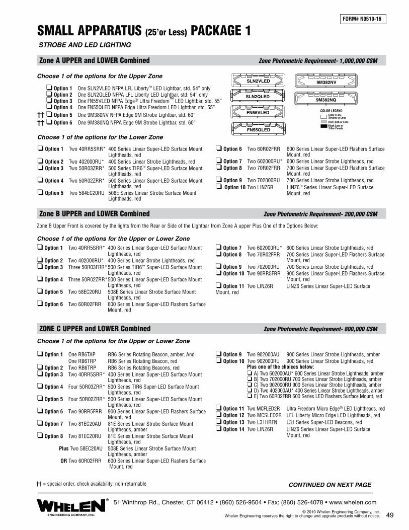
SMALL APPARATUS (25’or Less) PACKAGE 1
Zone A UPPER and LOWER Combined Zone Photometric Requirement- 1,000,000 CSM
Choose 1 of the options for the Upper Zone
❏ Option 1 One SLN2VLED NFPA LFL Liberty™ LED Lightbar, std. 54” only❏ Option 2 One SLN2QLED NFPA LFL Liberty LED Lightbar, std. 54” only❏ Option 3 One FN55VLED NFPA Edge® Ultra Freedom™ LED Lightbar, std. 55”❏ Option 4 One FN55QLED NFPA Edge Ultra Freedom LED Lightbar, std. 55”❏ Option 5 One 9M380NV NFPA Edge 9M Strobe Lightbar, std. 60”❏ Option 6 One 9M380NQ NFPA Edge 9M Strobe Lightbar, std. 60”
Choose 1 of the options for the Lower Zone
❏ Option 1 Two 40RR5SRR* 400 Series Linear Super-LED Surface Mount Lightheads, red❏ Option 2 Two 402000RU* 400 Series Linear Strobe Lightheads, red❏ Option 3 Two 50R03ZRR* 500 Series TIR6™ Super-LED Surface Mount Lightheads, red❏ Option 4 Two 50R02ZRR* 500 Series Linear Super-LED Surface Mount Lightheads, red❏ Option 5 Two 584EC20RU 508E Series Linear Strobe Surface Mount Lightheads, red
❏ Option 6 Two 60R02FRR 600 Series Linear Super-LED Flashers Surface Mount, red❏ Option 7 Two 602000RU* 600 Series Linear Strobe Lightheads, red❏ Option 8 Two 70R02FRR 700 Series Linear Super-LED Flashers Surface Mount, red❏ Option 9 Two 702000RU 700 Series Linear Strobe Lightheads, red❏ Option 10 Two LINZ6R LINZ6™ Series Linear Super-LED Surface Mount, red
Zone B UPPER and LOWER Combined Zone Photometric Requirement- 200,000 CSM
Choose 1 of the options for the Upper or Lower Zone
❏ Option 1 Two 40RR5SRR* 400 Series Linear Super-LED Surface Mount Lightheads, red❏ Option 2 Two 402000RU* 400 Series Linear Strobe Lightheads, red❏ Option 3 Three 50R03FRR* 500 Series TIR6™ Super-LED Surface Mount Lightheads, red❏ Option 4 Three 50R02ZRR* 500 Series Linear Super-LED Surface Mount Lightheads, red❏ Option 5 Two 58EC20RU 508E Series Linear Strobe Surface Mount Lightheads, red❏ Option 6 Two 60R02FRR 600 Series Linear Super-LED Flashers Surface Mount, red
❏ Option 7 Two 602000RU* 600 Series Linear Strobe Lightheads, red❏ Option 8 Two 70R02FRR 700 Series Linear Super-LED Flashers Surface Mount, red❏ Option 9 Two 702000RU 700 Series Linear Strobe Lightheads, red❏ Option 10 Two 90RR5FRR 900 Series Linear Super-LED Flashers Surface Mount, red❏ Option 11 Two LINZ6R LINZ6 Series Linear Super-LED Surface Mount, red
Choose 1 of the options for the Upper or Lower Zone
ZONE C UPPER and LOWER Combined Zone Photometric Requirement- 800,000 CSM
❏ Option 1 One RB6TAP RB6 Series Rotating Beacon, amber, And One RB6TRP RB6 Series Rotating Beacon, red❏ Option 2 Two RB6TRP RB6 Series Rotating Beacons, red❏ Option 3 Two 40RR5SRR* 400 Series Linear Super-LED Surface Mount Lightheads, red❏ Option 4 Four 50R03ZRR* 500 Series TIR6 Super-LED Surface Mount Lightheads, red❏ Option 5 Four 50R02ZRR* 500 Series Linear Super-LED Surface Mount Lightheads, red❏ Option 6 Two 90RR5FRR 900 Series Linear Super-LED Flashers Surface Mount, red❏ Option 7 Two 81EC20AU 81E Series Linear Strobe Surface Mount Lightheads, amber❏ Option 8 Two 81EC20RU 81E Series Linear Strobe Surface Mount Lightheads, red Plus Two 58EC20AU 508E Series Linear Strobe Surface Mount Lightheads, amber OR Two 60R02FRR 600 Series Linear Super-LED Flashers Surface Mount, red
❏ Option 9 Two 902000AU 900 Series Linear Strobe Lightheads, amber❏ Option 10 Two 902000RU 900 Series Linear Strobe Lightheads, red Plus one of the choices below: ❏ A) Two 602000AU* 600 Series Linear Strobe Lightheads, amber ❏ B) Two 702000RU 700 Series Linear Strobe Lightheads, amber ❏ C) Two 902000RU 900 Series Linear Strobe Lightheads, amber ❏ D) Two 402000AU* 400 Series Linear Strobe Lightheads, amber ❏ E) Two 60R02FRR 600 Series LED Flashers Surface Mount, red ❏ Option 11 Two MCFLED2R Ultra Freedom Micro Edge® LED Lightheads, red❏ Option 12 Two MCSLED2R LFL Liberty Micro Edge LED Lightheads, red❏ Option 13 Two L31HRFN L31 Series Super-LED Beacons, red❏ Option 14 Two LINZ6R LINZ6 Series Linear Super-LED Surface Mount, red
FORM# N0510-16
STROBE AND LED LIGHTING
SLN2VLED
SLN2QLED
FN55VLED
FN55QLED
9M382NQ
9M382NV
49ENGINEERING COMPANY, INC.
®51 Winthrop Rd., Chester, CT 06412 • (860) 526-9504 • Fax: (860) 526-4078 • www.whelen.com
© 2010 Whelen Engineering Company, Inc. Whelen Engineering reserves the right to change and upgrade products without notice.
Zone B Upper Front is covered by the lights from the Rear or Side of the Lightbar from Zone A upper Plus One of the Options Below:
Clear LEDS,Strobes or Lens
Red LEDS or LensBlack Lens orFiller Panels
COLOR LEGEND
†† = special order, check availability, non-returnable
����
CONTINUED ON NEXT PAGE

Zone D UPPER and LOWER Combined Zone Photometric Requirement- 200,000 CSM
CERTIFICATE OF COMPLIANCE WITH NFPA 1901To Meet Certification, Check Box for the Option Chosen in Each Appropriate Zone
Note: This system is tested and certified by Whelen Engineering Company, Inc. to meet all require-ments for the NFPA 1901 Standards for Automotive Fire Apparatus (2009 Edition). See Chapter 13 titled: Low Voltage Electrical Systems & Warning Devices. This System is Certified only if all optical and electrical warning devices are installed and wired in accordance to the 1901 Standard and Specifications; and also in accordance to the device manufacturers mounting and wiring specifications.
FIRE DEPARTMENT
TRUCK NUMBER
Choose 1 of the options for the Upper or Lower Zone ❏ Option 1 Two 40RR5SRR* 400 Series Linear Super-LED Surface Mount Lightheads, red❏ Option 4 Four 50R03ZRR* 500 Series TIR6 Super-LED Surface Mount Lightheads, red❏ Option 2 Two 402000RU* 400 Series Linear Strobe Lightheads, red❏ Option 3 Three 50R03ZRR* 500 Series TIR6™ Super-LED Surface Mount Lightheads, red❏ Option 4 Three 50R02ZRR* 500 Series Linear Super-LED Surface Mount Lightheads, red❏ Option 5 Two 58EC20RU 508 Series Linear Strobe Surface Mount Lightheads, red
❏ Option 6 Two 60R02FRR 600 Series Linear Super-LED Flashers Surface Mount, red❏ Option 7 Two 602000RU* 600 Series Linear Strobe Lightheads, red❏ Option 8 Two 70R02FRR 700 Series Linear Super-LED Flashers Surface Mount, red❏ Option 9 Two 702000RU 700 Series Linear Strobe Lightheads, red❏ Option 10 Two LINZ6R LINZ6 Series Linear Super-LED Surface Mount, red
Zone D Upper Front is covered by the lights from the Rear or Side of the Lightbar from Zone A upper
SMALL APPARATUS (25’or Less) PACKAGE 1 (cont.)FORM# N0510-16
STROBE AND LED LIGHTING
50ENGINEERING COMPANY, INC.
®51 Winthrop Rd., Chester, CT 06412 • (860) 526-9504 • Fax: (860) 526-4078 • www.whelen.com
© 2010 Whelen Engineering Company, Inc. Whelen Engineering reserves the right to change and upgrade products without notice.
This package meets all zone requirements of NFPA 1901 specifications.

SMALL APPARATUS (25’ or Less) PACKAGE 2
ZONE A UPPER and LOWER Combined Zone Photometric Requirement- 1,000,000 CSM
Choose 1 of the options for the Upper Zone
Choose 1 of the options for the Upper Zone
❏ Option 1 Two 40RR5SRR* 400 Series Linear Super-LED Surface Mount Lightheads, red❏ Option 2 Two 40J000AU* 400 Series Halogen Lightheads, red❏ Option 3 Two 50R03ZRR* 500 Series TIR6 Super-LED Surface Mount Lightheads, red❏ Option 4 Two 50R02ZRR* 500 Series Linear Super-LED Surface Mount Lightheads, red❏ Option 5 Two 580CAARR 508 Series Dual Halogen Surface Mount Lightheads, red
❏ Option 6 Two 60R02FRR 600 Series Linear Super-LED Flashers Surface Mount, red❏ Option 7 Two 60F000RR* 600 Series Halogen Lightheads, red❏ Option 8 Two 70R02FRR 700 Series Linear Super-LED Surface Mount Lightheads, red❏ Option 9 Two 70F000RR 700 Series Halogen Lightheads, red❏ Option 10 Two LINZ6R LINZ6™ Series Linear Super-LED Surface Mount, red
Zone B Upper is covered by the Rotator from the Lightbar from Zone A upper; Plus One of the Options Below:
ZONE B UPPER and LOWER Combined Zone Photometric Requirement- 200,000 CSM
Choose 1 of the options for the Upper or Lower Zone
❏ Option 1 Two 40RR5SRR* 400 Series Linear Super-LED Surface Mount Lightheads, red❏ Option 2 Two 40J000AU* 400 Series Halogen Lightheads, red❏ Option 3 Three 50R03ZRR* 500 Series TIR6 Super-LED Surface Mount Lightheads, red❏ Option 4 Three 50R02ZRR* 500 Series Linear Super-LED Surface Mount Lightheads, red❏ Option 5 Two 580CAARR 508 Series Dual Halogen Surface Mount Lightheads, red❏ Option 6 Two 60R02FRR 600 Series Linear Super-LED Flashers Surface Mount, red
❏ Option 7 Two 60F000RR* 600 Series Halogen Lightheads, red❏ Option 8 Two 70R02FRR 700 Series Linear Super-LED Flashers Surface Mount, red❏ Option 9 Two 70F000RR 700 Series Halogen Lightheads, red❏ Option 10 Two 90RR5FRR 900 Series Linear Super-LED Flashers Surface Mount, red❏ Option 11 Two LINZ6R LINZ6 Series Linear Super-LED Surface Mount, red
FORM# N0510-17
FLASHING LED / HALOGEN AND ROTATING HALOGEN LIGHTING
51ENGINEERING COMPANY, INC.
®51 Winthrop Rd., Chester, CT 06412 • (860) 526-9504 • Fax: (860) 526-4078 • www.whelen.com
© 2010 Whelen Engineering Company, Inc. Whelen Engineering reserves the right to change and upgrade products without notice.
❏ Option 1 One DI3S2N Delta™ Independence™ 3 Rotator Lightbar, 56”❏ Option 2 One DI4S2N Delta Independence 4 Rotator Lightbar, 56”
Clear rotators or Lens
Red Lens
COLOR LEGENDDI3S2N DI4S2N
Choose 1 of the options for the Upper Zone or Lower Zone
❏ Option 1 One RB6TAP RB6 Series Rotating Beacon, amber One RB6TRP RB6 Series Rotating Beacon, red❏ Option 2 Two RB6TRP RB6 Series Rotating Beacons, red❏ Option 3 Two 40RR5SRR* 400 Series Linear Super-LED Surface Mount Lightheads, red❏ Option 4 Four 50R03ZRR* 500 Series TIR6 Super-LED Surface Mount ` Lightheads, red❏ Option 5 Four 50R02ZRR* 500 Series Linear Super-LED Surface Mount Lightheads, red❏ Option 6 Two 90RR5FRR 900 Series Linear Super-LED Surface Mount Lightheads, red❏ Option 7 Two 810CAAAR 810 Series Halogen Surface Mount Lightheads, amber❏ Option 8 Two 810CAARR 810 Series Halogen Surface Mount Lightheads, red Plus Two 580CAAAR 508 Series Halogen Surface Mount Lightheads, amber OR Two 60R02FRR 600 Series Linear Super-LED Flashers Surface Mount, red
❏ Option 9 Two 90F000AR 900 Series Halogen Lightheads, amber❏ Option 10 Two 90F000RR 900 Series Halogen Lightheads, red Plus One of the Options Below: ❏ A) Two 40J000RU* 400 Series Halogen Lightheads, red ❏ B) Two 60R02FRR 600 Series Linear Super-LED Flashers Surface Mount, red ❏ C) Two 60F000RR* 600 Series Halogen Lightheads, red ❏ D) Two 70F000RR 700 Series Halogen Lightheads, red ❏ E) Two 90F000RR 900 Series Halogen Lightheads, red
❏ Option 11 Two MCFLED2R Ultra Freedom Micro Edge® LED Lightheads, red❏ Option 12 Two MCSLED2R LFL Liberty Micro Edge LED Lightheads, red❏ Option 13 Two L31HRFN L31 Series Super-LED Beacons, red❏ Option 14 Two LINZ6R LINZ6 Series Linear Super-LED Surface Mount, red
ZONE C UPPER and LOWER Combined Zone Photometric Requirement- 800,000 CSM
CONTINUED ON NEXT PAGE

*Requires optional flange purchased separately
This package meets all zone requirements of NFPA 1901 specifications.
Zone D Upper is covered by the Rotator from the Lightbar from Zone A upper; Plus One of the Options Below:
Choose 1 of the options for the Upper or Lower Zone
❏ Option 1 Two 40RR5SRR* 400 Series Linear Super-LED Surface Mount Lightheads, red❏ Option 2 Two 40J000AU* 400 Series Halogen Lightheads, red❏ Option 3 Three 50R03ZRR* 500 Series TIR6 Super-LED Surface Mount Lightheads, red❏ Option 4 Three 50R02ZRR* 500 Series Linear Super-LED Surface Mount Lightheads, red❏ Option 5 Two 580CAARR 508 Series Dual Halogen Surface Mount Lightheads, red❏ Option 6 Two 60R02FRR 600 Series Linear Super-LED Flashers Surface Mount, red
❏ Option 7 Two 60F000RR* 600 Series Halogen Lightheads, red❏ Option 8 Two 70R02FRR 700 Series Linear Super-LED Flashers Surface Mount, red❏ Option 9 Two 70F000RR 700 Series Halogen Lightheads, red❏ Option 10 Two 90RR5FRR 900 Series Linear Super-LED Flashers Surface Mount, red❏ Option 11 Two LINZ6R LINZ6 Series Linear Super-LED Surface Mount, red
ZONE D UPPER and LOWER Combined Zone Photometric Requirement- 200,000 CSM
SMALL APPARATUS (25’ or Less) PACKAGE 2 (cont.)FORM# N0510-17
FLASHING LED / HALOGEN AND ROTATING HALOGEN LIGHTING
52 ENGINEERING COMPANY, INC.
®51 Winthrop Rd., Chester, CT 06412 • (860) 526-9504 • Fax: (860) 526-4078 • www.whelen.com
© 2010 Whelen Engineering Company, Inc. Whelen Engineering reserves the right to change and upgrade products without notice.
CERTIFICATE OF COMPLIANCE WITH NFPA 1901To Meet Certification, Check Box for the Option Chosen in Each Appropriate Zone
Note: This system is tested and certified by Whelen Engineering Company, Inc. to meet all require-ments for the NFPA 1901 Standards for Automotive Fire Apparatus (2009 Edition). See Chapter 13 titled: Low Voltage Electrical Systems & Warning Devices. This System is Certified only if all optical and electrical warning devices are installed and wired in accordance to the 1901 Standard and Specifications; and also in accordance to the device manufacturers mounting and wiring specifications.
FIRE DEPARTMENT
TRUCK NUMBER

295 SERIES SIREN AMPLIFIERSAll 295 Series Sirens meet and exceed California Title XIII. 295 Sirens all feature three siren warning tones, plus airhorn, Public Address and Hands-Free operation, Diagnostix™ & SI TEST®. 5 year warranty on most models. 295SLSA1 .......Single unit, 17 Scan-Lock™ siren tones, hard-wired microphone 295HFS2 .........Full function remote siren amplifier, flush mount 295HFS3 .........Remote, surface mount head 295HFS4 .........9-switch light control, surface mount head 295HFSA5 ......9-switch light control, low current switching, park kill, time out relay. 295SLSA6 .......Single unit, 9-switch light control, standard switching, 17 Scan-Lock siren tones, removable microphone 295HFSA7 ......Remote dual tone, flush mount 295HFSC9 ......Self-contained, dual or mono, 8 programmable profiles, removable microphone 295SL100 .......Full function, up to two 100 watt speakers, heavy-duty microphone, 17 Scan-Lock siren tones, 2 year warranty 295SL101 .......Full function, up to two 100 watt speakers, heavy-duty plug-in microphone, 17 Scan-Lock siren tones, 2 year warranty
ALPHA SIREN AMPLIFIERS ALPHA12R .....100 watt remote siren amplifier, remote switches purchased separately
100 WATT RMS SIREN SPEAKERSFor bumper and flange mounting, Projector® Series speakers produce 122.5dB, exceeding California Title XIII, Class A (120dB @ 10’) and S.A.E. J1849 when used with Whelen 295HFS Series. SA31I01D ....... 100 watt speaker for driver side of 2001 to present International® Series chassis SA31I01P ........ 100 watt speaker for passenger side of 2001 to present International Series chassis SA32G01 ........ 200 watt speaker for Chevrolet 3500/4500 Series, 2001-2009 SA32C06 ........ UnderPro™ dual speaker for Chevrolet Express Van, 2006-09 SA122FMP .....100 watt speaker, polished cast aluminum speaker, flange mount
SA314 SERIES SA314A ........... 100 watt compact speaker for behind bumper mounting, natural aluminum SA314B ........... 100 watt compact speaker for behind bumper mounting, aluminum, black epoxy finish SA315P ........... 100 watt compact speaker for behind bumper mounting, black nylon composite SACSTCMP .... Optional polished flange casting, contoured mount for SA314AMounting Brackets SAK23 .............Ford Expedition, 2007-2010 SAK24 .............Chevrolet Tahoe/Silverado, 2007-2010 SAK25 .............Chevrolet Express Van, 2006-2010 SAK32 .............Ford E350/450, 2008-2011, passenger or driver side SAK29 .............Universal bail mount bracket, SA314 speaker
HOWLER™ LOW FREQUENCY TONE SIRENIncludes siren amplifier and two speakers. Works in conjunction with existing siren systems (purchased separately) HOWLER ........ Siren amplifier with tow speakers and vehicle specific mounting bracket.Mounting Brackets HWLRB1 .........Ford Crown Victoria, 2008-2010 HWLRB2 .........Ford Expedition, 2008-2009 HWLRB3 .........Ford F-Series, Super Duty, 2008-2010 HWLRB4 .........Ford E-Series, 2008-2009 HWLRB5 .........Chevrolet Surburban, 2008-2009 and Tahoe, 2008-2010 HWLRB10 .......Dodge 4500, 2009-2010 HWLRB11 .......Chevrolet Express G-Series, 2010
Enhance your NFPA 1901 Specification Lighting Packages
295HFS3
295SL101295SL100
SA31I01P
SACSTCMPSA315P
ALPHA12R
SA122FMP
295HFSA7
295HFS4295HFSA5
295SLSA6
295HFSA9
HOWLER
295HFS2
295SLSA1
SA314A SA314P
53
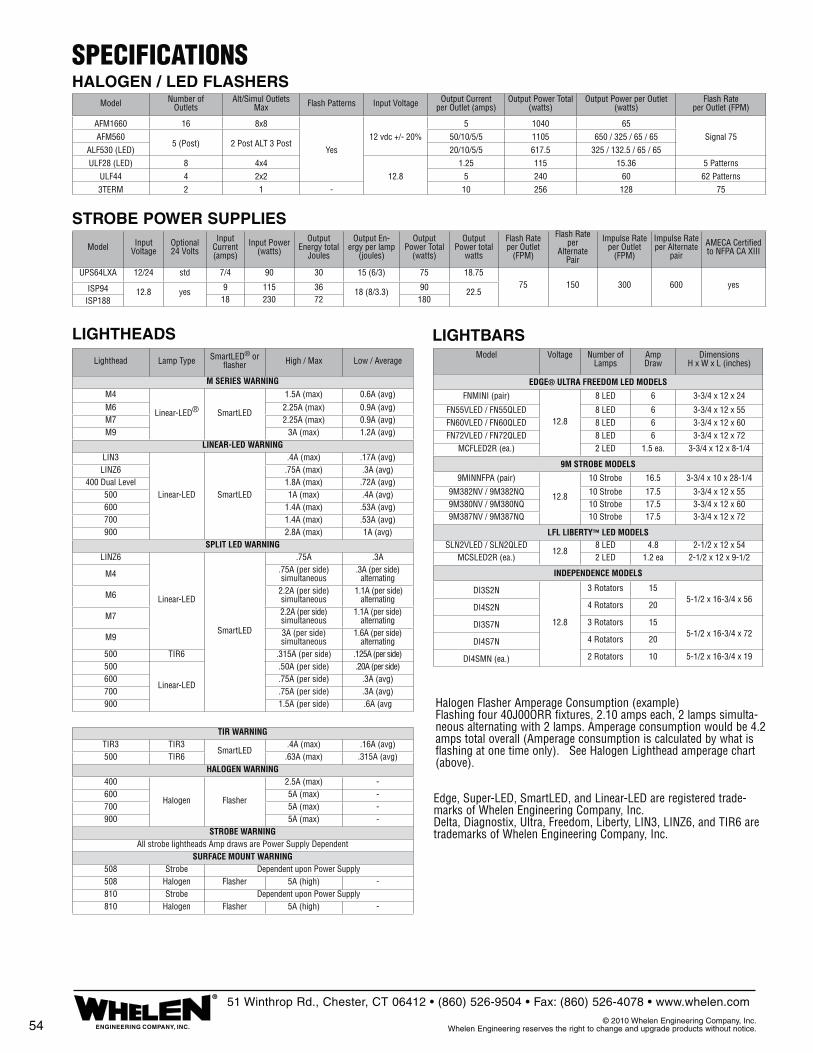
STROBE POWER SUPPLIES
SPECIFICATIONSHALOGEN / LED FLASHERS
Halogen Flasher Amperage Consumption (example) Flashing four 40J00ORR fixtures, 2.10 amps each, 2 lamps simulta-neous alternating with 2 lamps. Amperage consumption would be 4.2 amps total overall (Amperage consumption is calculated by what is flashing at one time only). See Halogen Lighthead amperage chart (above).
Edge, Super-LED, SmartLED, and Linear-LED are registered trade-marks of Whelen Engineering Company, Inc.Delta, Diagnostix, Ultra, Freedom, Liberty, LIN3, LINZ6, and TIR6 are trademarks of Whelen Engineering Company, Inc.
LIGHTBARSLIGHTHEADS
ENGINEERING COMPANY, INC.
®51 Winthrop Rd., Chester, CT 06412 • (860) 526-9504 • Fax: (860) 526-4078 • www.whelen.com
© 2010 Whelen Engineering Company, Inc. Whelen Engineering reserves the right to change and upgrade products without notice.54
Lighthead Lamp Type SmartLED® or flasher High / Max Low / Average
M SERIES WARNINGM4
Linear-LED® SmartLED
1.5A (max) 0.6A (avg)M6 2.25A (max) 0.9A (avg)M7 2.25A (max) 0.9A (avg)M9 3A (max) 1.2A (avg)
LINEAR-LED WARNINGLIN3
Linear-LED SmartLED
.4A (max) .17A (avg)LINZ6 .75A (max) .3A (avg)
400 Dual Level 1.8A (max) .72A (avg)500 1A (max) .4A (avg)600 1.4A (max) .53A (avg)700 1.4A (max) .53A (avg)900 2.8A (max) 1A (avg)
SPLIT LED WARNINGLINZ6
Linear-LED
SmartLED
.75A .3A
M4 .75A (per side) simultaneous
.3A (per side) alternating
M6 2.2A (per side) simultaneous
1.1A (per side) alternating
M7 2.2A (per side) simultaneous
1.1A (per side) alternating
M9 3A (per side) simultaneous
1.6A (per side) alternating
500 TIR6 .315A (per side) .125A (per side)500
Linear-LED
.50A (per side) .20A (per side)600 .75A (per side) .3A (avg)700 .75A (per side) .3A (avg)900 1.5A (per side) .6A (avg
TIR WARNINGTIR3 TIR3
SmartLED.4A (max) .16A (avg)
500 TIR6 .63A (max) .315A (avg)HALOGEN WARNING
400
Halogen Flasher
2.5A (max) -600 5A (max) -700 5A (max) -900 5A (max) -
STROBE WARNINGAll strobe lightheads Amp draws are Power Supply Dependent
SURFACE MOUNT WARNING508 Strobe Dependent upon Power Supply508 Halogen Flasher 5A (high) -810 Strobe Dependent upon Power Supply810 Halogen Flasher 5A (high) -
Model Voltage Number of Lamps
Amp Draw
DimensionsH x W x L (inches)
EDGE® ULTRA FREEDOM LED MODELS
FNMINI (pair)
12.8
8 LED 6 3-3/4 x 12 x 24
FN55VLED / FN55QLED 8 LED 6 3-3/4 x 12 x 55FN60VLED / FN60QLED 8 LED 6 3-3/4 x 12 x 60FN72VLED / FN72QLED 8 LED 6 3-3/4 x 12 x 72
MCFLED2R (ea.) 2 LED 1.5 ea. 3-3/4 x 12 x 8-1/4
9M STROBE MODELS
9MINNFPA (pair)
12.8
10 Strobe 16.5 3-3/4 x 10 x 28-1/4
9M382NV / 9M382NQ 10 Strobe 17.5 3-3/4 x 12 x 559M380NV / 9M380NQ 10 Strobe 17.5 3-3/4 x 12 x 609M387NV / 9M387NQ 10 Strobe 17.5 3-3/4 x 12 x 72
LFL LIBERTY™ LED MODELSSLN2VLED / SLN2QLED
12.88 LED 4.8 2-1/2 x 12 x 54
MCSLED2R (ea.) 2 LED 1.2 ea 2-1/2 x 12 x 9-1/2
INDEPENDENCE MODELS
DI3S2N
12.8
3 Rotators 155-1/2 x 16-3/4 x 56
DI4S2N 4 Rotators 20
DI3S7N 3 Rotators 155-1/2 x 16-3/4 x 72
DI4S7N 4 Rotators 20
DI4SMN (ea.) 2 Rotators 10 5-1/2 x 16-3/4 x 19
Model Number of Outlets
Alt/Simul Outlets Max Flash Patterns Input Voltage Output Current
per Outlet (amps)Output Power Total
(watts)Output Power per Outlet
(watts)Flash Rate
per Outlet (FPM)
AFM1660 16 8x8
Yes12 vdc +/- 20%
5 1040 65Signal 75AFM560
5 (Post) 2 Post ALT 3 Post50/10/5/5 1105 650 / 325 / 65 / 65
ALF530 (LED) 20/10/5/5 617.5 325 / 132.5 / 65 / 65ULF28 (LED) 8 4x4
12.81.25 115 15.36 5 Patterns
ULF44 4 2x2 5 240 60 62 Patterns3TERM 2 1 - 10 256 128 75
Model Input Voltage
Optional 24 Volts
Input Current (amps)
Input Power (watts)
Output Energy total
Joules
Output En-ergy per lamp
(joules)
Output Power Total
(watts)
Output Power total
watts
Flash Rateper Outlet
(FPM)
Flash Rate per
Alternate Pair
Impulse Rate per Outlet
(FPM)
Impulse Rate per Alternate
pairAMECA Certified to NFPA CA XIII
UPS64LXA 12/24 std 7/4 90 30 15 (6/3) 75 18.7575 150 300 600 yesISP94 12.8 yes 9 115 36 18 (8/3.3) 90 22.5
ISP188 18 230 72 180

NOTES

Whelen Products are Proudly Designed & Manufactured in the U.S.A.
www.whelen.com
51 Winthrop Road, Chester, CT 06412-0684
ENGINEERING COMPANY, INC.
Engineers for the Emergency Warning Industry
Distributed By:
© 2010 Whelen Engineering Company, Inc.Printed in U.S.A. Code: 10409L- 053010
®

Schematics

ELECTRICAL DRAWINGS PACKAGE
CAMBRIDGE HEAVY RESCUE
SVI TRUCK PROJECT# 909
SHEET 1 (THIS COVER SHEET) - REVISION CONTROL & HISTORY
SHEET 2 - HARNESS LAYOUT 12VDC EXTERNAL SYSTEMS AND WARNING LIGHTS
SHEET 3 - CAB 12VDC SYSTEMS SVI UPGRADES / MODIFICATIONS
SHEET 4 - 12V PANEL WIRING DIAGRAM
SHEET 5 - 12VDC SCHEMATICS BODY DRVR SIDE HARNESS
SHEET 6 - 12VDC SCHEMATICS BODY PSGR SIDE HARNESS
SHEET 7 - 12VDC SCHEMATICS BODY WARNING, REELS, UPR CMPTS
SHEET 8 - AUX TRAILER CONNECTOR
SHEET 9 - LINE VOLTAGE SYSTEM DIAGRAM
CMPT C1 -
- (1) ELEC CORD REEL; 200' BLK 10/3; L5-30R
- 120VAC LOAD CENTER
- (2) VERT LED NIGHTSTIKS
- (1) FOLD OUT STEP SUPPORT
CMPT C2
- (2) VERT LED NIGHTSTIKS
- (1) FOLD OUT STEP SUPPORT
CMPT C3 - ABOVE REAR WHEELS
- (2) VERT LED NIGHTSTIKS
CMPT C4
- (1) HYD HOSE REEL; 100' DUAL LINE; ORG
- (1) HYD HOSE REEL; 100' DUAL LINE; ORG
- (1) 240VAC RCPT; HPU SW'D
- (2) VERT LED NIGHTSTIKS
UPR CMPTS (5 TTL)
- FWD TRANS CMPT
- (4) SIDE CMPTS; 2 EA SIDE
- REAR STAIRWAY CMPTS; POSNs 1 & 6
CMPT S1 -
- 12VDC PANEL
- (1) ELEC CORD REEL; 200' BLK 10/3; L5-30R
- CMD LIGHT PENDANT
- (2) VERT LED NIGHTSTIKS
- (1) FOLD OUT STEP SUPPORT
CMPT S2
- (2) VERT LED NIGHTSTIKS
- (1) FOLD OUT STEP SUPPORT
CMPT S3 - ABOVE REAR WHEELS
- (2) VERT LED NIGHTSTIKS
CMPT S4
- (1) 120V RCPT; 5-20R; FWD WALL; GEN/SHR
- (2) VERT LED NIGHTSTIKS
=====
- BRITAX MARKERS; REAR BODY EACH CORNER
- (4) SIDE SCN LTS; WHLN 900s; 2 EA SIDE; VMUX
- (2) REAR SCN LTS; WHLN 900s; 1 EA SIDE
- TRAF ADVSR; SPLIT DISPLAY; VISTA CONTROLLED
- ONAN PROT-AC PTO GEN; 15KW
- (2) EXT SIDE OUTLETS; 1 EA SIDE; NOT IN SPEC
- (1) COMMAND LIGHT TOWER
- REAR CAMERA MAST
ELECTRICAL SPEC NOTES (CAMBRIDGE 909):
- CHANGE ORDER ITEMS IN ORANGE
- SPARTAN CHASS W/WELDON MULTIPLEX SYS
- LIGHTBAR WHELEN EDGE FN72QLED
- KUSSMAUL 1200 PUMP PLUS BATT SYS
- SHORE INLET; 20A KUSSMAUL A/E; YEL CVR
- (1) FRNT BROW LTS; 12VDC PFP1
- AUX TRAILER HITCH & WIRING
+++ CHASSIS MODS +++
- REAR COMMAND DESK
-(1) REFRIG; PS CABINET
-(1) DUAL GANG 12VDC PORT
-(1) 120V RCPT; CBNT BK WALL; SHR/GEN
COVER SHEETCAMBRIDGE ONJBC NONE P1
1 9
SVI TRUCK PROJECT 909CAMBRIDGE_HR_909_ELECTRICAL.DWG
SVI FIRE & RESCUE TRUCKSELECTRICAL DESIGN PACKAGE
CIRCUIT SCHEMATICS AND CHASSIS
ELECTRICAL ADDITIONS / MODIFICATIONS
AS PROVIDED BY SVI TRUCKS
NOTE: ALL INFORMATION PROVIDED HERE IS IN ADDITION TO CAB /CHASSIS
AND ALL EQUIPMENT MANUFACTURER'S DOCUMENTATION. CONSULT
ORIGINAL OEM MANUALS AND DOCUMENTATION AS REQUIRED.

12V PANEL
ADJ. SHELF (46" DEEP)
E
SM 1000# TRAY
TRANSVERSE
ADJ. SHELF (46" DEEP)
SM 1000# TRAY
TRANSVERSE
SM 1000# TRAY
TRANSVERSE
120/240V PANEL
ADJ. SHELF (46" DEEP)
400# TRAY
(24" DEEP)
E
SM 1000# TRAY
TRANSVERSE
ADJ. SHELF (46" DEEP)
SM 1000# TRAY
TRANSVERSE
SM 1000# TRAY
(70" DEEP)
H
H H
SM 1000# TRAY
TRANSVERSE
D3
DRIVER SIDE WARNING LIGHT DEVICES
D7
P3
CURBSIDE WARNING LIGHT DEVICES
P7
P4
DRIVER SIDE 12VDC BODY HARNESSES
CURBSIDE 12VDC BODY HARNESSES
ROUTING LAYOUT - EXTERIOR 12VDC ELECTRICAL
DRIVER / STREETSIDE HARNESS LAYOUT PASSENGER / CURBSIDE HARNESS LAYOUT
P1
D1 D2L
P2L
D4
CLC
CMPT C1
CMPT C2
CMPT C3
CMPT C4
CMPT S1
CMPT S2
CMPT S3
CMPT S4
DROP 3
DROP 4
DROP 4
DROP 3
RR CNR SILL
DROP 1
DROP 1
DROP 2
DROP 2
TAIL
LTS
LWR
CORNER
REAR
BUMPER
LIC
PLATE
RR CNR SILL
3X
LWR TRI
MRKRS
UC3
UC4
WWL
E
EXT RCPT ???
LEFT OUTLET
EXT RCPT ???
RIGHT OUTLET
UC1
UC2
WWL
WWL
R6
UCF
SC6
SC1
5-20R DPLX
03 OUTLET
GEN/SHR
CM
PT SW
CTRL RLY
R1
E
P6D6
L6-30R OUTLET
04 OUTLET
NOTE: THIS SHEET SHOWS A PRELIMINARY SALES
DRAWING USED ONLY AS REFERENCE FOR
ELECTRICAL LAYOUT. ACTUAL TRUCK FEATURES AND
LOCATIONS MAY DIFFER ON FINAL PRODUCTION
VERSION OF APPARATUS.
H
R7
REEL SW PWR
REEL 1 SW SIG
REEL 1 PWR
LT SCENE PWR
LT SCENE NEG
LT CMPT1 LTS
NEGATIVE 1
NEGATIVE 1
HPU1 RLY SIG
HPU1 SW SIG
CTRL SW PWR
HPU1 RLY SIG
NEGATIVE 1
LT CMPT2 LTS
NEGATIVE 1
LT CMPT1 LTS
NEGATIVE 1
LT CMPT2 SW
NEGATIVE 1
LT CMPT1 SW
NEGATIVE 1
LT CMPT3 LTS
NEGATIVE 1
LT CMPT2 LTS
NEGATIVE 1
LT DOT PWR
DOT LTS NEG
LT SCBA AJAR
NEGATIVE 1
UNBDY LTS PWR
NEGATIVE 1
LT CMPT3 SW
NEGATIVE 1
LT CMPT4 SW
NEGATIVE 1
LT CMPT4 LTS
NEGATIVE 1
LT CMPT3 LTS
NEGATIVE 1
NEGATIVE 1
NEGATIVE 1
NEGATIVE 1
STEP C1 LTS
STEP C1 SW
LT SCENE PWR
LT SCENE NEG
RR SCENE PWR
RR SCENE NEG
LT CMPT4 SW
UNBDY LTS PWR
NEGATIVE 1
STEP LDR SW
NEGATIVE 1
UNBDY LTS PWR
DOT LTS NEG
CLR MKR PWR
STOP LTS PWR
BACKUP PWR
LT TURN PWR
EXTRA 1
EXTRA 2
EXTRA 3
EXTRA 4
TWR UP IND D2
TWR IND PWR
DOT LTS NEG
CLR MKR PWR
DOT LTS NEG
CLR MKR PWR
DOT LTS NEG
CLR MKR PWR
LTA
LTA
LTA
LTA
LTA
LEFT TA LAMPS
= WIRE PROVIDED BUT NOT USED
CLR MKR PWR
CLR MKR NEG
TWR IND PWR
TWR UP IND D1
UNBDY LTS PWR
NEGATIVE 1
LT SO STEPS
3X
REEL SW PWR
REEL 6 SW SIG
REEL 6 PWR
RT SCENE PWR
RT SCENE NEG
RT CMPT1 LTS
NEGATIVE 1
RT CMPT3 SW
NEGATIVE 1
RT CMPT4 SW
NEGATIVE 1
RT CMPT4 LTS
NEGATIVE 1
RT CMPT3 LTS
NEGATIVE 1
NEGATIVE 1
NEGATIVE 1
RR SCENE PWR
RR SCENE NEG
RT CMPT4 SW
UNBDY LTS PWR
NEGATIVE 1
UNBDY LTS PWR
DOT LTS NEG
CLR MKR PWR
STOP LTS PWR
BACKUP PWR
RT TURN PWR
EXTRA 1
EXTRA 2
EXTRA 3
EXTRA 4
TWR UP IND P2
TWR IND PWR
DOT LTS NEG
CLR MKR PWR
RTA
RTA
RTA
RTA
RTA
RIGHT TA LAMPS
DOT LTS NEG
CLR MKR PWR
NEGATIVE 1
UNBDY LTS PWR
TWR UP IND P1
TWR IND PWR
RT CMPT2 LTS
NEGATIVE 1
RT CMPT1 LTS
NEGATIVE 1
RT CMPT2 SW
NEGATIVE 1
RT CMPT1 SW
NEGATIVE 1
RT CMPT3 LTS
NEGATIVE 1
RT CMPT2 LTS
NEGATIVE 1
RT DOT PWR
DOT LTS NEG
UNBDY LTS PWR
NEGATIVE 1
NEGATIVE 1
STEP C6 LTS
STEP C6 SW
RT SCENE PWR
RT SCENE NEG
TAIL
LTS
LWR
CORNER
UP CMPT2 SW
UP CMPT4 SW
UP CMPT2 LTS
UP CMPT4 LTS
NEGATIVE 2
NEGATIVE 2
WLKWY LTS NEG
WLKWY LTS PWR
WLKWY LTS NEG
WLKWY LTS PWR
UP CMPT1 SW
UP CMPT3 SW
UP CMPT1 LTS
UP CMPT3 LTS
NEGATIVE 2
NEGATIVE 2
WLKWY LTS NEG
WLKWY LTS PWR
WLKWY LTS NEG
WLKWY LTS PWR
UP CMPT1 SW
UP CMPT1 LTS
NEGATIVE 2
HARNESS LAYOUT 12VDC SYSTEMSCAMBRIDGE ONJBC NONE P1
2 9
SVI TRUCK PROJECT 909CAMBRIDGE_HR_909_ELECTRICAL.DWG
SVI FIRE & RESCUE TRUCKSELECTRICAL DESIGN PACKAGE
CIRCUIT SCHEMATICS AND CHASSIS
ELECTRICAL ADDITIONS / MODIFICATIONS
AS PROVIDED BY SVI TRUCKS
NOTE: ALL INFORMATION PROVIDED HERE IS IN ADDITION TO CAB /CHASSIS
AND ALL EQUIPMENT MANUFACTURER'S DOCUMENTATION. CONSULT
ORIGINAL OEM MANUALS AND DOCUMENTATION AS REQUIRED.
H
R8
LT CMPT2 SW
NEGATIVE 1
LT CMPT1 SW
NEGATIVE 1
LT CMPT3 SW
NEGATIVE 1
LT CMPT4 SW
NEGATIVE 1
BRITAX
MKR
DOT LTS NEG
CLR MKR PWR
DOT LTS NEG
CLR MKR PWR
BRITAX
MKR
RT CMPT2 SW
NEGATIVE 1
RT CMPT1 SW
NEGATIVE 1
RT CMPT3 SW
NEGATIVE 1
RT CMPT4 SW
NEGATIVE 1
NEGATIVE 1
REAR
MAST
NEGATIVE 2
LKUP LTS PWR
AUX 12V PWR
REEL SW PWR
REEL 8 SW SIG
REEL 8 PWR
REEL SW PWR
REEL 7 SW SIG
REEL 7 PWR
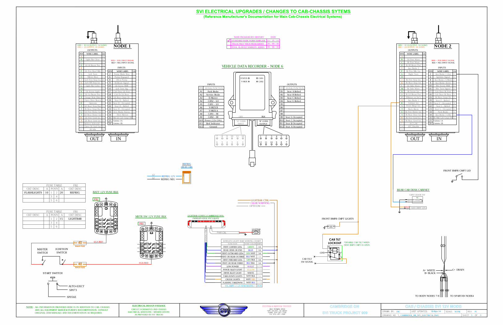
SVI ELECTRICAL UPGRADES / CHANGES TO CAB-CHASSIS SYTEMS
(Reference Manufacturer's Documentation for Main Cab-Chassis Electrical Systems)
CAB / CHASSIS SVI 12V MODS
FRONT BMPR CMPT LIGHTS
86
CAB TILTLOCKOUT
85
30
87
87a
GND
CAB TILT
SW SIGNAL
*DISABLE CAB TILT WHEN
FRNT BMPT CMPT IS OPEN
FRONT BMPR CMPT LID
C= DRAIN
B=BLACK
A= WHITE
TO SPARTAN NODE4TO BODY NODES 7/8
START SWITCH
40MAXI FUSE
MASTER
SWITCH
IGNITION
SWITCH
40MAXI FUSE
BATT 12V FUSE BLK
FB2
6GA RED
MSTR SW 12V FUSE BLK
FB1
6GA RED
--A
--A--A
--A --A
--A
--A--A
--A --A
--A
AUTO-EJECT
SP073
SP056E
10A
VEHICLE DATA RECORDER - NODE 6
123456
7 8 9 10 11 12
"A" CONN
INPUT
"B" CONN
OUTPUT
1 2 3 4 5 6
789101112
INPUTS
WIRE LABEL
INOUT
PINCH
INPUTS
1
2
3
4
5
7
9
10
11
12
13
14
15
16
17
18
19
20
21
22
23
WIRE LABELPINCH
OUTPUTS
6
8
24
NODE 1
25
26
34 1
2
3
4
5
6
7
8
9
10
11
12
13
14
15
16
35
17
18
19
20
8
21
33
16
6
2
9
10
22
23
R
S
F
T
G
H
L
B
M
C
N
D
O
P
Q
E
A
J
W
X
K
U
V
7
ORG = 2A OUTPUT; 16/18AWG
GRN = 10.5A OUTPUT; 14/16AWG
RED = POS INPUT SIGNAL
BLK = NEG INPUT SIGNAL
GRYBLK
PINSIGNAL/FUNCTION
A1Park Brake
A2
A3
A4
A5
A6
A7
A8
A9
A10
A11
A12
Service Brake
E-Master
CAN2 - LO
CAN1 - LO
V-MUX B
V-MUX A
CAN1 - HI
CAN2 - HI
Power (12v/24v)
Red Indicator
Ground
OUTPUTS
PINSIGNAL/FUNCTION
B1Seat A Belted
B2
B3
B4
B5
B6
B7
B8
B9
B10
B11
B12
Seat B Belted
Seat C Belted
Seat G Belted
Seat G Occupied
Seat C Occupied
Seat B Occupied
Seat A Occupied
STATUS
V-MUX
CAN1
CAN2
Horn Button
Md Lft Cab Cmpt Dr
Lft Rear Grnd Lts
Lft Frnt Grnd Lts
Lft Rear Dome Lts
Lft Frnt Dome Lts
Rt Rear Stop/Haz
Lft Rear Stop/Haz
Airhorn Solenoid
Open Door Beacn
Gauge Rckr Dimr
Lft Lo Beam Pwr
Lft Scene Light
Light Bar Color
Left Frnt Step Lts
Mirror Heat
Left Turn
Lft Frnt Roof Mkr
Lft Hi Beam Pwr
Light Bar Clear
Pump Mode Req
Pump Engaged
OK to Pump
Hi Beam Signal
Lft Scene RKR
Left Turn Sig
Cab Door Lft Frnt
Cab Dr Lft Rear
Lft Rear Cmpt Dr
Seat D - Belted
Seat D - Occupied
Seat H - Belted
Seat H - Occupied
Srvc Brake Status
Comms 1A
Comms 1B
25
26
14
11 HI Idle
Open Dr Gnd Out
WIRE LABEL
INOUT
PINCH
INPUTS
1
2
3
4
5
7
9
10
11
12
13
14
15
16
17
18
19
20
21
22
23
WIRE LABELPINCH
OUTPUTS
6
8
24
NODE 2
25
26
34 1
2
3
4
5
6
7
8
9
10
11
12
13
14
15
16
35
17
18
19
20
8
21
33
16
6
2
9
10
22
23
R
S
F
T
G
H
L
B
M
C
N
D
O
P
Q
E
A
J
W
X
K
U
V
7
ORG = 2A OUTPUT; 16/18AWG
GRN = 10.5A OUTPUT; 14/16AWG
RED = POS INPUT SIGNAL
BLK = NEG INPUT SIGNAL
Aux Brake 3 (HI)
Rt Rear Step Lts
Comms 1A
Comms 1B
25
26
14
11
Rt Mid Cab Cmpt Dr
Park Brake
Seat L - Occupied
Seat L - Belted
Rt Rear Cmpt Dr
Cab Door Rt Rear
Cab Door Rt Frnt
Rht Turn Signal
Aux Brake Active
Aux Brake 2 (Med)
Ignition Signal
Aux Brake 1 (Lo)
Rt Frnt Step Lts
Right Turn
Rt Frnt Mkr Lts
Aux Brake 2
Rt HI Beam Pwr
Rt Frnt Warn
Lft Frnt Warn
Lft Side Warn
Rt Side Warn
Rt Scene Lts
Rt LO Beam Pwr
EMaster to Sw's
Back Alarm
Rt Frnt Dome Lts
Rt Rear Door Lts
Rt Frnt Grnd Lts
Rt Rear Grnd Lts
A/C L.M.
ATC Disable
Left RR Step Lts
Aux Brake 1
Rht Scene RKR
Seat F - Belted
Seat F - Occupied
WHELEN LIGHT BAR WIRING CHART
FRNT CORNER LEDs GREEN 3A
FUNCTION WIRE COLOR AMPS
REAR CRNR OR END BLUE 3A
FRNT OUTBOARD LEDsGRN/WHT
3A
FRNT OR REAR OUTBRD
BLU/WHT
3A
FRNT INBOARD LEDs
GRN/BLK
3A
FRNT OR REAR INBRD
BLU/BLK
3A
LOW POWER VIOLET 0.5A
PSNGR ALLEY LIGHT YELLOW 2.5A
DRVR ALLEY LIGHT WHITE 2.5A
TAKE-DOWN LIGHTS
WHT/BLK
5A
CRUISE LIGHTS
WHT/ORG
5A
FLASHNG TAKEDWNS
WHT/BLU
2.5A
TTL AMPS x 1.25 FUSE RATING =
SIG
NA
L C
BL
15A
PWR CBL
LIGHTBAR CONFIG (CAMBRIDGE 909)
(WHELEN EDGE FN72QLED)
20A
LIGHTBAR
LIGHTBAR CTRL
CLEAR WARNING
OPTICOM
FUSE TABLE FB2
POSNACKT DESC A CKT DESC
1
3
2
4
5 6
10FLASHLIGHTS 20 REFRIG
FUSE TABLE FB1
POSNACKT DESC A CKT DESC
1
3
2
4
5 6
15 LIGHTBAR
NODE PROGRAM REV HISTORY
STANDARD NODE PGRM TEMPLATE
DATE
11 / 18 / 14
TRUCK PROJ VMUX PRGM ADDED
99 / 99 / 99
FINAL AS-BUILT MARKUPS ADDED
99 / 99 / 99
CAMBRIDGE ONJBC NONE P1
3 9
SVI TRUCK PROJECT 909CAMBRIDGE_HR_909_ELECTRICAL.DWG
SVI FIRE & RESCUE TRUCKSELECTRICAL DESIGN PACKAGE
CIRCUIT SCHEMATICS AND CHASSIS
ELECTRICAL ADDITIONS / MODIFICATIONS
AS PROVIDED BY SVI TRUCKS
NOTE: ALL INFORMATION PROVIDED HERE IS IN ADDITION TO CAB /CHASSIS
AND ALL EQUIPMENT MANUFACTURER'S DOCUMENTATION. CONSULT
ORIGINAL OEM MANUALS AND DOCUMENTATION AS REQUIRED.
LED CBNT LTS
B
R
CBNT DOOR SW
B
B
NC
REAR CAB DESK CABINET
REFRIG 12V
12
12
REFRIG NEG
REFRIG
(REAR CAB)
Cabinet Lts
Front Bmpr Lts
Opticom

12VDC PANEL WIRING DIAGRAM
12VDC PANEL LAYOUT & INTERCONNECT DIAGRAM
BATT
GND
BUSS
4GA
-- --
----
-- --
1
3
5
2
4
6
(FB3)
6GA
A
B
C -SHLD
-COMM A (BLK)
-COMM B (WHT)
DATA COMM SPLITTER
INOUT
L
A
K
M
N
P
O
Q
X
W
V
S
T
U
R
B
C
D
E
J
H
G
F
19
20
18
34
33
31
35
27
26
28
25 30
29
32
7
8
9
10
1112
13
14
15
16
17
1
2 6
5
4
3
21
22
24
23
HERCULES NODE CONNECTOR DETAIL
C78
A
B
C
D
E
F
G
H
J
K
L
M
N
P
VIO
BLK
WHT
SD WARN PWR
SD WARN NEG
EXTRA 1
BLURR WARN PWR
WHTRR WARN NEG
WHTEXTRA 2
RED
VIO
BLK
SD WARN PWR
SD WARN NEG
BLURR WARN PWR
RR WARN NEG WHT
WHTEXTRA 3
WHTEXTRA 4
UNBDY LTS PWRRED
UNBDY LTS PWR
WARN LTS
FLASH PAT
CONN REF
LFPT#
1
2
3
4
5
6
7
8
D1
D2L
D3
D4
D6
RFP
P1
P2L
P3
P4
P69
D7 P710
11
12
GND GND
--- ---
--- ---
--- ---
--- ---
--- ---
MASTER SW PWR
C5-A18
MECH HARN
CHASS BATT+ IN InPOWERDC Contactor
LOAD+BATT
CONTROL STATUS
18GA
BLK
FLASH PATTERN PROGRAMMING
WARNING LIGHTS SCAN-LOCK PROG:
-WHELEN -
APPLY 12VDC < 1SEC ON
DESIRED TERMINAL TO CHANGE FLASH
PATTERN; INSTALL GND END CAP TO
PREVENT INADVERTENT PROG CHGS.
MSTR SW
----
-- --
----
1
3
5
2
4
6
(FB1)
6GA
MSTR SW
-- --
----
-- --
1
3
5
2
4
6
(FB2)
10A
10A
10A
20A
TRLR MSTR PWR
TRLR MSTR PWR
REEL SW PWR
REEL SW PWR
15A
C80-01
C80-02
TWR IND PWR
C69-04
C5-03
C5-04
STRAP
REEL 1 PWR
REEL1 SW SIG
(RS1)
40A
REEL REWIND SOLENOIDS
C80-B
12
11
10
9
8
7
6
5
4
3
2
1
REEL SW PWR
REEL SW PWR
TO FB1
R10
R9
R8
R7
R6
R5
R4
R3
R2
R1
40A
40A
40A
REEL 6 PWR
REEL 6 SW SIG
(RS6)
REEL 7 PWR
REEL 7 SW SIG
(RS7)
REEL 8 PWR
REEL 8 SW SIG
(RS8)
8GA
8GA
8GA
8GA
CAMBRIDGE ONJBC NONE P1
4 9
SVI TRUCK PROJECT 909CAMBRIDGE_HR_909_ELECTRICAL.DWG
SVI FIRE & RESCUE TRUCKSELECTRICAL DESIGN PACKAGE
CIRCUIT SCHEMATICS AND CHASSIS
ELECTRICAL ADDITIONS / MODIFICATIONS
AS PROVIDED BY SVI TRUCKS
NOTE: ALL INFORMATION PROVIDED HERE IS IN ADDITION TO CAB /CHASSIS
AND ALL EQUIPMENT MANUFACTURER'S DOCUMENTATION. CONSULT
ORIGINAL OEM MANUALS AND DOCUMENTATION AS REQUIRED.
C70 CBH
19
20
RTA
RTA
RTA
RTA (B)
RTA (W)
C68 SBH
20
21
22
23
21
SS LAMPS
BK
R BK
R BK
R BK
R
CS LAMPS
BK
RBK
RBK
RBK
R
1 2 3 4 8765
LTA
LTA
LTA
LTA (B)
LTA (W)
19
TO
NODE
R
TO
NODE
R
1/0
WHT
BLK
MECH
INOUT
PINCH
INPUTS
CAB COMM DATA
LINK TW-PR
8AWG
1/0
NODE Left
25
26
341
2
3
4
5
6
7
8
9
10
11
12
13
14
15
16
35
17
18
19
20
8
21
33
16
6
2
9
10
22
23
ORG = 2A OUTPUT; 16/18AWG
GRN = 10.5A OUTPUT; 14/16AWG
R 1
2
3
4
5
7
9
10
11
12
S
F
T
G
H
L
B
M
C
N 13
14
15
16
17
18
19
20
21
22
23
D
O
P
Q
E
A
J
W
X
K
PIN CH
OUTPUTS
6
8
U
V
7 24
C68-06
C100-17
C68-04
C69-16
C71-18
C68-08
C100-04
C68-02
C5-19
C69-17
C71-15
C78-A,H
C100-08
LT CMPT3 LTS
WLKWY LTS PWR
LT CMPT2 LTS
LT TURN PWR
RR SCENE PWR
BACK UP PWR
LT CMPT4 LTS
UP CMPT1 LTS
LT CMPT1 LTS
PTO A PWR
LT DOT PWR
LT SCENE PWR
STOP LTS PWR
SD WARN PWR
UP CMPT3 LTS
SIGNAL NAME
C69-18
C69-15
SIGNAL NAME
C5-20
PTO A IND
C69-12
STEP LDR SW
C100-01
UP CMPTF SW
C100-03
UP CMPT1 SW
C68-01
LT CMPT1 SW
C68-03
LT CMPT2 SW
C68-05
LT CMPT3 SW
C68-07
LT CMPT4 SW
C100-07
UP CMPT3 SW
B
W
C58-V
C58-W
C58-X
C68-16
STEP C1 SW
C68-17
STEP C1 LTS
INOUT
PINCH
INPUTS
CAB COMM DATA
LINK TW-PR
8AWG
NODE Right
25
26
341
2
3
4
5
6
7
8
9
10
11
12
13
14
15
16
35
17
18
19
20
8
21
33
16
6
2
9
10
22
23
ORG = 2A OUTPUT; 16/18AWG
GRN = 10.5A OUTPUT; 14/16AWG
R 1
2
3
4
5
7
9
10
11
12
S
F
T
G
H
L
B
M
C
N 13
14
15
16
17
18
19
20
21
22
23
D
O
P
Q
E
A
J
W
X
K
PINCH
OUTPUTS
6
8
U
V
7 24
C70-06
C78-G,P
C100-10
C70-04
C71-16
C70-08
C100-02
C70-02
C71-17
C71-13
C100-06
RT CMPT3 LTS
UNBDY LTS PWR
UP CMPT4 LTS
RT CMPT2 LTS
RT TURN PWR
RT CMPT4 LTS
UP CMPTF LTS
RR WARN PWR
RT CMPT1 LTS
RT DOT PWR
RT SCENE PWR
CLR MKR PWR
UP CMPT2 LTS
SIGNAL NAME
C69-13
SIGNAL NAME
C100-05UP CMPT2 SW
C100-09UP CMPT4 SW
C70-15
C70-01RT CMPT1 SW
C70-03RT CMPT2 SW
C70-05RT CMPT3 SW
C70-16
STEP C6 LTS
C78-C,K
C70-07RT CMPT4 SW
STEP C6 SW
B
W
NODE PROGRAM REV HISTORY
STANDARD NODE PGRM TEMPLATE
DATE
11 / 18 / 14
TRUCK PROGRAM VMUX ADDED
99 / 99 / 99
FINAL AS-BUILT MARKUPS ADDED
99 / 99 / 99
2514
11 26
2514
11 26
C68-21
TRAF ADSR (LTA)
C68-22
TRAF ADSR (LTA)
C70-20
TRAF ADSR (RTA)
C68-20
TRAF ADSR (LTA)
C70-22
TRAF ADSR (RTA)
C70-21
TRAF ADSR (RTA)
C70-19TRAF ADSR (RTA)
C68-19
TRAF ADSR (LTA)
C5-05
C5-06
TRLR CLR WARN
TRLR COL WARN
C5-24 TRLR UNBDY LTS
C69-09C71-09
C69-07
C71-07
C71-02
TWR UP IND P1
C69-02
TWR UP IND D1
22
23
AUX 12V PWR
C70-11
CTRL SW PWR
C69-04
RR MAST SW
10A
HPU CTRL
*USE ONLY IF
HPU REM SW'D
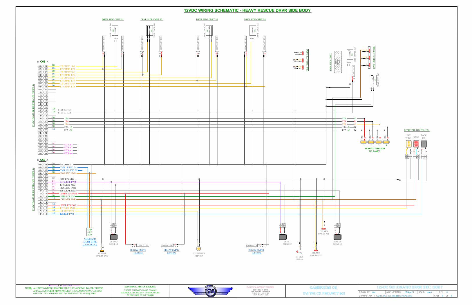
12VDC WIRING SCHEMATIC - HEAVY RESCUE DRVR SIDE BODY
DS FWD
SCENE LT
CLR MKR
LWR SS FWD
LED
CM
PT LTS
B
R
CM
PT D
OO
R SW
B B
NC
LED
CM
PT LTS
B
R
DRVR SIDE CMPT S1
01
B- C68 -A
18
LT CMPT1 SW
02
16
LT CMPT1 LTS
03
18
LT CMPT2 SW
04
16
LT CMPT2 LTS
05
18
LT CMPT3 SW
06
16
LT CMPT3 LTS
07
18
LT CMPT4 SW
08
16
LT CMPT4 LTS
LED
CM
PT LTS
B
R
CM
PT D
OO
R SW
BB
NC
LED
CM
PT LTS
B
R
DRVR SIDE CMPT S2
LED
CM
PT LTS
B
R
CM
PT D
OO
R SW
B B
NC
LED
CM
PT LTS
B
R
DRVR SIDE CMPT S3
LED
CM
PT LTS
B
R
CM
PT D
OO
R SW
BB
NC
LED
CM
PT LTS
B
R
DRVR SIDE CMPT S4
09
10
11
12
13
14
15
16
17
18
19
20
21
22
23
24
25
26
27
28
29
30
31
14
EXTRA 3
14
EXTRA 2
14
EXTRA 1
STEP C1 SW
18
STEP CM
PT1 SW
BB
NC
CM
PT LTS
B
R
01
B- C69 -A
10
02
03
04
05
06
07
08
09
10
11
12
13
14
15
16
17
18
NEGATIVE 1
18
TWR UP IND D1
18
TWR UP IND D2
18
TWR IND PWR
12
DOT LTS NEG
LT SCENE PWR
14
LT SCENE NEG
14
RR SCENE PWR
14
RR SCENE NEG
14
UNBDY LTS PWR
14
18
STEP LDR SW
CLR MKR PWR
16
STOP LTS PWR
16
LT TURN PWR
LT DOT PWR
BACKUP PWR
16
16
16
01
02
03
04
05
06
07
08
09
10
11
12
13
14
15
16
17
18
19
20
22
23
24
25
26
27
28
29
30
31
01
02
03
04
05
06
07
08
09
10
11
12
13
14
15
16
17
18
21
LW
R STEP CM
PT
B
R
BY
1 2 3
1 2 3
DOT MARKER
MIDSHIP
BY
B
Y
1 2 3
1 2 3
B
R
1 2 3
1 2 3
B
R
1 2 3
1 2 3
R
REAR TAIL LIGHTS (DS)
LEFT
TURN
STOP
BACK
UP
DS AFT
SCENE LT
B
R
1 2 3
1 2 3
CLR MKR
LWR DS AFT
BY
CLR MKR
UPR DS AFT
B
Y
REAR DS
SCENE LT
B
R
1 2 3
1 2 3
UNBDY LTS
B
R
BELOW CMPT1
(OPTION)
UNBDY LTS
B
R
BELOW CMPT2
(OPTION)
UNBDY LTS
B
R
BELOW CMPT4
(OPTION)
STEP C1 LTS
18
B
Y
B
Y
B
Y
LW
R CN
TR CLR M
KRS
REAR STEP SW
BB
NC
B
Y
B
Y
B
Y
UPR CN
TR CLR M
KRS
12VDC SCHEMATIC DRVR SIDE BODY
12VD
C PAN
EL BU
LKH
EAD
(SEE SH
EET 4)
12VD
C PAN
EL BU
LKH
EAD
(SEE SH
EET 4)
LT SCENE PWR
CAMBRIDGE ONJBC NONE P1
5 9
SVI TRUCK PROJECT 909CAMBRIDGE_HR_909_ELECTRICAL.DWG
SVI FIRE & RESCUE TRUCKSELECTRICAL DESIGN PACKAGE
CIRCUIT SCHEMATICS AND CHASSIS
ELECTRICAL ADDITIONS / MODIFICATIONS
AS PROVIDED BY SVI TRUCKS
NOTE: ALL INFORMATION PROVIDED HERE IS IN ADDITION TO CAB /CHASSIS
AND ALL EQUIPMENT MANUFACTURER'S DOCUMENTATION. CONSULT
ORIGINAL OEM MANUALS AND DOCUMENTATION AS REQUIRED.
14
EXTRA 4
LTA -W
16
18
LTA -B
18
LTA
18
LTA
18
LTA
LTA -W
LTA -B
LTA
LTA
LTA
W
B
O
R
G
TRAFFIC ADVISOR
DS LAMPS
BK
R BK
R BK
R BK
R
1 2 3 4
DS MKR
BRITAX
BY
CMD
LIGHT
AJAR
COMMAND
LIGHT CTRL
(LWR CMPT S1)
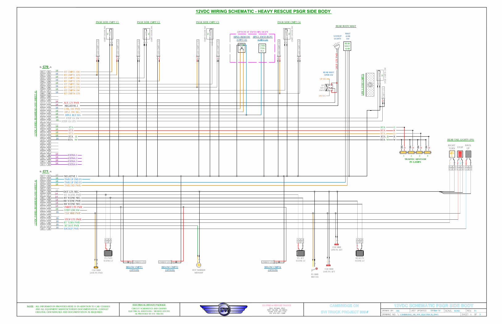
12VDC WIRING SCHEMATIC - HEAVY RESCUE PSGR SIDE BODY
PS FWD
SCENE LT
CLR MKR
LWR PS FWD
LED
CM
PT LTS
B
R
CM
PT D
OO
R SW
B B
NC
LED
CM
PT LTS
B
R
PSGR SIDE CMPT C1
01
B- C70 -A
18
RT CMPT1 SW
02
16
RT CMPT1 LTS
03
18
RT CMPT2 SW
04
16
RT CMPT2 LTS
05
18
RT CMPT3 SW
06
16
RT CMPT3 LTS
07
18
RT CMPT4 SW
08
16
RT CMPT4 LTS
LED
CM
PT LTS
B
R
CM
PT D
OO
R SW
BB
NC
LED
CM
PT LTS
B
R
PSGR SIDE CMPT C2
LED
CM
PT LTS
B
R
CM
PT D
OO
R SW
B B
NC
LED
CM
PT LTS
B
R
PSGR SIDE CMPT C3
LED
CM
PT LTS
B
R
CM
PT D
OO
R SW
BB
NC
LED
CM
PT LTS
B
R
PSGR SIDE CMPT C4
09
10
11
12
13
14
15
16
17
18
19
20
21
22
23
24
25
26
27
28
29
30
31
14
EXTRA 3
14
EXTRA 2
14
EXTRA 1
18
STEP C6 SW
STEP C6 LTS
18
STEP CM
PT6 SW
BB
NC
CM
PT LTS
B
R
01
B- C71 -A
10
02
03
04
05
06
07
08
09
10
11
12
13
14
15
16
17
18
NEGATIVE 1
18
TWR UP IND P1
18
TWR UP IND P2
18
TWR IND PWR
12
DOT LTS NEG
RT SCENE PWR
14
RT SCENE NEG
14
RR SCENE PWR
14
RR SCENE NEG
14
UNBDY LTS PWR
14
18
STEP LDR SW
CLR MKR PWR
16
STOP LTS PWR
16
RT TURN PWR
RT DOT PWR
BACKUP PWR
16
16
16
01
02
03
04
05
06
07
08
09
10
11
12
13
14
15
16
17
18
19
20
22
23
24
25
26
27
28
29
30
31
01
02
03
04
05
06
07
08
09
10
11
12
13
14
15
16
17
18
21
UPR 3 STEP CM
PTS
B
R
B
Y
1 2 3
1 2 3
DOT MARKER
MIDSHIP
B
Y
B
Y
1 2 3
1 2 3
B
R
1 2 3
1 2 3
B
R
1 2 3
1 2 3
R
REAR TAIL LIGHTS (PS)
RIGHT
TURN
STOP
BACK
UP
PS AFT
SCENE LT
B
R
1 2 3
1 2 3
B
Y
CLR MKR
UPR PS AFT
B
Y
REAR PS
SCENE LT
B
R
1 2 3
1 2 3
UNBDY LTS
B
R
BELOW CMPT1
(OPTION)
UNBDY LTS
B
R
BELOW CMPT2
(OPTION)
UNBDY LTS
B
R
BELOW CMPT4
(OPTION)
12VDC SCHEMATIC PSGR SIDE BODY
12VD
C PAN
EL BU
LKH
EAD
(SEE SH
EET 4)
12VD
C PAN
EL BU
LKH
EAD
(SEE SH
EET 4)
CAMBRIDGE ONJBC NONE P1
6 9
SVI TRUCK PROJECT 909#CAMBRIDGE_HR_909_ELECTRICAL.DWG
SVI FIRE & RESCUE TRUCKSELECTRICAL DESIGN PACKAGE
CIRCUIT SCHEMATICS AND CHASSIS
ELECTRICAL ADDITIONS / MODIFICATIONS
AS PROVIDED BY SVI TRUCKS
NOTE: ALL INFORMATION PROVIDED HERE IS IN ADDITION TO CAB /CHASSIS
AND ALL EQUIPMENT MANUFACTURER'S DOCUMENTATION. CONSULT
ORIGINAL OEM MANUALS AND DOCUMENTATION AS REQUIRED.
AUX 12V PWR
REAR
MAST
AJAR
MAST
AJAR
SW
LOOKUP
LIGHTS
REAR BODY MAST
UP
OFF
DWN
UP SIG
DN SIG
REAR MAST
OPER SW
LKU
P LTS PW
R
14
NEGATIVE 2
14
CLR MKR
LWR PS AFT
14
EXTRA 4
RTA -W
16
18
RTA -B
18
RTA
18
RTA
18
RTA
RTA -W
RTA -B
RTA
RTA
RTA
W
B
O
R
G
TRAFFIC ADVISOR
PS LAMPS
BK
R BK
R BK
R BK
R
1 2 3 4
PS MKR
BRITAX
BY
16
CTRL SW PWR
HPU1 SW SIG
18
18
HPU1 RLY SIG
IND
HPU1 REM SW
(CMPT C4)
12VDC
CTRL
RLY
HPU1 SW'D RCPT
(CMPT C4)
OPTION IF SW'D HPU RCPT

W/V
R
1 2 3
1 2 3
B
A
B- C78 -A
B
C
D
E
F
G
H
J
K
L
M
N
P
SD WARN PWR
RR WARN PWR
UNBDY LTS PWR
A
B
C
D
E
F
G
H
J
K
L
M
N
P
14
SD WARN NEG
14
RR WARN NEG
14
14
EXTRA 1 -W
14
EXTRA 2 -W
14
SD WARN PWR
RR WARN PWR
UNBDY LTS PWR
14
SD WARN NEG
14
RR WARN NEG
14
14
EXTRA 3 -W
14
EXTRA 4 -W
14
01
02
03
04
05
06
07
08
01
02
03
04
05
06
07
08
B- C79 -A
RR WARN PWR
UNBDY LTS PWR
RR WARN NEG
14
14
EXTRA 3 -W
14
EXTRA 4 -W
14
SD WARN PWR
14
SD WARN NEG
14
16
16
16
NCNC
01
02
03
04
05
06
07
08
09
10
11
12
PS UPR FWD
WARNING P1
FLSH PAT P1
18
FLSH PAT P2L
18
FLSH PAT P3
18
FLSH PAT P4
18
FLSH PAT NEG
18
FLSH PAT P6
18
FLSH PAT P7
18
RFP
01
02
03
04
05
06
07
08
09
10
11
12
FLSH PAT D1
18
FLSH PAT D2L
18
FLSH PAT D3
18
FLSH PAT D4
18
FLSH PAT D6
18
FLSH PAT D7
18
LFP
FLSH PAT NEG
18
W/V
R
A B C
B
W/V
R
1 2 3
1 2 3
B
PS UPR AFT
WARNING P3
W/V
R
1 2 3
1 2 3
B
RR PS UPR
WARNING P4
W/V
R
1 2 3
1 2 3
B
RR PS LWR
WARNING P6
W/V
R B
PS LWR MID
WARNING P2L
PS LWR AFT
WARNING P7
UN
BD
Y LTS
B
R
W/V
R
1 2 3
1 2 3
B
DS UPR FWD
WARNING D1
W/V
R
B
W/V
R
1 2 3
1 2 3
B
DS UPR AFT
WARNING D3
W/V
R
1 2 3
1 2 3
B
RR DS UPR
WARNING D4
W/V
R
1 2 3
1 2 3
B
RR DS LWR
WARNING D6
W/V
R
B
DS LWR MID
WARNING D2L
DS LWR AFT
WARNING D7
UN
BD
Y LTS
BR
REAR BMPR
UNBDY LTS
B- C80 -A
01
02
03
04
05
06
07
08
09
10
11
12
REEL SW PWR
REEL SW PWR
14
14
REEL 10 SW SIG
01
02
03
04
05
06
07
08
09
10
11
12
01
02
03
04
05
06
01
02
03
04
05
06
B- C87 -A
16
REEL 9 SW SIG
16
REEL 8 SW SIG
16
REEL 7 SW SIG
16
REEL 6 SW SIG
16
REEL 5 SW SIG
16
REEL 4 SW SIG
16
REEL 3 SW SIG
16
REEL 2 SW SIG
16
REEL 1 SW SIG
16
REEL 10 SW SIG
16
REEL 9 SW SIG
16
REEL 8 SW SIG
16
REEL 7 SW SIG
16
REEL 6 SW SIG
16
REEL SW PWR
14
FLASH PATTERN PROGRAMMING
WARNING LIGHTS SCAN-LOCK PROG:
-WHELEN -
APPLY 12VDC < 1SEC ON
DESIRED TERMINAL TO CHANGE FLASH
PATTERN; INSTALL GND END CAP TO
PREVENT INADVERTENT PROG CHGS.
SEE FLASH PATTERN
PROGRAMMING NOTE.
FLSH
PAT EN
DCAP
SEE FLASH PATTERN
PROGRAMMING NOTE.
FLSH
PAT EN
DCAP
REEL6 CMPT C1
REWIND
SWITCH
REWIND
MTR
REEL1 CMPT S1
REWIND
SWITCH
REWIND
MTR
REEL7 CMPT C4
REWIND
SWITCH
REWIND
MTR
REEL8 CMPT C4
REWIND
SWITCH
REWIND
MTR
REEL 6 PWR
8
REEL 7 PWR
REEL 8 PWR
8
8
DIRECT WIRE
TO SOLENOIDS
12VDC PANEL
REEL 1 PWR
8
DIRECT WIRE
TO SOLENOIDS
12VDC PANEL
REAR BMPR
UNBDY LTS
SEE 12V
PANEL
SHEET 4
SEE 12V
PANEL
SHEET 4
PISTON SW
B
B
CMPT LTS
B
R
FWD TRANS CMPT
B- C100 -A
01
02
03
04
05
06
07
08
09
10
11
12
01
02
03
04
05
06
07
08
09
10
11
12
01
02
03
04
05
06
01
02
03
04
05
06
B- C101 -A
SEE 12V
PANEL
SHEET 4
13
14
15 NEGATIVE 2
16
WLKWY LTS PWR17
WLKWY LTSW
18
13
14
15
16
17
18 NCNC
14
14
18
UP CMPT4 SW
UP CMPT4 LTS
18
18
UP CMPT3 SW
UP CMPT3 LTS
18
18
UP CMPT2 SW
UP CMPT2 LTS
18
18
UP CMPT1 SW
UP CMPT1 LTS
18
18
UP CMPTF SW
UP CMPTF LTS
18
18
UP CMPT2 SW
UP CMPT2 LTS
18
18
UP CMPT4 SW
UP CMPT4 LTS
18
18
07
08
09
10
11
12
NCNC
NCNC
NCNC
NEGATIVE 2
WLKWY LTS PWR
WLKWY LTSW
14
14
18
B
B
CMPT LTS
B
R
UPR CMPT1 DS FWD
B
B
CMPT LTS
B
R
UPR CMPT3 DS AFT
PISTON SW PISTON SW
WLKWY LTS
B
R
WLKWY LTS
B
R
B
B
CMPT LTS
B
R
UPR CMPT2 PS FWD
B
B
CMPT LTS
B
R
UPR CMPT4 PS AFT
PISTON SW PISTON SW
WLKWY LTS
B
R
WLKWY LTS
B
R
NCNC
NCNC
NCNC
NCNC
NCNC
NCNC
07
08
09
10
11
12
A B C
A B C
A B C
A B C
A B C
A B C
A B C
12VDC SCHEMATIC WARNING, REELS, UPR CMPTSCAMBRIDGE ONJBC NONE P1
7 9
SVI TRUCK PROJECT 909CAMBRIDGE_HR_909_ELECTRICAL.DWG
SVI FIRE & RESCUE TRUCKSELECTRICAL DESIGN PACKAGE
CIRCUIT SCHEMATICS AND CHASSIS
ELECTRICAL ADDITIONS / MODIFICATIONS
AS PROVIDED BY SVI TRUCKS
NOTE: ALL INFORMATION PROVIDED HERE IS IN ADDITION TO CAB /CHASSIS
AND ALL EQUIPMENT MANUFACTURER'S DOCUMENTATION. CONSULT
ORIGINAL OEM MANUALS AND DOCUMENTATION AS REQUIRED.
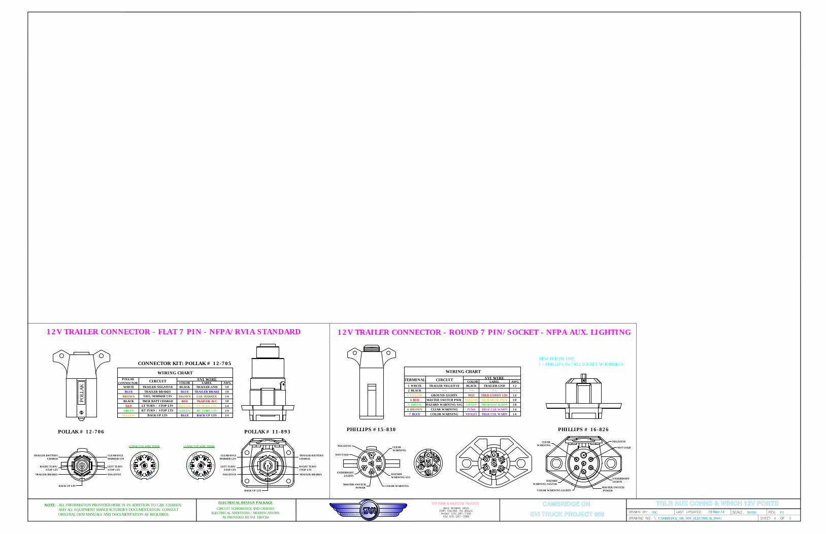
TRLR AUX CONNS & WINCH 12V PORTS
TERMINAL CIRCUIT
SVI WIRE
1 WHITE
2 BLACK
3 YELLOW
4 RED
5 GREEN
6 BROWN
7 BLUE
TRAILER NEGATIVE
NA
MASTER SWITCH PWR
GROUND LIGHTS
HAZARD WARNING SIG
COLOR WARNING
AWGCOLOR LABEL
BLACK
NA
YELLOW
RED
GREEN
VIOLET
12
NA
10
14
18
14
TRAILER GND
NA
TRLR MSTR PWR
TRLR UNBDY LTS
TRLR HAZ WARN
TRLR COL WARN
PHILLIPS #15-830 PHILLIPS # 16-826
CLEAR WARNING PINK 14TRLR CLR WARN
3BD
NEGATIVE
NOT USED
UNDERBODY
LIGHTS
MASTER SWITCH
POWER
COLOR WARNING
HAZARD
WARNING SIG
CLEAR
WARNING
NEGATIVE
NOT USED
UNDERBODY
LIGHTS
MASTER SWITCH
POWER
COLOR WARNING LIGHTS
HAZARD
WARNING SIGNAL
CLEAR
WARNING
12V TRAILER CONNECTOR - ROUND 7 PIN/SOCKET - NFPA AUX. LIGHTING
NEW BUILDS USE:
1 - PHILLIPS 16-7402 SOCKET W/HARNESS
PO
LLAK
GREEN
B
L
A
C
K
B
R
O
W
N
RED
W
H
I
T
E
B
L
U
E
YELLOW
CLEARANCE
MARKER LTS
LEFT TURN/
STOP LTS
NEGATIVE
TRAILER BATTERY
CHARGE
RIGHT TURN/
STOP LTS
TRAILER BRAKES
BACK UP LTS
CLEARANCE
MARKER LTS
LEFT TURN/
STOP LTS
NEGATIVE
TRAILER BATTERY
CHARGE
RIGHT TURN/
STOP LTS
TRAILER BRAKES
BACK UP LTS
POLLAK # 12-706 POLLAK # 11-893
12V TRAILER CONNECTOR - FLAT 7 PIN - NFPA/RVIA STANDARD
WIRING CHART
WIRING CHART
POLLAK
CONNECTOR
CIRCUIT
SVI WIRE
WHITE
BLUE
GREEN
BLACK
RED
BROWN
YELLOW
TRAILER NEGATIVE
TRAILER BRAKES
TAIL/MARKER LTS
TRLR BATT CHARGE
LT TURN / STOP LTS
RT TURN / STOP LTS
BACK UP LTS
AWGCOLOR LABEL
BLACK
BLUE
BROWN
RED
YELLOW
GREEN
BLUE
10
10
14
10
14
14
14
TRAILER GND
TRAILER BRAKE
CLR MARKER
TRAILER ACC
LT TURN LTS
RT TURN LTS
BACK UP LTS
CONNECTOR KIT: POLLAK # 12-705
GREEN
B
L
A
C
K
B
R
O
W
N
RED
W
H
I
T
E
B
L
U
E
YELLOW
CONNECTOR WIRE TERMS CONNECTOR WIRE TERMS
CAMBRIDGE ONJBC NONE P1
8 9
SVI TRUCK PROJECT 909CAMBRIDGE_HR_909_ELECTRICAL.DWG
SVI FIRE & RESCUE TRUCKSELECTRICAL DESIGN PACKAGE
CIRCUIT SCHEMATICS AND CHASSIS
ELECTRICAL ADDITIONS / MODIFICATIONS
AS PROVIDED BY SVI TRUCKS
NOTE: ALL INFORMATION PROVIDED HERE IS IN ADDITION TO CAB /CHASSIS
AND ALL EQUIPMENT MANUFACTURER'S DOCUMENTATION. CONSULT
ORIGINAL OEM MANUALS AND DOCUMENTATION AS REQUIRED.
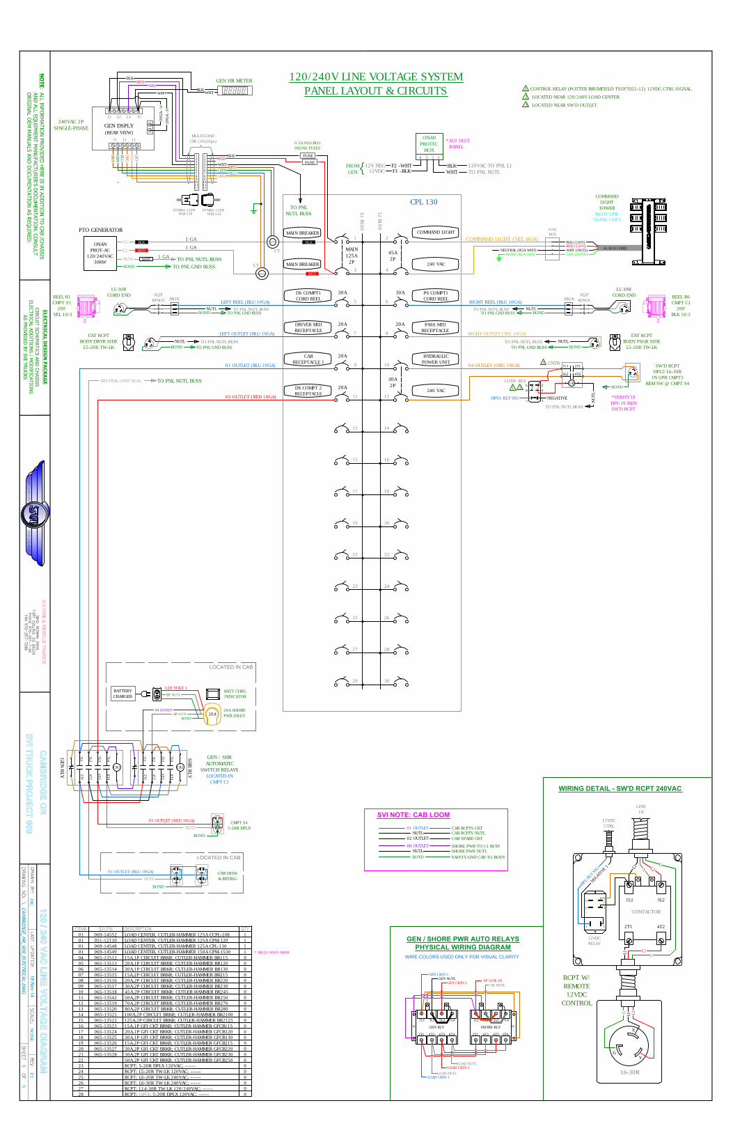
120 / 240 VA
C L
INE
VO
LT
AG
E D
IAG
RA
M
CPL 130
120/240V LINE VOLTAGE SYSTEM
PANEL LAYOUT & CIRCUITS
L1 BU
SS
L2 BU
SS
45A
2P
MAIN
125A
2P
56
7 8
9 10
11 12
1314
1516
17 18
19 20
21 22
23 24
25 26
2728
34
1 2
29 30
PTO GENERATOR
ONAN
PROT-AC
120/240VAC
30KW
0.5A SLO-BLO
INLINE FUSES
CT
CT
L1 L2 L3 N
BLK
RED
VIO
WHT
BRN
GRN
I1 I2 I3
BLU
ORG
YEL
GRY
GEN DSPLY
(REAR VIEW)
240VAC 2P
SINGLE-PHASE
20G
A -W
20G
A -B
DTM04-12PB DTM06-12SB
WM-12PWM-12S
MULTICOND
CBL (10x20ga)
1
2
3
4
5
6
7
8
9
10
11
12
1
2
3
4
5
6
7
8
9
10
11
12
RED
BLK
WHT
BRN
GRN
BLU
ORG
TO PNL
NUTL BUSS
COMMAND
LIGHT
TOWER
BODY UPR
TRANS CMPT
1 CONTROL RELAY (POTTER BRUMFIELD T92P7D22-12) 12VDC CTRL SIGNAL.
2 LOCATED NEAR 120/240V LOAD CENTER.
GEN HR METER
SP NUTL
08 OUTLET
20A SHORE
PWR INLET
GEN / SHR
AUTOMATIC
SWITCH RELAYS
LOCATED IN
CMPT C1
20A
BATT CHRG
INDICATOR
1L1
3L2
5L3
7L4
2T1
4T2
6T3
8T4
CR1
GEN
RLY
SH
R RLY
CAB DESK
& REFRIG
CR1
NEUTRAL (WHT 8GA)
TO PNL NUTL BUSS
01 OUTLET (BLU 10GA)
03 OUTLET (RED 10GA)
1L1
3L2
5L3
7L4
2T1
4T2
6T3
8T4
BATTERY
CHARGER
SP NUTL
120 VOLT 1
BOND
EXT RCPT
BODY DRVR SIDE
L5-20R TW-LK
20A
LEFT OUTLET (BLU 10GA)
NUTL
TO PNL NUTL BUSS
BOND
TO PNL GND BUSS
W
EXT RCPT
BODY PSGR SIDE
L5-20R TW-LK
NUTL
TO PNL NUTL BUSS
BOND
TO PNL GND BUSS
20A
RIGHT OUTLET (YEL 10GA)
W
04 OUTLET (ORG 10GA)
1L1
3L2
2T1
4T2
CR
240 VAC
30A
2P
12VDC RLY
6
8
1
2
4
3
CNTR
HPU1 RLY SIG NEGATIVE
X
Y
TO PNL NUTL BUSS
BOND
NU
TL
3
SW'D RCPT
HPU2 L6-30R
IN UPR CMPT3
REM SW @ CMPT S4
3 LOCATED NEAR SW'D OUTLET.
3
1
20A
20A
DRIVER MID
RECEPTACLE
HYDRAULIC
POWER UNIT
PASS MID
RECEPTACLE
DS COMPT 2
RECEPTACLE
CAB
RECEPTACLE 1
1L1 3L2
2T14T2
CONTACTOR
12VDC
RELAY
X
Y
G
N
G
L
2
L
1
G
L2
L1
L1
G
L2
L6-30R
LINE
IN
12VDC
CTRL
N
E
G
A
T
I
V
E
1
H
P
U
R
L
Y
S
I
G
RCPT W/
REMOTE
12VDC
CONTROL
2
4
3
6
8
7
01
WIRING DETAIL - SW'D RCPT 240VAC
MAIN BREAKER
MAIN BREAKER
240 VAC
COMMAND LIGHT
NC
1L1 3L2 7L45L3
2T14T2
8T46T3
1L1 3L2 7L45L3
2T14T2
8T46T3
NC
SHORE RLYGEN RLY
SP NUTL
SP LINE IN
GEN CKT#1
GEN NUTL
GEN CKT#2
LOAD CKT#1
LOAD NUTL
LOAD CKT#2
LOAD NUTL
GEN / SHORE PWR AUTO RELAYS
PHYSICAL WIRING DIAGRAM
WIRE COLORS USED ONLY FOR VISUAL CLARITY
BLK
WHT
NUTL
BOND
03 OUTLET (RED 10GA)
CMPT S4
5-20R DPLX
NUTL
BOND
01 OUTLET (BLU 10GA)
01 069-14552 LOAD CENTER, CUTLER-HAMMER 125A CCPL-108 1
04 15A,1P CIRCUIT BRKR; CUTLER-HAMMER BR115 0
01 051-12110 LOAD CENTER, CUTLER-HAMMER 125A CPM-120
01 069-14548 LOAD CENTER, CUTLER-HAMMER 125A CPL-130
01 069-14549 LOAD CENTER, CUTLER-HAMMER 150A CPM-1530
1
1
1
* REQ'S MAIN BRKR
05 0
06 0
07
08
20A,1P CIRCUIT BRKR; CUTLER-HAMMER BR120
30A,1P CIRCUIT BRKR; CUTLER-HAMMER BR130
15A,2P CIRCUIT BRKR; CUTLER-HAMMER BR215 0
0
0
20A,2P CIRCUIT BRKR; CUTLER-HAMMER BR220
30A,2P CIRCUIT BRKR; CUTLER-HAMMER BR23009
045A,2P CIRCUIT BRKR; CUTLER-HAMMER BR24510
070A,2P CIRCUIT BRKR; CUTLER-HAMMER BR270
080A,2P CIRCUIT BRKR; CUTLER-HAMMER BR280
12
0100A,2P CIRCUIT BRKR; CUTLER-HAMMER BR2100
13
0125A,2P CIRCUIT BRKR; CUTLER-HAMMER BR2125
14
15A,1P GFI CKT BRKR; CUTLER-HAMMER GFCB115
20A,1P GFI CKT BRKR; CUTLER-HAMMER GFCB120
30A,1P GFI CKT BRKR; CUTLER-HAMMER GFCB130
15A,2P GFI CKT BRKR; CUTLER-HAMMER GFCB215
20A,2P GFI CKT BRKR; CUTLER-HAMMER GFCB220
30A,2P GFI CKT BRKR; CUTLER-HAMMER GFCB230
50A,2P GFI CKT BRKR; CUTLER-HAMMER GFCB250
0
0
0
0
0
0
0
15
16
17
18
19
20
21
0RCPT; 5-20R DPLX 120VAC; ------
22
0
0
0
0
0
23
24
25
26
27
28
RCPT; L5-20R TW-LK 120VAC; ------
RCPT; L6-20R TW-LK 240VAC; ------
RCPT; L6-30R TW-LK 240VAC; ------
RCPT; L14-30R TW-LK 120/240VAC; ------
RCPT; GFCI; 5-20R DPLX 120VAC; ------
065-13512
065-13513
065-13514
065-13515
065-13516
065-13517
065-13518
065-13519
065-13520
065-13521
065-13522
065-13523
065-13524
065-13525
065-13526
065-13527
065-13528
050A,2P CIRCUIT BRKR; CUTLER-HAMMER BR25011
065-13542
SVI NOTE: CAB LOOM
01 OUTLET
NUTL
CAB RCPTS CKT
CAB RCPTS NUTL
02 OUTLETCAB SPARE CKT
08 OUTLET
NUTL
SHORE PWR TO C1 RLYS
SHORE PWR NUTL
BONDSAFETY GND CAB TO BODY
ITEM# SVI P/N DESCRIPTION QTY
L1
L2
NUTL
BOND
TO PNL NUTL BUSS
TO PNL GND BUSS
WHT
BLK
RED
BLK
RED
FUSE
FUSE
F1 -BLK
F2 -WHT
ONAN
PROTEC
BOX
1234
BLK
WHT
12VDC
12V NEGFROM
GEN
120VAC TO PNL L1
TO PNL NUTL
*ADJ DIST
PANEL
RED (120V)
BLK (120V)
WHT (NUTL)
GRN (BOND)
4x 8GA CORD
COMMAND LIGHT (YEL 8GA)
NEUTRAL (8GA WHT)
BOND (8GA GRN)
JUNC
BOX
LOCATED IN CAB
1 GA
1 GA
1 GA
CA
MB
RID
GE
ON
JBC
NO
NE
P1
99
SV
I TR
UC
K P
RO
JEC
T 909
30A
NUTL
REEL R6
CMPT C1
200'
BLK 10/3
RIGHT REEL (BLU 10GA)
TO PNL NUTL BUSS
BONDTO PNL GND BUSS
SLIP
RINGS
L5-30R
CORD END
JBOX
W
PS COMPT1
CORD REEL
30A
NUTL
REEL R1
CMPT S1
200'
YEL 10/3
LEFT REEL (BLU 10GA)
TO PNL NUTL BUSS
BONDTO PNL GND BUSS
SLIP
RINGS
L5-30R
CORD END
JBOX
W
DS COMPT1
CORD REEL
LOCATED IN CAB
*VERIFY IF
HPU IS REM
SW'D RCPT