Calculo Recipiente
45
OPERADORA CICSA S.A. DE C.V. SWECOMEX Calle 5 No. 899 Zona Industrial 44940 Guadalajara Jalisco Mexico COMPRESS Pressure Vessel Design Calculations Designer: GDELATORRE Date: Viernes, Enero 29, 2010
-
Upload
independent -
Category
Documents
-
view
1 -
download
0
Transcript of Calculo Recipiente

OPERADORA CICSA S.A. DE C.V.
SWECOMEX
Calle 5 No. 899
Zona Industrial 44940
Guadalajara Jalisco Mexico
COMPRESS Pressure Vessel Design Calculations
Designer: GDELATORREDate: Viernes, Enero 29, 2010

Deficiencies Summary
No deficiencies found.
1/44

Nozzle Schedule
Nozzlemark Service Size
Materials
Nozzle Impact Norm Fine Grain Pad Impact Norm Fine Grain Flange
N1 Nozzle #1 4" Sch 120 SA-106 B Smls pipe No No No N/A N/A N/A N/A WN A105Class 150
N2 Nozzle #2 6" Sch 80 (XS) SA-106 B Smls pipe No No No SA-516 70 No No No WN A105Class 150
2/44

Nozzle Summary
Nozzlemark
OD(in)
tn
(in)Req t
n(in)
A1? A2?Shell Reinforcement
Pad Corr(in)
Aa/A
r(%)
Nom t(in)
Design t(in)
User t(in)
Width(in)
tpad(in)
N1 4.5 0.438 0.3799 Yes Yes 0.5 0.352 N/A N/A 0.125 119.6
N2 6.625 0.432 0.4023 Yes Yes 0.5 0.352 2 0.5 0.125 256.0
tn: Nozzle thicknessReq tn: Nozzle thickness required per UG-45/UG-16Nom t: Vessel wall thicknessDesign t: Required vessel wall thickness due to pressure + corrosion allowance per UG-37User t: Local vessel wall thickness (near opening)Aa: Area available per UG-37, governing conditionAr: Area required per UG-37, governing conditionCorr: Corrosion allowance on nozzle wall
3/44

Pressure Summary
Pressure Summary for Chamber bounded by Ellipsoidal Head #1 and Ellipsoidal Head #2
IdentifierP
Design( psi)
T
Design( °F)
MAP( psi)
MAEP( psi)
Te
external( °F)
MDMT( °F)
MDMTExemption
ImpactTested
Ellipsoidal Head #2 150 250 249.69 38.6 250 -45.8 Note 1 No
Straight Flange on Ellipsoidal Head #2 150 250 330.03 23.86 250 -45.8 Note 2 No
Cylinder #1 150 250 280.53 23.86 300 -45.7 Note 3 No
Straight Flange on Ellipsoidal Head #1 150 250 330.03 23.86 250 -45.8 Note 2 No
Ellipsoidal Head #1 150 250 249.69 38.6 250 -45.8 Note 4 No
Rings #1 N/A N/A N/A 15 300 N/A N/A No
Nozzle #1 (N1) 150 250 150 15 300 -55 Note 5 No
Nozzle #2 (N2) 150 250 150 15 300 -46.5 Nozzle Note 6 No
Pad Note 7 No
Chamber design MDMT is 15 °FChamber rated MDMT is -45.7 °F @ 150 psi
Chamber Design MAWP hot & corroded is 150 psi
Chamber MAP cold & new is 150 psi @ 70 °F
Chamber MAEP is 15 psi @ 250 °FVacuum rings did not govern the external pressure rating.
Notes for Maximum Pressure Rating:
Note # Details
1. Option to calculate MAWP was not selected. See the Calculation->General tab of the Set Mode dialog.
Notes for MDMT Rating:
Note # Exemption Details
1. Straight Flange governs MDMT
2. Material impact test exemption temperature from Fig UCS-66 Curve B = -7 °FFig UCS-66.1 MDMT reduction = 38.8 °F, (coincident ratio = 0.6124659) UCS-66 governing thickness = 0.5 in
3. Material impact test exemption temperature from Fig UCS-66 Curve B = -7 °FFig UCS-66.1 MDMT reduction = 38.7 °F, (coincident ratio = 0.6129608) UCS-66 governing thickness = 0.5 in
4. Straight Flange governs MDMT
5. Flange rating governs: UCS-66(b)(1)(b)
6. Nozzle is impact test exempt to -155 °F per UCS-66(b)(3) (coincident ratio = 0.10476).
7. Pad impact test exemption temperature from Fig UCS-66 Curve B = -7 °FFig UCS-66.1 MDMT reduction = 39.5 °F, (coincident ratio = 0.60523) UCS-66 governing thickness = 0.5 in.
Design notes are available on the Settings Summary page.
4/44

Revision History
No. Date Operator Notes
0 8/23/2010 GUSTAVO New vessel created ASME Section VIII Division 1 [Build 6310]
5/44
Settings Summary
COMPRESS 2010 Build 7000
Units: U.S. Customary
Datum Line Location: 0.00" from right seam
Design
ASME Section VIII Division 1, 2007 Edition
Design or Rating: Get Thickness from PressureMinimum thickness: 0.0625" per UG-16(b)Design for cold shut down only: NoDesign for lethal service (full radiography required): NoDesign nozzles for: Design P onlyCorrosion weight loss: 100% of theoretical lossUG-23 Stress Increase: 1.20Skirt/legs stress increase: 1.0Minimum nozzle projection: 6"Juncture calculations for α > 30 only: YesPreheat P-No 1 Materials > 1.25" and <= 1.50" thick: NoUG-37(a) shell tr calculation considers longitudinal stress: NoButt welds are tapered per Figure UCS-66.3(a).
Hydro/Pneumatic Test
Shop Hydrotest Pressure: 1.3 times design PTest liquid specific gravity: 1.00Maximum stress during test: 90% of yield
Required Marking - UG-116
UG-116 (e) Radiography: RT4UG-116 (f) Postweld heat treatment: None
Code Cases\Interpretations
Use Code Case 2547: NoApply interpretation VIII-1-83-66: NoApply interpretation VIII-1-86-175: YesApply interpretation VIII-1-83-115: NoApply interpretation VIII-1-01-37: YesNo UCS-66.1 MDMT reduction: NoNo UCS-68(c) MDMT reduction: NoDisallow UG-20(f) exemptions: No
6/44

UG-22 Loadings
UG-22 (a) Internal or External Design Pressure : YesUG-22 (b) Weight of the vessel and normal contents under operating or test conditions: NoUG-22 (c) Superimposed static reactions from weight of attached equipment (external loads): NoUG-22 (d)(2) Vessel supports such as lugs, rings, skirts, saddles and legs: NoUG-22 (f) Wind reactions: NoUG-22 (f) Seismic reactions: NoNote: UG-22 (b),(c) and (f) loads only considered when supports are present.
7/44

Thickness Summary
ComponentIdentifier
Material Diameter(in)
Length(in)
Nominal t(in)
Design t(in)
Total Corrosion(in)
JointE
Load
Ellipsoidal Head #2 SA-516 70 60 ID 15.375 0.375* 0.3526 0.125 1.00 Internal
Straight Flange on Ellipsoidal Head #2 SA-516 70 60 ID 2 0.5 0.4379 0.125 1.00 External
Cylinder #1 SA-516 70 60 ID 360 0.5 0.4379 0.125 0.85 External
Straight Flange on Ellipsoidal Head #1 SA-516 70 60 ID 2 0.5 0.4379 0.125 1.00 External
Ellipsoidal Head #1 SA-516 70 60 ID 15.375 0.375* 0.3526 0.125 1.00 Internal
Nominal t: Vessel wall nominal thickness
Design t: Required vessel thickness due to governing loading + corrosion
Joint E: Longitudinal seam joint efficiency
* Head minimum thickness after forming
Load
internal: Circumferential stress due to internal pressure governs
external: External pressure governs
Wind: Combined longitudinal stress of pressure + weight + wind governs
Seismic: Combined longitudinal stress of pressure + weight + seismic governs
8/44
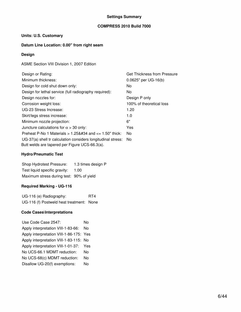
Weight Summary
ComponentWeight ( lb) Contributed by Vessel Elements
Surface Areaft2Metal
New*
Metal
Corroded*Insulation &
Supports Lining Piping+ Liquid
OperatingLiquid
TestLiquid
Ellipsoidal Head #2 500.8 340 0 0 0 1,145.8 1,224.7 34
Cylinder #1 9,674.9 7,271.1 0 0 0 32,646.5 36,757 479
Ellipsoidal Head #1 500.8 340 0 0 0 1,145.8 1,224.7 34
TOTAL: 10,676.4 7,951.1 0 0 0 34,938.1 39,206.5 546
* Shells with attached nozzles have weight reduced by material cut out for opening.
Component
Weight ( lb) Contributed by AttachmentsSurface Area
ft2Body Flanges Nozzles &Flanges Packed
BedsTrays &
SupportsRings &
ClipsVerticalLoads
New Corroded New Corroded
Ellipsoidal Head #2 0 0 0 0 0 0 0 0 0
Cylinder #1 0 0 93.6 80.5 0 0 86.7 0 16
Ellipsoidal Head #1 0 0 0 0 0 0 0 0 0
TOTAL: 0 0 93.6 80.5 0 0 86.7 0 16
Vessel operating weight, Corroded: 43,056 lbVessel operating weight, New: 45,528 lbVessel empty weight, Corroded: 8,118 lbVessel empty weight, New: 10,857 lbVessel test weight, New: 50,063 lbVessel surface area: 562 ft2
Vessel center of gravity location - from datum - lift condition
Vessel Lift Weight, New: 10,857 lbCenter of Gravity: 180.9384"
Vessel Capacity
Vessel Capacity** (New): 4,700 US galVessel Capacity** (Corroded): 4,741 US gal**The vessel capacity does not include volume of nozzle, piping or other attachments.
9/44

Long Seam Summary
Shell Long SeamAngles
Component Seam 1
Cylinder #1 45°
Shell Plate Lengths
Component StartingAngle Plate 1
Cylinder #1 45° 190.0664"
*Plate Lengths use the circumfrence of the vessel based on the mid diameter of the components
10/44

Shell Rollout
11/44

Hydrostatic Test
Shop test pressure determination for Chamber bounded by Ellipsoidal Head #1 and Ellipsoidal Head #2 basedon design P per UG-99(b)
Shop hydrostatic test gauge pressure is 195 psi at 70 °F (the chamber design P = 150 psi)
The shop test is performed with the vessel in the horizontal position.
IdentifierLocal testpressure
psi
Test liquidstatic head
psi
UG-99stressratio
UG-99pressure
factor
Stressduring test
psi
Allowabletest stress
psi
Stressexcessive?
Ellipsoidal Head #2 (1) 197.707 2.707 1 1.30 14,235 34,200 No
Straight Flange on Ellipsoidal Head #2 197.707 2.707 1 1.30 11,961 34,200 No
Cylinder #1 197.707 2.707 1 1.30 11,961 34,200 No
Straight Flange on Ellipsoidal Head #1 197.707 2.707 1 1.30 11,961 34,200 No
Ellipsoidal Head #1 197.707 2.707 1 1.30 14,235 34,200 No
Nozzle #1 (N1) 195.523 0.523 1 1.30 16,452 51,300 No
Nozzle #2 (N2) 195.523 0.523 1 1.30 10,615 51,300 No
Notes:(1) Ellipsoidal Head #2 limits the UG-99 stress ratio.(2) PL stresses at nozzle openings have been estimated using the method described in PVP-Vol. 399, pages 77-82.(3) 1.5*0.9*Sy used as the basis for the maximum local primary membrane stress at the nozzle intersection PL.(4) The zero degree angular position is assumed to be up, and the test liquid height is assumed to the top-mostflange.
The field test condition has not been investigated for the Chamber bounded by Ellipsoidal Head #1 and EllipsoidalHead #2.
The test temperature of 70 °F is warmer than the minimum recommended temperature of -15.7 °F so the brittlefracture provision of UG-99(h) has been met.
12/44

Vacuum Summary
Component Line of SupportElevation
above Datum(in)
Length Le(in)
Ellipsoidal Head #2 - 377.375 N/A
- 1/3 depth of Ellipsoidal Head #2 367.0417 N/A
Straight Flange on Ellipsoidal Head #2 Top - 362 187.0417
Straight Flange on Ellipsoidal Head #2 Bottom - 360 187.0417
Cylinder #1 Top - 360 187.0417
- Rings #1 180 187.0417
Cylinder #1 Bottom - 0 187.0417
Straight Flange on Ellipsoidal Head #1 Top - 0 187.0417
Straight Flange on Ellipsoidal Head #1 Bottom - -2 187.0417
- 1/3 depth of Ellipsoidal Head #1 -7.0417 N/A
Ellipsoidal Head #1 - -17.375 N/A
Notes
For main components, the listed value of 'Le' is the largest unsupported length for the component.
For Rings, the listed value of 'Le' is Ls per UG-29.
13/44

Cylinder #1
ASME Section VIII Division 1, 2007 Edition
Component: CylinderMaterial specification: SA-516 70 (II-D p. 18, ln. 22)Material impact test exemption temperature from Fig UCS-66 Curve B = -7 °FFig UCS-66.1 MDMT reduction = 38.7 °F, (coincident ratio = 0.6129608)UCS-66 governing thickness = 0.5 in
Internal design pressure: P = 150 psi @ 250 °FExternal design pressure: Pe = 15 psi @ 300 °F
Static liquid head:
Ps = 1.79psi (SG = 1.1, Hs = 45",Operating head)
Pth = 2.71psi
(SG = 1, Hs = 75", Horizontal testhead)
Corrosion allowance Inner C = 0.125" Outer C = 0"
Design MDMT = 15 °F No impact test performedRated MDMT = -45.7 °F Material is not normalized
Material is not produced to Fine Grain PracticePWHT is not performed
Radiography: Longitudinal joint - Spot UW-11(b) Type 1Left circumferential joint - Spot UW-11(a)(5)b Type 1Right circumferential joint - Spot UW-11(a)(5)b Type 1
Estimated weight New = 9,674.9 lb corr = 7,271.1 lbCapacity New = 4,406.39 US gal corr = 4,443.19 US gal
ID = 60"LengthLc
= 360"
t = 0.5"
Design thickness, (at 250 °F) UG-27(c)(1)
t = P*R / (S*E - 0.60*P) + Corrosion= 151.79*30.125 / (20,000*0.85 - 0.60*151.79) + 0.125= 0.3955"
Maximum allowable pressure, (at 70 °F) UG-27(c)(1)
P = S*E*t / (R + 0.60*t)= 20,000*0.85*0.5 / (30 + 0.60*0.5)= 280.53 psi
External Pressure, (Corroded & at 300 °F) UG-28(c)
L /Do
= 187.0417/ 61 = 3.0663
Do/ t = 61 /
0.3129 = 194.9551
14/44
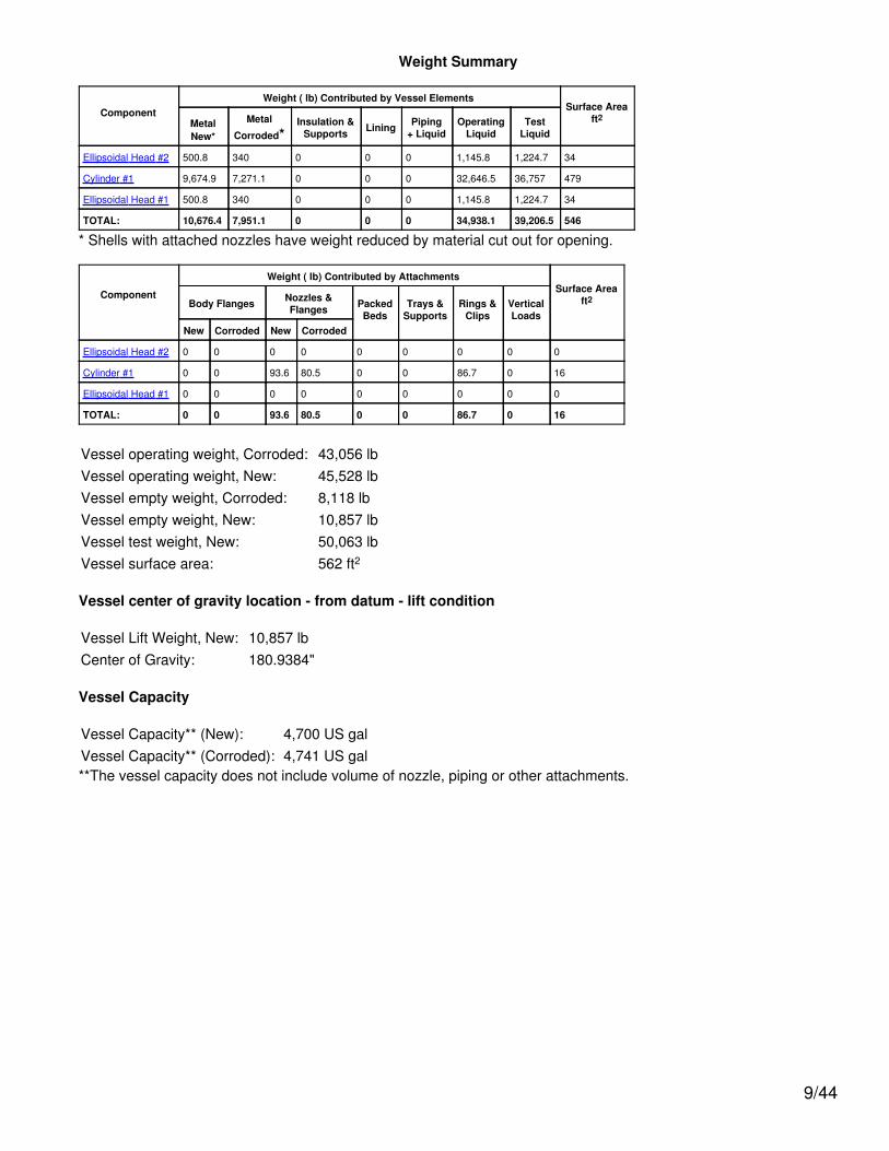
From table G: A = 0.000153From tableCS-2: B = 2,193.2461
psi
Pa = 4*B / (3*(Do / t))
= 4*2,193.25 / (3*(61 /0.3129))
= 15 psi
Design thickness for external pressure Pa = 15 psi
ta = t +Corrosion = 0.3129
+ 0.125 = 0.4379"
Maximum Allowable External Pressure, (Corroded & at 300 °F) UG-28(c)
L /Do
= 187.0417/ 61 = 3.0663
Do/ t = 61 /
0.375 = 162.6667
From table G: A = 0.000203From tableCS-2: B = 2,910.7112
psi
Pa = 4*B / (3*(Do / t))
= 4*2,910.71 / (3*(61 /0.375))
= 23.86 psi
% Extreme fiber elongation - UCS-79(d)
EFE = (50*t / Rf)*(1 - Rf / Ro)= (50*0.5 / 30.25)*(1 - 30.25 / ∞)= 0.8264%
The extreme fiber elongation does not exceed 5%.
15/44

Ellipsoidal Head #2
ASME Section VIII, Division 1, 2007 Edition
Component: Ellipsoidal HeadMaterial Specification: SA-516 70 (II-D p.18, ln. 22)Straight Flange governs MDMT
Internal design pressure: P = 150 psi @ 250 °FExternal design pressure: Pe = 15 psi @ 250 °F
Static liquid head:
Ps= 1.7868 psi (SG=1.1, Hs=45" Operating head)Pth= 2.7073 psi (SG=1, Hs=75" Horizontal test head)
Corrosion allowance: Inner C = 0.125" Outer C = 0"
Design MDMT = 15°F No impact test performedRated MDMT = -45.8°F Material is not normalized
Material is not produced to fine grain practicePWHT is not performedDo not Optimize MDMT / Find MAWP
Radiography: Category A joints - Seamless No RT Head to shell seam - Spot UW-11(a)(5)(b) Type 1
Estimated weight*: new = 500.8 lb corr = 340 lbCapacity*: new = 146.9 US gal corr = 149.1 US gal* includes straight flange
Inner diameter = 60"Minimum head thickness = 0.375"Head ratio D/2h = 2 (new)Head ratio D/2h = 1.9917 (corroded)Straight flange length Lsf = 2"Nominal straight flange thickness tsf = 0.5"Results Summary
The governing condition is internal pressure.Minimum thickness per UG-16 = 0.0625" + 0.125" = 0.1875"Design thickness due to internal pressure (t) = 0.3526"Design thickness due to external pressure (te) = 0.281"Maximum allowable pressure (MAP) = 249.69 psiMaximum allowable external pressure (MAEP) = 38.6 psi
K (Corroded)
K=(1/6)*[2 + (D / (2*h))2]=(1/6)*[2 + (60.25 / (2*15.125))2]=0.994502
K (New)
K=(1/6)*[2 + (D / (2*h))2]=(1/6)*[2 + (60 / (2*15))2]=1
16/44

Design thickness for internal pressure, (Corroded at 250 °F) Appendix 1-4(c)
t = P*D*K / (2*S*E - 0.2*P) + Corrosion= 151.79*60.25*0.994502 / (2*20,000*1 - 0.2*151.79) + 0.125= 0.3525"
The head internal pressure design thickness is 0.3526".
Maximum allowable pressure, (New at 70 °F) Appendix 1-4(c)
P = 2*S*E*t / (K*D + 0.2*t) - Ps= 2*20,000*1*0.375 / (1*60 +0.2*0.375) - 0= 249.69 psi
The maximum allowable pressure (MAP) is 249.69 psi.
Design thickness for external pressure, (Corroded at 250 °F) UG-33(d)
Equivalent outside spherical radius (Ro)Ro = Ko*Do
= 0.889*60.75= 54.0082 in
A = 0.125 / (Ro / t)= 0.125 / (54.0082 / 0.155989)= 0.000361
From Table CS-2: B=5,193.4546 psi
Pa = B / (Ro / t)= 5,193.455 / (54.0082 / 0.156)= 15 psi
t = 0.156" + Corrosion = 0.156" + 0.125" = 0.281"Check the external pressure per UG-33(a)(1) Appendix 1-4(c)
t = 1.67*Pe*D*K / (2*S*E - 0.2*1.67*Pe) + Corrosion= 1.67*15*60.25*0.994502 / (2*20,000*1 - 0.2*1.67*15) + 0.125= 0.1625"
The head external pressure design thickness (te) is 0.281".
Maximum Allowable External Pressure, (Corroded at 250 °F) UG-33(d)
Equivalent outside spherical radius (Ro)Ro = Ko*Do
= 0.889*60.75= 54.0082 in
A = 0.125 / (Ro / t)= 0.125 / (54.0082 / 0.25)= 0.000579
From Table CS-2: B=8,339.8389 psi
Pa = B / (Ro / t)= 8,339.839 / (54.0082 / 0.25)
17/44

= 38.6045 psi
Check the Maximum External Pressure, UG-33(a)(1) Appendix 1-4(c)
P = 2*S*E*t / ((K*D + 0.2*t)*1.67) - Ps2= 2*20,000*1*0.25 / ((0.994502*60.25 +0.2*0.25)*1.67) - 0= 99.85 psi
The maximum allowable external pressure (MAEP) is 38.6 psi.
% Extreme fiber elongation - UCS-79(d)
EFE = (75*t / Rf)*(1 - Rf / Ro)= (75*0.5 / 10.45)*(1 - 10.45 / ∞)= 3.5885%
The extreme fiber elongation does not exceed 5%.
18/44

Straight Flange on Ellipsoidal Head #2
ASME Section VIII Division 1, 2007 Edition
Component: Straight FlangeMaterial specification: SA-516 70 (II-D p. 18, ln. 22)Material impact test exemption temperature from Fig UCS-66 Curve B = -7 °FFig UCS-66.1 MDMT reduction = 38.8 °F, (coincident ratio = 0.6124659)UCS-66 governing thickness = 0.5 in
Internal design pressure: P = 150 psi @ 250 °FExternal design pressure: Pe = 15 psi @ 250 °F
Static liquid head:
Ps = 1.79psi (SG = 1.1, Hs = 45",Operating head)
Pth = 2.71psi
(SG = 1, Hs = 75", Horizontal testhead)
Corrosion allowance Inner C = 0.125" Outer C = 0"
Design MDMT = 15 °F No impact test performedRated MDMT = -45.8 °F Material is not normalized
Material is not produced to Fine Grain PracticePWHT is not performed
Radiography: Longitudinal joint - Seamless No RTCircumferential joint - Spot UW-11(a)(5)b Type 1
Estimated weight New = 53.8 lb corr = 40.4 lbCapacity New = 24.48 US gal corr = 24.68 US gal
ID = 60"LengthLc
= 2"
t = 0.5"
Design thickness, (at 250 °F) UG-27(c)(1)
t = P*R / (S*E - 0.60*P) + Corrosion= 151.79*30.125 / (20,000*1.00 - 0.60*151.79) + 0.125= 0.3547"
Maximum allowable pressure, (at 70 °F) UG-27(c)(1)
P = S*E*t / (R + 0.60*t)= 20,000*1.00*0.5 / (30 + 0.60*0.5)= 330.03 psi
External Pressure, (Corroded & at 250 °F) UG-28(c)
L /Do
= 187.0417/ 61 = 3.0663
Do/ t = 61 /
0.3129 = 194.9551
From table G: A = 0.000153
19/44

From tableCS-2: B = 2,193.2463
psi
Pa = 4*B / (3*(Do / t))
= 4*2,193.25 / (3*(61 /0.3129))
= 15 psi
Design thickness for external pressure Pa = 15 psi
ta = t +Corrosion = 0.3129
+ 0.125 = 0.4379"
Maximum Allowable External Pressure, (Corroded & at 250 °F) UG-28(c)
L /Do
= 187.0417/ 61 = 3.0663
Do/ t = 61 /
0.375 = 162.6667
From table G: A = 0.000203From tableCS-2: B = 2,910.7119
psi
Pa = 4*B / (3*(Do / t))
= 4*2,910.71 / (3*(61 /0.375))
= 23.86 psi
% Extreme fiber elongation - UCS-79(d)
EFE = (50*t / Rf)*(1 - Rf / Ro)= (50*0.5 / 30.25)*(1 - 30.25 / ∞)= 0.8264%
The extreme fiber elongation does not exceed 5%.
20/44

Straight Flange on Ellipsoidal Head #1
ASME Section VIII Division 1, 2007 Edition
Component: Straight FlangeMaterial specification: SA-516 70 (II-D p. 18, ln. 22)Material impact test exemption temperature from Fig UCS-66 Curve B = -7 °FFig UCS-66.1 MDMT reduction = 38.8 °F, (coincident ratio = 0.6124659)UCS-66 governing thickness = 0.5 in
Internal design pressure: P = 150 psi @ 250 °FExternal design pressure: Pe = 15 psi @ 250 °F
Static liquid head:
Ps = 1.79psi (SG = 1.1, Hs = 45",Operating head)
Pth = 2.71psi
(SG = 1, Hs = 75", Horizontal testhead)
Corrosion allowance Inner C = 0.125" Outer C = 0"
Design MDMT = 15 °F No impact test performedRated MDMT = -45.8 °F Material is not normalized
Material is not produced to Fine Grain PracticePWHT is not performed
Radiography: Longitudinal joint - Seamless No RTCircumferential joint - Spot UW-11(a)(5)b Type 1
Estimated weight New = 53.8 lb corr = 40.4 lbCapacity New = 24.48 US gal corr = 24.68 US gal
ID = 60"LengthLc
= 2"
t = 0.5"
Design thickness, (at 250 °F) UG-27(c)(1)
t = P*R / (S*E - 0.60*P) + Corrosion= 151.79*30.125 / (20,000*1.00 - 0.60*151.79) + 0.125= 0.3547"
Maximum allowable pressure, (at 70 °F) UG-27(c)(1)
P = S*E*t / (R + 0.60*t)= 20,000*1.00*0.5 / (30 + 0.60*0.5)= 330.03 psi
External Pressure, (Corroded & at 250 °F) UG-28(c)
L /Do
= 187.0417/ 61 = 3.0663
Do/ t = 61 /
0.3129 = 194.9551
From table G: A = 0.000153
21/44

From tableCS-2: B = 2,193.2461
psi
Pa = 4*B / (3*(Do / t))
= 4*2,193.25 / (3*(61 /0.3129))
= 15 psi
Design thickness for external pressure Pa = 15 psi
ta = t +Corrosion = 0.3129
+ 0.125 = 0.4379"
Maximum Allowable External Pressure, (Corroded & at 250 °F) UG-28(c)
L /Do
= 187.0417/ 61 = 3.0663
Do/ t = 61 /
0.375 = 162.6667
From table G: A = 0.000203From tableCS-2: B = 2,910.7112
psi
Pa = 4*B / (3*(Do / t))
= 4*2,910.71 / (3*(61 /0.375))
= 23.86 psi
% Extreme fiber elongation - UCS-79(d)
EFE = (50*t / Rf)*(1 - Rf / Ro)= (50*0.5 / 30.25)*(1 - 30.25 / ∞)= 0.8264%
The extreme fiber elongation does not exceed 5%.
22/44

Ellipsoidal Head #1
ASME Section VIII, Division 1, 2007 Edition
Component: Ellipsoidal HeadMaterial Specification: SA-516 70 (II-D p.18, ln. 22)Straight Flange governs MDMT
Internal design pressure: P = 150 psi @ 250 °FExternal design pressure: Pe = 15 psi @ 250 °F
Static liquid head:
Ps= 1.7868 psi (SG=1.1, Hs=45" Operating head)Pth= 2.7073 psi (SG=1, Hs=75" Horizontal test head)
Corrosion allowance: Inner C = 0.125" Outer C = 0"
Design MDMT = 15°F No impact test performedRated MDMT = -45.8°F Material is not normalized
Material is not produced to fine grain practicePWHT is not performedDo not Optimize MDMT / Find MAWP
Radiography: Category A joints - Seamless No RT Head to shell seam - Spot UW-11(a)(5)(b) Type 1
Estimated weight*: new = 500.8 lb corr = 340 lbCapacity*: new = 146.9 US gal corr = 149.1 US gal* includes straight flange
Inner diameter = 60"Minimum head thickness = 0.375"Head ratio D/2h = 2 (new)Head ratio D/2h = 1.9917 (corroded)Straight flange length Lsf = 2"Nominal straight flange thickness tsf = 0.5"Results Summary
The governing condition is internal pressure.Minimum thickness per UG-16 = 0.0625" + 0.125" = 0.1875"Design thickness due to internal pressure (t) = 0.3526"Design thickness due to external pressure (te) = 0.281"Maximum allowable pressure (MAP) = 249.69 psiMaximum allowable external pressure (MAEP) = 38.6 psi
K (Corroded)
K=(1/6)*[2 + (D / (2*h))2]=(1/6)*[2 + (60.25 / (2*15.125))2]=0.994502
K (New)
K=(1/6)*[2 + (D / (2*h))2]=(1/6)*[2 + (60 / (2*15))2]=1
23/44

Design thickness for internal pressure, (Corroded at 250 °F) Appendix 1-4(c)
t = P*D*K / (2*S*E - 0.2*P) + Corrosion= 151.79*60.25*0.994502 / (2*20,000*1 - 0.2*151.79) + 0.125= 0.3525"
The head internal pressure design thickness is 0.3526".
Maximum allowable pressure, (New at 70 °F) Appendix 1-4(c)
P = 2*S*E*t / (K*D + 0.2*t) - Ps= 2*20,000*1*0.375 / (1*60 +0.2*0.375) - 0= 249.69 psi
The maximum allowable pressure (MAP) is 249.69 psi.
Design thickness for external pressure, (Corroded at 250 °F) UG-33(d)
Equivalent outside spherical radius (Ro)Ro = Ko*Do
= 0.889*60.75= 54.0082 in
A = 0.125 / (Ro / t)= 0.125 / (54.0082 / 0.155989)= 0.000361
From Table CS-2: B=5,193.4546 psi
Pa = B / (Ro / t)= 5,193.455 / (54.0082 / 0.156)= 15 psi
t = 0.156" + Corrosion = 0.156" + 0.125" = 0.281"Check the external pressure per UG-33(a)(1) Appendix 1-4(c)
t = 1.67*Pe*D*K / (2*S*E - 0.2*1.67*Pe) + Corrosion= 1.67*15*60.25*0.994502 / (2*20,000*1 - 0.2*1.67*15) + 0.125= 0.1625"
The head external pressure design thickness (te) is 0.281".
Maximum Allowable External Pressure, (Corroded at 250 °F) UG-33(d)
Equivalent outside spherical radius (Ro)Ro = Ko*Do
= 0.889*60.75= 54.0082 in
A = 0.125 / (Ro / t)= 0.125 / (54.0082 / 0.25)= 0.000579
From Table CS-2: B=8,339.8389 psi
Pa = B / (Ro / t)= 8,339.839 / (54.0082 / 0.25)
24/44

= 38.6045 psi
Check the Maximum External Pressure, UG-33(a)(1) Appendix 1-4(c)
P = 2*S*E*t / ((K*D + 0.2*t)*1.67) - Ps2= 2*20,000*1*0.25 / ((0.994502*60.25 +0.2*0.25)*1.67) - 0= 99.85 psi
The maximum allowable external pressure (MAEP) is 38.6 psi.
% Extreme fiber elongation - UCS-79(d)
EFE = (75*t / Rf)*(1 - Rf / Ro)= (75*0.5 / 10.45)*(1 - 10.45 / ∞)= 3.5885%
The extreme fiber elongation does not exceed 5%.
25/44

Rings #1
Stiffener ring calculations per UG-29(a)
Ring type: Flat barRing description: 3/8x4 Flat BarRing material: SA-516 70 (II-D p. 18, ln. 22)External pressure: 15 psiRing is located: outside the vesselDistance from ring neutral axis to datum: 180 inRing corrosion allowance: 0 inDistance to previous support: 187.0417 inDistance to next support: 187.0417 in
L / Do = 187.0417 / 61 = 3.066257Do / t = 61 / 0.3130040 = 194.8857From Table G: A = 0.000153From Table CS-2: B = 2,195 psi
Pa = 4*B / (3*(Do / t))= 4*2,195 / (3*(61 / 0.3130040))= 15.016 psi
B = 0.75*P*Do / (t + As / Ls)= 0.75*15*61 / (0.313 + 1.5 / 187.0417)= 2,138 psi
From Table CS-2: A = 0.00014916 (ring, 300°F)
Is' = [Do2*Ls*(t + As / Ls)*A] / 10.9
= [612*187.0417*(0.313 + 1.5 / 187.0417)*0.00014916] / 10.9= 3.057364 in4
I' for the composite corroded shell-ring cross section is 6.100676 in4
As I' >= Is' a 3/8x4 Flat Bar stiffener is adequate for an external pressure of 15 psi.
Check the stiffener ring attachment welds per UG-30
Fillet weld is: Continuous both sidesFillet weld leg size: 0.25 inVessel thickness at weld location, new: 0.5 inVessel corrosion allowance at weld location: 0.125 inStiffener thickness at weld location: 0.375 in
Per UG-30(f)(1) the minimum attachment weld size is 0.25 in
The fillet weld size of 0.25 in is adequate per UG-30(f)(1).
Radial pressure load, P*Ls = 15*187.0417 = 2,805.62 lbf/inRadial shear load, V = 0.01*P*Ls*Do = 0.01*15*187.0417*61 = 1,711.43 lbf
26/44
First moment of area, Q = 1.97*0.9448 = 1.864 in3
Weld shear flow, q = V*Q / I' = 522.9177 lbf/inCombined weld load, fw = Sqr(2,805.62482 + 522.91772) = 2,853.94 lbf/in
Allowable weld stress per UW-18(d) Sw = 0.55*S = 0.55*20,000 = 11,000 psi
Fillet weld size required to resist radial pressure and shear
= fw*(dweld segment
+ dtoe
) / (Sw*dweld total
) + corrosion= 2,853.94*(1 + 0) / (11,000*2) + 0= 0.1297 in
The fillet weld size of 0.25 in is adequate to resist radial pressure and shear.
27/44
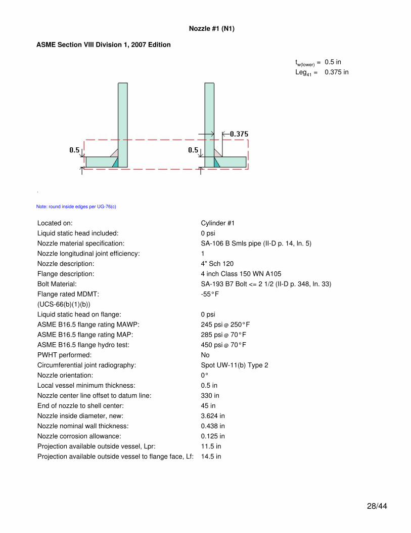
Nozzle #1 (N1)
ASME Section VIII Division 1, 2007 Edition
tw(lower) = 0.5 inLeg41 = 0.375 in
Note: round inside edges per UG-76(c)
Located on: Cylinder #1Liquid static head included: 0 psiNozzle material specification: SA-106 B Smls pipe (II-D p. 14, ln. 5)Nozzle longitudinal joint efficiency: 1Nozzle description: 4" Sch 120Flange description: 4 inch Class 150 WN A105Bolt Material: SA-193 B7 Bolt <= 2 1/2 (II-D p. 348, ln. 33)Flange rated MDMT: -55°F(UCS-66(b)(1)(b))Liquid static head on flange: 0 psiASME B16.5 flange rating MAWP: 245 psi @ 250°FASME B16.5 flange rating MAP: 285 psi @ 70°FASME B16.5 flange hydro test: 450 psi @ 70°FPWHT performed: NoCircumferential joint radiography: Spot UW-11(b) Type 2Nozzle orientation: 0°Local vessel minimum thickness: 0.5 inNozzle center line offset to datum line: 330 inEnd of nozzle to shell center: 45 inNozzle inside diameter, new: 3.624 inNozzle nominal wall thickness: 0.438 inNozzle corrosion allowance: 0.125 inProjection available outside vessel, Lpr: 11.5 inProjection available outside vessel to flange face, Lf: 14.5 in
28/44

Reinforcement Calculations for Internal Pressure
UG-37 Area Calculation Summary (in2)For P = 150 psi @ 250 °F
The opening is adequately reinforced
UG-45 NozzleWall
ThicknessSummary (in)The nozzle passes
UG-45
Arequired
Aavailable A1 A2 A3 A5
Awelds treq tmin
0.8998 1.0762 0.5601 0.3959 -- -- 0.1202 0.3324 0.3833
UG-41 Weld Failure Path Analysis Summary
The nozzle is exempt from weld strength calculationsper UW-15(b)(1)
UW-16 Weld Sizing Summary
Weld description Required weldthroat size (in)
Actual weldthroat size (in) Status
Nozzle to shell fillet (Leg41) 0.2191 0.2625 weld size is adequate
Calculations for internal pressure 150 psi @ 250 °F
Fig UCS-66.2 general note (1) applies.
Nozzle is impact test exempt to -155 °F per UCS-66(b)(3) (coincident ratio = 0.06614).
Nozzle UCS-66 governing thk: 0.3833 inNozzle rated MDMT: -155 °FParallel Limit of reinforcement per UG-40
LR = MAX(d, Rn + (tn - Cn) + (t - C))= MAX(3.874, 1.937 + (0.438 - 0.125) + (0.5 - 0.125))= 3.874 in
Outer Normal Limit of reinforcement per UG-40
LH = MIN(2.5*(t - C), 2.5*(tn - Cn) + te)= MIN(2.5*(0.5 - 0.125), 2.5*(0.438 - 0.125) + 0)= 0.7825 in
Nozzle required thickness per UG-27(c)(1)
trn = P*Rn / (Sn*E - 0.6*P)= 150*1.937 / (17,100*1 - 0.6*150)= 0.0171 in
29/44

Required thickness tr from UG-37(a)
tr = P*R / (S*E - 0.6*P)= 150*30.125 / (20,000*1 - 0.6*150)= 0.227 in
Area required per UG-37(c)
Allowable stresses: Sn = 17,100, Sv = 20,000 psi
fr1 = lesser of 1 or Sn / Sv = 0.855
fr2 = lesser of 1 or Sn / Sv = 0.855
A = d*tr*F + 2*tn*tr*F*(1 - fr1)= 3.874*0.227*1 + 2*0.313*0.227*1*(1 - 0.855)= 0.8998 in2
Area available from FIG. UG-37.1
A1 = larger of the following= 0.5601 in2
= d*(E1*t - F*tr) - 2*tn*(E1*t - F*tr)*(1 - fr1)= 3.874*(1*0.375 - 1*0.227) - 2*0.313*(1*0.375 - 1*0.227)*(1 - 0.855)= 0.5601 in2
= 2*(t + tn)*(E1*t - F*tr) - 2*tn*(E1*t - F*tr)*(1 - fr1)= 2*(0.375 + 0.313)*(1*0.375 - 1*0.227) - 2*0.313*(1*0.375 - 1*0.227)*(1 - 0.855)= 0.1903 in2
A2 = smaller of the following= 0.3959 in2
= 5*(tn - trn)*fr2*t= 5*(0.313 - 0.0171)*0.855*0.375= 0.4744 in2
= 5*(tn - trn)*fr2*tn= 5*(0.313 - 0.0171)*0.855*0.313= 0.3959 in2
A41 = Leg2*fr2= 0.3752*0.855= 0.1202 in2
Area = A1 + A2 + A41
= 0.5601 + 0.3959 + 0.1202
30/44

= 1.0762 in2
As Area >= A the reinforcement is adequate.
UW-16(c) Weld Check
Fillet weld: tmin = lesser of 0.75 or tn or t = 0.313 intc(min) = lesser of 0.25 or 0.7*tmin = 0.2191 intc(actual) = 0.7*Leg = 0.7*0.375 = 0.2625 in
The fillet weld size is satisfactory.
Weld strength calculations are not required for this detail which conforms to Fig. UW-16.1, sketch (c-e).
UG-45 Nozzle Neck Thickness Check
Wall thickness per UG-45(a): tr1 = 0.1421 in (E =1)Wall thickness per UG-45(b)(1): tr2 = 0.352 inWall thickness per UG-16(b): tr3 = 0.1875 inStandard wall pipe per UG-45(b)(4): tr4 = 0.3324 inThe greater of tr2 or tr3: tr5 = 0.352 inThe lesser of tr4 or tr5: tr6 = 0.3324 in
31/44

Required per UG-45 is the larger of tr1 or tr6 = 0.3324 in
Available nozzle wall thickness new, tn = 0.875*0.438 = 0.3833 in
The nozzle neck thickness is adequate.
Reinforcement Calculations for External Pressure
UG-37 Area Calculation Summary (in2)For Pe = 15 psi @ 300 °F
The opening is adequately reinforced
UG-45 NozzleWall
ThicknessSummary (in)The nozzle passes
UG-45
Arequired
Aavailable A1 A2 A3 A5
Awelds treq tmin
0.6203 0.7425 0.235 0.3873 -- -- 0.1202 0.1875 0.3833
UG-41 Weld Failure Path Analysis Summary
Weld strength calculations are not required for externalpressure
UW-16 Weld Sizing Summary
Weld description Required weldthroat size (in)
Actual weldthroat size (in) Status
Nozzle to shell fillet (Leg41) 0.2191 0.2625 weld size is adequate
Calculations for external pressure 15 psi @ 300 °F
Parallel Limit of reinforcement per UG-40
LR = MAX(d, Rn + (tn - Cn) + (t - C))= MAX(3.874, 1.937 + (0.438 - 0.125) + (0.5 - 0.125))= 3.874 in
Outer Normal Limit of reinforcement per UG-40
LH = MIN(2.5*(t - C), 2.5*(tn - Cn) + te)= MIN(2.5*(0.5 - 0.125), 2.5*(0.438 - 0.125) + 0)= 0.7825 in
Nozzle required thickness per UG-28 trn = 0.0235 in
From UG-37(d)(1) required thickness tr = 0.3129 in
Area required per UG-37(d)(1)
Allowable stresses: Sn = 17,100, Sv = 20,000 psi
32/44
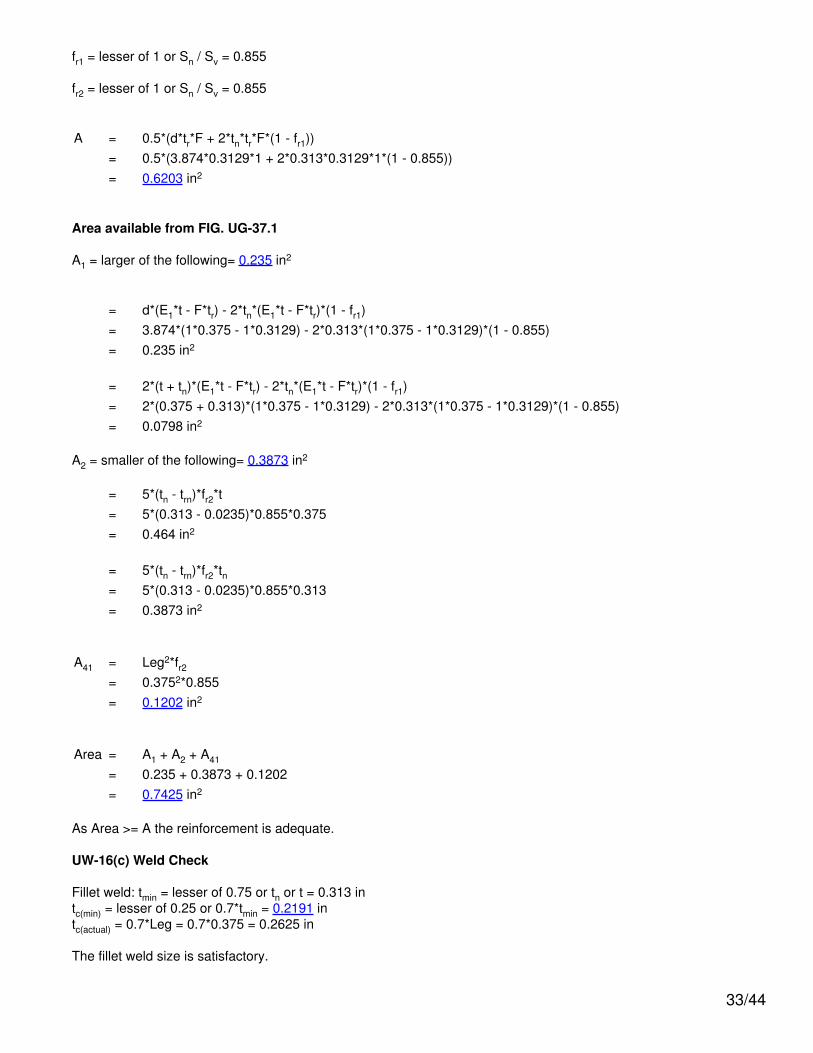
fr1 = lesser of 1 or Sn / Sv = 0.855
fr2 = lesser of 1 or Sn / Sv = 0.855
A = 0.5*(d*tr*F + 2*tn*tr*F*(1 - fr1))= 0.5*(3.874*0.3129*1 + 2*0.313*0.3129*1*(1 - 0.855))= 0.6203 in2
Area available from FIG. UG-37.1
A1 = larger of the following= 0.235 in2
= d*(E1*t - F*tr) - 2*tn*(E1*t - F*tr)*(1 - fr1)= 3.874*(1*0.375 - 1*0.3129) - 2*0.313*(1*0.375 - 1*0.3129)*(1 - 0.855)= 0.235 in2
= 2*(t + tn)*(E1*t - F*tr) - 2*tn*(E1*t - F*tr)*(1 - fr1)= 2*(0.375 + 0.313)*(1*0.375 - 1*0.3129) - 2*0.313*(1*0.375 - 1*0.3129)*(1 - 0.855)= 0.0798 in2
A2 = smaller of the following= 0.3873 in2
= 5*(tn - trn)*fr2*t= 5*(0.313 - 0.0235)*0.855*0.375= 0.464 in2
= 5*(tn - trn)*fr2*tn= 5*(0.313 - 0.0235)*0.855*0.313= 0.3873 in2
A41 = Leg2*fr2= 0.3752*0.855= 0.1202 in2
Area = A1 + A2 + A41
= 0.235 + 0.3873 + 0.1202= 0.7425 in2
As Area >= A the reinforcement is adequate.
UW-16(c) Weld Check
Fillet weld: tmin = lesser of 0.75 or tn or t = 0.313 intc(min) = lesser of 0.25 or 0.7*tmin = 0.2191 intc(actual) = 0.7*Leg = 0.7*0.375 = 0.2625 in
The fillet weld size is satisfactory.
33/44

Weld strength calculations are not required for this detail which conforms to Fig. UW-16.1, sketch (c-e).
UG-45 Nozzle Neck Thickness Check
Wall thickness per UG-45(a): tr1 = 0.1485 inWall thickness per UG-45(b)(2): tr2 = 0.1476 inWall thickness per UG-16(b): tr3 = 0.1875 inStandard wall pipe per UG-45(b)(4): tr4 = 0.3324 inThe greater of tr2 or tr3: tr5 = 0.1875 inThe lesser of tr4 or tr5: tr6 = 0.1875 in
Required per UG-45 is the larger of tr1 or tr6 = 0.1875 in
Available nozzle wall thickness new, tn = 0.875*0.438 = 0.3833 in
The nozzle neck thickness is adequate.
External Pressure, (Corroded & at 300 °F) UG-28(c)
L /Do
= 14.5831/ 4.5 = 3.2407
Do/ t = 4.5 /
0.0235 = 191.1050
From table G: A = 0.000150From tableCS-2: B = 2,149.908
psi
Pa = 4*B / (3*(Do / t))
= 4*2,149.91 / (3*(4.5 /0.0235))
= 15 psi
Design thickness for external pressure Pa = 15 psi
ta = t +Corrosion = 0.0235
+ 0.125 = 0.1485"
34/44

Nozzle #2 (N2)
ASME Section VIII Division 1, 2007 Edition
tw(lower) = 0.5 inLeg41 = 0.375 intw(upper) = 0.5 inLeg42 = 0.3125 inDp = 10.625 inte = 0.5 in
Note: round inside edges per UG-76(c)
Located on: Cylinder #1Liquid static head included: 0 psiNozzle material specification: SA-106 B Smls pipe (II-D p. 14, ln. 5)Nozzle longitudinal joint efficiency: 1Nozzle description: 6" Sch 80 (XS)Pad material specification: SA-516 70 (II-D p. 18, ln. 22)Pad diameter: 10.625 inFlange description: 6 inch Class 150 WN A105Bolt Material: SA-193 B7 Bolt <= 2 1/2 (II-D p. 348, ln. 33)Flange rated MDMT: -55°F(UCS-66(b)(1)(b))Liquid static head on flange: 0 psiASME B16.5 flange rating MAWP: 245 psi @ 250°FASME B16.5 flange rating MAP: 285 psi @ 70°FASME B16.5 flange hydro test: 450 psi @ 70°FPWHT performed: NoCircumferential joint radiography: Spot UW-11(b) Type 2Nozzle orientation: 0°Local vessel minimum thickness: 0.5 inNozzle center line offset to datum line: 280 inEnd of nozzle to shell center: 45 inNozzle inside diameter, new: 5.761 inNozzle nominal wall thickness: 0.432 inNozzle corrosion allowance: 0.125 inProjection available outside vessel, Lpr: 11 inProjection available outside vessel to flange face, Lf: 14.5 inPad is split: No
35/44
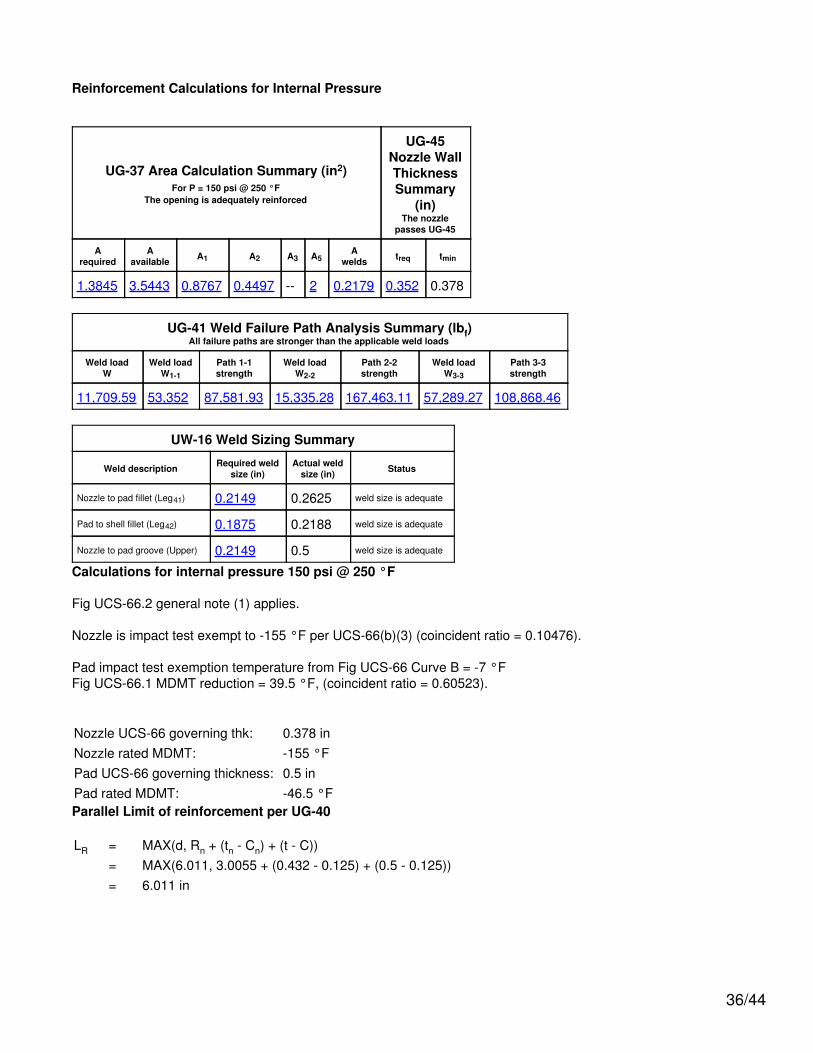
Reinforcement Calculations for Internal Pressure
UG-37 Area Calculation Summary (in2)For P = 150 psi @ 250 °F
The opening is adequately reinforced
UG-45Nozzle WallThicknessSummary
(in)The nozzle
passes UG-45
Arequired
Aavailable A1 A2 A3 A5
Awelds treq tmin
1.3845 3.5443 0.8767 0.4497 -- 2 0.2179 0.352 0.378
UG-41 Weld Failure Path Analysis Summary (lbf)All failure paths are stronger than the applicable weld loads
Weld loadW
Weld loadW1-1
Path 1-1strength
Weld loadW2-2
Path 2-2strength
Weld loadW3-3
Path 3-3strength
11,709.59 53,352 87,581.93 15,335.28 167,463.11 57,289.27 108,868.46
UW-16 Weld Sizing Summary
Weld description Required weldsize (in)
Actual weldsize (in) Status
Nozzle to pad fillet (Leg41) 0.2149 0.2625 weld size is adequate
Pad to shell fillet (Leg42) 0.1875 0.2188 weld size is adequate
Nozzle to pad groove (Upper) 0.2149 0.5 weld size is adequate
Calculations for internal pressure 150 psi @ 250 °F
Fig UCS-66.2 general note (1) applies.
Nozzle is impact test exempt to -155 °F per UCS-66(b)(3) (coincident ratio = 0.10476).
Pad impact test exemption temperature from Fig UCS-66 Curve B = -7 °FFig UCS-66.1 MDMT reduction = 39.5 °F, (coincident ratio = 0.60523).
Nozzle UCS-66 governing thk: 0.378 inNozzle rated MDMT: -155 °FPad UCS-66 governing thickness: 0.5 inPad rated MDMT: -46.5 °FParallel Limit of reinforcement per UG-40
LR = MAX(d, Rn + (tn - Cn) + (t - C))= MAX(6.011, 3.0055 + (0.432 - 0.125) + (0.5 - 0.125))= 6.011 in
36/44

Outer Normal Limit of reinforcement per UG-40
LH = MIN(2.5*(t - C), 2.5*(tn - Cn) + te)= MIN(2.5*(0.5 - 0.125), 2.5*(0.432 - 0.125) + 0.5)= 0.9375 in
Nozzle required thickness per UG-27(c)(1)
trn = P*Rn / (Sn*E - 0.6*P)= 150*3.0055 / (17,100*1 - 0.6*150)= 0.0265 in
Required thickness tr from UG-37(a)
tr = P*R / (S*E - 0.6*P)= 150*30.125 / (20,000*1 - 0.6*150)= 0.227 in
Area required per UG-37(c)
Allowable stresses: Sn = 17,100, Sv = 20,000, Sp = 20,000 psi
fr1 = lesser of 1 or Sn / Sv = 0.855
fr2 = lesser of 1 or Sn / Sv = 0.855
fr3 = lesser of fr2 or Sp / Sv = 0.855
fr4 = lesser of 1 or Sp / Sv = 1
A = d*tr*F + 2*tn*tr*F*(1 - fr1)= 6.011*0.227*1 + 2*0.307*0.227*1*(1 - 0.855)= 1.3845 in2
Area available from FIG. UG-37.1
A1 = larger of the following= 0.8767 in2
= d*(E1*t - F*tr) - 2*tn*(E1*t - F*tr)*(1 - fr1)= 6.011*(1*0.375 - 1*0.227) - 2*0.307*(1*0.375 - 1*0.227)*(1 - 0.855)= 0.8767 in2
= 2*(t + tn)*(E1*t - F*tr) - 2*tn*(E1*t - F*tr)*(1 - fr1)= 2*(0.375 + 0.307)*(1*0.375 - 1*0.227) - 2*0.307*(1*0.375 - 1*0.227)*(1 - 0.855)= 0.1887 in2
A2 = smaller of the following= 0.4497 in2
= 5*(tn - trn)*fr2*t
37/44

= 5*(0.307 - 0.0265)*0.855*0.375= 0.4497 in2
= 2*(tn - trn)*(2.5*tn + te)*fr2= 2*(0.307 - 0.0265)*(2.5*0.307 + 0.5)*0.855= 0.608 in2
A41 = Leg2*fr3= 0.3752*0.855= 0.1202 in2
A42 = Leg2*fr4= 0.31252*1= 0.0977 in2
A5 = (Dp - d - 2*tn)*te*fr4= (10.625 - 6.011 - 2*0.307)*0.5*1= 2 in2
Area = A1 + A2 + A41 + A42 + A5
= 0.8767 + 0.4497 + 0.1202 + 0.0977 + 2= 3.5443 in2
As Area >= A the reinforcement is adequate.
UW-16(c)(2) Weld Check
Inner fillet: tmin = lesser of 0.75 or tn or te = 0.307 intc(min) = lesser of 0.25 or 0.7*tmin = 0.2149 intc(actual) = 0.7*Leg = 0.7*0.375 = 0.2625 in
Outer fillet: tmin = lesser of 0.75 or te or t = 0.375 intw(min) = 0.5*tmin = 0.1875 intw(actual) = 0.7*Leg = 0.7*0.3125 = 0.2188 in
UG-45 Nozzle Neck Thickness Check
Wall thickness per UG-45(a): tr1 = 0.1515 in (E =1)Wall thickness per UG-45(b)(1): tr2 = 0.352 inWall thickness per UG-16(b): tr3 = 0.1875 inStandard wall pipe per UG-45(b)(4): tr4 = 0.37 inThe greater of tr2 or tr3: tr5 = 0.352 inThe lesser of tr4 or tr5: tr6 = 0.352 in
Required per UG-45 is the larger of tr1 or tr6 = 0.352 in
38/44

Available nozzle wall thickness new, tn = 0.875*0.432 = 0.378 in
The nozzle neck thickness is adequate.
Allowable stresses in joints UG-45(c) and UW-15(c)
Groove weld in tension: 0.74*20,000 = 14,800 psiNozzle wall in shear: 0.7*17,100 = 11,970 psiInner fillet weld in shear: 0.49*17,100 = 8,379 psiOuter fillet weld in shear: 0.49*20,000 = 9,800 psiUpper groove weld in tension: 0.74*20,000 = 14,800 psiStrength of welded joints:
(1) Inner fillet weld in shear(π / 2)*Nozzle OD*Leg*Si = (π / 2)*6.625*0.375*8,379 = 32,698.6 lbf
(2) Outer fillet weld in shear(π / 2)*Pad OD*Leg*So = (π / 2)*10.625*0.3125*9,800 = 51,112.24 lbf
(3) Nozzle wall in shear(π / 2)*Mean nozzle dia*tn*Sn = (π / 2)*6.318*0.307*11,970 = 36,469.69 lbf
(4) Groove weld in tension(π / 2)*Nozzle OD*tw*Sg = (π / 2)*6.625*0.375*14,800 = 57,756.22 lbf
(6) Upper groove weld in tension(π / 2)*Nozzle OD*tw*Sg = (π / 2)*6.625*0.5*14,800 = 77,008.29 lbf
Loading on welds per UG-41(b)(1)
W = (A - A1 + 2*tn*fr1*(E1*t - F*tr))*Sv
= (1.3845 - 0.8767 + 2*0.307*0.855*(1*0.375 - 1*0.227))*20,000= 11,709.59 lbf
W1-1 = (A2 + A5 + A41 + A42)*Sv
= (0.4497 + 2 + 0.1202 + 0.0977)*20,000= 53,352 lbf
W2-2 = (A2 + A3 + A41 + A43 + 2*tn*t*fr1)*Sv
= (0.4497 + 0 + 0.1202 + 0 + 2*0.307*0.375*0.855)*20,000= 15,335.28 lbf
W3-3 = (A2 + A3 + A5 + A41 + A42 + A43 + 2*tn*t*fr1)*Sv
= (0.4497 + 0 + 2 + 0.1202 + 0.0977 + 0 + 2*0.307*0.375*0.855)*20,000= 57,289.27 lbf
39/44

Load for path 1-1 lesser of W or W1-1 = 11709.59 lbfPath 1-1 through (2) & (3) = 51,112.24 + 36,469.69 = 87,581.93 lbfPath 1-1 is stronger than W so it is acceptable per UG-41(b)(2).
Load for path 2-2 lesser of W or W2-2 = 11709.59 lbfPath 2-2 through (1), (4), (6) = 32,698.6 + 57,756.22 + 77,008.29 = 167,463.11 lbfPath 2-2 is stronger than W so it is acceptable per UG-41(b)(2).
Load for path 3-3 lesser of W or W3-3 = 11709.59 lbfPath 3-3 through (2), (4) = 51,112.24 + 57,756.22 = 108,868.46 lbfPath 3-3 is stronger than W so it is acceptable per UG-41(b)(2).
Reinforcement Calculations for External Pressure
UG-37 Area Calculation Summary (in2)For Pe = 15 psi @ 300 °F
The opening is adequately reinforced
UG-45 NozzleWall
ThicknessSummary (in)The nozzle passes
UG-45
Arequired
Aavailable A1 A2 A3 A5
Awelds treq tmin
0.9543 3.0305 0.3678 0.4448 -- 2 0.2179 0.1875 0.378
UG-41 Weld Failure Path Analysis Summary
Weld strength calculations are not required for externalpressure
UW-16 Weld Sizing Summary
Weld description Required weldsize (in)
Actual weldsize (in) Status
Nozzle to pad fillet (Leg41) 0.2149 0.2625 weld size is adequate
Pad to shell fillet (Leg42) 0.1875 0.2188 weld size is adequate
Nozzle to pad groove (Upper) 0.2149 0.5 weld size is adequate
Calculations for external pressure 15 psi @ 300 °F
Parallel Limit of reinforcement per UG-40
LR = MAX(d, Rn + (tn - Cn) + (t - C))= MAX(6.011, 3.0055 + (0.432 - 0.125) + (0.5 - 0.125))= 6.011 in
Outer Normal Limit of reinforcement per UG-40
LH = MIN(2.5*(t - C), 2.5*(tn - Cn) + te)= MIN(2.5*(0.5 - 0.125), 2.5*(0.432 - 0.125) + 0.5)= 0.9375 in
40/44

Nozzle required thickness per UG-28 trn = 0.0295 in
From UG-37(d)(1) required thickness tr = 0.3129 in
Area required per UG-37(d)(1)
Allowable stresses: Sn = 17,100, Sv = 20,000, Sp = 20,000 psi
fr1 = lesser of 1 or Sn / Sv = 0.855
fr2 = lesser of 1 or Sn / Sv = 0.855
fr3 = lesser of fr2 or Sp / Sv = 0.855
fr4 = lesser of 1 or Sp / Sv = 1
A = 0.5*(d*tr*F + 2*tn*tr*F*(1 - fr1))= 0.5*(6.011*0.3129*1 + 2*0.307*0.3129*1*(1 - 0.855))= 0.9543 in2
Area available from FIG. UG-37.1
A1 = larger of the following= 0.3678 in2
= d*(E1*t - F*tr) - 2*tn*(E1*t - F*tr)*(1 - fr1)= 6.011*(1*0.375 - 1*0.3129) - 2*0.307*(1*0.375 - 1*0.3129)*(1 - 0.855)= 0.3678 in2
= 2*(t + tn)*(E1*t - F*tr) - 2*tn*(E1*t - F*tr)*(1 - fr1)= 2*(0.375 + 0.307)*(1*0.375 - 1*0.3129) - 2*0.307*(1*0.375 - 1*0.3129)*(1 - 0.855)= 0.0792 in2
A2 = smaller of the following= 0.4448 in2
= 5*(tn - trn)*fr2*t= 5*(0.307 - 0.0295)*0.855*0.375= 0.4448 in2
= 2*(tn - trn)*(2.5*tn + te)*fr2= 2*(0.307 - 0.0295)*(2.5*0.307 + 0.5)*0.855= 0.6014 in2
A41 = Leg2*fr3= 0.3752*0.855= 0.1202 in2
41/44

A42 = Leg2*fr4= 0.31252*1= 0.0977 in2
A5 = (Dp - d - 2*tn)*te*fr4= (10.625 - 6.011 - 2*0.307)*0.5*1= 2 in2
Area = A1 + A2 + A41 + A42 + A5
= 0.3678 + 0.4448 + 0.1202 + 0.0977 + 2= 3.0305 in2
As Area >= A the reinforcement is adequate.
UW-16(c)(2) Weld Check
Inner fillet: tmin = lesser of 0.75 or tn or te = 0.307 intc(min) = lesser of 0.25 or 0.7*tmin = 0.2149 intc(actual) = 0.7*Leg = 0.7*0.375 = 0.2625 in
Outer fillet: tmin = lesser of 0.75 or te or t = 0.375 intw(min) = 0.5*tmin = 0.1875 intw(actual) = 0.7*Leg = 0.7*0.3125 = 0.2188 in
UG-45 Nozzle Neck Thickness Check
Wall thickness per UG-45(a): tr1 = 0.1545 inWall thickness per UG-45(b)(2): tr2 = 0.1476 inWall thickness per UG-16(b): tr3 = 0.1875 inStandard wall pipe per UG-45(b)(4): tr4 = 0.37 inThe greater of tr2 or tr3: tr5 = 0.1875 inThe lesser of tr4 or tr5: tr6 = 0.1875 in
Required per UG-45 is the larger of tr1 or tr6 = 0.1875 in
Available nozzle wall thickness new, tn = 0.875*0.432 = 0.378 in
The nozzle neck thickness is adequate.
External Pressure, (Corroded & at 300 °F) UG-28(c)
L /Do
= 14.6804 /6.625 = 2.2159
Do /t = 6.625 /
0.0295 = 224.3186
From table G: A = 0.000176From tableCS-2: B = 2,523.5771
psi
42/44

Pa = 4*B / (3*(Do / t))
= 4*2,523.58 / (3*(6.625 /0.0295))
= 15 psi
Design thickness for external pressure Pa = 15 psi
ta = t +Corrosion = 0.0295
+ 0.125 = 0.1545"
43/44

Liquid Level bounded by Ellipsoidal Head #1
Location from Center Line 14.875"
Operating Liquid Specific Gravity 1.1Test liquid specific gravity 1
44/44