1. Develop a program to obtain bus admittance matrix Y‐bus ...
Upload
khangminh22Category
view
0download
0
BUS Updated 12/2011
0/0/00?-1No Product Name Assigned
Section NamePreliminary Working Document
WorkCentre 5335 Family Service Documentation
Service Documentation
WorkCentre 5335 Family Service Documentation
705P01303
Initial Issue
07/2011
***Xerox Private Data***
All service documentation is supplied to Xerox external customers for informational purposesonly. Xerox service documentation is intended for use by certified, product-trained service per-sonnel only. Xerox does not warrant or represent that it will notify or provide to such customerany future change to this documentation. Customer performed service of equipment, or mod-ules, components, or parts of such equipment may affect whether Xerox is responsible to fixmachine defects under the warranty offered by Xerox with respect to such equipment. Youshould consult the applicable warranty for its terms regarding customer or third-party providedservice.
If the customer services such equipment, modules, components or parts thereof, the customerreleases Xerox from any and all liability for the customer actions, and the customer agrees toindemnify, defend and hold xerox harmless from any third party claims which arise directly orindirectly for such service.
While Xerox has tried to make the documentation accurate, Xerox will have no liability arisingout of any inaccuracies or omissions. Changes are periodically made to this document.Changes, technical inaccuracies, and typographical errors will be corrected in subsequent edi-tions.
Prepared by Creative and Technical Communications – North America
800 Phillips Road, Building 218-01A
Webster, New York 14580
ISO9001 and ISO27001 Certified
©2011 by Xerox Corporation. All rights reserved.
XEROX® and XEROX and design® are trademarks of Xerox Corporation in the US and/orother countries.
Changes are periodically made to this document. Changes, technical inaccuracies, and typo-graphic errors will be corrected in subsequent editions.
CAUTION
This equipment generates, uses and can radiate radio frequency energy, and if not installedand used in accordance with the instructions documentation, may cause interference to radiocommunications. It has been tested and found to comply with the limits for a Class A comput-ing device pursuant to subpart B of part 15 of FCC rules, which are designed to provide rea-sonable protection against such interference when operated in a commercial environment.Operation of this equipment in a residential area is likely to cause interference in which casethe user, at his own expense, will be required to correct the interference.

BUS Updated 12/2011
0/0/00?-2 No Product Name Assigned
Preliminary Working DocumentSection Name

BUS Updated 12/2011
07/2011iWorkCentre 5335 Family Service Documentation
IntroductionInitial Issue
IntroductionAbout this Manual ........................................................................................................... iiiOrganization.................................................................................................................... iiiHow to Use this Documentation...................................................................................... ivSymbology and Nomenclature ........................................................................................ vTranslated Warnings ....................................................................................................... x

BUS Updated 12/2011
07/2011ii WorkCentre 5335 Family Service Documentation
Initial IssueIntroduction

BUS Updated 12/2011
07/2011iiiWorkCentre 5335 Family Service Documentation
IntroductionInitial Issue
About this ManualThis Service Manual is part of the multinational documentation system for this copier/printers.The Service Documentation is used in order to diagnose machine malfunctions, adjust compo-nents and has information which is used to maintain the product in superior operating condi-tion. It is the controlling publication for a service call. Information on its use is found in theIntroduction of the Service Documentation.
This manual contains information that applies to NASG (XC) and ESG (XE) copiers.
Service Manual RevisionThe Service Manual will be updated as the machine changes or as problem areas are identi-fied.
OrganizationThe titles of the sections and a description of the information contained in each section arecontained in the following paragraphs:
Section 1: Service Call ProceduresThis section contains procedures that determine what actions are to be taken during a servicecall on the machine and in what sequence they are to be completed. This is the entry level forall service calls.
Section 2: Status Indicator RAPsThis section contains the diagnostic aids for troubleshooting the Fault Code and non-FaultCode related faults (with the exception of image quality problems).
Section 3: Image QualityThis section contains the diagnostic aids for troubleshooting any image quality problems, aswell as image quality specifications and image defect samples.
Section 4: Repairs/AdjustmentsThis section contains all the Adjustments and Repair procedures.
Repairs
Repairs include procedures for removal and replacement of parts which have the followingspecial conditions:
When there is a personnel or machine safety issue.
When removal or replacement cannot be determined from the exploded view of theParts List.
When there is a cleaning or a lubricating activity associated with the procedure.
When the part requires an adjustment after replacement.
When a special tool is required for removal or replacement.
Use the repair procedures for the correct order of removal and replacement, for warnings, cau-tions, and notes.
Adjustments
Adjustments include procedures for adjusting the parts that must be within specification for thecorrect operation of the system.
Use the adjustment procedures for the correct sequence of operation for specifications, warn-ings, cautions and notes.
Section 5: Parts ListsThis section contains the Copier/Printer Parts List.
Section 6: General Procedures/InformationThis section contains General Procedures, Diagnostic Programs, and Copier/Printer Informa-tion.

BUS Updated 12/2011
07/2011iv WorkCentre 5335 Family Service Documentation
Initial IssueIntroduction
Section 7: Wiring DataThis section contains drawings, lists of plug/jack locations, and diagrams of the power distribu-tion wire networks in the machine. Block Schematic Diagrams are found in pdf format in theSGS.
How to Use this DocumentationThe Service Call Procedures in Section 1 describe the sequence of activities used during theservice call. The call must be entered using these procedures.
Use of the Block Schematic DiagramsBlock Schematic Diagrams (BSDs) are included in Section 7 (Wiring Data) of the SGS. TheBSDs show the functional relationship of the electrical circuitry to any mechanical, or non-mechanical, inputs or outputs throughout the machine. Inputs and outputs such as motor drive,mechanical linkages, operator actions, and air flow are shown. The BSDs will provide an over-all view of how the entire subsystem works.
It should be noted that the BSDs no longer contain an Input Power Block referring to Chain 1. Itwill be necessary to refer to the Wirenets in order to trace a wire back to its source.

BUS Updated 12/2011
07/2011vWorkCentre 5335 Family Service Documentation
IntroductionInitial Issue
Symbology and NomenclatureThe following reference symbols are used throughout the documentation.
Warnings, Cautions, and NotesWarnings, Cautions, and Notes will be found throughout the Service Documentation. Thewords WARNING or CAUTION may be listed on an illustration when the specific componentassociated with the potential hazard is pointed out; however, the message of the WARNING orCAUTION is always located in the text. Their definitions are as follows:
WARNINGDo not perform repair activities with the power on or electrical power supplied to themachine. The machine could activate and cause serious personal injury when the poweris on or electrical power is supplied.
DANGER: Ne pas effectuer de dépannage avec le contact principal activé ou avec l'ali-mentation électrique appliquée à la machine: celle-ci pourrait démarrer et causer degraves blessures.
AVVERTENZA: Non effettuare alcuna riparazione con la macchina accesa o con l'ali-mentazione elettrica inserita. La macchina potrebbe avviarsi all'improvviso e causaregravi ferite.
VORSICHT: Es dürfen keine Reparaturarbeiten durchgeführt werden, solange das Geräteingeschalten oder mit der Stromquelle verbunden ist. Das Gerät kann u.U in den Aktiv-Zustand übergehen und somit erhebliche körperliche Schäden verursachen.
AVISO: No realice reparaciones con la máquina encendida o conectada a la corriente. Lamáquina podría activarse y ocasionar daños personales graves.
CAUTION
A Caution is used whenever an operating or maintenance procedure, a practice, condition, orstatement, if not strictly observed, could result in damage to the equipment.
NOTE: A Note is used whenever it is necessary to highlight an operating or maintenance pro-cedure, practice, condition, or statement.
Machine Safety IconsThe following safety icons are displayed on the machine:

BUS Updated 12/2011
07/2011vi WorkCentre 5335 Family Service Documentation
Initial IssueIntroduction
WARNINGUse extreme care when replacing the Raster Output Scanner (ROS) or touching the highvoltage lead. Discharge the laser assembly by touching the high voltage lead to themachine frame. The ROS utilizes a laser assembly that stores a high voltage chargeafter the power has been removed and represents a shock hazard that could cause seri-ous personal injury if not discharged.
DANGER: Faire très attention lors du changement du générateur de balayage (ROS) oulors de la manipulation du câble de haute tension. Décharger le système laser entouchant le câble HT au bâti machine: le ROS utilise un système laser qui retient unehaute tension après la coupure de l'alimentation, représentant un risque de choc et degraves blessures.
AVVERTENZA: Fare estrema attenzione nel sostituire il Raster Output Scanner (ROS) onel toccare il cavo di alta tensione. Scaricare il complessivo laser collegando il cavo dialta tensione col telaio della macchina. Il ROS utilizza un complessivo laser che ritieneuna carica di alta tensione dopo il taglio dell'alimentazione con conseguente grave peri-colo di scossa elettrica e serie ferite.
VORSICHT: Beim Ersetzen der Lasereinheit (ROS) und beim Umgang mit Hochspan-nungsleitern ist äußerste Vorsicht geboten. Die Lasereinheit muss durch Berühren desHochspannungsleiters mit dem Gehäuse des Geräts entladen werden. Nach Betrieb derLasereinheit (ROS) bleibt immer eine Hochspannungsladung zurück, welche ein hohesElektroschockrisiko darstellt. Äußerste Vorsicht ist geboten.
AVISO: Use extrema precaución para sustituir el Escáner de salida ráster (ROS) o tocarel cable de alto voltaje. Descargue el sistema láser tocando el cable de alto voltaje delbastidor de la máquina. El ROS utiliza un sistema láser que retiene carga de alto voltajedespués de interrumpir la alimentación de energía y representa un grave peligro quepuede ocasionar daños personales graves si no se descarga.
WARNINGDo not defeat or electrically bypass the ROS Safety Interlock Switch for any reason. TheROS emits an undetectable laser beam that could cause serious permanent damage tothe eyes if directly viewed or viewed from a surface that may have reflected the laserbeam.
DANGER: Ne pas shunter le contact de sécurité du ROS, quelle que soit la raison. LeROS émet un rayon laser indétectable qui peut causer de graves blessures perma-nentes aux yeux s'il est regardé directement ou par le biais d'une surface qui le réflé-chit.
AVVERTENZA: Non ostacolare o bypassare elettronicamente l'interruttore blocco disicurezza ROS per nessun motivo. Il ROS emette un raggio laser invisibile che puòcausare gravi ferite permanenti agli occhi se viene guardato direttamente o attraversouna superficie riflettente.
VORSICHT: Den ROS (Rasterausgabescanner)-Sicherheitssperrschalter auf keinen Fallvernichten oder elektronisch umgehen. Der ROS sondert einen nicht feststellbarenLaserstrahl ab, der irreparable Augenschäden verursachen kann, wenn direkt oder übereine Spiegelfläche hineingesehen wird.
AVISO: No intente modificar o desviar electrónicamente el interruptor de seguridad porningún motivo. El ROS emite un rayo láser que no se puede detectar, que podría puedecausar grave daño permanente a los ojos si se lo mira directamente o desde una super-ficie que refleja el rayo láser.
Figure 1 Laser Hazard Symbol
Laser Hazard Statement
DANGER INVISIBLE LASER RADIATION WHEN OPEN. AVOID DIRECT EXPOSURE TOBEAM.
CAUTION
The use of controls or adjustments other than those specified in the Laser Safety Training Pro-gram may result in an exposure to dangerous laser radiation.
For additional information, review the Laser Safety Training program.
An arrow points to the location to install, to gain access to, or to release an object.
Figure 2 Customer Access Label
This symbol indicates that a surface can be hot. Use caution when reaching in the machine toavoid touching the hot surfaces.
Figure 3 Heated Surface Label
Danger label indicates where electrical currents exist when the machine is closed and operat-ing. Use caution when reaching in the machine.
Figure 4 Shock Hazard Label

BUS Updated 12/2011
07/2011viiWorkCentre 5335 Family Service Documentation
IntroductionInitial Issue
These symbols indicate components that may be damaged by Electrostatic Discharge (ESD).
Figure 5 ESD warning Label
Electrostatic Discharge (ESD) Field Service KitThe purpose of the ESD Protection Program is to preserve the inherent reliability and quality ofelectronic components that are handled by the Field Service Personnel. This program is beingimplemented now as a direct result of advances in microcircuitry technology, as well as a newacknowledgment of the magnitude of the ESD problem in the electronics industry today.
This program will reduce Field Service costs that are charged to PWB failures. Ninety percentof all PWB failures that are ESD related do not occur immediately. Using the ESD Field ServiceKit will eliminate these delayed failures and intermittent problems caused by ESD. This willimprove product reliability and reduce callbacks.
The ESD Field Service Kit should be used whenever Printed Wiring Boards or ESD sensitivecomponents are being handled. This includes activities like replacing or reseating of circuitboards or connectors. The kit should also be used in order to prevent additional damage whencircuit boards are returned for repair.
The instructions for using the ESD Field Service Kit can be found in ESD Field Service KitUsage in the General Procedures section of the Service Documentation.
Illustration SymbolsFigure 6 shows symbols and conventions that are commonly used in illustrations.

BUS Updated 12/2011
07/2011viii WorkCentre 5335 Family Service Documentation
Initial IssueIntroduction
Figure 6 Illustration Symbols

BUS Updated 12/2011
07/2011ixWorkCentre 5335 Family Service Documentation
IntroductionInitial Issue
Signal NomenclatureRefer to Figure 7 for an example of Signal Nomenclature used in Circuit Diagrams and BSDs.
Figure 7 Signal Nomenclature
Voltage Measurement and SpecificationsMeasurements of DC voltage must be made with reference to the specified DC Common,unless some other point is referenced in a diagnostic procedure. All measurements of AC volt-age should be made with respect to the adjacent return or ACN wire.
Logic Voltage LevelsMeasurements of logic levels must be made with reference to the specified DC Common,unless some other point is referenced in a diagnostic procedure.
DC Voltage Measurements in RAPsThe RAPs have been designed so that when it is required to use the DMM to measure a DCvoltage, the first test point listed is the location for the red (+) meter lead and the second testpoint is the location for the black meter lead. For example, the following statement may befound in a RAP:
There is +5 VDC from TP7 to TP68.
In this example, the red meter lead would be placed on TP7 and the black meter lead on TP68.
Other examples of a statement found in a RAP might be:
• There is -15 VDC from TP21 to TP33.
• -15 VDC is measured between TP21 and TP33.
• In these examples, the red meter lead would be placed on TP21 and the black meter leadwould be placed on TP33.
• If a second test point is not given, it is assumed that the black meter lead may be attachedto the copier frame.
Table 1 Voltage Measurement and Specifications
VOLTAGE SPECIFICATION
INPUT POWER 220 V 198 VAC TO 242 VAC
INPUT POWER 100 V 90 VAC TO 135 VAC
INPUT POWER 120 V 90 VAC TO 135 VAC
+5 VDC +4.75 VDC TO +5.25 VDC
+24 VDC +23.37 VDC TO +27.06 VDC
Table 2 Logic Levels
VOLTAGE H/L SPECIFICATIONS
+5 VDC H= +3.00 TO +5.25 VDCL= 0.0 TO 0.8 VDC
+24 VDC H= +23.37 TO +27.06 VDC L= 0.0 TO 0.8 VDC
BUS Updated 12/2011
07/2011x WorkCentre 5335 Family Service Documentation
Initial IssueIntroduction
Translated WarningsTranslated Warnings are located at point of need in the Service Documentation.
BUS Updated 12/2011
07/20111-1WorkCentre 5335 Family Service Documentation
Service Call ProceduresInitial Issue
1 Service Call ProceduresService Call Procedures.................................................................................................. 1-3Initial Actions ................................................................................................................... 1-3Call Flow ......................................................................................................................... 1-4Detailed Maintenance Activities (HFSI)........................................................................... 1-6Cleaning Procedures....................................................................................................... 1-6Final Actions.................................................................................................................... 1-7

BUS Updated 12/2011
07/20111-2 WorkCentre 5335 Family Service Documentation
Initial IssueService Call Procedures

BUS Updated 12/2011
07/20111-3WorkCentre 5335 Family Service Documentation Service Call Procedures, Initial Actions
Service Call ProceduresInitial Issue
Service Call ProceduresService StrategyThe service strategy for the WorkCentre 5335 Family is to perform any High Frequency Ser-vice Item (HFSI) actions before attempting to repair any problems. Some problems will be cor-rected by this strategy without the need to diagnose them. The Repair Analysis Procedures(RAPs) will be used for any remaining problems.
Problems that occur in the Basic Printer mode will be repaired before problems that occurwhen using the accessories.
Image Quality problems should be repaired after all other problems are repaired.
Service Call ProceduresThe Service Call Procedures are a guide for performing any service on this machine. Theprocedures are designed to be used with the Service Manual. Perform each step in order.
Initial Actions
The Initial Actions gather information about the condition of the machine and the problem thatcaused the service call.
Call Flow
Call Flow summarizes the sequence of the Service Call Procedures.
Detailed Maintenance Activities
Detailed Maintenance Activities section provides the information needed to perform the HighFrequency Service Item (HFSI) actions.
Cleaning Procedures
The Cleaning Procedures list what needs to be cleaned at each service call.
Final Actions
The Final Actions will test the copier/printer and return it to the customer. Administrative activi-
ties are also performed in the Final Actions.
Initial ActionsPurpose The purpose of the Initial Action section of the Service Call Procedures is to determine the rea-son for the service call and to identify and organize the actions which must be performed.
Procedure1. Gather the information about the service call and the condition of the copier/printer.
a. Question the operator(s). Ask about the location of most recent paper jams. Askabout the image quality and the copier/printer performance in general, including anyunusual sounds or other indications.
b. After informing the customer, disconnect the machine from the customer’s network.
c. Check that the power cords are in good condition, correctly plugged in the powersource, and free from any defects that would be a safety hazard. Repair or replacethe power cords as required. Check that the circuit breakers are not tripped.
d. Inspect any rejected copies. Inquire as to, or otherwise determine, the paper qualityand weight, the specified paper for optimum Image Quality, 24# Xerox Color Expres-sions (NASG) or ColorTech+90gsm (ESG). Look for any damage to the copies, oilmarks, image quality defects, or other indications of a problem.
e. Record the billing meter readings.
f. Access Diagnostic Routines (Accessing UI Diagnostics)..
NOTE: If a fault code is displayed while performing a diagnostics procedure, go tothat fault code RAP and repair the fault. Return to Diagnostics and continue with thedC procedure that you were performing.
g. Print the HFSI Report and determine what HFSI action is required based on the cus-tomer output volume. Refer to the Detailed Maintenance Activities section for thedetailed HFSI information. Record any items that require action.
h. Display and record the information in the Jam Counter, Fault Counter, and ShutdownHistory. Classify this information into categories:
Information that is related to the problem that caused the service call.
Information that is related to secondary problems.
Information that does not require action, such as a single occurrence of a prob-lem.
i. Check the Service Log for any recent activities that are related to the problem thatcaused the service call or any secondary problem.
2. Perform any required HFSI activities identified above. Refer to the Detailed MaintenanceActivities section.
3. Exit diagnostics. Try to duplicate the problem by running the same jobs that the customerwas running.
4. Check the Image Quality in the Basic Copier Mode. Select the tray that is loaded with 11 x17 or A3 paper, if unable to complete tray selection, go to Call Flow.
Set the copier/printer to the following setup:
• Output Color - Auto
• Original Type - Photo and Text Halftone
• R/E - Auto
• Lighter/Darker - Auto Contrast

BUS Updated 12/2011
07/20111-4 WorkCentre 5335 Family Service DocumentationInitial Actions, Call Flow
Initial IssueService Call Procedures
• Sharpness - Normal
• Preset Color Balance - Normal
• Color Shift - Normal
• Color Saturation - Normal
• Copy Position - No Shift
• Variable Color Balance - Normal
Run four copies of the Color Test Pattern.
Check the Image Quality. If the customer has identified any Image Quality Defects orproblems, go to IQ1 IOT Image Quality Entry RAP.
5. Go to Call Flow.
Call FlowThis procedure should be performed at every service call.
Initial ActionsAsk the operator about the problem. If the problem appears to be related to operator error, oran attempt to perform a job outside of the machine specifications, assist the customer in learn-ing the correct procedure.
ProcedureAsk the operator about the problem.• If the problem is identified by a fault code (including Paper/Document Jams), refer to Sec-
tion 2 for the procedure and then proceed with servicing.
• If the problem is noise or smell, select a mode (1 Sided/2Sided, Finisher etc.), find thecause of the problem and proceed with servicing.
The operator operated the machine correctly.Y N
Explain to the operator how to operate the machine correctly.
The UI display is normal.Y N
Go to Machine Not Ready RAP. Refer to BSDs (CH2.1-CH2.4).
The problem occurs only in Print mode.Y N
The problem occurs only in Copy mode.Y N
The problem occurs only in Fax mode.Y N
There is an error message displayed.Y N
Refer to Table 1 Other Faults and identify the problem and follow the cor-rective action.
Refer to Table 2 Error Messages and identify the message and follow the cor-rective action.
The problem occurs only in certain modes such as Broadcast transmission.Y N
Perform a transmission test with the call center or station. The problem reoc-curs.Y N
Ask the customer for permission to establish communications withthe remote machine that is causing the problem. Perform a Sendtransmission test with the remote machine. Transmission was nor-mal.Y N
Print the protocol trace to identify whether it is the remote machine orthe machine that is causing the problem.• If the problem lies in the machine:
A B C D E

BUS Updated 12/2011
07/20111-5WorkCentre 5335 Family Service Documentation Call Flow
Service Call ProceduresInitial Issue
Analyze the protocol trace, refer to Section 2 and then proceedwith servicing.
• If the problem appears to lie in the remote machine:
Ask the customer to check the status of the remote machine.
There is a problem with Receive transmission test. Perform Receive trans-mission tests with other stations within the company. Check that there isno problem with the machine and then ask the customer to check the sta-tus of the remote machine.
Analyze the protocol trace, refer to Section 2 and then proceed with servicing.
Check the machine settings and if necessary, ask the customer for permission to testthe machine in the mode in which the problem occurs.Analyze the protocol trace when the problem reoccurs, for FAX problems go to GP13 FAX Diagnostics, or go to Section 2 to proceed with servicing.
There is an image quality problem.Y N
If there is an alignment problem, obtain separate Platen/DADF output samples, referto Section 4 Adjustments and then proceed with servicing.
Refer to Section 3 IQ1 IOT Image Quality Entry RAP and then proceed with servicing.
There is a problem with the network.Y N
There is a problem with the USB connection.Y N
There is an image quality problem.Y N
The problem lies in a certain Client PC.Y N
There is a problem with a certain application or programming language A.Obtain the latest information on restrictions and technical information. Pro-ceed accordingly.
Check the settings of that particular Client PC and if necessary ask the user toreinstall the printer driver.
Refer to IQ1 IOT Image Quality Entry RAP and then proceed with servicing.If the problem persists, ask the user to reinstall the printer driver.
Check the machine settings and if necessary ask the user to reinstall the printer driver.
If the problem continues, replace the network cable. If the problem persists, replace the USBcable. Check the machine settings and discuss the problem with the customer's networkadministrator.
Table 1 Other Faults
Problem Corrective Action
Copies jam in the Finisher when the output tray is near maximum capacity.
Verify condition of paper.
Can not make copies when Auditron is enabled.
Enter Diagnostics (Accessing UI Diagnostics).. Select Copy on screen. Machine will operate without auditron restriction.
Loud snapping noise is heard. Enter Component Control [042-003] and press the Start button. If noise is present there is binding in toner drive system. Repair as required
HCF (Tray 6) Paper Size Sensing Problems
Go to BSD 7.11 - HCF (Tray 6) Paper Size Sensing and check the Tray 6 Size Sensors for open or short circuits.
HCF (Tray 6) Paper Loading Prob-lems
Go to BSD 7.11 - HCF (Tray 6) Paper Size Sensing and check the Tray 6 In Sensor for open or short circuit.
Table 2 Error Messages
Message Corrective Action
Tray 1 is out of Paper Reload paper into Tray 1. I f problem still exists, go to 024-950 RAP
Tray 2 is out of Paper Reload paper into Tray 2. I f problem still exists, go to 024-951 RAP
Tray 3 is out of paper Reload paper into Tray 3. I f problem still exists, go to 024-952 RAP
Tray 4 is out of paper Reload paper into Tray 4. I f problem still exists, go to 024-953 RAP
Tray 5 is out of paper Reload paper into Tray 5. I f problem still exists, go to 024-954 RAP
A B C D E
F
F

BUS Updated 12/2011
07/20111-6 WorkCentre 5335 Family Service DocumentationDetailed Maintenance Activities, Cleaning Proce-
Initial IssueService Call Procedures
Detailed Maintenance Activities (HFSI)Procedure1. Access Diagnostic Routines (Accessing UI Diagnostics).
2. Select NVM Read/Write.
3. Refer to Table 1 and enter a counter number for any High Frequency Service Item (HFSI)counters to be checked. Use the customer's output volume numbers to help determinewhich HFSI components should be serviced. Consider components near threshold ascandidates for service.
4. Refer to Cleaning Procedures for detailed cleaning instructions.
Cleaning ProceduresPurposeTo provide cleaning procedures to be performed at every service call.
ProcedureCAUTION
Do not use any solvents unless directed to do so by the Service Manual.
General Cleaning
Use a dry lint free cloth or a lint free cloth moistened with water for all cleaning unless directedotherwise by the Service Manual. Wipe with a dry lint free cloth if a moistened cloth is used.
1. Feed Components (Rolls and Pads)
Follow the General Cleaning procedure above.
2. Toner Dispense Units
Vacuum the Toner Dispense units.
3. Jam Sensors
Clean the sensors with a dry cotton swab.
4. Scanner
a. Switch off the power and allow the Exposure Lamp to cool off.
b. Using the optical Cleaning Cloth, clean the front and rear of the Document Glass,Document Cover, White Reference Strip, Reflector, and Mirror.
c. Clean the Exposure Lamp with a clean cloth and Film Remover.
d. Clean the Lens with Lens and Mirror Cleaner and lint free cloth.
5. DADF
Check the paper path for debris or damage. Clean the rolls with a clean cloth and FilmRemover as required.
6. Document Glass and Constant Velocity Transport Glass
Follow the General Cleaning procedure above.
7. Finisher
Check the paper path for debris or damage. Clean the Finisher with a dry lint free cloth.
Table 1 High Frequency Service Items
Counter NameThres-hold Service Action to be performed
954-800 Tray 1 Feed counter 300K Replace the Feed Roll, Retard Roll, Nudger Roll (PL 9.7).
954-801 Tray 2 Feed counter 300K Replace the Feed Roll, Retard Roll, Nudger Roll (PL 9.7).
954-802 Tray 3 Feed counter 300K Replace the Feed Roll, Retard Roll, Nudger Roll (PL 11.10).
954-803 Tray 4 Feed counter 300K Replace the Feed Roll, Retard Roll, Nudger Roll (PL 11.10).
954-804 MSI Feed counter 50K Replace the Feed Roll, Retard Pad (PL 13.2).
954-805 HCF Feed/Retard/Nudger
300K Replace the Feed Roll, Retard Pad and Nudger Roll (PL 10.5, PL 10.6).
954-820 BTR 300K Replace the BTR Housing Assembly (PL 6.1)
954-850 Fuser Counter 17.5M Replace the Fuser (PL 7.1).

BUS Updated 12/2011
07/20111-7WorkCentre 5335 Family Service Documentation Final Actions
Service Call ProceduresInitial Issue
Final ActionsPurposeTo provide a guide for procedures to be done at the end of every service call.
Procedure1. Ensure that the exterior of the copier/printer and the adjacent area are clean. Use a dry
cloth or a cloth moistened with water to clean the copier/printer. Do not use solvents.
2. Check the supply of consumables. Ensure that an adequate supply of consumables isavailable according to local operating procedures.
3. Complete the Service Log.
4. Perform the following steps to make a copy of the Demonstration Original for the cus-tomer:
a. Load Tray 1 with 8.5 x 11 inch (A4) or 11 x 17 inch paper.
b. Place the Color Test Pattern on the glass with the short edge of the test pattern reg-istered to the left edge of the glass. Select Tray 1 and make a single copy.
c. Print out the Machine Settings (Configuration Report). Store this report with the ser-vice log in the Inner Cover.
d. Ask the customer to verify the Print and Scan functions.
e. Present the copies to the customer.
5. Reconnect the machine to the customer network. Verify the function.
6. Issue copy credits as needed.
7. Discuss the service call with the customer to ensure that the customer understands what
has been done and is satisfied with the results of the service call.

BUS Updated 12/2011
07/20111-8 WorkCentre 5335 Family Service DocumentationFinal Actions
Initial IssueService Call Procedures

BUS Updated 12/2011
07/20112-1WorkCentre 5335 Family Service Documentation
Status Indicator RAPsInitial Issue
2 Status Indicator RAPsChain 002002-500 UI error............................................................................................................. 2-21
Chain 003 - Controller003-311 IIT CDI Interface Mismatch RAP....................................................................... 2-23003-318 IIT Software RAP .............................................................................................. 2-23003-319 IIT Video Driver Detection RAP ........................................................................ 2-24003-320 IISS-ESS Communication 1 RAP ..................................................................... 2-24003-321 IISS-ESS Communication 2 RAP ..................................................................... 2-25003-322 IISS-ESS Communication 3 RAP ..................................................................... 2-25003-323 IISS-ESS Communication 4 RAP ..................................................................... 2-26003-324 IISS-ESS Communication 5 RAP ..................................................................... 2-26003-325 IISS-ESS Communication 6 RAP ..................................................................... 2-27003-326 IISS-ESS Communication 7 RAP ..................................................................... 2-27003-327 IISS-ESS Communication 8 RAP ..................................................................... 2-28003-328 IISS-ESS Communication 9 RAP ..................................................................... 2-28003-329 IISS-ESS Communication 10 RAP ................................................................... 2-29003-330 IISS-ESS Communication 11 RAP ................................................................... 2-29003-331 IISS-ESS Communication 12 RAP ................................................................... 2-30003-332 IISS-ESS Communication 13 RAP ................................................................... 2-30003-333 IISS-ESS Communication 14 RAP ................................................................... 2-31003-334 IISS-ESS Communication 15 RAP ................................................................... 2-31003-335 IISS-ESS Communication 16 RAP ................................................................... 2-32003-336 IISS-ESS Communication 17 RAP ................................................................... 2-32003-337 IISS-ESS Communication 18 RAP ................................................................... 2-33003-338 IISS-ESS Communication 19 RAP ................................................................... 2-33003-339 IISS-ESS Communication 20 RAP ................................................................... 2-34003-340 IISS-ESS Communication 21 RAP ................................................................... 2-34003-341 IISS-ESS Communication 22 RAP ................................................................... 2-35003-342 IISS-ESS Communication 23 RAP ................................................................... 2-35003-343 IISS-ESS Communication 24 RAP ................................................................... 2-36003-344 IISS_ESS X Hotline Power On RAP ................................................................. 2-36003-345 PIO Unlatched 1 RAP ....................................................................................... 2-37003-346 PIO Unlatched 2 RAP ....................................................................................... 2-37003-702 Different Magnification for Side 1 and Side 2 RAP ........................................... 2-38003-750 Book Duplex Documents RAP .......................................................................... 2-38003-751 Panther Capacity RAP ...................................................................................... 2-39003-752 600dpi Cannot be Scanned RAP ...................................................................... 2-39003-753 300dpi Cannot be Scanned RAP ...................................................................... 2-40003-754 Scan Recoverable Error RAP ........................................................................... 2-40003-755 S2X Command Error RAP ................................................................................ 2-41003-756 All Original Sheets are Blank RAP.................................................................... 2-41003-757 400dpi Cannot be Scanned RAP ...................................................................... 2-42003-760 Scan Settings RAP ........................................................................................... 2-42003-761 Incorrect Paper Tray Size RAP......................................................................... 2-43003-763 Adjustment Chart RAP...................................................................................... 2-43003-764 Image Overlay RAP .......................................................................................... 2-44
003-780 Fax Scan Compression Fail RAP...................................................................... 2-44003-795 AMS Limit RAP ................................................................................................. 2-45003-930 300 DPI Scan RAP............................................................................................ 2-45003-931 400 DPI Scan RAP............................................................................................ 2-46003-932 600 DPI Scan RAP............................................................................................ 2-46003-933 300 DPI Scan RAP............................................................................................ 2-47003-934 400 DPI Scan RAP............................................................................................ 2-47003-935 600 DPI Scan RAP............................................................................................ 2-48003-940 Memory RAP..................................................................................................... 2-48003-941 Page Memory Insufficient RAP ......................................................................... 2-49003-942 Document Size Auto Detect RAP...................................................................... 2-49003-944 Image Repeat Count RAP................................................................................. 2-50003-946 Image Rotation (Copy APS) RAP ..................................................................... 2-51003-947 Return Documents Count RAP ......................................................................... 2-51003-948 Return Documents Mismatch RAP ................................................................... 2-52003-952 Document Color Mismatch RAP ....................................................................... 2-52003-955 Documents Size Exchange RAP....................................................................... 2-53003-956 Document Size Unknown Error RAP ................................................................ 2-53003-963 APS Object Tray RAP....................................................................................... 2-54003-965 ATS/APS Paper Detect RAP............................................................................. 2-54003-966 ATS/APS Destination (IIT) RAP........................................................................ 2-55003-967 DADF APS No Destination RAP ....................................................................... 2-55003-968 Punch Position Error RAP................................................................................. 2-56003-969 Punch Size Error RAP....................................................................................... 2-56003-971 Copy Prevention Code Detected RAP .............................................................. 2-57003-972 Maximum Stored Page RAP ............................................................................. 2-57003-973 Image Rotation RAP ......................................................................................... 2-58003-974 Next Original Specification RAP........................................................................ 2-58003-976 FAX Line Memory Overflow RAP...................................................................... 2-59003-977 Document Mismatch (Multiple Scan) RAP........................................................ 2-59003-978 Color Document Mismatch RAP ....................................................................... 2-60003-980 Staple Position RAP.......................................................................................... 2-60003-981 Staple Size RAP................................................................................................ 2-61003-982 IITsc HDD Access Error RAP............................................................................ 2-61
Chain 005 - DADF005-121 DADF Feed Out Sensor On Jam RAP.............................................................. 2-63005-122 DADF Simplex/Side 1 Pre Registration Sensor On Jam RAP .......................... 2-64005-123 DADF Simplex/Side 1 Registration Sensor On Jam RAP................................. 2-65005-125 DADF Registration Sensor Off Jam RAP.......................................................... 2-66005-131 DADF Invert Sensor On Jam (During Invert) RAP............................................ 2-66005-132 DADF Invert Sensor On Jam RAP.................................................................... 2-67005-134 DADF Inverter Sensor Off Jam (During Invert) RAP......................................... 2-67005-135 DADF Side 2 Pre Registration Sensor On Jam RAP........................................ 2-68005-136 DADF Side 2 Registration Sensor On Jam RAP............................................... 2-68005-139 DADF Invert Sensor Off Jam RAP.................................................................... 2-69005-145 DADF Registration Sensor Off Jam (Invert) RAP ............................................. 2-69005-146 DADF Pre Registration Sensor Off Jam RAP ................................................... 2-70

BUS Updated 12/2011
07/20112-2 WorkCentre 5335 Family Service Documentation
Initial IssueStatus Indicator RAPs
005-147 DADF Pre Registration Sensor Off Jam (Invert) RAP....................................... 2-70005-194 Size Mismatch Jam On SS Mix-Size RAP ........................................................ 2-71005-196 Size Mismatch Jam On No Mix-Size RAP ........................................................ 2-71005-197 Prohibit Combine Size Jam RAP ...................................................................... 2-72005-198 Too Short Size Jam RAP .................................................................................. 2-72005-199 Too Long Size Jam RAP................................................................................... 2-73005-210 DADF Download Fail RAP ................................................................................ 2-73005-275 DADF RAM Test Fail RAP ................................................................................ 2-74005-280 DADF EEPROM. Fail RAP ............................................................................... 2-74005-305 DADF Feeder Cover Interlock Open (when running) RAP ............................... 2-75005-500 DADF Write Error During Download RAP......................................................... 2-75005-906 DADF Feed Out Sensor Static Jam RAP.......................................................... 2-76005-907 DADF Pre Registration Sensor Static Jam RAP............................................... 2-76005-913 DADF Inverter Sensor Static Jam RAP ............................................................ 2-77005-915 DADF APS Sensor 1 Static Jam RAP .............................................................. 2-77005-916 DADF APS Sensor 2 Static Jam RAP .............................................................. 2-78005-917 DADF APS Sensor 3 Static Jam RAP .............................................................. 2-78005-940 DADF No Original RAP..................................................................................... 2-79005-941 Doc Number of Sheets is Insufficient RAP ....................................................... 2-79005-942 Doc Fault Loading on DADF RAP..................................................................... 2-80005-945 FS-Size Mismatch Jam On No Mix-Size or SS Mix-Size (Cont) RAP............... 2-80005-946 SS-Size Mismatch Jam On No Mix-Size (Cont) RAP ....................................... 2-81005-947 FS-Size Mismatch Jam On No Mix-Size or SS Mix-Size RAP.......................... 2-81005-948 SS-Size Mismatch Jam On No Mix-Size RAP .................................................. 2-82
010 Fuser010-338 Fuser On Time Failure RAP.............................................................................. 2-83010-379 Fuser Hot Not Ready Return Time Failure RAP ............................................... 2-84010-420 Fuser Near End Of Life ..................................................................................... 2-84010-421 Fuser End Of Life.............................................................................................. 2-85010-398 Fuser Fan Fault RAP ........................................................................................ 2-85
Chain 012 (Integrated Finisher)012-132 (Integrated Finisher) Entrance Sensor ON Jam RAP ....................................... 2-87012-151 (Integrated Finisher) Compiler Exit Sensor OFF Jam RAP .............................. 2-88012-152 (Integrated Finisher) Compiler Exit Sensor ON Jam RAP ................................ 2-89012-161 (Integrated Finisher) Set Eject Jam RAP .......................................................... 2-90012-211 (Integrated Finisher) Stacker Tray Fail RAP ..................................................... 2-91012-221 (Integrated Finisher) Front Tamper Home Sensor ON Fail RAP ...................... 2-93012-223 (Integrated Finisher) Front Tamper Home Sensor OFF Fail RAP .................... 2-94012-224 (Integrated Finisher) Rear Tamper Home Sensor OFF Fail RAP ..................... 2-95012-259 (Integrated Finisher) Eject Home Sensor ON Fail RAP .................................... 2-96012-263 (Integrated Finisher) Rear Tamper Home Sensor ON Fail RAP....................... 2-97012-280 (Integrated Finisher) Eject Home Sensor OFF Fail RAP .................................. 2-98012-283 (Integrated Finisher) Set Clamp Home Sensor ON Fail RAP ........................... 2-99012-284 (Integrated Finisher) Set Clamp Home Sensor OFF Fail RAP ......................... 2-100012-291 (Integrated Finisher) Stapler Fail RAP .............................................................. 2-101012-301 (Integrated Finisher) Top Cover Interlock OPEN RAP...................................... 2-102012-302 (Integrated Finisher) Front Cover Interlock OPEN RAP ................................... 2-103012-903 (Integrated Finisher) Paper Remains at Compiler Exit Sensor RAP................. 2-104012-935 (Integrated Finisher) Paper Remains at Entrance Sensor RAP........................ 2-104
Chain 012 (Finisher LX)012-111 H-Transport Entrance Sensor Off Jam A RAP (LX) .......................................... 2-105012-112 H-Transport Entrance Sensor On Jam A RAP (LX) .......................................... 2-105012-126 H-Transport Entrance Sensor Off Jam B RAP (LX) .......................................... 2-106012-131 H-Transport Entrance Sensor On Jam B RAP (LX) .......................................... 2-106012-132 Finisher Entrance Sensor On Jam RAP (LX).................................................... 2-107012-151 Compiler Exit Sensor Off Jam RAP (LX)........................................................... 2-107012-152 Compiler Exit Sensor On Jam RAP (LX)........................................................... 2-108012-161 Finisher Set Eject Jam RAP (LX) ...................................................................... 2-108012-211 Stacker Tray Failure RAP (LX).......................................................................... 2-109012-212 Stacker Tray Upper Limit Failure RAP (LX) ...................................................... 2-110012-213 Stacker Tray Lower Limit Failure RAP (LX) ...................................................... 2-111012-221 Front Tamper Home Sensor On Failure RAP (LX) ........................................... 2-112012-223 Front Tamper Home Sensor Off Failure RAP (LX) ........................................... 2-113012-224 Rear Tamper Home Sensor Off Failure RAP (LX) ............................................ 2-114012-231 Punch Home Sensor On Fail RAP (LX) ............................................................ 2-115012-243 Booklet Folder Home Sensor On Fail RAP (LX) ............................................... 2-116012-249 Booklet Front Stapler Fail RAP (LX) ................................................................. 2-116012-260 Eject Clamp Home Sensor On Failure RAP (LX).............................................. 2-117012-263 Rear Tamper Failure RAP (LX)......................................................................... 2-118012-265 Booklet Folder Home Sensor OFF Fail RAP (LX)............................................. 2-119012-268 Booklet Rear Stapler Fail RAP (LX) .................................................................. 2-119012-269 Booklet Sub-CPU Communications Fail RAP (LX) ........................................... 2-120012-282 Eject Clamp Home Sensor Off Failure RAP (LX).............................................. 2-120012-283 Set Clamp Home Sensor On Failure RAP (LX) ................................................ 2-121012-284 Set Clamp Home Sensor Off Failure RAP (LX) ................................................ 2-122012-291 Stapler Failure RAP (LX)................................................................................... 2-123012-295 Stapler Move Position Sensor On Failure RAP (LX)......................................... 2-124012-296 Staple Move Sensor Off Failure RAP (LX)........................................................ 2-124012-300 Eject Cover Open RAP (LX).............................................................................. 2-125012-302 Finisher Front Cover Open RAP (LX) ............................................................... 2-126012-303 Finisher H-Transport Cover Open RAP (LX)..................................................... 2-126012-334 Download Mode Failure RAP (LX) .................................................................... 2-127012-500 Download Failure RAP (LX) .............................................................................. 2-127012-700 Punch Box Nearly Full RAP (LX) ...................................................................... 2-128012-901 H-Transport Entrance Sensor Static Jam RAP (LX) ......................................... 2-128012-903 Paper Remains at Compiler Exit Sensor RAP (LX) .......................................... 2-129012-905 Compiler Tray No Paper Sensor Static JAM RAP (LX)..................................... 2-129012-911 Stacker Lower Safety Warning RAP ................................................................. 2-130012-914 Stacker Tray Stapled Set Over Count RAP ...................................................... 2-130012-923 H-Transport Entrance Sensor Static Jam RAP (LX) ......................................... 2-131012-935 Paper at Finisher Entrance Sensor RAP (LX)................................................... 2-131012-949 Punch Box Missing RAP (LX) ........................................................................... 2-132012-965 Stapler Near Empty RAP .................................................................................. 2-132012-966 Scratch Sheet Compile RAP............................................................................. 2-133012-969 IOT Center Tray Full RAP................................................................................. 2-133
Chain 013 (Finisher LX)013-210 Booklet Staple Move Home Sensor ON RAP (LX)............................................ 2-135013-211 Booklet Staple Move Home Sensor OFF RAP (LX).......................................... 2-136013-212 Booklet Staple Move Position Sensor On Fail RAP (LX) .................................. 2-137013-213 Booklet Staple Move Position Sensor Off Fail RAP (LX) .................................. 2-138

BUS Updated 12/2011
07/20112-3WorkCentre 5335 Family Service Documentation
Status Indicator RAPsInitial Issue
013-220 Folder Detect Fail RAP (LX) ............................................................................. 2-139013-306 Booklet Safety Switches Open RAP (LX) ......................................................... 2-139013-307 Booklet Cover Open RAP (LX) ......................................................................... 2-140
Chain 016 - Controller016-210 Software Option (HDD Not Exist) RAP ............................................................. 2-141016-211 Software Option (System Memory Low) RAP................................................... 2-141016-212 Software Option (Page Memory Low) RAP ...................................................... 2-142016-213 Software Option (Printer PWB) RAP................................................................. 2-142016-214 Software Option Fail (Fax CARD Not Exist) RAP ............................................. 2-143016-215 Software Option Fail (JPEG Board Not Exist) RAP .......................................... 2-143016-216 Software Option Fail (ExtMemory Not Exist) RAP ............................................ 2-144016-217 Software Option Fail (Controller ROM does not Support Printer Kit) RAP ....... 2-144016-218 PostScript (PS) Kit not Installed RAP ............................................................... 2-145016-219 Software Option RAP........................................................................................ 2-145016-229 SW Option Failure RAP .................................................................................... 2-146016-230 SW Option Failed - PS Image Log Kit (License Required) RAP....................... 2-146016-231 SW Option Failed - (Image Ext PWB Not Exist) RAP ....................................... 2-147016-232 MRC HW Initialize RAP .................................................................................... 2-147016-233 SW Option Fail (USB Host Failed or Not Installed) RAP .................................. 2-148016-234 XCP Out of Memory Error RAP ........................................................................ 2-148016-235 XCP Internal Error RAP .................................................................................... 2-149016-310 SSMM Job Log Full RAP .................................................................................. 2-149016-311 Scanner Install RAP.......................................................................................... 2-150016-312 SW Option Fail (Hybrid Water Mark Not Exist) RAP......................................... 2-150016-313 Hybrid Water Mark Setting Mismatch RAP ....................................................... 2-151016-314 Hybrid Water Mark Not Exist RAP .................................................................... 2-151016-315 IIT Interface RAP .............................................................................................. 2-152016-316 Page Memory Not Detected RAP ..................................................................... 2-152016-317 Page Memory Error- Standard RAP ................................................................. 2-153016-318 Page Memory Error- Option RAP ..................................................................... 2-153016-320 Doc Conversion SW Error RAP ........................................................................ 2-154016-321 Fax Module RAP............................................................................................... 2-154016-322 JBA Account Full RAP ...................................................................................... 2-155016-323 B Formatting RAP ............................................................................................. 2-155016-325 Using Personal Certificate RAP ........................................................................ 2-156016-326 Cont-UI Cable Connection Fail RAP................................................................. 2-156016-328 Cont-MCU Cable Connection Fail RAP ........................................................... 2-157016-330 Memory Diag Fail-1 RAP .................................................................................. 2-157016-331 Memory Diag Fail-2 RAP .................................................................................. 2-158016-332 Memory Diag Fail-3 RAP .................................................................................. 2-158016-335 ROM Diag Fail-1 RAP....................................................................................... 2-159016-336 ESS Program ROM Fail-2 RAP ........................................................................ 2-159016-337 ESS ProgramROM Fail-3 RAP ......................................................................... 2-160016-338 ESS FontROM Fail-1 RAP................................................................................ 2-160016-339 ESS FontROM Fail-2 RAP................................................................................ 2-161016-340 ESS FontROM Fail-3 RAP................................................................................ 2-161016-341 ESS FontROM Fail-4 RAP................................................................................ 2-162016-342 ESS RTC Failure RAP ...................................................................................... 2-162016-345 ESS NV-Memory Failure RAP .......................................................................... 2-163016-347 ESS PageMemory Failure RAP ........................................................................ 2-163016-348 ESS PageMemory Failure-2 RAP..................................................................... 2-164
016-350 ESS EEPROM DIAG Failure 1 RAP ................................................................. 2-164016-351 ESS EEPROM DIAG Failure 2 RAP ................................................................. 2-165016-360 Cont UI Fail-1 RAP............................................................................................ 2-165016-362 Cont UI Fail-2 RAP............................................................................................ 2-166016-364 Cont USB2.0 Host Fail RAP.............................................................................. 2-166016-365 Cont USB2.0 Device Fail RAP.......................................................................... 2-167016-366 Cont HDD Fail-1 RAP ....................................................................................... 2-167016-367 Cont HDD Fail-2 RAP ....................................................................................... 2-168016-368 Cont Thumbnail Fail RAP.................................................................................. 2-168016-370 ESS Failure RAP............................................................................................... 2-169016-371 ESS USB1.1 Host Failure RAP......................................................................... 2-169016-372 Cont HDD FileSystem Fail-A RAP .................................................................... 2-170016-373 Cont HDD FileSystem Fail-B RAP .................................................................... 2-170016-374 Cont HDD FileSystem Fail-C RAP................................................................... 2-171016-375 Cont HDD FileSystem Fail-D RAP................................................................... 2-171016-376 Cont HDD FileSystem Fail-E RAP ................................................................... 2-172016-377 Cont HDD FileSystem Fail-F RAP ................................................................... 2-172016-378 Cont HDD FileSystem Fail-G RAP................................................................... 2-173016-379 Cont HDD FileSystem Fail-H RAP................................................................... 2-173016-380 Cont HDD FileSystem Fail-I RAP..................................................................... 2-174016-381 Cont HDD FileSystem Fail-J RAP.................................................................... 2-174016-382 Cont HDD FileSystem Fail-P RAP ................................................................... 2-175016-400 802.1x Authentication Failure RAP ................................................................... 2-175016-401 802.1x EAP Type Not Supported RAP.............................................................. 2-176016-402 802.1x Authentication Failure by Timing Out RAP............................................ 2-176016-403 802.1x Certificate Failure RAP.......................................................................... 2-177016-404 802.1x Inside Failure RAP ................................................................................ 2-177016-405 Certificate DB File Error RAP............................................................................ 2-178016-406 802.1x Client Certificate Failure RAP............................................................... 2-178016-407 XCP Plug-in Security Exception RAP ............................................................... 2-179016-408 XCP Invalid Plug-in RAP................................................................................... 2-179016-409 XCP Plug-in Version Incompatible RAP............................................................ 2-180016-410 XCP Plug-in Property Invalid RAP .................................................................... 2-180016-411 XCP Unsupported Class Version RAP.............................................................. 2-181016-412 XCP Plug-in Misc Error RAP............................................................................. 2-181016-450 SMB Host Name Duplicated RAP..................................................................... 2-182016-453 Dynamic DNS - IPv6 Address Dynamic Update Error RAP.............................. 2-182016-454 DNS Dynamic Update RAP............................................................................... 2-183016-455 SMTP Server Time-out RAP............................................................................. 2-183016-456 SMTP Time Asynchronous RAP....................................................................... 2-184016-461 Under Non-Transmitted Image Log Stagnation RAP........................................ 2-184016-500 Downloader Fail RAP........................................................................................ 2-185016-502 ROM Write RAP................................................................................................ 2-185016-503 SMTP Redirector RAP ...................................................................................... 2-186016-504 Redirector POP Server RAP............................................................................. 2-186016-505 Redirector POP Authentication RAP................................................................. 2-187016-506 Image Log RAP................................................................................................. 2-187016-507 Image Log Send RAP ....................................................................................... 2-188016-508 Image Log RAP................................................................................................. 2-188016-509 Image Log RAP................................................................................................. 2-189016-510 Image Log RAP................................................................................................. 2-189016-511 Image Log RAP................................................................................................. 2-190

BUS Updated 12/2011
07/20112-4 WorkCentre 5335 Family Service Documentation
Initial IssueStatus Indicator RAPs
016-512 Image Log RAP................................................................................................. 2-190016-513 SMTP Server Reception Error RAP.................................................................. 2-191016-514 XPS Error RAP ................................................................................................. 2-191016-515 XPS Short of Memory RAP............................................................................... 2-192016-516 XPS Print Ticket Description Error RAP ........................................................... 2-192016-517 PS Booklet Illegal Color Mode Change RAP .................................................... 2-193016-518 PS Booklet Conflict WM RAP ........................................................................... 2-193016-519 Device DV - Reached Limit RAP ...................................................................... 2-194016-522 LDAP RAP ........................................................................................................ 2-194016-523 LDAP RAP ........................................................................................................ 2-195016-524 LDAP RAP ........................................................................................................ 2-195016-525 LDAP RAP ........................................................................................................ 2-196016-526 LDAP RAP ........................................................................................................ 2-196016-527 LDAP RAP ........................................................................................................ 2-197016-529 Remote Download Server Time-out RAP ......................................................... 2-197016-533 Kerberos Authentication Protocol Error 37 RAP ............................................... 2-198016-534 LDAP RAP ........................................................................................................ 2-198016-535 Remote Download File Access Error RAP........................................................ 2-199016-536 Host Name Resolution Error in Remote Download RAP .................................. 2-199016-537 Remote Download Server Connection Error RAP ............................................ 2-200016-538 Remote Download File Write Error RAP........................................................... 2-200016-539 LDAP RAP ........................................................................................................ 2-201016-543 Attestation Agent Error 543 (REALM_UNKNOWN) RAP ................................. 2-201016-545 Attestation Agent Error 545 (CLOCKSKEW_ERR) RAP .................................. 2-202016-546 Attestation Agent Error 546 RAP ...................................................................... 2-202016-548 Attestation Agent Error 548 (UNREGISTERED_DEVICE) RAP....................... 2-203016-553 Attestation Agent Error 553 (VERSION_MISMATCH) RAP ............................. 2-203016-554 Attestation Agent Error 554 (CONFIGRATION_ERROR) RAP ........................ 2-204016-555 Attestation Agent Error 555 (SERVICE_ISNOT_WORKING) RAP .................. 2-204016-556 Attestation Agent Error 556 (SERVICE_IS_PROCESSING) RAP.................... 2-205016-557 Attestation Agent Error 557 (INTERNAL_ERROR) RAP .................................. 2-205016-558 Attestation Agent Error 558 (MISC_ERR) RAP ................................................ 2-206016-559 Remote Download Parameter Error RAP ......................................................... 2-206016-560 Attestation Agent Error 560 RAP ...................................................................... 2-207016-562 Attestation Agent Error 562 RAP ...................................................................... 2-207016-563 ImageLog Memory Full (Exp. Kit) RAP ............................................................. 2-208016-564 Remote Download Server Authentication Failed RAP...................................... 2-208016-565 Backup Restore Error RAP ............................................................................... 2-209016-566 NVM Backup Restore Condition Error RAP...................................................... 2-209016-567 NVM Backup Capacity Full RAP....................................................................... 2-210016-568 NVM Backup Restore Failed RAP .................................................................... 2-210016-569 Attestation Agent Error 569 RAP ...................................................................... 2-211016-570 Job Ticket Out of Memory RAP ........................................................................ 2-211016-571 Job Ticket Parameter Mismatch RAP ............................................................... 2-212016-572 Job Ticket Media Error RAP ............................................................................. 2-212016-573 Job Ticket Parse Error RAP.............................................................................. 2-213016-574 Host Name Error RAP....................................................................................... 2-213016-575 DNS Server Error in FTP RAP.......................................................................... 2-214016-576 Server Connection Error in FTP RAP ............................................................... 2-214016-577 FTP Service RAP.............................................................................................. 2-215016-578 Login/Password Error RAP ............................................................................... 2-215016-579 Scanning Picture Error RAP ............................................................................. 2-216
016-580 File Name Acquisition Failure RAP................................................................... 2-216016-581 File Name Suffix Limit Error RAP...................................................................... 2-217016-582 File Creation Failure RAP ................................................................................. 2-217016-583 Lock Folder Creation Failure RAP .................................................................... 2-218016-584 Folder Creation Failure RAP............................................................................. 2-218016-585 File Delete Failure RAP..................................................................................... 2-219016-586 Lock Folder Delete Failure RAP........................................................................ 2-219016-587 Folder Delete Failure RAP ................................................................................ 2-220016-588 Data Write-in Failure RAP................................................................................. 2-220016-589 Data Read Failure RAP..................................................................................... 2-221016-590 Data Reading Failure from FTP Server RAP ................................................... 2-221016-591 FTP Scan Filing Policy Injustice RAP .............................................................. 2-222016-592 NEXTNAME.DAT File Access Error in FTP RAP............................................. 2-222016-593 Internal Scan Error RAP.................................................................................... 2-223016-594 TYPE Command Failure RAP........................................................................... 2-223016-595 Port Command Failure RAP.............................................................................. 2-224016-596 CDUP command failure in FTP RAP ............................................................... 2-224016-597 Same Name File Exists in FTP Server RAP .................................................... 2-225016-598 E-mail Message Oversize RAP......................................................................... 2-225016-599 E-mail Message Oversize RAP......................................................................... 2-226016-600 Key Operator Authentication Locked RAP........................................................ 2-226016-601 Illegal Access Detection RAP............................................................................ 2-227016-603 HDD not found Fail RAP ................................................................................... 2-227016-604 Debug Log by System RAP .............................................................................. 2-228016-605 Debug Log by ExtCont RAP.............................................................................. 2-228016-700 Password is Under Minimum RAP.................................................................... 2-229016-701 ART EX Memory Expended RAP...................................................................... 2-229016-702 Out of Page Buffer RAP.................................................................................... 2-230016-703 E-mail To Invalid Box RAP................................................................................ 2-230016-704 Mailbox Full RAP............................................................................................... 2-231016-705 Secure Print RAP.............................................................................................. 2-231016-706 Maximum Users Exceeded RAP....................................................................... 2-232016-707 Sample Print RAP ............................................................................................. 2-232016-708 HDD Full Annotation/Watermark RAP .............................................................. 2-233016-709 ART EX Command RAP ................................................................................... 2-233016-710 Delayed Print RAP ............................................................................................ 2-234016-711 E-mail Transmission Size Limit RAP................................................................. 2-234016-712 Panther Capacity (I-Formatted) RAP ................................................................ 2-235016-713 Security Box Password RAP............................................................................. 2-235016-714 Security Box Enable RAP ................................................................................. 2-236016-715 ESCP Form Invalid Password RAP .................................................................. 2-236016-716 TIFF Data Overflow RAP .................................................................................. 2-237016-717 Fax/affix Send RAP........................................................................................... 2-237016-718 PCL6 Memory RAP........................................................................................... 2-238016-719 Out of PCL Memory RAP.................................................................................. 2-238016-720 PCL Command RAP ......................................................................................... 2-239016-721 Other Errors RAP.............................................................................................. 2-239016-722 Staple Position RAP.......................................................................................... 2-240016-723 Punch Position Error RAP................................................................................. 2-240016-724 Staple Position RAP.......................................................................................... 2-241016-725 B-Formatter Image RAP.................................................................................... 2-241016-726 PDL Auto Switch RAP....................................................................................... 2-242

BUS Updated 12/2011
07/20112-5WorkCentre 5335 Family Service Documentation
Status Indicator RAPsInitial Issue
016-727 Printer Request RAP......................................................................................... 2-242016-728 TIFF Data Unsupported RAP............................................................................ 2-243016-729 TIFF Data Size RAP ......................................................................................... 2-243016-730 ART Command Unsupported RAP ................................................................... 2-244016-731 TIFF Data Invalid RAP ...................................................................................... 2-244016-732 Form Not Registered RAP ................................................................................ 2-245016-733 Destination Address RAP ................................................................................. 2-245016-734 Destination Report Output Error RAP .............................................................. 2-246016-735 Updating Job Template RAP ............................................................................ 2-246016-736 Remote Directory Lock Error RAP ................................................................... 2-247016-737 Remote Lock Directory Remove Error RAP..................................................... 2-247016-738 PS Booklet Output Size Illegal RAP.................................................................. 2-248016-739 Mismatch Between PS Booklet and Output RAP.............................................. 2-248016-740 PS Booklet Output Tray Incorrect RAP............................................................. 2-249016-741 Cannot Shift to Download Mode Failure RAP................................................... 2-249016-742 Download Data Product ID Error RAP .............................................................. 2-250016-743 Download Data Model Mismatch RAP.............................................................. 2-250016-744 Download Data CheckSum Error RAP ............................................................. 2-251016-745 XPJL Soft Failure RAP...................................................................................... 2-251016-746 Unsupported PDF File RAP .............................................................................. 2-252016-747 Insufficient Memory RAP .................................................................................. 2-252016-748 HDD Full RAP ................................................................................................... 2-253016-749 JCL Syntax Error RAP ...................................................................................... 2-253016-750 Print Job RAP ................................................................................................... 2-254016-751 PDF Error RAP ................................................................................................. 2-254016-752 PDF Memory Limit RAP.................................................................................... 2-255016-753 PDF PassWord Mismatch RAP ........................................................................ 2-255016-754 PDF LZW Not Installed RAP............................................................................. 2-256016-755 PDF Print Prohibited RAP................................................................................. 2-256016-756 Deuteron-Prohibit Service RAP ........................................................................ 2-257016-757 Auditron-Invalid User RAP ................................................................................ 2-257016-758 Auditron-Disabled Function RAP ...................................................................... 2-258016-759 Auditron-Reached Limit RAP ............................................................................ 2-258016-760 PS Decompose Failure RAP............................................................................. 2-259016-761 FIFO Empty RAP .............................................................................................. 2-259016-762 Print LANG Not Installed RAP .......................................................................... 2-260016-763 POP Server Not Found RAP............................................................................. 2-260016-764 SMTP Server Connect Error RAP..................................................................... 2-261016-765 SMTP Server HD Full RAP ............................................................................... 2-261016-766 SMTP Server File System Error RAP ............................................................... 2-262016-767 Invalid E-mail Address RAP.............................................................................. 2-262016-768 Invalid Sender Address RAP ............................................................................ 2-263016-769 SMTP Server Unsupported DSN RAP.............................................................. 2-263016-770 FAX Function Cancelled RAP........................................................................... 2-264016-771 Scan Data Repository Error (DNS Address) RAP ........................................... 2-264016-772 Scan Data Repository ERR (DNS Library) RAP ............................................... 2-265016-773 Invalid IP Address RAP.................................................................................... 2-265016-774 HD Full - Compression Convert RAP................................................................ 2-266016-775 HD Full - Image Convert RAP........................................................................... 2-266016-776 Image Convert Error RAP ................................................................................. 2-267016-777 HD Access ERR-Image Convert RAP .............................................................. 2-267016-778 HD Full - Scan Image Convert RAP.................................................................. 2-268
016-779 Scan Image Conversion Error RAP .................................................................. 2-268016-780 HD Access ERR-Image Convert RAP.............................................................. 2-269016-781 Scan Server Connect Error RAP....................................................................... 2-269016-782 Scan Server Login Error RAP .......................................................................... 2-270016-783 Invalid Server Path RAP .................................................................................. 2-270016-784 Server Write Error RAP.................................................................................... 2-271016-785 Server HD Full RAP ......................................................................................... 2-271016-786 HD Full-Scan Write Error RAP.......................................................................... 2-272016-787 Invalid Server IP ADD RAP.............................................................................. 2-272016-787 Invalid Server IP Address RAP ........................................................................ 2-273016-788 Retrieve to Browser Failure RAP ...................................................................... 2-273016-789 HD Full - Job Memory RAP.............................................................................. 2-274016-790 E-mail Fragment Over RAP .............................................................................. 2-274016-791 File Retrieve Fail RAP...................................................................................... 2-275016-792 Specified Job Not Found RAP .......................................................................... 2-275016-793 MF I/O HD Full RAP.......................................................................................... 2-276016-794 Media Reader Not Installed RAP ...................................................................... 2-276016-795 Media Reader Format Error RAP...................................................................... 2-277016-796 Document Insert Operation Error RAP.............................................................. 2-277016-797 Media Reader Image File Read Error RAP....................................................... 2-278016-798 No Trust Marking Option RAP........................................................................... 2-278016-799 Print Instruction Failure RAP............................................................................. 2-279016-910 Required Resource Not Ready (IOTsc detect) RAP......................................... 2-279016-911 Multi-Paper Required On A Single Tray RAP .................................................. 2-280016-940 Duplex Output Side 1 and 2 Size Difference RAP ............................................ 2-280016-941 Booklet Mixed-in-Size Image Detected RAP..................................................... 2-281016-942 Duplex Size Difference Between Side 1 and 2 RAP......................................... 2-281016-943 Insert doc Duplex Mix Size NG RAP................................................................. 2-282016-944 Documents Merged NG RAP............................................................................ 2-282016-945 Insert Doc Duplex Print NG RAP ...................................................................... 2-283016-946 Insert Doc NG RAP........................................................................................... 2-283016-947 APS No Destination Error RAP......................................................................... 2-284016-948 Small Book Action NG RAP .............................................................................. 2-284016-949 Insert Mix Doc NG RAP .................................................................................... 2-285016-981 HDD Access Failure RAP ................................................................................. 2-285016-982 HDD Access Error 2 RAP ................................................................................. 2-286016-983 Image Log HDD Full RAP ................................................................................. 2-286016-985 Data Size Over Flow (Scan to E-mail) RAP...................................................... 2-287
Chain 017017-713 Start TLS Unsupported Fault ........................................................................... 2-289017-714 SMTP Over SSL Fault...................................................................................... 2-289017-715 SSL Cert Untrusted Fault ................................................................................. 2-290017-716 SSL Cert Date Invalid Fault.............................................................................. 2-290017-717 SSL Server Cert Expired Fault......................................................................... 2-291017-718 SSL Server Cert Invalid Fault........................................................................... 2-291017-719 SMTP Over SSL Internal Fault......................................................................... 2-292017-720 Contract Type Fault.......................................................................................... 2-292017-721 Geographic Region Fault ................................................................................. 2-293017-722 Total Impressions Over Fault ........................................................................... 2-293
Chain 018 - Network

BUS Updated 12/2011
07/20112-6 WorkCentre 5335 Family Service Documentation
Initial IssueStatus Indicator RAPs
018-400 IPSEC Error (Configuration Mismatch) RAP..................................................... 2-295018-401 Inconsistent SIP Configuration RAP ................................................................. 2-295018-402 SIP Server Communication Fail RAP ............................................................... 2-296018-403 SIP Registration Fail (Authentication) RAP....................................................... 2-296018-404 SIP Registration Fail (Other) RAP .................................................................... 2-297018-500 CA Message Receiver Boot Error (S_cert lost) RAP ........................................ 2-297018-501 CA Server Connection Error RAP..................................................................... 2-298018-502 Login Failure in SMB RAP ................................................................................ 2-298018-503 CA Message Receiver Timeout RAP................................................................ 2-299018-504 CA Session ID Mismatch RAP.......................................................................... 2-299018-505 SMB-DOS Protocol Error RAP.......................................................................... 2-300018-506 CA Field ID Mismatch RAP............................................................................... 2-300018-507 CA Credential Error RAP .................................................................................. 2-301018-508 CA Server Fatal Error RAP ............................................................................... 2-301018-509 Template Parameter Conflict RAP.................................................................... 2-302018-510 Host Name Solution Error in BMLinkS RAP ..................................................... 2-302018-511 DNS Server Un-sets Up in BMLinkS RAP ........................................................ 2-303018-512 Service Connect Error in BMLinkS RAP ........................................................... 2-303018-513 BMLinkS Service Not Found RAP .................................................................... 2-304018-514 BMLinkS Access-Right-Violation RAP .............................................................. 2-304018-515 BMLinkS Storage-Access-Error RAP................................................................ 2-305018-516 BMLinkS Unsupported-attribute RAP ............................................................... 2-305018-517 BMLinkS Storage-Full RAP............................................................................... 2-306018-518 BMLinkS Operation-Not-Available RAP............................................................ 2-306018-519 BMLinkS Unknown-error RAP .......................................................................... 2-307018-520 Internal Error in BMLinkS Scan RAP ................................................................ 2-307018-521 Request Send Failure in BMLinkS RAP............................................................ 2-308018-522 Response Receive Failure in BMLinkS RAP .................................................... 2-308018-523 Image Send Failure in BMLinkS RAP ............................................................... 2-309018-524 Invalid Device Network Setting RAP................................................................. 2-309018-525 HDD Full or HDD Access Error RAP ................................................................ 2-310018-526 Rejected to be Refresh RAP............................................................................. 2-310018-527 JT Monitor Internal Error RAP........................................................................... 2-311018-528 Soap Request Error RAP.................................................................................. 2-311018-529 Duplicate Scan Request RAP ........................................................................... 2-312018-530 Authentication Error RAP.................................................................................. 2-312018-531 Failed to Create a New Job RAP ...................................................................... 2-313018-532 Too Many Jobs to Create a New Job RAP ....................................................... 2-313018-543 Shared Name Error in SMB Server RAP .......................................................... 2-314018-547 Number Restriction Over of SMB Scan Users RAP.......................................... 2-314018-556 HTTP Server Script Error RAP ......................................................................... 2-315018-557 HTTP Invalid Char in Filename RAP ................................................................ 2-315018-558 HTTP File Not Found RAP................................................................................ 2-316018-559 HTTP File Duplication Fail RAP........................................................................ 2-316018-560 HTTP Server Login Fail RAP ............................................................................ 2-317018-561 HTTP Server Not Found RAP........................................................................... 2-317018-562 HTTP Client Error RAP ..................................................................................... 2-318018-563 HTTP Server Error RAP.................................................................................... 2-318018-564 Host Name Solution Error in HTTP RAP .......................................................... 2-319018-565 Proxy Name Solution Error in HTTP RAP......................................................... 2-319018-566 Server Connect Error in HTTP RAP ................................................................. 2-320018-567 HTTP Server Access Fail RAP ......................................................................... 2-320
018-568 HTTP Server SSL Access Fail RAP.................................................................. 2-321018-569 HTTP Server Certificate Fail RAP..................................................................... 2-321018-570 HTTP Certificate Fail RAP ................................................................................ 2-322018-571 Internal Error in Scan RAP................................................................................ 2-322018-572 Invalid Char in Context RAP ............................................................................. 2-323018-573 Invalid Char in Server RAP ............................................................................... 2-323018-574 Invalid Char in Volume RAP.............................................................................. 2-324018-575 Invalid Char in Login RAP................................................................................. 2-324018-576 Invalid Char in Path RAP .................................................................................. 2-325018-577 Invalid Char in File RAP.................................................................................... 2-325018-578 NW Server Not Found RAP .............................................................................. 2-326018-579 NW Server Disk Full RAP ................................................................................. 2-326018-580 Netware Invalid Volume RAP............................................................................ 2-327018-581 Netware Invalid Path RAP................................................................................. 2-327018-582 Access Right Fail RAP...................................................................................... 2-328018-583 NW Server Disk Error RAP ............................................................................... 2-328018-584 NW Server Access Fail RAP............................................................................. 2-329018-585 Netware Error in Use RAP ................................................................................ 2-329018-586 Netware Login Fail RAP.................................................................................... 2-330018-587 File Duplication Fail RAP .................................................................................. 2-330018-588 Scan Filing Policy Invalid RAP.......................................................................... 2-331018-589 NEXTNAME.DAT Error RAP............................................................................. 2-331018-590 Same Name Exists RAP ................................................................................... 2-332018-591 File Name Suffix Limit Over RAP...................................................................... 2-332018-592 Lock Folder Create Fail RAP ............................................................................ 2-333018-593 Lock Folder Delete Fail RAP............................................................................. 2-333018-595 LDAP Protocol Error 595 RAP .......................................................................... 2-334018-596 LDAP Protocol Error 596 RAP .......................................................................... 2-334018-701 LDAP Protocol Error 01 RAP ............................................................................ 2-335018-702 LDAP Protocol Error 02 RAP ............................................................................ 2-335018-703 LDAP Protocol Error 03 RAP ............................................................................ 2-336018-704 LDAP Protocol Error 04 RAP ............................................................................ 2-336018-705 LDAP Protocol Error 05 RAP ............................................................................ 2-337018-706 LDAP Protocol Error 06 RAP ............................................................................ 2-337018-707 LDAP Protocol Error 07 RAP ............................................................................ 2-338018-708 LDAP Protocol Error 08 RAP ............................................................................ 2-338018-710 LDAP Protocol Error 09 RAP ............................................................................ 2-339018-711 LDAP Protocol Error 11 RAP ............................................................................ 2-339018-712 LDAP Protocol Error 12 RAP ............................................................................ 2-340018-713 LDAP Protocol Error 13 RAP ............................................................................ 2-340018-714 LDAP Protocol Error 14 RAP ............................................................................ 2-341018-716 LDAP Protocol Error 16 RAP ............................................................................ 2-341018-717 LDAP Protocol Error 17 RAP ............................................................................ 2-342018-718 LDAP Protocol Error 18 RAP ............................................................................ 2-342018-719 LDAP Protocol Error 19 RAP ............................................................................ 2-343018-720 LDAP Protocol Error 20 RAP ............................................................................ 2-343018-721 LDAP Protocol Error 21 RAP ............................................................................ 2-344018-725 Kerberos Authentication Protocol Error (22) RAP............................................. 2-344018-726 Kerberos Authentication Protocol Error (70) RAP............................................. 2-345018-727 Kerberos Authentication Protocol Error (71) RAP............................................. 2-345018-728 Kerberos Authentication Protocol Error (72) RAP............................................. 2-346018-732 LDAP Protocol Error 32 RAP ............................................................................ 2-346

BUS Updated 12/2011
07/20112-7WorkCentre 5335 Family Service Documentation
Status Indicator RAPsInitial Issue
018-733 LDAP Protocol Error 33 RAP ............................................................................ 2-347018-734 LDAP Protocol Error 34 RAP ............................................................................ 2-347018-735 LDAP Protocol Error 35 RAP ............................................................................ 2-348018-736 LDAP Protocol Error 36 RAP ............................................................................ 2-348018-748 LDAP Protocol Error 48 RAP ............................................................................ 2-349018-749 LDAP Protocol Error 49 RAP ............................................................................ 2-349018-750 LDAP Protocol Error 50 RAP ............................................................................ 2-350018-751 LDAP Protocol Error 51 RAP ............................................................................ 2-350018-752 LDAP Protocol Error 52 RAP ............................................................................ 2-351018-753 LDAP Protocol Error 53 RAP ............................................................................ 2-351018-754 LDAP Protocol Error 54 RAP ............................................................................ 2-352018-764 LDAP Protocol Error 64 RAP ............................................................................ 2-352018-765 LDAP Protocol Error RAP ................................................................................. 2-353018-766 LDAP Protocol Error 66 RAP ............................................................................ 2-353018-767 LDAP Protocol Error 67 RAP ............................................................................ 2-354018-768 LDAP Protocol Error 68 RAP ............................................................................ 2-354018-769 LDAP Protocol Error 69 RAP ............................................................................ 2-355018-770 LDAP Protocol Error 70 RAP ............................................................................ 2-355018-771 LDAP Protocol Error 71 RAP ............................................................................ 2-356018-780 LDAP Protocol Error 80 RAP ............................................................................ 2-356018-781 LDAP Protocol Error 81 RAP ............................................................................ 2-357018-782 LDAP Protocol Error 82 RAP ............................................................................ 2-357018-783 LDAP Protocol Error 83 RAP ............................................................................ 2-358018-784 LDAP Protocol Error 84 RAP ............................................................................ 2-358018-785 LDAP Protocol Error 85 RAP ............................................................................ 2-359018-786 LDAP Protocol Error 86 RAP ............................................................................ 2-359018-787 LDAP Protocol Error 87 RAP ............................................................................ 2-360018-788 LDAP Protocol Error 88 RAP ............................................................................ 2-360018-789 LDAP Protocol Error 89 RAP ............................................................................ 2-361018-790 LDAP Protocol Error 90 RAP ............................................................................ 2-361018-791 LDAP Protocol Error 91 RAP ............................................................................ 2-362018-792 LDAP Protocol Error 92 RAP ............................................................................ 2-362018-793 LDAP Protocol Error 93 RAP ............................................................................ 2-363018-794 LDAP Protocol Error 94 RAP ............................................................................ 2-363018-795 LDAP Protocol Error 95 RAP ............................................................................ 2-364018-796 LDAP Protocol Error 96 RAP ............................................................................ 2-364018-797 LDAP Protocol Error 97 RAP ............................................................................ 2-365
Chain 021 - FDI021-215 Invalid Accessory Type RAP............................................................................ 2-367021-360 Accessory Fail RAP .......................................................................................... 2-367021-515 Wrong M/C Type Code RAP............................................................................. 2-368021-516 Wrong Serial Number RAP ............................................................................... 2-368021-523 Internal Error RAP............................................................................................. 2-369021-524 Inconsistency of Installation Status RAP .......................................................... 2-369021-525 Inconsistency of Withdrawal Status RAP.......................................................... 2-370021-528 Communication Setting Error RAP ................................................................... 2-370021-733 Accessory Error RAP ....................................................................................... 2-371021-941 Scan Service Paused By Disable RAP ............................................................. 2-371021-942 Scan Service Paused By Color Mode RAP ...................................................... 2-372021-943 Print Service Paused By Disable RAP.............................................................. 2-372021-944 Print Service Paused By Color Mode RAP ....................................................... 2-373
021-945 Service Paused By Disable RAP ...................................................................... 2-373021-946 Service Paused By Color Mode RAP................................................................ 2-374
Chain 023023-600 Held Down Key Error (UI-Panel) ...................................................................... 2-375023-601 Held Down Softkey Error (UI-Panel) ................................................................ 2-375
Chain 024 - Controller Communications024-340 IOT-ESS Communication 1 RAP ...................................................................... 2-377024-341 IOT-ESS Communication 2 RAP ...................................................................... 2-377024-342 IOT-ESS Communication 3 RAP ...................................................................... 2-378024-343 IOT-ESS Communication 4 RAP ...................................................................... 2-378024-345 IOT-ESS Communication 5 RAP ...................................................................... 2-379024-346 IOT-ESS Communication 6 RAP ...................................................................... 2-379024-347 IOT-ESS Communication 7 RAP ...................................................................... 2-380024-348 IOT-ESS Communication 8 RAP ...................................................................... 2-380024-349 IOT-ESS Communication 9 RAP ...................................................................... 2-381024-350 IOT-ESS Communication 10 RAP .................................................................... 2-381024-351 IOT-ESS Communication 11 RAP .................................................................... 2-382024-352 IOT-ESS Communication 12 RAP .................................................................... 2-382024-353 IOT-ESS Communication 13 RAP .................................................................... 2-383024-354 IOT-ESS Communication 14 RAP .................................................................... 2-383024-355 IOT-ESS Communication 15 RAP .................................................................... 2-384024-356 IOT-ESS Communication 16 RAP .................................................................... 2-384024-357 IOT-ESS Communication 17 RAP .................................................................... 2-385024-358 IOT-ESS Communication 18 RAP .................................................................... 2-385024-359 IOT-ESS Communication 19 RAP .................................................................... 2-386024-360 IOT-ESS Initialization RAP................................................................................ 2-386024-361 Invalid IOT Paper Size RAP.............................................................................. 2-387024-362 Page Sync Start RAP........................................................................................ 2-387024-363 Page Sync Stop RAP........................................................................................ 2-388024-364 DMA Transfer RAP ........................................................................................... 2-388024-365 Overflow Loop Back Write RAP ........................................................................ 2-389024-366 JBIG Library Other Failure RAP........................................................................ 2-389024-367 Decompression Synchronization RAP .............................................................. 2-390024-368 PCI RAP............................................................................................................ 2-390024-370 Marker Code Detection RAP............................................................................. 2-391024-371 IOT-ESS Communication Fail 21 RAP............................................................. 2-391024-372 IOT-ESS Communication Fail 22 RAP............................................................. 2-392024-373 IOT-ESS Communication Fail 23 RAP............................................................. 2-392024-374 Registration Con PLL Parameter Fail RAP...................................................... 2-393024-375 IOT-ESS Communication Fail 24 RAP............................................................. 2-393024-376 IOT-ESS Communication Fail 25 RAP............................................................. 2-394024-600 Billing Master Counter RAP .............................................................................. 2-394024-601 Billing Backup Counter 1 RAP .......................................................................... 2-395024-602 Billing Backup Counter 2 RAP .......................................................................... 2-395024-603 Software Key Master Counter RAP................................................................... 2-396024-604 Software Key Backup Counter 1 RAP............................................................... 2-396024-605 Software Key Backup Counter 2 RAP............................................................... 2-397024-606 Billing Meter Type Master Counter RAP .......................................................... 2-397024-607 Billing Meter Type Backup Counter 1 RAP ..................................................... 2-398024-608 Billing Meter Type Backup Counter 2 RAP ..................................................... 2-398

BUS Updated 12/2011
07/20112-8 WorkCentre 5335 Family Service Documentation
Initial IssueStatus Indicator RAPs
024-609 Billing Count Type Master Counter RAP.......................................................... 2-399024-610 Billing Count Type Backup Counter 1 RAP..................................................... 2-399024-611 Billing Count Type Backup Counter 2 RAP..................................................... 2-400024-612 Modal Break Point Master Counter RAP ......................................................... 2-400024-613 Modal Break Point Backup Counter 1 RAP ..................................................... 2-401024-614 Modal Break Point Backup Counter 2 RAP ..................................................... 2-401024-700 Memory Shortage or HDD Not Mounted RAP .................................................. 2-402024-701 Invalid Instruction of Face Inversion RAP ........................................................ 2-402024-702 Paper Jam RAP ............................................................................................... 2-403024-742 Print Booklet Sheets Counts Over RAP........................................................... 2-403024-746 Print Request Failure-Paper RAP .................................................................... 2-404024-747 Print Instruction Fail RAP................................................................................. 2-404024-748 Bates Numbering Digit Over RAP.................................................................... 2-405024-775 Print Booklet Sheets Counts Over (Not Field Attachment) RAP...................... 2-405024-900 Upper Tray Out Of Place ................................................................................. 2-406024-910 Tray 1 Size Mismatch RAP .............................................................................. 2-406024-911 Tray 2 Size Mismatch RAP .............................................................................. 2-407024-912 Tray 3 Size Mismatch RAP .............................................................................. 2-407024-913 Tray 4 Size Mismatch RAP .............................................................................. 2-408024-916 Mix Full Stack RAP ........................................................................................... 2-408024-917 Stacker Tray Staple Set Over Count RAP ........................................................ 2-409024-926 Puncher Waste Bin Not Set RAP...................................................................... 2-409024-928 (Integrated Office Finisher) Scratch Sheet Compile RAP ................................. 2-410024-928 (Finisher LX) Scratch Sheet Compile RAP ....................................................... 2-410024-934 Paper Type Mismatch RAP.............................................................................. 2-411024-936 Tray 2 Paper Mismatch RAP ........................................................................... 2-411024-937 Tray 3 Paper Mismatch RAP ........................................................................... 2-412024-938 OHP Kind Mismatch at Tray 4 (Not white frame OHP) RAP............................ 2-412024-939 OHP Kind Mismatch (Not white frame OHP) RAP........................................... 2-413024-942 Booklet Sheet Over Count RAP........................................................................ 2-413024-943 Booklet Low Staple RAP................................................................................... 2-414024-946 Tray 1 Position RAP.......................................................................................... 2-414024-947 Tray 2 Position RAP.......................................................................................... 2-415024-948 Tray 3 Position RAP.......................................................................................... 2-415024-949 Tray 4 Position RAP.......................................................................................... 2-416024-950 Tray 1 No Paper RAP ....................................................................................... 2-416024-951 Tray 2 No Paper RAP ....................................................................................... 2-417024-952 Tray 3 No Paper RAP ....................................................................................... 2-417024-953 Tray 4 No Paper RAP ....................................................................................... 2-418024-954 Tray 5 No Paper RAP ....................................................................................... 2-418024-959 Tray 1 Size Mismatch RAP ............................................................................... 2-419024-960 Tray 2 Size Mismatch RAP ............................................................................... 2-419024-961 Tray 3 Size Mismatch RAP ............................................................................... 2-420024-962 Tray 4 Paper Size Mismatch RAP .................................................................... 2-420024-963 Finisher Punch DustBox Full RAP ................................................................... 2-421024-965 ATS/APS Paper (IOT Detect) RAP ................................................................... 2-421024-966 ATS/APS Destination RAP ............................................................................... 2-422024-967 Mixed Width Paper (Stapler Job) RAP.............................................................. 2-422024-968 Stapler/Punch Concurrence RAP ..................................................................... 2-423024-969 Different Width Mix Punch RAP ........................................................................ 2-423024-976 Staple Status Failed RAP ................................................................................. 2-424024-977 Stapler Feed Ready RAP.................................................................................. 2-424
024-979 Low Staples RAP (Integrated Finisher)............................................................. 2-425024-979 Low Staples RAP (Finisher LX)......................................................................... 2-425024-980 Stacker Tray Full RAP....................................................................................... 2-426024-982 Finisher Stacker Tray Lower Safety RAP.......................................................... 2-426024-984 Booklet Low Staple Front RAP.......................................................................... 2-427024-989 Booklet Low Staple R RAP .............................................................................. 2-427024-990 Punch Dust Full RAP ....................................................................................... 2-428
Chain 025 - HDD025-596 Diagnostic HDD Maintenance RAP................................................................... 2-429025-597 Diagnostic HDD Initialize RAP .......................................................................... 2-429
Chain 026 - Scan; Controller026-400 Exceed the Number of Connection of USB Host Fail RAP .............................. 2-431026-700 LDAP Protocol MAX Error RAP ........................................................................ 2-431026-701 Address Book Request Overflow RAP.............................................................. 2-432026-702 Address Book Directory Service Overflow RAP................................................ 2-432026-703 Abort with Logout RAP..................................................................................... 2-433026-704 DocuWorks Error RAP ...................................................................................... 2-433026-705 DocuWorks Short of Memory RAP.................................................................... 2-434026-706 DocuWorks Print Prohibited RAP...................................................................... 2-434026-707 DocuWorks Unlock Failed RAP ........................................................................ 2-435026-708 URL Data Size Over RAP ................................................................................. 2-435026-709 URL HDD Full RAP........................................................................................... 2-436026-710 S/MIME Unsupported Cipher Fail RAP............................................................. 2-436026-711 Multi-Page File Size Over Limit RAP ................................................................ 2-437026-712 HTTP Out Job Overlap Error RAP .................................................................... 2-437026-713 Could Not Detect Proxy Server Automatically RAP ......................................... 2-438026-714 Could Not Connect to Xerox Server or Proxy RAP.......................................... 2-438026-715 Connection to Xerox Server has Timed Out RAP............................................ 2-439026-716 An Invalid State Message Received from Server RAP .................................... 2-439026-717 Invalid Network Settings Were Found RAP ..................................................... 2-440026-718 PS Print Instruction Fail RAP ............................................................................ 2-440026-719 Internal Error in Scan RAP............................................................................... 2-441026-720 Media Full RAP ................................................................................................ 2-441026-721 Media Access Fail RAP.................................................................................... 2-442026-722 Media Format Fail RAP.................................................................................... 2-442026-723 Media Access Fail RAP.................................................................................... 2-443026-726 Options Inconsistent RAP ................................................................................ 2-443026-727 Media Filepath Fail RAP .................................................................................. 2-444026-728 WSD Scan Network Access Fail RAP.............................................................. 2-444026-729 WSD Scan Data Transfer Fail RAP ................................................................. 2-445026-730 Can't Detect Paper Size Of Specified Tray RAP.............................................. 2-445
Chain 027 - Network027-400 Net Off Line RAP............................................................................................... 2-447027-442 Duplicate IP Address RAP ................................................................................ 2-447027-443 DNS Renewal Failure of Dynamic RAP ............................................................ 2-448027-444 Duplicate IP Address RAP ................................................................................ 2-448027-445 Illegal IP Address RAP...................................................................................... 2-449027-446 Duplicate IP Address RAP ................................................................................ 2-449027-447 Duplicate IP Address RAP ................................................................................ 2-450

BUS Updated 12/2011
07/20112-9WorkCentre 5335 Family Service Documentation
Status Indicator RAPsInitial Issue
027-452 Duplicate IP Address RAP ................................................................................ 2-450027-500 SMTP Server Mail I/O RAP............................................................................... 2-451027-501 POP Server RAP .............................................................................................. 2-451027-502 POP Authentication RAP .................................................................................. 2-452027-503 POP Server Communication Timeout RAP ...................................................... 2-452027-504 Invalid Response Reception from SMTP Server RAP ...................................... 2-453027-513 SMB Scan Client RAP ...................................................................................... 2-453027-514 Host Name Resolution with SMB Scan Fails RAP............................................ 2-454027-515 DNS Server is Not Set with SMB Scan RAP .................................................... 2-454027-516 Server Connection Error in SMB RAP .............................................................. 2-455027-518 Login/Password Error RAP ............................................................................... 2-455027-519 Scanning Picture Preservation Place Error in SMB RAP................................. 2-456027-520 File Name Acquisition Failure RAP................................................................... 2-456027-521 File Name Suffix Limit Over in SMB RAP ........................................................ 2-457027-522 File Creation Failure RAP ................................................................................. 2-457027-523 SMB Scan Lock Folder Creation Failure RAP .................................................. 2-458027-524 Folder Creation Failure RAP............................................................................. 2-458027-525 File Delete Failure RAP .................................................................................... 2-459027-526 Lock Folder Delete Failure in SMB RAP.......................................................... 2-459027-527 Folder Delete Failure RAP ................................................................................ 2-460027-528 Data Write-in Failure RAP................................................................................. 2-460027-529 Data Read Failure RAP .................................................................................... 2-461027-530 File Name Conflict RAP .................................................................................... 2-461027-531 Incorrect SMB Scan Filing RAP ........................................................................ 2-462027-532 NEXTNAME.DAT File Access Error in SMB RAP ............................................ 2-462027-533 Internal Error in SMB Scan RAP....................................................................... 2-463027-543 Server Name Specification Error RAP .............................................................. 2-463027-547 SMB Protocol Error 4-007 RAP ........................................................................ 2-464027-548 SMB Protocol Error 4-008 RAP ........................................................................ 2-464027-549 SMB Protocol Error 4-009 RAP ........................................................................ 2-465027-564 SMB Protocol Error 4-024 RAP ....................................................................... 2-465027-565 SMB Protocol Error 4-025 RAP ........................................................................ 2-466027-566 SMB Protocol Error 4-026 RAP ........................................................................ 2-466027-569 SMB (TCP/IP) is not Started RAP..................................................................... 2-467027-572 SMB Protocol Error 4-032 RAP ........................................................................ 2-467027-573 SMB Protocol Error 4-033 RAP ........................................................................ 2-468027-574 SMB Protocol Error 4-034 RAP ........................................................................ 2-468027-576 SMB Protocol Error 4-036 RAP ........................................................................ 2-469027-578 SMB Protocol Error 4-038 RAP ........................................................................ 2-469027-584 SMB Protocol Error 4-044 RAP ........................................................................ 2-470027-585 SMB Protocol Error 4-045 RAP ........................................................................ 2-470027-586 SMB Protocol Error 4-046 RAP ........................................................................ 2-471027-587 SMB Protocol Error 4-047 RAP ........................................................................ 2-471027-588 SMB Protocol Error 4-048 RAP ........................................................................ 2-472027-589 SMB Protocol Error 4-049 RAP ........................................................................ 2-472027-590 SMB Protocol Error 4-050 RAP ........................................................................ 2-473027-591 SMB Protocol Error 4-051 RAP ........................................................................ 2-473027-599 SMB Protocol Error 4-Other RAP .................................................................... 2-474027-600 ExtPrint Check Mode Error RAP....................................................................... 2-474027-700 Mail Address Domain Error RAP ..................................................................... 2-475027-701 Network Cable Disconnected RAP ................................................................... 2-475027-702 Certificate for Addresses was not Found RAP................................................ 2-476
027-703 Certificate for Addresses was Expired RAP..................................................... 2-476027-704 Certificate for Recipients Untrusted RAP......................................................... 2-477027-705 Certificate for Recipients was Revoked RAP.................................................... 2-477027-706 Device Certificate not Found RAP ................................................................... 2-478027-707 Device Certificate Expired RAP ....................................................................... 2-478027-708 Certificate Valid RAP......................................................................................... 2-479027-709 Certificate Revoked RAP .................................................................................. 2-479027-710 Invalid S/MIME Mail RAP.................................................................................. 2-480027-711 S/MIME Mail Certificate RAP ............................................................................ 2-480027-712 S/MIME Mail Certificate RAP ............................................................................ 2-481027-713 S/MIME Mail Altered RAP................................................................................. 2-481027-714 S/MIME Mail Invalid RAP.................................................................................. 2-482027-715 S/MIME Mail Certificate Registration RAP........................................................ 2-482027-716 E-mail Signature RAP ....................................................................................... 2-483027-720 Extension Server Host RAP.............................................................................. 2-483027-721 Extension Server RAP ...................................................................................... 2-484027-722 Extension Server Time-out RAP ....................................................................... 2-484027-723 Extension Server Authentication RAP............................................................... 2-485027-724 Extension Server Access RAP.......................................................................... 2-485027-725 Extension Server Operation RAP...................................................................... 2-486027-726 Extension Server State RAP............................................................................. 2-486027-727 Extension Server Parameters RAP................................................................... 2-487027-728 Extension Server File RAP................................................................................ 2-487027-730 SMTP Mail Division Error RAP.......................................................................... 2-488027-731 Server Limit Error RAP...................................................................................... 2-488027-732 Server Access Error RAP.................................................................................. 2-489027-733 Server SSL Error RAP ...................................................................................... 2-489027-734 Server Certificate Error RAP............................................................................. 2-490027-735 Device SSL Config Error RAP........................................................................... 2-490027-736 Device Certificate Error RAP............................................................................. 2-491027-737 Template Server Read RAP.............................................................................. 2-491027-739 Invalid Template Server Path RAP ................................................................... 2-492027-740 Template Server Login RAP ............................................................................. 2-492027-741 Template Server Connect RAP......................................................................... 2-493027-742 HDD File System RAP ...................................................................................... 2-493027-743 Template Server Install RAP............................................................................. 2-494027-744 Template Address RAP..................................................................................... 2-494027-745 Template Address Server RAP......................................................................... 2-495027-746 Job Template Pool Server RAP ........................................................................ 2-495027-750 Fax Document Inhibited RAP............................................................................ 2-496027-751 Job Template Analysis RAP.............................................................................. 2-496027-752 Required User Entry Not Entered RAP............................................................. 2-497027-753 Job Flow Service Disabled RAP ....................................................................... 2-497027-754 Job Flow Service File Signature Mismatch RAP............................................... 2-498027-760 XJT Command Fail RAP.................................................................................. 2-498027-761 Web Print Time Out RAP ................................................................................. 2-499027-762 Illegal Web Print Job Ticket RAP ..................................................................... 2-499027-763 Auditron - Unable to Verify User RAP............................................................... 2-500027-770 PDL Error RAP................................................................................................. 2-500027-772 SMTP Server Error (HELO) RAP...................................................................... 2-501027-773 SMTP Server Communication Timeout RAP .................................................... 2-501027-774 Address Inaccurate Character RAP.................................................................. 2-502

BUS Updated 12/2011
07/20112-10 WorkCentre 5335 Family Service Documentation
Initial IssueStatus Indicator RAPs
027-775 Too Many SMTP Address RAP ........................................................................ 2-502027-776 SMTP Server Error (EHLO) RAP...................................................................... 2-503027-777 SMTP Server Un-Supports SMTP-AUTH RAP................................................. 2-503027-778 No Mode Specified by SMTP-AUTH RAP ........................................................ 2-504027-779 Authentication Failure by SMTP-AUTH RAP .................................................... 2-504027-796 E-mail Not Printed RAP .................................................................................... 2-505027-797 Invalid Output Destination RAP ........................................................................ 2-505
Chain 033 - FAX033-310 Fax Charge Function Fail RAP ......................................................................... 2-507033-311 Invalid Address Book Data RAP ....................................................................... 2-507033-312 Fax PWB Time Out RAP................................................................................... 2-508033-313 Fax USB Fault RAP .......................................................................................... 2-508033-314 Fax/ESS Software Mismatch RAP.................................................................... 2-509033-315 USB Fatal Error RAP ........................................................................................ 2-509033-316 FAX Device Cont Error RAP ............................................................................. 2-510033-317 FAX Device Cont Error RAP ............................................................................. 2-510033-318 Image Processing Error RAP............................................................................ 2-511033-319 Fax Cont2 SW Fail RAP ................................................................................... 2-511033-320 Controller No Response on Booting RAP ......................................................... 2-512033-321 Fax PWB No Response on Booting RAP ......................................................... 2-512033-322 FAX I/F Timeout RAP ....................................................................................... 2-513033-323 Fax PWB I/F Timeout RAP ............................................................................... 2-513033-324 USB State Change Error RAP .......................................................................... 2-514033-325 Fax PWB Fatal Error RAP ................................................................................ 2-514033-326 Fax Manager Fatal Error RAP .......................................................................... 2-515033-327 FCM No Response to Stop Request RAP ........................................................ 2-515033-328 Failed to Initialize Fax Log RAP........................................................................ 2-516033-329 Fax Process Error RAP..................................................................................... 2-516033-330 FoIP Unrecoverable Error RAP......................................................................... 2-517033-331 FoIP Controller Init Fail RAP............................................................................. 2-517033-332 FoIP Controller Boot Fail RAP .......................................................................... 2-518033-333 FoIP Controller Wake-up Fail RAP ................................................................... 2-518033-334 FoIP Controller Message Fail RAP ................................................................... 2-519033-335 Illegal Fault Code Notice RAP .......................................................................... 2-519033-336 Access to a Non-Mounted Channel RAP.......................................................... 2-520033-337 FaxCard Mismatch RAP ................................................................................... 2-520033-338 Illegal Type of FaxBox RAP .............................................................................. 2-521033-363 Fax Control RAP ............................................................................................... 2-521033-500 No CS after RS Req RAP ................................................................................. 2-522033-501 No PIX Data RAP.............................................................................................. 2-522033-502 Post Message Resend Exceeded RAP ............................................................ 2-523033-503 T1 Timeout RAP ............................................................................................... 2-523033-504 T2 Timeout RAP ............................................................................................... 2-524033-505 T5 Timeout RAP ............................................................................................... 2-524033-506 DCN Receive RAP............................................................................................ 2-525033-507 Destination Has No Receiving Ability RAP ....................................................... 2-525033-508 Destination Polling Error RAP........................................................................... 2-526033-509 DCS/NSS Re-transmission Error RAP.............................................................. 2-526033-510 Fallback Error RAP ........................................................................................... 2-527033-511 DTC/NSC Resend Error RAP ........................................................................... 2-527033-512 Remote Has No Relay RAP.............................................................................. 2-528
033-513 Remote Has No Mailbox RAP........................................................................... 2-528033-514 Carrier Down Detected RAP ............................................................................. 2-529033-516 EOR Receive RAP............................................................................................ 2-529033-517 ECM Phase C Flag Timeout RAP..................................................................... 2-530033-518 Remote Cannot Receive SUB RAP .................................................................. 2-530033-519 PTS Has No SEP Capability RAP..................................................................... 2-531033-520 Remote Cannot Receive Password RAP.......................................................... 2-531033-521 Transmission Canceled via DTMF RAP............................................................ 2-532033-522 DTMF I/F Timeout RAP..................................................................................... 2-532033-523 Line 1 Not Connected RAP............................................................................... 2-533033-524 Line 2 Not Connected RAP............................................................................... 2-533033-525 Line 3 Not Connected RAP............................................................................... 2-534033-526 ECM Error RAP................................................................................................. 2-534033-527 EOR-Q Send RAP............................................................................................. 2-535033-528 RTN Send RAP................................................................................................. 2-535033-529 RTN Receive RAP ............................................................................................ 2-536033-530 DTMF Illegal Procedure Error RAP................................................................... 2-536033-531 DTMF Procedure Error RAP ............................................................................. 2-537033-532 Illegal Command Received RAP....................................................................... 2-537033-533 T.30 Protocol Error RAP ................................................................................... 2-538033-534 Unsupported Function at Remote RAP............................................................. 2-538033-535 DCN Receive at Phase B Send RAP................................................................ 2-539033-536 Ring Stop before Fax Device Release RAP...................................................... 2-539033-537 In/Out Conflict RAP........................................................................................... 2-540033-538 Fax Sending Image Process Error RAP............................................................ 2-540033-539 Fax Receive Image Process Error RAP............................................................ 2-541033-540 Fax Printing Image Process Error RAP............................................................. 2-541033-541 No Destination Specified RAP .......................................................................... 2-542033-542 Illegal Channel Request RAP............................................................................ 2-542033-543 Illegal Dial Data RAP......................................................................................... 2-543033-544 Busy Tone Detected RAP ................................................................................. 2-543033-545 T0 Timeout RAP................................................................................................ 2-544033-546 No Dial Tone RAP............................................................................................. 2-544033-547 Abort During Transmission RAP ....................................................................... 2-545033-548 Cannot Perform Manual Send RAP .................................................................. 2-545033-549 Fax Service Disabled RAP................................................................................ 2-546033-550 Cannot Disable Fax Service RAP ..................................................................... 2-546033-551 Fax I/F Error RAP.............................................................................................. 2-547033-552 G3 Receive Error RAP...................................................................................... 2-547033-553 No Mailbox/Relay RAP...................................................................................... 2-548033-554 Wrong Password/Receive RAP ........................................................................ 2-548033-555 Incorrect Machine Password RAP .................................................................... 2-549033-556 Wrong Password/Send RAP............................................................................. 2-549033-557 Destinations or Services Overflow RAP............................................................ 2-550033-558 Remote ID Rejection RAP................................................................................. 2-550033-563 Wrong Paper Size RAP..................................................................................... 2-551033-564 Fax Power Fail RAP.......................................................................................... 2-551033-565 Destination Overflow RAP................................................................................. 2-552033-566 Unable to Initiate Call RAP................................................................................ 2-552033-567 Illegal Dial Data RAP......................................................................................... 2-553033-568 FCM Watchdog Timeout RAP........................................................................... 2-553033-569 Image Direction Conflict RAP............................................................................ 2-554

BUS Updated 12/2011
07/20112-11WorkCentre 5335 Family Service Documentation
Status Indicator RAPsInitial Issue
033-570 Retry Overflow RAP.......................................................................................... 2-554033-571 Manual Send Job Canceled RAP ..................................................................... 2-555033-572 Fax Report Print Job Delayed RAP .................................................................. 2-555033-573 Domain Regulation Check Error RAP............................................................... 2-556033-574 Access to a Non-Mounted Channel RAP.......................................................... 2-556033-575 Modem Polarity Inversion Detected RAP.......................................................... 2-557033-576 Inaccurate Dial Data RAP ................................................................................. 2-557033-577 Modem Image Under Run RAP ........................................................................ 2-558033-578 Modem Frame Size Over RAP ......................................................................... 2-558033-580 Missing VoIP Gateway RAP ............................................................................. 2-559033-581 Access Authentication Failure RAP .................................................................. 2-559033-582 Mismatched Ability RAP.................................................................................... 2-560033-583 Temporarily Unavailable RAP........................................................................... 2-560033-584 SIP Request Timeout RAP ............................................................................... 2-561033-585 SIP Request Error RAP .................................................................................... 2-561033-586 T38 Protocol Not Ready RAP ........................................................................... 2-562033-587 T38 Session Error RAP..................................................................................... 2-562033-588 T38 Packet Lost RAP........................................................................................ 2-563033-589 T38 Malformed Packet Received RAP ............................................................. 2-563033-590 T38 Send Error RAP ......................................................................................... 2-564033-591 FoIP Max Sessions Overflow RAP ................................................................... 2-564033-592 FoIP Internal Timeout RAP ............................................................................... 2-565033-593 Canceled by Remote Peer RAP ....................................................................... 2-565033-710 No Document RAP............................................................................................ 2-566033-711 Page Error RAP ................................................................................................ 2-566033-712 Fax Control RAP ............................................................................................... 2-567033-713 Fax Control RAP ............................................................................................... 2-567033-716 No Specified Mailbox RAP................................................................................ 2-568033-717 Incorrect Password RAP................................................................................... 2-568033-718 No Document in Mailbox RAP .......................................................................... 2-569033-719 Fax Job Canceled RAP..................................................................................... 2-569033-721 Fax Page Creation Failed RAP......................................................................... 2-570033-724 Fax Receive Memory Overflow RAP ................................................................ 2-570033-725 Insufficient HDD Space RAP ............................................................................ 2-571033-726 Fax Duplex Print Error RAP .............................................................................. 2-571033-727 Cannot Rotate Image RAP ............................................................................... 2-572033-728 Auto Print Canceled RAP.................................................................................. 2-572033-731 Inconsistent Instructions RAP ........................................................................... 2-573033-732 Print Job Canceled RAP ................................................................................... 2-573033-733 Fax Document Number RAP ............................................................................ 2-574033-734 Fax Print Suspension RAP ............................................................................... 2-574033-735 Fax Memory Allocate Timeout RAP.................................................................. 2-575033-736 Internet FAX Off Ramp Fail RAP ...................................................................... 2-575033-737 Fax Card Job Canceled RAP............................................................................ 2-576033-738 JBIG Information Fail RAP................................................................................ 2-576033-740 Fax Immediate Receive Print Canceled RAP ................................................... 2-577033-741 Fax Page Read Open Timeout RAP................................................................. 2-577033-742 Fax Page Read Close Timeout RAP ................................................................ 2-578033-743 Fax Page Write Open Timeout RAP ................................................................. 2-578033-744 Fax Page Write Close Timeout RAP................................................................. 2-579033-745 Fax Data Write Timeout RAP............................................................................ 2-579033-746 Fax Data Read Timeout RAP ........................................................................... 2-580
033-747 Fax Service Start RAP ...................................................................................... 2-580033-749 Fax Card Memory Error RAP............................................................................ 2-581033-750 Fax Format Error RAP ...................................................................................... 2-581033-751 Activity Report Suspended RAP ....................................................................... 2-582033-755 Fax Printing is Canceled RAP........................................................................... 2-582033-790 Fax Control RAP ............................................................................................... 2-583033-791 Fax Control RAP ............................................................................................... 2-583033-792 Fax Control RAP ............................................................................................... 2-584
Chain 034 - FAX034-211 Slot1 Board Failure RAP................................................................................... 2-585034-212 Slot2 Board Failure RAP................................................................................... 2-585034-500 Dial Error RAP................................................................................................... 2-586034-501 Selected Channel Dial Error RAP ..................................................................... 2-586034-505 Fax Work Memory Exceeded RAP ................................................................... 2-587034-506 Unsupported Function at Remote RAP............................................................. 2-587034-507 Password Check Error RAP.............................................................................. 2-588034-508 Transmission Canceled via DTMF RAP............................................................ 2-588034-509 DTMF Illegal Procedure RAP............................................................................ 2-589034-510 DTMF Procedure Error RAP ............................................................................. 2-589034-511 Unable to Send File at Remote RAP................................................................. 2-590034-512 Detect Endless Loop RAP................................................................................. 2-590034-513 Receive Command Error RAP .......................................................................... 2-591034-514 Requested Function Unsupported RAP............................................................ 2-591034-515 Illegal Command Received RAP....................................................................... 2-592034-519 No. of Destinations Exceeded RAP .................................................................. 2-592034-520 No. of Services Exceeded RAP ........................................................................ 2-593034-521 Internal I/F Error RAP........................................................................................ 2-593034-522 No Manual Send Line RAP ............................................................................... 2-594034-523 Fax Service Disabled RAP................................................................................ 2-594034-527 Dial Control Error RAP...................................................................................... 2-595034-528 Cannot Perform Manual Send RAP .................................................................. 2-595034-529 Document Paper Size RAP............................................................................... 2-596034-530 DTMF I/F Timeout RAP..................................................................................... 2-596034-550 Write to Fax Card-ROM Error Detection RAP................................................... 2-597034-700 GCPLock-G3DicepBusy-CodecHang RAP....................................................... 2-597034-701 Software Reset RAP ......................................................................................... 2-598034-702 No Destination Specified RAP .......................................................................... 2-598034-703 D Channel Link RAP ......................................................................................... 2-599034-704 ISDN D Channel Data Link Error RAP.............................................................. 2-599034-705 ISDN Layer 1 Stopped-Power On RAP............................................................. 2-600034-706 ISDN Layer 1 Stopped-Power Off RAP............................................................. 2-600034-707 FRMR Received RAP ....................................................................................... 2-601034-708 Illegal Frame Received N(R) RAP .................................................................... 2-601034-709 Illegal Frame Received RAP............................................................................. 2-602034-710 DL Link Establishment Received RAP.............................................................. 2-602034-711 Waiting for Link Timeout RAP........................................................................... 2-603034-712 Internal Error (Interrupt) RAP............................................................................ 2-603034-713 Timeout-Transmission Canceled RAP.............................................................. 2-604034-714 Line Disconnected-Timeout T305 RAP............................................................. 2-604034-715 Line Disconnected-Timeout 3082 RAP............................................................. 2-605034-716 Connection Timeout (T313) RAP...................................................................... 2-605

BUS Updated 12/2011
07/20112-12 WorkCentre 5335 Family Service Documentation
Initial IssueStatus Indicator RAPs
034-717 Resume Timeout RAP ...................................................................................... 2-606034-718 Normal Disconnection RAP .............................................................................. 2-606034-719 No Available Lines RAP.................................................................................... 2-607034-720 Timeout (60s,T330,309,301,310) RAP ............................................................. 2-607034-721 Format, Contents Error RAP............................................................................. 2-608034-722 Suspension Timeout RAP................................................................................. 2-608034-723 No Timer Assigned RAP ................................................................................... 2-609034-724 Illegal Sequence RAP ....................................................................................... 2-609034-725 L3 Task Internal Error RAP............................................................................... 2-610034-726 HD81501 I/F Buffer Busy RAP.......................................................................... 2-610034-727 No Reply for 3 sec. for 1300Hz RAP ................................................................ 2-611034-728 Invalid Destination RAP .................................................................................... 2-611034-729 Line Disconnect, In-Channel PB Send RAP ..................................................... 2-612034-730 In and Out Call Conflict RAP............................................................................. 2-612034-731 Fax Network Disconnected RAP....................................................................... 2-613034-732 Fax Network Timeout Disconnect RAP............................................................. 2-613034-733 Call Status Mismatch RAP................................................................................ 2-614034-734 HI Task Internal Error RAP ............................................................................... 2-614034-735 ISDN D Channel RAP ....................................................................................... 2-615034-736 Wrong Notice from FAX Network RAP ............................................................. 2-615034-737 Incoming Call Response Error RAP.................................................................. 2-616034-738 Layer 1 Start Up Error RAP .............................................................................. 2-616034-739 Layer 1 Not Synchronized RAP ........................................................................ 2-617034-740 Transmission of Frame Error RAP.................................................................... 2-617034-741 Unable to Send Frame RAP ............................................................................. 2-618034-742 Frame Send Error RAP..................................................................................... 2-618034-743 Abnormal Frame-Sending DMA RAP ............................................................... 2-619034-744 Unacceptable Channel RAP ............................................................................. 2-619034-745 Outgoing Call to Channel Set RAP ................................................................... 2-620034-746 No Usable Lines RAP ....................................................................................... 2-620034-747 Switching Equipment Congestion RAP............................................................. 2-621034-748 Specified Line Cannot be Used RAP ................................................................ 2-621034-749 Network Congestion Error RAP ........................................................................ 2-622034-750 Network Error RAP ........................................................................................... 2-622034-751 Temporary Network Error RAP ......................................................................... 2-623034-752 Destination Terminal Busy RAP........................................................................ 2-623034-753 Destination Not Responding RAP..................................................................... 2-624034-754 No Response from Destination RAP................................................................. 2-624034-755 Destination Rejecting Call RAP ........................................................................ 2-625034-756 Destination Faulty RAP..................................................................................... 2-625034-757 Others (Normal, Semi-normal) RAP ................................................................. 2-626034-758 Incorrect Destination Fax Dial No. RAP............................................................ 2-626034-759 No Relay Network Route RAP .......................................................................... 2-627034-760 No Line To Destination RAP ............................................................................. 2-627034-761 Incorrect Format Destination Fax No. RAP....................................................... 2-628034-762 Facility Rejected RAP ....................................................................................... 2-628034-763 Communication Capability Disallowed RAP ..................................................... 2-629034-764 Communication Capability Not Configured RAP............................................... 2-629034-765 Feature Limit Error RAP.................................................................................... 2-630034-766 Selected Communication Not Implemented RAP ............................................. 2-630034-767 Selected Mode Not Implemented RAP ............................................................. 2-631034-768 Restricted Digital Information Only RAP ........................................................... 2-631
034-769 Error by Service, Feature RAP.......................................................................... 2-632034-770 Reply to Status Query RAP............................................................................... 2-632034-771 Access Information Discarded RAP.................................................................. 2-633034-772 Fax Connection Error RAP................................................................................ 2-633034-773 Invalid Dial Number Specified RAP................................................................... 2-634034-774 Invalid Line Specified RAP................................................................................ 2-634034-775 Others (Invalid Message Class) RAP................................................................ 2-635034-776 Insufficient Required Information RAP.............................................................. 2-635034-777 Undefined Message Type RAP......................................................................... 2-636034-778 Incorrect Message or Type RAP....................................................................... 2-636034-779 No information or Not Defined RAP .................................................................. 2-637034-780 Invalid Information RAP .................................................................................... 2-637034-781 Call Status, Message Mismatch RAP ............................................................... 2-638034-782 Error Cleared due to Timeout RAP ................................................................... 2-638034-783 Other Errors (Operation, etc.) RAP................................................................... 2-639034-784 Destination Number Changed RAP .................................................................. 2-639034-785 Incompatible Destination RAP .......................................................................... 2-640034-786 Call Identity not in Use RAP.............................................................................. 2-640034-787 Call Identity in Use RAP.................................................................................... 2-641034-788 Show Other Causes RAP.................................................................................. 2-641034-789 G4 Presentation Illegal Event RAP ................................................................... 2-642034-790 Line 0 (Ext) not Connected RAP....................................................................... 2-642034-791 Line 1 not Connected RAP................................................................................ 2-643034-792 Line 2 not Connected RAP................................................................................ 2-643034-793 Line 3 not Connected RAP................................................................................ 2-644034-794 Line 4 not Connected RAP................................................................................ 2-644034-795 Line 5 not Connected RAP................................................................................ 2-645034-796 Dial Error (Incorrect Fax No. 2) RAP................................................................. 2-645034-797 Communication Parameter Error RAP.............................................................. 2-646034-798 Data Parameter Error RAP ............................................................................... 2-646034-799 Auto Dial Without Dial Data RAP ...................................................................... 2-647
Chain 035 - FAX035-550 Write to Fax G3-ROM error detection RAP....................................................... 2-649035-700 Modem Faulty RAP........................................................................................... 2-649035-701 T1 Transmission Timeout RAP ......................................................................... 2-650035-702 Destination Receive Rejected RAP................................................................... 2-650035-703 DCN Receive at Phase B Send RAP................................................................ 2-651035-704 Destination Polling Error RAP........................................................................... 2-651035-705 DCS/NSS Resend Exceeded RAP ................................................................... 2-652035-706 Fallback Error RAP ........................................................................................... 2-652035-707 Wrong Password/Receive Banned RAP........................................................... 2-653035-708 Post-message Resend Exceeded RAP ............................................................ 2-653035-709 RTN Receive RAP ............................................................................................ 2-654035-710 PIN Receive RAP.............................................................................................. 2-654035-711 DCN Receive at Phase D RAP ......................................................................... 2-655035-712 No Response after 3 NSC RAP ........................................................................ 2-655035-713 T2 Timeout after Sending FTT RAP.................................................................. 2-656035-714 DCN Received after NSC/DTC RAP................................................................. 2-656035-715 Wrong Password-Polling Error RAP ................................................................. 2-657035-716 No Post Message-T2 Timeout RAP.................................................................. 2-657035-717 RTN Send RAP................................................................................................. 2-658

BUS Updated 12/2011
07/20112-13WorkCentre 5335 Family Service Documentation
Status Indicator RAPsInitial Issue
035-718 Receive T1 Timeout RAP ................................................................................. 2-658035-719 Busy Tone Detected at Phase-B RAP .............................................................. 2-659035-720 Unable to Receive by Remote RAP.................................................................. 2-659035-721 DCN Received at Phase B RAP ....................................................................... 2-660035-722 Wrong Frame Length of 300bps RAP............................................................... 2-660035-723 No CD after Receiving Flag RAP...................................................................... 2-661035-724 DCN Receive after Sending FTT RAP.............................................................. 2-661035-725 Remote has no Mailbox/Relay RAP.................................................................. 2-662035-726 PhaseC Cannot Receive-10 secs RAP............................................................. 2-662035-727 50% Error During G3 Receive RAP .................................................................. 2-663035-728 C EOL Cannot Receive in 10 sec RAP............................................................. 2-663035-729 Carrier Down Detected RAP ............................................................................. 2-664035-730 No CS with Phase-C High Speed RAP............................................................. 2-664035-731 Fax V.8 Error RAP ............................................................................................ 2-665035-732 Fax V.34 PCH CD Off RAP............................................................................... 2-665035-733 Fax V.34 C/PCH CS None RAP ....................................................................... 2-666035-734 Polling Error at Remote Step V8 RAP .............................................................. 2-666035-735 No Document in Polling Box Step V8 RAP ....................................................... 2-667035-736 No Reply DCN after Sending CTC RAP ........................................................... 2-667035-737 No Reply DCN after Sending EOR RAP........................................................... 2-668035-738 No Reply DCN after Sending RR RAP ............................................................. 2-668035-739 Fax T5 Timeout RAP ........................................................................................ 2-669035-740 Sending Stopped after EOR Send RAP............................................................ 2-669035-741 ECM Phase C Flag Timeout RAP..................................................................... 2-670035-742 EOR Send or Receive RAP .............................................................................. 2-670035-743 Remote Cannot Receive SUB Function RAP ................................................... 2-671035-744 Remote Cannot Receive Password RAP.......................................................... 2-671035-745 PTX has No SEP Capability RAP ..................................................................... 2-672035-746 Busy-Cannot Detect Dial Tone RAP ................................................................. 2-672035-747 Abort While Dialing RAP ................................................................................... 2-673035-748 Abort During Transmission RAP ....................................................................... 2-674035-749 No Reply from Remote Station RAP................................................................. 2-674035-750 Power Off during Transmission RAP ................................................................ 2-675035-751 Document Send Operation Canceled RAP....................................................... 2-675035-752 Number of Job Restriction Error RAP ............................................................... 2-676035-753 Fax Memory Full RAP....................................................................................... 2-676035-754 File Management Memory Full RAP ................................................................. 2-677035-755 File Add Page Error RAP .................................................................................. 2-677035-756 Cannot Add Page RAP ..................................................................................... 2-678035-757 No Receive Page RAP...................................................................................... 2-678035-758 No Specified File or Page RAP......................................................................... 2-679035-759 No Specified Job RAP ...................................................................................... 2-679035-760 File Common Processing Error RAP ................................................................ 2-680035-761 File Processing Error RAP ................................................................................ 2-680035-762 Line Disconnected during ISDN RAP ............................................................... 2-681
Chain 036 - FAX036-500 Illegal PDRP Parameter RAP ........................................................................... 2-683036-501 Illegal RDPBP Parameter RAP ......................................................................... 2-683036-502 Illegal RDPBN Parameter RAP......................................................................... 2-684036-503 Illegal RDCLP Parameter RAP ......................................................................... 2-684036-504 Illegal RDGR Parameter RAP........................................................................... 2-685
036-505 Undefined Response RAP ................................................................................ 2-685036-506 Negotiation Not Allowed RAP ........................................................................... 2-686036-507 RDPBP Receive at Full Capacity RAP.............................................................. 2-686036-508 RDPBN Receive Terminal Error RAP ............................................................... 2-687036-509 RDPBN Receive Other RAP ............................................................................. 2-687036-510 RDGR Receive RAP ......................................................................................... 2-688036-511 Illegal Procedure 1551 RAP.............................................................................. 2-688036-512 Illegal CDS Parameter RAP.............................................................................. 2-689036-513 Illegal CDC Parameter RAP.............................................................................. 2-689036-514 Illegal CDE Parameter RAP.............................................................................. 2-690036-515 Illegal CDD Parameter RAP.............................................................................. 2-690036-516 Illegal CDR Parameter RAP.............................................................................. 2-691036-517 Illegal CDPB Parameter RAP............................................................................ 2-691036-518 Illegal CDCL Parameter RAP............................................................................ 2-692036-519 Undefined Command RAP................................................................................ 2-692036-520 Not Negotiable CDS Receive RAP ................................................................... 2-693036-521 Not Negotiable CDC Receive RAP ................................................................... 2-693036-522 CDD Receive Terminal Error RAP.................................................................... 2-694036-523 Other Than Above CDD Receive RAP.............................................................. 2-694036-524 CDR Receive Terminal Error RAP.................................................................... 2-695036-525 Other Than Above CDR Receive RAP.............................................................. 2-695036-526 Illegal CDUI (Normal Document) RAP .............................................................. 2-696036-527 Illegal CDUI (Operator Document) RAP............................................................ 2-696036-528 Illegal CDUI (Control Document) RAP .............................................................. 2-697036-529 Illegal CDUI (Monitor Document) RAP.............................................................. 2-697036-530 CDS Receive-Illegal Document RAP ................................................................ 2-698036-531 DMA Channel 1 Terminated RAP ..................................................................... 2-698036-532 DMA Channel 2 Terminated RAP ..................................................................... 2-699036-533 Cannot Convert Resources RAP ...................................................................... 2-699036-534 Decode Error in Data Convert RAP .................................................................. 2-700036-535 White Line Transfer Error (Compress) RAP...................................................... 2-700036-536 White Line Transfer Error (Decomp) RAP......................................................... 2-701036-537 No RTC during Data Convert RAP.................................................................... 2-701036-538 Document Descriptor Analysis Error RAP......................................................... 2-702036-539 Page Descriptor Analysis Error RAP................................................................. 2-702036-540 Text Unit Analysis Error RAP............................................................................ 2-703036-541 Page Boundary Without TU RAP...................................................................... 2-703036-542 Relay Broadcast Error in G4 RAP..................................................................... 2-704036-550 Write to FaxG4-ROM Error RAP....................................................................... 2-704036-700 G4 Communication Error RAP.......................................................................... 2-705036-701 Receive Variable N(R) Error RAP..................................................................... 2-705036-702 Info Frame Size Exceeded (NI) RAP ................................................................ 2-706036-703 Monitor/Unnumbered Frame Error RAP............................................................ 2-706036-704 Undefined Command/Response 1104 RAP...................................................... 2-707036-705 N2 Timeout of Receive Timer RAP................................................................... 2-707036-706 SABM Wait Timeout in G4 RAP........................................................................ 2-708036-707 UA Wait Timeout in G4 RAP............................................................................. 2-708036-708 Cannot Establish Link in G4 RAP ..................................................................... 2-709036-709 DISC Receive Before Link Close RAP.............................................................. 2-709036-710 FRMR Receive (Z=1) RAP................................................................................ 2-710036-711 FRMR Receive (Y=1) RAP ............................................................................... 2-710036-712 FRMR Received (Z=1) W=1 RAP ..................................................................... 2-711

BUS Updated 12/2011
07/20112-14 WorkCentre 5335 Family Service Documentation
Initial IssueStatus Indicator RAPs
036-713 FRMR Receive (W=1) RAP .............................................................................. 2-711036-714 Global Address Receive RAP ........................................................................... 2-712036-715 Line Open Timeout in G4 RAP ......................................................................... 2-712036-716 Wrong LSI Send (Busy Timeout) RAP.............................................................. 2-713036-717 Abnormal LSI Operation RAP ........................................................................... 2-713036-718 Disconnection Notice Timeout RAP.................................................................. 2-714036-719 C Line On - Line 1 Off RAP............................................................................... 2-714036-720 C Line Off - Line 1 On RAP............................................................................... 2-715036-721 Line 1 Off During Transmission RAP ................................................................ 2-715036-722 Call Disconnected During Flag Detect RAP...................................................... 2-716036-723 Call Disconnected While Awaiting UA RAP ...................................................... 2-716036-724 Call Disconnected While Awaiting SABM RAP................................................. 2-717036-725 Disc Received Before Session RAP ................................................................. 2-717036-726 Illegal Header Received RAP ........................................................................... 2-718036-727 Illegal Parameter of CC Packet RAP ................................................................ 2-718036-728 Illegal Parameter of CN Packet RAP ................................................................ 2-719036-729 Illegal Parameter of DT Packet RAP................................................................. 2-719036-730 Illegal Parameter of RI Packet RAP.................................................................. 2-720036-731 Illegal Parameter of IT Packet RAP .................................................................. 2-720036-732 Illegal Parameter of CI Packet RAP.................................................................. 2-721036-733 Illegal Parameter of CF Packet RAP................................................................. 2-721036-734 Undefined Packet Received RAP ..................................................................... 2-722036-735 CC Wait Timeout RAP ...................................................................................... 2-722036-736 CF Wait Timeout RAP....................................................................................... 2-723036-737 CI Received Before G4 Session RAP............................................................... 2-723036-738 DT Packet P(S ), P(R ) Error RAP .................................................................... 2-724036-739 RR, RNR Packet P(S) Error RAP ..................................................................... 2-724036-740 Busy Timeout RAP............................................................................................ 2-725036-741 SI Received in Transmission RAP .................................................................... 2-725036-742 SF Received in Transmission RAP................................................................... 2-726036-743 DT Packet D Bit Error RAP ............................................................................... 2-726036-744 G4 Wait for Reply Timeout RAP ....................................................................... 2-727036-745 G4 CN Wait Timeout RAP ................................................................................ 2-727036-746 G4 Data Link Disconnect Notice Timeout RAP................................................. 2-728036-747 Fast Select Response Received RAP .............................................................. 2-728036-748 Receive Remote Charge Request RAP............................................................ 2-729036-749 Abnormal LCGN RAP ....................................................................................... 2-729036-750 Illegal Procedure 1301 RAP.............................................................................. 2-730036-751 Illegal TCA Parameter RAP .............................................................................. 2-730036-752 Illegal TCR Parameter RAP .............................................................................. 2-731036-753 Illegal TCC Parameter RAP .............................................................................. 2-731036-754 Illegal TBR Parameter RAP .............................................................................. 2-732036-755 Illegal TDT Parameter RAP .............................................................................. 2-732036-756 Undefined Ttransport Block Receive RAP ........................................................ 2-733036-757 TCA Wait Timeout RAP .................................................................................... 2-733036-758 TCR Wait Timeout RAP .................................................................................... 2-734036-759 TCC Wait Timeout RAP .................................................................................... 2-734036-760 TBR Wait Timeout RAP .................................................................................... 2-735036-761 TDT Block Size Error RAP................................................................................ 2-735036-762 G4 NetWork Disconnect Notice Timeout RAP.................................................. 2-736036-763 Illegal Procedure 1401 RAP.............................................................................. 2-736036-764 Illegal CSS Parameter RAP .............................................................................. 2-737
036-765 Illegal CSE Parameter RAP .............................................................................. 2-737036-766 Illegal CSA Parameter RAP .............................................................................. 2-738036-767 Illegal CSUI Parameter RAP............................................................................. 2-738036-768 Illegal CSCC Parameter RAP ........................................................................... 2-739036-769 Illegal RSSP Parameter RAP............................................................................ 2-739036-770 Illegal RSSN Parameter RAP............................................................................ 2-740036-771 Illegal RSEP Parameter RAP............................................................................ 2-740036-772 Illegal RSAP Parameter RAP............................................................................ 2-741036-773 Illegal RSUI Parameter RAP............................................................................. 2-741036-774 Illegal RSCCP Parameter RAP......................................................................... 2-742036-775 Undefined Command/Response 1413 RAP...................................................... 2-742036-776 RSSN Receive RAP.......................................................................................... 2-743036-777 G4 Line Disconnect Notice Timeout RAP ......................................................... 2-743036-778 CSA Received (Wrong Terminal) RAP ............................................................. 2-744036-779 CSA Receive (Others) RAP .............................................................................. 2-744036-780 CSS Wait Timeout RAP .................................................................................... 2-745036-781 RSSP Wait Timeout RAP.................................................................................. 2-745036-782 RSAP Wait Timeout RAP.................................................................................. 2-746036-783 RSEP Wait Timeout RAP.................................................................................. 2-746036-784 RSCCP Wait Timeout RAP............................................................................... 2-747036-785 CSUI/RSUI Wait Timeout RAP ......................................................................... 2-747036-786 Incorrect Password (RSSN) RAP...................................................................... 2-748036-787 Wrong Password-Polling Error for Remote RAP............................................... 2-748036-788 Poll Send Error at Remote RAP........................................................................ 2-749036-789 No Password for RSSP Receive RAP .............................................................. 2-749036-790 Polling Rejected by Remote RAP ..................................................................... 2-750036-791 Set Password-RSSP Received RAP................................................................. 2-750036-792 CSE Received after RSSP Send RAP.............................................................. 2-751036-793 Select Communication Error RAP..................................................................... 2-751036-794 Line Disconnected During ISDN Mode RAP..................................................... 2-752036-795 Canceled by Remote Station RAP.................................................................... 2-752036-796 Sent Without Multiple Sets RAP........................................................................ 2-753036-797 Illegal Procedure 1501 RAP.............................................................................. 2-753036-798 Illegal RDEP Parameter RAP............................................................................ 2-754036-799 Illegal RDDP Parameter RAP ........................................................................... 2-754
Chain 041 - IOT Manager (MCU)041-310 IM Logic Fail RAP ............................................................................................ 2-755041-324 MCU PWB F1 Open RAP ................................................................................ 2-755041-325 MCU PWB F2 Open RAP ................................................................................ 2-756041-326 MCU PWB F3 Open RAP ................................................................................ 2-756041-327 MCU PWB F4 Open RAP ................................................................................ 2-757041-328 MCU PWB F5 Open RAP ................................................................................ 2-757041-329 MCU PWB F6 Open RAP ................................................................................ 2-758041-330 MCU PWB F7 Open RAP ................................................................................ 2-758041-331 MCU PWB F8 Open RAP ................................................................................ 2-759041-340 MCU NVM (EEPROM) Data Fail RAP ............................................................. 2-759041-341 MCU NVM (EEPROM) Access Fail RAP .......................................................... 2-760041-342 MCU NVM (EEPROM) Buffer Fail RAP ........................................................... 2-760041-347 Serial I/O Fail RAP........................................................................................... 2-761041-500 Write to IOT-ROM Error Detection (During Download) RAP............................ 2-761041-501 Write to IOT-NVM-ROM Error Detection (during download) RAP.................... 2-762

BUS Updated 12/2011
07/20112-15WorkCentre 5335 Family Service Documentation
Status Indicator RAPsInitial Issue
Chain 042 - Drives042-310 Main Motor Failure RAP.................................................................................... 2-763042-323 Drum Motor Failure RAP................................................................................... 2-763042-400 Odor Filter End Of Life ...................................................................................... 2-764042-401 VOC Filter End Of Life ...................................................................................... 2-764
Chain 045 - MM045-310 Image Ready NG RAP..................................................................................... 2-765045-311 Controller Communication Fail RAP ................................................................ 2-765
Chain 047 - Output Control047-211 Exit 1 OCT Home Fail RAP.............................................................................. 2-767047-213 Finisher Type Mismatch.................................................................................... 2-767047-216 Finisher Communication Fail RAP ................................................................... 2-768047-217 HCF Communication Fault................................................................................ 2-768047-218 Tray Module Communication Fail RAP............................................................ 2-769047-320 ALL Destination Tray Broken RAP................................................................... 2-769
Chain 059 - Fuser059-314 Control (Center) Thermistor Failure RAP.......................................................... 2-771059-315 Control (Center) Thermistor Over Temperature Failure RAP ........................... 2-771059-316 Rear Thermistor Failure RAP............................................................................ 2-772059-317 Rear Thermistor Over Temperature Failure RAP ............................................. 2-772
Chain 061 - ROS061-320 ROS Motor Fail RAP........................................................................................ 2-773061-325 SOS Fail RAP .................................................................................................. 2-773
Chain 062 - IIT/IPS062-277 ESS-DADF Communication Fail RAP............................................................... 2-775062-300 Platen Interlock Open RAP ............................................................................... 2-775062-311 IIT Software Logic Fail RAP.............................................................................. 2-776062-345 IIT EEPROM Fail (IIT) RAP .............................................................................. 2-777062-360 Carriage Position Fail RAP ............................................................................... 2-777062-362 X Hard Fail RAP................................................................................................ 2-778062-371 Lamp Illumination Fail RAP............................................................................... 2-778062-380 Platen AGC Fail RAP........................................................................................ 2-779062-386 Platen AOC Fail RAP........................................................................................ 2-780062-389 Carriage Over Run Fail RAP............................................................................. 2-781062-393 CCD PWB Sync Signal Fail RAP...................................................................... 2-782062-394 Cont PWBA Memory Fail RAP.......................................................................... 2-783062-395 IIT PWB Power Cable Connection Fail RAP..................................................... 2-783062-396 CCD Cable Connection Fail RAP ..................................................................... 2-784062-397 IIT-Cont Video Cable Connection Fail RAP ...................................................... 2-784062-398 IIT-Cont I/O Cable Connection Fail RAP .......................................................... 2-785062-500 Write to Error During Download RAP................................................................ 2-785062-790 PreIPS X- Recognition Fail RAP....................................................................... 2-786
Chain 071 - Tray 1 PH071-100Tray 1 Pre Misfeed RAP .................................................................................... 2-787071-105 Registration Sensor On Jam (Tray 1) RAP....................................................... 2-787071-210 Tray 1 Lift Fail RAP........................................................................................... 2-788071-212 Tray 1 Paper Size Switch Broken RAP............................................................. 2-788
Chain 072 - Tray 2 PH072-100Tray 2 Pre Misfeed RAP .................................................................................... 2-789072-101Tray 2 Misfeed RAP........................................................................................... 2-789072-105 Registration Sensor On Jam (Tray 2) RAP...................................................... 2-790072-210 Tray 2 Lift Fail RAP.......................................................................................... 2-790072-212 Tray 2 Paper Size Sensor Broken RAP ........................................................... 2-791072-900 Tray 2 Feed Out Sensor Static Jam RAP ........................................................ 2-791
Chain 073 - Tray 3 PH073-101 Tray 3 Misfeed RAP.......................................................................................... 2-793073-105 Registration Sensor On Jam (Tray 3) RAP....................................................... 2-794073-210 Tray 3 Lift Fail RAP........................................................................................... 2-794073-212 Tray 3 Paper Size Sensor Broken RAP ............................................................ 2-795073-900 Tray 3 Feed Out Sensor Static Jam RAP ......................................................... 2-795
Chain 074 - Tray 4 PH074-101 Tray 4 Misfeed RAP......................................................................................... 2-797074-102 Feed Out Sensor 2 On Jam (Tray3/4)............................................................... 2-798074-103 Feed Out Sensor 3 On Jam (Tray4).................................................................. 2-798074-105 Registration Sensor On Jam (Tray 4) RAP...................................................... 2-799074-210 Tray 3 Lift Fail RAP.......................................................................................... 2-799074-212 Tray 4 Paper Size Sensor Broken RAP ........................................................... 2-800074-900 Tray 4 Feed Out Sensor Static Jam RAP ........................................................ 2-800
Chain 075 - Tray 5 (MSI) PH075-135 Registration Sensor On Jam (Tray 4) RAP...................................................... 2-801
Chain 077 - Paper Transportation077-101 Registration Sensor Off Jam RAP..................................................................... 2-803077-103 Exit Sensor 1 Off Jam RAP............................................................................... 2-803077-106 Exit Sensor 1 On Jam RAP............................................................................... 2-804077-109 Exit Sensor 2 On Jam RAP............................................................................... 2-804077-113 Exit Sensor 2 Off Jam RAP............................................................................... 2-805077-129 Registration Sensor On Jam (Duplex Wait) RAP.............................................. 2-805077-130 Registration Sensor On Jam (Duplex Direct) RAP............................................ 2-806077-131 Duplex Sensor On Jam RAP............................................................................. 2-806077-211 Tray Module Type Mismatch RAP .................................................................... 2-807077-212 Tray Module Reset Fail RAP............................................................................. 2-807077-214 Tray Module Logic Fail RAP ............................................................................. 2-808077-300 Front Cover Interlock Open RAP ...................................................................... 2-808077-301 L/H Cover Interlock Open RAP ......................................................................... 2-809077-305 Tray Module L/H Cover Open RAP................................................................... 2-809077-307 Duplex Cover Open RAP .................................................................................. 2-810077-308 L/H Upper Cover Open RAP............................................................................. 2-810077-309 L/H Lower Cover Open RAP............................................................................. 2-811077-314 P/H Module Logic Fail RAP............................................................................... 2-811077-900 Registration Sensor Static Jam RAP ................................................................ 2-812077-901 Exit Sensor 1 Static Jam RAP........................................................................... 2-812077-902 Exit Sensor 2 Static Jam RAP........................................................................... 2-813077-907 Duplex Sensor Static Jam RAP ........................................................................ 2-813
Chain 078 - HCF078-100Tray 6 (HCF) Pre Misfeed RAP.......................................................................... 2-815

BUS Updated 12/2011
07/20112-16 WorkCentre 5335 Family Service Documentation
Initial IssueStatus Indicator RAPs
078-101 HCF to Feed Out Sensor Fault RAP................................................................. 2-816078-102 HCF to Registration Sensor Fault RAP............................................................. 2-817078-104 HCF Feed Out Sensor Fault RAP..................................................................... 2-818078-216 Logic Failure RAP ............................................................................................. 2-818078-250 HCF Lift Fault RAP ........................................................................................... 2-819078-300 HCF Top Cover Interlock Open RAP ................................................................ 2-820078-301 HCF Docking interlock Open RAP .................................................................... 2-820078-900 Tray 6 (HCF) Feed Out Sensor Static Jam RAP ............................................. 2-821
Chain 091 - Xerographics091-313 CRUM ASIC Communication Fail RAP............................................................. 2-823091-314 Fuser Fan Fault RAP ........................................................................................ 2-823091-401 Drum Cartridge Near Life RAP ......................................................................... 2-824091-402 Drum Cartridge Life Over RAP ......................................................................... 2-824091-406 Drum Cartridge Pre Near Life RAP................................................................... 2-825091-600 Temperature Sensor Fail RAP.......................................................................... 2-825091-600 Humidity Sensor Fail RAP ................................................................................ 2-826091-912 Drum Cartridge Life End RAP........................................................................... 2-826091-913 Drum Cartridge Life End RAP........................................................................... 2-827091-914 Drum CRUM Communication Fail RAP ............................................................ 2-827091-915 Drum CRUM Data Broken RAP ........................................................................ 2-828091-916 Drum CRUM Data Mismatch RAP .................................................................... 2-828091-921 Drum CRUM Not In Position RAP..................................................................... 2-829
Chain 092 - ProCon092-315 ATC Fail RAP................................................................................................... 2-831092-323 Dispense Fail RAP............................................................................................ 2-831092-656 ATC Average Fail RAP ..................................................................................... 2-832092-660 ATC Amplitude Fail RAP................................................................................... 2-832
Chain 093 - Development093-400 Toner Cartridge Near Empty RAP .................................................................... 2-833093-406 Toner Cartridge Pre Near Empty RAP.............................................................. 2-833093-912 Toner Cartridge Empty...................................................................................... 2-834093-916 Toner CRUM Not In Position RAP .................................................................... 2-834093-924 Toner K CRUM Communication Fail RAP ........................................................ 2-835093-925 Toner CRUM Data Broken RAP ....................................................................... 2-835093-926 Toner CRUM Data Mismatch Fail RAP............................................................. 2-836093-956 Dev Install Mode Fail RAP ................................................................................ 2-837093-959 Dev Install Times Over Fail RAP ...................................................................... 2-838
Chain 094 - Transfer094-315 BTR Illegal output ............................................................................................. 2-839
Chain 102 - UI/Dongle SW102-311 USB Dongle Access Fault................................................................................. 2-841102-312 USB Dongle Illegal MAC Address Fault............................................................ 2-841102-313 USB Dongle Illegal IOT Speed Key Fault ......................................................... 2-842102-314 USB Dongle IOT Speed Setting Fault............................................................... 2-842102-315 USB Dongle SW Key Setting Fault ................................................................... 2-843102-316 USB Dongle Country Code Setting Fault .......................................................... 2-843102-317 USB Dongle PagePack Setting Fault................................................................ 2-844102-318 USB Dongle Country Code Setting Fault .......................................................... 2-844
102-319 Dongle NVM List Setting Fault .......................................................................... 2-845102-356 EWS Soft Fail RAP ........................................................................................... 2-845
Chain 116 - Controller116-210 Media Reader Fatal Error RAP ......................................................................... 2-847116-211 MediaReader Cable Disconnected RAP.......................................................... 2-847116-212 MediaLib SW Logic Fail RAP........................................................................... 2-848116-220 Transition to Download Mode Download RAP Initialization Failure ................. 2-848116-312 HDD Encrypt Key RAP...................................................................................... 2-849116-313 HDD Encrypt Setup RAP .................................................................................. 2-849116-314 Ethernet Address RAP...................................................................................... 2-850116-315 System Memory DIMM R/W Check RAP.......................................................... 2-850116-316 ESS RAM DIMM R/W Check RAP.................................................................... 2-851116-317 Standard ROM DIMM Check Fail RAP ............................................................. 2-851116-318 ESS ROM DIMM Check RAP ........................................................................... 2-852116-319 Controller UI Configuration RAP ....................................................................... 2-852116-321 System Software RAP....................................................................................... 2-853116-322 WebDAV S/W Fail RAP .................................................................................... 2-853116-323 ESS NVRAM R/W Check RAP ......................................................................... 2-854116-324 System Controller RAP ..................................................................................... 2-854116-325 ESS Fan RAP ................................................................................................... 2-855116-328 L2 Cache Fail RAP............................................................................................ 2-855116-329 Serial Software RAP ......................................................................................... 2-856116-330 HDD File System RAP ...................................................................................... 2-856116-331 Invalid Log Information RAP ............................................................................. 2-857116-332 ESS Standard ROM RAP.................................................................................. 2-857116-333 LocalTalk Software RAP ................................................................................... 2-858116-334 ESS NVM Data Compare Fail RAP .................................................................. 2-858116-336 Redirector HD Fail RAP .................................................................................... 2-859116-337 SNTP Software RAP......................................................................................... 2-859116-338 JBA RAP ........................................................................................................... 2-860116-339 JBA No HD RAP .............................................................................................. 2-860116-340 Memory Not Enough RAP................................................................................. 2-861116-341 ROM Version RAP ............................................................................................ 2-861116-342 SESAMi Manager Fail RAP .............................................................................. 2-862116-343 Main PWB IC RAP ............................................................................................ 2-862116-346 Formatter RAP .................................................................................................. 2-863116-348 Redirector RAP ................................................................................................. 2-863116-349 SIF Fail to Call Pflite RAP ................................................................................. 2-864116-350 AppleTalk Software RAP................................................................................... 2-864116-351 Ether Talk Software RAP .................................................................................. 2-865116-352 NetWare Software RAP .................................................................................... 2-865116-353 HDD Mechanical RAP....................................................................................... 2-866116-354 HDD Product RAP............................................................................................. 2-866116-355 Agent Software RAP ......................................................................................... 2-867116-356 HDD Format RAP.............................................................................................. 2-867116-357 PostScript RAP ................................................................................................. 2-868116-358 Salutation Software RAP................................................................................... 2-868116-359 PLW Fatal Error RAP........................................................................................ 2-869116-360 SMB Software RAP........................................................................................... 2-869116-361 Spool HDD RAP................................................................................................ 2-870116-362 SSDP Software RAP......................................................................................... 2-870

BUS Updated 12/2011
07/20112-17WorkCentre 5335 Family Service Documentation
Status Indicator RAPsInitial Issue
116-363 BMLinkS/Print Service Software RAP............................................................... 2-871116-364 Timer RAP ........................................................................................................ 2-871116-365 Spool RAP ........................................................................................................ 2-872116-366 Software Report RAP........................................................................................ 2-872116-367 Parallel IF Software RAP .................................................................................. 2-873116-368 Dump Print RAP................................................................................................ 2-873116-370 XJCL RAP......................................................................................................... 2-874116-371 PCL Decomposer Software RAP ...................................................................... 2-874116-372 Formatter RAP .................................................................................................. 2-875116-373 Dynamic DNS Software RAP............................................................................ 2-875116-374 Auto Switch RAP............................................................................................... 2-876116-375 Formatter RAP .................................................................................................. 2-876116-376 Port 9100 Software RAP................................................................................... 2-877116-377 Video DMA RAP ............................................................................................... 2-877116-378 MCR Software RAP .......................................................................................... 2-878116-379 MCC Software RAP .......................................................................................... 2-878116-380 ESS Font ROM DIMM RAP .............................................................................. 2-879116-381 ABL Initialize RAP............................................................................................. 2-879116-382 ABL Initialize RAP............................................................................................. 2-880116-383 PIT Lib Failure RAP .......................................................................................... 2-880116-384 DCS Fatal Error RAP ........................................................................................ 2-881116-385 IDC Software RAP ............................................................................................ 2-881116-386 FAX Cable Insertion Error RAP ........................................................................ 2-882116-388 HD Not Installed RAP ....................................................................................... 2-882116-389 RAM Install RAP ............................................................................................... 2-883116-390 ROM NVM Mismatch RAP................................................................................ 2-883116-391 Country Code RAP ........................................................................................... 2-884116-392 ROM DIMM Machine Code Check Fail RAP .................................................... 2-884116-393 AAA Manager Fatal Error RAP ......................................................................... 2-885116-394 AAA Manager Settings Failure RAP ................................................................. 2-885116-395 USB Software RAP ........................................................................................... 2-886116-396 FIPS140 Self-Test Fail ...................................................................................... 2-886116-397 AAAmgr illegal setting area coverage threshold ............................................... 2-887116-399 Initialization RAP............................................................................................... 2-887116-700 Image Expansion Kit Insufficient Memory RAP ................................................ 2-888116-701 Memory Duplex RAP ........................................................................................ 2-888116-702 Substitute Font RAP ......................................................................................... 2-889116-703 PostScript Language RAP ................................................................................ 2-889116-704 Media Reader: No Media RAP.......................................................................... 2-890116-705 Media Reader: Format Error RAP..................................................................... 2-890116-706 Media Reader: File Attribute Read Error RAP .................................................. 2-891116-707 Media Reader: Image File Read Error RAP...................................................... 2-891116-708 Media Reader: File Attribute Read Error RAP .................................................. 2-892116-709 Media Reader: File Attribute Read Error RAP .................................................. 2-892116-710 HP-GL/2 Memory Overflow RAP ...................................................................... 2-893116-711 PLW Form Merge Error RAP ............................................................................ 2-893116-712 PLW Form Memory Shortage RAP................................................................... 2-894116-713 HDD Job Full RAP ............................................................................................ 2-894116-714 HP-GL/2 Command RAP .................................................................................. 2-895116-715 PLW Form Registration Error RAP ................................................................... 2-895116-716 Media Reader: Corrupt or Missing Media File RAP .......................................... 2-896116-717 Media Reader: Media File Read Error RAP...................................................... 2-896
116-718 PLW Form Overlay Error RAP .......................................................................... 2-897116-719 XPIF Parameter Cancelled RAP...................................................................... 2-897116-720 PCL Memory RAP............................................................................................. 2-898116-725 Image Log Data Insufficient Disk Space RAP................................................... 2-898116-737 ART User Defined Area Shortage RAP ............................................................ 2-899116-738 Overlay Size Orientation RAP........................................................................... 2-899116-739 Form/Logo Capacity RAP ................................................................................. 2-900116-740 Arithmetic RAP.................................................................................................. 2-900116-741 Maximum Forms Data Register RAP................................................................ 2-901116-742 Max Logo Registered RAP................................................................................ 2-901116-743 Form/Logo Size Overflow RAP ......................................................................... 2-902116-745 ART Command Error RAP................................................................................ 2-902116-746 Selected Form RAP .......................................................................................... 2-903116-747 Invalid Page Margin RAP.................................................................................. 2-903116-748 Page Image Data RAP...................................................................................... 2-904116-749 PostScript Font RAP ......................................................................................... 2-904116-750 Banner Sheet Cancelled RAP........................................................................... 2-905116-752 Print Job Ticket Description Warning RAP........................................................ 2-905116-771 Invalid JBIG Parameter DL Fixed RAP ............................................................. 2-906116-772 Invalid JBIG Parameter D Fixed RAP ............................................................... 2-906116-773 Invalid JBIG Parameter P Fixed RAP ............................................................... 2-907116-774 Invalid JBIG Parameter YD Fixed RAP............................................................. 2-907116-775 Invalid JBIG Parameter L0 Fixed RAP.............................................................. 2-908116-776 Invalid JBIG Parameter MX Fixed RAP ............................................................ 2-908116-777 Invalid JBIG Parameter MY Fixed RAP ............................................................ 2-909116-778 Invalid JBIG Par VLength Fixed RAP................................................................ 2-909116-780 Attached Document RAP .................................................................................. 2-910116-790 Stapling Canceled RAP (Integrated Finisher) ................................................... 2-910116-790 Stapling Canceled RAP (Finisher LX) ............................................................... 2-911
Chain 117117-310 WSD Scan S/W Fail ......................................................................................... 2-913117-316 Contract Manager Software Fail ...................................................................... 2-913117-317 Contract Manager PPP_contract Finishing Fail ............................................... 2-914117-318 Contract Manager PPP DC Command Fail...................................................... 2-914117-325 Contract Manager RTC Hardware Fail............................................................. 2-915117-326 ESS NVRAM SW Access Fail.......................................................................... 2-915117-330 XBDS Soft Fail ................................................................................................. 2-916
Chain 118118-310 IPSEC Internal Fail RAP .................................................................................. 2-917
Chain 121 - FDI121-316 FDI / Secure Access Conflict RAP................................................................... 2-919121-318 Auth/Account Settings Is Not Supported RAP ................................................. 2-919121-333 FDI-ESS Communication Fail ........................................................................... 2-920121-334 FDI Login Fail RAP .......................................................................................... 2-920121-335 FDI Wake Up Answer Fail RAP ....................................................................... 2-921121-336 Unknown Accessory RAP ................................................................................ 2-921121-337 Accessory Self Diag Fail RAP.......................................................................... 2-922121-338 FDI Answer Time Out RAP .............................................................................. 2-922121-339 Price Table Error RAP...................................................................................... 2-923

BUS Updated 12/2011
07/20112-18 WorkCentre 5335 Family Service Documentation
Initial IssueStatus Indicator RAPs
121-340 EP Accessory Miss Match RAP ....................................................................... 2-923121-350 FDI Logic Fail RAP .......................................................................................... 2-924121-370 FDI Unexpected Error RAP.............................................................................. 2-924
Chain 123 - UI Communication123-207 Communication Manager Target RAP .............................................................. 2-925123-209 Controller UI Communication RAP ................................................................... 2-925123-310 Send Queue RAP ............................................................................................. 2-926123-311 Receive Queue RAP......................................................................................... 2-926123-312 Diag Mode Change Fail (Punch Unit Type Set) RAP ...................................... 2-927123-317 Receive Message Queue RAP ......................................................................... 2-927123-318 Receive Finish Queue RAP .............................................................................. 2-928123-320 NVM Initialized for FCW Composition RAP ...................................................... 2-928123-322 UI Target RAP................................................................................................... 2-929123-323 UI Address RAP................................................................................................ 2-929123-325 Object Creation RAP......................................................................................... 2-930123-326 Memory Overflow RAP ..................................................................................... 2-930123-327 Button Overflow RAP ........................................................................................ 2-931123-328 UI Internal Range RAP ..................................................................................... 2-931123-329 UI Coordinates RAP.......................................................................................... 2-932123-332 I/F Fail (Invalid Parameter CP) RAP ................................................................. 2-932123-333 Interface Communication RAP.......................................................................... 2-933123-337 Frame Data RAP............................................................................................... 2-933123-341 Event Queue RAP............................................................................................. 2-934123-342 Event Queue RAP............................................................................................. 2-934123-343 Invalid Class RAP ............................................................................................. 2-935123-344 Invalid Type RAP .............................................................................................. 2-935123-345 Timer Queue Full RAP...................................................................................... 2-936123-346 Invalid Timer Number RAP ............................................................................... 2-936123-352 Sys EEPROM Read Error (UI-Panel) RAP ...................................................... 2-937123-353 UI Cable Connect Error (UI-Panel) RAP.......................................................... 2-937123-354 Decrease in 24V Error (UI-Panel) RAP............................................................ 2-938123-355 Decrease in 5V Error (UI-Panel) RAP.............................................................. 2-938123-357 Sys EEPROM Write Error (UI-Panel) RAP ...................................................... 2-939123-358 Log EEPROM Write Error (UI-Panel) RAP ...................................................... 2-939123-362 No Object (UI-Panel) RAP ............................................................................... 2-940123-368 UI Memory RAP ................................................................................................ 2-940123-369 Interface Value RAP ......................................................................................... 2-941123-370 Interface Length RAP........................................................................................ 2-941123-371 Interface Parameter RAP.................................................................................. 2-942123-372 Interface Sequence RAP .................................................................................. 2-942123-373 Channel RAP .................................................................................................... 2-943123-374 User Job ID RAP............................................................................................... 2-943123-375 Internal Resource RAP ..................................................................................... 2-944123-376 Internal Memory RAP........................................................................................ 2-944123-377 UI Timer RAP.................................................................................................... 2-945123-378 Interface Format RAP ....................................................................................... 2-945123-379 Dispatch RAP.................................................................................................... 2-946123-380 Copy Interface RAP .......................................................................................... 2-946123-381 Fax Interface RAP............................................................................................. 2-947123-382 Scanner Interface RAP ..................................................................................... 2-947123-383 Report Interface RAP........................................................................................ 2-948
123-384 Server Access RAP........................................................................................... 2-948123-385 Service Object RAP .......................................................................................... 2-949123-386 Service Object RAP .......................................................................................... 2-949123-387 Service Object RAP .......................................................................................... 2-950123-388 Attribute RAP .................................................................................................... 2-950123-389 UI Comparator RAP .......................................................................................... 2-951123-390 Job Parameter RAP .......................................................................................... 2-951123-391 Job Parameter RAP .......................................................................................... 2-952123-392 Auditron RAP .................................................................................................... 2-952123-393 UI Compiling RAP ............................................................................................. 2-953123-394 File Access RAP ............................................................................................... 2-953123-395 UI NVM RAP ..................................................................................................... 2-954123-396 UI Software RAP............................................................................................... 2-954123-397 UI Manager RAP............................................................................................... 2-955123-398 Release Queue RAP......................................................................................... 2-955123-399 UI Internal RAP ................................................................................................. 2-956123-400 Internal Interface RAP....................................................................................... 2-956
Chain 124 - Billing & Serialization124-310 Product Designation RAP ................................................................................. 2-957124-311 Product Serial Number RAP ............................................................................. 2-957124-312 Machine Codes Mismatch RAP ........................................................................ 2-958124-313 Serial Number RAP........................................................................................... 2-958124-314 IOT Speed RAP ................................................................................................ 2-959124-315 IOT Speed Mismatch RAP................................................................................ 2-959124-316 Product Mode RAP ........................................................................................... 2-960124-317 All Product Mode RAP ...................................................................................... 2-960124-318 Product Type Software Key RAP...................................................................... 2-961124-319 All Product Types Software Key RAP ............................................................... 2-961124-320 EEPROM RAP .................................................................................................. 2-962124-321 Backup SRAM RAP .......................................................................................... 2-962124-322 Software Key RAP ............................................................................................ 2-963124-323 Software Key Registration RAP ........................................................................ 2-963124-324 All Billings Mismatch RAP................................................................................. 2-964124-325 Billing Restoration RAP..................................................................................... 2-964124-326 IOT Speed Not Registered RAP ....................................................................... 2-965124-327 IOT Speed Change SW Fail RAP ..................................................................... 2-965124-328 Punch Unit User Initial Set Up RAP ................................................................. 2-966124-331 ESS ROM DIMM Not Found RAP.................................................................... 2-966124-332 Contract Data Mismatch RAP .......................................................................... 2-967124-333 ASIC RAP ......................................................................................................... 2-967124-334 ESS ROM 1 RAP .............................................................................................. 2-968124-335 Font ROM RAP ................................................................................................. 2-968124-337 ESS RAM RAP.................................................................................................. 2-969124-338 Duplicate Font ROMs RAP ............................................................................... 2-969124-339 ROM DIMM Mismatch RAP .............................................................................. 2-970124-340 CRUM Market Fail All RAP .............................................................................. 2-970124-341 CRUM Market Fail MCU RAP.......................................................................... 2-971124-342 CRUM Market Fail SYS 1 RAP........................................................................ 2-971124-343 CRUM Market Fail SYS 2 RAP........................................................................ 2-972124-344 All Billings Meter Types Mismatch RAP........................................................... 2-972124-345 Billing Meter Type Restoration Fail RAP.......................................................... 2-973
BUS Updated 12/2011
07/20112-19WorkCentre 5335 Family Service Documentation
Status Indicator RAPsInitial Issue
124-346 All Billing Count Types Mismatch RAP ............................................................ 2-973124-347 Billing Count Type Restoration Fail RAP ......................................................... 2-974124-348 All Modal Break Points Mismatch RAP ............................................................ 2-974124-349 Modal Break Point Restoration Fail RAP ......................................................... 2-975124-350 CRUM OEM Fail All RAP................................................................................. 2-975124-351 CRUM OEM Fail MCU RAP............................................................................. 2-976124-352 CRUM OEM Fail SYS 1 RAP........................................................................... 2-976124-353 CRUM OEM Fail SYS 2 RAP........................................................................... 2-977124-360 CRUM Validation Fail All RAP ......................................................................... 2-977124-361 CRUM Validation Fail MCU RAP ..................................................................... 2-978124-362 CRUM Validation Fail SYS 1 RAP ................................................................... 2-978124-363 CRUM Validation Fail SYS 2 RAP ................................................................... 2-979124-372 IOT Controller Software RAP............................................................................ 2-979124-373 IOT Manager SW Fail RAP.............................................................................. 2-980124-374 IOT Controller Software RAP............................................................................ 2-980124-380 CRUM Market Fail All (2) RAP......................................................................... 2-981124-381 CRUM Market Fail MCU (2) RAP .................................................................... 2-981124-382 CRUM Market Fail SYS 1 (2) RAP .................................................................. 2-982124-383 CRUM Market Fail SYS 2 (2) RAP .................................................................. 2-982124-390 CRUM OEM Fail All (2) RAP ........................................................................... 2-983124-391 CRUM OEM Fail MCU (2) RAP ....................................................................... 2-983124-392 CRUM OEM Fail SYS 1 (2) RAP ..................................................................... 2-984124-393 CRUM OEM Fail SYS 2 (2) RAP ..................................................................... 2-984124-701 Side Tray to Center Tray RAP .......................................................................... 2-985124-702 Finisher Tray to Center Tray RAP..................................................................... 2-985124-705 Punching Cancelled RAP.................................................................................. 2-986124-706 Folding Cancelled RAP..................................................................................... 2-986124-708 Output Tray Changed Failure RAP ................................................................... 2-987124-709 Stapler Sheets Counts RAP.............................................................................. 2-987124-710 Output Tray Changed from MailBoxSorter RAP .............................................. 2-988
Chain 125 PSWcont Unexpected Fail RAP.................................................................................... 2-989
Chain 127 - External Communications127-310 ESR Task Fatal Error RAP .............................................................................. 2-991127-314 WSD Print S/W Fail RAP .................................................................................. 2-991127-315 ThinPrint S/W Fail RAP..................................................................................... 2-992127-320 DFE Critical Fail RAP....................................................................................... 2-992127-337 Job Template HDD Write RAP.......................................................................... 2-993127-342 Job Template Monitor RAP............................................................................... 2-993127-353 LPD Software RAP ........................................................................................... 2-994127-354 FTP Server Software RAP ................................................................................ 2-994127-396 Mail I/O Software RAP ...................................................................................... 2-995127-398 IPP Software RAP............................................................................................. 2-995127-399 JME Software RAP ........................................................................................... 2-996127-700 SIP Registration Fail RAP................................................................................ 2-996
Chain 133 - Fax133-210 Illegal Fax Parameter RAP ............................................................................... 2-997133-211 Fax Parameter Value Invalid RAP .................................................................... 2-997133-212 Fax Read Error- No Data RAP.......................................................................... 2-998
133-213 Fax Read Error- Invalid Data RAP.................................................................... 2-998133-214 Fax USB Initializing RAP................................................................................... 2-999133-215 Fax USB Device RAP ....................................................................................... 2-999133-216 Fax USB Host Fatal RAP.................................................................................. 2-1000133-217 Fax Manager Short of Memory RAP................................................................. 2-1000133-218 Fax Card Message Library Short of Memory RAP............................................ 2-1001133-219 Fax Work Memory RAP .................................................................................... 2-1001133-220 Fax Control Task RAP ...................................................................................... 2-1002133-221 Fax Card Boot RAP........................................................................................... 2-1002133-222 Fax Card does not respond RAP ...................................................................... 2-1003133-223 Fax Card Reset RAP......................................................................................... 2-1003133-224 Controller ROM Fax Card ROM RAP................................................................ 2-1004133-226 Country Code RAP............................................................................................ 2-1004133-280 Fax Option Slot 1 Board RAP ........................................................................... 2-1005133-281 Received unknown message RAP.................................................................... 2-1005133-282 Fax Card Download RAP.................................................................................. 2-1006133-283 Fax Report Mailbox RAP................................................................................... 2-1006133-700 Staple/Punch Cancelled RAP ........................................................................... 2-1007133-710 Tray Select Fail RAP......................................................................................... 2-1007
Chain 134 - FAX134-210 Fax Controller Parameter RAP ......................................................................... 2-1009134-211 FAX PWB RAP.................................................................................................. 2-1009
Chain 202 - Timers202-399 Internal Timer RAP............................................................................................ 2-1011
Chain 500500-030 DC612 Print NG By IOT Wait State ................................................................. 2-1013500-033 Diag Document Not Detected/Enough............................................................. 2-1013500-035 Diag Document Invalid Size ............................................................................. 2-1014500-990 DC612 Print NG By Any Reason ..................................................................... 2-1014
Other FaultsAC Power RAP................................................................................................................ 2-1015STBY +5VDC Power RAP............................................................................................... 2-1016+5VDC Power RAP ......................................................................................................... 2-1016+24VDC Power RAP ....................................................................................................... 2-1017Machine Not Ready RAP ................................................................................................ 2-1018OF 13-1 Secure Access RAP.......................................................................................... 2-1019OF 16-1 Network Checkout............................................................................................. 2-1022OF 99-1 Reflective Sensor RAP...................................................................................... 2-1029OF 99-2 Transmissive Sensor......................................................................................... 2-1030OF 99-3 Switch................................................................................................................ 2-1031OF 99-4 Generic Solenoid/Clutch RAP........................................................................... 2-1032OF 99-6 2 Wire Motor Open............................................................................................ 2-1033OF 99-7 2 Wire Motor On................................................................................................ 2-1033OF 99-8 Set Gate Solenoid Open ................................................................................... 2-1034OF 99-9 Multiple Wire Motor ........................................................................................... 2-1035

BUS Updated 12/2011
07/20112-20 WorkCentre 5335 Family Service Documentation
Initial IssueStatus Indicator RAPs

BUS Updated 12/2011
07/20112-21WorkCentre 5335 Family Service Documentation 002-500
Status Indicator RAPsInitial Issue
002-500 UI errorUI detection error during the startup of a CUI scan job:
1. The IIT is occupied
2. Fault has occurred
3. Service is not CUI
4. Upper limit number of sheets for the XSA
ProcedureAfter the Fault has been cleared, perform the same operation again. Or, check for any restric-tions due to XSA.

BUS Updated 12/2011
07/20112-22 WorkCentre 5335 Family Service Documentation002-500
Initial IssueStatus Indicator RAPs
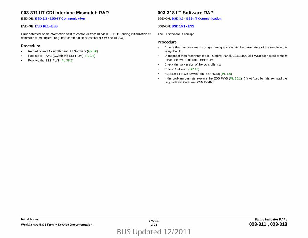
BUS Updated 12/2011
07/20112-23WorkCentre 5335 Family Service Documentation 003-311 , 003-318
Status Indicator RAPsInitial Issue
003-311 IIT CDI Interface Mismatch RAPBSD-ON: BSD 3.3 - ESS-IIT Communication
BSD-ON: BSD 16.1 - ESS
Error detected when information sent to controller from IIT via IIT CDI I/F during initialization ofcontroller is insufficient. (e.g. bad combination of controller SW and IIT SW)
Procedure• Reload correct Controller and IIT Software (GP 16).
• Replace IIT PWB (Switch the EEPROM) (PL 1.6)
• Replace the ESS PWB (PL 35.2)
003-318 IIT Software RAPBSD-ON: BSD 3.3 - ESS-IIT Communication
BSD-ON: BSD 16.1 - ESS
The IIT software is corrupt.
Procedure• Ensure that the customer is programming a job within the parameters of the machine uti-
lizing the UI.
• Disconnect then reconnect the IIT, Control Panel, ESS, MCU all PWBs connected to them(RAM, Firmware module, EEPROM)
• Check the sw version of the controller sw
• Reload Software (GP 16)
• Replace IIT PWB (Switch the EEPROM) (PL 1.6)
• If the problem persists, replace the ESS PWB (PL 35.2). (If not fixed by this, reinstall theoriginal ESS PWB and RAM DIMM.)

BUS Updated 12/2011
07/20112-24 WorkCentre 5335 Family Service Documentation003-319, 003-320
Initial IssueStatus Indicator RAPs
003-319 IIT Video Driver Detection RAPBSD-ON: BSD 3.3 - ESS-IIT Communication
BSD-ON: BSD 16.1 - ESS
One of the following errors is detected:
• Compression Threshold overflow
• DMA Transfer error
• Other system compression errors
Procedure• Ensure that the customer is programming a job within the parameters of the machine uti-
lizing the UI.
• Disconnect then reconnect the IIT, Control Panel, ESS, MCU all PWBs connected to them(RAM, Firmware module, EEPROM)
• Reload Software (GP 16)
• Replace IIT PWB (Switch the EEPROM) (PL 1.6)
• If the problem persists, replace the ESS PWB (PL 35.2). (If not fixed by this, reinstall theoriginal ESS PWB and RAM DIMM.)
003-320 IISS-ESS Communication 1 RAPBSD-ON: BSD 3.3 - ESS-IIT Communication
BSD-ON: BSD 16.1 - ESS
BSD-ON: BSD 34.1 - FAX
An abnormal parameter is set as the argument for the send function. After avoiding detectioncondition of 116-389 at power on, extended memory capacity in document scanning areabelow 256MB is detected with IITsc-detected Fault Code, while Fax Card is mounted.
Procedure• Disconnect and reconnect the IIT Harness (PL 1.6).
• Reload Software (GP 16).
• If the problem persists, replace the IIT PWB (Switch the EEPROM) (PL 1.6).

BUS Updated 12/2011
07/20112-25WorkCentre 5335 Family Service Documentation 003-321, 003-322
Status Indicator RAPsInitial Issue
003-321 IISS-ESS Communication 2 RAPBSD-ON: BSD 3.3 - ESS-IIT Communication
BSD-ON: BSD 16.1 - ESS
The ACK (acknowledgement code) could not be received after 2 resend attempts. (TheSequencing No. of the sent Message Packet is incorrect.) Error detected when informationsent to controller from IIT via IIT CDI I/F during initialization of controller is insufficient. (e.g. badcombination of controller SW and IIT SW).
Procedure• Disconnect and reconnect the IIT Harness (PL 1.6).
• Reload Software (GP 16).
• If the problem persists, replace the IIT PWB (Switch the EEPROM) (PL 1.6).
• Replace the ESS PWB (PL 35.2)
003-322 IISS-ESS Communication 3 RAPBSD-ON: BSD 3.3 - ESS-IIT Communication
BSD-ON: BSD 16.1 - ESS
The ACK (acknowledgement code) could not be received after 2 resend attempts. (The PacketNo. of the sent Message Packet is incorrect.)
Procedure• Ensure that the customer is programming a job within the parameters of the machine uti-
lizing the UI.
• Disconnect then reconnect the IIT, Control Panel, ESS, MCU all PWBs connected to them(RAM, Firmware module, EEPROM)
• Reload Software (GP 16)
• Replace IIT PWB (Switch the EEPROM) (PL 1.6)
• If the problem persists, replace the ESS PWB (PL 35.2). (If not fixed by this, reinstall theoriginal ESS PWB and RAM DIMM.)
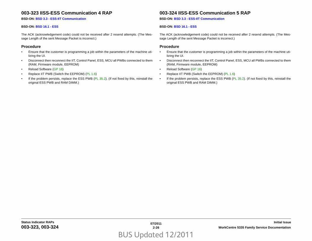
BUS Updated 12/2011
07/20112-26 WorkCentre 5335 Family Service Documentation003-323, 003-324
Initial IssueStatus Indicator RAPs
003-323 IISS-ESS Communication 4 RAPBSD-ON: BSD 3.3 - ESS-IIT Communication
BSD-ON: BSD 16.1 - ESS
The ACK (acknowledgement code) could not be received after 2 resend attempts. (The Mes-sage Length of the sent Message Packet is incorrect.)
Procedure• Ensure that the customer is programming a job within the parameters of the machine uti-
lizing the UI.
• Disconnect then reconnect the IIT, Control Panel, ESS, MCU all PWBs connected to them(RAM, Firmware module, EEPROM)
• Reload Software (GP 16)
• Replace IIT PWB (Switch the EEPROM) (PL 1.6)
• If the problem persists, replace the ESS PWB (PL 35.2). (If not fixed by this, reinstall theoriginal ESS PWB and RAM DIMM.)
003-324 IISS-ESS Communication 5 RAPBSD-ON: BSD 3.3 - ESS-IIT Communication
BSD-ON: BSD 16.1 - ESS
The ACK (acknowledgement code) could not be received after 2 resend attempts. (The Mes-sage Length of the sent Message Packet is incorrect.)
Procedure• Ensure that the customer is programming a job within the parameters of the machine uti-
lizing the UI.
• Disconnect then reconnect the IIT, Control Panel, ESS, MCU all PWBs connected to them(RAM, Firmware module, EEPROM)
• Reload Software (GP 16)
• Replace IIT PWB (Switch the EEPROM) (PL 1.6)
• If the problem persists, replace the ESS PWB (PL 35.2). (If not fixed by this, reinstall theoriginal ESS PWB and RAM DIMM.)

BUS Updated 12/2011
07/20112-27WorkCentre 5335 Family Service Documentation 003-325, 003-326
Status Indicator RAPsInitial Issue
003-325 IISS-ESS Communication 6 RAPBSD-ON: BSD 3.3 - ESS-IIT Communication
BSD-ON: BSD 16.1 - ESS
The ACK (acknowledgement code) could not be received after 2 resend attempts. (A parityerror was detected by hardware in the IIT PWB.)
Procedure• Ensure that the customer is programming a job within the parameters of the machine uti-
lizing the UI.
• Disconnect then reconnect the IIT, Control Panel, ESS, MCU all PWBs connected to them(RAM, Firmware module, EEPROM)
• Reload Software (GP 16)
• Replace IIT PWB (Switch the EEPROM) (PL 1.6)
• If the problem persists, replace the ESS PWB (PL 35.2). (If not fixed by this, reinstall theoriginal ESS PWB and RAM DIMM.)
003-326 IISS-ESS Communication 7 RAPBSD-ON: BSD 3.3 - ESS-IIT Communication
BSD-ON: BSD 16.1 - ESS
The ACK (acknowledgement code) could not be received after 2 resend attempts. (Framingerror was detected by hardware in the IIT PWB.)
Procedure• Ensure that the customer is programming a job within the parameters of the machine uti-
lizing the UI.
• Disconnect then reconnect the IIT, Control Panel, ESS, MCU all PWBs connected to them(RAM, Firmware module, EEPROM)
• Reload Software (GP 16)
• Replace IIT PWB (Switch the EEPROM) (PL 1.6)
• If the problem persists, replace the ESS PWB (PL 35.2). (If not fixed by this, reinstall theoriginal ESS PWB and RAM DIMM.)

BUS Updated 12/2011
07/20112-28 WorkCentre 5335 Family Service Documentation003-327, 003-328
Initial IssueStatus Indicator RAPs
003-327 IISS-ESS Communication 8 RAPBSD-ON: BSD 3.3 - ESS-IIT Communication
BSD-ON: BSD 16.1 - ESS
The ACK (acknowledgement code) could not be received after 2 resend attempts. (An overrunerror was detected by hardware in the IIT PWB.)
Procedure• Ensure that the customer is programming a job within the parameters of the machine uti-
lizing the UI.
• Disconnect then reconnect the IIT, Control Panel, ESS, MCU all PWBs connected to them(RAM, Firmware module, EEPROM)
• Reload Software (GP 16)
• Replace IIT PWB (Switch the EEPROM) (PL 1.6)
• If the problem persists, replace the ESS PWB (PL 35.2). (If not fixed by this, reinstall theoriginal ESS PWB and RAM DIMM.)
003-328 IISS-ESS Communication 9 RAPBSD-ON: BSD 3.3 - ESS-IIT Communication
BSD-ON: BSD 16.1 - ESS
The ACK (acknowledgement code) could not be received after 2 resend attempts. (Afterheader recognition, receive interruption was detected by the IIT PWB.)
Procedure• Ensure that the customer is programming a job within the parameters of the machine uti-
lizing the UI.
• Disconnect then reconnect the IIT, Control Panel, ESS, MCU all PWBs connected to them(RAM, Firmware module, EEPROM)
• Reload Software (GP 16)
• Replace IIT PWB (Switch the EEPROM) (PL 1.6)
• If the problem persists, replace the ESS PWB (PL 35.2). (If not fixed by this, reinstall theoriginal ESS PWB and RAM DIMM.)

BUS Updated 12/2011
07/20112-29WorkCentre 5335 Family Service Documentation 003-329, 003-330
Status Indicator RAPsInitial Issue
003-329 IISS-ESS Communication 10 RAPBSD-ON: BSD 3.3 - ESS-IIT Communication
BSD-ON: BSD 16.1 - ESS
The NAK (Negative Acknowledgement) that notifies of the occurrence of a transmission failureis received. (The Sequencing No. of the received Message Packet is incorrect.)
Procedure• Ensure that the customer is programming a job within the parameters of the machine uti-
lizing the UI.
• Disconnect then reconnect the IIT, Control Panel, ESS, MCU all PWBs connected to them(RAM, Firmware module, EEPROM)
• Reload Software (GP 16)
• Replace IIT PWB (Switch the EEPROM) (PL 1.6)
• If the problem persists, replace the ESS PWB (PL 35.2). (If not fixed by this, reinstall theoriginal ESS PWB and RAM DIMM.)
003-330 IISS-ESS Communication 11 RAPBSD-ON: BSD 3.3 - ESS-IIT Communication
BSD-ON: BSD 16.1 - ESS
The NAK (Negative Acknowledgement) that notifies of the occurrence of a transmission failureis received. (The Packet No. of the received Message Packet is incorrect.)
Procedure• Ensure that the customer is programming a job within the parameters of the machine uti-
lizing the UI.
• Disconnect then reconnect the IIT, Control Panel, ESS, MCU all PWBs connected to them(RAM, Firmware module, EEPROM)
• Reload Software (GP 16)
• Replace IIT PWB (Switch the EEPROM) (PL 1.6)
• If the problem persists, replace the ESS PWB (PL 35.2). (If not fixed by this, reinstall theoriginal ESS PWB and RAM DIMM.)

BUS Updated 12/2011
07/20112-30 WorkCentre 5335 Family Service Documentation003-331, 003-332
Initial IssueStatus Indicator RAPs
003-331 IISS-ESS Communication 12 RAPBSD-ON: BSD 3.3 - ESS-IIT Communication
BSD-ON: BSD 16.1 - ESS
The NAK (Negative Acknowledgement) that notifies of the occurrence of a transmission failureis received. (The Message Length of the received Message Packet is incorrect.)
Procedure• Ensure that the customer is programming a job within the parameters of the machine uti-
lizing the UI.
• Disconnect then reconnect the IIT, Control Panel, ESS, MCU all PWBs connected to them(RAM, Firmware module, EEPROM)
• Reload Software (GP 16)
• Replace IIT PWB (Switch the EEPROM) (PL 1.6)
• If the problem persists, replace the ESS PWB (PL 35.2). (If not fixed by this, reinstall theoriginal ESS PWB and RAM DIMM.)
003-332 IISS-ESS Communication 13 RAPBSD-ON: BSD 3.3 - ESS-IIT Communication
BSD-ON: BSD 16.1 - ESS
The NAK (Negative Acknowledgement) that notifies of the occurrence of a transmission failureis received. (The Check Code of the received Message Packet is incorrect.)
Procedure• Ensure that the customer is programming a job within the parameters of the machine uti-
lizing the UI.
• Disconnect then reconnect the IIT, Control Panel, ESS, MCU all PWBs connected to them(RAM, Firmware module, EEPROM)
• Reload Software (GP 16)
• Replace IIT PWB (Switch the EEPROM) (PL 1.6)
• If the problem persists, replace the ESS PWB (PL 35.2). (If not fixed by this, reinstall theoriginal ESS PWB and RAM DIMM.)

BUS Updated 12/2011
07/20112-31WorkCentre 5335 Family Service Documentation 003-333, 003-334
Status Indicator RAPsInitial Issue
003-333 IISS-ESS Communication 14 RAPBSD-ON: BSD 3.3 - ESS-IIT Communication
BSD-ON: BSD 16.1 - ESS
The NAK (Negative Acknowledgement) that notifies of the occurrence of a transmission failureis received. (A parity error was detected by hardware of the UART.)
Procedure• Ensure that the customer is programming a job within the parameters of the machine uti-
lizing the UI.
• Disconnect then reconnect the IIT, Control Panel, ESS, MCU all PWBs connected to them(RAM, Firmware module, EEPROM)
• Reload Software (GP 16)
• Replace IIT PWB (Switch the EEPROM) (PL 1.6)
• If the problem persists, replace the ESS PWB (PL 35.2). (If not fixed by this, reinstall theoriginal ESS PWB and RAM DIMM.)
003-334 IISS-ESS Communication 15 RAPBSD-ON: BSD 3.3 - ESS-IIT Communication
BSD-ON: BSD 16.1 - ESS
The NAK (Negative Acknowledgement) that notifies of the occurrence of a transmission failureis received. (A framing error was detected by hardware of the UART.)
Procedure• Ensure that the customer is programming a job within the parameters of the machine uti-
lizing the UI.
• Disconnect then reconnect the IIT, Control Panel, ESS, MCU all PWBs connected to them(RAM, Firmware module, EEPROM)
• Reload Software (GP 16)
• Replace IIT PWB (Switch the EEPROM) (PL 1.6)
• If the problem persists, replace the ESS PWB (PL 35.2). (If not fixed by this, reinstall theoriginal ESS PWB and RAM DIMM.)

BUS Updated 12/2011
07/20112-32 WorkCentre 5335 Family Service Documentation003-335, 003-336
Initial IssueStatus Indicator RAPs
003-335 IISS-ESS Communication 16 RAPBSD-ON: BSD 3.3 - ESS-IIT Communication
BSD-ON: BSD 16.1 - ESS
The NAK (Negative Acknowledgement) that notifies of the occurrence of a transmission failureis received. (An overrun error was detected by hardware of the UART.)
Procedure• Ensure that the customer is programming a job within the parameters of the machine uti-
lizing the UI.
• Disconnect then reconnect the IIT, Control Panel, ESS, MCU all PWBs connected to them(RAM, Firmware module, EEPROM)
• Reload Software (GP 16)
• Replace IIT PWB (Switch the EEPROM) (PL 1.6)
• If the problem persists, replace the ESS PWB (PL 35.2). (If not fixed by this, reinstall theoriginal ESS PWB and RAM DIMM.)
003-336 IISS-ESS Communication 17 RAPBSD-ON: BSD 3.3 - ESS-IIT Communication
BSD-ON: BSD 16.1 - ESS
The NAK (Negative Acknowledgement) that notifies of the occurrence of a transmission failureis received. (After the header was recognized, it was detected that receiving was aborted.)
Procedure• Ensure that the customer is programming a job within the parameters of the machine uti-
lizing the UI.
• Disconnect then reconnect the IIT, Control Panel, ESS, MCU all PWBs connected to them(RAM, Firmware module, EEPROM)
• Reload Software (GP 16)
• Replace IIT PWB (Switch the EEPROM) (PL 1.6)
• If the problem persists, replace the ESS PWB (PL 35.2). (If not fixed by this, reinstall theoriginal ESS PWB and RAM DIMM.)

BUS Updated 12/2011
07/20112-33WorkCentre 5335 Family Service Documentation 003-337, 003-338
Status Indicator RAPsInitial Issue
003-337 IISS-ESS Communication 18 RAPBSD-ON: BSD 3.3 - ESS-IIT Communication
BSD-ON: BSD 16.1 - ESS
After restoring from Power Saver mode, there was no response to the Power On commandsent to the IIT PWB within the specified time.
Procedure• Ensure that the customer is programming a job within the parameters of the machine uti-
lizing the UI.
• Disconnect then reconnect the IIT, Control Panel, ESS, MCU all PWBs connected to them(RAM, Firmware module, EEPROM)
• Reload Software (GP 16)
• Replace IIT PWB (Switch the EEPROM) (PL 1.6)
• If the problem persists, replace the ESS PWB (PL 35.2). (If not fixed by this, reinstall theoriginal ESS PWB and RAM DIMM.)
003-338 IISS-ESS Communication 19 RAPBSD-ON: BSD 3.3 - ESS-IIT Communication
BSD-ON: BSD 16.1 - ESS
The Driver detects Illegal Send Parameter Argument from Application.
Procedure• Ensure that the customer is programming a job within the parameters of the machine uti-
lizing the UI.
• Disconnect then reconnect the IIT, Control Panel, ESS, MCU all PWBs connected to them(RAM, Firmware module, EEPROM)
• Reload Software (GP 16)
• Replace IIT PWB (Switch the EEPROM) (PL 1.6)
• If the problem persists, replace the ESS PWB (PL 35.2). (If not fixed by this, reinstall theoriginal ESS PWB and RAM DIMM.)

BUS Updated 12/2011
07/20112-34 WorkCentre 5335 Family Service Documentation003-339, 003-340
Initial IssueStatus Indicator RAPs
003-339 IISS-ESS Communication 20 RAPBSD-ON: BSD 3.3 - ESS-IIT Communication
BSD-ON: BSD 16.1 - ESS
The establishment of parameter transmission failed.
Procedure• Ensure that the customer is programming a job within the parameters of the machine uti-
lizing the UI.
• Disconnect then reconnect the IIT, Control Panel, ESS, MCU all PWBs connected to them(RAM, Firmware module, EEPROM)
• Reload Software (GP 16)
• Replace IIT PWB (Switch the EEPROM) (PL 1.6)
• If the problem persists, replace the ESS PWB (PL 35.2). (If not fixed by this, reinstall theoriginal ESS PWB and RAM DIMM.)
003-340 IISS-ESS Communication 21 RAPBSD-ON: BSD 3.3 - ESS-IIT Communication
BSD-ON: BSD 16.1 - ESS
A parameter synchronization error during sending occurred.
Procedure• Ensure that the customer is programming a job within the parameters of the machine uti-
lizing the UI.
• Disconnect then reconnect the IIT, Control Panel, ESS, MCU all PWBs connected to them(RAM, Firmware module, EEPROM)
• Reload Software (GP 16)
• Replace IIT PWB (Switch the EEPROM) (PL 1.6)
• If the problem persists, replace the ESS PWB (PL 35.2). (If not fixed by this, reinstall theoriginal ESS PWB and RAM DIMM.)

BUS Updated 12/2011
07/20112-35WorkCentre 5335 Family Service Documentation 003-341, 003-342
Status Indicator RAPsInitial Issue
003-341 IISS-ESS Communication 22 RAPBSD-ON: BSD 3.3 - ESS-IIT Communication
BSD-ON: BSD 16.1 - ESS
A parameter transmission error during sending occurred.
Procedure• Ensure that the customer is programming a job within the parameters of the machine uti-
lizing the UI.
• Disconnect then reconnect the IIT, Control Panel, ESS, MCU all PWBs connected to them(RAM, Firmware module, EEPROM)
• Reload Software (GP 16)
• Replace IIT PWB (Switch the EEPROM) (PL 1.6)
• If the problem persists, replace the ESS PWB (PL 35.2). (If not fixed by this, reinstall theoriginal ESS PWB and RAM DIMM.)
003-342 IISS-ESS Communication 23 RAPBSD-ON: BSD 3.3 - ESS-IIT Communication
BSD-ON: BSD 16.1 - ESS
The driver detected an incorrect receive parameter argument from the application.
Procedure• Ensure that the customer is programming a job within the parameters of the machine uti-
lizing the UI.
• Disconnect then reconnect the IIT, Control Panel, ESS, MCU all PWBs connected to them(RAM, Firmware module, EEPROM)
• Reload Software (GP 16)
• Replace IIT PWB (Switch the EEPROM) (PL 1.6)
• If the problem persists, replace the ESS PWB (PL 35.2). (If not fixed by this, reinstall theoriginal ESS PWB and RAM DIMM.)

BUS Updated 12/2011
07/20112-36 WorkCentre 5335 Family Service Documentation003-343, 003-344
Initial IssueStatus Indicator RAPs
003-343 IISS-ESS Communication 24 RAPBSD-ON: BSD 3.3 - ESS-IIT Communication
BSD-ON: BSD 16.1 - ESS
A parameter synchronization error during receiving occurred.
Procedure• Ensure that the customer is programming a job within the parameters of the machine uti-
lizing the UI.
• Disconnect then reconnect the IIT, Control Panel, ESS, MCU all PWBs connected to them(RAM, Firmware module, EEPROM)
• Reload Software (GP 16)
• Replace IIT PWB (Switch the EEPROM) (PL 1.6)
• If the problem persists, replace the ESS PWB (PL 35.2). (If not fixed by this, reinstall theoriginal ESS PWB and RAM DIMM.)
003-344 IISS_ESS X Hotline Power On RAPBSD-ON: BSD 3.3 - ESS-IIT Communication
BSD-ON: BSD 16.1 - ESS
There is a communication failure at power on between the controller and the IIT.
Initial ActionsPower On/Off
Procedure• Ensure that the customer is programming a job within the parameters of the machine uti-
lizing the UI.
• Disconnect then reconnect the IIT, Control Panel, ESS, MCU all PWBs connected to them(RAM, Firmware module, EEPROM)
• Reload Software (GP 16)
• Replace IIT PWB (Switch the EEPROM) (PL 1.6)
• If the problem persists, replace the ESS PWB (PL 35.2). (If not fixed by this, reinstall theoriginal ESS PWB and RAM DIMM.)

BUS Updated 12/2011
07/20112-37WorkCentre 5335 Family Service Documentation 003-345, 003-346
Status Indicator RAPsInitial Issue
003-345 PIO Unlatched 1 RAPBSD-ON: BSD 3.3 - ESS-IIT Communication
BSD-ON: BSD 16.1 - ESS
When Job Fail signal was received from the IIT PWB, a hot line PIO (Programmed Input Out-put) error was detected from IISS.
Procedure• Ensure that the customer is programming a job within the parameters of the machine uti-
lizing the UI.
• Disconnect then reconnect the IIT, Control Panel, ESS, MCU all PWBs connected to them(RAM, Firmware module, EEPROM)
• Reload Software (GP 16)
• Replace IIT PWB (Switch the EEPROM) (PL 1.6)
• If the problem persists, replace the ESS PWB (PL 35.2). (If not fixed by this, reinstall theoriginal ESS PWB and RAM DIMM.)
003-346 PIO Unlatched 2 RAPBSD-ON: BSD 3.3 - ESS-IIT Communication
BSD-ON: BSD 16.1 - ESS
When IIT image was received from the IIT PWB, a PIO (Programmed Input/Output) error wasdetected from IISS.
Procedure• Ensure that the customer is programming a job within the parameters of the machine uti-
lizing the UI.
• Disconnect then reconnect the IIT, Control Panel, ESS, MCU all PWBs connected to them(RAM, Firmware module, EEPROM)
• Reload Software (GP 16)
• Replace IIT PWB (Switch the EEPROM) (PL 1.6)
• If the problem persists, replace the ESS PWB (PL 35.2). (If not fixed by this, reinstall theoriginal ESS PWB and RAM DIMM.)

BUS Updated 12/2011
07/20112-38 WorkCentre 5335 Family Service Documentation003-702, 003-750
Initial IssueStatus Indicator RAPs
003-702 Different Magnification for Side 1 and Side 2 RAPBSD-ON: BSD 3.3 - ESS-IIT Communication
BSD-ON: BSD 16.1 - ESS
In copying the two sides of the document simultaneously, the machine detected such settingsas apply different magnification ratios to the face (side 1) and the back (side 2) of the docu-ment.
Procedure• Change the settings so that the same magnification ratio can be applied to the face (side
1) and the back (side 2) of the document.
• Check the sw version of the controller sw - reload Software (GP 16)
• Disconnect then reconnect the ESS, MCU all PWBs connected to them (RAM, Firmwaremodule, EEPROM)
003-750 Book Duplex Documents RAPBook duplex is not set up with the correct sheet is stored with the current setting conditions.
Procedure• Ask customer to check the Book Duplex setup menu.
• Disconnect then reconnect the ESS, MCU all PWBs connected to them (RAM, Firmwaremodule, EEPROM)
• Check the sw version of the controller sw - reload Software (GP 16)

BUS Updated 12/2011
07/20112-39WorkCentre 5335 Family Service Documentation 003-751, 003-752
Status Indicator RAPsInitial Issue
003-751 Panther Capacity RAPThe Panther (continuous data protection protocol or utility) - Image data too small for IOT Hard-ware to handle found in document range designation and scan area range (Width mm XLength mm).
Procedure• Increase resolution. To increase Scan size range (Width mm X Length mm).
• Disconnect then reconnect the ESS, MCU all PWBs connected to them (RAM, Firmwaremodule, EEPROM)
• Check the sw version of the controller sw - reload Software (GP 16)
003-752 600dpi Cannot be Scanned RAPBSD-ON: BSD 3.5 - ESS-DADF Communication
This status code is displayed - Unscannable 600dpi resolution detected after DADF Mix DuplexMode Job is accepted.
ProcedurePerform scanning below 400 dpi resolution or perform scanning in other than mixedmode.
If powering OFF then ON does not resolve the problem, perform the following:
1. Check the connection between IIT PWB and ESS PWB.
2. Check the sw version of the controller sw - reload Software (GP 16)
3. Replace IIT PWB (Switch the EEPROM) (PL 1.6)
4. Replace ESS PWB (PL 35.2).

BUS Updated 12/2011
07/20112-40 WorkCentre 5335 Family Service Documentation003-753, 003-754
Initial IssueStatus Indicator RAPs
003-753 300dpi Cannot be Scanned RAPBSD-ON: BSD 3.5 - ESS-DADF Communication
This status code is displayed if - Unscannable 300dpi or higher resolution detected after DADFMix Duplex Mode Job is accepted.
Procedure• Perform scanning below 200 dpi resolution.
Or perform scanning in other than mixed mode.
• If powering OFF then ON does not resolve the problem, perform the following:
1. Check the connection between IIT PWB and ESS PWB.
2. Check the sw version of the controller sw - reload Software (GP 16)
3. Replace IIT PWB (Switch the EEPROM) (PL 1.6)
4. Replace ESS PWB (PL 35.2).
003-754 Scan Recoverable Error RAPBSD-ON: BSD 3.5 - ESS-DADF Communication
Recoverable high-compression Scan error
Procedure• Retry the job.
• Disconnect then reconnect the ESS, MCU all PWBs connected to them (RAM, Firmwaremodule, EEPROM)
• Check the sw version of the controller sw - reload Software (GP 16)

BUS Updated 12/2011
07/20112-41WorkCentre 5335 Family Service Documentation 003-755, 003-756
Status Indicator RAPsInitial Issue
003-755 S2X Command Error RAPBSD-ON: BSD 3.5 - ESS-DADF Communication
High-compression Scan command error.
Procedure• Retry the job.
• Disconnect then reconnect the ESS, MCU all PWBs connected to them (RAM, Firmwaremodule, EEPROM)
• Check the sw version of the controller sw - reload Software (GP 16)
003-756 All Original Sheets are Blank RAPBSD-ON: BSD 3.5 - ESS-DADF Communication
All scanned original sheets judged as Blank by Blank Paper Detection.
Procedure• Ensure that the originals are not blank and oriented correctly. Retry the job.
• Disconnect then reconnect the ESS, MCU all PWBs connected to them (RAM, Firmwaremodule, EEPROM)
• Check the sw version of the controller sw - reload Software (GP 16)

BUS Updated 12/2011
07/20112-42 WorkCentre 5335 Family Service Documentation003-757, 003-760
Initial IssueStatus Indicator RAPs
003-757 400dpi Cannot be Scanned RAPBSD-ON: BSD 3.5 - ESS-DADF Communication
This status code is displayed if over 400dpi cannot be scanned (DADF). 400/600dpi disabledfor DADF Mix Duplex Mode Scan.
Procedure• Perform scan with 300dpi or lower resolution or change the job to that scannable with
NON-MIX mode.
• If powering OFF then ON does not resolve the problem, perform the following:
1. Check the cable between IIT PWB and ESS PWB (PL 35.2), MCU all PWBs con-nected to them (RAM, Firmware module, EEPROM).
2. Check the sw version of the controller sw - reload Software (GP 16)
3. Replace IIT PWB (Switch the EEPROM) (PL 1.6)
4. Replace ESS PWB (PL 35.2).
003-760 Scan Settings RAPBSD-ON: BSD 3.5 - ESS-DADF Communication
The job properties are incorrect.
Procedure• Abort the job. Change Job Startup parameters such as Tray No., Paper size etc. and retry.
• Disconnect then reconnect the IIT, ESS, MCU all PWBs connected to them (RAM, Firm-ware module, EEPROM)
• Check the sw version of the controller sw - reload Software (GP 16)
• Replace IIT PWB (Switch the EEPROM) (PL 1.6)

BUS Updated 12/2011
07/20112-43WorkCentre 5335 Family Service Documentation 003-761, 003-763
Status Indicator RAPsInitial Issue
003-761 Incorrect Paper Tray Size RAPThe paper size in the tray selected by auto tray switching APS differs from the paper size in thetray selected at the tray selection. When Cover Text Tray or Interleaf +Nset Tray is selected byAPS, the paper size for that tray is different from that for Cover Tray or OHP Tray.
Procedure• Ask customer to either change the paper size for the tray, or change the paper type prior-
ity setting. Change Job Startup parameters such as Tray No., Paper size etc. and retry.
• Disconnect then reconnect the ESS, MCU all PWBs connected to them (RAM, Firmwaremodule, EEPROM)
• Check the sw version of the controller sw - reload Software (GP 16)
• Ensure that the Paper Tray Settings are set properly.
003-763 Adjustment Chart RAPWhen Automatic Gradation Correction is performed the patch for position detection on the doc-ument is not available.
Procedure• Disconnect then reconnect the ESS, MCU all PWBs connected to them (RAM, Firmware
module, EEPROM)
• Check the sw version of the controller sw - reload Software (GP 16)
• Properly set the Automatic Gradation Correction Chart for automatic tone correction.
• Perform White Reference and CCD Calibration ADJ 6.6.

BUS Updated 12/2011
07/20112-44 WorkCentre 5335 Family Service Documentation003-764, 003-780
Initial IssueStatus Indicator RAPs
003-764 Image Overlay RAPWhen only one page can be stored in Image Overlay (with 1 sheet-original). This fault occurswith BW M/C, not with color M/C.
Initial ActionsAutomatically abort job. Power Off/On.
Procedure• Ask customer to verify the job setup and rerun the job.
• Disconnect then reconnect the ESS, MCU all PWBs connected to them (RAM, Firmwaremodule, EEPROM)
• Check the sw version of the controller sw - reload Software (GP 16)
003-780 Fax Scan Compression Fail RAPBSD-ON: BSD 34.1 - FAX
The compressed data size is larger than 8 times the size of the uncompressed data.
Procedure• Ask customer to abort the job. Change Scan resolution parameter and retry.
• Disconnect then reconnect the IIT Harness (PL 1.6), ESS, MCU all PWBs connected tothem (RAM, Firmware module, EEPROM)
• Check the sw version of the controller sw - reload Software (GP 16)
• Replace IIT PWB (Switch the EEPROM) (PL 1.6)

BUS Updated 12/2011
07/20112-45WorkCentre 5335 Family Service Documentation 003-795, 003-930
Status Indicator RAPsInitial Issue
003-795 AMS Limit RAPAMS (Auto R/E) limit error. (The R/E ratio became out of range after the document auto detec-tion when AMS is specified.)
Initial ActionsAsk customer to abort the job. Enter the correct R/E ratio or change the paper size.
Procedure• Disconnect then reconnect the IIT, ESS, MCU all PWBs connected to them (RAM, Firm-
ware module, EEPROM)
• Check the sw version of the controller sw - reload Software (GP 16)
• Replace IIT PWB (Switch the EEPROM) (PL 1.6)
003-930 300 DPI Scan RAPBSD-ON: BSD 3.5 - ESS-DADF Communication
300dpi/400dpi/600dpi disabled with DADF Mix Duplex Mode Scan. Due to insufficient PageMemory space, A3 original cannot be scanned with specified resolution. A4/B4 original can bescanned. There is a problem scanning 300 DPI.
Procedure• Increase Page Memory (PL 35.2). Verify scan settings are correctly set and menu selec-
tions are correctly set. Scan with 300dpi or less.
• Disconnect then reconnect the ESS, MCU all PWBs connected to them (RAM, Firmwaremodule, EEPROM)
• Check the sw version of the controller sw - reload Software (GP 16)

BUS Updated 12/2011
07/20112-46 WorkCentre 5335 Family Service Documentation003-931, 003-932
Initial IssueStatus Indicator RAPs
003-931 400 DPI Scan RAPBSD-ON: BSD 3.5 - ESS-DADF Communication
For scanning in the DADF mix duplex mode, 400dpi and 600dpi are not available. BecausePage Memory is not enough, a selected resolution is not available for scanning a A3 docu-ment. It is available for scanning a A4/B4 document.
Procedure• Verify scan settings are correctly set (at below 400dpi) and menu selections are correctly
set. Increase Page Memory (PL 35.2).
• Disconnect then reconnect the ESS, MCU all PWBs connected to them (RAM, Firmwaremodule, EEPROM)
• Check the sw version of the controller sw - reload Software (GP 16)
003-932 600 DPI Scan RAPBSD-ON: BSD 3.5 - ESS-DADF Communication
For scanning in the DADF mix duplex mode, 600dpi is not available.
Procedure• Verify scan settings (scanning at below 600dpi) are correctly set and menu selections are
correctly set. Increase Page Memory (PL 35.2).
• Disconnect then reconnect the ESS, MCU all PWBs connected to them (RAM, Firmwaremodule, EEPROM)
• Check the sw version of the controller sw - reload Software (GP 16)

BUS Updated 12/2011
07/20112-47WorkCentre 5335 Family Service Documentation 003-933, 003-934
Status Indicator RAPsInitial Issue
003-933 300 DPI Scan RAPBSD-ON: BSD 3.5 - ESS-DADF Communication
Scanning in the DADF mix duplex mode, 300dpi, 400dpi and 600dpi are not available (whenthe next document exists). Because Page Memory is insufficient, a selected resolution is notavailable for scanning an A3 document. It is available for scanning an A4/B4 document.
Procedure• Verify scan settings (Operate for scanning at below 300dpi) are correctly set and menu
selections are correctly set. Increase Page Memory (PL 35.2).
• Disconnect then reconnect the ESS, MCU all PWBs connected to them (RAM, Firmwaremodule, EEPROM)
• Check the sw version of the controller sw - reload Software (GP 16)
003-934 400 DPI Scan RAPBSD-ON: BSD 3.5 - ESS-DADF Communication
When scanning in the DADF mix duplex mode, 400dpi and 600dpi are not available (when thenext document exists). Because Page Memory is insufficient, a selected resolution is not avail-able for scanning an A3 document. It is available for scanning an A4/B4 document.
Procedure• Verify scan settings (at below 400dpi) are correctly set and menu selections are correctly
set. Increase Page Memory (PL 35.2).
• Disconnect then reconnect the ESS, MCU all PWBs connected to them (RAM, Firmwaremodule, EEPROM)
• Check the sw version of the controller sw - reload Software (GP 16)

BUS Updated 12/2011
07/20112-48 WorkCentre 5335 Family Service Documentation003-935, 003-940
Initial IssueStatus Indicator RAPs
003-935 600 DPI Scan RAPBSD-ON: BSD 3.5 - ESS-DADF Communication
When scanning in the DADF mix duplex mode, 600dpi is not available (when the next docu-ment exists). Because Page Memory is insufficient, a selected resolution is not available forscanning an A3 document. It is available for scanning an A4/B4 document.
Procedure• Verify scan settings (at below 600dpi) are correctly set and menu selections are correctly
set. Increase Page Memory (PL 35.2).
• Disconnect then reconnect the ESS, MCU all PWBs connected to them (RAM, Firmwaremodule, EEPROM)
• Check the sw version of the controller sw - reload Software (GP 16)
003-940 Memory RAPInsufficient Page Memory detected.
When IITsc is activated for the jobs that meet the following AND conditions:
• Page Memory < 384MB (PL 35.2)
• Side 2 cover image is selected
• Color mode is not set to Black/White
• High Quality mode
Procedure• Power Off/On.
• Cancel the job. Clear the B/W setting for Color mode or the Side 2 cover image setting,and execute the job again.
• Disconnect then reconnect the ESS, MCU all PWBs connected to them (RAM, Firmwaremodule, EEPROM)
• Check the sw version of the controller sw - reload Software (GP 16)
• If the problem persists replace the IIT PWB (Switch the EEPROM) (PL 1.6).

BUS Updated 12/2011
07/20112-49WorkCentre 5335 Family Service Documentation 003-941, 003-942
Status Indicator RAPsInitial Issue
003-941 Page Memory Insufficient RAPA shortage of page memory. There is not enough page memory to store the image.
Procedure• Change the parameter(s) and operate again.
• If the problem persists, check that the Page Memory (PL 35.2) is installed and turn OFFthen ON the power.
• Disconnect then reconnect the ESS, MCU all PWBs connected to them (RAM, Firmwaremodule, EEPROM)
• Check the sw version of the controller sw - reload Software (GP 16)
• Reseat/Replace Page Memory (PL 35.2).
003-942 Document Size Auto Detect RAPBSD-ON:BSD 5.2 - Document Size Sensing (1 of 2)
The document size cannot be automatically detected.
Initial Actions• If the document in question is a non-standard size, ask customer to manually set the doc-
ument size. If the fault occurs with standard size documents, continue with the procedure.
• Check fault history for occurrences of 005-194, 005-196, or 005-197 faults. Troubleshootany of these faults first.
• Disconnect then reconnect the ESS, MCU all PWBs connected to them (RAM, Firmwaremodule, EEPROM)
• Check the sw version of the controller sw - reload Software (GP 16)
ProcedureExecute Component Control [005-221]. Block and unblock the DADF Tray Size 1 Sensor. Thedisplay changes.Y N
Check the wires between P/J756 and P/J761 for an open or shorted circuit or a dam-aged or loose connector. The wires are OK. Y N
Repair as required.
There is approx. +5VDC between P/J756 pin 3 on the DADF PWB and GND.Y N
Replace the DADF PWB (PL 51.2).
Measure the voltage between P/J756 pin 2 on the DADF PWB and GND (-). Block andunblock the DADF Tray Size 1 Sensor. The voltage changes.Y N
Replace the DADF Tray Size 1 Sensor (PL 51.10).
Replace the DADF PWB (PL 51.2).
Execute Component Control [005-222]. Block and unblock the DADF Tray Size 2 Sensor. Thedisplay changes.Y N
Check the wires between P/J756 and P/J764 for an open or shorted circuit or a dam-aged or loose connector. The wires are OK. Y N
Repair as required.
Measure the voltage between the DADF PWB P/J756-6 (+) and GND (-). The voltage isapprox. +5VDC.Y N
Replace the DADF PWB (PL 51.2).
Measure the voltage between the DADF PWB P/J756-5 (+) and GND (-). Actuate theDADF Tray Size 2 Sensor with paper. The voltage changes.
A

BUS Updated 12/2011
07/20112-50 WorkCentre 5335 Family Service Documentation003-942, 003-944
Initial IssueStatus Indicator RAPs
Y NReplace the DADF Tray Size 2 Sensor (PL 51.10).
Replace the DADF PWB (PL 51.2).
Replace the DADF PWB (PL 51.2).
003-944 Image Repeat Count RAPIncorrect image repeat count. Even one image cannot be pasted when "Set Repeated Count-Auto" is specified for image repeat.
Procedure• Ask customer to check the job setups (Change the image repeat count parameter and
repeat the operation.)
• Disconnect then reconnect the ESS, MCU all PWBs connected to them (RAM, Firmwaremodule, EEPROM)
• Check the sw version of the controller sw - reload Software (GP 16)
A

BUS Updated 12/2011
07/20112-51WorkCentre 5335 Family Service Documentation 003-946, 003-947
Status Indicator RAPsInitial Issue
003-946 Image Rotation (Copy APS) RAPImage rotation is different in every direction of Copy (APS). Part of the image will be lost if theimage is not rotated. However, a paper size that does not support rotation was selected.
Initial ActionsSelect a tray with paper manually that supports rotation and repeat the operation.
Procedure• Disconnect then reconnect the ESS, MCU all PWBs connected to them (RAM, Firmware
module, EEPROM)
• Check the sw version of the controller sw - reload Software (GP 16)
• Replace the IIT PWB (Switch the EEPROM) (PL 1.6).
003-947 Return Documents Count RAPIf a user has returned an insufficient number of documents using Return Document, the mes-sage indicating that additional N number of documents are required is displayed and job can-cellation is prompted.
Procedure• Reload the correct number of document and repeat the operation.
• Disconnect then reconnect the ESS, MCU all PWBs connected to them (RAM, Firmwaremodule, EEPROM)
• Check the sw version of the controller sw - reload Software (GP 16)

BUS Updated 12/2011
07/20112-52 WorkCentre 5335 Family Service Documentation003-948, 003-952
Initial IssueStatus Indicator RAPs
003-948 Return Documents Mismatch RAPReturned document size mismatch (Different size settings before/after return).
A different document was returned by a user using Return Document
• This error occurs only when the page information for the returned document has beenalready sent to the post-process software module.
• However, because distributed page information will be discarded when the machinerecovers from an interruption, the above fault is not considered an error.
• The check items to determine different documents are document size/orientation andColor mode in ACS only.
Procedure• Check the document setup and repeat the operation.
• Disconnect then reconnect the ESS, MCU all PWBs connected to them (RAM, Firmwaremodule, EEPROM)
• Check the sw version of the controller sw - reload Software (GP 16)
003-952 Document Color Mismatch RAPReturned document color mismatch (Different color detected before/after return).
A different color of document was returned by a user using Return Document.
• This error occurs only when the page information for the returned document has beenalready sent to the post-process.
• However, the error always occurs when recovered from interruption since the sent pageinformation has been discarded.
• The check items to determine different documents are document size/orientation andColor mode in ACS only.
Procedure• Ask customer to cancel the job, check job settings (with the correct color again) and rerun
the job.
• Disconnect then reconnect the IIT, ESS, MCU all PWBs connected to them (RAM, Firm-ware module, EEPROM)
• Check the sw version of the controller sw - reload Software (GP 16)
• If the problem persists, replace the IIT PWB (Switch the EEPROM) (PL 1.6).

BUS Updated 12/2011
07/20112-53WorkCentre 5335 Family Service Documentation 003-955, 003-956
Status Indicator RAPsInitial Issue
003-955 Documents Size Exchange RAPDocument size change error (MixMode). When loading a document with Mixed Size Originalsprohibited, a document of different size/orientation from the initial document was detected.Only Image Overlay has the function that inhibits different sizes during document added.
Initial ActionsCheck the document size/orientation and repeat the operation.
Procedure• Disconnect then reconnect the ESS, MCU all PWBs connected to them (RAM, Firmware
module, EEPROM)
• Check the sw version of the controller sw - reload Software (GP 16)
• Replace the DADF PWB (PL 51.2).
• If the problem persists, replace the IIT PWB (Switch the EEPROM) (PL 1.6).mm
003-956 Document Size Unknown Error RAPDocument size undefined error (Only APS is selected for the function requiring document sizesetting). Undefined document size was detected when Platen is selected and only APSrequires document size selection.
Procedure1. Enter a document size from the Panel or select a tray.
2. If powering OFF then ON does not resolve the problem, perform the following:
3. Check the connection between the IIT PWB and ESS, MCU all PWBs connected to them(RAM, Firmware module, EEPROM)
4. Check the sw version of the controller sw - reload Software (GP 16)
5. DADF APS Sensors 1-3: Component Control [005-218/219/220] (PL 51.17)
6. Replace IIT PWB (Switch the EEPROM) (PL 1.6).
7. Replace ESS PWB (PL 35.2).

BUS Updated 12/2011
07/20112-54 WorkCentre 5335 Family Service Documentation003-963, 003-965
Initial IssueStatus Indicator RAPs
003-963 APS Object Tray RAPNo APS compatible tray to set the relevant size. There was no APS compatible tray that couldsupply paper for printing without image loss.
• Image larger than A3/17 Inches
• Non-TTM tray does not support APS and the image is larger than A4/Letter.
• All the APS supporting trays have failure.
• APS supporting trays are all set to unavailable.
• Non-standard size setting for all trays.
• Black/White Copy for color attributes of all trays.
• Color Copy for B/W attributes of all trays
Initial ActionsCheck Admin mode. Ensure that the affected tray has not been excluded from Auto TraySwitching (Tools/Paper tray Priority settings).
Procedure• Select a tray that supplies the required size paper and repeat the operation.
• Disconnect then reconnect the ESS, MCU all PWBs connected to them (RAM, Firmwaremodule, EEPROM)
• Check the sw version of the controller sw - reload Software (GP 16)
003-965 ATS/APS Paper Detect RAPAPS/ATS NG (No Paper) (IIT). There was no paper in the tray that can be selected for APS.
Procedure• Select a tray that supplies the required size paper and repeat the operation. Turn the
power OFF then ON. If the problem persists, replace the tray module.
• Disconnect then reconnect the ESS, MCU all PWBs connected to them (RAM, Firmwaremodule, EEPROM)
• Check the sw version of the controller sw - reload Software (GP 16)

BUS Updated 12/2011
07/20112-55WorkCentre 5335 Family Service Documentation 003-966, 003-967
Status Indicator RAPsInitial Issue
003-966 ATS/APS Destination (IIT) RAPATS/APS No Destination Error. ATS/APS NG (Other than No Paper) (IIT). The correct size isnot loaded for APS operation.
Procedure• Select a tray that supplies the required size paper and repeat the operation. Turn the
power OFF then ON. If the problem persists, replace the tray module.
• Disconnect then reconnect the ESS, MCU all PWBs connected to them (RAM, Firmwaremodule, EEPROM)
• Check the sw version of the controller sw - reload Software (GP 16)
003-967 DADF APS No Destination RAP• Document size with DADF 8.5×11SEF Document size input not included.
• Mix Size is not selected.
• Magnification is variable.
• APS Copy job with the above is designated but the tray to be selected is not available.Although A4SEF original is set, it is detected as 8.5×11SEF
Procedure1. Load tray with the paper of the size displayed on the Panel or select the tray in which the
paper requested is loaded.
2. If A4SEF document is detected as Letter document, cancel the job and then readjustDADF document guide securely until they touches the edges of the documents. Re-runthe job.
3. Disconnect then reconnect the ESS, MCU all PWBs connected to them (RAM, Firmwaremodule, EEPROM)
4. Check the sw version of the controller sw - reload Software (GP 16)

BUS Updated 12/2011
07/20112-56 WorkCentre 5335 Family Service Documentation003-968, 003-969
Initial IssueStatus Indicator RAPs
003-968 Punch Position Error RAPPunch Position Error. It is not possible to punch at the selected location.
Procedure• Specify an appropriate punch position, clear Punching or cancel Punch, and execute the
job again.
• If powering OFF then ON does not resolve the problem, perform the following:
• Check the connection between the IIT PWB and ESS, MCU all PWBs connected to them(RAM, Firmware module, EEPROM)
• Check the sw version of the controller sw - reload Software (GP 16)
• Replace IIT PWB (Switch the EEPROM) (PL 1.6).
• Replace ESS PWB (PL 35.2).
003-969 Punch Size Error RAPBSD-ON: BSD 34.1 - FAX
The number of slow-scan lines has exceeded the upper limit due to Fax parallel composition,long- document enlargement, etc.
Procedure• Press the Continue button to store as much data as the memory capacity and continue
scanning the next document. Or, press the Cancel button to abort the job.
• Turn the power OFF then ON. If the problem persists, check the installation of the PageMemory (PL 35.2).
• If powering OFF then ON does not resolve the problem, perform the following:
• Disconnect then reconnect the harness between the IIT PWB and ESS, MCU all PWBsconnected to them (RAM, Firmware module, EEPROM)
• Check the sw version of the controller sw - reload Software (GP 16)
• Replace IIT PWB (Switch the EEPROM) (PL 1.6).
• Replace ESS PWB (PL 35.2).

BUS Updated 12/2011
07/20112-57WorkCentre 5335 Family Service Documentation 003-971, 003-972
Status Indicator RAPsInitial Issue
003-971 Copy Prevention Code Detected RAPWhen job scan was executed by a user who has the permission to temporarily clear the copyrestriction code detection, copy restriction codes were detected in the document.
ProcedureBecause this document cannot be copied, press the "Cancel" or "Continue" button on thepanel.
003-972 Maximum Stored Page RAPThe number of pages stored exceeded the maximum number set in the system data. Whenscanning a document, the no. of pages that has accumulated in the machine has exceeded thevalue of "Maximum Stored Number of Copy Sheets" set in system data.
Procedure• Set the number of pages of the document to be within the maximum number of pages that
can be stored.
• Disconnect then reconnect the ESS, MCU all PWBs connected to them (RAM, Firmwaremodule, EEPROM)
• Check the sw version of the controller sw - reload Software (GP 16)

BUS Updated 12/2011
07/20112-58 WorkCentre 5335 Family Service Documentation003-973, 003-974
Initial IssueStatus Indicator RAPs
003-973 Image Rotation RAPThe document and the image are different in orientation (except when Poster is specified).When rotation is not available even though the orientation of the document and the image aredifferent and part of the image will be lost if it is not rotated.
Procedure• Ask customer to verify the image loss and use a larger paper size if available. Or use
reduction to make a smaller document and repeat the operation.
• Disconnect then reconnect the ESS, MCU all PWBs connected to them (RAM, Firmwaremodule, EEPROM)
• Check the sw version of the controller sw - reload Software (GP 16)
003-974 Next Original Specification RAPNext document specified. Scanning is complete for all loaded documents.
Procedure• Ask customer to verify that scanning is complete or other documents should be loaded.
• Disconnect then reconnect the ESS, MCU all PWBs connected to them (RAM, Firmwaremodule, EEPROM)
• Check the sw version of the controller sw - reload Software (GP 16)

BUS Updated 12/2011
07/20112-59WorkCentre 5335 Family Service Documentation 003-976, 003-977
Status Indicator RAPsInitial Issue
003-976 FAX Line Memory Overflow RAPBSD-ON: BSD 34.1 - FAX
No. of lines in the Slow Scan direction exceeded during Fax N-up. The number of lines in theSlow Scan Direction exceeds the upper limit during processes such as Fax parallel synthesisor enlargement of long-sized documents. Page Memory (PL 35.2) is full.
Initial ActionsPower Off/On. Press the Cancel button to stop the job. Decrease a resolution or magnificationratio and rerun the job. check the installation of the Page Memory (PL 35.2)
Procedure• Disconnect then reconnect the harness between the FAX, ESS, MCU all PWBs con-
nected to them (RAM, Firmware module, EEPROM)
• Check the sw version of the controller sw - reload Software (GP 16)
• If the problem persists replace the FAX PWB (PL 18.5).
003-977 Document Mismatch (Multiple Scan) RAPDocument size mismatch (Document exchange during Multi Scan). During multiple scan a doc-ument was switched during Bound Originals/Booklet Creation/Poster scanning. When anyoperation that requires Return Document occurs in the job with Multi Scan (Bound Originals/Booklet/Poster) on Platen, a user returned a document of a different size from the original.
Procedure• Ask customer to process a job recovery or to cancel the job and rerun the job. Reload a
correct size document and resume operation
• Disconnect then reconnect the ESS, MCU all PWBs connected to them (RAM, Firmwaremodule, EEPROM)
• Check the sw version of the controller sw - reload Software (GP 16)
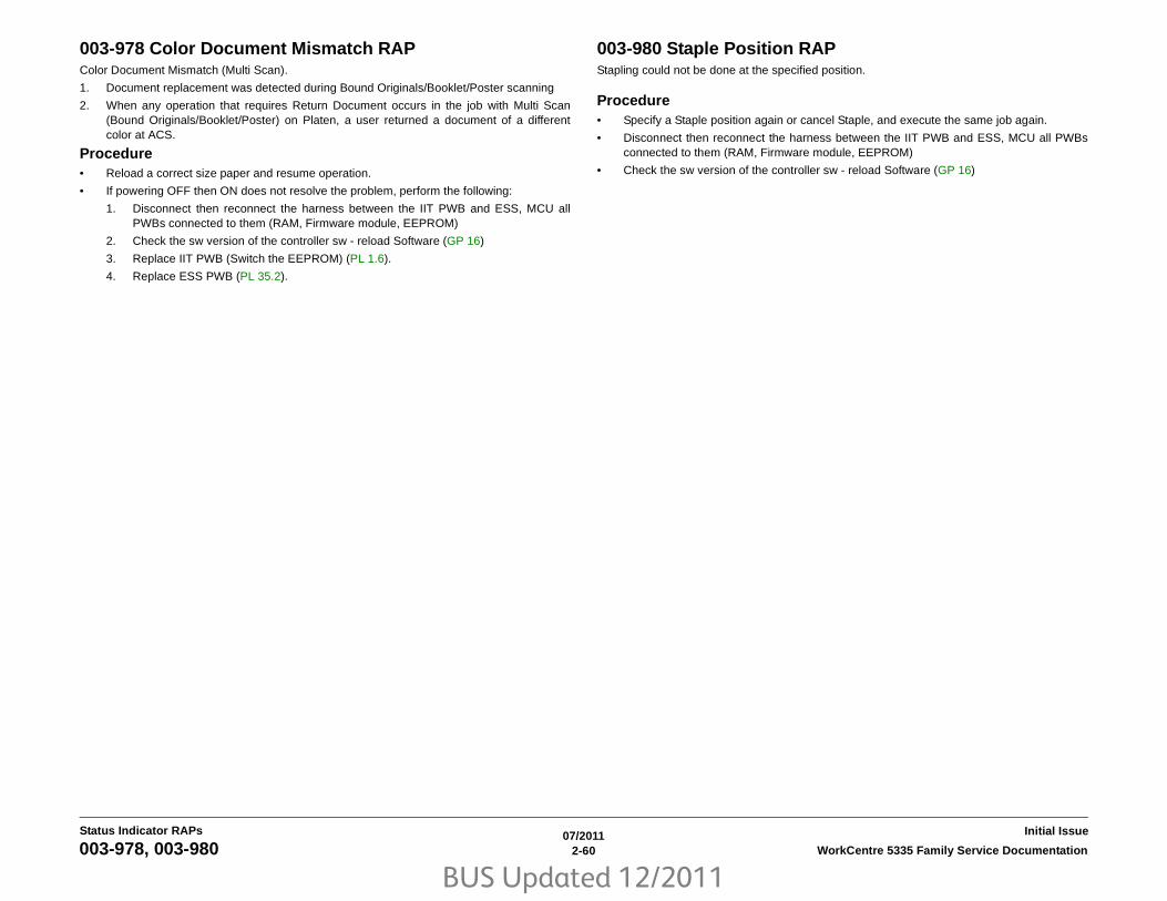
BUS Updated 12/2011
07/20112-60 WorkCentre 5335 Family Service Documentation003-978, 003-980
Initial IssueStatus Indicator RAPs
003-978 Color Document Mismatch RAPColor Document Mismatch (Multi Scan).
1. Document replacement was detected during Bound Originals/Booklet/Poster scanning
2. When any operation that requires Return Document occurs in the job with Multi Scan(Bound Originals/Booklet/Poster) on Platen, a user returned a document of a differentcolor at ACS.
Procedure• Reload a correct size paper and resume operation.
• If powering OFF then ON does not resolve the problem, perform the following:
1. Disconnect then reconnect the harness between the IIT PWB and ESS, MCU allPWBs connected to them (RAM, Firmware module, EEPROM)
2. Check the sw version of the controller sw - reload Software (GP 16)
3. Replace IIT PWB (Switch the EEPROM) (PL 1.6).
4. Replace ESS PWB (PL 35.2).
003-980 Staple Position RAPStapling could not be done at the specified position.
Procedure• Specify a Staple position again or cancel Staple, and execute the same job again.
• Disconnect then reconnect the harness between the IIT PWB and ESS, MCU all PWBsconnected to them (RAM, Firmware module, EEPROM)
• Check the sw version of the controller sw - reload Software (GP 16)

BUS Updated 12/2011
07/20112-61WorkCentre 5335 Family Service Documentation 003-981, 003-982
Status Indicator RAPsInitial Issue
003-981 Staple Size RAPStaple size error (Copy APS). Stapling could not be done for the selected paper size.
Procedure• Specify a Staple position again or cancel Staple, and execute the same job again.
• Disconnect then reconnect the ESS, MCU all PWBs connected to them (RAM, Firmwaremodule, EEPROM)
• Check the sw version of the controller sw - reload Software (GP 16)
003-982 IITsc HDD Access Error RAPHD-FULL was detected with no pages stored. An error where the FULL is not cleared evenafter some time has passed.
Procedure• Disconnect then reconnect the HDD, ESS, MCU all PWBs connected to them (RAM,
Firmware module, EEPROM)
• Perform GP 14 - only the first three parts - make sure to follow sequence and heed cau-tions
• If the problem persists, expand the HDD partition size of the Copy service.
• If the problem persists, go to Hard Disk Failure Prediction Test.
• Check the sw version of the controller sw - reload Software (GP 16)
• Replace HDD (PL 35.2)
• Replace ESS PWB (PL 35.2) (If not fixed by this, reinstall the original ESS PWB and RAMDIMM.

BUS Updated 12/2011
07/20112-62 WorkCentre 5335 Family Service Documentation003-981, 003-982
Initial IssueStatus Indicator RAPs

BUS Updated 12/2011
07/20112-63WorkCentre 5335 Family Service Documentation 005-121
Status Indicator RAPsInitial Issue
005-121 DADF Feed Out Sensor On Jam RAPBSD-ON: BSD 5.5 - Document Feed (2 of 2)
After feeding started (DADF Feed Motor On (CW)) in Duplex, the DADF Feed Out Sensor didnot turn ON within the specified time.
NOTE: When turning the power OFF, turn OFF the power switch first and then the main powerswitch.
ProcedureRemove the DADF Rear Cover and open the Top Cover. Enter the Diag Mode, turn ON Com-ponent Control [005-205]. Activate the Actuator of the DADF Feed Out Sensor manually.Does the display change between High/Low?Y N
Disconnect the DADF Feed Out Sensor connector P/J772. Is High displayed?Y N
Check the wire between the DADF Feed Out Sensor P/J772-2 and the DADF PWBP/J757-5 for a short circuit. If no problems are found, replace the DADF PWB (PL51.2).
Is the voltage between the DADF Feed Out Sensor P/J772-1 (+) and P/J772-3 (-)+5VDC?Y N
Check the wires between the DADF PWB P/J757-6 and the DADF Feed Out SensorP/J772-1, as well as between the DADF PWB P/J757-4 and the DADF Feed OutSensor P/J772-3 for open circuits and poor contacts.
Replace the DADF Feed Out Sensor (PL 51.6).
Press the Stop button. Turn ON Component Control [005-010] (DADF Feed Motor). Does theDADF Feed Motor operate?Y N
Is the voltage between the DADF Feed Motor P/J776-5/2 (+) and the GND (-)+24VDC?Y N
Is the voltage between the DADF PWB P/J754-B1/B2 (+) and the GND (-)+24VDC?Y N
Is the voltage between the DADF PWB P/J753-2 (+) and the GND (-)+24VDC?Y N
Refer to BSD 5.1 - Document Setting and check the +24VDC circuit to theDADF PWB P/J753-2.
Replace the DADF PWB (PL 51.2).
Check the wires between the DADF PWB P/J754-B1 and the DADF Feed Motor P/J776-5, as well as between the DADF PWB P/J754-B2 and the DADF Feed MotorP/J776-2 for an open circuit and poor contact.
Turn OFF the power and disconnect P/J754 from the DADF PWB.
Measure the wire wound resistance of the Motor.• Between P/J754 pin-B1 and P/J754 pin-B5/B6
• Between P/J754 pin-B2 and P/J754 pin-B3/B4
Is the resistance approximately 1Ohm for each?Y N
Replace the DADF Feed Motor (PL 51.5).
Replace the DADF PWB (PL 51.2).
Check the following:• The document path for foreign substances.
• The DADF Feed/Nudger Roll for contamination, wear or revolution failure.
• The DADF Feed Out Sensor Actuator for disengagement, drag and damage.
A
A

BUS Updated 12/2011
07/20112-64 WorkCentre 5335 Family Service Documentation005-122
Initial IssueStatus Indicator RAPs
005-122 DADF Simplex/Side 1 Pre Registration Sensor On Jam RAPBSD-ON: BSD 5.5 - Document Feed (2 of 2)
• After Pre-Feed started for the first sheet (DADF Feed Motor On (CW)) in Simplex andDuplex, the DADF Pre Registration Sensor did not turn ON within the specified time.
• After Pre-Feed started for the second sheet onwards (DADF Feed Motor On (CW)) inDuplex, the DADF Pre Registration Sensor did not turn ON within the specified time.
NOTE: When turning the power OFF, turn OFF the power switch first and then the main powerswitch.
ProcedureOpen the Top Cover and remove the Invert Chute. Enter the Diag Mode, turn ON ComponentControl [005-206]. Block the DADF Pre Registration Sensor using a sheet of paper, etc. Doesthe display change to High?Y N
Disconnect the DADF Pre Registration Sensor connector P/J774. Does the displaychange to High?Y N
Check the wire between the DADF Pre Registration Sensor P/J774-2 and the DADFPWB P/J757-11 for a short circuit. If no problems are found, replace the DADF PWB(PL 51.2).
Is the voltage between P/J774-1 (+) and P/J774-3 (-) +5VDC?Y N
Check the wires between the DADF PWB P/J757-12 and the DADF Pre Registra-tion Sensor P/J774-1, as well as between the DADF PWB P/J757-10 and theDADF Pre Registration Sensor P/J774-3 for open circuits and poor contacts.
Replace the DADF Pre Registration Sensor (PL 51.17).
Press the Stop button. Turn ON Component Control [005-010] (DADF Feed Motor). Does theDADF Feed Motor operate?Y N
Is the voltage between the DADF Feed Motor P/J776-5/2 (+) and the GND (-)+24VDC?Y N
Is the voltage between the DADF PWB P/J754-B1/B2 (+) and the GND (-)+24VDC?Y N
Is the voltage between the DADF PWB P/J753-2 (+) and the GND (-)+24VDC?Y N
Refer to BSD 5.1 - Document Setting and check the +24VDC circuit to theDADF PWB P/J753-2.
Replace the DADF PWB (PL 51.2).
Check the wires between the DADF PWB P/J754-B1 and the DADF Feed Motor P/J776-5, as well as between the DADF PWB P/J754-B2 and the DADF Feed MotorP/J776-2 for an open circuit and poor contact.
Turn OFF the power and disconnect P/J754 from the DADF PWB.Measure the wire wound resistance of the Motor.• Between P/J754 pin-B1 and P/J754 pin-B5/B6
• Between P/J754 pin-B2 and P/J754 pin-B3/B4
Is the resistance approximately. 1Ohm for each?Y N
Replace the DADF Feed Motor (PL 51.5).
Replace the DADF PWB (PL 51.2).
Check the following:• The document path for foreign substances.
• Overly strong Retard pressure.
• The DADF Pre Registration Sensor Actuator for disengagement, drag and damage.
A
A
B
B
C
C

BUS Updated 12/2011
07/20112-65WorkCentre 5335 Family Service Documentation 005-123
Status Indicator RAPsInitial Issue
005-123 DADF Simplex/Side 1 Registration Sensor On Jam RAPBSD-ON: BSD 5.5 - Document Feed (2 of 2)
BSD-ON: BSD 5.6 - Document Scan and Invert
After Pre Registration operation started (DADF Feed Motor On (CCW)), the DADF RegistrationSensor did not turn ON within the specified time.
NOTE: When turning the power OFF, turn OFF the power switch first and then the main powerswitch.
ProcedureOpen the Top Cover and remove the Invert Chute. Enter the Diag Mode, turn ON ComponentControl [005-110]. Turn ON the DADF Registration Sensor using a sheet of paper, etc. Doesthe display change to "H" (opposite to the voltage level)?Y N
Remove the DADF Rear Cover. Is the voltage between the DADF PWB P/J757-14 (+)and the GND (-) +5VDC?Y N
Replace the DADF PWB (PL 51.2).
The voltage between the DADF Registration Sensor P/J775-2 (+) and the GND (-)+5VDC?Y N
Check the connection between the DADF Registration Sensor P/J775-2 and theDADF PWB P/J757-14 for an open circuit and poor contact.
The voltage between the DADF Registration Sensor P/J775-1 (+) and P/J775-3 (-)+5VDC?Y N
Check the wires between the DADF PWB P/J757-15 and the DADF RegistrationSensor P/J775-1, as well as between the DADF PWB P/J757-13 and the DADFRegistration Sensor P/J775-3 for open circuits and poor contacts.
Replace the DADF Registration Sensor (PL 51.17).
Press the Stop button. Turn ON Component Control [005-008] (DADF Feed Motor). Does theDADF Feed Motor operate?Y N
The voltage between the DADF Feed Motor P/J776-5/2 (+) and the GND (-) +24VDC?Y N
The voltage between the DADF PWB P/J754-B1/B2 (+) and the GND (-)+24VDC?Y N
The voltage between the DADF PWB P/J753-2 (+) and the GND (-)+24VDC?Y N
Refer to BSD 5.1 - Document Setting and check the +24VDC circuit to theDADF PWB P/J753-2.
Replace the DADF PWB (PL 51.2).
Check the wires between the DADF PWB P/J754-B1 and the DADF Feed Motor P/J776-5, as well as between the DADF PWB P/J754-B2 and the DADF Feed MotorP/J776-2 for an open circuit and poor contact.
Turn OFF the power and disconnect P/J754 from the DADF PWB. Measure the wirewound resistance of the Motor.• Between P/J754 pin-B1 and P/J754 pin-B5/B6
• Between P/J754 pin-B2 and P/J754 pin-B3/B4
The resistance approximately 1Ohm for each?Y N
Replace the DADF Feed Motor (PL 51.5).
Replace the DADF PWB (PL 51.2).
Check the following:• The document path for foreign substances.
• The Transportation Roll for contamination, wear or revolution failure.
A
A
B
B
C
C
D
D

BUS Updated 12/2011
07/20112-66 WorkCentre 5335 Family Service Documentation005-125, 005-131
Initial IssueStatus Indicator RAPs
005-125 DADF Registration Sensor Off Jam RAPBSD-ON: BSD 5.5 - Document Feed (2 of 2)
BSD-ON: BSD 5.6 - Document Scan and Invert
After the DADF Pre Registration Sensor turned OFF, the DADF Registration Sensor did notturn OFF within the specified time.
NOTE: When turning the power OFF, turn OFF the power switch first and then the main powerswitch.
ProcedureCheck the following:
• Transportation failure due to foreign substance in the document path
• The surface of the roll for foreign substance
• The surface of the roll for wear
• Check the sw version of the controller sw - update if required.
• DADF Feed Motor: Component Control [005-008] (PL 51.5)
• DADF Registration Motor: Component Control [005-033] (PL 51.5)
• Check the circuit between the DADF Registration Sensor and the DADF PWB
• Check the circuit between the DADF Pre Registration Sensor and the DADF PWB
• DADF Registration Sensor: Component Control [005-110] (PL 51.17)
• DADF Pre Registration Sensor: Component Control [005-206] (PL 51.17)
• DADF PWB failure. (PL 51.2)
005-131 DADF Invert Sensor On Jam (During Invert) RAPBSD-ON: BSD 5.6 - Document Scan and Invert
After the DADF Registration Sensor turned ON at Invert, the DADF Invert Sensor did not turnON within the specified time.
NOTE: When turning the power OFF, turn OFF the power switch first and then the main powerswitch.
ProcedureCheck the following:
• Transportation failure due to foreign substance in the document path
• The surface of the roll for foreign substance
• The surface of the roll for wear
• Check the sw version of the controller sw - update if required.
• DADF Registration Motor: Component Control [005-033] (PL 51.5)
• Check the circuit between the DADF Registration Sensor and the DADF PWB
• Check the circuit between the DADF Inverter Sensor and the DADF PWB
• DADF Registration Sensor: Component Control [005-110] (PL 51.17)
• DADF Invert Sensor: Component Control [005-211] (PL 51.9)
• DADF PWB failure. (PL 51.2)

BUS Updated 12/2011
07/20112-67WorkCentre 5335 Family Service Documentation 005-132, 005-134
Status Indicator RAPsInitial Issue
005-132 DADF Invert Sensor On Jam RAPBSD-ON: BSD 5.6 - Document Scan and Invert
After the Read Speed Control operation started (DADF Registration Motor On (CCW)), theDADF Invert Sensor did not turn ON within the specified time.
NOTE: When turning the power OFF, turn OFF the power switch first and then the main powerswitch.
ProcedureCheck the following:
• Transportation failure due to foreign substance in the document path
• The surface of the roll for foreign substance
• The surface of the roll for wear
• Check the sw version of the controller sw - update if required.
• DADF Registration Motor: Component Control [005-033] (PL 51.5)
• Check the circuit between the DADF Inverter Sensor and the DADF PWB
• DADF Invert Sensor: Component Control [005-211] (PL 51.9)
• DADF PWB failure. (PL 51.2)
005-134 DADF Inverter Sensor Off Jam (During Invert) RAPBSD-ON: BSD 5.6 - Document Scan and Invert
• After the DADF Registration Sensor turned OFF at Invert of the last document, the DADFInverter Sensor did not turn OFF within the specified time.
• During the Invert where there is a next document, after the Read Speed Control operationstarted (DADF Registration Motor On (CCW)), the DADF Inverter Sensor did not turn OFFwithin the specified time.
NOTE: When turning the power OFF, turn OFF the power switch first and then the main powerswitch.
ProcedureCheck the following:
• Transportation failure due to foreign substance in the document path
• The surface of the roll for foreign substance
• The surface of the roll for wear
• Check the sw version of the controller sw - update if required.
• DADF Registration Motor: Component Control [005-033] (PL 51.5)
• Check the circuit between the DADF Registration Sensor and the DADF PWB
• Check the circuit between the DADF Inverter Sensor and the DADF PWB
• DADF Registration Sensor: Component Control [005-110] (PL 51.17)
• DADF Invert Sensor: Component Control [005-211] (PL 51.9)
• DADF PWB failure. (PL 51.2)

BUS Updated 12/2011
07/20112-68 WorkCentre 5335 Family Service Documentation005-135 , 005-136
Initial IssueStatus Indicator RAPs
005-135 DADF Side 2 Pre Registration Sensor On Jam RAPBSD-ON: BSD 5.1 - Document Setting
BSD-ON: BSD 5.5 - Document Feed (2 of 2)
BSD-ON: BSD 5.6 - Document Scan and Invert
After the Invert operation started (DADF Registration Motor On (CW)) at Invert, the DADF PreRegistration Sensor did not turn ON within the specified time.
NOTE: When turning the power OFF, turn OFF the power switch first and then the main powerswitch.
ProcedureCheck the following:
• Transportation failure due to foreign substance in the document path
• The surface of the roll for foreign substance
• The surface of the roll for wear
• Check the sw version of the controller sw - update if required.
• DADF Registration Motor: Component Control [005-033] (PL 51.5)
• Check the circuit between the DADF Pre Registration Sensor and the DADF PWB
• DADF Pre Registration Sensor: Component Control [005-206] (PL 51.17)
• DADF PWB failure. (PL 51.2)
• The Gate Solenoid Component Control [005-090] for operation failure
• Check if the Exit Roll is nipping properly. (Including the operations of Exit Nip ReleaseSolenoid (Component Control [005-072])) (PL 51.6).
005-136 DADF Side 2 Registration Sensor On Jam RAPBSD-ON: BSD 5.5 - Document Feed (2 of 2)
BSD-ON: BSD 5.6 - Document Scan and Invert
After the DADF Pre Registration Sensor turned ON at Invert, the DADF Registration Sensordid not turn ON within the specified time.
NOTE: When turning the power OFF, turn OFF the power switch first and then the main powerswitch.
ProcedureCheck the following:
• Transportation failure due to foreign substance in the document path
• The surface of the roll for foreign substance
• The surface of the roll for wear
• Check the sw version of the controller sw - update if required.
• Check if the Exit Roll is nipping properly. (Including the operations of Exit Nip ReleaseSolenoid (Component Control [005-072])) (PL 51.6)
• Check the circuit between the DADF Pre Registration Sensor and the DADF PWB
• DADF Pre Registration Sensor: Component Control [005-206] (PL 51.17)
• Check the circuit between the DADF Registration Sensor and the DADF PWB
• DADF Registration Sensor: Component Control [005-110] (PL 51.17)
• DADF Feed Motor: Component Control [005-008] (PL 51.5)
• DADF PWB failure. (PL 51.2)

BUS Updated 12/2011
07/20112-69WorkCentre 5335 Family Service Documentation 005-139, 005-145
Status Indicator RAPsInitial Issue
005-139 DADF Invert Sensor Off Jam RAPBSD-ON: BSD 5.1 - Document Setting
BSD-ON: BSD 5.6 - Document Scan and Invert
• After the DADF Registration Sensor turned OFF in the Scan operation, the DADF InvertSensor did not turn OFF within the specified time.
• During the 1 Sided mode scan operation where there is a next document, after the NextDocument Scan Read Speed Control started (DADF Registration Motor On (CCW)), theDADF Inverter Sensor did not turn OFF within the specified time.
NOTE: When turning the power OFF, turn OFF the power switch first and then the main powerswitch.
ProcedureCheck the following:
• Transportation failure due to foreign substance in the document path
• The surface of the roll for foreign substance
• The surface of the roll for wear
• Check the sw version of the controller sw - update if required.
• The Gate Solenoid Component Control [005-090] for operation failure
• DADF Registration Motor: Component Control [005-033] (PL 51.5)
• Check if the Exit Roll is nipping properly. (Including the operations of Exit Nip ReleaseSolenoid (Component Control [005-072])) (PL 51.6)
• Check the circuit between the DADF Registration Sensor and the DADF PWB
• DADF Registration Sensor: Component Control [005-110] (PL 51.17)
• Check the circuit between the DADF Inverter Sensor and the DADF PWB
• DADF Invert Sensor: Component Control [005-211] (PL 51.9)
• DADF PWB failure. (PL 51.2)
005-145 DADF Registration Sensor Off Jam (Invert) RAPBSD-ON: BSD 5.5 - Document Feed (2 of 2)
BSD-ON: BSD 5.6 - Document Scan and Invert
After the DADF Pre Registration Sensor turned OFF at Invert, the DADF Registration Sensordid not turn OFF within the specified time.
NOTE: When turning the power OFF, turn OFF the power switch first and then the main powerswitch.
ProcedureCheck the following:
• Transportation failure due to foreign substance in the document path
• The surface of the roll for foreign substance
• The surface of the roll for wear
• Check the sw version of the controller sw - update if required.
• DADF Registration Motor: Component Control [005-033] (PL 51.5)
• DADF Feed Motor: Component Control [005-008] (PL 51.5)
• Check the circuit between the DADF Registration Sensor and the DADF PWB
• DADF Registration Sensor: Component Control [005-110] (PL 51.17)
• Check the circuit between the DADF Pre Registration Sensor and the DADF PWB
• DADF Pre Registration Sensor: Component Control [005-206] (PL 51.17)
• DADF PWB failure. (PL 51.2)

BUS Updated 12/2011
07/20112-70 WorkCentre 5335 Family Service Documentation005-146, 005-147
Initial IssueStatus Indicator RAPs
005-146 DADF Pre Registration Sensor Off Jam RAPBSD-ON: BSD 5.5 - Document Feed (2 of 2)
BSD-ON: BSD 5.6 - Document Scan and Invert
After the DADF Feed Out Sensor turned OFF in 1 Sided mode, the DADF Pre RegistrationSensor did not turn OFF within the specified time.
NOTE: When turning the power OFF, turn OFF the power switch first and then the main powerswitch.
ProcedureCheck the following:
• Transportation failure due to foreign substance in the document path
• The surface of the roll for foreign substance
• The surface of the roll for wear
• Check the sw version of the controller sw - update if required.
• DADF Registration Motor: Component Control [005-033] (PL 51.5)
• DADF Feed Motor: Component Control [005-010] (PL 51.5)
• Check if the Exit Roll is nipping properly. (Including the operations of Exit Nip ReleaseSolenoid (Component Control [005-072])) (PL 51.6)
• Check the circuit between the DADF Pre Registration Sensor and the DADF PWB
• DADF Pre Registration Sensor: Component Control [005-206] (PL 51.17)
• DADF PWB failure. (PL 51.2)
005-147 DADF Pre Registration Sensor Off Jam (Invert) RAPBSD-ON: BSD 5.5 - Document Feed (2 of 2)
BSD-ON: BSD 5.6 - Document Scan and Invert
After the DADF Registration Motor turned ON at Invert, the DADF Pre Registration Sensor didnot turn OFF within the specified time.
NOTE: When turning the power OFF, turn OFF the power switch first and then the main powerswitch.
ProcedureCheck the following:
• Transportation failure due to foreign substance in the document path
• The surface of the roll for foreign substance
• The surface of the roll for wear
• Check the sw version of the controller sw - update if required.
• DADF Registration Motor: Component Control [005-033] (PL 51.5)
• DADF Feed Motor: Component Control [005-010] (PL 51.5)
• Check the circuit between the DADF Pre Registration Sensor and the DADF PWB
• DADF Pre Registration Sensor: Component Control [005-206] (PL 51.17)
• DADF PWB failure. (PL 51.2)

BUS Updated 12/2011
07/20112-71WorkCentre 5335 Family Service Documentation 005-194, 005-196
Status Indicator RAPsInitial Issue
005-194 Size Mismatch Jam On SS Mix-Size RAPBSD-ON: BSD 5.3 Document Size Sensing (2 of 2)
In Slow Scan (SS) Mixed mode, it was detected that the size in the Fast Scan Direction wasdifferent from the width of the document guide.
NOTE: When turning the power OFF, turn OFF the power switch first and then the main powerswitch.
ProcedureCheck the following:
• Check that the DADF Tray Set Guide operates normally.
• Check the circuit between the DADF Tray Set Guide Sensors 1-3 and the DADF PWB
• DADF Tray Set Guide Sensors 1-3: Component Control [005-215/216/217] (PL 51.10)
005-196 Size Mismatch Jam On No Mix-Size RAPBSD-ON: BSD 5.2 - Document Size Sensing (1 of 2)
BSD-ON: BSD 5.3 Document Size Sensing (2 of 2)
BSD-ON: BSD 5.4 - Document Feed (1 of 2)
A document in a different size from the first document was detected in the No Mix mode.
NOTE: When turning the power OFF, turn OFF the power switch first and then the main powerswitch.
ProcedureCheck the following:
• DADF Tray Set Guide Sensors 1-3: Component Control [005-215/216/217] (PL 51.10)
• DADF APS Sensor 1: Component Control [005-218] (PL 51.17)
• Document Tray Size Sensor 1/2: Component Control [005-221/222] (PL 51.10)
• Check the sw version of the controller sw - update if required (GP 16).
• If no problems are found, replace the DADF PWB (PL 51.2).

BUS Updated 12/2011
07/20112-72 WorkCentre 5335 Family Service Documentation005-197, 005-198
Initial IssueStatus Indicator RAPs
005-197 Prohibit Combine Size Jam RAPBSD-ON: BSD 5.5 - Document Feed (2 of 2)
A prohibited size combination was detected.
ProcedureExplain to the customer that the following combinations are prohibited.
• 5.5 x 8.5 SEF and all the other document sizes.
• A5 SEF and all the other document sizes.
• B5 SEF, plus 11 x 15 SEF, 11 x 17 SEF, A4 LEF, A3 LEF, 8.5 x 11 LEF.
005-198 Too Short Size Jam RAPBSD-ON: BSD 5.5 - Document Feed (2 of 2)
It was detected that the document length in Slow Scan direction was out of the specifications.
• Simplex mode: shorter than 85mm
• Duplex mode: shorter than 110mm
NOTE: When turning the power OFF, turn OFF the power switch first and then the main powerswitch.
ProcedureCheck the document size a user has scanned. If its length is within the available range forDADF feeding, check the circuit between the DADF Pre Registration Sensor, the DADF FeedOut Sensor, and the DADF PWB.
Check the sw version of the controller sw - update if required (GP 16). If no problems arefound, replace the DADF PWB (PL 51.2).

BUS Updated 12/2011
07/20112-73WorkCentre 5335 Family Service Documentation 005-199, 005-210
Status Indicator RAPsInitial Issue
005-199 Too Long Size Jam RAPBSD-ON: BSD 5.5 - Document Feed (2 of 2)
It was detected that the document length in Slow Scan direction was out of the specifications.
• Simplex and Duplex modes: 431.9mm or longer
• Fax mode: 1501.0mm or longer
NOTE: When turning the power OFF, turn OFF the power switch first and then the main powerswitch.
ProcedureCheck the document size a user has scanned. If its length is within the available range forDADF feeding, check the circuit between the DADF Pre Registration Sensor, the DADF FeedOut Sensor, and the DADF PWB.
Check the sw version of the controller sw - update if required (GP 16). If no problems arefound, replace the DADF PWB (PL 51.2).
005-210 DADF Download Fail RAPBSD-ON: BSD 3.5 - ESS-DADF Communication
When the IISS starts up (Power ON/Sleep recovery), it was detected that the DADF is inDownload Mode.
ProcedureComplete the DADF software download.

BUS Updated 12/2011
07/20112-74 WorkCentre 5335 Family Service Documentation005-275, 005-280
Initial IssueStatus Indicator RAPs
005-275 DADF RAM Test Fail RAPBSD-ON: BSD 3.5 - ESS-DADF Communication
The DADF PWB RAM failed during the Read/Write operation. (At Power ON)
NOTE: When turning the power OFF, turn OFF the power switch first and then the main powerswitch.
ProcedureIf the problem persists switch the power OFF then ON.
Check the sw version of the controller sw - update if required (GP 16). If no problems arefound, replace the DADF PWB (PL 51.2).
005-280 DADF EEPROM. Fail RAPBSD-ON: BSD 3.5 - ESS-DADF Communication
The DADF EEPROM. Read/Write operation failed.
NOTE: When turning the power OFF, turn OFF the power switch first and then the main powerswitch.
ProcedureIf the problem persists after turning the power OFF then ON. Check the sw version of the con-troller sw - update if required. Replace the DADF PWB (PL 51.2).

BUS Updated 12/2011
07/20112-75WorkCentre 5335 Family Service Documentation 005-305, 005-500
Status Indicator RAPsInitial Issue
005-305 DADF Feeder Cover Interlock Open (when running) RAPBSD-ON: BSD 5.1 - Document Setting
The Feeder Cover Interlock was opened during DADF operation.
NOTE: When turning the power OFF, turn OFF the power switch first and then the main powerswitch.
ProcedureCheck the following:
• The DADF Feeder Cover for misalignment or damage.
• DADF Interlock Switch: Component Control [005-212] (PL 51.5)
• Check the sw version of the controller sw - update if required
• If the problem persists, check the circuit between the DADF Interlock Switch and theDADF PWB. If no problems are found, replace the DADF PWB (PL 51.2).
005-500 DADF Write Error During Download RAPJob Fail. An error has occurred during the process of writing data to the DADF-ROM (DuringDownload. Not able to carry out normal operation because ROM content is missing.
ProcedureRetry job. If retry failed, replace the DADF PWB (PL 51.2) and perform download again.

BUS Updated 12/2011
07/20112-76 WorkCentre 5335 Family Service Documentation005-906, 005-907
Initial IssueStatus Indicator RAPs
005-906 DADF Feed Out Sensor Static Jam RAPBSD-ON: BSD 5.5 - Document Feed (2 of 2)
The DADF Feed Out Sensor turns ON at the following timings.
1. When Power is ON
2. At Feeder Cover Interlock Close
3. At Platen Interlock Close
NOTE: When turning the power OFF, turn OFF the power switch first and then the main powerswitch.
ProcedureCheck the following:
• Check the DADF Feed Out Sensor for remaining paper, the Actuator for return failure, for-eign substances, contamination on sensors, and etc.
• DADF Feed Out Sensor: Component Control [005-205] (PL 51.6)
• Check the sw version of the controller sw - update if required
• If the problem persists, check the circuit between the DADF Feed Out Sensor and theDADF PWB. If no problems are found, replace the DADF PWB (PL 51.2).
005-907 DADF Pre Registration Sensor Static Jam RAPBSD-ON: BSD 5.5 - Document Feed (2 of 2)
The DADF Pre Registration Sensor turns ON at the following timings:
1. When Power is ON
2. At Feeder Cover Interlock Close
3. At Platen Interlock Close
NOTE: When turning the power OFF, turn OFF the power switch first and then the main powerswitch.
ProcedureCheck the following:
• Check the DADF Pre Registration Sensor for remaining paper, the Actuator for return fail-ure, foreign substances, contamination on sensors, and etc.
• DADF Pre Registration Sensor: Component Control [005-206] (PL 51.17)
• Check the sw version of the controller sw - update if required
• If the problem persists, check the circuit between the DADF Pre Registration Sensor andthe DADF PWB. If no problems are found, replace the DADF PWB (PL 51.2).

BUS Updated 12/2011
07/20112-77WorkCentre 5335 Family Service Documentation 005-913, 005-915
Status Indicator RAPsInitial Issue
005-913 DADF Inverter Sensor Static Jam RAPBSD-ON: BSD 5.6 - Document Scan and Invert
The DADF Invert Sensor turns On at the timings below.
1. When Power is ON
2. At Feeder Cover Interlock Close
3. At Platen Interlock Close
NOTE: When turning the power OFF, turn OFF the power switch first and then the main powerswitch.
ProcedureCheck the following:
• Check the DADF Inverter Sensor for remaining paper, the Actuator for return failure, for-eign substances, contamination on sensors, and etc.
• DADF Invert Sensor: Component Control [005-211] (PL 51.9)
• Check the sw version of the controller sw - update if required
• If the problem persists, check the circuit between the DADF Invert Sensor and the DADFPWB. If no problems are found, replace the DADF PWB (PL 51.2).
005-915 DADF APS Sensor 1 Static Jam RAPBSD-ON: BSD 5.4 - Document Feed (1 of 2)
The DADF APS Sensor 1 turns ON at the timings below.
1. When Power is ON
2. At Feeder Cover Interlock Close
3. At Platen Interlock Close
NOTE: When turning the power OFF, turn OFF the power switch first and then the main powerswitch.
ProcedureCheck the following:
• Check the DADF APS Sensor 1 for remaining paper, the Actuator for return failure, foreign substances, contamination on sensors, and etc.
• DADF APS Sensor 1: Component Control [005-218] (PL 51.17)
• Check the sw version of the controller sw - update if required
• If the problem persists, check the circuit between the DADF APS Sensor 1 and the DADFPWB. If no problems are found, replace the DADF PWB (PL 51.2).

BUS Updated 12/2011
07/20112-78 WorkCentre 5335 Family Service Documentation005-916, 005-917
Initial IssueStatus Indicator RAPs
005-916 DADF APS Sensor 2 Static Jam RAPBSD-ON: BSD 5.4 - Document Feed (1 of 2)
The DADF APS Sensor 2 turns ON at the timings below.
1. When Power is ON
2. At Feeder Cover Interlock Close
3. At Platen Interlock Close
NOTE: When turning the power OFF, turn OFF the power switch first and then the main powerswitch.
ProcedureCheck the following:
• Check the DADF APS Sensor 2 for remaining paper, the Actuator for return failure, for-eign substances, contamination on sensors, and etc.
• DADF APS Sensor 2: Component Control [005-219] (PL 51.17)
• Check the sw version of the controller sw - update if required
• If the problem persists, check the circuit between the DADF APS Sensor 2 and the DADFPWB. If no problems are found, replace the DADF PWB (PL 51.2).
005-917 DADF APS Sensor 3 Static Jam RAPBSD-ON: BSD 5.4 - Document Feed (1 of 2)
The DADF APS Sensor 3 turns ON at the timings below.
1. When Power is ON
2. At Feeder Cover Interlock Close
3. At Platen Interlock Close
NOTE: When turning the power OFF, turn OFF the power switch first and then the main powerswitch.
ProcedureCheck the following:
• Check the sw version of the controller sw - update if required
• Check the DADF APS Sensor 3 for remaining paper, the Actuator for return failure, for-eign substances, contamination on sensors, and etc.
• DADF APS Sensor 3: Component Control [005-220] (PL 51.17)
• If the problem persists, check the circuit between the DADF APS Sensor 3 and the DADFPWB. If no problems are found, replace the DADF PWB (PL 51.2).
• Check the sw version of the controller sw - update if required

BUS Updated 12/2011
07/20112-79WorkCentre 5335 Family Service Documentation 005-940, 005-941
Status Indicator RAPsInitial Issue
005-940 DADF No Original RAPOperation Fail. Final document correction notification due to DADF document being pulled out.
Procedure• Reload the document.
• Change the system data 700-530 to "0" and disable the automatic startup boot operationat System Fail (make sure to reset to 1 when complete
• Check the sw version of the controller sw - update if required
005-941 Doc Number of Sheets is Insufficient RAPOperation Fail. Though all documents/N documents reloaded, the machine detected one ormore documents were missing. Whether all documents or N documents are reloaded, themachine detects one or more documents are missing while skipping scanned documents (i.e.feeding them without scanning them). If a failure occurs before the machine finishes scanningdocuments and outputs them, the machine skips scanned documents even if it instructs theuser to reload N documents.
Procedure• As the number of documents is insufficient, reload a proper number of documents.
• Change the system data 700-530 to "0" and disable the automatic startup boot operationat System Fail (make sure to reset to 1 when complete
• Check the sw version of the controller sw - update if required

BUS Updated 12/2011
07/20112-80 WorkCentre 5335 Family Service Documentation005-942, 005-945
Initial IssueStatus Indicator RAPs
005-942 Doc Fault Loading on DADF RAPOperation Fail. DADF-loaded documents Fail (DADF-250). When the Nudger Solenoid isturned ON to return at the start of a job, it is detected that the Level Sensor does not turn OFF.
Procedure1. Reduce documents in number and reload a smaller number of them.
005-945 FS-Size Mismatch Jam On No Mix-Size or SS Mix-Size (Cont) RAPBSD-ON: BSD 5.3 Document Size Sensing (2 of 2)
BSD-ON: BSD 5.4 - Document Feed (1 of 2)
In No Mix or Slow Scan (SS) Mixed mode, it was detected that a document with a different sizein Fast Scan (FS) direction was transported from the DADF. (If paper was not fed, 005-945 isdisplayed. If paper was fed, 005-947 is displayed.)
NOTE: When turning the power OFF, turn OFF the power switch first and then the main powerswitch.
ProcedureCheck the following:
• Check the sw version of the controller sw - update if required
• Check that the DADF Tray Set Guide operates normally.
• DADF Tray Set Guide Sensors 1-3: Component Control [005-215/216/217] (PL 51.10)
• Check the circuit between the DADF Tray Set Guide Sensors 1-3 and the DADF PWB
• DADF APS Sensors 1-3: Component Control [005-218/219/220] (PL 51.17)
• Check the circuit between the DADF APS Sensors 1-3 and the DADF PWB.
• Change the system data 700-530 to "0" and disable the automatic startup boot operationat System Fail (make sure to reset to 1 when complete
• If no problems are found, replace the DADF PWB (PL 51.2).

BUS Updated 12/2011
07/20112-81WorkCentre 5335 Family Service Documentation 005-946, 005-947
Status Indicator RAPsInitial Issue
005-946 SS-Size Mismatch Jam On No Mix-Size (Cont) RAPBSD-ON: BSD 5.2 - Document Size Sensing (1 of 2)
BSD-ON: BSD 5.4 - Document Feed (1 of 2)
BSD-ON: BSD 5.5 - Document Feed (2 of 2)
BSD-ON: BSD 5.6 - Document Scan and Invert
In No Mix mode, it was detected that a document with a different size in Slow Scan (SS) direc-tion was transported from the DADF. (If paper was not fed, 005-946 is displayed. If paper wasfed, 005-948 is displayed.)
NOTE: When turning the power OFF, turn OFF the power switch first and then the main powerswitch.
ProcedureCheck the following:
• Check the sw version of the controller sw - update if required
• Document Tray Size Sensor 1/2: Component Control [005-221/222] (PL 51.10)
• Check the circuit between the Document Tray Size Sensor 1/2 and the DADF PWB.
• DADF Feed Out Sensor: Component Control [005-205] (PL 51.16)
• DADF Registration Sensor: Component Control [005-110] (PL 51.17)
• DADF APS Sensors 1-3: Component Control [005-218/219/220] (PL 51.17)
• Check the circuit between the DADF APS Sensors 1-3 and the DADF PWB.
• If no problems are found, replace the DADF PWB (PL 51.2).
• Change the system data 700-530 to "0" and disable the automatic startup boot operationat System Fail (make sure to reset to 1 when complete
005-947 FS-Size Mismatch Jam On No Mix-Size or SS Mix-Size RAPBSD-ON: BSD 5.3 Document Size Sensing (2 of 2)
BSD-ON: BSD 5.4 - Document Feed (1 of 2)
In No Mix or Slow Scan (SS) Mixed mode, it was detected that a document with a different sizein Fast Scan (FS) direction was transported from the DADF. (If paper was not fed, 005-945 isdisplayed. If paper was fed, 005-947 is displayed.)
NOTE: When turning the power OFF, turn OFF the power switch first and then the main powerswitch.
ProcedureCheck the following:
• Check the sw version of the controller sw - update if required
• Check that the DADF Tray Set Guide operates normally.
• DADF Tray Set Guide Sensors 1-3: Component Control [005-215/216/217] (PL 51.10)
• Check the circuit between the DADF Tray Set Guide Sensors 1-3 and the DADF PWB
• DADF APS Sensors 1-3: Component Control [005-218/219/220] (PL 51.17)
• Check the circuit between the DADF APS Sensors 1-3 and the DADF PWB.
• If no problems are found, replace the DADF PWB (PL 51.2).
• Change the system data 700-530 to "0" and disable the automatic startup boot operationat System Fail (make sure to reset to 1 when complete

BUS Updated 12/2011
07/20112-82 WorkCentre 5335 Family Service Documentation005-948
Initial IssueStatus Indicator RAPs
005-948 SS-Size Mismatch Jam On No Mix-Size RAPBSD-ON: BSD 5.2 - Document Size Sensing (1 of 2)
BSD-ON: BSD 5.4 - Document Feed (1 of 2)
BSD-ON: BSD 5.5 - Document Feed (2 of 2)
BSD-ON: BSD 5.6 - Document Scan and Invert
In No Mix mode, it was detected that a document with a different size in Slow Scan (SS) direc-tion was transported from the DADF. (If paper was not fed, 005-946 is displayed. If paper wasfed, 005-948 is displayed.)
NOTE: When turning the power OFF, turn OFF the power switch first and then the main powerswitch.
ProcedureCheck the following:
• Check the sw version of the controller sw - update if required
• Document Tray Size Sensor 1/2: Component Control [005-221/222] (PL 51.10)
• Check the circuit between the Document Tray Size Sensor 1/2 and the DADF PWB.
• DADF Feed Out Sensor: Component Control [005-205] (PL 51.16)
• DADF Registration Sensor: Component Control [005-110] (PL 51.17)
• DADF APS Sensors 1-3: Component Control [005-218/219/220] (PL 51.17)
• Check the circuit between the DADF APS Sensors 1-3 and the DADF PWB.
• If no problems are found, replace the DADF PWB (PL 51.2).
• Change the system data 700-530 to "0" and disable the automatic startup boot operationat System Fail (make sure to reset to 1 when complete

BUS Updated 12/2011
07/20112-83WorkCentre 5335 Family Service Documentation 010-338
Status Indicator RAPsInitial Issue
010-338 Fuser On Time Failure RAPBSD-ON: BSD 10.1 - Fusing Heat Control
• After the Main Lamp turned On during warm up, the Control Thermistor did not detectREADY temperature within the specified time.
• After the Main Lamp turned On during standby, the Control Thermistor did not detect aspecific temperature within the specified time.
• After the Sub Lamp turned On during standby, the Control Thermistor did not detect aspecific temperature within the specified time.
• After the empty rotation started, the Control Thermistor did not detect the empty rotationfinishing temperature within the specified time.
• After the Main Lamp turned On during printing, the Control Thermistor did not detect aspecific temperature within the specified time.
• After the Sub Lamp turned On during printing, the Control Thermistor did not detect a spe-cific temperature within the specified time.
Initial Actions• Voltage Supply
• Indoor Temperature
Procedure
NOTE: When this fault occurs, NVM location 744-005 is set to 1, 2, or 3, depending on thefault. You must reset this location to 0 in order to clear the fault.
Check for paper on the Fuser. The Fuser has no paper wrapped round it.Y N
Remove the paper.
Check the installation of the Fuser Unit. The Fuser Unit is securely installed.Y N
Install the Fuser Unit securely.
Remove the Fuser Unit. Check the conductivity of the contact points of the Thermostat. Thecontact points are connected.Y N
Replace the Fuser Unit (PL 7.1).
Check the resistance of the Main Lamp between J621-6 and J621-7 for an open circuit or ashort circuit (BSD 10.1). The resistance of the Main Lamp is 100 ohms or lower.Y N
Replace the Fuser Unit (PL 7.1).
Check the resistance of the Sub Lamp between J621-2 and J621-7 for an open circuit or ashort circuit (BSD 10.1). The resistance of the Sub Lamp is 100 ohms or lower.Y N
Replace the Fuser Unit (PL 7.1).
Check the resistance of the Control (Center) Thermistor between J621-5 and J621-1 (BSD10.1). There is no open circuit in the Center STS and the resistance is 3k ohms or higher.Y N
Replace the Fuser Unit (PL 7.1).
Check the resistance of the Rear Thermistor between J621-7 and J621-3 (BSD 10.1). Theresistance is 3k ohms or higher.Y N
Replace the Fuser Unit (PL 7.1).
Check the wire between P/J411-B7 and J621-7 for an open circuit or a short circuit ( BSD10.1). The wire between P/J411 and J621 is conducting without an open circuit or ashort circuit.Y N
Repair the open circuit or short circuit.
Check the wire between P/J414 and P530 for an open circuit or a short circuit (BSD 10.1).The wire between P/J414 and P530 conducts and if free of a short circuit.Y N
Repair the open circuit or short circuit.
Replace the Fuser Unit (PL 7.1). If the problem persists, replace the AC Drive PWB (PL 18.2)If the problem persists, replace the MCU PWB (PL 18.2).
A
A

BUS Updated 12/2011
07/20112-84 WorkCentre 5335 Family Service Documentation010-379, 010-420
Initial IssueStatus Indicator RAPs
010-379 Fuser Hot Not Ready Return Time Failure RAPBSD-ON: BSD 10.1 - Fusing Heat Control
Recovery time from High-temp Not Ready state becomes larger than the setting value (NVM).
Initial Actions• Power OFF/ON
ProcedureCheck for paper on the Fuser. The Fuser has no paper wrapped round it.Y N
Remove the paper.
Check the installation of the Fuser Unit. The Fuser Unit is securely installed.Y N
Install the Fuser Unit securely.
Check the resistance of the Rear Thermistor between J621-7 and J621-3 ( BSD 10.1). Theresistance is 3k ohms or higher.Y N
Replace the Fuser Unit (PL 7.1).
Check the resistance of the Center Thermistor between J621-5 and J621-1 (BSD 10.1). Theresistance is 3k ohms or higher.Y N
Replace the Fuser Unit (PL 7.1).
Check the wire between P/J411 and J621 for an open circuit or a short circuit (BSD 10.1).The wire between P/J411 and J621 is conducting without an open circuit or a short cir-cuit.Y N
Repair the open circuit or short circuit.
Replace the Fuser Unit (PL 7.1). If the problem persists, replace the MCU PWB (PL 18.2).
010-420 Fuser Near End Of LifeReplace the Fuser Assembly in 100K copies.
ProcedureThe Fuser Assembly was replaced.Y N
Replace the Fuser Assembly (PL 7.1)
Run the HFSI Counter Report [954-850]. Check the volume on the fuser and compare toFuser HFSI value in Detailed Maintenance Activities.Y N
Replace the MCU PWB (PL 18.2).
If the problem continues, replace the MCU PWB (PL 18.2).

BUS Updated 12/2011
07/20112-85WorkCentre 5335 Family Service Documentation 010-421, 010-398
Status Indicator RAPsInitial Issue
010-421 Fuser End Of LifeFuser at end of life.
ProcedureReplace the Fuser Assembly (PL 7.1) and reset the HFSI Value (HFSI Counter) [954-850].
010-398 Fuser Fan Fault RAPBSD-ON: BSD 10.2 - Fusing
Fan (for air exhaust around the Fuser) rotation failure.
ProcedureExecute Component Control for the Fuser Fan [042-006]. The Fuser Fan rotates.Y N
Check the wires between P/J210 on the Fuser Fan and P/J411 on the MCU PWB for anopen or shorted circuit, or a loose or damaged connector. The wires are OK.Y N
Repair as required.
Replace the Fuser Fan (PL 4.1) before replacing the MCU PWB (PL 18.2)
Check the wire between P/J210-3 on the Fuser Fan and P/J411-B12 on the MCU PWB for anopen circuit. If OK, replace the MCU PWB (PL 18.2).

BUS Updated 12/2011
07/20112-86 WorkCentre 5335 Family Service Documentation010-421, 010-398
Initial IssueStatus Indicator RAPs

BUS Updated 12/2011
07/20112-87WorkCentre 5335 Family Service Documentation 012-132 (Integrated Finisher)
Status Indicator RAPsInitial Issue
012-132 (Integrated Finisher) Entrance Sensor ON Jam RAPBSD-ON: BSD 12.3 Integrated Finisher Transportation
Finisher Entrance Sensor does not turn On within a specified time after receiving the SheetExit command (the sheet to be ejected has turned ON the IOT Exit Sensor 1).
Initial Actions• Check that the Finisher Entrance Sensor is properly installed and free from foreign
objects and that the actuator is not broken.
• Power Off/On.
ProcedureCheck the specifications of paper. Paper is in spec.Y N
Replace the paper with new paper that is in spec.
Check the condition of the paper. The paper is in normal condition without any problemthat causes the paper to be bent or caught.Y N
Resolve any problem that causes the paper to be bent or caught.
Check the transport path for a foreign object, deformed part, and paper dust. The transportpath is in normal condition.Y N
Repair the deformed part(s) and remove the foreign object(s) and paper dust.
Check that the Finisher is installed properly. The Finisher is properly installed and properlyconnected to the IOT.Y N
Reinstall the Finisher properly.
Enter Component Control [012-140]. Actuate the Finisher Entrance Sensor. The displaychanges.Y N
Check the connections of P/J8709 and P/J8729. P/J8709 and P/J8729 are securelyconnected.Y N
Connect P/J8709 and P/J8729 securely.
Check for an open or short circuit between P/J8709 and P/J8729. The wires betweenP/J8709 and P/J8729 are OK.Y N
Repair the open or short circuit.
Measure the voltage between Finisher PWB P/J8709-6 (+) and GND (-). The voltage isapprox. +5VDC.Y N
Go to Integrated Finisher Wirenets and check the +5VDC circuit.
Measure the voltage between Finisher PWB P/J8709-5 (+) and GND (-). Actuate the Fin-isher Entrance Sensor. The voltage changes.Y N
Replace the Finisher Entrance Sensor (PL 22.5).
Check the wires and connectors for an intermittent open or short circuit. If the problemcontinues, replace the Finisher PWB (PL 22.7).
Check the wires and connectors for an intermittent open or short circuit. If the problem contin-ues, replace the Finisher PWB (PL 22.7).
A
A
B
B

BUS Updated 12/2011
07/20112-88 WorkCentre 5335 Family Service Documentation012-151 (Integrated Finisher)
Initial IssueStatus Indicator RAPs
012-151 (Integrated Finisher) Compiler Exit Sensor OFF Jam RAPBSD-ON: BSD 12.3 Integrated Finisher Transportation
The Compiler Exit Sensor does not turn Off within a specified time after it has turned On.
Initial Actions• Check the Compiler Exit Sensor is properly installed and free from foreign objects and
that the actuator is not binding.
• Power Off/On.
ProcedureCheck the specifications of paper. Paper is in spec.Y N
Replace the paper with new paper that is in spec.
Check the condition of the paper. The paper is in normal condition without any problemthat causes the paper to be bent or caught.Y N
Resolve any problem that causes the paper to be bent or caught.
Check the transport path for a foreign object, deformed part, and paper dust. The transportpath is in normal condition with no foreign object, deformed part and paper dust.Y N
Repair the deformed part(s) and remove the foreign object(s) and paper dust.
Check the Transport Roll for wear, deterioration and paper dust. The Transport Roll is innormal condition, not worn and deteriorated and with no paper dust.Y N
Remove the paper dust and replace the worn or deteriorated Transport Roll.
Check the drive mechanism to the Transport Roll for a deformed, broken part, and/or belt dam-age. The drive mechanism is free of defects.Y N
Repair defects or damage to the drive mechanism.
Enter Component Control [012-150]. Actuate the Compiler Exit Sensor. The display changes.Y N
Check the connections of P/J8709 and P/J8728. P/J8709 and P/J8728 are securelyconnected.Y N
Connect P/J8709 and P/J8728 securely.
Check for an open or short circuit between P/J8709 and P/J8728. The wire P/J8709and P/J8728 are OK.Y N
Repair the open or short circuit.
Measure the voltage between Finisher PWB P/J8709-3 (+) and GND (-). The voltage isapprox. +5VDC.Y N
Go to Integrated Finisher Wirenets and check the +5VDC circuit.
Measure the voltage between Finisher PWB P/J8709-2 (+) and GND (-). Actuate theCompiler Exit Sensor. The voltage changes.Y N
Replace the Compiler Exit Sensor (PL 22.5).
Check the wires and connectors for an intermittent open or short circuit. If the problemcontinues, replace the Finisher PWB (PL 22.7).
Enter [012-095]. The Finisher Transport Motor rotates.Y N
Check the connections of P/J8706 and P/J8739 . P/J8706 and P/J8739 are securelyconnected.Y N
Connect P/J8706 and P/J8739 securely.
Check for an open or short circuit between P/J8706 and P/J8739. The wire betweenP/J8706 and P/J8739 are OK.Y N
Repair the open or short circuit.
Measure the voltage between Finisher PWB P/J8706-5 (+) and GND (-), and P/J8706-7(+) and GND (-). Each voltage is approx. +24VDC.Y N
Go to Integrated Finisher Wirenets and check the +24VDC circuit.
Check the wires and connectors for an intermittent open or short circuit. If the problemcontinues, replace the Finisher Transport Motor (PL 22.4). If the problem persists, replacethe Finisher PWB (PL 22.7).
Enter [012-013]. When the Sub Paddle Solenoid is turned On/Off, the Sub Paddle ShaftAssembly goes down/up.Y N
Check the Sub Paddle mechanism for a deformed or broken part and not-seated gears.The Sub Paddle mechanism is free from defects and gears are seating properly.Y N
Repair defects to the Sub Paddle mechanism.
Check the connections of P/J8705 and P/J8734. P/J8705 and P/J8734 are securelyconnected.Y N
Connect P/J8705 and P/J8734 securely.
Check for an open or short circuit between P/J8705 and P/J8734. The wires betweenP/J8705 and P/J8734 are OK.Y N
Repair the open or short circuit.
A
A
B
B
C D

BUS Updated 12/2011
07/20112-89WorkCentre 5335 Family Service Documentation 012-151 (Integrated Finisher), 012-152 (Integrated
Status Indicator RAPsInitial Issue
Measure the voltage between Finisher PWB P/J8705-1 (+) and GND (-). The voltage isapprox. +24VDC.Y N
Go to Integrated Finisher Wirenets and check the +24VDC circuit. If the circuit is OK,replace the Finisher PWB (PL 22.7).
Enter [012-013], measure the voltage between Finisher PWB P/J8705-2 (+) and GND (-). The voltage changes.Y N
Replace the Finisher PWB (PL 22.7).
Replace the Sub Paddle Solenoid (PL 22.3).
Check the wires and connectors for an intermittent open or short circuit. If the problem contin-ues, replace the Finisher PWB (PL 22.7).
012-152 (Integrated Finisher) Compiler Exit Sensor ON Jam RAPBSD-ON: BSD 12.3 Integrated Finisher Transportation
The Compiler Exit Sensor does not turn On within a specified time after receiving the SheetExit command (the paper to be ejected has turned On the IOT Exit Sensor 1).
Initial Actions• Check the Compiler Exit Sensor is properly installed and free from foreign objects and
that the actuator is not broken.
• Power Off/On.
ProcedureCheck the specifications of paper. Paper is in spec.Y N
Replace the paper with new paper that is in spec.
Check the condition of the paper. The paper is in normal condition without any problemthat causes the paper to be bent or caught.Y N
Resolve any problem that causes the paper to be bent or caught.
Check the transport path for a foreign object, deformed part, and paper dust. The transportpath is in normal condition with no foreign object, deformed part and paper dust.Y N
Repair the deformed part(s) and remove the foreign object(s) and paper dust.
Check the Transport Roll for wear, deterioration and paper dust. The Transport Roll is innormal condition.Y N
Remove the paper dust and replace the worn or deteriorated Transport Roll.
Check the drive mechanism to the Transport Roll for a deformed parts, broken parts, and/orbelt damage. The drive mechanism free from defects.Y N
Repair defects or damage to the drive mechanism.
Check that the Finisher is installed properly. The Finisher is properly installed and properlyconnected to the IOT.Y N
Reinstall the Finisher properly.
Enter Component Control [012-150]. Actuate the Compiler Exit Sensor. The displaychanges.Y N
Check the connections of P/J8709 and P/J8728. P/J8709 and P/J8728 are securelyconnected.Y N
Connect P/J8709 and P/J8728 securely.
C D
A B

BUS Updated 12/2011
07/20112-90 WorkCentre 5335 Family Service Documentation012-152 (Integrated Finisher), 012-161 (Integrated Fin-
Initial IssueStatus Indicator RAPs
Check for an open or short circuit between P/J8709 and P/J8728. The wires betweenJ 8709 and P/J8728 are OK.Y N
Repair the open or short circuit.
Measure the voltage between Finisher PWB P/J8709-3 (+) and GND (-). The voltage isapprox. +5VDC.Y N
Go to Integrated Finisher Wirenets and check the +5VDC circuit.
Measure the voltage between Finisher PWB P/J8709-2 (+) and GND (-). Actuate theCompiler Exit Sensor. The voltage normally changes.Y N
Replace the Compiler Exit Sensor (PL 22.5).
Check the wires and connectors for an intermittent open or short circuit. If the problemcontinues, replace the Finisher PWB (PL 22.7).
Enter [012-095]. The Finisher Transport Motor rotates.Y N
Check the connections of P/J8706 and P/J8739. P/J8706 and P/J8739 are securelyconnected.Y N
Connect P/J8706 and P/J8739 securely.
Check for an open or short circuit between P/J8706 and P/J8739. The wire betweenP/J8706 and P/J8739 are OK.Y N
Repair the open or short circuit.
Measure the voltage between Finisher PWB P/J8706-5 (+) and GND (-), and P/J8706-7(+) and GND (-). Each voltage is approx. +24VDC.Y N
Go to Integrated Finisher Wirenets and check the +24VDC circuit.
Check the wires and connectors for an intermittent open or short circuit. If the problemcontinues, replace the Finisher Transport Motor (PL 22.4). If the problem persists, replacethe Finisher PWB (PL 22.7).
Check the wires and connectors for an intermittent open or short circuit. If the problem contin-ues, replace the Finisher PWB (PL 22.7).
012-161 (Integrated Finisher) Set Eject Jam RAPBSD-ON: BSD 12.6 - Integrated Finisher Set Eject (1 of 2)
In the Eject Motor’s ejecting operation, Eject Home Sensor ON was detected within a specifiedtime after the start of the reverse operation of the Eject Motor.
(The Eject Motor should have ejected paper, but returned Home earlier than specified.)
Initial Actions• Check the Eject Home Sensor is properly installed, not broken, and has no foreign object.
• Power Off/On.
ProcedureCheck the specifications of paper. Paper is in spec.Y N
Replace the paper with new paper that is in spec.
Check the condition of the paper. The paper is in normal condition without any problemthat causes the paper to be bent or caught.Y N
Resolve any problem that causes the paper to be bent or caught.
Check the Eject mechanism for deformed parts, broken parts, and/or belt damage. The Ejectmechanism free from defects.Y N
Repair the Eject mechanism.
Enter Component Control [012-252]. Block and unblock the Eject Home Sensor with a piece ofpaper. The display changes.Y N
Check the connections of P/J8700 and P/J8725. P/J8700 and P/J8725 are securelyconnected.Y N
Connect P/J8700 and P/J8725 securely.
Check for an open or short circuit between P/J8700 and P/J8725. The wires betweenP/J8700 and P/J8725 are OK.Y N
Repair the open or short circuit.
Measure the voltage between Finisher PWB P/J8700-9 (+) and GND (-). The voltage isapprox. +5VDC.Y N
Go to Integrated Finisher Wirenets and check the +5VDC circuit.
Measure the voltage between Finisher PWB P/J8700-2 (+) and GND (-). Block andunblock the Eject Home Sensor with a piece of paper. The voltage changes.Y N
Replace the Eject Home Sensor (PL 22.10).
A B
A B

BUS Updated 12/2011
07/20112-91WorkCentre 5335 Family Service Documentation 012-161 (Integrated Finisher), 012-211 (Integrated
Status Indicator RAPsInitial Issue
Check the wires and connectors for an intermittent open or short circuit. If the problemcontinues, replace the Finisher PWB (PL 22.7).
Enter [012-054] and [012-056] alternately. The Eject Motor rotates.Y N
Check the connections of P/J8706 and P/J8741. P/J8706 and P/J8741 are securelyconnected.Y N
Connect P/J8706 and P/J8741 securely.
Check for an open or short circuit between P/J8706 and P/J8741. The wires betweenP/J8706 and P/J8741 are OK.Y N
Repair the open or short circuit.
Measure the voltage between Finisher PWB P/J8706-13 (+) and GND (-), and betweenP/J8706-15 (+) and GND (-). The voltage is approx. +24VDC.Y N
Go to Integrated Finisher Wirenets and check the +24VDC circuit.
Check the Eject Motor drive mechanism for deformed parts, broken parts, and/or beltdamage The drive mechanism free from defects.Y N
Repair defects or damage to the drive mechanism.
Replace the Eject Motor (PL 22.9). If the problem continues, replace the Finisher PWB(PL 22.7).
Check the wires and connectors for an intermittent open or short circuit. If the problem contin-ues, replace the Finisher PWB (PL 22.7).
012-211 (Integrated Finisher) Stacker Tray Fail RAPBSD-ON: BSD 12.8 - Integrated Finisher Stacker Tray Control
• Within a specified time after the Stacker Tray started lifting up, the Stack Height Sensordid not detect the lifting up of the Stacker Tray.
• Within a specified time after the Stacker Tray started going down at initialization and dur-ing a job, the lower position of the tray (Full) could not be detected based on the changesin the Stacker Stack Sensor 1 and the Stacker Stack Sensor 2.
Initial Actions• Check the Stack Height Sensor is properly installed, not broken, and has no foreign
object.
• Check the Stacker Stack Sensors 1 and 2 are properly installed and have no foreignobjects and that their actuators are not broken.
• Power Off/On.
ProcedureCheck the drive mechanism to the Stacker Tray for a deformed or broken part and not-seatedgears. The mechanism is free from defects and the gears seat properly.Y N
Repair the mechanism.
Enter Component Control [012-267]. Block and unblock the Stack Height Sensor with a pieceof paper. The display changes.Y N
Check the connections of P/J8708 and P/J8727. P/J8708 and P/J8727 are securelyconnected.Y N
Connect P/J8708 and P/J8727 securely.
Check for an open or short circuit between P/J8708 and P/J8727. The wire betweenP/J8708 and P/J8727 are OK.Y N
Repair the open or short circuit.
Measure the voltage between Finisher PWB P/J8708-3 (+) and GND (-). The voltage isapprox. +5VDC.Y N
Go to Integrated Finisher Wirenets and check the +5VDC circuit.
Measure the voltage between Finisher PWB P/J8708-2 (+) and GND (-). Block andunblock the Stack Height Sensor with a piece of paper. The voltage changes.Y N
Replace the Stack Height Sensor (PL 22.10).
Check the wires and connectors for an intermittent open or short circuit. If the problemcontinues, replace the Finisher PWB (PL 22.7).
Enter [012-278]. Block and unblock the Stacker Stack Sensor 1 by rotating the actuator. Thedisplay changes.
A B

BUS Updated 12/2011
07/20112-92 WorkCentre 5335 Family Service Documentation012-211 (Integrated Finisher)
Initial IssueStatus Indicator RAPs
Y NCheck the connections of P/J8707 and P/J8722. P/J8707 and P/J8722 are securelyconnected.Y N
Connect P/J8707 and P/J8722 securely.
Check for an open or short circuit between P/J8707 and P/J8722. The wires betweenP/J8707 and P/J8722 are OK.Y N
Repair the open or short circuit.
Measure the voltage between Finisher PWB P/J8707-6 (+) and GND (-). The voltage isapprox. +5VDC.Y N
Go to Integrated Finisher Wirenets and check the +5VDC circuit.
Measure the voltage between Finisher PWB P/J8707-5 (+) and (-). Block and unblock theStacker Stack Sensor 1 by rotating the actuator. The voltage changes.Y N
Replace the Stacker Stack Sensor 1 (PL 22.8).
Check the wires and connectors for an intermittent open or short circuit. If the problemcontinues, replace the Finisher PWB (PL 22.7).
Enter [012-279]. Block and unblock the Stacker Stack Sensor 2 by rotating the actuator. Thedisplay changes.Y N
Check the connections of P/J8707 and P/J8721. P/J8707 and P/J8721 are securelyconnected.Y N
Connect P/J8707 and P/J8721 securely.
Check for an open or short circuit between P/J8707 and P/J8721. The wires betweenP/J8707 and P/J8721 are OK.Y N
Repair the open or short circuit.
Measure the voltage between Finisher PWB P/J8707-3 (+) and GND (-). The voltage isapprox. +5VDC.Y N
Go to Integrated Finisher Wirenets and check the +5VDC circuit.
Measure the voltage between Finisher PWB P/J8707-2 (+) and GND (-). Block andunblock the Stacker Stack Sensor 2 by rotating the actuator. The voltage changes.Y N
Replace the Stacker Stack Sensor 2 (PL 22.8).
Check the wires and connectors for an intermittent open or short circuit. If the problemcontinues, replace the Finisher PWB (PL 22.7).
Enter [012-060] and [012-061] alternately. The Stacker Motor rotates.
Y NCheck the connections of P/J8711 and P/J8736. P/J8711 and P/J8736 are securelyconnected.Y N
Connect P/J8711 and P/J8736 securely.
Check for an open or short circuit between P/J8711 and P8736. The wires between P/J8711 and P8736 are OK.Y N
Repair the open or short circuit.
Enter [012-060], measure the voltage between Finisher PWB P/J8711-1 (+) and GND (-). The voltage changes.Y N
Go to Integrated Finisher Wirenets and check the +24VDC circuit. If the problemcontinues, replace the Finisher PWB (PL 22.7).
Enter [012-061], measure the voltage between Finisher PWB P/J8711-2 (+) and GND (-). The voltage changes.Y N
Go to Integrated Finisher Wirenets and check the +24VDC circuit. If the problemcontinues, replace the Finisher PWB (PL 22.7).
Check the wires and connectors for an intermittent open and short circuit. If the problemcontinues, replace the Stacker Motor (PL 22.8).
Check the wires and connectors for an intermittent open or short circuit. If the problem contin-ues, replace the Finisher PWB (PL 22.7).

BUS Updated 12/2011
07/20112-93WorkCentre 5335 Family Service Documentation 012-221 (Integrated Finisher)
Status Indicator RAPsInitial Issue
012-221 (Integrated Finisher) Front Tamper Home Sensor ON Fail RAPBSD-ON: BSD 12.4 - Integrated Finisher Tamping and Offset
During the moving of the Front Tamper, when the Front Tamper Home Sensor was Off, to thehome position, the Front Tamper Home Sensor did not detected turning On within a specifiedtime after the Front Tamper started moving.
Initial Actions• Check the Front Tamper Home Sensor is properly installed and has no foreign object and
that the actuator is not broken.
• Power Off/ON.
ProcedureCheck the Front Tamper for any foreign object, deformation and binding that prevents it frommoving. The Front Tamper is defects and binding.Y N
Repair the deformation and remove the foreign object(s) and the binding.
Check the drive mechanism to the Front Tamper for a deformed or broken part and not-seatedgears. The drive mechanism is free from defects and the gears seat properly.Y N
Repair the Front Tamper mechanism.
Enter Component Control [012-220]. Move the Front Tamper by hand to block and unblock theFront Tamper Home Sensor. The display changes.Y N
Check the connections of P/J8700 and P/J8724. P/J8700 and P/J8724 are securelyconnected.Y N
Connect P/J8700 and P/J8724 securely.
Check for an open or short circuit between P/J8700 and P/J8724. The wires betweenP/J8700 and P/J8724 are OK.Y N
Repair the open wire or short circuit.
Measure the voltage between Finisher PWB P/J8700-6 (+) and GND (-). The voltage isapprox. +5VDC.Y N
Go to Integrated Finisher Wirenets and check the +5VDC circuit.
Measure the voltage between Finisher PWB P/J8700-5 (+) and GND (-). Move the FrontTamper by hand to block and unblock the Front Tamper Home Sensor. The voltagechanges.Y N
Replace the Front Tamper Home Sensor (PL 22.10).
Check the wires and connectors for an intermittent open or short circuit. If the problemcontinues, replace the Finisher PWB (PL 22.7).
Enter [012-020] and [012-023] alternately. The Front Tamper Motor rotates.Y N
Check the connections of P/J8710, J8738A and P/J8738B. P/J8710, J8738A andJ8738B are securely connected.Y N
Connect P/J8710, J8738A and P/J8738B securely.
Check for an open or short circuit between P/J8710, J8738A and J8738B. The wiresbetween are OK.Y N
Repair the open or short circuit.
Measure the voltage between Finisher PWB P/J8710-5 (+) and GND (-), and between P/J8710-7 (+) and GND (-). The voltage is approx. +24VDC.Y N
Go to Integrated Finisher Wirenets and check the +24VDC circuit. If the problemcontinues, replace the Finisher PWB (PL 22.7).
Replace the Front Tamper Motor (PL 22.10). If the problem continues, replace the Fin-isher PWB (PL 22.7).
Check the wires and connectors for an intermittent open or short circuit. If the problem contin-ues, replace the Finisher PWB (PL 22.7).
A
A
B
B

BUS Updated 12/2011
07/20112-94 WorkCentre 5335 Family Service Documentation012-223 (Integrated Finisher)
Initial IssueStatus Indicator RAPs
012-223 (Integrated Finisher) Front Tamper Home Sensor OFF Fail RAPBSD-ON: BSD 12.4 - Integrated Finisher Tamping and Offset
• At the end of the operation to turn Off the Front Tamper Home Sensor that was On, theFront Tamper Home Sensor was not detected being Off.
• The Front Tamper Home Sensor should have turned Off and then the Front Tamper Motorstopped, but the Front Tamper Home Sensor was On.
Initial Actions• Check the Front Tamper Home Sensor is properly installed and has no foreign object and
that the actuator is not broken.
• Power Off/ON.
ProcedureCheck the Front Tamper for any foreign object, deformation and binding that prevents it frommoving. The Front Tamper free from defects and binding.Y N
Repair the deformation and remove the foreign object(s) and the binding.
Check the drive mechanism to the Front Tamper for a deformed or broken part and not-seatedgears. The drive mechanism is free from defects and the gears seat properly.Y N
Repair the Front Tamper drive mechanism.
Enter Component Control [012-220]. Move the Front Tamper by hand to block and unblock theFront Tamper Home Sensor. The display changes.Y N
Check the connections of P/J8700 and P/J8724. P/J8700 and P/J8724 are securelyconnected.Y N
Connect P/J8700 and P/J8724 securely.
Check for an open or short circuit between P/J8700 and P/J8724. The wires betweenP/J8700 and P/J8724 are OK.Y N
Repair the open or short circuit.
Measure the voltage between Finisher PWB P/J8700-6 (+) and GND (-). The voltage isapprox. +5VDC.Y N
Go to Integrated Finisher Wirenets and check the +5VDC circuit.
Measure the voltage between Finisher PWB P/J8700-5 (+) and GND (-). Move the FrontTamper by hand to block and unblock the Front Tamper Home Sensor. The voltagechanges.Y N
Replace the Front Tamper Home Sensor (PL 22.10).
Check the wires and connectors for an intermittent open or short circuit. If the problemcontinues, replace the Finisher PWB (PL 22.7).
Enter [012-020] and [012-023] alternately. The Front Tamper Motor rotates.Y N
Check the connections of P/J8710, J8738A and P/J8738B. P/J8710, J8738A andJ8738B are securely connected.Y N
Connect P/J8710, J8738A and P/J8738B securely.
Check for an open wire or short circuit between P/J8710, J8738A and J8738B. Thewire between P/J8710, J8738A and J8738B are OK.Y N
Repair the open wire or short circuit.
Measure the voltage between Finisher PWB P/J8710-5 (+) and GND (-), and between P/J8710-7 (+) and GND (-). Each voltage is approx. +24VDC.Y N
Go to Integrated Finisher Wirenets and check the +24VDC circuit. If the problemcontinues, replace the Finisher PWB (PL 22.7).
Replace the Front Tamper Motor (PL 22.10). If the problem continues, replace the Fin-isher PWB (PL 22.7).
Check the wires and connectors for an intermittent open or short circuit. If the problem contin-ues, replace the Finisher PWB (PL 22.7).
A
A
B
B

BUS Updated 12/2011
07/20112-95WorkCentre 5335 Family Service Documentation 012-224 (Integrated Finisher)
Status Indicator RAPsInitial Issue
012-224 (Integrated Finisher) Rear Tamper Home Sensor OFF Fail RAPBSD-ON: BSD 12.4 - Integrated Finisher Tamping and Offset
• At the end of the operation of trying to turn Off the Rear Tamper Home Sensor that wasOn, the Rear Tamper Home Sensor was not detected being Off.
• The Rear Tamper Home Sensor should have turned Off and then the Rear Tamper Motorstopped, but the Rear Tamper Home Sensor was On.
Initial Actions• Check the Rear Tamper Home Sensor is properly installed and has no foreign object and
that the actuator is not broken.
• Power Off/ON.
ProcedureCheck the Rear Tamper for any foreign object, deformation and binding that prevents it frommoving. The Rear Tamper is free from defects and binding.Y N
Repair the deformation and remove the foreign object(s) and the binding.
Check the drive mechanism to the Rear Tamper for a deformed or broken part and not-seatedgears. The drive mechanism is in normal condition, not deformed or broken and with nonot-seated gears.Y N
Repair the Rear Tamper drive mechanism.
Enter Component Control [012-221]. Move the Rear Tamper by hand to block and unblock theRear Tamper Home Sensor. The display of changes.Y N
Check the connections of P/J8700 and P/J8726. P/J8700 and P/J8726 are securelyconnected.Y N
Connect P/J8700 and P/J8726 securely.
Check for an open or short circuit between P/J8700 and P/J8726. The wires betweenP/J8700 and P/J8726 are OK.Y N
Repair the open wire or short circuit.
Measure the voltage between Finisher PWB P/J8700-12 (+) and GND (-). The voltageis approx. +5VDC.Y N
Go to Integrated Finisher Wirenets and check the +5VDC circuit.
Measure the voltage between Finisher PWB P/J8700-11 (+) and GND (-). Move the RearTamper by hand to block and unblock the Rear Tamper Home Sensor. The voltagechanges.Y N
Replace the Rear Tamper Home Sensor (PL 22.9).
Check the wires and connectors for an intermittent open or short circuit. If the problemcontinues, replace the Finisher PWB (PL 22.7).
Enter [012-026] and [012-029] alternately. The Rear Tamper Motor rotates.Y N
Check the connections of P/J8710, J8737A and P/J8738B. P/J8710, J8737A and P/J8738B are securely connected.Y N
Connect P/J8710, J8737A and P/J8738B securely.
Check for an open wire or short circuit between P/J8710, J8737A and J8737B. Thewire between P/J8710, J8737A and J8737B are OK.Y N
Repair the open or short circuit.
Measure the voltage between Finisher PWB P/J8710-1 (+) and GND (-), and between P/J8710-3 (+) and GND (-). The voltage is approx. +24VDC.Y N
Go to Integrated Finisher Wirenets and check the +24VDC circuit. If the problemcontinues, replace the Finisher PWB (PL 22.7).
Repair the Rear Tamper Motor (PL 22.10). If the problem continues, replace the FinisherPWB (PL 22.7).
Check the wires and connectors for an intermittent open or short circuit. If the problem contin-ues, replace the Finisher PWB (PL 22.7).
A
A
B
B

BUS Updated 12/2011
07/20112-96 WorkCentre 5335 Family Service Documentation012-259 (Integrated Finisher)
Initial IssueStatus Indicator RAPs
012-259 (Integrated Finisher) Eject Home Sensor ON Fail RAPBSD-ON: BSD 12.6 - Integrated Finisher Set Eject (1 of 2)
In the Eject Motor’s initializing operation and ejecting operation, one of the following is met.
• With the Eject Home Sensor Off, the Eject Motor started rotating in reverse direction.Within a specified time after that, the Eject Home Sensor was not detected turning On.
• With the Eject Home Sensor Off, the Eject Motor started rotating in reverse direction. TheEject Home Sensor should have been detected turning On and then the Eject Motorstopped, but then the Eject Home Sensor was not On.
Initial Actions• Check the Eject Home Sensor is properly installed, not broken and has no foreign object.
• Power Off/ON.
ProcedureCheck the Eject mechanism for a deformed or broken part and not-seated belts. The mecha-nism is free from defects and belt damage.Y N
Repair the mechanism.
Enter Component Control [012-252]. Block and unblock the Eject Home Sensor. The displaychanges.Y N
Check the connections of P/J8700 and P/J8725. P/J8700 and P/J8725 are securelyconnected.Y N
Connect P/J8700 and P/J8725 securely.
Check for an open wire or short circuit between P/J8700 and P/J8725. The wirebetween P/J8700 and P/J8725 is normally conductive with no open wire or shortcircuit.Y N
Repair the open wire or short circuit.
Measure the voltage between Finisher PWB P/J8700-9 (+) and GND (-). The voltage isapprox. +5VDC.Y N
Go to Integrated Finisher Wirenets and check the +5VDC circuit.
Measure the voltage between Finisher PWB P/J8700-2 (+) and GND (-). Block andunblock the Eject Home Sensor. The voltage changesY N
Replace the Eject Home Sensor (PL 22.10).
Check the wires and connectors for an intermittent open or short circuit. If the problemcontinues, replace the Finisher PWB (PL 22.7).
Enter [012-054] and [012-056] alternately. The Eject Motor rotates.
Y NCheck the connections of P/J8706 and P/J8741. P/J8706 and P/J8741 are securelyconnected.Y N
Connect P/J8706 and P/J8741 securely.
Check for an open or short circuit between P/J8706 and P/J8741. The wires betweenP/J8706 and P/J8741 are OK.Y N
Repair the open wire or short circuit.
Measure the voltage between Finisher PWB P/J8706-13 (+) and GND (-), and betweenP/J8706-15 (+) and GND (-). Each voltage is approx. +24VDC.Y N
Go to Integrated Finisher Wirenets and check the +24VDC circuit. If the problemcontinues, replace the Finisher PWB (PL 22.7).
Replace the Eject Motor (PL 22.9). If the problem continues, replace the Finisher PWB(PL 22.7).
Check the wires and connectors for an intermittent open or short circuit. If the problem contin-ues, replace the Finisher PWB (PL 22.7).

BUS Updated 12/2011
07/20112-97WorkCentre 5335 Family Service Documentation 012-263 (Integrated Finisher)
Status Indicator RAPsInitial Issue
012-263 (Integrated Finisher) Rear Tamper Home Sensor ON Fail RAPBSD-ON: BSD 12.4 - Integrated Finisher Tamping and Offset
During the moving of the Rear Tamper from when the Rear Tamper Home Sensor was Off tothe home position, the Rear Tamper Home Sensor was not detected turning On within a speci-fied time after the Rear Tamper started moving.
Initial Actions• Check the Rear Tamper Home Sensor is properly installed and has no foreign object and
that the actuator is not broken.
• Power Off/ON.
ProcedureCheck the Rear Tamper for any foreign object, deformation and binding that prevents it frommoving. The Rear Tamper is free from defects and binding.Y N
Repair the deformation and remove the foreign object(s) and the binding.
Check the drive mechanism to the Rear Tamper for a deformed or broken part and not-seatedgears. The drive mechanism is free from defects and gears seat properly.Y N
Repair the Rear Tamper drive mechanism.
Enter Component Control [012-221]. Move the Rear Tamper by hand to block and unblock theRear Tamper Home Sensor. The display changes.Y N
Check the connections of P/J8700 and P/J8726. P/J8700 and P/J8726 are securelyconnected.Y N
Connect P/J8700 and P/J8726 securely.
Check for an open wire or short circuit between P/J8700 and P/J8726. The wirebetween P/J8700 and P/J8726 are OK.Y N
Repair the open or short circuit.
Measure the voltage between Finisher PWB P/J8700-12 (+) and GND (-). The voltageis approx. +5VDC.Y N
Go to Integrated Finisher Wirenets and check the +5VDC circuit.
Measure the voltage between Finisher PWB P/J8700-11 (+) and GND (-). Move the RearTamper by hand to block and unblock the Rear Tamper Home Sensor. The voltagechanges.Y N
Replace the Rear Tamper Home Sensor (PL 22.9).
Check the wires and connectors for an intermittent open or short circuit. If the problemcontinues, replace the Finisher PWB (PL 22.7).
Enter [012-026] and [012-029] alternately. The Rear Tamper Motor rotates.Y N
Check the connections of P/J8710, J8737A and P/J8738B. P/J8710, J8737A and P/J8738B are securely connected.Y N
Connect P/J8710, J8737A and P/J8738B securely.
Check for an open or short circuit between P/J8710, J8737A and J8737B. The wiresbetween P/J8710, J8737A and J8737B are OK.Y N
Repair the open or short circuit.
Measure the voltage between Finisher PWB P/J8710-1 (+) and GND (-), and between P/J8710-3 (+) and GND (-). Each voltage is approx. +24VDC.Y N
Go to Integrated Finisher Wirenets and check the +24VDC circuit. If the problemcontinues, replace the Finisher PWB (PL 22.7).
Replace the Rear Tamper Motor (PL 22.10). If the problem continues, replace the FinisherPWB (PL 22.7).
Check the wires and connectors for an intermittent open or short circuit. If the problem contin-ues, replace the Finisher PWB (PL 22.7).
A
A
B
B

BUS Updated 12/2011
07/20112-98 WorkCentre 5335 Family Service Documentation012-280 (Integrated Finisher)
Initial IssueStatus Indicator RAPs
012-280 (Integrated Finisher) Eject Home Sensor OFF Fail RAPBSD-ON: BSD 12.6 - Integrated Finisher Set Eject (1 of 2)
In the Eject Motor’s initializing operation and ejecting operation, the Eject Motor had rotatedforward for a time corresponding to a specified number of pulses since the Eject Home Sensorwas On, and then the motor stopped, but then the Eject Home Sensor was not detected turningOff.
Initial Actions• Check the Eject Home Sensor is properly installed, not broken and has no foreign object.
• Power Off/ON.
ProcedureCheck the Eject mechanism for a deformed or broken part and not-seated belts. The mecha-nism is free from defects and belt damage.Y N
Repair the mechanism.
Enter Component Control [012-252]. Block and unblock the Eject Home Sensor with a piece ofpaper. The display changes.Y N
Check the connections of P/J8700 and P/J8725. P/J8700 and P/J8725 are securelyconnected.Y N
Connect P/J8700 and P/J8725 securely.
Check for an open or short circuit between P/J8700 and P/J8725. The wires betweenP/J8700 and P/J8725 are OK.Y N
Repair the open or short circuit.
Measure the voltage between Finisher PWB P/J8700-9 (+) and GND (-). The voltage isapprox. +5VDC.Y N
Go to Integrated Finisher Wirenets and check the +5VDC circuit.
Measure the voltage between Finisher PWB P/J8700-2 (+) and GND (-). Block andunblock the Eject Home Sensor with a piece of paper. The voltage changes.Y N
Replace the Eject Home Sensor (PL 22.10).
Check the wires and connectors for an intermittent open or short circuit. If the problemcontinues, replace the Finisher PWB (PL 22.7).
Enter [012-054] and [012-056] alternately. The Eject Motor rotates.Y N
Check the connections of P/J8706 and P/J8741. P/J8706 and P/J8741 are securelyconnected.
Y NConnect P/J8706 and P/J8741 securely.
Check for an open or short circuit between P/J8706 and P/J8741. The wires betweenP/J8706 and P/J8741 are OK.Y N
Repair the open or short circuit.
Measure the voltage between Finisher PWB P/J8706-13 (+) and GND (-), and betweenP/J8706-15 (+) and GND (-). Each voltage is approx. +24VDC.Y N
Go to Integrated Finisher Wirenets and check the +24VDC circuit. If the problemcontinues, replace the Finisher PWB (PL 22.7).
Replace the Eject Motor (PL 22.9). If the problem continues, replace the Finisher PWB(PL 22.7).
Check the wires and connectors for an intermittent open or short circuit. If the problem contin-ues, replace the Finisher PWB (PL 22.7).
A
A

BUS Updated 12/2011
07/20112-99WorkCentre 5335 Family Service Documentation 012-283 (Integrated Finisher)
Status Indicator RAPsInitial Issue
012-283 (Integrated Finisher) Set Clamp Home Sensor ON Fail RAPBSD-ON: BSD 12.7 - Integrated Finisher Set Eject (2 of 2)
In the initialize operations each at Power On, when Interlock closed and at the start of a job,and in the Set Clamp Motor’s ejecting operation, the Set Clamp Home Sensor was notdetected turning On within a specified time after the start of the Set Clamp Motor operation.
Initial Actions• Check the Set Clamp Home Sensor is properly installed and has no foreign object and
that the actuator is not broken.
• Power Off/ON.
ProcedureCheck the Set Clamp mechanism for a deformed or broken part and not-seated belts. Themechanism is free from defects and belt damage.Y N
Repair the Set Clamp mechanism.
Enter Component Control [012-251]. Rotate the Set Clamp Shaft by hand to block and unblockthe Set Clamp Home Sensor. The display changes.Y N
Check the connections of P/J8707, P/J8742B, P/J8742A and P/J8723. P/J8707, P/J8742B, P/J8742A and P/J8723 are securely connected.Y N
Connect P/J8707, P/J8742B, P/J8742A and P/J8723 securely.
Check for an open or short circuit between P/J8707 and J8742B, and between J8742Aand P/J8723. The wires between P/J8707 and J8742B and between J8742A andP/J8723 are OK.Y N
Repair the open or short circuit.
Measure the voltage between Finisher PWB P/J8707-9 (+) and GND (-). The voltage isapprox. +5VDC.Y N
Go to Integrated Finisher Wirenets and check the +5VDC circuit.
Measure the voltage between Finisher PWB P/J8707-8 (+) and GND (-). Rotate the SetClamp Shaft by hand to block and unblock the Set Clamp Home Sensor. The voltagechanges.Y N
Replace the Set Clamp Home Sensor (PL 22.4).
Check the wires and connectors for an intermittent open or short circuit. If the problemcontinues, replace the Finisher PWB (PL 22.7).
Enter [012-017]. The Set Clamp Motor rotates.
Y NCheck the connections of P/J8708 and P/J8740. P/J8708 and P/J8740 are securelyconnected.Y N
Connect P/J8708 and P/J8740 securely.
Check for an open or short circuit between P/J8708 and P/J8740. The wires betweenP/J8708 and P/J8740 are OK.Y N
Repair the open or short circuit.
Measure the voltage between Finisher PWB P/J8708-9 (+) and GND (-), and between P/J8708-11 (+) and GND (-). Each voltage is approx. +24VDC.Y N
Go to Integrated Finisher Wirenets and check the +24VDC circuit. If the problemcontinues, replace the Finisher PWB (PL 22.7).
Replace the Set Clamp Motor (PL 22.9). If the problem continues, replace the FinisherPWB (PL 22.7).
Check the wires and connectors for an intermittent open or short circuit. If the problem contin-ues, replace the Finisher PWB (PL 22.7).

BUS Updated 12/2011
07/20112-100 WorkCentre 5335 Family Service Documentation012-284 (Integrated Finisher)
Initial IssueStatus Indicator RAPs
012-284 (Integrated Finisher) Set Clamp Home Sensor OFF Fail RAPBSD-ON: BSD 12.7 - Integrated Finisher Set Eject (2 of 2)
In the initialize operations each at Power On, when Interlock closed and at the start of a job,and in the Set Clamp Motor’s ejecting operation, the Set Clamp Home Sensor was notdetected turning Off within a specified time after the start of the Set Clamp Motor operation.
Initial Actions• Check the Set Clamp Home Sensor is properly installed and has no foreign object and
that the actuator is not broken.
• Power Off/ON.
ProcedureCheck the Set Clamp mechanism for a deformed or broken part and not-seated belts. Themechanism is free from defects and belt damage.Y N
Repair the Set CLamp mechanism.
Enter Component Control [012-251]. Rotate the Set Clamp Shaft by hand to block and unblockthe Set Clamp Home Sensor. The display changes.Y N
Check the connections of P/J8707, P/J8742B, P/J8742A and P/J8723. P/J8707, P/J8742B, P/J8742A and P/J8723 are securely connected.Y N
Connect P/J8707, P/J8742B, P/J8742A and P/J8723 securely.
Check for an open or short circuit between P/J8707 and J8742B, and between J8742Aand P/J8723. The wires between P/J8707 and J8742B and between J8742A and P/J8723 are OK.Y N
Repair the open or short circuit.
Measure the voltage between Finisher PWB P/J8707-9 (+) and GND (-). The voltage isapprox. +5VDC.Y N
Go to Integrated Finisher Wirenets and check the +5VDC circuit.
Measure the voltage between Finisher PWB P/J8707-8 (+) and GND (-). Rotate the SetClamp Shaft by hand to block and unblock the acceptance surface of the Set ClampHome Sensor. The voltage changes normally.Y N
Replace the Set Clamp Home Sensor (PL 22.4).
Check the wires and connectors for an intermittent open or short circuit. If the problemcontinues, replace the Finisher PWB (PL 22.7).
Enter [012-017]. The Set Clamp Motor rotates.
Y NCheck the connections of P/J8708 and P/J8740. P/J8708 and P/J8740 are securelyconnected.Y N
Connect P/J8708 and P/J8740 securely.
Check for an open or short circuit between P/J8708 and P/J8740. The wires betweenP/J8708 and P/J8740 are OK.Y N
Repair the open or short circuit.
Measure the voltage between Finisher PWB P/J8708-9 (+) and GND (-), and between P/J8708-11 (+) and GND (-). Each voltage is approx. +24VDC.Y N
Go to Integrated Finisher Wirenets and check the +24VDC circuit. If the problemcontinues, replace the Finisher PWB (PL 22.7).
Replace the Set Clamp Motor (PL 22.9). If the problem continues, replace the FinisherPWB (PL 22.7).
Check the wires and connectors for an intermittent open or short circuit. If the problem contin-ues, replace the Finisher PWB (PL 22.7).

BUS Updated 12/2011
07/20112-101WorkCentre 5335 Family Service Documentation 012-291 (Integrated Finisher)
Status Indicator RAPsInitial Issue
012-291 (Integrated Finisher) Stapler Fail RAPBSD-ON: BSD 12.5 - Integrated Finisher Staple Control
Within a specified time after the Staple Motor started rotating in reverse direction, the StapleHead Home Sensor was never detected turning On.
Initial Actions• Check that the Staple Assembly and the Cartridge are properly installed, not broken and
include no foreign objects.
• Power Off/ON.
ProcedureEnter Component Control [012-046] and [012-047] alternately. The Staple Motor rotates.Y N
Check the connections of P/J8705 and P/J8735. P/J8705 and P/J8735 are securelyconnected.Y N
Connect P/J8705 and P/J8735 securely.
Check for an open or short circuit between P/J8705 and P/J8735. The wires betweenP/J8705 and P/J8735 are OK.Y N
Repair the open wire or short circuit.
Enter [012-046] and [012-047] alternately. Measure the voltages between Finisher PWBP/J8705-3, 4, 5, 6 (+) and GND (-). Each voltage changes.Y N
Check the wires and connectors for an intermittent open or short circuit. If the prob-lem continues, replace the Finisher PWB (PL 22.7)
Replace the Staple Assembly (PL 22.4).
Enter [012-046] and [012-047] alternately. The display changes.Y N
Check the connections of P/J8701 and P/J8731. P/J8701 and P/J8731 are securelyconnected.Y N
Connect P/J8701 and P/J8731 securely.
Check for an open or short circuit between P/J8701 and P/J8731. The wires betweenP/J8701 and P/J8731 are OK.Y N
Repair the open or short circuit.
Measure the voltage between Finisher PWB P/J8701-9 (+) and GND (-). The voltage isapprox. +5VDC.Y N
Go to Integrated Finisher Wirenets and check the +5VDC circuit.
Measure the voltage between Finisher PWB P/J8731-5 (+) and GND (-). Enter [012-046]and [012-047] alternately. The voltage changes.Y N
Replace the Staple Assembly (PL 22.4).
Check the wires and connectors for an intermittent open or short circuit. If the problemcontinues, replace the Finisher PWB (PL 22.7).
Check the wires and connectors for an intermittent open or short circuit. If the problem contin-ues, replace the Finisher PWB (PL 22.7).
A
A
B
B

BUS Updated 12/2011
07/20112-102 WorkCentre 5335 Family Service Documentation012-301 (Integrated Finisher)
Initial IssueStatus Indicator RAPs
012-301 (Integrated Finisher) Top Cover Interlock OPEN RAPBSD-ON: BSD 12.1 - Integrated Finisher DC Power and Interlock Switching
The Top Cover Interlock Open was detected.
Initial Actions• Check that the Top Cover can be opened and closed.
• Check the Finisher Top Cover Interlock Sensor and the Finisher Top Cover Interlock +24VSwitch are properly installed, not broken, and have no foreign objects
• Power Off/ON.
ProcedureCheck the following; • Top Cover installation
• Finisher Top Cover Interlock Sensor for damage
• Finisher Top Cover Interlock +24V Switch actuator for any damage
These parts are in normal condition.Y N
Repair or replace any of the parts that has a defect.
Enter Component Control [012-300]. Open and close the Top Cover to block and unblock theFinisher Top Cover Interlock Sensor. The display changes.Y N
Check the connections of P/J8701 and P/J8730. P/J8701 and P/J8730 are securelyconnected.Y N
Connect P/J8701 and P/J8730 securely.
Check for an open or short circuit between P/J8701 and P/J8730. The wires betweenP/J8701 and P/J8730 are OK.Y N
Repair the open or short circuit.
Measure the voltage between Finisher PWB P/J8701-3 (+) and GND (-). The voltage isapprox. +5VDC.Y N
Go to Integrated Finisher Wirenets and check the +5VDC circuit.
Measure the voltage between Finisher PWB P/J8701-2 (+) and GND (-). Open and closethe Top Cover to block and unblock the Finisher Top Cover Interlock Sensor. The volt-age changes.Y N
Replace the Finisher Top Cover Interlock Sensor (PL 22.3).
Check the wires and connectors for an intermittent open or short circuit. If the problemcontinues, replace the Finisher PWB (PL 22.7).
Measure the voltage between Finisher PWB P/J8702-1 (+) and GND (-). The voltage isapprox. +24VDC.Y N
Go to Integrated Finisher Wirenets and check the +24VDC circuit. If the problem contin-ues, replace the Finisher PWB (PL 22.7).
Check the wires and connectors for an intermittent open or short circuit. If the problem contin-ues, replace the Finisher PWB (PL 22.7).
A
A

BUS Updated 12/2011
07/20112-103WorkCentre 5335 Family Service Documentation 012-302 (Integrated Finisher)
Status Indicator RAPsInitial Issue
012-302 (Integrated Finisher) Front Cover Interlock OPEN RAPBSD-ON: BSD 12.1 - Integrated Finisher DC Power and Interlock Switching
The Front Cover Interlock Open was detected.
Initial Actions• Check that the Top Cover can be opened and closed.
• Check that the Finisher Front Interlock Switch is properly installed, not broken, and has noforeign object.
• Power Off/ON.
ProcedureCheck the following; • Front Cover installation
• hinges for any damage
• Finisher Top Cover Interlock Sensor for any damage
Thee above parts are OK.Y N
Repair or replace any of the parts that are defected.
Enter Component Control [012-302]. Open and close the Front Cover to turn On and Off theFinisher Front Interlock Switch. The display changes.Y N
Connect the connections of P/J8702 and P/J8733. P/J8702 and P/J8733 are securelyconnected.Y N
Connect P/J8702 and P/J8733 securely.
Check for an open or short circuit between P/J8702 and P/J8733. The wires betweenP/J8702 and P/J8733 are OK.Y N
Repair the open or short circuit.
Measure the voltage between Finisher PWB P/J8702-4 (+) and GND (-). Open and closethe Front Cover to turn On and Off the Finisher Front Interlock Switch. The voltagechanges.Y N
Replace the Finisher Front Interlock Switch (PL 22.7).
Check the wires and connectors for an intermittent open or short circuit. If the problemcontinues, replace the Finisher PWB (PL 22.7).
Measure the voltage between Finisher PWB P/J8702-1 (+) and (-). The voltage is approx.+24VDC.Y N
Go to Integrated Finisher Wirenets and check the +24VDC circuit.
Check the wires and connectors for an intermittent open or short circuit. If the problem contin-ues, replace the Finisher PWB (PL 22.7).
A
A

BUS Updated 12/2011
07/20112-104 WorkCentre 5335 Family Service Documentation012-903 (Integrated Finisher), 012-935 (Integrated Fin-
Initial IssueStatus Indicator RAPs
012-903 (Integrated Finisher) Paper Remains at Compiler Exit Sensor RAPBSD-ON: BSD 12.3 - Integrated Finisher Transportation
• At Power On, the Compiler Exit Sensor detected paper.
• While the Main Motor was operating at initialization at Power On, the Compiler Exit Sen-sor detected paper.
• When the Cycle down operation at the end of a job was complete, the Compiler Exit Sen-sor was On.
Initial Actions• Check the power supply voltage at the customer site for a drop.
• Check the Compiler Exit Sensor is properly installed and free from foreign objects andthat the actuator is not binding.
• Power Off/ON.
ProcedureCheck for paper remaining on the Compiler Exit Sensor and how it is installed. The sensor isproperly installed with no paper left there.Y N
Remove the remaining paper and reinstall the sensor properly.
Enter Component Control [012-150]. Actuate the Compiler Exit Sensor. The displaychanges.Y N
Check the connections of P/J8709 and P/J8728. P/J8709 and P/J8728 are securelyconnected.Y N
Connect P/J8709 and P/J8728.
Check for an open or short circuit between P/J8709 and P/J8728. The wires betweenP/J8709 and P/J8728 are OK.Y N
Repair the open or short circuit.
Measure the voltage between Finisher PWB P/J8709-3 (+) and GND (-). The voltage isapprox.+5VDC.Y N
Go to Integrated Finisher Wirenets and check the +5VDC circuit.
Measure the voltage between Finisher PWB P/J8709-2 (+) and GND (-). Actuate theCompiler Exit Sensor. The voltage changes.Y N
Replace the Compiler Exit Sensor (PL 22.5).
Check the wires and connectors for an intermittent open or short circuit. If the problemcontinues, replace the Finisher PWB (PL 22.7).
Check the wires and connectors for an intermittent open or short circuit. If the problem contin-ues, replace the Finisher PWB (PL 22.7).
012-935 (Integrated Finisher) Paper Remains at Entrance Sensor RAPBSD-ON: BSD 12.3 Integrated Finisher Transportation
• At Power On the Finisher Entrance Sensor detected paper.
• While the Main Motor was operating at initialization at Power On, the Finisher EntranceSensor detected paper.
• When the Cycle down operation at the end of a job was complete, the Finisher EntranceSensor was On.
Initial Actions• Check the power supply voltage at the customer site for a drop.
• Check the Finisher Entrance Sensor is properly installed and free from foreign objectsand that the actuator is not binding.
• Power Off/ON.
ProcedureCheck for paper remaining on the Finisher Entrance Sensor and how it is installed. The sen-sor is properly installed and free from paper.Y N
Remove the remaining paper and reinstall the sensor properly.
Enter Component Control [012-140]. Move the Finisher Entrance Sensor actuator by hand orwith a piece of paper. The display changes.Y N
Check the connections of P/J8709 and P/J8729. P/J8709 and P/J8729 are securelyconnected.Y N
Connect P/J8709 and P/J8729 securely.
Check for an open or short circuit between P/J8709 and P/J8729. The wire betweenP/J8709 and P/J8729 are OK.Y N
Repair the open or short circuit.
Measure the voltage between P/J8709-6 (+) on the Finisher PWB and GND (-). Thevoltage is approx. +5VDC.Y N
Go to Integrated Finisher Wirenets and check the +5VDC circuit.
Measure the voltage between P/J8709-5 (+) on the Finisher PWB and GND (-). Actuatethe Finisher Entrance Sensor. The voltage changes.Y N
Replace the Finisher Entrance Sensor (PL 22.5).
Check the wires and connectors for an intermittent open or short circuit. If the problemcontinues, replace the Finisher PWB (PL 22.7).
Check the wires and connectors for an intermittent open or short circuit. If the problem contin-ues, replace the Finisher PWB (PL 22.7).

BUS Updated 12/2011
07/20112-105WorkCentre 5335 Family Service Documentation 012-111, 012-112
Status Indicator RAPsInitial Issue
012-111 H-Transport Entrance Sensor Off Jam A RAP (LX)BSD-ON: BSD 12.14 - Office Finisher LX Horizontal Transportation
The H-Transport Entrance Sensor did not turn off within the specified time after it turned on.
ProcedureCheck the H-Transport Drive Rolls (PL 23.4) and Pinch Rolls (PL 23.3) for wear or contamina-tion. Check for obstructions or damage in the paper path. The Paper Path is OK.Y N
Clean or replace as required.
Execute Component Control [012-190], H-Transport Entrance Sensor. Actuate the H-TransportEntrance Sensor (PL 23.4). The display changes.Y N
Check the wire between J8861 pin 2 and J8897 pin 6 for an open or short circuit, or aloose or damaged connector. The wire is OK.Y N
Repair/reconnect as required.
Measure the voltage between J8897, pins 4 and 5 on the Finisher PWB. The voltage isapprox. +5VDC.Y N
Replace the Finisher PWB (PL 23.16).
Measure the voltage between J8897, pin 6 on the Finisher PWB and GND. Actuate theH-Transport Entrance Sensor. The voltage changes.Y N
Replace the H-Transport Entrance Sensor (PL 23.4).
Replace the Finisher PWB (PL 23.16).
Power OFF. Open the H-Transport Top Cover. Cheat the H-Transport Interlock Sensor. PowerON. The H-Transport Belt rotates.Y N
Check the wires between P/J8862 on the H-Transport Motor and J8897 on the FinisherPWB for an open or short circuit, or a loose or damaged connector. The wires are OK.Y N
Repair/reconnect as required.
Measure the resistance of the H-Transport Motor between each pin P/J8862-1/2/5/6. The resistance is approx. 20 Ohm.Y N
Replace the H-Transport Motor (PL 23.4).
Replace the Finisher PWB (PL 23.16). If the problem persists, replace the H-TransportMotor (PL 23.4).
Check the H-Transport Entrance Sensor and H-Transport Motor circuits for an intermittent con-dition. If the problem continues, replace the Finisher PWB (PL 23.16).
012-112 H-Transport Entrance Sensor On Jam A RAP (LX)BSD-ON: BSD 12.14 - Office Finisher LX Horizontal Transportation
After the Fuser Exit Sensor turned on, the H-Transport Entrance Sensor did not turn on withinthe specified time.
ProcedureCheck the H-Transport Drive Rolls (PL 23.4) and Pinch Rolls (PL 23.3) for wear or contamina-tion. Check for obstructions or damage in the paper path. The Paper Path is OK.Y N
Clean or replace as required.
Execute Component Control [012-190], H-Transport Entrance Sensor. Actuate the H-TransportEntrance Sensor (PL 23.4). The display changes.Y N
Check the wire between J8861 pin 2 and J8897 pin 6 for an open or short circuit, or aloose or damaged connector. The wire is OK.Y N
Repair/reconnect as required.
Measure the voltage between J8897, pins 4 and 5 on the Finisher PWB. The voltage isapprox. +5VDC.Y N
Replace the Finisher PWB (PL 23.16).
Measure the voltage between J8897, pin 6 on the Finisher PWB and GND. Actuate theH-Transport Entrance Sensor. The voltage changes.Y N
Replace the H-Transport Entrance Sensor (PL 23.4).
Replace the Finisher PWB (PL 23.16).
Power OFF. Open the H-Transport Top Cover. Cheat the H-Transport Interlock Sensor. PowerON. The H-Transport Belt rotates.Y N
Check the wires between P/J8862 on the H-Transport Motor and J8897 on the FinisherPWB for an open or short circuit, or a loose or damaged connector. The wires are OK.Y N
Repair/reconnect as required.
Measure the resistance of the H-Transport Motor between each pin P/J8862-1/2/5/6. The resistance is approx. 20 Ohm.Y N
Replace the H-Transport Motor (PL 23.4).
Replace the Finisher PWB (PL 23.16). If the problem persists, replace the H-TransportMotor (PL 23.4).
Check the H-Transport Entrance Sensor and H-Transport Motor circuits for an intermittent con-dition. If the problem continues, replace the Finisher PWB (PL 23.16).

BUS Updated 12/2011
07/20112-106 WorkCentre 5335 Family Service Documentation012-126, 012-131
Initial IssueStatus Indicator RAPs
012-126 H-Transport Entrance Sensor Off Jam B RAP (LX)BSD-ON: BSD 12.14 - Office Finisher LX Horizontal Transportation
After the H-Transport Entrance Sensor turned On, the H-Transport Entrance Sensor did notturn Off within the specified time.
ProcedureCheck the H-Transport Drive Rolls (PL 23.4) and Pinch Rolls (PL 23.3) for wear or contamina-tion. Check for obstructions or damage in the paper path. The Rolls and Paper Path are OK.Y N
Clean or replace as required.
Execute Component Control [012-190], H-Transport Entrance Sensor. Actuate the H-TransportEntrance Sensor (PL 23.4). The display changes.Y N
Check the wire between J8861 pin 2 and J8897 pin 6 for an open or short circuit, or aloose or damaged connector. The wire is OK.Y N
Repair/reconnect as required.
Measure the voltage between J8897, pins 4 and 5 on the Finisher PWB. The voltage isapprox. +5VDC.Y N
Replace the Finisher PWB (PL 23.16).
Measure the voltage between J8897, pin 6 on the Finisher PWB and GND. Actuate theH-Transport Entrance Sensor. The voltage changes.Y N
Replace the H-Transport Entrance Sensor (PL 23.4).
Replace the Finisher PWB (PL 23.16).
Power OFF. Open the H-Transport Top Cover. Cheat the H-Transport Interlock Sensor. PowerON. The H-Transport Belt rotates.Y N
Check the wires between P/J8862 on the H-Transport Motor and J8897 on the FinisherPWB for an open or short circuit, or a loose or damaged connector. The wires are OK.Y N
Repair/reconnect as required.
Measure the resistance of the H-Transport Motor between each pin P/J8862-1/2/5/6. The resistance is approx. 20 Ohm.Y N
Replace the H-Transport Motor (PL 23.4).
Replace the Finisher PWB (PL 23.16). If the problem persists, replace the H-TransportMotor (PL 23.4).
Check the H-Transport Entrance Sensor and H-Transport Motor circuits for an intermittent con-dition. If the problem continues, replace the Finisher PWB (PL 23.16).
012-131 H-Transport Entrance Sensor On Jam B RAP (LX)BSD-ON: BSD 12.14 - Office Finisher LX Horizontal Transportation
After the Fuser Exit Sensor turned On, the H-Transport Entrance Sensor did not turn On withinthe specified time.
ProcedureCheck the H-Transport Drive Rolls (PL 23.4) and Pinch Rolls (PL 23.3) for wear or contamina-tion. Check for obstructions or damage in the paper path. The Rolls and Paper Path are OK.Y N
Clean or replace as required.
Execute Component Control [012-190], H-Transport Entrance Sensor. Actuate the H-TransportEntrance Sensor (PL 23.4). The display changes.Y N
Check the wire between J8861 pin 2 and J8897 pin 6 for an open or short circuit, or aloose or damaged connector. The wire is OK.Y N
Repair/reconnect as required.
Measure the voltage between J8897, pins 4 and 5 on the Finisher PWB. The voltage isapprox. +5VDC.Y N
Replace the Finisher PWB (PL 23.16).
Measure the voltage between J8897, pin 6 on the Finisher PWB and GND. Actuate theH-Transport Entrance Sensor. The voltage changes.Y N
Replace the H-Transport Entrance Sensor (PL 23.4).
Replace the Finisher PWB (PL 23.16).
Power OFF. Open the H-Transport Top Cover. Cheat the H-Transport Interlock Sensor. PowerON. The H-Transport Belt rotates.Y N
Check the wires between P/J8862 on the H-Transport Motor and J8897 on the FinisherPWB for an open or short circuit, or a loose or damaged connector. The wires are OK.Y N
Repair/reconnect as required.
Measure the resistance of the H-Transport Motor between each pin P/J8862-1/2/5/6. The resistance is approx. 20 Ohm.Y N
Replace the H-Transport Motor (PL 23.4).
Replace the Finisher PWB (PL 23.16). If the problem persists, replace the H-TransportMotor (PL 23.4).
Check the H-Transport Entrance Sensor and H-Transport Motor circuits for an intermittent con-dition. If the problem continues, replace the Finisher PWB (PL 23.16).

BUS Updated 12/2011
07/20112-107WorkCentre 5335 Family Service Documentation 012-132, 012-151
Status Indicator RAPsInitial Issue
012-132 Finisher Entrance Sensor On Jam RAP (LX)BSD-ON: BSD 12.16 - Office Finisher LX Transportation
After the Fuser Exit Sensor turned On, the Finisher Entrance Sensor did not turn On within thespecified time.
ProcedureExecute Component Control [012-100], Finisher Entrance Sensor. Actuate the FinisherEntrance Sensor (PL 23.14). The display changes.Y N
Check the wire between J8868 pin 2 and P/J8988 pin 2 for an open or short circuit, or aloose or damaged connector. The wire is OK.Y N
Repair/reconnect as required.
Measure the voltage between P/J8988, pins 3 and 1 on the Finisher PWB. The voltageis approx. P/J8988 +5VDC.Y N
Replace the Finisher PWB (PL 23.16).
Measure the voltage between P/J8988, pin 2 on the Finisher PWB and GND. Actuate theFinisher Entrance Sensor. The voltage changes.Y N
Replace the Finisher Entrance Sensor (PL 23.14).
Replace the Finisher PWB (PL 23.16).
Execute Component Control [012-038], Transport Motor. The Transport Motor rotates.Y N
Check the wires between P/J8879 on the Transport Motor and P/J8983 on the FinisherPWB for an open or short circuit, or a loose or damaged connector. The wires are OK.Y N
Repair/reconnect as required.
Measure the resistance of the Transport Motor between each pin P/J8879-1/2/5/6. Theresistance is approx. 20 Ohm.Y N
Replace the Transport Motor (PL 23.13).
Replace the Finisher PWB (PL 23.16). If the problem persists, replace the TransportMotor (PL 23.13).
Check the Entrance Roller, Paddle Shaft and Eject Belt for wear, damage or contamination (PL23.13).Check the Finisher Entrance Sensor and Transport Motor circuits for an intermittent condition. If the problem continues, replace the Finisher PWB (PL 23.16).
012-151 Compiler Exit Sensor Off Jam RAP (LX)BSD-ON: BSD 12.16 - Office Finisher LX Transportation
After the Compiler Exit Sensor turned On, the Compiler Exit Sensor did not turn Off within thespecified time.
ProcedureExecute Component Control [012-150], Compiler Exit Sensor. Actuate the Compiler Exit Sen-sor (PL 23.14). The display changes.Y N
Check the wire between J8869 pin 2 and P/J8988 pin 5 for an open or short circuit, or aloose or damaged connector. The wire is OK.Y N
Repair/reconnect as required.
Measure the voltage between P/J8988, pins 6 and 4 on the Finisher PWB. The voltageis approx. +5VDC.Y N
Replace the Finisher PWB (PL 23.16).
Measure the voltage between P/J8988, pin 5 on the Finisher PWB and GND. Actuate theCompiler Exit Sensor. The voltage changes.Y N
Replace the Compiler Exit Sensor (PL 23.4).
Replace the Finisher PWB (PL 23.16).
Execute Component Control [012-038], Transport Motor. The Transport Motor rotates.Y N
Check the wires between P/J8879 on the Transport Motor and P/J8983 on the FinisherPWB for an open or short circuit, or a loose or damaged connector. The wires are OK.Y N
Repair/reconnect as required.
Measure the resistance of the Transport Motor between each pin P/J8879-1/2/5/6. Theresistance is approx. 20 Ohm.Y N
Replace the Transport Motor (PL 23.13).
Replace the Finisher PWB (PL 23.16). If the problem persists, replace the TransportMotor (PL 23.13).
Check the Exit Roller, Paddle Shaft and Eject Belt for wear, damage or contamination (PL23.13).Check the Compiler Exit Sensor and Transport Motor circuits for an intermittent condition. If the problem continues, replace the Finisher PWB (PL 23.16).
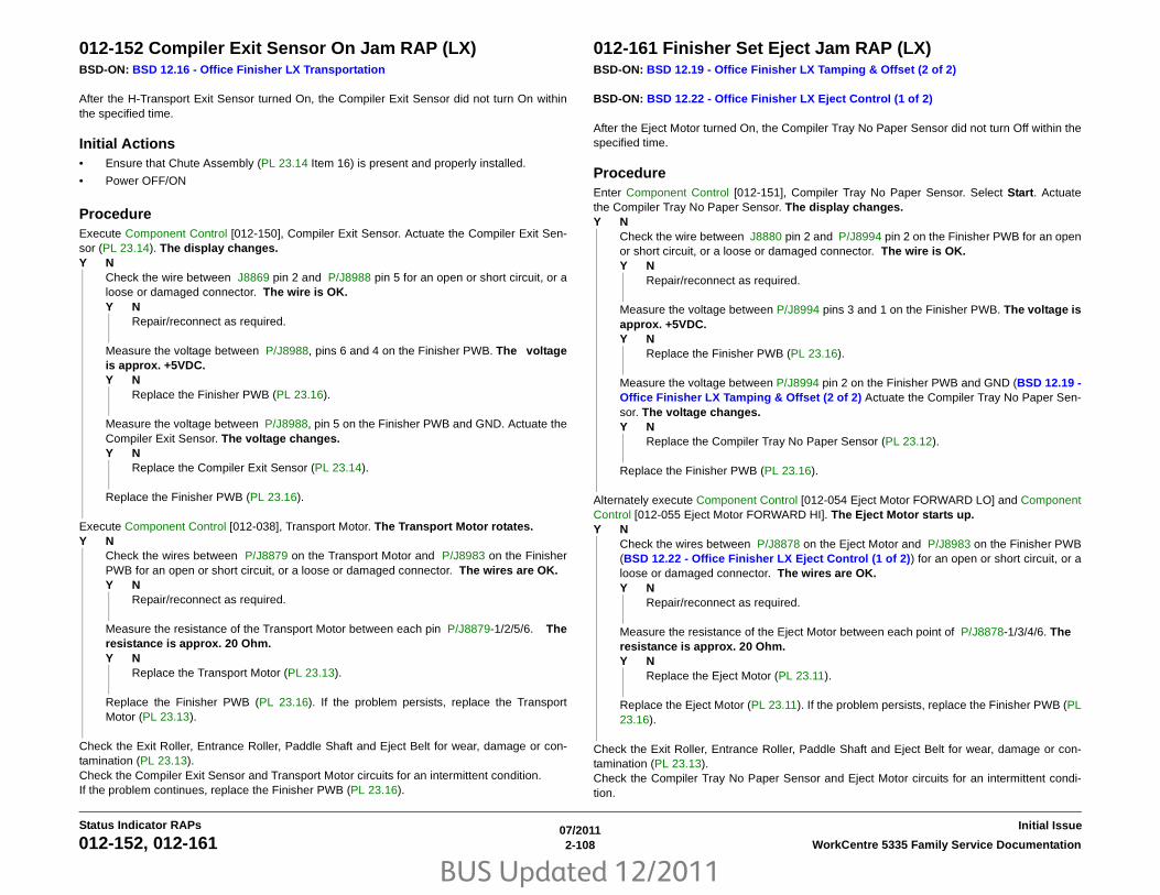
BUS Updated 12/2011
07/20112-108 WorkCentre 5335 Family Service Documentation012-152, 012-161
Initial IssueStatus Indicator RAPs
012-152 Compiler Exit Sensor On Jam RAP (LX)BSD-ON: BSD 12.16 - Office Finisher LX Transportation
After the H-Transport Exit Sensor turned On, the Compiler Exit Sensor did not turn On withinthe specified time.
Initial Actions• Ensure that Chute Assembly (PL 23.14 Item 16) is present and properly installed.
• Power OFF/ON
ProcedureExecute Component Control [012-150], Compiler Exit Sensor. Actuate the Compiler Exit Sen-sor (PL 23.14). The display changes.Y N
Check the wire between J8869 pin 2 and P/J8988 pin 5 for an open or short circuit, or aloose or damaged connector. The wire is OK.Y N
Repair/reconnect as required.
Measure the voltage between P/J8988, pins 6 and 4 on the Finisher PWB. The voltageis approx. +5VDC.Y N
Replace the Finisher PWB (PL 23.16).
Measure the voltage between P/J8988, pin 5 on the Finisher PWB and GND. Actuate theCompiler Exit Sensor. The voltage changes.Y N
Replace the Compiler Exit Sensor (PL 23.14).
Replace the Finisher PWB (PL 23.16).
Execute Component Control [012-038], Transport Motor. The Transport Motor rotates.Y N
Check the wires between P/J8879 on the Transport Motor and P/J8983 on the FinisherPWB for an open or short circuit, or a loose or damaged connector. The wires are OK.Y N
Repair/reconnect as required.
Measure the resistance of the Transport Motor between each pin P/J8879-1/2/5/6. Theresistance is approx. 20 Ohm.Y N
Replace the Transport Motor (PL 23.13).
Replace the Finisher PWB (PL 23.16). If the problem persists, replace the TransportMotor (PL 23.13).
Check the Exit Roller, Entrance Roller, Paddle Shaft and Eject Belt for wear, damage or con-tamination (PL 23.13).Check the Compiler Exit Sensor and Transport Motor circuits for an intermittent condition. If the problem continues, replace the Finisher PWB (PL 23.16).
012-161 Finisher Set Eject Jam RAP (LX)BSD-ON: BSD 12.19 - Office Finisher LX Tamping & Offset (2 of 2)
BSD-ON: BSD 12.22 - Office Finisher LX Eject Control (1 of 2)
After the Eject Motor turned On, the Compiler Tray No Paper Sensor did not turn Off within thespecified time.
ProcedureEnter Component Control [012-151], Compiler Tray No Paper Sensor. Select Start. Actuatethe Compiler Tray No Paper Sensor. The display changes.Y N
Check the wire between J8880 pin 2 and P/J8994 pin 2 on the Finisher PWB for an openor short circuit, or a loose or damaged connector. The wire is OK.Y N
Repair/reconnect as required.
Measure the voltage between P/J8994 pins 3 and 1 on the Finisher PWB. The voltage isapprox. +5VDC.Y N
Replace the Finisher PWB (PL 23.16).
Measure the voltage between P/J8994 pin 2 on the Finisher PWB and GND (BSD 12.19 -Office Finisher LX Tamping & Offset (2 of 2) Actuate the Compiler Tray No Paper Sen-sor. The voltage changes.Y N
Replace the Compiler Tray No Paper Sensor (PL 23.12).
Replace the Finisher PWB (PL 23.16).
Alternately execute Component Control [012-054 Eject Motor FORWARD LO] and ComponentControl [012-055 Eject Motor FORWARD HI]. The Eject Motor starts up.Y N
Check the wires between P/J8878 on the Eject Motor and P/J8983 on the Finisher PWB(BSD 12.22 - Office Finisher LX Eject Control (1 of 2)) for an open or short circuit, or aloose or damaged connector. The wires are OK.Y N
Repair/reconnect as required.
Measure the resistance of the Eject Motor between each point of P/J8878-1/3/4/6. Theresistance is approx. 20 Ohm.Y N
Replace the Eject Motor (PL 23.11).
Replace the Eject Motor (PL 23.11). If the problem persists, replace the Finisher PWB (PL23.16).
Check the Exit Roller, Entrance Roller, Paddle Shaft and Eject Belt for wear, damage or con-tamination (PL 23.13).Check the Compiler Tray No Paper Sensor and Eject Motor circuits for an intermittent condi-tion.

BUS Updated 12/2011
07/20112-109WorkCentre 5335 Family Service Documentation 012-161, 012-211
Status Indicator RAPsInitial Issue
If the problem continues, replace the Finisher PWB (PL 23.16). 012-211 Stacker Tray Failure RAP (LX)BSD-ON: BSD 12.24 - Office Finisher LX Stacker Tray Control
Stack Height Sensor 1 is not ON within the specified time after stacker tray starts elevat-ing.While Stacker Tray is elevating or lowering, the state of the Encoder Sensor does notchange within the specified time.
Initial Actions• Check for obstructions under the tray.
• Check the operation of the Stacker Height Sensor 1 actuator.
• Check the tray raise/lower mechanism for damage or contamination.
ProcedureExecute Component Control [012-264], Stacker Height Sensor 1. Actuate the Stacker HeightSensor 1. The display changes.Y N
Check the wire between J8873 pin 2 and P/J8988 pin 17 for an open or short circuit, or aloose or damaged connector. The wire is OK.Y N
Repair/reconnect as required.
Measure the voltage between P/J8988, pins 16 and 18 on the Finisher PWB. The volt-age is approx. +5VDC.Y N
Replace the Finisher PWB (PL 23.16).
Measure the voltage between P/J8988, pin 17 on the Finisher PWB and GND. Actuatethe Stacker Height Sensor 1. The voltage changes.Y N
Replace the Stacker Height Sensor 1 (PL 23.11).
Replace the Finisher PWB (PL 23.16).
Execute Component Control [012-263], Stacker Encoder Sensor. Manually rotate the Encoder(PL 23.7) to block and unblock the sensor. The display changes.Y N
Check the wire between J8875 pin 2 and P/J8988 pin 23 for an open or short circuit, or aloose or damaged connector. The wire is OK.Y N
Repair/reconnect as required.
Measure the voltage between P/J8988, pins 22 and 24 on the Finisher PWB. The volt-age is approx. +5VDC.Y N
Replace the Finisher PWB (PL 23.16).
Measure the voltage between P/J8988, pin 23 on the Finisher PWB and GND. Manuallyrotate the Encoder (PL 23.7) to block and unblock the Stacker Encoder Sensor. The volt-age changes.
A

BUS Updated 12/2011
07/20112-110 WorkCentre 5335 Family Service Documentation012-211, 012-212
Initial IssueStatus Indicator RAPs
Y NReplace the Stacker Encoder Sensor (PL 23.7).
Replace the Finisher PWB (PL 23.16).
Alternately execute Component Control [012-060], Stacker Motor Up, and [012-061], StackerMotor Down. The Stacker Motor (PL 23.7) Moves.Y N
There is +24 VDC from P/J8986 pin 12 to GND (BSD 12.24 - Office Finisher LXStacker Tray Control)Y N
Go to BSD 12.24 - Office Finisher LX Stacker Tray Control and check the circuitof the Option Switch (PL 23.9). Repair/reconnect as required.
Check the wires between P/J8986 pins 11 and 12, and the Stacker Motor for an open orshort circuit, or a loose or damaged connector. The wires are OK.Y N
Repair/reconnect as required.
Replace the Stacker Elevator Motor (PL 23.7). If the problem persists, replace the Fin-isher PWB (PL 23.16).
Replace the Finisher PWB (PL 23.16).
012-212 Stacker Tray Upper Limit Failure RAP (LX)BSD-ON: BSD 12.24 - Office Finisher LX Stacker Tray Control
The stacker has continued to elevate after the defined period of time has passed since StackerNo Paper Sensor is ON during stacker elevation.
Initial Actions• Check for obstructions under the tray.
• Check the operation of the Stacker Height Sensor actuators.
• Check the tray raise/lower mechanism for damage or contamination.
ProcedureExecute Component Control [012-264], Stacker Height Sensor 1. Actuate the Stacker HeightSensor 1. The display changes.Y N
Check the wire between J8873 pin 2 and P/J8988 pin 17 for an open or short circuit, or aloose or damaged connector. The wire is OK.Y N
Repair/reconnect as required.
Measure the voltage between P/J8988, pins 16 and 18 on the Finisher PWB (BSD 12.24- Office Finisher LX Stacker Tray Control). The voltage is approx. +5VDC.Y N
Replace the Finisher PWB (PL 23.16).
Measure the voltage between P/J8988, pin 17 on the Finisher PWB and GND BSD 12.24- Office Finisher LX Stacker Tray Control. Actuate the Stacker Height Sensor 1. Thevoltage changes.Y N
Replace the Stacker Height Sensor 1 (PL 23.11).
Replace the Finisher PWB (PL 23.16).
Execute Component Control [012-265], Stacker Height Sensor 2. Block and unblock theStacker Height Sensor 2. The display changes.Y N
Check the wire between J8874 pin 2 and P/J8988 pin 20 for an open or short circuit, or aloose or damaged connector. The wire is OK.Y N
Repair/reconnect as required.
Measure the voltage between P/J8988, pins 19 and 21 on the Finisher PWB (BSD 12.24- Office Finisher LX Stacker Tray Control). The voltage is approx. +5VDC.Y N
Replace the Finisher PWB (PL 23.16).
Measure the voltage between P/J8988, pin 20 on the Finisher PWB and GND (BSD12.24 - Office Finisher LX Stacker Tray Control). Actuate the Stacker Height Sensor 1.The voltage changes.
A
A

BUS Updated 12/2011
07/20112-111WorkCentre 5335 Family Service Documentation 012-212, 012-213
Status Indicator RAPsInitial Issue
Y NReplace the Stacker Height Sensor 2 (PL 23.11).
Replace the Finisher PWB (PL 23.16).
Execute Component Control [012-263], Stacker Encoder Sensor. Manually rotate the Encoder(PL 23.7) to block and unblock the sensor. The display changes.Y N
Check the wire between J8875 pin 2 and P/J8988 pin 23 for an open or short circuit, or aloose or damaged connector. The wire is OK.Y N
Repair/reconnect as required.
Measure the voltage between P/J8988, pins 22 and 24 on the Finisher PWB (BSD 12.24- Office Finisher LX Stacker Tray Control). The voltage is approx. +5VDC.Y N
Replace the Finisher PWB (PL 23.16).
Measure the voltage between P/J8988, pin 23 on the Finisher PWB and GND BSD 12.24- Office Finisher LX Stacker Tray Control. Manually rotate the Encoder (PL 23.7) toblock and unblock the Stacker Encoder Sensor. The voltage changes.Y N
Replace the Stacker Encoder Sensor (PL 23.7).
Replace the Finisher PWB (PL 23.16).
Execute Component Control [012-262], Stacker No Paper Sensor. Block and unblock the Sen-sor (PL 23.7). The display changes.Y N
Check the wire between J8872 pin 2 and P/J8988 pin 14 for an open or short circuit, or aloose or damaged connector. The wire is OK.Y N
Repair/reconnect as required.
Measure the voltage between P/J8988, pins 13 and 15 on the Finisher PWB BSD 12.24 -Office Finisher LX Stacker Tray Control. The voltage is approx. +5VDC.Y N
Replace the Finisher PWB (PL 23.16).
Measure the voltage between P/J8988, pin 14 on the Finisher PWB and GND BSD 12.24- Office Finisher LX Stacker Tray Control. Actuate the Stacker No Paper Sensor. Thevoltage changes.Y N
Replace the Stacker No Paper Sensor (PL 23.7).
Replace the Finisher PWB (PL 23.16).
Replace the Finisher PWB (PL 23.16).
012-213 Stacker Tray Lower Limit Failure RAP (LX)BSD-ON: BSD 12.24 - Office Finisher LX Stacker Tray Control
Stacker descended lower than normal levels, below low limit height.
Initial Actions• Check for obstructions under the tray.
• Check the operation of the Stacker Height Sensor actuators.
• Check the tray raise/lower mechanism for damage or contamination.
ProcedureExecute Component Control [012-264], Stacker Height Sensor 1. Actuate the Stacker HeightSensor 1. The display changes.Y N
Check the wire between J8873 pin 2 and P/J8988 pin 17 for an open or short circuit, or aloose or damaged connector. The wire is OK.Y N
Repair/reconnect as required.
Measure the voltage between P/J8988, pins 16 and 18 on the Finisher PWB (BSD 12.24- Office Finisher LX Stacker Tray Control). The voltage is approx. +5VDC.Y N
Replace the Finisher PWB (PL 23.16).
Measure the voltage between P/J8988, pin 17 on the Finisher PWB and GND (BSD12.24 - Office Finisher LX Stacker Tray Control).Actuate the Stacker Height Sensor 1.The voltage changes.Y N
Replace the Stacker Height Sensor 1 (PL 23.11).
Replace the Finisher PWB (PL 23.16).
Execute Component Control [012-265], Stacker Height Sensor 2. Block and unblock theStacker Height Sensor 2. The display changes.Y N
Check the wire between J8874 pin 2 and P/J8988 pin 20 for an open or short circuit, or aloose or damaged connector. The wire is OK.Y N
Repair/reconnect as required.
Measure the voltage between P/J8988, pins 19 and 21 on the Finisher BSD 12.24 -Office Finisher LX Stacker Tray Control The voltage is approx. +5VDC.Y N
Replace the Finisher PWB (PL 23.16).
Measure the voltage between P/J8988, pin 20 on the Finisher PWB and GND BSD 12.24- Office Finisher LX Stacker Tray Control. Actuate the Stacker Height Sensor 1. Thevoltage changes.Y N
Replace the Stacker Height Sensor 2 (PL 23.11).
A
A B
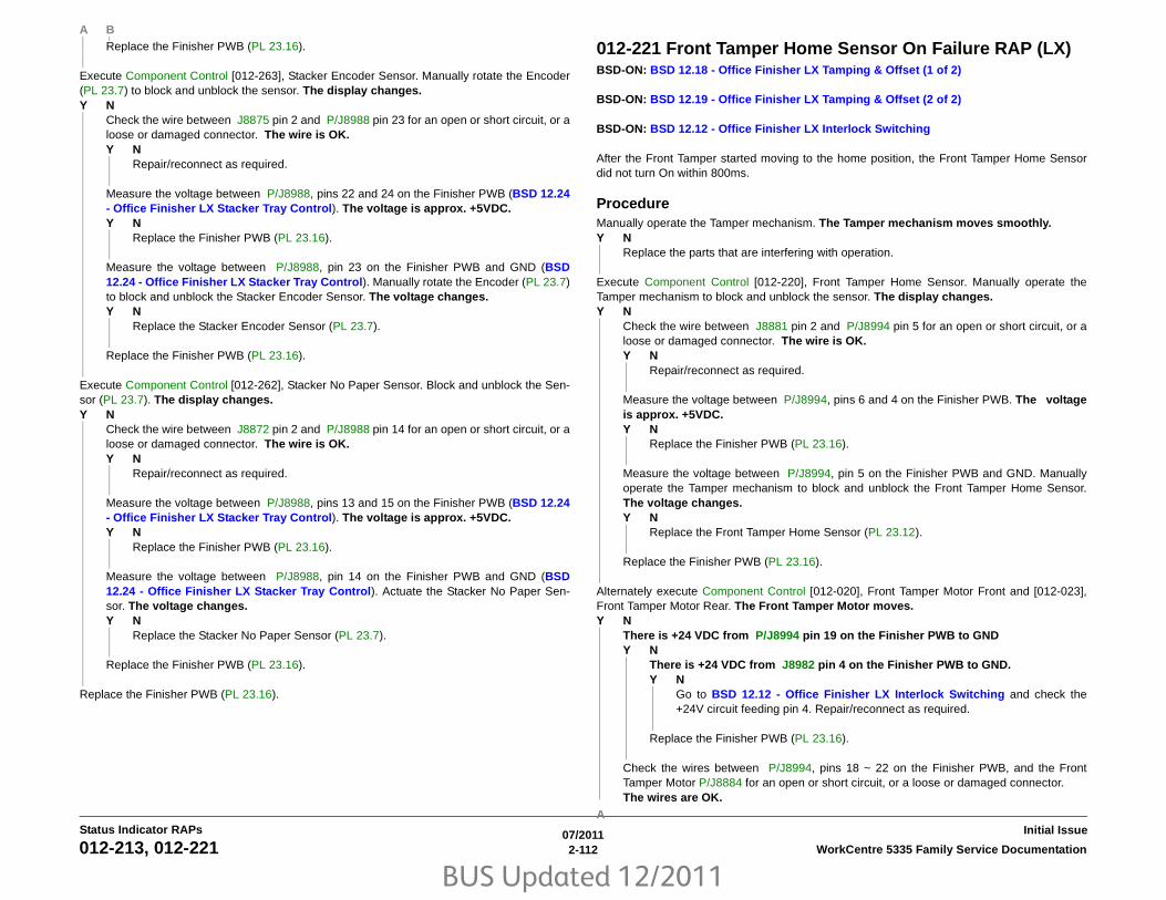
BUS Updated 12/2011
07/20112-112 WorkCentre 5335 Family Service Documentation012-213, 012-221
Initial IssueStatus Indicator RAPs
Replace the Finisher PWB (PL 23.16).
Execute Component Control [012-263], Stacker Encoder Sensor. Manually rotate the Encoder(PL 23.7) to block and unblock the sensor. The display changes.Y N
Check the wire between J8875 pin 2 and P/J8988 pin 23 for an open or short circuit, or aloose or damaged connector. The wire is OK.Y N
Repair/reconnect as required.
Measure the voltage between P/J8988, pins 22 and 24 on the Finisher PWB (BSD 12.24- Office Finisher LX Stacker Tray Control). The voltage is approx. +5VDC.Y N
Replace the Finisher PWB (PL 23.16).
Measure the voltage between P/J8988, pin 23 on the Finisher PWB and GND (BSD12.24 - Office Finisher LX Stacker Tray Control). Manually rotate the Encoder (PL 23.7)to block and unblock the Stacker Encoder Sensor. The voltage changes.Y N
Replace the Stacker Encoder Sensor (PL 23.7).
Replace the Finisher PWB (PL 23.16).
Execute Component Control [012-262], Stacker No Paper Sensor. Block and unblock the Sen-sor (PL 23.7). The display changes.Y N
Check the wire between J8872 pin 2 and P/J8988 pin 14 for an open or short circuit, or aloose or damaged connector. The wire is OK.Y N
Repair/reconnect as required.
Measure the voltage between P/J8988, pins 13 and 15 on the Finisher PWB (BSD 12.24- Office Finisher LX Stacker Tray Control). The voltage is approx. +5VDC.Y N
Replace the Finisher PWB (PL 23.16).
Measure the voltage between P/J8988, pin 14 on the Finisher PWB and GND (BSD12.24 - Office Finisher LX Stacker Tray Control). Actuate the Stacker No Paper Sen-sor. The voltage changes.Y N
Replace the Stacker No Paper Sensor (PL 23.7).
Replace the Finisher PWB (PL 23.16).
Replace the Finisher PWB (PL 23.16).
012-221 Front Tamper Home Sensor On Failure RAP (LX)BSD-ON: BSD 12.18 - Office Finisher LX Tamping & Offset (1 of 2)
BSD-ON: BSD 12.19 - Office Finisher LX Tamping & Offset (2 of 2)
BSD-ON: BSD 12.12 - Office Finisher LX Interlock Switching
After the Front Tamper started moving to the home position, the Front Tamper Home Sensordid not turn On within 800ms.
ProcedureManually operate the Tamper mechanism. The Tamper mechanism moves smoothly.Y N
Replace the parts that are interfering with operation.
Execute Component Control [012-220], Front Tamper Home Sensor. Manually operate theTamper mechanism to block and unblock the sensor. The display changes.Y N
Check the wire between J8881 pin 2 and P/J8994 pin 5 for an open or short circuit, or aloose or damaged connector. The wire is OK.Y N
Repair/reconnect as required.
Measure the voltage between P/J8994, pins 6 and 4 on the Finisher PWB. The voltageis approx. +5VDC.Y N
Replace the Finisher PWB (PL 23.16).
Measure the voltage between P/J8994, pin 5 on the Finisher PWB and GND. Manuallyoperate the Tamper mechanism to block and unblock the Front Tamper Home Sensor.The voltage changes.Y N
Replace the Front Tamper Home Sensor (PL 23.12).
Replace the Finisher PWB (PL 23.16).
Alternately execute Component Control [012-020], Front Tamper Motor Front and [012-023],Front Tamper Motor Rear. The Front Tamper Motor moves.Y N
There is +24 VDC from P/J8994 pin 19 on the Finisher PWB to GNDY N
There is +24 VDC from J8982 pin 4 on the Finisher PWB to GND.Y N
Go to BSD 12.12 - Office Finisher LX Interlock Switching and check the+24V circuit feeding pin 4. Repair/reconnect as required.
Replace the Finisher PWB (PL 23.16).
Check the wires between P/J8994, pins 18 ~ 22 on the Finisher PWB, and the FrontTamper Motor P/J8884 for an open or short circuit, or a loose or damaged connector. The wires are OK.
A B
A

BUS Updated 12/2011
07/20112-113WorkCentre 5335 Family Service Documentation 012-221, 012-223
Status Indicator RAPsInitial Issue
Y NRepair/reconnect as required.
Replace the front Tamper Motor (PL 23.12). If the problem persists, replace the FinisherPWB (PL 23.16).
Replace the Finisher PWB (PL 23.16).
012-223 Front Tamper Home Sensor Off Failure RAP (LX)BSD-ON: BSD 12.18 - Office Finisher LX Tamping & Offset (1 of 2)
BSD-ON: BSD 12.19 - Office Finisher LX Tamping & Offset (2 of 2)
BSD-ON: BSD 12.12 - Office Finisher LX Interlock Switching
After the Front Tamper started moving away from the home position, the Front Tamper HomeSensor did not turn Off within the specified time.
ProcedureManually operate the Tamper mechanism. The Tamper mechanism moves smoothly.Y N
Replace the parts that are interfering with operation.
Execute Component Control [012-220], Front Tamper Home Sensor. Manually operate theTamper mechanism to block and unblock the sensor. The display changes.Y N
Check the wire between J8881 pin 2 and P/J8994 pin 5 for an open or short circuit, or aloose or damaged connector. The wire is OK.Y N
Repair/reconnect as required.
Measure the voltage between P/J8994, pins 6 and 4 on the Finisher PWB BSD 12.18 -Office Finisher LX Tamping & Offset (1 of 2). The voltage is approx. +5VDC.Y N
Replace the Finisher PWB (PL 23.16).
Measure the voltage between P/J8994, pin 5 on the Finisher PWB and GND (BSD 12.18- Office Finisher LX Tamping & Offset (1 of 2). Manually operate the Tamper mecha-nism to block and unblock the Front Tamper Home Sensor. The voltage changes.Y N
Replace the Front Tamper Home Sensor (PL 23.12).
Replace the Finisher PWB (PL 23.16).
Alternately execute Component Control [012-020], Front Tamper Motor Front and [012-023],Front Tamper Motor Rear. The Front Tamper Motor moves.Y N
There is +24 VDC from P/J8994 pin 19 on the Finisher PWB to GNDY N
There is +24 VDC from J8982 pin 4 on the Finisher PWB to GND Y N
Go to BSD 12.12 - Office Finisher LX Interlock Switching: J8982 and checkthe +24V circuit feeding pin 4. Repair/reconnect as required.
Replace the Finisher PWB (PL 23.16).
Check the wires between P/J8994, pins 18 ~ 22 on the Finisher PWB, and the FrontTamper Motor P/J8884 for an open or short circuit, or a loose or damaged connector. The wires are OK.
A
A

BUS Updated 12/2011
07/20112-114 WorkCentre 5335 Family Service Documentation012-223, 012-224
Initial IssueStatus Indicator RAPs
Y NRepair/reconnect as required.
Replace the Front Tamper Motor (PL 23.12). If the problem persists, replace the FinisherPWB (PL 23.16).
Replace the Finisher PWB (PL 23.16).
012-224 Rear Tamper Home Sensor Off Failure RAP (LX)BSD-ON: BSD 12.18 - Office Finisher LX Tamping & Offset (1 of 2)
BSD-ON: BSD 12.19 - Office Finisher LX Tamping & Offset (2 of 2)
BSD-ON: BSD 12.12 - Office Finisher LX Interlock Switching
After the Rear Tamper started moving away from the home position, the Rear Tamper HomeSensor did not turn Off within the specified time.
ProcedureManually operate the Tamper mechanism. The Tamper mechanism moves smoothly.Y N
Replace the parts that are interfering with operation.
Execute Component Control [012-221], Rear Tamper Home Sensor. Manually operate theTamper mechanism to block and unblock the sensor. The display changes.Y N
Check the wire between J8882 pin 2 and P/J8994 pin 8 for an open or short circuit, or aloose or damaged connector. The wire is OK.Y N
Repair/reconnect as required.
Measure the voltage between P/J8994, pins 9 and 7 on the Finisher PWB. The voltageis approx. +5VDC.Y N
Replace the Finisher PWB (PL 23.16).
Measure the voltage between P/J8994, pin 8 on the Finisher PWB and GND. Manuallyoperate the Tamper mechanism to block and unblock the Rear Tamper Home Sensor.The voltage changes.Y N
Replace the Rear Tamper Home Sensor (PL 23.12).
Replace the Finisher PWB (PL 23.16).
Alternately execute Component Control [012-026], Rear Tamper Motor Front and [012-029],Rear Tamper Motor Rear. The Rear Tamper Motor moves.Y N
There is +24 VDC from P/J8994 pin 19 on the Finisher PWB to GNDY N
There is +24 VDC from J8982 pin 4 on the Finisher PWB to GNDY N
Go to BSD 12.12 - Office Finisher LX Interlock Switching and check the+24V circuit feeding pin 4. Repair/reconnect as required.
Replace the Finisher PWB (PL 23.16).
Check the wires between P/J8994, pins 13 ~ 17 on the Finisher PWB, and the RearTamper Motor P/J8883 for an open or short circuit, or a loose or damaged connector. The wires are OK.
A
A

BUS Updated 12/2011
07/20112-115WorkCentre 5335 Family Service Documentation 012-224, 012-231
Status Indicator RAPsInitial Issue
Y NRepair/reconnect as required.
Replace the Rear Tamper Motor (PL 23.12). If the problem persists, replace the FinisherPWB (PL 23.16).
Replace the Finisher PWB (PL 23.16).
012-231 Punch Home Sensor On Fail RAP (LX)BSD-ON: BSD 12.15 - Office Finisher LX Punch
The Punch Home Sensor did not turn ON within the specified time after the Punch Motorstarted running.
Initial ActionsCheck the following:
• Punch Home Actuator for deformation
• Punch Home Sensor for proper installation
• Punch Home Sensor connectors
• Punch Motor for proper operation
• Punch Motor connectors
ProcedureEnter Component Control [12-074] and [12-078], Punch Motor (PL 23.5), alternately. SelectStart. The Punch Motor runs.Y N
Select Stop. Check circuit of the Punch Motor. Refer to BSD 12.15 - Office Finisher LXPunch to troubleshoot the Circuit.
Select Stop. Select [12-271], Punch Home Sensor (PL 23.5). Select Start. Actuate the sensorwith a piece of paper. The display changes.Y N
Go to BSD 12.15 - Office Finisher LX Punch. Check circuit of the Punch Home Sensor.
Select Stop. If the problem continues, replace the Finisher PWB (PL 23.16).
A

BUS Updated 12/2011
07/20112-116 WorkCentre 5335 Family Service Documentation012-243, 012-249
Initial IssueStatus Indicator RAPs
012-243 Booklet Folder Home Sensor On Fail RAP (LX)BSD-ON: BSD 12.17 - Office Finisher LX Folding
Folder Home Sensor is not turned on after the lapse of 500ms from Motor ON while FolderKnife is returning to Home.
Initial Actions• The Folder Home Sensor for improper installation
• The Folder Home Sensor connectors for connection failure
• The Folder Knife Motor connectors for connection failure
• The Knife drive mechanism for a foreign substance
ProcedureEnter Component Control [013-022], Folder Knife Motor FWD and [013-023], Folder KnifeMotor REV alternately. Select Start. The Fold Knife Motor energizes.Y N
Select Stop. Refer to (BSD 12.17 - Office Finisher LX Folding. Check continuitybetween the Booklet Folder Knife Motor ( P/J8905) and the Finisher PWB ( P8985), andbetween the Booklet PWB ( P/J8994) and the Finisher PWB ( P8985). The continuitycheck is OK.Y N
Repair the open circuit or short circuit.
Replace the Booklet Folder Knife Motor (PL 23.15). If the problem continues, replace theBooklet PWB (PL 23.21).
Select Stop. Enter [13-101], Folder Home Sensor. Select Start. Block/unblock the FolderHome Sensor. The display changed.Y N
Check the wire between J8904 pin 2 and P/J8990 pin 2 on the FInisher PWB for an openor short circuit, or a loose or damaged connector. The wire is OK.Y N
Repair/reconnect as required.
Measure the voltage between P/J8990, pins 3 and 1 on the Finisher PWB (BSD 12.17 -Office Finisher LX Folding The voltage is approx. +5VDC.Y N
Replace the Finisher PWB (PL 23.16).
Measure the voltage between P/J8990, pin 2 on the Finisher PWB and GND BSD 12.17- Office Finisher LX Folding. Block/unblock the Folder Home Sensor. The voltagechanges.Y N
Replace the Folder Home Sensor (PL 23.15).
Replace the Finisher PWB (PL 23.16).
If the problem continues, replace the Finisher PWB (PL 23.16).
012-249 Booklet Front Stapler Fail RAP (LX)BSD-ON: BSD 12.26 - Office Finisher Booklet Staple Control (1 of 2 - Front)
BSD-ON: BSD 12.13 - Office Finisher LX Booklet Interlock Switching
The Booklet Front Staple Home Switch is not ON (does not return to home position) within thespecified time after the Booklet Front Staple Motor starts to reverse.
Initial ActionsCheck the Booklet Front Stapler for jammed staples or an incorrectly installed staple cartridge.
ProcedureEnter Component Control [12-024], Staple Motor FWD. and then [12-025], Staple Motor REV. The Front Booklet Stapler cycles normally.Y N
There is +24 VDC from P/J8993 pin 5 on the Booklet PWB to GND.Y N
Check the circuit from the Booklet PWB to the Booklet Stapler Cover Switch (BSD12.13 - Office Finisher LX Booklet Interlock Switching. Repair/replace asrequired (PL 23.21).
Switch off the power. Check the wires between P/J8994 on the Booklet PWB and J8894on the Front Booklet Stapler for a loose or damaged connector, or an open or short circuit.If the wires are OK, replace the Front Booklet Stapler Assembly (PL 23.19). If the problemremains, replace the Booklet PWB (PL 23.21).
Switch off the power. Check the wire between P/J8995, pin 5 on the Booklet PWB and J8894pin 3 on the Front Booklet Stapler for a loose or damaged connector, or an open or short cir-cuit. If the wires are OK, replace the Front Booklet Stapler Assembly (PL 23.19). If the problemremains, replace the Booklet PWB (PL 23.21).

BUS Updated 12/2011
07/20112-117WorkCentre 5335 Family Service Documentation 012-260
Status Indicator RAPsInitial Issue
012-260 Eject Clamp Home Sensor On Failure RAP (LX)BSD-ON: BSD 12.22 - Office Finisher LX Eject Control (1 of 2)
After the Eject Clamp started ascending, the Eject Clamp Home Sensor did not turn On within500ms.
Initial Actions• Manually operate the Eject mechanism. Check for binding, a dirty sensor, or damage.
• Check the actuator for the Eject Clamp Home Sensor b for damage
ProcedureExecute Component Control [012-250], Eject Clamp Home Sensor. Block and unblock theEject Clamp Home Sensor The display changes.Y N
Check the wire between J8870 pin 2 on the Eject Clamp Home Sensor and P/J8988 pin8 on the Finisher PWB for an open or short circuit, or loose or damaged connectors. Thewire is OK.Y N
Repair/replace as required.
Measure the voltage between P/J8988, pins 9 and 7 on the Finisher PWB. The voltageis approx. +5VDC.Y N
Replace the Finisher PWB (PL 23.16).
Measure the voltage between P/J8988 pin 8 on the Finisher PWB and GND. Actuate theEject Clamp Home Sensor. The voltage changes.Y N
Replace the Eject Clamp Home Sensor (PL 23.11).
Replace the Finisher PWB (PL 23.16).
Alternately execute Component Control [012-052], Eject Clamp Up and [012-053], Eject ClampDown. The Eject Motor (PL 22.9) starts up.Y N
Check the wires between P/J8878 pins 1~6 on the Eject Motor and P/J8983 pins 5~8 onthe Finisher PWB for an open or short circuit, or loose or damaged connectors BSD 12.22- Office Finisher LX Eject Control (1 of 2). The wires are OK.Y N
Repair/replace as required.
Measure the resistance of the Eject Motor between each pin of P/J8878-1/3/4/6. Theresistance is approx. 2Ohm.Y N
Replace the Eject Motor (PL 23.11).
Replace the Finisher PWB (PL 23.16). If the problem remains, replace the Eject Motor(PL 23.11)
Go to BSD 12.22 - Office Finisher LX Eject Control (1 of 2). Check for an intermittent circuitor intermittent mechanical problem. If the check is OK, replace the Finisher PWB (PL 23.16).
A
A

BUS Updated 12/2011
07/20112-118 WorkCentre 5335 Family Service Documentation012-263
Initial IssueStatus Indicator RAPs
012-263 Rear Tamper Failure RAP (LX)BSD-ON: BSD 12.18 - Office Finisher LX Tamping & Offset (1 of 2)
BSD-ON: BSD 12.19 - Office Finisher LX Tamping & Offset (2 of 2)
BSD-ON: BSD 12.12 - Office Finisher LX Interlock Switching
After the Rear Tamper started moving to the home position, the Rear Tamper Home Sensor didnot turn On within 800ms.
ProcedureManually operate the Tamper mechanism. The Tamper mechanism moves smoothly.Y N
Replace the parts that are interfering with operation.
Execute Component Control [012-221], Rear Tamper Home Sensor. Manually operate theTamper mechanism to block and unblock the sensor. The display changes.Y N
Check the wire between J8882 pin 2 and P/J8994 pin 8 for an open or short circuit, or aloose or damaged connector. The wire is OK.Y N
Repair/reconnect as required.
Measure the voltage between P/J8994, pins 9 and 7 on the Finisher PWB. The voltageis approx. +5VDC.Y N
Replace the Finisher PWB (PL 23.16).
Measure the voltage between P/J8994, pin 8 on the Finisher PWB and GND BSD 12.19- Office Finisher LX Tamping & Offset (2 of 2). Manually operate the Tamper mecha-nism to block and unblock the Rear Tamper Home Sensor. The voltage changes.Y N
Replace the Rear Tamper Home Sensor (PL 23.12).
Replace the Finisher PWB (PL 23.16).
Alternately execute Component Control [012-026], Rear Tamper Motor Front and [012-029],Rear Tamper Motor Rear. The Rear Tamper Motor moves.Y N
There is +24 VDC from P/J8994 pin 14 on the Finisher PWB to GNDY N
There is +24 VDC from J8982 pin 4 on the Finisher PWB to GNDY N
Go to BSD 12.12 - Office Finisher LX Interlock Switching and check the+24V circuit feeding pin 4. Repair/reconnect as required.
Replace the Finisher PWB (PL 23.16).
Check the wires between P/J8994, pins 13 ~ 17 on the Finisher PWB, and the RearTamper Motor P/J8883 for an open or short circuit, or a loose or damaged connector. The wires are OK.
Y NRepair/reconnect as required.
Replace the Rear Tamper Motor (PL 23.12). If the problem persists, replace the FinisherPWB (PL 23.16).
Replace the Finisher PWB (PL 23.16).
A
A

BUS Updated 12/2011
07/20112-119WorkCentre 5335 Family Service Documentation 012-265, 012-268
Status Indicator RAPsInitial Issue
012-265 Booklet Folder Home Sensor OFF Fail RAP (LX)BSD-ON: BSD 12.17 - Office Finisher LX Folding
When the Booklet Home moves from Home position, the Folder Home Sensor did not turn OFFwithin the specified time.
Initial Actions• The Folder Home Sensor for improper installation
• The Folder Home Sensor connectors for connection failure
• The Booklet Fold Knife Motor connectors for connection failure
• The Knife drive mechanism for a foreign substance
ProcedureEnter Component Control [013-022], Folder Knife Motor FWD and [013-023], Folder KnifeMotor REV alternately. Select Start. The Fold Knife Motor energizes.Y N
Select Stop. Refer to BSD 12.17 - Office Finisher LX Folding Check continuity betweenthe Folder Knife Motor ( P/J8905) and the Finisher PWB ( P8985), and between the Book-let PWB ( P/J8994) and the Finisher PWB ( P8985). The continuity check is OK.Y N
Repair the open circuit or short circuit.
Replace the Folder Knife Motor (PL 23.15). If the problem continues, replace the BookletPWB (PL 23.21).
Select Stop. Enter [13-101], Folder Home Sensor. Select Start. Block/unblock the FolderHome Sensor. The display changed.Y N
Check the wire between J8904 pin 2 and P/J8990 pin 2 on the FInisher PWB for an openor short circuit, or a loose or damaged connector. The wire is OK.Y N
Repair/reconnect as required.
Measure the voltage between P/J8990, pins 3 and 1 on the Finisher PWB BSD 12.17 -Office Finisher LX Folding The voltage is approx. +5VDC.Y N
Replace the Finisher PWB (PL 23.16).
Measure the voltage between P/J8990, pin 2 on the Finisher PWB and GND (BSD 12.17- Office Finisher LX Folding.Block/unblock the Folder Home Sensor. The voltagechanges.Y N
Replace the Folder Home Sensor (PL 23.15).
Replace the Finisher PWB (PL 23.16).
If the problem continues, replace the Finisher PWB (PL 23.16).
012-268 Booklet Rear Stapler Fail RAP (LX)BSD-ON: BSD 12.27 - Office Finisher Booklet Staple Control (2 of 2 - Rear)
BSD-ON: BSD 12.13 - Office Finisher LX Booklet Interlock Switching
The Booklet Rear Staple Home Switch is not ON (does not return to home position) within thespecified time after the Booklet Rear Staple Motor starts to reverse.
Initial ActionsCheck the Booklet Rear Stapler for jammed staples or an incorrectly installed staple cartridge.
ProcedureEnter Component Control [12-026], Staple Motor FWD. and then [12-027], Staple Motor REV. The Front Booklet Stapler cycles normally.Y N
There is +24 VDC from P/J8993 pin 5 on the Booklet PWB to GND.Y N
Check the circuit from the Booklet PWB to the Booklet Stapler Cover Switch (BSD12.13 - Office Finisher LX Booklet Interlock Switching. Repair/replace asrequired (PL 23.21).
Switch off the power. Check the wires between P/J8995 on the Booklet PWB and P/J8995 on the Rear Booklet Stapler BSD 12.27 - Office Finisher Booklet Staple Control(2 of 2 - Rear) for a loose or damaged connector, or an open or short circuit. If the wiresare OK, replace the Rear Booklet Stapler Assembly (PL 23.20). If the problem remains,replace the Booklet PWB (PL 23.21).
Switch off the power. Check the wire between P/J8995, pin 12 on the Booklet PWB and P/J8995 pin 3 on the Rear Booklet Stapler BSD 12.27 - Office Finisher Booklet Staple Control(2 of 2 - Rear) for a loose or damaged connector, or an open or short circuit. If the wires areOK, replace the Rear Booklet Stapler Assembly (PL 23.20). If the problem remains, replace theBooklet PWB (PL 23.21).

BUS Updated 12/2011
07/20112-120 WorkCentre 5335 Family Service Documentation012-269, 012-282
Initial IssueStatus Indicator RAPs
012-269 Booklet Sub-CPU Communications Fail RAP (LX)BSD-ON:
Communications between the Finisher PWB and the Booklet PWB Failed
Initial Actions• Check the connectors at the Finisher PWB and the Booklet PWB are connected or seated
properly
• Check the wiring between the Finisher PWB and the Booklet PWB for damage
ProcedurePower off and power on the printer. Execute Component Control [013-161], Booklet MakerDetected. The problem is resolved.Y N
Reload the software. The problem is resolved.Y N
Replace the Finisher PWB (PL 23.16). If the problem continues, replace the BookletPWB (PL 23.21).
Rerun the job.
Rerun the job.
012-282 Eject Clamp Home Sensor Off Failure RAP (LX)BSD-ON: BSD 12.22 - Office Finisher LX Eject Control (1 of 2)
After the Eject Clamp started descending, the Eject Clamp Home Sensor did not turn Off within200ms.
Initial Actions• Manually operate the Eject mechanism. Check for binding, a dirty sensor, or damage.
• Check the actuator for the Eject Clamp Home Sensor for damage
ProcedureExecute Component Control [012-250], Eject Clamp Home Sensor. Block and unblock theEject Clamp Home Sensor The display changes.Y N
Check the wire between J8870 pin 2 on the Eject Clamp Home Sensor and P/J8988 pin8 on the Finisher PWB for an open or short circuit, or loose or damaged connectors. Thewire is OK.Y N
Repair/replace as required.
Measure the voltage between P/J8988, pins 9 and 7 on the Finisher PWB. The voltageis approx. +5VDC.Y N
Replace the Finisher PWB (PL 23.16).
Measure the voltage between P/J8988 pin 8 on the Finisher PWB and GND. Actuate theEject Clamp Home Sensor. The voltage changes.Y N
Replace the Eject Clamp Home Sensor (PL 23.11).
Replace the Finisher PWB (PL 23.16).
Alternately execute Component Control [012-052], Eject Clamp Up and [012-053], Eject ClampDown. The Eject Motor starts.Y N
Check the wires between P/J8878 pins 1~6 on the Eject Motor and P/J8983 pins 5~8 onthe Finisher PWB for an open or short circuit, or loose or damaged connectors BSD 12.22- Office Finisher LX Eject Control (1 of 2). The wires are OK.Y N
Repair/replace as required.
Measure the resistance of the Eject Motor between each pin of P/J8878-1/3/4/6. Theresistance is approx. 2Ohm.Y N
Replace the Eject Motor (PL 23.11).
Replace the Finisher PWB (PL 23.16). If the problem remains, replace the Eject Motor(PL 23.11)
A

BUS Updated 12/2011
07/20112-121WorkCentre 5335 Family Service Documentation 012-282, 012-283
Status Indicator RAPsInitial Issue
Go to BSD 12.22 - Office Finisher LX Eject Control (1 of 2). Check for an intermittent circuitor intermittent mechanical problem. If the check is OK, replace the Finisher PWB (PL 23.16).
012-283 Set Clamp Home Sensor On Failure RAP (LX)BSD-ON: BSD 12.22 - Office Finisher LX Eject Control (1 of 2)
BSD-ON: BSD 12.23 - Office Finisher LX Eject Control (2 of 2)
After the Set Clamp started, the Set Clamp Home Sensor did not turn On within 200ms.
Initial Actions• Manually operate the Eject mechanism. Check for binding, a dirty sensor, or damage.
• Check the actuator for the Set Clamp Home Sensor for damage
ProcedureExecute Component Control [012-251], Set Clamp Home Sensor. Actuate the Set ClampHome Sensor. The display changes.Y N
Check the wire between J8871 pin 2 on the Set Clamp Home Sensor and P/J8988 pin 11on the Finisher PWB for an open or short circuit, or loose or damaged connectors. Thewire is OK.Y N
Repair/replace as required.
Measure the voltage between P/J8988, pins 12 and 10 on the Finisher PWB. The volt-age is approx. +5VDC.Y N
Replace the Finisher PWB (PL 23.16).
Measure the voltage between the P/J8988 pin 11 on the Finisher PWB and GND). Actu-ate the Eject Clamp Home Sensor. The voltage changes.Y N
Replace the Eject Clamp Home Sensor (PL 23.11).
Replace the Finisher PWB (PL 23.16).
Alternately execute Component Control [012-052], Eject Clamp Up and [012-053], Eject ClampDown. The Eject Motor starts.Y N
Check the wires between P/J8878 pins 1~6 on the Eject Motor and P/J8983 pins 5~8 onthe Finisher PWB for an open or short circuit, or loose or damaged connectors BSD 12.22- Office Finisher LX Eject Control (1 of 2)). The wires are OK.Y N
Repair/replace as required.
Measure the resistance of the Eject Motor between each pin of P/J8878-1/3/4/6. Theresistance is approx. 2 Ohm.Y N
Replace the Eject Motor (PL 23.11).
Replace the Finisher PWB (PL 23.16). If the problem remains, replace the Eject Motor(PL 23.11)
A
A

BUS Updated 12/2011
07/20112-122 WorkCentre 5335 Family Service Documentation012-283, 012-284
Initial IssueStatus Indicator RAPs
Execute Component Control [012-050 Set Clamp Clutch ON]. The Set Clamp Clutch ener-gizes.Y N
Select Stop. Check the wires between P/J8877 pins 1 and 2 on the Set Clamp Clutch andP/J8983 pins 3 and 4 on the Finisher PWB for an open or short circuit, or loose or dam-aged connectors (BSD 12.23 - Office Finisher LX Eject Control (2 of 2). The wires areOK.Y N
Repair/replace as required.
Measure the voltage between the Finisher PWB P8983-4 (+) and GND (-). The voltageis approx. +24VDC.Y N
Replace the Set Clamp Clutch (PL 23.11). If the problem persists, replace the Fin-isher PWB (PL 23.16).
Replace the Finisher PWB (PL 23.16).
Replace the Finisher PWB (PL 23.16).
012-284 Set Clamp Home Sensor Off Failure RAP (LX)BSD-ON: BSD 12.22 - Office Finisher LX Eject Control (1 of 2)
BSD-ON: BSD 12.23 - Office Finisher LX Eject Control (2 of 2)
After the Set Clamp completed operation, the Set Clamp Home Sensor did not turn Off withinthe specified time.
Initial Actions• Manually operate the Eject mechanism. Check for binding, a dirty sensor, or damage.
• Check the actuator for the Set Clamp Home Sensor for damage
ProcedureExecute Component Control [012-251], Set Clamp Home Sensor. Actuate the Set ClampHome Sensor. The display changes.Y N
Check the wire between J8871 pin 2 on the Set Clamp Home Sensor and P/J8988 pin 11on the Finisher PWB for an open or short circuit, or loose or damaged connectors. Thewire is OK.Y N
Repair/replace as required.
Measure the voltage between P/J8988, pins 12 and 10 on the Finisher PWB. The volt-age is approx. +5VDC.Y N
Replace the Finisher PWB (PL 23.16).
Measure the voltage between the P/J8988 pin 11 on the Finisher PWB and GND). Actu-ate the Eject Clamp Home Sensor. The voltage changes.Y N
Replace the Eject Clamp Home Sensor (PL 23.11).
Replace the Finisher PWB (PL 23.16).
Alternately execute Component Control [012-052], Eject Clamp Up and [012-053], Eject ClampDown. The Eject Motor starts.Y N
Check the wires between P/J8878 pins 1~6 on the Eject Motor and P/J8983 pins 5~8 onthe Finisher PWB for an open or short circuit, or loose or damaged connectors (BSD12.22 - Office Finisher LX Eject Control (1 of 2). The wires are OK.Y N
Repair/replace as required.
Measure the resistance of the Eject Motor between each pin of P/J8878-1/3/4/6. Theresistance is approx. 2Ohm.Y N
Replace the Eject Motor (PL 23.11).
Replace the Finisher PWB (PL 23.16). If the problem remains, replace the Eject Motor(PL 23.11)
A
A

BUS Updated 12/2011
07/20112-123WorkCentre 5335 Family Service Documentation 012-284, 012-291
Status Indicator RAPsInitial Issue
Execute Component Control [012-050 Set Clamp Clutch ON]. The Set Clamp Clutch ener-gizes.Y N
Select Stop. Check the wires between P/J8877 pins 1 and 2 on the Set Clamp Clutch andP/J8983 pins 3 and 4 on the Finisher PWB for an open or short circuit, or loose or dam-aged connectors BSD 12.23 - Office Finisher LX Eject Control (2 of 2). The wires areOK.Y N
Repair/replace as required.
Measure the voltage between the Finisher PWB P8983-4 (+) and GND (-). The voltageis approx. +24VDC.Y N
Replace the Set Clamp Clutch (PL 23.11). If the problem persists, replace the Fin-isher PWB (PL 23.16).
Replace the Finisher PWB (PL 23.16).
Replace the Finisher PWB (PL 23.16).
012-291 Stapler Failure RAP (LX)BSD-ON: BSD 12.21 - Office Finisher LX Staple Control
• After the Stapler Motor turned On (Forward rotation), the Staple Head Home Sensor didnot switch from Off to On within the specified time.
• After the Stapler Motor turned On (Reverse rotation), the Staple Head Home Sensor didnot turn On within the specified time.
Initial ActionsCheck the Stapler for jammed staples or an incorrectly installed staple cartridge.
ProcedureExecute Component Control [012-046], Staple Motor FWD, and [012-047], Staple Motor REV.The Stapler cycles.Y N
Check the wires between J8887, pins 1~4 on the Stapler Assembly and P/J8981 pins9~12 on the Finisher PWB for an open or short circuit, or loose or damaged connectors. Ifthe wires are OK, the Stapler Assembly (PL 23.8). If the problem continues, replace theFinisher PWB (PL 23.16).
Select Stop. Execute [012-244], Staple Home Sensor. The display is “Low.”Y N
There is +5 VDC from pin 5 to pin 1 of J8886 on the Stapler Assembly.Y N
Check the wires from P/J8981, pins 4 and 8, to J8886 pins 5 and 1 for an open cir-cuit. If the wires are OK, replace the Finisher PWB (PL 23.16).
Check the wire from J8886 pin 4 to P/J8981 pin 5 for an open circuit. If the wire is OK,replace the Stapler Assembly (PL 23.8).
Go to BSD 12.21 - Office Finisher LX Staple Control Check for an intermittent connection. Ifthe check is good, replace the Stapler Assembly (PL 23.8). If the problem continues, replacethe Finisher PWB (PL 23.16).
A

BUS Updated 12/2011
07/20112-124 WorkCentre 5335 Family Service Documentation012-295, 012-296
Initial IssueStatus Indicator RAPs
012-295 Stapler Move Position Sensor On Failure RAP (LX)BSD-ON: BSD 12.20 - Office Finisher LX Staple Positioning
• After the Stapler started moving to the staple position, the Stapler Move Position Sensordid not turn On within 2sec.
• After the Stapler completed moving to the Staple Position, the Stapler Move Position Sen-sor did not turn On.
Initial ActionsCheck the Stapler, Base Frame, and Rail (PL 23.8) for freedom of movement.
ProcedureExecute Component Control [012-241], Stapler Move Position Sensor. Move the Stapler byhand from the Home position to the staple position and back. The display changes.Y N
Check the wire between J8885 pin 2 on the Stapler Move Position Sensor and P/J8981pin 2 on the Finisher PWB for an open or short circuit, or loose or damaged connectors.The wire is OK.Y N
Repair/replace as required.
Measure the voltage between P/J8981, pins 3 and 1 on the Finisher PWB BSD 12.20 -Office Finisher LX Staple Positioning. The voltage is approx. +5VDC.Y N
Replace the Finisher PWB (PL 23.16).
Measure the voltage between P/J8981 pin 2 on the Finisher PWB and GND BSD 12.20 -Office Finisher LX Staple Positioning Move the Stapler by hand from the Home positionto the staple position and back. The voltage changes.Y N
Replace the Stapler Move Position Sensor (PL 23.8).
Replace the Finisher PWB (PL 23.16).
Alternately execute Component Control [012-045], Staple Move Motor Rear and [012-042],Staple Move Motor Front. The Stapler Move Motor moves.Y N
Check the wires between P/J8981 pins 13~16 on the Finisher PWB and P/J8888 on theStapler Move Motor BSD 12.20 - Office Finisher LX Staple Positioning for an open orshort circuit, or loose or damaged connectors. The wires are OK. Y N
Repair/replace as required.
Replace the Staple Move Motor (PL 23.8). If the problem persists, replace the FinisherPWB (PL 23.16).
Go to BSD 12.20 - Office Finisher LX Staple Positioning Check for an intermittent connec-tion. If the check is good, replace the Stapler Assembly (PL 23.8). If the problem continues,replace the Finisher PWB (PL 23.16).
012-296 Staple Move Sensor Off Failure RAP (LX)BSD-ON: BSD 12.20 - Office Finisher LX Staple Positioning
• After the Stapler started moving to the Staple Position and the Staple Move Sensor turnedOff, the Staple Move Sensor did not turn Off within 500ms.
• After the Staple Position had been fixed, the Staple Move Sensor turned Off.
• After the Staple Move Sensor turned On when paper passed through the Dual Staple 1Position while moving to the Rear Staple Position, the Staple Move Sensor did not turn Offwithin 500ms.
Initial ActionsCheck the Stapler, Base Frame, and Rail (PL 23.8) for freedom of movement.
ProcedureExecute Component Control [012-241], Stapler Move Position Sensor. Move the Stapler byhand from the Home position to the staple position and back. The display changes.Y N
Check the wire between J8885 pin 2 on the Stapler Move Position Sensor and P/J8981pin 2 on the Finisher PWB for an open or short circuit, or loose or damaged connectors.The wire is OK.Y N
Repair/replace as required.
Measure the voltage between P/J8981, pins 3 and 1 on the Finisher PWB BSD 12.20 -Office Finisher LX Staple Positioning. The voltage is approx. +5VDC.Y N
Replace the Finisher PWB (PL 23.16).
Measure the voltage between P/J8981 pin 2 on the Finisher PWB and GND BSD 12.20 -Office Finisher LX Staple Positioning). Move the Stapler by hand from the Home posi-tion to the staple position and back. The voltage changes.Y N
Replace the Stapler Move Position Sensor (PL 23.8).
Replace the Finisher PWB (PL 23.16).
Alternately execute Component Control [012-045], Staple Move Motor Rear and [012-042],Staple Move Motor Front. The Stapler Move Motor moves.Y N
Check the wires between P/J8981 pins 13~16 on the Finisher PWB and P/J8888 on theStapler Move Motor BSD 12.20 - Office Finisher LX Staple Positioning for an open orshort circuit, or loose or damaged connectors. The wires are OK. Y N
Repair/replace as required.
Replace the Staple Move Motor (PL 23.8). If the problem persists, replace the FinisherPWB (PL 23.16).
A
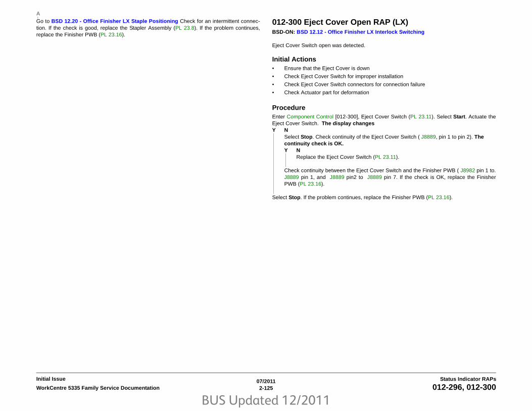
BUS Updated 12/2011
07/20112-125WorkCentre 5335 Family Service Documentation 012-296, 012-300
Status Indicator RAPsInitial Issue
Go to BSD 12.20 - Office Finisher LX Staple Positioning Check for an intermittent connec-tion. If the check is good, replace the Stapler Assembly (PL 23.8). If the problem continues,replace the Finisher PWB (PL 23.16).
012-300 Eject Cover Open RAP (LX)BSD-ON: BSD 12.12 - Office Finisher LX Interlock Switching
Eject Cover Switch open was detected.
Initial Actions• Ensure that the Eject Cover is down
• Check Eject Cover Switch for improper installation
• Check Eject Cover Switch connectors for connection failure
• Check Actuator part for deformation
ProcedureEnter Component Control [012-300], Eject Cover Switch (PL 23.11). Select Start. Actuate theEject Cover Switch. The display changesY N
Select Stop. Check continuity of the Eject Cover Switch ( J8889, pin 1 to pin 2). Thecontinuity check is OK.Y N
Replace the Eject Cover Switch (PL 23.11).
Check continuity between the Eject Cover Switch and the Finisher PWB ( J8982 pin 1 to.J8889 pin 1, and J8889 pin2 to J8889 pin 7. If the check is OK, replace the FinisherPWB (PL 23.16).
Select Stop. If the problem continues, replace the Finisher PWB (PL 23.16).
A

BUS Updated 12/2011
07/20112-126 WorkCentre 5335 Family Service Documentation012-302 , 012-303
Initial IssueStatus Indicator RAPs
012-302 Finisher Front Cover Open RAP (LX)BSD-ON: BSD 12.12 - Office Finisher LX Interlock Switching
The Finisher Front Cover is open.
Initial Actions• Check the installation of the H-Transport Open Sensor
• Opening/closing of the Finisher H-Transport Cover.
ProcedureExecute Component Control [012-302], Front Door Interlock Switch. Open/close the FinisherFront Cover. The display changes.Y N
Open the Front Door and cheat the Front Door Interlock Switch The display changes.Y N
Check the wires between J8982 pin 3 and J8891 pin 2B, and from J8891 pin 2A toJ8982 pin 2 for an open or short circuit, or a loose or damaged connector. Thewires are OK.Y N
Repair/reconnect as required.
Remove the cheater. Measure the voltage between J8891 pin 2A on the Front DoorInterlock Switch and GND (BSD 12.12 - Office Finisher LX Interlock Switching).The voltage is approx. +5VDC.Y N
Check the wire from J8891 pin 2A to J8982 pin 3 for an open or short circuit,or a loose or damaged connector. If the wires are OK, replace the FinisherPWB (PL 23.16).
Cheat the Interlock Switch. The voltage drops to 0 VDC.Y N
Replace the Front Door Interlock Switch (PL 23.16).
Replace the Finisher PWB (PL 23.16).
Check the actuator for damage or misalignment
Check the Interlock circuit for an intermittent condition BSD 12.12 - Office Finisher LX Inter-lock Switching If the problem continues, replace the Finisher PWB (PL 23.16).
012-303 Finisher H-Transport Cover Open RAP (LX)BSD-ON: BSD 12.14 - Office Finisher LX Horizontal Transportation
The Finisher H-Transport Cover is open.
Initial Actions• Check the installation of the H-Transport Open Sensor
• Opening/closing of the Finisher H-Transport Cover.
ProcedureExecute Component Control [012-303], H-Transport Open Sensor. Actuate the H-TransportOpen Sensor (PL 23.4). The display changes.Y N
Check the wire between J8860 pin 2 and J8897 pin 2 for an open or short circuit, or aloose or damaged connector. The wire is OK.Y N
Repair/reconnect as required.
Measure the voltage between J8897, pins 3 and 1 on the Finisher PWB (BSD 12.14 -Office Finisher LX Horizontal Transportation. The voltage is approx. +5VDC.Y N
Replace the Finisher PWB (PL 23.16).
Measure the voltage between J8897, pin 2 on the Finisher PWB and GND (BSD 12.14 -Office Finisher LX Horizontal Transportation). Actuate the H-Transport Open Sensor.The voltage changes.Y N
Replace the H-Transport Open Sensor (PL 23.4).
Replace the Finisher PWB (PL 23.16).
If the problem continues, replace the Finisher PWB (PL 23.16).

BUS Updated 12/2011
07/20112-127WorkCentre 5335 Family Service Documentation 012-334, 012-500
Status Indicator RAPsInitial Issue
012-334 Download Mode Failure RAP (LX)Failure in previous download (abnormal termination during download); can only start in Down-load Mode upon turning power on.
ProcedureDownload defective; check the following:
• Cable connection between Finisher and IOT is not connected or defective
• Finisher power cable is plugged in properly
012-500 Download Failure RAP (LX)Detected error while writing to Finisher ROM.Proper operation not available since ROM mayhave been erased.
ProcedureRetry download. If the problem continues, replace the FInisher PWB (PL 23.16).

BUS Updated 12/2011
07/20112-128 WorkCentre 5335 Family Service Documentation012-700, 012-901
Initial IssueStatus Indicator RAPs
012-700 Punch Box Nearly Full RAP (LX)BSD-ON: BSD 12.15 - Office Finisher LX Punch
Punch Box nearly full.
ProcedureEmpty the Punch Box and re-insert. If the fault remains, check the circuit of the Punch Box SetSensor.
012-901 H-Transport Entrance Sensor Static Jam RAP (LX)BSD-ON: BSD 12.14 - Office Finisher LX Horizontal Transportation
Paper remains on the H-Transport Entrance Sensor.
Initial ActionsCheck the paper path. If no paper is found continue with this RAP.
Clean the sensor.
ProcedureExecute Component Control [012-190], H-Transport Entrance Sensor. Actuate the H-TransportEntrance Sensor (PL 23.4). The display changes.Y N
Check the wire between J8861 pin 2 and J8897 pin 6 for an open or short circuit, or aloose or damaged connector. The wire is OK.Y N
Repair/reconnect as required.
Measure the voltage between J8897, pins 4 and 5 on the Finisher PWB (BSD 12.14 -Office Finisher LX Horizontal Transportation). The voltage is approx. +5VDC.Y N
Replace the Finisher PWB (PL 23.16).
Measure the voltage between J8897, pin 6 on the Finisher PWB and GND BSD 12.14 -Office Finisher LX Horizontal Transportation. Actuate the H-Transport Entrance Sen-sor. The voltage changes.Y N
Replace the H-Transport Entrance Sensor (PL 23.4).
Replace the Finisher PWB (PL 23.16).
If the problem continues, replace the Finisher PWB (PL 23.16).

BUS Updated 12/2011
07/20112-129WorkCentre 5335 Family Service Documentation 012-903, 012-905
Status Indicator RAPsInitial Issue
012-903 Paper Remains at Compiler Exit Sensor RAP (LX)BSD-ON: BSD 12.16 - Office Finisher LX Transportation
Paper remains on the Compiler Exit Sensor.
Initial ActionsCheck the paper path. If no paper is found continue with this RAP.
Clean the sensor.
ProcedureExecute Component Control [012-150], Compiler Exit Sensor. Actuate the Compiler Exit Sen-sor (PL 23.14). The display changes.Y N
Check the wire between J8869 pin 2 and P/J8988 pin 5 for an open or short circuit, or aloose or damaged connector. The wire is OK.Y N
Repair/reconnect as required.
Measure the voltage between P/J8988, pins 6 and 4 on the Finisher PWB (BSD 12.16 -Office Finisher LX Transportation). The voltage is approx. +5VDC.Y N
Replace the Finisher PWB (PL 23.16).
Measure the voltage between P/J8988, pin 5 on the Finisher PWB and GND (BSD 12.16- Office Finisher LX Transportation).Actuate the Compiler Exit Sensor. The voltagechanges.Y N
Replace the Compiler Exit Sensor (PL 23.14).
Replace the Finisher PWB (PL 23.16).
If the problem continues, replace the Finisher PWB (PL 23.16).
012-905 Compiler Tray No Paper Sensor Static JAM RAP (LX)BSD-ON: BSD 12.19 - Office Finisher LX Tamping & Offset (2 of 2)
Paper remains on the Compiler Tray No Paper Sensor.
Initial ActionsCheck the paper path. If no paper is found continue with this RAP.
Clean the sensor.
ProcedureEnter Component Control [012-151], Compiler Tray No Paper Sensor. Select Start. Actuatethe Compiler Tray No Paper Sensor. The display changes.Y N
Check the wire between J8880 pin 2 and P/J8994 pin 2 on the Finisher PWB for an openor short circuit, or a loose or damaged connector. The wire is OK.Y N
Repair/reconnect as required.
Measure the voltage between P/J8994 pins 3 and 1 on the Finisher PWB (BSD 12.19 -Office Finisher LX Tamping & Offset (2 of 2). The voltage is approx. +5VDC.Y N
Replace the Finisher PWB (PL 23.16).
Measure the voltage between P/J8994 pin 2 on the Finisher PWB and GND (BSD 12.19- Office Finisher LX Tamping & Offset (2 of 2). Actuate the Compiler Tray No PaperSensor. The voltage changes.Y N
Replace the Compiler Tray No Paper Sensor (PL 23.12).
Replace the Finisher PWB (PL 23.16).
If the problem continues, replace the Finisher PWB (PL 23.16).

BUS Updated 12/2011
07/20112-130 WorkCentre 5335 Family Service Documentation012-911, 012-914
Initial IssueStatus Indicator RAPs
012-911 Stacker Lower Safety Warning RAPThe Height Alignment was not successful within 250msec when the Height Adjustment wasperformed for output paper to the Stacker Tray (Tray lowering down) in the middle of a job.
ProcedureRemove all paper from the Stacker. If the problem continues, go to the 012-213 RAP.
012-914 Stacker Tray Stapled Set Over Count RAPThe Staple Set Count of the Stacker Tray has exceeded 50 sets during the Staple Set Ejectoperation.
ProcedureRemove all paper from the Stacker. If the problem continues, go to the 012-161 RAP.

BUS Updated 12/2011
07/20112-131WorkCentre 5335 Family Service Documentation 012-923, 012-935
Status Indicator RAPsInitial Issue
012-923 H-Transport Entrance Sensor Static Jam RAP (LX)BSD-ON: BSD 12.14 - Office Finisher LX Horizontal Transportation
During standby, paper was detected by the H-Transport Entrance Sensor.
Initial ActionsCheck the paper path. If no paper is found continue with this RAP.
Clean the sensor.
ProcedureExecute Component Control [012-190], H-Transport Entrance Sensor. Actuate the H-TransportEntrance Sensor (PL 23.4). The display changes.Y N
Check the wire between J8861 pin 2 and J8897 pin 6 for an open or short circuit, or aloose or damaged connector. The wire is OK.Y N
Repair/reconnect as required.
Measure the voltage between J8897, pins 4 and 5 on the Finisher PWB (BSD 12.14 -Office Finisher LX Horizontal Transportation). The voltage is approx. +5VDC.Y N
Replace the Finisher PWB (PL 23.16).
Measure the voltage between J8897, pin 6 on the Finisher PWB and GND (BSD 12.14 -Office Finisher LX Horizontal Transportation). Actuate the H-Transport Entrance Sen-sor. The voltage changes.Y N
Replace the H-Transport Entrance Sensor (PL 23.4).
Replace the Finisher PWB (PL 23.16).
If the problem continues, replace the Finisher PWB (PL 23.16).
012-935 Paper at Finisher Entrance Sensor RAP (LX)BSD-ON: BSD 12.16 - Office Finisher LX Transportation
Control logic reports paper at the Finisher Entrance Sensor.
Initial Actions• Check for obstructions in the paper path
• Check that the Finisher is docked correctly to ensure proper Transport Gate operation
ProcedureEnter Component Control [012-100], Finisher Entrance Sensor. Select Start. Actuate the Fin-isher Entrance Sensor. The display changes.Y N
Check the wire between J8868 pin 2 and P/J8988 pin 2 for an open or short circuit, or aloose or damaged connector. The wire is OK.Y N
Repair/reconnect as required.
Measure the voltage between P/J8988 pins 3 and 1 on the Finisher PWB (BSD 12.16 -Office Finisher LX Transportation). The voltage is approx. +5VDC.Y N
Replace the Finisher PWB (PL 23.16).
Measure the voltage between P/J8988 pin 2 on the Finisher PWB and GND (BSD 12.16 -Office Finisher LX Transportation). Actuate the Finisher Entrance Sensor. The volt-age changes.Y N
Replace the Finisher Entrance Sensor (PL 23.14).
Replace the Finisher PWB (PL 23.16).
Replace the Finisher PWB (PL 23.16).

BUS Updated 12/2011
07/20112-132 WorkCentre 5335 Family Service Documentation012-949, 012-965
Initial IssueStatus Indicator RAPs
012-949 Punch Box Missing RAP (LX)BSD-ON: BSD 12.15 - Office Finisher LX Punch
Punch Box Set Sensor detected Punch Box to be missing.
Initial Actions• Ensure that the Punch Box is present and installed properly
ProcedureEnter Component Control [012-275], Punch Box Set Sensor (PL 23.5). Select Start. Removeand insert the Punch Box manually. The display changesY N
Select Stop. Check continuity between the Punch Box Set Sensor ( J8866); P8863; andthe Finisher PWB ( J8897). The continuity check is OK.Y N
Repair the open circuit or short circuit.
Replace the Punch Box Set Sensor (PL 23.5). If the problem continues, replace the Fin-isher PWB (PL 23.16).
Check the Punch Box Set Sensor Actuator and Punch Box Guide for deformation. The PunchBox can be removed and inserted properly.Y N
Repair or replace the Punch Box (PL 23.2).
Select Stop. If the problem continues, replace the Finisher PWB (PL 23.16).
012-965 Stapler Near Empty RAP• Low Staple Sensor ON is detected during power ON and Interlock Close
• Low Staple Sensor ON is detected right before the Staple Head Close operation
ProcedureCheck the Staple Cartridge. If the Staples are NOT low, go to the 012-291 RAP.

BUS Updated 12/2011
07/20112-133WorkCentre 5335 Family Service Documentation 012-966, 012-969
Status Indicator RAPsInitial Issue
012-966 Scratch Sheet Compile RAPPaper was detected that was either out of spec, in poor condition (wrinkled, curled) and wasejected to the compiler.
NOTE: This Code is an operation message. If this fail code is frequently declared, perform theprocedure below.
Initial Actions• Check that the Top Cover can be opened and closed.
• Power Off/On.
ProcedureCheck the specifications of paper. The paper is in spec.Y N
Replace the paper with new paper that is in spec.
Check the condition of the paper. The paper is in normal condition without any problemthat causes the paper to be bent (dog eared) or jam.Y N
Resolve any problem that causes the paper to be bent or caught.
Check for a Fault Code. Another Fault Code is displayed.Y N
If the problem continues, replace the Finisher PWB (PL 23.16).
Go to the appropriate Fault Code.
012-969 IOT Center Tray Full RAPThe H-Transport Entrance Sensor is detected to be ON for 10 successive seconds.
ProcedureGo to the 012-126 RAP.
BUS Updated 12/2011
07/20112-134 WorkCentre 5335 Family Service Documentation012-966, 012-969
Initial IssueStatus Indicator RAPs

BUS Updated 12/2011
07/20112-135WorkCentre 5335 Family Service Documentation 013-210
Status Indicator RAPsInitial Issue
013-210 Booklet Staple Move Home Sensor ON RAP (LX)BSD-ON: BSD 12.25 - Office Finisher Booklet Staple Positioning
Booklet Staple Move Home Sensor does not turn on within designated time period
Initial Actions• Ensure the Staple Head is free from obstructions
• Check for 013-306 or 013-307 Faults.
ProcedureExecute Component Control [013-143], Booklet Staple Move Home Sensor. Move the BookletStaplers to block and unblock the sensor (PL 23.18). The display changes.Y N
Check the wire between J8897 pin 2 and P/J8991 pin 2 for an open or short circuit, or aloose or damaged connector. The wire is OK.Y N
Repair/reconnect as required.
Measure the voltage between P/J8991, pins 3 and 1 on the Booklet PWB. The voltageis approx. +5VDC.Y N
Replace the Booklet PWB (PL 23.21).
Measure the voltage between P/J8991 pin 2 on the Booklet PWB and GND. Actuate theBooklet Staple Move Home Sensor. The voltage changes.Y N
Replace the Booklet Staple Move Home Sensor (PL 23.18).
Replace the Booklet PWB (PL 23.21).
Alternately execute Component Control [013-028], Stapler Move Motor In and [013-029], Sta-pler Move Motor Out. The Stapler Move Motor moves.Y N
Check the wires between P/J8992 pins 1~6 on the Booklet PWB and P/J8906 on theBooklet Stapler Move Motor for an open or short circuit, or loose or damaged connectors.The wires are OK. Y N
Repair/replace as required.
Monitor the voltage at J8984, pin 3. Alternately execute Component Control [013-028],Stapler Move Motor In and [013-029], Stapler Move Motor Out. An AC clock pulse isdetected.Y N
Check the wire between J8984, pin 3 and J8985 pin 4. If the wire is OK, replace theFinisher PWB (PL 23.16).
Replace the Booklet Stapler Move Motor (PL 23.18). If the problem persists, replace theBooklet PWB (PL 23.21).
Go to BSD 12.25 - Office Finisher Booklet Staple Positioning5 and check for an intermittentcircuit.
A
A

BUS Updated 12/2011
07/20112-136 WorkCentre 5335 Family Service Documentation013-211
Initial IssueStatus Indicator RAPs
013-211 Booklet Staple Move Home Sensor OFF RAP (LX)BSD-ON: BSD 12.25 - Office Finisher Booklet Staple Positioning
Booklet Staple Move Home Sensor does not turn off within designated time period
Initial Actions• Ensure the Staple Head is free from obstructions
• Check for 013-306 or 013-307 Faults.
ProcedureExecute Component Control [013-143], Booklet Staple Move Home Sensor. Move the BookletStaplers to block and unblock the sensor (PL 23.18). The display changes.Y N
Check the wire between J8897 pin 2 and P/J8991 pin 2 for an open or short circuit, or aloose or damaged connector. The wire is OK.Y N
Repair/reconnect as required.
Measure the voltage between P/J8991, pins 3 and 1 on the Booklet PWB. The voltageis approx. +5VDC.Y N
Replace the Booklet PWB (PL 23.21).
Measure the voltage between P/J8991 pin 2 on the Booklet PWB and GND. Actuate theBooklet Staple Move Home Sensor. The voltage changes.Y N
Replace the Booklet Staple Move Home Sensor (PL 23.18).
Replace the Booklet PWB (PL 23.21).
Alternately execute Component Control [013-028], Stapler Move Motor In and [013-029], Sta-pler Move Motor Out. The Stapler Move Motor moves.Y N
Check the wires between P/J8992 pins 1~6 on the Booklet PWB and P/J8906 on theBooklet Stapler Move Motor for an open or short circuit, or loose or damaged connectors.The wires are OK. Y N
Repair/replace as required.
Monitor the voltage at J8984, pin 3. Alternately execute Component Control [013-028],Stapler Move Motor In and [013-029], Stapler Move Motor Out. An AC clock pulse isdetected.Y N
Check the wire between J8984, pin 3 and J8985 pin 4. If the wire is OK, replace theFinisher PWB (PL 23.16).
Replace the Booklet Stapler Move Motor (PL 23.18). If the problem persists, replace theBooklet PWB (PL 23.21).
Go to BSD 12.25 - Office Finisher Booklet Staple Positioning and check for an intermittentcircuit.
A
A

BUS Updated 12/2011
07/20112-137WorkCentre 5335 Family Service Documentation 013-212
Status Indicator RAPsInitial Issue
013-212 Booklet Staple Move Position Sensor On Fail RAP (LX)BSD-ON: BSD 12.25 - Office Finisher Booklet Staple Positioning
Booklet Staple Move Position Sensor does not turn on within designated time period
Initial Actions• Ensure the Staple Head is free from obstructions
• Check for 013-306 or 013-307 Faults.
ProcedureExecute Component Control [013-144], Booklet Staple Move Position Sensor. Move the Book-let Stapler to block and unblock the sensor (PL 23.18). The display changes.Y N
Check the wire between J8898 pin 2 and P/J8991 pin 5; and the wire between J8984,pin 5 and J8985 pin 5 for an open or short circuit, or a loose or damaged connector. The wires are OK.Y N
Repair/reconnect as required.
Measure the voltage between P/J8991, pins 6 and 4 on the Booklet PWB. The voltageis approx. +5VDC.Y N
Replace the Booklet PWB (PL 23.21).
Measure the voltage between P/J8991 pin 5 on the Booklet PWB and GND. Actuate theBooklet Staple Move Position Sensor. The voltage changes.Y N
Replace the Booklet Staple Move Position Sensor (PL 23.18).
Measure the voltage between J8895 pin 5 on the Finisher PWB and GND. Actuate theBooklet Staple Move Position Sensor. The voltage changes.Y N
Replace the Booklet PWB (PL 23.21). If the problem persists, replace the FinisherPWB (PL 23.16).
Replace the Finisher PWB (PL 23.16).
Alternately execute Component Control [013-028], Stapler Move Motor In and [013-029], Sta-pler Move Motor Out. The Stapler Move Motor moves.Y N
Check the wires between P/J8992 pins 1~6 on the Booklet PWB and P/J8906 on theBooklet Stapler Move Motor for an open or short circuit, or loose or damaged connectors.The wires are OK. Y N
Repair/replace as required.
Monitor the voltage at J8984, pin 3. Alternately execute Component Control [013-028],Stapler Move Motor In and [013-029], Stapler Move Motor Out. An AC clock pulse isdetected.Y N
Check the wire between J8984, pin 3 and J8985 pin 4. If the wire is OK, replace theFinisher PWB (PL 23.16).
Replace the Booklet Stapler Move Motor (PL 23.18). If the problem persists, replace theBooklet PWB (PL 23.21).
Go to BSD 12.25 - Office Finisher Booklet Staple Positioning and check for an intermittentcircuit.
A
A
B
B

BUS Updated 12/2011
07/20112-138 WorkCentre 5335 Family Service Documentation013-213
Initial IssueStatus Indicator RAPs
013-213 Booklet Staple Move Position Sensor Off Fail RAP (LX)BSD-ON: BSD 12.25 - Office Finisher Booklet Staple Positioning
Booklet Staple Move Position Sensor does not turn off within designated time period
Initial Actions• Ensure the Staple Head is free from obstructions
• Check for 013-306 or 013-307 Faults.
ProcedureExecute Component Control [013-144], Booklet Staple Move Position Sensor. Move the Book-let Stapler to block and unblock the sensor (PL 23.18). The display changes.Y N
Check the wire between J8898 pin 2 and P/J8991 pin 5; and the wire between J8984,pin 5 and J8895 pin 5 for an open or short circuit, or a loose or damaged connector. The wires are OK.Y N
Repair/reconnect as required.
Measure the voltage between P/J8991, pins 6 and 4 on the Booklet PWB. The voltageis approx. +5VDC.Y N
Replace the Booklet PWB (PL 23.21).
Measure the voltage between P/J8991 pin 5 on the Booklet PWB and GND. Actuate theBooklet Staple Move Position Sensor. The voltage changes.Y N
Replace the Booklet Staple Move Position Sensor (PL 23.18).
Measure the voltage between J8895 pin 5 on the Finisher PWB and GND. Actuate theBooklet Staple Move Position Sensor. The voltage changes.Y N
Replace the Booklet PWB (PL 23.21). If the problem persists, replace the FinisherPWB (PL 23.16).
Replace the Finisher PWB (PL 23.16).
Alternately execute Component Control [013-028], Stapler Move Motor In and [013-029], Sta-pler Move Motor Out. The Stapler Move Motor moves.Y N
Check the wires between P/J8992 pins 1~6 on the Booklet PWB and P/J8906 on theBooklet Stapler Move Motor for an open or short circuit, or loose or damaged connectors.The wires are OK. Y N
Repair/replace as required.
Monitor the voltage at J8984, pin 3. Alternately execute Component Control [013-028],Stapler Move Motor In and [013-029], Stapler Move Motor Out. An AC clock pulse isdetected.Y N
Check the wire between J8984, pin 3 and J8895 pin 4. If the wire is OK, replace theFinisher PWB (PL 23.16).
Replace the Booklet Stapler Move Motor (PL 23.18). If the problem persists, replace theBooklet PWB (PL 23.21).
Go to BSD 12.25 - Office Finisher Booklet Staple Positioning and check for an intermittentcircuit.
A
A
B
B

BUS Updated 12/2011
07/20112-139WorkCentre 5335 Family Service Documentation 013-220, 013-306
Status Indicator RAPsInitial Issue
013-220 Folder Detect Fail RAP (LX)BSD-ON: BSD 12.17 - Office Finisher LX Folding
Control logic cannot detect the Folder Assembly.
ProcedureExecute Component Control [013-160], Folder Detected. The display is ‘Low.’Y N
There is less than 1 VDC at P/J8990 pin 4.Y N
Check the wires between P/J8990 pins 4 and 5. Make sure that P/J8903 is securelyfastened.
Replace the Finisher PWB (PL 23.16).
Go to BSD 12.17 - Office Finisher LX Folding and check for an intermittent circuit.
013-306 Booklet Safety Switches Open RAP (LX)BSD-ON: BSD 12.13 - Office Finisher LX Booklet Interlock Switching
Control logic senses that one or more Booklet Safety Switch is open.
Initial ActionsCheck for 013-307 Faults.
ProcedureThere is +24 VDC between P/J8993 pin 3 on the Booklet PWB and GND.Y N
There is +24 VDC between P/J8993 pin 6 on the Booklet PWB and GND.Y N
Go to the 013-307 RAP
GO to BSD 12.13 - Office Finisher LX Booklet Interlock Switching and check the cir-cuit through the Booklet Safety Switches (PL 23.21).
Replace the Booklet PWB (PL 23.21).

BUS Updated 12/2011
07/20112-140 WorkCentre 5335 Family Service Documentation013-307
Initial IssueStatus Indicator RAPs
013-307 Booklet Cover Open RAP (LX)BSD-ON: BSD 12.13 - Office Finisher LX Booklet Interlock Switching
Control logic senses that the Booklet Cover is open.
Initial ActionsEnsure the Cover is closed
ProcedureThere is +24 VDC between P/J8993 pin 5 on the Booklet PWB and GND.Y N
GO to BSD 12.13 - Office Finisher LX Booklet Interlock Switching and check the cir-cuit from P/J8993 to and from J8899 on the Booklet Stapler Cover Switch (PL 23.21).
Replace the Booklet PWB (PL 23.21).

BUS Updated 12/2011
07/20112-141WorkCentre 5335 Family Service Documentation 016-210, 016-211
Status Indicator RAPsInitial Issue
016-210 Software Option (HDD Not Exist) RAPBSD-ON: BSD 16.1 - ESS
One of the Software option functions cannot be executed due to a HDD error or the HDD is notinstalled.
Initial ActionsPower Off/On
Procedure• Check HDD electrical connections. Check for 5VDC between P/J302-4 (red) and P/J302-
3 (blk) on the HDD
• If the problem persists perform Initialize Hard Disk.
• If the problem persists, replace the HDD (PL 35.2).
016-211 Software Option (System Memory Low) RAPBSD-ON: BSD 16.1 - ESS
One of the Software option functions cannot be executed due to insufficient System Memorycapacity.
Initial ActionsPower Off/On. Add more memory to Option Memory on the ESS PWB (PL 35.2).
ProcedureRefer customer to following User Guide headings to check memory usage:
• Allocate Memory
• Memory Settings
• Covers
• Mailbox Screen
• Properties
• Properties Features
• Data Encryption
• Memory Full Procedure
• Maximum Stored Pages

BUS Updated 12/2011
07/20112-142 WorkCentre 5335 Family Service Documentation016-212, 016-213
Initial IssueStatus Indicator RAPs
016-212 Software Option (Page Memory Low) RAPBSD-ON: BSD 16.1 - ESS
One of the Software option functions cannot be executed due to insufficient Page Memorycapacity.
Initial ActionsPower Off/On. Expand the Memory (Page) of the ESS PWB (PL 35.2).
ProcedureRefer customer to following User Guide headings to check memory usage:
• Allocate Memory
• Memory Settings
• Properties
• Properties Features
• Maximum Stored Pages
• Mailbox Screen
• Data Encryption
• Memory Full Procedure
• Covers
016-213 Software Option (Printer PWB) RAPOne of the Software option functions cannot be executed due to a PRT_CARD error orPRT_CARD not installed.
Initial ActionsIf this fault occurs during installation or network setup, the machine SW may not have beenloaded correctly; go to GP 3 .
Procedure
NOTE: the Printer PWB is an option that the customer must purchase and is ordered by theSales rep.
• Check installation of the Printer PWB (USB or Parallel).
• Remove and reseat the Printer PWB if one is present.
• If the problem persists, replace the Printer PWB

BUS Updated 12/2011
07/20112-143WorkCentre 5335 Family Service Documentation 016-214, 016-215
Status Indicator RAPsInitial Issue
016-214 Software Option Fail (Fax CARD Not Exist) RAPBSD-ON: BSD 34.1 - FAX
One of the FAX address book functions cannot be executed due to a FAX PWB error notinstalled.
Initial ActionsPower Off/On
ProcedureCheck the installation of the FAX PWB (PL 18.5).
016-215 Software Option Fail (JPEG Board Not Exist) RAPAn JPEG Board error or JPEG Board not installed was detected. The scanner functions cannotbe executed due to a JPEG Board error or JPEG Board not installed.
Initial ActionsPower Off/On
ProcedureCheck installation and electrical connections of the Installation of the JPEG Board.

BUS Updated 12/2011
07/20112-144 WorkCentre 5335 Family Service Documentation016-216 , 016-217
Initial IssueStatus Indicator RAPs
016-216 Software Option Fail (ExtMemory Not Exist) RAPThe system detected that the Extension Memory was not installed. Color Scanner orSACAN_ACS functions cannot be executed because the Extension Memory is not installed.
Initial ActionsPower Off/On
ProcedurePull out and then insert the IISS Extension Memory (memory on the extension PWB at the sideof the IIT PWB).
016-217 Software Option Fail (Controller ROM does not Support Printer Kit) RAPFunctions such as local printing cannot be executed due to a Printer Kit option PWB error orthe ESS PWB ROM is incompatible with the Printer Kit.
Initial ActionsPower Off/On. Upgrade the firmware in the Controller ROM that supports Printer Kit
Procedure• Remove and reseat Printer PWB (USB or Parallel), ESS PWB (PL 35.2).
• If the problem persists, replace the Parallel Printing PWB or the ESS PWB (PL 35.2).
• If the problem persists, reload the machine software (GP 16).
BUS Updated 12/2011
07/20112-145WorkCentre 5335 Family Service Documentation 016-218, 016-219
Status Indicator RAPsInitial Issue
016-218 PostScript (PS) Kit not Installed RAPBSD-ON: BSD 16.1 - ESS
Because PostScript (PS) Kit is not installed, XDOD functions cannot be fulfilled.
NOTE: the Postscript kit is a standard feature in XC machines, but it is optional elsewhere
Procedure• Switch the power OFF then ON.
• XC: Reload the machine software (GP 16). If the problem continues, replace the ESSPWB (PL 35.2)
XE: Check whether or not the Postscript kit is installed by pressing the Machine Status button,then selecting the Software Versions button. If the Postscript kit is installed, Item 2 will read"Controller + PS ROM". If Item 2 reads "Controller ROM", then the Postscript kit is notinstalled. The Postscript feature is installedY N
the customer must order the Postscript kit from the Sales rep
• If the problem continues, replace the Postscript ROM (PL 35.2). If the problem continues,replace the ESS PWB (PL 35.2). Reload the machine software (GP 16).
.
016-219 Software Option RAPBSD-ON: BSD 16.1 - ESS
Functions such as local printing cannot be executed due to the Printing Kit SW Option notbeing enabled. The ROM was replaced without license (Printer Kit SW Key not set).
Initial ActionsIf this fault occurs during installation or network setup, the machine SW may not have beenloaded correctly; go to GP 3 .
ProcedureInstall the Printer Kit SW Option Key Software Options and set to enable.

BUS Updated 12/2011
07/20112-146 WorkCentre 5335 Family Service Documentation016-229, 016-230
Initial IssueStatus Indicator RAPs
016-229 SW Option Failure RAPBSD-ON: BSD 16.1 - ESS
SW Option Fail (FCW-UI Not Exist) The extension MEM PWB is not installed.
NOTE: Even thought this refers to the UIs that are not installed on the machine the actual UI isthe MCW UI this fault can be generated if the ESS does not detect the UI is installed. Thereforecheck the connections from the UI to the ESS PWB.
ProcedureDisconnect and reconnect the UI Cable at the ESS PWB.
016-230 SW Option Failed - PS Image Log Kit (License Required) RAPThe PS-ROM was installed in a machine where SW key: "Image Log Kit Enabled" and SW key:"Image Log Kit for PS Disabled" are specified. When the "PS-ROM" is installed in the machine,the image log function cannot operate unless the "Image Log Kit for PS" has been installed.
Procedure• Switch the Machine Power Off then On.
• If the problem is still present, In UI Diagnostics (Accessing UI Diagnostics) ensure that theSW Key for the PS Image Log Kit is entered and enabled. Contact the System Adminis-trator to get the SW Key if required.
BUS Updated 12/2011
07/20112-147WorkCentre 5335 Family Service Documentation 016-231, 016-232 MRC HW Initialize RAP
Status Indicator RAPsInitial Issue
016-231 SW Option Failed - (Image Ext PWB Not Exist) RAPThis fault is generated when the Thumbnail Preview PWB is not detected due to failed PWB orthe Image Compression Kit has not been installed while the “Thumbnail Preview” Software Keyhas been enabled.
Initial Actions• Switch the machine power Off and On.
• This fault could be declared if the Thumbnail Preview option had been installed and thenthe Thumbnail Preview PWB was removed. The Option may still be enabled.
• When the SW Option function is set to "Enabled", the ESS PWB (PL 35.2) either detectedthat the Image Ext PWB is not installed, or the Image Ext PWB has failed.
– Thumbnail SW Option
– Preview SW Option
– Image Lock SW Option
ProcedureCAUTION
If the option was removed from the machine but the fault cannot be cleared, Do Not enter theSoftware Option Key command "ClearAllFlags" in an attempt to correct this condition; themachine will not boot up afterward.
Instead, contact Field Engineering for assistance with this condition.
• The Image Extension Kit (Ama + toto board) has a failure or is not installed. Replace orinstall it.
• Check the sw version of the controller sw - reload Software (GP 16)
• Uninstall and reinstall the Image Ext PWB and retry the job.
• If the problem is still present replace the Image Ext PWB.
016-232 MRC HW Initialize RAPMRC HW Initialize Error. Error occurs while high-compression board is being initialized.
Procedure• Switch the power Off then On.
• Check the sw version of the controller sw - reload Software (GP 16)
• Replace high compression board. When the cause cannot be identified, to take the follow-ing action to check if the status can be improved:
– Replace Memory Module on Main PWB
– Replace Main PWB

BUS Updated 12/2011
07/20112-148 WorkCentre 5335 Family Service Documentation016-233, 016-234
Initial IssueStatus Indicator RAPs
016-233 SW Option Fail (USB Host Failed or Not Installed) RAPBSD-ON: BSD 16.1 - ESS
SW optional function not achieved. Any one of the SW optional functions cannot be usedbecause the USB Host has a failure/is not installed. When the SW optional function is beingenabled, the USB port (and USB Host Card) for the ESS PWB (PL 35.2) was detected to benot installed or having errors.
Procedure• Turn the power OFF then ON.
• Check the sw version of the controller sw - reload Software (GP 16)
• If the problem persists, install the USB Host Card on the ESS PWB, replace the ESSPWB (PL 35.2).
016-234 XCP Out of Memory Error RAPXCP stops when JVM is unable to function due to insufficient memory space.
Initial ActionsPower Off/On. The software module that runs Java within the Controller has ran out of memoryand became unable to continue operating.
ProcedureIf the problem persists perform Initialize Hard Disk.

BUS Updated 12/2011
07/20112-149WorkCentre 5335 Family Service Documentation 016-235, 016-310
Status Indicator RAPsInitial Issue
016-235 XCP Internal Error RAPJVM stopped due to an internal error.
Initial ActionsPower Off/On
ProcedureIf the problem persists perform Initialize Hard Disk.
016-310 SSMM Job Log Full RAPJob log file is not obtained from external application (AWAYS) and the files over specified limit(280 files) are stored.
Initial ActionsPower Off/On after receiving job log file (GetJobLog) from external application (AWAYS) viaSSM.
ProcedureObtain job log file (GetJobLog) from external application (AWAYS) via SSMI. After that, PowerOFF/ON.
If problem persists call support center.

BUS Updated 12/2011
07/20112-150 WorkCentre 5335 Family Service Documentation016-311 , 016-312
Initial IssueStatus Indicator RAPs
016-311 Scanner Install RAPBSD-ON: BSD 16.1 - ESS
The system detected that the scanner is not installed.
Procedure• Ensure that the customer is programming a job within the parameters of the machine uti-
lizing the UI.
• Disconnect then reconnect the IF Cable PL 10.7, IIT, ESS, MCU all PWBs connected tothem (RAM, Firmware module, EEPROM)
• Check the sw version of the controller sw - update if required
• Replace RAM DIMM on ESS PWB (PL 35.2)
• Replace ESS PWB (PL 35.2) (If not fixed by this, reinstall the original ESS PWB and RAMDIMM)
016-312 SW Option Fail (Hybrid Water Mark Not Exist) RAPHybrid Water Mark detection hardware unloaded is detected with SW option function being setto Valid. Detected prior to 016-313 detection.
ProcedureCheck the following:
1. Ensure that the customer is programming a job within the parameters of the machine uti-lizing the UI.
2. In UI Diagnostics, (Accessing UI Diagnostics) ensure that the password for the SecureWatermark Kit, Software Option is installed.
3. Ensure that the Hybrid WaterMark PWB is installed and connected correctly. Plugs intoIIT PWB under the IPS cover (PL 1.6).
4. Ensure that the Hard Disk Drive HDD (PL 35.2) is installed and operational.
5. Confirm System Memory PL 35.2 is sufficient for this option (768MB).
NOTE: If the Hybrid (Secure) WaterMark was installed and is no longer installed (PWBnot plugged into the top of the IIT PWB) but the SW Key had been installed the only wayto clear fault is to enter NVM Read/Write and reset NVM 785-021 to “0”. This will clear thefault.
6. Disconnect then reconnect the ESS, MCU all PWBs connected to them (RAM, Firmwaremodule, EEPROM)
7. Check the sw version of the controller sw - update if required
8. Replace RAM DIMM on ESS PWB (PL 35.2)
9. Replace ESS PWB (PL 35.2) (If not fixed by this, reinstall the original ESS PWB and RAMDIMM.)

BUS Updated 12/2011
07/20112-151WorkCentre 5335 Family Service Documentation 016-313, 016-314 Hybrid Water Mark Not Exist RAP
Status Indicator RAPsInitial Issue
016-313 Hybrid Water Mark Setting Mismatch RAPThis is a configuration error type of fault related to the Secure Watermark Kit.
ProcedureCheck the following:
1. Ensure that the customer is programming a job within the parameters of the machine uti-lizing the UI.
2. In UI Diagnostics, (Accessing UI Diagnostics) ensure that the password for the SecureWatermark Kit, Software Option is installed.
3. Ensure that the HDD (PL 35.2) is installed and operational.
4. Confirm System Memory is sufficient for this option (768MB).
5. Disconnect then reconnect the ESS, MCU all PWBs connected to them (RAM, Firmwaremodule, EEPROM)
6. Check the sw version of the controller sw - update if required
7. Replace RAM DIMM on ESS PWB (PL 35.2)
8. Replace ESS PWB (PL 35.2) (If not fixed by this, reinstall the original ESS PWB and RAMDIMM.)
016-314 Hybrid Water Mark Not Exist RAPBSD-ON: BSD 16.1 - ESS
SW Option Fail (HybridWaterMark Not Exist). While SW option function is enabled, simulta-neous duplex scanning with 2 HWM boards (for Side1 and Side2) is conducted using the com-bination of DADF:PF1.5/IIT:PF1-BW. When reproduction limitation code is detected, thefunction is reflected only on page for which the code is detected.
Procedure• Ensure that the customer is programming a job within the parameters of the machine uti-
lizing the UI.
• Power OFF/ON.
• Disconnect then reconnect the ESS, MCU all PWBs connected to them (RAM, Firmwaremodule, EEPROM)
• Check the sw version of the controller sw - update if required
• Replace RAM DIMM on ESS PWB (PL 35.2)
• Replace ESS PWB (PL 35.2) (If not fixed by this, reinstall the original ESS PWB and RAMDIMM.)

BUS Updated 12/2011
07/20112-152 WorkCentre 5335 Family Service Documentation016-315, 016-316
Initial IssueStatus Indicator RAPs
016-315 IIT Interface RAPBSD-ON: BSD 16.1 - ESS
An error was detected in the IF between the IIT and the IOT.
Procedure• Ensure that the customer is programming a job within the parameters of the machine uti-
lizing the UI.
• Disconnect then reconnect the IF between Scanner and IOT, IIT, ESS, MCU all PWBsconnected to them (RAM, Firmware module, EEPROM)
• Check the sw version of the controller sw - update if required
• Replace RAM DIMM on ESS PWB (PL 35.2)
• Replace ESS PWB (PL 35.2) (If not fixed by this, reinstall the original ESS PWB and RAMDIMM.)
• Replace the IIT PWB (PL 1.6). If the problem persists, replace the MCU PWB (PL 18.2).
016-316 Page Memory Not Detected RAPBSD-ON: BSD 16.1 - ESS
The system detected that the Page Memory (Standard) of the scanner was not installed.
Initial ActionsPower Off/On
Procedure• Ensure connectors on the ESS PWB (PL 35.2) and the IIT PWB (PL 1.6) are securely
connected.
• Check the installation of the Printer PWB if present.

BUS Updated 12/2011
07/20112-153WorkCentre 5335 Family Service Documentation 016-317, 016-318
Status Indicator RAPsInitial Issue
016-317 Page Memory Error- Standard RAPBSD-ON: BSD 16.1 - ESS
The system detected an error in the Page Memory (Standard) of the scanner.
Initial ActionsPower Off/On. Remove/install PageMemory(Standard).
Procedure• Ensure that the customer is programming a job within the parameters of the machine uti-
lizing the UI.
• Check the installation of the Printer PWB if present.
• Disconnect then reconnect the IIT, ESS, MCU all PWBs connected to them (RAM, Firm-ware module, EEPROM)
• Check the sw version of the controller sw - update if required
• Replace RAM DIMM on ESS PWB (PL 35.2)
• Replace ESS PWB (PL 35.2) (If not fixed by this, reinstall the original ESS PWB and RAMDIMM.)
016-318 Page Memory Error- Option RAPBSD-ON: BSD 16.1 - ESS
The system detected an error in the Page Memory (Option) of the scanner.
Initial ActionsPower Off/On
ProcedureCheck the installation of the Printer PWB if present.
Refer customer to following User Guide headings to check memory usage:
• Allocate Memory
• Memory Settings
• Properties
• Properties Features
• Maximum Stored Pages
• Mailbox Screen
• Data Encryption
• Memory Full Procedure
• Covers

BUS Updated 12/2011
07/20112-154 WorkCentre 5335 Family Service Documentation016-320, 016-321
Initial IssueStatus Indicator RAPs
016-320 Doc Conversion SW Error RAPBSD-ON: BSD 16.1 - ESS
A fatal error with doc conversion software was detected.
ProcedureIf powering OFF then ON does not resolve the problem, perform the following:
1. Check ESS PWB and IIT PWB connections
2. If the above actions do not resolve the problem, replace ESS PWB (PL 35.2).
3. Reinstall the software.
016-321 Fax Module RAPBSD-ON: BSD 34.1 - FAX
With SysCheckFax(), ERROR is returned. If PFNOTEXIST is returned, M/C configuration isregarded as that without FAX.
Initial ActionsPower Off/On
Procedure• Ensure that the customer is programming a job within the parameters of the machine uti-
lizing the UI.
• Perform FAX Diagnostic GP 13
• Disconnect then reconnect the PWBs in the FAX Module)
• Check the sw version of the fax & controller sw - update if required
• Replace the Fax PWB (PL 18.5)

BUS Updated 12/2011
07/20112-155WorkCentre 5335 Family Service Documentation 016-322, 016-323
Status Indicator RAPsInitial Issue
016-322 JBA Account Full RAPBSD-ON: BSD 16.1 - ESS
The accumulated accounting data in Job Based Accounting reached the specified value.
Procedure• Switch the power off then on 2 minutes after the job is attempted (after an external
Accounting Server has read the accounting data).
• If the problem persists, have the customer perform a manual retrieval of machine datafrom their Accounting server.
• If the problem persists, perform Initialize Hard Disk and then have the customer push theUser Accounts to the machine from their Accounting server.
• Ensure that the customer is programming a job within the parameters of the machine uti-lizing the UI.
• Disconnect then reconnect the ESS, MCU all PWBs connected to them (RAM, Firmwaremodule, EEPROM)
• Check the sw version of the controller sw - update if required
• Replace RAM DIMM on ESS PWB (PL 35.2)
• Replace ESS PWB (PL 35.2) (If not fixed by this, reinstall the original ESS PWB and RAMDIMM.)
016-323 B Formatting RAPBSD-ON: BSD 34.1 - FAX
An internal formatting error occurred. Unrecoverable error is detected within Fax Send imageconversion area B-Formatter task from extended mailbox in "Multi-Send using Job Flow Indica-tion" or "UI Multi-Send".
Initial ActionsPower Off/On
Procedure• Ensure that the customer is programming a job within the parameters of the machine uti-
lizing the UI.
• Disconnect then reconnect the ESS, MCU all PWBs connected to them (RAM, Firmwaremodule, EEPROM)
• Check the sw version of the controller sw - update if required
• Replace RAM DIMM on ESS PWB (PL 35.2)
• Replace ESS PWB (PL 35.2) (If not fixed by this, reinstall the original ESS PWB and RAMDIMM.)

BUS Updated 12/2011
07/20112-156 WorkCentre 5335 Family Service Documentation016-325 , 016-326
Initial IssueStatus Indicator RAPs
016-325 Using Personal Certificate RAPIC certificate card with personal info is used.
ProcedureSet NVM Read/Write location [790-389] to 0.
016-326 Cont-UI Cable Connection Fail RAPThe controller has detected a failure at its cable connection with the UI.
ProcedureTurn the power OFF and ON
If the problem persists, perform the following:
1. Check the connection of the cable between the controller and UI.
2. Replace the cable.

BUS Updated 12/2011
07/20112-157WorkCentre 5335 Family Service Documentation 016-328, 016-330 Memory Diag Fail-1 RAP
Status Indicator RAPsInitial Issue
016-328 Cont-MCU Cable Connection Fail RAPThe controller has detected a failure at its cable connection with the MCU.
ProcedureTurn the power OFF and ON.
If the problem persists, perform the following:
1. Check the connection of the cable between the controller and MCU.
2. Replace the cable.
016-330 Memory Diag Fail-1 RAPBSD-ON: BSD 16.1 - ESS
Cont SystemMemory Diag Fail-1. Capacity of Slot1 loaded memory is out of spec.
Procedure• Power Off/On.
• Check the sw version of the controller sw - update if required
• Remove/insert ESS RAM DIMM.
• Replace ESS RAM DIMM (PL 35.2).
• Replace ESS PWB (PL 35.2).

BUS Updated 12/2011
07/20112-158 WorkCentre 5335 Family Service Documentation016-331 Memory Diag Fail-2 RAP, 016-332 Memory
Initial IssueStatus Indicator RAPs
016-331 Memory Diag Fail-2 RAPBSD-ON: BSD 16.1 - ESS
Cont SystemMemory Diag Fail-2. Capacity of Slot2 loaded memory is out of spec.
Procedure• Power Off/On.
• Check the sw version of the controller sw - update if required
• Remove/insert ESS RAM DIMM.
• Replace ESS RAM DIMM (PL 35.2).
• Replace ESS PWB (PL 35.2).
016-332 Memory Diag Fail-3 RAPBSD-ON: BSD 16.1 - ESS
Cont SystemMemory Diag Fail-3. Capacity of Slot3 loaded memory is out of spec.
Procedure• Power Off/On.
• Check the sw version of the controller sw - update if required
• Remove/insert ESS RAM DIMM.
• Replace ESS RAM DIMM (PL 35.2).
• Replace ESS PWB (PL 35.2).

BUS Updated 12/2011
07/20112-159WorkCentre 5335 Family Service Documentation 016-335 ROM Diag Fail-1 RAP, 016-336
Status Indicator RAPsInitial Issue
016-335 ROM Diag Fail-1 RAPBSD-ON: BSD 16.1 - ESS
Cont Program ROM Diag Fail-1. Program ROM2 CheckSum is not correct.
Procedure• Power Off/On.
• Check the sw version of the controller sw - update if required
• Replace ESS ROM DIMM (PL 35.2).
• Replace the ESS PWB (PL 35.2).
016-336 ESS Program ROM Fail-2 RAPBSD-ON: BSD 16.1 - ESS
Program ROM1 Write Command failure.
Initial ActionsPower Off/On
ProcedurePerform the following:
• Remove/insert ESS ROM.
• Replace ESS ROM ((PL 35.2).
• Remove/insert Print Kit.
• Check the sw version of the controller sw - update if required
• Replace Printer Kit.
• Replace ESS PWB (PL 35.2).
BUS Updated 12/2011
07/20112-160 WorkCentre 5335 Family Service Documentation016-337, 016-338
Initial IssueStatus Indicator RAPs
016-337 ESS ProgramROM Fail-3 RAPProgram ROM2 Write Command failure.
Initial ActionsPower Off/On
ProcedureRemove/insert ESS ROM DIMM. If the problem continues, replace ESS ROM DIMM (PL 35.2).If the problem persists, replace ESS PWB (PL 35.2).
016-338 ESS FontROM Fail-1 RAPOnBoard loaded Font ROM ID is out of spec.
Initial ActionsPower Off/On
ProcedureReplace Print Kit. If the problem continues, replace ESS PWB (PL 35.2).

BUS Updated 12/2011
07/20112-161WorkCentre 5335 Family Service Documentation 016-339, 016-340
Status Indicator RAPsInitial Issue
016-339 ESS FontROM Fail-2 RAPSlot1 loaded Font ROM ID is out of spec.
Initial ActionsPower Off/On
ProcedurePerform the following:
• Remove/insert ESS FontROM DIMM.
• Replace ESS FontROM DIMM (PL 35.2).
• Remove/insert Print Kit.
• Replace Printer Kit (PL xxx).
• Replace ESS PWB (PL 35.2).
016-340 ESS FontROM Fail-3 RAPSlot2 loaded Font ROM ID is out of spec.
Initial ActionsPower Off/On
ProcedureRemove/insert ESS FontROM DIMM. If the problem continues, replace ESS FontROM DIMM#2 (PL 35.2). If the problem persists, replace ESS PWB (PL 35.2).

BUS Updated 12/2011
07/20112-162 WorkCentre 5335 Family Service Documentation016-341, 016-342
Initial IssueStatus Indicator RAPs
016-341 ESS FontROM Fail-4 RAPSlot2 loaded Font ROM CheckSum is out of spec.
Initial ActionsPower Off/On
ProcedureRemove/insert ESS FontROM DIMM. If the problem continues, replace ESS FontROM DIMM(PL 35.2). If the problem persists, replace ESS PWB (PL 35.2).
016-342 ESS RTC Failure RAPRTC time range is out of the specified range. (Ex. 13 month 36 day) Time does not go on.
Initial ActionsPower Off/On
ProcedureIf the problem persists, replace ESS PWB (PL 35.2).

BUS Updated 12/2011
07/20112-163WorkCentre 5335 Family Service Documentation 016-345, 016-347
Status Indicator RAPsInitial Issue
016-345 ESS NV-Memory Failure RAPInitial address data is 0x00.
Initial ActionsPower Off/On
ProcedureRemove/insert System Memory. If problem continues, replace ESS PWB (PL 35.2).
016-347 ESS PageMemory Failure RAPSlot2 loaded memory capacity is out of spec.
Initial ActionsPower Off/On
ProcedureRemove/insert System Memory. If the problem continues, replace ESS PWB (PL 35.2).

BUS Updated 12/2011
07/20112-164 WorkCentre 5335 Family Service Documentation016-348, 016-350
Initial IssueStatus Indicator RAPs
016-348 ESS PageMemory Failure-2 RAPW/R/V test error for Page Memory.
Initial ActionsPower Off/On
ProcedureRemove/insert System Memory. If the problem continues, replace ESS PWB (PL 35.2).
016-350 ESS EEPROM DIAG Failure 1 RAPBSD-ON: BSD 16.1 - ESS
Product ID cannot be obtained.
Initial ActionsPower Off/On.
Procedure1. Check connections between the following components:
• ESS EEPROM and ESS PWB (check for bent pins etc.) (PL 35.2).
2. Check the sw version of the controller sw - update if required
3. If problem persists replace ESS PWB. PL 35.2.

BUS Updated 12/2011
07/20112-165WorkCentre 5335 Family Service Documentation 016-351, 016-360
Status Indicator RAPsInitial Issue
016-351 ESS EEPROM DIAG Failure 2 RAPBSD-ON: BSD 16.1 - ESS
Read/Write/Verify error for the ESS EEPROM.
Initial ActionsPower Off/On.
Procedure1. Check connections between the following components:
• ESS EEPROM and ESS PWB (check for bent pins etc.) (PL 35.2).
2. Check the sw version of the controller sw - update if required
3. If problem persists replace ESS PWB. PL 35.3.
016-360 Cont UI Fail-1 RAPBSD-ON: BSD 16.1 - ESS
Cont UI Diagnostic Fail-1. An error occurred during W/R/V test of PCI Config interval.
ProcedureTurn the power OFF then ON. If the problem persists, perform the following:
1. Remove and re-install the UI I/F PWB (PL 1.7).
2. Check the sw version of the controller sw - update if required
3. If problem persists replace ESS PWB. PL 35.3.
4. Replace the UI I/F PWB (PL 1.7).
5. Replace the ESS PWB (PL 35.2).

BUS Updated 12/2011
07/20112-166 WorkCentre 5335 Family Service Documentation016-362, 016-364
Initial IssueStatus Indicator RAPs
016-362 Cont UI Fail-2 RAPBSD-ON: BSD 16.1 - ESS
Cont UI Diagnostic Fail-2. UI Communication error has occurred. An error occurred during W/R/V test of VRAM. The Command/Status line is normal if entering the Long Boot Mode.
ProcedureTurn the power OFF then ON. If the problem persists, perform the following:
1. Disconnect and connect the UI cable (PL 18.2).
2. Remove and re-install the UI I/F PWB (PL 1.7).
3. Check the sw version of the controller sw - update if required
4. Replace the UI cable (PL 18.2).
5. Replace the UI I/F PWB (PL 1.7).
6. Replace the Control Panel Assembly (PL 18.3).
7. Replace the ESS PWB (PL 35.2).
016-364 Cont USB2.0 Host Fail RAPBSD-ON: BSD 16.1 - ESS
Cont USB2.0 Host Diagnostic Fail. An error occurred during W/R/V test of PCI Config intervalor W/R/V test of internal register.
ProcedureTurn the power OFF then ON. If the problem persists, replace the ESS PWB (PL 35.2). Checkthe sw version of the controller sw - update if required.

BUS Updated 12/2011
07/20112-167WorkCentre 5335 Family Service Documentation 016-365, 016-366
Status Indicator RAPsInitial Issue
016-365 Cont USB2.0 Device Fail RAPBSD-ON: BSD 16.1 - ESS
Cont USB2.0 Device Diagnostic Fail. An error occurred during W/R/V test of PCI Config inter-val or W/R/V test of internal register.
ProcedureTurn the power OFF then ON. If the problem persists, replace the ESS PWB (PL 35.2). Checkthe sw version of the controller sw - update if required.
016-366 Cont HDD Fail-1 RAPBSD-ON: BSD 16.1 - ESS
Cont HDD Diagnostic Fail-1. An error has occurred during IDE Controller check (ideDrv equiv-alent)
ProcedureTurn the power OFF then ON. If the problem persists, perform the following:
• Disconnect and re-connect the HDD Wire Harness (PL 35.2).
• Check for 5VDC between P/J302-1 (red) and P/J302-3 (blk) on the HDD.
• Check the sw version of the controller sw - update if required
• Replace the HDD and the HDD Wire Harness (PL 35.2).
• Replace the ESS PWB (PL 35.2).

BUS Updated 12/2011
07/20112-168 WorkCentre 5335 Family Service Documentation016-367, 016-368
Initial IssueStatus Indicator RAPs
016-367 Cont HDD Fail-2 RAPBSD-ON: BSD 16.1 - ESS
Cont HDD Diagnostic Fail-2. An error occurred during W/R/V test of HDD.
ProcedureTurn the power OFF then ON. If the problem persists, perform the following:
• Disconnect and re-connect the HDD Wire Harness (PL 35.2).
• Check for 5VDC between P/J302-1 (red) and P/J302-3 (blk) on the HDD.
• Check the sw version of the controller sw - update if required
• Replace the HDD and the HDD Wire Harness (PL 35.2).
• Replace the ESS PWB (PL 35.2).
016-368 Cont Thumbnail Fail RAPBSD-ON: BSD 16.1 - ESS
Cont Diagnostic Fail. An error occurred during W/R/V test of PCI Config interval or W/R/V testof internal register.
Procedure
NOTE:
Turn the power OFF then ON. If the problem persists, perform the following
• Replace the ESS PWB (PL 35.2). Check the sw version of the controller sw - update ifrequired.

BUS Updated 12/2011
07/20112-169WorkCentre 5335 Family Service Documentation 016-370, 016-371
Status Indicator RAPsInitial Issue
016-370 ESS Failure RAPBSD-ON: BSD 16.1 - ESS
Error is detected in rendering engine diagnosis.
Initial ActionsPower Off/On
ProcedureReplace ESS PWB (PL 35.2). Check the sw version of the controller sw - update if required.
016-371 ESS USB1.1 Host Failure RAPBSD-ON: BSD 16.1 - ESS
BSD-ON: BSD 34.1 - FAX
Error is detected in USB1.1Host diagnosis (Communication with Fax PWB cannot be estab-lished).
Initial ActionsPower Off/On
ProcedurePerform the following in order:
• Check the FAX PWB connection
• Remove/insert FAX Cable
• Check the sw version of the controller sw - update if required
• Replace the FAX PWB (PL 18.5).
• Replace ESS PWB (PL 35.2).

BUS Updated 12/2011
07/20112-170 WorkCentre 5335 Family Service Documentation016-372, 016-373
Initial IssueStatus Indicator RAPs
016-372 Cont HDD FileSystem Fail-A RAPBSD-ON: BSD 16.1 - ESS
Boot Diag detected a logic error with HDD (Partition A).
ProcedurePerform the following:
1. Power OFF then ON.
2. Initialize the HDD Initialize Hard Disk.
016-373 Cont HDD FileSystem Fail-B RAPBSD-ON: BSD 16.1 - ESS
Boot Diag detected a logic error with HDD (Partition B).
ProcedurePerform the following:
1. Power OFF then ON.
2. Initialize the HDD Initialize Hard Disk.

BUS Updated 12/2011
07/20112-171WorkCentre 5335 Family Service Documentation 016-374, 016-375
Status Indicator RAPsInitial Issue
016-374 Cont HDD FileSystem Fail-C RAPBSD-ON: BSD 16.1 - ESS
Boot Diag detected a logic error with HDD (Partition C).
ProcedurePerform the following:
1. Power OFF then ON.
2. Initialize the HDD Initialize Hard Disk.
016-375 Cont HDD FileSystem Fail-D RAPBSD-ON: BSD 16.1 - ESS
Boot Diag detected a logic error with HDD (Partition D).
ProcedurePerform the following:
1. Power OFF then ON.
2. Initialize the HDD Initialize Hard Disk.

BUS Updated 12/2011
07/20112-172 WorkCentre 5335 Family Service Documentation016-376, 016-377
Initial IssueStatus Indicator RAPs
016-376 Cont HDD FileSystem Fail-E RAPBSD-ON: BSD 16.1 - ESS
Boot Diag detected a logic error with HDD (Partition E).
ProcedurePerform the following:
1. Power OFF then ON.
2. Initialize the HDD Initialize Hard Disk.
016-377 Cont HDD FileSystem Fail-F RAPBSD-ON: BSD 16.1 - ESS
Boot Diag detected a logic error with HDD (Partition F).
ProcedurePerform the following:
1. Power OFF then ON.
2. Initialize the HDD Initialize Hard Disk.

BUS Updated 12/2011
07/20112-173WorkCentre 5335 Family Service Documentation 016-378, 016-379
Status Indicator RAPsInitial Issue
016-378 Cont HDD FileSystem Fail-G RAPBSD-ON: BSD 16.1 - ESS
Boot Diag detected a logic error with HDD (Partition G).
ProcedurePerform the following:
1. Power OFF then ON.
2. Initialize the HDD Initialize Hard Disk.
016-379 Cont HDD FileSystem Fail-H RAPBSD-ON: BSD 16.1 - ESS
Boot Diag detected a logic error with HDD (Partition H).
ProcedurePerform the following:
1. Power OFF then ON.
2. Initialize the HDD Initialize Hard Disk.

BUS Updated 12/2011
07/20112-174 WorkCentre 5335 Family Service Documentation016-380, 016-381
Initial IssueStatus Indicator RAPs
016-380 Cont HDD FileSystem Fail-I RAPBSD-ON: BSD 16.1 - ESS
Boot Diag detected a logic error with HDD (Partition I).
ProcedurePerform the following:
1. Power OFF then ON.
2. Initialize the HDD Initialize Hard Disk.
016-381 Cont HDD FileSystem Fail-J RAPBSD-ON: BSD 16.1 - ESS
Boot Diag detected a logic error with HDD (Partition J).
ProcedurePerform the following:
1. Power OFF then ON.
2. Initialize the HDD Initialize Hard Disk.

BUS Updated 12/2011
07/20112-175WorkCentre 5335 Family Service Documentation 016-382, 016-400
Status Indicator RAPsInitial Issue
016-382 Cont HDD FileSystem Fail-P RAPBSD-ON: BSD 16.1 - ESS
Boot Diag detected a logic error with HDD (Partition P).
ProcedurePerform the following:
1. Power OFF then ON.
2. Initialize the HDD Initialize Hard Disk.
016-400 802.1x Authentication Failure RAP802.1x Authentication Error (incorrect user name or password). The user name or passwordthat has been set in the machine is incorrect. The settings are different from those in theAuthentication Device switch that is physically connected to the machine via the network.
Procedure1. Enter the correct user name or password for 802.1x authentication from the machine
panel.
2. Check the settings in the Authentication Device switch that is physically connected to themachine via the network.

BUS Updated 12/2011
07/20112-176 WorkCentre 5335 Family Service Documentation016-401, 016-402
Initial IssueStatus Indicator RAPs
016-401 802.1x EAP Type Not Supported RAP802.1x Authentication Method Mismatch (the authentication server does not support theauthentication method of the machine). A Fail signal, which indicates that the authenticationmethod set in the machine cannot be processed, was received from the Authentication Deviceswitch that is physically connected to the machine via the network.
Procedure• Set the authentication method of the machine to be the same as the one set in the
authentication server.
• Check the 802.1x authentication method from the UI.
016-402 802.1x Authentication Failure by Timing Out RAP802.1x Authentication Time-out (there was no response signal from the Authentication Device).The authentication was timed-out because there was no response signal from the Authentica-tion Device switch that is physically connected to the machine via the network.
Procedure• Check the switch settings and network connections of the Authentication Device switch
that is physically connected to the machine via the network and connect it properly.
• If the problem persists, check the settings of the switch that the device is connected toand the network connection.

BUS Updated 12/2011
07/20112-177WorkCentre 5335 Family Service Documentation 016-403, 016-404
Status Indicator RAPsInitial Issue
016-403 802.1x Certificate Failure RAP802.1x Authentication Certificate Mismatch. The root server certificate for the authenticationserver is not stored in the machine or it is mismatched.
Procedure• Store the root server certificate for the authentication server in the machine.
• If the root certificate of the server certificate cannot be obtained, disable the 802.1x set-ting item "Verify Server Certificate" in the device.
016-404 802.1x Inside Failure RAPOther 802.1x Authentication Errors
An internal error has occurred in the 802.1x supplicant function of the machine.
An incorrect protocol signal was received from the authentication server.
ProcedureRepeat the operation.

BUS Updated 12/2011
07/20112-178 WorkCentre 5335 Family Service Documentation016-405, 016-406
Initial IssueStatus Indicator RAPs
016-405 Certificate DB File Error RAPCertificate data base file is wrong. When certificate database file is loaded while system is on,header error and size error are detected.
ProcedureErrors with certificate database file were detected. Enter Diagnostic mode (Accessing UI Diag-nostics). Perform Delete All Certificates / Initialize Settings.
016-406 802.1x Client Certificate Failure RAPAn error in setting up Client Certificate for 802.1x authentication. Although “EAP-TLS" isselected as the authentication method for 802.1x authentication, SSL Client Certificate is notset up or deleted.
Procedure1. Store SSL Client Certificate in this machine and set it up as SSL Client Certificate.
2. If SSLClient Certificate cannot be set up, select an authentication method other than"EAP-TLS".

BUS Updated 12/2011
07/20112-179WorkCentre 5335 Family Service Documentation 016-407 , 016-408
Status Indicator RAPsInitial Issue
016-407 XCP Plug-in Security Exception RAPPackage Manager detected a security exception error.
ProcedureModify the plug-in and re-install.
016-408 XCP Invalid Plug-in RAPPackage Manager detected an invalid plug-in.
ProcedureModify the plug-in and re-install.

BUS Updated 12/2011
07/20112-180 WorkCentre 5335 Family Service Documentation016-409, 016-410
Initial IssueStatus Indicator RAPs
016-409 XCP Plug-in Version Incompatible RAPPackage Manager detected an incompatible plug-in version.
ProcedureModify the plug-in and re-install.
016-410 XCP Plug-in Property Invalid RAPPackage Manager detected an invalid plug-in property.
ProcedureModify the plug-in and re-install.

BUS Updated 12/2011
07/20112-181WorkCentre 5335 Family Service Documentation 016-411, 016-412
Status Indicator RAPsInitial Issue
016-411 XCP Unsupported Class Version RAPPackage Manager detected an unsupported class version.
ProcedureModify the plug-in and re-install.
016-412 XCP Plug-in Misc Error RAPPackage Manager detected a miscellaneous plug-in error.
ProcedureModify the plug-in and re-install.

BUS Updated 12/2011
07/20112-182 WorkCentre 5335 Family Service Documentation016-450, 016-453
Initial IssueStatus Indicator RAPs
016-450 SMB Host Name Duplicated RAPA PC of the same host name exists on the network.
Initial ActionsPower Off/On
ProcedureRefer the customer to the Network Management > TCP/IP Protocol Configuration section ofthe System Administrator Guide for the steps on changing the TCP/IP and SMB Host Namesset in the machine so they no longer conflict with another device on the network.
If the System Administrator Guide is not available, the Host Name can be changed by perform-ing the following from within the machine's CentreWare Internet Services web page:
1. Click the Properties tab.
2. Enter the System Administrator User Name and Password (default admin, 1111) ifprompted.
3. Click the Connectivity folder, then the Protocols folder.
4. Click TCP/IP and enter a new Host Name (obtained from the customer) into the HostName field.
5. Click Apply and reboot the machine when prompted.
016-453 Dynamic DNS - IPv6 Address Dynamic Update Error RAPUpdating the IPv6 address / host name in DNS server failed
ProcedureHave the customer confirm that the DNS server address is correctly set in the machine byprinting a configuration report and checking the DNS setting.
Confirm with the customer's system administrator whether their DNS server allows DynamicDNS registration using IPv6 address.
If the customer does not want the Dynamic DNS Registration setting enabled in the machine,perform the following steps to disable the setting from within the machine's CentreWare Inter-net Services web page:
• Click the Properties tab.
• Enter the System Administrator User Name and Password (default admin, 1111) ifprompted.
• Click the Connectivity folder, then the Protocols folder.
• Click TCP/IP and enter a new Host Name (obtained from the customer) into the HostName field.
• Click Apply and reboot the machine when prompted.

BUS Updated 12/2011
07/20112-183WorkCentre 5335 Family Service Documentation 016-454, 016-455
Status Indicator RAPsInitial Issue
016-454 DNS Dynamic Update RAPDNS Dynamic Update failed.
Initial ActionsPower Off/On
ProcedurePrint a Configuration Report and have the customer confirm that the DNS settings listed underthe main header "Communication Settings" are correctly set in the machine.
Confirm with the customer's system administrator whether their DNS server allows DynamicDNS registration using IPv6 address.
If the customer does not want the Dynamic DNS Registration setting enabled in the machine,perform the following steps to disable the setting from within the machine's CentreWare Inter-net Services web page:
• Click the Properties tab.
• Enter the System Administrator User Name and Password (default admin, 1111) ifprompted.
• Click the Connectivity folder, then the Protocols folder.
• Click TCP/IP and enter a new Host Name (obtained from the customer) into the HostName field.
• Click Apply and reboot the machine when prompted.
016-455 SMTP Server Time-out RAPThere is no response from the SMTP server within the specified time (60sec).
Initial ActionsPower Off/On
ProcedureVerify that the customer can print to the machine. The customer can printY N
The customer can open the machine's CentreWare Internet Services web page fromtheir PCY N
Verify that the green link LED is lit next to the Ethernet port on the side of themachine when the customer's network cable is connected.Print a machine Configuration Report and have the customer verify that the TCP/IPsettings are correct.Refer to GP 1 and try printing from your PWS to verify that the machine will print. Ifyou can print from your PWS, contact your next level of support.
Have the customer contact the Xerox Customer Support Center to obtain help for theirprinting problem.
Disconnect the customer's network cable from the machine and try to send an email from themachine. Press the Job Status button on the UI, then select the Completed Jobs tab andselect the Email job that was just attempted to see the fault code Fault 016-781 is declaredby the machine.Y N
Reload the machine software (GP 16) If the problem persists, contact your next level of support
Print a Configuration Report and have the customer verify that the SMTP Server settings arecorrect. If they are, then have the customer contact the Customer Support Center.

BUS Updated 12/2011
07/20112-184 WorkCentre 5335 Family Service Documentation016-456, 016-461
Initial IssueStatus Indicator RAPs
016-456 SMTP Time Asynchronous RAPA standard time synchronized source message and an asynchronous message was receivedfrom the SMTP server.
Initial ActionsPower Off/On
ProcedureIf the time on the machine is incorrect, User Guide heading Changing the Default Time Set-tings procedure resets the time. Or follow procedure below.
1. Press the Log In/Out button on the control panel.
2. Enter the Key Operator ID using the numeric keypad on the control panel. Select Confirm
NOTE: The default Key Operator ID is “1111”. If the Authentication feature is enabled, youmay be required to enter a password. The default password is “admin”.
3. Select System Settings on the System Administrator Menu screen.
4. Select System Settings on the System Settings screen.
5. Select Common Settings on the System Settings screen.
6. Select Machine Clock/Timers on the Common Settings screen.
7. Select the required option.
8. Select Change Settings.
9. Change the value using the scroll buttons or select required options.
10. Select Save.
11. Return to main menu.
016-461 Under Non-Transmitted Image Log Stagnation RAPLimitation of creation of new job due to Image Log transfer suspension is in process.
ProcedureCheck Image Log management server condition and network condition and identify/fix the fac-tors that interfere with Image Log transfer to Image Log server.
Check transfer setting and transfer the log to be transferred.
Or change the transfer guarantee level to “Low”. If it is set to “Low”, Image Log may not trans-ferred the Log, but delete the log in order.

BUS Updated 12/2011
07/20112-185WorkCentre 5335 Family Service Documentation 016-500, 016-502
Status Indicator RAPsInitial Issue
016-500 Downloader Fail RAPBSD-ON: BSD 16.1 - ESS
Error detected while in data write to Cont-ROM. (DLD (Download Direct) system)
Procedure• Refer to GP 16 and try installing the software using one of the other methods listed (PWS
with the Software Download Tool, USB Thumb Drive or CentreWare Internet ServicesWeb Page).
• If the problem persists, replace the ESS PWB (PL 35.2)
• If the problem continues, obtain another software CD or download another copy of thesoftware file from Xerox.com and try reloading that software.
016-502 ROM Write RAPBSD-ON: BSD 16.1 - ESS
There is a ROM writing failure in the Controller.
Initial ActionsPower Off/On
Procedure• Remove and reinstall the memory PWBs on the ESS (PL 35.2).
• If the problem persists, disconnect and reconnect the electrical connections on the HDD(PL 35.2).
• Check the sw version of the controller sw - update if required
• If the problem persists, replace the ESS PWB (PL 35.2).

BUS Updated 12/2011
07/20112-186 WorkCentre 5335 Family Service Documentation016-503, 016-504
Initial IssueStatus Indicator RAPs
016-503 SMTP Redirector RAPThe Redirector cannot resolve the SMTP (Simple Mail Transfer Protocol) Server address.
Initial ActionsPower Off/On
ProcedurePrint a Configuration Report and have the customer confirm that the DNS settings listed underthe main header "Communication Settings" are correctly set in the machine.
Have the customer confirm that the SMTP Server settings listed under the sub-header "EmailService Settings" are correctly set in the machine.
If the customer has entered the Host Name of their SMTP Server into the machine's SMTPServer settings of the machine, then have them enter the IP Address of their SMTP server.
If the problem persists, then have the customer refer to the product's System AdministratorGuide to be sure that the machine is properly configured or have them contact the Xerox Cus-tomer Support Center.
016-504 Redirector POP Server RAPThe Redirector cannot resolve the POP (Post Office Protocol) Server address.
Initial ActionsPower Off/On
ProcedurePrint a Configuration Report and have the customer confirm that the DNS settings listed underthe main header "Communication Settings" are correctly set in the machine.
Have the customer confirm that the POP3 Server settings listed under the sub-header "EmailService Settings" are correctly set in the machine.
If the customer has entered the Host Name of their POP3 Server into the machine's POP3Server settings, then have them enter the IP Address of their POP3 server into the machine.
If the problem persists, then have the customer refer to the product's System AdministratorGuide to be sure that the machine is properly configured or have them contact the Xerox Cus-tomer Support Center.

BUS Updated 12/2011
07/20112-187WorkCentre 5335 Family Service Documentation 016-505, 016-506
Status Indicator RAPsInitial Issue
016-505 Redirector POP Authentication RAPThe Redirector cannot pass POP (Post Office Protocol) authentication.
Initial ActionsPower Off/On
ProcedurePrint a Configuration Report and have the customer confirm that the POP3 Server settings,including the POP3 Server Login Name listed under the sub-header "Email Service Settings"are correctly set in the machine.
NOTE: The POP3 Password is not listed on the Configuration Report for security reasons.
If the problem persists, have the customer perform the following thru the CentreWare InternetServices Web Page of the machine:
• Re-enter the POP3 Server Password in Properties>Connectivity>Protocols>POPS Setupto ensure that it is entered correctly.
• Enter the customer's Domain name ahead of the Login Name in the POP3 Server LoginName field (i.e.: xerox\emailuser).
If the problem persists, have the customer refer to the product's System Administrator Guide tobe sure that the machine is properly configured or have them contact the Xerox Customer Sup-port Center.
016-506 Image Log RAPBSD-ON: BSD 16.1 - ESS
The Image Log in the HDD is full. Because the log image storage area on the disk is full, a jobcannot be continued. When the system data "Level of Ensuring Log image Creation" is set to"High" the log image storage area on the disk becomes full (during processing any job otherthan copy/scan jobs).
Initial ActionsPower Off/On
ProcedureSwitch off the power and disconnect and reconnect the electrical connectors in the ESS andHD. Switch on the power.
If the problem persists perform Initialize Hard Disk.
If the problem persists, replace the HDD (PL 35.2).

BUS Updated 12/2011
07/20112-188 WorkCentre 5335 Family Service Documentation016-507, 016-508
Initial IssueStatus Indicator RAPs
016-507 Image Log Send RAPBSD-ON: BSD 16.1 - ESS
The Image Log send command 1 in the HDD failed. A log image transfer fails, making it impos-sible to continue a target job which will consist of created images. With the system data "AutoTransfer Setting" set to "Transfer by the job" a log image transfer fails, making it impossible tocontinue a target job.
Initial ActionsPower Off/On
ProcedureSwitch off the power and disconnect and reconnect the electrical connectors in the ESS andHD. Switch on the power.
If the problem persists perform Initialize Hard Disk.
If the problem persists, replace the HDD (PL 35.2).
016-508 Image Log RAPBSD-ON: BSD 16.1 - ESS
The Image Log send command 2 in the HDD failed. A log image transfer fails, making it impos-sible to continue an image transfer job.
Initial ActionsPower Off/On. Check the state of the destination image log control server and that of the net-work, and clear any factor preventing image logs from being transferred to the image log con-trol server.
ProcedureSwitch off the power and disconnect and reconnect the electrical connectors in the ESS andHD. Switch on the power.
If the problem persists perform Initialize Hard Disk.
If the problem persists, replace the HDD (PL 35.2).

BUS Updated 12/2011
07/20112-189WorkCentre 5335 Family Service Documentation 016-509, 016-510
Status Indicator RAPsInitial Issue
016-509 Image Log RAPBSD-ON: BSD 16.1 - ESS
The Image Log block send command 1 in the HDD failed. With the system data "Auto TransferSetting" set to "Transfer by the job," transfer rules are not registered, causing a job to be dis-continued.
Initial ActionsPower Off/On
ProcedureSwitch off the power and disconnect and reconnect the electrical connectors in the ESS andHD. Switch on the power. Register rules for transfer from the destination image log controlserver to the device.
If the problem persists perform Initialize Hard Disk.
If the problem persists perform GP 16 Special Boot Modes HDD Initialization.
If the problem persists, replace the HDD (PL 35.2).
016-510 Image Log RAPBSD-ON: BSD 16.1 - ESS
The Image Log block send command 2 in the HDD failed.
Initial ActionsPower Off/On. Rules for log image transfer are not registered. Because transfer rules are notregistered, a transfer fails. Register rules for transfer from the destination image log controlserver to the device.
ProcedureSwitch off the power and disconnect and reconnect the electrical connectors in the ESS andHD. Switch on the power.
If the problem persists perform Initialize Hard Disk.
If the problem persists, replace the HDD (PL 35.2).

BUS Updated 12/2011
07/20112-190 WorkCentre 5335 Family Service Documentation016-511, 016-512
Initial IssueStatus Indicator RAPs
016-511 Image Log RAPBSD-ON: BSD 16.1 - ESS
The Image Log invalid send rule 1 executed in the HD.
Initial ActionsPower Off/On. With the system data "Auto Transfer Setting" set to "Transfer by the job," illegaltransfer rules cause a job to be discontinued. Overwrite rules for transfer from the destinationimage log control server to the device.
ProcedureSwitch off the power and disconnect and reconnect the electrical connectors in the ESS andHD. Switch on the power.
If the problem persists perform Initialize Hard Disk.
If the problem persists, replace the HDD (PL 35.2).
016-512 Image Log RAPBSD-ON: BSD 16.1 - ESS
The Image Log invalid send rule 2 executed in the HD.
Initial ActionsPower Off/On. Rules for log image transfer are illegal. Illegal transfer rules cause a transfer fail-ure. Overwrite rules for transfer from the destination image log control server to the device.
ProcedureSwitch off the power and disconnect and reconnect the electrical connectors in the ESS andHDD. Switch on the power.
If the problem persists perform Initialize Hard Disk.
If the problem persists, replace the HDD (PL 35.2).

BUS Updated 12/2011
07/20112-191WorkCentre 5335 Family Service Documentation 016-513, 016-514
Status Indicator RAPsInitial Issue
016-513 SMTP Server Reception Error RAPA timeout error occurred when the machine was receiving a response from SMTP Server (afterthe machine connected to the server)
ProcedureThe usual cause for this fault is that the server or the network is busy. Wait for a while and thenrerun the job. If the situation does not improve, contact the network administrator.
016-514 XPS Error RAPInvalid Schema, parameter error, XPS (XML Paper Specification) file breakage and XPS (XMLPaper Specification) decomposer internal error occurs while in XPS Bridge is processing.
ProcedurePrint using printer driver (ART-EX,PCL etc.) from XPS Viewer. If the problem persists, go to thefollowing to resolve it.
• Disconnect then reconnect the ESS, MCU all PWBs connected to them (RAM, Firmwaremodule, EEPROM)
• Check the sw version of the controller sw - update if required

BUS Updated 12/2011
07/20112-192 WorkCentre 5335 Family Service Documentation016-515, 016-516
Initial IssueStatus Indicator RAPs
016-515 XPS Short of Memory RAPMemory shortage is detected in XPS (XML Paper Specification) Bridge processing.
Procedure• Change print mode to “Standard” if it is set to “High image quality” or “High speed”
• When the problem continues, extend memory capacity
• When the problem persists even with memory extended to the max. capacity, print usingdriver (ART-EX, PCL etc.) from XPS Viewer
• Disconnect then reconnect the ESS, MCU all PWBs connected to them (RAM, Firmwaremodule, EEPROM)
• Check the sw version of the controller sw - update if required
016-516 XPS Print Ticket Description Error RAPPrint Ticket included in XPS (XML Paper Specification) Document is “Grammar this machinedoes not support “or “Print request content this machine does not support”.
Procedure• Check if there is any problem in usage of the application for submitting print job and print
request content.
• When no problem is found, to contact supplier of the relevant application for submittingprint job
• When the problem cannot be solved, to obtain printer setting list, job history report andprint data with Print Ticket which has been submitted
• Disconnect then reconnect the ESS, MCU all PWBs connected to them (RAM, Firmwaremodule, EEPROM)
• Check the sw version of the controller sw - update if required

BUS Updated 12/2011
07/20112-193WorkCentre 5335 Family Service Documentation 016-517, 016-518
Status Indicator RAPsInitial Issue
016-517 PS Booklet Illegal Color Mode Change RAPPSDecomp detects change of Process Color Model or resolution/bi-tone/con-tone parameterwhile in interpretation of job with Booklet designation.
Procedure• Have customer resubmit the job with corrected parameters. Rewrite the PostScript file in
the way that does not allow the page device, Process Color Model, to be changed in theprocess
• Disconnect then reconnect the ESS, MCU all PWBs connected to them (RAM, Firmwaremodule, EEPROM)
• Check the sw version of the controller sw - update if required
016-518 PS Booklet Conflict WM RAPPS Booklet and Watermarks were specified at the same time.
Procedure• PS Booklet and Watermark/UUID cannot be specified at the same time. Cancel either
one.
• Disconnect then reconnect the ESS, MCU all PWBs connected to them (RAM, Firmwaremodule, EEPROM)
• Check the sw version of the controller sw - update if required

BUS Updated 12/2011
07/20112-194 WorkCentre 5335 Family Service Documentation016-519, 016-522
Initial IssueStatus Indicator RAPs
016-519 Device DV - Reached Limit RAPDevice Document Volume - Reached Limit.
ProcedureChange the maximum number of documents that can be printed.
016-522 LDAP RAPThere is a SSL (Secure Socket Layer) error in the LDAP (Lightweight Directory Access Proto-col) protocol.
Initial ActionsPower Off/On
ProcedureHave the customer refer to the product System Administrator Guide to disable SSL in themachine and then have them try using the LDAP protocol. This process will half split the prob-lem to determine if the problem is with SSL or LDAP.
If the problem persists, have the customer contact the Xerox Customer Support Center andask for help with LDAP.
If the LDAP problem is eliminated, have the customer contact the Xerox Customer SupportCenter and ask for help with SSL.

BUS Updated 12/2011
07/20112-195WorkCentre 5335 Family Service Documentation 016-523, 016-524
Status Indicator RAPsInitial Issue
016-523 LDAP RAPThere is a SSL (Secure Socket Layer) error in the LDAP (Lightweight Directory Access Proto-col) protocol.
Initial ActionsPower Off/On
ProcedureHave the customer refer to the product System Administrator Guide to disable SSL in themachine and then have them try using the LDAP protocol. This process will half split the prob-lem to determine if the problem is with SSL or LDAP.
If the problem persists, have the customer contact the Xerox Customer Support Center andask for help with LDAP.
If the LDAP problem is eliminated, have the customer contact the Xerox Customer SupportCenter and ask for help with SSL.
016-524 LDAP RAPThere is a SSL (Secure Socket Layer) error in the LDAP (Lightweight Directory Access Proto-col) protocol.
Initial ActionsPower Off/On
ProcedureHave the customer refer to the product System Administrator Guide to disable SSL in themachine and then have them try using the LDAP protocol. This process will half split the prob-lem to determine if the problem is with SSL or LDAP.
If the problem persists, have the customer contact the Xerox Customer Support Center andask for help with LDAP.
If the LDAP problem is eliminated, have the customer contact the Xerox Customer SupportCenter and ask for help with SSL.

BUS Updated 12/2011
07/20112-196 WorkCentre 5335 Family Service Documentation016-525, 016-526
Initial IssueStatus Indicator RAPs
016-525 LDAP RAPThere is a SSL (Secure Socket Layer) error in the LDAP (Lightweight Directory Access Proto-col) protocol.
Initial ActionsPower Off/On
ProcedureHave the customer refer to the product System Administrator Guide to disable SSL in themachine and then have them try using the LDAP protocol. This process will half split the prob-lem to determine if the problem is with SSL or LDAP.
If the problem persists, have the customer contact the Xerox Customer Support Center andask for help with LDAP.
If the LDAP problem is eliminated, have the customer contact the Xerox Customer SupportCenter and ask for help with SSL.
016-526 LDAP RAPThere is a SSL (Secure Socket Layer) error in the LDAP (Lightweight Directory Access Proto-col) protocol.
Initial ActionsPower Off/On
ProcedureHave the customer refer to the product System Administrator Guide to disable SSL in themachine and then have them try using the LDAP protocol. This process will half split the prob-lem to determine if the problem is with SSL or LDAP.
If the problem persists, have the customer contact the Xerox Customer Support Center andask for help with LDAP.
If the LDAP problem is eliminated, have the customer contact the Xerox Customer SupportCenter and ask for help with SSL.

BUS Updated 12/2011
07/20112-197WorkCentre 5335 Family Service Documentation 016-527, 016-529
Status Indicator RAPsInitial Issue
016-527 LDAP RAPThere is a SSL (Secure Socket Layer) error in the LDAP (Lightweight Directory Access Proto-col) protocol.
Initial ActionsPower Off/On
ProcedureHave the customer refer to the product System Administrator Guide to disable SSL in themachine and then have them try using the LDAP protocol. This process will half split the prob-lem to determine if the problem is with SSL or LDAP.
If the problem persists, have the customer contact the Xerox Customer Support Center andask for help with LDAP.
If the LDAP problem is eliminated, have the customer contact the Xerox Customer SupportCenter and ask for help with SSL.
016-529 Remote Download Server Time-out RAPThere was no response within the specified time (60 sec.) when connecting to the RemoteDownload server.
ProcedureCheck the network connection. Check that the Remote Download server is properly con-figured and operating on the network.

BUS Updated 12/2011
07/20112-198 WorkCentre 5335 Family Service Documentation016-533, 016-534
Initial IssueStatus Indicator RAPs
016-533 Kerberos Authentication Protocol Error 37 RAPThe time setting for the machine and the Kerberos (a computer network authentication proto-col, which allows nodes communicating over a non-secure network to prove their identity toone another in a secure manner) Server are set at different times or the Daylight Saving Timesettings are different and should be the same.
ProcedureDo the following:
1. Enter CE Mode, refer to Entering and Exiting Service Rep. Mode and access the UI Diag-nostics, refer to Accessing UI Diagnostics. Select the Date / Time from the Maintenance/Diagnostics screen.
2. Check and record the Time and Daylight Saving Time settings.
3. Have the System Administrator check the Time and Daylight Saving Time settings for theKerberos Server.
4. Adjust the Time and/or the Daylight Time setting that does not agree with the KerberosServer in Date / Time.
5. Exit UI Diagnostics. The machine should reboot with the time change.
If the problem persists, perform the following steps at the machine UI:
1. Enter CE Mode
2. Press the Machine Status button and then select the Tools tab.
3. Select System Settings, then Common Settings and then Machine / Clock Timers
4. Enable the setting NTP Time Synchronization
5. Select the setting Time Server Address and enter the Kerberos Server Name or IPAddress that can be found on the Configuration Report.
6. Save the settings and reboot the machine.
If the problem persists, have the customer contact the Xerox Customer Support Center
016-534 LDAP RAPThere was a Kerberos server authentication protocol error. The realm assigned to the machinedoes not exist on the Kerberos server or the machine is not connecting to the Kerberos serveraddress.
Initial ActionsPower Off/On
ProcedureCheck that the realm name and Kerberos server address settings on the machine are correct.If connected with Windows 2000 or Windows 2003 Server, make sure the realm name is inupper case characters.

BUS Updated 12/2011
07/20112-199WorkCentre 5335 Family Service Documentation 016-535, 016-536
Status Indicator RAPsInitial Issue
016-535 Remote Download File Access Error RAPThe specified FW update file (Download image file) is not found in the Remote Downloadserver.
ProcedureCheck the Remote Download server for the FW update file.
016-536 Host Name Resolution Error in Remote Download RAPFailed to resolve the hostname (server name) during the DNS access before connecting to theRemote Download server. DNS library call error.
Procedure• Check the connection to the DNS.
• Check whether the Remote Download server name has been registered in the DNS.

BUS Updated 12/2011
07/20112-200 WorkCentre 5335 Family Service Documentation016-537, 016-538
Initial IssueStatus Indicator RAPs
016-537 Remote Download Server Connection Error RAPThe port of the connection destination Remote Download server is not open.
ProcedureCheck the network connection setting (port) of the Remote Download server.
016-538 Remote Download File Write Error RAPThe FW update file that was obtained from the Remote Download server cannot be savedproperly into the HDD.
ProcedureCheck the HDD for free space and delete unnecessary files. Or, replace the HDD.

BUS Updated 12/2011
07/20112-201WorkCentre 5335 Family Service Documentation 016-539, 016-543
Status Indicator RAPsInitial Issue
016-539 LDAP RAPThere was a Kerberos server authentication protocol error.
Initial ActionsPower Off/On
ProcedureThis error was generated by the software.
016-543 Attestation Agent Error 543 (REALM_UNKNOWN) RAPThe specified realm/domain has disappeared from the ApeosWare Authentication Agent. (Thedomain was manually deleted at the ApeosWare Authentication Agent after obtaining the realmname list from the device.)
ProcedureEither update the realm list using the Realm Update button of the device or add the domaininto the ApeosWare Authentication Agent. To update the device realm information, perform thefollowing: Press the [Authentication Agent] button on the Authentication window of the device.The Authentication Agent window appears. Press the [Update] button on the window.

BUS Updated 12/2011
07/20112-202 WorkCentre 5335 Family Service Documentation016-545, 016-546
Initial IssueStatus Indicator RAPs
016-545 Attestation Agent Error 545 (CLOCKSKEW_ERR) RAPA Clock skew error has occurred in attestation.
The time of ApeosWare Authentication Agent and Active Directory is out of sync with the upperlimit of the Kerberos ClockSkew set in the Active Directory.
ProcedureMatch the time of the PC where the ApeosWare Authentication agent is installed in with thetime of the PC where the Active Directory is.
Furthermore, if the Windows Time Service in the PC where the ApeosWare AuthenticationAgent is installed is stopped, start it up.
Refer to the ApeosWare Authentication agent User Guide for solutions.
016-546 Attestation Agent Error 546 RAPA general user tried to obtain the information of another user.
ProcedurePo/Po. Contact our Customer Support Center.

BUS Updated 12/2011
07/20112-203WorkCentre 5335 Family Service Documentation 016-548, 016-553
Status Indicator RAPsInitial Issue
016-548 Attestation Agent Error 548 (UNREGISTERED_DEVICE) RAPThe information of the machine that is performing the authentication operation is not in thedatabase (GetUserInformation method only).
The device is not registered in the ApeosWare Authentication Agent.
ProcedureRegister the device in the ApeosWare Authentication Agent. Refer to the ApeosWare Authen-tication Agent User Guide for solutions. Match the time of the PC where the ApeosWareAuthentication agent is installed in with the time of the PC where the Active Directory is.
016-553 Attestation Agent Error 553 (VERSION_MISMATCH) RAPThe version information written in the SOAP Header cannot be understood. The ApeosWareAuthentication Agent does not support the version of the device interface.
ProcedureThe version of the ApeosWare Authentication Agent needs to be upgraded.
Check that the machine is a product that is supported by the upgraded version of theApeosWare Authentication Agent.

BUS Updated 12/2011
07/20112-204 WorkCentre 5335 Family Service Documentation016-554, 016-555
Initial IssueStatus Indicator RAPs
016-554 Attestation Agent Error 554 (CONFIGRATION_ERROR) RAPThe existence check for the specified user in the event of an authentication error has failed.
The domain user reference login name or the reference password of the ApeosWare Authenti-cation Agent domain is incorrect.
ProcedureSet the domain user reference login name or the reference password of the ApeosWareAuthentication Agent domain to the correct items.
016-555 Attestation Agent Error 555 (SERVICE_ISNOT_WORKING) RAPTimed out when connecting to the authentication server.
The ApeosWare Authentication Agent cannot connect to the database or the Active Directory.
ProcedureCheck that the ApeosWare Authentication Agent can connect to the database or the ActiveDirectory.
Refer to the ApeosWare Authentication Agent User Guide for solutions.

BUS Updated 12/2011
07/20112-205WorkCentre 5335 Family Service Documentation 016-556, 016-557
Status Indicator RAPsInitial Issue
016-556 Attestation Agent Error 556 (SERVICE_IS_PROCESSING) RAPTime-out during database processing.
Error has occurred in the database that the ApeosWare Authentication Agent is connected todue to overloading.
ProcedureWait for a while before authenticating again as the service is overloaded.
If that did not solve the problem, check the ApeosWare Authentication Agent.
Refer to the ApeosWare Authentication Agent User Guide for solutions.
016-557 Attestation Agent Error 557 (INTERNAL_ERROR) RAPAnother error has occurred in attestation.
An internal error has occurred in the ApeosWare Authentication Agent.
ProcedureCheck the ApeosWare Authentication Agent.
Refer to the ApeosWare Authentication Agent User Guide for solutions.

BUS Updated 12/2011
07/20112-206 WorkCentre 5335 Family Service Documentation016-558, 016-559
Initial IssueStatus Indicator RAPs
016-558 Attestation Agent Error 558 (MISC_ERR) RAPThe machine has received an unknown error from the ApeosWare Authentication Agent.
ProcedureTurn the power OFF then ON.
016-559 Remote Download Parameter Error RAPWhen performing the Remote Download, an invalid value is set in the required system data.
ProcedureCheck that all system data that must be set to perform the Remote Download have been prop-erly set. Example: Check the server settings corresponding to the IP mode, etc.

BUS Updated 12/2011
07/20112-207WorkCentre 5335 Family Service Documentation 016-560, 016-562
Status Indicator RAPsInitial Issue
016-560 Attestation Agent Error 560 RAPA communication error has occurred between the ApeosWare Authentication Agent and themachine
ProcedureCheck that the network cable is connected and check the settings of the Authentication Agentfunction.
If DNS address of the Server is set as the Server name/IP address of the ApeosWare Authen-tication Agent in the printer function settings list, check that DNS is enabled
016-562 Attestation Agent Error 562 RAPAttestation Agent Error
*ICCG External Attestation agent detected a duplicated ID
ProcedureCorrect a temporary user entered into Active Directory or Attestation Agent so that it does nothave the same IC card info as any other user.

BUS Updated 12/2011
07/20112-208 WorkCentre 5335 Family Service Documentation016-563, 016-564
Initial IssueStatus Indicator RAPs
016-563 ImageLog Memory Full (Exp. Kit) RAPWhen the system data "Log/Image Creation Guarantee Level" is set to "High," the ThumbnailPreview Kit has insufficient memory.
ProcedureSet the image quality to "Normal."
016-564 Remote Download Server Authentication Failed RAPWhen accessing the Remote Download server, an authentication error notification was issuedfrom the server.
ProcedureCheck that the correct user name and password was specified when accessing the RemoteDownload server.

BUS Updated 12/2011
07/20112-209WorkCentre 5335 Family Service Documentation 016-565, 016-566
Status Indicator RAPsInitial Issue
016-565 Backup Restore Error RAP• When performing backup, there is no backup storage destination.
• When performing restore or deletion of backup files, there are no backup files.
Procedure• For USB backup, check that the USB Memory is properly installed. If the problem per-
sists, use a PC to check the USB memory for a "backup" directory. If it is not there, createit.
• When performing restore or deletion of backup files from the USB backup file, check thatthe USB Memory is properly installed.
016-566 NVM Backup Restore Condition Error RAP• During backup, the FW download file that has the same version as the machine cannot be
found.
• During restore, the machine configuration during backup and restore does not match.Therefore, the restore cannot be performed.
Procedure• During backup, save the FW download file into the "dwld" directory in the USB memory,
plug it into the machine, and then perform the backup.
• During restore, use the same IOT and IIT ROM versions as those during backup. Whenperforming restore using a USB backup file, also use the same HDD configuration.
• If there is no HDD, use the same ESS ROM versions as well. If the same configurationcannot be attained, delete the backup file from the panel.

BUS Updated 12/2011
07/20112-210 WorkCentre 5335 Family Service Documentation016-567, 016-568
Initial IssueStatus Indicator RAPs
016-567 NVM Backup Capacity Full RAPThe backup destination has insufficient capacity.
Procedure• Before performing the HDD backup, delete existing backup files through the panel to
increase the capacity.
• Before performing USB backup, delete the backup files in the USB memory through thepanel, or use a PC to delete unnecessary files in the USB memory to increase the capac-ity.
016-568 NVM Backup Restore Failed RAPBSD-ON: BSD 16.1 - ESS
One of the following problems has occurred:
• NVM data could not be backed up or restored for some reason
• An HDD access error has occurred.
• A USB Memory access error has occurred.
• The backup file was corrupted during restore.
Procedure• Format the HDD before performing HDD backup.
• Before performing restore using the HDD backup file, delete backup files through thepanel. If the problem persists, format the HDD.
• For USB backup, check that the USB Memory is properly installed. If the problem per-sists, use a PC to format the USB Memory.
• When performing restore using USB backup files, check that the USB Memory is properlyinstalled. If the problem persists, use the panel or a PC to delete the backup files.
• If the problem still persists, use a PC to format the USB Memory.

BUS Updated 12/2011
07/20112-211WorkCentre 5335 Family Service Documentation 016-569, 016-570
Status Indicator RAPsInitial Issue
016-569 Attestation Agent Error 569 RAPErrors related to the functions of the Authentication Agent other than listed previously Attesta-tion Agent Error
ProcedureTurn the power OFF then ON
016-570 Job Ticket Out of Memory RAPXPIF Parser detects 'out of memory' while interpreting job ticket.
ProcedureIncrease memory size for job ticket on UI Panel (see SA Guide), restart MC, and then re-runthe job.

BUS Updated 12/2011
07/20112-212 WorkCentre 5335 Family Service Documentation016-571, 016-572
Initial IssueStatus Indicator RAPs
016-571 Job Ticket Parameter Mismatch RAPDecomposer detects job ticket has instruction that is inconsistent with device spec.
ProcedureCheck for a mismatch between parameters specified by job ticket, correct the parameters andthen resend the job.
016-572 Job Ticket Media Error RAPDecomposer detects paper whose properties are specified by job ticket cannot be recognizedas paper (size/type/color) supported by device.
ProcedureCheck that the device that receives data can print it onto paper whose properties (size/type/weight/color/punched) are specified by job ticket.

BUS Updated 12/2011
07/20112-213WorkCentre 5335 Family Service Documentation 016-573, 016-574
Status Indicator RAPsInitial Issue
016-573 Job Ticket Parse Error RAPXPIF Parser has received and processed job ticket that has syntax impossible to interpret.
ProcedureEnsure the following: software is properly installed on client that generates job ticket; opera-tional requirements are met; and software version matches device version.
016-574 Host Name Error RAPA failure in resolving a problem with a host name in FTP scan
ProcedureCheck the connection to DNS.
Or check that the destination server name is entered on DNS.

BUS Updated 12/2011
07/20112-214 WorkCentre 5335 Family Service Documentation016-575, 016-576
Initial IssueStatus Indicator RAPs
016-575 DNS Server Error in FTP RAPIn FTP scan, the server was not found on DNS.
ProcedurePrint a Configuration Report and have the customer confirm that the DNS settings listed underthe main header "Communication Settings" are correctly set in the machine.
Have the customer confirm that the Default File Destination or Alternate File Destination set-tings listed on the last page of the report are correctly set in the machine.
If the customer has entered the Host Name of their FTP Server into the File Destination set-tings, then have them enter the IP Address of their FTP server into the machine.
If the problem persists, then have the customer refer to the product's System AdministratorGuide to be sure that the machine is properly configured or have them contact the Xerox Cus-tomer Support Center.
016-576 Server Connection Error in FTP RAPIn FTP scan, there is a problem with the connection to the server.
ProcedureVerify that the customer can print to the machine. The customer can printY N
The customer can open the machine's CentreWare Internet Services web page fromtheir PCY N
Verify that the green link LED is lit next to the Ethernet port on the side of themachine when the customer's network cable is connected.Print a machine Configuration Report and have the customer verify that the TCP/IPsettings are correct.Refer to GP 1 and try printing from your PWS to verify that the machine will print. Ifyou can print from your PWS, contact your next level of support.
Have the customer contact the Xerox Customer Support Center to obtain help for theirprinting problem.
Disconnect the customer's network cable from the machine and try to send an email from themachine. Press the Job Status button on the UI, then select the Completed Jobs tab andselect the Email job that was just attempted to see the fault code Fault 016-781 is declaredby the machine.Y N
Reload the machine software (GP 16) If the problem persists, contact your next level of support
Print a Configuration Report and have the customer verify that the SMTP Server settings arecorrect. If they are, then have the customer contact the Customer Support Center.

BUS Updated 12/2011
07/20112-215WorkCentre 5335 Family Service Documentation 016-577, 016-578
Status Indicator RAPsInitial Issue
016-577 FTP Service RAPFTP Service has a problem.
ProcedureCheck the following:
• FTP Service is activated
• Check that the FTP port number of the Server matches the FTP port number that is set onthe machine.
016-578 Login/Password Error RAPA login name or password error in FTP scan.
ProcedurePrint a Configuration Report and have the customer confirm that the Default File Destination orAlternate File Destination settings listed on the last page of the report are correctly set in themachine, especially the Login Name.
Ask the customer to reset or change the Password for the machine's User account on theirFTP server as the Password may have expired. If they change the Password at their server,then the new Password must be entered into the File Destination settings in the machine.Refer to the System Administrator Guide.
Have the customer attempt to log in to their FTP server from a PC on their network and usingthe Login Name and Password specified in the machine. This will verify that the Name andPassword are correct.
If the machine problem persists, then have the customer refer to the product's System Admin-istrator Guide to be sure that the machine is properly configured or have them contact theXerox Customer Support Center.

BUS Updated 12/2011
07/20112-216 WorkCentre 5335 Family Service Documentation016-579, 016-580
Initial IssueStatus Indicator RAPs
016-579 Scanning Picture Error RAPThere is a problem with the place to save images scanned in FTP scan.
ProcedurePrint a Configuration Report and have the customer confirm that the Default File Destination orAlternate File Destination settings listed on the last page of the report are correctly set in themachine, especially the Login Name.
Have the customer perform the following:
1. Log in to their FTP server from a PC on their network and using the Login Name andPassword specified in the machine.
2. Create a Folder on the FTP server in the location that the machine should be transferringfiles into and copy a file into the Folder. Then delete the file and folder. This will verify thatthe machine's User account has proper permissions on the FTP server.
3. Have them verify that there is sufficient file space in the destination on the FTP server toallow the machine to transfer files.
If the machine problem persists, then have the customer refer to the product's System Admin-istrator Guide to be sure that the machine is properly configured or have them contact theXerox Customer Support Center.
016-580 File Name Acquisition Failure RAPA failure in acquiring a file name/folder on the FTP scan server.
ProcedurePrint a Configuration Report and have the customer confirm that the Default File Destination orAlternate File Destination settings listed on the last page of the report are correctly set in themachine, especially the Login Name.
Have the customer perform the following:
1. Log in to their FTP server from a PC on their network and using the Login Name andPassword specified in the machine.
2. Create a Folder on the FTP server in the location that the machine should be transferringfiles into and copy a file into the Folder. Then delete the file and folder. This will verify thatthe machine's User account has proper permissions on the FTP server.
3. Have them verify that there is sufficient file space in the destination on the FTP server toallow the machine to transfer files.
If the machine problem persists, then have the customer refer to the product's System Admin-istrator Guide to be sure that the machine is properly configured or have them contact theXerox Customer Support Center.

BUS Updated 12/2011
07/20112-217WorkCentre 5335 Family Service Documentation 016-581, 016-582
Status Indicator RAPsInitial Issue
016-581 File Name Suffix Limit Error RAPThe suffix of a FTP scan file name/folder name exceeds the limit.
ProcedureChange the file name/destination folder, or move or delete the file in the destination folder.
016-582 File Creation Failure RAPA failure in creating a FTP scan file.
ProcedurePrint a Configuration Report and have the customer confirm that the Default File Destination orAlternate File Destination settings listed on the last page of the report are correctly set in themachine, especially the Login Name.
Have the customer perform the following:
1. Log in to their FTP server from a PC on their network and using the Login Name andPassword specified in the machine.
2. Create a Folder on the FTP server in the location that the machine should be transferringfiles into and copy a file into the Folder. Then delete the file and folder. This will verify thatthe machine's User account has proper permissions on the FTP server.
3. Have them verify that there is sufficient file space in the destination on the FTP server toallow the machine to transfer files.
4. Have the customer check for an abundance of files and folders and delete some of themif possible.
If the machine problem persists, then have the customer refer to the product's System Admin-istrator Guide to be sure that the machine is properly configured or have them contact theXerox Customer Support Center.
BUS Updated 12/2011
07/20112-218 WorkCentre 5335 Family Service Documentation016-583, 016-584
Initial IssueStatus Indicator RAPs
016-583 Lock Folder Creation Failure RAPA failure in creating a FTP scan lock folder
ProcedureCheck the following:
• If the existing lock directory (*.LCK) is left on the destination, manually delete it and retrythe job.
• That the specified name is a folder name that can be created in the storage place.
• That there is no folder with the same name as the specified one.
• That the storage place has some space available.
016-584 Folder Creation Failure RAPA failure in creating a FTP scan folder
ProcedurePrint a Configuration Report and have the customer confirm that the Default File Destination orAlternate File Destination settings listed on the last page of the report are correctly set in themachine, especially the Login Name.
Have the customer perform the following:
1. Log in to their FTP server from a PC on their network and using the Login Name andPassword specified in the machine.
2. Create a Folder on the FTP server in the location that the machine should be transferringfiles into and copy a file into the Folder. Then delete the file and folder. This will verify thatthe machine's User account has proper permissions on the FTP server.
3. Have them verify that there is sufficient file space in the destination on the FTP server toallow the machine to transfer files.
4. Have the customer check for an abundance of files and folders and delete some of themif possible.
If the machine problem persists, then have the customer refer to the product's System Admin-istrator Guide to be sure that the machine is properly configured or have them contact theXerox Customer Support Center.

BUS Updated 12/2011
07/20112-219WorkCentre 5335 Family Service Documentation 016-585, 016-586
Status Indicator RAPsInitial Issue
016-585 File Delete Failure RAPA failure in deleting a FTP scan file. Check the right to access the server.
ProcedurePrint a Configuration Report and have the customer confirm that the Default File Destination orAlternate File Destination settings listed on the last page of the report are correctly set in themachine, especially the Login Name.
Have the customer perform the following:
1. Log in to their FTP server from a PC on their network and using the Login Name andPassword specified in the machine.
2. Create a Folder on the FTP server in the location that the machine should be transferringfiles into and copy a file into the Folder. Then delete the file and folder. This will verify thatthe machine's User account has proper permissions on the FTP server.
If the machine problem persists, then have the customer refer to the product's System Admin-istrator Guide to be sure that the machine is properly configured or have them contact theXerox Customer Support Center.
016-586 Lock Folder Delete Failure RAPA failure in deleting a FTP scan lock folder
ProcedureCheck the following:
• The right to access the server.
• If the existing lock directory (*.LCK) is left on the destination, manually delete it and retrythe job.

BUS Updated 12/2011
07/20112-220 WorkCentre 5335 Family Service Documentation016-587, 016-588
Initial IssueStatus Indicator RAPs
016-587 Folder Delete Failure RAPA failure in deleting a FTP scan folder
ProcedurePrint a Configuration Report and have the customer confirm that the Default File Destination orAlternate File Destination settings listed on the last page of the report are correctly set in themachine, especially the Login Name.
Have the customer perform the following:
1. Log in to their FTP server from a PC on their network and using the Login Name andPassword specified in the machine.
2. Create a Folder on the FTP server in the location that the machine should be transferringfiles into and copy a file into the Folder. Then delete the file and folder. This will verify thatthe machine's User account has proper permissions on the FTP server.
If the machine problem persists, then have the customer refer to the product's System Admin-istrator Guide to be sure that the machine is properly configured or have them contact theXerox Customer Support Center.
016-588 Data Write-in Failure RAPA failure in writing data onto the FTP scan server
ProcedurePrint a Configuration Report and have the customer confirm that the Default File Destination orAlternate File Destination settings listed on the last page of the report are correctly set in themachine, especially the Login Name.
Have the customer perform the following:
1. Log in to their FTP server from a PC on their network and using the Login Name andPassword specified in the machine.
2. Create a Folder on the FTP server in the location that the machine should be transferringfiles into and copy a file into the Folder. Then delete the file and folder. This will verify thatthe machine's User account has proper permissions on the FTP server.
3. Have them verify that there is sufficient file space in the destination on the FTP server toallow the machine to transfer files.
4. Have the customer check for an abundance of files and folders and delete some of themif possible.
If the machine problem persists, then have the customer refer to the product's System Admin-istrator Guide to be sure that the machine is properly configured or have them contact theXerox Customer Support Center.

BUS Updated 12/2011
07/20112-221WorkCentre 5335 Family Service Documentation 016-589, 016-590
Status Indicator RAPsInitial Issue
016-589 Data Read Failure RAPA failure in reading data from the FTP scan server
ProcedurePrint a Configuration Report and have the customer confirm that the Default File Destination orAlternate File Destination settings listed on the last page of the report are correctly set in themachine, especially the Login Name.
Have the customer perform the following:
1. Log in to their FTP server from a PC on their network and using the Login Name andPassword specified in the machine.
2. Create a Folder on the FTP server in the location that the machine should be transferringfiles into and copy a file into the Folder.
3. Have the customer try to open the copied file on the FTP server.This will verify that themachine's User account has proper permissions on the FTP server.
If the machine problem persists, then have the customer refer to the product's System Admin-istrator Guide to be sure that the machine is properly configured or have them contact theXerox Customer Support Center.
016-590 Data Reading Failure from FTP Server RAP"Prohibit Overwrite" is selected for FTP scan "File Name Conflict". Unable to save a file afterconnecting to the FTP server during scanner (Save to PC) FTP transfer because "File NameConflict" is set to "Cancel Job".
ProcedureSet "File Name Conflict" to other than "Cancel Job".

BUS Updated 12/2011
07/20112-222 WorkCentre 5335 Family Service Documentation016-591, 016-592
Initial IssueStatus Indicator RAPs
016-591 FTP Scan Filing Policy Injustice RAPIncorrect FTP scan filing policy (when additional items are selected). Incorrect filing policy(when additional items are selected) was detected after connecting with the FTP server.
Procedure1. When "Add" is selected for "File Name Conflict", check that the file format is not set to
Multi-page.
016-592 NEXTNAME.DAT File Access Error in FTP RAPNEXTNAME.DAT file access error during FTP scan. An error has occurred when accessing theNEXTNAME.DAT file after connecting to the FTP server during scanner (Save to PC) FTPtransfer.
Procedure1. When "Add" is selected for "File Name Conflict", check that the NEXTNAME.DAT file is
correct.

BUS Updated 12/2011
07/20112-223WorkCentre 5335 Family Service Documentation 016-593, 016-594
Status Indicator RAPsInitial Issue
016-593 Internal Scan Error RAPAn internal error occurred in FTP scan. A Redirector internal error has occurred after connect-ing to the FTP server.
ProcedureIf the same operation causes this to reoccur, contact our Custom Support Center.
016-594 TYPE Command Failure RAPIn FTP scan, a TYPE command failed. (network error)
ProcedureIf the same operation causes this to reoccur, contact our Custom Support Center.

BUS Updated 12/2011
07/20112-224 WorkCentre 5335 Family Service Documentation016-595, 016-596
Initial IssueStatus Indicator RAPs
016-595 Port Command Failure RAPIn FTP scan, a Port command failed. (network error)
ProcedureIf the same operation causes this to reoccur, contact our Custom Support Center.
016-596 CDUP command failure in FTP RAPThe CDUP command has failed during FTP scan (Network error). The CDUP command hasfailed after connecting to the FTP server.
ProcedureRepeat the operation.

BUS Updated 12/2011
07/20112-225WorkCentre 5335 Family Service Documentation 016-597, 016-598
Status Indicator RAPsInitial Issue
016-597 Same Name File Exists in FTP Server RAPThe process was cancelled since a file (folder) with the same name exists during FTP scan(CreditMutuel specifications).
ProcedurePerform the same operation again without multiple machines accessing the same folderin the same server.
016-598 E-mail Message Oversize RAPIn paginating, mail data size per page exceeds system data "max message size."
ProcedurePerform the following:
1. Reduce resolution (image-to-send quality) and resend the job.
2. Reduce magnification and resend the job
3. Perform the following steps at the machine UI to increase the size of the Email jobsthat the machine will transfer:
a. Enter CE Mode (refer to Entering and Exiting Service Rep. Mode).
b. Press the Machine Status button and then select the Tools tab.
c. Select System Settings, then Email / Service Settings and then Email Con-trols
d. Increase the settings Maximum Data Size Per Email and Maximum TotalData Size to 20MB and 100MB respectively.
e. Save the settings and reboot the machine.
4. If the problem persists, have the customer check the maximum allowable size foremails and attachments on their SMTP (Email) server as this could be causing thefault in the machine.

BUS Updated 12/2011
07/20112-226 WorkCentre 5335 Family Service Documentation016-599, 016-600
Initial IssueStatus Indicator RAPs
016-599 E-mail Message Oversize RAPIn paginating, mail data size per page exceeds system data "max message size."
ProcedurePerform the following:
1. Reduce resolution (image-to-send quality) and resend the job.
2. Reduce magnification and resend the job
3. Perform the following steps at the machine UI to increase the size of the Email jobsthat the machine will transfer:
a. Enter CE Mode (refer to Entering and Exiting Service Rep. Mode).
b. Press the Machine Status button and then select the Tools tab.
c. Select System Settings, then Email / Service Settings and then Email Con-trols
d. Increase the settings Maximum Data Size Per Email and Maximum TotalData Size to 20MB and 100MB respectively.
e. Save the settings and reboot the machine.
4. If the problem persists, have the customer check the maximum allowable size foremails and attachments on their SMTP (Email) server as this could be causing thefault in the machine.
016-600 Key Operator Authentication Locked RAPThe number of incorrect Key Operator log in attempts reached the limit.
Procedure
NOTE: Default is 5 events. NVM Read/Write [700-563] can be set between 1 to 10 events.
With this feature enabled, the machine denies access when an incorrect System AdministratorID is entered the selected number of times.
If required, refer to GP 2 to reset password to 1111 (default) if the System Administrator ID isunavailable.

BUS Updated 12/2011
07/20112-227WorkCentre 5335 Family Service Documentation 016-601, 016-603
Status Indicator RAPsInitial Issue
016-601 Illegal Access Detection RAPThe number of incorrect authentication login attempts reached the limit.
Procedure
NOTE: Default is 10 users. NVM location [700-564] can be set 1 to 600 users.
If required, refer to GP 2 to reset password to 1111 (default) if the System Administrator ID isunavailable.
016-603 HDD not found Fail RAPBSD-ON: BSD 16.1 - ESS
The HDD went undetected
Procedure• Switch the power off, then on
• Go to BSD 16.1 - ESS and check the cables between the ESS PWB and the HDD.
• If problem still exists, replace the ESS PWB (PL 35.2).
BUS Updated 12/2011
07/20112-228 WorkCentre 5335 Family Service Documentation016-604, 016-605
Initial IssueStatus Indicator RAPs
016-604 Debug Log by System RAPAutomatic creation of Debug Log by System
Procedure• Switch the power off, then on
• If problem still exists, replace the ESS PWB (PL 35.2).
016-605 Debug Log by ExtCont RAPAutomatic creation of Debug Log by ExtCont
Procedure• Switch the power off, then on
• If problem still exists, replace the ESS PWB (PL 35.2).

BUS Updated 12/2011
07/20112-229WorkCentre 5335 Family Service Documentation 016-700, 016-701
Status Indicator RAPsInitial Issue
016-700 Password is Under Minimum RAPJob with password of which number of digit is below the minimum value for a password isreceived.
Make the minimum number of password digit for Security Print and Authentication Print setta-ble. Do not store job with password of which number of digit is below the minimum value.
ProcedureIncrease the number of digit of the password of desired print job to a value larger than the min-imum.
016-701 ART EX Memory Expended RAPInsufficient memory was detected while using the ART EX.
Initial ActionsPower Off/On
Procedure• Increase the allocated memory of the ART EX. (In some cases, actual memory must be
increased)
• Change the print mode. (Example: High Quality mode → Normal mode)
• Lower the resolution.
• Set [Page Print mode] to [Enabled].
• Execute [Image Compression] in the [Graphics] tab of the printer driver.
• Disconnect then reconnect the ESS, MCU all PWBs connected to them (RAM, Firmwaremodule, EEPROM)
• Check the sw version of the controller sw - update if required

BUS Updated 12/2011
07/20112-230 WorkCentre 5335 Family Service Documentation016-702, 016-703
Initial IssueStatus Indicator RAPs
016-702 Out of Page Buffer RAPInsufficient Print Page Buffer is detected.
Initial ActionsPower Off/On
Procedure• Set [Print Mode] to [High Speed] and reduce the print resolution before retrying the opera-
tion.
• Increase the memory to increase the page buffer.
• Retry the operation in [Print Page Mode]. (PLW Decomposer (=ART-EX) only)
• Disconnect then reconnect the ESS, MCU all PWBs connected to them (RAM, Firmwaremodule, EEPROM)
• Check the sw version of the controller sw - update if required
016-703 E-mail To Invalid Box RAPBSD-ON: BSD 34.1 - FAX
The system detected an unopened or invalid mailbox and aborted a job when receiving an E-mail.
Initial ActionsPower Off/On
Even if there are no options such as Internet FAX and Scan To E-Mail, this fault occurs in nor-mal Fax receiving and sending. Here is detailed description.
• In Fax/Internet FAX sending, a mailbox is to be used in the machine for Fax communica-tions, but the mailbox could not be set up.
• In receiving Email/Fax/Internet FAX no mailbox or an invalid mailbox is detected, and ajob is over.
ProcedurePerform the following:
• Check whether a selected mailbox is set up. If not, set it up.
• Ask the sender to send E-Mail/Fax/Internet FAX to a valid mailbox. If this does not resolvethe problem, perform the following.
• Replace the FMO (the IF Board for Fax).
• If this does not resolve the problem, it then indicates that the HDD can be defect. Performthe following in order.
– Disconnect then reconnect the HDD, ESS, MCU all PWBs connected to them (RAM,Firmware module, EEPROM)
– Check the sw version of the controller sw - update if required
– Perform GP 14 - only the first two parts - make sure to follow sequence and heedcautions
1. Job Log Clear Mode
2. HDD Initialize Mode
– Replace HDD (PL 35.2)
– Replace ESS PWB (PL 35.2) (If not fixed by this, reinstall the original ESS PWB andRAM DIMM.)

BUS Updated 12/2011
07/20112-231WorkCentre 5335 Family Service Documentation 016-704, 016-705
Status Indicator RAPsInitial Issue
016-704 Mailbox Full RAPWhen accessing the HD, the control logic detected that the mailbox was full (it exceeded themaximum number of documents per box) and aborted the job.
Initial ActionsPower Off/On
ProcedureDelete unnecessary documents and then repeat the operation.
Refer customer to Mailbox section in User Guide.
• Disconnect then reconnect the ESS, MCU all PWBs connected to them (RAM, Firmwaremodule, EEPROM)
• Check the sw version of the controller sw - update if required
016-705 Secure Print RAPRegistration for Secure Print failed because Security Storage cannot be done without a HD.
Initial ActionsPower Off/On
1. Although the machine was set to store scanned documents into a Mailbox, the ScannerKit or E-mail Kit option was not installed.
2. The Printer Driver for this machine was not used. # Not for HDD standard machines butfor machines with options #
3. A Secure Print, Mailbox Print, Auditron Print, or Private Print job was received without theFunctional Expansion Kit installed.
Procedure1. For 1., press the <All Services> button and check whether [Scanner (Scan to Mailbox)] is
displayed. If it is displayed, check whether scanned documents can be stored into a Mail-box. If documents cannot be stored into the Mailbox, install the Scanner Kit or E-mail Kitoption.
2. For 2., use the Printer Driver for this machine. # Not for HDD standard machines but formachines with options #
3. For 3., check whether the Functional Expansion Kit is installed in this machine. When theFunctional Expansion Kit is not installed.
• If the function is not used, set [Hard Disk] in the [Options] tab to [Not Available] at thePrinter Driver
• To use the function, install the Functional Expansion Kit.
• When the Functional Expansion Kit is installed
– Set [Hard Disk] in the [Options] tab to [Available] at the Printer Driver
– Check whether the options required for mailbox storage are installed. Requiredoptions: up to DMP5 - Scanner Kit; DMP6 or later - Scanner Kit or E-mail Kit
– If the problem persists, perform the following procedure to repair it.
Disconnect then reconnect the HDD, ESS, MCU all PWBs connected tothem (RAM, Firmware module, EEPROM)
Check the sw version of the controller sw. Reload software
Perform GP 14 - only the first two parts - make sure to follow sequenceand heed cautions
a. Job Log Clear Mode
b. HDD Initialize Mode
Replace HDD (PL 35.2)
Replace ESS PWB (PL 35.2) (If not fixed by this, reinstall the original ESSPWB and RAM DIMM.)

BUS Updated 12/2011
07/20112-232 WorkCentre 5335 Family Service Documentation016-706, 016-707
Initial IssueStatus Indicator RAPs
016-706 Maximum Users Exceeded RAPThe system detected that a job exceeded the maximum no. of users for Secure and SamplePrints and aborted the job. FULL status was detected at HD access and a job was aborted
Initial ActionsPower Off/On
Procedure• Delete unnecessary documents/users and print again.
• Refer customer to User Guide headings Maximum Stored Pages,
• Disconnect then reconnect the ESS, MCU all PWBs connected to them (RAM, Firmwaremodule, EEPROM)
• Check the sw version of the controller sw - update if required
016-707 Sample Print RAPProof Print Registration failed because it cannot be stored without a HD.
Initial ActionsPower Off/On
ProcedureIf the problem occurred at installation, check whether the operations for Proof Print are correct.
• Disconnect then reconnect the HDD, ESS, MCU all PWBs connected to them (RAM,Firmware module, EEPROM)
• Check the sw version of the controller sw - update if required
• Perform GP 14 - only the first two parts - make sure to follow sequence and heed cau-tions
1. Job Log Clear Mode
2. HDD Initialize Mode
• Replace HDD (PL 35.2)
• Replace ESS PWB (PL 35.2) (If not fixed by this, reinstall the original ESS PWB and RAMDIMM.)

BUS Updated 12/2011
07/20112-233WorkCentre 5335 Family Service Documentation 016-708, 016-709
Status Indicator RAPsInitial Issue
016-708 HDD Full Annotation/Watermark RAPBSD-ON: BSD 16.1 - ESS
When an Annotation/Watermark image was to be stored in the HDD, the Full status wasdetected and the job was aborted.
Initial ActionsPower Off/On
Procedure1. Check HDD electrical connections (PL 35.2).
2. If the problem persists perform Initialize Hard Disk.
3. If the problem persists, replace the HDD (PL 35.2).
4. Cancel Annotation/Watermark and repeat the operation
5. Reduce the no. of document pages. In Mixed Size mode, only a single size is available
6. For printing Stored Document, delete unnecessary documents from the HDD and repeatthe operation
7. Expand the capacity of the HDD partition of the relevant service.
8. If the problem persists, perform the following procedures in sequence to repair it.
• Disconnect then reconnect the HDD, ESS, MCU all PWBs connected to them (RAM,Firmware module, EEPROM)
• Check the sw version of the controller sw - update if required
• Perform GP 14 - only the first two parts - make sure to follow sequence and heedcautions
a. Job Log Clear Mode
b. HDD Initialize Mode
• Replace HDD (PL 35.2)
• Replace ESS PWB (PL 35.2) (If not fixed by this, reinstall the original ESS PWB andRAM DIMM.)
016-709 ART EX Command RAPAn ART EX command error occurred during PLW processing.
• Syntax error, undefined command
• Parameter error
• Decomposer internal error, etc
Initial ActionsPower Off/On
ProcedureThis error occurs when some parts of the created print file are missing or abnormal. In parallelconnection, check it according to the procedures given below.
1. Set [Parallel Bi-Directional Communication] to [OFF] in the printer driver
2. Set a longer time for [Auto Output Time] by selecting [Port Settings]>[Parallel] in CWIS
3. Replace the parallel cable
4. If a long parallel cable is used, use a short cable (genuine) and try printing again
5. Change the BIOS settings in the PC. (Change the current parallel port settings to others.)
6. Change the power supply outlet (socket)
7. In network connection, connect the PC with the printer
8. If the problem persists, perform the following procedure to repair it
• Disconnect then reconnect the ESS, MCU all PWBs connected to them (RAM, Firm-ware module, EEPROM)
• Check the sw version of the controller sw - update if required

BUS Updated 12/2011
07/20112-234 WorkCentre 5335 Family Service Documentation016-710, 016-711
Initial IssueStatus Indicator RAPs
016-710 Delayed Print RAPBSD-ON: BSD 16.1 - ESS
• A Delay Print Job was received from the machine that has no HDD installed.
• The number of jobs that can be simultaneously received (100 jobs) was exceeded.
Initial ActionsPower Off/On
ProcedureCheck whether the HDD is installed
1. (If HDD is installed or HDD is full, free up the HDD capacity.)
2. If Secure Print/Proof Print or Knowledge Storage Print is specified, disable them
3. Reduce the Delay Print jobs waiting to 100 jobs or less.
4. If the problem has occurred at installation, check whether the operations are correct
5. If the problem persists, perform the following procedures in sequence to repair it
• Disconnect then reconnect the HDD, ESS, MCU all PWBs connected to them (RAM,Firmware module, EEPROM)
• Check the sw version of the controller sw - update if required
• Perform GP 14 - only the first two parts - make sure to follow sequence and heedcautions
a. Job Log Clear Mode
b. HDD Initialize Mode
• If the problem persists perform Initialize Hard Disk.
• If the problem persists, replace the HDD (PL 35.2).
• Replace ESS PWB (PL 35.2) (If not fixed by this, reinstall the original ESS PWB andRAM DIMM.)
016-711 E-mail Transmission Size Limit RAPThe send module (redirector) attempted to send data exceeding the system data size limit forScan to E-mail.
Initial ActionsPower Off/On
Procedure1. Decrease the send parameter for resolution (send image quality) and resend.
2. Reduce the image using the send parameter and resend (e.g. 11 x 17 to 8.5 x 11 or A3 toA4).
3. Reduce resolution (image-to-send quality) and resend the job.
4. Reduce magnification and resend the job
5. Perform the following steps at the machine UI to increase the size of the Email jobs thatthe machine will transfer:
a. Enter CE Mode (refer to Entering and Exiting Service Rep. Mode).
b. Press the Machine Status button and then select the Tools tab.
c. Select System Settings, then Email / Service Settings and then Email Controls
d. Increase the settings Maximum Data Size Per Email and Maximum Total DataSize to 20MB and 100MB respectively.
e. Save the settings and reboot the machine.
6. If the problem persists, have the customer check the maximum allowable size for emailsand attachments on their SMTP (Email) server as this could be causing the fault in themachine.
BUS Updated 12/2011
07/20112-235WorkCentre 5335 Family Service Documentation 016-712, 016-713
Status Indicator RAPsInitial Issue
016-712 Panther Capacity (I-Formatted) RAPCapability of Panther in Scan service was deteriorated (I-Formatter).
Initial ActionsPower Off/On
Procedure• Increase the resolution or enlarge the scan area
• Ask customer to cancel and rerun the job.
• Disconnect then reconnect the ESS, MCU all PWBs connected to them (RAM, Firmwaremodule, EEPROM)
• Check the sw version of the controller sw - update if required
016-713 Security Box Password RAPPassword check error was detected during data storage in a Mailbox. Though the Mailboxspecified for the job exists, the password set in the specified Mailbox and the password speci-fied for the job do not match.
Initial ActionsPower Off/On
Procedure• Set a correct password and try again. If the problem persists, perform the following proce-
dure to repair it.
• Disconnect then reconnect the ESS, MCU all PWBs connected to them (RAM, Firmwaremodule, EEPROM)
• Check the sw version of the controller sw - update if required

BUS Updated 12/2011
07/20112-236 WorkCentre 5335 Family Service Documentation016-714, 016-715
Initial IssueStatus Indicator RAPs
016-714 Security Box Enable RAPBox not opened error was detected during data storage in a Mailbox. The mailbox specified forthe job does not exist.
Initial ActionsPower Off/On
Procedure• Open the appropriate mailbox and try again. If the problem persists, perform the following
procedure to repair it.
• Disconnect then reconnect the ESS, MCU all PWBs connected to them (RAM, Firmwaremodule, EEPROM)
• Check the sw version of the controller sw - update if required
016-715 ESCP Form Invalid Password RAPIncorrect password was input when attempting to use ESCP form. Job is aborted.
Procedure• Input the correct password to use ESCP Form.
• Disconnect then reconnect the ESS, MCU all PWBs connected to them (RAM, Firmwaremodule, EEPROM)
• Check the sw version of the controller sw - update if required

BUS Updated 12/2011
07/20112-237WorkCentre 5335 Family Service Documentation 016-716, 016-717
Status Indicator RAPsInitial Issue
016-716 TIFF Data Overflow RAPThere is a spooling problem with TIFF (Tagged Image File Format) data. The system detectedthat the files to be spooled in TIFF exceeded the disk capacity
Initial ActionsPower Off/On
Procedure• Install the HDD or increase the capacity of the HDD
• If the problem persists, perform the following procedures in sequence to repair it
– Disconnect then reconnect the HDD, ESS, MCU all PWBs connected to them (RAM,Firmware module, EEPROM)
– Check the sw version of the controller sw - update if required
– Remove and replace the DIMM (PL 35.2).
– Perform GP 14 - only the first two parts - make sure to follow sequence and heedcautions
1. Job Log Clear Mode
2. HDD Initialize Mode
– Perform Initialize Hard Disk.
– Replace HDD (PL 35.2)
– Replace ESS PWB (PL 35.2) (If not fixed by this, reinstall the original ESS PWB andRAM DIMM.)
016-717 Fax/affix Send RAPBSD-ON: BSD 34.1 - FAX
The Fax/Internet FAX Send Result Information is not saved in the Cont
Failed attempt to create "Unsent Report" or "Monitor Report" because the "Send ResultData" that is required to create the report is not stored in the memory/HDD of the device.
– HDD Full due to an Internet FAX document send with size exceeding the partition Csize (2GB or 4GB), resulting in the "Internet FAX Send Result Data" being unable tobe stored.
– Over 200 jobs were executed since the last selected Output Report job, resulting inthe "Internet FAX Send Result Data" being overwritten.
Procedure• Split any Internet FAX documents that would exceed 2GB in document storage size into
several jobs and control the usage amount of memory, HDD, etc.
• If there is a large amount of Scanner/Internet FAX documents being processed, pleasewait until the other scanner/Internet FAX jobs are completed before performing yourScanner/Internet FAX job.
• Do not perform over 200 jobs in between the end of the job that you want to output thereport for until the actual report output operation.
If the problem persists, perform the following procedure to repair it.
– Disconnect then reconnect the HDD, ESS, MCU all PWBs connected to them (RAM,Firmware module, EEPROM)
– Check the sw version of the controller sw - update if required
– Remove and replace the DIMM (PL 35.2).
– Perform GP 14 - only the first two parts - make sure to follow sequence and heedcautions
1. Job Log Clear Mode
2. HDD Initialize Mode
– Perform Initialize Hard Disk.
– Replace HDD (PL 35.2)
– Disconnect then reconnect the ESS, MCU all PWBs connected to them (RAM, Firm-ware module, EEPROM)

BUS Updated 12/2011
07/20112-238 WorkCentre 5335 Family Service Documentation016-718, 016-719
Initial IssueStatus Indicator RAPs
016-718 PCL6 Memory RAPInsufficient PCL6 Decomposer Memory
Procedure• As the PLW memory is fixed, decreasing the resolution may reduce the PLW memory.
(Only when PLW is enabled)
• Disconnect then reconnect the ESS, MCU all PWBs connected to them (RAM, Firmwaremodule, EEPROM)
• Check the sw version of the controller sw - update if required
016-719 Out of PCL Memory RAPInsufficient memory is detected while using PCL.
Initial ActionsPower Off/On
Procedure• Increase the PCL memory size. Increasing the memory for the whole system will increase
the memory to be allocated to the Decomposer in some measure.
• UI settings or other ways cannot explicitly increase the PCL memory.
• Therefore, if a job is aborted due to insufficient memory when the memory has beenincreased to the maximum capacity, change the printer driver settings to see if printingbecomes available.
• If the problem persists, perform the following procedure to repair it.
– Disconnect then reconnect the ESS, MCU all PWBs connected to them (RAM, Firm-ware module, EEPROM)
– Check the sw version of the controller sw - update if required

BUS Updated 12/2011
07/20112-239WorkCentre 5335 Family Service Documentation 016-720, 016-721
Status Indicator RAPsInitial Issue
016-720 PCL Command RAPA PCL command error occurred during PCL processing.
Initial ActionsPower Off/On
Procedure• Ask customer to cancel and rerun the job.
• Disconnect then reconnect the ESS, MCU all PWBs connected to them (RAM, Firmwaremodule, EEPROM)
• Check the sw version of the controller sw - update if required
016-721 Other Errors RAPAn unexpected error occurred during printing at the PLW decomposer.
An unexpected error occurred during printing.
• Paper types cannot be determined because all the settings for [Custom Paper Prior-ity] are set to [Disabled] in CWIS, etc.
• This ia an error that is not related to ART system commands/forms.
• ESCP command error.
• Incorrect control code from the input stream, etc.
Procedure• Make settings for [Custom Paper Priority] in CWIS, etc.
• Disconnect then reconnect the ESS, MCU all PWBs connected to them (RAM, Firmwaremodule, EEPROM)
• Check the sw version of the controller sw - update if required

BUS Updated 12/2011
07/20112-240 WorkCentre 5335 Family Service Documentation016-722, 016-723
Initial IssueStatus Indicator RAPs
016-722 Staple Position RAPThe job was cancelled when the Staple Position could not be determined.
Initial ActionsEnsure the staple position selection matches the available staple position in the finisher.
Procedure• Set the Staple reference point, paper size, etc. of the Print Data that is sent to the printing
section to be the ones that can be processed by the machine.
• Check the system at the client side.
• Disconnect then reconnect the ESS, MCU all PWBs connected to them (RAM, Firmwaremodule, EEPROM)
• Check the sw version of the controller sw - update if required
016-723 Punch Position Error RAPThe job is canceled due to impossible Punch position, paper size, etc. Punch position that isnot supported by this machine or the paper size that is not supported by the Finisher was spec-ified.
Procedure• Set the Punch reference point, paper size, etc. of the Print Data that is sent to the printing
section to be the ones that can be processed by the machine.
• Check the system at the client side.
• Disconnect then reconnect the ESS, MCU all PWBs connected to them (RAM, Firmwaremodule, EEPROM)
• Check the sw version of the controller sw - update if required

BUS Updated 12/2011
07/20112-241WorkCentre 5335 Family Service Documentation 016-724, 016-725
Status Indicator RAPsInitial Issue
016-724 Staple Position RAPThe staple selection and hole punch selection is not compatible.
Initial ActionsEnsure the staple position selection and hole punch position selection is compatible (no holeswill be punched on staples or staples located in holes)
Procedure• Change settings so that the same blinding position (same side of output paper) is speci-
fied.
• Disconnect then reconnect the ESS, MCU all PWBs connected to them (RAM, Firmwaremodule, EEPROM)
• Check the sw version of the controller sw - update if required
016-725 B-Formatter Image RAPBSD-ON: BSD 34.1 - FAX
An error has occurred in the B-Formatter during the image conversion of scanned document toFax sending document. An error has occurred where the Mailbox document cannot be con-verted to Facsimile Data when Job Flow function of the machine is used to send the scanneddocuments stored in the Mailbox to the Facsimile Device
Initial ActionsPower Off/On
Procedure• Do not use the Job Flow function.
• On the Facsimile selection screen of the machine, specify to directly scan the documentand send it to the Facsimile recipient.
• Check the sw version of the controller sw - update if required
• If the problem persists, replace the ESS PWB (PL 35.2).

BUS Updated 12/2011
07/20112-242 WorkCentre 5335 Family Service Documentation016-726, 016-727
Initial IssueStatus Indicator RAPs
016-726 PDL Auto Switch RAPPrint language auto judgement has failed.
Initial ActionsPower Off/On
ProcedureIn parallel connection, check it according to the procedures given below.
1. Set a longer time for [Auto Output Time] by selecting [Port Settings]>[Parallel] inCWIS.
2. Replace the parallel cable.
3. If a long parallel cable is used, use a short cable (genuine) and try printing again.
4. Change the print language from [Auto] to [ARTEX] or [PS] fixed by selecting [Emula-tion Settings]>[Print Mode] in CWIS.
5. If not in parallel connection, check Step 4 above.
6. Disconnect then reconnect the ESS, MCU all PWBs connected to them (RAM, Firm-ware module, EEPROM)
7. Check the sw version of the controller sw - update if required
016-727 Printer Request RAPThe result of a print request is a zero-page document that cannot be stored in a mailbox, andthe job is canceled. The P-Formatter attempted to store a 0 page document into the Mailbox,but the job is canceled because 0 page documents cannot be stored
Initial ActionsPower Off/On
Procedure• Do not allow the Print Result that is to be stored in the Mailbox to be 0 page.
• If Paper Saving is "ON", turn it "OFF" and print again. Check that the printed document isnot a blank paper, and input some text if it is blank.
• Disconnect then reconnect the ESS, MCU all PWBs connected to them (RAM, Firmwaremodule, EEPROM)
• Check the sw version of the controller sw - update if required

BUS Updated 12/2011
07/20112-243WorkCentre 5335 Family Service Documentation 016-728 , 016-729
Status Indicator RAPsInitial Issue
016-728 TIFF Data Unsupported RAPBSD-ON: BSD 34.1 - FAX
The TIFF (Tagged Image File Format) data contains a tag that is not set in the Image FileExpansion Library.
Initial ActionsPower Off/On
ProcedureRefer customer to following User Guide headings:
• TIFF-S, TIFF-S, and TIFF-J in Internet iFax Profile
• Job Templates - Network Scanning
• File Format
• Properties
016-729 TIFF Data Size RAPBSD-ON: BSD 34.1 - FAX
The specified TIFF (Tagged Image File Format) settings exceed the upper limit of the validnumber of colors and pixels.
Initial ActionsPower Off/On
ProcedureRefer customer to following User Guide headings:
• TIFF-S, TIFF-S, and TIFF-J in Internet Fax Profile
• Job Templates - Network Scanning
• File Format
• Properties
• Disconnect then reconnect the ESS, MCU all PWBs connected to them (RAM, Firmwaremodule, EEPROM)
• Check the sw version of the controller sw - update if required

BUS Updated 12/2011
07/20112-244 WorkCentre 5335 Family Service Documentation016-730, 016-731
Initial IssueStatus Indicator RAPs
016-730 ART Command Unsupported RAPA command not supported by the ART was detected.
Initial ActionsPower Off/On
Procedure• Disconnect then reconnect the ESS, MCU all PWBs connected to them (RAM, Firmware
module, EEPROM)
• Check the sw version of the controller sw - update if required
016-731 TIFF Data Invalid RAPBSD-ON: BSD 34.1 - FAX
The TIFF (Tagged Image File Format) data is corrupt.
Initial ActionsPower Off/On
ProcedureAsk customer to cancel and rerun the job.
If the problem persists, refer customer to following User Guide headings:
• TIFF-S, TIFF-S, and TIFF-J in Internet iFax Profile
• Job Templates - Network Scanning
• File Format
• Properties
• Disconnect then reconnect the ESS, MCU all PWBs connected to them (RAM, Firmwaremodule, EEPROM)
• Check the sw version of the controller sw - update if required

BUS Updated 12/2011
07/20112-245WorkCentre 5335 Family Service Documentation 016-732, 016-733
Status Indicator RAPsInitial Issue
016-732 Form Not Registered RAPThe decomposer detected that the form specified in emulation is not registered.
Initial ActionsPower Off/On
Procedure• Rerun the job.
• Disconnect then reconnect the ESS, MCU all PWBs connected to them (RAM, Firmwaremodule, EEPROM)
• Check the sw version of the controller sw - update if required
016-733 Destination Address RAPThere is an error in the destination address. A failure to resolve a P2P address problem (beforeconnection to the server).
1. When E-mails are sent using Peer-to-peer communication, an IP address could not beobtained from the text on the right side of @ in the destination E-mail address.
2. When E-mails are sent using Peer-to-peer communication, DNS cannot be resolved withthe text on the right side of @ in the destination E-mail address as FQDN.
Initial ActionsPower Off/On
Procedure1. Check if the destination address has been entered properly.
2. Set a correct DNS server address.
If the problem persists, perform the following procedures in sequence to repair it.
• Disconnect then reconnect the ESS, MCU all PWBs connected to them (RAM, Firm-ware module, EEPROM)
• Check the sw version of the controller sw - update if required

BUS Updated 12/2011
07/20112-246 WorkCentre 5335 Family Service Documentation016-734, 016-735
Initial IssueStatus Indicator RAPs
016-734 Destination Report Output Error RAPDestination Result report output has failed.
Procedure1. Set [Receive via SMTP] for E-mail receive setting on the sending device.
2. Remove the restriction on receiving E-mails from a self-domain in the receivable domainlist if any.
If the problem persists, perform the following procedures in sequence to repair it.
• Disconnect then reconnect the ESS, MCU all PWBs connected to them (RAM, Firm-ware module, EEPROM)
• Check the sw version of the controller sw - update if required
016-735 Updating Job Template RAPThe system attempted to output the Job Template List while the Job Template was beingupdated.
Initial ActionsPower Off/On
Procedure• Ask customer to cancel and rerun the job.
• Disconnect then reconnect the ESS, MCU all PWBs connected to them (RAM, Firmwaremodule, EEPROM)
• Check the sw version of the controller sw - update if required

BUS Updated 12/2011
07/20112-247WorkCentre 5335 Family Service Documentation 016-736, 016-737
Status Indicator RAPsInitial Issue
016-736 Remote Directory Lock Error RAPCreation of Lock directories has failed
Procedure1. Delete any existing lock directories (*.LCK) in the transfer destination manually and then
execute the job again.
2. Make correct settings for the permissions to the transfer destination directories.
3. Secure a disk capacity if the HDD for the transfer destination directory is full.
If the problem persists, perform the following procedure to repair it.
• Disconnect then reconnect the ESS, MCU all PWBs connected to them (RAM, Firm-ware module, EEPROM)
• Check the sw version of the controller sw - update if required
016-737 Remote Lock Directory Remove Error RAPFailed to delete the Lock directory. Power was turned OFF in the middle of FTP transferbecause the CDI cable was disconnected or the Reset SW of DFE was actuated.
Procedure• Delete any existing lock directories (*.LCK) in the transfer destination manually and then
execute the job again.
• Disconnect then reconnect the ESS, MCU all PWBs connected to them (RAM, Firmwaremodule, EEPROM)
• Check the sw version of the controller sw - update if required

BUS Updated 12/2011
07/20112-248 WorkCentre 5335 Family Service Documentation016-738, 016-739
Initial IssueStatus Indicator RAPs
016-738 PS Booklet Output Size Illegal RAPPS Booklet Print Output Paper Size is illegal.
ProcedureSpecify the paper size that allows booklet printing.
016-739 Mismatch Between PS Booklet and Output RAPMismatch between PS Booklet Doc and Output Paper
Procedure• Specify the combination of the document/paper sizes that allows booklet printing.
• Disconnect then reconnect the ESS, MCU all PWBs connected to them (RAM, Firmwaremodule, EEPROM)
• Check the sw version of the controller sw - update if required

BUS Updated 12/2011
07/20112-249WorkCentre 5335 Family Service Documentation 016-740, 016-741
Status Indicator RAPsInitial Issue
016-740 PS Booklet Output Tray Incorrect RAPPS Booklet Output Tray is incorrect.
Procedure• Specify the tray that allows booklet printing.
• Disconnect then reconnect the ESS, MCU all PWBs connected to them (RAM, Firmwaremodule, EEPROM)
• Check the sw version of the controller sw - update if required
016-741 Cannot Shift to Download Mode Failure RAPNot able to change into Download Mode.
• Unable to transit to Download Mode because download prohibition was detected due toSysData:700-420 = 1, or because a job exists.
• The machine did not transit to Download Mode because it detected "User Operation inProgress". (The machine remains in the "User Operation in Progress" state for 1 minuteafter panel operation was completed)
Procedure• After completing a panel operation, wait for 1 minute or longer before starting the down-
load operation.
• Cancel the Download Prohibited mode (set SysData:700-420 to 0) before retrying theoperation.

BUS Updated 12/2011
07/20112-250 WorkCentre 5335 Family Service Documentation016-742, 016-743
Initial IssueStatus Indicator RAPs
016-742 Download Data Product ID Error RAPDownload data Product ID mismatch. The Product ID sent by the Download Data does notmatch the Product ID (SysData: 700-421 ~ 700-428) stored in the SEEP-ROM.
ProcedureDownload data is illegal. Obtain the download data again and retry.
016-743 Download Data Model Mismatch RAPBSD-ON: BSD 34.1 - FAX
Machine model/Panel type error.
• The ModelName obtained from the installed IISS/DADF/IOT/FaxCard/Finisher do notmatch the ModelName found in the firmware, CDI header inclusive, in the Download File.
"ModelName obtained from the currently installed ROM header" and "ModelName storedin Download File" are compared in the Controller.
• The panel type (HBorFCW) connected to the device during Download is different from thepanel type (HBorFCW) stored in the Controller firmware, CDI header inclusive, in theDownload File.
Procedure• The Download File is illegal. Find a Download File that has the same model with the
device VerUP and retry job.
• Or, find a Download File that supports the Panel (FCW-UI or HB-UI type) connected to thedevice and retry job.

BUS Updated 12/2011
07/20112-251WorkCentre 5335 Family Service Documentation 016-744, 016-745
Status Indicator RAPsInitial Issue
016-744 Download Data CheckSum Error RAPDownload data CheckSum is not correct.
ProcedureProperly connect the cable to the device and restart the operation.
016-745 XPJL Soft Failure RAPXPJL fatal error in downloading. (Error occurs after XPJL recognizes received data to be down-load data).
ProcedurePower OFF/ON.

BUS Updated 12/2011
07/20112-252 WorkCentre 5335 Family Service Documentation016-746, 016-747
Initial IssueStatus Indicator RAPs
016-746 Unsupported PDF File RAPThere was transparency or JBIG2 in a PDF version 1.3 file.
Procedure• Ask customer to print using the driver from Acrobat Reader.
• Disconnect then reconnect the ESS, MCU all PWBs connected to them (RAM, Firmwaremodule, EEPROM)
• Check the sw version of the controller sw - update if required
016-747 Insufficient Memory RAPAn error occurred while processing the annotation image data due to insufficient memory.
ProcedureTake one of the following actions:
• Increase the annotation image memory size
• Reduce the number of the images in [Repeat Image]
• If the problem persists, Power Off/On the machine
• Disconnect then reconnect the ESS, MCU all PWBs connected to them (RAM, Firmwaremodule, EEPROM)
• Check the sw version of the controller sw - update if required

BUS Updated 12/2011
07/20112-253WorkCentre 5335 Family Service Documentation 016-748 , 016-749
Status Indicator RAPsInitial Issue
016-748 HDD Full RAPBSD-ON: BSD 16.1 - ESS
HDD Full status was detected and the job was aborted when accessing a mailbox.
Initial ActionsPower Off/On
Procedure1. Refer customer to check Mailbox section in User Guide to make available more HDD
space.
2. Split the job into pages in order to prevent FULL state. Reduce the resolution if possible.
3. Delete documents that are no longer needed, such as: Mailbox documents, FAX SendWait documents, Secure Print documents and Delayed Print documents. Make sure thatthere is space in the HDD before re-scanning and re-printing.
4. Disconnect then reconnect the HDD, ESS, MCU all PWBs connected to them (RAM,Firmware module, EEPROM)
5. Check the sw version of the controller sw - update if required
6. Perform GP 14 - only the first two parts - make sure to follow sequence and heed cau-tions
a. Job Log Clear Mode
b. HDD Initialize Mode
7. Perform Initialize Hard Disk
8. Replace HDD (PL 35.2)
9. Replace ESS PWB (PL 35.2) (If not fixed by this, reinstall the original ESS PWB and RAMDIMM.)
016-749 JCL Syntax Error RAPBSD-ON: BSD 34.1 - FAX
The PJL/XPJL detected a print language that cannot be printed.
1. The print language received from the printer driver is a print language that cannot beprinted by the machine.
2. ContentsBridge was used to attempt to print a PDF file through a machine that cannotprocess PDF.
3. When this happens with a received Internet FAX document, the Internet FAX documentthat was sent by the other machine is in a print language that cannot be printed by thismachine.
Initial ActionsPower Off/On
Procedure1. In the case of 1, use the printer driver of the machine to print. Explanation: Depending on
PostScript, etc. options are necessary to print the desired print language. For moredetails, please contact our sales representatives.
2. In the case of 2, do not use ContentsBridge to print a PDF file.
3. In case of 3, please request the other party to resend the Internet FAX document using aprint language that can be printed by this machine.
4. Disconnect then reconnect the ESS, MCU all PWBs connected to them (RAM, Firmwaremodule, EEPROM)
5. Check the sw version of the controller sw - update if required

BUS Updated 12/2011
07/20112-254 WorkCentre 5335 Family Service Documentation016-750, 016-751
Initial IssueStatus Indicator RAPs
016-750 Print Job RAPThe control logic detected an error in the print job ticket.
Initial ActionsPower Off/On
Procedure• Refer customer to User Guide section Change Print Settings or Print Mode Settings.
• When the customer uses applications such as "ContentsBridge2005", etc. to send PDFdirectly, the machine received the print job ticket that was sent together with the PDF.However, the print job ticket data is either "Text that is not supported in this machine" or"Print instruction that is not supported in this machine".
• Disconnect then reconnect the ESS, MCU all PWBs connected to them (RAM, Firmwaremodule, EEPROM)
• Check the sw version of the controller sw - update if required
016-751 PDF Error RAPOne of the following errors occurred while performing PDF Bridge processing:
• Syntax error
• Use of undefined commands
• Parameter error
• Broken PDF file
• Internal error
Initial ActionsPower Off/On
Procedure• Ask customer to print using the driver from Acrobat Reader.
• Disconnect then reconnect the ESS, MCU all PWBs connected to them (RAM, Firmwaremodule, EEPROM)
• Check the sw version of the controller sw - update if required

BUS Updated 12/2011
07/20112-255WorkCentre 5335 Family Service Documentation 016-752, 016-753
Status Indicator RAPsInitial Issue
016-752 PDF Memory Limit RAPInsufficient memory was detected during PDF Bridge processing.
Initial ActionsPower Off/On
Procedure• When the Print mode is set to [High Quality], change the setting to [Normal]. When the
Print mode is set to [Standard], change the setting to [High Speed]. (Only for the machinewith High Quality mode.)
• Expand the memory capacity.
• If the problem persists after expanding to the maximum capacity, print using a driver fromAcrobat Reader.
• Disconnect then reconnect the ESS, MCU all PWBs connected to them (RAM, Firmwaremodule, EEPROM)
• Check the sw version of the controller sw - update if required
016-753 PDF PassWord Mismatch RAPPDF Password Mismatched. The password specified on the UI panel and the password speci-fied in XJPL (specified by the contents bridge) did not agree when processing a PDF file thatwas password protected.
Procedure• Specify the correct password on UI Panel or through Contents Bridge.
• Disconnect then reconnect the ESS, MCU all PWBs connected to them (RAM, Firmwaremodule, EEPROM)
• Check the sw version of the controller sw - update if required

BUS Updated 12/2011
07/20112-256 WorkCentre 5335 Family Service Documentation016-754, 016-755
Initial IssueStatus Indicator RAPs
016-754 PDF LZW Not Installed RAPPDF LZW Not Installed. A PDF file that used LZW compression technology was processed bythe PDF bridge when the ‘Contents Bridge Expansion Kit’ was not installed.
Procedure• Install ‘Contents Bridge Expansion Kit,’ or print from Acrobat Reader by using the driver.
• Disconnect then reconnect the ESS, MCU all PWBs connected to them (RAM, Firmwaremodule, EEPROM)
• Check the sw version of the controller sw - update if required
016-755 PDF Print Prohibited RAPPDF Print Prohibited. A PDF file for which it had been specified that printing was prohibitedwas processed.
Procedure• Clear the prohibition of printing a PDF file and then print it by using Acrobat.
• Disconnect then reconnect the ESS, MCU all PWBs connected to them (RAM, Firmwaremodule, EEPROM)
• Check the sw version of the controller sw - update if required

BUS Updated 12/2011
07/20112-257WorkCentre 5335 Family Service Documentation 016-756, 016-757
Status Indicator RAPsInitial Issue
016-756 Deuteron-Prohibit Service RAPAuditron-Prohibit Service. The use of this service is prohibited.
Procedure• Ask the account administrator to permit the use of services.
• Disconnect then reconnect the ESS, MCU all PWBs connected to them (RAM, Firmwaremodule, EEPROM)
• Check the sw version of the controller sw - update if required
016-757 Auditron-Invalid User RAPAuditron-Invalid User. A user account is invalid.
Procedure• Set the correct account and retry.
• Disconnect then reconnect the ESS, MCU all PWBs connected to them (RAM, Firmwaremodule, EEPROM)
• Check the sw version of the controller sw - update if required

BUS Updated 12/2011
07/20112-258 WorkCentre 5335 Family Service Documentation016-758, 016-759
Initial IssueStatus Indicator RAPs
016-758 Auditron-Disabled Function RAPAuditron-Disabled Function. A function cannot be used due to lack of rights or permission.
Procedure1. Reset to another function available for the account and retry.
2. Ask the account administrator to add the rights.
3. Disconnect then reconnect the ESS, MCU all PWBs connected to them (RAM, Firmwaremodule, EEPROM)
4. Check the sw version of the controller sw - update if required (GP 16)
016-759 Auditron-Reached Limit RAPAuditron-Reached Limit. The upper bound to the number of pages that can be copied wasreached.
Procedure• Ask the account administrator to set a new paper qty.
• Disconnect then reconnect the ESS, MCU all PWBs connected to them (RAM, Firmwaremodule, EEPROM)
• Check the sw version of the controller sw - update if required (GP 16)

BUS Updated 12/2011
07/20112-259WorkCentre 5335 Family Service Documentation 016-760, 016-761
Status Indicator RAPsInitial Issue
016-760 PS Decompose Failure RAPPS Decompose Failure. An error occurred during postscript (option) processing.
Procedure• Set a print mode to ‘Speed Preferred.’
• Resend the job. (If the problem persists, check the execution environment and data.)
• Disconnect then reconnect the ESS, MCU all PWBs connected to them (RAM, Firmwaremodule, EEPROM)
• Check the sw version of the controller sw - update if required (GP 16)
016-761 FIFO Empty RAPFIFO Empty. Image expansion error (FIFO empty error).
ProcedurePrint in the Speed Preferred mode. If this does not resolve the problem, use the PrintGuarantee mode for print. (Only for the machine with this mode.)
Disconnect then reconnect the ESS, MCU all PWBs connected to them (RAM, Firmwaremodule, EEPROM)
Check the sw version of the controller sw - update if required (GP 16)

BUS Updated 12/2011
07/20112-260 WorkCentre 5335 Family Service Documentation016-762, 016-763
Initial IssueStatus Indicator RAPs
016-762 Print LANG Not Installed RAPPrint LANG Not Installed. A function that is not installed (such as a print language or print util-ity) was specified.
Procedure• In ‘Printer Mode’ specify a print language.
• Disconnect then reconnect the ESS, MCU all PWBs connected to them (RAM, Firmwaremodule, EEPROM)
• Check the sw version of the controller sw - update if required (GP 16)
016-763 POP Server Not Found RAPThe machine cannot find the POP server (when trying to connect to it).
Procedure• Print a Configuration Report and have the customer confirm that the DNS settings listed
under the main header "Communication Settings" are correctly set in the machine.
• Have the customer confirm that the POP3 Server settings listed under the sub-header"Email Service Settings" are correctly set in the machine.
• If the customer has entered the Host Name of their POP3 Server into the machine'sPOP3 Server settings, then have them enter the IP Address of their POP3 server into themachine.
• If the problem persists, then have the customer refer to the product's System Administra-tor Guide to be sure that the machine is properly configured or have them contact theXerox Customer Support Center.
BUS Updated 12/2011
07/20112-261WorkCentre 5335 Family Service Documentation 016-764, 016-765
Status Indicator RAPsInitial Issue
016-764 SMTP Server Connect Error RAPSMTP Server Connect Error. It was not possible to connect to the SMTP server.
ProcedurePrint a Configuration Report and have the customer confirm that the DNS settings listed underthe main header "Communication Settings" are correctly set in the machine.
Have the customer confirm that the SMTP Server settings listed under the sub-header "EmailService Settings" are correctly set in the machine.
If the customer has entered the Host Name of their SMTP Server into the machine's SMTPServer settings of the machine, then have them enter the IP Address of their SMTP server.
If the problem persists, then have the customer refer to the product's System AdministratorGuide to be sure that the machine is properly configured or have them contact the Xerox Cus-tomer Support Center.
016-765 SMTP Server HD Full RAPSMTP Server HD Full. It was not possible to send mail because the HDD capacity of the SMTPserver was full.
ProcedureInform the customer that the machine is receiving communication from their SMTP (Email)server that the server disk drive or Mailboxes are full. They must delete jobs on their serverbefore the machine will be allowed to email again.
If the problem persists, then have the customer refer to the product's System AdministratorGuide to be sure that the machine is properly configured or have them contact the Xerox Cus-tomer Support Center. Retrieve E-mails in the SMTP Server HD. Check the server capacity.

BUS Updated 12/2011
07/20112-262 WorkCentre 5335 Family Service Documentation016-766, 016-767
Initial IssueStatus Indicator RAPs
016-766 SMTP Server File System Error RAPSMTP Server File System Error. An error occurred in the SMTP server.
ProcedureInform the customer that the machine is receiving communication from their SMTP (Email)server that the server disk drive or Mailboxes are full. They must delete jobs on their serverbefore the machine will be allowed to email again.
If the problem persists, then have the customer refer to the product's System AdministratorGuide to be sure that the machine is properly configured or have them contact the Xerox Cus-tomer Support Center.
016-767 Invalid E-mail Address RAPInvalid E-mail Address. It was not possible to send because the mail address was wrong.
ProcedureInform the customer that the machine is receiving communication from their SMTP (Email)server that the recipient email address they are attempting to send to is invalid. Have them tryto email to an address that is within their building (same domain name). They can email to anaddress within their DomainY N
Disconnect the network cable from the machine and attempt to send another email jobThe 016-781 fault is declaredY N
Reload the machine software using the PWS / Software Download Tool and down-load each individual software file rather than the "All-In-One" file.If the problem persists, contact your next level of support
Have the customer refer to the product's System Administrator Guide to be sure that themachine is properly configured or have them contact the Xerox Customer Support Center.
If they are not able to email outside of their Domain then their SMTP (Email) server must beconfigured for email relaying. They should contact the Xerox Customer Support Center forassistance.• Disconnect then reconnect the ESS, MCU all PWBs connected to them (RAM, Firmware
module, EEPROM)
• Check the sw version of the controller sw - update if required (GP 16)

BUS Updated 12/2011
07/20112-263WorkCentre 5335 Family Service Documentation 016-768, 016-769
Status Indicator RAPsInitial Issue
016-768 Invalid Sender Address RAPInvalid Sender Address. It was not possible to connect to the SMTP server because the mailaddress of this equipment was not correct.
ProcedurePrint a Configuration Report and have the customer confirm the following settings on thereport:
• The Machine's E-mail Address setting listed under the sub-header "Email Service Set-tings" is entered correctly in the machine.
• The Host Name setting listed under the sub-header "SMB" does not contain a space inthe name.
• If the problem persists, then have the customer refer to the product's System Administra-tor Guide to be sure that the machine is properly configured or have them contact theXerox Customer Support Center.
016-769 SMTP Server Unsupported DSN RAPSMTP Server Unsupported DSN. The SMTP server does not support path verification (DNS).
ProcedureEnable the ESMTP function of the nearest SMTP server, or set DNS to OFF and send.

BUS Updated 12/2011
07/20112-264 WorkCentre 5335 Family Service Documentation016-770, 016-771
Initial IssueStatus Indicator RAPs
016-770 FAX Function Cancelled RAPBSD-ON: BSD 34.1 - FAX
The direct fax function is disabled.
ProcedureTo release the direct FAX job prohibition, set the target system to "0". Check with the SystemAdministrator whether the function is enabled.
016-771 Scan Data Repository Error (DNS Address) RAPThe Scanned Data Repository Address cannot be solved (Response to DNS Address). Anerror occurred while recalling the DNS Resolution Library.
Procedure]Check the connection to the DNS. Or, check whether the Scan Data Repository domainname has been registered in the DNS.
If the problem persists, perform the following procedures in sequence to repair it.
– Disconnect then reconnect the ESS, MCU all PWBs connected to them (RAM, Firm-ware module, EEPROM)
– Check the sw version of the controller sw - update if required (GP 16)

BUS Updated 12/2011
07/20112-265WorkCentre 5335 Family Service Documentation 016-772 , 016-773
Status Indicator RAPsInitial Issue
016-772 Scan Data Repository ERR (DNS Library) RAPIn trying to run a job using SMTP, the device found that the device had not been registered onthe DNS server. (before connection to the server). An error occurred while recalling the DNSResolution Library.
Initial ActionsPower Off/On
Procedure• Set the DNS address. Or, set the Scan Data Repository address using IP address.
• Disconnect then reconnect the ESS, MCU all PWBs connected to them (RAM, Firmwaremodule, EEPROM)
• Check the sw version of the controller sw - update if required (GP 16)
016-773 Invalid IP Address RAPLocal machine IP address failure (DHCP lease expired). When connection fails, the valid flagof the resource IP address is "False".
Procedure• Check the DHCP environment. Or, set a fixed IP address in the machine.
If the problem persists, perform the following procedures in sequence to repair it.
– Disconnect then reconnect the ESS, MCU all PWBs connected to them (RAM, Firm-ware module, EEPROM)
– Check the sw version of the controller sw - update if required (GP 16)
BUS Updated 12/2011
07/20112-266 WorkCentre 5335 Family Service Documentation016-774 , 016-775
Initial IssueStatus Indicator RAPs
016-774 HD Full - Compression Convert RAPHDD Full at Compression type conversion. HDD Full occurred when the S-Formatter did thecompression type conversion of the JBIG compressed images into the MH system (partition#1). Disk Full was detected when opening/writing file for Compression type conversion
Initial ActionsPower Off/On
Procedure• Free up some HDD space and repeat the operation.
If the problem persists, perform the following procedure to repair it.
– Disconnect/reconnect HDD
– Check the sw version of the controller sw - update if required (GP 16)
– Perform GP 14 - only the first two parts - make sure to follow sequence and heedcautions
1. Job Log Clear Mode
2. HDD Initialize Mode
– Replace HDD (PL 35.2)
– Replace ESS PWB (PL 35.2) (If not fixed by this, reinstall the original ESS PWB andRAM DIMM.)
016-775 HD Full - Image Convert RAPInsufficient HDD capacity was detected during image conversion process by S-Formatter. DiskFull was detected when opening/writing file for image processing operation.
Initial ActionsPower Off/On
Procedure• Free up some HDD space and repeat the operation.
• Retrieve each page from the EWS.
• If the problem persists, perform the following procedure to repair it.
– Disconnect/reconnect HDD
– Check the sw version of the controller sw - update if required (GP 16)
– Perform GP 14 - only the first two parts - make sure to follow sequence and heedcautions
1. Job Log Clear Mode
2. HDD Initialize Mode
– Replace HDD (PL 35.2)
– Replace ESS PWB (PL 35.2) (If not fixed by this, reinstall the original ESS PWB andRAM DIMM.)

BUS Updated 12/2011
07/20112-267WorkCentre 5335 Family Service Documentation 016-776 , 016-777
Status Indicator RAPsInitial Issue
016-776 Image Convert Error RAPBSD-ON: BSD 34.1 - FAX
An error that is not due to HDD access has occurred during image conversion process at theS-Formatter.
Initial ActionsPower Off/On
Procedure1. If the failure occurred during Salutation/Fax to Email, obtain the pages one by one from
the Mailbox through a Web Browser and try again.
2. If the problem occurred when encrypting or specifying a signature using the "Default Cer-tificate",
• Check the validity of the certificate.
• Set the correct date and time on the machine.
016-777 HD Access ERR-Image Convert RAPThe HDD Access Error has occurred during image conversion process by S-Formatter. Anerror other than Disk Full was detected when opening/reading/writing file for compression con-version/image processing operation
Initial ActionsPower Off/On
Procedure• Disconnect/reconnect HDD
• Check the sw version of the controller sw - update if required (GP 16)
• Perform GP 14 - only the first two parts - make sure to follow sequence and heed cau-tions
1. Job Log Clear Mode
2. HDD Initialize Mode
• Replace the HDD (PL 35.2) and perform the operation again.
• Replace ESS PWB (PL 35.2) (If not fixed by this, reinstall the original ESS PWB and RAMDIMM.)

BUS Updated 12/2011
07/20112-268 WorkCentre 5335 Family Service Documentation016-778 , 016-779
Initial IssueStatus Indicator RAPs
016-778 HD Full - Scan Image Convert RAPInsufficient HDD capacity was detected during scanned image conversion process in I-Format-ter. HDD Full was detected when opening/writing file for operation
Initial ActionsPower Off/On
Procedure• Free up some HDD space and scan again.
• Disconnect/reconnect HDD
• Check the sw version of the controller sw - update if required (GP 16)
• Perform GP 14 - only the first two parts - make sure to follow sequence and heed cau-tions
1. Job Log Clear Mode
2. HDD Initialize Mode
• Replace HDD (PL 35.2)
• Replace ESS PWB (PL 35.2) (If not fixed by this, reinstall the original ESS PWB and RAMDIMM.)
016-779 Scan Image Conversion Error RAPScan Image Conversion Error. An error occurred during scan image conversion processing.
Procedure• Repeat the operation.
• If an error occurs when scanning a relatively large-size document such as A3 with [ScanResolution 600dpi] specified, reduce the scan resolution to 400dpi or less and operateagain.
• Disconnect then reconnect the ESS, MCU all PWBs connected to them (RAM, Firmwaremodule, EEPROM)
• Check the sw version of the controller sw - update if required (GP 16)

BUS Updated 12/2011
07/20112-269WorkCentre 5335 Family Service Documentation 016-780, 016-781
Status Indicator RAPsInitial Issue
016-780 HD Access ERR-Image Convert RAPA HDD access error was detected during scanned image conversion processing in I-Formatter.An error other than HDD Full was detected when opening/writing file for operation.
Procedure• Disconnect/reconnect HDD
• Check the sw version of the controller sw - update if required (GP 16)
• Perform GP 14 - only the first two parts - make sure to follow sequence and heed cau-tions
1. Job Log Clear Mode
2. HDD Initialize Mode
• Replace ESS PWB (PL 35.2) (If not fixed by this, reinstall the original ESS PWB and RAMDIMM.)
• Replace HDD (PL 35.2) and try scanning again.
016-781 Scan Server Connect Error RAPScan Server Connect Error. The Centreware scan service could not connect to the server tosend a file.
Failed to connect to the SMTP mail server.
1. The machine and server cannot communicate with each other.
2. After establishing connection between this machine and the server, it was detectedthat the hostname set in the machine is not of ASCII characters.
Procedure1. Check the network cable for connection.
2. If the host name set up on this machine has non-ASCII letters, set a new host name usingASCII letters.
Log In/Out =>System Settings =>Network Settings =>Machine Mail Address/Host Name=>Host Name
3. Check that the server IP address is correct.

BUS Updated 12/2011
07/20112-270 WorkCentre 5335 Family Service Documentation016-782, 016-783
Initial IssueStatus Indicator RAPs
016-782 Scan Server Login Error RAPA failure in logging in to the server to transfer a file to it.
<FTP>
Failed to log into FTP server
<SMB>
Failed to log into SMB server.
Also occurs in SMB when the network cable is disconnected
ProcedurePerform the following procedures:
1. For SMB, first check the connection of the network cable. If that does not solve it,proceed as follows.
2. As EUC Code (Japanese) cannot be used in the hostname of the current specifica-tion, change it to English.
3. Register the job flow from EasyAdmin.
Now even if the hostname is in EUC Code (Japanese), transfer is possible.
4. Check the "Server Name/IP Address" at the address display.
WinNT4.0: Because SMB transfer to WinNT4.0 is not possible with IP Address,change the "Server Name/IP Address" to Hostname.
WinXP: Can SMB transfer normally even with IP Address.
5. In the default settings of WinXP, empty password cannot be used for access thoughthe network.
Change the WinXP settings to "Allow Empty Password Access" and operate again.
6. Set a login name and a password at the Destination Server.
7. Make correct settings for the attributes of the Job Template file.
8. At the CW, set the same account as above as a resource in the client PC.
016-783 Invalid Server Path RAPWhen transferring a file to the server, a selected path is not found.
<FTP>
"CWD" command failure of output directory specified in DocumentPath attributes. Eitherthe specified path does not exist, or no access right
<SMB>
Either the specified path does not exist, or no access right
Procedure1. Make correct settings for the attributes of the Job Template file.
2. Check the server path name set in the Job Template and set up again.

BUS Updated 12/2011
07/20112-271WorkCentre 5335 Family Service Documentation 016-784, 016-785
Status Indicator RAPsInitial Issue
016-784 Server Write Error RAPA failure in writing to the server to transfer a file to it.
<FTP>
FTP command "STOR" or write failure, outside of HDD Full
<SMB>
Write error in the forwarding server, outside of HDD Full
ProcedurePerform the following procedures:
1. Check that there is "Write Authorization" in the server directory.
2. Free some space on the server disk.
016-785 Server HD Full RAPWhen transferring a file to the server, the server file system becomes full.
<FTP>
FTP command "STOR" or write failure, when HDD Full was detected
<SMB>
Write error in the forwarding server, when HDD Full was detected
ProcedurePerform the following procedures:
1. Check that there is "Write Authorization" in the server directory.
2. Free some space on the server disk.

BUS Updated 12/2011
07/20112-272 WorkCentre 5335 Family Service Documentation016-786, 016-787
Initial IssueStatus Indicator RAPs
016-786 HD Full-Scan Write Error RAPHD Full-Scan Write Error. It was not possible to write a file while using the scan functionbecause the HDD capacity was insufficient.
Procedure1. Turn the machine OFF then ON.
2. If no paper remains in the tray of this machine, replenish the paper.
3. If this occurs when sending e-mail, take any one of the following actions:
– Reduce the resolution and re-send it.
– Reduce the size and re-send it.
– Reduce the number of pages and separate the job into several batches when send-ing.
– Set [Output Color] to [Black] and re-send it.
4. A print job may make HDD full for a while, so wait for a while and retry.
5. Perform GP 14 - only the first two parts - make sure to follow sequence and heed cau-tions
a. Job Log Clear Mode
b. HDD Initialize Mode
6. Initialize Hard Disk.
7. Disconnect then reconnect the HDD, ESS, MCU all PWBs connected to them (RAM,Firmware module, EEPROM)
8. Check the sw version of the controller sw. Reload software.
9. Replace ESS PWB (PL 35.2) (If not fixed by this, reinstall the original ESS PWB and RAMDIMM.)
016-787 Invalid Server IP ADD RAP[JT Syntax Error during Scanning]
This is a syntax error in the Job Template during Scan to FTP operation and limited to thefollowing cases (because of Redirector detection):
Incorrect Server IP Address (IP Syntax Error)
A text with incorrect format has been entered as the IP address for Job Template settings.
ProcedureSpecify the correct Job Template.
1. Check the settings of Job Template.

BUS Updated 12/2011
07/20112-273WorkCentre 5335 Family Service Documentation 016-787, 016-788
Status Indicator RAPsInitial Issue
016-787 Invalid Server IP Address RAPThis is a syntax error in the Job Template during Scan to FTP operation and limited to the fol-lowing cases (because of Redirector detection): Incorrect Server IP Address (IP Syntax Error).A text with incorrect format has been entered as the IP address for Job Template settings
ProcedureSpecify the correct Job Template.
1. Check the settings of Job Template.
016-788 Retrieve to Browser Failure RAPRetrieve to Browser Failed. The retrieval of a file from a web browser failed.
Procedure1. Reload the browser page and perform retrieval operation again.
2. Activate the browser again and perform retrieval operation again.
3. Turn the device OFF then ON and perform retrieval operation again.
Note that no actions are required if the job was canceled by a user.
4. Improve the connection status to a network.
5. Check whether there are problems such as duplicated IP addresses.
BUS Updated 12/2011
07/20112-274 WorkCentre 5335 Family Service Documentation016-789, 016-790
Initial IssueStatus Indicator RAPs
016-789 HD Full - Job Memory RAPRedirector Task Operational HDD Limit Overflow.
Procedure• [For E-mail Send]
• Use a lower resolution or reduce the size before sending.
• Reduce the no. of pages to split the job into a few.
• Send with B/W Binary etc.
• Disconnect then reconnect the HDD, ESS, MCU all PWBs connected to them (RAM,Firmware module, EEPROM)
• Check the sw version of the controller sw. Reload software
• Perform GP 14 - only the first two parts - make sure to follow sequence and heed cau-tions
1. Job Log Clear Mode
2. HDD Initialize Mode
• Replace HDD (PL 35.2)
• Replace ESS PWB (PL 35.2) (If not fixed by this, reinstall the original ESS PWB and RAMDIMM.)
016-790 E-mail Fragment Over RAPIn paginating and partial fragmenting of message, the qty of mail fragments per addressexceeds system data "max fragment qty."
ProcedurePerform the following:
1. Reduce resolution (image-to-send quality) and resend the job.
2. Reduce magnification and resend the job.
3. Change ""max fragment qty"" to a larger value.

BUS Updated 12/2011
07/20112-275WorkCentre 5335 Family Service Documentation 016-791, 016-792
Status Indicator RAPsInitial Issue
016-791 File Retrieve Fail RAPThis error occurred during Scan to FTP/SMB, CWSS. Access to the transfer destination andjob template storage destination has failed
ProcedureCheck the Server directory structure and files (for their existence, etc.) and the accessrights for both. Also, check whether access to the specified transfer destination server isavailable.
016-792 Specified Job Not Found RAPSpecified Job Not Found. The job log for a job specified in the panel could not be obtainedwhen outputting an aggregate report by job.
Procedure• Repeat the operation.
• Disconnect then reconnect the ESS, MCU all PWBs connected to them (RAM, Firmwaremodule, EEPROM)
• Check the sw version of the controller sw - update if required (GP 16)

BUS Updated 12/2011
07/20112-276 WorkCentre 5335 Family Service Documentation016-793, 016-794
Initial IssueStatus Indicator RAPs
016-793 MF I/O HD Full RAPMF I/O HD Full. The HDD capacity was insufficient.
Procedure• Delete the files in the HDD. Or, initialize the HD (Initialize Hard Disk).
• Disconnect then reconnect the HDD, ESS, MCU all PWBs connected to them (RAM,Firmware module, EEPROM)
• Check the sw version of the controller sw - update if required (GP 16)
• Perform GP 14 - only the first two parts - make sure to follow sequence and heed cau-tions
1. Job Log Clear Mode
2. HDD Initialize Mode
• Replace HDD (PL 35.2)
• Replace ESS PWB (PL 35.2) (If not fixed by this, reinstall the original ESS PWB and RAMDIMM.)
016-794 Media Reader Not Installed RAPMedia Reader: Media No Insert.
Procedure• Check that the Media is installed.
• Disconnect then reconnect the ESS, MCU all PWBs connected to them (RAM, Firmwaremodule, EEPROM)
• Check the sw version of the controller sw - update if required (GP 16)

BUS Updated 12/2011
07/20112-277WorkCentre 5335 Family Service Documentation 016-795, 016-796
Status Indicator RAPsInitial Issue
016-795 Media Reader Format Error RAPMedia Reader: Format Error.
Procedure1. Check the contents in the Media from the PC. Check the file format/directory in the media
and the selected mode (Digital Camera Print/Document Print), then make settings again.
2. Disconnect then reconnect the ESS, MCU all PWBs connected to them (RAM, Firmwaremodule, EEPROM)
3. Check the sw version of the controller sw - update if required (GP 16)
016-796 Document Insert Operation Error RAPDocument insert operation error.
Procedure1. Check the contents in the Media from the PC. Check whether the print file attribute data is
displayed in the PC and make settings again.
2. Disconnect then reconnect the ESS, MCU all PWBs connected to them (RAM, Firmwaremodule, EEPROM)
3. Check the sw version of the controller sw - update if required (GP 16)

BUS Updated 12/2011
07/20112-278 WorkCentre 5335 Family Service Documentation016-797, 016-798
Initial IssueStatus Indicator RAPs
016-797 Media Reader Image File Read Error RAPMedia Reader: Image File Read Error.
Procedure1. Check the contents in the Media from the PC. Check whether the print file images are dis-
played in the PC and make settings again.
2. Disconnect then reconnect the ESS, MCU all PWBs connected to them (RAM, Firmwaremodule, EEPROM)
3. Check the sw version of the controller sw - update if required (GP 16)
016-798 No Trust Marking Option RAPNo Trust Marking Option. When the decomposer called the S-image library the error of no HDDwas returned.
Procedure• Install the necessary options (HDD).
• Disconnect then reconnect the HDD, ESS, MCU all PWBs connected to them (RAM,Firmware module, EEPROM)
• Check the sw version of the controller sw - update if required (GP 16)
• Perform GP 14 - only the first two parts - make sure to follow sequence and heed cau-tions
1. Job Log Clear Mode
2. HDD Initialize Mode
• Replace HDD (PL 35.2)
• Replace ESS PWB (PL 35.2) (If not fixed by this, reinstall the original ESS PWB and RAMDIMM.)

BUS Updated 12/2011
07/20112-279WorkCentre 5335 Family Service Documentation 016-799, 016-910
Status Indicator RAPsInitial Issue
016-799 Print Instruction Failure RAPPrint Instruction Fail. A print parameter was incorrect.
Procedure• Perform the job again.
• Disconnect then reconnect the ESS, MCU all PWBs connected to them (RAM, Firmwaremodule, EEPROM)
• Check the sw version of the controller sw - update if required (GP 16)
016-910 Required Resource Not Ready (IOTsc detect) RAPRequested paper or staple is not ready to perform a job.
Procedure• Perform the job again.
• Disconnect then reconnect the ESS, MCU all PWBs connected to them (RAM, Firmwaremodule, EEPROM)
• Check the sw version of the controller sw - update if required (GP 16)

BUS Updated 12/2011
07/20112-280 WorkCentre 5335 Family Service Documentation016-911, 016-940
Initial IssueStatus Indicator RAPs
016-911 Multi-Paper Required On A Single Tray RAPThe paper and staples requested by the print specification are not loaded, or, Different sizesand/or types of paper switching are requested from the same Tray.
Procedure• Force this Job to run and follow the panel display to replenish the paper, switch the paper,
and replenish the staples. Or, cancel this Job.
• Disconnect then reconnect the ESS, MCU all PWBs connected to them (RAM, Firmwaremodule, EEPROM)
• Check the sw version of the controller sw - update if required (GP 16)
016-940 Duplex Output Side 1 and 2 Size Difference RAPAfter the start of a job with Duplex Output selected, a difference was detected in sizebetween side 1 and side 2.
Procedure• Specify the job to avoid the detection conditions.
• Disconnect then reconnect the ESS, MCU all PWBs connected to them (RAM, Firmwaremodule, EEPROM)
• Check the sw version of the controller sw - update if required (GP 16)

BUS Updated 12/2011
07/20112-281WorkCentre 5335 Family Service Documentation 016-941, 016-942
Status Indicator RAPsInitial Issue
016-941 Booklet Mixed-in-Size Image Detected RAPAfter the start of a job with Booklet selected, mixed-in-size/orientation pages with imageswere detected.
Procedure• Specify the job to avoid the detection conditions.
• Disconnect then reconnect the ESS, MCU all PWBs connected to them (RAM, Firmwaremodule, EEPROM)
• Check the sw version of the controller sw - update if required (GP 16)
016-942 Duplex Size Difference Between Side 1 and 2 RAPAs a result of deletion of a page for which Duplex was selected, a difference was detectedin size between side 1 and side 2.
Procedure• Specify the job to avoid the detection conditions.
• Disconnect then reconnect the ESS, MCU all PWBs connected to them (RAM, Firmwaremodule, EEPROM)
• Check the sw version of the controller sw - update if required (GP 16)
BUS Updated 12/2011
07/20112-282 WorkCentre 5335 Family Service Documentation016-943, 016-944
Initial IssueStatus Indicator RAPs
016-943 Insert doc Duplex Mix Size NG RAPDifferent size settings for side 1 and side 2 were detected after the document and separa-tors had been inserted for the pages with 2-Sided Print specified.
Procedure• Specify the job to avoid the detection conditions.
• Disconnect then reconnect the ESS, MCU all PWBs connected to them (RAM, Firmwaremodule, EEPROM)
• Check the sw version of the controller sw - update if required (GP 16)
016-944 Documents Merged NG RAPThe document collate setting for the pages including the cover with images or the docu-ment with separators with Document Attachment specified was detected.
Procedure• Specify the job to avoid the detection conditions.
• Disconnect then reconnect the ESS, MCU all PWBs connected to them (RAM, Firmwaremodule, EEPROM)
• Check the sw version of the controller sw - update if required (GP 16)

BUS Updated 12/2011
07/20112-283WorkCentre 5335 Family Service Documentation 016-945, 016-946
Status Indicator RAPsInitial Issue
016-945 Insert Doc Duplex Print NG RAPThe documents that do not support 2-Sided Print has been inserted for the pages for 2-Sided Print.
Procedure• Specify the job to avoid the detection conditions.
• Disconnect then reconnect the ESS, MCU all PWBs connected to them (RAM, Firmwaremodule, EEPROM)
• Check the sw version of the controller sw - update if required (GP 16)
016-946 Insert Doc NG RAPIt was found that a doc or a divider was inserted after the cover or divider page.
Procedure• Specify the job to avoid the detection conditions.
• Disconnect then reconnect the ESS, MCU all PWBs connected to them (RAM, Firmwaremodule, EEPROM)
• Check the sw version of the controller sw - update if required (GP 16)

BUS Updated 12/2011
07/20112-284 WorkCentre 5335 Family Service Documentation016-947, 016-948
Initial IssueStatus Indicator RAPs
016-947 APS No Destination Error RAPThe system detected that no tray is loaded with paper for Auto Paper Selection after thejob for which the paper for APS (Auto Paper Selection) was selected or APS was set hasstarted.
Procedure• Specify the job to avoid the detection conditions.
• Disconnect then reconnect the ESS, MCU all PWBs connected to them (RAM, Firmwaremodule, EEPROM)
• Check the sw version of the controller sw - update if required (GP 16)
016-948 Small Book Action NG RAPThe covers with images, separators, or blank pages were detected after the job hadstarted with Booklet specified.
Procedure• Specify the job to avoid the detection conditions.
• Disconnect then reconnect the ESS, MCU all PWBs connected to them (RAM, Firmwaremodule, EEPROM)
• Check the sw version of the controller sw - update if required (GP 16)

BUS Updated 12/2011
07/20112-285WorkCentre 5335 Family Service Documentation 016-949, 016-981
Status Indicator RAPsInitial Issue
016-949 Insert Mix Doc NG RAPThe document with a different size/orientation from the operated page was tried to beinserted for the job with Attachment specified.
Procedure• Specify the job to avoid the detection conditions.
• Disconnect then reconnect the ESS, MCU all PWBs connected to them (RAM, Firmwaremodule, EEPROM)
• Check the sw version of the controller sw - update if required (GP 16)
016-981 HDD Access Failure RAPBSD-ON: BSD 34.1 - FAX
A failure in access to HDD
HDD Full was detected because Mailbox Scan, Fax Scan, Secure Print, Delay Print,Sample Print, or Scheduled Print was specified when the HDD partition/ide0c capacity issmall.
– Print Job only prints the jobs stored in the HD, so this Fault does not occur for "JobFail 16-748".
Procedure1. Split the job into pages in order to prevent FULL state. Reduce the resolution if possible.
2. Delete documents that are no longer needed, such as: Mailbox documents, FAX SendWait documents, Secure Print documents and Delayed Print documents. Make sure thatthere is space in the HDD before re-scanning and re-printing.

BUS Updated 12/2011
07/20112-286 WorkCentre 5335 Family Service Documentation016-982, 016-983
Initial IssueStatus Indicator RAPs
016-982 HDD Access Error 2 RAPHDD Access Error 2. It was determined that the HDD was full during a collation job, destinationstorage job, or divided job.
Procedure• Process or delete the jobs (documents) stored in the same HDD partition, and repeat the
operation.
• If the above procedures do not resolve the problem, expand the HDD partition size of therelevant service.
• Disconnect then reconnect the HDD, ESS, MCU all PWBs connected to them (RAM,Firmware module, EEPROM)
• Check the sw version of the controller sw - update if required (GP 16)
• Perform GP 14 - only the first two parts - make sure to follow sequence and heed cau-tions
1. Job Log Clear Mode
2. HDD Initialize Mode
• Replace HDD (PL 35.2)
• Replace ESS PWB (PL 35.2) (If not fixed by this, reinstall the original ESS PWB and RAMDIMM.)
016-983 Image Log HDD Full RAPThis is prepared for the user to interfere and cancel a copy/scan job when the log image stor-age area on the disk becomes full with the level of ensuring creation set to [High].
Procedure• Press the Cancel Job button to cancel the job.
• Rerun the job
• If the situation is the same despite some re-attempts, delete unnecessary documentssaved in the device or change the level of ensuring creation (to Low). However, if the levelis set to Low, log image creation cannot be ensured.

BUS Updated 12/2011
07/20112-287WorkCentre 5335 Family Service Documentation 016-985
Status Indicator RAPsInitial Issue
016-985 Data Size Over Flow (Scan to E-mail) RAPData Size Over Flow (Scan to E-mail). It was not possible to send during a scan to e-mailbecause the data size exceeded the upper bound.
Procedure1. Reduce resolution (image quality for transmission), which is a send parameter, and
resend.
2. Reduce reduce/enlarge ratio, which is a send parameter, and resend. (E.g. Reduce A3 toA4.)
3. Change ‘Upper limit of data size’ in the System Setting screen on UI Panel. (Default 2MBrecommended)
4. Disconnect then reconnect the ESS, MCU all PWBs connected to them (RAM, Firmwaremodule, EEPROM)
5. Check the sw version of the controller sw - update if required (GP 16)

BUS Updated 12/2011
07/20112-288 WorkCentre 5335 Family Service Documentation016-985
Initial IssueStatus Indicator RAPs

BUS Updated 12/2011
07/20112-289WorkCentre 5335 Family Service Documentation 017-713, 017-714
Status Indicator RAPsInitial Issue
017-713 Start TLS Unsupported FaultThe SMTP Server did not respond to STARTTLS.
(Reference: SMTPERR_STARTTLS_NONSUPPORT)
ProcedureChange the SSL Operation Mode setting to other than STARTTLS Mode (TLS Mode),
017-714 SMTP Over SSL FaultSSL communication Faulture with SMTP Server.
(Reference: SMTPERR_SSL_FaultED)
ProcedureIf this fault occurred in the TLS Mode, it may be due to a wrong Port Number. Check the PortNumber settings of the SMTP Server.
Other than that, it may be due to an internal error that has occurred in the program; reload ESSSW.

BUS Updated 12/2011
07/20112-290 WorkCentre 5335 Family Service Documentation017-715, 017-716
Initial IssueStatus Indicator RAPs
017-715 SSL Cert Untrusted FaultAn SSL Server Authentication Error has occurred because there is something wrong in theServer Certificate Data.
(Reference: SMTPERR_SSL_AUTH_CERT)
ProcedureThe Multifunction Device is unable to trust the SSL Certificate of the SMTP Server. Registerthe Root Certificate of the SMTP Server SSL Certificate in the Multifunction Device.
017-716 SSL Cert Date Invalid FaultThe validity period of the Server Certificate has not started yet.
(Reference: SMTPERR_SSL_AUTH_CERT_BEFORE_EXPIRATION)
Procedure
NOTE: Although you can also avoid this problem by turning OFF the Multifunction Device [SSLServer Verification] setting, take note that this will render it unable to gurantee the authenticy ofthe SMTP Server to which it is connecting.
Check that the clock of the SMTP Server and the Multifunction Device are correct. If the clocksare correct, change the SMTP Server SSL Certificate to one that is valid.

BUS Updated 12/2011
07/20112-291WorkCentre 5335 Family Service Documentation 017-717, 017-718
Status Indicator RAPsInitial Issue
017-717 SSL Server Cert Expired FaultThe validity period of the Server Certificate has expired.
(Reference: SMTPERR_SSL_AUTH_CERT_EXPIRED)
Procedure
NOTE: Although you can also avoid this problem by turning OFF the Multifunction Device [SSLServer Verification] setting, take note that this will render it unable to gurantee the authenticy ofthe SMTP Server to which it is connecting.
Check the validity period of the SMTP Server Certificate. Also check whether the clock of theMultifunction Device is correct.
017-718 SSL Server Cert Invalid FaultThe Server Name does not match the Server Address of the Server Certificate.
(Reference: SMTPERR_SSL_AUTH_MISREPRESENTATION)
Procedure
NOTE: Although you can also avoid this problem by turning OFF the Multifunction Device [SSLServer Verification] setting, take note that this will render it unable to gurantee the authenticy ofthe SMTP Server to which it is connecting.
Check that the Server Name that are registered in the SMTP Server Certificate and the ServerAddress are correct.

BUS Updated 12/2011
07/20112-292 WorkCentre 5335 Family Service Documentation017-719, 017-720
Initial IssueStatus Indicator RAPs
017-719 SMTP Over SSL Internal FaultSoftware internal error has occurred during SMTP Over SSL process.
(Reference: SMTPERR_SSL_AUTH_FaultED)
ProcedureRepeat the operation.
017-720 Contract Type FaultThe Contract Type value specified by PJL Command is wrong.
ProcedureCorrect the Contract Type value specified by PJL Command and try again.

BUS Updated 12/2011
07/20112-293WorkCentre 5335 Family Service Documentation 017-721, 017-722
Status Indicator RAPsInitial Issue
017-721 Geographic Region FaultThe Geographic Region value specified by PJL Command is wrong.
ProcedureCorrect the Geographic Region value specified by PJL Command and try again.
017-722 Total Impressions Over FaultA change request for Geographic Region or Contract Type was received when the TotalImpressions of Billing Meter is 9999900 or more.
ProcedurePerform the operation when the value of Total Impressions is between 0 and 9,999,900.

BUS Updated 12/2011
07/20112-294 WorkCentre 5335 Family Service Documentation017-721, 017-722
Initial IssueStatus Indicator RAPs

BUS Updated 12/2011
07/20112-295WorkCentre 5335 Family Service Documentation 018-400, 018-401
Status Indicator RAPsInitial Issue
018-400 IPSEC Error (Configuration Mismatch) RAPWhile IPSEC is set to Enable, password is not set in authentication mode = [Pre-shared key] orIPSEC certificate is not set in authentication mode = [Digital signature].
ProcedureMake IPSEC setting consistent with Authentication mode and enable IPSEC again. Inconsis-tency in IPSEC setting: Password is not set with Authentication mode = [Pre-shared Key] orAuthentication mode = IPSEC certificate is not set with [Digital signature].
018-401 Inconsistent SIP Configuration RAPOne of the following has been detected: the "IP Operation Mode setting” and the "Method ofObtaining SIP Server Address setting” on the device are inconsistent with each other, or the"IP Operation Mode setting” and the "SIP Server Address setting” are inconsistent.
Procedure• When “IP Operation Mode” is set to IPv4 and "IP Address Obtainment Mode" is manually
set, set “Method of Obtaining SIP Server Address” to “manual”.
• In any case except when “IP Operation Mode” is set to IPv4 and "IP Address ObtainmentMode" is manually set, set “Method of Obtaining SIP Server Address” to “manual” orDHCP.
• When “IP Operation Mode” is set to IPv6, set "Method of Obtaining SIP Server Address”to “manual” or DHCPv6.
• If “Method of Obtaining SIP Server Address” is set to “manual” and the address is setusing FQDN strings, set up the DNS Server in the way that enables DNS to properly solvean address problem.
• When “IP Operation Mode” is set to IPv4 and “IP Address Obtainment Mode” is manuallyset, set up SIP Server Address using an IPv4 address or FQDN strings.
• When “IP Operation Mode” is set to IPv6, set up SIP Server Address using an IPv6address or FQDN strings.
• It is mandatory to set up Primary SIP Registrar Server Address and Primary SIP ProxyServer Address.

BUS Updated 12/2011
07/20112-296 WorkCentre 5335 Family Service Documentation018-402 , 018-403
Initial IssueStatus Indicator RAPs
018-402 SIP Server Communication Fail RAPFailed to register system info to the SIP registrar server due to any of the following reasons.
1) Failed to acquire SIP server address via DHCP or DHCP v6.
2) Could not communicate with SIP registrar server (server address set by manual)
3) Could not communicate with SIP registrar server (server address acquired by DHCP orDHCPv6.
4) Could not communicate with SIP registrar server.
Procedure1) If "SIP server address acquisition method" is DHCP or DHCPv6, check if the system is com-municating with DHCP server or DHCPv6 server properly. Also check for cables, switches, net-work hubs.
2) If "SIP server address acquisition method" is DHCP or DHCPv6, check if DHCP server orDHCPv6 server is on.
3) If "SIP server address acquisition method" is set to Manual, check if the address is set cor-rectly. If address is set by using FQDN name, check if DNS setting is correct or not.
4) If "SIP server address is DHCP or DHCPv6, check if SIP server address distributed byDHCP server or DHCPv6 server is correct.
5) Check for cables/switches/network hubs between system and SIP registrar server. Alsocheck if SIP registrar server is on.
018-403 SIP Registration Fail (Authentication) RAPFailed to register system info to the SIP registrar server due to authentication error.
ProcedureWhen the SIP Registrar Server is set up in the way that requires it to authenticate a machine,set the correct user name and password for authentication of this machine when registering itwith the SIP Registrar Server.

BUS Updated 12/2011
07/20112-297WorkCentre 5335 Family Service Documentation 018-404 , 018-500
Status Indicator RAPsInitial Issue
018-404 SIP Registration Fail (Other) RAPFailed to register system info to the SIP registrar server due to any reason other than authenti-cation error.
ProcedureCheck if SIP registrar server is ready to receive system info and retry job.
018-500 CA Message Receiver Boot Error (S_cert lost) RAPJob cannot be executed with designated combination of parameters (storage file size, papersize, paper tray, Duplex designation, output tray).
ProcedureRe-set paper size, paper tray, Duplex designation and output tray etc. and retry job.

BUS Updated 12/2011
07/20112-298 WorkCentre 5335 Family Service Documentation018-501, 018-502
Initial IssueStatus Indicator RAPs
018-501 CA Server Connection Error RAPWhen server certificate and secret key are not available at device start, SSL server necessaryto CA cannot be started.
ProcedureNo server certificate for the device. Set server certificate or disable CA function.
018-502 Login Failure in SMB RAPLimitation of the workstation to log in the server in SMB Scan is detected at SMB server login.
ProcedureVerify designated user property information to check if workstation can login to the server islimited or not.

BUS Updated 12/2011
07/20112-299WorkCentre 5335 Family Service Documentation 018-503, 018-504
Status Indicator RAPsInitial Issue
018-503 CA Message Receiver Timeout RAPAt SMB server login, limitation of workstation that can be logged in with SMB scan is detected.
ProcedureVerify designated user property information to check if workstation can login to the server islimited or not.
018-504 CA Session ID Mismatch RAPWhen message is received from CA server, no reaction of JRM/UI is made, resulting in time-out.
ProcedureTimeout occurs while waiting for a response to CA server due to inside load of the device.Retry authentication operation.

BUS Updated 12/2011
07/20112-300 WorkCentre 5335 Family Service Documentation018-505, 018-506
Initial IssueStatus Indicator RAPs
018-505 SMB-DOS Protocol Error RAPUnable to authenticate due to an incorrect SMB user name or password.
In SMB Authentication:
– The user could not be identified because of his/her wrong user name or password.
– The time SMB Server tells differs from the time the machine tells. (This occurs underWindows Server 2003)
In Scanner to SMB:
– When trying to send a scanned image, the user could not log in to the SMB serverbecause of his/her wrong user name or password.
– The time SMB Server tells differs from the time the machine tells. (This occurs underWindows Server 2003)
[The following applies to DMP6-2 and later products only.]
– The specified user name is not registered as a user that can use Share Windows.(MacOS X v10.4)
ProcedureTake either of the following actions to resolve the problem.
– Contact the network administrator for the correct user name or password.
– In the case of Windows Server 2003, synchronize the time SMB Server tells with thetime this machine tells.
NOTE:
There is no way to confirm Password. If the user forgets his/her password, he/she needs to setup a new password.
This is how to reset Password:
1. On the domain controller for the active directory that has user info, select [Start]menu>[All Programs]>[Management Tool]>[Active Directory Users and Computers].
2. From the left frame of the [Active Directory Users and Computers] window, select[Active Directory Users and Computers [Server]]>[Domain]>[Users], and list userinformation.
3. Right-click the target user on the right frame of the [Active Directory Users andComputers] window and select [Reset Password].
[The following applies to DMP6-2 and later products only.]
– Confirm users that are allowed to use Share Windows. (MacOS X v10.4)
This is how to confirm users.
1. From [Dock], start the [System Environment Settings] icon.
2. On the [System Environment Settings] window, click the [Share] icon.
3. From the Select Service window, select “Share Windows” and click the [Account]button.
018-506 CA Field ID Mismatch RAPWhen the fault occurs in SMB authentication:
• Unable to authenticate due to wrong user name or password
• Time of SMB server and that of M/C are not the same. The fault occurs with WindowsServer 2003
• When the fault occurs while scanner transfers scanned data to PC storage to SMB:
– Unable to log in to SMB server while in scanned data transfer due to wrong username or password
– Time of SMB server and that of M/C are not the same. The fault occurs with Win-dows Server 2003.
NOTE: For only [SC12041: Product of DMP6-2 or later]:
Designated user name is not registered as user allowed to use shared Windows MacOS Xv10.4.
ProcedureTake any of the following actions:
-Check user name or password with network administrator.
-For Windows Server 2003, to make time of SMB server and that of this M/C identical.
-Password cannot be verified. When you forget password, password needs to be reset accord-ing to the following procedure:
1) Select [Start] menu> [All programs] >[Management tool] >[Active Directory user and com-puter] on domain controller of active directory where user information is set.
2) Select [Active Directory user and computer [Server]] >[Domain] >[Users] and list user infor-mation from the left frame of [Active Directory user and computer] window.
3) Right-click target user from the right frame of [Active Directory user and computer] windowand select [Reset password].
Verify user who can use Windows Share MacOS X v10.4 according to the following procedure:
1) Activate [System setting] icon from [Dock].
2) Click [Share] icon in [System setting] window.
3) Select [Windows Share] on Service selection screen and click [Account] button.
4) Check account you want to make valid and click [Complete] button.

BUS Updated 12/2011
07/20112-301WorkCentre 5335 Family Service Documentation 018-507, 018-508
Status Indicator RAPsInitial Issue
018-507 CA Credential Error RAPWhile in communication with CA server for authentication, Field ID of CA server and Field ID ofdevice are not the same (Communication error, or device internal error, or wrong code).
ProcedureError occurs in authentication operation between CA server and the device. Retry authentica-tion operation.
018-508 CA Server Fatal Error RAPWhen CA authentication server requests user information entry, the entered information isjudged to be inconsistent by the server.
ProcedureUser authentication fails. Input user name or password is not correct. Verify and input correctuser name and password.

BUS Updated 12/2011
07/20112-302 WorkCentre 5335 Family Service Documentation018-509, 018-510
Initial IssueStatus Indicator RAPs
018-509 Template Parameter Conflict RAP1. In CUI scanning, start of a job designated with template name that does not exit isrequested.
2. Job template attribute conflict.
3. Address of server for image storage is not set in job template.
Procedure• Check if the content designated with job template is correct or not, for example:
– Setting that is not usable in the device is described
– Transfer destination repository is not correctly set.
– Template name that does not exist is designated.
018-510 Host Name Solution Error in BMLinkS RAPHost name solution error in BMLinkS.
ProcedureCheck if DNS is available; check the following:
• Search and obtain the latest information
• Ensure the connection with DNS server is intact
• Ensure the server name/host name of transfer destination BMLinkS storage serviceserver is registered to DNS
• Ensure DNS server address is set

BUS Updated 12/2011
07/20112-303WorkCentre 5335 Family Service Documentation 018-511, 018-512
Status Indicator RAPsInitial Issue
018-511 DNS Server Un-sets Up in BMLinkS RAPDNS server un-sets up in BMLinkS.
ProcedureSet DNS server address. Alternatively, specify transfer destination BMLinkS storage serviceserver using IP address.
018-512 Service Connect Error in BMLinkS RAPService Connect error in BMLinkS.
ProcedureCheck if the network communication is enabled between transfer destination BMLinks serviceserver and device, check the following:
- search and obtain latest information
- network cable is connected
- BMLinkS service of transfer destination is active

BUS Updated 12/2011
07/20112-304 WorkCentre 5335 Family Service Documentation018-513, 018-514
Initial IssueStatus Indicator RAPs
018-513 BMLinkS Service Not Found RAPBMLinkS Service Not Found.
ProcedureCheck the following:
- Search and obtain latest information
- If the storage service for relevant user is active in transfer destination BMLinkS storage ser-vice
018-514 BMLinkS Access-Right-Violation RAPBMLinkS access-right-violation.
ProcedureCheck if the login name (username) and password are correct.

BUS Updated 12/2011
07/20112-305WorkCentre 5335 Family Service Documentation 018-515, 018-516
Status Indicator RAPsInitial Issue
018-515 BMLinkS Storage-Access-Error RAPBMLinkS storage-access-error.
ProcedureCheck the following:
- If specified filename is allowed in storage location
- If specified filename is used by any other user
018-516 BMLinkS Unsupported-attribute RAPBMLinkS unsupported-attribute.
ProcedureCheck the following:
- Whether any characters prohibited in BMLinkS storage service are used in filename; if anyexist, change filename accordingly
- whether any files/folders with the same name as specified filename exist
- configure settings so that upon detection of duplicate filenames, files are overwritten
- make names of storage destination folders / files shorter

BUS Updated 12/2011
07/20112-306 WorkCentre 5335 Family Service Documentation018-517, 018-518
Initial IssueStatus Indicator RAPs
018-517 BMLinkS Storage-Full RAPBMLinkS unsupported-attribute.
ProcedureCheck if there is space left in the storage location.
018-518 BMLinkS Operation-Not-Available RAPBMLinkS operation-not-available.
ProcedureWait before repeating the same operations.

BUS Updated 12/2011
07/20112-307WorkCentre 5335 Family Service Documentation 018-519, 018-520
Status Indicator RAPsInitial Issue
018-519 BMLinkS Unknown-error RAPBMLinkS unknown-error.
ProcedureCheck the following:
- Search and obtain latest information
- if the file can be written to BMLinkS server
If situation does not improve, contact our telephone center or dealer.
018-520 Internal Error in BMLinkS Scan RAPInternal error in BMLinkS Scan.
ProcedureRepeat the same operations. If situation does not improve, contact our telephone center ordealer.

BUS Updated 12/2011
07/20112-308 WorkCentre 5335 Family Service Documentation018-521, 018-522
Initial IssueStatus Indicator RAPs
018-521 Request Send Failure in BMLinkS RAPInternal error in BMLinkS Scan.
ProcedureRepeat the same operations. If situation does not improve, contact our telephone center ordealer.
018-522 Response Receive Failure in BMLinkS RAPResponse receive failure in BMLinkS.
ProcedureRepeat the same operations. If situation does not improve, contact our telephone center ordealer.

BUS Updated 12/2011
07/20112-309WorkCentre 5335 Family Service Documentation 018-523, 018-524
Status Indicator RAPsInitial Issue
018-523 Image Send Failure in BMLinkS RAPImage send failure in BMLinkS.
ProcedureRepeat the same operations. If situation does not improve, contact our telephone center ordealer.
018-524 Invalid Device Network Setting RAP1. While device DNS is not set, server name is described in job template with FQDN.
2. Transfer protocol port described in job template is not activated on device (SMB, FTP etc.).
ProcedureCheck if network-related setting and port necessary to scan job execution are properly done onthe device side.
-Ensure that the DNS server setting correct.
-Ensure that the port of the designated protocol is activated.

BUS Updated 12/2011
07/20112-310 WorkCentre 5335 Family Service Documentation018-525, 018-526
Initial IssueStatus Indicator RAPs
018-525 HDD Full or HDD Access Error RAP1. While in CUI scan start processing, internal HDD Full occurs (job template partition).
2. While in CUI scan start processing, internal HDD failure is detected.
ProcedureCheck for HDD Full, or replace the HDD where the error had occurred. Retry the operation
after a short interval.
018-526 Rejected to be Refresh RAPCUI scan start request is received while in job template polling.
ProcedureRetry the operation after a short interval.

BUS Updated 12/2011
07/20112-311WorkCentre 5335 Family Service Documentation 018-527, 018-528
Status Indicator RAPsInitial Issue
018-527 JT Monitor Internal Error RAPJob Template Monitor internal error.
ProcedureRetry the operation.
018-528 Soap Request Error RAPIncorrect argument request is received from Soap client of Custom Service.
ProcedureCheck if the custom service setting is correct.

BUS Updated 12/2011
07/20112-312 WorkCentre 5335 Family Service Documentation018-529, 018-530
Initial IssueStatus Indicator RAPs
018-529 Duplicate Scan Request RAPWhile in CUI scan start processing requested from Soap client of Custom Service, another CUIscan start request is received.
ProcedureRetry the operation after a short interval.
018-530 Authentication Error RAP1. Limitation of total DV sheet, limitation of DV color mode, limitation of DV service use.
2. Use of unregistered card.
3. While in authentication information retrieval, job error occurs due to external device connec-tion.
ProcedureConduct correct authentication operation or verify limitation by M/C administrator (color mode,total sheet volume, service).

BUS Updated 12/2011
07/20112-313WorkCentre 5335 Family Service Documentation 018-531, 018-532
Status Indicator RAPsInitial Issue
018-531 Failed to Create a New Job RAPError of JRM detection while in CUI scan job start
ProcedureRetry the operation.
018-532 Too Many Jobs to Create a New Job RAPError of JRM detection while in CUI scan job start
ProcedureRetry the operation.

BUS Updated 12/2011
07/20112-314 WorkCentre 5335 Family Service Documentation018-543, 018-547
Initial IssueStatus Indicator RAPs
018-543 Shared Name Error in SMB Server RAPA shared name on the SMB scan server is wrong.
Procedure• Check the shared name specified and set the correct name. [DMP6-2 and later products
only]
• Check that the user has the right to access the shared name specified. (MacOS X v10.2)
Perform the following:
1. Log in as the specified user.
2. From [Dock], start the [Finder] icon.
3. On the [Finder] window click the [Home] icon.
4. From the [File] menu, select [View info].
5. Select [Proprietary Right and Access Right] and check that "Read/Write” is selectedin the [Access] box for the owner.
018-547 Number Restriction Over of SMB Scan Users RAPThe limited number of SMB scan users is exceeded.
Procedure1. Check what the limited number of users that can connect to a shared folder is.
2. Check that the number of users that use the server simultaneously is not over max.

BUS Updated 12/2011
07/20112-315WorkCentre 5335 Family Service Documentation 018-556, 018-557
Status Indicator RAPsInitial Issue
018-556 HTTP Server Script Error RAPDue to some reason, the abnormal detection code "XRXERROR" was received from the HTTPserver.
ProcedurePerform the following.
1. Check that the drive and directory that are specified in the HTTP server that sendsscanned documents are accessible.
2. Repeat the operation.
018-557 HTTP Invalid Char in Filename RAPA file name that contains invalid characters was specified.
ProcedureMake sure that the file name that is specified in the scanned document destination does notcontain any invalid characters.

BUS Updated 12/2011
07/20112-316 WorkCentre 5335 Family Service Documentation018-558, 018-559
Initial IssueStatus Indicator RAPs
018-558 HTTP File Not Found RAPThe HTTP directory/file name does not exist.
ProcedurePerform the following.
1. Check that the directory that is specified in the scanned document destination HTTPserver exists.
2. Check that the file name that is specified in the scanned document destination HTTPserver exists.
018-559 HTTP File Duplication Fail RAP"Prohibit Overwrite" is selected for scan "File Name Conflict"
ProcedureWhen performing scan Jobs, set "File Name Conflict" to other than "Cancel Job".

BUS Updated 12/2011
07/20112-317WorkCentre 5335 Family Service Documentation 018-560, 018-561
Status Indicator RAPsInitial Issue
018-560 HTTP Server Login Fail RAPHTTP User Authentication Error. Status 401 was received.
ProcedurePerform the following.
1. Check whether the scanned document destination HTTP server is accessible from thePC.
2. Check the login user name.
3. Check the login password.
4. Check the name of scanned document destination HTTP server.
5. Check the server path name of scanned document destination HTTP server.
018-561 HTTP Server Not Found RAPHTTP Status 404 was received. Either:
• The host name is incorrect, or
• The script storage is incorrect.
ProcedurePerform the following.
1. Check whether the scanned document destination HTTP server is accessible from thePC.
2. Check the name of scanned document destination HTTP server.
3. Check the server path name of scanned document destination HTTP server.

BUS Updated 12/2011
07/20112-318 WorkCentre 5335 Family Service Documentation018-562, 018-563
Initial IssueStatus Indicator RAPs
018-562 HTTP Client Error RAPHTTP Status 4xx (other than 401 or 404) was received.
ProcedurePerform the following.
1. Check whether the scanned document destination HTTP server is accessible from thePC.
2. Check the server settings.
018-563 HTTP Server Error RAPHTTP Status 5xx was received.
ProcedurePerform the following.
1. Check whether the scanned document destination HTTP server is accessible fromthe PC.
2. Check the server settings.

BUS Updated 12/2011
07/20112-319WorkCentre 5335 Family Service Documentation 018-564, 018-565
Status Indicator RAPsInitial Issue
018-564 Host Name Solution Error in HTTP RAPDNS resolution of the specified host name has failed.
ProcedurePerform the following.
• Check whether the scanned document destination HTTP server has been registered inthe DNS.
• Check whether it is connected to the DNS server.
• Check whether the DNS server address is set.
018-565 Proxy Name Solution Error in HTTP RAPDNS resolution of the proxy server name that is set in the device has failed.
ProcedurePerform the following.
• Check whether the proxy server name that is set in the device has been registered in theDNS.
• Check whether it is connected to the DNS server.
• Check whether the DNS server address is set.

BUS Updated 12/2011
07/20112-320 WorkCentre 5335 Family Service Documentation018-566, 018-567
Initial IssueStatus Indicator RAPs
018-566 Server Connect Error in HTTP RAPFailed to connect to the HTTP server.
ProcedurePerform the following.
1. Check the network cable of the device.
2. Check whether the scanned document destination HTTP server is accessible from thePC.
018-567 HTTP Server Access Fail RAPOne of the following has occurred:
• The communication was cut when reading.
• The communication was cut when writing.
• The file close process has failed.
ProcedureCheck whether the scanned document destination HTTP server is accessible from the PC.

BUS Updated 12/2011
07/20112-321WorkCentre 5335 Family Service Documentation 018-568, 018-569
Status Indicator RAPsInitial Issue
018-568 HTTP Server SSL Access Fail RAPAn error has occurred during SSL/TLS connection
ProcedurePerform the following.
1. Check whether the scanned document destination HTTP server is accessible from thePC.
2. Check whether the SSL setting of the scanned document destination HTTP server isvalid.
3. Check the name of scanned document destination HTTP server.
4. Check the server path name of scanned document destination HTTP server.
018-569 HTTP Server Certificate Fail RAPThere is a problem with SSL certificate of the server.
ProcedurePerform the following.
1. Check whether the scanned document destination HTTP server is accessible from thePC.
2. Check whether the SSL server certificate of the scanned document destination HTTPserver is registered in the device.
3. Check whether the SSL server certificate of the scanned document destination HTTPserver is valid.
For example, check the following:
• The certificate has not expired yet.
• The time that is set in the device is correct.
• It is not in the discard list.
• The certificate path of the SSL server certificate and import any necessary CA certif-icate.
4. If the certificate is not registered in the scanned document destination HTTP server, dis-able the device certificate validation.

BUS Updated 12/2011
07/20112-322 WorkCentre 5335 Family Service Documentation018-570, 018-571
Initial IssueStatus Indicator RAPs
018-570 HTTP Certificate Fail RAPA client certificate authentication error has occurred in the HTML server.
ProcedurePerform the following.
1. Check whether the scanned document destination HTTP server is accessible from thePC.
2. Check whether the SSL client certificate is set correctly in the device.
3. Check whether a valid device certificate is registered in the scanned document destina-tion HTTP server.
018-571 Internal Error in Scan RAPScan Network Sending Software Internal Error
ProcedureRepeat the operation.

BUS Updated 12/2011
07/20112-323WorkCentre 5335 Family Service Documentation 018-572, 018-573
Status Indicator RAPsInitial Issue
018-572 Invalid Char in Context RAPA context name that contains invalid characters was specified.
ProcedureCheck whether the specified context name is correct.
018-573 Invalid Char in Server RAPA connection name that contains invalid characters was specified.
ProcedureCheck whether the specified connection name is correct.

BUS Updated 12/2011
07/20112-324 WorkCentre 5335 Family Service Documentation018-574, 018-575
Initial IssueStatus Indicator RAPs
018-574 Invalid Char in Volume RAPA volume name that contains invalid characters was specified.
ProcedureCheck whether the specified volume name is correct.
018-575 Invalid Char in Login RAPInvalid Netware Login. A user name or password that contains invalid characters was speci-fied.
ProcedureCheck whether the specified user name/password is correct.

BUS Updated 12/2011
07/20112-325WorkCentre 5335 Family Service Documentation 018-576, 018-577
Status Indicator RAPsInitial Issue
018-576 Invalid Char in Path RAPA path name that contains invalid characters was specified
ProcedureCheck whether the specified path name is correct.
018-577 Invalid Char in File RAPInvalid Netware File Name Characters
ProcedureCheck whether the specified file name is correct.

BUS Updated 12/2011
07/20112-326 WorkCentre 5335 Family Service Documentation018-578, 018-579
Initial IssueStatus Indicator RAPs
018-578 NW Server Not Found RAPNetware Error.
A nonexistent server/tree was specified.
ProcedurePerform the following.
1. Check the network cable of the device.
2. Check whether the NetWare server is accessible from the PC.
3. Check the server name/tree name.
4. Execute DSREPAIR from the Server Console of the NetWare server.
018-579 NW Server Disk Full RAPNetware Error - Hard Disk Full
ProcedurePerform the following.
1. Check whether the NetWare server is accessible from the PC.
2. Check the capacity of the data storage server.
3. Execute DSREPAIR from the Server Console of the NetWare server.

BUS Updated 12/2011
07/20112-327WorkCentre 5335 Family Service Documentation 018-580, 018-581
Status Indicator RAPsInitial Issue
018-580 Netware Invalid Volume RAPNetware Error - A nonexistent volume name was specified.
ProcedurePerform the following.
1. Check whether the NetWare server is accessible from the PC.
2. Check the volume name.
3. Execute DSREPAIR from the Server Console of the NetWare server.
018-581 Netware Invalid Path RAPNetware Error - Path Does Not Exist.
ProcedurePerform the following.
1. Check whether the NetWare server is accessible from the PC.
2. Check the directory path name.
3. Execute DSREPAIR from the Server Console of the NetWare server.

BUS Updated 12/2011
07/20112-328 WorkCentre 5335 Family Service Documentation018-582, 018-583
Initial IssueStatus Indicator RAPs
018-582 Access Right Fail RAPNetware Resources Access Rights Verification. One of the following conditions exist:
• The User who is logged in does not have the right to open the file.
• The User who is logged in does not have the right to create the file.
• The User who is logged in does not have the right to access the directory.
• The User who is logged in does not have the right to read the file.
• The User who is logged in does not have the right to write to the file.
• The User who is logged in does not have the right to delete the directory/file.
• Although all the specified directories/files are read-only, a deletion request was issued.
• Although some of the specified directories/files are read-only, a deletion request wasissued.
ProcedurePerform the following.
1. Check whether the NetWare server is accessible from the PC.
2. Check the rights of the User - Example:
Check if the user has the right to open the file.
Check if the user has the right to create the file.
Check if the user has the right to access the directory.
Check if the user has the right to read the file.
Check if the user has the right to write to the file.
Check if the user has the right to delete the file/directory.
3. Execute DSREPAIR from the Server Console of the NetWare server.
018-583 NW Server Disk Error RAPNetware Error - Disk Access Error
ProcedurePerform the following.
1. Check the HDD of the Netware server.
2. Check whether the NetWare server is accessible from the PC.
3. Execute DSREPAIR from the Server Console of the NetWare server.

BUS Updated 12/2011
07/20112-329WorkCentre 5335 Family Service Documentation 018-584, 018-585
Status Indicator RAPsInitial Issue
018-584 NW Server Access Fail RAPNetware Error
ProcedurePerform the following.
1. Check whether the NetWare server is accessible from the PC.
2. Execute DSREPAIR from the Server Console of the NetWare server.
018-585 Netware Error in Use RAPNetware files currently in use by other users
ProcedurePerform the following.
1. Check whether the NetWare server is accessible from the PC.
2. Check the current usage status of other users.
3. Execute DSREPAIR from the Server Console of the NetWare server.

BUS Updated 12/2011
07/20112-330 WorkCentre 5335 Family Service Documentation018-586, 018-587
Initial IssueStatus Indicator RAPs
018-586 Netware Login Fail RAPThe Netware server has refused the login.
ProcedurePerform the following.
1. Check whether the NetWare server is accessible from the PC.
2. Check the login user name.
3. Check the login password.
4. Check the volume name.
5. Check the server name/tree name.
6. Check the context name.
7. Execute DSREPAIR from the Server Console of the NetWare server.
018-587 File Duplication Fail RAPFile Name Conflict Stop. "Prohibit Overwrite" is selected for scan "File Name Conflict"
ProcedureSet "File Name Conflict" to other than "Cancel Job".

BUS Updated 12/2011
07/20112-331WorkCentre 5335 Family Service Documentation 018-588, 018-589
Status Indicator RAPsInitial Issue
018-588 Scan Filing Policy Invalid RAPInvalid filing policy (when additional items are selected) was detected after connecting with theserver.
ProcedureWhen "Add" is selected for "File Name Conflict", check that the file format is not set to Multi-page.
018-589 NEXTNAME.DAT Error RAPFailed to access the NEXTNAME.DAT file.
ProcedureWhen "Add" is selected for "File Name Conflict", check that the NEXTNAME.DAT file is correct.

BUS Updated 12/2011
07/20112-332 WorkCentre 5335 Family Service Documentation018-590, 018-591
Initial IssueStatus Indicator RAPs
018-590 Same Name Exists RAPProcess stopped because a file with the same name already exists
ProcedurePerform the same operation again without multiple machines accessing the same folder in thesame server.
018-591 File Name Suffix Limit Over RAPWhen determining the file/folder name in the server after connecting to the server, the suffix ofthe file name/folder name has exceeded the limit.
ProcedureChange the file name/destination folder on the scan server. Else, move or delete the files in thedestination folder.

BUS Updated 12/2011
07/20112-333WorkCentre 5335 Family Service Documentation 018-592, 018-593
Status Indicator RAPsInitial Issue
018-592 Lock Folder Create Fail RAPScan Lock Folder Creation Failed
ProcedureCheck the following:
1. If a lock directory (*.LCK) remained in the transfer destination, delete it manually and retrythe job.
2. Check whether there is a folder that has the same name as the specified name.
018-593 Lock Folder Delete Fail RAPScan Lock Folder Deletion Failed
ProcedureIf a lock directory (*.LCK) remained in the transfer destination, delete it manually and retry thejob.

BUS Updated 12/2011
07/20112-334 WorkCentre 5335 Family Service Documentation018-595, 018-596
Initial IssueStatus Indicator RAPs
018-595 LDAP Protocol Error 595 RAPAttestation Server detected a duplicated user. LDAP (Lightweight Directory Access Protocol)
Duplicate ID is detected in ICCG external authentication (LDAP protocol).
ProcedureCorrect the user entered in database on the LDAP server so that it does not have the same ICcard info as any other user.
018-596 LDAP Protocol Error 596 RAP(1) Error other than 018-595 that occurs with authentication LDAP (Lightweight DirectoryAccess Protocol) protocol (ProtocolCategory=7)
(2) Protocol type delivered to Coml_Fault_GetNETCeCode(?) is unexpected.
FTP/HTTP is designated or protocol type larger than LDAP_NETAUTH(=7) is desig-nated.(DMP6-2)
ProcedureRetry the operation.

BUS Updated 12/2011
07/20112-335WorkCentre 5335 Family Service Documentation 018-701, 018-702
Status Indicator RAPsInitial Issue
018-701 LDAP Protocol Error 01 RAPLDAP (Lightweight Directory Access Protocol) protocol error in Address Book operation01(Operation error).
ProcedureVerify that print jobs are printing or print a Configuration Report and verify that network setupsettings are indicated. The printer is operational or the Config Report indicates valid net-work settings.Y N
Check for damage with the network connection. If there is no damage then there is aproblem with the network. Tell the customer that the network requires service.
There is a problem with the LDAP setups on the machine or with the remote LDAP server. Askthe customer to verify the machine LDAP setups. If the check is OK, there may be a problemwith the remote LDAP server.
018-702 LDAP Protocol Error 02 RAPThere is a LDAP (Lightweight Directory Access Protocol) error. LDAP protocol error in AddressBook operation 02 (Protocol Error).
ProcedureVerify that print jobs are printing or print a Configuration Report and verify that network setupsettings are indicated. The printer is operational or the Config Report indicates valid net-work settings.Y N
Check for damage with the network connection. If there is no damage then there is aproblem with the network. Tell the customer that the network requires service.
There is a problem with the LDAP setups on the machine or with the remote LDAP server. Askthe customer to verify the machine LDAP setups. If the check is OK, there may be a problemwith the remote LDAP server.

BUS Updated 12/2011
07/20112-336 WorkCentre 5335 Family Service Documentation018-703, 018-704
Initial IssueStatus Indicator RAPs
018-703 LDAP Protocol Error 03 RAPLDAP (Lightweight Directory Access Protocol) protocol error in Address Book operation 03(Search timeout).
ProcedureVerify that print jobs are printing or print a Configuration Report and verify that network setupsettings are indicated. The printer is operational or the Config Report indicates valid net-work settings.Y N
Check for damage with the network connection. If there is no damage then there is aproblem with the network. Tell the customer that the network requires service.
There is a problem with the LDAP setups on the machine or with the remote LDAP server. Askthe customer to verify the machine LDAP setups. If the check is OK, there may be a problemwith the remote LDAP server.
018-704 LDAP Protocol Error 04 RAPLDAP (Lightweight Directory Access Protocol) protocol error in Address Book operation 04(Search target data volume is too large).
ProcedureVerify that print jobs are printing or print a Configuration Report and verify that network setupsettings are indicated. The printer is operational or the Config Report indicates valid net-work settings.Y N
Check for damage with the network connection. If there is no damage then there is aproblem with the network. Tell the customer that the network requires service.
There is a problem with the LDAP setups on the machine or with the remote LDAP server. Askthe customer to verify the machine LDAP setups. If the check is OK, there may be a problemwith the remote LDAP server.

BUS Updated 12/2011
07/20112-337WorkCentre 5335 Family Service Documentation 018-705, 018-706
Status Indicator RAPsInitial Issue
018-705 LDAP Protocol Error 05 RAPThere is a LDAP (Lightweight Directory Access Protocol) error (Comparison request result isfalse).
ProcedureVerify that print jobs are printing or print a Configuration Report and verify that network setupsettings are indicated. The printer is operational or the Config Report indicates valid net-work settings.Y N
Check for damage with the network connection. If there is no damage then there is aproblem with the network. Tell the customer that the network requires service.
There is a problem with the LDAP setups on the machine or with the remote LDAP server. Askthe customer to verify the machine LDAP setups. If the check is OK, there may be a problemwith the remote LDAP server.
018-706 LDAP Protocol Error 06 RAPThere is a LDAP (Lightweight Directory Access Protocol) error (Comparison request result istrue).
ProcedureVerify that print jobs are printing or print a Configuration Report and verify that network setupsettings are indicated. The printer is operational or the Config Report indicates valid net-work settings.Y N
Check for damage with the network connection. If there is no damage then there is aproblem with the network. Tell the customer that the network requires service.
The message means that the result has come out as designated and is not error message.

BUS Updated 12/2011
07/20112-338 WorkCentre 5335 Family Service Documentation018-707, 018-708
Initial IssueStatus Indicator RAPs
018-707 LDAP Protocol Error 07 RAPThere is a LDAP (Lightweight Directory Access Protocol) error (Designated authenticationmethod is not supported).
ProcedureVerify that print jobs are printing or print a Configuration Report and verify that network setupsettings are indicated. The printer is operational or the Config Report indicates valid net-work settings.Y N
Check for damage with the network connection. If there is no damage then there is aproblem with the network. Tell the customer that the network requires service.
There is a problem with the LDAP setups on the machine or with the remote LDAP server. Askthe customer to verify the machine LDAP setups. If the check is OK, there may be a problemwith the remote LDAP server.
018-708 LDAP Protocol Error 08 RAPThere is a LDAP (Lightweight Directory Access Protocol) error (Stronger authentication isrequired).
ProcedureVerify that print jobs are printing or print a Configuration Report and verify that network setupsettings are indicated. The printer is operational or the Config Report indicates valid net-work settings.Y N
Check for damage with the network connection. If there is no damage then there is aproblem with the network. Tell the customer that the network requires service.
There is a problem with the LDAP setups on the machine or with the remote LDAP server. Askthe customer to change authentication method. Check with network administrator to reexamineauthentication setting. If the check is OK, there may be a problem with the remote LDAPserver.

BUS Updated 12/2011
07/20112-339WorkCentre 5335 Family Service Documentation 018-710, 018-711
Status Indicator RAPsInitial Issue
018-710 LDAP Protocol Error 09 RAPThere is a LDAP (Lightweight Directory Access Protocol) error (No registration in searchrange).
ProcedureVerify that print jobs are printing or print a Configuration Report and verify that network setupsettings are indicated. The printer is operational or the Config Report indicates valid net-work settings.Y N
Check for damage with the network connection. If there is no damage then there is aproblem with the network. Tell the customer that the network requires service.
There is a problem with the LDAP setups on the machine or with the remote LDAP server. Askthe customer to verify the machine LDAP setups. If the check is OK, there may be a problemwith the remote LDAP server.
018-711 LDAP Protocol Error 11 RAPThere is a LDAP (Lightweight Directory Access Protocol) error (Administration limit exceeded).
ProcedureVerify that print jobs are printing or print a Configuration Report and verify that network setupsettings are indicated. The printer is operational or the Config Report indicates valid net-work settings.Y N
Check for damage with the network connection. If there is no damage then there is aproblem with the network. Tell the customer that the network requires service.
There is a problem with the LDAP setups on the machine or with the remote LDAP server. Askthe customer to verify the machine LDAP setups. If the check is OK, there may be a problemwith the remote LDAP server.

BUS Updated 12/2011
07/20112-340 WorkCentre 5335 Family Service Documentation018-712, 018-713
Initial IssueStatus Indicator RAPs
018-712 LDAP Protocol Error 12 RAPThere is a LDAP (Lightweight Directory Access Protocol) error (Extended function is notusable).
ProcedureVerify that print jobs are printing or print a Configuration Report and verify that network setupsettings are indicated. The printer is operational or the Config Report indicates valid net-work settings.Y N
Check for damage with the network connection. If there is no damage then there is aproblem with the network. Tell the customer that the network requires service.
There is a problem with the LDAP setups on the machine or with the remote LDAP server. Askthe customer to verify the machine LDAP setups. If the check is OK, there may be a problemwith the remote LDAP server.
018-713 LDAP Protocol Error 13 RAPThere is a LDAP (Lightweight Directory Access Protocol) error (Confidentiality is required).
ProcedureVerify that print jobs are printing or print a Configuration Report and verify that network setupsettings are indicated. The printer is operational or the Config Report indicates valid net-work settings.Y N
Check for damage with the network connection. If there is no damage then there is aproblem with the network. Tell the customer that the network requires service.
There is a problem with the LDAP setups on the machine or with the remote LDAP server. Askthe customer to verify the machine LDAP setups. If the check is OK, there may be a problemwith the remote LDAP server.

BUS Updated 12/2011
07/20112-341WorkCentre 5335 Family Service Documentation 018-714, 018-716
Status Indicator RAPsInitial Issue
018-714 LDAP Protocol Error 14 RAPThere is a LDAP (Lightweight Directory Access Protocol) error (SASL bind processing inprogress).
ProcedureVerify that print jobs are printing or print a Configuration Report and verify that network setupsettings are indicated. The printer is operational or the Config Report indicates valid net-work settings.Y N
Check for damage with the network connection. If there is no damage then there is aproblem with the network. Tell the customer that the network requires service.
There is a problem with the LDAP setups on the machine or with the remote LDAP server. Askthe customer to verify the machine LDAP setups. If the check is OK, there may be a problemwith the remote LDAP server.
018-716 LDAP Protocol Error 16 RAPThere is a LDAP (Lightweight Directory Access Protocol) error (Requested attribute does notexist).
ProcedureVerify that print jobs are printing or print a Configuration Report and verify that network setupsettings are indicated. The printer is operational or the Config Report indicates valid net-work settings.Y N
Check for damage with the network connection. If there is no damage then there is aproblem with the network. Tell the customer that the network requires service.
There is a problem with the LDAP setups on the machine or with the remote LDAP server. Askthe customer to verify the machine LDAP setups. If the check is OK, there may be a problemwith the remote LDAP server.

BUS Updated 12/2011
07/20112-342 WorkCentre 5335 Family Service Documentation018-717, 018-718
Initial IssueStatus Indicator RAPs
018-717 LDAP Protocol Error 17 RAPThere is a LDAP (Lightweight Directory Access Protocol) error (Designated attribute is unde-fined).
ProcedureVerify that print jobs are printing or print a Configuration Report and verify that network setupsettings are indicated. The printer is operational or the Config Report indicates valid net-work settings.Y N
Check for damage with the network connection. If there is no damage then there is aproblem with the network. Tell the customer that the network requires service.
There is a problem with the LDAP setups on the machine or with the remote LDAP server. Askthe customer to verify the machine LDAP setups. If the check is OK, there may be a problemwith the remote LDAP server.
018-718 LDAP Protocol Error 18 RAPThere is a LDAP (Lightweight Directory Access Protocol) error (Inappropriate combination).
ProcedureVerify that print jobs are printing or print a Configuration Report and verify that network setupsettings are indicated. The printer is operational or the Config Report indicates valid net-work settings.Y N
Check for damage with the network connection. If there is no damage then there is aproblem with the network. Tell the customer that the network requires service.
There is a problem with the LDAP setups on the machine or with the remote LDAP server. Askthe customer to verify the machine LDAP setups. If the check is OK, there may be a problemwith the remote LDAP server.
BUS Updated 12/2011
07/20112-343WorkCentre 5335 Family Service Documentation 018-719, 018-720
Status Indicator RAPsInitial Issue
018-719 LDAP Protocol Error 19 RAPThere is a LDAP (Lightweight Directory Access Protocol) error (Constraint violation).
ProcedureVerify that print jobs are printing or print a Configuration Report and verify that network setupsettings are indicated. The printer is operational or the Config Report indicates valid net-work settings.Y N
Check for damage with the network connection. If there is no damage then there is aproblem with the network. Tell the customer that the network requires service.
There is a problem with the LDAP setups on the machine or with the remote LDAP server. Askthe customer to verify the machine LDAP setups. If the check is OK, there may be a problemwith the remote LDAP server.
018-720 LDAP Protocol Error 20 RAPThere is a LDAP (Lightweight Directory Access Protocol) error (Designated attribute existsalready).
ProcedureVerify that print jobs are printing or print a Configuration Report and verify that network setupsettings are indicated. The printer is operational or the Config Report indicates valid net-work settings.Y N
Check for damage with the network connection. If there is no damage then there is aproblem with the network. Tell the customer that the network requires service.
There is a problem with the LDAP setups on the machine or with the remote LDAP server. Askthe customer to verify the machine LDAP setups. If the check is OK, there may be a problemwith the remote LDAP server.

BUS Updated 12/2011
07/20112-344 WorkCentre 5335 Family Service Documentation018-721, 018-725
Initial IssueStatus Indicator RAPs
018-721 LDAP Protocol Error 21 RAPThere is a LDAP (Lightweight Directory Access Protocol) error (Designated attribute value syn-tax error).
ProcedureVerify that print jobs are printing or print a Configuration Report and verify that network setupsettings are present. The printer is operational or the Config Report indicates valid net-work settings.Y N
Check for damage with the network connection. If there is no damage then there is aproblem with the network. Tell the customer that the network requires service.
There is a problem with the LDAP setups on the machine or with the remote LDAP server. Askthe customer to verify the machine LDAP setups. If the check is OK, there may be a problemwith the remote LDAP server.
018-725 Kerberos Authentication Protocol Error (22) RAPUser's Kerberos password expired.
ProcedureAsk server's administrator to extend the password expiration date.

BUS Updated 12/2011
07/20112-345WorkCentre 5335 Family Service Documentation 018-726 , 018-727
Status Indicator RAPsInitial Issue
018-726 Kerberos Authentication Protocol Error (70) RAPUpper CA authentication of user's Smart Card is not registered on the device.
ProcedureCheck if upper CA authentication of user's Smart Card is registered on the device. If not, regis-ter it on the device.
018-727 Kerberos Authentication Protocol Error (71) RAPAuthentication in user's Smart Card is invalid (rejected by Kerberos server).
ProcedureCheck if authentication of user's Smart Card is valid. If not valid, renew Smart card. If Kerberosserver is set to not allow use user's Smart Card, ask the server administrator to give permis-sion to such user.

BUS Updated 12/2011
07/20112-346 WorkCentre 5335 Family Service Documentation018-728 , 018-732
Initial IssueStatus Indicator RAPs
018-728 Kerberos Authentication Protocol Error (72) RAPKDC authentication of Kerberos server is invalid (rote CA authentication is not registered onthe device, or KDC authentication is expired, or KDC authentication address is incorrect).
Procedure1) Check if route CA authentication is registered on the device. If not, register it on the device.
2) Check if KDC authentication is expired. If expired, get renewed.
3) Check if the Kerberos server address set on the device matches the address written in theKerberos server KDC authentication. If they are different, change the Kerbeors Server addressset on the device, or check the Kerbeors Server KDC certificate. In this case, there is a possi-bility of a wrong setting or Kerbeors Server impersonation.
018-732 LDAP Protocol Error 32 RAPThere is a LDAP (Lightweight Directory Access Protocol) error (No corresponding object).
ProcedureVerify that print jobs are printing or print a Configuration Report and verify that network setupsettings are indicated. The printer is operational or the Config Report indicates valid net-work settings.Y N
Check for damage with the network connection. If there is no damage then there is aproblem with the network. Tell the customer that the network requires service.
There is a problem with the LDAP setups on the machine or with the remote LDAP server. Askthe customer to verify the machine LDAP setups. If the check is OK, there may be a problemwith the remote LDAP server.

BUS Updated 12/2011
07/20112-347WorkCentre 5335 Family Service Documentation 018-733, 018-734
Status Indicator RAPsInitial Issue
018-733 LDAP Protocol Error 33 RAPThere is a LDAP (Lightweight Directory Access Protocol) error.
ProcedureVerify that print jobs are printing or print a Configuration Report and verify that network setupsettings are indicated. The printer is operational or the Config Report indicates valid net-work settings.Y N
Check for damage with the network connection. If there is no damage then there is aproblem with the network. Tell the customer that the network requires service.
There is a problem with the LDAP setups on the machine or with the remote LDAP server. Askthe customer to verify the machine LDAP setups. If the check is OK, there may be a problemwith the remote LDAP server.
018-734 LDAP Protocol Error 34 RAPThere is a LDAP (Lightweight Directory Access Protocol) error (Wrong alias).
ProcedureVerify that print jobs are printing or print a Configuration Report and verify that network setupsettings are indicated. The printer is operational or the Config Report indicates valid net-work settings.Y N
Check for damage with the network connection. If there is no damage then there is aproblem with the network. Tell the customer that the network requires service.
There is a problem with the LDAP setups on the machine or with the remote LDAP server. Askthe customer to verify the machine LDAP setups. If the check is OK, there may be a problemwith the remote LDAP server.

BUS Updated 12/2011
07/20112-348 WorkCentre 5335 Family Service Documentation018-735, 018-736
Initial IssueStatus Indicator RAPs
018-735 LDAP Protocol Error 35 RAPThere is a LDAP (Lightweight Directory Access Protocol) error (Object at the end).
ProcedureVerify that print jobs are printing or print a Configuration Report and verify that network setupsettings are indicated. The printer is operational or the Config Report indicates valid net-work settings.Y N
Check for damage with the network connection. If there is no damage then there is aproblem with the network. Tell the customer that the network requires service.
There is a problem with the LDAP setups on the machine or with the remote LDAP server. Askthe customer to verify the machine LDAP setups. If the check is OK, there may be a problemwith the remote LDAP server.
018-736 LDAP Protocol Error 36 RAPThere is a LDAP (Lightweight Directory Access Protocol) error (Alias cannot be referred).
ProcedureVerify that print jobs are printing or print a Configuration Report and verify that network setupsettings are indicated. The printer is operational or the Config Report indicates valid net-work settings.Y N
Check for damage with the network connection. If there is no damage then there is aproblem with the network. Tell the customer that the network requires service.
There is a problem with the LDAP setups on the machine or with the remote LDAP server. Askthe customer to verify the machine LDAP setups. If the check is OK, there may be a problemwith the remote LDAP server.

BUS Updated 12/2011
07/20112-349WorkCentre 5335 Family Service Documentation 018-748, 018-749
Status Indicator RAPsInitial Issue
018-748 LDAP Protocol Error 48 RAPThere is a LDAP (Lightweight Directory Access Protocol) error (Authentication rejected).
ProcedureVerify that print jobs are printing or print a Configuration Report and verify that network setupsettings are indicated. The printer is operational or the Config Report indicates valid net-work settings.Y N
Check for damage with the network connection. If there is no damage then there is aproblem with the network. Tell the customer that the network requires service.
There is a problem with the LDAP setups on the machine or with the remote LDAP server. Askthe customer to verify the machine LDAP setups. Check with network administrator to verifyauthentication setting of server side, If the check is OK, there may be a problem with theremote LDAP server.
018-749 LDAP Protocol Error 49 RAPThere is a LDAP (Lightweight Directory Access Protocol) error (Designated authentication cer-tificate is invalid/Login name is invalid).
ProcedureVerify that print jobs are printing or print a Configuration Report and verify that network setupsettings are indicated. The printer is operational or the Config Report indicates valid net-work settings.Y N
Check for damage with the network connection. If there is no damage then there is aproblem with the network. Tell the customer that the network requires service.
There is a problem with the LDAP setups on the machine or with the remote LDAP server. Ask the customer to re-verify user name and password to be used for authentication to cancelincorrect search login name. Check with network administrator to verify authentication settingof server side when the status is not improved. Verify the machine LDAP setups. If the check is OK, there may be a problem with the remoteLDAP server.

BUS Updated 12/2011
07/20112-350 WorkCentre 5335 Family Service Documentation018-750, 018-751
Initial IssueStatus Indicator RAPs
018-750 LDAP Protocol Error 50 RAPThere is a LDAP (Lightweight Directory Access Protocol) error (No user access right).
ProcedureVerify that print jobs are printing or print a Configuration Report and verify that network setupsettings are indicated. The printer is operational or the Config Report indicates valid net-work settings.Y N
Check for damage with the network connection. If there is no damage then there is aproblem with the network. Tell the customer that the network requires service.
There is a problem with the LDAP setups on the machine or with the remote LDAP server. Askthe customer to verify the machine LDAP setups. Check with network administrator to verify access rights for server sideIf the check is OK, there may be a problem with the remote LDAP server.
018-751 LDAP Protocol Error 51 RAPThere is a LDAP (Lightweight Directory Access Protocol) error (Busy).
ProcedureVerify that print jobs are printing or print a Configuration Report and verify that network setupsettings are indicated. The printer is operational or the Config Report indicates valid net-work settings.Y N
Check for damage with the network connection. If there is no damage then there is aproblem with the network. Tell the customer that the network requires service.
There is a problem with the LDAP setups on the machine or with the remote LDAP server. Askthe customer to verify the machine LDAP setups. If the check is OK, there may be a problemwith the remote LDAP server.
BUS Updated 12/2011
07/20112-351WorkCentre 5335 Family Service Documentation 018-752, 018-753
Status Indicator RAPsInitial Issue
018-752 LDAP Protocol Error 52 RAPThere is a LDAP (Lightweight Directory Access Protocol) error (Cannot Process).
ProcedureVerify that print jobs are printing or print a Configuration Report and verify that network setupsettings are indicated. The printer is operational or the Config Report indicates valid net-work settings.Y N
Check for damage with the network connection. If there is no damage then there is aproblem with the network. Tell the customer that the network requires service.
There is a problem with the LDAP setups on the machine or with the remote LDAP server. Askthe customer to verify the machine LDAP setups. If the check is OK, there may be a problemwith the remote LDAP server.
018-753 LDAP Protocol Error 53 RAPThere is a LDAP (Lightweight Directory Access Protocol) error (Execution rejected).
ProcedureVerify that print jobs are printing or print a Configuration Report and verify that network setupsettings are indicated. The printer is operational or the Config Report indicates valid net-work settings.Y N
Check for damage with the network connection. If there is no damage then there is aproblem with the network. Tell the customer that the network requires service.
There is a problem with the LDAP setups on the machine or with the remote LDAP server. Askthe customer to verify the machine LDAP setups. If the check is OK, there may be a problemwith the remote LDAP server.

BUS Updated 12/2011
07/20112-352 WorkCentre 5335 Family Service Documentation018-754, 018-764
Initial IssueStatus Indicator RAPs
018-754 LDAP Protocol Error 54 RAPThere is a LDAP (Lightweight Directory Access Protocol) error (Loop detected).
ProcedureVerify that print jobs are printing or print a Configuration Report and verify that network setupsettings are indicated. The printer is operational or the Config Report indicates valid net-work settings.Y N
Check for damage with the network connection. If there is no damage then there is aproblem with the network. Tell the customer that the network requires service.
There is a problem with the LDAP setups on the machine or with the remote LDAP server. Askthe customer to verify the machine LDAP setups. If the check is OK, there may be a problemwith the remote LDAP server.
018-764 LDAP Protocol Error 64 RAPThere is a LDAP (Lightweight Directory Access Protocol) error (illegal naming). Update-relatedproblem.
ProcedureVerify that print jobs are printing or print a Configuration Report and verify that network setupsettings are indicated. The printer is operational or the Config Report indicates valid net-work settings.Y N
Check for damage with the network connection. If there is no damage then there is aproblem with the network. Tell the customer that the network requires service.
There is a problem with the LDAP setups on the machine or with the remote LDAP server. Askthe customer to verify the machine LDAP setups. If the check is OK, there may be a problemwith the remote LDAP server.

BUS Updated 12/2011
07/20112-353WorkCentre 5335 Family Service Documentation 018-765, 018-766
Status Indicator RAPsInitial Issue
018-765 LDAP Protocol Error RAPThere is a LDAP (Lightweight Directory Access Protocol) error (Wrong object class designa-tion). Update-related problem
ProcedureVerify that print jobs are printing or print a Configuration Report and verify that network setupsettings are indicated. The printer is operational or the Config Report indicates valid net-work settings.Y N
Check for damage with the network connection. If there is no damage then there is aproblem with the network. Tell the customer that the network requires service.
There is a problem with the LDAP setups on the machine or with the remote LDAP server. Askthe customer to verify the machine LDAP setups. If the check is OK, there may be a problemwith the remote LDAP server.
018-766 LDAP Protocol Error 66 RAPThere is a LDAP (Lightweight Directory Access Protocol) error (Not executable with entry otherthan at the end). Update-related problem
ProcedureVerify that print jobs are printing or print a Configuration Report and verify that network setupsettings are indicated. The printer is operational or the Config Report indicates valid net-work settings.Y N
Check for damage with the network connection. If there is no damage then there is aproblem with the network. Tell the customer that the network requires service.
There is a problem with the LDAP setups on the machine or with the remote LDAP server. Askthe customer to verify the machine LDAP setups. If the check is OK, there may be a problemwith the remote LDAP server.

BUS Updated 12/2011
07/20112-354 WorkCentre 5335 Family Service Documentation018-767, 018-768
Initial IssueStatus Indicator RAPs
018-767 LDAP Protocol Error 67 RAPThere is a LDAP (Lightweight Directory Access Protocol) error (Not executable with RDN).Update-related problem.
ProcedureVerify that print jobs are printing or print a Configuration Report and verify that network setupsettings are indicated. The printer is operational or the Config Report indicates valid net-work settings.Y N
Check for damage with the network connection. If there is no damage then there is aproblem with the network. Tell the customer that the network requires service.
There is a problem with the LDAP setups on the machine or with the remote LDAP server. Askthe customer to verify the machine LDAP setups. If the check is OK, there may be a problemwith the remote LDAP server.
018-768 LDAP Protocol Error 68 RAPThere is a LDAP (Lightweight Directory Access Protocol) error (Designated entry alreadyexists). Update-related problem
ProcedureVerify that print jobs are printing or print a Configuration Report and verify that network setupsettings are indicated. The printer is operational or the Config Report indicates valid net-work settings.Y N
Check for damage with the network connection. If there is no damage then there is aproblem with the network. Tell the customer that the network requires service.
There is a problem with the LDAP setups on the machine or with the remote LDAP server. Askthe customer to verify the machine LDAP setups. If the check is OK, there may be a problemwith the remote LDAP server.

BUS Updated 12/2011
07/20112-355WorkCentre 5335 Family Service Documentation 018-769, 018-770
Status Indicator RAPsInitial Issue
018-769 LDAP Protocol Error 69 RAPThere is a LDAP (Lightweight Directory Access Protocol) error (Object class not changeable).Update-related problem.
ProcedureVerify that print jobs are printing or print a Configuration Report and verify that network setupsettings are indicated. The printer is operational or the Config Report indicates valid net-work settings.Y N
Check for damage with the network connection. If there is no damage then there is aproblem with the network. Tell the customer that the network requires service.
There is a problem with the LDAP setups on the machine or with the remote LDAP server. Askthe customer to verify the machine LDAP setups. If the check is OK, there may be a problemwith the remote LDAP server.
018-770 LDAP Protocol Error 70 RAPThere is a LDAP (Lightweight Directory Access Protocol) error (search target too large).
ProcedureVerify that print jobs are printing or print a Configuration Report and verify that network setupsettings are indicated. The printer is operational or the Config Report indicates valid net-work settings.Y N
Check for damage with the network connection. If there is no damage then there is aproblem with the network. Tell the customer that the network requires service.
Ask the customer to retry search with narrower search target by changing search condition/search start position in Address Book internal data. If the check is OK, there may be a problemwith the remote LDAP server.

BUS Updated 12/2011
07/20112-356 WorkCentre 5335 Family Service Documentation018-771, 018-780
Initial IssueStatus Indicator RAPs
018-771 LDAP Protocol Error 71 RAPThere is a LDAP (Lightweight Directory Access Protocol) error (Influence on multiple DSA).
ProcedureVerify that print jobs are printing or print a Configuration Report and verify that network setupsettings are indicated. The printer is operational or the Config Report indicates valid net-work settings.Y N
Check for damage with the network connection. If there is no damage then there is aproblem with the network. Tell the customer that the network requires service.
There is a problem with the LDAP setups on the machine or with the remote LDAP server. Askthe customer to verify the machine LDAP setups. If the check is OK, there may be a problemwith the remote LDAP server.
018-780 LDAP Protocol Error 80 RAPThere is a LDAP (Lightweight Directory Access Protocol) error (Unknown error occurs).
ProcedureVerify that print jobs are printing or print a Configuration Report and verify that network setupsettings are indicated. The printer is operational or the Config Report indicates valid net-work settings.Y N
Check for damage with the network connection. If there is no damage then there is aproblem with the network. Tell the customer that the network requires service.
There is a problem with the LDAP setups on the machine or with the remote LDAP server. Askthe customer to verify the machine LDAP setups. If the check is OK, there may be a problemwith the remote LDAP server.

BUS Updated 12/2011
07/20112-357WorkCentre 5335 Family Service Documentation 018-781, 018-782
Status Indicator RAPsInitial Issue
018-781 LDAP Protocol Error 81 RAPThere is a LDAP (Lightweight Directory Access Protocol) error (Cannot connect with server).
ProcedureVerify that print jobs are printing or print a Configuration Report and verify that network setupsettings are indicated. The printer is operational or the Config Report indicates valid net-work settings.Y N
Check for damage with the network connection. If there is no damage then there is aproblem with the network. Tell the customer that the network requires service.
There is a problem with the LDAP setups on the machine or with the remote LDAP server. Askthe customer to verify the machine LDAP setups. 1. Check if network cable is connected or not.
2. Verify activation status of requested server when the cable is connected.
3. Check if server name is correct or not, and correct it if incorrect, using "Specification set-ting" - "Network setting"- "External authentication server/Directory service setting"- "LDAPserver/Directory service setting.
If the check is OK, there may be a problem with the remote LDAP server.
018-782 LDAP Protocol Error 82 RAPThere is a LDAP (Lightweight Directory Access Protocol) error (Program error or SASL authen-tication error).
ProcedureVerify that print jobs are printing or print a Configuration Report and verify that network setupsettings are indicated. The printer is operational or the Config Report indicates valid net-work settings.Y N
Check for damage with the network connection. If there is no damage then there is aproblem with the network. Tell the customer that the network requires service.
There is a problem with the LDAP setups on the machine or with the remote LDAP server. Askthe customer to verify the machine LDAP setups. If the check is OK, there may be a problemwith the remote LDAP server.

BUS Updated 12/2011
07/20112-358 WorkCentre 5335 Family Service Documentation018-783, 018-784
Initial IssueStatus Indicator RAPs
018-783 LDAP Protocol Error 83 RAPThere is a LDAP (Lightweight Directory Access Protocol) error (Sent message encoding error).
ProcedureVerify that print jobs are printing or print a Configuration Report and verify that network setupsettings are indicated. The printer is operational or the Config Report indicates valid net-work settings.Y N
Check for damage with the network connection. If there is no damage then there is aproblem with the network. Tell the customer that the network requires service.
There is a problem with the LDAP setups on the machine or with the remote LDAP server. Askthe customer to verify the machine LDAP setups. If the check is OK, there may be a problemwith the remote LDAP server.
018-784 LDAP Protocol Error 84 RAPThere is a LDAP (Lightweight Directory Access Protocol) error (Received message decodingerror).
ProcedureVerify that print jobs are printing or print a Configuration Report and verify that network setupsettings are indicated. The printer is operational or the Config Report indicates valid net-work settings.Y N
Check for damage with the network connection. If there is no damage then there is aproblem with the network. Tell the customer that the network requires service.
There is a problem with the LDAP setups on the machine or with the remote LDAP server. Askthe customer to verify the machine LDAP setups. If the check is OK, there may be a problemwith the remote LDAP server.

BUS Updated 12/2011
07/20112-359WorkCentre 5335 Family Service Documentation 018-785, 018-786
Status Indicator RAPsInitial Issue
018-785 LDAP Protocol Error 85 RAPThere is a LDAP (Lightweight Directory Access Protocol) error (Search timeout).
ProcedureVerify that print jobs are printing or print a Configuration Report and verify that network setupsettings are indicated. The printer is operational or the Config Report indicates valid net-work settings.Y N
Check for damage with the network connection. If there is no damage then there is aproblem with the network. Tell the customer that the network requires service.
Ask the customer to retry search with narrower search target by changing search condition/search start position in Address Book internal data. Ask the customer to verify the machineLDAP setups. If the check is OK, there may be a problem with the remote LDAP server.
018-786 LDAP Protocol Error 86 RAPThere is a LDAP (Lightweight Directory Access Protocol) error (Unknown authenticationmethod is designated).
ProcedureVerify that print jobs are printing or print a Configuration Report and verify that network setupsettings are indicated. The printer is operational or the Config Report indicates valid net-work settings.Y N
Check for damage with the network connection. If there is no damage then there is aproblem with the network. Tell the customer that the network requires service.
There is a problem with the LDAP setups on the machine or with the remote LDAP server. Askthe customer to verify the machine LDAP setups. If the check is OK, there may be a problemwith the remote LDAP server.

BUS Updated 12/2011
07/20112-360 WorkCentre 5335 Family Service Documentation018-787, 018-788
Initial IssueStatus Indicator RAPs
018-787 LDAP Protocol Error 87 RAPThere is a LDAP (Lightweight Directory Access Protocol) error (Error in search filter descrip-tion).
ProcedureVerify that print jobs are printing or print a Configuration Report and verify that network setupsettings are indicated. The printer is operational or the Config Report indicates valid net-work settings.Y N
Check for damage with the network connection. If there is no damage then there is aproblem with the network. Tell the customer that the network requires service.
There is a problem with the LDAP setups on the machine or with the remote LDAP server. Askthe customer to verify the machine LDAP setups. If the check is OK, there may be a problemwith the remote LDAP server.
018-788 LDAP Protocol Error 88 RAPThere is a LDAP (Lightweight Directory Access Protocol) error (Operation command can-celed).
ProcedureVerify that print jobs are printing or print a Configuration Report and verify that network setupsettings are indicated. The printer is operational or the Config Report indicates valid net-work settings.Y N
Check for damage with the network connection. If there is no damage then there is aproblem with the network. Tell the customer that the network requires service.
There is a problem with the LDAP setups on the machine or with the remote LDAP server. Askthe customer to verify the machine LDAP setups. If the check is OK, there may be a problemwith the remote LDAP server.

BUS Updated 12/2011
07/20112-361WorkCentre 5335 Family Service Documentation 018-789, 018-790
Status Indicator RAPsInitial Issue
018-789 LDAP Protocol Error 89 RAPThere is a LDAP (Lightweight Directory Access Protocol) error (illegal parameter delivered).
ProcedureVerify that print jobs are printing or print a Configuration Report and verify that network setupsettings are indicated. The printer is operational or the Config Report indicates valid net-work settings.Y N
Check for damage with the network connection. If there is no damage then there is aproblem with the network. Tell the customer that the network requires service.
There is a problem with the LDAP setups on the machine or with the remote LDAP server. Askthe customer to verify the machine LDAP setups. If the check is OK, there may be a problemwith the remote LDAP server.
018-790 LDAP Protocol Error 90 RAPThere is a LDAP (Lightweight Directory Access Protocol) error (Memory shortage).
ProcedureVerify that print jobs are printing or print a Configuration Report and verify that network setupsettings are indicated. The printer is operational or the Config Report indicates valid net-work settings.Y N
Check for damage with the network connection. If there is no damage then there is aproblem with the network. Tell the customer that the network requires service.
There is a problem with the LDAP setups on the machine or with the remote LDAP server. Askthe customer to verify the machine LDAP setups. If the check is OK, there may be a problemwith the remote LDAP server.

BUS Updated 12/2011
07/20112-362 WorkCentre 5335 Family Service Documentation018-791, 018-792
Initial IssueStatus Indicator RAPs
018-791 LDAP Protocol Error 91 RAPThere is a LDAP (Lightweight Directory Access Protocol) error (cannot connect with server).
ProcedureVerify that print jobs are printing or print a Configuration Report and verify that network setupsettings are indicated. The printer is operational or the Config Report indicates valid net-work settings.Y N
Check for damage with the network connection. If there is no damage then there is aproblem with the network. Tell the customer that the network requires service.
There is a problem with the LDAP setups on the machine or with the remote LDAP server. Askthe customer to verify the machine LDAP setups. If the check is OK, there may be a problemwith the remote LDAP server.
018-792 LDAP Protocol Error 92 RAPThere is a LDAP (Lightweight Directory Access Protocol) error (Function not supported).
ProcedureVerify that print jobs are printing or print a Configuration Report and verify that network setupsettings are indicated. The printer is operational or the Config Report indicates valid net-work settings.Y N
Check for damage with the network connection. If there is no damage then there is aproblem with the network. Tell the customer that the network requires service.
There is a problem with the LDAP setups on the machine or with the remote LDAP server. Askthe customer to verify the machine LDAP setups. If the check is OK, there may be a problemwith the remote LDAP server.
BUS Updated 12/2011
07/20112-363WorkCentre 5335 Family Service Documentation 018-793, 018-794
Status Indicator RAPsInitial Issue
018-793 LDAP Protocol Error 93 RAPThere is a LDAP (Lightweight Directory Access Protocol) error (Result not sent back).
ProcedureVerify that print jobs are printing or print a Configuration Report and verify that network setupsettings are indicated. The printer is operational or the Config Report indicates valid net-work settings.Y N
Check for damage with the network connection. If there is no damage then there is aproblem with the network. Tell the customer that the network requires service.
There is a problem with the LDAP setups on the machine or with the remote LDAP server. Askthe customer to verify the machine LDAP setups. If the check is OK, there may be a problemwith the remote LDAP server.
018-794 LDAP Protocol Error 94 RAPThere is a LDAP (Lightweight Directory Access Protocol) error (No more result).
ProcedureVerify that print jobs are printing or print a Configuration Report and verify that network setupsettings are indicated. The printer is operational or the Config Report indicates valid net-work settings.Y N
Check for damage with the network connection. If there is no damage then there is aproblem with the network. Tell the customer that the network requires service.
There is a problem with the LDAP setups on the machine or with the remote LDAP server. Askthe customer to verify the machine LDAP setups. If the check is OK, there may be a problemwith the remote LDAP server.

BUS Updated 12/2011
07/20112-364 WorkCentre 5335 Family Service Documentation018-795, 018-796
Initial IssueStatus Indicator RAPs
018-795 LDAP Protocol Error 95 RAPThere is a LDAP (Lightweight Directory Access Protocol) error (Still more result).
ProcedureVerify that print jobs are printing or print a Configuration Report and verify that network setupsettings are indicated. The printer is operational or the Config Report indicates valid net-work settings.Y N
Check for damage with the network connection. If there is no damage then there is aproblem with the network. Tell the customer that the network requires service.
There is a problem with the LDAP setups on the machine or with the remote LDAP server. Askthe customer to verify the machine LDAP setups. If the check is OK, there may be a problemwith the remote LDAP server.
018-796 LDAP Protocol Error 96 RAPThere is a LDAP (Lightweight Directory Access Protocol) error (Client loop detected).
ProcedureVerify that print jobs are printing or print a Configuration Report and verify that network setupsettings are indicated. The printer is operational or the Config Report indicates valid net-work settings.Y N
Check for damage with the network connection. If there is no damage then there is aproblem with the network. Tell the customer that the network requires service.
There is a problem with the LDAP setups on the machine or with the remote LDAP server. Askthe customer to verify the machine LDAP setups. If the check is OK, there may be a problemwith the remote LDAP server.

BUS Updated 12/2011
07/20112-365WorkCentre 5335 Family Service Documentation 018-797
Status Indicator RAPsInitial Issue
018-797 LDAP Protocol Error 97 RAPThere is a LDAP (Lightweight Directory Access Protocol) error (Max. number of reference hopexceeded).
ProcedureVerify that print jobs are printing or print a Configuration Report and verify that network setupsettings are indicated. The printer is operational or the Config Report indicates valid net-work settings.Y N
Check for damage with the network connection. If there is no damage then there is aproblem with the network. Tell the customer that the network requires service.
There is a problem with the LDAP setups on the machine or with the remote LDAP server. Askthe customer to verify the machine LDAP setups. If the check is OK, there may be a problemwith the remote LDAP server.

BUS Updated 12/2011
07/20112-366 WorkCentre 5335 Family Service Documentation018-797
Initial IssueStatus Indicator RAPs

BUS Updated 12/2011
07/20112-367WorkCentre 5335 Family Service Documentation 021-215, 021-360
Status Indicator RAPsInitial Issue
021-215 Invalid Accessory Type RAPThe setting for accessory type, NVM location 850-007, does not mkatch the type of accessoryinstalled must be set to 0.
Procedure
NOTE: IF FDI is removed from the IOT, NVM 850-007 must be set to 0.
Change the value in NVM location 850-007 to the appropriate one for the connected acces-sory, then power OFF then ON. Or replace the connected accessory with the appropriate onefor the setting, then power OFF then ON.
021-360 Accessory Fail RAPBSD-ON: BSD 3.7 - ESS-FDI Communication
An error occurred in the connection to the foreign accessory. The accessory that should beinstalled is not found.
ProcedureTurn the power OFF then ON.
1. Check the connection to the accessory, pull out and insert the FDI and replace the cable.
2. If the problem persists, replace the FDI.
3. If the trouble persists, replace the ESS PWB (PL 35.2).
4. Check that the Controller software is the latest version.

BUS Updated 12/2011
07/20112-368 WorkCentre 5335 Family Service Documentation021-515, 021-516
Initial IssueStatus Indicator RAPs
021-515 Wrong M/C Type Code RAPIllegal product code is detected on server side. SOAP Fault indicating that product codeincluded in the message from the device is illegal is reported. Code=Client, Subcode=Invalid-Operation, Subcode3=InvalidProductCode.
ProcedurePower OFF/ON. If the problem persists, perform the procedures:
• Ensure that the customer is programming a job within the parameters of the machine uti-lizing the UI.
• Disconnect then reconnect the ESS, MCU all PWBs connected to them (RAM, Firmwaremodule, EEPROM)
• Check the sw version of the controller sw - update if required
• Replace RAM DIMM on ESS PWB (PL 35.2)
• Replace ESS PWB (PL 35.2) (If not fixed by this, reinstall the original ESS PWB and RAMDIMM)
021-516 Wrong Serial Number RAPIllegal serial number is detected on server side. SOAP Fault indicating that serial numberincluded in the message from the device is illegal is reported. Code=Client, Subcode=Invalid-Operation, Subcode3=InvalidSerialNumber.
ProcedurePower OFF/ON. If the problem persists, perform the procedures:
• Ensure that the customer is programming a job within the parameters of the machine uti-lizing the UI.
• Disconnect then reconnect the ESS, MCU all PWBs connected to them (RAM, Firmwaremodule, EEPROM)
• Check the sw version of the controller sw - update if required
• Replace RAM DIMM on ESS PWB (PL 35.2)
• Replace ESS PWB (PL 35.2) (If not fixed by this, reinstall the original ESS PWB and RAMDIMM)
BUS Updated 12/2011
07/20112-369WorkCentre 5335 Family Service Documentation 021-523, 021-524
Status Indicator RAPsInitial Issue
021-523 Internal Error RAPSoftware failure where operation can be continued is detected. Or, memory access error whereoperation can be continued is detected. Or, "CURLE_SEND_ERROR"is sent back from lib-cURL. Or, "CURLE_RECV_ERROR"is sent back from libcURL.
ProcedurePower OFF/ON. If the problem persists, perform the procedures:
• Ensure that the customer is programming a job within the parameters of the machine uti-lizing the UI.
• Disconnect then reconnect the ESS, MCU all PWBs connected to them (RAM, Firmwaremodule, EEPROM)
• Check the sw version of the controller sw - update if required
• Replace RAM DIMM on ESS PWB (PL 35.2)
• Replace ESS PWB (PL 35.2) (If not fixed by this, reinstall the original ESS PWB and RAMDIMM)
021-524 Inconsistency of Installation Status RAPInstallation is requested but installed status is detected internally. When starting installationprocessing, System Data "Installation status" indicates "already installed".
ProcedurePower OFF/ON. If the problem persists, perform the procedures:
• Ensure that the customer is programming a job within the parameters of the machine uti-lizing the UI.
• Disconnect then reconnect the ESS, MCU all PWBs connected to them (RAM, Firmwaremodule, EEPROM)
• Check the sw version of the controller sw - update if required
• Replace RAM DIMM on ESS PWB (PL 35.2)
• Replace ESS PWB (PL 35.2) (If not fixed by this, reinstall the original ESS PWB and RAMDIMM)

BUS Updated 12/2011
07/20112-370 WorkCentre 5335 Family Service Documentation021-525, 021-528
Initial IssueStatus Indicator RAPs
021-525 Inconsistency of Withdrawal Status RAPWithdrawal is requested but withdrawn status is detected internally. When starting withdrawalprocessing, System Data "Installation status" indicates "Not installed".
ProcedurePower OFF/ON. If the problem persists, perform the procedures:
• Ensure that the customer is programming a job within the parameters of the machine uti-lizing the UI.
• Disconnect then reconnect the ESS, MCU all PWBs connected to them (RAM, Firmwaremodule, EEPROM)
• Check the sw version of the controller sw - update if required
• Replace RAM DIMM on ESS PWB (PL 35.2)
• Replace ESS PWB (PL 35.2) (If not fixed by this, reinstall the original ESS PWB and RAMDIMM)
021-528 Communication Setting Error RAPAt the start of communication, communication-disabling setting is detected. At the start of com-munication, System Data "Installation status" indicates "Not installed".
ProcedurePower OFF/ON. If the problem persists, perform the procedures:
• Ensure that the customer is programming a job within the parameters of the machine uti-lizing the UI.
• Disconnect then reconnect the ESS, MCU all PWBs connected to them (RAM, Firmwaremodule, EEPROM)
• Check the sw version of the controller sw - update if required
• Replace RAM DIMM on ESS PWB (PL 35.2)
• Replace ESS PWB (PL 35.2) (If not fixed by this, reinstall the original ESS PWB and RAMDIMM)

BUS Updated 12/2011
07/20112-371WorkCentre 5335 Family Service Documentation 021-733, 021-941
Status Indicator RAPsInitial Issue
021-733 Accessory Error RAPJob Fail. Color is inhibited or card limit value is reached while Accessory is mounted.
ProcedurePower OFF/ON. If the problem persists, perform the procedures:
• Operate color limitation KeySW to enable color, or to replace the card by a card of whichupper limit value for color is not reached.
• Ensure that the customer is programming a job within the parameters of the machine uti-lizing the UI.
• Disconnect then reconnect the ESS, MCU all PWBs connected to them (RAM, Firmwaremodule, EEPROM)
• Check the sw version of the controller sw - update if required
• Replace RAM DIMM on ESS PWB (PL 35.2)
• Replace ESS PWB (PL 35.2) (If not fixed by this, reinstall the original ESS PWB and RAMDIMM)
021-941 Scan Service Paused By Disable RAPWith a Foreign Device accessory installed, the card was missing, insufficient fee paid or ashortage of card value.
ProcedureInsert a Xerox card, copy card or cash into the accessory, and ensure that there are sufficientfees or card value.
BUS Updated 12/2011
07/20112-372 WorkCentre 5335 Family Service Documentation021-942, 021-943
Initial IssueStatus Indicator RAPs
021-942 Scan Service Paused By Color Mode RAPWith a Foreign Device accessory installed, there was Color Mode Restriction or the upper limitwas reached.
ProcedureOperate the Color Restriction Key SW to allow Color. Or, replace the card with another cardthat does not reach its upper limit in Color mode.
021-943 Print Service Paused By Disable RAPWith a Foreign Device accessory installed, the card was missing, insufficient fee paid or ashortage of card value.
ProcedureInsert a Xerox card, copy card or cash into the accessory, and ensure that there are sufficientfees or card value.

BUS Updated 12/2011
07/20112-373WorkCentre 5335 Family Service Documentation 021-944, 021-945
Status Indicator RAPsInitial Issue
021-944 Print Service Paused By Color Mode RAPOne of the following has occurred:
1. "Color Print Prohibited" is set in the machine.
When color is prohibited, this error will appear when "Black" is not specified for print-ing from the PC even if the printed document contains only B/W pages.
2. The number of color print sheets of the Accessory (= DocuLyzer) that is installed tothe machine has reached the upper limit.
Procedure1. Operate the color limit keys in the machine to allow color print.
Or, use the Printer Driver in the PC to instruct printing in "Black" mode (instructing "Auto"or "Color" will not improve the situation.)
In DocuLyzer, reset the "Color Current Count Value for Each Output Color" of the targetcard.
Or, insert a card with count that has not reached the upper limit of the color count.
021-945 Service Paused By Disable RAPWith a Foreign Device accessory installed, the card was missing, insufficient fee paid or ashortage of card value.
ProcedureInsert a Xerox card, copy card or cash into the accessory, and ensure that there are sufficientfees or card value.

BUS Updated 12/2011
07/20112-374 WorkCentre 5335 Family Service Documentation021-946
Initial IssueStatus Indicator RAPs
021-946 Service Paused By Color Mode RAPWith a Foreign Device accessory installed, there was Color Mode Restriction or the upper limitwas reached.
ProcedureOperate the Color Restriction Key SW to allow Color. Or, replace the card with another cardthat does not reach its upper limit in Color mode.

BUS Updated 12/2011
07/20112-375WorkCentre 5335 Family Service Documentation 023-600, 023-601
Status Indicator RAPsInitial Issue
023-600 Held Down Key Error (UI-Panel)NOTE: This is a hidden Fault.
A hard key on the panel has been found to be held down for one or more consecutive minutes.
ProcedureThis is a Fault to convey a message. No action is required.
023-601 Held Down Softkey Error (UI-Panel)NOTE: This is a hidden Fault.
The Touch Panel has been found to be held down for one or more consecutive minutes.
ProcedureThis is a Fault to convey a message. No action is required.

BUS Updated 12/2011
07/20112-376 WorkCentre 5335 Family Service Documentation023-600, 023-601
Initial IssueStatus Indicator RAPs

BUS Updated 12/2011
07/20112-377WorkCentre 5335 Family Service Documentation 024-340, 024-341
Status Indicator RAPsInitial Issue
024-340 IOT-ESS Communication 1 RAPBSD-ON: BSD 3.1 - ESS - MCU Communication
BSD-ON: BSD 16.1 - ESS
ESS PWB detected a communication failure between IOT and ESS.
Initial ActionsPower Off/On
Procedure• Ensure that the customer is programming a job within the parameters of the machine uti-
lizing the UI.
• Check that connectors on the MCU PWB (PL 18.2) and on the ESS PWB (PL 35.2) aresecurely connected. Disconnect then reconnect the IIT, Control Panel, ESS, MCU allPWBs connected to them (RAM, Firmware module, EEPROM)
• Check the sw version of the controller sw. If the problem continues, reload Software (GP16).
• Replace ESS PWB (PL 35.2) (If not fixed by this, reinstall the original ESS & MCU)
• If the problem persists, replace the MCU PWB (PL 18.2)
024-341 IOT-ESS Communication 2 RAPBSD-ON: BSD 3.1 - ESS - MCU Communication
BSD-ON: BSD 16.1 - ESS
ESS PWB detected a communication failure between IOT and ESS.
Initial ActionsPower Off/On
Procedure• Ensure that the customer is programming a job within the parameters of the machine uti-
lizing the UI.
• Check that connectors on the MCU PWB (PL 18.2) and on the ESS PWB (PL 35.2) aresecurely connected. Disconnect then reconnect the IIT, Control Panel, ESS, MCU allPWBs connected to them (RAM, Firmware module, EEPROM)
• Check the sw version of the controller sw. If the problem continues, reload Software (GP16).
• Replace ESS PWB (PL 35.2) (If not fixed by this, reinstall the original ESS & MCU)
• If the problem persists, replace the MCU PWB (PL 18.2)
BUS Updated 12/2011
07/20112-378 WorkCentre 5335 Family Service Documentation024-342, 024-343
Initial IssueStatus Indicator RAPs
024-342 IOT-ESS Communication 3 RAPBSD-ON: BSD 3.1 - ESS - MCU Communication
BSD-ON: BSD 16.1 - ESS
ESS PWB detected a communication failure between IOT and ESS.
Initial ActionsPower Off/On
Procedure• Ensure that the customer is programming a job within the parameters of the machine uti-
lizing the UI.
• Check that connectors on the MCU PWB MCU PWB (PL 18.2) and on the ESS PWB (PL35.2) are securely connected. Disconnect then reconnect the IIT, Control Panel, ESS,MCU all PWBs connected to them (RAM, Firmware module, EEPROM)
• Check the sw version of the controller sw. If the problem continues, reload Software (GP16).
• Replace ESS PWB (PL 35.2) (If not fixed by this, reinstall the original ESS & MCU)
• If the problem persists, replace the MCU PWB MCU PWB (PL 18.2)
024-343 IOT-ESS Communication 4 RAPBSD-ON: BSD 3.1 - ESS - MCU Communication
BSD-ON: BSD 16.1 - ESS
ESS PWB detected a communication failure between IOT and ESS.
Initial ActionsPower Off/On
Procedure• Ensure that the customer is programming a job within the parameters of the machine uti-
lizing the UI.
• Check that connectors on the MCU PWB MCU PWB (PL 18.2) and on the ESS PWB (PL35.2) are securely connected. Disconnect then reconnect the IIT, Control Panel, ESS,MCU all PWBs connected to them (RAM, Firmware module, EEPROM)
• Check the sw version of the controller sw. If the problem continues, reload Software (GP16).
• Replace ESS PWB (PL 35.2) (If not fixed by this, reinstall the original ESS & MCU)
• If the problem persists, replace the MCU PWB MCU PWB (PL 18.2)

BUS Updated 12/2011
07/20112-379WorkCentre 5335 Family Service Documentation 024-345, 024-346
Status Indicator RAPsInitial Issue
024-345 IOT-ESS Communication 5 RAPBSD-ON: BSD 3.1 - ESS - MCU Communication
BSD-ON: BSD 16.1 - ESS
ESS PWB detected a communication failure between IOT and ESS.
Initial ActionsPower Off/On
Procedure• Ensure that the customer is programming a job within the parameters of the machine uti-
lizing the UI.
• Check that connectors on the MCU PWB MCU PWB (PL 18.2) and on the ESS PWB (PL35.2) are securely connected. Disconnect then reconnect the IIT, Control Panel, ESS,MCU all PWBs connected to them (RAM, Firmware module, EEPROM)
• Check the sw version of the controller sw. If the problem continues, reload Software (GP16).
• Replace ESS PWB (PL 35.2) (If not fixed by this, reinstall the original ESS & MCU)
• If the problem persists, replace the MCU PWB MCU PWB (PL 18.2)
024-346 IOT-ESS Communication 6 RAPBSD-ON: BSD 3.1 - ESS - MCU Communication
BSD-ON: BSD 16.1 - ESS
ESS PWB detected a communication failure between IOT and ESS.
Initial ActionsPower Off/On
Procedure• Ensure that the customer is programming a job within the parameters of the machine uti-
lizing the UI.
• Check that connectors on the MCU PWB MCU PWB (PL 18.2) and on the ESS PWB (PL35.2) are securely connected. Disconnect then reconnect the IIT, Control Panel, ESS,MCU all PWBs connected to them (RAM, Firmware module, EEPROM)
• Check the sw version of the controller sw. If the problem continues, reload Software (GP16).
• Replace ESS PWB (PL 35.2) (If not fixed by this, reinstall the original ESS & MCU)
• If the problem persists, replace the MCU PWB MCU PWB (PL 18.2)

BUS Updated 12/2011
07/20112-380 WorkCentre 5335 Family Service Documentation024-347, 024-348
Initial IssueStatus Indicator RAPs
024-347 IOT-ESS Communication 7 RAPBSD-ON: BSD 3.1 - ESS - MCU Communication
BSD-ON: BSD 16.1 - ESS
The ESS PWB detected a communication error between the IOT and the ESS.
Procedure• Ensure that the customer is programming a job within the parameters of the machine uti-
lizing the UI.
• Check that connectors on the MCU PWB MCU PWB (PL 18.2) and on the ESS PWB (PL35.2) are securely connected. Disconnect then reconnect the IIT, Control Panel, ESS,MCU all PWBs connected to them (RAM, Firmware module, EEPROM)
• Check the sw version of the controller sw. If the problem continues, reload Software (GP16).
• Replace ESS PWB (PL 35.2) (If not fixed by this, reinstall the original ESS & MCU)
• If the problem persists, replace the MCU PWB MCU PWB (PL 18.2)
024-348 IOT-ESS Communication 8 RAPBSD-ON: BSD 3.1 - ESS - MCU Communication
BSD-ON: BSD 16.1 - ESS
The ESS PWB detected a communication error between the IOT and the ESS.
Procedure• Ensure that the customer is programming a job within the parameters of the machine uti-
lizing the UI.
• Check that connectors on the MCU PWB MCU PWB (PL 18.2) and on the ESS PWB (PL35.2) are securely connected. Disconnect then reconnect the IIT, Control Panel, ESS,MCU all PWBs connected to them (RAM, Firmware module, EEPROM)
• Check the sw version of the controller sw. If the problem continues, reload Software (GP16).
• Replace ESS PWB (PL 35.2) (If not fixed by this, reinstall the original ESS & MCU)
• If the problem persists, replace the MCU PWB MCU PWB (PL 18.2)

BUS Updated 12/2011
07/20112-381WorkCentre 5335 Family Service Documentation 024-349, 024-350
Status Indicator RAPsInitial Issue
024-349 IOT-ESS Communication 9 RAPBSD-ON: BSD 3.1 - ESS - MCU Communication
BSD-ON: BSD 16.1 - ESS
ESS PWB detected a communication failure between IOT and ESS
Initial ActionsPower Off/On
Procedure• Ensure that the customer is programming a job within the parameters of the machine uti-
lizing the UI.
• Check that connectors on the MCU PWB MCU PWB (PL 18.2) and on the ESS PWB (PL35.2) are securely connected. Disconnect then reconnect the IIT, Control Panel, ESS,MCU all PWBs connected to them (RAM, Firmware module, EEPROM)
• Check the sw version of the controller sw. If the problem continues, reload Software (GP16).
• Replace ESS PWB (PL 35.2) (If not fixed by this, reinstall the original ESS & MCU)
• If the problem persists, replace the MCU PWB MCU PWB (PL 18.2)
024-350 IOT-ESS Communication 10 RAPBSD-ON: BSD 3.1 - ESS - MCU Communication
BSD-ON: BSD 16.1 - ESS
ESS PWB detected a communication failure between IOT and ESS
Initial ActionsPower Off/On
Procedure• Ensure that the customer is programming a job within the parameters of the machine uti-
lizing the UI.
• Check that connectors on the MCU PWB MCU PWB (PL 18.2) and on the ESS PWB (PL35.2) are securely connected. Disconnect then reconnect the IIT, Control Panel, ESS,MCU all PWBs connected to them (RAM, Firmware module, EEPROM)
• Check the sw version of the controller sw. If the problem continues, reload Software (GP16).
• Replace ESS PWB (PL 35.2) (If not fixed by this, reinstall the original ESS & MCU)
• If the problem persists, replace the MCU PWB MCU PWB (PL 18.2)

BUS Updated 12/2011
07/20112-382 WorkCentre 5335 Family Service Documentation024-351, 024-352
Initial IssueStatus Indicator RAPs
024-351 IOT-ESS Communication 11 RAPBSD-ON: BSD 3.1 - ESS - MCU Communication
BSD-ON: BSD 16.1 - ESS
ESS PWB detected a communication failure between IOT and ESS
Initial ActionsPower Off/On
Procedure• Ensure that the customer is programming a job within the parameters of the machine uti-
lizing the UI.
• Check that connectors on the MCU PWB MCU PWB (PL 18.2) and on the ESS PWB (PL35.2) are securely connected. Disconnect then reconnect the IIT, Control Panel, ESS,MCU all PWBs connected to them (RAM, Firmware module, EEPROM)
• Check the sw version of the controller sw. If the problem continues, reload Software (GP16).
• Replace ESS PWB (PL 35.2) (If not fixed by this, reinstall the original ESS & MCU)
• If the problem persists, replace the MCU PWB MCU PWB (PL 18.2)
024-352 IOT-ESS Communication 12 RAPBSD-ON: BSD 3.1 - ESS - MCU Communication
BSD-ON: BSD 16.1 - ESS
IOT-ESS Communication Failure 12. ESS PWB detected a communication failure betweenIOT and ESS.
Initial ActionsPower Off/On
Procedure• Ensure that the customer is programming a job within the parameters of the machine uti-
lizing the UI.
• Check that connectors on the MCU PWB MCU PWB (PL 18.2) and on the ESS PWB (PL35.2) are securely connected. Disconnect then reconnect the IIT, Control Panel, ESS,MCU all PWBs connected to them (RAM, Firmware module, EEPROM)
• Check the sw version of the controller sw. If the problem continues, reload Software (GP16).
• Replace ESS PWB (PL 35.2) (If not fixed by this, reinstall the original ESS & MCU)
• If the problem persists, replace the MCU PWB MCU PWB (PL 18.2)

BUS Updated 12/2011
07/20112-383WorkCentre 5335 Family Service Documentation 024-353, 024-354
Status Indicator RAPsInitial Issue
024-353 IOT-ESS Communication 13 RAPBSD-ON: BSD 3.1 - ESS - MCU Communication
BSD-ON: BSD 16.1 - ESS
IOT-ESS Communication Failure 13. ESS PWB detected a communication failure betweenIOT and ESS.
Initial ActionsPower Off/On
Procedure• Ensure that the customer is programming a job within the parameters of the machine uti-
lizing the UI.
• Check that connectors on the MCU PWB MCU PWB (PL 18.2) and on the ESS PWB (PL35.2) are securely connected. Disconnect then reconnect the IIT, Control Panel, ESS,MCU all PWBs connected to them (RAM, Firmware module, EEPROM)
• Check the sw version of the controller sw. If the problem continues, reload Software (GP16).
• Replace ESS PWB (PL 35.2) (If not fixed by this, reinstall the original ESS & MCU)
• If the problem persists, replace the MCU PWB MCU PWB (PL 18.2)
024-354 IOT-ESS Communication 14 RAPBSD-ON: BSD 3.1 - ESS - MCU Communication
BSD-ON: BSD 16.1 - ESS
ESS PWB detected a communication failure between IOT and ESS
Initial ActionsPower Off/On
Procedure• Ensure that the customer is programming a job within the parameters of the machine uti-
lizing the UI.
• Check that connectors on the MCU PWB MCU PWB (PL 18.2) and on the ESS PWB (PL35.2) are securely connected. Disconnect then reconnect the IIT, Control Panel, ESS,MCU all PWBs connected to them (RAM, Firmware module, EEPROM)
• Check the sw version of the controller sw. If the problem continues, reload Software (GP16).
• Replace ESS PWB (PL 35.2) (If not fixed by this, reinstall the original ESS & MCU)
• If the problem persists, replace the MCU PWB MCU PWB (PL 18.2)

BUS Updated 12/2011
07/20112-384 WorkCentre 5335 Family Service Documentation024-355, 024-356
Initial IssueStatus Indicator RAPs
024-355 IOT-ESS Communication 15 RAPBSD-ON: BSD 3.1 - ESS - MCU Communication
BSD-ON: BSD 16.1 - ESS
IOT-ESS Communication Failure 15. ESS PWB detected a communication failure betweenIOT and ESS.
Initial ActionsPower Off/On
Procedure• Ensure that the customer is programming a job within the parameters of the machine uti-
lizing the UI.
• Check that connectors on the MCU PWB MCU PWB (PL 18.2) and on the ESS PWB (PL35.2) are securely connected. Disconnect then reconnect the IIT, Control Panel, ESS,MCU all PWBs connected to them (RAM, Firmware module, EEPROM)
• Check the sw version of the controller sw. If the problem continues, reload Software (GP16).
• Replace ESS PWB (PL 35.2) (If not fixed by this, reinstall the original ESS & MCU)
• If the problem persists, replace the MCU PWB MCU PWB (PL 18.2)
024-356 IOT-ESS Communication 16 RAPBSD-ON: BSD 3.1 - ESS - MCU Communication
BSD-ON: BSD 16.1 - ESS
ESS PWB detected a communication failure between IOT and ESS.
Initial ActionsPower Off/On
Procedure• Ensure that the customer is programming a job within the parameters of the machine uti-
lizing the UI.
• Check that connectors on the MCU PWB MCU PWB (PL 18.2) and on the ESS PWB (PL35.2) are securely connected. Disconnect then reconnect the IIT, Control Panel, ESS,MCU all PWBs connected to them (RAM, Firmware module, EEPROM)
• Check the sw version of the controller sw. If the problem continues, reload Software (GP16).
• Replace ESS PWB (PL 35.2) (If not fixed by this, reinstall the original ESS & MCU)
• If the problem persists, replace the MCU PWB MCU PWB (PL 18.2)

BUS Updated 12/2011
07/20112-385WorkCentre 5335 Family Service Documentation 024-357, 024-358
Status Indicator RAPsInitial Issue
024-357 IOT-ESS Communication 17 RAPBSD-ON: BSD 3.1 - ESS - MCU Communication
BSD-ON: BSD 16.1 - ESS
IOT-ESS Communication Failure 17. ESS PWB detected a communication failure betweenIOT and ESS.
Initial ActionsPower Off/On
Procedure• Ensure that the customer is programming a job within the parameters of the machine uti-
lizing the UI.
• Check that connectors on the MCU PWB MCU PWB (PL 18.2) and on the ESS PWB (PL35.2) are securely connected. Disconnect then reconnect the IIT, Control Panel, ESS,MCU all PWBs connected to them (RAM, Firmware module, EEPROM)
• Check the sw version of the controller sw. If the problem continues, reload Software (GP16).
• Replace ESS PWB (PL 35.2) (If not fixed by this, reinstall the original ESS & MCU)
• If the problem persists, replace the MCU PWB MCU PWB (PL 18.2)
024-358 IOT-ESS Communication 18 RAPBSD-ON: BSD 3.1 - ESS - MCU Communication
BSD-ON: BSD 16.1 - ESS
IOT-ESS Communication Failure 18. ESS PWB detected a communication failure betweenIOT and ESS.
Initial ActionsPower Off/On
Procedure• Ensure that the customer is programming a job within the parameters of the machine uti-
lizing the UI.
• Check that connectors on the MCU PWB MCU PWB (PL 18.2) and on the ESS PWB (PL35.2) are securely connected. Disconnect then reconnect the IIT, Control Panel, ESS,MCU all PWBs connected to them (RAM, Firmware module, EEPROM)
• Check the sw version of the controller sw. If the problem continues, reload Software (GP16).
• Replace ESS PWB (PL 35.2) (If not fixed by this, reinstall the original ESS & MCU)
• If the problem persists, replace the MCU PWB MCU PWB (PL 18.2)
BUS Updated 12/2011
07/20112-386 WorkCentre 5335 Family Service Documentation024-359, 024-360
Initial IssueStatus Indicator RAPs
024-359 IOT-ESS Communication 19 RAPBSD-ON: BSD 3.1 - ESS - MCU Communication
BSD-ON: BSD 16.1 - ESS
IOT-ESS Communication Failure 19. ESS PWB detected a communication failure betweenIOT and ESS.
Initial ActionsPower Off/On
Procedure• Ensure that the customer is programming a job within the parameters of the machine uti-
lizing the UI.
• Check that connectors on the MCU PWB MCU PWB (PL 18.2) and on the ESS PWB (PL35.2) are securely connected. Disconnect then reconnect the IIT, Control Panel, ESS,MCU all PWBs connected to them (RAM, Firmware module, EEPROM)
• Check the sw version of the controller sw. If the problem continues, reload Software (GP16).
• Replace ESS PWB (PL 35.2) (If not fixed by this, reinstall the original ESS & MCU)
• If the problem persists, replace the MCU PWB MCU PWB (PL 18.2)
024-360 IOT-ESS Initialization RAPBSD-ON: BSD 3.1 - ESS - MCU Communication
BSD-ON: BSD 16.1 - ESS
The IOT and ESS failed to initialize
Initial ActionsPower Off/On
Procedure• Ensure that the customer is programming a job within the parameters of the machine uti-
lizing the UI.
• Check that connectors on the MCU PWB MCU PWB (PL 18.2) and on the ESS PWB (PL35.2) are securely connected. Disconnect then reconnect the IIT, Control Panel, ESS,MCU all PWBs connected to them (RAM, Firmware module, EEPROM)
• Check the sw version of the controller sw. If the problem continues, reload Software (GP16).
• Replace ESS PWB (PL 35.2) (If not fixed by this, reinstall the original ESS & MCU)
• If the problem persists, replace the MCU PWB MCU PWB (PL 18.2)

BUS Updated 12/2011
07/20112-387WorkCentre 5335 Family Service Documentation 024-361, 024-362
Status Indicator RAPsInitial Issue
024-361 Invalid IOT Paper Size RAPBSD-ON: BSD 3.1 - ESS - MCU Communication
BSD-ON: BSD 16.1 - ESS
Invalid IOT Paper Size Group Information.
Initial ActionsPower Off/On
Procedure• Ensure that the customer is programming a job within the parameters of the machine uti-
lizing the UI.
• Check that connectors on the MCU PWB MCU PWB (PL 18.2) and on the ESS PWB (PL35.2) are securely connected. Disconnect then reconnect the IIT, Control Panel, ESS,MCU all PWBs connected to them (RAM, Firmware module, EEPROM)
• Check the sw version of the controller sw. If the problem continues, reload Software (GP16).
• Replace ESS PWB (PL 35.2) (If not fixed by this, reinstall the original ESS & MCU)
• If the problem persists, replace the MCU PWB MCU PWB (PL 18.2)
024-362 Page Sync Start RAPBSD-ON: BSD 3.1 - ESS - MCU Communication
BSD-ON: BSD 16.1 - ESS
During IOT output, before the output data was written to FIFO Full (first in first out), Page Syncactivated.
Initial ActionsPower Off/On
Procedure• Ensure that the customer is programming a job within the parameters of the machine uti-
lizing the UI.
• Check that connectors on the MCU PWB MCU PWB (PL 18.2) and on the ESS PWB (PL35.2) are securely connected. Disconnect then reconnect the IIT, Control Panel, ESS,MCU all PWBs connected to them (RAM, Firmware module, EEPROM)
• Check the sw version of the controller sw. If the problem continues, reload Software (GP16).
• Replace ESS PWB (PL 35.2) (If not fixed by this, reinstall the original ESS & MCU)
• If the problem persists, replace the MCU PWB MCU PWB (PL 18.2)

BUS Updated 12/2011
07/20112-388 WorkCentre 5335 Family Service Documentation024-363, 024-364
Initial IssueStatus Indicator RAPs
024-363 Page Sync Stop RAPBSD-ON: BSD 3.1 - ESS - MCU Communication
BSD-ON: BSD 16.1 - ESS
During IOT output, before output in the specified size, Page Sync was disabled.
Initial ActionsMove away machines that are noisy.
Procedure• Ensure that the customer is programming a job within the parameters of the machine uti-
lizing the UI.
• Check that connectors on the MCU PWB MCU PWB (PL 18.2) and on the ESS PWB (PL35.2) are securely connected. Disconnect then reconnect the IIT, Control Panel, ESS,MCU all PWBs connected to them (RAM, Firmware module, EEPROM)
• Check the sw version of the controller sw. If the problem continues, reload Software (GP16).
• Replace ESS PWB (PL 35.2) (If not fixed by this, reinstall the original ESS & MCU)
• If the problem persists, replace the MCU PWB MCU PWB (PL 18.2)
024-364 DMA Transfer RAPBSD-ON: BSD 3.1 - ESS - MCU Communication
BSD-ON: BSD 16.1 - ESS
Reduction/enlargement failed to access the data in Direct Memory Access.
Procedure
NOTE: There is a high probability that the cause is faulty firmware or data corruption (RAM orHDD).
• Ensure that the customer is programming a job within the parameters of the machine uti-lizing the UI.
• Uninstall and reinstall the Page Memory (PL 35.2).
• If the problem persists, replace the Page Memory (PL 35.2).
• Replace RAM DIMM on ESS PWB (PL 35.2)
• Disconnect then reconnect the HDD, ESS, MCU all PWBs connected to them (RAM,Firmware module, EEPROM)
• Check the sw version of the controller sw - update if required
• Replace ESS PWB (PL 35.2) (If not fixed by this, reinstall the original ESS
• Perform GP 14 - only the first two parts - make sure to follow sequence and heed cau-tions
1. Job Log Clear Mode
2. HDD Initialize Mode

BUS Updated 12/2011
07/20112-389WorkCentre 5335 Family Service Documentation 024-365, 024-366
Status Indicator RAPsInitial Issue
024-365 Overflow Loop Back Write RAPOverflow on the Loop Back Write.
ProcedureSwitch the power Off then On.
024-366 JBIG Library Other Failure RAPBSD-ON: BSD 3.1 - ESS - MCU Communication
BSD-ON: BSD 16.1 - ESS
JBIG Library Other Failure.
ProcedureSwitch the power Off then On. If the problem persists, replace the ESS PWB (PL 35.2). Checkthe sw version of the controller sw - update if required--

BUS Updated 12/2011
07/20112-390 WorkCentre 5335 Family Service Documentation024-367, 024-368
Initial IssueStatus Indicator RAPs
024-367 Decompression Synchronization RAPBSD-ON: BSD 3.1 - ESS - MCU Communication
BSD-ON: BSD 16.1 - ESS
Incorrect line synchronization was detected.
Initial ActionsPower Off/On
Procedure• Ensure that the customer is programming a job within the parameters of the machine uti-
lizing the UI.
• Uninstall and reinstall the Page Memory (PL 35.2)
• If the problem persists, replace the Page Memory (PL 35.2).
• Check that connectors on the HDD, MCU PWB (PL 18.2) and on the ESS PWB (PL 35.2)are securely connected. Disconnect then reconnect the ESS, MCU all PWBs connectedto them (RAM, Firmware module, EEPROM)
• Check the sw version of the controller sw - update if required
• Replace RAM DIMM on ESS PWB (PL 35.2)
• Perform GP 14 - only the first two parts - make sure to follow sequence and heed cau-tions
1. Job Log Clear Mode
2. HDD Initialize Mode
• Replace HDD (PL 35.2)
• Replace ESS PWB (PL 35.2) (If not fixed by this, reinstall the original ESS PWB)
024-368 PCI RAPBSD-ON: BSD 3.1 - ESS - MCU Communication
BSD-ON: BSD 16.1 - ESS
PCI access error occurred due to a faulty PCI bus.
Procedure• Ensure that the customer is programming a job within the parameters of the machine uti-
lizing the UI.
• Uninstall and reinstall the Page Memory (PL 35.2)
• If the problem persists, replace the Page Memory (PL 35.2).
• Check that connectors on the HDD, MCU PWB (PL 18.2) and on the ESS PWB (PL 35.2)are securely connected. Disconnect then reconnect the ESS, MCU all PWBs connectedto them (RAM, Firmware module, EEPROM)
• Check the sw version of the controller sw - update if required
• Replace RAM DIMM on ESS PWB (PL 35.2)
• Perform GP 14 - only the first two parts - make sure to follow sequence and heed cau-tions
1. Job Log Clear Mode
2. HDD Initialize Mode
• Replace HDD (PL 35.2)
• Replace ESS PWB (PL 35.2) (If not fixed by this, reinstall the original ESS PWB)

BUS Updated 12/2011
07/20112-391WorkCentre 5335 Family Service Documentation 024-370, 024-371
Status Indicator RAPsInitial Issue
024-370 Marker Code Detection RAPBSD-ON: BSD 3.1 - ESS - MCU Communication
BSD-ON: BSD 16.1 - ESS
During Enlarge, when the file was enlarged only by the specified size, the end code (FF02)cannot be found in the compressed data.
ProcedureThe problem occurs only for specific documents.Y N
Perform following as required:
1. Ensure that the customer is programming a job within the parameters of the machineutilizing the UI.
2. Check that connectors on the MCU PWB (PL 18.2) and on the ESS PWB (PL 35.2)are securely connected.
3. Check the sw version of the controller sw - update if required
4. Uninstall and reinstall the Page Memory and System Memory (PL 35.2).
5. If the problem persists, replace the Page Memory and System Memory (PL 35.2).
6. Replace RAM DIMM on ESS PWB (PL 35.2)
7. If the problem persists, replace the HDD (PL 35.2).
8. Perform GP 14 - only the first two parts - make sure to follow sequence and heedcautions
a. Job Log Clear Mode
b. HDD Initialize Mode
9. If the problem persists, replace the ESS PWB (PL 35.2).
10. Replace MCU PWB (PL 18.2)
Perform following as required:
1. Reload Software (GP 16).
2. Change the Print mode (Normal/High Quality/High Resolution).
3. Change the port settings or the Receive Buffer size.)
024-371 IOT-ESS Communication Fail 21 RAPBSD-ON: BSD 3.1 - ESS - MCU Communication
BSD-ON: BSD 16.1 - ESS
Sub System Fail. The communication between the ESS and IOT has not been established,which is detected by the Controller. When the Controller and IOT are turned ON (includingrecovery from Power Saver mode), a response from the IOT to a request to establish commu-nications from the Controller was not detected within the specified time.
Procedure• Turn the power OFF then ON.
• Ensure that the customer is programming a job within the parameters of the machine uti-lizing the UI.
• Disconnect then reconnect the IIT, Control Panel, ESS, MCU all PWBs connected to them(RAM, Firmware module, EEPROM)
• Check the sw version of the controller sw - update if required
• Replace MCU PWB (PL 18.2)
• Replace ESS PWB (PL 35.2) (If not fixed by this, reinstall the original ESS & MCU)

BUS Updated 12/2011
07/20112-392 WorkCentre 5335 Family Service Documentation024-372, 024-373
Initial IssueStatus Indicator RAPs
024-372 IOT-ESS Communication Fail 22 RAPBSD-ON: BSD 3.1 - ESS - MCU Communication
BSD-ON: BSD 16.1 - ESS
Sub System Fail. Sending error detected by Controller (Incorrect parameter instruction). Anillegal instruction for IOT Port No., Timeout Time, Pointer, or Transfer Size was detected.
Procedure• Turn the power OFF then ON.
• Ensure that the customer is programming a job within the parameters of the machine uti-lizing the UI.
• Disconnect then reconnect the IIT, Control Panel, ESS, MCU all PWBs connected to them(RAM, Firmware module, EEPROM)
• Check the sw version of the controller sw - update if required
• Replace MCU PWB (PL 18.2)
• Replace ESS PWB (PL 35.2) (If not fixed by this, reinstall the original ESS & MCU)
024-373 IOT-ESS Communication Fail 23 RAPBSD-ON: BSD 3.1 - ESS - MCU Communication
BSD-ON: BSD 16.1 - ESS
Sub System Fail. DLL communication failure recovery error detected by Controller. When amessage packet is sent from the Controller, the ACK packet from the IOT cannot be receivedwithin the specified time after the specified number of retries.
Procedure• Turn the power OFF then ON.
• Ensure that the customer is programming a job within the parameters of the machine uti-lizing the UI.
• Disconnect then reconnect the IIT, Control Panel, ESS, MCU all PWBs connected to them(RAM, Firmware module, EEPROM)
• Check the sw version of the controller sw - update if required
• Replace MCU PWB (PL 18.2)
• Replace ESS PWB (PL 35.2) (If not fixed by this, reinstall the original ESS & MCU)

BUS Updated 12/2011
07/20112-393WorkCentre 5335 Family Service Documentation 024-374, 024-375
Status Indicator RAPsInitial Issue
024-374 Registration Con PLL Parameter Fail RAPBSD-ON: BSD 3.1 - ESS - MCU Communication
BSD-ON: BSD 16.1 - ESS
Sub System Fail. RegiCon adjustment value setting error detected by Controller (Incorrectparameter instruction). Incorrect color registration adjustment value is sent from the IOT.
Procedure• Turn the power OFF then ON.
• Ensure that the customer is programming a job within the parameters of the machine uti-lizing the UI.
• Disconnect then reconnect the IIT, Control Panel, ESS, MCU all PWBs connected to them(RAM, Firmware module, EEPROM)
• Check the sw version of the controller sw - update if required
• Replace MCU PWB (PL 18.2)
• Replace ESS PWB (PL 35.2) (If not fixed by this, reinstall the original ESS & MCU)
024-375 IOT-ESS Communication Fail 24 RAPBSD-ON: BSD 3.1 - ESS - MCU Communication
BSD-ON: BSD 16.1 - ESS
Sub System Fail. DLL receiving error detected by Controller (Incorrect parameter instruction).An illegal instruction for IOT Port No., Timeout Time, or Pointer was detected.
Procedure• Turn the power OFF then ON.
• Ensure that the customer is programming a job within the parameters of the machine uti-lizing the UI.
• Disconnect then reconnect the IIT, Control Panel, ESS, MCU all PWBs connected to them(RAM, Firmware module, EEPROM)
• Check the sw version of the controller sw - update if required
• Replace MCU PWB (PL 18.2)
• Replace ESS PWB (PL 35.2) (If not fixed by this, reinstall the original ESS & MCU)

BUS Updated 12/2011
07/20112-394 WorkCentre 5335 Family Service Documentation024-376, 024-600
Initial IssueStatus Indicator RAPs
024-376 IOT-ESS Communication Fail 25 RAPBSD-ON: BSD 3.1 - ESS - MCU Communication
BSD-ON: BSD 16.1 - ESS
Sub System Fail. (IOT): MCU image signal truncation detected by the Controller. Occurs whena break in connection is detected at the loopback terminal of the image signal line.
Procedure• Turn the power OFF then ON.
• Ensure that the customer is programming a job within the parameters of the machine uti-lizing the UI.
• Disconnect then reconnect the IIT, Control Panel, ESS, MCU all PWBs connected to them(RAM, Firmware module, EEPROM)
• Check the sw version of the controller sw - update if required
• Replace MCU PWB (PL 18.2)
• Replace ESS PWB (PL 35.2) (If not fixed by this, reinstall the original ESS & MCU)
024-600 Billing Master Counter RAPBSD-ON: BSD 3.1 - ESS - MCU Communication
BSD-ON: BSD 16.1 - ESS
There is a billing master counter error.
ProcedurePerform GP 10.

BUS Updated 12/2011
07/20112-395WorkCentre 5335 Family Service Documentation 024-601, 024-602
Status Indicator RAPsInitial Issue
024-601 Billing Backup Counter 1 RAPBSD-ON: BSD 3.1 - ESS - MCU Communication
BSD-ON: BSD 16.1 - ESS
There is a billing backup counter error.
ProcedurePerform GP 10.
024-602 Billing Backup Counter 2 RAPBSD-ON: BSD 3.1 - ESS - MCU Communication
BSD-ON: BSD 16.1 - ESS
There is a billing backup counter error.
ProcedurePerform GP 10.

BUS Updated 12/2011
07/20112-396 WorkCentre 5335 Family Service Documentation024-603, 024-604
Initial IssueStatus Indicator RAPs
024-603 Software Key Master Counter RAPThere is a software key master counter error.
ProcedureAuto-recovers.
024-604 Software Key Backup Counter 1 RAPThere is a software key backup counter 1 error.
ProcedureAuto-recovers.

BUS Updated 12/2011
07/20112-397WorkCentre 5335 Family Service Documentation 024-605, 024-606
Status Indicator RAPsInitial Issue
024-605 Software Key Backup Counter 2 RAPThere is a software key backup counter 2 error.
ProcedureAuto-recovers.
024-606 Billing Meter Type Master Counter RAPRecord. Billing Meter Type is automatically repaired. (ESS SEEP repaired).
[This is a hidden Fail.]
Billing Meter Type (kept in ESS SEEP) has been automatically repaired.
NOTE: A Shutdown History report is logged.
ProcedureThis is a Fail to convey a message. No action is required.

BUS Updated 12/2011
07/20112-398 WorkCentre 5335 Family Service Documentation024-607, 024-608
Initial IssueStatus Indicator RAPs
024-607 Billing Meter Type Backup Counter 1 RAPRecord. Billing Meter Type is automatically repaired. (ESS NVM repaired)
[This is a hidden Fail.]
Billing Meter Type (kept in ESS NVM) has been automatically repaired.
NOTE: A Shutdown History report is logged.
ProcedureThis is a Fail to convey a message. No action is required.
024-608 Billing Meter Type Backup Counter 2 RAPRecord. Billing Meter Type is automatically repaired. (IOT NVM repaired).
[This is a hidden Fail.]
Billing Meter Type (kept in IOT NVM) has been automatically repaired.
NOTE: A Shutdown History report is logged.
ProcedureThis is a Fail to convey a message. No action is required.

BUS Updated 12/2011
07/20112-399WorkCentre 5335 Family Service Documentation 024-609, 024-610
Status Indicator RAPsInitial Issue
024-609 Billing Count Type Master Counter RAPRecord. Billing Count Type is automatically repaired. (ESS SEEP repaired).
[This is a hidden Fail.]
Billing Count Type (kept in ESS SEEP) has been automatically repaired.
NOTE: A Shutdown History report is logged.
ProcedureThis is a Fail to convey a message. No action is required.
024-610 Billing Count Type Backup Counter 1 RAPRecord. Billing Count Type is automatically repaired. (ESS NVM repaired).
[This is a hidden Fail.]
Billing Count Type (kept in ESS NVM) has been automatically repaired.
NOTE: A Shutdown History report is logged.
ProcedureThis is a Fail to convey a message. No action is required.

BUS Updated 12/2011
07/20112-400 WorkCentre 5335 Family Service Documentation024-611, 024-612
Initial IssueStatus Indicator RAPs
024-611 Billing Count Type Backup Counter 2 RAPRecord. Billing Count Type is automatically repaired. (IOT NVM repaired).
[This is a hidden Fail.]
Billing Count Type (kept in IOT NVM) has been automatically repaired.
NOTE: A Shutdown History report is logged.
ProcedureThis is a Fail to convey a message. No action is required.
024-612 Modal Break Point Master Counter RAPRecord. Modal Break Point is automatically repaired. (ESS SEEP repaired)
[This is a hidden Fail.]
Modal Break Point (kept in ESS SEEP) has been automatically repaired.
NOTE: A Shutdown History report is logged.
ProcedureThis is a Fail to convey a message. No action is required.

BUS Updated 12/2011
07/20112-401WorkCentre 5335 Family Service Documentation 024-613, 024-614
Status Indicator RAPsInitial Issue
024-613 Modal Break Point Backup Counter 1 RAPRecord. Modal Break Point is automatically repaired. (ESS NVM repaired)
[This is a hidden Fail.]
Modal Break Point (kept in ESS NVM) has been automatically repaired.
NOTE: A Shutdown History report is logged.
ProcedureThis is a Fail to convey a message. No action is required.
024-614 Modal Break Point Backup Counter 2 RAPRecord. Modal Break Point is automatically repaired. (IOT NVM repaired).
[This is a hidden Fail.]
Modal Break Point (kept in IOT NVM) has been automatically repaired.
NOTE: A Shutdown History report is logged.
ProcedureThis is a Fail to convey a message. No action is required.

BUS Updated 12/2011
07/20112-402 WorkCentre 5335 Family Service Documentation024-700, 024-701
Initial IssueStatus Indicator RAPs
024-700 Memory Shortage or HDD Not Mounted RAPBSD-ON: BSD 3.1 - ESS - MCU Communication
BSD-ON: BSD 16.1 - ESS
Job is unprintable due to [System memory capacity shortage] or [HDD unmounted] signal isreceived.
Procedure1. Mount the HDD (PL 35.2).
2. Uninstall and Reinstall Page Memory (PL 35.2).
3. Replace Page Memory (PL 35.2).
4. Power OFF/ON.
5. If 016-210 or 016-211 faults are present repair as necessary.
024-701 Invalid Instruction of Face Inversion RAPJob. Job cancellation due to the invalid Invert instruction.
IOTsc has detected that the device has been instructed to print paper that is not invertible.
(E.g.)
– Coil punch x Tab paper x Invert instruction
– Paper size/type not invertible x Invert instruction
ProcedureInstruct the device in the way that enables it to invert paper for reoutput.

BUS Updated 12/2011
07/20112-403WorkCentre 5335 Family Service Documentation 024-702, 024-742
Status Indicator RAPsInitial Issue
024-702 Paper Jam RAPJob cancellation due to paper jam. When paper jam occurs as printing is in progress for a PrintService Job (when Jam Recovery is set to "OFF").
Procedure]Resolve the paper jam and print again.
024-742 Print Booklet Sheets Counts Over RAPBSD-ON: BSD 3.1 - ESS - MCU Communication
BSD-ON: BSD 16.1 - ESS
Job Fail. A printer job whose paper quantity exceeds Booklet Paper Quantity is canceled.
The number of sheets per set exceeds a specific allowable number for Booklet.
* This fault is detected at the start of print.
– If the number of sheets is larger by one, automatically only saddle stitching is dese-lected and the sheets become folded in half for output.
– If folding is only selected, an allowable number of sheets per set are automaticallyfolded for output.
Procedure• Choose creation of every Booklet using a maximum number of sheets, or deselect Book-
let.
• When every Booklet is created using a maximum number of sheets, a specific signature islaid out on top of each booklet consisting of the max number of sheets.
• Disconnect then reconnect the ESS, MCU all PWBs connected to them (RAM, Firmwaremodule, EEPROM)
• Check the sw version of the controller sw - update if required

BUS Updated 12/2011
07/20112-404 WorkCentre 5335 Family Service Documentation024-746, 024-747
Initial IssueStatus Indicator RAPs
024-746 Print Request Failure-Paper RAPJob Fail. There are parameters that are incompatible with the specified paper type. The papertype specified by the job is incompatible with options such as Paper Tray, Output Tray, Auto-matic 2 Sided Print/Staple (E.g. Auto 2-Sided Print is specified for Transparencies).
ProcedureDo not specify parameters that are incompatible with the specified paper type.
024-747 Print Instruction Fail RAPJob Fail. Operation cannot be continued due to combination of unprintable parameters (storedfile size, paper size, paper tray, duplex command, output tray). The specified combination ofparameters (stored file size, paper size, paper tray, duplex command, output tray) cannot beexecuted or continued. When a job cannot continue due to component failure when [Start] but-ton is pressed after a temporary interruption due to a component failure during a print opera-tion, this error is also displayed.
ProcedureChange the print parameter and print again.

BUS Updated 12/2011
07/20112-405WorkCentre 5335 Family Service Documentation 024-748, 024-775
Status Indicator RAPsInitial Issue
024-748 Bates Numbering Digit Over RAPBSD-ON: BSD 3.1 - ESS - MCU Communication
BSD-ON: BSD 16.1 - ESS
Job Fail. The number of Bates Numbering digits is exceeded. In the process of printing BatesNumbering, a maximum number of 9 or the user-specified number of digits is exceeded.
Procedure• Reduce the number of documents to less than the user-specified number or reduce the
number of numbering digits in order to copy them again.
• Disconnect then reconnect the ESS, MCU all PWBs connected to them (RAM, Firmwaremodule, EEPROM)
• Check the sw version of the controller sw - update if required
024-775 Print Booklet Sheets Counts Over (Not Field Attachment) RAPBSD-ON: BSD 3.1 - ESS - MCU Communication
BSD-ON: BSD 16.1 - ESS
Job Fail. A printer job whose paper quantity exceeds Booklet Paper Quantity is canceled. (Thisoccurs with a job without simplex/duplex setting.)
This fault is detected at the start of print.
The number of sheets per set for printer print exceeds a specific allowable number forBooklet.
– If the number of sheets is larger by one, automatically only saddle stitching is dese-lected and the sheets become folded in three for output.
– If folding is only selected, an allowable number of sheets per set are automaticallyfolded for output.
Because the Print Service operation of setting simplex/duplex is done by Driver, only theoperation without simplex/duplex setting is done by the machine.
As a detection of this Fail causes a job to be canceled, a message is only displayed indi-cating the job is canceled.
Procedure• Choose creation of every Booklet using a maximum number of sheets, or deselect Book-
let.
• When every Booklet is created using a maximum number of sheets, a specific signature islaid out on top of each booklet consisting of the max number of sheets.
• Disconnect then reconnect the ESS, MCU all PWBs connected to them (RAM, Firmwaremodule, EEPROM)
• Check the sw version of the controller sw - update if required

BUS Updated 12/2011
07/20112-406 WorkCentre 5335 Family Service Documentation024-900, 024-910
Initial IssueStatus Indicator RAPs
024-900 Upper Tray Out Of PlaceA tray above the paper tray selected was "out of place" so it was decided that paper feed wasimpossible. This fault occurs depending on the configuration of the paper transport in theengine.(This occurs only with Front C Path Engine.)
ProcedureEnsure that the customer is programming a job within the parameters of the machine uti-lizing the UI. Load the correct paper in the tray. Ensure that all Trays are closed.
024-910 Tray 1 Size Mismatch RAPBSD-ON: BSD 7.1 - Tray 1 Paper Size Sensing
BSD-ON: BSD 3.1 - ESS - MCU Communication
BSD-ON: BSD 16.1 - ESS
Operation Error. Size Mismatch Tray 1: Measured Length Mismatch. When the paper slowscan direction length is measured on the paper path, the length is different from the slow scanlength for the size detected by the tray.
Procedure• Load the correct paper in the tray.
• Ensure that the customer is programming a job within the parameters of the machine uti-lizing the UI.
• The Tray 1 Paper Size Switch for failure: Analog Monitor [071-200];Component Control[071-104] (PL 9.1)
• The connection between the Tray 1 Paper Size Sensor P/J122 and the MCU PWB P/J414 for open circuit, short circuit, and poor contact
• Disconnect then reconnect the IIT, Control Panel, ESS, MCU all PWBs connected to them(RAM, Firmware module, EEPROM)
• Reload the machine software (GP 16).
• Replace MCU PWB (PL 18.2)
• Replace ESS PWB (PL 35.2) (If not fixed by this, reinstall the original ESS & MCU)

BUS Updated 12/2011
07/20112-407WorkCentre 5335 Family Service Documentation 024-911, 024-912
Status Indicator RAPsInitial Issue
024-911 Tray 2 Size Mismatch RAPBSD-ON: BSD 7.2 - Tray 2 Paper Size Sensing
BSD-ON: BSD 3.1 - ESS - MCU Communication
BSD-ON: BSD 16.1 - ESS
Operation Error. Size Mismatch Tray 2: Measured Length Mismatch. When the paper slowscan direction length is measured on the paper path, the length is different from the slow scanlength for the size detected by the tray.
Procedure• Load the correct paper in the tray.
If the problem persists, check the sensor using the Generic Sensor Failure RAP.
• Ensure that the customer is programming a job within the parameters of the machine uti-lizing the UI.
• The Tray 2 Paper Size Switch for failure: Analog Monitor [072-200];Component Control[072-104] (PL 9.1)
• The connection between the Tray 2 Paper Size Sensor P/J123 and the MCU PWB P/J414 for open circuit, short circuit, and poor contact
• Disconnect then reconnect the IIT, Control Panel, ESS, MCU all PWBs connected to them(RAM, Firmware module, EEPROM)
• Check the sw version of the controller sw - update if required (GP 16)
• Replace MCU PWB (PL 18.2)
• Replace ESS PWB (PL 35.2) (If not fixed by this, reinstall the original ESS & MCU)
024-912 Tray 3 Size Mismatch RAPBSD-ON: BSD 7.3 - Tray 3 Paper Size Sensing (TTM)
BSD-ON: BSD 3.1 - ESS - MCU Communication
BSD-ON: BSD 16.1 - ESS
Operation Error. Size Mismatch Tray 3: Measured Length Mismatch. When the paper slowscan direction length is measured on the paper path, the length is different from the slow scanlength for the size detected by the tray.
Procedure• Load the correct paper in the tray.
If the problem persists, check the sensor using the Generic Sensor Failure RAP.
• Ensure that the customer is programming a job within the parameters of the machine uti-lizing the UI.
• The Tray 3 Paper Size Switch for failure: Analog Monitor [073-200];Component Control[073-104] (PL 11.12)
• The connection between the Tray 3 Paper Size Sensor P/J102 and the Tray ModulePWB P/J548 for open circuit, short circuit, and poor contact
• Disconnect then reconnect the IIT, Control Panel, ESS, MCU all PWBs connected to them(RAM, Firmware module, EEPROM)
• Check the sw version of the controller sw - update if required (GP 16)
• Replace MCU PWB (PL 18.2)
• Replace ESS PWB (PL 35.2) (If not fixed by this, reinstall the original ESS & MCU)

BUS Updated 12/2011
07/20112-408 WorkCentre 5335 Family Service Documentation024-913, 024-916
Initial IssueStatus Indicator RAPs
024-913 Tray 4 Size Mismatch RAPBSD-ON: BSD 7.4 - Tray 4 Paper Size Sensing (TTM)
BSD-ON: BSD 3.1 - ESS - MCU Communication
BSD-ON: BSD 16.1 - ESS
Operation Error. Size Mismatch Tray 4: Measured Length Mismatch. When the paper slowscan direction length is measured on the paper path, the length is different from the slow scanlength for the size detected by the tray.
Procedure• Load the correct paper in the tray.
If the problem persists, check the sensor using the Generic Sensor Failure RAP.
• Ensure that the customer is programming a job within the parameters of the machine uti-lizing the UI.
• The Tray 4 Paper Size Switch for failure: Analog Monitor [074-200];Component Control[074-104] (PL 11.12)
• The connection between the Tray 4 Paper Size Sensor P/J103 and the Tray ModulePWB P/J548 for open circuit, short circuit, and poor contact
• Disconnect then reconnect the IIT, Control Panel, ESS, MCU all PWBs connected to them(RAM, Firmware module, EEPROM)
• Check the sw version of the controller sw - update if required (GP 16)
• Replace MCU PWB (PL 18.2)
• Replace ESS PWB (PL 35.2) (If not fixed by this, reinstall the original ESS & MCU)
024-916 Mix Full Stack RAPBSD-ON: BSD 3.1 - ESS - MCU Communication
BSD-ON: BSD 12.8 - Integrated Finisher Stacker Tray Control
BSD-ON: BSD 12.24 - Office Finisher LX Stacker Tray Control
BSD-ON: BSD 16.1 - ESS
Any of the following conditions could cause this fault:
• The output paper stacked on the Finisher Stacker Tray reaches capacity (for the samepaper size only).
• The paper size in either the process or cross-process direction of the current job is largerthan the top sheet size of the previous job
• The top sheet size (width) of previous job is less than 279.4mm and Staple Mode ischanged
• The top sheet size of the previous job is “unknown”
Initial ActionsPower Off/On
Procedure• Go to the 012-212 Stacker Tray Upper Limit Failure RAP (LX) (Office Finisher LX), 012-
211 (Integrated Finisher) Stacker Tray Fail.
• Ensure that the customer is programming a job within the parameters of the machine uti-lizing the UI.
• Disconnect then reconnect the IIT, Control Panel, ESS, MCU all PWBs connected to them(RAM, Firmware module, EEPROM)
• Check the sw version of the controller sw - update if required
• Replace MCU PWB (PL 18.2)
• Replace ESS PWB (PL 35.2) (If not fixed by this, reinstall the original ESS & MCU)

BUS Updated 12/2011
07/20112-409WorkCentre 5335 Family Service Documentation 024-917, 024-926
Status Indicator RAPsInitial Issue
024-917 Stacker Tray Staple Set Over Count RAPBSD-ON: BSD 3.1 - ESS - MCU Communication
BSD-ON: BSD 12.8 - Integrated Finisher Stacker Tray Control
BSD-ON: BSD 12.24 - Office Finisher LX Stacker Tray Control
BSD-ON: BSD 16.1 - ESS
The number of stapled copies exceeded the capacity of the Stacker Tray.
Initial Actions• Power Off/On
• Empty the tray
ProcedureCheck the connection of each Finisher PWB connector. The connectors are securely con-nected.Y N
Connect the connectors.
Turn on the power again. [024-917] reoccurs.Y N
Return to Service Call Procedures.
Check the Stacker Tray No Paper Sensor operation and circuit (BSD 12.24 - Office Finisher LXStacker Tray Control. If the sensor fails, replace it, PL 23.7 Finisher LX)
024-926 Puncher Waste Bin Not Set RAPBSD-ON: BSD 12.15 - Office Finisher LX Punch
The Puncher Waste Bin is not installed correctly or there is a failure in the Punch Box Set Sen-sor or related circuitry.
Initial Actions• Remove and reinstall the Puncher Waste Bin to its correct location.
• Check for any debris or obstructions in the path of the Punch Waste Bin or the Punch BoxSet Sensor.
ProcedureEnter Component Control [012-275]. and remove and reinstall the Punch Waste Bin. The dis-play changes.Y N
Check the circuit of the Punch Box Set Sensor on BSD 12.15 - Office Finisher LXPunch. Check the wires and connectors for an intermittent open or short circuit. If theproblem continues, replace the Finisher PWB (PL 23.16).
Check the sw version of the controller sw - update if required (GP 16) If OK, Replace the Fin-isher PWB (PL 23.16).

BUS Updated 12/2011
07/20112-410 WorkCentre 5335 Family Service Documentation024-928 (Integrated Office Finisher), 024-928 (Finish-
Initial IssueStatus Indicator RAPs
024-928 (Integrated Office Finisher) Scratch Sheet Compile RAPPaper was detected that was either out of spec, in poor condition (wrinkled, curled) and wasejected to the compiler.
NOTE: This code is an operation message. If this code is frequently declared, perform the pro-cedure below.
Initial Actions• Check that the Top Cover can be opened and closed.
• Power Off/On.
ProcedureCheck the specifications of paper. The paper is in spec.Y N
Replace the paper with new paper that is in spec.
Check the condition of the paper. The paper is in normal condition without any problemthat causes the paper to be bent (dog eared) or jam.Y N
Resolve any problem that causes the paper to be bent or caught.
Check for a Fault Code. Another Fault Code is displayed.Y N
If the problem continues, replace the Finisher PWB (PL 22.7).
Go to the appropriate Fault Code.
024-928 (Finisher LX) Scratch Sheet Compile RAP A sheet, which is identified as an abnormal sheet (scratch sheet) by Sheet Exit command fromIOT, is ejected to the Compiler Tray.
Initial ActionsEnsure that the Eject cover is closed.
ProcedureCheck all connectors on the Finisher PWB. The connectors are connected correctly.Y N
Connect the connectors.
Switch the power Off then On. Open and close the Eject Cover. If the fault is still present,replace the Finisher PWB (PL 22.7).

BUS Updated 12/2011
07/20112-411WorkCentre 5335 Family Service Documentation 024-934, 024-936
Status Indicator RAPsInitial Issue
024-934 Paper Type Mismatch RAPOperation Error. Paper Type Mismatch. This error occurs when the paper fed is different fromthat specified in the Controller (Plain paper and Heavyweight cannot be recognized).
Procedure• Load the specified media.
• Disconnect then reconnect the ESS, MCU all PWBs connected to them (RAM, Firmwaremodule, EEPROM)
• Check the sw version of the controller sw - update if required (GP 16)
024-936 Tray 2 Paper Mismatch RAPBSD-ON: BSD 7.2 - Tray 2 Paper Size Sensing
Operation Error. Tray 2 Paper Type Mismatch.
1. Transparencies are loaded in Tray 2, when Tray 5 should have been used.
2. Other paper is loaded when a Transparencies job is performed
3. Transparencies with borders was detected.
Jam occurs when borders were detected by checking transparencies for borders (by theOHP Sensor) after feeding started.
Procedure• Check UI Settings and ensure that Tray 5 is selected with the correct media.
• Disconnect then reconnect the ESS, MCU all PWBs connected to them (RAM, Firmwaremodule, EEPROM)
• Check the sw version of the controller sw - update if required (GP 16)

BUS Updated 12/2011
07/20112-412 WorkCentre 5335 Family Service Documentation024-937, 024-938
Initial IssueStatus Indicator RAPs
024-937 Tray 3 Paper Mismatch RAPBSD-ON: BSD 7.3 - Tray 3 Paper Size Sensing (TTM)
Operation Error. Tray 3 Paper Type Mismatch.
1. Transparencies are loaded in Tray 3, when Tray 5 should have been used.
2. Other paper is loaded when a Transparencies job is performed
3. Transparencies with borders was detected.
Jam occurs when borders were detected by checking transparencies for borders (by theOHP Sensor) after feeding started.
Procedure• Check UI Settings and ensure that Tray 5 is selected with the correct media.
• Disconnect then reconnect the ESS, MCU all PWBs connected to them (RAM, Firmwaremodule, EEPROM)
• Check the sw version of the controller sw - update if required (GP 16)
024-938 OHP Kind Mismatch at Tray 4 (Not white frame OHP) RAPBSD-ON: BSD 7.5 - Tray 1 Paper Stacking
Operation Error. BUTTON: Paper Type Mismatch. Transparencies With Borders Detected Tray4.
1. Transparencies are loaded in Tray 4, when Tray 5 should have been used.
2. Other paper is loaded when a Transparencies job is performed
3. Transparencies with borders was detected.
Jam occurs when borders were detected by checking transparencies for borders (by theOHP Sensor) after feeding started.
Procedure• Check UI Settings and ensure that Tray 5 is selected with the correct media.
• Disconnect then reconnect the ESS, MCU all PWBs connected to them (RAM, Firmwaremodule, EEPROM)
• Check the sw version of the controller sw - update if required (GP 16)

BUS Updated 12/2011
07/20112-413WorkCentre 5335 Family Service Documentation 024-939, 024-942
Status Indicator RAPsInitial Issue
024-939 OHP Kind Mismatch (Not white frame OHP) RAPBSD-ON: BSD 7.5 - Tray 1 Paper Stacking
Operation Error. Paper Type Mismatch. The system is shut down (stop) if Transparencies withborders are detected regardless of the paper type setting in the Controller.
Transparencies are loaded when a non-transparencies job is performed.
Other paper is loaded when a Transparencies job is performed
Transparencies with borders was detected.
Jam occurs when borders were detected by checking transparencies for borders (by theOHP Sensor) after feeding started.
Procedure• Check UI Settings and ensure that Tray 5 is selected with the correct media.
• Disconnect then reconnect the ESS, MCU all PWBs connected to them (RAM, Firmwaremodule, EEPROM)
• Check the sw version of the controller sw - update if required (GP 16)
024-942 Booklet Sheet Over Count RAPBooklet Sheets Over Count. The number of sheets in a booklet is over the limit.
Initial ActionsCheck the maximum number of sheets for Booklet.
ProcedureProgram job in compliance with the maximum number of sheets for Booklet. Switch the powerOFF then ON.Cancel Booklet. The same error recurs.Y N
Bind sheets by the maximum number of sheets for Booklet.
Replace the Booklet PWB (PL 23.21) followed by the Finisher PWB (PL 22.7) or (PL 23.16) • Disconnect then reconnect the ESS, MCU all PWBs connected to them (RAM, Firmware
module, EEPROM)
• Check the sw version of the controller sw - update if required (GP 16)

BUS Updated 12/2011
07/20112-414 WorkCentre 5335 Family Service Documentation024-943, 024-946
Initial IssueStatus Indicator RAPs
024-943 Booklet Low Staple RAPBSD-ON: BSD 12.26 - Office Finisher Booklet Staple Control (1 of 2 - Front)
BSD-ON: BSD 12.27 - Office Finisher Booklet Staple Control (2 of 2 - Rear)
Booklet Low Staple. There are few remaining staples for booklets. (This fault can also occur ifthe cartridge is removed.)
Procedure• Replace the Staple Cartridge. If the problem persists, go to the 012-249 LX or 012-268 LX
RAPs.
• Disconnect then reconnect the ESS, MCU all PWBs connected to them (RAM, Firmwaremodule, EEPROM)
• Check the sw version of the controller sw - update if required
024-946 Tray 1 Position RAPBSD-ON: BSD 7.1 - Tray 1 Paper Size Sensing
The Tray 1 Paper Size Switch detected no tray.
Initial Actions• Switch the power off, then on.
• Pull out and re-insert Tray 1.
ProcedureCheck the following:
• Broken link and breakage at the bottom of the tray
• The Actuator at the rear of the Tray for operation failure
• The Tray 1 Paper Size Switch for failure: Analog Monitor [071-200];Component Control[071-104] (PL 9.1)
• The connection between the Tray 1 Paper Size Sensor P/J122 and the MCU PWB P/J414 for open circuit, short circuit, and poor contact
Reload the machine software (GP 16). If no problems are found, replace the MCU PWB (PL18.2).

BUS Updated 12/2011
07/20112-415WorkCentre 5335 Family Service Documentation 024-947, 024-948
Status Indicator RAPsInitial Issue
024-947 Tray 2 Position RAPBSD-ON: BSD 7.2 - Tray 2 Paper Size Sensing
The Tray 2 Paper Size Switch detected no tray.
Initial Actions• Switch the power off, then on.
• Pull out and re-insert Tray 2.
ProcedureCheck the following:
• Broken link and breakage at the bottom of the tray
• The Actuator at the rear of the Tray for operation failure
• The Tray 2 Paper Size Switch for failure: Analog Monitor [072-200];Component Control[072-104] (PL 9.1)
• The connection between the Tray 2 Paper Size Sensor P/J123 and the MCU PWB P/J414 for open circuit, short circuit, and poor contact
Reload the machine software (GP 16). If no problems are found, replace the MCU PWB (PL18.2).
024-948 Tray 3 Position RAPBSD-ON: BSD 7.3 - Tray 3 Paper Size Sensing (TTM)
The Tray 3 Paper Size Switch detected no tray.
Initial Actions• Switch the power off, then on.
• Pull out and re-insert Tray3.
ProcedureCheck the following:
• Broken link and breakage at the bottom of the tray
• The Actuator at the rear of the Tray for operation failure
• The Tray 3 Paper Size Switch for failure: Analog Monitor [073-200];Component Control[073-104] (PL 11.12)
• The connection between the Tray 3 Paper Size Sensor P/J102 and the Tray ModulePWB P/J548 for open circuit, short circuit, and poor contact
Reload the machine software (GP 16). If no problems are found, replace the Tray Module PWB(PL 11.13).

BUS Updated 12/2011
07/20112-416 WorkCentre 5335 Family Service Documentation024-949, 024-950
Initial IssueStatus Indicator RAPs
024-949 Tray 4 Position RAPBSD-ON: BSD 7.4 - Tray 4 Paper Size Sensing (TTM)
The Tray 4 Paper Size Switch detected no tray.
Initial Actions• Switch the power off, then on.
• Pull out and re-insert Tray4.
ProcedureCheck the following:
• Broken link and breakage at the bottom of the tray
• The Actuator at the rear of the Tray for operation failure
• The Tray 4 Paper Size Switch for failure: Analog Monitor [074-200];Component Control[074-104] (PL 11.12)
• The connection between the Tray 4 Paper Size Sensor P/J103 and the Tray ModulePWB P/J548 for open circuit, short circuit, and poor contact
Reload the machine software (GP 16). If no problems are found, replace the Tray Module PWB(PL 11.13).
024-950 Tray 1 No Paper RAPBSD-ON: BSD 7.5 - Tray 1 Paper Stacking
Tray 1 is out of paper.
Initial Actions• Power Off/On
ProcedureCheck the installation of the Tray 1 No Paper Sensor (PL 9.4) and the operation of the actua-tor. The Sensor is installed correctly and the actuator works.Y N
Reinstall the Sensor.
Execute Component Control [071-101 Tray 1 No Paper Sensor]. Manually activate the Tray 1No Paper Sensor (PL 9.5). The display changes.Y N
Go to BSD 7.5 - Tray 1 Paper Stacking, Troubleshoot the circuit of the Tray 1 No PaperSensor. Refer to the OF 99-2, Transmissive Sensor RAP.
Go to the 071-210 RAP to check the Tray 1 Feed LIft Motor.• Disconnect then reconnect the ESS, MCU all PWBs connected to them (RAM, Firmware
module, EEPROM)
• Check the sw version of the controller sw - update if required (GP 16)

BUS Updated 12/2011
07/20112-417WorkCentre 5335 Family Service Documentation 024-951, 024-952
Status Indicator RAPsInitial Issue
024-951 Tray 2 No Paper RAPBSD-ON: BSD 7.6 - Tray 2 Paper Stacking
Tray 2 is out of paper.
Initial Actions• Power Off/On
ProcedureCheck the installation of the Tray 2 No Paper Sensor (PL 9.4) and the operation of the actua-tor. The Sensor is installed correctly and the actuator works.Y N
Reinstall the Sensor.
Execute Component Control [072-101], Tray 2 No Paper Sensor. Manually activate the Tray 2No Paper Sensor. The display changes.Y N
Go to BSD 7.6 - Tray 2 Paper Stacking. Troubleshoot the circuit of the Tray 2 No PaperSensor (PL 9.5). Refer to the OF 99-2, Transmissive Sensor RAP.
Go to the 072-210 RAP to check the Tray 2 Feed LIft Motor.• Disconnect then reconnect the ESS, MCU all PWBs connected to them (RAM, Firmware
module, EEPROM)
• Check the sw version of the controller sw - update if required (GP 16)
024-952 Tray 3 No Paper RAPBSD-ON: BSD 7.7 - Tray 3 Paper Stacking (TTM)
Tray 3 is out of paper.
Initial Actions• Power Off/On
ProcedureCheck the installation of the Tray 3 No Paper Sensor (PL 10.4) and the operation of the actua-tor. The Sensor is installed correctly and the actuator works.Y N
Reinstall the Sensor.
Execute Component Control [073-101], Tray 3 No Paper Sensor. Manually activate the Tray 3No Paper Sensor (PL 11.8). The display changes.Y N
Go to BSD 7.7 - Tray 3 Paper Stacking (TTM) Troubleshoot the circuit of the Tray 3 TrayEmpty Sensor. Refer to the OF 99-2, Transmissive Sensor RAP.
Go to the 073-210 RAP to check the Tray 3 Feed LIft Motor.• Disconnect then reconnect the ESS, MCU all PWBs connected to them (RAM, Firmware
module, EEPROM)
• Check the sw version of the controller sw - update if required (GP 16)

BUS Updated 12/2011
07/20112-418 WorkCentre 5335 Family Service Documentation024-953, 024-954
Initial IssueStatus Indicator RAPs
024-953 Tray 4 No Paper RAPBSD-ON: BSD 7.8 - Tray 4 Paper Stacking (TTM)
There is no paper in Tray 4.
Initial Actions• Check the tray for paper.
• Switch the power OFF then ON.
• Check the operation of the actuator.
ProcedureExecute Component Control [074-101 Tray 4 No Paper Sensor]. Activate the actuator of theTray 4 No Paper Sensor (PL 10.4). The display changes.Y N
Go to BSD 7.8 - Tray 4 Paper Stacking (TTM) and troubleshoot the Tray 4 No PaperSensor circuit.
Go to the 074-210 RAP to check the Tray 4 Feed LIft Motor.• Disconnect then reconnect the ESS, MCU all PWBs connected to them (RAM, Firmware
module, EEPROM)
• Check the sw version of the controller sw - update if required (GP 16)
024-954 Tray 5 No Paper RAPBSD-ON: BSD 7.9 - Tray 5 (MSI) Paper Stacking
Tray 5 is out of paper.
Initial Actions• Power Off/On
ProcedureExecute Component Control [075-100 Tray 5 No Paper Sensor]. Activate the actuator of theTray 5 No Paper Sensor (PL 13.2). The display changes.Y N
Go to BSD 7.9 - Tray 5 (MSI) Paper Stacking and troubleshoot the Tray 5 No PaperSensor circuit.
Replace the MCU PWB (PL 18.2).• Disconnect then reconnect the ESS, MCU all PWBs connected to them (RAM, Firmware
module, EEPROM)
• Check the sw version of the controller sw - update if required

BUS Updated 12/2011
07/20112-419WorkCentre 5335 Family Service Documentation 024-959, 024-960
Status Indicator RAPsInitial Issue
024-959 Tray 1 Size Mismatch RAPBSD-ON: BSD 7.1 - Tray 1 Paper Size Sensing
The paper size in Tray 1 and the paper size specified for printing are different.
Initial ActionsLoad the correct size paper in Tray 1.
Procedure• If problem persists go to the 071-212 RAP.
• Disconnect then reconnect the ESS, MCU all PWBs connected to them (RAM, Firmwaremodule, EEPROM)
• Check the sw version of the controller sw - update if required (GP 16)
024-960 Tray 2 Size Mismatch RAPBSD-ON: BSD 7.2 - Tray 2 Paper Size Sensing
The paper size in Tray 2 and the paper size specified for printing are different.
Initial ActionsLoad the correct size paper in Tray 2.
Procedure• If problem persists go to the 072-212 RAP.
• Disconnect then reconnect the ESS, MCU all PWBs connected to them (RAM, Firmwaremodule, EEPROM)
• Check the sw version of the controller sw - update if required (GP 16)

BUS Updated 12/2011
07/20112-420 WorkCentre 5335 Family Service Documentation024-961, 024-962
Initial IssueStatus Indicator RAPs
024-961 Tray 3 Size Mismatch RAPBSD-ON: BSD 7.3 - Tray 3 Paper Size Sensing (TTM)
The paper size in Tray 3 and the paper size specified for printing are different.
Initial ActionsLoad the correct size paper in Tray 3.
Procedure• Go to the 073-212 RAP.
• Disconnect then reconnect the ESS, MCU all PWBs connected to them (RAM, Firmwaremodule, EEPROM)
• Check the sw version of the controller sw - update if required (GP 16)
024-962 Tray 4 Paper Size Mismatch RAPBSD-ON: BSD 7.4 - Tray 4 Paper Size Sensing (TTM)
Procedure• .Go to the 074-212 Tray 4 Paper Size Sensor RAP.
• Disconnect then reconnect the ESS, MCU all PWBs connected to them (RAM, Firmwaremodule, EEPROM)
• Check the sw version of the controller sw - update if required (GP 16)

BUS Updated 12/2011
07/20112-421WorkCentre 5335 Family Service Documentation 024-963, 024-965
Status Indicator RAPsInitial Issue
024-963 Finisher Punch DustBox Full RAPBSD-ON: BSD 12.15 - Office Finisher LX Punch
Operation Error. Finisher Punch DustBox FULL. The number of chads has become equal to orover the number that makes the Punch Dust Box full.
Procedure• Remove the chads.
• Disconnect then reconnect the ESS, MCU all PWBs connected to them (RAM, Firmwaremodule, EEPROM)
• Check the sw version of the controller sw - update if required (GP 16)
024-965 ATS/APS Paper (IOT Detect) RAPNo paper loaded of the designated paper for the job.
Initial Actions• Power Off/On
• Reload the relevant tray.
Procedure• Disconnect then reconnect the ESS, MCU all PWBs connected to them (RAM, Firmware
module, EEPROM)
• Check the sw version of the controller sw - update if required (GP 16)

BUS Updated 12/2011
07/20112-422 WorkCentre 5335 Family Service Documentation024-966, 024-967
Initial IssueStatus Indicator RAPs
024-966 ATS/APS Destination RAPAPS/ATS is unable to detect the paper size.
Initial ActionsChange the Paper that is selected or change the tray.
Procedure• Disconnect then reconnect the ESS, MCU all PWBs connected to them (RAM, Firmware
module, EEPROM)
• Check the sw version of the controller sw - update if required (GP 16)
024-967 Mixed Width Paper (Stapler Job) RAPPaper Width Mix was detected during stapling.
Initial Actions• Power Off/On
Procedure• Cancel stapling for that job.
• Disconnect then reconnect the ESS, MCU all PWBs connected to them (RAM, Firmwaremodule, EEPROM)
• Check the sw version of the controller sw - update if required (GP 16)

BUS Updated 12/2011
07/20112-423WorkCentre 5335 Family Service Documentation 024-968, 024-969
Status Indicator RAPsInitial Issue
024-968 Stapler/Punch Concurrence RAPBSD-ON: BSD 12.15 - Office Finisher LX Punch
Staple position and Punch position are the same.
Initial Actions• Check if there is the specified paper in the tray.
• Switch the power OFF then ON.
ProcedureCancel Staple mode and Punch mode. The same problem recurs.Y N
Correct the settings.
Check the connection of each connector of the Finisher PWB. The connectors are properlyconnected.Y N
Connect the connectors properly.
Check the connection of the cable between the machine and the Finisher. The cable is prop-erly connected.Y N
Connect the cable properly.
Replace the Finisher PWB (PL 23.16).• Disconnect then reconnect the ESS, MCU all PWBs connected to them (RAM, Firmware
module, EEPROM)
• Check the sw version of the controller sw - update if required
024-969 Different Width Mix Punch RAPBSD-ON: BSD 12.15 - Office Finisher LX Punch
Different Width Mix Punch. Paper of different widths was detected while printing in punchmode.
Initial Actions• Check if there is the specified paper in the tray.
• Switch the power OFF then ON.
ProcedureCopy: Cancel Punch mode (user intervention) Printer: Cancel Punch mode (auto cancella-tion) The same problem recurs.Y N
Correct the settings.
Check the connection of each connector of the Finisher PWB. The connectors are properlyconnected.Y N
Connect the connectors properly.
Check the connection of the cable between the machine and the Finisher. The cable is prop-erly connected.Y N
Connect the cable properly.
• Replace the Finisher PWB (PL 23.16), if the problem continues, replace the MCU PWB(PL 18.2).
• Disconnect then reconnect the ESS, MCU all PWBs connected to them (RAM, Firmwaremodule, EEPROM)
• Check the sw version of the controller sw - update if required

BUS Updated 12/2011
07/20112-424 WorkCentre 5335 Family Service Documentation024-976, 024-977
Initial IssueStatus Indicator RAPs
024-976 Staple Status Failed RAPBSD-ON: BSD 12.21 - Office Finisher LX Staple Control
• After the Stapler Motor turned On (Forward rotation), the system did not detect that theStaple Head Home Sensor switched from Off to On within the specified time.
• After the Stapler Motor turned On (Reverse rotation), the Staple Head Home Sensor didnot turn On within the specified time.
Initial Actions• Power Off/On
Procedure• Go to the 012-291 Stapler Failure RAP
• Disconnect then reconnect the ESS, MCU all PWBs connected to them (RAM, Firmwaremodule, EEPROM)
• Check the sw version of the controller sw - update if required (GP 16)
024-977 Stapler Feed Ready RAPBSD-ON: BSD 12.21 - Office Finisher LX Staple Control
Procedure • Go to 012-291 (Office Finisher LX).
• Disconnect then reconnect the ESS, MCU all PWBs connected to them (RAM, Firmwaremodule, EEPROM)
• Check the sw version of the controller sw - update if required (GP 16)

BUS Updated 12/2011
07/20112-425WorkCentre 5335 Family Service Documentation 024-979, 024-979
Status Indicator RAPsInitial Issue
024-979 Low Staples RAP (Integrated Finisher)BSD-ON: BSD 12.5 - Integrated Finisher Staple Control
Staples Near Empty or Staple-feed failure.
Initial ActionsPower Off/On
ProcedureExecute Component Control [012-242 Low Staple Sensor]. Install and remove the Staple Car-tridge. The display changes.Y N
Check the Staple Cartridge for failure or foreign substances. There are no foreign sub-stances and nothing has failed.Y N
Repair the failure and remove the foreign substances.
Check the wires between P/J8731 and P/J8701 for a loose connection, or an open or ashort circuit. The wires are OK.Y N
Repair as required.
Measure the voltage between the Finisher PWB P/J8701 -5 (+) and GND (-). The volt-age is approx. +5VDC.Y N
Replace the Finisher PWB (PL 22.7).
Measure the voltage between the Finisher PWB P/J8701-7 (+) and GND (-). Install andremove the Staple Cartridge. The voltage changes.Y N
Replace the Finisher PWB (PL 22.7).
Replace the Staple Assembly (PL 22.4) If the problem persists, replace the Finisher PWB(PL 22.7).
Check the sw version of the controller sw - update if required. Replace the Finisher PWB (PL22.7) If the problem persists, replace the MCU PWB (PL 18.2).
024-979 Low Staples RAP (Finisher LX)BSD-ON: BSD 12.21 - Office Finisher LX Staple Control
Staples Near Empty or Staple-feed failure.
Initial ActionsPower Off/On
ProcedureExecute Component Control [012-242 Low Staple Sensor]. Install and remove the Staple Car-tridge. The display changes.Y N
Check the Staple Cartridge for failure or foreign substances. There are no foreign sub-stances and nothing has failed.Y N
Repair the failure and remove the foreign substances.
Check the wires between J8886 and P/J8981 for a loose connection, or an open or ashort circuit. The wires are OK.Y N
Repair as required.
Measure the voltage between the Finisher PWB J8886-5 (+) and GND (-). The voltageis approx. +5VDC.Y N
Replace the Finisher PWB (PL 22.7).
Measure the voltage between the Finisher PWB J8886-7 (+) and GND (-). Install andremove the Staple Cartridge. The voltage changes.Y N
Replace the Finisher PWB (PL 23.16).
Replace the Staple Assembly (PL 23.4) If the problem persists, replace the Finisher PWB(PL 23.16).
Check the sw version of the controller sw - update if required. Replace the Finisher PWB (PL23.16).

BUS Updated 12/2011
07/20112-426 WorkCentre 5335 Family Service Documentation024-980, 024-982
Initial IssueStatus Indicator RAPs
024-980 Stacker Tray Full RAPBSD-ON: BSD 12.24 - Office Finisher LX Stacker Tray Control
The output paper stacked on the Finisher Stacker Tray reaches capacity (for mixed paper size).There are a number of different conditions that can cause this fault and those conditions differfor the different finishers.
Initial Actions• Remove the paper from the Stacker Tray
• Power Off/On
Procedure• Go to the 012-211 (Integrated Finisher) RAP.
• Remove the paper from the Stacker Tray
• Check the Stack Height Sensor 1 Component Control [012-264] and block and unblockthe sensor, and Stack Height Sensor 2 Component Control [012-265].
• Check the wiring for an open or short circuit repair as required.
• Check the sw version of the controller sw - update if required
• Replace the defective Sensor (PL 23.11).
• If the fault is still occurring replace the Finisher PWB (PL 23.16).
• Disconnect then reconnect the ESS, MCU all PWBs connected to them (RAM, Firmwaremodule, EEPROM)
024-982 Finisher Stacker Tray Lower Safety RAPBSD-ON: BSD 12.24 - Office Finisher LX Stacker Tray Control
Stacker tray moved down past the lower limit position.
Initial ActionsPower Off/On
Procedure• Go to 012-213 Stacker Tray Lower Limit Failure RAP (LX), 012-211 (Integrated Finisher)
Stack Tray Fail.
• Disconnect then reconnect the ESS, MCU all PWBs connected to them (RAM, Firmwaremodule, EEPROM)
• Check the sw version of the controller sw - update if required (GP 16)

BUS Updated 12/2011
07/20112-427WorkCentre 5335 Family Service Documentation 024-984, 024-989
Status Indicator RAPsInitial Issue
024-984 Booklet Low Staple Front RAPBSD-ON: BSD 12.21 - Office Finisher LX Staple Control
The Booklet Low Staple Software detects low staple condition just before Booklet Staple Frontstarts operating.
Procedure • Go to 012-291 (Office Finisher LX).
• Disconnect then reconnect the ESS, MCU all PWBs connected to them (RAM, Firmwaremodule, EEPROM)
• Check the sw version of the controller sw - update if required (GP 16)
024-989 Booklet Low Staple R RAPBSD-ON: BSD 12.27 - Office Finisher Booklet Staple Control (2 of 2 - Rear)
1. Booklet Stapler Low Staple R signal ON was detected just before Stapling operation.
2. Booklet Stapler Low Staple R signal was detected at Power ON, at initialization, or whenthe interlock was closed.
Procedure• Check for Staple needles and reload them correctly.
If the problem persists, refer to the BSD 12.27 - Office Finisher Booklet Staple Control (2of 2 - Rear) and check the Rear Low Staple Switch circuit for an open or short.
• Disconnect then reconnect the ESS, MCU all PWBs connected to them (RAM, Firmwaremodule, EEPROM)
• Check the sw version of the controller sw - update if required (GP 16)

BUS Updated 12/2011
07/20112-428 WorkCentre 5335 Family Service Documentation024-990
Initial IssueStatus Indicator RAPs
024-990 Punch Dust Full RAPBSD-ON: BSD 12.15 - Office Finisher LX Punch
Operation Error. Punch Dust Box Full is detected.
Procedure• Clear the Punch Dust scrap.
If the problem persists, check the 024-926.
• Disconnect then reconnect the ESS, MCU all PWBs connected to them (RAM, Firmwaremodule, EEPROM)
• Check the sw version of the controller sw - update if required
BUS Updated 12/2011
07/20112-429WorkCentre 5335 Family Service Documentation 025-596, 025-597
Status Indicator RAPsInitial Issue
025-596 Diagnostic HDD Maintenance RAPA error is declared when the HDD Fail Forecast occurred.
Initial ActionsPower Off/On
ProcedureCheck the HDD electrical connections.If the problem persists perform Initialize Hard Disk.If the problem persists replace the HDD (PL 35.2).
025-597 Diagnostic HDD Initialize RAPAn error is declared when the HDD Initialization Diagnostic was executed.
Initial ActionsPower Off/On
ProcedureCheck the HDD electrical connections.If the problem persists perform Initialize Hard Disk UI Diagnostics.If the problem persists replace the HDD (PL 35.2).

BUS Updated 12/2011
07/20112-430 WorkCentre 5335 Family Service Documentation025-596, 025-597
Initial IssueStatus Indicator RAPs

BUS Updated 12/2011
07/20112-431WorkCentre 5335 Family Service Documentation 026-400, 026-700
Status Indicator RAPsInitial Issue
026-400 Exceed the Number of Connection of USB Host Fail RAPInfo. Failure because the USB Host Port maximum connection has been exceeded. The num-ber of machines that are connected to the USB Host Port of this machine has exceeded themaximum permissible number of connections.
ProcedureDisconnect some of the machines that are connected to this USB Host Port and ensurethat the number of connected machines are below the maximum permissible number ofconnections.
If the USB Host connected machine is still not operating correctly after the above errorhas been resolved, turn the power OFF then ON.
026-700 LDAP Protocol MAX Error RAPUnspecified LDAP protocol is detected in Address Book operation. LDAP Server is using pro-tocol unsupported with this machine. his fault is usually caused by server setting or customer'smis-operation.
ProcedureThe server uses an undefined LDAP protocol that is not supported by the machine.
Perform the following in sequence.
1. Get the procedures for reproducing an error according to the operation that wasperformed when the error occurred.
2. Check whether the Controller ROM is the latest version. If not, upgrade it to thelatest.
This is caused by mistakes in server settings or client operation. Contact the SupportDepartment and do not replace the ESS-PWB.

BUS Updated 12/2011
07/20112-432 WorkCentre 5335 Family Service Documentation026-701, 026-702
Initial IssueStatus Indicator RAPs
026-701 Address Book Request Overflow RAPA large number of Address Book inquiries are made at a time for the machine’s internal soft-ware from the control panel and multiple input devices of Web-UI. JRM directory service pro-cessing ability is exceeded.
Initial ActionsCheck if Controller ROM is the latest version. (GP 6)
Procedure1. If check reveals that the latest software version is not installed. Reload software (GP 16)
with the latest available version.
2. Power Off/On, retry request.
026-702 Address Book Directory Service Overflow RAPJRM directory service that is the machine’s internal software receives multiple requests of thesame work.
ProcedureReload software (GP 16) and run the same job again.

BUS Updated 12/2011
07/20112-433WorkCentre 5335 Family Service Documentation 026-703, 026-704
Status Indicator RAPsInitial Issue
026-703 Abort with Logout RAPJob. At installation of additional document, authentication is already cancelled.
When in Fax or Scan services, authentication is cancelled at additional document loading,the job will be aborted.
"At additional document loading” mentioned here means:
1. When a request to add documents is made (at the end of scanning: Platen: everysheet; DADF: every time a document or documents are installed)
2. When the job is continued with the next document existing.
ProcedureMake it impossible for authentication to be cancelled at additional document loading.
026-704 DocuWorks Error RAPSyntax error, use of undefined command, parameter error, DocuWorks file damage, or Docu-Works decomposer internal error occurred during DocuWorks decomposing.
ProcedureUse printer driver (ART-EX, PCL, etc.) of DocuWorks Viewer to print a job.

BUS Updated 12/2011
07/20112-434 WorkCentre 5335 Family Service Documentation026-705 , 026-706
Initial IssueStatus Indicator RAPs
026-705 DocuWorks Short of Memory RAPShortage of memory was detected during DocuWorks decomposing.
ProcedureIf "High Image Quality" is selected for printing, change it to "Standard" or "High Speed". If theproblem persists though the memory has added up to the maximum, print from DocuWorksViewer by use of Printer Driver (ART-EX, PCL, etc.). If problem persists, additional memory isrequired.
026-706 DocuWorks Print Prohibited RAPDocuWorks is processing a DocuWorks document which is prohibited to print.
ProcedureBecause the document is prohibited to print, enter "Full Access Password" from the Docu-Works Viewer to cancel the restriction, and print the document using printer driver (ART-EX,PCL, etc.).

BUS Updated 12/2011
07/20112-435WorkCentre 5335 Family Service Documentation 026-707 , 026-708
Status Indicator RAPsInitial Issue
026-707 DocuWorks Unlock Failed RAPThis error occurs when a password entered from the UI does not match the password set in theContent Bridge Utility while printing a "security protected" DocuWorks file.
Procedure1) Check if the password is correct.
2) Enter "Full Access Password" from the DocuWorks Viewer to cancel the restriction, and printthe document using printer driver (ART-EX, PCL, etc.).
026-708 URL Data Size Over RAPScan to URL stored data size too large.
In Scan to URL, scan data size of 1 job exceeded the upper limit.
Procedure1) Lower the scan resolution.
2) Change the scan size (e.g. from A3 to A4).
3) If the max scan data size is set to a smaller number, change the number to a larger number.

BUS Updated 12/2011
07/20112-436 WorkCentre 5335 Family Service Documentation026-709 , 026-710
Initial IssueStatus Indicator RAPs
026-709 URL HDD Full RAPScan to URL hard disk is full.
In Scan to URL, the HDD partition becomes full, and job failed.
ProcedureTry a job again when there is enough space in HDD.
026-710 S/MIME Unsupported Cipher Fail RAPE-mail was received using an unsupported encryption method.
Procedure1) Ask the E-mail sender to use 3DES encryption method.
2) Turn off FIPS140 authentication mode.

BUS Updated 12/2011
07/20112-437WorkCentre 5335 Family Service Documentation 026-711 , 026-712
Status Indicator RAPsInitial Issue
026-711 Multi-Page File Size Over Limit RAPThe size of a multi-page file generated by scan service exceeded the upper limit.
Initial ActionsThe upper limit for each format is defined as follows.
TIFF: 2GB-1byte
XPS: 2GB-1byte
PDF: 2GB-1byte
XDW: 1GB
(1GB= 1024x1024x1024 = 2^30 byte)
Procedure1) Lower the scan resolution.
2) Reduce the number of pages for scan.
026-712 HTTP Out Job Overlap Error RAPFailed to retrieve a file in the box because retrieval of file overlaps with another CWIS job.+
While high compression or OCR processing requested by a print job through network is still inprogress, high compression or OCR processing was also requested by a job retrieval viaHTTP.
ProcedureTry job retrieval again after high compression or OCR processing requested by a print jobthrough network is completed.

BUS Updated 12/2011
07/20112-438 WorkCentre 5335 Family Service Documentation026-713, 026-714
Initial IssueStatus Indicator RAPs
026-713 Could Not Detect Proxy Server Automatically RAPJob. Auto detection of the proxyhas failed.
The proxy server could not be detected automatically.
When the proxy server is not manually set up, an automatic attempt is made to obtain theproxy server setting from the DHCP server. However, the attempt has failed.
For the details, see below:
– The contents of the obtained PAC file have a problem. (An error occurred during therunning of JavaScript.)
– The PAC file could not be obtained. (Timeout/Connection error)
– The PAC file could not be obtained. (No PAC file/Too large file)
– PAC File URL info could not be obtained. (Timeout)
– PAC File URL info could not be obtained. (No URL is included in the response to theinquiry.)
ProcedureCheck the following:
– the default Gateway setting
– the subnet mask setting
– the DNS Server address setting
If despite the confirmation of the above settings, the situation has not improved, contactthe network administrator for advice because there is a possibility of a network failure,DHCP Server failure, or an improper DHCP Server setting. (For example, if the DHCPServer is not set up in the way that allows it to give back the proxy server address, an erroof this code will occur.)
The Network Environment check items are as follows:
– The HTTP server that provides the PAC file (CFILE) is operating normally, or theserver can be reached on the network.
– The contents of the PAC file have no mistakes in syntax or selected server address,or the file size is 64KB or less.
– The DHCP server that has an entry of CURL info is operating normally, or the servercan be reached on the network.
When after the implementation of the corrective actions, the machine has established nor-mal communication with the Xerox Communication Server, the fault will be cleared.
If the network is normal but the situation has not improved, collect the pfshowinfo9 logand network log immediately after the occurrence of the problem and contact the supportdivision for directions.
026-714 Could Not Connect to Xerox Server or Proxy RAPJob. Network error. The machine could not connect to the Xerox Communication Server or theproxy server. (A network path problem, an open wire, etc.)
ProcedureCheck the following:
– the connection of the LAN Cable
– the IP Address setting
– the default Gateway setting
– the subnet mask setting
– the DNS Server address setting
– the proxy server address setting
If despite the confirmation of the above settings, the situation has not improved, contactthe network administrator for advice because there is a possibility of a network failure.
When after the implementation of the corrective actions, the machine has established nor-mal communication with the Xerox Communication Server, the fault will be cleared.
If the network is normal but the situation has not improved, collect the pfshowinfo9 logand network log immediately after the occurrence of the problem and contact the supportdivision for directions.

BUS Updated 12/2011
07/20112-439WorkCentre 5335 Family Service Documentation 026-715, 026-716
Status Indicator RAPsInitial Issue
026-715 Connection to Xerox Server has Timed Out RAPJob. There is no response from the Xerox Communication Server for a certain period of time,resulting in a timeout.
ProcedureTurn the power OFF then ON.
When after the implementation of the corrective action, the machine has established nor-mal communication with the Xerox Communication Server, the fault will be cleared.
If the situation has not improved, collect the pfshowinfo9 log and network log immediatelyafter the occurrence of the problem and contact the support division for directions.
026-716 An Invalid State Message Received from Server RAPJob. A server error is detected. The Xerox Communication Server has responded with a mes-sage indicating an abnormal condition.
ProcedureTurn the power OFF then ON.
When after the implementation of the corrective action, the machine has established nor-mal communication with the Xerox Communication Server, the fault will be cleared.
If the situation has not improved, collect the pfshowinfo9 log and network log immediatelyafter the occurrence of the problem and contact the support division for directions.

BUS Updated 12/2011
07/20112-440 WorkCentre 5335 Family Service Documentation026-717, 026-718
Initial IssueStatus Indicator RAPs
026-717 Invalid Network Settings Were Found RAPJob. Setting error. An invalid or improper network setting has prevented the machine from com-municating.
[ProcedureCheck the following:
– the IP Address setting
– the default Gateway setting
– the subnet mask setting
– the DNS Server address setting
– the proxy server address setting
– the Xerox Communication Server URL setting
– Set “Verify the remote server certificate” to “OFF”.
If despite the confirmation of the above settings, the situation has not improved, contactthe customer network administrator because there is a possibility of a network failure.
When after the implementation of the corrective actions, the machine has established nor-mal communication with the Xerox Communication Server, the fault will be cleared.
If the network is normal but the situation has not improved, collect the pfshowinfo9 logand network log immediately after the occurrence of the problem and contact the supportdivision for directions.
026-718 PS Print Instruction Fail RAPError caused because PostScript job was requested in combination with a feature which is notavailable for PS.
Job cannot be executed because of invalid combination of print parameters (finishing job,paper size, paper tray, duplex/simplex, output destination).
Procedure• Set parameters (finishing job, paper size, paper tray, duplex/simplex, output destination,
etc.) correctly and print the job again.
• Disconnect then reconnect the ESS, MCU all PWBs connected to them (RAM, Firmwaremodule, EEPROM)
• Check the sw version of the controller sw - update if required

BUS Updated 12/2011
07/20112-441WorkCentre 5335 Family Service Documentation 026-719, 026-720
Status Indicator RAPsInitial Issue
026-719 Internal Error in Scan RAPJob. An error internal to software (during job).
ProcedureRetry the same operation.
026-720 Media Full RAPJob. Media Space Full error (during job). The media does not have enough space available.
ProcedureCheck the media where scanned documents will be sent for available space.

BUS Updated 12/2011
07/20112-442 WorkCentre 5335 Family Service Documentation026-721, 026-722
Initial IssueStatus Indicator RAPs
026-721 Media Access Fail RAPJob. Media Access Error (during job). An attempt to access media has failed for some reason.
ProcedurePerform the following in order:
1. Check that the media exists where scanned documents will be sent.
2. Check that the PC can access the media where scanned documents will be sent.
3. Check that a file can be created in a specified storage.
026-722 Media Format Fail RAPJob. Media Not Formatted error. The Media is not formatted.
NOTE: Unsupported Formats are included (during job).
ProcedureCheck that the media where scanned documents will be sent is formatted.

BUS Updated 12/2011
07/20112-443WorkCentre 5335 Family Service Documentation 026-723, 026-726
Status Indicator RAPsInitial Issue
026-723 Media Access Fail RAPJob. Media Access Error. (Occurs when no job is in progress.) An attempt to access media hasfailed for some reason.
NOTE: On DMP2009-2 or later, this is used as an error during media browsing.
ProcedurePerform the following in order:
1. Check that the media is neither removed nor reinserted while being referred to orthat during that time, another media is not inserted.
2. Check that the PC can access any file in the media.
026-726 Options Inconsistent RAPJob. XPJL detects a mismatch in device configuration information. The device configurationinfo included in XPJL does not match the actual configuration.
ProcedureSet up the device configuration info on the printer driver screen so that it can match theactual configuration.

BUS Updated 12/2011
07/20112-444 WorkCentre 5335 Family Service Documentation026-727, 026-728
Initial IssueStatus Indicator RAPs
026-727 Media Filepath Fail RAPJob. Media filepath fail. The storage path with the specified character string length (includingthe filename) cannot be created in the media.
ProcedureShorten the specified storage location or the filename.
If the problem persists, perform the following procedure to repair the problem.
If the problem still persists, obtain the pfshowinfo9 log immediately after the problem hasoccurred and contact the support department for instructions.
026-728 WSD Scan Network Access Fail RAPJob. WSD Scan Network Access Fail. An error occurred during communication with WSDScan Client. WSD Scan Client cancelled its job.
ProcedureCheck the following:
1. Check if the destination WSD Scan Client is ready to communicate with this machine vianetwork. For example, check the following:
• Network Cable connection
If the problem persists, collect PfShowInfo 8 log at its occurrence and contact the supportdepartment for directions

BUS Updated 12/2011
07/20112-445WorkCentre 5335 Family Service Documentation 026-729, 026-730
Status Indicator RAPsInitial Issue
026-729 WSD Scan Data Transfer Fail RAPJob. WSD Scan Data Transfer Fail. An error occurred during communication with WSD ScanClient. WSD Scan Client cancelled its job.
ProcedureCheck the following:
1. Check if the destination WSD Scan Client is ready to communicate with this machine vianetwork. For example, check the following:
• The WSD Scan Client has sufficient space available.
• Network Cable connection
If the problem persists, collect PfShowInfo 8 log at its occurrence and contact the supportdepartment for directions.
2.5.1 Description of Log Collection & Extraction Tool Function
026-730 Can't Detect Paper Size Of Specified Tray RAPInfo. The paper size of the paper tray selected is unknown.
ProcedureBefore running the print job, check the position of the guides to the paper tray selected.

BUS Updated 12/2011
07/20112-446 WorkCentre 5335 Family Service Documentation026-729, 026-730
Initial IssueStatus Indicator RAPs

BUS Updated 12/2011
07/20112-447WorkCentre 5335 Family Service Documentation 027-400, 027-442
Status Indicator RAPsInitial Issue
027-400 Net Off Line RAPNet Off Line.
ProcedureIf any other messages are displayed, clear the relevant error.
If panel operations are being carried out, finish these operations.
If remote access is being carried out, wait until the relevant access is finished. If the problempersists, turn the power OFF then ON.
027-442 Duplicate IP Address RAPDevice with the same IP address as IPv6 “Stateless Auto Setting Address1” of M/C exists onthe network. When 027-442 to 027-447 occur at one time, the faults are displayed in ascendingorder of Link number.
Procedure1. Check for no print output.
2. Check for network related failures.
3. Change the IP address of the machine IPv6 “Stateless Auto Set Address1. or the IPaddress of the device on the network.

BUS Updated 12/2011
07/20112-448 WorkCentre 5335 Family Service Documentation027-443, 027-444
Initial IssueStatus Indicator RAPs
027-443 DNS Renewal Failure of Dynamic RAPIPv6 - Stateless automatic setting IP address2 duplicated. When 027-442 to 027-447 occur atone time, the faults are displayed in ascending order of Link number.
Procedure1. Check for no print output.
2. Check for network related failures.
3. Change the IP address of the machine IPv6 “Stateless Auto Set Address1. or the IPaddress of the device on the network.
027-444 Duplicate IP Address RAPIPv6 - ‘Stateless automatic setting IP address3’ duplicated on the network in another device.When 027-442 to 027-447 occur at one time, the faults are displayed in ascending order ofLink number.
Procedure1. Check for no print output.
2. Check for network related failures.
3. Change the IP address of the machine IPv6 “Stateless Auto Set Address1. or the IPaddress of the device on the network.

BUS Updated 12/2011
07/20112-449WorkCentre 5335 Family Service Documentation 027-445, 027-446
Status Indicator RAPsInitial Issue
027-445 Illegal IP Address RAPIPv6 “Manual setting address” set to M/C is not correct. When 027-442 to 027-447 occur at onetime, the faults are displayed in ascending order of Link number.
Procedure• Check if incorrect address is used for IPv6 address automatically is set as the manual
address or not.
027-446 Duplicate IP Address RAPDevice with the same IP address as IPv6 “Manual setting address” of M/C exists on the net-work. When 027-442 to 027-447 occur at one time, the faults are displayed in ascending orderof Link number.
Procedure1. Check for no print output.
2. Check for network related failures.
3. Change the IP address of the machine IPv6 “Stateless Auto Set Address1. or the IPaddress of the device on the network.

BUS Updated 12/2011
07/20112-450 WorkCentre 5335 Family Service Documentation027-447, 027-452
Initial IssueStatus Indicator RAPs
027-447 Duplicate IP Address RAPDevice with the same IP address as IPv6 “Link local address” of M/C exists on the network.When 027-442 to 027-447 occur at one time, the faults are displayed in ascending order ofLink number.
Procedure1. Check for no print output.
2. Check for network related failures.
3. Change the IP address of the machine IPv6 “Stateless Auto Set Address1. or the IPaddress of the device on the network.
027-452 Duplicate IP Address RAPA device with the same IP address exists on the network.
ProcedureChange one of the IP addresses.

BUS Updated 12/2011
07/20112-451WorkCentre 5335 Family Service Documentation 027-500, 027-501
Status Indicator RAPsInitial Issue
027-500 SMTP Server Mail I/O RAPThe Mail I/O cannot resolve the SMTP (Simple Mail Transfer Protocol) Server address.
Procedure1. Specify the correct SMTP Server name or specify the IP address.
2. Check with a customer System Administrator that the Mail Server has been launched andthe environment is already used for other purposes (such as for PC).
3. Check that a correct SMTP server address is reflected in the device setting list.
2-1. When the SMTP Server address is specified using IP address, set a correct IPaddress.
2-2. When the SMTP Server address is specified using FQDN (name: aaa.co.jp), checkthat the FQDN name is correct. Also check that a correct DNS server address is set forthe device, and set a correct IP address.
027-501 POP Server RAPThe Mail I/O cannot resolve the POP (Post Office Protocol) Server address.
Initial ActionsPower Off/On
Procedure1. Specify the correct POP (Post Office Protocol) Server name or specify the IP address.
2. Check with a customer System Administrator that the Mail Server has been launched andthe environment is already used for other purposes (such as for PC).
3. Check that a correct POP server address is reflected in the device setting list.
2-1. When the POP Server address is specified using IP address, set a correct IPaddress.
2-2. When the POP Server address is specified using FQDN (name: aaa.co.jp), checkthat FQDN name is correct. Also check that a correct DNS server address is set for thedevice, and set a correct IP address.

BUS Updated 12/2011
07/20112-452 WorkCentre 5335 Family Service Documentation027-502, 027-503
Initial IssueStatus Indicator RAPs
027-502 POP Authentication RAPThe Mail I/O cannot pass POP (Post Office Protocol) authentication.
Initial ActionsPower Off/On
ProcedureCheck that the login name and password for the POP (Post Office Protocol) Server are correct.
027-503 POP Server Communication Timeout RAPPOP server communication timeout.
Initial ActionsPower Off/On
ProcedureWait a while before repeating the operations. If the situation does not improve, consult networkadministrator.

BUS Updated 12/2011
07/20112-453WorkCentre 5335 Family Service Documentation 027-504, 027-513
Status Indicator RAPsInitial Issue
027-504 Invalid Response Reception from SMTP Server RAPAn internal error. Or an unexpected response was received from the server.
Initial ActionsPower Off/On
ProcedureRepeat the same operations.
027-513 SMB Scan Client RAPA SMB scan client does not have the right to access. (Win9x series)
Initial ActionsPower Off/On
ProcedureCheck if the specified user is allowed to read/write a file in storage place on the SMB server. Ifnot, make the setting that allows the user to access.

BUS Updated 12/2011
07/20112-454 WorkCentre 5335 Family Service Documentation027-514 , 027-515
Initial IssueStatus Indicator RAPs
027-514 Host Name Resolution with SMB Scan Fails RAPResolution of SMB server host name or server name fails at DNS access in SMB transfer ofscanner (Storage in PC).
Initial ActionsPower Off/On
ProcedurePerform the job again.
027-515 DNS Server is Not Set with SMB Scan RAPDNS server is not set at DNS access in SMB transfer of scanner (Storage in PC).
Initial ActionsPower Off/On
ProcedurePerform the job again.

BUS Updated 12/2011
07/20112-455WorkCentre 5335 Family Service Documentation 027-516, 027-518
Status Indicator RAPsInitial Issue
027-516 Server Connection Error in SMB RAPIn SBM scan, there is a problem with the connection to the server.
ProcedureCheck that the destination SMB server and this machine are set up so that they can communi-cate with each other on the network. For example, check the following:
• Network Cable for connection
• TCP/IP Setup
• Communication through Port 137 (UDP), Port 138 (UDP) and Port 139 (TCP)
• If any communication is conducted beyond subnet, check WINS Server settings andcheck that any problem with server name address can be resolved properly
• Check the following network settings to see if the computer operates as an SMB server.
– Check that the file sharing service for Microsoft network is enabled.
– Check that NetBIOS over TCP/IP is enabled in the TCP/IP settings.
– Check the file sharing service (communications through port 137 (UDP), port 138(UDP), and port 139 (TCP)) is allowed in the firewall settings.
• For communication that goes beyond the subnet, check the WINS server settings andcheck whether the server name address can be resolved correctly.
• Check whether the NetBIOS interface device at the transfer destination SMB server hasstarted (happens in Windows NT4.0 Server/Workstation).
1. Select the [Start] menu -> [Settings] to open [Control Panel].
2. Open [Services] and select the [Messenger] service.
3. Select the [Start Up], [Auto], [OK], and then [Close].
4. Open [Devices] in [Control Panel] and select the [NetBIOS Interface] device.
5. Select the [Start Up], [Auto] or [Manual], [OK], and then [Close].
6. Reboot the computer.
027-518 Login/Password Error RAPA login name or password error in SMB scan.
• The user could not be identified because the user name or password was wrong.(MacOSX v10.2)
• The user name specified has not been registered as a user that is allowed to use ShareWindows. (MacOS X v10.2)
ProcedureCheck the login name (user name) and password are correct.
• Check the password set for the shared folder.
• Contact the network administrator for the user name or password. (MacOS X v10.2)
• Check for users that are allowed to use Share Windows. (MacOS X v10.2)
This is how to check for users:
1. From [Dock], start the [System Environment Settings] icon.
2. On the [System Environment Settings] window, click the [Account] icon.
3. Click the [To change, click the key] icon and log in.
4. Select the user and click the [Edit users] button.
5. Enter the password. After that, put a checkmark on [Permit the user to log in from Win-dows] and then click the [OK] button.

BUS Updated 12/2011
07/20112-456 WorkCentre 5335 Family Service Documentation027-519, 027-520
Initial IssueStatus Indicator RAPs
027-519 Scanning Picture Preservation Place Error in SMB RAPJob Fail. Scan image storage destination or file name specification error during scanner (Saveto PC) SMB transfer.
There is a problem with the storage destination or file name of the specified scan imageduring scanner (Save to PC) SMB transfer.
– The specified storage destination does not exist on the server.
– A prohibited character was detected in the specified storage destination or file name.
– The specified storage destination is linked to a different shared folder due to the dis-tributed file system (DFS).
ProcedureTake any one of the following actions:
– Check if the storage destination is correct.
– Check that the specified file name can be created on the SMB server.
– Check for the settings of the distributed file system (DFS) with the system adminis-trator.
The checking procedure is as follows:
1. On the SMB server, select the [Start] menu > [All Programs] > [Administrative Tools]> [Distributed File System].
2. Select the specified storage destination from the left pane of the [Distributed FileSystem] and check the [Target] information displayed in the right pane of the window.
3. Based on the information, specify the SMB server, shared name, and storage desti-nation directly.
027-520 File Name Acquisition Failure RAPA failure in acquiring a file name/folder on the SMB scan server.
ProcedureCheck the access rights to the SMB scan server. Turn the power OFF then ON.

BUS Updated 12/2011
07/20112-457WorkCentre 5335 Family Service Documentation 027-521, 027-522
Status Indicator RAPsInitial Issue
027-521 File Name Suffix Limit Over in SMB RAPThe file name/folder name suffix that can be specified for SMB Scan has exceeded the limitvalue.
Procedure1. Change the file name/destination folder on the SMB scan server. Else, move or delete the
files in the destination folder.
027-522 File Creation Failure RAPA failure in creating a SMB scan file.
ProcedureCheck the following:
• That the specified name is a file name that can be created in the storage place.
• That the specified file name is not used by another user.
• That there is no file or folder with the same name as the specified file name.

BUS Updated 12/2011
07/20112-458 WorkCentre 5335 Family Service Documentation027-523 , 027-524
Initial IssueStatus Indicator RAPs
027-523 SMB Scan Lock Folder Creation Failure RAPLock folder creation in SMB server fails in SMB transfer of scanner (Storage in PC). Desig-nated lock folder already exists.
Initial ActionsCheck if lock folder with the same name as designated one exists or not.
ProcedureIf check is true, Manually delete the duplicate lock folder and retry job when existing lock direc-tory (*.LCK) remains in transfer destination.
027-524 Folder Creation Failure RAPA failure in creating a SMB scan folder
ProcedureCheck the following:
• That the specified name is a folder name that can be created in the storage place.
• That there is no folder with the same name as the specified one.
• That the storage place has some space available.

BUS Updated 12/2011
07/20112-459WorkCentre 5335 Family Service Documentation 027-525, 027-526
Status Indicator RAPsInitial Issue
027-525 File Delete Failure RAPFailed to delete an SMB scan file on the SMB scan server:
1. SMBCL_NG_BAD_FILE
The file does not exist.
2. SMBCL_NG_DOS_BAD_SHARE
The file is open.
3. SMBCL_NG_FILE_IS_DIR (New)
The specified file name already exists as a directory.
ProcedureCheck whether the file in the specified storage destination is being used by another user.
027-526 Lock Folder Delete Failure in SMB RAPJob Fail. Failed to delete an SMB scan lock folder.
Failed to delete a lock folder on the SMB scan server.
1. SMBCL_NG_BAD_FILE
The file does not exist.
2. SMBCL_NG_DIR_NOT_EMPTY (New)
The directory is not empty.
3. SMBCL_NG_NOT_A_DIR (New)
The specified directory name is not a directory.
Procedure1. When a lock directory (*.LCK) remained in the transfer destination, delete it manually and
retry the job.

BUS Updated 12/2011
07/20112-460 WorkCentre 5335 Family Service Documentation027-527, 027-528
Initial IssueStatus Indicator RAPs
027-527 Folder Delete Failure RAPFailed to delete a folder on the SMB scan server.
1. SMBCL_NG_BAD_FILE
The file does not exist.
2. SMBCL_NG_DIR_NOT_EMPTY (New)
The directory is not empty.
3. SMBCL_NG_NOT_A_DIR (New)
The specified directory name is not a directory.
ProcedureCheck that another user does not handle the file in the specified storage place.
027-528 Data Write-in Failure RAPNo space available in the specified storage place on the SMB scan data server.
ProcedureCheck that the storage place has some space available.

BUS Updated 12/2011
07/20112-461WorkCentre 5335 Family Service Documentation 027-529, 027-530
Status Indicator RAPsInitial Issue
027-529 Data Read Failure RAPAn error internal to SMB Library occurred.
ProcedureLog in to the SMB server from another PC using the same user name and check whether youcan write a file into the same storage destination on that SMB server.
027-530 File Name Conflict RAPUnable to save a file during scanner (Save to PC) SMB transfer because "File Name Conflict"is set to "Cancel Job"
Initial ActionsSet "File Name Conflict" to other than "Cancel Job"
ProcedurePerform the job again.

BUS Updated 12/2011
07/20112-462 WorkCentre 5335 Family Service Documentation027-531 , 027-532
Initial IssueStatus Indicator RAPs
027-531 Incorrect SMB Scan Filing RAPIncorrect SMB scan filing policy (when additional items are selected)
Initial ActionsWhen "Add" is selected for "File Name Conflict", check that the file format is not set to Multi-page
ProcedurePerform the job again.
027-532 NEXTNAME.DAT File Access Error in SMB RAPAn error has occurred when accessing the NEXTNAME.DAT file during scanner (Save to PC)SMB transfer.
Initial ActionsWhen "Add" is selected for "File Name Conflict", check that the NEXTNAME.DAT file is correct
ProcedurePerform the job again.

BUS Updated 12/2011
07/20112-463WorkCentre 5335 Family Service Documentation 027-533 , 027-543
Status Indicator RAPsInitial Issue
027-533 Internal Error in SMB Scan RAPAn internal error has occurred during SMB scan
Initial ActionsPower Off/On
ProcedurePerform the job again.
027-543 Server Name Specification Error RAPThe SMB server (NetBIOS) name specification is incorrect.
ProcedureCheck that the SMB server name is correct.

BUS Updated 12/2011
07/20112-464 WorkCentre 5335 Family Service Documentation027-547, 027-548
Initial IssueStatus Indicator RAPs
027-547 SMB Protocol Error 4-007 RAPSMB protocol error. An invalid character was detected in the specified domain name.
Procedure1. On the Active Directory domain controller, select the [Start] menu → [All Programs] →
[Administrative Tools] → [Active Directory Domains and Trusts].
2. In the left pane of the "Active Directory Domains and Trusts" window, select [Active Direc-tory Domains and Trusts] → [Domain], then right-click and select [Properties].
3. After selecting the [General] tab in the [Domain Properties] window, check the domainname for [Domain Name (Windows 2000 or earlier)].
< When this error occurred during SMB Scanner >
1. The system administrator is to check the domain name and set it correctly.
027-548 SMB Protocol Error 4-008 RAPSMB protocol error. An invalid character was detected in the specified domain name.
ProcedureCheck with the network administrator for the domain name.
How to check the user name:
1. Common Operation 1. On the Active Directory domain controller in which the User Infor-mation was set, select the [Start] menu → [All Programs] → [Administrative Tools] →[Active Directory Users and Computers].
2. Common Operation 2. In the left pane of the Active Directory Users and Computers win-dow, select [Active Directory Users and Computers [Server]] → [Domain] → [Users] tolist the user information.
3. Common Operation 3. In the right pane of the Active Directory Users and Computers win-dow, right-click target user and select [Properties].
4. After selecting the [Account] tab in the [User Properties] window, check the user name for[User Logon Name (Windows 2000 or earlier)].
< When this error occurred during SMB Scanner >
1. The system administrator is to set the user name correctly.
BUS Updated 12/2011
07/20112-465WorkCentre 5335 Family Service Documentation 027-549, 027-564
Status Indicator RAPsInitial Issue
027-549 SMB Protocol Error 4-009 RAPSMB protocol error. The specification of Password is incorrect.
ProcedureSwitch the power off, then on. Perform the same operation again.
027-564 SMB Protocol Error 4-024 RAPJob Fail. SMB protocol error (4-024). The host is missing.
Procedure1. Check that the authentication server and the device can communicate through the net-
work. (Check the network group, TCP/IP Settings, check the communication at Port No.137 (UDP)/Port No. 138 (UDP)/Port No. 139 (TCP))
2. Check that the SMB (TCP/IP) at the device side has started up.
a. Specify the network address of the device through a Web browser, and display theremote UI screen of the CenterWare Internet Services.
b. Select the "Properties" tab and select "Start Port" from the left frame of the proper-ties list.
c. Put a check on the "Start" of "SMB", and check that "TCP/IP" is already checked for"Transport Protocol".
3. If the authentication server and the device are connected to different subnets, check thatthe device has settings that can resolve the address of the authentication server.
a. In the Admin Mode screen of the device, check the "System Settings" → "SystemSettings" → "Network Settings" → "External Authentication Server/Directory ServiceSettings" → "SMB Server Settings" → "SMB Server Specification Method".
In case the "Domain Name and Server Name Specification" is already set and theserver is already specified by NetBIOS Name
Check if the authentication server and the device can resolve the addresses fromthe WINS server.
In case the "Domain Name and Server Name Specification" is already set and theserver is already specified by FQDN Name
Check if the authentication server and the device can resolve the addresses fromthe DNS server.
4. Check if the "NetBIOS over TCP/IP" has become enabled at the authentication serversettings.
a. Right click the "My Network" icon and select "Properties".
b. Right click the "Local Area Connection" icon and select "Properties".
c. Select the "General" tab in the "Local Area Connection Properties" window, select"Internet Protocol (TCP/IP)" and press the [Properties] button.
d. Click the [Advanced] button in the "Internet Protocol (TCP/IP) Properties" window.
e. Select the "WINS" tab in the "Advanced TCP/IP Settings" window to check the "Net-BIOS Settings".
5. Check at the Internet connection firewall if the communication through Ports 137, 138 and139 are not blocked. (If the authentication server is WinXP)
a. Right click the "My Network" icon and select "Properties".
b. Right click the "Local Area Connection" icon and select "Properties".
c. Select the "Advanced" tab in the "Local Area Connection Properties" window andclick the [Settings...] button.
d. Select the "Service" tab in the "Advanced" window to check that communicationthrough 137 (UDP), 138 (UDP) and 139 (TCP) are permitted.

BUS Updated 12/2011
07/20112-466 WorkCentre 5335 Family Service Documentation027-565, 027-566
Initial IssueStatus Indicator RAPs
027-565 SMB Protocol Error 4-025 RAPSMB protocol error. Cannot connect.
ProcedureCheck that the authentication server and the device can communicate through the network.(Check the network group, TCP/IP Settings, check the communication at Port No. 137 (UDP)/Port No. 138 (UDP)/Port No. 139 (TCP))
Switch the power off, then on. Perform the same operation again.
027-566 SMB Protocol Error 4-026 RAPSMB protocol error. SMB (TCP/IP) is not active. The library cannot be initialized.
ProcedureCheck on CentreWare Internet Services that SMB (TCP/IP) is active on the [Port Status]screen of the [Properties] tab.

BUS Updated 12/2011
07/20112-467WorkCentre 5335 Family Service Documentation 027-569, 027-572
Status Indicator RAPsInitial Issue
027-569 SMB (TCP/IP) is not Started RAPSMB (TCP/IP) has not been started.
ProcedureCheck on CentreWare Internet Services that SMB (TCP/IP) is active on the [Port Status]screen of the [Properties] tab.
027-572 SMB Protocol Error 4-032 RAPSMB protocol error. Incorrect parameter.
ProcedureSwitch the power off, then on. Perform the same operation again.

BUS Updated 12/2011
07/20112-468 WorkCentre 5335 Family Service Documentation027-573, 027-574
Initial IssueStatus Indicator RAPs
027-573 SMB Protocol Error 4-033 RAPSMB protocol error. Incorrect character code.
ProcedureSwitch the power off, then on. Perform the same operation again.
027-574 SMB Protocol Error 4-034 RAPSMB protocol error. Incorrect data size.
ProcedureSwitch the power off, then on. Perform the same operation again.

BUS Updated 12/2011
07/20112-469WorkCentre 5335 Family Service Documentation 027-576, 027-578
Status Indicator RAPsInitial Issue
027-576 SMB Protocol Error 4-036 RAPSMB protocol error. Incorrect domain data size.
ProcedureSwitch the power off, then on. Perform the same operation again.
027-578 SMB Protocol Error 4-038 RAPSMB protocol error. Communication timeout has occurred.
ProcedureSwitch the power off, then on. Check that the authentication server and the device can commu-nicate through the network. (Check the network group, TCP/IP Settings, check the communi-cation at Port No. 137 (UDP)/Port No. 138 (UDP)/Port No. 139 (TCP)).

BUS Updated 12/2011
07/20112-470 WorkCentre 5335 Family Service Documentation027-584, 027-585
Initial IssueStatus Indicator RAPs
027-584 SMB Protocol Error 4-044 RAPSMB protocol error. The SMB server is in shared security mode.
ProcedureThe SMB server may be on Windows 95, Windows 98, or Windows Me OS. Set the SMBserver on an OS other than Windows 95, Windows 98, or Windows Me OS.
027-585 SMB Protocol Error 4-045 RAPSMB protocol error. Login disabled period.
ProcedureCheck with the system administrator for the login-permitted period.

BUS Updated 12/2011
07/20112-471WorkCentre 5335 Family Service Documentation 027-586, 027-587
Status Indicator RAPsInitial Issue
027-586 SMB Protocol Error 4-046 RAPSMB protocol error. The password has expired.
ProcedureObtain a valid password from the system administrator.
027-587 SMB Protocol Error 4-047 RAPSMB protocol error. The password must be changed.
ProcedureLog in to Windows, and change the password. Ask the system administrator to change the set-ting so that you do not need to change the login password next time. After selecting the[Account] tab in the [User Properties] window, uncheck [User must change password at nextlogon] under [Account Options].

BUS Updated 12/2011
07/20112-472 WorkCentre 5335 Family Service Documentation027-588, 027-589
Initial IssueStatus Indicator RAPs
027-588 SMB Protocol Error 4-048 RAPSMB protocol error. The user is invalid.
ProcedureAsk the system administrator to validate the user.
Perform the following.
After selecting the [Account] tab in the [User Properties] window, uncheck [Account Disabled]under [Account Options].
027-589 SMB Protocol Error 4-049 RAPSMB protocol error. The user was locked out.
ProcedureAsk the system administrator to cancel the lockout status.
Perform the following.
After selecting the [Account] tab in the [User Properties] window, uncheck [Account locked out].

BUS Updated 12/2011
07/20112-473WorkCentre 5335 Family Service Documentation 027-590, 027-591
Status Indicator RAPsInitial Issue
027-590 SMB Protocol Error 4-050 RAPSMB protocol error. The user was locked out.
ProcedureObtain a valid user account from the system administrator. Or, ask the system administrator toextend the account expiration date.
Perform the following.
After selecting the [Account] tab in the [User Properties] window, select [End of:] from [Accountexpires] and extend the validity.
Request the system administrator to disable the account expiry.
Perform the following.
After selecting the [Account] tab in the [User Properties] window, select [Never] from [Accountexpires].
027-591 SMB Protocol Error 4-051 RAPSMB protocol error. Users are restricted. A blank password is invalid.
ProcedureSet the password for the user.

BUS Updated 12/2011
07/20112-474 WorkCentre 5335 Family Service Documentation027-599, 027-600
Initial IssueStatus Indicator RAPs
027-599 SMB Protocol Error 4-Other RAPJob Fail. SMB/LDAP Protocol Error (code for others).
1. An error internal to SMB Library excluding 027-547 through 027-578 occurred.
2. The protocol category with which to fill in Coml_Fault_GetNETCeCode( ) was an unex-pected one.
* FTP/HTTP/an undefined category was specified. (DMP6-1)
ProcedureOperate again.
027-600 ExtPrint Check Mode Error RAPIn H/W Check Mode, the controller detected an error with the external CDI.
ProcedureIf the problem persists, perform the following:
• Check the command between DFE and M/C, and disconnect then connect the VideoCable between DFE and M/C.
• Power Off/On

BUS Updated 12/2011
07/20112-475WorkCentre 5335 Family Service Documentation 027-700, 027-701
Status Indicator RAPsInitial Issue
027-700 Mail Address Domain Error RAPJob Fail. Sending to the domain of the destination mail address is prohibited. (before connect-ing to the server). The domain of the destination mail address is designated as a prohibiteddomain.
ProcedureCheck that the domain of the destination mail address is not designated as a prohibiteddomain.
027-701 Network Cable Disconnected RAPA network cable disconnection was detected.
ProcedureConnect the Network Cable.

BUS Updated 12/2011
07/20112-476 WorkCentre 5335 Family Service Documentation027-702, 027-703
Initial IssueStatus Indicator RAPs
027-702 Certificate for Addresses was not Found RAPJob Fail. No certificate for the destination exists. (before connection to the server) when send-ing SMIME mail (SMLNG_KEY_NOTHING)
Procedure1. Store a certificate for the destination in this machine.
027-703 Certificate for Addresses was Expired RAPJob Fail. The certificate for the destination expired. (before connection to the server) whensending SMIME mail (VKCMERR_CERT_EXPIRED).
Procedure1. Store the correct certificate for the destination in this machine. Check the following:
• the term for which the certificate is valid
• The time the device tells is correct.

BUS Updated 12/2011
07/20112-477WorkCentre 5335 Family Service Documentation 027-704, 027-705
Status Indicator RAPsInitial Issue
027-704 Certificate for Recipients Untrusted RAPWhen sending SMIME mail (SMLNG_KEY_UNTRUST), Certificate for addresses wasuntrusted.
ProcedureCheck certificate path of certificate for recipient, and import the required CA certificate.
027-705 Certificate for Recipients was Revoked RAPThe certificate for the destination is on a list of revoked certificates.
ProcedureStore certificate for recipient that is not included in the CRL to the device.
BUS Updated 12/2011
07/20112-478 WorkCentre 5335 Family Service Documentation027-706, 027-707
Initial IssueStatus Indicator RAPs
027-706 Device Certificate not Found RAPJob Fail. No device certificate exists. (before connection to the server). When SMIME mail wassent, No Certificate was detected.
Procedure1. Store the device certificate in this machine.
027-707 Device Certificate Expired RAPJob Fail. The device certificate expired. (before connection to the server). When SMIME mailwas sent, an invalid (expired) certificate was detected.
ProcedureStore the correct device certificate in this machine. Check the following:
• the term for which the certificate is valid
• The time the device tells is correct.

BUS Updated 12/2011
07/20112-479WorkCentre 5335 Family Service Documentation 027-708, 027-709
Status Indicator RAPsInitial Issue
027-708 Certificate Valid RAPThe authentication certificate is not credible.
Procedure1. Check that the mail address written on the device certificate is the same as that set up on
the device.
2. Check for the certification path for the device certificate and import the necessary CA cer-tificate.
027-709 Certificate Revoked RAPThe authentication certificate is revoked.
ProcedureStore in this machine a destination certificate that is not on the list of revoked certificates.

BUS Updated 12/2011
07/20112-480 WorkCentre 5335 Family Service Documentation027-710, 027-711
Initial IssueStatus Indicator RAPs
027-710 Invalid S/MIME Mail RAPThe Mail I/O received S/MIME (Secure/Multipurpose Internet Mail Extensions) mail eventhough S/MIME was set to “Off”.
Procedure• Enable S/MIME as required.
• Disconnect then reconnect the ESS, MCU all PWBs connected to them (RAM, Firmwaremodule, EEPROM)
• Check the sw version of the controller sw - update if required (GP 6, GP 16)
027-711 S/MIME Mail Certificate RAPThe Mail I/O received the S/MIME (Secure/Multipurpose Internet Mail Extensions) signaturemail but could not obtain the sender certificate.
Procedure• Request for the mail to be resent. Check the setting of the S/MIME device as required.
• To validate the signature, a valid sender certificate is required. Register the sender certifi-cate in M/C or change your mailer options so that the S/MIME signature mails from thesender will be sent with the certificate.
• Disconnect then reconnect the ESS, MCU all PWBs connected to them (RAM, Firmwaremodule, EEPROM)
• Check the sw version of the controller sw - update if required (GP 6, GP 16)

BUS Updated 12/2011
07/20112-481WorkCentre 5335 Family Service Documentation 027-712, 027-713
Status Indicator RAPsInitial Issue
027-712 S/MIME Mail Certificate RAPThe Mail I/O received the S/MIME (Secure/Multipurpose Internet Mail Extensions) signaturemail with valid sender certificate but a signature verification error is detected.
Procedure• Request that mail to be resent with a valid sender certificate.
• Disconnect then reconnect the ESS, MCU all PWBs connected to them (RAM, Firmwaremodule, EEPROM)
• Check the sw version of the controller sw - update if required (GP 6, GP 16)
027-713 S/MIME Mail Altered RAPThe Mail I/O received the S/MIME (Secure/Multipurpose Internet Mail Extensions) signaturemail but corrupted mail is detected.
Procedure• Check the sender as required.
• Disconnect then reconnect the ESS, MCU all PWBs connected to them (RAM, Firmwaremodule, EEPROM)
• Check the sw version of the controller sw - update if required (GP 6, GP 16)

BUS Updated 12/2011
07/20112-482 WorkCentre 5335 Family Service Documentation027-714, 027-715
Initial IssueStatus Indicator RAPs
027-714 S/MIME Mail Invalid RAPThe Mail I/O received the S/MIME (Secure/Multipurpose Internet Mail Extensions) signaturemail with different sender mail address and signature mail address.
Procedure• Check the sender as required.
• Disconnect then reconnect the ESS, MCU all PWBs connected to them (RAM, Firmwaremodule, EEPROM)
• Check the sw version of the controller sw - update if required (GP 6, GP 16)
027-715 S/MIME Mail Certificate Registration RAPThe certificate supported by S/MIME (Secure/Multipurpose Internet Mail Extensions)encrypted mail is not registered in the device.
Procedure• Check that the certificate of the destination is registered in the certificate store of the
device.
• Disconnect then reconnect the ESS, MCU all PWBs connected to them (RAM, Firmwaremodule, EEPROM)
• Check the sw version of the controller sw - update if required (GP 6, GP 16)

BUS Updated 12/2011
07/20112-483WorkCentre 5335 Family Service Documentation 027-716, 027-720
Status Indicator RAPsInitial Issue
027-716 E-mail Signature RAPThe system detected that prohibited E-mails without a signature were received.
Procedure• Disconnect then reconnect the ESS, MCU all PWBs connected to them (RAM, Firmware
module, EEPROM)
• Check the sw version of the controller sw - update if required (GP 6, GP 16)
027-720 Extension Server Host RAPEither the specified Server for the application interface cannot be found or the DNS could notbe resolved.
Procedure• Check the connection to the destination Server for the application interface. Set the desti-
nation Server address for the application interface using IP address as required.
• Disconnect then reconnect the ESS, MCU all PWBs connected to them (RAM, Firmwaremodule, EEPROM)
• Check the sw version of the controller sw - update if required (GP 6, GP 16)

BUS Updated 12/2011
07/20112-484 WorkCentre 5335 Family Service Documentation027-721 , 027-722
Initial IssueStatus Indicator RAPs
027-721 Extension Server RAPThe system attempted to connect to the application interface but the host replied that the appli-cation cannot be found.
Procedure• Either the specified server for the application interface cannot be found or the DNS could
not be resolved during Web service interface.
• An error occurred during DNS resolution for FQDN (HTTP/HTTPS) because no DNSServer is set up, and so on.
• Check that the DNS server address is set properly. Check that the PC running the appli-cation interface (CWFS) is registered in DNS.
• Disconnect then reconnect the ESS, MCU all PWBs connected to them (RAM, Firmwaremodule, EEPROM)
• Check the sw version of the controller sw - update if required (GP 6, GP 16)
027-722 Extension Server Time-out RAPThe system attempted to connect to the application interface but failed due to a time-out.
Procedure1. If a number of documents is specified for scanning, scan one document and store it.
2. When scanning and storing are successful, change the application interface timeoutvalue. If scanning and storing are not successful, perform step (3).
3. Check that the scan document can be uploaded from the PC browser. When uploading issuccessful, change the application interface timeout value.

BUS Updated 12/2011
07/20112-485WorkCentre 5335 Family Service Documentation 027-723, 027-724
Status Indicator RAPsInitial Issue
027-723 Extension Server Authentication RAPThe system attempted to connect to the application interface but authentication failed.
Procedure• Check the User Name and password to be entered for creating a job flow. (Currently, this
failure does not occur because CWFS does not support authentication.)
• If the problem persists, obtain instructions from DocuShare and then perform the followingprocedure to repair it.
• Disconnect then reconnect the ESS, MCU all PWBs connected to them (RAM, Firmwaremodule, EEPROM)
• Check the sw version of the controller sw - update if required (GP 6, GP 16)
027-724 Extension Server Access RAPThe application interface failed (for all causes other than service could not be found, time-outor authentication failure).
Procedure• Check the host and then repeat the operation.
• Disconnect then reconnect the ESS, MCU all PWBs connected to them (RAM, Firmwaremodule, EEPROM)
• Check the sw version of the controller sw - update if required (GP 6, GP 16)

BUS Updated 12/2011
07/20112-486 WorkCentre 5335 Family Service Documentation027-725, 027-726
Initial IssueStatus Indicator RAPs
027-725 Extension Server Operation RAPJob operation of the application interface failed.
Procedure• Check the destination host of the application interface and then repeat the operation.
• Disconnect then reconnect the ESS, MCU all PWBs connected to them (RAM, Firmwaremodule, EEPROM)
• Check the sw version of the controller sw - update if required (GP 6, GP 16)
027-726 Extension Server State RAPThe status of the destination of the application interface is unknown.
Procedure• Check the destination host of the application interface and then repeat the operation.
• Disconnect then reconnect the ESS, MCU all PWBs connected to them (RAM, Firmwaremodule, EEPROM)
• Check the sw version of the controller sw - update if required (GP 6, GP 16)
BUS Updated 12/2011
07/20112-487WorkCentre 5335 Family Service Documentation 027-727 , 027-728
Status Indicator RAPsInitial Issue
027-727 Extension Server Parameters RAPThe parameter used for the application interface is incorrect.
Procedure• Check the destination host of the application interface and then repeat the operation.
• Disconnect then reconnect the ESS, MCU all PWBs connected to them (RAM, Firmwaremodule, EEPROM)
• Check the sw version of the controller sw - update if required (GP 6, GP 16)
027-728 Extension Server File RAPThe number of files requested to be sent exceeded the maximum number of files that can besent during Web service interface (this occurs when a single-page document is being stored).
Procedure• Set the job so that the maximum number of files that can be sent will not be exceeded and
then repeat the operation.
• Disconnect then reconnect the ESS, MCU all PWBs connected to them (RAM, Firmwaremodule, EEPROM)
• Check the sw version of the controller sw - update if required (GP 6, GP 16)

BUS Updated 12/2011
07/20112-488 WorkCentre 5335 Family Service Documentation027-730, 027-731
Initial IssueStatus Indicator RAPs
027-730 SMTP Mail Division Error RAPSMTP mail division error.
Procedure1. The number of original pages scanned exceeds the preset pagination value.
Increase the preset pagination value, or reduce the number of original pages scanned.
027-731 Server Limit Error RAPJob Template Server Connection Limit Count Error. The CWSS NetWare Job and NetWarepolling were started up simultaneously.
ProcedureFinish the currently active NetWare Job, and then retry the operation.

BUS Updated 12/2011
07/20112-489WorkCentre 5335 Family Service Documentation 027-732, 027-733
Status Indicator RAPsInitial Issue
027-732 Server Access Error RAPJob Template Server Access Error. Either the Job Template server has insufficient capacity ora failure has occurred in the server disk.
ProcedureCheck that the server disk is normal and has free space, and then retry the operation.
027-733 Server SSL Error RAPThe SSL setting for the Job Template server not enabled.
ProcedureCheck that the SSL setting for the Job Template server is enabled.

BUS Updated 12/2011
07/20112-490 WorkCentre 5335 Family Service Documentation027-734, 027-735
Initial IssueStatus Indicator RAPs
027-734 Server Certificate Error RAPThe Job Template Server certificate is invalid.
ProcedurePerform the following.
1. Using the HTTPS protocol, check whether the Job Template server is accessible from thePC.
2. Check whether the SSL server certificate of the Job Template server is registered in thedevice.
3. Check whether the SSL server certificate of the Job Template server is valid.
For example, check the following:
• The certificate has not expired yet.
• The time that is set in the device is correct.
• It is not in the discard list.
• The certificate path of the SSL server certificate and import any necessary CA certif-icate.
4. If the certificate is not registered in the Job Template server, disable the device certificatevalidation.
027-735 Device SSL Config Error RAPDevice SSL Error
ProcedurePerform the following.
1. Enable the SSL settings of the M/C.
2. Or, specify HTTP as the transfer protocol.

BUS Updated 12/2011
07/20112-491WorkCentre 5335 Family Service Documentation 027-736, 027-737
Status Indicator RAPsInitial Issue
027-736 Device Certificate Error RAPDevice SSL Certificate validation Error
ProcedurePerform the following.
1. Enable the server certificate validation settings of the M/C.
2. Or, disable the server certificate validation setting during transfer.
027-737 Template Server Read RAPAn error was received from the server for one of the following FTP commands: “TYPE A”,“LIST” and “RETR” when reading from the Job Template Pool Server.
Procedure• Check that “Read Authorization” is established for the storage destination server directory
set as a resource.
• Disconnect then reconnect the ESS, MCU all PWBs connected to them (RAM, Firmwaremodule, EEPROM)
• Check the sw version of the controller sw - update if required (GP 6, GP 16)

BUS Updated 12/2011
07/20112-492 WorkCentre 5335 Family Service Documentation027-739, 027-740
Initial IssueStatus Indicator RAPs
027-739 Invalid Template Server Path RAPAn error was received from the Server for the FTP command “CWD” and the specified path ofthe Job Template Pool Server cannot be found.
Procedure• Set the resource of the storage destination path from the client PC using CentreWare.
• Disconnect then reconnect the ESS, MCU all PWBs connected to them (RAM, Firmwaremodule, EEPROM)
• Check the sw version of the controller sw - update if required (GP 6, GP 16)
027-740 Template Server Login RAPLogin to the FTP Server failed.
Procedure• Set the login name and password in the Job Template file storage destination.
• From another PC connected to the network, check that login to the above account is pos-sible.
• From a client PC, set a login name and password as a resource using Centreware.
• Disconnect then reconnect the ESS, MCU all PWBs connected to them (RAM, Firmwaremodule, EEPROM)
• Check the sw version of the controller sw - update if required (GP 6, GP 16)

BUS Updated 12/2011
07/20112-493WorkCentre 5335 Family Service Documentation 027-741 , 027-742
Status Indicator RAPsInitial Issue
027-741 Template Server Connect RAPThe system failed in obtaining data connection or list data while connecting to the Job Tem-plate Pool Server using the FTP command “LIST”.
Procedure• Connect the network cable from the machine correctly.
• From the destination server, use “ping” to check that the machine can be “seen”.
• Perform the “ping” test on the destination server from the PSW.
• From a client PC, check that FTP connection to the destination server is possible.
• Disconnect then reconnect the ESS, MCU all PWBs connected to them (RAM, Firmwaremodule, EEPROM)
• Check the sw version of the controller sw - update if required (GP 6, GP 16)
027-742 HDD File System RAPThe HDD is full when writing to a local HDD Job Template or when writing temporary work files.
Initial ActionsPower Off/On
Procedure• Delete the files in the HDD. Or, initialize the HD.
• Scanned images may cause the HDD to be full. Wait for a while and try again.
• Disconnect then reconnect the HDD, ESS, MCU all PWBs connected to them (RAM,Firmware module, EEPROM)
• Check the sw version of the controller sw - update if required
• Perform GP 14 - only the first two parts - make sure to follow sequence and heed cau-tions
1. Job Log Clear Mode
2. HDD Initialize Mode
• Replace HDD (PL 35.3)
• Replace ESS PWB (PL 35.2) (If not fixed by this, reinstall the original ESS PWB)

BUS Updated 12/2011
07/20112-494 WorkCentre 5335 Family Service Documentation027-743, 027-744
Initial IssueStatus Indicator RAPs
027-743 Template Server Install RAPThe address format of the Job Template Pool Server is incorrect.
Procedure• Set the parameters related to the Job Template Pool Server.
• Disconnect then reconnect the ESS, MCU all PWBs connected to them (RAM, Firmwaremodule, EEPROM)
• Check the sw version of the controller sw - update if required (GP 6, GP 16)
027-744 Template Address RAPAn error occurred while recalling the DNS Resolution Library.
Procedure• Check the connection to the DNS (Domain Name System). Check that the Job Template
Pool Server domain name is registered in the DNS.
• Disconnect then reconnect the ESS, MCU all PWBs connected to them (RAM, Firmwaremodule, EEPROM)
• Check the sw version of the controller sw - update if required (GP 6, GP 16)

BUS Updated 12/2011
07/20112-495WorkCentre 5335 Family Service Documentation 027-745, 027-746
Status Indicator RAPsInitial Issue
027-745 Template Address Server RAPThe DNS Server address is not set during address resolution.
Initial ActionsPower Off/On
Procedure• Set the DNS address. Check the Job Template Pool Server address using IP address.
• Disconnect then reconnect the ESS, MCU all PWBs connected to them (RAM, Firmwaremodule, EEPROM)
• Check the sw version of the controller sw - update if required (GP 6, GP 16)
027-746 Job Template Pool Server RAPThe port of the protocol specified in Job Template Pool Server settings is not running.
Procedure• Start up the port of the protocol (FTP client or SMB) specified in Job Template Pool Server
settings.
• Disconnect then reconnect the ESS, MCU all PWBs connected to them (RAM, Firmwaremodule, EEPROM)
• Check the sw version of the controller sw - update if required (GP 6, GP 16)

BUS Updated 12/2011
07/20112-496 WorkCentre 5335 Family Service Documentation027-750, 027-751
Initial IssueStatus Indicator RAPs
027-750 Fax Document Inhibited RAPiFAX Document E-mail and iFAX Transfer instructions were received when iFAX Document E-mail and iFAX Transfer is prohibited.
Procedure• Change the transfer setting to receive iFAX.
• Disconnect then reconnect the ESS, MCU all PWBs connected to them (RAM, Firmwaremodule, EEPROM)
• Check the sw version of the controller sw - update if required (GP 6, GP 16)
027-751 Job Template Analysis RAPAn error is detected when analyzing the given instruction.
Procedure• Verify the job set up selections.
• Disconnect then reconnect the ESS, MCU all PWBs connected to them (RAM, Firmwaremodule, EEPROM)
• Check the sw version of the controller sw - update if required (GP 6, GP 16)

BUS Updated 12/2011
07/20112-497WorkCentre 5335 Family Service Documentation 027-752, 027-753
Status Indicator RAPsInitial Issue
027-752 Required User Entry Not Entered RAPThe instruction to start the job is issued but the required user entry not entered.
Procedure• Do not link the entry box to instructions that require user entry.
• Set preset values for the items in the instruction requiring user entry.
• Disconnect then reconnect the ESS, MCU all PWBs connected to them (RAM, Firmwaremodule, EEPROM)
• Check the sw version of the controller sw - update if required (GP 6, GP 16)
027-753 Job Flow Service Disabled RAPThe system attempted to create a job to recall an external service while the Job Flow Service isinvalid.
Procedure• Ask customer to enable the Job Flow Service.
• Disconnect then reconnect the ESS, MCU all PWBs connected to them (RAM, Firmwaremodule, EEPROM)
• Check the sw version of the controller sw - update if required (GP 6, GP 16)

BUS Updated 12/2011
07/20112-498 WorkCentre 5335 Family Service Documentation027-754, 027-760
Initial IssueStatus Indicator RAPs
027-754 Job Flow Service File Signature Mismatch RAPJob flow service File signature setting mismatch.
Procedure• Check the system data setting of the XDW/PDF signature and the signature setting that is
specified in the instruction. If the system data setting is different from the setting in theinstruction, either change the instruction or change the system data
• Disconnect then reconnect the ESS, MCU all PWBs connected to them (RAM, Firmwaremodule, EEPROM)
• Check the sw version of the controller sw - update if required (GP 6, GP 16)
027-760 XJT Command Fail RAPJob Fail. XJT Command Error (Parameter setting out of specifications). Incorrect Commandfrom XDOD Client.
Procedure• Check the following:
Check 1: Check if the parameter setting specified in XDOD client is out of system specifi-cations.
Check 2: Check the XDOD client and Controller versions, and then save the XDOD jobticket and contact Support G for checking.
(It would be the best if PRN file can be obtained, but it is not possible from the XDOD cli-ent.)
• Disconnect then reconnect the ESS, MCU all PWBs connected to them (RAM, Firmwaremodule, EEPROM)
• Check the sw version of the controller sw - update if required (GP 6, GP 16)

BUS Updated 12/2011
07/20112-499WorkCentre 5335 Family Service Documentation 027-761, 027-762
Status Indicator RAPsInitial Issue
027-761 Web Print Time Out RAPJob Fail. Although a Web Print job was received, the machine did not start printing within the[On-Demand Print Duration] time ([On-Demand Print Duration] is a KO system data). AlthoughOn-demand Print due to print request from this machine restarted and instructed the machineto print, the time "since the print was requested until the printing actually started" has exceededthe system data [= On-Demand Print Duration]. One of the causes for this error is that on-demand print was instructed for multiple documents.
ProcedureTake any one of the following actions:
1. If on-demand print for multiple documents was instructed using the external accessfunction, reduce the number of documents before retrying it.
2. If the problem persists, enter the System Administrator mode and select [SystemSettings] > [System Settings] > [Machine Clock/Timers] > [On-Demand Print Dura-tion] > to either extend the time or set it to 0.
[# Supplement #] When using the external access function to instruct printing of multipledocuments by on-demand print, the machine does not take the print processing time intoconsideration until the last document is received. Therefore, for cases of large volumedocuments or complicated documents that require long data processing time, themachine may issue timeout even before receiving the last document. Set the validity timeaccording to the document format to be printed.
027-762 Illegal Web Print Job Ticket RAPJob Fail. Although a Web Print job was received, the attached job execution ticket is incorrect.
Although on-demand job was instructed to this machine using the external access func-tion, the specified job ticket has the following inaccuracies:
– The job ticket is abnormally overwritten due to a software error in this machine.
– The job ticket is abnormally overwritten due to a bug in the external server fromwhich the job was sent.
– The job ticket is abnormally overwritten due to network problems.
– The job ticket was intentionally tampered with.
ProcedureInstruct to print again.

BUS Updated 12/2011
07/20112-500 WorkCentre 5335 Family Service Documentation027-763 , 027-770
Initial IssueStatus Indicator RAPs
027-763 Auditron - Unable to Verify User RAPAuditron - Unable to verify user account because it is unable to communicate with externalaccount server.
Initial ActionsCheck if external account server is working properly.
ProcedureConnect the network cable from the machine correctly.
From the destination server, use “ping” to check that the machine can be “seen”.
Perform the “ping” test on the destination server from the PSW.
From a client PC, check that network connection to the destination server is possible.
027-770 PDL Error RAPJob Fail. Cont Detection DFE PDL Error. The DFE detected a failure in PDL during job pro-cessing.
ProcedureChange the job conditions and try again.

BUS Updated 12/2011
07/20112-501WorkCentre 5335 Family Service Documentation 027-772, 027-773
Status Indicator RAPsInitial Issue
027-772 SMTP Server Error (HELO) RAPSMTP server error (HELO Command refusal).
ProcedureIf the device hostname is described in non-ASCII characters, set the device hostname usingASCII characters.
If situation does not improve, consult network administrator and check the SMTP server sup-ports HELO command.
027-773 SMTP Server Communication Timeout RAPSMTP server communication timeout.
ProcedureTimeout in communication with SMTP server
Wait a while before repeating the operations.
If the situation does not improve, consult network administrator.

BUS Updated 12/2011
07/20112-502 WorkCentre 5335 Family Service Documentation027-774, 027-775
Initial IssueStatus Indicator RAPs
027-774 Address Inaccurate Character RAPSMTP address inaccurate character.
ProcedureUse only ASCII characters for the destination email address.
027-775 Too Many SMTP Address RAPToo many SMTP address.
ProcedureReduce the number of destination email addresses.
If the situation does not improve, consult network administrator.

BUS Updated 12/2011
07/20112-503WorkCentre 5335 Family Service Documentation 027-776, 027-777
Status Indicator RAPsInitial Issue
027-776 SMTP Server Error (EHLO) RAPSMTP server error (EHLO Command refusal).
ProcedureIf the device hostname is described in non-ASCII characters, set the device hostname usingASCII characters.
If situation does not improve, consult network administrator and check the SMTP server sup-ports EHLO command.
027-777 SMTP Server Un-Supports SMTP-AUTH RAPSMTP server un-supports SMTP-AUTH.
ProcedureSend email without SMTP-AUTH.
If the SMTP-AUTH feature is required, consult system administrator

BUS Updated 12/2011
07/20112-504 WorkCentre 5335 Family Service Documentation027-778, 027-779
Initial IssueStatus Indicator RAPs
027-778 No Mode Specified by SMTP-AUTH RAPThere is no mode specified by SMTP-AUTH.
ProcedureConsult the network administrator; check the server SMTP authentication method.
The Device supports the following methods: plain authentication, login (base 64) authentica-tion, and CRAM-MD5 (challenge-response).
027-779 Authentication Failure by SMTP-AUTH RAPSMTP authentication failure.
ProcedureCheck if the authentication information (username/password) has been set properly

BUS Updated 12/2011
07/20112-505WorkCentre 5335 Family Service Documentation 027-796, 027-797
Status Indicator RAPsInitial Issue
027-796 E-mail Not Printed RAPE-mails without attachments were received when the settings were set to [Do not print headerand content].
Procedure• Ask customer to change the settings and repeat the operation.
• Ask customer to check the remote machine.
• If the problem persists, replace the ESS PWB (PL 35.2).
• Disconnect then reconnect the ESS, MCU all PWBs connected to them (RAM, Firmwaremodule, EEPROM)
• Check the sw version of the controller sw - update if required (GP 6, GP 16)
027-797 Invalid Output Destination RAPBSD-ON: BSD 34.1 - FAX
E-mail was received with E-mail to Box and E-mail to Fax not selected.
Procedure• Change the settings and repeat the operation.
• If the problem persists, replace the ESS PWB (PL 35.2).
• Disconnect then reconnect the ESS, MCU all PWBs connected to them (RAM, Firmwaremodule, EEPROM)
• Check the sw version of the controller sw - update if required (GP 6, GP 16)

BUS Updated 12/2011
07/20112-506 WorkCentre 5335 Family Service Documentation027-796, 027-797
Initial IssueStatus Indicator RAPs

BUS Updated 12/2011
07/20112-507WorkCentre 5335 Family Service Documentation 033-310, 033-311
Status Indicator RAPsInitial Issue
033-310 Fax Charge Function Fail RAPBSD-ON: BSD 34.1 - FAX
Sub-System. The Fax send billing function was turned ON although multiple lines are installed.
ProcedureTurn OFF the FAX send billing function or change to a single-line installation.
033-311 Invalid Address Book Data RAPData in Address Book is invalid.
ProcedureInitialize NVM (Sys-USER). Perform Initialize NVM.

BUS Updated 12/2011
07/20112-508 WorkCentre 5335 Family Service Documentation033-312, 033-313
Initial IssueStatus Indicator RAPs
033-312 Fax PWB Time Out RAPBSD-ON: BSD 34.1 - FAX
Host is unable to enter Sleep mode within a specified period of time after receiving "enterSleep mode" request.
Procedure• Switch the power off, then on.
• Ensure that the customer is programming a job within the parameters of the machine uti-lizing the UI.
• Disconnect then reconnect the PWB’s in the FAX Module
• Check the sw version of the fax & controller sw - update if required
• Perform FAX Diagnostic GP 13
• Replace the Fax PWB (PL 18.5)
033-313 Fax USB Fault RAPBSD-ON: BSD 34.1 - FAX
Controller cannot communicate with Fax PWB after Fax is initialized
Procedure• Switch the power off, then on.
• Check that the Fax USB cable and FAX Module are connected
• Check the sw version of the fax & controller sw - update if required
• Ensure that the customer is programming a job within the parameters of the machine uti-lizing the UI.
• Perform FAX Diagnostic GP 13
• Replace the FAX PWB (PL 18.5)

BUS Updated 12/2011
07/20112-509WorkCentre 5335 Family Service Documentation 033-314, 033-315
Status Indicator RAPsInitial Issue
033-314 Fax/ESS Software Mismatch RAPBSD-ON: BSD 34.1 - FAX
Controller SW version does support Fax PWB SW version
ProcedureSwitch the power off, then on.
Reload software
033-315 USB Fatal Error RAPBSD-ON: BSD 34.1 - FAX
Fatal error was declared from USB Fax Class Driver (problem with USB driver, USB hardware,etc.).
Procedure• Switch the power off, then on.
• Ensure that the customer is programming a job within the parameters of the machine uti-lizing the UI.
• Disconnect then reconnect the PWB’s in the FAX Module
• Check the sw version of the fax & controller sw - update if required
• Perform FAX Diagnostic GP 13
• Replace the Fax PWB (PL 18.5)

BUS Updated 12/2011
07/20112-510 WorkCentre 5335 Family Service Documentation033-316, 033-317
Initial IssueStatus Indicator RAPs
033-316 FAX Device Cont Error RAPBSD-ON: BSD 34.1 - FAX
Fatal error occurred in FaxDevCont or PrintFormat.
Procedure• Switch the power off, then on.
• Ensure that the customer is programming a job within the parameters of the machine uti-lizing the UI.
• Disconnect then reconnect the PWB’s in the FAX Module
• Check the sw version of the fax & controller sw - update if required
• Perform FAX Diagnostic GP 13
• Replace the Fax PWB (PL 18.5)
033-317 FAX Device Cont Error RAPBSD-ON: BSD 34.1 - FAX
Fatal error occurred in FaxDevCont or PrintFormat.
Procedure• Switch the power off, then on.
• Ensure that the customer is programming a job within the parameters of the machine uti-lizing the UI.
• Disconnect then reconnect the PWB’s in the FAX Module
• Check the sw version of the fax & controller sw - update if required
• Perform FAX Diagnostic GP 13
• Replace the FAX PWB (PL 18.5)

BUS Updated 12/2011
07/20112-511WorkCentre 5335 Family Service Documentation 033-318, 033-319
Status Indicator RAPsInitial Issue
033-318 Image Processing Error RAPBSD-ON: BSD 34.1 - FAX
Fatal error occurred in Fax Imaging Processing
Procedure• Repeat the operation.
• Ensure that the customer is programming a job within the parameters of the machine uti-lizing the UI.
• Disconnect then reconnect the PWB’s in the FAX Module
• Check the sw version of the fax & controller sw - update if required
• Perform FAX Diagnostic GP 13
• Replace the Fax PWB (PL 18.5)
033-319 Fax Cont2 SW Fail RAPBSD-ON: BSD 34.1 - FAX
Failure occurred during Fax Cont2 software processing, and cannot continue processing.
Procedure• Switch the power off, then on.
• Ensure that the customer is programming a job within the parameters of the machine uti-lizing the UI.
• Perform FAX Diagnostic GP 13
• Disconnect then reconnect the PWB’s in the FAX Module
• Check the sw version of the fax & controller sw - update if required
• Replace the Fax PWB (PL 18.5)

BUS Updated 12/2011
07/20112-512 WorkCentre 5335 Family Service Documentation033-320, 033-321
Initial IssueStatus Indicator RAPs
033-320 Controller No Response on Booting RAPBSD-ON: BSD 34.1 - FAX
Controller does not respond to Fax within a specified time at booting
Procedure• Switch the power off, then on.
• Ensure that the customer is programming a job within the parameters of the machine uti-lizing the UI.
• Disconnect then reconnect the PWB’s in the FAX Module
• Check the sw version of the fax & controller sw - update if required
• Perform FAX Diagnostic GP 13
• Replace the Fax PWB (PL 18.5)
033-321 Fax PWB No Response on Booting RAPBSD-ON: BSD 34.1 - FAX
Fax does not respond to Controller within a specified time at booting
Procedure• Switch the power off, then on.
• Ensure that the customer is programming a job within the parameters of the machine uti-lizing the UI.
• Disconnect then reconnect the PWB’s in the FAX Module
• Check the sw version of the fax & controller sw - update if required
• Perform FAX Diagnostic GP 13
• Replace the Fax PWB (PL 18.5)

BUS Updated 12/2011
07/20112-513WorkCentre 5335 Family Service Documentation 033-322, 033-323
Status Indicator RAPsInitial Issue
033-322 FAX I/F Timeout RAPBSD-ON: BSD 34.1 - FAX
Fax2 in Fax Cont did not respond to an incoming message within a specified period of time.
Procedure• Switch the power off, then on.
• Ensure that the customer is programming a job within the parameters of the machine uti-lizing the UI.
• Disconnect then reconnect the PWB’s in the FAX Module
• Check the sw version of the fax & controller sw - update if required
• Perform FAX Diagnostic GP 13
• Replace the Fax PWB (PL 18.5)
033-323 Fax PWB I/F Timeout RAPBSD-ON: BSD 34.1 - FAX
Failure detected in Faxc2 (timeout of response from Fax PWB interface)
Procedure• Switch the power off, then on.
• If the problem persists, check the Fax line connection (telephone line).
• If the problem persists, check the electrical connections on the FAX PWB.
• Check the sw version of the fax & controller sw - update if required
• If the problem persists, perform GP 13 Fax Checkout.
• Ensure that the customer is programming a job within the parameters of the machine uti-lizing the UI.
• Replace the FAX PWB (PL 18.5)

BUS Updated 12/2011
07/20112-514 WorkCentre 5335 Family Service Documentation033-324, 033-325
Initial IssueStatus Indicator RAPs
033-324 USB State Change Error RAPBSD-ON: BSD 34.1 - FAX
USB entered into an unexpected state.
Procedure• Switch the power off, then on.
• Ensure that the customer is programming a job within the parameters of the machine uti-lizing the UI.
• Disconnect then reconnect the PWB’s in the FAX Module
• Check the sw version of the fax & controller sw - update if required
• Perform FAX Diagnostic GP 13
• Replace the Fax PWB (PL 18.5)
033-325 Fax PWB Fatal Error RAPBSD-ON: BSD 34.1 - FAX
Bit error found during debugging of Fax PWB
Procedure• Switch the power off, then on.
• Ensure that the customer is programming a job within the parameters of the machine uti-lizing the UI.
• Disconnect then reconnect the PWB’s in the FAX Module
• Check the sw version of the fax & controller sw - update if required
• Perform FAX Diagnostic GP 13
• Replace the Fax PWB (PL 18.5)

BUS Updated 12/2011
07/20112-515WorkCentre 5335 Family Service Documentation 033-326, 033-327
Status Indicator RAPsInitial Issue
033-326 Fax Manager Fatal Error RAPBSD-ON: BSD 34.1 - FAX
Fatal error detected in Fax PWB.
Procedure• Switch the power off, then on.
• Ensure that the customer is programming a job within the parameters of the machine uti-lizing the UI.
• If the problem persists, check the Fax line connection (telephone line).
• If the problem persists, check the electrical connections on the FAX PWB.
• Check the sw version of the fax & controller sw - update if required
• If the problem persists, perform GP 13 Fax Checkout.
• Replace the FAX PWB (PL 18.5)
033-327 FCM No Response to Stop Request RAPBSD-ON: BSD 34.1 - FAX
When the Fax PWB did not respond during fax communication, the controller sent communica-tion disconnection request to Fax PWB, but Fax PWB did not respond.
Procedure• Switch the power off, then on.
• Ensure that the customer is programming a job within the parameters of the machine uti-lizing the UI.
• If the problem persists, check the Fax line connection (telephone line).
• If the problem persists, check the electrical connections on the FAX PWB.
• Check the sw version of the fax & controller sw - update if required
• If the problem persists, perform GP 13 Fax Checkout.
• Replace the FAX PWB (PL 18.5)

BUS Updated 12/2011
07/20112-516 WorkCentre 5335 Family Service Documentation033-328, 033-329
Initial IssueStatus Indicator RAPs
033-328 Failed to Initialize Fax Log RAPBSD-ON: BSD 34.1 - FAX
Failed to initialize communication log.
Procedure• Switch the power off, then on.
• Ensure that the customer is programming a job within the parameters of the machine uti-lizing the UI.
• If the problem persists, Initialize Hard Disk.
• If the problem continues, Initialize NVM.
• Perform FAX Diagnostic GP 13
• Disconnect then reconnect the PWB’s in the FAX Module
• Check the sw version of the fax & controller sw - update if required
• Replace the Fax PWB (PL 18.5)
033-329 Fax Process Error RAPBSD-ON: BSD 34.1 - FAX
Failure detected in Fax Cont.
Procedure• Switch the power off, then on.
• Ensure that the customer is programming a job within the parameters of the machine uti-lizing the UI.
• Disconnect then reconnect the PWB’s in the FAX Module
• Check the sw version of the fax & controller sw - update if required
• If the problem persists, Initialize Hard Disk.
• If the problem continues, Initialize NVM.
• Perform FAX Diagnostic GP 13
• Replace the Fax PWB (PL 18.5)

BUS Updated 12/2011
07/20112-517WorkCentre 5335 Family Service Documentation 033-330, 033-331
Status Indicator RAPsInitial Issue
033-330 FoIP Unrecoverable Error RAPBSD-ON: BSD 34.1 - FAX
Fatal software error found in FoIP (FAX Over Internet Protocol) (including T38, SIP)
Procedure• Switch the power off, then on.
• Ensure that the customer is programming a job within the parameters of the machine uti-lizing the UI.
• Disconnect then reconnect the PWB’s in the FAX Module
• Check the sw version of the fax & controller sw - update if required
• Perform FAX Diagnostic GP 13
• Replace the FAX PWB (PL 18.5)
033-331 FoIP Controller Init Fail RAPBSD-ON: BSD 34.1 - FAX
Failed to initialize FoIP (FAX Over Internet Protocol) Controller
Procedure• Switch the power off, then on.
• Ensure that the customer is programming a job within the parameters of the machine uti-lizing the UI.
• Disconnect then reconnect the PWB’s in the FAX Module
• Check the sw version of the fax & controller sw - update if required
• Perform FAX Diagnostic GP 13
• Replace the FAX PWB (PL 18.5)

BUS Updated 12/2011
07/20112-518 WorkCentre 5335 Family Service Documentation033-332, 033-333
Initial IssueStatus Indicator RAPs
033-332 FoIP Controller Boot Fail RAPBSD-ON: BSD 34.1 - FAX
FoIP (FAX Over Internet Protocol) Cont did not respond within a specified period of time atbooting.
Procedure• Switch the power off, then on.
• Ensure that the customer is programming a job within the parameters of the machine uti-lizing the UI.
• Disconnect then reconnect the PWB’s in the FAX Module
• Check the sw version of the fax & controller sw - update if required
• Perform FAX Diagnostic GP 13
• Replace the FAX PWB (PL 18.5)
033-333 FoIP Controller Wake-up Fail RAPBSD-ON: BSD 34.1 - FAX
FoIP (FAX Over Internet Protocol) did not respond within a specified period of time when thesystem is in Sleep mode.
Procedure• Switch the power off, then on.
• Ensure that the customer is programming a job within the parameters of the machine uti-lizing the UI.
• Disconnect then reconnect the PWB’s in the FAX Module
• Check the sw version of the fax & controller sw - update if required
• Perform FAX Diagnostic GP 13
• Replace the FAX PWB (PL 18.5)

BUS Updated 12/2011
07/20112-519WorkCentre 5335 Family Service Documentation 033-334, 033-335
Status Indicator RAPsInitial Issue
033-334 FoIP Controller Message Fail RAPBSD-ON: BSD 34.1 - FAX
Message Send function of FoIP (FAX Over Internet Protocol) returned NG.
Procedure• Switch the power off, then on.
• Ensure that the customer is programming a job within the parameters of the machine uti-lizing the UI.
• Disconnect then reconnect the PWB’s in the FAX Module
• Check the sw version of the fax & controller sw - update if required
• Perform FAX Diagnostic GP 13
• Replace the FAX PWB (PL 18.5)
033-335 Illegal Fault Code Notice RAPBSD-ON: BSD 34.1 - FAX
A notice of Fault with an invalid Fault Code has been received from FaxCardMini or FoIP (FAXOver Internet Protocol)
Procedure• Switch the power off, then on.
• Ensure that the customer is programming a job within the parameters of the machine uti-lizing the UI.
• Disconnect then reconnect the PWB’s in the FAX Module
• Check the sw version of the fax & controller sw - update if required
• Perform FAX Diagnostic GP 13
• Replace the FAX PWB (PL 18.5)

BUS Updated 12/2011
07/20112-520 WorkCentre 5335 Family Service Documentation033-336, 033-337
Initial IssueStatus Indicator RAPs
033-336 Access to a Non-Mounted Channel RAPBSD-ON: BSD 34.1 - FAX
A message to a channel that is not installed is received from FoIP (FAX Over Internet Proto-col).
Procedure• Switch the power off, then on.
• Ensure that the customer is programming a job within the parameters of the machine uti-lizing the UI.
• Disconnect then reconnect the PWB’s in the FAX Module
• Check the sw version of the fax & controller sw - update if required
• Perform FAX Diagnostic GP 13
• Replace the FAX PWB (PL 18.5)
033-337 FaxCard Mismatch RAPBSD-ON: BSD 34.1 - FAX
At start-up, it has been detected that FaxBox for another model is connected
ProcedureThe correct FaxBox is not connected.

BUS Updated 12/2011
07/20112-521WorkCentre 5335 Family Service Documentation 033-338, 033-363
Status Indicator RAPsInitial Issue
033-338 Illegal Type of FaxBox RAPBSD-ON: BSD 34.1 - FAX
"Fax Kit” has been connected to the model to which “Fax Kit 2” should be connected
ProcedureRemove the “Fax Kit” and connect the "Fax Kit 2 (Faxmini)”.
033-363 Fax Control RAPBSD-ON: BSD 34.1 - FAX
There was an ESS reset when the FAX PWB did not respond.
Initial ActionsPower Off/On
Procedure• Check the electrical connections on the FAX PWB.
• Check the sw version of the fax & controller sw - update if required
• If the problem persists, replace the FAX PWB (PL 18.5).

BUS Updated 12/2011
07/20112-522 WorkCentre 5335 Family Service Documentation033-500, 033-501
Initial IssueStatus Indicator RAPs
033-500 No CS after RS Req RAPBSD-ON: BSD 34.1 - FAX
CS of the modem did not turn on in response to RS request.
Procedure• Check the status of the machine sending the fax, and retry fax job.
• Check phone line connection, grounding, electrical noise
• Ensure that the customer is programming a job within the parameters of the machine uti-lizing the UI.
• Disconnect then reconnect the PWB’s in the FAX Module
• Check the sw version of the fax & controller sw - update if required
• Perform FAX Diagnostic GP 13
• Replace the FAX PWB (PL 18.5)
033-501 No PIX Data RAPBSD-ON: BSD 34.1 - FAX
Image length of received fax document was "0"
Procedure• Check the status of the machine sending the fax, and retry fax job.
• Check phone line connection, grounding, electrical noise
• Ensure that the customer is programming a job within the parameters of the machine uti-lizing the UI.
• Disconnect then reconnect the PWB’s in the FAX Module
• Check the sw version of the fax & controller sw - update if required
• Perform FAX Diagnostic GP 13
• Replace the FAX PWB (PL 18.5)

BUS Updated 12/2011
07/20112-523WorkCentre 5335 Family Service Documentation 033-502, 033-503
Status Indicator RAPsInitial Issue
033-502 Post Message Resend Exceeded RAPBSD-ON: BSD 34.1 - FAX
Sent post message command three times, but no response.
Procedure• Check the status of the machine sending the fax, and retry fax job.
• Check phone line connection, grounding, electrical noise
• Ensure that the customer is programming a job within the parameters of the machine uti-lizing the UI.
• Disconnect then reconnect the PWB’s in the FAX Module
• Check the sw version of the fax & controller sw - update if required
• Perform FAX Diagnostic GP 13
• Replace the FAX PWB (PL 18.5)
033-503 T1 Timeout RAPBSD-ON: BSD 34.1 - FAX
A T1 timeout has occurred.
Procedure• Check the status of the machine sending the fax, and retry fax job.
• Check phone line connection, grounding, electrical noise
• Ensure that the customer is programming a job within the parameters of the machine uti-lizing the UI.
• Disconnect then reconnect the PWB’s in the FAX Module
• Check the sw version of the fax & controller sw - update if required
• Perform FAX Diagnostic GP 13
• Replace the FAX PWB (PL 18.5)

BUS Updated 12/2011
07/20112-524 WorkCentre 5335 Family Service Documentation033-504, 033-505
Initial IssueStatus Indicator RAPs
033-504 T2 Timeout RAPBSD-ON: BSD 34.1 - FAX
T2 Timeout has occurred.
Procedure• Check the status of the machine sending the fax, and retry fax job.
• Check phone line connection, grounding, electrical noise
• Ensure that the customer is programming a job within the parameters of the machine uti-lizing the UI.
• Disconnect then reconnect the PWB’s in the FAX Module
• Check the sw version of the fax & controller sw - update if required
• Perform FAX Diagnostic GP 13
• Replace the FAX PWB (PL 18.5)
033-505 T5 Timeout RAPBSD-ON: BSD 34.1 - FAX
T5 Timeout has occurred.
Procedure• Check the status of the machine sending the fax, and retry fax job.
• Check phone line connection, grounding, electrical noise
• Ensure that the customer is programming a job within the parameters of the machine uti-lizing the UI.
• Disconnect then reconnect the PWB’s in the FAX Module
• Check the sw version of the fax & controller sw - update if required
• Perform FAX Diagnostic GP 13
• Replace the FAX PWB (PL 18.5)

BUS Updated 12/2011
07/20112-525WorkCentre 5335 Family Service Documentation 033-506, 033-507
Status Indicator RAPsInitial Issue
033-506 DCN Receive RAPBSD-ON: BSD 34.1 - FAX
Received DCN (disconnect message)
Procedure• User on machine sending the fax cancelled fax sending job, or a problem exists with the
machine sending the fax.
• Check the status of the machine sending the fax, and retry fax job.
• Check phone line connection, grounding, electrical noise
• Ensure that the customer is programming a job within the parameters of the machine uti-lizing the UI.
• Disconnect then reconnect the PWB’s in the FAX Module
• Check the sw version of the fax & controller sw - update if required
• Perform FAX Diagnostic GP 13
• Replace the FAX PWB (PL 18.5)
033-507 Destination Has No Receiving Ability RAPBSD-ON: BSD 34.1 - FAX
Fax receiving machine unable to receive fax
Procedure• Check if fax receiving machine memory is full or not ready to receive fax.
• Check the status of the machine sending the fax, and retry fax job.
• Check phone line connection, grounding, electrical noise
• Ensure that the customer is programming a job within the parameters of the machine uti-lizing the UI.
• Disconnect then reconnect the PWB’s in the FAX Module
• Check the sw version of the fax & controller sw - update if required
• Perform FAX Diagnostic GP 13
• Replace the FAX PWB (PL 18.5)

BUS Updated 12/2011
07/20112-526 WorkCentre 5335 Family Service Documentation033-508, 033-509
Initial IssueStatus Indicator RAPs
033-508 Destination Polling Error RAPBSD-ON: BSD 34.1 - FAX
Fax message is not ready to be sent in response to polling request
Procedure• Fax message should be ready to be sent on the fax machine.
• Check the status of the machine sending the fax, and retry fax job.
• Check phone line connection, grounding, electrical noise
• Ensure that the customer is programming a job within the parameters of the machine uti-lizing the UI.
• Disconnect then reconnect the PWB’s in the FAX Module
• Check the sw version of the fax & controller sw - update if required
• Perform FAX Diagnostic GP 13
• Replace the FAX PWB (PL 18.5)
033-509 DCS/NSS Re-transmission Error RAPBSD-ON: BSD 34.1 - FAX
DCS/NSS resend trials reached the maximum number
Procedure• Try again. If the problem is not resolved, check the status of fax receiving machine on the
other end.
• Check the status of the machine sending the fax, and retry fax job.
• Check phone line connection, grounding, electrical noise
• Ensure that the customer is programming a job within the parameters of the machine uti-lizing the UI.
• Disconnect then reconnect the PWB’s in the FAX Module
• Check the sw version of the fax & controller sw - update if required
• Perform FAX Diagnostic GP 13
• Replace the FAX PWB (PL 18.5)

BUS Updated 12/2011
07/20112-527WorkCentre 5335 Family Service Documentation 033-510, 033-511
Status Indicator RAPsInitial Issue
033-510 Fallback Error RAPBSD-ON: BSD 34.1 - FAX
Received FTT at 2400 bps
Procedure• Check the status of the machine sending the fax, and retry fax job.
• Check phone line connection, grounding, electrical noise
• Ensure that the customer is programming a job within the parameters of the machine uti-lizing the UI.
• Disconnect then reconnect the PWB’s in the FAX Module
• Check the sw version of the fax & controller sw - update if required
• Replace the FAX PWB (PL 18.5)
• Perform FAX Diagnostic GP 13
033-511 DTC/NSC Resend Error RAPBSD-ON: BSD 34.1 - FAX
No response after third DTC/NSC send.
Procedure• Check the status of the machine sending the fax, and retry fax job.
• Check phone line connection, grounding, electrical noise
• Ensure that the customer is programming a job within the parameters of the machine uti-lizing the UI.
• Disconnect then reconnect the PWB’s in the FAX Module
• Check the sw version of the fax & controller sw - update if required
• Perform FAX Diagnostic GP 13
• Replace the FAX PWB (PL 18.5)

BUS Updated 12/2011
07/20112-528 WorkCentre 5335 Family Service Documentation033-512, 033-513
Initial IssueStatus Indicator RAPs
033-512 Remote Has No Relay RAPBSD-ON: BSD 34.1 - FAX
Fax machine on the other end does not support relay broadcasting
Procedure• Ensure that the customer is programming a job within the parameters of the machine uti-
lizing the UI.
• Disconnect then reconnect the PWB’s in the FAX Module
• Check the sw version of the fax & controller sw - update if required
• Perform FAX Diagnostic GP 13
• Replace the FAX PWB (PL 18.5)
033-513 Remote Has No Mailbox RAPBSD-ON: BSD 34.1 - FAX
Fax machine on the other end does not Mailbox capability
Procedure• Ensure that the customer is programming a job within the parameters of the machine uti-
lizing the UI.
• Disconnect then reconnect the PWB’s in the FAX Module
• Check the sw version of the fax & controller sw - update if required
• Perform FAX Diagnostic GP 13
• Replace the FAX PWB (PL 18.5)

BUS Updated 12/2011
07/20112-529WorkCentre 5335 Family Service Documentation 033-514, 033-516
Status Indicator RAPsInitial Issue
033-514 Carrier Down Detected RAPBSD-ON: BSD 34.1 - FAX
Phone line carrier down
Procedure• Check the status of the machine sending the fax, and retry fax job.
• Check phone line connection, grounding, electrical noise
• Ensure that the customer is programming a job within the parameters of the machine uti-lizing the UI.
• Disconnect then reconnect the PWB’s in the FAX Module
• Check the sw version of the fax & controller sw - update if required
• Perform FAX Diagnostic GP 13
• Replace the FAX PWB (PL 18.5)
033-516 EOR Receive RAPBSD-ON: BSD 34.1 - FAX
Received EOR-Q
Procedure• Check the status of the machine sending the fax, and retry fax job.
• Check phone line connection, grounding, electrical noise
• Ensure that the customer is programming a job within the parameters of the machine uti-lizing the UI.
• Disconnect then reconnect the PWB’s in the FAX Module
• Check the sw version of the fax & controller sw - update if required
• Perform FAX Diagnostic GP 13
• Replace the FAX PWB (PL 18.5)

BUS Updated 12/2011
07/20112-530 WorkCentre 5335 Family Service Documentation033-517, 033-518
Initial IssueStatus Indicator RAPs
033-517 ECM Phase C Flag Timeout RAPBSD-ON: BSD 34.1 - FAX
ECM Phase C Flag Timeout
Procedure• Check the status of the machine sending the fax, and retry fax job.
• Check phone line connection, grounding, electrical noise
• Ensure that the customer is programming a job within the parameters of the machine uti-lizing the UI.
• Disconnect then reconnect the PWB’s in the FAX Module
• Check the sw version of the fax & controller sw - update if required
• Perform FAX Diagnostic GP 13
• Replace the FAX PWB (PL 18.5)
033-518 Remote Cannot Receive SUB RAPBSD-ON: BSD 34.1 - FAX
Receiving machine does not support SUB
Procedure• Check the status of the machine sending the fax, and retry fax job.
• Check phone line connection, grounding, electrical noise
• Ensure that the customer is programming a job within the parameters of the machine uti-lizing the UI.
• Disconnect then reconnect the PWB’s in the FAX Module
• Check the sw version of the fax & controller sw - update if required
• Perform FAX Diagnostic GP 13
• Replace the FAX PWB (PL 18.5)

BUS Updated 12/2011
07/20112-531WorkCentre 5335 Family Service Documentation 033-519, 033-520
Status Indicator RAPsInitial Issue
033-519 PTS Has No SEP Capability RAPBSD-ON: BSD 34.1 - FAX
Receiving machine does not support SEP
Procedure• Check the status of the machine sending the fax, and retry fax job.
• Check phone line connection, grounding, electrical noise
• Ensure that the customer is programming a job within the parameters of the machine uti-lizing the UI.
• Disconnect then reconnect the PWB’s in the FAX Module
• Check the sw version of the fax & controller sw - update if required
• Perform FAX Diagnostic GP 13
• Replace the FAX PWB (PL 18.5)
033-520 Remote Cannot Receive Password RAPBSD-ON: BSD 34.1 - FAX
Receiving machine does not support PWB/SID
Procedure• Check the status of the machine sending the fax, and retry fax job.
• Check phone line connection, grounding, electrical noise
• Ensure that the customer is programming a job within the parameters of the machine uti-lizing the UI.
• Disconnect then reconnect the PWB’s in the FAX Module
• Check the sw version of the fax & controller sw - update if required
• Perform FAX Diagnostic GP 13
• Replace the FAX PWB (PL 18.5)

BUS Updated 12/2011
07/20112-532 WorkCentre 5335 Family Service Documentation033-521, 033-522
Initial IssueStatus Indicator RAPs
033-521 Transmission Canceled via DTMF RAPBSD-ON: BSD 34.1 - FAX
The device has sent an order refusal signal and stopped the communication
Procedure• The receiving Fax machine has a condition, such as out of paper, not ready, etc.
• Check the status of the machine sending the fax, and retry fax job.
• Check phone line connection, grounding, electrical noise
• Ensure that the customer is programming a job within the parameters of the machine uti-lizing the UI.
• Disconnect then reconnect the PWB’s in the FAX Module
• Check the sw version of the fax & controller sw - update if required
• Perform FAX Diagnostic GP 13
• Replace the FAX PWB (PL 18.5)
033-522 DTMF I/F Timeout RAPBSD-ON: BSD 34.1 - FAX
Correct operation is not conducted within a specified time.
Procedure• Check the status of the machine sending the fax, and retry fax job.
• Check phone line connection, grounding, electrical noise
• Ensure that the customer is programming a job within the parameters of the machine uti-lizing the UI.
• Disconnect then reconnect the PWB’s in the FAX Module
• Check the sw version of the fax & controller sw - update if required
• Perform FAX Diagnostic GP 13
• Replace the FAX PWB (PL 18.5)

BUS Updated 12/2011
07/20112-533WorkCentre 5335 Family Service Documentation 033-523, 033-524
Status Indicator RAPsInitial Issue
033-523 Line 1 Not Connected RAPBSD-ON: BSD 34.1 - FAX
Procedure• Check the status of the machine sending the fax, and retry fax job.
• Check phone line connection, grounding, electrical noise
• Ensure that the customer is programming a job within the parameters of the machine uti-lizing the UI.
• Disconnect then reconnect the PWB’s in the FAX Module
• Check the sw version of the fax & controller sw - update if required
• Perform FAX Diagnostic GP 13
• Replace the FAX PWB (PL 18.5)
033-524 Line 2 Not Connected RAPBSD-ON: BSD 34.1 - FAX
Procedure• Switch the power off, then on.
• Check the status of the machine sending the fax, and retry fax job.
• Check phone line connection, grounding, electrical noise
• Ensure that the customer is programming a job within the parameters of the machine uti-lizing the UI.
• Disconnect then reconnect the PWB’s in the FAX Module
• Check the sw version of the fax & controller sw - update if required
• Perform FAX Diagnostic GP 13
• Replace the FAX PWB (PL 18.5)

BUS Updated 12/2011
07/20112-534 WorkCentre 5335 Family Service Documentation033-525, 033-526
Initial IssueStatus Indicator RAPs
033-525 Line 3 Not Connected RAPBSD-ON: BSD 34.1 - FAX
Procedure• Switch the power off, then on.
• Check the status of the machine sending the fax, and retry fax job.
• Check phone line connection, grounding, electrical noise
• Ensure that the customer is programming a job within the parameters of the machine uti-lizing the UI.
• Disconnect then reconnect the PWB’s in the FAX Module
• Check the sw version of the fax & controller sw - update if required
• Perform FAX Diagnostic GP 13
• Replace the FAX PWB (PL 18.5)
033-526 ECM Error RAPBSD-ON: BSD 34.1 - FAX
Channel 2 is not connected
Procedure• Switch the power off, then on.
• Check the status of the machine sending the fax, and retry fax job.
• Check phone line connection, grounding, electrical noise
• Ensure that the customer is programming a job within the parameters of the machine uti-lizing the UI.
• Disconnect then reconnect the PWB’s in the FAX Module
• Check the sw version of the fax & controller sw - update if required
• Perform FAX Diagnostic GP 13
• Replace the FAX PWB (PL 18.5)

BUS Updated 12/2011
07/20112-535WorkCentre 5335 Family Service Documentation 033-527, 033-528
Status Indicator RAPsInitial Issue
033-527 EOR-Q Send RAPBSD-ON: BSD 34.1 - FAX
Procedure• Switch the power off, then on.
• Check the status of the machine sending the fax, and retry fax job.
• Check phone line connection, grounding, electrical noise
• Ensure that the customer is programming a job within the parameters of the machine uti-lizing the UI.
• Disconnect then reconnect the PWB’s in the FAX Module
• Check the sw version of the fax & controller sw - update if required
• Perform FAX Diagnostic GP 13
• Replace the FAX PWB (PL 18.5)
033-528 RTN Send RAPBSD-ON: BSD 34.1 - FAX
Procedure• Switch the power off, then on.
• Check the status of the machine sending the fax, and retry fax job.
• Check phone line connection, grounding, electrical noise
• Ensure that the customer is programming a job within the parameters of the machine uti-lizing the UI.
• Disconnect then reconnect the PWB’s in the FAX Module
• Check the sw version of the fax & controller sw - update if required
• Perform FAX Diagnostic GP 13
• Replace the FAX PWB (PL 18.5)

BUS Updated 12/2011
07/20112-536 WorkCentre 5335 Family Service Documentation033-529, 033-530
Initial IssueStatus Indicator RAPs
033-529 RTN Receive RAPBSD-ON: BSD 34.1 - FAX
Procedure• Switch the power off, then on.
• Check the status of the machine sending the fax, and retry fax job.
• Check phone line connection, grounding, electrical noise
• Ensure that the customer is programming a job within the parameters of the machine uti-lizing the UI.
• Disconnect then reconnect the PWB’s in the FAX Module
• Check the sw version of the fax & controller sw - update if required
• Perform FAX Diagnostic GP 13
• Replace the FAX PWB (PL 18.5)
033-530 DTMF Illegal Procedure Error RAPBSD-ON: BSD 34.1 - FAX
Communication cancelled due to DTMF illegal procedure error
Procedure• Switch the power off, then on.
• Ensure that correct DTMF procedure is followed
• Check the status of the machine sending the fax, and retry fax job.
• Check phone line connection, grounding, electrical noise
• Ensure that the customer is programming a job within the parameters of the machine uti-lizing the UI.
• Disconnect then reconnect the PWB’s in the FAX Module
• Check the sw version of the fax & controller sw - update if required
• Perform FAX Diagnostic GP 13
• Replace the FAX PWB (PL 18.5)
BUS Updated 12/2011
07/20112-537WorkCentre 5335 Family Service Documentation 033-531, 033-532
Status Indicator RAPsInitial Issue
033-531 DTMF Procedure Error RAPBSD-ON: BSD 34.1 - FAX
Communication cancelled due to DTMF Procedure Error
Procedure• Switch the power off, then on.
• Check the status of the machine sending the fax, and retry fax job.
• Check phone line connection, grounding, electrical noise
• Ensure that the customer is programming a job within the parameters of the machine uti-lizing the UI.
• Disconnect then reconnect the PWB’s in the FAX Module
• Check the sw version of the fax & controller sw - update if required
• Perform FAX Diagnostic GP 13
• Replace the FAX PWB (PL 18.5)
033-532 Illegal Command Received RAPBSD-ON: BSD 34.1 - FAX
Procedure• Switch the power off, then on.
• Check the status of the machine sending the fax, and retry fax job.
• Check phone line connection, grounding, electrical noise
• Ensure that the customer is programming a job within the parameters of the machine uti-lizing the UI.
• Disconnect then reconnect the PWB’s in the FAX Module
• Check the sw version of the fax & controller sw - update if required
• Perform FAX Diagnostic GP 13
• Replace the FAX PWB (PL 18.5)

BUS Updated 12/2011
07/20112-538 WorkCentre 5335 Family Service Documentation033-533, 033-534
Initial IssueStatus Indicator RAPs
033-533 T.30 Protocol Error RAPBSD-ON: BSD 34.1 - FAX
Procedure• Switch the power off, then on.
• Check the status of the machine sending the fax, and retry fax job.
• Check phone line connection, grounding, electrical noise
• Ensure that the customer is programming a job within the parameters of the machine uti-lizing the UI.
• Disconnect then reconnect the PWB’s in the FAX Module
• Check the sw version of the fax & controller sw - update if required
• Perform FAX Diagnostic GP 13
• Replace the FAX PWB (PL 18.5)
033-534 Unsupported Function at Remote RAPBSD-ON: BSD 34.1 - FAX
Machine on the other end does not support Remote Sorting.
Procedure• Switch the power off, then on.
• Check the remote terminal
• Check the status of the machine sending the fax, and retry fax job.
• Check phone line connection, grounding, electrical noise
• Ensure that the customer is programming a job within the parameters of the machine uti-lizing the UI.
• Disconnect then reconnect the PWB’s in the FAX Module
• Check the sw version of the fax & controller sw - update if required
• Perform FAX Diagnostic GP 13
• Replace the FAX PWB (PL 18.5)

BUS Updated 12/2011
07/20112-539WorkCentre 5335 Family Service Documentation 033-535, 033-536
Status Indicator RAPsInitial Issue
033-535 DCN Receive at Phase B Send RAPBSD-ON: BSD 34.1 - FAX
Received DCN (disconnect message) in response to Phase B command (DCS/NSS/NSC/DTC)
Procedure• Switch the power off, then on.
• Check destination is correct, check mailbox info, and retry fax job.
• Check phone line connection, grounding, electrical noise
• Check the status of the machine sending the fax, and retry fax job.
• Ensure that the customer is programming a job within the parameters of the machine uti-lizing the UI.
• Disconnect then reconnect the PWB’s in the FAX Module
• Check the sw version of the fax & controller sw - update if required
• Perform FAX Diagnostic GP 13
• Replace the FAX PWB (PL 18.5)
033-536 Ring Stop before Fax Device Release RAPBSD-ON: BSD 34.1 - FAX
A collision of incoming call and outgoing call.
Procedure• Switch the power off, then on.
• Retry fax job.
• Check phone line connection, grounding, electrical noise
• Check destination is correct, check mailbox info, and retry fax job.
• Check the status of the machine sending the fax, and retry fax job.
• Ensure that the customer is programming a job within the parameters of the machine uti-lizing the UI.
• Disconnect then reconnect the PWB’s in the FAX Module
• Check the sw version of the fax & controller sw - update if required
• Perform FAX Diagnostic GP 13
• Replace the FAX PWB (PL 18.5)

BUS Updated 12/2011
07/20112-540 WorkCentre 5335 Family Service Documentation033-537, 033-538
Initial IssueStatus Indicator RAPs
033-537 In/Out Conflict RAPBSD-ON: BSD 34.1 - FAX
Fax send was canceled due to incoming call/outgoing call conflict
Procedure• Switch the power off, then on.
• Check destination is correct, check mailbox info, and retry fax job.
• Check phone line connection, grounding, electrical noise
• Check the status of the machine sending the fax, and retry fax job.
• Ensure that the customer is programming a job within the parameters of the machine uti-lizing the UI.
• Disconnect then reconnect the PWB’s in the FAX Module
• Check the sw version of the fax & controller sw - update if required
• Perform FAX Diagnostic GP 13
• Replace the FAX PWB (PL 18.5)
033-538 Fax Sending Image Process Error RAPBSD-ON: BSD 34.1 - FAX
Procedure• Retry fax job.
• Switch the power off, then on.
• Check destination is correct, check mailbox info, and retry fax job.
• Check phone line connection, grounding, electrical noise
• Check the status of the machine sending the fax, and retry fax job.
• Ensure that the customer is programming a job within the parameters of the machine uti-lizing the UI.
• Disconnect then reconnect the PWB’s in the FAX Module
• Check the sw version of the fax & controller sw - update if required
• Perform FAX Diagnostic GP 13
• Replace the FAX PWB (PL 18.5)

BUS Updated 12/2011
07/20112-541WorkCentre 5335 Family Service Documentation 033-539, 033-540
Status Indicator RAPsInitial Issue
033-539 Fax Receive Image Process Error RAPBSD-ON: BSD 34.1 - FAX
Procedure• Retry fax job.
• Switch the power off, then on.
• Check destination is correct, check mailbox info, and retry fax job.
• Check phone line connection, grounding, electrical noise
• Check the status of the machine sending the fax, and retry fax job.
• Ensure that the customer is programming a job within the parameters of the machine uti-lizing the UI.
• Disconnect then reconnect the PWB’s in the FAX Module
• Check the sw version of the fax & controller sw - update if required
• Perform FAX Diagnostic GP 13
• Replace the FAX PWB (PL 18.5)
033-540 Fax Printing Image Process Error RAPBSD-ON: BSD 34.1 - FAX
Procedure• Retry fax job.
• Switch the power off, then on.
• Check destination is correct, check mailbox info, and retry fax job.
• Check phone line connection, grounding, electrical noise
• Check the status of the machine sending the fax, and retry fax job.
• Ensure that the customer is programming a job within the parameters of the machine uti-lizing the UI.
• Disconnect then reconnect the PWB’s in the FAX Module
• Check the sw version of the fax & controller sw - update if required
• Perform FAX Diagnostic GP 13
• Replace the FAX PWB (PL 18.5)

BUS Updated 12/2011
07/20112-542 WorkCentre 5335 Family Service Documentation033-541, 033-542
Initial IssueStatus Indicator RAPs
033-541 No Destination Specified RAPBSD-ON: BSD 34.1 - FAX
Unable to initiate call because no auto dial specified
Procedure• Reprogram auto dial info, and retry fax job.
• Retry fax job.
• Switch the power off, then on.
• Check destination is correct, check mailbox info, and retry fax job.
• Check phone line connection, grounding, electrical noise
• Check the status of the machine sending the fax, and retry fax job.
• Ensure that the customer is programming a job within the parameters of the machine uti-lizing the UI.
• Disconnect then reconnect the PWB’s in the FAX Module
• Check the sw version of the fax & controller sw - update if required
• Perform FAX Diagnostic GP 13
• Replace the FAX PWB (PL 18.5)
033-542 Illegal Channel Request RAPBSD-ON: BSD 34.1 - FAX
Fax service was requested for a channel which is not present on Fax PWB.
Procedure• Check which line is specified and resend. Retry fax job.
• Switch the power off, then on.
• Check destination is correct, check mailbox info, and retry fax job.
• Check phone line connection, grounding, electrical noise
• Check the status of the machine sending the fax, and retry fax job.
• Ensure that the customer is programming a job within the parameters of the machine uti-lizing the UI.
• Disconnect then reconnect the PWB’s in the FAX Module
• Check the sw version of the fax & controller sw - update if required
• Perform FAX Diagnostic GP 13
• Replace the FAX PWB (PL 18.5)

BUS Updated 12/2011
07/20112-543WorkCentre 5335 Family Service Documentation 033-543, 033-544
Status Indicator RAPsInitial Issue
033-543 Illegal Dial Data RAPBSD-ON: BSD 34.1 - FAX
Auto dial contains invalid data
Procedure• Reprogram auto dial info, and retry fax job.
• Ensure that the customer is programming a job within the parameters of the machine uti-lizing the UI.
• Disconnect then reconnect the PWB’s in the FAX Module
• Check the sw version of the fax & controller sw - update if required
• Perform FAX Diagnostic GP 13
• Replace the FAX PWB (PL 18.5)
033-544 Busy Tone Detected RAPBSD-ON: BSD 34.1 - FAX
Procedure• Phone line on the other machine is busy. Try again later.
• Ensure that the customer is programming a job within the parameters of the machine uti-lizing the UI.
• Disconnect then reconnect the PWB’s in the FAX Module
• Check the sw version of the fax & controller sw - update if required
• Perform FAX Diagnostic GP 13
• Replace the FAX PWB (PL 18.5)

BUS Updated 12/2011
07/20112-544 WorkCentre 5335 Family Service Documentation033-545, 033-546
Initial IssueStatus Indicator RAPs
033-545 T0 Timeout RAPBSD-ON: BSD 34.1 - FAX
Initial Actions(3-Line Fax option only) If this fault occurs only when attempting a broadcast fax and whenattempting a broadcast fax the first fax job will complete but the next number is never dialed,check if there is a phone line connected to all three ports. If not then configure the empty portsto receive only.
Procedure• Machine on the other end may not be a fax machine. Check number.
• Ensure that the customer is programming a job within the parameters of the machine uti-lizing the UI.
• Disconnect then reconnect the PWB’s in the FAX Module
• Check the sw version of the fax & controller sw - update if required
• Perform FAX Diagnostic GP 13
• Replace the FAX PWB (PL 18.5)
033-546 No Dial Tone RAPBSD-ON: BSD 34.1 - FAX
Procedure• Check the status of the machine on the other end, and retry fax job.
• Check phone line connection, grounding, electrical noise
• Ensure that the customer is programming a job within the parameters of the machine uti-lizing the UI.
• Disconnect then reconnect the PWB’s in the FAX Module
• Check the sw version of the fax & controller sw - update if required
• Perform FAX Diagnostic GP 13
• Replace the FAX PWB (PL 18.5)

BUS Updated 12/2011
07/20112-545WorkCentre 5335 Family Service Documentation 033-547, 033-548
Status Indicator RAPsInitial Issue
033-547 Abort During Transmission RAPThe fax job was intentionally aborted
ProcedureNo Action
033-548 Cannot Perform Manual Send RAPBSD-ON: BSD 34.1 - FAX
No line available for manual fax send
Procedure• Establish communication over phone line and resend,
• Ensure that the customer is programming a job within the parameters of the machine uti-lizing the UI.
• Disconnect then reconnect the PWB’s in the FAX Module
• Check the sw version of the fax & controller sw - update if required
• Perform FAX Diagnostic GP 13
• Replace the FAX PWB (PL 18.5)

BUS Updated 12/2011
07/20112-546 WorkCentre 5335 Family Service Documentation033-549, 033-550
Initial IssueStatus Indicator RAPs
033-549 Fax Service Disabled RAPBSD-ON: BSD 34.1 - FAX
Fax service was disabled because of shortage of memory, too many jobs in queue, or systemfail
Procedure• Retry fax job later.
• Ensure that the customer is programming a job within the parameters of the machine uti-lizing the UI.
• Disconnect then reconnect the PWB’s in the FAX Module
• Check the sw version of the fax & controller sw - update if required
• Perform FAX Diagnostic GP 13
• Replace the FAX PWB (PL 18.5)
033-550 Cannot Disable Fax Service RAPBSD-ON: BSD 34.1 - FAX
The machine attempted to enter Diagnostic mode but could not because fax transmission is inprocess
Procedure• Wait until Fax job is finished.
• Ensure that the customer is programming a job within the parameters of the machine uti-lizing the UI.
• Disconnect then reconnect the PWB’s in the FAX Module
• Check the sw version of the fax & controller sw - update if required
• Perform FAX Diagnostic GP 13
• Replace the FAX PWB (PL 18.5)

BUS Updated 12/2011
07/20112-547WorkCentre 5335 Family Service Documentation 033-551, 033-552
Status Indicator RAPsInitial Issue
033-551 Fax I/F Error RAPBSD-ON: BSD 34.1 - FAX
Some operation interrupted the fax job before the fax transmission was completed
Procedure• Retry fax job later.
• Ensure that the customer is programming a job within the parameters of the machine uti-lizing the UI.
• Disconnect then reconnect the PWB’s in the FAX Module
• Check the sw version of the fax & controller sw - update if required
• Perform FAX Diagnostic GP 13
• Replace the FAX PWB (PL 18.5)
033-552 G3 Receive Error RAPBSD-ON: BSD 34.1 - FAX
While G3 fax is receiving image data, the number of detected Phase-C errors exceeded thespecified number.
Procedure• Check the status of fax machine on the other end.
• Ensure that the customer is programming a job within the parameters of the machine uti-lizing the UI.
• Disconnect then reconnect the PWB’s in the FAX Module
• Check the sw version of the fax & controller sw - update if required
• Perform FAX Diagnostic GP 13
• Replace the FAX PWB (PL 18.5)

BUS Updated 12/2011
07/20112-548 WorkCentre 5335 Family Service Documentation033-553, 033-554
Initial IssueStatus Indicator RAPs
033-553 No Mailbox/Relay RAPBSD-ON: BSD 34.1 - FAX
F code sent from the machine on the other end requests a function which this fax machinedoes not have.
Procedure• Ask sender to check if wrong F code was entered.
• Retry fax job later.
• Ensure that the customer is programming a job within the parameters of the machine uti-lizing the UI.
• Disconnect then reconnect the PWB’s in the FAX Module
• Check the sw version of the fax & controller sw - update if required
• Perform FAX Diagnostic GP 13
• Replace the FAX PWB (PL 18.5)
033-554 Wrong Password/Receive RAPBSD-ON: BSD 34.1 - FAX
Received Fax message without password or password not matched. Communication discon-nected because of Direct Mail prevention function.
Procedure• Ensure that the customer is programming a job within the parameters of the machine uti-
lizing the UI.
• Disconnect then reconnect the PWB’s in the FAX Module
• Check the sw version of the fax & controller sw - update if required
• Perform FAX Diagnostic GP 13
• Replace the FAX PWB (PL 18.5)

BUS Updated 12/2011
07/20112-549WorkCentre 5335 Family Service Documentation 033-555, 033-556
Status Indicator RAPsInitial Issue
033-555 Incorrect Machine Password RAPBSD-ON: BSD 34.1 - FAX
The password entered from this machine did not match password received from othermachine.
Procedure• Check if password was entered correctly.
• Ensure that the customer is programming a job within the parameters of the machine uti-lizing the UI.
• Disconnect then reconnect the PWB’s in the FAX Module
• Check the sw version of the fax & controller sw - update if required
• Perform FAX Diagnostic GP 13
• Replace the FAX PWB (PL 18.5)
033-556 Wrong Password/Send RAPBSD-ON: BSD 34.1 - FAX
The machine on the other end did not send remote ID, or mismatch of fax send password andremote ID
Procedure• Check if password was entered correctly.
• Ensure that the customer is programming a job within the parameters of the machine uti-lizing the UI.
• Disconnect then reconnect the PWB’s in the FAX Module
• Check the sw version of the fax & controller sw - update if required
• Perform FAX Diagnostic GP 13
• Replace the FAX PWB (PL 18.5)

BUS Updated 12/2011
07/20112-550 WorkCentre 5335 Family Service Documentation033-557, 033-558
Initial IssueStatus Indicator RAPs
033-557 Destinations or Services Overflow RAPBSD-ON: BSD 34.1 - FAX
The number of requested services or the number of requested destinations exceeded theupper limit.
Procedure• Try the job later when the queue is shorter.
• Ensure that the customer is programming a job within the parameters of the machine uti-lizing the UI.
• Disconnect then reconnect the PWB’s in the FAX Module
• Check the sw version of the fax & controller sw - update if required
• Perform FAX Diagnostic GP 13
• Replace the FAX PWB (PL 18.5)
033-558 Remote ID Rejection RAPBSD-ON: BSD 34.1 - FAX
• Remote ID received from fax sending machine is on reception rejection list
• The fax machine is set to not accept fax message if fax sending machine does not sendremote ID and no ID was sent.
Procedure• Change the fax machine setting to be able to receive fax message even if destination
does not send remote ID.
• Ask sender to set remote ID on their fax machine.
• Ensure that the customer is programming a job within the parameters of the machine uti-lizing the UI.
• Disconnect then reconnect the PWB’s in the FAX Module
• Check the sw version of the fax & controller sw - update if required
• Perform FAX Diagnostic GP 13
• Replace the FAX PWB (PL 18.5)

BUS Updated 12/2011
07/20112-551WorkCentre 5335 Family Service Documentation 033-563, 033-564
Status Indicator RAPsInitial Issue
033-563 Wrong Paper Size RAPBSD-ON: BSD 34.1 - FAX
The available paper does not match the size of the faxed document
Procedure• Load the correct paper and retry fax job.
• Check that the paper tray is properly installed.
• Ensure that the customer is programming a job within the parameters of the machine uti-lizing the UI.
• Disconnect then reconnect the PWB’s in the FAX Module
• Check the sw version of the fax & controller sw - update if required
• Perform FAX Diagnostic GP 13
• Replace the FAX PWB (PL 18.5)
033-564 Fax Power Fail RAPBSD-ON: BSD 34.1 - FAX
Power discontinuity error occurred during communication. The machine is powered off, or sys-tem is reset.
Procedure• Check the status of the machine on the other end, and retry fax job.
• Check phone line connection, grounding, electrical noise
• Ensure that the customer is programming a job within the parameters of the machine uti-lizing the UI.
• Disconnect then reconnect the PWB’s in the FAX Module
• Check the sw version of the fax & controller sw - update if required
• Perform FAX Diagnostic GP 13
• Replace the FAX PWB (PL 18.5)

BUS Updated 12/2011
07/20112-552 WorkCentre 5335 Family Service Documentation033-565, 033-566
Initial IssueStatus Indicator RAPs
033-565 Destination Overflow RAPBSD-ON: BSD 34.1 - FAX
The number of requested destinations exceeded the upper limit.
Procedure• Try the job later when the queue is shorter.
• Ensure that the customer is programming a job within the parameters of the machine uti-lizing the UI.
• Disconnect then reconnect the PWB’s in the FAX Module
• Check the sw version of the fax & controller sw - update if required
• Perform FAX Diagnostic GP 13
• Replace the FAX PWB (PL 18.5)
033-566 Unable to Initiate Call RAPBSD-ON: BSD 34.1 - FAX
Unable to call because no auto dial programmed
Procedure• Specify the proper address by using Speed Dial where correct Fax address numbers are
registered.
• Ensure that the customer is programming a job within the parameters of the machine uti-lizing the UI.
• Disconnect then reconnect the PWB’s in the FAX Module
• Check the sw version of the fax & controller sw - update if required
• Perform FAX Diagnostic GP 13
• Replace the FAX PWB (PL 18.5)

BUS Updated 12/2011
07/20112-553WorkCentre 5335 Family Service Documentation 033-567, 033-568
Status Indicator RAPsInitial Issue
033-567 Illegal Dial Data RAPBSD-ON: BSD 34.1 - FAX
Auto Dial data contains invalid data
Procedure• Program auto dial correctly and retry fax job.
• Ensure that the customer is programming a job within the parameters of the machine uti-lizing the UI.
• Disconnect then reconnect the PWB’s in the FAX Module
• Check the sw version of the fax & controller sw - update if required
• Perform FAX Diagnostic GP 13
• Replace the FAX PWB (PL 18.5)
033-568 FCM Watchdog Timeout RAPBSD-ON: BSD 34.1 - FAX
No response from FCM within a specified time during Fax transmission
Procedure• Send a command to the remote terminal to resend it. Retry fax job.

BUS Updated 12/2011
07/20112-554 WorkCentre 5335 Family Service Documentation033-569, 033-570
Initial IssueStatus Indicator RAPs
033-569 Image Direction Conflict RAPBSD-ON: BSD 34.1 - FAX
Orientation of image data does not match orientation of paper from paper source.
Procedure• Feed paper as directed on the panel. If the problem persists, remove the Finisher, and
then load an APS-selected tray with the paper whose direction is the same as the direc-tion of the image, in order to change the state of the paper feed trays. After that, turn thepower OFF then ON.
• Ensure that the customer is programming a job within the parameters of the machine uti-lizing the UI.
• Disconnect then reconnect the PWB’s in the FAX Module
• Check the sw version of the fax & controller sw - update if required
• Perform FAX Diagnostic GP 13
• Replace the FAX PWB (PL 18.5)
033-570 Retry Overflow RAPBSD-ON: BSD 34.1 - FAX
The number of retries exceeded the specified number
Procedure• Switch the power off, then on, and retry fax job.
• Ensure that the customer is programming a job within the parameters of the machine uti-lizing the UI.
• Disconnect then reconnect the PWB’s in the FAX Module
• Check the sw version of the fax & controller sw - update if required
• Perform FAX Diagnostic GP 13
• Replace the FAX PWB (PL 18.5)

BUS Updated 12/2011
07/20112-555WorkCentre 5335 Family Service Documentation 033-571, 033-572
Status Indicator RAPsInitial Issue
033-571 Manual Send Job Canceled RAPBSD-ON: BSD 34.1 - FAX
When the machine is about to execute a fax job, the machine detected Fax Report Log Fullstate.
Procedure• Check the status of the machine on the other end, and retry fax job.
• Check phone line connection, grounding, electrical noise
• Ensure that the customer is programming a job within the parameters of the machine uti-lizing the UI.
• Disconnect then reconnect the PWB’s in the FAX Module
• Check the sw version of the fax & controller sw - update if required
• Perform FAX Diagnostic GP 13
• Replace the FAX PWB (PL 18.5)
033-572 Fax Report Print Job Delayed RAPBSD-ON: BSD 34.1 - FAX
When the machine is about to initiate a job, the machine detected "job full" state. The machinegenerated Fax report, but did not print.
Procedure• No Action. The report will print when the queue is empty
• Ensure that the customer is programming a job within the parameters of the machine uti-lizing the UI.
• Disconnect then reconnect the PWB’s in the FAX Module
• Check the sw version of the fax & controller sw - update if required
• Perform FAX Diagnostic GP 13
• Replace the FAX PWB (PL 18.5)

BUS Updated 12/2011
07/20112-556 WorkCentre 5335 Family Service Documentation033-573, 033-574
Initial IssueStatus Indicator RAPs
033-573 Domain Regulation Check Error RAPBSD-ON: BSD 34.1 - FAX
Unauthorized domain was selected when selecting destination.
Procedure• Check destination is correct. Check setting of domain restriction.
• Ensure that the customer is programming a job within the parameters of the machine uti-lizing the UI.
• Disconnect then reconnect the PWB’s in the FAX Module
• Check the sw version of the fax & controller sw - update if required
• Perform FAX Diagnostic GP 13
• Replace the FAX PWB (PL 18.5)
033-574 Access to a Non-Mounted Channel RAPBSD-ON: BSD 34.1 - FAX
A message to a channel that is not installed is received. (invalid DI)
ProcedureCheck for an installed channel.

BUS Updated 12/2011
07/20112-557WorkCentre 5335 Family Service Documentation 033-575, 033-576
Status Indicator RAPsInitial Issue
033-575 Modem Polarity Inversion Detected RAPPolarity Inversion has been detected.
ProcedureRetry the same operation.
033-576 Inaccurate Dial Data RAPBSD-ON: BSD 34.1 - FAX
Dial data is invalid.
ProcedureCheck the dial data.

BUS Updated 12/2011
07/20112-558 WorkCentre 5335 Family Service Documentation033-577, 033-578
Initial IssueStatus Indicator RAPs
033-577 Modem Image Under Run RAPAn underrun has occurred in a modem.
ProcedureRetry the same operation.
033-578 Modem Frame Size Over RAPBSD-ON: BSD 34.1 - FAX
The frame size of the received command has exceeded a specified value.
Procedure• Retry the same operation.
Check the remote machine and retry the same operation.
Check the line status.
Check the Fax Card.
• Check the sw version of the fax & controller sw - update if required

BUS Updated 12/2011
07/20112-559WorkCentre 5335 Family Service Documentation 033-580, 033-581
Status Indicator RAPsInitial Issue
033-580 Missing VoIP Gateway RAPBSD-ON: BSD 34.1 - FAX
VoIP gateway, which corresponds to the entered phone number, does not exist.
Procedure• Set correctly the address of VoIP gateway.
• Ensure that the customer is programming a job within the parameters of the machine uti-lizing the UI.
• Disconnect then reconnect the PWB’s in the FAX Module
• Check the sw version of the fax & controller sw - update if required
• Perform FAX Diagnostic GP 13
• Replace the FAX PWB (PL 18.5)
033-581 Access Authentication Failure RAPBSD-ON: BSD 34.1 - FAX
SIP call connection was rejected because it failed to get authentication.
Procedure• Check authenticated user name, password on proxy server. Check settings on SIP server.
• Ensure that the customer is programming a job within the parameters of the machine uti-lizing the UI.
• Disconnect then reconnect the PWB’s in the FAX Module
• Check the sw version of the fax & controller sw - update if required
• Perform FAX Diagnostic GP 13
• Replace the FAX PWB (PL 18.5)

BUS Updated 12/2011
07/20112-560 WorkCentre 5335 Family Service Documentation033-582, 033-583
Initial IssueStatus Indicator RAPs
033-582 Mismatched Ability RAPBSD-ON: BSD 34.1 - FAX
SIP connection was rejected due to inconsistency in capability information.
Procedure• Check setting on SIP server acting between two machines.
• Ensure that the customer is programming a job within the parameters of the machine uti-lizing the UI.
• Disconnect then reconnect the PWB’s in the FAX Module
• Check the sw version of the fax & controller sw - update if required
• Perform FAX Diagnostic GP 13
• Replace the FAX PWB (PL 18.5)
033-583 Temporarily Unavailable RAPBSD-ON: BSD 34.1 - FAX
Destination of SIP communication is temporarily short of resources and rejected connection.
Procedure• Retry fax job later.
• Ensure that the customer is programming a job within the parameters of the machine uti-lizing the UI.
• Disconnect then reconnect the PWB’s in the FAX Module
• Check the sw version of the fax & controller sw - update if required
• Perform FAX Diagnostic GP 13
• Replace the FAX PWB (PL 18.5)

BUS Updated 12/2011
07/20112-561WorkCentre 5335 Family Service Documentation 033-584, 033-585
Status Indicator RAPsInitial Issue
033-584 SIP Request Timeout RAPBSD-ON: BSD 34.1 - FAX
SIP communication ended by timeout.
Procedure• Check that the address or telephone number for entry is correct.
Check that the network is connected.
Check that the SIP server is active.
Check that the network cables between this machine and the SIP server and between thismachine and the remote terminal are properly connected.
Check that the SIP server and the remote terminal are ready to communicate.
– Ensure that the customer is programming a job within the parameters of the machineutilizing the UI.
– Disconnect then reconnect the PWB’s in the FAX Module
– Check the sw version of the fax & controller sw - update if required
– Perform FAX Diagnostic GP 13
– Replace the FAX PWB (PL 18.5)
033-585 SIP Request Error RAPBSD-ON: BSD 34.1 - FAX
Other error occurred during SIP communication.
Procedure• Switch the power Off, then On.
• Ensure that the customer is programming a job within the parameters of the machine uti-lizing the UI.
• Disconnect then reconnect the PWB’s in the FAX Module
• Check the sw version of the fax & controller sw - update if required
• Perform FAX Diagnostic GP 13
• Replace the FAX PWB (PL 18.5)

BUS Updated 12/2011
07/20112-562 WorkCentre 5335 Family Service Documentation033-586, 033-587
Initial IssueStatus Indicator RAPs
033-586 T38 Protocol Not Ready RAPBSD-ON: BSD 34.1 - FAX
• IP address is not determined,
• or, the machine failed to get an IP address through DHCP,
• or when using SIP server, registration on the registrar server is not completed,
Procedure• Wait for a while, and try again.
• Get an IP address.
• Register with registrar server
• Ensure that the customer is programming a job within the parameters of the machine uti-lizing the UI.
• Disconnect then reconnect the PWB’s in the FAX Module
• Check the sw version of the fax & controller sw - update if required
• Perform FAX Diagnostic GP 13
• Replace the FAX PWB (PL 18.5)
033-587 T38 Session Error RAPBSD-ON: BSD 34.1 - FAX
Unable to establish T38 session (including RTP session).
Procedure• Check network cable is connected firmly. Check if the machine on the other end is active.
• Ensure that the customer is programming a job within the parameters of the machine uti-lizing the UI.
• Disconnect then reconnect the PWB’s in the FAX Module
• Check the sw version of the fax & controller sw - update if required
• Perform FAX Diagnostic GP 13
• Replace the FAX PWB (PL 18.5)

BUS Updated 12/2011
07/20112-563WorkCentre 5335 Family Service Documentation 033-588, 033-589
Status Indicator RAPsInitial Issue
033-588 T38 Packet Lost RAPBSD-ON: BSD 34.1 - FAX
Detected a unrecoverable loss of T38 packet data.
Procedure• If there is any other job in process, wait until the job is completed, and then try again.
• Ensure that the customer is programming a job within the parameters of the machine uti-lizing the UI.
• Disconnect then reconnect the PWB’s in the FAX Module
• Check the sw version of the fax & controller sw - update if required
• Perform FAX Diagnostic GP 13
• Replace the FAX PWB (PL 18.5)
033-589 T38 Malformed Packet Received RAPBSD-ON: BSD 34.1 - FAX
Received T38 data contains invalid content (ASN.1 decode error, etc.).
Procedure• Check if the machine on the other end has any problem.
• Ensure that the customer is programming a job within the parameters of the machine uti-lizing the UI.
• Disconnect then reconnect the PWB’s in the FAX Module
• Check the sw version of the fax & controller sw - update if required
• Perform FAX Diagnostic GP 13
• Replace the FAX PWB (PL 18.5)

BUS Updated 12/2011
07/20112-564 WorkCentre 5335 Family Service Documentation033-590, 033-591
Initial IssueStatus Indicator RAPs
033-590 T38 Send Error RAPBSD-ON: BSD 34.1 - FAX
Error occurred when sending packet data (TCP, UDP, RTP) at T38 protocol.
Procedure• Check network cable is connected firmly. Check if the machine on the other end is active.
• Ensure that the customer is programming a job within the parameters of the machine uti-lizing the UI.
• Disconnect then reconnect the PWB’s in the FAX Module
• Check the sw version of the fax & controller sw - update if required
• Perform FAX Diagnostic GP 13
• Replace the FAX PWB (PL 18.5)
033-591 FoIP Max Sessions Overflow RAPBSD-ON: BSD 34.1 - FAX
There was a request to initiate a session FOIP (FAX Over Internet Protocol) when the maxnumber of sessions are simultaneously in process.
Procedure• Wait until the ongoing IP Fax receiving or sending operation is complete. Try the job later
when the queue is shorter.
• Ensure that the customer is programming a job within the parameters of the machine uti-lizing the UI.
• Disconnect then reconnect the PWB’s in the FAX Module
• Check the sw version of the fax & controller sw - update if required
• Perform FAX Diagnostic GP 13
• Replace the FAX PWB (PL 18.5)

BUS Updated 12/2011
07/20112-565WorkCentre 5335 Family Service Documentation 033-592, 033-593
Status Indicator RAPsInitial Issue
033-592 FoIP Internal Timeout RAPBSD-ON: BSD 34.1 - FAX
Timeout caused by a factor which does not require to send Timeout Notification. Either receiv-ing image data ended as timeout; or FoIP (FAX Over Internet Protocol) internal processingended as timeout.
Procedure• Check that the network cable is connected firmly. Check if the machine on the other end is
active.
• Ensure that the customer is programming a job within the parameters of the machine uti-lizing the UI.
• Disconnect then reconnect the PWB’s in the FAX Module
• Check the sw version of the fax & controller sw - update if required
• Perform FAX Diagnostic GP 13
• Replace the FAX PWB (PL 18.5)
033-593 Canceled by Remote Peer RAPBSD-ON: BSD 34.1 - FAX
Received a request from the machine on the other end to cancel SIP session.
Procedure• Ask the sender to resend the fax message.
• Ensure that the customer is programming a job within the parameters of the machine uti-lizing the UI.
• Disconnect then reconnect the PWB’s in the FAX Module
• Check the sw version of the fax & controller sw - update if required
• Perform FAX Diagnostic GP 13
• Replace the FAX PWB (PL 18.5)

BUS Updated 12/2011
07/20112-566 WorkCentre 5335 Family Service Documentation033-710, 033-711
Initial IssueStatus Indicator RAPs
033-710 No Document RAPBSD-ON: BSD 34.1 - FAX
The specified document does not exist.
Initial ActionsPower Off/On
Procedure• Ask customer to cancel the job and resend.
• Ensure that the customer is programming a job within the parameters of the machine uti-lizing the UI.
• Disconnect then reconnect the PWB’s in the FAX Module
• Check the sw version of the fax & controller sw - update if required
• Perform FAX Diagnostic GP 13
• Replace the FAX PWB (PL 18.5)
033-711 Page Error RAPBSD-ON: BSD 34.1 - FAX
Specified page does not exist; or specified page has data error.
ProcedureSwitch the power Off then On. Re-try the Fax job.
BUS Updated 12/2011
07/20112-567WorkCentre 5335 Family Service Documentation 033-712, 033-713
Status Indicator RAPsInitial Issue
033-712 Fax Control RAPBSD-ON: BSD 34.1 - FAX
Memory is at maximum limit.
Initial ActionsPower Off/On
Procedure• Ask customer to cancel the job and resend.
• Ensure that the customer is programming a job within the parameters of the machine uti-lizing the UI.
• Disconnect then reconnect the PWB’s in the FAX Module
• Check the sw version of the fax & controller sw - update if required
• Perform FAX Diagnostic GP 13
• Replace the FAX PWB (PL 18.5)
033-713 Fax Control RAPBSD-ON: BSD 34.1 - FAX
The Chain-Link does not exist.
Initial ActionsPower Off/On
Procedure• Ask customer to cancel the job and resend.
• Ensure that the customer is programming a job within the parameters of the machine uti-lizing the UI.
• Disconnect then reconnect the PWB’s in the FAX Module
• Check the sw version of the fax & controller sw - update if required
• Perform FAX Diagnostic GP 13
• Replace the FAX PWB (PL 18.5)

BUS Updated 12/2011
07/20112-568 WorkCentre 5335 Family Service Documentation033-716, 033-717
Initial IssueStatus Indicator RAPs
033-716 No Specified Mailbox RAPBSD-ON: BSD 34.1 - FAX
The specified mailbox does not exist.
Initial ActionsPower Off/On
Procedure• Ensure that the customer is programming a job within the parameters of the machine uti-
lizing the UI.
• Disconnect then reconnect the PWB’s in the FAX Module
• Check the sw version of the fax & controller sw - update if required
• Perform FAX Diagnostic GP 13
• Replace the FAX PWB (PL 18.5)
033-717 Incorrect Password RAPBSD-ON: BSD 34.1 - FAX
Verification of the specified password failed.
Procedure1. Verify machine is connected to dedicated analog line (not ISDN).
2. Verify that no password is set:
a. Enter Admin mode (GP 9).
b. Select System Settings.
c. Select System Settings again.
d. Select FAX Mode Settings.
e. Select Local Terminal Settings.
f. Check that Machine Password is (not set).
If it is (not set), select close/exit as required. If a password is set, continue.
g. Select Machine Password and select Change Settings.
h. Select Backspace as required to delete the password.
i. Select Save.
j. Select Close/Exit as required.
k. Select Close again.
l. Select Close again.
m. Power machine off and on to verify setting change.
• Ensure that the customer is programming a job within the parameters of themachine utilizing the UI.
• Disconnect then reconnect the PWB’s in the FAX Module
• Check the sw version of the fax & controller sw - update if required
• Perform FAX Diagnostic GP 13
• Replace the FAX PWB (PL 18.5)

BUS Updated 12/2011
07/20112-569WorkCentre 5335 Family Service Documentation 033-718, 033-719
Status Indicator RAPsInitial Issue
033-718 No Document in Mailbox RAPBSD-ON: BSD 34.1 - FAX
The document does not exist in the Polling Send box or the specified mailbox.
Initial ActionsPower Off/On
Procedure• Ask customer to cancel the job and resend.
• Ensure that the customer is programming a job within the parameters of the machine uti-lizing the UI.
• Disconnect then reconnect the PWB’s in the FAX Module
• Check the sw version of the fax & controller sw - update if required
• Perform FAX Diagnostic GP 13
• Replace the FAX PWB (PL 18.5)
033-719 Fax Job Canceled RAPBSD-ON: BSD 34.1 - FAX
The document does not exist in the Polling Send box or the specified mailbox.
Procedure• Ask customer to cancel the job and resend.
• If the problem persists, check the Fax line connection (telephone line).
• Ensure that the customer is programming a job within the parameters of the machine uti-lizing the UI.
• Disconnect then reconnect the PWB’s in the FAX Module
• Check the sw version of the fax & controller sw - update if required
• Perform FAX Diagnostic GP 13
• Replace the FAX PWB (PL 18.5)

BUS Updated 12/2011
07/20112-570 WorkCentre 5335 Family Service Documentation033-721, 033-724
Initial IssueStatus Indicator RAPs
033-721 Fax Page Creation Failed RAPBSD-ON: BSD 34.1 - FAX
The specified page cannot be created.
Procedure• Ask customer to cancel the job and resend.
• Ensure that the customer is programming a job within the parameters of the machine uti-lizing the UI.
• Disconnect then reconnect the PWB’s in the FAX Module
• Check the sw version of the fax & controller sw - update if required
• Perform FAX Diagnostic GP 13
• Replace the FAX PWB (PL 18.5)
033-724 Fax Receive Memory Overflow RAPBSD-ON: BSD 34.1 - FAX
The total data amount of received image data exceeded the upper limit of the image dataamount that can be received for one system data communication.
Procedure• Install the HDD or install additional RAM.
• If the problem persists refer customer to User Guide to find information on lowering mem-ory usage.
• Ensure that the customer is programming a job within the parameters of the machine uti-lizing the UI.
• Disconnect then reconnect the PWB’s in the FAX Module
• Check the sw version of the fax & controller sw - update if required
• Perform FAX Diagnostic GP 13
• Replace the FAX PWB (PL 18.5)

BUS Updated 12/2011
07/20112-571WorkCentre 5335 Family Service Documentation 033-725, 033-726
Status Indicator RAPsInitial Issue
033-725 Insufficient HDD Space RAPBSD-ON: BSD 34.1 - FAX
The HDD was full during Fax Receive, Format or report creation. 2-Sided Printing Not Avail-able When Receiving Fax.
Initial ActionsPower Off/On
Procedure• Ask customer to delete un-necessary data in HDD.
• Ensure that the customer is programming a job within the parameters of the machine uti-lizing the UI.
• Disconnect then reconnect the PWB’s in the FAX Module
• Check the sw version of the fax & controller sw - update if required
• Perform FAX Diagnostic GP 13
• Replace the FAX PWB (PL 18.5)
033-726 Fax Duplex Print Error RAPBSD-ON: BSD 34.1 - FAX
'Duplex printing of received fax document is disabled (Mix size)
Procedure• Pages of multiple sizes are included in a received document and duplex printing is dis-
abled. The received document is, therefore, printed in simplex. No action required.
• Ensure that the customer is programming a job within the parameters of the machine uti-lizing the UI.
• Disconnect then reconnect the PWB’s in the FAX Module
• Check the sw version of the fax & controller sw - update if required
• Perform FAX Diagnostic GP 13
• Replace the FAX PWB (PL 18.5)

BUS Updated 12/2011
07/20112-572 WorkCentre 5335 Family Service Documentation033-727, 033-728
Initial IssueStatus Indicator RAPs
033-727 Cannot Rotate Image RAPBSD-ON: BSD 34.1 - FAX
Rotation is not available when receiving Fax (insufficient memory).
Initial ActionsPower off/on
Procedure• Printing with automatic image rotation of received page is disabled due to received data
volume. Therefore, job is canceled and printing is re-conducted without image rotation.No action required.
• Ensure that the customer is programming a job within the parameters of the machine uti-lizing the UI.
• Disconnect then reconnect the PWB’s in the FAX Module
• Check the sw version of the fax & controller sw - update if required
• Perform FAX Diagnostic GP 13
• Replace the FAX PWB (PL 18.5)
033-728 Auto Print Canceled RAPBSD-ON: BSD 34.1 - FAX
Formatting for Fax Auto Printing was aborted because a command for Fax Manual Printingwas given during the operation.
Procedure• After manual printing job completion, M/C will automatically recover printing job. No action
required.
• Ensure that the customer is programming a job within the parameters of the machine uti-lizing the UI.
• Disconnect then reconnect the PWB’s in the FAX Module
• Check the sw version of the fax & controller sw - update if required
• Perform FAX Diagnostic GP 13
• Replace the FAX PWB (PL 18.5)

BUS Updated 12/2011
07/20112-573WorkCentre 5335 Family Service Documentation 033-731, 033-732
Status Indicator RAPsInitial Issue
033-731 Inconsistent Instructions RAPBSD-ON: BSD 34.1 - FAX
When the system was waiting to receive a Fax job, a simultaneous request from the user tostop the job was received.
ProcedureNo action necessary. Ask customer to request a re-resend.
033-732 Print Job Canceled RAPStored jobs are deleted in Forced Polling. As there was a print job during Forced Polling, thejob was canceled.
ProcedureThis is an error during maintenance system operation. No action is required.

BUS Updated 12/2011
07/20112-574 WorkCentre 5335 Family Service Documentation033-733, 033-734
Initial IssueStatus Indicator RAPs
033-733 Fax Document Number RAPBSD-ON: BSD 34.1 - FAX
The job document number related to the job could not be obtained.
Procedure• Ask customer to cancel the job and resend.
• Ensure that the customer is programming a job within the parameters of the machine uti-lizing the UI.
• Disconnect then reconnect the PWB’s in the FAX Module
• Check the sw version of the fax & controller sw - update if required
• Perform FAX Diagnostic GP 13
• Replace the FAX PWB (PL 18.5)
033-734 Fax Print Suspension RAPBSD-ON: BSD 34.1 - FAX
Fax Print and Fax Auto Report were started at the same time.
Procedure• When report job is requested during fax receive printing preparation, fax receive printing
is temporarily suspended but M/C automatically conducts recovery. No action required.
• Ensure that the customer is programming a job within the parameters of the machine uti-lizing the UI.
• Disconnect then reconnect the PWB’s in the FAX Module
• Check the sw version of the fax & controller sw - update if required
• Perform FAX Diagnostic GP 13
• Replace the FAX PWB (PL 18.5)

BUS Updated 12/2011
07/20112-575WorkCentre 5335 Family Service Documentation 033-735, 033-736
Status Indicator RAPsInitial Issue
033-735 Fax Memory Allocate Timeout RAPBSD-ON: BSD 34.1 - FAX
An error occurred in reserving fax receive memory.
Procedure• Ask customer to request a re-resend.
• Ensure that the customer is programming a job within the parameters of the machine uti-lizing the UI.
• Disconnect then reconnect the PWB’s in the FAX Module
• Check the sw version of the fax & controller sw - update if required
• Perform FAX Diagnostic GP 13
• Replace the FAX PWB (PL 18.5)
033-736 Internet FAX Off Ramp Fail RAPBSD-ON: BSD 34.1 - FAX
Fax was not transferred as the data capacity exceeded the threshold value while the FaxTransfer Prohibition Function was activated, based on the data capacity of the Internet Fax OffRamp.
ProcedureAsk customer to cancel the job and resend. No action is required because this is limitationspecification violation by user setting.

BUS Updated 12/2011
07/20112-576 WorkCentre 5335 Family Service Documentation033-737, 033-738
Initial IssueStatus Indicator RAPs
033-737 Fax Card Job Canceled RAPBSD-ON: BSD 34.1 - FAX
The Fax Controller detected a failure and could not continue processing the job.
Initial ActionsPower off/on
Procedure• Ask customer to cancel the job and resend.
• Ensure that the customer is programming a job within the parameters of the machine uti-lizing the UI.
• Disconnect then reconnect the PWB’s in the FAX Module
• Check the sw version of the fax & controller sw - update if required
• Perform FAX Diagnostic GP 13
• Replace the FAX PWB (PL 18.5)
033-738 JBIG Information Fail RAPBSD-ON: BSD 34.1 - FAX
The Fax Controller detected an error in JBIG data during coding/decoding of the JBIG data.
Procedure• Ask customer to cancel the job and resend.
• Ensure that the customer is programming a job within the parameters of the machine uti-lizing the UI.
• Disconnect then reconnect the PWB’s in the FAX Module
• Check the sw version of the fax & controller sw - update if required
• Perform FAX Diagnostic GP 13
• Replace the FAX PWB (PL 18.5)

BUS Updated 12/2011
07/20112-577WorkCentre 5335 Family Service Documentation 033-740 , 033-741
Status Indicator RAPsInitial Issue
033-740 Fax Immediate Receive Print Canceled RAPBSD-ON: BSD 34.1 - FAX
The user canceled immediate printing upon receiving.
Procedure• Job cancel by user request. No action required. Ask customer to request a re-resend.
• Ensure that the customer is programming a job within the parameters of the machine uti-lizing the UI.
• Disconnect then reconnect the PWB’s in the FAX Module
• Check the sw version of the fax & controller sw - update if required
• Perform FAX Diagnostic GP 13
• Replace the FAX PWB (PL 18.5)
033-741 Fax Page Read Open Timeout RAPBSD-ON: BSD 34.1 - FAX
When transferring image data to the FAX PWB, the conditions for sending the response to theFAX PWB did not match.
Procedure• Ask customer to request a re-resend.
• Ensure that the customer is programming a job within the parameters of the machine uti-lizing the UI.
• Disconnect then reconnect the PWB’s in the FAX Module
• Check the sw version of the fax & controller sw - update if required
• Perform FAX Diagnostic GP 13
• Replace the FAX PWB (PL 18.5)

BUS Updated 12/2011
07/20112-578 WorkCentre 5335 Family Service Documentation033-742, 033-743
Initial IssueStatus Indicator RAPs
033-742 Fax Page Read Close Timeout RAPBSD-ON: BSD 34.1 - FAX
When transferring image data to the Fax Card, the conditions for sending the response tothe Fax Card did not match.
This often occurs when the HD free area is equal to or less than the HD capacity immedi-ate threshold (820-053) during immediate send operation.
Procedure• When the remaining memory is low at approximately 10%, delete the images stored in the
HD to secure the HD capacity and perform the same operation again.
Set the HD capacity immediate threshold (820-053) to a larger value if this occurred dur-ing immediate send operation.
• Ensure that the customer is programming a job within the parameters of the machine uti-lizing the UI.
• Disconnect then reconnect the PWB’s in the FAX Module
• Check the sw version of the fax & controller sw - update if required
• Perform FAX Diagnostic GP 13
• Replace the FAX PWB (PL 18.5)
033-743 Fax Page Write Open Timeout RAPBSD-ON: BSD 34.1 - FAX
When transferring image data to the FAX PWB, the conditions for sending the response to theFAX PWB did not match.
Procedure• Ask customer to request a re-resend.
• Ensure that the customer is programming a job within the parameters of the machine uti-lizing the UI.
• Disconnect then reconnect the PWB’s in the FAX Module
• Check the sw version of the fax & controller sw - update if required
• Perform FAX Diagnostic GP 13
• Replace the FAX PWB (PL 18.5)

BUS Updated 12/2011
07/20112-579WorkCentre 5335 Family Service Documentation 033-744, 033-745
Status Indicator RAPsInitial Issue
033-744 Fax Page Write Close Timeout RAPBSD-ON: BSD 34.1 - FAX
When transferring image data to the FAX PWB, the conditions for sending the response to theFAX PWB did not match.
Procedure• Ask customer to request a re-resend.
• Ensure that the customer is programming a job within the parameters of the machine uti-lizing the UI.
• Disconnect then reconnect the PWB’s in the FAX Module
• Check the sw version of the fax & controller sw - update if required
• Perform FAX Diagnostic GP 13
• Replace the FAX PWB (PL 18.5)
033-745 Fax Data Write Timeout RAPBSD-ON: BSD 34.1 - FAX
When transferring image data to the FAX PWB, the conditions for sending the response to theFAX PWB did not match.
Procedure• Ask customer to request a re-resend.
• Ensure that the customer is programming a job within the parameters of the machine uti-lizing the UI.
• Disconnect then reconnect the PWB’s in the FAX Module
• Check the sw version of the fax & controller sw - update if required
• Perform FAX Diagnostic GP 13
• Replace the FAX PWB (PL 18.5)

BUS Updated 12/2011
07/20112-580 WorkCentre 5335 Family Service Documentation033-746, 033-747
Initial IssueStatus Indicator RAPs
033-746 Fax Data Read Timeout RAPBSD-ON: BSD 34.1 - FAX
When transferring image data to the FAX PWB, the conditions for sending the response to theFAX PWB did not match.
Procedure• Ask customer to request a re-resend.
• Ensure that the customer is programming a job within the parameters of the machine uti-lizing the UI.
• Disconnect then reconnect the PWB’s in the FAX Module
• Check the sw version of the fax & controller sw - update if required
• Perform FAX Diagnostic GP 13
• Replace the FAX PWB (PL 18.5)
033-747 Fax Service Start RAPBSD-ON: BSD 34.1 - FAX
When requesting to start the service from the FAX PWB, the job could not be created due tocauses such as job number overflow.
ProcedureAsk customer to request a re-resend.

BUS Updated 12/2011
07/20112-581WorkCentre 5335 Family Service Documentation 033-749, 033-750
Status Indicator RAPsInitial Issue
033-749 Fax Card Memory Error RAPBSD-ON: BSD 34.1 - FAX
During Fax formatting, the extended image data is larger than the memory reserved.
Initial ActionsPower off/on
ProcedureNo action necessary since the job failed due to insufficient extended memory and it can berecovered using the encoding method that can be stored in the extended memory. Ask cus-tomer to cancel the job and resend.
033-750 Fax Format Error RAPBSD-ON: BSD 34.1 - FAX
During formatting, when image data was retrieved from the Fax Card, even though the imagedata was determined to be free from error, extension failed.
Procedure• Ask customer to cancel the job and resend.
• Ensure that the customer is programming a job within the parameters of the machine uti-lizing the UI.
• Disconnect then reconnect the PWB’s in the FAX Module
• Check the sw version of the fax & controller sw - update if required
• Perform FAX Diagnostic GP 13
• Replace the FAX PWB (PL 18.5)
BUS Updated 12/2011
07/20112-582 WorkCentre 5335 Family Service Documentation033-751, 033-755
Initial IssueStatus Indicator RAPs
033-751 Activity Report Suspended RAPWhen a communication management report occurred at a print prohibited time period, themachine just goes into sleep mode and the report output is postponed.
ProcedureNo action is necessary as it will automatically restart after exiting the print prohibited timeperiod.
033-755 Fax Printing is Canceled RAPBSD-ON: BSD 34.1 - FAX
Fax document printing is canceled as fax service is inoperative.
Initial ActionsPower Off/On
Procedure(1) Check Fax cable connection
(2) Verify Fax item error code (133-xxx, 134-xxx) occurred with the machine Control Panel dis-play and Fault History report, and follow recovery procedure for the relevant Fault Code.

BUS Updated 12/2011
07/20112-583WorkCentre 5335 Family Service Documentation 033-790, 033-791
Status Indicator RAPsInitial Issue
033-790 Fax Control RAPBSD-ON: BSD 34.1 - FAX
The FAX PWB Re-dial Wait Status was set without calculating the number of re-dial attempts.
ProcedureAsk customer to cancel the job and resend.
033-791 Fax Control RAPBSD-ON: BSD 34.1 - FAX
The number of re-dial attempts was calculated and FAX PWB Re-dial Wait Status was set.
ProcedureAsk customer to cancel the job and resend.

BUS Updated 12/2011
07/20112-584 WorkCentre 5335 Family Service Documentation033-792
Initial IssueStatus Indicator RAPs
033-792 Fax Control RAPBSD-ON: BSD 34.1 - FAX
The RCC Service was immediately terminated.
ProcedureAsk customer to cancel the job and resend.

BUS Updated 12/2011
07/20112-585WorkCentre 5335 Family Service Documentation 034-211 , 034-212
Status Indicator RAPsInitial Issue
034-211 Slot1 Board Failure RAPBSD-ON:BSD 34.1 - FAX
Failure was detected on the Fax Option Slot 1 PWB.
Procedure• Check the installation of the PWB in Slot 1 on the FAX PWB.
• Check the sw version of the fax & controller sw - update if required
• If the problem persists, perform GP 13 Fax Checkout.
• If the problem persists, replace the FAX PWB (PL 18.5).
034-212 Slot2 Board Failure RAPBSD-ON: BSD 34.1 - FAX
Failure was detected on the Fax Option Slot 2 PWB.
Procedure• Check the installation of the PWB in Slot 2 on the FAX PWB.
• Check the sw version of the fax & controller sw - update if required
• If the problem persists, perform GP 13 Fax Checkout.
• If the problem persists, replace the FAX PWB (PL 18.5).

BUS Updated 12/2011
07/20112-586 WorkCentre 5335 Family Service Documentation034-500 , 034-501
Initial IssueStatus Indicator RAPs
034-500 Dial Error RAPBSD-ON: BSD 34.1 - FAX
There is incorrect information in the dial data (Recipient telephone number).
Procedure• Ask customer to verify the Fax number and resend.
• Ensure that the customer is programming a job within the parameters of the machine uti-lizing the UI.
• Disconnect then reconnect the PWBs in the FAX Module
• Check the sw version of the fax & controller sw - update if required
• Perform FAX Diagnostic GP 13
• Replace the FAX PWB (PL 18.5).
034-501 Selected Channel Dial Error RAPBSD-ON: BSD 34.1 - FAX
The specified channel is not installed.
Procedure• Ask customer to verify that the specified channel is installed.
• Ensure that the customer is programming a job within the parameters of the machine uti-lizing the UI.
• Disconnect then reconnect the PWBs in the FAX Module
• Check the sw version of the fax & controller sw - update if required
• Perform FAX Diagnostic GP 13
• Replace the FAX PWB (PL 18.5).
BUS Updated 12/2011
07/20112-587WorkCentre 5335 Family Service Documentation 034-505, 034-506
Status Indicator RAPsInitial Issue
034-505 Fax Work Memory Exceeded RAPBSD-ON: BSD 34.1 - FAX
Transmission exceeded memory capacity.
Procedure• Ask customer to cancel the job and resend.
• Ensure that the customer is programming a job within the parameters of the machine uti-lizing the UI.
• Disconnect then reconnect the PWBs in the FAX Module
• Check the sw version of the fax & controller sw - update if required
• Perform FAX Diagnostic GP 13
• Replace the FAX PWB (PL 18.5).
034-506 Unsupported Function at Remote RAPBSD-ON: BSD 34.1 - FAX
A send error is detected in the Recipients Print Sets function when the receiving Fax does notsupport remote collating and copying.
Procedure• Ask customer to reconfigure the job and resend.
• Ensure that the customer is programming a job within the parameters of the machine uti-lizing the UI.
• Disconnect then reconnect the PWBs in the FAX Module
• Check the sw version of the fax & controller sw - update if required
• Perform FAX Diagnostic GP 13
• Replace the FAX PWB (PL 18.5).

BUS Updated 12/2011
07/20112-588 WorkCentre 5335 Family Service Documentation034-507, 034-508
Initial IssueStatus Indicator RAPs
034-507 Password Check Error RAPBSD-ON: BSD 34.1 - FAX
• The password is incorrect.
• An error in the mailbox number is detected.
• No documents for polling are found.
Procedure• Ask customer to check if the password, mailbox number or document for valid polling.
• Ask customer to cancel the job and then resend.
• Ensure that the customer is programming a job within the parameters of the machine uti-lizing the UI.
• Disconnect then reconnect the PWBs in the FAX Module
• Check the sw version of the fax & controller sw - update if required
• Perform FAX Diagnostic GP 13
• Replace the FAX PWB (PL 18.5).
034-508 Transmission Canceled via DTMF RAPBSD-ON: BSD 34.1 - FAX
The Fax controller sent a reject command signal and stopped the transmission.
Procedure• Check the Fax line connection (telephone line).
• Ask customer to allow a 5 minute recovery time and then resend.
• Ensure that the customer is programming a job within the parameters of the machine uti-lizing the UI.
• Disconnect then reconnect the PWBs in the FAX Module
• Check the sw version of the fax & controller sw - update if required
• Perform FAX Diagnostic GP 13
• Replace the FAX PWB (PL 18.5).

BUS Updated 12/2011
07/20112-589WorkCentre 5335 Family Service Documentation 034-509, 034-510
Status Indicator RAPsInitial Issue
034-509 DTMF Illegal Procedure RAPBSD-ON: BSD 34.1 - FAX
The Fax controller stopped the transmission after receiving the invalid procedure signal fromthe receiving Fax.
Procedure• Check the Fax line connection (telephone line).
• Ask customer to cancel the job and then resend.
• Ensure that the customer is programming a job within the parameters of the machine uti-lizing the UI.
• Disconnect then reconnect the PWBs in the FAX Module
• Check the sw version of the fax & controller sw - update if required
• Perform FAX Diagnostic GP 13
• Replace the FAX PWB (PL 18.5).
034-510 DTMF Procedure Error RAPBSD-ON: BSD 34.1 - FAX
The Fax controller stopped the transmission after receiving the reject command signal from thereceiving Fax.
Procedure• Check the Fax line connection (telephone line).
• Ask customer to allow a 5 minute recovery time and then resend.
• Ask customer to cancel the job and then resend.
• Ensure that the customer is programming a job within the parameters of the machine uti-lizing the UI.
• Disconnect then reconnect the PWBs in the FAX Module
• Check the sw version of the fax & controller sw - update if required
• Perform FAX Diagnostic GP 13
• Replace the FAX PWB (PL 18.5).

BUS Updated 12/2011
07/20112-590 WorkCentre 5335 Family Service Documentation034-511 , 034-512
Initial IssueStatus Indicator RAPs
034-511 Unable to Send File at Remote RAPBSD-ON: BSD 34.1 - FAX
The remote machine does not support the file transfer function.
Procedure• There is a problem with the receiving Fax. Ask customer to cancel the job and then
resend.
• Ensure that the customer is programming a job within the parameters of the machine uti-lizing the UI.
• Disconnect then reconnect the PWBs in the FAX Module
• Check the sw version of the fax & controller sw - update if required
• Perform FAX Diagnostic GP 13
• Replace the FAX PWB (PL 18.5).
034-512 Detect Endless Loop RAPBSD-ON: BSD 34.1 - FAX
An infinite loop was detected at the receiving Fax relay broadcast.
Procedure• There is a problem with the receiving Fax. Ask customer to cancel the job and then
resend.
• Ensure that the customer is programming a job within the parameters of the machine uti-lizing the UI.
• Disconnect then reconnect the PWBs in the FAX Module
• Check the sw version of the fax & controller sw - update if required
• Perform FAX Diagnostic GP 13
• Replace the FAX PWB (PL 18.5).

BUS Updated 12/2011
07/20112-591WorkCentre 5335 Family Service Documentation 034-513, 034-514
Status Indicator RAPsInitial Issue
034-513 Receive Command Error RAPBSD-ON: BSD 34.1 - FAX
The Fax controller received an illegal command from the receiving Fax during remote mainte-nance.
ProcedureCheck the Fax line connection (telephone line).
Ask customer to cancel the job and then resend.
034-514 Requested Function Unsupported RAPBSD-ON: BSD 34.1 - FAX
The Fax controller received a remote maintenance request from the receiving Fax but the Faxcontroller does not support this function.
ProcedureCheck Fax setup.
Ask customer to cancel the job and then resend.

BUS Updated 12/2011
07/20112-592 WorkCentre 5335 Family Service Documentation034-515, 034-519
Initial IssueStatus Indicator RAPs
034-515 Illegal Command Received RAPBSD-ON: BSD 34.1 - FAX
The Fax controller received a DIS signal from the receiving Fax.
A DCS signal is received when this function is not supported.
An illegal command was received.
Procedure• Check the Fax line connection (telephone line).
• Ensure that the customer is programming a job within the parameters of the machine uti-lizing the UI.
• Disconnect then reconnect the PWBs in the FAX Module
• Check the sw version of the fax & controller sw - update if required
• Perform FAX Diagnostic GP 13
• Replace the FAX PWB (PL 18.5).
034-519 No. of Destinations Exceeded RAPBSD-ON: BSD 34.1 - FAX
The number of recipients exceeded the limit.
Procedure• Ask customer to reduce the number of recipients and then resend.
• Ensure that the customer is programming a job within the parameters of the machine uti-lizing the UI.
• Disconnect then reconnect the PWBs in the FAX Module
• Check the sw version of the fax & controller sw - update if required
• Perform FAX Diagnostic GP 13
• Replace the FAX PWB (PL 18.5).

BUS Updated 12/2011
07/20112-593WorkCentre 5335 Family Service Documentation 034-520, 034-521
Status Indicator RAPsInitial Issue
034-520 No. of Services Exceeded RAPBSD-ON: BSD 34.1 - FAX
The number of services exceeded the limit.
Procedure• Ask customer to reduce the number of selections and then resend.
• Ensure that the customer is programming a job within the parameters of the machine uti-lizing the UI.
• Disconnect then reconnect the PWBs in the FAX Module
• Check the sw version of the fax & controller sw - update if required
• Perform FAX Diagnostic GP 13
• Replace the FAX PWB (PL 18.5).
034-521 Internal I/F Error RAPBSD-ON: BSD 34.1 - FAX
Service designated with SI does not exist (This error may not be sent back due to crosssequence fix).
Initial ActionsPower OFF/ON
Procedure• Verify software version, if required, upgrade to the latest version.
• Ensure that the customer is programming a job within the parameters of the machine uti-lizing the UI.
• Disconnect then reconnect the PWBs in the FAX Module
• Check the sw version of the fax & controller sw - update if required
• Perform FAX Diagnostic GP 13
• Replace the FAX PWB (PL 18.5).

BUS Updated 12/2011
07/20112-594 WorkCentre 5335 Family Service Documentation034-522, 034-523
Initial IssueStatus Indicator RAPs
034-522 No Manual Send Line RAPBSD-ON: BSD 34.1 - FAX
There is no phone line available for manual transmission when manual transmission is dis-abled.
Procedure• Ask customer to allow a 5 minute recovery time and then resend.
• Ensure that the customer is programming a job within the parameters of the machine uti-lizing the UI.
• Disconnect then reconnect the PWBs in the FAX Module
• Check the sw version of the fax & controller sw - update if required
• Perform FAX Diagnostic GP 13
• Replace the FAX PWB (PL 18.5).
034-523 Fax Service Disabled RAPBSD-ON: BSD 34.1 - FAX
The system cannot accept the service because Fax operation was prohibited due to EP-TRESS or Diag Services.
Procedure• Ask customer to allow a 5 minute recovery time and then resend.
• Ensure that the customer is programming a job within the parameters of the machine uti-lizing the UI.
• Disconnect then reconnect the PWBs in the FAX Module
• Check the sw version of the fax & controller sw - update if required
• Perform FAX Diagnostic GP 13
• Replace the FAX PWB (PL 18.5).

BUS Updated 12/2011
07/20112-595WorkCentre 5335 Family Service Documentation 034-527, 034-528
Status Indicator RAPsInitial Issue
034-527 Dial Control Error RAPBSD-ON: BSD 34.1 - FAX
Dial Control Error
Initial ActionsPower OFF/ON
Procedure• Verify software version, if required, upgrade to the latest version.
• Ensure that the customer is programming a job within the parameters of the machine uti-lizing the UI.
• Disconnect then reconnect the PWBs in the FAX Module
• Check the sw version of the fax & controller sw - update if required
• Perform FAX Diagnostic GP 13
• Replace the FAX PWB (PL 18.5).
034-528 Cannot Perform Manual Send RAPBSD-ON: BSD 34.1 - FAX
A manual transmission was requested during dialing.
Procedure• Ask customer to resend.
• Ensure that the customer is programming a job within the parameters of the machine uti-lizing the UI.
• Disconnect then reconnect the PWBs in the FAX Module
• Check the sw version of the fax & controller sw - update if required
• Perform FAX Diagnostic GP 13
• Replace the FAX PWB (PL 18.5).

BUS Updated 12/2011
07/20112-596 WorkCentre 5335 Family Service Documentation034-529, 034-530
Initial IssueStatus Indicator RAPs
034-529 Document Paper Size RAPBSD-ON: BSD 34.1 - FAX
When confirming and receiving print jobs, the jobs cannot be printed when the document sizedoes not match the paper size.
Procedure• Ask customer to check if the paper tray guides are set correctly.
• Ask customer to check the size of the paper loaded in the tray.
• Ensure that the customer is programming a job within the parameters of the machine uti-lizing the UI.
• Disconnect then reconnect the PWBs in the FAX Module
• Check the sw version of the fax & controller sw - update if required
• Perform FAX Diagnostic GP 13
• Replace the FAX PWB (PL 18.5).
034-530 DTMF I/F Timeout RAPBSD-ON: BSD 34.1 - FAX
DTMF I/F Time-out is detected when an operation did not occur within the specified time.
Procedure• Check the Fax line connection (telephone line).
• Ensure that the customer is programming a job within the parameters of the machine uti-lizing the UI.
• Disconnect then reconnect the PWBs in the FAX Module
• Check the sw version of the fax & controller sw - update if required
• Perform FAX Diagnostic GP 13
• Replace the FAX PWB (PL 18.5).

BUS Updated 12/2011
07/20112-597WorkCentre 5335 Family Service Documentation 034-550, 034-700
Status Indicator RAPsInitial Issue
034-550 Write to Fax Card-ROM Error Detection RAPBSD-ON: BSD 34.1 - FAX
An error has occurred during the process of writing data to the Fax Card-ROM. During Down-load.
ProcedureRetry job. If retry failed, replace the Fax Card-ROM and perform download again.download
034-700 GCPLock-G3DicepBusy-CodecHang RAPBSD-ON: BSD 34.1 - FAX
-GCP lock Date task noRTC ACK). Hardware failure, software I/F error.
-G3 Dicep not changed to idle status, causing timeout.
-CODEC hang-up.
Initial ActionsPower OFF/ON
Procedure• Verify software version, if required, upgrade to the latest version.
• Ensure that the customer is programming a job within the parameters of the machine uti-lizing the UI.
• Disconnect then reconnect the PWBs in the FAX Module
• Check the sw version of the fax & controller sw - update if required
• Perform FAX Diagnostic GP 13
• Replace the FAX PWB (PL 18.5).

BUS Updated 12/2011
07/20112-598 WorkCentre 5335 Family Service Documentation034-701, 034-702
Initial IssueStatus Indicator RAPs
034-701 Software Reset RAPBSD-ON: BSD 34.1 - FAX
Software Reset.
Initial ActionsPower OFF/ON
Procedure• Verify software version, if required, upgrade to the latest version.
• Ensure that the customer is programming a job within the parameters of the machine uti-lizing the UI.
• Disconnect then reconnect the PWBs in the FAX Module
• Check the sw version of the fax & controller sw - update if required
• Perform FAX Diagnostic GP 13
• Replace the FAX PWB (PL 18.5).
034-702 No Destination Specified RAPBSD-ON: BSD 34.1 - FAX
Unable the to initiate the call without the address specified, no destination specified.
Procedure• Check the Fax line connection (telephone line).
• Ensure that the customer is programming a job within the parameters of the machine uti-lizing the UI.
• Disconnect then reconnect the PWBs in the FAX Module
• Check the sw version of the fax & controller sw - update if required
• Perform FAX Diagnostic GP 13
• Replace the FAX PWB (PL 18.5).

BUS Updated 12/2011
07/20112-599WorkCentre 5335 Family Service Documentation 034-703, 034-704
Status Indicator RAPsInitial Issue
034-703 D Channel Link RAPBSD-ON: BSD 34.1 - FAX
The D Channel was deleted from the network.
Procedure• Check the Fax line connection (telephone line).
• Ensure that the customer is programming a job within the parameters of the machine uti-lizing the UI.
• Disconnect then reconnect the PWBs in the FAX Module
• Check the sw version of the fax & controller sw - update if required
• Perform FAX Diagnostic GP 13
• Replace the FAX PWB (PL 18.5).
034-704 ISDN D Channel Data Link Error RAPBSD-ON: BSD 34.1 - FAX
There is a ISDN D Channel error.
Procedure• Check the Fax line connection (telephone line).
• Ensure that the customer is programming a job within the parameters of the machine uti-lizing the UI.
• Disconnect then reconnect the PWBs in the FAX Module
• Check the sw version of the fax & controller sw - update if required
• Perform FAX Diagnostic GP 13
• Replace the FAX PWB (PL 18.5).

BUS Updated 12/2011
07/20112-600 WorkCentre 5335 Family Service Documentation034-705, 034-706
Initial IssueStatus Indicator RAPs
034-705 ISDN Layer 1 Stopped-Power On RAPBSD-ON: BSD 34.1 - FAX
Layer 1 is deactivated with the power on.
Procedure• Check the Fax line connection (telephone line).
• Ensure that the customer is programming a job within the parameters of the machine uti-lizing the UI.
• Disconnect then reconnect the PWBs in the FAX Module
• Check the sw version of the fax & controller sw - update if required
• Perform FAX Diagnostic GP 13
• Replace the FAX PWB (PL 18.5).
034-706 ISDN Layer 1 Stopped-Power Off RAPBSD-ON: BSD 34.1 - FAX
Layer 1 is deactivated with the power off.
Procedure• Check the Fax line connection (telephone line).
• Ensure that the customer is programming a job within the parameters of the machine uti-lizing the UI.
• Disconnect then reconnect the PWBs in the FAX Module
• Check the sw version of the fax & controller sw - update if required
• Perform FAX Diagnostic GP 13
• Replace the FAX PWB (PL 18.5).

BUS Updated 12/2011
07/20112-601WorkCentre 5335 Family Service Documentation 034-707, 034-708
Status Indicator RAPsInitial Issue
034-707 FRMR Received RAPBSD-ON: BSD 34.1 - FAX
There is an internal fax communication error during preparation to transmit the fax.
Procedure• Check the Fax line connection (telephone line).
• Ensure that the customer is programming a job within the parameters of the machine uti-lizing the UI.
• Disconnect then reconnect the PWBs in the FAX Module
• Check the sw version of the fax & controller sw - update if required
• Perform FAX Diagnostic GP 13
• Replace the FAX PWB (PL 18.5).
034-708 Illegal Frame Received N(R) RAPBSD-ON: BSD 34.1 - FAX
There is an internal fax communication error during preparation to transmit the fax.
Procedure• Check the Fax line connection (telephone line).
• Ensure that the customer is programming a job within the parameters of the machine uti-lizing the UI.
• Disconnect then reconnect the PWBs in the FAX Module
• Check the sw version of the fax & controller sw - update if required
• Perform FAX Diagnostic GP 13
• Replace the FAX PWB (PL 18.5).

BUS Updated 12/2011
07/20112-602 WorkCentre 5335 Family Service Documentation034-709, 034-710
Initial IssueStatus Indicator RAPs
034-709 Illegal Frame Received RAPBSD-ON: BSD 34.1 - FAX
There is an internal fax communication error during preparation to transmit the fax.
Procedure• Check the Fax line connection (telephone line).
• Ensure that the customer is programming a job within the parameters of the machine uti-lizing the UI.
• Disconnect then reconnect the PWBs in the FAX Module
• Check the sw version of the fax & controller sw - update if required
• Perform FAX Diagnostic GP 13
• Replace the FAX PWB (PL 18.5).
034-710 DL Link Establishment Received RAPBSD-ON: BSD 34.1 - FAX
There is an internal fax communication error during preparation to transmit the fax.
Procedure• Check the Fax line connection (telephone line).
• Ensure that the customer is programming a job within the parameters of the machine uti-lizing the UI.
• Disconnect then reconnect the PWBs in the FAX Module
• Check the sw version of the fax & controller sw - update if required
• Perform FAX Diagnostic GP 13
• Replace the FAX PWB (PL 18.5).

BUS Updated 12/2011
07/20112-603WorkCentre 5335 Family Service Documentation 034-711, 034-712
Status Indicator RAPsInitial Issue
034-711 Waiting for Link Timeout RAPBSD-ON: BSD 34.1 - FAX
Fax controller is waiting for a data link time-out.
Procedure• Check the Fax line connection (telephone line).
• Ensure that the customer is programming a job within the parameters of the machine uti-lizing the UI.
• Disconnect then reconnect the PWBs in the FAX Module
• Check the sw version of the fax & controller sw - update if required
• Perform FAX Diagnostic GP 13
• Replace the FAX PWB (PL 18.5).
034-712 Internal Error (Interrupt) RAPBSD-ON: BSD 34.1 - FAX
There is an internal processing error.
Procedure• Check the remote machine settings and line status, then perform the operation again.
• Check the Fax line connection (telephone line).
• Ensure that the customer is programming a job within the parameters of the machine uti-lizing the UI.
• Disconnect then reconnect the PWBs in the FAX Module
• Check the sw version of the fax & controller sw - update if required
• Perform FAX Diagnostic GP 13
• Replace the FAX PWB (PL 18.5).

BUS Updated 12/2011
07/20112-604 WorkCentre 5335 Family Service Documentation034-713, 034-714
Initial IssueStatus Indicator RAPs
034-713 Timeout-Transmission Canceled RAPBSD-ON: BSD 34.1 - FAX
There is a transmission time-out.
Procedure• Check the self-terminal status and line status, then perform the operation again.
• Check the Fax line connection (telephone line).
• Ensure that the customer is programming a job within the parameters of the machine uti-lizing the UI.
• Disconnect then reconnect the PWBs in the FAX Module
• Check the sw version of the fax & controller sw - update if required
• Perform FAX Diagnostic GP 13
• Replace the FAX PWB (PL 18.5).
034-714 Line Disconnected-Timeout T305 RAPBSD-ON: BSD 34.1 - FAX
There is a wait release time-out.
Procedure• Check the remote machine settings and line status, then perform the operation again.
• Check the Fax line connection (telephone line).
• Ensure that the customer is programming a job within the parameters of the machine uti-lizing the UI.
• Disconnect then reconnect the PWBs in the FAX Module
• Check the sw version of the fax & controller sw - update if required
• Perform FAX Diagnostic GP 13
• Replace the FAX PWB (PL 18.5).

BUS Updated 12/2011
07/20112-605WorkCentre 5335 Family Service Documentation 034-715, 034-716
Status Indicator RAPsInitial Issue
034-715 Line Disconnected-Timeout 3082 RAPBSD-ON: BSD 34.1 - FAX
There is a wait release complete time-out.
Procedure• Check the remote machine settings and line status, then perform the operation again.
• Check the Fax line connection (telephone line).
• Ensure that the customer is programming a job within the parameters of the machine uti-lizing the UI.
• Disconnect then reconnect the PWBs in the FAX Module
• Check the sw version of the fax & controller sw - update if required
• Perform FAX Diagnostic GP 13
• Replace the FAX PWB (PL 18.5).
034-716 Connection Timeout (T313) RAPBSD-ON: BSD 34.1 - FAX
There is a connection time-out.
Procedure• Check the self-terminal status and line status, then perform the operation again.
• Check the Fax line connection (telephone line).
• Ensure that the customer is programming a job within the parameters of the machine uti-lizing the UI.
• Disconnect then reconnect the PWBs in the FAX Module
• Check the sw version of the fax & controller sw - update if required
• Perform FAX Diagnostic GP 13
• Replace the FAX PWB (PL 18.5).

BUS Updated 12/2011
07/20112-606 WorkCentre 5335 Family Service Documentation034-717, 034-718
Initial IssueStatus Indicator RAPs
034-717 Resume Timeout RAPBSD-ON: BSD 34.1 - FAX
There is an internal fax communication error during preparation to transmit the fax.
Procedure• Check the Fax line connection (telephone line).
• Ensure that the customer is programming a job within the parameters of the machine uti-lizing the UI.
• Disconnect then reconnect the PWBs in the FAX Module
• Check the sw version of the fax & controller sw - update if required
• Perform FAX Diagnostic GP 13
• Replace the FAX PWB (PL 18.5).
034-718 Normal Disconnection RAPBSD-ON: BSD 34.1 - FAX
There is an internal fax communication error during preparation to transmit the fax.
Procedure• Check the Fax line connection (telephone line).
• Ensure that the customer is programming a job within the parameters of the machine uti-lizing the UI.
• Disconnect then reconnect the PWBs in the FAX Module
• Check the sw version of the fax & controller sw - update if required
• Perform FAX Diagnostic GP 13
• Replace the FAX PWB (PL 18.5).

BUS Updated 12/2011
07/20112-607WorkCentre 5335 Family Service Documentation 034-719, 034-720
Status Indicator RAPsInitial Issue
034-719 No Available Lines RAPBSD-ON: BSD 34.1 - FAX
There is an internal fax communication error during preparation to transmit the fax.
Procedure• Check the Fax line connection (telephone line).
• Ensure that the customer is programming a job within the parameters of the machine uti-lizing the UI.
• Disconnect then reconnect the PWBs in the FAX Module
• Check the sw version of the fax & controller sw - update if required
• Perform FAX Diagnostic GP 13
• Replace the FAX PWB (PL 18.5).
034-720 Timeout (60s,T330,309,301,310) RAPBSD-ON: BSD 34.1 - FAX
There is an internal fax communication error during preparation to transmit the fax.
• 60sec Card Timer Timeout
• T.330 Timeout (Response Message Timeout)
• T.309 Timeout (Link Resetting Error)
• T.301 Timeout (Response Message Timeout)
• T.310 Timeout (Call, Response Message Timeout)
Procedure• Check the remote machine settings and line status, then perform the operation again.
• Check the Fax line connection (telephone line).
• Ensure that the customer is programming a job within the parameters of the machine uti-lizing the UI.
• Disconnect then reconnect the PWBs in the FAX Module
• Check the sw version of the fax & controller sw - update if required
• Perform FAX Diagnostic GP 13
• Replace the FAX PWB (PL 18.5).

BUS Updated 12/2011
07/20112-608 WorkCentre 5335 Family Service Documentation034-721, 034-722
Initial IssueStatus Indicator RAPs
034-721 Format, Contents Error RAPBSD-ON: BSD 34.1 - FAX
Upper layer primitive format error, Content error.
Initial ActionsPower OFF/ON
Procedure• Verify software version, if required, upgrade to the latest version.
• Check the Fax line connection (telephone line).
• Ensure that the customer is programming a job within the parameters of the machine uti-lizing the UI.
• Disconnect then reconnect the PWBs in the FAX Module
• Check the sw version of the fax & controller sw - update if required
• Perform FAX Diagnostic GP 13
• Replace the FAX PWB (PL 18.5).
034-722 Suspension Timeout RAPBSD-ON: BSD 34.1 - FAX
There is an internal fax communication error during preparation to transmit the fax.
Procedure• Check the remote machine settings and line status, then perform the operation again.
• Check the Fax line connection (telephone line).
• Ensure that the customer is programming a job within the parameters of the machine uti-lizing the UI.
• Disconnect then reconnect the PWBs in the FAX Module
• Check the sw version of the fax & controller sw - update if required
• Perform FAX Diagnostic GP 13
• Replace the FAX PWB (PL 18.5).

BUS Updated 12/2011
07/20112-609WorkCentre 5335 Family Service Documentation 034-723, 034-724
Status Indicator RAPsInitial Issue
034-723 No Timer Assigned RAPBSD-ON: BSD 34.1 - FAX
No assigned time.
Initial ActionsPower OFF/ON
Procedure• Verify software version, if required, upgrade to the latest version.
• Check the Fax line connection (telephone line).
• Ensure that the customer is programming a job within the parameters of the machine uti-lizing the UI.
• Disconnect then reconnect the PWBs in the FAX Module
• Check the sw version of the fax & controller sw - update if required
• Perform FAX Diagnostic GP 13
• Replace the FAX PWB (PL 18.5).
034-724 Illegal Sequence RAPBSD-ON: BSD 34.1 - FAX
There is an internal fax communication error during preparation to transmit the fax.
Procedure• Check the self-terminal status and line status, then perform the operation again.
• Check the Fax line connection (telephone line).
• Ensure that the customer is programming a job within the parameters of the machine uti-lizing the UI.
• Disconnect then reconnect the PWBs in the FAX Module
• Check the sw version of the fax & controller sw - update if required
• Perform FAX Diagnostic GP 13
• Replace the FAX PWB (PL 18.5).

BUS Updated 12/2011
07/20112-610 WorkCentre 5335 Family Service Documentation034-725, 034-726
Initial IssueStatus Indicator RAPs
034-725 L3 Task Internal Error RAPBSD-ON: BSD 34.1 - FAX
There is an internal fax communication error during preparation to transmit the fax.
Procedure• Check the remote machine settings and line status, then perform the operation again.
• Check the Fax line connection (telephone line).
• Ensure that the customer is programming a job within the parameters of the machine uti-lizing the UI.
• Disconnect then reconnect the PWBs in the FAX Module
• Check the sw version of the fax & controller sw - update if required
• Perform FAX Diagnostic GP 13
• Replace the FAX PWB (PL 18.5).
034-726 HD81501 I/F Buffer Busy RAPBSD-ON: BSD 34.1 - FAX
The I/F buffer is busy.
Procedure• Check the remote machine settings and line status, then perform the operation again.
• Check the Fax line connection (telephone line).
• Ensure that the customer is programming a job within the parameters of the machine uti-lizing the UI.
• Disconnect then reconnect the PWBs in the FAX Module
• Check the sw version of the fax & controller sw - update if required
• Perform FAX Diagnostic GP 13
• Replace the FAX PWB (PL 18.5).

BUS Updated 12/2011
07/20112-611WorkCentre 5335 Family Service Documentation 034-727, 034-728
Status Indicator RAPsInitial Issue
034-727 No Reply for 3 sec. for 1300Hz RAPBSD-ON: BSD 34.1 - FAX
No response over 3 sec. at 1300Hz incoming call.
Initial ActionsPower OFF/ON
Procedure• Check the Fax line connection (telephone line).
• Ensure that the customer is programming a job within the parameters of the machine uti-lizing the UI.
• Disconnect then reconnect the PWBs in the FAX Module
• Check the sw version of the fax & controller sw - update if required
• Perform FAX Diagnostic GP 13
• Replace the FAX PWB (PL 18.5).
034-728 Invalid Destination RAPBSD-ON: BSD 34.1 - FAX
Calling is disabled due to wrong dial data.
Initial ActionsPower OFF/ON
Procedure• Check the Fax line connection (telephone line).
• Ensure that the customer is programming a job within the parameters of the machine uti-lizing the UI.
• Disconnect then reconnect the PWBs in the FAX Module
• Check the sw version of the fax & controller sw - update if required
• Perform FAX Diagnostic GP 13
• Replace the FAX PWB (PL 18.5).

BUS Updated 12/2011
07/20112-612 WorkCentre 5335 Family Service Documentation034-729, 034-730
Initial IssueStatus Indicator RAPs
034-729 Line Disconnect, In-Channel PB Send RAPBSD-ON: BSD 34.1 - FAX
The line was disconnected when sending In-Channel PB.
Procedure• Ask customer to reconnect line and resend.
• Check the Fax line connection (telephone line).
• Ensure that the customer is programming a job within the parameters of the machine uti-lizing the UI.
• Disconnect then reconnect the PWBs in the FAX Module
• Check the sw version of the fax & controller sw - update if required
• Perform FAX Diagnostic GP 13
• Replace the FAX PWB (PL 18.5).
034-730 In and Out Call Conflict RAPBSD-ON: BSD 34.1 - FAX
There is a conflict between incoming and outgoing calls
Procedure• Check the Fax line connection (telephone line).
• Ensure that the customer is programming a job within the parameters of the machine uti-lizing the UI.
• Disconnect then reconnect the PWBs in the FAX Module
• Check the sw version of the fax & controller sw - update if required
• Perform FAX Diagnostic GP 13
• Replace the FAX PWB (PL 18.5).

BUS Updated 12/2011
07/20112-613WorkCentre 5335 Family Service Documentation 034-731, 034-732
Status Indicator RAPsInitial Issue
034-731 Fax Network Disconnected RAPBSD-ON: BSD 34.1 - FAX
The network disconnected the Fax setup.
Procedure• Check the Fax line connection (telephone line).
• Ensure that the customer is programming a job within the parameters of the machine uti-lizing the UI.
• Disconnect then reconnect the PWBs in the FAX Module
• Check the sw version of the fax & controller sw - update if required
• Perform FAX Diagnostic GP 13
• Replace the FAX PWB (PL 18.5).
034-732 Fax Network Timeout Disconnect RAPBSD-ON: BSD 34.1 - FAX
The network disconnected the Fax setup after a time-out.
Procedure• Check the Fax line connection (telephone line).
• Ensure that the customer is programming a job within the parameters of the machine uti-lizing the UI.
• Disconnect then reconnect the PWBs in the FAX Module
• Check the sw version of the fax & controller sw - update if required
• Perform FAX Diagnostic GP 13
• Replace the FAX PWB (PL 18.5).

BUS Updated 12/2011
07/20112-614 WorkCentre 5335 Family Service Documentation034-733, 034-734
Initial IssueStatus Indicator RAPs
034-733 Call Status Mismatch RAPBSD-ON: BSD 34.1 - FAX
There is a sequence error or message incompatibility.
Procedure• Check the Fax line connection (telephone line).
• Ensure that the customer is programming a job within the parameters of the machine uti-lizing the UI.
• Disconnect then reconnect the PWBs in the FAX Module
• Check the sw version of the fax & controller sw - update if required
• Perform FAX Diagnostic GP 13
• Replace the FAX PWB (PL 18.5).
034-734 HI Task Internal Error RAPBSD-ON: BSD 34.1 - FAX
HI Task internal error.
Initial ActionsPower OFF/ON
Procedure• Verify software version, if required, upgrade to the latest version.
• Check the Fax line connection (telephone line).
• Ensure that the customer is programming a job within the parameters of the machine uti-lizing the UI.
• Disconnect then reconnect the PWBs in the FAX Module
• Check the sw version of the fax & controller sw - update if required
• Perform FAX Diagnostic GP 13
• Replace the FAX PWB (PL 18.5).

BUS Updated 12/2011
07/20112-615WorkCentre 5335 Family Service Documentation 034-735, 034-736
Status Indicator RAPsInitial Issue
034-735 ISDN D Channel RAPBSD-ON: BSD 34.1 - FAX
The connection is limited to D channel.
Procedure• Connect only to D Channel and receive.
• Check the Fax line connection (telephone line).
• Ensure that the customer is programming a job within the parameters of the machine uti-lizing the UI.
• Disconnect then reconnect the PWBs in the FAX Module
• Check the sw version of the fax & controller sw - update if required
• Perform FAX Diagnostic GP 13
• Replace the FAX PWB (PL 18.5).
034-736 Wrong Notice from FAX Network RAPBSD-ON: BSD 34.1 - FAX
The Fax network sent the wrong notice.
Procedure• Ask customer to cancel the job and resend.
• Check the Fax line connection (telephone line).
• Ensure that the customer is programming a job within the parameters of the machine uti-lizing the UI.
• Disconnect then reconnect the PWBs in the FAX Module
• Check the sw version of the fax & controller sw - update if required
• Perform FAX Diagnostic GP 13
• Replace the FAX PWB (PL 18.5).

BUS Updated 12/2011
07/20112-616 WorkCentre 5335 Family Service Documentation034-737, 034-738
Initial IssueStatus Indicator RAPs
034-737 Incoming Call Response Error RAPBSD-ON: BSD 34.1 - FAX
The control failed during call response.
Procedure• Check the remote machine settings and line status, then perform the operation again.
• Check the Fax line connection (telephone line).
• Ensure that the customer is programming a job within the parameters of the machine uti-lizing the UI.
• Disconnect then reconnect the PWBs in the FAX Module
• Check the sw version of the fax & controller sw - update if required
• Perform FAX Diagnostic GP 13
• Replace the FAX PWB (PL 18.5).
034-738 Layer 1 Start Up Error RAPBSD-ON: BSD 34.1 - FAX
There is a Layer 1 start up or activation error.
Procedure• Check the Fax line connection (telephone line).
• Ensure that the customer is programming a job within the parameters of the machine uti-lizing the UI.
• Disconnect then reconnect the PWBs in the FAX Module
• Check the sw version of the fax & controller sw - update if required
• Perform FAX Diagnostic GP 13
• Replace the FAX PWB (PL 18.5).

BUS Updated 12/2011
07/20112-617WorkCentre 5335 Family Service Documentation 034-739, 034-740
Status Indicator RAPsInitial Issue
034-739 Layer 1 Not Synchronized RAPBSD-ON: BSD 34.1 - FAX
Layer 1 synchronization is lost.
Procedure• Check the Fax line connection (telephone line).
• Ensure that the customer is programming a job within the parameters of the machine uti-lizing the UI.
• Disconnect then reconnect the PWBs in the FAX Module
• Check the sw version of the fax & controller sw - update if required
• Perform FAX Diagnostic GP 13
• Replace the FAX PWB (PL 18.5).
034-740 Transmission of Frame Error RAPBSD-ON: BSD 34.1 - FAX
There is a frame transmission error.
Procedure• Check the Fax line connection (telephone line).
• Ensure that the customer is programming a job within the parameters of the machine uti-lizing the UI.
• Disconnect then reconnect the PWBs in the FAX Module
• Check the sw version of the fax & controller sw - update if required
• Perform FAX Diagnostic GP 13
• Replace the FAX PWB (PL 18.5).

BUS Updated 12/2011
07/20112-618 WorkCentre 5335 Family Service Documentation034-741, 034-742
Initial IssueStatus Indicator RAPs
034-741 Unable to Send Frame RAPBSD-ON: BSD 34.1 - FAX
There is a frame send error.
Procedure• Check the Fax line connection (telephone line).
• Ensure that the customer is programming a job within the parameters of the machine uti-lizing the UI.
• Disconnect then reconnect the PWBs in the FAX Module
• Check the sw version of the fax & controller sw - update if required
• Perform FAX Diagnostic GP 13
• Replace the FAX PWB (PL 18.5).
034-742 Frame Send Error RAPBSD-ON: BSD 34.1 - FAX
A frame send error is detected.
Procedure• Check the Fax line connection (telephone line).
• Ensure that the customer is programming a job within the parameters of the machine uti-lizing the UI.
• Disconnect then reconnect the PWBs in the FAX Module
• Check the sw version of the fax & controller sw - update if required
• Perform FAX Diagnostic GP 13
• Replace the FAX PWB (PL 18.5).

BUS Updated 12/2011
07/20112-619WorkCentre 5335 Family Service Documentation 034-743, 034-744
Status Indicator RAPsInitial Issue
034-743 Abnormal Frame-Sending DMA RAPBSD-ON: BSD 34.1 - FAX
When sending frames, the DMA (Dynamic Memory Access) was abnormally terminated.
Procedure• Check the Fax line connection (telephone line).
• Ensure that the customer is programming a job within the parameters of the machine uti-lizing the UI.
• Disconnect then reconnect the PWBs in the FAX Module
• Check the sw version of the fax & controller sw - update if required
• Perform FAX Diagnostic GP 13
• Replace the FAX PWB (PL 18.5).
034-744 Unacceptable Channel RAPBSD-ON: BSD 34.1 - FAX
An incorrect channel was terminated.
Procedure• Check the Fax line connection (telephone line).
• Ensure that the customer is programming a job within the parameters of the machine uti-lizing the UI.
• Disconnect then reconnect the PWBs in the FAX Module
• Check the sw version of the fax & controller sw - update if required
• Perform FAX Diagnostic GP 13
• Replace the FAX PWB (PL 18.5).

BUS Updated 12/2011
07/20112-620 WorkCentre 5335 Family Service Documentation034-745, 034-746
Initial IssueStatus Indicator RAPs
034-745 Outgoing Call to Channel Set RAPBSD-ON: BSD 34.1 - FAX
A call is initiated to the configured channel.
Procedure• Check the Fax line connection (telephone line).
• Ensure that the customer is programming a job within the parameters of the machine uti-lizing the UI.
• Disconnect then reconnect the PWBs in the FAX Module
• Check the sw version of the fax & controller sw - update if required
• Perform FAX Diagnostic GP 13
• Replace the FAX PWB (PL 18.5).
034-746 No Usable Lines RAPBSD-ON: BSD 34.1 - FAX
There are no usable lines.
Procedure• Ask customer to cancel the job and resend.
• Check the Fax line connection (telephone line).
• Ensure that the customer is programming a job within the parameters of the machine uti-lizing the UI.
• Disconnect then reconnect the PWBs in the FAX Module
• Check the sw version of the fax & controller sw - update if required
• Perform FAX Diagnostic GP 13
• Replace the FAX PWB (PL 18.5).

BUS Updated 12/2011
07/20112-621WorkCentre 5335 Family Service Documentation 034-747, 034-748
Status Indicator RAPsInitial Issue
034-747 Switching Equipment Congestion RAPBSD-ON: BSD 34.1 - FAX
The network switching equipment is busy.
Procedure• Ask customer to cancel the job and resend.
• Check the Fax line connection (telephone line).
• Ensure that the customer is programming a job within the parameters of the machine uti-lizing the UI.
• Disconnect then reconnect the PWBs in the FAX Module
• Check the sw version of the fax & controller sw - update if required
• Perform FAX Diagnostic GP 13
• Replace the FAX PWB (PL 18.5).
034-748 Specified Line Cannot be Used RAPBSD-ON: BSD 34.1 - FAX
The specified line can not be used.
Procedure• Check the remote machine settings and line status, then perform the operation again.
• Ask customer to cancel the job and resend.
• Check the Fax line connection (telephone line).
• Ensure that the customer is programming a job within the parameters of the machine uti-lizing the UI.
• Disconnect then reconnect the PWBs in the FAX Module
• Check the sw version of the fax & controller sw - update if required
• Perform FAX Diagnostic GP 13
• Replace the FAX PWB (PL 18.5).

BUS Updated 12/2011
07/20112-622 WorkCentre 5335 Family Service Documentation034-749, 034-750
Initial IssueStatus Indicator RAPs
034-749 Network Congestion Error RAPBSD-ON: BSD 34.1 - FAX
There is a network busy error.
Procedure• Check the remote machine settings and line status, then perform the operation again.
• Ask customer to cancel the job and resend.
• Check the Fax line connection (telephone line).
• Ensure that the customer is programming a job within the parameters of the machine uti-lizing the UI.
• Disconnect then reconnect the PWBs in the FAX Module
• Check the sw version of the fax & controller sw - update if required
• Perform FAX Diagnostic GP 13
• Replace the FAX PWB (PL 18.5).
034-750 Network Error RAPBSD-ON: BSD 34.1 - FAX
There is an error on the network.
Procedure• Check the remote machine settings and line status, then perform the operation again.
• Ask customer to cancel the job and resend.
• Check the Fax line connection (telephone line).
• Ensure that the customer is programming a job within the parameters of the machine uti-lizing the UI.
• Disconnect then reconnect the PWBs in the FAX Module
• Check the sw version of the fax & controller sw - update if required
• Perform FAX Diagnostic GP 13
• Replace the FAX PWB (PL 18.5).

BUS Updated 12/2011
07/20112-623WorkCentre 5335 Family Service Documentation 034-751, 034-752
Status Indicator RAPsInitial Issue
034-751 Temporary Network Error RAPBSD-ON: BSD 34.1 - FAX
There is a temporary error on the network.
Procedure• Check the remote machine settings and line status, then perform the operation again.
• Ask customer to cancel the job and resend.
• Check the Fax line connection (telephone line).
• Ensure that the customer is programming a job within the parameters of the machine uti-lizing the UI.
• Disconnect then reconnect the PWBs in the FAX Module
• Check the sw version of the fax & controller sw - update if required
• Perform FAX Diagnostic GP 13
• Replace the FAX PWB (PL 18.5).
034-752 Destination Terminal Busy RAPBSD-ON: BSD 34.1 - FAX
The receiving Fax is busy.
Procedure• Check the remote machine settings and line status, then perform the operation again.
• Ask customer to cancel the job and resend.
• Check the Fax line connection (telephone line).
• Ensure that the customer is programming a job within the parameters of the machine uti-lizing the UI.
• Disconnect then reconnect the PWBs in the FAX Module
• Check the sw version of the fax & controller sw - update if required
• Perform FAX Diagnostic GP 13
• Replace the FAX PWB (PL 18.5).

BUS Updated 12/2011
07/20112-624 WorkCentre 5335 Family Service Documentation034-753, 034-754
Initial IssueStatus Indicator RAPs
034-753 Destination Not Responding RAPBSD-ON: BSD 34.1 - FAX
The receiving Fax is not responding.
Procedure• Check the remote machine settings and line status, then perform the operation again.
• Ask customer to cancel the job and resend.
• Check the Fax line connection (telephone line).
• Ensure that the customer is programming a job within the parameters of the machine uti-lizing the UI.
• Disconnect then reconnect the PWBs in the FAX Module
• Check the sw version of the fax & controller sw - update if required
• Perform FAX Diagnostic GP 13
• Replace the FAX PWB (PL 18.5).
034-754 No Response from Destination RAPBSD-ON: BSD 34.1 - FAX
The receiving Fax is not responding.
Procedure• Check the remote machine settings and line status, then perform the operation again.
• Ask customer to cancel the job and resend.
• Check the Fax line connection (telephone line).
• Ensure that the customer is programming a job within the parameters of the machine uti-lizing the UI.
• Disconnect then reconnect the PWBs in the FAX Module
• Check the sw version of the fax & controller sw - update if required
• Perform FAX Diagnostic GP 13
• Replace the FAX PWB (PL 18.5).

BUS Updated 12/2011
07/20112-625WorkCentre 5335 Family Service Documentation 034-755, 034-756
Status Indicator RAPsInitial Issue
034-755 Destination Rejecting Call RAPBSD-ON: BSD 34.1 - FAX
The receiving Fax refused the call.
Procedure• Check the remote machine settings and line status, then perform the operation again.
• Ask customer to cancel the job and resend.
• Check the Fax line connection (telephone line).
• Ensure that the customer is programming a job within the parameters of the machine uti-lizing the UI.
• Disconnect then reconnect the PWBs in the FAX Module
• Check the sw version of the fax & controller sw - update if required
• Perform FAX Diagnostic GP 13
• Replace the FAX PWB (PL 18.5).
034-756 Destination Faulty RAPBSD-ON: BSD 34.1 - FAX
There is a fault at the receiving Fax.
Procedure• Check the remote machine settings and line status, then perform the operation again.
• Ask customer to cancel the job and resend.
• Check the Fax line connection (telephone line).
• Ensure that the customer is programming a job within the parameters of the machine uti-lizing the UI.
• Disconnect then reconnect the PWBs in the FAX Module
• Check the sw version of the fax & controller sw - update if required
• Perform FAX Diagnostic GP 13
• Replace the FAX PWB (PL 18.5).

BUS Updated 12/2011
07/20112-626 WorkCentre 5335 Family Service Documentation034-757, 034-758
Initial IssueStatus Indicator RAPs
034-757 Others (Normal, Semi-normal) RAPBSD-ON: BSD 34.1 - FAX
There is a fault at the receiving Fax.
Procedure• Check the remote machine settings and line status, then perform the operation again.
• Ask customer to cancel the job and resend.
• Check the Fax line connection (telephone line).
• Ensure that the customer is programming a job within the parameters of the machine uti-lizing the UI.
• Disconnect then reconnect the PWBs in the FAX Module
• Check the sw version of the fax & controller sw - update if required
• Perform FAX Diagnostic GP 13
• Replace the FAX PWB (PL 18.5).
034-758 Incorrect Destination Fax Dial No. RAPBSD-ON: BSD 34.1 - FAX
The destination Fax number is invalid or incorrect.
Procedure• Check the remote machine settings and line status, then perform the operation again.
• Ask customer to cancel the job and resend.
• Check the Fax line connection (telephone line).
• Ensure that the customer is programming a job within the parameters of the machine uti-lizing the UI.
• Disconnect then reconnect the PWBs in the FAX Module
• Check the sw version of the fax & controller sw - update if required
• Perform FAX Diagnostic GP 13
• Replace the FAX PWB (PL 18.5).

BUS Updated 12/2011
07/20112-627WorkCentre 5335 Family Service Documentation 034-759, 034-760
Status Indicator RAPsInitial Issue
034-759 No Relay Network Route RAPBSD-ON: BSD 34.1 - FAX
There is a network error.
Procedure• Check the remote machine settings and line status, then perform the operation again.
• Ask customer to cancel the job and resend.
• Check the Fax line connection (telephone line).
• Ensure that the customer is programming a job within the parameters of the machine uti-lizing the UI.
• Disconnect then reconnect the PWBs in the FAX Module
• Check the sw version of the fax & controller sw - update if required
• Perform FAX Diagnostic GP 13
• Replace the FAX PWB (PL 18.5).
034-760 No Line To Destination RAPBSD-ON: BSD 34.1 - FAX
There is no line or route to the destination.
Procedure• Check the remote machine settings and line status, then perform the operation again.
• Ask customer to cancel the job and resend.
• Check the Fax line connection (telephone line).
• Ensure that the customer is programming a job within the parameters of the machine uti-lizing the UI.
• Disconnect then reconnect the PWBs in the FAX Module
• Check the sw version of the fax & controller sw - update if required
• Perform FAX Diagnostic GP 13
• Replace the FAX PWB (PL 18.5).

BUS Updated 12/2011
07/20112-628 WorkCentre 5335 Family Service Documentation034-761, 034-762
Initial IssueStatus Indicator RAPs
034-761 Incorrect Format Destination Fax No. RAPBSD-ON: BSD 34.1 - FAX
The Fax number format is invalid.
Procedure• Check the remote machine settings and line status, then perform the operation again.
• Ask customer to cancel the job and resend.
• Check the Fax line connection (telephone line).
• Ensure that the customer is programming a job within the parameters of the machine uti-lizing the UI.
• Disconnect then reconnect the PWBs in the FAX Module
• Check the sw version of the fax & controller sw - update if required
• Perform FAX Diagnostic GP 13
• Replace the FAX PWB (PL 18.5).
034-762 Facility Rejected RAPBSD-ON: BSD 34.1 - FAX
There is a problem with the destination.
Procedure• Check the remote machine settings and line status, then perform the operation again.
• Ask customer to cancel the job and resend.
• Check the Fax line connection (telephone line).
• Ensure that the customer is programming a job within the parameters of the machine uti-lizing the UI.
• Disconnect then reconnect the PWBs in the FAX Module
• Check the sw version of the fax & controller sw - update if required
• Perform FAX Diagnostic GP 13
• Replace the FAX PWB (PL 18.5).

BUS Updated 12/2011
07/20112-629WorkCentre 5335 Family Service Documentation 034-763, 034-764
Status Indicator RAPsInitial Issue
034-763 Communication Capability Disallowed RAPBSD-ON: BSD 34.1 - FAX
Fax communication with the receiving Fax is not authorized.
Procedure• Check the remote machine settings and line status, then perform the operation again.
• Ask customer to cancel the job and resend.
• Check the Fax line connection (telephone line).
• Ensure that the customer is programming a job within the parameters of the machine uti-lizing the UI.
• Disconnect then reconnect the PWBs in the FAX Module
• Check the sw version of the fax & controller sw - update if required
• Perform FAX Diagnostic GP 13
• Replace the FAX PWB (PL 18.5).
034-764 Communication Capability Not Configured RAPBSD-ON: BSD 34.1 - FAX
Communication capability is not configured.
Procedure• Check the remote machine settings and line status, then perform the operation again.
• Ask customer to cancel the job and resend.
• Check the Fax line connection (telephone line).
• Ensure that the customer is programming a job within the parameters of the machine uti-lizing the UI.
• Disconnect then reconnect the PWBs in the FAX Module
• Check the sw version of the fax & controller sw - update if required
• Perform FAX Diagnostic GP 13
• Replace the FAX PWB (PL 18.5).

BUS Updated 12/2011
07/20112-630 WorkCentre 5335 Family Service Documentation034-765, 034-766
Initial IssueStatus Indicator RAPs
034-765 Feature Limit Error RAPBSD-ON: BSD 34.1 - FAX
There is a feature limit error.
Procedure• Check the remote machine settings and line status, then perform the operation again.
• Ask customer to cancel the job and resend.
• Check the Fax line connection (telephone line).
• Ensure that the customer is programming a job within the parameters of the machine uti-lizing the UI.
• Disconnect then reconnect the PWBs in the FAX Module
• Check the sw version of the fax & controller sw - update if required
• Perform FAX Diagnostic GP 13
• Replace the FAX PWB (PL 18.5).
034-766 Selected Communication Not Implemented RAPBSD-ON: BSD 34.1 - FAX
The selected communication is not implemented.
Procedure• Check the remote machine settings and line status, then perform the operation again.
• Ask customer to cancel the job and resend.
• Check the Fax line connection (telephone line).
• Ensure that the customer is programming a job within the parameters of the machine uti-lizing the UI.
• Disconnect then reconnect the PWBs in the FAX Module
• Check the sw version of the fax & controller sw - update if required
• Perform FAX Diagnostic GP 13
• Replace the FAX PWB (PL 18.5).

BUS Updated 12/2011
07/20112-631WorkCentre 5335 Family Service Documentation 034-767, 034-768
Status Indicator RAPsInitial Issue
034-767 Selected Mode Not Implemented RAPBSD-ON: BSD 34.1 - FAX
The selected mode is not implemented.
Procedure• Check the remote machine settings and line status, then perform the operation again.
• Ask customer to cancel the job and resend.
• Check the Fax line connection (telephone line).
• Ensure that the customer is programming a job within the parameters of the machine uti-lizing the UI.
• Disconnect then reconnect the PWBs in the FAX Module
• Check the sw version of the fax & controller sw - update if required
• Perform FAX Diagnostic GP 13
• Replace the FAX PWB (PL 18.5).
034-768 Restricted Digital Information Only RAPBSD-ON: BSD 34.1 - FAX
Restricted digital information is insufficient for Fax operation.
Procedure• Check the remote machine settings and line status, then perform the operation again.
• Ask customer to cancel the job and resend.
• Check the Fax line connection (telephone line).
• Ensure that the customer is programming a job within the parameters of the machine uti-lizing the UI.
• Disconnect then reconnect the PWBs in the FAX Module
• Check the sw version of the fax & controller sw - update if required
• Perform FAX Diagnostic GP 13
• Replace the FAX PWB (PL 18.5).

BUS Updated 12/2011
07/20112-632 WorkCentre 5335 Family Service Documentation034-769, 034-770
Initial IssueStatus Indicator RAPs
034-769 Error by Service, Feature RAPBSD-ON: BSD 34.1 - FAX
There is a feature error.
Procedure• Check the remote machine settings and line status, then perform the operation again.
• Ask customer to cancel the job and resend.
• Check the Fax line connection (telephone line).
• Ensure that the customer is programming a job within the parameters of the machine uti-lizing the UI.
• Disconnect then reconnect the PWBs in the FAX Module
• Check the sw version of the fax & controller sw - update if required
• Perform FAX Diagnostic GP 13
• Replace the FAX PWB (PL 18.5).
034-770 Reply to Status Query RAPBSD-ON: BSD 34.1 - FAX
There is a reply and response to status query.
Procedure• Check the remote machine settings and line status, then perform the operation again.
• Ask customer to cancel the job and resend.
• Check the Fax line connection (telephone line).
• Ensure that the customer is programming a job within the parameters of the machine uti-lizing the UI.
• Disconnect then reconnect the PWBs in the FAX Module
• Check the sw version of the fax & controller sw - update if required
• Perform FAX Diagnostic GP 13
• Replace the FAX PWB (PL 18.5).

BUS Updated 12/2011
07/20112-633WorkCentre 5335 Family Service Documentation 034-771, 034-772
Status Indicator RAPsInitial Issue
034-771 Access Information Discarded RAPBSD-ON: BSD 34.1 - FAX
Access information was discarded.
Procedure• Check the remote machine settings and line status, then perform the operation again.
• Ask customer to cancel the job and resend.
• Check the Fax line connection (telephone line).
• Ensure that the customer is programming a job within the parameters of the machine uti-lizing the UI.
• Disconnect then reconnect the PWBs in the FAX Module
• Check the sw version of the fax & controller sw - update if required
• Perform FAX Diagnostic GP 13
• Replace the FAX PWB (PL 18.5).
034-772 Fax Connection Error RAPBSD-ON: BSD 34.1 - FAX
There is an internal connection error.
Procedure• Check the remote machine settings and line status, then perform the operation again.
• Ask customer to cancel the job and resend.
• Check the Fax line connection (telephone line).
• Ensure that the customer is programming a job within the parameters of the machine uti-lizing the UI.
• Disconnect then reconnect the PWBs in the FAX Module
• Check the sw version of the fax & controller sw - update if required
• Perform FAX Diagnostic GP 13
• Replace the FAX PWB (PL 18.5).

BUS Updated 12/2011
07/20112-634 WorkCentre 5335 Family Service Documentation034-773, 034-774
Initial IssueStatus Indicator RAPs
034-773 Invalid Dial Number Specified RAPBSD-ON: BSD 34.1 - FAX
An invalid Fax number was dialed.
Procedure• Ask customer to verify the Fax number and resend.
• Check the remote machine settings and line status, then perform the operation again.
• Ask customer to cancel the job and resend.
• Check the Fax line connection (telephone line).
• Ensure that the customer is programming a job within the parameters of the machine uti-lizing the UI.
• Disconnect then reconnect the PWBs in the FAX Module
• Check the sw version of the fax & controller sw - update if required
• Perform FAX Diagnostic GP 13
• Replace the FAX PWB (PL 18.5).
034-774 Invalid Line Specified RAPBSD-ON: BSD 34.1 - FAX
An invalid line or channel was specified.
Procedure• Check the remote machine settings and line status, then perform the operation again.
• Ask customer to cancel the job and resend.
• Check the Fax line connection (telephone line).
• Ensure that the customer is programming a job within the parameters of the machine uti-lizing the UI.
• Disconnect then reconnect the PWBs in the FAX Module
• Check the sw version of the fax & controller sw - update if required
• Perform FAX Diagnostic GP 13
• Replace the FAX PWB (PL 18.5).

BUS Updated 12/2011
07/20112-635WorkCentre 5335 Family Service Documentation 034-775, 034-776
Status Indicator RAPsInitial Issue
034-775 Others (Invalid Message Class) RAPBSD-ON: BSD 34.1 - FAX
An unspecified invalid message was received.
Procedure• Check the remote machine settings and line status, then perform the operation again.
• Ask customer to cancel the job and resend.
• Check the Fax line connection (telephone line).
• Ensure that the customer is programming a job within the parameters of the machine uti-lizing the UI.
• Disconnect then reconnect the PWBs in the FAX Module
• Check the sw version of the fax & controller sw - update if required
• Perform FAX Diagnostic GP 13
• Replace the FAX PWB (PL 18.5).
034-776 Insufficient Required Information RAPBSD-ON: BSD 34.1 - FAX
A required information element is missing.
Procedure• Check the remote machine settings and line status, then perform the operation again.
• Ask customer to cancel the job and resend.
• Check the Fax line connection (telephone line).
• Ensure that the customer is programming a job within the parameters of the machine uti-lizing the UI.
• Disconnect then reconnect the PWBs in the FAX Module
• Check the sw version of the fax & controller sw - update if required
• Perform FAX Diagnostic GP 13
• Replace the FAX PWB (PL 18.5).

BUS Updated 12/2011
07/20112-636 WorkCentre 5335 Family Service Documentation034-777, 034-778
Initial IssueStatus Indicator RAPs
034-777 Undefined Message Type RAPBSD-ON: BSD 34.1 - FAX
An undefined type of message was received.
Procedure• Check the remote machine settings and line status, then perform the operation again.
• Ask customer to cancel the job and resend.
• Check the Fax line connection (telephone line).
• Ensure that the customer is programming a job within the parameters of the machine uti-lizing the UI.
• Disconnect then reconnect the PWBs in the FAX Module
• Check the sw version of the fax & controller sw - update if required
• Perform FAX Diagnostic GP 13
• Replace the FAX PWB (PL 18.5).
034-778 Incorrect Message or Type RAPBSD-ON: BSD 34.1 - FAX
An incorrect message was received.
Procedure• Check the remote machine settings and line status, then perform the operation again.
• Ask customer to cancel the job and resend.
• Check the Fax line connection (telephone line).
• Ensure that the customer is programming a job within the parameters of the machine uti-lizing the UI.
• Disconnect then reconnect the PWBs in the FAX Module
• Check the sw version of the fax & controller sw - update if required
• Perform FAX Diagnostic GP 13
• Replace the FAX PWB (PL 18.5).

BUS Updated 12/2011
07/20112-637WorkCentre 5335 Family Service Documentation 034-779, 034-780
Status Indicator RAPsInitial Issue
034-779 No information or Not Defined RAPBSD-ON: BSD 34.1 - FAX
No information was received, or the information is not defined.
Procedure• Check the remote machine settings and line status, then perform the operation again.
• Ask customer to cancel the job and resend.
• Check the Fax line connection (telephone line).
• Ensure that the customer is programming a job within the parameters of the machine uti-lizing the UI.
• Disconnect then reconnect the PWBs in the FAX Module
• Check the sw version of the fax & controller sw - update if required
• Perform FAX Diagnostic GP 13
• Replace the FAX PWB (PL 18.5).
034-780 Invalid Information RAPBSD-ON: BSD 34.1 - FAX
Invalid information was received.
Procedure• Check the remote machine settings and line status, then perform the operation again.
• Ask customer to cancel the job and resend.
• Check the Fax line connection (telephone line).
• Ensure that the customer is programming a job within the parameters of the machine uti-lizing the UI.
• Disconnect then reconnect the PWBs in the FAX Module
• Check the sw version of the fax & controller sw - update if required
• Perform FAX Diagnostic GP 13
• Replace the FAX PWB (PL 18.5).

BUS Updated 12/2011
07/20112-638 WorkCentre 5335 Family Service Documentation034-781, 034-782
Initial IssueStatus Indicator RAPs
034-781 Call Status, Message Mismatch RAPBSD-ON: BSD 34.1 - FAX
A received message is not compatible with the call status.
Procedure• Check the remote machine settings and line status, then perform the operation again.
• Ask customer to cancel the job and resend.
• Check the Fax line connection (telephone line).
• Ensure that the customer is programming a job within the parameters of the machine uti-lizing the UI.
• Disconnect then reconnect the PWBs in the FAX Module
• Check the sw version of the fax & controller sw - update if required
• Perform FAX Diagnostic GP 13
• Replace the FAX PWB (PL 18.5).
034-782 Error Cleared due to Timeout RAPBSD-ON: BSD 34.1 - FAX
An error cleared due to time-out.
Procedure• Check the remote machine settings and line status, then perform the operation again.
• Ask customer to cancel the job and resend.
• Check the Fax line connection (telephone line).
• Ensure that the customer is programming a job within the parameters of the machine uti-lizing the UI.
• Disconnect then reconnect the PWBs in the FAX Module
• Check the sw version of the fax & controller sw - update if required
• Perform FAX Diagnostic GP 13
• Replace the FAX PWB (PL 18.5).

BUS Updated 12/2011
07/20112-639WorkCentre 5335 Family Service Documentation 034-783, 034-784
Status Indicator RAPsInitial Issue
034-783 Other Errors (Operation, etc.) RAPBSD-ON: BSD 34.1 - FAX
An unspecified protocol error occurred.
Procedure• Check the remote machine settings and line status, then perform the operation again.
• Ask customer to cancel the job and resend.
• Check the Fax line connection (telephone line).
• Ensure that the customer is programming a job within the parameters of the machine uti-lizing the UI.
• Disconnect then reconnect the PWBs in the FAX Module
• Check the sw version of the fax & controller sw - update if required
• Perform FAX Diagnostic GP 13
• Replace the FAX PWB (PL 18.5).
034-784 Destination Number Changed RAPBSD-ON: BSD 34.1 - FAX
The destination Fax number changed.
Procedure• Check the remote machine settings and line status, then perform the operation again.
• Ask customer to cancel the job and resend.
• Check the Fax line connection (telephone line).
• Ensure that the customer is programming a job within the parameters of the machine uti-lizing the UI.
• Disconnect then reconnect the PWBs in the FAX Module
• Check the sw version of the fax & controller sw - update if required
• Perform FAX Diagnostic GP 13
• Replace the FAX PWB (PL 18.5).

BUS Updated 12/2011
07/20112-640 WorkCentre 5335 Family Service Documentation034-785, 034-786
Initial IssueStatus Indicator RAPs
034-785 Incompatible Destination RAPBSD-ON: BSD 34.1 - FAX
An incompatible destination error was received.
Procedure• Check the remote machine settings and line status, then perform the operation again.
• Ask customer to cancel the job and resend.
• Check the Fax line connection (telephone line).
• Ensure that the customer is programming a job within the parameters of the machine uti-lizing the UI.
• Disconnect then reconnect the PWBs in the FAX Module
• Check the sw version of the fax & controller sw - update if required
• Perform FAX Diagnostic GP 13
• Replace the FAX PWB (PL 18.5).
034-786 Call Identity not in Use RAPBSD-ON: BSD 34.1 - FAX
The call identity is not in use.
Procedure• Check the remote machine settings and line status, then perform the operation again.
• Ask customer to cancel the job and resend.
• Check the Fax line connection (telephone line).
• Ensure that the customer is programming a job within the parameters of the machine uti-lizing the UI.
• Disconnect then reconnect the PWBs in the FAX Module
• Check the sw version of the fax & controller sw - update if required
• Perform FAX Diagnostic GP 13
• Replace the FAX PWB (PL 18.5).

BUS Updated 12/2011
07/20112-641WorkCentre 5335 Family Service Documentation 034-787, 034-788
Status Indicator RAPsInitial Issue
034-787 Call Identity in Use RAPBSD-ON: BSD 34.1 - FAX
The call identity is in use.
Procedure• Check the remote machine settings and line status, then perform the operation again.
• Ask customer to cancel the job and resend.
• Check the Fax line connection (telephone line).
• Ensure that the customer is programming a job within the parameters of the machine uti-lizing the UI.
• Disconnect then reconnect the PWBs in the FAX Module
• Check the sw version of the fax & controller sw - update if required
• Perform FAX Diagnostic GP 13
• Replace the FAX PWB (PL 18.5).
034-788 Show Other Causes RAPBSD-ON: BSD 34.1 - FAX
The cause for a Fax failure is not identified.
Procedure• Check the remote machine settings and line status, then perform the operation again.
• Ask customer to cancel the job and resend.
• Check the Fax line connection (telephone line).
• Ensure that the customer is programming a job within the parameters of the machine uti-lizing the UI.
• Disconnect then reconnect the PWBs in the FAX Module
• Check the sw version of the fax & controller sw - update if required
• Perform FAX Diagnostic GP 13
• Replace the FAX PWB (PL 18.5).
BUS Updated 12/2011
07/20112-642 WorkCentre 5335 Family Service Documentation034-789, 034-790
Initial IssueStatus Indicator RAPs
034-789 G4 Presentation Illegal Event RAPBSD-ON: BSD 34.1 - FAX
There is a presentation of an illegal event.
Procedure• Check the remote machine settings and line status, then perform the operation again.
• Ask customer to cancel the job and resend.
• Check the Fax line connection (telephone line).
• Ensure that the customer is programming a job within the parameters of the machine uti-lizing the UI.
• Disconnect then reconnect the PWBs in the FAX Module
• Check the sw version of the fax & controller sw - update if required
• Perform FAX Diagnostic GP 13
• Replace the FAX PWB (PL 18.5).
034-790 Line 0 (Ext) not Connected RAPBSD-ON: BSD 34.1 - FAX
Channel 0 outside line is not connected.
Procedure• Check the remote machine settings and line status, then perform the operation again.
• Ask customer to cancel the job and resend.
• Check the Fax line connection (telephone line).
• Ensure that the customer is programming a job within the parameters of the machine uti-lizing the UI.
• Disconnect then reconnect the PWBs in the FAX Module
• Check the sw version of the fax & controller sw - update if required
• Perform FAX Diagnostic GP 13
• Replace the FAX PWB (PL 18.5).

BUS Updated 12/2011
07/20112-643WorkCentre 5335 Family Service Documentation 034-791, 034-792
Status Indicator RAPsInitial Issue
034-791 Line 1 not Connected RAPBSD-ON: BSD 34.1 - FAX
Channel 1 outside line is not connected.
Procedure• Check the remote machine settings and line status, then perform the operation again.
• Ask customer to cancel the job and resend.
• Check the Fax line connection (telephone line).
• Ensure that the customer is programming a job within the parameters of the machine uti-lizing the UI.
• Disconnect then reconnect the PWBs in the FAX Module
• Check the sw version of the fax & controller sw - update if required
• Perform FAX Diagnostic GP 13
• Replace the FAX PWB (PL 18.5).
034-792 Line 2 not Connected RAPBSD-ON: BSD 34.1 - FAX
Channel 2 outside line is not connected.
Procedure• Check the remote machine settings and line status, then perform the operation again.
• Ask customer to cancel the job and resend.
• Check the Fax line connection (telephone line).
• Ensure that the customer is programming a job within the parameters of the machine uti-lizing the UI.
• Disconnect then reconnect the PWBs in the FAX Module
• Check the sw version of the fax & controller sw - update if required
• Perform FAX Diagnostic GP 13
• Replace the FAX PWB (PL 18.5).

BUS Updated 12/2011
07/20112-644 WorkCentre 5335 Family Service Documentation034-793, 034-794
Initial IssueStatus Indicator RAPs
034-793 Line 3 not Connected RAPBSD-ON: BSD 34.1 - FAX
Channel 3 outside line is not connected.
Procedure• Check the remote machine settings and line status, then perform the operation again.
• Ask customer to cancel the job and resend.
• Check the Fax line connection (telephone line).
• Ensure that the customer is programming a job within the parameters of the machine uti-lizing the UI.
• Disconnect then reconnect the PWBs in the FAX Module
• Check the sw version of the fax & controller sw - update if required
• Perform FAX Diagnostic GP 13
• Replace the FAX PWB (PL 18.5).
034-794 Line 4 not Connected RAPBSD-ON: BSD 34.1 - FAX
Channel 4 outside line is not connected.
Procedure• Check the remote machine settings and line status, then perform the operation again.
• Ask customer to cancel the job and resend.
• Check the Fax line connection (telephone line).
• Ensure that the customer is programming a job within the parameters of the machine uti-lizing the UI.
• Disconnect then reconnect the PWBs in the FAX Module
• Check the sw version of the fax & controller sw - update if required
• Perform FAX Diagnostic GP 13
• Replace the FAX PWB (PL 18.5).

BUS Updated 12/2011
07/20112-645WorkCentre 5335 Family Service Documentation 034-795, 034-796
Status Indicator RAPsInitial Issue
034-795 Line 5 not Connected RAPBSD-ON: BSD 34.1 - FAX
Channel 5 outside line is not connected.
Procedure• Check the remote machine settings and line status, then perform the operation again.
• Ask customer to cancel the job and resend.
• Check the Fax line connection (telephone line).
• Ensure that the customer is programming a job within the parameters of the machine uti-lizing the UI.
• Disconnect then reconnect the PWBs in the FAX Module
• Check the sw version of the fax & controller sw - update if required
• Perform FAX Diagnostic GP 13
• Replace the FAX PWB (PL 18.5).
034-796 Dial Error (Incorrect Fax No. 2) RAPBSD-ON: BSD 34.1 - FAX
Incorrect information in the dial data (Recipient Telephone Number).
Procedure• Ask customer to verify the Fax number and resend.
• Check the remote machine settings and line status, then perform the operation again.
• Ask customer to cancel the job and resend.
• Check the Fax line connection (telephone line).
• Ensure that the customer is programming a job within the parameters of the machine uti-lizing the UI.
• Disconnect then reconnect the PWBs in the FAX Module
• Check the sw version of the fax & controller sw - update if required
• Perform FAX Diagnostic GP 13
• Replace the FAX PWB (PL 18.5).
BUS Updated 12/2011
07/20112-646 WorkCentre 5335 Family Service Documentation034-797, 034-798
Initial IssueStatus Indicator RAPs
034-797 Communication Parameter Error RAPBSD-ON: BSD 34.1 - FAX
Job error communication option parameter has error.
Initial ActionsPower OFF/ON
Procedure• Check the remote machine settings and line status, then perform the operation again.
• Ask customer to cancel the job and resend.
• Check the Fax line connection (telephone line).
• Ensure that the customer is programming a job within the parameters of the machine uti-lizing the UI.
• Disconnect then reconnect the PWBs in the FAX Module
• Check the sw version of the fax & controller sw - update if required
• Perform FAX Diagnostic GP 13
• Replace the FAX PWB (PL 18.5).
034-798 Data Parameter Error RAPBSD-ON: BSD 34.1 - FAX
Job error communication data parameter has error.
Initial ActionsPower OFF/ON
Procedure• Check the remote machine settings and line status, then perform the operation again.
• Ask customer to cancel the job and resend.
• Check the Fax line connection (telephone line).
• Ensure that the customer is programming a job within the parameters of the machine uti-lizing the UI.
• Disconnect then reconnect the PWBs in the FAX Module
• Check the sw version of the fax & controller sw - update if required
• Perform FAX Diagnostic GP 13
• Replace the FAX PWB (PL 18.5).

BUS Updated 12/2011
07/20112-647WorkCentre 5335 Family Service Documentation 034-799
Status Indicator RAPsInitial Issue
034-799 Auto Dial Without Dial Data RAPBSD-ON: BSD 34.1 - FAX
Auto Dial is activated but no dial data is found.
Initial ActionsPower OFF/ON
Procedure• Check the remote machine settings and line status, then perform the operation again.
• Ask customer to cancel the job and resend.
• Check the Fax line connection (telephone line).
• Ensure that the customer is programming a job within the parameters of the machine uti-lizing the UI.
• Disconnect then reconnect the PWBs in the FAX Module
• Check the sw version of the fax & controller sw - update if required
• Perform FAX Diagnostic GP 13
• Replace the FAX PWB (PL 18.5).

BUS Updated 12/2011
07/20112-648 WorkCentre 5335 Family Service Documentation034-799
Initial IssueStatus Indicator RAPs

BUS Updated 12/2011
07/20112-649WorkCentre 5335 Family Service Documentation 035-550, 035-700
Status Indicator RAPsInitial Issue
035-550 Write to Fax G3-ROM error detection RAPBSD-ON: BSD 34.1 - FAX
An error has occurred during the process of writing data to the FaxG3-ROM. (During down-load).
ProcedureRetry job.
035-700 Modem Faulty RAPBSD-ON: BSD 34.1 - FAX
• CS is not turned OFF at modem control.
• HDLC frame sending error.
Procedure• Check the remote machine settings and line status, then perform the operation again.
• Ask customer to cancel the job and resend.
• Check the Fax line connection (telephone line).
• Ensure that the customer is programming a job within the parameters of the machine uti-lizing the UI.
• Disconnect then reconnect the PWBs in the FAX Module
• Check the sw version of the fax & controller sw - update if required
• Perform FAX Diagnostic GP 13
• Replace the FAX PWB (PL 18.5).

BUS Updated 12/2011
07/20112-650 WorkCentre 5335 Family Service Documentation035-701, 035-702
Initial IssueStatus Indicator RAPs
035-701 T1 Transmission Timeout RAPBSD-ON: BSD 34.1 - FAX
• Sending T1 T.O.
• T1 timed out in sending operation. (FX)
• At sending, DIS was not sent after the conversation request from the remote machine hasfailed.
Procedure• Check the remote machine settings and line status, then perform the operation again.
• Ask customer to cancel the job and resend.
• Check the Fax line connection (telephone line).
• Ensure that the customer is programming a job within the parameters of the machine uti-lizing the UI.
• Disconnect then reconnect the PWBs in the FAX Module
• Check the sw version of the fax & controller sw - update if required
• Perform FAX Diagnostic GP 13
• Replace the FAX PWB (PL 18.5).
035-702 Destination Receive Rejected RAPBSD-ON: BSD 34.1 - FAX
For the NSS/DTC (Non-Standard Setup/Digital Transmit Command) signal sent from the Faxcontroller, the DCN (Disconnect) signal was received from the receiving Fax, or transmissionwas rejected by the Select Receive function on the receiving Fax.
Procedure• There is a problem with the receiving Fax. Ask customer to cancel the job and resend.
• Check the remote machine settings and line status, then perform the operation again.
• Check the Fax line connection (telephone line).
• Ensure that the customer is programming a job within the parameters of the machine uti-lizing the UI.
• Disconnect then reconnect the PWBs in the FAX Module
• Check the sw version of the fax & controller sw - update if required
• Perform FAX Diagnostic GP 13
• Replace the FAX PWB (PL 18.5).

BUS Updated 12/2011
07/20112-651WorkCentre 5335 Family Service Documentation 035-703 , 035-704
Status Indicator RAPsInitial Issue
035-703 DCN Receive at Phase B Send RAPBSD-ON: BSD 34.1 - FAX
DCN (Distributed Computer Network) signal was received from the receiving Fax when send-ing in Phase-B (pre-message processing).
Procedure• There is a problem with the receiving Fax. Ask customer to cancel the job and resend.
• Check the remote machine settings and line status, then perform the operation again.
• Check the Fax line connection (telephone line).
• Ensure that the customer is programming a job within the parameters of the machine uti-lizing the UI.
• Disconnect then reconnect the PWBs in the FAX Module
• Check the sw version of the fax & controller sw - update if required
• Perform FAX Diagnostic GP 13
• Replace the FAX PWB (PL 18.5).
035-704 Destination Polling Error RAPBSD-ON: BSD 34.1 - FAX
Polling could not be done because the receiving Fax does not support Polling Send function, orthe stored document/original was not set.
Procedure• There is a problem with the receiving Fax. Ask customer to cancel the job and resend.
• Check the remote machine settings and line status, then perform the operation again.
• Check the Fax line connection (telephone line).
• Ensure that the customer is programming a job within the parameters of the machine uti-lizing the UI.
• Disconnect then reconnect the PWBs in the FAX Module
• Check the sw version of the fax & controller sw - update if required
• Perform FAX Diagnostic GP 13
• Replace the FAX PWB (PL 18.5).

BUS Updated 12/2011
07/20112-652 WorkCentre 5335 Family Service Documentation035-705, 035-706
Initial IssueStatus Indicator RAPs
035-705 DCS/NSS Resend Exceeded RAPBSD-ON:BSD 34.1 - FAX
The NSS (Non-Standard Facilities Set-up) signal was sent out three times but there was noresponse from the receiving Fax, or the DCN (Disconnect) signal was received.
Resending of DCS/NSS (Digital Command Signal/Non-Standard Facilities Set-up) signalexceeded the limit.
Procedure• There is a problem with the receiving Fax. Ask customer to cancel the job and resend.
• Check the remote machine settings and line status, then perform the operation again.
• Check the Fax line connection (telephone line).
• Ensure that the customer is programming a job within the parameters of the machine uti-lizing the UI.
• Disconnect then reconnect the PWBs in the FAX Module
• Check the sw version of the fax & controller sw - update if required
• Perform FAX Diagnostic GP 13
• Replace the FAX PWB (PL 18.5).
035-706 Fallback Error RAPBSD-ON: BSD 34.1 - FAX
When sending the NSS (Non-Standard Facilities Set-up) signal, fall back could not be done ora fall back error occurred (In User/Auto Resend Standby).
Procedure• There is a problem with the receiving Fax. Ask customer to cancel the job and resend.
• Check the remote machine settings and line status, then perform the operation again.
• Check the Fax line connection (telephone line).
• Ensure that the customer is programming a job within the parameters of the machine uti-lizing the UI.
• Disconnect then reconnect the PWBs in the FAX Module
• Check the sw version of the fax & controller sw - update if required
• Perform FAX Diagnostic GP 13
• Replace the FAX PWB (PL 18.5).

BUS Updated 12/2011
07/20112-653WorkCentre 5335 Family Service Documentation 035-707, 035-708
Status Indicator RAPsInitial Issue
035-707 Wrong Password/Receive Banned RAPBSD-ON: BSD 34.1 - FAX
The password does not exist or it was inconsistent.
Transmission was received from another party other than the selected party for transmission.
Procedure• There is a problem with the receiving Fax. Ask customer to cancel the job and resend.
• Check the remote machine settings and line status, then perform the operation again.
• Check the Fax line connection (telephone line).
• Ensure that the customer is programming a job within the parameters of the machine uti-lizing the UI.
• Disconnect then reconnect the PWBs in the FAX Module
• Check the sw version of the fax & controller sw - update if required
• Perform FAX Diagnostic GP 13
• Replace the FAX PWB (PL 18.5).
035-708 Post-message Resend Exceeded RAPBSD-ON: BSD 34.1 - FAX
The post command was sent out three times but there was no response from the receivingFax, or a DCN (Disconnect) signal was received.
• No response after post command is sent out three times, or DCN received as a responseof the post command.
Poor line quality.
Receiving terminal failure.
• Post message resending exceeded the limit.
• DCN received.
Procedure• There is a problem with the receiving Fax. Ask customer to cancel the job and resend.
• Check the remote machine settings and line status, then perform the operation again.
• Check the Fax line connection (telephone line).
• Ensure that the customer is programming a job within the parameters of the machine uti-lizing the UI.
• Disconnect then reconnect the PWBs in the FAX Module
• Check the sw version of the fax & controller sw - update if required
• Perform FAX Diagnostic GP 13
• Replace the FAX PWB (PL 18.5).

BUS Updated 12/2011
07/20112-654 WorkCentre 5335 Family Service Documentation035-709 , 035-710
Initial IssueStatus Indicator RAPs
035-709 RTN Receive RAPBSD-ON: BSD 34.1 - FAX
The Fax controller received a RTN (Retrain Negative) signal from the receiving Fax.
• RTN received. Poor line quality. Receiving terminal failure.
• RTN was received at G3 sending.
Procedure• If the problem persists reduce the send speed and then repeat the operation.
• There is a problem with the receiving Fax. Ask customer to cancel the job and resend.
• Check the remote machine settings and line status, then perform the operation again.
• Check the Fax line connection (telephone line).
• Ensure that the customer is programming a job within the parameters of the machine uti-lizing the UI.
• Disconnect then reconnect the PWBs in the FAX Module
• Check the sw version of the fax & controller sw - update if required
• Perform FAX Diagnostic GP 13
• Replace the FAX PWB (PL 18.5).
035-710 PIN Receive RAPBSD-ON: BSD 34.1 - FAX
The Fax controller received a PIN (Procedure Interrupt Negative) signal from the receivingFax.
PIN received. Poor line quality.
Operator was called from the recipient machine.
Procedure• There is a problem with the receiving Fax. Ask customer to cancel the job and resend.
• Check the remote machine settings and line status, then perform the operation again.
• Check the Fax line connection (telephone line).
• Ensure that the customer is programming a job within the parameters of the machine uti-lizing the UI.
• Disconnect then reconnect the PWBs in the FAX Module
• Check the sw version of the fax & controller sw - update if required
• Perform FAX Diagnostic GP 13
• Replace the FAX PWB (PL 18.5).

BUS Updated 12/2011
07/20112-655WorkCentre 5335 Family Service Documentation 035-711, 035-712
Status Indicator RAPsInitial Issue
035-711 DCN Receive at Phase D RAPBSD-ON: BSD 34.1 - FAX
DCN (Disconnect) signal or an invalid command was received from the receiving Fax whensending in Phase-D.
Procedure• There is a problem with the receiving Fax. Ask customer to cancel the job and resend.
• Check the remote machine settings and line status, then perform the operation again.
• Check the Fax line connection (telephone line).
• Ensure that the customer is programming a job within the parameters of the machine uti-lizing the UI.
• Disconnect then reconnect the PWBs in the FAX Module
• Check the sw version of the fax & controller sw - update if required
• Perform FAX Diagnostic GP 13
• Replace the FAX PWB (PL 18.5).
035-712 No Response after 3 NSC RAPBSD-ON: BSD 34.1 - FAX
• The password was incorrect.
• Stored documents/originals for polling was not set on the receiving Fax.
• Document jam on the receiving Fax.
Procedure• There is a problem with the receiving Fax. Ask customer to cancel the job and resend.
• Check the remote machine settings and line status, then perform the operation again.
• Check the Fax line connection (telephone line).
• Ensure that the customer is programming a job within the parameters of the machine uti-lizing the UI.
• Disconnect then reconnect the PWBs in the FAX Module
• Check the sw version of the fax & controller sw - update if required
• Perform FAX Diagnostic GP 13
• Replace the FAX PWB (PL 18.5).

BUS Updated 12/2011
07/20112-656 WorkCentre 5335 Family Service Documentation035-713, 035-714
Initial IssueStatus Indicator RAPs
035-713 T2 Timeout after Sending FTT RAPBSD-ON: BSD 34.1 - FAX
No response signal was returned from the receiving Fax after the FTT (Failure To Train) signalwas sent.
Procedure• Fax phone line may also carry a DSL (Digital Subscriber Line) internet signal, but this is
not supported by the hardware.
• There is a problem with the receiving Fax. Ask customer to cancel the job and resend.
• Check the remote machine settings and line status, then perform the operation again.
• Check the Fax line connection (telephone line).
• Ensure that the customer is programming a job within the parameters of the machine uti-lizing the UI.
• Disconnect then reconnect the PWBs in the FAX Module
• Check the sw version of the fax & controller sw - update if required
• Perform FAX Diagnostic GP 13
• Replace the FAX PWB (PL 18.5).
035-714 DCN Received after NSC/DTC RAPBSD-ON: BSD 34.1 - FAX
• Incorrect password
• No originals for polling
• Paper jam on the receiving Fax
Procedure• There is a problem with the receiving Fax. Ask customer to cancel the job and resend.
• Check the remote machine settings and line status, then perform the operation again.
• Check the Fax line connection (telephone line).
• Ensure that the customer is programming a job within the parameters of the machine uti-lizing the UI.
• Disconnect then reconnect the PWBs in the FAX Module
• Check the sw version of the fax & controller sw - update if required
• Perform FAX Diagnostic GP 13
• Replace the FAX PWB (PL 18.5).

BUS Updated 12/2011
07/20112-657WorkCentre 5335 Family Service Documentation 035-715 , 035-716
Status Indicator RAPsInitial Issue
035-715 Wrong Password-Polling Error RAPBSD-ON: BSD 34.1 - FAX
A password mismatch interrupted polling.
Procedure• There is a problem with the receiving Fax. Ask customer to cancel the job and resend.
• Check the remote machine settings and line status, then perform the operation again.
• Check the Fax line connection (telephone line).
• Ensure that the customer is programming a job within the parameters of the machine uti-lizing the UI.
• Disconnect then reconnect the PWBs in the FAX Module
• Check the sw version of the fax & controller sw - update if required
• Perform FAX Diagnostic GP 13
• Replace the FAX PWB (PL 18.5).
035-716 No Post Message-T2 Timeout RAPBSD-ON: BSD 34.1 - FAX
• No post messages. Sending machine failure. Poor line quality.
• T2 timed out. Command timer timeout on the terminal receiving T.30.
Procedure• There is a problem with the receiving Fax. Ask customer to cancel the job and resend.
• Check the remote machine settings and line status, then perform the operation again.
• Check the Fax line connection (telephone line).
• Ensure that the customer is programming a job within the parameters of the machine uti-lizing the UI.
• Disconnect then reconnect the PWBs in the FAX Module
• Check the sw version of the fax & controller sw - update if required
• Perform FAX Diagnostic GP 13
• Replace the FAX PWB (PL 18.5).

BUS Updated 12/2011
07/20112-658 WorkCentre 5335 Family Service Documentation035-717, 035-718
Initial IssueStatus Indicator RAPs
035-717 RTN Send RAPBSD-ON: BSD 34.1 - FAX
• RTN sent. Poor line quality.
• RTN was sent when G3 was received.
Procedure• If the problem persists reduce the send speed and then repeat the operation.
• There is a problem with the receiving Fax. Ask customer to cancel the job and resend.
• Check the remote machine settings and line status, then perform the operation again.
• Check the Fax line connection (telephone line).
• Ensure that the customer is programming a job within the parameters of the machine uti-lizing the UI.
• Disconnect then reconnect the PWBs in the FAX Module
• Check the sw version of the fax & controller sw - update if required
• Perform FAX Diagnostic GP 13
• Replace the FAX PWB (PL 18.5).
035-718 Receive T1 Timeout RAPBSD-ON: BSD 34.1 - FAX
When no data was sent from the receiving Fax, or after receiving more than 1 page manually,the receiving Fax changed the resolution or the document size and the Fax controller returnedto Phase-B (pre-message processing), but no data was sent from the receiving Fax.
Procedure• There is a problem with the receiving Fax. Ask customer to cancel the job and resend.
• Check the remote machine settings and line status, then perform the operation again.
• Check the Fax line connection (telephone line).
• Ensure that the customer is programming a job within the parameters of the machine uti-lizing the UI.
• Disconnect then reconnect the PWBs in the FAX Module
• Check the sw version of the fax & controller sw - update if required
• Perform FAX Diagnostic GP 13
• Replace the FAX PWB (PL 18.5).

BUS Updated 12/2011
07/20112-659WorkCentre 5335 Family Service Documentation 035-719, 035-720
Status Indicator RAPsInitial Issue
035-719 Busy Tone Detected at Phase-B RAPBSD-ON: BSD 34.1 - FAX
A busy tone was detected in receive Phase-B (pre-message processing).
Procedure• There is a problem with the receiving Fax. Ask customer to cancel the job and resend.
• Check the remote machine settings and line status, then perform the operation again.
• Check the Fax line connection (telephone line).
• Ensure that the customer is programming a job within the parameters of the machine uti-lizing the UI.
• Disconnect then reconnect the PWBs in the FAX Module
• Check the sw version of the fax & controller sw - update if required
• Perform FAX Diagnostic GP 13
• Replace the FAX PWB (PL 18.5).
035-720 Unable to Receive by Remote RAPBSD-ON: BSD 34.1 - FAX
• A compatibility problem
• Can not receive the DIS/NSF/NSC/DTC (DIgital Identification/Non-Standard Facilities/Non-Standard Facilities Command/Digital Transmit Command) signals
• Memory is full
Procedure• There is a problem with the receiving Fax. Ask customer to cancel the job and resend.
• Check the remote machine settings and line status, then perform the operation again.
• Check the Fax line connection (telephone line).
• Ensure that the customer is programming a job within the parameters of the machine uti-lizing the UI.
• Disconnect then reconnect the PWBs in the FAX Module
• Check the sw version of the fax & controller sw - update if required
• Perform FAX Diagnostic GP 13
• Replace the FAX PWB (PL 18.5).

BUS Updated 12/2011
07/20112-660 WorkCentre 5335 Family Service Documentation035-721, 035-722
Initial IssueStatus Indicator RAPs
035-721 DCN Received at Phase B RAPBSD-ON: BSD 34.1 - FAX
DCN (Disconnect) signal was received from the receiving Fax when receiving in Phase-B (pre-message processing).
Procedure• There is a problem with the receiving Fax. Ask customer to cancel the job and resend.
• Check the remote machine settings and line status, then perform the operation again.
• Check the Fax line connection (telephone line).
• Ensure that the customer is programming a job within the parameters of the machine uti-lizing the UI.
• Disconnect then reconnect the PWBs in the FAX Module
• Check the sw version of the fax & controller sw - update if required
• Perform FAX Diagnostic GP 13
• Replace the FAX PWB (PL 18.5).
035-722 Wrong Frame Length of 300bps RAPBSD-ON: BSD 34.1 - FAX
The frame length exceeded 3.45 sec. in 300bps command/response.
Procedure• There is a problem with the receiving Fax. Ask customer to cancel the job and resend.
• Check the remote machine settings and line status, then perform the operation again.
• Check the Fax line connection (telephone line).
• Ensure that the customer is programming a job within the parameters of the machine uti-lizing the UI.
• Disconnect then reconnect the PWBs in the FAX Module
• Check the sw version of the fax & controller sw - update if required
• Perform FAX Diagnostic GP 13
• Replace the FAX PWB (PL 18.5).

BUS Updated 12/2011
07/20112-661WorkCentre 5335 Family Service Documentation 035-723, 035-724
Status Indicator RAPsInitial Issue
035-723 No CD after Receiving Flag RAPBSD-ON: BSD 34.1 - FAX
The Fax controller could not receive the CD (Collision Detection) signal within 3mins afterreceiving the signal from the receiving Fax.
Procedure• There is a problem with the receiving Fax. Ask customer to cancel the job and resend.
• Check the remote machine settings and line status, then perform the operation again.
• Check the Fax line connection (telephone line).
• Ensure that the customer is programming a job within the parameters of the machine uti-lizing the UI.
• Disconnect then reconnect the PWBs in the FAX Module
• Check the sw version of the fax & controller sw - update if required
• Perform FAX Diagnostic GP 13
• Replace the FAX PWB (PL 18.5).
035-724 DCN Receive after Sending FTT RAPBSD-ON: BSD 34.1 - FAX
• DCN was received after FTT had been sent. Sending machine failure. Poor line quality.
• DCN was received.
Procedure• There is a problem with the receiving Fax. Ask customer to cancel the job and resend.
• Check the remote machine settings and line status, then perform the operation again.
• Check the Fax line connection (telephone line).
• Ensure that the customer is programming a job within the parameters of the machine uti-lizing the UI.
• Disconnect then reconnect the PWBs in the FAX Module
• Check the sw version of the fax & controller sw - update if required
• Perform FAX Diagnostic GP 13
• Replace the FAX PWB (PL 18.5).

BUS Updated 12/2011
07/20112-662 WorkCentre 5335 Family Service Documentation035-725, 035-726
Initial IssueStatus Indicator RAPs
035-725 Remote has no Mailbox/Relay RAPBSD-ON: BSD 34.1 - FAX
• For the Secure or Relay communication, the remote machine did not support the function.Remote machine failure (no sending capability).
• The remote machine did not support Relay Broadcast.
• No mailbox function in the remote machine. (Mailbox type by FX)
Procedure• There is a problem with the receiving Fax. Ask customer to cancel the job and resend.
• Check the remote machine settings and line status, then perform the operation again.
• Check the Fax line connection (telephone line).
• Ensure that the customer is programming a job within the parameters of the machine uti-lizing the UI.
• Disconnect then reconnect the PWBs in the FAX Module
• Check the sw version of the fax & controller sw - update if required
• Perform FAX Diagnostic GP 13
• Replace the FAX PWB (PL 18.5).
035-726 PhaseC Cannot Receive-10 secs RAPBSD-ON: BSD 34.1 - FAX
At PHASE-C, training cannot be received within 10sec. Poor line quality.
Procedure• There is a problem with the receiving Fax. Ask customer to cancel the job and resend.
• Check the remote machine settings and line status, then perform the operation again.
• Check the Fax line connection (telephone line).
• Ensure that the customer is programming a job within the parameters of the machine uti-lizing the UI.
• Disconnect then reconnect the PWBs in the FAX Module
• Check the sw version of the fax & controller sw - update if required
• Perform FAX Diagnostic GP 13
• Replace the FAX PWB (PL 18.5).

BUS Updated 12/2011
07/20112-663WorkCentre 5335 Family Service Documentation 035-727, 035-728
Status Indicator RAPsInitial Issue
035-727 50% Error During G3 Receive RAPBSD-ON: BSD 34.1 - FAX
• PHASE-C error exceeded the limit. Poor line quality.
• While receiving G3 image information, 50% or more decode error occurred when 148mmwas received.
Procedure• There is a problem with the receiving Fax. Ask customer to cancel the job and resend.
• Check the remote machine settings and line status, then perform the operation again.
• Check the Fax line connection (telephone line).
• Ensure that the customer is programming a job within the parameters of the machine uti-lizing the UI.
• Disconnect then reconnect the PWBs in the FAX Module
• Check the sw version of the fax & controller sw - update if required
• Perform FAX Diagnostic GP 13
• Replace the FAX PWB (PL 18.5).
035-728 C EOL Cannot Receive in 10 sec RAPBSD-ON: BSD 34.1 - FAX
• The Fax controller did not detect a normal line within 1 minute after it had begun toreceive G3 image information.
• The Fax controller did not detect the EOL (End of Line) signal within 13sec (default) whenreceiving.
• The Fax controller could not receive the EOL (End of Line) signal within 10sec in Phase-C(message transmission).
Procedure• There is a problem with the receiving Fax. Ask customer to cancel the job and resend.
• Check the remote machine settings and line status, then perform the operation again.
• Check the Fax line connection (telephone line).
• Ensure that the customer is programming a job within the parameters of the machine uti-lizing the UI.
• Disconnect then reconnect the PWBs in the FAX Module
• Check the sw version of the fax & controller sw - update if required
• Perform FAX Diagnostic GP 13
• Replace the FAX PWB (PL 18.5).

BUS Updated 12/2011
07/20112-664 WorkCentre 5335 Family Service Documentation035-729, 035-730
Initial IssueStatus Indicator RAPs
035-729 Carrier Down Detected RAPBSD-ON: BSD 34.1 - FAX
Carrier broken. While receiving the image information, T2 timeout occurred after the carrierwas broken. Dropout occurred.
Procedure• There is a problem with the receiving Fax. Ask customer to cancel the job and resend.
• Check the remote machine settings and line status, then perform the operation again.
• Check the Fax line connection (telephone line).
• Ensure that the customer is programming a job within the parameters of the machine uti-lizing the UI.
• Disconnect then reconnect the PWBs in the FAX Module
• Check the sw version of the fax & controller sw - update if required
• Perform FAX Diagnostic GP 13
• Replace the FAX PWB (PL 18.5).
035-730 No CS with Phase-C High Speed RAPBSD-ON: BSD 34.1 - FAX
• At PHASE-C, CS has not come from a high-speed modem.
• The CS of the modem did not turn ON as a response to the RS request at commandsending operation.
• The CS of the modem did not turn ON as a response to the RS request during training athigh speed.
• HDLC frame sending error
Procedure• There is a problem with the receiving Fax. Ask customer to cancel the job and resend.
• Check the remote machine settings and line status, then perform the operation again.
• Check the Fax line connection (telephone line).
• Ensure that the customer is programming a job within the parameters of the machine uti-lizing the UI.
• Disconnect then reconnect the PWBs in the FAX Module
• Check the sw version of the fax & controller sw - update if required
• Perform FAX Diagnostic GP 13
• Replace the FAX PWB (PL 18.5).

BUS Updated 12/2011
07/20112-665WorkCentre 5335 Family Service Documentation 035-731, 035-732
Status Indicator RAPsInitial Issue
035-731 Fax V.8 Error RAPBSD-ON: BSD 34.1 - FAX
An error was detected during V.8 internal Fax attributes selections.
• V.8 Parameter N.G
• V.8 error.
Procedure• There is a problem with the receiving Fax. Ask customer to cancel the job and resend.
• Check the remote machine settings and line status, then perform the operation again.
• Check the Fax line connection (telephone line).
• Ensure that the customer is programming a job within the parameters of the machine uti-lizing the UI.
• Disconnect then reconnect the PWBs in the FAX Module
• Check the sw version of the fax & controller sw - update if required
• Perform FAX Diagnostic GP 13
• Replace the FAX PWB (PL 18.5).
035-732 Fax V.34 PCH CD Off RAPBSD-ON: BSD 34.1 - FAX
The V.34 CD (Collision Detection) is off.
Procedure• There is a problem with the receiving Fax. Ask customer to cancel the job and resend.
• Check the remote machine settings and line status, then perform the operation again.
• Check the Fax line connection (telephone line).
• Ensure that the customer is programming a job within the parameters of the machine uti-lizing the UI.
• Disconnect then reconnect the PWBs in the FAX Module
• Check the sw version of the fax & controller sw - update if required
• Perform FAX Diagnostic GP 13
• Replace the FAX PWB (PL 18.5).

BUS Updated 12/2011
07/20112-666 WorkCentre 5335 Family Service Documentation035-733, 035-734
Initial IssueStatus Indicator RAPs
035-733 Fax V.34 C/PCH CS None RAPBSD-ON: BSD 34.1 - FAX
There is an error in V.34 mode (33.6 KBPS rate).
Procedure• There is a problem with the receiving Fax. Ask customer to cancel the job and resend.
• Check the remote machine settings and line status, then perform the operation again.
• Check the Fax line connection (telephone line).
• Ensure that the customer is programming a job within the parameters of the machine uti-lizing the UI.
• Disconnect then reconnect the PWBs in the FAX Module
• Check the sw version of the fax & controller sw - update if required
• Perform FAX Diagnostic GP 13
• Replace the FAX PWB (PL 18.5).
035-734 Polling Error at Remote Step V8 RAPBSD-ON: BSD 34.1 - FAX
There was no document for polling at the remote machine at Step V.8. Polling send operationerror in the remote machine.
Procedure• There is a problem with the receiving Fax. Ask customer to cancel the job and resend.
• Check the remote machine settings and line status, then perform the operation again.
• Check the Fax line connection (telephone line).
• Ensure that the customer is programming a job within the parameters of the machine uti-lizing the UI.
• Disconnect then reconnect the PWBs in the FAX Module
• Check the sw version of the fax & controller sw - update if required
• Perform FAX Diagnostic GP 13
• Replace the FAX PWB (PL 18.5).

BUS Updated 12/2011
07/20112-667WorkCentre 5335 Family Service Documentation 035-735, 035-736
Status Indicator RAPsInitial Issue
035-735 No Document in Polling Box Step V8 RAPBSD-ON: BSD 34.1 - FAX
Polling was requested when there was no document for polling in V.8 procedure. Remotemachine operation error, self terminal polling send setting error.
Procedure• There is a problem with the receiving Fax. Ask customer to cancel the job and resend.
• Check the remote machine settings and line status, then perform the operation again.
• Check the Fax line connection (telephone line).
• Ensure that the customer is programming a job within the parameters of the machine uti-lizing the UI.
• Disconnect then reconnect the PWBs in the FAX Module
• Check the sw version of the fax & controller sw - update if required
• Perform FAX Diagnostic GP 13
• Replace the FAX PWB (PL 18.5).
035-736 No Reply DCN after Sending CTC RAPBSD-ON: BSD 34.1 - FAX
• No response to the CTC sent, or DCS was received. Poor line quality.
• DCN was received.
Procedure• There is a problem with the receiving Fax. Ask customer to cancel the job and resend.
• Check the remote machine settings and line status, then perform the operation again.
• Check the Fax line connection (telephone line).
• Ensure that the customer is programming a job within the parameters of the machine uti-lizing the UI.
• Disconnect then reconnect the PWBs in the FAX Module
• Check the sw version of the fax & controller sw - update if required
• Perform FAX Diagnostic GP 13
• Replace the FAX PWB (PL 18.5).

BUS Updated 12/2011
07/20112-668 WorkCentre 5335 Family Service Documentation035-737, 035-738
Initial IssueStatus Indicator RAPs
035-737 No Reply DCN after Sending EOR RAPBSD-ON: BSD 34.1 - FAX
The Fax controller received the DCN (Disconnect) signal, or no response was returned fromthe receiving Fax to the EOR (End Of Retransmission) signal sent by the Fax controller.
Resending of CTC/EOR (Continue To Correct/End Of Retransmission) signal exceeded thelimit.
Procedure• There is a problem with the receiving Fax. Ask customer to cancel the job and resend.
• Check the remote machine settings and line status, then perform the operation again.
• Check the Fax line connection (telephone line).
• Ensure that the customer is programming a job within the parameters of the machine uti-lizing the UI.
• Disconnect then reconnect the PWBs in the FAX Module
• Check the sw version of the fax & controller sw - update if required
• Perform FAX Diagnostic GP 13
• Replace the FAX PWB (PL 18.5).
035-738 No Reply DCN after Sending RR RAPBSD-ON: BSD 34.1 - FAX
The Fax controller received the DCN (Disconnect) signal from the receiving Fax, or noresponse was returned from the receiving Fax to the RR (Receive Ready) signal sent by theFax controller.
Procedure• There is a problem with the receiving Fax. Ask customer to cancel the job and resend.
• Check the remote machine settings and line status, then perform the operation again.
• Check the Fax line connection (telephone line).
• Ensure that the customer is programming a job within the parameters of the machine uti-lizing the UI.
• Disconnect then reconnect the PWBs in the FAX Module
• Check the sw version of the fax & controller sw - update if required
• Perform FAX Diagnostic GP 13
• Replace the FAX PWB (PL 18.5).

BUS Updated 12/2011
07/20112-669WorkCentre 5335 Family Service Documentation 035-739, 035-740
Status Indicator RAPsInitial Issue
035-739 Fax T5 Timeout RAPBSD-ON: BSD 34.1 - FAX
There is a time-out after initial 2 way transmissions are established. Remote machine failure.
Procedure• There is a problem with the receiving Fax. Ask customer to cancel the job and resend.
• Check the remote machine settings and line status, then perform the operation again.
• Check the Fax line connection (telephone line).
• Ensure that the customer is programming a job within the parameters of the machine uti-lizing the UI.
• Disconnect then reconnect the PWBs in the FAX Module
• Check the sw version of the fax & controller sw - update if required
• Perform FAX Diagnostic GP 13
• Replace the FAX PWB (PL 18.5).
035-740 Sending Stopped after EOR Send RAPBSD-ON: BSD 34.1 - FAX
• Sending was aborted after EOR was sent. Poor line quality. SC (modem) Board. NCUBoard failure.
• EOR-Q was sent at ECM sending.
Procedure• There is a problem with the receiving Fax. Ask customer to cancel the job and resend.
• Check the remote machine settings and line status, then perform the operation again.
• Check the Fax line connection (telephone line).
• Ensure that the customer is programming a job within the parameters of the machine uti-lizing the UI.
• Disconnect then reconnect the PWBs in the FAX Module
• Check the sw version of the fax & controller sw - update if required
• Perform FAX Diagnostic GP 13
• Replace the FAX PWB (PL 18.5).

BUS Updated 12/2011
07/20112-670 WorkCentre 5335 Family Service Documentation035-741, 035-742
Initial IssueStatus Indicator RAPs
035-741 ECM Phase C Flag Timeout RAPBSD-ON: BSD 34.1 - FAX
There is a time-out during Phase-C (message transmission).
Procedure• There is a problem with the receiving Fax. Ask customer to cancel the job and resend.
• Check the remote machine settings and line status, then perform the operation again.
• Check the Fax line connection (telephone line).
• Ensure that the customer is programming a job within the parameters of the machine uti-lizing the UI.
• Disconnect then reconnect the PWBs in the FAX Module
• Check the sw version of the fax & controller sw - update if required
• Perform FAX Diagnostic GP 13
• Replace the FAX PWB (PL 18.5).
035-742 EOR Send or Receive RAPBSD-ON: BSD 34.1 - FAX
After the EOR (End of Re-transmission) signal was sent, the ERR (Response For End OfTransmission) signal was returned, or the EOR-Q (End Of Re-transmission-Quit) signal wasreceived by the Fax controller.
Procedure• There is a problem with the receiving Fax. Ask customer to cancel the job and resend.
• Check the remote machine settings and line status, then perform the operation again.
• Check the Fax line connection (telephone line).
• Ensure that the customer is programming a job within the parameters of the machine uti-lizing the UI.
• Disconnect then reconnect the PWBs in the FAX Module
• Check the sw version of the fax & controller sw - update if required
• Perform FAX Diagnostic GP 13
• Replace the FAX PWB (PL 18.5).

BUS Updated 12/2011
07/20112-671WorkCentre 5335 Family Service Documentation 035-743, 035-744
Status Indicator RAPsInitial Issue
035-743 Remote Cannot Receive SUB Function RAPBSD-ON: BSD 34.1 - FAX
The receiving Fax can not receive a SUB (Sub-Address).
Procedure• There is a problem with the receiving Fax. Ask customer to cancel the job and resend.
• Check the remote machine settings and line status, then perform the operation again.
• Check the Fax line connection (telephone line).
• Ensure that the customer is programming a job within the parameters of the machine uti-lizing the UI.
• Disconnect then reconnect the PWBs in the FAX Module
• Check the sw version of the fax & controller sw - update if required
• Perform FAX Diagnostic GP 13
• Replace the FAX PWB (PL 18.5).
035-744 Remote Cannot Receive Password RAPBSD-ON: BSD 34.1 - FAX
The receiving Fax can not receive a password.
Procedure• There is a problem with the receiving Fax. Ask customer to cancel the job and resend.
• Check the remote machine settings and line status, then perform the operation again.
• Check the Fax line connection (telephone line).
• Ensure that the customer is programming a job within the parameters of the machine uti-lizing the UI.
• Disconnect then reconnect the PWBs in the FAX Module
• Check the sw version of the fax & controller sw - update if required
• Perform FAX Diagnostic GP 13
• Replace the FAX PWB (PL 18.5).

BUS Updated 12/2011
07/20112-672 WorkCentre 5335 Family Service Documentation035-745, 035-746
Initial IssueStatus Indicator RAPs
035-745 PTX has No SEP Capability RAPBSD-ON: BSD 34.1 - FAX
The receiving Fax does not support the SEP (Separator) function.
Procedure• There is a problem with the receiving Fax. Ask customer to cancel the job and resend.
• Check the remote machine settings and line status, then perform the operation again.
• Check the Fax line connection (telephone line).
• Ensure that the customer is programming a job within the parameters of the machine uti-lizing the UI.
• Disconnect then reconnect the PWBs in the FAX Module
• Check the sw version of the fax & controller sw - update if required
• Perform FAX Diagnostic GP 13
• Replace the FAX PWB (PL 18.5).
035-746 Busy-Cannot Detect Dial Tone RAPBSD-ON: BSD 34.1 - FAX
• Busy
• The system could not detect dial tone before dialing. DT1 was not detected.
• Busy tone was detected before dialing. BT1 was detected.
• Busy tone was detected before dialing. BT2 was detected.
• Congestion tone was detected before dialing. Switch Board was busy. CT1 was detected.
• Congestion tone was detected before dialing. CT2 was detected.
• The system could not detect dial tone during dialing (=). DT1 was not detected.
This could happen when an external line was used with 0 signal sent from the PBX.
• Busy tone was detected during dialing (=). BT1 was detected.
• Busy tone was detected during dialing (=). BT2 was detected.
• Congestion tone was detected during dialing (=). CT1 was detected.
• Congestion tone was detected during dialing (=). CT2 was detected.
• The system could not detect 2nd dial tone during dialing (==). DT2 was not detected.
• Busy tone was detected during dialing (==). BT1 was detected.
• Busy tone was detected during dialing (==). BT2 was detected.
• Congestion tone was detected during dialing (==). CT1 was detected.
• Congestion tone was detected during dialing (==). CT2 was detected.
• The system could not detect 3rd dial tone during dialing (====). DT3 was not detected.
• Busy tone was detected during dialing (===). BT1 was detected.
• Busy tone was detected during dialing (===). BT2 was detected.
• Congestion tone was detected during dialing (===). CT1 was detected.
• Congestion tone was detected during dialing (===). CT2 was detected.
• Busy tone was detected after dialing. BT1 was detected.
• Busy tone was detected after dialing. BT2 was detected.
• Congestion tone was detected after dialing. CT1 was detected.
• Congestion tone was detected after dialing. CT2 was detected.
• The system could not detect dial tone before dialing. (PBX) DT was not detected.
• Busy tone was detected before dialing. (PBX) BT was not detected.
• Congestion tone was detected before dialing. (PBX) CT was detected.
• Busy tone was detected after dialing. (PBX) BT was not detected.
• Congestion tone was detected after dialing. (PBX) CT was detected.
Procedure• If the connections are good then there is a problem with the customers PBX (Private
Branch Exchange) line or the receiving fax.
• Check the Switch Board.
• Check the circuit condition.
• Check the call conditions of the external line ("0" call).
• There is a problem with the receiving Fax. Ask customer to cancel the job and resend.
• Check the remote machine settings and line status, then perform the operation again.
• Check the Fax line connection (telephone line).

BUS Updated 12/2011
07/20112-673WorkCentre 5335 Family Service Documentation 035-746 , 035-747
Status Indicator RAPsInitial Issue
• Ensure that the customer is programming a job within the parameters of the machine uti-lizing the UI.
• Disconnect then reconnect the PWBs in the FAX Module
• Check the sw version of the fax & controller sw - update if required
• Perform FAX Diagnostic GP 13
• Replace the FAX PWB (PL 18.5).
035-747 Abort While Dialing RAPBSD-ON: BSD 34.1 - FAX
The operation was stopped during dialing by using the Stop button.
ProcedureThe customer terminated the transmission. Ask customer to resend the job.

BUS Updated 12/2011
07/20112-674 WorkCentre 5335 Family Service Documentation035-748, 035-749
Initial IssueStatus Indicator RAPs
035-748 Abort During Transmission RAPBSD-ON: BSD 34.1 - FAX
The operation was stopped during transmission by using the Stop button.
ProcedureThe customer terminated the transmission. Ask customer to resend the job.
035-749 No Reply from Remote Station RAPBSD-ON: BSD 34.1 - FAX
• Busy with no response (Redial exceeded limit)
• The remote machine did not respond after dialing. CED and DIS were not detected.
Procedure• There is a problem with the receiving Fax. Ask customer to cancel the job and resend.
• Check the remote machine settings and line status, then perform the operation again.
• Check the Fax line connection (telephone line).
• Ensure that the customer is programming a job within the parameters of the machine uti-lizing the UI.
• Disconnect then reconnect the PWBs in the FAX Module
• Check the sw version of the fax & controller sw - update if required
• Perform FAX Diagnostic GP 13
• Replace the FAX PWB (PL 18.5).

BUS Updated 12/2011
07/20112-675WorkCentre 5335 Family Service Documentation 035-750 , 035-751
Status Indicator RAPsInitial Issue
035-750 Power Off during Transmission RAPBSD-ON: BSD 34.1 - FAX
An error due to Power OFF during transmission. The power has turned OFF. System reset hasoccurred.
Procedure• Check the self-terminal status and line status, then perform the operation again.
• There is a problem with the receiving Fax. Ask customer to cancel the job and resend.
• Check the remote machine settings and line status, then perform the operation again.
• Check the Fax line connection (telephone line).
• Ensure that the customer is programming a job within the parameters of the machine uti-lizing the UI.
• Disconnect then reconnect the PWBs in the FAX Module
• Check the sw version of the fax & controller sw - update if required
• Perform FAX Diagnostic GP 13
• Replace the FAX PWB (PL 18.5).
035-751 Document Send Operation Canceled RAPThe operation was stopped during document sending by using the Stop button.
ProcedureAsk customer to cancel the job and resend.

BUS Updated 12/2011
07/20112-676 WorkCentre 5335 Family Service Documentation035-752 , 035-753
Initial IssueStatus Indicator RAPs
035-752 Number of Job Restriction Error RAPBSD-ON: BSD 34.1 - FAX
The number of jobs exceeded the limit.
Procedure• There is a problem with the receiving Fax. Ask customer to cancel the job and resend.
• Check the remote machine settings and line status, then perform the operation again.
• Check the Fax line connection (telephone line).
• Ensure that the customer is programming a job within the parameters of the machine uti-lizing the UI.
• Disconnect then reconnect the PWBs in the FAX Module
• Check the sw version of the fax & controller sw - update if required
• Perform FAX Diagnostic GP 13
• Replace the FAX PWB (PL 18.5).
035-753 Fax Memory Full RAPBSD-ON: BSD 34.1 - FAX
This fault occurs in Fax receive of 999 sheets or more. Image information memory full, (Filefull, append record error)
Procedure• Turn the power OFF then ON.
• There is a problem with the receiving Fax. Ask customer to cancel the job and resend.
• Check the remote machine settings and line status, then perform the operation again.
• Check the Fax line connection (telephone line).
• Ensure that the customer is programming a job within the parameters of the machine uti-lizing the UI.
• Disconnect then reconnect the PWBs in the FAX Module
• Check the sw version of the fax & controller sw - update if required
• Perform FAX Diagnostic GP 13
• Replace the FAX PWB (PL 18.5).

BUS Updated 12/2011
07/20112-677WorkCentre 5335 Family Service Documentation 035-754, 035-755
Status Indicator RAPsInitial Issue
035-754 File Management Memory Full RAPBSD-ON: BSD 34.1 - FAX
File management area full
Initial ActionsPower OFF/ON
Procedure• There is a problem with the receiving Fax. Ask customer to cancel the job and resend.
• Check the remote machine settings and line status, then perform the operation again.
• Check the Fax line connection (telephone line).
• Ensure that the customer is programming a job within the parameters of the machine uti-lizing the UI.
• Disconnect then reconnect the PWBs in the FAX Module
• Check the sw version of the fax & controller sw - update if required
• Perform FAX Diagnostic GP 13
• Replace the FAX PWB (PL 18.5).
035-755 File Add Page Error RAPBSD-ON: BSD 34.1 - FAX
File append record error.
Initial ActionsPower OFF/ON
Procedure• There is a problem with the receiving Fax. Ask customer to cancel the job and resend.
• Check the remote machine settings and line status, then perform the operation again.
• Check the Fax line connection (telephone line).
• Ensure that the customer is programming a job within the parameters of the machine uti-lizing the UI.
• Disconnect then reconnect the PWBs in the FAX Module
• Check the sw version of the fax & controller sw - update if required
• Perform FAX Diagnostic GP 13
• Replace the FAX PWB (PL 18.5).

BUS Updated 12/2011
07/20112-678 WorkCentre 5335 Family Service Documentation035-756, 035-757
Initial IssueStatus Indicator RAPs
035-756 Cannot Add Page RAPBSD-ON: BSD 34.1 - FAX
No additional data of file.
Initial ActionsPower OFF/ON
Procedure• There is a problem with the receiving Fax. Ask customer to cancel the job and resend.
• Check the remote machine settings and line status, then perform the operation again.
• Check the Fax line connection (telephone line).
• Ensure that the customer is programming a job within the parameters of the machine uti-lizing the UI.
• Disconnect then reconnect the PWBs in the FAX Module
• Check the sw version of the fax & controller sw - update if required
• Perform FAX Diagnostic GP 13
• Replace the FAX PWB (PL 18.5).
035-757 No Receive Page RAPBSD-ON: BSD 34.1 - FAX
No received page.
Initial ActionsPower OFF/ON
Procedure• There is a problem with the receiving Fax. Ask customer to cancel the job and resend.
• Check the remote machine settings and line status, then perform the operation again.
• Check the Fax line connection (telephone line).
• Ensure that the customer is programming a job within the parameters of the machine uti-lizing the UI.
• Disconnect then reconnect the PWBs in the FAX Module
• Check the sw version of the fax & controller sw - update if required
• Perform FAX Diagnostic GP 13
• Replace the FAX PWB (PL 18.5).

BUS Updated 12/2011
07/20112-679WorkCentre 5335 Family Service Documentation 035-758, 035-759
Status Indicator RAPsInitial Issue
035-758 No Specified File or Page RAPBSD-ON: BSD 34.1 - FAX
No designated file or page.
Initial ActionsPower OFF/ON
Procedure• There is a problem with the receiving Fax. Ask customer to cancel the job and resend.
• Check the remote machine settings and line status, then perform the operation again.
• Check the Fax line connection (telephone line).
• Ensure that the customer is programming a job within the parameters of the machine uti-lizing the UI.
• Disconnect then reconnect the PWBs in the FAX Module
• Check the sw version of the fax & controller sw - update if required
• Perform FAX Diagnostic GP 13
• Replace the FAX PWB (PL 18.5).
035-759 No Specified Job RAPBSD-ON: BSD 34.1 - FAX
No relevant job at communication, reservation cancel.
Initial ActionsPower OFF/ON
Procedure• There is a problem with the receiving Fax. Ask customer to cancel the job and resend.
• Check the remote machine settings and line status, then perform the operation again.
• Check the Fax line connection (telephone line).
• Ensure that the customer is programming a job within the parameters of the machine uti-lizing the UI.
• Disconnect then reconnect the PWBs in the FAX Module
• Check the sw version of the fax & controller sw - update if required
• Perform FAX Diagnostic GP 13
• Replace the FAX PWB (PL 18.5).

BUS Updated 12/2011
07/20112-680 WorkCentre 5335 Family Service Documentation035-760, 035-761
Initial IssueStatus Indicator RAPs
035-760 File Common Processing Error RAPBSD-ON: BSD 34.1 - FAX
• Invalid File
• File error - Timeout occurred during COMM file access.
Or, the File Handler did not send an error code when an error has occurred.
Initial ActionsPower OFF/ON
Procedure• There is a problem with the receiving Fax. Ask customer to cancel the job and resend.
• Check the remote machine settings and line status, then perform the operation again.
• Check the Fax line connection (telephone line).
• Ensure that the customer is programming a job within the parameters of the machine uti-lizing the UI.
• Disconnect then reconnect the PWBs in the FAX Module
• Check the sw version of the fax & controller sw - update if required
• Perform FAX Diagnostic GP 13
• Replace the FAX PWB (PL 18.5).
035-761 File Processing Error RAPBSD-ON: BSD 34.1 - FAX
Timeout occurs in file error COMM file access or file handler does not send back error code aterror occurrence.
Initial ActionsPower OFF/ON
Procedure• There is a problem with the receiving Fax. Ask customer to cancel the job and resend.
• Check the remote machine settings and line status, then perform the operation again.
• Check the Fax line connection (telephone line).
• Ensure that the customer is programming a job within the parameters of the machine uti-lizing the UI.
• Disconnect then reconnect the PWBs in the FAX Module
• Check the sw version of the fax & controller sw - update if required
• Perform FAX Diagnostic GP 13
• Replace the FAX PWB (PL 18.5).

BUS Updated 12/2011
07/20112-681WorkCentre 5335 Family Service Documentation 035-762
Status Indicator RAPsInitial Issue
035-762 Line Disconnected during ISDN RAPBSD-ON: BSD 34.1 - FAX
There was a break in the ISDN (Integrated Services Digital Network) transmission.
Procedure• There is a problem with the receiving Fax. Ask customer to cancel the job and resend.
• Check the remote machine settings and line status, then perform the operation again.
• Check the Fax line connection (telephone line).
• Ensure that the customer is programming a job within the parameters of the machine uti-lizing the UI.
• Disconnect then reconnect the PWBs in the FAX Module
• Check the sw version of the fax & controller sw - update if required
• Perform FAX Diagnostic GP 13
• Replace the FAX PWB (PL 18.5).

BUS Updated 12/2011
07/20112-682 WorkCentre 5335 Family Service Documentation035-762
Initial IssueStatus Indicator RAPs

BUS Updated 12/2011
07/20112-683WorkCentre 5335 Family Service Documentation 036-500, 036-501
Status Indicator RAPsInitial Issue
036-500 Illegal PDRP Parameter RAPBSD-ON: BSD 34.1 - FAX
There is a fax error with either the Fax controller or the receiving fax.
Procedure• There is a problem with the receiving Fax. Ask customer to cancel the job and resend.
• Check the remote machine settings and line status, then perform the operation again.
• Check the Fax line connection (telephone line).
• Ensure that the customer is programming a job within the parameters of the machine uti-lizing the UI.
• Disconnect then reconnect the PWBs in the FAX Module
• Check the sw version of the fax & controller sw - update if required
• Perform FAX Diagnostic GP 13
• Replace the FAX PWB (PL 18.5).
036-501 Illegal RDPBP Parameter RAPBSD-ON: BSD 34.1 - FAX
There is a fax error with either the Fax controller or the receiving fax.
Procedure• There is a problem with the receiving Fax. Ask customer to cancel the job and resend.
• Check the remote machine settings and line status, then perform the operation again.
• Check the Fax line connection (telephone line).
• Ensure that the customer is programming a job within the parameters of the machine uti-lizing the UI.
• Disconnect then reconnect the PWBs in the FAX Module
• Check the sw version of the fax & controller sw - update if required
• Perform FAX Diagnostic GP 13
• Replace the FAX PWB (PL 18.5).

BUS Updated 12/2011
07/20112-684 WorkCentre 5335 Family Service Documentation036-502, 036-503
Initial IssueStatus Indicator RAPs
036-502 Illegal RDPBN Parameter RAPBSD-ON: BSD 34.1 - FAX
There is a fax error with either the Fax controller or the receiving fax.
Procedure• There is a problem with the receiving Fax. Ask customer to cancel the job and resend.
• Check the remote machine settings and line status, then perform the operation again.
• Check the Fax line connection (telephone line).
• Ensure that the customer is programming a job within the parameters of the machine uti-lizing the UI.
• Disconnect then reconnect the PWBs in the FAX Module
• Check the sw version of the fax & controller sw - update if required
• Perform FAX Diagnostic GP 13
• Replace the FAX PWB (PL 18.5).
036-503 Illegal RDCLP Parameter RAPBSD-ON: BSD 34.1 - FAX
There is a fax error with either the Fax controller or the receiving fax.
Procedure• There is a problem with the receiving Fax. Ask customer to cancel the job and resend.
• Check the remote machine settings and line status, then perform the operation again.
• Check the Fax line connection (telephone line).
• Ensure that the customer is programming a job within the parameters of the machine uti-lizing the UI.
• Disconnect then reconnect the PWBs in the FAX Module
• Check the sw version of the fax & controller sw - update if required
• Perform FAX Diagnostic GP 13
• Replace the FAX PWB (PL 18.5).

BUS Updated 12/2011
07/20112-685WorkCentre 5335 Family Service Documentation 036-504, 036-505
Status Indicator RAPsInitial Issue
036-504 Illegal RDGR Parameter RAPBSD-ON: BSD 34.1 - FAX
There is a fax error with either the Fax controller or the receiving fax.
Procedure• There is a problem with the receiving Fax. Ask customer to cancel the job and resend.
• Check the remote machine settings and line status, then perform the operation again.
• Check the Fax line connection (telephone line).
• Ensure that the customer is programming a job within the parameters of the machine uti-lizing the UI.
• Disconnect then reconnect the PWBs in the FAX Module
• Check the sw version of the fax & controller sw - update if required
• Perform FAX Diagnostic GP 13
• Replace the FAX PWB (PL 18.5).
036-505 Undefined Response RAPBSD-ON: BSD 34.1 - FAX
There is a fax error with either the Fax controller or the receiving fax.
Procedure• There is a problem with the receiving Fax. Ask customer to cancel the job and resend.
• Check the remote machine settings and line status, then perform the operation again.
• Check the Fax line connection (telephone line).
• Ensure that the customer is programming a job within the parameters of the machine uti-lizing the UI.
• Disconnect then reconnect the PWBs in the FAX Module
• Check the sw version of the fax & controller sw - update if required
• Perform FAX Diagnostic GP 13
• Replace the FAX PWB (PL 18.5).

BUS Updated 12/2011
07/20112-686 WorkCentre 5335 Family Service Documentation036-506, 036-507
Initial IssueStatus Indicator RAPs
036-506 Negotiation Not Allowed RAPBSD-ON: BSD 34.1 - FAX
There is a fax error with either the Fax controller or the receiving fax.
Procedure• There is a problem with the receiving Fax. Ask customer to cancel the job and resend.
• Check the remote machine settings and line status, then perform the operation again.
• Check the Fax line connection (telephone line).
• Ensure that the customer is programming a job within the parameters of the machine uti-lizing the UI.
• Disconnect then reconnect the PWBs in the FAX Module
• Check the sw version of the fax & controller sw - update if required
• Perform FAX Diagnostic GP 13
• Replace the FAX PWB (PL 18.5).
036-507 RDPBP Receive at Full Capacity RAPBSD-ON: BSD 34.1 - FAX
RDPBP Receive (receive at full capacity), remote terminal runs out of paper etc.
Procedure• There is a problem with the receiving Fax. Ask customer to cancel the job and resend.
• Check the remote machine settings and line status, then perform the operation again.
• Check the Fax line connection (telephone line).
• Ensure that the customer is programming a job within the parameters of the machine uti-lizing the UI.
• Disconnect then reconnect the PWBs in the FAX Module
• Check the sw version of the fax & controller sw - update if required
• Perform FAX Diagnostic GP 13
• Replace the FAX PWB (PL 18.5).

BUS Updated 12/2011
07/20112-687WorkCentre 5335 Family Service Documentation 036-508, 036-509
Status Indicator RAPsInitial Issue
036-508 RDPBN Receive Terminal Error RAPBSD-ON: BSD 34.1 - FAX
There is a fax error with either the Fax controller or the receiving fax.
Procedure• There is a problem with the receiving Fax. Ask customer to cancel the job and resend.
• Check the remote machine settings and line status, then perform the operation again.
• Check the Fax line connection (telephone line).
• Ensure that the customer is programming a job within the parameters of the machine uti-lizing the UI.
• Disconnect then reconnect the PWBs in the FAX Module
• Check the sw version of the fax & controller sw - update if required
• Perform FAX Diagnostic GP 13
• Replace the FAX PWB (PL 18.5).
036-509 RDPBN Receive Other RAPBSD-ON: BSD 34.1 - FAX
There is a fax error with either the Fax controller or the receiving fax.
Procedure• There is a problem with the receiving Fax. Ask customer to cancel the job and resend.
• Check the remote machine settings and line status, then perform the operation again.
• Check the Fax line connection (telephone line).
• Ensure that the customer is programming a job within the parameters of the machine uti-lizing the UI.
• Disconnect then reconnect the PWBs in the FAX Module
• Check the sw version of the fax & controller sw - update if required
• Perform FAX Diagnostic GP 13
• Replace the FAX PWB (PL 18.5).

BUS Updated 12/2011
07/20112-688 WorkCentre 5335 Family Service Documentation036-510, 036-511
Initial IssueStatus Indicator RAPs
036-510 RDGR Receive RAPBSD-ON: BSD 34.1 - FAX
There is a fax error with either the Fax controller or the receiving fax.
Procedure• There is a problem with the receiving Fax. Ask customer to cancel the job and resend.
• Check the remote machine settings and line status, then perform the operation again.
• Check the Fax line connection (telephone line).
• Ensure that the customer is programming a job within the parameters of the machine uti-lizing the UI.
• Disconnect then reconnect the PWBs in the FAX Module
• Check the sw version of the fax & controller sw - update if required
• Perform FAX Diagnostic GP 13
• Replace the FAX PWB (PL 18.5).
036-511 Illegal Procedure 1551 RAPBSD-ON: BSD 34.1 - FAX
There is a fax error with either the Fax controller or the receiving fax.
Procedure• There is a problem with the receiving Fax. Ask customer to cancel the job and resend.
• Check the remote machine settings and line status, then perform the operation again.
• Check the Fax line connection (telephone line).
• Ensure that the customer is programming a job within the parameters of the machine uti-lizing the UI.
• Disconnect then reconnect the PWBs in the FAX Module
• Check the sw version of the fax & controller sw - update if required
• Perform FAX Diagnostic GP 13
• Replace the FAX PWB (PL 18.5).

BUS Updated 12/2011
07/20112-689WorkCentre 5335 Family Service Documentation 036-512, 036-513
Status Indicator RAPsInitial Issue
036-512 Illegal CDS Parameter RAPBSD-ON: BSD 34.1 - FAX
There is a fax error with either the Fax controller or the receiving fax.
Procedure• There is a problem with the receiving Fax. Ask customer to cancel the job and resend.
• Check the remote machine settings and line status, then perform the operation again.
• Check the Fax line connection (telephone line).
• Ensure that the customer is programming a job within the parameters of the machine uti-lizing the UI.
• Disconnect then reconnect the PWBs in the FAX Module
• Check the sw version of the fax & controller sw - update if required
• Perform FAX Diagnostic GP 13
• Replace the FAX PWB (PL 18.5).
036-513 Illegal CDC Parameter RAPBSD-ON: BSD 34.1 - FAX
There is a fax error with either the Fax controller or the receiving fax.
Procedure• There is a problem with the receiving Fax. Ask customer to cancel the job and resend.
• Check the remote machine settings and line status, then perform the operation again.
• Check the Fax line connection (telephone line).
• Ensure that the customer is programming a job within the parameters of the machine uti-lizing the UI.
• Disconnect then reconnect the PWBs in the FAX Module
• Check the sw version of the fax & controller sw - update if required
• Perform FAX Diagnostic GP 13
• Replace the FAX PWB (PL 18.5).

BUS Updated 12/2011
07/20112-690 WorkCentre 5335 Family Service Documentation036-514, 036-515
Initial IssueStatus Indicator RAPs
036-514 Illegal CDE Parameter RAPBSD-ON: BSD 34.1 - FAX
There is a fax error with either the Fax controller or the receiving fax.
Procedure• There is a problem with the receiving Fax. Ask customer to cancel the job and resend.
• Check the remote machine settings and line status, then perform the operation again.
• Check the Fax line connection (telephone line).
• Ensure that the customer is programming a job within the parameters of the machine uti-lizing the UI.
• Disconnect then reconnect the PWBs in the FAX Module
• Check the sw version of the fax & controller sw - update if required
• Perform FAX Diagnostic GP 13
• Replace the FAX PWB (PL 18.5).
036-515 Illegal CDD Parameter RAPBSD-ON: BSD 34.1 - FAX
There is a fax error with either the Fax controller or the receiving fax.
Procedure• There is a problem with the receiving Fax. Ask customer to cancel the job and resend.
• Check the remote machine settings and line status, then perform the operation again.
• Check the Fax line connection (telephone line).
• Ensure that the customer is programming a job within the parameters of the machine uti-lizing the UI.
• Disconnect then reconnect the PWBs in the FAX Module
• Check the sw version of the fax & controller sw - update if required
• Perform FAX Diagnostic GP 13
• Replace the FAX PWB (PL 18.5).

BUS Updated 12/2011
07/20112-691WorkCentre 5335 Family Service Documentation 036-516, 036-517
Status Indicator RAPsInitial Issue
036-516 Illegal CDR Parameter RAPBSD-ON: BSD 34.1 - FAX
There is a fax error with either the Fax controller or the receiving fax.
Procedure• There is a problem with the receiving Fax. Ask customer to cancel the job and resend.
• Check the remote machine settings and line status, then perform the operation again.
• Check the Fax line connection (telephone line).
• Ensure that the customer is programming a job within the parameters of the machine uti-lizing the UI.
• Disconnect then reconnect the PWBs in the FAX Module
• Check the sw version of the fax & controller sw - update if required
• Perform FAX Diagnostic GP 13
• Replace the FAX PWB (PL 18.5).
036-517 Illegal CDPB Parameter RAPBSD-ON: BSD 34.1 - FAX
There is a fax error with either the Fax controller or the receiving fax.
Procedure• There is a problem with the receiving Fax. Ask customer to cancel the job and resend.
• Check the remote machine settings and line status, then perform the operation again.
• Check the Fax line connection (telephone line).
• Ensure that the customer is programming a job within the parameters of the machine uti-lizing the UI.
• Disconnect then reconnect the PWBs in the FAX Module
• Check the sw version of the fax & controller sw - update if required
• Perform FAX Diagnostic GP 13
• Replace the FAX PWB (PL 18.5).

BUS Updated 12/2011
07/20112-692 WorkCentre 5335 Family Service Documentation036-518, 036-519
Initial IssueStatus Indicator RAPs
036-518 Illegal CDCL Parameter RAPBSD-ON: BSD 34.1 - FAX
There is a fax error with either the Fax controller or the receiving fax.
Procedure• There is a problem with the receiving Fax. Ask customer to cancel the job and resend.
• Check the remote machine settings and line status, then perform the operation again.
• Check the Fax line connection (telephone line).
• Ensure that the customer is programming a job within the parameters of the machine uti-lizing the UI.
• Disconnect then reconnect the PWBs in the FAX Module
• Check the sw version of the fax & controller sw - update if required
• Perform FAX Diagnostic GP 13
• Replace the FAX PWB (PL 18.5).
036-519 Undefined Command RAPBSD-ON: BSD 34.1 - FAX
There is a fax error with either the Fax controller or the receiving fax.
Procedure• There is a problem with the receiving Fax. Ask customer to cancel the job and resend.
• Check the remote machine settings and line status, then perform the operation again.
• Check the Fax line connection (telephone line).
• Ensure that the customer is programming a job within the parameters of the machine uti-lizing the UI.
• Disconnect then reconnect the PWBs in the FAX Module
• Check the sw version of the fax & controller sw - update if required
• Perform FAX Diagnostic GP 13
• Replace the FAX PWB (PL 18.5).

BUS Updated 12/2011
07/20112-693WorkCentre 5335 Family Service Documentation 036-520, 036-521
Status Indicator RAPsInitial Issue
036-520 Not Negotiable CDS Receive RAPBSD-ON: BSD 34.1 - FAX
There is a fax error with either the Fax controller or the receiving fax.
Procedure• There is a problem with the receiving Fax. Ask customer to cancel the job and resend.
• Check the remote machine settings and line status, then perform the operation again.
• Check the Fax line connection (telephone line).
• Ensure that the customer is programming a job within the parameters of the machine uti-lizing the UI.
• Disconnect then reconnect the PWBs in the FAX Module
• Check the sw version of the fax & controller sw - update if required
• Perform FAX Diagnostic GP 13
• Replace the FAX PWB (PL 18.5).
036-521 Not Negotiable CDC Receive RAPBSD-ON: BSD 34.1 - FAX
There is a fax error with either the Fax controller or the receiving fax.
Procedure• There is a problem with the receiving Fax. Ask customer to cancel the job and resend.
• Check the remote machine settings and line status, then perform the operation again.
• Check the Fax line connection (telephone line).
• Ensure that the customer is programming a job within the parameters of the machine uti-lizing the UI.
• Disconnect then reconnect the PWBs in the FAX Module
• Check the sw version of the fax & controller sw - update if required
• Perform FAX Diagnostic GP 13
• Replace the FAX PWB (PL 18.5).

BUS Updated 12/2011
07/20112-694 WorkCentre 5335 Family Service Documentation036-522, 036-523
Initial IssueStatus Indicator RAPs
036-522 CDD Receive Terminal Error RAPBSD-ON: BSD 34.1 - FAX
There is a fax error with either the Fax controller or the receiving fax.
Procedure• There is a problem with the receiving Fax. Ask customer to cancel the job and resend.
• Check the remote machine settings and line status, then perform the operation again.
• Check the Fax line connection (telephone line).
• Ensure that the customer is programming a job within the parameters of the machine uti-lizing the UI.
• Disconnect then reconnect the PWBs in the FAX Module
• Check the sw version of the fax & controller sw - update if required
• Perform FAX Diagnostic GP 13
• Replace the FAX PWB (PL 18.5).
036-523 Other Than Above CDD Receive RAPBSD-ON: BSD 34.1 - FAX
There is a fax error with either the Fax controller or the receiving fax.
Procedure• There is a problem with the receiving Fax. Ask customer to cancel the job and resend.
• Check the remote machine settings and line status, then perform the operation again.
• Check the Fax line connection (telephone line).
• Ensure that the customer is programming a job within the parameters of the machine uti-lizing the UI.
• Disconnect then reconnect the PWBs in the FAX Module
• Check the sw version of the fax & controller sw - update if required
• Perform FAX Diagnostic GP 13
• Replace the FAX PWB (PL 18.5).

BUS Updated 12/2011
07/20112-695WorkCentre 5335 Family Service Documentation 036-524, 036-525
Status Indicator RAPsInitial Issue
036-524 CDR Receive Terminal Error RAPBSD-ON: BSD 34.1 - FAX
There is a fax error with either the Fax controller or the receiving fax.
Procedure• There is a problem with the receiving Fax. Ask customer to cancel the job and resend.
• Check the remote machine settings and line status, then perform the operation again.
• Check the Fax line connection (telephone line).
• Ensure that the customer is programming a job within the parameters of the machine uti-lizing the UI.
• Disconnect then reconnect the PWBs in the FAX Module
• Check the sw version of the fax & controller sw - update if required
• Perform FAX Diagnostic GP 13
• Replace the FAX PWB (PL 18.5).
036-525 Other Than Above CDR Receive RAPBSD-ON: BSD 34.1 - FAX
There is a fax error with either the Fax controller or the receiving fax.
Procedure• There is a problem with the receiving Fax. Ask customer to cancel the job and resend.
• Check the remote machine settings and line status, then perform the operation again.
• Check the Fax line connection (telephone line).
• Ensure that the customer is programming a job within the parameters of the machine uti-lizing the UI.
• Disconnect then reconnect the PWBs in the FAX Module
• Check the sw version of the fax & controller sw - update if required
• Perform FAX Diagnostic GP 13
• Replace the FAX PWB (PL 18.5).

BUS Updated 12/2011
07/20112-696 WorkCentre 5335 Family Service Documentation036-526, 036-527
Initial IssueStatus Indicator RAPs
036-526 Illegal CDUI (Normal Document) RAPBSD-ON: BSD 34.1 - FAX
There is a fax error with either the Fax controller or the receiving fax.
Procedure• There is a problem with the receiving Fax. Ask customer to cancel the job and resend.
• Check the remote machine settings and line status, then perform the operation again.
• Check the Fax line connection (telephone line).
• Ensure that the customer is programming a job within the parameters of the machine uti-lizing the UI.
• Disconnect then reconnect the PWBs in the FAX Module
• Check the sw version of the fax & controller sw - update if required
• Perform FAX Diagnostic GP 13
• Replace the FAX PWB (PL 18.5).
036-527 Illegal CDUI (Operator Document) RAPBSD-ON: BSD 34.1 - FAX
There is a fax error with either the Fax controller or the receiving fax.
Procedure• There is a problem with the receiving Fax. Ask customer to cancel the job and resend.
• Check the remote machine settings and line status, then perform the operation again.
• Check the Fax line connection (telephone line).
• Ensure that the customer is programming a job within the parameters of the machine uti-lizing the UI.
• Disconnect then reconnect the PWBs in the FAX Module
• Check the sw version of the fax & controller sw - update if required
• Perform FAX Diagnostic GP 13
• Replace the FAX PWB (PL 18.5).

BUS Updated 12/2011
07/20112-697WorkCentre 5335 Family Service Documentation 036-528, 036-529
Status Indicator RAPsInitial Issue
036-528 Illegal CDUI (Control Document) RAPBSD-ON: BSD 34.1 - FAX
There is a fax error with either the Fax controller or the receiving fax.
Procedure• There is a problem with the receiving Fax. Ask customer to cancel the job and resend.
• Check the remote machine settings and line status, then perform the operation again.
• Check the Fax line connection (telephone line).
• Ensure that the customer is programming a job within the parameters of the machine uti-lizing the UI.
• Disconnect then reconnect the PWBs in the FAX Module
• Check the sw version of the fax & controller sw - update if required
• Perform FAX Diagnostic GP 13
• Replace the FAX PWB (PL 18.5).
036-529 Illegal CDUI (Monitor Document) RAPBSD-ON: BSD 34.1 - FAX
There is a fax error with either the Fax controller or the receiving fax.
Procedure• There is a problem with the receiving Fax. Ask customer to cancel the job and resend.
• Check the remote machine settings and line status, then perform the operation again.
• Check the Fax line connection (telephone line).
• Ensure that the customer is programming a job within the parameters of the machine uti-lizing the UI.
• Disconnect then reconnect the PWBs in the FAX Module
• Check the sw version of the fax & controller sw - update if required
• Perform FAX Diagnostic GP 13
• Replace the FAX PWB (PL 18.5).

BUS Updated 12/2011
07/20112-698 WorkCentre 5335 Family Service Documentation036-530, 036-531
Initial IssueStatus Indicator RAPs
036-530 CDS Receive-Illegal Document RAPBSD-ON: BSD 34.1 - FAX
CDS (control document) Receive occurred when the receiver and sender of an abnormal doc-ument do not match.
Procedure• There is a problem with the receiving Fax. Ask customer to cancel the job and resend.
• Check the remote machine settings and line status, then perform the operation again.
• Check the Fax line connection (telephone line).
• Ensure that the customer is programming a job within the parameters of the machine uti-lizing the UI.
• Disconnect then reconnect the PWBs in the FAX Module
• Check the sw version of the fax & controller sw - update if required
• Perform FAX Diagnostic GP 13
• Replace the FAX PWB (PL 18.5).
036-531 DMA Channel 1 Terminated RAPBSD-ON: BSD 34.1 - FAX
• DMA Channel 1 was abnormally terminated.
• (G4) Presentation received an illegal event.
Procedure• There is a problem with the receiving Fax. Ask customer to cancel the job and resend.
• Check the remote machine settings and line status, then perform the operation again.
• Check the Fax line connection (telephone line).
• Ensure that the customer is programming a job within the parameters of the machine uti-lizing the UI.
• Disconnect then reconnect the PWBs in the FAX Module
• Check the sw version of the fax & controller sw - update if required
• Perform FAX Diagnostic GP 13
• Replace the FAX PWB (PL 18.5).

BUS Updated 12/2011
07/20112-699WorkCentre 5335 Family Service Documentation 036-532, 036-533
Status Indicator RAPsInitial Issue
036-532 DMA Channel 2 Terminated RAPBSD-ON: BSD 34.1 - FAX
• DMA Channel 2 was abnormally terminated.
• (G4) Presentation received an illegal event.
Procedure• There is a problem with the receiving Fax. Ask customer to cancel the job and resend.
• Check the remote machine settings and line status, then perform the operation again.
• Check the Fax line connection (telephone line).
• Ensure that the customer is programming a job within the parameters of the machine uti-lizing the UI.
• Disconnect then reconnect the PWBs in the FAX Module
• Check the sw version of the fax & controller sw - update if required
• Perform FAX Diagnostic GP 13
• Replace the FAX PWB (PL 18.5).
036-533 Cannot Convert Resources RAPBSD-ON: BSD 34.1 - FAX
• Resources for converting data cannot be obtained.
• (G4) Presentation received an illegal event.
Procedure• There is a problem with the receiving Fax. Ask customer to cancel the job and resend.
• Check the remote machine settings and line status, then perform the operation again.
• Check the Fax line connection (telephone line).
• Ensure that the customer is programming a job within the parameters of the machine uti-lizing the UI.
• Disconnect then reconnect the PWBs in the FAX Module
• Check the sw version of the fax & controller sw - update if required
• Perform FAX Diagnostic GP 13
• Replace the FAX PWB (PL 18.5).

BUS Updated 12/2011
07/20112-700 WorkCentre 5335 Family Service Documentation036-534, 036-535
Initial IssueStatus Indicator RAPs
036-534 Decode Error in Data Convert RAPBSD-ON: BSD 34.1 - FAX
• Decoding error occurred in data conversion.
• (G4) Presentation received an illegal event.
Procedure• There is a problem with the receiving Fax. Ask customer to cancel the job and resend.
• Check the remote machine settings and line status, then perform the operation again.
• Check the Fax line connection (telephone line).
• Ensure that the customer is programming a job within the parameters of the machine uti-lizing the UI.
• Disconnect then reconnect the PWBs in the FAX Module
• Check the sw version of the fax & controller sw - update if required
• Perform FAX Diagnostic GP 13
• Replace the FAX PWB (PL 18.5).
036-535 White Line Transfer Error (Compress) RAPBSD-ON: BSD 34.1 - FAX
• White line transfer to encoded DICEP error occurred in data conversion.
• (G4) Presentation received an illegal event.
Procedure• There is a problem with the receiving Fax. Ask customer to cancel the job and resend.
• Check the remote machine settings and line status, then perform the operation again.
• Check the Fax line connection (telephone line).
• Ensure that the customer is programming a job within the parameters of the machine uti-lizing the UI.
• Disconnect then reconnect the PWBs in the FAX Module
• Check the sw version of the fax & controller sw - update if required
• Perform FAX Diagnostic GP 13
• Replace the FAX PWB (PL 18.5).

BUS Updated 12/2011
07/20112-701WorkCentre 5335 Family Service Documentation 036-536, 036-537
Status Indicator RAPsInitial Issue
036-536 White Line Transfer Error (Decomp) RAPBSD-ON: BSD 34.1 - FAX
• White line transfer to decoded DICEP error occurred in data conversion.
• (G4) Presentation received an illegal event.
Procedure• There is a problem with the receiving Fax. Ask customer to cancel the job and resend.
• Check the remote machine settings and line status, then perform the operation again.
• Check the Fax line connection (telephone line).
• Ensure that the customer is programming a job within the parameters of the machine uti-lizing the UI.
• Disconnect then reconnect the PWBs in the FAX Module
• Check the sw version of the fax & controller sw - update if required
• Perform FAX Diagnostic GP 13
• Replace the FAX PWB (PL 18.5).
036-537 No RTC during Data Convert RAPBSD-ON: BSD 34.1 - FAX
• RTC was not detected in data conversion.
• (G4) Presentation received an illegal event.
Procedure• There is a problem with the receiving Fax. Ask customer to cancel the job and resend.
• Check the remote machine settings and line status, then perform the operation again.
• Check the Fax line connection (telephone line).
• Ensure that the customer is programming a job within the parameters of the machine uti-lizing the UI.
• Disconnect then reconnect the PWBs in the FAX Module
• Check the sw version of the fax & controller sw - update if required
• Perform FAX Diagnostic GP 13
• Replace the FAX PWB (PL 18.5).

BUS Updated 12/2011
07/20112-702 WorkCentre 5335 Family Service Documentation036-538, 036-539
Initial IssueStatus Indicator RAPs
036-538 Document Descriptor Analysis Error RAPBSD-ON: BSD 34.1 - FAX
There is a fax error with either the Fax controller or the receiving fax.
Procedure• There is a problem with the receiving Fax. Ask customer to cancel the job and resend.
• Check the remote machine settings and line status, then perform the operation again.
• Check the Fax line connection (telephone line).
• Ensure that the customer is programming a job within the parameters of the machine uti-lizing the UI.
• Disconnect then reconnect the PWBs in the FAX Module
• Check the sw version of the fax & controller sw - update if required
• Perform FAX Diagnostic GP 13
• Replace the FAX PWB (PL 18.5).
036-539 Page Descriptor Analysis Error RAPBSD-ON: BSD 34.1 - FAX
There is a fax error with either the Fax controller or the receiving fax.
Procedure• There is a problem with the receiving Fax. Ask customer to cancel the job and resend.
• Check the remote machine settings and line status, then perform the operation again.
• Check the Fax line connection (telephone line).
• Ensure that the customer is programming a job within the parameters of the machine uti-lizing the UI.
• Disconnect then reconnect the PWBs in the FAX Module
• Check the sw version of the fax & controller sw - update if required
• Perform FAX Diagnostic GP 13
• Replace the FAX PWB (PL 18.5).

BUS Updated 12/2011
07/20112-703WorkCentre 5335 Family Service Documentation 036-540, 036-541
Status Indicator RAPsInitial Issue
036-540 Text Unit Analysis Error RAPBSD-ON: BSD 34.1 - FAX
There is a fax error with either the Fax controller or the receiving fax.
Procedure• There is a problem with the receiving Fax. Ask customer to cancel the job and resend.
• Check the remote machine settings and line status, then perform the operation again.
• Check the Fax line connection (telephone line).
• Ensure that the customer is programming a job within the parameters of the machine uti-lizing the UI.
• Disconnect then reconnect the PWBs in the FAX Module
• Check the sw version of the fax & controller sw - update if required
• Perform FAX Diagnostic GP 13
• Replace the FAX PWB (PL 18.5).
036-541 Page Boundary Without TU RAPBSD-ON: BSD 34.1 - FAX
There is a fax error with either the Fax controller or the receiving fax.
Procedure• There is a problem with the receiving Fax. Ask customer to cancel the job and resend.
• Check the remote machine settings and line status, then perform the operation again.
• Check the Fax line connection (telephone line).
• Ensure that the customer is programming a job within the parameters of the machine uti-lizing the UI.
• Disconnect then reconnect the PWBs in the FAX Module
• Check the sw version of the fax & controller sw - update if required
• Perform FAX Diagnostic GP 13
• Replace the FAX PWB (PL 18.5).

BUS Updated 12/2011
07/20112-704 WorkCentre 5335 Family Service Documentation036-542, 036-550
Initial IssueStatus Indicator RAPs
036-542 Relay Broadcast Error in G4 RAPBSD-ON: BSD 34.1 - FAX
There is a fax error with either the Fax controller or the receiving fax.
Procedure• There is a problem with the receiving Fax. Ask customer to cancel the job and resend.
• Check the remote machine settings and line status, then perform the operation again.
• Check the Fax line connection (telephone line).
• Ensure that the customer is programming a job within the parameters of the machine uti-lizing the UI.
• Disconnect then reconnect the PWBs in the FAX Module
• Check the sw version of the fax & controller sw - update if required
• Perform FAX Diagnostic GP 13
• Replace the FAX PWB (PL 18.5).
036-550 Write to FaxG4-ROM Error RAPBSD-ON: BSD 34.1 - FAX
An error was detected when writing data to the FaxG4-ROM
Not able to carry out normal operation because ROM content is missing.
ProcedureRetry job. If retry failed, replace the FaxG4-ROM and perform the download again. PerformGP 13 Fax Checkout.

BUS Updated 12/2011
07/20112-705WorkCentre 5335 Family Service Documentation 036-700, 036-701
Status Indicator RAPsInitial Issue
036-700 G4 Communication Error RAPBSD-ON: BSD 34.1 - FAX
There is a fax error with either the Fax controller or the receiving fax.
Procedure• There is a problem with the receiving Fax. Ask customer to cancel the job and resend.
• Check the remote machine settings and line status, then perform the operation again.
• Check the Fax line connection (telephone line).
• Ensure that the customer is programming a job within the parameters of the machine uti-lizing the UI.
• Disconnect then reconnect the PWBs in the FAX Module
• Check the sw version of the fax & controller sw - update if required
• Perform FAX Diagnostic GP 13
• Replace the FAX PWB (PL 18.5).
036-701 Receive Variable N(R) Error RAPBSD-ON: BSD 34.1 - FAX
There is a fax error with either the Fax controller or the receiving fax.
Procedure• There is a problem with the receiving Fax. Ask customer to cancel the job and resend.
• Check the remote machine settings and line status, then perform the operation again.
• Check the Fax line connection (telephone line).
• Ensure that the customer is programming a job within the parameters of the machine uti-lizing the UI.
• Disconnect then reconnect the PWBs in the FAX Module
• Check the sw version of the fax & controller sw - update if required
• Perform FAX Diagnostic GP 13
• Replace the FAX PWB (PL 18.5).

BUS Updated 12/2011
07/20112-706 WorkCentre 5335 Family Service Documentation036-702, 036-703
Initial IssueStatus Indicator RAPs
036-702 Info Frame Size Exceeded (NI) RAPBSD-ON: BSD 34.1 - FAX
Information frame size exceeded the limit (NI over).
Procedure• There is a problem with the receiving Fax. Ask customer to cancel the job and resend.
• Check the remote machine settings and line status, then perform the operation again.
• Check the Fax line connection (telephone line).
• Ensure that the customer is programming a job within the parameters of the machine uti-lizing the UI.
• Disconnect then reconnect the PWBs in the FAX Module
• Check the sw version of the fax & controller sw - update if required
• Perform FAX Diagnostic GP 13
• Replace the FAX PWB (PL 18.5).
036-703 Monitor/Unnumbered Frame Error RAPBSD-ON: BSD 34.1 - FAX
There is a fax error with either the Fax controller or the receiving fax.
Procedure• There is a problem with the receiving Fax. Ask customer to cancel the job and resend.
• Check the remote machine settings and line status, then perform the operation again.
• Check the Fax line connection (telephone line).
• Ensure that the customer is programming a job within the parameters of the machine uti-lizing the UI.
• Disconnect then reconnect the PWBs in the FAX Module
• Check the sw version of the fax & controller sw - update if required
• Perform FAX Diagnostic GP 13
• Replace the FAX PWB (PL 18.5).

BUS Updated 12/2011
07/20112-707WorkCentre 5335 Family Service Documentation 036-704, 036-705
Status Indicator RAPsInitial Issue
036-704 Undefined Command/Response 1104 RAPBSD-ON: BSD 34.1 - FAX
There is a fax error with either the Fax controller or the receiving fax.
Procedure• There is a problem with the receiving Fax. Ask customer to cancel the job and resend.
• Check the remote machine settings and line status, then perform the operation again.
• Check the Fax line connection (telephone line).
• Ensure that the customer is programming a job within the parameters of the machine uti-lizing the UI.
• Disconnect then reconnect the PWBs in the FAX Module
• Check the sw version of the fax & controller sw - update if required
• Perform FAX Diagnostic GP 13
• Replace the FAX PWB (PL 18.5).
036-705 N2 Timeout of Receive Timer RAPBSD-ON: BSD 34.1 - FAX
There is a fax error with either the Fax controller or the receiving fax.
Procedure• There is a problem with the receiving Fax. Ask customer to cancel the job and resend.
• Check the remote machine settings and line status, then perform the operation again.
• Check the Fax line connection (telephone line).
• Ensure that the customer is programming a job within the parameters of the machine uti-lizing the UI.
• Disconnect then reconnect the PWBs in the FAX Module
• Check the sw version of the fax & controller sw - update if required
• Perform FAX Diagnostic GP 13
• Replace the FAX PWB (PL 18.5).

BUS Updated 12/2011
07/20112-708 WorkCentre 5335 Family Service Documentation036-706, 036-707
Initial IssueStatus Indicator RAPs
036-706 SABM Wait Timeout in G4 RAPBSD-ON: BSD 34.1 - FAX
• SABM Wait Timeout
• (G4) Data link cannot be connected.
Procedure• There is a problem with the receiving Fax. Ask customer to cancel the job and resend.
• Check the remote machine settings and line status, then perform the operation again.
• Check the Fax line connection (telephone line).
• Ensure that the customer is programming a job within the parameters of the machine uti-lizing the UI.
• Disconnect then reconnect the PWBs in the FAX Module
• Check the sw version of the fax & controller sw - update if required
• Perform FAX Diagnostic GP 13
• Replace the FAX PWB (PL 18.5).
036-707 UA Wait Timeout in G4 RAPBSD-ON: BSD 34.1 - FAX
• UA Wait Timeout
• (G4) Data link cannot be connected.
Procedure• There is a problem with the receiving Fax. Ask customer to cancel the job and resend.
• Check the remote machine settings and line status, then perform the operation again.
• Check the Fax line connection (telephone line).
• Ensure that the customer is programming a job within the parameters of the machine uti-lizing the UI.
• Disconnect then reconnect the PWBs in the FAX Module
• Check the sw version of the fax & controller sw - update if required
• Perform FAX Diagnostic GP 13
• Replace the FAX PWB (PL 18.5).

BUS Updated 12/2011
07/20112-709WorkCentre 5335 Family Service Documentation 036-708, 036-709
Status Indicator RAPsInitial Issue
036-708 Cannot Establish Link in G4 RAPBSD-ON: BSD 34.1 - FAX
• Cannot Establish Link
• (G4) Data link cannot be established.
Procedure• There is a problem with the receiving Fax. Ask customer to cancel the job and resend.
• Check the remote machine settings and line status, then perform the operation again.
• Check the Fax line connection (telephone line).
• Ensure that the customer is programming a job within the parameters of the machine uti-lizing the UI.
• Disconnect then reconnect the PWBs in the FAX Module
• Check the sw version of the fax & controller sw - update if required
• Perform FAX Diagnostic GP 13
• Replace the FAX PWB (PL 18.5).
036-709 DISC Receive Before Link Close RAPBSD-ON: BSD 34.1 - FAX
Link was force-closed (when DISC was received before the session).
Procedure• There is a problem with the receiving Fax. Ask customer to cancel the job and resend.
• Check the remote machine settings and line status, then perform the operation again.
• Check the Fax line connection (telephone line).
• Ensure that the customer is programming a job within the parameters of the machine uti-lizing the UI.
• Disconnect then reconnect the PWBs in the FAX Module
• Check the sw version of the fax & controller sw - update if required
• Perform FAX Diagnostic GP 13
• Replace the FAX PWB (PL 18.5).

BUS Updated 12/2011
07/20112-710 WorkCentre 5335 Family Service Documentation036-710, 036-711
Initial IssueStatus Indicator RAPs
036-710 FRMR Receive (Z=1) RAPBSD-ON: BSD 34.1 - FAX
There is a fax error with either the Fax controller or the receiving fax.
Procedure• There is a problem with the receiving Fax. Ask customer to cancel the job and resend.
• Check the remote machine settings and line status, then perform the operation again.
• Check the Fax line connection (telephone line).
• Ensure that the customer is programming a job within the parameters of the machine uti-lizing the UI.
• Disconnect then reconnect the PWBs in the FAX Module
• Check the sw version of the fax & controller sw - update if required
• Perform FAX Diagnostic GP 13
• Replace the FAX PWB (PL 18.5).
036-711 FRMR Receive (Y=1) RAPBSD-ON: BSD 34.1 - FAX
There is a fax error with either the Fax controller or the receiving fax.
Procedure• There is a problem with the receiving Fax. Ask customer to cancel the job and resend.
• Check the remote machine settings and line status, then perform the operation again.
• Check the Fax line connection (telephone line).
• Ensure that the customer is programming a job within the parameters of the machine uti-lizing the UI.
• Disconnect then reconnect the PWBs in the FAX Module
• Check the sw version of the fax & controller sw - update if required
• Perform FAX Diagnostic GP 13
• Replace the FAX PWB (PL 18.5).

BUS Updated 12/2011
07/20112-711WorkCentre 5335 Family Service Documentation 036-712, 036-713
Status Indicator RAPsInitial Issue
036-712 FRMR Received (Z=1) W=1 RAPBSD-ON: BSD 34.1 - FAX
There is a fax error with either the Fax controller or the receiving fax.
Procedure• There is a problem with the receiving Fax. Ask customer to cancel the job and resend.
• Check the remote machine settings and line status, then perform the operation again.
• Check the Fax line connection (telephone line).
• Ensure that the customer is programming a job within the parameters of the machine uti-lizing the UI.
• Disconnect then reconnect the PWBs in the FAX Module
• Check the sw version of the fax & controller sw - update if required
• Perform FAX Diagnostic GP 13
• Replace the FAX PWB (PL 18.5).
036-713 FRMR Receive (W=1) RAPBSD-ON: BSD 34.1 - FAX
There is a fax error with either the Fax controller or the receiving fax.
Procedure• There is a problem with the receiving Fax. Ask customer to cancel the job and resend.
• Check the remote machine settings and line status, then perform the operation again.
• Check the Fax line connection (telephone line).
• Ensure that the customer is programming a job within the parameters of the machine uti-lizing the UI.
• Disconnect then reconnect the PWBs in the FAX Module
• Check the sw version of the fax & controller sw - update if required
• Perform FAX Diagnostic GP 13
• Replace the FAX PWB (PL 18.5).

BUS Updated 12/2011
07/20112-712 WorkCentre 5335 Family Service Documentation036-714, 036-715
Initial IssueStatus Indicator RAPs
036-714 Global Address Receive RAPBSD-ON: BSD 34.1 - FAX
There is a fax error with either the Fax controller or the receiving fax.
Procedure• There is a problem with the receiving Fax. Ask customer to cancel the job and resend.
• Check the remote machine settings and line status, then perform the operation again.
• Check the Fax line connection (telephone line).
• Ensure that the customer is programming a job within the parameters of the machine uti-lizing the UI.
• Disconnect then reconnect the PWBs in the FAX Module
• Check the sw version of the fax & controller sw - update if required
• Perform FAX Diagnostic GP 13
• Replace the FAX PWB (PL 18.5).
036-715 Line Open Timeout in G4 RAPBSD-ON: BSD 34.1 - FAX
• Line Open Timeout (Including No HDLC Flag)
• (G4) Flag cannot be received for 4sec or more.
Procedure• There is a problem with the receiving Fax. Ask customer to cancel the job and resend.
• Check the remote machine settings and line status, then perform the operation again.
• Check the Fax line connection (telephone line).
• Ensure that the customer is programming a job within the parameters of the machine uti-lizing the UI.
• Disconnect then reconnect the PWBs in the FAX Module
• Check the sw version of the fax & controller sw - update if required
• Perform FAX Diagnostic GP 13
• Replace the FAX PWB (PL 18.5).

BUS Updated 12/2011
07/20112-713WorkCentre 5335 Family Service Documentation 036-716, 036-717
Status Indicator RAPsInitial Issue
036-716 Wrong LSI Send (Busy Timeout) RAPBSD-ON: BSD 34.1 - FAX
There is a fax error with either the Fax controller or the receiving fax.
Procedure• There is a problem with the receiving Fax. Ask customer to cancel the job and resend.
• Check the remote machine settings and line status, then perform the operation again.
• Check the Fax line connection (telephone line).
• Ensure that the customer is programming a job within the parameters of the machine uti-lizing the UI.
• Disconnect then reconnect the PWBs in the FAX Module
• Check the sw version of the fax & controller sw - update if required
• Perform FAX Diagnostic GP 13
• Replace the FAX PWB (PL 18.5).
036-717 Abnormal LSI Operation RAPBSD-ON: BSD 34.1 - FAX
There is a fax error with either the Fax controller or the receiving fax.
Procedure• There is a problem with the receiving Fax. Ask customer to cancel the job and resend.
• Check the remote machine settings and line status, then perform the operation again.
• Check the Fax line connection (telephone line).
• Ensure that the customer is programming a job within the parameters of the machine uti-lizing the UI.
• Disconnect then reconnect the PWBs in the FAX Module
• Check the sw version of the fax & controller sw - update if required
• Perform FAX Diagnostic GP 13
• Replace the FAX PWB (PL 18.5).

BUS Updated 12/2011
07/20112-714 WorkCentre 5335 Family Service Documentation036-718, 036-719
Initial IssueStatus Indicator RAPs
036-718 Disconnection Notice Timeout RAPBSD-ON: BSD 34.1 - FAX
Disconnection Notice Timeout (10sec).
Procedure• There is a problem with the receiving Fax. Ask customer to cancel the job and resend.
• Check the remote machine settings and line status, then perform the operation again.
• Check the Fax line connection (telephone line).
• Ensure that the customer is programming a job within the parameters of the machine uti-lizing the UI.
• Disconnect then reconnect the PWBs in the FAX Module
• Check the sw version of the fax & controller sw - update if required
• Perform FAX Diagnostic GP 13
• Replace the FAX PWB (PL 18.5).
036-719 C Line On - Line 1 Off RAPBSD-ON: BSD 34.1 - FAX
Though Line C was turned ON, Line I was not turned ON.
Procedure• There is a problem with the receiving Fax. Ask customer to cancel the job and resend.
• Check the remote machine settings and line status, then perform the operation again.
• Check the Fax line connection (telephone line).
• Ensure that the customer is programming a job within the parameters of the machine uti-lizing the UI.
• Disconnect then reconnect the PWBs in the FAX Module
• Check the sw version of the fax & controller sw - update if required
• Perform FAX Diagnostic GP 13
• Replace the FAX PWB (PL 18.5).

BUS Updated 12/2011
07/20112-715WorkCentre 5335 Family Service Documentation 036-720, 036-721
Status Indicator RAPsInitial Issue
036-720 C Line Off - Line 1 On RAPBSD-ON: BSD 34.1 - FAX
Though Line C was turned OFF, Line I was not turned OFF.
Procedure• There is a problem with the receiving Fax. Ask customer to cancel the job and resend.
• Check the remote machine settings and line status, then perform the operation again.
• Check the Fax line connection (telephone line).
• Ensure that the customer is programming a job within the parameters of the machine uti-lizing the UI.
• Disconnect then reconnect the PWBs in the FAX Module
• Check the sw version of the fax & controller sw - update if required
• Perform FAX Diagnostic GP 13
• Replace the FAX PWB (PL 18.5).
036-721 Line 1 Off During Transmission RAPBSD-ON: BSD 34.1 - FAX
Line I was turned OFF during transmission.
Procedure• There is a problem with the receiving Fax. Ask customer to cancel the job and resend.
• Check the remote machine settings and line status, then perform the operation again.
• Check the Fax line connection (telephone line).
• Ensure that the customer is programming a job within the parameters of the machine uti-lizing the UI.
• Disconnect then reconnect the PWBs in the FAX Module
• Check the sw version of the fax & controller sw - update if required
• Perform FAX Diagnostic GP 13
• Replace the FAX PWB (PL 18.5).

BUS Updated 12/2011
07/20112-716 WorkCentre 5335 Family Service Documentation036-722, 036-723
Initial IssueStatus Indicator RAPs
036-722 Call Disconnected During Flag Detect RAPBSD-ON: BSD 34.1 - FAX
There is a fax error with either the Fax controller or the receiving fax.
Procedure• There is a problem with the receiving Fax. Ask customer to cancel the job and resend.
• Check the remote machine settings and line status, then perform the operation again.
• Check the Fax line connection (telephone line).
• Ensure that the customer is programming a job within the parameters of the machine uti-lizing the UI.
• Disconnect then reconnect the PWBs in the FAX Module
• Check the sw version of the fax & controller sw - update if required
• Perform FAX Diagnostic GP 13
• Replace the FAX PWB (PL 18.5).
036-723 Call Disconnected While Awaiting UA RAPBSD-ON: BSD 34.1 - FAX
After SABM was sent, call was disconnected when waiting for UA.
Procedure• There is a problem with the receiving Fax. Ask customer to cancel the job and resend.
• Check the remote machine settings and line status, then perform the operation again.
• Check the Fax line connection (telephone line).
• Ensure that the customer is programming a job within the parameters of the machine uti-lizing the UI.
• Disconnect then reconnect the PWBs in the FAX Module
• Check the sw version of the fax & controller sw - update if required
• Perform FAX Diagnostic GP 13
• Replace the FAX PWB (PL 18.5).

BUS Updated 12/2011
07/20112-717WorkCentre 5335 Family Service Documentation 036-724, 036-725
Status Indicator RAPsInitial Issue
036-724 Call Disconnected While Awaiting SABM RAPBSD-ON: BSD 34.1 - FAX
There is a fax error with either the Fax controller or the receiving fax.
Procedure• There is a problem with the receiving Fax. Ask customer to cancel the job and resend.
• Check the remote machine settings and line status, then perform the operation again.
• Check the Fax line connection (telephone line).
• Ensure that the customer is programming a job within the parameters of the machine uti-lizing the UI.
• Disconnect then reconnect the PWBs in the FAX Module
• Check the sw version of the fax & controller sw - update if required
• Perform FAX Diagnostic GP 13
• Replace the FAX PWB (PL 18.5).
036-725 Disc Received Before Session RAPBSD-ON: BSD 34.1 - FAX
There is a fax error with either the Fax controller or the receiving fax.
Procedure• There is a problem with the receiving Fax. Ask customer to cancel the job and resend.
• Check the remote machine settings and line status, then perform the operation again.
• Check the Fax line connection (telephone line).
• Ensure that the customer is programming a job within the parameters of the machine uti-lizing the UI.
• Disconnect then reconnect the PWBs in the FAX Module
• Check the sw version of the fax & controller sw - update if required
• Perform FAX Diagnostic GP 13
• Replace the FAX PWB (PL 18.5).
BUS Updated 12/2011
07/20112-718 WorkCentre 5335 Family Service Documentation036-726, 036-727
Initial IssueStatus Indicator RAPs
036-726 Illegal Header Received RAPBSD-ON: BSD 34.1 - FAX
• Illegal Header Receive (Line Switching), Illegal Procedure (Packet Switching)
• (G4) Other network errors.
Procedure• There is a problem with the receiving Fax. Ask customer to cancel the job and resend.
• Check the remote machine settings and line status, then perform the operation again.
• Check the Fax line connection (telephone line).
• Ensure that the customer is programming a job within the parameters of the machine uti-lizing the UI.
• Disconnect then reconnect the PWBs in the FAX Module
• Check the sw version of the fax & controller sw - update if required
• Perform FAX Diagnostic GP 13
• Replace the FAX PWB (PL 18.5).
036-727 Illegal Parameter of CC Packet RAPBSD-ON: BSD 34.1 - FAX
There is a fax error with either the Fax controller or the receiving fax.
• CC Packet Parameter Error
• (G4) Other network errors.
Procedure• There is a problem with the receiving Fax. Ask customer to cancel the job and resend.
• Check the remote machine settings and line status, then perform the operation again.
• Check the Fax line connection (telephone line).
• Ensure that the customer is programming a job within the parameters of the machine uti-lizing the UI.
• Disconnect then reconnect the PWBs in the FAX Module
• Check the sw version of the fax & controller sw - update if required
• Perform FAX Diagnostic GP 13
• Replace the FAX PWB (PL 18.5).

BUS Updated 12/2011
07/20112-719WorkCentre 5335 Family Service Documentation 036-728, 036-729
Status Indicator RAPsInitial Issue
036-728 Illegal Parameter of CN Packet RAPBSD-ON: BSD 34.1 - FAX
There is a fax error with either the Fax controller or the receiving fax.
• CN Packet Parameter Error
• (G4) Other network errors.
Procedure• There is a problem with the receiving Fax. Ask customer to cancel the job and resend.
• Check the remote machine settings and line status, then perform the operation again.
• Check the Fax line connection (telephone line).
• Ensure that the customer is programming a job within the parameters of the machine uti-lizing the UI.
• Disconnect then reconnect the PWBs in the FAX Module
• Check the sw version of the fax & controller sw - update if required
• Perform FAX Diagnostic GP 13
• Replace the FAX PWB (PL 18.5).
036-729 Illegal Parameter of DT Packet RAPBSD-ON: BSD 34.1 - FAX
There is a fax error with either the Fax controller or the receiving fax.
• DT Packet Parameter Error
• (G4) Other network errors.
Procedure• There is a problem with the receiving Fax. Ask customer to cancel the job and resend.
• Check the remote machine settings and line status, then perform the operation again.
• Check the Fax line connection (telephone line).
• Ensure that the customer is programming a job within the parameters of the machine uti-lizing the UI.
• Disconnect then reconnect the PWBs in the FAX Module
• Check the sw version of the fax & controller sw - update if required
• Perform FAX Diagnostic GP 13
• Replace the FAX PWB (PL 18.5).

BUS Updated 12/2011
07/20112-720 WorkCentre 5335 Family Service Documentation036-730, 036-731
Initial IssueStatus Indicator RAPs
036-730 Illegal Parameter of RI Packet RAPBSD-ON: BSD 34.1 - FAX
There is a fax error with either the Fax controller or the receiving fax.
• RI Packet Parameter Error
• (G4) Other network errors.
Procedure• There is a problem with the receiving Fax. Ask customer to cancel the job and resend.
• Check the remote machine settings and line status, then perform the operation again.
• Check the Fax line connection (telephone line).
• Ensure that the customer is programming a job within the parameters of the machine uti-lizing the UI.
• Disconnect then reconnect the PWBs in the FAX Module
• Check the sw version of the fax & controller sw - update if required
• Perform FAX Diagnostic GP 13
• Replace the FAX PWB (PL 18.5).
036-731 Illegal Parameter of IT Packet RAPBSD-ON: BSD 34.1 - FAX
There is a fax error with either the Fax controller or the receiving fax.
• IT Packet Parameter Error
• (G4) Other network errors.
Procedure• There is a problem with the receiving Fax. Ask customer to cancel the job and resend.
• Check the remote machine settings and line status, then perform the operation again.
• Check the Fax line connection (telephone line).
• Ensure that the customer is programming a job within the parameters of the machine uti-lizing the UI.
• Disconnect then reconnect the PWBs in the FAX Module
• Check the sw version of the fax & controller sw - update if required
• Perform FAX Diagnostic GP 13
• Replace the FAX PWB (PL 18.5).

BUS Updated 12/2011
07/20112-721WorkCentre 5335 Family Service Documentation 036-732, 036-733
Status Indicator RAPsInitial Issue
036-732 Illegal Parameter of CI Packet RAPBSD-ON: BSD 34.1 - FAX
There is a fax error with either the Fax controller or the receiving fax.
• CI Packet Parameter Error
• (G4) Other network errors.
Procedure• There is a problem with the receiving Fax. Ask customer to cancel the job and resend.
• Check the remote machine settings and line status, then perform the operation again.
• Check the Fax line connection (telephone line).
• Ensure that the customer is programming a job within the parameters of the machine uti-lizing the UI.
• Disconnect then reconnect the PWBs in the FAX Module
• Check the sw version of the fax & controller sw - update if required
• Perform FAX Diagnostic GP 13
• Replace the FAX PWB (PL 18.5).
036-733 Illegal Parameter of CF Packet RAPBSD-ON: BSD 34.1 - FAX
There is a fax error with either the Fax controller or the receiving fax.
• CF Packet Parameter Error
• (G4) Other network errors.
Procedure• There is a problem with the receiving Fax. Ask customer to cancel the job and resend.
• Check the remote machine settings and line status, then perform the operation again.
• Check the Fax line connection (telephone line).
• Ensure that the customer is programming a job within the parameters of the machine uti-lizing the UI.
• Disconnect then reconnect the PWBs in the FAX Module
• Check the sw version of the fax & controller sw - update if required
• Perform FAX Diagnostic GP 13
• Replace the FAX PWB (PL 18.5).

BUS Updated 12/2011
07/20112-722 WorkCentre 5335 Family Service Documentation036-734, 036-735
Initial IssueStatus Indicator RAPs
036-734 Undefined Packet Received RAPBSD-ON: BSD 34.1 - FAX
There is a fax error with either the Fax controller or the receiving fax.
• Undefined Packet Receive
• (G4) Other network errors.
Procedure• There is a problem with the receiving Fax. Ask customer to cancel the job and resend.
• Check the remote machine settings and line status, then perform the operation again.
• Check the Fax line connection (telephone line).
• Ensure that the customer is programming a job within the parameters of the machine uti-lizing the UI.
• Disconnect then reconnect the PWBs in the FAX Module
• Check the sw version of the fax & controller sw - update if required
• Perform FAX Diagnostic GP 13
• Replace the FAX PWB (PL 18.5).
036-735 CC Wait Timeout RAPBSD-ON: BSD 34.1 - FAX
There is a fax error with either the Fax controller or the receiving fax.
Procedure• There is a problem with the receiving Fax. Ask customer to cancel the job and resend.
• Check the remote machine settings and line status, then perform the operation again.
• Check the Fax line connection (telephone line).
• Ensure that the customer is programming a job within the parameters of the machine uti-lizing the UI.
• Disconnect then reconnect the PWBs in the FAX Module
• Check the sw version of the fax & controller sw - update if required
• Perform FAX Diagnostic GP 13
• Replace the FAX PWB (PL 18.5).

BUS Updated 12/2011
07/20112-723WorkCentre 5335 Family Service Documentation 036-736, 036-737
Status Indicator RAPsInitial Issue
036-736 CF Wait Timeout RAPBSD-ON: BSD 34.1 - FAX
There is a fax error with either the Fax controller or the receiving fax.
Procedure• There is a problem with the receiving Fax. Ask customer to cancel the job and resend.
• Check the remote machine settings and line status, then perform the operation again.
• Check the Fax line connection (telephone line).
• Ensure that the customer is programming a job within the parameters of the machine uti-lizing the UI.
• Disconnect then reconnect the PWBs in the FAX Module
• Check the sw version of the fax & controller sw - update if required
• Perform FAX Diagnostic GP 13
• Replace the FAX PWB (PL 18.5).
036-737 CI Received Before G4 Session RAPBSD-ON: BSD 34.1 - FAX
There is a fax error with either the Fax controller or the receiving fax.
• CI Receive (Before the session ended)
• (G4) A cut off request packet was received from the remote machine.
Procedure• There is a problem with the receiving Fax. Ask customer to cancel the job and resend.
• Check the remote machine settings and line status, then perform the operation again.
• Check the Fax line connection (telephone line).
• Ensure that the customer is programming a job within the parameters of the machine uti-lizing the UI.
• Disconnect then reconnect the PWBs in the FAX Module
• Check the sw version of the fax & controller sw - update if required
• Perform FAX Diagnostic GP 13
• Replace the FAX PWB (PL 18.5).

BUS Updated 12/2011
07/20112-724 WorkCentre 5335 Family Service Documentation036-738, 036-739
Initial IssueStatus Indicator RAPs
036-738 DT Packet P(S ), P(R ) Error RAPBSD-ON: BSD 34.1 - FAX
There is a fax error with either the Fax controller or the receiving fax. DT Packet P (S) and P(R) errors occurred.
Procedure• There is a problem with the receiving Fax. Ask customer to cancel the job and resend.
• Check the remote machine settings and line status, then perform the operation again.
• Check the Fax line connection (telephone line).
• Ensure that the customer is programming a job within the parameters of the machine uti-lizing the UI.
• Disconnect then reconnect the PWBs in the FAX Module
• Check the sw version of the fax & controller sw - update if required
• Perform FAX Diagnostic GP 13
• Replace the FAX PWB (PL 18.5).
036-739 RR, RNR Packet P(S) Error RAPBSD-ON: BSD 34.1 - FAX
There is a fax error with either the Fax controller or the receiving fax. RR and RNR packet P (S)errors occurred.
Procedure• There is a problem with the receiving Fax. Ask customer to cancel the job and resend.
• Check the remote machine settings and line status, then perform the operation again.
• Check the Fax line connection (telephone line).
• Ensure that the customer is programming a job within the parameters of the machine uti-lizing the UI.
• Disconnect then reconnect the PWBs in the FAX Module
• Check the sw version of the fax & controller sw - update if required
• Perform FAX Diagnostic GP 13
• Replace the FAX PWB (PL 18.5).

BUS Updated 12/2011
07/20112-725WorkCentre 5335 Family Service Documentation 036-740, 036-741
Status Indicator RAPsInitial Issue
036-740 Busy Timeout RAPBSD-ON: BSD 34.1 - FAX
There is a fax error with either the Fax controller or the receiving fax.
Procedure• There is a problem with the receiving Fax. Ask customer to cancel the job and resend.
• Check the remote machine settings and line status, then perform the operation again.
• Check the Fax line connection (telephone line).
• Ensure that the customer is programming a job within the parameters of the machine uti-lizing the UI.
• Disconnect then reconnect the PWBs in the FAX Module
• Check the sw version of the fax & controller sw - update if required
• Perform FAX Diagnostic GP 13
• Replace the FAX PWB (PL 18.5).
036-741 SI Received in Transmission RAPBSD-ON: BSD 34.1 - FAX
There is a fax error with either the Fax controller or the receiving fax.
• SI Receive (In transmission)
• (G4) An unexpected restart packet was received.
Procedure• There is a problem with the receiving Fax. Ask customer to cancel the job and resend.
• Check the remote machine settings and line status, then perform the operation again.
• Check the Fax line connection (telephone line).
• Ensure that the customer is programming a job within the parameters of the machine uti-lizing the UI.
• Disconnect then reconnect the PWBs in the FAX Module
• Check the sw version of the fax & controller sw - update if required
• Perform FAX Diagnostic GP 13
• Replace the FAX PWB (PL 18.5).

BUS Updated 12/2011
07/20112-726 WorkCentre 5335 Family Service Documentation036-742, 036-743
Initial IssueStatus Indicator RAPs
036-742 SF Received in Transmission RAPBSD-ON: BSD 34.1 - FAX
There is a fax error with either the Fax controller or the receiving fax.
• SF Receive (In transmission)
• (G4) An unexpected restart packet was received.
Procedure• There is a problem with the receiving Fax. Ask customer to cancel the job and resend.
• Check the remote machine settings and line status, then perform the operation again.
• Check the Fax line connection (telephone line).
• Ensure that the customer is programming a job within the parameters of the machine uti-lizing the UI.
• Disconnect then reconnect the PWBs in the FAX Module
• Check the sw version of the fax & controller sw - update if required
• Perform FAX Diagnostic GP 13
• Replace the FAX PWB (PL 18.5).
036-743 DT Packet D Bit Error RAPBSD-ON: BSD 34.1 - FAX
There is a fax error with either the Fax controller or the receiving fax.
Procedure• There is a problem with the receiving Fax. Ask customer to cancel the job and resend.
• Check the remote machine settings and line status, then perform the operation again.
• Check the Fax line connection (telephone line).
• Ensure that the customer is programming a job within the parameters of the machine uti-lizing the UI.
• Disconnect then reconnect the PWBs in the FAX Module
• Check the sw version of the fax & controller sw - update if required
• Perform FAX Diagnostic GP 13
• Replace the FAX PWB (PL 18.5).

BUS Updated 12/2011
07/20112-727WorkCentre 5335 Family Service Documentation 036-744, 036-745
Status Indicator RAPsInitial Issue
036-744 G4 Wait for Reply Timeout RAPBSD-ON: BSD 34.1 - FAX
There is a fax error with either the Fax controller or the receiving fax.
• Reply Timeout
• (G4) Network timer timed out.
Procedure• There is a problem with the receiving Fax. Ask customer to cancel the job and resend.
• Check the remote machine settings and line status, then perform the operation again.
• Check the Fax line connection (telephone line).
• Ensure that the customer is programming a job within the parameters of the machine uti-lizing the UI.
• Disconnect then reconnect the PWBs in the FAX Module
• Check the sw version of the fax & controller sw - update if required
• Perform FAX Diagnostic GP 13
• Replace the FAX PWB (PL 18.5).
036-745 G4 CN Wait Timeout RAPBSD-ON: BSD 34.1 - FAX
There is a fax error with either the Fax controller or the receiving fax.
• CN Wait Timeout
• (G4) Network timer timed out.
Procedure• There is a problem with the receiving Fax. Ask customer to cancel the job and resend.
• Check the remote machine settings and line status, then perform the operation again.
• Check the Fax line connection (telephone line).
• Ensure that the customer is programming a job within the parameters of the machine uti-lizing the UI.
• Disconnect then reconnect the PWBs in the FAX Module
• Check the sw version of the fax & controller sw - update if required
• Perform FAX Diagnostic GP 13
• Replace the FAX PWB (PL 18.5).

BUS Updated 12/2011
07/20112-728 WorkCentre 5335 Family Service Documentation036-746, 036-747
Initial IssueStatus Indicator RAPs
036-746 G4 Data Link Disconnect Notice Timeout RAPBSD-ON: BSD 34.1 - FAX
There is a fax error with either the Fax controller or the receiving fax.
• Disconnection Notice Timeout (10sec)
• (G4) Data Link Failure
Procedure• There is a problem with the receiving Fax. Ask customer to cancel the job and resend.
• Check the remote machine settings and line status, then perform the operation again.
• Check the Fax line connection (telephone line).
• Ensure that the customer is programming a job within the parameters of the machine uti-lizing the UI.
• Disconnect then reconnect the PWBs in the FAX Module
• Check the sw version of the fax & controller sw - update if required
• Perform FAX Diagnostic GP 13
• Replace the FAX PWB (PL 18.5).
036-747 Fast Select Response Received RAPBSD-ON: BSD 34.1 - FAX
There is a fax error with either the Fax controller or the receiving fax. Fast Select that limitsresponses received.
Procedure• There is a problem with the receiving Fax. Ask customer to cancel the job and resend.
• Check the remote machine settings and line status, then perform the operation again.
• Check the Fax line connection (telephone line).
• Ensure that the customer is programming a job within the parameters of the machine uti-lizing the UI.
• Disconnect then reconnect the PWBs in the FAX Module
• Check the sw version of the fax & controller sw - update if required
• Perform FAX Diagnostic GP 13
• Replace the FAX PWB (PL 18.5).

BUS Updated 12/2011
07/20112-729WorkCentre 5335 Family Service Documentation 036-748, 036-749
Status Indicator RAPsInitial Issue
036-748 Receive Remote Charge Request RAPBSD-ON: BSD 34.1 - FAX
There is a fax error with either the Fax controller or the receiving fax.
Procedure• There is a problem with the receiving Fax. Ask customer to cancel the job and resend.
• Check the remote machine settings and line status, then perform the operation again.
• Check the Fax line connection (telephone line).
• Ensure that the customer is programming a job within the parameters of the machine uti-lizing the UI.
• Disconnect then reconnect the PWBs in the FAX Module
• Check the sw version of the fax & controller sw - update if required
• Perform FAX Diagnostic GP 13
• Replace the FAX PWB (PL 18.5).
036-749 Abnormal LCGN RAPBSD-ON: BSD 34.1 - FAX
There is a fax error with either the Fax controller or the receiving fax.
Procedure• There is a problem with the receiving Fax. Ask customer to cancel the job and resend.
• Check the remote machine settings and line status, then perform the operation again.
• Check the Fax line connection (telephone line).
• Ensure that the customer is programming a job within the parameters of the machine uti-lizing the UI.
• Disconnect then reconnect the PWBs in the FAX Module
• Check the sw version of the fax & controller sw - update if required
• Perform FAX Diagnostic GP 13
• Replace the FAX PWB (PL 18.5).

BUS Updated 12/2011
07/20112-730 WorkCentre 5335 Family Service Documentation036-750, 036-751
Initial IssueStatus Indicator RAPs
036-750 Illegal Procedure 1301 RAPBSD-ON: BSD 34.1 - FAX
There is a fax error with either the Fax controller or the receiving fax.
Procedure• There is a problem with the receiving Fax. Ask customer to cancel the job and resend.
• Check the remote machine settings and line status, then perform the operation again.
• Check the Fax line connection (telephone line).
• Ensure that the customer is programming a job within the parameters of the machine uti-lizing the UI.
• Disconnect then reconnect the PWBs in the FAX Module
• Check the sw version of the fax & controller sw - update if required
• Perform FAX Diagnostic GP 13
• Replace the FAX PWB (PL 18.5).
036-751 Illegal TCA Parameter RAPBSD-ON: BSD 34.1 - FAX
There is a fax error with either the Fax controller or the receiving fax. Parameter error occurredin TCA.
Procedure• There is a problem with the receiving Fax. Ask customer to cancel the job and resend.
• Check the remote machine settings and line status, then perform the operation again.
• Check the Fax line connection (telephone line).
• Ensure that the customer is programming a job within the parameters of the machine uti-lizing the UI.
• Disconnect then reconnect the PWBs in the FAX Module
• Check the sw version of the fax & controller sw - update if required
• Perform FAX Diagnostic GP 13
• Replace the FAX PWB (PL 18.5).

BUS Updated 12/2011
07/20112-731WorkCentre 5335 Family Service Documentation 036-752, 036-753
Status Indicator RAPsInitial Issue
036-752 Illegal TCR Parameter RAPBSD-ON: BSD 34.1 - FAX
There is a fax error with either the Fax controller or the receiving fax.
Procedure• There is a problem with the receiving Fax. Ask customer to cancel the job and resend.
• Check the remote machine settings and line status, then perform the operation again.
• Check the Fax line connection (telephone line).
• Ensure that the customer is programming a job within the parameters of the machine uti-lizing the UI.
• Disconnect then reconnect the PWBs in the FAX Module
• Check the sw version of the fax & controller sw - update if required
• Perform FAX Diagnostic GP 13
• Replace the FAX PWB (PL 18.5).
036-753 Illegal TCC Parameter RAPBSD-ON: BSD 34.1 - FAX
There is a fax error with either the Fax controller or the receiving fax.
Procedure• There is a problem with the receiving Fax. Ask customer to cancel the job and resend.
• Check the remote machine settings and line status, then perform the operation again.
• Check the Fax line connection (telephone line).
• Ensure that the customer is programming a job within the parameters of the machine uti-lizing the UI.
• Disconnect then reconnect the PWBs in the FAX Module
• Check the sw version of the fax & controller sw - update if required
• Perform FAX Diagnostic GP 13
• Replace the FAX PWB (PL 18.5).

BUS Updated 12/2011
07/20112-732 WorkCentre 5335 Family Service Documentation036-754, 036-755
Initial IssueStatus Indicator RAPs
036-754 Illegal TBR Parameter RAPBSD-ON: BSD 34.1 - FAX
There is a fax error with either the Fax controller or the receiving fax.
Procedure• There is a problem with the receiving Fax. Ask customer to cancel the job and resend.
• Check the remote machine settings and line status, then perform the operation again.
• Check the Fax line connection (telephone line).
• Ensure that the customer is programming a job within the parameters of the machine uti-lizing the UI.
• Disconnect then reconnect the PWBs in the FAX Module
• Check the sw version of the fax & controller sw - update if required
• Perform FAX Diagnostic GP 13
• Replace the FAX PWB (PL 18.5).
036-755 Illegal TDT Parameter RAPBSD-ON: BSD 34.1 - FAX
There is a fax error with either the Fax controller or the receiving fax.
Procedure• There is a problem with the receiving Fax. Ask customer to cancel the job and resend.
• Check the remote machine settings and line status, then perform the operation again.
• Check the Fax line connection (telephone line).
• Ensure that the customer is programming a job within the parameters of the machine uti-lizing the UI.
• Disconnect then reconnect the PWBs in the FAX Module
• Check the sw version of the fax & controller sw - update if required
• Perform FAX Diagnostic GP 13
• Replace the FAX PWB (PL 18.5).

BUS Updated 12/2011
07/20112-733WorkCentre 5335 Family Service Documentation 036-756, 036-757
Status Indicator RAPsInitial Issue
036-756 Undefined Ttransport Block Receive RAPBSD-ON: BSD 34.1 - FAX
There is a fax error with either the Fax controller or the receiving fax.
Procedure• There is a problem with the receiving Fax. Ask customer to cancel the job and resend.
• Check the remote machine settings and line status, then perform the operation again.
• Check the Fax line connection (telephone line).
• Ensure that the customer is programming a job within the parameters of the machine uti-lizing the UI.
• Disconnect then reconnect the PWBs in the FAX Module
• Check the sw version of the fax & controller sw - update if required
• Perform FAX Diagnostic GP 13
• Replace the FAX PWB (PL 18.5).
036-757 TCA Wait Timeout RAPBSD-ON: BSD 34.1 - FAX
There is a fax error with either the Fax controller or the receiving fax.
Procedure• There is a problem with the receiving Fax. Ask customer to cancel the job and resend.
• Check the remote machine settings and line status, then perform the operation again.
• Check the Fax line connection (telephone line).
• Ensure that the customer is programming a job within the parameters of the machine uti-lizing the UI.
• Disconnect then reconnect the PWBs in the FAX Module
• Check the sw version of the fax & controller sw - update if required
• Perform FAX Diagnostic GP 13
• Replace the FAX PWB (PL 18.5).

BUS Updated 12/2011
07/20112-734 WorkCentre 5335 Family Service Documentation036-758, 036-759
Initial IssueStatus Indicator RAPs
036-758 TCR Wait Timeout RAPBSD-ON: BSD 34.1 - FAX
There is a fax error with either the Fax controller or the receiving fax.
Procedure• There is a problem with the receiving Fax. Ask customer to cancel the job and resend.
• Check the remote machine settings and line status, then perform the operation again.
• Check the Fax line connection (telephone line).
• Ensure that the customer is programming a job within the parameters of the machine uti-lizing the UI.
• Disconnect then reconnect the PWBs in the FAX Module
• Check the sw version of the fax & controller sw - update if required
• Perform FAX Diagnostic GP 13
• Replace the FAX PWB (PL 18.5).
036-759 TCC Wait Timeout RAPBSD-ON: BSD 34.1 - FAX
There is a fax error with either the Fax controller or the receiving fax.
Procedure• There is a problem with the receiving Fax. Ask customer to cancel the job and resend.
• Check the remote machine settings and line status, then perform the operation again.
• Check the Fax line connection (telephone line).
• Ensure that the customer is programming a job within the parameters of the machine uti-lizing the UI.
• Disconnect then reconnect the PWBs in the FAX Module
• Check the sw version of the fax & controller sw - update if required
• Perform FAX Diagnostic GP 13
• Replace the FAX PWB (PL 18.5).

BUS Updated 12/2011
07/20112-735WorkCentre 5335 Family Service Documentation 036-760, 036-761
Status Indicator RAPsInitial Issue
036-760 TBR Wait Timeout RAPBSD-ON: BSD 34.1 - FAX
There is a fax error with either the Fax controller or the receiving fax.
Procedure• There is a problem with the receiving Fax. Ask customer to cancel the job and resend.
• Check the remote machine settings and line status, then perform the operation again.
• Check the Fax line connection (telephone line).
• Ensure that the customer is programming a job within the parameters of the machine uti-lizing the UI.
• Disconnect then reconnect the PWBs in the FAX Module
• Check the sw version of the fax & controller sw - update if required
• Perform FAX Diagnostic GP 13
• Replace the FAX PWB (PL 18.5).
036-761 TDT Block Size Error RAPBSD-ON: BSD 34.1 - FAX
There is a fax error with either the Fax controller or the receiving fax.
Procedure• There is a problem with the receiving Fax. Ask customer to cancel the job and resend.
• Check the remote machine settings and line status, then perform the operation again.
• Check the Fax line connection (telephone line).
• Ensure that the customer is programming a job within the parameters of the machine uti-lizing the UI.
• Disconnect then reconnect the PWBs in the FAX Module
• Check the sw version of the fax & controller sw - update if required
• Perform FAX Diagnostic GP 13
• Replace the FAX PWB (PL 18.5).

BUS Updated 12/2011
07/20112-736 WorkCentre 5335 Family Service Documentation036-762, 036-763
Initial IssueStatus Indicator RAPs
036-762 G4 NetWork Disconnect Notice Timeout RAPBSD-ON: BSD 34.1 - FAX
There is a fax error with either the Fax controller or the receiving fax.
• Disconnection Notice Timeout (10sec)
• (G4) Network Failure
Procedure• There is a problem with the receiving Fax. Ask customer to cancel the job and resend.
• Check the remote machine settings and line status, then perform the operation again.
• Check the Fax line connection (telephone line).
• Ensure that the customer is programming a job within the parameters of the machine uti-lizing the UI.
• Disconnect then reconnect the PWBs in the FAX Module
• Check the sw version of the fax & controller sw - update if required
• Perform FAX Diagnostic GP 13
• Replace the FAX PWB (PL 18.5).
036-763 Illegal Procedure 1401 RAPBSD-ON: BSD 34.1 - FAX
There is a fax error with either the Fax controller or the receiving fax.
Procedure• There is a problem with the receiving Fax. Ask customer to cancel the job and resend.
• Check the remote machine settings and line status, then perform the operation again.
• Check the Fax line connection (telephone line).
• Ensure that the customer is programming a job within the parameters of the machine uti-lizing the UI.
• Disconnect then reconnect the PWBs in the FAX Module
• Check the sw version of the fax & controller sw - update if required
• Perform FAX Diagnostic GP 13
• Replace the FAX PWB (PL 18.5).

BUS Updated 12/2011
07/20112-737WorkCentre 5335 Family Service Documentation 036-764, 036-765
Status Indicator RAPsInitial Issue
036-764 Illegal CSS Parameter RAPBSD-ON: BSD 34.1 - FAX
There is a fax error with either the Fax controller or the receiving fax.
Procedure• There is a problem with the receiving Fax. Ask customer to cancel the job and resend.
• Check the remote machine settings and line status, then perform the operation again.
• Check the Fax line connection (telephone line).
• Ensure that the customer is programming a job within the parameters of the machine uti-lizing the UI.
• Disconnect then reconnect the PWBs in the FAX Module
• Check the sw version of the fax & controller sw - update if required
• Perform FAX Diagnostic GP 13
• Replace the FAX PWB (PL 18.5).
036-765 Illegal CSE Parameter RAPBSD-ON: BSD 34.1 - FAX
There is a fax error with either the Fax controller or the receiving fax.
Procedure• There is a problem with the receiving Fax. Ask customer to cancel the job and resend.
• Check the remote machine settings and line status, then perform the operation again.
• Check the Fax line connection (telephone line).
• Ensure that the customer is programming a job within the parameters of the machine uti-lizing the UI.
• Disconnect then reconnect the PWBs in the FAX Module
• Check the sw version of the fax & controller sw - update if required
• Perform FAX Diagnostic GP 13
• Replace the FAX PWB (PL 18.5).

BUS Updated 12/2011
07/20112-738 WorkCentre 5335 Family Service Documentation036-766, 036-767
Initial IssueStatus Indicator RAPs
036-766 Illegal CSA Parameter RAPBSD-ON: BSD 34.1 - FAX
There is a fax error with either the Fax controller or the receiving fax.
Procedure• There is a problem with the receiving Fax. Ask customer to cancel the job and resend.
• Check the remote machine settings and line status, then perform the operation again.
• Check the Fax line connection (telephone line).
• Ensure that the customer is programming a job within the parameters of the machine uti-lizing the UI.
• Disconnect then reconnect the PWBs in the FAX Module
• Check the sw version of the fax & controller sw - update if required
• Perform FAX Diagnostic GP 13
• Replace the FAX PWB (PL 18.5).
036-767 Illegal CSUI Parameter RAPBSD-ON: BSD 34.1 - FAX
There is a fax error with either the Fax controller or the receiving fax.
Procedure• There is a problem with the receiving Fax. Ask customer to cancel the job and resend.
• Check the remote machine settings and line status, then perform the operation again.
• Check the Fax line connection (telephone line).
• Ensure that the customer is programming a job within the parameters of the machine uti-lizing the UI.
• Disconnect then reconnect the PWBs in the FAX Module
• Check the sw version of the fax & controller sw - update if required
• Perform FAX Diagnostic GP 13
• Replace the FAX PWB (PL 18.5).

BUS Updated 12/2011
07/20112-739WorkCentre 5335 Family Service Documentation 036-768, 036-769
Status Indicator RAPsInitial Issue
036-768 Illegal CSCC Parameter RAPBSD-ON: BSD 34.1 - FAX
There is a fax error with either the Fax controller or the receiving fax.
Procedure• There is a problem with the receiving Fax. Ask customer to cancel the job and resend.
• Check the remote machine settings and line status, then perform the operation again.
• Check the Fax line connection (telephone line).
• Ensure that the customer is programming a job within the parameters of the machine uti-lizing the UI.
• Disconnect then reconnect the PWBs in the FAX Module
• Check the sw version of the fax & controller sw - update if required
• Perform FAX Diagnostic GP 13
• Replace the FAX PWB (PL 18.5).
036-769 Illegal RSSP Parameter RAPBSD-ON: BSD 34.1 - FAX
There is a fax error with either the Fax controller or the receiving fax.
Procedure• There is a problem with the receiving Fax. Ask customer to cancel the job and resend.
• Check the remote machine settings and line status, then perform the operation again.
• Check the Fax line connection (telephone line).
• Ensure that the customer is programming a job within the parameters of the machine uti-lizing the UI.
• Disconnect then reconnect the PWBs in the FAX Module
• Check the sw version of the fax & controller sw - update if required
• Perform FAX Diagnostic GP 13
• Replace the FAX PWB (PL 18.5).

BUS Updated 12/2011
07/20112-740 WorkCentre 5335 Family Service Documentation036-770, 036-771
Initial IssueStatus Indicator RAPs
036-770 Illegal RSSN Parameter RAPBSD-ON: BSD 34.1 - FAX
There is a fax error with either the Fax controller or the receiving fax.
Procedure• There is a problem with the receiving Fax. Ask customer to cancel the job and resend.
• Check the remote machine settings and line status, then perform the operation again.
• Check the Fax line connection (telephone line).
• Ensure that the customer is programming a job within the parameters of the machine uti-lizing the UI.
• Disconnect then reconnect the PWBs in the FAX Module
• Check the sw version of the fax & controller sw - update if required
• Perform FAX Diagnostic GP 13
• Replace the FAX PWB (PL 18.5).
036-771 Illegal RSEP Parameter RAPBSD-ON: BSD 34.1 - FAX
There is a fax error with either the Fax controller or the receiving fax.
Procedure• There is a problem with the receiving Fax. Ask customer to cancel the job and resend.
• Check the remote machine settings and line status, then perform the operation again.
• Check the Fax line connection (telephone line).
• Ensure that the customer is programming a job within the parameters of the machine uti-lizing the UI.
• Disconnect then reconnect the PWBs in the FAX Module
• Check the sw version of the fax & controller sw - update if required
• Perform FAX Diagnostic GP 13
• Replace the FAX PWB (PL 18.5).

BUS Updated 12/2011
07/20112-741WorkCentre 5335 Family Service Documentation 036-772, 036-773
Status Indicator RAPsInitial Issue
036-772 Illegal RSAP Parameter RAPBSD-ON: BSD 34.1 - FAX
There is a fax error with either the Fax controller or the receiving fax.
Procedure• There is a problem with the receiving Fax. Ask customer to cancel the job and resend.
• Check the remote machine settings and line status, then perform the operation again.
• Check the Fax line connection (telephone line).
• Ensure that the customer is programming a job within the parameters of the machine uti-lizing the UI.
• Disconnect then reconnect the PWBs in the FAX Module
• Check the sw version of the fax & controller sw - update if required
• Perform FAX Diagnostic GP 13
• Replace the FAX PWB (PL 18.5).
036-773 Illegal RSUI Parameter RAPBSD-ON: BSD 34.1 - FAX
There is a fax error with either the Fax controller or the receiving fax.
Procedure• There is a problem with the receiving Fax. Ask customer to cancel the job and resend.
• Check the remote machine settings and line status, then perform the operation again.
• Check the Fax line connection (telephone line).
• Ensure that the customer is programming a job within the parameters of the machine uti-lizing the UI.
• Disconnect then reconnect the PWBs in the FAX Module
• Check the sw version of the fax & controller sw - update if required
• Perform FAX Diagnostic GP 13
• Replace the FAX PWB (PL 18.5).

BUS Updated 12/2011
07/20112-742 WorkCentre 5335 Family Service Documentation036-774, 036-775
Initial IssueStatus Indicator RAPs
036-774 Illegal RSCCP Parameter RAPBSD-ON: BSD 34.1 - FAX
There is a fax error with either the Fax controller or the receiving fax.
Procedure• There is a problem with the receiving Fax. Ask customer to cancel the job and resend.
• Check the remote machine settings and line status, then perform the operation again.
• Check the Fax line connection (telephone line).
• Ensure that the customer is programming a job within the parameters of the machine uti-lizing the UI.
• Disconnect then reconnect the PWBs in the FAX Module
• Check the sw version of the fax & controller sw - update if required
• Perform FAX Diagnostic GP 13
• Replace the FAX PWB (PL 18.5).
036-775 Undefined Command/Response 1413 RAPBSD-ON: BSD 34.1 - FAX
There is a fax error with either the Fax controller or the receiving fax.
Procedure• There is a problem with the receiving Fax. Ask customer to cancel the job and resend.
• Check the remote machine settings and line status, then perform the operation again.
• Check the Fax line connection (telephone line).
• Ensure that the customer is programming a job within the parameters of the machine uti-lizing the UI.
• Disconnect then reconnect the PWBs in the FAX Module
• Check the sw version of the fax & controller sw - update if required
• Perform FAX Diagnostic GP 13
• Replace the FAX PWB (PL 18.5).

BUS Updated 12/2011
07/20112-743WorkCentre 5335 Family Service Documentation 036-776, 036-777
Status Indicator RAPsInitial Issue
036-776 RSSN Receive RAPBSD-ON: BSD 34.1 - FAX
There is a fax error with either the Fax controller or the receiving fax.
• RSSN Receive
• (G4) Connection error was received from the session. (RSSN)
Procedure• There is a problem with the receiving Fax. Ask customer to cancel the job and resend.
• Check the remote machine settings and line status, then perform the operation again.
• Check the Fax line connection (telephone line).
• Ensure that the customer is programming a job within the parameters of the machine uti-lizing the UI.
• Disconnect then reconnect the PWBs in the FAX Module
• Check the sw version of the fax & controller sw - update if required
• Perform FAX Diagnostic GP 13
• Replace the FAX PWB (PL 18.5).
036-777 G4 Line Disconnect Notice Timeout RAPBSD-ON: BSD 34.1 - FAX
There is a fax error with either the Fax controller or the receiving fax. Disconnection NoticeTimeout (10sec).
Procedure• There is a problem with the receiving Fax. Ask customer to cancel the job and resend.
• Check the remote machine settings and line status, then perform the operation again.
• Check the Fax line connection (telephone line).
• Ensure that the customer is programming a job within the parameters of the machine uti-lizing the UI.
• Disconnect then reconnect the PWBs in the FAX Module
• Check the sw version of the fax & controller sw - update if required
• Perform FAX Diagnostic GP 13
• Replace the FAX PWB (PL 18.5).
BUS Updated 12/2011
07/20112-744 WorkCentre 5335 Family Service Documentation036-778, 036-779
Initial IssueStatus Indicator RAPs
036-778 CSA Received (Wrong Terminal) RAPBSD-ON: BSD 34.1 - FAX
There is a fax error with either the Fax controller or the receiving fax.
• CSA Receive (Error at terminal)
• (G4) Session abortion was received.
Procedure• There is a problem with the receiving Fax. Ask customer to cancel the job and resend.
• Check the remote machine settings and line status, then perform the operation again.
• Check the Fax line connection (telephone line).
• Ensure that the customer is programming a job within the parameters of the machine uti-lizing the UI.
• Disconnect then reconnect the PWBs in the FAX Module
• Check the sw version of the fax & controller sw - update if required
• Perform FAX Diagnostic GP 13
• Replace the FAX PWB (PL 18.5).
036-779 CSA Receive (Others) RAPBSD-ON: BSD 34.1 - FAX
There is a fax error with either the Fax controller or the receiving fax.
• CSA Receive (Others)
• (G4) Session abortion was received.
Procedure• There is a problem with the receiving Fax. Ask customer to cancel the job and resend.
• Check the remote machine settings and line status, then perform the operation again.
• Check the Fax line connection (telephone line).
• Ensure that the customer is programming a job within the parameters of the machine uti-lizing the UI.
• Disconnect then reconnect the PWBs in the FAX Module
• Check the sw version of the fax & controller sw - update if required
• Perform FAX Diagnostic GP 13
• Replace the FAX PWB (PL 18.5).

BUS Updated 12/2011
07/20112-745WorkCentre 5335 Family Service Documentation 036-780, 036-781
Status Indicator RAPsInitial Issue
036-780 CSS Wait Timeout RAPBSD-ON: BSD 34.1 - FAX
There is a fax error with either the Fax controller or the receiving fax. Poor line quality.
Procedure• There is a problem with the receiving Fax. Ask customer to cancel the job and resend.
• Check the remote machine settings and line status, then perform the operation again.
• Check the Fax line connection (telephone line).
• Ensure that the customer is programming a job within the parameters of the machine uti-lizing the UI.
• Disconnect then reconnect the PWBs in the FAX Module
• Check the sw version of the fax & controller sw - update if required
• Perform FAX Diagnostic GP 13
• Replace the FAX PWB (PL 18.5).
036-781 RSSP Wait Timeout RAPBSD-ON: BSD 34.1 - FAX
There is a fax error with either the Fax controller or the receiving fax. Poor line quality.
Procedure• There is a problem with the receiving Fax. Ask customer to cancel the job and resend.
• Check the remote machine settings and line status, then perform the operation again.
• Check the Fax line connection (telephone line).
• Ensure that the customer is programming a job within the parameters of the machine uti-lizing the UI.
• Disconnect then reconnect the PWBs in the FAX Module
• Check the sw version of the fax & controller sw - update if required
• Perform FAX Diagnostic GP 13
• Replace the FAX PWB (PL 18.5).

BUS Updated 12/2011
07/20112-746 WorkCentre 5335 Family Service Documentation036-782, 036-783
Initial IssueStatus Indicator RAPs
036-782 RSAP Wait Timeout RAPBSD-ON: BSD 34.1 - FAX
There is a fax error with either the Fax controller or the receiving fax. Poor line quality.
Procedure• There is a problem with the receiving Fax. Ask customer to cancel the job and resend.
• Check the remote machine settings and line status, then perform the operation again.
• Check the Fax line connection (telephone line).
• Ensure that the customer is programming a job within the parameters of the machine uti-lizing the UI.
• Disconnect then reconnect the PWBs in the FAX Module
• Check the sw version of the fax & controller sw - update if required
• Perform FAX Diagnostic GP 13
• Replace the FAX PWB (PL 18.5).
036-783 RSEP Wait Timeout RAPBSD-ON: BSD 34.1 - FAX
There is a fax error with either the Fax controller or the receiving fax. Poor line quality.
Procedure• There is a problem with the receiving Fax. Ask customer to cancel the job and resend.
• Check the remote machine settings and line status, then perform the operation again.
• Check the Fax line connection (telephone line).
• Ensure that the customer is programming a job within the parameters of the machine uti-lizing the UI.
• Disconnect then reconnect the PWBs in the FAX Module
• Check the sw version of the fax & controller sw - update if required
• Perform FAX Diagnostic GP 13
• Replace the FAX PWB (PL 18.5).

BUS Updated 12/2011
07/20112-747WorkCentre 5335 Family Service Documentation 036-784, 036-785
Status Indicator RAPsInitial Issue
036-784 RSCCP Wait Timeout RAPBSD-ON: BSD 34.1 - FAX
There is a fax error with either the Fax controller or the receiving fax.
Procedure• There is a problem with the receiving Fax. Ask customer to cancel the job and resend.
• Check the remote machine settings and line status, then perform the operation again.
• Check the Fax line connection (telephone line).
• Ensure that the customer is programming a job within the parameters of the machine uti-lizing the UI.
• Disconnect then reconnect the PWBs in the FAX Module
• Check the sw version of the fax & controller sw - update if required
• Perform FAX Diagnostic GP 13
• Replace the FAX PWB (PL 18.5).
036-785 CSUI/RSUI Wait Timeout RAPBSD-ON: BSD 34.1 - FAX
There is a fax error with either the Fax controller or the receiving fax.
Procedure• There is a problem with the receiving Fax. Ask customer to cancel the job and resend.
• Check the remote machine settings and line status, then perform the operation again.
• Check the Fax line connection (telephone line).
• Ensure that the customer is programming a job within the parameters of the machine uti-lizing the UI.
• Disconnect then reconnect the PWBs in the FAX Module
• Check the sw version of the fax & controller sw - update if required
• Perform FAX Diagnostic GP 13
• Replace the FAX PWB (PL 18.5).

BUS Updated 12/2011
07/20112-748 WorkCentre 5335 Family Service Documentation036-786, 036-787
Initial IssueStatus Indicator RAPs
036-786 Incorrect Password (RSSN) RAPBSD-ON: BSD 34.1 - FAX
There is a fax error with either the Fax controller or the receiving fax. "Incorrect Password"(RSSN) was returned from the remote machine.
Procedure• There is a problem with the receiving Fax. Ask customer to cancel the job and resend.
• Check the remote machine settings and line status, then perform the operation again.
• Check the Fax line connection (telephone line).
• Ensure that the customer is programming a job within the parameters of the machine uti-lizing the UI.
• Disconnect then reconnect the PWBs in the FAX Module
• Check the sw version of the fax & controller sw - update if required
• Perform FAX Diagnostic GP 13
• Replace the FAX PWB (PL 18.5).
036-787 Wrong Password-Polling Error for Remote RAPBSD-ON: BSD 34.1 - FAX
There is a fax error with either the Fax controller or the receiving fax. "Incorrect Polling Pass-word" (RSSP) was returned from the remote machine.
Procedure• There is a problem with the receiving Fax. Ask customer to cancel the job and resend.
• Check the remote machine settings and line status, then perform the operation again.
• Check the Fax line connection (telephone line).
• Ensure that the customer is programming a job within the parameters of the machine uti-lizing the UI.
• Disconnect then reconnect the PWBs in the FAX Module
• Check the sw version of the fax & controller sw - update if required
• Perform FAX Diagnostic GP 13
• Replace the FAX PWB (PL 18.5).
BUS Updated 12/2011
07/20112-749WorkCentre 5335 Family Service Documentation 036-788, 036-789
Status Indicator RAPsInitial Issue
036-788 Poll Send Error at Remote RAPBSD-ON: BSD 34.1 - FAX
There is a fax error with either the Fax controller or the receiving fax. "No Poll Send Original"(RSSP) was returned from the remote machine.
Procedure• There is a problem with the receiving Fax. Ask customer to cancel the job and resend.
• Check the remote machine settings and line status, then perform the operation again.
• Check the Fax line connection (telephone line).
• Ensure that the customer is programming a job within the parameters of the machine uti-lizing the UI.
• Disconnect then reconnect the PWBs in the FAX Module
• Check the sw version of the fax & controller sw - update if required
• Perform FAX Diagnostic GP 13
• Replace the FAX PWB (PL 18.5).
036-789 No Password for RSSP Receive RAPBSD-ON: BSD 34.1 - FAX
There is a fax error with either the Fax controller or the receiving fax. No password for RSSPwas received for the CSS PA password entered.
Procedure• There is a problem with the receiving Fax. Ask customer to cancel the job and resend.
• Check the remote machine settings and line status, then perform the operation again.
• Check the Fax line connection (telephone line).
• Ensure that the customer is programming a job within the parameters of the machine uti-lizing the UI.
• Disconnect then reconnect the PWBs in the FAX Module
• Check the sw version of the fax & controller sw - update if required
• Perform FAX Diagnostic GP 13
• Replace the FAX PWB (PL 18.5).

BUS Updated 12/2011
07/20112-750 WorkCentre 5335 Family Service Documentation036-790, 036-791
Initial IssueStatus Indicator RAPs
036-790 Polling Rejected by Remote RAPBSD-ON: BSD 34.1 - FAX
There is a fax error with either the Fax controller or the receiving fax. RSSP without send rightswas received in Poll Receive.
Procedure• There is a problem with the receiving Fax. Ask customer to cancel the job and resend.
• Check the remote machine settings and line status, then perform the operation again.
• Check the Fax line connection (telephone line).
• Ensure that the customer is programming a job within the parameters of the machine uti-lizing the UI.
• Disconnect then reconnect the PWBs in the FAX Module
• Check the sw version of the fax & controller sw - update if required
• Perform FAX Diagnostic GP 13
• Replace the FAX PWB (PL 18.5).
036-791 Set Password-RSSP Received RAPBSD-ON: BSD 34.1 - FAX
There is a fax error with either the Fax controller or the receiving fax. RSSN was sent whensetting password.
Procedure• There is a problem with the receiving Fax. Ask customer to cancel the job and resend.
• Check the remote machine settings and line status, then perform the operation again.
• Check the Fax line connection (telephone line).
• Ensure that the customer is programming a job within the parameters of the machine uti-lizing the UI.
• Disconnect then reconnect the PWBs in the FAX Module
• Check the sw version of the fax & controller sw - update if required
• Perform FAX Diagnostic GP 13
• Replace the FAX PWB (PL 18.5).

BUS Updated 12/2011
07/20112-751WorkCentre 5335 Family Service Documentation 036-792, 036-793
Status Indicator RAPsInitial Issue
036-792 CSE Received after RSSP Send RAPBSD-ON: BSD 34.1 - FAX
There is a fax error with either the Fax controller or the receiving fax.
Procedure• There is a problem with the receiving Fax. Ask customer to cancel the job and resend.
• Check the remote machine settings and line status, then perform the operation again.
• Check the Fax line connection (telephone line).
• Ensure that the customer is programming a job within the parameters of the machine uti-lizing the UI.
• Disconnect then reconnect the PWBs in the FAX Module
• Check the sw version of the fax & controller sw - update if required
• Perform FAX Diagnostic GP 13
• Replace the FAX PWB (PL 18.5).
036-793 Select Communication Error RAPBSD-ON: BSD 34.1 - FAX
There is a fax error with either the Fax controller or the receiving fax.
Procedure• There is a problem with the receiving Fax. Ask customer to cancel the job and resend.
• Check the remote machine settings and line status, then perform the operation again.
• Check the Fax line connection (telephone line).
• Ensure that the customer is programming a job within the parameters of the machine uti-lizing the UI.
• Disconnect then reconnect the PWBs in the FAX Module
• Check the sw version of the fax & controller sw - update if required
• Perform FAX Diagnostic GP 13
• Replace the FAX PWB (PL 18.5).

BUS Updated 12/2011
07/20112-752 WorkCentre 5335 Family Service Documentation036-794, 036-795
Initial IssueStatus Indicator RAPs
036-794 Line Disconnected During ISDN Mode RAPBSD-ON: BSD 34.1 - FAX
There is a fax error with either the Fax controller or the receiving fax.
• Calling cut off during ISDN communication
• The ISDN session received an illegal event.
Procedure• There is a problem with the receiving Fax. Ask customer to cancel the job and resend.
• Check the remote machine settings and line status, then perform the operation again.
• Check the Fax line connection (telephone line).
• Ensure that the customer is programming a job within the parameters of the machine uti-lizing the UI.
• Disconnect then reconnect the PWBs in the FAX Module
• Check the sw version of the fax & controller sw - update if required
• Perform FAX Diagnostic GP 13
• Replace the FAX PWB (PL 18.5).
036-795 Canceled by Remote Station RAPBSD-ON: BSD 34.1 - FAX
There is a fax error with either the Fax controller or the receiving fax. Disconnected becausethe remote machine does not support multi-copying.
Procedure• There is a problem with the receiving Fax. Ask customer to cancel the job and resend.
• Check the remote machine settings and line status, then perform the operation again.
• Check the Fax line connection (telephone line).
• Ensure that the customer is programming a job within the parameters of the machine uti-lizing the UI.
• Disconnect then reconnect the PWBs in the FAX Module
• Check the sw version of the fax & controller sw - update if required
• Perform FAX Diagnostic GP 13
• Replace the FAX PWB (PL 18.5).

BUS Updated 12/2011
07/20112-753WorkCentre 5335 Family Service Documentation 036-796, 036-797
Status Indicator RAPsInitial Issue
036-796 Sent Without Multiple Sets RAPBSD-ON: BSD 34.1 - FAX
There is a fax error with either the Fax controller or the receiving fax. Normal sending was per-formed because the remote machine does not support multi-copying.
Procedure• There is a problem with the receiving Fax. Ask customer to cancel the job and resend.
• Check the remote machine settings and line status, then perform the operation again.
• Check the Fax line connection (telephone line).
• Ensure that the customer is programming a job within the parameters of the machine uti-lizing the UI.
• Disconnect then reconnect the PWBs in the FAX Module
• Check the sw version of the fax & controller sw - update if required
• Perform FAX Diagnostic GP 13
• Replace the FAX PWB (PL 18.5).
036-797 Illegal Procedure 1501 RAPBSD-ON: BSD 34.1 - FAX
There is a fax error with either the Fax controller or the receiving fax.
Procedure• There is a problem with the receiving Fax. Ask customer to cancel the job and resend.
• Check the remote machine settings and line status, then perform the operation again.
• Check the Fax line connection (telephone line).
• Ensure that the customer is programming a job within the parameters of the machine uti-lizing the UI.
• Disconnect then reconnect the PWBs in the FAX Module
• Check the sw version of the fax & controller sw - update if required
• Perform FAX Diagnostic GP 13
• Replace the FAX PWB (PL 18.5).

BUS Updated 12/2011
07/20112-754 WorkCentre 5335 Family Service Documentation036-798, 036-799
Initial IssueStatus Indicator RAPs
036-798 Illegal RDEP Parameter RAPBSD-ON: BSD 34.1 - FAX
There is a fax error with either the Fax controller or the receiving fax.
Procedure• There is a problem with the receiving Fax. Ask customer to cancel the job and resend.
• Check the remote machine settings and line status, then perform the operation again.
• Check the Fax line connection (telephone line).
• Ensure that the customer is programming a job within the parameters of the machine uti-lizing the UI.
• Disconnect then reconnect the PWBs in the FAX Module
• Check the sw version of the fax & controller sw - update if required
• Perform FAX Diagnostic GP 13
• Replace the FAX PWB (PL 18.5).
036-799 Illegal RDDP Parameter RAPBSD-ON: BSD 34.1 - FAX
There is a fax error with either the Fax controller or the receiving fax.
Procedure• There is a problem with the receiving Fax. Ask customer to cancel the job and resend.
• Check the remote machine settings and line status, then perform the operation again.
• Check the Fax line connection (telephone line).
• Ensure that the customer is programming a job within the parameters of the machine uti-lizing the UI.
• Disconnect then reconnect the PWBs in the FAX Module
• Check the sw version of the fax & controller sw - update if required
• Perform FAX Diagnostic GP 13
• Replace the FAX PWB (PL 18.5).

BUS Updated 12/2011
07/20112-755WorkCentre 5335 Family Service Documentation 041-310, 041-324
Status Indicator RAPsInitial Issue
041-310 IM Logic Fail RAPBSD-ON: BSD 3.1 - ESS-MCU Communication
The IM (Image Management) software control error was detected.
NOTE: When turning the power OFF, turn OFF the power switch first and then the main powerswitch.
Procedure1. Turn the power OFF and ON.
2. Install the correct version of the IOT firmware.
3. Initialize the IOT NVM (Initialize NVM). If the problem persists, replace the MCU PWB (PL18.2).
041-324 MCU PWB F1 Open RAPBSD-ON: BSD 1.9 - Power Interlock Switching (2 of 2)
BSD-ON: BSD 6.9 - ROS Laser Control (2 of 2)
Fuse 1 on the MCU PWB has blown.
NOTE: Remove the cause of Fuse meltdown before replacing the MCU PWB.
When turning the power OFF, turn OFF the power switch first and then the main power switch.
CAUTION
Chip fuses on the MCU PWB seldom fail because of an internal MCU problem. The cause isalmost always a short circuit in the wiring or components fed by the fuse. You MUST determinethe source of the short before replacing the MCU PWB.
Procedure1. Go to +3.3Volt IOT wirenets for +3.3 VDC and BSD 1.9 - Power Interlock Switching (2 of
2) for INTLK +24 VDC. Check the ROS Assembly (PL 2.1) circuit for overcurrent andovervoltage, and then replace the faulty parts or repair the circuits.
2. Turn the power OFF and replace the MCU PWB (PL 18.2).

BUS Updated 12/2011
07/20112-756 WorkCentre 5335 Family Service Documentation041-325, 041-326
Initial IssueStatus Indicator RAPs
041-325 MCU PWB F2 Open RAPBSD-ON: BSD 1.9 - Power Interlock Switching (2 of 2)
BSD-ON: BSD 9.1 - CRU Life Control
BSD-ON: BSD 9.3 - Development and Toner Dispense Control
Fuse 2 on the MCU PWB has blown.
NOTE: Remove the cause of Fuse meltdown before replacing the MCU PWB.
When turning the power OFF, turn OFF the power switch first and then the main power switch.
CAUTION
Chip fuses on the MCU PWB seldom fail because of an internal MCU problem. The cause isalmost always a short circuit in the wiring or components fed by the fuse. You MUST determinethe source of the short before replacing the MCU PWB.
Procedure1. Dispense Motor for revolution failure: Component Control [093-002] (PL 8.2)
2. Check the Toner Dispense Motor +24 Volt IOT wirenets circuits for overcurrent and over-voltage, and then replace the faulty parts or repair the circuits.
3. Check the CRU Fan +24 Volt IOT wirenets circuits for overcurrent and overvoltage, andthen replace the faulty parts or repair the circuits.
4. Turn the power OFF and replace the MCU PWB (PL 18.2).
041-326 MCU PWB F3 Open RAPBSD-ON: BSD 1.9 - Power Interlock Switching (2 of 2)
BSD-ON: BSD 9.2 - Charging and Exposure
BSD-ON: BSD 8.5 - Registration
Fuse 3 on the MCU PWB has blown.
NOTE: Remove the cause of Fuse meltdown before replacing the MCU PWB.
When turning the power OFF, turn OFF the power switch first and then the main power switch.
CAUTION
Chip fuses on the MCU PWB seldom fail because of an internal MCU problem. The cause isalmost always a short circuit in the wiring or components fed by the fuse. You MUST determinethe source of the short before replacing the MCU PWB.
Procedure1. Check the HVPS (PL 18.1) circuit +24 Volt IOT wirenets for overcurrent and overvoltage,
and then replace the faulty parts or repair the circuits.
2. Check the Registration Clutch (PL 15.1) circuit +24 Volt IOT wirenets for overcurrent andovervoltage, and then replace the faulty parts or repair the circuits.
3. Turn the power OFF and replace the MCU PWB (PL 18.2).

BUS Updated 12/2011
07/20112-757WorkCentre 5335 Family Service Documentation 041-327, 041-328
Status Indicator RAPsInitial Issue
041-327 MCU PWB F4 Open RAPBSD-ON: BSD 1.9 - Power Interlock Switching (2 of 2)
BSD-ON: BSD 10.2 - Fusing
BSD-ON: BSD 10.4 - Exit 2 Drive
Fuse 4 on the MCU PWB has blown.
NOTE: Remove the cause of Fuse meltdown before replacing the MCU PWB.
When turning the power OFF, turn OFF the power switch first and then the main power switch.
CAUTION
Chip fuses on the MCU PWB seldom fail because of an internal MCU problem. The cause isalmost always a short circuit in the wiring or components fed by the fuse. You MUST determinethe source of the short before replacing the MCU PWB.
Procedure1. Check the Fuser Fan (PL 4.1) circuit +24 Volt IOT wirenets for overcurrent and overvolt-
age, and then replace the faulty parts or repair the circuits.
2. Check the Exit Gate Solenoid (PL 17.4) circuit +24 Volt IOT wirenets for overcurrent andovervoltage, and then replace the faulty parts or repair the circuits.
3. Turn the power OFF and replace the MCU PWB (PL 18.2).
041-328 MCU PWB F5 Open RAPBSD-ON: BSD 1.9 - Power Interlock Switching (2 of 2)
BSD-ON: BSD 8.1 - Trays 1~5 Paper Feeding
BSD-ON: BSD 10.6 Exit 1 Drive/OCT Control
Fuse 5 on the MCU PWB has blown.
NOTE: Remove the cause of Fuse meltdown before replacing the MCU PWB.
When turning the power OFF, turn OFF the power switch first and then the main power switch.
CAUTION
Chip fuses on the MCU PWB seldom fail because of an internal MCU problem. The cause isalmost always a short circuit in the wiring or components fed by the fuse. You MUST determinethe source of the short before replacing the MCU PWB.
Procedure1. Check the MSI Feed Solenoid (PL 13.2) circuit +24 Volt IOT wirenets for overcurrent and
overvoltage, and then replace the faulty parts or repair the circuits.
2. Check the Offset Motor (PL 17.1) circuit +24 Volt IOT wirenets for overcurrent and over-voltage, and then replace the faulty parts or repair the circuits.
3. Turn the power OFF and replace the MCU PWB (PL 18.2).

BUS Updated 12/2011
07/20112-758 WorkCentre 5335 Family Service Documentation041-329, 041-330
Initial IssueStatus Indicator RAPs
041-329 MCU PWB F6 Open RAPBSD-ON: BSD 1.9 - Power Interlock Switching (2 of 2)
BSD-ON: BSD 1.7 - DC Power Distribution (options)
Fuse 6 on the MCU PWB has blown.
NOTE: Remove the cause of Fuse meltdown before replacing the MCU PWB.
When turning the power OFF, turn OFF the power switch first and then the main power switch.
CAUTION
Chip fuses on the MCU PWB seldom fail because of an internal MCU problem. The cause isalmost always a short circuit in the wiring or components fed by the fuse. You MUST determinethe source of the short before replacing the MCU PWB.
Procedure1. Check the Tray Module PWB (PL 11.13) circuit +24 Volt IOT wirenets for overcurrent and
overvoltage, and then replace the faulty parts or repair the circuits.
2. Turn the power OFF and replace the MCU PWB (PL 18.2).
041-330 MCU PWB F7 Open RAPBSD-ON: BSD 1.9 - Power Interlock Switching (2 of 2)
BSD-ON: BSD 1.7 - DC Power Distribution (options),
BSD-ON: BSD 12.1 - Integrated Finisher DC Power and Interlock Switching,
Fuse 7 on the MCU PWB has blown.
NOTE: Remove the cause of Fuse meltdown before replacing the MCU PWB.
When turning the power OFF, turn OFF the power switch first and then the main power switch.
CAUTION
Chip fuses on the MCU PWB seldom fail because of an internal MCU problem. The cause isalmost always a short circuit in the wiring or components fed by the fuse. You MUST determinethe source of the short before replacing the MCU PWB.
Procedure1. Check the Finisher PWB (INT) (PL 22.7) circuit +24 Volt IOT wirenets for overcurrent and
overvoltage, and then replace the faulty parts or repair the circuits.
2. Turn the power OFF and replace the MCU PWB (PL 18.2).

BUS Updated 12/2011
07/20112-759WorkCentre 5335 Family Service Documentation 041-331, 041-340
Status Indicator RAPsInitial Issue
041-331 MCU PWB F8 Open RAPBSD-ON: BSD 1.9 - Power Interlock Switching (2 of 2)
BSD-ON: BSD 1.7 - DC Power Distribution (options),
Fuse 8 on the MCU PWB has blown.
NOTE: Remove the cause of Fuse meltdown before replacing the MCU PWB.
When turning the power OFF, turn OFF the power switch first and then the main power switch.
CAUTION
Chip fuses on the MCU PWB seldom fail because of an internal MCU problem. The cause isalmost always a short circuit in the wiring or components fed by the fuse. You MUST determinethe source of the short before replacing the MCU PWB.
Procedure1. Check the HCF PWB (PL 10.8) circuit +24 Volt IOT wirenets for overcurrent and overvolt-
age, and then replace the faulty parts or repair the circuits.
2. Turn the power OFF and replace the MCU PWB (PL 18.2).
041-340 MCU NVM (EEPROM) Data Fail RAPBSD-ON: BSD 3.1 - ESS-MCU Communication
The specific values of the NVM (EEPROM) data are not in their specified addresses.
NOTE: When turning the power OFF, turn OFF the power switch first and then the main powerswitch.
Procedure1. Turn the power OFF and ON.
2. Install the correct version of the IOT firmware.
3. Initialize the IOT NVM. If the problem persists, replace the MCU PWB (PL 18.2).

BUS Updated 12/2011
07/20112-760 WorkCentre 5335 Family Service Documentation041-341, 041-342
Initial IssueStatus Indicator RAPs
041-341 MCU NVM (EEPROM) Access Fail RAPBSD-ON: BSD 3.1 - ESS-MCU Communication
NVM (EEPROM) access error (The read values are different from those that were written, orthere is I2C communication error).
NOTE: When turning the power OFF, turn OFF the power switch first and then the main powerswitch.
Procedure1. Turn the power OFF and ON.
2. Turn the power OFF and check whether there is poor connection between the EEPROMand the MCU PWB.
If no problems are found, replace the MCU PWB (PL 18.2).
041-342 MCU NVM (EEPROM) Buffer Fail RAPBSD-ON: BSD 3.1 - ESS-MCU Communication
NVM (EEPROM) buffer fail (The write buffer has overflowed).
NOTE: When turning the power OFF, turn OFF the power switch first and then the main powerswitch.
Procedure1. Turn the power OFF and ON.
2. Turn the power OFF and check whether there is poor connection between the EEPROMand the MCU PWB.
If no problems are found, replace the MCU PWB (PL 18.2).

BUS Updated 12/2011
07/20112-761WorkCentre 5335 Family Service Documentation 041-347 , 041-500
Status Indicator RAPsInitial Issue
041-347 Serial I/O Fail RAPBSD-ON: BSD 3.1 - ESS-MCU Communication
The Serial I/O control clock is not input from the MCU PWB FPGA (Field-Programmable GateArray) to the CPLD (Complex Programmable Logic Device).
NOTE: When turning the power OFF, turn OFF the power switch first and then the main powerswitch.
CAUTION
Chip fuses on the MCU PWB seldom fail because of an internal MCU problem. The cause isalmost always a short circuit in the wiring or components fed by the fuse. You MUST determinethe source of the short before replacing the MCU PWB.
Procedure1. Turn the power OFF and ON.
2. Turn the power OFF and check whether there is any foreign substances or improper sol-dering at the FPGA (Field-Programmable Gate Array) and CPLD (Complex Programma-ble Logic Device) pins on the MCU PWB.
If no problems are found, replace the MCU PWB (PL 18.2).
041-500 Write to IOT-ROM Error Detection (During Download) RAPJob Fail. An error has occurred during the process of writing data to the IOT-ROM. (DuringDownload. Not able to carry out normal operation because ROM content is missing.
ProcedureRetry job. If retry failed, replace the IOT-ROM and perform download again.

BUS Updated 12/2011
07/20112-762 WorkCentre 5335 Family Service Documentation041-501
Initial IssueStatus Indicator RAPs
041-501 Write to IOT-NVM-ROM Error Detection (during download) RAPJob Fail. Write to IOT-NVM-ROM error detection Download. Not able to carry out normal oper-ation because ROM content is missing.
ProcedureRetry job. If retry failed, replace the MCU PWB and perform download again.

BUS Updated 12/2011
07/20112-763WorkCentre 5335 Family Service Documentation 042-310, 042-323
Status Indicator RAPsInitial Issue
042-310 Main Motor Failure RAPBSD-ON: BSD 4.1 - Main Drive Control
The Main Motor is not rotating at the specified speed.
Initial Actions• Power OFF/ON
• Reload the Xero/Developer Cartridge (PL 8.1) and the Fuser Unit (PL 7.1).
ProcedureClose the LH Cover and the Front Cover.Execute Component Control [042-003 Main Motor ON]. The Main Motor can be heard.Y N
Go to BSD 4.1 - Main Drive Control and the wires between the MCU PWB ( P/J407 andP/J408) and the Main Motor ( P205 and P204) for an open or short circuit. If OK replacethe Main Motor (PL 3.2)
Check the installation of the Main Drive Assembly (PL 3.1 and PL 3.2). The Main DriveAssembly is installed correctly.Y N
Install the Main Drive Assembly correctly.
Check the wire between P/J407-9 and P205-8 for an open circuit or a short circuit (BSD 4.1 -Main Drive Control). The wires are conducting without an open circuit or a short circuit.Y N
Repair the open circuit or short circuit.
Manually rotate the Main Motor rotor. It rotates smoothly.Y N
Check for foreign substances that are interfering with operation or installation failure.Foreign substances or installation failure are found.Y N
Replace the Main Drive Assembly (PL 3.1).
Remove the foreign substances that are interfering with operation and correct the installa-tion failure.
Replace the Main Drive Assembly (PL 3.1) If the problem persists, replace the MCU PWB (PL18.2).
042-323 Drum Motor Failure RAPBSD-ON: BSD 9.5 Drum Drive Control
The Main Motor is not rotating at the specified speed.
Initial Actions• Power OFF/ON
• Reload the Xero/Developer Cartridge (PL 8.1) and the Fuser Unit (PL 7.1).
ProcedureClose the LH Cover and the Front Cover.Execute Component Control [042-001 Drum Motor ON]. The Drum Motor can be heard.Y N
Go to BSD 9.5 Drum Drive Control and the wires between the MCU PWB ( P/J407 and P/J408) and the Main Motor ( P/J202 and P/J207) for an open or short circuit. If OK replacethe Drum Motor (PL 3.2)
Check the installation of the Main Drive Assembly (PL 3.1 and PL 3.2). The Main DriveAssembly is installed correctly.Y N
Install the Main Drive Assembly correctly.
Check the wire between P/J407-1 and P/J207-8 for an open circuit or a short circuit (BSD 9.5Drum Drive Control). The wires are conducting without an open circuit or a short circuit.Y N
Repair the open circuit or short circuit.
Manually rotate the Drum Motor rotor. It rotates smoothly.Y N
Check for foreign substances that are interfering with operation or installation failure.Foreign substances or installation failure are found.Y N
Replace the Main Drive Assembly (PL 3.1).
Remove the foreign substances that are interfering with operation and correct the installa-tion failure.
Replace the Main Drive Assembly (PL 3.1) If the problem persists, replace the MCU PWB (PL18.2).

BUS Updated 12/2011
07/20112-764 WorkCentre 5335 Family Service Documentation042-400, 042-401
Initial IssueStatus Indicator RAPs
042-400 Odor Filter End Of LifeOdor Filter at end of life.
ProcedureReplace the Odor Filter and reset the HFSI Value (HFSI Counter) [954-860].
042-401 VOC Filter End Of LifeVOC Filter at end of life.
ProcedureReplace the VOC Filter and reset the HFSI Value (HFSI Counter) [954-861].

BUS Updated 12/2011
07/20112-765WorkCentre 5335 Family Service Documentation 045-310, 045-311
Status Indicator RAPsInitial Issue
045-310 Image Ready NG RAPBSD-ON: BSD 3.1 - ESS-MCU Communication
A Controller image preparation failure was detected.
NOTE: When turning the power OFF, turn OFF the power switch first and then the main powerswitch.
Procedure1. Turn the power OFF and ON.
2. Turn the power OFF and check whether there is poor connection or foreign substances atthe following connectors.
• Between the ESS PWB P/J320 and the MCU PWB P/J402
• Between the ESS PWB P/J1323 and the MCU PWB P/J403
If no problems are found, replace the following parts in sequence:
• Check the sw version of the controller sw - update if required
• MCU PWB (PL 18.2)
• ESS PWB (PL 35.2)
045-311 Controller Communication Fail RAPBSD-ON: BSD 3.1 - ESS-MCU Communication
Communication error between ESS PWB and MCU PWB was detected.
NOTE: When turning the power OFF, turn OFF the power switch first and then the main powerswitch.
Procedure1. Turn the power OFF and ON.
2. Turn the power OFF and check whether there is poor connection or foreign substances atthe following connectors.
• Between the ESS PWB P/J320 and the MCU PWB P/J402
• Between the ESS PWB P/J1323 and the MCU PWB P/J403
If no problems are found, replace the following parts in sequence:
• Check the sw version of the controller sw - update if required
• MCU PWB (PL 18.2)
• ESS PWB (PL 35.2)

BUS Updated 12/2011
07/20112-766 WorkCentre 5335 Family Service Documentation045-310, 045-311
Initial IssueStatus Indicator RAPs

BUS Updated 12/2011
07/20112-767WorkCentre 5335 Family Service Documentation 047-211, 047-213
Status Indicator RAPsInitial Issue
047-211 Exit 1 OCT Home Fail RAPBSD-ON: BSD 10.6 - Exit 1 Drive/OCT Control
After the Exit 1 OCT Motor has run for the specified operation time, the Exit 1 OCT Home Posi-tion Sensor does not turn ON.
NOTE: When turning the power OFF, turn OFF the power switch first and then the main powerswitch.
Initial Actions• Check the Exit 1 OCT Home Position Sensor for improper installation, contamination, and
etc.
• Check the Shielding Board, which blocks the detection section of the Exit 1 OCT HomePosition Sensor, for damage and check the OCT Chute for improper installation.
ProcedureTurn the power ON and enter the Diag mode.Turn ON Component Control [077-102] (Exit 1 OCT Home Position Sensor). Move the OCTChute manually to block/clear the light path to the Exit 1 OCT Home Position Sensor. Doesthe display change between High/Low?Y N
Go to BSD 10.6 - Exit 1 Drive/OCT Control to check the Exit 1 OCT Home Position Sen-sor (PL 17.1) for an open or short circuit.
Press the Stop button. Turn ON Component Control [077-010] and Component Control [077-011] alternately. Does the OCT 1 Chute move forward and backward?Y N
Remove the Rear Lower Cover. Is the voltage between the MCU PWB P/J417-11/12(+) and the GND (-) +24VDC?Y N
Go to +24VDC Power RAP.
Turn the power OFF and check the Exit 1 OCT Motor Gear for blockage and the OCTChute for damage. Also, check the connection between the MCU PWB P/J417 and theExit 1 OCT Motor P/J217 for open circuit, short circuit, and poor contact.If no problems are found, replace the following parts in sequence:• Exit 1 OCT Motor (PL 17.1)
• MCU PWB (PL 18.2)
Press the Stop button. Turn the power OFF and replace the MCU PWB (PL 18.2).
047-213 Finisher Type MismatchBSD-ON: BSD 3.6 - IOT-Finisher Communication
Finisher type connected is incorrect.
ProcedureEnsure that the finisher connected is the proper Finisher.

BUS Updated 12/2011
07/20112-768 WorkCentre 5335 Family Service Documentation047-216, 047-217
Initial IssueStatus Indicator RAPs
047-216 Finisher Communication Fail RAPBSD-ON: BSD 3.6 - IOT-Finisher Communication
Communication failure between the Finisher and the IOT was detected.
NOTE: When turning the power OFF, turn OFF the power switch first and then the main powerswitch.
Procedure1. Turn the power OFF and ON.
2. Turn the power OFF and check the connection between the MCU PWB P/J422 and theFinisher PWB P/J8704 (Integrated) or J8889 (External) for open circuit, short circuit, andpoor contact. Also, check the power supply at the Finisher.
If no problems are found, replace the MCU PWB (PL 18.2).
047-217 HCF Communication FaultBSD-ON: BSD 3.10 - MCU-HCF Communications
Communication failure between the HCF and the IOT was detected.
NOTE: When turning the power OFF, turn OFF the power switch first and then the main powerswitch.
Procedure1. Turn the power OFF and ON.
2. Turn the power OFF and check the connection between the MCU PWB P/J419 and theHCF PWB J 800A and J 800B for open circuit, short circuit, and poor contact. Also, checkthe power supply at the HCF.
If no problems are found, replace the HCF PWB (PL 10.8) before replacing the MCUPWB (PL 18.2).

BUS Updated 12/2011
07/20112-769WorkCentre 5335 Family Service Documentation 047-218, 047-320
Status Indicator RAPsInitial Issue
047-218 Tray Module Communication Fail RAPBSD-ON: BSD 3.2 - -MCU-Tray Module Communication
Communication error between Tray Module PWB and MCU PWB was detected.
NOTE: When turning the power OFF, turn OFF the power switch first and then the main powerswitch.
Procedure1. Turn the power OFF and ON.
2. Turn the power OFF. Go to the BSD 3.2 - -MCU-Tray Module Communication. Check theconnection between the MCU PWB P423 and the Tray Module PWB P/J541 for open cir-cuit, short circuit, and poor contact.
If no problems are found, replace the following parts in sequence:
• Reload the machine software (GP 16).
• Tray Module PWB (PL 11.13)
• MCU PWB (PL 18.2)
047-320 ALL Destination Tray Broken RAPAll Trays connected to the IOT have become unusable.
ProcedureEnter Shutdown History. Go to the RAP of the affected Output Tray.

BUS Updated 12/2011
07/20112-770 WorkCentre 5335 Family Service Documentation047-218, 047-320
Initial IssueStatus Indicator RAPs

BUS Updated 12/2011
07/20112-771WorkCentre 5335 Family Service Documentation 059-314, 059-315
Status Indicator RAPsInitial Issue
059-314 Control (Center) Thermistor Failure RAPBSD-ON: BSD 10.1 - Fusing Heat Control
The Control (Center) Thermistor has an open circuit.
Initial Actions• Power OFF/ON
Procedure Check the installation of the Fuser Unit. The Fuser Unit is securely installed.Y N
Install the Fuser Unit securely.
Check the resistance of the Center Thermistor between J621-5 and J621-1 (BSD 10.1). Theresistance is 3k ohms or higher.Y N
Replace the Fuser Unit (PL 7.1).
Check the Center Thermistor wiring between P/J411 and J621 for an open circuit or a shortcircuit (BSD 10.1). The wire between P/J410 and J621 is conducting without an open cir-cuit or a short circuit.Y N
Repair the open circuit or short circuit.
Replace the Fuser Unit (PL 7.1). If the problem persists, replace the MCU PWB (PL 18.2).
059-315 Control (Center) Thermistor Over Temperature Failure RAPBSD-ON: BSD 10.1 - Fusing Heat Control
The Control (Center) Thermistor detected a temperature higher than the specified value.
Procedure
NOTE: When this fault occurs, NVM location 744-005 is set to 1, 2, or 3, depending on thefault. You must reset this location to 0 in order to clear the fault.
Check the resistance of the Center Thermistor between J621-5 and J621-1 (BSD 10.1). Theresistance is 3k ohms or higher.Y N
Replace the Fuser Unit (PL 7.1).
Check the Center Thermistor wiring between P/J411 and J621 for an open circuit or a shortcircuit ( BSD 10.1). The wire between P/J410 and J621 is conducting without an opencircuit or a short circuit.Y N
Repair the open circuit or short circuit.
Replace the Fuser Unit (PL 7.1). If the problem persists, replace the AC Drive PWB (PL 18.2)before replacing the MCU PWB (PL 18.2).

BUS Updated 12/2011
07/20112-772 WorkCentre 5335 Family Service Documentation059-316, 059-317
Initial IssueStatus Indicator RAPs
059-316 Rear Thermistor Failure RAPBSD-ON: BSD 10.1 - Fusing Heat Control
The Rear Thermistor has an open circuit.
Initial Actions• Power OFF/ON
ProcedureCheck the installation of the Fuser Unit. The Fuser Unit is securely installed.Y N
Install the Fuser Unit securely.
Check the resistance of the Rear Thermistor between J621-7 and J621-3 ( BSD 10.1). Theresistance is 3k ohms or higher.Y N
Replace the Fuser Unit (PL 7.1).
Check the Rear Thermistor wiring between P/J411 and J621 for an open circuit or a short cir-cuit ( BSD 10.1). The wire between P/J410 and J621 is conducting without an open cir-cuit or a short circuit.Y N
Repair the open circuit or short circuit.
Replace the Fuser Unit (PL 7.1). If the problem persists, replace the MCU PWB (PL 18.2).
059-317 Rear Thermistor Over Temperature Failure RAPBSD-ON: BSD 10.1 - Fusing Heat Control
The Rear Thermistor detected a temperature higher than the specified value.
Procedure
NOTE: When this fault occurs, NVM location 744-005 is set to 1, 2, or 3, depending on thefault. You must reset this location to 0 in order to clear the fault.
Check the resistance of the Rear Thermistor between J621-7 and J621-3 (BSD 10.1). Theresistance is 3k ohms or higher.Y N
Replace the Fuser Unit (PL 7.1).
Check the Rear Thermistor wiring between P/J411 and J621 for an open circuit or a short cir-cuit ( BSD 10.1). The wire between P/J410 and J621 is conducting without an open cir-cuit or a short circuit.Y N
Repair the open circuit or short circuit.
Replace the Fuser Unit (PL 7.1). If the problem persists, replace the AC Drive PWB (PL 18.2)before replacing the MCU PWB (PL 18.2).

BUS Updated 12/2011
07/20112-773WorkCentre 5335 Family Service Documentation 061-320, 061-325
Status Indicator RAPsInitial Issue
061-320 ROS Motor Fail RAPBSD-ON: BSD 6.9 - ROS Laser Control
ROS ready is not detected within the specified time (10s).
NOTE: When turning the power OFF, turn OFF the power switch first and then the main powerswitch.
ProcedureTurn the power OFF and check the following connections for open circuit, short circuit, andpoor connection. After the check is complete, turn the power OFF and ON.
• ROS Motor for ROS Motor Ready Signal: Component Control [061-001]
• Between the MCU PWB P/J406 and the LDD PWB P/J 620
If the problem persists, reload the machine software (GP 16).
If the problem persists, replace the following parts in sequence:
• ROS (PL 3.1)
• MCU PWB (PL 18.2)
061-325 SOS Fail RAPBSD-ON: BSD 6.8 - Laser Control and Scanning
SOS interval is found to be longer than the specified value (102% of the specified SOS inter-val) 5 consecutive times when checked by ROS software.
NOTE: When turning the power OFF, turn OFF the power switch first and then the main powerswitch.
Procedure1. Turn the power OFF and ON.
2. Turn the power OFF and check between the MCU PWB P/J404 and the LDD PWB P/J140 for open circuit, short circuit, and poor connection.
3. If no problems are found, replace the following parts in sequence:
• If the problem persists, reload the machine software (GP 16).
• ROS (PL 3.1)
• MCU PWB (PL 18.2)

BUS Updated 12/2011
07/20112-774 WorkCentre 5335 Family Service Documentation061-320, 061-325
Initial IssueStatus Indicator RAPs

BUS Updated 12/2011
07/20112-775WorkCentre 5335 Family Service Documentation 062-277, 062-300
Status Indicator RAPsInitial Issue
062-277 ESS-DADF Communication Fail RAPBSD-ON: BSD 3.5 - ESS-DADF Communication
Communication cannot be established between the ESS PWB and the DADF PWB.
NOTE: When turning the power OFF, turn OFF the power switch first and then the main powerswitch.
Procedure1. Turn the power OFF and ON.
2. Turn the power OFF and check the following:
• The connectors of the ESS PWB P/J390 and the IIT PWB P/J7192 for damage, for-eign substances, bent connector pins, burns, and improper soldering on the PWB
• The connection between the IIT PWB P/J7501 and the DADF PWB P/J751 as wellas between the IIT PWB P/J7502 and the DADF PWB P/J752 for open circuit, shortcircuit, and poor contact
• The connectors of the IIT PWB P/J7501, P/J7502 and the DADF PWB P/J751, P/J752 for damage, foreign substances, bent connector pins, burns, and improper sol-dering on the PWB
If no problems are found, replace the following parts in sequence:
• Reload the machine software (GP 16).
• DADF PWB (PL 51.2)
• ESS PWB (PL 35.2)
• IIT PWB (Switch the EEPROM) (PL 1.6)
062-300 Platen Interlock Open RAPBSD-ON: BSD 6.7 - Platen Document Sensing
The Platen Interlock is open.
NOTE: When turning the power OFF, turn OFF the power switch first and then the main powerswitch.
ProcedureCheck the following:
• The DADF for improper closing.
• The Platen Close Sensor for failure: Component Control [062-300] (PL 1.3).
• The connection between the Platen Close Sensor P/J7251 and the IIT PWB P/J722 foropen circuit, short circuit, and poor contact
• The connection between the IIT PWB P/J7192-30 and the ESS PWB P/J390-11 for opencircuit, short circuit, and poor contact
If no problems are found, replace the following parts in sequence:
• Reload the machine software (GP 16).
• ESS PWB (PL 35.2)
• IIT PWB (Switch the EEPROM) (PL 1.6)

BUS Updated 12/2011
07/20112-776 WorkCentre 5335 Family Service Documentation062-311
Initial IssueStatus Indicator RAPs
062-311 IIT Software Logic Fail RAPBSD-ON: BSD 3.3 - ESS-IIT Communication
A software error was detected at the ESS PWB.
NOTE: When turning the power OFF, turn OFF the power switch first and then the main powerswitch.
Procedure1. Turn the power ON and enter the Diag mode. Change the value for NVM location [715-
030] to "1" and then execute NVM Write.
2. A 3 or 4-digit number is displayed in the current value column.
3. Check the upper 1 or 2 digits, or the lower 2 digits using the following table and replacethe appropriate parts.
Sample Display
• 110 (3-digit display):
LED Lamp PWB failure and LED Lamp Flexible Flat Cable is damaged or has poorcontact.
(The first digit "1" in "110" is the upper digit, which indicates the LED Lamp PWB ("0"in "01" is not displayed). The lower 2 digits "10" indicates the LED Lamp Flexible FlatCable.)
• 1000 (4-digit display):
The LED Lamp Flexible Flat Cable is damaged or has poor contact.
(The first 2 digits "10" in "1000" are the upper digits, which indicates the LED LampFlexible Flat Cable. The lower 2 digits "00" indicates that nothing is applicable (nofailures).
NOTE: Execute the IIT diagnosis and then call NVM location [715-030] again (press theChange Settings button) to check the value (diagnosis result).
4. After replacing the appropriate parts, again change the value for NVM location [715-030]to "1" and then execute "NVM Write".
5. Check that the current value column becomes "000".
6. If the problem persists, reload the machine software (GP 16).
7. If the problem persists after performing the above procedure, replace the ESS PWB (PL35.2).
Table 1 LED
Current value Component Name PL No.
00 Not applicable (No errors) -
01 LED Lamp PWB PL 1.4
02 CCD Lens Assembly PL 1.2
03 CCD Flexible Flat Cable PL 1.2
10 LED Lamp Flexible Flat Cable PL 1.4
12 IIT-ESS Video Cable PL 18.4
14 IIT-ESS I/O Cable PL 18.4
17 LVPS-IIT/Fax Power Cable (DC Harness) PL 18.4

BUS Updated 12/2011
07/20112-777WorkCentre 5335 Family Service Documentation 062-345, 062-360
Status Indicator RAPsInitial Issue
062-345 IIT EEPROM Fail (IIT) RAPBSD-ON: BSD 3.3 - ESS-IIT Communication
Write failure to EEPROM or communication failure with EEPROM has occurred.
NOTE: When turning the power OFF, turn OFF the power switch first and then the main powerswitch.
ProcedureTurn the power OFF and ON.
If the problem persists, turn the power OFF and replace the IIT PWB (Switch the EEPROM)(PL 1.6) (Write the values from the IIT Shipment Inspection NVM List).
062-360 Carriage Position Fail RAPBSD-ON: BSD 6.1 - Document Illumination
The Carriage position error was detected.
NOTE: When turning the power OFF, turn OFF the power switch first and then the main powerswitch.
ProcedureRemove the Platen Glass and move the Full Rate Carriage to right and left manually. Does the Carriage moves smoothly, with no interference?Y N
Check the Carriage operation for mechanical load, the Carriage Cable for winding failure,the Rail for contamination/foreign substances, and the Full Rate/Half Rate Carriage forimproper position (ADJ 6.2), etc.
Turn the power ON and enter the Diag mode. Turn ON Component Control [062-005] (Scan) or[062-006] (Return). Does the Carriage move?Y N
Turn the power OFF and check the following:• The connection between the Carriage Motor P/J7258 and the IIT PWB P/J721 for
open circuit, short circuit, and poor contact
• The coaxial cable between the IIT PWB P/J7191 and the ESS PWB P/J336 foropen circuit, short circuit, and poor contact
• The connection between the IIT PWB P/J7192 and the ESS PWB P/J390 for opencircuit, short circuit, and poor contact
If no problems are found, replace the following parts in sequence:• IIT PWB (Switch the EEPROM) (PL 1.6)
• Carriage Motor (PL 1.6)
• ESS PWB (PL 35.2)
Press the Stop button. Turn ON Component Control [062-212] (IIT Registration Sensor). Man-ually move the Carriage and turn the IIT Registration Sensor ON then OFF. Does the displaychange between High/Low?Y N
Use OF 99-2 RAP to check the IIT Registration Sensor.
It can be considered that there were no errors. Again, check the Carriage operation, check forany noise source around the machine and check for any abnormal electrical discharge, etc.If the problem occurs frequently, replace the following parts in sequence:• If the problem persists, reload the machine software (GP 16).
• ESS PWB (PL 35.2)
• IIT PWB (Switch the EEPROM) (PL 1.6)

BUS Updated 12/2011
07/20112-778 WorkCentre 5335 Family Service Documentation062-362, 062-371
Initial IssueStatus Indicator RAPs
062-362 X Hard Fail RAPBSD-ON: BSD 3.3 - ESS-IIT Communication
Hard modification of authentication device was detected (at usual detection/power ON).
NOTE: When turning the power OFF, turn OFF the power switch first and then the main powerswitch.
Procedure• Turn the power OFF and ON.
• If the problem persists, reload the machine software (GP 16).
• If the problem persists, turn the power OFF and replace the ESS PWB (PL 35.2).
062-371 Lamp Illumination Fail RAPBSD-ON: BSD 6.1 - Document Illumination
BSD-ON: BSD 6.6 - Image Input
Insufficient light from Lamp detected in CCD. (During white gradation correction/AGC beforeScan starts)
NOTE: When turning the power OFF, turn OFF the power switch first and then the main powerswitch.
Initial ActionsCheck the light path for any obstacle, and the lamp, the lens, the mirror and the White Correct-ing Plate for deterioration or contamination.
Procedure1. Turn the power ON and enter the Diag mode. Change the value for NVM location [715-
030] to "1" and then execute "NVM Write".
2. A 3 or 4-digit number is displayed in the current value column.
3. Check the upper 1 or 2 digits, or the lower 2 digits using the following table and replacethe appropriate parts.
Sample Display
• 110 (3-digit display):
LED Lamp PWB failure and LED Lamp Flexible Flat Cable is damaged or has poorcontact.
(The first digit "1" in "110" is the upper digit, which indicates the LED Lamp PWB ("0"in "01" is not displayed). The lower 2 digits "10" indicates the LED Lamp Flexible FlatCable.)
• 1000 (4-digit display):
The LED Lamp Flexible Flat Cable is damaged or has poor contact.
(The first 2 digits "10" in "1000" are the upper digits, which indicates the LED LampFlexible Flat Cable. The lower 2 digits "00" indicates that nothing is applicable (nofailures).)

BUS Updated 12/2011
07/20112-779WorkCentre 5335 Family Service Documentation 062-371, 062-380
Status Indicator RAPsInitial Issue
NOTE: Execute the IIT diagnosis and then call NVM location [715-030] again (press theChange Settings button) to check the value (diagnosis result).
4. After replacing the appropriate parts, again change the value for NVM location [715-030]to "1" and then execute "NVM Write".
5. Check that the current value column becomes "000".
6. If the problem persists after performing the above procedure, continue and check the fol-lowing:
• LED Lamp broken: Component Control [062-002] (PL 1.2)
• Check the Flat Cable between the LED Lamp PWB P/J7001 and the IIT PWB P/J723 for open circuits, short circuits, and poor contacts (especially, check whetherthe Flat Cable was inserted in a skewed manner).
• Check the Flat Cable between the CCD Lens Assembly P/J700 and the IIT PWB P/J710 for open circuits, short circuits, and poor contacts (especially, check whetherthe Flat Cable was inserted in a skewed manner).
• The coaxial cable between the IIT PWB P/J7191 and the ESS PWB P/J336 foropen circuit, short circuit, and poor contact
062-380 Platen AGC Fail RAPBSD-ON: BSD 6.1 - Document Illumination
BSD-ON: BSD 6.6 - Image Input
Insufficient lamp brightness was detected when performing AGC.
NOTE: When turning the power OFF, turn OFF the power switch first and then the main powerswitch.
Initial ActionsCheck the light path for any obstacle, and the lamp, the lens, the mirror and the White Correct-ing Plate for deterioration or contamination.
Procedure1. Turn the power ON and enter the Diag mode. Change the value for NVM location [715-
030] to "1" and then execute "NVM Write".
2. A 3 or 4-digit number is displayed in the current value column.
3. Check the upper 1 or 2 digits, or the lower 2 digits using the following table and replacethe appropriate parts.
Sample Display
• 110 (3-digit display):
LED Lamp PWB failure and LED Lamp Flexible Flat Cable is damaged or has poorcontact.
(The first digit "1" in "110" is the upper digit, which indicates the LED Lamp PWB ("0"in "01" is not displayed). The lower 2 digits "10" indicates the LED Lamp Flexible FlatCable.)
• 1000 (4-digit display):
The LED Lamp Flexible Flat Cable is damaged or has poor contact.
(The first 2 digits "10" in "1000" are the upper digits, which indicates the LED LampFlexible Flat Cable. The lower 2 digits "00" indicates that nothing is applicable (nofailures).)
Table 1 LED
Current value Component Name PL No.
00 Not applicable (No errors) -
01 LED Lamp PWB PL 1.4
02 CCD Lens Assembly PL 1.2
03 CCD Flexible Flat Cable PL 1.2
10 LED Lamp Flexible Flat Cable PL 1.4
12 IIT-ESS Video Cable PL 18.4
14 IIT-ESS I/O Cable PL 18.4
17 LVPS-IIT/Fax Power Cable (DC Harness) PL 18.4

BUS Updated 12/2011
07/20112-780 WorkCentre 5335 Family Service Documentation062-380, 062-386
Initial IssueStatus Indicator RAPs
NOTE: Execute the IIT diagnosis and then call NVM location [715-030] again (press theChange Settings button) to check the value (diagnosis result).
4. After replacing the appropriate parts, again change the value for NVM location [715-030]to "1" and then execute "NVM Write".
5. Check that the current value column becomes "000".
6. If the problem persists after performing the above procedure, continue and check the fol-lowing:
• LED Lamp broken: Component Control [062-002] (PL 1.2)
• Check the Flat Cable between the LED Lamp PWB P/J7001 and the IIT PWB P/J723 for open circuits, short circuits, and poor contacts (especially, check whetherthe Flat Cable was inserted in a skewed manner).
• Check the Flat Cable between the CCD Lens Assembly P/J700 and the IIT PWB P/J710 for open circuits, short circuits, and poor contacts (especially, check whetherthe Flat Cable was inserted in a skewed manner).
• The coaxial cable between the IIT PWB P/J7191 and the ESS PWB P/J336 foropen circuit, short circuit, and poor contact
062-386 Platen AOC Fail RAPBSD-ON: BSD 6.6 - Image Input
A CCD output error was detected when performing AOC.
NOTE: When turning the power OFF, turn OFF the power switch first and then the main powerswitch.
Initial ActionsCheck the light path for any obstacle, and the lamp, the lens, the mirror and the White Correct-ing Plate for deterioration or contamination.
Procedure1. Turn the power ON and enter the Diag mode. Change the value for NVM location [715-
030] to "1" and then execute "NVM Write".
2. A 3 or 4-digit number is displayed in the current value column.
3. Check the upper 1 or 2 digits, or the lower 2 digits using the following table and replacethe appropriate parts.
Sample Display
• 110 (3-digit display):
LED Lamp PWB failure and LED Lamp Flexible Flat Cable is damaged or has poorcontact.
(The first digit "1" in "110" is the upper digit, which indicates the LED Lamp PWB ("0"in "01" is not displayed). The lower 2 digits "10" indicates the LED Lamp Flexible FlatCable.)
• 1000 (4-digit display):
The LED Lamp Flexible Flat Cable is damaged or has poor contact.
(The first 2 digits "10" in "1000" are the upper digits, which indicates the LED LampFlexible Flat Cable. The lower 2 digits "00" indicates that nothing is applicable (nofailures).)
Table 1 LED
Current value Component Name PL No.
00 Not applicable (No errors) -
01 LED Lamp PWB PL 1.4
02 CCD Lens Assembly PL 1.2
03 CCD Flexible Flat Cable PL 1.2
10 LED Lamp Flexible Flat Cable PL 1.4
12 IIT-ESS Video Cable PL 18.3
14 IIT-ESS I/O Cable PL 18.3
17 LVPS-IIT/Fax Power Cable (DC Harness) PL 18.3

BUS Updated 12/2011
07/20112-781WorkCentre 5335 Family Service Documentation 062-386, 062-389
Status Indicator RAPsInitial Issue
NOTE: Execute the IIT diagnosis and then call NVM location [715-030] again (press theChange Settings button) to check the value (diagnosis result).
4. After replacing the appropriate parts, again change the value for NVM location [715-030]to "1" and then execute "NVM Write".
5. Check that the current value column becomes "000".
6. If the problem persists after performing the above procedure, check the following:
• Check the Flat Cable between the CCD Lens Assembly P/J700 and the IIT PWB P/J710 for open circuits, short circuits, and poor contacts (especially, check whetherthe Flat Cable was inserted in a skewed manner).
• The coaxial cable between the IIT PWB P/J7191 and the ESS PWB P/J336 foropen circuit, short circuit, and poor contact
If no problems are found, replace the following parts in sequence:
• CCD Lens Assembly (PL 1.2)
• ESS PWB (PL 35.2)
• IIT PWB (Switch the EEPROM) (PL 1.6)
062-389 Carriage Over Run Fail RAPBSD-ON: BSD 6.1 - Document Illumination
The Carriage has overrun at the Scan End.
NOTE: When turning the power OFF, turn OFF the power switch first and then the main powerswitch.
ProcedureRemove the Platen Glass and move the Full Rate Carriage to right and left manually. Does the Carriage moves smoothly, with no interference?Y N
Check the Carriage operation for mechanical load, the Carriage Cable for winding failure,the Rail for contamination/foreign substances, and the Full Rate/Half Rate Carriage forimproper position (ADJ 6.2), etc.
Turn the power ON and enter the Diag mode. Turn ON Component Control [062-005] (Scan) or[062-006] (Return). Does the Carriage move?Y N
Turn the power OFF and check the following:• The connection between the Carriage Motor P/J7258 and the IIT PWB P/J721 for
open circuit, short circuit, and poor contact
• The coaxial cable between the IIT PWB P/J7191 and the ESS PWB P/J336 foropen circuit, short circuit, and poor contact
• The connection between the IIT PWB P/J7192 and the ESS PWB P/J390 for opencircuit, short circuit, and poor contact
If no problems are found, replace the following parts in sequence:• IIT PWB (Switch the EEPROM) (PL 1.6)
• Carriage Motor (PL 1.6)
• ESS PWB (PL 35.2)
Press the Stop button. Turn ON Component Control [062-212] (IIT Registration Sensor). Man-ually move the Carriage and turn the IIT Registration Sensor ON then OFF. Does the displaychange between High/Low?Y N
Use OF 99-2 RAP to check the IIT Registration Sensor.
It can be considered that there were no errors. Again, check the Carriage operation, check forany noise source around the machine and check for any abnormal electrical discharge, etc.If the problem occurs frequently, replace the following parts in sequence:• If the problem persists, reload the machine software (GP 16).
• ESS PWB (PL 35.2)
• IIT PWB (Switch the EEPROM) (PL 1.6)
Table 1 LED
Current value Component Name PL No.
00 Not applicable (No errors) -
01 LED Lamp PWB PL 1.4
02 CCD Lens Assembly PL 1.2
03 CCD Flexible Flat Cable PL 1.2
10 LED Lamp Flexible Flat Cable PL 1.4
12 IIT-ESS Video Cable PL 18.3
14 IIT-ESS I/O Cable PL 18.3
17 LVPS-IIT/Fax Power Cable (DC Harness) PL 18.3

BUS Updated 12/2011
07/20112-782 WorkCentre 5335 Family Service Documentation062-393
Initial IssueStatus Indicator RAPs
062-393 CCD PWB Sync Signal Fail RAPBSD-ON: BSD 6.6 - Image Input
• Write failure to the Shading Memory has occurred.
• Averaging processing error has occurred in the ASIC.
NOTE: When turning the power OFF, turn OFF the power switch first and then the main powerswitch.
Procedure1. Turn the power ON and enter the Diag mode. Change the value for NVM location [715-
030] to "1" and then execute "NVM Write".
2. A 3 or 4-digit number is displayed in the current value column.
3. Check the upper 1 or 2 digits, or the lower 2 digits using the following table and replacethe appropriate parts.
Sample Display
• 110 (3-digit display):
LED Lamp PWB failure and LED Lamp Flexible Flat Cable is damaged or has poorcontact.
(The first digit "1" in "110" is the upper digit, which indicates the LED Lamp PWB ("0"in "01" is not displayed). The lower 2 digits "10" indicates the LED Lamp Flexible FlatCable.)
• 1000 (4-digit display):
The LED Lamp Flexible Flat Cable is damaged or has poor contact.
(The first 2 digits "10" in "1000" are the upper digits, which indicates the LED LampFlexible Flat Cable. The lower 2 digits "00" indicates that nothing is applicable (nofailures).)
NOTE: Execute the IIT diagnosis and then call NVM location[715-030] again (press theChange Settings button) to check the value (diagnosis result).
4. After replacing the appropriate parts, again change the value for NVM location [715-030]to "1" and then execute "NVM Write".
5. Check that the current value column becomes "000".
6. If the problem persists after performing the above procedure, check the following:
• Check the Flat Cable between the CCD Lens Assembly P/J700 and the IIT PWB P/J710 for open circuits, short circuits, and poor contacts (especially, check whetherthe Flat Cable was inserted in a skewed manner).
• The coaxial cable between the IIT PWB P/J7191 and the ESS PWB P/J336 foropen circuit, short circuit, and poor contact
If no problems are found, replace the following parts in sequence:
• If the problem persists, reload the machine software (GP 16).
• ESS PWB (PL 35.2)
• IIT PWB (Switch the EEPROM) (PL 1.6)
Table 1 LED
Current value Component Name PL No.
00 Not applicable (No errors) -
01 LED Lamp PWB PL 1.4
02 CCD Lens Assembly PL 1.2
03 CCD Flexible Flat Cable PL 1.2
10 LED Lamp Flexible Flat Cable PL 1.4
12 IIT-ESS Video Cable PL 18.3
14 IIT-ESS I/O Cable PL 18.3
17 LVPS-IIT/Fax Power Cable (DC Harness) PL 18.3

BUS Updated 12/2011
07/20112-783WorkCentre 5335 Family Service Documentation 062-394, 062-395
Status Indicator RAPsInitial Issue
062-394 Cont PWBA Memory Fail RAPSub Cont PWBA Memory Fail. It was detected that Read/Write were not available to the ESSPWB (PL 35.2) RAM (Gap Memory).
ProcedurePerform the following.
1. Turn the power OFF then ON.
2. If the problem persists, reload the machine software (GP 16).
3. Replace the ESS PWB (PL 35.2).
062-395 IIT PWB Power Cable Connection Fail RAPBSD-ON: BSD 3.3 - ESS-IIT Communication
BSD-ON: BSD 1.5 - DC Power Generation (2 of 2)
The IIT PWB power source error was detected.
NOTE: When turning the power OFF, turn OFF the power switch first and then the main powerswitch.
ProcedureTurn the power OFF and remove the IIT Rear Cover.Turn the power ON. Is the voltage between the Main LVPS P/J502-1 (+) and the GND (-)+24VDC?Y N
Go to +24VDC Power RAP.
Turn the power OFF and go to IIT/DADF Wirenets and check the connection between the MainLVPS P/J502 and the IIT PWB P/J720 for open circuit, short circuit, and poor contact.If the problem persists, reload the machine software (GP 16). the problem persists, replace the IIT PWB (Switch the EEPROM) (PL 1.6).
BUS Updated 12/2011
07/20112-784 WorkCentre 5335 Family Service Documentation062-396, 062-397
Initial IssueStatus Indicator RAPs
062-396 CCD Cable Connection Fail RAPBSD-ON: BSD 3.3 - ESS-IIT Communication
A CCD Flat Cable connection error was detected.
NOTE: When turning the power OFF, turn OFF the power switch first and then the main powerswitch.
Procedure1. Turn the power OFF and ON.
2. Turn the power OFF and check the following:
• Check the Flat Cable between the CCD Lens Assembly P/J700 and the IIT PWB P/J710 for open circuits, short circuits, and poor contacts (especially, check whetherthe Flat Cable was inserted in a skewed manner).
• The coaxial cable between the IIT PWB P/J7191 and the ESS PWB P/J336 foropen circuit, short circuit, and poor contact
If no problems are found, replace the following parts in sequence:
• Reload the machine software (GP 16).
• IIT PWB (Switch the EEPROM) (PL 1.6)
• ESS PWB (PL 35.2)
062-397 IIT-Cont Video Cable Connection Fail RAPBSD-ON: BSD 3.3 - ESS-IIT Communication
An ESS Video Cable connection error was detected.
NOTE: When turning the power OFF, turn OFF the power switch first and then the main powerswitch.
Procedure1. Turn the power OFF and ON.
2. Turn the power OFF and check the coaxial cable between the IIT PWB P/J7191 and theESS PWB P/J336 for open circuit, short circuit, and poor contact.
If no problems are found, replace the following parts in sequence:
• Reload the machine software (GP 16).
• ESS PWB (PL 35.2)
• IIT PWB (Switch the EEPROM) (PL 1.6)

BUS Updated 12/2011
07/20112-785WorkCentre 5335 Family Service Documentation 062-398, 062-500
Status Indicator RAPsInitial Issue
062-398 IIT-Cont I/O Cable Connection Fail RAPBSD-ON: BSD 3.3 - ESS-IIT Communication
An ESS I/O Cable connection error was detected.
NOTE: When turning the power OFF, turn OFF the power switch first and then the main powerswitch.
Procedure1. Turn the power OFF and ON.
2. Turn the power OFF and check the coaxial cable between the IIT PWB P/J7191 and theESS PWB P/J336 for open circuit, short circuit, and poor contact.
If no problems are found, replace the following parts in sequence:
• Reload the machine software (GP 16).
• ESS PWB (PL 35.2)
• IIT PWB (Switch the EEPROM) (PL 1.6)
062-500 Write to Error During Download RAPBSD-ON: BSD 3.3 - ESS-IIT Communication
Job Fail. An error has occurred during the process of writing data to the IISS-ROM. An errorwas detected when writing data to the IISS-ROM. Not able to carry out normal operationbecause ROM content is missing.
ProcedureRetry job. If retry failed, replace the IIT PWB (PL 1.6) and retry the download operation. If theproblem persists, replace the ESS PWB (PL 35.2).

BUS Updated 12/2011
07/20112-786 WorkCentre 5335 Family Service Documentation062-790
Initial IssueStatus Indicator RAPs
062-790 PreIPS X- Recognition Fail RAPBSD-ON: BSD 3.3 - ESS-IIT Communication
The document being scanned is a legal tender, securities, etc., and therefore is prohibited bylaw.
ProcedureRefer to "Legal Notices" in the User Guide to check the document types available for copying.

BUS Updated 12/2011
07/20112-787WorkCentre 5335 Family Service Documentation 071-100, 071-105
Status Indicator RAPsInitial Issue
071-100Tray 1 Pre Misfeed RAPBSD-ON: BSD 7.5 - Tray 1 Paper Stacking
BSD-ON: BSD 8.1 - Trays 1~5 Paper Feeding
Tray1 Pre Feed Sensor is not turned ON by the paper in specified time from Tray1 Feed Start.
Initial Actions• A paper transportation failure due to a foreign substance/burr on the paper path
• The Tray 1 Feed Roll, Retard Roll, and Nudger Roll for contamination, wear, and revolu-tion failure (when the jam has occurred during Feed from Tray 1)
• Use of paper out of spec
• The Tray 1 Pre Feed Sensor for contamination, improper installation, and Actuator opera-tion failure
ProcedureCheck the following:
• The Tray 1 Pre Feed Sensor for failure: Component Control [071-105] (PL 9.5)
• The Tray 1 Feed/Lift Motor failure: Component Control [071-003] CW (PL 9.6)
• The connection between the Tray 1 Pre Feed Sensor P/J107 and the MCU PWB P/J410for open circuit, short circuit, and poor contact
Reload the machine software (GP 16). If no problems are found, replace the MCU PWB (PL18.2).
071-105 Registration Sensor On Jam (Tray 1) RAPBSD-ON: BSD 4.1 - Main Drive Control
BSD-ON: BSD 7.5 - Tray 1 Paper Stacking
BSD-ON: BSD 8.5 - Registration
The Registration Sensor does not turn ON within the specified time after the RegistrationClutch On after the Feed from Tray 1 has started.
NOTE: When turning the power OFF, turn OFF the power switch first and then the main powerswitch.
Initial Actions• A paper transportation failure due to a foreign substance/burr on the paper path
• The Tray 1 Feed Roll, Retard Roll, and Nudger Roll for contamination, wear, and revolu-tion failure (when the jam has occurred during Feed from Tray 1)
• Use of paper out of spec
• The Registration Sensor for contamination, improper installation, and Actuator operationfailure
ProcedureCheck the following:
• The Registration Sensor for failure: Component Control [077-104] (PL 15.1)
• The connection between the Registration Sensor P/J121 and the MCU PWB P/J415 foropen circuit, short circuit, and poor contact
• The Main Drive Motor for revolution failure: Component Control [042-003] CW (PL 3.2)
Reload the machine software (GP 16). If no problems are found, replace the MCU PWB (PL18.2).

BUS Updated 12/2011
07/20112-788 WorkCentre 5335 Family Service Documentation071-210, 071-212
Initial IssueStatus Indicator RAPs
071-210 Tray 1 Lift Fail RAPBSD-ON: BSD 7.5 - Tray 1 Paper Stacking
Tray 1 Lift NG has occurred 3 times in a row.
NOTE: When turning the power OFF, turn OFF the power switch first and then the main powerswitch.
ProcedureRemove Tray 1. Turn the power ON and enter the Diag mode. Turn ON Component Control[071-002] CCW [071-003] CW] (Tray 1 Feed/Lift Motor). Does the Tray 1 Feed/Lift Motorrotate?Y N
Check the connection between the MCU PWB P/J417 and the Tray 1 Feed/Lift Motor P/J213 for open circuit, short circuit, and poor contact. Measure the resistance between theMCU PWB P/J417-5/6/7/8 and the Frame. Is the resistance infinite for all?Y N
Check the wires of the pins with non-infinite resistance for peeled-off coatings andshort circuits due to pinching.
Replace the Tray 1 Feed/Lift Motor (PL 9.6).Replace the MCU PWB (PL 18.2).
Press the Stop button. Turn ON Component Control [071-102] (Tray 1 Level Sensor). Use asheet of paper, etc. to block/clear the light path to the Tray 1 Level Sensor. Does the displaychange between High/Low?Y N
Use OF 99-2 RAP to check the Tray 1 Level Sensor (PL 9.5).
Press the Stop button and turn the power OFF.Reload the machine software (GP 16). Check the Tray Lift Gear for damage or the Tray Liftmechanism for mechanical load. If no problems are found, replace the MCU PWB (PL 18.2).
071-212 Tray 1 Paper Size Switch Broken RAPBSD-ON: BSD 7.1 - Tray 1 Paper Size Sensing
Abnormal output AD value from Tray 1 Size Sensor was detected.
NOTE: When turning the power OFF, turn OFF the power switch first and then the main powerswitch.
ProcedureCheck the following:
• Broken link and breakage at the bottom of the tray
• The Actuator at the rear of the Tray for operation failure
• The Tray 1 Paper Size Switch for failure: Analog Monitor [071-200];Component Control[071-104] (PL 9.1)
• The connection between the Tray 1 Paper Size Sensor P/J122 and the MCU PWB P/J414 for open circuit, short circuit, and poor contact
Reload the machine software (GP 16). If no problems are found, replace the MCU PWB (PL18.2).

BUS Updated 12/2011
07/20112-789WorkCentre 5335 Family Service Documentation 072-100, 072-101
Status Indicator RAPsInitial Issue
072-100Tray 2 Pre Misfeed RAPBSD-ON: BSD 7.6 - Tray 2 Paper Stacking
BSD-ON: BSD 8.2 - IOT Paper Transportation
Tray2 Pre Feed Sensor is not turned ON by the paper in specified time from Tray 2 Feed Start.
Initial Actions• A paper transportation failure due to a foreign substance/burr on the paper path
• The Tray 2 Feed Roll, Retard Roll, and Nudger Roll for contamination, wear, and revolu-tion failure (when the jam has occurred during Feed from Tray 2)
• Use of paper out of spec
• The Tray 2 Pre Feed Sensor for contamination, improper installation, and Actuator opera-tion failure
ProcedureCheck the following:
• The Tray 2 Pre Feed Sensor for failure: Component Control [072-105] (PL 9.5)
• The Tray 2 Feed/Lift Motor failure: Component Control [072-003] CW (PL 9.6)
• The connection between the Tray 2 Pre Feed Sensor P/J107 and the MCU PWB P/J410for open circuit, short circuit, and poor contact
Reload the machine software (GP 16). If no problems are found, replace the MCU PWB (PL18.2).
072-101Tray 2 Misfeed RAPBSD-ON: BSD 7.6 - Tray 2 Paper Stacking
BSD-ON: BSD 8.2 - IOT Paper Transportation
The Tray 2 Feed Out Sensor does not turn ON within the specified time after the Feed fromTray 2 has started.
Initial Actions• A paper transportation failure due to a foreign substance/burr on the paper path
• The Feed Out Sensor for contamination, improper installation, and Actuator operation fail-ure
• The Tray 2 Feed Roll, Retard Roll, and Nudger Roll for contamination, wear, and revolu-tion failure (when the jam has occurred during Feed from Tray 2)
• The Takeaway Roll 2 and Pinch Roll for contamination, wear, and revolution failure
• The Takeaway Roll 2 Drive Gear for wear and damage
• The Feed Roll, Retard Roll, and Nudger Roll Drive Gears for wear and damage
• Use of paper out of spec
ProcedureCheck the following:
• The Feed Out Sensor for failure: Component Control [072-100] (PL 9.5)
• Takeaway Motor failure: Component Control [077-050] CW (PL 15.1)
• The connection between the Feed Out Sensor P/J110 and the MCU PWB P/J410 foropen circuit, short circuit, and poor contact
Reload the machine software (GP 16). If no problems are found, replace the MCU PWB (PL18.2).

BUS Updated 12/2011
07/20112-790 WorkCentre 5335 Family Service Documentation072-105, 072-210
Initial IssueStatus Indicator RAPs
072-105 Registration Sensor On Jam (Tray 2) RAPBSD-ON: BSD 4.1 - Main Drive Control
BSD-ON: BSD 8.5 - Registration
The Registration Sensor does not turn ON within the specified time after the RegistrationClutch On after the Feed from Tray 2 has started.
NOTE: When turning the power OFF, turn OFF the power switch first and then the main powerswitch.
Initial ActionsCheck the following:
• A paper transportation failure due to a foreign substance/burr on the paper path
• The Tray 2 Feed Roll, Retard Roll, and Nudger Roll for contamination, wear, and revolu-tion failure (when the jam has occurred during Feed from Tray 2)
• The Takeaway Roll 2 and Pinch Roll for contamination, wear, and revolution failure
• The Takeaway Roll 2 Drive Gear for wear and damage
• Use of paper out of spec
• The Registration Sensor for contamination, improper installation, and Actuator operationfailure
ProcedureCheck the following:
• The Registration Sensor for failure: Component Control [077-104] (PL 15.1)
• The connection between the Registration Sensor P/J121 and the MCU PWB P/J 415 foropen circuit, short circuit, and poor contact
• The Main Drive Motor for revolution failure: Component Control [042-003] CW (PL 3.2)
• The Registration Transport Assy (PL 15.1) for installation failure
Reload the machine software (GP 16). If no problems are found, replace the MCU PWB (PL18.2).
072-210 Tray 2 Lift Fail RAPBSD-ON: BSD 7.6 - Tray 2 Paper Stacking
Tray 2 Lift NG has occurred 3 times in a row.
NOTE: When turning the power OFF, turn OFF the power switch first and then the main powerswitch.
ProcedureRemove Tray 2. Turn the power ON and enter the Diag mode. Turn ON Component Control[072-002] CCW [072-003] CW] (Tray 1 Feed/Lift Motor). Does the Tray 2 Feed/Lift Motorrotate?Y N
Check the connection between the MCU PWB P/J410 and the Tray 1 Feed/Lift Motor P/J216 for open circuit, short circuit, and poor contact. Measure the resistance between theMCU PWB P/J416-A1/A2/A3/A4 and the Frame. Is the resistance infinite for all?Y N
Check the wires of the pins with non-infinite resistance for peeled-off coatings andshort circuits due to pinching.
Replace the Tray 2 Feed/Lift Motor (PL 9.5).Replace the MCU PWB (PL 18.2).
Press the Stop button. Turn ON Component Control [072-102] (Tray 2 Level Sensor). Use asheet of paper, etc. to block/clear the light path to the Tray 1 Level Sensor. Does the displaychange between High/Low?Y N
Use OF 99-2 RAP to check the Tray 2 Level Sensor (PL 9.6).
Press the Stop button and turn the power OFF.Reload the machine software (GP 16). Check the Tray Lift Gear for damage or the Tray Liftmechanism for mechanical load. If no problems are found, replace the MCU PWB (PL 18.2).

BUS Updated 12/2011
07/20112-791WorkCentre 5335 Family Service Documentation 072-212, 072-900
Status Indicator RAPsInitial Issue
072-212 Tray 2 Paper Size Sensor Broken RAPBSD-ON: BSD 7.2 - Tray 2 Paper Size Sensing
Abnormal output AD value from Tray 2 Size Sensor was detected.
NOTE: When turning the power OFF, turn OFF the power switch first and then the main powerswitch.
ProcedureCheck the following:
• Broken link and breakage at the bottom of the tray
• The Actuator at the rear of the Tray for operation failure
• The Tray 2 Paper Size Switch for failure: Analog Monitor [072-200];Component Control[072-104] (PL 9.1)
• The connection between the Tray 2 Paper Size Sensor P/J123 and the MCU PWB P/J414 for open circuit, short circuit, and poor contact
Reload the machine software (GP 16). If no problems are found, replace the MCU PWB (PL18.2).
072-900 Tray 2 Feed Out Sensor Static Jam RAPBSD-ON: BSD 8.2 - IOT Paper Transportation
When the power was turned ON, the M/C was stopped (Cycle Down/ Shut Down), or when theinterlocks were closed (all interlocks including options), the Tray 2 Feed Out Sensor detectedpaper.
NOTE: When turning the power OFF, turn OFF the power switch first and then the main powerswitch.
ProcedureCheck the following:
• The Feed Out Sensor (PL 15.1) for remaining paper, contamination, Actuator return fail-ure, or improper installation
• The Feed Out Sensor for failure: Component Control [072-100] (PL 15.1)
• The connection between the Feed Out Sensor P/J110-1 and the MCU PWB P/J410-B3for short circuit
Reload the machine software (GP 16). If no problems are found, replace the MCU PWB (PL18.2).

BUS Updated 12/2011
07/20112-792 WorkCentre 5335 Family Service Documentation072-212, 072-900
Initial IssueStatus Indicator RAPs

BUS Updated 12/2011
07/20112-793WorkCentre 5335 Family Service Documentation 073-101
Status Indicator RAPsInitial Issue
073-101 Tray 3 Misfeed RAPBSD-ON: BSD 7.7 - Tray 3 Paper Stacking (TTM)
BSD-ON: BSD 8.3 - Paper Transportation (Tandem Tray Module)
BSD-ON: BSD 8.4 - Tandem Tray Module Takeaway Drive
The Tray 3 Feed Out Sensor does not turn ON within the specified time after the Feed fromTray 3 has started.
NOTE: When turning the power OFF, turn OFF the power switch first and then the main powerswitch.
Initial Actions• Check F4 on the Tray Module PWB for an open.
• Go to the +24VDC-2 IOT wirenets. Check the connection between the MCU PWB P423-2 and the Tray Module PWB P/J541-8 for open circuit, short circuit, and poor contact.
ProcedureRemove Tray 3. Turn the power ON and enter the Diag mode. Turn ON Component Control[073-001] (Tray 3 Feed/Lift Motor). Does the Tray 3 Feed/Lift Motor rotate?Y N
Go to the +24VDC-2 IOT wirenets. Is the voltage between the Tray Module PWB P/J541-8 (+) and the GND (-) +24VDC?Y N
Go to +24VDC Power RAP.
Turn the power OFF, then measure the Tray 3 Feed/Lift Motor wire wound resistance.Check the resistance of the following.• Between the Tray Module PWB P/J555 -1 and P/J555-2
• Between the Tray Module PWB P/J555-3 and P/J555-4
Is the resistance approx. 4Ohm for each? (When the temperature is 25 °C)Y N
Check the connection between the Tray Module PWB P/J555 and the Tray 3 Feed/Lift Motor P/J222 for open circuit, short circuit, and poor contact. If there are noproblems, replace the Tray 3 Feed/Lift Motor (PL 11.9).
Measure the resistance between the Tray Module PWB P/J555-1/2/3/4 and the Frame. Is the resistance infinite for all?Y N
Check the wires of the pins with non-infinite resistance for peeled-off coatings andshort circuits due to pinching.
Replace the following parts in sequence:• Tray Module PWB (PL 11.13)
• MCU PWB (PL 18.2)
• Press the Stop button. Turn ON Component Control [077-033] (TM Takeaway Motor).
Does the TM Takeaway Motor rotate?Y N
Is the voltage between the TM Takeaway Motor P/J224-2/5 (+) and the GND (-)+24VDC?Y N
Go to +24VDC Power RAP.
Turn the power OFF, disconnect the TM Takeaway Motor connector P/J224.Measure the TM Takeaway Motor wire wound resistance.• Between the TM Takeaway Motor P/J224-2 and P/J224-1
• Between the TM Takeaway Motor P/J224-2 and P/J224-3
• Between the TM Takeaway Motor P/J224-5 and P/J224-4
• Between the TM Takeaway Motor P/J224-5 and P/J224-6
Is the resistance approx. 0.85Ohm for each? (When the temperature is 25 °C)Y N
Replace the TM Takeaway Motor (PL 11.5)
Measure the resistance between the disconnected TM Takeaway Motor connectors P/J224-1/3/4/6 and the Frame. Is the resistance infinite for all?Y N
Check the wires of the pins with non-infinite resistance for peeled-off coatings andshort circuits due to pinching.
Check the connection between the Tray Module PWB P/J554 and the TM TakeawayMotor P/J224 for open circuit, short circuit, and poor contact. If no problems are found,replace the following parts in sequence:• Tray Module PWB (PL 11.13)
• MCU PWB (PL 18.2)
Press the Stop button and open the L/H Cover. Turn ON Component Control [073-103] (Tray 3Feed Out Sensor). Move the Actuator manually to block/clear the light path to the Tray 3 FeedOut Sensor. Does the display change between High/Low?Y N
Use to check the Tray 3 Feed Out Sensor (PL 11.7).
Press the Stop button and turn the power OFF. Check the following:• A paper transportation failure due to a foreign substance/burr on the paper path
• The Feed Roll, Retard Roll, and Nudger Roll for contamination, wear, and revolution fail-ure
• The Takeaway Roll 3 and Pinch Roll for contamination, wear, and revolution failure
• The Feed Roll, Retard Roll, and Nudger Roll Drive Gears for wear and damage
• The Takeaway Roll 3 Drive Gear for wear and damage
• Use of paper out of spec
If no problems are found, replace the following parts in sequence:• Reload the machine software (GP 16).
• Tray Module PWB (PL 11.13)
• MCU PWB (PL 18.2)

BUS Updated 12/2011
07/20112-794 WorkCentre 5335 Family Service Documentation073-105, 073-210
Initial IssueStatus Indicator RAPs
073-105 Registration Sensor On Jam (Tray 3) RAPBSD-ON: BSD 4.1 - Main Drive Control
BSD-ON: BSD 8.4 - Tandem Tray Module Takeaway Drive
BSD-ON: BSD 8.5 - Registration
The Registration Sensor does not turn ON within the specified time after the RegistrationClutch On after the Feed from Tray 3 has started.
NOTE: When turning the power OFF, turn OFF the power switch first and then the main powerswitch.
Initial ActionsCheck the following:
• A paper transportation failure due to a foreign substance/burr on the paper path
• The Tray 3 Feed Roll, Retard Roll, and Nudger Roll for contamination, wear, and revolu-tion failure (when the jam has occurred during Feed from Tray 3)
• The Registration Sensor for contamination, improper installation, and Actuator operationfailure
• The TM Takeaway Roll and Pinch Roll for contamination, wear, and revolution failure
• The TM Takeaway Roll Drive Gear for wear and damage
• The Take Away Roll 2 or 3 and the Pinch Roll for contamination, wear and a revolutionfailure
• The Drive Gear of the Take Away Roll 2 or 3 for wear and damage
• Use of paper out of spec
ProcedureCheck the following:
• The Registration Sensor for failure: Component Control [077-104] (PL 15.1)
• The connection between the Registration Sensor P/J121 and the MCU PWB P/J415 foropen circuit, short circuit, and poor contact
• The Main Drive Motor for revolution failure: Component Control [042-003] CW (PL 3.2)
• The TM Takeaway Motor for failure: Component Control [077-033] (PL 11.15) (when thejam has occurred during Feed from Tray 3)
• The Registration Transport Assy (PL 15.1) for installation failure
Reload the machine software (GP 16). If no problems are found, replace the MCU PWB (PL18.2).
073-210 Tray 3 Lift Fail RAPBSD-ON: BSD 7.7 - Tray 3 Paper Stacking (TTM)
Tray 3 Lift NG has occurred 3 times in a row.
NOTE: When turning the power OFF, turn OFF the power switch first and then the main powerswitch.
ProcedureRemove Tray 3. Turn the power ON and enter the Diag mode. Turn ON Component Control[073-001] (Tray 3 Feed/Lift Motor). Does the Tray 3 Feed/Lift Motor rotate?Y N
Turn the power OFF, then measure the Tray 3 Feed/Lift Motor wire wound resistance.Check the resistance of the following.• Between the Tray Module PWB P/J555 -1 and P/J555-2
• Between the Tray Module PWB P/J555-3 and P/J555-4
Is the resistance approx. 4Ohm for each? (When the temperature is 25 °C)Y N
Check the connection between the Tray Module PWB P/J555 and the Tray 3 Feed/Lift Motor P/J222 for open circuit, short circuit, and poor contact. If there are noproblems, replace the Tray 3 Feed/Lift Motor (PL 11.9).
Measure the resistance between the Tray Module PWB P/J555-1/2/3/4 and the Frame. Is the resistance infinite for all?Y N
Check the wires of the pins with non-infinite resistance for peeled-off coatings andshort circuits due to pinching.
Replace the following parts in sequence:• Tray Module PWB (PL 11.13)
• MCU PWB (PL 18.2)
Press the Stop button. Turn ON Component Control [073-102] (Tray 3 Level Sensor). Use asheet of paper, etc. to block/clear the light path to the Tray 3 Level Sensor. Does the display change between High/Low?Y N
Use to check the Tray 3 Level Sensor (PL 11.8).
Press the Stop button and turn the power OFF.Check the Tray Lift Gear for damage or the Tray Lift mechanism for mechanical load. If noproblems are found, replace the following parts in sequence:• Tray Module PWB (PL 11.13)
• MCU PWB (PL 18.2)
• Reload the machine software (GP 16).

BUS Updated 12/2011
07/20112-795WorkCentre 5335 Family Service Documentation 073-212, 073-900
Status Indicator RAPsInitial Issue
073-212 Tray 3 Paper Size Sensor Broken RAPBSD-ON: BSD 7.3 - Tray 3 Paper Size Sensing (TTM)
Abnormal output AD value from Tray 3 Size Sensor was detected.
NOTE: When turning the power OFF, turn OFF the power switch first and then the main powerswitch.
ProcedureCheck the following:
• Broken link and breakage at the bottom of the tray
• The Actuator at the rear of the Tray for operation failure
• The Tray 3 Paper Size Switch for failure: Analog Monitor [073-200];Component Control[073-104] (PL 11.12)
• The connection between the Tray 3 Paper Size Sensor P/J102 and the Tray ModulePWB P/J548 for open circuit, short circuit, and poor contact
Reload the machine software (GP 16). If no problems are found, replace the Tray Module PWB(PL 11.13).
073-900 Tray 3 Feed Out Sensor Static Jam RAPBSD-ON: BSD 8.3 - Paper Transportation (Tandem Tray Module)
When the power was turned ON, the M/C was stopped (Cycle Down/ Shut Down), or when theinterlocks were closed (all interlocks including options), the Tray 3 Feed Out Sensor detectedpaper.
NOTE: When turning the power OFF, turn OFF the power switch first and then the main powerswitch.
ProcedureCheck the following:
• The Feed Out Sensor (PL 11.7) for remaining paper, contamination, Actuator return fail-ure, or improper installation
• The Feed Out Sensor for failure: Component Control [073-100] (PL 11.7)
• The connection between the Feed Out Sensor P/J108-2 and the Tray Module PWB P/J548-B3 for short circuit
Reload the machine software (GP 16). If no problems are found, replace the MCU PWB (PL18.2).

BUS Updated 12/2011
07/20112-796 WorkCentre 5335 Family Service Documentation073-212, 073-900
Initial IssueStatus Indicator RAPs

BUS Updated 12/2011
07/20112-797WorkCentre 5335 Family Service Documentation 074-101
Status Indicator RAPsInitial Issue
074-101 Tray 4 Misfeed RAPBSD-ON: BSD 7.8 - Tray 4 Paper Stacking (TTM)
BSD-ON: BSD 8.3 - Paper Transportation (Tandem Tray Module)
BSD-ON: BSD 8.4 - Tandem Tray Module Takeaway Drive
The Tray 4 Feed Out Sensor does not turn ON within the specified time after the Feed fromTray 4 has started.
NOTE: When turning the power OFF, turn OFF the power switch first and then the main powerswitch.
Initial Actions• Check F4 on the Tray Module PWB for an open.
• Go to the +24VDC-2 IOT wirenets. Check the connection between the MCU PWB P423-2 and the Tray Module PWB P/J541-8 for open circuit, short circuit, and poor contact.
ProcedureRemove Tray 4. Turn the power ON and enter the Diag mode. Turn ON Component Control[074-001] (Tray 4 Feed/Lift Motor). Does the Tray 4 Feed/Lift Motor rotate?Y N
Go to the +24VDC-2 IOT wirenets. Is the voltage between the Tray Module PWB P/J541-8 (+) and the GND (-) +24VDC?Y N
Go to +24VDC Power RAP.
Turn the power OFF, then measure the Tray 4 Feed/Lift Motor wire wound resistance.Check the resistance of the following.• Between the Tray Module PWB P/J555 -5 and P/J555-6
• Between the Tray Module PWB P/J555-7 and P/J555-8
Is the resistance approx. 4Ohm for each? (When the temperature is 25 °C)Y N
Check the connection between the Tray Module PWB P/J555 and the Tray 4 Feed/Lift Motor P/J223 for open circuit, short circuit, and poor contact. If there are noproblems, replace the Tray 3 Feed/Lift Motor (PL 11.9).
Measure the resistance between the Tray Module PWB P/J555-5/6/7/8 and the Frame. Is the resistance infinite for all?Y N
Check the wires of the pins with non-infinite resistance for peeled-off coatings andshort circuits due to pinching.
Replace the following parts in sequence:• Tray Module PWB (PL 11.13)
• MCU PWB (PL 18.2)
Press the Stop button. Turn ON Component Control [077-033] (TM Takeaway Motor). Does the TM Takeaway Motor rotate?
Y NIs the voltage between the TM Takeaway Motor P/J224-2/5 (+) and the GND (-)+24VDC?Y N
Go to +24VDC Power RAP.
Turn the power OFF, disconnect the TM Takeaway Motor connector P/J224.Measure the TM Takeaway Motor wire wound resistance.• Between the TM Takeaway Motor P/J224-2 and P/J224-1
• Between the TM Takeaway Motor P/J224-2 and P/J224-3
• Between the TM Takeaway Motor P/J224-5 and P/J224-4
• Between the TM Takeaway Motor P/J224-5 and P/J224-6
Is the resistance approx. 0.85Ohm for each? (When the temperature is 25 °C)Y N
Replace the TM Takeaway Motor (PL 11.5)
Measure the resistance between the disconnected TM Takeaway Motor connectors P/J224-1/3/4/6 and the Frame. Is the resistance infinite for all?Y N
Check the wires of the pins with non-infinite resistance for peeled-off coatings andshort circuits due to pinching.
Check the connection between the Tray Module P/J554 and the TM Takeaway Motor P/J224 for open circuit, short circuit, and poor contact. If no problems are found, replace thefollowing parts in sequence:• Tray Module PWB (PL 11.13)
• MCU PWB (PL 18.2)
Press the Stop button and open the L/H Cover. Turn ON Component Control [074-103] (Tray 4Feed Out Sensor). Move the Actuator manually to block/clear the light path to the Tray 4 FeedOut Sensor. Does the display change between High/Low?Y N
Use to check the Tray 4 Feed Out Sensor (PL 11.7).
Press the Stop button and turn the power OFF. Check the following:• A paper transportation failure due to a foreign substance/burr on the paper path
• The Feed Roll, Retard Roll, and Nudger Roll for contamination, wear, and revolution fail-ure
• The Takeaway Roll 4 and Pinch Roll for contamination, wear, and revolution failure
• The Feed Roll, Retard Roll, and Nudger Roll Drive Gears for wear and damage
• The Takeaway Roll 4 Drive Gear for wear and damage
• Use of paper out of spec
If no problems are found, replace the following parts in sequence:• Reload the machine software (GP 16).
• Tray Module PWB (PL 11.13)
• MCU PWB (PL 18.2)

BUS Updated 12/2011
07/20112-798 WorkCentre 5335 Family Service Documentation074-102, 074-103
Initial IssueStatus Indicator RAPs
074-102 Feed Out Sensor 2 On Jam (Tray3/4)BSD-ON: BSD 8.2 - IOT Paper Transportation
BSD-ON: BSD 8.3 - Paper Transportation (Tandem Tray Module)
Tray 2 Feed Out Sensor is not turned ON by the paper in specified time from Tray 3/4 FeedStart.
ProcedureClear the paper jam. Operate the printer from Tray 2. A 072-101 misfeed occurs.Y N
Operate the printer from Tray 3. A 073-101 misfeed occurs.Y N
Check the following:• A paper transportation failure due to a foreign substance/burr on the paper path
between the Tray 3/4 Module and the Tray 2 Feedout Sensor
• The Feed Out Sensor for contamination, improper installation, and Actuatoroperation failure
• Use of paper out of spec
Go to 073-101 Tray 3 Misfeed RAP.
Go to 072-101 Tray 2 Misfeed RAP.
074-103 Feed Out Sensor 3 On Jam (Tray4)BSD-ON: BSD 8.3 - Paper Transportation (Tandem Tray Module)
Tray 3 Feed Out Sensor is not turned ON by the paper in specified time from Tray 4 Feed Start.
ProcedureClear the paper jam. Operate the printer from Tray 3. A 073-101 misfeed occurs.Y N
Check the following:• A paper transportation failure due to a foreign substance/burr on the paper path
between Tray 3 and Tray 4 Feedout Sensor
• The Feed Out Sensor for contamination, improper installation, and Actuator opera-tion failure
• Use of paper out of spec
Go to 073-101 Tray 3 Misfeed RAP.

BUS Updated 12/2011
07/20112-799WorkCentre 5335 Family Service Documentation 074-105, 074-210
Status Indicator RAPsInitial Issue
074-105 Registration Sensor On Jam (Tray 4) RAPBSD-ON: BSD 4.1 - Main Drive Control
BSD-ON: BSD 8.4 - Tandem Tray Module Takeaway Drive
BSD-ON: BSD 8.5 - Registration
The Registration Sensor does not turn ON within the specified time after the RegistrationClutch On after the Feed from Tray 4 has started.
NOTE: When turning the power OFF, turn OFF the power switch first and then the main powerswitch.
Initial ActionsCheck the following:
• A paper transportation failure due to a foreign substance/burr on the paper path
• The Tray 4 Feed Roll, Retard Roll, and Nudger Roll for contamination, wear, and revolu-tion failure (when the jam has occurred during Feed from Tray 4)
• The Registration Sensor for contamination, improper installation, and Actuator operationfailure
• The TM Takeaway Roll and Pinch Roll for contamination, wear, and revolution failure
• The TM Takeaway Roll Drive Gear for wear and damage
• The Take Away Roll 2, 3 or 4 and the Pinch Roll for contamination, wear and a revolutionfailure
• The Drive Gear of the Take Away Roll 2, 3 or 4 for wear and damage
• Use of paper out of spec
ProcedureCheck the following:
• The Registration Sensor for failure: Component Control [077-104] (PL 15.1)
• The connection between the Registration Sensor P/J121 and the MCU PWB P/J415 foropen circuit, short circuit, and poor contact
• The Main Drive Motor for revolution failure: Component Control [042-003] CW (PL 3.2)
• The TM Takeaway Motor for failure: Component Control [077-033] (PL 11.15) (when thejam has occurred during Feed from Tray 3)
• The Registration Transport Assy (PL 15.1 ) for installation failure
Reload the machine software (GP 16). If no problems are found, replace the MCU PWB (PL18.2).
074-210 Tray 3 Lift Fail RAPBSD-ON: BSD 7.8 - Tray 4 Paper Stacking (TTM)
Tray 4 Lift NG has occurred 3 times in a row.
NOTE: When turning the power OFF, turn OFF the power switch first and then the main powerswitch.
ProcedureRemove Tray 4. Turn the power ON and enter the Diag mode. Turn ON Component Control[074-001] (Tray 4 Feed/Lift Motor). Does the Tray 4 Feed/Lift Motor rotate?Y N
Turn the power OFF, then measure the Tray 3 Feed/Lift Motor wire wound resistance.Check the resistance of the following.• Between the Tray Module PWB P/J555 -5 and P/J555-6
• Between the Tray Module PWB P/J555-7 and P/J555-8
Is the resistance approx. 4Ohm for each? (When the temperature is 25 °C)Y N
Check the connection between the Tray Module PWB P/J555 and the Tray 4 Feed/Lift Motor P/J223 for open circuit, short circuit, and poor contact. If there are noproblems, replace the Tray 3 Feed/Lift Motor (PL 11.9).
Measure the resistance between the Tray Module PWB P/J555-5/6/7/8 and the Frame. Is the resistance infinite for all?Y N
Check the wires of the pins with non-infinite resistance for peeled-off coatings andshort circuits due to pinching.
Replace the following parts in sequence:• Tray Module PWB (PL 11.13)
• MCU PWB (PL 18.2)
Press the Stop button. Turn ON Component Control [074-102] (Tray 4 Level Sensor). Use asheet of paper, etc. to block/clear the light path to the Tray 4 Level Sensor. Does the display change between High/Low?Y N
Use to check the Tray 4 Level Sensor (PL 11.8).
Press the Stop button and turn the power OFF.Check the Tray Lift Gear for damage or the Tray Lift mechanism for mechanical load. If noproblems are found, replace the following parts in sequence:• Tray Module PWB (PL 11.13)
• MCU PWB (PL 18.2)
• Reload the machine software (GP 16).

BUS Updated 12/2011
07/20112-800 WorkCentre 5335 Family Service Documentation074-212, 074-900
Initial IssueStatus Indicator RAPs
074-212 Tray 4 Paper Size Sensor Broken RAPBSD-ON: BSD 7.4 - Tray 4 Paper Size Sensing (TTM)
Abnormal output AD value from Tray 4 Size Sensor was detected.
NOTE: When turning the power OFF, turn OFF the power switch first and then the main powerswitch.
ProcedureCheck the following:
• Broken link and breakage at the bottom of the tray
• The Actuator at the rear of the Tray for operation failure
• The Tray 4 Paper Size Switch for failure: Analog Monitor [074-200];Component Control[074-104] (PL 11.12)
• The connection between the Tray 4 Paper Size Sensor P/J103 and the Tray ModulePWB P/J548 for open circuit, short circuit, and poor contact
Reload the machine software (GP 16). If no problems are found, replace the Tray Module PWB(PL 11.13).
074-900 Tray 4 Feed Out Sensor Static Jam RAPBSD-ON: BSD 8.3 - Paper Transportation (Tandem Tray Module)
When the power was turned ON, the M/C was stopped (Cycle Down/ Shut Down), or when theinterlocks were closed (all interlocks including options), the Tray 4 Feed Out Sensor detectedpaper.
NOTE: When turning the power OFF, turn OFF the power switch first and then the main powerswitch.
ProcedureCheck the following:
• The Tray 4 Feed Out Sensor (PL 11.7) for remaining paper, contamination, Actuatorreturn failure, or improper installation
• The Tray 4 Feed Out Sensor for failure: Component Control [073-100] (PL 11.7)
• The connection between the Tray 4 Feed Out Sensor P/J116-2 and the Tray ModulePWB P/J548-A2 for short circuit
Reload the machine software (GP 16). If no problems are found, replace the Tray Module PWB(PL 11.13).

BUS Updated 12/2011
07/20112-801WorkCentre 5335 Family Service Documentation 075-135
Status Indicator RAPsInitial Issue
075-135 Registration Sensor On Jam (Tray 4) RAPBSD-ON: BSD 4.1 - Main Drive Control
BSD-ON: BSD 7.9 - Tray 5 (MSI) Paper Stacking
BSD-ON: BSD 8.5 - Registration
The Registration Sensor does not turn ON within the specified time after the RegistrationClutch On after the Feed from the MSI has started.
NOTE: When turning the power OFF, turn OFF the power switch first and then the main powerswitch.
Initial ActionsCheck the following:
• A paper transportation failure due to a foreign substance/burr on the paper path
• The Registration Sensor for contamination, improper installation, and Actuator operationfailure
• The Takeaway Roll and Pinch Roll for contamination, wear, and revolution failure
• The Takeaway Roll Drive Gear for wear and damage
• Use of paper out of spec
ProcedureCheck the following:
• The Registration Sensor for failure: Component Control [077-104] (PL 15.1)
• The connection between the Registration Sensor P/J121 and the MCU PWB P/J415 foropen circuit, short circuit, and poor contact
• The Main Drive Motor for revolution failure: Component Control [042-003] CW (PL 3.2)
• The Registration Transport Assy (PL 15.1 ) for installation failure
Reload the machine software (GP 16). If no problems are found, replace the MCU PWB (PL18.2).

BUS Updated 12/2011
07/20112-802 WorkCentre 5335 Family Service Documentation075-135
Initial IssueStatus Indicator RAPs

BUS Updated 12/2011
07/20112-803WorkCentre 5335 Family Service Documentation 077-101, 077-103
Status Indicator RAPsInitial Issue
077-101 Registration Sensor Off Jam RAPBSD-ON: BSD 4.1 - Main Drive Control
BSD-ON: BSD 7.9 - Tray 5 (MSI) Paper Stacking
BSD-ON: BSD 8.5 - Registration
BSD-ON: BSD 9.5 Drum Drive Control
The Registration Sensor does not turn OFF within the specified time after the RegistrationClutch On.
NOTE: When turning the power OFF, turn OFF the power switch first and then the main powerswitch.
Initial ActionsCheck the following:
• A paper transportation failure due to a foreign substance/burr on the paper path
• Each Takeaway Roll and Pinch Roll for contamination, wear, and revolution failure
• The Registration Roll and Pinch Roll for contamination, wear, and revolution failure
• Each Exit Roll and Pinch Roll for contamination, wear, and revolution failure
• Each Takeaway Roll Drive Gear for wear and damage
• The Registration Roll Drive Gear for wear and damage
• The BTR for contamination, wear, and revolution failure
• The Fuser Drive Gear for wear and damage
• Each Exit Roll Drive Gear for wear and damage
• Use of paper out of spec
• The Registration Sensor for contamination, improper installation, and Actuator operationfailure
ProcedureCheck the following:
• The Registration Sensor for failure: Component Control [077-104] (PL 15.1)
• The Registration Clutch for failure: Component Control [077-002] (PL 15.1)
• The Main Drive Motor for revolution failure: Component Control [042-003] CW (PL 3.2)
• The Takeaway Clutch for failure: Component Control [077-001] (PL 15.1)
• The Registration Transport Assy (PL 15.1) for installation failure
Reload the machine software (GP 16). If no problems are found, replace the MCU PWB (PL18.2).
077-103 Exit Sensor 1 Off Jam RAPBSD-ON: BSD 10.2 - Fusing
BSD-ON: BSD 10.4 - Exit 2 Drive
After the Fuser Exit Sensor turned ON, the Fuser Exit Sensor did not turn OFF within the spec-ified time.
NOTE: When turning the power OFF, turn OFF the power switch first and then the main powerswitch.
Initial ActionsCheck the following:
• A paper transportation failure due to a foreign substance/burr on the paper path
• The Fuser for wound up, stuck paper
• The Fuser Exit Sensor for contamination, improper installation, and Actuator operationfailure
• Each Exit Roll and Pinch Roll for contamination, wear, and revolution failure
• Each Exit Roll Drive Gear for wear and damage
• The Exit 1 Gate for operation failure
• Use of paper out of spec
ProcedureCheck the following:
• The Fuser Exit Sensor for failure: Component Control [077-101] (PL 7.1)
• The Exit 2 Motor for revolution failure: Component Control [077-015] (PL 17.5)
• The Exit Gate Solenoid for failure: Component Control [077-004] (PL 17.5)
Reload the machine software (GP 16). If no problems are found, replace the MCU PWB (PL18.2).

BUS Updated 12/2011
07/20112-804 WorkCentre 5335 Family Service Documentation077-106, 077-109
Initial IssueStatus Indicator RAPs
077-106 Exit Sensor 1 On Jam RAPBSD-ON: BSD 4.1 - Main Drive Control
BSD-ON: BSD 10.2 - Fusing
The Fuser Exit Sensor does not turn ON within the specified time after the Registration ClutchOn.
NOTE: When turning the power OFF, turn OFF the power switch first and then the main powerswitch.
ProcedureCheck the following:
• The Fuser Exit Sensor for failure: Component Control [077-101] (PL 7.1)
• A paper transportation failure due to a foreign substance/burr on the paper path
• The Fuser Exit Sensor for contamination, improper installation, and Actuator operationfailure
• Each Takeaway Roll and Pinch Roll for contamination, wear, and revolution failure
• The Registration Roll and Pinch Roll for contamination, wear, and revolution failure
• The BTR for contamination, wear, and revolution failure
• The Fuser for wound up, stuck paper
• The Fuser Drive Gear for wear and damage
• Use of paper out of spec
Reload the machine software (GP 16). If no problems are found, replace the MCU PWB (PL18.2).
077-109 Exit Sensor 2 On Jam RAPBSD-ON: BSD 10.3 - Exit Transportation
BSD-ON: BSD 10.4 - Exit 2 Drive
After the Fuser Exit Sensor turned ON, the Exit 2 Sensor did not turn ON within the specifiedtime.
NOTE: When turning the power OFF, turn OFF the power switch first and then the main powerswitch.
Initial ActionsCheck the following:
• A paper transportation failure due to a foreign substance/burr on the paper path
• Each Exit Roll and Pinch Roll for contamination, wear, and revolution failure
• The Fuser for wound up, stuck paper
• Each Exit Roll Drive Gear for wear and damage
• The Exit 1 Gate for operation failure
• Use of paper out of spec
• The Exit 2 Sensor for contamination, improper installation, and Actuator operation failure
ProcedureCheck the following:
• The Exit 2 Sensor for failure: Component Control [077-100] (PL 17.4)
• The connection between the Exit 2 Sensor P/J115 and the MCU PWB P/J411 for opencircuit, short circuit, and poor contact
• The Exit 2 Motor for revolution failure: Component Control [077-015] (PL 17.5)
• The Exit Gate Solenoid for failure: Component Control [077-004] (PL 17.4)
Reload the machine software (GP 16). If no problems are found, replace the MCU PWB (PL18.2).

BUS Updated 12/2011
07/20112-805WorkCentre 5335 Family Service Documentation 077-113, 077-129
Status Indicator RAPsInitial Issue
077-113 Exit Sensor 2 Off Jam RAPBSD-ON: BSD 10.3 - Exit Transportation
After the Exit 2 Sensor turned ON, the Exit 2 Sensor did not turn OFF within the specified time.
NOTE: When turning the power OFF, turn OFF the power switch first and then the main powerswitch.
ProcedureCheck the following:
• A paper transportation failure due to a foreign substance/burr on the paper path
• Each Exit Roll and Pinch Roll for contamination, wear, and revolution failure
• The Fuser for wound up, stuck paper
• Each Exit Roll Drive Gear for wear and damage
• The Exit 1 Gate for operation failure
• Use of paper out of spec
• The Exit 2 Sensor for contamination, improper installation, and Actuator operation failure
• The Exit 2 Sensor for failure: Component Control [077-100] (PL 17.4)
• The connection between the Exit 2 Sensor P/J115 and the MCU PWB P/J411 for opencircuit, short circuit, and poor contact
• The Exit 2 Motor for revolution failure: Component Control [077-015] (PL 17.5)
• The Exit Gate Solenoid for failure: Component Control [077-004] (PL 17.4)
Reload the machine software (GP 16). If no problems are found, replace the MCU PWB (PL18.2).
077-129 Registration Sensor On Jam (Duplex Wait) RAPBSD-ON: BSD 4.1 - Main Drive Control
BSD-ON: BSD 8.5 - Registration
BSD-ON: BSD 10. 5 - Duplex
The Registration Sensor does not turn ON within the specified time after the RegistrationClutch On after the Feed has started in Duplex Direct mode.
NOTE: When turning the power OFF, turn OFF the power switch first and then the main powerswitch.
Initial ActionsCheck the following:
• A paper transportation failure due to a foreign substance/burr on the paper path
• Each Duplex Roll and Pinch Roll for contamination, wear, and revolution failure
• Each Duplex Roll Drive Gear for wear and damage
• Use of paper out of spec
• The Registration Sensor for contamination, improper installation, and Actuator operationfailure
ProcedureCheck the following:
• The Registration Sensor for failure: Component Control [077-104] (PL 15.1)
• The connection between the Registration Sensor P/J121 and the MCU PWB P/J415 foropen circuit, short circuit, and poor contact
• The Registration Clutch for failure: Component Control [077-002] (PL 15.1)
• The Main Drive Motor for revolution failure: Component Control [042-003] CW (PL 3.2)
• The Takeaway Clutch for failure: Component Control [077-001] (PL 15.1)
• The Registration Transport Assy (PL 15.1) for installation failure
• The Duplex Motor for failure: Component Control [077-070] (PL 14.4)
Reload the machine software (GP 16). If no problems are found, replace the MCU PWB (PL18.2).

BUS Updated 12/2011
07/20112-806 WorkCentre 5335 Family Service Documentation077-130, 077-131
Initial IssueStatus Indicator RAPs
077-130 Registration Sensor On Jam (Duplex Direct) RAPBSD-ON: BSD 4.1 - Main Drive Control
BSD-ON: BSD 8.5 - Registration
BSD-ON: BSD 10. 5 - Duplex
The Registration Sensor does not turn ON within the specified time after the RegistrationClutch On after the Feed has started in Duplex Direct mode.
NOTE: When turning the power OFF, turn OFF the power switch first and then the main powerswitch.
ProcedureCheck the following:
• A paper transportation failure due to a foreign substance/burr on the paper path
• Each Duplex Roll and Pinch Roll for contamination, wear, and revolution failure
• Each Duplex Roll Drive Gear for wear and damage
• Use of paper out of spec
• The Registration Sensor for contamination, improper installation, and Actuator operationfailure
Reload the machine software (GP 16). If no problems are found, replace the MCU PWB (PL18.2).
077-131 Duplex Sensor On Jam RAPBSD-ON: BSD 8.5 - Registration
BSD-ON: BSD 10. 5 - Duplex
The Duplex Sensor does not turn ON within the specified time after the Exit 2 Motor has startedrotating in the Duplex intake direction.
NOTE: When turning the power OFF, turn OFF the power switch first and then the main powerswitch.
Initial ActionsCheck the following:
• A paper transportation failure due to a foreign substance/burr on the paper path
• Each Duplex Roll and Pinch Roll for contamination, wear, and revolution failure
• Each Exit Roll and Pinch Roll for contamination, wear, and revolution failure
• Each Duplex Roll Drive Gear for wear and damage
• Each Exit Roll Drive Gear for wear and damage
• Use of paper out of spec
• The Duplex Sensor for contamination, improper installation, and Actuator operation failure
ProcedureCheck the following:
• The Duplex Sensor for failure: Component Control [077-105] (PL 14.4)
• The connection between the Duplex Sensor P/J109 and the MCU PWB P/J409 for opencircuit, short circuit, and poor contact
• The Duplex Motor for failure: Component Control [077-070] (PL 14.4)
• The Exit 2 Motor for revolution failure: Component Control [077-015] (PL 17.5)
• The Exit Gate Solenoid for failure: Component Control [077-004] (PL 17.4)
Reload the machine software (GP 16). If no problems are found, replace the MCU PWB (PL18.2).

BUS Updated 12/2011
07/20112-807WorkCentre 5335 Family Service Documentation 077-211, 077-212
Status Indicator RAPsInitial Issue
077-211 Tray Module Type Mismatch RAPBSD-ON: BSD 3.2 - -MCU-Tray Module Communication
A different type of Tray Module is connected.
NOTE: When turning the power OFF, turn OFF the power switch first and then the main powerswitch.
Procedure1. Turn the power OFF and ON.
2. Turn the power OFF and check the following:
• The DIP Switch settings on the Tray Module PWB
• Go to the IOT wirenets. The connection between the MCU PWB P423 and the TrayModule PWB P/J541 for open circuit, short circuit, and poor contact
If no problems are found, replace the following parts in sequence:
• Reload the machine software (GP 16).
• Tray Module PWB (PL 11.13)
• MCU PWB (PL 18.2)
077-212 Tray Module Reset Fail RAPBSD-ON: BSD 1.7 - DC Power Distribution (options)
BSD-ON: BSD 3.2 - -MCU-Tray Module Communication
The Tray Module reset was detected.
NOTE: When turning the power OFF, turn OFF the power switch first and then the main powerswitch.
Procedure1. Turn the power OFF and ON.
2. Go to the IOT wirenets. Check whether the voltage between the Tray Module PWB P/J541-5 (+) and the GND (-) is +5VDC and whether the voltage between the Tray ModulePWB P/J541-8 (+) and the GND (-) is +24VDC.
3. Turn the power OFF and go to the IOT wirenets and check the connection between theMCU PWB P423 and the Tray Module PWB P/J541 for open circuit, short circuit, andpoor contact
If no problems are found, replace the following parts in sequence:
• Reload the machine software (GP 16).
• Tray Module PWB (PL 11.13)
• MCU PWB (PL 18.2)

BUS Updated 12/2011
07/20112-808 WorkCentre 5335 Family Service Documentation077-214, 077-300
Initial IssueStatus Indicator RAPs
077-214 Tray Module Logic Fail RAPBSD-ON: BSD 3.2 - -MCU-Tray Module Communication
I/F mismatch between the IOT and the Tray Module was detected.
NOTE: When turning the power OFF, turn OFF the power switch first and then the main powerswitch.
Procedure1. Turn the power OFF and ON.
2. Turn the power OFF. Go to the IOT wirenets. Check the connection between the MCUPWB P423 and the Tray Module PWB P/J541 for open circuit, short circuit, and poorcontact.
If no problems are found, replace the following parts in sequence:
• Reload the machine software (GP 16).
• Tray Module PWB (PL 11.13)
• MCU PWB (PL 18.2)
077-300 Front Cover Interlock Open RAPBSD-ON: BSD 1.8 - Power Interlock Switching (1 of 2)
BSD-ON: BSD 1.9 - Power Interlock Switching (2 of 2)
The Front Cover is open.
NOTE: When turning the power OFF, turn OFF the power switch first and then the main powerswitch.
ProcedureCheck the following:
• The Front Cover for damage or mismatch.
• The connection between the Front Cover Interlock Switch and the MCU PWB for open cir-cuit, short circuit, and poor contact
• The connection between the L/H Cover Interlock Switch and the MCU PWB for open cir-cuit, short circuit, and poor contact
Reload the machine software (GP 16). If no problems are found, replace the MCU PWB (PL18.2).

BUS Updated 12/2011
07/20112-809WorkCentre 5335 Family Service Documentation 077-301, 077-305
Status Indicator RAPsInitial Issue
077-301 L/H Cover Interlock Open RAPBSD-ON: BSD 1.8 - Power Interlock Switching (1 of 2)
The L/H Cover is open.
NOTE: When turning the power OFF, turn OFF the power switch first and then the main powerswitch.
ProcedureCheck the following:
• The L/H Cover Unit for damage or mismatch
• The L/H Cover Interlock Switch for failure: Component Control [077-300] (PL 18.2)
Reload the machine software (GP 16). If no problems are found, replace the MCU PWB (PL18.2).
077-305 Tray Module L/H Cover Open RAPBSD-ON: BSD 1.8 - Power Interlock Switching (1 of 2)
The Tray Module L/H Cover is open.
NOTE: When turning the power OFF, turn OFF the power switch first and then the main powerswitch.
Procedure1. Turn the power OFF and ON.
2. Check the following:
• The Tray Module L/H Cover for damage or mismatch
• The Tray Module L/H Cover Switch for failure: Component Control [077-306] (PL11.13)
• The connection between the Tray Module L/H Cover Switch P/J104 and the TrayModule PWB P/J548 for open circuit, short circuit, and poor contact
If no problems are found, replace the following parts in sequence:
– Reload the machine software (GP 16).
– Tray Module PWB (PL 11.13)
– MCU PWB (PL 18.2)

BUS Updated 12/2011
07/20112-810 WorkCentre 5335 Family Service Documentation077-307, 077-308
Initial IssueStatus Indicator RAPs
077-307 Duplex Cover Open RAPBSD-ON: BSD 1.8 - Power Interlock Switching (1 of 2)
The Duplex Cover is open.
NOTE: When turning the power OFF, turn OFF the power switch first and then the main powerswitch.
ProcedureCheck the following:
• The Duplex Cover for damage or mismatch.
• The Duplex Cover Switch for failure: Component Control [077-305] (PL 14.4)
• The connection between the Duplex Cover Switch P/J108 and the MCU PWB P/J409 foropen circuit, short circuit, and poor contact
Reload the machine software (GP 16). If no problems are found, replace the MCU PWB (PL18.2).
077-308 L/H Upper Cover Open RAPBSD-ON: BSD 1.8 - Power Interlock Switching (1 of 2)
The L/H High Cover is open.
NOTE: When turning the power OFF, turn OFF the power switch first and then the main powerswitch.
ProcedureCheck the following:
• The L/H High Cover Assembly for damage or mismatch
• The L/H High Cover Switch for failure: Component Control [077-302] (PL 17.4)
• Turn the power OFF. Check the connection between the L/H High Cover Switch P/J116and the MCU PWB P/J409 for open circuit, short circuit, and poor contact
Reload the machine software (GP 16). If no problems are found, replace the MCU PWB (PL18.2).

BUS Updated 12/2011
07/20112-811WorkCentre 5335 Family Service Documentation 077-309, 077-314
Status Indicator RAPsInitial Issue
077-309 L/H Lower Cover Open RAPBSD-ON: BSD 1.8 - Power Interlock Switching (1 of 2)
The L/H Low Cover is open.
NOTE: When turning the power OFF, turn OFF the power switch first and then the main powerswitch.
ProcedureCheck the following:
• The L/H Lower Cover Assembly for damage or mismatch
• The L/H Lower Cover Switch for failure: Component Control [077-301] (PL 15.2)
• The connection between the L/H Lower Cover Switch P/J111 and the MCU PWB P/J410for open circuit, short circuit, and poor contact
Reload the machine software (GP 16). If no problems are found, replace the MCU PWB (PL18.2).
077-314 P/H Module Logic Fail RAPBSD-ON: BSD 3.2 - -MCU-Tray Module Communication
A fatal error was detected in the Tray Module.
NOTE: When turning the power OFF, turn OFF the power switch first and then the main powerswitch.
Procedure1. Turn the power OFF and ON.
2. Turn the power OFF and check the connection between the MCU PWB P423 and theTray Module PWB P/J541 for open circuit, short circuit, and poor contact.
If no problems are found, replace the following parts in sequence:
• Reload the machine software (GP 16).
• Tray Module PWB (PL 11.13)
• MCU PWB (PL 18.2)

BUS Updated 12/2011
07/20112-812 WorkCentre 5335 Family Service Documentation077-900, 077-901
Initial IssueStatus Indicator RAPs
077-900 Registration Sensor Static Jam RAP BSD-ON: BSD 8.5 - Registration
When the power was turned ON, the M/C was stopped (Cycle Down/ Shut Down), or when theinterlocks were closed (all interlocks including options), the Registration Sensor detectedpaper.
NOTE: When turning the power OFF, turn OFF the power switch first and then the main powerswitch.
ProcedureCheck the following:
• The Registration Sensor for remaining paper, contamination, Actuator return failure, orimproper installation
• The Registration Sensor for failure: Component Control [077-104] (PL 15.1)
• The connection between the Registration Sensor P/J121 and the MCU PWB P/J415 foropen circuit, short circuit, and poor contact
Reload the machine software (GP 16). If no problems are found, replace the MCU PWB (PL18.2).
077-901 Exit Sensor 1 Static Jam RAP BSD-ON: BSD 10.2 - Fusing
When the power was turned ON, the M/C was stopped (Cycle Down/ Shut Down), or when theinterlocks were closed (all interlocks including options), the Fuser Exit Sensor detected paper.
NOTE: When turning the power OFF, turn OFF the power switch first and then the main powerswitch.
ProcedureCheck the following:
• The Fuser Exit Sensor for remaining paper, contamination, Actuator return failure, orimproper installation
• The Fuser Exit Sensor for failure: Component Control [077-101] (PL 7.1)
Reload the machine software (GP 16). If no problems are found, replace the MCU PWB (PL18.2).

BUS Updated 12/2011
07/20112-813WorkCentre 5335 Family Service Documentation 077-902, 077-907
Status Indicator RAPsInitial Issue
077-902 Exit Sensor 2 Static Jam RAP BSD-ON: BSD 10.3 - Exit Transportation
When the power was turned ON, the M/C was stopped (Cycle Down/ Shut Down), or when theinterlocks were closed (all interlocks including options), the Exit 2 Sensor detected paper.
NOTE: When turning the power OFF, turn OFF the power switch first and then the main powerswitch.
ProcedureCheck the following:
• The Exit 2 Sensor for remaining paper, contamination, Actuator return failure, or improperinstallation
• The Exit 2 Sensor for failure: Component Control [077-100] (PL 17.4)
• The connection between the Exit 2 Sensor P/J115 and the MCU PWB P/J411 for opencircuit, short circuit, and poor contact
• The L/H Upper Cover Assembly for damage or mismatch
Reload the machine software (GP 16). If no problems are found, replace the MCU PWB (PL18.2).
077-907 Duplex Sensor Static Jam RAP BSD-ON: BSD 10. 5 - Duplex
When the power was turned ON, the M/C was stopped (Cycle Down/ Shut Down), or when theinterlocks were closed (all interlocks including options), the Duplex Sensor detected paper.
NOTE: When turning the power OFF, turn OFF the power switch first and then the main powerswitch.
ProcedureCheck the following:
• The Duplex Sensor for remaining paper, contamination, Actuator return failure, orimproper installation
• The Duplex Sensor for failure: Component Control [077-105] (PL 14.4)
• The connection between the Duplex Sensor P/J109 and the MCU PWB P/J409 for opencircuit, short circuit, and poor contact
Reload the machine software (GP 16). If no problems are found, replace the MCU PWB (PL18.2).

BUS Updated 12/2011
07/20112-814 WorkCentre 5335 Family Service Documentation077-902, 077-907
Initial IssueStatus Indicator RAPs

BUS Updated 12/2011
07/20112-815WorkCentre 5335 Family Service Documentation 078-100
Status Indicator RAPsInitial Issue
078-100Tray 6 (HCF) Pre Misfeed RAPBSD-ON: BSD 7.10 - HCF (Tray 6) Paper Stacking
BSD-ON: BSD 8.6 - HCF (Tray 6) Paper Feeding
Tray2 Pre Feed Sensor is not turned ON by the paper in specified time from Tray 2 Feed Start.
Initial Actions• A paper transportation failure due to a foreign substance/burr on the paper path
• The Tray 6 Feed Roll, Retard Roll, and Nudger Roll for contamination, wear, and revolu-tion failure (when the jam has occurred during Feed from Tray 6)
• Use of paper out of spec
• The Tray 6 Pre Feed Sensor for contamination, improper installation, and Actuator opera-tion failure
ProcedureExecute Component Control [078-100], Tray 6 Pre Feed. Sensor. Block and unblock the Sen-sor. The display changes.Y N
The connection between the Tray 6 Pre Feed. Sensor PF/JF61 and the HCF PWB PF/JF02 for open circuit, short circuit, and poor contact. If OK, replace the Tray 6 Pre Feed.Sensor (PL 10.5)
Open and close Tray 6. The Tray 6 Lift/Feed Motor operatesY N
Check the circuit between PF/JF58 on the Tray 6 Lift/Feed Motor and PF/JF06 on theHCF PWB for an open or a short circuit, or a loose or damaged connector. The wiresare OK.Y N
Repair as required.
Check that the resistance through Tray 6 Lift/Feed Motor is approx. 0.8 ohms at the mea-surement points below.• PF/JF58-3 to pins 1/2
• PF/JF58-4 to pins 5/6
The resistances are OK+Y N
Replace the Tray 6 Lift/Feed Motor (PL 10.4).
There is +24VDC from PF/JF06 pins 3 and 4, to GND.Y N
Go to IOT wirenets and troubleshoot the +24VDC circuit.
Replace the Tray 6 Lift/Feed Motor (PL 10.4). If the problem persists, replace the HCFPWB (PL 10.8).
Check the following:• The Tray 6 Pre Feed Sensor for failure: Component Control [078-100] (PL 10.5)
• The Tray 6 Feed/Lift Motor failure: Component Control [078-003] CW (PL 10.4)
• The Tray 6 In Sensor failure: Component Control [078-204] CW (PL 10.1)
• The connection between the Tray 2 Pre Feed Sensor PF61 and the HCF PWB PF02 foropen circuit, short circuit, and poor contact
Reload the machine software (GP 16). If no problems are found, replace the MCU PWB (PL18.2).

BUS Updated 12/2011
07/20112-816 WorkCentre 5335 Family Service Documentation078-101
Initial IssueStatus Indicator RAPs
078-101 HCF to Feed Out Sensor Fault RAPBSD-ON: BSD 8.2 - IOT Paper Transportation
BSD-ON: BSD 8.4 - Tandem Tray Module Takeaway Drive
The Tray 2 Feed Out Sensor did not come on within the specified time after the start of feedfrom Tray 6 (HCF).
Initial Actions• Clear any paper jam and switch the power off then on.
• Check for out-of-spec paper.
• Check paper path for a foreign object/burr/piece of paper
ProcedureClear the paper jam. Operate the printer from Tray 2. A 072-101 misfeed occurs.Y N
Press the Stop button. Turn ON Component Control [077-033] (TM Takeaway Motor). Does the TM Takeaway Motor rotate?Y N
Is the voltage between the TM Takeaway Motor P/J224-4/6 (+) and the GND (-)+24VDC?Y N
Go to +24VDC Power RAP.
Turn the power OFF, disconnect the TM Takeaway Motor connector P/J224.Measure the TM Takeaway Motor wire wound resistance.• Between the TM Takeaway Motor P/J224-2 and P/J224-1
• Between the TM Takeaway Motor P/J224-2 and P/J224-3
• Between the TM Takeaway Motor P/J224-5 and P/J224-4
• Between the TM Takeaway Motor P/J224-5 and P/J224-6
Is the resistance approx. 0.85Ohm for each? (When the temperature is 25 °C)Y N
Replace the TM Takeaway Motor (PL 11.5)
Measure the resistance between the disconnected TM Takeaway Motor connectorsP/J224-1/3/4/6 and the Frame. Is the resistance infinite for all?Y N
Check the wires of the pins with non-infinite resistance for peeled-off coatingsand short circuits due to pinching.
Check the connection between the Tray Module PWB P/J554 and the TM TakeawayMotor P/J224 for open circuit, short circuit, and poor contact. If no problems arefound, replace the following parts in sequence:• Tray Module PWB (PL 11.13)
• MCU PWB (PL 18.2)
Check the following:
• Takeaway Rolls 1 and 2 and 3 for dirt/paper particles/wear/a poor rotation
• HCF and IOT for a poor docking
• HCF Transport Belt for poor tension
• HCF Transport Roll for dirt/paper particles/wear/a poor rotation
• HCF Takeaway Rolls 1-3 for dirt/ paper particles/wear/a poor rotation
• HCF Exit Roll for dirt/ paper particles/wear/a poor rotation
• Drive gears for wear/breakage
• If the results of the above checks are OK, replace Tray Module PWB (PL 11.13).
Go to 072-101 Tray 2 Misfeed RAP.
A
A

BUS Updated 12/2011
07/20112-817WorkCentre 5335 Family Service Documentation 078-102
Status Indicator RAPsInitial Issue
078-102 HCF to Registration Sensor Fault RAPBSD-ON: BSD 8.4 - Tandem Tray Module Takeaway Drive
BSD-ON: BSD 8.5 - Registration
The paper transported from HCF did not turn on the Registration Sensor within the specifiedtime.
Initial Actions• Clear any jam and switch the power off then on.
• Check for out-of-spec paper.
• Paper Path for a foreign object/burr/piece of paper
ProcedureExecute Component Control [077-104], Reg. Sensor. Block and unblock the Reg. Sensor. Thedisplay changes.Y N
The connection between the Registration Sensor P/J121 and the MCU PWB P/J 415 foropen circuit, short circuit, and poor contact. If OK, replace the Registration Sensor (PL15.1)
Press the Stop button. Turn ON Component Control [077-033] (TM Takeaway Motor). Does the TM Takeaway Motor rotate?Y N
Is the voltage between the TM Takeaway Motor P/J224-2/5 (+) and the GND (-)+24VDC?Y N
Go to +24VDC Power RAP.
Turn the power OFF, disconnect the TM Takeaway Motor connector P/J224.Measure the TM Takeaway Motor wire wound resistance.• Between the TM Takeaway Motor P/J224-2 and P/J224-1
• Between the TM Takeaway Motor P/J224-2 and P/J224-3
• Between the TM Takeaway Motor P/J224-5 and P/J224-4
• Between the TM Takeaway Motor P/J224-5 and P/J224-6
Is the resistance approx. 0.85Ohm for each? (When the temperature is 25 °C)Y N
Replace the TM Takeaway Motor (PL 11.5)
Measure the resistance between the disconnected TM Takeaway Motor connectors P/J224-1/3/4/6 and the Frame. Is the resistance infinite for all?Y N
Check the wires of the pins with non-infinite resistance for peeled-off coatings andshort circuits due to pinching.
Check the connection between the Tray Module PWB P/J554 and the TM TakeawayMotor P/J224 for open circuit, short circuit, and poor contact. If no problems are found,replace the following parts in sequence:• Tray Module PWB (PL 11.13)
• MCU PWB (PL 18.2)
Check the following:
• Takeaway Rolls 1 and 2 and 3 for dirt/paper particles/wear/a poor rotation
• HCF and IOT for a poor docking
• HCF Transport Belt for poor tension
• HCF Transport Roll for dirt/paper particles/wear/a poor rotation
• HCF Takeaway Rolls 1-3 for dirt/ paper particles/wear/a poor rotation
• HCF Exit Roll for dirt/ paper particles/wear/a poor rotation
• Drive gears for wear/breakage
• If the results of the above checks are OK, replace Tray Module PWB (PL 11.13).
A
A

BUS Updated 12/2011
07/20112-818 WorkCentre 5335 Family Service Documentation078-104 , 078-216
Initial IssueStatus Indicator RAPs
078-104 HCF Feed Out Sensor Fault RAPBSD-ON: 8.7 HCF (Tray 6) Paper Transportation
The paper transported from HCF did not turn on the Tray 6 Feed Out Sensor within the speci-fied time.
Initial Actions• Clear any jam and switch the power off then on.
• Check for out-of-spec paper.
• Paper Path for a foreign object/burr/piece of paper
ProcedureExecute Component Control [078-101], Tray 6 Feed out Sensor. Block and unblock the FeedOut Sensor. The display changes.Y N
Go to BSD and check the following for an open wire, short or poor contact:• Feed Out Sensor PF/JF67-1 to HCF PWB PF/JF01-3
• Feed Out Sensor PF/JF67-3 to HCF PWB PF/JF01-1
• Feed Out Sensor PF/JF67-2 to HCF PWB PF/JF01-2
If OK, replace the Feed Out Sensor (PL 10.8) before replacing the HCF PWB (PL 10.8).
Execute Component Control [078-093], Tray 6 Takeaway Motor. There is operation noisefrom the Takeaway Motor.Y N
Check the circuit between PF/JF57 on the Tray 6 Takeaway Motor and PF/JF06 on theHCF PWB for an open or a short circuit, or a loose or damaged connector. The wiresare OK.Y N
Repair as required.
Check that the resistance through Tray 6 Takeaway Motor is approx. 0.8 ohms (at 25degrees C / 77 degrees F) at the measurement points below.• PF/JF57-3 to pins 1/2
• PF/JF57-4 to pins 5/6
The resistances are OKY N
Replace the Tray 6 Takeaway Motor (PL 10.8).
There is +24VDC from PF/JF06 pins 9 and 10, to GND.Y N
Go to IOT wirenets and troubleshoot the +24VDC circuit.
Replace the Tray 6 Takeaway Motor (PL 10.8). If the problem persists, replace the HCFPWB (PL 10.8).
Check the HCF Take Away components and repair as required (PL 10.4).
078-216 Logic Failure RAPBSD-ON: BSD 3.10 - MCU-HCF Communications
Cannot read from and/or write to the NVM in HCF Module. HCF Module fatal error is detected.
Initial ActionsPower OFF/ON
ProcedureCheck wires and connectors between the HCF and the IOT.
Reload Software. If the problem continues, replace the HCF PWB (PL 10.8).

BUS Updated 12/2011
07/20112-819WorkCentre 5335 Family Service Documentation 078-250
Status Indicator RAPsInitial Issue
078-250 HCF Lift Fault RAPBSD-ON: BSD 7.10 - HCF (Tray 6) Paper Stacking
HCF Tray Lift failure. The Tray 6 Level Sensor does not turn ON within the specified time afterthe trays were inserted.
Initial Actions• Clear any jam and switch the power off then on.
• Check the size of the paper in the tray.
• Remove any debris or foreign substances in the tray.
ProcedureOpen and close Tray 6. The Tray 6 Lift/Feed Motor operatesY N
Check the circuit between PF/JF58 on the Tray 6 Lift/Feed Motor and PF/JF 06 on theHCF PWB for an open or a short circuit, or a loose or damaged connector. The wiresare OK.Y N
Repair as required.
Check that the resistance through Tray 6 Lift/Feed Motor is approx. 0.8 ohms at the mea-surement points below.• PF/JF58-3 to pins 1/2
• PF/JF58-4 to pins 5/6
The resistances are OK+Y N
Replace the Tray 6 Lift/Feed Motor (PL 10.4).
There is +24VDC from PF/JF pins 3 and 4, to GND.Y N
Go to IOT wirenets and troubleshoot the +24VDC circuit.
Replace the Tray 6 Lift/Feed Motor (PL 10.4). If the problem persists, replace the HCFPWB (PL 10.8).
Check the installation of the Tray 6 Stack Height Sensor (PL 10.5) and the operation of theactuator. The Stack Height Sensor is installed correctly and the actuator works.Y N
Reinstall the Tray 6 Stack Height Sensor.
Execute Component Control [078-201], Tray 6 Stack Height Sensor. Manually activate the Tray6 Stack Height Sensor. The display changes.Y N
Check the wires between PF/JF62 on the Tray 6 Stack Height Sensor and PF/JF 102 onthe HCF PWB for an open or shorted circuit, or a loose or damaged connector. Thewires are OK.Y N
Repair as required.
There is approx. +5VDC from PF/JF 02 pin 3 to GND.Y N
Replace the HCF PWB (PL 10.8).
Monitor the voltage between PF/JF62-2 (+) and GND (-) while you activate the actuatorof the Tray 6 Stack Height Sensor. The voltage changes.Y N
Replace the Tray 6 Stack Height Sensor (PL 10.5).
Replace the following the HCF PWB (PL 10.8)
Check the mechanical components (PL 10.4) of the lift mechanism for dirty or damaged gears,broken or out-of-place cables. If OK, replace the HCF PWB (PL 10.8).
A
A
B
B

BUS Updated 12/2011
07/20112-820 WorkCentre 5335 Family Service Documentation078-300, 078-301
Initial IssueStatus Indicator RAPs
078-300 HCF Top Cover Interlock Open RAPBSD-ON: BSD 1.7 - DC Power Distribution (options)
BSD-ON: BSD 1.11 - HCF Power Distribution
The HCF Top Cover Interlock is open.
ProcedureExecute Component Control [078-300 HCF Top Cover Interlock]. Open and close the TopCover. The display changes.Y N
+24VDC is measured between PF/JF05-2 on the HCF PWB and GND.Y N
+24VDC is measured between PF/JF05-1 on the HCF PWB and GND.Y N
+24VDC is measured from PF/JF04 pins 1 and 2 on the HCF PWB to GND.Y N
Use BSD 1.7 - DC Power Distribution (options) and the IOT wirenets totroubleshoot the 24 VDC circuit.
Replace the HCF PWB (PL 10.8).
Check the wires between PF/JF05-1 on the HCF PWB and FS001 on the HCF TopCover Interlock Switch, and between FS002 on the HCF Top Cover Interlock Switchand PF/JF05-2 on the HCF PWB for an open wire or poor contact. If the wires aregood, replace the HCF Top Cover Interlock Switch (PL 10.7).
Replace the HCF PWB (PL 10.8).
The problem could be misalignment between the HCF Top Cover and the HCF Top CoverInterlock Switch. Check if the Switch/Cover is improperly installed and if the actuator is brokenor bent. If the check is good, replace the following in sequence:
• HCF PWB (PL 10.8)
• MCU PWB (PL 18.2)
078-301 HCF Docking interlock Open RAPBSD-ON: BSD 1.11 - HCF Power Distribution
HCF Docking Interlock Open. The HCF and the IOT were undocked.
Initial Actions• Check that the HCF and the IOT are docked properly.
• Switch the power OFF then ON.
ProcedureExecute Component Control [078-301], HCF Docking Interlock. Dock and Undock the HCF.The display changes.Y N
Undock the HCF. Press the HCF Docking Interlock several times. The display changes.Y N
The voltage between PF/JF08-2 on the HCF PWB and GND drops to less that 1VDC when the Docking Interlock is pressed.Y N
Check the wires between PF/JF08-1 on the HCF PWB and FS003 on the HCFDocking Interlock, and between FS004 on the HCF Docking Interlock and PF/JF08-2 on the HCF PWB for an open wire or poor contact. If the wires are good,replace the HCF Docking Interlock Switch (PL 10.8).
Replace the HCF PWB (PL 10.8).
The problem could be misalignment between the HCF Docking Base and the IOT. Referto PL 19.3.
The problem may be intermittent. Check the circuit (BSD 1.11 - HCF Power Distribution) forloose or damaged wiring.

BUS Updated 12/2011
07/20112-821WorkCentre 5335 Family Service Documentation 078-900
Status Indicator RAPsInitial Issue
078-900 Tray 6 (HCF) Feed Out Sensor Static Jam RAPBSD-ON: 8.7 HCF (Tray 6) Paper Transportation
When the power was turned ON, the M/C was stopped (Cycle Down/ Shut Down), or when theinterlocks were closed (all interlocks including options), the Tray 6 Feed Out Sensor detectedpaper.
NOTE: When turning the power OFF, turn OFF the power switch first and then the main powerswitch.
ProcedureCheck the following:
• The Tray 6 Feed Out Sensor (PL 10.7) for remaining paper, contamination, Actuatorreturn failure, or improper installation
• The Tray 6 Feed Out Sensor for failure: Component Control [078-101] (PL 10.7)
• The connection between the Tray 6 Feed Out Sensor PF/JF67-2 and the HCF PWB PF/JF01-2 for short circuit
Reload the machine software (GP 16). If no problems are found, replace the HCF PWB (PL10.8).

BUS Updated 12/2011
07/20112-822 WorkCentre 5335 Family Service Documentation078-900
Initial IssueStatus Indicator RAPs

BUS Updated 12/2011
07/20112-823WorkCentre 5335 Family Service Documentation 091-313, 091-314
Status Indicator RAPsInitial Issue
091-313 CRUM ASIC Communication Fail RAPBSD-ON: BSD 9.1 - CRU Life Control
Communication error between CPU of the MCU PWB and ASIC was detected.
NOTE: When turning the power OFF, turn OFF the power switch first and then the main powerswitch.
Procedure1. Turn the power OFF and ON.
2. Turn the power OFF and replace the Xero Cartridge, then the MCU PWB (PL 18.2).
091-314 Fuser Fan Fault RAPBSD-ON: BSD 9.1 - CRU Life Control
Fan (for air exhaust around the Fuser) rotation failure.
ProcedureExecute Component Control for the CRU Fan [042-203]. The CRU Fan rotates.Y N
Check the wires between P/J200 on the CRU Fan and P/J414 on the MCU PWB for anopen or shorted circuit, or a loose or damaged connector. The wires are OK.Y N
Repair as required.
Replace the CRU Fan (PL 4.1) before replacing the MCU PWB (PL 18.2)
Check the wire between P/J200-3 on the CRU Fan and P/J414-A4 on the MCU PWB for anopen circuit. If OK, replace the MCU PWB (PL 18.2).

BUS Updated 12/2011
07/20112-824 WorkCentre 5335 Family Service Documentation091-401, 091-402
Initial IssueStatus Indicator RAPs
091-401 Drum Cartridge Near Life RAPIt was detected that the replacement timing for Drum is closer than Pre Near.
ProcedureThe Drum needs to be replaced soon. Replace the Drum (PL 8.1) as required.
091-402 Drum Cartridge Life Over RAPDrum has reached the end of its life span.
ProcedureReplace the Drum (PL 8.1).

BUS Updated 12/2011
07/20112-825WorkCentre 5335 Family Service Documentation 091-406, 091-600
Status Indicator RAPsInitial Issue
091-406 Drum Cartridge Pre Near Life RAPIt was detected that the replacement timing for Drum is closer than Near.
ProcedureThe Drum needs to be replaced soon. Replace the Drum (PL 8.1) as required.
091-600 Temperature Sensor Fail RAPBSD-ON: BSD 9.4 - Transfer
Environment Temp Sensor failure.
NOTE: When turning the power OFF, turn OFF the power switch first and then the main powerswitch.
ProcedureCheck the following:
• The Temperature Sensor for failure: Component Control [092-200] (PL 8.2).
• The connection between the Hum and Temp Sensor P/J150 and the MCU PWB P/J415for open circuit, short circuit, and poor contact
If no problems are found, reload the machine software (GP 16).

BUS Updated 12/2011
07/20112-826 WorkCentre 5335 Family Service Documentation091-600, 091-912
Initial IssueStatus Indicator RAPs
091-600 Humidity Sensor Fail RAPBSD-ON: BSD 9.4 - Transfer
Environment Humidity Sensor failure.
NOTE: When turning the power OFF, turn OFF the power switch first and then the main powerswitch.
ProcedureCheck the following:
• The Humidity Sensor for failure: Component Control [092-201] (PL 8.2).
• The connection between the Hum and Temp Sensor P/J150 and the MCU PWB P/J415for open circuit, short circuit, and poor contact
If no problems are found, reload the machine software (GP 16).
091-912 Drum Cartridge Life End RAPBSD-ON: BSD 9.1 - CRU Life Control
Drum Not In Position.
ProcedureReinstall or replace the Drum (PL 8.1) as necessary.

BUS Updated 12/2011
07/20112-827WorkCentre 5335 Family Service Documentation 091-913, 091-914
Status Indicator RAPsInitial Issue
091-913 Drum Cartridge Life End RAPBSD-ON: BSD 9.1 - CRU Life Control
Drum has reached the end of its life span.
ProcedureReplace the Drum (PL 8.1).
091-914 Drum CRUM Communication Fail RAPBSD-ON: BSD 9.1 - CRU Life Control
Communication failure with Drum was detected.
Procedure1. Turn the power OFF and ON.
2. Check the following:
• The connection between the MCU PWB P/J413 and the Drum CRUM PWB P/J999for an open circuit and poor contact.
• The connection terminals between the Drum CRUM PWB and the Drum CRUMPWB for damage and foreign substances
• The Drum CRUM PWB for contamination or disengagement
• The Drum for improper installation
If no problems are found, replace the following parts in sequence:
• Drum (PL 8.1)
• MCU PWB (PL 18.2)

BUS Updated 12/2011
07/20112-828 WorkCentre 5335 Family Service Documentation091-915, 091-916
Initial IssueStatus Indicator RAPs
091-915 Drum CRUM Data Broken RAPBSD-ON: BSD 9.1 - CRU Life Control
The system detected that the data written to the Drum and the data read from the Drum (K) donot match.
Procedure1. Turn the power OFF and ON.
2. Check the following:
• The connection between the MCU PWB P/J413 and the Drum CRUM PWB P/J999for an open circuit and poor contact.
• The connection terminals between the Drum CRUM PWB and the Drum CRUMPWB for damage and foreign substances
• The Drum CRUM PWB for contamination or disengagement
• The Drum for improper installation
If no problems are found, replace the following parts in sequence:
• Drum (PL 8.1)
• MCU PWB (PL 18.2)
091-916 Drum CRUM Data Mismatch RAPBSD-ON: BSD 9.1 - CRU Life Control
Incorrect authentication area data was detected in Drum.
Procedure1. Turn the power OFF and ON.
2. Check the following:
• The connection between the MCU PWB P/J413 and the Drum CRUM PWB P/J999for an open circuit and poor contact.
• The connection terminals between the Drum CRUM PWB and the Drum CRUMPWB for damage and foreign substances
• The Drum CRUM PWB for contamination or disengagement
• The Drum for improper installation
If no problems are found, replace the following parts in sequence:
• Drum (PL 8.1)
• MCU PWB (PL 18.2)

BUS Updated 12/2011
07/20112-829WorkCentre 5335 Family Service Documentation 091-921
Status Indicator RAPsInitial Issue
091-921 Drum CRUM Not In Position RAPBSD-ON: BSD 9.1 - CRU Life Control
The Drum is not in the proper position (loose CRUM).
Procedure1. Remove and reinstall the Drum.
2. Polish the connection terminals between the Drum CRUM PWB and the Drum CRUMPWB with dry cloth. (When cleaning, do not use Drum cleaner, etc.)
3. Check the following:
• The connection between the MCU PWB P/J413 and the Drum CRUM PWB P/J999for an open circuit and poor contact.
• The connection terminals between the Drum CRUM PWB and the Drum CRUMPWB for damage and foreign substances
• The Drum CRUM PWB for contamination or disengagement
• The Drum for improper installation
If no problems are found, replace the following parts in sequence:
• Drum (PL 8.1)
• MCU PWB (PL 18.2)

BUS Updated 12/2011
07/20112-830 WorkCentre 5335 Family Service Documentation091-921
Initial IssueStatus Indicator RAPs

BUS Updated 12/2011
07/20112-831WorkCentre 5335 Family Service Documentation 092-315, 092-323
Status Indicator RAPsInitial Issue
092-315 ATC Fail RAPBSD-ON: BSD 9.3 - Development and Toner Dispense Control
The frequency at which the ATC Average Fail or the ATC Amplitude Fail has been occurringhas exceeded the threshold value.
NOTE: •
Although this Fault can be cleared by turning the power OFF and ON and it will be possi-ble to output a few sheets of printouts, when this Fault has occurred a certain number oftimes, it will no longer be clearable by turning the power OFF and ON. To clear it, clear thevalue of NVM location [752-022] (ATC Average Fail) or NVM location [752-023] (ATCAmplitude Fail) to "0" (NVM Read/Write). If the machine is not repaired back to normalstatus, this Fault will occur again during the operation.
• When turning the power OFF, turn OFF the power switch first and then the main powerswitch.
ProcedureCheck the following:
• The connection between the MCU PWB P/J413 and the Xero/Developer Cartridge P/J615 for open circuit, short circuit, and poor contact
• The Toner Dispense Motor for revolution failure: Component Control [093-002] (PL 8.2)
• The Toner Cartridge for internal toner blockage
If no problems are found, replace the following parts in sequence:
• Drum Cartridge (PL 8.1)
• MCU PWB (PL 18.2)
092-323 Dispense Fail RAP BSD-ON: BSD 9.3 - Development and Toner Dispense Control
Toner Cartridge becomes Empty despite less use of Toner amount.
NOTE: When turning the power OFF, turn OFF the power switch first and then the main powerswitch.
ProcedureCheck the following:
• The connection between the MCU PWB P/J413 and the Xero/Developer Cartridge P/J615 for open circuit, short circuit, and poor contact
• The Toner Dispense Motor for revolution failure: Component Control [093-002] (PL 8.2)
• The Toner Cartridge for internal toner blockage
If no problems are found, replace the following parts in sequence:
• Drum Cartridge (PL 8.1)
• MCU PWB (PL 18.2)

BUS Updated 12/2011
07/20112-832 WorkCentre 5335 Family Service Documentation092-656, 092-660
Initial IssueStatus Indicator RAPs
092-656 ATC Average Fail RAP BSD-ON: BSD 9.3 - Development and Toner Dispense Control
The average measured value of ATC Sensor is out of the range of appropriate values. (This isa hidden failure. Data is only recorded in history.)
NOTE: When turning the power OFF, turn OFF the power switch first and then the main powerswitch.
ProcedureCheck the following:
• The connection between the MCU PWB P/J413 and the Xero/Developer Cartridge P/J615 for open circuit, short circuit, and poor contact
• The Toner Dispense Motor for revolution failure: Component Control [093-002] (PL 8.2)
• The Toner Cartridge for internal toner blockage
If no problems are found, replace the following parts in sequence:
• Drum Cartridge (PL 8.1)
• MCU PWB (PL 18.2)
092-660 ATC Amplitude Fail RAP BSD-ON: BSD 9.3 - Development and Toner Dispense Control
The difference between the maximum and minimum values in the ATC Sensor measurementset is lower than the threshold value. (This is a hidden failure. Data is only recorded in history.)
NOTE: When turning the power OFF, turn OFF the power switch first and then the main powerswitch.
ProcedureCheck the following:
• The connection between the MCU PWB P/J413 and the Xero/Developer Cartridge P/J615 for open circuit, short circuit, and poor contact
• The Toner Dispense Motor for revolution failure: Component Control [093-002] (PL 8.2)
• The Toner Cartridge for internal toner blockage
If no problems are found, replace the following parts in sequence:
• Drum Cartridge (PL 8.1)
• MCU PWB (PL 18.2)

BUS Updated 12/2011
07/20112-833WorkCentre 5335 Family Service Documentation 093-400, 093-406
Status Indicator RAPsInitial Issue
093-400 Toner Cartridge Near Empty RAPIt was detected that the replacement timing for Toner Cartridge is closer than Pre Near.
ProcedureThe Toner Cartridge needs to be replaced soon. Replace the Toner Cartridge as required.
093-406 Toner Cartridge Pre Near Empty RAPIt was detected that the Toner Cartridge needs to be replaced soon.
ProcedureThe Toner Cartridge needs to be replaced soon. Replace the Toner Cartridge as required.

BUS Updated 12/2011
07/20112-834 WorkCentre 5335 Family Service Documentation093-912, 093-916
Initial IssueStatus Indicator RAPs
093-912 Toner Cartridge Empty The Toner Cartridge Empty state was detected.
ProcedureReplace the Toner Cartridge.
093-916 Toner CRUM Not In Position RAPBSD-ON: BSD 9.1 - CRU Life Control
The Toner CRUM is not in the proper position.
NOTE: When turning the power OFF, turn OFF the power switch first and then the main powerswitch.
NOTE: The WC 5325/5330/5335 is shipped with “Worldwide Neutral” Toner Cartridge. Whenthe cartridges shipped with the machine are installed, the machine is set to Worldwide Neutralconfiguration.
When the first toner cartridge is replaced in the WC 5325/5330/5335, the Geographic Differen-tiation Code and Toner Cartridge Type in NVM are automatically changed to the same settingsas the replacement cartridge. Once these NVM are set, the WC 5325/5330/5335 toner config-uration can only be changed with a CRUM conversion.
One or more Toner Cartridges are of the wrong type (i.e., a “Sold” cartridge installed in a“metered” configured machine.
Procedure1. Remove and reinstall the Toner Cartridge.
2. Polish the connection terminals between the Toner Cartridge CRUM PWB and the TonerCRUM PWB with a dry cloth. (When cleaning, do not use Drum cleaner, etc.)
3. Check the following:
• The connection between the MCU PWB P/J404 and the Toner CRUM PWB P/J102for open circuit, short circuit, and poor contact
• The connection terminals between the Toner Cartridge CRUM PWB and the TonerCRUM PWB for damage and foreign substances
• The Toner Cartridge for improper installation
If no problems are found, replace the following parts in sequence:
• Toner Cartridge (PL 8.1)
• Toner CRUM PWB (PL 8.2)
• MCU PWB (PL 18.2)
• Go to the 093-926 Toner CRUM Data Mismatch Fail RAP.

BUS Updated 12/2011
07/20112-835WorkCentre 5335 Family Service Documentation 093-924, 093-925
Status Indicator RAPsInitial Issue
093-924 Toner K CRUM Communication Fail RAPBSD-ON: BSD 9.1 - CRU Life Control
Communication failure with Toner CRUM was detected.
NOTE: When turning the power OFF, turn OFF the power switch first and then the main powerswitch.
NOTE: The WC 5325/5330/5335 is shipped with “Worldwide Neutral” Toner Cartridges. Whenthe cartridges shipped with the machine are installed, the machine is set to Worldwide Neutralconfiguration.
When the first toner cartridge is replaced in the WC 5325/5330/5335, the Geographic Differen-tiation Code and Toner Cartridge Type in NVM are automatically changed to the same settingsas the replacement cartridge. Once these NVM are set, the WC 5325/5330/5335 toner config-uration can only be changed with a CRUM conversion.
One or more Toner Cartridges are of the wrong type (i.e., a “Sold” cartridge installed in a“metered” configured machine.
Procedure1. Turn the power OFF and ON.
2. Check the connection between the MCU PWB P/J404 and the Toner CRUM PWB P/J102 for open circuit, short circuit, and poor contact. Also, remove and reinstall the TonerCartridge and check for improper installation.
If no problems are found, replace the following parts in sequence:
• Toner Cartridge (PL 8.1)
• Toner CRUM PWB (PL 8.2)
• MCU PWB (PL 18.2)
• Go to the 093-926 Toner CRUM Data Mismatch Fail RAP.
093-925 Toner CRUM Data Broken RAPBSD-ON: BSD 9.1 - CRU Life Control
The system detected that the data written to the Toner CRUM and the data read from the TonerCRUM do not match.
NOTE: The WC 5325/5330/5335 is shipped with “Worldwide Neutral” Toner Cartridges. Whenthe cartridges shipped with the machine are installed, the machine is set to Worldwide Neutralconfiguration.
When the first toner cartridge is replaced in the WC 5325/5330/5335, the Geographic Differen-tiation Code and Toner Cartridge Type in NVM are automatically changed to the same settingsas the replacement cartridge. Once these NVM are set, the WC 5325/5330/5335 toner config-uration can only be changed with a CRUM conversion.
One or more Toner Cartridges are of the wrong type (i.e., a “Sold” cartridge installed in a“metered” configured machine.
Initial ActionsRemove and reinstall the Toner Cartridge.
ProcedureAn Error Message appears on the UI - Reinsert an improperly seated consumable orreplace any consumables with Error. Press Machine Status button and select Suppliestab for details. Remove and reinstall the Toner Cartridge and check for improper installation.The problem continuesY N
End
Check the NVM locations in Table 1.
The NVM values match the expected customer configuration.Y N
Determine correct Contract Type from customer. Contact Technical Support Center oryour NTS for the CRUM conversion procedure.
1. Polish the connection terminals between the Toner Cartridge CRUM PWB and the TonerCRUM PWB with a dry cloth. (When cleaning, do not use Drum cleaner, etc.)
2. Check the following:
• The connection between the MCU PWB P/J404 and the Toner CRUM PWB P/J102for open circuit, short circuit, and poor contact
Table 1 CRUM Data NVM
NVM Location Name Values (read-only)
767-094 Geographic Setting 3 = North America/Europe12 = DMO15 = Worldwide
767-104 Contract Type 2 = Sold 3 = Metered31 = Neutral

BUS Updated 12/2011
07/20112-836 WorkCentre 5335 Family Service Documentation093-925, 093-926
Initial IssueStatus Indicator RAPs
• The connection terminals between the Toner Cartridge CRUM PWB and the TonerCRUM PWB for damage and foreign substances
• The Toner Cartridge for improper installation
If no problems are found, replace the following parts in sequence:
• Toner Cartridge (K) (PL 8.1)
• Toner CRUM PWB (PL 8.2)
• MCU PWB (PL 18.2)
093-926 Toner CRUM Data Mismatch Fail RAPBSD-ON: BSD 9.1 - CRU Life Control
Incorrect authentication area data was detected in the Toner CRUM. This fault is displayed ifthe wrong type of Toner cartridge is installed.
NOTE: The WC 5325/5330/5335 is shipped with “Worldwide Neutral” Toner Cartridges. Whenthe cartridges shipped with the machine are installed, the machine is set to Worldwide Neutralconfiguration.
When the first toner cartridge is replaced in the WC 5325/5330/5335, the Geographic Differen-tiation Code and Toner Cartridge Type in NVM are automatically changed to the same settingsas the replacement cartridge. Once these NVM are set, the WC 5325/5330/5335 toner config-uration can only be changed with a CRUM conversion.
One or more Toner Cartridges are of the wrong type (i.e., a “Sold” cartridge installed in a“metered” configured machine.
Initial ActionsRemove and reinstall the Toner Cartridge.
ProcedureAn Error Message appears on the UI - Reinsert an improperly seated consumable orreplace any consumable with an Error. Press Machine Status button and select Suppliestab for details. Remove and reinstall the Toner Cartridge and check for improper installation.The problem continuesY N
End
Check the NVM locations in Table 1.
The NVM values match the expected customer configuration.Y N
Determine correct Contract Type from customer. Contact Technical Support Center oryour NTS for the CRUM conversion procedure.
1. Polish the connection terminals between the Toner Cartridge CRUM PWB and the TonerCRUM PWB with a dry cloth. (When cleaning, do not use Drum cleaner, etc.)
2. Check the following:
• The connection between the MCU PWB P/J404 and the Toner CRUM PWB P/J102for open circuit, short circuit, and poor contact
Table 1 CRUM Data NVM
NVM Location Name Values (read-only)
767-094 Geographic Setting 3 = North America/Europe12 = DMO15 = Worldwide
767-104 Contract Type 2 = Sold 3 = Metered31 = Neutral

BUS Updated 12/2011
07/20112-837WorkCentre 5335 Family Service Documentation 093-926, 093-956
Status Indicator RAPsInitial Issue
• The connection terminals between the Toner Cartridge CRUM PWB and the TonerCRUM PWB for damage and foreign substances
• The Toner Cartridge for improper installation
If no problems are found, replace the following parts in sequence:
• Toner Cartridge (PL 8.1)
• Toner CRUM PWB (PL 8.2)
• MCU PWB (PL 18.2)
093-956 Dev Install Mode Fail RAPBSD-ON: BSD 9.1 - CRU Life Control
In the Install Developer mode after the installation of the Xerographic Cartridge, no picture ispainted on the patch. (The seal is left unremoved.)
ProcedurePeel off the developer seal from the Xerographic Cartridge.

BUS Updated 12/2011
07/20112-838 WorkCentre 5335 Family Service Documentation093-959
Initial IssueStatus Indicator RAPs
093-959 Dev Install Times Over Fail RAPThe number of Developer installation mode executions has exceeded the upper limit.
ProcedureReplace the Xerographic Cartridge

BUS Updated 12/2011
07/20112-839WorkCentre 5335 Family Service Documentation 094-315
Status Indicator RAPsInitial Issue
094-315 BTR Illegal outputBSD-ON: BSD 9.4 - Transfer
BTR output is implemented while Drum Motor is stopped
Initial ActionsSwitch the power off then on
ProcedureIf the problem is still present, reload system software (GP 16) If the problem persists, replacethe MCU PWB (PL 18.2) .

BUS Updated 12/2011
07/20112-840 WorkCentre 5335 Family Service Documentation094-315
Initial IssueStatus Indicator RAPs

BUS Updated 12/2011
07/20112-841WorkCentre 5335 Family Service Documentation 102-311, 102-312
Status Indicator RAPsInitial Issue
102-311 USB Dongle Access FaultInitial ActionsSwitch the Power Off then On.
Connect the Dongle to the Front panel USB port and retry
Verify that the correct Dongle is present
ProcedureOrder new (correct) Dongle. If this does not resolve the problem, replace the ESS PWB (PL35.2)
102-312 USB Dongle Illegal MAC Address FaultInitial ActionsSwitch the Power Off then On.
Connect the Dongle to the Front panel USB port and retry
Verify that the correct Dongle is present
ProcedureOrder new (correct) Dongle. If this does not resolve the problem, replace the ESS PWB (PL35.2)

BUS Updated 12/2011
07/20112-842 WorkCentre 5335 Family Service Documentation102-313, 102-314
Initial IssueStatus Indicator RAPs
102-313 USB Dongle Illegal IOT Speed Key FaultInitial ActionsSwitch the Power Off then On.
Connect the Dongle to the Front panel USB port and retry
Verify that the correct Dongle is present
ProcedureOrder new (correct) Dongle. If this does not resolve the problem, replace the ESS PWB (PL35.2).
102-314 USB Dongle IOT Speed Setting FaultInitial ActionsSwitch the Power Off then On.
Connect the Dongle to the Front panel USB port and retry
Verify that the correct Dongle is present
ProcedureOrder new (correct) Dongle. If this does not resolve the problem, replace the ESS PWB (PL35.2).

BUS Updated 12/2011
07/20112-843WorkCentre 5335 Family Service Documentation 102-315, 102-316
Status Indicator RAPsInitial Issue
102-315 USB Dongle SW Key Setting FaultInitial ActionsSwitch the Power Off then On.
Connect the Dongle to the Front panel USB port and retry
Verify that the correct Dongle is present
ProcedureOrder new (correct) Dongle. If this does not resolve the problem, replace the ESS PWB (PL35.2).
102-316 USB Dongle Country Code Setting FaultInitial ActionsSwitch the Power Off then On.
Connect the Dongle to the Front panel USB port and retry
Verify that the correct Dongle is present
ProcedureOrder new (correct) Dongle. If this does not resolve the problem, replace the ESS PWB (PL35.2).

BUS Updated 12/2011
07/20112-844 WorkCentre 5335 Family Service Documentation102-317, 102-318
Initial IssueStatus Indicator RAPs
102-317 USB Dongle PagePack Setting FaultInitial ActionsSwitch the Power Off then On.
Connect the Dongle to the Front panel USB port and retry
Verify that the correct Dongle is present
ProcedureOrder new (correct) Dongle. If this does not resolve the problem, replace the ESS PWB (PL35.2).
102-318 USB Dongle Country Code Setting FaultInitial ActionsSwitch the Power Off then On.
Connect the Dongle to the Front panel USB port and retry
Verify that the correct Dongle is present
ProcedureOrder new (correct) Dongle. If this does not resolve the problem, replace the ESS PWB (PL35.2).

BUS Updated 12/2011
07/20112-845WorkCentre 5335 Family Service Documentation 102-319, 102-356
Status Indicator RAPsInitial Issue
102-319 Dongle NVM List Setting FaultInitial ActionsSwitch the Power Off then On.
Connect the Dongle to the Front panel USB port and retry
Verify that the correct Dongle is present
ProcedureOrder new (correct) Dongle. If this does not resolve the problem, replace the ESS PWB (PL35.2).
102-356 EWS Soft Fail RAPFatal error related to the EWS. A problem occurred during software processing, and process-ing could no longer continue.
Procedure• Change the system data 700-530 to "0" and disable the automatic startup boot operation
at SystemFail (make sure to reset to 1 when complete)
• Specially check for faulty ports or Net connection. Check which of the following ports isfaulty.
– SNTP
– NetWare
– Salutation IO
– SMB
– Port 9100
– USB
– lpd
– FTP Serv
– MailIO
– IPP
• Ensure that the customer is programming a job within the parameters of the machine uti-lizing the UI.
• Disconnect then reconnect the HDD, ESS, MCU all PWBs connected to them (RAM,Firmware module, EEPROM)
• Reinstall the latest version of the ESS software (GP 16).
• Replace RAM DIMM on ESS PWB (PL 35.2)
• Replace ESS PWB (PL 35.2) (If not fixed by this, reinstall the original ESS PWB)
• Perform GP 14 - - only the first three parts - make sure to follow sequence and heed cau-tions
• Replace HDD (PL 35.3)

BUS Updated 12/2011
07/20112-846 WorkCentre 5335 Family Service Documentation102-319, 102-356
Initial IssueStatus Indicator RAPs

BUS Updated 12/2011
07/20112-847WorkCentre 5335 Family Service Documentation 116-210, 116-211
Status Indicator RAPsInitial Issue
116-210 Media Reader Fatal Error RAPWhen this error is detected in OSDD.
Initial ActionsPower Off/On
Procedure1. Power Off
2. Check/Replace the following:
a. Media Reader (PL 35.2). Check: Media Reader communication P/J343.
b. Check +5VDC to ESS (+5VDC Power RAP).
3. Ensure that the customer is programming a job within the parameters of the machine uti-lizing the UI.
4. Disconnect then reconnect the ESS, MCU all PWBs connected to them (RAM, Firmwaremodule, EEPROM)
5. Check the sw version of the controller sw - update if required
6. Replace RAM DIMM on ESS PWB (PL 35.2)
7. Replace ESS PWB (PL 35.2) (If not fixed by this, reinstall the original ESS PWB)
116-211 MediaReader Cable Disconnected RAPService Fail. [Media Reader] Connection Cable Disconnected. This error was detected in theOSDD.
Procedure1. Check the USB Cable connection with the power OFF. If the problem persists, refer to the
following to repair it.
2. Ensure that the customer is programming a job within the parameters of the machine uti-lizing the UI.
3. Disconnect then reconnect the ESS, MCU all PWBs connected to them (RAM, Firmwaremodule, EEPROM)
4. Check the sw version of the controller sw - update if required
5. Replace RAM DIMM on ESS PWB (PL 35.2)
6. Replace ESS PWB (PL 35.2) (If not fixed by this, reinstall the original ESS PWB)

BUS Updated 12/2011
07/20112-848 WorkCentre 5335 Family Service Documentation116-212, 116-220
Initial IssueStatus Indicator RAPs
116-212 MediaLib SW Logic Fail RAPService Fail. [Media Reader] MediaLib SW Logic Fail. MediaLib internal logic error hasoccurred.
Procedure1. Turn the power OFF then ON.
2. Check if this is an existing failure (to TSC).
3. Ensure that the customer is programming a job within the parameters of the machine uti-lizing the UI.
4. Disconnect then reconnect the ESS, MCU all PWBs connected to them (RAM, Firmwaremodule, EEPROM)
5. Check the sw version of the controller sw - update if required
6. Replace RAM DIMM on ESS PWB (PL 35.2)
7. Replace ESS PWB (PL 35.2) (If not fixed by this, reinstall the original ESS PWB)
116-220 Transition to Download Mode Download RAP Initialization FailureService Fail. Download failed to initialize when transitioning to Download Mode. (During Nor-mal Mode or Forced Download Mode). The Downloader software that processes downloadswithin the ESS failed to initialize during transition into Download Mode.
Procedure• Check the system memory connection of the ESS PWB (PL 35.2).
• Ensure that the customer is programming a job within the parameters of the machine uti-lizing the UI.
• Disconnect then reconnect the ESS, MCU all PWBs connected to them (RAM, Firmwaremodule, EEPROM)
• Check the sw version of the controller sw - update if required
• Replace RAM DIMM on ESS PWB (PL 35.2)
• Replace ESS PWB (PL 35.2) (If not fixed by this, reinstall the original ESS PWB)

BUS Updated 12/2011
07/20112-849WorkCentre 5335 Family Service Documentation 116-312 , 116-313
Status Indicator RAPsInitial Issue
116-312 HDD Encrypt Key RAPAn error in the HDD encryption key is detected during boot.
Initial ActionsPower Off/On
Procedure• Check the HDD electrical connections (PL 35.2).
• Check the sw version of the controller sw - update if required
• If the problem persists perform Hard Disk Failure Prediction Test.
• If the test is OK, perform GP 14 (HDD Initialization Special Boot).
• If the problem persists replace the HDD (PL 35.2).
• Replace ESS PWB (PL 35.2) (If not fixed by this, reinstall the original ESS PWB)
116-313 HDD Encrypt Setup RAPThe encryption key is set up but the HDD is not encrypted.
Procedure• Change NVM location 700-448 to “0” to enable encryption. Exit diagnostics to reboot the
machine.
• If the customer does not want encryption, the SA must enter Tools and disable encryp-tion.
• Check the HDD electrical connections (PL 35.2).
• Check the sw version of the controller sw - update if required
• If the problem persists perform Hard Disk Failure Prediction Test.
• Perform GP 14 - only the first 3 parts - make sure to follow sequence and heed cautions
CAUTION
All customer data on the HDD (customer’s files/configuration such as mailboxes, scanneddocuments, user IDs and account IDs for accounting) will be deleted.
1. Job Log Clear Mode
2. HDD Initialize Mode
3. HDD Format Mode
• Replace HDD (PL 35.2)
• Replace ESS PWB (PL 35.2) (If not fixed by this, reinstall the original ESS PWB)

BUS Updated 12/2011
07/20112-850 WorkCentre 5335 Family Service Documentation116-314, 116-315
Initial IssueStatus Indicator RAPs
116-314 Ethernet Address RAPAn Ethernet address error is detected.
Initial ActionsPower Off/On
Procedure• Check the EEPROM on the ESS.
• Change the system data 700-530 to "0" and disable the automatic startup boot operationat SystemFail (make sure to reset to 1 when complete
• Specially check for faulty ports or Net connection. Check which of the following ports isfaulty.
– SNTP
– NetWare
– Salutation IO
– SMB
– Port 9100
– USB
– lpd
– FTP Serv
– MailIO
– IPP
– Check the sw version of the controller sw - update if required
– Replace ESS PWB (PL 35.2) (If not fixed by this, reinstall the original ESS PWB)
116-315 System Memory DIMM R/W Check RAPAn error is detected during the Read/Write operation of the System Memory DIMM.
Initial ActionsPower Off/On
Procedure• Pull out and insert the System Memory DIMM.
• Check the sw version of the controller sw - update if required
• If the problem persists, replace the System Memory DIMM (PL 35.2).
• If the problem persists, replace the ESS PWB (PL 35.2).

BUS Updated 12/2011
07/20112-851WorkCentre 5335 Family Service Documentation 116-316, 116-317
Status Indicator RAPsInitial Issue
116-316 ESS RAM DIMM R/W Check RAPAn error is detected during the Read/Write operation of the ESS RAM DIMM.
Initial ActionsPower Off/On
ProcedureTurn OFF then ON the power. If the problem persists, perform the following:
1. Remove and insert ESS RAM DIMM.
2. Check the sw version of the controller sw - update if required
3. Replace ESS RAM DIMM.
4. Replace the ESS PWB (PL 35.2).
116-317 Standard ROM DIMM Check Fail RAPAn error is detected when the ESS ROM ESS ROM DIMM was checked.
Initial ActionsPower Off/On
ProcedureTurn OFF then ON the power. If the problem persists, perform the following:
1. Remove and insert ESS ROM DIMM.
2. Check the sw version of the controller sw - update if required
3. Replace ESS ROM DIMM.
4. Replace the ESS PWB (PL 35.2).

BUS Updated 12/2011
07/20112-852 WorkCentre 5335 Family Service Documentation116-318 , 116-319
Initial IssueStatus Indicator RAPs
116-318 ESS ROM DIMM Check RAPAn error is detected when the option ROM DIMM was checked.
Initial ActionsPower Off/On
ProcedureTurn the power OFF then ON. If the problem persists, perform the following procedure.
Pull out and insert the Prt-Kit or the ROM DIMM.
If the problem persists, replace the Prt-Kit or the ROM-DIMM.
116-319 Controller UI Configuration RAPThere is a configuration mismatch between the Controller ROM and the UI.
Procedure• If the Controller or UI was just serviced, check the electrical connections.
• Check the sw version of the controller sw - update if required
• If the problem occurred during customer usage, replace the Controller ROM.
• If the problem persists, replace the UI PWB (PL 1.7).

BUS Updated 12/2011
07/20112-853WorkCentre 5335 Family Service Documentation 116-321 , 116-322
Status Indicator RAPsInitial Issue
116-321 System Software RAPAn internal controller error shut down the processor.
Initial ActionsPower Off/On
Procedure• Check the installation of the DDR DIMM.
• Reload Software (GP 16).
• Remove and re-install or replace the System Memory and Page Memory DIMM (PL 35.2).
• Ensure that the customer is programming a job within the parameters of the machine uti-lizing the UI.
• Disconnect then reconnect the ESS, MCU all PWBs connected to them (RAM, Firmwaremodule, EEPROM)
• If the problem persists, replace the ESS PWB (PL 35.2).
116-322 WebDAV S/W Fail RAPDue to an error in software processing, subsequent processes cannot be performed.
Procedure• Power Off/On
• Ensure that the customer is programming a job within the parameters of the machine uti-lizing the UI.
• Disconnect then reconnect the ESS, MCU all PWBs connected to them (RAM, Firmwaremodule, EEPROM)
• Check the sw version of the controller sw - update if required
• Replace RAM DIMM on ESS PWB (PL 35.2)
• Replace ESS PWB (PL 35.2) (If not fixed by this, reinstall the original ESS PWB)

BUS Updated 12/2011
07/20112-854 WorkCentre 5335 Family Service Documentation116-323, 116-324
Initial IssueStatus Indicator RAPs
116-323 ESS NVRAM R/W Check RAPAn error is detected during the ESS PWB NVM Read/Write Check.
Initial ActionsPower Off/On
Procedure1. Remove and re-install or replace the System Memory and Page Memory DIMM (PL 35.2).
2. Disconnect and reconnect the NV-RAM Board and turn ON the power.
3. If problem 116-323 still persists, replace the NV-RAM Board.
4. After the replacement of the NV-RAM Board, 116-334 will occur. Take the correctiveactions for 116-334 in order.
5. If problem 116-323 still persists, go to the following procedure to resolve it.
6. Ensure that the customer is programming a job within the parameters of the machine uti-lizing the UI.
7. Disconnect then reconnect the ESS, MCU all PWBs connected to them (RAM, Firmwaremodule, EEPROM)
8. Check the sw version of the controller sw - update if required
9. Replace RAM DIMM on ESS PWB (PL 35.2)
10. Replace ESS PWB (PL 35.2) (If not fixed by this, reinstall the original ESS PWB)
116-324 System Controller RAPAn exceptional Controller error shut down the processor. A fatal software exception error hasoccurred in the ESS PWB (PL 35.2). The cause is most likely the ESS PWB (PL 35.2) softwarefailure
Initial ActionsPower Off/On
Procedure• Remove and re-install or replace the System Memory and Page Memory DIMMs (PL
35.2).
• Turn OFF the power, then turn it ON while pressing both the [Start] and the [Stop] but-tons. By maintaining that state for 6 seconds, the machine will automatically delete theprint data that had caused the error and then restart itself.
• If the problem persists, carry out the following procedure:
• Pull out and insert or replace the RAM DIMM.
• Check the sw version of the controller sw - update if required
• If the problem persists, replace the ESS PWB (PL 35.2).
• If the problem persists, go to 116-334.

BUS Updated 12/2011
07/20112-855WorkCentre 5335 Family Service Documentation 116-325, 116-328
Status Indicator RAPsInitial Issue
116-325 ESS Fan RAPThe ESS fan failed.
ProcedureTurn the power OFF then ON. Replace the ESS fan (PL 35.2).
116-328 L2 Cache Fail RAPA failure was detected in the Level 2 Cache built in the CPU.
Initial ActionsPower Off/On
Procedure• Ensure that the customer is programming a job within the parameters of the machine uti-
lizing the UI.
• Disconnect then reconnect the ESS, MCU all PWBs connected to them (RAM, Firmwaremodule, EEPROM)
• Check the sw version of the controller sw - update if required
• Replace RAM DIMM on ESS PWB (PL 35.2)
• Replace ESS PWB (PL 35.2) (If not fixed by this, reinstall the original ESS PWB)

BUS Updated 12/2011
07/20112-856 WorkCentre 5335 Family Service Documentation116-329, 116-330
Initial IssueStatus Indicator RAPs
116-329 Serial Software RAPA system call error related to the Serial I/F was detected.
Initial ActionsPower Off/On
Procedure• Ensure that the customer is programming a job within the parameters of the machine uti-
lizing the UI.
• Disconnect then reconnect the ESS, MCU all PWBs connected to them (RAM, Firmwaremodule, EEPROM)
• Check the sw version of the controller sw - update if required
• Replace RAM DIMM on ESS PWB (PL 35.2)
• Replace ESS PWB (PL 35.2) (If not fixed by this, reinstall the original ESS PWB)
116-330 HDD File System RAPThe HDD Check detected an error during power on or the HDD is not formatted.
Initial ActionsPower Off/On
Procedure• Check the HDD electrical connections (PL 35.2).
• Check the sw version of the controller sw - update if required
• If the problem persists perform Hard Disk Failure Prediction Test.
Perform GP 14 - only the first 3 parts - make sure to follow sequence and heed cautions
CAUTION
All customer data on the HDD (customer’s files/configuration such as mailboxes, scanneddocuments, user IDs and account IDs for accounting) will be deleted.
1. Job Log Clear Mode
2. HDD Initialize Mode
3. HDD Format Mode
• Replace ESS PWB (PL 35.2) (If not fixed by this, reinstall the original ESS PWB)

BUS Updated 12/2011
07/20112-857WorkCentre 5335 Family Service Documentation 116-331, 116-332
Status Indicator RAPsInitial Issue
116-331 Invalid Log Information RAPA log error is detected.
Initial ActionsPower Off/On
Procedure• Check the HDD electrical connections (PL 35.2).
• Check the sw version of the controller sw - update if required
• If the problem persists perform Hard Disk Failure Prediction Test.
• Perform GP 14 - only the first two parts - make sure to follow sequence and heed cau-tions
1. Job Log Clear Mode
2. HDD Initialize Mode
• Replace HDD (PL 35.2)
• Replace ESS PWB (PL 35.2) (If not fixed by this, reinstall the original ESS PWB)
116-332 ESS Standard ROM RAPAn error is detected in the ESS Built-In Standard ROM.
Initial ActionsPower Off/On
Procedure• Reinstall or replace the ESS Built-In Standard ROM (PL 35.2).
• Check the sw version of the controller sw - update if required
• If the problem persists, replace the ESS PWB (PL 35.2).

BUS Updated 12/2011
07/20112-858 WorkCentre 5335 Family Service Documentation116-333, 116-334
Initial IssueStatus Indicator RAPs
116-333 LocalTalk Software RAPDue to an error in software processing, subsequent processes cannot be performed.
Initial ActionsPower Off/On
Procedure• Change the system data 700-530 to "0" and disable the automatic startup boot operation
at SystemFail (make sure to reset to 1 when complete
• Specially check for faulty ports or Net connection. Check which of the following ports isfaulty.
– SNTP
– NetWare
– Salutation IO
– SMB
– Port 9100
– USB
– lpd
– FTP Serv
– MailIO
– IPP
– Check the sw version of the controller sw - Reload Software (GP 16)
– Replace ESS PWB (PL 35.2) (If not fixed by this, reinstall the original ESS PWB)
116-334 ESS NVM Data Compare Fail RAPSystem Cont detects ESS-NVM with factory settings is installed] or [Illegal ESS-NVM datais occurring].
Procedure• As powering OFF then ON after a detection of 116-334 will presumably cause other errors
124-3xx that indicate various data mismatches between the three locations, resolveone(s) following the corrective actions for the relevant Fault Code(s).
• Ensure that the customer is programming a job within the parameters of the machine uti-lizing the UI.
• Disconnect then reconnect the ESS, MCU all PWBs connected to them (RAM, Firmwaremodule, EEPROM)
• Check the sw version of the controller sw - update if required
• Replace RAM DIMM on ESS PWB (PL 35.2)
• Replace ESS PWB (PL 35.2) (If not fixed by this, reinstall the original ESS PWB)

BUS Updated 12/2011
07/20112-859WorkCentre 5335 Family Service Documentation 116-336, 116-337
Status Indicator RAPsInitial Issue
116-336 Redirector HD Fail RAPA failure is detected during HDD access
Initial ActionsPower Off/On
Procedure• Check the HDD electrical connections (PL 35.2).
• Check the sw version of the controller sw - update if required
• If the problem persists perform Hard Disk Failure Prediction Test.
• Perform GP 14 - only the first two parts - make sure to follow sequence and heed cau-tions
1. Job Log Clear Mode
2. HDD Initialize Mode
• Replace HDD (PL 35.2)
• Replace ESS PWB (PL 35.2) (If not fixed by this, reinstall the original ESS PWB)
116-337 SNTP Software RAPAn error in SNTP (Simple Network Transfer Processing) caused an internal shutdown.
Initial ActionsPower Off/On
Procedure• Check the HDD electrical connections (PL 35.2).
• Check the sw version of the controller sw - update if required
• If the problem persists perform Hard Disk Failure Prediction Test.
• Perform GP 14 - only the first two parts - make sure to follow sequence and heed cau-tions
1. Job Log Clear Mode
2. HDD Initialize Mode
• Replace HDD (PL 35.2)
• Replace ESS PWB (PL 35.2) (If not fixed by this, reinstall the original ESS PWB)

BUS Updated 12/2011
07/20112-860 WorkCentre 5335 Family Service Documentation116-338, 116-339
Initial IssueStatus Indicator RAPs
116-338 JBA RAPA JBA (Job Based Accounting) processing error caused an internal shutdown.
Initial ActionsPower Off/On
Procedure• Ensure that the customer is programming a job within the parameters of the machine uti-
lizing the UI.
• Disconnect then reconnect the ESS, MCU all PWBs connected to them (RAM, Firmwaremodule, EEPROM)
• Check the sw version of the controller sw - update if required
• Replace RAM DIMM on ESS PWB (PL 35.2)
• Replace ESS PWB (PL 35.2) (If not fixed by this, reinstall the original ESS PWB)
116-339 JBA No HD RAPWhen the JBA is started up, the HDD is not installed.
Procedure• Check the HDD electrical connections (PL 35.2).
• Check the sw version of the controller sw - update if required
• If the problem persists perform Hard Disk Failure Prediction Test.
• Perform GP 14 - only the first two parts - make sure to follow sequence and heed cau-tions
1. Job Log Clear Mode
2. HDD Initialize Mode
• Replace HDD (PL 35.2)
• Replace ESS PWB (PL 35.2) (If not fixed by this, reinstall the original ESS PWB)

BUS Updated 12/2011
07/20112-861WorkCentre 5335 Family Service Documentation 116-340, 116-341
Status Indicator RAPsInitial Issue
116-340 Memory Not Enough RAPInsufficient memory was detected during initialization. A PS option requiring an additionalmemory was installed but memory was not added.
Initial ActionsPower Off/On
ProcedureRemove the PostScript Option and perform the operation. For permanent recovery, add theController memory.
116-341 ROM Version RAP[ROM DIMM Version Mismatch]
Versions of the multiple ROM DIMMs installed are incorrect.
An invalid combination of ROM DIMMs are installed.
When installing multiple ROM DIMMs, it is necessary to match both the major versionsand the minor versions.
Procedure
NOTE: When installing multiple ROM DIMMs, it is necessary to match both the major versionsand the minor versions.
Check the versions of the multiple ROM DIMMs installed and replace them with an appropriatecombination of DIMMs (PL 35.2).

BUS Updated 12/2011
07/20112-862 WorkCentre 5335 Family Service Documentation116-342, 116-343
Initial IssueStatus Indicator RAPs
116-342 SESAMi Manager Fail RAPAn internal shutdown occurred due to an error in processing SNMP (Simple Network Manage-ment Protocol).
Initial ActionsPower Off/On
ProcedureReload Software (GP 16).
116-343 Main PWB IC RAPAn error is detected in the IC in the ESS PWB.
Initial ActionsPower Off/On
Procedure• Ensure that the customer is programming a job within the parameters of the machine uti-
lizing the UI.
• Disconnect then reconnect the ESS, MCU all PWBs connected to them (RAM, Firmwaremodule, EEPROM)
• Check the sw version of the controller sw - update if required
• Replace RAM DIMM on ESS PWB (PL 35.2)
• Replace ESS PWB (PL 35.2) (If not fixed by this, reinstall the original ESS PWB)

BUS Updated 12/2011
07/20112-863WorkCentre 5335 Family Service Documentation 116-346, 116-348
Status Indicator RAPsInitial Issue
116-346 Formatter RAPErrors are detected by the Formatter.
Initial ActionsPower Off/On
Procedure• Ensure that the customer is programming a job within the parameters of the machine uti-
lizing the UI.
• Remove and re-install or replace the System Memory and Page Memory DIMMs (PL35.2).
• Disconnect then reconnect the ESS, MCU all PWBs connected to them (RAM, Firmwaremodule, EEPROM)
• Check the sw version of the controller sw - update if required
• Replace ESS PWB (PL 35.2) (If not fixed by this, reinstall the original ESS PWB)
116-348 Redirector RAPA system function recall error is detected by the Redirector.
Initial ActionsPower Off/On
Procedure• Ensure that the customer is programming a job within the parameters of the machine uti-
lizing the UI.
• Remove and re-install or replace the System Memory and Page Memory DIMMs (PL35.2).
• Disconnect then reconnect the ESS, MCU all PWBs connected to them (RAM, Firmwaremodule, EEPROM)
• Check the sw version of the controller sw - update if required
• Replace ESS PWB (PL 35.2) (If not fixed by this, reinstall the original ESS PWB)

BUS Updated 12/2011
07/20112-864 WorkCentre 5335 Family Service Documentation116-349, 116-350
Initial IssueStatus Indicator RAPs
116-349 SIF Fail to Call Pflite RAPAn error occurred calling the Pflite function using the SIF.
Initial ActionsPower Off/On
Procedure• Change the system data 700-530 to "0" and disable the automatic startup boot operation
at SystemFail (make sure to reset to 1 when complete
• Specially check for faulty ports or Net connection. Check which of the following ports isfaulty.
– SNTP
– NetWare
– Salutation IO
– SMB
– Port 9100
– USB
– lpd
– FTP Serv
– MailIO
– IPP
• Ensure that the customer is programming a job within the parameters of the machine uti-lizing the UI.
• Remove and re-install or replace the System Memory and Page Memory DIMMs (PL35.2).
• Disconnect then reconnect the ESS, MCU all PWBs connected to them (RAM, Firmwaremodule, EEPROM)
• Check the sw version of the controller sw - update if required
• Replace ESS PWB (PL 35.2) (If not fixed by this, reinstall the original ESS PWB)
116-350 AppleTalk Software RAPAn internal shutdown occurred after an AppleTalk processing error.
Initial ActionsPower Off/On
Procedure• Specially check for faulty ports or Net connection. Check which of the following ports is
faulty.
– SNTP
– NetWare
– Salutation IO
– SMB
– Port 9100
– USB
– lpd
– FTP Serv
– MailIO
– IPP
• Ensure that the customer is programming a job within the parameters of the machine uti-lizing the UI.
• Remove and re-install or replace the System Memory and Page Memory DIMMs (PL35.2).
• Disconnect then reconnect the ESS, MCU all PWBs connected to them (RAM, Firmwaremodule, EEPROM)
• Check the sw version of the controller sw - update if required
• Replace ESS PWB (PL 35.2) (If not fixed by this, reinstall the original ESS PWB)

BUS Updated 12/2011
07/20112-865WorkCentre 5335 Family Service Documentation 116-351, 116-352
Status Indicator RAPsInitial Issue
116-351 Ether Talk Software RAPAn internal shutdown occurred after an Ether Talk processing error.
Initial ActionsPower Off/On
Procedure• Change the system data 700-530 to "0" and disable the automatic startup boot operation
at SystemFail (make sure to reset to 1 when complete
• Specially check for faulty ports or Net connection. Check which of the following ports isfaulty.
– SNTP
– NetWare
– Salutation IO
– SMB
– Port 9100
– USB
– lpd
– FTP Serv
– MailIO
– IPP
• Ensure that the customer is programming a job within the parameters of the machine uti-lizing the UI.
• Remove and re-install or replace the System Memory and Page Memory DIMMs (PL35.2).
• Disconnect then reconnect the ESS, MCU all PWBs connected to them (RAM, Firmwaremodule, EEPROM)
• Check the sw version of the controller sw - update if required
• Replace ESS PWB (PL 35.2) (If not fixed by this, reinstall the original ESS PWB)
116-352 NetWare Software RAPAn internal shutdown occurred after a NetWare processing error.
Initial ActionsPower Off/On
Procedure• Change the system data 700-530 to "0" and disable the automatic startup boot operation
at SystemFail (make sure to reset to 1 when complete
• Specially check for faulty ports or Net connection. Check which of the following ports isfaulty.
– SNTP
– NetWare
– Salutation IO
– SMB
– Port 9100
– USB
– lpd
– FTP Serv
– MailIO
– IPP
• Ensure that the customer is programming a job within the parameters of the machine uti-lizing the UI.
• Remove and re-install or replace the System Memory and Page Memory DIMMs (PL35.2).
• Disconnect then reconnect the ESS, MCU all PWBs connected to them (RAM, Firmwaremodule, EEPROM)
• Check the sw version of the controller sw - update if required
• Replace ESS PWB (PL 35.2) (If not fixed by this, reinstall the original ESS PWB)

BUS Updated 12/2011
07/20112-866 WorkCentre 5335 Family Service Documentation116-353, 116-354
Initial IssueStatus Indicator RAPs
116-353 HDD Mechanical RAPThe HDD was not booted due to a mechanical HDD failure detected on booting.
Initial ActionsPower Off/On
Procedure• Check the HDD electrical connections (PL 35.2).
• Check the sw version of the controller sw - update if required
• If the problem persists perform Hard Disk Failure Prediction Test.
Perform GP 14 - only the first 3 parts - make sure to follow sequence and heed cautions
CAUTION
All customer data on the HDD (customer’s files/configuration such as mailboxes, scanneddocuments, user IDs and account IDs for accounting) will be deleted.
1. Job Log Clear Mode
2. HDD Initialize Mode
3. HDD Format Mode
• Replace HDD (PL 35.2)
• Replace ESS PWB (PL 35.2) (If not fixed by this, reinstall the original ESS PWB)
116-354 HDD Product RAPThe HDD was not started up due to a Product Code error detected in the HDD on booting. It ispossible that the HDD had been formatted by the M/C of a different product.
Initial ActionsPower Off/On
Procedure• Check the HDD electrical connections (PL 35.2).
• Check the sw version of the controller sw - update if required
• If the problem persists perform Hard Disk Failure Prediction Test.
Perform GP 14 - only the first 3 parts - make sure to follow sequence and heed cautions
CAUTION
All customer data on the HDD (customer’s files/configuration such as mailboxes, scanneddocuments, user IDs and account IDs for accounting) will be deleted.
1. Job Log Clear Mode
2. HDD Initialize Mode
3. HDD Format Mode
• Replace HDD (PL 35.2)
• Replace ESS PWB (PL 35.2) (If not fixed by this, reinstall the original ESS PWB)

BUS Updated 12/2011
07/20112-867WorkCentre 5335 Family Service Documentation 116-355, 116-356
Status Indicator RAPsInitial Issue
116-355 Agent Software RAPAn internal shutdown occurred after an SNMP (Simple Network Management Protocol) pro-cessing error.
Initial ActionsPower Off/On
Procedure• Change the system data 700-530 to "0" and disable the automatic startup boot operation
at SystemFail (make sure to reset to 1 when complete
• Check the sw version of the controller sw - update if required
• Remove and re-install or replace the System Memory and Page Memory DIMMs (PL35.2).
• Specially check for faulty ports or Net connection. Check which of the following ports isfaulty.
– SNTP
– NetWare
– Salutation IO
– SMB
– Port 9100
– USB
– lpd
– FTP Serv
– MailIO
– IPP
– Replace ESS PWB (PL 35.2) (If not fixed by this, reinstall the original ESS PWB)
116-356 HDD Format RAPThe M/C was not started up due to an insufficient HDD capacity error detected during HDD for-matting.
Initial ActionsPower Off/On
Procedure• Check the HDD electrical connections (PL 35.2).
• Check the sw version of the controller sw - update if required
• If the problem persists perform Hard Disk Failure Prediction Test.
Perform GP 14 - only the first 3 parts - make sure to follow sequence and heed cautions
CAUTION
All customer data on the HDD (customer’s files/configuration such as mailboxes, scanneddocuments, user IDs and account IDs for accounting) will be deleted.
1. Job Log Clear Mode
2. HDD Initialize Mode
3. HDD Format Mode
• Replace HDD (PL 35.2)
• Replace ESS PWB (PL 35.2) (If not fixed by this, reinstall the original ESS PWB)

BUS Updated 12/2011
07/20112-868 WorkCentre 5335 Family Service Documentation116-357, 116-358
Initial IssueStatus Indicator RAPs
116-357 PostScript RAPDue to an error in software processing, subsequent processes cannot be performed.
Initial ActionsPower Off/On
Procedure• Remove and re-install or replace the System Memory and Page Memory DIMMs (PL
35.2).
• Ensure that the customer is programming a job within the parameters of the machine uti-lizing the UI.
• Check the sw version of the controller sw - update if required
• Disconnect then reconnect the ESS, MCU all PWBs connected to them (RAM, Firmwaremodule, EEPROM)
• Replace RAM DIMM on ESS PWB (PL 35.2)
• Replace ESS PWB (PL 35.2) (If not fixed by this, reinstall the original ESS PWB)
116-358 Salutation Software RAPAn internal shutdown occurred after a Salutation processing error.
Initial ActionsPower Off/On
Procedure• Change the system data 700-530 to "0" and disable the automatic startup boot operation
at SystemFail (make sure to reset to 1 when complete
• Remove and re-install or replace the System Memory and Page Memory DIMMs (PL35.2).
• Specially check for faulty ports or Net connection. Check which of the following ports isfaulty.
– SNTP
– NetWare
– Salutation IO
– SMB
– Port 9100
– USB
– lpd
– FTP Serv
– MailIO
– IPP
– Check the sw version of the controller sw - update if required
– Replace ESS PWB (PL 35.2) (If not fixed by this, reinstall the original ESS PWB)

BUS Updated 12/2011
07/20112-869WorkCentre 5335 Family Service Documentation 116-359 , 116-360
Status Indicator RAPsInitial Issue
116-359 PLW Fatal Error RAPPLW software fail.
Initial ActionsPower Off/On, and check for reproducibility.
Procedure• Refer to the Error History Report. If the same failure occurs frequently, perform the Long-
boot Diagnostic Tests (GP 20).
• Ensure that the customer is programming a job within the parameters of the machine uti-lizing the UI.
• Check the installation status of the ESS PWB (PL 35.2) connector cables to install themsecurely, then perform the same operation where the error occurred.
• Download the latest version of the software Software Download (GP 16).
• Turn the power OFF, remove and insert the System Memory and Page Memory DIMMs(PL 35.2), then turn the power ON again to perform the same operation where the erroroccurred.
• Replace the ESS PWB (PL 35.2) and perform the same operation where the erroroccurred.
116-360 SMB Software RAPAn internal shutdown occurred after a SMB (Server Message Block) processing error.
Initial ActionsPower Off/On
Procedure• Change the system data 700-530 to "0" and disable the automatic startup boot operation
at SystemFail (make sure to reset to 1 when complete
• Remove and re-install or replace the System Memory and Page Memory DIMMs (PL35.2).
• Specially check for faulty ports or Net connection. Check which of the following ports isfaulty.
– SNTP
– NetWare
– Salutation IO
– SMB
– Port 9100
– USB
– lpd
– FTP Serv
– MailIO
– IPP
– Check the sw version of the controller sw - update if required
– Replace ESS PWB (PL 35.2) (If not fixed by this, reinstall the original ESS PWB)

BUS Updated 12/2011
07/20112-870 WorkCentre 5335 Family Service Documentation116-361, 116-362
Initial IssueStatus Indicator RAPs
116-361 Spool HDD RAPThe controller spool detected an error during HDD access.
Initial ActionsPower Off/On
Procedure• Check the HDD electrical connections (PL 35.2).
• Check the sw version of the controller sw - update if required
• If the problem persists perform Hard Disk Failure Prediction Test.
• Perform GP 14 - only the first two parts - make sure to follow sequence and heed cau-tions
1. Job Log Clear Mode
2. HDD Initialize Mode
• Replace HDD (PL 35.2)
• Replace ESS PWB (PL 35.2) (If not fixed by this, reinstall the original ESS PWB)
116-362 SSDP Software RAPAn internal shutdown occurred after an SSDP (Simple Service Discovery Protocol) processingerror.
Initial ActionsPower Off/On
Procedure• Check the HDD electrical connections (PL 35.2).
• Check the sw version of the controller sw - update if required
• If the problem persists perform Hard Disk Failure Prediction Test.
• Perform GP 14 - only the first two parts - make sure to follow sequence and heed cau-tions
1. Job Log Clear Mode
2. HDD Initialize Mode
• Replace HDD (PL 35.2)
• Replace ESS PWB (PL 35.2) (If not fixed by this, reinstall the original ESS PWB)

BUS Updated 12/2011
07/20112-871WorkCentre 5335 Family Service Documentation 116-363, 116-364
Status Indicator RAPsInitial Issue
116-363 BMLinkS/Print Service Software RAPAn internal shutdown occurred after an SNMP processing error.
Initial ActionsPower Off/On
Procedure• Change the system data 700-530 to "0" and disable the automatic startup boot operation
at SystemFail (make sure to reset to 1 when complete
• Remove and re-install or replace the System Memory and Page Memory DIMMs (PL35.2).
• Specially check for faulty ports or Net connection. Check which of the following ports isfaulty.
– SNTP
– NetWare
– Salutation IO
– SMB
– Port 9100
– USB
– lpd
– FTP Serv
– MailIO
– IPP
– Check the sw version of the controller sw - update if required
– Replace ESS PWB (PL 35.2) (If not fixed by this, reinstall the original ESS PWB)
116-364 Timer RAPA timer failure is detected in the ESS PWB.
Initial ActionsPower Off/On
ProcedureCheck the connection of each ESS PWB connector. The connectors are correctly con-nected.Y N
Connect the connectors.
Turn on the power again. The problem persists.Y N
Return to Service Call Procedures.
Check the sw version of the controller sw - update if required. Replace the ESS PWB (PL35.2).

BUS Updated 12/2011
07/20112-872 WorkCentre 5335 Family Service Documentation116-365, 116-366
Initial IssueStatus Indicator RAPs
116-365 Spool RAPAn internal shutdown occurred after an SPL processing error.
Initial ActionsPower Off/On
Procedure• Check the HDD electrical connections (PL 35.2).
• Check the sw version of the controller sw - update if required
• If the problem persists perform Hard Disk Failure Prediction Test.
• Perform GP 14 - only the first two parts - make sure to follow sequence and heed cau-tions
1. Job Log Clear Mode
2. HDD Initialize Mode
• Replace HDD (PL 35.2)
• Replace ESS PWB (PL 35.2) (If not fixed by this, reinstall the original ESS PWB)
116-366 Software Report RAPAn internal shutdown occurred after a reporting error.
Initial ActionsPower Off/On
Procedure• Remove and re-install or replace the System Memory and Page Memory DIMMs (PL
35.2).
• Ensure that the customer is programming a job within the parameters of the machine uti-lizing the UI.
• Disconnect then reconnect the ESS, MCU all PWBs connected to them (RAM, Firmwaremodule, EEPROM)
• Check the sw version of the controller sw - update if required
• Replace RAM DIMM on ESS PWB (PL 35.2)
• Replace ESS PWB (PL 35.2) (If not fixed by this, reinstall the original ESS PWB)

BUS Updated 12/2011
07/20112-873WorkCentre 5335 Family Service Documentation 116-367, 116-368
Status Indicator RAPsInitial Issue
116-367 Parallel IF Software RAPAn internal shutdown occurred after a processing error.
Initial ActionsPower Off/On
Procedure• Change the system data 700-530 to "0" and disable the automatic startup boot operation
at SystemFail (make sure to reset to 1 when complete
• Remove and re-install or replace the System Memory and Page Memory DIMMs (PL35.2).
• Specially check for faulty ports or Net connection. Check which of the following ports isfaulty.
– SNTP
– NetWare
– Salutation IO
– SMB
– Port 9100
– USB
– lpd
– FTP Serv
– MailIO
– IPP
– Check the sw version of the controller sw - update if required
– Replace ESS PWB (PL 35.2) (If not fixed by this, reinstall the original ESS PWB)
116-368 Dump Print RAPAn internal shutdown occurred after a processing error.
Initial ActionsPower Off/On
Procedure• Remove and re-install or replace the System Memory and Page Memory DIMMs (PL
35.2).
• Ensure that the customer is programming a job within the parameters of the machine uti-lizing the UI.
• Disconnect then reconnect the ESS, MCU all PWBs connected to them (RAM, Firmwaremodule, EEPROM)
• Check the sw version of the controller sw - update if required
• Replace RAM DIMM on ESS PWB (PL 35.2)
• Replace ESS PWB (PL 35.2) (If not fixed by this, reinstall the original ESS PWB)

BUS Updated 12/2011
07/20112-874 WorkCentre 5335 Family Service Documentation116-370 , 116-371
Initial IssueStatus Indicator RAPs
116-370 XJCL RAPAn internal shutdown occurred after a XJCL (X Job Control Language) processing error.
Initial ActionsPower Off/On
Procedure• Change the system data 700-530 to "0" and disable the automatic startup boot operation
at SystemFail (make sure to reset to 1 when complete
• Remove and re-install or replace the System Memory and Page Memory DIMMs (PL35.2).
• Specially check for faulty ports or Net connection. Check which of the following ports isfaulty.
– SNTP
– NetWare
– Salutation IO
– SMB
– Port 9100
– USB
– lpd
– FTP Serv
– MailIO
– IPP
– Check the sw version of the controller sw - update if required
– Replace ESS PWB (PL 35.2) (If not fixed by this, reinstall the original ESS PWB)
116-371 PCL Decomposer Software RAPAn internal shutdown occurred after a PCL (Printer Command Language) processing error.
Initial ActionsPower Off/On
Procedure• Remove and re-install or replace the System Memory and Page Memory DIMMs (PL
35.2).
• Ensure that the customer is programming a job within the parameters of the machine uti-lizing the UI.
• Disconnect then reconnect the ESS, MCU all PWBs connected to them (RAM, Firmwaremodule, EEPROM)
• Check the sw version of the controller sw - update if required
• Replace RAM DIMM on ESS PWB (PL 35.2)
• Replace ESS PWB (PL 35.2) (If not fixed by this, reinstall the original ESS PWB)
BUS Updated 12/2011
07/20112-875WorkCentre 5335 Family Service Documentation 116-372, 116-373
Status Indicator RAPsInitial Issue
116-372 Formatter RAPAn internal shutdown occurred after a processing error.
Initial ActionsPower Off/On
Procedure• Remove and re-install or replace the System Memory and Page Memory DIMMs (PL
35.2).
• Ensure that the customer is programming a job within the parameters of the machine uti-lizing the UI.
• Disconnect then reconnect the ESS, MCU all PWBs connected to them (RAM, Firmwaremodule, EEPROM)
• Check the sw version of the controller sw - update if required
• Replace RAM DIMM on ESS PWB (PL 35.2)
• Replace ESS PWB (PL 35.2) (If not fixed by this, reinstall the original ESS PWB)
116-373 Dynamic DNS Software RAPAn internal shutdown occurred after a DDNS (Dynamic Domain Name System) processingerror.
Initial ActionsPower Off/On
Procedure• Change the system data 700-530 to "0" and disable the automatic startup boot operation
at SystemFail (make sure to reset to 1 when complete
• Remove and re-install or replace the System Memory and Page Memory DIMMs (PL35.2).
• Specially check for faulty ports or Net connection. Check which of the following ports isfaulty.
– SNTP
– NetWare
– Salutation IO
– SMB
– Port 9100
– USB
– lpd
– FTP Serv
– MailIO
– IPP
– Check the sw version of the controller sw - update if required
– Replace ESS PWB (PL 35.2) (If not fixed by this, reinstall the original ESS PWB)

BUS Updated 12/2011
07/20112-876 WorkCentre 5335 Family Service Documentation116-374, 116-375
Initial IssueStatus Indicator RAPs
116-374 Auto Switch RAPAn internal shutdown occurred after a processing error.
Initial ActionsPower Off/On
Procedure• Ensure that the customer is programming a job within the parameters of the machine uti-
lizing the UI.
• Disconnect then reconnect the ESS, MCU all PWBs connected to them (RAM, Firmwaremodule, EEPROM)
• Replace RAM DIMM on ESS PWB (PL 35.2)
• Replace ESS PWB (PL 35.2) (If not fixed by this, reinstall the original ESS PWB)
• Change the system data 700-530 to "0" and disable the automatic startup boot operationat SystemFail (make sure to reset to 1 when complete
• Remove and re-install or replace the System Memory and Page Memory DIMMs (PL35.2).
• Specially check for faulty ports or Net connection. Check which of the following ports isfaulty.
– SNTP
– NetWare
– Salutation IO
– SMB
– Port 9100
– USB
– lpd
– FTP Serv
– MailIO
– IPP
– Check the sw version of the controller sw - update if required
– Replace ESS PWB (PL 35.2) (If not fixed by this, reinstall the original ESS PWB)
116-375 Formatter RAPA response such as system function recall error is detected.
Initial ActionsPower Off/On
Procedure• Ensure that the customer is programming a job within the parameters of the machine uti-
lizing the UI.
• Remove and re-install or replace the System Memory and Page Memory DIMMs (PL35.2).
• Disconnect then reconnect the ESS, MCU all PWBs connected to them (RAM, Firmwaremodule, EEPROM)
• Check the sw version of the controller sw - update if required
• Replace RAM DIMM on ESS PWB (PL 35.2)
• Replace ESS PWB (PL 35.2) (If not fixed by this, reinstall the original ESS PWB)

BUS Updated 12/2011
07/20112-877WorkCentre 5335 Family Service Documentation 116-376, 116-377
Status Indicator RAPsInitial Issue
116-376 Port 9100 Software RAPAn internal shutdown occurred after a processing error.
Initial ActionsPower Off/On
Procedure• Change the system data 700-530 to "0" and disable the automatic startup boot operation
at SystemFail (make sure to reset to 1 when complete
• Remove and re-install or replace the System Memory and Page Memory DIMMs (PL35.2).
• Specially check for faulty ports or Net connection. Check which of the following ports isfaulty.
– SNTP
– NetWare
– Salutation IO
– SMB
– Port 9100
– USB
– lpd
– FTP Serv
– MailIO
– IPP
– Check the sw version of the controller sw - update if required
– Replace ESS PWB (PL 35.2) (If not fixed by this, reinstall the original ESS PWB)
116-377 Video DMA RAPA Video DMA (Direct Memory Access) failure is detected.
Initial ActionsPower Off/On
Procedure• Ensure that the customer is programming a job within the parameters of the machine uti-
lizing the UI.
• Reinstall or replace the DIMM (PL 35.2).
• Remove and re-install or replace the System Memory and Page Memory DIMMs (PL35.2).
• Disconnect then reconnect the ESS, MCU all PWBs connected to them (RAM, Firmwaremodule, EEPROM)
• Check the sw version of the controller sw - update if required
• Replace RAM DIMM on ESS PWB (PL 35.2)
• Replace ESS PWB (PL 35.2) (If not fixed by this, reinstall the original ESS PWB)
BUS Updated 12/2011
07/20112-878 WorkCentre 5335 Family Service Documentation116-378, 116-379
Initial IssueStatus Indicator RAPs
116-378 MCR Software RAPFatal error of MCR (Mail Contents Requester).
Initial ActionsPower Off/On
Procedure• Change the system data 700-530 to "0" and disable the automatic startup boot operation
at SystemFail (make sure to reset to 1 when complete
• Remove and re-install or replace the System Memory and Page Memory DIMMs (PL35.2).
• Specially check for faulty ports or Net connection. Check which of the following ports isfaulty.
– SNTP
– NetWare
– Salutation IO
– SMB
– Port 9100
– USB
– lpd
– FTP Serv
– MailIO
– IPP
– Check the sw version of the controller sw - update if required
– Replace ESS PWB (PL 35.2) (If not fixed by this, reinstall the original ESS PWB)
116-379 MCC Software RAPAn internal shutdown occurred after an MCC processing error.
Initial ActionsPower Off/On
Procedure• Change the system data 700-530 to "0" and disable the automatic startup boot operation
at SystemFail (make sure to reset to 1 when complete
• Remove and re-install or replace the System Memory and Page Memory DIMMs (PL35.2).
• Specially check for faulty ports or Net connection. Check which of the following ports isfaulty.
– SNTP
– NetWare
– Salutation IO
– SMB
– Port 9100
– USB
– lpd
– FTP Serv
– MailIO
– IPP
– Check the sw version of the controller sw - update if required
– Replace ESS PWB (PL 35.2) (If not fixed by this, reinstall the original ESS PWB)

BUS Updated 12/2011
07/20112-879WorkCentre 5335 Family Service Documentation 116-380, 116-381
Status Indicator RAPsInitial Issue
116-380 ESS Font ROM DIMM RAPBSD-ON: BSD 16.1 - ESS
BSD-ON: BSD 34.1 - FAX
An error is detected when the Font ROM DIMM was checked.
Initial ActionsPower Off/On
ProcedurePull out and insert the ESS Prt-Kit, the Fax Board or the ROM DIMM (PL 35.2) Switch on thepower. The problem persists.Y N
Return to Service Call Procedures.
Check the connection of each ESS PWB connector. The connectors are correctly con-nected.Y N
Connect the connectors.
Turn on the power again. The problem persists.Y N
Return to Service Call Procedures.
• Check the sw version of the controller sw - update if required. Replace the ESS PWB (PL35.2)
• If the problem persists, replace the Printer PWB (PL 13.2).
• If the problem persists, replace the PS DIMM (PL 35.2).
116-381 ABL Initialize RAPCorrupted data is detected in the ABL (Address Book Library).
Initial ActionsPower Off/On
ProcedureCheck the connection of each ESS PWB connector. The connectors are correctly con-nected.Y N
Connect the connectors.
Turn on the power again. The problem persists.Y N
Return to Service Call Procedures.
Clear the ESS NVM. (Perform this only after explaining to the user the purpose of clearingrecipient information.) Check the sw version of the controller sw - update if required.If the problem persists replace the ESS PWB (PL 35.2).

BUS Updated 12/2011
07/20112-880 WorkCentre 5335 Family Service Documentation116-382, 116-383
Initial IssueStatus Indicator RAPs
116-382 ABL Initialize RAPHDD access by the ABL (Address Book Library) failed.
Initial ActionsPower Off/On
Set ChainLink 790-664 to 0.
If the problem persists, replace the NVM component on the NVM Controller.
Procedure• Check the HDD electrical connections (PL 35.2).
• Check the sw version of the controller sw - update if required
• If the problem persists perform Hard Disk Failure Prediction Test.
• Perform GP 14 - only the first two parts - make sure to follow sequence and heed cau-tions
1. Job Log Clear Mode
2. HDD Initialize Mode
• Replace HDD (PL 35.2)
• Replace ESS PWB (PL 35.2) (If not fixed by this, reinstall the original ESS PWB)
116-383 PIT Lib Failure RAPPIT Lib Failure.
Initial ActionsPower Off/On
1. It was detected that the Image Extension Kit (Ama + toto board) was not installed on theESS PWB (PL 35.2) during job execution.
2. An Ama + toto board failure was detected during job execution.
3. An HDD access error was detected during job execution.
NOTE: Although 016-231 is detected during power ON, this fail is a "job execution detec-tion" and has a different timing.
Procedure• (1) (2) After turning the power OFF then ON, check the panel top right display to see
whether 016-231 has occurred, without this error (= 116-383) occurring.
If 016-231 has occurred, perform the corrective actions for 016-231.
If the error does not occur, proceed to (3) for the HDD access error.
If the problem persists, perform the following procedure to repair it.
• Check the HDD electrical connections (PL 35.2).
• Check the sw version of the controller sw - update if required
• If the problem persists perform Hard Disk Failure Prediction Test.
• Perform GP 14 - only the first two parts - make sure to follow sequence and heed cau-tions
1. Job Log Clear Mode
2. HDD Initialize Mode
• Replace HDD (PL 35.2)
• Replace ESS PWB (PL 35.2) (If not fixed by this, reinstall the original ESS PWB)

BUS Updated 12/2011
07/20112-881WorkCentre 5335 Family Service Documentation 116-384 , 116-385
Status Indicator RAPsInitial Issue
116-384 DCS Fatal Error RAPDCS-related fatal error.
Due to an error in software processing, subsequent processes cannot be performed.
Initial ActionsPower Off/On
Procedure• Ensure that the customer is programming a job within the parameters of the machine uti-
lizing the UI.
• Reinstall or replace the DIMM (PL 35.2).
• Remove and re-install or replace the System Memory and Page Memory DIMMs (PL35.2).
• Disconnect then reconnect the ESS, MCU all PWBs connected to them (RAM, Firmwaremodule, EEPROM)
• Check the sw version of the controller sw - update if required
• Replace RAM DIMM on ESS PWB (PL 35.2)
• Replace ESS PWB (PL 35.2) (If not fixed by this, reinstall the original ESS PWB)
116-385 IDC Software RAPAn internal shutdown occurred after an IDC (scripting language) processing error.
Initial ActionsPower Off/On
Procedure• Ensure that the customer is programming a job within the parameters of the machine uti-
lizing the UI.
• Reinstall or replace the DIMM (PL 35.2).
• Remove and re-install or replace the System Memory and Page Memory DIMMs (PL35.2).
• Disconnect then reconnect the ESS, MCU all PWBs connected to them (RAM, Firmwaremodule, EEPROM)
• Check the sw version of the controller sw - update if required
• Replace RAM DIMM on ESS PWB (PL 35.2)
• Replace ESS PWB (PL 35.2) (If not fixed by this, reinstall the original ESS PWB)

BUS Updated 12/2011
07/20112-882 WorkCentre 5335 Family Service Documentation116-386 , 116-388
Initial IssueStatus Indicator RAPs
116-386 FAX Cable Insertion Error RAPBSD-ON: BSD 34.1 - FAX
Incorrect USB port used for FAX.
Procedure1. Turn off machine power.
2. Connect the Fax USB cable to the correct USB port.
3. Turn on machine power.
116-388 HD Not Installed RAPBSD-ON: BSD 16.1 - ESS
BSD-ON: BSD 34.1 - FAX
1. The system detected that the HDD was not installed, even though the system configura-tion (with Fax and Finisher) requires a HDD.
Initial ActionsPower Off/On
Procedure• Check the HDD electrical connections (PL 35.2).
• Check the sw version of the controller sw - update if required
• If the problem persists perform Hard Disk Failure Prediction Test.
Perform GP 14 - only the first 3 parts - make sure to follow sequence and heed cautions
CAUTION
All customer data on the HDD (customer’s files/configuration such as mailboxes, scanneddocuments, user IDs and account IDs for accounting) will be deleted.
1. Job Log Clear Mode
2. HDD Initialize Mode
3. HDD Format Mode
• Replace HDD (PL 35.2)
• Replace ESS PWB (PL 35.2) (If not fixed by this, reinstall the original ESS PWB)

BUS Updated 12/2011
07/20112-883WorkCentre 5335 Family Service Documentation 116-389, 116-390
Status Indicator RAPsInitial Issue
116-389 RAM Install RAPBSD-ON: BSD 16.1 - ESS
BSD-ON: BSD 34.1 - FAX
The control logic detected that the required RAM capacity is not installed or available.
1. The system detected that additional RAM was not installed, even though the system con-figuration (with HDD etc.) requires the installation of additional RAM.
2. Insufficient System Memory was detected when SW optional function was enabled.
[Option name to be detected]
• Printer Kit
• Scanner Kit
Initial ActionsPower Off/On
Procedure• Ensure that the customer is programming a job within the parameters of the machine uti-
lizing the UI.
• Reinstall or replace the DIMM (PL 35.2).
• Remove and re-install or replace the System Memory and Page Memory DIMMs (PL35.2).
• Disconnect then reconnect the ESS, MCU all PWBs connected to them (RAM, Firmwaremodule, EEPROM)
• Check the sw version of the controller sw - update if required
• Replace RAM DIMM on ESS PWB (PL 35.2)
• Replace ESS PWB (PL 35.2) (If not fixed by this, reinstall the original ESS PWB)
116-390 ROM NVM Mismatch RAPBSD-ON: BSD 16.1 - ESS
BSD-ON: BSD 34.1 - FAX
Incompatible versions of the standard ROM and NVM are detected.
Procedure1. Initialize the NVM by following the instructions on the LCD display.
2. If the NVM is not to be initialized, use a compatible version of the Controller ROM (Stan-dard ROM).

BUS Updated 12/2011
07/20112-884 WorkCentre 5335 Family Service Documentation116-391, 116-392
Initial IssueStatus Indicator RAPs
116-391 Country Code RAPAn illegal country code is set.
When the machine is turned on and started (or also rebooted), nation info, territory codeand paper size group kept in SEEP-ROM are checked. As a result, an undefined code isdetected regarding one(s) of those pieces of information.
However, when it is turned on and started (or also rebooted) in the following way, themachine starts successfully without checking for an error.
– Special Boot (Power Saver+Clear All+Power ON)
ProcedurePerform GP 15 Country Code Setting.
Turn OFF then ON the power. If the problem persists, perform the following:
1. Enter the correct nation code, territory code and paper size group in SEEP-ROM.
* CL No.
700-165=nation code
700-338=territory code
700-402=paper size group
For correct data, see System Data List.
2. After entering the correct values in SEEP-ROM, be sure to initialize NVMs (Sys-Sys-tem).
If NVMs (Sys-System) are not initialized, NVN values generated based on wrongdata in SEEP-ROM will not be updated to be the correct values.
116-392 ROM DIMM Machine Code Check Fail RAPBSD-ON: BSD 16.1 - ESS
BSD-ON: BSD 34.1 - FAX
ROM DIMM machine code check fail
The machine code that is stored in the EEPROM of the ESS ROM, which is inserted in SLOT1or SLOT2, does not match the machine code that is stored in the EEPROM on the ESS PWB(PL 35.2).
Initial ActionsCheck the machine codes for both SLOT1 and SLOT2. If even one of them does not match,this Fault will occur.
Procedure
NOTE: Although the correct way is to insert ESS ROM for Netware into SLOT1 and the ESSROM for Printer Kit into SLOT2, the machine will not display this Fault Code even if they areinserted wrongly as long as the machine codes are matched.
Insert the Printer Kit or the PS Kit and Emulation Kit that is specified for this machine intotheir specified slots on the ESS PWB (PL 35.2).
The correct way is to insert the ESS ROM for Netware into SLOT1 and the ESS ROM forPrinter Kit into SLOT2.
However, if the problem persists even when the Printer Kit or the PS Kit and Emulation Kitthat is specified for this machine has been inserted into their specified slots, either replacethe Kits or the ESS PWB (PL 35.2).

BUS Updated 12/2011
07/20112-885WorkCentre 5335 Family Service Documentation 116-393 , 116-394
Status Indicator RAPsInitial Issue
116-393 AAA Manager Fatal Error RAPAAA software failure.
ProcedureUpgrade to the latest version. (GP 16).
116-394 AAA Manager Settings Failure RAPAbnormal authentication mode and accounting mode settings detected during AAA Managerboot sequence.
ProcedureUpgrade to the latest version. (GP 16).

BUS Updated 12/2011
07/20112-886 WorkCentre 5335 Family Service Documentation116-395, 116-396
Initial IssueStatus Indicator RAPs
116-395 USB Software RAPThere is an internal shutdown due to a USB (Universal Serial Bus) related error.
Initial ActionsPower Off/On
Procedure• Change the system data 700-530 to "0" and disable the automatic startup boot operation
at SystemFail (make sure to reset to 1 when complete
• Remove and re-install or replace the System Memory and Page Memory DIMMs (PL35.2).
• Specially check for faulty ports or Net connection. Check which of the following ports isfaulty.
– SNTP
– NetWare
– Salutation IO
– SMB
– Port 9100
– USB
– lpd
– FTP Serv
– MailIO
– IPP
– Check the sw version of the controller sw - update if required
– Replace ESS PWB (PL 35.2) (If not fixed by this, reinstall the original ESS PWB)
116-396 FIPS140 Self-Test FailFailure detected during FIPS140 module self-test at booting
Initial ActionsPower Off/On
Procedure1. Turn the power OFF then ON.
2. Reload Software (GP 16).
3. Replace or upload again the ROM (FW).
4. If the problem persists, replace the ESS PWB (PL 35.2).

BUS Updated 12/2011
07/20112-887WorkCentre 5335 Family Service Documentation 116-397 , 116-399
Status Indicator RAPsInitial Issue
116-397 AAAmgr illegal setting area coverage thresholdThe Plain Total Color Judge Threshold setting is wrong.
When the condition below is met in setting system data values in boot sequence:
720-061(threshold B) <= 720-060(threshold A)
*If Chain-Link 720-060 Value is not below 720-061 Value, FAULT will be detected.
Initial ActionsPower Off/On
Procedure1. Turn the power OFF then ON.
2. Set up system data values that meet the relation between them as below:
• Chain-Link NVM Read/Write 720-061(threshold B) > Chain-Link 720-060(thresholdA)
• *Chain-Link NVM Read/Write 720-060 Value must be below 720-061 Value.
116-399 Initialization RAPBSD-ON: BSD 16.1 - ESS
BSD-ON: BSD 34.1 - FAX
Initialization exceeded 10 minutes.
When 10 minutes had passed after the Pflite has started up, "the machine remains in ini-tializing state" was detected. => 10 minutes had passed in a situation where neither Acknor Nack was returned from any task.
This failure is detected only in startup modes such as "Normal Cold Boot" and "RebootMode (during Diag exit, etc.)". In other modes such as "Recovery from Power Save" and"Special Boot Mode", the failure is not detected because the timeout time of 10 minutes isdifficult to guarantee.
– Reboot the machine once if it remains in initializing state even when the 10-minutetimeout time has passed after power ON.
– Obtain the "PfShowInfo8" log and save it in the HDD before rebooting.
– "Ready to Copy" is displayed and the error code is not displayed at normal start upafter rebooting.
– If 116-399 occurs again after rebooting, the System Fail screen is displayed.
– For cases where 116-399 is displayed, the pfshowinfo8 log is obtained twice succes-sively.
– Although the log is saved in the HDD even if 116-399 is not displayed because themachine cannot shift to the SysFail state, the latest histories might not get logged.
Initial ActionsPower Off/On
ProcedureReload Software (GP 16).
If the problem persists, replace the ESS PWB (PL 35.2).
BUS Updated 12/2011
07/20112-888 WorkCentre 5335 Family Service Documentation116-700 , 116-701
Initial IssueStatus Indicator RAPs
116-700 Image Expansion Kit Insufficient Memory RAPImage Expansion Kit has insufficient memory.
Procedure
NOTE: When the system data (Log or Image Creation Guarantee Level) is set to Low, theImage Extension Kit has insufficient memory.
Ask the customer to set the image quality to Normal.
116-701 Memory Duplex RAPBSD-ON: BSD 16.1 - ESS
BSD-ON: BSD 34.1 - FAX
One-page data was printed on multiple pages during 2-Sided Print (The title with two or morelines was printed on 2 pages).
Initial ActionsPower Off/On
ProcedureExpand the memory.
If the problem persists perform Hard Disk Failure Prediction Test.
If the problem persists replace the HDD (PL 35.2).

BUS Updated 12/2011
07/20112-889WorkCentre 5335 Family Service Documentation 116-702, 116-703
Status Indicator RAPsInitial Issue
116-702 Substitute Font RAPThe print function is using a substitute font.
Initial ActionsPower Off/On
ProcedureInstall an appropriate Font ROM.
116-703 PostScript Language RAPThere is an error in PostScript grammar interpretation or language interpretation.
Initial ActionsPower Off/On
Procedure• Ensure that the customer is programming a job within the parameters of the machine uti-
lizing the UI.
• Reinstall or replace the DIMM (PL 35.2).
• Remove and re-install or replace the System Memory and Page Memory DIMMs (PL35.2).
• Disconnect then reconnect the ESS, MCU all PWBs connected to them (RAM, Firmwaremodule, EEPROM)
• Check the sw version of the controller sw - update if required
• Replace RAM DIMM on ESS PWB (PL 35.2)
• Replace ESS PWB (PL 35.2) (If not fixed by this, reinstall the original ESS PWB)

BUS Updated 12/2011
07/20112-890 WorkCentre 5335 Family Service Documentation116-704 , 116-705
Initial IssueStatus Indicator RAPs
116-704 Media Reader: No Media RAPMedia is not inserted or is inserted incorrectly.
ProcedureInform the customer that no media is inserted.
116-705 Media Reader: Format Error RAPMedia Reader format error detected while no job is present.
The MediaLib detected this error while performing the operation that requires access to media.
ProcedureCheck the contents in the Media from the PC. Check the file format/directory and selectedmode (Digital Camera Print/Document Print). Inform the customer the media may be defective.
BUS Updated 12/2011
07/20112-891WorkCentre 5335 Family Service Documentation 116-706 , 116-707
Status Indicator RAPsInitial Issue
116-706 Media Reader: File Attribute Read Error RAPMedia Reader format error detected while no job is present.
The MediaLib detected this error while performing the operation that requires access to media.
ProcedureCheck the contents in the Media from the PC. Check whether the printed file attribute informa-tion is displayed in the PC. Inform the customer the media may be defective.
116-707 Media Reader: Image File Read Error RAPMedia Reader image file read error detected while no job is present.
The MediaLib detected this error while performing the operation that requires access to Media.
ProcedureCheck the contents in the Media from the PC. Check whether the print file images are dis-played in the PC. Inform the customer the media may be defective.

BUS Updated 12/2011
07/20112-892 WorkCentre 5335 Family Service Documentation116-708 , 116-709
Initial IssueStatus Indicator RAPs
116-708 Media Reader: File Attribute Read Error RAPFile Attribute Retrieval Error
The MediaLib detected this error while performing the operation that requires access to Media.
ProcedureCheck the contents in the Media from the PC. Check whether the printed file attribute informa-tion is displayed in the PC. Inform the customer the media may be defective.
116-709 Media Reader: File Attribute Read Error RAPImage File Retrieval Error
The MediaLib detected this error while performing the operation that requires access to Media.
ProcedureCheck the contents in the Media from the PC. Check whether the print file images are dis-played in the PC. Inform the customer the media may be defective.

BUS Updated 12/2011
07/20112-893WorkCentre 5335 Family Service Documentation 116-710 , 116-711
Status Indicator RAPsInitial Issue
116-710 HP-GL/2 Memory Overflow RAPHP-GL/2 Memory Overflow
ProcedureIncrease HP-GL spool size or mount HDD.
116-711 PLW Form Merge Error RAPForm Overlay is impossible because the size and orientation of the PLW form's drawing is dif-ferent from that of the paper.
ProcedureAsk customer to check setups so that the paper is the same size and orientation as the overlay.

BUS Updated 12/2011
07/20112-894 WorkCentre 5335 Family Service Documentation116-712 , 116-713
Initial IssueStatus Indicator RAPs
116-712 PLW Form Memory Shortage RAPPLW form/logo data cannot be registered due to capacity shortage of RAM or hard disk freespace.
ProcedureAsk customer to check the registered forms/logos using the Operation Panel utility, delete theunnecessary forms/logos. Or, increase the allocated capacity of the RAM disk.
Refer customer to User Guide heading Data Encryption to check RAM usage.
If the problem persists perform Hard Disk Failure Prediction Test.
If the problem persists replace the HDD (PL 35.2).
116-713 HDD Job Full RAPBSD-ON: BSD 16.1 - ESS
BSD-ON: BSD 34.1 - FAX
The job output was split into batches when HDD capacity was reached.
Initial ActionsPower Off/On
Procedure• Check the HDD electrical connections (PL 35.2).
• Check the sw version of the controller sw - update if required
• If the problem persists perform Hard Disk Failure Prediction Test.
Perform GP 14 - only the first 3 parts - make sure to follow sequence and heed cautions
CAUTION
All customer data on the HDD (customer’s files/configuration such as mailboxes, scanneddocuments, user IDs and account IDs for accounting) will be deleted.
1. Job Log Clear Mode
2. HDD Initialize Mode
3. HDD Format Mode
• Replace HDD (PL 35.2)
• Replace ESS PWB (PL 35.2) (If not fixed by this, reinstall the original ESS PWB)

BUS Updated 12/2011
07/20112-895WorkCentre 5335 Family Service Documentation 116-714, 116-715
Status Indicator RAPsInitial Issue
116-714 HP-GL/2 Command RAPBSD-ON: BSD 16.1 - ESS
BSD-ON: BSD 34.1 - FAX
There is a command error in the HP-GL/2 (Hewlett Packard printer control language)
Initial ActionsPower Off/On
Procedure• Check the HDD electrical connections (PL 35.2).
• Check the sw version of the controller sw - update if required
• If the problem persists perform Hard Disk Failure Prediction Test.
• Perform GP 14 - only the first two parts - make sure to follow sequence and heed cau-tions
1. Job Log Clear Mode
2. HDD Initialize Mode
• Replace HDD (PL 35.2)
• Replace ESS PWB (PL 35.2) (If not fixed by this, reinstall the original ESS PWB)
116-715 PLW Form Registration Error RAPBSD-ON: BSD 16.1 - ESS
BSD-ON: BSD 34.1 - FAX
PLW form cannot be registered due to limitation of the number of forms that can be registered.
Initial ActionsPower Off/On
Procedure• Ask customer to check the registered forms/logos using the Operation Panel utility, delete
the forms/logos that are unnecessary.
• Refer customer to User Guide heading Data Encryption to check RAM usage.
• Check the HDD electrical connections (PL 35.2).
• Check the sw version of the controller sw - update if required
• If the problem persists perform Hard Disk Failure Prediction Test.
• Perform GP 14 - only the first two parts - make sure to follow sequence and heed cau-tions
1. Job Log Clear Mode
2. HDD Initialize Mode
• Replace HDD (PL 35.2)
• Replace ESS PWB (PL 35.2) (If not fixed by this, reinstall the original ESS PWB)

BUS Updated 12/2011
07/20112-896 WorkCentre 5335 Family Service Documentation116-716 , 116-717
Initial IssueStatus Indicator RAPs
116-716 Media Reader: Corrupt or Missing Media File RAPThe MediaLib detected this error while performing the operation that requires access to Media.
ProcedureCheck the contents in the Media from the PC. Check the file format/directory and selectedmode (Digital Camera Print/Document Print).
116-717 Media Reader: Media File Read Error RAPNew execution request Cannot Be Received.
Initial ActionsPower Off/On
ProcedureCheck the contents in the Media from the PC. Check the file format/directory and selectedmode (Digital Camera Print/Document Print).

BUS Updated 12/2011
07/20112-897WorkCentre 5335 Family Service Documentation 116-718 , 116-719
Status Indicator RAPsInitial Issue
116-718 PLW Form Overlay Error RAPDesignated form is not registered.
Initial ActionsPower Off/On
ProcedureUse a registered form or register the required form.
116-719 XPIF Parameter Cancelled RAPThe device was instructed to execute a function it did not support.
The device was instructed to execute a function or a combination of functions that it was notready to execute.
ProcedureSome of the parameters are disabled by XPIF so the device cannot execute them; cancelthe disabled parameter(s).

BUS Updated 12/2011
07/20112-898 WorkCentre 5335 Family Service Documentation116-720, 116-725
Initial IssueStatus Indicator RAPs
116-720 PCL Memory RAPThe PCL Printer Control Language) Memory capacity is insufficient.
Initial ActionsPower Off/On
ProcedureDo not start up the ports that are unnecessary. Adjust the various Buffer Memory sizes. Addadditional memory.
116-725 Image Log Data Insufficient Disk Space RAPBSD-ON: BSD 16.1 - ESS
BSD-ON: BSD 34.1 - FAX
Disk full occurs in Image Log area.
Initial ActionsPower Off/On
Procedure• Check the HDD electrical connections (PL 35.2).
• Check the sw version of the controller sw - update if required
• If the problem persists perform Hard Disk Failure Prediction Test.
Perform GP 14 - only the first 3 parts - make sure to follow sequence and heed cautions
CAUTION
All customer data on the HDD (customer’s files/configuration such as mailboxes, scanneddocuments, user IDs and account IDs for accounting) will be deleted.
1. Job Log Clear Mode
2. HDD Initialize Mode
3. HDD Format Mode
• Replace HDD (PL 35.2)
• Replace ESS PWB (PL 35.2) (If not fixed by this, reinstall the original ESS PWB)

BUS Updated 12/2011
07/20112-899WorkCentre 5335 Family Service Documentation 116-737 , 116-738
Status Indicator RAPsInitial Issue
116-737 ART User Defined Area Shortage RAPBSD-ON:BSD 16.1 - ESS
BSD-ON:BSD 34.1 - FAX
User-defined data (external character, pattern) cannot be registered with ART due to RAMcapacity shortage.
Initial ActionsPower Off/On
Procedure• Ask the customer to run the job again.
• Ask customer to check the registered forms/logos using the Operation Panel utility, deletethe forms/logos that are unnecessary.
• Refer customer to User Guide heading Data Encryption to check RAM usage.
• Check the HDD electrical connections (PL 35.2).
• Check the sw version of the controller sw - update if required
• If the problem persists perform Hard Disk Failure Prediction Test.
• Perform GP 14 - only the first two parts - make sure to follow sequence and heed cau-tions
1. Job Log Clear Mode
2. HDD Initialize Mode
• Replace HDD (PL 35.2)
• Replace ESS PWB (PL 35.2) (If not fixed by this, reinstall the original ESS PWB)
116-738 Overlay Size Orientation RAPThe drawing size/orientation of the form is different from the size/orientation of the paper.
ProcedureAsk customer to check setups so that the paper is the same size and orientation as the overlay.

BUS Updated 12/2011
07/20112-900 WorkCentre 5335 Family Service Documentation116-739, 116-740
Initial IssueStatus Indicator RAPs
116-739 Form/Logo Capacity RAPBSD-ON: BSD 16.1 - ESS
BSD-ON: BSD 34.1 - FAX
Form/logo registration was not possible because of insufficient RAM disk or HDD capacity.
Initial ActionsPower Off/On
Procedure• Ask the customer to run the job again.
• Ask customer to check the registered forms/logos using the Operation Panel utility, deletethe forms/logos that are unnecessary.
• Refer customer to User Guide heading Data Encryption to check RAM usage.
• Check the HDD electrical connections (PL 35.2).
• Check the sw version of the controller sw - update if required
• If the problem persists perform Hard Disk Failure Prediction Test.
• Perform GP 14 - only the first two parts - make sure to follow sequence and heed cau-tions
1. Job Log Clear Mode
2. HDD Initialize Mode
• Replace HDD (PL 35.2)
• Replace ESS PWB (PL 35.2) (If not fixed by this, reinstall the original ESS PWB)
116-740 Arithmetic RAPThe number calculated in the interpreter exceeded the limit value.
Initial ActionsPower Off/On
ProcedureUpgrade the driver. Ask customer to cancel and rerun the job.

BUS Updated 12/2011
07/20112-901WorkCentre 5335 Family Service Documentation 116-741, 116-742
Status Indicator RAPsInitial Issue
116-741 Maximum Forms Data Register RAPThe large quantity of forms put a limit on form data registration.
Initial ActionsPower Off/On
ProcedureAsk customer to check the registered forms using the UI utility and delete the forms that areunnecessary.
If the problem persists Ask customer to delete forms that are not required by the print com-mand.
116-742 Max Logo Registered RAPThe number of logo data registrations is exceeded.
ProcedureAsk customer to check the registered logos using the UI utility and delete any unused logos.
If the problem persists delete logos that are not required by the print job.

BUS Updated 12/2011
07/20112-902 WorkCentre 5335 Family Service Documentation116-743, 116-745
Initial IssueStatus Indicator RAPs
116-743 Form/Logo Size Overflow RAPThe received data (form/logo) exceeds the registered buffer size.
Initial ActionsPower Off/On
ProcedureAsk customer to increase the size of the Form Registration Area using the UI.
If the problem persists install the HDD (PL 35.2).
116-745 ART Command Error RAPDecomposer checks grammar error and excess of various limit values during decomposing.
Initial ActionsPower Off/On
ProcedureUpgrade the driver. If the problem persists reload Software (GP 16).

BUS Updated 12/2011
07/20112-903WorkCentre 5335 Family Service Documentation 116-746, 116-747
Status Indicator RAPsInitial Issue
116-746 Selected Form RAPThe selected form is not registered.
ProcedureAsk customer to use a registered form or register the required form.
116-747 Invalid Page Margin RAPSubtracting the paper margin from the valid coordinate area results in a negative value.
ProcedureAsk customer to reset the margins setup.

BUS Updated 12/2011
07/20112-904 WorkCentre 5335 Family Service Documentation116-748, 116-749
Initial IssueStatus Indicator RAPs
116-748 Page Image Data RAPDrawing data does not exist in the page data.
Initial ActionsPower Off/On
ProcedureAsk customer to cancel and rerun the job.
116-749 PostScript Font RAPThe specified font is not found in the ROM or the HDD.
Initial ActionsPower Off/On
ProcedureAdd fonts. Or, specify a substitute using UI.

BUS Updated 12/2011
07/20112-905WorkCentre 5335 Family Service Documentation 116-750, 116-752
Status Indicator RAPsInitial Issue
116-750 Banner Sheet Cancelled RAPBanner Sheet cancelled.
ProcedureSet the Banner Sheet Feed Tray to normal status (see “Detected when”), or change Bannersheet feed tray.
116-752 Print Job Ticket Description Warning RAPPDF Print Job Ticket description warning.
When a user instructs to print from an application that directly sends PDF, such as"ContentsBridge2005", the machine received the print job ticket sent together with thePDF but the job ticket data includes "printing instructions that are not supported by themachine".
In particular, the job ticket also contains printing instructions that are only supported byother machines that was developed after this machine was released. Those instructionsthat are unrelated to the functions provided in this machine are cancelled before process-ing.
Procedure• Ask customer to cancel and rerun the job.
• Check the sw version of the controller sw - update if required
• Although some functions that are not supported by this machine were specified in theprint job ticket, those instructions will be cancelled because they are unrelated to the func-tions provided in this machine and the printing will continue. You can check for the can-celled functions by outputting the Job History Report.
To use the cancelled printing instructions, print to a machine that supports those func-tions.
Obtain the Printer Setting List, Job History Report, and the print job ticket that was sentwhen the problem reoccurred, then contact the Support Department.
• Disconnect then reconnect the ESS, MCU all PWBs connected to them (RAM, Firmwaremodule, EEPROM)

BUS Updated 12/2011
07/20112-906 WorkCentre 5335 Family Service Documentation116-771, 116-772
Initial IssueStatus Indicator RAPs
116-771 Invalid JBIG Parameter DL Fixed RAPAn incorrect JBIG parameter DL was automatically corrected.
Initial ActionsPower Off/On
ProcedureNo action necessary.
116-772 Invalid JBIG Parameter D Fixed RAPAn incorrect JBIG parameter D was automatically corrected.
Initial ActionsPower Off/On
ProcedureNo action necessary.

BUS Updated 12/2011
07/20112-907WorkCentre 5335 Family Service Documentation 116-773 , 116-774
Status Indicator RAPsInitial Issue
116-773 Invalid JBIG Parameter P Fixed RAPAn incorrect JBIG parameter P was automatically corrected.
Initial ActionsPower Off/On
ProcedureNo action necessary.
116-774 Invalid JBIG Parameter YD Fixed RAPAn incorrect JBIG parameter YD was automatically corrected.
Initial ActionsPower Off/On
ProcedureNo action necessary.

BUS Updated 12/2011
07/20112-908 WorkCentre 5335 Family Service Documentation116-775 , 116-776
Initial IssueStatus Indicator RAPs
116-775 Invalid JBIG Parameter L0 Fixed RAPAn incorrect JBIG parameter LO was automatically corrected.
Initial ActionsPower Off/On
ProcedureNo action necessary.
116-776 Invalid JBIG Parameter MX Fixed RAPAn incorrect JBIG parameter MX was automatically corrected.
Initial ActionsPower Off/On
ProcedureNo action necessary.

BUS Updated 12/2011
07/20112-909WorkCentre 5335 Family Service Documentation 116-777 , 116-778
Status Indicator RAPsInitial Issue
116-777 Invalid JBIG Parameter MY Fixed RAPAn incorrect JBIG parameter MY was automatically corrected.
Initial ActionsPower Off/On
ProcedureNo action necessary.
116-778 Invalid JBIG Par VLength Fixed RAPAn incorrect JBIG parameter VLENGTH was automatically corrected.
Initial ActionsPower Off/On
ProcedureNo action necessary.

BUS Updated 12/2011
07/20112-910 WorkCentre 5335 Family Service Documentation116-780, 116-790
Initial IssueStatus Indicator RAPs
116-780 Attached Document RAPThere was an error in the document attached to the E-mail to XXX.
Initial ActionsPower Off/On
ProcedureNo action necessary.
116-790 Stapling Canceled RAP (Integrated Finisher)BSD-ON: BSD 12.5 - Integrated Finisher Staple Control
When Staple was specified, there were no staples.
1. If the operator stops a FAX/Internet FAX Mailbox received documents print, cancel one ofthe lead Stapler and print.
2. If 1. is not possible, cancel Stapler for all copy and print
Initial ActionsPower Off/On
ProcedureExecute Component Control [012-242 Low Staple Sensor]. Install and remove the Staple Car-tridge. The display changes.Y N
Check the Staple Cartridge for failure or foreign substances. There are no foreign sub-stances and nothing has failed.Y N
Repair the failure and remove the foreign substances.
Check the wires between P/J8731 and P/J8701 for a loose connection, or an open or ashort circuit. The wires are OK.Y N
Repair as required.
Measure the voltage between the Finisher PWB P/J8701 -5 (+) and GND (-). The volt-age is approx. +5VDC.Y N
Replace the Finisher PWB (PL 22.7).
Measure the voltage between the Finisher PWB P/J8701-7 (+) and GND (-). Install andremove the Staple Cartridge. The voltage changes.Y N
Replace the Finisher PWB (PL 22.7).
Replace the Staple Assembly (PL 22.4) If the problem persists, replace the Finisher PWB(PL 22.7).
Check the sw version of the controller sw - update if required. Replace the Finisher PWB (PL22.7) If the problem persists, replace the MCU PWB (PL 18.2).

BUS Updated 12/2011
07/20112-911WorkCentre 5335 Family Service Documentation 116-790
Status Indicator RAPsInitial Issue
116-790 Stapling Canceled RAP (Finisher LX)BSD-ON: BSD 12.21 - Office Finisher LX Staple Control
When Staple was specified, there were no staples.
1. If the operator stops a FAX/Internet FAX Mailbox received documents print, cancel one ofthe lead Stapler and print.
2. If 1. is not possible, cancel Stapler for all copy and print
Initial ActionsPower Off/On
ProcedureExecute Component Control [012-242 Low Staple Sensor]. Install and remove the Staple Car-tridge. The display changes.Y N
Check the Staple Cartridge for failure or foreign substances. There are no foreign sub-stances and nothing has failed.Y N
Repair the failure and remove the foreign substances.
Check the wires between J8886 and P/J8981 for a loose connection, or an open or ashort circuit. The wires are OK.Y N
Repair as required.
Measure the voltage between the Finisher PWB J8886-5 (+) and GND (-). The voltageis approx. +5VDC.Y N
Replace the Finisher PWB (PL 22.7).
Measure the voltage between the Finisher PWB J8886-7 (+) and GND (-). Install andremove the Staple Cartridge. The voltage changes.Y N
Replace the Finisher PWB (PL 23.16).
Replace the Staple Assembly (PL 23.4) If the problem persists, replace the Finisher PWB(PL 23.16).
Check the sw version of the controller sw - update if required. Replace the Finisher PWB (PL23.16).

BUS Updated 12/2011
07/20112-912 WorkCentre 5335 Family Service Documentation116-790
Initial IssueStatus Indicator RAPs

BUS Updated 12/2011
07/20112-913WorkCentre 5335 Family Service Documentation 117-310, 117-316
Status Indicator RAPsInitial Issue
117-310 WSD Scan S/W FailA problem occurred in the processing of WSD Scan Service Software, causing the processingto discontinue after that.
ProcedurePower OFF then ON.
117-316 Contract Manager Software FailWhen the Contract Manager is running, it can no longer perform task control due to softwaremalfunction.
ProcedureTurn the power OFF, make sure that the Control Panel has turned OFF, and then turn thepower ON again.

BUS Updated 12/2011
07/20112-914 WorkCentre 5335 Family Service Documentation117-317, 117-318
Initial IssueStatus Indicator RAPs
117-317 Contract Manager PPP_contract Finishing FailThe Contract Manager detected that the PagePackPIN contract has ended.
ProcedureWait for reboot.
117-318 Contract Manager PPP DC Command FailThe Contract Manager detected that the DC command write that was performed at the end of aPPP contract has failed.
ProcedureWait for reboot.

BUS Updated 12/2011
07/20112-915WorkCentre 5335 Family Service Documentation 117-325, 117-326
Status Indicator RAPsInitial Issue
117-325 Contract Manager RTC Hardware FailFailed to obtain RTC timer value due to hardware problem in the contract function
ProcedureTurn the power OFF, make sure that the Control Panel has turned OFF, and then turn thepower ON again.
117-326 ESS NVRAM SW Access FailWhen acessing the NVRAM data during start up or operation, a software malfunction wherethe software parameters detected by the OSDD is mismatched, etc. occurs.
ProcedureTurn the power OFF, make sure that the Control Panel has turned OFF, and then turn thepower ON again.

BUS Updated 12/2011
07/20112-916 WorkCentre 5335 Family Service Documentation117-330
Initial IssueStatus Indicator RAPs
117-330 XBDS Soft FailXBDS-related Fatal Error. A problem has occurred in the software processing and it is unableto continue with the subsequent processes.
ProcedureTurn the power OFF and ON, perform the same operation and check whether the problem isreoccurring.
Check whether HTTP and HTTPS have started up normally and are operable.
NOTE: As data is obtained via SNMP for the Alert section, it depends on whether the SNMPAgent has started up normally.

BUS Updated 12/2011
07/20112-917WorkCentre 5335 Family Service Documentation 118-310
Status Indicator RAPsInitial Issue
118-310 IPSEC Internal Fail RAPAn internal error was detected during initialization of the IPSEC.
ProcedureTurn the power OFF then ON.
BUS Updated 12/2011
07/20112-918 WorkCentre 5335 Family Service Documentation118-310
Initial IssueStatus Indicator RAPs

BUS Updated 12/2011
07/20112-919WorkCentre 5335 Family Service Documentation 121-316, 121-318
Status Indicator RAPsInitial Issue
121-316 FDI / Secure Access Conflict RAPSysR. Prohibited Combination of FDI Accessory Connection and Secure Access Authentica-tion. The Accessory is connected and the authentication method is set to Secure Access.Because Secure Access itself is an alternate method for IC Card authentication of EPA con-nection, there is no meaning to install both. Therefore, combination of the Accessory connec-tion and the Secure Access authentication is prohibited.
Procedure
NOTE: FDI and Auditron or FDI and Secure Access cannot be enabled at the same time.
1. Remove the FDI Accessory connection.
2. Remove the FDI Accessory connection temporarily, set the authentication method to anoption other than Secure Access (either of: Authentication OFF, LOCAL Authentication orREMOTE Authentication), and then connect the Accessory again.
121-318 Auth/Account Settings Is Not Supported RAPSysR. Auth/Account Settings Is Not Supported.
When (1) or (2) in the following is met:
1. When "Accessory Type" = ICCG only
The machine operates normally only when the following system data is set (AND).
Authentication=Remote, Accounting=OFF (Keep Log), Feature Service Path-way=Locked, Job Status Pathway=Locked, Machine Status Pathway=Locked, Pass-word for ICCG External Authentication Link=OFF, and AuthenticationSystem=AWAA
In addition, when Authentication != Remote, it becomes system failure.
Therefore, cases other than the above forms the detection condition.
2. When "Accessory Type" = There are connections other than ICCG
The following cases are the detection conditions:
Authentication=OFF, Accounting=XSA or OFF (Keep Log)
Authentication=Local, Accounting=OFF or XSA or OFF (Keep Log)
(When Authentication=Remote or CA, it becomes system failure)
ProcedurePO PO the machine. (None applicable because it is automatic reboot)

BUS Updated 12/2011
07/20112-920 WorkCentre 5335 Family Service Documentation121-333, 121-334
Initial IssueStatus Indicator RAPs
121-333 FDI-ESS Communication FailBSD-ON: BSD 3.7 - ESS-FDI Communication
Transmission between the FDI and the machine failed.
Initial ActionsThis fault typically appears if the Foreign Device Interface (FDI) has been installed then subse-quently removed.
• Ensure that NVM location 850-001 is set to 0 (= FDI Not Present)
If the fault appears when the FDI is connected, perform the Procedure.
ProcedureCheck the connectors and harness between the Foreign Device Interface and the ESS PWBfor damage. The connectors and harness are OK.Y N
Repair or replace as required.
Check the Foreign Interface for damage. The device is OK.Y N
Replace the Foreign Interface.
Replace the ESS PWB (PL 35.2).
121-334 FDI Login Fail RAPBSD-ON: BSD 3.7 - ESS-FDI Communication
System Fail. Verification of the login information in WAKE UP ANSWER resulted in an error.
Procedure1. Check connection of the cable between the FDI and the ESS.
2. If they are connected correctly, turn the power OFF then ON. If the problem persists, per-form the following procedure to repair it.
3. Check the sw version of the controller sw - update if required
4. Reinstall or replace the FDI
5. Ensure that the customer is programming a job within the parameters of the machine uti-lizing the UI.
6. Disconnect then reconnect the ESS, MCU all PWBs connected to them (RAM, Firmwaremodule, EEPROM)
7. Replace RAM DIMM on ESS PWB (PL 35.2)
8. Replace ESS PWB (PL 35.2) (If not fixed by this, reinstall the original ESS PWB and RAMDIMM)

BUS Updated 12/2011
07/20112-921WorkCentre 5335 Family Service Documentation 121-335, 121-336
Status Indicator RAPsInitial Issue
121-335 FDI Wake Up Answer Fail RAPBSD-ON: BSD 3.7 - ESS-FDI Communication
System Fail. The WAKE UP ANSWER cannot be received.
Procedure1. Check connection of the cable between the FDI and the ESS.
2. If they are connected correctly, turn the power OFF then ON. If the problem persists, per-form the following procedure to repair it.
3. Check the sw version of the controller sw - update if required
4. Replace the FDI
5. Ensure that the customer is programming a job within the parameters of the machine uti-lizing the UI.
6. Disconnect then reconnect the ESS, MCU all PWBs connected to them (RAM, Firmwaremodule, EEPROM)
7. Replace RAM DIMM on ESS PWB (PL 35.2)
8. Replace ESS PWB (PL 35.2) (If not fixed by this, reinstall the original ESS PWB and RAMDIMM)
121-336 Unknown Accessory RAPBSD-ON: BSD 3.7 - ESS-FDI Communication
System Fail. Accessories type unknown. The accessory type was unknown in WAKE UPANSWER.
Procedure1. Check connection of the cable between the FDI and the ESS.
2. If they are connected correctly, turn the power OFF then ON. If the problem persists, per-form the following procedure to repair it.
3. Check the sw version of the controller sw - update if required
4. Replace the FDI.
5. Ensure that the customer is programming a job within the parameters of the machine uti-lizing the UI.
6. Disconnect then reconnect the ESS, MCU all PWBs connected to them (RAM, Firmwaremodule, EEPROM)
7. Replace RAM DIMM on ESS PWB (PL 35.2)
8. Replace ESS PWB (PL 35.2) (If not fixed by this, reinstall the original ESS PWB and RAMDIMM)
BUS Updated 12/2011
07/20112-922 WorkCentre 5335 Family Service Documentation121-337, 121-338
Initial IssueStatus Indicator RAPs
121-337 Accessory Self Diag Fail RAPBSD-ON: BSD 3.7 - ESS-FDI Communication
System Fail. Accessories self-diagnostic result error. Self-diagnostic of the accessories inWAKE UP ANSWER resulted in an error.
Procedure1. Check connection of the cable between the FDI and the ESS.
2. If they are connected correctly, turn the power OFF then ON. If the problem persists, per-form the following procedure to repair it.
3. Check the sw version of the controller sw - update if required
4. Replace the FDI.
5. Ensure that the customer is programming a job within the parameters of the machine uti-lizing the UI.
6. Disconnect then reconnect the ESS, MCU all PWBs connected to them (RAM, Firmwaremodule, EEPROM)
7. Replace RAM DIMM on ESS PWB (PL 35.2)
8. Replace ESS PWB (PL 35.2) (If not fixed by this, reinstall the original ESS PWB and RAMDIMM)
121-338 FDI Answer Time Out RAPBSD-ON: BSD 3.7 - ESS-FDI Communication
System Fail. FDI - Answer Timeout. Answers other than WAKE UP ANSWER from the FDIcannot be received.
Procedure1. Check connection of the cable between the FDI and the ESS.
2. If they are connected correctly, turn the power OFF then ON. If the problem persists, per-form the following procedure to repair it.
3. Check the sw version of the controller sw - update if required
4. Replace the FDI.
5. Ensure that the customer is programming a job within the parameters of the machine uti-lizing the UI.
6. Disconnect then reconnect the ESS, MCU all PWBs connected to them (RAM, Firmwaremodule, EEPROM)
7. Replace RAM DIMM on ESS PWB (PL 35.2)
8. Replace ESS PWB (PL 35.2) (If not fixed by this, reinstall the original ESS PWB and RAMDIMM)

BUS Updated 12/2011
07/20112-923WorkCentre 5335 Family Service Documentation 121-339, 121-340
Status Indicator RAPsInitial Issue
121-339 Price Table Error RAPBSD-ON: BSD 3.7 - ESS-FDI Communication
System Fail. Unit price table error. Detection Condition (1): When the M/C is running, a notifica-tion is issued from the Coin Kit indicating that the price data in the Coin Kit has been changed.Detection Condition (2): When the M/C is booting or returning from Power Save, a notificationis issued from the Coin Kit indicating a unit price error. (The unit price table in the Coin Kit con-tains unset unit price(s)).
Procedure• Detection Condition (1): Turn the power OFF then ON.
Detection Condition (2): Correct the unit price settings in the Coin Kit, and then turn thepower OFF then ON.
• Ensure that the customer is programming a job within the parameters of the machine uti-lizing the UI.
• Disconnect then reconnect the ESS, MCU all PWBs connected to them (RAM, Firmwaremodule, EEPROM)
• Check the sw version of the controller sw - update if required
• Replace RAM DIMM on ESS PWB (PL 35.2)
• Replace ESS PWB (PL 35.2) (If not fixed by this, reinstall the original ESS PWB and RAMDIMM)
121-340 EP Accessory Miss Match RAPBSD-ON: BSD 3.7 - ESS-FDI Communication
System Fail. FDI - Accessories Form Mismatch. The combination of accessories that areinstalled does not match the specifications.
Procedure• Checks whether they are installed correctly against the specifications.
If they are installed correctly, turn the power OFF then ON. If the problem persists, per-form the following procedure to repair it.
• Check the sw version of the controller sw - update if required
• Reinstall or replace the FDI.
• Ensure that the customer is programming a job within the parameters of the machine uti-lizing the UI.
• Disconnect then reconnect the ESS, MCU all PWBs connected to them (RAM, Firmwaremodule, EEPROM)
• Replace RAM DIMM on ESS PWB (PL 35.2)
• Replace ESS PWB (PL 35.2) (If not fixed by this, reinstall the original ESS PWB and RAMDIMM)

BUS Updated 12/2011
07/20112-924 WorkCentre 5335 Family Service Documentation121-350, 121-370
Initial IssueStatus Indicator RAPs
121-350 FDI Logic Fail RAPBSD-ON: BSD 3.7 - ESS-FDI Communication
System Fail. FDI - Unexpected Error. Due to an error in software processing, subsequent pro-cesses cannot be performed.
Procedure• Checks whether they are installed correctly against the specifications.
If they are installed correctly, turn the power OFF then ON. If the problem persists, per-form the following procedure to repair it.
• Check the sw version of the controller sw - update if required
• Reinstall or replace the FDI.
• Ensure that the customer is programming a job within the parameters of the machine uti-lizing the UI.
• Disconnect then reconnect the ESS, MCU all PWBs connected to them (RAM, Firmwaremodule, EEPROM)
• Replace RAM DIMM on ESS PWB (PL 35.2)
• Replace ESS PWB (PL 35.2) (If not fixed by this, reinstall the original ESS PWB and RAMDIMM)
121-370 FDI Unexpected Error RAPBSD-ON: BSD 3.7 - ESS-FDI Communication
BSD-ON: BSD 34.1 - FAX
System Fail. Unexpected Error.
Pflite Function Error
Library Function Error
Undefined Message/Undefined Parameter Received, etc.
Procedure• Checks whether they are installed correctly against the specifications.
If they are installed correctly, turn the power OFF then ON. If the problem persists, per-form the following procedure to repair it.
• Check the sw version of the controller sw - update if required
• Reinstall or replace the FDI.
• Ensure that the customer is programming a job within the parameters of the machine uti-lizing the UI.
• Disconnect then reconnect the ESS, MCU all PWBs connected to them (RAM, Firmwaremodule, EEPROM)
• Replace RAM DIMM on ESS PWB (PL 35.2)
• Replace ESS PWB (PL 35.2) (If not fixed by this, reinstall the original ESS PWB and RAMDIMM)

BUS Updated 12/2011
07/20112-925WorkCentre 5335 Family Service Documentation 123-207, 123-209
Status Indicator RAPsInitial Issue
123-207 Communication Manager Target RAPBSD-ON: BSD 2.1 - User Interface (UI)
BSD-ON: BSD 3.4 - ESS - UI Communication
A mailbox operations value is incorrect.
Initial ActionsPower Off/On
Procedure• Ensure that the customer is programming a job within the parameters of the machine uti-
lizing the UI.
• Disconnect then reconnect the IIT, UI I/F, ESS, MCU all PWBs connected to them (RAM,Firmware module, EEPROM)
• Check the sw version of the controller sw - update if required
• Replace UI I/F PWB (PL 1.7)
• Replace ESS PWB (PL 35.2) (If not fixed by this, reinstall the original ESS PWB.)
123-209 Controller UI Communication RAPBSD-ON: BSD 2.1 - User Interface (UI)
BSD-ON: BSD 3.4 - ESS - UI Communication
An incorrect check value is received during Controller UI Communications.
Initial ActionsPower Off/On
Procedure• Ensure that the customer is programming a job within the parameters of the machine uti-
lizing the UI.
• Disconnect then reconnect the IIT, UI I/F, ESS, MCU all PWBs connected to them (RAM,Firmware module, EEPROM)
• Check the sw version of the controller sw - update if required
• Replace UI I/F PWB (PL 1.7)
• Replace ESS PWB (PL 35.2) (If not fixed by this, reinstall the original ESS PWB.)

BUS Updated 12/2011
07/20112-926 WorkCentre 5335 Family Service Documentation123-310, 123-311
Initial IssueStatus Indicator RAPs
123-310 Send Queue RAPBSD-ON: BSD 2.1 - User Interface (UI)
BSD-ON: BSD 3.4 - ESS - UI Communication
The upper limit of the processing capability for sending data from the UI to the Controller wasexceeded.
Initial ActionsPower Off/On
Procedure• Ensure that the customer is programming a job within the parameters of the machine uti-
lizing the UI.
• Disconnect then reconnect the IIT, UI I/F, ESS, MCU all PWBs connected to them (RAM,Firmware module, EEPROM)
• Check the sw version of the controller sw - update if required
• Replace UI I/F PWB (PL 1.7)
• Replace ESS PWB (PL 35.2) (If not fixed by this, reinstall the original ESS PWB.)
123-311 Receive Queue RAPBSD-ON: BSD 2.1 - User Interface (UI)
BSD-ON: BSD 3.4 - ESS - UI Communication
The data received from the Controller exceeded the upper limit of the processing capability inthe UI.
Initial ActionsPower Off/On
Procedure• Ensure that the customer is programming a job within the parameters of the machine uti-
lizing the UI.
• Disconnect then reconnect the IIT, UI I/F, ESS, MCU all PWBs connected to them (RAM,Firmware module, EEPROM)
• Check the sw version of the controller sw - update if required
• Replace UI I/F PWB (PL 1.7)
• Replace ESS PWB (PL 35.2) (If not fixed by this, reinstall the original ESS PWB.)

BUS Updated 12/2011
07/20112-927WorkCentre 5335 Family Service Documentation 123-312, 123-317
Status Indicator RAPsInitial Issue
123-312 Diag Mode Change Fail (Punch Unit Type Set) RAPBSD-ON: BSD 2.1 - User Interface (UI)
BSD-ON: BSD 3.4 - ESS - UI Communication
System Fail. SB-Fin Punch Unit Initial Installation NG After Diag Mode. The data received fromthe Controller has exceeded the upper limit of the processing capability in the Panel.
Procedure• Ensure that the customer is programming a job within the parameters of the machine uti-
lizing the UI.
• Disconnect then reconnect the IIT, UI I/F, ESS, MCU all PWBs connected to them (RAM,Firmware module, EEPROM)
• Check the sw version of the controller sw - update if required
• Replace UI I/F PWB (PL 1.7)
• Replace ESS PWB (PL 35.2) (If not fixed by this, reinstall the original ESS PWB.)
123-317 Receive Message Queue RAPBSD-ON: BSD 2.1 - User Interface (UI)
BSD-ON: BSD 3.4 - ESS - UI Communication
The data received from the Controller exceeded the upper limit of the processing capability inthe UI.
Initial ActionsPower Off/On
Procedure• If the problem persists replace the UI I/F PWB (PL 1.7).
• Ensure that the customer is programming a job within the parameters of the machine uti-lizing the UI.
• Disconnect then reconnect the IIT, UI I/F, ESS, MCU all PWBs connected to them (RAM,Firmware module, EEPROM)
• Check the sw version of the controller sw - update if required
• Replace UI I/F PWB (PL 1.7)
• Replace ESS PWB (PL 35.2) (If not fixed by this, reinstall the original ESS PWB.)

BUS Updated 12/2011
07/20112-928 WorkCentre 5335 Family Service Documentation123-318, 123-320
Initial IssueStatus Indicator RAPs
123-318 Receive Finish Queue RAPBSD-ON: BSD 2.1 - User Interface (UI)
BSD-ON: BSD 3.4 - ESS - UI Communication
The data received from the Controller exceeded the upper limit of the processing capability inthe UI.
Initial ActionsPower Off/On
Procedure• Ensure that the customer is programming a job within the parameters of the machine uti-
lizing the UI.
• Disconnect then reconnect the IIT, UI I/F, ESS, MCU all PWBs connected to them (RAM,Firmware module, EEPROM)
• Check the sw version of the controller sw - update if required
• Replace UI I/F PWB (PL 1.7)
• Replace ESS PWB (PL 35.2) (If not fixed by this, reinstall the original ESS PWB.)
123-320 NVM Initialized for FCW Composition RAPBSD-ON: BSD 2.1 - User Interface (UI)
BSD-ON: BSD 3.4 - ESS - UI Communication
Automatic recovery with detection of incorrect value in system data area that is not compatiblebetween different UI panels (FCW/HB).
When the M/C was started or booted, it was detected that a value, which is out of theguaranteed range for the currently installed panel, is set in the system data area that hasno compatibility among the different type of UI panels (HB/FCW/MCW).
This error does not occur during the usual physical UI panel type replacement.
If for some reason the incorrect data got stored, the machine performs reboot and auto-matic recovery using the same system as when the panel is physically replaced.
Initial ActionsPower Off/On
Procedure• Even when this error code is displayed, the machine can still be used normally after
pressing [Close].
However, set necessary settings before using it because the Controller NVM has been ini-tialized into the FCW/MCW panel configuration.
• Disconnect and reconnect the electrical connections on the UI PWB and the ESS PWB.
• If the problem persists reload software (GP 16).
• If the problem persists replace the Control Panel Assembly (PL 1.7).
• If the problem persists replace the ESS PWB (PL 35.2).

BUS Updated 12/2011
07/20112-929WorkCentre 5335 Family Service Documentation 123-322 , 123-323
Status Indicator RAPsInitial Issue
123-322 UI Target RAPBSD-ON: BSD 2.1 - User Interface (UI)
BSD-ON: BSD 3.4 - ESS - UI Communication
Serial transmission failed.
Initial ActionsPower Off/On
Procedure• Ensure that the customer is programming a job within the parameters of the machine uti-
lizing the UI.
• Disconnect then reconnect the IIT, UI I/F, ESS, MCU all PWBs connected to them (RAM,Firmware module, EEPROM)
• Check the sw version of the controller sw - update if required
• Replace UI I/F PWB (PL 1.7)
• Replace ESS PWB (PL 35.2) (If not fixed by this, reinstall the original ESS PWB.)
123-323 UI Address RAPBSD-ON: BSD 2.1 - User Interface (UI)
BSD-ON: BSD 3.4 - ESS - UI Communication
Serial transmission failed.
Initial ActionsPower Off/On
Procedure• Ensure that the customer is programming a job within the parameters of the machine uti-
lizing the UI.
• Disconnect then reconnect the IIT, UI I/F, ESS, MCU all PWBs connected to them (RAM,Firmware module, EEPROM)
• Check the sw version of the controller sw - update if required
• Replace UI I/F PWB (PL 1.7)
• Replace ESS PWB (PL 35.2) (If not fixed by this, reinstall the original ESS PWB.)
BUS Updated 12/2011
07/20112-930 WorkCentre 5335 Family Service Documentation123-325, 123-326
Initial IssueStatus Indicator RAPs
123-325 Object Creation RAPBSD-ON: BSD 2.1 - User Interface (UI)
BSD-ON: BSD 3.4 - ESS - UI Communication
The specified object could not be created due to UI software failure and a setting or specifica-tion error.
Initial ActionsPower Off/On
Procedure• Ensure that the customer is programming a job within the parameters of the machine uti-
lizing the UI.
• Disconnect then reconnect the IIT, UI I/F, ESS, MCU all PWBs connected to them (RAM,Firmware module, EEPROM)
• Check the sw version of the controller sw - update if required
• Replace UI I/F PWB (PL 1.7)
• Replace ESS PWB (PL 35.2) (If not fixed by this, reinstall the original ESS PWB.)
123-326 Memory Overflow RAPBSD-ON: BSD 2.1 - User Interface (UI)
BSD-ON: BSD 3.4 - ESS - UI Communication
The UI software failed and memory capacity is exceeded.
Initial ActionsPower Off/On
Procedure• Ensure that the customer is programming a job within the parameters of the machine uti-
lizing the UI.
• Disconnect then reconnect the IIT, UI I/F, ESS, MCU all PWBs connected to them (RAM,Firmware module, EEPROM)
• Check the sw version of the controller sw - update if required
• Replace UI I/F PWB (PL 1.7)
• Replace ESS PWB (PL 35.2) (If not fixed by this, reinstall the original ESS PWB.)

BUS Updated 12/2011
07/20112-931WorkCentre 5335 Family Service Documentation 123-327, 123-328
Status Indicator RAPsInitial Issue
123-327 Button Overflow RAPBSD-ON: BSD 2.1 - User Interface (UI)
BSD-ON: BSD 3.4 - ESS - UI Communication
The UI software failed and memory requirements exceeded the upper limit.
Initial ActionsPower Off/On
Procedure• Ensure that the customer is programming a job within the parameters of the machine uti-
lizing the UI.
• Disconnect then reconnect the IIT, UI I/F, ESS, MCU all PWBs connected to them (RAM,Firmware module, EEPROM)
• Check the sw version of the controller sw - update if required
• Replace UI I/F PWB (PL 1.7)
• Replace ESS PWB (PL 35.2) (If not fixed by this, reinstall the original ESS PWB.)
123-328 UI Internal Range RAPBSD-ON: BSD 2.1 - User Interface (UI)
BSD-ON: BSD 3.4 - ESS - UI Communication
UI software failure and a coordinate value outside the range of the display screen is detected.
Initial ActionsPower Off/On
Procedure• Ensure that the customer is programming a job within the parameters of the machine uti-
lizing the UI.
• Disconnect then reconnect the IIT, UI I/F, ESS, MCU all PWBs connected to them (RAM,Firmware module, EEPROM)
• Check the sw version of the controller sw - update if required
• Replace UI I/F PWB (PL 1.7)
• Replace ESS PWB (PL 35.2) (If not fixed by this, reinstall the original ESS PWB.)

BUS Updated 12/2011
07/20112-932 WorkCentre 5335 Family Service Documentation123-329, 123-332
Initial IssueStatus Indicator RAPs
123-329 UI Coordinates RAPBSD-ON: BSD 2.1 - User Interface (UI)
BSD-ON: BSD 3.4 - ESS - UI Communication
UI software failure and a coordinate value that cannot be displayed is detected.
Initial ActionsPower Off/On
Procedure• Ensure that the customer is programming a job within the parameters of the machine uti-
lizing the UI.
• Disconnect then reconnect the IIT, UI I/F, ESS, MCU all PWBs connected to them (RAM,Firmware module, EEPROM)
• Check the sw version of the controller sw - update if required
• Replace UI I/F PWB (PL 1.7)
• Replace ESS PWB (PL 35.2) (If not fixed by this, reinstall the original ESS PWB.)
123-332 I/F Fail (Invalid Parameter CP) RAPBSD-ON: BSD 2.1 - User Interface (UI)
BSD-ON: BSD 3.4 - ESS - UI Communication
ESS PWB Internal UI-SW failure.
Initial ActionsPower Off/On
Procedure• Ensure that the customer is programming a job within the parameters of the machine uti-
lizing the UI.
• Disconnect then reconnect the IIT, UI I/F, ESS, MCU all PWBs connected to them (RAM,Firmware module, EEPROM)
• Check the sw version of the controller sw - update if required
• Replace UI I/F PWB (PL 1.7)
• Replace ESS PWB (PL 35.2) (If not fixed by this, reinstall the original ESS PWB.)
BUS Updated 12/2011
07/20112-933WorkCentre 5335 Family Service Documentation 123-333 , 123-337
Status Indicator RAPsInitial Issue
123-333 Interface Communication RAPBSD-ON: BSD 2.1 - User Interface (UI)
BSD-ON: BSD 3.4 - ESS - UI Communication
The system detected that transmission with the Control Panel could not be established.
The H/W connection in the UI is faulty and the internal connection isn’t detected.
Initial ActionsPower Off/On
Procedure• Ensure that the customer is programming a job within the parameters of the machine uti-
lizing the UI.
• Disconnect then reconnect the IIT, UI I/F, ESS, MCU all PWBs connected to them (RAM,Firmware module, EEPROM)
• Check the sw version of the controller sw - update if required
• Replace UI I/F PWB (PL 1.7)
• Replace ESS PWB (PL 35.2) (If not fixed by this, reinstall the original ESS PWB.)
123-337 Frame Data RAPBSD-ON: BSD 2.1 - User Interface (UI)
BSD-ON: BSD 3.4 - ESS - UI Communication
The UI software failed and an incorrect data type value is detected.
Initial ActionsPower Off/On
Procedure• Ensure that the customer is programming a job within the parameters of the machine uti-
lizing the UI.
• Disconnect then reconnect the IIT, UI I/F, ESS, MCU all PWBs connected to them (RAM,Firmware module, EEPROM)
• Check the sw version of the controller sw - update if required
• Replace UI I/F PWB (PL 1.7)
• Replace ESS PWB (PL 35.2) (If not fixed by this, reinstall the original ESS PWB.)

BUS Updated 12/2011
07/20112-934 WorkCentre 5335 Family Service Documentation123-341, 123-342
Initial IssueStatus Indicator RAPs
123-341 Event Queue RAPBSD-ON: BSD 2.1 - User Interface (UI)
BSD-ON: BSD 3.4 - ESS - UI Communication
The UI software failed with a full event queue.
Initial ActionsPower Off/On
Procedure• Ensure that the customer is programming a job within the parameters of the machine uti-
lizing the UI.
• Disconnect then reconnect the IIT, UI I/F, ESS, MCU all PWBs connected to them (RAM,Firmware module, EEPROM)
• Check the sw version of the controller sw - update if required
• Replace UI I/F PWB (PL 1.7)
• Replace ESS PWB (PL 35.2) (If not fixed by this, reinstall the original ESS PWB.)
123-342 Event Queue RAPBSD-ON: BSD 2.1 - User Interface (UI)
BSD-ON: BSD 3.4 - ESS - UI Communication
The UI software failed with an empty queue.
Initial ActionsPower Off/On
Procedure• Ensure that the customer is programming a job within the parameters of the machine uti-
lizing the UI.
• Disconnect then reconnect the IIT, UI I/F, ESS, MCU all PWBs connected to them (RAM,Firmware module, EEPROM)
• Check the sw version of the controller sw - update if required
• Replace UI I/F PWB (PL 1.7)
• Replace ESS PWB (PL 35.2) (If not fixed by this, reinstall the original ESS PWB.)

BUS Updated 12/2011
07/20112-935WorkCentre 5335 Family Service Documentation 123-343, 123-344
Status Indicator RAPsInitial Issue
123-343 Invalid Class RAPBSD-ON: BSD 2.1 - User Interface (UI)
BSD-ON: BSD 3.4 - ESS - UI Communication
The UI software failed.
Initial ActionsPower Off/On
Procedure• Ensure that the customer is programming a job within the parameters of the machine uti-
lizing the UI.
• Disconnect then reconnect the IIT, UI I/F, ESS, MCU all PWBs connected to them (RAM,Firmware module, EEPROM)
• Check the sw version of the controller sw - update if required
• Replace UI I/F PWB (PL 1.7)
• Replace ESS PWB (PL 35.2) (If not fixed by this, reinstall the original ESS PWB.)
123-344 Invalid Type RAPBSD-ON: BSD 2.1 - User Interface (UI)
BSD-ON: BSD 3.4 - ESS - UI Communication
The UI software failed.
Initial ActionsPower Off/On
Procedure• Ensure that the customer is programming a job within the parameters of the machine uti-
lizing the UI.
• Disconnect then reconnect the IIT, UI I/F, ESS, MCU all PWBs connected to them (RAM,Firmware module, EEPROM)
• Check the sw version of the controller sw - update if required
• Replace UI I/F PWB (PL 1.7)
• Replace ESS PWB (PL 35.2) (If not fixed by this, reinstall the original ESS PWB.)
BUS Updated 12/2011
07/20112-936 WorkCentre 5335 Family Service Documentation123-345, 123-346
Initial IssueStatus Indicator RAPs
123-345 Timer Queue Full RAPBSD-ON: BSD 2.1 - User Interface (UI)
BSD-ON: BSD 3.4 - ESS - UI Communication
The UI software failed an event timer.
Initial ActionsPower Off/On
Procedure• Ensure that the customer is programming a job within the parameters of the machine uti-
lizing the UI.
• Disconnect then reconnect the IIT, UI I/F, ESS, MCU all PWBs connected to them (RAM,Firmware module, EEPROM)
• Check the sw version of the controller sw - update if required
• Replace UI I/F PWB (PL 1.7)
• Replace ESS PWB (PL 35.2) (If not fixed by this, reinstall the original ESS PWB.)
123-346 Invalid Timer Number RAPBSD-ON: BSD 2.1 - User Interface (UI)
BSD-ON: BSD 3.4 - ESS - UI Communication
The UI software failed a timer routine.
Initial ActionsPower Off/On
Procedure• Ensure that the customer is programming a job within the parameters of the machine uti-
lizing the UI.
• Disconnect then reconnect the IIT, UI I/F, ESS, MCU all PWBs connected to them (RAM,Firmware module, EEPROM)
• Check the sw version of the controller sw - update if required
• Replace UI I/F PWB (PL 1.7)
• Replace ESS PWB (PL 35.2) (If not fixed by this, reinstall the original ESS PWB.)

BUS Updated 12/2011
07/20112-937WorkCentre 5335 Family Service Documentation 123-352, 123-353
Status Indicator RAPsInitial Issue
123-352 Sys EEPROM Read Error (UI-Panel) RAPBSD-ON: BSD 2.1 - User Interface (UI)
BSD-ON: BSD 3.4 - ESS - UI Communication
SysR. Sys EEPROM Read Error (UI-Panel). An error internal to the con-panel (an abnormalvalue in EEPROM for Sys) has been detected.
Procedure• Turn the power OFF then ON, and then replace the One-Touch Key Module of the MCW-
Panel.
• Ensure that the customer is programming a job within the parameters of the machine uti-lizing the UI.
• Disconnect then reconnect the IIT, UI I/F, ESS, MCU all PWBs connected to them (RAM,Firmware module, EEPROM)
• Check the sw version of the controller sw - update if required
• Replace UI I/F PWB (PL 1.7)
• Replace ESS PWB (PL 35.2) (If not fixed by this, reinstall the original ESS PWB.)
123-353 UI Cable Connect Error (UI-Panel) RAPBSD-ON: BSD 2.1 - User Interface (UI)
BSD-ON: BSD 3.4 - ESS - UI Communication
SysR. UI Cable Connection Error (UI-Panel). The Control Panel has detected that the UI Cableis disconnected.
Procedure• Turn the power OFF then ON, and then replace the One-Touch Key Module of the MCW-
Panel.
• Ensure that the customer is programming a job within the parameters of the machine uti-lizing the UI.
• Disconnect then reconnect the IIT, UI I/F, ESS, MCU all PWBs connected to them (RAM,Firmware module, EEPROM)
• Check the sw version of the controller sw - update if required
• Replace UI I/F PWB (PL 1.7)
• Replace ESS PWB (PL 35.2) (If not fixed by this, reinstall the original ESS PWB.)

BUS Updated 12/2011
07/20112-938 WorkCentre 5335 Family Service Documentation123-354, 123-355
Initial IssueStatus Indicator RAPs
123-354 Decrease in 24V Error (UI-Panel) RAPBSD-ON: BSD 2.1 - User Interface (UI)
BSD-ON: BSD 3.4 - ESS - UI Communication
24V Power Drop Detected error (UI-Panel). The Control Panel has detected a drop in 24Vpower voltage.
Procedure• Turn the power OFF then ON, and then replace the One-Touch Key Module of the MCW-
Panel.
• Ensure that the customer is programming a job within the parameters of the machine uti-lizing the UI.
• Disconnect then reconnect the IIT, UI I/F, ESS, MCU all PWBs connected to them (RAM,Firmware module, EEPROM)
• Check the sw version of the controller sw - update if required
• Replace UI I/F PWB (PL 1.7)
• Replace ESS PWB (PL 35.2) (If not fixed by this, reinstall the original ESS PWB.)
123-355 Decrease in 5V Error (UI-Panel) RAPBSD-ON: BSD 2.1 - User Interface (UI)
BSD-ON: BSD 3.4 - ESS - UI Communication
. 5V Power Drop Detected error (UI-Panel). The Control Panel has detected a drop in 5Vpower voltage.
Procedure• Turn the power OFF then ON, and then replace the One-Touch Key Module of the MCW-
Panel.
• Ensure that the customer is programming a job within the parameters of the machine uti-lizing the UI.
• Disconnect then reconnect the IIT, UI I/F, ESS, MCU all PWBs connected to them (RAM,Firmware module, EEPROM)
• Check the sw version of the controller sw - update if required
• Replace UI I/F PWB (PL 1.7)
• Replace ESS PWB (PL 35.2) (If not fixed by this, reinstall the original ESS PWB.)

BUS Updated 12/2011
07/20112-939WorkCentre 5335 Family Service Documentation 123-357, 123-358
Status Indicator RAPsInitial Issue
123-357 Sys EEPROM Write Error (UI-Panel) RAPBSD-ON: BSD 2.1 - User Interface (UI)
BSD-ON: BSD 3.4 - ESS - UI Communication
SysR. Sys EEPROM Write Error (UI-Panel). The Control Panel has detected that writing in theEEPROM there failed.
Procedure• Turn the power OFF then ON, and then replace the One-Touch Key Module of the MCW-
Panel.
• Ensure that the customer is programming a job within the parameters of the machine uti-lizing the UI.
• Disconnect then reconnect the IIT, UI I/F, ESS, MCU all PWBs connected to them (RAM,Firmware module, EEPROM)
• Check the sw version of the controller sw - update if required
• Replace UI I/F PWB (PL 1.7)
• Replace ESS PWB (PL 35.2) (If not fixed by this, reinstall the original ESS PWB.)
123-358 Log EEPROM Write Error (UI-Panel) RAPBSD-ON: BSD 2.1 - User Interface (UI)
BSD-ON: BSD 3.4 - ESS - UI Communication
SysR. Log EEPROM Write Error (UI-Panel). The Control Panel has detected that writing in theEEPROM there for logging failed.
Procedure• Turn the power OFF then ON, and then replace the One-Touch Key Module of the MCW-
Panel.
• Ensure that the customer is programming a job within the parameters of the machine uti-lizing the UI.
• Disconnect then reconnect the IIT, UI I/F, ESS, MCU all PWBs connected to them (RAM,Firmware module, EEPROM)
• Check the sw version of the controller sw - update if required
• Replace UI I/F PWB (PL 1.7)
• Replace ESS PWB (PL 35.2) (If not fixed by this, reinstall the original ESS PWB.)

BUS Updated 12/2011
07/20112-940 WorkCentre 5335 Family Service Documentation123-362, 123-368
Initial IssueStatus Indicator RAPs
123-362 No Object (UI-Panel) RAPBSD-ON: BSD 2.1 - User Interface (UI)
BSD-ON: BSD 3.4 - ESS - UI Communication
System Fail. No Object. UI SW failure in the ESS PWB.
Procedure• Ensure that the customer is programming a job within the parameters of the machine uti-
lizing the UI.
• Disconnect then reconnect the IIT, UI I/F, ESS, MCU all PWBs connected to them (RAM,Firmware module, EEPROM)
• Check the sw version of the controller sw - update if required
• Replace UI I/F PWB (PL 1.7)
• Replace ESS PWB (PL 35.2) (If not fixed by this, reinstall the original ESS PWB.)
123-368 UI Memory RAPBSD-ON: BSD 2.1 - User Interface (UI)
BSD-ON: BSD 3.4 - ESS - UI Communication
There is insufficient memory or the connection failed.
Initial ActionsPower Off/On
Procedure• Ensure that the customer is programming a job within the parameters of the machine uti-
lizing the UI.
• Disconnect then reconnect the IIT, UI I/F, ESS, MCU all PWBs connected to them (RAM,Firmware module, EEPROM)
• Check the sw version of the controller sw - update if required
• Replace UI I/F PWB (PL 1.7)
• Replace ESS PWB (PL 35.2) (If not fixed by this, reinstall the original ESS PWB.)

BUS Updated 12/2011
07/20112-941WorkCentre 5335 Family Service Documentation 123-369, 123-370
Status Indicator RAPsInitial Issue
123-369 Interface Value RAPBSD-ON: BSD 2.1 - User Interface (UI)
BSD-ON: BSD 3.4 - ESS - UI Communication
The UI software failed with an invalid interface value.
Initial ActionsPower Off/On
Procedure• Ensure that the customer is programming a job within the parameters of the machine uti-
lizing the UI.
• Disconnect then reconnect the IIT, UI I/F, ESS, MCU all PWBs connected to them (RAM,Firmware module, EEPROM)
• Check the sw version of the controller sw - update if required
• Replace UI I/F PWB (PL 1.7)
• Replace ESS PWB (PL 35.2) (If not fixed by this, reinstall the original ESS PWB.)
123-370 Interface Length RAPBSD-ON: BSD 2.1 - User Interface (UI)
BSD-ON: BSD 3.4 - ESS - UI Communication
There is an error in the parameter sent from the Controller.
Initial ActionsPower Off/On
Procedure• Ensure that the customer is programming a job within the parameters of the machine uti-
lizing the UI.
• Disconnect then reconnect the IIT, UI I/F, ESS, MCU all PWBs connected to them (RAM,Firmware module, EEPROM)
• Check the sw version of the controller sw - update if required
• Replace UI I/F PWB (PL 1.7)
• Replace ESS PWB (PL 35.2) (If not fixed by this, reinstall the original ESS PWB.)

BUS Updated 12/2011
07/20112-942 WorkCentre 5335 Family Service Documentation123-371 , 123-372
Initial IssueStatus Indicator RAPs
123-371 Interface Parameter RAPBSD-ON: BSD 2.1 - User Interface (UI)
BSD-ON: BSD 3.4 - ESS - UI Communication
There is an error in the parameter sent from the Controller.
Initial ActionsPower Off/On
Procedure• Ensure that the customer is programming a job within the parameters of the machine uti-
lizing the UI.
• Disconnect then reconnect the IIT, UI I/F, ESS, MCU all PWBs connected to them (RAM,Firmware module, EEPROM)
• Check the sw version of the controller sw - update if required
• Replace UI I/F PWB (PL 1.7)
• Replace ESS PWB (PL 35.2) (If not fixed by this, reinstall the original ESS PWB.)
123-372 Interface Sequence RAPBSD-ON: BSD 2.1 - User Interface (UI)
BSD-ON: BSD 3.4 - ESS - UI Communication
The initialization command from the Controller was not sent within the specified time.
Initial ActionsPower Off/On
Procedure• Ensure that the customer is programming a job within the parameters of the machine uti-
lizing the UI.
• Disconnect then reconnect the IIT, UI I/F, ESS, MCU all PWBs connected to them (RAM,Firmware module, EEPROM)
• Check the sw version of the controller sw - update if required
• Replace UI I/F PWB (PL 1.7)
• Replace ESS PWB (PL 35.2) (If not fixed by this, reinstall the original ESS PWB.)

BUS Updated 12/2011
07/20112-943WorkCentre 5335 Family Service Documentation 123-373, 123-374
Status Indicator RAPsInitial Issue
123-373 Channel RAPBSD-ON: BSD 2.1 - User Interface (UI)
BSD-ON: BSD 3.4 - ESS - UI Communication
There is an error in the channel sent from the Controller.
Initial ActionsPower Off/On
Procedure• Ensure that the customer is programming a job within the parameters of the machine uti-
lizing the UI.
• Disconnect then reconnect the IIT, UI I/F, ESS, MCU all PWBs connected to them (RAM,Firmware module, EEPROM)
• Check the sw version of the controller sw - update if required
• Replace UI I/F PWB (PL 1.7)
• Replace ESS PWB (PL 35.2) (If not fixed by this, reinstall the original ESS PWB.)
123-374 User Job ID RAPBSD-ON: BSD 2.1 - User Interface (UI)
BSD-ON: BSD 3.4 - ESS - UI Communication
There is an error in the Job ID parameter sent from the Controller.
Initial ActionsPower Off/On
Procedure• Ensure that the customer is programming a job within the parameters of the machine uti-
lizing the UI.
• Disconnect then reconnect the IIT, UI I/F, ESS, MCU all PWBs connected to them (RAM,Firmware module, EEPROM)
• Check the sw version of the controller sw - update if required
• Replace UI I/F PWB (PL 1.7)
• Replace ESS PWB (PL 35.2) (If not fixed by this, reinstall the original ESS PWB.)

BUS Updated 12/2011
07/20112-944 WorkCentre 5335 Family Service Documentation123-375, 123-376
Initial IssueStatus Indicator RAPs
123-375 Internal Resource RAPBSD-ON: BSD 2.1 - User Interface (UI)
BSD-ON: BSD 3.4 - ESS - UI Communication
The UI software failed.
Initial ActionsPower Off/On
Procedure• Ensure that the customer is programming a job within the parameters of the machine uti-
lizing the UI.
• Disconnect then reconnect the IIT, UI I/F, ESS, MCU all PWBs connected to them (RAM,Firmware module, EEPROM)
• Check the sw version of the controller sw - update if required
• Replace UI I/F PWB (PL 1.7)
• Replace ESS PWB (PL 35.2) (If not fixed by this, reinstall the original ESS PWB.)
123-376 Internal Memory RAPBSD-ON: BSD 2.1 - User Interface (UI)
BSD-ON: BSD 3.4 - ESS - UI Communication
The UI software failed.
Initial ActionsPower Off/On
Procedure• Ensure that the customer is programming a job within the parameters of the machine uti-
lizing the UI.
• Disconnect then reconnect the IIT, UI I/F, ESS, MCU all PWBs connected to them (RAM,Firmware module, EEPROM)
• Check the sw version of the controller sw - update if required
• Replace UI I/F PWB (PL 1.7)
• Replace ESS PWB (PL 35.2) (If not fixed by this, reinstall the original ESS PWB.)
BUS Updated 12/2011
07/20112-945WorkCentre 5335 Family Service Documentation 123-377 , 123-378
Status Indicator RAPsInitial Issue
123-377 UI Timer RAPBSD-ON: BSD 2.1 - User Interface (UI)
BSD-ON: BSD 3.4 - ESS - UI Communication
The UI software failed.
Initial ActionsPower Off/On
Procedure• Ensure that the customer is programming a job within the parameters of the machine uti-
lizing the UI.
• Disconnect then reconnect the IIT, UI I/F, ESS, MCU all PWBs connected to them (RAM,Firmware module, EEPROM)
• Check the sw version of the controller sw - update if required
• Replace UI I/F PWB (PL 1.7)
• Replace ESS PWB (PL 35.2) (If not fixed by this, reinstall the original ESS PWB.)
123-378 Interface Format RAPBSD-ON: BSD 2.1 - User Interface (UI)
BSD-ON: BSD 3.4 - ESS - UI Communication
There is an error in the data format sent from the Controller.
Initial ActionsPower Off/On
Procedure• Ensure that the customer is programming a job within the parameters of the machine uti-
lizing the UI.
• Disconnect then reconnect the IIT, UI I/F, ESS, MCU all PWBs connected to them (RAM,Firmware module, EEPROM)
• Check the sw version of the controller sw - update if required
• Replace UI I/F PWB (PL 1.7)
• Replace ESS PWB (PL 35.2) (If not fixed by this, reinstall the original ESS PWB.)

BUS Updated 12/2011
07/20112-946 WorkCentre 5335 Family Service Documentation123-379, 123-380
Initial IssueStatus Indicator RAPs
123-379 Dispatch RAPBSD-ON: BSD 2.1 - User Interface (UI)
BSD-ON: BSD 3.4 - ESS - UI Communication
The UI software failed.
Initial ActionsPower Off/On
Procedure• Ensure that the customer is programming a job within the parameters of the machine uti-
lizing the UI.
• Disconnect then reconnect the IIT, UI I/F, ESS, MCU all PWBs connected to them (RAM,Firmware module, EEPROM)
• Check the sw version of the controller sw - update if required
• Replace UI I/F PWB (PL 1.7)
• Replace ESS PWB (PL 35.2) (If not fixed by this, reinstall the original ESS PWB.)
123-380 Copy Interface RAPBSD-ON: BSD 2.1 - User Interface (UI)
BSD-ON: BSD 3.4 - ESS - UI Communication
The UI software failed.
Initial ActionsPower Off/On
Procedure• Ensure that the customer is programming a job within the parameters of the machine uti-
lizing the UI.
• Disconnect then reconnect the IIT, UI I/F, ESS, MCU all PWBs connected to them (RAM,Firmware module, EEPROM)
• Check the sw version of the controller sw - update if required
• Replace UI I/F PWB (PL 1.7)
• Replace ESS PWB (PL 35.2) (If not fixed by this, reinstall the original ESS PWB.)

BUS Updated 12/2011
07/20112-947WorkCentre 5335 Family Service Documentation 123-381, 123-382
Status Indicator RAPsInitial Issue
123-381 Fax Interface RAPBSD-ON: BSD 2.1 - User Interface (UI)
BSD-ON: BSD 3.4 - ESS - UI Communication
The UI software failed.
Initial ActionsPower Off/On
Procedure• Ensure that the customer is programming a job within the parameters of the machine uti-
lizing the UI.
• Disconnect then reconnect the IIT, UI I/F, ESS, MCU all PWBs connected to them (RAM,Firmware module, EEPROM)
• Check the sw version of the controller sw - update if required
• Replace UI I/F PWB (PL 1.7)
• Replace ESS PWB (PL 35.2) (If not fixed by this, reinstall the original ESS PWB.)
123-382 Scanner Interface RAPBSD-ON: BSD 2.1 - User Interface (UI)
BSD-ON: BSD 3.4 - ESS - UI Communication
The UI software failed.
Initial ActionsPower Off/On
Procedure• Ensure that the customer is programming a job within the parameters of the machine uti-
lizing the UI.
• Disconnect then reconnect the IIT, UI I/F, ESS, MCU all PWBs connected to them (RAM,Firmware module, EEPROM)
• Check the sw version of the controller sw - update if required
• Replace UI I/F PWB (PL 1.7)
• Replace ESS PWB (PL 35.2) (If not fixed by this, reinstall the original ESS PWB.)

BUS Updated 12/2011
07/20112-948 WorkCentre 5335 Family Service Documentation123-383, 123-384
Initial IssueStatus Indicator RAPs
123-383 Report Interface RAPBSD-ON: BSD 2.1 - User Interface (UI)
BSD-ON: BSD 3.4 - ESS - UI Communication
The UI software failed.
Initial ActionsPower Off/On
Procedure• Ensure that the customer is programming a job within the parameters of the machine uti-
lizing the UI.
• Disconnect then reconnect the IIT, UI I/F, ESS, MCU all PWBs connected to them (RAM,Firmware module, EEPROM)
• Check the sw version of the controller sw - update if required
• Replace UI I/F PWB (PL 1.7)
• Replace ESS PWB (PL 35.2) (If not fixed by this, reinstall the original ESS PWB.)
123-384 Server Access RAPBSD-ON: BSD 2.1 - User Interface (UI)
BSD-ON: BSD 3.4 - ESS - UI Communication
The UI software failed.
Initial ActionsPower Off/On
Procedure• Ensure that the customer is programming a job within the parameters of the machine uti-
lizing the UI.
• Disconnect then reconnect the IIT, UI I/F, ESS, MCU all PWBs connected to them (RAM,Firmware module, EEPROM)
• Check the sw version of the controller sw - update if required
• Replace UI I/F PWB (PL 1.7)
• Replace ESS PWB (PL 35.2) (If not fixed by this, reinstall the original ESS PWB.)

BUS Updated 12/2011
07/20112-949WorkCentre 5335 Family Service Documentation 123-385, 123-386
Status Indicator RAPsInitial Issue
123-385 Service Object RAPBSD-ON: BSD 2.1 - User Interface (UI)
BSD-ON: BSD 3.4 - ESS - UI Communication
There is an invalid service object overflow failure.
Initial ActionsPower Off/On
Procedure• Ensure that the customer is programming a job within the parameters of the machine uti-
lizing the UI.
• Disconnect then reconnect the IIT, UI I/F, ESS, MCU all PWBs connected to them (RAM,Firmware module, EEPROM)
• Check the sw version of the controller sw - update if required
• Replace UI I/F PWB (PL 1.7)
• Replace ESS PWB (PL 35.2) (If not fixed by this, reinstall the original ESS PWB.)
123-386 Service Object RAPBSD-ON: BSD 2.1 - User Interface (UI)
BSD-ON: BSD 3.4 - ESS - UI Communication
There is an invalid service object attribute failure.
Initial ActionsPower Off/On
Procedure• Ensure that the customer is programming a job within the parameters of the machine uti-
lizing the UI.
• Disconnect then reconnect the IIT, UI I/F, ESS, MCU all PWBs connected to them (RAM,Firmware module, EEPROM)
• Check the sw version of the controller sw - update if required
• Replace UI I/F PWB (PL 1.7)
• Replace ESS PWB (PL 35.2) (If not fixed by this, reinstall the original ESS PWB.)

BUS Updated 12/2011
07/20112-950 WorkCentre 5335 Family Service Documentation123-387, 123-388
Initial IssueStatus Indicator RAPs
123-387 Service Object RAPBSD-ON: BSD 2.1 - User Interface (UI)
BSD-ON: BSD 3.4 - ESS - UI Communication
There is an invalid service object attribute failure.
Initial ActionsPower Off/On
Procedure• Ensure that the customer is programming a job within the parameters of the machine uti-
lizing the UI.
• Disconnect then reconnect the IIT, UI I/F, ESS, MCU all PWBs connected to them (RAM,Firmware module, EEPROM)
• Check the sw version of the controller sw - update if required
• Replace UI I/F PWB (PL 1.7)
• Replace ESS PWB (PL 35.2) (If not fixed by this, reinstall the original ESS PWB.)
123-388 Attribute RAPBSD-ON: BSD 2.1 - User Interface (UI)
BSD-ON: BSD 3.4 - ESS - UI Communication
The UI software failed attribute control.
Initial ActionsPower Off/On
Procedure• Ensure that the customer is programming a job within the parameters of the machine uti-
lizing the UI.
• Disconnect then reconnect the IIT, UI I/F, ESS, MCU all PWBs connected to them (RAM,Firmware module, EEPROM)
• Check the sw version of the controller sw - update if required
• Replace UI I/F PWB (PL 1.7)
• Replace ESS PWB (PL 35.2) (If not fixed by this, reinstall the original ESS PWB.)

BUS Updated 12/2011
07/20112-951WorkCentre 5335 Family Service Documentation 123-389, 123-390
Status Indicator RAPsInitial Issue
123-389 UI Comparator RAPBSD-ON: BSD 2.1 - User Interface (UI)
BSD-ON: BSD 3.4 - ESS - UI Communication
The UI software failed comparator management.
Initial ActionsPower Off/On
Procedure• Ensure that the customer is programming a job within the parameters of the machine uti-
lizing the UI.
• Disconnect then reconnect the IIT, UI I/F, ESS, MCU all PWBs connected to them (RAM,Firmware module, EEPROM)
• Check the sw version of the controller sw - update if required
• Replace UI I/F PWB (PL 1.7)
• Replace ESS PWB (PL 35.2) (If not fixed by this, reinstall the original ESS PWB.)
123-390 Job Parameter RAPBSD-ON: BSD 2.1 - User Interface (UI)
BSD-ON: BSD 3.4 - ESS - UI Communication
The UI software failed job parameter control.
Initial ActionsPower Off/On
Procedure• Ensure that the customer is programming a job within the parameters of the machine uti-
lizing the UI.
• Disconnect then reconnect the IIT, UI I/F, ESS, MCU all PWBs connected to them (RAM,Firmware module, EEPROM)
• Check the sw version of the controller sw - update if required
• Replace UI I/F PWB (PL 1.7)
• Replace ESS PWB (PL 35.2) (If not fixed by this, reinstall the original ESS PWB.)

BUS Updated 12/2011
07/20112-952 WorkCentre 5335 Family Service Documentation123-391, 123-392
Initial IssueStatus Indicator RAPs
123-391 Job Parameter RAPBSD-ON: BSD 2.1 - User Interface (UI)
BSD-ON: BSD 3.4 - ESS - UI Communication
The UI software failed job parameter control.
Initial ActionsPower Off/On
Procedure• Ensure that the customer is programming a job within the parameters of the machine uti-
lizing the UI.
• Disconnect then reconnect the IIT, UI I/F, ESS, MCU all PWBs connected to them (RAM,Firmware module, EEPROM)
• Check the sw version of the controller sw - update if required
• Replace UI I/F PWB (PL 1.7)
• Replace ESS PWB (PL 35.2) (If not fixed by this, reinstall the original ESS PWB.)
123-392 Auditron RAPBSD-ON: BSD 2.1 - User Interface (UI)
BSD-ON: BSD 3.4 - ESS - UI Communication
The UI software failed auditron control.
Initial ActionsPower Off/On
Procedure• Ensure that the customer is programming a job within the parameters of the machine uti-
lizing the UI.
• Disconnect then reconnect the IIT, UI I/F, ESS, MCU all PWBs connected to them (RAM,Firmware module, EEPROM)
• Check the sw version of the controller sw - update if required
• Replace UI I/F PWB (PL 1.7)
• Replace ESS PWB (PL 35.2) (If not fixed by this, reinstall the original ESS PWB.)

BUS Updated 12/2011
07/20112-953WorkCentre 5335 Family Service Documentation 123-393, 123-394
Status Indicator RAPsInitial Issue
123-393 UI Compiling RAPBSD-ON: BSD 2.1 - User Interface (UI)
BSD-ON: BSD 3.4 - ESS - UI Communication
The UI software failed a compiler function.
Initial ActionsPower Off/On
Procedure• Ensure that the customer is programming a job within the parameters of the machine uti-
lizing the UI.
• Disconnect then reconnect the IIT, UI I/F, ESS, MCU all PWBs connected to them (RAM,Firmware module, EEPROM)
• Check the sw version of the controller sw - update if required
• Replace UI I/F PWB (PL 1.7)
• Replace ESS PWB (PL 35.2) (If not fixed by this, reinstall the original ESS PWB.)
123-394 File Access RAPBSD-ON: BSD 2.1 - User Interface (UI)
BSD-ON: BSD 3.4 - ESS - UI Communication
The UI software failed a file access routine.
Initial ActionsPower Off/On
Procedure• Ensure that the customer is programming a job within the parameters of the machine uti-
lizing the UI.
• Disconnect then reconnect the IIT, UI I/F, ESS, MCU all PWBs connected to them (RAM,Firmware module, EEPROM)
• Check the sw version of the controller sw - update if required
• Replace UI I/F PWB (PL 1.7)
• Replace ESS PWB (PL 35.2) (If not fixed by this, reinstall the original ESS PWB.)

BUS Updated 12/2011
07/20112-954 WorkCentre 5335 Family Service Documentation123-395, 123-396
Initial IssueStatus Indicator RAPs
123-395 UI NVM RAPBSD-ON: BSD 2.1 - User Interface (UI)
BSD-ON: BSD 3.4 - ESS - UI Communication
The UI software failed an NVM access routine.
Initial ActionsPower Off/On
Procedure• Ensure that the customer is programming a job within the parameters of the machine uti-
lizing the UI.
• Disconnect then reconnect the IIT, UI I/F, ESS, MCU all PWBs connected to them (RAM,Firmware module, EEPROM)
• Check the sw version of the controller sw - update if required
• Replace UI I/F PWB (PL 1.7)
• Replace ESS PWB (PL 35.2) (If not fixed by this, reinstall the original ESS PWB.)
123-396 UI Software RAPBSD-ON: BSD 2.1 - User Interface (UI)
BSD-ON: BSD 3.4 - ESS - UI Communication
The UI software failed.
Initial ActionsPower Off/On
Procedure• Ensure that the customer is programming a job within the parameters of the machine uti-
lizing the UI.
• Disconnect then reconnect the IIT, UI I/F, ESS, MCU all PWBs connected to them (RAM,Firmware module, EEPROM)
• Check the sw version of the controller sw - update if required
• Replace UI I/F PWB (PL 1.7)
• Replace ESS PWB (PL 35.2) (If not fixed by this, reinstall the original ESS PWB.)

BUS Updated 12/2011
07/20112-955WorkCentre 5335 Family Service Documentation 123-397, 123-398
Status Indicator RAPsInitial Issue
123-397 UI Manager RAPBSD-ON: BSD 2.1 - User Interface (UI)
BSD-ON: BSD 3.4 - ESS - UI Communication
The UI software failed.
Initial ActionsPower Off/On
Procedure• Ensure that the customer is programming a job within the parameters of the machine uti-
lizing the UI.
• Disconnect then reconnect the IIT, UI I/F, ESS, MCU all PWBs connected to them (RAM,Firmware module, EEPROM)
• Check the sw version of the controller sw - update if required
• Replace UI I/F PWB (PL 1.7)
• Replace ESS PWB (PL 35.2) (If not fixed by this, reinstall the original ESS PWB.)
123-398 Release Queue RAPBSD-ON: BSD 2.1 - User Interface (UI)
BSD-ON: BSD 3.4 - ESS - UI Communication
The UI software failed a full queue release.
Initial ActionsPower Off/On
Procedure• Ensure that the customer is programming a job within the parameters of the machine uti-
lizing the UI.
• Disconnect then reconnect the IIT, UI I/F, ESS, MCU all PWBs connected to them (RAM,Firmware module, EEPROM)
• Check the sw version of the controller sw - update if required
• Replace UI I/F PWB (PL 1.7)
• Replace ESS PWB (PL 35.2) (If not fixed by this, reinstall the original ESS PWB.)

BUS Updated 12/2011
07/20112-956 WorkCentre 5335 Family Service Documentation123-399, 123-400
Initial IssueStatus Indicator RAPs
123-399 UI Internal RAPBSD-ON: BSD 2.1 - User Interface (UI)
BSD-ON: BSD 3.4 - ESS - UI Communication
The UI software failed.
Initial ActionsPower Off/On
Procedure• Ensure that the customer is programming a job within the parameters of the machine uti-
lizing the UI.
• Disconnect then reconnect the IIT, UI I/F, ESS, MCU all PWBs connected to them (RAM,Firmware module, EEPROM)
• Check the sw version of the controller sw - update if required
• Replace UI I/F PWB (PL 1.7)
• Replace ESS PWB (PL 35.2) (If not fixed by this, reinstall the original ESS PWB.)
123-400 Internal Interface RAPBSD-ON: BSD 2.1 - User Interface (UI)
BSD-ON: BSD 3.4 - ESS - UI Communication
There is insufficient memory capacity or an internal error or invalid interface sequencing or acorrupt parameter was entered.
Initial ActionsPower Off/On
Procedure• Ensure that the customer is programming a job within the parameters of the machine uti-
lizing the UI.
• Disconnect then reconnect the IIT, UI I/F, ESS, MCU all PWBs connected to them (RAM,Firmware module, EEPROM)
• Check the sw version of the controller sw - update if required
• Replace UI I/F PWB (PL 1.7)
• Replace ESS PWB (PL 35.2) (If not fixed by this, reinstall the original ESS PWB.)

BUS Updated 12/2011
07/20112-957WorkCentre 5335 Family Service Documentation 124-310, 124-311
Status Indicator RAPsInitial Issue
124-310 Product Designation RAPBSD-ON: BSD 3.8 - Electronic Billing
There is an error in the product designation nomenclature.
Procedure• Turn the power OFF then ON. If the problem persists, perform the following procedure to
repair it.
• Reload software GP 16
• Replace the MCU PWB (PL 18.2) and the ESS PWB (PL 35.2).
• Go to Machine ID/Billing Data.
124-311 Product Serial Number RAPBSD-ON: BSD 3.8 - Electronic Billing
There is an error in the product serial number.
Procedure• Turn the power OFF then ON. If the problem persists, perform the following procedure to
repair it.
• Reload software GP 16
• Replace the MCU PWB (PL 18.2) and the ESS PWB (PL 35.2).
• Go to Machine ID/Billing Data.

BUS Updated 12/2011
07/20112-958 WorkCentre 5335 Family Service Documentation124-312, 124-313
Initial IssueStatus Indicator RAPs
124-312 Machine Codes Mismatch RAPBSD-ON: BSD 3.8 - Electronic Billing
The machine codes do not match.
ProcedureTurn the power OFF then ON. If the problem persists, perform the following procedure to repairit.Execute Machine ID/Billing Data. Compare the 3 product No. All 3 numbers are different.Y N
Execute Machine ID/Billing Data. Make the 3 values match. Replace the PWB thatdoesn’t match.
Reload software GP 16. Replace the MCU PWB (PL 18.2) and the ESS PWB (PL 35.2).
124-313 Serial Number RAPBSD-ON: BSD 3.8 - Electronic Billing
The serial numbers did not match.
ProcedureTurn the power OFF then ON. If the problem persists, perform the following procedure to repairit.Execute Machine ID/Billing Data. Compare the 3 product No. All 3 numbers are different.Y N
Execute Machine ID/Billing Data. Make the 3 values match. Replace the PWB thatdoesn’t match.
Reload software GP 16. Replace the MCU PWB (PL 18.2) and the ESS PWB (PL 35.2).

BUS Updated 12/2011
07/20112-959WorkCentre 5335 Family Service Documentation 124-314, 124-315
Status Indicator RAPsInitial Issue
124-314 IOT Speed RAPBSD-ON: BSD 3.8 - Electronic Billing
The IOT is not running at the correct speed.
ProcedureTurn the power OFF then ON. If the problem persists, perform the following procedure torepair it.
Reload software GP 16. Replace the MCU PWB (PL 18.2) and the ESS PWB (PL 35.2).
Go to Machine ID/Billing Data.
124-315 IOT Speed Mismatch RAPBSD-ON: BSD 3.8 - Electronic Billing
There is an IOT speed mismatch.
ProcedureExecute NVM Read/Write. Compare the values in the following NVM locations:
[700-600]
[700-601]
[700-602]
The 3 values match.Y N
Go to Machine ID/Billing Data.
Reload software GP 16. Replace the MCU PWB (PL 18.2) and the ESS PWB (PL 35.2).

BUS Updated 12/2011
07/20112-960 WorkCentre 5335 Family Service Documentation124-316, 124-317
Initial IssueStatus Indicator RAPs
124-316 Product Mode RAPBSD-ON: BSD 3.8 - Electronic Billing
There is an error in product mode of operation.
ProcedureTurn the power OFF then ON. If the problem persists, perform the following procedure torepair it.
Reload software GP 16. Replace the MCU PWB (PL 18.2) and the ESS PWB (PL 35.2).
Go to Machine ID/Billing Data.
124-317 All Product Mode RAPBSD-ON: BSD 3.8 - Electronic Billing
There is an error in all modes of product operation.
ProcedureTurn the power OFF then ON. Execute NVM Read/Write. Compare the values in the followingNVM locations:
[700-600]
[700-601]
[700-602]
The 3 values match.Y N
Go to Machine ID/Billing Data.
Reload software GP 16. Replace the MCU PWB (PL 18.2) and the ESS PWB (PL 35.2).

BUS Updated 12/2011
07/20112-961WorkCentre 5335 Family Service Documentation 124-318, 124-319
Status Indicator RAPsInitial Issue
124-318 Product Type Software Key RAPBSD-ON: BSD 3.8 - Electronic Billing
There is a mismatch between the software key and the type of product.
ProcedureTurn the power OFF then ON. If the problem persists, perform the following procedure torepair it.
Reload software GP 16. Replace the MCU PWB (PL 18.2) and the ESS PWB (PL 35.2).
Go to Machine ID/Billing Data.
124-319 All Product Types Software Key RAPBSD-ON: BSD 3.8 - Electronic Billing
There is a mismatch between the software key and any type of product.
ProcedureTurn the power OFF then ON. Execute NVM Read/Write. Compare the values in the followingNVM locations:
[700-606]
[700-607]
[700-608]
The 3 values match.Y N
Go to Machine ID/Billing Data.
Reload software GP 16. Replace the MCU PWB (PL 18.2) and the ESS PWB (PL 35.2).

BUS Updated 12/2011
07/20112-962 WorkCentre 5335 Family Service Documentation124-320 , 124-321
Initial IssueStatus Indicator RAPs
124-320 EEPROM RAPBSD-ON: BSD 3.8 - Electronic Billing
A write error occurred in the ESS PWB EEPROM.
ProcedureReload software GP 16. Pull out and insert EEPROM, or replace the ESS PWB.
If the system is not restored after the ESS PWB has been replaced, re-install the original ESSPWB
124-321 Backup SRAM RAPBSD-ON: BSD 3.8 - Electronic Billing
Write error occurred in the NVM on the ESS Board.
Procedure1. If the Fax Card is installed, reinstall it.
2. Reload software GP 16. Replace the ESS PWB.
If the system is not restored after the ESS PWB has been replaced, re-install the originalESS PWB.

BUS Updated 12/2011
07/20112-963WorkCentre 5335 Family Service Documentation 124-322, 124-323
Status Indicator RAPsInitial Issue
124-322 Software Key RAPBSD-ON: BSD 3.8 - Electronic Billing
There is a software key mismatch.
ProcedureTurn the power OFF then ON. If the problem persists, perform the following procedure torepair it.
Reload software GP 16. Replace the MCU PWB (PL 18.2) and the ESS PWB (PL 35.2).
Go to Machine ID/Billing Data.
124-323 Software Key Registration RAPBSD-ON: BSD 3.8 - Electronic Billing
There is a software key registration failure.
ProcedureTurn the power OFF then ON. Execute NVM Read/Write. Compare the values in the followingNVM locations:
[700-603]
[700-604]
[700-605]
The 3 values match.Y N
Go to Machine ID/Billing Data.
Reload software GP 16. Replace the MCU PWB (PL 18.2) and the ESS PWB (PL 35.2).

BUS Updated 12/2011
07/20112-964 WorkCentre 5335 Family Service Documentation124-324, 124-325
Initial IssueStatus Indicator RAPs
124-324 All Billings Mismatch RAPBSD-ON: BSD 3.8 - Electronic Billing
All Billings Mismatch
Procedure• Switch the power off, then on. If the problem still exists, go to Machine ID/Billing Data.
Reload software GP 16. If problem still persists replace the ESS PWB (PL 35.2) beforereplacing the MCU PWB (PL 18.2).
124-325 Billing Restoration RAPBSD-ON: BSD 3.8 - Electronic Billing
Billing counter auto repair failed.
ProcedureGo to Machine ID/Billing Data. Compare the 3 serial numbers The 3 serial numbers match.Y N
Perform Machine ID/Billing Data. Replace the PWB that doesn’t match.
Reload software GP 16. Replace the MCU PWB (PL 18.2). If problem still persists replace theESS PWB (PL 35.2).

BUS Updated 12/2011
07/20112-965WorkCentre 5335 Family Service Documentation 124-326, 124-327
Status Indicator RAPsInitial Issue
124-326 IOT Speed Not Registered RAPThe IOT Speed Change Software Key has not been entered.
ProcedureEnter Software Options GP 5. Add the Software Key supplied for the Speed Change.
124-327 IOT Speed Change SW Fail RAPFatal error occurs during the speed change software enablement process.
The fault could be caused by any of the following:
• The machine could not enter the Diagnostic Mode
• Software Options application error
• EEPROM Read / Write error
• Reboot Error
ProcedureTurn OFF then ON the power. If the problem persists, perform the following:
1. Replace IOT.
2. Reload software GP 16. Replace the ESS PWB (PL 35.2).

BUS Updated 12/2011
07/20112-966 WorkCentre 5335 Family Service Documentation124-328, 124-331
Initial IssueStatus Indicator RAPs
124-328 Punch Unit User Initial Set Up RAPSystem Fail. Punch Unit User Initial Installation Screen Displayed. The notification from theFinisher indicates that the Punch Unit was detected but the punch hole configuration isunknown.
ProcedureSelect the Punch Unit according to the instruction on the screen.
124-331 ESS ROM DIMM Not Found RAPSystem Fail. Forgotten to install the ESS ROM DIMM (Standard ROM) (deleted becauseunable to display). The system detected that the ESS ROM DIMM was not installed (deletedbecause unable to display).
ProcedureTurn the power OFF and ON.
If the problem persists, perform the following:
Pull out and insert the Prt-Kit or the ROM DIMM (Standard ROM). Or, replace it.

BUS Updated 12/2011
07/20112-967WorkCentre 5335 Family Service Documentation 124-332, 124-333
Status Indicator RAPsInitial Issue
124-332 Contract Data Mismatch RAPSystem Fail. Contract data mismatch. Case where the contract data on IOT side and Controllerside mismatches.
ProcedureMatch the contract data on IOT and Controller.
124-333 ASIC RAPA decompression error occurred in an ESS ASIC (Application Specific Integrated Circuit).
Initial ActionsPower Off/On
Procedure• Ensure that the customer is programming a job within the parameters of the machine uti-
lizing the UI.
• Remove and re-install the System Memory (PL 35.2).
• Disconnect then reconnect the ESS, MCU all PWBs connected to them (RAM, Firmwaremodule, EEPROM)
• Check the sw version of the controller sw - update if required
• Replace RAM DIMM on ESS PWB (PL 35.2)
• Replace ESS PWB (PL 35.2) (If not fixed by this, reinstall the original ESS PWB and RAMDIMM.)

BUS Updated 12/2011
07/20112-968 WorkCentre 5335 Family Service Documentation124-334, 124-335
Initial IssueStatus Indicator RAPs
124-334 ESS ROM 1 RAPAn error was detected in ESS ROM 1.
Procedure• Turn the power OFF then ON. If the problem persists, perform the following procedure to
repair it.
• Ensure that the customer is programming a job within the parameters of the machine uti-lizing the UI.
• Remove and re-install the System Memory (PL 35.2).
• Disconnect then reconnect the ESS, MCU all PWBs connected to them (RAM, Firmwaremodule, EEPROM)
• Check the sw version of the controller sw - update if required
• Replace RAM DIMM on ESS PWB (PL 35.2)
• Replace ESS PWB (PL 35.2) (If not fixed by this, reinstall the original ESS PWB and RAMDIMM.)
124-335 Font ROM RAPThe Font ROM could not be detected.
Initial ActionsPower Off/On
Procedure• Turn the power OFF then ON. If the problem persists, perform the following procedure to
repair it.
• Ensure that the customer is programming a job within the parameters of the machine uti-lizing the UI.
• Pull out and insert or replace the Font ROM.
• Remove and re-install the System Memory (PL 35.2).
• Disconnect then reconnect the ESS, MCU all PWBs connected to them (RAM, Firmwaremodule, EEPROM)
• Check the sw version of the controller sw - update if required
• Replace RAM DIMM on ESS PWB (PL 35.2)
• Replace ESS PWB (PL 35.2) (If not fixed by this, reinstall the original ESS PWB and RAMDIMM.)

BUS Updated 12/2011
07/20112-969WorkCentre 5335 Family Service Documentation 124-337, 124-338
Status Indicator RAPsInitial Issue
124-337 ESS RAM RAPAn error was detected in the ESS RAM.
Procedure• Turn the power OFF then ON. If the problem persists, perform the following procedure to
repair it.
• Ensure that the customer is programming a job within the parameters of the machine uti-lizing the UI.
• Reinstall or replace all the RAM DIMM.
• Remove and re-install the System Memory (PL 35.2).
• Disconnect then reconnect the ESS, MCU all PWBs connected to them (RAM, Firmwaremodule, EEPROM)
• Check the sw version of the controller sw - update if required
• Replace RAM DIMM on ESS PWB (PL 35.2)
• Replace ESS PWB (PL 35.2) (If not fixed by this, reinstall the original ESS PWB and RAMDIMM.)
124-338 Duplicate Font ROMs RAPThe system detected that a duplicate Font ROM is installed.
Initial ActionsCheck that the correct ROM DIMM are installed.
Procedure1. Pull out and insert the Prt-Kit or the ROM DIMM. Replace it.

BUS Updated 12/2011
07/20112-970 WorkCentre 5335 Family Service Documentation124-339 , 124-340
Initial IssueStatus Indicator RAPs
124-339 ROM DIMM Mismatch RAPThe system detected that an incorrect ROM DIMM is installed.
Initial ActionsCheck that the correct ROM DIMMs are installed, in their correct locations.
ProcedureRemove and re-install or replace the ROM DIMMs (PL 35.2).
124-340 CRUM Market Fail All RAPSystem Fail. All three CRUM destinations are not set (0 or different values are set). The CRUMdestinations stored in three positions match but their values are not set (0).
ProcedureReplace the machine, or replace the MCU Board (PL 18.2).
Go to the Fault Code for the color that displays an error:
– 093-926 Toner CRUM Data Mismatch Fail RAP

BUS Updated 12/2011
07/20112-971WorkCentre 5335 Family Service Documentation 124-341, 124-342
Status Indicator RAPsInitial Issue
124-341 CRUM Market Fail MCU RAPSystem Fail. One of CRUM destinations is different from the others (IOT). One of the CRUMdestinations stored in three positions does not match (Data stored in the MCU Board does notmatch).
Procedure• (Software available for Machine ID/Billing Data)
• Enter Machine ID/Billing Data. Master SYS1 to resolve the problem. If the problem per-sists, replace the MCU PWB (PL 18.2).
(Software unavailable for Machine ID/Billing Data)
Replace the MCU PWB (PL 18.2).
• Go to the Fault Code for the color that displays an error:
– 093-926 Toner CRUM Data Mismatch Fail RAP
124-342 CRUM Market Fail SYS 1 RAPSystem Fail. One of CRUM destinations is different from the others (SYS 1). One of the CRUMdestinations stored in three positions does not match (Data stored in the ESS PWB (PL 35.2)does not match).
Procedure• (Software available for Machine ID/Billing Data)
Enter Machine ID/Billing Data. Master the MCU to resolve the problem. If the problem per-sists, replace the Cont PWB.
(Software unavailable for Machine ID/Billing Data)
Extract the EEPROM from and reinsert it into the ESS PWB (PL 35.2). If the problem stillpersists, replace the ESS PWB (PL 35.2).
• Go to the Fault Code for the color that displays an error:
– 093-926 Toner CRUM Data Mismatch Fail RAP

BUS Updated 12/2011
07/20112-972 WorkCentre 5335 Family Service Documentation124-343, 124-344
Initial IssueStatus Indicator RAPs
124-343 CRUM Market Fail SYS 2 RAPSystem Fail. One of CRUM destinations is different from the others (SYS 2). One of the CRUMdestinations stored in three positions does not match (Data stored in the ESS PWB (PL 35.2)does not match).
Procedure• (Software available for Machine ID/Billing Data)
Enter Machine ID/Billing Data. Master SYS2 to resolve the problem. If the problem per-sists, replace the Cont NVM and the Cont PWB in order.
(Software unavailable for Machine ID/Billing Data)
Reload software GP 16. If the problem still reoccurs, replace the ESS PWB (PL 35.2).
• Go to the Fault Code for the color that displays an error:
– 093-926 Toner CRUM Data Mismatch Fail RAP
124-344 All Billings Meter Types Mismatch RAPBSD-ON: BSD 3.8 - Electronic Billing
System Fail. Billing Meter Type Fail (All the three are different from each other.) All the billingmeter types kept at multiple locations are different.
ProcedurePower OFF then ON. If the problem persists, perform the following:
Reload software GP 16. Replace the MCU PWB (PL 18.2) and the ESS PWB (PL 35.2).

BUS Updated 12/2011
07/20112-973WorkCentre 5335 Family Service Documentation 124-345, 124-346
Status Indicator RAPsInitial Issue
124-345 Billing Meter Type Restoration Fail RAPBSD-ON: BSD 3.8 - Electronic Billing
System Fail. Billing Meter Type Fail (One mismatches the others but cannot be automaticallyrepaired.) When one billing meter type did not match, this machine tried to automatically cor-rect it but failed.
ProcedurePower OFF then ON. If the problem persists, perform the following:
• In NVM Read/Write compare the values in the following NVMs: 720-002 and 720-062. Ifthe values in both are the same, replace the MCU PWB (PL 18.2).
Reload software GP 16. If they are different, replace the ESS PWB.
124-346 All Billing Count Types Mismatch RAPBSD-ON: BSD 3.8 - Electronic Billing
System Fail. Billing Count Type Fail (All the three are different from each other.) All the billingcount types kept at multiple locations are different.
ProcedurePower OFF then ON. If the problem persists, perform the following:
Reload software GP 16. Replace the MCU PWB (PL 18.2) and the ESS PWB (PL 35.2).

BUS Updated 12/2011
07/20112-974 WorkCentre 5335 Family Service Documentation124-347, 124-348
Initial IssueStatus Indicator RAPs
124-347 Billing Count Type Restoration Fail RAPBSD-ON: BSD 3.8 - Electronic Billing
System Fail. Billing Count Type Fail (One mismatches the others but cannot be automaticallyrepaired.) When one billing count type did not match, this machine tried to automatically cor-rect it but failed.
ProcedurePower OFF then ON. If the problem persists, perform the following:
In NVM Read/Write compare the values in the following NVMs:
If the values in both 720-052 and 720-063 are the same, replace the MCU PWB (PL18.2).
If they are different, replace the ESS PWB. Reload software GP 16.
124-348 All Modal Break Points Mismatch RAPBSD-ON: BSD 3.8 - Electronic Billing
System Fail. Modal Break Point Fail (All the three are different from each other.) All the ModalBreak Points kept at multiple locations are different.
ProcedurePower OFF then ON. If the problem persists, perform the following:
Reload software GP 16. Replace the MCU PWB (PL 18.2) and the ESS PWB (PL 35.2).

BUS Updated 12/2011
07/20112-975WorkCentre 5335 Family Service Documentation 124-349, 124-350
Status Indicator RAPsInitial Issue
124-349 Modal Break Point Restoration Fail RAPBSD-ON: BSD 3.8 - Electronic Billing
System Fail. Modal Break Point Fail (One mismatches the others but cannot be automaticallyrepaired.) When one Modal Break Point did not match, this machine tried to automatically cor-rect it but failed.
ProcedurePower OFF then ON. If the problem persists, perform the following:
In NVM Read/Write compare the values in the following NVMs:
If the values in both 720-057 and 720-064 are the same, replace the MCU PWB (PL18.2).
Reload software GP 16. If they are different, replace the ESS PWB.
124-350 CRUM OEM Fail All RAPSystem Fail. All three CRUM OEM destinations are not set (0 or different values are set). TheCRUM OEM destinations stored in three positions match but their values are not set (0).
Procedure• Go to the Fault Code for the color that displays an error:
– 093-926 Toner CRUM Data Mismatch Fail RAP
• Reload software GP 16. Replace the machine, or replace the MCU Board (PL 18.2).

BUS Updated 12/2011
07/20112-976 WorkCentre 5335 Family Service Documentation124-351, 124-352
Initial IssueStatus Indicator RAPs
124-351 CRUM OEM Fail MCU RAPSystem Fail. One of CRUM OEM destinations is different from the others (IOT). One of theCRUM OEM destinations stored in three positions does not match (Data stored in the MCUBoard does not match).
Procedure• (Software available for Machine ID/Billing Data)
• Enter Machine ID/Billing Data. Master SYS1 to resolve the problem. If the problem per-sists, replace the MCU PWB (PL 18.2).
(Software unavailable for Machine ID/Billing Data)
Reload software GP 16. Replace the MCU PWB (PL 18.2).
• Go to the Fault Code for the color that displays an error:
– 093-926 Toner CRUM Data Mismatch Fail RAP
124-352 CRUM OEM Fail SYS 1 RAPSystem Fail. One of CRUM OEM destinations is different from the others (SYS 1). One of theCRUM OEM destinations stored in three positions does not match (Data stored in the ESSPWB (PL 35.2) does not match).
Procedure• (Software available for Machine ID/Billing Data)
Enter Machine ID/Billing Data. Master the MCU to resolve the problem. If the problem per-sists, replace the Cont PWB.
(Software unavailable for Machine ID/Billing Data)
Reload software GP 16. Remove the EEPROM from and reinstall it into the ESS PWB(PL 35.2). If the problem still persists, replace the ESS PWB (PL 35.2).
• Go to the Fault Code for the color that displays an error:
– 093-926 Toner CRUM Data Mismatch Fail RAP

BUS Updated 12/2011
07/20112-977WorkCentre 5335 Family Service Documentation 124-353, 124-360
Status Indicator RAPsInitial Issue
124-353 CRUM OEM Fail SYS 2 RAPSystem Fail. One of CRUM OEM destinations is different from the others (SYS 2). One of theCRUM OEM destinations stored in three positions does not match (Data stored in the ESSPWB (PL 35.2) does not match).
Procedure• (Software available for Machine ID/Billing Data)
Enter Machine ID/Billing Data. Meter SYS2 to resolve the problem. If the problem per-sists, replace the Cont NVM and the Cont PWB in order.
(Software unavailable for Machine ID/Billing Data)
Reload software GP 16. If the problem still persists, replace the ESS PWB (PL 35.2).
• Go to the Fault Code for the color that displays an error:
– 093-926 Toner CRUM Data Mismatch Fail RAP
124-360 CRUM Validation Fail All RAPSystem Fail. All three CRUM Enable/Disable settings are not set (0 or different values are set).The CRUM Enable/Disable settings stored in three positions match but their values are not set(0).
Procedure• Go to the Fault Code for the color that displays an error:
– 093-926 Toner CRUM Data Mismatch Fail RAP
• Reload software GP 16. Replace the machine, or replace the MCU Board (PL 18.2).
BUS Updated 12/2011
07/20112-978 WorkCentre 5335 Family Service Documentation124-361, 124-362
Initial IssueStatus Indicator RAPs
124-361 CRUM Validation Fail MCU RAPSystem Fail. One of CRUM Enable/Disable settings is different from the others (IOT). One ofthe CRUM Enable/Disable settings stored in three positions does not match (Data stored in theMCU Board does not match).
Procedure• (Software available for Machine ID/Billing Data)
• Enter Machine ID/Billing Data. Master SYS1 to resolve the problem. If the problem per-sists, replace the MCU PWB (PL 18.2).
(Software unavailable for Machine ID/Billing Data)
Reload software GP 16. Replace the MCU PWB (PL 18.2).
• Go to the Fault Code for the color that displays an error:
– 093-926 Toner CRUM Data Mismatch Fail RAP
124-362 CRUM Validation Fail SYS 1 RAPSystem Fail. One of CRUM Enable/Disable settings is different from the others (SYS 1). One ofthe CRUM Enable/Disable settings stored in three positions does not match (Data stored in theESS PWB (PL 35.2) does not match).
Procedure• (Software available for Machine ID/Billing Data)
Enter Machine ID/Billing Data. Master the MCU to resolve the problem. If the problem per-sists, replace the Cont PWB.
(Software unavailable for Machine ID/Billing Data)
Reload software GP 16. Remove the EEPROM from and reinstall it into the ESS PWB(PL 35.2).
• Go to the Fault Code for the color that displays an error:
– 093-926 Toner CRUM Data Mismatch Fail RAP

BUS Updated 12/2011
07/20112-979WorkCentre 5335 Family Service Documentation 124-363, 124-372
Status Indicator RAPsInitial Issue
124-363 CRUM Validation Fail SYS 2 RAPSystem Fail. One of CRUM Enable/Disable settings is different from the others (SYS 2). One ofthe CRUM Enable/Disable settings stored in three positions does not match (Data stored in theESS PWB (PL 35.2) does not match).
Procedure• (Software available for Machine ID/Billing Data)
Enter Machine ID/Billing Data. Master SYS2 to resolve the problem. If the problem per-sists, replace the Cont NVM and the Cont PWB in order.
(Software unavailable for Machine ID/Billing Data)
Reload software GP 16, If the problem still persists, replace the ESS PWB (PL 35.2).
• Go to the Fault Code for the color that displays an error:
– 093-926 Toner CRUM Data Mismatch Fail RAP
124-372 IOT Controller Software RAPDue to an error in the software of the IOT Controller, subsequent processes cannot be per-formed.
Procedure• Ensure that the customer is programming a job within the parameters of the machine uti-
lizing the UI.
• Disconnect then reconnect the IIT, UI I/F, ESS, MCU all PWBs connected to them (RAM,Firmware module, EEPROM)
• Check the sw version of the controller sw - update if required
• Replace MCU PWB (PL 18.2)
• Replace ESS PWB (PL 35.2) (If not fixed by this, reinstall the original ESS PWB & MCUPWB)

BUS Updated 12/2011
07/20112-980 WorkCentre 5335 Family Service Documentation124-373, 124-374
Initial IssueStatus Indicator RAPs
124-373 IOT Manager SW Fail RAPSystem Fail. IOT Manager Software Failure. An error in the IOT Manager software wasdetected.
Procedure• Turn the power OFF then ON. If the problem persists, perform the following procedure to
repair it.
• Ensure that the customer is programming a job within the parameters of the machine uti-lizing the UI.
• Disconnect then reconnect the IIT, UI I/F, ESS, MCU all PWBs connected to them (RAM,Firmware module, EEPROM)
• Check the sw version of the controller sw - update if required
• Replace MCU PWB (PL 18.2)
• Replace ESS PWB (PL 35.2) (If not fixed by this, reinstall the original ESS PWB & MCUPWB)
124-374 IOT Controller Software RAPDue to an error in the software of the IOT Controller, subsequent processes cannot be per-formed.
Procedure• Turn the power OFF then ON. If the problem persists, perform the following procedure to
repair it.
• Ensure that the customer is programming a job within the parameters of the machine uti-lizing the UI.
• Disconnect then reconnect the IIT, UI I/F, ESS, MCU all PWBs connected to them (RAM,Firmware module, EEPROM)
• Reload Firmware (GP 16).
• Replace MCU PWB (PL 18.2)
• Replace ESS PWB (PL 35.2) (If not fixed by this, reinstall the original ESS PWB & MCUPWB)

BUS Updated 12/2011
07/20112-981WorkCentre 5335 Family Service Documentation 124-380, 124-381
Status Indicator RAPsInitial Issue
124-380 CRUM Market Fail All (2) RAPSystem Fail. All three CRUM destinations are not set (0 or different values are set) #Case-(2).The CRUM destinations stored in three positions match but their values are not set (0).
Procedure• Go to the Fault Code for the color that displays an error:
– 093-926 Toner CRUM Data Mismatch Fail RAP
• Reload Firmware (GP 16)Replace the MCU PWB (PL 18.2) and the ESS PWB (PL 35.2).
124-381 CRUM Market Fail MCU (2) RAPSystem Fail. One of CRUM destinations is different from the others (IOT). #Case-(2). One ofthe CRUM destinations stored in three positions does not match (Data stored in the MCUBoard does not match).
Procedure• (Software available for Machine ID/Billing Data)
• Enter Machine ID/Billing Data. Master SYS1 to resolve the problem. If the problem per-sists, replace the MCU PWB (PL 18.2).
(Software unavailable for Machine ID/Billing Data)
Reload Firmware (GP 16)Replace the MCU PWB (PL 18.2).
• Go to the Fault Code for the color that displays an error:
– 093-926 Toner CRUM Data Mismatch Fail RAP

BUS Updated 12/2011
07/20112-982 WorkCentre 5335 Family Service Documentation124-382, 124-383
Initial IssueStatus Indicator RAPs
124-382 CRUM Market Fail SYS 1 (2) RAPSystem Fail. One of CRUM destinations is different from the others (SYS 1). #Case-(2). One ofthe CRUM destinations stored in three positions does not match (Data stored in the ESS PWB(PL 35.2) does not match).
Procedure• (Software available for Machine ID/Billing Data)
Enter Machine ID/Billing Data. Master the MCU to resolve the problem. If the problem per-sists, replace the Cont PWB.
(Software unavailable for Machine ID/Billing Data)
Reload Firmware (GP 16)Extract the EEPROM from and reinsert it into the ESS PWB (PL35.2). If the problem still persists, replace the ESS PWB (PL 35.2).
• Go to the Fault Code for the color that displays an error:
– 093-926 Toner CRUM Data Mismatch Fail RAP
124-383 CRUM Market Fail SYS 2 (2) RAPSystem Fail. One of CRUM destinations is different from the others (SYS 2). #Case-(2). One ofthe CRUM destinations stored in three positions does not match (Data stored in the ESS PWB(PL 35.2) does not match).
Procedure]• (Software available for Machine ID/Billing Data)
Enter Machine ID/Billing Data. Master SYS2 to resolve the problem. If the problem per-sists, replace the Cont NVM and the Cont PWB in order.
(Software unavailable for Machine ID/Billing Data)
Reload Firmware (GP 16). If the problem still reoccurs, replace the ESS PWB (PL 35.2).
• Go to the Fault Code for the color that displays an error:
– 093-926 Toner CRUM Data Mismatch Fail RAP

BUS Updated 12/2011
07/20112-983WorkCentre 5335 Family Service Documentation 124-390, 124-391
Status Indicator RAPsInitial Issue
124-390 CRUM OEM Fail All (2) RAPSystem Fail. All three CRUM OEM destinations are not set (0 or different values are set).#Case-(2). The CRUM OEM destinations stored in three positions match but their values arenot set (0).
Procedure• Go to the Fault Code for the color that displays an error:
– 093-926 Toner CRUM Data Mismatch Fail RAP
• Replace the machine, or replace the MCU Board (PL 18.2). Reload Firmware (GP 16)
124-391 CRUM OEM Fail MCU (2) RAPSystem Fail. One of CRUM OEM destinations is different from the others (IOT). #Case-(2).One of the CRUM OEM destinations stored in three positions does not match (Data stored inthe MCU Board does not match).
Procedure• (Software available for Machine ID/Billing Data)
• Enter Machine ID/Billing Data. Master SYS1 to resolve the problem. If the problem per-sists, replace the MCU PWB (PL 18.2).
(Software unavailable for Machine ID/Billing Data)
Reload Firmware (GP 16). Replace the MCU PWB (PL 18.2).
• Go to the Fault Code for the color that displays an error:
– 093-926 Toner CRUM Data Mismatch Fail RAP

BUS Updated 12/2011
07/20112-984 WorkCentre 5335 Family Service Documentation124-392, 124-393
Initial IssueStatus Indicator RAPs
124-392 CRUM OEM Fail SYS 1 (2) RAPSystem Fail. One of CRUM OEM destinations is different from the others (SYS 1). #Case-(2).One of the CRUM OEM destinations stored in three positions does not match (Data stored inthe ESS PWB (PL 35.2) does not match).
Procedure• (Software available for Machine ID/Billing Data)
Enter Machine ID/Billing Data. Master the MCU to resolve the problem. If the problem per-sists, replace the Cont PWB.
(Software unavailable for Machine ID/Billing Data)
Reload Firmware (GP 16). Extract the EEPROM from and reinsert it into the ESS PWB(PL 35.2). If the problem still persists, replace the ESS PWB (PL 35.2).
• Go to the Fault Code for the color that displays an error:
– 093-926 Toner CRUM Data Mismatch Fail RAP
124-393 CRUM OEM Fail SYS 2 (2) RAPSystem Fail. One of CRUM OEM destinations is different from the others (SYS 2). #Case-(2).One of the CRUM OEM destinations stored in three positions does not match (Data stored inthe ESS PWB (PL 35.2) does not match).
Procedure• (Software available for Machine ID/Billing Data)
Enter Machine ID/Billing Data. Master SYS2 to resolve the problem. If the problem per-sists, replace the Cont NVM and the Cont PWB in order.
(Software unavailable for Machine ID/Billing Data)
Reload Firmware (GP 16). If the problem still reoccurs, replace the ESS PWB (PL 35.2).
• Go to the Fault Code for the color that displays an error:
– 093-926 Toner CRUM Data Mismatch Fail RAP

BUS Updated 12/2011
07/20112-985WorkCentre 5335 Family Service Documentation 124-701, 124-702
Status Indicator RAPsInitial Issue
124-701 Side Tray to Center Tray RAPThe output destination was changed by the customer from the Side Tray to the Center Tray.
ProcedureReplace the paper with paper that can be output to Side Tray and rerun the job.
124-702 Finisher Tray to Center Tray RAPThe output destination was changed by the customer from the Finisher Tray to the Center Tray.
ProcedureReplace the paper with paper that can be output to Stacker and rerun the job.

BUS Updated 12/2011
07/20112-986 WorkCentre 5335 Family Service Documentation124-705, 124-706
Initial IssueStatus Indicator RAPs
124-705 Punching Cancelled RAPPunching Cancelled. A punch specification was deleted.
ProcedureRepair the Punch using the proper RAP.
124-706 Folding Cancelled RAPFolding Cancelled. A folding specification was deleted.
ProcedureRepair the Folder Tray using the proper RAP.

BUS Updated 12/2011
07/20112-987WorkCentre 5335 Family Service Documentation 124-708, 124-709
Status Indicator RAPsInitial Issue
124-708 Output Tray Changed Failure RAPThe output tray has been changed to the Sub Tray because a failure was detected in the spec-ified output tray.
The paper was output from the center tray instead of from the selected tray
1. A different paper size other than the selected size was output for double-sided set-ting
2. Puncher of Finisher C malfunctioned
[(1) Sub Tray output when there is a size mismatch during double-sided setting]
• When there is a size mismatch, Simplex setting outputs to the selected tray andDuplex setting outputs to the Sub tray.
• The aim in changing the output to the Sub Tray based on the Sheet Deliveredreceive timing from the IOT is displayed in the Control Panel which displays "Copy-ing" message when the [Start] button is pressed, until the IOT stops.
• There is no special display in the driver.
[(2) Sub Tray output when the Finisher malfunctioned]
• Decolor and Puncher failures are not SubSystemFail, they are LocalFail.
• When Decolor fails, output goes to the selected Finisher.
• When Puncher fails, output goes to the Sub Tray.
However, when booklet is selected, output goes to the Booklet.
• The aim in changing the output to the Sub Tray based on the SheetDelivered receivetiming from the IOT is displayed in the Control Panel which displays "Copying" mes-sage when the [Start] button is pressed, until the IOT stops.
ProcedureFor case (1), please check that the same selected paper size has been set on the papertray.
For case (2), check that the error codes: 012-231, 012-232, 012-233 or 012-234 has beendisplayed, and repair the specified Output Tray using the proper RAP.
124-709 Stapler Sheets Counts RAPThe No. of Stapler Sheets exceeded was detected but printing was continued.
ProcedureAsk customer to check the job setup.
BUS Updated 12/2011
07/20112-988 WorkCentre 5335 Family Service Documentation124-710
Initial IssueStatus Indicator RAPs
124-710 Output Tray Changed from MailBoxSorter RAPThe machine changed output tray from Sorter to another and continued printing. Paper thatcannot be output to Mailbox Sorter was detected. (paper size and paper type).
ProcedureReplace the paper with paper that can be output to Mailbox Sorter and rerun the job.

BUS Updated 12/2011
07/20112-989WorkCentre 5335 Family Service Documentation
Status Indicator RAPsInitial Issue
PSWcont Unexpected Fail RAPPSWcont Unexpected Error. PSW Cont Software Failure. Due to an error in software process-ing, subsequent processes cannot be performed.
ProcedureTurn the power OFF then ON. If the problem persists, perform the following procedure to repairit.
• Ensure that the customer is programming a job within the parameters of the machine uti-lizing the UI.
• Disconnect then reconnect the ESS, MCU all PWBs connected to them (RAM, Firmwaremodule, EEPROM)
• Check the sw version of the controller sw - update if required
• Replace RAM DIMM on ESS PWB (PL 35.3)
Replace ESS PWB (PL 35.2) (If not fixed by this, reinstall the original ESS PWB andRAM DIMM.)

BUS Updated 12/2011
07/20112-990 WorkCentre 5335 Family Service Documentation
Initial IssueStatus Indicator RAPs

BUS Updated 12/2011
07/20112-991WorkCentre 5335 Family Service Documentation 127-310, 127-314
Status Indicator RAPsInitial Issue
127-310 ESR Task Fatal Error RAPA fatal error occurred in ESR Task.
Procedure• Turn the power OFF then ON. If the problem persists, perform the following procedure to
repair it.
• Ensure that the customer is programming a job within the parameters of the machine uti-lizing the UI.
• Disconnect then reconnect the ESS, MCU all PWBs connected to them (RAM, Firmwaremodule, EEPROM)
• Check the sw version of the controller sw - update if required
• Replace RAM DIMM on ESS PWB (PL 35.2)
• Replace ESS PWB (PL 35.2) (If not fixed by this, reinstall the original ESS PWB and RAMDIMM.)
127-314 WSD Print S/W Fail RAPWSD Print S/W Fail. ESS detected a Video Link error.
Procedure• Turn the power OFF then ON. If the problem persists, perform the following procedure to
repair it.
• Ensure that the customer is programming a job within the parameters of the machine uti-lizing the UI.
• Disconnect then reconnect the ESS, MCU all PWBs connected to them (RAM, Firmwaremodule, EEPROM)
• Check the sw version of the controller sw - update if required
• Replace RAM DIMM on ESS PWB (PL 35.2)
• Replace ESS PWB (PL 35.2) (If not fixed by this, reinstall the original ESS PWB and RAMDIMM.)

BUS Updated 12/2011
07/20112-992 WorkCentre 5335 Family Service Documentation127-315 , 127-320
Initial IssueStatus Indicator RAPs
127-315 ThinPrint S/W Fail RAPThin Print-related fatal error
Primary CausesProblem occurred during software processing, and processing cannot be continued further.
Procedure• Turn the power OFF then ON. If the problem persists, perform the following procedure to
repair it.
• Ensure that the customer is programming a job within the parameters of the machine uti-lizing the UI.
• Disconnect then reconnect the ESS, MCU all PWBs connected to them (RAM, Firmwaremodule, EEPROM)
• Check the sw version of the controller sw - update if required
• Replace RAM DIMM on ESS PWB (PL 35.2)
• Replace ESS PWB (PL 35.2) (If not fixed by this, reinstall the original ESS PWB and RAMDIMM.)
127-320 DFE Critical Fail RAPAn error occurred in the connection to the DFE. Or, the DFE needs to treat the device as Sys-temFail.
ProcedureTake the corrective actions based on the Fault Code displayed in the DFE monitor, thenreboot the system.
If the problem persists, perform the following procedures.
1. Check the connection to the DFE.
2. Check the device settings.
3. Check the DFE HW.
4. Check the device HW.

BUS Updated 12/2011
07/20112-993WorkCentre 5335 Family Service Documentation 127-337, 127-342
Status Indicator RAPsInitial Issue
127-337 Job Template HDD Write RAPThere was a file access failure during internal polling or an error occurred when writing to theHDD Job Template sector.
Initial ActionsPower Off/On
Procedure• Ask customer to cancel and rerun the job.
• Turn the power OFF then ON. If the problem persists, perform the following procedure torepair it.
• Ensure that the customer is programming a job within the parameters of the machine uti-lizing the UI.
• Disconnect then reconnect the HDD, ESS, MCU all PWBs connected to them (RAM,Firmware module, EEPROM)
• Check the sw version of the controller sw - update if required
• Replace RAM DIMM on ESS PWB (PL 35.2)
• Replace ESS PWB (PL 35.2) (If not fixed by this, reinstall the original ESS PWB and RAMDIMM.)
• If the problem persists perform NVM Read/Write.
• Perform GP 14 - only the first two parts - make sure to follow sequence and heed cau-tions
1. Job Log Clear Mode
2. HDD Initialize Mode
• Replace HDD (PL 35.2)
127-342 Job Template Monitor RAPA system function recall error is detected.
Initial ActionsPower Off/On
Procedure• Ask customer to cancel and rerun the job.
• Turn the power OFF then ON. If the problem persists, perform the following procedure torepair it.
• Ensure that the customer is programming a job within the parameters of the machine uti-lizing the UI.
• Disconnect then reconnect the HDD, ESS, MCU all PWBs connected to them (RAM,Firmware module, EEPROM)
• Check the sw version of the controller sw - update if required
• Replace RAM DIMM on ESS PWB (PL 35.2)
• Replace ESS PWB (PL 35.2) (If not fixed by this, reinstall the original ESS PWB and RAMDIMM.)

BUS Updated 12/2011
07/20112-994 WorkCentre 5335 Family Service Documentation127-353 , 127-354
Initial IssueStatus Indicator RAPs
127-353 LPD Software RAPDue to a fatal error that occurred in processing related to the LPD, subsequent processes can-not be performed.
Initial ActionsPower Off/On
Procedure• Ask customer to cancel and rerun the job.
• Turn the power OFF then ON. If the problem persists, perform the following procedure torepair it.
• Ensure that the customer is programming a job within the parameters of the machine uti-lizing the UI.
• Disconnect then reconnect the HDD, ESS, MCU all PWBs connected to them (RAM,Firmware module, EEPROM)
• Check the sw version of the controller sw - update if required
• Replace RAM DIMM on ESS PWB (PL 35.2)
• Replace ESS PWB (PL 35.2) (If not fixed by this, reinstall the original ESS PWB and RAMDIMM.)
127-354 FTP Server Software RAPThere is a FTP Server software failure.
Initial ActionsPower Off/On
ProcedureAsk customer to cancel and rerun the job.
If the problem persists reload software (GP 16).

BUS Updated 12/2011
07/20112-995WorkCentre 5335 Family Service Documentation 127-396, 127-398
Status Indicator RAPsInitial Issue
127-396 Mail I/O Software RAPThere is an error in Mail I/O processing.
Initial ActionsPower Off/On
Procedure• Ask customer to cancel and rerun the job.
• Turn the power OFF then ON. If the problem persists, perform the following procedure torepair it.
• Ensure that the customer is programming a job within the parameters of the machine uti-lizing the UI.
• Disconnect then reconnect the HDD, ESS, MCU all PWBs connected to them (RAM,Firmware module, EEPROM)
• Check the sw version of the controller sw - update if required
• Replace RAM DIMM on ESS PWB (PL 35.2)
• Replace ESS PWB (PL 35.2) (If not fixed by this, reinstall the original ESS PWB and RAMDIMM.)
127-398 IPP Software RAPThere is an IPP (Internet Printing Protocol) error.
Initial ActionsPower Off/On
Procedure• Ask customer to cancel and rerun the job.
• Turn the power OFF then ON. If the problem persists, perform the following procedure torepair it.
• Ensure that the customer is programming a job within the parameters of the machine uti-lizing the UI.
• Disconnect then reconnect the HDD, ESS, MCU all PWBs connected to them (RAM,Firmware module, EEPROM)
• Check the sw version of the controller sw - update if required
• Replace RAM DIMM on ESS PWB (PL 35.2)
• Replace ESS PWB (PL 35.2) (If not fixed by this, reinstall the original ESS PWB and RAMDIMM.)

BUS Updated 12/2011
07/20112-996 WorkCentre 5335 Family Service Documentation127-399, 127-700
Initial IssueStatus Indicator RAPs
127-399 JME Software RAPDue to a fatal error that occurred in processing related to the JME, subsequent processes can-not be performed.
Initial ActionsPower Off/On
Procedure• Ask customer to cancel and rerun the job.
• Turn the power OFF then ON. If the problem persists, perform the following procedure torepair it.
• Ensure that the customer is programming a job within the parameters of the machine uti-lizing the UI.
• Disconnect then reconnect the HDD, ESS, MCU all PWBs connected to them (RAM,Firmware module, EEPROM)
• Check the sw version of the controller sw - update if required
• Replace RAM DIMM on ESS PWB (PL 35.2)
• Replace ESS PWB (PL 35.2) (If not fixed by this, reinstall the original ESS PWB and RAMDIMM.)
127-700 SIP Registration Fail RAPWarning. A failure in registering with the SIP Registration Server. An error has occurred in reg-istering device info with the SIP Registration Server.
ProcedureCheck what the SIP Registration Server is set to on the device.
Check that the SIP Registration Server is available.

BUS Updated 12/2011
07/20112-997WorkCentre 5335 Family Service Documentation 133-210 , 133-211
Status Indicator RAPsInitial Issue
133-210 Illegal Fax Parameter RAPBSD-ON: BSD 34.1 - FAX
The parameter value is incorrect due to reasons such as excessive length.
The required parameter is not sent.
Initial ActionsPower Off/On
Procedure• Ensure that the customer is programming a job within the parameters of the machine uti-
lizing the UI.
• Disconnect then reconnect the PWB’s in the FAX Module)
• Check the sw version of the fax & controller sw - update if required
• Perform FAX Diagnostic GP 13
• Replace the Fax PWB (PL 18.5)
133-211 Fax Parameter Value Invalid RAPBSD-ON: BSD 34.1 - FAX
A parameter value exceeds the range or the required parameter is not sent.
Initial ActionsPower Off/On
Procedure• Ensure that the customer is programming a job within the parameters of the machine uti-
lizing the UI.
• Disconnect then reconnect the PWB’s in the FAX Module)
• Check the sw version of the fax & controller sw - update if required
• Perform FAX Diagnostic GP 13
• Replace the Fax PWB (PL 18.5)

BUS Updated 12/2011
07/20112-998 WorkCentre 5335 Family Service Documentation133-212, 133-213
Initial IssueStatus Indicator RAPs
133-212 Fax Read Error- No Data RAPBSD-ON: BSD 34.1 - FAX
The specified data does not exist (incorrect number or channel).
Initial ActionsPower Off/On
Procedure• Ensure that the customer is programming a job within the parameters of the machine uti-
lizing the UI.
• Disconnect then reconnect the PWB’s in the FAX Module)
• Check the sw version of the fax & controller sw - update if required
• Perform FAX Diagnostic GP 13
• Replace the Fax PWB (PL 18.5)
133-213 Fax Read Error- Invalid Data RAPBSD-ON: BSD 34.1 - FAX
Corrupted data interrupted a read on the specified data.
The specified data cannot be read due to reasons such as the specified data is broken.
• The host may treat this failure as a System Fail.
Initial ActionsPower Off/On
Procedure• Ensure that the customer is programming a job within the parameters of the machine uti-
lizing the UI.
• Disconnect then reconnect the PWB’s in the FAX Module)
• Check the sw version of the fax & controller sw - update if required
• Perform FAX Diagnostic GP 13
• Replace the Fax PWB (PL 18.5)

BUS Updated 12/2011
07/20112-999WorkCentre 5335 Family Service Documentation 133-214, 133-215
Status Indicator RAPsInitial Issue
133-214 Fax USB Initializing RAPBSD-ON: BSD 34.1 - FAX
Fax failed initialization.
Initial ActionsPower Off/On
Procedure• Check the USB connection. If OK then replace the USB cable (PL 18.5).
• Ensure that the customer is programming a job within the parameters of the machine uti-lizing the UI.
• Disconnect then reconnect the PWB’s in the FAX Module)
• Check the sw version of the fax & controller sw - update if required
• Perform FAX Diagnostic GP 13
• Replace the Fax PWB (PL 18.5)
133-215 Fax USB Device RAPBSD-ON: BSD 34.1 - FAX
There is an error in the Fax USB interface.
Initial ActionsPower Off/On
Procedure• Check the USB connection. If OK then replace the USB cable (PL 18.5).
• Ensure that the customer is programming a job within the parameters of the machine uti-lizing the UI.
• Disconnect then reconnect the PWB’s in the FAX Module)
• Check the sw version of the fax & controller sw - update if required
• Perform FAX Diagnostic GP 13
• Replace the Fax PWB (PL 18.5)

BUS Updated 12/2011
07/20112-1000 WorkCentre 5335 Family Service Documentation133-216, 133-217
Initial IssueStatus Indicator RAPs
133-216 Fax USB Host Fatal RAPBSD-ON: BSD 34.1 - FAX
There is a Fax/USB processing error.
Initial ActionsPower Off/On
Procedure• Check the USB connection. If OK then replace the USB cable (PL 18.5).
• Ensure that the customer is programming a job within the parameters of the machine uti-lizing the UI.
• Disconnect then reconnect the PWB’s in the FAX Module)
• Check the sw version of the fax & controller sw - update if required
• Perform FAX Diagnostic GP 13
• Replace the Fax PWB (PL 18.5)
133-217 Fax Manager Short of Memory RAPBSD-ON: BSD 34.1 - FAX
There is a Fax/USB processing error. Insufficient Fax Manager Memory.
Initial ActionsPower Off/On
Procedure• Check the USB connection. If OK then replace the USB cable (PL 18.5).
• Ensure that the customer is programming a job within the parameters of the machine uti-lizing the UI.
• Disconnect then reconnect the PWB’s in the FAX Module)
• Check the sw version of the fax & controller sw - update if required
• Perform FAX Diagnostic GP 13
• Replace the Fax PWB (PL 18.5)

BUS Updated 12/2011
07/20112-1001WorkCentre 5335 Family Service Documentation 133-218 , 133-219
Status Indicator RAPsInitial Issue
133-218 Fax Card Message Library Short of Memory RAPBSD-ON: BSD 34.1 - FAX
There is a Fax/USB processing error. Insufficient Fax Card Message Library Memory
Procedure• Turn the power Off/On.
• Check the USB connection. If OK then replace the USB cable (PL 18.5).
• Ensure that the customer is programming a job within the parameters of the machine uti-lizing the UI.
• Disconnect then reconnect the PWB’s in the FAX Module)
• Check the sw version of the fax & controller sw - update if required
• Perform FAX Diagnostic GP 13
• Replace the Fax PWB (PL 18.5)
133-219 Fax Work Memory RAPBSD-ON: BSD 34.1 - FAX
Memory capacity reached during Fax processing. Due to insufficient memory, the system wasunable to reserve the memory required for the processing.
Procedure• Turn the power Off/On.
• Check the USB connection. If OK then replace the USB cable (PL 18.5).
• Ensure that the customer is programming a job within the parameters of the machine uti-lizing the UI.
• Disconnect then reconnect the PWB’s in the FAX Module)
• Check the sw version of the fax & controller sw - update if required
• Perform FAX Diagnostic GP 13
• Replace the Fax PWB (PL 18.5)

BUS Updated 12/2011
07/20112-1002 WorkCentre 5335 Family Service Documentation133-220, 133-221
Initial IssueStatus Indicator RAPs
133-220 Fax Control Task RAPBSD-ON: BSD 34.1 - FAX
An error during Fax Controller software processing caused a Fax shutdown.
Procedure• Turn the power Off/On.
• Check the USB connection. If OK then replace the USB cable (PL 18.5).
• Ensure that the customer is programming a job within the parameters of the machine uti-lizing the UI.
• Disconnect then reconnect the PWB’s in the FAX Module)
• Check the sw version of the fax & controller sw - update if required
• Perform FAX Diagnostic GP 13
• Replace the Fax PWB (PL 18.5)
133-221 Fax Card Boot RAPBSD-ON: BSD 34.1 - FAX
The FAX PWB did not respond within the specified time to boot.
Procedure• Turn the power Off/On.
• Check the USB connection. If OK then replace the USB cable (PL 18.5).
• Ensure that the customer is programming a job within the parameters of the machine uti-lizing the UI.
• Disconnect then reconnect the PWB’s in the FAX Module)
• Check the sw version of the fax & controller sw - update if required
• Perform FAX Diagnostic GP 13
• Replace the Fax PWB (PL 18.5)

BUS Updated 12/2011
07/20112-1003WorkCentre 5335 Family Service Documentation 133-222 , 133-223
Status Indicator RAPsInitial Issue
133-222 Fax Card does not respond RAPBSD-ON: BSD 34.1 - FAX
The FAX PWB did not respond within the specified time.
Procedure• Turn the power Off/On.
• Check the USB connection. If OK then replace the USB cable (PL 18.5).
• Ensure that the customer is programming a job within the parameters of the machine uti-lizing the UI.
• Disconnect then reconnect the PWB’s in the FAX Module)
• Check the sw version of the fax & controller sw - update if required
• Perform FAX Diagnostic GP 13
• Replace the Fax PWB (PL 18.5)
133-223 Fax Card Reset RAPBSD-ON: BSD 34.1 - FAX
The controller reset when the FAX PWB did not respond.
Procedure• Turn the power Off/On.
• Check the USB connection. If OK then replace the USB cable (PL 18.5).
• Ensure that the customer is programming a job within the parameters of the machine uti-lizing the UI.
• Disconnect then reconnect the PWB’s in the FAX Module)
• Check the sw version of the fax & controller sw - update if required
• Perform FAX Diagnostic GP 13
• Replace the Fax PWB (PL 18.5)

BUS Updated 12/2011
07/20112-1004 WorkCentre 5335 Family Service Documentation133-224, 133-226
Initial IssueStatus Indicator RAPs
133-224 Controller ROM Fax Card ROM RAPBSD-ON: BSD 34.1 - FAX
The Controller detected a version mismatch.
ProcedureCheck the electrical connections on the FAX PWB (PL 18.5). Upgrade both the Controller andFax Card ROM to the latest version.
If the problem persists reload software (GP 16).
133-226 Country Code RAPBSD-ON: BSD 34.1 - FAX
The Controller detects an invalid country code. The code that does not provide FAX Service isset in the System Data Country Code.
ProcedureCheck Country Code setting (GP 15).

BUS Updated 12/2011
07/20112-1005WorkCentre 5335 Family Service Documentation 133-280, 133-281
Status Indicator RAPsInitial Issue
133-280 Fax Option Slot 1 Board RAPBSD-ON: BSD 34.1 - FAX
Failure was detected on the Fax Option Slot 1 board. Due to either a Fax Card failure or FaxCont SW failure, subsequent processes could not be performed
ProcedurePull out and insert the FAX PWB (PL 18.5). Switch on the power. The problem persists.Y N
Return to Service Call Procedures.
Check the connection of each FAX PWB (PL 18.5) connector. The connectors are securelyconnected.Y N
Connect the connectors.
Turn on the power again. The problem persists.Y N
Return to Service Call Procedures.
Check the sw version of the fax & controller sw - update if required. Replace the FAX PWB (PL18.5).
133-281 Received unknown message RAPBSD-ON: BSD 34.1 - FAX
A message not specified in I/F settings was received from the Fax Card.
ProcedurePull out and insert the FAX PWB (PL 18.5). Switch on the power. The problem persists.Y N
Return to Service Call Procedures.
Check the connection of each FAX PWB (PL 18.5) connector. The connectors are securelyconnected.Y N
Connect the connectors.
Turn on the power again. The problem persists.Y N
Return to Service Call Procedures.
Check the sw version of the fax & controller sw - update if required. Replace the FAX PWB (PL18.5).
BUS Updated 12/2011
07/20112-1006 WorkCentre 5335 Family Service Documentation133-282 , 133-283
Initial IssueStatus Indicator RAPs
133-282 Fax Card Download RAPBSD-ON: BSD 34.1 - FAX
An FAX PWB download could not be completed when either a FAX PWB or Fax Controller soft-ware failure occurred.
Procedure• Turn the power Off/On.
• Check the USB connection. If OK then replace the USB cable (PL 18.5).
• Ensure that the customer is programming a job within the parameters of the machine uti-lizing the UI.
• Disconnect then reconnect the PWB’s in the FAX Module)
• Check the sw version of the fax & controller sw - update if required
• Perform FAX Diagnostic GP 13
• Replace the Fax PWB (PL 18.5)
133-283 Fax Report Mailbox RAPBSD-ON: BSD 34.1 - FAX
The Fax Report mailbox did not open.
Procedure• Turn the power Off/On.
• Check the USB connection. If OK then replace the USB cable (PL 18.5).
• Ensure that the customer is programming a job within the parameters of the machine uti-lizing the UI.
• Disconnect then reconnect the PWB’s in the FAX Module)
• Check the sw version of the fax & controller sw - update if required
• Perform FAX Diagnostic GP 13
• Replace the Fax PWB (PL 18.5)

BUS Updated 12/2011
07/20112-1007WorkCentre 5335 Family Service Documentation 133-700 , 133-710
Status Indicator RAPsInitial Issue
133-700 Staple/Punch Cancelled RAPThe Controller cancelled the Staple/Punch operation due to staple relationship with the printpaper, or during data format processing for fax receive document printing in the Controller.
Staple/Punch request is canceled to continue printing.
ProcedureChange Staple/Punch position designation or select paper according to Staple/Punch position.
133-710 Tray Select Fail RAPWhen printing Fax-received documents, it was performed via the Bypass tray since theselected tray cannot be used for Fax.
The "Receiving Paper Size Tray Mode Function" is provided to determine "Which tray toprint the Fax-received data from". This error can occur when this function is "enabled."
Even if this function is "disabled," this error can also occur when printing Fax reports anddocuments for polling.
* When set to automatically print Fax/Internet FAX received documents, this machineautomatically selects a paper tray. During that selection, any of the following occurs.
– Since the selected tray is set as "Unavailable for Fax document print", the machineselects the Bypass tray to continue printing.
– Since the paper size in the selected tray is set as a size that cannot be used for Fax,the machine selects the Bypass tray to continue printing.
– Since the paper type (= paper quality) in the selected tray is set as a quality thatcannot be used for Fax, the machine selects the Bypass tray to continue printing.
– If none of the above applies, the selected tray might be malfunctioning.
* This error also occurs when any of the four conditions above is detected when "thecustomer selects the Bypass tray and tries to print from a mailbox".
Procedure• Load the paper size that can be used for Fax printing.
A3SEF, A4LEF, B4SEF, B5LEF, A4SEF, A5SEF, B5SEF, Letter SEF, Legal (14inch), Legal(13inch), Ledger, Letter LEF, and Half Letter SEF can be used.
• Load the paper type (= paper quality) that can be used for Fax printing.
Plain Paper, Bond Paper, Recycled Paper, Backing Paper, and Custom Paper can beused.
• When the machine is set to "Enable Receiving Paper Size Tray Mode Function", performany one of the following:
1. Select [Settings List] → [Fax Control] → [Tray Mode] to add the tray number that thecustomer wants to specify for printing.
2. Select a tray number for the customer's printing use from the one of the trays thatare set in [Settings List] → [Fax Control] → [Tray Mode].
Instead of selecting [Settings List] → [Fax Control] → [Tray Mode], the same settings can beperformed through [System Data: 820-002] → [Tray selection in tray mode].
If the problem persists, perform the following procedure to repair it. Check the sw version of thecontroller sw - update if required

BUS Updated 12/2011
07/20112-1008 WorkCentre 5335 Family Service Documentation133-700 , 133-710
Initial IssueStatus Indicator RAPs

BUS Updated 12/2011
07/20112-1009WorkCentre 5335 Family Service Documentation 134-210, 134-211
Status Indicator RAPsInitial Issue
134-210 Fax Controller Parameter RAPBSD-ON: BSD 34.1 - FAX
The parameter value is incorrect or the required parameter is not sent.
Initial ActionsPower Off/On
ProcedurePull out and insert the Fax PWB (PL 18.5). The problem persists.Y N
Return to Service Call Procedures.
Check the electrical connections on the Fax PWB (PL 18.5). The connectors are securelyconnected.Y N
Connect the connectors.
Switch on the power. The problem persists.Y N
Return to Service Call Procedures.
Reload software GP 16. Replace the Fax PWB (PL 18.5).
134-211 FAX PWB RAPBSD-ON: BSD 34.1 - FAX
A failure is detected on the Fax PWB.
Initial ActionsPower Off/On
Procedure• Ensure that the customer is programming a job within the parameters of the machine uti-
lizing the UI.
• Disconnect then reconnect the PWBs in the FAX Module)
• Check the sw version of the fax & controller sw - update if required
• Perform FAX Diagnostic GP 13
• Replace the Fax PWB (PL 18.5)

BUS Updated 12/2011
07/20112-1010 WorkCentre 5335 Family Service Documentation134-210, 134-211
Initial IssueStatus Indicator RAPs

BUS Updated 12/2011
07/20112-1011WorkCentre 5335 Family Service Documentation 202-399
Status Indicator RAPsInitial Issue
202-399 Internal Timer RAPAn internal error was detected in the machine timer.
The setting value of SystemData=700-124 (Auto Clear Timer (Auto Resume Timer,Auditron Off Timer, Tools Off Timer) is detected to be 1~29 in MF machines.
Procedure• Turn the power OFF then ON.
• Check the value of SystemData=700-124 (Auto Clear Timer (Auto Resume Timer, Audi-toron Off Timer, Tools Off Timer).
• If the value of 1~29 is set in an MF machine, a Fail will occur.
• If this Fail occurs when timer related System Data Settings Value for other than 700-124is changed, check the normal values for the related System Data.
• If the problem persists, perform the following procedure to repair it.
• Ensure that the customer is programming a job within the parameters of the machine uti-lizing the UI.
• Disconnect then reconnect the ESS, MCU all PWBs connected to them (RAM, Firmwaremodule, EEPROM)
• Check the sw version of the controller sw - update if required
• Replace RAM DIMM on ESS PWB (PL 35.2)
• Replace ESS PWB (PL 35.2) (If not fixed by this, reinstall the original ESS PWB and RAMDimm)

BUS Updated 12/2011
07/20112-1012 WorkCentre 5335 Family Service Documentation202-399
Initial IssueStatus Indicator RAPs

BUS Updated 12/2011
07/20112-1013WorkCentre 5335 Family Service Documentation 500-030, 500-033
Status Indicator RAPsInitial Issue
500-030 DC612 Print NG By IOT Wait StateThe following occurs (However, this includes the cases that may not occur when DC612starts):
• Fusing Unit: Shifted to Warming Up and Sagging occurred.
Fusing Unit Relay State: Shifted to Not Ready.
Drum Cycle State: Shifted to Cleaning Request.
Drum Crum State: Unknown.
ProcedureReturn from the Wait state and try again.
500-033 Diag Document Not Detected/Enough-When a Diag job requiring a document is performed and the document cannot be detected.
-When a Diag job requiring multiple documents is performed and the number of loaded sheetsis not sufficient to meet the specification.
ProcedureLoad the required number of documents and perform the job again.

BUS Updated 12/2011
07/20112-1014 WorkCentre 5335 Family Service Documentation500-035, 500-990
Initial IssueStatus Indicator RAPs
500-035 Diag Document Invalid Size-The size of the detected document is different from the specified document size.
ProcedureUse a document of the specified size and perform the job again.
500-990 DC612 Print NG By Any ReasonPrinting could not start due to unknown reason in Diag DC612 Test Pattern Print, or it wasaborted. (Only end response). This occurs during Diag execution only, and Fault Code is dis-played on the PC-Diag and Panel.
ProcedurePerform the same operation again.
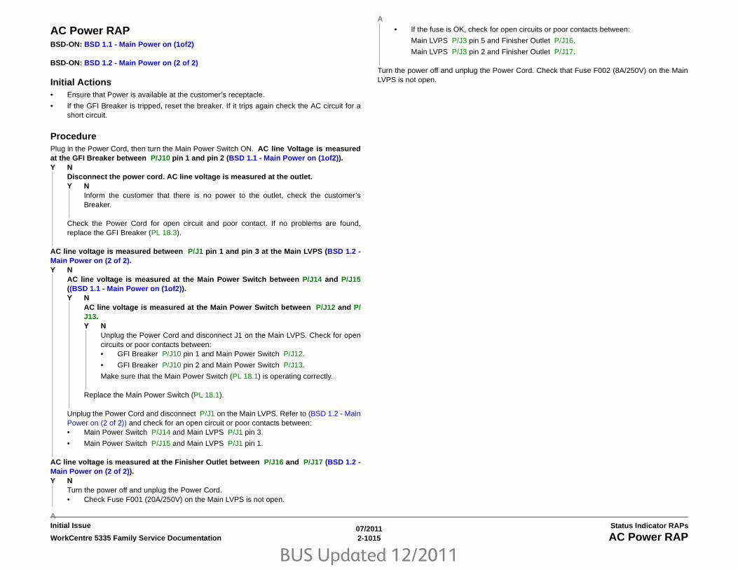
BUS Updated 12/2011
07/20112-1015WorkCentre 5335 Family Service Documentation AC Power RAP
Status Indicator RAPsInitial Issue
AC Power RAPBSD-ON: BSD 1.1 - Main Power on (1of2)
BSD-ON: BSD 1.2 - Main Power on (2 of 2)
Initial Actions• Ensure that Power is available at the customer’s receptacle.
• If the GFI Breaker is tripped, reset the breaker. If it trips again check the AC circuit for ashort circuit.
ProcedurePlug in the Power Cord, then turn the Main Power Switch ON. AC line Voltage is measuredat the GFI Breaker between P/J10 pin 1 and pin 2 (BSD 1.1 - Main Power on (1of2)).Y N
Disconnect the power cord. AC line voltage is measured at the outlet.Y N
Inform the customer that there is no power to the outlet, check the customer’sBreaker.
Check the Power Cord for open circuit and poor contact. If no problems are found,replace the GFI Breaker (PL 18.3).
AC line voltage is measured between P/J1 pin 1 and pin 3 at the Main LVPS (BSD 1.2 -Main Power on (2 of 2).Y N
AC line voltage is measured at the Main Power Switch between P/J14 and P/J15((BSD 1.1 - Main Power on (1of2)).Y N
AC line voltage is measured at the Main Power Switch between P/J12 and P/J13. Y N
Unplug the Power Cord and disconnect J1 on the Main LVPS. Check for opencircuits or poor contacts between: • GFI Breaker P/J10 pin 1 and Main Power Switch P/J12.
• GFI Breaker P/J10 pin 2 and Main Power Switch P/J13.
Make sure that the Main Power Switch (PL 18.1) is operating correctly.
Replace the Main Power Switch (PL 18.1).
Unplug the Power Cord and disconnect P/J1 on the Main LVPS. Refer to (BSD 1.2 - MainPower on (2 of 2)) and check for an open circuit or poor contacts between:• Main Power Switch P/J14 and Main LVPS P/J1 pin 3.
• Main Power Switch P/J15 and Main LVPS P/J1 pin 1.
AC line voltage is measured at the Finisher Outlet between P/J16 and P/J17 (BSD 1.2 -Main Power on (2 of 2)).Y N
Turn the power off and unplug the Power Cord. • Check Fuse F001 (20A/250V) on the Main LVPS is not open.
• If the fuse is OK, check for open circuits or poor contacts between:
Main LVPS P/J3 pin 5 and Finisher Outlet P/J16.
Main LVPS P/J3 pin 2 and Finisher Outlet P/J17.
Turn the power off and unplug the Power Cord. Check that Fuse F002 (8A/250V) on the MainLVPS is not open.
A
A

BUS Updated 12/2011
07/20112-1016 WorkCentre 5335 Family Service DocumentationSTBY +5VDC Power RAP, +5VDC Power RAP
Initial IssueStatus Indicator RAPs
STBY +5VDC Power RAPBSD-ON: BSD 1.2 - Main Power on (2 of 2)
BSD-ON: BSD 1.4 - DC Power Generation (1 of 2)
NOTE: When turning the power OFF; first, turn OFF the Power Switch, then the Main PowerSwitch.
ProcedureTurn the Main Power Switch ON, then turn the Power Switch ON. +5VDC is measured at theMain LVPS between P/J501 pins 7, 8, 9, and 10 (+); and GND (-) (BSD 1.4 - DC PowerGeneration (1 of 2)).Y N
AC line voltage is measured at the Main LVPS between P/J1 pin 1 and pin 3 (BSD1.2 - Main Power on (2 of 2)).Y N
Go to AC Power RAP.
Turn the power OFF and disconnect P/J501 on the Main LVPS. Turn ON machine power,wait 15seconds. +5VDC is measured at the Main LVPS between P/J501 pins 7, 8, 9,and 10 (+); and GND (-).Y N
Replace the Main LVPS (PL 18.2).
Check the +5VDC circuit for a short circuit to frame by referring to Chapter 7 Wiring Data.
Check the wire to the applicable component for an open circuit or poor contact by referring toChapter 7 Wiring Data.
+5VDC Power RAPBSD-ON: BSD 1.2 - Main Power on (2 of 2)
BSD-ON: BSD 1.3 - LVPS Control
BSD-ON: BSD 1.4 - DC Power Generation (1 of 2)
BSD-ON: BSD 1.7 - DC Power Distribution (options)
BSD-ON: BSD 1.9 - Power Interlock Switching (2 of 2)
NOTE: When turning the power OFF; first, turn OFF the Power Switch, then the Main PowerSwitch.
When measuring the voltage (+5VDC), turn ON the power then measure it before the machinegoes into the Power Save mode.
ProcedureTurn the power ON; turn ON the Main Power Switch, then turn ON the Power Switch. +5VDC is measured at the Main LVPS between P/J501 pin 3 and pin 5 (+), and GND (-)(BSD 1.7 - DC Power Distribution (options).Y N
AC line voltage is measured at the Main LVPS between P/J1 pin 1 and pin 3 (BSD1.2 - Main Power on (2 of 2)).Y N
Go to AC Power RAP.
Turn the power OFF and disconnect the Main LVPS connectors P/J502, P/J503, and P/J506. Turn ON machine power, wait 15 seconds. +5VDC is measured at the Main LVPSbetween P/J502 pin 3 and pin 5 (+), and GND (-) (BSD 1.7 - DC Power Distribution(options)).Y N
The STBY +5VDC LED, Green, on the ESS PWB is lit (Figure 1). Y N
• Ensure that P/J501 on the Main LVPS and P/J300 on the ESS PWB areproperly seated and that the Wire Harness is not damaged (BSD 1.4 - DCPower Generation (1 of 2)).
• If the checks are OK, go to STBY +5VDC Power RAP.
The +24VDC LED, Orange, on the ESS PWB is lit (Figure 1). Y N
Check in the following order:• Ensure that P/J501 on the Main LVPS and P/J300 on the ESS PWB are
properly seated, and that the Wire Harness is not damaged (BSD 1.4 - DCPower Generation (1 of 2)).
• Refer to (BSD 1.3 - LVPS Control) and check the 5V C-F On Signal to theMain LVPS.
• Replace the Main LVPS (PL 18.2).
Replace the Main LVPS (PL 18.2).
A B

BUS Updated 12/2011
07/20112-1017WorkCentre 5335 Family Service Documentation +5VDC Power RAP, +24VDC Power RAP
Status Indicator RAPsInitial Issue
Check the +5VDC circuit for a short circuit to frame by referring to Chapter 7 Wiring Data.
Measure for +5VDC on the Main LVPS at the following locations:• Between P/J503 pin 7 (+) and GND (-) (BSD 1.4 - DC Power Generation (1 of 2)).
• Between P/J506 pin 1 (+) and GND (-) (BSD 1.9 - Power Interlock Switching (2 of 2)).
+5VDC is measured at both locations.Y N
Replace the Main LVPS (PL 18.2).
Check the wire to the applicable component for an open circuit or poor contact by referring toChapter 7 Wiring Data.
Figure 1 ESS PWB LED Locations
+24VDC Power RAPBSD-ON: BSD 1.2 - Main Power on (2 of 2)
BSD-ON: BSD 1.3 - LVPS Control
BSD-ON: BSD 1.4 - DC Power Generation (1 of 2)
BSD-ON: BSD 1.5 - DC Power Generation (2 of 2)
BSD-ON: BSD 1.7 - DC Power Distribution (options)
BSD-ON: BSD 1.9 - Power Interlock Switching (2 of 2)
NOTE: When turning the power OFF; first, turn OFF the Power Switch, then the Main PowerSwitch.
ProcedureTurn the power ON; turn ON the Main Power Switch, then turn ON the Power Switch. +24VDC is measured at the Main LVPS between P/J501 pin 6 (+), and GND (-) (BSD 1.5 -DC Power Generation (2 of 2)).Y N
AC line voltage is measured at the Main LVPS between P/J1 pin 1 and pin 3 (BSD1.2 - Main Power on (2 of 2)).Y N
Go to AC Power RAP.
Turn the power OFF and disconnect the Main LVPS connectors P/J501, P/J502, and P/J503. Turn ON machine power, wait 15 seconds. +24VDC is measured at the MainLVPS between P/J501 pin 6 (+), and GND (-) (BSD 1.5 - DC Power Generation (2 of2)).Y N
+5VDC is measured at the Main LVPS between P/J502 pins 3 and pin 5 (+), andGND (-) (BSD 1.5 - DC Power Generation (2 of 2)).Y N
+5VDC is measured at the Main LVPS between P/J501 pins 7, 8, 9, and 10(+), and GND (-) (BSD 1.4 - DC Power Generation (1 of 2)).Y N
Go to STBY +5VDC Power RAP.
Refer to BSD 1.3 - LVPS Control and check the 5V C-F On Signal to the MainLVPS. If the problem continues, replace the Main LVPS (PL 18.2).
Replace the Main LVPS (PL 18.2).
Check the +24VDC circuit for a short circuit to frame by referring to Chapter 7 WiringData.
+24 VDC LED, Orange
STBY +5 VDC LED, Green
A B
A

BUS Updated 12/2011
07/20112-1018 WorkCentre 5335 Family Service Documentation+24VDC Power RAP, Machine Not Ready RAP
Initial IssueStatus Indicator RAPs
Measure for +24VDC on the Main LVPS at the following locations:• Between P/J502 pins 1 and 7 (+), and GND (-) (BSD 1.5 - DC Power Generation (2 of 2))
(BSD 1.4 - DC Power Generation (1 of 2)).
• Between P/J503 pins 5, 6, and 8 (+), and GND (-) (BSD 1.9 - Power Interlock Switching(2 of 2)) (BSD 1.5 - DC Power Generation (2 of 2).
+24VDC is measured at all locations.Y N
Replace the Main LVPS (PL 18.2).
Check the wire to the applicable component for an open circuit or poor contact by referring toChapter 7 Wiring Data.
Machine Not Ready RAP“Machine not ready” is defined as any condition where the machine is not capable of perform-ing its basic tasks (Copy or Print). This does not include failure of ancillary devices (Finishers,IIT, Fax, Paper Trays). “Not ready” ranges from a machine that is totally inert, without any indi-cation of power, to a machine that appears ready but does not respond to either Control Panelcommands or Network input.
ProcedureThe first step is to categorize the problem. Decide which of the following condition bestdescribes the problem:
• Dead Machine
• Does not complete Boot-up
• Boots up; does not respond to Control Panel
• Boots up; does not print (or other Network problems).
Dead Machine
If the machine shows no sign of power (fans or motors running, backlight on UI display, LED’son Control panel), check for AC line voltage at the Finisher Outlet.
1. If AC Voltage is not present, go to the AC Power RAP.
2. If AC Voltage is present, open the ESS Cover PL 35.1.
• If STBY +5VDC LED, Green CR231 (Figure 1), is not lit, go to STBY +5VDC PowerRAP.
• If +24VDC LED, Orange CR201 (Figure 1), is not lit, go to the +24VDC Power RAP.
If there is some indication of power from the machine, perform GP 20, Long Boot DiagnosticTests.
If the UI remains blank during the test, the problem is likely in the Control Panel Assembly, theESS, or in the connection between them:
1. Refer to BSD 2.1 - User Interface (UI) and BSD 3.4 - ESS-UI Communication.
2. Check the UI Cable between P/J352 on the ESS PWB and P/J1 on the UI I/F PWB fordamage or loose connections.
3. Check the connections on the wire harness and PWB’s within the Control Panel Assem-bly.
4. If the check is good, replace the Control Panel Assembly (PL 1.7). If the problem contin-ues, replace the ESS PWB (PL 35.2)
Does not complete Boot-up
Failure to complete the boot routine can be caused by corrupt software or mismatched soft-ware versions. GP 6 details how to check s/w versions; GP 16 explains how to reload s/w.
Boot failures can also be caused by hardware failures in the ESS, or communication failuresbetween the ESS and the rest of the machine. The ESS PWB has a group of diagnostic LED’sthat change state as the boot-up progresses. See GP 19, Boot Sequence, for details
Some boot-up failures may be caused by structural flaws in a command sent to the machine. Inthese cases, it is sometimes possible to bypass or delete the offending code during the startupprocess. Refer to GP 14, Special Boot Modes. Take note of the Cautions in the procedure.
A

BUS Updated 12/2011
07/20112-1019WorkCentre 5335 Family Service Documentation Machine Not Ready RAP, OF 13-1
Status Indicator RAPsInitial Issue
Boots up; does not respond to Control Panel
Check the following:
1. Refer to BSD 2.1 - User Interface (UI) and BSD 3.4 - ESS-UI Communication.
2. Check the UI Cable betweenPJ352 on the ESS PWB andPJ1 on the UI I/F PWB for dam-age or loose connections.
3. Check the connections on the wire harness and PWB’s within the Control Panel Assem-bly.
4. If the check is good, replace the Control Panel Assembly (PL 1.7). If the problem contin-ues, replace the ESS PWB (PL 35.2).
Boots up; does not print (or other Network problems).
Go to the OF 16-1 RAP.
Figure 1 ESS PWB LED Locations
OF 13-1 Secure Access RAPOverviewXerox Secure Access uses an external device, such as a card reader or biometric device, toauthorize access to the machine. This reader then passes the information to the controller,which handles the authentication process including, which GUI screens are displayed, accept-ing GUI responses, that defines their content and order. The controller can pass user identitiesand passwords directly to the machine after gathering the data from an external server. Allcommunication is via a secure network link, Figure 1 Network Diagram.
Xerox Secure Access shall be controlled via the CentreWare Internet Services GUI. The activestatus is displayed in tools within Access Control. If communication cannot be established withthe Xerox Secure Access Server the service may be temporarily disabled by touching the nowenabled Off button within the Xerox Secure Access tools window. Once communication is rees-tablished the stored Xerox Secure Access setting shall be restored.
Figure 1 Network Diagram
Initial Action
Before working on the Xerox Secure Access, check out the machine in the service mode toinsure no faults are displayed and that the machine is functioning properly. If it is not, repair anyproblems before proceeding with diagnosing the Secure Access Accessory. Diagnostics canbe entered to test copier functionality when Secure Access is installed.
Perform the following steps
• Check the connection between the Card Reader and the Secure Access AuthenticationDevice.
• Check for the LED’s are on or blinking on the Secure Access Authentication Device. If theLED’s on the Secure Access Authentication Device are not operating, go to SecureAccess Authentication Device Failure.
+24 VDC LED, Orange
STBY +5 VDC LED, Green

BUS Updated 12/2011
07/20112-1020 WorkCentre 5335 Family Service DocumentationOF 13-1
Initial IssueStatus Indicator RAPs
• Check for the LED’s are on or blinking on the Card Reader. If the LED’s on the CardReader are not operating, go to Card Reader Failure.
• If customers have problems of install / setting up, or any other problems related to theirSecure Access Administrator, they should refer to the Secure Access System Administra-tor’s Guide or contact Xerox Technical Support.
Secure Access Authentication Device Failure
The primary failure modes are power problems or failed hardware components. The symptomof these failures can be detected by observing the Led’s on the Secure Access AuthenticationDevice, Figure 2.
Figure 2 Authentication Device
Check the power to the Secure Access Authentication Device.
• Check the power supply at the wall socket. If there is no power at the wall socket, havethe customer restore power and continue when confirmed.
• Disconnect the power cord from the wall socket and the power supply. Check the powercord for continuity and damage. If necessary install a new power cord. Disconnect thepower cord from the power supply and plug the power cord into the wall outlet. Using amultimeter, check for line voltage at the end of the power cord disconnected from thepower supply. If there is power at the wall but not at the end of the power cord. Install anew power cord.
• Disconnect the small power cord from the Secure Access Authentication Device. Checkthere is +5V at the connector that plugs into the Secure Access Authentication Device. Ifthere is no +5V, install a new power supply.
• There is a ‘Keyed’ switch on the end of the Secure Access Authentication Device. Obtainthe key from the customer. Insert the key into the ‘keyed’ switch and cycle the switch 1quarter turn clockwise and then back to its start position. Observe the LEDs and listen foran audible tone.
• If the LEDs on the Secure Access Authentication Device “Uplink” and “Downlink” Ethernetports do not cycle on and off as the controller goes through its boot-up process, or if theaudible tone is not heard. Install a new Secure Access Authentication Device.
NOTE: A new device will require the Secure Access Administrator to reconfigure theserver with the new MAC address for the new part. Be sure to inform the Secure AccessAdministrator of the MAC address of the device being removed and the MAC address ofthe new device.
Card Reader Failure
The primary failure modes are power problems or failed hardware components. The symptomof these failures can be detected by observing the LED on the Card Reader. Refer to Table 1.
• The Green LED on the Card Reader is On
• The Green LED on the Card Reader Flashes Rapidly
• The Red LED on the Card Reader is On
• The Red LED on Card Reader Flashes Slowly
• The Red LED on Card Reader Flashes Rapidly
• The Card Reader LED’s are not On or Blinking
The Green LED on the Card Reader is On
• This indicates an active Secure Access Session and the Card Read correctly corre-sponds to a valid Secure Access Account.
• If the UI on the machine is locked, check with the customer for a second PIN number foradditional security. This PIN number will need to be entered via the soft keys on the UI.
• Ensure that the card corresponds to a valid Secure Access Account.
The Green LED on the Card Reader Flashes Rapidly
• This indicates a valid card swipe and in the process of authentication on the server.
• If the UI on the machine is locked, check with the customer for a second PIN number foradditional security. This PIN number will need to be entered via the soft keys on the UI.
Table 1 LED Symptom Descriptions
When the LED on the card Reader is Description
Red The authentication device is in idle mode; there is no active session.
Green The authentication device is in ready mode; a session is active.
Slow Flashing Red The authentication device has no connection to the server.
Slow Flashing Green
The authentication device is communicating to the server.
Fast flashing red Invalid card / password; access denied.

BUS Updated 12/2011
07/20112-1021WorkCentre 5335 Family Service Documentation OF 13-1
Status Indicator RAPsInitial Issue
• If the UI on the machine is locked and no secondary PIN is required. Check that the XeroxSecure Access is installed correctly, and ask customer to check the configuration at theserver.
The Red LED on the Card Reader is On
• This indicates the Card Reader is in an idle state. If the red LED remains on, and the UIremains locked after a card is swiped, re-orient the card and re-swipe.
• Try a known good card in the reader. If the other card is working on the problem CardReader. Ask customer to make sure the card corresponds to a valid Secure AccessAccount.
• Try the card in a known good reader. If the card is working on a known good Card Reader,it may be a problem with the Secure Access Authentication Device. Check to see is theLEDs on the Secure Access Authentication Device are on.
The Red LED on Card Reader Flashes Slowly
• This indicates the reader is connected to the controller but the controller is not connectedto the server. Check the Ethernet green LED on the Authentication Device.
• If the Ethernet green LED on the Authentication Device is off, make sure the connectorsof the LAN connections are working properly. If the connections are working, this indi-cates the network may not work properly. Ask customer to check with Network Adminis-trator.
• If the Ethernet green LED on the Authentication Device is either on or flashing, contactthe Secure Access Administrator
The Red LED on Card Reader Flashes Rapidly
• This indicates a valid card but does not correspond to a valid Secure Access Account atthe server, test with a known valid user’s card.
• If all cards react the same way, this indicates the Server Configuration may not be correct.Ask customer to check the Server Configuration.
• If all the card react this way, this indicates the cards are not valid. Ask customer to checkthe Server Configuration
The Card Reader LED’s are not On or Blinking
• Check to see is the Secure Access is correctly installed.
• If there is still no LED on the Card Reader, install a new the Card Reader.
NOTE: If there is another working card reader available, the readers can be switched toconfirm failure. If the Card Reader is not functioning, the web page of the machine has asetting that will enable UI keypad access. If the users know their card access number,they can use the machine by manually entering their number. The process is as follows:
1. Go to the machine web page under properties and then security and check the box thatsays “Allow local user interface initiation”.
2. Enable the keypad and test with valid credentials. This will validate the rest of the secureaccess function.
3. Leave it in this mode until the new card reader can be installed.

BUS Updated 12/2011
07/20112-1022 WorkCentre 5335 Family Service DocumentationOF 16-1
Initial IssueStatus Indicator RAPs
OF 16-1 Network Checkout Check for SMB FailureThe following describes the possible causes, check procedures, and corrective actions when afailure occurs when SMB is used.
1. Check at [Printer Not Found]
2. Check at [Print Not Available]
3. Check at [Documents Cannot Be Deleted from [Printer] Window]
4. Check [Machine Settings] a. IP addresses are managed in a whole system. Consult with the Network Administra-tor thoroughly before perform setting.
Table 1 Printer Not Found
Cause Check Method Corrective Action
The operation protocols of the computer and main processor are different.
Though the printer can be found when search is performed using [Search Other Computer] ([Start] > [Search] > [Other Comput-ers], it cannot be found in [Network Computers].
Match the SMB transport protocols (NetBEUI, TCP/IP) of the main pro-cessor and each computer.
Networks (subnets) are different. Though the printer can be found when search is performed using [Search Other Computer] ([Start] > [Search] > [Other Comput-ers], it cannot be found in [Network Computers].
When the main processor and the computer are in different networks, check with the System Administrator.
The host name set in the main processor already exists.
Print the "System Settings List". Check that "Host name dupli-cated" is described in the SMB status information.
Use CentreWare Internet Services to change the host name to an undu-plicated name or return the main processor settings to default.
Table 2 Print Not Available
Cause Check Method Corrective Action
The main processor is processing a print request from another computer.(When [Do not spool] is set for [Receiving Buffer])
Check that the main processor is processing a print. (A write error dialog appears indicating that there are no areas to stored the files in queue.)
After print process has been completed in the main processor, issue a print request or switch the main processor setting to the spool mode.
The number of connections in the main pro-cessor exceeds the maximum value.
The port connection is also being held when the printer is paused due to no paper because it is held since a job request has been issued to Net until printing is complete.Check the maximum number of sessions of SMB from the EWS "Protocol" menu to check that the jobs more than "maximum number of sessions" were requested at the same time at site.
Wait for a while and issue the same print request again.Or, check the number of users that can use the machine at the same time and set the maximum number of sessions to an appropriate value from the EWS "Protocol" menu.
Table 3 Documents Cannot Be Deleted
Cause Check Method Corrective Action
Try to delete all the print data displayed in [Printers] window. (This can only be done by the administrator of this machine.)
From the "Printers" menu, check if the print data is tried to be deleted. ([Clear Print Jobs] menu)
Select the print data to be deleted and delete the print data from [Docu-ments] menu in the [Printers] window. ([Cancel Job] menu)
There are different print data owners. Check that the name displayed [Owner] of the selected print data matches the login name who has logged in to Windows.
Log in to Windows using the name displayed in [Owner] of the print data to delete the data.
Service Pack 4.0 or later is not installed. (For Windows NT 4.0)
Check the version of Service Pack, which is displayed at start up of Windows NT 4.0.
Install Service Pack version 4.0 or later.

BUS Updated 12/2011
07/20112-1023WorkCentre 5335 Family Service Documentation OF 16-1
Status Indicator RAPsInitial Issue
b. Depending on the network environment, set the subnet mask and gateway settingsonly if necessary. Consult with the Network Administrator to set necessary settings.
c. If a memory becomes insufficient when [Enabled] is set for the port status, the portstatus may be automatically reset to [Disabled]. BIn this case, [Disabled] an unusedport or change the memory allocated capacity.
d. Depending on the usage environment, set the receiving buffer capacity [SMB(Spool)] size. When the receiving buffer capacity [SMB (Spool)] size is smaller thanthe sent data, the data may not be able to be received.
5. Check [Computer Settings]
a. IP addresses are managed in a whole system. Consult with the Network Administra-tor thoroughly before perform setting.
b. To perform network settings (such as IP address), etc. on the host used under NIS(Network Information Service) management, consult with the NIS Administrator.
6. Check at [Power OFF]
Before turning the machine OFF, take note of the following:
a. When [Memory] is set for [SMB (Spool)]
All the print data including the data being printed that have been spooled in themachine memory will be deleted.
When turning the power ON again, no print data remains. However, if the power isturned OFF immediately after print instruction, the print data may be stored on thecomputer.
In this case, even if a new print instruction is issued after the power is turned ON, thestored print data will be printed first.
b. When [Hard Disk] is set for [SMB (Spool)]
All the print data including the data being printed that have been spooled in themachine hard disk will be saved.
When the power is turned ON again and a new print instruction is issued, the storedprint data will be printed first.
c. When [Do not spool] is set for [SMB (Spool)]
All the print data including the data being printed that have been spooled in themachine receiving buffer will be deleted. When the power is turned ON again, noprint data remains.
However, if the power is turned OFF immediately after print instruction, the print datamay be stored on the computer.
In this case, even if a new print instruction is issued, the stored print data will beprinted first.
7. Check [At Printing]
a. When [Hard Disk] or [Memory] is set for [SMB (Spool)]
When the machine starts receiving print data and the print data size is larger thanthe hard disk or memory remaining capacity, the print data will not be received.
NOTE: If the print data exceeds the receiving capacity, some computers will resenddata immediately. In this case, the computer looks like stopped. As a correctiveaction for this, abort sending the print data on the computer.
b. When [Do not spool] is set for [SMB (Spool)]
When a print request is received from a computer, the print requests from other com-puters cannot be received.
c. When a computer IP address or name has been changed
When a computer IP address or name has been changed, the inquiry and cancella-tion of processes from the main processor cannot be performed properly. Turn themachine OFF then ON when no print data is stored in the machine receiving buffer.
NOTE: The print cancel/forced output processes of the print data stored in themachine receiving buffer can be operated from the machine Operation Panel. Referto "11 Job Check" in "User Guide" for more information on how to operate.
d. When the machine is in the offline state
When the machine is in offline state and a print instruction is issued from a computer,the data will not be received in the machine, and an error dialog box appears on thecomputer indicating that write error has occurred. However, for SMB, the print datacan be received from the computer even when the machine is offline.
e. Deleting Jobs
For Windows NT 4.0, jobs can be deleted when Service Pack 4.0 or later is installed.When a job is deleted while data is being received, write error appears. In this case,the [Retry] button on the error dialog box is not available.
Check for NetWare FailureThe following describes the possible causes, check procedures, and corrective actions when afailure occurs when NetWare is used.
1. Check at [Printing Not Performed]
Table 4 Printing Not Performed
Cause Check Method Corrective Action
The network configuration devices (HUB etc.) do not match the automatic settings of the frame type.
Check that the data link lamp of the network configuration device port that is connected to the machine is lit on.Check that the same frame types are used in the file servers that exist on a network.
Set the frame type that has been set for the file server to be connected from the machine.
A failure has occurred on the network from a workstation to a printer.
Use NWADMIN from the workstation to check that the target printer objects can be viewed.
Replace the non-communicating network cable that exists between the workstation and the printer.

BUS Updated 12/2011
07/20112-1024 WorkCentre 5335 Family Service DocumentationOF 16-1
Initial IssueStatus Indicator RAPs
The user name of a job sender or the group name to which the job sender belongs is not registered in the [Users] for Print queue.
Use NWADMIN from the workstation to view the target queue objects and check that the user name of the job sender or the group name to which the job sender belongs is registered in the [Users] information.
1. Resend print data to the print queue in which the user name of the job sender or the group name to which the job sender belongs has been registered in [Users] of [Print Queue Information].2. Use NWADMIN from the workstation to register the user name of the job sender or the group name to which the job sender belongs in the [Users] of [Print Queue Information].
Sending jobs to the print queue is prohib-ited.
Use PCONSOLE to check that [Yes] is set for [User can register data to queue] in the [Current Queue Status] of [Print Queue Infor-mation].
Set it to [Yes] using PCONSOLE.
Same as above Use NWADMIN from the workstation to check that the operator flag is checked in [Identification] for the target print queue.
Use NWADMIN from the workstation to check that the each item for the operator flag is checked in [Identification] for the target print queue.
The user name of a job sender or the group name to which the job sender belongs is not defined for the print server users of a print server.
Use NWADMIN from the workstation to check that the user name of the job sender or the group name to which the job sender belongs is registered in [Users] of the target print server.
1. Resend print data to the print queue in which the user name of the job sender or the group name to which the job sender belongs has been registered in [Users] of [Print Server Information].2. Use NWADMIN from the workstation to register the user name of the job sender or the group name to which the job sender belongs in the [Users] information of the target print server.
The print queue that has sent print data is not allocated to the printer.
Use NWADMIN from the workstation to check that the target printer is allocated in the list of the printers in service in [Allocation] of the target print queue.
1. Resend print data to the print queue that has been allocated to the printer.2. Use NWADMIN from the workstation to add a target queue using [Allocation] of the target printer.
The data type of the print data does not match the print environment settings of the workstation.
- When the workstation uses Windows, make settings so that it does not output Ctrl-D.
The number of print queues that exceeds the maximum number of supported queues has been set.
Use NWADMIN from the workstation to check that the desired print queue is allocated in the list of the printers in [Allocation] of the target printer.
Resend print data to the print queue that has been allocated to the printer.
No slave file servers have been set (bindery service mode).
Use PCONSOLE from the workstation to check that a slave file server is registered in [Service NetWare Server] of the appropriate print server in [Print Server Information].
Use PCONSOLE from the workstation to register a slave file server and then reflect the setting parameters.
Printer types are different. Use PCONSOLE from the workstation to check that Port: LPT1 and Position: Auto Mode (Local) are set in [Print Server Informa-tion] > [Printers] > [Environment Settings for Printer xxx].
Use PCONSOLE from the workstation to set Port: LPT1 and Position: Auto Mode (Local), and reflect the setting parameters.
The slave file server settings are different (bindery service mode).
Use PCONSOLE from the workstation to check that [Defined by Other Settings] is displayed for the printer type in [Print Server Information] > [Printers] > [Environment Settings for Printer xxx].
If it is not set to [Defined by Other Settings], change it to [Defined by Other Settings] and then reflect the setting parameters.
The sheet number of the print data is differ-ent from the sheet number that has been set in the printer.
Use NWADMIN from the workstation to select a target printer and then check that the start sheet number in the environment settings is the same as the number of the print data.
Use NWADMIN from the workstation to match the number for [Start Sheet] with the number of the print data in the environment settings for the target printer.
IPX check sum level settings are different. Use the set command in the file server console screen to check the IPX check sum is not set to Level 2.
Enter the following command in the file sever console screen to set the IPX check sum to Level 0 or Level 1. Set Enable IPX Checksum=x (x: 0 or 1)
NCP packet signature level settings are dif-ferent.
Use the set command in the file server console screen to check the NCP packet signature is not set to Level 3.
Enter the following command in the file sever console screen to set the NCP packet signature to Level 0, 1, or 2 and then restart the file server. Set NCP Packet Signature Option=x (x: 0, 1, or 2)
Table 4 Printing Not Performed
Cause Check Method Corrective Action

BUS Updated 12/2011
07/20112-1025WorkCentre 5335 Family Service Documentation OF 16-1
Status Indicator RAPsInitial Issue
2. Check at [Printing not performed as desired]
3. Check at [Printer failure not notified]
4. Check at [Job completion not notified]
The default device name setting is wrong. Print "System Settings List" to check the lower 6 digits (3 bytes) of the Ethernet address.
1. Use a correct Ethernet address to set the device name.2. Set the device name to other than the default value.
No directory tree name is set. Print the "System Settings List" to check if a tree name is set. Set a tree name.
Context is not set in place. Print the "System Settings List" to check if a context is set. Set the Context.
Another printer object has been connected. Use NWADMIN from the workstation to check that a correct object has been allocated in the Layout Information of the desired print server.
1. Use the CentreWare Utilities CD-ROM from the workstation to set the file server name/tree/context/operation mode correctly.2. Use the CentreWare Internet Services from the workstation to set the file server name/tree/context/operation mode correctly.
The NetWare port is not enabled. Print the "System Settings List" to check if the NetWare port is enabled.
Enable the NetWare port.
The file server is down. Search for a target file server from [Network Computers].
A printer with the same device name exists on a network.
Turn OFF the machine and use NWADMIN from the workstation to check that the appropriate printer object status is set to job standby.
Use the CentreWare Utilities CD-ROM from the workstation to set a dif-ferent device name.
The NetWare port is not enabled. Print the "System Settings List" to check if the network number remains [0000000] (NetWare server down) when the IPX/SPX is being used.Also check if the IP address remains [0.0.0.0] (Fixed IP address not set, or address providing server (DHCP) is down) when TCP/IP is used.
For IPX/SPX, activate the NetWare server.For TCP/IP, set a fixed IP address or activate the address providing server (DHCP).
Table 4 Printing Not Performed
Cause Check Method Corrective Action
Table 5 Printing not performed as desired
Cause Check Method Corrective Action
Different printer languages are set in the print data and the main processor.
Check the printer language in the main processor. Match the printer languages set in the print data and the main proces-sor.
Table 6 Printer failure not notified
Cause Check Method Corrective Action
The notifier is not registered in the notifier list of the print server.
Use PCONSOLE from the workstation to check that the user name of a job sender or the group name to which the job sender belongs is registered in [Print Server Information] > [Printers] > [Environment Settings for Printer xxx] > [Notification].
Register the user name of a job sender or the group name to which the job sender belongs in [Notification].
Table 7 Job completion not notified
Cause Check Method Corrective Action
The NOTIFY option was not set for sending print data from a workstation.
Check that the NOTIFY option is set for sending print data. Set the NOTIFY option for sending print data from a workstation.

BUS Updated 12/2011
07/20112-1026 WorkCentre 5335 Family Service DocumentationOF 16-1
Initial IssueStatus Indicator RAPs
Check for TCP/IP (LPD) FailureThe following describes the possible causes and actions when a failure occurs when TCP/IP(LPD) is used.
1. For Windows95, Windows98 and Windows Me
2. For Windows NT 4.0, Windows2000, Windows Xp, and Windows Server 2003
When no printing is available or desired printing is not performed, follow the check proce-dures described below to take the corrective actions.
NetWare CASTOFF was executed on the user workstation.
- Execute NetWare CASTON on the user workstation.
Table 7 Job completion not notified
Cause Check Method Corrective Action
Table 8 Windows95, Windows98 and Windows Me
Cause Status Display Check Method Corrective Action
The machine is connected to a network that is different from the computer.
Printing Not Avail-able status (Network Error)
Check with the Network System Administra-tor that a router or gateway exists between the network in which the computer is con-nected and the network in which the machine is connected.
Connect the machine directly to the network in which the computer is connected.
Connection cannot be established due to the failure on the network from a computer to the printer.
Printing Not Avail-able status (Network Error)
None. Request the Network System Administrator to check for any network fail-ures.
The machine was turned OFF after print instruction had been issued from a com-puter. Or, a print instruction was issued from a computer when the machine is turned OFF.
Printing Not Avail-able status (Network Error)
Check that the machine is turned ON. Turn ON the machine.
Print instructions are issued from multiple computers to the machine at the same time.
Printing Not Avail-able status (Network Error)
None. None (printing will be automatically resumed).
Print files cannot be spooled due to insuffi-cient computer disk capacity.
Printing Not Avail-able status (Spool Error)
Open [My Computer] and right-click the disk in which the system is installed (e.g. Drive C). Select [Properties] from the displayed menu to check the free disk space.
Delete unnecessary files to secure the disk free space.Then, select [Pause] from the [Documents] menu of the [Printers] win-dow to clear the pause status (resumes printing).
Table 9 Windows NT 4.0, Windows2000, Windows Xp, and Windows Server 2003
Cause Check Method Corrective Action
Incorrect IP address is set. Ask the Network Administrator to check if the IP address set in this machine is correct.
Set a correct IP address in the machine.
When the LPD spool is set for a memory spool, the print data size in a single print instruction sent from a computer exceeds the upper limit of receivable capacity.
Check the LPD spool memory capacity and compare it with the print data capacity that is tried to send in a single print instruction.
1. If the print data capacity exceeds the memory capacity upper limit, split the file into smaller sizes than the memory capacity upper limit and then send the print instruction.2. If multiple print data capacities exceed the memory capacity upper limit, reduce the number of files to be sent for printing at the same time.
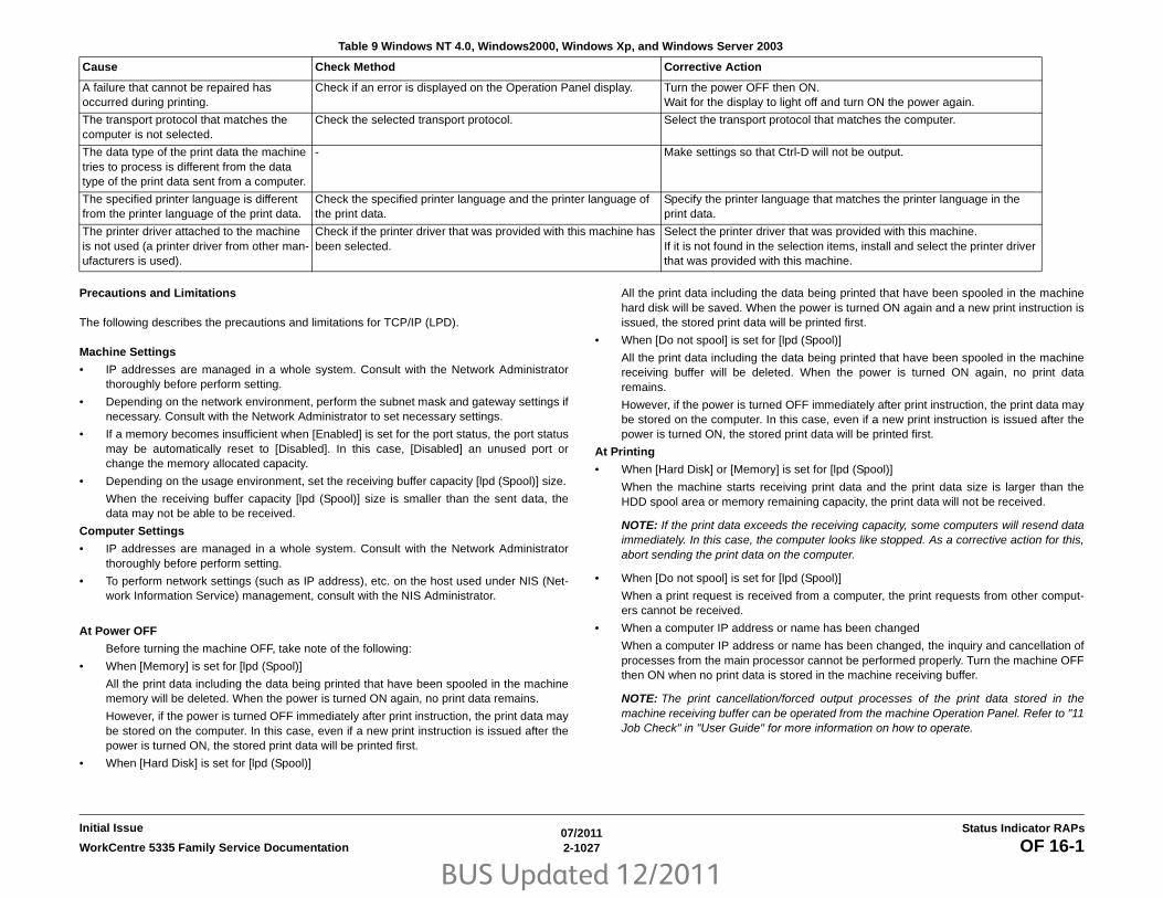
BUS Updated 12/2011
07/20112-1027WorkCentre 5335 Family Service Documentation OF 16-1
Status Indicator RAPsInitial Issue
Precautions and Limitations
The following describes the precautions and limitations for TCP/IP (LPD).
Machine Settings
• IP addresses are managed in a whole system. Consult with the Network Administratorthoroughly before perform setting.
• Depending on the network environment, perform the subnet mask and gateway settings ifnecessary. Consult with the Network Administrator to set necessary settings.
• If a memory becomes insufficient when [Enabled] is set for the port status, the port statusmay be automatically reset to [Disabled]. In this case, [Disabled] an unused port orchange the memory allocated capacity.
• Depending on the usage environment, set the receiving buffer capacity [lpd (Spool)] size.
When the receiving buffer capacity [lpd (Spool)] size is smaller than the sent data, thedata may not be able to be received.
Computer Settings
• IP addresses are managed in a whole system. Consult with the Network Administratorthoroughly before perform setting.
• To perform network settings (such as IP address), etc. on the host used under NIS (Net-work Information Service) management, consult with the NIS Administrator.
At Power OFF
Before turning the machine OFF, take note of the following:
• When [Memory] is set for [lpd (Spool)]
All the print data including the data being printed that have been spooled in the machinememory will be deleted. When the power is turned ON again, no print data remains.
However, if the power is turned OFF immediately after print instruction, the print data maybe stored on the computer. In this case, even if a new print instruction is issued after thepower is turned ON, the stored print data will be printed first.
• When [Hard Disk] is set for [lpd (Spool)]
All the print data including the data being printed that have been spooled in the machinehard disk will be saved. When the power is turned ON again and a new print instruction isissued, the stored print data will be printed first.
• When [Do not spool] is set for [lpd (Spool)]
All the print data including the data being printed that have been spooled in the machinereceiving buffer will be deleted. When the power is turned ON again, no print dataremains.
However, if the power is turned OFF immediately after print instruction, the print data maybe stored on the computer. In this case, even if a new print instruction is issued after thepower is turned ON, the stored print data will be printed first.
At Printing
• When [Hard Disk] or [Memory] is set for [lpd (Spool)]
When the machine starts receiving print data and the print data size is larger than theHDD spool area or memory remaining capacity, the print data will not be received.
NOTE: If the print data exceeds the receiving capacity, some computers will resend dataimmediately. In this case, the computer looks like stopped. As a corrective action for this,abort sending the print data on the computer.
• When [Do not spool] is set for [lpd (Spool)]
When a print request is received from a computer, the print requests from other comput-ers cannot be received.
• When a computer IP address or name has been changed
When a computer IP address or name has been changed, the inquiry and cancellation ofprocesses from the main processor cannot be performed properly. Turn the machine OFFthen ON when no print data is stored in the machine receiving buffer.
NOTE: The print cancellation/forced output processes of the print data stored in themachine receiving buffer can be operated from the machine Operation Panel. Refer to "11Job Check" in "User Guide" for more information on how to operate.
A failure that cannot be repaired has occurred during printing.
Check if an error is displayed on the Operation Panel display. Turn the power OFF then ON.Wait for the display to light off and turn ON the power again.
The transport protocol that matches the computer is not selected.
Check the selected transport protocol. Select the transport protocol that matches the computer.
The data type of the print data the machine tries to process is different from the data type of the print data sent from a computer.
- Make settings so that Ctrl-D will not be output.
The specified printer language is different from the printer language of the print data.
Check the specified printer language and the printer language of the print data.
Specify the printer language that matches the printer language in the print data.
The printer driver attached to the machine is not used (a printer driver from other man-ufacturers is used).
Check if the printer driver that was provided with this machine has been selected.
Select the printer driver that was provided with this machine.If it is not found in the selection items, install and select the printer driver that was provided with this machine.
Table 9 Windows NT 4.0, Windows2000, Windows Xp, and Windows Server 2003
Cause Check Method Corrective Action

BUS Updated 12/2011
07/20112-1028 WorkCentre 5335 Family Service DocumentationOF 16-1
Initial IssueStatus Indicator RAPs
Check for Centreware Internet Services FailureThe following describes the situations and corrective actions when a failure occurs when "Cen-treWare Internet Services" is used.
Check for Scanning Failure1. When a document is retrieved from a Mailbox
• If [Save] is set for [Delete Document After Retrieval], multiple clients can access tothe same document.
• If [Delete] is set for [Delete Document After Retrieval], only 1 client can access to thesame document. The document stored or read by a client cannot be viewed from theother clients.
In both cases, documents can be added to the accessed Mailbox.
• The documents that have been retrieved using CentreWare Internet Services will notbe deleted regardless of the setting in [Delete Document After Retrieval].
2. Screen Display
When the document with a lot of colors is scanned, they cannot be displayed properly inthe display mode that displays using fewer colors than the scanned colors. Use the dis-play mode that allows displaying using more colors than the colors used in the image.
3. A network scanner driver and Mailbox Viewer 2 are used at the same time.
When a computer uses a network scanner driver and Mailbox Viewer 2 at the same time,the computer cannot connect to the printer.
When multiple computers use the network scanner drivers or Mailbox Viewer 2 to retrievedocuments from the same machine at the same time, up to 3 computers can be con-nected.
4. When the documents stored in Mailbox is printed
When stored documents are to be printed (the documents are to be retrieved) by select-ing [Mailbox] from the machine touch panel display, scanned documents cannot beprinted.
5. When a TIFF file is used
The TIFF files that have been created using CentreWare Scan Services or MailboxViewer 2 are compressed using the MMR, MH, JBIG, or JPEG compression method. Toopen a TIFF file, use the application software applicable for those compression methods.
NOTE: JBIG compressed TIFF files cannot be created in Mailbox Viewer 2.
6. Restrictions on Scan Capacity and No. of Sheets
The maximum read capacity for a page is 297x432mm. A3 or 11”x17" for the standardsize
The Mailbox method allows up to 999 sheets to be read in a single scan operation.
Check for Mail FailureCorrective Action
Table 10 CWIS
Symptoms Corrective Action
Cannot be connected to "Cen-treWare Internet Services".
Check that the machine is operating properly. Check that the machine is turned ON.
Same as above Check that "Internet Services" is activated. Print the "System Settings List" for checking.
Same as above Check that the Internet address has been entered properly. Check the Internet address again. If connection is not suc-cessful, enter the IP address and try connection.
Same as above Check if a proxy server is used. Some proxy servers disable connection. When proxy server is not used, set the Web browser to "Do not use proxy server" or set the used address to "Do not use proxy server".
[Wait for a while] appears and stays.
Wait for a while without any action. If the situation has not been changed, select the [Refresh] button. If the situation does not change after selecting the [Refresh] button, check if the machine is operating properly.
The [Refresh] button is not functioning. Or, even if a menu in the left frame is selected, the right frame can-not be refreshed.
Check that the specified Web browser is used. Refer to "Com-munication (Port/Protocol) Setting Items in CentreWare Inter-net Services" in User Guide to check the used Web browser is supported.
The screen display collapses. Change the Web browser window size.
The latest information is not displayed.
Select the [Refresh] button.
Selecting the [Apply new set-tings] button does not reflect settings.
Check that the entered values are correct. If invalid values have been entered, they are automatically changed to values within the limit range.
Same as above Check that the machine is operating or has completed opera-tion using the machine Operation Panel. If Auto Reset func-tion is set, the settings in CentreWare Internet Services will not be applied until the specified time has passed. Wait for a while.
Selecting [Apply new set-tings] button displays a mes-sage such as [Invalid or unrecognizable response was returned from the server] or [No data found] on the Web browser.
1. Check if the password is correct. The password confirma-tion entry does not match. Enter a correct password. 2. Restart the machine.
Jobs cannot be deleted. Wait for a while and then select the [Refresh] button.

BUS Updated 12/2011
07/20112-1029WorkCentre 5335 Family Service Documentation OF 16-1, OF 99-1
Status Indicator RAPsInitial Issue
The following describes the corrective actions for troubles when Mail Notice Service, Print E-mail, or Scanner (Send E-mail) is used.
OF 99-1 Reflective Sensor RAPSensors consist of a light-emitting diode and a photo transistor. When energized, the light fromthe LED causes the photo transistor to conduct, drawing current through a pull-up resistor. Thevoltage drop across the resistor causes the input signal to the control logic to change from ahigh to a low.
Reflective sensors operate by light from the LED being reflected off the paper to the photo tran-sistor, causing the output of the sensor to go to the low (L) state.
Initial ActionsEnsure that the sensor is not actuated.
Procedure
NOTE: To view the Circuit Diagram for this procedure refer to (Figure 1).
Enter the component control code indicated in the Procedure and/or Circuit Diagram of theRAP that sent you here. Actuate the sensor using a sheet of paper. The display changeswith each actuation.Y N
Clean the sensor and then block and unblock it. The display changes with each actua-tion. Y N
Access to some sensors in this machine is difficult. Follow the Y leg if you canaccess the sensor connector. Follow the N leg if access is not possible. The sen-sor connector is accessible.Y N
Check the voltage at the output of the PWB or power supply (refer to the CircuitDiagram). In Figure 1 for this generic procedure, voltage is provided from J533on the I/F (MDD) PWB. Check for pull-up voltage for the output signal. This volt-age will be either +5 VDC or +3.3 VDC depending on the circuit (refer to thesensors BDSD or Circuit Diagram for the correct voltage). The voltage corre-sponds with the voltage shown in the Circuit Diagram.Y N
Check for short circuit(s) that may be loading down the line. Check thepower input to the PWB(s). If this does not resolve the problem, replacethe PWB.
Refer to the Circuit Diagram. Check the wires from the PWB to the sensor foropens, shorts, or loose contacts. If the wires are OK, replace the sensor. If thisdoes not resolve the problem, replace the PWB
The display indicates a constant L.Y N
Check for +5VDC to the sensor (typically pins 1 and 3 on a 3 pin connec-tor). +5 VDC is present. Y N
Use the circuit diagram and/or the wirenets in Section 7 to trace the prob-lem.
Table 11 Mail Failure
Symptoms Corrective Action
Cannot receive mails(Print E-mail)
1. Check that the machine mail address has been set.2. Check that [Receive E-mail] is set to [Enabled].3. Check that the SMTP server IP address and the POP3 server IP address (when POP3 is selected for receiving protocol), etc. are set properly.4. Check that the POP user name and password are set properly.5. Check that [Domain List] has been set. Check that the user's domain is included in the receive-allowed domains using Centre-Ware Internet Services.6. Check that the SMTP and POP servers are operating properly. Check with the Network Administrator.
Mails cannot be sent(Mail Notice, Scanner (Send E-mail))
1. Check that the machine mail address has been set.2. Check that [Mail Notice Service] is set to [Enabled]. (For mail notice)3. Check that [Send E-mail] is set to [Enabled].4. Check that the SMTP server IP address etc. is set properly.5. Check that the notification items to be sent have been set cor-rectly. (For Mail Notice) Check settings from the CentreWare Inter-net Services Properties screen.6. Check that the send destination mail address has been entered properly.7. Check that the SMTP server is operating properly. Check with the Network Administrator.
A B C D

BUS Updated 12/2011
07/20112-1030 WorkCentre 5335 Family Service DocumentationOF 99-1, OF 99-2
Initial IssueStatus Indicator RAPs
Disconnect the sensor. Use a jumper wire to connect the output wire from thesensor (typically pin 2 on a 3 pin connector) to DC COM or GND. The displaychanges from H to L.Y N
There is either an open circuit or a failed PWB. Use the Circuit Diagram totrace the output wire to the PWB. If the wire is OK, replace the PWB.
Replace the sensor.
Disconnect the sensor. The display indicates H.Y N
When sensors are unplugged, the input at the PWB should always be high ifthere is no harness short or PWB failure. Check the output wire from the sensor(typically pin 2 on a 3 pin connector) to the PWB for a short circuit. If the wire isgood, replace the PWB. Figure 1 represents a typical sensor for this machine.
The sensor is shorted. Replace the sensor.
Look for unusual sources of contamination.
The sensor and the circuit appear to operate normally. Check the adjustment of the sensor.Clean the sensor. Check for intermittent connections, shorted, or open wires. If the problemcontinues, replace the sensor.
Figure 1 Typical Reflective Sensor Circuit Diagram
OF 99-2 Transmissive SensorSensors consist of a light-emitting diode and a photo transistor. When energized, the light fromthe LED causes the photo transistor to conduct, drawing current through a pull-up resistor. Thevoltage drop across the resistor causes the input signal to the control logic to change from ahigh to a low.
Transmissive sensors have a flag or actuator that is pushed into the space between the LEDand transistor, blocking the light beam and causing the output of the sensor to go to the high(H) state. This actuation may be caused by a sheet of paper striking a pivoting flag, or a rotat-ing actuator on a shaft or roll.
Some sensors have built-in inverters and the outputs will go to the low (L) state when the sen-sors are blocked. In other situations, the processing of the signal in control logic may cause thelogic level displayed on the UI or the PWS to be the opposite of the actual voltage output by thesensor. The specific RAP and/or Circuit Diagram will indicate if this is the case. Figure 1 is anexample of a typical sensor circuit for this machine
Procedure
NOTE: To view the Circuit Diagram for this procedure refer to (Figure 1).
Enter the component control code indicated in the specific RAP and/or Circuit Diagram. Blockand unblock the sensor. The display changes with each actuation.Y N
Clean the sensor and then block and unblock it. The display changes with each actua-tion. Y N
Access to some sensors in this machine is difficult. Follow the Y leg if you canaccess the sensor connector. Follow the N leg if access is not possible. The sen-sor connector is accessible.Y N
Check for +5VDC at the output of the PWB or power supply. Refer to (Figure 1)as an example in this generic procedure, voltage is provided from J533 on the I/F (MDD) PWB. Check for pull-up voltage for the output signal. This voltage willbe either +5 VDC or +3.3 VDC, depending on the circuit. Refer to the sensorsBSD or circuit diagram for the correct voltage. Y N
Check for short circuit(s) that may be loading down the line. Check thepower input to the PWB(s). If this does not resolve the problem, replacethe PWB.
Refer to the sensors Circuit Diagram. Check the wires from the PWB to thesensor for opens, shorts, or loose contacts. If the wires are OK, replace thesensor. If this does not resolve the problem, replace the PWB
The display indicates a constant LY N
Check for +5VDC to the sensor (typically pins 1 and 3 on a 3 pin connec-tor). +5 VDC is present. Y N
Use the circuit diagram and /or the wirenets in Section 7 to trace the prob-lem.
A B C D
A B C D
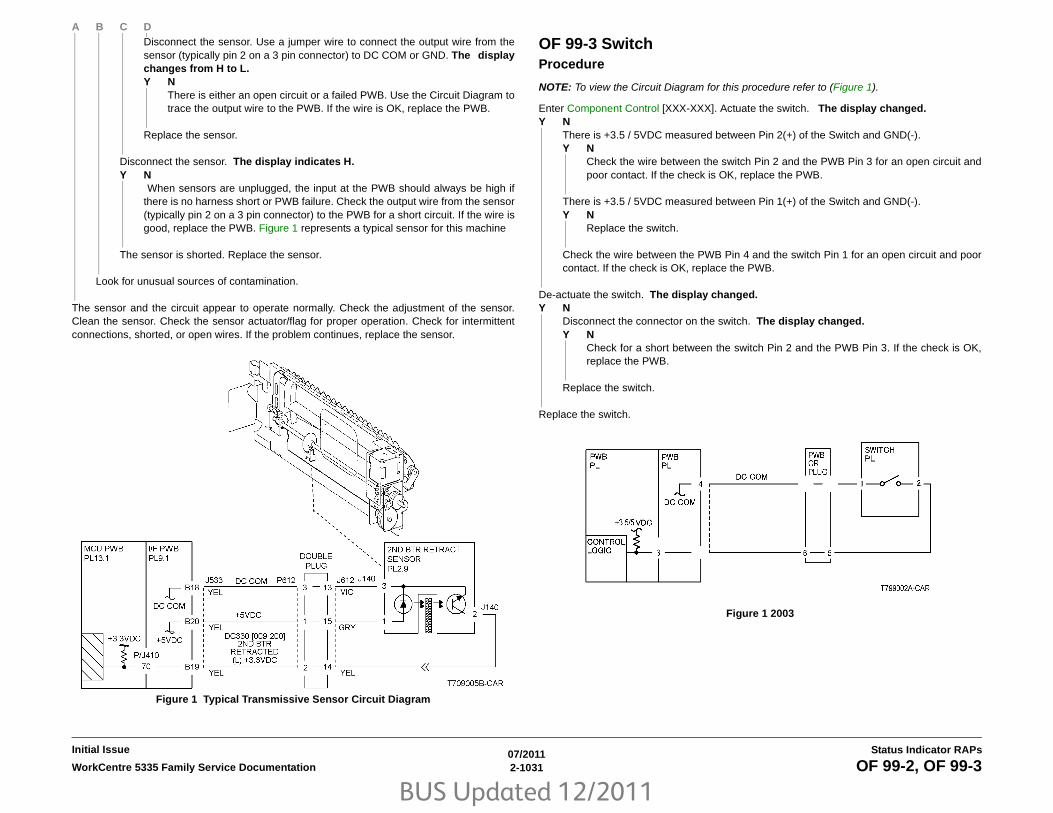
BUS Updated 12/2011
07/20112-1031WorkCentre 5335 Family Service Documentation OF 99-2, OF 99-3
Status Indicator RAPsInitial Issue
Disconnect the sensor. Use a jumper wire to connect the output wire from thesensor (typically pin 2 on a 3 pin connector) to DC COM or GND. The displaychanges from H to L.Y N
There is either an open circuit or a failed PWB. Use the Circuit Diagram totrace the output wire to the PWB. If the wire is OK, replace the PWB.
Replace the sensor.
Disconnect the sensor. The display indicates H.Y N
When sensors are unplugged, the input at the PWB should always be high ifthere is no harness short or PWB failure. Check the output wire from the sensor(typically pin 2 on a 3 pin connector) to the PWB for a short circuit. If the wire isgood, replace the PWB. Figure 1 represents a typical sensor for this machine
The sensor is shorted. Replace the sensor.
Look for unusual sources of contamination.
The sensor and the circuit appear to operate normally. Check the adjustment of the sensor.Clean the sensor. Check the sensor actuator/flag for proper operation. Check for intermittentconnections, shorted, or open wires. If the problem continues, replace the sensor.
Figure 1 Typical Transmissive Sensor Circuit Diagram
OF 99-3 SwitchProcedure
NOTE: To view the Circuit Diagram for this procedure refer to (Figure 1).
Enter Component Control [XXX-XXX]. Actuate the switch. The display changed.Y N
There is +3.5 / 5VDC measured between Pin 2(+) of the Switch and GND(-). Y N
Check the wire between the switch Pin 2 and the PWB Pin 3 for an open circuit andpoor contact. If the check is OK, replace the PWB.
There is +3.5 / 5VDC measured between Pin 1(+) of the Switch and GND(-). Y N
Replace the switch.
Check the wire between the PWB Pin 4 and the switch Pin 1 for an open circuit and poorcontact. If the check is OK, replace the PWB.
De-actuate the switch. The display changed.Y N
Disconnect the connector on the switch. The display changed.Y N
Check for a short between the switch Pin 2 and the PWB Pin 3. If the check is OK,replace the PWB.
Replace the switch.
Replace the switch.
Figure 1 2003
A B C D

BUS Updated 12/2011
07/20112-1032 WorkCentre 5335 Family Service DocumentationOF 99-4
Initial IssueStatus Indicator RAPs
OF 99-4 Generic Solenoid/Clutch RAPSolenoids and electric clutches are essentially electromagnets. Typically, a positive voltage isapplied to one end of a coil, and a current driver is connected to the other end. Control Logicswitches this driver to GND potential, actuating the magnet. Bi-directional solenoids have abipolar driver connected to each end. One leg is switched to 24 VDC and the other to GND.
Figure 1 is a circuit diagram of a typical solenoid.
Initial ActionsEnsure that there is no damage or binding in the solenoid or in any mechanical linkage. If thereis an Adjustment for the clutch or solenoid, make sure that the procedure was performed cor-rectly
ProcedureThe clutch/solenoid is always energized.Y N
Enter the component control code (Component Control) given in the RAP or the CircuitDiagram. Press the Start button The Clutch or solenoid energizes.Y N
Press the Stop button There is +24 VDC between the switched leg (J407 pin A6in the example, Figure 1) of the control PWB and GND.Y N
There is +24 VDC between the powered leg (J407 pin A7 in the example,Figure 1) of the control PWB and GND.Y N
Disconnect the connector (J407 in the example, Figure 1). There is +24VDC between the powered leg of the control PWB and GND.Y N
Refer to the 24 VDC wirenets. check the input power to the controlPWB. +24 VDC is present.Y N
Use the 24 VDC wirenets to troubleshoot the problem.
Replace the control PWB.
Check the wire in the powered leg of the circuit, (J407 pin A7 in the exam-ple, Figure 1) for a short circuit to GND. If the wire is OK, replace theclutch or solenoid.
Disconnect the connector (J407 in the example, Figure 1). Check continuitythrough the two wires and the clutch or solenoid. There is less than 100ohms between the two legs of the circuit.Y N
Disconnect the clutch or solenoid. Check continuity through the two wiresand the clutch or solenoid. There is less than 100 ohms across theclutch or solenoid.Y N
Replace the clutch or solenoid.
One of the two wires between the control PWB and the clutch or solenoidis open. Repair or replace the wiring as required.
Replace the control PWB.
Press the Start button. There is less than 1 VDC between the switched leg of thecontrol PWB and GND.Y N
Replace the PWB.
Replace the clutch or solenoid.
The clutch or solenoid appears to be functioning correctly. Refer to the Circuit Diagram forthe RAP that sent you here. Check the wires for loose connections or damage that maycause intermittent operation. Perform any required adjustments.
There is a short circuit on the switched leg (J407 pin A6 in the example) from the solenoid orclutch. Check the wire for a short circuit to GND. If the wire is OK, replace the solenoid. If theproblem persists, replace the controlling PWB.
Figure 1 Typical Solenoid/Clutch Circuit Diagram
A
A
B
B
C
C
D
D
E
E

BUS Updated 12/2011
07/20112-1033WorkCentre 5335 Family Service Documentation OF 99-6, OF 99-7
Status Indicator RAPsInitial Issue
OF 99-6 2 Wire Motor OpenProcedure
NOTE: Before performing this RAP, ensure that the motor is free to rotate.
NOTE: To view the Circuit Diagram for this procedure refer to (Figure 1).
Enter the Component Control [XXX-XXX].There is +24VDC measured between Pin 3(+) of the PWB and GND(-). Y N
There is +24VDC measured between the Motor Pin 2(+) of the Motor and GND(-). Y N
There is +24VDC measured between the Motor Pin 1(+) of the Motor and GND(-). Y N
There is +24VDC measured between the PWB Pin 4(+) of the PWB and GND(-). Y N
Replace the PWB.
Check the wire between the PWB Pin 4 and the Motor Pin 1 for an open circuitor poor contact.
Replace the motor.
Check the wire between the PWB Pin 3 and the Motor Pin 2 for an open circuit or poorcontact.
Replace the PWB.
Figure 1 Motor CD
OF 99-7 2 Wire Motor OnProcedure
NOTE: To view the Circuit Diagram for this procedure refer to (Figure 1).
Turn off the power. Remove the PWB connector. There is 10 Ohm’s or less measuredbetween the connector Pin 3 and the frame.Y N
Replace the PWB.
Check the wire between the connector Pin 3 and the motor Pin 2 for a short circuit.If the check is OK, replace the motor.
Figure 1 Motor CD

BUS Updated 12/2011
07/20112-1034 WorkCentre 5335 Family Service DocumentationOF 99-8
Initial IssueStatus Indicator RAPs
OF 99-8 Set Gate Solenoid OpenProcedure
NOTE: To view the Circuit Diagram for this procedure refer to (Figure 1).
There is +24VDC measured between the Nip/Release Solenoid Pin 1 (+) and GND (-).Y N
There is +24VDC measured between the PWB Pin 5 (+) and GND(-).Y N
Check +24VDC inputs on the PWB. If the check is OK, replace the PWB.
Check the wire between the PWB Pin 5 and the Nip/Release Solenoid Pin 1 for an opencircuit or poor contact.
Enter Component Control [XXX-XXX]. There is +24VDC measured between the PWB Pin 4(+) and GND(-).Y N
There is +24VDC measured between the Nip/Release Solenoid Pin 3 (+) and GND (-).Y N
Replace the Nip/Release Solenoid.
Check the wire between the PWB Pin 4 and the Nip/Release Solenoid Pin 3 for an opencircuit and poor contact.
Follow the following when the release caused a problem. Go to the Component Control [XXX-XXX]. There is +24VDC measured between the PWBPin 6 (+) and GND(-).Y N
There is +24VDC measured between the Nip/Release Solenoid Pin 2 (+) and GND (-)Y N
Replace the Nip/Release Solenoid.
Check the wire between the PWB Pin 6 and the Nip/Release Solenoid Pin 2 for an opencircuit or poor contact.
Replace the PWB.
Figure 1 Nip Solenoid CD

BUS Updated 12/2011
07/20112-1035WorkCentre 5335 Family Service Documentation OF 99-9
Status Indicator RAPsInitial Issue
OF 99-9 Multiple Wire MotorFor use on DC motors that:
• have 1 or 2 DC power inputs
• are controlled by 2 or more drivers
• have no DC COM connections for return power
• have no specific feedback circuits
Procedure
NOTE: To view the Circuit Diagram for this procedure refer to (Figure 1).
Connect black meter lead to ground. Measure voltage at each pin of J2 (example only, refer tothe actual Circuit Diagram for the correct voltage and connector designation). +24 VDC ismeasured at each pin.Y N
Disconnect J2. Measure voltage at P2-1 and P2-6. +24 VDC is measured.Y N
Switch machine off then on. Measure voltage at P2-1 and P2-6. +24 VDC is mea-sured.Y N
If an interlock circuit is present, check the interlock circuit. Repair as required. Ifthe interlock circuit is good, replace the PWB.
Check the motor wires for a short circuit. If the wires are good, replace the Motor.
Check the motor wires for obvious damage. If the wires are good, replace the Motor.
Replace the PWB. Figure 1 Motor CD

BUS Updated 12/2011
07/20112-1036 WorkCentre 5335 Family Service DocumentationOF 99-9
Initial IssueStatus Indicator RAPs

BUS Updated 12/2011
07/20113-1WorkCentre 5335 Family Service Documentation
Image QualityInitial Issue
3 Image Quality Image Quality RAPsIQ1 IOT Image Quality Entry RAP .................................................................................. 3-3IQ2 IIT Image Quality Entry RAP .................................................................................... 3-3IQ3 Low Image Density RAP .......................................................................................... 3-4IQ4 Wrinkled Image RAP ................................................................................................ 3-4IQ5 Residual Image (Ghosting) RAP .............................................................................. 3-5IQ6 Background RAP...................................................................................................... 3-5IQ7 Deletion RAP............................................................................................................ 3-6IQ8 Skew/Misregistration RAP........................................................................................ 3-6IQ9 Process Direction Bands, Streaks and Smears RAP ............................................... 3-7IQ10 Unfused Copy/Toner Offset RAP ........................................................................... 3-8IQ11 Repeating Bands, Streaks, Spots and Smears RAP.............................................. 3-8IQ12 Mottle RAP ............................................................................................................. 3-9IQ13 Spots RAP.............................................................................................................. 3-9IQ14 Black Prints RAP .................................................................................................... 3-10IQ15 Blank Image RAP ................................................................................................... 3-10
Copy Quality SpecificationsCopy Quality Specifications ............................................................................................ 3-13IQS1 Solid Area Density Specification ............................................................................ 3-16IQS2 Uniformity Specification ......................................................................................... 3-17IQS3 Exposure Level Specification................................................................................. 3-18IQS4 Lead Edge Registration Specification .................................................................... 3-19IQS5 Side Edge Registration Specification..................................................................... 3-20IQS6 Skew Specification................................................................................................. 3-21IQS7 Lead Edge Deletion Specification .......................................................................... 3-22IQS8 Trail Edge Deletion Specification ........................................................................... 3-23IQS9 Side Edge Deletion Specification........................................................................... 3-24IQS10 Resolution Specification....................................................................................... 3-25IQS11 Skips And Smears Specification .......................................................................... 3-26IQS12 Magnification Specification .................................................................................. 3-27IQS13 Background Specification .................................................................................... 3-28
Defect SamplesImage Defect Samples.................................................................................................... 3-29Auger Mark...................................................................................................................... 3-29Strobing (28mm or 14mm Pitch Density) ........................................................................ 3-30White Streaks (Process Direction) .................................................................................. 3-30Black Bands .................................................................................................................... 3-31Toner Contamination....................................................................................................... 3-31Toner Splattering............................................................................................................. 3-32White Spots (Irregular) .................................................................................................... 3-32Transparency Offset (80mm Pitch Ghosts) ..................................................................... 3-33Regular Blanks In Process Direction (Spots, Streaks, Bands etc.) ................................. 3-33Regular Toner Contamination In Process Direction (Spots, Streaks, Bands etc.) .......... 3-34Regular Toner Contamination In Process Direction (Side 2) .......................................... 3-35Transparency Blocking.................................................................................................... 3-35Moire Due To Interference With Copy Original ............................................................... 3-36
Light Background Due To Auto Exposure In Copies Of Originals With Frames ............. 3-36Fluctuation In Auto Exposure Values For Copies Of Originals Of Medium Density ........ 3-37Gradation Jump In Text & Photo Mode For 100 lpi Photo Originals ............................... 3-38CVT (Constant Velocity Transport) Scan Streaks ........................................................... 3-39Defects Related To Scan Print ........................................................................................ 3-39Moire In Text Mode (Fine) B/W Scan/Fax For 133 lpi Originals...................................... 3-40Black Discoloration Around White Texts In Medium Density Background ...................... 3-40

BUS Updated 12/2011
07/20113-2 WorkCentre 5335 Family Service Documentation
Initial IssueImage Quality

BUS Updated 12/2011
07/20113-3WorkCentre 5335 Family Service Documentation IQ1, IQ2
Image QualityInitial Issue
IQ1 IOT Image Quality Entry RAPInitial ActionsDetermine whether the problem occurs in Copy Mode or Printer Mode. If the problem occurs inCopy Mode, go to IQ2 IIT Image Quality Entry RAP.
ProcedureDetermine the problem and go to the relevant RAP.
IQ2 IIT Image Quality Entry RAPInitial ActionsClean the Platen Glass.
Clean the mirrors and lens with lint-free cloth.
Procedure Determine the problem and go to the relevant RAP.
Table 1 Print Quality
Problem Symptoms RAP
Low Image Density Overall low density of images. IQ3 RAP
Wrinkled Image The printed paper is wrinkled, folded or torn. IQ4 RAP
Residual Image (Ghosting)
Ghost images appear on the paper. Parts of the previous page or current page appear as ghost images on the paper.
IQ5 RAP
Background Toner smudges appear on the whole or part of the page. The smudges appear as extremely bright gray stains.
IQ6 RAP
Deletion Part of the image is missing. IQ7 RAP
Skew/Misregistration Printed images are not parallel to the edges of the paper. IQ8 RAP
Process Direction Bands, Streaks and Smears
Vertical black lines or white streaks running in the direc-tion of the paper orientation.
IQ9 RAP
Unfused Copy/Toner Offset
Printed images are not properly fused onto the paper. The images come off easily when rubbed.
IQ10 RAP
Repeating Bands, Streaks, Spots and Smears
Horizontal black lines or white streaks running in the direction of the paper orientation.
IQ11 RAP
Mottle Uneven printed image density. IQ12 RAP
Spots Toner spots are spread irregularly over the whole page. IQ13 RAP
Black Prints Paper is printed completely black. IQ14 RAP
Blank Image Paper is printed completely white. IQ15 RAP
Table 1 Image Quality
Problem Symptoms RAP
Low Image Density Overall low density of images. IQ3 RAP
Background Toner smudges appear on the whole or part of the page. The smudges appear as extremely bright gray stains.
IQ6 RAP
Process Direction Bands, Streaks and Smears
Vertical black lines or white streaks running in the direc-tion of the paper orientation.
IQ9 RAP
Repeating Bands, Streaks, Spots and Smears
Horizontal black lines or white streaks running in the direction of the paper orientation.
IQ11 RAP
Spots Toner spots are spread irregularly over the whole page. IQ13 RAP
Black Prints Paper is printed completely black. IQ14 RAP

BUS Updated 12/2011
07/20113-4 WorkCentre 5335 Family Service DocumentationIQ3, IQ4
Initial IssueImage Quality
IQ3 Low Image Density RAPOverall low density of images.
ProcedureCheck for dirt on the Platen Glass. The Platen Glass is clean.Y N
Clean the Platen Glass. If there is a stubborn stain, replace the Platen Glass.
Check the drum ground contact point for dirt and distortion. The drum ground contact pointis clean and there is no distortion.Y N
Clean the drum ground contact point and correct the distortion.
Remove the Xerographic Cartridge (PL 8.1) and reinstall. Turn the power Off/On and print.The problem reoccurs.Y N
End
Install a new Xerographic Cartridge (PL 8.1). Turn the power Off/On and print. The problemreoccurs.Y N
End
Set to print a black copy. During the print cycle, turn off the power after the feeding sound isheard (i.e. terminate processing midway through copying). Check the surface of the drum.There is a considerable amount of toner left on the surface of the drum. Y N
Replace the MCU PWB (PL 18.2). If the problem persists, replace the ESS PWB (PL35.2).
Replace the BTR. If the problem persists, replace the HVPS and the MCU PWB (PL 18.2).
IQ4 Wrinkled Image RAPThe printed paper is wrinkled, folded or torn.
ProcedureCheck the paper type. Paper used is within specifications.Y N
Use paper within specifications.
Use paper from a freshly opened packet. The problem reoccurs.Y N
End
Remove the Fuser Unit (PL 7.1) and reinstall. Turn the power Off/On and print. The problemreoccurs.Y N
End
Check for foreign substances and distortions in the paper delivery path. There are no foreignsubstances or distortions in the paper delivery path.Y N
Remove the foreign substances and correct the distortion.
Replace the Fuser Unit (PL 7.1).

BUS Updated 12/2011
07/20113-5WorkCentre 5335 Family Service Documentation IQ5, IQ6
Image QualityInitial Issue
IQ5 Residual Image (Ghosting) RAPGhost images appear on the paper. Parts of the previous page or current page appear as ghostimages on the paper.
ProcedureRemove the Xerographic Cartridge (PL 8.1) and reinstall. Turn the power Off/On and print.The problem reoccurs.Y N
End
Install a new Xerographic Cartridge (PL 8.1). Turn the power Off/On and print. The problemreoccurs.Y N
End
Remove the Fuser Unit (PL 7.1). Check for dirt on the surface of the Heat Roll. The surfaceof the Heat Roll is clean.Y N
Clean the Heat Roll. If there is difficulty in removing the dirt, replace the Fuser Unit (PL7.1)
Replace the MCU PWB (PL 18.1). If the problem persists, replace the ESS PWB (PL 35.2).
IQ6 Background RAPToner smudges appear on the whole or part of the page. The smudges appear as extremelybright gray stains.
ProcedureCheck for dirt on the Platen Glass. The Platen Glass is clean.Y N
Clean the Platen Glass. If there is a stubborn stain, replace the Platen Glass (PL 1.2).
Remove the Xerographic Cartridge (PL 8.1) and reinstall. Turn the power Off/On and print.The problem reoccurs.Y N
End
Install a new Xerographic Cartridge (PL 8.1). Turn the power Off/On and print. The problemreoccurs.Y N
End
Check the surface of the BTR for dirt and distortion. The surface of the BTR is clean andthere is no distortion.Y N
Clean the BTR. If there is distortion, replace the BTR (PL 6.1).
Remove the HVPS and reinstall. Turn the power Off/On and print. The problem reoccurs.Y N
End
Replace the MCU PWB (PL 18.1). If the problem persists, replace the HVPS and the ESSPWB (PL 35.2).

BUS Updated 12/2011
07/20113-6 WorkCentre 5335 Family Service DocumentationIQ7, IQ8
Initial IssueImage Quality
IQ7 Deletion RAPPart of the image is missing.
ProcedureCheck the paper type. Paper used is within specifications.Y N
Use paper within specifications.
Use paper from a freshly opened packet. The problem reoccurs.Y N
End
Remove the Xerographic Cartridge and reinstall. Turn the power Off/On and print. The prob-lem reoccurs.Y N
End
Install a new Xerographic Cartridge (PL 8.1). Turn the power Off/On and print. The problemreoccurs.Y N
End
Check the surface of the BTR for distortion. There is no distortion on the surface of theBTR.Y N
Replace the BTR (PL 6.1).
Replace the MCU PWB (PL 18.2). If the problem persists, replace the ESS PWB (PL 35.2).
IQ8 Skew/Misregistration RAPPrinted images are not parallel to the edges of the paper.
ProcedureCheck the location where the machine is installed. The machine is installed on a stable hor-izontal surface.Y N
Install the machine on a stable horizontal surface.
Remove the Xerographic Cartridge (PL 8.1) and reinstall. Turn the power Off/On and print.The problem reoccurs.Y N
End
Check the installation of the Paper Cassette. The Paper Cassette is correctly installed.Y N
Install the Paper Cassette correctly.
Check for distortion in the paper delivery path. There is no distortion in the paper deliverypath.Y N
Correct the distortion or replace the distorted part.
Replace the MCU PWB (PL 18.2). If the problem persists, replace the ESS PWB (PL 35.2).

BUS Updated 12/2011
07/20113-7WorkCentre 5335 Family Service Documentation IQ9
Image QualityInitial Issue
IQ9 Process Direction Bands, Streaks and Smears RAPVertical black lines or white streaks running in the direction of the paper orientation.
ProcedureCheck the IIT Carriage Mirrors for scratches and dirt. There are no scratches or dirt on themirrors.Y N
Clean the mirrors. If there is a scratch or stubborn stain, replace the Number1/Number2/Number3 Mirror (PL 1.4 & PL 1.5).
Remove the Xerographic Cartridge (PL 8.1) and reinstall. Turn the power Off/On and print.The problem reoccurs.Y N
End
Install a new Xerographic Cartridge (PL 8.1). Turn the power Off/On and print. The problemreoccurs.Y N
End
Check the surface of the BTR for dirt and distortion. The surface of the BTR is clean andthere is no distortion.Y N
Clean the BTR. If there is distortion, replace the BTR (PL 6.1).
Check for dirt in the paper delivery path. The paper delivery path is clean.Y N
Clean the paper delivery path.
Check the IIT Carriage Mirror. The mirror is clean and there is no distortion.Y N
Clean the mirror. If there is distortion, replace the mirror.
Remove the Fuser Unit (PL 7.1). Check for dirt on the surface of the Heat Roll. The surfaceof the Heat Roll is clean.Y N
Clean the Heat Roll. If there is difficulty in removing the dirt, replace the Fuser Unit (PL7.1).
Check the surface of the BTR for dirt and distortion. The surface of the BTR is clean andthere is no distortion.Y N
Clean the BTR. If there is distortion, replace the BTR (PL 6.1).
Check the IIT Carriage Mirror. The mirror is clean and there is no distortion.Y N
Clean the mirror. If there is distortion, replace the mirror.
Check the ROS Window for scratches and distortion. The ROS Window is clean and thereare no scratches.
Y NClean the ROS Window. If there is a scratch, replace the ROS Window.
Replace the ROS Unit (PL 2.1). If the problem persists, replace the MCU PWB (PL 18.2). If theproblem persists, replace the ESS PWB (PL 35.2).

BUS Updated 12/2011
07/20113-8 WorkCentre 5335 Family Service DocumentationIQ10, IQ11
Initial IssueImage Quality
IQ10 Unfused Copy/Toner Offset RAPPrinted images are not properly fused onto the paper. The images come off easily whenrubbed.
ProcedureCheck the paper type. Paper used is within specifications.Y N
Use paper within specifications.
Use paper stored under room conditions. The problem reoccurs.Y N
End
Check the power supply voltage. The voltage is within the specified range.Y N
Connect a power supply with voltage within the specified range.
Remove the Fuser Unit (PL 7.1) and reinstall. The problem reoccurs.Y N
End
Check the fusing temperature using the Diagnostics. A normal fusing temperature is set.Y N
Set a normal fusing temperature.
Replace the Fuser Unit (PL 7.1).
IQ11 Repeating Bands, Streaks, Spots and Smears RAPHorizontal black lines or white streaks running in the direction of the paper orientation.
ProcedureCheck the moving parts of the IIT Carriage for foreign substances and distortion. There areno foreign substances or distortion of the parts.Y N
Remove the foreign substances. If there is distortion in the Capstan Pulley, Capstan Shaftor Carriage Cable (PL 1.3), replace the parts accordingly.
Remove the Xerographic Cartridge (PL 8.1) and reinstall. Turn the power Off/On and print.The problem reoccurs.Y N
End
Install a new Xerographic Cartridge (PL 8.1). Turn the power Off/On and print. The problemreoccurs.Y N
End
Check the surface of the BTR for dirt and distortion. The surface of the BTR is clean andthere is no distortion.Y N
Clean the BTR. If there is distortion, replace the BTR (PL 6.1).
Check the pitch of the black streaks or blanks. The pitch of the black streaks or blanks areapprox.78mm (the circumference of the Heat Roll).Y N
Clean the Heat Roll. If there is difficulty in removing the dirt, replace the Fuser Unit (PL7.1).
Replace the ROS Unit (PL 2.1). If the problem persists, replace the MCU PWB (PL 18.2). If theproblem persists, replace the ESS PWB (PL 35.2).

BUS Updated 12/2011
07/20113-9WorkCentre 5335 Family Service Documentation IQ12, IQ13
Image QualityInitial Issue
IQ12 Mottle RAPUneven printed image density.
ProcedureCheck the paper type. Paper used is within specifications.Y N
Use paper within specifications.
Use paper from a freshly opened packet. The problem reoccurs.Y N
End
Remove the Xerographic Cartridge (PL 8.1) and reinstall. Turn the power Off/On and print.The problem reoccurs.Y N
End
Install a new Xerographic Cartridge (PL 8.1). Turn the power Off/On and print. The problemreoccurs.Y N
End
Check the surface of the BTR for dirt and distortion. The surface of the BTR is clean andthere is no distortion.Y N
Clean the BTR. If there is distortion, replace the BTR (PL 6.1).
Remove the HVPS and reinstall. Turn the power Off/On and print. The problem reoccurs.Y N
End
Replace the MCU PWB (PL 18.2). If the problem persists, replace the ESS PWB (PL 35.2).
IQ13 Spots RAPToner spots are spread irregularly over the whole page.
ProcedureCheck for dirt on the Platen Glass. The Platen Glass is clean.Y N
Clean the Platen Glass. If there is a stubborn stain, replace the Platen Glass (PL 1.2).
Remove the Xerographic Cartridge (PL 8.1) and reinstall. Turn the power Off/On and print.The problem reoccurs.Y N
End
Install a new Xerographic Cartridge (PL 8.1). Turn the power Off/On and print. The problemreoccurs.Y N
End
Check the surface of the BTR for dirt and distortion. The surface of the BTR is clean andthere is no distortion.Y N
Clean the BTR. If there is distortion, replace the BTR (PL 6.1).
Check for dirt in the paper delivery path. The paper delivery path is clean.Y N
Clean the paper delivery path.
Remove the Fuser Unit (PL 7.1). Check for dirt on the surface of the Heat Roll. The surfaceof the Heat Roll is clean.Y N
Clean the Heat Roll. If there is difficulty in removing the dirt, replace the Fuser Unit (PL7.1).
Check the paper type. Paper used is within specifications.Y N
Use paper within specifications.
Use paper from a freshly opened packet. The problem reoccurs.Y N
End
Replace the MCU PWB (PL 18.2). If the problem persists, replace the ESS PWB (PL 35.2).

BUS Updated 12/2011
07/20113-10 WorkCentre 5335 Family Service DocumentationIQ14, IQ15
Initial IssueImage Quality
IQ14 Black Prints RAPPaper is printed completely black.
BSD-Reference: BSD 6.8 - ROS Laser Control (1 of 2)
ProcedureCheck the moving parts of the IIT Carriage for foreign substances and distortion. There areno foreign substances or distortion of the parts.Y N
Remove the foreign substances. If there is distortion in the Capstan Pulley, Capstan Shaftor Carriage Cable (PL 1.3), replace the parts accordingly.
Remove the Xerographic Cartridge (PL 8.1) and reinstall. Turn the power Off/On and print.The problem reoccurs.Y N
End
Install a new Xerographic Cartridge (PL 8.1). Turn the power Off/On and print. The problemreoccurs.Y N
End
Remove the HVPS and reinstall. Turn the power Off/On and print. The problem reoccurs.Y N
End
Check the connections of P500 at the HVPS and P/J403 on the MCU PWB. The connec-tors are connected correctly.Y N
Connect the connectors.
Check the wires between P500 at the HVPS and P/J403 on the MCU PWB for an open circuitor a short circuit. The wires are conducting without an open circuit or a short circuit.Y N
Repair the open circuit or short circuit.
Check the wires between P/J160 and P/J170 on the ROS, and P/J405 on the MCU PWB;and between P/J401 on the MCU PWB and P/J328 on the ESS PWB for an open circuit or ashort circuit. The wires are conducting without an open circuit or a short circuit.Y N
Repair the open circuit or short circuit.
Replace the HVPS (PL 18.1). If the problem reoccurs, replace the ROS (PL 2.1). If the problemreoccurs, replace the MCU PWB (PL 18.2). If the problem reoccurs, replace the ESS PWB (PL35.2).
IQ15 Blank Image RAPPaper is printed completely white.
BSD-Reference: BSD 6.8 - ROS Laser Control (1 of 2)
ProcedureCheck the installation of the ROS (REP 6.2). The ROS is installed correctly.Y N
Install the ROS correctly (REP 6.2).
Check the drum ground contact point for dirt and distortion. The drum ground contact pointis clean and there is no distortion.Y N
Clean the drum ground contact point and correct the distortion.
Remove the Xerographic Cartridge (PL 8.1) and reinstall. Turn the power Off/On and print.The problem reoccurs.Y N
End
Install a new Xerographic Cartridge (PL 8.1). Turn the power Off/On and print. The problemreoccurs.Y N
End
Set to print a black copy. During the print cycle, turn off the power after the feeding sound isheard (i.e. terminate processing midway through copying). Check the surface of the drum.There is a considerable amount of toner left on the surface of the drum.Y N
Check the connections of P/J140 at the ROS and P/J404 on the MCU PWB. The con-nectors are connected correctly.Y N
Connect the connectors.
Check the installation of the ROS (REP 6.2). The ROS is installed correctly.Y N
Install the ROS correctly (REP 6.2).
Measure the voltage at P/J404 Pin 2 on the MCU PWB. The voltage is approx. +5VDC.Y N
Replace the MCU PWB (PL 18.2).
Check the wires between P/J140 at the ROS and P/J404 on the MCU PWB for an opencircuit or a short circuit. The wire are conducting without an open circuit or a shortcircuit.Y N
Repair the open circuit or short circuit.
Replace the ROS Unit (PL 2.1). If the problem persists, replace the MCU PWB (PL 18.2).
A
BUS Updated 12/2011
07/20113-11WorkCentre 5335 Family Service Documentation IQ15
Image QualityInitial Issue
Replace the BTR (PL 6.1). If the problem persists, replace the HVPS (PL 18.1) and the MCUPWB (PL 18.2).
A

BUS Updated 12/2011
07/20113-12 WorkCentre 5335 Family Service DocumentationIQ15
Initial IssueImage Quality

BUS Updated 12/2011
07/20113-13WorkCentre 5335 Family Service Documentation
Image QualityInitial Issue
Copy Quality SpecificationsTest PatternsProcedure
Test Patterns
1. The following test patterns are used with those products.
Standard Test Pattern: USCO/XCL, 82P524; XL, 82P521.
Output Reference Guide: USCO/XL, SIR 542.00.
Visual Scale: USCO/XL, 82P448
Standard Test Pattern, 82P524/82P521Procedure
This test pattern is the standard multinational test pattern used for the evaluation of copy qual-ity for those products.
Side A (Figure 1) is used to evaluate solid area density, uniformity, exposure level, registration,skew, and lead edge deletion.
Figure 1 Standard Test Pattern (Side A)

BUS Updated 12/2011
07/20113-14 WorkCentre 5335 Family Service Documentation
Initial IssueImage Quality
Side B (Figure 2) is used to evaluate skips and smears, resolution, and magnification.
Figure 2 Standard Test Pattern (Side B)

BUS Updated 12/2011
07/20113-15WorkCentre 5335 Family Service Documentation
Image QualityInitial Issue
Output Reference Guide, SIR542.00Procedure
This test document serves as a reference guide for measuring the solid area density of theSide A copies of the test pattern, 82P524 and 82P521 (Figure 3).
Figure 3 Output Reference Guide, SIR542.00

BUS Updated 12/2011
07/20113-16 WorkCentre 5335 Family Service Documentation
Initial IssueImage Quality
IQS1 Solid Area Density SpecificationProcedureUsing Side A of the Standard Test Pattern (Figure 1), evaluate the solid area density per thefollowing table.
Figure 1 Standard Test Pattern (Side A)
Table 1 Solid Area Density Specification
Copies
Copy Quality Mode Specification
Input Density
Output Density
1 Normal The 1.0 solid area density nearest the center of the copy should be the 1.0 solid area density block on the Output Reference Guide.
1.0 1.0

BUS Updated 12/2011
07/20113-17WorkCentre 5335 Family Service Documentation
Image QualityInitial Issue
IQS2 Uniformity SpecificationProcedureMake a copy of Side A of the Standard Test Pattern.
The density of all the 1.0 blocks are same (Figure 1).
Figure 1 Standard Test Pattern 1.0 Blocks

BUS Updated 12/2011
07/20113-18 WorkCentre 5335 Family Service Documentation
Initial IssueImage Quality
IQS3 Exposure Level SpecificationProcedureUse Side A of the Standard Test Pattern.
In the Standard Copy mode, and with the copy darkness control set at the middle of the scale,the 0.20G(Or0.20B) line pair must be copied completely.
In the Standard Copy mode, and with the copy darkness control set two level lighter from at themiddle of the scale, the 0.10 line pair should not copy at all (Figure 1).
Figure 1 Exposure Level

BUS Updated 12/2011
07/20113-19WorkCentre 5335 Family Service Documentation
Image QualityInitial Issue
IQS4 Lead Edge Registration SpecificationProcedureUse Side A of the Standard Test Pattern.
The center 10 mm reference line on the copy must be 10 mm (plus or minus the ranges listedin the following charts) from the lead edge of a 100% copy (Figure 1).
Figure 1 Lead Edge Registration
Table 1 Specification of Lead Edge Registration
Configuration Range
Platen (Simplex) +/-1.6mm
Platen (Duplex) +/-2.0mm
Platen (MPT) +/-2.2mm
DADF (Simplex) +/-2.2mm
DADF (Duplex) +/-3.0mm

BUS Updated 12/2011
07/20113-20 WorkCentre 5335 Family Service Documentation
Initial IssueImage Quality
IQS5 Side Edge Registration SpecificationProcedureUse Side A of the Standard Test Pattern.
For a copy that is folded in half, the crease in the copy should be within the following rangesfrom the center line of a 100% copy (Figure 1).
Figure 1 Side Edge Registration
Table 1 Specification of Side Edge Registration
Configuration Range
Platen (Simplex) +/-2.1mm
Platen (Duplex) +/-2.5mm
Platen (MPT) +/-3.0mm
DADF (Simplex) +/-2.9mm
DADF (Duplex) +/-3.2mm

BUS Updated 12/2011
07/20113-21WorkCentre 5335 Family Service Documentation
Image QualityInitial Issue
IQS6 Skew SpecificationProcedureUse Side A of the Standard Test Pattern.
Skew must be within the following ranges (with respect to each other) at the two 10 mm refer-ence lines shown (Figure 1).
Figure 1 Skew
Table 1 Specification of Skew
Configuration Range
Platen (Simplex) +/-1.42
Platen (Duplex) +/-1.87
Platen (MPT) +/-1.78
DADF (Simplex) +/-2.04
DADF (Duplex) +/-2.40

BUS Updated 12/2011
07/20113-22 WorkCentre 5335 Family Service Documentation
Initial IssueImage Quality
IQS7 Lead Edge Deletion SpecificationProcedureUse Side A of the Standard Test Pattern.
The image deleted intentionally along the lead edge must be 2.0 mm from the lead edge of thecopy (Figure 1).(maximum is 4mm)
Figure 1 Lead Edge Deletion

BUS Updated 12/2011
07/20113-23WorkCentre 5335 Family Service Documentation
Image QualityInitial Issue
IQS8 Trail Edge Deletion SpecificationProcedureUse Side A of the Standard Test Pattern.
The image deleted intentionally along the trail edge must be 2mm from the trail edge of thecopy (Figure 1). (maximum is 4mm)
Figure 1 Trail Edge Deletion

BUS Updated 12/2011
07/20113-24 WorkCentre 5335 Family Service Documentation
Initial IssueImage Quality
IQS9 Side Edge Deletion SpecificationProcedureUse Side A of the Standard Test Pattern.
The image deleted intentionally along both of side edge must be 2mm from the side edge ofthe copy (Figure 1). (maximum is 4mm)
Figure 1 Side Edge Deletion

BUS Updated 12/2011
07/20113-25WorkCentre 5335 Family Service Documentation
Image QualityInitial Issue
IQS10 Resolution SpecificationProcedureUse Side B of the Standard Test Pattern.
The complete resolution of designated LP/mm lines for specific magnification percentages islisted in Table below.
It is also required that the designated LP/mm lines be resolved in the top-to-bottom directionand the side-to-side direction over the entire copy (Figure 1).
Figure 1 Resolution
Table 1 Resolution Specifications
Magnification(%) Resolution LP/mm
70 2.5
100 4.3
141 3.5
200 3.5

BUS Updated 12/2011
07/20113-26 WorkCentre 5335 Family Service Documentation
Initial IssueImage Quality
IQS11 Skips And Smears SpecificationProcedureUse Side B of the Standard Test Pattern.
[Reduction]
Except for the first 2 mm from the lead edge of the copy, 1.8 ladder chart must be completelyresolved.
[100% /Enlargement]
Except for the first 2 mm from the lead edge of the copy, 2.5 ladder chart must be completelyresolved (Figure 1).
Figure 1 Skips and Smears
Table 1 Skips and Smears Specifications
Magnification(%) Ladder LP/mm
70 1.8
100 2.5
141 2.5
200 2.5

BUS Updated 12/2011
07/20113-27WorkCentre 5335 Family Service Documentation
Image QualityInitial Issue
IQS12 Magnification SpecificationProcedureUse Side B of the Standard Test Pattern.
The tolerance for each magnification setting in the lead edge to trail edge direction and thefront to rear direction are listed in Table below.
Refer to Figure 1 for the areas to be measured. For 65% and 101%, use areas A and B for themagnification in the lead edge to trail edge direction; and areas C and D for magnification inthe front to rear direction. For 154% use areas A and E for magnification in the lead edge totrail edge direction; and areas C and F for magnification in the front to rear direction.
Figure 1 Areas of Side B to be Measured
Table 1 Magnification Specifications
Magnification(%) Measurement
65 130+/-2mm
101 202+/-2mm
154 154+/-2mm
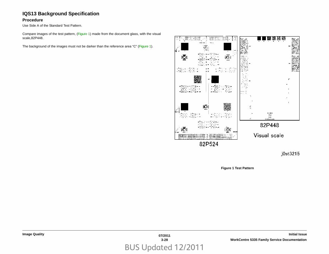
BUS Updated 12/2011
07/20113-28 WorkCentre 5335 Family Service Documentation
Initial IssueImage Quality
IQS13 Background SpecificationProcedureUse Side A of the Standard Test Pattern.
Compare images of the test pattern, (Figure 1) made from the document glass, with the visualscale,82P448.
The background of the images must not be darker than the reference area “C” (Figure 1).
Figure 1 Test Pattern

BUS Updated 12/2011
07/20113-29WorkCentre 5335 Family Service Documentation Auger Mark
Image QualityInitial Issue
Image Defect SamplesIOT
The following figures contain examples of defects and their possible causes.
• Auger Mark
• Strobing (28mm or 14mm Pitch Density)
• White Streaks (Process Direction)
• Black Bands
• Toner Contamination
• Toner Splattering
• White Spots (Irregular)
• Transparency Offset (80mm Pitch Ghosts)
• Regular Blanks In Process Direction (Spots, Streaks, Bands etc.)
• Regular Toner Contamination In Process Direction (Spots, Streaks, Bands etc.)
• Regular Toner Contamination In Process Direction (Side 2)
• Transparency Blocking
IIT
The following figures contain examples of defects and their possible causes.
• Moire Due To Interference With Copy Original
• Light Background Due To Auto Exposure In Copies Of Originals With Frames
• Fluctuation In Auto Exposure Values For Copies Of Originals Of Medium Density
• Gradation Jump In Text & Photo Mode For 100 lpi Photo Originals
• CVT (Constant Velocity Transport) Scan Streaks
• Defects Related To Scan Print
• Moire In Text Mode (Fine) B/W Scan/Fax For 133 lpi Originals
• Black Discoloration Around White Texts In Medium Density Background
Auger Mark
Figure 1 Auger Mark Defect Sample
Cause1. The Developer Magnetic Roll magnetic field failed.
2. There was a drop in the level of developer material.
Corrective Action1. Replace the Xerographic Cartridge (PL 8.1).
NOTE: This may occur immediately after a new CRU is installed. -> Correct by feeding afew sheets of paper.

BUS Updated 12/2011
07/20113-30 WorkCentre 5335 Family Service DocumentationStrobing (28mm or 14mm Pitch Density), White
Initial IssueImage Quality
Strobing (28mm or 14mm Pitch Density)
Figure 1 Strobing (28mm or 14mm Pitch Density) Defect Sample
Cause1. Developer Magnetic Roll bias.
Corrective Action1. Replace the Xerographic Cartridge(PL 8.1).
White Streaks (Process Direction)
Figure 1 White Streaks (Process Direction) Defect Sample
Cause1. Foreign substances are blocking the ROS Laser.
2. Developer material clogging on the Developer Magnetic Roll due to foreign substances.
Corrective Action1. Clean the light path between the ROS and the Xerographic Cartridge and the seal glass.
2. Replace the Xerographic Cartridge (PL 8.1).

BUS Updated 12/2011
07/20113-31WorkCentre 5335 Family Service Documentation Black Bands, Toner Contamination
Image QualityInitial Issue
Black Bands
Figure 1 Black Bands Defect Sample
Cause1. The developer material is not well mixed.
Corrective Action1. Mix the developer material by processing blank paper.
Toner Contamination
Figure 1 Toner Contamination Defect Sample
Cause1. Cloud toner dropped from the Xerographic Cartridge.
Corrective Action1. Mix the developer material by processing blank paper.
2. Replace the Xerographic Cartridge (PL 8.1).

BUS Updated 12/2011
07/20113-32 WorkCentre 5335 Family Service DocumentationToner Splattering, White Spots (Irregular)
Initial IssueImage Quality
Toner Splattering
Figure 1 Toner Splattering Defect Sample)
Cause1. Paper size mismatch occurred (tray settings and paper size are different).
2. The resistance of the paper increased under dry conditions.
Corrective Action1. Check the tray settings.
2. Use paper from a freshly opened packet.
White Spots (Irregular)
Figure 1 White Spots (Irregular) Defect Sample)
Cause1. The resistance of the paper increased under dry conditions.
Corrective Action1. Use paper from a freshly opened packet.

BUS Updated 12/2011
07/20113-33WorkCentre 5335 Family Service Documentation Transparency Offset (80mm Pitch Ghosts), Regular
Image QualityInitial Issue
Transparency Offset (80mm Pitch Ghosts)
Figure 1 Transparency Offset (80mm Pitch Ghosts) Defect Sample
Cause1. Transparencies were processed in Plain Paper mode.
Corrective Action1. Select Transparency mode.
Regular Blanks In Process Direction (Spots, Streaks, Bands etc.)
Figure 1 Regular Blanks In Process Direction (Spots, Streaks, Bands etc.) Defect Sam-ple
Cause1. 94mm pitch -> Drum: Scratches or foreign substances
2. 28mm pitch -> Developer Roll: Developer material fixed on the Developer Roll
3. 44mm pitch -> Charger: Scratches or foreign substances
4. 80mm pitch -> Fuser H/R: Scratches or foreign substances
Corrective Action1. 1, 4: Clean or replace the Xerographic Cartridge (PL 8.1) or the Fuser Unit (PL 7.1).
2. 2, 3: Replace the Xerographic Cartridge (PL 8.1).

BUS Updated 12/2011
07/20113-34 WorkCentre 5335 Family Service DocumentationRegular Toner Contamination In Process Direction
Initial IssueImage Quality
Regular Toner Contamination In Process Direction (Spots, Streaks, Bands etc.)
Figure 1 Regular Toner Contamination In Process Direction (Spots, Streaks, Bands etc.) Defect Sample
Cause1. 94mm pitch -> Drum: Scratches or foreign substances
2. 28mm pitch -> Magnetic Roll: Developer material fixed on the Magnetic Roll
3. 44mm pitch -> BCR: Scratches or foreign substances
4. 80mm pitch -> Heat Roll: Scratches or foreign substances
5. 19mm pitch -> Fuser Roll-Exit: Dirt
6. 44mm pitch -> Registration: Dirt
Corrective Action1. 1, 4, 5, 6: Clean or replace the Xerographic Cartridge (PL 8.1) or the Fuser Unit (PL 7.1).
2. 2, 3: Replace the Xerographic Cartridge (PL 8.1).

BUS Updated 12/2011
07/20113-35WorkCentre 5335 Family Service Documentation Regular Toner Contamination In Process Direction
Image QualityInitial Issue
Regular Toner Contamination In Process Direction (Side 2)
Figure 1 Regular Toner Contamination In Process Direction (Side 2) Defect Sample
Cause1. 94mm pitch -> Fuser Pressure Roll: Scratches or foreign substances
2. 59mm pitch -> BRT Roll: Dirt, scratches or paper size mismatch
3. 44mm pitch -> Pinch Roll: Dirt
Corrective Action1. 1, 2, 3: Clean or replace the relevant parts.
2. 2: Change the tray settings.
Transparency Blocking
Figure 1 Transparency Blocking Sample Image
Cause1. Transparencies were continuously printed in Plain Paper mode.
Corrective Action1. Select Transparency mode.

BUS Updated 12/2011
07/20113-36 WorkCentre 5335 Family Service DocumentationMoire Due To Interference With Copy Original, Light
Initial IssueImage Quality
Moire Due To Interference With Copy OriginalCauseWhen copying, interference with the original may cause moire. Combinations of certain anglesof screen ruling near 150lpi and Reduce/Enlarge ratio may cause moire. Precautions shouldbe taken during enlargement.
Corrective Action• Reduce sharpness.
Secondary defect: Text is blurred.
• Make copies at a different Reduce/Enlarge ratio.
• Change the orientation of the original.
Light Background Due To Auto Exposure In Copies Of Originals With FramesWhen Auto Exposure is turned [On] for originals with dark frames along the Lead RegistrationEdge, the suppression value is set so large such that areas of medium density appearextremely light.
Figure 1 Light Background (in circled area for example) Due To Auto Exposure In Cop-ies Of Originals With Frames Defect Sample
CauseAuto Exposure performs background detection of images at a distance of up to 10mm from theLead Registration Edge. As there were dark frames along the Lead Registration Edge, AutoExposure could not detect the original background density. Therefore, Auto Exposure was per-formed based on the density of the frames.

BUS Updated 12/2011
07/20113-37WorkCentre 5335 Family Service Documentation Light Background Due To Auto Exposure In Copies
Image QualityInitial Issue
Corrective Action• Disable Auto Exposure.
Fluctuation In Auto Exposure Values For Copies Of Originals Of Medium DensityWhen Auto Exposure is turned [On] for originals with background of medium density (0.5G),the effectiveness of Auto Exposure fluctuates for each job.
CauseAs medium density (0.5G) is near the upper limit value for background detection, the AutoExposure value fluctuates according to the result of background detection that varies accord-ing to the variations in the density of the original and how the original is placed.
Corrective Action• Disable Auto Exposure.

BUS Updated 12/2011
07/20113-38 WorkCentre 5335 Family Service DocumentationGradation Jump In Text & Photo Mode For 100 lpi
Initial IssueImage Quality
Gradation Jump In Text & Photo Mode For 100 lpi Photo OriginalsIn Text mode, making copies of images of 100 lpi (halftone dot) gradation may result in a tonejump.
Figure 1 Gradation Jump In Text & Photo Mode For 100 lpi Photo Originals Defect Sam-ple
CauseAs Text & Photo mode gives priority to 175 lpi halftone dots and text quality, Sharpen Edge isperformed for lower lpi.
Corrective Action• Make copies in Photo mode.
Secondary defect: Text is blurred.
• Change the setting from [More Text] to [Text], and then to [Photo] and [More Photo].
Secondary defect: Image quality of photographs deteriorate in [More Text] and [Text] set-tings. Text becomes blurred in [More Photo] and [Photo] settings.

BUS Updated 12/2011
07/20113-39WorkCentre 5335 Family Service Documentation CVT (Constant Velocity Transport) Scan Streaks,
Image QualityInitial Issue
CVT (Constant Velocity Transport) Scan StreaksStreaks may occur in the CVT, even if they do not occur in the Platen.
CauseEven though CVT streak detection is performed for both color and B/W scans, there may becases where foreign substances on the CVT Glass could not be detected and removed.
Corrective Action• Clean the CVT Glass.
Defects Related To Scan PrintMoire may occur when scanned images are printed.
CauseInterference with the printer screen and printer driver resolution conversion processing by theoriginal causes moire.
Corrective Action• Reduce sharpness.
Secondary defect: Text is blurred.

BUS Updated 12/2011
07/20113-40 WorkCentre 5335 Family Service DocumentationMoire In Text Mode (Fine) B/W Scan/Fax For 133 lpi
Initial IssueImage Quality
Moire In Text Mode (Fine) B/W Scan/Fax For 133 lpi OriginalsDuring Fax Scan and B/W Scan mode, moire occurs in Text mode halftone dot images. Or,moire is especially obvious in Text mode (Fine) 133 lpi halftone dot images.
CauseIn Text mode, text is given priority, causing halftone dot moires.
Corrective Action• Change from Text mode to Text & Photo mode or Photo mode.
However, as the amount of data increases in Text & Photo mode, the machine takes alonger time for transmission.
Black Discoloration Around White Texts In Medium Density BackgroundBlack discoloration occurs around white texts with a certain background density, causing diffi-culties in reading the text.
CauseDiscoloration occurs during resolution conversion in Fax Send.
Due to separation error in text graphic separation, parts determined as text are darkened andare output as graphics that look like dark smears.
Occurrences and severity of the occurrences vary according to the combinations of Send/Receive type, Send route and Receive settings.
Corrective Action• Perform sending and document storage according to the capabilities of the receiver.
It is possible to suppress resolution conversion during Send/Receive by preventing a mis-match in Send image quality (resolution).
• Change the setting for resolution conversion processing to [More Photo].
Secondary defect: As this reduces the sensitivity for separation between text and photo-graphs, edges appear less smooth.

BUS Updated 12/2011
07/20114-1WorkCentre 5335 Family Service Documentation
Repairs & AdjustmentsInitial Issue
4 Repairs & AdjustmentsREPAIRS
3. ESS - MCU PWBsREP 3.1 HDD .................................................................................................................. 4-3REP 3.2 ESS Chassis Assembly .................................................................................... 4-4REP 3.3 ESS PWB ......................................................................................................... 4-5REP 3.4 AC Driver PWB ................................................................................................. 4-7REP 3.5 MCU PWB ........................................................................................................ 4-8REP 3.6 Main LVPS........................................................................................................ 4-10
4. Main DriveREP 4.1 Main Drive......................................................................................................... 4-11
5. DADFREP 5.1 DADF ................................................................................................................ 4-13REP 5.2 DADF Platen Cushion....................................................................................... 4-14REP 5.3 DADF Front Cover ............................................................................................ 4-15REP 5.4 DADF Rear Cover............................................................................................. 4-15REP 5.5 DADF Feeder Assembly ................................................................................... 4-16REP 5.6 DADF PWB....................................................................................................... 4-18REP 5.7 Left Counter Balance ........................................................................................ 4-19REP 5.8 Right Counter Balance...................................................................................... 4-20REP 5.9 DADF Document Tray ...................................................................................... 4-21REP 5.10 Top Cover ....................................................................................................... 4-23REP 5.11 Harness Guide and Wire Harness .................................................................. 4-23REP 5.12 DADF Registration Motor................................................................................ 4-25REP 5.13 DADF Feed Motor........................................................................................... 4-26REP 5.14 Registration Chute .......................................................................................... 4-27REP 5.15 Retard Chute .................................................................................................. 4-28REP 5.16 Takeaway Roll ................................................................................................ 4-28REP 5.17 Sensor Bracket ............................................................................................... 4-31REP 5.18 Nudger Roll, Feed Roll ................................................................................... 4-31REP 5.19 Retard Roll ...................................................................................................... 4-33
6. IIT/ScannerREP 6.1 Platen Cushion ................................................................................................. 4-35REP 6.2 ROS Assembly ................................................................................................. 4-36REP 6.3 Platen Glass ..................................................................................................... 4-39REP 6.4 CCD Lens Assembly......................................................................................... 4-39REP 6.5 Front/Rear Carriage Cable ............................................................................... 4-40REP 6.6 LED Lamp PWB................................................................................................ 4-44REP 6.7 Lamp Wire Harness .......................................................................................... 4-45REP 6.8 Light Guide ....................................................................................................... 4-47REP 6.9 Carriage Motor.................................................................................................. 4-48REP 6.10 IIT PWB .......................................................................................................... 4-49REP 6.11 Control Panel Assembly ................................................................................. 4-51
7. Paper TraysREP 7.1 Paper Trays 1, 2, 3, and 4 Assembly................................................................ 4-53
REP 7.2 MSI Assembly ................................................................................................... 4-54REP 7.3 Tray 3 Cable ..................................................................................................... 4-55REP 7.4 Tray 4 Cable ..................................................................................................... 4-58
8. Paper FeedersREP 8.1 Tray 1 Feeder Assembly................................................................................... 4-61REP 8.2 Tray 2 Feeder Assembly................................................................................... 4-63REP 8.3 Tray 3 Feeder Assembly................................................................................... 4-64REP 8.4 Tray 4 Feeder Assembly................................................................................... 4-65REP 8.5 Feed, Nudger, Retard Roll ................................................................................ 4-66REP 8.6 MSI Feed Roll ................................................................................................... 4-67REP 8.7 Takeaway Motor Assembly............................................................................... 4-68
9. XerographicsREP 9.1 Xerographic Cartridge Guide Assembly............................................................ 4-69REP 9.2 Xerographic Interlock Switch ............................................................................ 4-74REP 9.3 Humidity / Temperature Sensor ........................................................................ 4-74REP 9.4 HVPS ................................................................................................................ 4-75REP 9.5 Toner Cartridge Guide ...................................................................................... 4-77REP 9.6 Toner Dispense Motor ...................................................................................... 4-77
10 DuplexREP 10.1 Duplex Motor................................................................................................... 4-81REP 10.2 Duplex Sensor ................................................................................................ 4-82REP 10.3 Fuser............................................................................................................... 4-84REP 10.4 Fuser Exit Sensor ........................................................................................... 4-84REP 10.5 Exit 2 Transport Assembly .............................................................................. 4-85REP 10.6 Exit 2 Guide Assembly / Exit Gate .................................................................. 4-88REP 10.7 Exit 2 Sensor / Exit Gate Solenoid.................................................................. 4-88REP 10.8 Left Hand Chute Interlock Switch.................................................................... 4-89REP 10.9 Exit 2 Motor..................................................................................................... 4-90REP 10.10 Offset Motor .................................................................................................. 4-91REP 10.11 OTC Home Position Sensor.......................................................................... 4-92REP 10.12 Registration Transport .................................................................................. 4-92
12. Integrated FinisherREP 12.1 Integrated Office Finisher................................................................................ 4-95REP 12.2 Paddle Belt...................................................................................................... 4-96REP 12.3 Sub Paddle Solenoid ...................................................................................... 4-99REP 12.5 Staple Assembly ............................................................................................. 4-100REP 12.6 Set Clamp Home Sensor ................................................................................ 4-101REP 12.7 Exit Roll Assembly .......................................................................................... 4-102REP 12.8 Pinch Roll........................................................................................................ 4-104REP 12.9 Finisher Entrance Sensor ............................................................................... 4-105REP 12.10 Compiler Exit Sensor .................................................................................... 4-106REP 12.11 Main Paddle Shaft Assembly ........................................................................ 4-108REP 12.12 Lower Chute Assembly ................................................................................. 4-110REP 12.13 Entrance Roll Assembly................................................................................ 4-112

BUS Updated 12/2011
07/20114-2 WorkCentre 5335 Family Service Documentation
Initial IssueRepairs & Adjustments
REP 12.14 Upper Chute Assembly................................................................................. 4-114REP 12.15 Finisher PWB................................................................................................ 4-115REP 12.16 Stacker Tray Assembly................................................................................. 4-116REP 12.17 Stacker Shaft Assembly................................................................................ 4-117REP 12.18 Stacker Motor ............................................................................................... 4-120REP 12.19 Stacker Sensor ............................................................................................. 4-121REP 12.20 Compiler Assembly....................................................................................... 4-122REP 12.21 Set Clamp Shaft............................................................................................ 4-124REP 12.22 Eject Belt....................................................................................................... 4-126REP 12.23 Eject/Set Clamp Motor Assembly ................................................................. 4-127REP 12.24 Rear Tamper Home Sensor.......................................................................... 4-129REP 12.25 Eject Shaft Assembly.................................................................................... 4-130REP 12.26 Front /Rear Tamper Motor Assembly ........................................................... 4-132REP 12.27 Front Tamper Home Sensor ......................................................................... 4-134REP 12.28 Eject Clamp Home Sensor ........................................................................... 4-135REP 12.29 Stack Height Sensor ..................................................................................... 4-136
13. Office Finisher LXREP 13.1 H-Transport Assembly (Office Finisher LX) .................................................... 4-139REP 13.2 Hole Punch Assembly (Office Finisher LX)..................................................... 4-139REP 13.3 H-Transport Belt (Office Finisher LX) ............................................................. 4-140REP 13.4 H-Transport Motor (Office Finisher LX) .......................................................... 4-140REP 13.5 Finisher LX Undocking.................................................................................... 4-141REP 13.6 Front Cover Assembly (Office Finisher LX) .................................................... 4-142REP 13.7 Rear Upper Cover (Office Finisher LX)........................................................... 4-142REP 13.8 Rear Lower Cover (Office Finisher LX)........................................................... 4-143REP 13.9 Eject Cover (Office Finisher LX) ..................................................................... 4-143REP 13.10 Foot Cover (Office Finisher LX) .................................................................... 4-145REP 13.11 Stacker Lower Cover (Office Finisher LX) .................................................... 4-146REP 13.12 Stacker Upper Cover (Office Finisher LX) .................................................... 4-146REP 13.13 Stack Height Sensors 1 and 2 (Office Finisher LX) ...................................... 4-147REP 13.14 Sub Paddle Solenoid Assembly (Office Finisher LX).................................... 4-147REP 13.15 Stapler Motor (Office Finisher LX) ................................................................ 4-148REP 13.16 Finisher Stapler Assembly (Office Finisher LX) ............................................ 4-149REP 13.17 Compiler Tray Assembly (Office Finisher LX)............................................... 4-150REP 13.18 Crease Assembly (Office Finisher LX).......................................................... 4-160REP 13.19 Stacker Elevator Motor (Office Finisher LX) ................................................. 4-161REP 13.20 Stacker Tray (Office Finisher LX) ................................................................. 4-162REP 13.21 Eject Belt (Office Finisher LX)....................................................................... 4-162REP 13.22 Eject Motor Assembly (Office Finisher LX) ................................................... 4-163REP 13.23 Finisher PWB (Office Finisher LX)................................................................ 4-163REP 13.24 Finisher LVPS (Office Finisher LX)............................................................... 4-164REP 13.25 Eject Motor (Office Finisher LX).................................................................... 4-164REP 13.26 Front/Rear Tamper Motor (Office Finisher LX) ............................................. 4-165REP 13.27 Front/Rear Tamper Home Sensors (Office Finisher LX) .............................. 4-165REP 13.28 Compiler No Paper Sensor (Office Finisher LX)........................................... 4-166REP 13.29 Front/Rear Carriage Assembly (Office Finisher LX) ..................................... 4-167REP 13.30 Booklet PWB (Office Finisher LX)................................................................. 4-167REP 13.31 Booklet Maker Assembly (Office Finisher LX) .............................................. 4-168REP 13.32 Booklet Front Cover (Office Finisher LX)...................................................... 4-170REP 13.33 Booklet Rear Cover (Office Finisher LX) ...................................................... 4-171REP 13.34 Booklet Top Cover (Office Finisher LX) ........................................................ 4-172
REP 13.35 Booklet PWB Cover (Office Finisher LX) ...................................................... 4-172REP 13.36 Booklet Left Cover (Office Finisher LX) ........................................................ 4-173REP 13.37 Booklet Front/Rear Stapler (Office Finisher LX) ........................................... 4-173REP 13.38 Booklet Stapler Move Motor (Office Finisher LX).......................................... 4-175
19. High Capacity FeederREP 19.1 HCF Tray 6 ..................................................................................................... 4-177REP 19.2 HCF Feeder .................................................................................................... 4-177REP 19.3 HCF Undocking............................................................................................... 4-178REP 19.4 HCF Tray Cables ............................................................................................ 4-179REP 19.5 HCF Feed, Nudger, Retard Rolls.................................................................... 4-183REP 19.6 HCF Feed Shaft .............................................................................................. 4-184REP 19.7 HCF Retard Lever Spring ............................................................................... 4-184REP 19.8 HCF Nudger Bracket/Nudger Lever/Torsion Spring ....................................... 4-185REP 19.9 HCF Casters ................................................................................................... 4-186REP 19.10 HCF Takeaway Roll ...................................................................................... 4-186REP 19.11 HCF PWB ..................................................................................................... 4-187REP 19.12 HCF Feed Motor ........................................................................................... 4-187
ADJUSTMENTS
5. DADF ADJsADJ 5.1 DADF Lead-Skew Adjustment........................................................................... 4-189ADJ 5.2 DADF Side Registration .................................................................................... 4-191ADJ 5.3 DADF Original Detection Correction (Size Detection Auto-Correction)............. 4-193ADJ 5.4 DADF Lead Edge Registration .......................................................................... 4-194
6. IIT ADJsADJ 6.1 Optical Axis Correction ...................................................................................... 4-197ADJ 6.2 Full/Half Rate Carriage Position Adjustment ..................................................... 4-198ADJ 6.3 IIT Lead Edge Registration................................................................................ 4-201ADJ 6.4 IIT Side Registration .......................................................................................... 4-202ADJ 6.5 IIT Vertical/Horizontal Reduce/Enlarge ............................................................. 4-203ADJ 6.6 IIT Calibration .................................................................................................... 4-204ADJ 6.7 DADF Original Detection Correction (Size Detection Auto-Correction)............. 4-206ADJ 6.9 UI Touch Panel Alignment................................................................................. 4-207
9. Xerographic Electrical ADJsADJ 9.1 Max Setup ......................................................................................................... 4-209ADJ 9.4 Adjust Toner Density ......................................................................................... 4-209ADJ 9.10 IOT Lead Edge/Side Edge Registration .......................................................... 4-210ADJ 9.11 Edge Erase Value Adjustment......................................................................... 4-211
12. Finisher ADJsADJ 12.1 Finisher LX Hole Punch Position ..................................................................... 4-213ADJ 12.2 Finisher LX Booklet Crease/Staple Position.................................................... 4-213

BUS Updated 12/2011
07/20114-3WorkCentre 5335 Family Service Documentation REP 3.1
Repairs & AdjustmentsInitial Issue
REP 3.1 HDDParts List on PL 35.3Removal
CAUTION
ESD procedures must be used when removing or replacing PWBs. Damage to electrical com-ponents is likely if static discharge reaches components.
Always wear a wrist strap to protect electrical parts from static damage. If a wrist strap is not
available, touch some metallic parts to discharge the static electricity before servicing.
1. Switch off the power and disconnect the power cord.
2. Remove the following covers (Figure 1).
a. Pull off the ESS Cap Cover.
b. ESS Cover (2 Screws).
c. Left Rear Middle Cover (2 Screws).
d. Rear Lower Cover (3 Screws).
Figure 1 Removing Covers
3. Remove the HDD (Figure 2).
a. Disconnect the connectors (2).
b. Release the Locking Tab and remove the HDD.
Figure 2 Removing HDD
Replacement1. To reinstall, carry out the removal steps in reverse order.
a
b
c
d
a
b

BUS Updated 12/2011
07/20114-4 WorkCentre 5335 Family Service DocumentationREP 3.2
Initial IssueRepairs & Adjustments
REP 3.2 ESS Chassis AssemblyParts List on PL 35.1 Removal
CAUTION
ESD procedures must be used when removing or replacing PWBs. Damage to electrical com-ponents is likely if static discharge reaches components.
Always wear a wrist strap to protect electrical parts from static damage. If a wrist strap is not
available, touch some metallic parts to discharge the static electricity before servicing.
1. Switch off the power and disconnect the power cord.
2. Remove the following covers (Figure 1).
a. Pull off the ESS Cap Cover.
b. ESS Cover (2 Screws).
c. Left Rear Middle Cover (2 Screws).
d. Rear Lower Cover (3 Screws).
Figure 1 Removing Covers
3. Perform the following (Figure 2).
a. Disconnect the MCU PWB connectors (3), and release the wires from the clamps onthe ESS PWB panel.
b. Disconnect the ESS PWB connectors (5) and wire clamp (1). Then route the con-nectors and wire harness through the PWB panel openings.
Figure 2 PWB PJ’s
4. Remove the ESS Chassis Assembly Screws (4), then lift up and remove (Figure 3).
Figure 3 Removing Screws
Replacement1. To reinstall, carry out the removal steps in reverse order.
a
b
c
d
b
a
4

BUS Updated 12/2011
07/20114-5WorkCentre 5335 Family Service Documentation REP 3.3
Repairs & AdjustmentsInitial Issue
REP 3.3 ESS PWBParts List on PL 35.2 Removal
CAUTION
ESD procedures must be used when removing or replacing PWBs. Damage to electrical com-ponents is likely if static discharge reaches components.
Always wear a wrist strap to protect electrical parts from static damage. If a wrist strap is not
available, touch some metallic parts to discharge the static electricity before servicing.
CAUTION
A loss of serialization and billing data will occur, and disable the machine, if both the ESS PWBwith EPROM and the MCU PWB with EPROM are replaced at the same time.
1. Switch off the power and disconnect the power cord.
2. Remove the following covers (Figure 1).
a. Pull off the ESS Cap Cover.
b. ESS Cover (2 Screws).
c. Left Rear Middle Cover (2 Screws).
d. Rear Lower Cover (3 Screws).
Figure 1 Removing Covers
3. Remove the HDD (Figure 2).
a. Disconnect the connectors (2).
b. Release the Locking Tab and remove the HDD.
Figure 2 HDD
4. Remove the HDD Bracket (3 Screws) (Figure 3).
Figure 3 Bracket Screws
a
b
c
d
a
b
4

BUS Updated 12/2011
07/20114-6 WorkCentre 5335 Family Service DocumentationREP 3.3
Initial IssueRepairs & Adjustments
5. Disconnect the ESS PWB connectors (9) (Figure 4).
Figure 4 ESS PWB PJ’s
6. Perform the following (Figure 5).
a. Remove the Screws (3) on the left side of the PWB.
b. Loosen the center and right side Screws (6).
Figure 5 Removing Screws
7. Remove the left side of the PWB panel (Figure 6).
a. Remove the PWB connector Screws (5).
b. Remove the panel left side Screws (5).
Figure 6 Removing Screws
8. Remove the ESS PWB (6 Screws) (Figure 7).
Figure 7 Removing Screws
ba
b
a
8

BUS Updated 12/2011
07/20114-7WorkCentre 5335 Family Service Documentation REP 3.3, REP 3.4
Repairs & AdjustmentsInitial Issue
CAUTION
Pin breakage occurs if the EPROM is carelessly removed.
9. When replacing the ESS PWB, remove the EPROM, the Memory PWB, and the Post-script PWB (if present, optional) (Figure 8).
Figure 8 ESS PWB
ReplacementCAUTION
A fatal error occurs to machine software if the ESS PWB is replaced before the EPROM isinstalled on the ESS PWB, and powered on.
1. When replacing the ESS PWB, install the EPROM, the Memory PWB, and the PostscriptPWB (if present, optional) from the old ESS PWB onto the new PWB.
2. To reinstall, carry out the removal steps in reverse order.
3. For easier reinstallation of the ESS PWB perform the following.
a. Reinstall the PWB with the right screws (3) and center screws (3) but do not tightenthem.
b. Reinstall the panel left side and tighten the screws (5).
c. Reinstall the PWB connector screws (5) and tighten them.
d. Reinstall the PWB left side screws (3), and tighten all the PWB screws (9).
e. Continue the reinstallation.
REP 3.4 AC Driver PWBParts List on PL 18.2 Removal1. Switch off the power and disconnect the power cord.
2. Remove the ESS Chassis REP 3.2.
3. Disconnect the AC Driver PWB connectors (3) (Figure 1).
Figure 1 PJ’s
4. Remove the AC Driver PWB and panel (3 Screws) (Figure 2).
Figure 2 Removing Screws
9
3
4

BUS Updated 12/2011
07/20114-8 WorkCentre 5335 Family Service DocumentationREP 3.4, REP 3.5
Initial IssueRepairs & Adjustments
NOTE: The AC Driver PWB screws (8) have a different thread than the other screws,keep them with the PWB for re-installation.
5. Remove the screws (3) from the bottom of the panel (Figure 3).
Figure 3 Removing Screws
6. Remove the AC Driver PWB screws (5) from the front of the panel (Figure 4).
Figure 4 Removing Screws
Replacement1. To reinstall, carry out the removal steps in reverse order.
REP 3.5 MCU PWBParts List on PL 18.2 Removal
CAUTION
ESD procedures must be used when removing or replacing PWBs. Damage to electrical com-ponents is likely if static discharge reaches components.
Always wear a wrist strap to protect electrical parts from static damage. If a wrist strap is not
available, touch some metallic parts to discharge the static electricity before servicing.
CAUTION
A loss of serialization and billing data will occur, and disable the machine, if both the ESS PWBwith EPROM and the MCU PWB with EPROM are replaced at the same time.
1. Switch off the power and disconnect the power cord.
2. Remove the following covers (Figure 1).
a. Pull off the ESS Cap Cover.
b. ESS Cover (2 Screws).
c. Left Rear Middle Cover (2 Screws).
d. Rear Lower Cover (3 Screws).
Figure 1 Removing Covers
6
a
b
c
d

BUS Updated 12/2011
07/20114-9WorkCentre 5335 Family Service Documentation REP 3.5
Repairs & AdjustmentsInitial Issue
3. Disconnect all the PJ’s from the MCU PWB (Figure 2).
Figure 2 PJ’s
4. Remove the Screws (6) and the MCU PWB (Figure 3).
Figure 3 Removing Screws
CAUTION
Pin breakage occurs if the EEPROM is carelessly removed.
5. When replacing the MCU PWB, remove the EEPROM from the old MCU PWB and installit onto the new MCU PWB (Figure 4).
Figure 4 EEPROM
ReplacementCAUTION
A fatal error occurs to machine software if the MCU PWB is replaced before the EPROM isinstalled on MCU PWB, and powered on.
1. When replacing the MCU PWB, install the EEPROM from the old MCU PWB onto the newPWB.
2. To reinstall, carry out the removal steps in reverse order.
3. Switch on the machine power.
4. Verify that the serial numbers and billing data are the same.
a. Refer to Machine ID/Billing Data.
Check that the Serial Number and Billing Data for IOT, Sys1, and Sys2 are the same.
b. If they are the same, return to Service Call Procedures in Section 1.4
5

BUS Updated 12/2011
07/20114-10 WorkCentre 5335 Family Service DocumentationREP 3.6
Initial IssueRepairs & Adjustments
REP 3.6 Main LVPSParts List on PL 18.2 Removal1. Switch off the power and disconnect the power cord.
2. Remove the Right Cover 2 (2 Screws) (Figure 1).
Figure 1 Removing Screws
3. Disconnect the Main LVPS connector (8) (Figure 2).
Figure 2 PJ’s
4. Remove the Main LVPS and Chassis (4 Screws) (Figure 3).
Figure 3 Removing Screws
5. Remove the Main LVPS (12 Screws) (Figure 4).
Figure 4 Removing Screws
Replacement1. To reinstall, carry out the removal steps in reverse order.
2
4
5

BUS Updated 12/2011
07/20114-11WorkCentre 5335 Family Service Documentation REP 4.1
Repairs & AdjustmentsInitial Issue
REP 4.1 Main DriveParts List on PL 3.1 Removal1. Switch off the power and disconnect the power cord.
2. Remove the following covers (Figure 1).
a. Pull off the ESS Cap Cover.
b. ESS Cover (2 Screws).
c. Left Rear Middle Cover (2 Screws).
d. Fax Cover, and Rear Upper Cover (2 Screws).
e. Rear Lower Cover (3 Screws).
Figure 1 Removing Covers
3. Remove the Fuser Exhaust Fan Assembly (Figure 2).
a. Disconnect the connector.
b. Remove the Screw (1) and the fan assembly.
Figure 2 Fuser Exhaust Fan
4. Disconnect the following connectors (Figure 3).
a. Takeaway Motor connector.
b. MCU PWB top and right side connectors, and release the wires from the clamps.
Figure 3 PJ’s
a
b
c
d
e
b
a
b
a

BUS Updated 12/2011
07/20114-12 WorkCentre 5335 Family Service DocumentationREP 4.1
Initial IssueRepairs & Adjustments
5. Perform the following (Figure 4).
a. Remove the MCU PWB chassis Screws (7).
b. Move the MCU PWB chassis to the left.
Figure 4 Removing Screws
CAUTION
Be careful not to damage any components on the motor PWB’s when removing or replacingthe Main Drive.
6. Remove the Main Drive (Figure 5).
a. Remove the Screws (4).
b. Lift the unit up to remove the drive belt from the pulley, then remove the Main Drive.
Figure 5 Removing Screws
Replacement1. To reinstall, carry out the removal steps in reverse order.
a
b
a

BUS Updated 12/2011
07/20114-13WorkCentre 5335 Family Service Documentation REP 5.1
Repairs & AdjustmentsInitial Issue
REP 5.1 DADFParts List on PL 51.1 Removal1. Switch off the power and disconnect the power cord.
2. Loosen the screws (x2) and disconnect the connector. (Figure 1)
(1) Disconnect the connector.
Figure 1 Connector
3. Remove the DADF. (Figure 2)
(1) Tilt the Counter Balance in the direction of the arrow and remove it from theinstallation holes.
Figure 2 Tilt Counter Balance
Replacement1. To install, carry out the removal steps in reverse order.
2. Install the DADF. (Figure 3)
(1) Insert the tabs of the Counter Balance into the grooves of the installation holes.
Figure 3 Inserting Tabs
3. Perform ADJ 5.3 DADF Original Detection Correction.
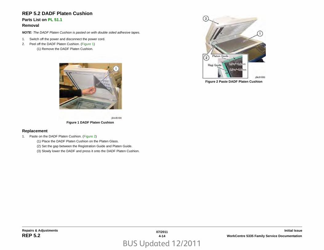
BUS Updated 12/2011
07/20114-14 WorkCentre 5335 Family Service DocumentationREP 5.2
Initial IssueRepairs & Adjustments
REP 5.2 DADF Platen CushionParts List on PL 51.1Removal
NOTE: The DADF Platen Cushion is pasted on with double sided adhesive tapes.
1. Switch off the power and disconnect the power cord.
2. Peel off the DADF Platen Cushion. (Figure 1)
(1) Remove the DADF Platen Cushion.
Figure 1 DADF Platen Cushion
Replacement1. Paste on the DADF Platen Cushion. (Figure 2)
(1) Place the DADF Platen Cushion on the Platen Glass.
(2) Set the gap between the Registration Guide and Platen Guide.
(3) Slowly lower the DADF and press it onto the DADF Platen Cushion.
Figure 2 Paste DADF Platen Cushion

BUS Updated 12/2011
07/20114-15WorkCentre 5335 Family Service Documentation REP 5.3, REP 5.4
Repairs & AdjustmentsInitial Issue
REP 5.3 DADF Front CoverParts List on PL 51.2 Removal1. Switch off the power and disconnect the power cord.
2. Open the Top Cover.
3. Open the DADF.
4. Remove the DADF Front Cover. (Figure 1)
(1) Remove the self-self-tapping screws (x4).
(2) Remove the DADF Front Cover.
Figure 1 DADF Front Cover Removal
Replacement1. To install, carry out the removal steps in reverse order.
REP 5.4 DADF Rear CoverParts List on PL 51.2 Removal1. Switch off the power and disconnect the power cord.
2. Turn the DADF Document Tray upside down. (Figure 1)
(1) Open the Top Cover.
(2) Turn the DADF Document Tray upside down.
Figure 1 DADF Upside Down
3. Remove the screws that secure the DADF Rear Cover. (Figure 2)
(1) Remove the screws (x2).
Figure 2 DADF Rear Cover
4. Open the DADF.
5. Release the hooks of the DADF Rear Cover. (Figure 3)

BUS Updated 12/2011
07/20114-16 WorkCentre 5335 Family Service DocumentationREP 5.4, REP 5.5
Initial IssueRepairs & Adjustments
(1) Release the hooks (x2).
Figure 3 Releasing Hooks
6. Close the DADF gently.
7. Remove the DADF Rear Cover. (Figure 4)
(1) Remove the DADF Rear Cover in the direction of the arrow.
(A) Hook
Figure 4 Removing DADF Rear Cover
Replacement1. To install, carry out the removal steps in reverse order.
REP 5.5 DADF Feeder AssemblyParts List on PL 51.2 Removal1. Switch off the power and disconnect the power cord.
2. Remove the DADF Front Cover. (REP 5.3)
3. Remove the DADF Rear Cover. (REP 5.4)
4. Remove the DADF. (REP 5.1)
5. Remove the DADF Document Tray. (REP 5.9)
6. Disconnect the DADF PWB connectors. (Figure 1)
(1) Disconnect the connectors (x4).
(2) Remove the self-tapping screw and the Ground Wire.
Figure 1 DADF Connectors
7. Remove the DADF Feeder Assembly. (Figure 2)
(1) Remove the self-tapping screw.
(2) Remove the DADF Feeder Assembly in the direction of the arrow.

BUS Updated 12/2011
07/20114-17WorkCentre 5335 Family Service Documentation REP 5.5
Repairs & AdjustmentsInitial Issue
Figure 2 DADF Feeder Assembly Removal
Replacement1. To install, carry out the removal steps in reverse order.
2. Align the positioning pin of the Base Frame and the hole of the DADF Feeder Assembly.(Figure 3)
Figure 3 Align the Positioning Pin
3. When installing the Feeder Assembly to the Base Frame, check the following (Figure 4)
(A) At the front: The Frame of the DADF Feeder Assembly is attached to the positioning pin of the Base Frame as shown in the figure.
(B) The Bracket of the DADF Feeder Assembly is attached to the support of the BaseFrame as shown in the figure.
Figure 4 Installing the Feeder Assembly to the Base Frame
4. Go to HFSI Counter and reset Counter 955-806.

BUS Updated 12/2011
07/20114-18 WorkCentre 5335 Family Service DocumentationREP 5.6
Initial IssueRepairs & Adjustments
REP 5.6 DADF PWBParts List on PL 51.2 Removal1. Switch off the power and disconnect the power cord.
2. Remove the DADF Rear Cover. (REP 5.4)
3. Disconnect the DADF PWB connectors. (Figure 1)
(1) Disconnect the connectors (x6).
Figure 1 DADF PWB Connectors
4. Remove the DADF PWB. (Figure 2)
(1) Remove the self-tapping screws (x2) and the Ground Wires (x2).
(2) Remove the self-tapping screws (x2).
(3) Remove the DADF PWB.
Figure 2 DADF PWB Removal
Replacement1. To install, carry out the removal steps in reverse order.
2. Switch the ROM on the new PWB with the EEPROM from the old PWB. (Figure 3)
This is because it stores the alignment value of the DADF.
Figure 3 ROM
3. Check the software version. Update the version if an old software is installed in the newPWB.
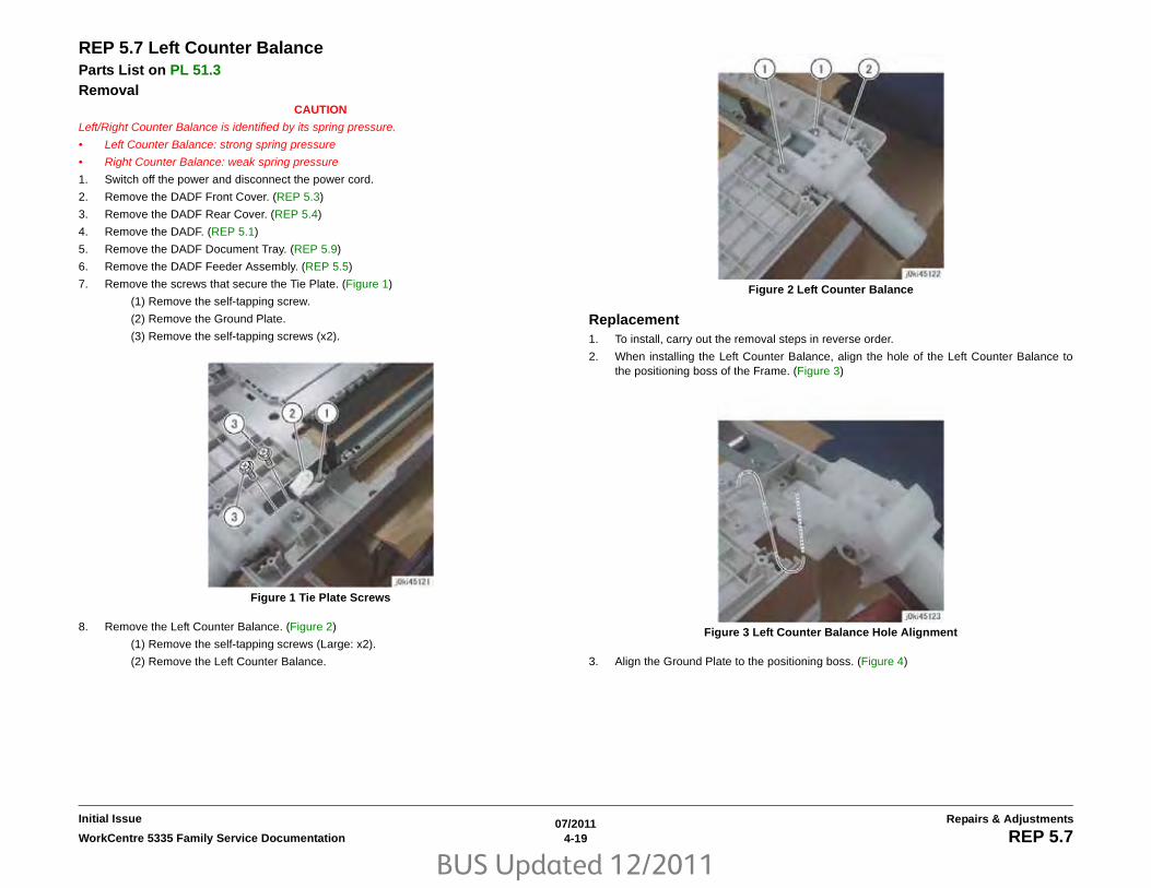
BUS Updated 12/2011
07/20114-19WorkCentre 5335 Family Service Documentation REP 5.7
Repairs & AdjustmentsInitial Issue
REP 5.7 Left Counter BalanceParts List on PL 51.3 Removal
CAUTION
Left/Right Counter Balance is identified by its spring pressure.
• Left Counter Balance: strong spring pressure
• Right Counter Balance: weak spring pressure
1. Switch off the power and disconnect the power cord.
2. Remove the DADF Front Cover. (REP 5.3)
3. Remove the DADF Rear Cover. (REP 5.4)
4. Remove the DADF. (REP 5.1)
5. Remove the DADF Document Tray. (REP 5.9)
6. Remove the DADF Feeder Assembly. (REP 5.5)
7. Remove the screws that secure the Tie Plate. (Figure 1)
(1) Remove the self-tapping screw.
(2) Remove the Ground Plate.
(3) Remove the self-tapping screws (x2).
Figure 1 Tie Plate Screws
8. Remove the Left Counter Balance. (Figure 2)
(1) Remove the self-tapping screws (Large: x2).
(2) Remove the Left Counter Balance.
Figure 2 Left Counter Balance
Replacement1. To install, carry out the removal steps in reverse order.
2. When installing the Left Counter Balance, align the hole of the Left Counter Balance tothe positioning boss of the Frame. (Figure 3)
Figure 3 Left Counter Balance Hole Alignment
3. Align the Ground Plate to the positioning boss. (Figure 4)

BUS Updated 12/2011
07/20114-20 WorkCentre 5335 Family Service DocumentationREP 5.7, REP 5.8
Initial IssueRepairs & Adjustments
Figure 4 Ground Plate Alignment
REP 5.8 Right Counter BalanceParts List on PL 51.3 Removal
CAUTION
Left/Right Counter Balance is identified by its spring pressure.
• Left Counter Balance: strong spring pressure
• Right Counter Balance: weak spring pressure
1. Switch off the power and disconnect the power cord.
2. Remove the DADF Rear Cover. (REP 5.4)
3. Remove the DADF. (REP 5.1)
4. Take note of the graduation of the scale. (Figure 1)
Figure 1 Graduation Scale Marks
5. Remove the Right Counter Balance. (Figure 2)
(1) Remove the self-tapping screws (Large: x3).
(2) Remove the screw (Small: x1) and remove the Ground Wire.
(3) Remove the right Counter Balance.

BUS Updated 12/2011
07/20114-21WorkCentre 5335 Family Service Documentation REP 5.8, REP 5.9
Repairs & AdjustmentsInitial Issue
Figure 2 Right Counter Balance Removal
Replacement1. To install, carry out the removal steps in reverse order.
2. If it was replaced, perform checking for DADF Lead-Skew Adjustment. (ADJ 5.1)
REP 5.9 DADF Document TrayParts List on PL 51.4 Removal1. Switch off the power and disconnect the power cord.
2. Remove the DADF Front Cover. (REP 5.3)
3. Remove the DADF Rear Cover. (REP 5.4)
4. Disconnect the connector of the DADF Document Set LED. (Figure 1)
(1) Remove the self-tapping screw.
(2) Remove the LED Bracket.
(3) Remove the wire harness from the hook.
(4) Disconnect the connector.
Figure 1 DADF Set LED Connector
5. Disconnect the connector. (Figure 2)
(1) Remove the clamp.
(2) Disconnect the connector of the P/J756.
(3) Remove the P/J756 wire harness from the Harness Guide.

BUS Updated 12/2011
07/20114-22 WorkCentre 5335 Family Service DocumentationREP 5.9
Initial IssueRepairs & Adjustments
Figure 2 DADF Set LED Connector Removal
6. At the front side of the DADF Document Tray, remove the boss of the DADF DocumentTray from the installation hole of the Frame. (Figure 3)
(1) Position the DADF Document Tray vertically.
(2) Press the boss of the DADF Document Tray in the direction of the arrow andremove it from the installation hole.
(3) Remove the wire harness of the DADF Document Set LED from the groove of theFrame.
Figure 3 Boss Removal
7. Pull out and remove the wire harness at the rear side of the DADF Document Tray fromthe hole of the Frame. (Figure 4)
(1) Pull out and remove the wire harness through the hole on the Frame.
Figure 4 Wire Harness Removal
Replacement1. To install, carry out the removal steps in reverse order.

BUS Updated 12/2011
07/20114-23WorkCentre 5335 Family Service Documentation REP 5.10, REP 5.11
Repairs & AdjustmentsInitial Issue
REP 5.10 Top CoverParts List on PL 51.4 Removal1. Switch off the power and disconnect the power cord.
2. Remove the DADF Front Cover. (REP 5.3)
3. Remove the DADF Rear Cover. (REP 5.4)
4. Remove the DADF. (REP 5.1)
5. Remove the DADF Document Tray. (REP 5.9)
6. Remove the DADF Feeder Assembly. (REP 5.5)
7. Remove the Registration Chute. (REP 5.14)
8. Open the Top Cover.
9. Remove the Top Cover. (Figure 1)
(1) Remove the self-tapping screw.
(2) Remove the Stud Bracket.
(3) Remove the Top Cover.
Figure 1 Top Cover Removal
Replacement1. To install, carry out the removal steps in reverse order.
REP 5.11 Harness Guide and Wire HarnessParts List on PL 51.5 Removal1. Switch off the power and disconnect the power cord.
2. Remove the DADF Front Cover. (REP 5.3)
3. Remove the DADF Rear Cover. (REP 5.4)
4. Remove the DADF. (REP 5.1)
5. Remove the DADF Document Tray. (REP 5.9)
6. Remove the DADF Feeder Assembly. (REP 5.5)
7. Remove the Registration Chute. (REP 5.14)
8. Remove the Top Cover. (REP 5.10)
9. Remove the wire harness from the Harness Guide. (Figure 1)
(1) Disconnect the connectors (x2).
(2) Remove the wire harness from the Harness Guide.
Figure 1 Wire Harness Removal
10. Remove the wire harness from the Harness Guide. (Figure 2)
(1) Remove the J753 wire harness from the Harness Guide.

BUS Updated 12/2011
07/20114-24 WorkCentre 5335 Family Service DocumentationREP 5.11
Initial IssueRepairs & Adjustments
Figure 2 J753 Location
11. Remove the wire harness of the solenoid from the Harness Guide. (Figure 3)
(1) Disconnect the connector (Blue).
(2) Disconnect the connector (White).
(3) Remove the wire harness from the Harness Guide.
Figure 3 Solenoid Harness Removal
12. Disconnect the connector. (Figure 4)
(1) Disconnect the connectors (x4).
Figure 4 Harness Connectors
13. Remove the Harness Guide and the wire harness. (Figure 5)
(1) Remove the screw.
(2) Remove the screw and the Ground Wire.
(3) Remove the Harness Guide and the wire harness.
Figure 5 Harness Removal
Replacement1. To install, carry out the removal steps in reverse order.
2. Hang the J753 wire harness to the hook (A). (Figure 6)
(A)Hook

BUS Updated 12/2011
07/20114-25WorkCentre 5335 Family Service Documentation REP 5.11, REP 5.12
Repairs & AdjustmentsInitial Issue
Figure 6 J753 Harness Hook
REP 5.12 DADF Registration MotorParts List on PL 51.5 Removal1. Switch off the power and disconnect the power cord.
2. Remove the DADF Front Cover. (REP 5.3)
3. Remove the DADF Rear Cover. (REP 5.4)
4. Remove the DADF. (REP 5.1)
5. Remove the DADF Document Tray. (REP 5.9)
6. Remove the DADF Feeder Assembly. (REP 5.5)
7. Remove the Registration Chute. (REP 5.14)
8. Remove the Top Cover. (REP 5.10)
9. Remove the Harness Guide and the wire harness. (REP 5.11)
10. Remove the DADF Registration Motor. (Figure 1)
(1) Remove the spring.
(2) Remove the screws (x2).
(3) Remove the DADF Registration Motor.
Figure 1 DADF Reg Motor
Replacement1. To install, carry out the removal steps in reverse order.
2. Install the Belt (A) to the Pulley of the DADF Registration Motor. (Figure 2)
(A)Belt

BUS Updated 12/2011
07/20114-26 WorkCentre 5335 Family Service DocumentationREP 5.12, REP 5.13
Initial IssueRepairs & Adjustments
Figure 2 Belt Installation
REP 5.13 DADF Feed MotorParts List on PL 51.5Removal1. Switch off the power and disconnect the power cord.
2. Remove the DADF Front Cover. (REP 5.3)
3. Remove the DADF Rear Cover. (REP 5.4)
4. Remove the DADF. (REP 5.1)
5. Remove the DADF Document Tray. (REP 5.9)
6. Remove the DADF Feeder Assembly. (REP 5.5)
7. Remove the Registration Chute. (REP 5.14)
8. Remove the Top Cover. (REP 5.10)
9. Remove the Harness Guide and the wire harness. (REP 5.11)
10. Turn the DADF Feeder Assembly upside down.
11. Remove the DADF Feed Motor. (Figure 1)
(1) Remove the spring.
(2) Remove the screws (x2).
(3) Remove the DADF Feed Motor.
Figure 1 DADF Feed Motor Removal
Replacement1. To install, carry out the removal steps in reverse order.
2. Install the Belt to the Pulley of the DADF Feed Motor. (Figure 2)

BUS Updated 12/2011
07/20114-27WorkCentre 5335 Family Service Documentation REP 5.13, REP 5.14
Repairs & AdjustmentsInitial Issue
Figure 2 DADF Feed Motor Pulley Install
REP 5.14 Registration ChuteParts List on PL 51.8 Removal1. Switch off the power and disconnect the power cord.
2. Remove the DADF Front Cover. (REP 5.3)
3. Remove the DADF Rear Cover. (REP 5.4)
4. Remove the DADF. (REP 5.1)
5. Remove the DADF Document Tray. (REP 5.9)
6. Remove the DADF Feeder Assembly. (REP 5.5)
7. Turn the DADF Feeder Assembly upside down.
8. Remove the Registration Chute. (Figure 1)
(1) Remove the self-tapping screws (x2).
(2) Remove the Registration Chute.
Figure 1 Registration Chute Removal
Replacement1. To install, carry out the removal steps in reverse order.
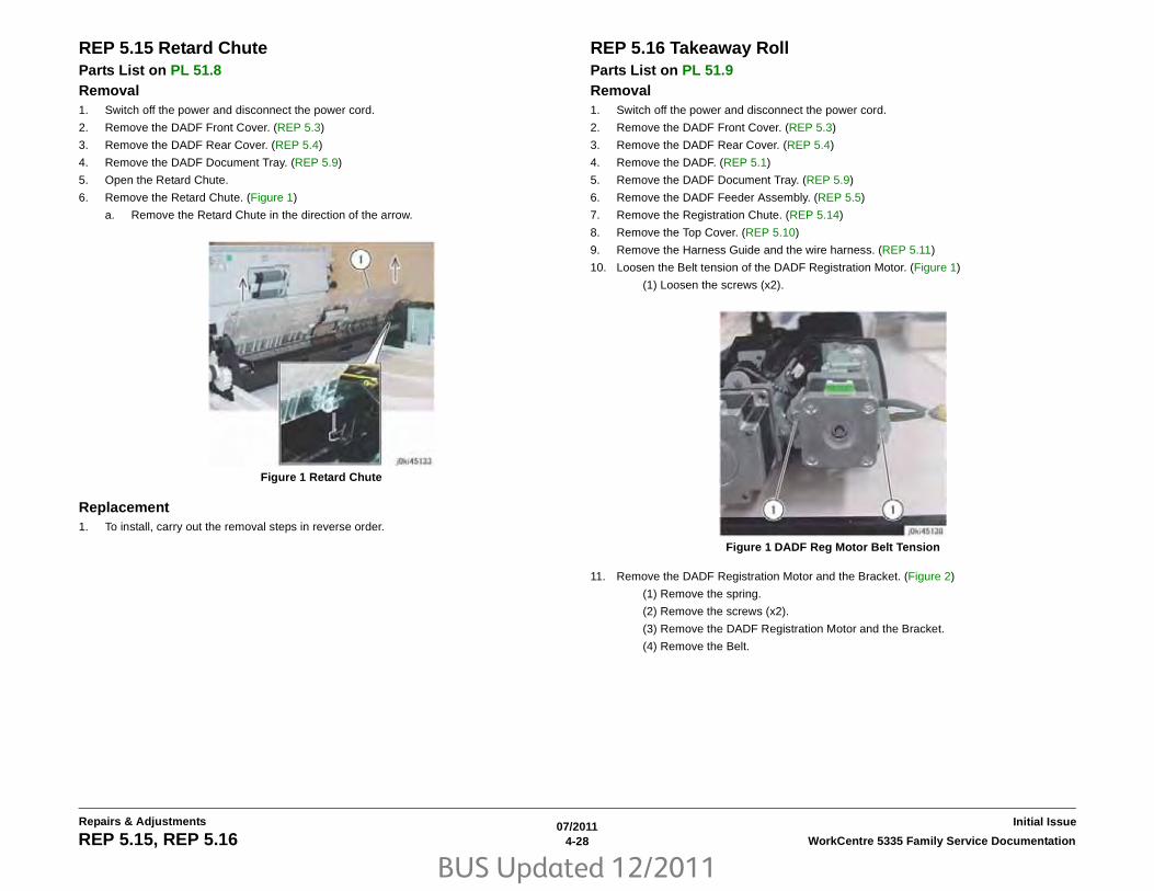
BUS Updated 12/2011
07/20114-28 WorkCentre 5335 Family Service DocumentationREP 5.15, REP 5.16
Initial IssueRepairs & Adjustments
REP 5.15 Retard ChuteParts List on PL 51.8 Removal1. Switch off the power and disconnect the power cord.
2. Remove the DADF Front Cover. (REP 5.3)
3. Remove the DADF Rear Cover. (REP 5.4)
4. Remove the DADF Document Tray. (REP 5.9)
5. Open the Retard Chute.
6. Remove the Retard Chute. (Figure 1)
a. Remove the Retard Chute in the direction of the arrow.
Figure 1 Retard Chute
Replacement1. To install, carry out the removal steps in reverse order.
REP 5.16 Takeaway RollParts List on PL 51.9 Removal1. Switch off the power and disconnect the power cord.
2. Remove the DADF Front Cover. (REP 5.3)
3. Remove the DADF Rear Cover. (REP 5.4)
4. Remove the DADF. (REP 5.1)
5. Remove the DADF Document Tray. (REP 5.9)
6. Remove the DADF Feeder Assembly. (REP 5.5)
7. Remove the Registration Chute. (REP 5.14)
8. Remove the Top Cover. (REP 5.10)
9. Remove the Harness Guide and the wire harness. (REP 5.11)
10. Loosen the Belt tension of the DADF Registration Motor. (Figure 1)
(1) Loosen the screws (x2).
Figure 1 DADF Reg Motor Belt Tension
11. Remove the DADF Registration Motor and the Bracket. (Figure 2)
(1) Remove the spring.
(2) Remove the screws (x2).
(3) Remove the DADF Registration Motor and the Bracket.
(4) Remove the Belt.

BUS Updated 12/2011
07/20114-29WorkCentre 5335 Family Service Documentation REP 5.16
Repairs & AdjustmentsInitial Issue
Figure 2 DADF Reg Motor Bracket Removal
12. Remove the Invert Chute. (Figure 3)
(1) Remove the self-tapping screws (x2).
(2) Remove the Invert Chute.
Figure 3 Invert Chute Removal
13. Remove the gear at the rear. (Figure 4)
(1) Remove the E-Clip.
(2) Remove the gear.
Figure 4 Rear Gear Removal
14. Remove the bearing at the rear. (Figure 5)
(1) Remove the E-Clip.
(2) Remove the bearing.
Figure 5 Bearing Removal
15. Remove the Ground Plate at the front. (Figure 6)
(1) Remove the self-tapping screws (x3).
(2) Remove the Ground Plate.

BUS Updated 12/2011
07/20114-30 WorkCentre 5335 Family Service DocumentationREP 5.16
Initial IssueRepairs & Adjustments
Figure 6 Ground Plate Removal
16. Remove the bearing at the front. (Figure 7)
(1) Remove the E-Clip.
(2) Remove the bearing.
Figure 7 Front Bearing Removal
17. Remove the Takeaway Roll. (Figure 8)
(1) Remove the Takeaway Roll.
Figure 8 Takeaway Roll Removal
Replacement1. To install, carry out the removal steps in reverse order.
2. Install the Belt (A) to the Pulley of the DADF Registration Motor. (Figure 9)
Figure 9 Belt Installation

BUS Updated 12/2011
07/20114-31WorkCentre 5335 Family Service Documentation REP 5.17, REP 5.18
Repairs & AdjustmentsInitial Issue
REP 5.17 Sensor BracketParts List on PL 51.8 Removal1. Switch off the power and disconnect the power cord.
2. Remove the DADF Front Cover. (REP 5.3)
3. Remove the DADF Rear Cover. (REP 5.4)
4. Remove the DADF. (REP 5.1)
5. Remove the DADF Document Tray. (REP 5.9)
6. Remove the DADF Feeder Assembly. (REP 5.5)
7. Remove the Registration Chute. (REP 5.14)
8. Remove the Top Cover. (REP 5.10)
9. Remove the Harness Guide and the wire harness. (REP 5.11)
10. Remove the Takeaway Roll. (REP 5.16)
11. Remove the Sensor Bracket. (Figure 1)
(1) Remove the self-tapping screws (x4).
(2) Disconnect the connector.
(3) Remove the Sensor Bracket.
(4) Pull out and remove the wire harnesses (x2) through the hole on the Frame.
Figure 1 Sensor Bracket Removal
Replacement1. To install, carry out the removal steps in reverse order.
REP 5.18 Nudger Roll, Feed RollParts List on PL 51.12 Removal
NOTE: Nudger, Feed,(REP 5.18) and Retard Rolls (REP 5.19) should be replaced at the sametime
1. Switch off the power and disconnect the power cord.
2. Open the Top Cover.
3. Open the Feed Upper Chute. (Figure 1)
(1) Release the hook and open the Feed Upper Chute.
Figure 1 Feed Upper Chute
4. Shift the housing. (Figure 2)
Release the hook and shift the housing in the direction of the arrow.
Figure 2 Housing Shift

BUS Updated 12/2011
07/20114-32 WorkCentre 5335 Family Service DocumentationREP 5.18
Initial IssueRepairs & Adjustments
5. Remove the housing. (Figure 3)
(1) Remove the housing in the direction of the arrow.
Figure 3 Housing Removal
6. Remove the Nudger Roll and the Feed Roll. (Figure 4)
(1) Remove the Nudger Roll.
(2) Remove the Feed Roll.
Figure 4 Nudger/Feed Roll Removal
Replacement1. To install, carry out the removal steps in reverse order.
2. Install the Nudger/Feed Roll while aligning them as shown in the figure. (Figure 5)
Figure 5 Nudger/Feed Roll Alignment
3. Go to HFSI Counter and reset Counter 955-806.

BUS Updated 12/2011
07/20114-33WorkCentre 5335 Family Service Documentation REP 5.19
Repairs & AdjustmentsInitial Issue
REP 5.19 Retard RollParts List on PL 51.14 Removal
NOTE: Nudger, Feed,(REP 5.18) and Retard Rolls (REP 5.19) should be replaced at the sametime
1. Switch off the power and disconnect the power cord.
2. Open the Top Cover.
3. Open the Retard Roll Cover. (Figure 1)
Figure 1 Retard Roll Cover
(1) Release the hook and open the Retard Roll Cover in the direction of the arrow.
4. Remove the Retard Roll. (Figure 2)
Remove the Retard Roll.
Figure 2 Retard Roll Removal
Replacement1. To install, carry out the removal steps in reverse order.
2. Go to HFSI Counter and reset Counter 955-806.

BUS Updated 12/2011
07/20114-34 WorkCentre 5335 Family Service DocumentationREP 5.19
Initial IssueRepairs & Adjustments

BUS Updated 12/2011
07/20114-35WorkCentre 5335 Family Service Documentation REP 6.1
Repairs & AdjustmentsInitial Issue
REP 6.1 Platen CushionParts List on PL 1.1Removal1. Peel the Platen Cushion from the Platen Cover (held in place by double-sided tape on the
inboard and outboard edges).
2. Remove any tape or cushion residue from the Platen Cover. Be careful not to damage themounting surfaces.
Replacement1. Place the Platen Cushion on the Platen Glass, at the proper position (Figure 1).
(1) Peel off the seals (x2).
(2) Leave a gap of 0.5 ±0.3mm between the Reg. Guide and the Platen Guide.
(3) Close the Platen Cover gently and press it onto the Platen Cushion.
Figure 1 Positioning the Cushion

BUS Updated 12/2011
07/20114-36 WorkCentre 5335 Family Service DocumentationREP 6.2
Initial IssueRepairs & Adjustments
REP 6.2 ROS AssemblyParts List on PL 2.1 Removal1. Switch off the power and disconnect the power cord.
2. Perform the following (Figure 1).
a. Open the Front Cover and the Left Hand Cover.
b. Remove the Xerographic Cartridge and the Toner Cartridge.
Figure 1 Removals
3. Remove the Exit 2 Tray, release the Rear Locking Tab and remove the tray (Figure 2).
Figure 2 Tray Removal
4. Remove the Front Left Cover and Exit Front Cover (Figure 3).
a. Remove Screw (1).
b. Pull out the bottom of the Front Left Cover and remove the covers.
Figure 3 Cover Removal
a
b
3
a
b

BUS Updated 12/2011
07/20114-37WorkCentre 5335 Family Service Documentation REP 6.2
Repairs & AdjustmentsInitial Issue
5. Remove the Top Cover (Figure 4).
a. Remove the Screws (4).
b. Lift the cover up and remove it.
Figure 4 Removing Screws
6. Remove the Front Cover (Figure 5).
a. Remove the Screws (3).
b. Pull the top of the cover out and lift it off.
Figure 5 Removing Screws
7. Remove the Toner Cartridge Connector (Figure 6).
a. Disconnect the PJ (1).
b. Remove Connector (1 Screw).
c. Release the wire harness from the front clamps and left side of the Cartridge Guide.
Figure 6 Wires
8. Remove the Toner Cartridge Guide (Figure 7).
a. On the left rear of the guide, remove the Dispenser Tube Screw (1).
b. Loosen the front Screws (2).
c. Lift the front of the guide up and remove it.
Figure 7 Removing Screws
a
a
b
a
c
a
b

BUS Updated 12/2011
07/20114-38 WorkCentre 5335 Family Service DocumentationREP 6.2
Initial IssueRepairs & Adjustments
9. Remove the ROS Cover (Figure 8).
a. Remove the Screws (2) on the left side of the cover.
b. Remove the top Screw (1).
c. Move the cover to the left and remove it.
Figure 8 Removing Screws
10. Disconnect the ROS PJ’s (4) and release the wire harness from the clamps (Figure 9).
Figure 9 PJ’s
CAUTION
Do not touch the ROS window when holding it.
NOTE: The ROS screws are longer then the other screws, keep them with the ROS for rein-stallation.
11. Remove the ROS (Figure 10).
a. Remove the Screws (5).
b. Remove the ROS.
Figure 10 Removing Screws
Replacement
NOTE: When reinstalling the ROS be sure to seat the ROS into the two locating holes in themachine frame.
1. To install, carry out the removal steps in reverse order.
a
b
c
10
a

BUS Updated 12/2011
07/20114-39WorkCentre 5335 Family Service Documentation REP 6.3, REP 6.4
Repairs & AdjustmentsInitial Issue
REP 6.3 Platen GlassParts List on PL 1.2 Removal1. Switch off the power and disconnect the power cord.
2. Open the Platen Cover or DADF.
3. Remove the Platen Glass (Figure 1)
(1) Remove the screws (x2).
(2) Remove the Right Side Plate.
(3) Remove the Platen Glass.
Figure 1 Platen Glass Removal
Replacement1. To install, carry out the removal steps in reverse order taking note of the following:
NOTE: Push the Platen Glass in the direction of arrow A and the Right Side Plate in the direc-tion of arrow B (Figure 2)
Figure 2 Platen Glass Positioning
REP 6.4 CCD Lens AssemblyParts List on PL 1.2 Removal
NOTE: Light axis correction using UI Diagnostics is required after replacing the parts. Afterreplacement, always check the light axis and perform the light axis correction adjustmentwhere necessary (The correction steps are described in this procedure.)
1. Switch off the power and disconnect the power cord.
2. Remove the following parts:
• Platen Glass (REP 6.3)
• Lens Cover (PL 1.2)
3. Move the APS Sensor (Figure 1)
(1) Remove the screw.
(2) Release the harness from the clamps (x3).
(3) Move the APS Sensor.
Figure 1 APS Sensor
4. Disconnect the CCD Flexible Print Cable (Figure 2)
(1) Release the hook and disconnect the connector.

BUS Updated 12/2011
07/20114-40 WorkCentre 5335 Family Service DocumentationREP 6.4, REP 6.5
Initial IssueRepairs & Adjustments
Figure 2 CCD Flexible Print Cable
5. Replace the CCD Lens Assembly (Figure 3)
NOTE: When removing the CCD Lens Assembly, never remove the screws (Red: x2) ofthe jig pin.
(1) Remove the screws (x4).
(2) Replace the CCD Lens Assembly.
(3) Secure the CCD Lens Assembly by using the screws (x4).
Figure 3 CCD Lens Assembly
6. Connect the CCD Flexible Print Cable.
7. Install the APS Sensor and Lens Cover.
8. Install the Platen Glass.
9. Perform ADJ 6.1.
10. Reinstall all removed parts.
REP 6.5 Front/Rear Carriage CableParts List on PL 1.3 Removal
CAUTION
The burr at the edge of the IIT Frame might cause injury. Be very careful when disconnect theCarriage.
NOTE: The front and rear coatings of the Carriage Cable are different.
Front: Silver
Rear: Black
NOTE: Only the replacement procedure for the Rear Carriage Cable is described here. Thereplacement procedures for the Front Carriage Cable is the same as for the Rear CarriageCable.
NOTE: The Carriage Cables must be replaced one at a time. Never remove both front and rearcables at the same time.
1. Switch off the power and disconnect the power cord.
2. Open the DADF or the Platen Cover.
3. Remove the following parts:
• Platen Glass (REP 6.3)
• Control Panel Assembly (REP 6.11)
• IIT Left Cover (PL 1.1)
4. Take note of the installation position of the Front Support (Figure 1)
Mark position
Figure 1 Front Support Installation Position
5. Remove the DADF Platen Glass (Figure 2)
(1) Remove the screw.
(2) Remove the Front Support.
(3) Remove the DADF Platen Glass.

BUS Updated 12/2011
07/20114-41WorkCentre 5335 Family Service Documentation REP 6.5
Repairs & AdjustmentsInitial Issue
When installing, place it such that the Mark is at the rear.
Figure 2 DADF Platen Glass Mark
6. Unfasten the Full Rate Carriage from the Carriage Cable (Figure 3)
(1) Move the Full Rate Carriage to the notch on the frame.
(2) Remove the screw.
Figure 3 Full Carriage Cable
7. Remove the Carriage Cable (Figure 4)
(1) Remove the spring from the Frame.
(2) Detach the cable from the spring.
Figure 4 Carriage Cable Removal
8. Remove the Carriage Cable (Figure 5)
(1) Pull out the ball from the notch of the Frame and remove the Carriage Cable.
Figure 5 Carriage Cable Ball
Replacement1. Insert the ball of the Carriage Cable into the groove of the pulley (Figure 6)

BUS Updated 12/2011
07/20114-42 WorkCentre 5335 Family Service DocumentationREP 6.5
Initial IssueRepairs & Adjustments
Figure 6 Carriage Cable
2. Wind the Carriage Cable at the spring end around the pulley for 2.5 rounds (Figure 7)
(1) Wind the cable 2.5 rounds.
(2) Fix the cable at the spring end on the Frame with tape.
Figure 7 Winding Carriage Cable
3. Wind the Carriage Cable at the ball end around the pulley for 3 rounds (Figure 8)
(1) Wind the cable 3 rounds.
(2) Fix the cable wound on the pulley with tape to prevent it from getting loose.
Figure 8 Taping Carriage Cable
The figure below shows the number of rounds made by Carriage Cable at the front andrear (Figure 9)
Figure 9 Front and Rear Carriage Cable
4. Install the ball end of the Carriage Cable (Figure 10)
(1) Hang the cable on the pulley at the front of the Half Rate Carriage.
(2) Hang the ball on the notch of the Frame.

BUS Updated 12/2011
07/20114-43WorkCentre 5335 Family Service Documentation REP 6.5
Repairs & AdjustmentsInitial Issue
Figure 10 Installing Ball End
5. Install the spring end of the Carriage Cable (Figure 11)
(1) Peel off the tape that secures the cable.
(2) Hang the cable on the pulley.
(3) Hang it on the pulley at the rear of Half Rate Carriage.
(4) Hang the spring on the Cable and attach it to the Frame.
Figure 11 Carriage Cable Spring End
6. Affix the cable to the Full Rate Carriage (Figure 12)
(1) Peel off the tape.
(2) Move the Full Rate Carriage to the notch on the frame.
(3) Affix the cable to the Full Rate Carriage.
Figure 12 Full Rate Carriage
7. Adjust the position of Full Rate/Half Rate Carriages (ADJ 6.2).
8. Restore the machine to its original state.

BUS Updated 12/2011
07/20114-44 WorkCentre 5335 Family Service DocumentationREP 6.6
Initial IssueRepairs & Adjustments
REP 6.6 LED Lamp PWBParts List on PL 1.4 Removal
NOTE: Do not touch the chip on the LED Lamp PWB.
1. Switch off the power and disconnect the power cord.
2. Open the Platen Cover or DADF.
3. Remove the Platen Glass (REP 6.3)
4. Move the Full Rate Carriage to the notch on the Frame.
5. Disconnect the Lamp Wire Harness (Figure 1)
(1) Move the Block of the Connector Housing in the direction of the arrow.
(2) Disconnect the Lamp Wire Harness.
Figure 1 Disconnecting Lamp Wire Harness
6. Remove the LED Bracket (Figure 2)
(1) Remove the screws (x3).
(2) Remove the LED Bracket.
Figure 2 LED Bracket
7. Remove the LED Lamp PWB (Figure 3)
(1) Remove the screws (x2).
(2) Remove the LED Lamp PWB.
Figure 3 LED Lamp PWB Removal
Replacement1. To install, carry out the removal steps in reverse order.
2. When installing the LED Lamp PWB, tighten the screw in the order of 1 then 2 (Figure 4)
3. When installing the LED Bracket, tighten the screw in the order of 3 to 5 (Figure 4)
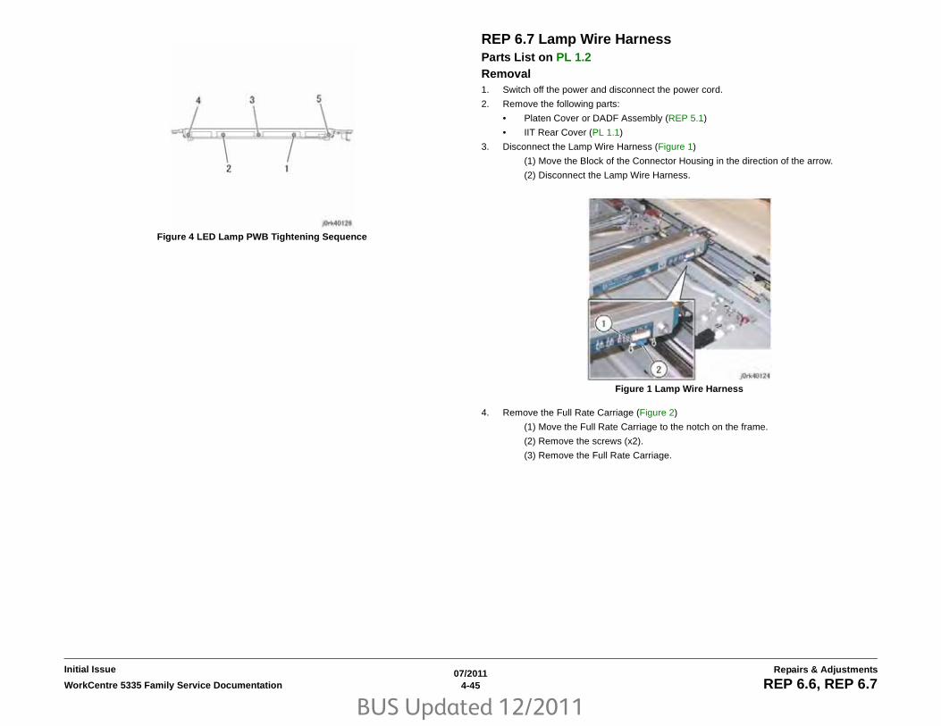
BUS Updated 12/2011
07/20114-45WorkCentre 5335 Family Service Documentation REP 6.6, REP 6.7
Repairs & AdjustmentsInitial Issue
Figure 4 LED Lamp PWB Tightening Sequence
REP 6.7 Lamp Wire HarnessParts List on PL 1.2 Removal1. Switch off the power and disconnect the power cord.
2. Remove the following parts:
• Platen Cover or DADF Assembly (REP 5.1)
• IIT Rear Cover (PL 1.1)
3. Disconnect the Lamp Wire Harness (Figure 1)
(1) Move the Block of the Connector Housing in the direction of the arrow.
(2) Disconnect the Lamp Wire Harness.
Figure 1 Lamp Wire Harness
4. Remove the Full Rate Carriage (Figure 2)
(1) Move the Full Rate Carriage to the notch on the frame.
(2) Remove the screws (x2).
(3) Remove the Full Rate Carriage.

BUS Updated 12/2011
07/20114-46 WorkCentre 5335 Family Service DocumentationREP 6.7
Initial IssueRepairs & Adjustments
Figure 2 Full Rate Carriage Removal
5. Turn the Full Rate Carriage upside down.
6. Remove the Lamp Wire Harness from the Full Rate Carriage (Figure 3)
(1) Remove the Screw & Plate.
(2) Remove the Lamp Wire Harness.
Figure 3 Full Rate Carriage Upside Down
7. Remove the Lamp Wire Harness from the Harness Guide of the Half Rate Carriage (Fig-ure 4)
(1) Remove the Lamp Wire Harness from the guide.
Figure 4 Lamp Wire Harness Removal
8. Remove the Lamp Wire Harness from the guide (Figure 5)
(1) Remove the Lamp Wire Harness from the guide.
Figure 5 Lamp Wire Harness Guide
9. Disconnect the Lamp Wire Harness from the IIT PWB (Figure 6)
(1) Move the Block of the Connector Housing in the direction of the arrow.
(2) Disconnect the Lamp Wire Harness.

BUS Updated 12/2011
07/20114-47WorkCentre 5335 Family Service Documentation REP 6.7, REP 6.8
Repairs & AdjustmentsInitial Issue
Figure 6 IIT PWB
Replacement1. To install, carry out the removal steps in reverse order.
2. Adjust the position of Full Rate/Half Rate Carriages (ADJ 6.2)
REP 6.8 Light GuideParts List on PL 1.4 Removal
NOTE: Do not touch the Light Guide using bare hands.
1. Switch off the power and disconnect the power cord.
2. Remove the DADF (REP 5.1)
3. Remove the Platen Glass (REP 6.3)
4. Move the Full Rate Carriage to the notch on the Frame.
5. Remove the LED Bracket (Figure 1)
(1) Remove the screws (x3).
(2) Remove the LED Bracket.
Figure 1 LED Bracket Removal
6. Remove the Light Guide (Figure 2)
(1) Remove the screw.
(2) Remove the Spring Guide.
(3) Remove the screw.
(4) Remove the Spring Guide.
(5) Remove the Light Guide.

BUS Updated 12/2011
07/20114-48 WorkCentre 5335 Family Service DocumentationREP 6.8, REP 6.9
Initial IssueRepairs & Adjustments
Figure 2 Light Guide Removal
Replacement1. To install, carry out the removal steps in reverse order.
2. When installing the Light Guide, insert the boss of the Light guide into the positioning holeof the Full Rate Carriage.
REP 6.9 Carriage MotorParts List on PL 1.6 Removal1. Switch off the power and disconnect the power cord.
2. Remove the following parts:
• DADF (REP 5.1)
• Filter Cover (PL 19.2)
• Rear Upper Cover (PL 19.2)
• IIT Right Cover (PL 1.1)
• IIT Rear Cover (PL 1.1)
• IIT Top Cover (PL 1.1)
3. Remove the Carriage Motor (Figure 1)
(1) Disconnect the connector.
(2) Remove the spring.
(3) Remove the screws (x3).
(4) Remove the Carriage Motor.
Figure 1 Carriage Motor Removal
Replacement1. To install, carry out the removal steps in reverse order.
2. Install the Belt to the Pulley of the Carriage Motor (Figure 2)

BUS Updated 12/2011
07/20114-49WorkCentre 5335 Family Service Documentation REP 6.9, REP 6.10
Repairs & AdjustmentsInitial Issue
Figure 2 Belt Installation
3. Take note of the following points when installing the Carriage Motor.
(1) Attach the spring.
(2) Loosely affix the Carriage Motor that comes attached with a belt.
(3) Move the carriage to fit the belt.
(4) Secure the Carriage Motor to the Main Unit.
4. After installing the Carriage Motor, move the Full Rate Carriage back and forth and checkthat it is moving smoothly.
REP 6.10 IIT PWBParts List on PL 1.6 Removal
NOTE: Backup the data before replacing the PWB (GP 3) When restoring the data, first down-load the backup and then perform the firmware upgrade (GP 3 and (GP 16) Downloading Soft-ware.
CAUTION
Static electricity may damage electrical parts. Always wear a wrist band during servicing. If awrist band is not available, touch some metallic parts before servicing to discharge the staticelectricity.
1. Switch off the power and disconnect the power cord.
2. Remove the IIT Rear Cover (Figure 1)
(1) Remove the cover.
(2) Disconnect the connectors (x2).
(3) Remove the screws (x2).
(4) Remove the IIT Rear Cover.
Figure 1 IIT Rear Cover Removal
3. Disconnect the connectors that are connected at the rear side to the IIT PWB (Figure 2)
(1) Unlock to disconnect the Connector (P7191).
(Do not pull out the Harness directly.)
(2) Move the block of the Connector Housing in the direction of the arrow and dis-connect the Flat Cable.
(3) Release the hook and disconnect the connector.
(4) Disconnect the connectors (x5).
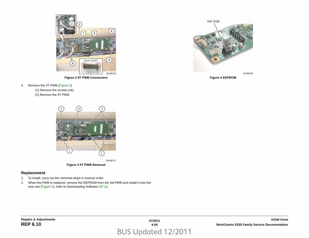
BUS Updated 12/2011
07/20114-50 WorkCentre 5335 Family Service DocumentationREP 6.10
Initial IssueRepairs & Adjustments
Figure 2 IIT PWB Connectors
4. Remove the IIT PWB (Figure 3)
(1) Remove the screws (x6).
(2) Remove the IIT PWB.
Figure 3 IIT PWB Removal
Replacement1. To install, carry out the removed steps in reverse order.
2. When the PWB is replaced, remove the EEPROM from the old PWB and install it onto thenew one (Figure 4), refer to Downloading Software GP 16.
Figure 4 EEPROM

BUS Updated 12/2011
07/20114-51WorkCentre 5335 Family Service Documentation REP 6.11
Repairs & AdjustmentsInitial Issue
REP 6.11 Control Panel AssemblyParts List on PL 1.7 Removal1. Switch off the power and disconnect the power cord.
2. Open the Platen Cover or DADF.
3. Remove the screws that secure the Control Panel (Figure 1).
(1) Remove the screws (x2).
Figure 1 Control Panel Screws
4. Remove the screws that secure the Control Panel (Figure 2).
(1) Remove the screws (x2).
Figure 2 Control Panel Screws
5. Remove the Control Panel (Figure 3).
(1) Hold the Control Panel and slide it slowly to the front.
(2) Release the UI Cable from the hooks.
(3) Release the hook at the bottom of the Connector Housing and disconnect theconnector.
(4) Disconnect the connector of the USB Cable.
Figure 3 Control Panel Removal
6. Turn the Control Panel upside down.
7. Remove the Overlay Cover (Figure 4).
(1) Release the hooks (x3) of the Overlay Cover.
(2) Remove the Overlay Cover in the direction of the arrow.
Figure 4 Overlay Cover Removal
1. Remove the screws (x2)

BUS Updated 12/2011
07/20114-52 WorkCentre 5335 Family Service DocumentationREP 6.11
Initial IssueRepairs & Adjustments
8. Turn the Control Panel so that the screen is face up.
9. Remove the self-tapping screw that secures the UI Lower Cover (Figure 5).
Figure 5 UI Lower Cover Removal
10. Turn the Control Panel upside down.
11. Remove the UI Lower Cover (Figure 6).
(1) Remove the self-tapping screws (x9).
(2) Remove the UI Lower Cover.
Figure 6 UI Lower Cover Removal
12. Remove the Base Frame (Figure 7).
(1) Remove the self-tapping screws (x7).
(2) Remove the Base Frame.
Figure 7 Base Frame Removal
Replacement1. To install, carry out the removal steps in reverse order.
1. Remove the screw

BUS Updated 12/2011
07/20114-53WorkCentre 5335 Family Service Documentation REP 7.1
Repairs & AdjustmentsInitial Issue
REP 7.1 Paper Trays 1, 2, 3, and 4 AssemblyParts List on PL 9.1, PL 11.2 RemovalPaper Trays 1 and 2
1. Remove the paper from the tray.
2. Pull the tray open.
3. Lift up the front of the tray so the rollers clear the stops and remove the tray.
Replacement1. To reinstall, carry out the removal steps in reverse order.
RemovalPaper Tray 3
1. Remove the paper from the tray.
2. Pull the tray open.
3. Remove Paper Tray 3.
a. Loosen the screw holding the stop bracket and move the stop bracket away from thetray (Figure 1).
b. Remove the tray.
Figure 1 Removing Screw
Replacement1. To reinstall, carry out the removal steps in reverse order.
RemovalPaper Tray 4
CAUTION
When removing Tray 4 be sure to support the Tray 4 Transport Assembly to prevent damagingthe tray or transport assembly.
1. Remove the paper from the tray.
2. Pull the tray open.
3. Remove Paper Tray 4.
a. Remove the screw and stop bracket (Figure 2).
b. Remove the tray.
Figure 2 Removing Screw
Replacement1. To reinstall, carry out the removal steps in reverse order. a
a

BUS Updated 12/2011
07/20114-54 WorkCentre 5335 Family Service DocumentationREP 7.2
Initial IssueRepairs & Adjustments
REP 7.2 MSI AssemblyParts List on PL 13.1 Removal1. Switch off the power and disconnect the power cord.
2. Remove the following covers (Figure 1).
a. Pull off the ESS Cap Cover.
b. ESS Cover (2 Screws).
c. Left Rear Middle Cover (2 Screws).
d. Rear Lower Cover (3 Screws).
Figure 1 Removing Covers
3. Perform the following steps (Figure 2).
a. Remove the Left Rear Covers (1 Screw).
b. Remove the Left Rear Lower Cover (1 Screw).
c. Disconnect P/J406 from the MCU PWB and release the wire harness to the MSIfrom the clamps.
Figure 2 Removing Screwsa
b
c
d
a
bc

BUS Updated 12/2011
07/20114-55WorkCentre 5335 Family Service Documentation REP 7.2, REP 7.3
Repairs & AdjustmentsInitial Issue
CAUTION
Support the MSI when removing the screws to prevent damaging the MSI.
4. Remove the screws (2) and slide out the MSI (Figure 3).
Figure 3 Removing Screws
Replacement1. To reinstall, carry out the removal steps in reverse order.
REP 7.3 Tray 3 CableParts List on PL 11.3 Removal
NOTE: This procedure shows the removal of the Front Cables, the steps to remove andreplace the Rear Cables are the same.
NOTE: The Screws used in the Tray are of different Length and Threads, keep the screws withthe parts for correct replacement.
1. Switch off the power and disconnect the power cord.
2. Remove Paper Tray 3 REP 7.1.
3. Remove the Tray 3 Cover (Figure 1):
a. Remove the Screws (2).
b. Remove the Cover.
Figure 1 Cover Removal
4

BUS Updated 12/2011
07/20114-56 WorkCentre 5335 Family Service DocumentationREP 7.3
Initial IssueRepairs & Adjustments
4. Remove the Screws (2) and the Brake (Figure 2).
Figure 2 Brake Removal
5. Remove the Screw (1) and Bracket (Figure 3).
Figure 3 Bracket Removal
6. Release the Cables from the Shaft (Figure 4):
a. Remove the E-Ring and Gear.
b. Slide the Pulley.
c. Release the Cables from the Shaft detente.
Figure 4 Cable Release
7. Remove the Guide (Figure 5):
a. Remove the Screws (4).
b. Remove the Guide.
Figure 5 Guide Removal

BUS Updated 12/2011
07/20114-57WorkCentre 5335 Family Service Documentation REP 7.3
Repairs & AdjustmentsInitial Issue
8. Remove the Guide (Figure 6):
a. Remove the Screw (1).
b. Remove the Guide.
Figure 6 Guide Removal
9. Remove the Cables (Figure 7):
a. Remove the Pulleys (2).
b. Raise the Plate and remove the Cables through the plate holes.
Figure 7 Cable Removal
Replacement
NOTE: Be careful not to twist or cross over the cables when installing them.
1. To install, carry out the removal steps in reverse order.

BUS Updated 12/2011
07/20114-58 WorkCentre 5335 Family Service DocumentationREP 7.4
Initial IssueRepairs & Adjustments
REP 7.4 Tray 4 CableParts List on PL 11.5 Removal
NOTE: This procedure shows the removal of the Front Cables, the steps to remove andreplace the Rear Cables are the same.
NOTE: The Screws used in the Tray are of different Length and Threads, keep the screws withthe parts for correct replacement.
1. Switch off the power and disconnect the power cord.
2. Remove Paper Tray 4 REP 7.1.
3. Remove the Cover (Figure 1):
a. Remove the Screws (2).
b. Remove the Cover.
Figure 1 Cover Removal
4. Remove the Screws (2) and the Brake (Figure 2).
Figure 2 Brake Removal
5. Remove the Screw (1) and Spring (Figure 3).
Figure 3 Spring Removal

BUS Updated 12/2011
07/20114-59WorkCentre 5335 Family Service Documentation REP 7.4
Repairs & AdjustmentsInitial Issue
6. Remove the E-Ring (Figure 4).
Figure 4 E-Ring Removal
7. Release the Cables from the Shaft (Figure 5):
a. Slide the Pulley.
b. Release the Cables from the Shaft detente.
Figure 5 Cable Release
8. Remove the Guide (Figure 6):
a. Remove the Screw (1).
b. Remove the Guide.
Figure 6 Guide Removal
9. Remove the Cables (Figure 7):
a. Remove the Pulleys (2).
b. Raise the Plate and remove the Cables through the plate holes.
Figure 7 Cable Removal
Replacement
NOTE: Be careful not to twist or cross over the cables when installing them.
1. To install, carry out the removal steps in reverse order.

BUS Updated 12/2011
07/20114-60 WorkCentre 5335 Family Service DocumentationREP 7.4
Initial IssueRepairs & Adjustments

BUS Updated 12/2011
07/20114-61WorkCentre 5335 Family Service Documentation REP 8.1
Repairs & AdjustmentsInitial Issue
REP 8.1 Tray 1 Feeder AssemblyParts List on PL 9.4 Removal1. Switch off the power and disconnect the power cord.
2. Remove Paper Trays 1 and 2.
a. Remove the paper from the trays.
b. Pull the tray open.
c. Lift up the front of the tray so the rollers clear the stops, and remove the tray.
3. Remove the MSI REP 7.2.
4. Perform the following (Figure 1).
a. Open the Left Hand Cover.
b. Disconnect P/J409 on the MCU PWB, and release the wire harness from theclamps.
Figure 1 P/Js
NOTE: Support the Left Hand Cover Assembly when releasing the supports to prevent damag-ing the cover.
5. Remove the Left Hand Cover Assembly (Figure 2).
a. Twist the Front Support and remove it from the slot.
b. Remove the K-Clip, and remove the Rear Support from the pin.
c. Move the cover down to a horizontal position, then lift it off the pivots.
Figure 2 Left Hand Cover
NOTE: The harness cover screw has a different thread than the other screws, keep it withthe harness cover for re-installation.
6. Remove the harness cover (1 Screw) (Figure 3).
Figure 3 Removing Screw
P/J 409
a
b
Screw

BUS Updated 12/2011
07/20114-62 WorkCentre 5335 Family Service DocumentationREP 8.1
Initial IssueRepairs & Adjustments
7. Remove Feeder 1 Chute (Figure 4).
Figure 4 Chute
8. Remove the Takeaway Chute (Figure 5).
NOTE: Make note of how the Sensor Wires are routed through the retainers on the chuteto avoid pinching the wires when reinstalling the chute.
a. Remove the Screws (2).
b. Release the Tab, and remove the chute.
Figure 5 Removing Screws
9. Perform the following (Figure 6).
a. Disconnect Feeder 1 P/Js (2).
b. Loosen the harness bracket, remove the Screws (3).
Figure 6 Removing Screws & P/Js
10. Remove Feeder 1 (Figure 7).
a. Remove the Screws (2).
b. First, slide out the front of the feeder; then remove it.
Figure 7 Removing Screws
Replacement1. To reinstall, carry out the removal steps in reverse order.
Chute
Screws
Tab
P/Js
Screws
Screws

BUS Updated 12/2011
07/20114-63WorkCentre 5335 Family Service Documentation REP 8.2
Repairs & AdjustmentsInitial Issue
REP 8.2 Tray 2 Feeder AssemblyParts List on PL 9.4 Removal1. Switch off the Power and disconnect the power cord.
2. Remove Paper Tray 2:
a. Remove the paper from the tray.
b. Pull the tray open.
c. Lift up the front of the tray so the rollers clear the stops and remove the tray.
3. Remove the MSI REP 7.2.
4. Remove the Lower Left Hand Cover (Figure 1).
a. Pull out the cap on the Locking Hinge Pin and remove the pin.
b. Raise the cover, then move the rear of the cover out and remove the cover from thefront pivot.
Figure 1 Removing Cover
NOTE: The harness cover screw has a different thread than the other screws, keep it with theharness cover for re-installation.
5. Remove the harness cover (1 Screw) (Figure 2).
Figure 2 Removing Screw
6. Perform the following (Figure 3).
a. Disconnect Feeder 2 P/Js (2) and release the harness from the clamp.
b. Remove the Pivot Bracket (1 Screw).
Figure 3 Removing Screws & P/Js
7. Remove Feeder 2 (Figure 4).
a. Remove the screws (2).
b. First, slide out the front of the feeder, then remove it.
Figure 4 Removal
Replacement1. To reinstall, carry out the removal steps in reverse order.
Pull out Cap
Screw
P/Js
Screw
Screws

BUS Updated 12/2011
07/20114-64 WorkCentre 5335 Family Service DocumentationREP 8.3
Initial IssueRepairs & Adjustments
REP 8.3 Tray 3 Feeder AssemblyParts List on PL 11.7 Removal1. Switch off the power and disconnect the power cord.
2. Remove Paper Trays 2, 3, and 4 REP 7.1.
3. Perform the following (Figure 1).
a. Remove the Left Lower Cover (2 Screws).
b. Open the Left Cover Assembly.
Figure 1 Covers
4. Remove the Harness Cover (1 Screw) (Figure 2).
Figure 2 Removing Screw
5. Disconnect Feeder 3 P/Js (2), and release the harness from the clamp (Figure 3).
Figure 3 P/Js
6. Perform the following (Figure 4).
a. Removing the Feed Out Chute.
b. Remove Tray 3 Feeder left side mounting screws (2).
Figure 4 Removal
Screws
Screw
PJ
Screws
Feed Out Chute

BUS Updated 12/2011
07/20114-65WorkCentre 5335 Family Service Documentation REP 8.3, REP 8.4
Repairs & AdjustmentsInitial Issue
7. Remove Feeder 3 (Figure 5).
a. Remove the inside rear mounting screw (1)
b. Raise the right rear of Feeder 3 to clear the drive gear, then move the front of Feeder3 to the left and slide it out.
Figure 5 Removal
Replacement
NOTE: Setting the right rear of the feeder on to the drive gear is technique sensitive and mayrequire you to gently rotate and wiggle the feeder to set it in place.
1. To reinstall, carry out the removal steps in reverse order.
REP 8.4 Tray 4 Feeder AssemblyParts List on PL 11.7 Removal1. Switch off the power and disconnect the power cord.
2. Remove Paper Trays 1, 2, 3, and 4 REP 7.1.
CAUTION
Be sure to support Feeder 4 when removing the screws and bracket to prevent damaging thefeeder.
3. Remove Feeder 4 (Figure 1).
a. Release the wire harness on Feeder 4 from the clamps.
b. Remove the rear mounting screws (2).
c. Remove the front mounting screw and bracket.
d. Rotate Feeder 4 counter-clockwise to access the 3 P/Js and disconnect them, thenremove Feeder 4.
Figure 1 Removing Screws & P/Js
Replacement
NOTE: Reinstall the 3 mounting screws but do not tighten them, then tighten the 2 rear screwsbefore tightening the front screw.
1. To reinstall, carry out the removal steps in reverse order.
Screw
Screws
Screw and bracket
Wire HarnessPJs

BUS Updated 12/2011
07/20114-66 WorkCentre 5335 Family Service DocumentationREP 8.5
Initial IssueRepairs & Adjustments
REP 8.5 Feed, Nudger, Retard RollParts List on PL 11.10 Removal
NOTE: The replacement procedure shows Feeder 1 Feed, Nudger, and Retard Rolls; the pro-cedure for Feeders 2, 3, and 4 are the same.
NOTE: The Feed, Nudger, and Retard Rolls (3) must be replaced at the same time.
NOTE: After replacing the Feed, Nudger, and Retard Rolls reset the HFSI Counter for thatfeeder.
1. Remove the Paper Tray REP 7.1.
2. Slide the guide to the front (Figure 1).
Figure 1 Guide
3. Remove the Feed, Nudger, and Retard Rolls (3) (Figure 2).
a. Release the locking tab and slide the roll off the shaft.
Figure 2 Removal
Replacement1. To install, carry out the removal steps in reverse order.
Guide
Locking tab

BUS Updated 12/2011
07/20114-67WorkCentre 5335 Family Service Documentation REP 8.6
Repairs & AdjustmentsInitial Issue
REP 8.6 MSI Feed RollParts List on PL 13.2 Removal1. Switch off the power and disconnect the power cord.
2. Open the Left Hand Cover. and perform the following (Figure 1).
a. Remove the Duplex Lower Chute.
b. Remove the screws (2) and the MSI Top Cover.
Figure 1 Removing Screws
3. Release the Core Roll locking tab from the shaft and slide it to the front (Figure 2).
Figure 2 Roll
4. Slide the Feed Roll to the front, to clear the locating pin, and remove it (Figure 3).
Figure 3 Removal
Replacement1. To install, carry out the removal steps in reverse order.
2. Go to HFSI Counter and reset counter 954-804
Screws
Chute
Locking tab
Locking pin
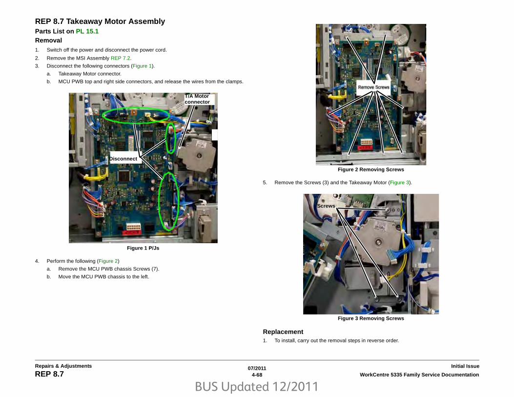
BUS Updated 12/2011
07/20114-68 WorkCentre 5335 Family Service DocumentationREP 8.7
Initial IssueRepairs & Adjustments
REP 8.7 Takeaway Motor AssemblyParts List on PL 15.1 Removal1. Switch off the power and disconnect the power cord.
2. Remove the MSI Assembly REP 7.2.
3. Disconnect the following connectors (Figure 1).
a. Takeaway Motor connector.
b. MCU PWB top and right side connectors, and release the wires from the clamps.
Figure 1 P/Js
4. Perform the following (Figure 2)
a. Remove the MCU PWB chassis Screws (7).
b. Move the MCU PWB chassis to the left.
Figure 2 Removing Screws
5. Remove the Screws (3) and the Takeaway Motor (Figure 3).
Figure 3 Removing Screws
Replacement1. To install, carry out the removal steps in reverse order.
T/A Motor connector
Disconnect
Screws

BUS Updated 12/2011
07/20114-69WorkCentre 5335 Family Service Documentation REP 9.1
Repairs & AdjustmentsInitial Issue
REP 9.1 Xerographic Cartridge Guide AssemblyParts List on PL 8.2 Removal1. Switch off the power and disconnect the power cord.
2. Remove the MSI Assembly REP 7.2.
3. Perform the following (Figure 1).
a. Open the Left Hand Cover.
b. Disconnect PJ409 on the MCU PWB, and release the wire harness from the clamps
Figure 1 PJ
NOTE: Support the Left Hand Cover Assembly when releasing the supports to prevent damag-ing the cover.
4. Remove the Left Hand Cover Assembly (Figure 2).
a. Twist the Front Support and remove it from the slot.
b. Remove the K-Clip, and remove the Rear Support from the pin.
c. Move the cover down to a horizontal position, then lift it off the pivots.
Figure 2 Left Hand Cover
5. Disconnect the connectors on the Top and Right side of the MCU PWB, and release thewire harnesses from the clamps (Figure 3).
Figure 3 PJ’s
a
b
a
b
c

BUS Updated 12/2011
07/20114-70 WorkCentre 5335 Family Service DocumentationREP 9.1
Initial IssueRepairs & Adjustments
6. Perform the following (Figure 4).
a. Remove the MCU PWB Bracket Screws (7)
b. Pivot the MCU PWB Bracket to the left.
Figure 4 Removing Screws
7. Perform the following (Figure 5).
a. Disconnect PJ609.
b. Remove harness clamp from the rear frame.
c. Release the wire harness from the clamps.
Figure 5 Wire Harness
NOTE: Support the Registration Transport when removing it to avoid damaging the wire har-ness connectors.
8. Remove the Registration Transport (Figure 6).
a. Remove the Screws (2)
b. Move the Front of the transport out of the slot and remove the transport.
Figure 6 Removing Screws
9. Perform the following (Figure 7).
a. Release the wires from the clamps.
b. Disconnect the Registration Transport PJ’s (2).
Figure 7 PJ’s
ab
c
a
b
a
b
b
a

BUS Updated 12/2011
07/20114-71WorkCentre 5335 Family Service Documentation REP 9.1
Repairs & AdjustmentsInitial Issue
10. Open the Front Cover, remove the Xerographic Cartridge and the Toner Cartridge (Figure8).
Figure 8 Removals
11. Remove the Exit 2 Tray, release the Rear Locking Tab and remove the tray (Figure 9).
Figure 9 Removing Tray
12. Remove the Front Left Cover and Exit Front Cover (Figure 10).
a. Remove Screw (1)
b. Pull out the bottom of the Front Left Cover and remove the covers.
Figure 10 Removing Cover
13. Remove the Top Cover (Figure 11).
a. Remove the Screws (4).
b. Lift the cover up and remove it.
Figure 11 Removing Screws
11
a
b
a

BUS Updated 12/2011
07/20114-72 WorkCentre 5335 Family Service DocumentationREP 9.1
Initial IssueRepairs & Adjustments
14. Remove the Front Cover (Figure 12).
a. Remove the Screws (3).
b. Pull the top of the cover out and lift it off.
Figure 12 Removing Screws
15. Remove the Toner Cartridge Connector (Figure 13).
a. Disconnect the PJ (1).
b. Remove Connector (1 Screw).
c. Release the wire harness from the front clamps and left side of the Cartridge Guide.
Figure 13 Wires & PJ
16. Remove the Toner Cartridge Guide (Figure 14).
a. On the left rear, remove the Dispenser Tube Screw (1).
b. Loosen the front Screws (2).
c. Lift the front of the guide up and remove the guide.
Figure 14 Removing Screws
17. Remove the ROS Cover (Figure 15).
a. Remove the Screws (2) on the left side of the cover.
b. Remove the top Screw (1).
c. Move the cover to the left and remove it.
Figure 15 Removing The Cover
a
a
b
c
b
a
a
b
c

BUS Updated 12/2011
07/20114-73WorkCentre 5335 Family Service Documentation REP 9.1
Repairs & AdjustmentsInitial Issue
18. Remove the HVPS (Figure 16).
a. Release the wire harness from the clamp, and disconnect the connector.
b. Remove the Screws (2).
c. Pull the HVPS out.
Figure 16 Removing Screws
19. Perform the following (Figure 17).
a. Release the Xerographic Module Connector from the frame.
b. Remove the Cartridge Guide top Screws (2).
Figure 17 Removing Screws
20. Release the BTR Contact Cover from the frame (2 locking tabs) (Figure 18).
Figure 18 Removal
21. Remove the Xerographic Cartridge Guide Assembly (Figure 19).
a. Remove the left side Screws (2).
b. Remove the guide, routing the front and rear wire harnesses through the frameopenings.
Figure 19 Removing Screws
Replacement1. To reinstall, carry out the removal steps in reverse order.
b
a
b
a
20
b
a

BUS Updated 12/2011
07/20114-74 WorkCentre 5335 Family Service DocumentationREP 9.2, REP 9.3
Initial IssueRepairs & Adjustments
REP 9.2 Xerographic Interlock SwitchParts List on PL 8.2Removal
NOTE: The Xerographic Interlock Switch is part of the wire harness, the switch and wire har-ness are replaced as a unit.
1. Switch off the power and disconnect the power cord.
2. Remove the Cartridge Guide REP 9.1.
3. Remove the Xerographic Interlock Switch (Figure 1).
a. Remove the Screw (1)
b. Remove the switch and wire harness.
Figure 1 Removing Screw
Replacement1. To reinstall, carry out the removal steps in reverse order.
REP 9.3 Humidity / Temperature SensorParts List on PL 8.2 Removal1. Switch off the power and disconnect the power cord.
NOTE: Do Not perform Steps 5, 6, and 7 of REP 9.1 Xerographic CRU Guide.
To access the Humidity / Temperature Sensor you do not need to fully remove the XerographicCartridge Guide or disconnect the MCU PWB connectors and wire harness on the rear.
2. Remove the Xerographic Cartridge Guide REP 9.1.
3. Remove the Humidity / Temperature Sensor (Figure 1).
a. Disconnect the connector.
b. Remove the Screw (1).
Figure 1 Removal
Replacement1. To reinstall, carry out the removal steps in reverse order.
a
ab

BUS Updated 12/2011
07/20114-75WorkCentre 5335 Family Service Documentation REP 9.4
Repairs & AdjustmentsInitial Issue
REP 9.4 HVPSParts List on PL 18.1 Removal1. Switch off the power and disconnect the power cord.
2. Perform the following (Figure 1).
a. Open the Front Cover and the Left Hand Cover.
b. Remove the Xerographic Cartridge and the Toner Cartridge.
Figure 1 Removals
3. Remove the Exit 2 Tray, release the Rear Locking Tab and remove the tray (Figure 2).
Figure 2 Removing Tray
4. Remove the Front Left Cover and Exit Front Cover (Figure 3).
a. Remove the Screw (1).
b. Pull out the bottom of the Front Left Cover and remove the covers.
Figure 3 Removing Covers
a
b
3
a
b

BUS Updated 12/2011
07/20114-76 WorkCentre 5335 Family Service DocumentationREP 9.4
Initial IssueRepairs & Adjustments
5. Remove the Top Cover (Figure 4).
a. Remove the Screws (4).
b. Lift the cover up and remove it.
Figure 4 Removing Screws
6. Remove the Front Cover (Figure 5).
a. Remove the Screws (3).
b. Pull the top of the cover out and lift it off.
Figure 5 Removing Screws
7. Remove the HVPS (Figure 6).
a. Release the wire harness from the clamp and disconnect the connector.
b. Remove the Screws (2) and pull the HVPS out.
Figure 6 Removing The HVPS
Replacement1. To reinstall, carry out the removal steps in reverse order.
a
a
b
a

BUS Updated 12/2011
07/20114-77WorkCentre 5335 Family Service Documentation REP 9.5, REP 9.6
Repairs & AdjustmentsInitial Issue
REP 9.5 Toner Cartridge GuideParts List on PL 8.2 Removal1. To remove the Toner Cartridge Guide go to REP 6.2 ROS Assembly Steps 1 through 8.
Replacement1. To reinstall, carry out the removal steps in reverse order.
REP 9.6 Toner Dispense MotorParts List on PL 8.2 Removal1. Switch off the power and disconnect the power cord.
2. Perform the following (Figure 1).
a. Open the Front Cover and the Left Hand Cover.
b. Remove the Xerographic Cartridge and the Toner Cartridge.
Figure 1 Removals
a
b

BUS Updated 12/2011
07/20114-78 WorkCentre 5335 Family Service DocumentationREP 9.6
Initial IssueRepairs & Adjustments
3. Remove the Exit 2 Tray, release the Rear Locking Tab and remove the tray (Figure 2).
Figure 2 Removing Tray
4. Remove the Front Left Cover and Exit Front Cover (Figure 3).
a. Remove Screw (1).
b. Pull out the bottom of the Front Left Cover and remove the covers.
Figure 3 Removing Covers
5. Remove the Top Cover (Figure 4).
a. Remove the Screws (4).
b. Lift the cover up and remove it.
Figure 4 Removing Screws
6. Remove the Front Cover (Figure 5).
a. Remove the Screws (3).
b. Pull the top of the cover out and lift it off.
Figure 5 Removing Screws
3
a
b
a
a

BUS Updated 12/2011
07/20114-79WorkCentre 5335 Family Service Documentation REP 9.6
Repairs & AdjustmentsInitial Issue
7. Remove the Toner Cartridge Connector (Figure 6).
a. Disconnect the PJ (1).
b. Remove Connector (1 Screw).
c. Release the wire harness from the front clamps and left side of the Cartridge Guide.
Figure 6 Wires & PJ
8. Remove the Toner Cartridge Guide (Figure 7).
a. On the left rear of the guide, remove the Dispenser Tube Screw (1).
b. Loosen the front Screws (2).
c. Lift the front of the guide up and remove it.
Figure 7 Removing The Screws
9. Remove the Toner Dispense Motor (Figure 8).
NOTE: The 4 motor screws are longer then the other screws, keep them with the motorfor reinstallation.
a. Disconnect the PJ (1).
b. Remove the Screws (4), and the Motor.
Figure 8 Removing The Motor
Replacement1. To reinstall, carry out the removal steps in reverse order.
a
bc
b
a
a
b

BUS Updated 12/2011
07/20114-80 WorkCentre 5335 Family Service DocumentationREP 9.6
Initial IssueRepairs & Adjustments

BUS Updated 12/2011
07/20114-81WorkCentre 5335 Family Service Documentation REP 10.1
Repairs & AdjustmentsInitial Issue
REP 10.1 Duplex MotorParts List on PL 14.4 Removal1. Switch off the power and disconnect the power cord.
2. Open the Left Hand Cover (Figure 1).
a. Release the front and rear locking tabs and remove the BTR Assembly.
Figure 1 Removal
3. Remove the Left Hand Chute Cover (4 Screws) (Figure 2).
Figure 2 Removing Screws
4. Remove the Left Hand Cover (7 Screws) (Figure 3).
NOTE: The Left Hand Cover Screws have a different thread than the other screws, keepthem with the cover for re-installation.
Figure 3 Removing Screws
5. Perform the following (Figure 4).
a. Disconnect the PJ from the Duplex Motor.
b. Remove the Harness Guide; loosen the top screw, remove the bottom screw.
Figure 4 Removing Screws
a
3
4
b
a

BUS Updated 12/2011
07/20114-82 WorkCentre 5335 Family Service DocumentationREP 10.1, REP 10.2
Initial IssueRepairs & Adjustments
6. Remove the Duplex Assembly from the Left Hand Cover (4 Screws) (Figure 5).
Figure 5 Removing Screws
7. Remove the Duplex Motor (2 Screws) (Figure 6).
Figure 6 Removing Screws
Replacement1. To install, carry out the removal steps in reverse order.
REP 10.2 Duplex Sensor Parts List on PL 14.4 Removal1. Switch off the power and disconnect the power cord.
2. Open the Left Hand Cover (Figure 1).
a. Release the front and rear locking tabs and remove the BTR Assembly.
Figure 1 Removal
3. Remove the Left Hand Chute Cover (4 Screws) (Figure 2).
Figure 2 Removing Screws
6
7
a
3

BUS Updated 12/2011
07/20114-83WorkCentre 5335 Family Service Documentation REP 10.2
Repairs & AdjustmentsInitial Issue
4. Remove the Left Hand Cover (7 Screws) (Figure 3).
NOTE: The Left Hand Cover Screws have a different thread than the other screws, keepthem with the cover for re-installation.
Figure 3 Removing Screws
5. Remove the Harness Guide (Figure 4).
a. Loosen the top screw, remove the bottom screw.
Figure 4 Removing Screws
6. Remove the Duplex Assembly from the Left Hand Cover (4 Screws) (Figure 5).
Figure 5 Removing Screws
7. Remove the Duplex Sensor (Figure 6).
NOTE: Be careful not to damage or lose the Sensor Actuator Spring.
Figure 6 Duplex Sensor
Replacement1. To install, carry out the removal steps in reverse order.
4
5
6

BUS Updated 12/2011
07/20114-84 WorkCentre 5335 Family Service DocumentationREP 10.3, REP 10.4
Initial IssueRepairs & Adjustments
REP 10.3 Fuser Parts List on PL 7.1Removal
CAUTION
The Fuser is Hot, do not start servicing the Fuser until has cooled down.
1. Switch off the power and disconnect the power cord.
2. Open the Left Hand Cover and remove the Fuser (Figure 1).
a. Loosen the knobs (2).
b. Hold the Fuser by the handles and remove it.
Figure 1 Removal
Replacement1. To install, carry out the removal steps in reverse order.
REP 10.4 Fuser Exit Sensor Parts List on PL 7.1Removal
CAUTION
The Fuser is Hot, do not start servicing the Fuser until has cooled down.
1. Switch off the power and disconnect the power cord.
2. Open the Left Hand Cover and remove the Fuser (Figure 1).
a. Loosen the knobs (2).
b. Hold the Fuser by the handles and remove it.
Figure 1 Removal
3. Remove the Plate (1 Screw) (Figure 2).
Figure 2 Removing Screw
a
b
a
b
3

BUS Updated 12/2011
07/20114-85WorkCentre 5335 Family Service Documentation REP 10.4, REP 10.5
Repairs & AdjustmentsInitial Issue
4. Remove the Exit Sensor Plate Assembly (Figure 3).
a. Remove the Screw (1).
b. Disconnect the connector.
Figure 3 Removing Screw
Replacement1. To install, carry out the removal steps in reverse order.
REP 10.5 Exit 2 Transport AssemblyParts List on PL 17.4 Removal1. Switch off the power and disconnect the power cord.
2. Remove the following covers (Figure 1).
a. Fax Cover.
b. Rear Upper Cover (2 Screws).
Figure 1 Removing Covers
3. Perform the following (Figure 2).
a. Open the Front Cover and the Left Hand Cover.
b. Remove the Xerographic Cartridge and the Toner Cartridge.
Figure 2 Removals
a
b
a
b
a
b

BUS Updated 12/2011
07/20114-86 WorkCentre 5335 Family Service DocumentationREP 10.5
Initial IssueRepairs & Adjustments
4. Remove the Exit 2 Tray, release the Rear Locking Tab and remove the tray (Figure 3).
Figure 3 Removing Tray
5. Remove the Front Left Cover and Exit Front Cover (Figure 4).
a. Remove Screw (1)
b. Pull out the bottom of the Front Left Cover and remove the covers.
Figure 4 Removing Covers
6. Remove the Top Cover Screws (4) (Figure 5).
Figure 5 Removing Screws
7. Remove the Front Cover (Figure 6).
a. Remove the Screws (3).
b. Raise the Top Cover, and pull the top of the Front Cover out and lift it off.
Figure 6 Removing Screws
3
a
b
6
a

BUS Updated 12/2011
07/20114-87WorkCentre 5335 Family Service Documentation REP 10.5
Repairs & AdjustmentsInitial Issue
8. Remove the Left Upper Cover (Figure 7).
a. Open the Left Hand High Chute.
b. Remove the Screws (2) and Cover.
Figure 7 Removing Screws
9. Remove the Left Hand High Chute (Figure 8).
a. Rotate the Front and Rear Stoppers 1/4 turn to release them from the brackets.
b. Lift the rear of the Chute and slide the front out of the pivot.
Figure 8 Removal
10. Remove the Exit 2 Assembly (Figure 9).
a. Disconnect the PJ’s (2).
b. Remove the screws (4), and remove the assembly.
Figure 9 Removing Screws
Replacement1. To install, carry out the removal steps in reverse order.
b
a
a
b
a
b

BUS Updated 12/2011
07/20114-88 WorkCentre 5335 Family Service DocumentationREP 10.6, REP 10.7
Initial IssueRepairs & Adjustments
REP 10.6 Exit 2 Guide Assembly / Exit GateParts List on PL 17.6 Removal1. Switch off the power and disconnect the power cord.
2. Remove the Exit 2 Assembly REP 10.5.
3. Remove the screws (6) and the Exit 2 Guide Assembly (Figure 1).
NOTE: The Exit 2 Guide Assembly Screws have a different thread than the other screws,keep them with the guide for re-installation.
Figure 1 Removing Screws
4. Exit 2 Guide Assembly (Figure 2).
a. Exit Gate.
Figure 2 Exit Gate
Replacement1. To install, carry out the removal steps in reverse order.
REP 10.7 Exit 2 Sensor / Exit Gate SolenoidParts List on PL 17.4 Removal1. Switch off the power and disconnect the power cord.
2. Remove the Exit 2 Assembly REP 10.5.
3. Remove the screws (6) and the Exit 2 Guide Assembly (Figure 1).
NOTE: The Exit 2 Guide Assembly Screws have a different thread than the other screws,keep them with the guide for re-installation.
Figure 1 Removing Screws
4. Exit 2 Sensor removal, disconnect the PJ (1) and release the sensor from the assembly.(Figure 2).
Figure 2 Exit 2 Sensor
3
a
3
4

BUS Updated 12/2011
07/20114-89WorkCentre 5335 Family Service Documentation REP 10.7, REP 10.8
Repairs & AdjustmentsInitial Issue
5. Exit Gate Solenoid removal (Figure 3).
a. Disconnect the connector (1).
b. Remove the Screws (2), and the solenoid.
Figure 3 Removing Screws
Replacement1. To install, carry out the removal steps in reverse order.
REP 10.8 Left Hand Chute Interlock SwitchParts List on PL 17.4Removal1. Switch off the power and disconnect the power cord.
2. Remove the Exit 2 Assembly REP 10.5.
3. Remove the screws (6) and the Exit 2 Guide Assembly (Figure 1).
NOTE: The Exit 2 Guide Assembly Screws have a different thread than the other screws,keep them with the guide for re-installation.
Figure 1 Removing Screws
4. Left Hand Chute Interlock Switch removal; disconnect the connector, and release the sen-sor from the assembly (Figure 2).
Figure 2 Removal
Replacement1. To install, carry out the removal steps in reverse order.
ab
3
4

BUS Updated 12/2011
07/20114-90 WorkCentre 5335 Family Service DocumentationREP 10.9
Initial IssueRepairs & Adjustments
REP 10.9 Exit 2 MotorParts List on PL 17.5 Removal1. Switch off the power and disconnect the power cord.
2. Remove the Exit 2 Assembly REP 10.5.
3. Perform the following (Figure 1).
a. Disconnect the motor PJ.
b. Remove the Rear Cover (1 Screw).
Figure 1 Removing Screw & PJ
4. Remove the Screws (2) and the Exit 2 Motor (Figure 2).
Figure 2 Removing Screws
Replacement1. To install, carry out the removal steps in reverse order.
a b
4
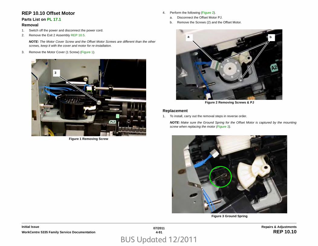
BUS Updated 12/2011
07/20114-91WorkCentre 5335 Family Service Documentation REP 10.10
Repairs & AdjustmentsInitial Issue
REP 10.10 Offset MotorParts List on PL 17.1 Removal1. Switch off the power and disconnect the power cord.
2. Remove the Exit 2 Assembly REP 10.5.
NOTE: The Motor Cover Screw and the Offset Motor Screws are different than the otherscrews, keep it with the cover and motor for re-installation.
3. Remove the Motor Cover (1 Screw) (Figure 1).
Figure 1 Removing Screw
4. Perform the following (Figure 2).
a. Disconnect the Offset Motor PJ.
b. Remove the Screws (2) and the Offset Motor.
Figure 2 Removing Screws & PJ
Replacement1. To install, carry out the removal steps in reverse order.
NOTE: Make sure the Ground Spring for the Offset Motor is captured by the mountingscrew when replacing the motor (Figure 3).
Figure 3 Ground Spring
3
ba

BUS Updated 12/2011
07/20114-92 WorkCentre 5335 Family Service DocumentationREP 10.11, REP 10.12
Initial IssueRepairs & Adjustments
REP 10.11 OTC Home Position SensorParts List on PL 17.1 Removal1. Switch off the power and disconnect the power cord.
2. Remove the Exit 2 Assembly REP 10.5.
3. Remove the Motor Cover (1 Screw) (Figure 1).
Figure 1 Removing Screw
4. Disconnect the PJ from the sensor, and release the sensor from the cover (Figure 2).
Figure 2 PJ
Replacement1. To install, carry out the removal steps in reverse order.
REP 10.12 Registration TransportParts List on PL 15.1Removal1. Switch off the power and disconnect the power cord.
2. Remove the MSI Assembly REP 7.2.
3. Perform the following (Figure 1).
a. Open the Left Hand Cover.
b. Disconnect PJ409 on the MCU PWB, and release the wire harness from the clamps
Figure 1 Removal
3
4
ba

BUS Updated 12/2011
07/20114-93WorkCentre 5335 Family Service Documentation REP 10.12
Repairs & AdjustmentsInitial Issue
NOTE: Support the Left Hand Cover Assembly when releasing the supports to prevent damag-ing the cover.
4. Remove the Left Hand Cover Assembly (Figure 2).
a. Twist the Front Support and remove it from the slot.
b. Remove the K-Clip, and remove the Rear Support from the pin.
c. Move the cover down to a horizontal position, then lift it off the pivots.
Figure 2 Left Hand Cover Removal
NOTE: Support the Registration Transport when removing it to avoid damaging the wire har-ness connectors.
5. Perform the following (Figure 3).
a. Remove the transport Screws (2).
b. Move the Front of the transport out of the slot and move the transport out.
Figure 3 Removing Screws
6. Remove the Registration Transport (Figure 4).
a. Release the wires from the clamps.
b. Disconnect the Registration Transport PJ’s (2), and remove the transport.
Figure 4 PJ’s
Replacement1. To install, carry out the removal steps in reverse order.
a
b
c
a
b
a
b

BUS Updated 12/2011
07/20114-94 WorkCentre 5335 Family Service DocumentationREP 10.12
Initial IssueRepairs & Adjustments

BUS Updated 12/2011
07/20114-95WorkCentre 5335 Family Service Documentation REP 12.1
Repairs & AdjustmentsInitial Issue
REP 12.1 Integrated Office FinisherParts List on PL 22.1Removal1. Switch off the power and disconnect the power cord.
2. Disconnect the Integrated Office Finisher Wire Harness:
(1)Remove the Cover.(Figure 1)
Figure 1 Remove Cover
(2)Remove Clamp. (Figure 2)
(3)Disconnect Connectors (2). (Figure 2)
Figure 2 Disconnect Connectors
3. Loosen the Thumb Screws (2) (Figure 3):
1Remove Cover
2Remove Clamp
3Disconnect Connectors (2)

BUS Updated 12/2011
07/20114-96 WorkCentre 5335 Family Service DocumentationREP 12.1, REP 12.2
Initial IssueRepairs & Adjustments
Figure 3 Loosen the Thumb Screws
4. Remove the Integrated Office Finisher.
Replacement1. Reverse the removal procedure for replacement.
REP 12.2 Paddle BeltParts List on PL 22.3 Removal1. Switch off the power and disconnect the power cord
2. Remove the Integrated Office Finisher from the machine (REP 12.1).
3. Remove the Compiler Assembly (REP 12.20)
4. Remove the front Pulley (Figure 1):
(1)Remove E-Clip.
(2)Remove Flange.
(3)Remove Belt from Pulley.
(4)Remove Pulley.
Figure 1 Removing the Pulley
5. Remove the Front Bearing (Figure 2):
(1)Remove Bearing.
Thumb Screws (2)

BUS Updated 12/2011
07/20114-97WorkCentre 5335 Family Service Documentation REP 12.2
Repairs & AdjustmentsInitial Issue
Figure 2 Removing the Front Bearing
6. Remove the Rear Gear (Figure 3)
(1)Remove E-Clip.
(2)Remove Gear.
Figure 3 Removing the Gear
7. Remove the Rear Bearing (Figure 4):
(1)Remove Bearing.
Figure 4 Removing the Bearing
8. Remove the Paddle Link Assembly (Figure 5):
(1)Remove Paddle Link Assembly.
Figure 5 Removing the Paddle Link Assembly

BUS Updated 12/2011
07/20114-98 WorkCentre 5335 Family Service DocumentationREP 12.2
Initial IssueRepairs & Adjustments
9. Remove the Bearing (Figure 6):
(1)Remove E-Clip.
(2)Remove Bearing.
Figure 6 Removing Bearing
10. Remove the Shaft Assembly (Figure 7):
(1)Remove Paddle Belt from Pulley.
(2)Remove Shaft Assembly in the direction of the arrow.
Figure 7 Removing Shaft Assembly
11. Remove the Paddle Belt (Figure 8):
(1)Remove E-Clips (2).
(2)Move Bearings (2) in the direction of the arrow.
(3)Remove Sub Paddle Shaft Assembly.
(4)Remove Paddle Belt.
Figure 8 Removing the Paddle Belt
Replacement1. Reverse the removal procedure for replacement.
2. Install the Paddle Link Assembly as shown in Figure 9.
Figure 9 Installing the Paddle Link Assembly

BUS Updated 12/2011
07/20114-99WorkCentre 5335 Family Service Documentation REP 12.3
Repairs & AdjustmentsInitial Issue
REP 12.3 Sub Paddle SolenoidParts List on PL 22.3Removal1. Switch off the power and disconnect the power cord.
2. Remove the Integrated Office Finisher from the machine (REP 12.1).
3. Remove the Inner Front Cover (PL 22.1)
4. Turn over the Integrated Office Finisher.
5. Remove the Bottom Cover (PL 22.2)
6. Disconnect the Connector (Figure 1):
(1)Release Clamps (3) and remove the wire.
(2)Disconnect Connector.
Figure 1 Disconnecting the Connector
7. Turn over the Integrated Office Finisher.
8. Remove the Sub Paddle Solenoid Assembly (Figure 2):
(1)Disconnect Connector.
(2)Release Wire from Hook.
(3)Remove Screws (2).
(4)Remove Sub Paddle Solenoid Assembly.
Figure 2 Removing the Sub Paddle Solenoid Assembly
9. Remove the Support (Figure 3):
(1)Remove Screw.
(2)Remove Support.
Figure 3 Removing the Support
10. Remove the Sub Paddle Solenoid (Figure 4):
(1)Remove Screws (2).
(2)Remove the Sub Paddle Solenoid.

BUS Updated 12/2011
07/20114-100 WorkCentre 5335 Family Service DocumentationREP 12.3, REP 12.5
Initial IssueRepairs & Adjustments
Figure 4 Removing the Sub Paddle Solenoid
Replacement1. Reverse the removal procedure for replacement.
2. Install the Sub Paddle Assembly as shown in Figure 5.
Figure 5 Installing the Sub Paddle Assembly
REP 12.5 Staple AssemblyParts List on PL 22.4Removal1. Switch off the power and disconnect the power cord.
2. Remove the Integrated Office Finisher from the machine (REP 12.1).
3. Remove the Inner Front Cover (PL 22.1)
4. Remove the Staple Assembly (Figure 1):
(1)Remove Clamps (2).
(2)Disconnect Connectors (2).
(3)Remove Screws (2).
(4)Remove Staple Assembly.
Figure 1 Removing the Staple Assembly
5. Remove the Bracket from the Staple Assembly (Figure 2):
(1)Remove Screws (2).
(2)Remove Bracket.

BUS Updated 12/2011
07/20114-101WorkCentre 5335 Family Service Documentation REP 12.5, REP 12.6
Repairs & AdjustmentsInitial Issue
Figure 2 Removing the Bracket
Replacement1. Reverse the removal procedure for replacement.
REP 12.6 Set Clamp Home SensorParts List on PL 22.4Removal1. Switch off the power and disconnect the power cord.
2. Remove the Integrated Office Finisher from the machine (REP 12.1).
3. Remove the Rear Cover (PL 22.1)
4. Disconnect the Connector (Figure 1):
(1)Release Clamp and remove the wire.
(2)Disconnect Connector.
Figure 1 Disconnecting Connector
5. Remove the Set Clamp Home Sensor Assembly (Figure 2):
(1)Remove Screw.
(2)Remove Set Clamp Home Sensor Assembly.

BUS Updated 12/2011
07/20114-102 WorkCentre 5335 Family Service DocumentationREP 12.6, REP 12.7
Initial IssueRepairs & Adjustments
Figure 2 Removing the Set Clamp Home Sensor Assembly
6. Remove the Set Clamp Home Sensor (Figure 3):
(1)Remove Set Clamp Home Sensor from Bracket.
(2)Disconnect Connector.
Figure 3 Removing the Set Clamp Home Sensor
Replacement1. Reverse the removal procedure for replacement.
REP 12.7 Exit Roll AssemblyParts List on PL 22.4 Removal
NOTE: The Integrated Office Finisher is available for use in several different machines. Thecolor of the Covers may be different from product to product, however, the repair proceduresare the same.
1. Switch off the power and disconnect the power cord.
2. Remove the Integrated Office Finisher from the machine (REP 12.1).
3. Remove the Inner Front Cover (PL 22.1)
4. Remove the Rear Cover (PL 22.1)
5. Remove the Left Cover (PL 22.2)
6. Remove the Upper Frame Section (Figure 1):
(1)Remove Screw and Bracket.
(2)Remove Screws (2).
(3)Remove Screw and Bracket.
(4)Remove Screws (2).
(5)Remove the Upper Frame Section

BUS Updated 12/2011
07/20114-103WorkCentre 5335 Family Service Documentation REP 12.7
Repairs & AdjustmentsInitial Issue
Figure 1 Removing the Upper Frame Section
NOTE: The screws do not thread into the Upper Chute. They are used like pins to securethe Upper Chute in place.
7. Remove the Upper Chute Assembly (Figure 2):
(1)Remove Screws (2).
(2)Remove Screw.
(3)Carefully Remove the Upper Chute Assembly.
Figure 2 Removing the Upper Chute Assembly
8. Remove the Exit Roll Assembly (Figure 3):
(1)Remove E-ring and Bearing.
(2)Remove E-ring and Bearing.
(3)Remove the Exit Roll Assembly.

BUS Updated 12/2011
07/20114-104 WorkCentre 5335 Family Service DocumentationREP 12.7, REP 12.8
Initial IssueRepairs & Adjustments
Figure 3 Removing the Exit Roll Assembly
Replacement1. Reverse the removal procedure for replacement.
NOTE: Ensure that the Paper Guides on the Upper Chute (PL 22.6) are not folded backon top of the Exit Roll Assembly.
REP 12.8 Pinch RollParts List on PL 22.5 Removal1. Switch off the power and disconnect the power cord.
2. Remove the Integrated Office Finisher from the machine (REP 12.1).
3. Remove the Compiler Assembly (REP 12.20)
4. Remove the Pinch Roll (Figure 1):
(1)Raise Springs (4) in the direction of the arrow.
(2)Remove Pinch Rolls (4).
Figure 1 Removing the Pinch Rolls
Replacement1. Reverse the removal procedure for replacement.
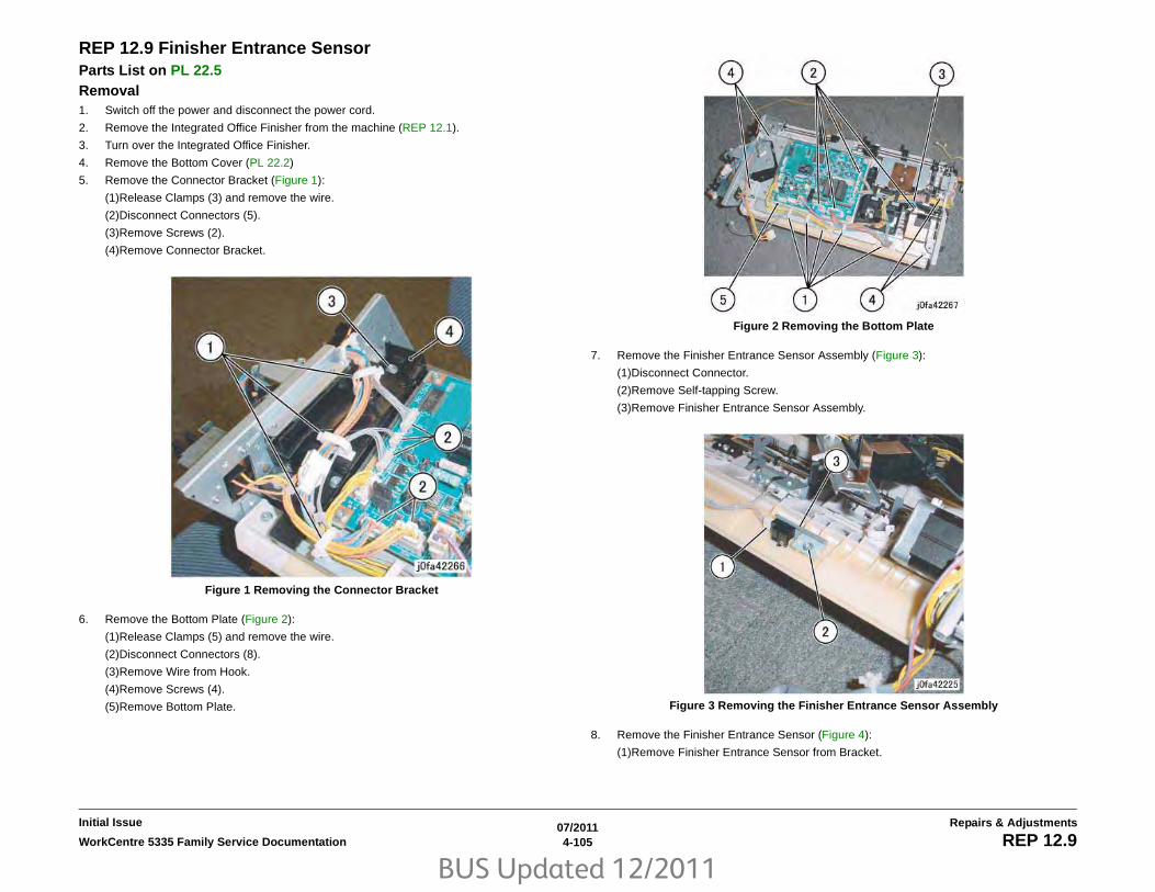
BUS Updated 12/2011
07/20114-105WorkCentre 5335 Family Service Documentation REP 12.9
Repairs & AdjustmentsInitial Issue
REP 12.9 Finisher Entrance SensorParts List on PL 22.5Removal1. Switch off the power and disconnect the power cord.
2. Remove the Integrated Office Finisher from the machine (REP 12.1).
3. Turn over the Integrated Office Finisher.
4. Remove the Bottom Cover (PL 22.2)
5. Remove the Connector Bracket (Figure 1):
(1)Release Clamps (3) and remove the wire.
(2)Disconnect Connectors (5).
(3)Remove Screws (2).
(4)Remove Connector Bracket.
Figure 1 Removing the Connector Bracket
6. Remove the Bottom Plate (Figure 2):
(1)Release Clamps (5) and remove the wire.
(2)Disconnect Connectors (8).
(3)Remove Wire from Hook.
(4)Remove Screws (4).
(5)Remove Bottom Plate.
Figure 2 Removing the Bottom Plate
7. Remove the Finisher Entrance Sensor Assembly (Figure 3):
(1)Disconnect Connector.
(2)Remove Self-tapping Screw.
(3)Remove Finisher Entrance Sensor Assembly.
Figure 3 Removing the Finisher Entrance Sensor Assembly
8. Remove the Finisher Entrance Sensor (Figure 4):
(1)Remove Finisher Entrance Sensor from Bracket.

BUS Updated 12/2011
07/20114-106 WorkCentre 5335 Family Service DocumentationREP 12.9, REP 12.10
Initial IssueRepairs & Adjustments
Figure 4 Removing the Finisher Entrance Sensor
Replacement1. Reverse the removal procedure for replacement.
REP 12.10 Compiler Exit SensorParts List on PL 22.5Removal1. Switch off the power and disconnect the power cord.
2. Remove the Integrated Office Finisher from the machine (REP 12.1).
3. Turn over the Integrated Office Finisher.
4. Remove the Bottom Cover (PL 22.2)
5. Remove the Connector Bracket (Figure 1):
(1)Release Clamps (3) and remove the wire.
(2)Disconnect Connectors (5).
(3)Remove Screws (2).
(4)Remove Connector Bracket.
Figure 1 Removing the Connector Bracket
6. Remove the Bottom Plate (Figure 2):
(1)Release Clamps (5) and remove the wire.
(2)Disconnect Connectors (8).
(3)Release Wire from Hook.
(4)Remove Screws (4).
(5)Remove Bottom Plate.

BUS Updated 12/2011
07/20114-107WorkCentre 5335 Family Service Documentation REP 12.10
Repairs & AdjustmentsInitial Issue
Figure 2 Removing the Bottom Plate
7. Remove the Compiler Exit Sensor Assembly (Figure 3):
(1)Remove Screw.
(2)Remove Compiler Exit Sensor Assembly.
Figure 3 Removing the Compiler Exit Sensor Assembly
8. Remove the Compiler Exit Sensor (Figure 4):
(1)Release Clamps (2) and remove the wire.
(2)Disconnect Connector.
(3)Remove Compiler Exit Sensor.
Figure 4 Removing the Compiler Exit Sensor
Replacement1. Reverse the removal procedure for replacement.

BUS Updated 12/2011
07/20114-108 WorkCentre 5335 Family Service DocumentationREP 12.11
Initial IssueRepairs & Adjustments
REP 12.11 Main Paddle Shaft AssemblyParts List on PL 22.5Removal1. Switch off the power and disconnect the power cord.
2. Remove the Integrated Office Finisher from the machine (REP 12.1).
3. Remove the Compiler Assembly (REP 12.20)
4. Remove the Gear (Figure 1):
(1)Remove E-Clip.
(2)Remove Gear.
(3)Remove KL-Clip.
(4)Remove Gear.
Figure 1 Removing the Gear
5. Remove the Gear Pulley (Figure 2):
(1)Remove E-Clip.
(2)Remove Gear.
(3)Remove Flange.
Figure 2 Removing the Gear Pulley
6. Remove the Bearing (Figure 3):
(1)Remove Bearing.
Figure 3 Removing the Bearing
7. Remove the Support Bearing from the Entrance Lower Chute Assembly (Figure 4):
(1)Remove Self-tapping Screw.
(2)Remove Support Bearing.

BUS Updated 12/2011
07/20114-109WorkCentre 5335 Family Service Documentation REP 12.11
Repairs & AdjustmentsInitial Issue
Figure 4 Removing the Support Bearing
8. Remove the Main Paddle Shaft Assembly (Figure 5):
(1)Remove Main Paddle Shaft Assembly.
Figure 5 Removing the Main Paddle Shaft Assembly
9. Remove the Support Bearing from the Main Paddle Shaft Assembly (Figure 6):
(1)Remove E-Clip.
(2)Remove Support Bearing.
Figure 6 Removing the Support Bearing
Replacement1. Reverse the removal procedure for replacement.

BUS Updated 12/2011
07/20114-110 WorkCentre 5335 Family Service DocumentationREP 12.12
Initial IssueRepairs & Adjustments
REP 12.12 Lower Chute AssemblyParts List on PL 22.5 Removal1. Switch off the power and disconnect the power cord.
2. Remove the Integrated Office Finisher from the machine (REP 12.1).
3. Remove the Compiler Assembly (REP 12.20)
4. Turn over the Integrated Office Finisher (Transport).
5. Remove the Stapler Assembly (Figure 1):
(1)Release Clamps (2) and remove the wire.
(2)Disconnect Connectors (2).
(3)Remove Screws (2).
(4)Remove Stapler Assembly.
Figure 1 Removing the Stapler Assembly
6. Turn over the Integrated Office Finisher.
7. Remove the Transport Motor (Figure 2):
(1)Remove Screws (2).
(2)Remove Belt from Pulley.
(3)Remove Transport Motor.
Figure 2 Removing the Transport Motor
8. Remove the Gear (Figure 3):
(1)Remove E-Clip.
(2)Remove Gear.
(3)Remove KL-Clip.
(4)Remove Gear.
Figure 3 Removing the Gear
9. Remove the Gear Pulley (Figure 4):
(1)Remove E-Clip.

BUS Updated 12/2011
07/20114-111WorkCentre 5335 Family Service Documentation REP 12.12
Repairs & AdjustmentsInitial Issue
(2)Remove Gear.
(3)Remove Pulley from Belt.
(4)Remove Flange.
Figure 4 Removing the Gear Pulley
10. Remove the Bearing (Figure 5):
(1)Remove the Bearing.
Figure 5 Removing the Bearing
11. Remove the Entrance Lower Chute Assembly (Figure 6):
(1)Remove Screws (2).
(2)Loosen Screws (2).
(3)Remove Entrance Lower Chute Assembly.
Figure 6 Removing the Entrance Lower Chute Assembly
Replacement1. Reverse the removal procedure for replacement.

BUS Updated 12/2011
07/20114-112 WorkCentre 5335 Family Service DocumentationREP 12.13
Initial IssueRepairs & Adjustments
REP 12.13 Entrance Roll AssemblyParts List on PL 22.6 Removal
NOTE: The Integrated Office Finisher is available for use in several different machines. Thecolor of the Covers may be different from product to product, however, the repair proceduresare the same.
1. Switch off the power and disconnect the power cord.
2. Remove the Integrated Office Finisher from the machine (REP 12.1).
3. Remove the Inner Front Cover (PL 22.1)
4. Remove the Rear Cover (PL 22.1)
5. Remove the Left Cover (PL 22.2)
6. Remove the Upper Frame Section (Figure 1):
(1)Remove Screw and Bracket.
(2)Remove Screws (2).
(3)Remove Screw and Bracket.
(4)Remove Screws (2).
(5)Remove the Upper Frame Section
Figure 1 Removing the Upper Frame Section
NOTE: The screws do not thread into the Upper Chute. They are used like pins to securethe Upper Chute in place.
7. Remove the Upper Chute Assembly (Figure 2):
(1)Remove Screws (2).
(2)Remove Screw.
(3)Carefully Remove the Upper Chute Assembly.

BUS Updated 12/2011
07/20114-113WorkCentre 5335 Family Service Documentation REP 12.13
Repairs & AdjustmentsInitial Issue
Figure 2 Removing the Upper Chute Assembly
8. Remove the Entrance Roll Assembly (Figure 3):
(1)Disconnect Spring.
(2)Remove E-Rings (2).
NOTE: Capture the Bearing
(3)Remove Arm.
(4)Slide Shaft out of the Bearing in the Arm.
Figure 3 Removing the Gear
Replacement1. Reverse the removal procedure for replacement.
NOTE: Ensure that the Paper Guides on the Upper Chute (PL 22.6) are not folded backon top of the Exit Roll Assembly.

BUS Updated 12/2011
07/20114-114 WorkCentre 5335 Family Service DocumentationREP 12.14
Initial IssueRepairs & Adjustments
REP 12.14 Upper Chute AssemblyParts List on PL 22.6 Removal
NOTE: The Integrated Office Finisher is available for use in several different machines. Thecolor of the Covers may be different from product to product, however, the repair proceduresare the same.
1. Switch off the power and disconnect the power cord.
2. Remove the Integrated Office Finisher from the machine (REP 12.1).
3. Remove the Inner Front Cover (PL 22.1)
4. Remove the Rear Cover (PL 22.1)
5. Remove the Left Cover (PL 22.2)
6. Remove the Upper Frame Section (Figure 1):
(1)Remove Screw and Bracket.
(2)Remove Screws (2).
(3)Remove Screw and Bracket.
(4)Remove Screws (2).
(5)Remove the Upper Frame Section
Figure 1 Removing the Upper Frame Section
NOTE: The screws do not thread into the Upper Chute. They are used like pins to securethe Upper Chute in place.
7. Remove the Upper Chute Assembly (Figure 2):
(1)Remove Screws (2).
(2)Remove Screw.
(3)Carefully Remove the Upper Chute Assembly.

BUS Updated 12/2011
07/20114-115WorkCentre 5335 Family Service Documentation REP 12.14, REP 12.15
Repairs & AdjustmentsInitial Issue
Figure 2 Removing the Upper Chute Assembly
Replacement1. Reverse the removal procedure for replacement.
NOTE: Ensure that the Paper Guides (PL 22.6) are not folded back on top of the Exit RollAssembly.
REP 12.15 Finisher PWBParts List on PL 22.7 Removal1. Switch off the power and disconnect the power cord.
2. Remove the Integrated Office Finisher from the machine (REP 12.1).
3. Turn over the Finisher.
4. Remove the Bottom Cover (PL 22.2)
5. Remove the Finisher PWB (Figure 1):
(1)Disconnect Connectors (12).
(2)Remove Screws (4).
(3)Remove Finisher PWB.
Figure 1 Removing the Finisher PWB
Replacement1. Reverse the removal procedure for replacement.

BUS Updated 12/2011
07/20114-116 WorkCentre 5335 Family Service DocumentationREP 12.16
Initial IssueRepairs & Adjustments
REP 12.16 Stacker Tray AssemblyParts List on PL 22.8 Removal1. Switch off the power and disconnect the power cord.
2. Remove the Integrated Office Finisher from the machine (REP 12.1).
3. Remove the Inner Front Cover (PL 22.1)
4. Remove the Rear Cover (PL 22.1)
5. Turn over the Integrated Office Finisher.
6. Remove the Bottom Cover (PL 22.2)
7. Remove the Tray Cover (PL 22.2)
8. Disconnect Connector (Figure 1):
(1)Release Clamp.
(2)Remove Clamp.
(3)Release and remove Wire from Hook.
(4)Release Clamp.
(5)Disconnect Connector.
(6)Release and remove Wire from Hook.
Figure 1 Disconnecting the Connector
9. Release the Clamps and the Hook to remove the wire (Figure 2):
(1)Release Clamps (5).
(2)Remove Wire from Hook.
Figure 2 Disconnecting the Wire
10. Remove the Stacker Sensor Assembly (Figure 3):
(1)Remove Screw.
(2)Remove Stacker Sensor Assembly.
(3)Release Clamps (4).
(4)Disconnect Connectors (2).
Figure 3 Removing the Stacker Sensor Assembly
11. Remove the Stacker Tray Assembly (Figure 4):
(1)Remove Screws (5).
(2)Remove Stacker Tray Assembly.

BUS Updated 12/2011
07/20114-117WorkCentre 5335 Family Service Documentation REP 12.16, REP 12.17
Repairs & AdjustmentsInitial Issue
Figure 4 Removing the Stacker Tray Assembly
Replacement1. Reverse the removal procedure for replacement.
2. Install the Stacker Tray Assembly and Integrated Office Finisher as shown in Figure 5.
Figure 5 Installing the Stacker Tray Assembly
REP 12.17 Stacker Shaft AssemblyParts List on PL 22.8Removal1. Switch off the power and disconnect the power cord.
2. Remove the Integrated Office Finisher from the machine (REP 12.1).
3. Remove the Rear Cover (PL 22.1)
4. Turn over the Integrated Office Finisher.
5. Remove the Tray Cover (PL 22.2)
6. Remove the rear Bracket (Figure 1):
(1)Remove Screw.
(2)Remove Bracket.
Figure 1 Removing the Rear Bracket
7. Remove the front Bracket (Figure 2):
(1)Remove Screw.
(2)Remove Bracket.

BUS Updated 12/2011
07/20114-118 WorkCentre 5335 Family Service DocumentationREP 12.17
Initial IssueRepairs & Adjustments
Figure 2 Removing the Front Bracket
8. Remove the Top Tray (Figure 3):
(1)Raise Integrated Office Finisher slightly in the direction of the arrow.
(2)Remove Top Tray.
Figure 3 Removing the Top Tray
9. Disconnect Connector (Figure 4):
(1)Release Clamps (5) and remove the wire.
(2)Release Wire from Hook.
(3)Disconnect Connector.
Figure 4 Disconnecting the Connector
10. Remove the Stacker Sensor Assembly (Figure 5):
(1)Remove Screw.
(2)Remove Stacker Sensor Assembly.
(3)Remove Wire from Clamps (5)
Figure 5 Removing the Stacker Sensor Assembly
11. Remove the Stacker Assembly (Figure 6):

BUS Updated 12/2011
07/20114-119WorkCentre 5335 Family Service Documentation REP 12.17
Repairs & AdjustmentsInitial Issue
(1)Remove Self-tapping Screws (5).
(2)Remove Screw.
(3)Remove Stacker Assembly.
Figure 6 Removing the Stacker Assembly
12. Remove the Actuator (Figure 7):
(1)Unhook.
(2)Remove Actuator.
Figure 7 Removing the Actuator
13. Move the Bearing (Figure 8):
(1)Remove E-Clip.
(2)Move Bearing in the direction of the arrow.
Figure 8 Moving the Bearing
14. Remove the Stacker Shaft Assembly (Figure 9):
(1)Remove Stacker Shaft Assembly in the direction of the arrow.
Figure 9 Removing the Stacker Shaft Assembly
Replacement1. Reverse the removal procedure for replacement.

BUS Updated 12/2011
07/20114-120 WorkCentre 5335 Family Service DocumentationREP 12.18
Initial IssueRepairs & Adjustments
REP 12.18 Stacker MotorParts List on PL 22.8Removal1. Switch off the power and disconnect the power cord.
2. Remove the Integrated Office Finisher from the machine (REP 12.1).
3. Remove the Rear Cover (PL 22.1)
4. Turn over the Integrated Office Finisher.
5. Remove the Tray Cover (PL 22.2)
6. Disconnect the Connector (Figure 1):
(1)Release Clamps (3) and remove the wire.
(2)Release Wire from Hook.
(3)Disconnect Connector.
Figure 1 Disconnecting the Connector
7. Remove the Bracket (Figure 2):
(1)Remove Screw.
(2)Remove Bracket.
Figure 2 Removing the Bracket
8. Remove the Stacker Motor Assembly (Figure 3):
(1)Remove Screws (2).
(2)Remove Stacker Motor Assembly.
Figure 3 Removing the Stacker Motor Assembly
9. Remove the Stacker Motor (Figure 4):
(1)Remove Screws (3).
(2)Remove Belt from Pulley.
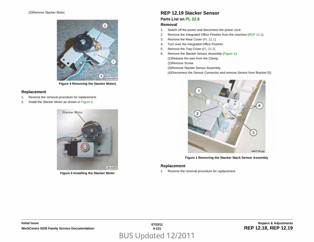
BUS Updated 12/2011
07/20114-121WorkCentre 5335 Family Service Documentation REP 12.18, REP 12.19
Repairs & AdjustmentsInitial Issue
(3)Remove Stacker Motor.
Figure 4 Removing the Stacker Motor)
Replacement1. Reverse the removal procedure for replacement.
2. Install the Stacker Motor as shown in Figure 5.
Figure 5 Installing the Stacker Motor
REP 12.19 Stacker Sensor Parts List on PL 22.8Removal1. Switch off the power and disconnect the power cord.
2. Remove the Integrated Office Finisher from the machine (REP 12.1).
3. Remove the Rear Cover (PL 22.1)
4. Turn over the Integrated Office Finisher.
5. Remove the Tray Cover (PL 22.2)
6. Remove the Stacker Sensor Assembly (Figure 1):
(1)Release the wire from the Clamp.
(2)Remove Screw.
(3)Remove Stacker Sensor Assembly.
(4)Disconnect the Sensor Connector and remove Sensor from Bracket (5)
Figure 1 Removing the Stacker Stack Sensor Assembly
Replacement1. Reverse the removal procedure for replacement.

BUS Updated 12/2011
07/20114-122 WorkCentre 5335 Family Service DocumentationREP 12.20
Initial IssueRepairs & Adjustments
REP 12.20 Compiler AssemblyParts List on PL 22.9 Removal1. Switch off the power and disconnect the power cord.
2. Remove the Integrated Office Finisher from the machine (REP 12.1).
3. Remove the Inner Front Cover (PL 22.1)
4. Remove the Rear Cover (PL 22.1)
5. Turn over the Integrated Office Finisher.
6. Remove the Bottom Cover (PL 22.2)
7. Remove the Tray Cover (PL 22.2)
8. Remove the Connector Bracket (Figure 1):
(1)Release Clamps (3) and remove the wire.
(2)Disconnect Connectors (5).
(3)Remove Screws (2).
(4)Remove Connector Bracket.
Figure 1 Removing the Connector Bracket
9. Remove the Bottom Plate (Figure 2):
(1)Release Clamps (5) and remove the wire.
(2)Disconnect Connectors (8).
(3)Remove Wire from Hook.
(4)Remove Screws (4).
(5)Remove Bottom Plate.
Figure 2 Removing the Bottom Plate
10. Release the Clamp from the wire (Figure 3):
(1)Release Clamp and remove the wire.
Figure 3 Releasing the Clamp
11. Remove the Stacker Tray (Figure 4):
(1)Release wires from Clamps (5)
(2)Disconnect the Connector
(3)Remove Screws (7)
(4)Remove the Stacker Tray

BUS Updated 12/2011
07/20114-123WorkCentre 5335 Family Service Documentation REP 12.20
Repairs & AdjustmentsInitial Issue
Figure 4 Removing the Stacker Tray
12. Remove the front Self-tapping Screw (Figure 5):
(1)Remove Self-tapping Screw.
Figure 5 Removing the Self-tapping Screw
13. Remove the rear Screw (Figure 6):
(1)Remove Screw.
Figure 6 Removing the Screw
14. Remove the Compiler Assembly (Figure 7):
(1)Remove Compiler Assembly.
Figure 7 Removing the Compiler Assembly
Replacement1. Reverse the removal procedure for replacement.

BUS Updated 12/2011
07/20114-124 WorkCentre 5335 Family Service DocumentationREP 12.21
Initial IssueRepairs & Adjustments
REP 12.21 Set Clamp ShaftParts List on PL 22.9Removal1. Switch off the power and disconnect the power cord.
2. Remove the Integrated Office Finisher from the machine (PL 22.1).
3. Remove the Compiler Assembly (REP 12.20)
4. Remove the Bracket Assembly (Figure 1):
(1)Release Clamps (2) and remove the wire.
(2)Remove Screws (2).
(3)Remove Bracket Assembly.
Figure 1 Removing the Bracket Assembly
5. Remove the KL-Clips from the Eject Shaft (Figure 2):
(1)Remove KL-Clips (2).
Figure 2 Removing the KL-Clips
6. Remove the Eject Shaft from the Front/Rear Tamper Motor Assembly (Figure 3):
(1)Move Bearings (2) in the direction of the arrow.
(2)Remove Eject Shaft in the direction of the arrow.
(3)Remove Belt from Pulley.
Figure 3 Removing the Eject Shaft
7. Remove the Actuator and the Bearing (Figure 4):
(1)Remove E-Clip.

BUS Updated 12/2011
07/20114-125WorkCentre 5335 Family Service Documentation REP 12.21
Repairs & AdjustmentsInitial Issue
(2)Remove Actuator.
(3)Remove E-Clip.
(4)Remove Bearing.
Figure 4 Removing the Actuator and Bearing
8. Remove the Bearing (Figure 5):
(1)Remove E-Clip.
(2)Remove Bearing.
Figure 5 Removing the Bearing
9. Remove the Set Clamp Shaft (Figure 6):
(1)Move Set Clamp Shaft in the direction of the arrow.
(2)Remove Belts (3) from Pulleys (3).
(3)Remove Set Clamp Shaft in the direction of the arrow.
Figure 6 Removing the Set Clamp Shaft
Replacement1. Reverse the removal procedure for replacement.
2. Install and align the Eject Belt with marks on the Pulleys (Figure 7):
Figure 7 Installing the Eject Belt

BUS Updated 12/2011
07/20114-126 WorkCentre 5335 Family Service DocumentationREP 12.22
Initial IssueRepairs & Adjustments
REP 12.22 Eject BeltParts List on PL 22.9Removal1. Switch off the power and disconnect the power cord.
2. Remove the Integrated Office Finisher from the machine (PL 22.1).
3. Remove the Compiler Assembly (REP 12.20)
4. Remove the Front/Rear Tamper Motor Assembly (REP 12.26)
5. Move the Eject Home Sensor Assembly (Figure 1):
(1)Remove Screw.
(2)Move Eject Home Sensor Assembly.
Figure 1 Moving the Eject Home Sensor Assembly (j0fa42279)
6. Remove the Eject Belt (Figure 2):
(1)Move the blades of Set Clamp Shaft in the direction of the arrow.
(2)Remove Eject Belt in the direction of the arrow.
Figure 2 Removing the Eject Belt
Replacement1. Reverse the removal procedure for replacement.
2. Install and align the Eject Belt with marks on the Pulleys (Figure 3), (Figure 4)
Figure 3 Eject Belt Alignment

BUS Updated 12/2011
07/20114-127WorkCentre 5335 Family Service Documentation REP 12.22, REP 12.23
Repairs & AdjustmentsInitial Issue
Figure 4 Eject Belt Alignment
REP 12.23 Eject/Set Clamp Motor AssemblyParts List on PL 22.9Removal1. Switch off the power and disconnect the power cord.
2. Remove the Integrated Office Finisher from the machine (REP 12.1).
3. Remove the Inner Front Cover (PL 22.1)
4. Remove the Rear Cover (PL 22.1)
5. Turn over the Integrated Office Finisher.
6. Remove the Bottom Cover (PL 22.2)
7. Remove the Connector Bracket (Figure 1):
(1)Release Clamps (3) and remove the wire.
(2)Disconnect Connectors (5).
(3)Remove Screws (2).
(4)Remove Connector Bracket.
Figure 1 Removing the Connector Bracket
8. Remove the Bottom Plate (Figure 2):
(1)Release Clamps (5) and remove the wire.
(2)Disconnect Connectors (8).
(3)Remove Wire from Hook.
(4)Remove Screws (4).
(5)Remove Bottom Plate.

BUS Updated 12/2011
07/20114-128 WorkCentre 5335 Family Service DocumentationREP 12.23
Initial IssueRepairs & Adjustments
Figure 2 Removing the Bottom Plate
9. Remove the Stacker Tray (Figure 3):
(1)Release wires from Clamps (5)
(2)Disconnect the Connector
(3)Remove Screws (7)
(4)Remove the Stacker Tray
Figure 3 Removing the Stacker Tray
10. Remove the screws securing the Eject/Set Clamp Motor Assembly (Figure 4):
(1)Release Clamps (2) and remove the wire.
(2)Remove Screws (2).
(3)Remove Self-tapping Screws (2).
Figure 4 Removing Screws
11. Remove the Eject/Set Clamp Motor Assembly (Figure 5):
(1)Remove Belts (2) from Pulley.
(2)Remove Eject/Set Clamp Motor Assembly.
Figure 5 Removing the Eject/Set Clamp Motor Assembly
Replacement1. Reverse the removal procedure for replacement.

BUS Updated 12/2011
07/20114-129WorkCentre 5335 Family Service Documentation REP 12.24
Repairs & AdjustmentsInitial Issue
REP 12.24 Rear Tamper Home Sensor Parts List on PL 22.9Removal1. Switch off the power and disconnect the power cord.
2. Remove the Integrated Office Finisher from the machine (REP 12.1).
3. Remove the Inner Front Cover (PL 22.1)
4. Remove the Rear Cover (PL 22.1)
5. Turn over the Integrated Office Finisher.
6. Remove the Bottom Cover (PL 22.2)
7. Remove the Connector Bracket (Figure 1):
(1)Release Clamps (3) and remove the wire.
(2)Disconnect Connectors (5).
(3)Remove Screws (2).
(4)Remove Connector Bracket.
Figure 1 Removing the Connector Bracket
8. Remove the Bottom Plate (Figure 2):
(1)Release Clamps (5) and remove the wire.
(2)Disconnect Connectors (8).
(3)Remove Wire form Hook.
(4)Remove Screw (4).
(5)Remove Bottom Plate.
Figure 2 Moving the Bottom Plate
9. Remove the Rear Tamper Home Sensor Assembly (Figure 3):
(1)Release Clamps (2) and remove the wire.
(2)Remove Self-tapping Screw.
(3)Move Rear Tamper Home Sensor Assembly in order to disconnect the connector.
Figure 3 Removing the Rear Tamper Home Sensor Assembly
10. Remove the Rear Tamper Home Sensor (Figure 4):
(1)Remove Rear Tamper Home Sensor from the bracket.

BUS Updated 12/2011
07/20114-130 WorkCentre 5335 Family Service DocumentationREP 12.24, REP 12.25
Initial IssueRepairs & Adjustments
Figure 4 Removing the Rear Tamper Home Sensor
Replacement1. Reverse the removal procedure for replacement.
REP 12.25 Eject Shaft AssemblyParts List on PL 22.9Removal1. Switch off the power and disconnect the power cord.
2. Remove the Integrated Office Finisher from the machine (PL 22.1).
3. Remove the Compiler Assembly (REP 12.20)
4. Remove the Bracket Assembly (Figure 1):
(1)Release Clamps (2) and remove the wire.
(2)Remove Screws (2).
(3)Remove Bracket Assembly.
Figure 1 Removing the Bracket Assembly
5. Remove the KL-Clips from the Eject Shaft (Figure 2):
(1)Remove KL-Clips (2).
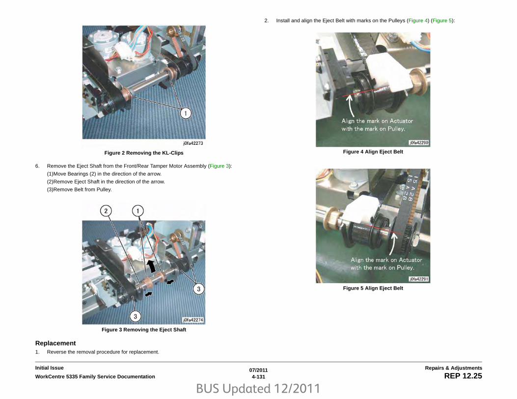
BUS Updated 12/2011
07/20114-131WorkCentre 5335 Family Service Documentation REP 12.25
Repairs & AdjustmentsInitial Issue
Figure 2 Removing the KL-Clips
6. Remove the Eject Shaft from the Front/Rear Tamper Motor Assembly (Figure 3):
(1)Move Bearings (2) in the direction of the arrow.
(2)Remove Eject Shaft in the direction of the arrow.
(3)Remove Belt from Pulley.
Figure 3 Removing the Eject Shaft
Replacement1. Reverse the removal procedure for replacement.
2. Install and align the Eject Belt with marks on the Pulleys (Figure 4) (Figure 5):
Figure 4 Align Eject Belt
Figure 5 Align Eject Belt

BUS Updated 12/2011
07/20114-132 WorkCentre 5335 Family Service DocumentationREP 12.26
Initial IssueRepairs & Adjustments
REP 12.26 Front /Rear Tamper Motor AssemblyParts List on PL 22.10 Removal1. Switch off the power and disconnect the power cord.
2. Remove the Integrated Office Finisher from the machine (PL 22.1).
3. Remove the Compiler Assembly (REP 12.20)
4. Remove the Bracket Assembly (Figure 1):
(1)Release Clamps (2) and remove the wire.
(2)Remove Screws (2).
(3)Remove Bracket Assembly.
Figure 1 Removing the Bracket Assembly
5. Remove the KL-Clips from the Eject Shaft (Figure 2):
(1)Remove KL-Clips (2).
Figure 2 Removing the KL-Clips
6. Remove the Eject Shaft from the Front/Rear Tamper Motor Assembly (Figure 3):
(1)Move Bearings (2) in the direction of the arrow.
(2)Remove Eject Shaft in the direction of the arrow.
(3)Remove Belt from Pulley.
Figure 3 Removing the Eject Shaft
7. Remove the Front/Rear Tamper Motor Assembly (Figure 4):
(1)Remove Self-tapping Screws (2).

BUS Updated 12/2011
07/20114-133WorkCentre 5335 Family Service Documentation REP 12.26
Repairs & AdjustmentsInitial Issue
(2)Remove Screw.
(3)Remove Front/Rear Tamper Motor Assembly.
Figure 4 Removing the Front/Rear Tamper Motor Assembly
Replacement1. Reverse the removal procedure for replacement.
2. Install and align the Eject Belt with marks on the Pulleys (Figure 5) (Figure 6):
Figure 5 Align Eject Belt
Figure 6 Align Eject Belt

BUS Updated 12/2011
07/20114-134 WorkCentre 5335 Family Service DocumentationREP 12.27
Initial IssueRepairs & Adjustments
REP 12.27 Front Tamper Home Sensor Parts List on PL 22.10Removal1. Switch off the power and disconnect the power cord.
2. Remove the Integrated Office Finisher from the machine (REP 12.1).
3. Remove the Inner Front Cover (PL 22.1)
4. Remove the Rear Cover (PL 22.1)
5. Turn over the Integrated Office Finisher.
6. Remove the Bottom Cover (PL 22.2)
7. Remove the Connector Bracket (Figure 1):
(1)Release Clamps (3) and remove the wire.
(2)Disconnect Connectors (5).
(3)Remove Screws (2).
(4)Remove Connector Bracket.
Figure 1 Removing the Connector Bracket
8. Remove the Bottom Plate (Figure 2):
(1)Release Clamps (5) and remove the wire.
(2)Disconnect Connectors (8).
(3)Remove Wire from Hook.
(4)Remove Screws (4).
(5)Remove Bottom Plate.
Figure 2 Removing the Bottom Plate
9. Remove the Front Tamper Home Sensor Assembly (Figure 3):
(1)Remove Screw.
(2)Remove Front Tamper Home Sensor Assembly.
Figure 3 Removing the Front Tamper Home Sensor Assembly
10. Remove the Front Tamper Home Sensor Assembly (Figure 4):
(1)Disconnect Connector.
(2)Remove Front Tamper Home Sensor Assembly.

BUS Updated 12/2011
07/20114-135WorkCentre 5335 Family Service Documentation REP 12.27, REP 12.28
Repairs & AdjustmentsInitial Issue
Figure 4 Removing the Front Tamper Home Sensor
Replacement1. Reverse the removal procedure for replacement.
REP 12.28 Eject Clamp Home SensorParts List on PL 22.10Removal1. Switch off the power and disconnect the power cord.
2. Remove the Integrated Office Finisher from the machine (REP 12.1).
3. Turn over the Integrated Office Finisher.
4. Remove the Bottom Cover (PL 22.2)
5. Remove the Connector Bracket (Figure 1):
(1)Release Clamps (3) and remove the wire.
(2)Disconnect Connectors (5).
(3)Remove Screws (2).
(4)Remove Connector Bracket.
Figure 1 Removing the Connector Bracket
6. Remove the Bottom Plate (Figure 2):
(1)Release Clamps (5) and remove the wire.
(2)Disconnect Connectors (8).
(3)Remove Wire from Hook.
(4)Remove Screws (4).
(5)Remove Bottom Plate.

BUS Updated 12/2011
07/20114-136 WorkCentre 5335 Family Service DocumentationREP 12.28, REP 12.29
Initial IssueRepairs & Adjustments
Figure 2 Removing the Bottom Plate
7. Remove the Eject Home Sensor (Figure 3):
(1)Release Clamp and remove the wire.
(2)Disconnect Connector.
(3)Remove Eject Home Sensor from the bracket.
Figure 3 Removing the Eject Home Sensor
Replacement1. Reverse the removal procedure for replacement.
REP 12.29 Stack Height SensorParts List on PL 22.10Removal1. Switch off the power and disconnect the power cord.
2. Remove the Integrated Office Finisher from the machine (REP 12.1).
3. Remove the Inner Front Cover (PL 22.1)
4. Remove the Rear Cover (PL 22.1)
5. Turn over the Integrated Office Finisher.
6. Remove the Bottom Cover (PL 22.2)
7. Remove the Connector Bracket (Figure 1):
(1)Release Clamps (3) and remove the wire.
(2)Disconnect Connectors (5).
(3)Remove Screws (2).
(4)Remove Connector Bracket.
Figure 1 Removing the Connector Bracket
8. Remove the Bottom Plate (Figure 2):
(1)Release Clamps (5) and remove the wire.
(2)Disconnect Connectors (8).
(3)Remove Wire from Hook.
(4)Remove Screws (4).
(5)Remove Bottom Plate.

BUS Updated 12/2011
07/20114-137WorkCentre 5335 Family Service Documentation REP 12.29
Repairs & AdjustmentsInitial Issue
Figure 2 Removing the Bottom Plate
9. Remove the Stacker Tray (Figure 3):
(1)Release wires from Clamps (5)
(2)Disconnect the Connector
(3)Remove Screws (7)
(4)Remove the Stacker Tray
Figure 3 Removing the Stacker Tray
10. Remove the Bracket Assembly (Figure 4):
(1)Release Clamps (2) and remove the wire.
(2)Remove Screws (2).
(3)Remove Bracket Assembly.
Figure 4 Removing the Bracket Assembly
11. Remove the Stack Height Sensor (Figure 5):
(1)Remove Clamp.
(2)Release Clamps (4) and remove the wire.
(3)Disconnect Connector.
(4)Remove Stack Height Sensor from the bracket.
Figure 5 Removing the Stack Height Sensor
Replacement1. Reverse the removal procedure for replacement.

BUS Updated 12/2011
07/20114-138 WorkCentre 5335 Family Service DocumentationREP 12.29
Initial IssueRepairs & Adjustments

BUS Updated 12/2011
07/20114-139WorkCentre 5335 Family Service Documentation REP 13.1, REP 13.2
Repairs & AdjustmentsInitial Issue
REP 13.1 H-Transport Assembly (Office Finisher LX)Parts List on PL 23.1Removal1. Switch off the power and disconnect the power cord.
2. Undock the Finisher Assembly (REP 13.5).
3. Move the H-Transport Assembly (Figure 1).
Figure 1 Removing the Docking Bracket
Replacement1. To install, carry out the removal steps in reverse order.
REP 13.2 Hole Punch Assembly (Office Finisher LX)Parts List on PL 23.2Removal1. Switch off the power and disconnect the power cord.
2. Open the H-Transport Top Cover and hold it open.
3. Open the H-Transport Front Cover.
4. Remove the Hole Punch Assembly (Figure 1).
Figure 1 Removing the Hole Punch Assembly
Replacement1. Insert the Hole Punch Assembly rear locating pin into the H-Transport frame.
2. Install the Hole Punch Assembly in reverse order of removal.
3. Perform ADJ 12.1 Finisher LX Hole Punch Position
1Disconnect Har-ness
2Remove Screws (2)
3Remove Docking Plate.
4Remove the H- Transport
2Remove the Connector Cover and disconnect the connector
1Disconnect the cable clamp
3Remove the Thumb Screw
4Remove the Hole Punch Assem-bly
Front Cover

BUS Updated 12/2011
07/20114-140 WorkCentre 5335 Family Service DocumentationREP 13.3, REP 13.4
Initial IssueRepairs & Adjustments
REP 13.3 H-Transport Belt (Office Finisher LX)Parts List on PL 23.4Removal1. Switch off the power and disconnect the power cord.
2. Remove the H-Transport Assembly (REP 13.1).
3. Remove the screws (2) on the H-Transport Rear Cover and remove the Cover.
4. Loosen the screws (2) on the Tension Bracket (Figure 1).
5. Remove the Belt.
Figure 1 Removing the H-Transport Belt
ReplacementInstall the H-Transport Belt in reverse order of removal.
REP 13.4 H-Transport Motor (Office Finisher LX)Parts List on PL 23.4Removal1. Switch off the power and disconnect the power cord.
2. Remove the H-Transport Assembly (REP 13.1).
3. Remove the H-Transport Rear Cover.
4. Place the H-Transport top down on a work surface.
5. Remove the H-Transport motor (Figure 1).
Figure 1 Removing the H-Transport Drive Motor
ReplacementReplace in reverse order of removal.
1Loosen the screws (2)
2Remove the Belt
1Remove the Screw and remove the Shield.
3Loosen the Screws (2) to remove Belt Tension.
4Remove the Screws (2) and remove the Motor.
2Disconnect the Connector

BUS Updated 12/2011
07/20114-141WorkCentre 5335 Family Service Documentation REP 13.5
Repairs & AdjustmentsInitial Issue
REP 13.5 Finisher LX Undocking Parts List on PL 23.1Removal1. Switch off the power and disconnect the Printer power cord.
2. Disconnect the Finisher Power Cord, the H-Transport Connector and the Finisher Con-nector from the IOT.
CAUTION
The Finisher is unstable when not docked with the Printer. Use care when handling anundocked Finisher so that it does not fall over.
3. Rotate the Feet (2) to free the Finisher. (Figure 1)
Figure 1 Finisher Feet
4. Open the Front Door of the Finisher.
5. Release the Screw that secures the Docking Plate and detach the Finisher.
(1) Remove the Screw.
(2) Pull the Docking Plate Lever towards you and detach the Finisher.(Figure 2).
Figure 2 Finisher Lever
Replacement1. Align the Printer Docking Bracket with the cut outs in the Finisher Docking Bracket.
2. Mate the Printer and the Finisher until it latches.
3. Check that the Finisher is firmly latched to the Printer.
4. Perform the remainder of the replacement procedure in reverse order of removal.
1Rotate the Feet
1Screw
2Docking Plate Lever

BUS Updated 12/2011
07/20114-142 WorkCentre 5335 Family Service DocumentationREP 13.6, REP 13.7
Initial IssueRepairs & Adjustments
REP 13.6 Front Cover Assembly (Office Finisher LX)Parts List on PL 23.6Removal1. Switch off the power and disconnect the power cord.
2. Undock the Finisher (REP 13.5).
CAUTION
Do not drop the Booklet Maker Thumb screw into the Finisher.
3. Remove the Booklet Maker and set aside (REP 13.31).
4. Open the Finisher upper Front Door.
5. Remove the screws (5).
6. Remove the Front Cover Assembly.
Replacement1. To install, carry out the removal steps in reverse order.
REP 13.7 Rear Upper Cover (Office Finisher LX)Parts List on PL 23.6Removal1. Switch off the power and disconnect the power cord.
2. Undock the Finisher (REP 13.5).
3. Remove the Booklet Maker (REP 13.31).
4. Remove the Rear Upper Cover.
(1) Remove the screws (4).
(2) Remove the Rear Upper Cover.
Replacement1. To install, carry out the removal steps in reverse order.

BUS Updated 12/2011
07/20114-143WorkCentre 5335 Family Service Documentation REP 13.8, REP 13.9
Repairs & AdjustmentsInitial Issue
REP 13.8 Rear Lower Cover (Office Finisher LX)Parts List on PL 23.6 Removal1. Switch off the power and disconnect the power cord.
2. Undock the Finisher (REP 13.5).
3. Remove the Rear Lower Cover.
(1) Remove the screws (3).
(2) Remove the Cover.
Replacement1. To install, carry out the removal steps in reverse order.
REP 13.9 Eject Cover (Office Finisher LX)Parts List on PL 23.10Removal1. Switch off the power and disconnect the power cord.
2. Remove the Eject Cover (Figure 1).
(1) Unlatch the Eject Cover, and move it to the left.
(2) Remove the Retaining Screw (1).
(3) Push the Latch through the hole in the Cover.
(4) Remove the Cover by moving it to the left.
Figure 1 Removing the Eject Cover
Eject Cover
Retaining Screw
Latch

BUS Updated 12/2011
07/20114-144 WorkCentre 5335 Family Service DocumentationREP 13.9
Initial IssueRepairs & Adjustments
Replacement1. Align the Eject Cover with the Pins (2) on both sides, and slide it to the right (Figure 2).
NOTE: The left side of the Cover is now captured by the Pins and cannot be lifted up.
Figure 2 Aligning the Eject Cover
2. Position the Eject Cover so that the Latch is inserted in the hole (Figure 3).
NOTE: The Latch must be outside the hole.
Figure 3 Inserting the Latch through the hole in the Cover
3. Place the Latch Spring in the position shown (Figure 4).
Figure 4 Positioning the Latch Spring
Pin (2)
Eject Cover
Latch
Eject Cover
Latch Spring

BUS Updated 12/2011
07/20114-145WorkCentre 5335 Family Service Documentation REP 13.9, REP 13.10
Repairs & AdjustmentsInitial Issue
4. Make sure the Latch Hook and Latch Pin are positioned as shown (Figure 5).
Figure 5 Positioning the Latch Hook and Latch Pin
5. Install the Retaining Screw (1) (Figure 6).
Figure 6 Installing the Retaining Screw
REP 13.10 Foot Cover (Office Finisher LX)Parts List on PL 23.6 Removal1. Switch off the power and disconnect the power cord.
2. Remove the Screw (1) (Figure 1).
3. Remove the Foot Cover.
Figure 1 Removing the Foot Cover
Replacement1. Reverse the removal procedure for replacement.
Latch Hook Latch Pin
Retaining Screw
Screw
Foot Cover

BUS Updated 12/2011
07/20114-146 WorkCentre 5335 Family Service DocumentationREP 13.11, REP 13.12
Initial IssueRepairs & Adjustments
REP 13.11 Stacker Lower Cover (Office Finisher LX)Parts List on PL 23.6 Removal1. Switch off the power and disconnect the power cord.
2. Remove the Foot Cover (REP 13.10).
3. Remove the Screws (2) (Figure 1).
4. Remove the Stacker Lower Cover.
Figure 1 Removing the Stacker Lower Cover
Replacement1. Reverse the removal procedure for replacement.
REP 13.12 Stacker Upper Cover (Office Finisher LX)Parts List on PL 23.7 Removal1. Switch off the power and disconnect the power cord.
2. Remove the Stacker Tray (REP 13.20).
3. Remove the Stacker Lower Cover (REP 13.11).
4. Remove the Screws (6) (Figure 1).
5. Remove the Stacker Upper Cover.
Figure 1 Removing the Stacker Upper Cover
Replacement1. Reverse the removal procedure for replacement.
Stacker Lower Cover
Screw (2)
Stacker Upper Cover
Screw (6)

BUS Updated 12/2011
07/20114-147WorkCentre 5335 Family Service Documentation REP 13.13, REP 13.14
Repairs & AdjustmentsInitial Issue
REP 13.13 Stack Height Sensors 1 and 2 (Office Finisher LX)Parts List on PL 23.11 Removal1. Switch off the power and disconnect the power cord.
2. Remove the Rear Upper Cover (REP 13.7).
3. Remove the Stack Height Sensor 1 or 2 (Figure 1).
(1) Disconnect the connector.
(2) Remove the Sensor.
Figure 1 Removing the Stack Height Sensor 1 or 2
REP 13.14 Sub Paddle Solenoid Assembly (Office Finisher LX)Parts List on PL 23.10 Removal1. Switch off the power and disconnect the power cord.
2. Remove the Eject Cover (REP 13.9).
3. Remove the Sub Paddle Solenoid Assembly (Figure 1).
(1) Disconnect the connector.
(2) Remove the wires from the wire clamps
(3) Remove the screw (1) from the Sub Paddle Solenoid Assembly.
(4) Remove the Sub Paddle Solenoid Assembly.
Figure 1 Removing the Sub Paddle Solenoid Assembly
1Discon-nect the connec-tor
2Remove the Sen-sor
Stack Height Sen-sor 2
Stack Height Sensor 1
1Discon-nect the Connec-tor
2Remove wires from wire clamp
3Remove the screw (1)

BUS Updated 12/2011
07/20114-148 WorkCentre 5335 Family Service DocumentationREP 13.15
Initial IssueRepairs & Adjustments
REP 13.15 Stapler Motor (Office Finisher LX)Parts List on PL 23.8 Removal1. Switch off the power and disconnect the power cord.
2. Remove the Finisher Stapler Assembly (REP 13.16).
3. Remove the Screws (2) (Figure 1).
Figure 1 Removing the Screws
4. Remove the Wire Guide (Figure 2).
(1) Pull out the Cable Clamps (3), and remove the wires from the Wire Guide.
(2) Remove the Screws (2).
(3) Remove the Wire Guide.
Figure 2 Removing the Wire Guide
5. Remove the Stapler Motor (Figure 3).
(1) Remove the wires from the Cable Clamp.
(2) Disconnect the Connector.
(3) Remove the Screws (2).
(4) Remove the Stapler Motor.
Screws
Cable Clamps
Screws
Wire Guide
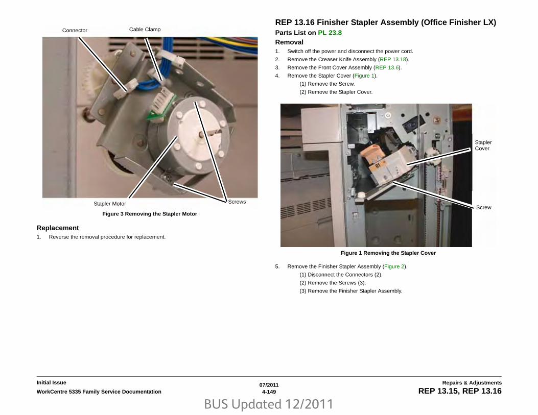
BUS Updated 12/2011
07/20114-149WorkCentre 5335 Family Service Documentation REP 13.15, REP 13.16
Repairs & AdjustmentsInitial Issue
Figure 3 Removing the Stapler Motor
Replacement1. Reverse the removal procedure for replacement.
REP 13.16 Finisher Stapler Assembly (Office Finisher LX)Parts List on PL 23.8 Removal1. Switch off the power and disconnect the power cord.
2. Remove the Creaser Knife Assembly (REP 13.18).
3. Remove the Front Cover Assembly (REP 13.6).
4. Remove the Stapler Cover (Figure 1).
(1) Remove the Screw.
(2) Remove the Stapler Cover.
Figure 1 Removing the Stapler Cover
5. Remove the Finisher Stapler Assembly (Figure 2).
(1) Disconnect the Connectors (2).
(2) Remove the Screws (3).
(3) Remove the Finisher Stapler Assembly.
Cable ClampConnector
ScrewsStapler Motor
StaplerCover
Screw

BUS Updated 12/2011
07/20114-150 WorkCentre 5335 Family Service DocumentationREP 13.16, REP 13.17
Initial IssueRepairs & Adjustments
Figure 2 Removing the Finisher Stapler Assembly
ReplacementReverse the removal procedure for replacement.
Perform ADJ 12.2 Finisher LX Booklet Crease/Staple Position
REP 13.17 Compiler Tray Assembly (Office Finisher LX)Parts List on PL 23.12 Removal1. Switch off the power and disconnect the power cord.
2. Undock the Finisher (REP 13.5).
3. Remove the Front Cover (REP 13.6).
4. Remove the Rear Upper Cover (REP 13.7).
5. Remove the Foot Cover (REP 13.10).
6. Remove the Stacker Lower Cover (REP 13.11).
7. Remove the Stacker Tray (REP 13.20).
8. Remove the Stacker Upper Cover (REP 13.12).
9. Remove the Eject Cover (REP 13.9).
10. Preparing to remove the Eject Roller Shaft (Figure 1).
Figure 1 Removing the E-ring and brass bearing
11. Remove the Eject Roll Shaft (Figure 2).
(1) Remove the E-ring and brass bearing from the front of the shaft.
(2) Remove the E-ring,
(3) Slide the Eject Roller shaft toward the front.
(4) Remove the Gear, and brass bushing.
(5) Remove the Eject Roll from the Finisher.
Screws (3)Connectors (2)Finisher Stapler Assembly

BUS Updated 12/2011
07/20114-151WorkCentre 5335 Family Service Documentation REP 13.17
Repairs & AdjustmentsInitial Issue
Figure 2 Removing the Eject Roll Shaft
12. Remove the Compiler Tray screw (Figure 3).
Figure 3 Removing the Compiler Tray screw
NOTE: Notice the position and orientation of the Set Clamp Holders.
13. Disconnect the springs from the Set Clamp Holders (3) (Figure 4).
1Remove the E-ring
2Slide the shaft toward front
3Remove the Gear and brass bearing
4Remove the shaft
NOTE: Notice the position of the Set Clamp Holders
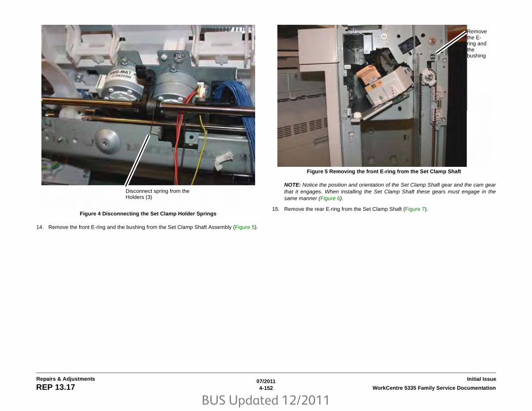
BUS Updated 12/2011
07/20114-152 WorkCentre 5335 Family Service DocumentationREP 13.17
Initial IssueRepairs & Adjustments
Figure 4 Disconnecting the Set Clamp Holder Springs
14. Remove the front E-ring and the bushing from the Set Clamp Shaft Assembly (Figure 5).
Figure 5 Removing the front E-ring from the Set Clamp Shaft
NOTE: Notice the position and orientation of the Set Clamp Shaft gear and the cam gearthat it engages. When installing the Set Clamp Shaft these gears must engage in thesame manner (Figure 6).
15. Remove the rear E-ring from the Set Clamp Shaft (Figure 7).
Disconnect spring from the Holders (3)
Remove the E-ring and the bushing

BUS Updated 12/2011
07/20114-153WorkCentre 5335 Family Service Documentation REP 13.17
Repairs & AdjustmentsInitial Issue
Figure 6 Set Clamp Shaft gear orientation Figure 7 Preparing to remove the Set Clamp Shaft
16. Slide the Gear, Spring and the Bushing away from the frame (Figure 8).
Notice the orien-tation of the gears on the shaft
1Remove the E-ring
2Slide the Gear away from the frame
3Disconnect the Spring from the Gear

BUS Updated 12/2011
07/20114-154 WorkCentre 5335 Family Service DocumentationREP 13.17
Initial IssueRepairs & Adjustments
Figure 8 Preparing to remove the Set Clamp Shaft
17. Slide the Set Clamp Shaft to the front to clear the rear frame then slide the Shaft to therear and remove it from the Finisher (Figure 9).
Figure 9 Removing the Set Clamp Shaft
18. Remove the Compiler Tray Assembly (Figure 10).
1Unlock and remove the Flag
2Slide the Gear, Spring and Bushing toward the end of the Shaft
1Slide the Shaft toward the front
2Slide the Shaft toward the rear and remove

BUS Updated 12/2011
07/20114-155WorkCentre 5335 Family Service Documentation REP 13.17
Repairs & AdjustmentsInitial Issue
Figure 10 Remove the Compiler Tray Assembly
19. Usually this level of Compiler Tray Assembly removal is for the purpose of removing theFront or Rear Tamper Motors, or the Front or Rear Tamper Home Sensors or the Com-piler Tray No Paper Sensor.
However if the Compiler Tray Assembly must be completely removed from the Finisher, itwill be necessary to disconnect all of the wire harness connectors to the Tamper Motors,Tamper Home Sensors and No Paper Sensor and disconnect the wires from all wire har-ness guides.
Replacement1. Route the wire harness through the wire guides and connect the proper connectors to the
No Paper Sensor, the Tamper Home Sensors and the Tamper Motors.
2. Place the Compiler Tray Assembly into position.
3. Install the Set Clamp Shaft front end into the front frame (Figure 11).
4. Slide the Shaft toward the front until the rear end of the Shaft can be inserted into the rearframe (Figure 11).
Figure 11 Installing the Set Clamp Shaft into position
5. Slide the 3 Set Clamp Holders with Springs into the correct location on the Shaft (Figure12).
Remove the Compiler Tray Assembly
1Insert the front end of the shaft into the front frame
2Insert the rear end of the Shaft into the rear frame

BUS Updated 12/2011
07/20114-156 WorkCentre 5335 Family Service DocumentationREP 13.17
Initial IssueRepairs & Adjustments
Figure 12 Preparing to install the Holder Springs
6. Install the Bushing, Spring and Gear onto the rear end of the Set Clamp Shaft (Figure 13).
Figure 13 Installing the Bushing, Spring and Gear
7. Rotate the Set Clamp Shaft until the Stack Height Sensor Flag is in the correct positionthen position the 2 gears into the configuration (Figure 14).
Holders and Springs in cor-rect location on the Shaft
1Bearing
2Spring
3Gear
4Install the Stack Height Sensor Flag onto the rear end of the Shaft as shown

BUS Updated 12/2011
07/20114-157WorkCentre 5335 Family Service Documentation REP 13.17
Repairs & AdjustmentsInitial Issue
Figure 14 Aligning the Gears and Stack Height Sensor Flag
8. Attach the Spring to the gear and slide the Gear into position.
9. Ensure that the 2 Gears and Stack Height Sensor Flag is in the position shown (Figure15) and install the E-ring.
Figure 15 Orientation of 2 Gears and Stack Height Sensor Flag
10. Install the Bushing onto the front end of the Set Clamp Shaft and install the E-ring (Figure16).
1Rotate shaft until Stack Height Flag is in position
2Position the 2 Gears
FlagPinion Gear position
Shaft Gear position on Pin-ion Gear
Install the E-ring

BUS Updated 12/2011
07/20114-158 WorkCentre 5335 Family Service DocumentationREP 13.17
Initial IssueRepairs & Adjustments
Figure 16 Installing the Bushing and E-ring
11. Ensure that the Set Clamp Holder Springs are connected (Figure 17).
Figure 17 Attaching the Set Clamp Holder Springs
12. Install the Eject Roll Shaft.
(1) Place the Eject Roll Shaft into position in the front and rear frame (Figure 18).
Install the Bush-ing and the E-ring
Spring attaches in 2 spots

BUS Updated 12/2011
07/20114-159WorkCentre 5335 Family Service Documentation REP 13.17
Repairs & AdjustmentsInitial Issue
Figure 18 Preparing to install the Eject Roll Shaft
(2) Install the brass bearing, the Gear and the E-ring onto the rear of the Eject RollShaft (Figure 19).
Figure 19 Installing the Eject Roll Shaft rear parts
(3) Install the brass bearing and E-ring onto the front of the Eject Roll Shaft (Figure20).
Eject Roll Shaft in position
1Install the brass Bearing
2Install the Gear
3Install the E-ring

BUS Updated 12/2011
07/20114-160 WorkCentre 5335 Family Service DocumentationREP 13.17, REP 13.18
Initial IssueRepairs & Adjustments
Figure 20 Installing the brass bearing and E-ring
13. Install the Compiler Tray screw (1).
14. Install the Eject Cover (REP 13.9).
15. Install the Stacker Upper Cover (REP 13.12).
16. Install the Stacker Tray (REP 13.20).
17. Install the Stacker Lower Cover (REP 13.11).
18. Install the Foot Cover (REP 13.10).
19. Install the Rear Upper Cover (REP 13.7).
20. Install the Front Cover (REP 13.6).
21. Dock the Finisher to the IOT (REP 13.5).
REP 13.18 Crease Assembly (Office Finisher LX)Parts List on PL 23.14 Removal1. Switch off the power and disconnect the power cord.
2. Remove the Crease Assembly (Figure 1).
(1) Open the Finisher Front Door.
(2) Remove the Guard.
NOTE: Pull out the Cable Tie to obtain additional slack in the wires.
(3) Disconnect the Cable.
(4) Remove the Thumbscrew.
(5) Pull the Crease Assembly straight out.
Figure 1 Removing the Crease Assembly
Replacement
NOTE: Make sure the Locating Pins (2) are properly engaged (Figure 2).
1. Reverse the removal procedure for replacement.
Guard
Cable TieCable
Thumbscrew
Crease Assembly

BUS Updated 12/2011
07/20114-161WorkCentre 5335 Family Service Documentation REP 13.18, REP 13.19
Repairs & AdjustmentsInitial Issue
Figure 2 Crease Assembly
2. Perform ADJ 12.2 Finisher LX Booklet Crease/Staple Position
REP 13.19 Stacker Elevator Motor (Office Finisher LX)Parts List on PL 23.7 Removal1. Switch off the power and disconnect the power cord.
2. Remove the Finisher Rear Upper Cover (REP 13.7).
3. Disconnect P/J8988 on the Finisher Control PWB.
4. Release the wires from the cable clamps.
5. Remove the wires from the wire guide, remove the screws (2) and move the wire guide toone side.
6. Remove the screws (2) from the motor mount using a 5.5 mm combination wrench.
7. Remove the Stacker Elevator Motor.
ReplacementInstall in reverse order of removal procedure.Locating Pins

BUS Updated 12/2011
07/20114-162 WorkCentre 5335 Family Service DocumentationREP 13.20, REP 13.21
Initial IssueRepairs & Adjustments
REP 13.20 Stacker Tray (Office Finisher LX)Parts List on PL 23.7 Removal1. Switch off the power and disconnect the power cord.
2. Remove the following:
(1) Booklet Maker Assembly (if installed) (REP 13.31).
(2) Front Cover Assembly (REP 13.6).
(3) Rear Upper Cover (REP 13.7).
3. Remove the Stacker Tray (Figure 1).
(1) Remove the Screws (4).
(2) Remove the Stacker Tray.
Figure 1 Removing the Stacker Tray
ReplacementReverse the removal procedure for replacement.
REP 13.21 Eject Belt (Office Finisher LX)Parts List on PL 23.13 Removal1. Switch off the power and disconnect the power cord.
2. Undock the Finisher (REP 13.5).
3. Remove the Booklet Maker (REP 13.31).
4. Remove the Rear upper Cover (REP 13.7).
5. Remove the Eject Motor Assembly (REP 13.22).
6. Remove the Eject Motor (REP 13.25).
7. Remove the Eject Belt.
Replacement1. To install, carry out the removal steps in reverse order.
Screws
Stacker Tray

BUS Updated 12/2011
07/20114-163WorkCentre 5335 Family Service Documentation REP 13.22, REP 13.23
Repairs & AdjustmentsInitial Issue
REP 13.22 Eject Motor Assembly (Office Finisher LX)Parts List on PL 23.11 Removal1. Switch off the power and disconnect the power cord.
2. Undock the Finisher (REP 13.5).
3. Remove the Booklet Maker (REP 13.31).
4. Remove the Rear Upper Cover (REP 13.7).
5. Preparing to remove the Eject Motor Assembly.
(1) Disconnect the Eject Motor connector
(2) Remove the wire harness from the Harness Guide
(3) Disconnect the wire harness clamps (2)
(4) Remove the screws (2) from the Harness Guide and move the Harness Guideaside.
(5) Disconnect the Spring
(6) Remove the Eject Motor Assembly screws (4)
6. Remove the Eject Motor Assembly.
Replacement1. To install, carry out the removal steps in reverse order.
REP 13.23 Finisher PWB (Office Finisher LX)Parts List on PL 23.16 Removal1. Switch off the power and disconnect the power cord.
2. Remove the Rear Upper Cover (REP 13.7).
3. Remove the Finisher PWB (Figure 1).
(1) Disconnect the Connectors (9).
(2) Remove the Screws (5).
(3) Remove the Finisher PWB.
Figure 1 Removing the Finisher PWB
Replacement1. Reverse the removal procedure for replacement.
Connectors
Screws
Screw
Screws
Finisher PWB

BUS Updated 12/2011
07/20114-164 WorkCentre 5335 Family Service DocumentationREP 13.24, REP 13.25
Initial IssueRepairs & Adjustments
REP 13.24 Finisher LVPS (Office Finisher LX)Parts List on PL 23.16 Removal1. Switch off the power and disconnect the power cord.
2. Remove the Rear Lower Cover (REP 13.8).
3. Remove the Finisher LVPS (Figure 1).
(1) Disconnect the Connectors (2).
(2) Remove the Screws (4).
(3) Remove the Finisher LVPS.
Figure 1 Removing the Finisher LVPS
ReplacementReverse the removal procedure for replacement.
REP 13.25 Eject Motor (Office Finisher LX)Parts List on PL 23.11 Removal1. Switch off the power and disconnect the power cord.
2. Undock the Finisher (REP 13.5).
3. Remove the Booklet Maker (REP 13.31).
4. Remove the Rear Upper Cover (REP 13.7).
5. Remove the Eject Motor Assembly (REP 13.22).
6. Remove the Eject Motor.
(1) Remove the screws (2)
(2) Remove the Eject motor
Replacement1. To install, carry out the removal steps in reverse order.
Connector ScrewScrew
Connector ScrewScrew
Finisher LVPS

BUS Updated 12/2011
07/20114-165WorkCentre 5335 Family Service Documentation REP 13.26, REP 13.27
Repairs & AdjustmentsInitial Issue
REP 13.26 Front/Rear Tamper Motor (Office Finisher LX)Parts List on PL 23.12 Removal1. Switch off the power and disconnect the power cord.
2. Remove the Compiler Tray (REP 13.17).
3. Turn the Compiler Tray over on a work surface.
4. Remove the Tamper Motor (Figure 1).
(1) Release the wires from the wire guide.
(2) Remove the screw (1) and remove the wire guide.
(3) Disconnect the Tamper Motor connector.
NOTE: The Rear Tamper Motor connector has already been disconnected.
(4) Remove the screws (2).
(5) Remove the Tamper Motor.
Figure 1 Removing the Tamper Motor
ReplacementReplace in reverse order of removal.
REP 13.27 Front/Rear Tamper Home Sensors (Office Finisher LX)Parts List on PL 23.12 Removal1. Switch off the power and disconnect the power cord.
2. Remove the Compiler Tray Assembly (REP 13.17).
3. Turn the Compiler Tray over on a work surface (Figure 1).
4. Disconnect the connector.
5. Remove the Front or Rear Tamper Home Sensor (PL 23.12).
Figure 1 Removing the Front or Rear Tamper Home Sensor1Remove wires from guide
2Remove the screw (1)
3Discon-nect the connec-tor
4Remove the screws (2)
1Discon-nect the connec-tor
Rear Tamper Home Sensor

BUS Updated 12/2011
07/20114-166 WorkCentre 5335 Family Service DocumentationREP 13.28
Initial IssueRepairs & Adjustments
REP 13.28 Compiler No Paper Sensor (Office Finisher LX)Parts List on PL 23.12 Removal1. Switch off the power and disconnect the power cord.
2. Remove the Compiler Tray Assembly (REP 13.17).
3. Turn the Compiler tray over on a work surface.
4. Remove the screw (1) that secures the bracket (PL 23.12) (Figure 1).
Figure 1 Removing the Bracket
5. Disconnect the connector (Figure 2).
6. Remove the screw (1) that secures the sensor.
7. Remove the Compiler No Paper Sensor.
Figure 2 Removing the Compiler No Paper Sensor
Remove the screw (1)
1Discon-nect the connec-tor
2Remove the screw (1)
3Remove the Sen-sor

BUS Updated 12/2011
07/20114-167WorkCentre 5335 Family Service Documentation REP 13.29, REP 13.30
Repairs & AdjustmentsInitial Issue
REP 13.29 Front/Rear Carriage Assembly (Office Finisher LX)Parts List on PL 23.7 Removal
NOTE: Ensure that the Stacker Tray is in the top position.
1. Switch off the power and disconnect the power cord.
2. Remove the Finisher Front Cover (REP 13.6).
3. Remove the Rear Upper and Rear Lower Covers (REP 13.7, REP 13.8).
4. Remove the Stacker Tray (REP 13.20).
5. Removing the Carriage Assembly (Figure 1).
(1) Disconnect and remove the Spring.
NOTE: The Carriage Bearings (2 each Assembly) are not fastened to the shafts. Use care tocatch the Bearings when the Carriage Assembly is removed.
(2) With a 6 inch common screwdriver, move the belt Clamp latch aside and removethe Stacker Belt and Carriage Assembly.
Figure 1 Removing the Carriage Assembly
Replacement
NOTE: Ensure that the Front and Rear Carriage Assemblies are installed at the same height.
1. Install the Front or Rear Carriage Assemblies in the reverse order of removal.
REP 13.30 Booklet PWB (Office Finisher LX)Parts List on PL 23.21 Removal1. Switch off the power and disconnect the power cord.
2. Remove the Booklet PWB Cover (REP 13.35).
3. Remove the Booklet PWB (Figure 1).
(1) Disconnect the Connectors (5).
(2) Remove the Screws (4).
(3) Remove the Booklet PWB.
Figure 1 Removing the Booklet PWB
Replacement1. Reverse the removal procedure for replacement.
1Remove the Spring
2Release latch and remove Belt
3Remove the Car-riage Assem-bly
Screws
Connectors
Booklet PWB
Screws

BUS Updated 12/2011
07/20114-168 WorkCentre 5335 Family Service DocumentationREP 13.31
Initial IssueRepairs & Adjustments
REP 13.31 Booklet Maker Assembly (Office Finisher LX)Parts List on PL 23.6 Removal1. Switch off the power and disconnect the power cord.
2. Unlatch the Eject Cover, and move it all the way to the left (Figure 1).
3. Remove the Thumbscrews (2) (Figure 1).
Figure 1 Eject Cover and Thumbscrew
4. Disconnect the Booklet Maker Assembly from the Finisher.
(1) Remove the Connector Cover (Figure 2).
Figure 2 Connector Cover
(2) Disconnect the Connector (Figure 3).
(3) Pull out the Cable Ties (4).
Eject Cover
Thumbscrew (2)
Connector Cover

BUS Updated 12/2011
07/20114-169WorkCentre 5335 Family Service Documentation REP 13.31
Repairs & AdjustmentsInitial Issue
Figure 3 Disconnecting the Booklet Maker Assembly
5. Lift the Booklet Maker Assembly off the Locating Pins (4), and remove (Figure 4).
Figure 4 Removing the Booklet Maker Assembly
Replacement1. Reverse the removal procedure for replacement.
Connector
Cable Tie (4)
Locating Pins
Booklet Maker Assembly

BUS Updated 12/2011
07/20114-170 WorkCentre 5335 Family Service DocumentationREP 13.32
Initial IssueRepairs & Adjustments
REP 13.32 Booklet Front Cover (Office Finisher LX)Parts List on PL 23.17 Removal1. Switch off the power and disconnect the power cord.
2. Remove the Booklet Maker Assembly from the Finisher (REP 13.31).
3. Remove the Booklet Front Cover.
(1) Remove the Screw (1) (Figure 1).
Figure 1 Removing the Booklet Front Cover
(2) Remove the Screws (2) (Figure 2).
(3) Remove the Booklet Front Cover.
Figure 2 Removing the Booklet Front Cover
Replacement1. Reverse the removal procedure for replacement.
Screw
Screws
BookletFront Cover

BUS Updated 12/2011
07/20114-171WorkCentre 5335 Family Service Documentation REP 13.33
Repairs & AdjustmentsInitial Issue
REP 13.33 Booklet Rear Cover (Office Finisher LX)Parts List on PL 23.17 Removal1. Switch off the power and disconnect the power cord.
2. Remove the Booklet Maker Assembly from the Finisher (REP 13.31).
3. Remove the Booklet PWB Cover (REP 13.35).
4. Remove the Booklet Rear Cover.
(1) Remove the Self-tapping Screws (2) (Figure 1).
(2) Remove the Booklet Side Cover.
Figure 1 Removing the Booklet Side Cover
(3) Remove the Screw (1) (Figure 2).
(4) Remove the Booklet Rear Cover.
Figure 2 Removing the Booklet Rear Cover
Replacement1. Reverse the removal procedure for replacement.
TappingScrews
BookletSide Cover
Screw
BookletRear Cover

BUS Updated 12/2011
07/20114-172 WorkCentre 5335 Family Service DocumentationREP 13.34, REP 13.35
Initial IssueRepairs & Adjustments
REP 13.34 Booklet Top Cover (Office Finisher LX)Parts List on PL 23.17 Removal1. Switch off the power and disconnect the power cord.
2. Remove the Booklet Front Cover (REP 13.32).
3. Remove the Booklet Rear Cover (REP 13.33).
4. Remove the Booklet Top Cover (Figure 1).
(1) Remove the Screws (4).
(2) Remove the Booklet Top Cover.
Figure 1 Removing the Booklet Top Cover
ReplacementReverse the removal procedure for replacement.
REP 13.35 Booklet PWB Cover (Office Finisher LX)Parts List on PL 23.17 Removal1. Switch off the power and disconnect the power cord.
2. Remove the Booklet PWB Cover (Figure 1).
(1) Remove the Self-tapping Screws (2).
(2) Remove the Screws (2).
(3) Remove the Booklet PWB Cover.
Figure 1 Removing the Booklet PWB Cover
ReplacementReverse the removal procedure for replacement.
Booklet Top Cover
Screws
TappingScrew
TappingScrew
Screws
BookletPWB Cover

BUS Updated 12/2011
07/20114-173WorkCentre 5335 Family Service Documentation REP 13.36, REP 13.37
Repairs & AdjustmentsInitial Issue
REP 13.36 Booklet Left Cover (Office Finisher LX)Parts List on PL 23.17 Removal1. Switch off the power and disconnect the power cord.
2. Remove the Booklet Maker from the Finisher (REP 13.31).
3. Remove the Booklet Maker Left Cover.
4. Align the slots at the front and rear of the Booklet Maker Left Cover with the flats on theMounting Pins.
5. Move the Booklet Maker Left Cover by allowing the flats on the Mounting Pins to slidethrough the slots in the Cover.
Replacement1. Reverse the removal procedure for replacement.
REP 13.37 Booklet Front/Rear Stapler (Office Finisher LX)Parts List on PL 23.19, PL 23.20Removal1. Switch off the power and disconnect the power cord.
2. Remove the Booklet Maker Assembly from the Finisher (REP 13.31).
3. Remove the Stapler Guide (Figure 1).
(1) Remove the Screw (1).
(2) Remove the Stapler Guide.
Figure 1 Removing the Stapler Guide
4. Remove the Stapler Lower Cover (Figure 2).
(1) Remove the Screw (1).
(2) Remove the Stapler Lower Cover.
Screw Stapler Guide

BUS Updated 12/2011
07/20114-174 WorkCentre 5335 Family Service DocumentationREP 13.37
Initial IssueRepairs & Adjustments
Figure 2 Removing the Stapler Lower Cover
5. Remove the Chute (Figure 3).
(1) Remove the Screw (1).
(2) Remove the Chute.
6. Remove the Stapler Rear Cover (Figure 3).
(1) Remove the Screws (2).
(2) Remove the Stapler Rear Cover.
Figure 3 Removing the Chute and Stapler Rear Cover
7. Remove the Stapler (Figure 4).
(1) Release the wires from the Clip.
(2) Disconnect the Connector.
(3) Remove the Screws (3).
(4) Remove the Stapler.
Screw Stapler Lower Cover
Chute
Screw
Screws
StaplerRear Cover

BUS Updated 12/2011
07/20114-175WorkCentre 5335 Family Service Documentation REP 13.37, REP 13.38
Repairs & AdjustmentsInitial Issue
Figure 4 Removing the Stapler
Replacement1. Reverse the removal procedure for replacement.
2. Perform ADJ 12.2 Finisher LX Booklet Crease/Staple Position
REP 13.38 Booklet Stapler Move Motor (Office Finisher LX)Parts List on PL 23.18 Removal1. Switch off the power and disconnect the power cord.
2. Remove the Booklet Maker Assembly from the Finisher (REP 13.31).
3. Remove the Cover for the Booklet Stapler Move Motor (Figure 1).
(1) Remove the Screw (1).
(2) Remove the Cover.
Figure 1 Removing the Cover
4. Remove the Booklet Stapler Move Motor (Figure 2).
(1) Open the Clip and release the wires.
(2) Disconnect the Connector.
(3) Remove the Screws (3).
(4) Remove the Booklet Stapler Move Motor.
Clip
ConnectorScrews
Stapler
ScrewCover

BUS Updated 12/2011
07/20114-176 WorkCentre 5335 Family Service DocumentationREP 13.38
Initial IssueRepairs & Adjustments
Figure 2 Removing the Booklet Stapler Move Motor
Replacement1. Reverse the removal procedure for replacement.
ClipConnector
Screws Booklet Stapler Move Motor

BUS Updated 12/2011
07/20114-177WorkCentre 5335 Family Service Documentation REP 19.1, REP 19.2
Repairs & AdjustmentsInitial Issue
REP 19.1 HCF Tray 6 Parts List on PL 10.1 Removal1. Switch off the power and disconnect the power cord.
2. Open the HCF Tray by pulling the tray toward you.
3. Remove all paper from the tray.
4. Using a small screwdriver, or other small, blunt instrument, release the stopper on eachrail of the tray by inserting the screwdriver into the hole of the stopper and pulling the traytoward you.
5. Remove the tray by pulling it toward you.
Replacement1. Slide the rails (2) into the HCF housing.
2. Line up the rails of the tray with the adjoining rails of the HCF and push the tray into place.
3. Place previously removed paper, or fresh paper, into the tray.
REP 19.2 HCF FeederParts List on PL 10.1 Removal1. Switch off the power and disconnect the power cord.
2. Remove the HCF Tray (REP 19.1).
3. Open the Feeder Top Cover.
4. Remove the (2) screws used to secure the HCF Feeder on its rail (Figure 1).
Figure 1 Feeder Securing Screws
5. Slide the HCF Feeder toward you.
1FeederSecuringScrews

BUS Updated 12/2011
07/20114-178 WorkCentre 5335 Family Service DocumentationREP 19.2, REP 19.3
Initial IssueRepairs & Adjustments
Replacement1. Position the HCF Feeder’s bottom rail-following feet (2) onto the internal HCF rail.
2. Slide the HCF Feeder back into the HCF until it seats.
CAUTION
Do not over tighten the HCF Feeder screws.
3. Reinstall the two securing screws and tighten until snug.
REP 19.3 HCF UndockingRemoval1. Switch off the power and disconnect the power cord.
2. Unplug the HCF Power Cable connected to the left rear of the copier/printer.
3. Grasping the HCF by its upper corners, pull the HCF away from the copier/printer toexpose the HCF Docking Base (Figure 1).
Figure 1 Exposing the docking base
4. Release the Docking Latch Spring Lever on the right side of the Docking Base.
5. Pull the HCF away from the copier/printer to un-dock it from the copier/printer.
Replacement1. Push the HCF toward the two Docking Points on the left side of the printer.
2. Align the holes in the HCF Docking Base with the Docking Points on the printer/copier.
NOTE: Rotate the Caster of the copier/printer so that it does not interfere with docking.
3. Push the HCF into place.
4. Reattach the HCF Power Cable.
Docking Points
HCF Docking Base
Docking Latch Spring Lever

BUS Updated 12/2011
07/20114-179WorkCentre 5335 Family Service Documentation REP 19.4
Repairs & AdjustmentsInitial Issue
REP 19.4 HCF Tray CablesParts List on PL 10.3 RemovalSwitch off the power and disconnect the power cord.
Removing the HCF Rear Tray Cables
1. Remove the HCF Tray (REP 19.1)
2. Remove the Gear Bracket Assembly (Figure 1).
Figure 1 Gear Bracket Assembly
3. At the rear of the HCF Tray, begin to free up movement of the Tray Cable Pulley (Figure2).
Figure 2 Lift Shaft Rear Tray Cable Pulley
NOTE: You will not be able to release the cable ends from underneath the Tray Cable Pulleyuntil you perform the next step, which puts slack in the cable enabling the Lift Shaft to be disen-gaged from its bracket, and the Tray Cable Pulley moved farther to the left releasing the cableends.
4. Prepare to remove the Rear Tray Cable (Figure 3).
Figure 3 Preparing to remove the Rear Tray Cable
1Remove the oval shaped Plate
3Remove the screws (3)
4Remove the Gear Bracket Assembly
2Remove the gears (2)
1Remove the E-ring
2Slide the Bushing away from the frame
Tray Cable Pulley
Remove the E-Rings (2), Wire Guides (2), and Pulleys (2)

BUS Updated 12/2011
07/20114-180 WorkCentre 5335 Family Service DocumentationREP 19.4
Initial IssueRepairs & Adjustments
5. When both sections of the cable are slack, disengage the Lift Shaft from the frame andslide the Tray Cable Pulley to the front of the Lift Shaft to release the Rear Lift Cable endsthat are trapped in the pocket underneath the Tray Cable Pulley (Figure 4).
Figure 4 Releasing the Cable ends from the Lift Shaft
6. Remove the Rear Tray Cable (Figure 5, Figure 6).
Figure 5 Removing the Rear Tray Cables
Figure 6 Rear Tray Cable details
3Remove the cable ends from the shaft
1Disengage the Lift Shaft from the frame
2Slide the Tray Cable Pulley to the front
1Remove the E-Ring (1), Wire Guide (1), and Pulley (1)
2Remove the Cables

BUS Updated 12/2011
07/20114-181WorkCentre 5335 Family Service Documentation REP 19.4
Repairs & AdjustmentsInitial Issue
Removing the HCF Front Tray Cables
1. Remove the (5) screws securing the HCF Tray’s Front Cover.
2. At the front of the HCF Tray, begin to free up movement of the front Tray Cable Pulley(Figure 7).
a. Remove the E-Ring on the Lift Shaft.
b. Slide the bearing to the rear on the Lift Shaft.
c. Front Tray Cable Pulley
Figure 7 Lift Shaft Front Tray Cable Pulley
NOTE: You will not be able to release the cable ends from underneath the Tray Cable Pulleyuntil you perform the next step, which puts slack in the cable enabling the Lift Shaft to be disen-gaged from its bracket, and the Tray Cable Pulley moved farther to the right releasing the cableends.
3. Remove the E-Rings, Wire Guides, and Pulleys from the front of the HCF Tray (Figure 8).
Figure 8 Preparing to remove the Front Tray Cables
4. When both sections of the cable are slack, disengage the Lift Shaft from the frame andslide the Tray Cable Pulley to the front of the Lift Shaft to release the Rear Lift Cable endsthat are trapped in the pocket underneath the Tray Cable Pulley (Figure 9).
Figure 9 Releasing the Cable ends from the Lift Shaft
1Remove E-Rings (2), Wire Guides (2), and Pulleys (2)

BUS Updated 12/2011
07/20114-182 WorkCentre 5335 Family Service DocumentationREP 19.4
Initial IssueRepairs & Adjustments
5. Remove the Front Tray Cables (Figure 10, Figure 11).
Figure 10 Removing the Front Tray Cables
Figure 11 Front Tray Cable details
Replacement1. Install the front Tray Cable by carrying out the removal steps in reverse order.
2. Install the rear Tray Cable by carrying out the removal steps in reverse order.
3. Reinstall the HCF Tray’s Front Cover.
a. Make sure to raise the gear on the Indicator Shaft so that it meshes with the adjoin-ing Lift Shaft gear.
b. Replace the (5) Installation Screws.
4. Reinstall the HCF Tray by lining up the rails of the tray with the adjoining rails of the HCFand pushing the tray into place.
1Remove the E-Ring (1), Wire guide (1), and Pulley (1)
2Remove the Cables

BUS Updated 12/2011
07/20114-183WorkCentre 5335 Family Service Documentation REP 19.5
Repairs & AdjustmentsInitial Issue
REP 19.5 HCF Feed, Nudger, Retard RollsParts List on PL 10.5, PL 10.6 Removal
NOTE: Remove and replace the Retard/Feed/Nudger Rolls at the same time.
1. Switch off the power and disconnect the power cord.
2. Open the Feeder Top Cover.
3. Release the green Lever to open the Upper Feeder Assembly to reveal the (3) rolls.
NOTE: For reference purposes, the single roll in the Upper Feeder Assembly is theNudger roll. The double roll in the Upper Feeder Assembly is the Feed Roll. The largerdouble roll in the Lower Feeder component is the Retard Roll.
4. Remove each roll by squeezing the roll’s shaft at both ends and lifting the roll up and outof the HCF (Figure 1).
Figure 1 Removing rolls
Replacement1. Install each new roll by squeezing its shaft at both ends and sliding the roll into place.
2. check that the rolls turn freely.
3. Flip down the Upper Feeder Assembly.
4. Close the Feeder Top Cover of the HCF.

BUS Updated 12/2011
07/20114-184 WorkCentre 5335 Family Service DocumentationREP 19.6, REP 19.7
Initial IssueRepairs & Adjustments
REP 19.6 HCF Feed ShaftParts List on PL 10.5Removal1. Switch off the power and disconnect the power cord.
2. Remove the HCF Feeder (REP 19.2)
3. Place the Feeder on a flat surface.
4. Open the Upper Feeder Assembly by releasing the green lever.
5. Remove the Nudger Roll by squeezing the roll’s shaft at both ends (with the thumb andforefinger of one hand) and lifting the roll up and out of the HCF.
6. Remove the E-Ring and bearing on the Feed Shaft (at the Nudger Roll end of the shaft).
7. Move the bearing at the opposite end of the shaft to the right, and slide the Feed Shaft tothe right to remove.
Replacement1. To install, carry out the removal steps in reverse order.
REP 19.7 HCF Retard Lever SpringParts List on PL 10.6 Removal1. Switch off the power and disconnect the power cord.
2. Remove the HCF Feeder (REP 19.2)
3. Place the Feeder on a flat surface and release the green Lever to open the Upper FeederAssembly.
4. Remove the Lower Chute (2 screws).
5. Remove the plastic Cover by removing (4) screws.
6. Remove the Retard Roll.
7. Remove the E-Rings on the Lever and Spring.
8. Remove the Lever.
9. Remove the Spring (Figure 1).
Figure 1 Removing the Retard Lever Spring
Spring. Note how exten-sion fits into Lever.
Lever
Retard Roll
Cover
Lower Chute

BUS Updated 12/2011
07/20114-185WorkCentre 5335 Family Service Documentation REP 19.7, REP 19.8
Repairs & AdjustmentsInitial Issue
Replacement
NOTE: Make sure the plastic pads on the Lower Chute fit in the track before pushing it in.
1. To install, carry out the removal steps in reverse order.
REP 19.8 HCF Nudger Bracket/Nudger Lever/Torsion SpringParts List on PL 10.4 Removal1. Switch off the power and disconnect the power cord.
2. Remove the HCF Feed Shaft (REP 19.6)
3. Disassemble the Feed Shaft by removing (4) E-Rings and unscrewing the Nudger Sup-port that retains the Torsion Spring.
Replacement1. Install replacement parts.
2. Carry out the removal steps in reverse order.

BUS Updated 12/2011
07/20114-186 WorkCentre 5335 Family Service DocumentationREP 19.9, REP 19.10
Initial IssueRepairs & Adjustments
REP 19.9 HCF CastersParts List on PL 10.8 Removal1. Switch off the power and disconnect the power cord.
2. Un-dock the HCF (REP 19.3).
3. Remove all paper from the HCF Tray.
4. Roll the HCF away from the copier/printer.
5. Turn the HCF over onto its left side to expose the casters on the underside of the HCF.
6. Remove (3) installation screws per caster.
Replacement1. Install a new caster or casters, by tightening the (3) installation screws per caster.
2. Turn the HCF back up to an upright position.
3. Roll the HCF back toward the copier/printer.
4. Place previously removed paper, or fresh paper, into the HCF Tray.
5. Dock the HCF.
REP 19.10 HCF Takeaway RollParts List on PL 10.7 Removal1. Switch off the power and disconnect the power cord.
2. Remove the HCF Feed Motor (REP 19.12).
3. Remove the Lower Chute (Figure 1).
• Remove the (2) securing screws.
Figure 1 Removing the Lower Chute
4. Slide the Takeaway Roll to the right until the left side is released, then lower the roll toremove.
Replacement1. To install, carry out the removal steps in reverse order.
2. After replacing, reset HFSI Counter 954-805.
Takeaway Roll (includes Shaft)

BUS Updated 12/2011
07/20114-187WorkCentre 5335 Family Service Documentation REP 19.11, REP 19.12
Repairs & AdjustmentsInitial Issue
REP 19.11 HCF PWBParts List on PL 10.8 Removal1. Switch off the power and disconnect the power cord.
2. Un-dock the HCF (REP 19.3).
3. Remove the plastic Rear Cover.
• Remove the (4) securing screws.
4. Disconnect all of the connectors connected to the HCF PWB.
5. Remove the (4) screws securing the HCF PWB.
6. Remove the HCF PWB.
Replacement1. To install, carry out the removal steps in reverse order.
REP 19.12 HCF Feed MotorParts List on PL 10.1 Removal1. Switch off the power and disconnect the power cord.
2. Un-dock the HCF (REP 19.3).
3. Remove the plastic Rear Cover.
• Remove the (4) securing screws.
NOTE: Be careful when removing the motor as it is meshed to a hidden gear.
4. Supporting the motor with one hand, remove the HCF Feed Motor (Figure 1).
• Disconnect the electrical Connector (1).
• Remove the (2) securing screws.
Figure 1 Removing the HCF Feed Motor
Replacement1. To install, carry out the removal steps in reverse order.
HCF Feed Motor

BUS Updated 12/2011
07/20114-188 WorkCentre 5335 Family Service DocumentationREP 19.11, REP 19.12
Initial IssueRepairs & Adjustments

BUS Updated 12/2011
07/20114-189WorkCentre 5335 Family Service Documentation ADJ 5.1
Repairs & AdjustmentsInitial Issue
ADJ 5.1 DADF Lead-Skew AdjustmentParts List on PL 51.1PurposeTo correct the feeding of the original by adjusting the position of the DADF. (DADF Lead-Skew,Perpendicularity)
NOTE: The following adjustments must be made before carrying out checking and adjustment.
• IOT Lead Edge/Side Edge Registration (ADJ 9.10)
• IIT Side Registration (ADJ 6.4)
Check1. Place the Test Chart 82E8220 on the Platen Glass.
2. Place 11x17” paper in Tray 1.
3. Make a copy using the following settings in Copy mode.
a. On the UI Ready to Copy Screen, select the Copy tab.
b. Under Output Color select Black.
c. Under the Paper Supply select 11x17” paper size.
d. Under 2 Sided Copying select 1 Sided.
e. Reduce / Enlarge should be set to 100%.
f. On the UI Ready to Copy Screen, select the Layout Adjustment tab, Image Shiftshould be Side 1 No Shift. Select Save if necessary.
NOTE: The copy made from the Platen Glass will be used as the original in the DADF.
4. Place the copy made from the Platen Glass into the DADF and make 3 copies.
5. Check that the difference in the distance between the side and the Edges at the 100mmmark and the 300mm mark in the 3 copies is within 00.5mm. (Figure 1)
Figure 1 Checking the Skew
6. If the value is not within the specified range, perform the Adjustment:
Check from the paper edge to the parallel line at the 100mm mark and the 300mm mark

BUS Updated 12/2011
07/20114-190 WorkCentre 5335 Family Service DocumentationADJ 5.1
Initial IssueRepairs & Adjustments
Adjustment1. Remove the DADF Rear Cover. (Figure 2)
2. Adjust the position of the DADF by moving the DADF in direction A or B. (Figure 2)
(1) Loosen the screws (x3).
(2) Move the DADF in direction A or B.
(3) Tighten the screws (x3).
Figure 2 DADF Rear Cover.
• The DADF moved in direction A. (Figure 3)
Figure 3 Direction A
• The DADF moved in direction B. (Figure 4)
Figure 4 Direction B
3. Reinstall the DADF Rear Cover.
4. After adjustment, perform DADF Side Registration (ADJ 5.2) and DADF Lead Edge Reg-istration. (ADJ 5.4).

BUS Updated 12/2011
07/20114-191WorkCentre 5335 Family Service Documentation ADJ 5.2
Repairs & AdjustmentsInitial Issue
ADJ 5.2 DADF Side RegistrationParts List on PL 51.1 PurposeTo adjust the original to the proper position (drum shaft direction) on the Platen.
NOTE: The following adjustments must be made before carrying out checking and adjustment.
• IOT Lead Edge/Side Edge Registration (ADJ 9.10)
• IIT Side Registration (ADJ 6.4)
• DADF Lead-Skew Adjustment (ADJ 5.1)
NOTE: DADF Side Registration is adjusted using the NVM for every paper width.
CheckCreate a test pattern
1. To create a Cross Line Test Pattern, use a plain white sheet of 8.5x11”/A4 paper and foldthe sheet precisely in half lengthwise and width wise. Then with a straight edge draw astraight line in the lengthwise crease and a straight line in the width wise crease.
Label the top for orientation purposes. (Figure 1)
Figure 1 Creating a Test Pattern Original
DADF Side Edge Registration Check - Side 1
1. Load Tray 1 with 8.5x11”/A4 paper.
2. Place the new Cross Line Test Pattern on the DADF with the word TOP Face Up andtowards the rear of the DADF.
3. Select the following:
• Tray 1
• 1-1 Sided.
• 100%
• 1 copy
4. Make one copy to the center tray.
5. Remove the copy from the center tray and Flip the copy left to right.
6. Fold the copy in half parallel to the short edge (A to B in Figure 1).
7. Check that the fold line is within 2.0mm from the reference line. If the value is not withinthe specified range, perform the Side 1 Adjustment. If the Check is OK, perform theDADF Side Edge Registration Check - Side 2.
TOP
A B

BUS Updated 12/2011
07/20114-192 WorkCentre 5335 Family Service DocumentationADJ 5.2
Initial IssueRepairs & Adjustments
DADF Side Edge Registration Check - Side 2
1. Place the Cross Line Test Pattern on the DADF with the word TOP Face Down andtowards the rear of the DADF.
2. Select the following:
• Tray 1
• 2-2 Sided.
• 100%
• 1 copy
3. Make one copy to the center tray.
4. Remove the copy from the center tray but DO NOT FLIP the copy this time.
5. Fold the copy in half parallel to the short edge (A to B in Figure 1).
6. Check that the fold line is within 2.0mm from the reference line. If the value is not withinthe specified range, perform the Side 2 Adjustment.
AdjustmentSide 1 Adjustment
NOTE: In order for the following NVM changes to take effect, you must exit diagnostics andswitch the power off, then on.
1. Enter NVM Read/Write. Change the value in location 711-272 to perform correction for allsizes. Change the value in the locations listed in Table 1 to perform correction for a spe-cific size.
2. Increase the value to move the image toward “TOP.” Each bit represents 0.1% change.
3. Repeat Check and Adjustment until the measurement is within the specified range.
Side 2 Adjustment
1. Enter NVM Read/Write. Change the value in location 711-274 to perform correction for allsizes. Change the value in the locations listed in Table 2 to perform correction for a spe-cific size.
2. Repeat the Check and Adjustment until the measurement is within the specified range.
NOTE: The Values of NVM 711-272 and 711-274 are written to NVM’s 715-110, 715-111, 715-112, and 715-113, when the machine power is switched on.
• 711-272 written to 715-110
• 711-274 written to 715-111, 715-112, 715-113
Table 1 Side 1
NVM Document Width Document Size
1 711-272 For all sizes For all sizes
2 715-056 139.7~148.0mm A5 SEF, 5.5x8.5” SEF
3 715-058 182.0~194.0mm B5 SEF, 16K SEF
4 715-060 203.2mm 8x10" SEF, 8x10.5" SEF
5 715-062 210mm A4 SEF, A5 LEF
6 715-064 214.9~215.9mm Letter SEF, Legal SEF, 5.5x8.5" LEF, 8.46x12.4" SEF, 8.5x13" SEF
7 715-066 254.0~257.0mm B4 SEF, B5 LEF, 8x10" LEF
8 715-068 266.7~267.0mm 16K LEF, 8K LEF, 8x10.5" LEF
9 715-070 279.4mm Letter LEF, 11x15" SEF, 11x17" SEF
10 715-072 297mm A4 LEF, A3 SEF
Table 2 Side 2 of 2 Sided mode
NVM Document Width Document Size
1 771-274 For all sizes For all sizes
2 715-057 139.7~148.0mm A5 SEF, 5.5x8.5" SEF
3 715-059 182.0~194.0mm B5 SEF, 16K SEF
4 715-061 203.2mm 8x10" SEF, 8x10.5" SEF
5 715-063 210mm A4 SEF, A5 LEF
6 715-065 214.9~215.9mm Letter SEF, Legal SEF, 5.5x8.5" LEF, 8.46x12.4" SEF, 8.5x13" SEF
7 715-067 254.0~257.0mm B4 SEF, B5 LEF, 8x10" LEF
8 715-069 266.7~267.0mm 16K LEF, 8K LEF, 8x10.5" LEF
9 715-071 279.4mm Letter LEF, 11x15" SEF, 11x17" SEF
10 715-073 297mm A4 LEF, A3 SEF

BUS Updated 12/2011
07/20114-193WorkCentre 5335 Family Service Documentation ADJ 5.3
Repairs & AdjustmentsInitial Issue
ADJ 5.3 DADF Original Detection Correction (Size Detection Auto-Correction)Parts List on PL 51.1 PurposeTo automatically adjust the original size during DADF scan to the desired original size.
Proceed with this adjustment only after the following operations/events.
• The DADF Assembly is replaced.
• An abnormality is detected after replacing the Reg. Roll, Feed Roll and Retard Roll.
• A size detection error occurs.
OverviewUsing the DADF, continuously scan 3 originals. The NVM Data is automatically correctedbased on the comparison between the Slow Scan Length and the reference value detected bythe DADF. The NVM Data that is corrected is "Size Correction Value for Slow Scan Originals inNon CVT Mode" (Chain Link No. 710-552). (Table 1)
Scanned originals differ according to the market as follows:
FX, XE/AP: A4 LEF (Slow scan length accuracy (210.0mm +/- 0.7mm))
XC: 8.5"x11" LEF (Slow scan length accuracy (215.9mm +/- 0.7mm))
Adjustment1. Enter UI Diagnostics "ADF Independent Operation (Size Detection Auto Adjust)".
2. Set 3 documents to be transported in the DADF.
* The size of the fed original differs according to the market.
FX, XE/AP: A4 LEF (Slow scan length accuracy (210.0mm +/- 0.7mm))
XC: 8.5"x11" LEF (Slow scan length accuracy (215.9mm +/- 0.7mm))
3. When the [Start] button is pressed, the DADF starts pulling in the document and the cor-rection value is calculated. At this point, the message "In progress" appears.
4. The applicable NVM Data will then be updated. After the operation, the UI screen will bedisplayed.
However, if this operation results in an NG, the NVM will not be updated and a messageindicating that an NG has occurred will be displayed.
5. The operation ends when the [Stop] button is pressed.
Status Confirmation Specifications
You may check the following status by using NVM Read after operations.
<Image Quality Restrictions>
• This operation cannot be terminated (or aborted) halfway through the process and has tobe completed from start to finish regardless of any abnormalities that occur.
• In cases where more than 4 originals are loaded in the DADF, this operation will not feedthe originals that are fed after the fourth sheet.
NOTE: If the problem still exists after the adjustment, repeat the procedure.
Table 1 DADF Size Detection
Chain-Link Display Data Name Reference
711-164 Size Correction Value for Slow Scan Originals in Non CVT Mode
Setting Range=144 to 256(equivalent to +/-56 increments [+/-10mm] <− 0.18mm/increment)Initial Value: 200 (However, there is an adjusted value set against the initial value when shipped.)

BUS Updated 12/2011
07/20114-194 WorkCentre 5335 Family Service DocumentationADJ 5.4
Initial IssueRepairs & Adjustments
ADJ 5.4 DADF Lead Edge RegistrationParts List on PL 1.4 PurposeTo adjust the original to the proper position (original feed direction) on the Platen.
NOTE: The following adjustments must be made before carrying out checking and adjustment.
• IOT Lead Edge/Side Edge Registration (ADJ 9.10)
• IIT Lead Edge Registration (ADJ 6.3)
• IIT Side Edge Registration (ADJ 6.4)
• DADF Lead-Skew Adjustment (ADJ 5.1)
Check1. Place the 82E8220 Test Pattern on the Document glass with the trade mark and part
number as the lead edge.
2. Set up the machine to make two sided copies of the test pattern as follows:
a. On the UI Ready to Copy Screen, select the Copy tab.
b. Under Output Color select Black.
c. Under the Paper Supply select 11x17” paper size.
d. Under 2 Sided Copying select 1 to 2 Sided.
e. Reduce / Enlarge should be set to 100%.
f. On the UI Ready to Copy Screen, select the Layout Adjustment tab, Image Shiftshould be Side 1 and Side 2 No Shift. Select Save.
3. Select a Quantity of 5.
4. Press the Start button to make a copy of side 1.
5. After side 1 is made, place a small piece of paper with the words side 2 written on it, ontothe Document Glass and under the 82E8220 Test Pattern.
NOTE: Side 2 can now be identified by the word “side 2” copied from the small piece ofpaper placed on the Document Glass under the test pattern from previous step.
6. Press the Start button to make a copy of side 2.
NOTE: The 2 sided copies will be used to run duplex sets for measurement through theDADF.
7. Place the 2 sided copies into the DADF and make one set of 2 sided copies.
8. On side 1 and side 2, measure on the scale from the 10 MM. line to the edge of the paper.The measurement should as follows. (Table 1)
If the value is not within the specified range, perform the Adjustment:
Figure 1 Identifying side 2
9. If the value is not within the specified range, perform the Adjustment:
Table 1 Specification
Item Simplex Duplex
Lead Edge 10 ± 0.5mm 10 ± 0.5mm
Piece of paper to identify side 2
The 10 MM. line is located on this scale

BUS Updated 12/2011
07/20114-195WorkCentre 5335 Family Service Documentation ADJ 5.4
Repairs & AdjustmentsInitial Issue
Adjustment1. Enter the Diagnostic mode (Accessing UI Diagnostics.).
2. Select NVM Read/Write.
3. Adjust the Lead Edge using the NVM locations specified in Table 2 until the measuredvalue falls within specifications.
• each bit equals approximately 0.06 MM.
• increasing the value moves the image toward the Lead Edge
4. Repeat Check and Adjustment until the Lead Edge measurement is within the specifiedrange.
Table 2 NVM List
Chain Link Name Min. Initial Max
711-140 DADF Lead Reg. Adjustment (Side 1) Replace All
80 129 230
711-141 DADF Lead Reg. Adjustment (Side 2) Replace All
80 129 230

BUS Updated 12/2011
07/20114-196 WorkCentre 5335 Family Service DocumentationADJ 5.4
Initial IssueRepairs & Adjustments

BUS Updated 12/2011
07/20114-197WorkCentre 5335 Family Service Documentation ADJ 6.1
Repairs & AdjustmentsInitial Issue
ADJ 6.1 Optical Axis CorrectionParts List on PL 1.1PurposeThe purpose of this adjustment is to align the CCD with the lens.
CAUTION
This procedure should only be performed if the Lens Kit is replaced, or if the documentationspecifically directs.
Check1. Install the Platen Glass.
CAUTION
Stray light will adversely affect the check. If there is significant ambient light around themachine (especially fluorescent light), open the platen cover as little as required to start thescan, and/or shroud the machine with a drop cloth, in order to keep as much stray light as pos-sible away from the Lens and CCD.
2. Ensure the document cover or DADF is fully raised and that there is nothing on the platenglass.
3. Enter UI Diagnostics (Accessing UI Diagnostics). Raise the platen cover. Select MaxSetup, IIT Cal., select the Optical Axis Correction and press Start.
4. Check the results in the Optical Axis Set Results box. If OK is displayed in the Resultbox, the check is good. Adjust the IIT Calibration (ADJ 6.6).
5. If the tool displays NG, perform the Adjustment.
Adjustment1. Remove the Platen Glass and the Optics cover.
2. Place an index mark on the barrel of a 5.5mm nut driver. The following figure shows thetool and the adjusting nuts. (Figure 1)
Figure 1 Tool and Front Optics Adjusting Nut
3. Check the results in the Front Nut Correction Angle and the Rear Nut CorrectionAngle box. The values displayed indicate the amount and direction of the correctionrequired:
• + means rotate clockwise
• - means rotate counterclockwise
• The amount of correction is displayed in degrees. Each division around the nut rep-resents 15 degrees (divide the displayed value by 15 to get the number of divisions).If a value higher than 990 is displayed, this may indicate that insufficient light isentering the CCD. Make sure that the Lens and Platen Glass are clean.
4. Make the indicated correction for both the front and rear screws,
5. Reinstall the Platen Glass and the Optics cover, then select on Start on the screen.
6. Repeat the Check and Adjust until OK is displayed.
7. Reinstall the Optics Cover and reinstall the Platen Glass.
8. Check/Adjust the IIT Calibration (ADJ 6.6).

BUS Updated 12/2011
07/20114-198 WorkCentre 5335 Family Service DocumentationADJ 6.2
Initial IssueRepairs & Adjustments
ADJ 6.2 Full/Half Rate Carriage Position AdjustmentParts List on PL 1.3 PurposeAdjust the position of the Full/Half Rate Carriage.
Adjustment1. Press the Job Status button to check that there are no jobs in progress.
2. Switch off the power and disconnect the power cord
3. Open DADF or the Platen Cover.
4. Remove the Platen Glass (REP 6.2)
5. Remove the Lens Cover Assembly (PL 18.4)
6. Remove the alignment pins from the Lens Assembly (Figure 1):
NOTE: When removing the alignment pins, never remove the screws (x4) that secure theLens Base.
(1) - Remove the screws (x2).
(2) - Remove the alignment pins (x2).
Figure 1 Remove the Alignment Pins
7. Align the alignment pin holes in the Half Rate Carriage with the holes in the rail (Figure 2).
Figure 2 Aligning the Half Rate Carriage 1/3
8. Install the alignment pin to the Half Rate Carriage. (Figure 3)
NOTE: Install the alignment pins near the edges (the front tool to the front and the reartool to the rear). The illustrations show only the rear.
(1) - Position the alignment pins. (Front/Rear)
(2) - Secure with a screw.

BUS Updated 12/2011
07/20114-199WorkCentre 5335 Family Service Documentation ADJ 6.2
Repairs & AdjustmentsInitial Issue
Figure 3 Installing Alignment Pins on Half Rate Carriage
NOTE: The position of the pulley can be changed if the alignment pin holes in the Half RateCarriage and the rail do not align and the tool cannot be inserted correctly. Perform step 9 if theholes do not align; otherwise proceed to step 10.
9. Adjust the pulleys (Figure 4).
(1) - Loosen the set screws (x2).
(2) - Turn the Pulley until the tool holes align.
(3) - Align the shaft concave with the Pulley end face and tighten the screws (x2).
Figure 4 Position Adjustment of Half Rate Carriage
10. Align the Full Rate Carriage (rear) (Figure 5).
(1) - Loosen the securing screw of the Carriage Cable.
(2) - Move the Full Rate Carriage until the pin holes align.
(3) - Tighten the screw.

BUS Updated 12/2011
07/20114-200 WorkCentre 5335 Family Service DocumentationADJ 6.2
Initial IssueRepairs & Adjustments
Figure 5 Aligning the Full Rate Carriage
11. Remove the alignment pin from the front of the Half Rate Carriage and install at the rearof the Full Rate Carriage. (Figure 6). The rear tool for Half Rate Carriage remainsinstalled.
(1) - Install the alignment pin.
(2) - Secure with a screw.
Figure 6 Position Adjustment of Full Rate Carriage
12. Align the front of the Full rate Carriage:
• Loosen the securing screw of the Carriage Cable if necessary in order to align theholes.
• Remove the alignment pin from the rear of the Half Rate Carriage and install at thefront of the Full Rate Carriage.
• Tighten the securing screw of the Carriage Cable
13. Slide the Full Rate Carriage to ensure that it moves smoothly.
14. Reinstall the Alignment Pins to their original positions.
15. Reinstall the Lens Cover Assembly to its original state.
16. Manually move the Full Rate Carriage to ensure that it moves smoothly.

BUS Updated 12/2011
07/20114-201WorkCentre 5335 Family Service Documentation ADJ 6.3
Repairs & AdjustmentsInitial Issue
ADJ 6.3 IIT Lead Edge RegistrationParts List on PL 1.1PurposeTo adjust the IIT scan timing in the Slow Scan direction and to correct the copy position.
CheckCAUTION
Perform this adjustment only if absolutely required; the IIT Lead Edge Registration affects theprecision of the document size detection.
NOTE: Before performing this procedure, make sure that the IOT Lead Edge Registration iscorrect. Refer to ADJ 9.10, IOT Side/Lead Edge Registration.
1. Place the Geometric Test Pattern (82E8220) on the Platen Glass correctly and make cop-ies with the following settings:
• Copy Mode: Black
• Paper Size: 11 x 17 in or A3
• Magnification: 100%
• No. of Copies: 2
2. On the 2nd copy, check that the distance from the lead edge to the top of Step 3 on theLE2 scale is 10.0mm +/- 2.1mm (Figure 1).
Figure 1 Checking IIT Lead Registration
3. If the value is not within the specified range, Perform the Adjustment:
Adjustment1. Enter the Diagnostic mode (Accessing UI Diagnostics).
2. Select NVM Read/Write location [715-050].
3. Change the value.
• 1 increment: 0.029mm
• Increment of the value: The image moves to the Tail Edge.
• Decrement of the value: The image moves to the Lead Edge.
4. Repeat Check and Adjustment until the Lead Edge measurement is within the specifiedrange.
Lead Edge
10.0mm +/- 2.1mm

BUS Updated 12/2011
07/20114-202 WorkCentre 5335 Family Service DocumentationADJ 6.4
Initial IssueRepairs & Adjustments
ADJ 6.4 IIT Side RegistrationParts List on PL 1.1PurposeTo adjust the IIT scan timing in the Fast Scan direction and to correct the copy position.
CheckCAUTION
Perform this adjustment only if absolutely required; the IIT Side Edge Registration affects theprecision of the document size detection.
NOTE: Before performing this procedure, make sure that the IOT Side Edge Registration iscorrect. (Refer to ADJ 9.10, IOT Side/Lead Edge Registration.)
1. Load 11 x 17 in. or A3 paper into Tray 2.
2. Place the Geometric Test Pattern (82E8220) on the Platen Glass correctly and make cop-ies with the following settings:
• Copy Mode: Black
• Paper Tray: Tray 2
• Magnification: 100%
• No. of Copies: 2
3. On the 2nd copy, check that the distance from the lead edge to the top of Step 3 on theSE2 and SE3 scales is 10.0mm +/- 1.6mm (Figure 1).
Figure 1 Checking IIT Side Edge Registration
4. If the value is not within the specified range, perform the Adjustment:
Adjustment1. Enter the Diagnostic mode (Accessing UI Diagnostics).
2. Enter NVM Read/Write location [715-053].
Change the value.
• 1 increment = 0.075mm
• increasing the value = The image moves IN.
• decreasing the value = The image moves OUT.
3. Repeat Check and Adjustment until the Side Edge measurement is within the specifiedrange.
10.0mm +/- 2.1mm
Lead Edge

BUS Updated 12/2011
07/20114-203WorkCentre 5335 Family Service Documentation ADJ 6.5
Repairs & AdjustmentsInitial Issue
ADJ 6.5 IIT Vertical/Horizontal Reduce/EnlargeParts List on PL 1.1PurposeTo correct the horizontal (fast scan)/vertical (slow scan) magnification ratio for a 100% copy.
CheckCAUTION
Perform this procedure only if absolutely required; changing IIT magnification may adverselyaffect resolution due to ASIC shift, and may cause a color shift.
1. Place the Geometric Test Pattern (82E8220) on the Platen Glass and make a copy usingthe following copy mode settings:
• Copy Mode: Black
• Document Type: Text/Photo
• Paper: 11 x17 in. or A3
• Magnification: 100%
• No. of Copies: 2
2. Check the 2nd copy for the following:
3. Check horizontal magnification (Figure 1):
Measure the 200mm line running from near LE1 to near LE3. Check that the dimension is200mm ±1mm.
Figure 1 Checking Horizontal Magnification
4. Check vertical magnification (Figure 2):
Measure the 300mm line running from near LE1 to the trail edge of the 1.8lp ladder.Check that the dimension is 300mm ±1mm.
Lead Edge
200mm+/-1mm

BUS Updated 12/2011
07/20114-204 WorkCentre 5335 Family Service DocumentationADJ 6.5, ADJ 6.6
Initial IssueRepairs & Adjustments
Figure 2 Checking Vertical Magnification
5. If either measurement is not with in specification, perform the Adjustment.
Adjustment1. Horizontal Magnification Adjustment
• Enter the correction value for NVM Read/Write location [715-702].
• Each bit represents 0.1% change:
Increase the value to increase magnification
Decrease the value to decrease magnification
2. Vertical Magnification Adjustment
• Enter the correction value for NVM Read/Write location [715-051].
• Each bit represents 0.1% change:
Increase the value to increase magnification
Decrease the value to decrease magnification
3. Repeat Check and Adjustment until the Horizontal/Vertical magnification measurementsare within specification.
ADJ 6.6 IIT CalibrationParts List on PL 1.1PurposeThe IIT Calibration is accomplished in two stages; White Reference Adjustment and CCD Cali-bration.
• The White Reference Adjustment calculates the White Reference Correction using whitepaper placed on the platen glass (reflectance difference from true white), and machineNVM value for “True White.”
• CCD Calibration uses the standard test pattern, 82E13120 to calibrate the sensitivity ofthe CCD. It looks at the 5 squares in the upper center of the test pattern as a reference todo the calibration.
White Reference AdjustmentCheck
CAUTION
If the Lens Kit was replaced, the Optical Axis Alignment (ADJ 6.1) must be performed first.
1. For the White Reference Check, use Xerox Digital Color Xpressions+ or Colotech +paper. Result values for RGB should be approximately 130 to 145.
• Digital Color Xpressions+ 24 lb. paper = 98 Brightness rating (90 gsm).
• Colortech + paper = (90 gsm).
2. Place 10 sheets of A3 or 11 x 17” (short edge lead) clean white paper on the DocumentGlass.
3. Access UI Diagnostics (Accessing UI Diagnostics).
4. Select MAX Setup on the Maintenance/Diagnostics screen.
5. Select IIT Calibration, then White Reference Adjustment.
6. Press the Start on the screen.
7. Result values for RGB should be in the range of 130 to 145. (Table 1)
8. If the values are within range proceed to the CCD Calibration Adjustment below.
Adjustment1. If the Lens Kit was replaced, go to ADJ 6.1.
2. Make sure you have placed 10 sheets of 11 x 17 digital color Xpressions+ paper againstthe registration edge of the platen glass (98 Brightness).
3. Clean the Optics:
a. Switch off the power and allow the Exposure Lamp to cool off.
NOTE: The white reference strip is located under the registration guide on the underside of theplaten glass.
b. Using the optical Cleaning Cloth, clean the front and rear of the Document Glass, theWhite Reference Strip, Reflector, and Mirrors.
Lead Edge
300mm +/-1mm
Table 1 White Reference
R 135
G 136
B 138

BUS Updated 12/2011
07/20114-205WorkCentre 5335 Family Service Documentation ADJ 6.6
Repairs & AdjustmentsInitial Issue
c. Clean the Exposure Lamp with a clean cloth and Film Remover.
d. Clean the Lens with Lens and Mirror Cleaner and lint free cloth.
4. If necessary, troubleshoot the Exposure Lamp, Lamp Ballast PWB, or IIT PWB.
CCD CalibrationCheck1. Enter the Diagnostic mode (Accessing UI Diagnostics).
2. Select Max Setup, IIT Calibration, then CCD Calibration.
3. Place the Standard Test Pattern 82E13120 on the Document Glass with the lead edge tothe left.
NOTE: If the Standard Test Pattern 82E13120 is not used, the Result for Pcon and Scanwill be NG.
4. Reflection values for YMCK vs. RGB should be as follows:
a. Values for “X” in Table 2 should be between 200 and 250.
b. The higher the number, the less reflectance. K is always higher than C, M or Y.
5. The b* Measurement should be within 10 bits (+/-) of the b* Target.
6. If values for “X” in Table 2 are less than 200, or if b* target Results Table 3 is NG, per-form the following checks or troubleshoot.
• Make sure test pattern 82E13120 is being used and that the test pattern is clean andfree of defects.
• Make sure the test pattern is position with the L.E. toward the left of the Platen Glassand registered.
• Clean both sides of the Document Glass, Document Cover, White Reference Strip,Reflector, and Mirrors.
• Clean the Lens with Lens and Mirror Cleaner and lint free cloth.
• Clean the Exposure Lamp with a clean cloth and Film Remover.
• Troubleshoot the Exposure Lamp, Lamp Ballast PWB and IIT PWB.
• Replace the Lens Kit if necessary.
NOTE: Do not select Optical Axis Calibration unless the Lens Kit is replaced.
Table 2 Values for “X” 200 to 250
Reflection Ratio
R G B
Y X
M X
C X
K X X X
Result OK
Table 3 b* Calibration Coefficient Check
PCON SCAN
b* coefficient 3 3
b* Patch Value(measurement)
226 214
b* Normal Value(target)
225 223
Result OK OK

BUS Updated 12/2011
07/20114-206 WorkCentre 5335 Family Service DocumentationADJ 6.7
Initial IssueRepairs & Adjustments
ADJ 6.7 DADF Original Detection Correction (Size Detection Auto-Correction)Parts List on PL 1.1PurposeTo automatically adjust the original size during DADF scan to the desired original size.
Proceed with this adjustment only after the following operations/events.
• The DADF Assembly. is replaced.
• An abnormality is detected after replacing the Reg. Roll, Feed Roll and Retard Roll.
• A size detection error occurs.
OverviewUsing the DADF, continuously scan 3 originals. The NVM Data is automatically correctedbased on the comparison between the Slow Scan Length and the reference value detected bythe DADF. The NVM Data that is corrected is "Size Correction Value for Slow Scan Originals inNon CVT Mode" (Chain Link No. 710-552).
This operation cannot be terminated (or aborted) halfway through the process and has to becompleted from start to finish regardless of any abnormalities that occur
Adjustment1. Enter the UI Diagnostic Mode (Accessing UI Diagnostics).
2. Select Sub System on the Maintenance / Diagnostics screen.
3. Select ADF Independent Operation on the Sub System screen.
4. The ADF Independent Operation screen is displayed.
5. Set 3 A4/LTR- size documents in the DADF.
6. When the Start button is pressed, the DADF starts pulling in the document and the cor-rection value is calculated. At this point, the message "In progress" appears.
7. The applicable NVM Data will then be updated. After the operation, the UI screen will bedisplayed.
However, if this operation results in an NG, the NVM will not be updated and a messageindicating that an NG has occurred will be displayed.
8. The operation ends when the Stop button is pressed.
Status Confirmation Specifications
You may check the following status by using NVM Read after operations.
NOTE: If it is still NG after the adjustment, repeat the procedure.
Table 1 NVM Data
Chain-Link Display Data Name Reference
711-164 Size Correction Value for Slow Scan Originals in Non CVT Mode
Setting Range=144 to 256(equivalent to 56 increments 10mm] ← 0.18mm/increment)Initial Value: 200 (However, there is an adjusted value set against the initial value when shipped.)

BUS Updated 12/2011
07/20114-207WorkCentre 5335 Family Service Documentation ADJ 6.9
Repairs & AdjustmentsInitial Issue
ADJ 6.9 UI Touch Panel AlignmentParts List on PL 1.7 PurposeTo align the position of the buttons on the display and the Touch Panel so that the user canselect the contents on the display using the Touch Panel.
NOTE: Any substitute used as a Touch Pen for this adjustment should have a pointed tip (suchas a ball point pen) Be careful not to damage the surface of the UI.
Adjustment1. Turn ON the power while holding down the [0], [1], [3] buttons.
The following appears on the display (Figure 1)
Figure 1 Touch Screen Display
2. Using the Touch Pen, touch the intersections of the vertical and horizontal lines, P1 to P9in sequence. (Keep the Touch Pen on each point for approx. 1 sec., then proceed to thenext point)
After pressing all the buttons, the machine automatically calculates the differencebetween the coordinates and the correction values. This calculation takes approx. 0.1sec.
3. After a few seconds, turn the power OFF then ON. The UI may be used after reboot asthe data has been corrected.
NOTE: Complete the whole procedure before turning the machine OFF. If power is turnedOFF during the adjustment, the “before” data will be restored.

BUS Updated 12/2011
07/20114-208 WorkCentre 5335 Family Service DocumentationADJ 6.9
Initial IssueRepairs & Adjustments

BUS Updated 12/2011
07/20114-209WorkCentre 5335 Family Service Documentation ADJ 9.1, ADJ 9.4
Repairs & AdjustmentsInitial Issue
ADJ 9.1 Max Setup PurposeMax Set Up measures performance of the automatic process control. Process Control adjustsBias voltage, Laser Diode output, toner concentration (TC) and BCR voltage automatically tomaintain density. It uses the ATC Sensor and Pixel count to determine the dispense timeneeded to attain the target TC.
AdjustmentMax Setup consists of several separate adjustments that may be performed sequentially orindividually depending on the situation being resolved. There are inter-dependencies betweenadjustments; hence, they should only be performed as directed in the documentation.
IOT SituationalThe following procedure is performed to address specific customer complaints or require-ments, or when directed following component replacement.
1. ADJ 9.4, Adjust Toner Density. This procedure does not change any parameters; it per-forms a one-time change to TC. It is important that the problem that caused the low orhigh TC condition is resolved before performing this adjustment.
IIT SituationalThe following procedures are performed to address specific customer complaints or require-ments, or when directed following component replacement.
1. ADJ 6.6, IIT Calibration
ADJ 9.4 Adjust Toner DensityPurposeThis procedure manually increases or decreases toner concentration (TC). It is used when axerographic problem or out-of-toner condition has prevented process control from maintainingthe TC target value.
This procedure does not change any parameters; it performs a one-time change to TC. It isimportant that the problem that caused the low or high TC condition is resolved before perform-ing this adjustment.
Check1. Enter the Diagnostic Mode (Accessing UI Diagnostics).
2. From the Maintenance/Diagnostics screen, select Max Setup.
3. Select Adjust Toner Density.
4. Measure Sensor State is selected, press Start to run the test.
5. Check, the TC Value is within +/-30 of the TC Target.
If the TC Value is not within specification go to Adjustment.
Adjustment1. Select Adjust Toner Density.
• If TC Value is too high, the amount of toner used to create the patch is too low. Use apositive Number in Select Quantity to increase the amount of toner in the Devel-oper Housing.
• If TC is too low, use a negative number in Select Quantity. Negative numbers willprint solid area coverage in order to tone down the developer.
• Adjust in increments of 2 or 3.
2. Press the Start button to begin Toner Density Adjustment.
3. After the adjustment ends:
Select, Measure Sensor State, then press Start.
Check, the TC Value is within +/-30 of the TC Target.
4. Repeat the adjustment until TC Value is within +/-30 of the TC Target.

BUS Updated 12/2011
07/20114-210 WorkCentre 5335 Family Service DocumentationADJ 9.10
Initial IssueRepairs & Adjustments
ADJ 9.10 IOT Lead Edge/Side Edge RegistrationPurposeThe purpose is to adjust the position of the printed image on the page by controlling where theROS writes the image. This is done by changing the value of the Lead Edge Registration andSide Edge Registration in UI Diagnostics. This adjustment must be completed prior to the IITLead Edge/Side Edge Registration, and the DADF Lead Edge Registration.
Each tray must be adjusted separately for:
• Lead Edge registration for side 1
• Lead Edge registration for side 2
• Side Edge registration for side 1
• Side Edge registration for side 2
SpecificationThe specifications for Lead Edge and Side Edge are shown in the table below.
Checking Side 1 Lead Edge Registration1. Load Trays 1 and 2, and the Tray 5 / Bypass, with 11 x 17 / A3 Bond/Plain paper. Load
Trays 3, 4, and 6 with 8 1/2 x 11 / A4 Bond/Plain paper.
2. The routine automatically selects the appropriate NVM location to set, based on thePaper Type setting for the trays.
3. Enter UI diagnostics (Entering and Exiting Service Rep. Mode).
4. Press the Machine Status button on the control panel.
5. Select the Tools tab on the UI screen.
6. System Settings and Common Service Settings will be highlighted.
7. In the Features column, scroll to and select Maintenance / Diagnostics.
8. Scroll to and select Registration, then select System Registration Adjustment.
9. Make the following selections:
a. Select Side 1, if not already selected.
b. Select Tray 1, if not already selected.
c. Select 5 for Print Count.
10. Select Print on the UI.
11. Remove the prints one at a time from the center output tray and Flip each one Right toLeft, to position it as shown in Figure 1 (lead edge to the left).
12. Label each printed sheet with the number of the print (1 through 5), the words “Tray 1,”and “Side 1,” and the location of the Lead Edge of each sheet.
13. Take the third print and measure from the lead edge to point A (as shown on Figure 1).Point A is at the intersection of the 7th line from the side edge and the first line from thelead edge.
14. If the measured value is not 10 +/- 1.5mm, perform the Adjustment. If the Check is OK,repeat steps 5 through 8 for Trays 2 - 5.
15. After all trays are set, proceed to Checking Side 2 Lead Edge Registration.
Figure 1 Test Pattern Measurement Points
Checking Side 2 Lead Edge Registration
NOTE: The grid pattern for side 1 does not align with the side 2 grid pattern; do not attempt toset registration by aligning the grids.
1. Make the following selections:
a. Select Tray 1, if not already selected.
b. Select Side 2.
c. Select 5 for Print Count, if not already selected.
2. Click Print.
NOTE: “Side 2” will be delivered face-down in the tray, with the Lead edge to the right. Flipeach one Right to Left to position it as shown in Figure 1 (lead edge to the left).
3. Label each printed sheet with the number of the print (1 through 5), the words “Tray 1”and “Side 2,” and the location of the Lead Edge of each sheet.
4. Take the third print and measure from the lead edge to point A (as shown on Figure 1).Point A is at the intersection of the 7th line from the side edge and the first line from thelead edge.
5. If the measured value is not 10 +/- 1.5mm, perform the Adjustment. If the Check is OK,repeat steps 2 through 4 for Trays 2 - 5.
6. After all trays are set, proceed to Checking Side 1 Side Edge Registration.
Table 1 Specification
Item Simplex Duplex Tray 5 / Bypass
Lead Edge 10 +/- 1.5mm 10+/- 1.5mm 10+/- 1.5mm
Side Edge 8.5+/- 1.7mm 8.5 +/-1.7mm 8.5+/- 2.9mm
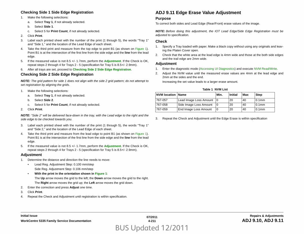
BUS Updated 12/2011
07/20114-211WorkCentre 5335 Family Service Documentation ADJ 9.10, ADJ 9.11
Repairs & AdjustmentsInitial Issue
Checking Side 1 Side Edge Registration1. Make the following selections:
a. Select Tray 1, if not already selected.
b. Select Side 1.
c. Select 5 for Print Count, if not already selected.
2. Click Print.
3. Label each printed sheet with the number of the print (1 through 5), the words “Tray 1”and “Side 1,” and the location of the Lead Edge of each sheet.
4. Take the third print and measure from the top edge to point B1 (as shown on Figure 1).Point B1 is at the intersection of the first line from the side edge and the line from the leadedge.
5. If the measured value is not 8.5 +/- 1.7mm, perform the Adjustment. If the Check is OK,repeat steps 2 through 4 for Trays 2 - 5 (specification for Tray 5 is 8.5+/- 2.9mm).
6. After all trays are set, proceed to Checking Side 2 Side Edge Registration.
Checking Side 2 Side Edge Registration
NOTE: The grid pattern for side 1 does not align with the side 2 grid pattern; do not attempt toset registration by aligning the grids.
1. Make the following selections:
a. Select Tray 1, if not already selected.
b. Select Side 2.
c. Select 5 for Print Count, if not already selected.
2. Click Print.
NOTE: “Side 2” will be delivered face-down in the tray, with the Lead edge to the right and theside edge to be checked towards you.
3. Label each printed sheet with the number of the print (1 through 5), the words “Tray 1”and “Side 2,” and the location of the Lead Edge of each sheet.
4. Take the third print and measure from the lead edge to point B1 (as shown on Figure 1).Point B1 is at the intersection of the first line from the side edge and the line from the leadedge.
5. If the measured value is not 8.5 +/- 1.7mm, perform the Adjustment. If the Check is OK,repeat steps 2 through 4 for Trays 2 - 5 (specification for Tray 5 is 8.5+/- 2.9mm).
Adjustment1. Determine the distance and direction the line needs to move:
• Lead Reg. Adjustment Step: 0.100 mm/step
Side Reg. Adjustment Step: 0.106 mm/step
• With the print in the orientation shown in Figure 1:
The Up arrow moves the grid to the left; the Down arrow moves the grid to the right.
The Right arrow moves the grid up; the Left arrow moves the grid down.
2. Enter the correction and press Adjust one time.
3. Click Print.
4. Repeat the Check and Adjustment until registration is within specification.
ADJ 9.11 Edge Erase Value AdjustmentPurposeTo correct both sides and Lead Edge (Rear/Front) erase values of the image.
NOTE: Before doing this adjustment, the IOT Lead Edge/Side Edge Registration must beadjusted to specification.
Check1. Specify a Tray loaded with paper. Make a black copy without using any originals and leav-
ing the Platen Cover open.
2. Check that the white area at the lead edge is 4mm wide and those at the both side edgesand the trail edge are 2mm wide.
Adjustment1. Enter the diagnostic mode (Accessing UI Diagnostics) and execute NVM Read/Write.
2. Adjust the NVM value until the measured erase values are 4mm at the lead edge and2mm at the sides and the end.
Increasing the set value leads to a larger erase amount.
3. Repeat the Check and Adjustment until the Edge Erase is within specification
Table 1 NVM List
NVM location Name Min. Initial Max Step
767-057 Lead Image Loss Amount 0 20 40 0.1mm
767-058 Side Image Loss Amount 0 20 40 0.1mm
767-059 End Image Loss Amount 0 20 40 0.1mm

BUS Updated 12/2011
07/20114-212 WorkCentre 5335 Family Service DocumentationADJ 9.10, ADJ 9.11
Initial IssueRepairs & Adjustments

BUS Updated 12/2011
07/20114-213WorkCentre 5335 Family Service Documentation ADJ 12.1, ADJ 12.2
Repairs & AdjustmentsInitial Issue
ADJ 12.1 Finisher LX Hole Punch PositionPurposeThis procedure sets the distance from the trail edge of the punched sheet to the center of thepunched holes.
NOTE: This adjustment is normally performed by the customer, via Admin mode.
Check1. Enter the Service Rep. Mode (Accessing UI Diagnostics) and select Finisher Adjust-
ment (on second page).
2. Select Adjust Punch Position/Booklet Fold Position.
3. Select choice #1 or #2, depending on the paper size, then select Change Settings.
4. Select Sample Printout.
5. Select the paper tray to be adjusted, then press Start. The selection must match thechoice made above.
6. Measure the distance between the trail edge of the sheet and the center of the bottomhole. If the distance is not 10 +/- 3 mm, perform the Adjustment
Adjustment1. Use the buttons on the UI to move the holes left or right. When the computed correction is
made, select Adjust.
2. Repeat the Check and Adjustment until the measurement is correct
ADJ 12.2 Finisher LX Booklet Crease/Staple PositionPurposeThis procedure centers the crease and staple positions in the booklet.
NOTE: This adjustment is normally performed by the customer, via Admin mode.
Check1. Enter the Service Rep. Mode (Accessing UI Diagnostics) and select Finisher Adjust-
ment (on second page).
2. Select Adjust Punch Position/Booklet Fold Position.
3. Select choice #3 or #4, depending on the paper size, then select Change Settings.
4. Select Sample Printout.
5. Select a paper tray with the appropriate paper, then press Start. The selection mustmatch the choice made above.
6. Measure the distance between the crease and the edges of the sheet (“A” and “B” on Fig-ure 1). The measurements should be equal, +/- 3.5 mm for A4/Letter size paper; 4 mm forall other sizes.
Figure 1 Measurements
7. Measure the distance between the crease and the staples (“X1” on Figure 1). The mea-surements should be less than 2.5 mm.
8. If either measurement is not within spec, perform the Adjustment.
Adjustment1. Examine the printed sample and determine which of 4 choices best describes the mis-
alignment; select the button for that description.
NOTE: The graphic in the following step is not displayed until a misalignment choice is made.
2. Measure “A” and “B” per the graphic displayed on the UI. Enter the correction and selectAdjust.
3. Repeat the Check and Adjustment until the measurement is correct.

BUS Updated 12/2011
07/20114-214 WorkCentre 5335 Family Service DocumentationADJ 12.1, ADJ 12.2
Initial IssueRepairs & Adjustments

BUS Updated 12/2011
07/20115-1WorkCentre 5335 Family Service Documentation
Parts ListInitial Issue
5 Parts ListsOverviewIntroduction ..................................................................................................................... 5-3Subsystem Information ................................................................................................... 5-4Symbology ...................................................................................................................... 5-5
Parts Lists
1. IITPL 1.1 IIT Covers ............................................................................................................ 5-7PL 1.2 CCD Lens Assembly/Platen Glass ...................................................................... 5-8PL 1.3 Full/Half Rate Carriage ........................................................................................ 5-9PL 1.4 Full Rate Carriage................................................................................................ 5-10PL 1.5 CCD Lens Base Plate.......................................................................................... 5-11PL 1.6 Motor/Transport PWB .......................................................................................... 5-12PL 1.7 Control Panel ....................................................................................................... 5-13PL 1.9 Convenience Stapler ........................................................................................... 5-14
2. ROSPL 2.1 ROS ..................................................................................................................... 5-15
3. DRIVEPL 3.1 Main Drive (1 of 2) ............................................................................................... 5-16PL 3.2 Main Drive (2 of 2) ............................................................................................... 5-17
4. NOHADPL 4.1 NOHAD................................................................................................................ 5-18
6. TransferPL 6.1 Transfer ............................................................................................................... 5-19
7. FusingPL 7.1 Fusing .................................................................................................................. 5-20
8. Xerographic/DevelopmentPL 8.1 CRU, Toner Cartridge.......................................................................................... 5-21PL 8.2 Toner System ...................................................................................................... 5-22
9. Feeder/Tray 1/2PL 9.1 Tray 1/2 Assembly ............................................................................................... 5-23PL 9.2 Tray 1/2 (1 of 2) ................................................................................................... 5-24PL 9.3 Tray 1/2 (2 of 2) ................................................................................................... 5-25PL 9.4 Tray Feeder 1/2 Assembly................................................................................... 5-26PL 9.5 Feeder 1/2 Assembly (1 of 2) .............................................................................. 5-27PL 9.6 Feeder 1/2 Assembly (2 of 2) .............................................................................. 5-28PL 9.7 Tray 1/2 Feed Roll, Nudger Roll, Retard Roll ...................................................... 5-29
9. Envelope TrayPL 9.8 Envelope Tray Assembly ..................................................................................... 5-30
10. HCF
PL 10.1 HCF Unit ............................................................................................................ 5-31PL 10.2 HCF Tray 6 (1 of 2) ............................................................................................ 5-32PL 10.3 HCF Tray 6 (2 of 2) ............................................................................................ 5-33PL 10.4 HCF Feeder (1 of 3)........................................................................................... 5-34PL 10.5 HCF Feeder (2 of 3)........................................................................................... 5-35PL 10.6 HCF Feeder (3 of 3)........................................................................................... 5-36PL 10.7 HCF Top Cover Unit .......................................................................................... 5-37PL 10.8 HCF Electrical and Rail...................................................................................... 5-38
11. Tray Module (TTM)PL 11.1 Tray Module (TTM) (Option) .............................................................................. 5-39PL 11.2 Tray 3/4 Assembly ............................................................................................. 5-40PL 11.3 Tray 3 Assembly (1 of 2).................................................................................... 5-41PL 11.4 Tray 3 Assembly (2 of 2).................................................................................... 5-42PL 11.5 Tray 4 Assembly (1 of 2).................................................................................... 5-43PL 11.6 Tray 4 Assembly (2 of 2).................................................................................... 5-44PL 11.7 Tray 3/4 Feeder Assembly, T/A Roll Assembly ................................................. 5-45PL 11.8 Tray 3/4 Feeder Assembly (1/2) ........................................................................ 5-46PL 11.9 Tray 3/4 Feeder Assembly (2/2) ........................................................................ 5-47PL 11.10 Tray 3/4 Feed/Nudger/Retard Roll................................................................... 5-48PL 11.11 Tray 3/4 Transport Assembly........................................................................... 5-49PL 11.12 Tray 3/4 Switch Assembly................................................................................ 5-50PL 11.13 Wire Harness ................................................................................................... 5-51PL 11.14 TM Drive .......................................................................................................... 5-52PL 11.15 Takeaway Motor Assembly.............................................................................. 5-53PL 11.16 Cover ............................................................................................................... 5-54PL 11.17 L/H Cover Assembly ........................................................................................ 5-55
13. MSIPL 13.1 MSI Assembly .................................................................................................... 5-56PL 13.2 Lower Frame Assembly ..................................................................................... 5-57PL 13.3 MSI Tray Assembly............................................................................................ 5-58
14. Duplex/BTRPL 14.1 L/H Cover Assembly, Duplex Unit...................................................................... 5-59PL 14.2 L/H Chute Assembly .......................................................................................... 5-60PL 14.3 L/H Frame Assembly ......................................................................................... 5-61PL 14.4 Duplex Assembly ............................................................................................... 5-62
15. RegistrationPL 15.1 Registration (1of2) ............................................................................................. 5-63PL 15.2 Registration (2of2) ............................................................................................. 5-64
17. ExitPL 17.1 Exit 1 .................................................................................................................. 5-65PL 17.2 Exit 2 .................................................................................................................. 5-66PL 17.3 Exit 2 Chute Assembly....................................................................................... 5-67PL 17.4 Exit 2 Transport Assembly (1of2)....................................................................... 5-68PL 17.5 Exit 2 Bracket Rear Assembly ........................................................................... 5-69

BUS Updated 12/2011
07/20115-2 WorkCentre 5335 Family Service Documentation
Initial IssueParts List
PL 17.6 Exit 2 Guide Assembly (2of2) ............................................................................ 5-70
18. ElectricalPL 18.1 Electrical (1of2).................................................................................................. 5-71PL 18.2 Electrical (2of2).................................................................................................. 5-72PL 18.3 AC Chassis Assembly ....................................................................................... 5-73PL 18.4 IOT Wire Harness .............................................................................................. 5-74PL 18.5 FAX Unit ............................................................................................................ 5-75
19. CoverPL 19.1 Cover-Front, Left................................................................................................ 5-76PL 19.2 Cover-Rear, Right.............................................................................................. 5-77
22. Integrated Office FinisherPL 22.1 Finisher Assembly (Part 1 of 2) ......................................................................... 5-78PL 22.2 Finisher Assembly (Part 2 of 2) ......................................................................... 5-79PL 22.3 Stacker Base Assembly (Part 1 of 5)................................................................. 5-80PL 22.4 Stacker Base Assembly (Part 2 of 5)................................................................. 5-81PL 22.5 Stacker Base Assembly (Part 3 of 5)................................................................. 5-82PL 22.6 Stacker Base Assembly (Part 4 of 5)................................................................. 5-83PL 22.7 Stacker Base Assembly (Part 5 of 5)................................................................. 5-84PL 22.8 Stacker Tray Assembly...................................................................................... 5-85PL 22.9 Compile Assembly (Part 1 of 2) ......................................................................... 5-86PL 22.10 Compile Assembly (Part 2 of 2) ....................................................................... 5-87
23. Office Finisher LXPL 23.1 H - Transport Assembly (1 of 5)......................................................................... 5-88PL 23.2 H - Transport Assembly (2 of 5)......................................................................... 5-89PL 23.3 H - Transport Assembly (3 of 5)......................................................................... 5-90PL 23.4 H - Transport Assembly (4 of 5)......................................................................... 5-91PL 23.5 H - Transport Assembly (5 of 5)......................................................................... 5-92PL 23.6 Finisher Covers.................................................................................................. 5-93PL 23.7 Finisher Stacker................................................................................................. 5-94PL 23.8 Finisher Stapler.................................................................................................. 5-95PL 23.9 Finisher Eject (1 of 5)......................................................................................... 5-96PL 23.10 Finisher Eject (2 of 5)....................................................................................... 5-97PL 23.11 Finisher Eject (3 of 5)....................................................................................... 5-98PL 23.12 Finisher Eject (4 of 5)....................................................................................... 5-99PL 23.13 Finisher Eject (5 of 5)....................................................................................... 5-100PL 23.14 Finisher Exit/Folder Assembly ......................................................................... 5-101PL 23.15 Folder Assembly .............................................................................................. 5-102PL 23.16 Finisher Electrical ............................................................................................ 5-103PL 23.17 Booklet Cover .................................................................................................. 5-104PL 23.18 Booklet Stapler Assembly................................................................................ 5-105PL 23.19 Booklet Front Stapler Assembly ...................................................................... 5-106PL 23.20 Booklet Rear Stapler Assembly ....................................................................... 5-107PL 23.21 Booklet Electrical ............................................................................................. 5-108
35. ESSPL 35.1 ESS (1/3) ........................................................................................................... 5-109PL 35.2 ESS (2/3) ........................................................................................................... 5-110PL 35.3 ESS (3/3) ........................................................................................................... 5-111
51. DADFPL 51.1 DADF Accessory................................................................................................ 5-112PL 51.2 Covers, PWB ..................................................................................................... 5-113PL 51.3 Base Frame ....................................................................................................... 5-114PL 51.4 Document Tray .................................................................................................. 5-115PL 51.5 DADF Drives (1 of 2).......................................................................................... 5-116PL 51.6 DADF Drives (2 of 2).......................................................................................... 5-117PL 51.7 Front Belt ........................................................................................................... 5-118PL 51.8 Registration, Retard, Invert, Output Chutes....................................................... 5-119PL 51.9 Roll, Sensor Bracket .......................................................................................... 5-120PL 51.10 Document Tray ................................................................................................ 5-121PL 51.11 Top Cover ........................................................................................................ 5-122PL 51.12 Upper Feeder................................................................................................... 5-123PL 51.13 Registration Chute ........................................................................................... 5-124PL 51.14 Retard Chute.................................................................................................... 5-125PL 51.15 Invert Chute ..................................................................................................... 5-126PL 51.16 Output Chute.................................................................................................... 5-127PL 51.17 Sensor Bracket ................................................................................................ 5-128
Common HardwareCommon Hardware ......................................................................................................... 5-129Part Number Index .......................................................................................................... 5-141

BUS Updated 12/2011
07/20115-3WorkCentre 5335 Family Service Documentation Introduction
Parts ListInitial Issue
IntroductionOverviewThe Parts List section identifies all part numbers and the corresponding location of all sparedsubsystem components.
OrganizationParts Lists
Each item number in the part number listing corresponds to an item number in the relatedillustration. All the parts in a given subsystem of the machine will be located in the sameillustration or in a series of associated illustrations.
Electrical Connectors and Fasteners
This section contains the illustrations and descriptions of the plugs, jacks, and fasteners usedin the machine. A part number listing of the connectors is included.
Common Hardware
The common hardware is listed in alphabetical order by the letter or letters used to identifyeach item in the part number listing and in the illustrations. Dimensions are in millimetersunless otherwise identified.
Part Number Index
This index lists all the spared parts in the machine in numerical order. Each number is followedby a reference to the parts list on which the part may be found.
Other InformationAbbreviations
Abbreviations are used in the parts lists and the exploded view illustrations to provideinformation in a limited amount of space. The following abbreviations are used in this manual:
SymbologySymbology used in the Parts List section is identified in the Symbology section.
Service Procedure ReferencingIf a part or assembly has an associated repair or adjustment procedure, the procedure numberwill be listed at the end of the part description in the parts lists e.g. (REP 5.1, ADJ 5.3)
Table 1
Abbreviation Meaning
A3 297 x 594 Millimeters
A4 210 x 297 Millimeters
A5 148 x 210 Millimeters
AD Auto Duplex
AWG American Wire Gauge
EMI Electro Magnetic Induction
GB Giga Byte
KB Kilo Byte
MB Mega Byte
MM Millimeters
MOD Magneto Optical Drive
NOHAD Noise Ozone Heat Air Dirt
PL Parts List
P/O Part of
R/E Reduction/Enlargement
REF: Refer to
SCSI Small Computer Systems Interface
W/ With
W/O Without
Table 2
Operating Companies
Abbreviation Meaning
AO Americas Operations
NASG - US North American Solutions Group - US
NASG - Canada
North American Solutions Group - Canada
XE Xerox Europe
Table 1
Abbreviation Meaning

BUS Updated 12/2011
07/20115-4 WorkCentre 5335 Family Service DocumentationSubsystem Information
Initial IssueParts List
Subsystem InformationUse of the Term “Assembly”The term “assembly” will be used for items in the part number listing that include other itemizedparts in the part number listing. When the word “assembly” is found in the part number listing,there will be a corresponding item number on the illustrations followed by a bracket and alisting of the contents of the assembly.
BracketsA bracket is used when an assembly or kit is spared, but is not shown in the illustration. Theitem number of the assembly or kit precedes the bracket; the item numbers of the piece partsfollow the bracket.
TagThe notation “W/Tag” in the parts description indicates that the part configuration has beenupdated. Check the change Tag index in the General Information section of the Service Datafor the name and purpose of the modification.
In some cases, a part or assembly may be spared in two versions: with the Tag and without theTag. In those cases, use whichever part is appropriate for the configuration of the machine onwhich the part is to be installed. If the machine does not have a particular Tag and the onlyreplacement part available is listed as “W/Tag”, install the Tag kit or all of the piece parts. TheChange Tag Index tells you which kit or piece parts you need.
Whenever you install a Tag kit or all the piece parts that make up a Tag, mark the appropriatenumber on the Tag matrix.

BUS Updated 12/2011
07/20115-5WorkCentre 5335 Family Service Documentation Symbology
Parts ListInitial Issue
SymbologyA Tag number within a circle pointing to an item number shows that the part has been changedby the tag number within the circle (Figure 1). Information on the modification is in the ChangeTag Index.
Figure 1 With Tag Symbol
A Tag number within a circle having a shaded bar and pointing to an item number shows thatthe configuration of the part shown is the configuration before the part was changed by the Tagnumber within the circle (Figure 2).
Figure 2 Without Tag Symbol

BUS Updated 12/2011
07/20115-6 WorkCentre 5335 Family Service DocumentationSymbology
Initial IssueParts List
A tag number within a circle with no apex shows that the entire drawing has been changed bythe tag number within the circle (Figure 3). Information on the modification is in the Change TagIndex.
Figure 3 Entire Drawing With Tag Symbol
A tag number within a circle with no apex and having a shaded bar shows that the entiredrawing was the configuration before being changed by the tag number within the circle(Figure 4).
Figure 4 Entire Drawing Without Tag Symbol

BUS Updated 12/2011
07/20115-7WorkCentre 5335 Family Service Documentation PL 1.1
Parts ListInitial Issue
PL 1.1 IIT CoversItem Part Description
1 – Right Outer Cover2 – Left Cover3 – Right Cover4 – Top Cover5 – Rear Cover6 848E49150 DADF Connector Cover7 – Transport Bracket Assembly8 – Screw9 – Caution Label10 – Label11 062K21136 IIT Assembly

BUS Updated 12/2011
07/20115-8 WorkCentre 5335 Family Service DocumentationPL 1.2
Initial IssueParts List
PL 1.2 CCD Lens Assembly/Platen GlassItem Part Description
1 – IIT Assembly2 – CCD Lens Base Plate Assembly
(P/O PL 1.2 Item 22)3 – Pin Assembly (P/O PL 1.2 Item 22)4 – Right Seal5 – Left Seal6 – Wire Harness Assembly (Includes
Items 20, 21) (REP 6.7)7 – CCD Lens Assembly (P/O PL 1.2
Item 22) (REP 6.4)8 090K93320 CVT Platen Glass (REP 6.3)9 090K93330 Platen Glass (REP 6.3)10 – Conductor (P/O PL 1.2 Item 22)11 130K64150 APS Sensor12 815E58941 Right Plate13 – Lens Cover Assembly14 – Lens Bracket (P/O PL 1.2 Item 22)15 849E15760 Rear Glass Support16 849E22651 Front Glass Support17 849E17910 Glass Support18 – Data Plate19 – PWB Assembly (P/O PL 1.2 Item
22)20 – Cable Band (P/O PL 1.2 Item 6)21 – Wire Harness Assembly (P/O PL
1.2 Item 6)22 604K57500 Lens/CCD Kit (Includes Items 2, 3,
7, 10, 14, 19) (REP 6.4)23 117E31780 CCD Flexible Flat Cable

BUS Updated 12/2011
07/20115-9WorkCentre 5335 Family Service Documentation PL 1.3
Parts ListInitial Issue
PL 1.3 Full/Half Rate CarriageItem Part Description
1 041K96191 Full Rate Carriage Assembly (ADJ 6.2)
2 041K96223 Half Rate Carriage Assembly (ADJ 6.2)
3 006K88780 Capstan Shaft4 020E47040 Capstan Pulley5 012K96780 Front Carriage Cable (REP 6.5)6 012K96790 Rear Carriage Cable (REP 6.5)7 – Cord Holder (P/O PL 1.1 Item 11)8 020E37030 Pulley9 117E31780 Cable10 120K92581 Actuator Assembly11 930W00123 Platen Sensor, Angle Sensor12 920W01235 Clamp13 013E23640 Bearing14 809E91540 Spring

BUS Updated 12/2011
07/20115-10 WorkCentre 5335 Family Service DocumentationPL 1.4
Initial IssueParts List
PL 1.4 Full Rate CarriageItem Part Description
1 – Full Rate Carriage (P/O PL 1.3 Item 1)
2 – Harness Guide (P/O PL 1.3 Item 1)3 – Slide Harness Guide (P/O PL 1.3
Item 1)4 – No 1 Mirror (P/O PL 1.3 Item 1)5 – LED Bracket (P/O PL 1.3 Item 1)6 – Guide Spring (P/O PL 1.3 Item 1)7 – Guide Spring (P/O PL 1.3 Item 1)8 – Light Guide (P/O PL 1.3 Item 1)
(REP 6.8)9 960K51290 LED Lamp PWB (REP 6.6)10 – Slide Cord (P/O PL 1.3 Item 1)11 – Clip (P/O PL 1.3 Item 1)

BUS Updated 12/2011
07/20115-11WorkCentre 5335 Family Service Documentation PL 1.5
Parts ListInitial Issue
PL 1.5 CCD Lens Base PlateItem Part Description
1 – Base Plate (P/O PL 1.2 Item 22)2 – Stage Plate (P/O PL 1.2 Item 22)3 – CCD Plate (P/O PL 1.2 Item 22)4 – Spring (P/O PL 1.2 Item 22)5 – Spring (P/O PL 1.2 Item 22)6 – Conductor (P/O PL 1.2 Item 22)7 – PWB Conductor (P/O PL 1.2 Item
22)8 920W01235 Clamp

BUS Updated 12/2011
07/20115-12 WorkCentre 5335 Family Service DocumentationPL 1.6
Initial IssueParts List
PL 1.6 Motor/Transport PWBItem Part Description
1 023E27590 Belt2 962K83770 Motor Wire Harness3 120E18070 Clamp4 868E47600 Hinge Support5 868E47610 Hinge Support6 127K61330 Carriage Motor (REP 6.9)7 130K76820 IIT Registration Sensor Assembly
(Includes Items 8, 9)8 – Sensor Bracket (P/O PL 1.6 Item 7)9 930W00123 IIT Registration Sensor10 – Bracket (Not Spared)11 809E92410 Spring12 920W01235 Clamp13 960K49301 IIT PWB (REP 6.10)14 – Bracket (Not Spared)15 962K83750 Sensor Wire Harness

BUS Updated 12/2011
07/20115-13WorkCentre 5335 Family Service Documentation PL 1.7
Parts ListInitial Issue
PL 1.7 Control PanelItem Part Description
1 848K57411 Control Panel Assembly (XE) (Includes Items 2, 6-9)
– 848K57401 Control Panel Assembly (XC) (Includes Items 2, 6-9) (REP 6.11)
2 – Control Panel (P/O PL 1.7 Item 1)3 – Stylus (Not Spared)4 – UI Cable (Not Spared)5 604K70430 Name Label6 – Clip Cover (P/O PL 1.7 Item 1)7 – USB Cover (P/O PL 1.7 Item 1)8 – USB Cap Cover9 868E43540 Bracket10 962K93370 UI USB Cable

BUS Updated 12/2011
07/20115-14 WorkCentre 5335 Family Service DocumentationPL 1.9
Initial IssueParts List
PL 1.9 Convenience StaplerItem Part Description
1 604K35710 Convenience Stapler (110V)– 604K35700 Convenience Stapler (220V)
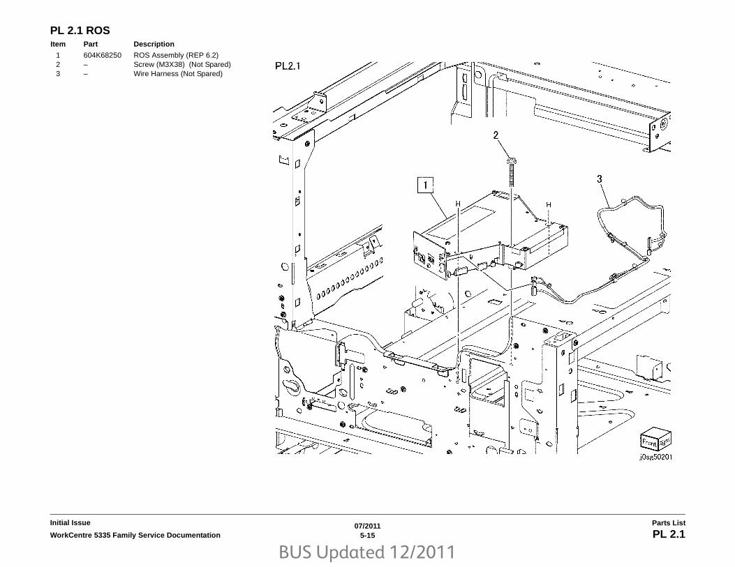
BUS Updated 12/2011
07/20115-15WorkCentre 5335 Family Service Documentation PL 2.1
Parts ListInitial Issue
PL 2.1 ROSItem Part Description
1 604K68250 ROS Assembly (REP 6.2)2 – Screw (M3X38) (Not Spared)3 – Wire Harness (Not Spared)

BUS Updated 12/2011
07/20115-16 WorkCentre 5335 Family Service DocumentationPL 3.1
Initial IssueParts List
PL 3.1 Main Drive (1 of 2)Item Part Description
1 007K17830 Main Drive Assembly (REF: PL 3.2) (REP 4.1)
2 – Flange (Not Spared)3 – Belt (Not Spared)

BUS Updated 12/2011
07/20115-17WorkCentre 5335 Family Service Documentation PL 3.2
Parts ListInitial Issue
PL 3.2 Main Drive (2 of 2)Item Part Description
1 127K64040 Drum Motor2 127K63770 Main Motor3 – Bracket (Not Spared)4 – Bracket (Not Spared)5 – Bracket (Not Spared)6 – Bracket (Not Spared)7 – Drum Shaft Assembly (with Item
31) (Not Spared)8 – Gear (Not Spared)9 – Gear (80T/28T) (Not Spared)10 – Gear (Not Spared)11 – Gear (Not Spared)12 – Gear (Not Spared)13 – Gear (27T) (Not Spared)14 – Gear (Not Spared)15 – Gear (64T/41T) (Not Spared)16 – Gear (28T) (Not Spared)17 – Gear (Not Spared)18 – Gear (Not Spared)19 – Link (Not Spared)20 – Pulley (25T) (Not Spared)21 – Exit Shaft (Not Spared)22 – Spring (Not Spared)23 – Spring (Not Spared)24 – Spring (Not Spared)25 – Coupling (Not Spared)26 – Pin Dowel (Not Spared)27 – Stud (Not Spared)28 – Label (Not Spared)29 – Wire Harness (Not Spared)30 413W11660 Bearing31 – Spring (Not Spared)

BUS Updated 12/2011
07/20115-18 WorkCentre 5335 Family Service DocumentationPL 4.1
Initial IssueParts List
PL 4.1 NOHADItem Part Description
1 054K45710 Fuser Duct Assembly (Includes Items 2-4)
2 – Fuser Duct (P/O PL 4.1 Item 1)3 – Fuser Fan (P/O PL 4.1 Item 1)4 – Connector (P/O PL 4.1 Item 1)5 – ROS Housing Duct (Not Spared)6 – ROS Housing Cover (Not Spared)7 054K45720 ROS Duct Assembly (Includes
Items 8-10)8 – ROS Duct (P/O PL 4.1 Item 7)9 – Fan (Not Spared)10 – CRU Connector (P/O PL 4.1 Item
7)

BUS Updated 12/2011
07/20115-19WorkCentre 5335 Family Service Documentation PL 6.1
Parts ListInitial Issue
PL 6.1 TransferItem Part Description
1 – BTR Assembly (Not Spared) (Includes Items 2-6)
2 – BTR Housing (Not Spared)3 – BiasTransfer Roll (BTR) (Not
Spared)4 – Bearing (Not Spared)5 – Spring (Not Spared)6 – Spring (Not Spared)7 – Rear Lever (Not Spared)8 – Front Lever (Not Spared)9 – Label (P/O PL 6.1 Item 15)10 012K94341 Shutter Link Assembly (Includes
Items 11-13)11 – Shutter Rod (P/O PL 6.1 Item 10)12 – Housing (P/O PL 6.1 Item 10)13 – Spring (P/O PL 6.1 Item 10)14 054K47100 Chute15 802K81270 BTR Housing Assembly (Includes
Items 1-9)

BUS Updated 12/2011
07/20115-20 WorkCentre 5335 Family Service DocumentationPL 7.1
Initial IssueParts List
PL 7.1 FusingItem Part Description
1 126K29392 Fuser (120V) (REP 10.3)– 126K29403 Fuser (220V) (REP 10.3)2 815K02550 Exit Sensor Plate Assembly
(Includes Items 3-11) (REP 10.4)3 – Exit Sensor Bracket (P/O PL 7.1
Item 2)4 – Actuator (P/O PL 7.1 Item 2)5 – Shaft (P/O PL 7.1 Item 2)6 – Spring (P/O PL 7.1 Item 2)7 – Fuser Exit Sensor (P/O PL 7.1 Item
2)8 – Bearing (P/O PL 7.1 Item 2)9 – Actuator Stopper (P/O PL 7.1 Item
2)10 – Stopper Tape (P/O PL 7.1 Item 2)11 – Screw (P/O PL 7.1 Item 2)12 – Wire Harness (Not Spared)13 – Plate (Not Spared)

BUS Updated 12/2011
07/20115-21WorkCentre 5335 Family Service Documentation PL 8.1
Parts ListInitial Issue
PL 8.1 CRU, Toner CartridgeItem Part Description
1 013R00591 Xerographic (Drum) Cartridge 2 006R01158 Toner Cartridge(WW - Metered) – 006R01159 Toner Cartridge (NA/ESG - Sold) – 006R01160 Toner Cartridge (DMO - Sold)

BUS Updated 12/2011
07/20115-22 WorkCentre 5335 Family Service DocumentationPL 8.2
Initial IssueParts List
PL 8.2 Toner SystemItem Part Description
1 – CRU Stopper (Not Spared)2 – Xero Cartridge Guide Assembly
(Not Spared) (REP 9.1)3 – Screw (Not Spared)4 – Plate (Not Spared)5 930W00803 Hum And Temp Sensor (REP 9.3)6 962K90031 Xerographic Wire Harness
(Includes the Interlock Switch) (REP 9.2)
7 – Contact Cover Assembly (Not Spared) (Includes Items 8-11)
8 – Contact Cover (P/O PL 8.2 Item 7)9 – Contact Spring (P/O PL 8.2 Item 7)10 – Contact Spring (P/O PL 8.2 Item 7)11 – Harness (Not Spared)12 032K96941 Cartridge Guide Assembly
(Includes Items 13-18)13 – Drive Shaft (Not Spared)14 – Gear 13T (Not Spared)15 – Dispenser (Not Spared)16 – Cartridge Stopper (Not Spared)17 – Toner Cartridge Guide (Not Spared)
(REP 9.5)18 – Dispenser Support (Not Spared)19 127K38040 Dispense Motor (REP 9.6)20 – PWB Bracket (Not Spared)21 604K68220 CRUM PWB22 – Wire Harness (Not Spared)

BUS Updated 12/2011
07/20115-23WorkCentre 5335 Family Service Documentation PL 9.1
Parts ListInitial Issue
PL 9.1 Tray 1/2 AssemblyItem Part Description
1 050K65076 Tray 1 Assembly (REF: PL 9.2) (REP 7.1)
2 – Tray 2 Assembly (REF: PL 9.2) (Same PN as Item 1) (REP 7.1)
3 – No.1 Label (P/O PL 9.1 Item 16)4 – No.2 Label (P/O PL 9.1 Item 16)5 – Instruction Label (P/O PL 9.1 Item
16)6 – Side Size Label (P/O PL 9.1 Item
16)7 – End Size Label (P/O PL 9.1 Item
16)8 003E75431 Stopper9 059E03500 Roller10 059E03510 Roller11 110K12100 Tray 1 Size Switch12 – Tray 2 Size Switch (Same PN as
Item 11)13 – Switch Bracket (Not Spared)14 014E45291 Slide Lock Block15 848E21141 Rail Cover16 604K68210 Label Kit (Includes Item 3-7)

BUS Updated 12/2011
07/20115-24 WorkCentre 5335 Family Service DocumentationPL 9.2
Initial IssueParts List
PL 9.2 Tray 1/2 (1 of 2)Item Part Description
1 – Tray 1/2 Assembly (REF: PL 9.3)2 848K40411 Tray 1/2 Front Cover Assembly
(Includes Items 3, 4)3 – Tray 1/2 Front Cover (Not Spared)4 – Handle Lever (Not Spared)5 003E75440 Latch6 809E75730 Spring7 – Max Label (P/O PL 9.1 Item 16)8 019E71680 Pad9 – End Spacer (Not Spared)10 – Side Spacer (Not Spared)

BUS Updated 12/2011
07/20115-25WorkCentre 5335 Family Service Documentation PL 9.3
Parts ListInitial Issue
PL 9.3 Tray 1/2 (2 of 2)Item Part Description
1 – Housing Cassette (Not Spared)2 – Tray Stopper (Not Spared)3 – Gear (13T) (P/O PL 9.3 Item 28)4 – Gear (13T/60T) (P/O PL 9.3 Item
28)5 – Gear (60T) (P/O PL 9.3 Item 28)6 807E13521 Pinion7 – End Guide Link (Not Spared)8 – Rear Plate (Not Spared)9 019K09580 Bottom Pad10 – Gasket (Not Spared)11 038E26533 End Guide12 038K89450 Front Guide Assembly (Includes
Items 13-18)13 – Front Guide (P/O PL 9.3 Item 12)14 – Knob (P/O PL 9.3 Item 12)15 – Pin (P/O PL 9.3 Item 12)16 – Spring (P/O PL 9.3 Item 12)17 – Spring (P/O PL 9.3 Item 12)18 010E93341 Lock Slide19 038E39090 Side Guide20 – End Guide Actuator (Not Spared)21 – Side Actuator (Not Spared)22 – Spring (Not Spared)23 – Bottom Plate (Not Spared)24 – Lift Shaft (Not Spared)25 – Spring (Not Spared)26 – Side Actuator (Not Spared)27 059E03522 Rear Roller28 604K20541 Gear Kit (Includes Items 3-5)
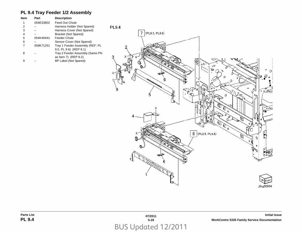
BUS Updated 12/2011
07/20115-26 WorkCentre 5335 Family Service DocumentationPL 9.4
Initial IssueParts List
PL 9.4 Tray Feeder 1/2 AssemblyItem Part Description
1 054E33802 Feed Out Chute2 – Harness Holder (Not Spared)3 – Harness Cover (Not Spared)4 – Bracket (Not Spared)5 054K45941 Feeder Chute6 – Sensor Cover (Not Spared)7 059K71251 Tray 1 Feeder Assembly (REF: PL
9.5, PL 9.6) (REP 8.1)8 – Tray 2 Feeder Assembly (Same PN
as Item 7) (REP 8.2)9 – BP Label (Not Spared)

BUS Updated 12/2011
07/20115-27WorkCentre 5335 Family Service Documentation PL 9.5
Parts ListInitial Issue
PL 9.5 Feeder 1/2 Assembly (1 of 2)Item Part Description
1 – Upper Frame (Not Spared)2 – Lower Frame (Not Spared)3 – Rail (Not Spared)4 – Chute (Not Spared)5 930W00113 Tray 1/2 No Paper Sensor6 – Tray 1/2 Level Sensor (Same PN
as Item 5)7 120E22481 Actuator8 – Holder (Not Spared)9 – Lever (Not Spared)10 – Holder Harness (Not Spared)11 413W11660 Bearing12 – Gear (30T) (Not Spared)13 – Bearing (Not Spared)14 – Spring (Not Spared)15 – Feed Roll/Nudger Roll Assembly
(REF: PL 9.7)16 – Spring (Not Spared)17 – Traceability Label (Not Spared)18 930W00211 Tray 1/2 Prefeed Sensor19 – Retard Roll Assembly (REF: PL
9.7)20 – Rear Harness Holder (Not Spared)21 – Center Harness Holder (Not
Spared)22 – Wire Harness (Not Spared)

BUS Updated 12/2011
07/20115-28 WorkCentre 5335 Family Service DocumentationPL 9.6
Initial IssueParts List
PL 9.6 Feeder 1/2 Assembly (2 of 2)Item Part Description
1 – Drive Bracket Assembly (Not Spared)
2 127K52790 Tray 1/2 Lift/Feed Motor3 – Gear (31T) (Not Spared)4 – Spacer (Not Spared)5 – Shaft Bearing (Not Spared)6 – Drive Shaft Assembly (Not Spared)
(Includes Item 7)7 – Drive Shaft (P/O PL 9.6 Item 6)8 – Gear (13T) (Not Spared)9 005K07130 Oneway Clutch10 007K97870 Oneway Gear11 – Gear (25T) (Not Spared)12 – Gear (29T/19T) (Not Spared)13 – Washer (Not Spared)14 – Spring (Not Spared)15 – Wire Harness (Not Spared)

BUS Updated 12/2011
07/20115-29WorkCentre 5335 Family Service Documentation PL 9.7
Parts ListInitial Issue
PL 9.7 Tray 1/2 Feed Roll, Nudger Roll, Retard RollItem Part Description
1 – Feed Roll (P/O PL 9.7 Item 19) (REP 8.5)
2 – Nudger Roll (P/O PL 9.7 Item 19) (REP 8.5)
3 – Feed Shaft (Not Spared)4 – Bearing (Not Spared)5 – Nudger Support (Not Spared)6 007E79380 Gear (33T)7 005K06760 Clutch Assembly (22T)8 005K05890 Oneway Clutch9 – Nudger Shaft (Not Spared)10 – Gear (25T) (Not Spared)11 – Retard Support (Not Spared)12 005K09290 Friction Clutch13 – Spacer (Not Spared)14 – Retard Shaft (Not Spared)15 – Bearing (Not Spared)16 – Spring (Not Spared)17 – Retard Roll (P/O PL 9.7 Item 19)
(REP 8.5)18 – Feed In Chute (Not Spared)19 604K56080 FeedRoll/Nudger Roll/Retard Roll
Kit (Includes Items 1, 2, 17) (REP 8.5)

BUS Updated 12/2011
07/20115-30 WorkCentre 5335 Family Service DocumentationPL 9.8
Initial IssueParts List
PL 9.8 Envelope Tray AssemblyItem Part Description
1 604K70020 Envelope Tray Assembly2 – Front Cover (P/O PL 9.8 Item 1)3 – Lever (P/O PL 9.8 Item 1)4 003E75440 Latch5 809E75730 Spring6 038E26533 End Guide7 – Envelope Tray Frame (P/O PL 9.8
Item 1)

BUS Updated 12/2011
07/20115-31WorkCentre 5335 Family Service Documentation PL 10.1
Parts ListInitial Issue
PL 10.1 HCF Unit Item Part Description
1 – Joint Plate (Not Spared)2 003K91881 Knob3 130K55590 HCF Tray Set Sensor4 801K15700 Tray Rail5 – HCF Tray 6 (REP 19.1)6 – Left Top Cover (Not Spared)7 – Right Cover (Not Spared)8 – Front Right Cover (Not Spared)9 – Left Cover (Not Spared)10 – Rear Cover (Not Spared)11 – HCF Feeder (Not Spared) (REP
19.2)12 – Label (Top) (Not Spared)13 – Label (Tray Number) (Not Spared)14 – Label (Size) (Not Spared)15 – Label (End) (Not Spared)16 – Frame Assembly (Not Spared)

BUS Updated 12/2011
07/20115-32 WorkCentre 5335 Family Service DocumentationPL 10.2
Initial IssueParts List
PL 10.2 HCF Tray 6 (1 of 2)Item Part Description
1 – Tray Latch Assembly (Not Spared)2 003K13592 Tray Latch3 – Spring (P/O PL 10.2 Item 1)4 – Latch Lever (P/O PL 10.2 Item 1)5 – Magnet (P/O PL 10.1 Item 5)6 – Wave Washer (P/O PL 10.1 Item 5)7 – Front Cover (P/O PL 10.1 Item 5)8 – Gear Bracket (P/O PL 10.1 Item 5)9 – Label (Gauge) (P/O PL 10.1 Item
5)10 – Frame (P/O PL 10.1 Item 5)11 – Plate (P/O PL 10.1 Item 5)12 – Bracket (P/O PL 10.1 Item 5)13 – Pin (P/O PL 10.1 Item 5)14 – Spring (P/O PL 10.1 Item 5)15 – Top Plate (P/O PL 10.1 Item 5)

BUS Updated 12/2011
07/20115-33WorkCentre 5335 Family Service Documentation PL 10.3
Parts ListInitial Issue
PL 10.3 HCF Tray 6 (2 of 2)Item Part Description
1 – Lift Shaft (P/O PL 10.1 Item 5)2 – Bearing (P/O PL 10.1 Item 5)3 – Bearing (P/O PL 10.1 Item 5)4 020E37620 Tray Cable Pulley5 – Gear (P/O PL 10.1 Item 5)6 – Gear (P/O PL 10.1 Item 5)7 – Bottom Plate (P/O PL 10.1 Item 5)8 019E58620 Pad9 – Front Side Guide (P/O PL 10.1 Item
5)10 – Rear Side Guide (P/O PL 10.1 Item
5)11 604K19981 Cable And Pulley Kit (REP 19.4)12 032E22410 Wire Guide (L)13 – Pulley (P/O PL 10.1 Item 5)14 – Wire Guide (S) (P/O PL 10.1 Item
5)15 – Pulley (P/O PL 10.1 Item 5)16 – Screw (P/O PL 10.1 Item 5)17 015K65532 Gear Bracket Assembly18 – Gear Bracket (P/O PL 10.3 Item 17)19 – Contact Gear (P/O PL 10.3 Item
17)20 – Gear (P/O PL 10.3 Item 17)21 – Gear (P/O PL 10.3 Item 17)22 – Brake (P/O PL 10.3 Item 17)23 – Spring (P/O PL 10.3 Item 17)24 807E04500 Lift Gear25 – Plate (P/O PL 10.1 Item 5)

BUS Updated 12/2011
07/20115-34 WorkCentre 5335 Family Service DocumentationPL 10.4
Initial IssueParts List
PL 10.4 HCF Feeder (1 of 3)Item Part Description
1 – Shaft (P/O PL 10.1 Item 11)2 007E78760 Gear (19T)3 – Gear (25T) (P/O PL 10.1 Item 11)4 007E78780 Gear (25T)5 007E78790 Gear (40T)6 013E25530 Bearing7 – Block (P/O PL 10.1 Item 11)8 – Spacer (P/O PL 10.1 Item 11)9 019E56470 Holder10 – Upper Feeder Assembly (P/O PL
10.1 Item 11)11 – Lower Feeder Assembly (P/O PL
10.1 Item 11)12 – Ball Bearing (P/O PL 10.1 Item 11)13 – Front Frame (P/O PL 10.1 Item 11)14 – Pin (P/O PL 10.1 Item 11)15 – Down Bracket (P/O PL 10.1 Item
11)16 – Link Bracket (P/O PL 10.1 Item 11)17 – Rear Frame (P/O PL 10.1 Item 11)18 – Tension Spring (P/O PL 10.1 Item
11)19 – Lift/Motor Frame (P/O PL 10.1 Item
11)20 – Bracket (P/O PL 10.4 Item 19)21 007K88520 Gear (23T/27T)22 007K88530 Gear (31T/36T)23 127K37901 Lift/Feed Motor (REP 19.12)24 – Plate (P/O PL 10.4 Item 19)25 – Spring (P/O PL 10.1 Item 11)

BUS Updated 12/2011
07/20115-35WorkCentre 5335 Family Service Documentation PL 10.5
Parts ListInitial Issue
PL 10.5 HCF Feeder (2 of 3)Item Part Description
1 – Upper Feeder Assembly (P/O PL 10.1 Item 11)
2 003E59570 Latch3 – Shaft Latch (P/O PL 10.5 Item 1)4 006K23124 Feed Shaft Assembly5 – Feed Shaft (P/O PL 10.5 Item 4)6 – Ball Bearing (P/O PL 10.5 Item 4)7 – Gear (20T) (P/O PL 10.5 Item 4)8 007E78180 Feed Gear (25T)9 – Lever (P/O PL 10.5 Item 1)10 – Bearing (P/O PL 10.5 Item 1)11 – Spacer (P/O PL 10.5 Item 1)12 – Pin Drive (P/O PL 10.5 Item 1)13 – Guide (P/O PL 10.5 Item 1)14 – Rear Upper Chute (P/O PL 10.5
Item 1)15 – Upper Chute (P/O PL 10.5 Item 1)16 120E21900 Actuator17 – Upper Frame (P/O PL 10.5 Item 1)18 – Spring (P/O PL 10.5 Item 1)19 – HCF Stack Height Sensor, HCF
Paper Sensor (P/O PL 10.5 Item 1)20 – HCF Pre Feed Sensor (P/O PL
10.5 Item 1)21 – Wire Harness (P/O PL 10.5 Item 1)22 059K26691 Feed Roll (REP 19.5)23 059K26702 Nudger Roll (REP 19.5)

BUS Updated 12/2011
07/20115-36 WorkCentre 5335 Family Service DocumentationPL 10.6
Initial IssueParts List
PL 10.6 HCF Feeder (3 of 3)Item Part Description
1 059K26591 Lower Feed Assembly2 – Retard Roll Assembly (P/O PL 10.6
Item 1) (REP 19.5)3 – Retard Shaft Assembly (P/O PL
10.6 Item 1)4 – Collar (P/O PL 10.6 Item 3)5 005K06701 Friction Clutch6 – Shaft (P/O PL 10.6 Item 3)7 007E78170 Gear (15T)8 007E89760 Gear (22T)9 013E23600 Bearing10 013E23610 Bearing11 – Retard Bracket (P/O PL 10.6 Item
1)12 – Slide (P/O PL 10.6 Item 1)13 – Lever (P/O PL 10.6 Item 1)14 – Lower Chute (P/O PL 10.6 Item 1)15 – Lower Frame (P/O PL 10.6 Item 1)16 – Spring (P/O PL 10.6 Item 1)17 – Spring (P/O PL 10.6 Item 1)

BUS Updated 12/2011
07/20115-37WorkCentre 5335 Family Service Documentation PL 10.7
Parts ListInitial Issue
PL 10.7 HCF Top Cover UnitItem Part Description
1 013E17100 Bearing2 – Bracket (Not Spared)3 – Pivot Bracket (Not Spared)4 – Top Cover Assembly (Not Spared)5 – Bearing (P/O PL 10.7 Item 4)6 – Upper Chute (P/O PL 10.7 Item 4)7 – Top Cover (P/O PL 10.7 Item 4)8 – Knob (P/O PL 10.7 Item 4)9 – Latch (P/O PL 10.7 Item 4)10 – Latch (P/O PL 10.7 Item 4)11 – Spring (P/O PL 10.7 Item 4)12 059E01430 Pinch Roller13 – Shaft (P/O PL 10.7 Item 4)14 – Shaft (P/O PL 10.7 Item 4)15 – Spring (P/O PL 10.7 Item 4)16 – Spring (P/O PL 10.7 Item 4)17 – Gasket (P/O PL 10.7 Item 4)18 059K36260 Takeaway Roll (REP 19.10)19 – Spring (Left) (P/O PL 10.1 Item 16)20 – Spring (Right) (P/O PL 10.1 Item
16)21 – Pivot Shaft (P/O PL 10.1 Item 16)22 – Bracket (P/O PL 10.1 Item 16)23 – Bracket (P/O PL 10.1 Item 16)24 – Lower Chute (P/O PL 10.1 Item 16)25 130K88150 Takeaway Sensor26 110E94770 Top Cover Interlock Switch

BUS Updated 12/2011
07/20115-38 WorkCentre 5335 Family Service DocumentationPL 10.8
Initial IssueParts List
PL 10.8 HCF Electrical and RailItem Part Description
1 – Plate (Not Spared)2 017E92820 Rack Caster (REP 19.9)3 – Foot (Not Spared)4 – Latch Lever (Not Spared)5 – Spring (Not Spared)6 801K15690 Rail7 127K47150 Takeaway Motor8 – Docking Interlock Switch (Not
Spared)9 960K31492 HCF PWB (REP 19.11)10 – Wire Harness (P/O PL 10.1 Item
16)11 130K55590 HCF Size Sensor R and L12 – Bracket (P/O PL 10.1 Item 16)

BUS Updated 12/2011
07/20115-39WorkCentre 5335 Family Service Documentation PL 11.1
Parts ListInitial Issue
PL 11.1 Tray Module (TTM) (Option)Item Part Description
1 826E48400 Docking Screw2 849E13150 Docking Bracket3 – Tray Module (TTM) (Not Spared)
(Includes Items 4-17)4 – Label (Tray No.3) (P/O PL 11.1
Item 19)5 – Label (Tray No.4) (P/O PL 11.1
Item 19)6 – Label (TTM) (P/O PL 11.1 Item 19)7 – Label (Instruction TTM) (P/O PL
11.1 Item 19)8 803E09040 Stopper (Tray 3)9 803E09030 Stopper (Tray 4)10 050K66262 Tray 3 Assembly (REF: PL 11.2)11 059K71810 Transport Assembly (REF: PL
11.11)12 050K66242 Tray 4 Assembly (REF: PL 11.2)13 017K94590 Adjuster Foot Assembly14 848E52692 Foot Cover15 868E51271 Foot Bracket16 – Screw Tap (Not Spared)17 826E28400 Screw Tap18 032E37871 Guide Transport19 604K68210 Label Kit (Includes Items 4-7)

BUS Updated 12/2011
07/20115-40 WorkCentre 5335 Family Service DocumentationPL 11.2
Initial IssueParts List
PL 11.2 Tray 3/4 AssemblyItem Part Description
1 – Tray 3 Assembly (REF: PL 11.3, PL 11.4) (REP 7.1)
2 848K49481 Tray 3 Front Cover Assembly (Includes Items 3-9)
3 – Tray 3 Front Cover (Not Spared)4 – Lever (Not Spared)5 – Link (Not Spared)6 – Link (Not Spared)7 – Spring (Not Spared)8 – Latch (Not Spared)9 – Cover (P/O PL 11.2 Item 2)10 – Tray 4 Assembly (REF: PL 11.5, PL
11.6) (REP 7.1)11 848K49471 Tray 4 Front Cover Assembly
(Includes Items 12-19)12 – Tray 4 Front Cover (Not Spared)13 – Lever (Not Spared)14 – Link (Not Spared)15 – Link (Not Spared)16 – Spring (Not Spared)17 – Latch (Not Spared)18 – Cover (P/O PL 11.2 Item 11)19 – Transport Bracket (P/O PL 11.2
Item 11)

BUS Updated 12/2011
07/20115-41WorkCentre 5335 Family Service Documentation PL 11.3
Parts ListInitial Issue
PL 11.3 Tray 3 Assembly (1 of 2)Item Part Description
1 – Pinion (P/O PL 11.3 Item 25)2 – Rack Gear (P/O PL 11.3 Item 25)3 – Cable LT (P/O PL 11.3 Item 22)
(REP 7.3)4 019E71680 Pad5 – Pulley (S) (P/O PL 11.3 Item 22)6 – Pulley (L) (P/O PL 11.3 Item 22)7 – Guide (Not Spared)8 – Guide (Not Spared)9 038K20970 Side Guide Assembly (Includes
Items 10-13)10 – Side Guide (P/O PL 11.3 Item 9)11 – Knob (P/O PL 11.3 Item 9)12 – Knob Assembly (P/O PL 11.3 Item
9)13 – Spring (P/O PL 11.3 Item 9)14 – Guide Assembly (Not Spared)15 – Size Actuator (Not Spared)16 – Shaft (P/O PL 11.3 Item 22)17 – Bottom Plate Assembly (Not
Spared) (Includes Items 18, 19)18 – Plate (P/O PL 11.3 Item 17)19 019K09580 Pad20 – Side Bracket (Not Spared)21 – Label (Max) (P/O PL 11.3 Item 24)22 604K68170 Pulley Cable Kit (Includes Items 3,
5, 6, 16)23 604K68180 Pad Kit24 604K68210 Label Kit (Includes Items 21)25 604K68260 Rack and Pinion Kit (Includes Items
1, 2)

BUS Updated 12/2011
07/20115-42 WorkCentre 5335 Family Service DocumentationPL 11.4
Initial IssueParts List
PL 11.4 Tray 3 Assembly (2 of 2)Item Part Description
1 006K89421 Lift Shaft Assembly (Includes Items 2-6)
2 – Lift Shaft (P/O PL 11.4 Item 1)3 413W11860 Bearing4 – Pulley (P/O PL 11.4 Item 19)5 – Spring (P/O PL 11.4 Item 1)6 – Joint (P/O PL 11.4 Item 1)7 019K93921 Brake Assembly8 – Pulley C (Not Spared)9 – Upper Roll (P/O PL 11.4 Item 20)10 059E05060 Upper Roll11 – Gear (18T) (P/O PL 11.4 Item 19)12 – Spring (Not Spared)13 – Bracket (Not Spared)14 – Sleeve Bearing (Not Spared)15 – Cassette Assembly (Not Spared)
(Includes Items 16-18)16 – Cassette (P/O PL 11.4 Item 15)17 – Rail (P/O PL 11.4 Item 15)18 – Cover (P/O PL 11.4 Item 15)19 604K68150 Pully Lift Kit (Includes Items 3, 4,
11)20 604K68160 Roller Kit

BUS Updated 12/2011
07/20115-43WorkCentre 5335 Family Service Documentation PL 11.5
Parts ListInitial Issue
PL 11.5 Tray 4 Assembly (1 of 2)Item Part Description
1 – Pinion (P/O PL 11.5 Item 21)2 – Rack Gear (P/O PL 11.5 Item 21)3 – Cable RT (P/O PL 11.5 Item 20)
(REP 7.4)4 019E71680 Pad5 – Pulley (P/O PL 11.5 Item 20)6 – Guide (Not Spared)7 038K20950 Side Guide Assembly (Includes
Items 8-11)8 – Side Guide (P/O PL 11.5 Item 7)9 – Knob (P/O PL 11.5 Item 7)10 – Knob Assembly (P/O PL 11.5 Item
7)11 – Spring (P/O PL 11.5 Item 7)12 – Guide Assembly (Not Spared)13 – Size Actuator (Not Spared)14 – Shaft (P/O PL 11.5 Item 20)15 – Bottom Plate Assembly (Not
Spared) (Includes Items 16, 17)16 – Plate (Not Spared)17 019K09580 Pad18 – Side Bracket (Not Spared)19 – Label (Max) (P/O PL 9.1 Item 16)20 604K68190 Pulley Cable Kit (Includes Items 3,
5, 14)21 604K68260 Rack and Pinion Kit (Includes Items
1, 2)22 604K68180 Pad Kit (Includes Items 4, 17)

BUS Updated 12/2011
07/20115-44 WorkCentre 5335 Family Service DocumentationPL 11.6
Initial IssueParts List
PL 11.6 Tray 4 Assembly (2 of 2)Item Part Description
1 006K89421 Lift Shaft Assembly (Includes Items 2-6)
2 – Lift Shaft (P/O PL 11.6 Item 1)3 413W11860 Bearing4 – Pulley (P/O PL 11.6 Item 1)5 – Spring (P/O PL 11.6 Item 1)6 – Joint (P/O PL 11.6 Item 1)7 019K93921 Brake Assembly8 – Pulley (Not Spared)9 – Upper Roll (Not Spared)10 059E05060 Upper Roll11 – Gear (18T) (Not Spared)12 – Spring (Not Spared)13 – Sleeve Bearing (Not Spared)14 – Bracket (Not Spared)15 – Cassette Assembly (Not Spared)
(Includes Items 16-18)16 – Cassette (P/O PL 11.6 Item 15)17 – Rail (P/O PL 11.6 Item 15)18 – Cover (P/O PL 11.6 Item 15)

BUS Updated 12/2011
07/20115-45WorkCentre 5335 Family Service Documentation PL 11.7
Parts ListInitial Issue
PL 11.7 Tray 3/4 Feeder Assembly, T/A Roll AssemblyItem Part Description
1 054K46240 Chute Assembly (Includes Items 2-4)
2 – Chute (Not Spared)3 130K76530 Feed Out Sensor 34 – Harness Assembly (Feed/Out 3)
(Not Spared)5 054E46500 Chute Feed Transport6 059K71510 T/A Roll Assembly (Includes Item
7-9)7 – T/A Roll (Not Spared)8 – Gear (16T) (Not Spared)9 – Bearing (Not Spared)10 110E12220 TM L/H Cover Interlock Switch11 – Bearing (Not Spared)12 – Harness Cover (Not Spared)13 054E33802 Feed Out Chute14 059K74280 Tray 3 Feeder Assembly (PL 11.8)
(REP 8.3)15 – Cover (Not Spared)16 – Tray 4 Feeder Assembly (PN Same
as Item 14) (REP 8.4)17 – Bracket (Not Spared)18 – Bracket (Not Spared)19 – Low Chute (Not Spared)20 054K46340 Chute Assembly (Includes Items
21-23)21 – Chute (P/O PL 11.7 Item 20)22 930W00212 Feed Out Sensor 423 – Harness Assembly (Feed/Out 4)
(P/O PL 11.7 Item 20)24 – Cover (Not Spared)25 – Pivot Bracket (Not Spared)26 032E37871 Transport Guide27 815E50081 Earth Plate

BUS Updated 12/2011
07/20115-46 WorkCentre 5335 Family Service DocumentationPL 11.8
Initial IssueParts List
PL 11.8 Tray 3/4 Feeder Assembly (1/2)Item Part Description
1 – Upper Frame (Not Spared)2 – Lower Frame (Not Spared)3 – Rail (Not Spared)4 – Chute (Not Spared)5 930W00123 Tray 3/4 Level Sensor6 930W00113 Tray 3/4 No Paper Sensor7 120E22481 Actuator8 – Holder (Not Spared)9 – Lever (Not Spared)10 – Harness Holder (Not Spared)11 413W11660 Bearing12 – Gear 30T (Not Spared)13 – Bearing (Not Spared)14 – Spring (Not Spared)15 – Feed/Nudger Roll Assembly (REF:
PL 11.10)16 – Spring (Not Spared)17 – Traceability Label (Not Spared)18 – Retard Roll Assembly (REF: PL
11.10)19 – Rear Harness Holder (Not Spared)20 – Center Harness Holder (Not
Spared)21 – Wire Harness (Not Spared)

BUS Updated 12/2011
07/20115-47WorkCentre 5335 Family Service Documentation PL 11.9
Parts ListInitial Issue
PL 11.9 Tray 3/4 Feeder Assembly (2/2)Item Part Description
1 – Drive Bracket Assembly (Not Spared)
2 127K52790 Tray 3/4 Lift/Feed Motor3 – Gear (31T) (Not Spared)4 – Spacer (Not Spared)5 – Shaft Bearing (Not Spared)6 – Drive Shaft Assembly (Not Spared)
(Includes Item 7)7 – Drive Shaft (Not Spared)8 – Gear (13T) (Not Spared)9 005K07130 Oneway Clutch10 007K97870 Oneway Gear11 – Gear (25T) (Not Spared)12 – Gear (29T/19T) (Not Spared)13 – Washer (Not Spared)14 – Spring (Not Spared)15 – Wire Harness (Not Spared)

BUS Updated 12/2011
07/20115-48 WorkCentre 5335 Family Service DocumentationPL 11.10
Initial IssueParts List
PL 11.10 Tray 3/4 Feed/Nudger/Retard RollItem Part Description
1 – Feed Roll (Not Spared) (REP 8.5)2 – Nudger Roll (Not Spared) (REP
8.5)3 – Feed Shaft (Not Spared)4 – Bearing (Not Spared)5 – Nudger Support (Not Spared)6 007E79380 Gear (33T) (Tray 3)7 005K06760 Oneway Gear (22T) (Tray 3)8 005K05890 Oneway Clutch9 – Nudger Shaft (Not Spared)10 – Gear (25T) (Not Spared)11 – Retard Support (Not Spared)12 005K09290 Friction Clutch13 – Spacer (Not Spared)14 – Retard Shaft (Not Spared)15 – Bearing (Not Spared)16 – Spring (Not Spared)17 – Retard Roll (P/O PL 11.10 Item 19)18 – Feed In Chute (Not Spared)19 604K56080 Feed/Nudger/Retard Roll Kit (REP
8.5)

BUS Updated 12/2011
07/20115-49WorkCentre 5335 Family Service Documentation PL 11.11
Parts ListInitial Issue
PL 11.11 Tray 3/4 Transport AssemblyItem Part Description
1 – Chute Ay Low (Not Spared)2 – Rail Transport Lh (Not Spared)3 059K26350 T/A Roll Assembly (Includes Items
4-7)4 – T/A Roll (P/O PL 11.11 Item 3)5 – Joint (P/O PL 11.11 Item 3)6 – Spring (P/O PL 11.11 Item 3)7 – Bearing (P/O PL 11.11 Item 3)8 – Chute Uo Trs (Not Spared)9 – Label Transport (Not Spared)10 059E98860 Roll Pinch Transport11 – Bearing 2 (Not Spared)12 – Bearing 1 (Not Spared)13 413W77559 Bearing14 – Spring (Not Spared)15 – Cover Pinch (Not Spared)16 – Spacer Rail (Not Spared)
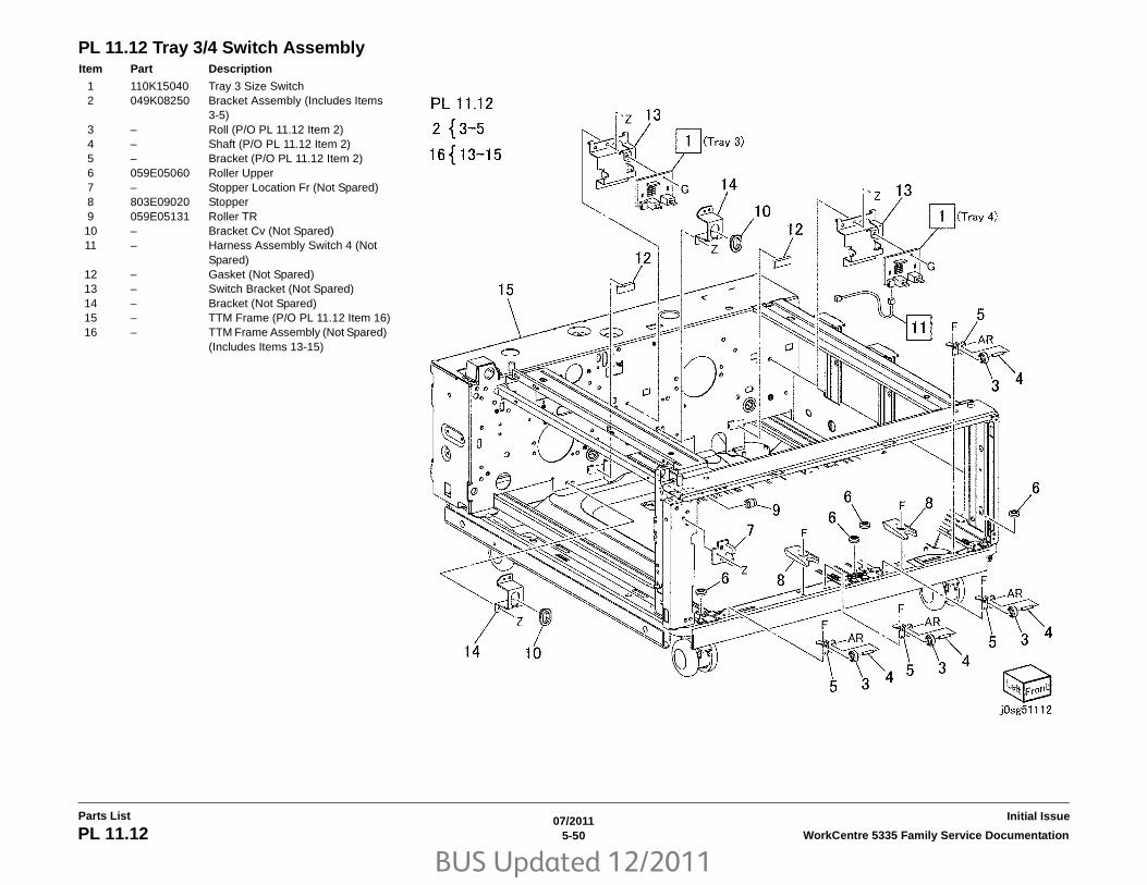
BUS Updated 12/2011
07/20115-50 WorkCentre 5335 Family Service DocumentationPL 11.12
Initial IssueParts List
PL 11.12 Tray 3/4 Switch AssemblyItem Part Description
1 110K15040 Tray 3 Size Switch2 049K08250 Bracket Assembly (Includes Items
3-5)3 – Roll (P/O PL 11.12 Item 2)4 – Shaft (P/O PL 11.12 Item 2)5 – Bracket (P/O PL 11.12 Item 2)6 059E05060 Roller Upper7 – Stopper Location Fr (Not Spared)8 803E09020 Stopper9 059E05131 Roller TR10 – Bracket Cv (Not Spared)11 – Harness Assembly Switch 4 (Not
Spared)12 – Gasket (Not Spared)13 – Switch Bracket (Not Spared)14 – Bracket (Not Spared)15 – TTM Frame (P/O PL 11.12 Item 16)16 – TTM Frame Assembly (Not Spared)
(Includes Items 13-15)

BUS Updated 12/2011
07/20115-51WorkCentre 5335 Family Service Documentation PL 11.13
Parts ListInitial Issue
PL 11.13 Wire HarnessItem Part Description
1 960K55022 Tray Module PWB2 – Wire Harness (IF) (Not Spared)3 – Wire Harness (Sensor) (Not
Spared)4 – Wire Harness (Motor 1) (Not
Spared)5 – Wire Harness (Motor 2) (Not
Spared)

BUS Updated 12/2011
07/20115-52 WorkCentre 5335 Family Service DocumentationPL 11.14
Initial IssueParts List
PL 11.14 TM DriveItem Part Description
1 049K07530 Gear Assembly (REF: PL 11.15)2 049K07520 Bracket Assembly (REF: PL 11.15)3 – Collar 2 (P/O PL 11.14 Item 12)4 – Pulley (P/O PL 11.14 Item 12)5 – Roll (P/O PL 11.14 Item 12)6 – Spring (P/O PL 11.14 Item 12)7 – Gear Assembly (P/O PL 11.14 Item
12) (Includes Items 8, 9)8 – Gear (P/O PL 11.14 Item 7)9 – Bracket (P/O PL 11.14 Item 7)10 049K07400 TM Takeaway Motor Assembly
(REF: PL 11.15)11 – Belt (P/O PL 11.14 Item 12)12 604K68200 Take Away Gear Kit (Includes Item
3-7, 11)

BUS Updated 12/2011
07/20115-53WorkCentre 5335 Family Service Documentation PL 11.15
Parts ListInitial Issue
PL 11.15 Takeaway Motor AssemblyItem Part Description
1 – Bracket Assembly (Not Spared)2 – Gear (18T) (Not Spared)3 – Lift Gear (Not Spared)4 – Lift Gear (Not Spared)5 – Lift Gear (57) (Not Spared)6 – Bracket Assembly, TM Take Away
Motor (Not Spared)7 – Gear (18T) (Not Spared)8 – Lift Gear (Not Spared)9 – Lift Gear (Not Spared)10 – Lift Gear (51) (Not Spared)11 – Bracket Assembly (Not Spared)12 – TM Take Away Motor (Not Spared)13 – Gear (70T) (Not Spared)14 – Gear (81T) (Not Spared)15 – Collar (Not Spared)

BUS Updated 12/2011
07/20115-54 WorkCentre 5335 Family Service DocumentationPL 11.16
Initial IssueParts List
PL 11.16 CoverItem Part Description
1 – Rear Cover (Not Spared)2 – Left Cover (Not Spared)3 – Right Cover (Not Spared)4 – Top Cover (Not Spared)5 – Latch Assembly (Not Spared)
(Includes Items 6, 7)6 – Latch (P/O PL 11.16 Item 5)7 – Shaft (P/O PL 11.16 Item 5)8 848K49451 L/H Cover Assembly (REF: PL
11.17)9 – Pivot Bracket (Not Spared)10 417W41349 Locking Caster11 417W41449 Caster12 – Screw (Not Spared)13 – Support Block (Not Spared)

BUS Updated 12/2011
07/20115-55WorkCentre 5335 Family Service Documentation PL 11.17
Parts ListInitial Issue
PL 11.17 L/H Cover AssemblyItem Part Description
1 – L/H Cover (Not Spared)2 – Handle (Not Spared)3 – L/H Chute (Not Spared)4 – Latch (Not Spared)5 – Hook (Not Spared)6 059E99241 Pinch Roll7 – Pinch Shaft (Not Spared)8 – Latch Spring (Not Spared)9 – Pinch Spring (Not Spared)10 – Gasket (Not Spared)11 – Label (Not Spared)

BUS Updated 12/2011
07/20115-56 WorkCentre 5335 Family Service DocumentationPL 13.1
Initial IssueParts List
PL 13.1 MSI AssemblyItem Part Description
1 059K71260 MSI Assembly (Includes Items 2-15) (REP 7.2)
2 – MSI Top Cover (P/O PL 13.1 Item 1)
3 054K45960 Pinch Chute Assembly (Includes Items 4-9)
4 – Pinch Chute (P/O PL 13.1 Item 3)5 – Pinch Guide (P/O PL 13.1 Item 3)6 – Pinch Spring Spacer (P/O PL 13.1
Item 3)7 – Pinch Shaft (P/O PL 13.1 Item 3)8 – Pinch Spring (P/O PL 13.1 Item 3)9 – Pinch Roll (P/O PL 13.1 Item 3)10 – MSI Front Handle (P/O PL 13.1
Item 1)11 – MSI Lower Assembly (P/O PL 13.1
Item 1)12 120E32540 Actuator13 050K67000 MSI Front Handle (REF: PL 13.3)14 – INST Label (P/O PL 13.1 Item 19)15 – Max Label (P/O PL 13.1 Item 19)16 – MSI Front Cover (Not Spared)17 – Number Label (Not Spared)18 – MSI Rear Cover (Not Spared)19 604K68210 Label Kit (Includes Items 14, 15)

BUS Updated 12/2011
07/20115-57WorkCentre 5335 Family Service Documentation PL 13.2
Parts ListInitial Issue
PL 13.2 Lower Frame AssemblyItem Part Description
1 – Feed Roll Assembly (Not Spared) (Includes Items 2-6)
2 059K40654 Feed Roll (REP 8.6)3 – Feed Shaft Assembly (P/O PL 13.2
Item 1)4 – Core Roll (P/O PL 13.2 Item 1)5 – Rear Lift Up Cam (P/O PL 13.2
Item 1)6 – Front Lift Up Cam (P/O PL 13.2
Item 1)7 – MSI Lower Frame (Not Spared)8 019K09420 MSI Retard Pad9 – Retard Shaft (Not Spared)10 – Pad Spring (Not Spared)11 815K04480 Bottom Plate12 – Spring (Not Spared)13 049K07430 Drive Bracket Assembly (Includes
Items 14-16)14 – Bracket (P/O PL 13.2 Item 13)15 – Idle Gear 18T (P/O PL 13.2 Item
13)16 – Gear 20T (P/O PL 13.2 Item 13)17 121E92780 MSI Feed Solenoid18 – Gear Cam (Not Spared)19 – Pick Up Gear (Not Spared)20 – Stopper (Not Spared)21 011E25210 Drive Lever22 – Spring (Not Spared)23 – Spring (Not Spared)24 – MSI Paper Guide (Not Spared)25 – Earth Plate (Not Spared)26 930W00123 MSI No Paper Sensor27 – Bearing Sleeve (Not Spared)28 – Spring Gear Cam (Not Spared)29 962K91070 Harness30 – Lower Chute (Not Spared)31 059K71272 Takeaway Roll32 – Collar (Not Spared)33 – Gear 18T (Not Spared)34 – T/A Guide (Not Spared)35 413W11660 Sleeve Bearing36 – Paper Guide (Not Spared)

BUS Updated 12/2011
07/20115-58 WorkCentre 5335 Family Service DocumentationPL 13.3
Initial IssueParts List
PL 13.3 MSI Tray AssemblyItem Part Description
1 – MSI Tray (Not Spared)2 – Front Rack (Not Spared)3 – Rear Rack (Not Spared)4 – MSI Paper Size Sensor Assembly
(Not Spared)5 – Pinion Gear (Not Spared)6 – Front Side Guide (Not Spared)7 – Rear Side Guide (Not Spared)8 – Tray Cover (Not Spared)9 – Extension Tray (Not Spared)10 – Spring (Not Spared)11 – Sensor Link (Not Spared)12 – Harness (Not Spared)

BUS Updated 12/2011
07/20115-59WorkCentre 5335 Family Service Documentation PL 14.1
Parts ListInitial Issue
PL 14.1 L/H Cover Assembly, Duplex UnitItem Part Description
1 848K47760 Cover Kit (Includes Items 2, 3, 4)2 803E06340 Tray Lock3 809E91630 Spring4 848K47770 L/H Cover5 054K46020 L/H Chute Assembly (REF: PL
14.2)6 110K16600 L/H Cover Interlock Assembly
(Includes Items 7-9)7 – Bracket (P/O PL 14.1 Item 6)8 – Switch Plate (P/O PL 14.1 Item 6)9 – Interlock Switch (P/O PL 14.1 Item
6)10 849E95630 Rear L/H Support11 868E48840 Front L/H Support12 – Door Label (P/O PL 14.1 Item 15)13 059K71300 Duplex Assembly (REF: PL 14.4)14 054E46391 L/H Chute Cover15 801K47070 L/H Frame (REF: PL 14.3)16 – L/H Label (FX) (Not Spared)17 – Label (Not Spared)18 – Shaft (Not Spared)19 – L/H Cover Assembly (Not Spared)
(Includes Items 1-5, 10-15)

BUS Updated 12/2011
07/20115-60 WorkCentre 5335 Family Service DocumentationPL 14.2
Initial IssueParts List
PL 14.2 L/H Chute AssemblyItem Part Description
1 – BTR Chute Assembly (Not Spared) (Includes Items 2-5)
2 – BTR Chute (P/O PL 14.2 Item 1)3 – Detack Saw (P/O PL 14.2 Item 1)4 – DTS Contact Spring (P/O PL 14.2
Item 1)5 – Spring (P/O PL 14.2 Item 1)6 – Bearing (Not Spared)7 – Tie Plate (Not Spared)8 – Registration Roll Assembly (Not
Spared)9 – Spring (Not Spared)10 – Guide (Not Spared)11 – Pinch Spring (Not Spared)12 – Earth Plate (Not Spared)13 – Chute Guide (Not Spared)14 – Rear Holder (Not Spared)15 – Front Holder (Not Spared)

BUS Updated 12/2011
07/20115-61WorkCentre 5335 Family Service Documentation PL 14.3
Parts ListInitial Issue
PL 14.3 L/H Frame AssemblyItem Part Description
1 – Harness Guide (Not Spared)2 – L/H Frame (Not Spared)3 011E25180 Front Latch Lever4 011E24180 Rear Latch Lever5 – Latch Plate (Not Spared)6 120E33110 Actuator7 – Spring (Not Spared)8 – Harness (Not Spared)9 – Front BTR Chute Lock (Not Spared)10 – Rear BTR Chute Lock (Not Spared)11 – Duplex Lower Chute (Not Spared)12 024E04380 CRU Shutter Rod

BUS Updated 12/2011
07/20115-62 WorkCentre 5335 Family Service DocumentationPL 14.4
Initial IssueParts List
PL 14.4 Duplex AssemblyItem Part Description
1 – Duplex Cover (P/O PL 14.4 Item 26)
2 – Lever Cover (P/O PL 14.4 Item 26)3 – Duplex Lever (P/O PL 14.4 Item 26)4 – Spring (P/O PL 14.4 Item 26)5 – Duplex Chute Assembly (Not
Spared)6 – Duplex Roller 1 (Not Spared)7 – Duplex Roller 2 (Not Spared)8 – Duplex Roller 3 (Not Spared)9 – Duplex Pinch Roller (Not Spared)10 – Dup Belt 1 (Not Spared)11 – Dup Belt 2 (Not Spared)12 – Pulley (26T) (Not Spared)13 930W00123 Duplex Sensor (REP 10.2)14 – Sensor Actuator (Not Spared)15 110E11580 Duplex Cover Interlock Switch16 – Wire Harness (Not Spared)17 – Duplex Conductor (Not Spared)18 – Bearing (Not Spared)19 127K58390 Duplex Motor (REP 10.1)20 – Bracket Assembly (Not Spared)21 – Idle Gear (13T/46T) (Not Spared)22 – Gear (Not Spared)23 – Spring (Not Spared)24 – Spring (Not Spared)25 – Spring (Not Spared)26 848K47760 Cover Assembly (Includes Items
1-4)

BUS Updated 12/2011
07/20115-63WorkCentre 5335 Family Service Documentation PL 15.1
Parts ListInitial Issue
PL 15.1 Registration (1of2)Item Part Description
1 127K63910 Takeaway Motor Assembly (Includes Items 2-13) (REP 8.7)
2 – Takeaway Motor (P/O PL 15.1 Item 1)
3 – Gear/Pulley (19T/29T) (P/O PL 15.1 Item 1)
4 – Gear/Pulley (20T/20T) (P/O PL 15.1 Item 1)
5 – Gear (20T) (P/O PL 15.1 Item 1)6 – Gear (23T) (P/O PL 15.1 Item 1)7 – Belt (P/O PL 15.1 Item 1)8 – Belt (P/O PL 15.1 Item 1)9 – Bracket (P/O PL 15.1 Item 1)10 – Gear Bracket (P/O PL 15.1 Item 1)11 – Collar (P/O PL 15.1 Item 1)12 – Gear (19T) (P/O PL 15.1 Item 1)13 – Motor Damper (P/O PL 15.1 Item 1)14 059K71651 Registration Transport Assembly
(Includes Items 15-24) (REP 10.12)
15 – Registration Chute (P/O PL 15.1 Item 14)
16 – Registration Roll Assembly (P/O PL 15.1 Item 14)
17 – Idler Roller (P/O PL 15.1 Item 14)18 121K37450 Registration Clutch Assembly19 – Bearing (P/O PL 15.1 Item 14)20 – Earth Plate (P/O PL 15.1 Item 14)21 130K64270 Registration Sensor22 – Paper Guide (P/O PL 15.1 Item 14)23 – Seal (P/O PL 15.1 Item 14)24 – Clamp (P/O PL 15.1 Item 14)25 054K46431 Takeaway Chute Assembly
(Includes Items 26-31)26 – Takeaway Chute (P/O PL 15.1 Item
25)27 930W00113 Feed Out Sensor and Bracket
(Includes Items 14, 15)28 – Actuator (P/O PL 15.1 Item 25)29 059E98780 Actuator Roller30 – Spring (P/O PL 15.1 Item 25)31 – Wire Harness (P/O PL 15.1 Item
25)32 059K71200 Takeaway Roller 233 807E35950 Gear (18T)34 013E39690 Bearing35 – Bearing (Not Spared)36 054E46260 Lower Chute37 – Block (Not Spared)

BUS Updated 12/2011
07/20115-64 WorkCentre 5335 Family Service DocumentationPL 15.2
Initial IssueParts List
PL 15.2 Registration (2of2)Item Part Description
1 848K47660 Left Lower Chute CoverAssembly (Includes Items 2-16)
2 – Left Lower Chute Cover (P/O PL 15.2 Item 1)
3 – L/H Bracket Assembly (P/O PL 15.2 Item 1) (Includes Items 4-9)
4 – L/H Lower Chute (P/O PL 15.2 Item 3)
5 – Pinch Roller (P/O PL 15.2 Item 3)6 – Bearing (P/O PL 15.2 Item 3)7 – Bearing (P/O PL 15.2 Item 3)8 – Spring (P/O PL 15.2 Item 3)9 – Spring (P/O PL 15.2 Item 3)10 – L/H Lower Handle Assembly (P/O
PL 15.2 Item 1) (Includes Items 11-13)
11 – L/H Lower Handle (P/O PL 15.2 Item 10)
12 – Shaft (P/O PL 15.2 Item 10)13 – Front Hook (P/O PL 15.2 Item 10)14 – Earth Plate (P/O PL 15.2 Item 1)15 – Spring (P/O PL 15.2 Item 1)16 – L/H Lower Inner Chute (P/O PL
15.2 Item 1)17 – Bracket (Not Spared)18 – Rivet (Not Spared)19 – Bracket (Not Spared)20 110E11580 L/H Lower Cover Interlock Switch

BUS Updated 12/2011
07/20115-65WorkCentre 5335 Family Service Documentation PL 17.1
Parts ListInitial Issue
PL 17.1 Exit 1Item Part Description
1 801K47080 Exit 1 Base Assembly (Includes Items 2-7)
2 – Exit 1 Base (P/O PL 17.1 Item 1)3 – Exit 1 Gear (P/O PL 17.1 Item 1)4 127K52280 Offset Motor (REP 10.10)5 – Offset Gear (P/O PL 17.1 Item 1)6 – Earth Spring (P/O PL 17.1 Item 1)7 – Bearing (P/O PL 17.1 Item 1)8 807E35890 Gear (21T)9 – Motor Cover (Not Spared)10 930W00113 OCT Home Position Sensor (REP
10.11)11 013E33410 Bearing12 054K46000 OCT Chute Assembly (Includes
Items 13-18)13 – OCT Chute (P/O PL 17.1 Item 12)14 – OCT Roller (P/O PL 17.1 Item 12)15 – Pinch Spring (P/O PL 17.1 Item 12)16 413W11660 Bearing17 – Exit Roller (P/O PL 17.1 Item 12)18 055E57522 Exit Guard19 055E58970 Paper Weight Guard20 036K92030 Paper Weight21 – Lower OCT Chute (Not Spared)

BUS Updated 12/2011
07/20115-66 WorkCentre 5335 Family Service DocumentationPL 17.2
Initial IssueParts List
PL 17.2 Exit 2Item Part Description
1 059K71290 Left Upper Cover2 – Exit 2 Chute Assembly (REF: PL
17.3)3 – Exit 2 Transport and Bracket
Assemblies (REF: PL 17.4, PL 17.5)
4 038K20750 Exit 2 Guide Assembly (REF: PL 17.6) (REP 10.5)
5 036K92050 Paper Weight

BUS Updated 12/2011
07/20115-67WorkCentre 5335 Family Service Documentation PL 17.3
Parts ListInitial Issue
PL 17.3 Exit 2 Chute AssemblyItem Part Description
1 003E75360 Exit 2 Rear Stopper2 003E76760 Exit 2 Front Stopper3 – Bearing (Not Spared)4 – Exit 2 Chute (Not Spared)5 – L/H High Chute (Not Spared)6 059K53741 Inverter Roller7 – Sleeve Bearing (Not Spared)8 – Gear (22T) (Not Spared)9 – Earth Plate (Not Spared)10 – Gear (52T) (Not Spared)11 – Gear Cover (Not Spared)12 – Caution Label (Not Spared)

BUS Updated 12/2011
07/20115-68 WorkCentre 5335 Family Service DocumentationPL 17.4
Initial IssueParts List
PL 17.4 Exit 2 Transport Assembly (1of2)Item Part Description
1 – Lower 2 Chute (Not Spared) (REP 10.5)
2 – Bracket (Not Spared)3 013E33410 Bearing4 059K66230 Exit 2 Roller5 055E57522 Exit Guard6 – Exit Pinch Roller (P/O PL 17.4 Item
24)7 – Exit Pinch Spring (P/O PL 17.4 Item
24)8 – Exit Chute (P/O PL 17.4 Item 24)9 – Inverter Pinch Roll (Not Spared)10 – Inverter Pinch Shaft (Not Spared)11 809E75460 Spring12 120E29430 Actuator13 059E98780 Actuator Roller14 809E37332 Spring15 921W11601 Exit Gate Solenoid (REP 10.7)16 – Exit Gate Link (Not Spared)17 – Solenoid Cover (Not Spared)18 930W00123 Exit 2 Sensor (REP 10.7)19 – Wire Harness (Not Spared)20 110E11580 L/H High Chute Interlock Switch21 – Label (Not Spared)22 – Bearing (Not Spared)23 807E31000 Gear 22T24 059K73820 Exit Pinch Roll Assembly (Includes
Items 6-8)
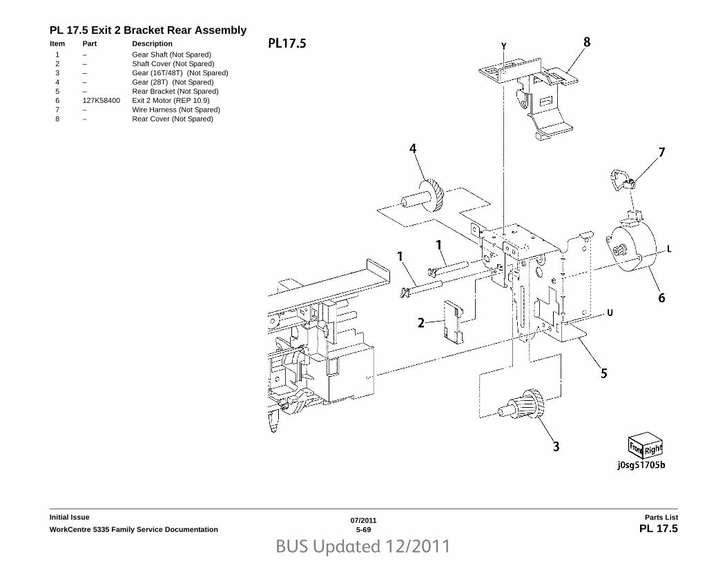
BUS Updated 12/2011
07/20115-69WorkCentre 5335 Family Service Documentation PL 17.5
Parts ListInitial Issue
PL 17.5 Exit 2 Bracket Rear AssemblyItem Part Description
1 – Gear Shaft (Not Spared)2 – Shaft Cover (Not Spared)3 – Gear (16T/48T) (Not Spared)4 – Gear (28T) (Not Spared)5 – Rear Bracket (Not Spared)6 127K58400 Exit 2 Motor (REP 10.9)7 – Wire Harness (Not Spared)8 – Rear Cover (Not Spared)

BUS Updated 12/2011
07/20115-70 WorkCentre 5335 Family Service DocumentationPL 17.6
Initial IssueParts List
PL 17.6 Exit 2 Guide Assembly (2of2)Item Part Description
1 038K20750 Exit2 Guide Assembly (Includes Items 2-4)
2 – Tray Guide (P/O PL 17.6 Item 1)3 – Gate Spring (P/O PL 17.6 Item 1)4 – Exit Gate (P/O PL 17.6 Item 1)5 – Earth Plate (Not Spared)6 – Exit Eliminator (Not Spared)7 – Gate Stopper (Not Spared)8 – Exit 2 Earth Plate (Not Spared)9 – Exit Eliminator (Not Spared)

BUS Updated 12/2011
07/20115-71WorkCentre 5335 Family Service Documentation PL 18.1
Parts ListInitial Issue
PL 18.1 Electrical (1of2)Item Part Description
1 110K16590 Main Power Switch Assembly (Includes Items 2-5)
2 – Switch Bracket (P/O PL 18.1 Item 1)
3 – Wire Harness (P/O PL 18.1 Item 1)4 – Wire Harness (P/O PL 18.1 Item 1)5 – Switch (P/O PL 18.1 Item 1)6 110E97990 Front Cover Interlock Switch7 962K90921 Power Switch Assembly8 105E19860 HVPS (REP 8.4)9 – IOT Heater Kit (Not Spared)

BUS Updated 12/2011
07/20115-72 WorkCentre 5335 Family Service DocumentationPL 18.2
Initial IssueParts List
PL 18.2 Electrical (2of2)Item Part Description
1 105E19980 Main LVPS (REP 3.6)2 105E17480 AC Drive PWB (110-240V) (REP
3.4)3 – HCF Chassis Assembly (Not
Spared) (Includes Items 4-7)4 – Connector Bracket (P/O PL 18.2
Item 3)5 – Blind Plate (P/O PL 18.2 Item 3)6 920W01210 Clamp7 – Edge Bush (P/O PL 18.2 Item 3)8 – HCF Harness (HCF: Option) (Not
Spared)9 – T/M Motor Harness (Not Spared)10 – Feeder Harness (Not Spared)11 – Fusing Unit Harness (Not Spared)12 – LVPS Harness (Not Spared)13 – AC Chassis (REF: PL 18.3) (FX,
FXTW)14 960K54911 MCU PWB (REP 3.5)15 – (Not Spared)16 – (Not Spared)17 – (Not Spared)18 – PWB Support (Not Spared)19 – Relay PWB Harness Assembly
(Not Spared)20 – PWB Support (Not Spared)21 – PWB Support (Not Spared)22 – Harness (Not Spared)23 – Clamp (Not Spared)24 917W03002 Power Cord (110V/15A)– 917W03102 Power Cord (220V)25 – Stopper Bracket (Not Spared)26 – Thumb Screw (Not Spared)27 – Fax Chassis Assembly (REF: PL
18.5)28 – Clamp (Not Spared)29 – Screw (Not Spared)

BUS Updated 12/2011
07/20115-73WorkCentre 5335 Family Service Documentation PL 18.3
Parts ListInitial Issue
PL 18.3 AC Chassis AssemblyItem Part Description
1 – AC Out Harness Assembly (P/O PL 18.3 Item 11)
2 – Outlet (P/O PL 18.3 Item 11)3 – Outlet (P/O PL 18.3 Item 11)4 – Inlet GFI Breaker (P/O PL 18.3 Item
11)5 – GFI Connector Bracket (P/O PL
18.3 Item 11)6 – AC Chassis (P/O PL 18.3 Item 11)7 – Wire Assembly 1 (P/O PL 18.3 Item
11)8 – Screw (P/O PL 18.3 Item 11)9 – Wire Assembly 4 (P/O PL 18.3 Item
11)10 – Wire Assembly 2 (P/O PL 18.3 Item
11)11 101K62410 AC Chassis Assembly (110-240V)
(Includes Items 1-10)

BUS Updated 12/2011
07/20115-74 WorkCentre 5335 Family Service DocumentationPL 18.4
Initial IssueParts List
PL 18.4 IOT Wire HarnessItem Part Description
1 – AC Fusing Harness (Not Spared)2 – IIT-ESS I/O Cable (Not Spared)3 – L/H Main Harness (Not Spared)4 – Harness (Not Spared)5 – DC Power Harness 1 (Not Spared)6 – DC Power Harness 2 (Not Spared)7 – IIT-ESS Video Cable (Not Spared)

BUS Updated 12/2011
07/20115-75WorkCentre 5335 Family Service Documentation PL 18.5
Parts ListInitial Issue
PL 18.5 FAX UnitItem Part Description
1 – Fax Box Assembly (Not Spared)2 – Fax Box (P/O PL 18.5 Item 1)3 – Bracket (P/O PL 18.5 Item 1)4 – Cover (P/O PL 18.5 Item 1)5 130K73070 Speaker6 960K56901 Fax PWB (XC) (XC)– 960K56911 Fax PWB (XE)– 960K56921 Fax PWB (Argentina/Brazil/India)7 – Label (P/O PL 18.5 Item 1)8 960K61730 G3 PWB (XE)– 960K61720 G3 PWB (XC)9 960K39720 Riser PWB10 117K39110 USB Cable11 – Cover (Not Spared)

BUS Updated 12/2011
07/20115-76 WorkCentre 5335 Family Service DocumentationPL 19.1
Initial IssueParts List
PL 19.1 Cover-Front, LeftItem Part Description
1 848K46920 Top Cover Assembly (Includes Item 2-7)
2 – Top Cover (P/O PL 19.1 Item 1)3 – Seal (P/O PL 19.1 Item 1)4 – Duct Cover Assembly (P/O PL 19.1
Item 1)5 – Add Tray (P/O PL 19.1 Item 1)6 – Stopper (P/O PL 19.1 Item 1)7 – Torsion Spring (P/O PL 19.1 Item 1)8 – Tapping Screw (Not Spared)9 604K68230 Strip A & B Kit (Includes Items 12,
20)10 848K59370 Front Cover Assembly11 – Front Right Foot (Not Spared)12 – Upper Stopper (P/O PL 19.1 Item 9)13 – Top Rear Cover (Not Spared)14 – Exit 2 Upper Cover (Not Spared)15 – Exit Front Cover (Not Spared)16 – Left Upper Cover (Not Spared)17 121E21331 Catch Magnet18 – Front Left Cover (Not Spared)19 848E62182 Inner Cover20 – Lower Stopper (P/O PL 19.1 Item 9)21 – Left Rear Cover (Not Spared)22 – Left Rear Lower Cover (Not
Spared)23 – Left Front Lower Cover (Not
Spared)24 – Left Lower Cover (Not Spared)
(APO/GCO)25 026K81200 Thumb Screw26 – CRU INST Label (Not Spared)27 – SW ELabel (Not Spared)28 – Front Left Foot (Not Spared)29 050E27371 Exit 2 Tray

BUS Updated 12/2011
07/20115-77WorkCentre 5335 Family Service Documentation PL 19.2
Parts ListInitial Issue
PL 19.2 Cover-Rear, RightItem Part Description
1 – Right Upper Cover Assembly (Not Spared) (Includes Item 2, 3)
2 – Right Cover 1 (P/O PL 19.2 Item 1)3 – Right Cover 2 (P/O PL 19.2 Item 1)4 – Right Lower Cover (Not Spared)5 – Right Rear Upper Cover (Not
Spared)6 – Rear Middle Cover (Not Spared)7 – Energy Label (Not Spared)8 – AP Indonesia Label (Not Spared)9 – CCC Label (Not Spared)10 – Data Plate (Not Spared)11 – Rear Upper Cover (Not Spared)12 – Fax Cover (Not Spared)13 – Blind Fax Cover (Not Spared)14 – Connector Fax Label (Not Spared)15 – Rear Lower Cover (Not Spared)16 – EPSV Cover (Not Spared)17 – Connector Cover (Not Spared)18 – Outlet Label (Not Spared)19 – Earth Label (Not Spared)20 – GFI Label (Not Spared)21 – ESS Cap Cover (Not Spared)22 – ESS Right Cover (Not Spared)23 – Rear Foot (Not Spared)24 – Fax Label (Not Spared)

BUS Updated 12/2011
07/20115-78 WorkCentre 5335 Family Service DocumentationPL 22.1
Initial IssueParts List
PL 22.1 Finisher Assembly (Part 1 of 2)Item Part Description
1 848K36702 Front Cover Assembly2 – Front Cover (P/O PL 22.1 Item 1)3 – Bracket (P/O PL 22.1 Item 1)4 – Magnet (P/O PL 22.1 Item 1)5 – Label (P/O PL 22.1 Item 1)6 848E50760 Front Inner Cover7 068K29871 Hinge8 068K29880 Hinge9 848K38631 Top Cover Assembly10 – Top Cover (P/O PL 22.1 Item 9)11 – Bracket (P/O PL 22.1 Item 9)12 – Stopper (P/O PL 22.1 Item 9)13 – Magnet (P/O PL 22.1 Item 9)14 848E50790 Rear Cover15 – Hinge (Not Spared)16 815E60280 IIT Cover17 042E92330 Static Eliminator

BUS Updated 12/2011
07/20115-79WorkCentre 5335 Family Service Documentation PL 22.2
Parts ListInitial Issue
PL 22.2 Finisher Assembly (Part 2 of 2)Item Part Description
1 – Bottom Cover (Not Spared)2 – Spacer (Not Spared)3 – Tray Cover (Not Spared)4 848E50770 Left Cover5 068K69530 Tray Support6 – Rear Bracket (Not Spared)7 962K42291 Wire Harness8 050K64830 Stacker Tray Assembly (REP
12.16)9 – Stacker Base Assembly (Not
Spared)10 – Extended Tray Assembly11 826E24180 Thumb Screw

BUS Updated 12/2011
07/20115-80 WorkCentre 5335 Family Service DocumentationPL 22.3
Initial IssueParts List
PL 22.3 Stacker Base Assembly (Part 1 of 5)Item Part Description
1 003E65500 Pulley Knob2 005E89470 Collar3 423W10454 Paddle Belt (REP 12.2)4 012K96370 Link Shaft Assembly5 – Link Shaft (P/O PL 22.3 Item 4)6 012E16150 Support7 – Sub Paddle Shaft Assembly (P/O
PL 22.3 Item 4)8 – Bearing (P/O PL 22.3 Item 4)9 423W06054 Paddle Belt (REP 12.2)10 413W11860 Bearing11 020K13900 Pulley12 005E89490 Collar13 807E13260 Gear (21T)14 120E27240 Actuator15 802K85560 Knob Cover Assembly16 – Knob Cover (P/O PL 22.3 Item 15)17 – Spring (P/O PL 22.3 Item 15)18 012K94990 Sub Paddle Solenoid Assembly19 – Bracket (Not Spared)20 130K70160 Finisher Top Cover Interlock
Sensor21 110K12980 Finisher Top Cover Interlock (+24V)22 – Support (P/O PL 22.3 Item 18)23 – Cushion (P/O PL 22.3 Item 18)24 – Link (P/O PL 22.3 Item 18)25 – Arm (P/O PL 22.3 Item 18)26 – Bracket (P/O PL 22.3 Item 18)27 121K34620 Sub Paddle Solenoid (REP 12.3)28 – Spring (P/O PL 22.3 Item 18)

BUS Updated 12/2011
07/20115-81WorkCentre 5335 Family Service Documentation PL 22.4
Parts ListInitial Issue
PL 22.4 Stacker Base Assembly (Part 2 of 5)Item Part Description
1 050K65200 Compile Assembly (REP 12.20)2 029K92350 Staple Assembly (REP 12.5)3 – Cartridge (P/O PL 22.4 Item 2)4 – Stapler (P/O PL 22.4 Item 2)5 – Bracket (Not Spared)6 – Support (Not Spared)7 930W00111 Set Clamp Home Sensor (REP
12.6)8 962K44980 Wire Harness9 022K72790 Exit Roll Assembly (REP 12.7)10 – Exit Roll (P/O PL 22.4 Item 9)11 004E15340 Damper12 004E15330 Center Damper13 – Bearing (Not Spared)14 007K94220 One Way Gear15 005E89470 Collar16 807E13230 Gear Pulley (16T/18T)17 127K49800 Finisher Transport Motor18 423W06954 Belt

BUS Updated 12/2011
07/20115-82 WorkCentre 5335 Family Service DocumentationPL 22.5
Initial IssueParts List
PL 22.5 Stacker Base Assembly (Part 3 of 5)Item Part Description
1 807E13250 Gear Pulley (37T/45T)2 005E89480 Collar3 413W75959 Bearing4 006K25001 Main Paddle Shaft Assembly (REP
12.11)5 423W09854 Belt6 – Shaft (Not Spared)7 413W77559 Bearing8 020E43500 Pulley (19T)9 054K30361 Lower Chute Assembly (REP
12.12)10 – Lower Chute (P/O PL 22.5 Item 9)11 022K73190 Pinch Roll (REP 12.8)12 809E65931 Spring13 – Support (Not Spared)14 – Bracket (Not Spared)15 – Bracket (Not Spared)16 130K93251 Compile Exit Sensor (REP 12.10)17 807E13240 Gear (27T)18 – Bracket (Not Spared)19 130K88190 Finisher Entrance Sensor (REP
12.9)

BUS Updated 12/2011
07/20115-83WorkCentre 5335 Family Service Documentation PL 22.6
Parts ListInitial Issue
PL 22.6 Stacker Base Assembly (Part 4 of 5)Item Part Description
1 068K29931 Bracket2 068K29941 Bracket3 054K42690 Upper Chute Assembly (REP
12.14)4 – Upper Chute (P/O PL 22.6 Item 3)5 042E92241 Eliminator6 022K72782 Entrance Roll Assembly (REP
12.13)7 031E97041 Rear Arm8 031E97020 Front Arm9 413W66250 Ball Bearing10 – Spring (Not Spared)11 042E92330 Eliminator12 – Guide Paper (P/O PL 22.6 Item 3)

BUS Updated 12/2011
07/20115-84 WorkCentre 5335 Family Service DocumentationPL 22.7
Initial IssueParts List
PL 22.7 Stacker Base Assembly (Part 5 of 5)Item Part Description
1 960K50453 Finisher PWB (REP 12.15)2 055K30850 Connector Bracket3 – Harness Guide (Not Spared)4 – PWB Bracket (Not Spared)5 – Wire Harness (Drive) (Not Spared)6 – Wire Harness (Stapler) (Not
Spared)7 – Wire Harness (Interlock) (Not
Spared)8 – Wire Harness (Front Sensor) (Not
Spared)9 – Wire Harness (Compile) (Not
Spared)10 – Wire Harness (Stacker) (Not
Spared)11 – Bracket (Not Spared)12 110E97990 Finisher Front Interlock Switch

BUS Updated 12/2011
07/20115-85WorkCentre 5335 Family Service Documentation PL 22.8
Parts ListInitial Issue
PL 22.8 Stacker Tray AssemblyItem Part Description
1 – Bearing (Not Spared)2 – Top Tray (Not Spared) (REP 12.16)3 – Bracket (Not Spared)4 – Plate (Not Spared)5 – Bracket (Not Spared)6 – Base Tray (Not Spared)7 – Base Bracket (Not Spared)8 006K25032 Stacker Shaft Assembly (REP
12.17)9 127K49420 Stacker Motor (REP 12.18)10 – Pulley (60T) (Not Spared)11 – Worm Gear (Not Spared)12 – Gear (16T/32T) (Not Spared)13 – Stud (Not Spared)14 – Bracket (Not Spared)15 – Bearing (Not Spared)16 423W07354 Belt17 – Bracket (Not Spared)18 930W00111 Stacker Sensor 1 (Q1), Sensor 2
(Q2) (REP 12.19)19 – Actuator (Not Spared)20 – Wire Harness (Not Spared)

BUS Updated 12/2011
07/20115-86 WorkCentre 5335 Family Service DocumentationPL 22.9
Initial IssueParts List
PL 22.9 Compile Assembly (Part 1 of 2)Item Part Description
1 006K25011 Set Clamp Shaft (REP 12.21)2 120E27220 Actuator3 413W11860 Bearing4 006K25020 Eject Shaft Assembly (REP 12.25)5 – Eject Shaft (P/O PL 22.9 Item 4)6 – Spacer (P/O PL 22.9 Item 4)7 – Pulley (P/O PL 22.9 Item 4)8 068K29830 Eject/Set Clamp Motor Assembly
(REP 12.23)9 930W00111 Rear Tamper Home Sensor (REP
12.24)10 – Support (Not Spared)11 423W26754 Belt12 423W29454 Belt13 023K91530 Eject Belt (REP 12.22)14 – Spring (P/O PL 22.9 Item 8)15 – Eject Motor, Set Clamp Motor (P/O
PL 22.9 Item 8)16 – Bracket (P/O PL 22.9 Item 8)

BUS Updated 12/2011
07/20115-87WorkCentre 5335 Family Service Documentation PL 22.10
Parts ListInitial Issue
PL 22.10 Compile Assembly (Part 2 of 2)Item Part Description
1 068K30510 Bracket Assembly2 – Bracket (P/O PL 22.10 Item 1)3 – Wire Harness (P/O PL 22.10 Item
1)4 050E25900 Compile Tray5 – Support (Not Spared)6 930W00111 Front Tamper Home Sensor (REP
12.27)7 038E34860 Paper Guide8 – Bracket (Not Spared)9 930W00212 Eject Clamp Home Sensor, Stack
Height Sensor (REP 12.28, REP 12.29)
10 962K42270 Wire Harness11 – Bracket (Not Spared)12 – Wire Harness (Not Spared)13 038K88990 Tamper Guide, Rear14 068K30740 Front/Rear Tamper Motor Assembly
(REP 12.26)15 – Front/Rear Tamper Motor (P/O PL
22.10 Item 14)16 – Bracket (P/O PL 22.10 Item 14)17 001E70981 Rail18 038K89260 Tamper Guide, Front

BUS Updated 12/2011
07/20115-88 WorkCentre 5335 Family Service DocumentationPL 23.1
Initial IssueParts List
PL 23.1 H - Transport Assembly (1 of 5)Item Part Description
1 059K65560 H-Transport Assembly (REP 13.1)2 068K59494 Docking Plate Assembly3 – Docking Plate (P/O PL 23.1 Item 2)4 – Side Guide (P/O PL 23.1 Item 2)5 – Center Guide (P/O PL 23.1 Item 2)6 826E07210 Thumb Screw7 – Bracket (P/O PL 23.1 Item 11)8 – Finisher Plate9 – Finisher LX Assembly (Not Spared)10 – HTU Spacer (Not Spared)11 604K70010 Gap Kit (Includes Items 6, 7 and PL
23.6 Items 18, 19)
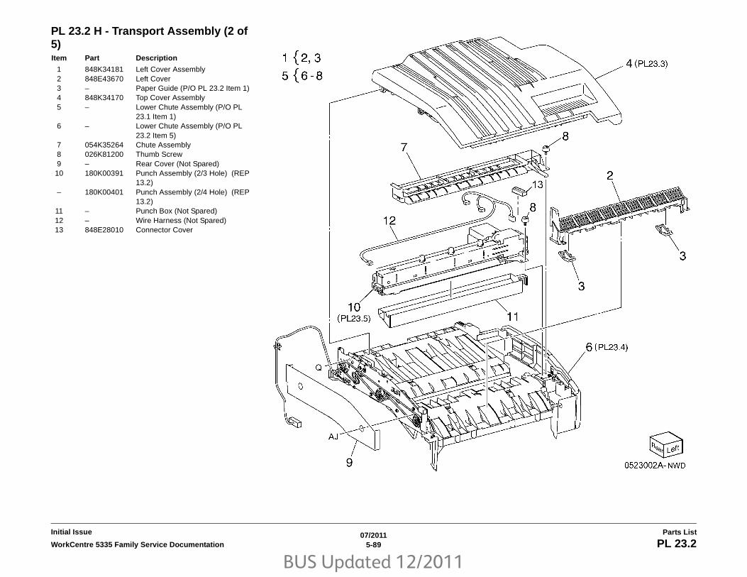
BUS Updated 12/2011
07/20115-89WorkCentre 5335 Family Service Documentation PL 23.2
Parts ListInitial Issue
PL 23.2 H - Transport Assembly (2 of 5)Item Part Description
1 848K34181 Left Cover Assembly2 848E43670 Left Cover3 – Paper Guide (P/O PL 23.2 Item 1)4 848K34170 Top Cover Assembly5 – Lower Chute Assembly (P/O PL
23.1 Item 1)6 – Lower Chute Assembly (P/O PL
23.2 Item 5)7 054K35264 Chute Assembly8 026K81200 Thumb Screw9 – Rear Cover (Not Spared)10 180K00391 Punch Assembly (2/3 Hole) (REP
13.2)– 180K00401 Punch Assembly (2/4 Hole) (REP
13.2)11 – Punch Box (Not Spared)12 – Wire Harness (Not Spared)13 848E28010 Connector Cover
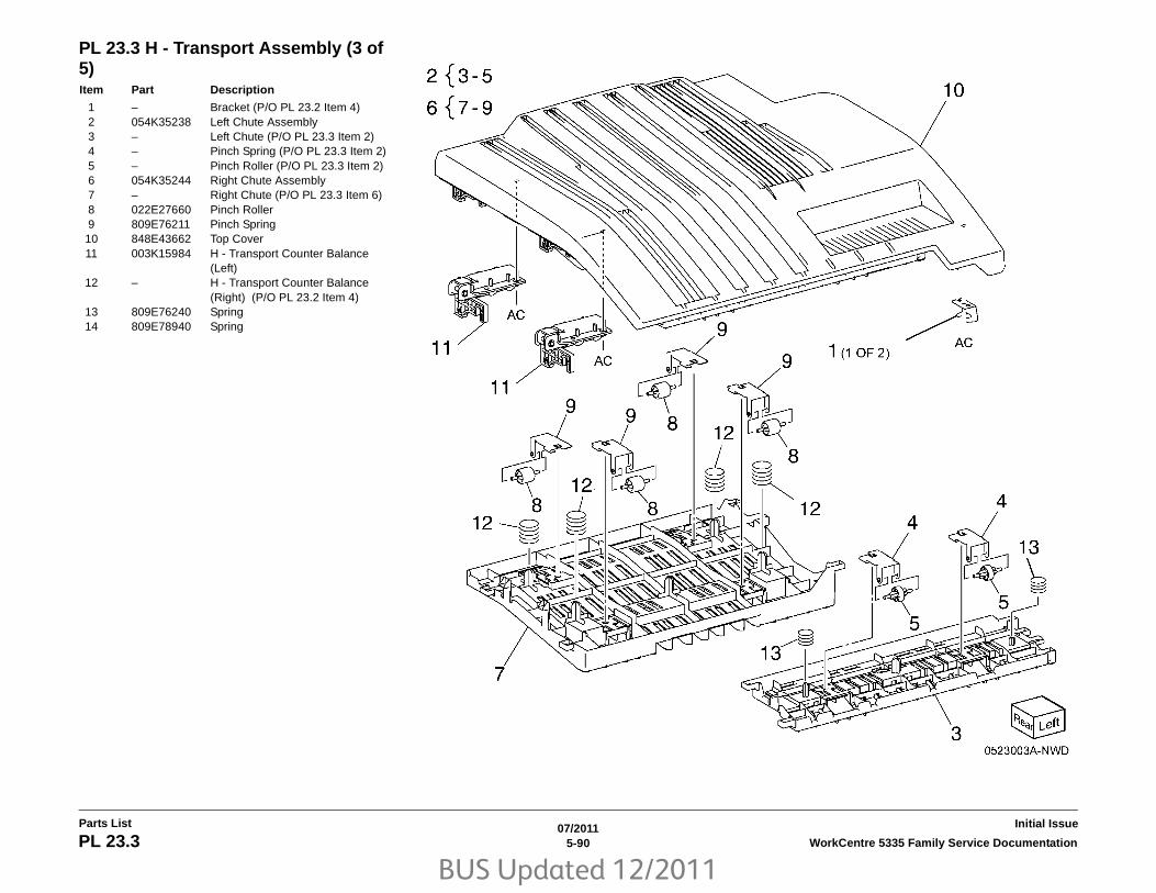
BUS Updated 12/2011
07/20115-90 WorkCentre 5335 Family Service DocumentationPL 23.3
Initial IssueParts List
PL 23.3 H - Transport Assembly (3 of 5)Item Part Description
1 – Bracket (P/O PL 23.2 Item 4)2 054K35238 Left Chute Assembly3 – Left Chute (P/O PL 23.3 Item 2)4 – Pinch Spring (P/O PL 23.3 Item 2)5 – Pinch Roller (P/O PL 23.3 Item 2)6 054K35244 Right Chute Assembly7 – Right Chute (P/O PL 23.3 Item 6)8 022E27660 Pinch Roller9 809E76211 Pinch Spring10 848E43662 Top Cover11 003K15984 H - Transport Counter Balance
(Left)12 – H - Transport Counter Balance
(Right) (P/O PL 23.2 Item 4)13 809E76240 Spring14 809E78940 Spring

BUS Updated 12/2011
07/20115-91WorkCentre 5335 Family Service Documentation PL 23.4
Parts ListInitial Issue
PL 23.4 H - Transport Assembly (4 of 5)Item Part Description
1 – Lower Chute (P/O PL 23.2 Item 6)2 – Magnet (P/O PL 23.2 Item 6)3 130E81600 H - Transport Open Sensor4 868E15540 Sensor Bracket5 809E81720 Actuator6 930W00211 H - Transport Entrance Sensor7 848K34192 H - Transport Front Cover
Assembly8 848E43641 H - Transport Front Cover9 921W41162 Gasket10 – Hinge11 – Bracket (P/O PL 23.2 Item 6)12 – Rear Frame Assembly (P/O PL
23.2 Item 6)13 127K57622 H - Transport Motor (REP 13.4)14 020E45330 Tension Pulley15 020K15720 Pulley (43T)16 020E45210 Pulley (43T)17 – Tension Bracket (P/O PL 23.2 Item
6)18 809E78950 Spring Tension19 059K54480 Drive Roll20 059K55070 Drive Roll21 013E33140 Bearing22 423W01154 H - Transport Belt (REP 13.3)23 413W14660 Sleeve Bearing24 962K60422 Wire Harness25 127E85570 Fan Blade26 016E97311 Pinch Bushing27 – Lower Hinge (P/O PL 23.4 Item 7)28 848E43630 Front Cover29 848E43651 Switch Cover30 – Cover (Not Spared)31 – Bracket (Not Spared)32 004E18112 Pinch Cushion33 921W41142 Gasket

BUS Updated 12/2011
07/20115-92 WorkCentre 5335 Family Service DocumentationPL 23.5
Initial IssueParts List
PL 23.5 H - Transport Assembly (5 of 5)Item Part Description
1 – Punch Motor (P/O PL 23.2 Item 10)2 – Punch Lower Cover (P/O PL 23.2
Item 10)3 – Punch Motor Cover (P/O PL 23.2
Item 10)4 – Sensor Bracket (P/O PL 23.2 Item
10)5 930W00111 Punch Encoder Sensor, Punch
Home Sensor, Punch Box Set Sensor
6 – Punch Frame Assembly (P/O PL 23.2 Item 10)
7 – Encoder/Gear Assembly (P/O PL 23.2 Item 10)
8 – Gear (P/O PL 23.2 Item 10)9 – Motor Bracket (P/O PL 23.2 Item
10)10 – Punch Top Cover (P/O PL 23.2
Item 10)11 – Bracket (P/O PL 23.2 Item 10)

BUS Updated 12/2011
07/20115-93WorkCentre 5335 Family Service Documentation PL 23.6
Parts ListInitial Issue
PL 23.6 Finisher CoversItem Part Description
1 – Plate (Not Spared)2 – Lower Plate (Not Spared)3 – Docking Lever (Not Spared)4 – Front Cover (REP 13.6)5 – Front Door (Not Spared)6 – Bracket (Not Spared)7 068K59531 Hinge8 848E15210 Rear Lower Cover (REP 13.8)9 848E15221 Rear Upper Cover (REP 13.7)10 848E15231 Connector Cover11 848E15241 Stacker Lower Cover (REP 13.11)12 848E48790 LH Cover13 – Cover (Not Spared)14 – Spring (Not Spared)15 848E22450 Foot Cover (REP 13.10)16 801K30701 Booklet Assembly (REP 13.31)17 – Thumb Screw (P/O PL 23.1 Item
11)18 – Upper Adjust Cover (P/O PL 23.1
Item 11)19 – Lower Adjust Cover (Not Spared)20 – Base Frame Assembly (Not
Spared)21 921W41162 Gasket22 – Extension Spring (Not Spared)23 – Paper Guide

BUS Updated 12/2011
07/20115-94 WorkCentre 5335 Family Service DocumentationPL 23.7
Initial IssueParts List
PL 23.7 Finisher StackerItem Part Description
1 041K95980 Front Carriage Assembly (REP 13.29)
2 – Bearing (P/O PL 23.7 Item 1)3 809E56850 Spring4 – Front Stacker Belt (P/O PL 23.7
Item 1)5 – Clamp (P/O PL 23.7 Item 1)6 – Front Carriage Assembly (P/O PL
23.7 Item 1)7 041K95990 Rear Carriage Assembly (REP
13.29)8 – Bearing (P/O PL 23.7 Item 7)9 – Clamp (P/O PL 23.7 Item 7)10 017K94890 Knob Caster Assembly11 – Rear Stacker Belt (P/O PL 23.7
Item 7)12 – Rear Carriage (P/O PL 23.7 Item 7)13 – Actuator (P/O PL 23.7 Item 7)14 – Carriage Tray (Not Spared)15 050K61105 Stacker Tray (REP 13.20)16 – Shaft (Not Spared)17 807E08990 Gear18 020E37710 Pulley19 146E90650 Encoder20 809E56860 Spring21 020E37720 Pulley (18T)22 068K58304 Stacker Elevator Motor Assembly
(REP 13.19)– 068K58303 Stacker Elevator Motor Assembly
(REP 13.19)23 – Bearing (P/O PL 23.7 Item 22)24 020E44181 Pulley (60T)25 – Gear (15T/37T) (P/O PL 23.7 Item
22)26 – Motor Bracket (P/O PL 23.7 Item
22)27 – Worm Shaft (P/O PL 23.7 Item 22)28 423W27654 Belt29 – Stacker Elevator Motor (P/O PL
23.7 Item 22)30 – Stacker Encoder Sensor Assembly
(Not Spared)31 – Bracket (P/O PL 23.7 Item 30)32 930W00111 Stacker Encoder Sensor, Stacker
No Paper Sensor33 – Stacker Upper Cover (Not Spared)
(REP 13.12)34 413W79359 Bearing35 017K94880 Caster Assembly36 251W31178 Washer37 017K94900 Adjustable Foot Assembly

BUS Updated 12/2011
07/20115-95WorkCentre 5335 Family Service Documentation PL 23.8
Parts ListInitial Issue
PL 23.8 Finisher StaplerItem Part Description
1 – Base Frame (P/O PL 23.8 Item 16)2 – Rail (P/O PL 23.8 Item 16)3 – Harness Guide4 029K92350 Stapler Assembly (REP 13.16)5 – Holder (Not Spared)6 – Stapler Move Position Sensor
Assembly (Not Spared)7 – Bracket (P/O PL 23.8 Item 6)8 130E94940 Stapler Move Position Sensor9 – Stapler Move Motor Assembly (Not
Spared)10 – Harness Guide (P/O PL 23.8 Item
16)11 – Harness Support Guide (P/O PL
23.8 Item 16)12 – Harness Guide (P/O PL 23.8 Item
16)13 – Stapler Cover (Not Spared)14 – Clamp (Not Spared)15 – Stapler Cartridge (Not Spared)16 – Stapler Unit (Not Spared)17 – Cable Band (Not Spared)18 – Harness Guide (Not Spared)19 – Stapler Motor Assembly (P/O PL
23.8 Item 9) (REP 13.15)20 127K57622 Motor Assembly

BUS Updated 12/2011
07/20115-96 WorkCentre 5335 Family Service DocumentationPL 23.9
Initial IssueParts List
PL 23.9 Finisher Eject (1 of 5)Item Part Description
1 – Eject Cover Assembly (Not Spared)2 – Eject Assembly (Not Spared)3 031K93790 Clamp Arm Assembly4 807E21370 Gear (25T)5 059K55111 Eject Roller6 807E21380 Gear (72T)7 807E21391 Gear (18T)8 120E29772 Actuator– 120E29771 Actuator9 006K86731 Set Clamp Shaft Assembly10 – Spring (P/O PL 23.9 Item 9)11 019K09391 Set Clamp Holder12 – Shaft (Not Spared)13 809E79060 Spring14 809E79080 Spring15 006K86741 Guide Paper Shaft Assembly16 – Guide Paper Shaft (P/O PL 23.9
Item 15)17 – Gear (20T) (P/O PL 23.9 Item 15)18 – Shaft (Not Spared)19 807E21420 Gear (19T)20 807E21400 Gear (31T)21 038E36490 Guide Paper (Left/Right)22 005E25820 Clutch23 807E21970 Gear (23T)24 – Stopper (Not Spared)25 – Bracket (Front) (Not Spared)26 – Bracket (Rear) (Not Spared)27 – Option Switch Assembly (Not
Spared)28 – Bracket (Not Spared)29 – Option Switch (Not Spared)30 413W77559 Sleeve Bearing31 – Bearing (Not Spared)32 – Clamp Arm (P/O PL 23.9 Item 3)33 – Roll (P/O PL 23.9 Item 3)34 – Shaft (P/O PL 23.9 Item 3)

BUS Updated 12/2011
07/20115-97WorkCentre 5335 Family Service Documentation PL 23.10
Parts ListInitial Issue
PL 23.10 Finisher Eject (2 of 5)Item Part Description
1 848E15291 Top Right Hand Cover2 011E20781 Top Cover Lever3 003E76111 Top Cover Latch4 – Shaft (Not Spared)5 809E79031 Spring6 – Eject Cover (REP 13.9)7 054K35301 Eject Chute8 121K41632 Sub Paddle Solenoid Assembly
(REP 13.14)9 – Bracket (P/O PL 23.10 Item 8)10 – Damper (P/O PL 23.10 Item 8)11 – Sub Paddle Solenoid (P/O PL
23.10 Item 8)12 – Eject Roller Assembly (Not Spared)13 031K93770 Paddle Arm Assembly14 – Sub Paddle Arm (Not Spared)15 423W08655 Belt16 – Sub Paddle (P/O PL 23.10 Item 13)17 – Pulley (P/O PL 23.10 Item 13)18 – Pulley (P/O PL 23.10 Item 13)19 – Gear/Pulley (31T/20T) (Not
Spared)20 – Eject Pinch Roller Assembly (Not
Spared)21 – Bearing (P/O PL 23.10 Item 20)22 059K55102 Eject Pinch Roller23 – Bracket (P/O PL 23.10 Item 20)24 – Shaft (P/O PL 23.10 Item 12)25 – Spring (Not Spared)26 – Bracket (P/O PL 23.10 Item 12)27 809E79050 Spring28 006K86690 Eject Drive Shaft29 – Bearing (Not Spared)30 – Bearing (Not Spared)31 – Eject Chute Assembly (Not Spared)32 – Eject Eliminator (P/O PL 23.10 Item
20)
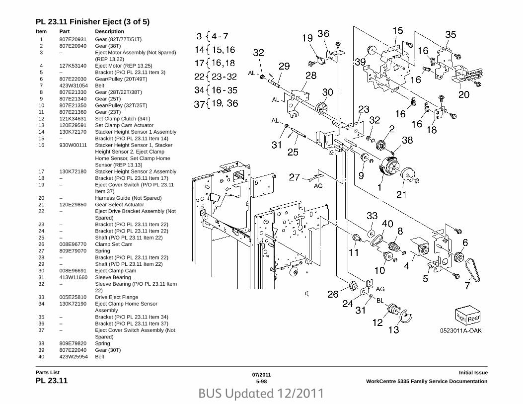
BUS Updated 12/2011
07/20115-98 WorkCentre 5335 Family Service DocumentationPL 23.11
Initial IssueParts List
PL 23.11 Finisher Eject (3 of 5)Item Part Description
1 807E20931 Gear (82T/77T/51T)2 807E20940 Gear (38T)3 – Eject Motor Assembly (Not Spared)
(REP 13.22)4 127K53140 Eject Motor (REP 13.25)5 – Bracket (P/O PL 23.11 Item 3)6 807E22030 Gear/Pulley (20T/49T)7 423W31054 Belt8 807E21330 Gear (28T/22T/38T)9 807E21340 Gear (25T)10 807E21350 Gear/Pulley (32T/25T)11 807E21360 Gear (23T)12 121K34631 Set Clamp Clutch (34T)13 120E29591 Set Clamp Cam Actuator14 130K72170 Stacker Height Sensor 1 Assembly15 – Bracket (P/O PL 23.11 Item 14)16 930W00111 Stacker Height Sensor 1, Stacker
Height Sensor 2, Eject Clamp Home Sensor, Set Clamp Home Sensor (REP 13.13)
17 130K72180 Stacker Height Sensor 2 Assembly18 – Bracket (P/O PL 23.11 Item 17)19 – Eject Cover Switch (P/O PL 23.11
Item 37)20 – Harness Guide (Not Spared)21 120E29850 Gear Select Actuator22 – Eject Drive Bracket Assembly (Not
Spared)23 – Bracket (P/O PL 23.11 Item 22)24 – Bracket (P/O PL 23.11 Item 22)25 – Shaft (P/O PL 23.11 Item 22)26 008E96770 Clamp Set Cam27 809E79070 Spring28 – Bracket (P/O PL 23.11 Item 22)29 – Shaft (P/O PL 23.11 Item 22)30 008E96691 Eject Clamp Cam31 413W11660 Sleeve Bearing32 – Sleeve Bearing (P/O PL 23.11 Item
22)33 005E25810 Drive Eject Flange34 130K72190 Eject Clamp Home Sensor
Assembly35 – Bracket (P/O PL 23.11 Item 34)36 – Bracket (P/O PL 23.11 Item 37)37 – Eject Cover Switch Assembly (Not
Spared)38 809E79820 Spring39 807E22040 Gear (30T)40 423W25954 Belt

BUS Updated 12/2011
07/20115-99WorkCentre 5335 Family Service Documentation PL 23.12
Parts ListInitial Issue
PL 23.12 Finisher Eject (4 of 5)Item Part Description
1 050K61091 Compiler Tray Assembly (REP 13.17)
2 038E36462 Tamper Guide, Rear3 – Compiler Center Paper Guide (P/O
PL 23.12 Item 1)4 – Compiler Rear Paper Guide (P/O
PL 23.12 Item 1)5 – Bracket (P/O PL 23.12 Item 1)6 127K58040 Tamper Motor7 – Rack (Front) (P/O PL 23.12 Item 1)8 930W00111 Front Tamper Home Sensor, Rear
Tamper Home Sensor (REP 13.27)9 130E81600 Compiler Tray No Paper Sensor
(REP 13.28)10 – Spring (P/O PL 23.12 Item 1)11 – Tamper Front Guide (P/O PL 23.12
Item 1)12 – Tamper Rear Guide (P/O PL 23.12
Item 1)13 – Compiler Tray (P/O PL 23.12 Item
1)14 – Paper Paddle Guide (P/O PL 23.12
Item 1)15 809E79000 Spring16 – Paper End Guide (P/O PL 23.12
Item 1)17 – Paper Tray Guide (P/O PL 23.12
Item 1)18 – Spring (P/O PL 23.12 Item 1)19 – Spring (P/O PL 23.12 Item 1)20 – Harness Guide (P/O PL 23.12 Item
1)21 120E29760 Actuator22 801E04903 Tamper Base23 038E36452 Tamper Guide, Front

BUS Updated 12/2011
07/20115-100 WorkCentre 5335 Family Service DocumentationPL 23.13
Initial IssueParts List
PL 23.13 Finisher Eject (5 of 5)Item Part Description
1 068K58823 Transport Motor2 068K58832 Tension Roller Assembly3 809E78980 Spring4 020E45341 Pulley (30T)5 020E45571 Pulley (41T)6 – Gear/Pulley (27T/30T) (Not
Spared)7 007K98300 Gear8 059K55080 Entrance Roller9 059K55090 Exit Roller10 423W18754 Eject Belt (REP 13.21)11 006K86813 Paddle Shaft Assembly12 033E92850 Cyclone Paddle13 – Paddle Shaft (P/O PL 23.13 Item
11)14 413W75959 Bearing

BUS Updated 12/2011
07/20115-101WorkCentre 5335 Family Service Documentation PL 23.14
Parts ListInitial Issue
PL 23.14 Finisher Exit/Folder AssemblyItem Part Description
1 – Lower Chute Assembly (Not Spared)
2 – Lower Chute (P/O PL 23.14 Item 1)3 806E22121 Shaft4 059E03710 Pinch Roll5 809E78960 Spring6 054K35540 Exit Upper Chute Assembly7 – Exit Upper Chute (P/O PL 23.14
Item 6)8 105E18000 Static Eliminator9 038E36420 Paper Guide10 130K88311 Compiler Exit Sensor, Finisher
Entrance Sensor11 054K35559 Exit Lower Chute Assembly– 054K35558 Exit Lower Chute Assembly (A)12 – Exit Lower Chute (P/O PL 23.14
Item 11)13 – Pinch Roll Assembly (P/O PL 23.14
Item 11)14 – Spring (P/O PL 23.14 Item 13)15 059K56321 Pinch Roll16 – Chute Assembly (Not Spared)17 – Lower Chute (P/O PL 23.14 Item
16)18 – Upper Chute (P/O PL 23.14 Item
16)19 – Thumb Screw (P/O PL 23.14 Item
16)20 – Chute Assembly (Not Spared)21 695K18691 Crease Assembly (Option) (REP
13.18)

BUS Updated 12/2011
07/20115-102 WorkCentre 5335 Family Service DocumentationPL 23.15
Initial IssueParts List
PL 23.15 Folder AssemblyItem Part Description
1 – Upper Chute (P/O PL 23.14 Item 21)
2 – Upper Plate (P/O PL 23.14 Item 21)3 – Knife Assembly (P/O PL 23.14 Item
21)4 – Blade Holder (P/O PL 23.15 Item 3)5 – Lower Holder 1 (P/O PL 23.15 Item
3)6 – Lower Holder 2 (P/O PL 23.15 Item
3)7 – Bracket (P/O PL 23.15 Item 3)8 – Blade (P/O PL 23.15 Item 3)9 – Spring (P/O PL 23.14 Item 2)10 – Frame (P/O PL 23.14 Item 21)11 – Front Cover (P/O PL 23.14 Item 21)12 – Bracket (P/O PL 23.14 Item 21)13 – Folder Knife Motor Assembly (P/O
PL 23.14 Item 21)14 – Motor Bracket (P/O PL 23.15 Item
13)15 – Folder Knife Motor (P/O PL 23.15
Item 13)16 – Folder Home Sensor (P/O PL 23.15
Item 13)17 – Cam Shaft Assembly (P/O PL
23.14 Item 21)18 – Guide (P/O PL 23.14 Item 21)19 – Gear (28T/8T) (P/O PL 23.14 Item
21)20 – Encoder (P/O PL 23.14 Item 21)21 – Bearing (P/O PL 23.14 Item 21)22 – Gear (12T/27T) (P/O PL 23.14
Item 21)23 – Gear (12T/30T) (P/O PL 23.14
Item 21)24 – Gear (12T/51T) (P/O PL 23.14
Item 21)25 – Wire Harness (P/O PL 23.14 Item
21)

BUS Updated 12/2011
07/20115-103WorkCentre 5335 Family Service Documentation PL 23.16
Parts ListInitial Issue
PL 23.16 Finisher ElectricalItem Part Description
1 – LVPS Cover (Not Spared)2 960K51447 Finisher PWB (REP 13.23)– 960K50992 Finisher PWB3 – Harness Guide (Not Spared)4 – Harness Guide (Not Spared)5 – Harness Guide (Not Spared)6 – Magnet (Not Spared)7 815K04920 Gasket Plate Assembly8 962K60592 Wire Harness9 – Wire Harness (Not Spared)10 – Wire Harness (Not Spared)11 – Wire Harness (Not Spared)12 – Wire Harness (Not Spared)13 962K60481 Wire Harness14 – Wire Harness (Not Spared)15 – Wire Harness (Not Spared)16 962K74540 Power Cable17 105E17550 Finisher LVPS (REP 13.24)18 – Bracket (Not Spared)19 110E97990 Finisher Front Door Interlock
Switch

BUS Updated 12/2011
07/20115-104 WorkCentre 5335 Family Service DocumentationPL 23.17
Initial IssueParts List
PL 23.17 Booklet CoverItem Part Description
1 – Frame Assembly (Not Spared)2 – Booklet Stapler Assembly (Not
Spared)3 848E15333 Rear Cover (REP 13.33)4 – Front Cover (Not Spared) (REP
13.32)5 – Top Cover (REP 13.34)6 848E15350 Side Cover7 848E15361 PWB Cover (REP 13.35)8 – Left Cover (Not Spared) (REP
13.36)9 – Harness Guide (Not Spared)

BUS Updated 12/2011
07/20115-105WorkCentre 5335 Family Service Documentation PL 23.18
Parts ListInitial Issue
PL 23.18 Booklet Stapler AssemblyItem Part Description
1 – Front Carriage Rail (Not Spared)2 – Frame (P/O PL 23.18 Item 1)3 – Core (P/O PL 23.18 Item 1)4 127K57051 Booklet Stapler Move Motor
Assembly (REP 13.38)5 – Belt (P/O PL 23.18 Item 4)6 – Bracket (P/O PL 23.18 Item 4)7 – Gear (12T) (P/O PL 23.18 Item 4)8 – Pulley (50T) (P/O PL 23.18 Item 4)9 127K57622 Booklet Stapler Move Motor10 – Wire Harness (P/O PL 23.18 Item
4)11 – Sensor Bracket Assembly (P/O PL
23.18 Item 1)12 – Sensor Bracket (P/O PL 23.18 Item
11)13 930W00111 Booklet Stapler Move Home
Sensor, Booklet Stapler Move Position Sensor
14 – Rear Rack Gear (Not Spared)15 – Carriage Assembly (Not Spared)16 – Carriage (P/O PL 23.18 Item 15)17 – Core (P/O PL 23.18 Item 15)18 – Core (Not Spared)19 – Front Rack Gear (Not Spared)20 848E15400 Motor Cover21 032K05222 Harness Guide Assembly22 – Harness Strap (P/O PL 23.18 Item
21)23 920W01210 Locking Clamp24 – Harness Guide (Front) (Not
Spared)25 – Harness Guide (Rear) (Not
Spared)26 – Rear Rack Guide (Not Spared)

BUS Updated 12/2011
07/20115-106 WorkCentre 5335 Family Service DocumentationPL 23.19
Initial IssueParts List
PL 23.19 Booklet Front Stapler AssemblyItem Part Description
1 – Booklet Front Stapler Assembly2 – Bracket (P/O PL 23.19 Item 1)3 – Rear Cover (P/O PL 23.19 Item 1)4 – Bracket (P/O PL 23.19 Item 1)5 – Chute6 – Sub Chute (P/O PL 23.19 Item 1)7 – Support (P/O PL 23.19 Item 1)8 – Spring (P/O PL 23.19 Item 1)9 – Exit Sub Chute (P/O PL 23.19 Item
1)10 – Spring (P/O PL 23.19 Item 1)11 – Front Cover (P/O PL 23.19 Item 1)12 848E15421 Lower Cover13 – Booklet Stapler Assembly (P/O PL
23.19 Item 1) (REP 13.37)14 – Wire Harness (P/O PL 23.19 Item
1)15 – Guide (P/O PL 23.19 Item 1)16 – Booklet Staple Cassette Assembly
(Not Spared)

BUS Updated 12/2011
07/20115-107WorkCentre 5335 Family Service Documentation PL 23.20
Parts ListInitial Issue
PL 23.20 Booklet Rear Stapler AssemblyItem Part Description
1 029K92500 Booklet Rear Stapler Assembly2 – Bracket (P/O PL 23.20 Item 1)3 – Rear Cover (P/O PL 23.20 Item 1)4 – Bracket (P/O PL 23.20 Item 1)5 054K35282 Chute6 – Sub Chute (P/O PL 23.20 Item 1)7 – Support (P/O PL 23.20 Item 1)8 – Spring (P/O PL 23.20 Item 1)9 – Sub Chute (P/O PL 23.20 Item 1)10 – Spring (P/O PL 23.20 Item 1)11 – Front Cover (P/O PL 23.20 Item 1)12 848E15421 Lower Cover13 – Booklet Stapler Assembly (P/O PL
23.20 Item 1) (REP 13.37)14 – Wire Harness (P/O PL 23.20 Item
1)15 – Guide (P/O PL 23.20 Item 1)16 – Booklet Staple Cassette Assembly
(P/O PL 23.20 Item 1)

BUS Updated 12/2011
07/20115-108 WorkCentre 5335 Family Service DocumentationPL 23.21
Initial IssueParts List
PL 23.21 Booklet ElectricalItem Part Description
1 068K58350 Booklet Stapler Safety Switch Assembly
2 110E12970 Booklet Stapler Safety Switch3 – Bracket (P/O PL 23.21 Item 1)4 960K32543 Booklet PWB (REP 13.30)5 – Wire Harness (Not Spared)6 – Wire Harness (Not Spared)7 – Wire Harness (Not Spared)8 – Booklet Stapler Cover Switch
Assembly (Not Spared)9 – Bracket (P/O PL 23.21 Item 8)10 – Booklet Stapler Cover Switch (P/O
PL 23.21 Item 8)11 – Plate (Not Spared)12 962K60533 Wire Harness13 962K60540 Wire Harness

BUS Updated 12/2011
07/20115-109WorkCentre 5335 Family Service Documentation PL 35.1
Parts ListInitial Issue
PL 35.1 ESS (1/3)Item Part Description
1 – ESS Cover (Not Spared)2 – ESS Chassis Assembly (REF: PL
35.2, PL 35.3) (REP 3.2)

BUS Updated 12/2011
07/20115-110 WorkCentre 5335 Family Service DocumentationPL 35.2
Initial IssueParts List
PL 35.2 ESS (2/3)Item Part Description
1 – Clamp (Not Spared)2 604K68240 ESS PWB Assembly (Includes
Items 3-10) (REP 3.3)3 – ESS PWB (P/O PL 35.2 Item 2)
(REP 3.3)4 – EEPROM (P/O PL 35.2 Item 2)5 – ESS Plate (P/O PL 35.2 Item 2)6 – USB Panel (P/O PL 35.2 Item 2)7 – Cable Guard8 – Plate (P/O PL 35.2 Item 2)9 – Seal (P/O PL 35.2 Item 2)10 – Cap (P/O PL 35.2 Item 2)11 – ESS Chassis (Not Spared)12 – Clamp (Not Spared)13 – PWB Support (Not Spared)14 – HDD Bracket (Not Spared)15 – Wire Harness (Not Spared)16 – Video Harness (Not Spared)

BUS Updated 12/2011
07/20115-111WorkCentre 5335 Family Service Documentation PL 35.3
Parts ListInitial Issue
PL 35.3 ESS (3/3)Item Part Description
1 101K61780 HDD Chassis Assembly (Includes Items 1-6)
2 – HDD Chassis (P/O PL 35.3 Item 1) (REP 3.1)
3 – HDD (P/O PL 35.3 Item 1)4 – Harness Assembly (P/O PL 35.3
Item 1)5 – Bumper (P/O PL 35.3 Item 1)6 – Flange Screw (P/O PL 35.3 Item 1)7 540K14860 DIMM Post Script8 133K26760 DIMM Memory (1GB)– 133K26860 DIMM Memory (2GB) (Required to
support Post Script)

BUS Updated 12/2011
07/20115-112 WorkCentre 5335 Family Service DocumentationPL 51.1
Initial IssueParts List
PL 51.1 DADF AccessoryItem Part Description
1 004K02962 DADF Platen Cushion (REP 5.2)2 059K71382 DADF Assembly (REP 5.1)3 – Label

BUS Updated 12/2011
07/20115-113WorkCentre 5335 Family Service Documentation PL 51.2
Parts ListInitial Issue
PL 51.2 Covers, PWBItem Part Description
1 – Base Frame (P/O PL 51.1 Item 2)2 – Feeder Assembly (P/O PL 51.1
Item 2) (REP 5.5)3 – Rear Cover (P/O PL 51.1 Item 2)
(REP 5.4)4 – Front Cover (P/O PL 51.1 Item 2)
(REP 5.3)5 962K71100 Transport Harness6 960K47306 DADF PWB (REP 5.6)7 – Wire Harness (P/O PL 51.1 Item 2)8 – Data Plate (P/O PL 51.1 Item 2)9 003K87990 Stopper10 – P Clamp (P/O PL 51.1 Item 2)11 – Bracket (P/O PL 51.1 Item 2)12 – Knob Label (Not Spared)

BUS Updated 12/2011
07/20115-114 WorkCentre 5335 Family Service DocumentationPL 51.3
Initial IssueParts List
PL 51.3 Base FrameItem Part Description
1 – Frame (P/O PL 51.1 Item 2)2 036K91873 Left Counter Balance (REP 5.7)3 036K91921 Right Counter Balance (REP 5.8)4 – Tie Plate (P/O PL 51.1 Item 2)5 054K41230 CVT Chute6 826E45980 Stud Screw7 – Ground Plate (P/O PL 51.1 Item 2)8 809E86290 CVT Spring9 019E73462 Floating Holder10 809E89310 Floating Spring11 – Bracket (P/O PL 51.1 Item 2)

BUS Updated 12/2011
07/20115-115WorkCentre 5335 Family Service Documentation PL 51.4
Parts ListInitial Issue
PL 51.4 Document TrayItem Part Description
1 050K64252 Document Tray Assembly (REP 5.9)
2 059K65063 Top Cover (REP 5.10)3 – Stud Bracket (P/O PL 51.1 Item 2)

BUS Updated 12/2011
07/20115-116 WorkCentre 5335 Family Service DocumentationPL 51.5
Initial IssueParts List
PL 51.5 DADF Drives (1 of 2)Item Part Description
1 032E32642 Harness Guide (REP 5.11)2 110K15933 Interlock Switch and Harness
Assembly3 – Bracket (P/O PL 51.5 Item 2)4 – Interlock Switch (P/O PL 51.5 Item
2)5 – Spring (P/O PL 51.5 Item 2)6 – Switch Wire Harness (P/O PL 51.5
Item 2)7 127K62910 Feed Motor (REP 5.13)8 127K62891 Registration Motor (REP 5.12)9 809E50763 Spring10 809E91390 Spring11 – Bracket (P/O PL 51.1 Item 2)12 – Bracket (P/O PL 51.1 Item 2)13 – Feeder Wire Harness (P/O PL 51.1
Item 2)14 – Motor Wire Harness (P/O PL 51.1
Item 2)15 – APS Wire Harness16 – Connector (Not Spared)17 – Connector (Not Spared)

BUS Updated 12/2011
07/20115-117WorkCentre 5335 Family Service Documentation PL 51.6
Parts ListInitial Issue
PL 51.6 DADF Drives (2 of 2)Item Part Description
1 011E22861 Nip Lever2 012E17151 Stopper Link3 012E17161 Release Link4 019K10320 Brake5 020E46551 Registration Roll Pulley6 020E46561 Pulley Gear7 020E46571 Pulley Gear8 059E98620 Roll9 121K46620 Gate Solenoid10 – Gate Solenoid (P/O PL 51.6 Item 9)11 – Cushion (P/O PL 51.6 Item 9)12 121K43660 Exit Nip Release Solenoid13 130K73000 Feed Out Sensor Assembly14 – Sensor Bracket (P/O PL 51.6 Item
13)15 930W00121 Feed Out Sensor, Document Set
Sensor16 423W06555 Belt17 423W31354 Belt18 807E26971 Gear19 807E26981 Exit Roll Gear20 807E26991 Gear21 807E27011 Take Away Roll Gear22 809E86320 Spring

BUS Updated 12/2011
07/20115-118 WorkCentre 5335 Family Service DocumentationPL 51.7
Initial IssueParts List
PL 51.7 Front BeltItem Part Description
1 020E46540 Out Roll Pulley2 020E46551 Registration Roll Pulley3 423W08855 Belt4 – Belt (Not Spared)5 803E02200 Knob Handle6 – Ground Plate (Not Spared)7 960K48840 Document LED Set8 – LED Bracket (P/O PL 51.7 Item 7)9 – Document LED (P/O PL 51.7 Item
7)

BUS Updated 12/2011
07/20115-119WorkCentre 5335 Family Service Documentation PL 51.8
Parts ListInitial Issue
PL 51.8 Registration, Retard, Invert, Output ChutesItem Part Description
1 054K39700 Registration Chute (REP 5.14)2 054K44171 Retard Chute (REP 5.15)3 054K41044 Invert Chute (REP 5.15)4 054K41050 Output Chute5 – Stamp Solenoid (Not Spared)

BUS Updated 12/2011
07/20115-120 WorkCentre 5335 Family Service DocumentationPL 51.9
Initial IssueParts List
PL 51.9 Roll, Sensor BracketItem Part Description
1 – Bearing (Not Spared)2 059K65081 Registration Roll3 – Take Away Roll (Not Spared) (REP
5.16)4 – Output Roll (Not Spared)5 – Exit Roll (Not Spared)6 068K69460 Sensor Bracket Assembly (REP
5.17)7 – Bearing (Not Spared)8 930W00121 Invert Sensor

BUS Updated 12/2011
07/20115-121WorkCentre 5335 Family Service Documentation PL 51.10
Parts ListInitial Issue
PL 51.10 Document TrayItem Part Description
1 – Sensor Bracket (P/O PL 51.4 Item 1)
2 930W00121 Tray Guide Set Sensor 1, Sensor 2, Sensor 3
3 – Tray Cover (P/O PL 51.4 Item 1)4 – Tray Wire Harness (P/O PL 51.4
Item 1)5 032K05861 Guide6 – Max Label (Not Spared)7 – Harness Cover (P/O PL 51.4 Item
1)8 – Harness Cover (P/O PL 51.4 Item
1)9 – Front Gear Rack (P/O PL 51.4 Item
1)10 – Rear Gear Rack (P/O PL 51.4 Item
1)11 930W00241 Size Sensor 1, Size Sensor 212 – Instruction Label (Not Spared)13 – Rack Spring (P/O PL 51.4 Item 1)14 – Pinion Gear (P/O PL 51.4 Item 1)15 – Side Guide (P/O PL 51.4 Item 1)16 – Side Guide (P/O PL 51.4 Item 1)17 – Upper Tray (P/O PL 51.4 Item 1)

BUS Updated 12/2011
07/20115-122 WorkCentre 5335 Family Service DocumentationPL 51.11
Initial IssueParts List
PL 51.11 Top CoverItem Part Description
1 – Top Cover (P/O PL 51.4 Item 2)2 – Upper Feed Chute (P/O PL 51.4
Item 2)3 059K65070 Upper Feeder (REP 5.5)4 011K03520 Lever Latch5 059K61230 Take Away Pinch Roll6 120K92500 Document Set Actuator7 120E32200 Feed Out Actuator8 – Bracket (P/O PL 51.4 Item 2)9 – Ground Plate (P/O PL 51.4 Item 2)10 897E24010 Size Label11 897E24000 Jam Label12 – Spring (Not Spared)13 – Spring (Not Spared)14 – Spring (Not Spared)

BUS Updated 12/2011
07/20115-123WorkCentre 5335 Family Service Documentation PL 51.12
Parts ListInitial Issue
PL 51.12 Upper FeederItem Part Description
1 – Housing (P/O PL 51.11 Item 3)2 – Feeder Pulley (P/O PL 51.12 Item
3)3 – Nudger Pulley (P/O PL 51.11 Item
3)4 – Belt (P/O PL 51.11 Item 3)5 – Feed Shaft (P/O PL 51.11 Item 3)6 – Nudger Shaft (P/O PL 51.11 Item 3)7 – Feed Roll, Nudger Roll (P/O PL
51.12 Item 11) (REP 5.18)8 – Bearing (P/O PL 51.11 Item 3)9 – Housing (P/O PL 51.12 Item 11)10 – Gear (P/O PL 51.11 Item 3)11 604K58410 DADF Feed Roll Kit

BUS Updated 12/2011
07/20115-124 WorkCentre 5335 Family Service DocumentationPL 51.13
Initial IssueParts List
PL 51.13 Registration ChuteItem Part Description
1 – Registration Chute (P/O PL 51.8 Item 1)
2 – Pinch Shaft (P/O PL 51.8 Item 1)3 – Registration Wide Pinch Roll (P/O
PL 51.8 Item 1)4 – Registration Short Pinch Roll (P/O
PL 51.8 Item 1)5 – Seal (P/O PL 51.8 Item 1)6 – Seal (P/O PL 51.8 Item 1)7 – Spring (P/O PL 51.8 Item 1)

BUS Updated 12/2011
07/20115-125WorkCentre 5335 Family Service Documentation PL 51.14
Parts ListInitial Issue
PL 51.14 Retard ChuteItem Part Description
1 – Chute (P/O PL 51.8 Item 2)2 – Set Gate (P/O PL 51.8 Item 2)3 – Housing (P/O PL 51.8 Item 2)4 – Spring (P/O PL 51.8 Item 2)5 – Retard Roll (P/O PL 51.8 Item 2)
(REP 5.19)6 848K43600 Retard Roll Cover7 – Seal (P/O PL 51.8 Item 2)8 – Seal (P/O PL 51.8 Item 2)9 – Label (P/O PL 51.8 Item 2)10 – Shaft (P/O PL 51.12 Item 11)11 – Pad (P/O PL 51.8 Item 2)

BUS Updated 12/2011
07/20115-126 WorkCentre 5335 Family Service DocumentationPL 51.15
Initial IssueParts List
PL 51.15 Invert ChuteItem Part Description
1 – Invert Chute (P/O PL 51.8 Item 3)2 – Pre Registration Actuator (P/O PL
51.8 Item 3)3 – Actuator (Aps 1) (P/O PL 51.8 Item
3)4 – Actuator (Aps 2) (P/O PL 51.8 Item
3)5 – Actuator (Aps 2) (P/O PL 51.8 Item
3)6 – Actuator (Aps 3) (P/O PL 51.8 Item
3)7 – Invert Actuator (P/O PL 51.8 Item
3)8 – Invert Gate (P/O PL 51.8 Item 3)9 – Spring (P/O PL 51.8 Item 3)10 – Spring (P/O PL 51.8 Item 3)11 – Seal (P/O PL 51.8 Item 3)12 – Seal (P/O PL 51.8 Item 3)13 – Pad (P/O PL 51.8 Item 3)
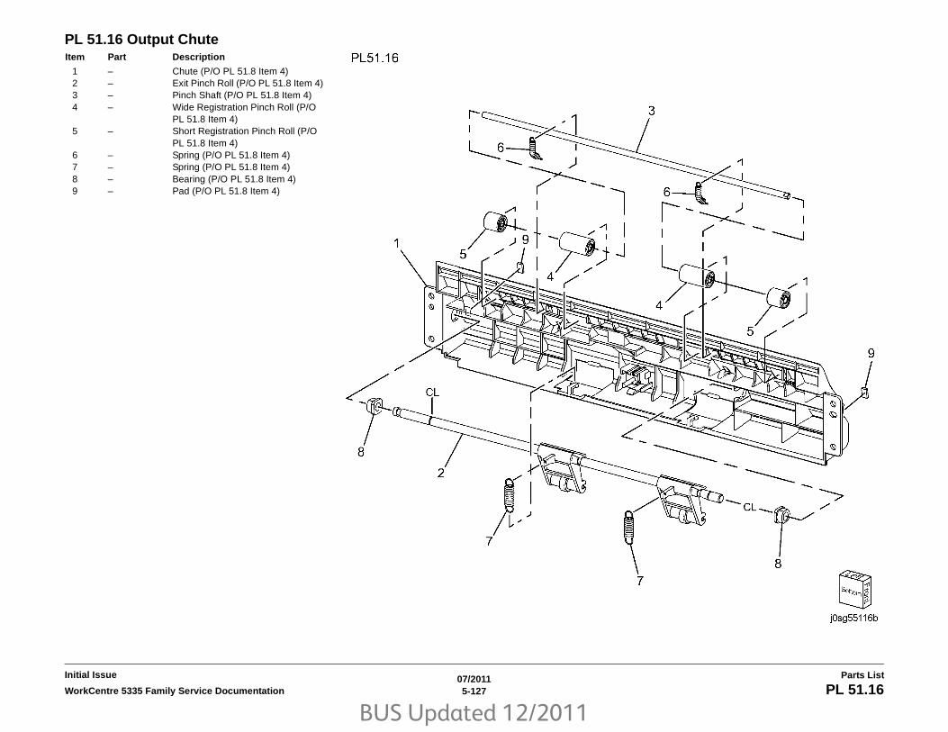
BUS Updated 12/2011
07/20115-127WorkCentre 5335 Family Service Documentation PL 51.16
Parts ListInitial Issue
PL 51.16 Output ChuteItem Part Description
1 – Chute (P/O PL 51.8 Item 4)2 – Exit Pinch Roll (P/O PL 51.8 Item 4)3 – Pinch Shaft (P/O PL 51.8 Item 4)4 – Wide Registration Pinch Roll (P/O
PL 51.8 Item 4)5 – Short Registration Pinch Roll (P/O
PL 51.8 Item 4)6 – Spring (P/O PL 51.8 Item 4)7 – Spring (P/O PL 51.8 Item 4)8 – Bearing (P/O PL 51.8 Item 4)9 – Pad (P/O PL 51.8 Item 4)

BUS Updated 12/2011
07/20115-128 WorkCentre 5335 Family Service DocumentationPL 51.17
Initial IssueParts List
PL 51.17 Sensor BracketItem Part Description
1 – Sensor Housing (P/O PL 51.4 Item 1)
2 120E31741 Registration Actuator3 – Spring (P/O PL 51.4 Item 1)4 – Sensor Guide (P/O PL 51.4 Item 1)5 – Wire Harness (Not Spared)6 930W00121 APS Sensor 1, APS Sensor 2, APS
Sensor 3, Registration Sensor, Pre Registration Sensor
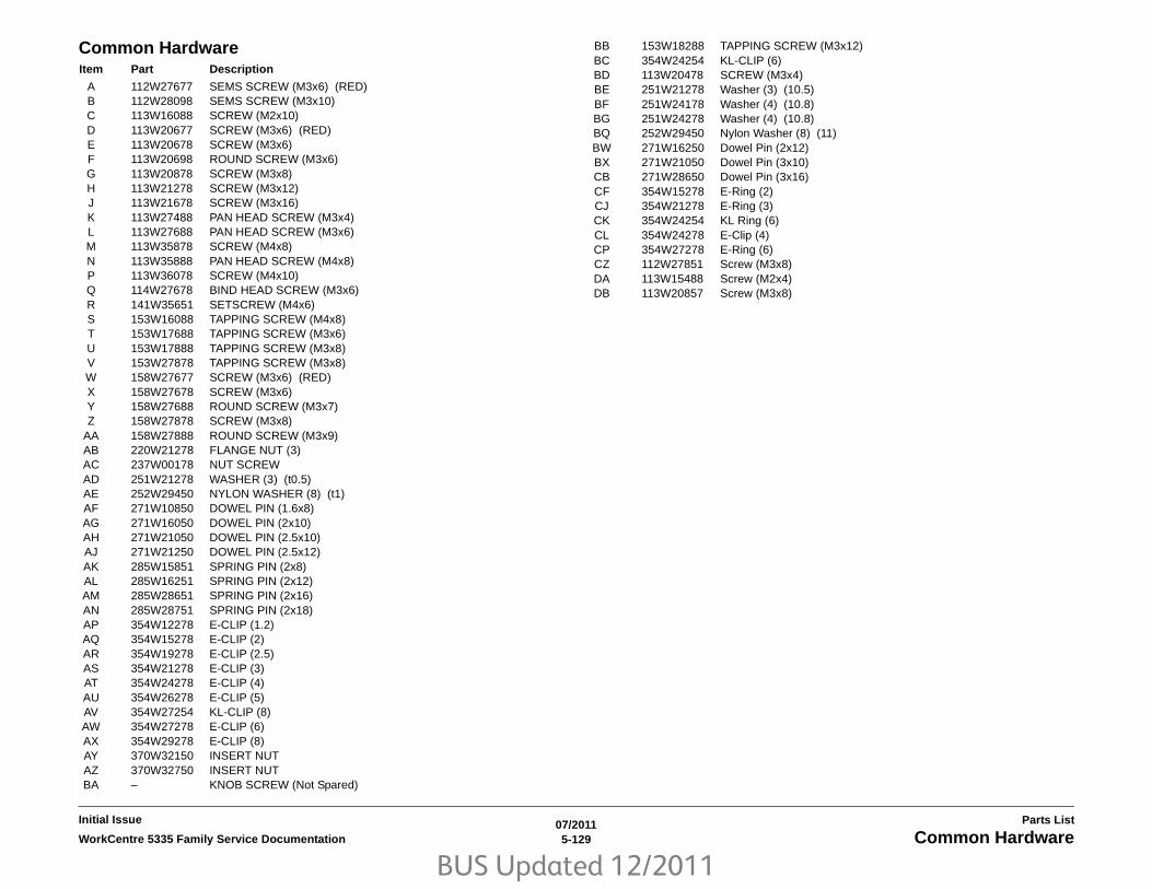
BUS Updated 12/2011
07/20115-129WorkCentre 5335 Family Service Documentation Common Hardware
Parts ListInitial Issue
Common Hardware Item Part Description
A 112W27677 SEMS SCREW (M3x6) (RED)B 112W28098 SEMS SCREW (M3x10)C 113W16088 SCREW (M2x10)D 113W20677 SCREW (M3x6) (RED)E 113W20678 SCREW (M3x6)F 113W20698 ROUND SCREW (M3x6)G 113W20878 SCREW (M3x8)H 113W21278 SCREW (M3x12)J 113W21678 SCREW (M3x16)K 113W27488 PAN HEAD SCREW (M3x4)L 113W27688 PAN HEAD SCREW (M3x6)M 113W35878 SCREW (M4x8)N 113W35888 PAN HEAD SCREW (M4x8)P 113W36078 SCREW (M4x10)Q 114W27678 BIND HEAD SCREW (M3x6)R 141W35651 SETSCREW (M4x6)S 153W16088 TAPPING SCREW (M4x8)T 153W17688 TAPPING SCREW (M3x6)U 153W17888 TAPPING SCREW (M3x8)V 153W27878 TAPPING SCREW (M3x8)W 158W27677 SCREW (M3x6) (RED)X 158W27678 SCREW (M3x6)Y 158W27688 ROUND SCREW (M3x7)Z 158W27878 SCREW (M3x8)
AA 158W27888 ROUND SCREW (M3x9)AB 220W21278 FLANGE NUT (3)AC 237W00178 NUT SCREWAD 251W21278 WASHER (3) (t0.5)AE 252W29450 NYLON WASHER (8) (t1)AF 271W10850 DOWEL PIN (1.6x8)AG 271W16050 DOWEL PIN (2x10)AH 271W21050 DOWEL PIN (2.5x10)AJ 271W21250 DOWEL PIN (2.5x12)AK 285W15851 SPRING PIN (2x8)AL 285W16251 SPRING PIN (2x12)AM 285W28651 SPRING PIN (2x16)AN 285W28751 SPRING PIN (2x18)AP 354W12278 E-CLIP (1.2)AQ 354W15278 E-CLIP (2)AR 354W19278 E-CLIP (2.5)AS 354W21278 E-CLIP (3)AT 354W24278 E-CLIP (4)AU 354W26278 E-CLIP (5)AV 354W27254 KL-CLIP (8)AW 354W27278 E-CLIP (6)AX 354W29278 E-CLIP (8)AY 370W32150 INSERT NUTAZ 370W32750 INSERT NUTBA – KNOB SCREW (Not Spared)
BB 153W18288 TAPPING SCREW (M3x12)BC 354W24254 KL-CLIP (6)BD 113W20478 SCREW (M3x4)BE 251W21278 Washer (3) (10.5)BF 251W24178 Washer (4) (10.8)BG 251W24278 Washer (4) (10.8)BQ 252W29450 Nylon Washer (8) (11)BW 271W16250 Dowel Pin (2x12)BX 271W21050 Dowel Pin (3x10)CB 271W28650 Dowel Pin (3x16)CF 354W15278 E-Ring (2)CJ 354W21278 E-Ring (3)CK 354W24254 KL Ring (6)CL 354W24278 E-Clip (4)CP 354W27278 E-Ring (6)CZ 112W27851 Screw (M3x8)DA 113W15488 Screw (M2x4)DB 113W20857 Screw (M3x8)

BUS Updated 12/2011
07/20115-130 WorkCentre 5335 Family Service DocumentationCommon Hardware
Initial IssueParts List

BUS Updated 12/2011
07/20115-131WorkCentre 5335 Family Service Documentation Common Hardware
Parts ListInitial Issue

BUS Updated 12/2011
07/20115-132 WorkCentre 5335 Family Service DocumentationCommon Hardware
Initial IssueParts List

BUS Updated 12/2011
07/20115-133WorkCentre 5335 Family Service Documentation Common Hardware
Parts ListInitial Issue

BUS Updated 12/2011
07/20115-134 WorkCentre 5335 Family Service DocumentationCommon Hardware
Initial IssueParts List

BUS Updated 12/2011
07/20115-135WorkCentre 5335 Family Service Documentation Common Hardware
Parts ListInitial Issue

BUS Updated 12/2011
07/20115-136 WorkCentre 5335 Family Service DocumentationCommon Hardware
Initial IssueParts List

BUS Updated 12/2011
07/20115-137WorkCentre 5335 Family Service Documentation Common Hardware
Parts ListInitial Issue

BUS Updated 12/2011
07/20115-138 WorkCentre 5335 Family Service DocumentationCommon Hardware
Initial IssueParts List

BUS Updated 12/2011
07/20115-139WorkCentre 5335 Family Service Documentation Common Hardware
Parts ListInitial Issue

BUS Updated 12/2011
07/20115-140 WorkCentre 5335 Family Service DocumentationCommon Hardware
Initial IssueParts List

BUS Updated 12/2011
07/20115-141WorkCentre 5335 Family Service Documentation
Parts ListInitial Issue
Part Number Index
The Part Number Index Table has been deleted from the EDOC.
Use SearchLite to search for Part Numbers and Part Descriptions.

BUS Updated 12/2011
07/20115-142 WorkCentre 5335 Family Service Documentation
Initial IssueParts List

BUS Updated 12/2011
07/20116-1WorkCentre 5335 Family Service Documentation
General Procedures & InformationInitial Issue
6 General Procedures & InformationTools & Diagnostics
UI DiagnosticsEntering and Exiting Service Rep. Mode ........................................................................ 6-3Accessing UI Diagnostics................................................................................................ 6-3Printing CSE Reports ...................................................................................................... 6-4Date / Time...................................................................................................................... 6-5Software Options............................................................................................................. 6-6NVM Read/Write ............................................................................................................. 6-6System Registration Adjustment ..................................................................................... 6-7Tray 5 Guide Adjustment ................................................................................................ 6-7Initialize Hard Disk .......................................................................................................... 6-8Print Test Patterns .......................................................................................................... 6-8MAX Setup ...................................................................................................................... 6-12IIT Calibration.................................................................................................................. 6-12Delete All Data ................................................................................................................ 6-13Initialize NVM .................................................................................................................. 6-13Component Control ......................................................................................................... 6-14Analog Monitor ................................................................................................................ 6-28Hard Disk Failure Prediction Test ................................................................................... 6-29Machine ID/Billing Data................................................................................................... 6-29HFSI Counters ................................................................................................................ 6-30Jam Counter.................................................................................................................... 6-30Failure Counter ............................................................................................................... 6-31Shutdown History ............................................................................................................ 6-31ADF Independent Operation .......................................................................................... 6-32Power On Self Test ......................................................................................................... 6-32USB Key.......................................................................................................................... 6-33Delete All Certificates / Initialize Settings........................................................................ 6-33
General ProceduresGP 1 Network Printing Simulation................................................................................... 6-35GP 2 System Administration Login Reset ....................................................................... 6-35GP 3 Initialization Kit Installation..................................................................................... 6-36GP 4 Intermittent Problem RAP ...................................................................................... 6-41GP 5 Software Options ................................................................................................... 6-42GP 6 Software Version.................................................................................................... 6-42GP 9 Entering Admin Mode ............................................................................................ 6-43GP 10 Replacing Billing PWB’s....................................................................................... 6-43GP 11 Foreign Device Interface Setup ........................................................................... 6-44GP 13 Fax Diagnostics ................................................................................................... 6-47GP 14 Special Boot Modes ............................................................................................. 6-49GP 15 Setting Country Code........................................................................................... 6-50GP 16 Downloading Software from USB Flash Drive ..................................................... 6-51GP 17 SMart eSolutions.................................................................................................. 6-52GP 19 Boot Sequence .................................................................................................... 6-54GP 20 Long Boot Diagnostic Tests ................................................................................. 6-57GP 21 Common Access Card Servicing ......................................................................... 6-58
General InformationSpace Requirements....................................................................................................... 6-61Product Specs. ................................................................................................................ 6-61Common Tools ................................................................................................................ 6-63Product Tools and Test Patterns..................................................................................... 6-64Cleaning Materials........................................................................................................... 6-64 CRUs and Consumables................................................................................................ 6-65Glossary of Terms........................................................................................................... 6-65
Change TagsChange Tags................................................................................................................... 6-69

BUS Updated 12/2011
07/20116-2 WorkCentre 5335 Family Service Documentation
Initial IssueGeneral Procedures & Information

BUS Updated 12/2011
07/20116-3WorkCentre 5335 Family Service Documentation Entering and Exiting Service Rep. Mode, Accessing
General Procedures & InformationInitial Issue
Entering and Exiting Service Rep. ModeCertain diagnostic routines and reports are available locally (on the UI) through Service Rep.Mode.
EnteringTo enter the Service Rep. Mode:
1. Press and hold the 0 key for 5 seconds, then while still holding down the 0 key, press theStart button.
The CE - Type Passcode screen will appear.
2. Enter 6789 and press Confirm.
3. The top right tab area of the UI display will change to orange and the text will change fromGuest to Service Rep. to indicate that the mode has changed.
NOTE: If a system failure has occurred when the machine is turned ON but it has notbeen repaired, the diagnostic procedures described in this section may not operate cor-rectly.
Functions enabled in Service Rep. ModeFunctions available in Service Rep. Mode can be divided into two groups; Diagnostics andReports
• UI Diagnostics: Several diagnostic routines are available (see Accessing UI Diagnos-tics).
• Printable Reports: Several machine history reports can be printed in Service Rep. Mode,one for example is the HFSI Report. These reports are in addition to the reports normallyavailable in System Admin mode (see Printing CSE Reports).
ExitingThere are two ways to exit from Service Rep. Mode:
• Switch the power Off then On (If actions performed in Service Rep. Mode cause themachine to restart upon exiting, the machine will come back up in normal user mode).
• Close any open diagnostic menus and Exit diagnostics. Press the Services button.Press and hold the 0 key then press the Start button.
Accessing UI DiagnosticsProcedure1. Enter the Service Rep. Mode (Entering and Exiting Service Rep. Mode).
2. Press the Machine Status button on the control panel.
3. Select the Tools tab on the UI screen.
4. System Settings and Common Service Settings will be highlighted.
5. In the Features column, scroll to and select Maintenance / Diagnostics.
Maintenance/Diagnostics MenusThe following selections will appear (on 1st page):
• Quick Setup Home
– IP Address Settings
– Security Settings
– E-mail Settings
– LPAD Settings
• Software Options
• NVM Read/Write
• Initialize Hard Disk
• Print Test Patterns
• Delete All Data
• Initialize NVM
– IOT
– Output (Finisher)
– IISS (IIT/IPS)
– IISS - Extension
– Input Device
– Sys - SYSTEM
– Sys - USER
• The following selections will appear (on 2nd page):
IO Check - this selection opens the following menu:
– Component Control
– Analog Monitor
• Sub System - this selection opens the following menu:
– ADF Independent Operation
– Hard Disk Failure Prediction Test
• Adjustments / Others - this selection opens the following menu:
– Machine ID/Billing Data
– HFSI Counter
– Finishers - Adjust Hole Punch Position and Booklet Crease/Staple Position (LX Fin-isher only - see ADJ 12.1 and ADJ 12.2)
• Registration - this selection opens the following menu:
– Tray 5 Guide Adjustment
– System Registration Adjustment

BUS Updated 12/2011
07/20116-4 WorkCentre 5335 Family Service DocumentationAccessing UI Diagnostics, Printing CSE Reports
Initial IssueGeneral Procedures & Information
• Faults - this selection opens the following menu:
– Jam Counter
– Failure Counter
– Shutdown History
• Restore NVM Values
• MAX Setup - this selection opens the following menu:
– Adjust Toner Density (ADJ 9.4)
Measure Sensor State
Adjust Toner Density
– IIT Calibration- this selection opens the following menu:
White Reference Adjustment
CCD Calibration
Optical Axis Correction (ADJ 6.1)
• The following selections will appear (on 3rd page):
– USB Key
– Power On Self Test
Off
On
– Delete All Certificates / Initialize Settings
Printing CSE ReportsReports MenuTo access the menu of printable reports:
1. Enter the Service Rep. Mode (Entering and Exiting Service Rep. Mode).
2. Press the Machine Status button on the Control Panel.
3. The Machine Information tab will be selected and displayed.
4. Select Print Reports.
5. Select CE. The following report selections will be displayed:
• Debug Log Report
• HFSI Report
• Jam Report
• Shutdown Report
• Failure Report
• NVM SETTING VALUE LIST
6. Select the required report and press Start. The report will be printed.
Debug Report
This report prints out debug messages with the time when the data was stored. The output for-mat is as follows: MM/DD/YYYY HH:MM:SS (AM/PM), [xxx] Recorded message.
HFSI Report
The HFSI information stored in the IOT will be displayed. Table 1 shows the format.
NOTE: The Spec Life counter is not always related to the number of fed sheets. Somecounters increment according to document length; some are revolutions of a particular roll, etc.Refer to Detailed Maintenance Activities for details.
Jam Report
The Jam Report displays a pre-programmed list of jam faults, and the number of occurrencessince that last time the counter was cleared.
Table 1 HFSI Report
Chain-Link
Current Value Spec Life
Average per Month
Last Replacement (P1)
Second Last Replacement (P2)
Third Last Replacement (P3)
xxx-xxx6-digit Dis-play
current count in location
count when replace-ment due (see Note)
average monthly (30 days) usage
X/Y Count at most recent replacement.Reason code: U=UM, S= SM O= Other
X/Y Count at 2 replace-ments ago.Reason code: U=UM, S= SM O= Other
X/Y Count at 3 replace-ments ago.Reason code: U=UM, S= SM O= Other

BUS Updated 12/2011
07/20116-5WorkCentre 5335 Family Service Documentation Printing CSE Reports, Date / Time
General Procedures & InformationInitial Issue
Shutdown Report
The Shutdown Report displays the 50 most recent shutdowns in three categories: systemfaults (System Fail History), paper jams (Paper Jam History), and document feeder jams (Doc-ument Feeder Jam History). The date of occurrence, the Chain-Link, and the copy count whenthe fault occurred are listed.
Failure Report
The Failure Report displays a pre-programmed list of non-jam faults, and the number of occur-rences since that last time the counter was cleared.
NVM SETTING VALUE LIST
This Report displays the machine serial number and software information, and a list of NVMlocations and Values.
Date / TimePurposeAllows easy access to change system Time, system Date, and time display format.
Procedure1. Enter Service Rep. Mode (Entering and Exiting Service Rep. Mode).
2. Press the Machine Status button on the Control Panel.
3. Select the Tools tab on the UI screen.
4. System Settings and Common Service Settings will be highlighted.
5. In the Features column, select Machine Clock / Timers.
a. Date will be highlighted.
b. To make changes, Select Change Settings.
c. The following Date change selections are displayed:
• Date Format
– Y/M/D
– M/D/Y
– D/M/Y
• Month (1-12)
• Day (1-31)
• Year
• Select Save to keep the changes or Cancel to discard them.
6. Select Time.
a. Time will be highlighted.
b. To make changes, Select Change Settings.
c. The following time selections are displayed:
• 12 Hour Clock or 24 Hour Clock
• AM or PM (12 hour clock only)
• Hours (1-12 w/ 12 hour clock, 0-23 w/ 24 hour clock)
• Minutes
• Select Save to keep the changes or Cancel to discard them.
7. Select Energy Saver Timers.
a. Energy Saver Timers will be highlighted.
• Low Power and Sleep times are displayed.
b. To make changes, Select Change Settings.
• From Last Operation to Low Power Mode and From Last Operation toSleep Mode selections are displayed.
• Change the timer settings.
• Select Save to keep the changes or Cancel to discard them.
8. To close Machine Clock / Timers, select Close.

BUS Updated 12/2011
07/20116-6 WorkCentre 5335 Family Service DocumentationSoftware Options, NVM Read/Write
Initial IssueGeneral Procedures & Information
Software OptionsCertain optional features must be enabled in software by entering a password (supplied bysales).
Procedure1. Enter UI Diagnostics (Accessing UI Diagnostics)
2. Select Software Options on the Maintenance/Diagnostics screen.
3. Select Keyboard.
4. Enter the password of the software option on the keyboard displayed on the UI.
5. Select Save.
6. Select Reboot.
NVM Read/WritePurposeIt is possible to refer to or set/change the NVM data.
NOTE: All the NVM data including the NVM for the Key Operator are accessible. However, Bill-ing and Auditron Administration Password cannot be rewritten.
Procedure1. Enter UI Diagnostics (Accessing UI Diagnostics)
2. Select NVM Read/Write on the Maintenance/Diagnostics screen.
NOTE: The machine does not accept, for example, 700-6 as an abbreviation of 700-006.
When a number starts with 0, the 0 must be entered.
3. Input the Chain-Link number and select Confirm / Change.
4. The Current Value and the New Value columns are displayed.
5. Enter the value that you wish to change to into the New Value column using the keypadand select Save.
The entered value can be cleared using the C button.
NOTE: If the entered value is invalid, the following message is displayed: Incorrectvalue. Please re-enter.
For a complete list of NVM locations and descriptions, refer to NVM Tables, under theLibrary tab of the Service Interface
6. The entered number is displayed in the Current Value column.
7. Select Close to return to the Maintenance / Diagnostics screen.

BUS Updated 12/2011
07/20116-7WorkCentre 5335 Family Service Documentation System Registration Adjustment, Tray 5 Guide Ad-
General Procedures & InformationInitial Issue
System Registration AdjustmentNOTE: For details on System Registration see adjustment ADJ 9.10.
Tray 5 Guide AdjustmentPurposeThis procedure calibrates the paper size detection circuits for Tray 5. It should be performedwhen the tray 5 size sensor is replaced or a size detection error occurs
Procedure 1. Enter UI Diagnostic mode (Accessing UI Diagnostics).
2. Select Registration on the Maintenance/Diagnostics screen.
3. Select Tray 5 Guide Adjustment
4. Push the paper guides to their minimum width.
5. Select the Minimum Size Position radio button, then press Start.
6. Push the paper guides to their maximum width.
7. Select the Maximum Size Position radio button, then press Start.

BUS Updated 12/2011
07/20116-8 WorkCentre 5335 Family Service DocumentationInitialize Hard Disk, Print Test Patterns
Initial IssueGeneral Procedures & Information
Initialize Hard DiskPurposeThis routine initializes Partition A of the HDD. Partition A contains the following data: addedfonts, forms for ART EX, ART IV (optional), PC-PR201H, ESC/P, and HP-GL/2 (optional), ARTIV User Defined Data, and SMB folder.
Initialization Procedure1. Enter UI Diagnostic mode (Accessing UI Diagnostics).
2. Press the Machine Status button on the Control Panel.
3. Select the Tools tab on the UI screen.
4. System Settings and Common Service Settings will be selected and displayed.
1. In the Features column, scroll to and select Maintenance / Diagnostics, then select Ini-tialize Hard Disk.
2. Select Partition A then select Start.
3. A confirmation message appears. Select Yes.
4. A message stating “Partition A has been initialized” will appear. Select Confirm.
5. Select Close.
6. Select Exit (Keep Log).
7. Select Yes or No, as appropriate, to the confirmation message.
The machine will reboot into user (Guest) mode.
This completes the initialization of Partition A.
Print Test PatternsPurposeThis routine outputs test patterns from the built-in Pattern Generator.
NOTE: An error message is displayed if the print cannot be made with the specified tray. Makesure that there is sufficient paper in the trays before starting the routine. If a jam or system faultoccurs, the process stops but a recovery message is not displayed. The fault code is displayedbut it is not recorded in History.
Procedure
1. Enter UI Diagnostics (Accessing UI Diagnostics).
2. Press the Machine Status button on the Control Panel.
3. Select the Tools tab on the UI screen.
4. System Settings and Common Service Settings will be selected and displayed.
NOTE: In order to print some test patterns correctly, you first will have to modify the NVMsetting(s) associated with those test patterns. There are three NVM locations that affecttest pattern printing: 870-207, 870-209, and 870-210. (Refer to Table 1). Always check theRequired NVM Settings column in Table 2 before attempting to print any built-in test pat-tern.
5. In the Features column, scroll to and select Maintenance / Diagnostics.
6. To print a test pattern that first requires NVM changes, perform a and then b below. Toprint a test pattern that does NOT require NVM changes, skip a and perform b.
a. If you must change one or more of the NVM settings for the test pattern you wish toprint:
i. Select NVM Read / Write.
ii. Enter the required NVM Chain-Link(s) and the setting(s) shown in Table 2.
iii. Save the new setting(s).
iv. Close the routine to return to the Maintenance / Diagnostics menu.
v. Continue at b.
b. On the Maintenance / Diagnostics menu select Print Test Pattern, enter the PatternNumber, the Quantity, and select the Paper Supply, then press Start.

BUS Updated 12/2011
07/20116-9WorkCentre 5335 Family Service Documentation Print Test Patterns
General Procedures & InformationInitial Issue
NOTE: To switch from a test pattern that requires one set of NVM values to a testpattern that requires a different set of values (on none), you must exit UI Diagnostic mode andallow the machine to reboot before entering the new NVM values (Exiting the Service Rep.Mode and rebooting the machine causes the NVM values to reset to their defaults.)
Table 1 NVM List
Chain-Link ItemDefault NVM Setting Parameter
870-207 Screen Setting 11: 106 line 0: Letter1: Photograph2: 2 values ED3: 24 ED4: 300 DACS5: 6006: 3007: 200C8: 200R9: 15010: FINE11: 106 lines12: Gray-Font(1200)13: 200L
870-209 Density Setting 0: 0% 0 - 100%
870-210 Resolution Setting 2: 600 x 600 0: 1200 x 12001: 1200 x 6002: 600 x 6003: 300 x 3004: Not used
Table 2 Test Patterns
Pattern # Name Qty. TrayPaper Size if using Trays 1-4
Paper Size if using MSI Image size
Simplex / Duplex Screen Resolution
Required NVM Settings Purpose
1 90 degree Grid (IOT) 1-99 Trays 1 - 4, MSI
A311” x 17”
A3 / 11” x 17” A3 x 17” Simplex / Duplex
- - 870-207: Default870-209: Default870-210: Default
Xerographics: Verifies ROS operation
51 Total Chart 600 dpi (Controller) A3
1-999 Tray 1 - 4, MSI
A3A4 LEF11” x 17”8.5” x 11” LEF
A3 A3 Simplex Photograph200R106 lines
600 x 600 870-207: Default870-209: Default870-210: Default
For adjustment in themarket/determining prob-lems.
52 Total Chart 600 dpi (Controller) 11” x 17”
1-999 Tray 1 - 4, MSI
A3A4 LEF11” x 17”8.5” x 11” LEF
A4 LEF 11” x 17” Simplex Photograph200R106 lines
600 x 600 870-207: Default870-209: Default870-210: Default
For adjustment in themarket/determining prob-lems.

BUS Updated 12/2011
07/20116-10 WorkCentre 5335 Family Service DocumentationPrint Test Patterns
Initial IssueGeneral Procedures & Information
53 Total Chart 1200 dpi (Controller) A3
1-999 Tray 1 - 4, MSI
A3A4 LEF11” x 17”8.5” x 11” LEF
A4 LEF A3 Simplex Letter, 2 values ED, 24ED300 DACS, 600, 300200c, 150, GrayFont 1200, 200L
1200 x 1200 870-207: 0870-209: Default870-210: 0
For adjustment in themarket/determining prob-lems.
54 Total Chart 1200 dpi (Controller) 11” x 17”
1-999 Tray 1 - 4, MSI
A3A4 LEF11” x 17”8.5” x 11” LEF
A4 LEF 11” x 17” Simplex Letter, 2 values ED, 24ED300 DACS, 600, 300200c, 150, GrayFont 1200, 200L
1200 x 1200 870-207: 0870-209: Default870-210: 0
For adjustment in themarket/determining prob-lems.
55 HT-600 (Controller) 1-999 Tray 1 - 4, MSI
A3A4 LEF11” x 17”8.5” x 11” LEF
A4 LEF A3 Simplex Photo, 200R, 106 lines
600 x 600 870-207: Default870-209: 50 (example)870-210: Default
For adjustment in themarket/determining prob-lems.
56 HT_1200 (Controller) 1-999 Tray 1 - 4, MSI
A3A4 LEF11” x 17”8.5” x 11” LEF
A4 LEF A3 Simplex Letter, 2 values ED, 24ED300 DACS, 600, 300200c, 150, GrayFont 1200, 200L
1200 x 1200 870-207: 0870-209: 50 (example)870-210: 0
For adjustment in themarket/determining prob-lems.
57 SDTP123600_A3 (Controller)
1-999 Tray 1 - 4, MSI
A3A4 LEF11” x 17”8.5” x 11” LEF
A4 LEF A3 Simplex / Duplex
Photo, 200R, 106 lines
600 x 600 870-207: Default870-209: Default870-210: Default
For adjustment in themarket/determining prob-lems.
58 Procon PG_600 (Controller)
1-999 Tray 1 - 4, MSI
A3A4 LEF11” x 17”8.5” x 11” LEF
A3 A4 Simplex Photo, 200R, 106 lines
600 x 600 870-207: Default870-209: Default870-210: Default
Gradation characteristics detection
59 Procon PG_1200 (Controller)
1-999 Tray 1 - 4, MSI
A3A4 LEF11” x 17”8.5” x 11” LEF
A3 A4 Simplex Letter, 2 values ED, 24ED300 DACS, 600, 300200c, 150, GrayFont 1200, 200L
1200 x 1200 870-207: 0870-209: Default870-210: 0
Gradation characteristics detection
60 Density_Adj (Control-ler)
1-999 Tray 1 - 4, MSI
A3A4 LEF11” x 17”8.5” x 11” LEF
A3 A3 Simplex Photo, 200R, 106 lines
600 x 600 870-207: Default870-209: Default870-210: Default
Table 2 Test Patterns
Pattern # Name Qty. TrayPaper Size if using Trays 1-4
Paper Size if using MSI Image size
Simplex / Duplex Screen Resolution
Required NVM Settings Purpose

BUS Updated 12/2011
07/20116-11WorkCentre 5335 Family Service Documentation Print Test Patterns
General Procedures & InformationInitial Issue
71 No Paper Run (Con-troller)
1-99 Tray 1 - - A4 LEF8.5” X 11” LEF
Simplex - - 870-207: Default870-209: Default870-210: Default
112 IIT Analog Gradation BW (IISS)
- Tray 1 - 4, MSI
- - - Simplex 2 value ED 600 x 600 870-207: 2870-209: Default870-210: Default
115 Pre IPS FS Increment BW (IISS)
- Tray 1 - 4, MSI
- - - Simplex 2 value ED 600 x 600 870-207: 2870-209: Default870-210: Default
119 Pre IPS SS Incre-ment BW (IISS)
- Tray 1 - 4, MSI
- - - Simplex 2 value ED 600 x 600 870-207: 2870-209: Default870-210: Default
120 Uniform Density (IISS)
- Tray 1 - 4, MSI
- - - Simplex 2 value ED 600 x 600 870-207: 2870-209: Default870-210: Default
123 Pre IPS BW (IISS) - Tray 1 - 4, MSI
- - - Simplex 2 value ED 600 x 600 870-207: 2870-209: Default870-210: Default
128 Post IPS Lattice (Grid) BW (IISS)
- Tray 1 - 4, MSI
- - - Simplex 2 value ED 600 x 600 870-207: 2870-209: Default870-210: Default
Table 2 Test Patterns
Pattern # Name Qty. TrayPaper Size if using Trays 1-4
Paper Size if using MSI Image size
Simplex / Duplex Screen Resolution
Required NVM Settings Purpose

BUS Updated 12/2011
07/20116-12 WorkCentre 5335 Family Service DocumentationMAX Setup, IIT Calibration
Initial IssueGeneral Procedures & Information
MAX SetupMAX Setup (ADJ 9.1) consists of related Image Quality and Process Control adjustments.
Some routines must be performed in a specific sequence; go to the referenced ADJ for com-prehensive instructions.
The MAX Setup menu contains the following items:
• Adjust Toner Density (ADJ 9.4)
• IIT Calibration- this selection opens the following menu:
– White Reference Setup (ADJ 6.6)
– CCD Calibration (ADJ 6.6)
– Optical Axis Correction (ADJ 6.1)
IIT CalibrationPurposeFunctional details:
• Computes and sets the White Reference Correction Coefficient.
• Corrects the IIT Sensitivity Dispersion.
NOTE: – For details on IIT Calibration, see adjustments ADJ 6.1 and ADJ 6.6.

BUS Updated 12/2011
07/20116-13WorkCentre 5335 Family Service Documentation Delete All Data, Initialize NVM
General Procedures & InformationInitial Issue
Delete All DataPurposeThis procedure deletes user-defined/registered information and information recorded automat-ically by the system from the hard disk, the Controller (ESS) NVM PWB and Buffer RAM.
CAUTION
This procedure also Initializes Sys System, IOT NVM, and IIT NVM resulting in loss of the fac-tory setups for System Registration, Image Quality and the Scanner setups.
Procedure1. Enter UI Diagnostic mode (Accessing UI Diagnostics).
2. Select Delete All Data.
3. Select Start.
4. A confirmation message appears. Select Delete.
5. The Deleting data... message appears.
6. When the message indicating the completion appears, exit UI Diagnostic mode, Switchoff the power, then switch on the power.
Initialize NVMProcedure1. Enter UI Diagnostic mode (Accessing UI Diagnostics). Select Initialize NVM. Selections
for the following subsystems appear:
• IOT
• Output (Finisher)
• IISS (IIT/IPS)
• IISS-Extension
• Input Device
• Sys-SYSTEM
• Sys-USER
2. Select the subsystem to be initialized and select Start.
CAUTION
All NVM for the selected subsystem will be reset to the default values. Any machine-specific,region-specific, or customer-specific information will need to be re-entered. Make sure that thisinformation is available before proceeding.
3. A confirmation message appears. Select Yes.
4. A message indicating completion will appear.
5. Select the Confirm button.
This completes the initialization. Remember to re-enter any machine-specific NVM data.
NOTE: For a complete listing of accessible NVM locations, refer to the NVM Tables in theLibrary section

BUS Updated 12/2011
07/20116-14 WorkCentre 5335 Family Service DocumentationComponent Control
Initial IssueGeneral Procedures & Information
Component ControlPurposeThe purpose of the Component Control is to display the logic state of input signals and to ener-gize output components.
NOTE: Refer to Table 1 for a list of all IOT, IIT, DADF, Tray Module, and HCF Input Compo-nents listed by Chain/Link number.
Refer to Table 2 for a list of all IOT, IIT, DADF, Tray Module, and HCF Output Componentslisted by Chain/Link number.
Refer to Table 3 for a list of all Integrated Office Finisher Input Components listed by Chain/Link number.
Refer to Table 4 for a list of all Integrated Office Finisher Output Components listed by Chain/Link number.
Refer to Table 5 for a list of all Office Finisher LX Input Components listed by Chain/Link num-ber.
Refer to Table 6 for a list of all Office Finisher LX Output Components listed by Chain/Linknumber.
Procedure1. Enter Diagnostic Mode (Accessing UI Diagnostics).
2. Press the Machine Status button on the Control Panel.
3. Select the Tools tab on the UI screen.
4. System Settings and Common Service Settings will be highlighted.
5. In the Features column, select Maintenance / Diagnostics.
Scroll to and select IO Check.
6. Select Component Control.
7. Input Chain-Link number, then press Start.
• In case of INPUT Component:
Indicates current status in Status column.
Count up (+1) when switching. (High to Low, Low to High)
• In case of OUTPUT Component:
Activates component
8. Press Stop button after confirming.
Stacking Components
NOTE: Some components cannot be energized at the same time as another component. If youactivate such a combination of components, the first component switched on will be automati-cally switched off.
1. When performing multiple component checking, input new Chain-Link number after one(or several) component(s) is (are) in operation.
NOTE: Only latest Chain-Link number is displayed.
2. When confirming the status of another component still in operation, select Enter Numberthen input Chain-Link number of applicable component.
3. Select Stop key after confirming. Stop operation of component indicated on screen.
Table 1 Input Component Control List - IOT/IIT/DADF/TM/HCF
Chain-Link Component Name Description
005-102 Document Sensor H = No paper detected by Document Sensor
005-110 Registration Sensor (DADF) L = Paper detected by Registration Sensor
005-205 DADF Feed Out Sensor H = Paper detected on Feed Out Sensor
005-206 DADF Pre-Reg. Sensor H = Paper detected on Pre Registration Sensor
005-211 DADF Inverter Sensor H = Paper detected on Inverter Sensor
005-212 DADF Feeder Cover Interlock Switch
H = Feeder Cover Open
005-213 DADF Interlock Switch H = Platen Interlock Open
005-215 DADF APS Tray Sensor #1 L = Light not blocked by Actuator
005-216 DADF APS Tray Sensor #2 L = Light not blocked by Actuator
005-217 DADF APS Tray Sensor #3 L = Light blocked by Actuator
005-218 DADF #1 APS Sensor L = Paper detected on APS No.1 Sensor.
005-219 DADF #2 APS Sensor L = Paper detected on APS No.1 Sensor.
005-220 DADF #3 APS Sensor L = Paper detected on APS No.1 Sensor.
005-221 DADF Tray Size Sensor No.1 L = Paper detected on APS No.1 Sensor.
005-222 DADF Tray Size Sensor No.2 L = Paper detected on APS No.1 Sensor.
005-224 Scan Start H = Scan signal ON
042-200 Drum Motor Detect the rotation of Drum Motor.
042-201 Main Motor Detect the rotation of Main Motor.
042-202 Fan Assy-Fuser Fail Detect the rotation of Fuser Fan.
042-203 Fan Assy-CRU Fail Detect the rotation of CRU Fan.
062-201 Sheet Abort Document RegistrationL = ON
062-212 IIT Registration Sensor Deactuation of Registration SensorL = ON
062-240 ADF Exist DADF is installed.H = ON status
062-251 APS Sensor 1 Document detected.H = APS ON
062-253 APS Sensor 3 Document detected.H = APS ON
062-272 Scan Start L = Scan available
062-300 Platen I/L Switch L = Platen is closed
062-301 Angle Sensor L = Platen is closed
071-101 Tray 1 No Paper Sensor Detects the Tray 1 No Paper Sensor ON/OFF.
071-102 Tray 1 Level Sensor Detects the Tray 1 Level Sensor ON/OFF.
071-104 Tray 1 Paper Size Switch Detect Tray 1 Paper Size Sensor Digital On/Off
071-105 Tray 1 Pre Feed Sensor
072-101 Tray 2 No Paper Sensor Detects the Tray 2 No Paper Sensor ON/OFF.

BUS Updated 12/2011
07/20116-15WorkCentre 5335 Family Service Documentation Component Control
General Procedures & InformationInitial Issue
072-102 Tray 2 Level Sensor Detects the Tray 2 Level Sensor ON/OFF.
072-103 Tray 2 Feed Out Sensor Detects the Tray 2 Feed Out Sensor ON/OFF.
072-104 Tray 2 Paper Size Switch Detect Tray 2 Paper Size Sensor Digital On/Off.
072-105 Tray 2 Pre Feed Sensor
073-101 Tray 3 No Paper Sensor Detects the Tray 3 No Paper Sensor ON/OFF.
073-102 Tray 3Level Sensor Detects the Tray 3 Level Sensor ON/OFF.
073-103 Tray 3 Feed Out Sensor Detects the Tray 3 Feed Out Sensor ON/OFF.
073-104 Tray 3 Paper Size Switch Detect Tray 3 Paper Size Sensor Digital On/Off.
074-101 Tray 4 No Paper Sensor Detects the Tray 4 No Paper Sensor ON/OFF.
074-102 Tray 4 Level Sensor Detects the Tray 4 Level Sensor ON/OFF.
074-103 Tray 4 Feed Out Sensor Detects the Tray 4 Feed Out Sensor ON/OFF.
074-104 Tray 4 Paper Size Switch Detect Tray 4 Paper Size Sensor Digital On/Off.
075-101 MSI No Paper Sensor Detects the MSI No Paper Sensor ON/OFF.
075-102 MSI Nudger Position Sensor Detects MSI Nudger Position Sensor ON/OFF.
075-103 MSI Feed Out Sensor Detects the MSI Feed Out Sensor ON/OFF.
077-100 Exit 2 Sensor Detects the Exit 2 Sensor ON/OFF.
077-101 Exit 1 Sensor Detects the Exit 1Sensor ON/OFF.
077-102 OCT Home Position Sensor Detect OCT Home Position Sensor On/Off
077-104 Registration Sensor Detects the Registration Sensor ON/OFF.
077-105 Duplex Sensor Detect Duplex Path Sensor On/Off.
077-113 Tray 3 Feed Out Sensor Detect #3 Feed Out Sensor On/Off.
077-114 Tray 4 Feed Out Sensor Detect Tray 4 Feed Out Sensor On/Off.
077-120 Status of IOT Feed Ready Detect OFF/ON of Feed Ready signal.
077-121 Status of TM Reg. Stop Detect OFF/ON of Regi Stop signal.
077-123 Status of TM Feed ON Detect OFF/ON of Feed ON signal.
077-300 Left Hand Interlock Switch Detect Left Hand Interlock Switch On/Off.
077-301 Left Hand Low Cover Switch Detect Left Hand Low Cover Switch On/Off.
077-302 Left Hand High Cover Switch Detect Left Hand High Cover Switch On/Off.
077-303 Front Interlock Switch Detect Front Interlock Switch On/Off.
077-305 Duplex Cover Switch Detect Duplex Cover Switch On/Off.
077-306 TM Left Hand Interlock Switch Detect TM Left Hand Interlock Switch On/Off.
078-100 HCF Prefeed Sensor
078-101 HCF Feed Out Sensor
078-200 HCF No Paper Sensor
Table 1 Input Component Control List - IOT/IIT/DADF/TM/HCF
Chain-Link Component Name Description

BUS Updated 12/2011
07/20116-16 WorkCentre 5335 Family Service DocumentationComponent Control
Initial IssueGeneral Procedures & Information
Table 2 Output Component Control List - IOT/IIT/DADF/HCF
Chain-Link Component Description Time-out conflicts
005-001 CVT Feed MotorCW 37.5mm/s
Turns ON for 50sec - Auto OFF Y 005-002 to 005-010005-013 to 005-022005-046 to 005-051005-090, 005-093
005-002 CVT Feed MotorCW 50.0mm/s.
Turns ON for 50sec - Auto OFF Y 005-001005-003 to 005-010005-013 to 005-022005-046 to 005-051005-090, 005-093
005-004 CVT Feed MotorCW 100.0mm/sec.
Turns ON for 50sec - Auto OFF Y 005-001 to 005-003005-005 to 005-010005-013 to 005-022005-046 to 005-051005-090, 005-093
005-005 CVT Feed MotorCW 150.0mm/s
Turns ON for 50sec - Auto OFF Y 005-001 to 005-004005-006 to 005-010005-013 to 005-022005-046 to 005-051005-090, 005-093
005-008 CVT Feed MotorCW 400.0mm/s
Turns ON for 50sec - Auto OFF Y 005-001 to 005-007005-009 to 005-010005-013 to 005-022005-046 to 005-051005-090, 005-093
005-010 CVT Feed MotorCW 133.3mm/sec.
Turns ON for 50sec - Auto OFF Y 005-001 to 005-009005-013 to 005-022005-046 to 005-051005-090, 005-093
005-020 CVT Pre-Reg. Motor CW 300.0mm/sec.
Turns ON for 50sec - Auto OFF Y 005-001 to 005-010005-013 to 005-019005-021 to 005-022005-046 to 005-051005-090, 005-093
005-021 CVT Pre-Reg. Motor CW 220.0mm/sec.
Turns ON for 50sec - Auto OFF Y 005-001 to 005-010005-013 to 005-020005-022005-046 to 005-051005-090, 005-093
005-022 CVT Pre-Reg. MotorCW 150.0mm/sec.
Turns ON for 50sec - Auto OFF Y 005-001 to 005-010005-013 to 005-021005-046 to 005-051005-090, 005-093
005-026 CVT Reg. MotorCCW 37.5mm/s
Turns ON for 50sec - Auto OFF Y 005-027 to 005-039005-041 to 005-042
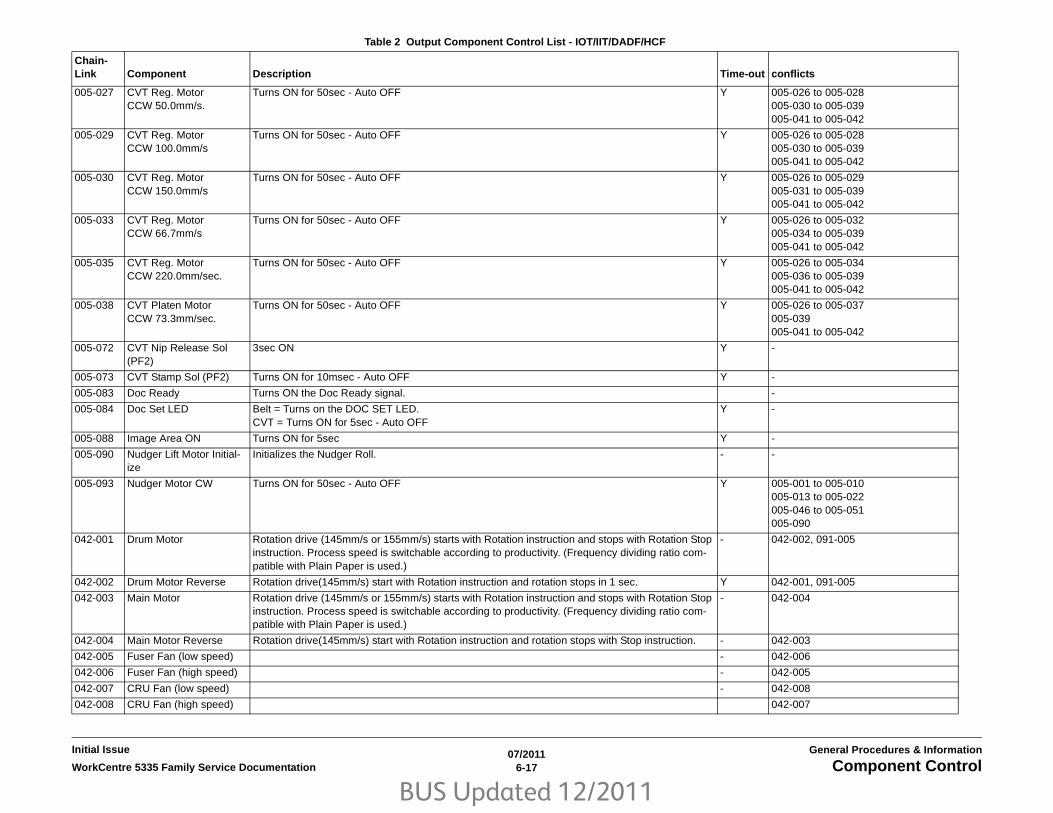
BUS Updated 12/2011
07/20116-17WorkCentre 5335 Family Service Documentation Component Control
General Procedures & InformationInitial Issue
005-027 CVT Reg. MotorCCW 50.0mm/s.
Turns ON for 50sec - Auto OFF Y 005-026 to 005-028005-030 to 005-039005-041 to 005-042
005-029 CVT Reg. MotorCCW 100.0mm/s
Turns ON for 50sec - Auto OFF Y 005-026 to 005-028005-030 to 005-039005-041 to 005-042
005-030 CVT Reg. MotorCCW 150.0mm/s
Turns ON for 50sec - Auto OFF Y 005-026 to 005-029005-031 to 005-039005-041 to 005-042
005-033 CVT Reg. MotorCCW 66.7mm/s
Turns ON for 50sec - Auto OFF Y 005-026 to 005-032005-034 to 005-039005-041 to 005-042
005-035 CVT Reg. MotorCCW 220.0mm/sec.
Turns ON for 50sec - Auto OFF Y 005-026 to 005-034005-036 to 005-039005-041 to 005-042
005-038 CVT Platen Motor CCW 73.3mm/sec.
Turns ON for 50sec - Auto OFF Y 005-026 to 005-037005-039005-041 to 005-042
005-072 CVT Nip Release Sol (PF2)
3sec ON Y -
005-073 CVT Stamp Sol (PF2) Turns ON for 10msec - Auto OFF Y -
005-083 Doc Ready Turns ON the Doc Ready signal. -
005-084 Doc Set LED Belt = Turns on the DOC SET LED.CVT = Turns ON for 5sec - Auto OFF
Y -
005-088 Image Area ON Turns ON for 5sec Y -
005-090 Nudger Lift Motor Initial-ize
Initializes the Nudger Roll. - -
005-093 Nudger Motor CW Turns ON for 50sec - Auto OFF Y 005-001 to 005-010005-013 to 005-022005-046 to 005-051005-090
042-001 Drum Motor Rotation drive (145mm/s or 155mm/s) starts with Rotation instruction and stops with Rotation Stop instruction. Process speed is switchable according to productivity. (Frequency dividing ratio com-patible with Plain Paper is used.)
- 042-002, 091-005
042-002 Drum Motor Reverse Rotation drive(145mm/s) start with Rotation instruction and rotation stops in 1 sec. Y 042-001, 091-005
042-003 Main Motor Rotation drive (145mm/s or 155mm/s) starts with Rotation instruction and stops with Rotation Stop instruction. Process speed is switchable according to productivity. (Frequency dividing ratio com-patible with Plain Paper is used.)
- 042-004
042-004 Main Motor Reverse Rotation drive(145mm/s) start with Rotation instruction and rotation stops with Stop instruction. - 042-003
042-005 Fuser Fan (low speed) - 042-006
042-006 Fuser Fan (high speed) - 042-005
042-007 CRU Fan (low speed) - 042-008
042-008 CRU Fan (high speed) 042-007
Table 2 Output Component Control List - IOT/IIT/DADF/HCF
Chain-Link Component Description Time-out conflicts

BUS Updated 12/2011
07/20116-18 WorkCentre 5335 Family Service DocumentationComponent Control
Initial IssueGeneral Procedures & Information
061-001 ROS Motor Start ROS Motor Start Signal
062-002 IIT Exposure Lamp Turns the Lamp ON for 180sec - Auto OFF Y -
062-005 IIT Scan Motor (Scan direction)
Moves it 50mm from current position in Scan direction - Auto OFF Y 062-006
062-006 IIT Scan Motor (Return direction)
Moves it 50mm from current position in Return direction - Auto OFF Y 062-005
062-086 IIT Image Area IMG-AREA Signal Output Y -
062-091 Exchange To ADF Turns ON the document exchange command signal to the DADF Y -
071-002 #1 Feed Motor 2-phase (CCW 2) Lift Direction
Drives the Motor with 2-phase excitation in the Lift direction, and at the Lift speed.This does not operate if the Level Sensor is ON when drive has started.When Level Sensor On is detected, the operation will stop.
- 071-003
071-003 #1 Feed Motor 1-2-phase (CW 1-2) Feed Direction
Drives the Motor with 1-2-phase excitation in the Feed direction, and at the Feed transport speed. - 071-002
072-002 #2 Feed Motor 2-phase (CCW 2) Lift Direction
Drives the Motor with 2-phase excitation in the Lift direction, and at the Lift speed.This does not operate if the Level Sensor is ON when drive has started.When Level Sensor On is detected, the operation will stop.
- 072-003
072-003 #2 Feed Motor 1-2-phase (CW 1-2) Feed Direction
Drives the Motor with 1-2-phase excitation in the Feed direction, and at the Feed transport speed. - 072-002
073-001 #3 Feed Motor 2-phase (CW 2) Feed Direction
Drives the Motor with 2-phase excitation in the Feed direction, and at the Feed transport speed. - 073-002073-003073-004
073-002 #3 Feed Motor 2-phase (CCW 2) Lift Direction
Drives the Motor with 2-phase excitation in the Lift direction, and at the Lift speed.This does not operate if the Level Sensor is ON when drive has started.When Level Sensor On is detected, the operation will stop.
- 073-001073-003073-004
073-003 #3 Feed Motor 1-2-phase (CW 1-2) Feed Direction
Drives the Motor with 1-2-phase excitation in the Feed direction, and at the Feed transport speed. - 073-001073-002073-004
073-004 #3 Feed Motor 1-2-phase (CCW 1-2) Lift Direction
Drives the Motor with 2-phase excitation in the Lift direction, and at the Lift speed.This does not operate if the Level Sensor is ON when drive has started.When Level Sensor On is detected, the operation will stop.
- 073-001073-002073-003
074-001 Tray 4 Feed Motor 2-phase (CW 2) Feed Direction
Drives the Motor with 2-phase excitation in the Feed direction, and at the Feed transport speed. - 073-002073-003073-004
074-002 Tray 4 Feed Motor 2-phase (CCW 2) Lift Direction
Drives the Motor with 2-phase excitation in the Lift direction, and at the Lift speed.This does not operate if the Level Sensor is ON when drive has started.When Level Sensor On is detected, the operation will stop.
- 074-001074-003074-004
074-003 Tray 4 Feed Motor 1-2-phase (CW 1-2) Feed Direction
Drives the Motor with 1-2-phase excitation in the Feed direction, and at the Feed transport speed. - 074-001074-002074-004
074-004 Tray 4 Feed Motor 1-2-phase (CCW 1-2) Lift Direction
Drives the Motor with 2-phase excitation in the Lift direction, and at the Lift speed.This does not operate if the Level Sensor is ON when drive has started.When Level Sensor On is detected, the operation will stop.
- 074-001074-002074-003
075-001 MSI Feed Solenoid Drives MSI Feed Solenoid for 2000msec. Y 2 sec. -
Table 2 Output Component Control List - IOT/IIT/DADF/HCF
Chain-Link Component Description Time-out conflicts

BUS Updated 12/2011
07/20116-19WorkCentre 5335 Family Service Documentation Component Control
General Procedures & InformationInitial Issue
077-002 Registration Clutch Turns ON the Registration Clutch.By combining this with Main Drive Motor[042-041], it is also able to drive the Registration Roll.
- -
077-004 Exit Gate Solenoid Switches the Exit Gate. Strong current for the first 110msec after the attraction had started, then switching to weak current When Off: Output to #1 Exit. When On: Output #2 Exit
-
077-010 #1 OCT Motor(CW 2-phase excitation mode)
Move #1 Exit Roll toward the shaft direction (Turn on for 1000msec and Time-out)CW: Move Exit Roll to the O/B side of M/C.
Y -1 sec. 077-011. 012, 013
077-011 #1 OCT Motor(CCW 2-phase excitation mode)
Move #1 Exit Roll to the shaft direction (Turn on for 1000msec and Time-out)CCW: Move Exit Roll to the I/B side of M/C.
Y -1 sec. 077-010, 012, 013
077-012 #1 OCT Motor(CW 1-2-phase excitation mode)
Move #1 Exit Roll to the shaft direction (Turn on for 1000msec and Time-out)CW: Move Exit Roll to the O/B side of M/C
Y -1 sec. 077-010, 011, 013
077-013 #1 OCT Motor(CCW 1-2-phase excita-tion mode)
Move #1 Exit Roll to the shaft direction. (Turn on for 1000msec and Time-out)CCW: Move Exit Roll to the I/B side of M/C.
Y -1 sec. 077-010, 011, 012
077-014 Exit 2 Drive Motor(63 speed forward rota-tion/MAX)
Drives the Transport Roll of the Exit Unit (Max Speed Normal Rotation)Exit output direction
- 077-015, 016, 017
077-015 Exit 2 Drive Motor(126 speed reverse rota-tion/MAX)
Drives the Transport Roll of the Exit Unit (Max Speed Normal Rotation)Exit Output direction
- 077-014, 016, 017
077-016 Exit 2 Drive Motor(63 speed forward rota-tion/MAX)
Drives the Transport Roll of the Exit Unit (Max Speed Reverse Rotation)Duplex direction
- 077-014, 015, 017
077-017 Exit 2 Drive Motor(126 speed reverse rota-tion/MAX)
Drives the Transport Roll of the Exit Unit (Max Speed Reverse Rotation)Duplex direction
Y 077-014, 015, 016
077-030 Output of the signal for TM Feed Ready
Turns on the Feed Ready signal -
077-031 Output of the signal for IOT Regi Stop
Turn on the Reg.Stop signal. -
077-032 Output of the signal for IOT Feed ON
Turn on the Feed On signal. -
077-033 TM T/A Motor in full speed
Drive TM T/A Motor at 155 mm/sec. -
077-034 TM T/A Motor in half speed
Drive TM T/A Motor at 145 mm/sec. -
077-050 Takeaway Motor Drives Takeaway Motor with 1-2 phase excitation. max. speed. (Output direction)Drives Takeaway Roll 2, MSI Feed Roll, and MSI Takeaway Roll.
077-051 Takeaway Motor Drives Takeaway Motor with 2 phase excitation. max. speed. (Output direction)Drives Takeaway Roll 2, MSI Feed Roll, and MSI Takeaway Roll.
077-070 Duplex Drive Motor Drives Duplex Drive Motor with 1-2 phase excitation. max. speed. (Pull-in direction)
Table 2 Output Component Control List - IOT/IIT/DADF/HCF
Chain-Link Component Description Time-out conflicts

BUS Updated 12/2011
07/20116-20 WorkCentre 5335 Family Service DocumentationComponent Control
Initial IssueGeneral Procedures & Information
077-071 Duplex Drive Motor Drives Duplex Drive Motor with 2 phase excitation. max. speed. (Pull-in direction)
078-003 HCF Feed Motor: Feed Drives the Motor in the Feed direction at a frequency of 2320PPS (307.5mm/s). 078-004
078-004 HCF Feed Motor: Lift Drives the Motor in the Lift direction at a frequency of 3395PPS (450mm/s).Drives it only when HCF Tray Level Sensor is Off. Stops driving it if the sensor turns On while it is driving.Does not drive it when HCF Tray In Sensor is Off.
078-003
078-093 HCF T/A Motor Drives HCF T/A Roll at a speed of 330 mm/s.
091-001 BCR AC Bias Enable the output of BCR AC Bias - 091-003,004,005
091-002 BCR DC Bias Enable the output of BCR DC Bias - 091-003,004,005
091-003 BCR AC/DC Bias Simultaneous output of BCR AC Bias, BCR DC Bias - 091-001, 002,004,005
091-004 BCR AC/DC Bias + Dev. DC Bias
Simultaneous output of BCR AC Bias, BCR DC Bias and Dev. DC Bias - 091-001, 002,003,005; 093-001
091-005 BCR AC/DC Bias + Dev. DC Bias + Drum Motor
Simultaneous output of BCR AC Bias, BCR DC Bias, Dev. DC Bias, and Drum Motor On - 091-001, 002,003,004; 093-001; 042-001, 002
093-001 Dev. DC Bias Dev DC output Output value: NVM (Deve-DC I/O Check output value) - 091-004, 091-005
093-002 Dispense Motor Output of Dispense Motor -
094-001 BTR (-) Outputs the BTR Bias (-). - 094-002
094-002 BTR (+) Outputs the BTR Bias (+). - 094-001
094-003 DTS Outputs the Detack Bias -
Table 2 Output Component Control List - IOT/IIT/DADF/HCF
Chain-Link Component Description Time-out conflicts

BUS Updated 12/2011
07/20116-21WorkCentre 5335 Family Service Documentation Component Control
General Procedures & InformationInitial Issue
Table 3 Input Component Control Codes - Integrated Office Finisher
Chain-Link Component Description
012-110 Registration Clutch ON IOT Registration Clutch status
012-111 IOT Exit Sensor IOT Exit Sensor status (Hot Line)
012-140 Ent Sensor Paper Detection by Ent Sensor
012-150 Compile Exit Sensor Paper Detection by Compiler Exit Sensor
012-220 Front Tamper Home Sensor Detection of Front Tamper Position
012-221 Rear Tamper Home Sensor Detection of Rear Tamper Position
012-242 Low Staple Sensor Detection of staples in Stapler and of Staple Car-tridge
012-243 Self Priming Sensor Detection of the status where Stapler Staple is ready
012-244 Staple Home Sensor Detection of Staple Head Position
012-251 Set Clamp Home Sensor Detection of Set Clamp Position
012-252 Eject Home Sensor Detection of Eject Belt Position
012-267 Stack Height Sensor Detection of paper on Stacker Tray
012-278 Stack Sensor1 Detection of Stacker Tray Position
012-279 Stack Sensor2 Detection of Stacker Tray Position
012-300 Top Cover Interlock Detection of Open/Closed Top Cover
012-302 Finisher Front Door SW Detection of Open/Closed Front Door

BUS Updated 12/2011
07/20116-22 WorkCentre 5335 Family Service DocumentationComponent Control
Initial IssueGeneral Procedures & Information
Table 4 Output Component Control Codes - Integrated Office Finisher
Chain-Link Component Description Time-out conflicts
012-013 Sub Paddle Solenoid Sub Paddle rotation 660ms 012-014
012-014 Sub Paddle Rotation Sub Paddle makes one rotation.(Rotates Transport Motor FORWARD at the same time as Sub Paddle Solenoid turns ON.)
Mot: 3162Sol: 660ms
012-013012-095012-096012-097
012-017 Set Clamp Motor Set Clamp Motor rotates forward. 250 pulses 012-061
012-020 Front Tamper Mot Low Front
Front Tamper moves to Front at low speed. 100 pulses 012-021012-022012-023012-024012-025
012-021 Front Tamper Mot Mid-dle Front
Front Tamper moves to Front at medium speed. 100 pulses 012-020012-022012-023012-024012-025
012-022 Front Tamper Mot High Front
Front Tamper moves to Front at high speed. 100 pulses 012-020012-021012-023012-024012-025
012-023 Front Tamper Mot Low Rear
Front Tamper moves to Rear at low speed. 100 pulses 012-020012-021012-022012-024012-025
012-024 Front Tamper Mot Mid-dle Rear
Front Tamper moves to Rear at medium speed. 100 pulses 012-020012-021012-022012-023012-025
012-025 Front Tamper Mot High Rear
Front Tamper moves to Rear at high speed. 100 pulses 012-020012-021012-022012-023012-024
012-026 Rear Tamper Mot Low Front
Rear Tamper moves to Front at low speed. 100 pulses 012-027012-028012-029012-030012-031

BUS Updated 12/2011
07/20116-23WorkCentre 5335 Family Service Documentation Component Control
General Procedures & InformationInitial Issue
012-027 Rear Tamper Mot Mid-dle Front
Rear Tamper moves to Front at medium speed. 100 pulses 012-026012-028012-029012-030012-031
012-028 Rear Tamper Mot High Front
Rear Tamper moves to Front at high speed. 100 pulses 012-026012-027012-029012-030012-031
012-029 Rear Tamper Mot Low Rear
Rear Tamper moves to Rear at low speed. 100 pulses 012-026012-027012-028012-030012-031
012-030 Rear Tamper Mot Mid-dle Rear
Rear Tamper moves to Rear at medium speed. 100 pulses 012-026012-027012-028012-029012-031
012-031 Rear Tamper Mot High Rear
Rear Tamper moves to Rear at high speed. 100 pulses 012-026012-027012-028012-029012-030
012-046 Staple Motor FOR-WARD
Staple MOT rotates forward. Staple Home OFF then ON
012-047
012-047 Staple Motor REVERSE
Staple MOT reverses. 180ms 012-046
012-054 Eject Motor Low FOR-WARD
Eject MOT rotates forward at low speed. 2000 pulses 012-055012-056012-057
012-055 Eject Motor High FOR-WARD
Eject MOT rotates forward at high speed. 2000 pulses 012-054012-056012-057
012-056 Eject Motor Low REVERSE
Eject MOT reverses at low speed. 2000 pulses 012-054012-055012-057
012-057 Eject Motor High REVERSE
Eject MOT reverses at high speed. 2000 pulses 012-054012-055012-056
012-060 Stacker Motor UP Stacker Tray goes up. 80ms 012-061
012-061 Stacker Motor DOWN Stacker Tray goes down. 80ms 012-060
012-095 Transport Motor Low Transport Mot rotates forward at low speed (equal to full IOT speed). - 012-014012-096012-097
Table 4 Output Component Control Codes - Integrated Office Finisher
Chain-Link Component Description Time-out conflicts

BUS Updated 12/2011
07/20116-24 WorkCentre 5335 Family Service DocumentationComponent Control
Initial IssueGeneral Procedures & Information
012-096 Transport Motor Hi Transport Mot rotates forward at high speed (transport speed in Finisher). - 012-014012-095012-097
012-097 Transport Motor Half Speed
Transport Mot rotates forward at half speed (equal to half IOT speed). - 012-014012-095012-096
Table 4 Output Component Control Codes - Integrated Office Finisher
Chain-Link Component Description Time-out conflicts

BUS Updated 12/2011
07/20116-25WorkCentre 5335 Family Service Documentation Component Control
General Procedures & InformationInitial Issue
Table 5 Input Component Control Codes - Office Finisher LX
Chain-Link Component Description
012-100 Transport Entrance Sensor
012-110 Reg. Clutch on Detect Monitors state of Reg. Clutch
012-111 IOT Exit Sensor
012-150 Compiler Exit Sensor Paper detected by Compiler Entrance Sensor
012-151 Compiler Tray No Paper Sen-sor
Paper detected by Compiler Paper Sensor
012-190 H-Transport Entrance Sensor Paper detected by H-Transport Entrance Sensor
012-220 Front Tamper Home Sensor Front Tamper in Home Position
012-221 Rear Tamper Home Sensor Rear Tamper in Home Position
012-241 Stapler Move Position Sensor Stapler at move position
012-242 Low Staple Sensor Detection of Staple Cartridge
012-243 Staple Ready Sensor Stapler ready to fire
012-244 Staple Home Sensor Staple Head in Home Position
012-250 Eject Clamp Home Sensor Eject Clamp in Home Position (raised)
012-251 Set Clamp Home Sensor Set Clamp in Home Position
012-260 Upper Limit Sensor Stacker Tray at upper limit
012-262 Stacker Paper Sensor Paper detected in Stacker Tray
012-263 Stacker Encoder Sensor
012-264 Stack Height Sensor 1 High stack in tray
012-265 Stack Height Sensor 2 High stack in tray
012-271 Punch Home Sensor
012-274 Punch Encoder Sensor
012-275 Punch Box Set Sensor
012-277 Puncher Detect
012-300 Eject Cover Switch
012-302 Fin. Front Door Intlk Switch
012-303 H-Transport Open Sensor
013-101 Folder Home Sensor
013-107 Booklet Front Low Staple Switch
013-108 Booklet Rear Low Staple Switch
013-141 Booklet Front Staple Home Switch
013-142 Booklet Rear Staple Home Switch
013-143 Booklet Stapler Move Position Sensor
013-144 Booklet Stapler Move Home Sensor
013-160 Folder Detect
013-161 Booklet Detect
013-300 Booklet Cover Open Switch
013-301 Booklet Safety Switch
Table 5 Input Component Control Codes - Office Finisher LX
Chain-Link Component Description

BUS Updated 12/2011
07/20116-26 WorkCentre 5335 Family Service DocumentationComponent Control
Initial IssueGeneral Procedures & Information
Table 6 Output Component Control Codes - Office Finisher LX
Chain-Link Component Description Time-out conflicts
012-013 Sub Paddle Solenoid 250 ms
012-018 Transport Motor Reverse Transport Motor reverse rotation 012-036, 012-037, 012-038
012-020 Front Tamper Mot Low Front Front Tamper moves to Front at low speed. 82 pulses 012-022, 012-023, 012-025
012-022 Front Tamper Mot High Front Front Tamper moves to Front at high speed. 82 pulses 012-020, 012-023, 012-025
012-023 Front Tamper Mot Low Rear Front Tamper moves to Rear at low speed. 82 pulses 012-020, 012-022, 012-025
012-025 Front Tamper Mot High Rear Front Tamper moves to Rear at high speed. 82 pulses 012-020, 012-022, 012-023 012-024
012-026 Rear Tamper Motor Low Front Rear Tamper moves to Front at low speed. 82 pulses 012-027, 012-028, 012-029, 012-031
012-028 Rear Tamper Motor High Front Rear Tamper moves to Front at high speed. 82 pulses 012-026, 012-029, 012-031
012-029 Rear Tamper Motor Low Rear Rear Tamper moves to Rear at low speed. 82 pulses 012-026, 012-028, 012-031
012-031 Rear Tamper Motor High Rear Rear Tamper moves to Rear at high speed. 82 pulses 012-026, 012-028, 012-029, 012-031
012-032 H-Transport Motor 1 Xport Motor normal rotation at speed 1 (highest speed) 012-033, 012-034, 012-035, 012-039
012-033 H-Transport Motor 2 Xport Motor normal rotation at speed 2 (high speed) 012-032, 012-034, 012-305, 012-039
012-034 H-Transport Motor 3 Xport Motor normal rotation at speed 3 (medium speed) 012-032, 012-033, 012-035, 012-039
012-035 H-Transport Motor 4 Xport Motor normal rotation at speed 4 (low speed) 012-032, 012-033, 012-034, 012-039
012-036 Transport Motor 1 Transport Motor normal rotation at speed 1 (high speed) 012-018, 012-037, 012-038
012-037 Transport Motor 2 Transport Motor normal rotation at speed 2 (med speed) 012-018, 012-036, 012-038
012-038 Transport Motor 3 Transport Motor normal rotation at speed 3 (low speed) 012-018, 012-036, 012-037
012-039 H-Transport Motor Reverse H-Transport Motor reverse rotation 012-032, 012-033, 012-034, 012-035
012-040 Stapler Move Motor Front Low Stapler Assy moves to Front at low speed 012-042, 012-043, 012-045
012-042 Stapler Move Motor Front High Stapler Assy moves to Front at high speed 012-040, 012-043, 012-045
012-043 Stapler Move Motor Rear Low Stapler Assy moves to Rear at low speed 012-040, 012-042, 012-045
012-045 Stapler Move Motor Rear High Stapler Assy moves to Rear at high speed 012-040, 012-042, 012-043
012-046 Staple Motor Forward Stapling operation is performed. 012-047
012-047 Staple Motor Reverse Staple motor reverses. 200ms 012-046
012-051 Set Clamp Paddle Rotate Set Clamp Paddle one time (both Set Clamp Paddle Clutch and Eject Motor Forward) turned on at the same time
583 pulses 012-086
012-052 Eject Clamp Up Eject Clamp Roll moving up. Eject Motor reverse rotation at high speed. 702 pulses after Home
012-053, 012-054, 012-055
012-053 Eject Clamp Down Eject Clamp Roll moving down. Eject Motor reverse rotation at high speed. 46 pulses after Home
012-052, 012-054, 012-055
012-054 Eject Motor Forward Low Eject Motor rotates forward at low speed 1136 pulses 012-052, 012-053, 012-055
012-055 Eject Motor Forward High Eject Motor rotates forward at High speed 1136 pulses 012-052, 012-053, 012-054
012-060 Stacker Motor Up Stacker Tray goes up. 500ms 012-061
012-061 Stacker Motor Down Stacker Tray goes down. 500ms 012-060
012-074 Punch Motor Move Home Punch motor home positioning when Home reached
012-077, 012-078, 012-079
012-077 Punch (2 hole) 2-hole punch movement when Home reached
012-074, 012-078, 012-079

BUS Updated 12/2011
07/20116-27WorkCentre 5335 Family Service Documentation Component Control
General Procedures & InformationInitial Issue
012-078 Punch (3 hole) 3-hole punch movement when Home reached
012-074, 012-077, 012-079
012-079 Punch (4 hole) 4-hole punch movement when Home reached
012-074, 012-077, 012-078
013-022 Knife Motor Forward Knife Motor normal rotation 013-023
013-023 Knife Motor Reverse Knife Motor reverse rotation 013-022
013-024 Booklet Front Stapler Motor Forward
Booklet Staple Motor Front normal rotation @ Stapler Home
013-025
013-025 Booklet Front Stapler Motor Reverse
Booklet Staple Motor Front reverse rotation @ Stapler Home
013-024
013-026 Booklet Rear Stapler Motor Forward
Booklet Staple Motor Rear normal rotation @ Stapler Home
013-027
013-027 Booklet Front Stapler Motor Reverse
Booklet Staple Motor Rear reverse rotation @ Stapler Home
013-026
013-028 Booklet Staple Move Motor In Drive Booklet Staple Move Motor in order to move Booklet Stapler to I/B side. 350 pulses 013-029
013-029 Booklet Staple Move Motor Out
Drive Booklet Staple Move Motor in order to move Booklet Stapler to O/B side. 350 pulses 013-028
Table 6 Output Component Control Codes - Office Finisher LX
Chain-Link Component Description Time-out conflicts

BUS Updated 12/2011
07/20116-28 WorkCentre 5335 Family Service DocumentationAnalog Monitor
Initial IssueGeneral Procedures & Information
Analog MonitorPurposeMonitors the analog values of the A/D converter sensors by driving each component (e.g.;,C.C). Temporary change of output values is possible. Output component check is also possi-ble. Table 1 shows the components that can be checked in Analog Monitor.
Procedure1. Enter UI Diagnostic mode (Accessing UI Diagnostics).
2. Select I/O Check then Analog Monitor on the Maintenance/Diagnostics screen.
3. The system displays the Analog Monitor Screen. The Analog Monitor screen contains thefollowing areas
a. Window to input Chain-Link number
b. Enter Number button
c. Show Current Status button
d. Change Output Level button
e. Input/Output display
f. Enabled/Disabled display
g. Level display
4. To run an input check
a. Select the Enter Number button and enter the Chain-Link number using the numericKeypad on the Control Panel.
b. Press the Start Button on the Control Panel.
5. To run an output component check:
a. Select the Enter Number button and enter the Chain-Link number using the numericKeypad on the Control Panel.
b. Press the Start Button on the Control Panel.
c. The output component in the machine is switched on.
d. The PWS changes the output component status to Enable.
e. You can switch on an input component to monitor the output component in themachine.
NOTE: If the component has a runtime restriction, the component is switched on forthat period and automatically switched off.
NOTE: Some components cannot be energized at the same time as another compo-nent. If you activate such a combination of components, the first componentswitched on will be automatically switched off.
NOTE: If the component cannot be automatically turned off, the following messageappears: Cannot check the component. Stop another output component.
Checking multiple components
1. To check multiple components simultaneously, repeat Step 5a through 6e.
2. To stop the check, select the Stop button on the Control Panel while the component isselected.
Changing output levels
1. You can temporarily change the output level of some output component by using the + or- to increment/decrement the output level by 1.
2. Select the component whose output level you want to change. Select + to increment or -to decrement.
3. Increment or decrement the output level by 1. The new output level is input into the sys-tem and the Analog Monitor shows the new output level in the Level column. If the outputlevel entered is out of the range, the Information screen shows the following message:!Invalid value. Enter again. (A value that is out of the range is a value that is higher thanthe upper limit or lower than the lower limit defined by the machine.)
Table 1 Analog Monitor Code List
Chain-Link Component Name Description
010-200 Heat Roll Center STS Sen-sor
Value of the Center STS Sensor. Range=1022 (low) ~ 132 (high). Standby = 246
010-201 Heat Roll Rear STS Sen-sor
Value of the Rear STS Sensor. Range=1022 (low) ~ 132 (high). Standby = 246
071-200 Tray 1 Size Sensor Displays the AD value for Tray 1 paper size. Range=0 ~ 989
072-200 Tray 2 Size Sensor Displays the AD value for Tray 2 paper size. Range=0 ~ 989
073-200 Tray 3 Size Sensor Displays the AD value for Tray 3 paper size. Range=0 ~ 989
074-200 Tray 4 Size Sensor Displays the AD value for Tray 4 paper size. Range=0 ~ 989
075-200 Tray 5 Size Sensor Displays the AD value for MSI paper size. Range=90.7 ~ 306.3
092-200 ENV_TEMP_Sensor Temperature Sensor Input Value
092-201 ENV_HUM_Sensor Humidity Sensor Input Value

BUS Updated 12/2011
07/20116-29WorkCentre 5335 Family Service Documentation Hard Disk Failure Prediction Test, Machine ID/Bill-
General Procedures & InformationInitial Issue
Hard Disk Failure Prediction TestPurposePerform failure prediction test for Hard Disk (HDD).
Procedure1. Enter the UI Diagnostic Mode (Accessing UI Diagnostics).
2. Select Sub System on the Maintenance / Diagnostics screen.
3. Select Hard Disk Failure Prediction Test.
4. Follow the instructions on the screen and press Start.
5. The result is displayed on the Hard Disk Failure Prediction Test screen.
6. If the result is NG, Fault Code is displayed.
Take action according to the message and press the Confirm button.
7. Select Close to return to the Sub System screen.
Machine ID/Billing DataPurposeThe serial no., product no., and billing count are stored at three locations; the EEPROM (IOT)on the MCU PWB (IOT), the EEPROM (SYS1) on the ESS PWB, and the ESS PWB (SYS2).This procedure allows the data in all three locations to be synchronized in case of replacementof one of the PWB’s, or due to data corruption associated with one of the following faults:
• 124-310 (Product No. Failure: Not initialized)
• 124-311 (Serial No. Failure: Not initialized)
• 124-312 (Product No. Mismatch)
• 124-313 (Serial No. Mismatch)
• 124-315 (IOT Speed Mismatch)
• 124-317 (IOT not the same)
• 124-324 (3 Billing Counter Mismatch)
• 124-325 (1 Billing Counter Mismatch; Unable to recover Billing Counter during recovery)
ProcedureGo to GP 10.

BUS Updated 12/2011
07/20116-30 WorkCentre 5335 Family Service DocumentationHFSI Counter, Jam Counter
Initial IssueGeneral Procedures & Information
HFSI CountersPurposeThis routine has two functions; it will reset the counter for a specific High Frequency Serviceitem to 0, or it can change the end-of-life threshold for that counter.
Procedure1. Enter UI Diagnostic mode (Accessing UI Diagnostics).
2. Select Adjustment/Others.
3. Select HFSI Counter.
4. Select the HFSI Counter from the list on the UI, and press Details. (see Detailed Mainte-nance Activities for a listing of HFSI items and counter numbers).
5. To clear the counter after a replacement, select Reset Current Value.
The specified HFSI Counter is reset and the message “Job completed” is displayed onthe screen.
6. To modify the end-of-life count, select Change Spec Life. Enter the new threshold value.
7. Select Close to return to the Adjustment/Others screen.
Jam CounterPurposeDisplays the No. of occurrences of jams from the time of reset on completion of the previousservice call up to now.
Procedure1. Enter the UI Diagnostic Mode (Accessing UI Diagnostics).
2. Select Faults on the Maintenance / Diagnostics screen.
3. The following Items are displayed on the Faults screen.
• Current Faults
• Jam Counter button
• Failure Counter button
• Shutdown History button
4. Select Jam Counter.
5. The following Items are displayed on the Jam Counter screen.
• Chain-Link
• Count
NOTE: •Displays failures from the last exit from the Service Mode with Exit (Clear Log)until now.
• The Count is reset when exiting from the Service Mode by using Exit (Clear Log).
6. Select Close to return to the Faults screen.

BUS Updated 12/2011
07/20116-31WorkCentre 5335 Family Service Documentation Failure Counter, Shutdown History
General Procedures & InformationInitial Issue
Failure CounterPurposeDisplays the No. of occurrences of failures from the time of reset on completion of the previousservice call up to now.
Procedure1. Enter the UI Diagnostic Mode (Accessing UI Diagnostics).
2. Select Faults on the Maintenance / Diagnostics screen.
3. The following Items are displayed on the Faults screen.
• Current Faults
• Jam Counter button
• Failure Counter button
• Shutdown History button
4. Select Failure Counter.
5. The following Items are displayed on the Failure Counter screen.
• Chain-Link
• Count
NOTE: •The screen displays the Failure History based on the data obtained from theMain Processor.
• Displays failures from the last exit from the Service Mode with Exit (Clear Log) untilnow.
• The Count is reset when exiting from the Service Mode by using Exit (Clear Log).
6. Select Close to return to the Faults screen.
Shutdown HistoryPurposeDisplays history classified into 4 categories: Paper Jam, Document Feeder Jam, Failure, andLast 40 Faults.
Procedure1. Enter the UI Diagnostic Mode (Accessing UI Diagnostics).
2. Select Faults on the Maintenance / Diagnostics screen.
3. The following Items are displayed on the Faults screen.
• Current Faults
• Jam Counter button
• Failure Counter button
• Shutdown History button
4. Select Shutdown History.
5. The following Items are displayed on the Shutdown History screen.
• Paper Jam button
• Document Feeder Jam button
• Failure button
• Last 40 Faults button
The Chain-Link, Date & Time, and Total CV of the selected button are displayed on thescreen.
NOTE: •The screen displays the Failure History based on the data obtained from theMain Processor.
• Displays failures from the last exit from the Service Mode with Exit (Clear Log) untilnow.
• The Count is reset when exiting from the Service Mode by using Exit (Clear Log).
6. Select Close to return to the Faults screen.
BUS Updated 12/2011
07/20116-32 WorkCentre 5335 Family Service DocumentationADF Independent Operation , Power On Self Test
Initial IssueGeneral Procedures & Information
ADF Independent Operation PurposeTo automatically adjust the original size during DADF scan to the desired original size.
ProcedureRefer to ADJ 6.7.
Power On Self TestPurposeUsed in conjunction with Long Boot Diagnostics.
ProcedureRefer to GP 19.

BUS Updated 12/2011
07/20116-33WorkCentre 5335 Family Service Documentation USB Key, Delete All Certificates / Initialize Settings
General Procedures & InformationInitial Issue
USB KeyPurposeUse this routine to reload the feature set and machine speed if software corruption occurs. Fora reload use the USB dongle shipped with the machine. For loading a new feature, use theUSB dongle included with the feature kit.
Procedure1. Plug the USB dongle into the designated USB port on the ESS PWB interface.
2. Press Start.
3. Follow the instructions on the UI screen.
Delete All Certificates / Initialize SettingsPurposeDeletes all security certificates which have been stored in the machine.
Procedure1. Select Delete All Certificates / Initialize Settings.
2. Press Start.
3. Select Yes on the confirmation popup. The machine will reboot automatically.

BUS Updated 12/2011
07/20116-34 WorkCentre 5335 Family Service DocumentationUSB Key, Delete All Certificates / Initialize Settings
Initial IssueGeneral Procedures & Information

BUS Updated 12/2011
07/20116-35WorkCentre 5335 Family Service Documentation GP 1, GP 2
General Procedures & InformationInitial Issue
GP 1 Network Printing SimulationPurposeThis procedure details a method of troubleshooting network printing problems.
ProcedurePrerequisites
The NextGen PWS Tool release includes an LPR Spooler application [Xerox TCP/IP Port Mon-itor]. This procedure assumes that this application has been installed. Also required are aCrossover Cable and a PWS equipped with a Network Interface Card.
Creating a printer on the PWS
1. Click the Windows Start button
2. Select Settings, then Printers
3. Select Add Printer
4. On the Add Printer Wizard screen, click Next
5. When the Add Printer Wizard asks the port you want to use, select LPT1: then click Next
6. Click Have Disk. Print Drivers can be found on the customer Drivers CD, or the latestdriver can also be downloaded from the Xerox website
7. Insert the CD and locate the PCL driver for your PWS’ operating system. Click OK.
8. On the next screen, enter a name for the printer. Do not set this printer as the default.
9. Select No when asked if you want to print a test page, then click Finish.
Configuring the printer port
1. In the Printers folder, right-click on the new printer and select Properties.
2. Click Add Port
3. In the Add Port screen, click Other, then select Xerox TCP/IP Port and click OK.
4. Enter the name and IP address for the new printer then click Next.
5. Select Custom, then Setup
6. The port will auto configure. Click Next.
7. Click Finish to close the Wizard and return to the Properties screen.
8. Click Apply to save the port configuration.
Configuring the print driver
1. In the Properties screen, select the Printer tab. Select the appropriate configurationitems.
2. Click Apply to save the print driver configuration.
3. A simple test of the printing function can be performed by selecting the General tab thenclicking Print Test Page.
GP 2 System Administration Login ResetPurposeThe Login ID was changed and needs to be reset to access the System Administrationscreens. This procedure enables the Login ID to be reset.
NOTE: Do not change Login ID without customer consent.
NOTE: There is now a Log In ID and an optional Passcode. The Passcode is not required.Unless the customer has enabled it, ignore it.
Procedure1. Enter Service Rep. Mode:
• Hold 0 (zero) for 5 seconds, and press Start.
• Enter 6789, then select Confirm.
2. Press the Machine Status button.
3. Select the Tools tab
4. Select Authentication/Security Settings
5. Select System Administrator Settings.
6. Select System Administrator’s Login ID.
7. Select On.
8. Select Keyboard.
9. Enter the default Log In ID (admin) and press Save.
10. Select Keyboard, re-enter the Log In ID, and select Save.
11. Select Save again to Return to the Features Screen
12. Select System Administrator's Passcode
13. Enter the default passcode (1111) in the blank window below New Passcode and pressSave
14. Enter 1111 in the blank window below Retype Passcode and press Save
15. Select Save again and Yes to accept the changes
16. Select the Service Button on the Control Panel
17. Press 0 and Start to exit Service Rep Mode.

BUS Updated 12/2011
07/20116-36 WorkCentre 5335 Family Service DocumentationGP 3
Initial IssueGeneral Procedures & Information
GP 3 Initialization Kit InstallationPurposeThe machine initialization procedure uses a USB dongle to load system software and make themachine operational. The carrier performs this procedure during the initial installation. If the ini-tialization procedure fails, the carrier will call for service. The present procedure consists of theinitialization steps performed by the rigger, plus the following:
• instructions for completing the Installation Wizard if the initialization procedure succeeds
• instructions to follow if the initialization procedure fails
ProcedureCAUTION
Do not power on the machine until you are directed to do so.
1. Verify that both the Main Power Switch and the Power Switch are in the OFF positions.
2. Connect the machine to the wall power receptacle.
3. Locate the USB dongle shipped with the machine. It should be stored in the compartmentin Paper Tray 1.
4. Remove the right rear corner cover to expose the ESS PWB interface.
5. Insert the USB dongle in the USB port located beside the plastic guard stop. It fits onlyone way.
6. Switch on the Main Power Switch and then the Power Switch. The machine should poweron and begin uploading the contents of the USB dongle. To verify that this is happening,observe the UI screen:
• If 102-311 USB Dongle Access Fault displays, go to the 102-311 RAP and trouble-shoot that fault.
• If the installation proceeds correctly, the Xerox “Sphere of Connectivity” screen willdisplay, followed within about one minute by the Energy Star screen, the WorkCentre53XX splash screen, and the 124-326 Fault/Error screen. No action is required forany of these screens.
a. If the Download Mode screen displays it indicates that the processor is upload-ing more recent software from the USB dongle. No action is required.
b. When the Network Cable Not Detected screen displays, press the Confirm but-ton. This screen will display on all installations because the carrier does notconnect the network cable.
c. Go to Perform Installation Wizard Perform Installation Wizard to completethe installation.
• If the Software Options screen (Figure 1) displays, continue with the next step.
Figure 1 Software Options screen
7. Power the machine OFF (switch OFF the Power Switch and then the Main Power Switch).
8. Remove the USB dongle from the ESS PWB interface.
9. Insert the USB dongle in the USB port on the Control Panel.
10. Power the machine ON.
• If the Xerox “Sphere of Connectivity” and subsequent screens display, indicating asuccessful installation, allow the installation to proceed as described in step 6, andthen continue at Perform Installation Wizard Perform Installation Wizard.
• If the Software Options screen displays with the USB dongle inserted in the ControlPanel USB port, perform the following:
a. Power the machine OFF.
b. Remove the USB dongle from the Control Panel.
c. Obtain a replacement USB dongle. Return the defective Dongle as directed.

BUS Updated 12/2011
07/20116-37WorkCentre 5335 Family Service Documentation GP 3
General Procedures & InformationInitial Issue
Perform Installation Wizard1. (Figure 2) When the processor is ready and the software download is complete, the
Installation Wizard Welcome screen displays. Press Next.
Figure 2 Installation Wizard Welcome screen
2. (Figure 3) The Tools Access screen will display. Select “Locked Restricted Access,” thenpress Next.
Figure 3 Tools Access screen
3. (Figure 4) The Millimeters / Inches screen appears next. Select the appropriate unit forthe customer, then select Next.
Figure 4 Millimeters / Inches screen
4. (Figure 5) The Time Zone screen displays next. Use the up/down arrows to scroll to thecorrect time zone. Then press Next.
Figure 5 Time Zone screen

BUS Updated 12/2011
07/20116-38 WorkCentre 5335 Family Service DocumentationGP 3
Initial IssueGeneral Procedures & Information
5. (Figure 6) The NTP Time Synchronization screen displays next. Press the Off button andthen press Next.
Figure 6 NTP Time Synchronization screen
6. (Figure 7) The Date screen appears. Use the Date Format button to select the desiredDay/Month/Year format. Then use the scroll arrows to select the correct Month, Day, andYear settings. Select Next.
Figure 7 Date screen
7. (Figure 8) The Time screen displays. Use the buttons to select the 12/24 hour clock andthe AM/PM settings. Then use the scroll arrows to select the correct Hours and Minutessettings. Select Next.
Figure 8 Time screen
8. (Figure 9) The Quick Setup Home screen displays. Press Next.
Figure 9 Quick Setup Home screen

BUS Updated 12/2011
07/20116-39WorkCentre 5335 Family Service Documentation GP 3
General Procedures & InformationInitial Issue
9. (Figure 10) The Device Setup Complete screen displays. Select Finished.
Figure 10 Device Setup Complete screen
10. (Figure 11 and Figure 12) The Select a Service screen (main menu) will show either theCopy function only (if copier-only) or multiple functions (if an MFP). The Select a Servicescreen confirms the correct version of the machine configuration (copier or MFP).
Figure 11 Copier Select a Service Screen
Figure 12 MFP Select a Service screen
11. Proceed to Mark and Store the USB Dongle Mark and Store the USB Dongle.
Mark and Store the USB Dongle1. With the machine still operating, remove the USB dongle from the USB port.
2. Select the Machine Status button on the Control Panel and locate the Machine SerialNumber on the lower, left part of the screen. Record this number on the dongle label (Fig-ure 13). The space is limited so make certain to record at least the last five digits of theSerial Number.
Figure 13 Serial Number information
3. Store the dongle in the compartment in Tray 1 or in Tray 2.
4. Proceed to Install Software Option Kits Install Software Option Kits (if present).

BUS Updated 12/2011
07/20116-40 WorkCentre 5335 Family Service DocumentationGP 3
Initial IssueGeneral Procedures & Information
Install Software Option Kits (if present)Software Option Kits vary by installation. A system may be installed with no software option kitsor with as many as five. The carrier normally installs these kits.
1. Locate the Software Option Kits, if present.
NOTE: The Scan Kit can have two PIN codes; all others have one PIN code.
2. Open the envelope for the first Software Option Kit and remove the instruction book.
3. Open the first Software Options Kit instruction book and locate the PIN code for the Soft-ware Option Kit that is specific to the option.
4. Press the Log In /Out button and login as Admin.
5. Install the first Software Option Kit as indicated in the booklet.
6. Install the remaining Software Option Kits.

BUS Updated 12/2011
07/20116-41WorkCentre 5335 Family Service Documentation GP 4
General Procedures & InformationInitial Issue
GP 4 Intermittent Problem RAPPurposeThe purpose of this RAP is to provide guidance for resolving an intermittent problem. This isnot an exact procedure, but a set of recommended actions that use the resources of the ser-vice manual to help locate the cause of an intermittent problem.
Procedure1. Check the service log. Recent service actions may provide information about the prob-
lem. For example, a component that was recently replaced to correct another problemmay be the cause of the new intermittent problem.
2. Run the machine in a mode that vigorously exercises the function that is suspected. Themachine may fail more frequently or may fail completely under these conditions. Look forsigns of failure or abnormal operation.
An intermittent problem can usually be associated with a RAP, since when it does fail, itresults in a fault code, a jam code, or some other observable symptom.
3. Using the RAP that is associated with the symptom of the intermittent problem, examineall of the components that are referenced in the RAP. Look for:
• contamination, such as a feed roller that has a build up of dirt or toner
• wear, such as gear teeth that are rounded or have excessive backlash
• HFSI, even if they are not near or have not exceeded the SPEC LIFE or COPYCOUNT value
• wires chafing against components of the machine, especially against moving com-ponents
• misaligned, mis-adjusted, or incorrectly installed components
• slow or slipping clutches; slow or binding solenoids
• damaged components
• excessive heat, or symptoms of excessive heat, such as the discoloration of a com-ponent
• loose cables or wires
• Packing materials not removed
4. Using the RAP that is associated with the symptom of the intermittent problem, performall of the adjustments for the components or functions that are referenced in the RAP.Check to ensure that the adjustment can be made and that there is an adequate range ofadjustment, and that it can be set to or near the nominal value. Any abnormality that isobserved may be an indication of the cause of the problem. For example, a componentcan be adjusted to the nominal value, but it is at the limit of the adjustment range. This isnot normal and may be an indication of the cause of the problem.
5. Operate all of the components in the appropriate RAP that is associated with the symp-tom of the intermittent problem with Component Control. Observe the components for anysymptoms of abnormal operation, such as a hesitation, or an unusual sound.
6. Check that the AC and DC power are within specification.
7. Get technical advice or assistance when it is appropriate. This will depend upon the situa-tion and the established local procedures.
8. Examine the components that are not in the RAP, but are associated with the function thatis failing. Refer to the BSD, Look for:
• contamination, such as a feed roller that has a build up of dirt or toner
• wear, such as gear teeth that are rounded or have excessive backlash
• HFSI, even if they are not near or have not exceeded the SPEC LIFE or COPYCOUNT value
• wires chafing against components of the machine, especially against moving com-ponents
• misaligned, mis-adjusted, or incorrectly installed components
• slow or slipping clutches; slow or binding solenoids
• damaged components
• excessive heat, or symptoms of excessive heat, such as the discoloration of a com-ponent
• loose cables or wires
9. Perform the adjustments for the components that are not in the RAP, but are associatedwith the function that is failing. Refer to the BSD’s. Check to ensure that the adjustmentCAN BE MADE and that there is an adequate range of adjustment, and that it can be setto or near the nominal value. Any abnormality that is observed may be an indication of thecause of the problem. For example, a component can be adjusted to the nominal value,but it is at the limit of the adjustment range. This is not normal and may be an indication ofthe cause of the problem
10. Operate all of the components that are not in the RAP, but are associated with the func-tion that is failing with Component Control. Refer to the BSD’s. Observe the componentsfor any symptoms of abnormal operation, such as a hesitation, or an unusual sound.
11. Replace any components or consumables that are known to be a frequent cause of theproblem. When doing this, consider the cost and time required. If the suspected item isinexpensive, can be installed quickly, and has a high probability of resolving the problem,then it is reasonable to replace it.
12. Leave an accurate and detailed record of your actions in the service log. Describe whatyou have observed, what actions you took, and the recommended next steps.

BUS Updated 12/2011
07/20116-42 WorkCentre 5335 Family Service DocumentationGP 5, GP 6
Initial IssueGeneral Procedures & Information
GP 5 Software OptionsPurposeThis customer purchased an option that needs to be enabled.
The following are the software options that are available:
• Scan Kit - Searchable PDF, Scan High Compression and Thumbnail Preview features areincluded. This kit consists of two software keys
• Searchable PDF Kit
• Thumbnail Preview Kit
• Server Fax Kit (requires Scan Kit)
• Data Security Kit
• Job Based Accounting Kit
• VOIP Fax Kit
• USB Enablement Kit - enables Print from/Scan To USB features. Thumbnail Preview fea-ture is included. Required for Media Card Reader and CAC feature
Procedure
NOTE: Immediate Image Overwrite causes the machine to operate at a slightly slower speeddue to the hard drive processor requiring additional time to map and overwrite specific areas ofthe hard drive. The speed reduction may not be observable during every print job.
1. Enter the UI Diagnostic Mode. Refer to Entering and Exiting Service Rep. Mode andAccessing UI Diagnostics.
2. Select Software Options in the Maintenance / Diagnostics Screen.
3. Enter the Software Key provided.
4. Select Save, then Reboot.
GP 6 Software VersionPurposeThe purpose of this procedure is to display the version level of the different software modules.
Procedure1. Press the Machine Status button on the Control Panel.
2. Select Machine Information on the Machine Status tab. The Machine ConfigurationCode, and the Serial Number are displayed. To see the Controller Version, press the Soft-ware Version button.
3. Select Software Version. All the firmware versions are displayed.

BUS Updated 12/2011
07/20116-43WorkCentre 5335 Family Service Documentation GP 9, GP 10
General Procedures & InformationInitial Issue
GP 9 Entering Admin ModePurposeThis procedure is used to enter the Admin Mode, using customer password, to make changeswithin the tools menus.
Procedure1. Press the Log In/Out button on the Control Panel
2. If there are Registered User accounts on the machine there will be a Pull Down menu dis-playing Registered User. Select the pull down menu and select System Administrator.
3. If the customer has enabled the Login ID - default (admin), enter the Login ID. The pass-word (1111) is the default; the customer may have set a unique password).
4. Press Enter on the touch screen.
NOTE: If this password does not work, the customer has reset the password. Ask cus-tomer for password. Do not change password (GP 2) without customer’s consent.
5. Press the Machine Status Button.
6. Select the Tools Tab.
7. Press the Log In/Out button to log out.
8. Press Logout.
GP 10 Replacing Billing PWB’sCAUTION
GP 10 is used to maintain the integrity of the serial number and billing data, when one or moreserialized PWB’s must be replaced. To maintain the integrity of the serial number and billingdata, never replace more than one of the three listed PWB’s at the same time. If any of the fol-lowing billing data PWB’s needs replacing, only replace them one at a time.
• ESS PWB (PL 35.2).
• MCU (PL 18.2).
• EEPROM on the ESS PWB (PL 35.2).
Failure to comply with the board replacement procedure in GP 10 could result in catastrophicNVM corruption.
PurposeThe serial number, product model number, and billing count are stored at three locations; theMCU EEPROM (IOT), the EEPROM on the ESS PWB (SYS1), and the ESS PWB (SYS2).This procedure allows the data in all three locations to be synchronized in case of replacementof one of the PWB’s, or due to data corruption associated with one of the following faults:
• 124-310 (Product No. Failure: Not initialized)
• 124-311 (Serial No. Failure: Not initialized)
• 124-312 (Product No. Mismatch)
• 124-313 (Serial No. Mismatch)
• 124-315 (IOT Speed Mismatch) Special Procedure required
• 124-317 (IOT not the same) Special Procedure required
• 124-324 (3 Billing Counter Mismatch)
• 124-325 (1 Billing Counter Mismatch; Unable to recover Billing Counter during recovery)
CAUTION
Fault codes 124-315 and 124-317 must be resolved using the Special Procedure. Use theStandard Procedure for all other fault codes on the list above.
Standard ProcedureUse this procedure to resolve 124-310 / 311 / 312 / 313 / 324 / 325 faults.
1. Enter UI Diagnostic mode (Entering and Exiting Service Rep. Mode).
2. Press the Machine Status button.
3. Select the Tools tab.
4. System Settings and Common Service Settings will be displayed and highlighted.
5. In Features, scroll to and select Maintenance/Diagnostics.
6. Select to and select Adjustment/Others.
7. Select Machine ID/Billing Data Settings.
8. Select a PWB with the correct data.
9. Select Start.
10. Enter the correct serial number in the Serial Number screen and then select Confirm.Enter the correct serial number again and select Confirm again.
11. Select Close and check that all three columns are the same.
12. If two or more serial numbers DO NOT match the machine label serial number, escalatethe service call to Field Engineering or the NTC.

BUS Updated 12/2011
07/20116-44 WorkCentre 5335 Family Service DocumentationGP 10, GP 11
Initial IssueGeneral Procedures & Information
Special Procedure1. Press and hold the 0 key for 5 seconds, then while still holding down the 0 key, press the
Start button. The CE- Type Passcode screen will appear.
2. Enter 6789 and press Confirm.
3. Press the Log In/Out button on the control panel. The Maintenance/Diagnostics screenwill appear.
4. Scroll to and select Adjustment/Others.
5. Scroll to and select Machine ID/Billing Data Settings.
6. Record the serial number for a correct PWB then select a PWB with the correct data.
7. Select Start.
8. Enter the correct serial number in the Serial Number screen and then select Confirm.Enter the correct serial number again and select Confirm again.
9. Select Close and check that all three columns are the same.
10. If the serial numbers match select Close and exit Service Rep. mode.
If two or more serial numbers DO NOT match the machine label serial number, escalatethe service call to Field Engineering or the NTC.
GP 11 Foreign Device Interface SetupPurposeThis procedure explains the process for installing and configuring the Foreign Device Interface(FDI).
Procedure1. Perform internal dip switch setup for the Bear DCS6061 FDI:
a. Remove the 3 Phillips screws on under side of the FDI.
b. Remove top cover to gain access to the internal DIP switches.
c. Set switches as shown in Figure 1.
Figure 1 FDI Switches
d. Reassemble the FDI.
2. Connect the FDI:
a. Switch off the power.
b. Connect the cable from P/J351 on the ESS PWB Chassis (Figure 2) to J1 on theFDI.
DIP Switches:
3,4, 5, 7 ON
1, 2, 6, 8, 9, 10 OFF
P2
J1

BUS Updated 12/2011
07/20116-45WorkCentre 5335 Family Service Documentation GP 11
General Procedures & InformationInitial Issue
Figure 2 ESS PWB Connection
c. The Foreign Accessory connects to P2 on the FDI.
d. Switch on the power.
3. Go to NVM Read/Write. Set the locations in Table 1 depending on the type of device andthe customer’s wishes:
J351
Table 1 FDI NVM Settings
NVM loc. Name Function Values
850-001 FDI Connection FDI is present. Automatically recognized only when FDI is connected upon M/C power on.Disabling FDI-CRD function, must enter [0], turn off MC and remove the FDI connection.
0 = disabled (default)1 = enabled
850-007 Accessory Type Type of Cost Recovery Device connected.This function is for UI Message.Disabling FDI-CRD function, must enter [0], turn off MC and remove the FDI connection.
0 = None or Foot Switch (default)1 = Additive Mode (UI msg = Use a Valid Card)2 = Subtractive Mode (UI msg = Use a Valid Card)3 = Dispenser - Subtractive Mode (UI msg = Use a Valid Card)4 = Coin-Op Kit - Subtractive Mode (UI msg = Insert Coins)5 = Multiple connection of CopyLyzer & Dispenser - Subtractive Mode (UI msg = Use a Valid Card)6 = Multiple connection of CopyLyzer & Coin-Op Kit - Subtractive Mode (UI msg = Insert Coins or Use a Valid Card)7 = Multiple connection of Dispenser & Coin-Op Kit - Subtractive Mode (UI msg = Insert Coins or Use a Valid Card)
850-009 Print Job Control Disable / Enable controlling charge print jobs by FDI-CRD 0 = disabled (default)1 = enabled
850-010 Interrupt Function Disable / Enable the function of Interrupt at Subtractive CRD configuration. 0 = disabled (default)1 = enabled
NOTE: When NVM 850-016 is set to 2, this setting is prohibited to be set to enable Interrupt.

BUS Updated 12/2011
07/20116-46 WorkCentre 5335 Family Service DocumentationGP 11
Initial IssueGeneral Procedures & Information
850-013 Scan-Ahead Func-tion
Enable/Disable Scan-Ahead Feature with FDI-CRD.This function is not effective if [850-030] = 0.
0 = Disable Scan-Ahead (default)1:Enable Scan-Ahead
NOTE: Setting of 1 is recommended on any Subtractive Device to avoid free side-2 copy/print with CRD.
850-014 FDI Connect Wait Time
Amount of time for MC to wait for FDI-CRD to boot-up after MC is power ON. If MC did not detect FDI-CRD within time, the system declares a fault (121-333).
0 = Wait for 10 seconds (default)1 - 9 = Number of minutes to wait before fault is declared.
850-015 Scan/Fax/Internet Fax Job Control
Disable / Enable controlling charge on Scan/Fax/Internet Fax jobs at storing and sending in Fax/Internet Fax jobs. Valid only when charge type is Xerox Card, JIS II Card or IC Card. (Multiple connection of CRD devices with the above the charge types)
0 = disabled (default)1 = enabled
850-016 Operational when Job-in-Process is disabled and Sub-tractive Mode CRD is connected
NOTE: This function is only available in FX/FX-IBG Market.
Change system behavior based on Subtractive CRD or CRD set to Sub-tractive Mode, and Job-in-Process is disabled.
0 = All Xerox Europe1 = Cancel2 = Pause automatically clear remaining jobs
850-017 Use of card num-ber upon Print Job Control
Disable / Enable charging Print Jobs to Card Number when the card were inserted.
NOTE: Valid only when Print Job Control [850-009] is enabled.
0 = disabled (default)1 = enabled
850-018 Paper Transfer in Duplex Mode
Disable/Enable single-sheet feed mode during Duplex Printing, when Sub-tractive CRD is connected.
0 = Regular Speed1 = Single-Sheet Feed Mode (default)
NOTE: Setting of 1 is recommended on any Subtractive Device to avoid free side-2 copy/print with CRD.
850-030 Copy Job Control Disable / Enable controlling charge copy jobs by FDI-CRD 0 = disabled (default)1 = enabled
700-125 Job Cancel Timer Amount of time (unit = seconds) until Paused Job is cancelled
Table 1 FDI NVM Settings
NVM loc. Name Function Values
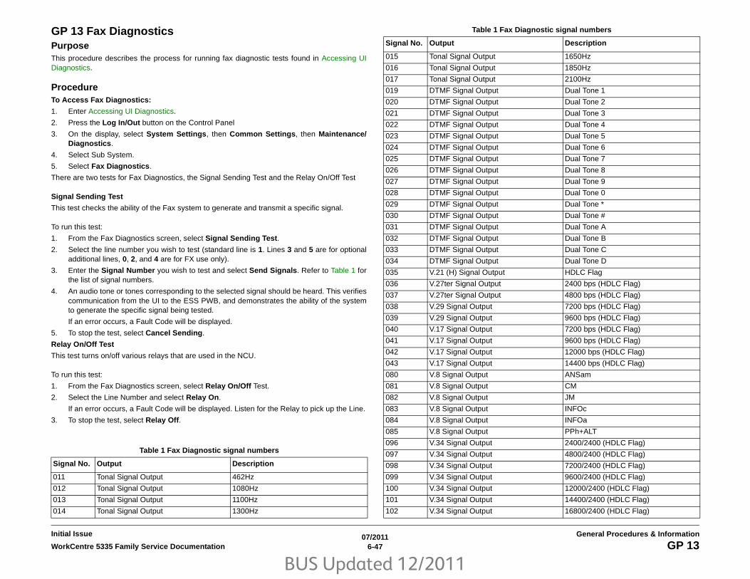
BUS Updated 12/2011
07/20116-47WorkCentre 5335 Family Service Documentation GP 13
General Procedures & InformationInitial Issue
GP 13 Fax DiagnosticsPurposeThis procedure describes the process for running fax diagnostic tests found in Accessing UIDiagnostics.
ProcedureTo Access Fax Diagnostics:
1. Enter Accessing UI Diagnostics.
2. Press the Log In/Out button on the Control Panel
3. On the display, select System Settings, then Common Settings, then Maintenance/Diagnostics.
4. Select Sub System.
5. Select Fax Diagnostics.
There are two tests for Fax Diagnostics, the Signal Sending Test and the Relay On/Off Test
Signal Sending Test
This test checks the ability of the Fax system to generate and transmit a specific signal.
To run this test:
1. From the Fax Diagnostics screen, select Signal Sending Test.
2. Select the line number you wish to test (standard line is 1. Lines 3 and 5 are for optionaladditional lines, 0, 2, and 4 are for FX use only).
3. Enter the Signal Number you wish to test and select Send Signals. Refer to Table 1 forthe list of signal numbers.
4. An audio tone or tones corresponding to the selected signal should be heard. This verifiescommunication from the UI to the ESS PWB, and demonstrates the ability of the systemto generate the specific signal being tested.
If an error occurs, a Fault Code will be displayed.
5. To stop the test, select Cancel Sending.
Relay On/Off Test
This test turns on/off various relays that are used in the NCU.
To run this test:
1. From the Fax Diagnostics screen, select Relay On/Off Test.
2. Select the Line Number and select Relay On.
If an error occurs, a Fault Code will be displayed. Listen for the Relay to pick up the Line.
3. To stop the test, select Relay Off.
Table 1 Fax Diagnostic signal numbers
Signal No. Output Description
011 Tonal Signal Output 462Hz
012 Tonal Signal Output 1080Hz
013 Tonal Signal Output 1100Hz
014 Tonal Signal Output 1300Hz
015 Tonal Signal Output 1650Hz
016 Tonal Signal Output 1850Hz
017 Tonal Signal Output 2100Hz
019 DTMF Signal Output Dual Tone 1
020 DTMF Signal Output Dual Tone 2
021 DTMF Signal Output Dual Tone 3
022 DTMF Signal Output Dual Tone 4
023 DTMF Signal Output Dual Tone 5
024 DTMF Signal Output Dual Tone 6
025 DTMF Signal Output Dual Tone 7
026 DTMF Signal Output Dual Tone 8
027 DTMF Signal Output Dual Tone 9
028 DTMF Signal Output Dual Tone 0
029 DTMF Signal Output Dual Tone *
030 DTMF Signal Output Dual Tone #
031 DTMF Signal Output Dual Tone A
032 DTMF Signal Output Dual Tone B
033 DTMF Signal Output Dual Tone C
034 DTMF Signal Output Dual Tone D
035 V.21 (H) Signal Output HDLC Flag
036 V.27ter Signal Output 2400 bps (HDLC Flag)
037 V.27ter Signal Output 4800 bps (HDLC Flag)
038 V.29 Signal Output 7200 bps (HDLC Flag)
039 V.29 Signal Output 9600 bps (HDLC Flag)
040 V.17 Signal Output 7200 bps (HDLC Flag)
041 V.17 Signal Output 9600 bps (HDLC Flag)
042 V.17 Signal Output 12000 bps (HDLC Flag)
043 V.17 Signal Output 14400 bps (HDLC Flag)
080 V.8 Signal Output ANSam
081 V.8 Signal Output CM
082 V.8 Signal Output JM
083 V.8 Signal Output INFOc
084 V.8 Signal Output INFOa
085 V.8 Signal Output PPh+ALT
096 V.34 Signal Output 2400/2400 (HDLC Flag)
097 V.34 Signal Output 4800/2400 (HDLC Flag)
098 V.34 Signal Output 7200/2400 (HDLC Flag)
099 V.34 Signal Output 9600/2400 (HDLC Flag)
100 V.34 Signal Output 12000/2400 (HDLC Flag)
101 V.34 Signal Output 14400/2400 (HDLC Flag)
102 V.34 Signal Output 16800/2400 (HDLC Flag)
Table 1 Fax Diagnostic signal numbers
Signal No. Output Description

BUS Updated 12/2011
07/20116-48 WorkCentre 5335 Family Service DocumentationGP 13
Initial IssueGeneral Procedures & Information
103 V.34 Signal Output 19200/2400 (HDLC Flag)
104 V.34 Signal Output 21600/2400 (HDLC Flag)
106 V.34 Signal Output 4800/2743 (HDLC Flag)
107 V.34 Signal Output 7200/2743 (HDLC Flag)
108 V.34 Signal Output 9600/2743 (HDLC Flag)
109 V.34 Signal Output 12000/2743 (HDLC Flag)
110 V.34 Signal Output 14400/2743 (HDLC Flag)
111 V.34 Signal Output 16800/2743 (HDLC Flag)
112 V.34 Signal Output 19200/2743 (HDLC Flag)
113 V.34 Signal Output 21600/2743 (HDLC Flag)
114 V.34 Signal Output 24000/2743 (HDLC Flag)
117 V.34 Signal Output 4800/3000 (HDLC Flag)
118 V.34 Signal Output 7200/3000 (HDLC Flag)
119 V.34 Signal Output 9600/3000 (HDLC Flag)
120 V.34 Signal Output 12000/3000 (HDLC Flag)
121 V.34 Signal Output 14400/3000 (HDLC Flag)
122 V.34 Signal Output 16800/3000 (HDLC Flag)
123 V.34 Signal Output 19200/3000 (HDLC Flag)
124 V.34 Signal Output 21600/3000 (HDLC Flag)
125 V.34 Signal Output 24000/3000 (HDLC Flag)
126 V.34 Signal Output 26400/3000 (HDLC Flag)
127 V.34 Signal Output 28800/3000 (HDLC Flag)
129 V.34 Signal Output 4800/3200 (HDLC Flag)
130 V.34 Signal Output 7200/3200 (HDLC Flag)
131 V.34 Signal Output 9600/3200 (HDLC Flag)
132 V.34 Signal Output 12000/3200 (HDLC Flag)
133 V.34 Signal Output 14400/3200 (HDLC Flag)
134 V.34 Signal Output 16800/3200 (HDLC Flag)
135 V.34 Signal Output 19200/3200 (HDLC Flag)
136 V.34 Signal Output 21600/3200 (HDLC Flag)
137 V.34 Signal Output 24000/3200 (HDLC Flag)
138 V.34 Signal Output 26400/3200 (HDLC Flag)
139 V.34 Signal Output 28800/3200 (HDLC Flag)
140 V.34 Signal Output 31200/3200 (HDLC Flag)
142 V.34 Signal Output 4800/3429 (HDLC Flag)
143 V.34 Signal Output 7200/3429 (HDLC Flag)
144 V.34 Signal Output 9600/3429 (HDLC Flag)
145 V.34 Signal Output 12000/3429 (HDLC Flag)
146 V.34 Signal Output 14400/3429 (HDLC Flag)
147 V.34 Signal Output 16800/3429 (HDLC Flag)
148 V.34 Signal Output 19200/3429 (HDLC Flag)
Table 1 Fax Diagnostic signal numbers
Signal No. Output Description
149 V.34 Signal Output 21600/3429 (HDLC Flag)
150 V.34 Signal Output 24000/3429 (HDLC Flag)
151 V.34 Signal Output 26400/3429 (HDLC Flag)
152 V.34 Signal Output 28800/3429 (HDLC Flag)
153 V.34 Signal Output 31200/3429 (HDLC Flag)
154 V.34 Signal Output 33600/3429 (HDLC Flag)
160 DTMF Signal Output Signal Tone 697Hz
161 DTMF Signal Output Signal Tone 770Hz
162 DTMF Signal Output Signal Tone 852Hz
163 DTMF Signal Output Signal Tone 941Hz
164 DTMF Signal Output Signal Tone 1209Hz
165 DTMF Signal Output Signal Tone 1336Hz
166 DTMF Signal Output Signal Tone 1477Hz
167 DTMF Signal Output Signal Tone 1633Hz
Table 1 Fax Diagnostic signal numbers
Signal No. Output Description

BUS Updated 12/2011
07/20116-49WorkCentre 5335 Family Service Documentation GP 14
General Procedures & InformationInitial Issue
GP 14 Special Boot ModesPurposeThis procedure describes methods of recovering from certain unclearable faults.
ProcedureSome boot-up failures, as well as some un-clearable fault codes, may be caused by softwarecorruption, or by structural flaws in a command sent to the machine. In these cases, it is some-times possible to bypass or delete the offending code during the startup process.
CAUTION
There are four special boot modes. Each mode performs a different set of initializations tobypass a specific set of problems. There is information lost in each procedure, thus, theyshould not be used unless specific directions are given. The following list gives these proce-dures, in the order from least-invasive to most-invasive. If you are instructed to perform a spe-cific initialization, perform only that procedure. If you are asked to perform the entire series,perform the steps in the order given, until the problem is resolved.
Job Log Clear Mode
This step will delete any print or copy job that is in process, and then perform a reboot.
To execute: With the machine completely powered off (both the Power Switch and the MainPower Switch in the OFF positions), simultaneously press and hold the 1, the Stop, and theEnergy Saver buttons on the Control Panel, and then switch on the Main Power Switch andthen the Power Switch. Continue to hold down the 1, Stop, and Energy Saver buttons whileswitching on the power. Hold the buttons down until the boot up screen (progress bar) appears.
HDD Initialize Mode
This step will delete all pending print or copy jobs in the IOT job queue, initialize the IOT HDD,and then perform a reboot.
CAUTION
All customer data on the HDD (customer’s files/configuration such as mailboxes, scanned doc-uments, user IDs and account IDs for accounting) will be deleted.
To execute: With the machine completely powered off (both the Power Switch and the MainPower Switch in the OFF positions), simultaneously press and hold the 6, the Stop, and theEnergy Saver buttons on the Control Panel, and then switch on the Main Power Switch andthen the Power Switch. Continue to hold down the 6, Stop, and Energy Saver buttons until theboot up screen (progress bar) appears.
HDD Format Mode
This step will delete all pending print or copy jobs in the IOT job queue, format the IOT HDD,and then perform a reboot.
CAUTION
All customer data on the HDD (customer’s files/configuration such as mailboxes, scanned doc-uments, user IDs and account IDs for accounting) will be deleted.
To execute: With the machine completely powered off (both the Power Switch and the MainPower Switch in the OFF positions), simultaneously press and hold the 4, the Stop, and theEnergy Saver buttons on the Control Panel, and then switch on the Main Power Switch andthen the Power Switch. Continue to hold down the 4, Stop, and Energy Saver buttons until theboot up screen (progress bar) appears.
NVRAM Init Mode
CAUTION
STOP HERE! This portion of the routine will set all IOT ESS NVM values to default. DO NOTexecute this step unless specifically directed to perform this portion.
Do not attempt this part of the procedure unless there is a known-good Machine Settingsfloppy, an accurate Configuration Report and/or other data that will enable you to reload thecorrect NVM values for this machine.
This step will initialize the IOT ESS NVM (SYS-System and SYS-User) and then reboot themachine to the Initialize Wizard. Follow the on-screen instructions when the Initialize Wizarddisplays.
To execute: With the machine completely powered off (both the Power Switch and the MainPower Switch in the OFF positions), simultaneously press and hold the 3, the Stop, and theEnergy Saver buttons on the Control Panel, and then switch on the Main Power Switch andthen the Power Switch. Continue to hold down the 3, Stop, and Energy Saver buttons whileswitching on the power. Hold the buttons down until the boot up screen (progress bar) appears.

BUS Updated 12/2011
07/20116-50 WorkCentre 5335 Family Service DocumentationGP 15
Initial IssueGeneral Procedures & Information
GP 15 Setting Country Code PurposeThis procedure is used to set the Country Code for correct FAX operation.
Procedure1. Enter Tools mode (GP 9).
2. Follow the path, System Settings -> System Settings ->Common Settings -> OtherSettings.
3. Scroll the Other Settings menu to find Country (on page 2; item 14, 15, or 16 dependingon configuration). To change the value:
• Select Change Settings.
• Scroll through the list to select the Country.
• Select Save.
4. Exit Tools mode.

BUS Updated 12/2011
07/20116-51WorkCentre 5335 Family Service Documentation GP 16
General Procedures & InformationInitial Issue
GP 16 Downloading Software from USB Flash DrivePurposeThis procedure provides for the installing/upgrading of system software.
Procedure (Flash Drive)1. Obtain Software
Software is distributed via multiple paths:
• The launch version of software is included in the initial PWS Software Download ToolCD.
• Any upgrades to the Tool will include the then-current version of software
• After launch, software will be available for downloading from www.xerox.com, andfrom GSN library XX -TBD.
• Major software releases are usually announced in a bulletin.
2. Prepare for the upgrade
a. Press the Machine Status button.
b. Machine Information will be displayed.
Record the current software information.
Select Print Reports and print out the Configuration Report or Select Software Ver-sion and record the current software information.
3. Prepare a USB Flash Drive
a. Ensure that the USB device to be used has sufficient free space to contain the filesto be downloaded.
b. Create a new folder in the USB Flash Drive and name it DWLD.
c. Copy the software file(s) obtained in Step 1 (unzip the file and extract the .bin file ifrequired) into the DWLD folder.
4. Start Upgrade
a. Power OFF the machine.
NOTE: if USB Printing is enabled, the USB port on the Control Panel can be used.
b. Insert the USB Flash Drive into the USB connector on the Control Panel (if available)or the ESS PWB Chassis (Figure 1).
The FAX Cable (if present) should remain plugged in during the SW upgrade. Thisenables the FAX software to be upgraded using this procedure.
Figure 1 ESS PWB Connection
5. Start the download
a. Power ON the machine while pressing the Energy Saver button. Hold the buttondown until Download Mode appears.
b. After a while, Transferring will be displayed on the UI and the S/W will start to down-load to the machine (Figure 2). If Transferring is not displayed after 3 minutes, thereis a problem either with the USB Device or with the USB port. Make sure the FlashDrive is plugged in all the way. Repeat the procedure with a different USB device.
Figure 2 Transferring
6. Finish the Download
a. While the download is in progress, Processing X / Y (where X is the module beingloaded, and Y is the total number of modules) is displayed on the UI to show theprogress of the download (Figure 3).
USB Connector
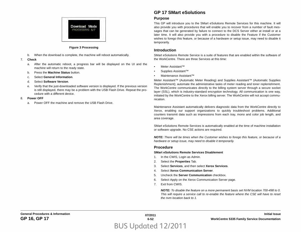
BUS Updated 12/2011
07/20116-52 WorkCentre 5335 Family Service DocumentationGP 16, GP 17
Initial IssueGeneral Procedures & Information
Figure 3 Processing
b. When the download is complete, the machine will reboot automatically.
7. Check
a. After the automatic reboot, a progress bar will be displayed on the UI and themachine will return to the ready state.
b. Press the Machine Status button.
c. Select General Information.
d. Select Software Version.
e. Verify that the just-downloaded software version is displayed. If the previous versionis still displayed, there may be a problem with the USB Flash Drive. Repeat the pro-cedure with a different device.
8. Power OFF
a. Power OFF the machine and remove the USB Flash Drive.
GP 17 SMart eSolutionsPurposeThis GP will introduce you to the SMart eSolutions Remote Services for this machine. It willalso provide you with procedures that will enable you to recover from a number of fault mes-sages that can be generated by failure to connect to the DCS Server either at install or at alater time. It will also provide you with a procedure to disable the Feature if the Customerwishes to forego this feature, or because of a hardware or setup issue, may need to disable ittemporarily.
IntroductionSMart eSolutions Remote Service is a suite of features that are enabled within the software ofthe WorkCentre. There are three Services at this time:
• Meter Assistant™
• Supplies Assistant™
• Maintenance Assistant™
Meter Assistant™ (Automatic Meter Reading) and Supplies Assistant™ (Automatic SuppliesReplenishment); automate the administrative tasks of meter reading and toner replenishment.The WorkCentre communicates directly to the billing system server through a secure socketlayer (SSL), which is industry-standard encryption technology. All communication is one way,initiated by the WorkCentre to the Xerox billing server. The WorkCentre will not accept commu-nication.
Maintenance Assistant automatically delivers diagnostic data from the WorkCentre directly toXerox, enabling our support organizations to quickly troubleshoot problems. Additionalcounters transmit data such as impressions from each tray, mono and color job length, andarea coverage.
SMart eSolutions Remote Services is automatically enabled at the time of machine installationor software upgrade. No CSE actions are required.
NOTE: There will be times when the Customer wishes to forego this feature, or because of ahardware or setup issue, may need to disable it temporarily.
ProcedureSMart eSolutions Remote Services Disablement
1. In the CWIS, Login as Admin.
2. Select the Properties Tab.
3. Select Services, and then select Xerox Services.
4. Select Xerox Communication Server.
5. Uncheck the Server Communication checkbox.
6. Select Apply on the Xerox Communication Server page.
7. Exit from CWIS.
NOTE: To disable the feature on a more permanent basis set NVM location 700-498 to 0.This will require a service call to re-enable the feature where the CSE will have to resetthe nvm location back to 1.

BUS Updated 12/2011
07/20116-53WorkCentre 5335 Family Service Documentation GP 17
General Procedures & InformationInitial Issue
Error Messages and Fault CodesThe Fault Codes may or may not be displayed with the message. Use the procedures undereach fault code / Error Message to fix the problem.
• 016-413 - Communication error with Xerox SMart eSolutions server. Make sure themachine proxy settings are correct.
Procedure
Make sure NVM location 700-498 is set to 1.
– Validate with the System Administrator that their network supports DNS and theyallow network traffic (HTTPS / SSL) to the outside world, initiated from the device.
– A Proxy server may be required for the communication to the outside world depend-ing on the customer network configuration. If that is the case the Proxy Server set-tings must be configured.
1. Have the System Administrator validate the DNS settings and Proxy ServerSettings on CWIS. DNS is in the following location [Properties Tab > Connec-tivity > Protocols > TCP/IP].
2. Proxy Server Settings is in the following location [Properties Tab > Connectiv-ity > Protocols > Proxy Server].
– If either of these are not possible, Smart eSolutions cannot be enabled at this cus-tomer site and must be disabled using the CWIS, refer to GP 17.
• 016-414 - Communication error with Xerox SMart eSolutions server. Check your NetworkSettings.
Procedure
Make sure NVM location 700-498 is set to 1.
1. Have the System Administrator validate the DNS settings and Proxy Server Settingson CWIS. DNS is in the following location [Properties Tab > Connectivity > Proto-cols > TCP/IP].
2. Proxy Server Settings is in the following location [Properties Tab > Connectivity >Protocols > Proxy Server].
• 016-415 - Communication error with Xerox SMart eSolutions server. Communication hastimed out.
Procedure
Make sure NVM location 700-498 is set to 1.
1. The server or the network may be down or too busy.
2. Contact the System Administrator to determine if there is a network problem.
3. If issues persist for an extended period - TBD.
• 016-416 - Communication error with Xerox SMart eSolutions server. An invalid responsehas been detected.
Procedure
Make sure NVM location 700-498 is set to 1.
1. The server or the network may be down or too busy.
2. Contact the System Administrator to determine if there is a network problem.
3. If issues persist for an extended period - TBD.
• 016-417 - Communication error with Xerox SMart eSolutions server. Check your NetworkSettings.
Procedure
1. Have the System Administrator validate the DNS settings and Proxy Server Settingson CWIS. DNS is in the following location: Properties Tab > Connectivity > Proto-cols > TCP/IP.
2. Proxy Server Settings are in the following location: Properties Tab > Connectivity> Protocols > Proxy Server.

BUS Updated 12/2011
07/20116-54 WorkCentre 5335 Family Service DocumentationGP 19
Initial IssueGeneral Procedures & Information
GP 19 Boot SequenceProcedureAssessment on the condition of the parts and the condition of the ESS PWB can be donebased on the ON/OFF states of the 8 LED’s on the ESS PWB. To check the condition of anerror where no Error Code is displayed, check the LED display on the ESS PWB.
As the device that can be connected differs depending on the board, it does not always meanthat diagnostic is possible. In the following table, items that are installed as features aremarked with "O".
Purpose1. Turn the power switch OFF, make sure that the screen display turns OFF, then turn the
main power switch OFF.
2. Unplug the power cord from the outlet.
3. Remove the ESS Cover.
4. Plug in the power cord, turn ON the main power switch, then turn ON the power switch.
CheckCheck the ESS PWB LED ON/OFF states, refer to (Figure 1) and (Table 1) LED Legend.
ESS PWB LED’s 0, 1, 2, 3 are Green; 4, 5, 6, 7 are Yellow.
Figure 1 ESS PWB On/Off LED’s
Table 1 LED legend - O”ON, x: OFF.
0
3
4
7
Table 1 LED Legend
Main Unit Lower
Main Unit Upper
State/Condition Related HW Failure Location/DetailsNormal Diagnostic
Long Boot Diagnostic
Related Fault Code7,6,5,4 3,2,1,0
O,O,O,O O,O,O,O Initial state at Power ON ESS Not all are ON: Failure at power source? Failure at ASSY?
O O
x,x,x,x x,x,x,O Interrupt vector setting com-pleted
ESS ON: ESS Error O O
x,x,x,x x,x,O,x EBC (ROM Controller) initial-ization completed
ESS ON: ESS Error O O
x,x,x,x x,O,x,O D-Cache zero clear ESS ON: ESS Error O O
x,x,x,x x,O,O,O DDR output buffer is enabledSoftware wait processing
ESS ON: ESS Error O O
x,x,x,x O,x,x,x DDR Controller usual initial-ization start
ESS ON: ESS Error O O
O,x,x,x O,x,x,x Recovery processing from CPU OFF start
ESS ON: ESS Error O O
O,O,O,O x,x,x,x DDR initialization has failed RAM Blinking: RAM Error O O
O,O,x,x x,x,x,x Save data check error RAM Blinking: RAM Error O O
x,x,x,x O,x,x,O DDR initialization has com-pleted
RAM ON: RAM Error O O

BUS Updated 12/2011
07/20116-55WorkCentre 5335 Family Service Documentation GP 19
General Procedures & InformationInitial Issue
x,x,x,x O,x,O,x I-Cache/D-Cache is disabled ESS ON: ESS Error O O
x,x,x,x O,x,O,O CPU internal register setting ESS ON: ESS Error O O
O,x,x,O x,x,x,x DDR memory write check RAM ON: RAM Error O O
O,O,O,O x,x,x,x DDR R/W test has failed RAM Blinking: RAM Error O O
x,x,x,x O,O,x,x DDR memory read check & zero clear has completed
RAM ON: RAM Error O O
x,x,x,x O,O,x,O Copy to memory for Panbug program (TEXT portion)
ROM/RAM ON: ROM/RAM Error O O
x,x,x,x O,O,O,x Copy to memory for Panbug program (BASE portion)
ROM/RAM ON: ROM/RAM Error O O
x,x,x,x O,O,O,O FPU register test has com-pleted
ESS ON: ESS Error O O
x,x,x,O x,x,x,x Jump preparation to C-Code has completed
ESS ON: ESS Error O O
x,x,O,x x,O,x,x Standard RAM diagnostic start
RAM ON: Standard RAM Error O O 116-315
x,x,O,x x,O,O,x Extension RAM diagnostic start
RAM ON: Extension RAM Error O 116-316
x,x,O,x O,x,x,x Standard ROM diagnostic start
ROM ON: Standard ROM Error O O 116-317
x,x,O,x O,x,O,x NVRAM diagnostic start NVM/ESS ON: NVRAM Error O O 116-323
x,x,O,O x,x,x,x Transition from MiniOS to CORE (DIAG) start
ROM/RAM ON: ROM/RAM Error O O 116-317
O,O,x,x x,x,O,x UI Cable Disconnect Detec-tion
UI/ESS ON: UI Cable Connection Error O O 016-326
O,O,x,x x,x,O,O MCU Harness Disconnect Detection
MCU/ESS ON: MCU Harness Connection Error O O 016-328
x,O,x,x x,x,x,x IO ASIC diagnostic start ESS ON: ASIC Error O O
x,O,x,x x,x,O,x Codec ASIC diagnostic start ESS ON: ASIC Error O O
x,O,x,x x,O,x,x Standard FontROM diagnos-tic start
ROM ON: ASIC Error O O 116-380
x,O,x,x x,O,O,x Extension FontROM diag-nostic start
ROM ON: ASIC Error O O 016-341
x,O,x,x O,x,x,x SEEP diagnostic start EEPROM ON: EEPROM Error O 016-351 016-350
x,O,x,x O,x,O,x Timer diagnostic start ESS ON: Timer Error O O 116-364
x,O,x,x O,O,x,x PageMemory diagnostic start RAM ON: RAM Error O 016-347
x,O,x,x O,O,O,x IITIF diagnostic start IPS/ESS ON: IIT/ESS Error O 016-315 016-316 016-317 016-318
Table 1 LED Legend
Main Unit Lower
Main Unit Upper
State/Condition Related HW Failure Location/DetailsNormal Diagnostic
Long Boot Diagnostic
Related Fault Code7,6,5,4 3,2,1,0

BUS Updated 12/2011
07/20116-56 WorkCentre 5335 Family Service DocumentationGP 19
Initial IssueGeneral Procedures & Information
x,O,x,O x,x,O,x RTC diagnostic start RTC ON: RTC Error O
x,O,x,O O,x,x,x USB 1.0 Host diagnostic start ESS ON: ESS Error O 016-371
x,O,x,O O,x,O,x USB 2.0 Host diagnostic start ESS ON: ESS Error O 016-364
x,O,x,O O,O,x,x USB 2.0 Device diagnostic start
ESS ON: ESS Error O 016-365
x,O,x,O O,O,O,x HDD diagnostic start HDD/ESS ON: HDD/ESS Error O 016-366 016-367
x,O,O,x x,x,x,x HDD(UFS) diagnostic start HDD ON: HDD/ESS Error O 016-372
x,O,x,O x,O,x,x UI Check start UI/ESS ON: ESS/UI Error O 016-362
O,O,O,O O,O,O,O VxWORKS boot completeUsual operation, recovery from Energy Saver state
System In Usual Operating State O O
Table 1 LED Legend
Main Unit Lower
Main Unit Upper
State/Condition Related HW Failure Location/DetailsNormal Diagnostic
Long Boot Diagnostic
Related Fault Code7,6,5,4 3,2,1,0
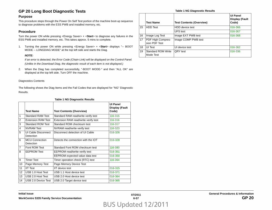
BUS Updated 12/2011
07/20116-57WorkCentre 5335 Family Service Documentation GP 20
General Procedures & InformationInitial Issue
GP 20 Long Boot Diagnostic TestsPurposeThis procedure steps through the Power On Self Test portion of the machine boot-up sequenceto diagnose problems with the ESS PWB and installed memory, etc.
ProcedureTurn the power ON while pressing <Energy Saver> + <Start> to diagnose any failures in theESS PWB and installed memory, etc. This takes approx. 5 mins to complete.
1. Turning the power ON while pressing <Energy Saver> + <Start> displays "-- BOOTMODE -- LONGDIAG MODE" at the top left side and starts the Diag.
NOTE:
If an error is detected, the Error Code (Chain-Link) will be displayed on the Control Panel.
(Unlike in the Download Diag, the diagnostic result of each item is not displayed.)
2. When the Diag has completed successfully, "-BOOT MODE-" and then "ALL OK" aredisplayed at the top left side. Turn OFF the machine.
Diagnostics Contents
The following shows the Diag Items and the Fail Codes that are displayed for "NG" Diagnostic
Results.
Table 1 NG Diagnostic Results
Test Name Test Contents (Overview)
UI Panel Display (Fault Code)
1 Standard RAM Test Standard RAM read/write verify test 116-315
2 Extension RAM Test Extension RAM read/write verify test 116-316
3 Standard ROM Test Standard ROM checksum test 116-317
4 NVRAM Test NVRAM read/write verify test 116-323
5 UI Cable Disconnect Detection
Disconnect detection of UI Cable 016-326
6 MCU Connection Detection
Detects the connection with the IOT 016-328
7 Font ROM Test Standard Font ROM checksum test 116-380
8 EEPROM Test EEPROM read/write verify test 016-351
EEPROM expected value data test 016-350
9 Timer Test Timer operation check (RTC) test 116-364
10 Page Memory Test Page Memory Device Test
11 IIT Test IIT device test 016-315
12 USB 1.0 Host Test USB 1.1 Host device test 016-371
13 USB 2.0 Host Test USB 2.0 Host device test 016-364
14 USB 2.0 Device Test USB 2.0 Target device test 016-365
15 HDD Test HDD device test 016-366
UFS test 016-367
16 Image Log Test Image EXT PWB test 016-368
17 PDF High Compres-sion PDF Test
Image COMP PWB test
18 UI Test UI device test 016-362
19 Standard ROM Write Mode Test
QRY test 016-336
Table 1 NG Diagnostic Results
Test Name Test Contents (Overview)
UI Panel Display (Fault Code)

BUS Updated 12/2011
07/20116-58 WorkCentre 5335 Family Service DocumentationGP 21
Initial IssueGeneral Procedures & Information
GP 21 Common Access Card ServicingDescriptionThe Xerox Common Access Card & Personal Identity Verification ID System is an embeddedauthentication solution. It supports Common Access Cards (CAC) cards issued to Departmentof Defense (DoD) personnel. These types of smart cards store identity information in the formof Personal Identification Numbers and of digitally encrypted certificates. These are used for idauthentication and authorization in order to gain access to work areas, computers, networks,and peripheral devices.
The Xerox CAC Enablement software supports a number of card readers and allows users toauthenticate at the device. The card reader is connected to a USB port on the WorkCentre.
Supported Card TypesThe CAC solution is compatible with most common CAC card types listed below. Other cardtypes may function with the CAC/PIV ID system but they have not been validated.
• Axalto Pegasus 64K / V2
• Axalto Cyberflex 32K / V1
• Axalto Cyberflex 64K / V2
• Gemplus GemXpresso 64K / V2
• Oberthur 72K / V2
• Oberthur CosmopoIIC 32K / V1
• Oberthur D1 72K / V2 (contact-less and PIV)
Supported Card ReadersThe following card readers are compatible with the CAC ID system:
• Gemplus GemPC USB SL
• Gemplus GemPC Twin
• SCM Micro SCR3310
• Panasonic ZU 9PS
Other USB CCID compliant readers may function with the CAC ID system, but have not beenvalidated.
PrerequisitesUSB Enablement Kit (software option).
The customer has the option of either supplying a compatible card reader for each MFP, or pur-chasing the Card Reader from Xerox.
Installation The customer is responsible for installation of the hardware and the enablement kit software(unless they have purchased Analyst services).
Service
NOTE: Xerox does not provide any on-site or remote repair or replacement of CAC compatibleCards or Card readers unless Xerox Service supplies the Card Reader. The card reader ismanufactured by SCM Microsystems, model SCR3310, and can be identified by the Xerox p/n(960K59280) on the underside of the device.
Only readers with the Xerox part number affixed are to be replaced by Xerox Service.
Service for CAC hardware is limited to verifying correct operation:
• CSE should check the following NVM values:
– Location 850-009 should be set to 0
– Location 700-379 should be set to 0101.
• Check out the machine in the service mode to insure no faults are displayed and that theWorkCentre is functioning correctly in diagnostic mode.
• If working properly, return the machine to customer user mode and have a user attempt touse their card to gain access to the machine features.
If the card functions properly, the CSE’s responsibilities have been met.
If the CAC System Fails
Check for any UI displayed messages that might indicate a card failure or card reader failure.Other messages might indicate authorization issues with the customer’s card.
Suggest that the user try their card in another device. If the card works in another device, sug-gest that they alert their on-site supervisor to try another card reader on the failed device orcheck for network connectivity to the failed device. For Xerox-supplied Card Readers, the CSEwill replace the faulty Card Reader..
Suggest that another user try their card on the device where the original card failed. If the sec-ond card works, suggest that the user’s card has failed.
Servicing non-CAC problems.
Diagnostic Tools
Diagnostics can be accessed as usual when the Common Access Card & Personal IdentityVerification ID System is installed.
Customer Tools
If the Machine Status pathway has been locked, the Tools will only be available to the user whohas either logged in as a System Admin or has logged in and Authenticated to the machineusing their Common Access Card and the correct password for that card.
CAC Feature Principles of Operation The following steps represent an authentication process.
1. The WorkCentre’s control panel will prompt the user to insert their card in the attachedreader.
2. Once a card is inserted the user will be prompted to enter their PIN.
3. The PIN is validated against the card, and if they match, this will unlock the card so thePrivate Certificate Key may be used.

BUS Updated 12/2011
07/20116-59WorkCentre 5335 Family Service Documentation GP 21
General Procedures & InformationInitial Issue
4. The user’s digital Certificate is read from the card.
Steps to validate the Chain of Trust
5. The WorkCentre may be configured to validate the Domain Controller (DC) certificate. Ifso it submits the DC Certificate and any associated Trusted Root Certificates, to theOnline Certificate Status Protocol (OCSP) Responder, to verify that the Domain Controllercertificate is valid and not revoked.
6. The system receives a response from the OCSP responder stating whether the certificateis valid and has not been revoked.
Authenticating with the Domain Controller
7. The system calls the Domain Controller using the PKINIT protocol to validate the CACuser’s Certificate.
8. The Domain Controller (Kerberos) returns an encrypted challenge.
9. The WorkCentre decrypts the challenge using the private key from the Domain ControllerCertificate that was downloaded on the WorkCentre. The Domain Controller then pro-vides a decrypted session key that the machine uses to decode subsequent communica-tion with the DC.
10. The CAC User’s Identity certificate is passed to the Domain Controller for Authorization.
11. If successful, the Domain Controller returns a Ticket Granting Ticket (TGT). Authenticationis complete and Authorization begins.
12. At this point authorization is complete and the authorized services such as (scan to e-mail, copy & fax) are now available.
13. The E-mail address is retrieved from the Signing Certificate and is available for inclusionin the From: field whenever the E-mail Service is selected.
14. The session is terminated when the card is removed from the reader, or the administratorsettable timeout expires.
CAC Feature Limitations:
• The CAC solution requires the Scan option to be installed.
• When CAC authentication is enabled on the device the Copy Feature is locked by defaultand can only be accessed once the user has successfully authenticated.
Possible Fault Codes That May Be Observed• 021-210:USB Card Reader connection error.
• 021-211:USB Card Reader broken.
• 021-212:USB Card Reader couldn’t start.
• 018-725:Users Kerberos password has expired. Please ask system administrator of KDCto extend password expiration date or change password.
• 018-726:Not all of Certificate Authority certificate(s) of the CAC Root and Intermediatecertificates are registered in device.
• 018-727:Check that CAC certificate is valid, or that the CAC user is registered on the con-figured Domain Controllers.
• 018-728:Check that the Domain Controller Certificate is invalid.
• 016-533:Domain Controller server clock-skew error. Enable NTP.
• 016-534:Could not connect with the configured Domain Controller realm.
• 016-539:Fatal error on the Domain Controller.
• 016-231:A fault or an error has occurred with the CAC Card Reader.

BUS Updated 12/2011
07/20116-60 WorkCentre 5335 Family Service DocumentationGP 21
Initial IssueGeneral Procedures & Information

BUS Updated 12/2011
07/20116-61WorkCentre 5335 Family Service Documentation Space Requirements, Product Specs.
General Procedures & InformationInitial Issue
Space RequirementsBasic Model : Installation Space (W x D): 1216 x 1582mm (47.9 x 63.2 inches) (Figure 1)
Figure 1 Base Model
With Office Finsher LX: Installation Space (W x D): 1695 x 1582mm (70.3 x 62.3 inches) (Fig-ure 2 )
Figure 2 w/ LX Finisher
Product Specs.Power RequirementsSingle Phase (2 conductors + ground wire)
Table 1 Voltage Requirements
RegionPower Voltage, VAC
Power Frequency, Hz Power Rating
ESG (XE)
220-240 VAC(-10%, +10%)
50 +/- 3% 10 AMP
USSG, XCL (XC)
110-127 VAC(-10%, +10%)
60 Hz +/- 3% 15 AMP
Table 2 Power Consumption
Condition WC5325 WC5330 WC5335
Running (avg.) 699W (115V)724W (220V)
721W (115V)742W (220V)
744W (115V)783W (220V)
Standby 127W (115V)122W (220V)
112W (115V)111W (220V)
115W (115V)118W (220V)
Low Power mode 89W (115V)87W (220V)
89W (115V)87W (220V)
89W (115V)87W (220V)
Sleep mode 1.3W (115V)1.8W (220V)
1.3W (115V)1.8W (220V)
1.3W (115V)1.8W (220V)

BUS Updated 12/2011
07/20116-62 WorkCentre 5335 Family Service DocumentationProduct Specs.
Initial IssueGeneral Procedures & Information
Product Codes Paper Capacities
Copy Speed(1 original on platen; plain paper; simplex; fed from Tray 1( WC5325/WC5330/WC5335))
• 8.5 x 11”/A4: 25 ppm/30 ppm/35 ppm
• 11 x17”/A3: 14 ppm/16 ppm/17 ppm
FCOT/FPOTMaximum First Copy Out Time: original on platen; 8.5” x 11” (A4); Tray 1 to Exit 1; 100%
• 4.2 sec. WC5325/5330
• 4.0 sec. WC5335
First Print Output Time (does not include ESS process time for prints); PCL6, 8.5” x 11” (A4);Tray 1 to center tray;
• 11 sec.
Environmental Data and RequirementsAmbient Temperature and Humidity requirement:
• Minimum: 10º C / 50ºF at 15% humidity
• Maximum: 28º C / 82ºF at 85% humidity
IIT/DADF Specifications
Table 3 Product Codes
Item Product Code
IOT/IIT/DADF/STAND - WH - 120VTwo 520 sheet trays, 50 sheet Bypass Tray, Automatic Duplex, Exit 1 w/ OCT, Exit 2 w/o OCT, Exit 2 Inner Tray, US standard 120v Power Cord, In-box Neutral Toner Cartridge, Drum Car-tridge - installed, Data Security & HDD, IN-BOX Regional Kit
AE7
IOT/IIT/DADF/STAND - WH - 120V GSATwo 520 sheet trays, 50 sheet Bypass Tray, Automatic Duplex, Exit 1 w/ OCT, Exit 2 w/o OCT, Exit 2 Inner Tray, US standard 120v Power Cord, In-box Neutral Toner Cartridge, Drum Car-tridge - installed Data Security & HDD, IN-BOX Regional Kit
AE7N
IOT/IIT/DADF/STAND - EH - 220VTwo 520 sheet trays, 50 sheet Bypass Tray, Automatic Duplex, Exit 1 w/ OCT, Exit 2 w/o OCT, Exit 2 Inner Tray, EU standard 220v Power Cord, In-box Neutral Toner Cartridge, Drum Car-tridge - installed, Data Security & HDD, IN-BOX Regional Kit )
AE8
IOT/IIT/DADF/TTM - WH - 120V Two 520 sheet trays, 2000 sheet (Ltr/A4) Tandem Tray Mod-ule, 50 sheet Bypass Tray, Automatic Duplex, Exit 1 w/ OCT, Exit 2 w/o OCT, Exit 2 Inner Tray, US standard 120v Power Cord, In-box Neutral Toner Cartridge, Drum Cartridge - installed, Data Security & HDD, IN-BOX Regional Kit
AE9
IOT/IIT/DADF/TTM - WH - 120V GSATwo 520 sheet trays, 2000 sheet (Ltr/A4) Tandem Tray Module, 50 sheet Bypass Tray, Automatic Duplex, Exit 1 w/ OCT, Exit 2 w/o OCT, Exit 2 Inner Tray, US standard 120v Power Cord, In-box Neutral Toner Cartridge, Drum Cartridge - installed, Data Security & HDD, IN-BOX Regional Kit
AE9N
IOT/IIT/DADF/TTM - EH - 220V(Two 520 sheet trays, 2000 sheet (Ltr/A4) Tandem Tray Module 50 sheet Bypass Tray, Automatic Duplex, Exit 1 w/ OCT, Exit 2 w/o OCT, Exit 2 Inner Tray, EU standard 220v Power Cord, In-box Neutral Toner Cartridge, Drum Cartridge - installed, Data Security & HDD, IN-BOX Regional Kit )
XMK
Integrated Office Finisher XDE
Office Finisher LX XLN
Table 4 Paper Capacities
Specification Paper Trays 1 - 4 Tray 5 (MSI)
Paper Sizes Standard Sizes
• Min.: 5.5 x 8.5” SEF/A5 SEF (148 x 210 mm)
• Max: A3 SEF/11 x 17” SEF
Custom Sizes
• Min.: 139.7 x 182 mm
• Max: 297 x 431.8 mm
Paper
• Min.: 100 x 140 mm (post-card)
• Max: A3 SEF/11 x 17” SEF
Envelopes
• Min.: 98 x 148 mm
• Max: 162 x 241 mm
Paper Weights Range: 60 - 256 gsm Range: 60-216 gsm
Capacities 20 lb. (80 gsm)
2080 sheets total:
• Trays 1 - 4: 520 sheets
Paper
• 50 sheets
Transparencies
• 70 sheets
Envelopes
• 10
Table 5 DADF Specifications
Document Size: Platen Max size: 334 x 452 mmMax scannable area: 297 x 432 mm
Document Size: DADF 5.5” x 8.5” to 11” x 17” (A3)Max: 297 x 432 mmMin.: 125 x 85 mm simplex; 125 x 110 duplex

BUS Updated 12/2011
07/20116-63WorkCentre 5335 Family Service Documentation Product Specs., Common Tools
General Procedures & InformationInitial Issue
Common ToolsDocument Weight: DADF Min:16lb (38gsm)
Max: 32lb (128 gsm)
Document Capacity: DADF 110 sheets 80 gsm
R/E Capability: Variable Percentages: 25% to 400% in 1% incrementsPresets can be changed in Admin mode
Table 5 DADF Specifications
Table 1 Common Tools
Description Part Number
Screw Driver (-) 3 x 50 600T40205
Screw Driver (+) 6 x 100 600T1989
Screw Driver (+) NO.1 499T356
Stubby Driver (+) (-) 600T40210
Screw Driver (=) 100MM 499T355
Spanner and Wrench 5.5 x 5.5 600T40501
Spanner and Wrench 7x 7 600T40502
Hex Key Set 600T02002
Box Driver 5.5MM 600T1988
Box Driver 1/4 inch
Side Cutting Nipper 600T40903
Round Nose Pliers 600T40901
Digital Multi-meter Set 600T2020
Interlock Cheater 600T91616
Silver Scale 150MM 600T41503
CE Tool Case 600T1901
Magnetic Screw Pick-up Tool 600T41911
Scribe Tool 600T41913
Magnetic pickup 600T41911
Eye Loop 600T42008
Flash Light 600T1824
Brush 600T41901
Tester Lead Wire (red) 600T 9583
Tester Lead Wire (black) 600T2030

BUS Updated 12/2011
07/20116-64 WorkCentre 5335 Family Service DocumentationProduct Tools and Test Patterns, Cleaning Materials
Initial IssueGeneral Procedures & Information
Product Tools and Test Patterns Cleaning Materials
Table 1 Tools and Test Patterns
Description Part Number
A3 (11" x 17") Test Pattern 082E02000
A3 Standard Test Pattern 082P521
A4 Test Pattern 082E2010
8.5" x 11" Test Pattern 082E2020
8.5" x 14" Test Pattern 082P524
SIR 542.00 Solid Area Density Scale 082E08230
SIR 494.00 Visual Scale 082P00448
HVPS test probe (1/10X) 600T1653
HVPS test probe adapter 600T1996
Copy Paper Carrying Case 600T1999
Copy Paper Zip Lock Bag 600T2000
Xerox Color Xpressions Plus 24# 11×17 in, 3R5465
Colortech Plus - 90 gsm - A3 3R94642
Service and Machine NVM Log 700P97436
Serial Cable 600T2058
USB Cable 600T02231
Null Modem Adapter (female/female) 113E40060
PWS power cord adapter 600T2018
Micro Probe Kit 600T02177
Table 1 Cleaning Materials
DescriptionUSSG Part Number
XE Part Number
Cleaning fluid (8oz., Formula A)
43P48 8R90034
Film remover (8 oz.) 43P45 8R90176
Lens/mirror cleaner 43P81 8R90178
Lint-free (white) cleaning cloth 19P3025 19P3025
Lint-free Optics cleaning cloth 499T90417 499T90417
Cleaning towels 35P3191 600S4372
Drop cloth 35P1737 35P1737
Cotton Swab 35P2162 35P2162

BUS Updated 12/2011
07/20116-65WorkCentre 5335 Family Service Documentation CRUs and Consumables, Glossary of Terms
General Procedures & InformationInitial Issue
CRUs and Consumables Glossary of Terms
Table 1 CRUs and Consumables
Name Part Number Comments
Black Toner Cartridge 006R01158 metered (worldwide)
006R01159 US/XCL/XE sold
006R01160 DMO sold
Black Drum Cartridge 013R00591
Staple Refills - Convenience Stapler 008R12941 3 refills/carton
Staple Refills - Integrated Office Finisher 008R12941 3 refills/carton
Staple Refills - Office Finisher LX 008R12941 3 refills/carton
Staple Cartridge - Convenience Stapler 008R12964 1 cartridge
Staple Cartridge - Office Finisher LX 008R12964 1 cartridge
Staple Cartridge - Office Finisher LX Booklet Maker
008R12897 8 cartridges/carton
Table 1 Glossary
Term Description
A3 Paper size 297 millimeters (11.69 inches) x 420 millimeters (16.54 inches).
A4 Paper size 210 millimeters (8.27 inches) x 297 millimeters (11.69 inches).
AC Alternating Current is type of current available at power source for machine.
A/D Analog to Digital refers to conversion of signal
ADC Automatic Density Control
ADJ Adjustment Procedure
AGC Automatic Gain Control
A/P Advanced/Professional (Finishers)
ApeosWare Authentica-tion
connected to external authentication server, Active Directory, does the authentication of your devices, be it a multifunction or a network printer. Changes in Active Directory are automatically reflected in Authentication Agent. Usage restriction can be set on copy, print, scan, fax, color or mono-chrome by user and by user group.
APS Auto Paper Select - The machine selects a suitable size of copy paper auto-matically based on the detected original size and the reproduction ratio you select.
ATC Automatic Toner Concentration
ATS Auto Tray Switch - The machine will automatically select a usable tray that has paper when the one presently in use becomes empty. This feature only works when the Auto Tray Switch is selected and the paper size being used is the same for all usable paper trays.
Attestation Agent
Remote attestation provides the basis for one platform toestablish trusts on another.
ASIC Application-Specific Integrated Circuit (ASIC) is an integrated circuit (IC) customized for a particular use, rather than intended for general-purpose use.
Bit Binary digit, either 1 or 0, representing an electrical state.
BMLinks stands for Business Machine Linkage Service. BMLinkS is a specification developed with participation of major Office Automation appliance vendors in Japan. With BMLinkS, it now becomes possible to create multi-vendor systems where Office Automation appliances are simple and easy to use on networks.
BSD Block Schematic Diagram
BTR Bias Transfer Roll
BUR Back up Roll
CA Certificate Authority or Certification Authority - an entity that issues digital certificates for use by other parties.
CCD Charge Coupled Device (Photoelectric Converter)
CD 1:Circuit Diagram; 2: Compact Disc
CDUP Use the CDUP subcommand to change the working directory to the parent directory on the foreign host.
Chip Integrated Circuit (IC)

BUS Updated 12/2011
07/20116-66 WorkCentre 5335 Family Service DocumentationGlossary of Terms
Initial IssueGeneral Procedures & Information
CPLD Complex Programmable Logic Device - a programmable logic device with complexity between that of PALs and FPGAs, and architectural features of both. The building block of a CPLD is the macro cell, which contains logic implementing disjunctive normal form expressions and more specialized logic operations.
CRU Customer Replaceable Unit
CRUM Customer Replaceable Unit Memory
CYMK Toner colors for machine; Y=yellow, C=cyan, M=magenta, and K=black
DADF Duplexing Automatic Document Feeder
DC Direct Current is type of power for machine components. Machine converts AC power from power source to DC power.
DIMM Dual In-line Memory Module - a series of dynamic random access memory integrated circuits.
DLD Download Direct Method - Down Load Direct (DLD) was developed to accelerate downloads
DMA Direct memory access (DMA) is a feature of modern computers and micro-processors that allows certain hardware subsystems within the computer to access system memory for reading and/or writing independently of the cen-tral processing unit.
DMM Digital Multimeter is generic name for meter that measures voltage, current, or electrical resistance.
DNS Domain Name System - a hierarchical naming system for computers, ser-vices, or any resource connected to the Internet or a private network. It associates various information with domain names assigned to each of the participants. Most importantly, it translates domain names meaningful to humans into the numerical (binary) identifiers associated with networking equipment for the purpose of locating and addressing these devices world-wide.
DTMF Dual-Tone Multi-Frequency signaling - is used for telecommunication sig-naling over analog telephone lines in the voice-frequency band between telephone handsets and other communications devices and the switching center.
Duplex 2-sided printing or copying
EA Emulsion Aggregation (toner)
EEPROM Electrically Erasable Programmable Read-Only Memory - a type of non-vol-atile memory used in computers and other electronic devices to store small amounts of data that must be saved when power is removed, e.g., calibra-tion tables or device configuration.
EME Electromagnetic Emissions are emitted from machine during normal opera-tion and power of these emissions are reduced by machine design features.
ESD Electrostatic Discharge. A transfer of charge between bodies at different electrostatic potential.
ESG European Solutions Group - also referred to as XE (Xerox Europe)
FE Field Engineer
Table 1 Glossary
Term Description
FIFO First In, First Out - an abstraction in ways of organizing and manipulation of data relative to time and prioritization. This expression describes the princi-ple of a queue processing technique or servicing conflicting demands by ordering process by first-come, first-served (FCFS) behaviour: what comes in first is handled first, what comes in next waits until the first is finished, etc.
FoIP FAX Over Internet Protocol
FPGA Field-Programmable Gate Array - an integrated circuit designed to be con-figured by the customer or designer after manufacturing
FS Fast Scan (direction) - LE - to - TE
FTP File Transfer Protocol - a standard network protocol used to exchange and manipulate files over a TCP/IP-based network, such as the Internet.
GND Ground
HCF High Capacity Feeder
HDD Hard Disk Drive
HFSI High Frequency Service Item
HGEA High Grade Emulsion Aggregation (toner)
HVPS High Voltage Power Supply
Hz Hertz (Cycles per second)
IBT Intermediate Belt Transfer
I/F Interface
IIO Intermediate Image Overwrite
IIT Image Input Terminal - the Scanner/CCD portion of the machine
IPSEC Internet Protocol Security - a protocol suite for securing Internet Protocol (IP) communications by authenticating and encrypting each IP packet of a data stream. IPsec also includes protocols for establishing mutual authenti-cation between agents at the beginning of the session and negotiation of cryptographic keys to be used during the session.
IOT Image Output Terminal - the ROS/Xero/paper handling/ fusing portion of the machine
IM Image Management Software - Windows and Macintosh software for view-ing, organizing, cataloging, managing, browsing, storing, sharing, and print-ing images.
IPS Image Processing Subsystem
IQ Image Quality
JBA Job-based Accounting
JBIG Joint Bi-level Image Experts Group - JBIG was designed for compression of binary images, particularly for faxes, but can also be used on other images.
KC 1000 copies
Kerberos a computer network authentication protocol, which allows nodes communi-cating over a non-secure network to prove their identity to one another in a secure manner.
LCD Liquid Crystal Display
Table 1 Glossary
Term Description

BUS Updated 12/2011
07/20116-67WorkCentre 5335 Family Service Documentation Glossary of Terms
General Procedures & InformationInitial Issue
LDAP Lightweight Directory Access Protocol - an application protocol for querying and modifying directory services running over TCP/IP
LE Lead Edge of copy or print paper, with reference to definition of term TE
LED Light Emitting Diode
LEF Long Edge Feed
LTR Letter size paper (8.5 x 11 inches)
LocalTalk a particular implementation of the physical layer of the AppleTalk network-ing system from Apple Computer. LocalTalk specifies a system of shielded twisted pair cabling, plugged into self-terminating transceivers, running at a rate of 230.4 kbit/s.
LUT Look Up Table - array of NVM locations that store process control data
LVPS Low Voltage Power Supply
MIME Multipurpose Internet Mail Extensions - an Internet standard that extends the format of e-mail to support:Text in character sets other than ASCII Non-text attachments Message bodies with multiple parts Header information in non-ASCII character sets
MCU Machine Control Unit - a microcontroller (also microcomputer, MCU or µC) is a small computer on a single integrated circuit consisting internally of a relatively simple CPU, clock, timers, I/O ports, and memory.
MF Multi-Function
MN Multinational
MOB Marks On Belt> MOB Sensor is used to determine Color Registration
MRD Machine Resident Disk
MSI Multi Sheet Inserter
NAK Negative Acknowledgement - negative acknowledgment or not acknowl-edged. It is a signal used in digital communications to ensure that data is received with a minimum of errors.
NIC Network Interface Card
NVM Non Volatile Memory
OCT Offsetting Catch Tray
OEM Original equipment manufacturer
OGM On-going Maintenance
PC Personal Computer
PCI Peripheral Component Interconnect - a computer bus for attaching hard-ware devices in a computer. These devices can take either the form of an integrated circuit fitted onto the motherboard itself, called a planar device in the PCI specification, or an expansion card that fits into a slot.
PDL Page Description Language - a language that describes the appearance of a printed page in a higher level than an actual output bitmap.
PIO Programmed Input/Output - a method of transferring data between the CPU and a peripheral such as a network adapter or an ATA storage device.
Table 1 Glossary
Term Description
PJL Printer Job Language - a method developed by Hewlett-Packard for switch-ing printer languages at the job level, and for status readback between the printer and the host computer.
PL Parts List
P/O Part of (Assembly Name)
POP Server Post Office Protocol - Version 3 (POP3) is intended to permit a workstation to dynamically access a maildrop on a server host in a useful fashion. Usu-ally, this means that the POP3 protocol is used to allow a workstation to retrieve mail that the server is holding for it.
PWB Printed Wiring Board
PWS Portable Workstation for Service
PJ Plug Jack (electrical connections)
Proxy Server a server (a computer system or an application program) that acts as an intermediary for requests from clients seeking resources from other servers.
RAM Random Access Memory
RAP Repair Analysis Procedure for diagnosis of machine status codes and abnormal conditions
R/E Reduction/Enlargement refers to features selection or components that enable reduction or enlargement
Redirector an operating system driver that sends data to and receives data from a remote device. A network redirector provides mechanisms to locate, open, read, write, and delete files and submit print jobs.
RegiCon Registration Control
REP Repair Procedure for disassembly and reassembly of component on machine
RIS Raster Input Scanner
ROM Read Only Memory
SAD Solid Area Density
SCP Service Call Procedure
SEF Short Edge Feed
Self-test An automatic process that is used to check Control Logic circuitry. Any fault that is detected during self-test is displayed by fault code or by LEDs on PWB.
SIMM Single Inline Memory Module used to increase printing capacity
Simplex Single sided copies
SIP Session Initiation Protocol - a signaling protocol, widely used for controlling multimedia communication sessions such as voice and video calls over Internet Protocol (IP).
S/MIME Secure/Multipurpose Internet Mail Extensions - a standard for public key encryption and signing of MIME data.
Software Key a small program that will generate valid CD keys or serial/registration num-bers for a piece of software.
SSL Secure Socket Layer - cryptographic protocols that provide security for communications over networks such as the Internet
Table 1 Glossary
Term Description

BUS Updated 12/2011
07/20116-68 WorkCentre 5335 Family Service DocumentationGlossary of Terms
Initial IssueGeneral Procedures & Information
SMB Server Message Block - operates as an application-layer network proto-col[1] mainly used to provide shared access to files, printers, serial ports, and miscellaneous communications between nodes on a network.
SMTP Simple Mail Transfer Protocol - an Internet standard for electronic mail (e-mail) transmission across Internet Protocol (IP) networks.
SSL Secure Sockets Layer - are cryptographic protocols that provide security for communications over networks such as the Internet.
TE Trail Edge of copy or print paper, with reference to definition of term LE
TMA Toner Mass/unit Area detection. The combined function of the MOB/ADC Sensors.
TRC Tone Reproduction Curve
UM Unscheduled Maintenance
UI User Interface
USB Universal Serial Bus
W/ With - indicates machine condition where specified condition is present
WebDAV Web-based Distributed Authoring and Versioning - a set of extensions to the Hypertext Transfer Protocol (HTTP) that allows computer-users to edit and manage files collaboratively on remote World Wide Web servers. RFC 4918 defines the extensions.
W/O Without - indicates machine condition where specified condition is not present
XBRA Xerox Brazil
XE Xerox Europe - also referred to as ESG (European Solutions Group)
XEIP Xerox Extensible Interface Platform (EIP). Xerox EIP is a software platform upon which developers can use standard web-based tools to create server-based applications that can be configured for the MFP’s touch-screen user interface.
XLA Xerox Latin America
YCMK Toner colors for machine; Y=yellow, C=cyan, M=magenta, and K=black
XMEX Xerox Mexico
Table 1 Glossary
Term Description

BUS Updated 12/2011
07/20116-69WorkCentre 5335 Family Service Documentation
General Procedures & InformationInitial Issue
Change TagsChange Tag IntroductionImportant modifications to the copier are identified by a tag number which is recorded on a tagmatrix:
• The tag matrix for the IOT is molded into the inside of the Front Door.
• The tag matrix for the Finisher is a label affixed to the inside of the Finisher Front Door
This section describes all of the tags associated with the machine, as well as multinationalapplicability, classification codes, and permanent or temporary modification information.
Classification Codes
A tag number may be required to identify differences between parts that cannot be inter-changed, or differences in diagnostic, repair, installation, or adjustment procedures.
A tag number may also be required to identify the presence of optional hardware, special non-volatile memory programming, or whether mandatory modifications have been installed. Eachtag number is given a classification code to identify the type of change that the tag has made.The classification codes and their descriptions are listed in Table 1.
Change TagsThere are no Change Tags currently in effect for this product.
Table 1 Classification Codes
Classification Code Description
M Mandatory tag.
N Tag not installed in the field.
O Optional tag.
R Repair tag.

BUS Updated 12/2011
07/20116-70 WorkCentre 5335 Family Service Documentation
Initial IssueGeneral Procedures & Information

BUS Updated 12/2011
07/20117-1WorkCentre 5335 Family Service Documentation
Wiring DataInitial Issue
7 Wiring Data Plug/Jack LocationsPlug/Jack Locations ........................................................................................................ 7-3IOT Plug/Jack Illustrations .............................................................................................. 7-9Integrated Office Finisher Plug/Jack Illustrations ............................................................ 7-20Office Finisher LX Plug/Jack Illustrations........................................................................ 7-21HCF Plug/Jack Illustrations ............................................................................................. 7-28
WirenetsIOT wirenets.................................................................................................................... 7-29IIT/DADF Wirenets .......................................................................................................... 7-40Integrated Finisher Wirenets ........................................................................................... 7-46LX Finisher Wirenets....................................................................................................... 7-49
Block Schematic Diagrams (BSDs)Block Schematic Diagrams (BSDs)................................................................................. 7-53Chain 1 - Input Power ..................................................................................................... 7-56Chain 2 - User Interface .................................................................................................. 7-67Chain 3 - Machine Run Control ....................................................................................... 7-68Chain 4 - Drives .............................................................................................................. 7-78Chain 5 - Document Input ............................................................................................... 7-79Chain 6 - Scanning and Image Input............................................................................... 7-88Chain 7 - Paper Supply ................................................................................................... 7-97Chain 8 - Paper Feed...................................................................................................... 7-108Chain 9 - Xerographics and Marking............................................................................... 7-116Chain 10 - Fusing and Post-Fuser Transport .................................................................. 7-121Chain 12 - Integrated Office Finisher .............................................................................. 7-127Chain 12 - Office Finisher LX .......................................................................................... 7-135Chain 16.......................................................................................................................... 7-153Chain 34.......................................................................................................................... 7-154

BUS Updated 12/2011
07/20117-2 WorkCentre 5335 Family Service Documentation
Initial IssueWiring Data

BUS Updated 12/2011
07/20117-3WorkCentre 5335 Family Service Documentation Plug/Jack Locations
Wiring DataInitial Issue
Plug/Jack LocationsHow to use the Plug/Jack Location ListThe Plug/Jack Location List below is provided to locate plugs, jacks, or other terminatingdevices. Locate the desired termination device in the first column (Connector Number) of thelist. Refer to the second column (Figure Number) to determine the figure number of the electri-cal termination device. Refer to the (Item Number) column to determine the item number in theadjacent Figure Number column. The fourth column supplies the title of the Figure or the asso-ciated component(s).
NOTE: Connectors numbered “CN” and “FS” are listed after the “P and J” connectors.
The following plug/jack locations are divided into 4 separate tables: Table 1, IOT Plug/Jacklocation List; Table 2, Integrated Office Finisher Plug/Jack Location list: Table 3, Office FinisherLX Plug/Jack Location List; and Table 4, HCF Plug/Jack Location list.

BUS Updated 12/2011
07/20117-4 WorkCentre 5335 Family Service DocumentationPlug/Jack Locations
Initial IssueWiring Data
IOT Plug/Jack location List
Table 1 Plug/Jack Location List
P/J No. Figure No. Item No. Remarks (where to connect)
P620 Figure 19 1 ROS
F1 Figure 2 12 DADF
P1 Figure 15 MCU PWB
P/J1 Figure 1 7 Control Panel PWB
P/J1 Figure 1 11 USB(UI)
P/J1 Figure 16 9 Main Low Voltage Power Supply
F2 Figure 2 13 DADF
P2 Figure 15 MCU PWB
P/J2 Figure 1 9 Control Panel PWB
P/J2 Figure 16 7 Main Low Voltage Power Supply
P/J3 Figure 1 8 Control Panel PWB
P/J3 Figure 16 8 Main Low Voltage Power Supply
P/J5 Figure 1 5 PWB(UI)
P/J6 Figure 1 6 PWB(UI)
P/J7 Figure 1 3 PWB(DSP)
F10 Figure 11 9 Fuser
P/J10 Figure 17 4 GFI Breaker
P/J11 Figure 1 10 UI Function PWB
P/J11 Figure 17 5 GFI Breaker
P/J12 Figure 5 12 Main Power/FrontCover Interlock Switch
P/J13 Figure 5 11 Main Power/FrontCover Interlock Switch
P/J14 Figure 5 9 Main Power/FrontCover Interlock Switch
P/J15 Figure 1 4 UI 10Key PWB
P/J15 Figure 5 10 Main Power Switch
P/J16 Figure 17 2 GFI Chassis
P/J17 Figure 17 3 GFI Chassis
P/J18 Figure 17 7 GFI Chassis
P/J19 Figure 17 9 GFI Chassis
P30 Figure 13 15 AC Driver PWB
P31 Figure 13 14 AC Driver PWB
P/J51 Figure 17 6 GFI Chassis
P/J52 Figure 17 13 GFI Chassis
P/J53 Figure 17 8 GFI Chassis
P/J80 Figure 17 11 GFI Chassis
P/J81 Figure 17 12 GFI Chassis
P/J90 Figure 17 20 GFI Chassis
P/J91 Figure 17 14 GFI Chassis
P/J92 Figure 17 15 GFI Chassis
P/J93 Figure 17 19 GFI Chassis
P/J94 Figure 17 18 GFI Chassis
P/J95 Figure 17 17 GFI Chassis
P/J102 Figure 20 4 Tray 3 Paper Size Sensor
P/J102 Figure 5 5 Toner Crum PWB
P/J108 Figure 6 2 MSI Paper Size Sensor
P/J108 Figure 10 1 Duplex Cover Open Switch
P/J103 Figure 20 11 Tray 4 Paper Size Sensor
P/J109 Figure 6 1 MSI No Paper Sensor
P/J109 Figure 10 2 Duplex Path Sensor
P/J104 Figure 20 10 Tray Module L/H Cover Switch
P/J105 Figure 8 3 Tray 1 Nudger Level Sensor
P/J106 Figure 8 2 Tray 1 No Paper Sensor
P/J107 Figure 8 2 Tray 1 Pre Feed Sensor
P/J108 Figure 20 6 Tray 3 Feed Out Sensor
P/J110 Figure 8 5 Feed Out Sensor 2
P/J110 Figure 20 2 Tray 3 No Paper Sensor
P/J111 Figure 8 6 L/H Lower Cover Interlock Switch
P/J111 Figure 20 3 Tray 3 Nudger Level Sensor
P/J112 Figure 8 3 Tray 2 Nudger Level Sensor
P/J113 Figure 8 2 Tray 2 No Paper Sensor
P/J114 Figure 8 4 Tray 2 Pre Feed Sensor
P/J114 Figure 20 2 Tray 4 No Paper Sensor
P/J115 Figure 9 5 Exit Sensor 2
P/J115 Figure 20 3 Tray 4 Nudger Level Sensor
P/J116 Figure 9 4 L/H Upper Cover Interlock Switch
P/J116 Figure 20 5 Tray 4 Feed Out Sensor
P/J117 Figure 9 1 Face up Tray Detect Switch
P/J118 Figure 5 18
P/J119 Figure 9 7 OCT Tray Home Sensor
P/J121 Figure 7 3 Registration Sensor
P/J122 Figure 18 1 Tray 1 Paper Size Sensor
P/J123 Figure 18 2 Tray 2 Paper Size Sensor
P131 Figure 11 Fuser
P132 Figure 11 Fuser
P/J140 Figure 19 ROS Unit
P/J150 Figure 7 2 Hum & Temp Sensor
P/J160 Figure 19 ROS Unit
P/J170 Figure 19 ROS Unit
P/J200 Figure 5 4 CRU Fan
P/J201 Figure 5 1 Drum/IBT Drive Motor
P/J202 Figure 13 4 Drum/IBT Drive Motor
Table 1 Plug/Jack Location List
P/J No. Figure No. Item No. Remarks (where to connect)

BUS Updated 12/2011
07/20117-5WorkCentre 5335 Family Service Documentation Plug/Jack Locations
Wiring DataInitial Issue
P203 Figure 13 Drum/IBT Drive Motor
P/J207 Figure 6 4 MSI Feed Solenoid
P204 Figure 13 Drum/IBT Drive Motor
P205 Figure 13 Main Drive Motor
P/J206 Figure 10 3 Duplex Motor
P/J208 Figure 9 3 Face Up Gate Solenoid
P/J209 Figure 9 6 Exit Gate solenoid
P/J210 Figure 13 5 Fuser Exhaust Fan
P/J211 Figure 7 1 Regi. Clutch
P/J213 Figure 13 7
P/J214 Figure 9 2 Exit Motor 2
P/J215 Figure 8 1 Tray 1 Feed/Lift Motor
P/J216 Figure 8 1 Tray 2 Feed/Lift Motor
P/J217 Figure 9 8 Exit Motor 1(OCT)
P/J222 Figure 20 1 Tray 3/4 Feeder (TTM)
P/J223 Figure 20 1 Tray 3/4 Feeder (TTM)
P/J224 Figure 21 15 TM Take Away Motor(2TM)
P/J300 Figure 14 15 ESS PWB
P/J302 Figure 14 21 ESS PWB
P/J320 Figure 14 12 ESS PWB
P/J328 Figure 14 14 ESS PWB
P/J330 Figure 14 2 ESS PWB
P/J332 Figure 14 16 ESS PWB
P/J336 Figure 14 20 ESS PWB
P/J340 Figure 14 10 ESS PWB
P/J342 Figure 14 5 ESS PWB
P/J343 Figure 14 17 ESS PWB
P/J344 Figure 14 6 ESS PWB
P/J345 Figure 14 7 ESS PWB
P/J346 Figure 14 8 ESS PWB
P/J351 Figure 14 4 ESS PWB
P/J352 Figure 12 4 FAX
P/J352 Figure 14 18 ESS PWB
P/J353 Figure 12 5
P/J355 Figure 12 1
P/J356 Figure 12 6
P/J363 Figure 12 2
P/J364 Figure 12 3
P/J380 Figure 14 9
P/J390 Figure 14 19 ESS PWB
P/J400 Figure 15 1 MCU PWB
Table 1 Plug/Jack Location List
P/J No. Figure No. Item No. Remarks (where to connect)
P/J401 Figure 15 4 MCU PWB
P/J402 Figure 15 5 MCU PWB
P/J403 Figure 15 6 MCU PWB
P/J404 Figure 15 12 MCU PWB
P/J405 Figure 15 13 MCU PWB
P/J406 Figure 15 14 MCU PWB
P/J407 Figure 15 9 MCU PWB
P/J408 Figure 15 11 MCU PWB
P/J409 Figure 15 10 MCU PWB
P/J410 Figure 15 24 MCU PWB
P/J411 Figure 15 23 MCU PWB
P/J412 Figure 15 26 MCU PWB
P/J413 Figure 15 22 MCU PWB
P/J414 Figure 15 25 MCU PWB
P/J415 Figure 15 16 MCU PWB
P/J416 Figure 15 15 MCU PWB
P/J417 Figure 15 8 MCU PWB
P/J419 Figure 15 2 MCU PWB
P/J422 Figure 15 18 MCU PWB
P423 Figure 15 17 MCU PWB
P/J423 Figure 20 12 Relay Connector
P/J426 Figure 15 20 MCU PWB
P500 Figure 5 13 Main Power
P/J501 Figure 16 5
P/J502 Figure 16 3 Main LVPS
P/J503 Figure 16 1
P/J505 Figure 16 4
P/J506 Figure 16 2
P530 Figure 13 16 AC Driver PWB
P/J541 Figure 21 1 Tray Module PWB
P/J548 Figure 21 18 Tray Module PWB
P/J554 Figure 21 16 Tray Module PWB
P/J555 Figure 21 2 Tray Module PWB
P/J602 Figure 10 4 Relay Connector
P/J603 Figure 8 11 Relay Connector
P/J605 Figure 8 8 Relay Connector
P/J606 Figure 8 9 Relay Connector
P/J607 Figure 9 9 Relay Connector
P/J613 Figure 13 Relay Connector
P/J614 Figure 6 14 Relay Connector
P/J614 Figure 11 1 Fuser
Table 1 Plug/Jack Location List
P/J No. Figure No. Item No. Remarks (where to connect)

BUS Updated 12/2011
07/20117-6 WorkCentre 5335 Family Service DocumentationPlug/Jack Locations
Initial IssueWiring Data
P/J608 Figure 6 3 Relay Connector
P/J615 Figure 5 17 Relay Connector
P/J616 Figure 9 10 Relay Connector
P/J617 Figure 8 10 Relay Connector
P/J618 Figure 8 7 Relay Connector
P/J620 Figure 19 ROS Motor
J621 Figure 11 Fuser
P/J662 Figure 20 8 Relay Connector
P/J663 Figure 20 15 Relay Connector
P/J671 Figure 20 7 Relay connector
P/J672 Figure 20 9 Relay Connector
P/J673 Figure 20 14 Relay Connector
P/J674 Figure 20 13 Relay Connector
P/J700 Figure 4 4 IIT (CCD Lens Assembly)
P/J710 Figure 4 18 IIT PWB
P/J720 Figure 4 14 IIT PWB
P/J721 Figure 4 3 IIT PWB
P/J722 Figure 4 13 IIT PWB
P/J723 Figure 4 2 IIT PWB
P/J724 Figure 4 19 IIT PWB
P/J751 Figure 3 12 DADF
P/J752 Figure 3 11 DADF
P/J753 Figure 3 10 DADF
P/J754 Figure 3 4 DADF
P/J755 Figure 3 9 DADF
P/J756 Figure 3 3 DADF
P/J757 Figure 3 1 DADF PWB
P/J758 Figure 3 2 DADF PWB
J759 Figure 3 14
J760 Figure 3 13
P/J761 Figure 2 18 DADF PWB
P/J762 Figure 2 3
P/J763 Figure 2 2
P/J764 Figure 2 1 DADF PWB
P/J765 Figure 2 17
P/J766 Figure 2 10 Relay Connector
P/J767 Figure 2 4
P/J768 Figure 2 5
P/J769 Figure 2 6
P/J770 Figure 2 11 Relay Connector
P/J771 Figure 3 5
Table 1 Plug/Jack Location List
P/J No. Figure No. Item No. Remarks (where to connect)
P/J772 Figure 3 6 DADF PWB
P/J773 Figure 2 7
P/J774 Figure 2 9
P/J775 Figure 2 8
P/J776 Figure 3 8
P/J777 Figure 3 7
P/J778 Figure 2 15
P/J779 Figure 2 14
P/J780 Figure 2 16
P/J791 Figure 2 19
P/J903 Figure 17 1 Relay Connector
P930/J96 Figure 4 1
P/J931 Figure 4 8 Heater
P/J932 Figure 4 9 Heater
P/J999 Figure 5 16 CRUM PWB
P/J1310 Figure 14 1
P/J1323 Figure 14 11 ESS PWB
P/J1324 Figure 14 13
P/J7001 Figure 4 21 LED Lamp
P/J7191 Figure 4 17 IIT
P/J7192 Figure 4 5 IIT
P/J7251 Figure 4 12 IIT
P/J7252 Figure 4 11
P/J7253 Figure 4 10
P/J7254 Figure 4 6
P/J7256 Figure 4 7
P/J7258 Figure 4 20 Carriage Motor
P/J7501 Figure 4 16 IIT
P/J7502 Figure 4 15 IIT
Table 1 Plug/Jack Location List
P/J No. Figure No. Item No. Remarks (where to connect)

BUS Updated 12/2011
07/20117-7WorkCentre 5335 Family Service Documentation Plug/Jack Locations
Wiring DataInitial Issue
Integrated Office Finisher Plug/Jack Location List
Table 2 Integrated Office Finisher Plug/Jack Location List
Connector Number
Figure Number
Item Number Figure Title
P/J8700 2 2 Integrated Office Finisher PWB Location
P/J8701 2 1 Integrated Office Finisher PWB Location
P/J8702 2 11 Integrated Office Finisher PWB Location
P/J8703 2 10 Integrated Office Finisher PWB Location
P/J8704 2 13 Integrated Office Finisher PWB Location
P/J8705 2 12 Integrated Office Finisher PWB Location
P/J8706 2 8 Integrated Office Finisher PWB Location
P/J8707 2 3 Integrated Office Finisher PWB Location
P/J8708 2 17 Integrated Office Finisher PWB Location
P/J8709 2 16 Integrated Office Finisher PWB Location
P/J8710 2 9 Integrated Office Finisher PWB Location
P/J8711 2 4 Integrated Office Finisher PWB Location
P/J8721 3 2 Integrated Office Finisher Bottom Location
P/J8722 3 1 Integrated Office Finisher Bottom Location
P/J8723 3 6 Integrated Office Finisher Bottom Location
P/J8724 1 1 Integrated Office Finisher Front Location
P/J8725 3 11 Integrated Office Finisher Bottom Location
P/J8726 1 7 Integrated Office Finisher Front Location
P/J8727 1 9 Integrated Office Finisher Front Location
P/J8728 1 8 Integrated Office Finisher Front Location
P/J8729 1 6 Integrated Office Finisher Front Location
P/J8730 1 2 Integrated Office Finisher Front Location
P/J8731 1 4 Integrated Office Finisher Front Location
P/J8732 1 3 Integrated Office Finisher Front Location
P/J8733 2 14 Integrated Office Finisher PWB Location
P/J8734 2 15 Integrated Office Finisher PWB Location
P/J8735 1 5 Integrated Office Finisher Front Location
P/J8736 3 5 Integrated Office Finisher Bottom Location
J8737A 3 9 Integrated Office Finisher Bottom Location
J8737B 3 9 Integrated Office Finisher Bottom Location
J8738A 3 10 Integrated Office Finisher Bottom Location
J8738B 3 10 Integrated Office Finisher Bottom Location
P/J8739 2 7 Integrated Office Finisher PWB Location
P/J8740 2 5 Integrated Office Finisher PWB Location
P/J8741 2 6 Integrated Office Finisher PWB Location
J8742A 3 7 Integrated Office Finisher Bottom Location
J8742B 3 8 Integrated Office Finisher Bottom Location
CN3 3 4 Integrated Office Finisher Bottom Location
CN4 3 3 Integrated Office Finisher Bottom Location
Table 2 Integrated Office Finisher Plug/Jack Location List
Connector Number
Figure Number
Item Number Figure Title

BUS Updated 12/2011
07/20117-8 WorkCentre 5335 Family Service DocumentationPlug/Jack Locations
Initial IssueWiring Data
Office Finisher LX Plug/Jack Location List
HCF Plug/Jack Location List
Table 3 Office Finisher (LX) Plug/Jack List
Connector Number
Figure Number
Item Number Figure Title
P/J590 3 15 Finisher (LX) Rear
P/J591 3 14 Finisher (LX) Rear
J8860 1 1 Finisher (LX) Horizontal Transport
J8861 1 4 Finisher (LX) Horizontal Transport
P/J8862 1 2 Finisher (LX) Horizontal Transport
J8863 1 7 Finisher (LX) Horizontal Transport
P8863 1 5 Finisher (LX) Horizontal Transport
J8864 1 8 Finisher (LX) Horizontal Transport
J8865 1 10 Finisher (LX) Horizontal Transport
J8866 1 6 Finisher (LX) Horizontal Transport
P/J8867 1 9 Finisher (LX) Horizontal Transport
J8868 4 4 Finisher (LX) Eject
J8869 4 3 Finisher (LX) Eject
J8870 3 24 Finisher (LX) Rear
J8871 3 23 Finisher (LX) Rear
J8872 3 21 Finisher (LX) Rear
J8873 3 2 Finisher (LX) Rear
J8874 3 1 Finisher (LX) Rear
J8875 3 22 Finisher (LX) Rear
P/J8876 4 5 Finisher (LX) Eject
P/J8877 3 20 Finisher (LX) Rear
P/J8878 3 7 Finisher (LX) Rear
P/J8879 3 5 Finisher (LX) Rear
J8880 4 7 Finisher (LX) Eject
J8881 4 11 Finisher (LX) Eject
J8882 4 6 Finisher (LX) Eject
P/J8883 4 8 Finisher (LX) Eject
P/J8884 4 10 Finisher (LX) Eject
J8885 2 7 Finisher (LX) Front
J8886 2 6 Finisher (LX) Front
J8887 2 5 Finisher (LX) Front
P/J8888 4 9 Finisher (LX) Eject
J8889 3 3 Finisher (LX) Rear
J8890 3 4 Finisher (LX) Rear
J8891 4 2 Finisher (LX) Eject
P/J8892 5 1 Booklet Maker Stapler Assembly
P/J8893 5 2 Booklet Maker Stapler Assembly
J8894 6 1 Booklet Maker PWB
J8895 6 3 Booklet Maker PWB
P/J8896 5 7 Booklet Maker Stapler Assembly
J8897 5 4 Booklet Maker Stapler Assembly
J8898 5 5 Booklet Maker Stapler Assembly
J8899 5 6 Booklet Maker Stapler Assembly
J8900 5 8 Booklet Maker Stapler Assembly
J8901 5 3 Booklet Maker Stapler Assembly
P/J8903 2 2 Finisher (LX) Front
P8903 4 1 Finisher (LX) Eject
J8904 2 3 Finisher (LX) Front
P/J8905 2 4 Finisher (LX) Front
P/J8906 6 2 Booklet Maker PWB
J8980 3 19 Finisher (LX) Rear
P/J8981 3 10 Finisher (LX) Rear
J8982 3 18 Finisher (LX) Rear
P/J8983 3 9 Finisher (LX) Rear
J8984 3 6 Finisher (LX) Rear
J8985 6 4 Booklet Maker PWB
P8985 3 17 Finisher (LX) Rear
P/J8986 3 8 Finisher (LX) Rear
J8987 1 3 Finisher (LX) Horizontal Transport
P8987 3 16 Finisher (LX) Rear
P/J8988 3 11 Finisher (LX) Rear
J8989 3 13 Finisher (LX) Rear
P/J8990 3 12 Finisher (LX) Rear
P/J8991 6 9 Booklet Maker PWB
P/J8992 6 7 Booklet Maker PWB
P/J8993 6 6 Booklet Maker PWB
P/J8994 6 5 Booklet Maker PWB
P/J8995 6 8 Booklet Maker PWB
Table 4 Plug/Jack List
Connector Number
Figure Number
Item Number Remarks
FS001 Figure 1 4 HCF Top Cover Interlock
FS002 Figure 1 4 HCF Top Cover Interlock
FS003 Figure 1 9 HCF Docking Interlock Switch
Table 3 Office Finisher (LX) Plug/Jack List
Connector Number
Figure Number
Item Number Figure Title

BUS Updated 12/2011
07/20117-9WorkCentre 5335 Family Service Documentation Plug/Jack Locations, IOT Plug/Jack Illustrations
Wiring DataInitial Issue
IOT Plug/Jack Illustrations
Figure 1 UI
FS004 Figure 1 9 HCF Docking Interlock Switch
PF/JF01 Figure 2 4 HCF PWB
PF/JF02 Figure 2 5 HCF PWB
PF/JF03 Figure 2 6 HCF PWB
PF/JF04 Figure 2 7 HCF PWB
PF/JF05 Figure 2 8 HCF PWB
PF/JF06 Figure 2 9 HCF PWB
PF/JF08 Figure 2 3 HCF PWB
PF/JF51 Figure 2 2 HCF (Tray 6 Size Sensor (Letter))
PF/JF52 Figure 2 1 HCF (Tray 6 Size Sensor (A4))
PF/JF53 Figure 2 10 HCF (Tray 6 In Sensor )
PF/JF54 Figure 1 3 HCF
PF/JF56 Figure 1 10 HCF
PF/JF56A Figure 1 10 HCF
PF/JF56B Figure 1 10 HCF
PF/JF57 Figure 2 11 HCF (Tray 6 Takeaway Motor)
PF/JF58 Figure 1 1 HCF (Tray 6 Lift Feed Motor)
PF/JF59 Figure 1 2 HCF
PF/JF60 Figure 1 8 HCF
PF/JF61 Figure 1 6 HCF (Tray 6 Pre Feed Sensor)
PF/JF62 Figure 1 7 HCF (Tray 6 Stack Height Sensor)
PF/JF67 Figure 1 5 HCF (Tray 6 Feed Out Sensor)
Table 4 Plug/Jack List
Connector Number
Figure Number
Item Number Remarks

BUS Updated 12/2011
07/20117-10 WorkCentre 5335 Family Service DocumentationIOT Plug/Jack Illustrations
Initial IssueWiring Data
Figure 2 DADF Rear Location Figure 3 DADF PWB

BUS Updated 12/2011
07/20117-11WorkCentre 5335 Family Service Documentation IOT Plug/Jack Illustrations
Wiring DataInitial Issue
Figure 4 IIT Figure 5 Main Power/FrontCover Interlock Switch

BUS Updated 12/2011
07/20117-12 WorkCentre 5335 Family Service DocumentationIOT Plug/Jack Illustrations
Initial IssueWiring Data
Figure 6 MSI Figure 7 Registration

BUS Updated 12/2011
07/20117-13WorkCentre 5335 Family Service Documentation IOT Plug/Jack Illustrations
Wiring DataInitial Issue
Figure 8 Tray1/2 Feeder Figure 9 L/H Side

BUS Updated 12/2011
07/20117-14 WorkCentre 5335 Family Service DocumentationIOT Plug/Jack Illustrations
Initial IssueWiring Data
Figure 10 Duplex Cover
Figure 11 Fuser

BUS Updated 12/2011
07/20117-15WorkCentre 5335 Family Service Documentation IOT Plug/Jack Illustrations
Wiring DataInitial Issue
Figure 12 Fax Figure 13 AC Driver PWB, Dev, Drive Motor

BUS Updated 12/2011
07/20117-16 WorkCentre 5335 Family Service DocumentationIOT Plug/Jack Illustrations
Initial IssueWiring Data
Figure 14 ESS
Figure 15 MCU PWB
P/J1310 P/J330
P/J1323 P/J320 P/J1324
P/J328
P/J351
P/J342
P/J344
P/J345
P/J346
P/J302
P/J336
P/J390
P/J352
P/J343
P/J332
P/J300
P/J340
P/J380
P/J400
P/J401
P/J402
P/J403
P/J417
P/J421
P/J426 P/J422 P423
P/J415
P/J416
P/J407
P/J409
P/J408
P/J404
P/J405
P/J406
P/J412
P/J414
P/J411 P/J413
P/J2 P/J1
P/J419
P/J410

BUS Updated 12/2011
07/20117-17WorkCentre 5335 Family Service Documentation IOT Plug/Jack Illustrations
Wiring DataInitial Issue
Figure 16 LVPS PWB Figure 17 GFI Chassis
P/J503
P/J506
P/J502
P/J505
P/J501
P/J1
P/J3
P/J2
(FX Only)
(FX Only)
(FX Only)

BUS Updated 12/2011
07/20117-18 WorkCentre 5335 Family Service DocumentationIOT Plug/Jack Illustrations
Initial IssueWiring Data
Figure 18 Tray 1 / Tray 2 Paper Size Sensor Figure 19 ROS
P/J123 P123 J123
P/J122 P122 J122
P/J620 P620 J620
P/J170 P170 J170
P/J160 P160 J160
P/J201 P201 J201
P/J140 P140 J140

BUS Updated 12/2011
07/20117-19WorkCentre 5335 Family Service Documentation IOT Plug/Jack Illustrations
Wiring DataInitial Issue
Figure 20 Tray 3/4 Feeder (TTM) Figure 21 Tray3/4 Feeder, Tray Module PWB, TM Take Away Motor

BUS Updated 12/2011
07/20117-20 WorkCentre 5335 Family Service DocumentationIntegrated Office Finisher
Initial IssueWiring Data
Integrated Office Finisher Plug/Jack Illustrations
Figure 1 Integrated Office Finisher Front Location
Figure 2 Integrated Office Finisher PWB Location

BUS Updated 12/2011
07/20117-21WorkCentre 5335 Family Service Documentation Integrated Office Finisher, Office Finisher LX Plug/
Wiring DataInitial Issue
Figure 3 Integrated Office Finisher Bottom Location
Office Finisher LX Plug/Jack Illustrations

BUS Updated 12/2011
07/20117-22 WorkCentre 5335 Family Service DocumentationOffice Finisher LX Plug/Jack Illustrations
Initial IssueWiring Data
Plug/Jack Illustrations
Figure 1 Finisher (LX) Horizontal Transport

BUS Updated 12/2011
07/20117-23WorkCentre 5335 Family Service Documentation Office Finisher LX Plug/Jack Illustrations
Wiring DataInitial Issue
Figure 2 Finisher (LX) Front

BUS Updated 12/2011
07/20117-24 WorkCentre 5335 Family Service DocumentationOffice Finisher LX Plug/Jack Illustrations
Initial IssueWiring Data
Figure 3 Finisher (LX) Rear

BUS Updated 12/2011
07/20117-25WorkCentre 5335 Family Service Documentation Office Finisher LX Plug/Jack Illustrations
Wiring DataInitial Issue
Figure 4 Finisher (LX) Eject

BUS Updated 12/2011
07/20117-26 WorkCentre 5335 Family Service DocumentationOffice Finisher LX Plug/Jack Illustrations
Initial IssueWiring Data
Figure 5 Booklet Maker Stapler Assembly

BUS Updated 12/2011
07/20117-27WorkCentre 5335 Family Service Documentation Office Finisher LX Plug/Jack Illustrations
Wiring DataInitial Issue
Figure 6 Booklet Maker PWB

BUS Updated 12/2011
07/20117-28 WorkCentre 5335 Family Service DocumentationHCF Plug/Jack Illustrations
Initial IssueWiring Data
HCF Plug/Jack IllustrationsPlug/Jack Illustrations
Figure 1 HCF 1/2
Figure 2 HCF 2/2

BUS Updated 12/2011
07/20117-29WorkCentre 5335 Family Service Documentation IOT wirenets
Wiring DataInitial Issue
IOT wirenets
Figure 1 ACH Wirenet

BUS Updated 12/2011
07/20117-30 WorkCentre 5335 Family Service DocumentationIOT wirenets
Initial IssueWiring Data
Figure 2 ACN Wirenet

BUS Updated 12/2011
07/20117-31WorkCentre 5335 Family Service Documentation IOT wirenets
Wiring DataInitial Issue
Figure 3 +2.5VDC/3.3VDC Wirenets

BUS Updated 12/2011
07/20117-32 WorkCentre 5335 Family Service DocumentationIOT wirenets
Initial IssueWiring Data
Figure 4 +5VDC Wirenet (1 of 2)

BUS Updated 12/2011
07/20117-33WorkCentre 5335 Family Service Documentation IOT wirenets
Wiring DataInitial Issue
Figure 5 +5VDC Wirenet (2 of 2)

BUS Updated 12/2011
07/20117-34 WorkCentre 5335 Family Service DocumentationIOT wirenets
Initial IssueWiring Data
Figure 6 5V RTN Wirenet (1 of 3)

BUS Updated 12/2011
07/20117-35WorkCentre 5335 Family Service Documentation IOT wirenets
Wiring DataInitial Issue
Figure 7 5V RTN Wirenet (2 of 3)

BUS Updated 12/2011
07/20117-36 WorkCentre 5335 Family Service DocumentationIOT wirenets
Initial IssueWiring Data
Figure 8 5V RTN Wirenet (3 of 3)

BUS Updated 12/2011
07/20117-37WorkCentre 5335 Family Service Documentation IOT wirenets
Wiring DataInitial Issue
Figure 9 +24 VDC Wirenet (1 of 2)

BUS Updated 12/2011
07/20117-38 WorkCentre 5335 Family Service DocumentationIOT wirenets
Initial IssueWiring Data
Figure 10 +24 VDC Wirenet (2 of 2)

BUS Updated 12/2011
07/20117-39WorkCentre 5335 Family Service Documentation IOT wirenets
Wiring DataInitial Issue
Figure 11 24V RTN Wirenet

BUS Updated 12/2011
07/20117-40 WorkCentre 5335 Family Service DocumentationIIT/DADF Wirenets
Initial IssueWiring Data
IIT/DADF Wirenets
Figure 1 IIT +3.3/+5/+24 VDC Wirenet

BUS Updated 12/2011
07/20117-41WorkCentre 5335 Family Service Documentation IIT/DADF Wirenets
Wiring DataInitial Issue
Figure 2 IIT 3.3/5/24V RTN Wirenet

BUS Updated 12/2011
07/20117-42 WorkCentre 5335 Family Service DocumentationIIT/DADF Wirenets
Initial IssueWiring Data
Figure 3 DADF +5VDC Wirenet

BUS Updated 12/2011
07/20117-43WorkCentre 5335 Family Service Documentation IIT/DADF Wirenets
Wiring DataInitial Issue
Figure 4 DADF 5V RTN Wirenet

BUS Updated 12/2011
07/20117-44 WorkCentre 5335 Family Service DocumentationIIT/DADF Wirenets
Initial IssueWiring Data
Figure 5 DADF +24VDC Wirenet

BUS Updated 12/2011
07/20117-45WorkCentre 5335 Family Service Documentation IIT/DADF Wirenets
Wiring DataInitial Issue
Figure 6 DADF 24V RTN Wirenet

BUS Updated 12/2011
07/20117-46 WorkCentre 5335 Family Service DocumentationIntegrated Finisher Wirenets
Initial IssueWiring Data
Integrated Finisher Wirenets
Figure 1 Integrated Office Finisher +5VDC Wirenet

BUS Updated 12/2011
07/20117-47WorkCentre 5335 Family Service Documentation Integrated Finisher Wirenets
Wiring DataInitial Issue
Figure 2 Integrated Office Finisher +24VDC Wirenet

BUS Updated 12/2011
07/20117-48 WorkCentre 5335 Family Service DocumentationIntegrated Finisher Wirenets
Initial IssueWiring Data
Figure 3 Integrated Office Finisher DC RTN Wirenet

BUS Updated 12/2011
07/20117-49WorkCentre 5335 Family Service Documentation LX Finisher Wirenets
Wiring DataInitial Issue
LX Finisher Wirenets
Figure 1 Office Finisher LX +5VDC Wirenet
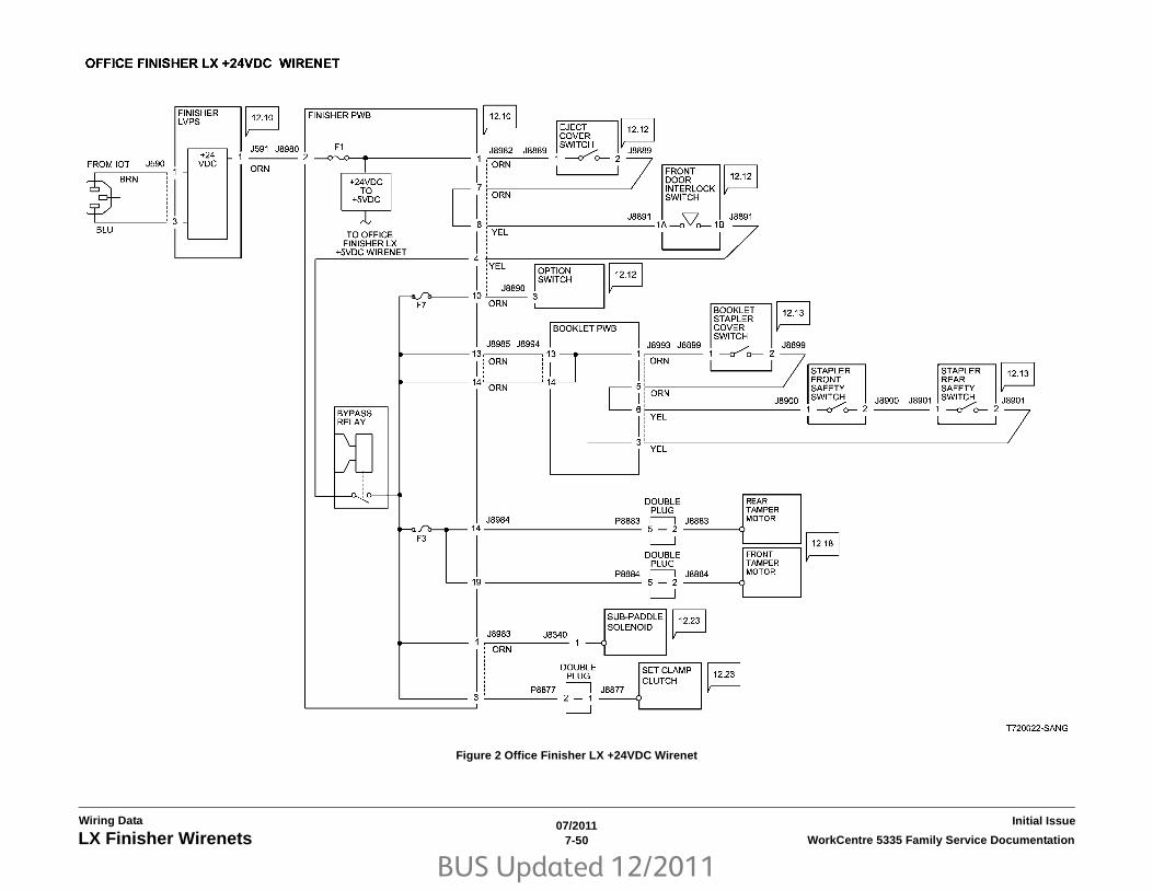
BUS Updated 12/2011
07/20117-50 WorkCentre 5335 Family Service DocumentationLX Finisher Wirenets
Initial IssueWiring Data
Figure 2 Office Finisher LX +24VDC Wirenet

BUS Updated 12/2011
07/20117-51WorkCentre 5335 Family Service Documentation LX Finisher Wirenets
Wiring DataInitial Issue
Figure 3 Office Finisher LX DC RTN Wirenet

BUS Updated 12/2011
07/20117-52 WorkCentre 5335 Family Service DocumentationLX Finisher Wirenets
Initial IssueWiring Data

BUS Updated 12/2011
07/20117-53WorkCentre 5335 Family Service Documentation Block Schematic Diagrams (BSDs)
Wiring DataInitial Issue
Block Schematic Diagrams (BSDs)Chain 1BSD 1.1 - Main Power on (1 of 2)
BSD 1.2 - Main Power on (2 of 2)
BSD 1.3 - LVPS Control
BSD 1.4 - DC Power Generation (1 of 2)
BSD 1.5 - DC Power Generation (2 of 2)
BSD 1.6 - IIT DC Power Distribution
BSD 1.7 - DC Power Distribution (options)
BSD 1.8 - Power Interlock Switching (1 of 2)
BSD 1.9 - Power Interlock Switching (2 of 2)
BSD 1.10 - PWB Location
BSD 1.11 - HCF Power Distribution
Chain 2BSD 2.1 - User Interface (UI)
Chain 3BSD 3.1 - ESS-MCU Communication
BSD 3.2 - -MCU-Tray Module Communication
BSD 3.3 - ESS-IIT Communication
BSD 3.4 - ESS-UI Communication
BSD 3.5 - ESS-DADF Communication
BSD 3.6 - IOT-Finisher Communication
BSD 3.7 - ESS-FDI Communication
BSD 3.8 - Electronic Billing
BSD 3.9 - Download Interface
BSD 3.10 - MCU-HCF Communications
Chain 4BSD 4.1 - Main Drive Control
Chain 5BSD 5.1 - Document Setting
BSD 5.2 - Document Size Sensing (1 of 2)
BSD 5.3 Document Size Sensing (2 of 2)
BSD 5.4 - Document Feed (1 of 2)
BSD 5.5 - Document Feed (2 of 2)
BSD 5.6 - Document Scan and Invert
BSD 5.7 - Document Exit Transportation
BSD 5.8 - Document Path
BSD 5.9 - Document Transmission
Chain 6BSD 6.1 - Document Illumination
BSD 6.2 - Copy Image Flow
BSD 6.3 - Scan Image Flow
BSD 6.4 - Print Image Flow
BSD 6.5 - Fax Image Flow
BSD 6.6 - Image Input
BSD 6.7 - Platen Document Sensing
BSD 6.8 - ROS Laser Control (1 of 2)
BSD 6.9 - ROS Laser Control (2 of 2)
Chain 7BSD 7.1 - Tray 1 Paper Size Sensing
BSD 7.2 - Tray 2 Paper Size Sensing
BSD 7.3 - Tray 3 Paper Size Sensing (TTM)
BSD 7.4 - Tray 4 Paper Size Sensing (TTM)

BUS Updated 12/2011
07/20117-54 WorkCentre 5335 Family Service DocumentationBlock Schematic Diagrams (BSDs)
Initial IssueWiring Data
BSD 7.5 - Tray 1 Paper Stacking
BSD 7.6 - Tray 2 Paper Stacking
BSD 7.7 - Tray 3 Paper Stacking (TTM)
BSD 7.8 - Tray 4 Paper Stacking (TTM)
BSD 7.9 - Tray 5 (MSI) Paper Stacking
BSD 7.10 - HCF (Tray 6) Paper Stacking
BSD 7.11 - HCF (Tray 6) Paper Size Sensing
Chain 8BSD 8.1 - Trays 1~5 Paper Feeding
BSD 8.2 - IOT Paper Transportation
BSD 8.3 - Paper Transportation (Tandem Tray Module)
BSD 8.4 - Tandem Tray Module Takeaway Drive
BSD 8.5 - Registration
BSD 8.6 - HCF (Tray 6) Paper Feeding
8.7 HCF (Tray 6) Paper Transportation
Chain 9BSD 9.1 - CRU Life Control
BSD 9.2 - Charging and Exposure
BSD 9.3 - Development and Toner Dispense Control
BSD 9.4 - Transfer
BSD 9.5 Drum Drive Control
Chain 10BSD 10.1 - Fusing Heat Control
BSD 10.2 - Fusing
BSD 10.3 - Exit Transportation
BSD 10.4 - Exit 2 Drive
BSD 10. 5 - Duplex
BSD 10.6 - Exit 1 Drive/OCT Control
Chain 12BSD 12.1 - Integrated Finisher DC Power and Interlock Switching
BSD 12.2 - IOT–Integrated Finisher Communication
BSD 12.3 - Integrated Finisher Transportation
BSD 12.4 - Integrated Finisher Tamping and Offset
BSD 12.5 - Integrated Finisher Staple Control
BSD 12.6 - Integrated Finisher Set Eject (1 of 2)
BSD 12.7 - Integrated Finisher Set Eject (2 of 2)
BSD 12.8 - Integrated Finisher Stacker Tray Control
BSD 12.10 - Office Finisher LX DC Power Generation
BSD 12.11 - Office Finisher LX DC Power Distribution
BSD 12.12 - Office Finisher LX Interlock Switching
BSD 12.13 - Office Finisher LX Booklet Interlock Switching
BSD 12.14 - Office Finisher LX Horizontal Transportation
BSD 12.15 - Office Finisher LX Punch
BSD 12.16 - Office Finisher LX Transportation
BSD 12.17 - Office Finisher LX Folding
BSD 12.18 - Office Finisher LX Tamping & Offset (1 of 2)
BSD 12.19 - Office Finisher LX Tamping & Offset (2 of 2)
BSD 12.20 - Office Finisher LX Staple Positioning
BSD 12.21 - Office Finisher LX Staple Control
BSD 12.22 - Office Finisher LX Eject Control (1 of 2)
BSD 12.23 - Office Finisher LX Eject Control (2 of 2)
BSD 12.24 - Office Finisher LX Stacker Tray Control
BSD 12.25 - Office Finisher Booklet Staple Positioning

BUS Updated 12/2011
07/20117-55WorkCentre 5335 Family Service Documentation Block Schematic Diagrams (BSDs)
Wiring DataInitial Issue
BSD 12.26 - Office Finisher Booklet Staple Control (1 of 2 - Front)
BSD 12.27 - Office Finisher Booklet Staple Control (2 of 2 - Rear)
Chain 16BSD 16.1 - ESS
Chain 34BSD 34.1 - FAX

BUS Updated 12/2011
07/20117-56 WorkCentre 5335 Family Service DocumentationChain 1 - Input Power
Initial IssueWiring Data
Chain 1 - Input Power
Figure 1 BSD 1.1 - Main Power on (1 of 2)

BUS Updated 12/2011
07/20117-57WorkCentre 5335 Family Service Documentation Chain 1 - Input Power
Wiring DataInitial Issue
Figure 2 BSD 1.2 - Main Power on (2 of 2)

BUS Updated 12/2011
07/20117-58 WorkCentre 5335 Family Service DocumentationChain 1 - Input Power
Initial IssueWiring Data
Figure 3 BSD 1.3 - LVPS Control

BUS Updated 12/2011
07/20117-59WorkCentre 5335 Family Service Documentation Chain 1 - Input Power
Wiring DataInitial Issue
Figure 4 BSD 1.4 - DC Power Generation (1 of 2)

BUS Updated 12/2011
07/20117-60 WorkCentre 5335 Family Service DocumentationChain 1 - Input Power
Initial IssueWiring Data
Figure 5 BSD 1.5 - DC Power Generation (2 of 2)

BUS Updated 12/2011
07/20117-61WorkCentre 5335 Family Service Documentation Chain 1 - Input Power
Wiring DataInitial Issue
Figure 6 BSD 1.6 - IIT DC Power Distribution

BUS Updated 12/2011
07/20117-62 WorkCentre 5335 Family Service DocumentationChain 1 - Input Power
Initial IssueWiring Data
Figure 7 BSD 1.7 - DC Power Distribution (options)

BUS Updated 12/2011
07/20117-63WorkCentre 5335 Family Service Documentation Chain 1 - Input Power
Wiring DataInitial Issue
Figure 8 BSD 1.8 - Power Interlock Switching (1 of 2)

BUS Updated 12/2011
07/20117-64 WorkCentre 5335 Family Service DocumentationChain 1 - Input Power
Initial IssueWiring Data
Figure 9 BSD 1.9 - Power Interlock Switching (2 of 2)

BUS Updated 12/2011
07/20117-65WorkCentre 5335 Family Service Documentation Chain 1 - Input Power
Wiring DataInitial Issue
Figure 10 BSD 1.10 - PWB Location

BUS Updated 12/2011
07/20117-66 WorkCentre 5335 Family Service DocumentationChain 1 - Input Power
Initial IssueWiring Data
Figure 11 BSD 1.11 - HCF Power Distribution

BUS Updated 12/2011
07/20117-67WorkCentre 5335 Family Service Documentation Chain 2 - User Interface
Wiring DataInitial Issue
Chain 2 - User Interface
Figure 1 BSD 2.1 - User Interface (UI)

BUS Updated 12/2011
07/20117-68 WorkCentre 5335 Family Service DocumentationChain 3 - Machine Run Control
Initial IssueWiring Data
Chain 3 - Machine Run Control
Figure 1 BSD 3.1 - ESS-MCU Communication

BUS Updated 12/2011
07/20117-69WorkCentre 5335 Family Service Documentation Chain 3 - Machine Run Control
Wiring DataInitial Issue
Figure 2 BSD 3.2 - -MCU-Tray Module Communication

BUS Updated 12/2011
07/20117-70 WorkCentre 5335 Family Service DocumentationChain 3 - Machine Run Control
Initial IssueWiring Data
Figure 3 BSD 3.3 - ESS-IIT Communication

BUS Updated 12/2011
07/20117-71WorkCentre 5335 Family Service Documentation Chain 3 - Machine Run Control
Wiring DataInitial Issue
Figure 4 BSD 3.4 - ESS-UI Communication

BUS Updated 12/2011
07/20117-72 WorkCentre 5335 Family Service DocumentationChain 3 - Machine Run Control
Initial IssueWiring Data
Figure 5 BSD 3.5 - ESS-DADF Communication

BUS Updated 12/2011
07/20117-73WorkCentre 5335 Family Service Documentation Chain 3 - Machine Run Control
Wiring DataInitial Issue
Figure 6 BSD 3.6 - IOT-Finisher Communication

BUS Updated 12/2011
07/20117-74 WorkCentre 5335 Family Service DocumentationChain 3 - Machine Run Control
Initial IssueWiring Data
Figure 7 BSD 3.7 - ESS-FDI Communication

BUS Updated 12/2011
07/20117-75WorkCentre 5335 Family Service Documentation Chain 3 - Machine Run Control
Wiring DataInitial Issue
Figure 8 BSD 3.8 - Electronic Billing

BUS Updated 12/2011
07/20117-76 WorkCentre 5335 Family Service DocumentationChain 3 - Machine Run Control
Initial IssueWiring Data
Figure 9 BSD 3.9 - Download Interface

BUS Updated 12/2011
07/20117-77WorkCentre 5335 Family Service Documentation Chain 3 - Machine Run Control
Wiring DataInitial Issue
Figure 10 BSD 3.10 - MCU-HCF Communications

BUS Updated 12/2011
07/20117-78 WorkCentre 5335 Family Service DocumentationChain 4 - Drives
Initial IssueWiring Data
Chain 4 - Drives
Figure 1 BSD 4.1 - Main Drive Control

BUS Updated 12/2011
07/20117-79WorkCentre 5335 Family Service Documentation Chain 5 - Document Input
Wiring DataInitial Issue
Chain 5 - Document Input
Figure 1 BSD 5.1 - Document Setting

BUS Updated 12/2011
07/20117-80 WorkCentre 5335 Family Service DocumentationChain 5 - Document Input
Initial IssueWiring Data
Figure 2 BSD 5.2 - Document Size Sensing (1 of 2)

BUS Updated 12/2011
07/20117-81WorkCentre 5335 Family Service Documentation Chain 5 - Document Input
Wiring DataInitial Issue
Figure 3 BSD 5.3 Document Size Sensing (2 of 2)

BUS Updated 12/2011
07/20117-82 WorkCentre 5335 Family Service DocumentationChain 5 - Document Input
Initial IssueWiring Data
Figure 4 BSD 5.4 - Document Feed (1 of 2)

BUS Updated 12/2011
07/20117-83WorkCentre 5335 Family Service Documentation Chain 5 - Document Input
Wiring DataInitial Issue
Figure 5 BSD 5.5 - Document Feed (2 of 2)

BUS Updated 12/2011
07/20117-84 WorkCentre 5335 Family Service DocumentationChain 5 - Document Input
Initial IssueWiring Data
Figure 6 BSD 5.6 - Document Scan and Invert

BUS Updated 12/2011
07/20117-85WorkCentre 5335 Family Service Documentation Chain 5 - Document Input
Wiring DataInitial Issue
Figure 7 BSD 5.7 - Document Exit Transportation

BUS Updated 12/2011
07/20117-86 WorkCentre 5335 Family Service DocumentationChain 5 - Document Input
Initial IssueWiring Data
Figure 8 BSD 5.8 - Document Path

BUS Updated 12/2011
07/20117-87WorkCentre 5335 Family Service Documentation Chain 5 - Document Input
Wiring DataInitial Issue
Figure 9 BSD 5.9 - Document Transmission
BUS Updated 12/2011
07/20117-88 WorkCentre 5335 Family Service DocumentationChain 6 - Scanning and Image Input
Initial IssueWiring Data
Chain 6 - Scanning and Image Input
Figure 1 BSD 6.1 - Document Illumination

BUS Updated 12/2011
07/20117-89WorkCentre 5335 Family Service Documentation Chain 6 - Scanning and Image Input
Wiring DataInitial Issue
Figure 2 BSD 6.2 - Copy Image Flow

BUS Updated 12/2011
07/20117-90 WorkCentre 5335 Family Service DocumentationChain 6 - Scanning and Image Input
Initial IssueWiring Data
Figure 3 BSD 6.3 - Scan Image Flow

BUS Updated 12/2011
07/20117-91WorkCentre 5335 Family Service Documentation Chain 6 - Scanning and Image Input
Wiring DataInitial Issue
Figure 4 BSD 6.4 - Print Image Flow

BUS Updated 12/2011
07/20117-92 WorkCentre 5335 Family Service DocumentationChain 6 - Scanning and Image Input
Initial IssueWiring Data
Figure 5 BSD 6.5 - Fax Image Flow

BUS Updated 12/2011
07/20117-93WorkCentre 5335 Family Service Documentation Chain 6 - Scanning and Image Input
Wiring DataInitial Issue
Figure 6 BSD 6.6 - Image Input

BUS Updated 12/2011
07/20117-94 WorkCentre 5335 Family Service DocumentationChain 6 - Scanning and Image Input
Initial IssueWiring Data
Figure 7 BSD 6.7 - Platen Document Sensing

BUS Updated 12/2011
07/20117-95WorkCentre 5335 Family Service Documentation Chain 6 - Scanning and Image Input
Wiring DataInitial Issue
Figure 8 BSD 6.8 - Laser Control and Scanning

BUS Updated 12/2011
07/20117-96 WorkCentre 5335 Family Service DocumentationChain 6 - Scanning and Image Input
Initial IssueWiring Data
Figure 9 BSD 6.9 - ROS Motor Control

BUS Updated 12/2011
07/20117-97WorkCentre 5335 Family Service Documentation Chain 7 - Paper Supply
Wiring DataInitial Issue
Chain 7 - Paper Supply
Figure 1 BSD 7.1 - Tray 1 Paper Size Sensing

BUS Updated 12/2011
07/20117-98 WorkCentre 5335 Family Service DocumentationChain 7 - Paper Supply
Initial IssueWiring Data
Figure 2 BSD 7.2 - Tray 2 Paper Size Sensing

BUS Updated 12/2011
07/20117-99WorkCentre 5335 Family Service Documentation Chain 7 - Paper Supply
Wiring DataInitial Issue
Figure 3 BSD 7.3 - Tray 3 Paper Size Sensing (TTM)

BUS Updated 12/2011
07/20117-100 WorkCentre 5335 Family Service DocumentationChain 7 - Paper Supply
Initial IssueWiring Data
Figure 4 BSD 7.4 - Tray 4 Paper Size Sensing (TTM)

BUS Updated 12/2011
07/20117-101WorkCentre 5335 Family Service Documentation Chain 7 - Paper Supply
Wiring DataInitial Issue
Figure 5 BSD 7.5 - Tray 1 Paper Stacking

BUS Updated 12/2011
07/20117-102 WorkCentre 5335 Family Service DocumentationChain 7 - Paper Supply
Initial IssueWiring Data
Figure 6 BSD 7.6 - Tray 2 Paper Stacking

BUS Updated 12/2011
07/20117-103WorkCentre 5335 Family Service Documentation Chain 7 - Paper Supply
Wiring DataInitial Issue
Figure 7 BSD 7.7 - Tray 3 Paper Stacking (TTM)

BUS Updated 12/2011
07/20117-104 WorkCentre 5335 Family Service DocumentationChain 7 - Paper Supply
Initial IssueWiring Data
Figure 8 BSD 7.8 - Tray 4 Paper Stacking (TTM)

BUS Updated 12/2011
07/20117-105WorkCentre 5335 Family Service Documentation Chain 7 - Paper Supply
Wiring DataInitial Issue
Figure 9 BSD 7.9 - Tray 5 (MSI) Paper Stacking

BUS Updated 12/2011
07/20117-106 WorkCentre 5335 Family Service DocumentationChain 7 - Paper Supply
Initial IssueWiring Data
Figure 10 BSD 7.10 - HCF (Tray 6) Paper Stacking

BUS Updated 12/2011
07/20117-107WorkCentre 5335 Family Service Documentation Chain 7 - Paper Supply
Wiring DataInitial Issue
Figure 11 BSD 7.11 - HCF (Tray 6) Paper Size Sensing

BUS Updated 12/2011
07/20117-108 WorkCentre 5335 Family Service Documentation
Initial IssueWiring Data
Chain 8 - Paper Feed

BUS Updated 12/2011
07/20117-109WorkCentre 5335 Family Service Documentation
Wiring DataInitial Issue
Figure 1 BSD 8.1 - Trays 1~5 Paper Feeding

BUS Updated 12/2011
07/20117-110 WorkCentre 5335 Family Service Documentation
Initial IssueWiring Data
Figure 2 BSD 8.2 - IOT Paper Transportation

BUS Updated 12/2011
07/20117-111WorkCentre 5335 Family Service Documentation
Wiring DataInitial Issue
Figure 3 BSD 8.3 - Paper Transportation (Tandem Tray Module)

BUS Updated 12/2011
07/20117-112 WorkCentre 5335 Family Service Documentation
Initial IssueWiring Data
Figure 4 BSD 8.4 - Tandem Tray Module Takeaway Drive

BUS Updated 12/2011
07/20117-113WorkCentre 5335 Family Service Documentation
Wiring DataInitial Issue
Figure 5 BSD 8.5 - Registration

BUS Updated 12/2011
07/20117-114 WorkCentre 5335 Family Service Documentation
Initial IssueWiring Data
Figure 6 BSD 8.6 - HCF (Tray 6) Paper Feeding

BUS Updated 12/2011
07/20117-115WorkCentre 5335 Family Service Documentation
Wiring DataInitial Issue
Figure 7 8.7 HCF (Tray 6) Paper Transportation

BUS Updated 12/2011
07/20117-116 WorkCentre 5335 Family Service Documentation
Initial IssueWiring Data
Chain 9 - Xerographics and Marking
Figure 1 BSD 9.1 - CRU Life Control

BUS Updated 12/2011
07/20117-117WorkCentre 5335 Family Service Documentation
Wiring DataInitial Issue
Figure 2 BSD 9.2 - Charging and Exposure

BUS Updated 12/2011
07/20117-118 WorkCentre 5335 Family Service Documentation
Initial IssueWiring Data
Figure 3 BSD 9.3 - Development and Toner Dispense Control

BUS Updated 12/2011
07/20117-119WorkCentre 5335 Family Service Documentation
Wiring DataInitial Issue
Figure 4 BSD 9.4 - Transfer

BUS Updated 12/2011
07/20117-120 WorkCentre 5335 Family Service Documentation
Initial IssueWiring Data
Figure 5 BSD 9.5 Drum Drive Control

BUS Updated 12/2011
07/20117-121WorkCentre 5335 Family Service Documentation Chain 10 - Fusing and Post-Fuser Transport
Wiring DataInitial Issue
Chain 10 - Fusing and Post-Fuser Transport
Figure 1 BSD 10.1 - Fusing Heat Control

BUS Updated 12/2011
07/20117-122 WorkCentre 5335 Family Service DocumentationChain 10 - Fusing and Post-Fuser Transport
Initial IssueWiring Data
Figure 2 BSD 10.2 - Fusing

BUS Updated 12/2011
07/20117-123WorkCentre 5335 Family Service Documentation Chain 10 - Fusing and Post-Fuser Transport
Wiring DataInitial Issue
Figure 3 BSD 10.3 - Exit Transportation

BUS Updated 12/2011
07/20117-124 WorkCentre 5335 Family Service DocumentationChain 10 - Fusing and Post-Fuser Transport
Initial IssueWiring Data
Figure 4 BSD 10.4 - Exit 2 Drive

BUS Updated 12/2011
07/20117-125WorkCentre 5335 Family Service Documentation Chain 10 - Fusing and Post-Fuser Transport
Wiring DataInitial Issue
Figure 5 BSD 10. 5 - Duplex

BUS Updated 12/2011
07/20117-126 WorkCentre 5335 Family Service DocumentationChain 10 - Fusing and Post-Fuser Transport
Initial IssueWiring Data
Figure 6 BSD Exit 1 Drive/OCT Control
BUS Updated 12/2011
07/20117-127WorkCentre 5335 Family Service Documentation Chain 12 - Integrated Office Finisher
Wiring DataInitial Issue
Chain 12 - Integrated Office Finisher
Figure 1 BSD 12.1 - Integrated Finisher DC Power and Interlock Switching

BUS Updated 12/2011
07/20117-128 WorkCentre 5335 Family Service DocumentationChain 12 - Integrated Office Finisher
Initial IssueWiring Data
Figure 2 BSD 12.2 - IOT–Integrated Finisher Communication

BUS Updated 12/2011
07/20117-129WorkCentre 5335 Family Service Documentation Chain 12 - Integrated Office Finisher
Wiring DataInitial Issue
Figure 3 BSD 12.3 - Integrated Finisher Transportation

BUS Updated 12/2011
07/20117-130 WorkCentre 5335 Family Service DocumentationChain 12 - Integrated Office Finisher
Initial IssueWiring Data
Figure 4 BSD 12.4 - Integrated Finisher Tamping and Offset

BUS Updated 12/2011
07/20117-131WorkCentre 5335 Family Service Documentation Chain 12 - Integrated Office Finisher
Wiring DataInitial Issue
Figure 5 BSD 12.5 - Integrated Finisher Staple Control

BUS Updated 12/2011
07/20117-132 WorkCentre 5335 Family Service DocumentationChain 12 - Integrated Office Finisher
Initial IssueWiring Data
Figure 6 BSD 12.6 - Integrated Finisher Set Eject (1 of 2)

BUS Updated 12/2011
07/20117-133WorkCentre 5335 Family Service Documentation Chain 12 - Integrated Office Finisher
Wiring DataInitial Issue
Figure 7 BSD 12.7 - Integrated Finisher Set Eject (2 of 2)

BUS Updated 12/2011
07/20117-134 WorkCentre 5335 Family Service DocumentationChain 12 - Integrated Office Finisher
Initial IssueWiring Data
Figure 8 BSD 12.8 - Integrated Finisher Stacker Tray Control

BUS Updated 12/2011
07/20117-135WorkCentre 5335 Family Service Documentation Chain 12 - Office Finisher LX
Wiring DataInitial Issue
Chain 12 - Office Finisher LX
Figure 1 BSD 12.10 - Office Finisher LX DC Power Generation

BUS Updated 12/2011
07/20117-136 WorkCentre 5335 Family Service DocumentationChain 12 - Office Finisher LX
Initial IssueWiring Data
Figure 2 BSD 12.11 - Office Finisher LX DC Power Distribution

BUS Updated 12/2011
07/20117-137WorkCentre 5335 Family Service Documentation Chain 12 - Office Finisher LX
Wiring DataInitial Issue
Figure 3 BSD 12.12 - Office Finisher LX Interlock Switching

BUS Updated 12/2011
07/20117-138 WorkCentre 5335 Family Service DocumentationChain 12 - Office Finisher LX
Initial IssueWiring Data
Figure 4 BSD 12.13 - Office Finisher LX Booklet Interlock Switching

BUS Updated 12/2011
07/20117-139WorkCentre 5335 Family Service Documentation Chain 12 - Office Finisher LX
Wiring DataInitial Issue
Figure 5 BSD 12.14 - Office Finisher LX Horizontal Transportation

BUS Updated 12/2011
07/20117-140 WorkCentre 5335 Family Service DocumentationChain 12 - Office Finisher LX
Initial IssueWiring Data
Figure 6 BSD 12.15 - Office Finisher LX Punch

BUS Updated 12/2011
07/20117-141WorkCentre 5335 Family Service Documentation Chain 12 - Office Finisher LX
Wiring DataInitial Issue
Figure 7 BSD 12.16 - Office Finisher LX Transportation

BUS Updated 12/2011
07/20117-142 WorkCentre 5335 Family Service DocumentationChain 12 - Office Finisher LX
Initial IssueWiring Data
Figure 8 BSD 12.17 - Office Finisher LX Folding

BUS Updated 12/2011
07/20117-143WorkCentre 5335 Family Service Documentation Chain 12 - Office Finisher LX
Wiring DataInitial Issue
Figure 9 BSD 12.18 - Office Finisher LX Tamping & Offset (1 of 2)

BUS Updated 12/2011
07/20117-144 WorkCentre 5335 Family Service DocumentationChain 12 - Office Finisher LX
Initial IssueWiring Data
Figure 10 BSD 12.19 - Office Finisher LX Tamping & Offset (2 of 2)

BUS Updated 12/2011
07/20117-145WorkCentre 5335 Family Service Documentation Chain 12 - Office Finisher LX
Wiring DataInitial Issue
Figure 11 BSD 12.20 - Office Finisher LX Staple Positioning

BUS Updated 12/2011
07/20117-146 WorkCentre 5335 Family Service DocumentationChain 12 - Office Finisher LX
Initial IssueWiring Data
Figure 12 BSD 12.21 - Office Finisher LX Staple Control

BUS Updated 12/2011
07/20117-147WorkCentre 5335 Family Service Documentation Chain 12 - Office Finisher LX
Wiring DataInitial Issue
Figure 13 BSD 12.22 - Office Finisher LX Eject Control (1 of 2)

BUS Updated 12/2011
07/20117-148 WorkCentre 5335 Family Service DocumentationChain 12 - Office Finisher LX
Initial IssueWiring Data
Figure 14 BSD 12.23 - Office Finisher LX Eject Control (2 of 2)

BUS Updated 12/2011
07/20117-149WorkCentre 5335 Family Service Documentation Chain 12 - Office Finisher LX
Wiring DataInitial Issue
Figure 15 BSD 12.24 - Office Finisher LX Stacker Tray Control

BUS Updated 12/2011
07/20117-150 WorkCentre 5335 Family Service DocumentationChain 12 - Office Finisher LX
Initial IssueWiring Data
Figure 16 BSD 12.25 - Office Finisher Booklet Staple Positioning

BUS Updated 12/2011
07/20117-151WorkCentre 5335 Family Service Documentation Chain 12 - Office Finisher LX
Wiring DataInitial Issue
Figure 17 BSD 12.26 - Office Finisher Booklet Staple Control (1 of 2 - Front)

BUS Updated 12/2011
07/20117-152 WorkCentre 5335 Family Service DocumentationChain 12 - Office Finisher LX
Initial IssueWiring Data
Figure 18 BSD 12.27 - Office Finisher Booklet Staple Control (2 of 2 - Rear)

BUS Updated 12/2011
07/20117-153WorkCentre 5335 Family Service Documentation Chain 16
Wiring DataInitial Issue
Chain 16
Figure 1 BSD 16.1 - ESS

BUS Updated 12/2011
07/20117-154 WorkCentre 5335 Family Service DocumentationChain 34
Initial IssueWiring Data
Chain 34

BUS Updated 12/2011
07/20117-155WorkCentre 5335 Family Service Documentation Chain 34
Wiring DataInitial Issue
Figure 1 BSD 34.1 - FAX
Copyright © 2022 FDOKUMEN