Effects of D20 and Osmotic Gradients on Potential and ... - NCBI
Upload
khangminh22Category
view
1download
0
Bull D10 and D20 I/O DrawersService Guide
86 A1 38EG 01ORDER REFERENCE


Bull D10 and D20 I/O DrawersService Guide
Hardware
June 2003
BULL CEDOC357 AVENUE PATTONB.P.2084549008 ANGERS CEDEX 01FRANCE
86 A1 38EG 01ORDER REFERENCE

The following copyright notice protects this book under the Copyright laws of the United States of Americaand other countries which prohibit such actions as, but not limited to, copying, distributing, modifying, andmaking derivative works.
Copyright Bull S.A. 1992, 2003
Printed in France
Suggestions and criticisms concerning the form, content, and presentation ofthis book are invited. A form is provided at the end of this book for this purpose.
To order additional copies of this book or other Bull Technical Publications, youare invited to use the Ordering Form also provided at the end of this book.
Trademarks and Acknowledgements
We acknowledge the right of proprietors of trademarks mentioned in this book.
AIX� is a registered trademark of International Business Machines Corporation, and is being used underlicence.
UNIX is a registered trademark in the United States of America and other countries licensed exclusively throughthe Open Group.
Linux is a registered trademark of Linus Torvalds.
The information in this document is subject to change without notice. Groupe Bull will not be liable for errorscontained herein, or for incidental or consequential damages in connection with the use of this material.
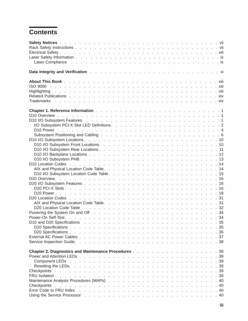
Contents
Safety Notices . . . . . . . . . . . . . . . . . . . . . . . . . . . . . . . . . viiRack Safety Instructions . . . . . . . . . . . . . . . . . . . . . . . . . . . . . . viiElectrical Safety . . . . . . . . . . . . . . . . . . . . . . . . . . . . . . . . . viiiLaser Safety Information . . . . . . . . . . . . . . . . . . . . . . . . . . . . . . ix
Laser Compliance . . . . . . . . . . . . . . . . . . . . . . . . . . . . . . . ix
Data Integrity and Verification . . . . . . . . . . . . . . . . . . . . . . . . . . . xi
About This Book . . . . . . . . . . . . . . . . . . . . . . . . . . . . . . . . xiiiISO 9000 . . . . . . . . . . . . . . . . . . . . . . . . . . . . . . . . . . . xiiiHighlighting . . . . . . . . . . . . . . . . . . . . . . . . . . . . . . . . . . xiiiRelated Publications . . . . . . . . . . . . . . . . . . . . . . . . . . . . . . . xivTrademarks . . . . . . . . . . . . . . . . . . . . . . . . . . . . . . . . . . xiv
Chapter 1. Reference Information . . . . . . . . . . . . . . . . . . . . . . . . . . 1D10 Overview . . . . . . . . . . . . . . . . . . . . . . . . . . . . . . . . . . 1D10 I/O Subsystem Features . . . . . . . . . . . . . . . . . . . . . . . . . . . . 1
I/O Subsystem PCI-X Slot LED Definitions. . . . . . . . . . . . . . . . . . . . . . . 2D10 Power . . . . . . . . . . . . . . . . . . . . . . . . . . . . . . . . . . 4Subsystem Positioning and Cabling . . . . . . . . . . . . . . . . . . . . . . . . . 6
D10 I/O Subsystem Locations . . . . . . . . . . . . . . . . . . . . . . . . . . . . 10D10 I/O Subsystem Front Locations. . . . . . . . . . . . . . . . . . . . . . . . . 10D10 I/O Subsystem Rear Locations . . . . . . . . . . . . . . . . . . . . . . . . . 11D10 I/O Backplane Locations . . . . . . . . . . . . . . . . . . . . . . . . . . . 12D10 I/O Subsystem PHB. . . . . . . . . . . . . . . . . . . . . . . . . . . . . 13
D10 Location Codes . . . . . . . . . . . . . . . . . . . . . . . . . . . . . . . 14AIX and Physical Location Code Table. . . . . . . . . . . . . . . . . . . . . . . . 14D10 I/O Subsystem Location Code Table . . . . . . . . . . . . . . . . . . . . . . . 15
D20 Overview. . . . . . . . . . . . . . . . . . . . . . . . . . . . . . . . . . 16D20 I/O Subsystem Features . . . . . . . . . . . . . . . . . . . . . . . . . . . . 16
D20 PCI-X Slots . . . . . . . . . . . . . . . . . . . . . . . . . . . . . . . . 16D20 Power . . . . . . . . . . . . . . . . . . . . . . . . . . . . . . . . . . 18
D20 Location Codes . . . . . . . . . . . . . . . . . . . . . . . . . . . . . . . 31AIX and Physical Location Code Table. . . . . . . . . . . . . . . . . . . . . . . . 31D20 Location Code Table . . . . . . . . . . . . . . . . . . . . . . . . . . . . 32
Powering the System On and Off . . . . . . . . . . . . . . . . . . . . . . . . . . 34Power-On Self-Test . . . . . . . . . . . . . . . . . . . . . . . . . . . . . . . . 34D10 and D20 Specifications . . . . . . . . . . . . . . . . . . . . . . . . . . . . 35
D10 Specifications . . . . . . . . . . . . . . . . . . . . . . . . . . . . . . . 35D20 Specifications . . . . . . . . . . . . . . . . . . . . . . . . . . . . . . . 36
External AC Power Cables . . . . . . . . . . . . . . . . . . . . . . . . . . . . . 37Service Inspection Guide. . . . . . . . . . . . . . . . . . . . . . . . . . . . . . 38
Chapter 2. Diagnostics and Maintenance Procedures . . . . . . . . . . . . . . . . . . 39Power and Attention LEDs . . . . . . . . . . . . . . . . . . . . . . . . . . . . . 39
Component LEDs . . . . . . . . . . . . . . . . . . . . . . . . . . . . . . . 39Resetting the LEDs . . . . . . . . . . . . . . . . . . . . . . . . . . . . . . . 39
Checkpoints . . . . . . . . . . . . . . . . . . . . . . . . . . . . . . . . . . 39FRU Isolation . . . . . . . . . . . . . . . . . . . . . . . . . . . . . . . . . . 39Maintenance Analysis Procedures (MAPs) . . . . . . . . . . . . . . . . . . . . . . . 40Checkpoints . . . . . . . . . . . . . . . . . . . . . . . . . . . . . . . . . . 40Error Code to FRU Index . . . . . . . . . . . . . . . . . . . . . . . . . . . . . 40Using the Service Processor . . . . . . . . . . . . . . . . . . . . . . . . . . . . 40
iii

Using System Management Services . . . . . . . . . . . . . . . . . . . . . . . . . 40
Chapter 3. Removal and Replacement Procedures . . . . . . . . . . . . . . . . . . . 41Safety Considerations . . . . . . . . . . . . . . . . . . . . . . . . . . . . . . . 41Handling Static-Sensitive Devices . . . . . . . . . . . . . . . . . . . . . . . . . . 42Stopping and Starting the System . . . . . . . . . . . . . . . . . . . . . . . . . . 42Removal and Replacement Procedures for the D10 I/O Subsystem . . . . . . . . . . . . . . 42
D10 FRU Replacement Procedure List . . . . . . . . . . . . . . . . . . . . . . . 42D10 Service Position . . . . . . . . . . . . . . . . . . . . . . . . . . . . . . 43D10 Operating Position . . . . . . . . . . . . . . . . . . . . . . . . . . . . . 43D10 Front Bezel . . . . . . . . . . . . . . . . . . . . . . . . . . . . . . . . 43D10 Covers . . . . . . . . . . . . . . . . . . . . . . . . . . . . . . . . . 44D10 PCI Adapters . . . . . . . . . . . . . . . . . . . . . . . . . . . . . . . 45Hot-Pluggable PCI Adapter . . . . . . . . . . . . . . . . . . . . . . . . . . . . 46PCI Hot-Plug Manager Access . . . . . . . . . . . . . . . . . . . . . . . . . . 53Removing and Replacing a PCI Adapter Cassette . . . . . . . . . . . . . . . . . . . 55PCI Adapter or Blank Filler Removal from a Cassette Assembly . . . . . . . . . . . . . . 59Replacing an Adapter in a PCI Adapter Cassette . . . . . . . . . . . . . . . . . . . . 70Short Adapter or Blank Filler Installation . . . . . . . . . . . . . . . . . . . . . . . 74Long Adapter Installation . . . . . . . . . . . . . . . . . . . . . . . . . . . . . 89D10 Fan . . . . . . . . . . . . . . . . . . . . . . . . . . . . . . . . . . 104D10 RIO Cable . . . . . . . . . . . . . . . . . . . . . . . . . . . . . . . . 105D10 RIO Bus Adapter Assembly . . . . . . . . . . . . . . . . . . . . . . . . . 105D10 I/O Backplane Assembly . . . . . . . . . . . . . . . . . . . . . . . . . . 106D10 Power Supply . . . . . . . . . . . . . . . . . . . . . . . . . . . . . . 107
Removal and Replacement Procedures for the D20 I/O Subsystem . . . . . . . . . . . . . 108D20 FRU Replacement Procedure List . . . . . . . . . . . . . . . . . . . . . . . 108D20 Service Position. . . . . . . . . . . . . . . . . . . . . . . . . . . . . . 109D20 Operating Position . . . . . . . . . . . . . . . . . . . . . . . . . . . . . 110D20 Service Access Cover. . . . . . . . . . . . . . . . . . . . . . . . . . . . 111D20 Front Bezel . . . . . . . . . . . . . . . . . . . . . . . . . . . . . . . 112D20 Operator Panel . . . . . . . . . . . . . . . . . . . . . . . . . . . . . . 113D20 Blowers . . . . . . . . . . . . . . . . . . . . . . . . . . . . . . . . . 115D20 Cooling Blower Cable. . . . . . . . . . . . . . . . . . . . . . . . . . . . 118D20 RIO Bus Adapter Assembly . . . . . . . . . . . . . . . . . . . . . . . . . 120D20 PCI Adapters . . . . . . . . . . . . . . . . . . . . . . . . . . . . . . . 123D20 Hot-Plug Disk Drives . . . . . . . . . . . . . . . . . . . . . . . . . . . . 137D20 Disk Drive Cage. . . . . . . . . . . . . . . . . . . . . . . . . . . . . . 142D20 Disk Drive Backplane. . . . . . . . . . . . . . . . . . . . . . . . . . . . 144D20 Power Supplies . . . . . . . . . . . . . . . . . . . . . . . . . . . . . . 146D20 Power Supply Bulkhead . . . . . . . . . . . . . . . . . . . . . . . . . . . 148D20 I/O Backplane Assembly . . . . . . . . . . . . . . . . . . . . . . . . . . 151
Chapter 4. Parts Information . . . . . . . . . . . . . . . . . . . . . . . . . . . 157D10 I/O Subsystem . . . . . . . . . . . . . . . . . . . . . . . . . . . . . . . 157
D10 I/O Subsystems Parts . . . . . . . . . . . . . . . . . . . . . . . . . . . 157D10 I/O Subsystem Parts (continued) . . . . . . . . . . . . . . . . . . . . . . . 159D10 SPCN, RIO, and Rack Beacon Cables (These parts are not shown.) . . . . . . . . . . 161D10 Rack Mounting Enclosure (These parts are not shown.) . . . . . . . . . . . . . . . 161
D20 I/O Subsystem . . . . . . . . . . . . . . . . . . . . . . . . . . . . . . . 162D20 I/O Backplane and Cabling. . . . . . . . . . . . . . . . . . . . . . . . . . 162D20 PCI Slots . . . . . . . . . . . . . . . . . . . . . . . . . . . . . . . . 163D20 Power, RIO Adapter, Cabling . . . . . . . . . . . . . . . . . . . . . . . . . 164D20 Operator Panel . . . . . . . . . . . . . . . . . . . . . . . . . . . . . . 165D20 Fans and Disk Drives. . . . . . . . . . . . . . . . . . . . . . . . . . . . 166D20 Covers and Brackets . . . . . . . . . . . . . . . . . . . . . . . . . . . . 167
iv D10 and D20 Service Guide

D20 RIO, SPCN, and Rack Beacon Cables . . . . . . . . . . . . . . . . . . . . . 167Power Cables . . . . . . . . . . . . . . . . . . . . . . . . . . . . . . . . . 168
Chapter 5. Fault and Attention LEDs . . . . . . . . . . . . . . . . . . . . . . . . 169Component LEDs . . . . . . . . . . . . . . . . . . . . . . . . . . . . . . . . 169
Resetting the LEDs . . . . . . . . . . . . . . . . . . . . . . . . . . . . . . 171
Appendix A. Environmental Notices . . . . . . . . . . . . . . . . . . . . . . . . 173Product Recycling and Disposal. . . . . . . . . . . . . . . . . . . . . . . . . . . 173Acoustical Noise Emissions . . . . . . . . . . . . . . . . . . . . . . . . . . . . 174
D10 Declared Acoustical Noise Emissions . . . . . . . . . . . . . . . . . . . . . . 174D20 Declared Acoustical Noise Emissions . . . . . . . . . . . . . . . . . . . . . . 174
Appendix B. Notices . . . . . . . . . . . . . . . . . . . . . . . . . . . . . . 175
Index . . . . . . . . . . . . . . . . . . . . . . . . . . . . . . . . . . . . 177
Contents v

vi D10 and D20 Service Guide

Safety Notices
A danger notice indicates the presence of a hazard that has the potential of causing death or seriouspersonal injury. Danger notices appear on the following pages:
v viii
v 41
v 146
A caution notice indicates the presence of a hazard that has the potential of causing moderate or minorpersonal injury. Caution notices appear on the following pages:
v viii
v viii
v 41
v 41
v ix
Note: For a translation of these notices, see System Unit Safety Information, order number SA23-2652.
Rack Safety Instructionsv Do not install this unit in a rack where the internal rack ambient temperatures will exceed 35 degrees C.
v Do not install this unit in a rack where the air flow is compromised. Any side, front or back of the unitused for air flow through the unit must not be in direct contact with the rack.
v Care should be taken to ensure that a hazardous condition is not created due to uneven mechanicalloading when installing this unit in a rack. If the rack has a stabilizer it must be firmly attached beforeinstalling or removing this unit.
v Consideration should be given to the connection of the equipment to the supply circuit so thatoverloading of circuits does not compromise the supply wiring or overcurrent protection. To provide thecorrect power connection to the rack, refer to the rating labels located on the equipment in the rack todetermine the total power requirement for the supply circuit.
v An electrical outlet that is not correctly wired could place hazardous voltage on the metal parts of thesystem or the devices that attach to the system. It is the responsibility of the customer to ensure thatthe outlet is correctly wired and grounded to prevent an electrical shock.
vii
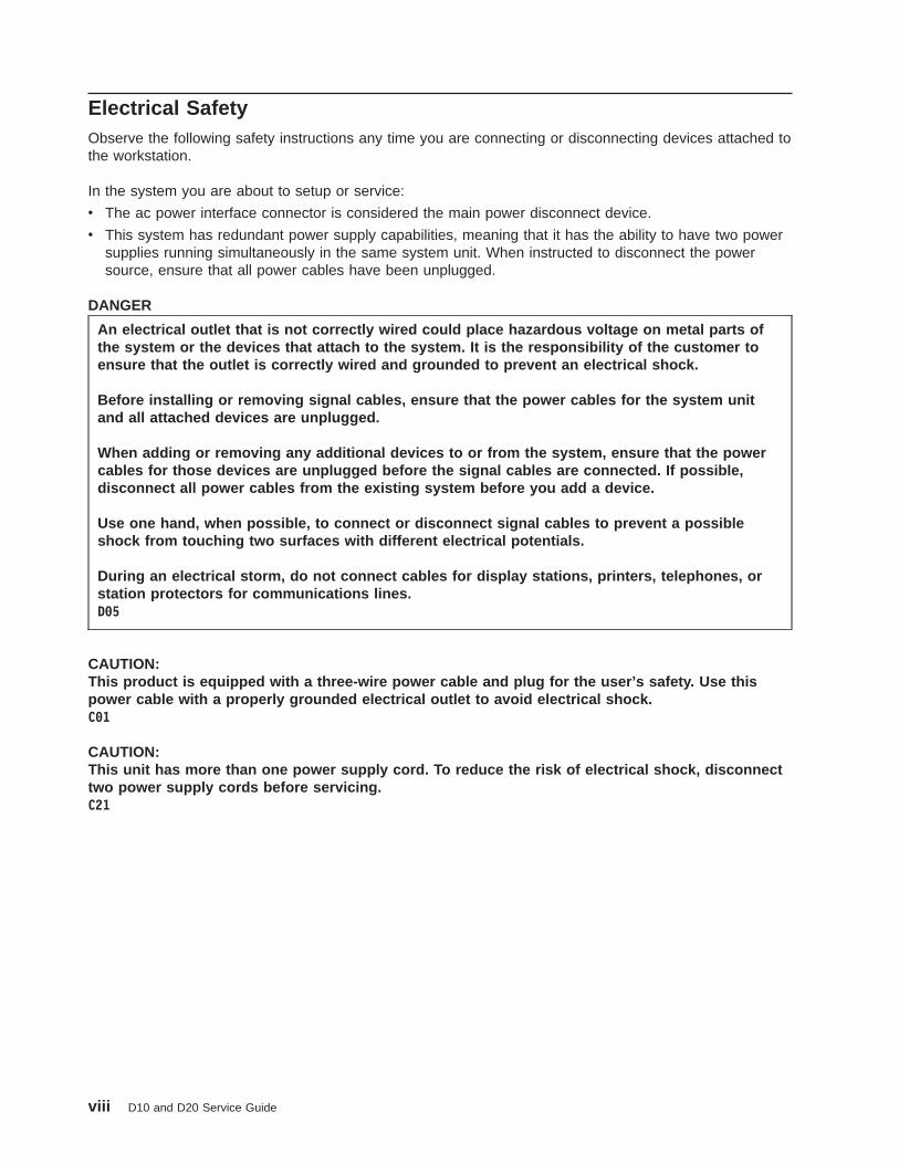
Electrical SafetyObserve the following safety instructions any time you are connecting or disconnecting devices attached tothe workstation.
In the system you are about to setup or service:
v The ac power interface connector is considered the main power disconnect device.
v This system has redundant power supply capabilities, meaning that it has the ability to have two powersupplies running simultaneously in the same system unit. When instructed to disconnect the powersource, ensure that all power cables have been unplugged.
DANGER
An electrical outlet that is not correctly wired could place hazardous voltage on metal parts ofthe system or the devices that attach to the system. It is the responsibility of the customer toensure that the outlet is correctly wired and grounded to prevent an electrical shock.
Before installing or removing signal cables, ensure that the power cables for the system unitand all attached devices are unplugged.
When adding or removing any additional devices to or from the system, ensure that the powercables for those devices are unplugged before the signal cables are connected. If possible,disconnect all power cables from the existing system before you add a device.
Use one hand, when possible, to connect or disconnect signal cables to prevent a possibleshock from touching two surfaces with different electrical potentials.
During an electrical storm, do not connect cables for display stations, printers, telephones, orstation protectors for communications lines.D05
CAUTION:This product is equipped with a three-wire power cable and plug for the user’s safety. Use thispower cable with a properly grounded electrical outlet to avoid electrical shock.C01
CAUTION:This unit has more than one power supply cord. To reduce the risk of electrical shock, disconnecttwo power supply cords before servicing.C21
viii D10 and D20 Service Guide

Laser Safety Information
CAUTION:This product may contain a CD-ROM, DVD-ROM, or laser module on a PCI card, which are class 1laser products.C30
Laser ComplianceAll lasers are certified in the U.S. to conform to the requirements of DHHS 21 CFR Subchapter J for class1 laser products. Outside the U.S., they are certified to be in compliance with the IEC 825 (first edition1984) as a class 1 laser product. Consult the label on each part for laser certification numbers andapproval information.
CAUTION:All laser modules are designed so that there is never any human access to laser radiation above aclass 1 level during normal operation, user maintenance, or prescribed service conditions. Dataprocessing environments can contain equipment transmitting on system links with laser modulesthat operate at greater than class 1 power levels. For this reason, never look into the end of anoptical fiber cable or open receptacle. Only trained service personnel should perform theinspection or repair of optical fiber cable assemblies and receptacles.C25, C26
Safety Notices ix

x D10 and D20 Service Guide

Data Integrity and VerificationThese computer systems contain mechanisms designed to reduce the possibility of undetected datacorruption or loss. This risk, however, cannot be eliminated. Users who experience unplanned outages,system failures, power fluctuations or outages, or component failures must verify the accuracy of operationsperformed and data saved or transmitted by the system at or near the time of the outage or failure. Inaddition, users must establish procedures to ensure that there is independent data verification before relyingon such data in sensitive or critical operations. Users should periodically check our support websites forupdated information and fixes applicable to the system and related software.
xi

xii D10 and D20 Service Guide

About This Book
This book provides maintenance information that is specific to the D10 and D20 I/O subsystems, as wellas adapters and attached devices that do not have their own service information. In this book, the I/Osubsystems are referred to as the D10 I/O subsystem or the D20 I/O subsystem.
MAPs that are common to all systems are contained in the Diagnostic Information for Multiple BusSystems.
This book is used by the service representative to repair system failures. This book assumes that theservice representative has had training on the processor subsystem to which an I/O subsystem isattached, in addition to training on the I/O subsystem drawer.
ISO 9000ISO 9000 registered quality systems were used in the development and manufacturing of this product.
HighlightingThe following highlighting conventions are used in this book:
Bold Identifies commands, subroutines, keywords, files, structures, directories, and other itemswhose names are predefined by the system. Also identifies graphical objects such as buttons,labels, and icons that the user selects.
Italics Identifies parameters whose actual names or values are to be supplied by the user.
Monospace Identifies examples of specific data values, examples of text similar to what you might seedisplayed, examples of portions of program code similar to what you might write as aprogrammer, messages from the system, or information you should actually type.
xiii
Related PublicationsThe following publications provide additional information about your system:
v The D10 I/O Drawer Installation Guide, order number 86 A1 32EG, contains information on how to installthe D10 I/O subsystem.
v The Installation Guide, order number 86 A1 39EG, contains information on how to install the D20 I/Osubsystem.
v The PL420T and PL420R User’s Guide, order number 86 A1 41EG, contains information to help users usethe system, use the service aids, and solve minor problems.
v The Diagnostic Information for Multiple Bus Systems, order number 86 A1 26HX, contains diagnosticinformation, service request numbers (SRNs), and failing function codes (FFCs).
v The Adapters Information for Multiple Bus Systems, order number 86 A1 27HX, contains information aboutadapterss for your system. This manual is intended to supplement the service information found in theDiagnostic Information for Multiple Bus Systems.
v The Site Preparation for Rack Systems Guide, order number 86 A1 30PX, contains information to help you planyour installation.
v The System Unit Safety Information, order number 86 X1 11WD, contains translations of safetyinformation used throughout this book.
xiv D10 and D20 Service Guide

Chapter 1. Reference Information
This chapter provides reference information for the D10 and D20 I/O subsystems.
D10 OverviewThe D10 is a 19-inch, rack-mountable I/O subsystem that is attached to a processor subsystem drawer toextend the system’s capacity for I/O adapters. The I/O drawer includes redundant concurrentlymaintainable power and cooling.
Five PCI-X slots and one PCI slot are available for PCI adapters. PCI adapters are installed through therear of the I/O subsystem using PCI adapter cassettes. Because the PCI slots support hot-pluggableadapters, the I/O subsystem can have adapters installed without turning off power or removing covers. TheD10 is 4 EIA units high. Two D10s can be installed side-by-side in a 19-inch rack enclosure.
D10 I/O Subsystem FeaturesThe following figure shows the front view of I/O subsystem.
2
3
1
5
4
1 Cooling Fan 4 Power Supply 12 Power cord channel 5 Power cord receptacles3 Power Supply 2
1

The following figure shows the rear view of the I/O subsystem.
1 2 3 4 5 6
1 2 3 4 5 6
78
9
11
10
12
1 PCI adapter slot 1 7 RIO bus adapter cardUpper connector 0Lower connector 1
2 PCI-X adapter slot 2 8 SPCN connector card3 PCI-X adapter slot 3 9 Lower SPCN connector J164 PCI-X adapter slot 4 10 Upper SPCN connector J155 PCI-X adapter slot 5 11 Rack beacon connector6 PCI-X adapter slot 6 12 Power cord channel
D10 Operator IndicatorsLEDs are used on the D10 as operator indicators. Tables found in “I/O Subsystem PCI-X Slot LEDDefinitions” and “D10 Power” on page 4 describes the LED states and their definitions. For moreinformation on LEDs and their definitions, see Chapter 5, “Fault and Attention LEDs”, on page 169. LEDscan be found on or near the following FRUs:
v LED indicators visible on each PCI adapter cassette
v LED indicators on the I/O subsystem backplane
v Attention/Identify LEDs for power supplies and fans
D10 PCI-X SlotsThe D10 has five PCI-X slots and one PCI slot. Adapters are installed and removed using a PCI adaptercassette, which allows adapters to be installed without turning off the power or opening the I/O subsystemcovers.
PCI adapters are installed using an adapter cassette, each adapter cassette shows two LEDs for eachadapter. There is a green power indicator LED (upper) and an amber fault/identify LED (lower). The slotsare numbered on the rear of the chassis from left to right 1 through 6. Slot 1 is a 5V PCI slot. Slots 2through 6 are 3.3V PCI-X.
I/O Subsystem PCI-X Slot LED DefinitionsThe green and amber LEDs (viewed on the rear of the PCI adapter cassette when installed) are used toindicate the state of the PCI slot during removal and replacement of an adapter. The following table
2 D10 and D20 Service Guide
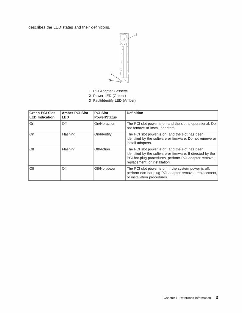
describes the LED states and their definitions.
3
2
1
1 PCI Adapter Cassette2 Power LED (Green )3 Fault/Identify LED (Amber)
Green PCI SlotLED Indication
Amber PCI SlotLED
PCI SlotPower/Status
Definition
On Off On/No action The PCI slot power is on and the slot is operational. Donot remove or install adapters.
On Flashing On/Identify The PCI slot power is on, and the slot has beenidentified by the software or firmware. Do not remove orinstall adapters.
Off Flashing Off/Action The PCI slot power is off, and the slot has beenidentified by the software or firmware. If directed by thePCI hot-plug procedures, perform PCI adapter removal,replacement, or installation.
Off Off Off/No power The PCI slot power is off. If the system power is off,perform non-hot-plug PCI adapter removal, replacement,or installation procedures.
Chapter 1. Reference Information 3
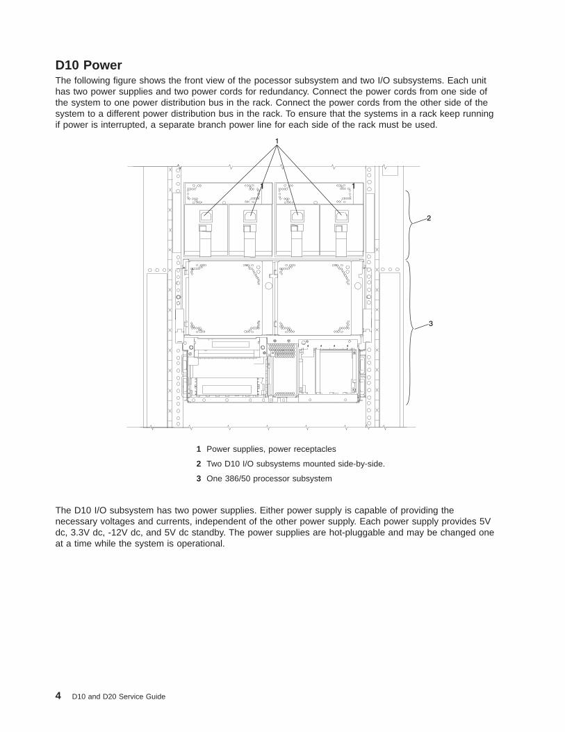
D10 PowerThe following figure shows the front view of the pocessor subsystem and two I/O subsystems. Each unithas two power supplies and two power cords for redundancy. Connect the power cords from one side ofthe system to one power distribution bus in the rack. Connect the power cords from the other side of thesystem to a different power distribution bus in the rack. To ensure that the systems in a rack keep runningif power is interrupted, a separate branch power line for each side of the rack must be used.
1 1
2
1
3
1 Power supplies, power receptacles
2 Two D10 I/O subsystems mounted side-by-side.
3 One 386/50 processor subsystem
The D10 I/O subsystem has two power supplies. Either power supply is capable of providing thenecessary voltages and currents, independent of the other power supply. Each power supply provides 5Vdc, 3.3V dc, -12V dc, and 5V dc standby. The power supplies are hot-pluggable and may be changed oneat a time while the system is operational.
4 D10 and D20 Service Guide

The following table describes power-supply LED indicators that are available on the D10.
LED Status LED Definition
Off Power source not connected
Blinking green LED System power source connected, but power is not turnedon
Blinking green LED, visibly begins to blink faster after thepower button has been pressed.
System power source connected, the power-on buttonhas been pressed and power-on initiated
Solid (not blinking) green LED, (There is approximately a30-second transition period from the time the power-onbutton is pressed to the time the power LED is on solid.)
System power source connected and turned on
The following figure shows the rear view of the processor subsystem and two I/O subsystems.
1 D10 I/O subsystem 3 Processor subsystem power supplies,power receptacles
2 386/50 processor subsystem 4 I/O backplane power (green) andfault/identify (amber) LEDs
D10 CoolingFans mounted inside each I/O subsystem power supply and an additional fan mounted on the front of thesubsystem provide cooling. The power supplies and the fan can be removed and replaced with the powerturned on, as long as only one fan is removed from the I/O subsystem at a time.
D10 Input/Output PortsThe connector ports on the rear of the D10 I/O subsystem are used to connect the RIO-2 cables, theSPCN cables, and the rack-beacon LED.
Chapter 1. Reference Information 5
Subsystem Positioning and CablingI/O subsystems can be installed in a standard 19-inch EIA rack in any location. The cables that connectthe subsystems allow some flexibility in drawer placement, but the I/O subsystems should be locatedabove the processor subsystem to which they are connected in the same rack.
Up to eight I/O subsystems can be connected to a processor subsystem. Use the following guidelines:
v Each I/O subsystem connects to the processor subsystem using one system power control network(SPCN) cable loop.
v Each I/O subsystem connects to the processor subsystem using one or more remote I/O (RIO) cableloops.
v Lowest cost configurations allow up to four I/O subsystems connected to the processor subsystem usinga single RIO loop.
v Optimum performance is achieved when each I/O drawer is connected to the processor subsystemthrough its own RIO loop.
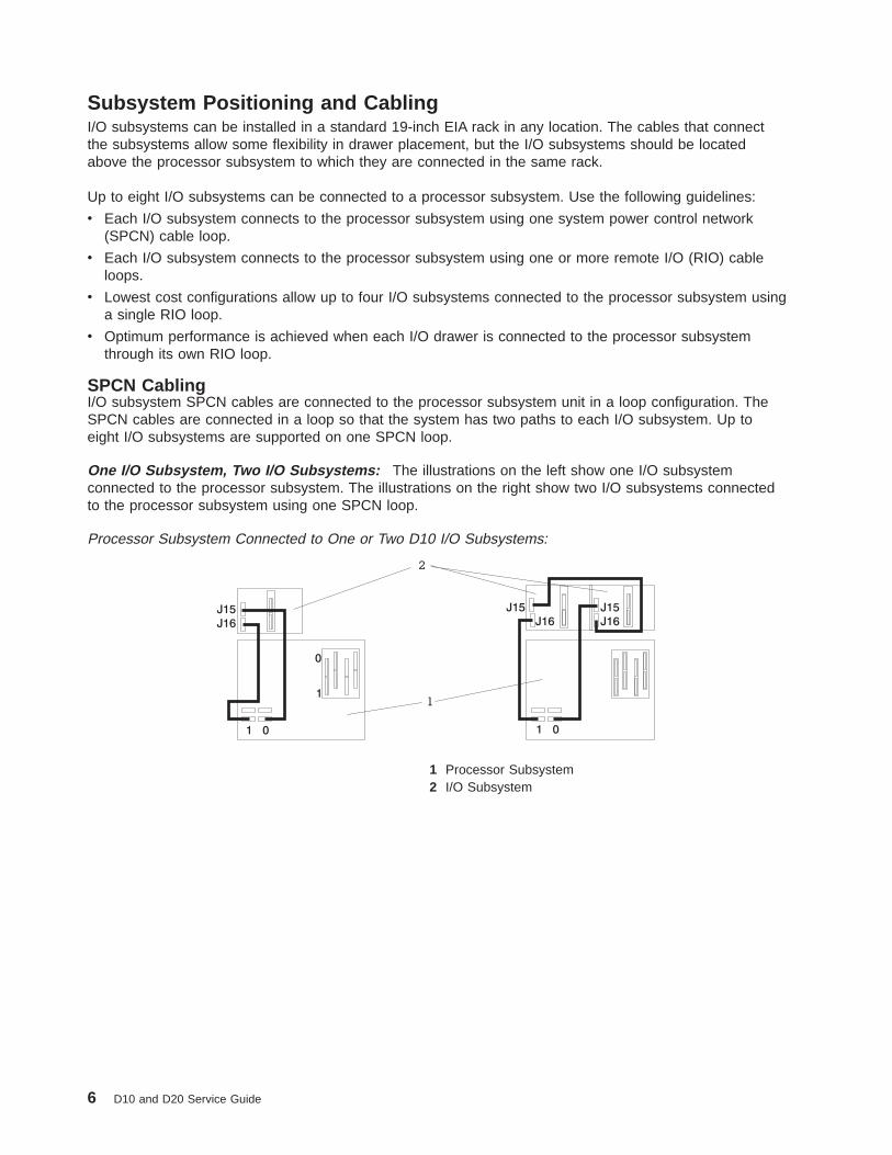
SPCN CablingI/O subsystem SPCN cables are connected to the processor subsystem unit in a loop configuration. TheSPCN cables are connected in a loop so that the system has two paths to each I/O subsystem. Up toeight I/O subsystems are supported on one SPCN loop.
One I/O Subsystem, Two I/O Subsystems: The illustrations on the left show one I/O subsystemconnected to the processor subsystem. The illustrations on the right show two I/O subsystems connectedto the processor subsystem using one SPCN loop.
Processor Subsystem Connected to One or Two D10 I/O Subsystems:
1 Processor Subsystem2 I/O Subsystem
6 D10 and D20 Service Guide

Four I/O Subsystems, Eight I/O Subsystems: The illustration on the left shows four I/O subsystemsconnected to the processor subsystem using one SPCN loop. The illustration on the right shows eight I/Osubsystems connected to the processor subsystem using one SPCN loop.
Processor Subsystem Connected to Four or Eight D10 I/O Subsystems:
1 Processor Subsystem2 I/O Subsystem
RIO CablingI/O subsystems are connected to the processor subsystem through remote I/O (RIO) cable loops. Thecable loops are connected to ports that are on the rear of the processor subsystem. The RIO cables areconnected in loops so that the system has two paths to each I/O subsystem when more than one I/Odrawer is in a loop.
If only one I/O subsystem is in a RIO loop and both the processor subsystem and the I/O subsystem areRIO-2 capable, the RIO-2 cables are used as one two-cable path to the I/O subsystem. In this cableconfiguration, the data rate is increased by a factor of 2.
v A maximum of eight D10 drawers are supported on one processor subsystem.
v If both D10 I/O drawers are connected to the same processor subsystem, the total number of I/Osubsystems supported is eight.
v The maximum number of I/O subsystems supported on one RIO loop is four.
v The D10 I/O drawers must be on separate RIO loops.
v The D10 with RIO cabling and D10 with RIO-2 cabling can share one RIO loop.
The system can have up to four RIO loops. A total of eight I/O drawers can be connected to the processorsubsystem in a variety of cabling configurations. For optimum performance, connect the RIO loops in aconfiguration that distributes multiple I/O drawers among as many RIO loops as possible. A dedicated RIOloop for each I/O drawer can provide optimum performance. Some examples of valid cabling examplesfollow.
Chapter 1. Reference Information 7
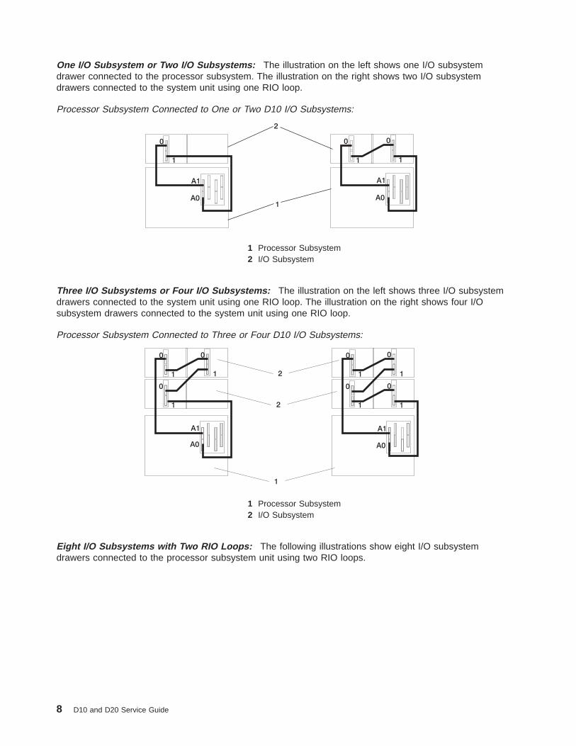
One I/O Subsystem or Two I/O Subsystems: The illustration on the left shows one I/O subsystemdrawer connected to the processor subsystem. The illustration on the right shows two I/O subsystemdrawers connected to the system unit using one RIO loop.
Processor Subsystem Connected to One or Two D10 I/O Subsystems:
A0 A0
A1 A1
0
1 1
00
1
1
2
1 Processor Subsystem2 I/O Subsystem
Three I/O Subsystems or Four I/O Subsystems: The illustration on the left shows three I/O subsystemdrawers connected to the system unit using one RIO loop. The illustration on the right shows four I/Osubsystem drawers connected to the system unit using one RIO loop.
Processor Subsystem Connected to Three or Four D10 I/O Subsystems:
1 Processor Subsystem2 I/O Subsystem
Eight I/O Subsystems with Two RIO Loops: The following illustrations show eight I/O subsystemdrawers connected to the processor subsystem unit using two RIO loops.
8 D10 and D20 Service Guide
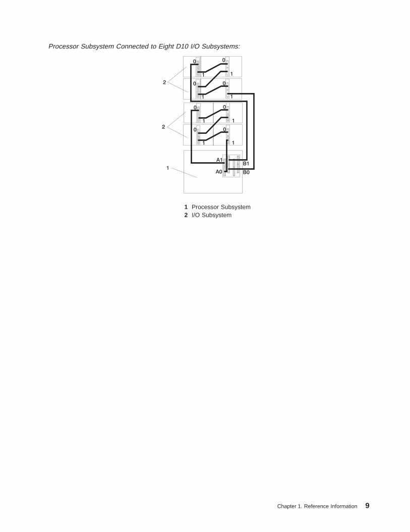
Processor Subsystem Connected to Eight D10 I/O Subsystems:
1 Processor Subsystem2 I/O Subsystem
Chapter 1. Reference Information 9
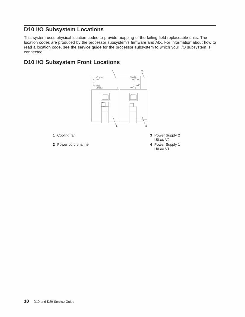
D10 I/O Subsystem LocationsThis system uses physical location codes to provide mapping of the failing field replaceable units. Thelocation codes are produced by the processor subsystem’s firmware and AIX. For information about how toread a location code, see the service guide for the processor subsystem to which your I/O subsystem isconnected.
D10 I/O Subsystem Front Locations
1 2
34
1 Cooling fan 3 Power Supply 2U0.dd-V2
2 Power cord channel 4 Power Supply 1U0.dd-V1
10 D10 and D20 Service Guide

D10 I/O Subsystem Rear Locations
1 2 3 4 5 6
1 2 3 4 5 6
78
9
11
10
12
1 PCI adapter slot 1U0.dd-P1-I1
7 RIO bus adapter cardU0.dd-P1.1
2 PCI-X adapter slot 2U0.dd-P1-I2
8 SPCN connector cardU0.dd-P1 (part of the I/O backplaneFRU)
3 PCI-X adapter slot 3U0.dd-P1-I3
9 SPCN Connector 2/J16U0.ddP1/Q5
4 PCI-X adapter slot 4U0.dd-P1-I4
10 SPCN Connector 1/J15U0.ddP1/Q4
5 PCI-X adapter slot 5U0.dd-P1-I5
11 Rack beacon connector
6 PCI-X adapter slot 6U0.dd-P1-I6
12 Power cord channel
Note: In the preceding table, dd is equal to the number assigned to each I/O subsystem by the connectedprocessor subsystem.
Chapter 1. Reference Information 11
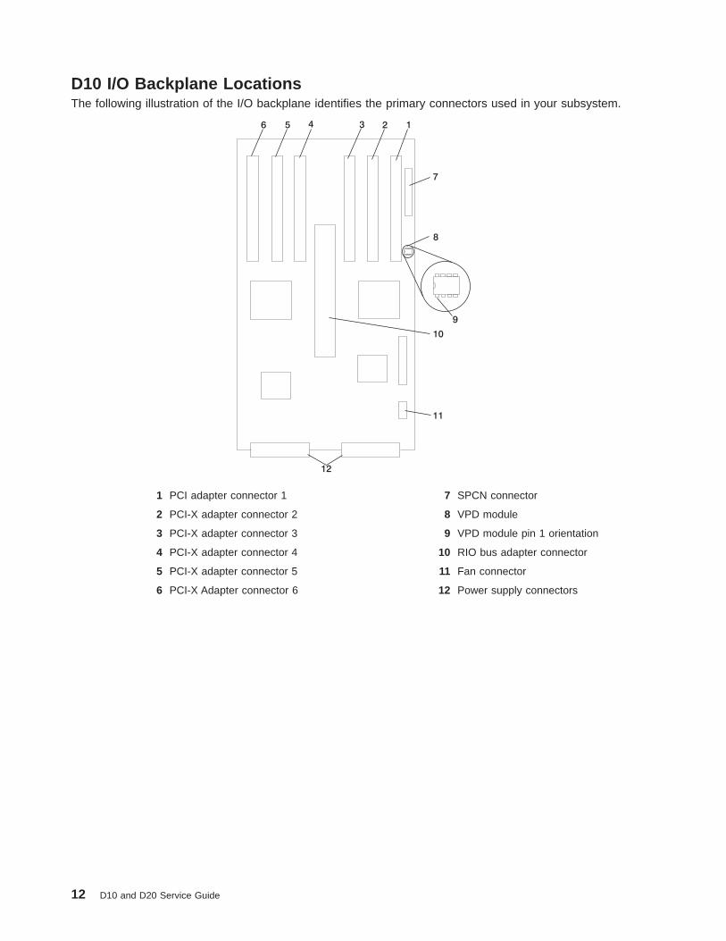
D10 I/O Backplane LocationsThe following illustration of the I/O backplane identifies the primary connectors used in your subsystem.
123456
7
8
9
10
11
12
1 PCI adapter connector 1 7 SPCN connector
2 PCI-X adapter connector 2 8 VPD module
3 PCI-X adapter connector 3 9 VPD module pin 1 orientation
4 PCI-X adapter connector 4 10 RIO bus adapter connector
5 PCI-X adapter connector 5 11 Fan connector
6 PCI-X Adapter connector 6 12 Power supply connectors
12 D10 and D20 Service Guide

D10 I/O Subsystem PHBEach D10 I/O Subsystem has two PCI host bridges (PHBs) through which the PCI slots are connected.
1 2 3 4 5 6
Slot PHB Slot Characteristics
1 1 64-bit 5V, 33 MHz
2 1 64-bit 3.3V, 131.5 MHz
3 1 64-bit 3.3V, 131.5 MHz
4 2 64-bit 3.3V, 131.5 MHz
5 2 64-bit 3.3V, 131.5 MHz
6 2 64-bit 3.3V, 131.5 MHz
Chapter 1. Reference Information 13

D10 Location CodesThis system (processor subsystem and attached I/O subsystems) use physical location codes inconjunction with AIX location codes to provide mapping of failing field replaceable units (FRUs). Thelocation codes are produced by the processor subsystem’s firmware and AIX. For information about how toread a location code, see the service guide for the processor subsystem to which your I/O subsystem isconnected.
AIX and Physical Location Code TableThis section covers the AIX and Physical Location Code tables for the D10.
The tables in this section contain the location codes for I/O subsystems when they are attached to thesystem unit. In the tables, the location code for the I/O subsystem number is represented by dd. The firsttime that an installed system is powered on, the I/O subsystems are numbered. For example, if a systemis first powered on with eight I/O subsystems connected, the dd value for the subsystems should benumbered from 2 through 9.
Note: If the system was powered on with I/O subsystems connected before delivery to the customer, theI/O subsystem location codes for the connected I/O subsystems are permanently set.
If at a later time, an I/O subsystem is removed from the system and a different I/O subsystem issubstituted, the substitute is assigned the next higher number available for its value of dd, which in theearlier example, is 10. If the original I/O subsystem is reinstalled in the system configuration, the systemuses the original dd value for the I/O subsystem.
To keep the system from renumbering the I/O drawer when an I/O backplane is replaced, the VPD modulefrom the old I/O backplane must be moved over to the new I/O backplane.
The following diagram defines each part of a location code.Ux.dd-xx-yy| | | || | | || | | yy This code is used for the next component (yy, yy, yy, ...)| | xx This code is used for the next component (Px, Fx, Vx, ...)| dd This code is the location code for the I/O drawer (2 to 63)Ux This code normally identifies the rack in which a drawer is installed.
The x will always be zero (0) for this system.
14 D10 and D20 Service Guide

D10 I/O Subsystem Location Code TableThe following table lists the location codes for a D10 I/O subsystem. The location code for the I/Osubsystem connected to a system unit is U0.dd (where dd can be any number from 2 through 63).
FRU Name Physical Location Code
D10 I/O Drawer U0. dd (dd = any number from 2 through 63)
I/O subsystem 1 drawer U0.dd
I/O backplane U0.dd-P1
RIO connector riser card U0.dd-P1.1
RIO port 0 (upper connector) U0.dd-P1.1/Q1
RIO port 0 cable U0.dd-P1.1/Q1#
RIO port 1 (lower connector) U0.dd-P1.1/Q2
RIO port 1 cable U0.dd-P1.1/Q2#
PHB1 U0.dd-P1
EADS_X under PHB1 U0.dd-P1
PCI slot 1 U0.dd-P1/I1
PCI slot 1 adapter U0.dd-P1-I1
PCI slot 2 U0.dd-P1/I2
PCI slot 2 adapter U0.dd-P1-I2
PCI slot 3 U0.dd-P1/I3
PCI slot 3 adapter U0.dd-P1-I3
PHB2 U0.dd-P1
EADS_X under PHB2 U0.dd-P1
PCI slot 4 U0.dd-P1/I4
PCI slot 4 adapter U0.dd-P1-I4
PCI slot 5 U0.dd-P1/I5
PCI slot 5 adapter U0.dd-P1-I5
PCI slot 6 U0.dd-P1/I6
PCI slot 6 adapter U0.dd-P1-I6
Power supply 1 (with 2 fans) U0.dd-V1
Power supply 2 (with 2 fans) U0.dd-V2
Cooling fan 5 U0.dd-F5
Rack indicator connector (4-pins) U0.dd-P1/Q3
SPCN connector 1/J15 U0.dd-P1/Q4
SPCN connector 2/J16 U0.dd-P1/Q5
Subsystem VPD U0.dd-P1
Chapter 1. Reference Information 15

D20 OverviewThe D20 is a 19-inch, rack-mountable I/O subsystem that is attached to a processor subsystem to extendthe system’s capacity for I/O adapters and disk drives. The I/O subsystem includes redundant concurrentlymaintainable power and cooling.
Seven PCI slots are available for PCI adapters. Because the PCI slots support hot-pluggable adapters, theI/O subsystem can have adapters installed without turning off power. The D20 is 4 EIA units high and iscompatible with 19-inch EIA rack enclosures.
D20 I/O Subsystem FeaturesThe features of the D20 enable this I/O subsystem to extend the input and output capabilities of theprocessor subsystem. Features such as PCI-X adapters and internal SCSI disk drives are supported.
D20 Operator IndicatorsLEDs are used on the D20 as operator indicators. Tables found in “D20 PCI-X Slots” and “D20 Power” onpage 18 describes the LED states and their definitions. For more information on LEDs and their definitions,see Chapter 5, “Fault and Attention LEDs”, on page 169. LEDs can be found on or near the followingFRUs:
v LED indicators visible on each PCI adapter light pipe
v LEDs for power on, attention, SCSI activity
v Attention/Identify LEDs
v Rack Beacon
D20 PCI-X SlotsSeven PCI-X slots are available. The slots are 64-bit capable at up to 131.5 Mhz, 3.3 volts. The slots arenumbered on the rear of the chassis from left to right 1 through 7. The I/O backplane and each I/O slothave green power indicator LEDs and amber identify LEDs. The following illustration shows the LEDlocations when viewing from the rear of the I/O drawer.
1 PCI-X Expansion Slot 1 6 PCI-X Expansion Slot 62 PCI-X Expansion Slot 2 7 PCI-X Expansion Slot 73 PCI-X Expansion Slot 3 A Green Power LEDs4 PCI-X Expansion Slot 4 B Amber Identify LEDs5 PCI-X Expansion Slot 5
16 D10 and D20 Service Guide

The green LEDs for the PCI-X adapter slots (viewed on the rear of the I/O subsystem) indicate the state ofthe PCI slot during removal and replacement of an adapter.
PCI LED (Green) Indication PCI Slot Status Definition
Off Off Slot power is Off. It is safe to removeor replace adapters.
On (not flashing) On Slot power is On. Do not remove orreplace adapters.
Flashing slowly (one flash persecond)
Slot has been identified by thesoftware. Do not remove or replaceadapters at this time.
Flashing rapidly (six to eight flashesper second)
Slot is ready removing or replacing anadapter.
D20 Disk DrivesThere are 12 hot-plug disk-drive bays provided. The bays are located behind the D20 front bezel. The D20has from 18.2 GB to 1.7 terabytes of disk storage capacity. The following disk drive sizes and speeds areavailable:
v 18.2 GB Ultra3 10K RPM 1 inch
v 36.4 GB Ultra3 10K RPM 1 inch
v 73.4 GB Ultra3 10K RPM 1 inch
v 146.8 GB Ultra3 10K RPM 1 inch
For an updated listing of hot-plug disk-drive sizes, contact your sales representative.
Chapter 1. Reference Information 17

D20 PowerThe D20 is standard with one power supply. If the customer wants redundant power in their I/Osubsystem, an optional power supply can be ordered. Either power supply, in a D20 that is configured withtwo power supplies, can provide the necessary voltages and currents, independent of the other powersupply. The left and right power-supply output voltages are connected and monitored by the powerdistribution board contained in the I/O subsystem.
The left and right power supplies are hot-pluggable and may be changed one at a time while the system isoperational. Each power supply is capable of converting available 110/220 V ac to the proper internalvoltages used by the system components. The internal voltage range is 5 volts system standby, 3.3 volts,5 volts, 12 volts and -12 volts. When operating correctly, each supply will share the current load whenpowered on. When in a fault state, the operating power supply will supply standby current to the faultedsupply for the DEVROS module. The following table describes power-related LED indicators that areavailable on the D20. The operator panel LED referred to in the following table is on the front of theprocessor subsystem to which the I/O subsystem is attached.
Status of LED Operator Panel LED (processor subsystem)
Off Power Source not connected
Blinking green LED System power source connected, but power is not turnedon
Blinking green LED, visibly begins to blink faster after thepower-button has been pressed.
System power source connected, the power-on buttonhas been pressed and power-on initiated
Solid (not blinking) green LED, (There is approximately a30-second transition period from the time the power onbutton is pressed to the time the power LED is on solid.)
System power source connected and turned on
D20 CoolingFour blowers are mounted on the top of the I/O subsystem to provide cooling.
Attention: The four cooling blowers mounted on top of the D20 are hot-plug. The one exception is whenyour subsystem has only one power supply either installed or functioning, in which case you must shutdown the system and subsystem. Failure to do so will automatically shut down the system.
D20 Input/Output PortsThe connector ports on the rear of the D20 I/O subsystem are used to connect the RIO-2 cables, theSPCN cables, and the rack-beacon LED.
18 D10 and D20 Service Guide

D20 I/O Subsystem LocationsThe system uses physical location codes to provide mapping of the failing field replaceable units. Thelocation codes are produced by the processor subsystem’s firmware and AIX. For information about how toread a location code, see the service guide for the processor subsystem to which your I/O subsystem isconnected.
D20 Front View
1 Serial Number 3 D20 Front Bezel2 Operator Panel 4 Disk Drives (maximum quantity 12 )
D20 Rear View
1 PCI-X Expansion Slot 1 9 Primary Power Supply2 PCI-X Expansion Slot 2 10 D20 I/O Drawer3 PCI-X Expansion Slot 3 11 Connector J11 (Not Used)4 PCI-X Expansion Slot 4 12 Connector J14 (Not Used)5 PCI-X Expansion Slot 5 13 Rear Serial Number Label6 PCI-X Expansion Slot 6 14 Connector J15 (SPCN 3)7 PCI-X Expansion Slot 7 15 Connector J16 (SPCN 4)8 Redundant Power Supply Receptacle 16 RIO Connectors
Upper Connector = 1Lower Connector = 0
Chapter 1. Reference Information 19

D20 Power Supply Locations
1
2 3 4
6
5
1 Power Supplies 4 Green AC Power LED2 Amber Fault/Identify LED 5 Power Supply Filler3 Green DC Good LED 6 D20 I/O Drawer
20 D10 and D20 Service Guide

D20 Blower LocationsThe following illustration identifies the I/O subsystem cooling blowers. Each blower has a green powerLED and an amber identify LED located on the front blower housing. The green LED indicates that ablower has power and is operating correctly. The amber LED is in the identify state when blinking.
1 Green LED 4 Blower Connector2 Amber LED 5 Hot-Plug Blower Assembly3 Snap Button 6 Docking Connector
Chapter 1. Reference Information 21

D20 I/O Backplane LocationsThe following illustration of the I/O backplane identifies the primary connectors used in your subsystem.
Note: Before replacing the I/O backplane, note the position of pin 1 on the VPD module.
1 PCI-X Adapter Connector 1 11 Disk Drive Power Connector
2 PCI-X Adapter Connector 2 12 Cooling Blower Connector
3 PCI-X Adapter Connector 3 13 VPD Module
4 PCI-X Adapter Connector 4 14 Redundant Power Supply Connector
5 PCI-X Adapter Connector 5 15 Primary Power Supply Connector
6 PCI-X Adapter Connector 6 16 Connector J11 (Not Used)
7 PCI-X Adapter Connector 7 17 Connector J14 (Not Used)
8 Operator Panel Connector 18 Connector J15 (SPCN 3)
9 RIO Bus Adapter Connector 19 Connector J16 (SPCN 4)
10 Disk Drive System Power Control Network(SPCN) Connector
20 4-pin Connector, Rack Beacon Connector
22 D10 and D20 Service Guide

D20 Reading the Operator Panel and I/O Backplane LEDsThe following illustration shows the component location on the operator panel
1 Power-On LED2 Attention LED3 Operator Panel4 Snap Buttons
The following table defines each LEDs function on the operator panel.
Number Component Name Component Description
1 Green Power LED Standby State - Blinking LED(System connected to power source but not powered on.)Powered On - LED is turned on solid (not blinking).
2 Amber Attention LED Normal State - LED is off.
Chapter 1. Reference Information 23

D20 SCSI IDs and Bay Locations
Index Bay Location Drive Name SCSI Bus ID
8 DB1 D01 Hot-Plug Disk Drive 8 - DB1
9 DB1 D02 Hot-Plug Disk Drive 9 - DB1
A DB1 D03 Hot-Plug Disk Drive A - DB1
B DB1 D04 Hot-Plug Disk Drive B - DB1
C DB1 D05 Hot-Plug Disk Drive C - DB1
D DB1 D06 Hot-Plug Disk Drive D - DB1
8 DB2 D07 Hot-Plug Disk Drive 8 - DB2
9 DB2 D08 Hot-Plug Disk Drive 9 - DB2
A DB2 D09 Hot-Plug Disk Drive A - DB2
B DB2 D10 Hot-Plug Disk Drive B - DB2
C DB2 D11 Hot-Plug Disk Drive C - DB2
D DB2 D12 Hot-Plug Disk Drive D - DB2
Note: The SCSI bus IDs are the recommended values and indicate how the IDs are set when the systemis shipped from the factory. Field installations might not comply with these recommendations.
24 D10 and D20 Service Guide
Cabling the D20 to a 286/C4The D20 subsystem can be installed in any location in a standard 19-inch EIA rack. The cables thatconnect the subsystems allow some flexibility in drawer placement. Up to two D20s can be connected to a286/C4. Each I/O subsystem is connected to the processor subsystem using a system power controlnetwork (SPCN) cable loop and a remote I/O (RIO) cable loop. One SPCN cable loop is needed toconnect the I/O subsystems to one processor subsystem.
Before connecting the RIO-2 and SPCN cables to the D20, do the following:
1. Ensure that your 286/C4 is running the latest level firmware. Refer to the ″Firmware Updates″ sectionof the ″Using the Service Processor″ chapter in the 286/C4 and 286/E4 Service Guide, order numberSA23-1277. For information about checking or upgrading the firmware level of your 286/C4.
2. After ensuring that your firmware is at the latest level, turn off the power and disconnect the 286/C4power cables from the power source.
3. Attach the RIO-2 and SPCN cables. For cabling diagrams, see “RIO-2 (Remote Input Output) Cabling”on page 26.
4. After connecting the RIO-2 and SPCN cables from the D20 to your system, reconnect the system’spower cables to the power source and refer to “Stopping and Starting the System” on page 42.
5. Run system verification. Refer to the ″Verifying the Hardware″ chapter in the 286/C4 and 286/E4Installation Guide, order number SA23-1277.
Your 286/C4 is expandable when connected up to two D20 I/O drawers. Each D20 can contain up to 7 I/OPCI adapter slots, and two 6-pack disk drive (DASD) bays.
Chapter 1. Reference Information 25
RIO-2 (Remote Input Output) CablingThe following rules apply to RIO-2 cable connections:
Notes:
1. To connect to a D20, you will be using the RIO-2 (Remote Input Output) and SPCN (System PowerControl Network) connectors and cables. The RIO-2 and SPCN cables provide two functions, remotedata bus connection, and power control.
2. The I/O drawers must be connected in a loop for both the RIO-2 and SPCN cables. The loopconnection provides redundant paths so that if a failure occurs in part of a cable, the system willcontinue to operate. If a failure does occur, a message is displayed on the system console; however,the system does continue to operate. See the following illustrations for possible cabling configurations.
To connect the RIO-2 cables to the rear of the 286/C4, do the following:
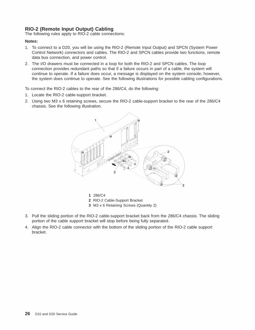
1. Locate the RIO-2 cable-support bracket.
2. Using two M3 x 6 retaining screws, secure the RIO-2 cable-support bracket to the rear of the 286/C4chassis. See the following illustration.
1 286/C42 RIO-2 Cable-Support Bracket3 M3 x 6 Retaining Screws (Quantity 2)
3. Pull the sliding portion of the RIO-2 cable-support bracket back from the 286/C4 chassis. The slidingportion of the cable support bracket will stop before being fully separated.
4. Align the RIO-2 cable connector with the bottom of the sliding portion of the RIO-2 cable supportbracket.
26 D10 and D20 Service Guide

5. Lift the RIO-2 cable and cable connector into the bottom of the RIO-2 cable-support bracket.
1 286/C42 RIO-2 Cable-Support Bracket3 Slide Portion of RIO-2 Cable-Support Bracket4 RIO-2 Connector Support Lever
6. Pull the RIO-2 connector back until the connector is seated against the support hook.
7. Push the RIO-2 connector forward, ensuring that the RIO-2 connector lever slides over the top of theconnector hooks.
8. Slowly push the assembly toward the chassis.
9. Secure the RIO-2 cable-support bracket with the captive thumbscrew, the RIO-2 connector and slideportion of the RIO-2 support bracket to the back of the 286/C4 chassis.
1 Captive Thumbscrews2 RIO-2 Cable and Connector3 RIO-2 Connector Support Lever
Chapter 1. Reference Information 27

286/C4 Attached to One I/O Drawer:
1 286/C42 D203 Cable from 286/C4 Connector RIO-2 0 to D20 Connector RIO-2 04 Cable from 286/C4 Connector RIO-2 1 to D20 Connector RIO-2 1
286/C4 Attached to Two I/O Drawers:
1 286/C42 D20 I/O Drawer3 D20 I/O Drawer4 Cable from 286/C4 Connector RIO-2 0 to D20 Connector RIO-2 05 Cable from 286/C4 Connector RIO-2 1 to D20 Connector RIO-2 16 Cable from D20 Connector RIO-2 1 to D20 Connector RIO-2 0
28 D10 and D20 Service Guide

SPCN (System Power Control Network) CablingThe following figures provide cabling examples for all valid cabling configurations. Match your configurationto the correct figure and connect your SPCN cables as shown.
286/C4 Attached to One I/O Drawer:
1 286/C42 D203 Cable from 286/C4 Connector SPCN 2 to D20 Connector SPCN 4 (J16)4 Cable from 286/C4 Connector SPCN 1 to D20 Connector SPCN 3 (J15)
286/C4 Attached to Two I/O Drawers:
1 286/C42 D20 I/O Drawer3 D20 I/O Drawer4 Cable from 286/C4 Connector SPCN 1 to D20 Connector SPCN 3 (J15)5 Cable from 286/C4 Connector SPCN 2 to D20 Connector SPCN 4 (J16)6 Cable from D20 Connector SPCN 4 (J16) to D20 Connector SPCN 3 (J15)
Chapter 1. Reference Information 29

D20 Internal Cabling
1 Cooling Blowers (Quantity 4) 6 Disk Drive Power Connector2 Operator Panel 7 Disk Drive SPCN Connector3 Disk Drive Backplanes 8 Disk Drive Power/Signal Cable
53P04164 Cooling Blower Cable
53P04199 Operator Panel Connector
5 Cooling Blower Connector 10 Operator Panel Cable53P0414
30 D10 and D20 Service Guide

D20 Location CodesThis system (processor subsystem and attached I/O subsystems) uses physical location codes inconjunction with AIX location codes to provide mapping of a failing field replaceable units (FRUs). Thelocation codes are produced by the processor subsystem’s firmware and AIX. For information about how toread a location code, see the service guide for the processor subsystem to which your I/O subsystem isconnected.
AIX and Physical Location Code TableThis section covers the AIX and Physical Location Code tables for the D20 I/O subsystem.
The tables in this section contain the location codes for I/O subsystems when they are attached to thesystem unit. In the tables, the location code for the I/O subsystem number is represented by dd. The firsttime that an installed system is powered on, the I/O subsystems are numbered. For example, if a systemis first powered on with two I/O subsystems connected, then the dd value for the connected I/Osubsystems should be numbered from 2 and 3.
Note: If the system was powered on with I/O subsystems connected before delivery to the customer, theI/O subsystem location codes for the drawers connected at that time are already assigned.
If at a later time, an I/O subsystem is removed from the system and a different I/O subsystem issubstituted, the substitute is assigned the next higher number available for its value of dd, which, in theearlier example, is 4. If the original I/O subsystem is reinstalled in the system configuration, the systemuses the original dd value for the I/O subsystem.
To keep the system from renumbering the I/O drawer when an I/O backplane is replaced, the VPD modulefrom the old I/O backplane must be moved over to the new I/O backplane.
The following diagram defines each part of a location code.Ux.dd-xx-yy| | | || | | || | | yy This code is used for the next component (yy, yy, yy, ...)| | xx This code is used for the next component (Px, Fx, Vx, ...)| dd This code is the location code for the I/O drawer (2 to 63)Ux This code normally identifies the rack in which a drawer is installed.
The x will always be zero (0) for this system.
Chapter 1. Reference Information 31
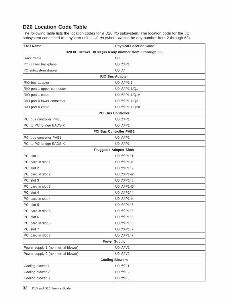
D20 Location Code TableThe following table lists the location codes for a D20 I/O subsystem. The location code for the I/Osubsystem connected to a system unit is U0.dd (where dd can be any number from 2 through 63).
FRU Name Physical Location Code
D20 I/O Drawer U0. dd (dd = any number from 2 through 63)
Rack frame U0
I/O drawer backplane U0.dd-P1
I/O subsystem drawer U0.dd
RIO Bus Adapter
RIO bus adapter U0.dd-P1.1
RIO port 1 upper connector U0.dd-P1.1/Q1
RIO port 1 cable U0.dd-P1.1/Q1#
RIO port 0 lower connector U0.dd-P1.1/Q2
RIO port 0 cable U0.dd-P1.1/Q2#
PCI Bus Controller
PCI bus controller PHB0 U0.dd-P1
PCI to PCI bridge EADS-X U0.dd-P1
PCI Bus Controller PHB2
PCI bus controller PHB2 U0.dd-P1
PCI to PCI bridge EADS-X U0.dd-P1
Pluggable Adapter Slots
PCI slot 1 U0.dd-P1/I1
PCI card in slot 1 U0.dd-P1-I1
PCI slot 2 U0.dd-P1/I2
PCI card in slot 2 U0.dd-P1-I2
PCI slot 3 U0.dd-P1/I3
PCI card in slot 3 U0.dd-P1-I3
PCI slot 4 U0.dd-P1/I4
PCI card in slot 4 U0.dd-P1-I4
PCI slot 5 U0.dd-P1/I5
PCI card in slot 5 U0.dd-P1/I5
PCI slot 6 U0.dd-P1/I6
PCI card in slot 6 U0.dd-P1/I6
PCI slot 7 U0.dd-P1/I7
PCI card in slot 7 U0.dd-P1/I7
Power Supply
Power supply 1 (no internal blower) U0.dd-V1
Power supply 2 (no internal blower) U0.dd-V2
Cooling Blowers
Cooling blower 1 U0.dd-F1
Cooling blower 2 U0.dd-F2
Cooling blower 3 U0.dd-F3
32 D10 and D20 Service Guide
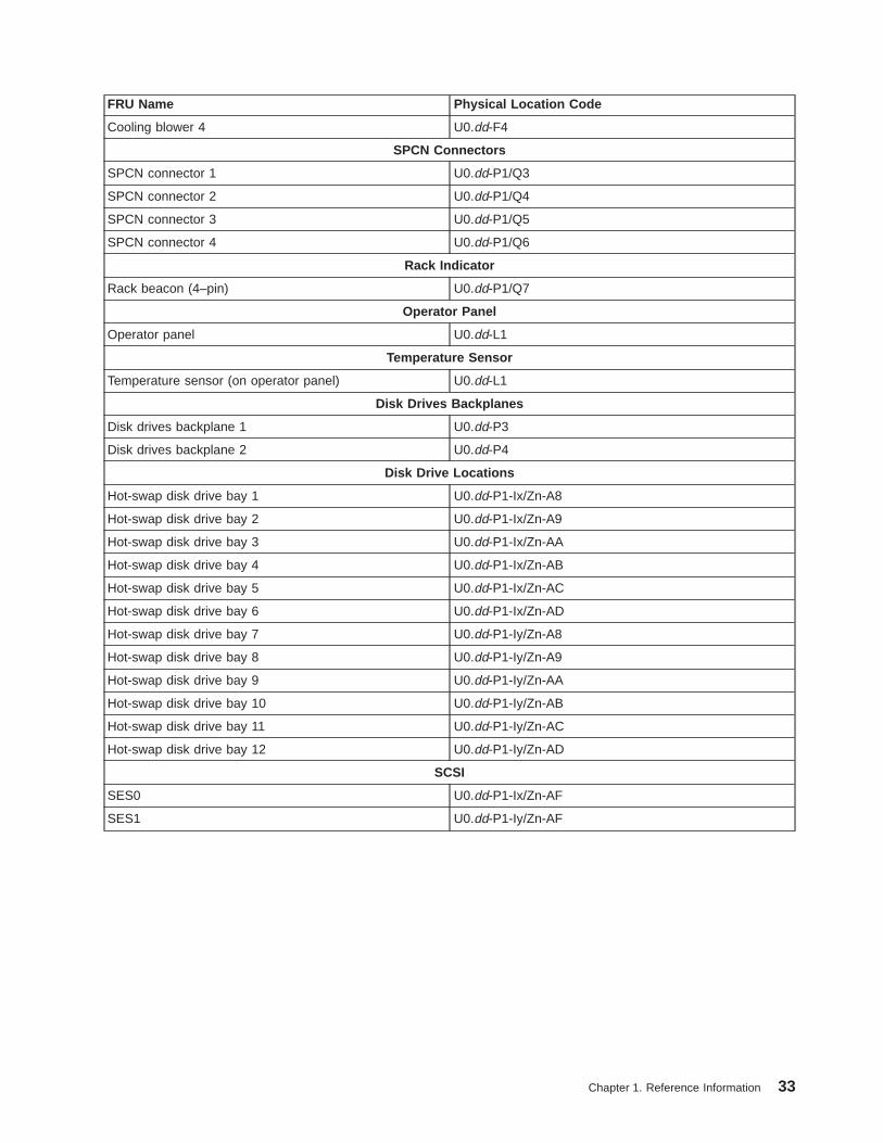
FRU Name Physical Location Code
Cooling blower 4 U0.dd-F4
SPCN Connectors
SPCN connector 1 U0.dd-P1/Q3
SPCN connector 2 U0.dd-P1/Q4
SPCN connector 3 U0.dd-P1/Q5
SPCN connector 4 U0.dd-P1/Q6
Rack Indicator
Rack beacon (4–pin) U0.dd-P1/Q7
Operator Panel
Operator panel U0.dd-L1
Temperature Sensor
Temperature sensor (on operator panel) U0.dd-L1
Disk Drives Backplanes
Disk drives backplane 1 U0.dd-P3
Disk drives backplane 2 U0.dd-P4
Disk Drive Locations
Hot-swap disk drive bay 1 U0.dd-P1-Ix/Zn-A8
Hot-swap disk drive bay 2 U0.dd-P1-Ix/Zn-A9
Hot-swap disk drive bay 3 U0.dd-P1-Ix/Zn-AA
Hot-swap disk drive bay 4 U0.dd-P1-Ix/Zn-AB
Hot-swap disk drive bay 5 U0.dd-P1-Ix/Zn-AC
Hot-swap disk drive bay 6 U0.dd-P1-Ix/Zn-AD
Hot-swap disk drive bay 7 U0.dd-P1-Iy/Zn-A8
Hot-swap disk drive bay 8 U0.dd-P1-Iy/Zn-A9
Hot-swap disk drive bay 9 U0.dd-P1-Iy/Zn-AA
Hot-swap disk drive bay 10 U0.dd-P1-Iy/Zn-AB
Hot-swap disk drive bay 11 U0.dd-P1-Iy/Zn-AC
Hot-swap disk drive bay 12 U0.dd-P1-Iy/Zn-AD
SCSI
SES0 U0.dd-P1-Ix/Zn-AF
SES1 U0.dd-P1-Iy/Zn-AF
Chapter 1. Reference Information 33

Powering the System On and OffPower for the I/O subsystems is controlled by the attached processor subsystem and the System PowerControl Network (SPCN).
For information about procedures to power the system on and off, refer to the service guide of theprocessor subsystem to which the I/O subsystem is attached.
Power-On Self-TestAfter power is turned on and before the operating system is loaded, the system does a power-on self-test(POST). The RIO loop that connects the I/O subsystems to the system unit is tested. Tests are alsoperformed on the installed adapters and devices in the I/O subsystems. If an error occurs during thePOST, an error code is displayed on the system operator panel LCD that indicates which part is failing andwhich subsystem contains the error.
34 D10 and D20 Service Guide

D10 and D20 SpecificationsThis section contains system specifications for both the D10 and D20 I/O subsystems.
D10 Specifications
Dimensions 7311-D10 Two 7311-D10s withEnclosure
Height 170 mm (6.6 in) 178 mm (7.0 in)Width 220 mm (8.7 in) 445 mm (17.5 in)Depth 711 mm (28.0 in) 711 mm (28.0 in)Weight 16.8 kg (37 lbs) 39.1 kg (86 lbs)ElectricalPower source loading for two 7311-D10 (max.) 0.21 kVAVoltage range 200 to 240 V ac, (dc not supported)Frequency 50 or 60 HzThermal output (typical) 461 Btu/hrThermal output (max.) 683 Btu/hrPower requirements (typical) 135 wattsPower requirements for two 7311-D10 (max.) 200 wattsPower factor 0.91Inrush current² 64 ampsMaximum altitude3, 4 3048 m (10000 ft.)
Temperature Requirements ³ Operating10 to 38°C
50 to 100°F)
Non-Operating1 to 60°C
(34 to 140°F)
Storage1 to 60°C
(34 to 140°F)
Humidity Requirements ⁴ Operating Non-Operating Storage(Noncondensing) 8 to 80% 8 to 80% 8 to 80%Wet Bulb 23°C (73°F) 27°C (81°F) 29°C (84°F)
Noise Emissions 1, 4 Operating IdleLWAd, one 7311-D10LWAd, two 7311-D10LWAd, four 7311-D10
5.6 bels5.9 bels6.2 bels
5.6 bels5.9 bels6.2 bels
<LpA>m, one 7311-D10<LpA>m, two 7311-D10<LpA>m, four 7311-D10
40 dBA43 dBA46 dBA
40 dBA43 dBA46 dBA
Install/Air Flow : Maintaining service clearance allows proper air flow.
Service Clearances : See 14T/0 and 14T/4 Installation and Service Guide, order number SA23-2544 for T00 or T42rack service clearances.
1. See page 174 for definitions of noise emissions positions. See noise emissions note 4.2. Inrush currents occur only at initial application of power, no inrush occurs during normal power off-on cycle.3. The upper limit of the dry bulb temperature must be derated 1°C per 137 m (450 ft.) above 915 m (3000 ft.).4. The upper limit of the wet bulb temperature must be derated 1°C per 274 m (900 ft. ) above 305 m (1000 ft.).
Chapter 1. Reference Information 35

D20 Specifications
Dimensions
Height 178 mm (7.0 in)Width 445 mm (17.5 in)Depth 610 mm (24.0 in)Maximum Weight 45.9kg (101 lbs)ElectricalPower source loading (max.) 0.358 kVAVoltage range 100 to 240 V ac, V dc not supportedFrequency 50 or 60 HzThermal output (typical) 774 Btu/hrThermal output (max.) 1161 Btu/hrPower requirements (typical) 227 wattsPower requirements for two7311-D20 (max.)
340 watts
Power factor 0.91Inrush current² 60 ampsMaximum altitude3, 4 3048 m (10,000 ft.)
TemperatureRequirements ³
Operating5 to 35°C
41 to 95°F)
Non-Operating1 to 43°C
(34 to 109°F)
Storage1 to 60°C
(34 to 140°F)
Humidity Requirements ⁴ Operating Non-Operating Storage(Noncondensing) 8 to 80% 8 to 80% 5 to 80%Wet Bulb 23°C (73°F) 27°C (81°F) 29°C (84°F)
Noise Emissions 1, 5 Operating IdleLWAd 6.1 bels 6.0 bels<LpA>m 44 dBA 43 dBA
Install/Air Flow Maintaining service clearance allows proper air flow.
Service Clearances : See 14T/0 and 14T/4 Installation and Service Guide, order number SA23-2544 for T00 or T42rack service clearances.
1. See 174 for definitions of noise emissions positions. See noise emissions note 4.2. Inrush currents occur only at initial application of power, no inrush occurs during normal power off-on cycle.3. The upper limit of the dry bulb temperature must be derated 1 degree C per 137 m (450 ft.) above 915 m (3000
ft.).4. The upper limit of the wet bulb temperature must be derated 1 degree C per 274 m (900 ft. ) above 305 m (1000
ft.).
36 D10 and D20 Service Guide

External AC Power CablesTo avoid electrical shock, a power cable with a grounded attachment plug is provided. Use only properlygrounded outlets.
Power cables used in the United States and Canada are listed by Underwriter’s Laboratories (UL) andcertified by the Canadian Standards Association (CSA). These power cords consist of the following:
v Electrical cables, Type SVT or SJT.
v Attachment plugs complying with National Electrical Manufacturers Association (NEMA) 5-15P, that is:
″For 115 V operation (D20 only), use a UL listed cable set consisting of a minimum 18 AWG, Type SVT orSJT three-conductor cord a maximum of 15 feet in length and a parallel blade, grounding type attachmentplug rated at 15 A, 125 V.″
″For 230 V operation in the United States use a UL listed cable set consisting of a minimum 18 AWG,Type SVT or SJT three-conductor cable a maximum of 15 feet in length, and a tandem blade, groundingtype attachment plug rated at 15 A, 250 V.″
v Appliance couplers complying with International Electrotechnical Commission (IEC) Standard 320, SheetC13.
Power cables used in other countries consist of the following:
v Electrical cables, Type HD21.
v Attachment plugs approved by the appropriate testing organization for the specific countries where theyare used.
″For units set at 230 V (outside of U.S.): use a cable set consisting of a minimum 18 AWG cable andgrounding type attachment plug rated 15 A, 250 V. The cable set should have the appropriate safetyapprovals for the country in which the equipment will be installed and should be marked `HAR’.″
For information about the power cables that are available, refer to Chapter 4, “Parts Information”, onpage 157.
Chapter 1. Reference Information 37
Service Inspection GuidePerform a service inspection on the system (processor subsystem and connected I/O subsystems) when:
v The system is inspected for a maintenance agreement.
v Service is requested and service has not recently been performed.
v An alterations and attachments review is performed.
v Changes have been made to the equipment that may affect the safe operation of the equipment.
v External devices with their own power cables have those cables attached.
If the inspection indicates an unacceptable safety condition, the condition must be corrected before anyonecan service the machine.
Note: The owner of the system is responsible to correct any unsafe conditions.
Perform the following checks:
1. Check the covers for sharp edges and for damage or alterations that expose the internal parts of thesystem.
2. Check the covers for proper fit to the system. They should be in place and secure.
3. Gently rock the system from side to side to determine if it is steady.
4. Set the power button of the system to Off.
5. Remove the covers.
6. Check for alterations or attachments. If there are any, check for obvious safety hazards, such asbroken wires, sharp edges, or broken insulation.
7. Check the internal cables for damage.
8. Check for dirt, water, and any other contamination within the system.
9. Check the voltage label on the back of the system to ensure that it matches the voltage at the outlet.
10. Check the external power cable for damage.
11. With the external power cable connected to the system, check for 0.1 ohm or less resistance betweenthe ground lug on the external power cable plug and the metal frame.
12. Perform the following checks on each device that has its own power cables:
a. Check for damage to the power cable.
b. Check for the correctly grounded power cable.
c. With the external power cable connected to the device, check for 0.1 ohm or less resistancebetween the ground lug on the external power cable plug and the metal frame of the device.
13. Install the covers.
38 D10 and D20 Service Guide

Chapter 2. Diagnostics and Maintenance Procedures
The system uses an integrated set of software diagnostic procedures to help isolate failing componentsand system maintenance. This book, along with the Diagnostic Information for Multiple Bus Systems, is thebasis of the diagnostic procedures. Refer to the system service guide when running diagnostics on yourI/O subsystem.
Power and Attention LEDsThe Power and Attention LEDs provide a means to identify failing components in your subsystem. When afailing component is detected in your system, the system’s Attention LED is turned on.
Component LEDsTo further help you identify the failing component, all system components have individual LEDs thatindicate a failure when lit. The LEDs are either on the component itself or on the carrier of the component(memory card, fan, memory module, or CPU).
The LEDs are either green or amber in color. A lit green LED indicates that the system or component isreceiving power. A lit amber LED identifies a system or component on the system. The amber LED canalso indicate when a system or component on a system has a problem or fault. For more information onLEDs and their definitions, see Chapter 5, “Fault and Attention LEDs”, on page 169.
Resetting the LEDsTo reset the LEDs, do the following:
1. Replace the failing component with the new component.
2. Log in as root user.
3. At the command line, type diag.
4. Select Task Selection .
5. Select Log Repair Action .
6. Select the device that was repaired. (If the device is not listed, select sysplanar0 .)
CheckpointsThe system uses various types of checkpoints, error codes, and SRNs, which are referred to throughoutyour system’s service guide. These codes can appear in the service processor boot progress log, the AIXerror log, and the operator panel display. Understanding the definition and relationships of these codes isimportant to the service personnel who are installing or maintaining the system.
Service Request Numbers (SRNs) are listed in the Diagnostic Information for Multiple Bus Systems, ordernumber SA23-2769.
FRU IsolationFor a list of error codes and recommended actions for each code, see your system’s service guide. Theseactions can refer to Chapter 4, “Parts Information”, on page 157, “Maintenance Analysis Procedures(MAPs)” on page 40, or provide informational message and directions. If a replacement part is indicated,direct reference is made to the part name. The respective AIX and physical location codes are listed foreach occurrence as required. For a list of locations codes, see your system’s service guide.
39
Maintenance Analysis Procedures (MAPs)The maintenance analysis procedures (MAPs) provide the service representative a step-by-step procedureto analyze a problem with the system and I/O subsystem hardware. Be prepared to record code numbersand other data while using the MAPs.
Because the D10 and D20 are subsystems, refer to your system’s service guide. The system’s serviceguide contains all of the MAPs needed for servicing the D10 and D20 I/O subsystems.
CheckpointsCheckpoints display on the system operator panel and the virtual terminal while the system unit ispowering on and going through the initial program load (IPL). See the system’s service guide fordescriptive information and a complete listing of all checkpoints used by the D10 and D20 I/O subsystems.
Error Code to FRU IndexThe Error Code to FRU Index lists fault symptoms and possible causes. The most likely cause is listedfirst. Use this index to help you decide which FRUs to replace when servicing the D10 or D20 I/Osubsystem. See your system’s service guide for more information and a complete listing of all error codesand FRUs used by the D10 and D20 I/O subsystem.
Using the Service ProcessorThe service processor is in the processor subsystem to which your I/O subsystem is connected and runson its own power boundary. The service processor continually monitors hardware attributes and theenvironmental conditions within the system and connected I/O subsystems. The service processor iscontrolled by firmware and does not require the operating system to be operational to perform its tasks.
The service processor menus allow you to configure service processor options, as well as enable anddisable functions.
Service processor menus are available using an ASCII terminal or an HMC virtual terminal window whenOK is displayed on the operator panel or when the service processor has detected a system problem (suchas a surveillance failure).
For more information about the service processor for the system to which your I/O subsystem isconnected, see the system’s service guide.
Using System Management ServicesUse the system management services menus to view information about the processor subsystem to whichthe I/O subsystem is connected. For more information about the service processor, see the service guidefor the attached system.
40 D10 and D20 Service Guide

Chapter 3. Removal and Replacement Procedures
Before performing any of the removal or replacement procedures in this chapter, read the following dangerand caution notices.
Safety ConsiderationsObserve the following safety precautions anytime you work with these I/O subsystems.
For the I/O subsystem you are about to setup or service:
v The ac power interface connector is considered the main power disconnect device.
v The I/O subsystems have independent redundant power supply capabilities, meaning that each unitmight be configured to have two power supplies running simultaneously in the same I/O subsystem.When instructed to disconnect the power source, ensure that all power cables that run to each servicedsubsystem are disconnected from the power distribution bus.
DANGER
An electrical outlet that is not correctly wired could place hazardous voltage on metal parts ofthe system or the devices that attach to the system. It is the responsibility of the customer toensure that the outlet is correctly wired and grounded to prevent an electrical shock.
Before installing or removing signal cables, ensure that the power cables for the system unitand all attached devices are unplugged.
When adding or removing any additional devices to or from the system, ensure that the powercables for those devices are unplugged before the signal cables are connected. If possible,disconnect all power cables from the existing system before you add a device.
Use one hand, when possible, to connect or disconnect signal cables to prevent a possibleshock from touching two surfaces with different electrical potentials.
During an electrical storm, do not connect cables for display stations, printers, telephones, orstation protectors for communications lines.D05
CAUTION:This product is equipped with a three-wire power cable and plug for the user’s safety. Use thispower cable with a properly grounded electrical outlet to avoid electrical shock.C01
CAUTION:This unit has more than one power supply cord. To reduce the risk of electrical shock, disconnecttwo power supply cords before servicing.C21
41

Handling Static-Sensitive Devices
Attention: Electronic boards and disk drives are sensitive to static electricity discharge. These devicesare wrapped in antistatic bags to prevent this damage.
Take the following precautions:
v If you have an antistatic wrist strap available, use it while handling the device.
v Do not remove the device from the antistatic bag until you are ready to install the device in the system.
v With the device still in its antistatic bag, touch it to a metal frame of the system.
v Grasp cards and boards by the edges. Hold drives by the frame. Avoid touching the solder joints orpins.
v If you need to lay the device down while it is out of the antistatic bag, lay it on the antistatic bag. Beforepicking it up again, touch the antistatic bag and the metal frame of the system at the same time.
v Handle the devices carefully to prevent permanent damage.
Stopping and Starting the SystemFor procedures to power the system on and off, refer to the service guide of the processor subsystem towhich the I/O subsystem is attached.
Removal and Replacement Procedures for the D10 I/O SubsystemThe following procedures cover the removal and replacement of the D10 I/O Subsystem FRUs.
Note: Before performing any of the removal or replacement procedures in this chapter, read the dangerand caution notices on “Safety Considerations” on page 41.
D10 FRU Replacement Procedure List
Field Replaceable Unit (FRU) FRU Procedure Name and Page Location
Adapters “D10 PCI Adapters” on page 45
Bezel “D10 Front Bezel” on page 43
Cover “D10 Covers” on page 44
Blower “D10 Fan” on page 104
I/O Backplane “D10 I/O Backplane Assembly” on page 106
Operating Position “D10 Operating Position” on page 43
Power Supplies “D10 Power Supply” on page 107
RIO Bus Adapter “D10 RIO Bus Adapter Assembly” on page 105
Service Position “D10 Service Position” on page 43
Static-Sensitive Devices “Handling Static-Sensitive Devices”
Stopping and Starting the System “Stopping and Starting the System”
42 D10 and D20 Service Guide

D10 Service PositionTo perform a removal or replacement procedure that requires access to the inside of the I/O subsystem,the subsystem must be removed from the rack and placed on a stable work surface.
To put the drawer into the service position, do the following:
1. Shut down the system unit to which the I/O subsystem is connected.
2. From the rear of the rack, disconnect the I/O subsystem’s power cables from the power distributionbus.
3. Remove the retaining screws located on the rear of the I/O subsystem drawer.
4. Label and disconnect all of the cables connected to the rear of the I/O subsystem.
5. From the rear of the rack, pull the I/O subsystem straight back until the subsystem stops.
6. To allow the subsystem to move further to the rear, press the stop latch on the side of the enclosure.
7. Support the I/O subsystem as you pull it toward the rear of the rack.
8. When the I/O subsystem is out of the rack, place it on a stable work surface.
D10 Operating PositionTo return the subsystem to the operating position, do the following:
1. From the rear of the rack, insert the I/O subsystem into the position from which it was removed. Theend of the I/O subsystem that has the power supplies goes toward the front of the rack.
2. Support the I/O subsystem as you push it toward the front of the rack.
3. Install the retaining screws in the rear of the I/O subsystem drawer.
4. Reconnect the cables to the rear of the I/O subsystem.
5. Reconnect the power cables.
6. Restart the system.
D10 Front BezelBefore performing the following procedure, read the “Safety Notices” on page vii.
RemovalTo remove the front bezel, do the following:
1. Open the front rack door.
2. Simultaneously press in both bezel-release tabs.
3. Pivoting the bezel from the top, swing the top forward.
4. Pull the bottom of the bezel up, then away from the subsystem chassis. This action releases the twotab hooks located on the bottom of the I/O subsystem chassis.
Front Bezel ReplacementTo replace the front bezel, do the following:
1. Open the front rack door.
2. Insert the two tabs located on the bottom edge of the bezel into their locking hooks, located on thechassis.
3. Pivot the front bezel up toward the top of the chassis.
4. Align the release tabs to the matching slots located on the front of the subsystem chassis.
5. Gently push the tabs into the slots until the bezel seats against the front of the subsystem.
6. If the subsystem is not completely in the operating position, push the subsystem back into theoperating position as described in “D10 Operating Position”.
7. Close the rack door.
Chapter 3. Removal and Replacement Procedures 43
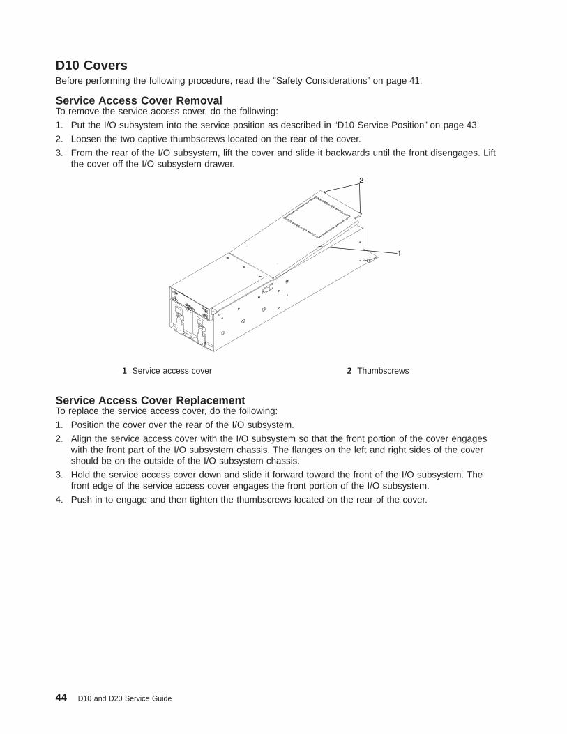
D10 CoversBefore performing the following procedure, read the “Safety Considerations” on page 41.
Service Access Cover RemovalTo remove the service access cover, do the following:
1. Put the I/O subsystem into the service position as described in “D10 Service Position” on page 43.
2. Loosen the two captive thumbscrews located on the rear of the cover.
3. From the rear of the I/O subsystem, lift the cover and slide it backwards until the front disengages. Liftthe cover off the I/O subsystem drawer.
1
2
1 Service access cover 2 Thumbscrews
Service Access Cover ReplacementTo replace the service access cover, do the following:
1. Position the cover over the rear of the I/O subsystem.
2. Align the service access cover with the I/O subsystem so that the front portion of the cover engageswith the front part of the I/O subsystem chassis. The flanges on the left and right sides of the covershould be on the outside of the I/O subsystem chassis.
3. Hold the service access cover down and slide it forward toward the front of the I/O subsystem. Thefront edge of the service access cover engages the front portion of the I/O subsystem.
4. Push in to engage and then tighten the thumbscrews located on the rear of the cover.
44 D10 and D20 Service Guide
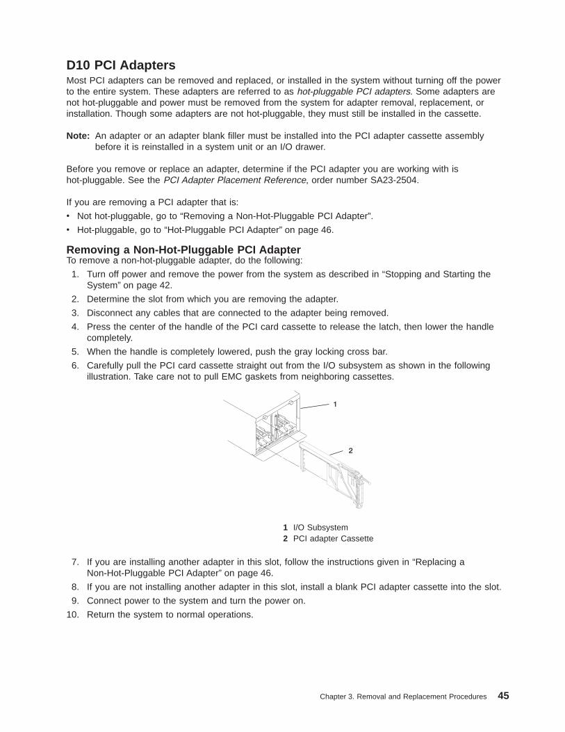
D10 PCI AdaptersMost PCI adapters can be removed and replaced, or installed in the system without turning off the powerto the entire system. These adapters are referred to as hot-pluggable PCI adapters. Some adapters arenot hot-pluggable and power must be removed from the system for adapter removal, replacement, orinstallation. Though some adapters are not hot-pluggable, they must still be installed in the cassette.
Note: An adapter or an adapter blank filler must be installed into the PCI adapter cassette assemblybefore it is reinstalled in a system unit or an I/O drawer.
Before you remove or replace an adapter, determine if the PCI adapter you are working with ishot-pluggable. See the PCI Adapter Placement Reference, order number SA23-2504.
If you are removing a PCI adapter that is:
v Not hot-pluggable, go to “Removing a Non-Hot-Pluggable PCI Adapter”.
v Hot-pluggable, go to “Hot-Pluggable PCI Adapter” on page 46.
Removing a Non-Hot-Pluggable PCI AdapterTo remove a non-hot-pluggable adapter, do the following:
1. Turn off power and remove the power from the system as described in “Stopping and Starting theSystem” on page 42.
2. Determine the slot from which you are removing the adapter.
3. Disconnect any cables that are connected to the adapter being removed.
4. Press the center of the handle of the PCI card cassette to release the latch, then lower the handlecompletely.
5. When the handle is completely lowered, push the gray locking cross bar.
6. Carefully pull the PCI card cassette straight out from the I/O subsystem as shown in the followingillustration. Take care not to pull EMC gaskets from neighboring cassettes.
1 I/O Subsystem2 PCI adapter Cassette
7. If you are installing another adapter in this slot, follow the instructions given in “Replacing aNon-Hot-Pluggable PCI Adapter” on page 46.
8. If you are not installing another adapter in this slot, install a blank PCI adapter cassette into the slot.
9. Connect power to the system and turn the power on.
10. Return the system to normal operations.
Chapter 3. Removal and Replacement Procedures 45

Replacing a Non-Hot-Pluggable PCI AdapterReplace the adapter using the following procedure:
Note: Because the adapter you are installing is not hot-pluggable, shut down the system and removepower before performing this procedure.
1. Press the center of the handle of the PCI card cassette to release the latch, then lower the handlecompletely.
2. When the handle is completely lowered, push the gray locking cross bar.
3. Hold the assembly straight on and level with the slot.
4. Align the bottom edge of the PCI cassette cover with the PCI card guide rail on the I/O backplane.
Note: If there is a cassette to the left of the one you are installing, align the ridge on the cover withthe ″tick″ in the notch of the neighboring cassette.
5. Slide the cassette partially into the guide.
6. Ensure the dovetail on the top track aligns with its mating component(s) on both sides.
7. When the cassette is fully inserted, prepare to activate the handle by lowering the gray locking bar.Lift the handle all the way up until you hear a click. The PCI card should be completely seated.
Note: To insert the adapter correctly, some minor forward or backward movement of the PCI adaptercassette might be necessary.
8. Set the color slide to blue.
9. Connect power to the system, and turn on the power as described in “Stopping and Starting theSystem” on page 42.
10. Ensure that the adapter is configured when the system completes the boot process.
Hot-Pluggable PCI AdapterBefore performing the following procedure, read “Safety Notices” on page vii.
Attention: The Linux operating system does not support these hot-plug procedures. Also, Linux does notsupport hot-plugging any hot-pluggable PCI adapters. Systems with Linux installed on one or morepartitions must be shut down and powered off before replacing any PCI adapter assigned to a Linuxpartition. Follow the non-hot-pluggable adapter procedures when replacing a PCI adapter in any partitionwith Linux installed.
The following hot-plug procedures take you through removing and replacing hot-plug PCI adapters usingsoftware that presents procedures on your display. The LEDs on a PCI adapter cassette are described in“I/O Subsystem PCI-X Slot LED Definitions” on page 2.
46 D10 and D20 Service Guide
Removing and Replacing a Hot-Pluggable PCI Adapter
Note: Use this procedure only when you are replacing an adapter with an identical adapter. If you arereplacing an adapter with an adapter that is not identical to the adapter removed, go to “Removinga Hot-Pluggable PCI Adapter” on page 49, and then to “Installing a Hot-Pluggable PCI Adapter” onpage 51.
To replace an adapter, perform the following steps:
1. Determine the slot from which you are removing the adapter.
2. Ensure that any processes or applications that might use the adapter are stopped.
Note: Removing a hot-pluggable PCI adapter requires the system administrator to take the PCIadapter offline before performing any PCI adapter hot-plug procedures. Before taking anadapter offline, the devices attached to the adapter must be taken offline as well. This actionprevents a service representative or user from causing an unexpected outage for systemusers.
For additional information about taking an adapter offline or removing it from the systemconfiguration, see the AIX System Management Guide: Operating System and Devices.
3. Log in as root user. If the system is a partitioned system, log in as root user on the partition that hasthe adapter assigned to it.
4. At the command line, type smitty .
5. Select Devices .
6. Select PCI Hot Plug Manager .
7. Select Unconfigure a Device and press Enter.
8. Press F4 to display the Device Names menu.
9. From the menu, select the adapter you are removing.
10. Answer YES to Keep Definition . Press Enter.
11. The ARE YOU SURE screen displays. Press Enter to verify the information. Successful unconfigure isindicated by the OK message displayed next to the Command field at the top of the screen.
12. Press F3 to return to the PCI Hot-Plug Manager menu.
13. Select Replace/Remove a PCI Hot-Plug Adapter and press Enter. The Replace/Remove a PCIHot-Plug Adapter menu displays.
14. Move the cursor to select the adapter that you are removing and press Enter.
15. Press the Tab key until the entry field displays the replace operation and then press the Enter key.Follow the instructions that display on the screen until you are instructed to remove the adapter.
16. When you are instructed to remove the adapter from the adapter slot, disconnect any cables that areconnected to the adapter being removed.
17. Press the center of the handle of the PCI card cassette to release the latch, then lower the handlecompletely.
18. When the handle is completely lowered, push the gray locking cross bar.
Chapter 3. Removal and Replacement Procedures 47
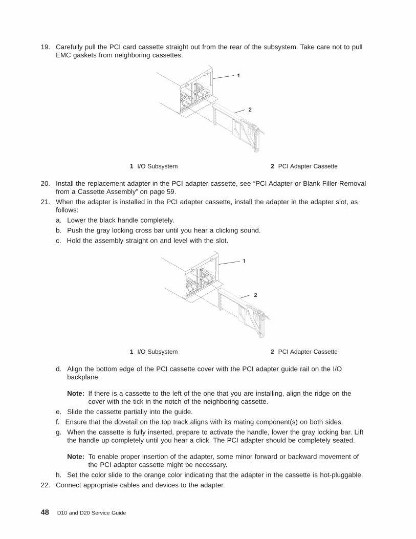
19. Carefully pull the PCI card cassette straight out from the rear of the subsystem. Take care not to pullEMC gaskets from neighboring cassettes.
1 I/O Subsystem 2 PCI Adapter Cassette
20. Install the replacement adapter in the PCI adapter cassette, see “PCI Adapter or Blank Filler Removalfrom a Cassette Assembly” on page 59.
21. When the adapter is installed in the PCI adapter cassette, install the adapter in the adapter slot, asfollows:
a. Lower the black handle completely.
b. Push the gray locking cross bar until you hear a clicking sound.
c. Hold the assembly straight on and level with the slot.
1 I/O Subsystem 2 PCI Adapter Cassette
d. Align the bottom edge of the PCI cassette cover with the PCI adapter guide rail on the I/Obackplane.
Note: If there is a cassette to the left of the one that you are installing, align the ridge on thecover with the tick in the notch of the neighboring cassette.
e. Slide the cassette partially into the guide.
f. Ensure that the dovetail on the top track aligns with its mating component(s) on both sides.
g. When the cassette is fully inserted, prepare to activate the handle, lower the gray locking bar. Liftthe handle up completely until you hear a click. The PCI adapter should be completely seated.
Note: To enable proper insertion of the adapter, some minor forward or backward movement ofthe PCI adapter cassette might be necessary.
h. Set the color slide to the orange color indicating that the adapter in the cassette is hot-pluggable.
22. Connect appropriate cables and devices to the adapter.
48 D10 and D20 Service Guide

23. Continue to follow the screen instructions until you receive a message that the replacement issuccessful. Successful replacement is indicated by the OK message displayed next to the Commandfield at the top of the screen.
24. Press the F3 key to return to the PCI Hot-Plug Manager menu.
25. Select Install/Configure Devices Added After IPL and press Enter. Then follow the instructions onthe screen. Successful replacement is indicated by the OK message displayed next to the Commandfield at the top of the screen.
26. If you do not have other adapters to replace, continue with the next step.ORIf you have other adapters to replace, press the F3 key to return to the PCI Hot-Plug Manager menuand then return to step 13 on page 47.
27. Press F10 to exit the Hot-Plug Manager.
If you have added, removed, or replaced any adapters, run the diag -a command. If the systemresponds with a menu or prompt, follow the instructions to complete the device configuration.
28. Install the covers that you removed earlier and return the drawer to the operating position.
Removing a Hot-Pluggable PCI AdapterIf you are permanently removing an adapter from a system, this procedure should be used.
Attention: The Linux operating system does not support these hot-plug procedures. Also, Linux does notsupport hot-plugging any hot-pluggable PCI adapters. Systems with Linux installed on one or morepartitions must be shut down and powered off before replacing any PCI adapter assigned to a Linuxpartition. Follow the non-hot-pluggable adapter procedures when replacing a PCI adapter in any partitionwith Linux installed.
Note: If you are removing an adapter and replacing it with an adapter that is identical to the adapter thatwas removed, use the “Removing and Replacing a Hot-Pluggable PCI Adapter” on page 47procedure.
To remove an adapter, perform the following steps:
1. Open the door of the rack.
2. Determine the slot from which you are removing the adapter.
3. Ensure that any processes or applications that might use the adapter are stopped.
Note: Removing a hot-pluggable PCI adapter requires the system administrator to take the PCIadapter offline before performing any PCI adapter hot-plug procedures. Before taking anadapter offline, the devices attached to the adapter must also be taken offline as well. Thisaction prevents a service representative or user from causing an unexpected outage forsystem users.
For more information on taking the PCI adapter online, see the AIX operating systemdocumentation. Documentation for the AIX operating system is available from the IBMEserver pSeries Information Center athttp://publib16.boulder.ibm.com/pseries/en_US/infocenter/base. Select AIX documentation .The AIX Documentation CD contains the base set of publications for the operating system,including system-management and end-user documentation.
Chapter 3. Removal and Replacement Procedures 49

4. Log in as root user. If the system is a partitioned system, log in as root user on the partition that hasthe adapter assigned to it.
5. At the command line, type smitty .
6. Select Devices .
7. Select PCI Hot Plug Manager .
8. Select Unconfigure a Device and press Enter.
9. Press F4 to display the Device Names menu.
10. Select the adapter you are removing from the menu.
11. Use the Tab key to answer NO to Keep Definition . Press Enter.
12. The ARE YOU SURE screen displays. Press Enter to verify the information. Successful unconfigure isindicated by the OK message displayed next to the Command field at the top of the screen.
13. Press F3 to return to the PCI Hot-Plug Manager menu.
14. Select Replace/Remove a PCI Hot-Plug Adapter and press Enter. The Replace/Remove a PCIHot-Plug Adapter menu displays.
15. Move the cursor to select the adapter that you are removing and press Enter. (The description entrydisplays as unknown).
16. Press the Tab key until the entry field displays the remove operation and then press the Enter key.Follow the instructions that display on the screen until you are instructed to remove the adapter.
17. When you are instructed to remove the adapter from the adapter slot, disconnect any cables that areconnected to the adapter being removed.
18. Press the center of the handle of the PCI card cassette to release the latch, then lower the handlecompletely.
19. When the handle is completely lowered, push the gray locking cross bar.
20. Carefully pull the PCI adapter cassette straight out from the I/O subsystem, as shown in the followingillustration. Take care not to pull EMC gaskets from neighboring cassettes.
1 I/O Subsystem 2 PCI adapter Cassette
21. If you are not installing another adapter in this slot, install a blank PCI adapter cassette into the slot.
22. Continue to follow the screen instructions until you receive a message that the adapter removal issuccessful. Successful removal is indicated by the OK message displayed next to the Command fieldat the top of the screen.
23. If you do not have other adapters to remove, continue with the next step.ORIf you have other adapters to remove, press the F3 key to return to the PCI Hot-Plug Manager menuand then return to step 14.
24. Press F10 to exit the Hot-Plug Manager.
25. Install any covers that you removed earlier, and return the drawer to the normal operations.
50 D10 and D20 Service Guide

Installing a Hot-Pluggable PCI AdapterAttention: The Linux operating system does not support these hot-plug procedures. Also, Linux does notsupport hot-plugging any hot-pluggable PCI adapters. Systems with Linux installed on one or morepartitions must be shut down and powered off before replacing any PCI adapter assigned to a Linuxpartition. Follow the non-hot-pluggable adapter procedures when replacing a PCI adapter in any partitionwith Linux installed.
Note: Before installing a new adapter, ensure the device driver for the adapter is installed. Check with thesystem administrator if the device driver is not already installed.
To install an adapter, perform the following steps:
1. Install the new adapter into a PCI adapter cassette, see “PCI Adapter or Blank Filler Removal from aCassette Assembly” on page 59.
2. Log in as root user. If the system is a partitioned system, log in as root user on the partition that hasthe adapter assigned to it.
3. At the command line, type smitty .
4. Select Devices .
5. Select PCI Hot Plug Manager .
6. From the PCI Hot-Plug Manager menu, select Add a PCI Hot-Plug Adapter and press Enter. TheAdd a Hot-Plug Adapter window displays.
7. See the PCI Adapter Placement Reference, order number SA23-2504, for adapter placementinformation. Select an empty PCI slot for the adapter.
8. Select the appropriate empty PCI slot from the ones listed on the screen, and press Enter.
9. Follow the instructions on the screen to install the adapter until the visual indicator (LED) for thespecified PCI slot is set to the Action state.
10. Install the new adapter in the adapter slot by performing the following:
a. Lower the black handle completely.
b. Push the gray locking cross bar until you hear a clicking sound.
c. Hold the assembly straight on and level with the slot.
d. Align the bottom edge of the PCI cassette cover with the PCI card guide rail on the I/Obackplane.
Note: If there is a cassette to the left of the one you are installing, align the ridge on the coverwith the ″tick″ in the notch of the neighboring cassette.
Chapter 3. Removal and Replacement Procedures 51
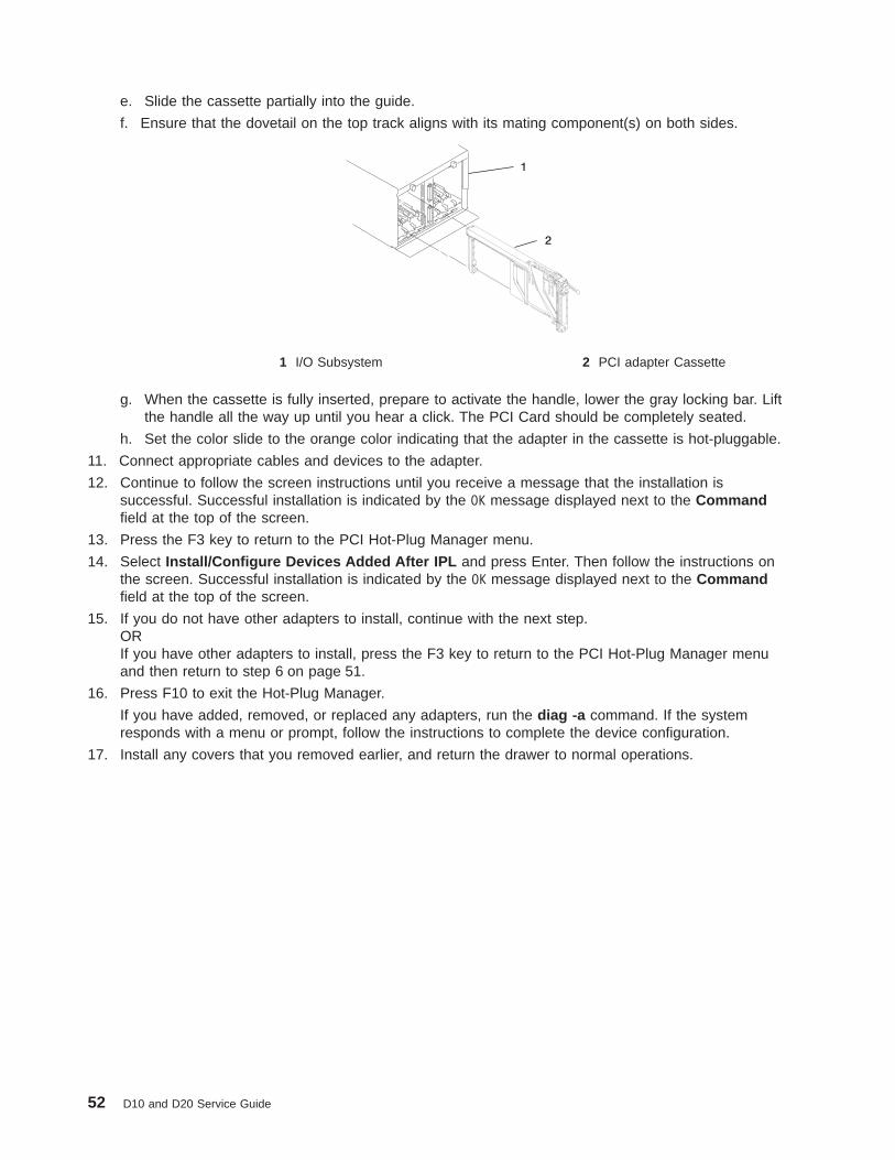
e. Slide the cassette partially into the guide.
f. Ensure that the dovetail on the top track aligns with its mating component(s) on both sides.
1 I/O Subsystem 2 PCI adapter Cassette
g. When the cassette is fully inserted, prepare to activate the handle, lower the gray locking bar. Liftthe handle all the way up until you hear a click. The PCI Card should be completely seated.
h. Set the color slide to the orange color indicating that the adapter in the cassette is hot-pluggable.
11. Connect appropriate cables and devices to the adapter.
12. Continue to follow the screen instructions until you receive a message that the installation issuccessful. Successful installation is indicated by the OK message displayed next to the Commandfield at the top of the screen.
13. Press the F3 key to return to the PCI Hot-Plug Manager menu.
14. Select Install/Configure Devices Added After IPL and press Enter. Then follow the instructions onthe screen. Successful installation is indicated by the OK message displayed next to the Commandfield at the top of the screen.
15. If you do not have other adapters to install, continue with the next step.ORIf you have other adapters to install, press the F3 key to return to the PCI Hot-Plug Manager menuand then return to step 6 on page 51.
16. Press F10 to exit the Hot-Plug Manager.
If you have added, removed, or replaced any adapters, run the diag -a command. If the systemresponds with a menu or prompt, follow the instructions to complete the device configuration.
17. Install any covers that you removed earlier, and return the drawer to normal operations.
52 D10 and D20 Service Guide

PCI Hot-Plug Manager Access
Attention: The Linux operating system does not support these hot-plug procedures. Also, Linux does notsupport hot-plugging any hot-pluggable PCI adapters. Systems with Linux installed on one or morepartitions must be shut down and powered off before replacing any PCI adapter assigned to a Linuxpartition. Follow the non-hot-pluggable adapter procedures when replacing a PCI adapter in any partitionwith Linux installed.
The installation instructions for hot-pluggable PCI adapters refer you to these procedures when it isappropriate to perform them.
Note: A PCI adapter is only hot-pluggable if the PCI adapter supports hot-plug applications. See the PCIAdapter Placement Reference, order number SA23-2504.
Accessing Hot-Plug Management Functions
Note: Removing or installing a Hot-Pluggable PCI adapter requires the system administrator to take thePCI adapter offline prior to performing the operation. Before taking an adapter offline, the devicesattached to the adapter must be taken offline as well. This action prevents a service representativeor user from causing an unexpected outage for system users.
For additional information about taking an adapter offline or removing it from the systemconfiguration, see the AIX System Management Guide: Operating System and Devices.
To access the hot-plug menus, do the following:
1. Log in as root user. If the system is a partitioned system, log in as root user on the partition that hasthe adapter assigned to it.
2. At the command line, type smitty .
3. Select Devices .
4. Select PCI Hot Plug Manager and press Enter.
5. The PCI Hot-Plug Manager menu displays. Return to the procedure that directed you here. For adescription of the menu options, see below.
PCI Hot-Plug Manager MenuThe following options are available from the PCI Hot Plug Manager menu:
Note: For information about the PCI slot LED states, see “I/O Subsystem PCI-X Slot LED Definitions” onpage 2.
Chapter 3. Removal and Replacement Procedures 53

List PCI Hot-Plug Slots
Provides a descriptive list of all slots that support PCI hot-plug capability. If the listing for a slot indicates itholds an “Unknown” device, select the Install/Configure Devices Added after IPL to configure theadapter in that slot.
Add a PCI Hot-Plug Adapter
Allows the user to add a new PCI hot-plug-capable adapter to the slot with the system turned on. You willbe asked to identify the PCI slot that you have selected prior to the actual operation. The selected PCI slotwill go into the Action state and finally into the On state.
Note: The system will indicate the slot holds an “Unknown” device until you perform the Install/ConfigureDevices Added After IPL option to configure the adapter.
Replace/Remove a PCI Hot-Plug Adapter
Allows the user to remove an existing adapter, or replace an existing adapter with an identical one. Forthis option to work, the adapter must be in the Defined state (see “Unconfigure a Device” option below).
You will be asked to identify the PCI slot prior to the actual operation. The selected PCI slot will go into theAction state.
Identify a PCI Hot-Plug Slot
Allows the user to identify a PCI slot. The selected PCI slot will go into the Identify state. See “I/OSubsystem PCI-X Slot LED Definitions” on page 2.
Unconfigure a Device
Allows the user to put an existing PCI adapter into the Defined state if the device is no longer in use.
This step must be completed successfully before starting any removal or replacement operation. If thisstep fails, the customer must take action to release the device.
Configure a Defined Device
Allows a new PCI adapter to be configured into the system if software support is already available for theadapter. The selected PCI slot will go into the On state.
54 D10 and D20 Service Guide

Install/Configure Devices Added After IPL
The system attempts to configure any new devices and tries to find and install any required software froma user-selected source.
The add, remove, and replace functions return information to the user indicating whether the operationwas successful. If additional instructions are provided on the screen, complete the recommended actions.If the instructions do not resolve the problem, see the following:
v If the adapter is listed as Unknown, perform the Install/Configure Devices Added After IPL option toconfigure the adapter.
v If you receive a warning indicating that needed device packages are not installed, the systemadministrator must install the specified packages before you can configure or diagnose the adapter.
v If you receive a failure message indicating a hardware error, the problem might be either the adapter orthe PCI slot. Isolate the problem by retrying the operation in a different PCI slot, or trying a differentadapter in the slot. If you determine that you have failing hardware, call your service representative.
Removing and Replacing a PCI Adapter CassettePerform these procedures only when you are directed to by the “Removing a Non-Hot-Pluggable PCIAdapter” on page 45 or “Hot-Pluggable PCI Adapter” on page 46.
Removing a PCI Adapter Cassette
Attention: Perform this procedure only when you are instructed to by the removal and replacementprocedures for a “Removing a Non-Hot-Pluggable PCI Adapter” on page 45 or “Hot-Pluggable PCIAdapter” on page 46.
Note: An adapter or a blank filler must be installed into the PCI adapter cassette assembly before it isreinstalled in a processor subsystem or an I/O subsystem.
The following illustration shows the PCI adapter cassette with the handle lowered.
1
2
3
4
1 dove-tail 3 Handle in the lowered position2 Gray locking crossbar 4 Center of handle
1. Determine the slot from which you are removing the PCI adapter cassette.
2. Disconnect any cables that are connected to the adapter cassette being removed.
Chapter 3. Removal and Replacement Procedures 55
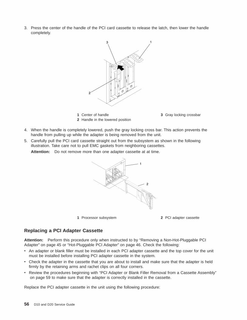
3. Press the center of the handle of the PCI card cassette to release the latch, then lower the handlecompletely.
1
2
3
1 Center of handle 3 Gray locking crossbar2 Handle in the lowered position
4. When the handle is completely lowered, push the gray locking cross bar. This action prevents thehandle from pulling up while the adapter is being removed from the unit.
5. Carefully pull the PCI card cassette straight out from the subsystem as shown in the followingillustration. Take care not to pull EMC gaskets from neighboring cassettes.
Attention: Do not remove more than one adapter cassette at at time.
1 Processor subsystem 2 PCI adapter cassette
Replacing a PCI Adapter Cassette
Attention: Perform this procedure only when instructed to by “Removing a Non-Hot-Pluggable PCIAdapter” on page 45 or “Hot-Pluggable PCI Adapter” on page 46. Check the following:
v An adapter or blank filler must be installed in each PCI adapter cassette and the top cover for the unitmust be installed before installing PCI adapter cassette in the system.
v Check the adapter in the cassette that you are about to install and make sure that the adapter is heldfirmly by the retaining arms and rachet clips on all four corners.
v Review the procedures beginning with “PCI Adapter or Blank Filler Removal from a Cassette Assembly”on page 59 to make sure that the adapter is correctly installed in the cassette.
Replace the PCI adapter cassette in the unit using the following procedure:
56 D10 and D20 Service Guide

1. Press the center of the handle of the PCI card cassette to release the latch, then lower the handlecompletely.
1
2
3
4
1 Dove-tail 3 Handle in the lowered position2 Gray locking crossbar 4 Center of handle
2. Study the PCI adapter slot opening carefully and note the location the dove-tail channels and thecassette guide slot. Use a flashlight to better see the dove-tail channels and the cassette guide slot
1 Dove-tailchannels
2 PCI cassette guide slot
Chapter 3. Removal and Replacement Procedures 57
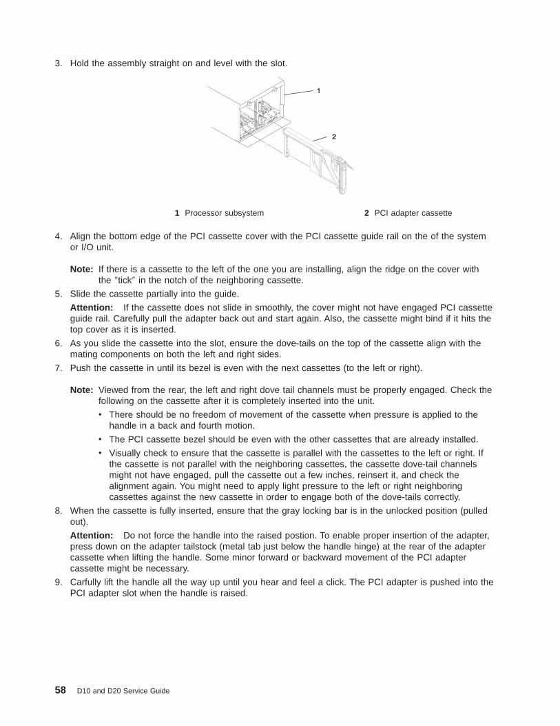
3. Hold the assembly straight on and level with the slot.
1 Processor subsystem 2 PCI adapter cassette
4. Align the bottom edge of the PCI cassette cover with the PCI cassette guide rail on the of the systemor I/O unit.
Note: If there is a cassette to the left of the one you are installing, align the ridge on the cover withthe ″tick″ in the notch of the neighboring cassette.
5. Slide the cassette partially into the guide.
Attention: If the cassette does not slide in smoothly, the cover might not have engaged PCI cassetteguide rail. Carefully pull the adapter back out and start again. Also, the cassette might bind if it hits thetop cover as it is inserted.
6. As you slide the cassette into the slot, ensure the dove-tails on the top of the cassette align with themating components on both the left and right sides.
7. Push the cassette in until its bezel is even with the next cassettes (to the left or right).
Note: Viewed from the rear, the left and right dove tail channels must be properly engaged. Check thefollowing on the cassette after it is completely inserted into the unit.
v There should be no freedom of movement of the cassette when pressure is applied to thehandle in a back and fourth motion.
v The PCI cassette bezel should be even with the other cassettes that are already installed.
v Visually check to ensure that the cassette is parallel with the cassettes to the left or right. Ifthe cassette is not parallel with the neighboring cassettes, the cassette dove-tail channelsmight not have engaged, pull the cassette out a few inches, reinsert it, and check thealignment again. You might need to apply light pressure to the left or right neighboringcassettes against the new cassette in order to engage both of the dove-tails correctly.
8. When the cassette is fully inserted, ensure that the gray locking bar is in the unlocked position (pulledout).
Attention: Do not force the handle into the raised postion. To enable proper insertion of the adapter,press down on the adapter tailstock (metal tab just below the handle hinge) at the rear of the adaptercassette when lifting the handle. Some minor forward or backward movement of the PCI adaptercassette might be necessary.
9. Carfully lift the handle all the way up until you hear and feel a click. The PCI adapter is pushed into thePCI adapter slot when the handle is raised.
58 D10 and D20 Service Guide

PCI Adapter or Blank Filler Removal from a Cassette AssemblyUse this procedure when you are preparing to install or replace an adapter or an adapter blank filler in thesystem unit or an I/O drawer.
Note: An adapter or an adapter blank filler must be installed into the PCI adapter cassette assemblybefore it is reinstalled in a system unit or an I/O drawer.
Determine the slot of the system or I/O drawer in which you plan to install or remove an adapter, and referto the procedures for removing an adapter from the system. Remove the PCI adapter cassette assemblyfrom the system unit or I/O drawer before beginning this procedure.
Note: It may take approximately 30 to 40 minutes to perform this procedure the first time. This timeincludes using the instructions in this guide and performing the steps. Thereafter, performing thisprocedure usually takes approximately 10 minutes.
Before performing the following steps, familiarize yourself with the entire procedure.
To remove a PCI adapter or blank filler from a cassette assembly, do the following:
1. Place the PCI adapter cassette assembly on a flat work surface with the cover facing up, and the topof the adapter facing you. See the following illustration.
1 Cover 3 Top of Cover2 Handle
Chapter 3. Removal and Replacement Procedures 59

2. Using two fingers, remove the bushing-lock pin from the bushing. The pin can be removed by pulling itout of the bushing with your fingernails.
1 Bushing
2 Bushing-Lock Pin
1 Bushing-Lock Pin
60 D10 and D20 Service Guide

3. Remove the bushing. The bushing can be removed by pulling it out of the PCI adapter cassetteassembly with your fingernails.
1 Bushing
4. Turn over the PCI adapter cassette assembly so that the top is facing away from you.
1 Top of Adapter2 Handle
Chapter 3. Removal and Replacement Procedures 61

5. Remove the bezel, as follows:
a. Locate the plastic latch fingers in the top part of the cassette.
1 Top of Cassette2 Bezel3 Plastic Latch Fingers
b. Using one hand, pinch the plastic latch fingers, and with your other hand, carefully lift the top partof the bezel extension out until the tabs clear the slots in the PCI adapter cassette assembly.
1 Slots2 Tab3 Bezel Extension
62 D10 and D20 Service Guide

c. While holding the bezel extension out, push the plastic cover latch out of the bezel hook, as shownin the following illustration. This action allows the bezel to be removed.
1 Bezel Extension2 Plastic Cover Latch in Bezel Hook
d. On the opposite side of the cassette (cover side), push the cover latch to release the bezel.
1 Cover Side2 Cover Latch
Chapter 3. Removal and Replacement Procedures 63
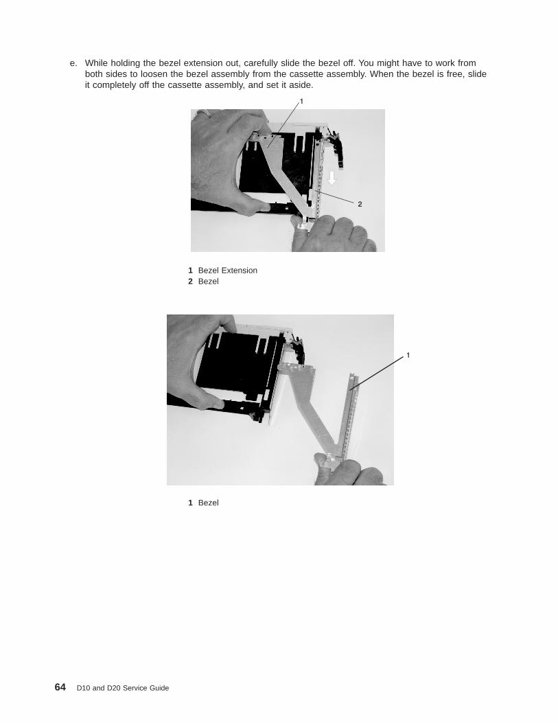
e. While holding the bezel extension out, carefully slide the bezel off. You might have to work fromboth sides to loosen the bezel assembly from the cassette assembly. When the bezel is free, slideit completely off the cassette assembly, and set it aside.
1 Bezel Extension2 Bezel
1 Bezel
64 D10 and D20 Service Guide

6. Turn over the cassette so that the cover is facing up, as shown in the following illustration. Remove thecover from the cassette as follows:
a. Slide the cover until it releases from the cassette assembly.
Attention: The cover might be tight and difficult to slide. If you grasp the left end (handle end) ofthe cassette and the right end of the cover, you can use enough force to pull the cover off the PCIadapter cassette assembly.
1 Left End of the Cassette2 Cassette Cover
b. Lift the cover off the assembly, and set it aside.
c. By pulling on both sides of the gray plastic locking bar, which is located on the handle, ensure thatthe handle is pulled into the unlocked position. Raise the handle on the cassette linkage assemblyuntil it locks into the up position (the blank filler or adapter moves downward).
1 Handle2 Gray Plastic Locking Bar
Chapter 3. Removal and Replacement Procedures 65
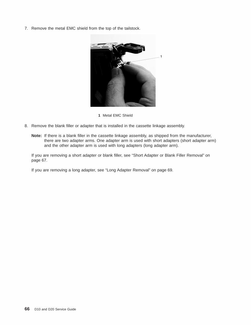
7. Remove the metal EMC shield from the top of the tailstock.
1 Metal EMC Shield
8. Remove the blank filler or adapter that is installed in the cassette linkage assembly.
Note: If there is a blank filler in the cassette linkage assembly, as shipped from the manufacturer,there are two adapter arms. One adapter arm is used with short adapters (short adapter arm)and the other adapter arm is used with long adapters (long adapter arm).
If you are removing a short adapter or blank filler, see “Short Adapter or Blank Filler Removal” onpage 67.
If you are removing a long adapter, see “Long Adapter Removal” on page 69.
66 D10 and D20 Service Guide
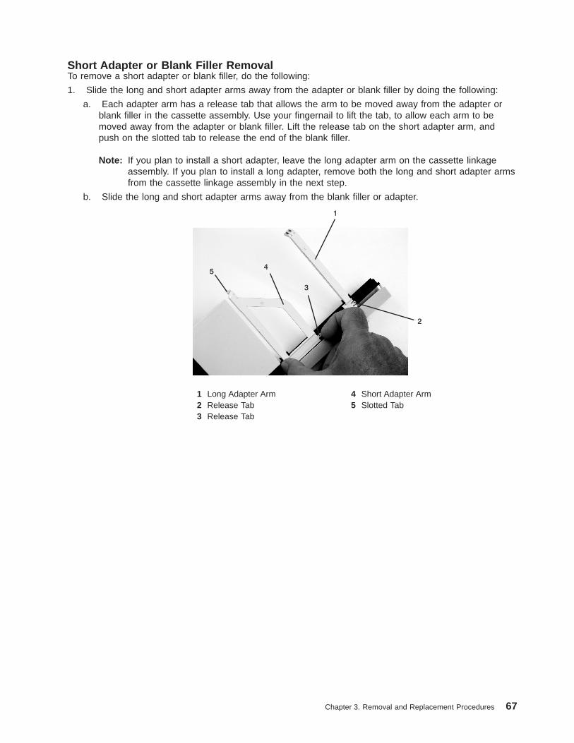
Short Adapter or Blank Filler RemovalTo remove a short adapter or blank filler, do the following:
1. Slide the long and short adapter arms away from the adapter or blank filler by doing the following:
a. Each adapter arm has a release tab that allows the arm to be moved away from the adapter orblank filler in the cassette assembly. Use your fingernail to lift the tab, to allow each arm to bemoved away from the adapter or blank filler. Lift the release tab on the short adapter arm, andpush on the slotted tab to release the end of the blank filler.
Note: If you plan to install a short adapter, leave the long adapter arm on the cassette linkageassembly. If you plan to install a long adapter, remove both the long and short adapter armsfrom the cassette linkage assembly in the next step.
b. Slide the long and short adapter arms away from the blank filler or adapter.
1 Long Adapter Arm 4 Short Adapter Arm2 Release Tab 5 Slotted Tab3 Release Tab
Chapter 3. Removal and Replacement Procedures 67

2. Remove the adapter or blank filler from the cassette linkage assembly by rotating the bottom of thetailstock out, as shown in the following illustration. Store the adapter or blank filler in a safe place.
1 Cassette LinkageAssembly
3 Handle
2 Bottom of Tailstock
3. The removal procedure for the PCI adapter cassette assembly is complete. To install a new adapter orblank filler in the cassette, go to “Installing a Hot-Pluggable PCI Adapter” on page 51.
68 D10 and D20 Service Guide

Long Adapter RemovalTo remove a long adapter, do the following:
1. Each adapter arm has a release tab that allows the arm to be moved away from the adapter in thecassette assembly. Use your fingernail to lift the tab, to allow the arm to be moved away from theadapter. Lift the release tab on the long adapter arm, and slide it off the cassette linkage assembly.
1 Release Tab
2. Remove the adapter from the cassette linkage assembly by rotating the bottom of the tailstock out, asshown in the following illustration. Store the adapter in a safe place.
1 Cassette LinkageAssembly
3 Bottom of Tailstock
2 Adapter 4 Handle
3. The removal procedure for the PCI adapter cassette assembly is complete. To install a new adapter orblank filler in the cassette, go to “Installing a Hot-Pluggable PCI Adapter” on page 51.
Chapter 3. Removal and Replacement Procedures 69

Replacing an Adapter in a PCI Adapter CassetteThis procedure is performed when preparing to install a new adapter or a blank filler in the processorsubsystem or an I/O drawer. Familiarize yourself with the entire procedure before performing the followingsteps.
1. Place the empty PCI adapter cassette linkage on a flat work surface in front of you. Position thecassette so that the handle is in the raised (up position), and on the left, with the top of the linkagefacing away from you.
Note: Your PCI adapter cassette linkage might not have the short or long adapter retaining armsinstalled if you removed them during the remove procedure. In the following figure, both armsare shown.
Note: If you are installing an adapter that is in the following list, use the additional brackets listed tohelp when you seat the adapter during installation. There are unique brackets (1) for eachadapter type (2):
1
2
53P5450 Bracket for Gigabit Ethernet PCI-X Adapter, FC 5700 or 10/100/1000 Base-TXEthernet PCI-X Adapter, FC 5701
44P2661 Bracket for Dual Channel Ultra3 SCSI PCI Adapter, FC 6203 Type 4Y44P0321 Bracket for 10/100 BaseT Ethernet PCI Adapter, FC 4962 Type AF44P2675 Bracket for 2 Gigabit Fibre Channel Adapter, FC 6228 Type 4W44P2676 Bracket for Gigabit Ethernet - SX PCI Adapter, FC 2969 Type 9U, or
10/100/1000 Base-T Ethernet PCI Adapter, FC 2975 Type A-A
70 D10 and D20 Service Guide
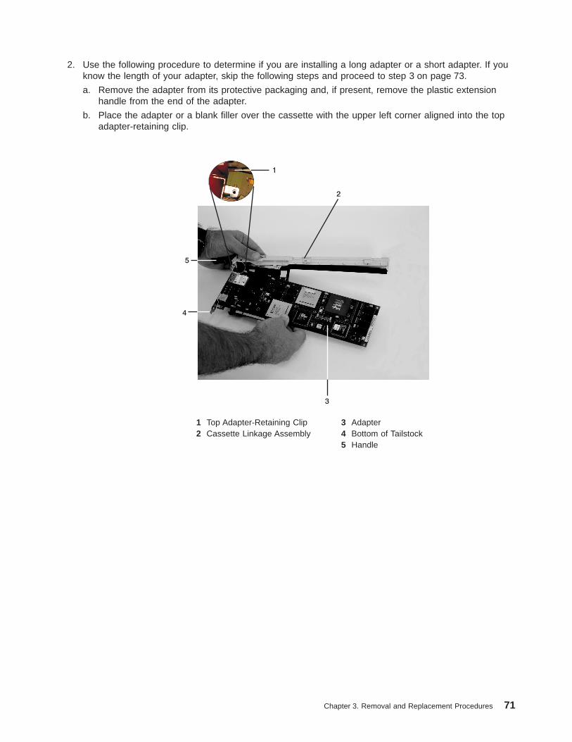
2. Use the following procedure to determine if you are installing a long adapter or a short adapter. If youknow the length of your adapter, skip the following steps and proceed to step 3 on page 73.
a. Remove the adapter from its protective packaging and, if present, remove the plastic extensionhandle from the end of the adapter.
b. Place the adapter or a blank filler over the cassette with the upper left corner aligned into the topadapter-retaining clip.
5
4
2
3
1
1 Top Adapter-Retaining Clip 3 Adapter2 Cassette Linkage Assembly 4 Bottom of Tailstock
5 Handle
Chapter 3. Removal and Replacement Procedures 71

c. The cassette linkage is marked to show long or short adapters similar to the adapter shown in thefollowing figure. Check the right end of the adapter to determine if it is long enough to fall into thelong area of the cassette linkage. Ensure that the corner on the left end of the adapter is stillaligned into the top adapter-retaining clip and determine the length of the adapter.
LONG
ARMARMSHORT
1
1 Top Adapter-Retaining Clip
72 D10 and D20 Service Guide

3. Remove the adapter or blank filler and ensure that the handle is in the up position. If you need tomove the handle, ensure that the gray locking bar is pulled into the unlocked position, and then rotatethe adapter handle until the handle is in the up position (the cassette linkage will extend down beyondthe cassette top).
If you are installing a short adapter or blank filler, proceed to “Short Adapter or Blank Filler Installation”on page 74. If you are installing a long adapter, proceed to “Long Adapter Installation” on page 89.
2
1
1 Handle2 Lock
Chapter 3. Removal and Replacement Procedures 73
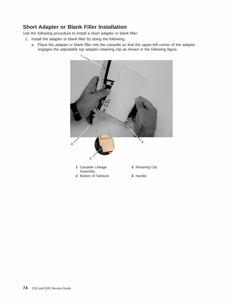
Short Adapter or Blank Filler InstallationUse the following procedure to install a short adapter or blank filler.
1. Install the adapter or blank filler by doing the following:
a. Place the adapter or blank filler into the cassette so that the upper-left corner of the adapterengages the adjustable top adapter-retaining clip as shown in the following figure.
4
3
1
2
1 Cassette LinkageAssembly
3 Retaining Clip
2 Bottom of Tailstock 4 Handle
74 D10 and D20 Service Guide

b. Rotate the adapter so that the adapter engages the slot in the bottom adapter-retaining clip andthe top corner of the adapter is seated into the adjustable top adapter-retaining clip.
Note: If the adapter is not a full-height adapter, you must slide the adjustable topadapter-retaining clip downward until the lower edge of the adapter is seated into the sloton the bottom adapter-retaining clip.
3
2
1
1 Adapter 3 Bottom Retaining Clip2 Slot
Chapter 3. Removal and Replacement Procedures 75

c. Slide the short-adapter retaining arm toward the adapter or blank filler on the cassette linkage rail.
1) If the short-adapter retaining arm has been removed from the cassette linkage rail, install theshort-adapter retaining arm and then slide the arm until it contacts the adapter or blank filleras shown in the following figure.
d. Ensure that the adjustable top retainer clip catches the corner of the adapter as shown in thefollowing figure:
1
1 Short Adapter Top Retaining Clip
76 D10 and D20 Service Guide

e. Use the lower short adapter-retaining clip to engage and hold the bottom of the adapter.
Note: It might be necessary to apply pressure to engage and hold the bottom of the adapter.
1
1 Lower Short Adapter Arm Clip
f. To hold the top of the adapter, slide down the adjustable top adapter-retaining clip on the retainingarm. Ensure that the bottom edge of the adapter is held by the lower part of the adapter retainingarm.
1
1 Short Adapter Adjustable Retaining Clip
Chapter 3. Removal and Replacement Procedures 77
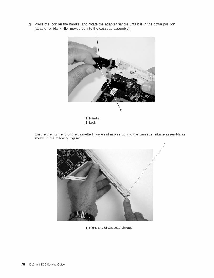
g. Press the lock on the handle, and rotate the adapter handle until it is in the down position(adapter or blank filler moves up into the cassette assembly).
2
1
1 Handle2 Lock
Ensure the right end of the cassette linkage rail moves up into the cassette linkage assembly asshown in the following figure:
1
1 Right End of Cassette Linkage
78 D10 and D20 Service Guide

h. Position the adapter and cassette assembly with the handle on the left (in the down position) andthe top facing away from you.
2
1
1 Top of Cassette2 Handle
Chapter 3. Removal and Replacement Procedures 79
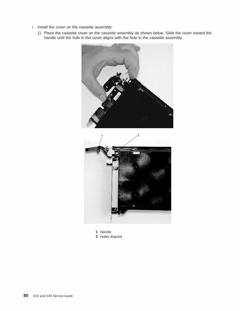
i. Install the cover on the cassette assembly:
1) Place the cassette cover on the cassette assembly as shown below. Slide the cover toward thehandle until the hole in the cover aligns with the hole in the cassette assembly.
21
1 Handle2 Holes Aligned
80 D10 and D20 Service Guide
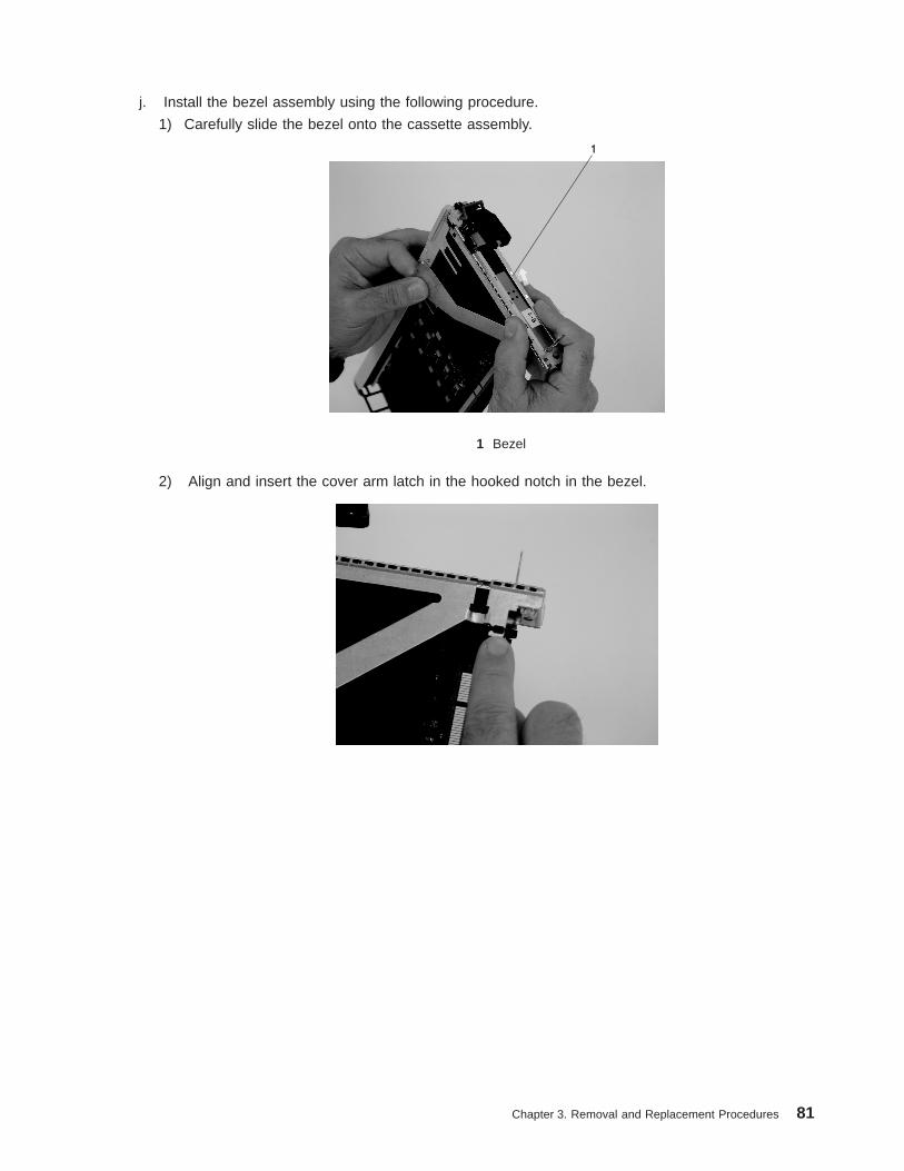
j. Install the bezel assembly using the following procedure.
1) Carefully slide the bezel onto the cassette assembly.
1
1 Bezel
2) Align and insert the cover arm latch in the hooked notch in the bezel.
Chapter 3. Removal and Replacement Procedures 81
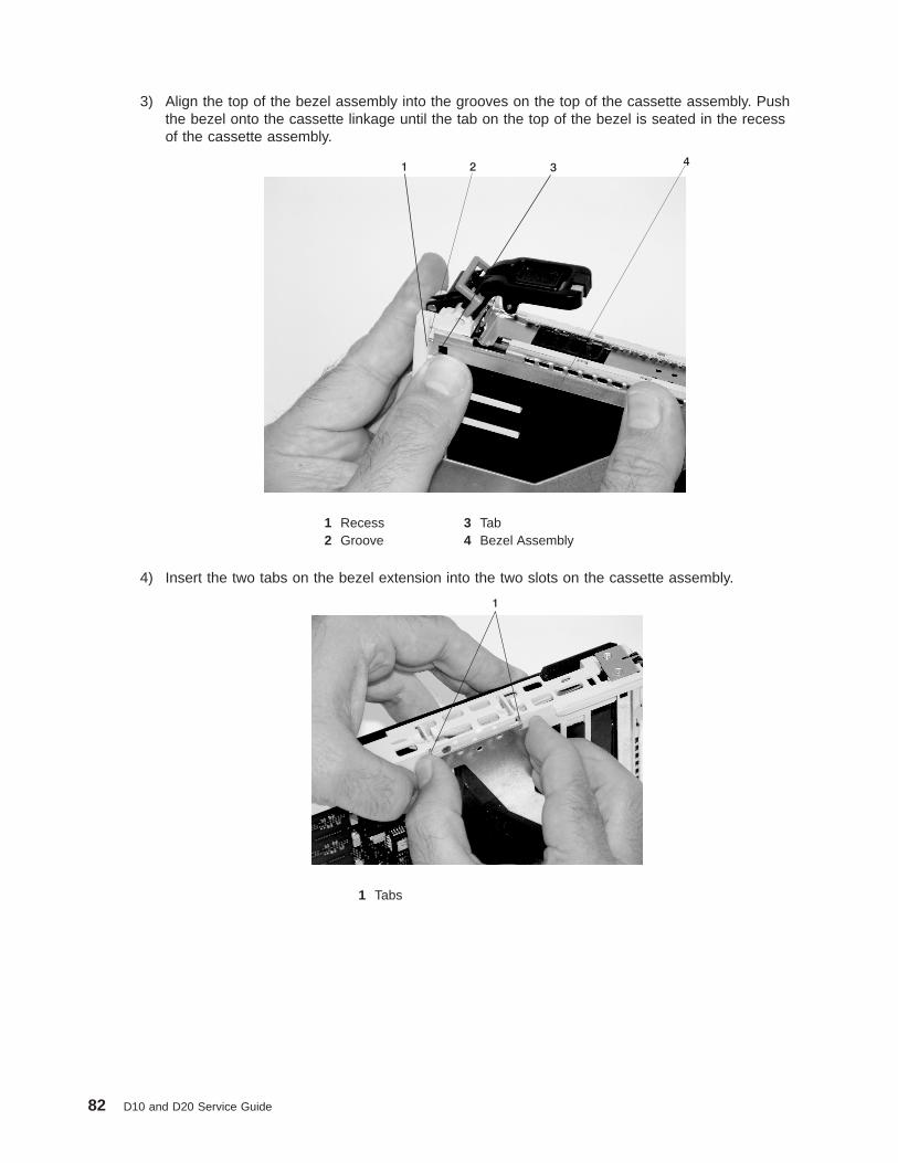
3) Align the top of the bezel assembly into the grooves on the top of the cassette assembly. Pushthe bezel onto the cassette linkage until the tab on the top of the bezel is seated in the recessof the cassette assembly.
1 2 34
1 Recess 3 Tab2 Groove 4 Bezel Assembly
4) Insert the two tabs on the bezel extension into the two slots on the cassette assembly.
1
1 Tabs
82 D10 and D20 Service Guide
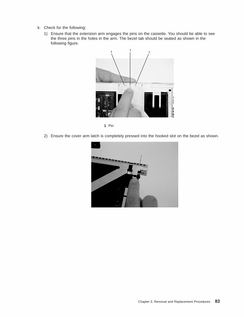
k. Check for the following:
1) Ensure that the extension arm engages the pins on the cassette. You should be able to seethe three pins in the holes in the arm. The bezel tab should be seated as shown in thefollowing figure.
11
1
1 Pin
2) Ensure the cover arm latch is completely pressed into the hooked slot on the bezel as shown.
Chapter 3. Removal and Replacement Procedures 83

3) Turn the cassette assembly over so the cover is up. Check the cover latch to ensure it isholding the bezel to the cover as shown.
1
1 Cover Latch
l. Ensure the holes are aligned, and insert the bushing as shown.
1
1 Bushing
84 D10 and D20 Service Guide

m. Insert the bushing lock pin into the hole in the bushing and push it in until it seats.
1
1 Bushing Lock Pin
n. By pulling on both sides, ensure the gray plastic locking bar on the handle is pulled into theunlocked position. Raise the handle on the cassette linkage until it locks into the up position (theblank filler or adapter moves downward).
1 Handle2 Gray Plastic Locking Bar
Chapter 3. Removal and Replacement Procedures 85

o. To install the metal EMC shield on the adapter bracket, do the following:
1) Ensure that the shield slides up inside the top of the cassette.
1 Metal EMC Shield
86 D10 and D20 Service Guide
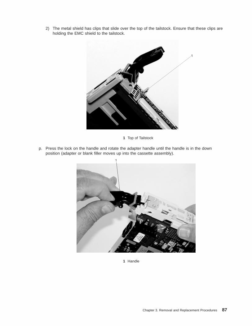
2) The metal shield has clips that slide over the top of the tailstock. Ensure that these clips areholding the EMC shield to the tailstock.
1
1 Top of Tailstock
p. Press the lock on the handle and rotate the adapter handle until the handle is in the downposition (adapter or blank filler moves up into the cassette assembly).
1
1 Handle
Chapter 3. Removal and Replacement Procedures 87

q. Using the system documentation, determine if the adapter you are installing is hot-swappable. Ifthe adapter is hot-swappable, move the slider on the color indicator to allow the orange to bevisible. If the adapter is not hot-swappable, the blue color is visible.
1 2
1 Orange for Hot-Swappable 2 Blue for Not Hot-Swappable
r. The adapter is ready to be installed into a system or an I/O drawer.
88 D10 and D20 Service Guide

Long Adapter InstallationUse the following procedure to install a long adapter.
Note: Ensure that both the retaining arms for the long and short adapters are removed from the cassettelinkage. Before continuing, see step 1a on page 67 to remove the arms.
1. Install the long adapter by doing the following:
a. Place the adapter into the cassette so that the upper left corner of the adapter engages the topadjustable adapter-retaining clip as shown in the following figure:
5
4
2
3
1
1 Top Adapter-Retaining Clip 3 Adapter2 Cassette Linkage Assembly 4 Bottom of Tailstock
5 Handle
Chapter 3. Removal and Replacement Procedures 89

b. Rotate the adapter so that the adapter engages the slot in the bottom retaining clip and the topcorner of the adapter is seated into the top adjustable adapter-retaining clip.
Note: If the adapter is not a full-height adapter, slide the top adjustable adapter-retaining clipdownward until the lower edge of the adapter is seated into the slot on the bottom retainingclip.
2
1
3
1 Adapter 3 Bottom Retaining Clip2 Slot
90 D10 and D20 Service Guide

c. Install the long adapter-retaining arm onto the cassette linkage rail, as shown in the followingfigure, and slide the arm toward the adapter.
1 2
3
1 Cassette Linkage Assembly 3 Top Adapter Retaining Clip2 Adapter Retaining Arm
Chapter 3. Removal and Replacement Procedures 91
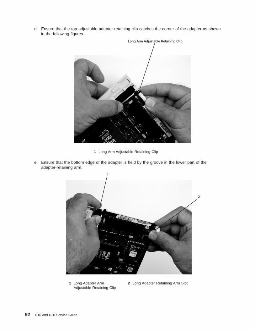
d. Ensure that the top adjustable adapter-retaining clip catches the corner of the adapter as shownin the following figures.
Long Arm Adjustable Retaining Clip
1 Long Arm Adjustable Retaining Clip
e. Ensure that the bottom edge of the adapter is held by the groove in the lower part of theadapter-retaining arm.
1
2
1 Long Adapter ArmAdjustable Retaining Clip
2 Long Adapter Retaining Arm Slot
92 D10 and D20 Service Guide
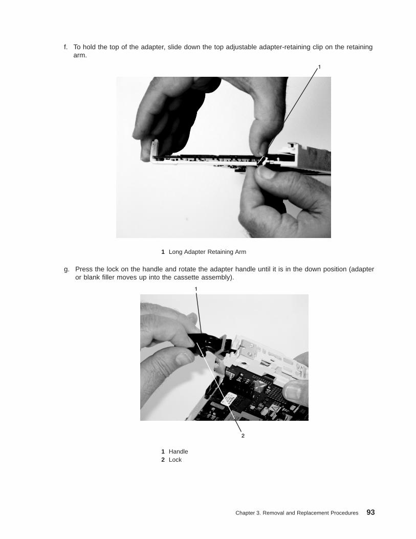
f. To hold the top of the adapter, slide down the top adjustable adapter-retaining clip on the retainingarm.
1
1 Long Adapter Retaining Arm
g. Press the lock on the handle and rotate the adapter handle until it is in the down position (adapteror blank filler moves up into the cassette assembly).
2
1
1 Handle2 Lock
Chapter 3. Removal and Replacement Procedures 93

Ensure the right end of the cassette linkage rail moves up into the cassette linkage assembly asshown below:
1
1 Right End of Cassette Linkage
h. Position the adapter and cassette assembly with the handle on the left (in the down position) andthe top facing away from you.
1
2
1 Handle2 Top of Cassette
94 D10 and D20 Service Guide

i. Install the cover on the cassette assembly by placing the cassette cover on the cassette assemblyas shown below. Slide the cover toward the handle until the hole in the cover aligns with the holein the cassette assembly.
21
1 Top of Cassette2 Handle
Chapter 3. Removal and Replacement Procedures 95

j. Install the bezel assembly using the following procedure:
1) Carefully slide the bezel onto the cassette assembly.
1
1 Bezel
2) Align and insert the cover arm latch in the hooked notch in the bezel.
96 D10 and D20 Service Guide

3) Align the top of the bezel assembly into the grooves on the top of the cassette assembly andthen push the bezel onto the cassette linkage until the tab on the top of the bezel is seated inthe recess of the cassette assembly.
1 2 34
1 Recess 3 Tab2 Groove 4 Bezel
4) Insert the two tabs on the bezel extension into the two slots on the cassette assembly.
1
1 Tabs
Chapter 3. Removal and Replacement Procedures 97

k. Check for the following:
1) Ensure that the extension arm engages the three pins on the cassette. You should be able tosee the pins in the holes in the arm. The bezel tab should be seated as shown in the followingfigure.
11
1
1 Pins
2) Ensure the cover arm latch is completely pressed into the hooked slot on the bezel as shown.
98 D10 and D20 Service Guide

3) Turn the cassette assembly over so the cover is up and check the cover latch to ensure it isholding the bezel to the cover as shown.
1
1 Cover Latch
l. Position the adapter with the cover side up. Ensure the holes are aligned and insert the bushingas shown.
1
1 Bushing
Chapter 3. Removal and Replacement Procedures 99

m. Insert the bushing lock pin into the hole in the bushing. Push on the pin until it seats.
1
1 Bushing Lock Pin
n. By pulling on both sides, ensure the gray plastic locking bar on the handle is pulled into theunlocked position. Raise the handle on the cassette linkage until it locks into the up position (theblank filler or adapter moves downward).
1 Handle2 Gray Plastic Locking Bar
100 D10 and D20 Service Guide
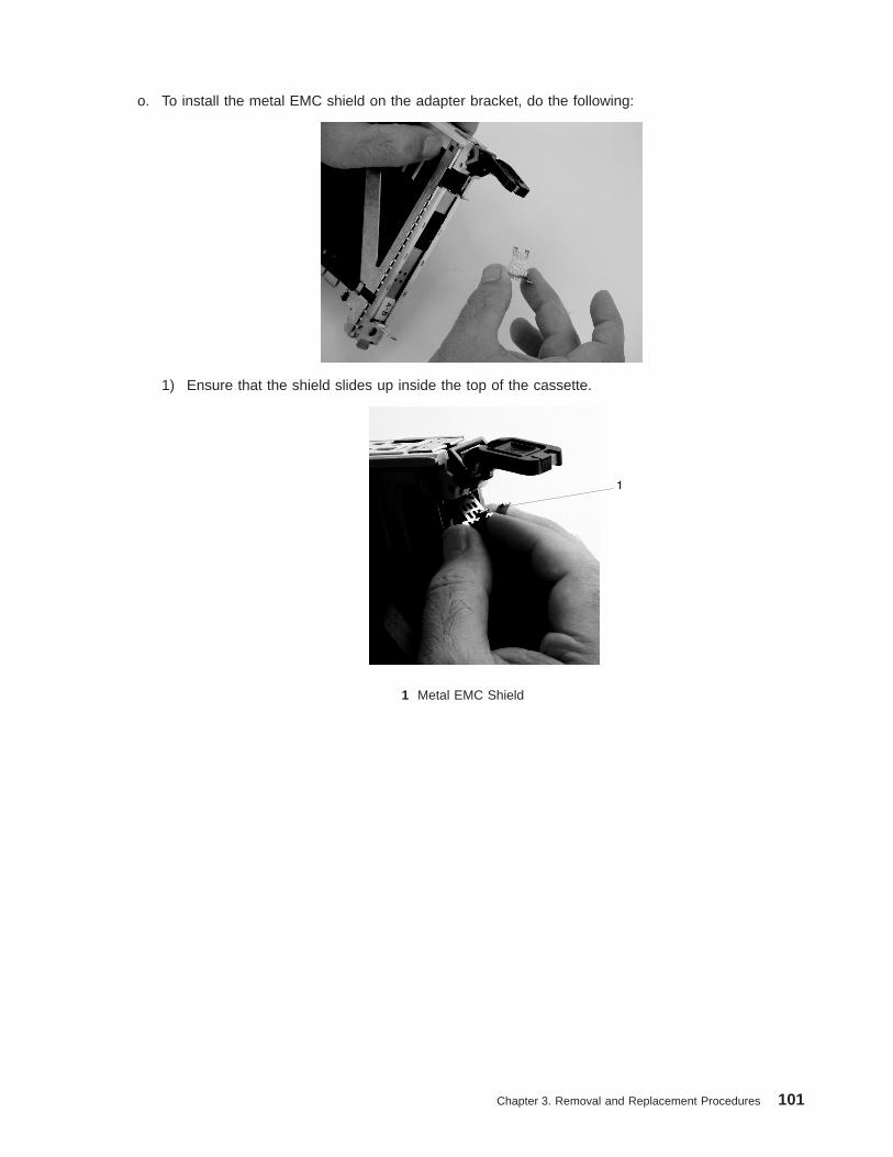
o. To install the metal EMC shield on the adapter bracket, do the following:
1) Ensure that the shield slides up inside the top of the cassette.
1 Metal EMC Shield
Chapter 3. Removal and Replacement Procedures 101

2) The metal shield has clips that slide over the top of the tailstock. Ensure that these clips areholding the EMC shield to the tailstock.
1
1 Top of Tailstock
p. Press the lock on the handle and rotate the adapter handle until the handle is in the downposition (adapter or blank filler moves up into the cassette assembly).
1
1 Handle
q. Using your system documentation, determine if the adapter you are installing is hot-swappable. Ifthe adapter is hot-swappable, move the slider on the color indicator to allow the orange to be
102 D10 and D20 Service Guide

visible. If the adapter is not hot-swappable, the blue color is visible.
1 2
1 Orange for Hot-Swappable2 Blue for Not Hot-Swappable
r. The adapter is ready to be installed into a system or an I/O drawer. Refer to your systemdocumentation for more information.
Chapter 3. Removal and Replacement Procedures 103

D10 FanBefore performing the following procedure, read “Safety Considerations” on page 41.
Hot-Swap Fan Assembly RemovalTo remove a hot-swap fan, do the following:
1. Locate the cooling fan assembly on the front of the I/O subsystem.
2. Unscrew the thumbscrew that holds the fan into the I/O subsystem.
3. Pull the fan assembly straight out until it is clear of the I/O subsystem.
12
1 Fan 2 Thumbscrew
Hot-Swap Fan Assembly ReplacementTo replace your subsystem’s hot-swap fan, do the following:
1. Position the fan with the connector (located on the fan housing) facing in toward the I/O subsystem.
2. Insert the replacement fan assembly into the I/O subsystem as far as possible.
3. Screw in the thumbscrew to hold the fan in position.
104 D10 and D20 Service Guide

D10 RIO Cable
Removal1. Turn off the power to the system.
2. Release the RIO cable retainers.
3. Disconnect the RIO cable.
ReplacementReplace in reverse order.
D10 RIO Bus Adapter Assembly
RemovalBefore performing the following procedure, read the “Safety Considerations” on page 41.
1. Turn off the system power.
2. Perform the procedure to put the I/O subsystem into the service position as described in “D10 ServicePosition” on page 43.
3. Remove the service access cover. (See “D10 Covers” on page 44).
4. Remove the screws that attach the RIO riser card to the I/O subsystem chassis.
5. Carefully pull the card straight up and out of the slot.
ReplacementReplace in reverse order.
Chapter 3. Removal and Replacement Procedures 105
D10 I/O Backplane AssemblyBefore performing the following procedure, read the “Safety Considerations” on page 41.
Note: The I/O backplane and the SPCN riser card are replaced as a pair.
Removal1. Turn off the system power.
2. Put the I/O subsystem into the service position as described in “D10 Service Position” on page 43.
3. Label and remove the PCI adapters. (See “D10 PCI Adapters” on page 45).
4. Remove the service access cover. (See “D10 Covers” on page 44).
5. Disconnect the fan cable from the I/O backplane.
6. Remove the power supplies. (See “D10 Power Supply” on page 107).
7. Remove the RIO bus adapter. (See “D10 RIO Bus Adapter Assembly” on page 105).
8. Remove the two screws that hold the SPCN connector card, and remove it from the I/O backplane.
9. Remove the screws that hold the PCI adapter mounting-guide, and remove the guides from the I/Obackplane.
10. Remove the screws that secure the I/O backplane to the subsystem chassis.
11. Lift the I/O subsystem backplane straight up and out of the subsystem chassis.
Note: If you are replacing the I/O subsystem backplane, mark and remove the VPD module (see“D10 I/O Backplane Locations” on page 12 for VPD module location) from the old backplaneand move it to the replacement I/O subsystem backplane.
Replacement
Note: If the power supplies are not removed from the I/O subsystem chassis, remove them beforereplacing the I/O subsystem backplane.
1. Place the I/O subsystem backplane assembly into the chassis. Align the backplane with the mountingscrew holes.
Note: If you are replacing an I/O subsystem backplane with a new one, remove the VPD modulefrom the old backplane and move it to the replacement I/O subsystem backplane. For VPDmodule location, see “D10 I/O Backplane Locations” on page 12. Put the module from the newbackplane onto the old backplane.
2. Position the PCI adapter mounting-guides on the I/O backplane, and install the screws to secure themounting-guides.
3. Secure the backplane with the remaining mounting screws removed earlier.
4. Reconnect the fan cable to the I/O backplane.
5. Install the new SPCN connector card on the new I/O subsystem backplane using the screws that youremoved earlier.
Note: The I/O backplane and the SPCN connector card are replaced as a pair.
6. Reinstall the RIO bus adapter card. (See “D10 RIO Bus Adapter Assembly” on page 105).
7. Reinstall the power supplies. (See “D10 Power Supply” on page 107).
8. Reinstall the cover. (See “D10 Covers” on page 44).
9. Reinstall all PCI adapters. (See “D10 PCI Adapters” on page 45).
10. Return the I/O subsystem to the operating position (see “D10 Operating Position” on page 43) andconnect RIO, SPCN, and adapter cables.
11. Connect the power cables.
12. Power the system on.
106 D10 and D20 Service Guide
D10 Power SupplyBefore performing the following procedure, read the “Safety Considerations” on page 41.
Removal
Attention: Do not remove two power supplies at the same time if performing hot-plug procedures. Powersupplies are considered as hot-pluggable FRUs only if you remove one power supply at a time. The powersupplies can be removed from the front of the I/O subsystem.
1. Disconnect the power cord from the power supply.
2. Unlatch the power supply handle and rotate the handle downward to unseat the power supply.
Attention: Do not remove a power supply for more than four minutes. If you cannot replace thepower supply in less than four minutes, shut down the system and then remove the power supply.
3. Pull the power supply straight out from the I/O subsystem.
ReplacementTo replace the power supply, perform the steps in the removal procedure in reverse order.
Chapter 3. Removal and Replacement Procedures 107

Removal and Replacement Procedures for the D20 I/O SubsystemNotes:
1. All of the parts in the D20 I/O Subsystem can be replaced with the subsystem installed in a rack. Thepower supplies, blowers, disk drives, and PCI adapters are hot-pluggable. Under normal conditions,during the swapping of these FRUs, there is no need to shut down or unplug the system.
2. Before performing any of the removal or replacement procedures in this chapter, read the danger andcaution notices on “Safety Considerations” on page 41.
D20 FRU Replacement Procedure List
Field Replaceable Unit (FRU) FRU Procedure Name and Page Location
Adapters “D20 PCI Adapters” on page 123
Bezel “D20 Front Bezel” on page 112
Cover “D20 Service Access Cover” on page 111
Disk Drives “D20 Hot-Plug Disk Drives” on page 137
Disk Drive Backplanes “D20 Disk Drive Backplane” on page 144
Disk Drive 12 Pack Cage “D20 Disk Drive Cage” on page 142
Disk Drive Configuration orDeconfiguration
“Deconfiguring (Removing) or Configuring a Disk Drive” on page 137
Blowers “D20 Blowers” on page 115
I/O Backplane “D20 I/O Backplane Assembly” on page 151
Operating Position “D20 Operating Position” on page 110
Operator Panel “D20 Operator Panel” on page 113
Power Supplies “D20 Power Supplies” on page 146
Power Bulkhead “D20 Power Supply Bulkhead” on page 148
RIO Bus Adapter “D20 RIO Bus Adapter Assembly” on page 120
Service Position “D20 Service Position” on page 109
Static-Sensitive Devices “Handling Static-Sensitive Devices” on page 42
Stopping and Starting the System “Stopping and Starting the System” on page 42
108 D10 and D20 Service Guide

D20 Service Position
Attention: When placing your D20 subsystem into the service position, all stability plates must be firmlyin position to prevent the rack from toppling. Ensure that only one system drawer is in the service positionat a time.
Before doing any service actions inside your D20 subsystem, put the D20 subsystem into the serviceposition.
To place the drawer into the service position, do the following:
1. Open the front rack door.
2. If your D20 subsystem is equipped with two blue thumbscrews securing it to the rack, remove thethumbscrews at this time. The screws are located on the bezel, just above each subsystem releaselatch.
1 Front Bezel2 Transport Retaining Screw for System Drawer
3. Release the subsystem release latches located on the left and right side.
4. Pull the system drawer out from the rack until the rails are fully extended.
Note: When the system rails are fully extended, safety latches on the slide rails lock into place. Thisaction prevents the system from being accidentally pulled out too far and dropped. The followingillustration shows a system drawer in the service position.
Chapter 3. Removal and Replacement Procedures 109

1 D20 Subsystem 4 Stabilizing Bar2 19-Inch Rack 5 Front Rack Door3 Extension Rail Safety Release Latch 6 System Drawer Release Latch
After completing the service actions, return the D20 subsystem to the operating position.
D20 Operating PositionTo return your D20 subsystem to the operating position, do the following:
1. Release the rail release latches located on each rail. See the illustration on page 110 for the locationof the release tabs.
Note: To release the left rail, pull the release latch up. To release the right rail, push the right latchdown.
2. Release latches must be in the open position. See the illustration on page 110 for the location of thesubsystem release latches.
3. Push the system drawer straight back into the rack until both release latches on the subsystem havelocked into position.
4. If you removed two thumbscrews from the front bezel, replace them at this time.
5. Close the front rack door.
110 D10 and D20 Service Guide

D20 Service Access CoverBefore performing the following procedure, read the “Safety Considerations” on page 41.
Opening the Service Access CoverTo open the service access cover, do the following:
1. Open the front rack door and place the D20 subsystem into the service position as described in “D20Service Position” on page 109.
2. Loosen the three captive thumbscrews located on the rear of the cover. See the following illustrationfor thumbscrew locations.
Note: The service access cover pivots on a piano hinge located directly behind the four coolingblowers.
3. To open the service access cover, lift the cover up from the back edge. The hinges allow the serviceaccess cover to swing open to about 170 degrees. Do not force the cover to come to a rest on top ofthe cooling blowers.
Note: When you open the service access cover, ensure you have enough height clearance.
4. Close and then secure the service access cover with the three thumbscrews located on its back edge.
Attention: For proper cooling and airflow, close the cover before turning on the system. Operating thesystem for extended periods of time (over 30 minutes) with the cover opened might damage the systemcomponents.
1 Thumbscrews 3 D20 Subsystem2 Service Access Cover
Service Access Cover RemovalIf you need to remove the service access cover from the subsystem, do the following:
1. Open the cover as described in the previous procedure.
2. Remove the four retaining screws that secure the cover hinge to the chassis.
3. Remove the cover.
Service Access Cover ReplacementTo install the service access cover, do the following:
1. Open the hinge, located on the service access cover.
2. Align the four holes located on the hinge with the four screw holes located on the top of the chassis.
3. Start and then tighten the four retaining screws that secure the service access cover to the chassis.
4. Close and then secure the service access cover with the three thumbscrews located on its back edge.
Chapter 3. Removal and Replacement Procedures 111

D20 Front BezelBefore performing the following procedure, read the “Safety Considerations” on page 41.
Front Bezel RemovalTo remove the front bezel, do the following:
1. Open the front rack door. If necessary, place the D20 subsystem into the service position as describedin “D20 Service Position” on page 109.
2. Simultaneously press in both bezel-release tabs. See the following illustration for bezel-release tablocations.
3. Pivoting the bezel from the bottom, swing the top of the bezel out.
4. Pull the bottom of the bezel up, and then away from the subsystem chassis. This action releases thetwo tabs located on the bottom of the bezel.
5. Put the bezel in a safe place.
1 Rack Door 3 Bezel-Release Tab (Locatedon each side of bezel)
2 Bezel 4 19-Inch Rack
Front Bezel ReplacementTo replace the front bezel, do the following:
1. Open the front rack door. If necessary, put the D20 subsystem into the service position as described in“D20 Service Position” on page 109.
2. Insert the two tabs located on the bottom edge of the bezel into their locking slots, located on thechassis.
3. Pivot the front bezel up toward the top of the chassis.
4. Align the release tabs to the matching slots located on the front of the subsystem chassis.
5. Gently push the tabs into the slots until the bezel seats against the front of the subsystem.
6. If the subsystem is in the service position, put the subsystem back into the operating position asdescribed in “D20 Operating Position” on page 110.
7. Close the rack door.
112 D10 and D20 Service Guide
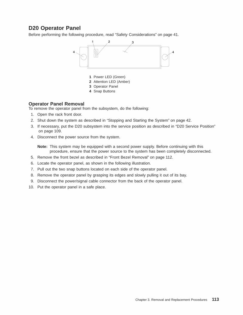
D20 Operator PanelBefore performing the following procedure, read “Safety Considerations” on page 41.
1 Power LED (Green)2 Attention LED (Amber)3 Operator Panel4 Snap Buttons
Operator Panel RemovalTo remove the operator panel from the subsystem, do the following:
1. Open the rack front door.
2. Shut down the system as described in “Stopping and Starting the System” on page 42.
3. If necessary, put the D20 subsystem into the service position as described in “D20 Service Position”on page 109.
4. Disconnect the power source from the system.
Note: This system may be equipped with a second power supply. Before continuing with thisprocedure, ensure that the power source to the system has been completely disconnected.
5. Remove the front bezel as described in “Front Bezel Removal” on page 112.
6. Locate the operator panel, as shown in the following illustration.
7. Pull out the two snap buttons located on each side of the operator panel.
8. Remove the operator panel by grasping its edges and slowly pulling it out of its bay.
9. Disconnect the power/signal cable connector from the back of the operator panel.
10. Put the operator panel in a safe place.
Chapter 3. Removal and Replacement Procedures 113
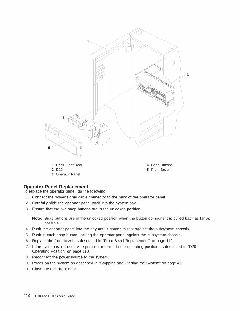
1 Rack Front Door 4 Snap Buttons2 D20 5 Front Bezel3 Operator Panel
Operator Panel ReplacementTo replace the operator panel, do the following:
1. Connect the power/signal cable connector to the back of the operator panel.
2. Carefully slide the operator panel back into the system bay.
3. Ensure that the two snap buttons are in the unlocked position.
Note: Snap buttons are in the unlocked position when the button component is pulled back as far aspossible.
4. Push the operator panel into the bay until it comes to rest against the subsystem chassis.
5. Push in each snap button, locking the operator panel against the subsystem chassis.
6. Replace the front bezel as described in “Front Bezel Replacement” on page 112.
7. If the system is in the service position, return it to the operating position as described in “D20Operating Position” on page 110.
8. Reconnect the power source to the system.
9. Power on the system as described in “Stopping and Starting the System” on page 42.
10. Close the rack front door.
114 D10 and D20 Service Guide
D20 BlowersBefore performing the following procedure, read “Safety Considerations” on page 41.
Each cooling blower assembly has a green LED and an amber LED. The green LED indicates when thecooling blower is receiving power. A blinking amber LED indicates when the cooling blower needs attentionfrom a potential cooling problem. When you are standing in front of and facing the I/O subsystem, thecooling blowers are labeled from left to right, 1 through 4, across the top blower retaining bracket.
Attention: If the I/O subsystem does not have two functional power supplies installed, do not remove ablower with the power turned on. If only one power supply is functional, removing of a blower will causethe system to turn power off.
Hot-Swap Blower RemovalTo remove a hot-swap blower, do the following:
1. Put the D20 subsystem into the service position as described in “D20 Service Position” on page 109.
2. Locate the cooling blower assemblies, as shown in the following illustration.
3. Pull out the snap button located on the front flange of the failing blower.
4. Using the snap button as a handle, pull the front of the blower up, allowing the back edge to pivot on arecessed ledge located just below the back edge of the blower.
Note: Using the snap button, lift the blower from the chassis. The blower connector will disconnectfrom its docking connector, which is located on the underside of the blower.
5. Pull the blower away from the system. Ensure that the two back tabs, located on the bottom back edgeof the blower assembly, have cleared their retaining slots.
Chapter 3. Removal and Replacement Procedures 115

1 Green LED 4 Blower Connector2 Amber LED 5 Hot-Plug Blower Assembly3 Snap Button 6 Docking Connector
116 D10 and D20 Service Guide
Hot-Swap Blower Replacement
Note: If a blower assembly is being replaced for a redundant failure, after the service repair action iscompleted, ask the customer to check the crontab file for any power/cooling warning messages.When a power or cooling error is encountered, AIX adds an entry to the crontab file to ″wall″ awarning message every 12 hours, to alert or remind the customer of the problem. Replacing thefaulty part does not clear this crontab entry, so unless the crontab file is edited to remove thisentry, the customer continues to be reminded of the failure despite its having been repaired. Thecrontab -l command reads the crontab file to determine if an entry exists. The crontab -ecommand edits the file.
To replace a hot-swap blower, do the following:
1. Grasp the blower by its snap button, and ensure that the snap button is in the unlocked position.
Note: Snap buttons are in the unlocked position when the button component is pulled back as far aspossible.
2. Install the two alignment tabs located on the lower back edge of the blower assembly into the tworetaining slots located on the chassis ledge.
3. Pivoting from the back, lower the front of the blower onto its docking connector.
4. Push down on the front of the blower until the front flange of the blower is seated on top of the chassisledge.
5. Push down on the snap button, locking the blower in place.
6. Return the subsystem back to the operating position as described in “D20 Operating Position” onpage 110.
7. Close the rack door.
Chapter 3. Removal and Replacement Procedures 117

D20 Cooling Blower CableThis procedure must be performed with the power turned off.
Cooling Blower Cable RemovalTo remove the cooling blower cable, do the following:
1. Open the rack front door.
2. Shut down the system as described in “Stopping and Starting the System” on page 42.
3. Put the D20 subsystem into the service position as described in “D20 Service Position” on page 109.
4. Disconnect the power source from the system.
Note: This system may be equipped with a second power supply. Before continuing with thisprocedure, ensure that the power source to the system has been completely disconnected.
5. Remove the four cooling blowers as described in “Hot-Swap Blower Removal” on page 115.
6. Open the service access cover as described in “Opening the Service Access Cover” on page 111.
7. Remove the power supplies and, if applicable, the power supply filler.
8. If necessary, remove the power supply bulkhead as described in “Power Supply Bulkhead Removal”on page 148.
9. Disconnect the blower cable from the I/O board.
10. Unclip the three cable ties from the chassis and the three cable ties from the blowerconnector-support bracket.
11. Remove the blower docking connectors from the chassis.
To remove each blower docking connector from the chassis, do the following:
a. Depress the connector release tab next to the blower docking connector. The connector releasetab has a small tab retaining clip that locks the blower docking connector into the blowerconnector support bracket. Depress the connector release tab far enough so that the tab retainingclip clears the bottom of the blower connector-support bracket.
b. With the connector release tab still depressed, slide the blower docking connector toward thedepressed tab.
c. Align the blower docking connector’s four retaining ears with the four small slots located on theblower connector-support bracket.
d. Push down on the blower docking connector to free it from the blower connector-support bracket.
12. Remove the cable from the subsystem.
118 D10 and D20 Service Guide

1 Cooling Blowers 6 Connector Retaining Ears2 Cable Ties 7 Blower Docking Connector3 Power Supply 8 D204 Tab Retaining Clip 9 Blower Connector Support5 Connector Release Tab
Cooling Blower Cable ReplacementReplace in reverse order.
Chapter 3. Removal and Replacement Procedures 119

D20 RIO Bus Adapter AssemblyBefore performing this procedure, read “Safety Considerations” on page 41.
In the following RIO bus adapter removal and replacement procedures, the RIO bus adapter assembly isreferred to as the RIO adapter.
RIO Bus Adapter RemovalTo remove the RIO adapter from the subsystem, do the following:
1. Open the rack front door.
2. Shut down the system as described in “Stopping and Starting the System” on page 42.
3. Put the D20 subsystem into the service position as described in“D20 Service Position” on page 109.
4. Disconnect the power source from the system.
Note: This system may be equipped with a second power supply. Before continuing with thisprocedure, ensure that the power source to the system has been completely disconnected.
5. Open the service access cover as described in “Opening the Service Access Cover” on page 111.
6. Disconnect the RIO-2 cables from the RIO connectors located on the rear of the subsystem.
7. Identify, and then disconnect and label all cables that cross over the top of the RIO adapter. Thesecables might interfere with the removal and installation of the RIO adapter.
8. Release the release latches located on top of the RIO adapter.
9. Simultaneously lift both retention handles.
10. Pivot the release handles up until they are perpendicular (90 degrees) to the top of the RIO adapter.
Note: By placing the handles perpendicular to the top of the RIO adapter, the base or hinged portionof each handle acts as a cam and will gently pry the RIO adapter up, disconnecting it from itsdocking connector.
11. Remove the RIO adapter from the subsystem chassis, and put it in a safe place.
120 D10 and D20 Service Guide
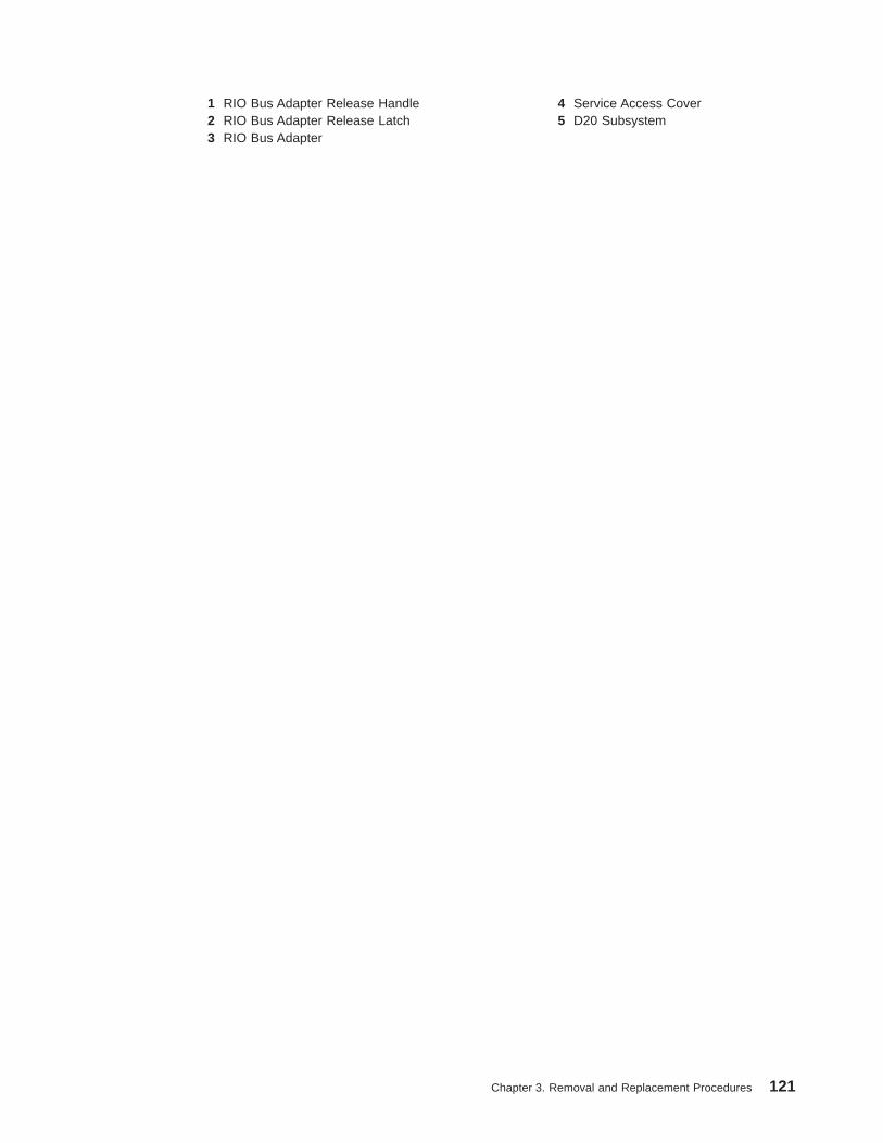
1 RIO Bus Adapter Release Handle 4 Service Access Cover2 RIO Bus Adapter Release Latch 5 D20 Subsystem3 RIO Bus Adapter
Chapter 3. Removal and Replacement Procedures 121
RIO Bus Adapter ReplacementTo replace the RIO bus adapter, do the following:
1. Grasp the two RIO adapter release handles.
2. Pivot both handles upward to 90 degrees, ensuring that the handles are perpendicular to the RIOadapter. The handle cams have now been placed into the correct position to assist you when seatingthe RIO adapter into its docking connector.
3. Before inserting the RIO adapter into its bay, observe the alignment bracket. The alignment bracket issecured to the power bulkhead.
4. Insert the RIO adapter into its bay. Ensure that the power cable receptacle located on the back of theRIO adapter is facing the back of the subsystem chassis.
5. Lower the RIO adapter through the alignment bracket. The alignment bracket will catch the back edgeof the RIO adapter closest to it.
The RIO adapter should now be resting on the top of its docking connector. The docking connectorhas two large alignment pins located on each end. These alignment pins will ensure alignment of theRIO adapter to its docking connector when seated.
6. Lower the RIO adapter locking handles, carefully seating the RIO adapter into the docking connector.The plastic latch located beneath each handle clicks when the RIO adapter is fully seated. This clickalso indicates that the handle is locked in the closed position.
7. Reconnect the RIO-2 cables to the RIO adapter connectors located on the back of the chassis.
8. Reconnect the cables that were disconnected during the RIO adapter removal.
9. Reconnect the power source to the system.
10. Close and then secure the service access cover with the three thumbscrews located on its backedge.
11. Return the D20 to the operating position as described in “D20 Operating Position” on page 110.
12. Power on the system as described in “Stopping and Starting the System” on page 42.
13. Close the rack front door.
122 D10 and D20 Service Guide

D20 PCI AdaptersBefore performing this procedure, read “Safety Considerations” on page 41.
Notes:
1. Some PCI adapter cards are shipped from the manufacturer with a blue handle or support along theback edge of the card. In this system unit, you must remove the blue handle or support from the card.
2. With this system, you can install PCI adapters with the power on. These adapters are referred to ashot-pluggable PCI adapters. Some adapters are not hot-pluggable, and the system must be poweredoff for this type of adapter installation.
Before you install the adapter, determine if the PCI adapter you are installing is hot-pluggable. See the PCIAdapter Placement Reference, order number SA23-2504.
If you are removing a PCI adapter that is:
v Non-hot-pluggable, go to “Non-Hot-Pluggable PCI Adapter Removal” on page 126.
v Hot-pluggable, go to “Hot-Pluggable PCI Adapter Removal” on page 129.
PCI Hot-Plug Manager AccessThe installation instructions for hot-pluggable PCI adapters refer you to these procedures when it isappropriate to perform them.
Note: A PCI adapter is only hot-pluggable if the PCI adapter is supported for hot-plug applications. Forcomplete information regarding your PCI adapter, see the PCI Adapter Placement Reference, ordernumber SA23-2504.
Accessing Hot-Plug Management Functions:
Note: Removing or installing a hot-pluggable PCI adapter requires the system administrator to take thePCI adapter offline prior to performing the operation. Before taking an adapter offline, the devicesattached to the adapter must be taken offline as well. This action prevents a service representativeor user from causing an unexpected outage for system users.
For additional information about taking an adapter offline or removing it from the systemconfiguration, see the AIX System Management Guide: Operating System and Devices.
This publication is also contained on the AIX Documentation CD. The documentation is madeaccessible by loading the documentation CD onto the hard disk or by mounting the CD in theCD-ROM drive.
Chapter 3. Removal and Replacement Procedures 123
To access the hot-plug menus, do the following:
1. Log in as root user.
2. At the command line, type smitty.
3. Select Devices .
4. Select PCI Hot Plug Manager and press Enter.
5. The PCI Hot-Plug Manager menu displays. Return to the procedure that directed you here. Thefollowing section describes the menu options.
PCI Hot-Plug Manager Menu: The following options are available from the PCI Hot Plug Manager menu:
Note: For information about the PCI slot LED states, see “D20 PCI-X Slots” on page 16.
List PCI Hot-Plug Slots
Provides a descriptive list of all slots that support PCI hot-plug capability. If the listing for a slot indicates itholds an “Unknown” device, select the Install/Configure Devices Added after IPL to configure theadapter in that slot.
Add a PCI Hot-Plug Adapter
Allows the user to add a new PCI hot-plug-capable adapter to the slot with the system turned on. You willbe asked to identify the PCI slot that you have selected prior to the actual operation. The selected PCI slotwill go into the Action state and finally into the On state.
Note: The system will indicate the slot holds an “Unknown” device until you perform the Install/ConfigureDevices Added After IPL option to configure the adapter.
Replace/Remove a PCI Hot-Plug Adapter
Allows the user to remove an existing adapter, or replace an existing adapter with an identical one. Forthis option to work, the adapter must be in the Defined state (see the “Unconfigure a Device” option).
You will be asked to identify the PCI slot prior to the actual operation. The selected PCI slot will go into theAction state.
Identify a PCI Hot-Plug Slot
Allows the user to identify a PCI slot. The selected PCI slot will go into the Identify state. See “D20 PCI-XSlots” on page 16.
124 D10 and D20 Service Guide

Unconfigure a Device
Allows the user to put an existing PCI adapter into the Defined state if the device is no longer in use.
This step must be completed successfully before starting any removal or replacement operation. If thisstep fails, the customer must take action to release the device.
Configure a Defined Device
Allows a new PCI adapter to be configured into the system if software support is already available for theadapter. The selected PCI slot will go into the On state.
Install/Configure Devices Added After IPL
The system attempts to configure any new devices and tries to find and install any required software froma user-selected source.
The add, remove, and replace functions return information to the user indicating whether the operationwas successful. If additional instructions are provided on the screen, complete the recommended actions.If the instructions do not resolve the problem, do the following:
v If the adapter is listed as Unknown, perform the Install/Configure Devices Added After IPL option toconfigure the adapter.
v If you receive a warning indicating that needed device packages are not installed, the systemadministrator must install the specified packages before you can configure or diagnose the adapter.
v If you receive a failure message indicating a hardware error, the problem might be either the adapter orthe PCI slot. Isolate the problem by retrying the operation in a different PCI slot, or trying a differentadapter in the slot. If you determine that you have failing hardware, call your service representative.
v Do not use Install/Configure Devices Added After IPL if your system is set up to run HACMPclustering. Consult with your system administrator or software support to determine the correct methodto configure the replacement device.
Chapter 3. Removal and Replacement Procedures 125

Non-Hot-Pluggable PCI Adapter RemovalTo remove a PCI adapter, do the following:
1. Open the front and rear rack doors, and place the subsystem into the service position as described in“D20 Service Position” on page 109.
2. Shut down the system as described in “Stopping and Starting the System” on page 42.
3. Disconnect the power source to the system.
Note: This system may be equipped with a second power supply. Before continuing with thisprocedure, ensure that the system power source has been completely disconnected.
4. Open the service access cover as described in “Service Access Cover Removal” on page 111.
5. Determine which adapters you plan to remove, and then label and disconnect all cables attached tothat adapter.
6. Record the slot number and location of each adapter being removed.
Note: Adapter slots are numbered on the rear of the subsystem unit.
7. Before handling any card, board, or memory DIMM, be sure to use your electrostatic discharge strapto minimize static-electric discharge. Refer to “Handling Static-Sensitive Devices” on page 42.
1 Hot-Plug PCI Adapters2 Service Access Cover3 D20 Subsystem
126 D10 and D20 Service Guide

8. Rotate the adapter retainer clip counterclockwise, as shown in the following illustration.
9. Lift the adapter retaining seat that is resting on the adapter retention bracket.
10. Carefully grasp the PCI adapter by its top edge or upper corners, and remove it from the system.
11. Store the adapter in a safe place.
12. If you do not plan to install another adapter into the vacated slot, seal the expansion slot using anexpansion-slot cover. If you are installing another adapter, go to “Adding or Replacing aNon-Hot-Pluggable PCI Adapter” on page 128.
13. If you have other options to install, refer to “D20 FRU Replacement Procedure List” on page 108. Ifyou do not have other options to install, continue on to the next step.
14. Close and then secure the service access cover with the three thumbscrews located on its backedge.
15. Connect the adapter cables.
16. Reconnect the power source to the system.
17. Route the cables through the cable-management arm.
18. Push the system drawer back into the operating position as described in “D20 Operating Position” onpage 110.
19. Power on the system as described in “Stopping and Starting the System” on page 42.
20. Close the rack doors.
1 D202 Service Access Cover3 Retainer Clip4 Retainer Seat5 PCI Adapter
Chapter 3. Removal and Replacement Procedures 127
Adding or Replacing a Non-Hot-Pluggable PCI AdapterTo add or replace an adapter, do the following:
1. Open the front and rear rack doors, and place the system into the service position as described in“D20 Service Position” on page 109.
2. Shut down the system as described in “Stopping and Starting the System” on page 42.
3. Disconnect the power source to the system.
Note: This system may be equipped with a second power supply. Before continuing with thisprocedure, ensure that the system has been completely disconnected from its power source.
4. Open the service access cover as described in “Service Access Cover Removal” on page 111.
5. Refer to the PCI Adapter Placement Reference for information regarding slot restrictions for adaptersthat can be used in this subsystem.
6. If necessary, remove the adapter expansion slot shield.
7. Before handling any card, board, or memory DIMM, be sure to use your electrostatic discharge strapto minimize static-electric discharge. Refer to “Handling Static-Sensitive Devices” on page 42.
8. If necessary, remove the adapter from the antistatic package.
Attention: Avoid touching the components and gold-edge connectors on the adapter.
9. Place the adapter, component-side up, on a flat, static-protective surface.
10. Set any jumpers or switches as instructed by the adapter’s manufacturer.
11. Carefully grasp the adapter by its top edge, and align the adapter with the expansion slot and itsconnector on the PCI riser card.
12. Press the adapter firmly into its connector.
Attention: When you install an adapter into your subsystem, be sure that it is completely andcorrectly seated in its connector.
13. Lower the adapter retaining seat onto the PCI adapter EMC shield/connector faceplate. Rotate theadapter retainer clip over the adapter retaining seat until it comes to a stop.
14. Close and then secure the service access cover with the three thumbscrews located on its backedge.
15. Connect the adapter cables.
16. Reconnect the power source to the system.
17. Route the cables through the cable-management arm.
18. Push the system drawer back into the operating position as described in “D20 Operating Position” onpage 110.
19. Power on the system as described in “Stopping and Starting the System” on page 42.
20. Close the rack doors.
128 D10 and D20 Service Guide

Hot-Pluggable PCI Adapter Removal
Attention: The Linux operating system does not support these hot-plug procedures. Also, Linux does notsupport hot-plugging any hot-pluggable PCI adapters. Systems with Linux installed on one or morepartitions must be shut down and powered off before replacing any PCI adapter assigned to a Linuxpartition. Follow the non-hot-pluggable adapter procedures when replacing a PCI adapter in any partitionwith Linux installed.
Note: Removing a hot-pluggable PCI adapter requires the system administrator to take the PCI adapteroffline before performing any PCI adapter hot-plug procedures. Before taking an adapter offline, thedevices attached to the adapter must also be taken offline. This action prevents a servicerepresentative or user from causing an unexpected outage for system users.
For additional information about taking an adapter offline or removing it from the systemconfiguration, see the AIX System Management Guide: Operating System and Devices.
This publication is also contained on the AIX Documentation CD. The documentation is madeaccessible by loading the documentation CD onto the hard disk or by mounting the CD in theCD-ROM drive.
To remove a hot-pluggable PCI adapter, do the following:
1. Open the front and rear rack doors, and place the system into the service position as described in“D20 Service Position” on page 109.
2. Open the service access cover as described in “Service Access Cover Removal” on page 111.
3. Determine which adapters you plan to remove.
4. Record the slot number and location of each adapter being removed.
Note: Adapter slots are numbered on the rear of the system unit.
5. Ensure that any processes or applications that might use the adapter are stopped.
6. Refer to “PCI Hot-Plug Manager Access” on page 123, and follow the steps in the access procedureto select PCI Hot Plug Manager . Then return here to continue.
7. Select Unconfigure a Device and press Enter.
8. Press F4 to display the Device Names menu.
9. Select the adapter you are removing.
10. Use the Tab key to answer NO to Keep Definition and YES to Unconfigure Child Devices . PressEnter.
11. The ARE YOU SURE screen displays. Press Enter to verify the information. Successfulunconfiguration is indicated by the OK message displayed next to the Command field at the top of thescreen.
12. Label and disconnect all cables attached to that adapter.
13. Press F3 to return to the PCI Hot-Plug Manager menu.
Chapter 3. Removal and Replacement Procedures 129

14. Select Replace/Remove a PCI Hot-Plug Adapter and press Enter. The Replace/Remove a PCIHot-Plug Adapter menu displays.
Note: If the PCI Hot-Plug Adapter menu indicates that the slot for the just replaced adapter isreading empty, do the following:
a. From the Replace/Remove a PCI Hot-Plug Adapter menu, select F3 to cancel.
b. Select Add PCI Hot-Plug Adapter , and press Enter. The display screen indicates that the PCIslot is empty.
c. On the display screen, select the indicated empty slot. Look at the adapter you intend to replace.A slow blinking amber LED located next to the adapter on the PCI riser card is indicating that theslot has been identified. Press Enter. The adapter, has been put into the action state.
d. Completely remove the hot-plug adapter from the slot. The LED goes off.
e. Reinstall the adapter, ensuring that it is correctly seated. Press Enter.
f. Select F3 to return to the PCI Hot-Plug Adapter Menu.
g. Select Install/Configure Devices Added after IPL .
h. At the display screen, identify the PCI hot-plug slot that your adapter is using. If it still shows asbeing empty, redo steps a through g. However, before you reinstall the adapter, test it. If theadapter fails the test, redo steps a through g with a new adapter.
15. Move the cursor to select the adapter that you are removing and press Enter. (The description entrydisplays as unknown).
16. Press the Tab key until the entry field displays the remove operation and then press the Enter key.Follow the instructions that display on the screen until you are instructed to remove the adapter.
17. When you are instructed to remove the adapter from the adapter slot, disconnect any cables that areconnected to the adapter being removed.
18. Before handling any card, board, or memory DIMM, be sure to use your electrostatic discharge strapto minimize static-electric discharge. Refer to “Handling Static-Sensitive Devices” on page 42.
1 Hot-Plug PCI Adapters2 Service Access Cover3 D20 Subsystem
130 D10 and D20 Service Guide
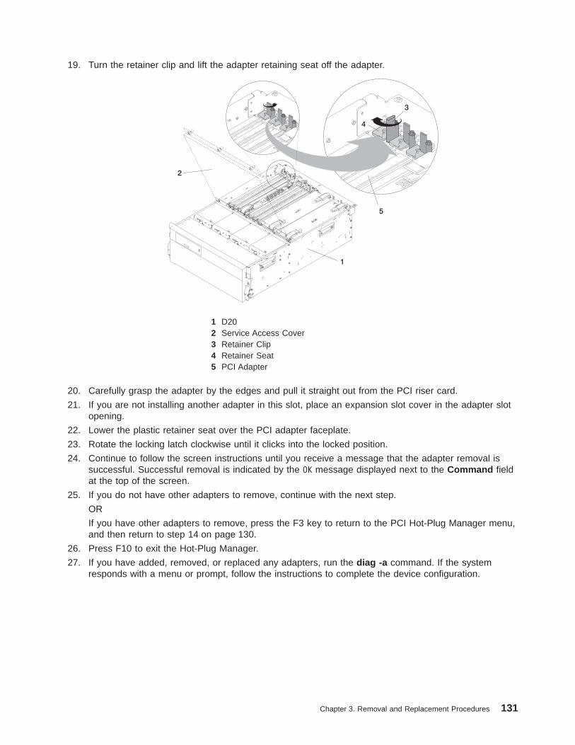
19. Turn the retainer clip and lift the adapter retaining seat off the adapter.
1 D202 Service Access Cover3 Retainer Clip4 Retainer Seat5 PCI Adapter
20. Carefully grasp the adapter by the edges and pull it straight out from the PCI riser card.
21. If you are not installing another adapter in this slot, place an expansion slot cover in the adapter slotopening.
22. Lower the plastic retainer seat over the PCI adapter faceplate.
23. Rotate the locking latch clockwise until it clicks into the locked position.
24. Continue to follow the screen instructions until you receive a message that the adapter removal issuccessful. Successful removal is indicated by the OK message displayed next to the Command fieldat the top of the screen.
25. If you do not have other adapters to remove, continue with the next step.
OR
If you have other adapters to remove, press the F3 key to return to the PCI Hot-Plug Manager menu,and then return to step 14 on page 130.
26. Press F10 to exit the Hot-Plug Manager.
27. If you have added, removed, or replaced any adapters, run the diag -a command. If the systemresponds with a menu or prompt, follow the instructions to complete the device configuration.
Chapter 3. Removal and Replacement Procedures 131

28. If you have other options to install, refer to “D20 FRU Replacement Procedure List” on page 108. Ifyou do not have other options to install, continue on to the next step.
29. Replace the service access cover as described in “Service Access Cover Replacement” on page 111.
30. Push the system drawer back into the operating position as described in “D20 Operating Position” onpage 110.
31. Connect the adapter cables.
32. Route the cables through the cable-management arm.
33. Close the rack doors.
Replacing a Hot-Pluggable PCI Adapter
Attention: The Linux operating system does not support these hot-plug procedures. Also, Linux does notsupport hot-plugging any hot-pluggable PCI adapters. Systems with Linux installed on one or morepartitions must be shut down and powered off before replacing any PCI adapter assigned to a Linuxpartition. Follow the non-hot-pluggable adapter procedures when replacing a PCI adapter in any partitionwith Linux installed.
Notes:
1. Use this procedure only when you are replacing an adapter with an identical adapter. If you arereplacing an adapter with an adapter that is not identical to the adapter removed, go to “Hot-PluggablePCI Adapter Removal” on page 129 and “Installing a Hot-Pluggable PCI Adapter” on page 135.
2. Removing a hot-pluggable PCI adapter requires the system administrator to take the PCI adapteroffline before performing any PCI adapter hot-plug procedures. Before taking an adapter offline, thedevices attached to the adapter must be taken offline as well. This action prevents a servicerepresentative or user from causing an unexpected outage for system users.
For additional information about taking an adapter offline or removing it from the system configuration,see the AIX System Management Guide: Operating System and Devices.
This publication is also contained on the AIX Documentation CD. The documentation is madeaccessible by loading the documentation CD onto the hard disk or by mounting the CD in the CD-ROMdrive.
To replace a hot-plug PCI adapter, do the following:
1. Open the front and rear rack doors, and place the system into the service position as described in“D20 Service Position” on page 109.
2. Remove the service access cover as described in “Service Access Cover Removal” on page 111.
3. Refer to the PCI Adapter Placement Reference, order number SA23-2504, for information regardingslot restrictions for adapters that can be used in this system.
4. Before handling any card, board, or memory DIMM, be sure to use your electrostatic discharge strapto minimize static-electric discharge. Refer to “Handling Static-Sensitive Devices” on page 42.
5. Determine the slot from which you are removing the adapter.
6. Ensure that any processes or applications that might use the adapter are stopped.
7. Refer to “PCI Hot-Plug Manager Access” on page 123, and follow the steps in the access procedureto select PCI Hot Plug Manager . Then return here to continue.
132 D10 and D20 Service Guide
8. Select Unconfigure a Device and press Enter.
Note: If the adapter or device has a problem that prevents it from being replaced by hot-plug, it mustbe replaced by shutting down the system. Go to “Adding or Replacing a Non-Hot-PluggablePCI Adapter” on page 128.
9. Press F4 to display the Device Names menu.
10. From the menu, select the adapter you are removing.
11. Use the tab key to answer YES to Keep Definition and YES to set Unconfigure Child Devices .Press Enter.
12. The ARE YOU SURE screen displays. Press Enter to verify the information. Successfulunconfiguration is indicated by the OK message displayed next to the Command field at the top of thescreen.
13. Press F3 to return to the PCI Hot-Plug Manager menu.
14. Select List PCI Hot-Plug Slots and press Enter.
Note: If the List PCI Hot-Plug Slots menu indicates that the slot for the adapter you intend to replaceor reseat is empty, do the following:
a. Press F3 to cancel.
b. Select Add PCI Hot-Plug Adapter , and press Enter. The display screen indicates that the PCIslot is empty.
c. On the display screen, select the indicated empty slot. Examine at the adapter you intend toreplace or reseat. A slow blinking amber LED located on the PCI riser card is indicating that theslot has been identified. Press Enter. The adapter is now in the action state.
d. Completely remove the hot-plug adapter from the slot. The LED goes off.
e. Reinstall the adapter, ensuring that it is correctly seated. Press Enter.
f. Press F3 to return to the ″PCI Hot-Plug Adapter Menu″.
g. Connect the appropriate cables and devices to the adapter.
h. Select List PCI Hot-Plug Slots , then press Enter.
i. Return to the error code or procedure that sent you here, if the ″List PCI Hot-Plug Slots″ menuindicates that the slot for the just-replaced or reseated adapter is empty.
15. Press F3 to cancel.
16. Select Replace/Remove a PCI Hot-Plug Adapter , then press Enter. The ″Replace/Remove a PCIHot-Plug Adapter menu displays.
Note: If the PCI Hot-Plug Adapter menu indicates that the slot for the just replaced adapter isreading empty, do the following:
a. From the Replace/Remove a PCI Hot-Plug Adapter menu, press F3 to cancel.
b. Select Add PCI Hot-Plug Adapter , and press Enter. The display screen indicates that the PCIslot is empty.
c. On the display screen, select the indicated empty slot. Examine at the adapter you intend toreplace. A slow blinking amber LED located on the PCI riser card is indicating that the slot hasbeen identified. Press Enter. The adapter has been put into the action state.
d. Completely remove the hot-plug adapter from the slot. The LED goes off.
e. Reinstall the adapter, ensuring that it is correctly seated. Press Enter.
f. Press F3 to return to the PCI Hot-Plug Adapter Menu.
g. Select Install/Configure Devices Added after IPL .
h. At the display screen, identify the PCI hot-plug slot that your adapter is using. If it still shows asbeing empty, redo steps a through g. However, before you reinstall the adapter, test it. If theadapter fails the test, redo steps a through g with a new adapter.
Chapter 3. Removal and Replacement Procedures 133

17. Move the cursor to select the adapter that you are removing, and press Enter.
18. Press the Tab key until the entry field displays the replace operation, and then press Enter. Follow theinstructions that display on the screen until you are instructed to remove the adapter.
19. When you are instructed to remove the adapter from the adapter slot, disconnect any cables that areconnected to the adapter being removed.
20. Turn the retainer clip, and lift the adapter retaining seat off the top of the adapter.
21. Carefully grasp the adapter by the edges, and pull it straight up and out of the subsystem.
22. If necessary, remove the replacement adapter from the antistatic package.
Attention: Avoid touching the components and gold-edge connectors on the adapter.
1 D202 Service Access Cover3 Retainer Clip4 Retainer Seat5 PCI Adapter
23. Place the adapter, component-side up, on a flat, static-protective surface.
24. Set any jumpers or switches as instructed by the adapter manufacturer.
25. Replace the adapter into the adapter slot. Carefully grasp the adapter by the edges and align theadapter in the slot guides. Insert the adapter fully into the adapter slot connector. If you are installinga full-length adapter, ensure that both ends of the adapter engage the card guides.
26. Lower the adapter retaining seat over the PCI adapter faceplate. Rotate the retainer clip until it stops.
27. Connect appropriate cables and devices to the adapter.
28. Continue to follow the screen instructions until you receive a message that the replacement issuccessful. Successful replacement is indicated by the OK message displayed next to the Commandfield at the top of the screen.
29. Press F3 to return to the PCI Hot-Plug Manager menu.
134 D10 and D20 Service Guide

30. Select Install/Configure Devices Added After IPL and press Enter. Follow the instructions on thescreen. Successful replacement is indicated by the OK message displayed next to the Command fieldat the top of the screen.
Do not use Install/Configure Devices Added After IPL if your system is set up to run HACMPclustering. Consult with your system administrator or software support to determine the correctmethod to configure the replacement device.
31. If you do not have other adapters to replace, continue with the next step.
OR
If you have other adapters to replace, press the F3 key to return to the PCI Hot-Plug Manager menuand then return to step 14 on page 133.
32. Press F10 to exit the Hot-Plug Manager.
If you have added, removed, or replaced any adapters, run the diag -a command. If the systemresponds with a menu or prompt, follow the instructions to complete the device configuration.
33. Close and then secure the service access cover with the three thumbscrews located on its backedge.
34. Connect the adapter cables.
35. Route the cables through the cable-management arm.
36. Push the system drawer back into the operating position as described in “D20 Operating Position” onpage 110.
37. Close the rack doors.
Installing a Hot-Pluggable PCI Adapter
Attention: The Linux operating system does not support these hot-plug procedures. Also, Linux does notsupport hot-plugging any hot-pluggable PCI adapters. Systems with Linux installed on one or morepartitions must be shut down and powered off before replacing any PCI adapter assigned to a Linuxpartition. Follow the non-hot-pluggable adapter procedures when replacing a PCI adapter in any partitionwith Linux installed.
Note: This system supports PCI hot-pluggable adapters, so the system does not need to be shut downand the power cables removed before adding or replacing an adapter.
To add or install an adapter, do the following:
1. Open the front and rear rack doors, and place the system into the service position as described in“D20 Service Position” on page 109.
2. Open the service access cover as described in “Service Access Cover Removal” on page 111.
3. Refer to the PCI Adapter Placement Reference, order number SA23-2504, for information regardingslot restrictions for adapters that can be used in this system.
4. If necessary, remove the adapter expansion slot shield.
5. Before handling any card, board, or memory DIMM, be sure to use your electrostatic discharge strapto minimize static-electric discharge. Refer to “Handling Static-Sensitive Devices” on page 42.
6. If necessary, remove the adapter from the antistatic package.
Attention: Avoid touching the components and gold-edge connectors on the adapter.
7. Place the adapter, component-side up, on a flat, static-protective surface.
8. Set any jumpers or switches as described by the adapter’s manufacturer.
Chapter 3. Removal and Replacement Procedures 135

9. Refer to “PCI Hot-Plug Manager Access” on page 123, and follow the steps in the access procedureto select PCI Hot Plug Manager . Then return here to continue.
10. From the PCI Hot-Plug Manager menu, select Add a PCI Hot-Plug Adapter and press Enter. TheAdd a Hot-Plug Adapter window displays.
11. See the PCI Adapter Placement Reference, order number SA23-2504, for adapter placementinformation. Then select an empty PCI slot for the adapter.
12. Select the appropriate empty PCI slot from the ones listed on the screen, and press Enter.
13. Rotate the retainer clip, lift the adapter retainer seat, and remove the expansion slot cover.
1 D202 Service Access Cover3 Retainer Clip4 Retainer Seat5 PCI Adapter
14. Follow the instructions on the screen to install the adapter until the LED for the specified PCI slot isset to the Action state. See “D20 PCI-X Slots” on page 16.
15. When you are instructed to install the adapter in the adapter slot, carefully grasp the adapter by theedges and align the adapter in the slot guides. Insert the adapter fully into the adapter slot connector.If you are installing a full-length adapter, ensure that both ends of the adapter engage the cardguides.
16. Lower the adapter retainer seat onto the PCI adapter faceplate. Rotate the adapter retainer clip until itstops.
17. Close and then secure the service access cover with the three thumbscrews located on its backedge.
18. Connect the adapter cables.
19. Route the adapter cables through the cable-management arm.
20. Push the system drawer back into the operating position as described in “D20 Operating Position” onpage 110.
21. Close the rack doors.
136 D10 and D20 Service Guide

D20 Hot-Plug Disk Drives
Attention: The Linux operating system does not support these hot-plug procedures. Also, Linux does notsupport hot-plugging any hot-pluggable PCI adapters. Systems with Linux installed on one or morepartitions must be shut down and powered off before replacing any PCI adapter assigned to a Linuxpartition. Follow the non-hot-pluggable adapter procedures when replacing a PCI adapter in any partitionwith Linux installed.
Before performing the following procedure, read “Safety Considerations” on page 41.
Note: You do not have to power off the system to remove a hot-plug disk drive. Before you perform theseprocedures, ensure that the customer has taken appropriate actions to back up the data for thedrive you are removing, and that the drive has been removed from the configuration. Physicallyremoving a hot-plug disk drive from the system before it has been removed from the systemconfiguration can cause unrecoverable data corruption.
Deconfiguring (Removing) or Configuring a Disk DriveUse this procedure if you are removing or installing a drive while the system power is turned on.
Deconfiguring (Removing)Before removing a disk drive from a volume group, do the following:
1. Log in as root user.
2. Before a disk can be removed from a volume group, all data must be backed up and the dataremoved from the disk to be replaced. Use AIX Logical Volume Manager to perform this task.
3. At the command line, type smitty.
4. Select System Storage Manager (Physical and Logical Storage) and press Enter.
5. Select Logical Volume Manager and press Enter.
6. Select Volume Groups and press Enter.
7. Select Set Characteristics of a Volume Group and press Enter.
8. Select Remove a Physical Volume from a Volume Group .
9. Press F4 to list the available volume groups, then select the volume group name and press Enter.
10. Press F4 to select a physical volume, and follow the instructions on the screen to select the physicalvolume. Then press Enter.
11. Press F3, Cancel, to go back to the first menu and select System Storage Management (Physicaland Logical Storage) .
12. Select Removable Disk Management .
13. Select Remove a Disk .
14. Select the desired disk from the list on the screen and press Enter.
Chapter 3. Removal and Replacement Procedures 137

15. Follow the instructions on the screen to remove the drive.
16. When you are asked ″Are you sure?″, press Enter. The power LED on the drive that you selected willremain on.
17. Remove the disk drive by pulling the disk drive lever toward you until it is completely open.
18. Remove the disk drive from the slot. The LED on the top of the slot will turn off when the disk drive isremoved.
19. Press F10 to exit smitty .
Configuring (Replacing)1. Remove the disk drive from its protective packaging, and open the drive latch handle.
2. Install the disk drive in the drive slot. Align the disk drive with the drive slot rails, and slide the diskdrive into the slot until it contacts the backplane at the rear of the drive bay. The drive should be infar enough for the latch handle to engage the latch. Push the disk drive lever up and to the rear tolock the disk drive. The LED above the slot will turn on.
3. Log in as root user.
4. At the command line, type smitty.
5. Select Devices .
6. Select Install/Configure Devices Added After IPL and press Enter. Successful configuration isindicated by the OK message displayed next to the Command field at the top of the screen
7. Press F3, Cancel, to go back to the first menu and select System Storage Management (Physicaland Logical Storage) and press Enter.
8. Select Logical Volume Manager and press Enter.
9. Select Volume Groups and press Enter.
10. Select Set Characteristics of a Volume Group and press Enter.
11. Select Add a Physical Volume to a Volume Group .
12. Fill in the fields for the drive you are adding to the system. Press F4 for a list of selections.
13. See the AIX System Management Guide: Operating System and Devices to finish the driveconfiguration.
14. Press F10 to exit smitty .
138 D10 and D20 Service Guide

Hot-Plug Disk Drive Removal
Attention: The Linux operating system does not support these hot-plug procedures. Also, Linux does notsupport hot-plugging any hot-pluggable PCI adapters. Systems with Linux installed on one or morepartitions must be shut down and powered off before replacing any PCI adapter assigned to a Linuxpartition. Follow the non-hot-pluggable adapter procedures when replacing a PCI adapter in any partitionwith Linux installed.
Attention: Before you perform the following procedure, ensure that the customer has taken appropriateactions to back up the data for the drive you are removing, and that the drive has been removed from theconfiguration. Physically removing a hot-plug drive from the system before it has been removed from thesystem configuration can cause unrecoverable data corruption. Refer to “Deconfiguring (Removing) orConfiguring a Disk Drive” on page 137.
To remove a hot-plug disk drive, do the following:
1. Before removing the disk, ensure that all data has been saved.
2. Deconfigure the drive that you are removing from the system. See “Deconfiguring (Removing) orConfiguring a Disk Drive” on page 137.
3. Open the rack front door.
4. Remove the front bezel as described in “Front Bezel Removal” on page 112.
5. Locate the hot-plug disk drive you plan to remove. If you are removing a faulty disk drive, a lit amberLED located at the front right side of each disk drive will help you isolate the faulty drive. Beforephysically removing any disk drive, do the following:
a. Log in as root user.
b. At the command line, type smitty.
c. Select System Storage Management (Physical and Logical Storage) .
d. Select Removable Disk Management .
e. Select Remove a Disk .
f. Select the desired disk from the list on the screen and press Enter.
6. Remove the disk drive by placing the handle on the disk drive into the open position (perpendicular tothe drive).
7. Pull the hot-plug disk drive out of the disk drive bay. The lit LED on the disk drive will turn off when thedisk drive is removed.
8. Press F10 to exit smitty .
Chapter 3. Removal and Replacement Procedures 139

1 Rack Front Door 3 Disk Drive Release Handle2 D20 4 Front Bezel
140 D10 and D20 Service Guide
Hot-Plug Disk Drive Replacement
Attention: The Linux operating system does not support these hot-plug procedures. Also, Linux does notsupport hot-plugging any hot-pluggable PCI adapters. Systems with Linux installed on one or morepartitions must be shut down and powered off before replacing any PCI adapter assigned to a Linuxpartition. Follow the non-hot-pluggable adapter procedures when replacing a PCI adapter in any partitionwith Linux installed.
Attention: Before you perform these procedures, ensure that the customer has taken appropriateactions to back up the data for the drive you are removing, and that the drive has been removed from theconfiguration. Physically removing a hot-plug drive from the system before it has been removed from thesystem configuration can cause unrecoverable data corruption. Refer to “Deconfiguring (Removing) orConfiguring a Disk Drive” on page 137.
Do not use Install/Configure Devices Added After IPL if your system is set up to run HACMP clustering.Consult with your system administrator or software support to determine the correct method to configurethe replacement disk.
1. To install a hot-plug disk drive, do the following:
a. Ensure the tray handle is open (perpendicular to the drive).
b. Align the drive/tray assembly so that it engages the guide rails in the bay.
c. Push the drive assembly into the bay until the tray handle engages the lock mechanism.
d. Push the tray handle in until it locks. The lit LED on the disk drive will turn on.
2. Log in as root user.
3. At the command line, type smitty.
4. Select Devices .
5. Select Install/Configure Devices Added After IPL and press Enter. Successful configuration isindicated by the OK message displayed next to the Command field at the top of the screen.
6. Press F10 to exit smitty .
7. Replace the front bezel as described in “Front Bezel Replacement” on page 112.
8. Close the rack doors.
Chapter 3. Removal and Replacement Procedures 141

D20 Disk Drive CageBefore performing the following procedure, read “Safety Considerations” on page 41.
Disk Drive Cage RemovalTo remove the disk drive cage, do the following:
1. Open the rack front door.
2. Shut down the system as described in “Stopping and Starting the System” on page 42.
3. Place the system into the service position as described in “D20 Service Position” on page 109.
4. Disconnect the power source from the system.
Note: This system may be equipped with a second power supply. Before continuing with thisprocedure, ensure that the power source to the system has been completely disconnected.
5. Remove the front bezel as described in “Front Bezel Removal” on page 112.
6. Before handling any card, board, or memory DIMM, be sure to use your electrostatic discharge strap tominimize static-electric discharge. Refer to “Handling Static-Sensitive Devices” on page 42.
7. Label and then remove all hot-plug disk drives as described in “Hot-Plug Disk Drive Removal” onpage 139.
8. Remove the 8 retaining screws that secure the disk drive cage to the front of the system chassis. Seethe following illustration.
9. Pull the disk drive cage assembly out of the subsystem.
Note: When pulling the disk drive cage out of the subsystem, use the center post and pull straightback toward you. Do Not grab, hold or pull on the light pipes.
142 D10 and D20 Service Guide
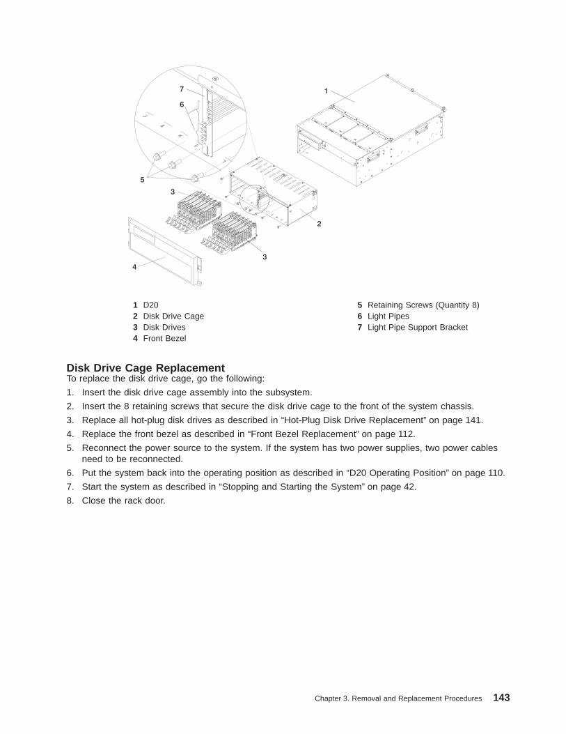
1 D20 5 Retaining Screws (Quantity 8)2 Disk Drive Cage 6 Light Pipes3 Disk Drives 7 Light Pipe Support Bracket4 Front Bezel
Disk Drive Cage ReplacementTo replace the disk drive cage, go the following:
1. Insert the disk drive cage assembly into the subsystem.
2. Insert the 8 retaining screws that secure the disk drive cage to the front of the system chassis.
3. Replace all hot-plug disk drives as described in “Hot-Plug Disk Drive Replacement” on page 141.
4. Replace the front bezel as described in “Front Bezel Replacement” on page 112.
5. Reconnect the power source to the system. If the system has two power supplies, two power cablesneed to be reconnected.
6. Put the system back into the operating position as described in “D20 Operating Position” on page 110.
7. Start the system as described in “Stopping and Starting the System” on page 42.
8. Close the rack door.
Chapter 3. Removal and Replacement Procedures 143
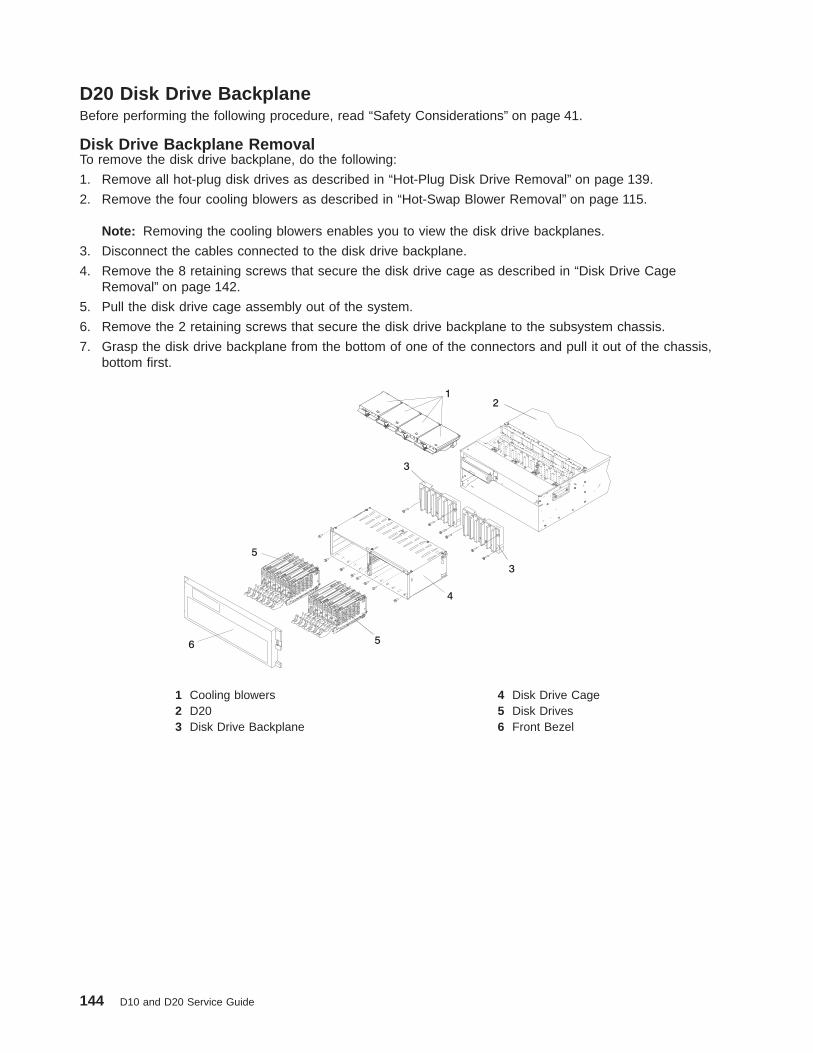
D20 Disk Drive BackplaneBefore performing the following procedure, read “Safety Considerations” on page 41.
Disk Drive Backplane RemovalTo remove the disk drive backplane, do the following:
1. Remove all hot-plug disk drives as described in “Hot-Plug Disk Drive Removal” on page 139.
2. Remove the four cooling blowers as described in “Hot-Swap Blower Removal” on page 115.
Note: Removing the cooling blowers enables you to view the disk drive backplanes.
3. Disconnect the cables connected to the disk drive backplane.
4. Remove the 8 retaining screws that secure the disk drive cage as described in “Disk Drive CageRemoval” on page 142.
5. Pull the disk drive cage assembly out of the system.
6. Remove the 2 retaining screws that secure the disk drive backplane to the subsystem chassis.
7. Grasp the disk drive backplane from the bottom of one of the connectors and pull it out of the chassis,bottom first.
1 Cooling blowers 4 Disk Drive Cage2 D20 5 Disk Drives3 Disk Drive Backplane 6 Front Bezel
144 D10 and D20 Service Guide

Disk Drive Backplane ReplacementTo replace the disk drive backplane, do the following:
1. Reconnect the power/signal cable to the connector located on the top edge of the disk drivebackplane.
2. Grasp a bottom edge of one of the connectors located on the disk drive backplane, and insert thebackplane into the disk drive bay.
3. Using the 3 supplied retaining screws, secure the disk drive backplane to the subsystem chassis.
4. Carefully insert the disk drive cage assembly into the system.
5. Align and then secure the disk drive cage to the subsystem chassis with the 7 previously removedretaining screws.
6. Before handling any card, board, or memory DIMM, be sure to use your electrostatic discharge strapto minimize static-electric discharge. Refer to “Handling Static-Sensitive Devices” on page 42.
7. Replace all hot-plug disk drives as described in “Hot-Plug Disk Drive Replacement” on page 141.
8. Reconnect the power source to the system.
9. Replace the front bezel as described in “Front Bezel Replacement” on page 112.
10. Power on the system as described in “Stopping and Starting the System” on page 42.
11. Close and then secure the service access cover with the three thumbscrews located on its backedge.
12. Return the subsystem into the operating position as described in “D20 Operating Position” onpage 110.
13. Close the rack front door.
Chapter 3. Removal and Replacement Procedures 145

D20 Power Supplies
DANGER
Do not attempt to open the covers of the power supply. Power supplies are not serviceable andare to be replaced as a unit.D02
The D20 subsystem has power supplies that have hot-swap capabilities. To use this feature, you musthave two power supplies in place.
Power Supply RemovalD20 subsystems configured at the factory with one power supply have a power supply filler panel. Thefiller panel protects the vacant power supply connector from dust or damage. If you plan to remove one ofthe power supplies from a subsystem configured with two power supplies, obtain the power supply fillerpanel. The part number for the power supply filler panel is 53P0233.
Note: You need not shut down the system to change a subsystem power supply.
Before performing any of the following procedure, read and understand all of the safety notices beginningwith “Safety Considerations” on page 41.
To remove a power supply from your subsystem, do the following:
1. Put the subsystem into the service position as described in “D20 Service Position” on page 109.
2. Open the service access cover as described in “D20 Service Access Cover” on page 111.
3. If your subsystem is configured with two power supplies, visually check the power supply LEDs. If oneof the power supplies has an amber LED that is lit or blinking, suspect that power supply to be faulty.
4. Remove the power cable from the rear of the power supply. Wait at least 10 seconds beforeperforming the next step.
5. Release, and then lift the power supply handles.
6. Lift the handles until they are perpendicular (90 degrees) to the top of the power supply. By placing thehandles perpendicular to the top of the power supply, the base or hinged portion of each handle actsas a cam and will gently pry the power supply from its docking connector located on the subsystemsystem board.
146 D10 and D20 Service Guide

7. Carefully remove the power supply from the subsystem.
1
2 3 4
6
5
1 Power Supplies 4 Green DC Good LED2 Green Power LED 5 Power Supply Filler3 Amber Fault/Identify LED 6 D20 Subsystem
Note: During normal operation, each power-supply bay must have either a power supply or filler panelinstalled for proper cooling.
Power Supply ReplacementTo replace a power supply, do the following:
1. Ensure the handles are in the unlocked position and perpendicular to the power supply.
2. Carefully insert the new power supply into the power supply bay.
3. Press the power supply onto the docking connectors.
4. Put the power supply handles into the locked position.
Note: The handles act as a cam and will correctly seat the power supply.
5. Reconnect the power source to the replaced power supply. The green LED located on the powersupply comes on solid.
6. Close and then secure the service access cover with the three thumbscrews located on its back edge.
7. Put the D20 subsystem back into the operating position as described in “D20 Operating Position” onpage 110.
8. If your system has successfully powered on, close the rack doors.
Chapter 3. Removal and Replacement Procedures 147
D20 Power Supply BulkheadBefore performing the following procedure, read the “Safety Considerations” on page 41.
Power Supply Bulkhead RemovalTo remove the power supply bulkhead, do the following:
1. Open the rack front door.
2. Shut down the system as described in “Stopping and Starting the System” on page 42.
3. Put the D20 subsystem into the service position.
4. Disconnect the power source from the system.
Note: This system may be equipped with a second power supply. Before continuing with thisprocedure, ensure that the power source to the system has been completely disconnected.
5. Open the service access cover as described in “Opening the Service Access Cover” on page 111.
6. Disconnect the RIO-2 cables from the RIO connectors located on the rear of the subsystem.
7. Disconnect the power cables from the power supplies
8. Label and then disconnect all PCI adapter cables from their respective adapters.
9. Remove the power supplies or power supply filler as described in “Power Supply Removal” onpage 146.
10. Remove the RIO bus adapter as described in “RIO Bus Adapter Removal” on page 120.
11. Remove all PCI adapters as described in “Non-Hot-Pluggable PCI Adapter Removal” on page 126.
Note: Alternately remove the PCI dividers as you are removing the PCI adapters.
12. Remove the three upper-retaining screws that secure the top edge of the power supply bulkhead tothe subsystem chassis.
13. Remove the three lower-retaining screws that secure the bottom portion of the power supply bulkheadto the subsystem chassis.
14. Remove the power supply bulkhead by lifting it straight up and out of the subsystem.
148 D10 and D20 Service Guide
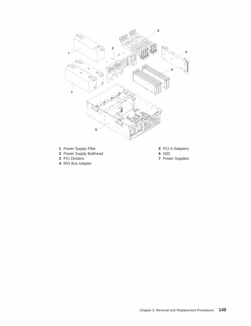
1 Power Supply Filler 5 PCI-X Adapters2 Power Supply Bulkhead 6 D203 PCI Dividers 7 Power Supplies4 RIO Bus Adapter
Chapter 3. Removal and Replacement Procedures 149

Power Supply Bulkhead ReplacementTo replace the power supply bulkhead, do the following:
1. Before handling any card, board, or memory DIMM, be sure to use your electrostatic discharge strapto minimize static-electric discharge. Refer to “Handling Static-Sensitive Devices” on page 42.
2. Insert the power supply bulkhead into the subsystem.
3. Align the three screw holes located on the top of the power supply bulkhead with the three threadedscrew holes located on the subsystem chassis.
4. Align the three screw holes located on the bottom of the power supply bulkhead with the threethreaded screw holes located on the subsystem chassis base.
5. Tighten the six retaining screws for the power supply bulkhead.
6. Replace the power supplies or the power supply filler as described in “Power Supply Replacement”on page 147.
7. Reconnect the power cables to the power supplies.
8. Replace the RIO bus adapter as described in “RIO Bus Adapter Replacement” on page 122.
9. Reconnect the RIO-2 cables from the RIO connectors located on the rear of the subsystem.
10. Replace all of the previously removed PCI adapters as described in “Adding or Replacing aNon-Hot-Pluggable PCI Adapter” on page 128.
Note: When you are reinstalling the PCI adapters, alternately reinstall the PCI dividers.
11. Reconnect all PCI adapter cables to their respective adapters.
12. Reconnect the power source to the system. The green LED located on the power supply comes onsolid.
13. Close then secure the service access cover with the three thumbscrews located on its back edge.
14. Put the D20 subsystem back into the operating position as described in “D20 Operating Position” onpage 110.
15. After the system has successfully powered on, close the rack doors.
150 D10 and D20 Service Guide
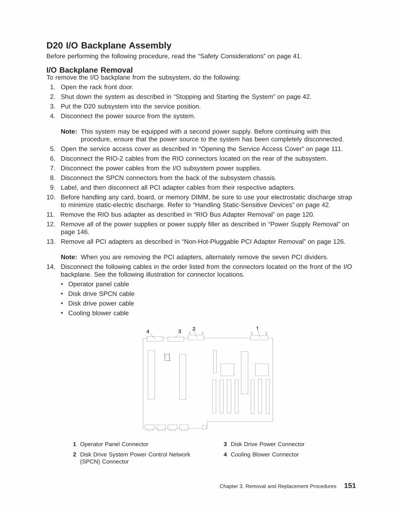
D20 I/O Backplane AssemblyBefore performing the following procedure, read the “Safety Considerations” on page 41.
I/O Backplane RemovalTo remove the I/O backplane from the subsystem, do the following:
1. Open the rack front door.
2. Shut down the system as described in “Stopping and Starting the System” on page 42.
3. Put the D20 subsystem into the service position.
4. Disconnect the power source from the system.
Note: This system may be equipped with a second power supply. Before continuing with thisprocedure, ensure that the power source to the system has been completely disconnected.
5. Open the service access cover as described in “Opening the Service Access Cover” on page 111.
6. Disconnect the RIO-2 cables from the RIO connectors located on the rear of the subsystem.
7. Disconnect the power cables from the I/O subsystem power supplies.
8. Disconnect the SPCN connectors from the back of the subsystem chassis.
9. Label, and then disconnect all PCI adapter cables from their respective adapters.
10. Before handling any card, board, or memory DIMM, be sure to use your electrostatic discharge strapto minimize static-electric discharge. Refer to “Handling Static-Sensitive Devices” on page 42.
11. Remove the RIO bus adapter as described in “RIO Bus Adapter Removal” on page 120.
12. Remove all of the power supplies or power supply filler as described in “Power Supply Removal” onpage 146.
13. Remove all PCI adapters as described in “Non-Hot-Pluggable PCI Adapter Removal” on page 126.
Note: When you are removing the PCI adapters, alternately remove the seven PCI dividers.
14. Disconnect the following cables in the order listed from the connectors located on the front of the I/Obackplane. See the following illustration for connector locations.
v Operator panel cable
v Disk drive SPCN cable
v Disk drive power cable
v Cooling blower cable
1 Operator Panel Connector 3 Disk Drive Power Connector
2 Disk Drive System Power Control Network(SPCN) Connector
4 Cooling Blower Connector
Chapter 3. Removal and Replacement Procedures 151

15. Remove the plastic membrane from the top of the I/O backplane by first removing the five retainingscrews that secure the plastic membrane to the I/O backplane.
Note: When removing the plastic membrane, slide the membrane under the light pipes that identifythe green and amber power LEDs.
16. Remove the three retaining screws that secure the front edge of the I/O backplane to the subsystemchassis.
17. Go to the rear of the subsystem, and remove the two retaining screws that secure the back edge ofthe I/O backplane to the back chassis bulkhead.
Note: The two retaining screws that secure the back edge of the I/O backplane to the rear chassisbulkhead are located just below the left SPCN connector and the rack indicator connector.
18. Remove the two retaining screws that secure the SCSI cable bracket to the subsystem-chassisbracket.
19. Remove the SCSI cable bracket by wiggling it up and down, then pulling it straight out and away fromthe PCI adapter-headstock bracket and the subsystem chassis bracket.
20. Remove the four retaining screws that secure the PCI adapter-headstock bracket to the chassis andpower supply bulkhead.
21. Remove the PCI adapter-headstock bracket by lifting it up, then out of the subsystem chassis.
22. Remove the four retaining screws that secure the power-supply bulkhead to the chassis
23. Remove the power-supply bulkhead by doing the following:
a. Lift the slotted tab off the alignment pin. The slotted tab and alignment pin are located at thebottom edge of the power-supply bulkhead.
b. Move the lower portion of the power-supply bulkhead out and away from the alignment pin.
Notes:
1) Ensure that the back edge of the power-supply bulkhead clears the disk drive backplane’splastic alignment pin. The disk drive backplane’s plastic alignment pin is located on the diskdrive-backplane support bracket between the power-supply bulkhead and the PCIadapter-headstock bracket.
2) The disk drive backplane-support bracket is not shown in the following illustration; however, itis easily located. This is the bracket that secures the service access cover to the chassis. Italso supports the disk drive backplanes, cooling blowers, power supply bulkhead, and PCIadapter headstock bracket.
c. Push the power-supply bulkhead toward the center of the I/O subsystem chassis.
Note: The upper-right corner of the power-supply bulkhead might get caught on the underside ofthe chassis support. If the power-supply bulkhead gets caught on the underside of thechassis support, wiggle the bulkhead until it is freed from under the chassis support.
24. Remove the I/O backplane by sliding the backplane toward the front of the I/O subsystem.
25. Slowly lift the I/O backplane straight up and out of the subsystem.
152 D10 and D20 Service Guide
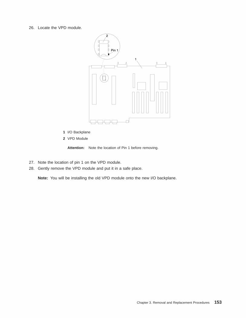
26. Locate the VPD module.
1 I/O Backplane
2 VPD Module
Attention: Note the location of Pin 1 before removing.
27. Note the location of pin 1 on the VPD module.
28. Gently remove the VPD module and put it in a safe place.
Note: You will be installing the old VPD module onto the new I/O backplane.
Chapter 3. Removal and Replacement Procedures 153

1 PCI Adapter Dividers (maximumquantity 7)
6 Plastic Membrane
2 RIO Bus Adapter 7 D203 PCI-X Adapters (maximum quantity 7) 8 SCSI Cable Bracket4 Power Supplies 9 PCI Adapter-Headstock Bracket5 I/O Backplane 10 Power-Supply Bulkhead
5a VPD Module
154 D10 and D20 Service Guide
I/O Backplane ReplacementTo replace the I/O backplane, do the following:
1. Before handling any card, board, or memory DIMM, be sure to use your electrostatic discharge strapto minimize static-electric discharge. Refer to “Handling Static-Sensitive Devices” on page 42.
2. Note the location of pin 1 on the VPD module.
3. Remove the VPD module that was installed on the new I/O backplane.
4. Install the VPD module from the old I/O backplane onto the new I/O backplane.
Note: When installing the VPD module, ensure that pin 1 is in the correct orientation.
5. Carefully align the I/O backplane to the alignment pins located on the chassis base.
6. Replace the three front retaining screws that secure the I/O backplane to the chassis.
7. Correctly align and then place the plastic membrane that protects the I/O backplane over the I/Obackplane. Secure it in place with five retaining screws.
8. Reconnect the following cables, in the order listed, to their respective connectors located on the frontof the I/O backplane:
v Cooling blower cable
v Disk drive power cable
v Disk drive SPCN cable
v Operator panel cable
9. Go to the rear of the subsystem chassis, and replace the two rear retaining screws.
Note: The two threaded screw holes used to secure the rear of the I/O backplane to the rear of thesubsystem chassis are located just below the left SPCN connector and the rack-indicatorconnector.
10. Replace the power-supply bulkhead by doing the following:
a. Rotate the power-supply bulkhead, placing the top right corner under the chassis support bracket.
b. Align the slotted tab, located on the lower edge of the power supply bulkhead, with the alignmentpin, located on the subsystem chassis.
c. Align the four clearance holes located on the power-supply bulkhead with the four screw holeslocated on the upper and lower subsystem chassis.
Note: When aligning the power-supply bulkhead, wiggle it until properly seated.
d. Secure the power-supply bulkhead to the subsystem chassis with four retaining screws.
11. Replace the PCI adapter-headstock bracket.
12. Align the four clearance holes on the bracket with the four screw holes located on the chassis.
13. Secure the PCI adapter-headstock bracket to the chassis with four retaining screws.
14. Replace the SCSI cable bracket, aligning the two screw holes and securing it with two retainingscrews to the chassis retaining bracket.
15. Reconnect the SPCN connectors from the back of the subsystem chassis.
16. Replace the power supplies or the power supply filler as described in “Power Supply Replacement”on page 147.
17. Replace the RIO bus adapter as described in “RIO Bus Adapter Replacement” on page 122.
18. Reconnect the RIO-2 cables from the RIO connectors located on the rear of the subsystem.
Chapter 3. Removal and Replacement Procedures 155
19. Replace all of the previously removed PCI adapters as described in “Adding or Replacing aNon-Hot-Pluggable PCI Adapter” on page 128.
Note: Alternately reinstall the PCI dividers, when reinstalling the PCI adapters.
20. Reconnect all PCI adapter cables to their respective adapters.
21. Reconnect the power cables to the power supplies.
22. Reconnect the power source to the system. The green LED located on the power supply comes onsolid.
23. Close and then secure the service access cover with the three thumbscrews located on its backedge.
24. Put the D20 subsystem back into the operating position as described in “D20 Operating Position” onpage 110.
25. After the system has successfully powered on, close the rack doors.
156 D10 and D20 Service Guide
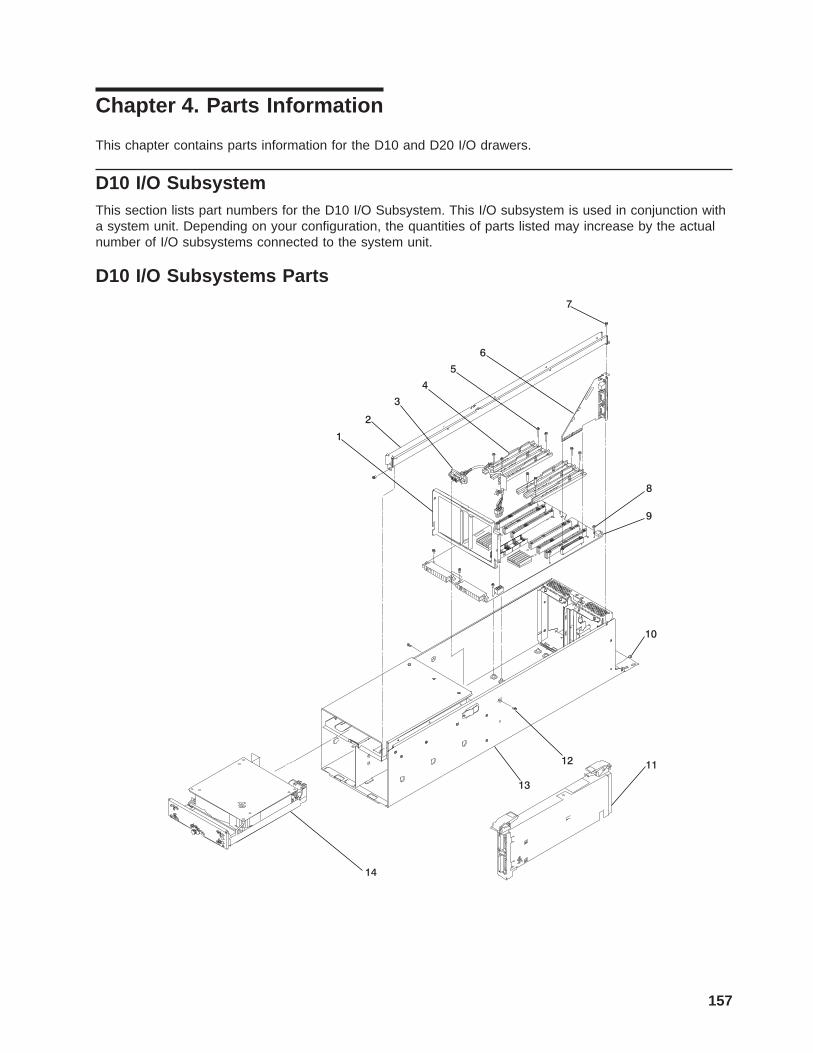
Chapter 4. Parts Information
This chapter contains parts information for the D10 and D20 I/O drawers.
D10 I/O SubsystemThis section lists part numbers for the D10 I/O Subsystem. This I/O subsystem is used in conjunction witha system unit. Depending on your configuration, the quantities of parts listed may increase by the actualnumber of I/O subsystems connected to the system unit.
D10 I/O Subsystems Parts
1
2
3
4
5
6
7
8
9
10
12
13
14
11
157
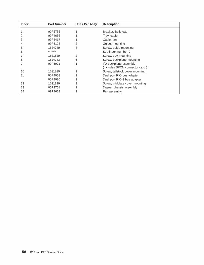
Index Part Number Units Per Assy Description
1 00P2752 1 Bracket, Bulkhead2 09P4656 1 Tray, cable3 09P5417 1 Cable, fan4 09P3128 2 Guide, mounting5 1624749 8 Screw, guide mounting6 ******* See index number 97 1621829 2 Screw, tray mounting8 1624743 6 Screw, backplane mounting9 09P5921 1 I/O backplane assembly
(includes SPCN connector card )10 1621829 1 Screw, tailstock cover mounting11 00P4053 1 Dual port RIO bus adapter
00P4080 1 Dual port RIO-2 bus adapter12 1621829 2 Screw, midplate cover mounting13 00P2751 1 Drawer chassis assembly14 09P4664 1 Fan assembly
158 D10 and D20 Service Guide

D10 I/O Subsystem Parts (continued)1
2
3
4
5
6
7
Chapter 4. Parts Information 159
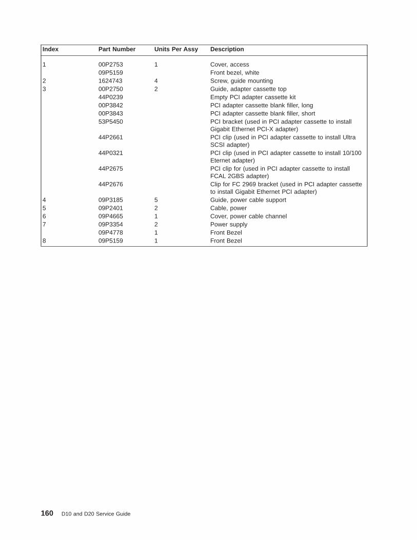
Index Part Number Units Per Assy Description
1 00P2753 1 Cover, access09P5159 Front bezel, white
2 1624743 4 Screw, guide mounting3 00P2750 2 Guide, adapter cassette top
44P0239 Empty PCI adapter cassette kit00P3842 PCI adapter cassette blank filler, long00P3843 PCI adapter cassette blank filler, short53P5450 PCI bracket (used in PCI adapter cassette to install
Gigabit Ethernet PCI-X adapter)44P2661 PCI clip (used in PCI adapter cassette to install Ultra
SCSI adapter)44P0321 PCI clip (used in PCI adapter cassette to install 10/100
Eternet adapter)44P2675 PCI clip for (used in PCI adapter cassette to install
FCAL 2GBS adapter)44P2676 Clip for FC 2969 bracket (used in PCI adapter cassette
to install Gigabit Ethernet PCI adapter)4 09P3185 5 Guide, power cable support5 09P2401 2 Cable, power6 09P4665 1 Cover, power cable channel7 09P3354 2 Power supply
09P4778 1 Front Bezel8 09P5159 1 Front Bezel
160 D10 and D20 Service Guide
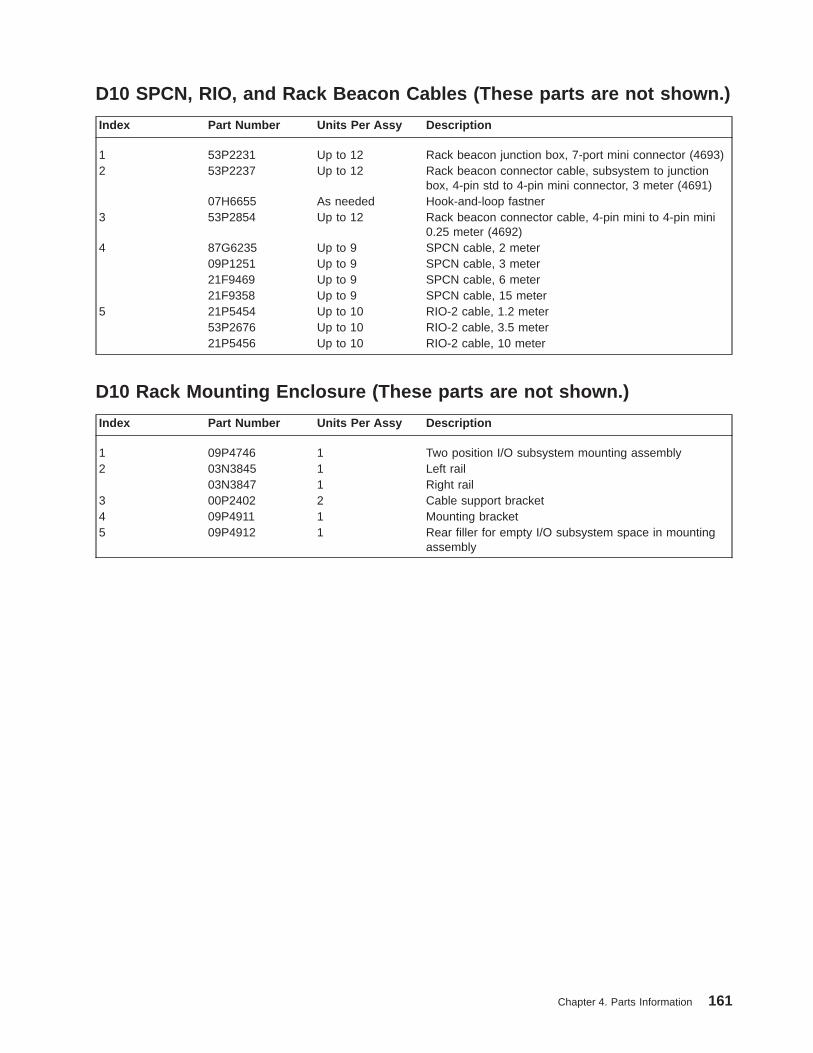
D10 SPCN, RIO, and Rack Beacon Cables (These parts are not shown.)
Index Part Number Units Per Assy Description
1 53P2231 Up to 12 Rack beacon junction box, 7-port mini connector (4693)2 53P2237 Up to 12 Rack beacon connector cable, subsystem to junction
box, 4-pin std to 4-pin mini connector, 3 meter (4691)07H6655 As needed Hook-and-loop fastner
3 53P2854 Up to 12 Rack beacon connector cable, 4-pin mini to 4-pin mini0.25 meter (4692)
4 87G6235 Up to 9 SPCN cable, 2 meter09P1251 Up to 9 SPCN cable, 3 meter21F9469 Up to 9 SPCN cable, 6 meter21F9358 Up to 9 SPCN cable, 15 meter
5 21P5454 Up to 10 RIO-2 cable, 1.2 meter53P2676 Up to 10 RIO-2 cable, 3.5 meter21P5456 Up to 10 RIO-2 cable, 10 meter
D10 Rack Mounting Enclosure (These parts are not shown.)
Index Part Number Units Per Assy Description
1 09P4746 1 Two position I/O subsystem mounting assembly2 03N3845 1 Left rail
03N3847 1 Right rail3 00P2402 2 Cable support bracket4 09P4911 1 Mounting bracket5 09P4912 1 Rear filler for empty I/O subsystem space in mounting
assembly
Chapter 4. Parts Information 161
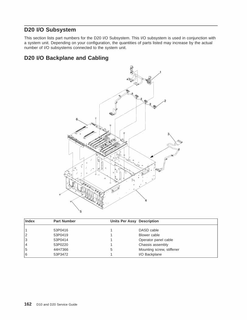
D20 I/O SubsystemThis section lists part numbers for the D20 I/O Subsystem. This I/O subsystem is used in conjunction witha system unit. Depending on your configuration, the quantities of parts listed may increase by the actualnumber of I/O subsystems connected to the system unit.
D20 I/O Backplane and Cabling
1
2
3
4
5
6
Index Part Number Units Per Assy Description
1 53P0416 1 DASD cable2 53P0419 1 Blower cable3 53P0414 1 Operator panel cable4 53P0220 1 Chassis assembly5 44H7366 5 Mounting screw, stiffener6 53P3472 1 I/O Backplane
162 D10 and D20 Service Guide

D20 PCI Slots
1
2
3
4
5
6
7
Index Part Number Units Per Assy Description
1 See Note 7 (maximumquantity)
PCI adapter
2 53P0248 1 Power supply bulkhead3 44H7366 4 Screw, power bulkhead mounting4 44H7366 3 Screw, PCI plate mounting5 53P0249 1 PCI adapter headstock bracket6 53P2728 5 PCI dividers7 53P2729 2 PCI dividersNote: See Diagnostic Information for Multiple Bus Systems for part numbers.
Chapter 4. Parts Information 163

D20 Power, RIO Adapter, Cabling
Index Part Number Units Per Assy Description
1 53P4832 2 (maximumquantity)
Power supply
253P3800 1 RIO bus adapter97H2459 1 RIO-2 bus adapter
3 53P2690 3 Cable bracket, SCSI4 44H7366 1 Screw, SCSI cable5 53P0639 5 RIO-2 cable bracket6 44H7366 2 Screw, RIO-2 cable bracket7 53P0417 Configuration
dependentSCSI bus cable
8 53P0418 Configurationdependent
SCSI bus cable
9 53P0233 1 Power supply filler
164 D10 and D20 Service Guide

D20 Operator Panel
Index Part Number Units Per Assy Description
1 53P0257 2 Disk-drive-backplane (disk drive cage included)2 53P0321 4 Screw, disk-drive-backplane mounting3 53P0330 1 Operator panel4 53P0275 1 Processor cover5 44H7366 4 Screw, cover-mounting
Chapter 4. Parts Information 165

D20 Fans and Disk Drives
Index Part Number Units Per Assy Description
1 53P0262 4 Blower2 D203 53P0257 1 Disk-drive cage 12 pack (disk drive back planes
included)4 53P0319 8 Screw, DASD-cage mounting5 Disk Drives6 53P0234 4 Screw, filler-plate mounting7 44H7366 1 (optional) Disk-drive filler plate8 53P3451 1 Left Rail9 53P3452 1 Right Rail
166 D10 and D20 Service Guide

D20 Covers and Brackets
Index Part Number Units Per Assy Description
1 53P1457 1 Front bezel2 44H7366 2 Screw, latch bracket3 53P2572 1 Latch bracket assembly left4 53P0295 4 Cable arm bracket5 44H7366 1 Screw, cable arm bracket6 53P2573 1 Latch bracket assembly right
D20 RIO, SPCN, and Rack Beacon Cables
Index Part Number Units Per Assy Description
1 53P2231 Up to 12 Rack beacon cable junction box2 53P2237 Up to 12 Rack beacon connector cable, 4-pin connector3 53P2854 Up to 12 Rack beacon connector cable, 4-pin
87G6235 SPCN cable, 2 meter09P1251 SPCN cable, 3 meter21F9469 SPCN cable, 6 meter21F9358 SPCN cable, 15 meter
4 53P2676 RIO-2 cable, 3.5 meter21P5456 RIO-2 cable, 10 meter
Chapter 4. Parts Information 167

Power Cables
Index Part Number Country or Region
1 1838574 Bahamas, Barbados, Bolivia, Brazil, Canada, Costa Rica, Dominican Republic, ElSalvador, Ecuador, Guatemala, Guyana, Haiti, Honduras, Jamaica, Japan, NetherlandsAntilles, Panama, Peru, Philippines, Taiwan, Thailand, Trinidad, Tobago, U.S.A. (exceptChicago), Venezuela
2 86G7648 Bahamas, Barbados, Bermuda, Bolivia, Brazil, Canada, Cayman Islands, Colombia, CostaRica, Dominican Republic, Ecuador, El Salvador, Guatemala, Guyana, Haiti, Honduras,Jamaica, Japan, Korea (South), Mexico, Netherlands Antilles, Nicaragua, Panama, Peru,Philippines, Puerto Rico, Saudi Arabia, Suriname, Trinidad, Taiwan, U.S.A. (exceptChicago), Venezuela
2 62X1045 Chicago, U.S.A.
3 6952311 Argentina, Australia, New Zealand
4 13F9979 Abu Dhabi, Austria, Belgium, Bulgaria, Botswana, China (Macau S.A.R), Egypt, Finland,France, Germany, Greece, Iceland, Indonesia, Korea (South), Lebanon, Luxembourg,Netherlands, Norway, Portugal, Saudi Arabia, Spain, Sudan, Sweden, Turkey, Yugoslavia
5 13F9997 Denmark
6 14F0015 Bangladesh, Burma, Pakistan, South Africa, Sri Lanka
7 14F0033 Bahrain, Bermuda, Brunei, Channel Islands, Cyprus, China (Hong Kong S.A.R), Ghana,India, Iraq, Ireland, Jordan, Kenya, Kuwait, Malawi, Malaysia, Nigeria, Oman, People’sRepublic of China, Qatar, Sierra Leone, Singapore, Tanzania, Uganda, United ArabEmirates (Dubai), United Kingdom, Zambia
8 14F0051 Liechtenstein, Switzerland
9 14F0069 Chile, Ethiopia, Italy
10 14F0087 Israel
11 6952291 Paraguay, Colombia, Uruguay
42F6841 AC Power Cable, (Power distribution bus to AC power supply, 286/C4 only)
1 2 3 4
5 6 7
8 9 10 11
168 D10 and D20 Service Guide
Chapter 5. Fault and Attention LEDs
This chapter contains information about fault and attention LEDs, which assist in identifying failingcomponents in your system.
Component LEDsIndividual LEDs are located on or near the failing components. The LEDs are located either on thecomponent itself or on the carrier of the component (for example, PCI adapters and disk drives). LEDs areeither green or amber.
Green LEDs indicate one of two things:
v Electrical power is present.
v Activity is occuring on a link. (The system could be sending or receiving information.)
Amber-colored LEDs indicate a fault or identify condition. If your system or one of the components on yoursystem has an amber-colored LED turned on or blinking, identify the problem and take the appropriateaction to restore the system to normal.
The following table identifies the location, color and status of your system component LEDs.
169

Unit(FRU)
LEDFunction
Location ViewableLocation
LED Color OFF ON Blink
Power and Packaging LEDs
RackIndicator
RackSummary Top of Rack
ExternalAmber Normal Fault Identify
AC Input External Front Green No Input AC Good Fault
I/OSubsystemDrawer
Attention OperatorPanel
External Front Amber Normal Fault Identify
Power External Front Green No AC System On Standby
FansIdentify FRU External Amber Normal Identify N/A
Power FRU External Green Power Off Power On N/A
PowerSupply
InputSource
FRU External Back Green No Input AC InputGood
N/A
Identify/COM Fail
FRU External Back Amber Normal N/A 1 Hz=Identify.25 Hz=Comm.Failed
DC OutputGood
FRU External Back GreenStandby Off System On Standby
Disk Drives(DASD)
Slot PowerDASDBackplane
External Front Green Power Off Power On N/A
ActivityDASDBackplane
External Front Green Not Active N/A Activity
Identify DASDBackplane
External Front Amber Normal ActionRemove
Identify
Media
Slot Power Backplane External Front Green Power Off Power On N/A
Activity/Identify
Backplane External Front Amber Normal Action Identify
Electronic Component LEDs
RIOConnectorCard
IdentifyFRU (Top) Internal Only Amber Normal Identify N/A
RIOExtenderCard
IdentifyFRU (Top) Internal Only Amber Normal Identify N/A
I/OBackplane
Identify FRU Internal Only Amber Normal Identify N/A
PCI AdapterConnectors(Slots)
Slot Power Backplane External Back Green Power Off Power On N/A
Action/Identify
Backplane External Back Amber NormalN/A Grn off - Action
Grn on -Identify
Disk DriveBackplane
No LED
Port LED Indicators
RIOPorts IdentifyTop of Each
ExternalConnector
External Back Amber Normal N/A Identify
170 D10 and D20 Service Guide

Resetting the LEDsAfter the repair action is completed, do the following:
1. Log in as root user.
2. At the command line, type diag.
3. Select Task Selection .
4. Select Log Repair Action .
5. Select the device that was repaired.
6. Press F10 to exit diagnostics.
If the attention LED remains on after you have completed the repair action and reset the LEDs, call forservice support.
Chapter 5. Fault and Attention LEDs 171

172 D10 and D20 Service Guide

Appendix A. Environmental Notices
Product Recycling and DisposalComponents of the system unit, such as structural parts and circuit boards, can be recycled whererecycling facilities exist. Companies are available to disassemble, reutilize, recycle, or dispose of electronicproducts. Contact your account representative for more information. This system unit contains parts suchas circuit boards, cables, electromagnetic compatibility gaskets and connectors which may contain leadand copper/beryllium alloys that require special handling and disposal at end of life. Before this unit isdisposed, these materials must be removed and recycled or discarded according to applicable regulations.This book contains specific information on each battery type where applicable.
This product may contain a sealed lead acid, nickel cadmium, nickel metal hydride, lithium, orlithium ion battery. Consult your user manual or service manual for specific battery information.The battery must be recycled or disposed of properly. Recycling facilities may not be available inyour area. For information on disposal of batteries, contact your local waste disposal facility.
173

Acoustical Noise EmissionsThe equivalent continuous A-weighted sound pressure level at workstations (emission sound pressurelevel at the 1-meter bystander positions) does not exceed 70 dB(A).
Der Geräuschpegel der Einheit ist kleiner oder gleich 70 db(A).
D10 Declared Acoustical Noise Emissions
Acoustical Characteristic
Product Configuration Declared A-Weighted Sound PowerLevel, L WAd (B)
Declared A-Weighted Sound PressureLevel, LpAm (dB)
Operating Idle Operating Idle
One D10 I/O subsystem 5.65 5.65 406 406
Two D10 I/O subsystems 5.95 5.95 436 436
Four D10 I/O subsystems 6.25 6.25 466 466
Notes:
1. Noise levels cited are for the typical configuration (A-Frame: Bulk Power, CEC cage, battery option, mediadrawer, and two I/O drawers).
2. The 0.6-B (6-dB) reduction in noise emission levels with the acoustical rear door corresponds to a factor of 4reduction. That is, the noise level of a single A-Frame with Slimline covers is about the same as the noise level offour A-Frames with acoustical covers.
3. LWAd is the upper-limit A-weighted sound power level; LpAm is the mean A-weighted sound pressure level at the1-meter bystander positions; 1 B = 10 dB.
4. All measurements made in conformance with ISO 7779 and declared in conformance with ISO 9296.
D20 Declared Acoustical Noise Emissions
Acoustical Characteristic
Product Configuration Declared A-Weighted Sound PowerLevel, L WAd (B)
Declared A-Weighted Sound PressureLevel, LpAm (dB)
Operating Idle Operating Idle
D20 I/O subsystem 6.15 6.05 446 436
Notes:
1. Noise levels cited are for the typical configuration (A-Frame: Bulk Power, CEC cage, battery option, mediadrawer, and two I/O drawers).
2. The 0.6-B (6-dB) reduction in noise emission levels with the acoustical rear door corresponds to a factor of 4reduction. That is, the noise level of a single A-Frame with Slimline covers is about the same as the noise level offour A-Frames with acoustical covers.
3. LWAd is the upper-limit A-weighted sound power level; LpAm is the mean A-weighted sound pressure level at the1-meter bystander positions; 1 B = 10 dB.
4. All measurements made in conformance with ISO 7779 and declared in conformance with ISO 9296.
174 D10 and D20 Service Guide

Appendix B. Notices
This information was developed for products and services offered in the U.S.A.
The manufacturer may not offer the products, services, or features discussed in this document in othercountries. Consult the manufacturer’s representative for information on the products and services currentlyavailable in your area. Any reference to the manufacturer’s product, program, or service is not intended tostate or imply that only that product, program, or service may be used. Any functionally equivalent product,program, or service that does not infringe any intellectual property right of the manufacturer may be usedinstead. However, it is the user’s responsibility to evaluate and verify the operation of any product,program, or service.
The manufacturer may have patents or pending patent applications covering subject matter described inthis document. The furnishing of this document does not give you any license to these patents. You cansend license inquiries, in writing, to the manufacturer.
The following paragraph does not apply to the United Kingdom or any country where suchprovisions are inconsistent with local law: THIS MANUAL IS PROVIDED ″AS IS″ WITHOUTWARRANTY OF ANY KIND, EITHER EXPRESSED OR IMPLIED, INCLUDING, BUT NOT LIMITED TO,THE IMPLIED WARRANTIES OF NON-INFRINGEMENT, MERCHANTABILITY OR FITNESS FOR APARTICULAR PURPOSE. Some states do not allow disclaimer of express or implied warranties in certaintransactions; therefore, this statement may not apply to you.
This information could include technical inaccuracies or typographical errors. Changes are periodicallymade to the information herein; these changes will be incorporated in new editions of the publication. Themanufacturer may make improvements and/or changes in the product(s) and/or the program(s) describedin this publication at any time without notice.
Information concerning products made by other than the manufacturer was obtained from the suppliers ofthose products, their published announcements, or other publicly available sources. The manufacturer hasnot tested those products and cannot confirm the accuracy of performance, compatibility or any otherclaims related to products made by other than the manufacturer. Questions on the capabilities of productsmade by other than the manufacturer should be addressed to the suppliers of those products.
175

176 D10 and D20 Service Guide
Index
Aacoustical
noiseemissions 174
adapter cassetteremoving 55replacing 56
adapter, PCI removal and replacement, D10 45adapters, PCI D20 123AIX documentation 47, 53, 123, 129, 132, 135, 137,
138AIX location codes 14, 31attention LEDs 169
Bbackplane, I/O removal and replacement D20 151battery
disposal, recycling 173bay locations 24beacon, parts 161bezel removal, D20 112bezel, front 43, 112blower locations 21blower, cable removal D20 118blower, cooling 18blowers, cooling 115blowers, hot-swap removal, D20 115blowers, hot-swap replacement, D20 117brackets, parts 159, 167bulkhead, power supply removal and replacement,
D20 148
Ccables, external parts 167cabling, parts 162cage, disk drive D20 142checkpoints 39, 40code, error 40codes, location 14, 31component LEDs 39cooling 5, 18cooling blower cable replacement, D20 119cooling blowers cable, D20 118cooling, parts 159, 163cover removal and replacement D10 44cover, service access 111covers 44covers, parts 159, 167
DD10 location code table 15D10 location codes 14D10 locations 10
codes, D10 14
D10 locations (continued)D10 15D10 I/O subsystem, front 10D10 I/O subsystem, rear 11I/O backplane 12PHB 13
D10 replacement procedure list 42D20 location code table 32D20 location codes 31D20 locations 19
blowers 21codes, D20 31D20 32D20 I/O subsystem, front 19D20 I/O subsystem, rear 19I/O backplane 22power supply 20SCSI bay locations 24
D20 replacement procedure list 108definitions, LED 2diagnostics overview 39disk drive backplane 144disk drive backplane replacement, D20 145disk drive cage removal D20 142disk drive cage replacement, D20 143disk drive, backplane removal D20 144disk drive, configuring 138disk drive, deconfiguring 137disk drive, hot-plug removal D20 139disk drive, hot-plug replacement, D20 141disk drive, parts 166disk drive, removing 137disk drive, replacing 138disk drives, hot-plug 137documentation
AIX 47, 53, 123, 129, 132, 135, 137, 138
Eelectrical safety vii
laser compliance statement ixerror code to FRU index 40external cables, parts 167
Ffan, cooling 5fan, parts 166fan, removal and replacement D10 104features, subsystem 1
cooling 5LED definitions 2operator indicators 2pci slot 2PCI-X slots 2ports, input/output 5ports, serial 5
177

features, subsystem (continued)power 4
features, system 16cooling 18disk drives 17operator panel 16PCI-X slots 16ports, input/output 18ports, serial 18power 18slots, PCI-X 16
front bezel removal, D10 43front bezel replacement, D10 43front bezel replacement, D20 112front, bezel 43FRU
index 40FRU isolation 39
Hhandling static-sensitive devices 42highlighting xiiihot-plug management functions 123hot-plug manager 123hot-plug manager menu 124hot-pluggable PCI adapter installation overview 53hot-pluggable PCI adapter removal and replacement,
D10 46hot-swap fan assembly D10 104hot-swap fan replacement, D10 104
II/O backplane assembly replacement, D10 106I/O backplane assembly, removal and replacement,
D10 106I/O backplane locations 12, 22I/O backplane removal D20 151I/O backplane replacement, D20 155I/O backplane, parts 157, 162index, error code to FRU 40information, reference 1input/output ports 5, 18IO backplane assembly removal, D10 106isolation, FRU 39
Llaser compliance statement ixlaser safety information ixLED definitions 2LED definitions, PCI-X 16LED, D10 power supply 5LEDs 169
attention LEDs 169component 39, 169component LEDs 169fault LEDs 169resetting 171resetting LEDs 171
location codes 14, 31location codes, physical 14, 31locations, D10 10locations, D20 19
MMAP rules 40
Nnoise emissions
acoustical 174non-hot-pluggable PCI adapter, removal D20 126
Ooperating position 110operating position, D10 43operator panel 23, 113operator panel removal, D20 113operator panel replacement, D20 114operator panel, parts 165overview
hot-pluggable PCI adapter 53overview, D10 1overview, D20 16overview, diagnostics 39
Pparts information
covers and brackets 167external cables 167fans and disk drives 166I/O backplane
PCI slots 157I/O backplane and cabling 162operator panel 165PCI slots 163power and cooling 159power, RIO 164rack mount and beacon connect 161RIO cables 167SPCN cables 167subsystem 157
parts, beacon 161PCI adapter cassette
removing 55replacing 56
PCI adapter removal and replacement, D10 45PCI adapter, hot-plug removal D20 129PCI-X definitions, LED 16PHB 13physical location codes 14, 31ports, input/output 5, 18power and lightpath LEDs 39power cables 37power supplies, removal and replacement 146power supply 4, 18
178 D10 and D20 Service Guide

power supply bulkhead removal D20 148power supply bulkhead replacement, D20 150power supply LED 5power supply locations 20power supply removal D20 146power supply removal, D10 107power supply replacement, D10 107power supply, hot-swap replacement, D20 147power supply, removal and replacement, D10 107Power-On Self-Test 34power, D10 4power, D20 18power, parts 159, 163, 164powering on and off 34product disposal 173
Rrecycling 173reference information 1related publications xivremoval and replacement procedures 41
adapter, adding or replacing a non-hot-plug 128adapter, hot-plug management functions 123adapter, hot-plug manager 123adapter, install hot-plug 135adapter, replace hot-plug 132adapters, PCI D20 123bezel 43bezel, front 112blowers, cooling 115cooling blowers cable, D20 118cover, service access 111covers 44devices, handling static-sensitive 42disk drive backplane 144disk drive cage, D20 142disk drive, configuring 137disk drive, deconfiguring 137disk drives, hot-plug 137fan, D10 104hot-plug manager menu 124hot-pluggable PCI adapter, 46I/O backplane assembly, D10 106I/O backplane D20 151operating position 110operator panel 113PCI adapter, D10 45power supplies 146power supply bulkhead D20 148power supply, D10 107RIO bus adapter, D10 105RIO bus adapter, D20 120RIO cable, D10 105safety considerations 41service position 109stopping the system 42
removal procedure list D10 42removal procedure list D20 108removal procedures 41
adapter, PCI D20 126
removal procedures (continued)bezel, D20 112blower cable, D20 118blowers, hot-swap, D20 115caution and danger 41disk drive backplane, D20 144disk drive cage D20 142front bezel, D10 43hot-plug adapter, D20 129hot-plug disk drive, D20 139hot-swap fan assembly D10 104I/O backplane, D20 151IO backplane assembly, D10 106operator panel, D20 113power supply bulkhead, D20 148power supply D20 146power supply, D10 107RIO bus adapter, D10 105RIO bus adapter, D20 120RIO cable, D10 105service access cover, D10 44service access cover, D20 111
removing a PCI adapter cassette 55replacement procedures 41
blowers, hot-swap, D20 117cooling blower cable, D20 119disk drive backplane, D20 145disk drive cage, D20 143disk drive, hot-plug, D20 141front bezel, D10 43front bezel, D20 112hot-swap fan, D10 104I/O backplane, D20 155operator panel, D20 114power supply bulkhead, D20 150power supply, D10 107power supply, hot-swap, D20 147RIO bus adapter, D10 105RIO bus adapter, D20 122RIO cable, D10 105service access cover, D10 44service access cover, D20 111
rereplacing a PCI adapter cassette 56resetting the LEDs 171RIO bus adapter removal D20 120RIO bus adapter removal, D10 105RIO bus adapter replacement, D10 105RIO bus adapter replacement, D20 122RIO bus adapter, D10 removal and replacement 105RIO bus adapter, D20 120RIO cable removal D10 105RIO cable replacement, D10 105RIO cable, removal and replacement D10 105RIO-2 cables 5RIO, parts 164
Ssafety considerations 41safety notices viiSCSI IDs 24
Index 179

Self-Test, Power-On 34serial port configurations 18service access cover removal, D10 44service access cover removal, D20 111service access cover replacement, D10 44service access cover replacement, D20 111service inspection guide 38service position 109service position, D10 43SPCN cables 5SPCN cables, parts 167specifications 35specifications, power cables 37stopping the system 42subsystem cables 5subsystem, power 4, 18system
stopping 42system management services 40system, powering on and off 34
Ttrademarks xiv
WWeb sites
AIX documentation 47, 53, 123, 129, 132, 135,137, 138
180 D10 and D20 Service Guide

Vos remarques sur ce document / Technical publication remark form
Titre / Title : Bull D10 and D20 I/O Drawers Service Guide
Nº Reférence / Reference Nº : 86 A1 38EG 01 Daté / Dated : June 2003
ERREURS DETECTEES / ERRORS IN PUBLICATION
AMELIORATIONS SUGGEREES / SUGGESTIONS FOR IMPROVEMENT TO PUBLICATION
Vos remarques et suggestions seront examinées attentivement.Si vous désirez une réponse écrite, veuillez indiquer ci-après votre adresse postale complète.
Your comments will be promptly investigated by qualified technical personnel and action will be taken as required.If you require a written reply, please furnish your complete mailing address below.
NOM / NAME : Date :
SOCIETE / COMPANY :
ADRESSE / ADDRESS :
Remettez cet imprimé à un responsable BULL ou envoyez-le directement à :
Please give this technical publication remark form to your BULL representative or mail to:
BULL CEDOC357 AVENUE PATTONB.P.2084549008 ANGERS CEDEX 01FRANCE

Technical Publications Ordering FormBon de Commande de Documents Techniques
To order additional publications, please fill up a copy of this form and send it via mail to:Pour commander des documents techniques, remplissez une copie de ce formulaire et envoyez-la à :
BULL CEDOCATTN / Mr. L. CHERUBIN357 AVENUE PATTONB.P.2084549008 ANGERS CEDEX 01FRANCE
Phone / Téléphone : +33 (0) 2 41 73 63 96FAX / Télécopie +33 (0) 2 41 73 60 19E–Mail / Courrier Electronique : [email protected]
Or visit our web sites at: / Ou visitez nos sites web à:http://www.logistics.bull.net/cedochttp://www–frec.bull.com http://www.bull.com
CEDOC Reference #No Référence CEDOC
QtyQté
CEDOC Reference #No Référence CEDOC
QtyQté
CEDOC Reference #No Référence CEDOC
QtyQté
_ _ _ _ _ _ _ _ _ [ _ _ ] _ _ _ _ _ _ _ _ _ [ _ _ ] _ _ _ _ _ _ _ _ _ [ _ _ ]
_ _ _ _ _ _ _ _ _ [ _ _ ] _ _ _ _ _ _ _ _ _ [ _ _ ] _ _ _ _ _ _ _ _ _ [ _ _ ]
_ _ _ _ _ _ _ _ _ [ _ _ ] _ _ _ _ _ _ _ _ _ [ _ _ ] _ _ _ _ _ _ _ _ _ [ _ _ ]
_ _ _ _ _ _ _ _ _ [ _ _ ] _ _ _ _ _ _ _ _ _ [ _ _ ] _ _ _ _ _ _ _ _ _ [ _ _ ]
_ _ _ _ _ _ _ _ _ [ _ _ ] _ _ _ _ _ _ _ _ _ [ _ _ ] _ _ _ _ _ _ _ _ _ [ _ _ ]
_ _ _ _ _ _ _ _ _ [ _ _ ] _ _ _ _ _ _ _ _ _ [ _ _ ] _ _ _ _ _ _ _ _ _ [ _ _ ]
_ _ _ _ _ _ _ _ _ [ _ _ ] _ _ _ _ _ _ _ _ _ [ _ _ ] _ _ _ _ _ _ _ _ _ [ _ _ ]
[ _ _ ] : no revision number means latest revision / pas de numéro de révision signifie révision la plus récente
NOM / NAME : Date :
SOCIETE / COMPANY :
ADRESSE / ADDRESS :
PHONE / TELEPHONE : FAX :
E–MAIL :
For Bull Subsidiaries / Pour les Filiales Bull :
Identification:
For Bull Affiliated Customers / Pour les Clients Affiliés Bull :
Customer Code / Code Client :
For Bull Internal Customers / Pour les Clients Internes Bull :
Budgetary Section / Section Budgétaire :
For Others / Pour les Autres :
Please ask your Bull representative. / Merci de demander à votre contact Bull.


BULL CEDOC357 AVENUE PATTONB.P.2084549008 ANGERS CEDEX 01FRANCE
86 A1 38EG 01ORDER REFERENCE
PLA
CE
BA
R C
OD
E IN
LO
WE
RLE
FT
CO
RN
ER
Utiliser les marques de découpe pour obtenir les étiquettes.Use the cut marks to get the labels.
86 A1 38EG 01
D10 and D20 I/ODrawers
Service Guide
86 A1 38EG 01
D10 and D20 I/ODrawers
Service Guide
86 A1 38EG 01
D10 and D20 I/ODrawers
Service Guide
Copyright © 2022 FDOKUMEN