Building Outrigger Sailing Canoes
185
-
Upload
khangminh22 -
Category
Documents
-
view
0 -
download
0
Transcript of Building Outrigger Sailing Canoes


INTERNATIONAL MARINE / McGRAW-HILLCamden, Maine ✦ New York ✦ Chicago ✦ San Francisco ✦ Lisbon ✦ London ✦ Madrid
Mexico City ✦ Milan ✦ New Delhi ✦ San Juan ✦ Seoul ✦ Singapore ✦ Sydney ✦ Toronto
BUILDINGOUTRIGGERSAILING
Gary Dierking
Modern Construction Methods for Three Fast, Beautiful Boats
CANOES

Copyright © 2008 by International Marine All rights reserved. Manufactured in the United States of America. Except as permitted under the United States CopyrightAct of 1976, no part of this publication may be reproduced or distributed in any form or by any means, or stored in a database or retrieval system, without the priorwritten permission of the publisher.
0-07-159456-6
The material in this eBook also appears in the print version of this title: 0-07-148791-3.
All trademarks are trademarks of their respective owners. Rather than put a trademark symbol after every occurrence of a trademarked name, we use names in an editorial fashion only, and to the benefit of the trademark owner, with no intention of infringement of the trademark. Where such designations appear in this book,they have been printed with initial caps.
McGraw-Hill eBooks are available at special quantity discounts to use as premiums and sales promotions, or for use in corporate training programs. For more information, please contact George Hoare, Special Sales, at [email protected] or (212) 904-4069.
TERMS OF USE
This is a copyrighted work and The McGraw-Hill Companies, Inc. (“McGraw-Hill”) and its licensors reserve all rights in and to the work. Use of this work is subject to these terms. Except as permitted under the Copyright Act of 1976 and the right to store and retrieve one copy of the work, you may not decompile, disassemble, reverse engineer, reproduce, modify, create derivative works based upon, transmit, distribute, disseminate, sell, publish or sublicense the work or anypart of it without McGraw-Hill’s prior consent. You may use the work for your own noncommercial and personal use; any other use of the work is strictly prohibited. Your right to use the work may be terminated if you fail to comply with these terms.
THE WORK IS PROVIDED “AS IS.” McGRAW-HILL AND ITS LICENSORS MAKE NO GUARANTEES OR WARRANTIES AS TO THE ACCURACY,ADEQUACY OR COMPLETENESS OF OR RESULTS TO BE OBTAINED FROM USING THE WORK, INCLUDING ANY INFORMATION THAT CAN BEACCESSED THROUGH THE WORK VIA HYPERLINK OR OTHERWISE, AND EXPRESSLY DISCLAIM ANY WARRANTY, EXPRESS OR IMPLIED,INCLUDING BUT NOT LIMITED TO IMPLIED WARRANTIES OF MERCHANTABILITY OR FITNESS FOR A PARTICULAR PURPOSE. McGraw-Hill andits licensors do not warrant or guarantee that the functions contained in the work will meet your requirements or that its operation will be uninterrupted or error free.Neither McGraw-Hill nor its licensors shall be liable to you or anyone else for any inaccuracy, error or omission, regardless of cause, in the work or for any damagesresulting therefrom. McGraw-Hill has no responsibility for the content of any information accessed through the work. Under no circumstances shall McGraw-Hilland/or its licensors be liable for any indirect, incidental, special, punitive, consequential or similar damages that result from the use of or inability to use the work,even if any of them has been advised of the possibility of such damages. This limitation of liability shall apply to any claim or cause whatsoever whether such claimor cause arises in contract, tort or otherwise.
DOI: 10.1036/0071487913

We hope you enjoy thisMcGraw-Hill eBook! If
you’d like more information about this book,its author, or related books and websites,please click here.
Professional
Want to learn more?
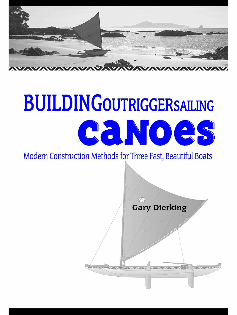
Contents
Preface vii
Acknowledgments x
IntroductionSome Outrigger Basics 1
A Brief History of the Outrigger Canoe 1Why Use an Outrigger? 1Length of an Outrigger Canoe 2Weight of an Outrigger Canoe 2Speed of an Outrigger Canoe 3Outboard Motors 3Sailing Rigs 3Paddling Your Outrigger 3Structure of the Outrigger Canoe 4Accommodation 4Mix and Match 4Units of Measurement 4Terminology 5Choosing Materials for an Outrigger Canoe 5How to Navigate This Book 5
Chapter 1.The Ulua 6
Materials for Building the Ulua 8Approximate Time and Cost for
Building the Ulua 8
Chapter 2.The T2 17
Materials for Building the T2 19Approximate Time and Cost for Building
the T2 21
Chapter 3.The Wa’apa 28
Rig Choice 29The Hull 29The Ama 31The Double Outrigger Option 31Materials for Building the Wa’apa 31Approximate Time and Cost for Building
the Wa’apa 32
Chapter 4.Sailing Rigs 43
The Oceanic Lateen Rig 43The Gibbons Rig 48The Hawaiian Rig 54Stub-Mast Rigs 55
Chapter 5.Boatbuilding Basics 58
Strip-Planking Versus Plywood 58Tools 59Materials 59Work Space 60Lofting 60Glues 61Screws, Nails, and Staples 62Cutting Plywood 63Cutting Strip Planks 64Scarfing Timber 65Joining Plywood Sheets with Fiberglass 67Joining Plywood Sheets with Butt Blocks 68Filleting 69Filling, Sanding, and Fairing 69
For more information about this title, click here

Sheathing with Fiberglass and Resin 71Laminating 73Bonded Fasteners 74Painting and Varnishing 74Metal Work 75Workshop Health and Safety 75Maintenance and Repair 75
Chapter 6.Building the Ulua and
T2 Strip-Composite Hulls 78Do a Practice Session 78The Strongback 79Molds 80Planking 82The Outer Stem 84Fairing and Smoothing the Hull 85Removing the Hull from the Mold 85Glassing the Interior 86Fitting the Interior Structure 86Fore and Aft Decks 87Manus, Splash Guards, and Dashboards 88Stretching the Ulua 90
Chapter 7.Building the Wa’apa Plywood Hull 95
Hull Middle Section 100
Chapter 8.Amas 102
Foam and Fiberglass Amas 103Building a Plywood Ama 106Strip-Planked Amas 109Ama Connections 110
Chapter 9.Cross Beams and Hull Connections 113
Building a Solid Laminated Iako 113Building a Hollow, Box Beam Iako 115Aluminum Tube Beams 116Connections 116
Chapter 10.Steering, Leeboards,
and Accessories 121Steering 121Leeboards 127Accessories 129
Chapter 11.Spars, Spar Specifications,
and Sails 134Spars 134Spar Specifications 137Sail 139
Chapter 12.Rigging, Tuning, and Sailing 147
Rigging and Tuning 147Sailing Basics 152Swamping and Capsize 156
Glossary 160
Resources 164
Index 165

vii
Far in the distant past, when I was maybe thir-teen years old, I started sailing small model
boats on the pond near our Wisconsin farm. I hadsome information from library books to guide me,but there was really no one to help or influence me.Steering, of course, was the problem. In the daysbefore radio-control, a quadrant on the rudder wasattached to the mainsheet. The harder the sheetpulled, the more the rudder was turned to counteractthe weather helm. This was a primitive system and itworked some of the time.
One day after watching my model constantlyrounding up into the wind and not holding a course,I spotted an interesting piece of driftwood on theedge of the pond. The driftwood was a piece of pinethat had warped into an elegant, curved shape. Itook it home and attached a single cross beam, witha pair of waterski-shaped wooden floats at each end.I removed the sailing rig from my balsa monohulland mounted it onto my new double outrigger.
I was elated the first time that it sailed. The lit-tle double outrigger not only went very fast, but italso steered a straight course, without any rudder.
I don’t know where I got the idea to attach out-riggers, but it could have had something to do withthe enormous pile of old National Geographic maga-zines that my grandfather had collected. No doubt Ihad seen outrigger canoes in the photographs thatthey had published. It took another ten years beforeI really learned my lesson.
I joined the U.S. Coast Guard after high schoolto start some real adventure. I had visions of steeringboats involved in daring sea rescues, but the realityturned out to be much different. My talent for elec-tronics kept me on shore stations instead of sea duty.
At that time the Coast Guard had LORAN trans-mitting stations all over the North Pacific, and Ispent a full year on Wake Island, a very small ring ofcoral with a beautiful lagoon. During my stay there,I restored a sunken fiberglass sailing dinghy. Themany hours of fast sailing in crystal-clear water whilewatching the coral heads passing below had a far-reaching effect on my future. An additional threemonths in Saipan and nine months in Palau ensuredthat my life would be intimately associated with thePacific.
After more than four years in the Coast Guard,I decided that I’d better go back to school. I pur-chased a 28'(8.5m), Swedish-built monohull andlived aboard it in a houseboat marina while workingat night and taking classes in the day. The SanFrancisco Bay area in the 1960s was a hotbed ofbackyard multihull building. The designs of ArthurPiver and Jim Brown were allowing people who hada big stack of plywood and few years of spare time tobuild their own boat and cruise long distances.
My friend Rich Clark, also living at themarina, had just completed building a 24'(7.2m)Piver Nugget trimaran, and I went along on its firstsail in San Francisco Bay. My experience on thefarm pond was duplicated out in the bay on a daywhen untried boats should have stayed in theirberths. We flew along at amazing speeds with finger-tip control. Steering was effortless until the under-strength plywood rudder snapped off at the water-line. We were now a good ten miles from home andwondering what to do next. It turned out to be anon-event. By simply sheeting in or out with thetwo sails, we were able to sail all the way home withvery good control. I had no idea at the time that
Preface
Copyright © 2008 by International Marine. Click here for terms of use.
Preface
viii
Pacific sailors had been doing just that for many cen-turies.
I bought that Nugget trimaran and sailed it forseveral years throughout San Francisco Bay anddown the coast. I could see that this was the type ofboat I wanted for my return to the tropical Pacific.The Jim Brown Searunner trimaran designs seemedto be just the right solution, and I started construc-tion of a 37-footer (11.2m) in 1968.
Now you’re asking yourself, how’s he going tocollege, earning a living, and building a big boat? Ibecame a college dropout, although I was doing welland enjoying it. The pull of the Pacific islands wastoo strong to resist, and I was focused on returningthere. Four years later, I was ready to go.
Since I had only $1,500 and a boat when I leftCalifornia, I had to work as much as possible in thevarious ports I visited. Building the Searunner hadgiven me the skills to apply for a professional boat-building job when I arrived in Honolulu. I spentmost of a year at a boatyard there and earned enoughfor the big jump into the South Pacific. I worked as asurveyor in Pago Pago for a year and designed amonohull cruiser for a crew member of another boat.The hull looked suspiciously similar to my trimaran’scenter hull.
In French Polynesia, I learned that a lot oflocal water transportation was done in long, narrow,sharpie-like hulls with a traditional-style outrigger.These were powered with outboard motors and wentvery fast with low power. I filed this informationaway for future reference, and with my presentdesigns, I always recommend that the builder try atwo-horsepower outboard and prepare to be amazedat the result.
During my time in Hawaii, I built a 16', two-piece plywood outrigger canoe, not unlike some ofthe sharpie-style hulls I had seen in French Polyne-sia. I built it in two bolt-together sections so that Icould carry it on the deck of my trimaran. It servedvery well as an extra dinghy while I lived aboard inHonolulu’s Keehi Lagoon and inspired the design ofthe Wa’apa offered in this book.
I built my first strip-planked outrigger canoewhen I returned to live in Saipan. I bought a copy ofDavid Hazen’s The Strippers Guide to Canoe-Buildingand realized that it was the ideal constructionmethod for rounded hull shapes. While I had alreadybuilt many plywood hulls, they almost always lookedlike plywood hulls. The 17' (5m) hull that I drewcouldn’t be identified with any particular island
group but was a combination of features that I liked.It came out drop-dead gorgeous, but it took a whileto sell because potential customers were afraid they’dscratch it. It turned out that strippers were a lottougher than they looked, and the little scratchesdisappeared with the next coat of varnish.
I built and repaired a lot of different boats dur-ing my time in Saipan, including the island’s first45-foot (13.7m) OC6 paddling canoe to be used incompetition. The clients wanted a solid fiberglasshull, so I used a one-off fiberglass rod material calledC-Flex. It held up very well until a large tree fellacross it in one of the regular typhoons.
By this time, I no longer intended to sail longpassages. I therefore sold my Searunner, Bird ofDawning, to a charter business, built a small houseand workshop in the jungle, and built still moresmall boats for the local population. By 1986, mywife and I were ready for a change.
We moved back to Honolulu, where I landed ajob at Aikane Catamarans. It turned out thatAikane Catamarans was owned by Rudy Choy, oneof the early pioneers in modern catamaran design.I worked on Rudy’s trans-Pacific racer, the 60' (18.3m)Aikane X-5. It had cross-beam problems, and Ibuilt a whole new pair from spruce timber and birchplywood.
My most vivid memory of that project was thefirst sailing test out in the channel between Oahuand Molokai. We were concerned with the massivecompression load from the 80' (24.4m) wing mast,especially when the whole boat went airborne off awave. I rode inside the beam just under the mast,with my flashlight, looking for stress cracks. Therewere none. A few months later, Rudy accomplishedhis long-held dream of breaking the speed recordbetween Los Angeles and Honolulu.
During the four years I spent at Aikane, I builtthree of Rudy’s 44' (13.4m) designs in either fiber-glass or foam-cored fiberglass, using vacuum bags,epoxy resin, and all of the latest hi-tech fabrics.
After living in Hawaii for a while, you realizethat you’re unlikely to ever be able to afford a houseon the beach. My wife Rose is from New Zealand,and she said it was time to go home, where you couldafford to live on the beach (or at least on the harborfront). New Zealand is a fine place for small-boat cruis-ing, with its innumerable bays and beaches. I startedthinking more and more about small portable boatswith their roots in the traditions of the Pacific. It wastime to put together everything I had learned while
ix
Preface
working and traveling among the islands. I collectedall of the books I could find on the subject. Almostall of the available literature was written by archeol-ogists or ethnologists and tended to focus on the sizeand shape of the object, and very little on how to useit. I decided to start building a series of outrigger sail-ing canoes, and to learn more about how theyworked through direct experience.
My first project was the 31' (9.4m) proa Te Wa.The 1⁄4" (6mm) plywood main hull was asymmetric,with the leeward side flatter than the windward side.The single outrigger float, or ama, was always kepton the windward side. The ends of the hulls wereidentical so that it could sail in either direction.When changing tacks, you also had to swap the cur-rent bow and stern. The sail and the steering oar hadto be moved to the other end of the hull. This proce-dure was called “shunting,” to differentiate it fromthe more common “tacking.” (Shunting and tackingare discussed in detail in Chapter 12.) Once the rigwas well set up and your crew member had practiced,the whole procedure could be done in as little as tenseconds.
I’m not the kind of person to just build a boatand sail it without wondering if I can improve it.Changing spars and sails on a 31-footer (9.4m)looked like it might get expensive and time-consuming, so I decided to build a smaller, 16' (4.8m)version to test some new ideas. I drew up the linesfor the Tarawa to be built in strip composite.
I first rigged the Tarawa with the classic Oceaniclateen rig, similar to what I was using on Te Wa. It waseasy to handle, and I adapted some bungee cords totend the backstays during the shunt. The Tarawawas the prototype for the T2 design offered in thisbook. The T2 is longer at 18' (5.4 m) but otherwiseis similar.
During my years of cruising on the Bird ofDawning, I always carried a copy of Euell Gibbons’sBeachcomber’s Handbook. While much of the book isdevoted to gathering wild foods in Hawaii, he alsobuilt a shunting sailing canoe for offshore fishing.His rig was different than any I’d ever seen or heardof and seemed to be worthy of an experiment. My
recent experience with windsurfing gave me someideas for modifying it, and they were successful. Thesail was very powerful and didn’t seem to have anyvices.
With the increasing popularity of Hawaiiancanoe paddling, I thought it was time for me toadapt a smaller, Hawaiian-style canoe to sailing.Hawaiian canoes are optimized for surf handling andhave very rounded hull shapes that won’t sail well towindward without some other source of lateral resist-ance. There is anecdotal evidence that traditionalcanoes used paddles held alongside the hull to allowthe canoes to sail somewhat to windward. I decidedto break with tradition and use a pivoting leeboardbolted to the side of the hull. At first I used a steer-ing oar, as I had with Te Wa and Tarawa, but a kick-up rudder was found to be less tiring over long peri-ods of time.
I felt that the Ulua had economic potential, soI made a set of female molds to allow fiberglasscopies to be built in a much shorter time. The plansin Chapter 1 show how to build the Ulua in stripcomposite, and the hull can be built lighter or heav-ier than the fiberglass production model, dependingon your wishes or building skills.
I find building a hull in strip composite to be avery satisfying experience, but not everyone is will-ing to attempt it. With fond memories of my two-piece canoe dinghy carried on the deck of mycruiser, I decided to redraw it for those builders whoreally wanted a quick-building plywood hull. The16' or 24' (4.8m or 7.2m) convertible Wa’apa wasthe result. It has a simple, flat-bottomed shape some-times called a “three-board canoe” in Hawaii. Due tothe shortage or expense of big logs, many island fish-erman now use paddling canoes constructed inmuch the same way as the Wa’apa.
So there you have it—my convoluted but (orso I think) intriguing story about how I got involvedin designing and building outrigger sailing canoes.So far, it’s been an amazing, unpredictable life, and Ihope that the following chapters will guide you hap-pily toward building your own projects with greatsuccess.
x
To the following individuals I wish to expressmy thanks and gratitude for their help either
directly or indirectly during my career as a boat-builder, sailor, and recently as an author.
In particular, I’d like to thank Wade Tarzia,who knows proas and how to write; MichaelSchacht, for convincing me to prepare my designsfor the backyard builder; Harmen Heilkema, a close
friend and proa designer with long experience; TimAnderson, for giving my Ulua a good hard test;Kevin O’Neill, who also knows proas and how towrite; Bob Holtzman, my editor; the many builderswho have purchased plans and given me invaluablefeedback; and my wife Rosemary, without whosesupport this project would have never been com-pleted.
Acknowledgments
Copyright © 2008 by International Marine. Click here for terms of use.

BUILDINGOUTRIGGERSAILING
caNoescaNoes

This page intentionally left blank

1
From Madagascar, off the east coast of Africa,all the way to Easter Island, the outrigger sail-
ing canoe is one of humankind’s most useful tools,and it remains in use today throughout the Indianand Pacific oceans. The outrigger sailing canoe’sbeauty and elegance, combined with a ruthless func-tionality and efficiency, make it a very attractiveoption for anyone wanting to build a small boat.
The evolution of the outrigger sailing canoe hasspanned many centuries with little change to thebasic configuration. Very few watercraft have under-gone such a long development under such exactingconditions. Every island group in the Pacific Oceanhas come up with a slightly different solution adaptedto either local conditions or traditions. While singleand double outriggers have been built in excess of100 feet (30m) in length, most canoes in daily usetoday are between 16' (4.8m) and 25' (7.6m). Thatrepresents a practical size for the home builder, and theboats you will build in this book are in that size range.
A BRIEF HISTORY OF THE OUTRIGGER CANOEThe people who explored and settled on the islandsof the Pacific Ocean did not have a written lan-guage, but rather memorized their history and cul-tural information. This fact makes it difficult to tracethe early development of the sailing canoes thatexplored one third of the earth’s surface, beginningas early as 6000 years ago. Most of the valuable infor-mation available was collected by early westernexplorers in the form of notes and drawings (oh, ifthey’d only had cameras).
At the time of first contact with westernexplorers, both double-hulled catamarans and singleoutrigger canoes were in use. The catamarans werefavored for hauling heavy freight or a lot of people.The single outrigger canoe was faster and betteradapted for chasing schools of fish or for courier use.In some cases, the same hull could be used with apartner as a catamaran or equipped with a single out-rigger, depending on its intended use. The doubleoutrigger canoe (trimaran) is not generally seen inPolynesia or Micronesia, but rather in Indonesia andthe Philippine Islands.
Both catamarans and single outriggers wereseen with shunting and tacking rigs, although theshunting rig was spreading and increasing its influ-ence at the time of western contact.
WHY USE AN OUTRIGGER?Outriggers are often seen attached to all kinds ofwatercraft that were not originally designed to beused in this way. Sailing canoes and kayaks areundergoing a revival, and the poor stability ofmany designs has led some owners to add one ortwo amas (the floating part of an outrigger) totheir craft. Results can be mixed. The extra stabil-ity comes at the cost of increased weight and com-plication in setup and rigging. Two or three hullsare more drag than one, and unless the sail plan isenlarged, you may end up going slower. Hulls orig-inally designed to sail without an outrigger arebeamier, and this, combined with the additionalama drag, may cause the performance to be disap-pointing.
INTRODUCTION
Some Outrigger Basics
Copyright © 2008 by International Marine. Click here for terms of use.

The key to getting an edge in performance is tohave a very narrow main hull as has been usedthroughout the Pacific and Indian oceans. Thewaterline-length-to-waterline-beam ratio can be asgreat as 30:1 on large, oceangoing outriggers anddouble canoes. On the smaller craft with which weare dealing, a 20:1 ratio is about the slimmest practi-cal hull that can still carry the necessary weight. Thefirst time I sailed aboard a 20:1 proa with plenty ofwind and a good rig, I was elated to feel an almosttotal lack of resistance when confronted with a waveface or steep chop. That sail was quite unlike any-thing I had ever experienced.
The term “proa” originally came from Indone-sia. When European explorers first saw the outriggercanoes of the Pacific islands, they called them proasbecause of their previous experience in Indonesiawhere the double outrigger canoe is common. Todaythe term is usually applied to canoes that shunt andalways keep their amas to windward. There are even“Atlantic proas” that always keep their amas to lee-ward. Unfortunately, there is no firm definition for“proa,” but I will use it in reference to canoes thatshunt, and I will use the term “tacking outrigger” forcanoes that tack. Throughout this book, you willencounter various mentions and discussions of tack-ing and shunting. The most complete description ofthese procedures is found in Chapter 12, and I rec-ommend that you read this material if you’d like adetailed explanation.
With the designs in this book I have tried toremain as faithful as possible to the design principlesthat have made the Pacific and Indian Ocean outrig-gers the enduring successes that they are today. Thedifference between ancient and modern outriggers isin the materials that we now have available. Somefirm traditionalists insist on duplicating the materi-als available in ancient times in which you built anoceangoing vessel with logs, coconut fiber, and anadze. This is fine, and the results can be a stunninglesson about all of the things you don’t really need tobuild a boat.
I’ve been a boatbuilder for more than fortyyears, and in that time I never turned down anopportunity to try some newer, better, or cheaperway to build a boat. I feel that the ancient builderswould have been no different, and if a roll of carbonfiber and a drum of epoxy fell out of the sky overTahiti in 892 A.D., they’d have been happy to use it.As it was, they still laughingly sailed circles aroundevery European ship.
The designs in this book use both ancient andmodern engineering solutions. The most obviousstructural feature is my prejudice for lashed connec-tions. Using lashings to connect the cross beams tothe hull and the ama provides exceptional strengthbut still allows a small degree of flexibility thatreduces the effects of high transient loads experi-enced by all multihulled craft at sea. While the tech-nique of lashing has been around since the begin-ning, we now have a full selection of synthetic lineto use, from the stretchiest nylon to new fibers thatstretch no more than steel cable. For most purposes,I find ordinary polyester/Dacron rope to be just right.Canoes that are used only for paddling often usestrips of rubber inner tube for lashing. Rubber is a bittoo stretchy for the main connections of a sailingcanoe, however, where the rig imposes much greaterloads.
LENGTH OF AN OUTRIGGER CANOEOne of the most obvious characteristics of an outrig-ger sailing canoe is its extreme length-to-beam ratio.Measurements can reveal a waterline length oftwenty or more times the waterline beam of the hull.An extremely narrow hull creates a very efficientshape which produces such small waves that it hasfew of the speed limitations found in beamier dis-placement hulls. A hull this narrow would, ofcourse, fall over without an ama or another hull tostabilize it.
Oceanic canoes are extravagant with length, asthey are seldom confined to modern marinas whereyou pay by length. Nothing contributes to comfortat sea more than pure length. Having said that, thecanoes in this book are all of a length to enable themto be built in your garage and transported on the roofof a car.
WEIGHT OF AN OUTRIGGER CANOEModern multihulls are generally quite light in weightcompared to traditional working canoes. A lightweight does cause some differences in operation com-pared to traditional practice. Hollow lightweightamas, for instance, cannot provide the necessary bal-last to windward that a solid log provides. A light-weight ama necessitates the greater use of movable
BUILDING OUTRIGGER SAILING CANOES
2
ballast (human, water, or cargo). Generally I recom-mend building the structure as light as possible,because once it’s built, it is always easier to addweight than to remove it.
SPEED OF AN OUTRIGGER CANOEEarly European explorers of the Pacific Ocean wereamazed at the speed and weatherliness of some of theoutrigger sailing canoes they encountered. This per-formance was accomplished without metal fastenersor fittings of any kind, while sails were woven ofplant leaf material and were very porous to the wind.Their speed was the result of the low, wave-makingshape of the hulls, the huge righting momentderived from an outrigger or second hull, and thelack of heavy ballast. An outrigger sailing canoe’swindward sailing ability varied, depending on thelocal design, but it was superior to that of Europeanvessels of the time. Modern sailing craft are betterperformers to windward but at a huge cost in expen-sive, high-modulus (low-stretch) materials in boththe sails and rigging.
The canoe designs contained in this book areall capable of reaching speeds up to about 12 knots(14 miles per hour) when you are sailing with thewind on your side (beam reach) or just aft of yourside (broad reach). When you are sailing into thewind, the average speed is between 5 and 6 knots.Greater speeds are possible with bigger sails andgreater overall beam, and you are certainly wel-come to experiment. Over the years, I’ve becomeless concerned with ultimate top speed and moreconcerned with a light canoe’s ability to keep goingin almost no wind. I’m a sailor and I’ll only paddleif I must.
OUTBOARD MOTORSClamping a two-horsepower outboard motor to yourcanoe can greatly increase its versatility. You caneasily cruise along at 6 knots at half-throttle. Theslim shape of the canoe’s hull requires very littlepower to drive it, so don’t be tempted to increase thesize of the motor, because the extra thrust is not nec-essary and the extra weight is not in a good location.
Electric power is also a possibility with the useof an outboard trolling motor and a sealed batterybox located near the center of the hull.
If you value your motor, however, leave it athome if you’ll be sailing in strong winds, or rig asafety ama (Figure 12-16) to prevent the motor fromgetting dunked.
SAILING RIGSTraditional sailing outriggers can be divided into twogroups—those that tack and those that shunt. (SeeChapter 12 for a complete discussion of shunting andtacking.) Shunting rigs predominate in Micronesiaand are also seen in Melanesia, Polynesia, and theIndian Ocean. Shunting canoes are unique in thatboth ends of the hull are identical and can act as thebow or stern. The ama is always kept on the wind-ward side, where it acts as floating ballast.
To change direction, the sail has to be movedor pivoted to the other end of the hull, while thecanoe drifts broadside with its ama (outrigger float)toward the wind. The steering device must alsochange ends. This is not as complex as it sounds andcan be accomplished in less than ten seconds in awell-set-up canoe. Because the canoe is never pur-posely aimed directly into the wind, there is no pos-sibility of stalling the sail and getting caught “inirons” as you might in a tacking vessel.
The tacking rig is the same as you see in anyother part of the world. It is used predominantlyin Polynesia and Indonesia. The ones I’ve shownon the plans are as simple as can be devised withunstayed masts and a single sail. A tacking rigused on a single outrigger canoe means that onone tack the ama will be to windward, and on theother tack it will be to leeward. Modern light-weight amas have sufficient buoyancy to stayafloat when pressed down to leeward. In tradition-ally built tacking canoes, crew members have tomove their weight out onto a balance boardextending from the opposite side of the canoe tokeep a solid-log ama from submerging.
PADDLING YOUR OUTRIGGEROne or more paddles is an essential part of yourequipment when leaving shore. Paddling is oftennecessary to get away from or into the shore and isvery useful if your sailing rig has blown away. All ofthe designs in this book can be comfortably pad-dled for short distances. The Wa’apa is the easiestto handle under paddle power. Its hard chines aid
3
Introduction
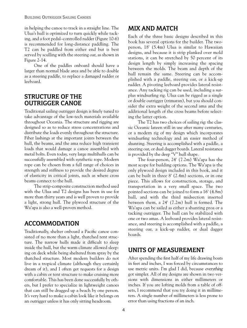
in helping the canoe to track in a straight line. TheUlua’s hull is optimized to turn quickly while tack-ing, and a foot pedal–controlled rudder (Figure 10-6)is recommended for long-distance paddling. TheT2 can be paddled from either end but is bestserved by sculling with the steering oar, as shown inFigure 2-14.
One of the paddles onboard should have alarger than normal blade area and be able to doubleas a steering paddle, to replace a damaged rudder orleeboard.
STRUCTURE OF THE OUTRIGGER CANOETraditional sailing outrigger design is finely tuned totake advantage of the low-tech materials availablethroughout Oceania. The structure and rigging aredesigned so as to reduce stress concentrations anddistribute the loads evenly throughout the structure.Fiber lashings at the important joints between thehull, the beams, and the ama reduce high transientloads that would damage a canoe assembled withmetal bolts. Even today, very large multihulls can besuccessfully assembled with synthetic rope. Modernrope can be chosen from a full range of choices instrength and stiffness to provide the desired degreeof elasticity in critical joints, such as where crossbeams connect to the hull.
The strip-composite construction method usedwith the Ulua and T2 designs has been in use formore than thirty years and is well proven to providea light, strong hull. The plywood structure of theWa’apa is also a well-proven method.
ACCOMMODATIONTraditionally, shelter onboard a Pacific canoe con-sisted of no more than a light, thatched tent struc-ture. The narrow hulls made it difficult to sleepinside the hull, but the warm climate allowed sleep-ing on deck while being sheltered from spray by thethatched structure. Most modern builders do notlive in a tropical climate (although they certainlydream of it), and I often get requests for a designwith a cabin or tent structure to make cruising morecomfortable. This has been done successfully by oth-ers, but I prefer to specialize in lightweight canoesthat can still be dragged up a beach by one person.It’s very hard to make a cabin look like it belongs onan outrigger unless it has only sitting headroom.
MIX AND MATCHEach of the three basic designs described in thisbook has several options for the builder. The two-person, 18' (5.4m) Ulua is similar to Hawaiiandesigns, and because it is strip planked over moldstations, it can be stretched by 50 percent of itsdesign length by simply increasing the spacingbetween the molds. The beam and depth of thehull remain the same. Steering can be accom-plished with a paddle, steering oar, or a kick-uprudder. A pivoting leeboard provides lateral resist-ance. Any tacking rig can be used, including a sur-plus windsurfing rig. Ulua can be rigged as a singleor double outrigger (trimaran), but you should con-sider the extra weight of the second ama and theadditional length of the cross beams before select-ing the latter option.
The T2 has two choices of sailing rig: the clas-sic Oceanic lateen still in use after many centuries,or a modern rig of my design which incorporateswindsurfing technology and an easier method ofshunting. Steering is accomplished with a paddle, asteering oar, or dual dagger boards. Lateral resistanceis provided by the deep “V” hull shape.
The four-person, 24' (7.2m) Wa’apa has themost scope for building options. The Wa’apa is theonly plywood design included in this book, and itcan be built in three 8' (2.4m) sections, or in onepiece. This allows for construction, storage, andtransportation in a very small space. The twopointed sections can be joined to form a 16' (4.8m)hull, and with the third midsection insertedbetween them, a 24' (7.2m) hull is formed. TheWa’apa can be sailed as either a shunting proa or atacking outrigger. The hull can be stabilized withone or two amas. A leeboard provides lateral resist-ance, and steering is accomplished with a paddle, asteering oar, a kick-up rudder, or dual daggerboards.
UNITS OF MEASUREMENTAfter spending the first half of my life drawing boatsin feet and inches, I was forced by circumstances touse metric units. I’m glad I did, because everythinggot simpler. All of my designs are shown in two ver-sions with dimensions in either millimeters orinches. If you are lofting molds from a table of off-sets, I recommend that you try doing it in millime-ters. A single number of millimeters is less prone toerror than using fractions of an inch.
BUILDING OUTRIGGER SAILING CANOES
4
TERMINOLOGYSome parts of the outrigger sailing canoe simply donot have very descriptive names in the English lan-guage. Every Pacific island group has its own lan-guage and, hence, different names for the parts oftheir canoes. The table below gives you at least anidea of some of these names. Also, for any otherterms with which you are not familiar, refer to theglossary at the end of the book.
NEW MARSHALL ENGLISH HAWAII TAHITI ZEALAND ISLANDS
Main Hull wa’a va’a waka WaOutriggerFloat ama ama ama Kubaak
OutriggerBoom iako iato kiato apet, kie
CHOOSING MATERIALS FOR ANOUTRIGGER CANOEChoosing suitable timber for your boatbuilding proj-ect is important and can be difficult depending uponyour location. Cedar-strip planks can be orderedalready prepared with cove-and-bead edges, but mostbuilders will choose to save money and cut their own.Western red cedar is the first choice for strip-planking because of its light weight, color, and rotresistance, but many other species are also appropri-ate. Spruce, pine, other types of cedar, redwood,paulownia, or cypress are a few others that have beenused successfully. Planking timber is ideally verylightweight, dry, straight-grained, and available inlong, clear lengths. If you cannot find suitable timberin your local area, check through boating or boat-building magazines for companies that will supply it.
Timber for gunwales, stems, and chines is ide-ally harder and heavier than cedar because it has tohold fasteners well and be exposed to more abuseduring use. Laminated cross beams can use cedar inthe inner layers, with a harder wood like fir ormahogany on the top and bottom.
Plywood can present you with just as difficult achoice unless you have a healthy budget and pur-chase the most expensive marine grades. BS1088 is aLloyds standard for marine plywood that ensuresmainly the quality of the veneers in all layers.Marine and exterior grades of plywood use the samewaterproof adhesive. With marine grade, you aremostly paying for the quality of the inner layers.
If you wish to use a plywood of unknown qual-ity, take a sample and expose it to repeated cycles ofboiling and baking in an oven. If you are using plywith one good side and one lesser-grade side, put theknotty side out and glass over it, leaving the betterside on the interior of the hull. One-fourth-inch(6mm) plywood is available with three or five plies;the five-ply is far superior. Check the dimensions ofplywood sheets, as some are metric sizes and someare imperial (i.e., inch) sizes.
Screws, nails and bolts are ideally made of anon-corrosive metal like silicon bronze or stainlesssteel. You can use galvanized steel fasteners if theywill be fiberglassed over.
HOW TO NAVIGATE THIS BOOK In the first three chapters of this book, I’ll introduceyou to each of the three designs being offered, alongwith the construction drawings and a materials list.Because two of the designs have very different sail-ing rig options, the next chapter describes in detailhow each of these rigs work.
Chapter 5 is a brief course on basic boatbuild-ing skills and how the materials are used. Chapters6 and 7 specifically describe each step in the hullconstruction. Chapters 8 through 11 will guide youthrough the construction of amas, cross beams,steering devices, and sailing rigs. Chapter 12teaches you how to make it all work and how tosurvive the experience. Refer to the glossary forany terms that you do not understand. For furtherreading on outrigger sailing canoes, Internet links,or to order full-size patterns, refer to the resourceschapter.
5
Introduction

6
“Ulua” is the Hawaiian term for the GiantTrevally fish found in deep, rocky water and off
some beaches of the Pacific islands.The Ulua canoe is based on Hawaiian outrigger
canoe design. The channels between the Hawaiianislands are extremely rough and more often than nothave strong trade winds blowing. This fact, along withthe very small number of natural harbors, provided thebreeding ground for a very special canoe. The ability to
maintain control during high-surf landings was themost important factor in their design.
The Ulua design broadly resembles the classicHawaiian canoe, with some differences. The roundbottom, which is important in the surf, performspoorly when sailed to windward. I’ve added a pivotingleeboard for lateral resistance that can be retractedwhen paddling or when landing in surf. A steering oaror rudder can be used instead of the traditional paddle
CHAPTER 1
The UluaLength overall 17’9”(5400mm)Hull width 18”(470mm)Overall width 6'7”(2000mm)Draft 8”(200mm) @ 400 lb (182 kg)
displacementHull weight 64 lb (29 kg) Weight fully rigged 122 lb (55 kg)Sailing rig type Tacking onlySail area 65 sq ft (6.0 sq m)Construction method Strip-planked
composite
FIGURE 1-1. The Ulua equipped with a tacking rig, leeboard, and rudder.
Copyright © 2008 by International Marine. Click here for terms of use.

7
The Ulua
for steering. The Ulua hull has a little more “V” in thehull than a traditional Hawaiian model, and thisimproves its speed and windward sailing ability.
Watertight bulkheads in each end of the hullprovide reserve buoyancy in the event of damage orcapsize. Additional reserve buoyancy can be built inunder the two seats in the form of foam blocks or hol-low storage compartments. The ama can be eithersolid foam covered with fiberglass, or hollow and stripplanked, with foam or plastic bottles inside for emer-gency flotation. The large ama is of sufficient size tosupport cargo stored on the iakos (outrigger booms)along with a crew member on the hiking seat.
A hiking seat enables the crew or helmspersonto shift their weight outboard of the narrow hull’s
gunwale to balance the force of the sail. It can consistof a slatted wooden seat or fabric stretched on aframe. The outboard edge is supported by a fore andaft pole resting on the iakos, while the inboard edgerests on the gunwale. At least one hiking seat mustbe fitted on the ama side of the hull, but an addi-tional seat can be installed on the opposite side, sup-ported by extended iakos.
The sailing rig shown is of a modern Hawaiiantype. The availability of fiberglass windsurfing mastsallows for a very simple lightweight plug-in rig thatcan be lowered entirely while at sea and stowed onthe iakos. A brailing line folds the boom and sail upagainst the mast for quick furling and thus avoidsdumping the sail onto the crew.
Boom
Sail
Leech
Reefpoints Clew
Foot
Head
Luff
Mast
TackMainsheet
Manu
Ama
Iako
Pola
Hikingseat
Leeboard
Outboardbracket
Gunwale
Wae
Rudder
Forestay
Splash board

The Ulua can be paddled, sailed, surfed, or pow-ered by a two-horsepower outboard motor. This canoeis capable of extended coastal expeditions and can becar-topped to your favorite launching spot or carriedon its side on a trailer with the ama up in the air.
The hull can be stretched to a greater length byincreasing the spacing between the molds before theplanking begins. You can safely increase the hulllength by 150 percent without any changes to thestructure.
While the Ulua is an excellent sailing canoe,the shape of the hull is optimized for its ability to turnquickly while tacking. For long-distance paddling,foot pedals, like those used in sea kayaks, can be con-nected with small lines to the sailing rudder. Steeringwith your feet allows for stronger paddling withoutusing energy to keep the canoe on a straight course.
MATERIALS FOR BUILDING THE ULUA
Hull• 60 planks of 1⁄4" � 3⁄4" � 18.5' (6mm � 19mm �
5700mm)• Enough planks for the hull and end decks can
be ripped from 5 pieces of timber, 51⁄2" � 3⁄4" �
18.5' (140mm � 19mm � 5.7m), assuming theuse of a thin kerf circular saw blade.
Molds• 2 sheets of 1⁄2" (12mm) or thicker plywood or
particle board
Stems • 2 pieces of 1" � 4" � 30" (25mm � 100mm �
750mm). These can be of cedar or any othersoftwood.
Gunwales• 4 pieces of 3⁄8" � 1" � 18.5' (10mm �
40mm � 5700mm). Harder woods likemahogany or ash are more durable.
Bulkheads and Ring Frame• 3 pieces of 16" � 18" � 3⁄16" or 1⁄4" (400mm �
450mm � 4 or 6mm) plywood. Bulkheads canbe strip composite.
Seats• 2 pieces of 3⁄4" � 10" � 18" (19mm � 250mm �
450mm). The seats can be of plywood or solid timber.
Iakos• 10 pieces of 5⁄16" � 23⁄8" � 6'8" (8mm �
60mm � 2000mm)
Fore and Aft Decks• 2 pieces of 18" � 3'8", 3⁄16" or 1⁄4" (450mm �
1100mm, 4 or 6mm plywood• OR: 30 strips of 3⁄16" � 3⁄4" � 44" (4 to 6mm �
19mm � 1100mm) plywood for strip decks
Epoxy Resin• 3 1-gallon (4-liter) kits of resin and hardener• Bag of glue powder• Bag of fairing powder
Fiberglass• 4 pieces of 6-ounce (200-gram) 18.5' � 26"
(6000mm � 650mm) for hull• 4 pieces of glass for top and bottom of strip
deck, 18" � 44" (450mm � 1100mm)• Miscellaneous strips for glassing in bulkheads• 2 pieces of 10-ounce (330-gram), 16' � 16"
(5000mm � 400mm) for ama, or:• 4 pieces of 6-ounce (200-gram) fiberglass cloth
Ama• 2 pieces of 4" � 8" � 12'8" (100mm �
200mm � 4000mm) blue Styrofoam (can use2" [50mm] foam and glue layers together) 1⁄2sheet; 1⁄8" or 3⁄16" (3mm or 4mm) plywood forshear web
APPROXIMATE TIME AND COSTFOR BUILDING THE ULUAThe amount of time that it takes to complete a sailingUlua is widely variable and reflects the personal stan-dards and skill of the individual builder. Gettingstarted can seem slow, with little to look at that resem-bles a canoe, but once planking commences, the hull
BUILDING OUTRIGGER SAILING CANOES
8
9
The Ulua
1 2 3 4 5 6 7 8 9 10 11 12 13 14 15 16 17
WL4
WL3
WL2
WL1
Baseline
1400
mm
4'
-7"
2400 mm7'-10 1/2"
5400 mm17'-9"
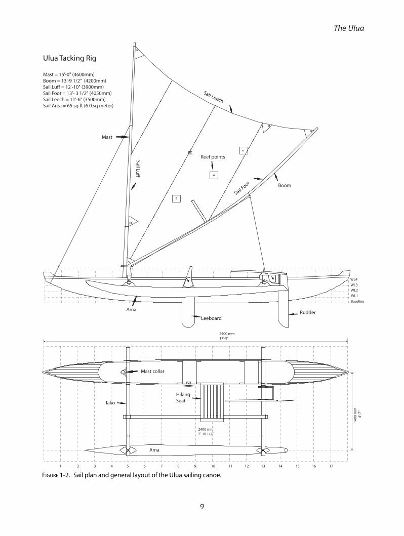
Ulua Tacking Rig
Mast = 15'-0" (4600mm)Boom = 13'-9 1/2" (4200mm)Sail Luff = 12'-10" (3900mm)Sail Foot = 13'- 3 1/2" (4050mm)Sail Leech = 11'-6" (3500mm)Sail Area = 65 sq ft (6.0 sq meter)
Mast
Boom
Sail Luff
Sail Foot
Sail Leech
RudderLeeboard
Ama
Ama
Iako
HikingSeat
Reef points
Mast collar
FIGURE 1-2. Sail plan and general layout of the Ulua sailing canoe.

10
Manu pieces cut from1" (25mm) timber, epoxyglued and screwed toouter gunwale and deck
Outer gunwaleor outwale
Same detail at bothends of the hull
Manu Detail
Station1 or 17
The manu shape canbe altered to yourindividual preference
Hiking Seat
27-1
/2"
(700
mm
)
15-3/4" (400mm)
3/8" x 2" (10 x 50mm) Slats fitinto dado in End pieces
1-3/4" x 3/4"(45 x 19mm)End pieces
Slat stiffener
Outboard Bracket
SS Rod weldedto Nut
3/8" (9mm) Pivot Bolt
3/4" (19mm) Plywood
Rudder Blade 3/4" (19mm)Straight Grained Timber
39-3/8" (1000mm)
38-1
/2"
(980
mm
)1-9/16"(40mm)
7-5/16"(185mm)
7-3/8" (188mm)
6-5/
16"
(160
mm
)
2-9/
16"
(65m
m)
4-1/8"(105mm)
39-3/8" (1000mm)
94-1/2" (2400mm)
29-1/2" (750mm)
7"(180mm)
Steering Oar
1-13/16" (46mm)
1-5/8"(42mm)
Curved Boom
7-3/8"(188mm) 9-13/16"
(250mm)
7-3/8"(188mm)
41-5/16" (1050 mm)
9-13/16"(250mm)
165-3/8" (4200mm)
Two pieces spar grade timber3/4" x 1-5/8" x 165-1/2"(19 x 42 x 4200mm)Bent and laminated along locating blocks
Iako (cross beam)
43-1
/4"
(110
0mm
)
8-5/8" (220mm)
15-3
/4"
(400
mm
)
10-1
/4"
(260
mm
)
Leeboard
3/4" (19mm)Straight Grained Timber
1/8" (3mm)AluminumPlate
4-7
/16"
(113
mm
)
Typical Clamping Block
4-7
/16"
(113
mm
)
4-5
/16"
(110
mm
)
3-15
/16"
(100
mm
)
3-1
/4"
(83m
m)
2-1
/4"
(57m
m)
1-1
/8"
(29m
m)
7-7/8"(200mm)
78-3/4" (2000mm)
Five laminations of5/16" x 1-5/8"(8 x 40mm) Timber
Rudder
41-5/16" (1050 mm) 41-5/16" (1050 mm)
41-5/16" (1050 mm)
FIGURE 1-3. Construction details for the manu, hiking seat, steering oar, iakos, boom, leeboard, and rudder.

11
Station 3
Station 5 Station 5 Station 12
Station 13Station 15
Outboard Motorand Rudder Bracket
3/16-1/4" (4-6mm) ply or strip deck with 3/4" (20mm) crown
1-1/2"x 3/8" (40x10mm)inwale and outwale
3/16-1/4" (4-6mm) ply or strip watertight bulkhead
Plastic screw-outaccess panel
Plastic screw-outdrain plug
1x1/8" (25x3mm) aluminumstrap mast collar bolted to wae
2-3/8"x1-1/2" (60x40mm)laminated 'iako
3/16"(4mm) polyester lashing
5/8"(15mm) lashingholes both sidesof wae
2-3/8"x3/4"(60x20mm) waeglued to ring frame
1/4"(6mm) ply ring framefilleted and glassed to hull
3"x6"x3/4"(75x150x19mm)mast step with dowel bolted to fit inside hollow windsurf mast. Step to be located tight against forward side of ring frame
Iako Gunwale
Wae
Lashing holes
Plywood ring frame
1/4"(6mm) ply saddle gluedto inside of hull to support waes. Same saddles at station 13
10"x 3/4"(250x19mm)timber seats
1-1/4x1-1/4"(30x30mm)cleats glued to hull tosupport seats
2-3/8"x1-1/2" (60x40mm)laminated 'iako
Ply saddles
Wae
3/16-1/4" (4-6mm) ply or strip watertight bulkhead
Timber seat
Aluminum anglebracket
3/8"(9mm) SS bolt
Timber gunwaleTimber Leeboard
1/8"(3mm)Aluminum plate
Fiberglass washer
1/4"(6mm) rodwelded to nut
SS nut & washer
3/8"(9mm) plasticbearing plate
Iako
1/4"(6mm)anti-torque line
Plastic cleat
Plywood pad
Outboardmotorbracket
1x5/8x6"(25x15x150mm) Hardwood
Nyloc nut
3/4"(19mm) Plywood
1/4"x3"(6x75mm)SS threaded rod epoxiedinto plywood
1/4"(96mm) ply or plastic pad for OB motor
Corner joints epoxy glued and screwed withoptional aluminum angle bracket reinforcement
9-5/8"(245mm)
5-1/2"(140mm)
11" (280mm)
2-3/16" (55mm)
FIGURE 1-4. Structural cross sections and outboard motor bracket construction.

12
Bow Stem MoldStern Stem Mold
Strongback
Sheer line
Waterline 4
Waterline 3
Waterline 2
Waterline 1
Baseline
Sta 1Sta 2Sta 17 Sta 16
Inner stem1x1"(25x25mm) laminated or sawn
Inner stem 1x1"(25x25mm) laminated or sawn
3-5/8"(92mm)
1-1/2"(38mm)
22-9/16" (573mm)
8-5/8"(219mm)
12-7/16"(316mm)
Holes for clampingstem lamination
Notch to fitover MoldExtension
22-7/16" (570mm)
13-11/16"
(348mm)
9-1/8"
(232mm)
2-15/16"
(75mm)
1-1/2"
(38mm)
11-13/16" (300mm)11-13/16" (300mm) 11-13/16" (300mm) 11- 13/16" (300mm)
3-15/16"
(100mm)
Typical
17 16 15 14 13 12 11 10 9 8 7 6 5 4 3 2 1
WL1
WL2
WL3
WL4
Strongback 7-7
/8"
(20
0m
m)
Top Edge of Mold extension
aligns with WL3
11-13/16" (300mm) Typical
Note that station molds 1-10
are on opposite sides of the
station line to stations 11-17
FIGURE 1-5. Stem and mold section setup.

13
Station Number 1 2 3 4 5 6 7 8 9 10 11 12 13 14 15 16 17
Sheer To Baseline 470 1-6-4
463 1-6-2
458 1-6-0+
455 1-5-7+
453 1-5-6+
451 1-5-6
451 1-5-6
451 1-5-6
451 1-5-6
451 1-5-6
451 1-5-6
452 1-5-6+
454 1-5-7
457 1-6-0
462 1-6-1+
470 1-6-4
483 1-7-0
86 0-3-3
140 0-5-4
168 0-6-5
185 0-7-2+
198 0-7-6+
208 0-8-1+
215 0-8-3+
218 0-8-4+
220 0-8-5+
220 0-8-5+
220 0-8-5+
219 0-8-5
215 0-8-3+
209 0-8-2
196 0-7-5+
167 0-6-4+
104 0-4-1
WL 4 Half-Breadth 71 0-2-6+
130 0-5-1
164 0-6-3+
185 0-7-2+
200 0-7-7
210 0-8-2
217 0-8-4+
219 0-8-5
221 0-8-5+
221 0-8-5+
221 0-8-5+
220 0-8-5+
215 0-8-3+
208 0-8-1+
191 0-7-4
155 0-6-0+
87 0-3-3+
WL3 Half-Breadth 32 0-1-2
104 0-4-1
150 0-5-7
179 0-7-0+
197 0-7-6
208 0-8-1+
215 0-8-3+
218 0-8-4+
220 0-8-5+
220 0-8-5+
220 0-8-5+
219 0-8-5
212 0-8-3
200 0-7-7
176 0-6-7+
128 0-5-0+
45 0-1-6
WL2 Half-Breadth 43 0-1-5+
105 0-4-1
146 0-5-6
172 0-6-6
189 0-7-3+
199 0-7-6+
206 0-8-1
210 0-8-2
212 0-8-2+
211 0-8-2+
208 0-8-1+
198 0-7-6+
177 0-6-7+
138 0-5-3+
72 0-2-6+
WL1 Half-Breadth 65 0-2-4+
108 0-4-2
137 0-5-3
155 0-6-1
167 0-6-4+
175 0-6-7
178 0-7-0
176 0-6-7+
170 0-6-5+
152 0-6-0
118 0-4-5
58 0-2-3
WL .5 Half Breadth 75 0-3-0
104 0-4-1
118 0-4-5
126 0-4-7+
128 0-5-0
124 0-4-7+
113 0-4-4
93 0-3-5+
54 0-2-1
Keel to Baseline 254 0-10-0
158 0-6-2
97 0-3-6+
56 0-2-1+
30 0-1-1+
14 0-0-4+
40-0-1+
10-0-0+
00-0-0
00-0-0
00-0-0
00-0-0
60-0-2
24 0-0-7+
60 0-2-3
126 0-4-7+
240 0-9-3+
30 Degree Diagonal
104 0-4-1
157 0-6-1+
196 0-7-6
226 0-8-7
247 0-9-6
263 0-10-3
272 0-10-5+
277 0-10-7
279 0-11-0
277 0-10-7
271 0-10-5+
258 0-10-2+
233 0-9-1+
192 0-7-4+
128 0-5-0+
41 0-1-5
Strongback Line
Waterline 4
Waterline 3
Waterline 2
Waterline 1
Baseline
Cen
terli
ne
Shee
r to
Bas
elin
e
Keel to Baseline
Waterline .5
30D
egD
iag
100m
m10
0mm
100m
m10
0mm
0-3
-7+
50m
m
0-3
-7+
0
-3-7
+
0-3
-7+
0
-2-0
50m
m
0-2
-0
Sheer Half Breadth
WL4 Half Breadth
WL3 Half Breadth
WL2 Half Breadth
WL1 Half Breadth
WL.5 HalfBreadth
Ulua Table of Offsets
The table of offsets enables you to reproduce the curved shape of the hull molds.The top number in each box is in millimeters, and the bottom number is feet, inches, and eighths of an inch. A plus sign adds a sixteenth of an inch. For example: 1-6-1+equals one foot, 6 inches, and three-sixteenths of an inch.
Draw a centerline, baseline, waterlines, strongback line, and the 30-degree diagonal,ensuring that the waterlines are parallel and spaced correctly. Measure and mark the offsets or half breadths, tack a small nail at each point, andbend a timber batten along the nails. Draw along the batten with a pencil.
Note that stations 1 and 17 have a strip removed from their centerlines to enablethem to straddle the stem molds. The strip to be removed must be exactly as wideas the thickness of your stem molds.
Sheer Half Breadth
FIGURE 1-6. Table of offsets and mold section lofting.

14
FIGURE 1-7. (ABOVE LEFT) Ulua sailing on a starboard tack,with the ama to leeward and the sailor seated in thehull. (Photo courtesy Rose Turner)
FIGURE 1-8. (ABOVE) Ulua sailing on a port tack, with theama to windward and the sailor on the hiking seat.(Photo courtesy Rose Turner)
FIGURE 1-9. (LEFT) Dan St. Gean’s stretched Uluaequipped with double outriggers.(Photo courtesy Dan St. Gean)
FIGURE 1-10. (BELOW) Kent Robertson’s stretched Uluaequipped with double outriggers and raised iakos.(Photo courtesy Kent Robertson)

15
The Ulua
FIGURE 1-11. An Ulua resting on the beach during a Hauraki Gulf cruise. (Photo courtesy Tim Anderson)
FIGURE 1-12. Michael Wise’s Ulua equipped with a fabric trampoline. (Photo courtesy Michael Wise)

will take shape rapidly. The average time to set up,plank, and fiberglass a bare hull is about 100 hours.The total time to complete a ready-to-sail Ulua is aminimum of 300 hours.
The minimum cost of materials is about U.S.$1,200. Half of this amount is for the epoxy resin
and fiberglass. The sailing rig can be home madewith a plastic tarp sail and a used Windsurfer mastfor a very low cost, or you can have a sail maker pro-vide a sail for a few hundred dollars more. Outriggersailing canoes will perform exceptionally well with-out expensive materials or hardware.
BUILDING OUTRIGGER SAILING CANOES
16

17
CHAPTER 2
The T2
The T2 is based on the designs of Micronesiansailing canoes. The T2 hull mostly resembles
canoes found in the Marshall Islands and nearbyKiribati and, at 18' (5.4m), would be used primarilyfor fishing and transportation within an atoll lagoon.The hull is a deep, rounded “V” with an asymmetricshape and is constructed with the strip-compositemethod. Each end of the hull is identical and the T2is sailed with either end as the bow. The ama isalways kept on the windward side and can be flownabove the water to reduce drag.
The T2 can be sailed with either the classicOceanic lateen rig or a modification of a rig devel-oped by Euell Gibbons (widely known for his books
on gathering wild foods) in the 1950s. The Oceaniclateen rig is very old but still very powerful. If you arean experienced sailor, you will have to develop somenew instincts when handling it. It is very forgivingof incorrect sheeting angles and will maintain itspower at a point where a more conventional rigwould have stalled. The Gibbons rig shown inFigures 2-1, 2-4, and 2-11 is completely untradi-tional with its roots in windsurfing and will appeal tothe sailor who is interested in high speed. My ver-sion of the Gibbons rig is still experimental, and youwon’t see many of them around, but it is worth thetime and effort to build one if you enjoy developingnew technology.
FIGURE 2-1. The T2 sailing canoe can be fitted with either an Oceanic lateen rig(see next page) or a Gibbons/Dierking rig as shown here.
Length overall 17’9”(5400mm)Hull width 16”(406mm)Overall width 9’ (2740mm)Draft 12”(305mm) @ 350 lb (160 kg)
displacement Hull weight 65 lb (29.5 kg) Weight fully rigged 135 lb (61 kg)Sailing rig type Shunting onlySail area 87 sq ft (8.1 sq m)Construction method Strip-planked composite
Copyright © 2008 by International Marine. Click here for terms of use.
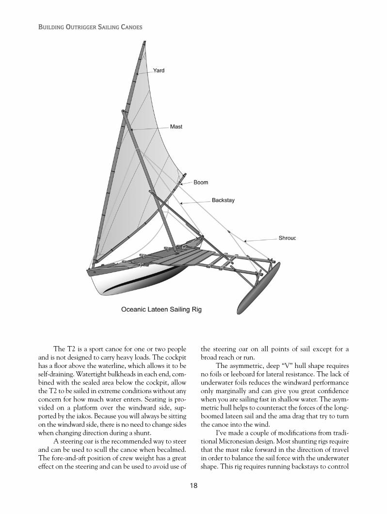
The T2 is a sport canoe for one or two peopleand is not designed to carry heavy loads. The cockpithas a floor above the waterline, which allows it to beself-draining. Watertight bulkheads in each end, com-bined with the sealed area below the cockpit, allowthe T2 to be sailed in extreme conditions without anyconcern for how much water enters. Seating is pro-vided on a platform over the windward side, sup-ported by the iakos. Because you will always be sittingon the windward side, there is no need to change sideswhen changing direction during a shunt.
A steering oar is the recommended way to steerand can be used to scull the canoe when becalmed.The fore-and-aft position of crew weight has a greateffect on the steering and can be used to avoid use of
the steering oar on all points of sail except for abroad reach or run.
The asymmetric, deep “V” hull shape requiresno foils or leeboard for lateral resistance. The lack ofunderwater foils reduces the windward performanceonly marginally and can give you great confidencewhen you are sailing fast in shallow water. The asym-metric hull helps to counteract the forces of the long-boomed lateen sail and the ama drag that try to turnthe canoe into the wind.
I’ve made a couple of modifications from tradi-tional Micronesian design. Most shunting rigs requirethat the mast rake forward in the direction of travelin order to balance the sail force with the underwatershape. This rig requires running backstays to control
BUILDING OUTRIGGER SAILING CANOES
18
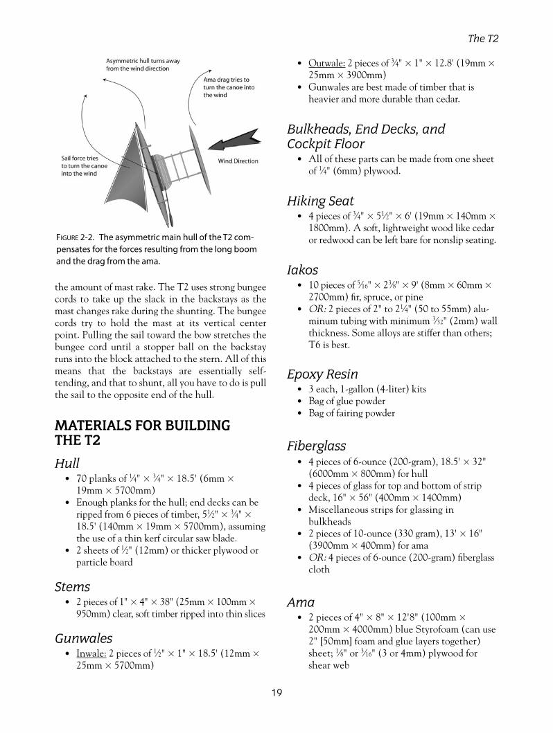
the amount of mast rake. The T2 uses strong bungeecords to take up the slack in the backstays as themast changes rake during the shunting. The bungeecords try to hold the mast at its vertical centerpoint. Pulling the sail toward the bow stretches thebungee cord until a stopper ball on the backstayruns into the block attached to the stern. All of thismeans that the backstays are essentially self-tending, and that to shunt, all you have to do is pullthe sail to the opposite end of the hull.
MATERIALS FOR BUILDING THE T2
Hull• 70 planks of 1⁄4" � 3⁄4" � 18.5' (6mm �
19mm � 5700mm)• Enough planks for the hull; end decks can be
ripped from 6 pieces of timber, 51⁄2" � 3⁄4" �
18.5' (140mm � 19mm � 5700mm), assumingthe use of a thin kerf circular saw blade.
• 2 sheets of 1⁄2" (12mm) or thicker plywood orparticle board
Stems• 2 pieces of 1" � 4" � 38" (25mm � 100mm �
950mm) clear, soft timber ripped into thin slices
Gunwales• Inwale: 2 pieces of 1⁄2" � 1" � 18.5' (12mm �
25mm � 5700mm)
• Outwale: 2 pieces of 3⁄4" � 1" � 12.8' (19mm �
25mm � 3900mm)• Gunwales are best made of timber that is
heavier and more durable than cedar.
Bulkheads, End Decks, and Cockpit Floor
• All of these parts can be made from one sheetof 1⁄4" (6mm) plywood.
Hiking Seat• 4 pieces of 3⁄4" � 51⁄2" � 6' (19mm � 140mm �
1800mm). A soft, lightweight wood like cedaror redwood can be left bare for nonslip seating.
Iakos• 10 pieces of 5⁄16" � 23⁄8" � 9' (8mm � 60mm �
2700mm) fir, spruce, or pine• OR: 2 pieces of 2" to 21⁄4" (50 to 55mm) alu-
minum tubing with minimum 3⁄32" (2mm) wallthickness. Some alloys are stiffer than others;T6 is best.
Epoxy Resin• 3 each, 1-gallon (4-liter) kits • Bag of glue powder• Bag of fairing powder
Fiberglass• 4 pieces of 6-ounce (200-gram), 18.5' � 32"
(6000mm � 800mm) for hull• 4 pieces of glass for top and bottom of strip
deck, 16" � 56" (400mm � 1400mm)• Miscellaneous strips for glassing in
bulkheads• 2 pieces of 10-ounce (330 gram), 13' � 16"
(3900mm � 400mm) for ama• OR: 4 pieces of 6-ounce (200-gram) fiberglass
cloth
Ama• 2 pieces of 4" � 8" � 12'8" (100mm �
200mm � 4000mm) blue Styrofoam (can use2" [50mm] foam and glue layers together)sheet; 1⁄8" or 3⁄16" (3 or 4mm) plywood forshear web
19
The T2
FIGURE 2-2. The asymmetric main hull of the T2 com-pensates for the forces resulting from the long boomand the drag from the ama.

20
T2 Oceanic Lateen Rig
Mast = 11'-8" (3550mm)Yard = 16'-5" (5000mm)Boom = 16'-11" (5150mm)Sail Luff = 16' (4875mm)Sail Foot = 16'-5" (5000mm)Sail Leech = 11'-11" (3630mm)Sail Area = 87 Sq Ft (8.1 Sq meter)
1" x 1" (25 x 25mm) guide spar lashed toupper edge of dashboards and to ends of 'iako allows yard to slide along leewardside of hull. Not needed for Gibbons rig.
0 1 2 3 3 3 3 3 3 3 2 1 0
11'-10" (3600mm)
Steering oar bracket
2" (51mm) 3-3/8"
(85mm) 3-15/16"(100mm)
7-7/
8" (2
00m
m)
7-5/
16"
(185
mm
)
6-3/
8" (1
61m
m)
Side shapesare arcs of acircle
11-13/16"(300mm)
7-7/
8" (2
00m
m)
T2 Ama shapefor foam or strip
Mainsheet is endless loop of line with bothends attached to the boom.
Mainsheet bridle
Backstay
Stopper ball
Bungee passes belowhiking seat andattaches to iako
Backstay
Stopper ball
Weather shroud bridle
Camcleat fortackline
Fairlead
Yard
MastBoom
Sail luff
Sail foot
Sail leech
87 Sq Ft (8.1 Sq meter)
Figure 2-3. Oceanic lateen sail plan, running backstay layout, and ama plan.
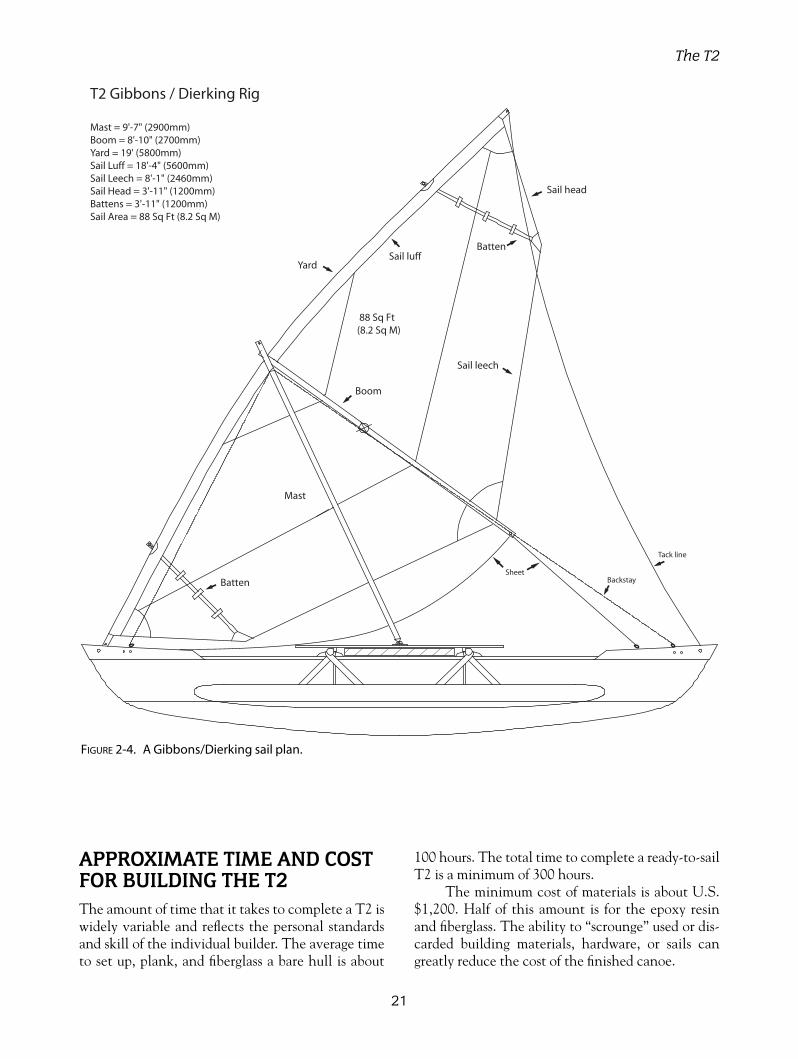
APPROXIMATE TIME AND COSTFOR BUILDING THE T2The amount of time that it takes to complete a T2 iswidely variable and reflects the personal standardsand skill of the individual builder. The average timeto set up, plank, and fiberglass a bare hull is about
100 hours. The total time to complete a ready-to-sailT2 is a minimum of 300 hours.
The minimum cost of materials is about U.S.$1,200. Half of this amount is for the epoxy resinand fiberglass. The ability to “scrounge” used or dis-carded building materials, hardware, or sails cangreatly reduce the cost of the finished canoe.
21
The T2
T2 Gibbons / Dierking Rig
Mast = 9'-7" (2900mm) Boom = 8'-10" (2700mm)Yard = 19' (5800mm)Sail Luff = 18'-4" (5600mm)Sail Leech = 8'-1" (2460mm)Sail Head = 3'-11" (1200mm)Battens = 3'-11" (1200mm)Sail Area = 88 Sq Ft (8.2 Sq M)
Tack line
BackstaySheet
Mast
Yard
Boom
Sail luff
Sail leech
Sail head
Batten
Batten
88 Sq Ft (8.2 Sq M)
FIGURE 2-4. A Gibbons/Dierking sail plan.

22
3-1/2" x 3/4" (90 x 19mm)Hardwood slats
Iako is 2" (50mm)aluminum tube or1-3/4" x 1-1/2"(45 x 40mm)solid laminatedtimber
3/4" x 5-1/2" (19 x 140mm)Timber slatted hiking seat
Hole for steering oarlock
3/4" x 3-1/2" (19 x 90mm)Hardwood steering bracket
9-3/
4" (2
50m
m)
Three lengths of 1/4" (6mm)Bungy passes belowseat and attaches to 'iako
1/4" (6mm)Foredecks
Backstay block attachesto inside of dashboard for Gibbons rig only
3/4" (19mm)Tube or dowel
1/4" (6mm) Lowstretch backstays
Endless tacklineCamcleat with fairleadfor tackline
Stopper ball
3/16" (4mm) Polyester Rope Lashings
Mast step
Hardwood saddle
Lashing holes Leeward side scupper
Watertight bulkheadwith access panel
1/4" (6mm) Plywooddashboards
Rowlock for steering oar
47-1/4" (1200mm)
11-13/16"(300mm)Typical
8'-0
" (2
440m
m)
11-13/16"(300mm)
3-15/16" (100mm)
5-7/8" (150mm)
5-7/8" (150mm)
5-7/8" (150mm)
5-7/8" (150mm)
27-7
/16"
(700
mm
)
14-11/16"(373mm)
1/4" (6mm) Plywood weatherboardattaches to inboard side of gunwaleto support mast base
1 2 3 4 5 6 7 8 9 8 7 6 5 4 3 2 1
10-1/4"(260mm)
1/4" (6mm) Plywood CockpitFloor with 1/2" x 1/2" (12 x 12mm)Stiffeners Under on 8" (200mm) Centers
Backstay for Lateenrig attaches to holethrough bow
Holes to attach Backstay block
FIGURE 2-5. Deck plan and hull profile.

23
1" x 3/4" (25 x 19mm)Outer Gunwale
1" x 1/2" (25 x 12mm)Inner Gunwale
Plywood Doublerat lashing Points
Hull is 3/16" or 1/4" (4 or 6mm)Strip Planking with 6 oz (200 gram)Fiberglass cloth Inside and Outside
1/4" (6mm) Plywood CockpitFloor with 1/2" x 1/2" (12 x 12mm)Stiffeners Under on 8" (200mm) Centers
3/16" (4mm) Polyester Rope Lashings
Bungy PoweredShock Absorber Strut
3/4" x 5-1/2" (19 x 140mm)Timber Slatted Hiking Seat
Epoxy Fillet Inside
1/4" (6mm) ply weatherboardscrewed and glued to innergunwale extends between 'iakoand supports inboard edge ofhiking Seat
'iako Saddles
'Iako is 2" (50mm)aluminum tube or1-3/4" x 1-1/2"(45 x 40mm)solid laminatedtimber
Tail end of weather shroudties to cleat on 'iako
Struts are 3/4" x 1-3/4" (19 x 45mm)hardwood epoxied to inside of ama
Ama can be solid foam sheathed in epoxy/fiberglass ORhollow plywood OR hollow strip planked
Weather shroud
Bridle connects to weathershroud with block
Bridle
3/16" (4mm) Polyester Rope Lashings
Mast
FIGURE 2-6. Structural cross section.

24
Sheer
Strongback
WL4
WL3
WL2
3/8"
(9mm)
19-1
/8"
(486
mm
)
14-1
3/16
" (3
76m
m)
7/8" (22mm)
3-1/8"(80mm)
7-1/8" (181mm)
3-15/16"(100mm)
5-7/8"(150mm)
5-7/8"(150mm)
5-7/8"(150mm)
5-7/8"(150mm)
Sta 0 Sta 1 Sta 2
3/8"
(9mm)
11-13/16" (300mm) 11-13/16" (300mm)
3/4" x 3/4"(19 x 19mm)Laminated Stem
Clamping Holes
Stem Mold (make two identical pieces)
1 2 3 4 5 6 7 8 9 8 7 6 5 4 3 2 1
Split Station 1 toStraddle Stem Mold Strongback
11-13/16"(300mm)
StemMold
LaminatedStem
StemMold
LaminatedStem
FIGURE 2-7. Mold section setup and stem mold layout.

25
Sheer line
Waterline 4
Waterline 3
Waterline 2
Waterline 1
Baseline
Cente
rlin
e
Sheer Half Breadth
WL4 Half Breadth
Hull Offsets
Leeward Side
Hull Offsets
Windward Side
1
50
mm
0-5
-7
150m
m
0-5
-7
1
50
mm
0-5
-7
150m
m
0-5
-7
100m
m
0-3
-7+
The table of offsets enables you to reproduce the curved shapeof the hull molds. The top number in each box is in millimeters,and the bottom number is feet, inches, and eighths of an inch.A plus sign adds a sixteenth of an inch. For example: 1-6-1+equals one foot, 6 inches, and three-sixteenths of an inch.
Because the hull is asymmetric, the offsets or half breadths aredifferent on each side of the hull. The two sides are designated as a windward and a leeward side.Both ends of the hull are identical so that most of the molds areused twice. Make two molds of stations 1-8, and one of station9 amidships.
Draw a centerline, baseline, waterlines, and strongback line,ensuring that the waterlines are parallel and spaced correctly. Measure and mark the offsets or half breadths, tack a small nailat each point, and bend a timber batten along the nails. Drawthe curved line along the batten with a pencil.
T2 Table of Offsets
Hull Offsets Leeward Side
Station Number 1 2 3 4 5 6 7 8 9
Sheer Half Breadth 260-1-0
520-2-0+
760-3-0
960-3-6
1130-4-3+
1290-5-0+
1410-5-4+
1460-5-6
1460-5-6
WL4 Half Breadth 240-0-7+
480-1-7
710-2-6+
900-3-4+
1070-4-1+
1210-4-6
1290-5-0+
1360-5-3
1360-5-3
WL3 Half Breadth 120-0-4
350-1-3
550-2-1+
720-2-6+
860-3-3
980-3-7
1070-4-1+
1120-4-3+
1130-4-3+
WL2 Half Breadth 160-0-5
310-1-2
440-1-6
570-2-2
680-2-5+
750-2-7+
790-3-1
810-3-1+
WL1 Half Breadth 0 0-0-0
100-0-3
200-0-6+
300-1-1+
350-1-3
390-1-4+
410-1-5
Keel to Baseline 3101-0-1+
2040-8-0+
1500-5-7
1140-4-4
810-3-1+
510-2-0
250-1-0
80-0-2+
00-0-0
Hull Offsets Windward (ama) Side
Station Number 1 2 3 4 5 6 7 8 9
Sheer Half Breadth 630-2-4
1180-4-5
1590-6-2
1900-7-4
2100-8-2
2210-8-5+
2250-8-7
2260-8-7
2270-8-7+
WL4 Half Breadth 550-2-1+
1110-4-3
1510-5-7+
1820-7-1+
2020-7-7+
2110-8-2+
2130-8-3
2150-8-3+
2160-8-4
WL3 Half Breadth 320-1-2
900-3-4+
1320-5-1+
1610-6-3
1790-7-0+
1890-7-3+
1910-7-4
1920-7-4+
1940-7-5
WL2 Half Breadth 480-1-7
910-3-4+
1220-4-6+
1420-5-4+
1540-6-0+
1590-6-2
1610-6-2+
1620-6-3
WL1 Half Breadth 0 0-0-0
370-1-4+
670-2-5
880-3-3+
990-3-7
1030-4-0+
1050-4-1
Keel to Baseline 3101-0-1+
2040-8-0+
1500-5-7
1140-4-4
810-3-1+
510-2-0
250-1-0
80-0-2+
00-0-0
Strongback
3/8"
(9mm)
FIGURE 2-8. Table of offsets and mold section lofting.
26
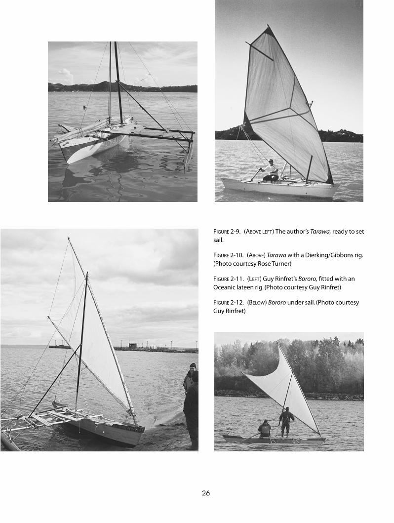
FIGURE 2-9. (ABOVE LEFT) The author’s Tarawa, ready to setsail.
FIGURE 2-10. (ABOVE) Tarawa with a Dierking/Gibbons rig.(Photo courtesy Rose Turner)
FIGURE 2-11. (LEFT) Guy Rinfret’s Bororo, fitted with anOceanic lateen rig. (Photo courtesy Guy Rinfret)
FIGURE 2-12. (BELOW) Bororo under sail. (Photo courtesyGuy Rinfret)
27
The T2
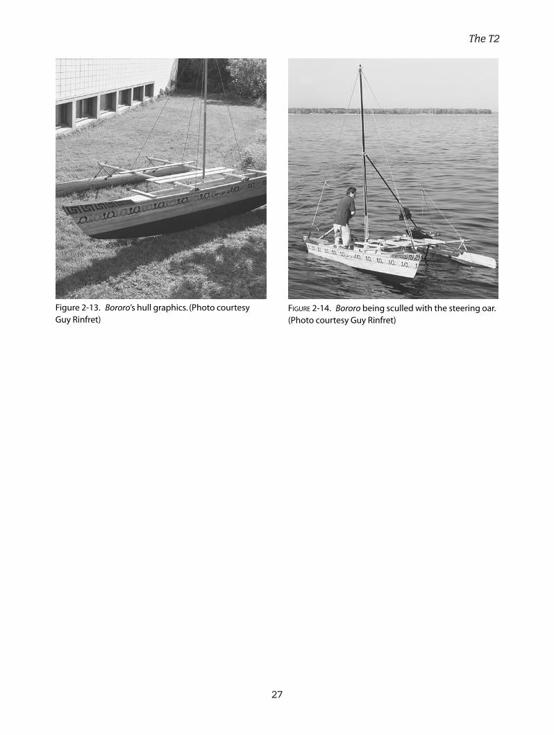
Figure 2-13. Bororo’s hull graphics. (Photo courtesyGuy Rinfret)
FIGURE 2-14. Bororo being sculled with the steering oar.(Photo courtesy Guy Rinfret)

28
In the late 1800s, when sawn lumber began toappear in Hawaii and other Pacific islands, the
local canoe builders immediately saw its use as an eas-ier way to build canoes. While perhaps slightly less effi-cient than round-bottomed shapes, a flat-bottomed,
dory-shaped hull has now become the standardworking canoe seen in many places throughout thePacific. The first models were simply built of threewide planks and came to be known as “three-boardcanoes,” or “wa’apa” in Hawaiian.
FIGURE 3-1. The Wa’apa outrigger sailing canoe equipped with a tacking rig.
Length overall 23’8”(7200mm)Hull width 211⁄4”(540mm)Overall width 11’ (3370mm)Draft 6”(150mm) @ 675 lb (306 kg) displacementHull weight 174 lb (79 kg), 58 lb (26 kg)
per sectionWeight fully rigged 275 lb (125 kg)Sailing rig type Tacking or ShuntingSail area 84 sq ft (7.8 sq m)
Tacking, 126 sq ft (11.7 sq m) Shunting
Construction method Plywood
CHAPTER 3
The Wa’apa
Copyright © 2008 by International Marine. Click here for terms of use.
I built a 16-footer in the 1970s that unbolted inthe center for easier stowage onboard my cruisingtrimaran. It proved to be a useful dinghy and a funsailer for exploring. This design is similar in shape tothat one, but it allows for a center section to beadded, which stretches the boat to 24'. The 24-footer seats four crew members and can be sailed as atacking outrigger or a shunting proa. The tackingconfiguration uses hiking seats on both sides of thehull, whereas the shunting version carries them onlyon the ama (windward) side of the hull.
The Wa’apa can be built as a one-piece hull ifyou choose, but one of its prime advantages is thatno hull or ama section is longer than 8' (2.4m). Itcan be built, stored, and transported in a smallspace. The three-section main hull and a two-pieceplywood ama require only six sheets of 1⁄4" (6mm)plywood. The hull sides and ama can be built with3⁄16" (4mm) plywood to save weight.
Waterline length is a wonderful thing, and it ischeap to build when hull beam and depth remainthe same. This design is extremely versatile in thatmany different options can be included with thebasic design. It can be sailed as a tacking outrigger,where the ama runs either on the windward or lee-ward side, or as a shunting proa, where the ama isalways kept on the windward side.
RIG CHOICEChoosing between the two rigs is difficult and reallyis a matter of personal choice. The shunting proa hasthe potential for greater performance but requires amore complicated rig. The mast is stayed, requiringtwo backstays and a weather shroud. Steering isaccomplished from either end with a long oar, a pairof dagger boards in the ends, or a pair of kick-uprudders. An endless tack line controls the butt of theyard and, when shunting, you simply pull the yardfrom one bow to the other without leaving your seat.The butt of the yard can slide along below the gun-wale of the hull’s leeward side.
One of the characteristics of the lateen or crab-claw rig is that the butt of the yard wants to swing towindward during a shunt. Keeping the butt below thegunwale prevents this annoying trait and avoids thenecessity of installing a guiding track, or guidingthe butt along by hand. The backstays that controlthe fore-and-aft rake of the mast can be controlledby a bungee cord that tries to hold the mast vertical.Pulling the butt of the yard to either bow will stretch
the bungee cord. A pair of spiller lines or lazy jacksare rigged to depower the sail in squalls and to holdthe boom, yard, and sail off of the deck when the sailis lowered with the halyard.
The tacking rig is very simple, with anunstayed windsurfing mast, no halyard, and a spiller/brailing line for brailing the sail up against the mast.This is especially convenient, as the sail is quicklystowed out of the way of paddlers. The whole rig iseasily pulled out and stowed on the iakos. The rigshown in Figure 3-4 uses a straight boom with aloose-footed sail. While not as visually attractive asa curved boom, this system allows you to reef the sailby simply rotating the mast and winding the sail upon it. The boom outhaul controlling the clew of thesail is led forward along the boom to an easilyreached cleat.
Long, narrow-beamed canoes are very sensitiveto weight distribution. The location of crew mem-bers or cargo weight has an effect on the fore-and-aftsailing balance of the canoe. Concentrating weightaft increases the lateral resistance of the hull in thatarea and will cause lee helm, or the tendency to turnaway from the wind. Weight concentrated forwardwill have the opposite effect. Using a fixed rudderaft, or on the iako, instead of an oar, will also changethe balance. For this reason, in Figure 3-4 I haveshown two mast-step locations for the tacking rig.This will allow you to adjust for different loadingconditions or steering setups.
THE HULLThe hull is a flat-bottomed dory shape, although adory would have more flare in the sides. I’m opposedto extreme flare in the sides, as I feel it slows the hullconsiderably when sailing into waves.
Because each hull section is slightly shorterthan a sheet of plywood, no scarf joints or buttblocks are necessary.
Each hull section is connected to the next withfour 5⁄16" (8mm) stainless-steel bolts. Washers cutfrom inner tubes or wetsuit material are placedbetween the hull sections to keep water out of thebolt holes.
The hull sides and decks can be made fromeither 1⁄4"(6mm) or 3⁄16" (4mm) plywood. Plywoodwith five plies is much better than three plies. Thebottom panels should be 1⁄4" (6mm) to avoid dam-age when the hull is resting on rocks. It is not nec-essary to fiberglass the entire hull if it is built from
29
The Wa’apa

BUILDING OUTRIGGER SAILING CANOES
30
FIGURE 3-2. The flat-bottomed hull shape of the Wa’apa.
FIGURE 3-3. A plywood, diamond-shaped ama with a quick-connecting strut.
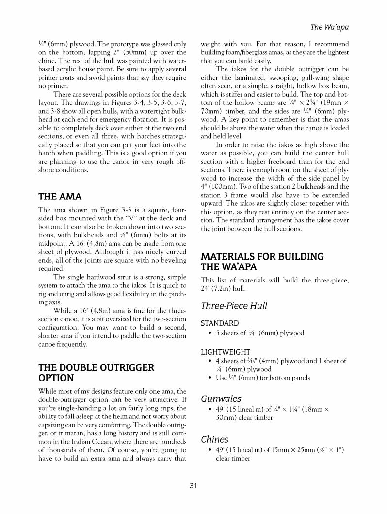
1⁄4" (6mm) plywood. The prototype was glassed onlyon the bottom, lapping 2" (50mm) up over thechine. The rest of the hull was painted with water-based acrylic house paint. Be sure to apply severalprimer coats and avoid paints that say they requireno primer.
There are several possible options for the decklayout. The drawings in Figures 3-4, 3-5, 3-6, 3-7,and 3-8 show all open hulls, with a watertight bulk-head at each end for emergency flotation. It is pos-sible to completely deck over either of the two endsections, or even all three, with hatches strategi-cally placed so that you can put your feet into thehatch when paddling. This is a good option if youare planning to use the canoe in very rough off-shore conditions.
THE AMAThe ama shown in Figure 3-3 is a square, four-sided box mounted with the “V” at the deck andbottom. It can also be broken down into two sec-tions, with bulkheads and 1⁄4" (6mm) bolts at itsmidpoint. A 16' (4.8m) ama can be made from onesheet of plywood. Although it has nicely curvedends, all of the joints are square with no bevelingrequired.
The single hardwood strut is a strong, simplesystem to attach the ama to the iakos. It is quick torig and unrig and allows good flexibility in the pitch-ing axis.
While a 16' (4.8m) ama is fine for the three-section canoe, it is a bit oversized for the two-sectionconfiguration. You may want to build a second,shorter ama if you intend to paddle the two-sectioncanoe frequently.
THE DOUBLE OUTRIGGEROPTIONWhile most of my designs feature only one ama, thedouble-outrigger option can be very attractive. Ifyou’re single-handing a lot on fairly long trips, theability to fall asleep at the helm and not worry aboutcapsizing can be very comforting. The double outrig-ger, or trimaran, has a long history and is still com-mon in the Indian Ocean, where there are hundredsof thousands of them. Of course, you’re going tohave to build an extra ama and always carry that
weight with you. For that reason, I recommendbuilding foam/fiberglass amas, as they are the lightestthat you can build easily.
The iakos for the double outrigger can beeither the laminated, swooping, gull-wing shapeoften seen, or a simple, straight, hollow box beam,which is stiffer and easier to build. The top and bot-tom of the hollow beams are 3⁄4" � 23⁄4" (19mm �
70mm) timber, and the sides are 1⁄4" (6mm) ply-wood. A key point to remember is that the amasshould be above the water when the canoe is loadedand held level.
In order to raise the iakos as high above thewater as possible, you can build the center hullsection with a higher freeboard than for the endsections. There is enough room on the sheet of ply-wood to increase the width of the side panel by 4" (100mm). Two of the station 2 bulkheads and thestation 3 frame would also have to be extendedupward. The iakos are slightly closer together withthis option, as they rest entirely on the center sec-tion. The standard arrangement has the iakos coverthe joint between the hull sections.
MATERIALS FOR BUILDING THE WA’APAThis list of materials will build the three-piece, 24' (7.2m) hull.
Three-Piece Hull
STANDARD • 5 sheets of 1⁄4" (6mm) plywood
LIGHTWEIGHT • 4 sheets of 3⁄16" (4mm) plywood and 1 sheet of
1⁄4" (6mm) plywood• Use 1⁄4" (6mm) for bottom panels
Gunwales• 49' (15 lineal m) of 3⁄4" � 11⁄4" (18mm �
30mm) clear timber
Chines• 49' (15 lineal m) of 15mm � 25mm (5⁄8" � 1")
clear timber
31
The Wa’apa

Bulkhead Perimeters• 12.6' (3.2 lineal m) of 3⁄4" � 1" (18mm �
25mm) clear timber• 8' (2.4 lineal m) of 3⁄4" � 13⁄8" (18mm �
35mm) clear timber• 18.4' (5.6 lineal m) of 3⁄4" � 2" (18mm �
50mm) clear timber
Stems• 3⁄4" � 3" � 4' (18mm � 75mm � 1200mm) of
plywood or solid softwood
Seat Supports• 11.8' (3.6 lineal m) of 3⁄4" � 11⁄4" (18mm �
30mm) clear timber
Plywood Ama• 1 sheet of 3⁄16" or 1⁄4" (4mm or 6mm) plywood• 64' (19.2 lineal m) of 5⁄8" � 5⁄8" (16mm �
16mm) clear timber• 6' (1.8 lineal m) of 3⁄4" � 31⁄2" (18mm �
90mm) hardwood
Iako (Cross Beams)
SOLID LAMINATED• 14 pieces of 23⁄4" � 5⁄16" � 10.8' (70mm �
8mm � 3.3m)• 1' (300mm) of 11⁄4" (30mm) hardwood dowel
HOLLOW BOX BEAM (DOUBLE OUTRIGGER)• 4 pieces of 23⁄4" � 3⁄4" � 13.2' (70mm �
18mm � 4m) fir, spruce, mahogany, or pine• 1⁄2 sheet of 1⁄4" (6mm) plywood • 2' (600mm) of 11⁄4" (30mm) hardwood
dowel
Epoxy Resin• 1 each of 1-gallon (4-liter) kit if used for glue
and sheathing of bottom only• 3 each of 1-gallon (4-liter) kit if used for glue
and to sheath entire hull and ama
APPROXIMATE TIME AND COSTFOR BUILDING THE WA’APABeing built of plywood, the Wa’apa requires less con-struction time than a strip-planked composite hull.The basic components (hull, ama, and iakos) willrequire about 160 hours, depending on the level offinish that you desire. Sheathing the entire hull infiberglass (rather than just the bottom) will addanother ten hours to the total time. The structurecan be built in less time, but appearance andlongevity may suffer.
The cost of building the basic structure will bea minimum of U.S. $1,000, with an additional U.S.$500 if you wish to completely sheath the hull andama with fiberglass. The cost of a sailing rig canrange from U.S. $20 to U.S. $2,000, depending onwhat you want and where you get it.
BUILDING OUTRIGGER SAILING CANOES
32

33
Mast = 17' (5200mm)Boom = 13'-10" (4220mm)Sail luff = 14'-9" (4500mm)Sail foot = 13'-9" (4190mm)Sail leech = 14'-9" (4500mm)Sail area = 84 Sq Ft (7.8 Sq M)
3'-9 1/4"(1150mm)
7'-1/2"(2150mm)
Spiller / Brailing line
2'- 1"(640mm)
23'- 8"
15'-6"(4720mm)
13-3/4"
(350mm)
7'- 10 1/2"(2400mm)
3'-11 1/4"(1200mm)
24' (7.2 meter) Hullwith Tacking Rig
Rope Forestay
Mast
Boom
Sail luff
Sail foot
Sail leech
84 Sq Ft(7.8 Sq M)
Leeboard
Ama
Steering oar
Ama strut
Mainsheet
Hiking seats
Leeboard
Steering oar bracket
Hiking seats
Mast steps
FIGURE 3-4. Tacking sail plan and general arrangement for the 24' (7.2m) hull.
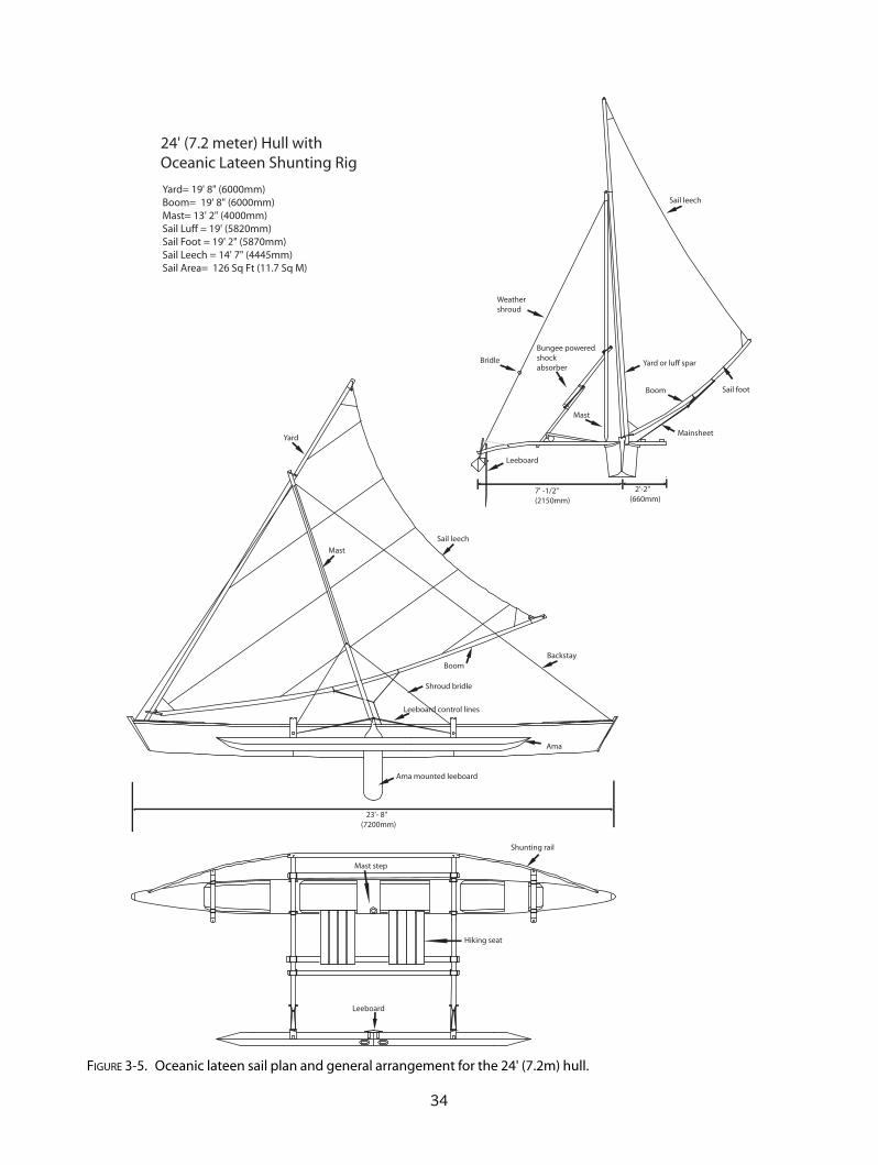
34
Yard= 19' 8" (6000mm)Boom= 19' 8" (6000mm)Mast= 13' 2" (4000mm)Sail Luff = 19' (5820mm)Sail Foot = 19' 2" (5870mm)Sail Leech = 14' 7" (4445mm)Sail Area= 126 Sq Ft (11.7 Sq M)
Leeboard
Bungee poweredshockabsorber
Bridle
Weathershroud
Mast
Yard or luff spar
Boom
Mainsheet
7' -1/2"(2150mm)
2'-2"(660mm)
23'- 8"(7200mm)
24' (7.2 meter) Hull withOceanic Lateen Shunting Rig
Sail leech
Sail foot
Yard
Mast
Boom
Sail leech
Backstay
Ama mounted leeboard
Leeboard control lines
Ama
Shunting rail
Hiking seat
Leeboard
Mast step
Shroud bridle
FIGURE 3-5. Oceanic lateen sail plan and general arrangement for the 24' (7.2m) hull.
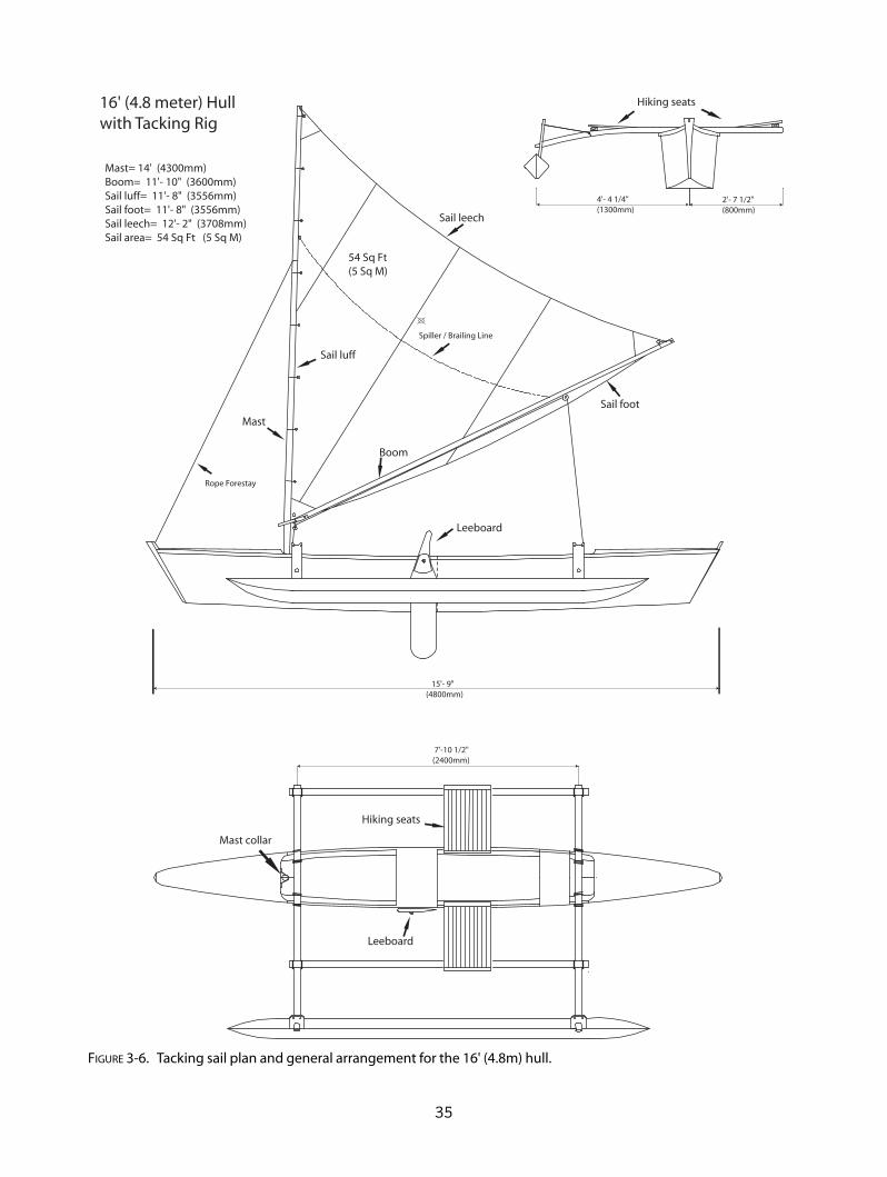
35
Mast= 14' (4300mm) Boom= 11'- 10" (3600mm)Sail luff= 11'- 8" (3556mm)Sail foot= 11'- 8" (3556mm)Sail leech= 12'- 2" (3708mm)Sail area= 54 Sq Ft (5 Sq M)
4'- 4 1/4"(1300mm)
2'- 7 1/2"(800mm)
Spiller / Brailing Line
15'- 9"(4800mm)
7'-10 1/2"(2400mm)
16' (4.8 meter) Hullwith Tacking Rig
Rope Forestay
54 Sq Ft (5 Sq M)
Hiking seats
Boom
Mast
Sail foot
Sail leech
Sail luff
Leeboard
Hiking seats
Leeboard
Mast collar
FIGURE 3-6. Tacking sail plan and general arrangement for the 16' (4.8m) hull.
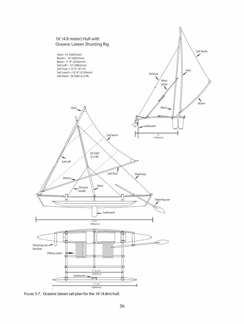
36
Yard= 14' (4267mm)Boom= 14' (4267mm)Mast= 11' 8" (3556mm)Sail Luff = 13' (3962mm)Sail Foot = 13' 6" (4115)Sail Leech = 10' 4" (3150mm)Sail Area= 56 SqFt (5.2 M)
6'(1829mm)
15'-9"(4800mm)
7'-10 1/2"
(2400mm)
11'-10"
(3600mm)
16' (4.8 meter) Hull withOceanic Lateen Shunting Rig
Yard
Boom
Sail leech
Mastprop
Shroud
Mast
Leeboard
Boom
Yard
Mast
Sail leech
Sail luff
56 SqFt (5.2 M)
Sail foot Backstay
Steering oar
Leeboard
Hiking seats
Steering oar bracket
Leeboard
Shroudbridle
FIGURE 3-7. Oceanic lateen sail plan for the 16' (4.8m) hull.

37
700mm27 1/2"
280mm11"
Mast = 19' - 8" (6000mm)Boom = 10' - 8" (3250mm)Mainsail Area = 104 sq ft (9.7 sq meters)Jib = 47 sq ft (4.4 sq meters)
2000mm6' - 8"
2400mm7' - 10 1/2"
4800mm15' - 9"
1060mm3' - 5 3/4"
24' (7.2 meter) Double Outrigger Hull withTacking Rig
Raised gunwale inmiddle hull section
Leeboard
Ama
Kick-uprudder
Ama struts
Leeboard
Sprit boom
Mast
Jib
Spinnaker
Mainsail
Shroud
Hikingseats
HatchHatch
Rudder control lines
FIGURE 3-8. Tacking sail plan for the 24' (7.2m) double outrigger–equipped hull.
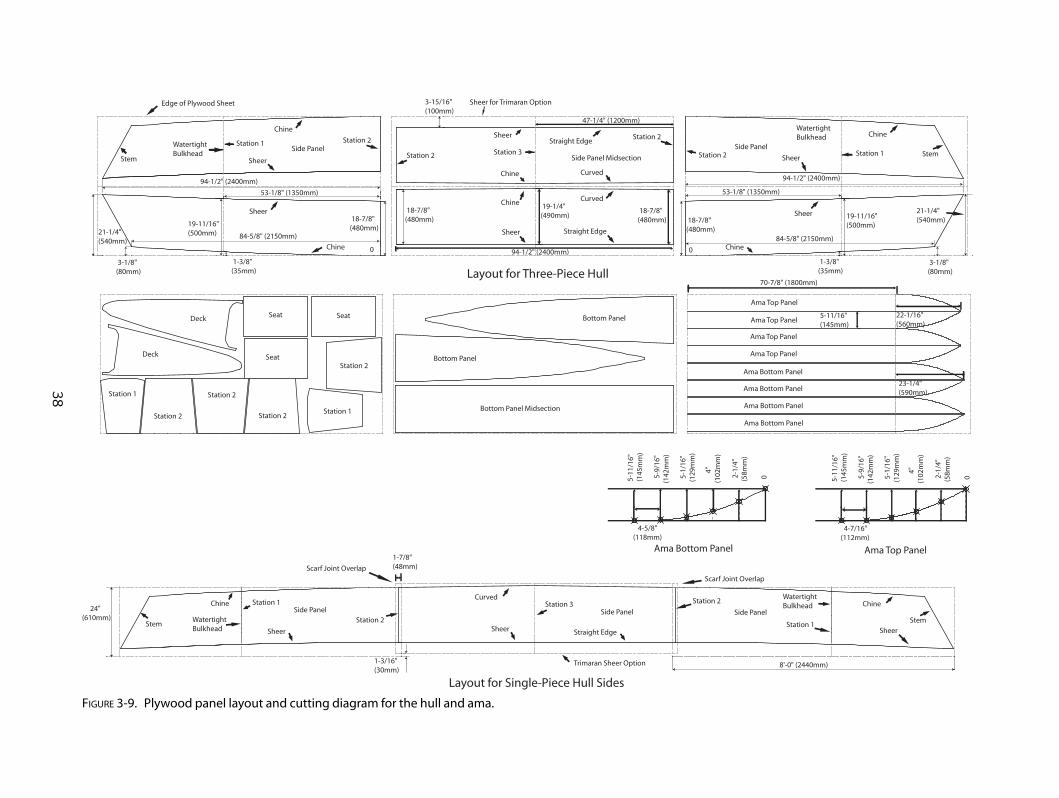
38
Side PanelSide Panel Midsection
Side Panel
3-15/16"(100mm)
Sheer for Trimaran Option
Sheer
Sheer
Sheer
Sheer Sheer
Sheer
SheerSheerSheer
Side Panel Side PanelSide Panel
Chine
Chine
Chine
Chine
Chine
Chine Chine
Station 1
Station 1
Station 1
Station 1
WatertightBulkhead
WatertightBulkhead
WatertightBulkhead
WatertightBulkhead
Station 1
Station 1
Station 2
Station 2
Station 2
Station 2
Station 2
Station 2
Station 3
Station 3
Straight Edge
Straight Edge
Straight Edge
Layout for Single-Piece Hull Sides
Layout for Three-Piece Hull
Stem
Stem Stem
Stem
Chine
Ama Top Panel
Ama Top Panel
Ama Top Panel
Ama Top Panel
Ama Bottom Panel
Ama Bottom Panel
Ama Bottom Panel
Ama Bottom Panel
Bottom Panel
Bottom Panel
Bottom Panel Midsection
Station 2
Station 2
Station 2
Station 2
Seat
Seat SeatDeck
Deck
Scarf Joint Overlap
Scarf Joint Overlap
Trimaran Sheer Option
Curved
Curved
21-1/4"(540mm)
3-1/8"(80mm)
19-11/16"(500mm)
1-3/8"(35mm)
18-7/8"(480mm) 18-7/8"
(480mm)
0
94-1/2" (2400mm)
53-1/8" (1350mm)
18-7/8"(480mm)
19-1/4"(490mm)
18-7/8"(480mm)
94-1/2" (2400mm)
53-1/8" (1350mm)
19-11/16"(500mm)
21-1/4"(540mm)
3-1/8"(80mm)
1-3/8"(35mm)
0
Curved
84-5/8" (2150mm) 84-5/8" (2150mm)
5-11/16"(145mm)
70-7/8" (1800mm)
94-1/2" (2400mm)
47-1/4" (1200mm)
Edge of Plywood Sheet
24"(610mm)
1-7/8"(48mm)
1-3/16"(30mm)
8'-0" (2440mm)
22-1/16"(560mm)
23-1/4"(590mm)
Ama Top PanelAma Bottom Panel
4-7/16"(112mm)
4-5/8"(118mm)
5-1
1/16
" (1
45m
m)
5-
9/16
"(1
42m
m)
5-1
/16"
(129
mm
)
4"(1
02m
m)
2-1
/4"
(58m
m)
0
5-1
1/16
" (1
45m
m)
5-
9/16
"(1
42m
m)
5-1
/16"
(129
mm
)
4"(1
02m
m)
2-1
/4"
(58m
m)
0
FIGURE 3-9. Plywood panel layout and cutting diagram for the hull and ama.

39
3" (75mm)
3" (75mm)
Bevel Edges10 Degrees3/4"(19mm)
Timber Stem
Slight ConcaveCurve
3/4"(19mm)
20-5/8"(525mm)
18-3/16"(462mm) 18-5/16"
(465mm)
Station 1
1"(25mm)
1-3/8"(35mm)
5-1/2" (140mm)
7-1/2"(190mm)
3/4"(19mm)
2"(50mm)
4"(100mm) DiameterCutouts
1-3/16"(30mm) 9-7/16"(240mm)
18-7/8"(480mm)
18-13/16"(478mm)
2"(50mm)
1"(25mm) 7-7/8"
(200mm)
1-3/16"(30mm)
9-1/2"(242mm)
19-1/4"(488mm)
19-5/16"(490mm)
7-15/16"(202mm)
2"(50mm)
Plastic AccessPanel
Station 2 Station 3
Station 3Station 2Station 1
1/4" or 3/16" (6 or 4mm)Plywood Deck
3/4"x1-1/4"(19 x 30mm)Timber Gunwale
1/4" or 3/16" (6 or 4mm)Plywood Side Panels
3/4"x1-1/2" (19 x 35mm)Timber Perimeter
1/4" or 3/16" (6 or 4mm)Plywood Bulkhead
5/8"x1"(15 x 25mm)Timber Chine
1/4"(6mm) PlywoodBottom Panel
1/4" or 3/16" (6 or 4mm)Plywood Deck and Seats
3/4"x1-1/4"(19 x 30mm)Timber Gunwale
1/4" or 3/16" (6 or 4mm)Plywood Side Panels
3/4"x 2" (19 x 50mm)Timber Perimeter
1/4" or 3/16" (6 or 4mm)Plywood Bulkhead
5/8"x1"(15 x 25mm)Timber Chine
1/4"(6mm) PlywoodBottom Panel
5/16"(8mm) Holesfor Stainless SteelBolts
1/4" or 3/16" (6 or 4mm)Plywood Seat
1/4" or 3/16" (6 or 4mm)Plywood Gussets onboth Sides
3/4"x 2" (19 x 50mm)Timber Perimeter
Limber Hole
Chine Miter Joint
Miter Joint
Stem
Side Panel
Chines
Gunwale and Chine Attachment
Bevel
ChineSide Panel
Bevel
Gunwale
1/8"(3mm)
1/8"(3mm)
Typical Main Hull Separation JointMast Step for Tacking Rig
Seat Support Saddles
Iako Lashing Points
Iako5/8"(15mm) Lashing Holes
Bottom of Gunwale
1/4"(6mm) Plywood Doubler
Inner Tube Rubber or WetsuitMaterial Washers
Top of Chine
Bottom Panel
Deck
Dual Mast Steps
5/16"(8mm)Stainless SteelBolts
Hollow Mast 12"x 8"(300x200mm)1/2"(12mm) PlywoodDoubler Under Seat
Plastic or HardwoodDowel to fit insideof Mast
9mm SS Bolt
4"x 3/4" (100 x 19mm)Timber Glued andScrewed to top of Chines
1-1/4"x3/4"(30x19mm)Seat Supports
1/4" (6mm)Plywood Saddles
Gunwale
1/4" (6mm)Plywood Doubler
Inside Hull Surface 3"(75mm)
Stem
FIGURE 3-10. Bulkhead layouts and structural details.

40
Leeboard Bracketfor Plywood Ama
Leeboard Bracketfor Foam Ama
Ama-Mounted Shunting Leeboard Tacking Rig Leeboard Mount
Leeboard Bracket
Plywood Ama
4" (100mm) Access Panels
Separation Joint
1/4" (6mm) Aluminum Plate
Leeboard
1/8" x 1" (3 x 25mm) Stainless Steel Flat Bar
1/2" (12mm) PlywoodBacking Plate
Plywood Ama
1/4" (6mm)Stainless Steel Bolts
1/2" (12mm)SS Bolt
1/4" (6mm) Aluminum Plate
Leeboard
1/8" x 1" (3 x 25mm) Stainless Steel Flat Bar
1/4" (6mm) Stainless SteelMachine Screws EpoxyBonded into 1' (25mm)Plywood or Timber Bulkheads
1/2" (12mm)SS Bolt
Ama-Mounted Leeboard Bracket
Control Lines
1/8" (3mm) AluminumPlate Screwed to OutboardSide of Leeboard
1/2" (12mm) SS Bolt
Shaping Guides
1" (25mm) ThickTimber Leeboard
11"(280mm)
6-1/4"(160mm)
14-3/16"(360mm)
35-7/16"(900mm)
1/8" (3mm) AluminumPlate Screwed to OutboardSide of Leeboard
1/2" (12mm) SS Bolt
Shaping Guides
1-1/4" (30mm) ThickTimber Leeboard
11"(280mm)
6-1/4"(160mm)
35-7/16"(900mm)
53-1/2"(1360mm)
Leeboard
Internal UnderseatLeeboard Bracket
Seat
3/4" (19mm)Timber
1/4" (6mm)Plywood Gussets
Plastic or PlywoodShim
1/2" (12mm)SS Bolt
6-3/8"(160mm)
6"(150mm)
6"(150mm)
FIGURE 3-11. Leeboard construction details and mounting options.

41
Hollow Box Iako for Double Outrigger
Laminated Iako End Detail
Hollow Box Iako Cross Section
Iako Laminating Jig Layout
Ama Separation Joint
Ama Struts
Outboard Motor Bracket
6" (150mm) x 1-1/4" (30mm) Hardwood Dowel Epoxy Gluedinto End of Cured Lamination
Seven Layers of 2-3/4" x 5/16"(70mm x 8mm) Timber Gluedwith Epoxy Glue
1-3/4" x 1- 3/4" x 3"(45mm x 45mm x 75mm)Blocks Screwed toFlat Surface
2-3/4"
(70mm) 2-9/
16"
(65m
m)
4-3
/8"
(112
mm
)
4-15
/16"
(125
mm
)
4-15/16"(125mm)
11-13/16"(300mm)
11-13/16"(300mm)
11-13/16"(300mm)
9-15/16"(252mm)
10'-8" (3252mm)
94-1/2" (2400mm)
3/4" x 2-3/4" (19mm x 70mm)Solid Timber
1/4" (6mm)Plywood
3-1/2"(90mm)
2-3/4"(70mm)
Seven Layers of 2-3/4" x 5/16"(70mm x 8mm) Timber Gluedwith Epoxy Glue
2-1/4"(56mm)
1-1/4" (30mm)DiameterHardwoodDowel
Four wraps of 2"(50mm) wide 6oz(200gr) FiberglassCloth
3/4" x 2-3/4" (19mm x 70mm)Top and Bottom Chord
4" (100mm)Solid Blocking
1-1/4" (30mm) Diameter HardwoodDowel Glued into Solid Blocking
2-9/16"(65mm)
3-1
/4"
(83m
m)
3-1
/2"
(90m
m)
9-13/16"(250mm)
Cen
terl
ine
31-7/8" (810mm) 37" (940mm)
10'-8" (4000mm)
3/4" (19mm) PlywoodBulkhead for each AmaHalf
Four 1/4" (6mm) StainlessSteel Bolts with Lock Nuts
1-1/2" (35mm
) 1-1/2
" (35m
m)
5/8" (16mm) Lashing Holes
3/4" x 3-1/2" (19mm x 90mm)Hardwood Strut
1-1/4" (30mm) Hole
Ama
1/2" (12mm) PlywoodBulkhead
15-3
/4"
(400
mm
)
2-9/16"(65mm)
4"(102mm)
3/4" x 3-1/2" (19mm x 90mm)Hardwood Strut
1/2" (12mm) PlywoodBulkhead
Epoxy Fillets
5/8"x5/8"(16mm x 16mm)Chine Stringers
1/2" (12mm) Slot Cutinto Strut that StraddlesBulkhead
5-11/16"
(145mm
) 5-11/1
6"
(145m
m)
11-3
/4"
(298
mm
)
Iako
1/4" (6mm) PlywoodBottom panel
3/4" (19mm) Plywood Sides
13" (330 mm)
3-1/2"(90mm)
6-1/2"(165mm)
6-1/2"(165mm)
1" (25mm)4" (100mm)
13" (330mm)
11-3/4"(300mm)
Corner Joints EpoxyGlued and Screwed
Hole
2-3/
8" (6
0mm
)
1-1/4 x 1-1/4" (30 x 30mm)
11-3/4" (300mm)
Double Layer 3/4" (19mm)Plywood transom
FIGURE 3-12. Construction details for iakos, ama struts, and outboard motor bracket.

42
FIGURE 3-13. (ABOVE LEFT) 24' (7.2m) Wa’apa with tackingrig. (Photo courtesy Rose Turner)
FIGURE 3-14. (ABOVE) Wa’apa sailing on port tack withthe ama to windward. (Photo courtesy Rose Turner)
FIGURE 3-15. (LEFT) Wa’apa viewed from the stern.(Photo courtesy Rose Turner)
FIGURE 3-16. (BELOW LEFT) Wa’apa disassembled andstacked for storage.
FIGURE 3-17. (BELOW) Four 5⁄16" (8mm) stainless-steelbolts are used to connect the hull sections together.
43
The sailing rigs shown for the designs in thisbook are divided between those that tack and
those that shunt. Tacking rigs are familiar to almosteveryone who has sailed anything from a dinghy onup to a square-rigged ship. The tacking rig is used ona hull that has a true bow and a true stern and thatchanges direction by passing its bow through the eyeof the wind. Shunting rigs are completely reversible,where the leading edge of the sail is shifted to theopposite end of the hull and the former bow becomesthe stern after the shunt is completed. A shunting rigtherefore requires a double-ended hull that can sailwith either end forward. During a shunt, the eye ofthe wind passes over the ama instead of the bow, aswith a tacking rig.
Both types of rig have advantages and disad-vantages, and deciding between them is mostly amatter of personal choice. The tacking rig can besimpler, with fewer stays and control lines, but itrequires stronger and heavier cross beams to resistthe upward forces and lateral transient forces whensailing with the ama to leeward. A tacking rig alsorequires an ama with sufficient buoyancy to keepit from submerging when it is to leeward. A shunt-ing rig always has the ama on the windward sideand can use lighter cross beams because theynever experience the bending loads that a tackingrig imposes.
You can now see that the hull and rig are aclosely integrated system, and not every choice of rigand hull can be made to work together. For instance,an asymmetric hull should only be used with ashunting rig, but a shunting rig can be used on asymmetric or asymmetric hull.
THE OCEANIC LATEEN RIG
The Oceanic lateen rig differs from the lateen seenin the Middle East by the addition of a boom, whichgives it greater efficiency when sailing off the wind.The Oceanic lateen is used on canoes that shuntrather than tack.
In most cases, the mast will tilt toward the cur-rent bow to keep the center of effort of the sail forwardof amidships. Running backstays are used on all butthe smallest canoes. One or more weather shroudsleading to a bridle near the ama are always used. Tradi-tionally, the backstays had to be released and reten-sioned during each shunt because the mast was tiltedin the opposite direction. In my design, the lower endsof the backstays are led to powerful bungee cords thattry to pull the mast vertical. Pulling the tack of the sailto either end will stretch the backstay bungee at theopposite end while the slack in the forward backstay istaken up by the other bungee. A stopper knot or plas-tic ball in the backstay ensures that the amount ofmast rake stays constant. The bungees are terminatedat the cross beams under the hiking seat.
The shunting procedure is unfamiliar to mostsailors but is easily mastered. Generally, a well-set-up canoe can complete a shunt in ten seconds.(Note: For a more detailed description of shunting,see Chapter 12.)
Assuming that you are sailing to windward, thefirst step is to bear away until the wind is blowingdirectly over the ama, at ninety degrees to the cen-terline of the hull. This can be accomplished bysheeting in hard, shifting your weight aft, or usingthe steering oar.
CHAPTER 4
Sailing Rigs
Copyright © 2008 by International Marine. Click here for terms of use.

Next, release the sheet so that the sail is luffingand the boom is straight out to leeward. Then,release the tack of the sail from the bow, causing themast to go vertical. Pull the yard by hand, or with anendless running tack line, to the other bow, pullingthe mast with it. If you have one steering oar, changeit to the other end, or if you have two, retract theone and extend the other. Sheet in the sail and go.Because you’ll be starting on a beam reach, an easedboom will make the canoe head into the wind. Sheetin harder as you reach the desired course.
With some rig designs, the butt of the yard willpass along the hull above the deck, allowing you tohave only one sheet line. On others where the yardbutt passes below the gunwale, a separate sheet foreach tack is needed, with the unused sheet loopedaround the front of the yard. The most convenientway to rig separate sheets is to use an endless loop ofline with both ends terminating on the boom.
While sailing with a shunting rig, you mustalways be aware of the possibility of back-winding. Ifyou sail too close to the wind or catch a gusting
BUILDING OUTRIGGER SAILING CANOES
44
FIGURE 4-1. Running rigging for a shunting Oceanic lateen rig.

header, the sail and boom will go back against themast and may render the canoe uncontrollable.With some rigging setups, the whole rig may fallover into the water. There is a way to keep your rigfrom falling over. You can use a mast prop, which isa pole lashed to the mast about a third of the way upand extending out to the outrigger platform. Sometraditional props are curved to act as a spring.
The mast prop shown for the T2 (Figure 2-6)consists of two straight, overlapping struts with abungee cord loop to make the prop act as a shockabsorber. If the sail is back-winded, the struts slidepast each other but are constrained by the bungee,allowing the rig to lay over about thirty degrees fromvertical. This relieves the force that is trying to sinkthe ama and capsize the canoe. In some cases, youcan recover from a back-winding with a strong sweepof the steering oar or paddle. The spiller/brailing line
shown in Figure 4-1 is useful in many ways. It can beused to brail up the boom and sail in the event of aback-winding and allow you to get back on coursemore easily. Or, you can lower the sail, get the canoeturned around, and rehoist the sail.
If you don’t wish to use a mast prop, you can fita lee shroud from the mast to the leeward side of thecanoe, but this can get in the way of the shuntingmaneuver.
I prefer my sailing amas to be buoyant enoughto withstand a back-winding in at least moderatewinds. Traditional solid amas would submerge imme-diately when back-winded.
The brailing/spiller line is useful in sudden squallsto reduce the power in the sail. You can have two sep-arate spiller lines rigged with one on each side of theboom. Pulling the leeward spiller raises the boom andintroduces a ridge across the sail, effectively reducing
45
Sailing Rigs
1.
2.
3.
FIGURE 4-2. To change tacks by shunting, the canoe is turned away from the wind until the ama is broadside to thewind direction.The sail is shifted to the opposite bow while the canoe is stopped and drifting slowly to leeward.Thesail is sheeted in and the canoe resumes its course to windward.

its area. Pulling the windward spiller lifts the boomand creates a deeper camber in the sail that can bemore efficient in light winds. Spillers are also usefulfor holding the sail and boom off of the deck or waterwhen the sail is lowered with the halyard.
The weather shroud is normally a runningshroud that can be used to tilt the mast and sail towindward or leeward. With a bridle rigged to theoutboard ends of the iakos, the shroud can beadjusted while sailing with a block and tackle. Instrong winds, the mast can be tilted to windward toreduce heeling by moving some of the weight of therig to windward and introducing a small lift compo-nent. In very light winds, shunting is easier if themast is allowed to tilt to leeward, because it preventsthe boom from trying to swing inboard.
Shunting outriggers do have one elegant struc-tural advantage over tacking outriggers. Keepingthe ama to windward at all times removes the bend-ing loads that would occur if a buoyant ama were toleeward, as in modern trimarans. The iakos areloaded primarily in compression and thus can beconstructed more lightly than those of a tackingoutrigger.
BUILDING OUTRIGGER SAILING CANOES
46
FIGURE 4-4. Force triangle of a shunting proastructure.
FIGURE 4-3. In strong winds,the mast and sail can be tilted to windward to reduce the projected area and heeling force. Inlight winds,the mast should be laterally vertical or tilting slightly to leeward to help the long boom swing out to leewardduring a shunt.

The shunting rig geometry is important tounderstand to avoid surprises the first time you try toshunt. By the way, it’s easy to test your whole shunt-ing procedure on your lawn or the beach by simplyorienting the canoe with the wind coming directlyover the ama.
Refer to Figure 4-8 to see how a small variationin the ratio of the mast length to the distance, fromthe butt end of the yard to its attachment point onthe mast, can affect the path of the yard’s butt as itpasses from bow to bow. The butt of the yard with thelonger mast tilted well forward (as is used in the Car-oline Islands) will follow a path high above the deck.This is necessary in canoes with a lee platform. Tradi-tionally, small huts were constructed on the lee plat-form, and a forward-tilted rig would allow the yard topass over the lee platform. Rigs where the yard buttpasses above the deck are more difficult for the single-handed sailor to handle because of the tendency ofthe yard butt to swing to windward, caused by theweight of the long boom off to leeward.
47
Sailing Rigs
FIGURE 4-5. T2 foredeck rigged with an Oceanic Lateen sail.This shows the traditional arrangementwhere the end of the yard rests on the foredeck.
FIGURE 4-6. T2 foredeck rigged with lateen yard hanging along leeward side of hull. This arrangementcan make shunting easier on small canoes.
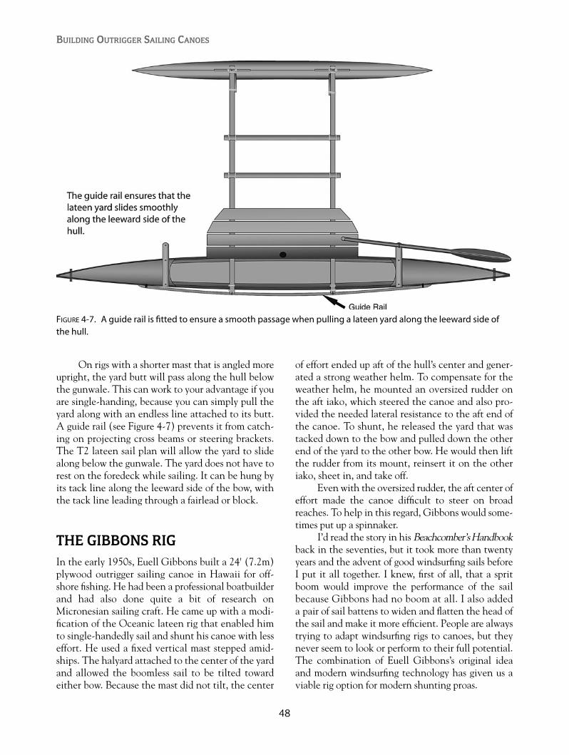
On rigs with a shorter mast that is angled moreupright, the yard butt will pass along the hull belowthe gunwale. This can work to your advantage if youare single-handing, because you can simply pull theyard along with an endless line attached to its butt.A guide rail (see Figure 4-7) prevents it from catch-ing on projecting cross beams or steering brackets.The T2 lateen sail plan will allow the yard to slidealong below the gunwale. The yard does not have torest on the foredeck while sailing. It can be hung byits tack line along the leeward side of the bow, withthe tack line leading through a fairlead or block.
THE GIBBONS RIGIn the early 1950s, Euell Gibbons built a 24' (7.2m)plywood outrigger sailing canoe in Hawaii for off-shore fishing. He had been a professional boatbuilderand had also done quite a bit of research onMicronesian sailing craft. He came up with a modi-fication of the Oceanic lateen rig that enabled himto single-handedly sail and shunt his canoe with lesseffort. He used a fixed vertical mast stepped amid-ships. The halyard attached to the center of the yardand allowed the boomless sail to be tilted towardeither bow. Because the mast did not tilt, the center
of effort ended up aft of the hull’s center and gener-ated a strong weather helm. To compensate for theweather helm, he mounted an oversized rudder onthe aft iako, which steered the canoe and also pro-vided the needed lateral resistance to the aft end ofthe canoe. To shunt, he released the yard that wastacked down to the bow and pulled down the otherend of the yard to the other bow. He would then liftthe rudder from its mount, reinsert it on the otheriako, sheet in, and take off.
Even with the oversized rudder, the aft center ofeffort made the canoe difficult to steer on broadreaches. To help in this regard, Gibbons would some-times put up a spinnaker.
I’d read the story in his Beachcomber’s Handbookback in the seventies, but it took more than twentyyears and the advent of good windsurfing sails beforeI put it all together. I knew, first of all, that a spritboom would improve the performance of the sailbecause Gibbons had no boom at all. I also addeda pair of sail battens to widen and flatten the head ofthe sail and make it more efficient. People are alwaystrying to adapt windsurfing rigs to canoes, but theynever seem to look or perform to their full potential.The combination of Euell Gibbons’s original ideaand modern windsurfing technology has given us aviable rig option for modern shunting proas.
BUILDING OUTRIGGER SAILING CANOES
48
FIGURE 4-7. A guide rail is fitted to ensure a smooth passage when pulling a lateen yard along the leeward side ofthe hull.

49
Sailing Rigs
FIGURE 4-8. Comparison of paths followed by the yard during a shunt between differently raked leading edges and mast lengths.The top arrangement is used when the yard must pass over a lee-ward platform built on extended cross beams.The bottom arrangement is used with a guide rail.

The downside to almost every Oceanic rig,however, is its inability to reef in the manner of morefamiliar rigs. The Gibbons/Dierking rig is no better inthat respect, and the best solution is to simply havesmaller duplicate sails with yards either carried ondeck (in the case of larger canoes) or changed on thebeach (like with a Windsurfer). This is not the hassle
that you would suspect, and the resulting smaller rigis cleaner than any reefed sail.
The most unusual aspect of my version is theattachment of the sprit boom. The boom actuallyhangs permanently from the masthead, and to raisethe sail, the yard is hauled up the boom on a slidingcollar or on a loop of parrel beads. The battens also
BUILDING OUTRIGGER SAILING CANOES
50
FIGURE 4-9. Euell Gibbons’s original shunting rig used in Hawaii in the 1950s.

are installed in an unusual manner, with the pocketopenings at the leading edge to allow the sail to befurled completely when lowered.
The addition of a tilting mast in my designdoes make the rig more complex than Gibbons’soriginal configuration but puts the center of effortwhere it belongs and greatly relieves the steeringload.
This sailing rig also allows the use of a smaller,overlapping rig inside of the main rig, sort of like astaysail inside of a jib. Both sails are shunted simul-taneously. The added complication, however, wouldbe more easily dealt with in a larger canoe.
The backstays are bungee-powered, as in mylateen rigs, so that when you release the endless lineholding the tack to the bow, the mast immediatelysprings to the vertical position. The line leading tothe former head of the sail is now pulled, and the sailtilts over to the new position.
Note that all shunting maneuvers must be donewith the wind coming square over the ama. Thecanoe will be drifting slowly to leeward, but since theshunt only takes ten seconds or less, you won’t driftvery far.
Although the mast is quite short, it does needto be stiff. Aluminum tubing, hollow wood, or
51
Sailing Rigs
FIGURE 4-10. Major components of the Gibbons/Dierking rig. Note that the boom is permanently hung from themasthead.
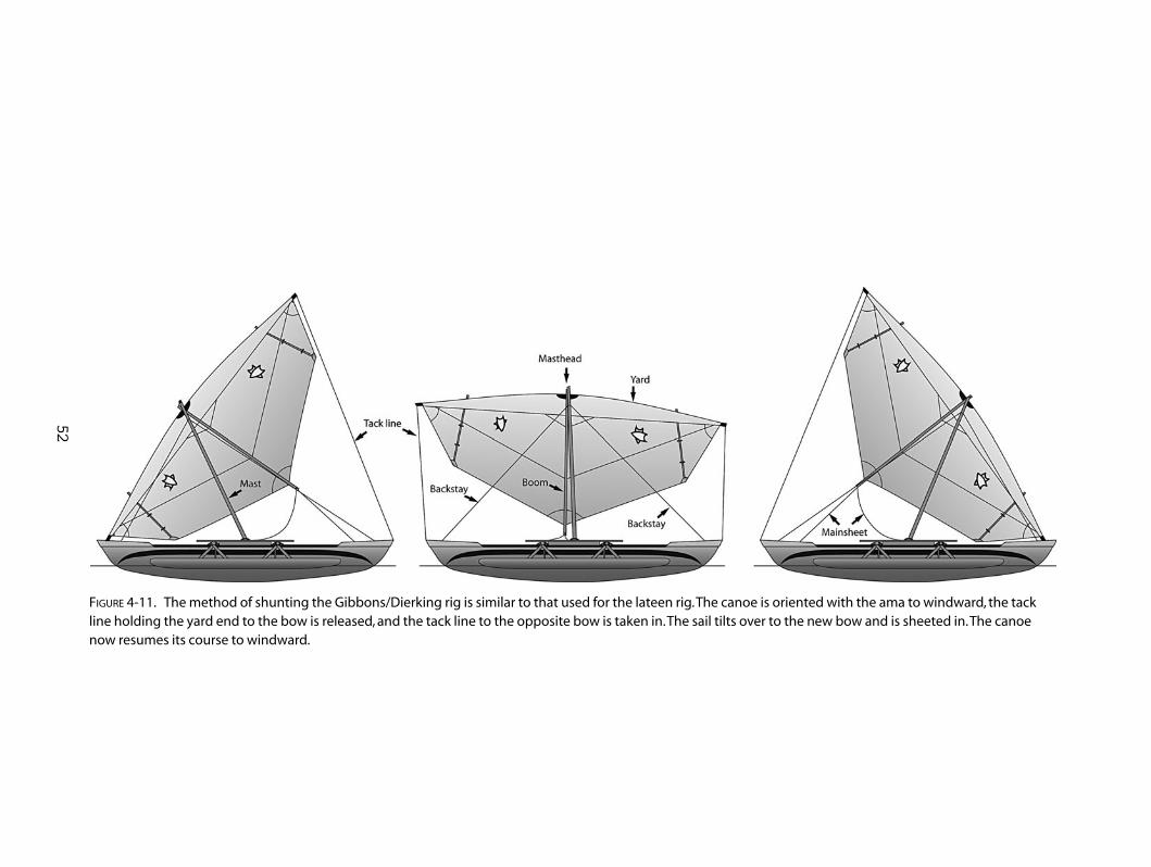
52
FIGURE 4-11. The method of shunting the Gibbons/Dierking rig is similar to that used for the lateen rig.The canoe is oriented with the ama to windward, the tackline holding the yard end to the bow is released, and the tack line to the opposite bow is taken in.The sail tilts over to the new bow and is sheeted in.The canoenow resumes its course to windward.
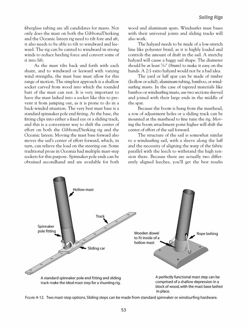
fiberglass tubing are all candidates for masts. Notonly does the mast on both the Gibbons/Dierkingand the Oceanic lateen rig need to tilt fore and aft,it also needs to be able to tilt to windward and lee-ward. The rig can be canted to windward in strongwinds to reduce heeling force and convert some ofit into lift.
As the mast tilts back and forth with eachshunt, and to windward or leeward with varyingwind strengths, the mast base must allow for thisrange of motion. The simplest approach is a shallowsocket carved from wood into which the roundedbutt of the mast can rest. It is very important tohave the mast lashed into a socket like this to pre-vent it from jumping out, as it is prone to do in aback-winded situation. The very best mast base is astandard spinnaker pole end fitting. At the base, thefitting clips into either a fixed eye or a sliding track,and this is a convenient way to shift the center ofeffort on both the Gibbons/Dierking rig and theOceanic lateen. Moving the mast base forward alsomoves the sail’s center of effort forward, which, inturn, can relieve the load on the steering oar. Sometraditional proas in Oceania had multiple mast-stepsockets for this purpose. Spinnaker pole ends can beobtained secondhand and are available for both
wood and aluminum spars. Windsurfer mast baseswith their universal joints and sliding tracks willalso work.
The halyard needs to be made of a low-stretchline like polyester braid, as it is highly loaded andcontrols the amount of draft in the sail. A stretchyhalyard will cause a baggy sail shape. The diametershould be at least 5⁄16" (8mm) to make it easy on thehands. A 2:1-ratio halyard would not be a bad idea.
The yard or luff spar can be made of timber(hollow or solid), aluminum tubing, bamboo, or wind-surfing masts. In the case of tapered materials likebamboo or windsurfing masts, use two sections sleevedand joined with their large ends in the middle ofthe spar.
Because the boom is hung from the masthead,a row of adjustment holes or a sliding track can bemounted at the masthead to fine tune the rig. Mov-ing the boom attachment point higher will shift thecenter of effort of the sail forward.
The structure of the sail is somewhat similarto a windsurfing sail, with a sleeve along the luffand the necessity of aligning the warp of the fabricparallel with the leech to withstand the high ten-sion there. Because there are actually two differ-ently aligned leeches, you’ll get the best results
53
Sailing Rigs
FIGURE 4-12. Two mast-step options. Sliding steps can be made from standard spinnaker or windsurfing hardware.

with a miter cut or a seam running parallel to theboom.
The single full-length batten at each end ofthe sail is mounted on the windward side, with ashort, sewn pocket only at the leech. Two or threeintermediate fabric straps are sewn on the sail tohold the batten in place. The batten extends outpast the luff spar and is tensioned with a small linelooped around the luff spar. This arrangement, whichis the opposite of conventional practice, makes furl-ing a lowered sail much easier. After the yard hasbeen lowered almost to the deck, the battened endsof the sail will still be sticking up in the air. Releas-ing the batten-tensioning lines on the yard allowsthat part of the sail to be pushed down along thebattens.
The Gibbons/Dierking is a true one-sided sail.In other words, one side of the fabric will always be
the windward side. In the study of flow over wingsections, research has shown that a smooth, low-drag surface is more important on the upper, low-pressure side of a wing. This corresponds to the lee-ward side of a sail. To take advantage of this fact,obstructions such as battens are located on the wind-ward or high-pressure side.
Staying on the subject of more advancedaerodynamics, a straight, asymmetric wing spar,with its flatter side to windward, could replace thestandard round yard. The greater thickness of awing spar would add great stiffness if this rig wereto be scaled up for a larger canoe. Taking this onestep further, a rigid, asymmetric wing sail couldbe used, or if you have one, a composite wing froma sailplane.
THE HAWAIIAN RIG
I call the simple tacking rig used on the Ulua aHawaiian-style rig. It is the least complicated of allthe rigs shown here and only has two strings to pull—the mainsheet and a spiller or brailing line.
This rig is based on a windsurfing mast that islight, stiff, and available everywhere. A hollow woodenspar of slightly larger diameter would also work.Although I sailed mine for several years with nostays at all, I’ve found that a simple, 1⁄4" (6mm), low-stretch rope forestay, attached about two thirds ofthe way up the mast, improved the sail shape whenclose-hauled in stronger winds.
The curved boom is not strictly necessary butdoes look the part and is easy to make. Althoughthe curved boom shown on the Ulua looks quiteelegant, it does not allow reefing of the sail unlessthe rig is taken down. The Wa’apa sail plan shows aloose-footed sail with a straight boom. A loose footallows the sail to be reefed by turning the mast andwinding up some of the sail after the outhaul hasbeen loosened.
Either the curved-boom laced foot or thestraight-boom loose foot can be used on both theUlua and the Wa’apa.
A tacking outrigger is probably not quite as effi-cient as a shunting rig, because on one of the tacksthe ama will be depressed into the water, causingmore drag than when it’s on the windward side. Inpractice, the speed difference is not really noticeable,but some other peculiarities are. When the ama is toleeward, its drag tends to turn the canoe to leeward.
BUILDING OUTRIGGER SAILING CANOES
54
FIGURE 4-13. Gibbons/Dierking rig masthead. A slidingtrack can be used instead of the adjustment holes.A short length of tube lashed to the yard and sliding onthe boom can replace the parrel beads. Note that theboom hangs from the masthead.

This affects the basic sailing balance between the lee-board’s lateral resistance and the sail’s center of effort.However, by pivoting the leeboard fore or aft, thebalance can be regained.
STUB-MAST RIGSAnother type of tacking rig used on some modernHawaiian sailing canoes has a short stub mast setinto the hull, with a longer luff spar hoisted parallelto it with a halyard. This can be an advantage in
that it allows the use of shorter spars for the luff ofthe sail, and the rig can be lowered more easily withthe short halyard. The luff spar needs either a wind-surfing universal joint at its base (see Figure 4-18) ora socket with a lashing.
The stub mast also enables you to use any oldwindsurfing rigs you may have stored away. The fullyrigged sail can still be lowered on to the iakos byreleasing the short halyard attached to the end of thewishbone boom. The bracket shown in Figure 4-18clamps to the iako.
55
Sailing Rigs
FIGURE 4-14. Hawaiian tacking rig. A rope forestay can improve the sail shape while sailing to windward instrong breezes.
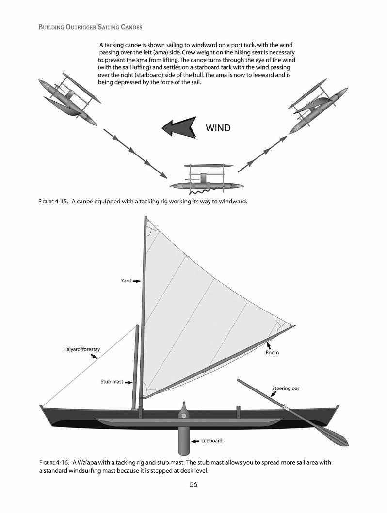
BUILDING OUTRIGGER SAILING CANOES
56
FIGURE 4-15. A canoe equipped with a tacking rig working its way to windward.
FIGURE 4-16. A Wa’apa with a tacking rig and stub mast. The stub mast allows you to spread more sail area with a standard windsurfing mast because it is stepped at deck level.
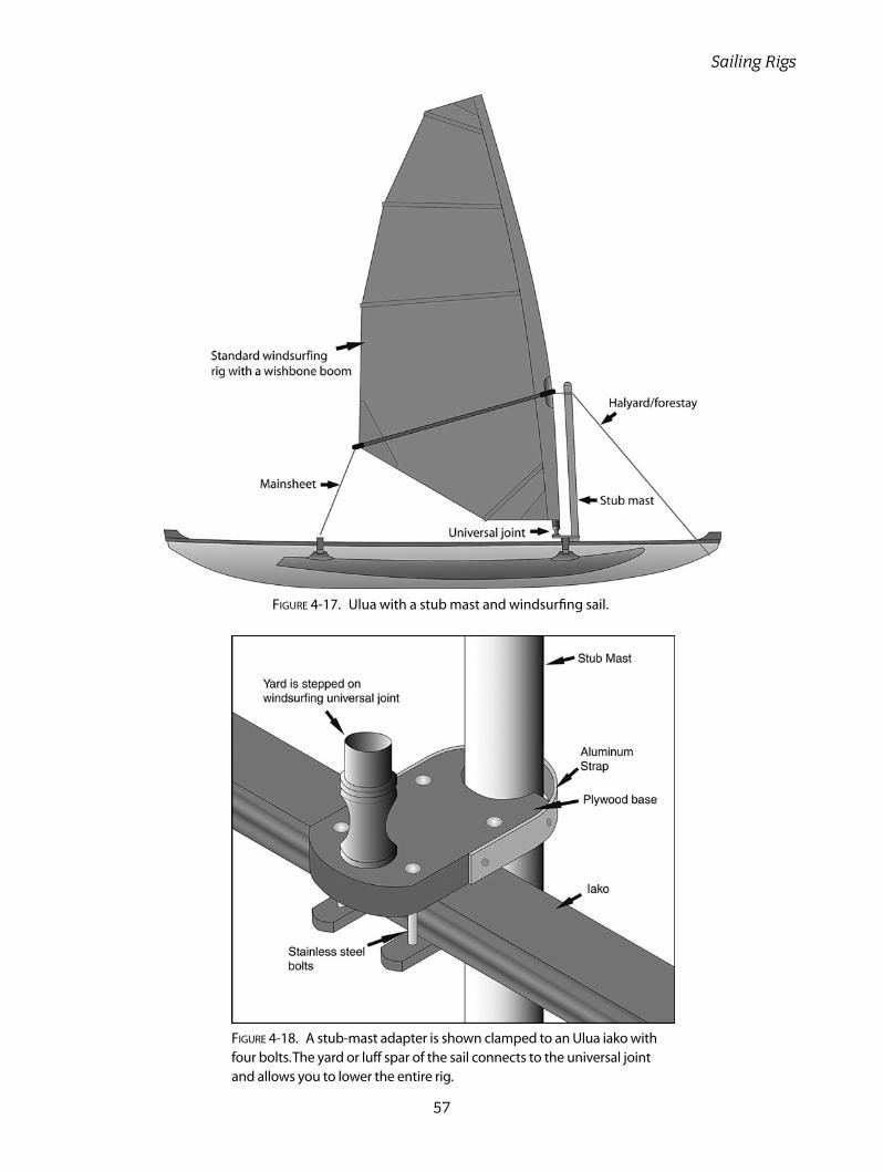
57
Sailing Rigs
FIGURE 4-17. Ulua with a stub mast and windsurfing sail.
FIGURE 4-18. A stub-mast adapter is shown clamped to an Ulua iako withfour bolts.The yard or luff spar of the sail connects to the universal jointand allows you to lower the entire rig.

58
The designs in this book use two very differentconstruction methods. The Ulua and the T2
are strip planked, and the Wa’apa is built from ply-wood panels.
STRIP-PLANKING VERSUSPLYWOODThere are many strip-planked canoes and kayaksaround that look like finely built furniture withmany intricate-looking joints, and because of this,many beginning boatbuilders are reluctant to trythis method. It’s true that the materials may cost alittle more than a plywood hull and more hours oflabor are involved, but the result can be highly pro-fessional, even for someone who’s never built any-thing before. It doesn’t actually require any tradi-tional boatbuilding skills. Assembling the hull oneplank at a time ensures that there will be no big mis-takes. The fairness (smooth curvature) of the hullcan be checked at every step. Even the worst-casescenarios can be fixed with putty and a coat of paintinstead of a clear varnish finish.
A strip-plank project first requires a strongback,which is a straight, level, flat surface on which tomount the molds. The molds are temporary plywood orparticle-board shapes that define the cross-sectionalshape of the hull. The hull is built upside down with itskeel at the top. The molds are screwed to the strong-back at specified intervals. Two special stem moldsdefine the ends of the hull. Permanent stems are lami-nated over the stem molds and beveled by hand toallow the planks to lay against them. The mold edgesare covered with plastic tape to prevent the planksfrom sticking to the molds. Beginning at the gunwale,
thin strips of wood are stapled to the molds andglued to the stems. Each additional plank is edge-glued to the previous one, until planking ends at thekeel. No plank-edge beveling is required until thelast few planks.
Strip-planked hulls derive most of their strengthfrom the fiberglass sheathing that is applied bothinside and outside the hull. The wooden strips act as acore material between the fiberglass skins to create avery strong but light, sandwich-composite panel. Thelengthwise grain of the wood also contributes longitu-dinal strength. Most damage to a strip-composite hullis only cosmetic, with most “write-offs” the result ofthe canoe flying off of a car roof, rather than anythingyou will experience on the water.
The plywood construction of the Wa’apa issimple and quick. It can be built as a one-piece hullor in two or three bolt-together sections. There is nostrongback or temporary structure to hold it together.The plywood side panels are prefabricated on a flattable and bent around two bulkheads and a stemtimber. The plywood bottom is nailed and glued intoplace, and the hull is basically complete after theinstallation of foredecks and seats.
The hull could be built using the popular“stitch-and-tape” method, but I feel that you’ll havebetter results using conventional chine timbers tojoin the side and bottom panels. Because the chineis already attached to the side panel during theassembly, its stiffness causes the panel to bend in avery smooth curve, avoiding the wavy chines some-times seen in stitch-and-tape hulls.
A fiberglass sheathing over the exterior of aplywood hull is not structurally necessary but canhelp to avoid problems later with some species of
CHAPTER 5
Boatbuilding Basics
Copyright © 2008 by International Marine. Click here for terms of use.

59
Boatbuilding Basics
plywood. Douglas fir or pine plywood will “check” ordevelop hairline cracks in a paint finish if the panelhasn’t been sheathed. Most tropical marine plywoodwill hold a paint finish without checking. I recom-mend at least sheathing the bottom and the chinesto provide increased abrasion resistance.
TOOLS
Power Tools• Jigsaw: A jigsaw is probably the most used
power tool in any boatbuilding project. Spendthe extra money to get one with variablespeed and adjustable orbital cut.
• Table saw or portable circular saw: You’ll needone of these to cut your planks for a stripperand to make gunwales, chines, or cross beams.A circular saw can be fitted to a portable tablefor ripping, or it can be fitted with a commer-cial or homemade rip-guide attachment.
• Drill: This can be either battery powered orplugged into the wall. You’ll need a variety ofbits for screw pilot holes or countersinking.
• Random orbital sander: This is probably thebest all-around type of sander.
• Router (optional): This is used to makeoptional bead and cove planks when fittedunder a router table. It is also useful for round-ing the edges of gunwales and chines.
• Thickness planer (optional): This is useful forsmoothing planks to an exact thickness andpreparing strips for laminated beams. It cansave a lot of sanding. Be sure to have earprotection.
• Vacuum cleaner (optional): A shop vacuum isgreat for cleaning the hull surface inside andout and can also be connected to some sanders.
Hand Tools• Staple gun: If you’re building a stripper, this
tool will get a lot of use. Your stapler must becapable of driving 9⁄16" (14mm) staples. Con-sider that you may have to disassemble it regu-larly to clean out hardened glue. The ArrowT50 has served me well.
• Japanese pull saw: Next to the jigsaw, I findthe Japanese pull saw to be the most valuabletool in the shop. It is the absolute best tool forworking with small strips and performing
many other tasks. It is extremely sharp whennew but is not easily sharpened.
• Block plane: Using a low-angle blade is best.Keep it very sharp for a pleasing experience.
• Staple puller: This can be found in a store, butI’ve always made mine by bending the tip ofan old, flat-tip screwdriver and sharpening theedge.
• Clamps: Use either sliding-bar or “C” clamps.You’ll want at least a dozen, preferably manymore. No shop has ever had too many. Plasticspring-powered clamps are also useful.
• Scissors• Wood chisels• Flat rasp• Screwdrivers• Hammer• Utility knife• Putty knife• Ruler• Square• Tape measure• Level• Sliding bevel gauge
Safety Gear• Dust masks • Disposable gloves• Safety glasses
MATERIALSChoosing materials for your project can be a realheadache, and in many cases it’s more about whatyou can get rather than what you would like to have.
Plywood is perhaps the trickiest material tochoose, and you’ll often not have much choice fromyour local supplier. The easiest (and most expen-sive) way to solve this problem is to buy propermarine-grade plywood. Marine-grade plywood ismanufactured with completely waterproof glue andwill have no unseen voids in its inner plies. Theplies on the outer surface will also be thicker, unlikein some cheaper grades that have paper-thin surfacelayers.
Marine-grade plywood made from wood speciessuch as okoume (gaboon), meranti, or Douglas fir areall good choices. Note that Douglas fir plywood doesnot seal well with a paint-only finish and should becompletely sheathed in fiberglass.
If you can’t resist purchasing some bargain-priced plywood at the local building supply, do thefollowing test to see if it’s suitable for the marineenvironment. Take a sample of the plywood and boilit for an hour or so. Put it into a slow oven, dry itcompletely, and repeat the process. If it’s not delam-inating after this test, it’s probably okay for yourcanoe. Plywood that is 1⁄4" (6mm) comes in eitherthree-ply or five-ply. The five-ply is definitely supe-rior. Some cheaper three-ply exterior grades have athick inner ply and very thin outer plies. An unseenvoid in the inner ply doesn’t leave much betweenyou and the ocean.
The choice of solid timber for your project willdepend on its intended use. Chines and bulkheadperimeters are normally made with medium-densitysoftwoods like Douglas fir, spruce, or pine. Western redcedar, while ideal for strip-planking, is too soft to holdfastenings well, or to be used as a gunwale where itwould be easily damaged. Outer gunwales are prefer-ably made of a harder timber like ash or mahogany.
Laminated cross beams (iakos) can be madeentirely from one species of softwood or optimized byusing a harder wood on the top and bottom layers,with a very light, timber-like cedar for the inner layers.
Western red cedar is the premiere plankingmaterial for a strip-planked hull. It is very light, easyto work, and rot-resistant. Western red cedar is,however, toxic to some people when it is sanded andcan cause asthma-like symptoms. Any lightweight,knot-free timber can be used for strip-planking, frombalsa to pine.
There are many brands of epoxy resin that aresuitable for your project. Look for brands that havegood documentation for their use in marine struc-tures and that have a range of additives available formaking your own glue and fairing mixtures. Someepoxies are more toxic to skin than others. Do someresearch through boating magazines and the Inter-net to get information on the relative safety of differ-ent brands of epoxy resin.
WORK SPACEI built my first real boat when I was fifteen years old,in an unused upstairs bedroom. When springarrived and the ice had melted in the lake, it wastime to get it outside. In spite of my calculations, itwouldn’t fit down the stairway and instead went outan upstairs window to many waiting hands. Thatwas probably one of the least ideal situations, but at
least canoes will fit through smaller windows than,say, scows.
Ideally, you’d have a large barn structure withbig doors opening out toward the shoreline of a pic-turesque harbor, but in most cases you’ll be buildingin a garage, basement, or carport.
You’ll need a work space that is dry and out ofdirect sunlight. Damp wood and epoxy don’t getalong well together, and direct sunlight will causeepoxy to harden before you’re finished working withit. While working with epoxy resin, try to stay withina temperature range of 65˚F (17˚C) to 85˚F (29˚C).Many modern glues and resins require a minimumtemperature to cure to their full strength, so if you’reworking during a cold winter, your space will need tobe heated. Be aware that you may be producing flamma-ble fumes that could ignite from your heat source.
You’ll need enough space to walk around theends of the hull, and to have a workbench and asmall table or cart to hold the epoxy supplies. Rip-ping planks on a table saw requires a clear spacetwice the length of the longest plank. You can dealwith this by either moving the saw outdoors or rip-ping with a portable circular saw indoors. If you’rebuilding with plywood, cut as many of the pieces aspossible before beginning the assembly to give your-self adequate space for the laying out and cutting.
Sanding can produce a lot of dust, which meansthat good ventilation is necessary, especially withtoxic woods such as western red cedar (see the sectionin this chapter on materials). Also consider how tokeep the dust and fumes out of your living space.
Good lighting is necessary and could save someembarrassment when you finally move the hull outinto the sunlight. Shining a strong light down theside of your hull in a dark workshop will reveal thequality of your workmanship in stark terms.
Portable, tent-like structures used for green-houses are okay as long as you have a way to shadethe hull from direct sunlight while sheathing orcoating anything with epoxy resin. Retired shippingcontainers can be purchased near seaports in sizes of20' (6m) or 40' (12m) and make good, secure work-shops. They have the extra advantage of beingportable and not requiring building permits.
LOFTINGLofting is just another term for drawing something atfull scale. With the dimensions shown in the plans,you’ll be able to re-create mold shapes and other
BUILDING OUTRIGGER SAILING CANOES
60

parts full size. You can loft either on paper or ontothe panel itself. In most cases, it’s quicker to drawthe part right onto the panel to be cut out.
You’ll need some thin finishing nails or brads, a hammer, a square, an accurate ruler, and a flexiblebatten or spline to bend into a curve. Battens can bestrips of aluminum flat bar or can be cut from wood oracrylic plastic. A fiberglass batten from a windsurfingsail works well. A batten for a given curve should beas stiff as possible but still be able to bend the requiredamount without breaking or popping out the nails.
For a strip-planking mold, begin by drawingthe centerline, the baseline, the strongback line,and the parallel waterlines, accurately and square toeach other. The offset dimensions (see Figure 5-1)indicate the distance between the centerline andthe edge of the mold, along each of the waterlines.The vertical dimensions indicate the distance fromthe keel to the baseline, the sheer line to the strong-back, and the spacing between waterlines.
Carefully measure the distances, and tap in athin finishing nail at each point. Choose a slenderbatten and bend it along the nails. Use the stiffestbatten that will follow the curve without breaking orpulling out the nails. Sight along the curve to detectany unfairness. Any error in measurement will usu-ally be quite obvious when the batten is held againstthe nails. If it looks satisfactory, tap in another set of
nails along the other side of the batten to hold it inplace. Draw a line along the batten so that it passesthrough the measured points. Repeat the procedurefor the other half of the mold.
Lofting parts for a plywood hull is easier withfewer points to plot and only straight lines to draw.Start by drawing a centerline and a baseline at rightangles to it. Measure the offsets shown, and connectthe dots with straight lines.
When lofting large plywood panels, such as thesides of the Wa’apa hull, use the edge of the plywoodsheet as the baseline. Check to be sure that the ply-wood sheet has straight edges and square corners.
GLUESAlmost all of the structural joints in modern boat-building projects depend on glue. It will pay divi-dends for you to become very well informed about alltypes of glue, and which glues are suitable for themarine environment.
The most versatile of all modern adhesives isepoxy. In fact, you can buy the basic resin and use it
61
Boatbuilding Basics
FIGURE 5-1. To create a mold station from a table ofoffsets, begin by drawing a horizontal baseline, a ver-tical centerline at a right angle to the baseline, and aseries of waterlines parallel to the baseline andspaced at the indicated intervals. Offsets are meas-ured from the centerline out along the waterlines.A series of offsets connected by a fair curve will deter-mine the shape of the mold.
FIGURE 5-2. To loft a bulkhead for the Wa’apa, draw a baseline and a centerline at a right angle to it.The baseline will also be the bottom of the bulkhead.Measure the “baseline-to-sheer”dimension verticallyup from the baseline, and the offset dimension hori-zontally from the centerline. The intersection of thesedimensions will determine the position of the upper(sheer) and lower (chine) corners of the bulkhead.

for every gluing and coating job in the project.Epoxy comes as two separate chemicals—a resin anda hardener—both with the consistency of syrup. Theyare usually combined in a ratio of four or five partsresin to one part hardener, although some brands usedifferent ratios. In all cases, getting the ratio right iscritical to achieving good results. You can purchasepumps from your dealer that will measure the epoxyin the right amounts, or you can weigh it on a bal-ance scale.
It is also important to mix the epoxy very com-pletely for a minute or more, as any molecules thathaven’t found a mate will remain uncured and willweaken the result. Once the epoxy is mixed, it canbe used directly to either coat a bare wood surface forwaterproofing, or to saturate fiberglass cloth.
To use the epoxy for glue, a modifier in the formof various powders is added to attain the desired con-sistency. The glue powder is available from the resinsupplier. To make an epoxy-based putty for fillingholes and fairing a surface, a different powder isadded that will cure to a more easily sanded materialthan the hard-glue mixture.
Epoxy is an excellent all-around choice forassembling plywood hulls and laminated structures,but it is unnecessary for edge-gluing planks whenyou are strip-planking. A strip-composite hull hasthe planking sandwiched between two layers of fiber-glass that does a good job of holding them together,making the use of a waterproof glue like epoxybetween the planks an unnecessary expense. Just usethe common white, or yellow aliphatic carpenters’glue, between planks, and you’ll have a much easiertime sanding later.
A more recent arrival in the waterproof gluechoices is polyurethane glue. It is a one-part glue sodoes not require any mixing. It can be used for edge-gluing planks and even foams up to fill any smallgaps. It can also be used for general-purpose laminat-ing but doesn’t always bond well to very dry wood. Itis usually recommended by the manufacturer thatyou wipe the surfaces to be glued with a damp spongefirst before applying the glue. If you’re going to use itfor anything besides edge-gluing strips, I’d recom-mend gluing up some scraps to test its adhesion.
Resorcinol glue is another option for someparts of your canoe. It is rated as the most waterproofof all glues but requires perfectly fitting joints and ahigh clamping pressure. It can be used for laminatedbeams or spars where good clamping pressure isavailable. It comes in the form of a powder and syrupthat must be mixed together.
All glues can have adhesion problems with oilywoods such as teak. When gluing teak, it is best towipe the contact surfaces with acetone to degreasethem just before applying the glue. Some epoxiescan have problems with white oak, too, so glue up atest sample with your materials before using them inyour canoe.
All glues except epoxy require good contact andclamping pressure for a strong bond. Epoxy is theopposite in that high clamping pressure can “starve”the joint—in other words, squeeze too much of theglue out and it gives you a weaker bond. So if you’rea rough joiner and there are a lot of gaps, epoxy isyour friend.
Normally, you do not thin epoxy, because itbecomes less waterproof if you do. There are specialepoxy thinners for cleaning brushes, etc., but lac-quer thinner or acetone will also work. Avoid clean-ing epoxy from your skin with thinner, as it onlyhelps it to penetrate deeper into your skin. Vinegarcan help to remove fresh epoxy with fewer harmfuleffects.
The downside of epoxy is that some people areallergic to the hardener. This results in an itchy rashwhere contact has been made. Once you becomesensitized to it, you may never be able to use it again.Your best defense is to always wear disposable plasticor rubber gloves. This applies to polyurethane glue,too, but mostly because once it’s on your hands ittakes days to wear off.
In the days before epoxy was widely available,strip canoes and plywood boats were sheathed withthe cheaper polyester resin. While this is fine for anall-fiberglass hull or a foam-sandwich hull, polyesterdoes not bond to wood as well as epoxy. Polyester isalso not as waterproof.
SCREWS, NAILS, AND STAPLESWhile glue is the primary structural fastener in thesesmall canoe designs, mechanical fasteners are stillused in many places. After many years of use, theintegrity of the wood fibers bonded with the glue candeteriorate if they are not carefully sealed from mois-ture. Screws or nails will act as your backup. Animportant rule to remember is that the length of anail or screw should be at least three times the thick-ness of the plywood through which it passes. Fasten-ing 1⁄4" (6mm) plywood to a framework requires atleast a 3⁄4" (18mm) nail or screw.
In the case of a plywood hull like the Wa’apa,the plywood sides and bottom are glued and nailed
BUILDING OUTRIGGER SAILING CANOES
62

along the gunwale and chine. The nails or screwsclamp the joint together while the glue hardens.Bronze or stainless-steel annular ring nails are thefirst choice for nails. The ridges along the shafts ofthe nails give great holding power, making themvery difficult to remove once they are hammered inflush. Use a steel punch to set the heads just belowthe plywood surface so that they can be coveredwith putty and sanded flush.
In the case of a strip hull like the Ulua, screwsare used to attach the gunwales, seats, and othersmall parts to the hull. Always drill a pilot hole forscrews before driving the screw into place. Specialbits are available for each size of screw and willensure that they have maximum holding power.Screws can be countersunk flush with the surface, orcounterbored below the surface, with special drillbits available for that purpose. Counterbored screwscan be covered with wooden plugs, which are avail-able from some stores, or you can make your ownwith a plug-cutting bit available from specialty tooldealers. Wooden plugs are especially attractive alongthe gunwale and are quick and easy to install. Eachplug is glued and tapped into place, and when theglue has hardened, the excess plug is shaved off witha sharp chisel. Sandpaper, wrapped around a block,will finish it flush with the surrounding surface.
Screws come with a variety of slot styles, withthe plain, slotted head; the Phillips head; the Pozidrive (similar to the Phillips); and the squaredrive. Avoid using the plain, slotted heads if possi-ble, because the screwdriver can easily slip out theside and damage the wood. A plywood hull can alsobe fastened along the sheer and chine with power-driven, narrow-crown staples. Staples are available instainless steel and sometimes bronze. Practice onscrap material, and adjust your air-powered or electric
stapler to drive the staple just below the surface ofthe material.
Wide-crown, plain, steel staples are used tohold strip planks in place while the glue hardens.These are usually driven with a hand-powered staplegun and are only available up to 9⁄16" (14mm) inlength. By allowing the crown of the staple to stayabove the surface, you will be able to remove it laterwithout damaging the soft surface of the plank.
A staple remover can be bought or made froman old flat screwdriver. Bend the tip of the screw-driver with a hammer and vise, and file it to asharp edge.
When removing a staple, hold a putty knife flaton the planking up close to the staple. Hook the tipof the removal tool under the crown, and lever itagainst the putty knife. If one of the staple legsbreaks off, use a needle-nose pliers to pull it out.Sometimes the staples are driven through plasticbanding strips to prevent damage to the plankingand to allow easier removal.
CUTTING PLYWOODIn most cases, a handheld jigsaw (also known as asaber saw) can be used to cut out bulkheads, panels,and other small parts from sheet plywood. It is diffi-cult to cut a fair curve or a straight line with a jigsaw;therefore, depending on your skill level, cut outsideof the line, and shave down to the line with a blockplane or sanding board. For cutting a long, straightsection, clamp a straight, stiff board parallel to theline to act as a guide. Use the special blades designedfor plywood to avoid splintering the edge.
A circular saw can also be used to cut long,curved pieces or straight lines with a guide. To cut
63
Boatbuilding Basics
FIGURE 5-3. The most commonly used mechanical fasteners in small-boat construction.

curves, retract the blade to just clear the bottom sur-face of the panel. A fine-toothed blade will reducesplintering.
CUTTING STRIP PLANKSCommercially manufactured red cedar planks forstrip building are available in some areas and can beexpensive, but there are several ways of making yourown. When I built my first stripper, I only had ahandheld circular saw, a jigsaw, a drill, and electricsanders. I clamped the 3⁄4" � 6" (20mm � 150mm)planking stock to a couple of sawhorses, and by usinga rip guide attached to the saw, I walked along theplank, taking off 3⁄4" (6mm) slices. This method hasthe advantage of needing only half the space requiredfor feeding planks though a stationary machine. Youcan make a rip guide by bolting a strip of timberparallel to the blade on the bottom side of the circu-lar saw.
The next most inexpensive method of cuttingplanks is to get one of the portable tables underwhich you can clamp your circular saw, thus turningit into a table saw.
Using a table saw is the most commonmethod to rip the planks. You’ll need good supportsfor the timber feeding in and out, and a featherboard to hold the plank tightly against the ripfence. Use a push stick to keep your fingers awayfrom the blade. Thin kerf blades are available toreduce waste.
A feather board is used to keep smaller piecesof stock pressed firmly against your table saw orrouter’s fence. The design of a feather board allowsthe stock to pass in one direction and causes resist-ance if it is moved in the other direction. A featherboard is basically a board with an angled end and1⁄8" to 14" wide “fingers” cut into the beveled end.As stock is forced between the fence and thefeather board, these fingers move slightly to allowthe stock to pass. The firm squeeze helps keep thestock tight against the fence and helps ensure amore accurate cut. In addition to keeping yourstock up against the fence, the fingers help reducethe chance of kickback. For more advanced work,such as with a router table, a second feather boardcan be clamped to the fence to hold the stock downon the table.
You can also use a band saw to rip planks, anddue to its narrow cut, it has the advantage of wastingthe least amount of wood. The surface will be more
BUILDING OUTRIGGER SAILING CANOES
64
FIGURE 5-4. The use of a feather board while rippingstrip planks is highly advisable and will prevent acci-dents while you are cutting thin planks.
FIGURE 5-5. Bead and cove planking against a moldstation.

irregular, however, and more may have to be sandedoff later or cleaned up with a thickness planer.
Bead and cove edges make the alignment ofthe planks on the mold easier and fit the edgestogether better when you are planking over a tightradius. A special pair of router bits must be pur-chased in order to do this yourself. If you decide tomake your own bead and cove planking, you’ll needa router, a router table to mount it, and the specialrouter bits. Use feather boards to hold the plankboth against the fence and down to the table.
Bead and cove edges are not as essential withthe outrigger canoes designs shown here becausethere are no tight curves to plank. I’ve only builtwith square-edged planks, and the joints are notreally noticeable. Normally, it is unnecessary to fillany gaps between square-edged planks unless youcan see through the gap. Sanding dust mixed withglue makes a good gap filler. Be sure to mask off theadjacent planks to avoid staining the surface.
It is not always possible to get full-length tim-ber for planking. Structurally, there is no need toscarf shorter lengths together before putting themon the mold. A simple butt joint done in place onthe mold is fine. If you still want to splice theplanks before planking, you can make quick scarfjoints by building a jig to fit up against a fixed discsander made from your table saw. Sanding is betterthan sawing with such thin, fragile strips.
When the planks are in place on the mold, theouter and inner faces should be edge grain, or verticalgrain. The grain lines should run straight and bespaced closely. If you rip slices from a flat or slashgrain plank, the slices will exhibit vertical grainwhen they are turned on their sides on the mold.A sanded hull with all edge grain will come outfairer than one with flat-grain planks. Sanding flat orslash-grain planks causes the softer areas to beremoved, with hard ridges remaining.
SCARFING TIMBERA scarf joint is a way of making short pieces of tim-ber or plywood into longer pieces, without makingthem thicker or weaker at the joint. Gunwales andspars are most commonly in need of scarf joints. Ifdone carefully, they will look very nice with a var-nished finish.
65
Boatbuilding Basics
FIGURE 5-6. A slash-grain board ripped into verticalgrain planks.
FIGURE 5-7. Timber planks can be spliced together with the use of a scarf joint. Long, tapered cuts are made with a saw to the ends of each piece to be joined. A plane or a sanding block is used to fit the ends exactly together.Adhesive is applied, and the joint is clamped together.

The length of the joint should be a minimumof eight times the thickness of the material. A 3⁄4"(19mm) thick gunwale would require a scarf joint atleast 6" (152mm) in length. Plywood that is 1⁄4"(6mm) requires a joint that is 2" (48mm) in length.
Cutting the taper on the ends of the piecesmust be precise. The first step is to draw the actualcutting line on three sides of the material. Make surethat the end of the timber strip is square beforemeasuring back from it.
One strategy is to remove most of the materialwith a power tool and do the final precision workwith a plane and sanding block. Clamp the piecesecurely to a table or workbench. You can removethe bulk of the material in several ways. A powerplane, disc grinder, jigsaw, or wide chisel can beused to remove most of the stock. Just don’t cut tooclose to the line. Use a sharp block plane and ahard sanding block or board to get down to theline. Make sure that the surface is flat without anyhigh points in the middle. Once you have the twoparts shaped, fit them together on edge on a flatsurface, and use the plane or sanding block to get agood fit.
Epoxy glue (discussed earlier in this chapter) isthe best adhesive to use if your fit is not perfect. Mixsome resin and hardener, but do not add the thick-ener yet. Paint a thin coat of the unthickened epoxyon the mating surfaces, and allow it to soak into theabsorbent end grain. Omitting this step can cause a
weaker joint, because the end grain will absorb theresin and leave mostly filler.
Mix the thickening powder into the remainingresin, and coat the two mating surfaces. Lay the jointflat on the table, and use a straightedge across thetop and sides of the joint to align the surfaces. Put atemporary staple into each side to prevent themfrom sliding around. Wrap plastic sheeting or waxedpaper around the joint, and clamp the piece againsta straight piece of timber with at least two springclamps or C-clamps.
If you have several joints to make, these can allbe clamped together, as long as each one is individu-ally wrapped with plastic. When the glue has cured,clean up the surfaces with sandpaper on a sandingboard.
Scarfing PlywoodIf you elect to build the Wa’apa plywood hull in onepiece, you will have to splice standard-length sheetsinto longer lengths. Scarfing is the best way to do this.
Scarfing plywood uses a similar procedure tothat used with solid timber. You will need a wideenough table or work surface to support the edge ofthe joint. Be sure that the surface is straight and flat,and that you have a firm, square edge under the endof the plywood sheet. Use a stiff board that is as longas the width of the plywood, and some clamps tohold the sheet firmly to the work surface.
BUILDING OUTRIGGER SAILING CANOES
66
FIGURE 5-8. Plywood scarf joints can be roughly cut with a plane or grinder and fitted more precisely with the use of a sanding block or plane.

Again, you can remove most of the materialwith planes or grinders, but be careful not to splinterthe delicate edges. (A circular-saw attachmentdesigned for cutting scarfs in plywood is availablefrom Gougeon Brothers, Inc., the company thatmakes West System epoxy [see the resources sectionat the end of the book].) The glue lines between thelaminates of the plywood will help you to produce aflat surface, because they will be straight when thesurface is flat.
Plywood scarfs can be cut one at a time, or theycan be stacked and staggered so that both sheets canbe done at the same time. The first sheet is laiddown with its edge even with the table’s edge. Thesecond sheet is laid on top of the first sheet with itsedge aligned with the end of the first sheet’s scarf.So, if you’re scarfing 1⁄4" (6mm) plywood, the secondsheet’s edge would be 2" (48mm) back from the firstsheet’s edge.
When you are gluing a plywood scarf, primethe surfaces with unthickened epoxy as in the tim-ber joints, apply the thickened glue after the firstcoat soaks into the wood, and line up the twosheets with the joint over a flat, solid surface cov-ered with plastic sheeting. Press the joint togetherto squeeze out any excess glue before determiningits position, then use a straightedge on the top sur-face and along the edges to bring the two piecesinto perfect alignment. Then hold them together
by driving at least two wide-crown staples throughthe joint.
Two options are available for applying the nec-essary clamping pressure, depending on how the ply-wood will be finished. If you plan on a clear finishwith a minimum number of blemishes, you can stackheavy weights on a stiff board that covers the joint.It is also possible to jam struts between the ceilingand the joint for downward pressure.
Another way to pressure the joint is with power-driven staples through thin ply, or by using scraptimber. The timber can be split away when the glueis hard, and the staples can be pulled with vise gripsand a putty knife to protect the surface. You can alsouse small nails hammered through the same timberor plywood scraps.
There are few limits as to how long you canmake a sheet of plywood. I have personally made 60'(18m) long sheets from 3⁄16" (4mm) plywood.
JOINING PLYWOOD SHEETSWITH FIBERGLASSAnother way exists to join plywood sheets withoutany cutting or shaping of the ends. The sheets arebutted edge to edge, and fiberglass tape is applied toboth sides of the joint. This has proven to be asstrong as the traditional scarf joint.
67
Boatbuilding Basics
FIGURE 5-9. By stacking both sheets of plywood to be joined with the top sheet set back by the width of the cut, bothcuts can be done at the same time and with greater accuracy.

Apply fiberglass tape to both sides of the jointat the same time. You’ll need a flat surface to supportboth sheets butted together, like the floor or a largetable. Cover the work surface area with clean, flat,plastic sheeting. Lay down a 4" (100mm) wide stripof 6-ounce (200-gram) fiberglass cloth, and wet itout with epoxy. Coat all of the contact areas on bothsides of the two pieces of plywood. Butt them together,centered over the strip of wet fiberglass.
Wet out the second strip of fiberglass on top ofthe butt joint, and cover it with more plastic sheet-ing. Lay a flat piece of board or a strip of heavy ply-wood on top of the joint, and weigh it down withanything heavy—the more the better.
As a last check, be sure that the two pieces ofplywood are still butted together solidly. The nextday, the fiberglass strips can be lightly sanded and areready for use.
There are also a couple of enhancements to thismethod. To obtain a perfectly flush joint, you cansand away some of the surface of the plywood on bothsides, before applying epoxy, to recess the fiberglasstape. Only remove about 1⁄32" (1 mm) of material.
Another enhancement is to use peelply betweenthe wet fiberglass and the plastic sheet. Peelply is sim-ply lightweight nylon, or polyester fabric, that can bepeeled off of the epoxy after it has cured. Peelply hasthe advantage of leaving a clean, textured surface thatrequires little or no sanding. Peelply can be used onmany places to which you know you’ll have to bondlater, because it keeps the surface clean until you areready to peel off the peelply (and bond to that sur-face). It is available from epoxy dealers, or you canuse white, uncolored nylon from a fabric store.
JOINING PLYWOOD SHEETSWITH BUTT BLOCKSOne of the oldest and most commonly used ways tojoin plywood sheets is through the use of butt blocks,or butt straps.
Butt-block splices will locally stiffen the panelconsiderably and should only be used where the paneldoes not have to be forced into a tight bend. A layer offiberglass on the outside is necessary to prevent a crack
BUILDING OUTRIGGER SAILING CANOES
68
FIGURE 5-10. Plywood sheets can be joined together with fiberglass cloth tape and epoxy resin. It is best to laminateboth sides of the plywood joint at the same time, rather than trying to turn a sheet with cured fiberglass tape on onlyone side.

appearing at the joint. The stiffening effect can beused to your advantage by locating the joint in sucha way as to allow it to replace a frame.
The butt block itself should be plywood to pre-vent splitting. A thick butt block is the easiest toinstall, as you can use short nails or screws passingthrough the plywood panel into the butt block. A thinbutt block, which is the same thickness as the pan-els, should be joined primarily with adhesive,although mechanical fasteners may be added forextra security.
Butt-block splices are not recommended in theone-piece Wa’apa design option, because the jointsare located over bulkhead locations and would requirethat the bulkheads be cut smaller to adjust to theincreased thickness of the panel.
FILLETINGWith the advent of epoxy resins, filleting hasbecome a popular way to join or seal joints in ply-wood or composite panels. Fillets are used in mydesigns primarily to bond and seal watertight bulk-heads. Filleting material is a mixture of mixed epoxyand a filler material or thickener to make a stiffputty. The filler material will determine the strengthand density of the fillet. Fillers can consist of gluepowder, which is a combination of colloidal silicaand cotton fiber, lightweight fillers like microspheresor microballoons, or even wood sanding dust. Glue
powder or wood dust will result in a high-densityfillet that is excellent for bonding and sealing water-tight bulkheads. It can be left without a fiberglasslayer applied over it.
Low-density fillets require one or more layers offiberglass tape. It is easiest to apply the glass tape toa fillet before the fillet hardens. This will result inthe best possible bond, and without any preparatorysanding.
The filleting tool, similar to a spatula, is madefrom scrap timber or plywood with the end roundedto the desired radius.
To make a fillet, thoroughly mix a small batchof epoxy. Too large a batch will produce more heatduring the reaction and may cause the epoxy toharden before you have applied all of it. Reserve aportion of the unthickened epoxy to prime any barewood surfaces. Add the thickener after the resin andhardener are mixed. Keep adding small amounts offiller until the mixture is stiff enough to stand with-out slumping. It should have the consistency ofpeanut butter.
Prime the wood surfaces with unfilled epoxybefore putting in the fillet. If the surface has previ-ously been coated, hand sand it, and clean the sur-face with epoxy thinner or acetone.
If you have only a small amount of filleting to do,apply the material with the filleting tool by daubing italong the joint. If you have a long fillet to make, putthe mixture into a small zip-lock plastic bag or acake-decorating bag; cut the corner from the bagand squeeze out the mixture along the joint. Use thefilleting tool to smooth and shape the radiused joint,and use a narrow, flat putty knife to clean the excessfrom the surface.
If you see your fillets starting to sag after you’veput them in place, use the putty knife to removethem, and mix in more filler.
FILLING, SANDING, AND FAIRINGCompleting a hull with a truly professional finishcan require a lot of filling, fairing, and sanding. Fill-ing is the application of any kind of putty to fill lowareas or nail and screw heads that are below the sur-face. If you’re planning on a clear, varnished finish,you won’t be able to fill low areas of the hull. Instead,you will have to sand or shave down the higher areasto match. A painted finish can require more prepara-tion than a varnished one, because the grain of the
69
Boatbuilding Basics
FIGURE 5-11. Joining plywood sheets with a butt block.Screws, nails, or a heavy weight can be used to hold thejoint together until the adhesive cures.

varnished wood sometimes disguises imperfectionsthat would be obvious if it were coated in paint.
Most strip-composite canoes are finished withvarnish. The fiberglass sheathing will be almostcompletely transparent but will still need the UVprotection from an exterior-grade or spar varnish.
Try to minimize any filling of the surface if thehull is to be varnished. Gaps between planks can befilled with commercial wood-putty mixtures, or amixture of sanding dust (not sawdust) and epoxy orwhite glue. Use masking tape on both sides of thegap to prevent staining the adjacent surface. Stapleholes do not need filling, as the first coat of resin willfill them. A hull that is to be painted will havedefects such as nail and screw heads. Punch nailheads below the surface and fill them with the samematerial. In addition, you can use one of the com-monly available polyester-based putties used forautomotive bodywork. This material is especiallyuseful if you’re in a hurry, since it can be applied,sanded, and painted within an hour. Because thismaterial is usually a pink color when mixed with itspolyester hardener, it is not suitable for a surface tobe varnished. It is best used only where the surfacewill be sheathed in fiberglass later and is not as per-manent if it is simply painted over. One of thelightweight epoxy fillers is best under a paint-onlysurface.
Sanding and fairing are two very differentprocesses. Sanding just tries to make the surfacesmooth and will make the hills and valleys equallysmooth and devoid of scratches. Just running avibrator or random orbital sander over a surfacewill make it smooth, but not necessarily fair. Fair-ing is the process of removing the hills and fillingthe valleys to make the hull surface a fair curvefrom end to end. The amount of fairing required fora strip hull can be greatly reduced by doing carefulwork during the stripping process. After each plankis stapled in place, sight down its length to ensurethat it lies in a fair curve. A bit of shimming andadjustment to the molds at this stage can save a lotof fairing work later.
The best tools for fairing any hull up to even100' (30m) consist of a selection of long sandingboards. Sanding boards up to 16" (400mm) in lengthare available from automotive-supply stores andhave a thin foam surface that helps the sandpapercut. Longer boards up to 4' (1200mm) are easilymade in the shop. The thickness of the board can bevaried to make it flexible enough to conform to theoverall curvature of the hull. Commercial boardsare equipped with clamps to hold the sandpaper, butshop-built boards can use either staples at the endsand along the edges, or spray contact adhesive, tohold the sandpaper in place.
BUILDING OUTRIGGER SAILING CANOES
70
FIGURE 5-12. Two uses for an epoxy fillet—the first to bond a bulkhead in place, and the second to form a chine withthe “stitch-and-tape”method.

Excessively coarse sandpaper like 36 or 40 gritshould not be used, because you’ll have to sand toomuch away later to get rid of the scratches. Beginwith 60 to 80 grit if you need to remove a lot ofwood. Final sanding, before glassing a strip hull,should be done with 120-grit paper. Use a dampsponge to wipe the surface, and look for scratchesthat haven’t been sanded away. Once you’ve coatedthe hull with epoxy, the scratches are there forever.Be sure to allow it to dry until the next day beforeapplying any epoxy.
Fine sanding to smooth the surface can be doneby hand but is much easier with a vibrating sander orrandom orbital sander. Belt sanders are too aggres-sive for soft cedar surfaces unless you are a masterwith them.
SHEATHING WITH FIBERGLASSAND RESINThe fiberglass sheathing on both the outside and theinside of the hull is vital for developing the fullstrength of a strip-composite hull. A plywood hull cangain abrasion resistance and a more durable surfacefinish with a sheathing of fiberglass cloth impregnated
with epoxy resin. The layer of fiberglass will alsocontribute to panel stiffness.
One layer of 6-ounce (200-gram) woven fiber-glass cloth is required on both sides of a strip-planked hull. Increasing the weight of fabric on theoutside will increase abrasion resistance, whereasincreasing the fabric weight on the inside will increasethe impact resistance. Heavier fabrics or multiple lay-ers will, however, reduce the clarity of a varnishedfinish.
Narrow canoe hulls are best glassed one side ata time, with the fabric overlapped 2" (50mm) alongthe keel and stem. When you are purchasing thefiberglass cloth, keep it rolled, not folded, becausewrinkles can be difficult or impossible to remove.
Unroll the fabric onto the hull with a finishededge that is 2" (50mm) past the keel line. You’llhave to cut the finished edge away when you get tothe stems. Leave 2" (50mm) of fabric hanging pastthe edge of the hull at the gunwale, because thiswill help to catch epoxy drips. Put a strip of mask-ing tape, 1" (25mm), away from the edge of the fab-ric at the keel to stop resin from running down theside of the hull. Crease the tape as you put it on sothat you will have a turned-up edge. Gently stretchout the fabric, pulling from the ends. A big, soft, dry
71
Boatbuilding Basics
FIGURE 5-13. Long sanding boards are the only way to achieve a truly fair surface.

paintbrush or a clean dust brush can help withremoving wrinkles.
Epoxy is best applied in a temperature range of65°F (17°C) to 85°F (29°C). Epoxy will cure fasterat warmer temperatures and also when mixed inlarger amounts. So the rule is that, in coolerweather, you can mix larger batches, because you’llhave plenty of time to work, but in hotter weather,you must use many small batches. The clarity of thefiberglass sheathing will depend upon the tempera-ture of the shop and the resin. If you’re working atthe cooler end of the range, it will require more timeand effort to get the resin to penetrate the fabric.Excessive brushing or rolling will create foam bub-bles in the resin, which can result in a milky finish.
Ideally, the first coat of epoxy is applied at themaximum temperature of the day. As the hull warmsduring the day, air is expelled from small gaps andstaple holes. As the hull cools later, the air is suckedback into those same openings. If you start glassingin the early morning, the escaping air will makehundreds of tiny bubbles on the resin surface. Start-ing the glassing as the temperature has peaked willcause the resin to actually be sucked into the open-ings. This is not an ideal situation, because youwould like to apply three coats of resin, a couple ofhours apart, to avoid having to sand between coats.If you only get the second coat of resin on the firstday, you’ll have to wipe the hull with a wet sponge,dry it to remove the greasy residue called “blush” leftby the curing epoxy, and hand sand it with 120-gritsandpaper before applying the last coat.
Start at the middle of the hull, and worktoward the ends, applying the resin with a big 3"(75mm) natural bristle brush, or a roller coveredin thin sponge. Special sponge rollers are availablefrom epoxy dealers. Don’t use the cheap, dispos-able glue brushes, as they will continuously lose theirbristles.
After applying several batches of epoxy, use aplastic squeegee to remove the excess. Start from thekeel, and run the squeegee down the fabric to thegunwale. Have a can or paper cup to catch the excessand to clean the squeegee. Do not reapply this resin,because it will be filled with air bubbles. Squeegee-ing is a very important step, because the fiberglasscloth tends to float up in the resin. If the resin isallowed to cure in this way, some of the fabric will besanded away at the high spots. When properlysqueegeed, the fabric will have a matte, not shiny,appearance.
One thing worse than too much resin is toolittle. If the fabric looks whitish, you may haveremoved too much epoxy, and you’ll have to brushon some more. Planking joints, staple holes, andend grain can all absorb extra epoxy and starve thefabric.
Don’t apply the epoxy, squeegee, and walkaway, or you’ll definitely end up with starved areas.Stay close by, and keep examining the hull fromevery angle.
When the first coat of epoxy has just set up sothat it can no longer run or be wiped off on your fin-ger, apply another coat with the brush or foam roller.The biggest mistake you can make is trying to applya heavy coat. Epoxy isn’t like paint—it will continuerunning for a long time. Apply only enough to fillthe weave of the cloth, and allow it to cure. Thethird coat is applied in the same way. Stand by withyour brush as the epoxy cures so that you can smoothout the inevitable runs. Additional coats may beapplied if you feel that the cloth has not been ade-quately covered, but be sure to clean and sand thehull first if it has cured for more than eight hours.Hardened runs are best removed with a sharp cabi-net scraper. A scraper can be used over the wholehull if you wish and has the advantage of better sur-face fairing and no sanding dust.
If you have a helper to speed things up, you canput the fiberglass on both sides before applying anyfiller coats of epoxy. You can go ahead and lay thefabric on the opposite side, overlapping the keel.Glass the opposite side of the hull in the same way,being sure to sand areas of the previously glassed sidethat will be overlapped if they have already curedhard. If you’ve had problems getting the glass towrap smoothly around the stem, trim off the unac-ceptable parts with a knife or sandpaper, and preparesome strips of fiberglass cut on the bias. Strips of fab-ric cut at a forty-five-degree angle will wrap arounda tight radius much easier than the straight weave.Use small, round patches of fabric on corners, likea knuckle on the stem.
Trim the excess cloth along the gunwale with asharp knife. I recommend wearing leather gloves to dothis, as the cut glass edge is very sharp. Run some finesandpaper along the edge to avoid getting cut later.
The hull sanding can be done now or later, butthe surface will be less contaminated if you leave thesanding until just before varnishing. At least sand astrip along the sheer, where the outer gunwale willbe attached. Start with 80 grit on a random orbital
BUILDING OUTRIGGER SAILING CANOES
72

sander, and finish with 120 grit. Sand just enough toget rid of the shiny surface. If you sand into the fiber-glass cloth, you can paint on some more resin andcarefully block-sand it the next day.
LAMINATINGLaminating is the process of gluing together severalthinner strips or layers of timber to make a thickermember, such as a stem or a curved cross beam. Lam-inating has the advantage of minimizing any weak-ness from poor grain orientation, or small knots anddefects, by distributing them throughout the mem-ber. It also allows you to optimize the strength-to-weight ratio of a cross beam by using a harder, strongertimber on the outside layer and a lightweight timberfor the inner layers.
Stems for strip-planked hulls use a temporarystem mold to determine their shape. The edge of the
stem mold is first covered with two layers of plastictape to prevent the stem laminations from bonding tothe edge. The thin layers of timber are then coatedwith glue and clamped to the stem mold by using therow of holes in the mold to take the clamps. After theglue has cured and the clamps have been removed,put a couple of temporary screws through the steminto the mold, and one through the back side of sta-tion two into the end of the stem, to hold the stemin place while it is shaped with a plane. Leave someof the screws in until the planking gets to that point,and then remove them.
The other major laminating projects are thecurved beams (iakos) on some of the designs. Drawthe curve on a flat table, using the offsets shown inthe plans. Screw blocks of wood to the table every 6"(150mm) or so along the line on the inside of thecurve. Use a sheet of plastic, or a double layer ofwaxed paper, and hold it in place with a few staplesto keep glue away from the table and the blocks.
Cut the timber strips to the thickness shown onthe plans. The strips can be ripped on a table saw witha smooth cutting blade, or run through a thicknessplaner, for a very smooth joint. Mix the epoxy andglue filler powder, and coat one side of all but onepiece. Bundle them together, and lay them up againstthe blocks. Use sliding bar clamps or “C” clamps tohold the bundle of strips loosely against the blocks,working from the straight end toward the curved end.Tighten the clamps gradually, and use a putty knife toremove excess glue that has squeezed out. If gapsexist between the layers, use additional clamps whereneeded. If a gap won’t close completely, use the puttyknife to force glue into the opening.
When the glue is hard and the clamps havebeen removed, you will observe a bit of spring-backor straightening of the curved beam. This is normaland is taken into account in the design. Use a disc orbelt sander to remove most of the hardened, squeezed-out glue, being careful not to sand too far into thewood. You can finish it completely with a sander, or
73
Boatbuilding Basics
FIGURE 5-14. Laminated stem on a T2 stem mold.Note the holes for clamping the strips to the mold.
FIGURE 5-15. Curved cross beams consist of thin layers of timber glued together and clamped against a series ofblocks screwed to a flat surface. Begin by drawing a baseline on the flat surface and measuring out the intervalsbetween stations. Measure and mark the offset vertically from the baseline at each station. Connect the offset markswith a drawn fair curve. Screw down 2" � 2" (50mm � 50mm) blocks at each offset mark.
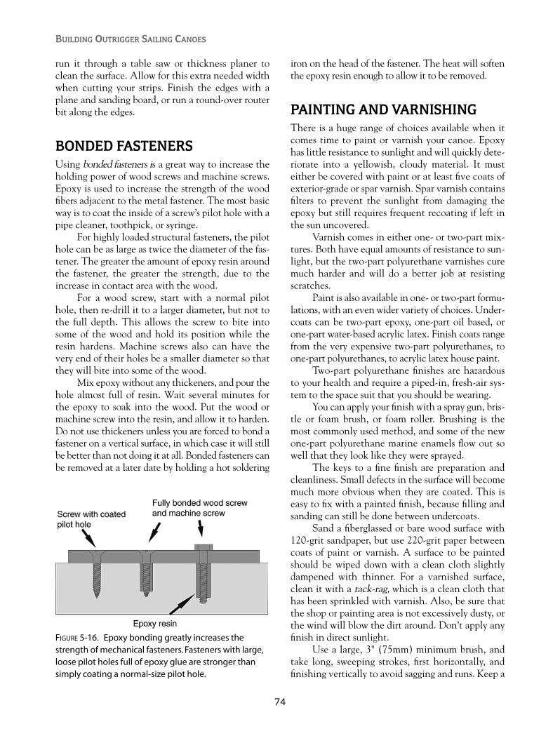
run it through a table saw or thickness planer toclean the surface. Allow for this extra needed widthwhen cutting your strips. Finish the edges with aplane and sanding board, or run a round-over routerbit along the edges.
BONDED FASTENERSUsing bonded fasteners is a great way to increase theholding power of wood screws and machine screws.Epoxy is used to increase the strength of the woodfibers adjacent to the metal fastener. The most basicway is to coat the inside of a screw’s pilot hole with apipe cleaner, toothpick, or syringe.
For highly loaded structural fasteners, the pilothole can be as large as twice the diameter of the fas-tener. The greater the amount of epoxy resin aroundthe fastener, the greater the strength, due to theincrease in contact area with the wood.
For a wood screw, start with a normal pilothole, then re-drill it to a larger diameter, but not tothe full depth. This allows the screw to bite intosome of the wood and hold its position while theresin hardens. Machine screws also can have thevery end of their holes be a smaller diameter so thatthey will bite into some of the wood.
Mix epoxy without any thickeners, and pour thehole almost full of resin. Wait several minutes forthe epoxy to soak into the wood. Put the wood ormachine screw into the resin, and allow it to harden.Do not use thickeners unless you are forced to bond afastener on a vertical surface, in which case it will stillbe better than not doing it at all. Bonded fasteners canbe removed at a later date by holding a hot soldering
iron on the head of the fastener. The heat will softenthe epoxy resin enough to allow it to be removed.
PAINTING AND VARNISHINGThere is a huge range of choices available when itcomes time to paint or varnish your canoe. Epoxyhas little resistance to sunlight and will quickly dete-riorate into a yellowish, cloudy material. It musteither be covered with paint or at least five coats ofexterior-grade or spar varnish. Spar varnish containsfilters to prevent the sunlight from damaging theepoxy but still requires frequent recoating if left inthe sun uncovered.
Varnish comes in either one- or two-part mix-tures. Both have equal amounts of resistance to sun-light, but the two-part polyurethane varnishes curemuch harder and will do a better job at resistingscratches.
Paint is also available in one- or two-part formu-lations, with an even wider variety of choices. Under-coats can be two-part epoxy, one-part oil based, orone-part water-based acrylic latex. Finish coats rangefrom the very expensive two-part polyurethanes, toone-part polyurethanes, to acrylic latex house paint.
Two-part polyurethane finishes are hazardousto your health and require a piped-in, fresh-air sys-tem to the space suit that you should be wearing.
You can apply your finish with a spray gun, bris-tle or foam brush, or foam roller. Brushing is themost commonly used method, and some of the newone-part polyurethane marine enamels flow out sowell that they look like they were sprayed.
The keys to a fine finish are preparation andcleanliness. Small defects in the surface will becomemuch more obvious when they are coated. This iseasy to fix with a painted finish, because filling andsanding can still be done between undercoats.
Sand a fiberglassed or bare wood surface with120-grit sandpaper, but use 220-grit paper betweencoats of paint or varnish. A surface to be paintedshould be wiped down with a clean cloth slightlydampened with thinner. For a varnished surface,clean it with a tack-rag, which is a clean cloth thathas been sprinkled with varnish. Also, be sure thatthe shop or painting area is not excessively dusty, orthe wind will blow the dirt around. Don’t apply anyfinish in direct sunlight.
Use a large, 3" (75mm) minimum brush, andtake long, sweeping strokes, first horizontally, andfinishing vertically to avoid sagging and runs. Keep a
BUILDING OUTRIGGER SAILING CANOES
74
FIGURE 5-16. Epoxy bonding greatly increases thestrength of mechanical fasteners. Fasteners with large,loose pilot holes full of epoxy glue are stronger thansimply coating a normal-size pilot hole.

wet edge and work as quickly as possible. The ambi-ent temperature and the type of paint you’re usingwill have a great effect on how fast you have towork. If you haven’t used a particular product before,practice on some scrap material rather than yourhull. Finishes applied with a foam roller can belightly finished with a good brush to smooth thebubbles left by the roller.
Spray painting with a compressor and spraygun is a whole subject on its own and can be donewith great success if you have a clean area, some pre-vious experience, and a good breathing apparatus.
Any non-water-based finish will emit strongfumes, so always wear a good respirator, designed tofilter out organic vapors.
METAL WORKIn all of my designs, I have minimized the use ofmetal parts. I’ve reduced the use of metal fittingsdown to blocks for running rigging. You can buy theblocks, or make them from wood with plasticsheaves.
If you’re building a leeboard, the aluminumreinforcing plate shown can be cut from a 1⁄8" (3mm)plate with a jigsaw or hacksaw.
WORKSHOP HEALTH ANDSAFETYTraditional boatbuilding, before the days of resinsand electric sanders, was a much healthier experi-ence. Almost every material we use for modern boat-building has some health hazards that must beguarded against.
Building a strip hull from western red cedarwill expose you to the sanding dust, which can beharmful to the lungs. It’s not something that waitsfor years to appear; it can cause breathing problemsimmediately. Be sure to wear a dust mask with twostraps when sanding, and use a sander with anattachment that catches the dust in a bag or a vac-uum system. Any fairing that you can do with asharp plane or scraper will save on the dust prob-lem. Other wood species are not as toxic as redcedar, but I would still use protection against inhal-ing the dust.
The sanding of cured epoxy can be reduced bythe use of a sharp scraper. Skin exposure to uncuredepoxy (especially the hardener) can cause an allergic
reaction in some people, resulting in a bad skin rash.Once you are sensitized to it, you may never be ableto get near epoxy again. It’s important to wear glovesat all times while mixing or applying epoxy. The dis-posable latex gloves used by doctors work well andare economical to buy in a dispensing box. Rubberdishwashing gloves are also good and hold up betterif you’re having problems tearing the thinner surgi-cal gloves.
Always wear safety glasses when mixing resin,and wear your dust mask when mixing in gluefillers, because they will form a cloud around yourhead.
If you do have to remove epoxy from your skin,try using vinegar or plenty of soap and water. Usingepoxy thinner or acetone only thins the resin so thatit can better penetrate your skin.
Painting with two-part polyurethane paints orvarnishes produces fumes that are carcinogenic, sobe sure to wear at least an organic vapor respirator,and ideally a system that pumps fresh air into a fullface mask. Cover your hands, too, because the thin-ner is also toxic.
Power tools of any kind have their own set ofdangers. When using your table saw, always pushthe stock with a pusher stick, kept handy for thatpurpose, and always use a feather board when rip-ping thin stock to avoid kickback. Don’t wearloose sleeves or baggy clothing around a table sawor router, or else you risk being pulled into theblade.
Router bits have been known to grab clothingand take off parts of fingers. And again—always wearsafety glasses.
MAINTENANCE AND REPAIRMaintaining the beauty and integrity of your cre-ation will ensure that it lasts a long time. Tradi-tional canoes in the Pacific and Indian oceansquite often have their own shelter on the water-front. Curved, arched, A-framed, and thatchedcanoe houses protected the vessels from the rav-ages of sun and rain. At the very least, they werecovered with palm fronds to protect them fromrapid drying and warping. Shade and good ventila-tion are still today the best ways to preserve yourcanoe.
A strip-planked canoe hull that has been fiber-glassed with epoxy resin will deteriorate very quicklyif it is not protected by several coats of spar varnish
75
Boatbuilding Basics
or paint. Epoxy resin, while very waterproof, has noresistance to ultraviolet light from the sun. Withoutthe protection of spar varnish (containing UVinhibitors) or paint, it will very soon turn hazy yel-low and deteriorate if left exposed to sunlight.
Of the two coatings, varnish requires themost maintenance, with recoating required every sixmonths if the craft is left out in the weather. Two-part polyurethane varnishes are much harder thanthe single-part mixture but have no greater resist-ance to the sun. They will require recoating just asoften if they are left exposed. Paint will last manyyears depending on how much money you want tospend. Two-part polyurethanes can last up to tenyears even when the boat is left in the sun.
The easiest way to extend the life of a var-nished finish is to simply cover it. From the cheapestblue tarp to a custom made acrylic cover, anything isbetter than just leaving the boat exposed. Storingthe canoe under a roof is even better, because itallows better ventilation and doesn’t trap moisture,which can produce mildew in the hull.
Plywood hulls, like on the Wa’apa, can be builtwithout the fiberglass sheathing on the outside if theplywood is of high-quality marine grade. Douglas firplywood, however, will develop “checking” if it isnot sheathed in fiberglass cloth. Checking is indi-cated by many fine cracks in the outer laminate ofthe plywood. A plain resin coating or any kind ofpaint won’t prevent checking.
Sails should always be stored within a coveror bag, or indoors when not being used. Polytarpsails will deteriorate quickly from sunlight, andeven the best commercial sailcloth will degradebut at a slower rate.
Most damage to canoe hulls consists of surfacescratches, which can be very disturbing to thebuilder who has spent many hours acquiring a per-fect finish. In most cases, these will disappear whenthe hull is recoated with varnish. If you can see awhitish blemish with the fiberglass weave showing,then you need to take more immediate action. Thefabric may be delaminated from the hull and willrequire some surgery with a razor blade to remove it.After removing the loose fiberglass, use fine sandpa-per to feather back the edges to allow a new patch offiberglass to be laminated in place.
If the planking has been gouged or splintered,you can remove the damaged timber with a sharprazor knife, leaving a forty-five-degree, anglededge. Carve a piece of timber to fit and glue it in
place. Don’t expect an invisible repair, since theedge of the old and new fiberglass will probably bevisible. In most cases, this type of damage happensbelow the waterline and the repair won’t benoticed.
Major damage may require the replacement ofseveral plank sections, but since you built this hulloriginally, you won’t have much trouble figuring outhow to do it.
If you’re a long way from civilization when seri-ous hull damage occurs, there are some precautionsyou can take. A roll of duct tape has saved morethan one cruise. Duct tape won’t stick to damp, saltysurfaces, so spend some time cleaning the surface.
Large offshore vessels have escaped sinking bypulling a sail or canvas under the hull with linesholding it to the gunwale. The water pressure willhold the fabric against the damage and keep most ofthe sea outside of your hull.
There are underwater epoxy putties available,although they will stick better if you dry things outas much as possible. My favorite Third World solu-tion involves using Styrofoam (expanded poly-styrene, or eps) scraps found on any beach in theworld and some gasoline. I’ve heard of this beingdone in locations that are thousands of miles apart,so I suspect that it is widespread. When the foampieces come in contact with gasoline, they melt intoa sticky goo that seems to bond to just about any-thing. This sticky goo combined with vegetablefibers like dried leaves, vines, or cotton cloth canbe used to make a reasonably secure fiberglass-likepatch.
Another kind of damage that is likely to occuris damage to the sailing rig, including broken masts,booms, and torn sails. Broken spars are difficult tojury-rig in a small canoe, but if you can get to thebeach, repair materials can be found. Spars can be“fished” where another stick or short piece of spar istightly lashed alongside the break. Wooden sparscan be “scarfed” with the use of a sharp knife and atight lashing. Note that almost all rig repairs requirestring or light lashing line. A supply of small, strongline and some imagination will take care of mostsituations.
A torn sail can be sewn if you have a needleand thread and some scrap fabric. Tears in the mid-dle, unstressed portion of a sail can be patched withcontact cement and a piece of fabric. Only thesolvent-based contact cements are strong enough tohold a sail together.
BUILDING OUTRIGGER SAILING CANOES
76
If it is too difficult or impossible to repair a bro-ken spar or sail, a smaller rig lashed together from whatremains will usually get you back to shore. Again, thatroll of light line will prove to be very useful.
Damage to a rudder may be difficult to repairaway from a workshop. I always recommend that
you carry a steering oar as a backup system. It iseasily stored out on the beams and can add itsweight to the ama. A steering oar can also be usedas a righting pole in the event of capsize. You willalways have a paddle, and that is also available forsteering.
77
Boatbuilding Basics
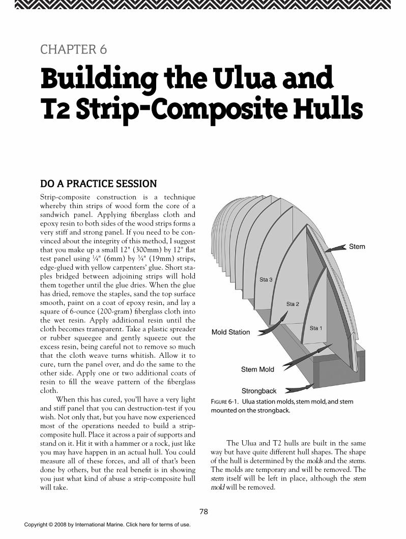
78
DO A PRACTICE SESSIONStrip-composite construction is a techniquewhereby thin strips of wood form the core of asandwich panel. Applying fiberglass cloth andepoxy resin to both sides of the wood strips forms avery stiff and strong panel. If you need to be con-vinced about the integrity of this method, I suggestthat you make up a small 12" (300mm) by 12" flattest panel using 1⁄4" (6mm) by 3⁄4" (19mm) strips,edge-glued with yellow carpenters’ glue. Short sta-ples bridged between adjoining strips will holdthem together until the glue dries. When the gluehas dried, remove the staples, sand the top surfacesmooth, paint on a coat of epoxy resin, and lay asquare of 6-ounce (200-gram) fiberglass cloth intothe wet resin. Apply additional resin until thecloth becomes transparent. Take a plastic spreaderor rubber squeegee and gently squeeze out theexcess resin, being careful not to remove so muchthat the cloth weave turns whitish. Allow it tocure, turn the panel over, and do the same to theother side. Apply one or two additional coats ofresin to fill the weave pattern of the fiberglasscloth.
When this has cured, you’ll have a very lightand stiff panel that you can destruction-test if youwish. Not only that, but you have now experiencedmost of the operations needed to build a strip-composite hull. Place it across a pair of supports andstand on it. Hit it with a hammer or a rock, just likeyou may have happen in an actual hull. You couldmeasure all of these forces, and all of that’s beendone by others, but the real benefit is in showingyou just what kind of abuse a strip-composite hullwill take.
The Ulua and T2 hulls are built in the sameway but have quite different hull shapes. The shapeof the hull is determined by the molds and the stems.The molds are temporary and will be removed. Thestem itself will be left in place, although the stemmold will be removed.
CHAPTER 6
Building the Ulua andT2 Strip-Composite Hulls
FIGURE 6-1. Ulua station molds, stem mold, and stemmounted on the strongback.
Copyright © 2008 by International Marine. Click here for terms of use.

79
Building Strip-Composite Hulls
THE STRONGBACKThe strongback is a firm, flat, level, and stable sur-face upon which the molds will be mounted. Youwon’t regret spending the time to give it thoseattributes.
The strongback is a box beam, constructed from3⁄4" (19mm) particle board or plywood. It has a topand sides but no bottom and has bulkheads insidespaced every 16" (400mm). Two heavy timber legssupport it at a convenient working height, or you canattach it to a pair of sawhorses. Thirty inches(760mm) is a good height for the top surface of thestrongback.
Take one 3⁄4" (19mm) sheet of particle board orplywood and cut it into six strips a little less than 8" (200mm) wide. By splicing the side panels end toend, you will have a 16' (4800mm) long strongback.This is shorter than the hull but actually makes iteasier to work on the ends of the hull without thestrongback getting in the way. Splice up two sidepanels and the top panel by joining two sections endto end, and making a butt block 8" (200mm) by
12" (300mm) and gluing and screwing it over thejoint. Make seven rectangular bulkheads to fit insideat 16" (400mm) intervals.
Stretch a string tightly along the center of thetop surface, held at each end by a small nail. Make
FIGURE 6-2. Completed strongback with cleats to locate mold positions.
FIGURE 6-3. Use butt splices on the inside of the strong-back sides and top to achieve the required length.
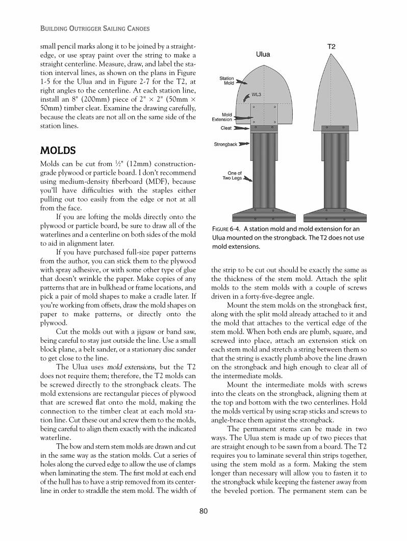
small pencil marks along it to be joined by a straight-edge, or use spray paint over the string to make astraight centerline. Measure, draw, and label the sta-tion interval lines, as shown on the plans in Figure1-5 for the Ulua and in Figure 2-7 for the T2, atright angles to the centerline. At each station line,install an 8" (200mm) piece of 2" � 2" (50mm �
50mm) timber cleat. Examine the drawing carefully,because the cleats are not all on the same side of thestation lines.
MOLDSMolds can be cut from 1⁄2" (12mm) construction-grade plywood or particle board. I don’t recommendusing medium-density fiberboard (MDF), becauseyou’ll have difficulties with the staples eitherpulling out too easily from the edge or not at allfrom the face.
If you are lofting the molds directly onto theplywood or particle board, be sure to draw all of thewaterlines and a centerline on both sides of the moldto aid in alignment later.
If you have purchased full-size paper patternsfrom the author, you can stick them to the plywoodwith spray adhesive, or with some other type of gluethat doesn’t wrinkle the paper. Make copies of anypatterns that are in bulkhead or frame locations, andpick a pair of mold shapes to make a cradle later. Ifyou’re working from offsets, draw the mold shapes onpaper to make patterns, or directly onto theplywood.
Cut the molds out with a jigsaw or band saw,being careful to stay just outside the line. Use a smallblock plane, a belt sander, or a stationary disc sanderto get close to the line.
The Ulua uses mold extensions, but the T2does not require them; therefore, the T2 molds canbe screwed directly to the strongback cleats. Themold extensions are rectangular pieces of plywoodthat are screwed flat onto the mold, making theconnection to the timber cleat at each mold sta-tion line. Cut these out and screw them to the molds,being careful to align them exactly with the indicatedwaterline.
The bow and stern stem molds are drawn and cutin the same way as the station molds. Cut a series ofholes along the curved edge to allow the use of clampswhen laminating the stem. The first mold at each endof the hull has to have a strip removed from its center-line in order to straddle the stem mold. The width of
the strip to be cut out should be exactly the same asthe thickness of the stem mold. Attach the splitmolds to the stem molds with a couple of screwsdriven in a forty-five-degree angle.
Mount the stem molds on the strongback first,along with the split mold already attached to it andthe mold that attaches to the vertical edge of thestem mold. When both ends are plumb, square, andscrewed into place, attach an extension stick oneach stem mold and stretch a string between them sothat the string is exactly plumb above the line drawnon the strongback and high enough to clear all ofthe intermediate molds.
Mount the intermediate molds with screwsinto the cleats on the strongback, aligning them atthe top and bottom with the two centerlines. Holdthe molds vertical by using scrap sticks and screws toangle-brace them against the strongback.
The permanent stems can be made in twoways. The Ulua stem is made up of two pieces thatare straight enough to be sawn from a board. The T2requires you to laminate several thin strips together,using the stem mold as a form. Making the stemlonger than necessary will allow you to fasten it tothe strongback while keeping the fastener away fromthe beveled portion. The permanent stem can be
BUILDING OUTRIGGER SAILING CANOES
80
FIGURE 6-4. A station mold and mold extension for anUlua mounted on the strongback. The T2 does not usemold extensions.
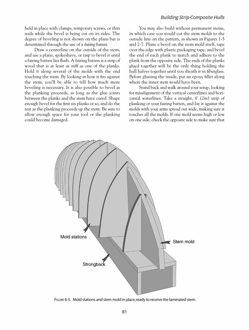
held in place with clamps, temporary screws, or thinnails while the bevel is being cut on its sides. Thedegree of beveling is not shown on the plans but isdetermined through the use of a fairing batten.
Draw a centerline on the outside of the stem,and use a plane, spokeshave, or rasp to bevel it untila fairing batten lies flush. A fairing batten is a strip ofwood that is at least as stiff as one of the planks.Hold it along several of the molds with the endtouching the stem. By looking at how it fits againstthe stem, you’ll be able to tell how much morebeveling is necessary. It is also possible to bevel asthe planking proceeds, as long as the glue jointsbetween the planks and the stem have cured. Shapeenough bevel for the first six planks or so, and do therest as the planking proceeds up the stem. Be sure toallow enough space for your tool or the plankingcould become damaged.
You may also build without permanent stems,in which case you would cut the stem molds to theoutside line on the pattern, as shown in Figures 1-5and 2-7. Plane a bevel on the stem mold itself, tapeover the edge with plastic packaging tape, and bevelthe end of each plank to match and adhere to theplank from the opposite side. The ends of the planksglued together will be the only thing holding thehull halves together until you sheath it in fiberglass.Before glassing the inside, put an epoxy fillet alongwhere the inner stem would have been.
Stand back and walk around your setup, lookingfor misalignment of the vertical centerlines and hori-zontal waterlines. Take a straight, 6' (2m) strip ofplanking or your fairing batten, and lay it against themolds with your arms spread out wide, making sure ittouches all the molds. If one mold seems high or lowon one side, check the opposite side to make sure that
81
Building Strip-Composite Hulls
FIGURE 6-5. Mold stations and stem mold in place,ready to receive the laminated stem.

it isn’t displaced to one side of the centerline beforetaking any action. If you wear strong glasses, rely onmeasurements rather than your eye, because theglasses can distort the shape of a straight line or curve.
High spots can be taken down with a blockplane, rasp, or sander. Low spots can be filled by glu-ing and stapling on thin strips of timber to be shapeddown when the glue cures, or if you want fasterresults, you can build up a a mold edge with polyesterauto-body putty. The putty will harden in ten min-utes, and you can plane or sand it to shape. Stapletemporary planks at many different locations on themold, and sight down them. This is a good practiceall through the planking procedure. Shaving, filling,or shimming with thin scraps can be done at anystage in the planking.
When everything is shaped and aligned to yoursatisfaction, cover the edges of all the molds withplastic packaging tape to avoid gluing the planks tothe mold. Do not cover a permanent stem, becausethe planks will be glued to it.
PLANKINGFor this stage, you’ll need some new tools. TheArrow T50 stapler is a good, reliable tool and can befield-stripped and cleaned when glue has frozen itsolid. Use the 9⁄16" (14mm) staples. You’ll spend a lotof time with your staple puller. When pulling a sta-ple, hold a small putty knife against the plankingnext to the staple to avoid making dents in theplanking with the puller. I highly recommend usinga Japanese pull saw for cutting planks and doingcareful surgery. When new, these are very sharp, sotry to keep the bloodstains off of the hull.
Because a strip-composite hull is sheathed inepoxy and fiberglass on both sides, it is unnecessaryto use a completely waterproof glue between theplank edges. The yellow, aliphatic carpenters’ glue ismost commonly used and causes the least mess. Inthe past, I’ve successfully used plastic resin, epoxy,and polyurethane glues. Epoxy is only normally usedon large hulls.
BUILDING OUTRIGGER SAILING CANOES
82
FIGURE 6-6. Use a batten or a piece of strip planking to check the stem bevel.
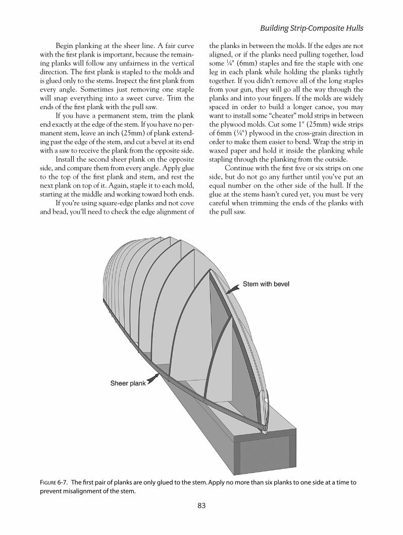
Begin planking at the sheer line. A fair curvewith the first plank is important, because the remain-ing planks will follow any unfairness in the verticaldirection. The first plank is stapled to the molds andis glued only to the stems. Inspect the first plank fromevery angle. Sometimes just removing one staplewill snap everything into a sweet curve. Trim theends of the first plank with the pull saw.
If you have a permanent stem, trim the plankend exactly at the edge of the stem. If you have no per-manent stem, leave an inch (25mm) of plank extend-ing past the edge of the stem, and cut a bevel at its endwith a saw to receive the plank from the opposite side.
Install the second sheer plank on the oppositeside, and compare them from every angle. Apply glueto the top of the first plank and stem, and rest thenext plank on top of it. Again, staple it to each mold,starting at the middle and working toward both ends.
If you’re using square-edge planks and not coveand bead, you’ll need to check the edge alignment of
the planks in between the molds. If the edges are notaligned, or if the planks need pulling together, loadsome 1⁄4" (6mm) staples and fire the staple with oneleg in each plank while holding the planks tightlytogether. If you didn’t remove all of the long staplesfrom your gun, they will go all the way through theplanks and into your fingers. If the molds are widelyspaced in order to build a longer canoe, you maywant to install some “cheater” mold strips in betweenthe plywood molds. Cut some 1" (25mm) wide stripsof 6mm (1⁄4") plywood in the cross-grain direction inorder to make them easier to bend. Wrap the strip inwaxed paper and hold it inside the planking whilestapling through the planking from the outside.
Continue with the first five or six strips on oneside, but do not go any further until you’ve put anequal number on the other side of the hull. If theglue at the stems hasn’t cured yet, you must be verycareful when trimming the ends of the planks withthe pull saw.
83
Building Strip-Composite Hulls
FIGURE 6-7. The first pair of planks are only glued to the stem. Apply no more than six planks to one side at a time toprevent misalignment of the stem.

If you plank too much of one side ahead of theother, it can pull the stem mold out of alignment. It’salways a good idea to sight down the stems often asplanking proceeds. Just the act of pushing the end ofthe plank against the stem during stapling can beenough to move it out of line.
Once the planking has proceeded as far asthe inner end of the stems, you have severaloptions for finishing up. My favorite method is tostop the planking at a point that leaves justenough space for one more plank at the inner endof the stem. I then install two planks togetherstraddling the keel line. You’ll need to bevel theedges of these two keel planks where they bearagainst each other.
You can fill in the last open areas by one of sev-eral ways. You can continue planking up from the side
planks, continue planking straight along the keelplanks, or alternate with a resultant herringbone pat-tern. If planking up from the side is resulting in hardlateral bends, you can either switch to straight keelplanks or taper the ends of the planks to ease the bend.
THE OUTER STEMPlane, rasp, or sand a flat surface where the planksattach to the stems, to receive an outer laminatedstem. Laminate thin strips of timber in place andclamp them down with waxed screws and washers.Sometimes you can clamp strips in place with tapeor string wrapped right around the hull and strong-back. Test it all before you apply the glue. Plane itdown fair with the hull after the glue has cured. Fillthe screw holes with wooden plugs.
BUILDING OUTRIGGER SAILING CANOES
84
FIGURE 6-8. After planking has proceeded as high as the inner ends of the stems, install a pair of beveled planks todefine the keel.
FIGURE 6-9. Planking to cover the bottom area can be installed parallel with the keel or parallel to the previous planks.

FAIRING AND SMOOTHING THE HULLA sharp plane or spokeshave is the best tool for ini-tial smoothing of the hull. A sharp paint scraper isalso useful. Shavings are much more manageablethan sanding dust that goes everywhere in the workspace. After doing all you can with the plane orscraper, begin sanding with 80-grit aluminum oxidesandpaper. The round random orbital sander is thebest tool for this job. A soft, foam-backed pad willsand curved surfaces better than a stiff, rubber pad.Hold the sander flat to avoid gouging the surface.
After the coarse sanding is complete, vacuumthe dust from the hull and look for gaps between theplanking that may need filling before the fiberglass isapplied. If the gap goes all the way through the hull,it should be filled. Mark the locations by puttingmasking tape along both sides of the gap. Mix sand-ing dust with your glue and force it into the gapswith a putty knife. In most cases, no filling is neces-sary. The sheathing of the hull with epoxy resin andfiberglass will fill in any small cracks.
Use 120-grit sandpaper for the final sanding.Do not sand it any finer than 120 grit, because thiswill provide the best base for the epoxy resin. Becareful when you are sanding close to edges at thestems and keel; it is best to sand these areas with along sanding board, like those used in automotivebody shops. You can sand the entire hull with a longsanding board if you wish. The hard fact is that thisis the only way to get near-perfect fairness.
To see what the hull will look like when it isfiberglassed, wipe a damp sponge or rag over the hullsurface. This will raise the grain and also expose anyscratches remaining from earlier coarse sanding. Allowthe hull to dry, and sand it again to smooth the raisedgrain and remove any visible scratches. Allow the hullto dry overnight before applying any epoxy resin.
Sheath the exterior with one layer of 6-ounce(200-gram) woven fiberglass cloth as described pre-viously. Apply three fill coats of resin, but leave thefinal sanding until you are ready to varnish the hull.Sand any area that will be bonded to later, such asalong the gunwale.
REMOVING THE HULL FROMTHE MOLDBefore you remove the hull from the mold, you’llneed to build a cradle to hold it securely upright. Usethe mold pattern copies that you saved for this, andmake a pair of cardboard patterns first to check forfit. Be sure to allow for some carpet or foam paddingon the inside edges of the cradle. Make the cradlefrom 1⁄2" (12mm) plywood or particle board.
You can either remove the screws holding themolds to the strongback, and roll the hull and moldsall together, or just try lifting the hull off with themolds still attached to the strongback. Hopefullyyou haven’t left any inaccessible screws holding thepermanent stem to the stem mold. If it won’t lift off,remove the mold to the strongback screws, and dis-assemble the mold from within after the hull andmold are righted.
Set the hull upright in its cradle, and take sometime to congratulate yourself. The hull sides arequite floppy at this stage, but have no fear, becausethey’ll be extremely rigid when everything’s finished.
Rip a pair of 5⁄8" � 11⁄2" (16mm � 38mm) straighttimber strips for temporary gunwales. These do notneed to be the full length of the hull and are best ifthey just go past the watertight bulkhead positions.Attach them to the outside of the hull with screwsdriven from the outside, just short enough to preventthem from sticking through the inside surface. They’lljust be biting into the fiberglass surface to hold.
Attach the temporary gunwales so that theupper edge is 1⁄4" (6mm) higher than the edge of thehull. Now you can screw on a couple of spreadersticks on top of the temporary gunwales from oneside to the other, holding the hull sides at the correctspacing. Measure the correct spacing from the molds.
85
Building Strip-Composite Hulls
FIGURE 6-10. The outer stem is laminated over the endsof the strip planks.

It is a good idea to keep a couple of spreader sticksuntil the interior of the hull is glassed in place to pre-vent any warping or distortion in the hull fromchanging humidity or weather conditions. The stickscan be removed temporarily while you are sandingthe interior.
GLASSING THE INTERIORRough shaping of the interior is best done with asharp scraper that you’ve ground or filed to a curvedworking edge that will fit into the tightest areas ofthe hull. Follow the scraping with the random orbitalsander. A soft, foam-backed pad will help to preventyou from digging into the surface. Fill the area alongthe edges of the stem with lightweight epoxy filler toenable the fiberglass to fit without voids.
The interior can be glassed in the same way asthe exterior, except that you only need one fill coatof resin after the fiberglass is bonded into place. Youcan either lay the glass in lengthwise, as on the exte-rior, or use shorter lengths and glass from gunwale togunwale, overlapping the edges for each new sectionof fiberglass. This will leave rib-like ridges on theinterior of the hull, but the fiberglass will be easier toinstall. Don’t try to fit the end of the glass into thenarrow stem area. Just cut it short of the stem andadd a bias-cut strip separately.
Be careful when squeegeeing the interior,because it is very easy to pull the fabric away fromthe surface in concave areas and not notice it untilit’s too late.
FITTING THE INTERIORSTRUCTURERemove the temporary outwales and sight down thesheer. Use a plane to fair the sheer line if needed.Install the inwale or inner gunwale with clamps andglue, or use screws from the outside. Leave a mil-limeter or so of hull above the gunwale strip.
Don’t let a stiff inwale distort the shape of thehull. The tight bend at the ends can be relieved withmany thin saw cuts across the grain of the inwale onthe side that doesn’t touch the hull. Epoxy glue soakedinto the cuts will restore the strength of the inwale.
Make the two watertight bulkheads, the waes(spreaders located below the cross-beam posi-tions), and the ring frame if you’re building theUlua. Cut holes for access panels and drains beforeinstalling bulkheads. Clean the hull surface withwater to remove any epoxy residue, and sand thesurface before bonding parts to it. Fillet the jointsbetween the bulkhead and hull with epoxy filler,and install a single 3" (75mm) bias-cut strip offiberglass over the fillets. The rows of staple holeson the outside are a good indicator for locating thestation lines.
Make plywood saddles for the ends of the waes,and bond them into place with epoxy glue. Make upseat support stringers, in the case of the Ulua, andbond them into place with epoxy glue. If you have aself-bailing cockpit, as in the T2, install the cockpitfloor now with thick glue followed by a fillet on top.When you are glassing the T2 cockpit floor, lap the
BUILDING OUTRIGGER SAILING CANOES
86
FIGURE 6-11. Saw cuts partially through the inwale allow it to make a tight bend without distorting the hull.

glass up over the fillets and onto the interior hull sides.Cut any access holes in the floor before installing it.
The mast step for the Ulua must be very stronglyattached to the hull and ring frame. Unstayed mastsexert quite powerful forces at the base. Bevel theunderside of the flat base to fit against the hull sides,and glue it in place with epoxy glue, being sure toclean and sand the interior surface of the hull first.Also, have one edge of the flat base glued tightlyagainst the ring frame. For additional security, I’d rec-ommend a layer of fiberglass over the flat base and lap-ping onto both the hull sides and the ring frame.
FORE AND AFT DECKSThe fore and aft decks can be strip-planked like thehull or made of plywood. Mark the inwale and hulledge where the fore and aft decks begin. You’ll needto cut a narrow strip of hull and inwale away to thedepth of your deck thickness. Use a jigsaw, and finishup with a coarse sanding board that is long enoughto allow you to sand across both inwales.
If you are having a strip deck rather than aplywood one, install some temporary deck beamscut to a circular arc. Put packaging tape over thetop of the temporary frames, the inwale, the hull,and the top of the bulkhead. Strip and glass in thenormal way, being sure to make the deck slightlylarger than the edge of the hull. Remove the deck,put it in a shaped cradle, sand it smooth, and glassthe underside.
Before you glue the deck to the hull, be sure tocheck that the hull is sitting level and untwisted.Lay a level across the hull at the wae locations, andmake sure that they are the same. Any twist will belocked in once the deck is glued down. The deck canbe clamped into place with masking or other tapewrapped around the hull. When the glue has cured,trim the deck edge very carefully with a plane andsanding block. Use a short scrap of outer gunwalematerial held up against the hull and deck edge tocheck your accuracy.
Install the outer gunwale with clamps or screwsand glue. The ends are under a lot of tension when
87
Building Strip-Composite Hulls
FIGURE 6-12. A temporary deck beam is necessary if you are strip-planking the foredecks. A narrow strip of hull andinwale is cut away to allow the deck to fit flush with the rest of the hull.
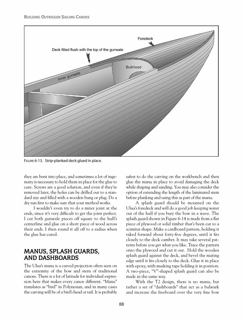
they are bent into place, and sometimes a lot of inge-nuity is necessary to hold them in place for the glue tocure. Screws are a good solution, and even if they’reremoved later, the holes can be drilled out to a stan-dard size and filled with a wooden bung or plug. Do adry run first to make sure that your method works.
I wouldn’t even try to do a miter joint at theends, since it’s very difficult to get the joint perfect.I cut both gunwale pieces off square to the hull’scenterline and glue on a short piece of wood acrosstheir ends. I then round it all off to a radius whenthe glue has cured.
MANUS, SPLASH GUARDS, AND DASHBOARDSThe Ulua’s manu is a carved projection often seen onthe extremity of the bow and stern of traditionalcanoes. There is a lot of latitude for individual expres-sion here that makes every canoe different. “Manu”translates as “bird” in Polynesian, and in many casesthe carving will be of a bird’s head or tail. It is probably
safest to do the carving on the workbench and thenglue the manu in place to avoid damaging the deckwhile shaping and sanding. You may also consider theoption of extending the length of the laminated stembefore planking and using this as part of the manu.
A splash guard should be mounted on theUlua’s foredeck and will do a good job keeping waterout of the hull if you bury the bow in a wave. Thesplash guard shown in Figure 6-14 is made from a flatpiece of plywood or solid timber that’s been cut to ascimitar shape. Make a cardboard pattern, holding itraked forward about forty-five degrees, until it fitsclosely to the deck camber. It may take several pat-terns before you get what you like. Trace the patternonto the plywood and cut it out. Hold the woodensplash guard against the deck, and bevel the matingedge until it fits closely to the deck. Glue it in placewith epoxy, with masking tape holding it in position.A two-piece, “V”-shaped splash guard can also bemade in the same way.
With the T2 design, there is no manu, butrather a set of “dashboards” that act as a bulwarkand increase the freeboard over the very fine bow
BUILDING OUTRIGGER SAILING CANOES
88
FIGURE 6-13. Strip-planked deck glued in place.

89
FIGURE 6-15. T2 fore or aft deck with plywood “dashboards”attached to the outside of the hull.
FIGURE 6-14. Ulua hull—outer gunwale, splash guard, and manu in place.
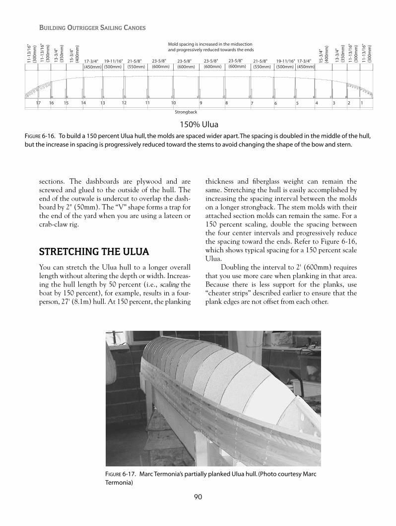
sections. The dashboards are plywood and arescrewed and glued to the outside of the hull. Theend of the outwale is undercut to overlap the dash-board by 2" (50mm). The “V” shape forms a trap forthe end of the yard when you are using a lateen orcrab-claw rig.
STRETCHING THE ULUAYou can stretch the Ulua hull to a longer overalllength without altering the depth or width. Increas-ing the hull length by 50 percent (i.e., scaling theboat by 150 percent), for example, results in a four-person, 27' (8.1m) hull. At 150 percent, the planking
thickness and fiberglass weight can remain thesame. Stretching the hull is easily accomplished byincreasing the spacing interval between the moldson a longer strongback. The stem molds with theirattached section molds can remain the same. For a150 percent scaling, double the spacing betweenthe four center intervals and progressively reducethe spacing toward the ends. Refer to Figure 6-16,which shows typical spacing for a 150 percent scaleUlua.
Doubling the interval to 2' (600mm) requiresthat you use more care when planking in that area.Because there is less support for the planks, use“cheater strips” described earlier to ensure that theplank edges are not offset from each other.
BUILDING OUTRIGGER SAILING CANOES
90
Strongback
17 16 15 14 13 12 11 10 9 8 7 6 5 4 3 2 1
23-5/8"(600mm)
23-5/8"(600mm)
23-5/8"(600mm)
23-5/8"(600mm)
21-5/8"(550mm)
21-5/8"(550mm)
19-11/16"(500mm)
17-3/4"(450mm)
15-3
/4"
(400
mm
)
13-3
/4"
(350
mm
)
11-1
3/16
"(3
00m
m)
11-1
3/16
"(3
00m
m)
19-11/16"(500mm)
17-3/4"(450mm)
15-3
/4"
(400
mm
)
13-3
/4"
(350
mm
)
11-1
3/16
"(3
00m
m)
11-1
3/16
"(3
00m
m)
150% Ulua
Mold spacing is increased in the midsectionand progressively reduced towards the ends
FIGURE 6-16. To build a 150 percent Ulua hull, the molds are spaced wider apart.The spacing is doubled in the middle of the hull,but the increase in spacing is progressively reduced toward the stems to avoid changing the shape of the bow and stern.
FIGURE 6-17. Marc Termonia’s partially planked Ulua hull. (Photo courtesy MarcTermonia)

91
Building Strip-Composite Hulls
FIGURE 6-18. Kent Robertson’s planked and glassed Ulua. (Photo courtesy Kent Robertson)
FIGURE 6-19. Clay Ghylin’s partially planked T2, with clamps being used rather than staples to hold the planks inplace. (Photo courtesy Clay Ghylin)

BUILDING OUTRIGGER SAILING CANOES
92
FIGURE 6-21. Clay Ghylin’s planked and glassed T2 hull. (Photo courtesy Clay Ghylin)
FIGURE 6-20. Fairing a T2 hull before glassing. (Photo courtesy Clay Ghylin)

93
Figure 6-23. T2 deck being glued to the hull. (Photo courtesy Clay Ghylin)
FIGURE 6-22. T2 bulkheads and cockpit floor support structure in place. (Photocourtesy Clay Ghylin)

BUILDING OUTRIGGER SAILING CANOES
94
FIGURE 6-24. Guy Rinfret’s T2 with dashboard, manu, and painted graphics. (Photo courtesy Guy Rinfret)
FIGURE 6-25. Kent Robertson’s Ulua with a traditional Hawaiianmanu and splash guard. (Photo courtesy Kent Robertson)

95
The Wa’apa consists of a three-piece hull thatcan be configured as a 24' (7.2m) hull, or, by
leaving out the midsection, a 16' (4.8m) hull. It canalternatively be built as a one- or two-piece hull.The layout for scarfing full-length panels is shown inFigure 3-9. The hull sections are joined with fourbolts at each bulkhead.
This method of building a flat-bottomed ply-wood hull is about as simple as can be devised. A hullsection consists of two side panels, a bulkhead at oneend, a stem timber at the bow, and a bulkhead orframe approximately midway between the two ends.
A pair of identical side panels are attached tothe station 2 bulkhead, bent around the station 1 bulkhead, and attached to the stem timber. Theside panels already have their gunwales and chinesattached before they are bent around the bulkheads.The bottom panel is added last.
Choose the best-quality plywood that you canafford, and you won’t regret it. Check the dimen-sions of the panels before you buy them. Most ply-wood sheets are 8' (2440mm) � 4' (1220mm), but
there are some metric sheets that are only 941⁄2"(2400mm) � 471⁄4" (1200mm). The smaller sheetswon’t allow for a 2" (50mm) scarf joint on the sidepanels if you wish to have a one-piece hull. Youronly option with the smaller sheets would be to usea butt splice with fiberglass strips on each side.
Examine Figure 3-9, which shows the cuttinglayout on the sheet of plywood. There isn’t muchwasted space, so lay the pieces out carefully. You willneed two stems, two of bulkhead number 1 (water-tight), four of bulkhead number 2, and one of framenumber 3. Number 3 will not be cut from plywood,but rather made up of a timber perimeter with ply-wood gussets reinforcing the corners. The stems arecut from 3⁄4" (18mm) solid timber.
Draw the side panels on the plywood sheets.Draw the curved lines with a straight timber battenheld between thin nails. Be sure to use the stiffestbatten possible to make the curves fair and identical.Cut out the side panels with a jigsaw or small circu-lar saw, being careful to stay slightly outside the line.Stack the matching panels together, and finish up
CHAPTER 7
Building the Wa’apaPlywood Hull
FIGURE 7-1. The Wa’apa can be configured as a two-piece, 16' (4.8m) hull, or as a three-piece, 24' (7.2m) hull.
Copyright © 2008 by International Marine. Click here for terms of use.
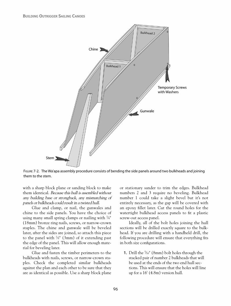
with a sharp block plane or sanding block to makethem identical. Because this hull is assembled withoutany building base or strongback, any mismatching ofpanels or bulkheads could result in a twisted hull.
Glue and clamp, or nail, the gunwales andchine to the side panels. You have the choice ofusing many small spring clamps or nailing with 3⁄4"(18mm) bronze ring nails, screws, or narrow-crownstaples. The chine and gunwale will be beveledlater, after the sides are joined, so attach this pieceto the panel with 1⁄8" (3mm) of it extending pastthe edge of the panel. This will allow enough mate-rial for beveling later.
Glue and fasten the timber perimeters to thebulkheads with nails, screws, or narrow-crown sta-ples. Check the completed similar bulkheadsagainst the plan and each other to be sure that theyare as identical as possible. Use a sharp block plane
or stationary sander to trim the edges. Bulkheadnumbers 2 and 3 require no beveling. Bulkheadnumber 1 could take a slight bevel but it’s notentirely necessary, as the gap will be covered withan epoxy fillet later. Cut the round holes for thewatertight bulkhead access panels to fit a plasticscrew-out access panel.
Ideally, all of the bolt holes joining the hullsections will be drilled exactly square to the bulk-head. If you are drilling with a handheld drill, thefollowing procedure will ensure that everything fitsin both size configurations.
1. Drill the 5⁄16" (8mm) bolt holes through thestacked pair of number 2 bulkheads that willbe used at the ends of the two end hull sec-tions. This will ensure that the holes will lineup for a 16' (4.8m) version hull.
BUILDING OUTRIGGER SAILING CANOES
96
FIGURE 7-2. The Wa’apa assembly procedure consists of bending the side panels around two bulkheads and joiningthem to the stem.
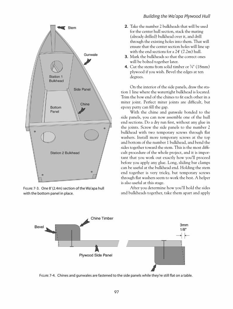
2. Take the number 2 bulkheads that will be usedfor the center hull section, stack the mating(already drilled) bulkhead over it, and drillthrough the existing holes into them. That willensure that the center section holes will line upwith the end sections for a 24' (7.2m) hull.
3. Mark the bulkheads so that the correct oneswill be bolted together later.
4. Cut the stems from solid timber or 3⁄4" (18mm)plywood if you wish. Bevel the edges at tendegrees.
On the interior of the side panels, draw the sta-tion 1 line where the watertight bulkhead is located.Trim the bow end of the chines to fit each other in amiter joint. Perfect miter joints are difficult, butepoxy putty can fill the gap.
With the chine and gunwale bonded to theside panels, you can now assemble one of the hullend sections. Do a dry run first, without any glue inthe joints. Screw the side panels to the number 2bulkhead with two temporary screws through flatwashers. Install more temporary screws at the topand bottom of the number 1 bulkhead, and bend thesides together toward the stem. This is the most diffi-cult procedure of the whole project, and it is impor-tant that you work out exactly how you’ll proceedbefore you apply any glue. Long, sliding bar clampscan be useful at the bulkhead end. Holding the stemend together is very tricky, but temporary screwsthrough flat washers seem to work the best. A helperis also useful at this stage.
After you determine how you’ll hold the sidesand bulkheads together, take them apart and apply
97
Building the Wa’apa Plywood Hull
FIGURE 7-3. One 8’ (2.4m) section of the Wa’apa hullwith the bottom panel in place.
FIGURE 7-4. Chines and gunwales are fastened to the side panels while they’re still flat on a table.
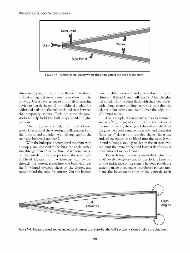
thickened epoxy to the joints. Reassemble them,and take diagonal measurements as shown in thedrawing. Use a bevel gauge or any angle-measuringdevice to match the panel-to-bulkhead angles. Putadditional nails into the bulkheads and stem betweenthe temporary screws. Tack on some diagonalsticks to help hold the hull shape until the gluehardens.
After the glue is cured, install a thickenedepoxy fillet around the watertight bulkhead on boththe forward and aft sides. Also fill any gaps at thestem and bulkhead number 2.
With the hull upside down, bevel the chine witha sharp plane, constantly checking the angle with astraightedge from chine to chine. Make some markson the outside of the side panels at the watertightbulkhead location so that fasteners can be putthrough the bottom panel into the bulkhead. Laythe 1⁄4" (6mm) plywood sheet on the chines, andtrace around the sides for cutting. Cut the bottom
panel slightly oversized, and glue and nail it to thechines, bulkhead 1, and bulkhead 2. After the gluehas cured, trim the edges flush with the sides. Finishwith a long, coarse sanding board to ensure that theedge is a fair curve, and round over the edge to a 1⁄4" (6mm) radius.
Use a couple of temporary screws to laminatean extra 3⁄4" (18mm) of soft timber on the outside ofthe stem, covering the edges of the side panels. Afterthe glue has cured, remove the screws and plane this“false stem” down to a rounded shape. Taper theends of the gunwales to blend into the stem. If youintend to hang a kick-up rudder on the aft stem, youcan omit the extra timber and leave it flat for easierinstallation of rudder fittings.
Before fitting the fore or stern deck, glue in asmall beveled ledge or cleat for the deck to fasten toon the inside face of the stem. The deck panels areeasier to make if you make a cardboard pattern first.Plane the bevel on the top of the gunwale to fit
BUILDING OUTRIGGER SAILING CANOES
98
FIGURE 7-5. A miter joint is used where the chines meet the base of the stem.
FIGURE 7-6. Measure equal angles and equal distances to ensure that the hull is properly aligned before the glue cures.

tightly to the deck panel. Note that the deck willtake the curve of the top of bulkhead number 1 atits aft end, and it will flatten out as it gets closer tothe stem. Cut the panel slightly oversized, and trimthe edge after it’s been glued and nailed down. Ifyou’re opting for the shunting crab-claw rig, install a1⁄2" (12mm) thick plywood pad under the deck panelright up close to the stem. This will provide a fasten-ing point for the end of a guide rail if you choose touse one.
When the two end hull sections have beencompleted, install the bolts in the predrilled holes tojoin the two sections. Use a plane or long sandingboard to correct any mismatch between the sections.Some filling with epoxy fairing putty may be needed.Use a batten to check for fairness.
The seats are cut from 1⁄4" (6mm) plywood witha timber stiffener under the unsupported edge. Ply-wood saddles shown on the drawing are glued to theinside hull surface to support the ends of the stiffeners.Plane the bevel on the top of the gunwales, and checkwith a straightedge spanning across the hull.
Glue and nail the seats to the top of the gun-wale and bulkheads as shown in Figures 3-4, 3-5, 3-6, 3-7, and 3-8. One or more seats will have athick, plywood doubler glued on the undersidewhere the mast passes through the seat. Bevel all ofthe remaining gunwales the same, and glue a 1⁄4"(6mm) strip of timber or scrap plywood to the topsurface of the gunwale between the seats and fore-deck, making it flush with the seats and deck. Roundall of the edges, and finish with a long sanding board.
99
Building the Wa’apa Plywood Hull
FIGURE 7-7. The middle section of a 24' (7.2m) Wa’apa hull.

HULL MIDDLE SECTIONThe central hull section is almost a rectangle, butnot quite. Straight edges never look right on a hull,so there is a slight curve along the gunwale and thechine.
Assemble the center hull section by attachingthe side panels to bulkheads number 2 at each endand frame number 3 in the middle. Again, checkthe diagonal measurements and panel-to-bulkheadangles. If you have space, it is possible to assemblethe center section with the number 2 bulkheadsclamped to the completed end hull sections. Put asheet of thin plastic between the bulkheads to pre-vent gluing it all together. Install the bolts to hold thebulkheads together during assembly. This method has
the advantage of giving your eye an opportunity tocheck the overall fairness and alignment of the hullsections.
A string stretched from stem to stem is a goodreference if you have the hull right-side up. Themiddle hull section can also be assembled upsidedown.
BUILDING OUTRIGGER SAILING CANOES
100
FIGURE 7-8. Forward hull section with foredeck and seatinstalled.
FIGURE 7-10. Side panels are fastened to the bulkheadsand bent together at the stem.
FIGURE 7-9. Bulkheads, side panels, and stem ready for assembly.

Glue and nail the side panels to the bulkheadsand center frame. Before cutting out the bottom panel,be sure that the diagonal measurements are equal, andthat the amount of curvature along the gunwale andchine is the same on both sides. Install the bottompanel and round the edges. Install the seats and finishthe gunwales, as was done for the end sections.
If you are going to sheath the bottom withfiberglass, you must also round over the edge wherethe hull sections meet, because fiberglass cloth willnot go over a sharp edge. After the glassing is fin-ished, form a sharp edge with epoxy putty, and sandit fair with the adjoining hull section.
101
Building the Wa’apa Plywood Hull
FIGURE 7-11. Hull section with bottom panel installed.
FIGURE 7-12. An outer stem is glued in place and shapedround and fair with the hull panels.
FiGURE 7-13. Three hull sections bolted together, com-plete with foredecks and seats.

102
CHAPTER 8
Amas
The ama is what differentiates the outriggercanoe from all other types of watercraft. It is
required to perform as flotation and ballast at thesame time. Traditionally, amas are carved from thelightest wood available. Breadfruit, hau, and wiliwiliwood are commonly used in Oceania. In other areas,cedar, poplar, balsa, paulownia, or any lightweightwood would work. Modern recreational canoes useeither a hollow, female-molded fiberglass ama madeof two halves or a solid, foam core shape with a fiber-glass skin. Plywood, strip planks, or PVC pipe haveall been successfully used to build amas.
A shunting proa, which has to sail with eitherend forward, will of course also require a two-wayama. Weight is less of a detriment to a shunting ama,since it will almost always be used as ballast. Buoy-ancy is valuable, however, if the canoe is caughtaback and the ama is forced under water. A shuntingama should have enough buoyancy to withstandgoing aback, especially if you sail in cold water.
A tacking outrigger is better served with anama that has its buoyancy concentrated more for-ward, to reduce the chance of a diagonal capsize. Abuoyant ama out to leeward must support the sailforces both sideways and forward. Therefore, thebest place to concentrate the ama’s buoyancy is as farto leeward and forward as is practical. In some cases,the bows of the main hull and ama will be extendedthe same distance forward from the iako. In Indone-sian double outriggers, bamboo amas sometimesextend beyond the bow of the main hull. Ama buoy-ancy aft of the aft iako is less important, and the amais usually cut short at that point. If the ama has atransom, it should normally ride above the water’ssurface in order to reduce drag.
Builders sometimes ask about toe in or toe out,and its effect on handling and performance. Hawaiianpaddling outriggers sometimes align their amas withthe bow closer to the big hull than the stern. I’veexperimented with this on the Ulua but haven’tnoticed any effect from it. Indonesian double outrig-gers toe their ama bows outward and claim that it isfaster.
Amas can also be tuned by installing woodenshims under the iakos where they cross the gunwale.If you mostly sail alone and sit aft with no weightforward, the stern of the ama may be dragging upmore of a wake than is desirable. By shimmingunder the starboard (right) forward lashing, theama’s bow will be pushed down, lifting the stern ofthe ama and reducing its drag-inducing wake.Shimming under the port (left) aft lashing will havethe same effect.
Traditionally, in places such as Tahiti, wheretacking outriggers are the most common type, theforward iako is extended outward on the non-amaside to allow a crew member to hike out and pre-vent the solid-timber ama from sinking when it isto leeward. On larger outriggers and some catama-rans, the forward iako was sometimes doubled upwith an identical beam a short distance away andparallel to it to support a narrow deck. The mastwas also stayed to the end of the iako on the non-ama side and gave the hiking crew something tohang on to.
With modern materials, it is now possible tobuild an ama that is buoyant enough to make hikingout unnecessary, although hiking out is still usefulfor speed enhancement to un-weight the ama andreduce its drag.
Copyright © 2008 by International Marine. Click here for terms of use.

103
Amas
In Hawaii, amas with a pronounced “banana”shape are seen. Due to the extremely rough condi-tions encountered there, a highly rockered shapeevolved that gives better stability to a canoe as itpasses through steep waves. And to make it reallyconfusing, traditional, nearly straight Samoan amashave their bows turned down slightly. The only logicI can see for this is that it ensures that the ama willbe “wave piercing.” Wave-piercing shapes can havelower drag because of a reduction in pitching overthe surface of waves.
FOAM AND FIBERGLASS AMASOther than an ama made from a solid log, the foamand fiberglass ama is, in my opinion, the easiest tobuild. I recommend using the method employed tobuild tens of thousands of surfboards since the1960s.
You may wonder why a lightweight construc-tion method is used to build an ama that is partiallyused for ballast. My philosophy is that, if you buildit light, you can always add weight in the form oflead dive weights, water ballast, or gear stowed outon the outrigger platform. If you build it heavy, youhave no options. In very light winds or when pad-dling, you don’t want to be moving any unneces-sary weight.
You have the choice of using polyurethanefoam or polystyrene foam. There are two main typesof polystyrene foam available. The most commontype seen is used in packing materials and cheap ice
chests. When this polystyrene foam is crushed, youwill see individual beads. I don’t recommend thatyou use this type, as it is open celled and water canmigrate through it if the outer fiberglass skin ispunctured.
The other type of polystyrene foam is closed-celled, extruded foam that will not absorb water.The one I’m experienced with is the light, blue-colored Styrofoam made by Dow. It comes in severalthicknesses, and you may have to glue layerstogether to reach the required thickness. I’ve gluedit with either polyurethane glue or epoxy resinmixed with lightweight quartz microspheres. Whiteor yellow carpenter’s glue doesn’t seem to curebetween layers of polystyrene foam.
Polystyrene foam must be glassed with epoxyresin. Polyester or vinylester resin will dissolve thefoam on contact.
Another option is the more expensive poly-urethane foam. The brown foam produced whenmixing two liquids together, or purchased in sheets,is quite fragile and requires extra layers of fiberglassto be durable enough. The white polyurethane foamused for surfboard blanks is exquisite to shape. Thebare foam can be decorated with water-based paintand glassed over with the clear polyester surfboardresin. The advantage of using polyurethane is that itcan be glassed with either the less expensive poly-ester or vinylester, although epoxy resin will alsowork. Note that anything you glass with epoxy resinmust be protected from the sun by either paint or aminimum of five coats of spar varnish.
FIGURE 8-1. A plywood shear web determines the profile shape of a foam-cored ama. Draw a horizontal baseline,measure and mark station locations, and measure vertical offsets at each station. Tack a batten along the marks anddraw a fair curve. The plywood shear web is then cut out with a jigsaw, and slabs of foam are glued to both sides.Use the offsets in the top view to make a half pattern that can be traced onto the top of the foam blank.
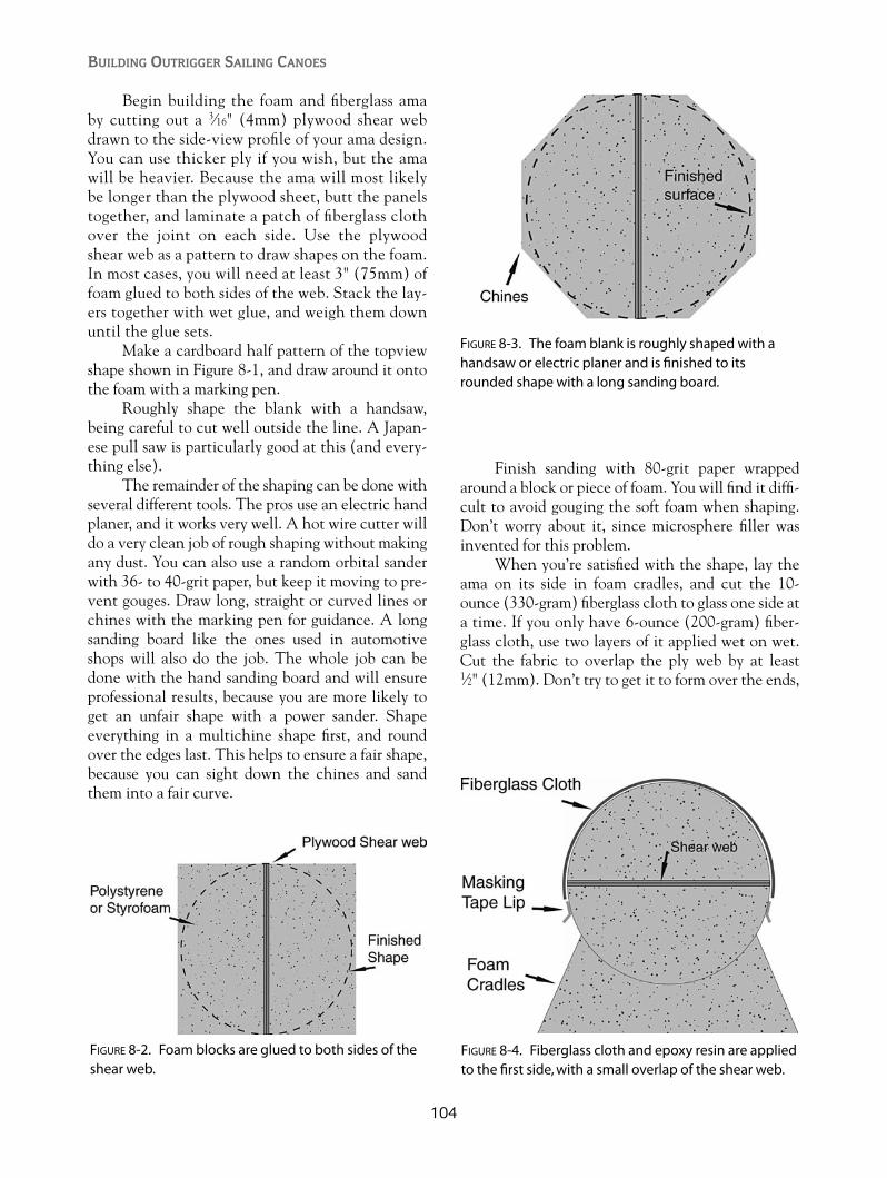
Begin building the foam and fiberglass amaby cutting out a 3⁄16" (4mm) plywood shear webdrawn to the side-view profile of your ama design.You can use thicker ply if you wish, but the amawill be heavier. Because the ama will most likelybe longer than the plywood sheet, butt the panelstogether, and laminate a patch of fiberglass clothover the joint on each side. Use the plywoodshear web as a pattern to draw shapes on the foam.In most cases, you will need at least 3" (75mm) offoam glued to both sides of the web. Stack the lay-ers together with wet glue, and weigh them downuntil the glue sets.
Make a cardboard half pattern of the topviewshape shown in Figure 8-1, and draw around it ontothe foam with a marking pen.
Roughly shape the blank with a handsaw,being careful to cut well outside the line. A Japan-ese pull saw is particularly good at this (and every-thing else).
The remainder of the shaping can be done withseveral different tools. The pros use an electric handplaner, and it works very well. A hot wire cutter willdo a very clean job of rough shaping without makingany dust. You can also use a random orbital sanderwith 36- to 40-grit paper, but keep it moving to pre-vent gouges. Draw long, straight or curved lines orchines with the marking pen for guidance. A longsanding board like the ones used in automotiveshops will also do the job. The whole job can bedone with the hand sanding board and will ensureprofessional results, because you are more likely toget an unfair shape with a power sander. Shapeeverything in a multichine shape first, and roundover the edges last. This helps to ensure a fair shape,because you can sight down the chines and sandthem into a fair curve.
Finish sanding with 80-grit paper wrappedaround a block or piece of foam. You will find it diffi-cult to avoid gouging the soft foam when shaping.Don’t worry about it, since microsphere filler wasinvented for this problem.
When you’re satisfied with the shape, lay theama on its side in foam cradles, and cut the 10-ounce (330-gram) fiberglass cloth to glass one side ata time. If you only have 6-ounce (200-gram) fiber-glass cloth, use two layers of it applied wet on wet.Cut the fabric to overlap the ply web by at least 1⁄2" (12mm). Don’t try to get it to form over the ends,
BUILDING OUTRIGGER SAILING CANOES
104
FIGURE 8-2. Foam blocks are glued to both sides of theshear web.
FIGURE 8-3. The foam blank is roughly shaped with ahandsaw or electric planer and is finished to itsrounded shape with a long sanding board.
FIGURE 8-4. Fiberglass cloth and epoxy resin are appliedto the first side, with a small overlap of the shear web.

because the fabric is too stiff for that. Stop 1⁄2"(12mm) short of the tip. Apply a masking-tape driplip a little beyond the edge of the fabric to preventresin from running down over the foam. Resin dripsare difficult to remove from foam without gougingthe surface.
If you have gouges to fill, fold or roll up the fab-ric, mix a stiff batch of resin and microspheres, andfill the gouges with a putty knife. Don’t overfill,because you’re not waiting for it to harden. Spreadthe fabric back onto the foam and begin wetting itwith the resin. Use either a brush or a foam roller,followed by a plastic spreader or squeegee to removeall excess resin.
Allow the first side to cure, roll it over in thecradles, and carefully block-sand the edge of thecured fiberglass to allow the next piece to overlapwithout air bubbles. If you have some really uglyspots, you can fill them with the stiff microspheremixture before you glass the second side. Repeat thesteps from the first side, again using the masking tapeto stop the runs. After the second side has cured,apply additional coats of resin with a brush to oneside at a time. Thin coats are best because the resinruns easily.
If you intend to mount a leeboard on the ama,double up the layer of fiberglass between the iakoattachment points to address the extra load.
To avoid the difficulty of wrapping glass aroundthe sharp ends, cut about 1⁄2" (12mm) of the ama off
with a hacksaw. Dig out some of the foam and mix abatch of stiff epoxy filler. Use the harder microfiberadditives to make a strong mixture. Fill the end andbuild it out to the original length. Shape it down fairwith the ama when it hardens. This will give you atougher end to deal with impact damage.
A direct connection between the ama andcross beam (iako) usually requires a curved beam toget the ama low enough. A pylon for direct attach-ment is used on the Ulua design. Begin with a 13⁄8"(40mm) thick piece of wood for the center of theraised pylon. Cut the wood to the shape shown inFigure 8-5. Glue it to the top of the ama with epoxy,and fit foam fairings in front of and behind the cen-ter wooden piece. An easy way to get the bottom ofthe foam fairings to fit perfectly is to tape somecoarse sandpaper to the top of the ama and move thefoam back and forth over it until it matches the sur-face of the ama. Glue the fairings in place, and aftercuring, shape them with coarse sandpaper wrappedaround a dowel or tube. Cover the entire pylon withtwo layers of fiberglass cloth large enough to spreadout at least 2" (50mm) onto the ama. The use ofmany small, round patches of fiberglass cloth willgreatly simplify getting around the angular shape.After curing, fill and fair with epoxy fairingcompound.
The dowel passing through the iako protrudesabout 1⁄2" (12mm) below its bottom surface, and itfits into a loose hole drilled in the top of the pylon.
105
Amas
FIGURE 8-5. The wooden pylon core is glued to the fiberglassed surface, and foam fairings are added. Fiberglass islapped over the pylon and down onto the finished ama surface and faired in with epoxy fairing compound. Hard-wood dowels are glued into drilled holes after glassing is completed.
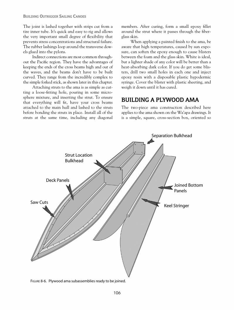
The joint is lashed together with strips cut from atire inner tube. It’s quick and easy to rig and allowsthe very important small degree of flexibility thatprevents stress concentrations and structural failure.The rubber lashings loop around the transverse dow-els glued into the pylons.
Indirect connections are most common through-out the Pacific region. They have the advantages ofkeeping the ends of the cross beams high and out ofthe waves, and the beams don’t have to be builtcurved. They range from the incredibly complex tothe simple forked stick, as shown later in this chapter.
Attaching struts to the ama is as simple as cut-ting a loose-fitting hole, pouring in some micro-sphere mixture, and inserting the strut. To ensurethat everything will fit, have your cross beamsattached to the main hull and lashed to the strutsbefore bonding the struts in place. Install all of thestruts at the same time, including any diagonal
members. After curing, form a small epoxy filletaround the strut where it passes through the fiber-glass skin.
When applying a painted finish to the ama, beaware that high temperatures, caused by sun expo-sure, can soften the epoxy enough to cause blistersbetween the foam and the glass skin. White is ideal,but a lighter shade of any color will be better than aheat-absorbing dark color. If you do get some blis-ters, drill two small holes in each one and injectepoxy resin with a disposable plastic hypodermicsyringe. Cover the blister with plastic sheeting, andweigh it down until it has cured.
BUILDING A PLYWOOD AMAThe two-piece ama construction described hereapplies to the ama shown on the Wa’apa drawings. Itis a simple, square, cross-section box, oriented so
BUILDING OUTRIGGER SAILING CANOES
106
FIGURE 8-6. Plywood ama subassemblies ready to be joined.

that it effectively has a “V” bottom and a “V” deck.It is the simplest possible plywood shape, with thepointed ends not even requiring any bevels. Alljoints are ninety degrees. The short, curved sectionunder the forefoot is joined by the “stitch-and-tape”method, where the plywood edges are pulledtogether with wire or monofilament nylon, edge-glued with thickened epoxy, and covered with a stripof fiberglass tape on the outside only.
A 16' (4.8m), two-piece ama can be built froma single sheet of 3⁄16" (4mm) or 1⁄4" (6mm) plywood.Use a straight board as a cutting guide to cut eight 53⁄4" (145mm) wide panels from the sheet of ply-wood. You can use either a circular saw, a jigsaw, or atable saw if you have plenty of space. One end ofeach panel is cut to a curve. The offsets for drawingthe curve are shown in Figure 8-7. Note that the off-sets for the deck and bottom panels are the same, butthe spacing between the offsets is greater for the bot-tom panels. The two bottom panels are 11⁄4" (30mm)longer than the two deck panels.
If you decide to have a one-piece ama, you’llhave to scarf or butt-splice the plywood panels to thefull length. The heavy separation bulkheads can bereplaced with a single lighter one.
Join the two pairs of deck panels with the tim-ber stringer along the top ridge, as shown in Figures8-6 and 8-8. Use glue with small nails. Install the twochine stringers along the bottom edge of the deckpanels. Make saw cuts halfway through the chinestringers every 3⁄4" (20mm) along the area that fol-lows the curved ends of the deck panels to enablethem to bend to the tight curve.
Install the 1⁄2" (12mm) bulkheads at the strutlocations with epoxy glue and small fillets, sincethese will be watertight bulkheads. With a bulkheadat the strut locations and the paired bulkheads at theseparation joint, the ama has four separate, sealedcompartments, with access panels into the middletwo compartments.
Install the 3⁄4" (18mm) plywood bulkheads atthe separation joint. Stack the two bulkheadstogether before installation, and drill the bolt holes.
If you are using an ama-mounted shunting lee-board, install two 1⁄2" (12mm) plywood backingblocks under the inboard side of the deck up againstthe separation bulkhead to take the mounting bolts.
Cut a 1⁄2" (12mm) wide notch into the end ofthe hardwood strut so that it can straddle the strutbulkhead. Cut a rectangular hole in the deck panelsto allow it to be epoxied and filleted to thebulkhead.
Join the two pairs of bottom panels with the keelstringer. The keel stringer is shorter than the onesused on the deck panels and stops where the curvedportion of the panels begins.
107
Amas
FIGURE 8-7. The curved ends of the ama deck and bottom panels can be laid out by measuring offsets from thestraight edge of the panel. Refer to Figure 3-9. Note that the bottom panel is slightly longer than the deck panelbecause it has to bend along the curve of the bow.
FIGURE 8-8. Plywood ama deck panels joined with astringer.
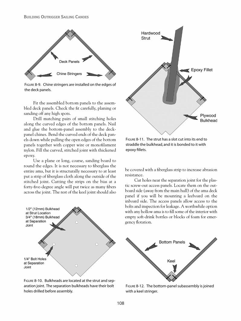
Fit the assembled bottom panels to the assem-bled deck panels. Check the fit carefully, planing orsanding off any high spots.
Drill matching pairs of small stitching holesalong the curved edges of the bottom panels. Nailand glue the bottom-panel assembly to the deck-panel chines. Bend the curved ends of the deck pan-els down while pulling the open edges of the bottompanels together with copper wire or monofilamentnylon. Fill the curved, stitched joint with thickenedepoxy.
Use a plane or long, coarse, sanding board toround the edges. It is not necessary to fiberglass theentire ama, but it is structurally necessary to at leastput a strip of fiberglass cloth along the outside of thestitched joint. Cutting the strips on the bias at aforty-five-degree angle will put twice as many fibersacross the joint. The rest of the keel joint should also
be covered with a fiberglass strip to increase abrasionresistance.
Cut holes near the separation joint for the plas-tic screw-out access panels. Locate them on the out-board side (away from the main hull) of the ama deckpanel if you will be mounting a leeboard on theinboard side. The access panels allow access to thebolts and inspection for leakage. A worthwhile optionwith any hollow ama is to fill some of the interior withempty soft-drink bottles or blocks of foam for emer-gency flotation.
BUILDING OUTRIGGER SAILING CANOES
108
FIGURE 8-9. Chine stringers are installed on the edges ofthe deck panels.
FIGURE 8-10. Bulkheads are located at the strut and sep-aration joint. The separation bulkheads have their boltholes drilled before assembly.
FIGURE 8-11. The strut has a slot cut into its end tostraddle the bulkhead, and it is bonded to it with epoxy fillets.
FIGURE 8-12. The bottom-panel subassembly is joinedwith a keel stringer.

STRIP-PLANKED AMASWhile strip-planking an open hull is relatively sim-ple, building a closed ama is more difficult. It can bedone in one of three ways.
1. Strip planked over a mold with the molds leftinside. No fiberglass is used on the interior. Theinterior molds make this the heaviest option.
2. Strip planked over a mold, one-half shell at atime, where the mold is discarded but theinside surface of the half shells is fiberglassed.
3. Strip planked into a female half-shell mold.
The first option is the easiest approach, whereyou set up a series of thin, plywood mold sectionsspaced every 12" (300mm) to 16" (400mm) and con-nected together by a 1⁄2" � 1⁄2" (12mm � 12mm)stringer running along the top spine of the deck andalong the keel. The end shape is defined by plywoodstems.
You’ll have to precoat the strips on their insidewith epoxy resin, because you won’t be able to accessor fiberglass this surface later.
Clamp or screw the frame to a solid base tokeep it straight for the first few planks. Begin with astrip at the midpoint of each side so that, with thestringers on the top and bottom, the frame will nowremain rigid. Continue planking in both directionsaway from the first plank by applying glue to eachprevious plank, and stapling the next plank tightlyagainst it. Alternate sides to avoid distorting theframe. Sand and fair the outside, and sheath it withfiberglass cloth.
109
Amas
FIGURE 8-13. Bottom-panel assembly ready to attach tothe deck assembly.
FIGURE 8-14. The keel joint at the curved end sectionsdoesn’t have a stringer, but is bonded with thick epoxyglue and overlaid with strips of fiberglass cloth andepoxy resin.
FIGURE 8-15. A typical framework for a strip-planked ama made up of station bulkheads, stringers notched in the topand bottom, and plywood stem molds at the ends.
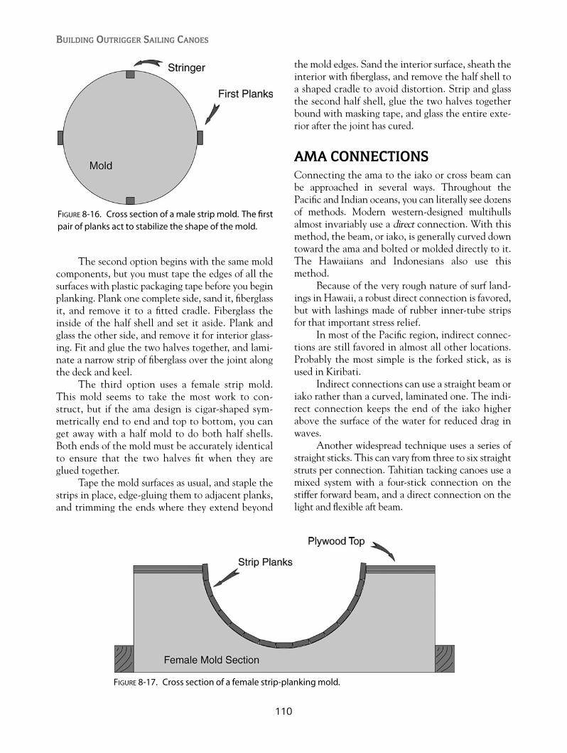
The second option begins with the same moldcomponents, but you must tape the edges of all thesurfaces with plastic packaging tape before you beginplanking. Plank one complete side, sand it, fiberglassit, and remove it to a fitted cradle. Fiberglass theinside of the half shell and set it aside. Plank andglass the other side, and remove it for interior glass-ing. Fit and glue the two halves together, and lami-nate a narrow strip of fiberglass over the joint alongthe deck and keel.
The third option uses a female strip mold.This mold seems to take the most work to con-struct, but if the ama design is cigar-shaped sym-metrically end to end and top to bottom, you canget away with a half mold to do both half shells.Both ends of the mold must be accurately identicalto ensure that the two halves fit when they areglued together.
Tape the mold surfaces as usual, and staple thestrips in place, edge-gluing them to adjacent planks,and trimming the ends where they extend beyond
the mold edges. Sand the interior surface, sheath theinterior with fiberglass, and remove the half shell toa shaped cradle to avoid distortion. Strip and glassthe second half shell, glue the two halves togetherbound with masking tape, and glass the entire exte-rior after the joint has cured.
AMA CONNECTIONSConnecting the ama to the iako or cross beam canbe approached in several ways. Throughout thePacific and Indian oceans, you can literally see dozensof methods. Modern western-designed multihullsalmost invariably use a direct connection. With thismethod, the beam, or iako, is generally curved downtoward the ama and bolted or molded directly to it.The Hawaiians and Indonesians also use thismethod.
Because of the very rough nature of surf land-ings in Hawaii, a robust direct connection is favored,but with lashings made of rubber inner-tube stripsfor that important stress relief.
In most of the Pacific region, indirect connec-tions are still favored in almost all other locations.Probably the most simple is the forked stick, as isused in Kiribati.
Indirect connections can use a straight beam oriako rather than a curved, laminated one. The indi-rect connection keeps the end of the iako higherabove the surface of the water for reduced drag inwaves.
Another widespread technique uses a series ofstraight sticks. This can vary from three to six straightstruts per connection. Tahitian tacking canoes use amixed system with a four-stick connection on thestiffer forward beam, and a direct connection on thelight and flexible aft beam.
BUILDING OUTRIGGER SAILING CANOES
110
FIGURE 8-16. Cross section of a male strip mold. The firstpair of planks act to stabilize the shape of the mold.
FIGURE 8-17. Cross section of a female strip-planking mold.
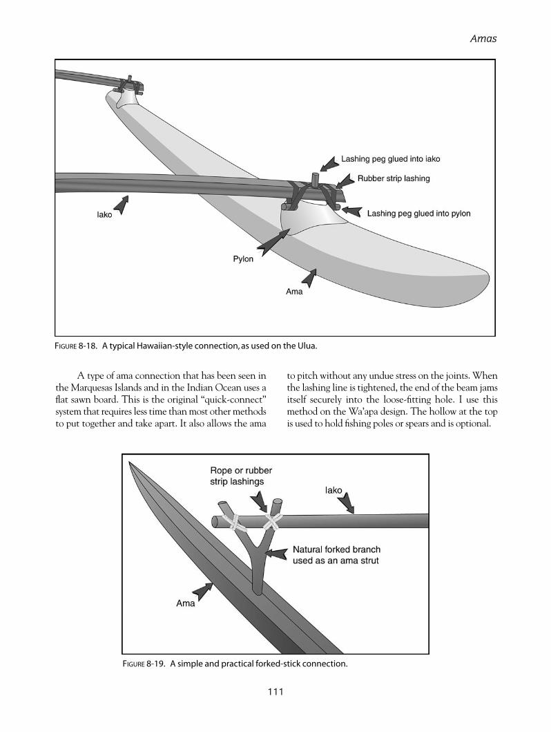
A type of ama connection that has been seen inthe Marquesas Islands and in the Indian Ocean uses aflat sawn board. This is the original “quick-connect”system that requires less time than most other methodsto put together and take apart. It also allows the ama
to pitch without any undue stress on the joints. Whenthe lashing line is tightened, the end of the beam jamsitself securely into the loose-fitting hole. I use thismethod on the Wa’apa design. The hollow at the topis used to hold fishing poles or spears and is optional.
111
Amas
FIGURE 8-18. A typical Hawaiian-style connection, as used on the Ulua.
FIGURE 8-19. A simple and practical forked-stick connection.

112
FIGURE 8-20. A Tahitian-style connection at the forwardcross beam.
FIGURE 8-21. A Marquesan “quick-connect”strut.A modified version is used on the Wa’apa.
FIGURE 8-22. Foam blocks being glued to a plywoodshear web. (Photo courtesy Marc Termonia)
FIGURE 8-23. Four 1⁄4" (6mm) bolts connect the two-piece plywood ama.
FIGURE 8-24. Tarawa’s original foam-filled ama has aninverted “V”plywood deck.
FIGURE 8-25. The Wa’apa connection method allowslimited movement of the ama in the pitch axis.

113
In a small canoe, the most practical beam oriako to connect the ama to the hull is a simple,
solid laminate. Larger canoes such as the Wa’apa canuse hollow beams to save weight. The iakos usedwith a tacking rig must be strong enough to resist thebending force generated when the ama is to leewardand is being forced down in the water, whereas iakosused with a shunting rig can be lighter because theyare normally only on the windward side.
A configuration sometimes used in modernHawaiian sailing canoes is called the broken wing. Asecond safety ama is mounted opposite the main amaand reduces the possibility of capsize in severe con-ditions. A safety ama is also a useful addition to ashunting proa.
Another option is the double-outrigger or tri-maran configuration. While this is a very attrac-tive option to beginning sailors, be aware that theadditional weight of an extra ama and increasedbeam length will cut into the payload. It is desir-able with a double outrigger to have both amasmounted higher so that when the craft is fullyloaded at rest, only one ama is touching the water.This will make tacking quicker and will alsoreduce overall drag.
Quite often in traditional outriggers, the gun-wale, or side of the hull, is raised between the iakosso that the beams can be mounted higher to clearthe waves. Modern Hawaiian racers add blockingunder the iako to raise their height above the water.The double-outrigger option shown in Figure 3-8incorporates a raised gunwale on the middle sectionfor this purpose.
A straight or slightly curved hollow box beamcan also be used with larger canoes. An 18' (5.4m)
canoe’s beams are almost too small to make thispractical, but a straight hollow beam is shown as anoption with the Wa’apa.
BUILDING A SOLID LAMINATED IAKODraw the shape of the curved beam on a flat table orsheet of plywood, using the offsets shown on the plan.Screw down a 11⁄2" � 11⁄2" � 3" (40mm � 40mm �
75mm) block of wood at each offset location.Choose the timber carefully, using only pieces
with straight grain and very small, tight knots. Usethe best pieces on the top and bottom lamination,or use a harder, stronger timber for the top and bot-tom, with softer timber in the middle, because mostof the stress occurs in the two outer layers. Thestrips can be cut with a table saw and laminated asthey are, or you can run them through a thicknessplaner if the saw cuts are too rough. In any case,epoxy glue will fill most gaps and result in a strongbeam.
Put a double layer of waxed paper along theform blocks. Apply adhesive to the strips and bundlethem together along the blocks. Start adding clampsfrom the straight end, and keep going until the curvedend is pulled down. Put additional clamps betweenthe blocks if the glue isn’t squeezing out in some loca-tions. Clean up the excess glue with a putty knife.
After removing the iako from the form, grindoff the excess glue. The easiest way to finish the iakois with a thickness planer, but if you don’t have one,you could run the iako through a table saw or justsand it smooth. Round the edges with a router or aplane and sanding board.
CHAPTER 9
Cross Beams and HullConnections
Copyright © 2008 by International Marine. Click here for terms of use.

BUILDING OUTRIGGER SAILING CANOES
114
FIGURE 9-1. A solid laminated iako is used on the Ulua.
FIGURE 9-2. The broken-wing configuration uses a “safety ama”opposite the main ama. It doesn’t touch the waterunless capsize is imminent.
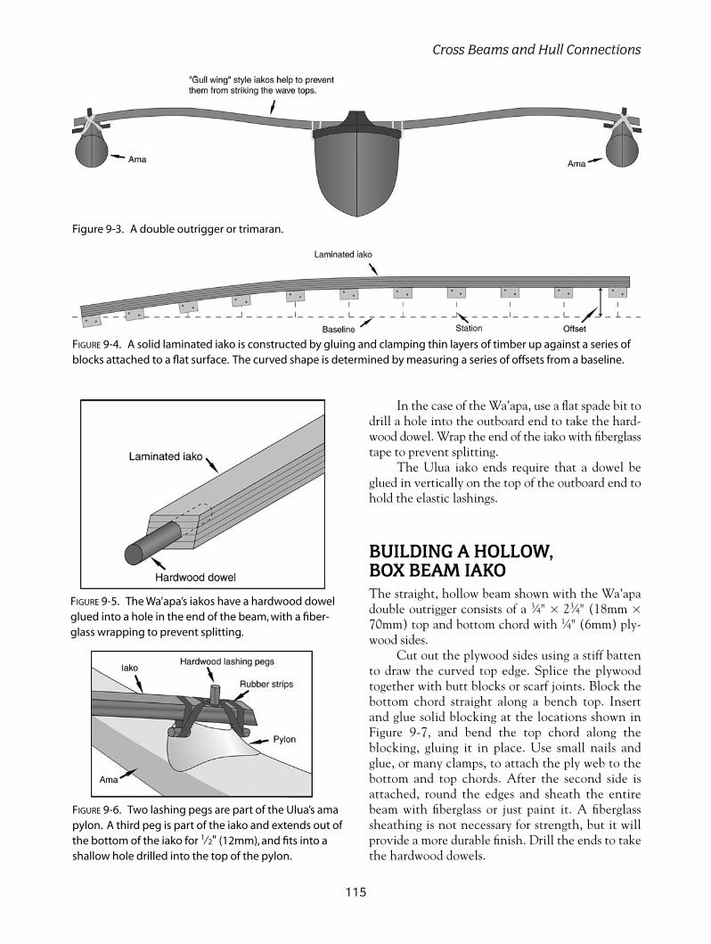
In the case of the Wa’apa, use a flat spade bit todrill a hole into the outboard end to take the hard-wood dowel. Wrap the end of the iako with fiberglasstape to prevent splitting.
The Ulua iako ends require that a dowel beglued in vertically on the top of the outboard end tohold the elastic lashings.
BUILDING A HOLLOW, BOX BEAM IAKOThe straight, hollow beam shown with the Wa’apadouble outrigger consists of a 3⁄4" � 23⁄4" (18mm �
70mm) top and bottom chord with 1⁄4" (6mm) ply-wood sides.
Cut out the plywood sides using a stiff battento draw the curved top edge. Splice the plywoodtogether with butt blocks or scarf joints. Block thebottom chord straight along a bench top. Insertand glue solid blocking at the locations shown inFigure 9-7, and bend the top chord along theblocking, gluing it in place. Use small nails andglue, or many clamps, to attach the ply web to thebottom and top chords. After the second side isattached, round the edges and sheath the entirebeam with fiberglass or just paint it. A fiberglasssheathing is not necessary for strength, but it willprovide a more durable finish. Drill the ends to takethe hardwood dowels.
115
Cross Beams and Hull Connections
Figure 9-3. A double outrigger or trimaran.
FIGURE 9-5. The Wa’apa’s iakos have a hardwood dowelglued into a hole in the end of the beam, with a fiber-glass wrapping to prevent splitting.
FIGURE 9-6. Two lashing pegs are part of the Ulua’s amapylon. A third peg is part of the iako and extends out ofthe bottom of the iako for 1⁄2" (12mm), and fits into ashallow hole drilled into the top of the pylon.
FIGURE 9-4. A solid laminated iako is constructed by gluing and clamping thin layers of timber up against a series ofblocks attached to a flat surface. The curved shape is determined by measuring a series of offsets from a baseline.

ALUMINUM TUBE BEAMSAluminum tubing with a minimum diameter of2"(50mm) and a wall thickness of 1⁄8" (3mm) is suit-able to use for iakos with the T2 and Ulua designs. Ifyou wish to have curved beams, it is best to take thetube to a specialist company to have this done. Thestiffest alloy, such as 6061-T6 (which is used for sparson all sizes of sailing craft), is the best for this appli-cation but may be too stiff for bending into a curve.
The alloy beams can be left bare, paintedwith special primers and paint, powder coated, oranodized. Anodizing is probably the best treatment,but care must be taken to insulate any stainless-steelhardware from contacting the aluminum surface to prevent corrosion through electrolytic attack.Plastic gaskets or silicone sealant will separate thedissimilar metals and prevent corrosion of thealuminum.
Where the round tubing crosses the gunwale ofthe canoe and attaches to the ama, it is best to havehardwood cradles to support them.
CONNECTIONSThe structural joints between the iakos and the hulland ama are an important consideration, since mostfailures will occur in these areas. Bolts with metalbrackets or straps have been used in many cases, butI feel that it is the least desirable solution in thesmall canoes that we are considering. The high-stress concentrations around bolts or metal fittingswill be the first source of failure.
Traditional lashings were made with sennit orcoconut-fiber rope. These lashings are very elasticand require frequent tightening and replacement.The most frequently seen lashing material now in
BUILDING OUTRIGGER SAILING CANOES
116
FIGURE 9-7. A hollow, box beam iako is specified for the Wa’apa double outrigger. Beams with gentle curvescan also be built with this method.
FIGURE 9-8. A hardwood cradle is used to support round, aluminum-tube iakos.

Oceania is large-diameter, nylon monofilament fish-ing line. For the designs in this book, I recommend3⁄16" (4mm) polyester rope.
Nylon rope can be used but does stretch whenwet; therefore, perhaps it’s a good idea to do thelashings while the nylon is already wet to prevent itfrom loosening. Cotton or a cotton/polyester blendis also used in modern Hawaiian canoes.
Another commonly seen lashing material usedthroughout Oceania is strips cut from rubber tire innertubes. Either cut long lengths around and around thetube, or cross-cut circular rubber bands. I always use therubber-band lashings on the iako-to-ama joint becauseit stays tight and gives just enough of the desired elas-ticity. I’ve bailed out of the Ulua in surf and seen thehull thrown airborne sideways and land on the ama inthe shallow water. A subsequent inspection revealedno damage or visible stress to any of the connections.
When sailing a tacking canoe, I prefer ropelashings at the hull-to-iako joint. With the ama toleeward, very high stresses occur at the lashings, andI prefer the lower stretch of rope lashings.
A variation of the rope-lashing method uses astraight piece of timber (wae) below the cross beamthat extends through the sides of the hull just belowthe gunwales. This allows lashing without leavingany open holes in the hull and is particularly usefulwhere the area is decked over, or is a watertightcompartment.
In order to prevent the iako from sliding out ofits lashings, I use what I call a “locater block”screwed to the top of the iako directly above thegunwale. The locater block also allows you to assem-ble the canoe the same way each time, since it deter-mines the spacing between the hull and the ama.
Beginning and finishing a simple lashing canbe confusing, and if it is not done well, you may bereturning to shore in several pieces. I use a very non-traditional, small plastic cleat at each location. Thelashing line can start with a figure-eight stopper knotthrough the base of the cleat, and then, when all ofthe wraps are completed, it can be tied off at thesame cleat. Without a cleat, you can use a series ofhalf hitches to finish a lashing.
117
Cross Beams and Hull Connections
FIGURE 9-9. A simple lashing connection with holes below the gunwale for the lashings to pass through.A wooden spreader (wae) is centered below the cross beam. There is one lashing hole on each side ofthe wae. A small cleat can be screwed to the doubler pad inside to begin and end the lashing.

118
FIGURE 9-10. This connection method uses a wae below the cross beam that extends out throughthe sides of the hull. This can be used if you don’t want lashing holes in the hull or if your crossbeam passes over a decked area of the hull.
FIGURE 9-11. Typical simple lashing with a locater block to prevent the iako fromslipping out of its lashings.

119
Cross Beams and Hull Connections
FIGURE 9-12. An elaborate, traditional-style lashing can be very impressive as long asyou don’t have to disassemble the canoe often.
FIGURE 9-13. Rubber-strip lashings are commonly used with paddling canoes but allowtoo much stretch for a sailing canoe when used on the main hull.

120
FIGURE 9-14. (ABOVE LEFT) A laminating jig for solid iakosconsists of a row of wooden blocks screwed to a flatsurface. Note the waxed paper taped in place to pre-vent gluing the beam to the table or the blocks.
FIGURE 9-15. (ABOVE) Strips of wood glued together andclamped to the blocks.
FIGURE 9-16. (LEFT) Wa’apa beam ends with hardwooddowels and fiberglass wrapping in place.
FIGURE 9-17. (BELOW) A Wa’apa lashing straddles twohull sections, with one lashing hole in each section.

121
STEERINGThere are several ways to steer an outrigger sailingcanoe, and quite often more than one method isused at the same time. The most common steeringmethods are as follows:
• Paddle• Steering oar• Rudder• Dagger boards• Crew weight shift• Sail trim
The tacking outrigger has a somewhat simplerproblem than a shunter, because a rudder or steeringoar can be mounted at one end and left there. Ashunting outrigger has to either move the rudder oroar during each shunt or have duplicates mounted ateach end.
Steering with a PaddleSteering with a paddle is almost always possible aslong as you have a crew member to tend the sail. Itis difficult to paddle-steer while single-handing,because the paddle requires two hands, and no handsare left to release the mainsheet in a gust. Paddlesteering is a fine art that won’t be learned quickly,but it is usually necessary when the canoe is beingpropelled only by paddlers.
A steering paddle generally has a larger bladearea and a stronger shaft than an ordinary paddle. Askilled steersman can make it all appear quite easy,but your first times can be exhausting experiences.
Most of the time while you are sailing, the paddlecan be used as a big skeg and simply be “poked” orheld down below the hull on the side opposite tothat which the boat is turning. A paddle in this posi-tion can also be used to lever water away from thehull or pull water toward the hull. Varying the depthof the poke will steer a canoe in a steady wind bychanging the position of the underwater center oflateral resistance. If the steering seat is just forwardof the iako, the handle of the paddle can be bracedagainst the forward edge of the iako.
Steering OarsThe steering oar is a versatile tool and has beenused to steer traditional craft up to 100' (30m) inlength or more for thousands of years. Larger vesselsused multiple oars deployed together, but in ourcase, a single, 8' to 10' (2.4 to 3.0m), ordinary oarwill suffice. The pivot point of the oar needs to beattached to a cross beam or steering bracket with astandard full-circle oarlock, or to a simple lashing inan emergency.
The oar can be used in several different ways:
1. The oar can function as a rudder by immersingthe blade and angling it to turn the canoe.This mode is most commonly used for coursecorrection on broad reaches and for roundingup into the wind to drop the sail, or to tack.
2. Going aback is the biggest no-no with shuntingproas and can necessitate dropping the sail. Itcan also cause a capsize. If you sail long enough,it will happen. Sailing up under headlands, or
CHAPTER 10
Steering, Leeboards,and Accessories
Copyright © 2008 by International Marine. Click here for terms of use.

getting a sudden wind shift, can put you into anembarrassing situation. This is where the steer-ing oar has saved me from difficulties on severaloccasions. Using it as an oar with a powerfulsweeping motion will kick the stern of the canoearound instantly. This is something you can’t dowith a rudder.
3. I also use the oar as a movable source of lat-eral resistance by simply trailing it like a skegparallel to the boat’s centerline, but varyingthe amount of immersion. If I’m beam-reaching and want to bear off, I’ll angle theoar deeper into the water and the canoe willturn downwind. The greater water pressure atthe increased depth of the blade holds thestern of the canoe firmly and allows the bowto fall away from the wind direction. Thisproduces less drag than using the oar as a rud-der and is readily apparent by the lack ofturbulence.
4. The oar can also be used with a sculling stroketo propel the canoe in calms. This works amaz-ingly well, and you’ll get better with practice.
A fully rigged sailing canoe is rarely well set upfor paddling, and the seamless transition fromcontrol to propulsion is a real delight.
So after all the good stuff, what’s the downside?Steering oars are fine for day sailing in good weather.They can become a handful in strong conditions, orwhere you’d like the canoe to self-steer for shortperiods. Just letting go of the oar, or lifting the blade,can cause the canoe to round up into the wind.
As a rule of thumb, I would recommend thatsteering oars be approximately one half the length ofthe canoe. Scaling the steering oar up to largercanoes can turn into real oceanic he-man stuff.Pacific museums contain huge steering oars that takeseveral men just to lift. This is all very well on anafternoon sail, but not what you want on an oceanpassage with your mate.
To make shunting quicker when sailing single-handed, I found that having an oar rigged at eachend of the hull was much better. The unused forwardoar is simply retracted inboard in its oarlock until itis needed on the other tack.
BUILDING OUTRIGGER SAILING CANOES
122
FIGURE 10-1. A steering paddle can be braced against the aft iako. In a well-tuned sailing canoe, immersing the pad-dle deeper into the water will cause the canoe to turn away from the wind direction. Lifting the paddle will causethe canoe to turn into the wind.

You will note that on my shunting canoedesigns, the oar is located on the windward side ofthe hull, whereas on traditional canoes it is always toleeward. A leeward position allows the water pres-sure to hold the oar against the side of the hull andmakes steering easier. Unfortunately, if you aresingle-handing and have to sit out on the windwardrail, you won’t be able to reach a steering oarmounted on the leeward side.
RuddersRudders as we know them were not widely used inOceania. A quarter rudder lashed to the side of thehull is used on some Micronesian proas. Viking shipshad a similar rudder location. It can be difficult to
mount a rudder on an outrigger canoe, because theyseldom have transoms, and a fixed, underhull rudderis damage-prone in the shallow water that canoesfrequent. The Ulua’s rudder mounts on the outboardmotor bracket that is clamped to the aft iako. Anystandard kick-up rudder such as is found on beachcats or sailing dinghies can be used.
It is important to mount the rudder and lee-board on the same side of the hull. Small amountsof change in heeling angle will require constantsteering correction if the rudder and leeboard areon opposite sides. The port (left) side of the hullis preferred, because if you use the single pivot-bolt attachment shown in Figure 10-5, the nutwill loosen if the rudder or leeboard kicks up.Mounting the boards on the starboard (right) side
123
Steering, Leeboards, and Accessories
FIGURE 10-2. A typical steering oar that can be used to steer a canoe or to propel it by sculling.
FIGURE 10-3. A steering oar in position and pivoting on a hardwood spreaderlashed to the gunwales. The lashing holes, which are securing the steeringbracket, are those used for the cross beams when the hull is in the 16’ (4.8m)configuration.
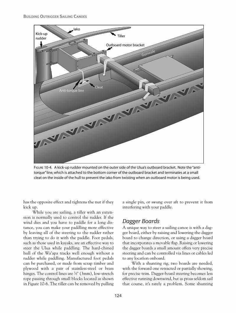
has the opposite effect and tightens the nut if theykick up.
While you are sailing, a tiller with an exten-sion is normally used to control the rudder. If thewind dies and you have to paddle for a long dis-tance, you can make your paddling more effectiveby leaving all of the steering to the rudder ratherthan trying to do it with the paddle. Foot pedals,such as those used in kayaks, are an effective way tosteer the Ulua while paddling. The hard-chinedhull of the Wa’apa tracks well enough without arudder while paddling. Manufactured foot pedalscan be purchased, or made from scrap timber andplywood with a pair of stainless-steel or brasshinges. The control lines are 1⁄8" (3mm), low-stretchrope passing through small blocks located as shownin Figure 10-6. The tiller can be removed by pulling
a single pin, or swung over aft to prevent it frominterfering with your paddle.
Dagger BoardsA unique way to steer a sailing canoe is with a dag-ger board, either by raising and lowering the daggerboard to change direction, or using a dagger boardthat incorporates a movable flap. Raising or loweringthe dagger boards a small amount offers very precisesteering and can be controlled via lines or cables ledto any location onboard.
With a shunting rig, two boards are needed,with the forward one retracted or partially showing,for precise trim. Dagger-board steering becomes lesseffective running downwind, but as proas seldom sailthat course, it’s rarely a problem. Some shunting
BUILDING OUTRIGGER SAILING CANOES
124
FIGURE 10-4. A kick-up rudder mounted on the outer side of the Ulua’s outboard bracket. Note the “anti-torque”line, which is attached to the bottom corner of the outboard bracket and terminates at a smallcleat on the inside of the hull to prevent the iako from twisting when an outboard motor is being used.

125
Steering, Leeboards, and Accessories
FIGURE 10-5. The Ulua kick-up rudder is mounted on the outer side of the outboard motor bracket.
FIGURE 10-6. Ulua foot-pedal steering arrangement to control the sailing rudder while paddling.
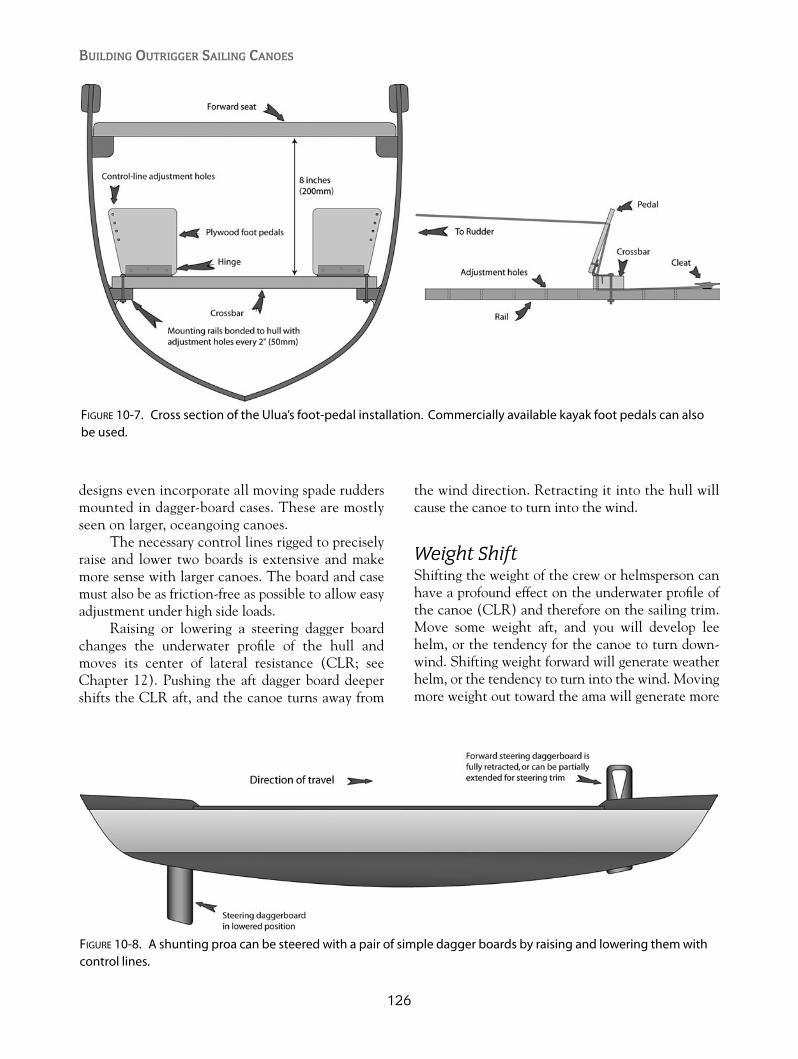
designs even incorporate all moving spade ruddersmounted in dagger-board cases. These are mostlyseen on larger, oceangoing canoes.
The necessary control lines rigged to preciselyraise and lower two boards is extensive and makemore sense with larger canoes. The board and casemust also be as friction-free as possible to allow easyadjustment under high side loads.
Raising or lowering a steering dagger boardchanges the underwater profile of the hull andmoves its center of lateral resistance (CLR; seeChapter 12). Pushing the aft dagger board deepershifts the CLR aft, and the canoe turns away from
the wind direction. Retracting it into the hull willcause the canoe to turn into the wind.
Weight ShiftShifting the weight of the crew or helmsperson canhave a profound effect on the underwater profile ofthe canoe (CLR) and therefore on the sailing trim.Move some weight aft, and you will develop leehelm, or the tendency for the canoe to turn down-wind. Shifting weight forward will generate weatherhelm, or the tendency to turn into the wind. Movingmore weight out toward the ama will generate more
BUILDING OUTRIGGER SAILING CANOES
126
FIGURE 10-7. Cross section of the Ulua’s foot-pedal installation. Commercially available kayak foot pedals can also be used.
FIGURE 10-8. A shunting proa can be steered with a pair of simple dagger boards by raising and lowering them withcontrol lines.

drag on that side and turn the canoe toward the ama.The T2, with its narrow, deep, “V” hull, is more sen-sitive in this regard than the more rounded hull ofthe Ulua. The placement of weight and sail trim,combined with the principal steering device, will allcontribute to an easily steered canoe. There is noth-ing simple about trying to analyze the forces resultingfrom small changes in rudders, leeboard angles, hullshape, sail trim, or a myriad of other factors.
Sail SteeringThe Oceanic lateen or crab-claw sail found univer-sally in Micronesia has the ability to maintain liftunder very high angles of attack. In other words, ifyou oversheet it, it won’t stall and lose drive like amore conventional sail. This is a very useful traitand can be used to steer a canoe on beam-reachingand close-hauled courses. Sheet in hard, and thecanoe will start to bear away; ease the sheet to stop itor to head back into the wind. With practice, youcan use this to do most of the steering on thosecourses without any input from the steering oar. Thiseffect is due to the very long boom that moves thecenter of effort well out to leeward when the sheet iseased. Once you are on a broad reach, you’ll needthe help of a paddle, oar, or rudder.
LEEBOARDSThe leeboard is an important factor in any round- orflat-bottomed canoe’s sailing performance. While tra-ditional Oceanic canoes did not have a mounted lee-board, crew members would hold their paddles alongthe side of the hull to achieve the same effect. Sincemany canoe sailors prefer to sail single-handed, theleeboard takes the place of that extra crew.
Traditional, mono-hulled canoes usually have apair of leeboards, and they are sailed with the leeward
board down and the windward board pivoted up.Because of its greater hull beam and heeling angle, aboard on the windward side is lifted too far out of thewater to be effective. Outrigger canoes have a narrowbeam and small heeling angles so that only one boardis necessary.
Note the cross-sectional shape differencebetween a tacking leeboard and a shunting leeboardshown in Figure 10-10. The shunting board will begoing both ways, but always with the same side towindward and leeward. This allows you to leave theleeward side almost flat, with most of the curvatureon the windward side generating lift more effectively.
The Ulua and Wa’apa designs use a single pivot-ing leeboard. Not only does the board provide lateralresistance, but by pivoting it fore and aft, you can easethe load on the steering or rudder by moving the cen-ter of lateral resistance to the best position. Normally,the leeboard would be positioned vertically when youare sailing to windward, and it is gradually angled aftas your course changes to a reach or run.
The Ulua’s leeboard is mounted on a singlepivot bolt just below the gunwale. The bolt passesthrough an aluminum angle bracket inside the hullon top of the forward seat and transfers the load tothe seat. A fixed leeboard is best used in combina-tion with a kick-up rudder. If you choose to steerwith an oar or paddle, the movable clamp-onbracket will allow better adjustment of the balancebetween the sail and the hull.
The Wa’apa’s tacking-rig leeboard pivots on asingle bolt that passes through the hull just below theseat, and passes the load into a plywood, gussetedangle bracket. A Wa’apa rigged with a shunting sail,however, has the leeboard mounted on the inboardside of the ama. This is an important distinction,because an ama-mounted leeboard will aid in keepingthe ama to windward while the canoe is undergoing
127
Steering, Leeboards, and Accessories
FIGURE 10-9. Dagger rudders are sometimes equipped with a movable flap.

128
FIGURE 10-10. Shunting and tacking leeboard cross-sectional shapes. Shunting and tacking leeboards arenot interchangeable.
FIGURE 10-11. A through-bolted, pivoting leeboard mounting on the Ulua hull. Note how theload is transferred to the seat through the metal bracket to prevent the side of the hull frombeing twisted.

the shunting operation. A shunting rig with a lee-board mounted on the main hull can become direc-tionally unstable during a shunt and possibly spinaround and set the sail aback.
All of the leeboards that I have built are sim-ple, edge-glued laminates of solid, straight-grainedtimber. To avoid warping, it is better to glue up sev-eral pieces rather than just use a wide board.
Laminate the blank for the leeboard by edge-gluing at least two boards with square, well-fittingedges. The narrower the strips that are gluedtogether, the less chance there is of any warpinglater. Alternate the grain direction, as shown inFigure 10-16, to avoid warping. After the glue hascured, cut out the shape with a jigsaw. To achieve an
airfoil shape, use an electric hand plane or a discsander with a foam-backed pad. These are both verypowerful tools and can cause a lot of damage in thewrong hands. Finish shaping with a coarse sandingboard. Fiberglassing the leeboard is optional. I usu-ally just apply five coats of spar varnish.
ACCESSORIES
Outboard Motor BracketsThe outboard brackets shown in the plans for theUlua and Wa’apa are used for more than just mount-ing an outboard motor. A rowlock mounted on the
129
Steering, Leeboards, and Accessories
FIGURE 10-12. Movable clamp-on leeboard brackets are recommended for canoes withoar or paddle steering, and enable precise location of the center of lateral resistance.

130130
FIGURE 10-13. The outline shape of a tacking and shunting leeboard can bethe same, but the cross-sectional shape must be different. The dotted lineshows how a tacking board would be shaped.
FIGURE 10-14. The Wa’apa tacking leeboard mount. The same bracketis used to support the mast step when the canoe is equipped with ashunting rig.
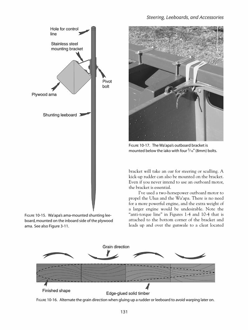
bracket will take an oar for steering or sculling. Akick-up rudder can also be mounted on the bracket.Even if you never intend to use an outboard motor,the bracket is essential.
I’ve used a two-horsepower outboard motor topropel the Ulua and the Wa’apa. There is no needfor a more powerful engine, and the extra weight ofa larger engine would be undesirable. Note the“anti-torque line” in Figures 1-4 and 10-4 that isattached to the bottom corner of the bracket andleads up and over the gunwale to a cleat located
131
Steering, Leeboards, and Accessories
FIGURE 10-15. Wa’apa’s ama-mounted shunting lee-board, mounted on the inboard side of the plywoodama. See also Figure 3-11.
FIGURE 10-16. Alternate the grain direction when gluing up a rudder or leeboard to avoid warping later on.
FIGURE 10-17. The Wa’apa’s outboard bracket ismounted below the iako with four 5⁄16" (8mm) bolts.

inside the hull. The thrust from the motor will try totwist the iako out of its lashings, and the short linewill prevent this from happening. Use a low-stretchline for this purpose.
Note in Figures 10-17 and 10-18 that theWa’apa bracket is mounted completely below theiako, while the Ulua’s bracket is notched to fitaround the iako. The different mounting height isnecessary, because the iakos are higher above thewater in the Wa’apa, and the outboard motor mustbe immersed enough to prevent the propeller fromventilating.
Because there can be a lot of stress on thebracket from either a motor or the steering device,be sure to build it strong. If you are not confidentabout your joinery, install aluminum angle bracketson the interior corners to reinforce the joint.
Hiking SeatsAll three designs show seats that extend outboardfrom the hull to allow one or more crew members tohike out and prevent the ama from lifting or sinking.The shunting T2 uses one large, slatted seat on theama (windward) side, while the Ulua and Wa’apatacking rigs can have seats on both sides of the hull.
The T2’s seat bridges across the two iakos, whilethe smaller hiking seats on the Ulua and Wa’apa aresupported by the gunwale on their inboard edge and afore and aft pole on their outboard edge. A loose lash-ing around the pole allows the seat to be pivoted out-board for paddling, where it rests against a second pole.
I’ve come to prefer a slatted, wooden seat overa canvas or netting trampoline, due to the difficultyof getting a trampoline out of the way when youneed to paddle.
BUILDING OUTRIGGER SAILING CANOES
132
FIGURE 10-18. A kick-up rudder and outboard motor mounted on the Ulua’s bracket. Note the anti-torque line coming from the bottom of the bracket, over the gunwale, and tied to a cleat.

133
Steering, Leeboards, and Accessories
FIGURE 10-19. The hiking seats on the Wa’apa pivot outboard for paddling and rest against a second bamboo pole.
FIGURE 10-20. A windward-side hiking seat on the T2, with a wooden knob bolted in place to snubthe sheet. Note the leeside guide rail to aid in shunting an Oceanic lateen sail.
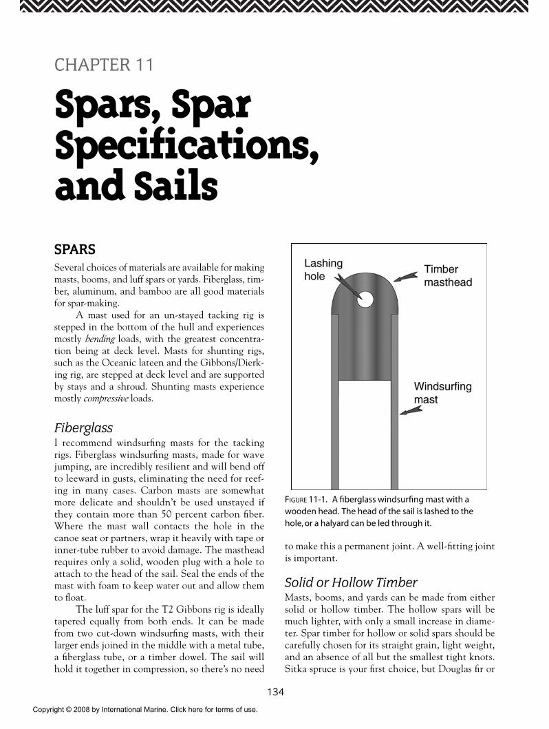
134
SPARSSeveral choices of materials are available for makingmasts, booms, and luff spars or yards. Fiberglass, tim-ber, aluminum, and bamboo are all good materialsfor spar-making.
A mast used for an un-stayed tacking rig isstepped in the bottom of the hull and experiencesmostly bending loads, with the greatest concentra-tion being at deck level. Masts for shunting rigs,such as the Oceanic lateen and the Gibbons/Dierk-ing rig, are stepped at deck level and are supportedby stays and a shroud. Shunting masts experiencemostly compressive loads.
FiberglassI recommend windsurfing masts for the tackingrigs. Fiberglass windsurfing masts, made for wavejumping, are incredibly resilient and will bend offto leeward in gusts, eliminating the need for reef-ing in many cases. Carbon masts are somewhatmore delicate and shouldn’t be used unstayed ifthey contain more than 50 percent carbon fiber.Where the mast wall contacts the hole in thecanoe seat or partners, wrap it heavily with tape orinner-tube rubber to avoid damage. The mastheadrequires only a solid, wooden plug with a hole toattach to the head of the sail. Seal the ends of themast with foam to keep water out and allow themto float.
The luff spar for the T2 Gibbons rig is ideallytapered equally from both ends. It can be madefrom two cut-down windsurfing masts, with theirlarger ends joined in the middle with a metal tube,a fiberglass tube, or a timber dowel. The sail willhold it together in compression, so there’s no need
to make this a permanent joint. A well-fitting jointis important.
Solid or Hollow TimberMasts, booms, and yards can be made from eithersolid or hollow timber. The hollow spars will bemuch lighter, with only a small increase in diame-ter. Spar timber for hollow or solid spars should becarefully chosen for its straight grain, light weight,and an absence of all but the smallest tight knots.Sitka spruce is your first choice, but Douglas fir or
CHAPTER 11
Spars, Spar Specifications, and Sails
FIGURE 11-1. A fiberglass windsurfing mast with awooden head. The head of the sail is lashed to thehole, or a halyard can be led through it.
Copyright © 2008 by International Marine. Click here for terms of use.
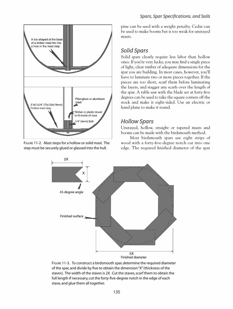
pine can be used with a weight penalty. Cedar canbe used to make booms but is too weak for unstayedmasts.
Solid SparsSolid spars clearly require less labor than hollowones. If you’re very lucky, you may find a single pieceof light, clear timber of adequate dimensions for thespar you are building. In most cases, however, you’llhave to laminate two or more pieces together. If thepieces are too short, scarf them before laminatingthe layers, and stagger any scarfs over the length ofthe spar. A table saw with the blade set at forty-fivedegrees can be used to take the square corners off thestock and make it eight-sided. Use an electric orhand plane to make it round.
Hollow SparsUnstayed, hollow, straight or tapered masts andbooms can be made with the birdsmouth method.
Most birdsmouth spars use eight strips ofwood with a forty-five-degree notch cut into oneedge. The required finished diameter of the spar
135
Spars, Spar Specifications, and Sails
FIGURE 11-2. Mast steps for a hollow or solid mast. Thestep must be securely glued or glassed into the hull.
FIGURE 11-3. To construct a birdsmouth spar, determine the required diameterof the spar, and divide by five to obtain the dimension “X”(thickness of thestaves). The width of the staves is 2X. Cut the staves, scarf them to obtain thefull length if necessary, cut the forty-five-degree notch in the edge of eachstave, and glue them all together.

determines the width and thickness of the individ-ual strips. Refer to the birdsmouth cross-sectionaldiagram (Figure 11-3). For a 21⁄2" (63mm) diame-ter spar, � = 1⁄2" (12.5mm), so that an individualstrip would be 1⁄2" (12.5mm) thick and 1" (25mm)wide.
If the timber stock is not long enough for thespar, scarf it to the full length before cutting thenotches. The angled notch in the birdsmouth stripscan be cut with a table saw set at forty-five degrees,or with a special router bit. Make solid inserts forthe ends and any other place where attachmentswill be made later. If the spar is to have a constantdiameter (untapered), you are ready to assemblethe spar.
After a dry test fit, apply epoxy or resorcinolglue and use cable ties, tape, hose clamps, or shortlengths of plastic line to bind it together. Do not useresorcinol glue unless your fit is perfect and you canapply high clamping pressure.
Rest the spar on a series of level blocks or a flatsurface. Use a string line or a straight line drawn onthe surface for a reference. Sight down the length ofthe spar after it’s clamped to ensure that it is straight.If you are building a curved spar, it is easy to bend itto the desired amount at this stage.
A tapered spar can have its largest diameter atone end (like an unstayed mast) or at its midpoint(yards or loose-footed sail booms). Material isremoved from the square, un-notched edge over thedistance that you want to taper the spar. While youare removing material from the square edge with aplane or saw, be sure that the edge remains square.To determine the maximum amount that you needto remove at the small end, take a scrap piece ofnotched strip sawn a little narrower, and cut it intoeight short pieces. Trial-fit the pieces together todetermine if you’ve removed enough. You can alsowork this out on paper, but a quick trial in the work-shop is just as fast.
After the glue has cured, use an electric orhand plane to remove the ridges on the spar, gradu-ally working toward a round shape. Finish with along sanding board and electric sander. A minimumof five coats of spar varnish are needed for a clearfinish.
BambooBamboo can provide an excellent spar material. Ifyou have access to large-diameter, long-lengthbamboo, by all means try it. Use the same diameter
bamboo spars as are specified for hollow timberconstruction.
If the bamboo is green and freshly cut, it is bestto soak it in the sea or a river for a few weeks to getrid of the insects that can shorten the life of the spar.Another two months of drying will result in a light,resilient spar. The drying can be accelerated byscraping the thin, outer surface from the bamboo.The thin, outer membrane also inhibits any gluingor paint bonding. In tropical countries, bamboo isoften seasoned by passing the green shafts throughthe flames of a fire. This treatment also gets rid ofinsects and glazes the surface. If the bamboo isalready dry, you can use a sander to remove the outersurface. Painted bamboo will have a longer life thanif it is left bare. The hollow ends should be pluggedwith a wooden dowel. A heavy string seizingwrapped around the ends and soaked in epoxy willprevent splitting.
AluminumAluminum tubing has a long history as spar materialand is the dominant material in use today. Alu-minum windsurfing masts are too fragile to use asunstayed masts, but could be used as booms orspliced together for yards.
If you are buying aluminum tubing that is notalready advertised as spar material, be sure of thealloy number; 6061-T6 is the most common spargrade and is much stiffer than household varieties.
There are standard fittings available for theends of aluminum spars, but you can make yourown by simply fitting a solid timber dowel into theend and drilling one or more holes through it forthe rigging. Put a couple of screws through the alu-minum into the wooden dowel to prevent it frommoving.
The mast steps used with the tacking rigs for analuminum spar are the same as are shown in Figure11-2 for a hollow windsurfing mast. The step for ashunting mast can be a simple wooden socket or apad eye to take a spinnaker pole end on the base ofthe mast.
Boom JawsBoom jaws are an ancient and simple way to termi-nate the inboard end of the boom. They can be fittedto hollow metal or bamboo booms by attaching thejaws to a short, timber stub that fits inside the end of
BUILDING OUTRIGGER SAILING CANOES
136

the boom. The jaws themselves should be made of ahard and strong wood, glued and through-bolted tothe stub or spar. The opening between the jawsshould be at least 3⁄4" (19mm) wider than the diame-ter of the mast at the contact point. The extra widthallows the boom to rotate to a limited degree and pre-vent excessive stress on the jaws.
Leather can be glued or tacked to the innercontact surface of the jaws to prevent abrasion of atimber mast.
SPAR SPECIFICATIONS
Ulua
MASTMast length = 15'0" (4600mm)
Fiberglass windsurfing masts: Tougher wave-jumping masts are best.
Aluminum mast:Diameter = 21⁄4" (57mm)
Wall thickness = 1⁄8" (3mm)Tapered solid timber mast:
Base diameter = 27⁄16" (62mm)Head diameter = 17⁄16" (36mm)
Tapered hollow timber mast:Base diameter = 211⁄16" (68mm)Head diameter = 19⁄16" (40mm)
BOOMBoom length = 13'91⁄2" (4200mm)
Curved timber boom length = 13'91⁄2" (4200mm). The boom is laminated from two pieces of
3⁄4" � 15⁄8" (19mm � 42mm) timber, bent along a jigas shown in Figure 11-3.
T2: Oceanic Lateen Rig
MASTLength = 11'8" (3550mm)
Fiberglass windsurfing masts can be used by cut-ting off the smaller end.
Aluminum mast:Diameter = 21⁄4" (57mm)
Wall thickness = 1⁄8" (3mm)Solid timber mast (untapered):
Diameter = 21⁄4" (57mm)Hollow timber mast (untapered):
Diameter = 21⁄4" (57mm)
YARDLength = 16'5" (5000mm)
Two fiberglass windsurfing masts can be joinedat their bases to make a fiberglass yard.
Aluminum yard:Diameter = 2" (50mm)
Wall thickness = 3⁄32" (2mm)Tapered, solid timber yard:
Midpoint diameter = 23⁄8" (60mm)End diameters = 13⁄16" (30mm)
Tapered, hollow timber yard:Midpoint diameter = 29⁄16" (66mm)
End diameters = 15⁄16" (33mm)Bamboo: Same size as hollow timber
CURVED BOOMLength = 16'11" (5150mm)
This boom is laminated from three pieces of3⁄4" � 15⁄8" (19mm � 42mm) timber bent along a jig.
T2: Gibbons/Dierking Rig
MASTLength = 9'7" (2925mm)
Aluminum mast:Diameter = 21⁄4" (57mm)
Wall thickness = 1⁄8" (3mm)Solid timber mast (untapered):
Diameter = 21⁄4" (57mm)Hollow timber mast (untapered):
Diameter = 21⁄4" (57mm)
YARDLength = 19' (5800mm)
Two fiberglass windsurfing masts can be joinedat their bases to make a fiberglass yard.
137
Spars, Spar Specifications, and Sails
FIGURE 11-4. Hardwood boom jaws should be through-bolted at the inner end of the boom.

Aluminum yard:Diameter = 2" (50mm)
Wall thickness = 3⁄32" (2mm)Tapered, solid timber yard:
Midpoint diameter = 23⁄8" (60mm)End diameters = 13⁄16" (30mm)
Tapered, hollow timber yard:Midpoint diameter = 29⁄16" (66mm)
End diameters = 15⁄16" (33mm)Bamboo: Same size as hollow timber
BOOMLength = 8'10" (2700mm)
The best material for this boom is 11⁄4" (32mm)aluminum tubing.
Wa’apa: Large Tacking Rig
MASTLength = 17'0" (5200mm)
Fiberglass windsurfing masts are available atthis length.
Aluminum mast:Diameter = 21⁄4" (57mm)
Wall thickness = 1⁄8" (3mm)Tapered, solid timber mast:
Base diameter = 213⁄16" (72mm)Head diameter = 111⁄16" (43mm)
Tapered, hollow timber mast:Base diameter = 31⁄16" (78mm)Head diameter = 17⁄8" (48mm)
Bamboo can be used with the support of a stubmast.
BOOMLength = 13'10" (4220mm)
Aluminum boom:Diameter = 21⁄2" (63mm)
Tapered, solid timber boom:Midpoint diameter = 23⁄8" (60mm)
End diameters = 13⁄4" (45mm)Tapered, hollow timber boom:
Midpoint diameter = 21⁄2" (63mm)End diameters = 2" (50mm)
Wa’apa: Small Tacking Rig
MASTLength = 14'0" (4300mm)
Fiberglass windsurfing masts are available atthis length.
Aluminum mast:Diameter = 2" (50mm)
Wall thickness = 3⁄32" (2mm)Tapered, solid timber mast:
Base diameter = 25⁄16" (59mm)Head diameter = 15⁄16" (34mm)
Tapered, hollow timber mast:Base diameter = 29⁄16" (66mm)Head diameter = 11⁄2" (38mm)
BOOMLength = 11'10" (3600mm)
Aluminum boom:Diameter = 2" (50mm)
Tapered, solid timber boom:Midpoint diameter = 2" (50mm)
End diameters = 11⁄2" (38mm)Tapered, hollow timber boom:
Midpoint diameter = 21⁄4" (57mm)End diameters = 13⁄4" (45mm)
Bamboo: Same size as hollow timber
Wa’apa: Large Shunting Rig
MASTLength = 13'2" (4000mm)
Aluminum mast:Diameter = 21⁄4" (57mm)
Wall thickness = 1⁄8" (3mm)Solid timber mast (untapered):
Diameter = 21⁄2" (63mm)Hollow timber mast (untapered):
Diameter = 21⁄2" (63mm)
YARDLength = 19'8" (6000mm)
Two fiberglass windsurfing masts can be joinedat their bases to make a fiberglass yard.
Aluminum yard:Diameter = 21⁄4" (57mm)
Wall thickness = 3⁄32" (2mm)Tapered, solid timber yard:
Midpoint diameter = 2 9⁄16" (65mm)End diameters = 13⁄8" (35mm)
Tapered, hollow timber yard:Midpoint diameter = 213⁄16" (72mm)
End diameters = 11⁄2" (38mm)Bamboo: Same size as hollow timber
BOOMLength = 19'8" (6000mm)
BUILDING OUTRIGGER SAILING CANOES
138

This curved boom is laminated from threepieces of 3⁄4" � 2" (19mm � 50mm) timber bentalong a jig.
Wa’apa: Small Shunting Rig
MASTLength = 11'8" (3556mm)
Aluminum mast:Diameter = 2" (50mm)
Wall thickness = 3⁄32" (2mm)Solid timber mast (untapered):
Diameter = 21⁄4" (57mm)Hollow timber mast (untapered):
Diameter = 21⁄4" (57mm)
YARDLength = 14' (4267mm)
Aluminum yard:Diameter = 2" (50mm)
Wall thickness = 3⁄32" (2mm)Tapered, solid timber yard:
Midpoint diameter = 2" (50mm)End diameters = 2" (50mm)
Tapered, hollow timber yard:Midpoint diameter = 2" (50mm)
End diameters = 2" (50mm)Bamboo: Same size as hollow timber
BOOMLength = 14'0" (4267mm)
Aluminum boom:Diameter = 2" (50mm)
Wall thickness = 3⁄32" (2mm)Tapered, solid timber boom:
Midpoint diameter = 2" (50mm)End diameters = 11⁄2" (38mm)
Tapered, hollow timber boom:Midpoint diameter = 21⁄4" (57mm)
End diameters = 13⁄4" (45mm)Bamboo: Same size as hollow timber
The Wa’apa double-outrigger sail plan, shownin Figure 3-8, requires a stayed mast. This is a veryconventional dinghy rig with the side staysattached to the fore and aft poles supporting thehiking seats. These fore and aft poles will have tobe extra stiff, and will need strong lashings tocarry the loads from the mast shrouds. They canbe made of any of the materials used for sparconstruction.
I have not provided specifications for this rig,as it is assumed that it will be a secondhand rig takenfrom a sailing dinghy or beach catamaran.
Fore and Aft Hiking Seat SupportPoles: Wa’apa and UluaThese specifications apply to both the Wa’apa andUlua.
Support pole length = 8'7" (2600mm)Aluminum tube support poles: 2" (50mm)
diameterSolid timber support poles: 21⁄4" diameterHollow timber support poles: 21⁄2" diameterBamboo: Same size as hollow timber
SAILSYou have the choice of having your sail made by aprofessional sail maker or making it yourself. Figures11-5 through 11-14 have enough information forthe sail maker to go ahead, and he will no doubthave good advice on building in some shape. A sailmaker can do a better job if you already have thespars that you’re going to use.
You can purchase polyester sailcloth (i.e.,DuPont Dacron®), or use one of the less expensivealternatives like polytarp. I don’t recommend thelightweight material commonly sold as blue tarp. Itwill stretch out of shape quite soon if you use it instrong winds and will impair your windward sailingability. I recommend the heavier grade that has a lotmore reinforcing fibers. It can be purchased fromcanvas supply companies and is sometimes used fortent floors. It is commonly available on a roll in a 6'(1.8m) width. All inexpensive grades of polytarp donot have much resistance to sunlight, but if you keepit stored out of the sun, you will get many years ofservice.
I always sew my sails together, but some peopleuse strong, adhesive tapes such as 3M Super Seamtape, or they use an iron to melt layers of polytarptogether.
A convenient way to lay out the sail is to cutlong sticks (like leftover strip planks) to the exactlength of each side of the sail, clamp the ends at thecorners, and lay the sticks on top of the fabric, notingthe alignment of the seams shown in Figures 11-7through 11-13. Use double-sided tape or siliconesealant to stick the panels together, overlapping about3⁄4" (19mm) to form a slightly oversized, blank piece of
139
Spars, Spar Specifications, and Sails
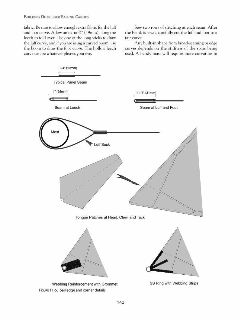
fabric. Be sure to allow enough extra fabric for the luffand foot curve. Allow an extra 3⁄4" (19mm) along theleech to fold over. Use one of the long sticks to drawthe luff curve, and if you are using a curved boom, usethe boom to draw the foot curve. The hollow leechcurve can be whatever pleases your eye.
Sew two rows of stitching at each seam. Afterthe blank is sewn, carefully cut the luff and foot to afair curve.
Any built-in shape from broad-seaming or edgecurves depends on the stiffness of the spars beingused. A bendy mast will require more curvature in
BUILDING OUTRIGGER SAILING CANOES
140
FIGURE 11-5. Sail edge and corner details.
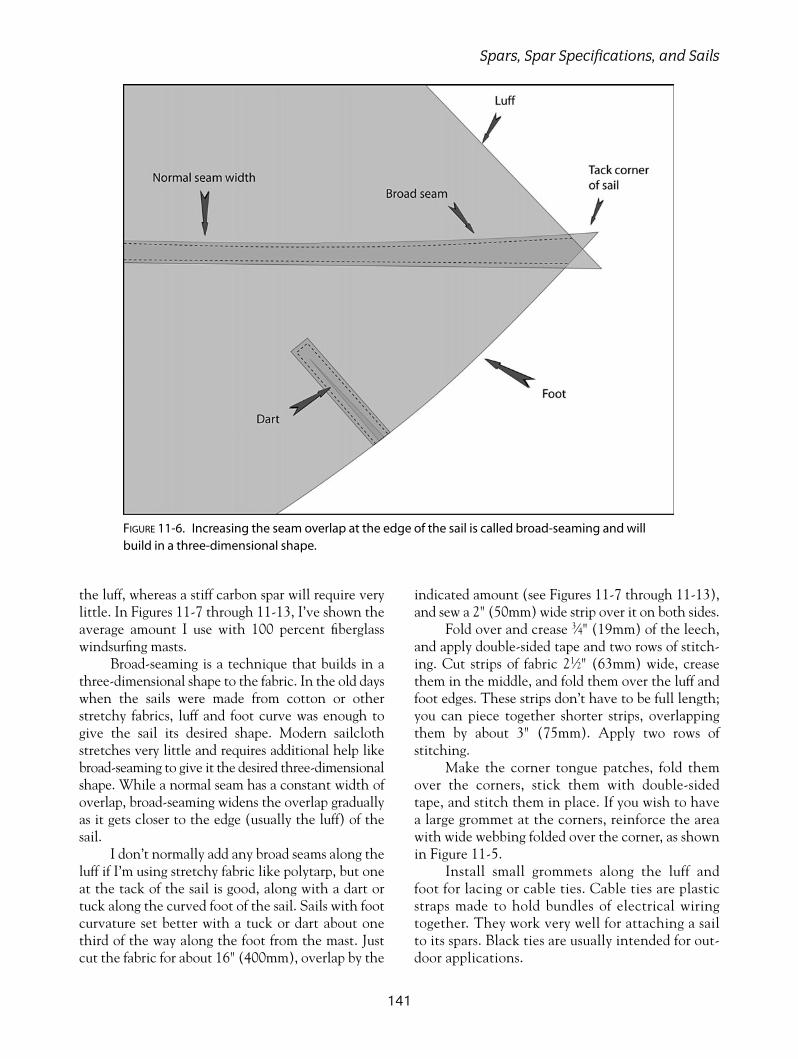
the luff, whereas a stiff carbon spar will require verylittle. In Figures 11-7 through 11-13, I’ve shown theaverage amount I use with 100 percent fiberglasswindsurfing masts.
Broad-seaming is a technique that builds in athree-dimensional shape to the fabric. In the old dayswhen the sails were made from cotton or otherstretchy fabrics, luff and foot curve was enough togive the sail its desired shape. Modern sailclothstretches very little and requires additional help likebroad-seaming to give it the desired three-dimensionalshape. While a normal seam has a constant width ofoverlap, broad-seaming widens the overlap graduallyas it gets closer to the edge (usually the luff) of thesail.
I don’t normally add any broad seams along theluff if I’m using stretchy fabric like polytarp, but oneat the tack of the sail is good, along with a dart ortuck along the curved foot of the sail. Sails with footcurvature set better with a tuck or dart about onethird of the way along the foot from the mast. Justcut the fabric for about 16" (400mm), overlap by the
indicated amount (see Figures 11-7 through 11-13),and sew a 2" (50mm) wide strip over it on both sides.
Fold over and crease 3⁄4" (19mm) of the leech,and apply double-sided tape and two rows of stitch-ing. Cut strips of fabric 21⁄2" (63mm) wide, creasethem in the middle, and fold them over the luff andfoot edges. These strips don’t have to be full length;you can piece together shorter strips, overlappingthem by about 3" (75mm). Apply two rows ofstitching.
Make the corner tongue patches, fold themover the corners, stick them with double-sidedtape, and stitch them in place. If you wish to havea large grommet at the corners, reinforce the areawith wide webbing folded over the corner, as shownin Figure 11-5.
Install small grommets along the luff andfoot for lacing or cable ties. Cable ties are plasticstraps made to hold bundles of electrical wiringtogether. They work very well for attaching a sailto its spars. Black ties are usually intended for out-door applications.
141
Spars, Spar Specifications, and Sails
FIGURE 11-6. Increasing the seam overlap at the edge of the sail is called broad-seaming and willbuild in a three-dimensional shape.

142
FIGURE 11-7. Sail layout for the Ulua tacking rig. Note that a luff sock canbe substituted for grommets and lacing along the luff.
FIGURE 11-8. Sail layout for a 16' (4.8m) Wa’apa with a tacking rig.

143
Spars, Spar Specifications, and Sails
FIGURE 11-9. Sail layout for a 24' (7.2m) Wa’apa with a tacking rig.
FIGURE 11-10. Sail layout for a 24' (7.2m) Wa’apa with a shunting rig.

BUILDING OUTRIGGER SAILING CANOES
144
FIGURE 11-11. Sail layout for a 16' (4.8m) Wa’apa with a shunting rig.
FIGURE 11-12. Sail layout for the T2 lateen shunting rig.

Making a Gibbons/Dierking SailThe structure of the Gibbons/Dierking sail is similarto a windsurfing sail, with a sock along the luff and thenecessity of aligning the warp of the fabric parallelwith the leech to withstand the high tension there.Because there are actually two differently alignedleeches, you’ll get the best results with a miter cut ora seam running parallel with the boom. The Gib-bons sail is a flat piece of fabric; there is no need for
broad seaming or darts. The halyard tension willcontrol the sail’s draft.
Begin by taking the yard, the boom, and somesmall line to rig up an oversized “bow and arrow.”Draw the bow, while leaving 6" (150mm) of arrow(boom) extending past the bow. The bend taken bythe yard will determine the luff curve and the basicshape of the sail and can be used to draw the shapeonto the fabric blank. The fabric blank is a slightly
145
Spars, Spar Specifications, and Sails
FIGURE 11-13. Sail layout for the T2 Gibbons/Dierking rig.
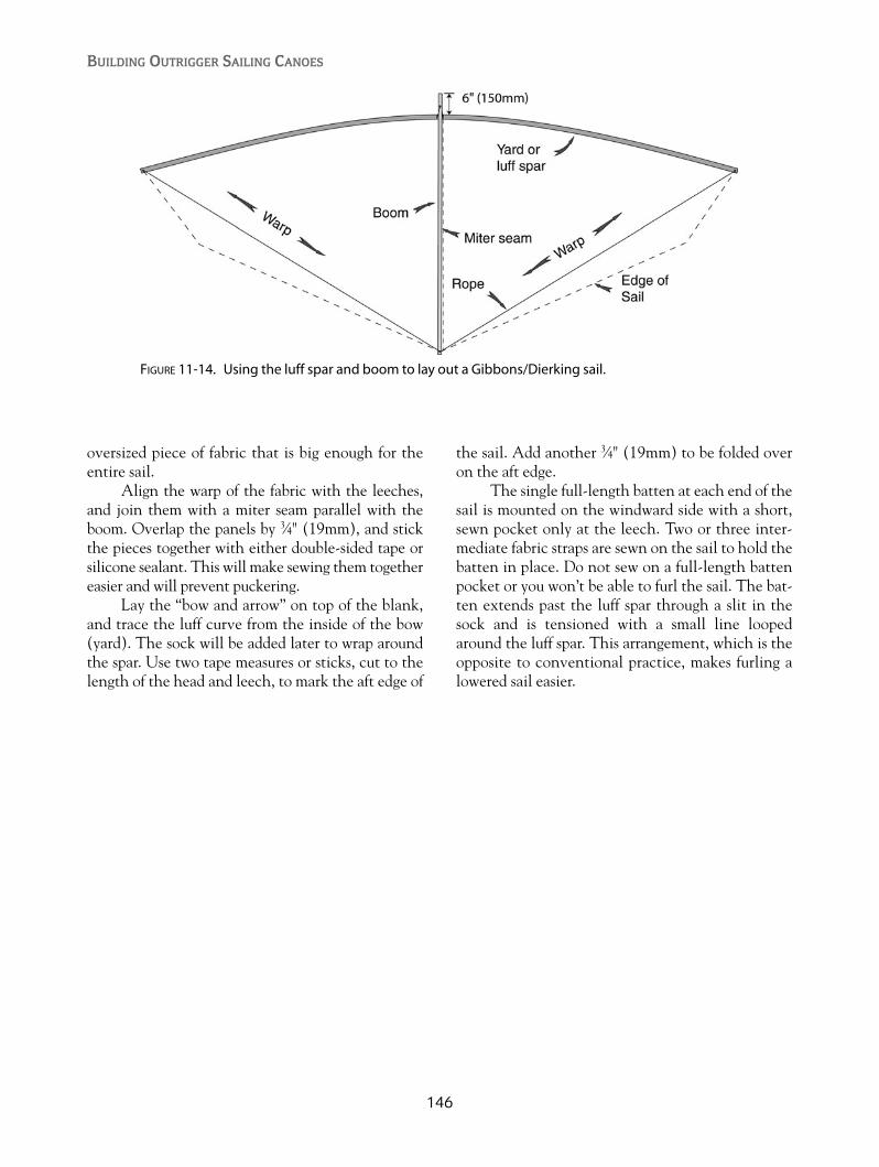
oversized piece of fabric that is big enough for theentire sail.
Align the warp of the fabric with the leeches,and join them with a miter seam parallel with theboom. Overlap the panels by 3⁄4" (19mm), and stickthe pieces together with either double-sided tape orsilicone sealant. This will make sewing them togethereasier and will prevent puckering.
Lay the “bow and arrow” on top of the blank,and trace the luff curve from the inside of the bow(yard). The sock will be added later to wrap aroundthe spar. Use two tape measures or sticks, cut to thelength of the head and leech, to mark the aft edge of
the sail. Add another 3⁄4" (19mm) to be folded overon the aft edge.
The single full-length batten at each end of thesail is mounted on the windward side with a short,sewn pocket only at the leech. Two or three inter-mediate fabric straps are sewn on the sail to hold thebatten in place. Do not sew on a full-length battenpocket or you won’t be able to furl the sail. The bat-ten extends past the luff spar through a slit in thesock and is tensioned with a small line loopedaround the luff spar. This arrangement, which is theopposite to conventional practice, makes furling alowered sail easier.
BUILDING OUTRIGGER SAILING CANOES
146
FIGURE 11-14. Using the luff spar and boom to lay out a Gibbons/Dierking sail.
147
RIGGING AND TUNING
CE and CLROne of the most important concepts to understandwhen you are setting up any sailing craft is the rela-tionship between the center of effort (CE) and thecenter of lateral resistance (CLR).
The CE is the geometric center of the sail,found by drawing lines between each corner of thesail and the midpoint of the opposite side. This doesnot necessarily indicate the true center of effort; it isonly used for estimation purposes.
The CLR can be found by making a scale draw-ing on a piece of stiff cardboard of the underwaterprofile of the hull, including the leeboard. There isdisagreement about whether a fixed rudder should beincluded in this, but I would say that a deep, high-aspect blade should be included, whereas a steeringoar or shallow rudder should not. The cardboardscale profile is cut out and balanced with a pin tofind the CLR.
The CE should always be at least even with, orforward of, the CLR, averaging about 5 percent ofthe waterline length forward of the CLR. This dis-tance is called the lead. If the canoe has strongweather helm (tries to turn into the wind), the leadshould be increased, whereas if steering is needed tokeep the canoe from bearing away from the wind, thelead should be reduced. Weather helm will increasein a stronger wind, so be sure to test in all conditions.
An outrigger canoe has a few more factors tomake it even more complicated. Weight distributionof crew and cargo also has an effect on this balance.
By sinking one end of the canoe more than theother, the underwater profile is altered and willaffect the amount of steering input needed. A singleperson sailing and sitting in the aft seat will lift thebow and could cause lee helm, or a tendency to turnaway from the wind. Too much weight forward cancause more weather helm. Narrow canoes are moresensitive to weight distribution than their beamiercousins.
The ama also has an effect on the sailing bal-ance of a tacking rig. On one tack, the ama is to lee-ward, where its drag tries to turn the canoe down-wind. On the other tack, it is unweighted, or flying,and causes very little or no drag. You can compensatefor this by angling the leeboard fore and aft. With theama to leeward, the blade of the leeboard would beangled forward to offset the effect of the ama drag.
There are several ways to change the balanceof a tacking rig: You can move the mast step foreand aft along with the collar (the fitting at gunwalelevel); you can change the rake of the mast byaltering the position of either the step or the collar;you can change the mounting position of the lee-board; or you can add or remove a permanentrudder.
The CE of an Oceanic lateen shunting rig canbe shifted fore and aft by changing the halyard attach-ment point on the yard or by having alternative mast-step positions with the use of a sliding track or extrasockets or pad eyes. Traditional Kiribati canoes oftenused a row of extra mast-step sockets to change theCE for different courses sailed, similar to the effectgained with a modern Windsurfer’s sliding masttrack.
CHAPTER 12
Rigging, Tuning, and Sailing
Copyright © 2008 by International Marine. Click here for terms of use.

Tacking Rig Setup
The Ulua is generally set up with a tacking rig. Asingle-part mainsheet begins with a loose bowlinearound the aft iako, leads up to the boom through ablock, goes to another block hanging below theboom jaws, then to another block below the jawsattached to the wae, and on to a cam cleat mountedbelow the aft edge of the forward seat. This allowseasy access from the aft hull seat and the hiking seat.A two-part mainsheet begins at the boom, goesdown to a block attached to the aft iako, heads backto the block on the boom, and then goes on to thejaws, as in the single-part sheet.
This mainsheet system has the added benefit oftightening the luff of the sail when close-hauled andloosening it when reaching or running. A separate
downhaul is not necessary, but a safety lanyard from theboom jaws to the wae is recommended to prevent themast falling out of the canoe in the event of a capsize.
The brailing/spiller line has a dual purpose.Since my tacking rigs don’t use halyards, the brailingline is used to pull the boom up against the mastwhile bundling up the sail as it goes up. The brailingline begins by being lashed to a grommet about threequarters of the way up the luff of the sail. It thenleads to another grommet that is an equal distanceout along the foot of the sail. The brailing line thenpasses through and leads to a small block that islashed to the same luff grommet. From there, it leadsto the forward iako for tying off, or it can be led aftto within reach of the crew. The other purpose ofthis line is to spill wind and de-power the sail duringsqualls by partial brailing of the sail.
BUILDING OUTRIGGER SAILING CANOES
148
FIGURE 12-1. Locating the CE of the sail and the CLR of the hull.

Traditional Oceanic canoes didn’t really havereefing methods as are used today. On larger vessels,a second smaller sail and spars could be carried onboard, but small canoes either used a spiller line tode-power the sail, or they dropped the sail andwaited out the squall. The sails in this book can allbe reefed, but not quickly and conveniently whilesailing. Simple reef points can be included whenmaking the sail and tied in with the rig lying on thebeach. This is about the only way to reef a sail witha curved boom. If you opt for a straight boom with aloose-footed sail, the sail can be partially wound upon the mast. The outhaul line will have to be read-justed to the new sail area.
I’ve recently experimented with installing along zipper to remove a portion of the sail area. Theaft edge or leech of the sail is normally hollow orcurved inward. By sewing on a zipper into a muchdeeper, hollow curve, a significant area of sail can beremoved. The corners of the sail at the zipper endsmust each be reinforced with a pair of grommets anda lashing. The installation of the zipper is best left toa professional, because it can form an undesirableridge in the sail if this process is not done right.
An unstayed windsurfing, mast-supported sailcan profit from a forestay. This is simply a 1⁄4" (6mm),low-stretch line leading from a loop around thehull’s bow (an eye strap keeps it from slipping off) toa loop of webbing around the mast about two thirdsof the way up, with the line continuing on to themasthead. As the sail is sheeted in hard to go towindward, the masthead will be bent aft. This hasthe effect of flattening the sail. Note that if you use aforestay, you won’t be able to reef by winding the sailaround the mast.
If you wish to make the Ulua go faster, you’llhave to increase the sail area. This can be done withhigher rigs and the necessity of a complete staying
system. To carry the increased sail area, you mustincrease the righting moment. In other words, youhave to hike out. The hiking seat shown is adequatefor the standard sail plan, but with a larger rig, youwill want a second seat on the non-ama side, sup-ported by iako extensions, which can be lashed inplace. Hiking on the non-ama side will prevent youfrom sinking the ama if you’re in a higher-poweredrig. You may also need another pair of seats to allowadditional crew members to hike out.
One advantage of an unstayed rig is that youcan ease the mainsail entirely and let the boom goflying toward the bow. This is useful when you areapproaching your destination while sailing down-wind, because it allows you to slow down withoutbrailing up the sail.
Shunting Rig SetupThe T2 and the Wa’apa have a choice of two quitedifferent rigs that share a few common components.The masts of both the Oceanic lateen rig and theGibbons/Dierking rig are supported by two backstays(leading from just below the masthead to each bow),a weather shroud (leading from just below the mast-head to a bridle between the outer ends of the iako),and a mast prop (a shock-absorbing strut attachedabout one third of the way up the mast and steppedon a fore and aft spar running between the iakos twothirds of the way out to the ama). In both rig types,the mast is tilted toward the direction of travel. Thisis necessary to place the CE forward of the CLR.
All of the stays and shrouds are running rig-ging, enabling you to fine-tune the balance whileunderway. The weather shroud can be tightened toangle the mast to windward in strong winds, therebyreducing heeling angle and introducing a small liftcomponent. In light airs, the mast is eased to leeward,
149
Rigging, Tuning, and Sailing
FIGURE 12-2. An Ulua with a second hiking seat opposite the ama.

where it makes shunting easier. The line from theweather-shroud bridle is led to within easy reach ofthe crew and can be fitted with a block and tackle sothat it can be adjusted under load.
The backstays begin just below the mastheadand lead to a block at the bow and back toward thenearest iako. A stopper knot or ball is placed alongthe backstay at the point where it will prevent themast from tilting any further forward than is required.A further enhancement puts a powerful loop ofbungee cord at the end of the backstay between thestopper and the iako. When set up correctly, the mastwill be held vertical if the tack lines are released.Pulling the yard end toward either bow will stretchone of the bungees and loosen the other. The bungeesmake the backstays self-adjusting during the shunt.
The mast prop is also bungee-powered. Thetwo parallel overlapping struts are pushing outwardbecause of the bungee loop, and are holding themast from falling to windward in light airs, or in the
event of getting back-winded. It will also allow therig to lay over up to twenty-five degrees from verticalin a back-winding situation and help to prevent theama from sinking.
The weight of bungee necessary for any givenrig is dependent on the rig size and the weight of themast. You can buy bungee cord by length from a rollat most marine-hardware stores or canvas-supplystores. I use three parallel lengths of 1⁄4" (6mm)bungee cord for the T2. Add more lengths until themast goes vertical when the tack line is released.
The sheet to control the sail and boom can bea single loop of line, with both ends attached to thesame point on the boom. From the boom, the sheetleads to a block that is attached to the leeward dash-board. It then loops around to windward of the mast(and behind the sailor), to another block on theother dashboard, and back to the boom. Routing thesheet behind the sailor prevents the sheet from tan-gling with other lines in the hull.
BUILDING OUTRIGGER SAILING CANOES
150
FIGURE 12-3. Ulua mainsheet, brailing line, and forestay leads.
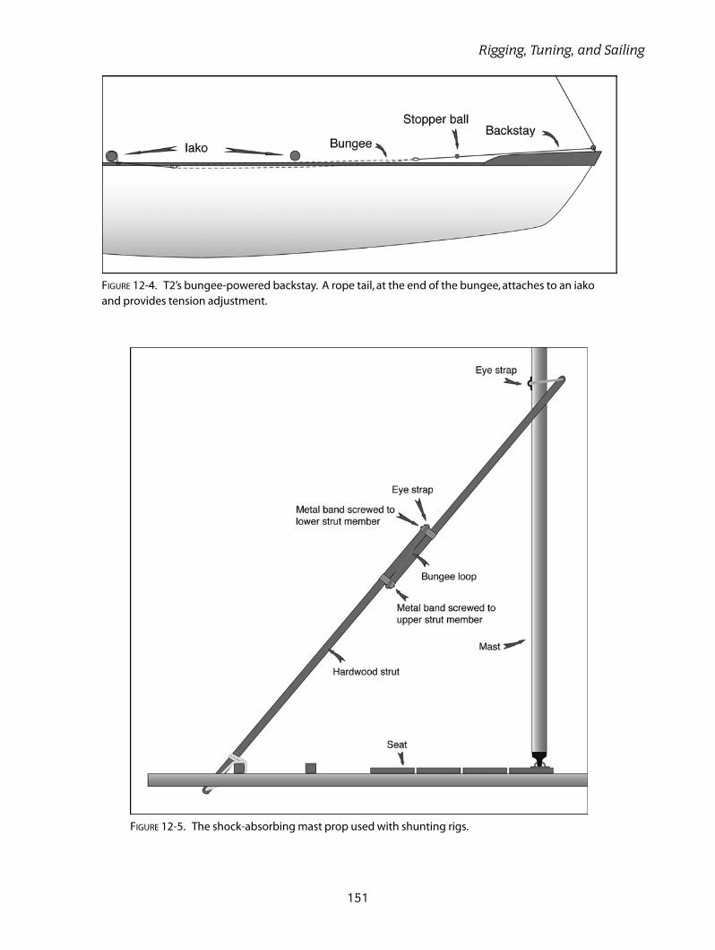
151
Rigging, Tuning, and Sailing
FIGURE 12-4. T2’s bungee-powered backstay. A rope tail, at the end of the bungee, attaches to an iakoand provides tension adjustment.
FIGURE 12-5. The shock-absorbing mast prop used with shunting rigs.
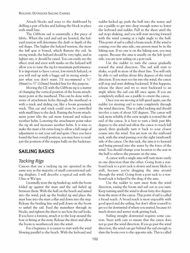
Attach blocks and stays to the dashboard bydrilling a pair of holes and lashing the block in placewith small line.
The Gibbons sail is essentially a flat piece offabric. When the yard and sail are hoisted, the hal-yard tension will determine the draft or depth of thesail shape. The higher the halyard tension, the morethe luff spar is bowed, which flattens the sail. Instrong winds, the halyard should be very tight, and inlighter airs, it should be eased. You can easily see theeffect; trial and error with marks on the halyard willallow you to tune the rig for maximum performance.It is important to have a stout, low-stretch halyard, oryou will end up with a baggy sail in strong winds—just what you don’t want. I’d recommend a 5⁄16"(8mm) to 3⁄8" (10mm) braided line for this purpose.
Moving the CE with the Gibbons rig is a matterof changing the vertical position of the boom attach-ment point at the masthead. This can be done with aseries of attachment holes through the masthead orwith a track and sliding car, like a boom goosenecktrack. This car and track could even be controlledwith small lines to the deck. Raising the boom attach-ment point tilts the sail more forward and reducesweather helm. Lowering the attachment point rakesthe rig aft and increases weather helm. It is wise tomake the mast a bit extra-long to allow a full range ofadjustment to suit your sail and spars. Once you havefound the best overall position, you may have to read-just the position of the stopper balls on the backstays.
SAILING BASICS
Tacking RigsCanoes that use a tacking rig are operated in thesame way as the majority of small conventional sail-ing dinghies. I will describe a typical sail with theUlua or Wa’apa.
I normally store the rig brailed up, with the boomfolded up against the mast and the sail furled upbetween them. With the hull on the beach and aimedinto the wind, pick up the brailed rig and place themast base into the mast collar and down into the step.Release the brailing line and pull down on the boomto unfurl the sail. Feed the mainsheet through itsblocks, and tighten the sheet to see how the sail looks.If you have a forestay, attach it to the loop around thebow or fitting at the stem. Release the sheet and allowthe boom to weathercock into the wind.
For a beginner, it is easiest to start with the windblowing parallel to the beach. With the leeboard and
rudder kicked up, push the hull into the water, anduse a paddle to get into deep enough water to lowerthe leeboard and rudder. Pull in the sheet until thesail stops shaking, and you will start moving forwardwith the wind coming at a right angle to the hull.This point of sail is called a beam reach. If the wind iscoming over the ama side, one person must be in thehiking seat. If no one is on the hiking seat, you maycapsize. Because the ama is usually on the left (port)side, you are now sailing on a port tack.
Use the rudder to turn the canoe graduallytoward the wind direction. The sail will start toshake, so pull in more of the sheet line. You will onlybe able to sail within about fifty degrees of the winddirection. If you steer too far into the wind, the canoewill stop and start drifting backward. If this happens,release the sheet and try to steer backward to anangle where the sail can fill once again. If you arecompletely stalled, use a paddle to orient the canoe.
Once you are moving at full speed again, use therudder (or steering oar) to turn completely throughthe wind direction. This is called tacking and shouldinvolve a turn of about 100 degrees. The canoe willtack more reliably if the crew weight is toward the aftend of the canoe. It is best to turn a little past fiftydegrees to the wind and allow the canoe to reach fullspeed; then gradually turn it back to your closestcourse into the wind. You are now on the starboardtack, with the wind passing over the right (starboard)side of the canoe. On this tack, the ama is to leewardand being pressed into the water by the force of thewind. You should change your location to the seat inthe hull to relieve the pressure on the ama.
A canoe with a single ama will turn more easilyin one direction than the other. Going from a star-board tack to a port tack is slower and more likely tostall, because you’re dragging the ama aroundthrough the wind. Going from a port tack to a star-board tack is helped by the drag of the ama.
Use the rudder to turn away from the winddirection, easing the boom and sail out as you turn.Keep turning until the wind is about forty-five degreesfrom the stern of the canoe. This point of sail is calleda broad reach. A broad reach is most enjoyable withgood speed and dry sailing, but don’t allow yourself toget too far downwind of where you started, because it’smuch slower and wetter work getting back.
Sailing straight downwind requires some cau-tion. Steer with care to ensure that the canoe doesnot go past the wind direction. If you go past the winddirection, the wind can get behind the sail enough toslam the boom over to the opposite side. This is called
BUILDING OUTRIGGER SAILING CANOES
152

jibing and can cause damage to the canoe and thecrew if it is not controlled. Practice jibing in lightwinds, and remember to duck as the boom passes overyour head. Pulling in and releasing the sheet as theboom is moving from side to side will help in control-ling the jib. During a jibe, remember to be in the hik-ing seat before beginning the maneuver.
The brailing line can be used to reduce the sailarea when you are broad-reaching or running instrong winds. It is also useful when approaching thebeach, where the sail can be completely brailed up.
Shunting RigsAlthough a shunting rig is more complex than atacking rig, it has an advantage in that you can trainfor the shunting event without actually putting thecanoe in the water. I like to call this training “lawnshunting.” During a shunt, a canoe will not bechanging direction or moving much, so you canpractice quite realistically on your lawn.
Orient the canoe with the wind passing directlyover the ama (beam reach). Note that a shunting rigmust always have the wind passing over the ama side.Have the butt of the yard pulled to one of the bowswith the tack line. Hoist the sail with the sheet looseto allow the boom to pivot out to leeward and weath-ercock into the wind. As the yard gets closer to itsfinal position, it will pull the masthead toward thebow. Pull in the sheet a little to see how the sail lookswith some wind in it. If you pull in too much, youmay experience your first “lawn capsize.”
When shunting on the water, you will alwaysorient the canoe in the same way, with the wind asclose as possible to ninety degrees from the centerlineof the hull. Too close to the wind or too far on abroad reach invites “back-winding” the sail. If thewind catches the back side of the sail, it’ll lay it flatagainst the mast and stall the canoe. If the wind isstrong, it can submerge the ama. If you are back-winded in light winds, you can usually turn the canoewith your paddle or steering oar. In strong winds, itmay be necessary to brail up the sail or lower it beforethe canoe can be returned to its course.
With the canoe properly oriented to the winddirection, the first step in shunting is to release thesheet, allowing the boom to swing out to leewardwith a completely loose sheet. If the wind is too lightto hold the boom all the way out, lean the mast toleeward by easing the weather shroud.
After releasing the tack line, the mast will bepulled to the vertical (fore and aft) position by the
bungees connected to the backstays. If you’re riggedwith an Oceanic lateen where the yard butt passesabove the deck, pull the opposite bow’s tack lineand grab the yard with your other hand to guide ittoward the new bow. As the yard butt approachesthe new bow, the pull on the tack line will becomegreater, because you are stretching the backstaybungees on the new backstay. For an Oceanic lateenwhere the yard butt passes below the leeward gun-wale, you don’t need to grab the yard; just pull theyard along the guide rail with the tack line.
One difference resulting from the path of theyard butt is that you’ll need two separate and iden-tical mainsheets if the butt passes below the gun-wale. If the yard passes above the gunwale, it canpass over a single mainsheet that can be used onboth tacks.
After pulling the yard to the new bow with thetack line, secure it in a cam cleat, and pull in themainsheet to move off in the opposite direction.
The procedure for the Gibbons/Dierking rig isvery similar to that for the Oceanic lateen. Thesheet is released, the tack line is released, the mastgoes vertical, the yard goes horizontal with the sailand boom flying out to leeward, the other end of theyard is pulled down to the new bow with the tackline, the mainsheet is pulled in, and off you go.
Tack lines in all cases are “endless lines.” TheOceanic lateen has both ends of the tack line tied toits yard butt, with the loop passing through two blockslocated at the bows of the canoe. The Gibbons/Dierking rig has the two ends of the tack lineattached to the two ends of the yard, and the loop alsopasses through two blocks at the bows of the canoe.
Steering a canoe rigged with the Oceanic lateenrig can be done with a steering oar in the usual waybut can also be aided through sail trim and weight dis-tribution. Sheeting in more than necessary will causethe canoe to turn away from the wind, and easing thesheet will cause it to turn toward the wind direction.This technique applies to close-hauled and beam-reaching courses. Broad-reaching will require the aidof a steering oar or paddle, and running dead down-wind is not recommended at any time with a shuntingrig because of the possibility of an accidental jibe andthe resulting back-winding. Weight concentrated aftin the hull will turn the canoe away from the wind,while weight moved forward will turn the canoetoward the wind.
Sheet adjustments with the Gibbons/Dierkingrig do not affect steering as much as in the Oceaniclateen rig. The shorter boom creates less turning
153
Rigging, Tuning, and Sailing

154
FIGURE 12-6. Oceanic lateen rig close-hauled on a porttack.
FIGURE 12-8. The tack line is used to pull the yard alongthe leeward side of the hull.
FIGURE 12-9. The tack line is secured in a cam cleatwhen the yard reaches the new bow.
FIGURE 12-10. The sail is sheeted in,and the canoe begins sailing on a starboard tack.
FIGURE 12-7. The canoe is steered onto a beam reach,and the mainsheet is released to allow the boom toswing out.
1 2
3 4
5
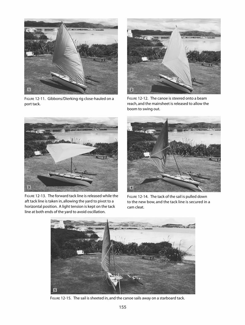
155
FIGURE 12-11. Gibbons/Dierking rig close-hauled on aport tack.
FIGURE 12-12. The canoe is steered onto a beam reach, and the mainsheet is released to allow the boom to swing out.
FIGURE 12-13. The forward tack line is released while theaft tack line is taken in, allowing the yard to pivot to ahorizontal position. A light tension is kept on the tackline at both ends of the yard to avoid oscillation.
FIGURE 12-14. The tack of the sail is pulled down to the new bow, and the tack line is secured in a cam cleat.
FIGURE 12-15. The sail is sheeted in, and the canoe sails away on a starboard tack.
1 2
4
5
3

moment than the much longer boom used with thelateen.
Because shunting rigs are quite alien to mostsailors, it can be a great help in visualizing themaneuver by making a small model with sticks andstring. The effects of small alterations in geometrycan readily be seen.
SWAMPING AND CAPSIZE
FlotationDuring the thousands of years that outrigger canoeshave been used for transportation and fishing, themost important safety device carried on board wasbetween the ears of the crew. Nothing built in to thedesign or carried on board can replace prudent sea-manship. It certainly helps if you grew up using smallboats and occasionally got into harm’s way. No bookor lecture can come close to simply spending time onthe water. Lessons learned on the water become apart of you and are never forgotten.
Traditional canoes being made of timber wouldnot sink unless they were carrying a load of stone.They could certainly swamp, though, and Oceanicpeople became adept at getting the water back outagain. A child or young person on board a sailingoutrigger would be employed at bailing for much ofthe time.
I remember once watching a Tongan man pad-dling his outrigger canoe across a harbor on a choppyday. He had a full load of fruit and vegetables thatput his freeboard down to nothing. The inevitablehappened, and produce was floating everywhere.What amazed me was that he had the canoe bailedin a few seconds. It was a simple dugout with no foreor aft decks. He swam around to one end of the hull,and with a quick down-and-up motion, had all ofthe water going out the other end in one wave.Another few minutes for the produce retrieval andhe was away again. For the rest of us who didn’t growup in the South Seas, some tangible safety devicesare in order.
Flotation is the single most important way tostay alive, or to get your canoe on its way again.Unless you’re an expert water person, wear yourlife jacket (PFD) and carry a knife. All of thedesigns described here have, at minimum, a sealedcompartment at both ends of the hull defined by awatertight or collision bulkhead. An empty com-partment will keep you afloat as long as it is sealed,
but if there was damage and it is leaking, you’llneed a backup system. The lightest and cheapestsolution is to fill your compartments with plasticsoft-drink bottles or chunks of foam usually dis-carded from packing. Put the foam chucks insealed plastic bags to keep the crumbs from gettingloose.
The Ulua and the Wa’apa have a lot of interiorvolume that will be filled with water in the event ofa capsize. If the waves are choppy, you may not beable to bail out the water faster than it’s coming overthe gunwales. Additional flotation would be a goodidea if you frequent rough water or are often alone.Blocks of shaped foam can be fitted under the twoseats. They can be nicely glassed or just strapped inwith webbing belts. The seats can also be built witha sealed chamber beneath them that acts as flotationand dry storage space. There are also inflatable airbags available as standard equipment for sailingdinghies. Any additional flotation must be verysecurely fastened, as it will try to come out when it’ssubmerged.
A hollow mast should have its ends sealed withplugs or foam. A mast filled with water makes recov-ery from a capsize more difficult.
Sailing canoes that race between the HawaiianIslands use a safety ama. This is a second ama carriedon the opposite side of the main ama. It is mounteddifferently in that it is closer to the main hull and isheld well above the waterline. It only comes intoplay when a capsize is imminent and will, in mostcases, prevent one. Iakos can be originally builtlonger to accommodate a safety ama, or short iakoextensions can be lashed on with an overlap overthe hull.
The safety ama does not require the sophisti-cated design of the main ama. It can, in fact, be aPVC pipe with its ends plugged, a simple foam-and-fiberglass log, or even the foam tubes used on swim-ming pool dividers, stiffened with a tube or doweldown its center. These can also be rigged as addi-tional flotation in the interior of the hull in manyingenious ways.
The T2 has no need for extra flotation. In addi-tion to the two sealed compartments in the end, ithas a raised, sealed floor in the cockpit area that isabove the waterline. Drain holes or scuppers arelocated at each end of the cockpit to drain out sprayor the entire interior in the event of a capsize. Asafety ama can also be rigged if you wish.
The Wa’apa has two sealed bow compartmentsthat are adequate if it is being sailed as a 16-footer,
BUILDING OUTRIGGER SAILING CANOES
156

but that will allow a lot of water inside if it is riggedas a 24-footer. The center section can have foamblocks or other material under the seats. There isalso the option of decking over the entire center sec-tion with hatches installed that, when open, wouldstill allow a paddler to sit normally with his or herfeet in the hull. A sealed bulkhead rather than thering frame at the center of this section would make iteven more secure. A safety ama or a double-outriggersetup will, of course, make it less likely to capsize inthe first place.
Amas are made from either solid foam, or theycan be made from hollow plywood or strip compos-ite. It is wise to fill any hollow ama with foamchunks or plastic bottles, in case of a slow leak ormajor damage.
Recovering from a CapsizeThe best way to prevent capsizing is to always keepa hand on or very near to the sheet controlling thesail. Don’t forget to move onto the hiking seat
157
Rigging, Tuning, and Sailing
FIGURE 12-16. A safety ama rigged on an Ulua with short, overlapping beams lashed to the top of the maincross beams. A second hiking seat can be rigged on the safety ama side.
FIGURE 12-17. A capsized outrigger canoe can be righted by standing on one of the iako endsand pulling on a line attached to the ama.

when the ama is on the windward side. When jib-ing (turning the canoe with the stern passingthrough the eye of the wind), be sure to be in thehiking seat before you begin the jibe. In most cases,if you capsize in one of these canoes, it will stopwith the ama up in the air. Most of the time you’llbe thrown into the water to leeward and will haveto swim around to the other side and pull the amaback down. Speed is of the essence, because thelonger you take to get into position, the more likelyit is that the wind will blow the canoe the rest ofthe way over. Release the mainsheet before youbegin righting the canoe so that the sail can spillwater and wind as it rises.
Traditional Oceanic canoes almost invariablyused solid wood amas made from the lightest mate-rial available. The most common technique forrighting a completely inverted canoe was to sink theama, pushing it under the main hull. This was possi-ble because of the limited buoyancy available from asolid log. Most amas attached to modern outriggersare hollow or foam-filled and are very difficult tosink unless you have several people to put theirweight on them. A light, buoyant ama will have tobe pulled over the top of the main hull.
A righting line can be kept rigged and stowedalong underneath the iako and can be used to pullthe ama up out of the water. A righting line is tiedto the ama either at one of the attachment pointsor with a bridle to both of them, and is led back tothe main hull. If you don’t have one alreadyrigged, always keep easily accessible pieces of linein the canoe that can also be used to fix manythings.
A righting pole can also be used to gain moremechanical advantage in righting a capsized canoe.It can be stowed out on the iako alongside the polethat supports the hiking seat. A steering oar can alsobe used as a righting pole.
In the unlikely event that you have capsized adouble outrigger, you can remove one of the amasand right the canoe as previously described. Lashingsof rubber-strip or polyester line are normally used atthe ama. If you carry a folding knife with a marline-spike in your pocket, you should be able to get eventhe nastiest knots undone.
Be sure that your mast has not come partly out of its step before you begin righting the canoe.This could cause severe damage to the mast and thecollar.
BUILDING OUTRIGGER SAILING CANOES
158
FIGURE 12-18. Using a righting pole or steering oar to right a capsized canoe.
Once the canoe is righted, you have to removethe water. A good-sized plastic bucket for each personon board is recommended. If you have more than oneperson on board, you may be able to get some of thewater out of the hull by sinking the ama as much aspossible and tipping the water out. Another tactic is
to hang off of one end of the canoe and get a surgegoing to slop some of it out. It’s not a bad idea to prac-tice all of these things on a nice, warm day, and you’llbe much better prepared if the real thing happens.
Be sure to have lanyards on the bailing buck-ets, paddles, and anything else carried in the hull.
159
Rigging, Tuning, and Sailing

Aft—Toward the back end of a hull or opposite tothe direction of travel.
Aka—A term sometimes used for the cross beamsor iako.
Ama—The small hull or float attached to the endsof the outrigger beams used to stabilize a narrowhull.
Amidships—The midsection of a hull; halfwaybetween the bow and stern.
Backstays—Lines leading from the top of the mastout to the two ends of the hull; backstays controlthe vertical angle of the mast.
Back-winding—In a shunting rig, the wind mustalways pass over the ama. If the canoe is allowed toturn with its ama away from the wind, the sail willflatten up against the spars and becomeunmanageable.
Ballast—Weight in the form of crew or inanimateobjects used to counterbalance the force of the sail.
Batten—A semi-flexible length of fiberglass orwood used to stiffen parts of a sail.
Beam reach—Sailing with the wind coming froma direction at ninety degrees to the direction oftravel.
Boom—The spar attached to the bottom edge orfoot of a sail.
Bow—The forward end of a hull.
Brailing line—A line rigged through a block on the upper part of the mast; the brailing line is used to lift the boom. It can be used to reduce the effective sail area when you are sailingdownwind.
Broad reach—Sailing with the wind at a forty-five-degree angle to the stern of the hull.
Broad-seaming—An overlapping seam in a sailwhere the amount of overlap is varied along itslength to induce a three-dimensional shape in thesail.
Bulkhead—A solid panel at right angles to thekeel that encloses compartments in the ends of thehull and adds structural strength.
CE—The center of effort of a sail. For calculationpurposes, it is also the geometric center of the sail.
Chine—A hull joint where two panels meet. Theridge where the sides join the bottom in a flat-bottomed hull is the chine.
Clew—The outer aft corner of a sail, attached tothe end of the boom.
CLR—The center of lateral resistance of the hulland any underwater appendages.
Collar—A loop of metal strap that holds the mastin place at deck level.
160
Glossary
Copyright © 2008 by International Marine. Click here for terms of use.

Dado—A rectangular groove cut into a piece ofwood.
Dagger boards—Retractable fins that passthrough the bottom of a hull to provide lateralresistance or steering.
Fairlead—A plastic or metal liner that fits into ahole through which a line can pass smoothly.
Foil—A wing-shaped, underwater appendage usedfor lateral resistance or steering. A sail is also a formof a foil.
Foot—The bottom edge of a sail.
Forestay—A line attached to the bow of a hull,leading up to a point on the mast, and used to holdup the mast or improve its bending characteristics.
Frame—A stiffening framework at right angles tothe keel that helps the hull to maintain its shape.
Freeboard—The distance between the surface ofthe water and the gunwale of the hull.
Gibbons rig—A shunting rig originally used byEuell Gibbons in the 1950s. My version incorpo-rates some windsurfing technology.
Gunwale—A narrow, wooden strip attached alongthe sheer. A two-piece gunwale consists of an inwalealong the inside of the hull and an outwale alongthe outside.
Halyard—A line used to pull a sail or its yard upthe mast.
Head—The top corner of a sail, or the top of the mast.
Hiking seat—A slatted or fabric seat for a crewmember; it is rigged outboard of the hull to provideballast to balance the force of the sail.
Iakos—Cross beams or outrigger booms used tohold the ama (outrigger float) at a set distance par-allel to the hull.
In irons—Stalling or drifting backward when a tack-ing rig passes its bow through the eye of the wind.
Jib—A sail set forward of the mast.
Keel—The line that defines the center bottom lineof the hull.
Keel rocker—The vertical curvature of the keel when viewed from the side. Increasing keel rocker makes the canoe turn quicker and tackeasily but makes paddling in a straight line moredifficult.
Lamination—A process where thin layers of woodare glued together to form larger and stronger parts.Curved members like cross beams are commonlylaminated.
Lashings—Structural joints in traditional outrig-ger canoes are held together with small ropewrapped around the joint. Lashing has provedeffective in reducing stress concentrations in mul-tihulled craft and is still recommended in manyapplications.
Lateen—See Oceanic lateen.
Lazy jacks—Lines leading from the upper portionof the mast down to the boom. A pair of brailinglines can perform as lazy jacks and catch the sail asit is lowered.
Lead—The distance between the CE and the CLR.
Leeboard—A board held alongside the hull to pre-vent drift to leeward. A leeboard performs the samefunction as a dagger board but is mounted outside ofthe hull instead of through it.
Leech—The aft free edge of a sail. The leech is notusually attached to a spar.
Lee helm—The tendency for a sailing craft to turnaway from the wind direction.
Leeward—Opposite to the direction from whichthe wind is blowing; i.e., downwind. If your hatblows off your head, it will fly to leeward.
Luff—The forward leading edge of a sail.
Mainsail—The sail that is attached along the aftside of the mast.
161
Glossary

Mainsheet—The line connected to the boom thatis used to pull the sail in or ease it out. The main-sheet controls the angle between the sail and thewind direction.
Manu—A Hawaiian term for the extended ends ofthe stem at the bow and stern. It is frequentlycarved into shapes resembling parts of a bird and isuseful for cutting through wave tops.
Mast—The main spar of any sailing rig; used tohold up the sail and other spars.
Masthead—The top of the mast.
Mast shrouds—A line or lines holding the mastup in a lateral direction. Shunting proas have ashroud leading out to a bridle connecting the outerends of the iakos.
Mold—A temporary shape cut from plywood orparticle board that supports the hull plankingbefore it is stiffened with fiberglass sheathing.Molds are removed from the hull later.
Oceanic lateen rig—A triangular sail rig consisting of an angled yard, a boom of equal or longer length, and a mast shorter than the other spars. It is used on shunting canoes where the yard is carried or pulled along from bowto bow.
Outboard bracket—A plywood bracket thatclamps onto the aft iako. The outboard bracket isused to mount an outboard motor, a steering oar, ora rudder.
Outhaul—A line connecting the outer end of theboom and the clew corner of the sail.
Parrel—Wooden or plastic beads threaded onto aline and looped around a spar.
Pola—A Hawaiian term for the fore and aft mem-bers resting on the top of the iakos. These are usedto support net, trampolines, or hiking seats and canbe used to aid in carrying the canoe.
Port—The left-hand side of a canoe when facingthe bow.
Port tack—Sailing with the wind coming over theleft or port side of the canoe.
Proa—Originally, this Indonesian term just meant“boat,” but the first shunting canoes observed byexplorers were called “proas,” or “praus,” and theterm is now commonly used to describe this type ofsailing canoe.
Rake—The angle of a mast or other spar, whenmeasured from vertical.
Reefing—Reducing the size of a sail by partiallyfurling it or removing some of its area.
Reef points—Grommets located in a sail to allowpartial furling.
Ring frame—A frame that attaches to the innersides of the hull and under the deck, but is open inthe middle.
Scarf joint—A long, tapered, overlapping jointused to produce long lengths of timber or plywoodwithout a reduction in strength.
Scull—Using a long steering oar in a “fish tail”motion to propel a canoe.
Scupper—A drain hole on deck or in a cockpit.
Sharpie—A flat-bottomed hull similar that of adory, but with less flare in the sides.
Sheer—The line that defines the upper edge of thehull viewed from the side.
Sheeting—Pulling or easing the mainsheet toadjust the angle of the sail.
Shunting—A maneuver during which a double-ended sailing canoe changes direction by reversingits ends. The bow becomes the stern and vice versa.A lateen sail will have its tack carried or pulled tothe new bow. Some modern shunting rigs simplypivot their booms 180 degrees.
Spars—Timber, metal, or composite poles used tosupport the edges of a sail.
Spiller lines—See Brailing line.
GLOSSARY
162
Spinnaker—A large, lightweight sail used to sailon downwind and broad-reaching courses.
Splashboard—A shaped or angled board forwardof an open cockpit; it is used to prevent water fromentering the hull.
Sprit boom—A boom whose inner end is attachedto the mast at a point higher than the tack of thesail.
Starboard—The right-hand side of a canoe whenfacing the bow.
Starboard tack—Sailing with the wind comingover the right or starboard side of the canoe.
Station—A longitudinal position shown in thehull plans and table of offsets. Stations are usuallyequally spaced and numbered sequentially.
Stay—A line used to hold up the mast.
Staysail—A small sail usually set between twolarger sails.
Stem—The structural member at the bow of a hullthat connects the two side panels.
Stern—The back end of a hull. The stern may beeither pointed in a double-ended shunting canoeor have a transom, in the case of some tackingcanoes.
Stringer—A longitudinal structural member usedto stiffen hulls.
Strongback—A rigid, solid, and level frameworkupon which a hull can be built. It does not becomea permanent part of the hull.
Tack—To change course by passing the bow throughthe eye of the wind. Also, the lower forward cornerof a sail, at the intersection of the mast and boom.
Tacking rig—A sailing rig that works similarly towestern rigs and turns through the eye of the windto make progress to windward. Boats with tackingrigs have a permanent bow and stern.
Tack line—A rope used to pull the butt of the yardfrom bow to bow in a shunting proa.
Trimaran—A hull rigged with identical amas onboth sides.
Wae—A Hawaiian term for spreaders or short beamslocated just below gunwale level to strengthen orstiffen the hull sides. These are usually located justbelow the iako and are sometimes lashed to it.
Weather helm—The tendency of a sailing craft toturn into the wind direction.
Windward—The side of a hull or rig that isexposed to the wind; or the direction from whichthe wind is blowing.
Wing mast—A mast that is normally larger in crosssection and that is shaped like an aircraft wing.
Yard—The spar attached to the leading edge of anOceanic lateen or Gibbons/Dierking rig.
163
Glossary
164
Resources
TRADITIONAL OUTRIGGERCANOE CULTUREDoran, Edwin, Jr. Wangka: Austronesian Canoe
Origins. College Station, Texas: Texas A&M University Press, 1981.
Gillett, Robert, James Ianelli, Tevita Waqavaka-toqa, and Matai Qica. Traditional SailingCanoes in Lau. Suva, Fiji: Institute of PacificStudies, University of the South Pacific, 1993.
Gladwin, Thomas. East is A Big Bird. Boston: Harvard University Press, 1970.
Grimble, Rosemary. Migrations, Myth and Magicfrom the Gilbert Islands. London: Routledgeand Kegan Paul Ltd., 1972.
Haddon, A.C., and J. Hornell. Canoes of Oceania.Honolulu, Hawaii: Bishop Museum Publications 27, 28, and 29. Reprinted as onevolume, 1975.
Holmes, Tommy. The Hawaiian Canoe. Hanalei,Kauai, Hawaii: Editions Limited, 1981.
Horridge, Adrian. Outrigger Canoes of Bali andMadura, Indonesia. Honolulu, Hawaii: BishopMuseum Special Publication 77, 1987.
Lewis, David. We, the Navigators. Wellington, New Zealand: A.H. & A.W. Reed Ltd., 1972.
Siers, James. Taratai, A Pacific Adventure.Wellington, New Zealand: Millwood PressLtd., 1977.
Siers, James. Taratai II, A Continuing Pacific Adventure. Wellington, New Zealand: Millwood Press Ltd., 1978.
BOATBUILDINGBradshaw, Todd, Canoe Rig, The Essence and the Art.
Brooklin, Maine: WoodenBoat Books, 2000. Gougeon, Meade. Gougeon Brothers on Boat Construc-
tion: Wood and West System Materials, 5th ed. BayCity, Michigan: Gougeon Brothers, Inc., 2005.
Hazen, David. The Stripper’s Guide to CanoeBuilding. Larkspur, California: Tamal Vista Publications, 1976.
Marino, Emiliano. The Sailmaker’s Apprentice.Camden, Maine: International Marine, 2001.
Moores, Ted. KayakCraft. Brooklin, Maine: WoodenBoat Publications, 1999.
INTERNET RESOURCESFull-sized paper patterns can be ordered from theauthor through the mail or online from the website.
Gary Dierking1485 Long Bay RoadCoromandel 3506New ZealandGary Dierking’s website: http://gary.dierking.nethttp://homepages.paradise.net.nz
Gougeon Brothers, Inc. (manufacturer of West Systemepoxy): http://www.westsystem.com
Proa links: http://www.wingo.com/proa/links.html
Yahoo proa group: http://groups.yahoo.com/group/proa_file
Proafile website: http://www.proafile.com/
Tim Anderson: http://www.mit.edu/people/robot/
Copyright © 2008 by International Marine. Click here for terms of use.

165
Index
Aaccommodations, 4aluminum spars, 53, 136aluminum tube beam iakos, 116amas
alignment, 102buoyancy, 102diamond-shaped, 30double-outrigger canoes, 31, 113, 115foam and fiberglass, 103–6, 112materials, 102, 157, 158painted finishes, 106plywood, 30, 31, 106–9, 112purpose of, 102safety ama, 3, 113, 114, 156, 157sailing balance, 147shapes, 103speed and, 54–55, 56strip-composite construction, 109–10tuning, 102
amas connections, 30, 31, 105–6,110–12
anti-torque line, 131–32Atlantic proas, 2
Bbackstays, 18–19, 29, 43, 51, 149,
150, 151back-winding, 44–45, 150, 153bamboo spars, 53, 136battens, 48, 50–51, 54, 61, 81–82, 146Beachcomber’s Handbook (Gibbons), 48
bead and cove planking, 59, 64, 65beam reach, 44, 152, 153, 154, 155bending loads, 46, 134birdsmouth spars, 135–36boatbuilding resources, 164boat covers, 75, 76bonded fasteners, 74boom jaws, 136–37, 148booms
Gibbons/Dierking sailing rig, 50–51,53, 54
Hawaiian rig, 54, 55Oceanic lateen rig, 18, 19repairs, 76–77tacking rigs, 29
Bororo, 26, 27brailing/spiller line, 7, 29, 33, 35, 44, 45–46,
148–49, 150, 153broad reach, 152, 153broad-seaming, 141broken-wing iako configuration, 113, 114building materials. See also plywood; timber
ancient vs. modern, 2choosing, 5, 59–60fasteners, 62–63, 74glues, 60, 61–62, 103
bulkheadslofting, 61materials, 60strip-composite construction, 86, 87watertight, 156
buoyancy, 7, 102butt blocks, 68–69butt joints, 65, 67–69
Numbers in Bold indicate pages with illustrations
Copyright © 2008 by International Marine. Click here for terms of use.

Ccabins, 4cable ties, 141canoe houses, 75capsize recovery, 157–59carpenters’ glue, 62, 82, 103center of effort (CE), 43, 53, 55, 147–48center of lateral resistance (CLR), 121, 126, 127,
129, 147–48checking, 59, 76chines, 60, 96, 97, 98clamps, 59close-hauled, 154, 155compressive loads, 46, 134connections. See also lashed connections
direct and indirect methods, 105–6, 110–12quick-connecting strut, 30, 31, 111, 112sticks, 110, 111
crab-claw rigs, 90, 99, 127cradle, 85, 116
Ddagger boards, 124, 126, 127dagger rudders, 127dashboards, 88, 89, 90, 94decks
plywood construction, 98–99, 100, 101strip-composite construction, 87–88, 89, 93
delamination test, 60double-outrigger canoes
advantages, 31capsized, 158iakos, 31, 113, 115tacking rig option, 31, 37, 139
duct tape, 76dust masks and respirators, 75
Eedge grain, 65epoxy putties, 76epoxy resin
additives, 62, 69advantages, 61–62allergies to, 62, 75applying, 72choosing, 60clamping procedures, 62conditions for working with, 60, 72
filleting, 69, 70mixing, 62safety gear, 62, 75scarf joints, 66, 67thinners, 62UV protection, 70, 74, 75–76
Ffairing, 70–71, 75, 85, 92fairing battens, 61, 81–82false stem, 98fasteners, 62–63, 74feather board, 64fiberglass, joining plywood with, 67–68fiberglass masts, 134fiberglass sheathing
benefits of, 71maintenance and repair, 75–76plywood construction, 58–59, 71, 101procedures, 71–73strip-composite construction, 58, 62, 70, 71–72,
85, 86varnish-finished hulls, 70, 74, 75–76
filleting, 69, 70filleting tool, 69, 70filling, 69–70finishes
hull preparation, 69–71, 74painting and varnishing, 69–70, 74–75, 76UV protection, 70, 74, 75–76
flotation, 7, 156–57foam and fiberglass amas, 103–6, 112foam flotation, 156foot pedals, 4, 8, 124, 125, 126forestay, 149, 150
GGhylin, Clay, 91, 92, 93Gibbons, Euell, 17, 48Gibbons/Dierking sailing rig
booms, 50–51, 53, 54characteristics, 50–54development of, 17masthead, 54masts, 51, 53, 54, 134rig setup, 149–52, 151sailing with, 51, 52, 53, 153, 155–56sails, 53–54, 145–46, 152spar specifications, 137–38
INDEX
166

167
Index
Gibbons/Dierking sailing rig (continued)steering, 153, 156T2, 17, 21, 26
Gibbons rig, 48, 50glues, 60, 61–62, 103gouged hulls, 76Gougeon Brothers, 67, 164guide rail, 48gunwales
iako mounting, 113materials, 60strip-composite construction, 72, 87–88temporary, 85Wa’apa, 96, 97
Hhalyards, 53, 152hand tools, 59Hawaiian rig, 7, 54–55health and safety, 75hiking out, 102hiking seats, 7, 132–33, 149hiking seat support poles, 139hollow box beam iako, 113, 115–16hollow timber spars, 134–36, 135
Iiako connections, 30, 31, 105–6, 110–12iakos
aluminum tube beams, 116broken-wing configuration, 113, 114compression loading, 46double-outrigger canoes, 31, 113, 115hollow box beams, 113, 115–16laminated, 30, 60, 73–74, 113–15, 120lashed connections, 116–19, 120mounting options, 113Ulua, 7, 14, 114, 115Wa’apa, 113, 115–16, 120
indirect connections, 105–6, 110–12Internet resources, 164inwale, 86
Jjibing, 152–53, 158joints, 65–69
Kkeel planks, 84Kiribati canoes, 17, 110, 111, 147
Llaminating
advantages, 73glues, 62iakos, 30, 60, 73–74, 113–15, 120procedures, 73–74
lashed connectionsadvantages, 2, 4, 106amas, 105–6, 110–12iakos, 116–19, 120materials, 2, 4, 106, 110, 116–17, 119
lawn shunting, 47, 153, 154, 155lead, 147leeboards, 127–29, 130, 131
reinforcing plate, 75rudder use with, 123–24sailing balance, 147
length-to-beam ratios, 2life jackets, 156locator block, 117, 118lofting, 60–61, 80luff spar, 55, 57, 134lumber. See timber
Mmainsheets, 148, 150, 153maintenance and repair, 75–77manu, 88, 89, 94marine-grade plywood, 59, 75mast prop, 23, 45, 149, 150, 151masts
flotation, 156Gibbons/Dierking sailing rig, 51, 53,
54, 134materials, 51, 53Oceanic lateen rig, 43, 134repairs, 76–77sailing balance, 147shunting rigs, 134tacking rigs, 29, 134
mast steps, 53, 87, 135, 136, 147metal work, 75Micronesian canoes, 3, 17, 48, 123, 127mold extensions, 80molds, 58, 61, 78, 80–82
Nnails, 62–63

INDEX
168
Ooars, steering, 10, 77, 121–23Oceanic lateen rig
booms, 18, 19characteristics, 43guide rail, 48limitations, 50masts, 43, 134rig setup, 149–52, 151running rigging, 44sailing balance, 147sailing with, 17, 43–48, 153, 154sail layout, 144sail steering, 127spar specifications, 137steering, 153T2, 17, 18, 20, 26Wa’apa, 34, 36yard path, 29, 44, 47–48, 49, 153
offsets, 61outboard motor brackets, 129, 131–32outboard motors, 3outer stem, 84–85outrigger booms. See iakosoutrigger canoes. See also double-outrigger canoes
accommodations, 4advantages, 1–2evolution of, 1history, 1length of, 1, 2resources, 164speed, 3structure, 4terminology, 5weight, 2–3
Ppaddles, 3–4, 121, 122painted finishes, 31, 69–70, 74–75, 76, 106peelply, 68personal flotation devices (PFDs), 156plugs, 63plywood
checking, 59, 75choosing, 5, 58–60, 95cutting, 63–64delamination test, 60joining with fiberglass, 67–68scarfing, 66–67
plywood construction
advantages, 4amas, 30, 31, 106–9, 112construction method, 58–59, 95–101decks, 98–99, 100, 101fasteners, 62–63fiberglass sheathing, 58–59, 71, 101lofting, 61strip-composite construction versus, 58–59
polyester-based putties, 70polyester resin, 62polystyrene foam, 103polyurethane finishes, 74, 75polyurethane foam, 103polyurethane glue, 62power tools, 59, 75proa, 2, 164putties, 70, 76pylon, 105–6, 115
Rreefing sails, 50, 149repairs, 76–77reserve buoyancy, 7resorcinol glue, 62respirators, 75righting line, 157, 158righting pole, 158Rinfret, Guy, 26, 94Robertson, Kent, 14, 91, 94rudders
dagger rudders, 127repairs, 77steering with, 123–24, 125
running, 153running rigging, 44, 149–52, 151
Ssafety ama, 3, 113, 114, 156, 157safety gear, 59, 62, 74, 75, 156sailing balance, 147–48sailing rigs. See also specific rig types
choosing, 43materials, 16options by boat design, 4repairs, 76–77types, 3, 43
sailsattaching to spars, 141duplicate sails, 50

169
Index
sails (continued)edge and corner details, 140laying out, 139–40materials, 139reefing, 50, 149repairs, 76–77sewing, 139–41specifications by boat design, 142–46storing, 76zippers in, 149
sail steering, 127, 153sanders, 59sanding, 70, 72–73, 74, 75, 85sanding boards, 70–71saws, 59, 63–64, 82scarf joints, 65–67scratches, 76screws, 62–63, 74scuppers, 156seats
hiking seats, 7, 132–33, 149Wa’apa, 39, 99–100, 101
shear web, 103, 112sheer plank, 83sheets, 150, 152shrouds, 29, 34, 43, 46, 149–50shunting canoes
amas, 102characteristics, 3definition, 2leeboards, 127, 128, 129, 130, 131steering oars, 122–23
shunting sailing rigs, 3. See also Gibbons/Dierkingsailing rig; Oceanic lateen rig
advantages, 43, 46back-winding, 44–45characteristics, 29, 43masts, 134modifications, 18–19practicing shunting procedure, 47, 153, 154, 155rig setup, 149–52, 151sailing balance, 147sailing with, 153–56, 154, 155sail layout, 143–44spar specifications, 138–39Wa’apa, 29, 34, 36
slash grain, 65solid timber spars, 134–35spars. See also booms; masts
materials and construction, 53, 134–36repairs, 76–77specifications by boat design, 137–39
spar varnish, 70, 74, 75–76speed, 3, 54–55, 56spiller/brailing line, 7, 44, 45–46, 148–49, 150, 153splash guards, 88, 89, 94spreader sticks, 85–86sprit boom, 50–51staple holes, 70staple remover, 59, 63staplers, 82staples, 63station molds, 78, 80–82steering
dagger boards, 124, 126, 127dagger rudders, 127foot pedals, 4, 8, 124, 125, 126oars, 10, 77, 121–23paddles, 3–4, 121, 122rudders, 123–24, 125sail steering, 127, 153shunting rigs, 153, 156T2, 4, 18, 27Ulua, 4, 6–7, 8, 10Wa’apa, 4, 29, 33, 36weight shifting, 126–27, 153
stem molds, 58, 73, 78, 80–81stems
outer, 84–85strip-composite construction, 58, 73, 78Wa’apa, 98, 101
St. Gean, Dan, 14stitch-and-tape construction method, 58strip-composite construction
advantages, 4amas, 109–10choosing materials, 5, 60construction method, 58, 78–94cutting strip planks, 64–65decks, 87–88, 89, 93fasteners, 63fiberglass sheathing, 58, 62, 70, 71–72, 85, 86grain lines of wood, 65gunwales, 72, 87–88interior finish, 86–87joints, 65lofting, 61maintenance and repair, 75–76molds, 80–82outer stem, 84–85planking, 82–84, 90, 91plywood construction versus, 58–59practice session, 78removing from mold, 85–86

INDEX
170
strongback, 58, 78, 79–80strut, quick-connecting, 30, 31, 111, 112stub-mast rig, 55–57Styrofoam and gasoline repairs, 76
TT2, 17–19, 26–27, 92
ama connections, 112building options, 4bulkheads, 93cockpit floor, 86–87, 93construction method, 4, 78–94cost to build, 21dashboards, 88, 89, 90, 94decks, 89, 93fairing, 92flotation, 156hiking seats, 132–33luff spar, 134materials list, 19paddling, 4planking, 91plans and offsets, 20–25sailing rig options, 4, 17, 18–19, 20, 21, 26,
47–48sailing rig setup, 149–52, 151sail layout, 144–46spar specifications, 137–38steering, 4, 18, 27stem mold, 73time to build, 21
tacking outriggersamas, 102definition, 2iakos, 113lashed connections, 117leeboards, 127, 128, 130, 131
tacking sailing rigs. See also Hawaiian rigadvantages, 43characteristics, 29, 43double-outrigger canoes, 31, 37, 139limitations, 54–55masts, 134rig setup, 148–49, 150sailing balance, 147sailing with, 3, 54–55, 56, 152–53sail layout, 142–43spar specifications, 138stub-mast rig, 55–57Ulua, 6, 7, 9, 14, 15Wa’apa, 28, 29, 33, 35, 37, 42
tack linesGibbons/Dierking sailing rig, 21, 52Oceanic lateen rig, 44shunting rigs, 29, 153, 154, 155
tack-rag, 74Tarawa, 26, 112teak, gluing, 62tent structures, 4terminology, 5Termonia, Marc, 90three-board canoes, 28timber
choosing, 60cutting strip planks, 64–65grain lines, 65sanding dust safety, 75scarfing, 65–66spars, 134–36, 135
toe in, 102toe out, 102tools, 59, 75two-part polyurethane finishes, 74, 75
UUlua, 6–8, 14–15
ama, 103, 149ama connections, 105–6, 111, 115building options, 4construction method, 4, 78–94cost to build, 16flotation, 156hiking seats, 7, 132, 149hiking seat support poles, 139iakos, 7, 14, 114, 115leeboards, 127, 128length, 8, 90manu, 88, 89, 94mast steps, 87materials list, 8150 percent scaling, 8, 90outboard motor brackets, 129, 131–32paddling, 4, 8planking, 90, 91plans and offsets, 9–13power options, 8rudder, 123–24, 125sailing rig options, 4, 7, 54, 57sailing rig setup, 148–49, 150sail layout, 142spar specifications, 137splash guards, 88, 89, 94
171
Index
Ulua (continued)steering, 4, 6–7, 8, 123–24, 125, 126time to build, 8, 16
units of measurement, 4
Vvarnished finishes, 69–70, 74–75, 76vertical grain, 65
WWa’apa, 28–31, 42, 120
ama, 30, 31, 106–9ama connections, 30, 31, 111, 112building options, 4bulkheads, 96, 100, 101chines, 96, 97, 98construction method, 4, 58–59, 95–101cost to build, 32decks, 31, 98–99, 100, 101double-outrigger option, 31, 37, 139fiberglass sheathing, 101flotation, 156–57gunwales, 96, 97hiking seats, 132–33hiking seat support poles, 139hull assemble bolt holes, 96–97hull construction, 29–31, 30iakos, 113, 115–16, 120leeboards, 127, 130, 131length, 29, 95lofting, 61materials list, 31–32outboard motor brackets, 129, 131–32paddling, 3–4panels, cutting out, 95–96plans and patterns, 33–41
sailing rig options, 4, 28, 29, 33, 35, 36, 37, 42,54, 56
sailing rig setup, 149–52, 151sail layout, 142–44seats, 39, 99–100, 101spar specifications, 138–39steering, 4, 29, 33, 36, 124stem, 98, 101time to build, 32
waes, 86, 87, 117, 118waterline-length-to-waterline-beam ratio, 2waterproof glues, 62watertight bulkheads, 156weather helm, 48, 147weather shroud, 29, 34, 43, 46, 149–50weight
distribution, 29, 147of outrigger canoes, 2–3shifting crew weight, 126–27, 153
windsurfing rigs, 48, 50, 55masts, 7, 53, 56, 134sails, 57
sliding mast tracks, 147wing spar, 54Wise, Michael, 15wooden plugs, 63workshop health and safety, 75work space, 60
Yyard path, 29, 44, 47–48, 49, 153yellow carpenters’ glue, 62, 82, 103
Zzippers in sails, 149