BS EN 13476‑1:2018
32
BSI Standards Publication Plastics piping systems for non-pressure underground drainage and sewerage - Structured-wall piping systems of unplasticized poly(vinyl chloride) (PVC-U), polypropylene (PP) and polyethylene (PE) Part 1: General requirements and performance characteristics BS EN 13476‑1:2018
-
Upload
khangminh22 -
Category
Documents
-
view
0 -
download
0
Transcript of BS EN 13476‑1:2018
BSI Standards Publication
WB11885_BSI_StandardCovs_2013_AW.indd 1 15/05/2013 15:06
Plastics piping systems for non-pressure underground drainage and sewerage - Structured-wall piping systems of unplasticized poly(vinyl chloride) (PVC-U), polypropylene (PP) and polyethylene (PE)
Part 1: General requirements and performance characteristics
BS EN 13476‑1:2018
National foreword
This British Standard is the UK implementation of EN 13476‑1:2018. It supersedes BS EN 13476‑1:2007, which is withdrawn.
The UK participation in its preparation was entrusted to Technical Committee PRI/88/1, Plastics piping for non‑pressure applications.
A list of organizations represented on this committee can be obtained on request to its secretary.
The responsible UK committee gives the following advice concerning the scope and contents of EN 13476‑1:2018.
• Attention is drawn to the scope of this standard, which, together with BS EN 13476‑2:2018 and BS EN 13476‑3:2018, is applicable to structured‑wall plastic piping systems made of unplasticized poly(vinyl chloride) (PVC‑U), polypropylene (PP) or polyethylene (PE) with any additives needed to facilitate the manufacture of components conforming to this standard.
• Multilayer composite pipes with an intermediate layer of metal; reinforced pipes; and pipes made of polymers other than PVC‑U, PP or PE are not covered by the scope of this standard. The test methods and performance criteria are not applicable to these types of pipe.
• Recycled material: The use of recycled or reprocessed materials is encouraged in the UK. However, their use should be strictly in accordance with this standard.
• Interchangeability: This standard does not guarantee interchangeability between manufacturers. It is strongly advised that users specify the bore series of pipes (DN/ID) as specified in BS EN 13476‑2:2018 and BS EN 13476‑3:2018 to maximize the hydraulic performance of these products.
• Initial ring stiffness: The BS EN 13476 series specifies four nominal ring stiffness classes (SN): SN2, SN4, SN8 and SN16.
— DN ≤500: SN4, SN8 or SN16;
— DN >500: SN2, SN4, SN8 or SN16.
From the viewpoint of installation, SN4 and SN8 are the traditionally recommended classes used in the UK for water company adopted sewers and are to be used if the system is to be installed in accordance with BS EN 752:2017 or BS EN 1610:2015 to achieve the intended resistance to long‑term deformation. If use of the SN2 class of pipe or fittings is intended, the installation should first be subject to a structural design soil load / traffic load calculation and the installation technique modified to suit the results of that calculation. The appropriate calculation method is given in the National Annex NA to BS EN 1295‑1. The short‑term E modulus for the material should be taken from Table A.1 of BS EN 13476‑1:2018. The long‑term value of E should be taken as the short‑term value divided by the creep ratio. The creep ratio is derived from the tests specified in the 'Mechanical characteristics' section of BS EN 13476‑2:2018 or BS EN 13476‑3:2018 as appropriate.
• Impact: Annex G of BS EN 13476‑2:2018 and BS EN 13476‑3:2018 details an impact resistance test at 23°C. This is the preferred test in the UK. Annex H therefore becomes informative in the UK.
BRITISH STANDARDBS EN 13476‑1:2018
This publication does not purport to include all the necessary provisions of a contract. Users are responsible for its correct application.
© The British Standards Institution 2018 Published by BSI Standards Limited 2018
ISBN 978 0 580 91093 7
ICS 93.030; 23.040.20
Compliance with a British Standard cannot confer immunity from legal obligations.
This British Standard was published under the authority of the Standards Policy and Strategy Committee on 30 June 2018.
Amendments/corrigenda issued since publication
Date Text affected
BRITISH STANDARD BS EN 13476‑1:2018

EUROPEAN STANDARD
NORME EUROPÉENNE
EUROPÄISCHE NORM
EN 13476-1
April 2018
ICS 23.040.01; 93.030 Supersedes EN 13476‑1:2007
EUROPEAN COMMITTEE FOR STANDARDIZATIONCOMITÉ EUROPÉEN DE NORMALISATIONEUROPÄISCHES KOMITEE FÜR NORMUNG
CEN-CENELEC Management Centre: Avenue Marnix 17, B-1000 Brussels
© 2018 CEN Ref. No. EN 13476‑1:2018: EAll rights of exploitation in any form and by any means reserved worldwide for CEN national Members
Plastics piping systems for non‑pressure underground drainage and sewerage ‑ Structured‑wall piping
systems of unplasticized poly(vinyl chloride) (PVC‑U), polypropylene (PP) and polyethylene (PE) ‑ Part
1:General requirements and performance characteristics
Systèmes de canalisations en plastique pour les branchements et les collecteurs d'assainissements sans pression enterrés ‑ Systèmes de canalisations
à parois structurées en poly(chlorure de vinyle) non plastifié (PVC‑U), polypropylène
(PP) et polyéthylène (PE) ‑ Partie 1: Exigences générales et caractéristiques de performance
Kunststoff‑Rohrleitungssysteme für erdverlegte drucklose Abwasserkanäle und ‑leitungen ‑
Rohrleitungssysteme mit profilierter Wandung aus weichmacherfreiem Polyvinylchlorid (PVC‑U),
Polypropylen (PP) und Polyethylen (PE) ‑ Teil 1: Allgemeine Anforderungen und Leistungsmerkmale
This European Standard was approved by CEN on 8 February 2018.
CEN members are bound to comply with the CEN/CENELEC Internal Regulations which stipulate the conditions for giving this European Standard the status of a national standard without any alteration. Up‑to‑date lists and bibliographical references concerning such national standards may be obtained on application to the CEN‑CENELEC Management Centre or to any CEN member.
This European Standard exists in three official versions (English, French, German). A version in any other language made by translation under the responsibility of a CEN member into its own language and notified to the CEN‑CENELEC Management Centre has the same status as the official versions.
CEN members are the national standards bodies of Austria, Belgium, Bulgaria, Croatia, Cyprus, Czech Republic, Denmark, Estonia, Finland, Former Yugoslav Republic of Macedonia, France, Germany, Greece, Hungary, Iceland, Ireland, Italy, Latvia, Lithuania, Luxembourg, Malta, Netherlands, Norway, Poland, Portugal, Romania, Serbia, Slovakia, Slovenia, Spain, Sweden, Switzerland, Turkey and United Kingdom.
English Version
EN 13476-1:2018
European foreword ............................................................................................................................................................................................................ iiiIntroduction ..................................................................................................................................................................................................................................v1 Scope ................................................................................................................................................................................................................................. 12 Normative references ...................................................................................................................................................................................... 13 Termsanddefinitions ..................................................................................................................................................................................... 2
3.1 Terms and definitions ....................................................................................................................................................................... 23.1.1 General definitions ......................................................................................................................................................... 23.1.2 Geometrical definitions .............................................................................................................................................. 3
3.2 Symbols and abbreviations .......................................................................................................................................................... 44 Material .......................................................................................................................................................................................................................... 5
4.1 General ........................................................................................................................................................................................................... 54.2 Utilization of non‑virgin material ........................................................................................................................................... 54.3 Sealing ring retaining components ........................................................................................................................................ 54.4 Sealing rings .............................................................................................................................................................................................. 54.5 Fused or welded joints ..................................................................................................................................................................... 54.6 Adhesives for PVC‑U ........................................................................................................................................................................... 5
5 Designation of wall construction ......................................................................................................................................................... 56 Appearance and colour .................................................................................................................................................................................. 5
6.1 Appearance ................................................................................................................................................................................................ 56.2 Colour .............................................................................................................................................................................................................. 6
7 Geometrical characteristics ...................................................................................................................................................................... 68 Typesoffittings ..................................................................................................................................................................................................... 6
8.1 General ........................................................................................................................................................................................................... 68.2 Design length of fittings .................................................................................................................................................................. 8
9 System performance related test methods and characteristics .......................................................................... 810 Marking, general ................................................................................................................................................................................................10
10.1 Presentation ........................................................................................................................................................................................... 1010.2 Marking process .................................................................................................................................................................................. 1010.3 Size 10
Annex A (informative)CharacteristicsofPVC-U,PPandPEpipesandfittings .....................................................11Annex B (informative) Structural design ......................................................................................................................................................13Annex C (informative)Designationofpipesandcorrespondingfittings ....................................................................14Annex D (informative) Guidance in cleaning plastics pipes ......................................................................................................15Bibliography .............................................................................................................................................................................................................................19
ii © ISO 2018 – All rights reserved
Contents Page
BS EN 13476‑1:2018
EN 13476-1:2018
European foreword
This document (EN 13476‑1:2018) has been prepared by Technical Committee CEN/TC 155 “Plastics piping systems and ducting systems”, the secretariat of which is held by NEN.
This European Standard shall be given the status of a national standard, either by publication of an identical text or by endorsement, at the latest by October 2018, and conflicting national standards shall be withdrawn at the latest by October 2018.
Attention is drawn to the possibility that some of the elements of this document may be the subject of patent rights. CEN not be held responsible for identifying any or all such patent rights.
This document supersedes EN 13476‑1:2007.
The main changes with respect to the previous edition are listed below:
a) updating of references in Clause 2, Table 2 and Bibliography;
b) deletion of Note 3 (Scope);
c) definition fabricated fitting changed (3.1.1.3);
d) clarification requirements sealing ring (4.4);
e) extension of nominal sizes range (Table 1, Table 2);
f) substitute “DURABILITY” Table 2;
g) new reference for hydraulic roughness (A.5);
h) text updated and new reference (Annex B);
i) adhesives PVC‑U added (4.6);
j) saddle branches deleted (8.1);
k) updated with new CEN template (entire document).
This standard is a part of a System Standard for plastics piping systems of particular materials for specified applications. There are a number of such System Standards.
System Standards are based on the results of the work being undertaken in ISO/TC 138 “Plastics pipes, fittings and valves for the transport of fluids”, which is a Technical Committee of the International Organization for Standardization (ISO).
They are supported by separate standards on test methods to which references are made throughout the System Standard.
The System Standards are consistent with general standards on functional requirements and on recommended practice for installation.
EN 13476 consists of the following parts under the general title “Plastics piping systems for non‑pressure underground drainage and sewerage — Structured‑wall piping systems of unplasticized poly(vinyl chloride) (PVC‑U), polypropylene (PP) and polyethylene (PE)”:
— Part 1: General requirements and performance characteristics (this standard);
— Part 2: Specifications for pipes and fittings with smooth internal and external surface and the system, Type A;
— Part 3: Specifications for pipes and fittings with smooth internal and profiled external surface and the system, Type B;
© ISO 2018 – All rights reserved iii
BS EN 13476‑1:2018
EN 13476-1:2018
— Part 4: Assessment of conformity.
National standards specifically for pipes and fittings for the transport of surface water are not considered to be conflicting with this standard and may thus be allowed to coexist.
According to the CEN/CENELEC Internal Regulations, the national standards organizations of the following countries are bound to implement this European Standard: Austria, Belgium, Bulgaria, Croatia, Cyprus, Czech Republic, Denmark, Estonia, Finland, Former Yugoslav Republic of Macedonia, France, Germany, Greece, Hungary, Iceland, Ireland, Italy, Latvia, Lithuania, Luxembourg, Malta, Netherlands, Norway, Poland, Portugal, Romania, Serbia, Slovakia, Slovenia, Spain, Sweden, Switzerland, Turkey and the United Kingdom.
iv © ISO 2018 – All rights reserved
BS EN 13476‑1:2018
EN 13476-1:2018
Introduction
Due to the variety in materials, pipe constructions, application areas and classes, several combinations are possible.
The purchaser or specifier may select between these possibilities by designating the pipe and fitting he or she prefers to use for each case, as described in Annex C “Designation of pipes and corresponding fittings”, taking into account any particular requirements and relevant national regulations and installation practices or codes.
© ISO 2018 – All rights reserved v
BS EN 13476‑1:2018

This page deliberately left blank
Plastics piping systems for non-pressure underground drainage and sewerage - Structured-wall piping systems of unplasticized poly(vinyl chloride) (PVC-U), polypropylene (PP) and polyethylene (PE) —
Part 1: General requirements and performance characteristics
1 Scope
This European Standard, together with EN 13476‑2 and EN 13476‑3, specifies the definitions and general requirements for pipes, fittings and the system based on unplasticized poly(vinyl chloride) (PVC‑U), polypropylene (PP) and polyethylene (PE) structured‑wall piping systems that are to be used for non‑pressure underground drainage and sewerage systems.
This standard is applicable to:
a) structured‑wall pipes and fittings, which are to be used buried in the ground outside a building structure only; reflected by the marking of products by “U”;
b) structured‑wall pipes and fittings, which are to be used buried in ground both outside (application area code “U”) and within a building structure (application area code “D”); reflected in the marking of products by “UD”.
In conjunction with EN 13476‑2 and EN 13476‑3, it is applicable to structured‑wall pipes and fittings with or without an integral socket with elastomeric ring seal joints, as well as welded and fused joints.
This part specifies general aspects and gives guidance concerning a national selection of requirement levels and classes where part 2 and part 3 of this standard provide options.
EN 13476‑2 and EN 13476‑3 specify material characteristics, dimensions and tolerances, test methods, test parameters and requirements for pipes with smooth internal and external surfaces, Type A, and pipes with smooth internal and profiled external surfaces, Type B.
This standard, together with EN 13476‑2 and EN 13476‑3, covers a range of pipe and fitting sizes, materials, pipe constructions, stiffness classes and tolerance classes and offers recommendations concerning colours.
NOTE 1 It is the responsibility of the purchaser or specifier to make the appropriate selections from these aspects, taking into account their particular requirements and any relevant national regulations and installation practices or codes.
NOTE 2 Pipes, fittings and other components conforming to any plastic product standards referred to in Clause 2 can be used with pipes and fittings conforming to this standard, when they conform to the requirements for joint dimensions given in part 2 and part 3 of this standard and to the performance requirements given in Clause 9.
2 Normative references
The following documents, in whole or in part, are normatively referenced in this document and are indispensable for its application. For dated references, only the edition cited applies. For undated references, the latest edition of the referenced document (including any amendments) applies.
EN 13476-1:2018
© ISO 2018 – All rights reserved 1
BS EN 13476‑1:2018
EN 13476-1:2018
EN 681‑1, Elastomeric seals — Materials requirements for pipe joint seals used in water and drainage applications — Part 1: Vulcanized rubber
EN 681‑2, Elastomeric Seals — Materials requirements for pipe joint seals used in water and drainage applications — Part 2: Thermoplastic elastomers
EN 681‑4, Elastomeric seals — Materials requirements for pipe joint seals used in water and drainage applications — Part 4: Cast polyurethane sealing elements
EN 13476‑2:2018, Plastics piping systems for non-pressure underground drainage and sewerage — Structured-wall piping systems of unplasticized poly(vinyl chloride) (PVC-U), polypropylene (PP) and polyethylene (PE) — Part 2: Specifications for pipes and fittings with smooth internal and external surface and the system, Type A
EN 13476‑3:2018, Plastics piping systems for non-pressure underground drainage and sewerage — Structured-wall piping systems of unplasticized poly(vinyl chloride) (PVC-U), polypropylene (PP) and polyethylene (PE) — Part 3: Specifications for pipes and fittings with smooth internal and profiled external surface and the system, Type B
EN ISO 472, Plastics — Vocabulary (ISO 472)
EN ISO 1043‑1, Plastics — Symbols and abbreviated terms — Part 1: Basic polymers and their special characteristics (ISO 1043-1)
EN ISO 9969, Thermoplastics pipes — Determination of ring stiffness (ISO 9969)
EN ISO 13967, Thermoplastics fittings — Determination of ring stiffness (ISO 13967)
ISO 11922‑1, Thermoplastics pipes for the conveyance of fluids — Dimensions and tolerances — Part 1: Metric series
3 Termsanddefinitions
For the purposes of this document, the terms and definitions given in EN ISO 472, EN ISO 1043‑1, ISO 11922‑1 and the following apply.
ISO and IEC maintain terminological databases for use in standardization at the following addresses:
• IEC Electropedia: available at http://www.electropedia.org/
• ISO Online browsing platform: available at http://www.iso.org/obp
3.1 Termsanddefinitions
3.1.1 Generaldefinitions
3.1.1.1application area codecode used to mark pipes and fittings to indicate the permitted application area(s) for which they are intendedExample 1: U: code for the area more than 1 m from the building to which the buried piping system is connectedExample 2: D: code for the area under and within 1 m from the building where the pipes and fittings are buried underground and are connected to the soil and waste discharge system of the building
NOTE In the “D” application area, the existence of hot water discharge in addition to external forces from the surroundings is usual.
2 © ISO 2018 – All rights reserved
BS EN 13476‑1:2018
EN 13476-1:2018
3.1.1.2structured-wallpipesandfittingsproducts which have an optimized design with regard to material usage to achieve the physical, mechanical and performance requirements of this standard
NOTE For a description of the particular designs covered by this standard, see Clause 5 in EN 13476‑2:2018 and EN 13476‑3:2018.
3.1.1.3fabricatedfittingfitting produced from pipe and/or from injection‑moulded fittings by thermoforming, solvent‑cementing or welding
NOTE Sealed ring retaining components are not considered as a piece.
3.1.2 Geometricaldefinitions
3.1.2.1nominal size, DNnumerical designation of the size of a component, other than a component designated by thread size, which is approximately equal to the manufacturing dimension in mm
3.1.2.2nominal size, DN/ODnominal size, related to the outside diameter
3.1.2.3nominal size, DN/IDnominal size, related to the inside diameter
3.1.2.4nominal diameter d n specified diameter, in mm, assigned to a nominal size (DN/OD or DN/ID)
3.1.2.5outside diameter de value of the measurement of the outside diameter through its cross‑section at any point of a pipe or spigot, rounded to the next greatest 0,1 mm
NOTE For Type B constructions, see EN 13476‑3.
3.1.2.6mean outside diameter d em value of the measurement of the outer circumference of a pipe or spigot in any cross‑section divided by π (pi ≈3,142), rounded to the next greatest 0,1 mm
NOTE For Type B constructions, see EN 13476‑3.
3.1.2.7mean inside diameter d im average value of a number of equally spaced measurements of inside diameter in the same cross‑section of a pipe or fitting
3.1.2.8wall thickness e measured wall thickness at any point of the body of a component
© ISO 2018 – All rights reserved 3
BS EN 13476‑1:2018

EN 13476-1:2018
3.1.2.9construction height e c radial distance between the top of ribs or corrugation or, in case of Type A1 and Type A2 pipes and fittings, the external surface of the wall and the internal surface of the wall
3.1.2.10ringflexibilityability of a pipe to resist diametric deflection without the loss of structural integrity
3.1.2.11pipe stiffnessmechanical characteristic of a pipe, which is a measure of the resistance to ring deflection under an external force as determined in accordance with EN ISO 9969
3.1.2.12fittingstiffnessmechanical characteristic of a fitting which is a measure of the resistance to ring deflection under an external force as determined in accordance with EN ISO 13967
3.1.2.13ring stiffness class SN numerical designation of the ring stiffness of the pipe or fitting which is a convenient round number, indicating the minimum required ring stiffness of the pipe or stiffness of the fitting
3.2 Symbols and abbreviations
dn,1 nominal diameter of the main of a branch
dn,2 nominal diameter of the branch of a branch
L1 insert length
Z1,Z2,Z3 design length of a fitting
α nominal angle of fitting
DN nominal size
DN/ID nominal size related to inside diameter
DN/OD nominal size related to outside diameter
PE polyethylene
PP polypropylene
PP‑MD Mineral modified PP
PVC‑U unplasticized poly(vinyl chloride)
RF ring flexibility performance
S pipe series S
SDR standard dimension ratio
SN ring stiffness class
4 © ISO 2018 – All rights reserved
BS EN 13476‑1:2018
EN 13476-1:2018
4 Material
4.1 General
The material shall be one of the materials specified in the relevant annexes of EN 13476‑2 or EN 13476‑3, as applicable.
NOTE Information about general material characteristics is given in Annex A.
4.2 Utilization of non-virgin material
The specifications for the material and levels of permitted addition are specified in EN 13476‑2 or EN 13476‑3.
4.3 Sealing ring retaining components
It is permitted that sealing rings are retained using components made from polymers other than PVC U, PP or PE.
4.4 Sealing rings
The sealing ring material shall conform to all the requirements in EN 681‑1, EN 681‑2 or EN 681‑4, as applicable.
The sealing ring shall have no detrimental effects on the component properties.
4.5 Fused or welded joints
When fused or welded joints are used, the pipes and/or fittings manufacturer's instructions for jointing shall be followed.
4.6 Adhesives for PVC-U
Requirements for adhesives for jointing of PVC‑U are specified in 4.7 of EN 13476‑2:2018 and 4.7 of EN 13476‑3:2018.
5 Designation of wall construction
Pipes and fittings with smooth internal and external surfaces are designated as Type A.
Pipes and fittings with smooth internal and profiled external surfaces are designated as Type B.
Definitions of wall constructions including schematic sketches and examples of typical jointing methods are given in EN 13476‑2 for Type A pipes and in EN 13476‑3 for Type B pipes.
6 Appearance and colour
6.1 Appearance
When viewed without magnification, the following requirements apply:
a) visible surfaces of pipes and fittings shall be smooth, clean and free from grooving, blistering, visible impurities or pores and any other surface irregularity likely to prevent conformity to this standard;
© ISO 2018 – All rights reserved 5
BS EN 13476‑1:2018
EN 13476-1:2018
b) pipe and fittings ends shall be cleanly cut square to the axis of the pipe, and within any cutting zone recommended by the manufacturer, or according to the profile geometry as specified by the manufacturer;
c) edges on spirally formed pipes and fittings which become sharp when cut, shall be rounded off.
6.2 Colour
The inner and outer layer of pipes and fittings shall be coloured throughout. The external layer of pipes and fittings should preferably be black, orange‑brown (approximately RAL 8023 [1]) or dusty grey (approximately RAL 7037 [1]). Other colours may be used.
7 Geometrical characteristics
This standard specifies nominal sizes for DN/ID and for DN/OD given in Table 1.
Table 1 — Nominal sizes
Nominal sizes: DN/ID (in mm) 100, 125, 150, 200, 225, 250, 300, 400, 500, 600, 800, 1000, 1200, 1400, 1600, 1800, 2000, 2200, 2400, 2500, 2600, 2800, 3000
Nominal sizes: DN/OD (in mm) 110, 125, 160, 200, 250, 315, 400, 500, 630, 800, 1000, 1200, 1400, 1600, 1800, 2000, 2200, 2400, 2500, 2600, 2800, 3000
NOTE For dimensions larger than DN 3000 OD/ID this document may be applied regarding appearance, colour, physical and mechanical characteristics as well as performance requirements.
Other sizes are permitted when following the conditions given in EN 13476‑2 or EN 13476‑3.
8 Typesoffittings
8.1 General
This standard is applicable for the following types of fittings.
Figures 1 to 6 give examples for typical designs. Other designs of fittings including all socket and all spigot, are permitted.
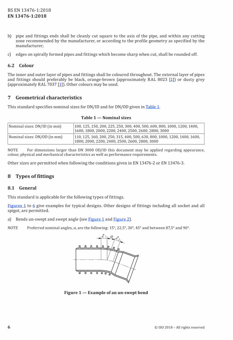
a) Bends un‑swept and swept angle (see Figure 1 and Figure 2).
NOTE Preferred nominal angles, α, are the following: 15°, 22,5°, 30°, 45° and between 87,5° and 90°.
Figure 1 — Example of an un-swept bend
6 © ISO 2018 – All rights reserved
BS EN 13476‑1:2018
EN 13476-1:2018
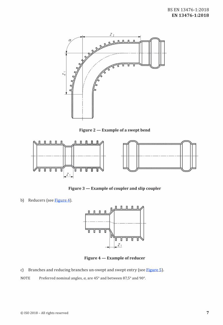
Figure 2 — Example of a swept bend
Figure 3 — Example of coupler and slip coupler
b) Reducers (see Figure 4).
Figure 4 — Example of reducer
c) Branches and reducing branches un‑swept and swept entry (see Figure 5).
NOTE Preferred nominal angles, α, are 45° and between 87,5° and 90°.
© ISO 2018 – All rights reserved 7
BS EN 13476‑1:2018
EN 13476-1:2018
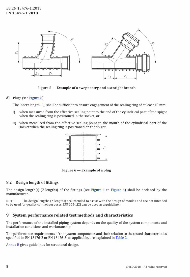
Figure 5 — Example of a swept entry and a straight branch
d) Plugs (see Figure 6).
The insert length, L1, shall be sufficient to ensure engagement of the sealing ring of at least 10 mm:
i) when measured from the effective sealing point to the end of the cylindrical part of the spigot when the sealing ring is positioned in the socket, or
ii) when measured from the effective sealing point to the mouth of the cylindrical part of the socket when the sealing ring is positioned on the spigot.
Figure 6 — Example of a plug
8.2 Designlengthoffittings
The design length(s) (Z‑lengths) of the fittings (see Figure 1 to Figure 6) shall be declared by the manufacturer.
NOTE The design lengths (Z‑lengths) are intended to assist with the design of moulds and are not intended to be used for quality control purposes, ISO 265‑1[2] can be used as a guideline.
9 System performance related test methods and characteristics
The performance of the installed piping system depends on the quality of the system components and installation conditions and workmanship.
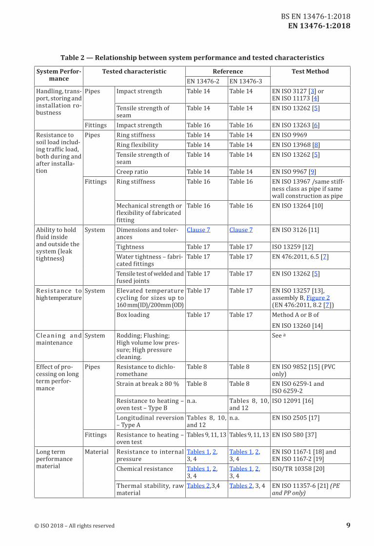
The performance requirements of the system components and their relation to the tested characteristics specified in EN 13476‑2 or EN 13476‑3, as applicable, are explained in Table 2.
Annex B gives guidelines for structural design.
8 © ISO 2018 – All rights reserved
BS EN 13476‑1:2018
EN 13476-1:2018
Table 2 — Relationship between system performance and tested characteristics
System Perfor-mance
Tested characteristic Reference Test MethodEN 13476‑2 EN 13476‑3
Handling, trans‑port, storing and installation ro‑bustness
Pipes Impact strength Table 14 Table 14 EN ISO 3127 [3] or EN ISO 11173 [4]
Tensile strength of seam
Table 14 Table 14 EN ISO 13262 [5]
Fittings Impact strength Table 16 Table 16 EN ISO 13263 [6]Resistance to soil load includ‑ing traffic load, both during and after installa‑tion
Pipes Ring stiffness Table 14 Table 14 EN ISO 9969Ring flexibility Table 14 Table 14 EN ISO 13968 [8]Tensile strength of seam
Table 14 Table 14 EN ISO 13262 [5]
Creep ratio Table 14 Table 14 EN ISO 9967 [9]Fittings Ring stiffness Table 16 Table 16 EN ISO 13967 /same stiff‑
ness class as pipe if same wall construction as pipe
Mechanical strength or flexibility of fabricated fitting
Table 16 Table 16 EN ISO 13264 [10]
Ability to hold fluid inside and outside the system (leak tightness)
System Dimensions and toler‑ances
Clause 7 Clause 7 EN ISO 3126 [11]
Tightness Table 17 Table 17 ISO 13259 [12]Water tightness – fabri‑cated fittings
Table 17 Table 17 EN 476:2011, 6.5 [7]
Tensile test of welded and fused joints
Table 17 Table 17 EN ISO 13262 [5]
Resist ance to high temperature
System Elevated temperature cycling for sizes up to 160 mm(ID)/200mm (OD)
Table 17 Table 17 EN ISO 13257 [13], assembly B, Figure 2 (EN 476:2011, 8.2 [7])
Box loading Table 17 Table 17 Method A or B ofEN ISO 13260 [14]
Clea ning a nd maintenance
System Rodding; Flushing; High volume low pres‑sure; High pressure cleaning.
See a
Effect of pro‑cessing on long term perfor‑mance
Pipes Resistance to dichlo‑romethane
Table 8 Table 8 EN ISO 9852 [15] (PVC only)
Strain at break ≥ 80 % Table 8 Table 8 EN ISO 6259‑1 and ISO 6259‑2
Resistance to heating – oven test – Type B
n.a. Tables 8, 10, and 12
ISO 12091 [16]
Longitudinal reversion – Type A
Tables 8, 10, and 12
n.a. EN ISO 2505 [17]
Fittings Resistance to heating – oven test
Tables 9, 11, 13 Tables 9, 11, 13 EN ISO 580 [37]
Long term performance material
Material Resistance to internal pressure
Tables 1, 2, 3, 4
Tables 1, 2, 3, 4
EN ISO 1167‑1 [18] and EN ISO 1167‑2 [19]
Chemical resistance Tables 1, 2, 3, 4
Tables 1, 2, 3, 4
ISO/TR 10358 [20]
Thermal stability, raw material
Tables 2,3,4 Tables 2, 3, 4 EN ISO 11357‑6 [21] (PE and PP only)
© ISO 2018 – All rights reserved 9
BS EN 13476‑1:2018
EN 13476-1:2018
System Perfor-mance
Tested characteristic Reference Test MethodEN 13476‑2 EN 13476‑3
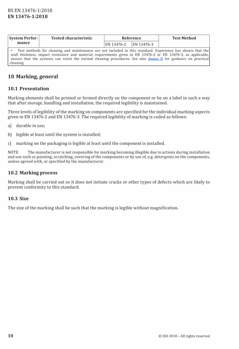
a Test methods for cleaning and maintenance are not included in this standard. Experience has shown that the wall thickness, impact resistance and material requirements given in EN 13476‑2 or EN 13476‑3, as applicable, ensure that the systems can resist the normal cleaning procedures. See also Annex D for guidance on practical cleaning
10 Marking, general
10.1 Presentation
Marking elements shall be printed or formed directly on the component or be on a label in such a way that after storage, handling and installation, the required legibility is maintained.
Three levels of legibility of the marking on components are specified for the individual marking aspects given in EN 13476‑2 and EN 13476‑3. The required legibility of marking is coded as follows:
a) durable in use;
b) legible at least until the system is installed;
c) marking on the packaging is legible at least until the component is installed.
NOTE The manufacturer is not responsible for marking becoming illegible due to actions during installation and use such as painting, scratching, covering of the components or by use of, e.g. detergents on the components, unless agreed with, or specified by the manufacturer.
10.2 Marking process
Marking shall be carried out so it does not initiate cracks or other types of defects which are likely to prevent conformity to this standard.
10.3 Size
The size of the marking shall be such that the marking is legible without magnification.
10 © ISO 2018 – All rights reserved
BS EN 13476‑1:2018
EN 13476-1:2018
Annex A (informative)
CharacteristicsofPVC-U,PPandPEpipesandfittings
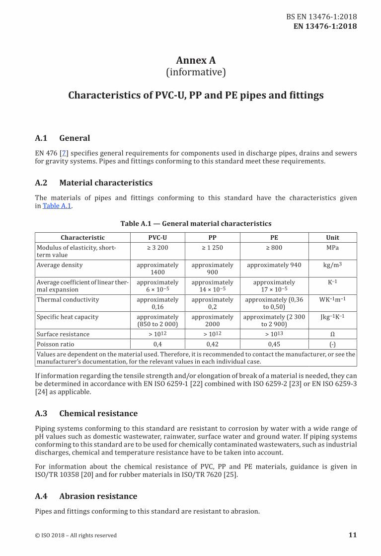
A.1 General
EN 476 [7] specifies general requirements for components used in discharge pipes, drains and sewers for gravity systems. Pipes and fittings conforming to this standard meet these requirements.
A.2 Material characteristics
The materials of pipes and fittings conforming to this standard have the characteristics given in Table A.1.
Table A.1 — General material characteristics
Characteristic PVC-U PP PE UnitModulus of elasticity, short‑term value
≥ 3 200 ≥ 1 250 ≥ 800 MPa
Average density approximately 1400
approximately 900
approximately 940 kg/m3
Average coefficient of linear ther‑mal expansion
approximately 6 × 10⁻⁵
approximately 14 × 10−5
approximately 17 × 10−5
K−1
Thermal conductivity approximately 0,16
approximately 0,2
approximately (0,36 to 0,50)
WK−1m−1
Specific heat capacity approximately (850 to 2 000)
approximately 2000
approximately (2 300 to 2 900)
Jkg−1K−1
Surface resistance > 1012 > 1012 > 1013 ΩPoisson ratio 0,4 0,42 0,45 (‑)Values are dependent on the material used. Therefore, it is recommended to contact the manufacturer, or see the manufacturer’s documentation, for the relevant values in each individual case.
If information regarding the tensile strength and/or elongation of break of a material is needed, they can be determined in accordance with EN ISO 6259‑1 [22] combined with ISO 6259‑2 [23] or EN ISO 6259‑3 [24] as applicable.
A.3 Chemical resistance
Piping systems conforming to this standard are resistant to corrosion by water with a wide range of pH values such as domestic wastewater, rainwater, surface water and ground water. If piping systems conforming to this standard are to be used for chemically contaminated wastewaters, such as industrial discharges, chemical and temperature resistance have to be taken into account.
For information about the chemical resistance of PVC, PP and PE materials, guidance is given in ISO/TR 10358 [20] and for rubber materials in ISO/TR 7620 [25].
A.4 Abrasion resistance
Pipes and fittings conforming to this standard are resistant to abrasion.
© ISO 2018 – All rights reserved 11
BS EN 13476‑1:2018
EN 13476-1:2018
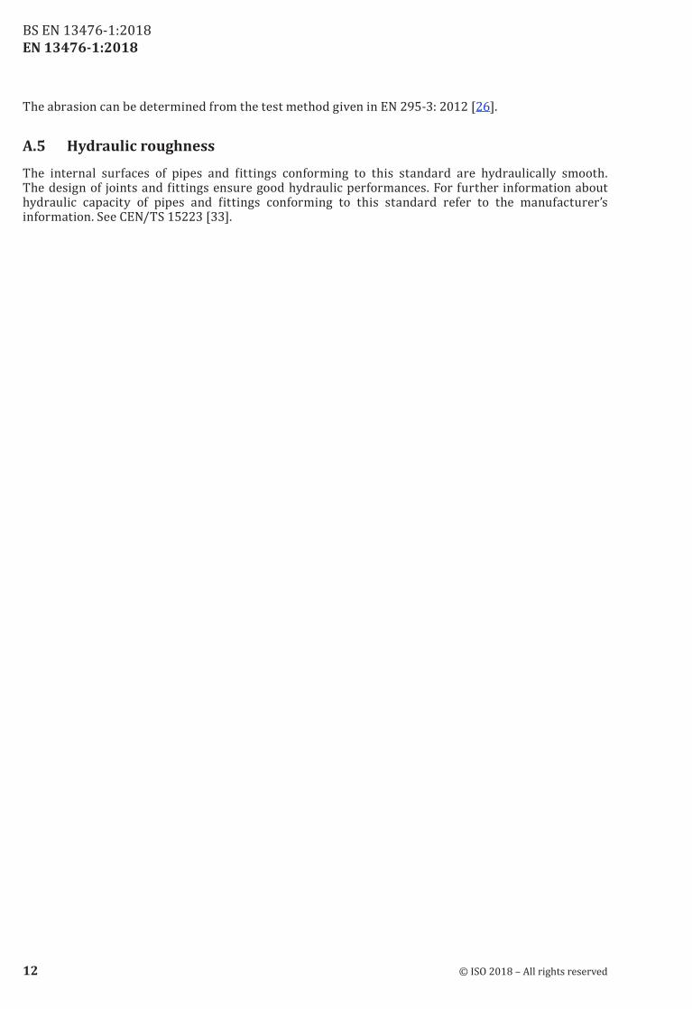
The abrasion can be determined from the test method given in EN 295‑3: 2012 [26].
A.5 Hydraulic roughness
The internal surfaces of pipes and fittings conforming to this standard are hydraulically smooth. The design of joints and fittings ensure good hydraulic performances. For further information about hydraulic capacity of pipes and fittings conforming to this standard refer to the manufacturer’s information. See CEN/TS 15223 [33].
12 © ISO 2018 – All rights reserved
BS EN 13476‑1:2018
EN 13476-1:2018
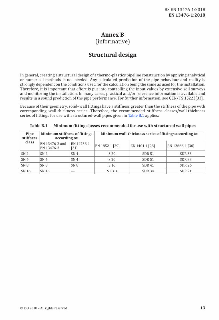
Annex B (informative)
Structural design
In general, creating a structural design of a thermo‑plastics pipeline construction by applying analytical or numerical methods is not needed. Any calculated prediction of the pipe behaviour and reality is strongly dependent on the conditions used for the calculation being the same as used for the installation. Therefore, it is important that effort is put into controlling the input values by extensive soil surveys and monitoring the installation. In many cases, practical and/or reference information is available and results in a sound prediction of the pipe performance. For further information, see CEN/TS 15223[33].
Because of their geometry, solid–wall fittings have a stiffness greater than the stiffness of the pipe with corresponding wall‑thickness series. Therefore, the recommended stiffness classes/wall‑thickness series of fittings for use with structured‑wall pipes given in Table B.1 applies:
TableB.1—Minimumfittingclassesrecommendedforusewithstructuredwallpipes
Pipe stiffness
class
Minimumstiffnessoffittingsaccording to:
Minimumwall-thicknessseriesoffittingsaccordingto:
EN 13476‑2 and EN 13476‑3
EN 14758‑1 [31] EN 1852‑1 [29] EN 1401‑1 [28] EN 12666‑1 [30]
SN 2 SN 2 SN 4 S 20 SDR 51 SDR 33SN 4 SN 4 SN 4 S 20 SDR 51 SDR 33SN 8 SN 8 SN 8 S 16 SDR 41 SDR 26SN 16 SN 16 — S 13.3 SDR 34 SDR 21
© ISO 2018 – All rights reserved 13
BS EN 13476‑1:2018
EN 13476-1:2018
Annex C (informative)
Designationofpipesandcorrespondingfittings
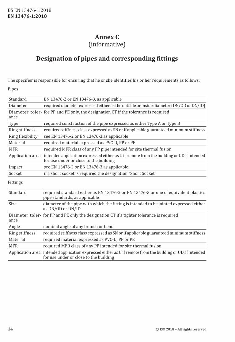
The specifier is responsible for ensuring that he or she identifies his or her requirements as follows:
Pipes
Standard EN 13476‑2 or EN 13476‑3, as applicableDiameter required diameter expressed either as the outside or inside diameter (DN/OD or DN/ID)Diameter toler‑ance
for PP and PE only, the designation CT if the tolerance is required
Type required construction of the pipe expressed as either Type A or Type BRing stiffness required stiffness class expressed as SN or if applicable guaranteed minimum stiffnessRing flexibility see EN 13476‑2 or EN 13476‑3 as applicableMaterial required material expressed as PVC‑U, PP or PEMFR required MFR class of any PP pipe intended for site thermal fusionApplication area intended application expressed either as U if remote from the building or UD if intended
for use under or close to the buildingImpact see EN 13476‑2 or EN 13476‑3 as applicableSocket if a short socket is required the designation “Short Socket”
Fittings
Standard required standard either as EN 13476‑2 or EN 13476‑3 or one of equivalent plastics pipe standards, as applicable
Size diameter of the pipe with which the fitting is intended to be jointed expressed either as DN/OD or DN/ID
Diameter toler‑ance
for PP and PE only the designation CT if a tighter tolerance is required
Angle nominal angle of any branch or bendRing stiffness required stiffness class expressed as SN or if applicable guaranteed minimum stiffnessMaterial required material expressed as PVC‑U, PP or PEMFR required MFR class of any PP intended for site thermal fusionApplication area intended application expressed either as U if remote from the building or UD, if intended
for use under or close to the building
14 © ISO 2018 – All rights reserved
BS EN 13476‑1:2018
EN 13476-1:2018
Annex D (informative)
Guidance in cleaning plastics pipes
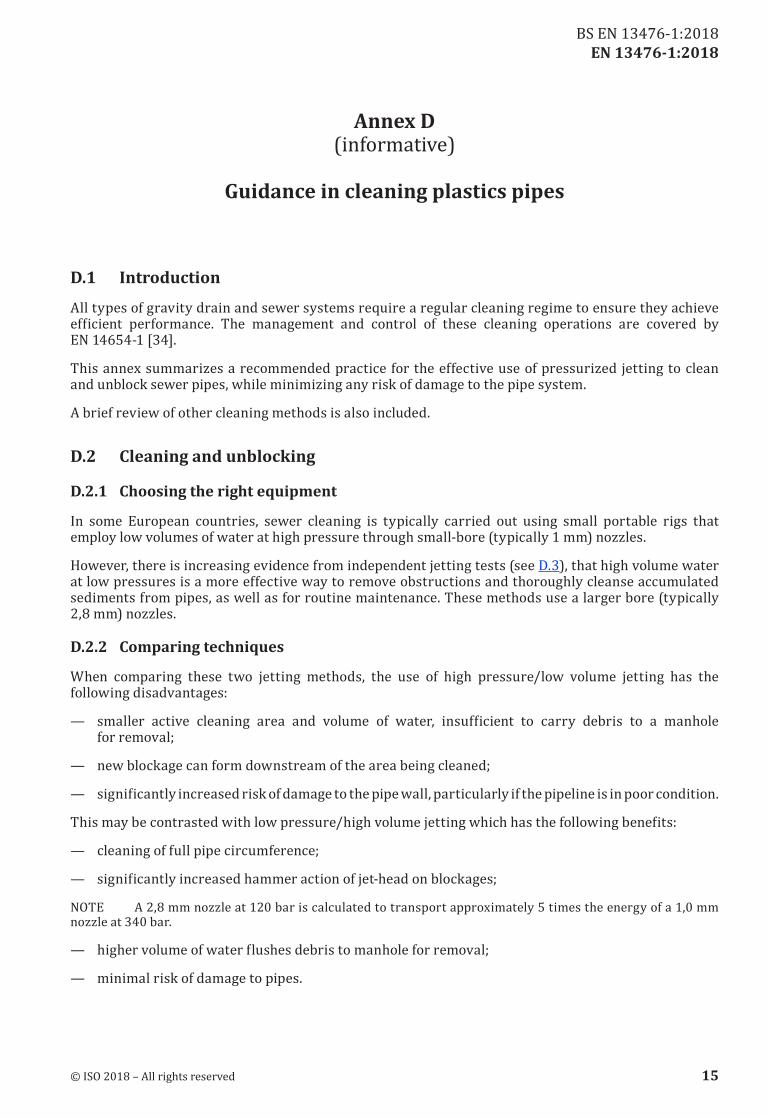
D.1 Introduction
All types of gravity drain and sewer systems require a regular cleaning regime to ensure they achieve efficient performance. The management and control of these cleaning operations are covered by EN 14654‑1 [34].
This annex summarizes a recommended practice for the effective use of pressurized jetting to clean and unblock sewer pipes, while minimizing any risk of damage to the pipe system.
A brief review of other cleaning methods is also included.
D.2 Cleaning and unblocking
D.2.1 Choosing the right equipment
In some European countries, sewer cleaning is typically carried out using small portable rigs that employ low volumes of water at high pressure through small‑bore (typically 1 mm) nozzles.
However, there is increasing evidence from independent jetting tests (see D.3), that high volume water at low pressures is a more effective way to remove obstructions and thoroughly cleanse accumulated sediments from pipes, as well as for routine maintenance. These methods use a larger bore (typically 2,8 mm) nozzles.
D.2.2 Comparing techniques
When comparing these two jetting methods, the use of high pressure/low volume jetting has the following disadvantages:
— smaller active cleaning area and volume of water, insufficient to carry debris to a manhole for removal;
— new blockage can form downstream of the area being cleaned;
— significantly increased risk of damage to the pipe wall, particularly if the pipeline is in poor condition.
This may be contrasted with low pressure/high volume jetting which has the following benefits:
— cleaning of full pipe circumference;
— significantly increased hammer action of jet‑head on blockages;
NOTE A 2,8 mm nozzle at 120 bar is calculated to transport approximately 5 times the energy of a 1,0 mm nozzle at 340 bar.
— higher volume of water flushes debris to manhole for removal;
— minimal risk of damage to pipes.
© ISO 2018 – All rights reserved 15
BS EN 13476‑1:2018
EN 13476-1:2018
D.3 Conclusions from independent jetting tests
D.3.1 Assessingefficiencyandimpact
Inevitably, the question arises whether low pressures (not exceeding 120 bar, for example), are capable of achieving the necessary cleaning efficiency for typical maintenance operations.
The efficiency and impact of jetting on the various pipe materials and constructions have been explored in a variety of independent tests over recent years. These studies have been conducted under controlled conditions to ensure the testing can be fairly and consistently replicated.
D.3.2 Testing of plastic pipes
Test work and general practice throughout Europe has demonstrated that, in practice, a pressure of 120 bar is sufficient for all plastics materials. This will remove blockages likely to occur in service, while debris is carried to the manhole by high water volume.
Plastics pipe materials (PVC‑U, PE and PP), in solid and structured‑wall construction types, were included in an extensive laboratory testing programme and TEPPFA study. New plastics pipes, as well as those which had been in service for several years, were subjected to 120 bar water pressures with a 2,8 mm nozzle over 50 cycles without damage to the pipe.
The test parameters conform to CEN/TR 14920 [35].
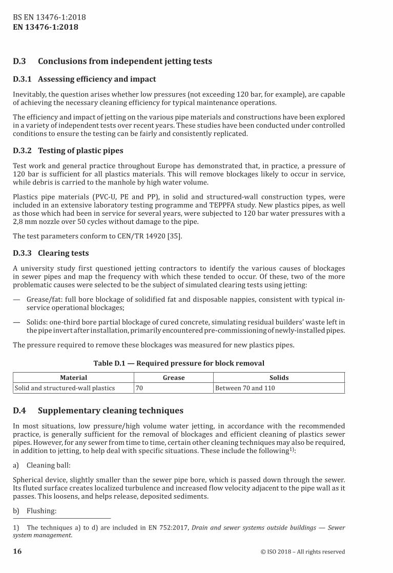
D.3.3 Clearing tests
A university study first questioned jetting contractors to identify the various causes of blockages in sewer pipes and map the frequency with which these tended to occur. Of these, two of the more problematic causes were selected to be the subject of simulated clearing tests using jetting:
— Grease/fat: full bore blockage of solidified fat and disposable nappies, consistent with typical in‑service operational blockages;
— Solids: one‑third bore partial blockage of cured concrete, simulating residual builders’ waste left in the pipe invert after installation, primarily encountered pre‑commissioning of newly‑installed pipes.
The pressure required to remove these blockages was measured for new plastics pipes.
Table D.1 — Required pressure for block removal
Material Grease SolidsSolid and structured‑wall plastics 70 Between 70 and 110
D.4 Supplementary cleaning techniques
In most situations, low pressure/high volume water jetting, in accordance with the recommended practice, is generally sufficient for the removal of blockages and efficient cleaning of plastics sewer pipes. However, for any sewer from time to time, certain other cleaning techniques may also be required, in addition to jetting, to help deal with specific situations. These include the following1):
a) Cleaning ball:
Spherical device, slightly smaller than the sewer pipe bore, which is passed down through the sewer. Its fluted surface creates localized turbulence and increased flow velocity adjacent to the pipe wall as it passes. This loosens, and helps release, deposited sediments.
b) Flushing:
1) The techniques a) to d) are included in EN 752:2017, Drain and sewer systems outside buildings — Sewer system management.
16 © ISO 2018 – All rights reserved
BS EN 13476‑1:2018
EN 13476-1:2018
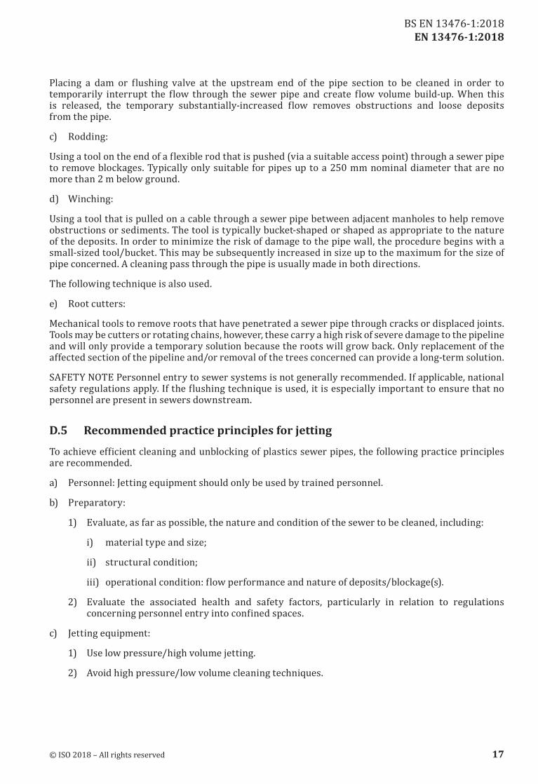
Placing a dam or flushing valve at the upstream end of the pipe section to be cleaned in order to temporarily interrupt the flow through the sewer pipe and create flow volume build‑up. When this is released, the temporary substantially‑increased flow removes obstructions and loose deposits from the pipe.
c) Rodding:
Using a tool on the end of a flexible rod that is pushed (via a suitable access point) through a sewer pipe to remove blockages. Typically only suitable for pipes up to a 250 mm nominal diameter that are no more than 2 m below ground.
d) Winching:
Using a tool that is pulled on a cable through a sewer pipe between adjacent manholes to help remove obstructions or sediments. The tool is typically bucket‑shaped or shaped as appropriate to the nature of the deposits. In order to minimize the risk of damage to the pipe wall, the procedure begins with a small‑sized tool/bucket. This may be subsequently increased in size up to the maximum for the size of pipe concerned. A cleaning pass through the pipe is usually made in both directions.
The following technique is also used.
e) Root cutters:
Mechanical tools to remove roots that have penetrated a sewer pipe through cracks or displaced joints. Tools may be cutters or rotating chains, however, these carry a high risk of severe damage to the pipeline and will only provide a temporary solution because the roots will grow back. Only replacement of the affected section of the pipeline and/or removal of the trees concerned can provide a long‑term solution.
SAFETY NOTE Personnel entry to sewer systems is not generally recommended. If applicable, national safety regulations apply. If the flushing technique is used, it is especially important to ensure that no personnel are present in sewers downstream.
D.5 Recommended practice principles for jetting
To achieve efficient cleaning and unblocking of plastics sewer pipes, the following practice principles are recommended.
a) Personnel: Jetting equipment should only be used by trained personnel.
b) Preparatory:
1) Evaluate, as far as possible, the nature and condition of the sewer to be cleaned, including:
i) material type and size;
ii) structural condition;
iii) operational condition: flow performance and nature of deposits/blockage(s).
2) Evaluate the associated health and safety factors, particularly in relation to regulations concerning personnel entry into confined spaces.
c) Jetting equipment:
1) Use low pressure/high volume jetting.
2) Avoid high pressure/low volume cleaning techniques.
© ISO 2018 – All rights reserved 17
BS EN 13476‑1:2018
EN 13476-1:2018
3) Select nozzle size appropriate to jetting equipment and size of pipe.
d) Jetting pressure/flow rate:
1) Maximum pressure at nozzle: 120 bar.
NOTE 60 bar is sufficient to remove soft debris. 80 bar to 120 bar may be required to remove a more substantial build‑up of material.
2) Recommended draw‑back speed: 6 m/min to 12 m/min.
e) After jetting:
1) Review the operational condition of the cleaned pipe.
2) If jetting was used to clear a blockage, use CCTV to investigate the possible cause of the blockage that had to be cleared, for example, was it due to structural problems/defects (e.g. cracking or collapse)?
Report and record any information, which may be useful for future maintenance or refurbishment works.
18 © ISO 2018 – All rights reserved
BS EN 13476‑1:2018
EN 13476-1:2018
Bibliography
[1] RAL 840 HR, Colour register
[2] ISO 265‑1:1988, Pipes and fittings of plastics materials — Fittings for domestic and industrial waste pipes — Basic dimensions: Metric series — Part 1: Unplasticized poly(vinyl chloride) (PVC-U)
[3] EN ISO 3127, Thermoplastics pipes — Determination of resistance to external blows — Round-the-clock method (ISO 3127)
[4] EN ISO 11173, Thermoplastics pipes — Determination of resistance to external blows — Staircase method (ISO 11173)
[5] EN ISO 13262, Thermoplastics piping systems for non-pressure underground drainage and sewerage — Thermoplastics spirally-formed structured-wall pipes — Determination of the tensile strength of a seam (ISO 13262)
[6] EN ISO 13263, Thermoplastics piping systems for non-pressure underground drainage and sewerage — Thermoplastics fittings — Test method for impact strength (ISO 13263)
[7] EN 476:2011, General requirements for components used in drains and sewers
[8] EN ISO 13968, Plastics piping and ducting systems — Thermoplastics pipes — Determination of ring flexibility (ISO 13968)
[9] EN ISO 9967, Thermoplastics pipes — Determination of creep ratio (ISO 9967)
[10] EN ISO 13264, Thermoplastics piping systems for non-pressure underground drainage and sewerage — Thermoplastics fittings — Test method for mechanical strength or flexibility of fabricated fittings (ISO 13264)
[11] EN ISO 3126, Plastics piping systems — Plastics components — Determination of dimensions (ISO 3126)
[12] EN ISO 13259, Thermoplastics piping systems for underground non-pressure applications — Test method for leaktightness of elastomeric sealing ring type joints (ISO 13259)
[13] EN ISO 13257, Thermoplastics piping systems for non-pressure applications — Test method for resistance to elevated temperature cycling (ISO 13257)
[14] EN ISO 13260, Thermoplastics piping systems for non-pressure underground drainage and sewerage — Test method for resistance to combined temperature cycling and external loading (ISO 13260)
[15] EN ISO 9852, Unplasticized poly(vinyl chloride) (PVC-U) pipes — Dichloromethane resistance at specified temperature (DCMT) — Test method (ISO 9852)
[16] ISO 12091, Structured-wall thermoplastics pipes — Oven test
[17] EN ISO 2505:2005, Thermoplastics pipes — Longitudinal reversion — Test method and parameters (ISO 2505:2005)
[18] EN ISO 1167‑1:2006, Thermoplastics pipes, fittings and assemblies for the conveyance of fluids — Determination of the resistance to internal pressure — Part 1: General method (ISO 1167-1:2006)
[19] EN ISO 1167‑2:2006, Thermoplastics pipes, fittings and assemblies for the conveyance of fluids — Determination of the resistance to internal pressure — Part 2: Preparation of pipe test pieces (ISO 1167-2:2006)
[20] ISO/TR 10358, Plastics pipes and fittings — Combined chemical-resistance classification table
© ISO 2018 – All rights reserved 19
BS EN 13476‑1:2018
EN 13476-1:2018
[21] EN ISO 11357‑6, Plastics — Differential scanning calorimetry (DSC) — Part 6: Determination of oxidation induction time (isothermal OIT) and oxidation induction temperature (dynamic OIT) (ISO 11357-6)
[22] EN ISO 6259‑1, Thermoplastics pipes — Determination of tensile properties — Part 1: General test method (ISO 6259-1)
[23] ISO 6259‑2, Thermoplastics pipes — Determination of tensile properties — Part 2: Pipes made of unplasticized poly(vinyl chloride) (PVC-U), chlorinated poly (vinyl chloride) (PVC-C) and high-impact poly (vinyl chloride) (PVC-HI)
[24] EN ISO 6259‑3, Thermoplastics pipes — Determination of tensile properties — Part 3: Polyolefin pipes (ISO 6259-3)
[25] ISO/TR 7620, Rubber materials — Chemical resistance
[26] EN 295‑3:2012, Vitrified clay pipe systems for drains and sewers — Part 3: Test methods
[27] EN 1610:2015, Construction and testing of drains and sewers
[28] EN 1401‑1, Plastics piping systems for non-pressure underground drainage and sewerage — Unplasticized poly(vinyl chloride) (PVC-U) — Part 1: Specifications for pipes, fittings and the system
[29] EN 1852‑1, Plastics piping systems for non-pressure underground drainage and sewerage — Polypropylene (PP) — Part 1: Specifications for pipes, fittings and the system
[30] EN 12666‑1, Plastics piping systems for non-pressure underground drainage and sewerage — Polyethylene (PE) — Part 1: Specifications for pipes, fittings and the system
[31] EN 14758‑1, Plastics piping systems for non-pressure underground drainage and sewerage — Polypropylene with mineral modifiers (PP-MD) — Part 1: Specifications for pipes, fittings and the system
[32] EN 1295‑1, Structural design of buried pipelines under various conditions of loading — Part 1: General requirements
[33] CEN/TS 15223:2017, Plastics piping systems — Validated design parameters of buried thermoplastics piping systems
[34] EN 14654‑1:2014, Management and control of operational activities in drain and sewer systems outside buildings — Part 1: Cleaning
[35] CEN/TR 14920:2005, Jetting resistance of drain and sewer pipes — Moving jet test method
[36] EN 752:2017, Drain and sewer systems outside buildings — Sewer system management
[37] EN ISO 580, Plastics piping and ducting systems — Injection-moulded thermoplastics fittings — Methods for visually assessing the effects of heating (ISO 580)
20 © ISO 2018 – All rights reserved
BS EN 13476‑1:2018

This page deliberately left blank
This page deliberately left blank
BSI is the national body responsible for preparing British Standards and other standards-related publications, information and services.
BSI is incorporated by Royal Charter. British Standards and other standardization products are published by BSI Standards Limited.
British Standards Institution (BSI)
About usWe bring together business, industry, government, consumers, innovators and others to shape their combined experience and expertise into standards -based solutions.
The knowledge embodied in our standards has been carefully assembled in a dependable format and refined through our open consultation process. Organizations of all sizes and across all sectors choose standards to help them achieve their goals.
Information on standardsWe can provide you with the knowledge that your organization needs to succeed. Find out more about British Standards by visiting our website at bsigroup.com/standards or contacting our Customer Services team or Knowledge Centre.
Buying standardsYou can buy and download PDF versions of BSI publications, including British and adopted European and international standards, through our website at bsigroup.com/shop, where hard copies can also be purchased.
If you need international and foreign standards from other Standards Development Organizations, hard copies can be ordered from our Customer Services team.
Copyright in BSI publicationsAll the content in BSI publications, including British Standards, is the property of and copyrighted by BSI or some person or entity that owns copyright in the information used (such as the international standardization bodies) and has formally licensed such information to BSI for commercial publication and use.
Save for the provisions below, you may not transfer, share or disseminate any portion of the standard to any other person. You may not adapt, distribute, commercially exploit, or publicly display the standard or any portion thereof in any manner whatsoever without BSI’s prior written consent.
Storing and using standardsStandards purchased in soft copy format:
• A British Standard purchased in soft copy format is licensed to a sole named user for personal or internal company use only.
• The standard may be stored on more than 1 device provided that it is accessible by the sole named user only and that only 1 copy is accessed at any one time.
• A single paper copy may be printed for personal or internal company use only.
• Standards purchased in hard copy format:
• A British Standard purchased in hard copy format is for personal or internal company use only.
• It may not be further reproduced – in any format – to create an additional copy. This includes scanning of the document.
If you need more than 1 copy of the document, or if you wish to share the document on an internal network, you can save money by choosing a subscription product (see ‘Subscriptions’).
Reproducing extractsFor permission to reproduce content from BSI publications contact the BSI Copyright & Licensing team.
SubscriptionsOur range of subscription services are designed to make using standards easier for you. For further information on our subscription products go to bsigroup.com/subscriptions.
With British Standards Online (BSOL) you’ll have instant access to over 55,000 British and adopted European and international standards from your desktop. It’s available 24/7 and is refreshed daily so you’ll always be up to date.
You can keep in touch with standards developments and receive substantial discounts on the purchase price of standards, both in single copy and subscription format, by becoming a BSI Subscribing Member.
PLUS is an updating service exclusive to BSI Subscribing Members. You will automatically receive the latest hard copy of your standards when they’re revised or replaced.
To find out more about becoming a BSI Subscribing Member and the benefits of membership, please visit bsigroup.com/shop.
With a Multi-User Network Licence (MUNL) you are able to host standards publications on your intranet. Licences can cover as few or as many users as you wish. With updates supplied as soon as they’re available, you can be sure your documentation is current. For further information, email [email protected].
RevisionsOur British Standards and other publications are updated by amendment or revision.
We continually improve the quality of our products and services to benefit your business. If you find an inaccuracy or ambiguity within a British Standard or other BSI publication please inform the Knowledge Centre.
Useful ContactsCustomer ServicesTel: +44 345 086 9001Email (orders): [email protected] (enquiries): [email protected]
SubscriptionsTel: +44 345 086 9001Email: [email protected]
Knowledge CentreTel: +44 20 8996 7004Email: [email protected]
Copyright & LicensingTel: +44 20 8996 7070Email: [email protected]
BSI Group Headquarters389 Chiswick High Road London W4 4AL UK
NO COPYING WITHOUT BSI PERMISSION EXCEPT AS PERMITTED BY COPYRIGHT LAW