Broadband Telecommunications Handbook Table of Contents
590
Broadband Telecommunications Handbook
-
Upload
telkomuniversity -
Category
Documents
-
view
0 -
download
0
Transcript of Broadband Telecommunications Handbook Table of Contents

Broadband Telecommunications Handbook
Table of ContentsBroadband Telecommunications Handbook, Second Edition......................................................1
Chapter 1: Introduction to Telecommunications Concepts..........................................................5Overview..................................................................................................................................5Basic Telecommunications Systems.......................................................................................6Components of the Telecommunications Networks.................................................................7Communications Network Architectures..................................................................................8The Local Loop........................................................................................................................9The Movement Toward Fiberoptic Networks...........................................................................9Digital Transfer Systems........................................................................................................11The Intelligent Networks of Tomorrow...................................................................................11Summary................................................................................................................................12
Chapter 2: Telecommunications Systems....................................................................................14Overview................................................................................................................................14What Constitutes a Telecommunications System..................................................................14A Topology of Connections Is Used.......................................................................................15The Local Loop......................................................................................................................16The Telecommunications Network.........................................................................................17The Network Hierarchy (Post−1984)......................................................................................17The Public−Switched Network...............................................................................................17The North American Numbering Plan....................................................................................18Private Networks....................................................................................................................18Hybrid Networks.....................................................................................................................18Hooking Things Up................................................................................................................18Equipment..............................................................................................................................19
Chapter 3: Virtual Private Networks...............................................................................................20History....................................................................................................................................20Intelligent PBX Solution.........................................................................................................22Virtual Private Networks (VPNs)............................................................................................22Users May Not Like It.............................................................................................................25
Chapter 4: Data Virtual Private Networks (VPNs).........................................................................27Internet−Based VPN..............................................................................................................27Goals......................................................................................................................................28
Shared Networks..............................................................................................................28Internet.............................................................................................................................28Performance.....................................................................................................................29Outsourcing......................................................................................................................29Security............................................................................................................................30
Creating the VPN...................................................................................................................33Encryption........................................................................................................................33Key Handling....................................................................................................................33Public Key Cryptography (RSA).......................................................................................34Authentication..................................................................................................................34
Router−Based VPN...............................................................................................................38Firewall−Based VPN..............................................................................................................39VPN−Specific Boxes..............................................................................................................39Throughput Comparison........................................................................................................40
i

Table of ContentsChapter 4: Data Virtual Private Networks (VPNs)
Remote Management of VPN Components...........................................................................41Cost Considerations...............................................................................................................41
Proprietary Protocols........................................................................................................41VoIP VPN.........................................................................................................................42
Summary................................................................................................................................42
Chapter 5: Advanced Intelligent Networks (AINs)........................................................................43Overview................................................................................................................................43Intelligent Networks (INs).......................................................................................................43Advanced Intelligent Networks (AINs)...................................................................................44Information Network Architecture...........................................................................................45Combining AIN and CTI Services..........................................................................................45The Intelligent Peripheral (IP)................................................................................................47IP Services.............................................................................................................................48Software Architecture: Client, Router, Server........................................................................49The Application......................................................................................................................49Results of AIN........................................................................................................................50Focus.....................................................................................................................................51
Chapter 6: Local Number Portability (LNP)...................................................................................53Three Flavors of LNP.............................................................................................................53The Road to True LNP...........................................................................................................53Basic LNP Networks..............................................................................................................55The Terminology....................................................................................................................56Before LNP............................................................................................................................57Number Administration and Call Routing in the Network.......................................................58
LRN..................................................................................................................................58Using a Database Solution....................................................................................................60Triggering Mechanisms..........................................................................................................61How Is a Telephone Number Ported?....................................................................................63Other Issues...........................................................................................................................63
Switching Systems...........................................................................................................64Billing, Administration, and Maintenance Systems..........................................................64Signaling..........................................................................................................................64Operator Services............................................................................................................64911 Services....................................................................................................................65Simplifying the Wireless E−911 Call................................................................................66
Chapter 7: Computer Telephony Integration (CTI).......................................................................68Overview................................................................................................................................68The Computer World..............................................................................................................69Other Possibilities..................................................................................................................71Why All the Hype?.................................................................................................................73Linking Computers and Communications..............................................................................74The Technology Advancement..............................................................................................76The Final Bond.......................................................................................................................77
ii

Table of ContentsChapter 8: Signaling System 7 (SS7).............................................................................................79
Overview................................................................................................................................79Presignaling System 7...........................................................................................................79Introduction to SS7................................................................................................................80Purpose of the SS7 Network..................................................................................................81What Is Out−of−Band Signaling?...........................................................................................81
Why Out−of−Band Signaling?..........................................................................................82The SS7 Network Architecture...............................................................................................82SS7 Interconnection...............................................................................................................84Basic Functions of the SS7 Network......................................................................................84Signaling Links.......................................................................................................................84The Link Architecture.............................................................................................................86Links and Linksets.................................................................................................................87
Combined Linksets...........................................................................................................87Routes and Routesets...........................................................................................................88SS7 Protocol Stack................................................................................................................90
Basic Call Setup with ISUP..............................................................................................91SS7 Applications....................................................................................................................92SS7 and IP.............................................................................................................................92SCTP.....................................................................................................................................93VoIP Impacts..........................................................................................................................95Overview of SIP Functionality................................................................................................95VoIP Telephony Signaling......................................................................................................97SS7 and Wireless Intelligent Networks..................................................................................97GSM Network Connection to SS7 Networks..........................................................................98The Signaling Protocol Stack for GSM..................................................................................99
Chapter 9: CTI Technologies and Applications..........................................................................101Overview..............................................................................................................................101Understanding Computer Telephony Technologies.............................................................101
Voice Processing...........................................................................................................101Telephone Network Interfaces.......................................................................................101Tone Processing............................................................................................................102Facsimile (Fax)...............................................................................................................102Automatic Speech Recognition (ASR)...........................................................................102Text−to−Speech (TTS)...................................................................................................102Switching........................................................................................................................102
Understanding Computer Telephony Solutions...................................................................103Information Access and Processing Applications..........................................................103AudioText.......................................................................................................................103
Voice Recording for Transaction Logging............................................................................103Technology Enhancements.................................................................................................104Other Technologies..............................................................................................................105
Automated Attendant.....................................................................................................106Integrated Voice Recognition and Response (IVR).......................................................106Fax−Back and Fax Processing......................................................................................107Fax−on−Demand (FOD)................................................................................................107Interactive Fax Response (IFR).....................................................................................107E−mail Reader...............................................................................................................107Text−to−Speech and Speech−to−Text..........................................................................108
iii

Table of ContentsChapter 9: CTI Technologies and Applications
Optical Character Recognition (OCR)............................................................................108Summary..............................................................................................................................108
Chapter 10: Integrated Services Digital Network (ISDN)............................................................110Overview..............................................................................................................................110Origins of ISDN....................................................................................................................110Origins of the Standards......................................................................................................111Interfaces.............................................................................................................................111Interface Components..........................................................................................................115
NT1................................................................................................................................115NT2................................................................................................................................115TE1................................................................................................................................116TE2................................................................................................................................116TA..................................................................................................................................116
Physical Delivery..................................................................................................................116The U Interface....................................................................................................................118The Physical Interface.........................................................................................................120Applications of the ISDN Interface.......................................................................................120
Multiple Channels...........................................................................................................120Telephone......................................................................................................................121Digital Fax......................................................................................................................121Analog Fax.....................................................................................................................121Computer/Video Conferencing.......................................................................................121Signaling........................................................................................................................121Telemetry.......................................................................................................................121Packet Switching............................................................................................................121
Primary−Rate ISDN.............................................................................................................122H0 Channels........................................................................................................................122H11 Channels......................................................................................................................122H12 Channels......................................................................................................................123Signaling on the D Channel.................................................................................................123Installation Problems............................................................................................................124BRI Application....................................................................................................................125Broadband ISDN..................................................................................................................126
Definitions......................................................................................................................126Conclusion...........................................................................................................................129
Chapter 11: Frame Relay...............................................................................................................130Overview..............................................................................................................................130Frame Relay Defined...........................................................................................................130What Can Frame Relay Bring to the Table?........................................................................131Where People Use Frame Relay.........................................................................................132The Frame...........................................................................................................................134The OSI Protocol Stack and Frame Relay...........................................................................135Frame Relay Speeds...........................................................................................................138Frame Relay Access............................................................................................................139Overall Frame Relay Core Protocols...................................................................................140Carriers' Implementation of IP−Enabled Frame Relay.........................................................141Frame Relay Versus IP........................................................................................................142
iv

Table of ContentsChapter 11: Frame Relay
Voice over Frame Relay (VoFR)..........................................................................................142Compressing the Information on VoFR..........................................................................144
Provisioning PVCs and SVCs..............................................................................................144Benefits of SVCs..................................................................................................................145Frame Relay Selected for Wireless Data on GPRS.............................................................146
Chapter 12: Asynchronous Transfer Mode (ATM)......................................................................147Overview..............................................................................................................................147What Is ATM?......................................................................................................................147Why the Interest in ATM?....................................................................................................149ATM Protocols.....................................................................................................................150Mapping Circuits Through an ATM Network........................................................................152The ATM Layered Architecture............................................................................................154ATM Traffic Management....................................................................................................155Contention Management......................................................................................................156The Double Leaky Bucket....................................................................................................158Categories of Service...........................................................................................................160Getting to the Elusive QoS...................................................................................................161Shaping the Traffic...............................................................................................................161Normal Bandwidth Allocation...............................................................................................162What Is MPOA?...................................................................................................................163LANE....................................................................................................................................163Voice over DSL and over ATM (VoDSL and VoATM)..........................................................166ATM Suitability for Voice Traffic...........................................................................................168Integrated Access at the Local Loop....................................................................................168
Chapter 13: ATM and Frame Relay Internetworking..................................................................170Overview..............................................................................................................................170ATM and Frame Relay Compared.......................................................................................170
Frame Relay Revisited...................................................................................................171ATM Revisited................................................................................................................172The Frame and ATM Merger..........................................................................................173
Transparency Across the Network.......................................................................................173Frame User−to−Network Interface (FUNI)...........................................................................175Data Exchange Interface (DXI)............................................................................................175What Constitutes a Frame?.................................................................................................177FUNI Interoperability............................................................................................................179Network Interworking...........................................................................................................179Service Interworking Functions............................................................................................180The DXI Interface.................................................................................................................181
DXI Mode 1 A/B.............................................................................................................181DXI Protocol Mode 1A....................................................................................................182DXI Protocol Mode 1B....................................................................................................183XI Mode 2.......................................................................................................................184DXI Protocol Mode 2......................................................................................................185
Summary..............................................................................................................................185
v

Table of ContentsChapter 14: Cable TV Systems.....................................................................................................186
Overview..............................................................................................................................186Cable Television Transmission............................................................................................187The Cable Infrastructure......................................................................................................188The Cable Television Distribution System...........................................................................190Signal Level.........................................................................................................................190Digital Video on Cable TV Systems.....................................................................................191Forming a Digital Video Signal.............................................................................................192Key Features of Digital Modulation......................................................................................193DTV Solution Introduction....................................................................................................193
Chapter 15: Cable Modem Systems and Technology................................................................196Overview..............................................................................................................................196Cable TV Technology..........................................................................................................197The New Market...................................................................................................................199System Upgrades................................................................................................................199Cable Modems.....................................................................................................................200Standards.............................................................................................................................202Return Path..........................................................................................................................203Applications..........................................................................................................................204The Combined Corporate and End User Networking Strategies.........................................205A Final Thought....................................................................................................................206
Chapter 16: xDSL...........................................................................................................................207Overview..............................................................................................................................207ADSL Defined......................................................................................................................207Modem Technologies...........................................................................................................208The Analog Modem History.................................................................................................209IDSL.....................................................................................................................................210HDSL...................................................................................................................................211
SDSL..............................................................................................................................213ADSL..............................................................................................................................214RADSL...........................................................................................................................214CDSL..............................................................................................................................214SHDSL...........................................................................................................................214VDSL..............................................................................................................................215The Hype of DSL Technologies.....................................................................................216
xDSL Coding Techniques....................................................................................................217Discreet Multitone..........................................................................................................217Using DMT for the Universal ADSL Service (G.Lite)......................................................218To Split or Not to Split....................................................................................................219CAP................................................................................................................................220
Provisioning xDSL................................................................................................................221Final Comment on Deployment...........................................................................................225
Chapter 17: Microwave− and Radio−Based Systems................................................................227Overview..............................................................................................................................227Other Applications................................................................................................................231
How Do You Make the Right Choices?..........................................................................232What About Bandwidth?......................................................................................................233
vi

Table of ContentsChapter 17: Microwave− and Radio−Based Systems
How Much Is Enough?.........................................................................................................234What About Reliability?........................................................................................................234The Choices Are Leased Lines, Fiber, or Microwave..........................................................234Microwave and the Other Wireless Solutions......................................................................235Microwave Radio Solutions..................................................................................................235Private User Microwave.......................................................................................................236
Chapter 18: MMDS and LMDS......................................................................................................239Overview..............................................................................................................................239Limited Frequency Spectrum...............................................................................................239System Configuration...........................................................................................................240Wireless Cable Sources.......................................................................................................241Advantages of Using MMDS................................................................................................242Internet Access....................................................................................................................242Key Elements.......................................................................................................................242
The Head−End...............................................................................................................243The Transmit Antenna....................................................................................................243The Transmission Line...................................................................................................243Channel Combiners.......................................................................................................243
Local Multipoint Distribution Service (LMDS).......................................................................243Enter the Competitive Discussion........................................................................................244WLL......................................................................................................................................245Not for Everyone..................................................................................................................246What About the Bandwidth?................................................................................................248Enter LMDS.........................................................................................................................248The Reasoning Behind LMDS.............................................................................................249Network Architectures Available to the Carriers..................................................................251Modulation and Access Techniques....................................................................................252Two−Way Service................................................................................................................252Propagation Issues..............................................................................................................253
Chapter 19: Specialized Mobile Radio (SMR)..............................................................................254Overview..............................................................................................................................254Improved Spectral Efficiency...............................................................................................256Motorola's VSELP−Coding Signals for Efficient Transmission............................................256
QAM Modulation............................................................................................................257Multiplied Channel Capacity...........................................................................................257The Advantage of Integration.........................................................................................257A Short Overview of Trunked Radio...............................................................................257The Control Channel (CC).............................................................................................259Service Areas and Licensing Blocks..............................................................................260Innovation and Integration..............................................................................................261Spectral Efficiency with Frequency Hopping..................................................................261Digital Transition............................................................................................................262
Is There Still a Benefit from Two−Way Radio?....................................................................263What Kind of Savings Can Your Business Expect?.......................................................263When Will You Need a Radio Service Provider?...........................................................263
vii

Table of ContentsChapter 20: Cellular Communications.........................................................................................264
Overview..............................................................................................................................264Coverage Areas...................................................................................................................264Analog Cellular Systems......................................................................................................265Log On.................................................................................................................................266Monitoring Control Channels...............................................................................................267Failing Signal.......................................................................................................................267Setup of a Call.....................................................................................................................268Setup of an Incoming Call....................................................................................................268Handoff................................................................................................................................269
Setting Up the Handoff...................................................................................................269The Handoff Occurs.......................................................................................................269Completion of the Handoff.............................................................................................270
The Cell Site (Base Station).................................................................................................270The Mobile Telephone Switching Office (MTSO).................................................................271Frequency Reuse Plans and Cell Patterns..........................................................................271Overlapping Coverage.........................................................................................................272Cell Site Configurations.......................................................................................................273Sectorized Cell Coverage....................................................................................................274Tiered Sites..........................................................................................................................275Reuse of Frequencies..........................................................................................................275Allocation of Frequencies.....................................................................................................276Establishing a Call from a Landline to a Mobile...................................................................276
Chapter 21: Global Services Mobile Communications (GSM)...................................................278History of Cellular Mobile Radio and GSM..........................................................................278Benchmarks in GSM............................................................................................................278GSM Metrics........................................................................................................................279Cell Structure.......................................................................................................................280
Types of Cells................................................................................................................283Analog to Digital Movement.................................................................................................286
Teleservices...................................................................................................................287Bearer Services..............................................................................................................287Supplementary Services................................................................................................288
GSM Architecture.................................................................................................................289Mobile Equipment or MS......................................................................................................290
SIM.................................................................................................................................290The MS Function............................................................................................................291
The Base Transceiver Station (BTS)...................................................................................292The Base Station Controller (BSC)......................................................................................293BSS......................................................................................................................................293The TRAU............................................................................................................................293
Locating the TRAU.........................................................................................................294MSC...............................................................................................................................294
The Registers Completing the Network Switching Systems (NSSs)...................................295The Cell................................................................................................................................296Location Area.......................................................................................................................297
MSC/VLR Service Area..................................................................................................297OSI Model — How GSM Signaling Functions in the OSI Model..........................................297Layer Functionality...............................................................................................................298
viii

Table of ContentsChapter 21: Global Services Mobile Communications (GSM)
MS Protocols........................................................................................................................299The MS to BTS Protocols....................................................................................................299BSC Protocols......................................................................................................................300MSC Protocols.....................................................................................................................300Defining the Channels..........................................................................................................300
Frequencies Allocated....................................................................................................301Primary GSM.......................................................................................................................301Radio Assignment................................................................................................................302Frequency Pairing................................................................................................................302
Extended GSM Radio Frequencies................................................................................302Modulation...........................................................................................................................303
Amplitude Shift Keying (ASK)........................................................................................303Frequency Shift Keying (FSK)........................................................................................304Phase Shift Keying (PSK)..............................................................................................304Gaussian Minimum Shift Keying (GMSK)......................................................................305
Access Methods...................................................................................................................306FDMA.............................................................................................................................306TDMA.............................................................................................................................306CDMA.............................................................................................................................307TDMA Frames................................................................................................................308
Time Slot Use......................................................................................................................309GSM FDMA/TDMA Combination.........................................................................................309Logical Channels.................................................................................................................309
The Physical Layer.........................................................................................................310Speech Coding on the Radio Link.......................................................................................310Channel Coding...................................................................................................................311Convolutional Coding...........................................................................................................311
Chapter 22: Personal Communications Services.......................................................................312Overview..............................................................................................................................312Digital Systems....................................................................................................................312Digital Cellular Evolution......................................................................................................313
TDMA.............................................................................................................................314CDMA.............................................................................................................................315
Spread Spectrum Services..................................................................................................316Capacity Gain......................................................................................................................318The CDMA Cellular Standard..............................................................................................318Spread Spectrum Goals.......................................................................................................319Spread Spectrum Services..................................................................................................320Synchronization...................................................................................................................320Balancing the Systems........................................................................................................321Common Air Interfaces........................................................................................................322
The Forward Channel....................................................................................................322The Reverse Channel....................................................................................................322
Walsh Codes........................................................................................................................323Traffic Channel.....................................................................................................................323Direct Sequence Spread Spectrum.....................................................................................323Seamless Networking with IS−41 and SS7..........................................................................325Automatic Roaming..............................................................................................................325
ix

Table of ContentsChapter 22: Personal Communications Services
Cellular and PCS Suppliers.................................................................................................325Final Thoughts.....................................................................................................................326
Chapter 23: Wireless Data Communications (Mobile IP)...........................................................328Overview..............................................................................................................................328IP Routing............................................................................................................................330Part of the Solution..............................................................................................................331Applications That Demand Mobile IP...................................................................................332Speed Isn't Everything.........................................................................................................334Variations in Data Communications (Wireless)....................................................................334Possible Drawbacks with Wireless......................................................................................335Pros and Cons to Wireless..................................................................................................335
Chapter 24: General Packet Radio Service (GPRS)....................................................................337Overview..............................................................................................................................337The New Wave of Internet User...........................................................................................338GPRS...................................................................................................................................340
The GPRS Story............................................................................................................341What Is GPRS?..............................................................................................................342Motivation for GPRS......................................................................................................343
Evolution of Wireless Data...................................................................................................344Wireless Data Technology Options................................................................................345The GSM Phase II Overlay Network..............................................................................347Circuit−Switched or Packet−Switched Traffic................................................................348GPRS Radio Technologies............................................................................................350
Cells and Routing Areas......................................................................................................350Attaching to the Serving GPRS Support Node....................................................................351PDP Contexts......................................................................................................................352Data Transfer.......................................................................................................................353GSM and NA−TDMA Evolution............................................................................................354Applications for GPRS.........................................................................................................355
Chat...............................................................................................................................355Textual and Visual Information.......................................................................................355Still Images.....................................................................................................................356Moving Images...............................................................................................................356Web Browsing................................................................................................................356Document Sharing/Collaborative Working.....................................................................356Audio..............................................................................................................................356Job Dispatch..................................................................................................................357Corporate E−mail...........................................................................................................357Internet E−mail...............................................................................................................357Vehicle Positioning.........................................................................................................357Remote LAN Access......................................................................................................358File Transfer...................................................................................................................358Home Automation..........................................................................................................358
Chapter 25: Third−Generation (3G) Wireless Systems..............................................................359Overview..............................................................................................................................359GPRS...................................................................................................................................360
x

Table of ContentsChapter 25: Third−Generation (3G) Wireless Systems
EDGE...................................................................................................................................362What Is Special about EDGE?.......................................................................................364
UMTS...................................................................................................................................364WCDMA...............................................................................................................................365
WCDMA Features..........................................................................................................365Mobile Internet — A Way of Life..........................................................................................366
Rich Voice......................................................................................................................367Applications of the Wireless Internet....................................................................................369Visions of Wireless...............................................................................................................369Positioning the Mobile Industry............................................................................................371Key Technologies................................................................................................................372
UTRA.............................................................................................................................372Multimode Second Generation/UMTS Terminals...........................................................373Satellite Systems............................................................................................................373USIM Cards/Smart Cards..............................................................................................373IP Compatibility..............................................................................................................374Spectrum for UMTS.......................................................................................................374
The cdma2000 Family of Standards....................................................................................375Purpose..........................................................................................................................375
Chapter 26: Satellite Communications Networking...................................................................377Uses of Satellites in Agriculture...........................................................................................377Uses of Satellites in Oceanography.....................................................................................377Commercial Providers..........................................................................................................377History of Satellites..............................................................................................................378How Do Satellites Work?.....................................................................................................378Satellite Frequency Bands...................................................................................................379Geosynchronous−Earth−Orbit (GEO) Satellites..................................................................381Medium−Earth−Orbit (MEO) Satellites................................................................................382Low−Earth−Orbit (LEO) Satellites........................................................................................382Orbital Slots.........................................................................................................................382Communications..................................................................................................................383Satellite Installations............................................................................................................383LEO Versus GEO.................................................................................................................386Niches in the GEO Sphere...................................................................................................386LEO Meets GEO..................................................................................................................386Space Security Unit.............................................................................................................387The Market for the Network.................................................................................................387Satellite Characteristics.......................................................................................................389Latency................................................................................................................................389Noise....................................................................................................................................389Bandwidth............................................................................................................................390Advantages..........................................................................................................................390TCP/IP over Satellite............................................................................................................390Satellite and ATM.................................................................................................................391Charting the Rules for the Internet.......................................................................................392Tailoring IP Can Accelerate Throughput..............................................................................392
xi

Table of ContentsChapter 27: Low−Earth−Orbit Satellites (LEOs).........................................................................394
Overview..............................................................................................................................394Low−Earth Orbit...................................................................................................................395So What Happened?............................................................................................................399The Benefits of These Service Offerings.............................................................................399
Deployment and Spacing of Satellites...........................................................................400The Space Segment......................................................................................................401The Cell Patterns...........................................................................................................403Traffic Carrying Capacity................................................................................................404Modulation Techniques..................................................................................................404The Gateway Segment..................................................................................................405The Earth Terminal........................................................................................................405The Switching Equipment..............................................................................................405Interconnecting to the PSTN..........................................................................................405The System Control Portion...........................................................................................406
Other Competitors to Iridium................................................................................................406Loral−Qualcomm............................................................................................................406
Chapter 28: The T Carrier Systems (T−1/T−2 and T−3)..............................................................408Overview..............................................................................................................................408The Difference Between T−x and DS−x..............................................................................408DS−1 Framing Review.........................................................................................................409Pulse Coded Modulation (PCM)..........................................................................................410The E−1 Pattern...................................................................................................................412The Framing Protocols: D4 Framing....................................................................................412
Contrasting the E−1 and DS−1 Frame...........................................................................413Extended Superframe Format (ESF)...................................................................................414
Other Restrictions..........................................................................................................415B8ZS....................................................................................................................................416T−2 Transmission (or DS−2)................................................................................................417
DS−2 Bit Stuffing............................................................................................................418Framing Bits for the DS−2..............................................................................................418
DS−3 Service (T−3).............................................................................................................420The DS−3 Frame Format...............................................................................................420DS−3 Bit Stuffing............................................................................................................421The DS−3 Overhead Bits...............................................................................................421
Chapter 29: Synchronous Optical Network (SONET).................................................................422Overview..............................................................................................................................422Background Leading to SONET Development....................................................................422
Synchronizing the Digital Signals...................................................................................423The SONET Signal..............................................................................................................423
Why Bother Synchronizing?...........................................................................................424The SONET Frame..............................................................................................................425
Overhead.......................................................................................................................425Inside the STS−1 Frame................................................................................................427
SONET Overhead................................................................................................................427Section Overhead..........................................................................................................428Line Overhead................................................................................................................429POH...............................................................................................................................431
xii

Table of ContentsChapter 29: Synchronous Optical Network (SONET)
Virtual Tributaries.................................................................................................................432SONET Multiplexing Functions............................................................................................433
Add−Drop Multiplexing: A SONET Benefit.....................................................................433SONET Topologies..............................................................................................................434
Point−to−Point...............................................................................................................434Point−to−Multipoint........................................................................................................435Hub and Spoke..............................................................................................................435Ring................................................................................................................................436
Evolution of SONET in the Rest of the World......................................................................436SDH................................................................................................................................437
Chapter 30: Synchronous Digital Hierarchy (SDH)[1]................................................................439Overview..............................................................................................................................439Why SDH/SONET................................................................................................................440
Synchronous Communications......................................................................................440Plesiochronous...............................................................................................................440SDH................................................................................................................................441Data Transmission Rates...............................................................................................442Some Differences to Note..............................................................................................443The Multiplexing Scheme...............................................................................................443Why the Hype?...............................................................................................................451The Model as It Pertains to SDH....................................................................................452
Chapter 31: Wave Division Multiplexing (WDM).........................................................................454Overview..............................................................................................................................454WDM....................................................................................................................................454Fiber Optics Summarized....................................................................................................456
Multimode Fiber.............................................................................................................457Single Mode Fiber..........................................................................................................458Benefits of Fiber over Other Forms of Media.................................................................458
Back to WDM.......................................................................................................................459Why DWDM?.......................................................................................................................460
Chapter 32: The Internet...............................................................................................................463A Brief History......................................................................................................................463Early Internet Services.........................................................................................................465
Gopher...........................................................................................................................465Veronica.........................................................................................................................465Wide Area Information Service (WAIS)..........................................................................466
World Wide Web (WWW)....................................................................................................466Browsers........................................................................................................................466Hypertext........................................................................................................................466Hyperlink........................................................................................................................467Universal Resource Locator (URL)................................................................................467Directory/Domain Name Service (DNS).........................................................................468Java™............................................................................................................................468
Surfing the Web...................................................................................................................469Tracking Visitors.............................................................................................................469Cookies..........................................................................................................................469
xiii

Table of ContentsChapter 32: The Internet
Search Engines..............................................................................................................470Standards.......................................................................................................................470
Internet Operation................................................................................................................471Connectionless Network Services (CLNS)..........................................................................474Options and Padding...........................................................................................................476Transmission Control Protocol (TCP)..................................................................................476
The Fields in the TCP Header........................................................................................476User Datagram Protocol (UDP)...........................................................................................477IP Addressing.......................................................................................................................478
Routers Versus Gateways.............................................................................................478Subnetting......................................................................................................................480Network Address Translation (NAT)..............................................................................482
DHCP, BOOTP, ARP, and RARP........................................................................................483Routing.................................................................................................................................484
Dynamic Routing Tables................................................................................................486Routing Versus Switching..............................................................................................487
Real−time Applications........................................................................................................488Multi−protocol Label Switching (MPLS)...............................................................................488Summary..............................................................................................................................489
Chapter 33: Voice over IP (VoIP)..................................................................................................490Overview..............................................................................................................................490VoIP.....................................................................................................................................492QoS......................................................................................................................................494Applications for VoIP............................................................................................................497
H.323 Protocol Suites....................................................................................................499Delay and Jitter on VoIP Networks................................................................................503Protocol Stack................................................................................................................504
Chapter 34: Multiprotocol Label Switching (MPLS)...................................................................508Overview..............................................................................................................................508Standard IP Networking.......................................................................................................508
Subnet Masking.............................................................................................................513Rules of Routing..................................................................................................................515
Variable Length Subnet Masks (VLSM).........................................................................516The Longest Match Syndrome.............................................................................................516
Classless Interdomain Routing (CIDR)..........................................................................517Enter MPLS..........................................................................................................................517
Traffic Engineering.........................................................................................................518QoS Routing...................................................................................................................519MPLS Forwarding Model................................................................................................520MPLS Components........................................................................................................521
Chapter 35: Intranets and Extranets............................................................................................522Overview..............................................................................................................................522Managing the Intranet..........................................................................................................523Web Page Organization.......................................................................................................523Document Security...............................................................................................................525Collaboration........................................................................................................................525
xiv
Table of ContentsChapter 35: Intranets and Extranets
Maintaining Interest..............................................................................................................525Jokes....................................................................................................................................525Forms...................................................................................................................................526Transition Intranet Solutions................................................................................................526Portal Products or Customized Web Pages.........................................................................526Building a Community..........................................................................................................527Bulletin Board Service..........................................................................................................528Customer Service................................................................................................................528Thin Clients..........................................................................................................................528Extranets..............................................................................................................................529Inventory Management........................................................................................................529
Wholesale......................................................................................................................529Secondary Markets........................................................................................................529
Privacy Issues......................................................................................................................530Perishable Goods Application..............................................................................................531Purchasing Cooperatives.....................................................................................................531Outsourcing..........................................................................................................................532Computer Hardware Vendor................................................................................................533Automating Customer Service.............................................................................................533Implementing Extranets.......................................................................................................535
Intranet...........................................................................................................................535Extranet..........................................................................................................................535
TCP Filtering........................................................................................................................536Stand−Alone System...........................................................................................................537Virus Checking.....................................................................................................................538Firewall Rules Bases...........................................................................................................539Firewall Performance (Again)..............................................................................................541Proxies.................................................................................................................................541
Forward Proxy................................................................................................................542Reverse Proxy................................................................................................................542
Proxy Security......................................................................................................................543Administration......................................................................................................................544
Firewalls.........................................................................................................................545Proxy..............................................................................................................................545
Domain Name System (DNS)..............................................................................................545Fungible Services................................................................................................................546
Chapter 36: Network Management SNMP...................................................................................547Overview..............................................................................................................................547Network Management Goals...............................................................................................547History..................................................................................................................................548Network Management Function Interaction.........................................................................549Database Structure..............................................................................................................550Architecture..........................................................................................................................552Network Management System Issues.................................................................................554
Bundling.........................................................................................................................554The GUI..........................................................................................................................554Network Size..................................................................................................................555Web−Enabled GUI.........................................................................................................555
xv

Table of ContentsChapter 36: Network Management SNMP
Alarm History..................................................................................................................555Alarm Presentation.........................................................................................................556Statistics.........................................................................................................................556Free Trials......................................................................................................................556Network Mapping...........................................................................................................556SNMPv3.........................................................................................................................559Security..........................................................................................................................559Java...............................................................................................................................560
List of Figures................................................................................................................................562
List of Tables..................................................................................................................................571
xvi

Broadband Telecommunications Handbook, SecondEditionRegis J. (Bud) Bates
Copyright © 2002 by The McGraw−Hill Companies, Inc. All rights reserved. Printed in the UnitedStates of America. Except as permitted under the United States Copyright Act of 1976, no part ofthis publication may be reproduced or distributed in any form or by any means, or stored in a database or retrieval system, without the prior written permission of the publisher.
1 2 3 4 5 6 7 8 9 0 DOC/DOC 9 8 7 6 5 4 3 2 1
ISBN 0−07−139851−1
The sponsoring editor for this book was Steve Chapman and the production supervisor was PamelaPelton. It was set in Century Schoolbook by MacAllister Publishing Services, LLC.
Printed and bound by R. R. Donnelley and Sons.
Throughout this book, trademarked names are used. Rather than put a trademark symbol afterevery occurrence of a trademarked name, we use names in an editorial fashion only, and to thebenefit of the trademark owner, with no intention of infringement of the trademark. Where suchdesignations appear in this book, they have been printed with initial caps.
Information contained in this work has been obtained by The McGraw−Hill Companies, Inc.("McGraw−Hill") from sources believed to be reliable. However, neither McGraw−Hill nor its authorsguarantees the accuracy or completeness of any information published herein and neitherMcGraw−Hill nor its authors shall be responsible for any errors, omissions, or damages arising outof use of this information. This work is published with the understanding that McGraw−Hill and itsauthors are supplying information but are not attempting to render engineering or other professionalservices. If such services are required, the assistance of an appropriate professional should besought.
This book is printed on recycled, acid−free paper containing a minimum of 50 percent recycledde−inked fiber.
Library of Congress Cataloging−in−Publication DataBates, Regis J. Broadband telecommunications handbook / Regis J. "Bud" Bates. — 2nd ed. p. cm. — (McGraw−Hill telecommunications) ISBN 0−07−139851−1 (alk. paper) 1. Broadband communication systems — handbooks, manuals, etc.2. Telecommunication systems — Handbooks, manuals, etc. I. Title II. Series.
TK5103.4.B38 2002
384 — dc21 2002021281
About the Author
1

Regis J. (Bud) Bates Jr.PresidentTC International Consulting, Inc.PO Box 51108Phoenix, AZ 85076−1108Tel. (800) 322−2202Fax (800) 260−6440http://www.tcic.com/
Mr. Bates has more than 36 years of experience in telecommunications and information systems.He oversees the overall operation of TC International Consulting, Inc. (TCIC) of Phoenix, Arizona.TCIC is a full−service management consulting organization that specializes in designing andintegrating information technologies. TC International Consulting leads the pack in strategicdevelopment and implementation of new technologies for carriers and corporations alike.
Bud's experience served in major network designs from Local Area Networks (LANs) to Wide AreaNetworks (WANs) using high−quality, all−digital transmission services: T1, T3, and SONET/SDH.His studies and recommendations resulted in significant financial savings. One project included thedesign and implementation of a Frame Relay network that spanned over 14 countries and 80locations. This project resulted in huge monthly savings while preserving subsecond response timesacross the network.
His articles have been published in Network World, Information Week, International Journal ofInformation Management, and others. He has authored numerous books published by McGraw−Hilland Artech House. His recent published books Voice and Data Communications, Fourth Edition,GPRS, and Optical Switching and Networking continue to fall on McGraw−Hill's best−seller list. Budalso develops and conducts various public seminars throughout the world, ranging from amanagerial overview to very technical instruction on voice, data, and LAN communications. Hespends much of his time working with the major telecommunications manufacturers in training theirstaff members on the innovations of technology and the convergence of voice and data networks forthe future. Many of his materials are used throughout the higher education institutions in certificationand graduate−level classes in telecommunications management.
Mr. Bates holds a degree in Business Management from Stonehill College, Easton, MA. He hascompleted graduate−level courses at Lehigh University and Saint Joseph's University, specifically inFinancial Management and Advanced Mathematics.
Acknowledgments
I would like to take the opportunity to recognize several people who had a considerable influence onmy ability to complete this project. One cannot produce a book or write a manuscript in a vacuum.Therefore, without the people who aided me, this book might not exist.
First, I have to readily acknowledge and thank all the folks at McGraw−Hill for their continuedsupport of this author and their exceptional patience. This holds especially true for my Senior EditorSteve Chapman. Steve has become a friend and editor all rolled up in one. He knows when to pushand when to back off when following up on a manuscript. Somewhere is an unwritten rule that anauthor is supposed to have unlimited time available and unmitigated commitment to completing thebook early. Well, in my case, it is not true! Too many challenges and changes crept into our livesand postponed the inevitable completion of this project. As the radical changes and slowdowns inthe industry cause major changes in the providers, the protocols, and the acceptance of any specificproduct, we had to juggle all the schedules to try to get to a completion of this second edition. I put
2

the McGraw−Hill people through the paces, promising to get the manuscript to them and missingjust about every date.
I thank Steve Chapman for his patience and his periodic prods to remind me to stick with it. I alsoappreciate the efforts of all the folks I never saw or talked with who remain in the background.These unsung heroes of the production department never get their credit, but we all should begrateful to them for their dedication and stick−to−it attitudes.
Beyond the folks at McGraw−Hill, there is a special person who has held the entire project togethermany times now. Her ability to keep after me to complete the project without creating a lot of frictionwas outstanding. Gabriele Bates has been the anchor in all these books, keeping track of what isdone, what is in motion, and what needs attention. Her dedication to the overall success of mybooks never gets the credit she truly deserves. Gabriele provides the gentle push I need from timeto time, keeping me focused and working at it. Even when she knows I am behind, there is no panic— just constant reinforcement and encouragement.
Several vendors and friends were supportive and helpful in garnering information for thedevelopment of this manuscript. I thank all of them, who are too numerous to mention each of themindividually. However, they know who they are and can take silent comfort in knowing they got ushere.
This book is also dedicated to you who buy the books we develop for your understanding. It is you,the reader of this material, who should also be praised for the demand for more information. Inmany cases, the ideas of broadband communications are still emerging for some of the areasdiscussed herein. However, we hope we were able to capture the spirit and the letter of the concepteven before it truly develops. Enjoy this book as you would a version of a 201 series after the Voiceand Data Communications Handbook, Fourth Edition. Convergence is the name of our industrytoday, yet we must continue to seek new ways of providing the information and using thetechnology. As long as you, the reader, continue to demand high−speed services, reliability, andmobility, I will have a job. That job will be to seek the ways of describing and applying thetechnologies so that you can use them.
I personally appreciate talking with readers who have bought a book and call (or e−mail) me with aquestion. As long as I can continue to get your feedback, I will continue to try to explain things in away that hopefully makes sense. I thoroughly enjoy it when a reader calls (or e−mails) to tell me thathe or she understood the materials better having read the book. Moreover, I hope that I cancontinue to offer one−on−one explanations to those of you who have a difficult time understanding apoint I make in this book. Once again, I appreciate your support!
Good luck and happy reading!
McGraw−Hill Telecommunications
Bass Fiber Optics HandbookBates Broadband Telecommunications HandbookBates GPRSBates Optical Switching and Networking HandbookBates Wireless Broadband HandbookBedell Wireless Crash CourseBenner Fibre Channel for SANsCamarillo SIP Demystified
3

Chernock Data BroadcastingClayton McGraw−Hill Illustrated Telecom Dictionary 3/eCollins Carrier Class Voice Over IPFaigen Wireless Data for the EnterpriseGuthery Mobile Application DevelopmentHarte 3G Wireless DemystifiedHarte Delivering xDSLHeld Deploying Optical Networking ComponentsKobb Wireless Spectrum FinderLee Mobile Cellular Telecommunications 2/eLee Lee's Essentials of WirelessLouis Broadband Crash CourseLouis M−Commerce Crash CourseLouis Telecommunications InternetworkingMuller Bluetooth DemystifiedMuller Desktop Encyclopedia of Telecommunications 3/eNichols Wireless SecurityPecar Telecommunications Factbook 2/eRadcom Telecom Protocol FinderRichard Service Discovery: Protocols and ProgrammingRoddy Satellite Communications 3/eRohde/Whitaker Communications Receivers 3/eRussell Signaling System #7 3/eRussell Telecommunications Protocols 2/eRussell Telecommunications Pocket ReferenceSayre Complete Wireless DesignShepard Telecommunications ConvergenceShepard Telecom Crash CourseShepard Optical Networking DemystifiedShepard SONET/SDH DemystifiedSimon Spread Spectrum Communications HandbookSmith Cellular System Design and OptimizationSmith Wireless Telecom FAQsSnyder Wireless Telecommunications Networking with ANSI−41 2/eSulkin Implementing the IP−PBXVacca I−Mode Crash CourseWetteroth OSI Reference Model for TelecommunicationsWhitaker Interactive Television Demystified
4

Chapter 1: Introduction to TelecommunicationsConcepts
Overview
Welcome to the world of Broadband Telecommunications again in this second edition! In this book,we attempt to del iver a ser ies of di f ferent approaches to the use and appl icat ion oftelecommunications' principles, concepts, and guidelines and offer new approaches to the use ofvoice and data communications.
Last year, I wrote The Voice and Data Communications Handbook, Fourth Edition, as a means ofintroducing several new ways of looking at the telecommunications industry. The Voice and DataHandbook is so successful that it begs for a sequel with a more in−depth approach to the moretechnical aspect of the use of telecommunications. Therefore, my goal is to delve into the topics ofbroadband communications. For those who have not read other books on this topic, I will attempt tosimplify the concepts discussed. For those who had a chance to read the first book (or others onthis topic), I will attempt to pick up where we left off during the first volume. This book is structuredby groupings of topics. For example, the first few chapters work with the convergence of voice anddata networks as we see the virtual private networks, intelligent networks, and the portability of oursystems for today and the future. Using a combined wired and wireless networking approach, weshall take one component at a time to determine what it is, what it does, and what it typically costs(not so much in actual cost as in opportunity costs).
After the first grouping of chapters, we step into a discussion of signaling systems that makewonderful things happen in the convergence world—coupled with that discussion is the idea ofcomputer and telephony integration. (What better way to describe convergence!) We also look atthe concept of Integrated Services Digital Network (ISDN), which is not as popular in the NorthAmerican countries as in many international markets. However, there is still a need to understandwhat it is and how it works.
After a few ideas have sunk in, we move on to a higher−speed data networking strategy, with theuse of Frame Relay. After Frame Relay, we discuss the use of Asynchronous Transfer Mode (ATM)for its merits and benefits. Next, we take the convergence a step farther and delve into the Frameand ATM internetworking applications—still a great way to carry our voice and data no matter howwe slice and dice it. We will also look at the IP−enabled Frame Relay services and Frame overxDSL.
Just when we thought it was safe to use these high−speed services across the Wide Area Network(WAN), we realized that local access is a problem. Entering into the discussion is the high−speedconvergence in the local loop arena with the use of CATV and cable modems to access the Internetat Local Area Network (LAN) speeds. Mix in a little xDSL, and we start the fires burning on the localwires. The use of copper wires or cable TV is the hot issue in data access.
From the discussion of the local loop, we then see the comparisons of a wireless local loop withLocal Multipoint Distribution Service (LMDS) and Multichannel Multipoint Distribution Service(MMDS). These techniques are all based on a form of Microwave, so the comparison of microwaveradio techniques is shown.
Wireless portability is another hot area in the marketplace. Therefore, we compare and contrast theuse of the Global System for Mobi le Communicat ions (GSM), cel lular, and personal
5

communications' services and capacities. Convergence is only as good as one's ability to place thevoice and data on the same links. We will look at the choices available in the market for TimeDivision Multiple Access (TDMA) and Code Division Multiple Access (CDMA) options at the radiolevel.
We then look at the wireless data operation such as wireless IP and the "always on" services of theInternet at the handset level using General Packet Radio Services (GPRS). We will even dip intothe future to see where the 3G wireless applications are developing and where they may have a usefor the future of our communications architectures. This will include the Wideband CDMAapproaches for the future and the Universal Mobile Telecommunication System (UMTS) application.
Leaving the low−end wireless services behind, we then enter into a discussion of the sky wave andsatellite transmission for voice and data. No satellite transmission discussion would be worthanything without paying homage to the Transmission Control Protocol (TCP) and Internet Protocol(IP) on the satellite networks. Yet, the satellite services are now facing direct competition where thelow−Earth−orbit (LEO) satellite strategies are becoming ever popular. The use of Teledesic, Iridium,or Globalstar systems is merely a transport system. These pull the pieces together and will offervoice and data transmission for years to come.
One could not go too far with the wireless−only world, so we back up and begin to contrast the useof the wired world again. This time, we look at T1, T2, and T3 on copper or coax cable, which is ajourney down memory lane for some. We also contrast the international market opportunities withE1, E2, and E3.
However, by adding a little fiber to the diet, we provide these digital architectures on SynchronousOptical Network (SONET) or Synchronous Digital Hierarchy (SDH) services. SONET makes the T1and T3 look like fun! Topics include the ability to carry Frame Relay and ATM as the networks arenow beginning to meld together. SONET is good, but if we use an older form of multiplexing(wavelength), we can get more yet from the fibers. So, we look at the benefits of dense wavelengthdivision multiplexing (DWDM) on the fiber to carry more SONET and more data. SDH is comparedto the SONET architecture to see what the main differences are between the two services.
With the infrastructure kicked around, the logical step is to complete this tour of thetelecommunications arena with the introduction of the Internet, intranets, and extranets. Wow, thisstuff really does come together! Using the Internet or the other two forms of nets, we can then carryour data transparently. What would convergence be without the voice? Therefore, the next step is tolook at the use of Voice over Internet Protocol (VoIP). A good deal of activity has been placed onthe development of Multiprotocol Label Switching (MPLS), so we have to analyze what and wherethe application of the multiprotocol label service fits in the overall networking structure. Lastly, wehave to come up with a management system to control all the pieces that we have grouped andbonded together. This is in the form of a Simple Network Management Protocol (SNMP) as thenetwork management tool of choice. If all the converged pieces work, there is no issue. However,with all the variants discussed in this book, we must believe that Murphy is alive and well! Thus, allthe pieces are blended together by groups, to form a homogenous network of internets.
Basic Telecommunications Systems
When the Federal Communications Commission (FCC) began removing regulatory barriers for thelong distance and customer premises equipment (CPE) markets, its goal was to increasecompetition through the number of suppliers in these markets. Recently, consumers have begun toenjoy lower prices and new bundled service offerings. The local and long distance markets are
6

examples of the new direction taken by the FCC in the 1980s to eliminate and mitigate thetraditional telephone monopoly into a set of competitive markets. Although these two components ofthe monopoly have been stripped away, barriers still exist at the local access network—the portionof the public network that extends between the interexchange carrier (IEC) network and the enduser. The local loop and the basic telecommunications infrastructure are not as readily available asone would like to think.
The growth of private network alternatives improves with facilities−based competition in thetransport of communications services. The industry realizes that more than 500 competitive localexchange carriers (CLECs) have grown out of the deregulation of the monopolies. These CLECsinclude cable television networks, wireless telephone networks, LANs, and metropolitan areanetworks. Incumbent local exchange carriers (ILECs) indicate that their networks are continuallyevolving into a multimedia platform capable of delivering a rich variety of text, imaging, andmessaging services as a direct response to the competition. Many suggest that their networks arewide open, for all competitors. Imagine an open network—a network with well−defined interfacesaccessible to all—allowing an unlimited number of entrants a means to offer competitive serviceslimited only by their imagination and the capabilities of the local loop network facilities.
If natural monopolies are still in the local exchange network, open access to these networkresources must be fostered to promote a competitive market in spite of the monopolistic nature ofthe ILECs. The FCC continues to wrestle with how far it has to go and what requirements arenecessary for open and equal access to the network.
Network unbundling, the process of breaking the network into separate functional elements, opensthe local access to competition. The CLECs that managed to survive the great fallout of 2001, selectthe unbundled components they need to provide their own service. If the unbundled price is still tooexpensive, the service provider will build its own private resources. This is the facilities−basedprovider. All too often, we hear about new suppliers who offer high−speed services, better than theincumbent. Yet, these suppliers are typically using the Bell System's wires to get to the consumer'sdoor. The only change that occurs is the person to whom we send the bill, hardly a competitive localnetworking strategy. As a result, the new providers (CATV, wireless local loop, IEC, andfacilities−based CLEC) are now in the mode to provide their own facilities.
Components of the Telecommunications Networks
Telecommunications network components fall into logical or physical elements. A logical element isa Software−Defined Network (SDN) or voice Virtual Private Network (VPN) feature or capability.This SDN or VPN feature can be as simple as the number translations performed in a switch toestablish a call. Switching systems have evolved into the use of external signaling systems to set upand tear down the call. These external physical and logical components formulate the basis of anetwork element. Moreover, Intelligent Networks (and Advanced Intelligent Networks) havesurpassed the wildest expectations of the service provider. These logical extensions of the networkbear higher revenue while opening the network to a myriad of new services. Number portability canalso be categorized with the logical elements because the number switching and logic are no longerbound to a specific system. A physical element is the actual switching element, such as the link orthe matrices used internally. A network is made up of a unique sequence of logical elementsimplemented by physical elements.
Given the local exchange network and local transport markets, open mandates had to beconsidered because the LEC has the power to stall competition. In many documented cases theLECs have purposefully dragged their feet to stall the competition and to discredit the new provider
7

in the eyes of the customer. This is a matter of survival of the fittest. The ILECs have the edge overthe network components because their networks were built over the past 120 years. This is thebasis for the deregulatory efforts in the networks because the LECs are fighting to survive theonslaught of new providers who are in the cream−skimming mode. If access mandates arenecessary, to what degree? These and other issues are driving the technological innovation,competition at the local loop, and the development of higher−capacity services in a very competitivemanner.
Communications Network Architectures
In any communications network there is architecture planned to make the interconnection work andto add the necessary features and functions. The Public Switched Telephone Network (PSTN)evolved using a five−level hierarchy to switch calls across the country or the globe. However, aswith any network architecture, there are rules for how the network adapted to the user need. Later inthe evolution of the network, we saw the use of a dynamic nonhierarchical routing protocol (DNHR)that was instituted to reduce the rigidity of the network protocols to something more on apeer−to−peer arrangement. The DNHR protocols and implementations were transparent to theuser, but the operator certainly had to manage the operation and maintenance of the PSTN. Theoperators did gain a sufficient amount of flexibility using the newer architectural models.
Conversely, in a data model, we saw several protocol stacks that emerged as proprietaryarchitectures consistent with the computing manufacturers. The data network architecture had asmany flavors as many ice cream companies. We saw the emergence of communicationsarchitecture that satisfied specific vendor products (like IBM's Systems Network Architecture [SNA],or DEC's Digital Network Architecture [DNA], and so on). These models and architectures used ahierarchy that added some value in the connection and transmission of data between and amongcomputing systems. Openness was a bad word in the data communications industry. Yet, users allscreamed for some form of standardization to solve the incompatibility problems at the time.
To solve the problem, we saw the emergence of the Open Systems Interconnect (OSI) model that ifimplemented, would create open communications architecture. Unfortunately this is too expensiveand offers little return on investment (ROI) to the manufacturing community. An alternative to theopen architecture was an open de facto standard such as the TCP/IP architecture. This was onethat met with optimism in the early stages of the networking development, and then with pessimismbecause the openness was too much for many managers to handle. More operations are gearedtoward a structure rather than a fluid opportunity. Finally, as the old saying goes, what goes aroundcomes around—the TCP/IP model has become one of the most widely implemented standards;albeit a de facto standard, in the world.
Ultimately we have seen the role of packet−switching−based network architecture emerge to be thechoice of many providers and users alike. The packet−based technological model assumes that alldata traffic is the same and can be dealt with equally. As a data model works, this is fine. However,the emergence of this packet−based architecture changes when we add real−time applications suchas voice, video, and audio needs. These applications demand that certain precedence is placed onthe real−time application and a lower priority model is applied for strictly a data application. Enterthe discussions of quality of service (QoS) and the demands for flexibility in handling the data andvoice applications on the same links. Through newer technological models we see the overallstructure of a layer 2 circuit switching architecture underlying layer 3 packet switching protocols inthe form of MPLS. This is all very confusing to the average human, and gets the architecturewizards excited at the same time.
8

The Local Loop
So much attention has been parlayed on the local loop. Nevertheless, is it a realistic expectation touse the network facilities for future high−speed services? Would the newer providers, such as theCATV companies, have an edge over the ILECs? These issues are the foundation of the network ofthe new millennium. The new providers will use whatever technology is available to attack thecompetition, including
CATV• Fiber−based architectures (fiber to the curb [FTTC], fiber to the home [FTTH], Hybrid FiberCoax [HFC])
•
Wireless microwave systems• Wireless third−generation cellular systems• Infrared and laser−based wireless architectures• Satellite and Digital Signature Standard (DSS) type services•
Regardless of the technology used, the demand never seems to be satisfied. Therefore, the field ofcompetitors will continue to metamorphose as the demand dictates and as the revenues continue toattract new business.
The Movement Toward Fiberoptic Networks
A transmission link transports information from one location to another in a usable andunderstandable format. The three functional attributes of this link are
Capacity• Condition• Quality of Service•
The deregulation of the local exchange networks has led to significant improvements in thefollowing criteria:
Access to network capacity• Access to intermediate points along the transmission path•
The transmission path may include pieces of the existing copper or newer fiber−based networkarchitectures. The current copper−based loop limits opportunities.
The transmission distances associated with the subscriber loop limit the amount ofbandwidth available over twisted wire pair roughly to the DS1 rate of 1.5 Mbps. Asbroadband services become increasingly popular, the copper network severely constrainsthe broadband services.
•
The current switched−star architecture runs at least one dedicated twisted pair from thecentral office to each customer's door without any intermediate locations available tounbundle the transport segment. This precludes a lot of the innovation desired by the enduser.
•
Although the current copper−based network is unattractive when unbundling the physicaltransmission components, fiber−based networks offer many more opportunities. Telephonecompanies can improve the local access network by deploying fiber in the future. The central office,
9

nodes at remote sites, and the curbside pedestal can all be improved with fiber−basedarchitectures. These nodes serve as flexibility points where signals can be switched or multiplexedto the appropriate destination. A small percentage of lines are served by digital loop carrier (DLC)systems that incorporate a second flexibility point into the architecture at the remote node. The thirdflexibility point at the pedestal has been proposed for FTTC systems in the future.
The bandwidth limitations of a fiber system are not due to the intrinsic properties of the fiber, but thelimitations of the switching, multiplexing, and transmission equipment connected to the fiber. Thisopens the world up for a myriad of new service offerings when fiber makes it to the consumer'sdoor. Third parties like Qwest Communications, Global Crossing[1] Global Crossing may not be as viable a player in this market. Global Crossing filed for Chapter11 protection in February 2002. The outcome is anyone's guess right now., and Level 3 arebecoming the carrier's carrier. They will install the fiber to the pedestal, the door, or to the backboneand sell the capacity to the Enterprise (end user), the ILEC, or the CLEC. This produces manyattractive alternatives to the broadband networks for the future. No longer will bandwidth be theconstraining factor; the application or the computer will be the bottleneck.
Because of the tremendous bandwidth available with fiberoptic cable and the technologicalimprovements in SONET and DWDM, virtually unlimited bandwidth will be available. This statementof course is contingent on the following caveats:
The overabundance of bandwidth is not likely to appear for some time.• This bandwidth is available only over the fiber links. Yet, installation of new technology is aslow process. Fiber will be deployed in hybrid network architectures, which continue to utilizeexisting portions of the copper network.
•
Several times during 2000 and 2001, published reports were released decrying the overabundanceof bandwidth in the local and long haul networks. The reports espoused that there is more fiber inthe ground than we can ever use, and that the overabundance (estimates are that only 10–20percent of the fiber is actually lit in use) will drive the prices down to unbelievable deals for the enduser and to the chagrin of the carriers. Unfortunately these reports are both correct and wrong at thesame time. True, there is a lot of fiber in the ground and much of it is dark. Unfortunately, manypeople ignore the fact that the fiber is old technology (having been displaced by the newer forms ofglass and electronics) and therefore it is not economical to attempt using it. This means that muchof the glut that is being discussed really doesn't exist; it means that it is too expensive to remove theglass in its current condition.
Also true is the fact that the emerging data networking standards and demands cooled off during2000 and 2001 while the bottom fell out of the telecommunications market as well as the Internetsuppliers. What everyone fails to see is that this was a cyclic correction of the market and that thetrue bandwidth demands for real−time packet−switched networks, real−time voice applications, andhigh−speed multimedia applications are all still developing. The next set of explosive demand willstart rolling again when we see the true value of the real−time QoS−oriented and multimediademands of our networks. Moreover, when the Internet finally starts carrying the time−sensitive datademands of the mission−critical services in an enterprise, the demand for faster, better, andcheaper will roll again.
Consequently, until fiber is deployed all the way to the customer premises, portions of the networkwill continue to present the same speed and throughput limitations hindering the rollout of the truetime−sensitive applications. A caveat here is that the vendors will continue to develop "band−aid"approaches to using copper and coax services until and when fiber reaches the door. Theseband−aid approaches help to keep the network one step ahead of the demand curve, but they will
10

ultimately become the bottleneck that will force the changeover from copper−based architecture tofiber and broadband wireless solutions to the door.
Digital Transfer Systems
The switching and multiplexing techniques characteristic of the transmission systems within thenetwork are all digital. Currently, the network employs a Synchronous Transfer Mode (STM)technique for switching and multiplexing these digital signals. The broadband networks of the futurewill continue to utilize a synchronous transmission hierarchy using the SONET standards defined bythe International Telecommunications Union (ITU). SONET describes a family of broadband digitaltransport signals operating in 50 Mbps increments. As a result, wherever SONET equipment isused, the standard interfaces at the central office, remote nodes, or subscriber premises will bemultiples of these rates.
Above the physical layer, however, changes are now underway that move away from thesynchronous communications modes. The ATM is the preferred method of transporting at the datalink layer. ATM uses the best of packet−switching and routing techniques to carry informationsignals, regardless of the desired bandwidth, over one high−speed switching fabric. Usingfixed−length cells, the information is processed at higher speeds, reducing some of the originallatency in the network. These cells then combine with the cells of other signals across a singlehigh−speed channel like a SONET OC−48. In time−division multiplexing (TDM), timing is crucial. InATM, statistical time−division multiplexing (STDM) timing is used, so the timing is less crucial at thedata link layer. The cells fit into the payload of the SONET frame structure for transmission wherethe timing is again used by the physical layer devices. ATM will use a combined switching andmultiplexing service at the cell level. Continued use of SONET multiplexers will combine andseparate SONET signals carrying ATM cells.
What distinguishes ATM from a synchronous approach is that subscribers have the ability tocustomize their use of the bandwidth without being constrained to the channel data rates.
When the intelligent networks are fully implemented, the logical network components will beseparated from the physical switching element—where the physical component of a current digitalswitch consists of 64 Kbps (DS0) access to the network switch.
ATM should improve the capability to separate the physical switching elements of the network. Thekey attribute of the ATM switch, which could facilitate more modularity, is the bandwidth flexibility.Because each information signal is segmented into cells, switching is performed in much smallerincrements. Current digital switching elements switch a DS0 signal whether the full bandwidth isneeded or not. With ATM, the switching element resources can be much more efficiently matched tothe bandwidth requirements of the user. Access to the ATM switch will be specified according to themaximum data rate forecasted for the particular access arrangement, instead of specifying thenumber of DS0 circuits required, as is the case today with digital switches.
The Intelligent Networks of Tomorrow
The ILECs developed the Advanced Intelligent Network (AIN) to provide new services or tocustomize current services based on the user demand. The central office switches contain thenecessary software to facilitate these enhanced features. The manufacturers of the systems havefully embodied their application software with the operating system's software within the switch to
11

create a simple interface for the carriers. When new features are added, the integrated softwaremust be fully tested by the switch manufacturer.
The limitations of a centralized architecture caused the vendors and manufacturers concern. Now,as intelligent services are deployed, the movement is to a distributed architecture and intelligentperipheral devices on the network. The LECs use a network architecture, which enables efficientand rapid network deployment.
The single most important feature of AIN is its flexibility to configure the network according to thecharacteristics of the service. The modular architecture allows the addition of adjunct processors,such as voice processing equipment, data communication gateways, video services, and directorylook−up features to the network without major modifications. These peripheral devices (servers)provide local customer database information and act like the intelligent centralized architectures ofold.
The basic architecture of the AIN takes these application functions and breaks them into a collectionof functionally specific components. Ultimately, AIN allows modifications to application softwarewithout having to alter the operating system of the switch.
Summary
The telecommunications systems include the variations of the local loop and the changes takingplace within that first (or last) mile. As the migration moves away from the local copper−based cableplant (a slow evolution for sure), the movement will be to other forms of communicationssubsystems to include the use of
Fiber optics• Coax cable• Radio−based systems• Light−based systems• Hybrids of the preceding•
These changes will take users and carriers alike into the new millennium. Using the CATV modemtechnologies on coax, the fiber−based SONET architectures in the backbone (and ultimately in thelocal loop), and copper wires in the xDSL technologies all combine to bring higher−speed access.
After access is accomplished, the use of the SONET−based protocols and multiplexing systemscreates an environment for the orchestration of newer services and features that will be bandwidthintensive. The SONET systems will be used to step up to the challenges of the new millenium. ATMwill add a new dimension to the access methods and the transport of the broadband informationthrough the use of STDM and cell−based transmission. No longer will the network suppliers have tocommit specific fixed bandwidth to an application that only rarely uses the service. Instead, theservices will merely use the cells as necessary to perform the functionality needed.
Wireless local loop services are relatively new in the broadband arena, but will play a significant rolein the future. The untethered ability to access the network no matter where you are will be attractiveto a large new population of users. Access to low−speed voice and data services are achievabletoday. However, the demand for real−time voice, data, video, and multimedia applications from aportable device is what the new generation of networks must accommodate. The broadbandconvergence will set the stage for all future development.
12

Today speeds are set in the kilobits to megabits per−second range. The broadband networks of thefuture will have to deal with demands for multi−megabit up to multi−gigabit per−second speeds.
Through each interface, the carriers must be able to preserve as much of their infrastructure aspossible so that forklift technological changes are not forced upon them. The business case for theevolution of the broadband convergence is one that mimics a classical business model. Using a7–15 year return−on−investment model, the carriers must see the benefit of profitability before theyinstall the architectural changes demanded today.
13
Chapter 2: Telecommunications Systems
Overview
Before going into the overall technologies of this book, now is a good time to review the goal of thebook. First, we plan to discuss technologies that are based on the current world of voice and dataconvergence. This convergence is one that has been sliding along for two decades, yet seems tohave caught everyone by surprise. Second, we will be talking about applications and some costissues throughout the book. Regardless of which discipline you come from, you cannot escape theultimate strategy management expects: increase productivity yet hold the line on costs. Lose eitherone of these in the equation and you will be sitting there trying to figure out why management neverbuys into any of your great ideas. The answer comes to us in the form of packaging. No matter howgreat your ideas are, if you cannot sell them, you cannot implement them.
So as we proceed through this material, try not to get frustrated with the constant mix of services,technological discussions, and costing issues. From time to time, we may also introduce some extratechnical notes that are for the more technically astute but can be ignored by the novice trying toprogress through the industry. As you read about a topic, do so with a focus on systems, rather thanindividual technologies. We have tried to make these somewhat stand−alone chapters, yet we havealso tied them together in bundles of three or four chapters to formulate a final telecommunicationssystem. Do what you must to understand the information, but do not force it as you read. The pieceswill all come together throughout the grouping of topics.
What Constitutes a Telecommunications System
A network is a series of interconnections that form a cohesive and ubiquitous connectivityarrangement when all tied together. That sounds rather vague, so let's look at the components ofwhat constitutes the telecommunications network. The telecommunications network referred to hereis the one that was built around voice communications but has been undergoing a metamorphosisfor the past two decades. The convergence of voice and data is nothing new; we have been tryingto run data over a voice network since the 1970s. However, to run data over the voice network, wehad to make the data look like voice. This caused significant problems for the data because thevoice network was noisy and error−prone. Reliability was a dream and integrity was unattainable, nomatter what the price.
Generally speaking, a network is a series of interconnection points. The telephone companies overthe years have been developing the connections throughout the world so that a level ofcost−effective services can be achieved and their return on investment (ROI) can be met. As amatter of due course, whenever a customer wants a particular form of service, the traditionalcarriers offer two answers:
It cannot be done technically.• The tariff will not allow us to do that!•
Regardless what the question happened to be, the telephone carriers were constantly the delay andthe limiting factor in meeting the needs and demands for data and voice communications.
In order to facilitate our interconnections, the telephone companies installed wires to the customer'sdoor. The wiring was selected as the most economical way to satisfy the need and the ROIequation. Consequently, the telephone companies installed the least expensive wiring possible.
14

Because they were primarily satisfying the demand for voice communications, they installed a thinwire (26−gauge) to most customers whose locations were within a mile or two from the centraloffice. At the demarcation point, they installed the least expensive termination device (RJ−11),satisfying the standard two−wire unshielded twisted pair communications infrastructure. Theposition of the demarcation point depended on the legal issues involved. In the early days of thetelephone network, the telephone companies owned everything, so they ran the wires to aninterface point and then connected their telephone equipment to the wires at the customer's end.The point here is that the telephone sets were essentially commodity−priced items requiring littlespecial effect or treatment.
When the data communications industry began during the late 1950s, the telephone companiesbegan to charge an inordinate amount of money to accommodate this different service.Functionally, they were in the voice business and not the data business. As a matter of fact, to thisday, most telephone companies do not know how to spell the word data! They profess that theyunderstand this technology, but when faced with tough decisions or generic questions, few of theirpeople can even talk about the services. How sad, they will be left behind if they do not changequickly.
New regulations in the United States, in effect since the divestiture agreement, changed thisdemarcation point to the entrance of the customer's building. From there, the customer hooked upwhatever equipment was desired. Few people remember that in early 1980, a 2400 bps modemcost $10,000. The items that customers purchase from myriad other sources include all the pieceswe see during the convergence process.
In the rest of the world today, where full divestiture or privatization has not yet taken place, thetelephone companies (or Post, Telephone, and Telegraph [PTTs]) still own the equipment. Otherareas of the world have a hybrid system under which customers might or might not own theirequipment. The combinations of this arrangement are almost limitless, depending on the degree ofprivatization and deregulation. However, the one characteristic that is common in most of the worldto date is that the local provider owns the wires from the outside world to the entrance of thecustomer's building. This local loop is now under constant attack from the wireless providers offeringsatellite service, local multipoint distribution services (LMDS), and multichannel multipointdistribution services (MMDS). Moreover, the CATV companies have installed coaxial cable or fiber,if new wiring has been installed, and they offer the interconnection to business and residentialconsumers alike.
The Competitive Local Exchange Carriers (CLECs) who survived the bloodbath and fallout of 2000and 2001 still remain as formidable foes to the local providers. They are installing fiber to manycorporate clients (or buildings) with less expense and long−term write−off issues. The CLECs areliterally walking away from the telephone companies' local loop and using their own infrastructure.Add the x−Type Digital Subscriber Line (xDSL) family of products to this equation and the telephonecompanies are running out of options. The Community Antenna Television (CATV) companies arestill outpacing the installation of Internet cable modems compared to the use of DSL services by theRegional Bell Operating Company (RBOC) and the CLECs. The numbers will probably change overtime, but the current rate of installation is in the favor of the cable companies. This is where theCATV companies see the convergence occurring.
A Topology of Connections Is Used
In the local loop, the topological layout of the wires has traditionally been a single−wire pair ormultiple pairs of wires strung to the customer's location. Just how many pairs of wires are needed
15

for the connection of a single line set to a telecommunications system and network? The answer(one pair) is obvious. However, other types of services, such as digital circuits and connections,require two pairs. The use of a single or dual pair of wires has been the norm. More recently, thelocal providers have been installing a four−pair (eight wires) connection to the customer location.The end user is now using separate voice lines, separate fax lines, and separate datacommunications hookups. Each of these requires a two−wire interface from the LEC. However, if aCATV provider has the technology installed, they can get a single coax (or fiber) to satisfy the voice,fax, data, and high−speed Internet access on a single interface, proving the convergence is rapidlyoccurring at the local loop.
It is far less expensive to install a coax running all services (TV, voice, and data) than multiple pairsof wire, so the topology is a dedicated local connection of one or more pairs from the telephoneprovider to the customer location or a shared coax from the CATV supplier. This is called a starand/or shared star−bus configuration. The telephone company connection to the customeroriginates from a centralized point called a central office (CO). The provider at this point might beusing a different topology. Either a star configuration to a hierarchy of other locations in the networklayout or a ring can be used. The ring is becoming a far more prevalent method of connection forthe local Telcos. Although we might also show the ring as a triangle, it is still a functional and logicalring. These star/ring or star/bus combinations constitute the bulk of the networking topologies today.
Remember one fundamental fact: the telephone network was designed to carry analog electricalsignals across a pair of wires to recreate a voice conversation at both ends. This network has beenbuilt to carry voice and does a reasonable job of doing so. Only recently have we been transmittingother forms of communication, such as fax, data, and video.
The telephone switch (such as DMS−100 or #a5ESS) makes routing decisions based on someparameter, such as the digits dialed by the customer. These decisions are made very quickly and across−connection is made in logic. This means that the switch sets up a logical connection toanother set of wires. Throughout this network, more or fewer connections are installed, dependingon the anticipated calling patterns of the user population. Sometimes there are many connectionsamong many offices. At other times, it can be simple with single connections.
The telephone companies have begun to see a shift in their traffic over the past few years. Moredata traffic is being generated across the networks than ever before. As a matter of fact, 1996marked the first year that as much data was carried on the network as voice. Since that time, datahas continued its escalated growth pattern upwards of 30 percent, whereas voice has been stableat around a 4−percent growth.
The Local Loop
Our interface to the telephone company network is the single−line telephone line, which has beeninstalled for decades and is written off after 30 or 40 years. Each subscriber or customer isdelivered at least one pair of wires per telephone line. There are exceptions to this rule, such aswhen the telephone company might have multiple users sharing a single pair of wires. If the numberof users demanding telephone service exceeds the number of pairs available, a Telco might offerthe service on a party line or shared set of wires.
It is in this outside plant, from the CO to the customer location, that 90 percent of all problemsoccur. This is not to imply that the Telco is doing a lousy job of delivering service to the customer. Inthe analog dial−up telephone network, each pair of the local loop is designed to carry a singletelephone call to service voice conversations. This is a proven technology that works for the most
16
part and continues to get better as the technologies advance.
What has just been described is the connection at the local portion of the network. From there, thelocal connectivity must be extended out to other locations in and around a metropolitan area oracross the country. The connections to other types of offices are then required.
The Telecommunications Network
Prior to 1984, AT&T owned most of the network through its local Bell operating telephonecompanies. A layered hierarchy of office connections was designed around a five−level architecture.Each of these layers was designed around the concept of call completion. The offices wereconnected together with wires of various types called trunks. These trunks can be twisted pairs ofwire, coaxial cables (like the CATV wire), radio (such as microwave), or fiber optics.
As the convergence of voice and data networks continues, we see a revisitation to the oldertechnologies as well as the new ones. Fiber is still the preferred medium from a carrier'sperspective. However, microwave radio is making a comeback in our telecommunications systems,linking door−to−door private−line services. Carrying voice, data, video, and high−speed Internetaccess is a given for a microwave system. Light−based systems, however, are limited in their useby telephone companies. It has been user demand that has brought infrared light and nowSynchronous Optical Network−based (SONET) infrared systems in place. Recently, the introductionof an unguided light introduced by Lucent Technologies operates at speeds up to 2.4 Gbps to 10Gbps. This offers the connectivity to almost anyone who can afford the system, because the right ofway is no longer an issue.
The Network Hierarchy (Post−1984)
After 1984, ownership of the network took a dramatic turn. AT&T separated itself from the BellOperating Companies (BOCs), opening the door for more competition and new ventures. Equalaccess became a reality and users were no longer frustrated in their attempts to open theirtelecommunications networks to competition.
The Public−Switched Network
The U.S. public−switched network is the largest and the best in the world. Over the years, thenetwork has penetrated to even the most remote locations around the country. The primarycall−carrying capacity in the United States is done through the public−switched network. Becausethis is the environment AT&T and the BOCs built, we still refer to it as the Bell System. However, aswe've already seen, significant changes have taken place to change that environment.
The public network enables access to the end office, connects through the long−distance network,and delivers to the end. This makes the cycle complete. Many companies use the switched networkexclusively, while others have created variations depending on need, finances, and size. Thenetwork is dynamic enough, however, to pass the call along longer routes through the hierarchy tocomplete the call in the first attempt wherever possible.
17
The North American Numbering Plan
The network−numbering plan was designed to enable a quick and discreet connection to anytelephone in the country. The North American Numbering Plan, as it is called, works on a series of10 numbers. As progress occurs, the use of Local Number Portability (LNP) and IntelligentNetworks (IN) enables the competitors to break in and offer new services to the consumer. Notethat there have been some changes in this numbering plan. When it originally was formulated, thetelephone numbers were divided into three sets of sequences. The area codes were set todesignate high−volume usage and enabled some number recognition tied to a state boundary. Withthe convergence in full swing, the numbering plan became a bottleneck.
Now with the use of LNP, the numbering plan will completely become obsolete as we know it. Nolonger will we recognize the number by an area code and correlate it to a specific geographic area.LNP will make the number a fully portable entity. Moreover, 10−digit dialing in the age ofconvergence becomes the norm because of the multitude of area codes that will reside in a state.
Private Networks
Many companies created or built their own private networks in the past. These networks are usuallycost−justified or based on the availability of lines, facilities, and special needs. Often these networksemploy a mix of technologies, such as private microwaves, satellite communications, fiber optics,and infrared transmission. The convergence of the networks has further been deployed because ofthe mix of services that the telephone companies did not service well. Many companies with privatenetworks have been subjected to criticisms because the networks were misunderstood. Often thenetworks were based on voice savings and could not be justified. Now that the telecommunicationsnetworks and systems are merging, the demand for higher speed and more availability is drivingeither a private network or a hybrid.
Hybrid Networks
Some companies have to decide whether to use a private− or public−switched network for theirvoice, data, video, and Internet needs. Therefore, these organizations use a mix of services basedon both private and public networks. The high−end usage is connected via private facilities creatinga virtual private network (VPN), while the lower−volume locations utilize the switched network.Installing private−line facilities comes from the integration of voice, data, video, graphics, and faxtransmissions. Now VPNs are used on the Internet to guarantee speed, throughput, quality ofservice, and reliability. This new wave of VPNs takes up where the voice VPNs left off. Only bycombining these services across a common circuitry will many organizations realize a savings.
Hooking Things Up
The Telco uses a variety of connections to service the customer locations. The typical two−wireinterface to the network is terminated in a demarcation point. Normally, Telco terminates in a block;this can be the standard modular block. Another version of connector for digital service is aneight−conductor (four−pair) called the RJ−48X. When a Telco brings in a digital circuit, the four−wirecircuit is terminated into a RJ−68 or a smart jack.
18

Equipment
Equipment in the telephony and telecommunications business is highly varied and complex. Themix of goods and services is as large as the human imagination, yet the standard types are theones that constitute the ends on the network. The convergence and computerization of ourequipment over the years has led to significant variations. The devices that hook up to the networkare covered in various other chapters, but here is a summary of certain connections and theirfunctions in the network:
The private branch exchange (PBX)• The modem (data communications device)• The multiplexer (enables more users on a single line)• Automatic call distributor (ACD)• Voice mail system (VMS)• Automated attendant (AA)• Radio systems• Cellular telephones• Fax machines• CATV connections• Web−enabled call centers• Integrated voice recognition and response systems•
This is a sampling of the types of equipment and services you will encounter in dealing withtelecommunications systems and convergence in this industry.
19

Chapter 3: Virtual Private NetworksThe term Virtual Private Network (VPN) can have different meanings, but it usually refers to voice orInternet. In this chapter, we'll learn the meaning of the term in both environments.
History
As corporate communication volumes increased, organizations realized the cost of telephoneservice was escalating. Originally, all long distance service was charged on a per minute basis.AT&T introduced a volume discount outbound calling plan called Wide Area Telephone Service(WATS)[1] Some people refer to the term as Wide Area Telecommunications Services. . For a monthly fixedpayment, the organization got 240 hours of service to one of five bands across the country. Eachband was priced, based on the distance from the originator's location. A typical company usuallyhad a band 5 line and a band 1 or 2 to cover adjacent state calls. It took some analysis to determinethe most cost−effective solution for each company's particular calling pattern.
Foreign exchange (FX) service provided a fixed rate calling plan if a company had a large callvolume for in−state locations. This is essentially subscribing to telephone service at the foreigncentral office location and leasing an extension cord from the telephone company to the homelocation. Originally, there were no usage charges on this line so the more you used it, the lessexpensive it was. Of course, long distance calls made from the foreign exchange were billed at thelong−distance rate. An FX line is needed to each high volume calling location.
Alternatively, a company could use a leased telephone line between locations. These lines went byseveral names: Terminal Interface Equipment (TIE) line, dedicated line, and a data line, when usedfor data. These are essentially point−to−point telephone lines that are available in two−wire orfour−wire configurations. Because the difference in cost between two− and four−wire connectionswas small (relative to the cost of the line), the four−wire option was preferred unless the companyneeded many lines.
The next logical step was to use these TIE lines to connect private branch exchanges (PBXs) at thevarious locations. Here again, there were no usage charges on these dedicated lines. A companywith locations in Seattle, Phoenix, Atlanta, and headquarters in Chicago might have a "hub andspoke" arrangement of TIE lines from their headquarters to each regional office. Each location thenmight have FX lines to adjacent cities; for example, a company based in Seattle might have an FXline to Tacoma, Kent, and Everett (see Figure 3−1).
20

Figure 3−1: Hub and spoke arrangement for TIE linesThere were corresponding inbound services where the called party paid. For example, the originalZenith operator provided toll−free calling in the days of manual switchboards. The inbound WATSservice, now known as 800 service, was originally also structured in bands. Finally, for local tollservice, remote call forwarding (RCF) allowed people to sign up for telephone service in a foreignexchange and have them make a long distance call from Tacoma, for example, back to Seattle atyour expense. Although this was more expensive (depending on the number of calls) than FX, anadvantage of RCF is that you can receive multiple calls at a time.
It soon became apparent to people working in the Phoenix location that they could call their uncle inKent by first asking the company operator (later by dialing) for the TIE line to Chicago. They wouldthen choose the TIE line to Seattle and finally dial across the FX line to Kent. The PBX, although notsmart, did allow a person to dial up the TIE and FX lines.
The important fly in this otherwise ingenious solution (ointment) to high−cost long distancetelephone service is that each TIE or FX line could only handle one call at a time. The challenge forthe telecommunications manager was therefore to figure out the optimum number of TIE linesbetween locations to minimize cost and waiting time for the TIE line, while maximizing savingsacross the commercial long distance circuits.
About this time, AT&T noticed a small drop in its long distance revenue from such business and asharp increase in the number of leased lines it was providing. Now, clearly it is much more profitableto rent a telephone channel out at $0.25 per minute than to lease that capacity to a corporation for$1,000 per month. Table 3−1 shows somewhat optimistically the amount of revenue that a normal
21
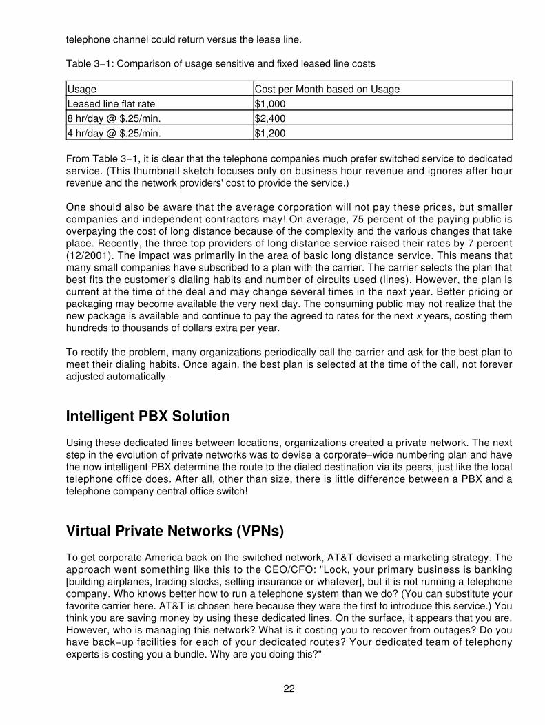
telephone channel could return versus the lease line.
Table 3−1: Comparison of usage sensitive and fixed leased line costs
Usage Cost per Month based on UsageLeased line flat rate $1,0008 hr/day @ $.25/min. $2,4004 hr/day @ $.25/min. $1,200
From Table 3−1, it is clear that the telephone companies much prefer switched service to dedicatedservice. (This thumbnail sketch focuses only on business hour revenue and ignores after hourrevenue and the network providers' cost to provide the service.)
One should also be aware that the average corporation will not pay these prices, but smallercompanies and independent contractors may! On average, 75 percent of the paying public isoverpaying the cost of long distance because of the complexity and the various changes that takeplace. Recently, the three top providers of long distance service raised their rates by 7 percent(12/2001). The impact was primarily in the area of basic long distance service. This means thatmany small companies have subscribed to a plan with the carrier. The carrier selects the plan thatbest fits the customer's dialing habits and number of circuits used (lines). However, the plan iscurrent at the time of the deal and may change several times in the next year. Better pricing orpackaging may become available the very next day. The consuming public may not realize that thenew package is available and continue to pay the agreed to rates for the next x years, costing themhundreds to thousands of dollars extra per year.
To rectify the problem, many organizations periodically call the carrier and ask for the best plan tomeet their dialing habits. Once again, the best plan is selected at the time of the call, not foreveradjusted automatically.
Intelligent PBX Solution
Using these dedicated lines between locations, organizations created a private network. The nextstep in the evolution of private networks was to devise a corporate−wide numbering plan and havethe now intelligent PBX determine the route to the dialed destination via its peers, just like the localtelephone office does. After all, other than size, there is little difference between a PBX and atelephone company central office switch!
Virtual Private Networks (VPNs)
To get corporate America back on the switched network, AT&T devised a marketing strategy. Theapproach went something like this to the CEO/CFO: "Look, your primary business is banking[building airplanes, trading stocks, selling insurance or whatever], but it is not running a telephonecompany. Who knows better how to run a telephone system than we do? (You can substitute yourfavorite carrier here. AT&T is chosen here because they were the first to introduce this service.) Youthink you are saving money by using these dedicated lines. On the surface, it appears that you are.However, who is managing this network? What is it costing you to recover from outages? Do youhave back−up facilities for each of your dedicated routes? Your dedicated team of telephonyexperts is costing you a bundle. Why are you doing this?"
22

The CFO and CEO look at each other and shrug their shoulders. "Our CIO or CTO[2] CTO is the Chief Telecommunications Officer or Chief Technology Officer depending on theorganization sold us on the idea for providing better service at a lower cost," they said in unison.
"Look," said AT&T. "We have the ultimate (outsourcing) deal that will provide all your currentcapabilities for one low price. We will manage the whole network for you and give you all the serviceyou currently enjoy with your private network with little or no hassle." Our product is called(somewhat obscurely) Software Defined NetworkTM because you can define the parameters of thenetwork yourself," AT&T said proudly.
Sprint and MCI/WorldCom[3] MCI and WorldCom were different entities at the time of this offering, but for this book areupdated to reflect current situations. TMSoftware Defined Network is a Trademark of AT&T. offeressentially the same product and call it a virtual private network (VPN). We use VPN here becauseit is both the generally used term, and it is descriptive of the offering.
Here is how the deal works: The company defines the locations that will be part of the VPN asshown in Figure 3−2. The larger the average traffic commitment made between these locations, thelower the price per minute can be. (The catch is that if traffic falls below the average commitment,cost falls into the next higher rate category.)
Figure 3−2: The VPN uses the PSTN as the backboneThe big advantage is that organizations no longer have to manage this far−flung network. Thecarrier will do it. Organizations can now lay off the telecommunications department. (Please notethat the staff supporting the PBX in each location is still needed to handle moves, adds, andchanges. In addition, the staff needed to maintain the dedicated data network is still needed. Even ifthe organization migrates to a Frame Relay network, some management of the vendor is alwaysrequired).
23

All the calls to specifically defined locations (offices) in Chicago, Atlanta, Phoenix, and Seattle areknown as on−net calls. These are priced at the reduced rate. Calls to business partners andcustomers are off−net calls and are charged at a higher rate. If the off−net call volume to thesespecific locations rises, the organization can still place FX lines into these areas. Again, there is nosubstitute for knowing the traffic distribution when evaluating any telecommunications plan.
As one can determine from the above description, it takes a sharp pencil to figure out if this is agood deal. It is definitely a good deal for the carrier who gets all those calls and minutes back on theswitched network.
The VPN is more reliable than a dedicated, line−based network because calls are really riding overthe Public Switched Telephone Network (PSTN), which is rich in multiple paths. One of the featuresof the private, line−based network was four− or five−digit dialing. This can be preserved intact if wewant. Because the switches in the telephone network are computers that have access to adatabase, they can easily look up how to route a number based on the originating location andnumber dialed. The VPN then is a special discount−billing plan, with the carrier managing thenetwork on which we can have a custom−dialing plan.
A caveat that should also be brought into the equation is that the large corporations will negotiatelong−term SDN/VPN agreements with the carrier. Typically, the agreements will bear a 3 to 5 yearterm whereby the customer enjoys the benefits of the fixed pricing arrangement, with some caveatson usage such as minimums, numbers of locations, average revenue generated per month, and soon. If, however, the average volume falls below an agreed−to level, the carrier may charge apenalty. This penalty may be in the form of
A minimum charge per site• A minimum charge per month• An averaged cost that is used on a quarterly basis (that is, they will bill the higher rate for anentire quarter if the customer does not achieve the minimum billing)
•
Any one of these charges may apply to the consumer's billing, depending on the agreementbetween the players. Incidentally, the customer and the carrier are usually sworn to secrecyregarding the rates and terms of the agreement, through some nondisclosure arrangement. Thepurpose of this nondisclosure is to keep the mass public coming back and asking for the same deal!Or is it? Sometimes the deal is not as good as it is supposed to be. One such case was a largefinancial company who had a deal with the carrier for 5 years, yet over that same period of time thecosts were rapidly plummeting. The customer was actually spending more per minute for theirSDN/VPN than if they just picked up the phone and made a long dis−tance call.
Newer contracts will usually bear some terms that state if the costs decrease over the term of theagreement, then the carrier will annually review and adjust the rates accordingly. It may also statethat the adjustments will be enacted if the costs drop by some fixed percentage point (like 10percent). In either case, the carrier will also hook a contingency that because they are tied toreducing the costs in the contract period should the prices fall, they also reserve the right to raisethe rates if their prices increase at greater than some tied percentage point (usually 10 percent). Sowhat we have is an agreement that is somewhat fluid and can be modified during the term of thecontract so long as both parties are in agreement. Where this is a benefit is when a company plansextraordinary growth over the term of the agreement, or when there is some speculation that somesites may be closed and contraction will drop the overall volumes.
24

Users May Not Like It
Without trying to throw a damper on the voice SDN/VPN, there are some conditions that may causethe end users to balk at its use. Many organizations' telecommunications management typically tryto match the needs of the organization without causing undue stress on the user. However, thespecial dialing procedures necessary to use a SDN/VPN often got in the way. Let's use an exampleof a group with road warriors. The traveling person needs to use long distance to customers,contacts, and back to headquarters. Therefore, a special calling card is issued that has the caller goto a pay phone. From there the caller dials a special 800 number to call into the SDN/VPN (thisrequires 11 digits). This is nothing more than a switch that is keeping track of the traffic and usageverification. Once into the SDN/VPN, the caller then dials the 11−digit telephone number for a NorthAmerican location. The number of dialed digits may be higher for international calls. Finally, thecaller must dial their user calling card number to validate it for authentication and billing purposes.This may be an additional 15 digits. So all told, the customer has just dialed 37 digits to make a call.This creates frustration for the caller, especially if they make several calls during the course of aday.
Let's complicate the above scenario a bit! After being frustrated by dialing all those digits, the callergets a busy tone. This means that they have to start over. Now the frustration really starts to mount.Moreover, one may be reading this and saying "what is the author talking about? I can dial anumber and if I get a busy tone, then I merely dial the pound key (#) and get my dial tone back."
That may be true for some calls and some phones, but this is not a guarantee. The individualphones at airports, hotels, and along the roadside may not allow this. Many may be phones that areused by a specific vendor/carrier (we have all seen the WorldCom and AT&T phone in the lobbies ofhotels that only allow the features on their own specific network). So if the caller is using aWorldCom phone and calling an AT&T network, all bets are off. The service may require that thecaller hangs up and starts over.
Moreover, when making a string of calls on a normal calling card, customers are able to use the #key to place the next call without entering the calling card number every time. This again is notnecessarily true with the special SDN/VPN cards. Although the carriers have taken great strides ineliminating these problems, they still cannot guarantee that everything works at every phone. By theway, with the SDN/VPN, the carriers allowed stored numbers in the central switch so that a usercould eliminate some of the dialing process by using a speed dialing arrangement. Corporatetelecommunications personnel may have predefined calls to each office with a three− to five−digitspeed number, thus the caller could eliminate some of the digits required. This is a noble gesture,but it does not always work the way it was planned, and therefore the end users begin to rebelagainst the amount of time they spend dialing digits to do their job.
Now back to the original purpose of the VPN—to save money and ease the process ofcommunicating between and among users within an organization—the ease of use is not assured,as stated previously, so the goals are not met entirely. From there, however, the user can usurp thesavings by doing many things:
Reducing the amount of calls they make by refusing to dial the digits• Calling around the VPN by using a separate calling card that is not billed under the specialarrangement
•
Placing operator assisted calls instead of dialing, thereby incurring a much higher cost perminute
•
25

Each of these situations complicates the overall purpose of using the VPN/SDN. One final commenthere is that the users also begin to bemoan the use of the network to their superiors, who thenbegin a grass roots effort to override the VPN. What was planned as a cost containment tool,becomes a more expensive solution overall, and management really does not want to hear all thecomplaints about a system as mundane as the telephone. Bear this in mind as you look into the useof these systems.
This discussion so far has only considered the case where the corporation owns the PBX andconnects it to the VPN. What if a Centrex system is provided by the incumbent local exchangecarrier (ILEC) or leased from a reseller? The answer is that one can still implement all the abovewith a Centrex system at any or all locations.
Because Centrex is essentially a PBX that is physically resident at the local central office, it too canhave TIE, FX, or RCF trunks. The long distance carrier supplying the VPN will be more than happyto terminate VPN trunks on a Centrex system.
In summary, the important points are as follows:
Calls are carried over the PSTN.• A custom dialing plan is used.• Pricing is dependent on the locale.• The number of locations.• The projected or committed traffic volumes.•
This is all achieved by computer databases in the network.
26

Chapter 4: Data Virtual Private Networks (VPNs)
Internet−Based VPN
One might say that these Internet−based data VPNs are the same as voice VPNs, but different atthe same time. The philosophical point is that a dedicated network will be overbuilt in some areasand underbuilt in others. A shared network offers the hope that we can spread the overall cost outwhile getting the benefits of a private network. Historically, this accounts for the popularity of shareddata networks beginning with X.25, Frame Relay, ATM, and now the Internet. The Internet hasbecome a popular, low−cost backbone infrastructure.
Because of its ubiquity, many companies now want to use a secure Virtual Private Network (VPN)over the public Internet. The challenge in designing a VPN is to exploit the technologies for bothintracompany and intercompany communication while still providing security. Of course the rule ofthumb we now use in an Internet Protocol (IP) network is "IP on everything." A VPN is an extensionof an organization's private intranet across a public network (that is, the Internet), creating a secureconnection essentially through a tunnel. VPNs securely convey information across the Internetconnecting remote users, branch offices, and business partners into the corporate network. Figure4−1 is a graphic depiction of an Internet−based VPN.
Figure 4−1: Tunnels provide secure access for VPNs.VPNs are owned by the carriers, but used by corporate customers, as though the customers ownedthem. A VPN is a secure connection that offers the privacy and management controls of a dedicatedpoint−to−point leased line, but actually operates over a shared routed network.
In the past we saw traditional networks being built as part of a leased line, point−to−point network.This was expensive and risky. A single link error brought the network down. Later a virtualnetworking scenario emerged using a packet−switching technology called Frame Relay. Thisdemanded that presubscribed links were established by being premapped in logic.
VPNs are created using encryption, authentication, and tunneling, a method by which data packetsin one protocol are encapsulated in another protocol. Tunneling enables traffic from multipleorganizations to travel across the same network, unaware of each other, as if enclosed inside theirown private steel pipe.
27

It is easy to jump to the conclusion that the Internet is free and, therefore, there are tremendouscost savings to be had from this free shared network. Later, we will explore some cost comparisons,but as one might guess, the relative cost benefit depends very much on each network's geographyand traffic volume.
Goals
The goal of any network is to support users in a flexible, reliable, secure, and inexpensive manner:
Network managers want the network to be flexible.• Users want the network to be reliable and secure.• Management wants the network to be inexpensive.•
A balance of these often−competing goals can be achieved, provided a good dialog is maintainedamong the participants. Table 4−1 shows the network goals in terms of applications, users, potentialnetwork solutions, and access to the network. It is an exercise left to the reader to select from thelist those applications and users who are to be served. The network list indicates that these usersand applications could be interconnected by any of these network technologies. As indicatedpreviously, dedicated networks are expensive and rarely fit the need perfectly. Frame Relay andAsynchronous Transfer Mode (ATM) are shared network technologies that can be very costeffective, depending on the geography and traffic volume. Dial−up telephony can be a networkingtechnology for highly mobile, low−volume users. Normally, we would like to have a backbonenetwork with direct access for various users and dial−up remote access for infrequent users. We willdiscuss these alternatives in the following sections.
Table 4−1: Mix of methods used to pick from
Access Network Users ApplicationDial−up Dial−up Road warriors E−mailISP Dedicated Telecommuters DB AccessxDSL X.25 Branch office Sales supportCable modem Frame Relay Customer Customer serviceISDN Internet Partners E−CommerceDedicated ATM Order entry
Shared Networks
The advantage of shared networks is that organizations do not have to incur the entire cost of theinfrastructure. For that reason, Frame Relay has been extremely popular. Because it (like X.25before it) is virtual circuit based, there is little concern about misdirected or intercepted traffic. Still,Frame Relay service is not universally available and access charges to a point−of−presence (POP)can be expensive. However, compared to the cost of dedicated networks, shared networks offerequivalent performance and a much lower cost.
Internet
The next logical step is to use the Internet as the private network. It is almost universally accessible,minimizing access charges. From our discussion of the Internet in Chapter 29, "SynchronousOptical Network (SONET)," two things are clear:
28

No one is watching the traffic or performance of the Net as a whole.• The path our data takes across the network is quite unpredictable.•
This leads to the conclusion that performance will be unpredictable and that our precious corporatedata may pass through a router on the campus of "Den−of−Hackers University." (It is not the intenthere to malign university students, but only to offer the observation that they are bright, curious, lovea challenge, and may have time on their hands and access opportunity to do a little extra curricularresearch on the vulnerability of data on the Internet.) There are then two problems: performanceand security.
Performance
The performance issue poses the problem of sizing the bandwidth on each link, which becomes amajor task as the network grows. Unfortunately, few network managers have a good handle on theamount of traffic flowing between any given pair of locations. Typically, they are too busy handlingmoves and additions to the network, which frequently leads to performance problems. Because thenetwork grew without the benefit of a design plan, invariably, it means that portions of the network,including servers, become overloaded.
A dedicated line network is expensive, requires maintenance, and necessitates a backup planshould a line or two fail. Using a shared network does not alleviate the problem of traffic analysis.On the contrary, we now have to worry about the capability of the Internet to provide the bandwidthwe need when we need it. Selecting our ISP to provide the performance we need becomes animportant issue.
Outsourcing
One solution is to outsource the network to a network provider (the analogy to a voice VPN here isstrong). The most popular previous solution was to lease Frame Relay service. The benefit was thatthe network provider took care of the management of the network and even provided levels ofredundancy (for which you paid) within its network. Unfortunately, to make most efficient use of thisservice, one still needed to have a handle on traffic volumes. For example, a committed informationrate (CIR) that was too low resulted in lost data and retransmission, while a CIR set too high was awaste of money.
A national or international carrier with its own Internet backbone then becomes a good choice as aVPN provider. One negotiates service level agreements (SLA), which include quality of service(QoS) guarantees. Some ISPs even provide Virtual IP Routing (VIPR) in which they permit you touse internal, unregistered IP addresses.
If one builds a completely independent, internal (intranet) network, one could use any set of IPaddresses one might choose. This alternative is attractive to large corporations that are constrainedto using class C addresses. If these private addresses were to get out onto the Internet, chaoswould quickly ensue. VIPR permits the flexibility to continue to use this unregistered set ofaddresses transparently across the Internet. This is strongly analogous to having one's own dialingplan on a voice VPN.
There are many possibilities and choices here. We can outsource the whole network, including theVPN equipment on each site, or outsource pieces.
Standard Outsourcing Issues A few points are worth making about outsourcing. One must takea realistic look at the task at hand:
29

If the internal staff possesses the capability to implement the VPN, do they have the time?• If you outsource the whole network, how permanent will the relationship be?• To what extent will the internal staff become involved in the design and maintenance of theVPN?
•
Choose your vendor carefully. Evaluate responsiveness in the areas of presale support, projectmanagement, and post−sale support. As in any procurement process, writing a system specificationand Request for Proposal (RFP) is essential. Also, make up the evaluation criteria ahead of time.You may (or may not) choose to publish the evaluation criteria in the RFP. Select the vendor who ismost responsive to your requirements. Here is a good opportunity for the vendor to do the trafficanalysis so that a traffic baseline for design can be established. Always include growth in the RFP.
Ongoing support will be critical. If the network spans multiple time zones, specify the minimumsupport requirements. For example, 9 A.M. to 5 P.M. CST is of little use to offices located in Taiwan.What training is offered as part of the package? The more knowledgeable the internal staff can be,the better they will be able to support the VPN — even when they are outsourcing support.
It is important to have a coordinated security plan so that we have an integrated and consistent viewacross our firewalls, proxy servers, and VPN equipment.
Security
The basic concept of a VPN is to provide a secure, point−to−point connection across the networkbetween communicating entities. A couple of questions about security are important to keep ourparanoia in check. The first question is how much security is enough? To answer that question, wemust consider the impact on our business if the data we are sending is
Simply lost. Is there a backup mechanism for sending or recovering the data?• Found by another business (not a competitor).• Found by a competitor.• Actively pursued by a competitor as shown in Figure 4−2.•
Figure 4−2: Competitors may actively pursue your data.In the last case, we must ask how much effort is the competitor willing to invest to get our data? Theanswer to these questions will help us decided how much security is enough. Note that in theforegoing example, one can equally substitute the word hacker for competitor.
What About Security Issues? Turning to security, remote access to a system must have integral
30

security to protect the network and users from unauthorized access and penetration. We have allheard about the teenaged hackers who have been creating havoc in the data processing andInternet business. These young hackers break into systems for the sheer pleasure of challengingthe system and showing their prowess with the modem as shown in Figure 4−3. And it works,because they do it every day. We, therefore, have to consider these issues before opening a door.
Figure 4−3: Hackers break in just to prove their prowess.We must start with different techniques such as VPNs, encryption, authenticating servers, andsecure firewalls. The key technologies that compose the security component of a VPN are
Access control to guarantee the security of network connections• Encryption to protect the privacy of data• Authentication to verify the user's identity as well as the integrity of the data•
What Can We Do to Secure the Site? Remote access users sitting in a distant site need to knowhow to use the system, so training is important. Check the pieces of the puzzle as shown in Figure4−4 to make sure that you have a good solution provider to handle your needs. A company withsalespersons who travel frequently would provide 800 number access. Hardware considerationsvary, depending on what networking you're using, the number of users, and whether the users needdesktops or laptops at the remote location. Standardization is essential — you don't want three orfour different platforms, and you don't want to have to support 47 varieties of software. We want toleave the variety of flavors to the ice cream manufacturers!
31

Figure 4−4: The pieces that must be considered for securityAdditionally, a firewall service will offer a bastion router capability to filter the packet, the protocol, orthe user id and address. These systems will help to keep out unwanted guests. Firewalls can be indifferent places, as we will see. They can also be integrated or CPE solutions.
Security must also be ensured while the data is in transit. Therefore, we need to use a form ofencryption so that an eavesdropper cannot listen in on our data and intercept it. By using InternetProtocol Security (IPSec) techniques, we introduce up to five different forms of encryption anddigital signatures. These will be sufficient to delay any access to the data and by the time the codecould be broken, the data will have little value.
Authentication is also a very effective tool that challenges the caller and requests a key−codedresponse. In a security dynamics environment, a challenge and response can be issued by defaultevery 30 seconds or user variable to effectively manage the logged−on users.
What Are the Risks? The risks posed on data integrity and security take many forms. We usuallythink of data protection in terms of the corruption or total loss of data. However, other areas ofconcern may be from the undetected interception of the data by hackers or crackers. Moreover, theinaccessibility of our data from the denial of service attacks has become more prevalent in thesecurity issues facing the IT manager. Lastly, there are also issues of invasions on our LANs orWANs when a promiscious device is attached to the network and picks off all data packetsregardless of the addressee. These sniffers, as they are called, can capture all data packets fromthe network, usually undetected.
Hackers• Crackers• Salami attackers• Denial−of−service attacks• Sniffers•
32

Creating the VPN
There are five ways to create a VPN:
Between desktops• Between routers• Between firewalls• Between VPN−specific boxes• With integrated boxes•
Although not normally considered a VPN, one can certainly use desktop PCs to encrypt data andsend it across the Internet securely. Additionally, software is available that runs on a desktopcapable of creating a VPN to a firewall or stand−alone VPN device. Most VPN equipment vendorsoffer corresponding software that runs on a laptop or desktop in order to provide a secure path tothe home office over the Internet. Most of the discussion then involves creating a VPN betweenbusiness locations, branch offices, and road warriors.
Encryption
The first basic rule is the more secure it is, the less convenient it is to use and the greater impact(negative) it will have on overall system performance. The strength of an encryption mechanism isdependent upon the complexity of the calculation and the length of the key. The most popularmechanism for which hardware is readily available is Data Encryption Standard (DES), developedby IBM and now standardized. The basic key is 54−bits long. Triple DES involves simply running thealgorithm with a 112−bit key. The question here is as always how secure do you need to be?
The more secure, the larger the key used (or the more times the algorithm is run with differentkeys). This all takes time to encode and to decode. Much has been made lately of the fact that byusing thousands of computers, a DES−encoded message could be broken in 39 days.
Keep in mind that this is for one key. If we change keys, it would take the crackers and hackersanother 39 days. Are they (hackers and competitors) motivated to do this? The method mentionedpreviously used the brute force attack of guessing keys. Changing keys often means that theattackers must start all over again. The other encryption standard (not widely supported) isInternational Data Encryption Algorithm (IDEA), which uses 128−bit keys.
The second basic rule is that encryption performed in hardware is much faster than in software.
Key Handling
A very important part (some say the most important) of an encryption is the mechanism used todisseminate keys. Here again, security is the inverse of convenience. True, keys can be sent in amulti−encrypted file. They can also be sent by snail mail or given over the telephone (not verysecure). The problem with this private key system is that both communicating parties must have thesame key. If all locations are talking to the home office, they all must have the same key, or thecentral office must keep separate key pairs for each location.
This key management nightmare can be handled in two ways. We could use the X.509 digitalcertificate system for key management. The other alternative is to use a public key system toencrypt the private key so that they can easily be exchanged.
33

Public Key Cryptography (RSA)
The layman's version (don't try this at home because it won't work as described here) is that each ofus thinks up a couple of prime numbers (the bigger the better). One number we keep for ourselvesand the other number we publish on our web site along with the product of the two prime numbersas our public key. Anyone wanting to send us something will use the public key to encrypt it with thepublic key, and only we can decrypt the message with our private key. We can authenticate thesource if the sender used his private key to encrypt his signature because only his public key willdecrypt his signature. The process is shown in Figure 4−5.
Figure 4−5: Security key management is used for IPSec.This system is secure because of the tremendous amount of processing power it takes to factorlarge prime numbers. (For example, if we could factor the product, we could determine the privatekey.) Unfortunately, performing the encryption and decryption are also processor intensive (slow).But it sure solves the key distribution problem. Therefore, we could use public key cryptography toencrypt and distribute the keys to all our VPN boxes.
Authentication
Authentication is the process of verifying that this is the party to whom I am speaking, and that theyhave authorized access. There are several ways of doing this; however, the most common way is toprovide an authentication server that passes out authenticated certificates based on something theuser has or knows.
User Level Authentication The user has or knows his/her account code (name) and password.User names are public, and passwords can be compromised. A more secure system is to use atype of secure ID card. These credit card sized devices are based on an internal clock thatgenerates a different pseudo random code every minute. The authentication server is timesynchronized with the card and therefore generates the same number at the same time. When theuser calls in, he/she must enter his/her account code and the code from the card as the password.The IP has embedded in it a set of layer 2 protocols called the Point−to−Point Protocol (PPP). InPPP, the basic security methods used are Password Authentication Procedure (PAP) and theChallenge Handshake Authentication Protocol (CHAP). PAP and CHAP do little for security. In fact,PAP and CHAP are part of the basic PPP protocol suite and fall short in providing a true securityprocedure. These schemes do not address issues of ironclad authentication and integrity, oreavesdropping. The PAP and CHAP are rudimentary procedures used to log on to a network, buthackers and crackers easily defeat both.
34

Layer 2 Tunnel Protocol (L2TP) is another variation of an IP encapsulation protocol as shown inFigure 4−6. An L2TP tunnel is created by encapsulating an L2TP frame inside a UDP packet, whichin turn is encapsulated inside an IP packet, whose source and destination addresses define thetunnel's ends. Because the outer encapsulating protocol is IP, clearly IPSec protocols can beapplied to this composite IP packet, thus protecting the data that flows within the L2TP tunnel.Authentication Header (AH), Encapsulated Security Payload (ESP), and Internet SecurityAssociation and Key Management Protocol (ISAKMP) can all be applied in a straightforward way.
Figure 4−6: The L2TP packetL2TPs are an excellent way of providing cost−effective remote access, multiprotocol transport, andremote LAN access. It does not provide cryptographic robust security. L2TP should, therefore, beused in conjunction with IPSec for providing secure remote access. L2TP supports bothhost−created and ISP−created tunnels. A remote host that implements L2TP should use IPSec toprotect any protocol that can be carried within a PPP packet.
Integrated at the VPN point of access, user authentication establishes the identity of the personusing the VPN node, and this is because an encrypted session is established between the twolocations. The user authentication mechanism enables the authorized user of the VPN systemaccess to the system, while preventing the attacker from accessing the system.
Some of the common user authentication schemes are
Operating system username/password• S/Key (one time) password• Remote Authentication Dial−In User Service (RADIUS)• Strong two−factor token−based scheme•
The strongest user authentication schemes available on the market are two−factor authenticationschemes. These require two elements to verify a user's identity: a physical element in theirpossession (a hardware electronic token), and a code that is memorized (a PIN).
Some cutting−edge solutions are beginning to use biometrics mechanisms such as fingerprints,voiceprints, and retinal scans. However, these are still relatively unproven.
When evaluating VPN solutions, it is important to consider a solution that has both dataauthentication and user authentication mechanisms. Currently, there are VPN solutions that provideonly one form of authentication.
Because of this, VPN solution providers that only support one of the two authentication mechanismswill typically refer to authentication generically, without qualification of whether they support dataauthentication, user authentication, or both. A complete VPN solution will support both dataauthentication (also known as the digital signature process or data integrity) as well as userauthentication (the process of verifying VPN user identity).
Packet Level Authentication The IPSec standard provides for packet level authentication toprevent man−in−the−middle attacks. (This is where someone intercepts your packets andsubstitutes his/her own.) IPSec is a layer 3 protocol that enhances the use of the layer 2 underlying
35

protocols. An authentication header is created for each packet. The layman's version of this is that achecksum is calculated and encrypted with the data. If the checksum calculated by the recipientdoesn't match the one sent by the originator, someone has tampered with the data. The IPSecstandard specifies two different algorithms for doing this MD−5 and SHA−1. If your vendor'sequipment supports both algorithms, it improves the chances for intervendor compatibility. Theother alternative is to simply not use packet level authentication.
In order to guarantee authenticity of the packets, a digital signature is required to authenticate thedevices to one another. IPSec has included the X.509 digital certificate standard. Essentially, theX.509 certificate server keeps a list of certificates for each user. When you want to receive datafrom another device, you first ask for the certificate from the certificate server. The sender stampsall data with that certificate. Because this process is secure, you may be sure that these packets areauthentic.
Your vendor then ideally supports both authentication algorithms and X.509. In any case, it isessential that someone in your organization understands in detail how each vendor supports thevarious levels of security that you intend to use. These authentication and encryption systems allhave to work together flawlessly. If the vendors you choose stick to the standards, it improves thechances of, but does not guarantee, an integrated working environment.
IPSec offers a variety of advantages. Chief among those are
IPSec is widely supported by the industry including Cisco, Microsoft, Nortel Networks, andso on.
•
This universal presence ensures interoperability and availability of secure solutions for alltypes of end users. In addition, all IPSec−compliant products from different vendors arerequired to be compatible.
•
IPSec provides for transparent security, irrespective of the applica−tions used.• IPSec is not limited to operating system−specific solutions. It will be ubiquitous with IP. It willalso be a mandatory part of the forthcoming Internet Protocol Version 6 (IPv6) standard.
•
IPSec offers a variety of strong encryption standards. The key design decision to support anopen architecture allows for easy adaptability of newer, stronger cryptographic algorithms.
•
IPSec includes a secure key−management solution with digital certificate support. IPSecguarantees the ease of management and use. This reduces deployment costs in large−scalecorporate networks.
•
IPSec used in conjunction with L2TP provides secure remote−access client−to−servercommunication. L2TP alone cannot provide for a totally secure communication channel due to itsfailure to provide per packet integrity, inability to encrypt the user datagram, and the limited securitycoverage only at the ends of the established tunnel. The major drawback to packet−filteringtechniques is that they require access to clear text, both in packet headers and in the packetpayloads.
There are two major drafts in IPSec: AH and ESP. They are defined as follows:
AH is used to provide connectionless integrity and data origin authentication for an entire IPdatagram (hereafter referred to as authentication).
•
ESP provides authentication and encryption for IP datagrams with the encryption algorithmdetermined by the user. In ESP authentication, the actual message digest is now inserted atthe end of the packet (whereas in AH the digest is inside the authentication).
•
AH provides data integrity only and ESP, formerly encryption only, now provides both encryption
36

and data integrity. The difference between AH data integrity and ESP data integrity is the scope ofthe data being authenticated.
AH authenticates the entire packet, while ESP doesn't authenticate the outer IP header. In ESPauthentication, the actual message digest is now inserted at the end of the packet, whereas in AHthe digest is inside the authentication header.
The IPSec standard dictates that prior to any data transfer occurring, a Security Association (SA)must be negotiated between the two VPN nodes (gateways or clients). The SA contains all theinformation required for execution of various network security services such as the IP layer services(header authentication and payload encapsulation), transport or application layer services, andself−protection of negotiation traffic.
These formats provide a consistent framework for transferring key and authentication data that isindependent of the key generation technique, encryption algorithm, and authentication mechanism.
One of the major benefits of the IPSec efforts is that the standardized packet structure and securityassociation within the IPSec standard will facilitate third−party VPN solutions that interoperate at thedata transmission level. However, it does not provide an automatic mechanism to exchange theencryption and data authentication keys needed to establish the encrypted session, whichintroduces the second major benefit of the IPSec standard: key management infrastructure or PublicKey Infrastructure (PKI).
The IPSec working group is in the development and adoption stages of a standardized keymanagement mechanism that enables safe and secure negotiation, distribution, and storage ofencryption and authentication keys. A standardized packet structure and key managementmechanism will facilitate fully interoperable third−party VPN solutions.
Other VPN technologies that are being proposed or implemented as alternatives to the IPSecstandard are not true IP security standards at all. Instead, they are encapsulation protocols thattunnel higher level protocols into a link layer protocols. When encryption is applied, some or all ofthe information needed by the packet filters may no longer be available. There are many differentforms of IPSec packets as shown in Figure 4−7. For example
Figure 4−7: The various forms of IP packets
In transport mode, ESP will encrypt the payload of the IP datagram. In tunnel mode, ESP willencrypt the entire original datagram, both header and payload.
•
37

In most IPSec−based VPNs, packet filtering will no longer be the principal method forenforcing access control. IPSec's AH protocol, which is cryptographically robust, will fill thatrole, thereby reducing the role of packet filtering for further refining after IPSec hasencrypted the packet.
•
Moreover, because IPSec's authentication and encryption protocols can be applied simultaneouslyto a given packet, strong access control can be enforced even when the data itself is encrypted.
Router−Based VPN
Several router vendors offer VPN products based on the ability of the router to perform the requisitesecurity functions. If your VPN is relatively small and the traffic volume not too heavy, then youmight consider this option as a cost−effective approach. You need to have compatible routers ateach location as shown in Figure 4−8. If there are individuals (for example, laptops ortelecommuters) that don't have routers, they must have software that is compatible with thatprovided on the router. Make sure your vendor provides the compatible software that provides thelevel of security that you require for your VPN. The absence of a firewall in Figure 4−8 may be takento mean that in this low−cost approach we are doing firewall functions on the router. In this case, thenetwork would logically appear as in Figure 4−9.
Figure 4−8: Compatible routers are used at each location for VPN services.
38

Figure 4−9: Stand−alone firewallThe general admonition here is that you may be creating a bottleneck in the router. For largenetworks, let routers route.
Firewall−Based VPN
The very same issues exist here as with routers. One needs to have compatible (preferably thesame vendor's) firewalls at each location. Mobile users or telecommuters must have compatibleVPN software. Firewalls are always potential bottlenecks, so asking them to perform VPNencryption can adversely affect all other access to your network. Here again, there is no substitutefor traffic analysis. We only recommend this solution for small networks where the traffic through thefirewall can easily be handled by the firewall hardware.
Figure 4−9 shows a stand−alone firewall hardware that filters all traffic into our network, whilemaintaining VPN functionality.
VPN−Specific Boxes
VPN specific boxes are the recommended solution for high volume, large networks. Severalvendors offer these solutions in both hardware and software incarnations. The general rule is thathardware boxes will outperform software boxes and are theoretically more secure because they arebased on proprietary technology that is harder to hack than publicly available operating systems. (Ahardened Unix−based system is also extremely difficult to hack.) Traffic volume and feature supportfor remote terminals and industry compatibility will guide your decision here.
These boxes set up secure tunneling by using IPSec encryption and certificates as describedpreviously. They are typically installed in parallel with your firewall. The firewall handles web (HTTP)requests, while the VPN box handles access to your internal database. Figure 4−10 shows thefirewall and VPN box in parallel, reinforcing the division of labor between the two boxes. Becausewe now have two "holes" into our network, it is imperative that we have the permissions and accessrights set up correctly. The firewall should not let users in who would be required to authenticate viathe VPN box.
39

Figure 4−10: The firewall and VPN box working in parallelThe integrated solution that some vendors are offering is an integrated custom box that doesrouting, firewall, and VPN all under one roof. This is an attractive option where traffic volume andperformance is not going to be an issue. Again, Figure 4−8 or 4−9 might be used to depict thisconfiguration.
Throughput Comparison
Unfortunately, although there is compatibility testing, there are no consistent performance criteriaacross the industry. It, therefore, becomes difficult to compare the performance of different vendorofferings. Vendor claims tend to be exaggerated. They will measure their product in the bestpossible light (for example, maximum−sized packets and data compression turned on, using thesimplest encryption algorithm). Our recommendation is to search the periodical literature for tests onthe vendors you are considering as a starting point.
Then, in your request for proposal (RFP), specify a test sequence. With encryption andauthentication, there is a lot of end−of−packet processing. This causes a significant performance hitwhen packet sizes are small.
The number of simultaneous sessions also affects performance. Vendors claim thousands ofsimultaneous sessions, but ask them how many they can set up or tear down at a time, and thenumber drops to fewer than 100. Notice also that during this peak−processing load of sessionsetup, overall throughput will be affected.
Here again, having knowledge of how your users use the system, when the peak sign−on demandoccurs, when the peak traffic occurs, and what kinds of response time you consider to bereasonable all influence your product selection. By the way, being able to set up 100sessions/second is plenty in a 1,000−user network. (How many of these users are actually using theVPN?) Worst case (which statistically never occurs) means that the last user might have to wait 10
40

seconds to get a session setup. Most likely, no one except the network manager with the Sniffer willever notice a delay.
Remote Management of VPN Components
If you have only two locations on your VPN, then remote management of policy is probably not anissue. For a large network, visiting each site to install policy rules becomes a burden. For largernetworks then, look for the ability to provide remote policy management of not only your VPNdevices, but also your firewalls and routers securely.
Cost Considerations
Figures don't lie, but liars know how to figure.
Although we're presenting some typical numbers here, you should run the numbers using your ownparticular configuration. The most beneficial comparisons of a VPN occur when compared to adedicated, line−based network or one that makes extensive use of long distance dial−up lines. Ifyou are already using a shared network (Frame Relay or ATM), the cost savings are not so striking.
Consider that a VPN box at each location might cost $5,000 including installation; multiplied byseven sites is equal to $35,000. Now, how long will it take to save this cost if you substitute your ISPcharges for each location and subtract the cost of your existing T1 or Frame Relay network? If youhad six T1s at $5,000/month, you might now have seven T1 access lines from your ISP at $3,000 or$4,000/month. The $7,000/month savings will pay off the $35,000 investment in 5 months. If yourFrame Relay service is costing $1,000/month per location, the break−even point doesn't happen inany reasonable period.
Using remote access server and dial−up lines is cheaper to install, costing about $6,000 to $7,000for about 20 users to install at the central location. Now comes the big bite, which is the longdistance charge from all the remote locations. This could easily grow to $5,000/month if each of theusers spent two hours online. Each working day at $0.10/minute is about $8,000/month. Plug inyour own assumptions as to duration and cost of telephone calls here. (Even at 1 hr/day and$0.06/minute, that is $2,000/month for 20 users). A VPN system might cost $14,000 to install,including licenses for PC software at each location. The ISP charges that are $20/user/month, plusan ISDN line at the home shop for $100/month, means that we are saving $1,500 in monthlycharges. We can pay off the system in 10 months. Again, do not assume that it will pay off in allcases. But, in all cases, it is worth the effort to perform the calculations.
Your VPN will definitely require more network management than a dial−up system, so the cost ofperhaps an additional system administrator may have to be added.
Proprietary Protocols
Most VPN products are designed strictly around IP. They will often handle other protocols, such asAppleTalk and IPX, by tunneling them inside of IP packets. This introduces both overhead anddelay. If the amount of "foreign" protocol traffic is small, then this is not significant. If the bulk of yournetwork is IPX or Apple talk, we recommend you investigate VPN vendors who will support theseprotocols in native mode.
41

VoIP VPN
The justification for doing VoIP on a VPN is primarily security, along with the reduced cost of VoIP.Depending on usage, voice generates relatively large amounts of traffic. Be sure to include thisadditional traffic in your sizing estimates.
Our discussion of VoIP applies to whether we have a VPN or not. With a VPN, the delays due toencryption are larger, and therefore we would expect that the performance of voice over the VPNwould be worse than VoIP. If we have chosen a network provider who will offer a SLA with QoS,there is a better chance for success, but the delays due to encryption and basic packet switchingwill still be there. With the exception of international calling, one must have a very large callingvolume to make it worthwhile to put voice over the Internet and suffer the attendant qualityreduction.
Summary
VPNs can provide a cost−effective solution to have secure communications across the Internet.Performance can be improved by utilizing a national/international ISP that will offer SLAs and QoS.Choosing hardware−based over software−based VPN equipment will generally provide betterperformance. Choosing VPN vendors who embrace standards and support multiple standardsincreases your flexibility to your vendor/equipment choices. Knowing your current and anticipatedtraffic volumes permits you to make improved cost performance studies.
42

Chapter 5: Advanced Intelligent Networks (AINs)
Overview
The Intelligent Network (IN) has been under development since Bell Communications Research firstintroduced it in 1984. The goal of intelligent networking is to integrate the features and benefits onthe new−generation networks and to allow various types of information to pass through thetelephone network without the need for special circuits. Data communications, Internetcommunications (using Internet Protocols [IPs]), and voice networking have converged to provide anew and exciting set of services. These services revolve around the backbone of the IN, which usesSignaling System 7 (SS7). Network architects envision one network capable of moving any form ofinformation, regardless of the bandwidth. Data and voice calls will traverse this network the sameway—making communication as simple as placing a traditional telephone call.
Intelligent Networks (INs)
The INs consist of intelligent nodes (computer peripherals), each capable of processing andcommunicating with one another over low− to midspeed data communications links. All nodes in theintelligent SS7 network are called signaling points that work with packet transmissions. A signalingpoint has the capability to do the following:
Read the packet address• Determine if the packet is for that node• Route the packet to another signaling point•
Signaling points provide access to the SS7 network and the various databases on the network.They also act as transfer points.
More information will be explained in the SS7 chapter later. However, the switching networkcontains Service Switching Points (SSP) and provides the basic infrastructure needed to processcalls and other related information:
The SSP provides the local access because it emerged as the Central Office (CO). The SSPcan also be other tandem points on the network or an ISDN interface for the SignalingTransfer Point (STP).
•
The STP provides packet switching for message−based signaling protocols for use in the INand for the Service Control Point (SCP).
•
The SCP provides access to the IN database. The SCP is connected to a ServiceManagement System (SMS).
•
SMS provides a human interface to the database as well as the capability to update thedatabase when needed.
•
Intelligent Peripherals (IPs) provide resource management of devices such as voiceannouncers. IPs are accessed by SCPs when appropriate.
•
The IN enables customers to tailor their specific service requirements within hours instead of days.It is expected that full IN implementation will continue to evolve through the new millennium;however, the infrastructure has been laid and work continues. Some of the features availableinclude the following:
Find−me service•
43

Follow−me service• Single (personal) number plans• Call routing service• Computer control service• Call pickup service•
Business is conducted by using a mix of public services, private networks, the Internet, wirelessnetworks, and specialized carriers. Voice−processing requirements for a telephone switch werequite modest and could be satisfied by the limited announcement capabilities offered by the switch,usually as sequenced announcements of greetings, instructions, and terminating messages. Nospecialized service creation environment was required to develop and deploy these services.Complex voice−processing capabilities, such as CO−based voice mail were provided, but not as anintegrated service of the switch. Complex voice−processing capabilities grew outside of theswitching network in the form of interactive voice response systems, voice mail systems, automaticcall distributors, and automated attendants. Over time, these systems embraced new technologies,including facsimile, speaker−dependent and speaker−independent voice recognit ion,text−to−speech, and voice identification.
Advanced Intelligent Networks (AINs)
AIN is a collection of components performing together to deliver complex call−switching andhandling services. The SSP is the CO that provides robust, call−switching capabilities. Whenswitching decisions require complex call processing, the SSP relies on the SCP, a subscriberdatabase, and it executes service logic. The SSP uses SS7 signaling, specifically TransactionCapabilities Application Part (TCAP) messages, requesting the SCP to determine the best way tohandle the call. The process supports telephony features, including 800 (888/877) and 900 calling,credit/debit card calling, call forwarding, and virtual private networks (VPNs). AIN has promised anarchitecture that is amenable to the rapid development and deployment of new services. How tomaintain the stringent performance requirements of a CO service within this rapidly changingenvironment is a major challenge in the advancement of AIN.
IPs and service nodes (SN) are elements of the AIN and must be reliable to be deployed and usedin the CO. IPs work in cooperation with SCPs to provide media services in support of call control.Service nodes combine the functions of the SCP and the IP. When viewed as point nodes in thenetwork, these elements (IP and SN) are subject to failure and require redundant components andmultiple communication paths. Software and procedures in support of CO reliability are alsorequired.
When switching decisions require complex voice−processing services, the SCP cannot alwaysprovide all the required services to the SSP. The SCP also cannot provide termination of voicecircuits and play recorded messages, collect touch−tone input, or perform other voice−processingservices. The call must be redirected to an IP. The IP provides the voice−processing services notavailable from the SCP.
AINs provide more features and functions that are not provided by INs. AIN does not specify thefeatures and services, but how end users use them. An essential component in AIN is the ServiceCreation Element (SCE). Today, Telco personnel at end offices handle service configuration andchanges. The SCE specifies the software used to program end office switches. The single mostimportant change is through a graphical user interface (GUI). Over time, the SCE will reside at theusers' organization, allowing customers to tailor their services on an as−needed basis, withouttelephone company assistance.
44

Some of these enhanced features available include the following items:
Calling name delivery• Call rejection• Call screening (visual or audio)• Call trace• Call trap• Personal ID numbers (pins)• Selective call acceptance• Selective call forwarding• Spoken caller identification•
Some of these features are already available at certain COs, but they are not yet ubiquitous.L imi tat ions to these serv ices are based on the capabi l i t ies of end of f ice swi tchingequipment—service offerings and tariffs will not be consistent throughout telephone companies.
Information Network Architecture
Information Network Architecture (INA) is still in development and viewed by many as the successorto AIN. However, there is considerable controversy over this view, and some believe that twoarchitectures will eventually develop. AIN is designed to facilitate the voice network, whereas INAwill manage the broadband network. The common belief is that INA will provide better utilities formanaging new broadband services offered by telephone companies.
Intelligent networking delivers computer and telephone integration capabilities inside the network.Two major market forces and architectural frameworks are merging to create the most explosivenetwork services opportunities of the late '90s. Enterprise Computer Telephony Integration (CTI)appl icat ions and AIN services are being integrated to provide an array of advancedcarrier−delivered services. Some of the features that will be available to the executive orprofessional, especially telecommuters, include the following items:
Virtual call centers• Consumer interactive applications• Centrex productivity enhancements• Formal and informal call centers• Virtual Automatic Call Distribution (ACD)•
Combining AIN and CTI Services
The evolution of AIN and CTI services underpins the marriage of these two architecturalframeworks. AIN has its roots in the Local Exchange Carriers' (LECs) (both Incumbent LEC [ILEC]and Competitive LEC [CLEC]) and Interexchange Carriers' (IEC) desire for vendor− andswitch−independent network architectures.
Improving the speed of service provisioning and delivering advanced network services is crucial tomaintain a competitive posture. As early as 1986, Ameritech began proposing a concept calledFeature Node Service Interface (FNSI). Through successive industry efforts, AIN emerged as anetwork standard in the early '90s. Figure 5−1 is the basic framework of the AIN architecture.
45

Figure 5−1: AIN architecture frameworkCTI is a complement to AIN proposed by the Private Branch Exchange (PBX) manufacturers. Theend user's desire is as follows:
Advanced applications• Faster feature delivery• Control and customization of applications all driving the development of the CTI interfaces•
Using an external processor, custom applications are configured to enhance the functionality of aPBX, especially in an ACD environment. Figure 5−2 shows the basic connections in a CTIapplication.
46

Figure 5−2: Basic CTI applicationBoth CTI and AIN use an external processor to deliver advanced complementary services to theswitch. The switch controls call−processing access to the external processor via an open interface.Both provide a GUI−based SCE for rapid service and application configuration. IPs provideadditional context information for call treatment. Integrated voice response units are the most widelydeployed IPs. Reporting, billing interfaces, and real−time monitoring tools are available in both.
With the introduction of the IN, these two technologies were brought together by necessity. Servicesrich in voice−processing content and requiring an abundance of digitized voice storage could nolonger be created solely with the innate capabilities of the switch. The variety of service offerings,their complexity, and, in many cases, the requirement for multilanguage support, quickly outpacedthe voice−processing capabilities and capacities of the switch. Voice−processing systems wereintegrated with switching systems to support these new services.
The Intelligent Peripheral (IP)
The Intelligent Peripheral (IP) must provide voice circuit support and some mechanism for obtaininginformation about an incoming call. Several mechanisms are available for capturing call informationincluding the following items:
ISDN User Part (ISUP) signaling• Integrated Service Digital Network (ISDN) signaling• In−band Dual Tone Multi−Frequency (DTMF) signaling• DTMF•
BellCore developed transaction protocols to handle the call processing using an 1129−protocolspecification. The 1129 transaction is triggered when a call comes in. It is initiated with the deliveryof a message from the IP to the SCP. Thereafter, the transaction continues with queries issued bythe SCP and synchronous responses to these queries returned by the IP, reporting results of the
47

requested action.
The BellCore recommendations call for multiple IPs within the network. Each is capable of workingwith multiple independent SCPs via communication across multiple data paths. Each IP operates asthough it is distributed across multiple host platforms interconnected by multiple LANs. IntroducingIP into an AIN environment is a major expense, requiring a significant investment in hardware,networking, and supporting software.
The BellCore philosophy is to provide redundant components and data paths, eliminating singlepoints of failure wherever possible. However, many situations exist whereby an IP or SN provides aservice, yet the service does not warrant a redundant infrastructure. Therefore, a solution isrequired for the IP or SN to provide suitable reliability inherently.
IP Services
The IP must be capable of establishing and maintaining communication with multiple SCPs.Furthermore, it handles the following functions:
Encoding and decoding complex messages• Interpreting these messages• Performing the requested service•
It must also be capable of switching functions including the following:
Call setup• Transfer• Call teardown• Detect call presentation and abandonment• Process requests requiring service logic• Access databases.•
Finally, beyond the capabilities described in the 1129 interface specification, the IP needs supportservices such as logging, administration, alarm processing, statistics gathering and reporting, anddatabase and network access. The IP falls into two categories of service: application processingand resource processing.
The application processor supports the call−processing logic and access to the databases and datanetworks. It initiates transactions, receives instructions, and reports success or failure of the action.The application processors also require connections to communication networks and hosts. An IPneeds multiple data paths because it must be able to contact multiple hosts and must be able tosurvive the loss of a single communication pathway. It needs to communicate with SCPs to receiveinstructions and communicate with switching facilities in order to terminate circuits. It also needs tocommunicate with other network elements, such as the SMS (for provisioning), and to internal andexternal databases. This requires multiple data paths and alternate routing.
The resource processor manages the switching, voice channel facilities, and media−processingresources. The media processing normally requires multiple processors and disk storage to handlethe media streams. It may also require switching, such as a time division multiplexer (TSM) orexternal switches.
48

These two elements are very different from each other. They perform different functions;consequently, they require very different hardware and software processing elements.
The architecture for AIN with the SSP, SCP, and IP in place on the stack is shown in Figure 5−3.
Figure 5−3: AIN protocol stack
Software Architecture: Client, Router, Server
The objective is to build an IP in which application processors drive multiple resource processors.This requires software on the application processor capable of supporting the physical structure. Aclient−router−server scheme is used.
The client includes the application, media processing logic, and controls; manages the resources;and drives a state machine. The IP, driven by the 1129 message set, operates as a state machine.This state machine is driven by messages from the SCP and by trigger events from the network.
The router handles message routing and session management functions. It makes decisions abouthow to route traffic and load−balance.
The servers support both local and remote devices. The local devices include local file systems,databases, and locally attached devices such as encryption boxes. The remote devices arenetworks and hosts. The remote servers must be multiple processor capable.
The Application
The application must be capable of supporting real−time, online updates, which must be donewithout any disruption of service. The system administrator must be able to introduce newinstructions and commands/responses without affecting service. On−the−fly changes to parameters,such as timers and retry limits, are necessary. The state machine itself must remain operationalwithout call loss while the application logic is being changed.
49

Results of AIN
It is possible to build IPs in support of the AIN. These peripheral devices must be economical andreliable enough to operate in a CO environment. Multiple hardware elements are required.Communication paths must be redundant.
Estimates are that by 2007, telephone industry spending will approximate $27 billion. Products andexpenses supporting AINs will expand exponentially. Approximately $5 billion was spent on AINproducts and services in 1998. Telephone industry spending on AIN will include STPs, SCPs,SSPs, IPs, SCE, and various hybrid products.
Recent studies indicate that the demand for AIN features and functions will be driven by thefollowing factors:
Demand for more customer control and services Businesses are placing more strategicreliance on telecommunications. They need features and functions tailored to their specificneeds. The number of functions and services required will be dictated by the lifestyle andbusiness−competitive environment of the end user. AIN is the only way to support suchrequirements. Services will have to be user−friendly and somewhat network−centric to meetthe demands of the future user.
•
Greater geographical distribution and newer technologies Future niche markets willprobably emerge. They need to be widely available by the suppliers (LEC and IEC) to beeffective and acceptable. AIN services must also become technology stable to supportmultiple vendor products and service on multiple switching systems. AIN−based servicesmust find a way to work across carrier boundaries.
•
Mobility and mobile applications in a changing world The business and personal use ofcommunications support from cellular phones, voice mail, pagers, and e−mail is growingexponentially. The need to support a mobile user is now equally important. AIN−basedservices must cross vendor products and billing mechanisms to be effective. Wirelessnetworks are among the fastest growing applications and services in the industry. Thegrowth rate of 300 percent per year shows little sign of slowing. Personal CommunicationsServices (PCS) networks are growing equally fast and demanding more services. Soon theAIN will have to support the single number for a user, regardless of where that user mayreside.
•
Internet, Broadband, and Multimedia A Communications Industry Reports (CIR)[1] CIR is a research f i rm special iz ing in market research and analysis of thetelecommunications industry. report notes that most of the services that AIN is currentlyconcerned with are narrowband and voice−oriented. However, the CIR report projects thebelief that many of the services currently identified with AIN will migrate to the Internet. Inaddition, AIN concepts will increasingly be required for multimedia and broadband services.The market for the next few years around the world is shown in Figure 5−4.
•
50

Figure 5−4: Growth in AIN services around the world
Focus
SS7 is an essential technology supporting and developing ISDN, INs, mobile (cellular) telephony,PCS and information systems, personal communications, and many other applications. Currently,this technology is being pursued by the telecommunication industry, including carriers, large privatenetworks, switch manufacturers, and an increasing number of software developers. The traditionalmethods of in−band signal ing and other common channel s ignal ing methods in thetelecommunication networks have given way to an overlay network using a more capable, layeredSS7 protocol.
Although the primary function of SS7 is to handle call−control−signaling requirements for voice anddata transmission services, it can provide a number of advanced services by use of networkdatabases. These include toll−free and alternate billing, rerouting, virtual networks, and other highlysophisticated telecommunications services denoted by IN services. Additionally, the transactioncapability of the SS7 protocol makes it applicable to a broad range of new services dealing withremote operations. In cellular telephony, SS7 is used for mobility management and handoverfunctions.
An IN describes architecture designed to facilitate the implementation of highly sophisticatedtelecommunications services including the following:
Features and functions• Multivendor interworking• Differing priority services offered by fixed networks, mobile networks, and personalcommunications systems
•
The new millennium will hold several benefits and service advantages unavailable in the past.These advantages will all be geared toward satisfying the changing needs and demands of theconsuming public. As IN and AIN evolve, newer services will be introduced. The various newproviders, such as the CLECs and the CATV companies, will compete to meet the one−stopshopping demands of the customer. AIN will be one of the deciding factors steering consumers tothe various providers. The first providers to implement the AIN features will have the edge overtaking the customer base.
The edge goes to the ILECs for now, because the infrastructure is theirs. However, as the new
51

millennium rolls through, changes will occur. This is one of the critical components in being able tocapture a niche in the market.
52

Chapter 6: Local Number Portability (LNP)With the Telecommunications Act of 1996 in the United States (and the Telecom Act of 1997 inCanada), a series of competitive changes were required in the network. For years when competitorstried to compete with the Bell System, their efforts were stymied. Part of the reason was thecompetitor's ability to serve a new customer. Whenever the new competitor offered to serve abusiness or residential customer, customers were required to change their business or residentialtelephone number to use the new Local Exchange Carrier (LEC). Local Number Portability (LNP) is,therefore, an essential issue in the telephony business. Because of the need to change numbers,the incumbent LECs (ILECs) were able to prevent losing their customers to the competition.
Three Flavors of LNP
LNP gives end users the ability to change Local Service Providers without changing their telephonenumbers. Three basic forms of LNP were introduced to the industry over the past few years (theonly one implemented is service provider portability):
Service provider portability enables subscribers to change Local Service Providers withoutchanging their telephone number. This assumes that users can change suppliers and keeptheir existing telephone number. Still to be completed is the ability to provide LNP in awireless world.
•
Service portability enables subscribers to change from one type of service to another (forexample, analog to digital — ISDN — without changing their telephone numbers) or to beserved from a different central office (where the service is available) and not have to take anew telephone number.
•
Geographic portability enables subscribers to move from one physical location to another(such as state to state) without changing telephone numbers.
•
The Federal Communications Commission (FCC) mandated service provider portability in July1996. Service provider LNP involves a circuit−switched network capability, enabling users on oneswitching system to move or port numbers to a different switching system. Congress mandatedLNP, set the regulations governing its implementation, and stated that any network modificationsrequired to comply with these rules were the responsibility of the existing LECs.
In February 1996, President Clinton signed the Telecommunications Act into law. The single mostsignificant characteristic of the new law is that it opens the local exchange market to competition. Inan effort to eliminate technical as well as regulatory market entry barriers, the law requires that allLECs — both ILECs and new competitive LECs (CLECs) — provide LNP. LNP provides "users oftelecommunications services with the abi l i ty to retain, at the same location, exist ingtelecommunications numbers without impairment of quality, reliability, or convenience, whenswitching from one telecommunications carrier to another."
The Road to True LNP
LNP is germane to achieving true local competition. In November 1994, the industry began toseriously investigate methods of providing true LNP. Although the importance of retaining atelephone number was recognized in the early 1960s, it became a significant issue associated with1−800 (and later 1−888, 1−877, 1−866, and 1−900) services during the 1980s. The need forportability among telephone companies and providers was never really an issue until the NorthAmerican Numbering Plan (NANP) administration published a proposal for future numbering plans
53

in North America. This NANP document was issued in January 1993. Of course, since that time, thelevel of interest has increased substantially. As equal access and competition catch up toderegulation, the use of LNP becomes critical.
In late 1994, MCI commissioned a study by the Gallup Organization to assess LNP and determinethe following:
The potential for businesses and consumers alike to switch local telephone service providersunder various market scenarios.
•
The perceived importance of various service factors regarding local telephone services.• Not surprisingly, the results of the MCI study indicated the following for residentialcustomers:
Nearly 2/3 of all customers were unlikely to switch providers if given the opportunity.♦ More than 3/4 stated that retaining their telephone number or numbers whenswitching carriers was very important.
♦
Eighty percent were unlikely to switch service providers if they would have to changetheir telephone numbers.
♦
Moreover, business customers showed the following results:
Fifty−seven percent were unlikely to switch local telephone service providers if giventhe opportunity.
♦
Eighty−three percent said that retaining their telephone number or numbers whenswitching Local Service Providers was extremely important.
♦
Ninety percent were unlikely to switch providers if they would have to change theirtelephone numbers.
♦
•
With business customers, the cost of changing numbers can be significant. When a businesschanges telephone numbers, the costs include reprinting stationary, business cards,advertisements, and literature. The statistics are shown in Figure 6−1.
Figure 6−1: Comparison of business and residential user concerns over service provider changeThese discussions led to an organization's development of the Carrier Portability Code (CPC)model, which was selected by the New York State Public Utility Commission LNP task force as thearchitecture to be used. MCI, with the support of several manufacturers, demonstrated thearchitecture to the FCC via a live test in May of 1995 to prove that true LNP was indeed technicallyfeasible.
54

On June 27, 1996, the FCC adopted rules on LNP. The FCC required LNP availability on apermanent basis as of October 1, 1997. This availability must be complete for the top 100Metropolitan Statistical Areas (MSA) by December 1998. After the December 1998 dates, all LECs(ILECs and CLECs) in other areas are required to provide LNP within six months upon request. TheFCC actually adopted performance criteria, rather than a specific technology to meet the need. Thecriteria includes the following information:
Support of existing services and capabilities• Efficient use of numbering plans• No change in numbers for end users• No requirement to rely on databases of another carrier in order to process (route) calls• No unreasonable degradation of service or reliability when implemented or when customersswitch carriers
•
No carriers' proprietary interest• Ability to accommodate location and service portability in future years• No adverse impact in outside areas where LNP is deployed•
States will have flexibility if they meet the criteria listed previously. Wireless carriers have beengranted a reprieve from the December dates, originally enabling a June 1999 implementation date.This has since been postponed until 2002 and may be extended again. The TelecommunicationsIndustry Association (TIA) continues to lobby against wireless carrier implementation of LNP. Theobvious reasons are costs associated with the changes in the network. However, the wirelessproviders are the first to demand that the wireline carriers (that is, CLEC and ILEC) implement LNPso that the wireless provider can offer a single phone and number to their customers. The PCSservice providers continue to offer customers a single number for their home and their cell phone.Moreover, the wireless carriers offer wider coverage areas that differ from the wireline carriers'coverage areas and the costs associated with placing and receiving a call.
Shortly after the studies were completed, several states began the process of officially selecting thearchitecture to be used for LNP in their respective states. The Illinois task force requested LNPsolutions from a wide array of companies via a Request for Proposal (RFP) developed by thecarriers that offered service in the state of Illinois at that time. An official voting body, which wascomprised of those carriers, was established to select the architecture. After considerablediscussion and deliberation, Lucent Technologies' Location Routing Number (LRN) architecture wasselected.
Basic LNP Networks
The components of LNP are not that much different from the original Signaling System 7 (SS7)networks used for years. The pieces serve different functions, which you can see by looking at thefollowing components:
The Switching Service Point (SSP) is the local CO or tandem switching office.• The Signal Transfer Point (STP) is a packet mode handler that routes data queries throughthe signaling network.
•
The Signal Control Part (SCP) is the database for features, routing, and Global TitleTranslation (GTT).
•
The LSMS is the Local Service Management System; SOA is the Service OrderAdministration.
•
55
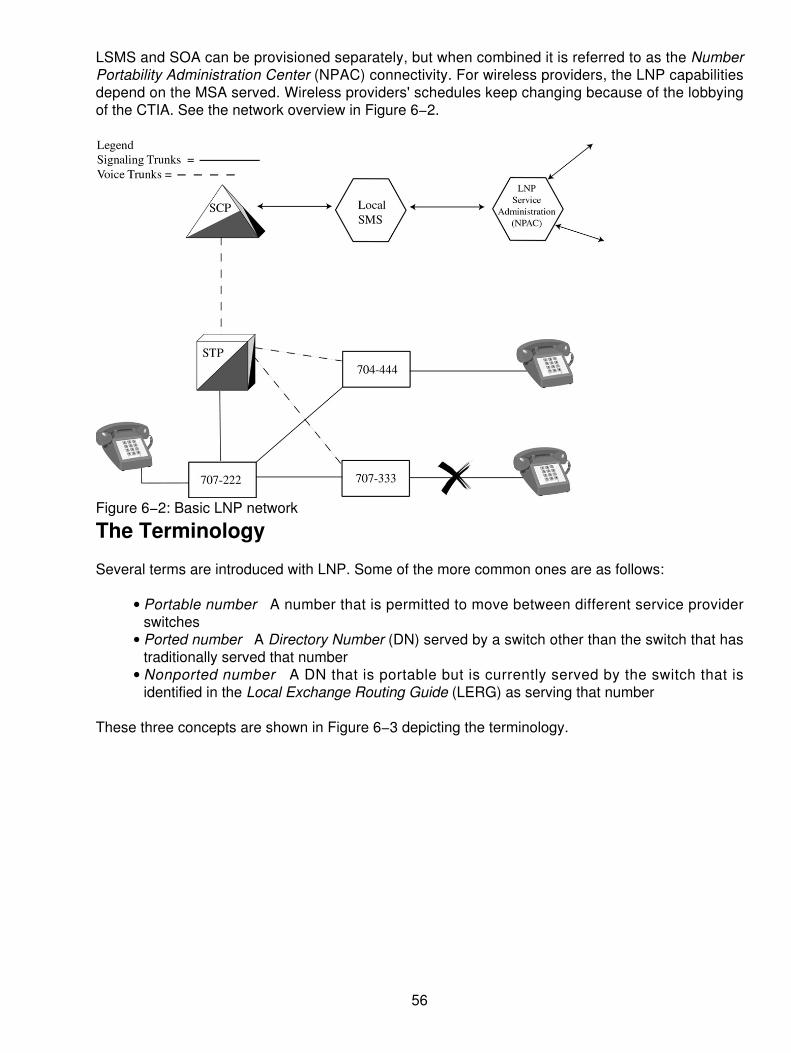
LSMS and SOA can be provisioned separately, but when combined it is referred to as the NumberPortability Administration Center (NPAC) connectivity. For wireless providers, the LNP capabilitiesdepend on the MSA served. Wireless providers' schedules keep changing because of the lobbyingof the CTIA. See the network overview in Figure 6−2.
Figure 6−2: Basic LNP network
The Terminology
Several terms are introduced with LNP. Some of the more common ones are as follows:
Portable number A number that is permitted to move between different service providerswitches
•
Ported number A Directory Number (DN) served by a switch other than the switch that hastraditionally served that number
•
Nonported number A DN that is portable but is currently served by the switch that isidentified in the Local Exchange Routing Guide (LERG) as serving that number
•
These three concepts are shown in Figure 6−3 depicting the terminology.
56

Figure 6−3: LNP terminology
Before LNP
In the earlier, non−LNP environment, a telephone number performed two functions:
It identified the customer.• It provided the network with information necessary to route a call to that customer.•
LNP separates these two functions, providing the means for customers to keep their DN whenchanging Local Service Providers. By separating those two functions, LNP gives customers theflexibility to respond to pricing and service changes offered by rival carriers.
As we have seen, numerous studies conclude that most business and residential customers arereluctant to switch from one service provider to another if they must change their telephonenumbers. Without LNP, new entrants (CLECs) would have to price their local exchange service 12to 15 percent lower than the existing LECs in order to persuade customers to switch carriers.Although the degree to which the lack of LNP hurts competition is arguable, it is clear that LNP isrequired to provide a level playing field. Interim number portability methods, such as remote callforwarding and direct inward dialing, exist, but these methods have several disadvantages:
Longer call setup times• Increased potential for call blocking• Continued reliance on the incumbent LEC's network• Use of more directory numbers, which are fast becoming depleted• Loss of feature functionality• Substantial ongoing costs to the new Local Service Provider.•
According to the Telecommunications Act, LNP will promote local exchange competition, which inturn will benefit all customers. As it has done in the long−distance market, competition in the localexchange market is expected to do the following:
Drive down the cost of service•
57

Encourage technological innovation• Stimulate demand for telecommunications services• Boost the United States' economic growth•
Number Administration and Call Routing in the Network
Telephone numbers in a pre−LNP environment have always been assigned to Local ServiceProviders' end offices on an area code and exchange code (Numbering Plan Area [NPA−NXX])basis. Each NPA−NXX contains 10,000 telephone numbers. Because an NPA−NXX is only servedby a single end office in the United States, the telephone number identifies the person as well as theactual end office that serves that person. In effect, the dialed NPA−NXX is the terminating switch'srouting address to the rest of the network. With the implementation of LNP, which enables anynumber of Local Service Providers to serve the same NPA−NXX, this routing scheme can no longerbe used.
LRN
With LRN, every switch in the network is assigned a unique 10−digit number that is used to identifyit to the rest of the network for call routing purposes. An essential advantage of the LRN is that callrouting is performed based on today's numbering format. LRN uses the strength of SS7 signalingwith Multi−Frequency (MF) interworking and promises to be a long−term solution for LNP. LNP isSS7, ISDN User Part (ISUP)−oriented and therefore does not work well with MF interworking.
LRN−LNP on the Switching Service Points (SSPs) performs the integral part of the overall networkLNP solution. The LRN is shown in Figure 6−2 with a new, 10−digit number assigned to theindividual switching points. LRN depends on Intelligent Network (IN) or Advanced IntelligentNetwork (AIN) capabilities deployed by the wireline carriers' networks. LRN is a 10−digit number touniquely identify a switch that has ported numbers. The LRN for a particular switch must be a nativeNPA−NXX assigned to the service provider for that switch.
LRN assigns a unique 10−digit telephone number to each switch in a defined geographic area. TheLRN now serves as the network address. Carriers routing telephone calls to end users who havechanged from one carrier to another (and kept their same number) perform a database dip to obtainthe LRN corresponding to the dialed telephone number. The database dip is performed for all callswhere the NPA−NXX of the called number has been flagged in the switch as a portable number.The carrier then routes the call to the new provider based on the LRN.
Shown in Figure 6−4 is the flow of LRN information, which is the same for both a wireline and awireless provider (with one modification: the JIP is not used in the wireless network and LRN flowfrom wireless).
58

Figure 6−4: The LRN in useWhen the caller dials the number (333−3333 in this case), the originating switch (612−222) sendsits signaling information (info dialed 333−3333) through the STP to the SCP, which analyzes theroute and returns the LRN (612−444−0001). Next an IAM message is forwarded from 612−222through the STP to the access tandem. The access tandem (AT) translates the LRN and sets up aspeech path (trunk) from 222 to 444. Switch 612−444 detects the LRN (612−444−0001) as itsaddress; therefore, the called number and the generic address parameter are swapped. From there,the call is connected (terminated) at 333−3333. The donor switch in this scenario has beenuninvolved throughout the process.
Similar to the 800−number service, a database is used to store the routing information forsubscribers who have moved or ported to another Local Service Provider. The LNP databasecontains the directory numbers of all ported subscribers and the location routing number of theswitch that serves them. The LNP database can be accessed by switches using either theAdvanced Intelligent Network (AIN 0.1) or Transaction Control Application Part Intelligent Network(TCAP IN) protocols. Each OLNP−capable switch in a portability area is assigned a unique 10−digitlocation routing number. A switch is defined as LNP−capable if it has the capability to launch LNPdatabase queries and route calls based on the returned response. The 10−digit LRN is chosen froman NXX native to that switch (an NXX that was originally owned by that switch prior to LNP) and isused by other switches to route calls to that switch.
New routing and signaling methods are required to implement this feature because the LRNarchitecture requires the transport of the network routing address (or the LRN of the terminatingswitch) and the called party number (CdPN). Only the ISUP signaling is being modified to carry theadditional information needed to support LNP. Workarounds to use MF trunks, such as sending onlythe dialed number when a MF route is used, have been included in the requirements.
The LRN feature uses the LRN returned from the LNP database to route the call and the CdPN tocomplete the call in the terminating switch. From a protocol perspective, the LRN of the end officeserving the subscriber is placed into the CdPN and the actual CdPN is populated in the newGeneric Address Parameter (GAP) field. As the call traverses the network, all switches will use the
59

LRN to route the call. When the call is delivered to the terminating switch, the terminating switch willcompare the LRN received in the CdPN field against its own LRN. If these numbers match, then theterminating switch will retrieve the CdPN from the GAP parameter and complete the call to thesubscriber.
Once a switch performs an LNP database query, that switch must set a new bit called theTranslated Called Number Indicator (TCNI) in the forward call indicator parameter of the InitialAddress Message (IAM). This will indicate to other switches in the call path that a query has alreadybeen performed. This new bit and the corresponding call−processing logic ensure that multiplequeries will not be performed for the same call.
Using a Database Solution
Many carriers felt that the best way to implement LNP is to establish databases that contain thecustomer routing information necessary to route telephone calls to the appropriate terminatingswitches. The LNP database, similar to that already used by the telecommunications industry toprovide 800−number portability, will use intelligent network or AIN capabilities. These capabilitiesseparate the customer−identification information from the call−routing information.
Rather than establishing one national database, similar to the 800−number database, carriers willprovide LNP via a system of multiple, regional databases. A national LNP database is not feasiblesimply because one database could not store the telephone numbers for the entire United Statespopulation or even the subset of the largest metropolitan areas.
Further, a regional database system offers specific advantages for carriers deploying LNP. Regionaldatabases effectively reduce the distance over which carriers must transmit routing information. Byminimizing that distance, a regional system reduces the associated routing costs incurred by thecarriers. A regional database system also ensures that carriers will have all the number portabilityrouting information they need to route calls between carriers' networks for that regional area.
Because many of the major carriers install their own SCP where the LNP database resides, a singleaccess point must be provided to effectively manage and distribute updates to the common regionalLNP database. These updates will provide all carriers with the changes made when end users portfrom one Local Service Provider to another. Most states have decided that an NPAC, similar to thearrangement used for 800−number portability, should be used. The LNP task force in Illinois issuedan RFP to the industry to solicit technical (and financial) proposals for the NPAC. Lockheed−Martinwas chosen to develop and administer the NPAC in Illinois. Other companies were selected bydifferent regions, but complications arose, and Lockheed−Martin was selected to replace those whocould not deliver. Management of the LNP database by a third party will ensure the security of allcarriers' customer bases. The full scenario of a call process is shown in Figure 6−5, using thecomponents of the network and the databases.
60

Figure 6−5: LNP scenario
Triggering Mechanisms
Using LNP requires end office switching systems to determine if a dialed NPA−NXX has beendeclared open for portability. The switching systems must set triggers on a portable NPA−NXX tocause, or "trigger," a query to the LNP database and retrieve the LRN of the dialed number. Mostswitching vendors are using AIN 0.1 triggers. AIN 0.1 triggers were defined by industryrequirements well before the development of LNP. These triggers are administered on theNPA−NXX digit string by using the administration capabilities of the switching systems.Unconditional trigger mechanisms are used during the transition from one service provider toanother, such as the following:
From a wireline to a wireless provider• From an ILEC to a CLEC• From a wireless to a wireline provider•
These triggers can be assigned at the donor switch (the old provider) and the recipient switch (thenew provider). By using an unconditional trigger, the trigger is used at the switch even if thedirectory number is present (see Figure 6−6).
61

Figure 6−6: Unconditional triggerThe industry requirements for the location routing number model state that either a TCAP IN"800−like" or AIN 0.1 query can be used. The protocol defines the information and structure of thequery between switching systems and the LNP database. Both of these protocols, defined withinindustry standards, are deployed in the network today. The AIN model is shown in Figure 6−7.
Figure 6−7: The AIN model
62

How Is a Telephone Number Ported?
Many steps are required to move or port an end user from one Local Service Provider to another.Database changes will be required in the following locations:
Old Local Service Provider's central office• New CLEC central office• LNP database•
Beyond that, the end user's copper pair must be disconnected from the old service provider'scentral office equipment and connected to the new Local Service Provider's central office equipmentor some patch field in a co−located office. All of these activities are controlled by the NPAC.
Several important steps must proceed the actual porting of a subscriber:
The NPA−NXX must be opened for porting by the NPAC. This drives the update of the LocalExchange Routing Guide (LERG) database, global title translations in the STPs, andend−office translations (to set the LNP trigger for the NPA−NXX) for all Local ServiceProviders in the portability area.
1.
The two service providers must arrange the physical transfer of the subscriber's copper pair.Both providers must have implemented the 10−digit unconditional trigger function in theirrespective end offices.
2.
Once all the pre−move actions have been performed, a subscriber can be ported. Theavailability of the unconditional trigger in both the new and old Local Service Provider's endoffices will preclude the need to synchronize every step of the porting process.
3.
The donor switch administers the 10−digit unconditional trigger on the porting subscriber'sdirectory number. This will cause an LNP query under all conditions (even when thesubscriber is still served by the old service provider's end office), thereby eliminating thecritical timing coordination between the donor and the recipient (new) Local ServiceProvider. This enables the activities at the donor switch to be performed autonomously withrespect to the recipient service provider and route calls to the subscriber based on the LNPquery response.
4.
The recipient switch administers the translations for the new subscriber and sets the 10−digitunconditional trigger. This enables the recipient switch to provision the subscriber prior tothe actual physical move of that subscriber's copper pair without causing calls to bemisrouted during that time period. As in the case of the donor switch, the 10−digitunconditional trigger also enables activities at the recipient switch to perform autonomously.
5.
After the subscriber's copper wire has been moved, the new Local Service Provider notifiesthe NPAC of the change. The NPAC then downloads each LNP database (in the portabilityarea) with the LRN of the new Local Service Provider (for the ported subscriber) and recordsthe transaction (for example, date/time). After the new Local Service Provider successfullytests the new subscriber, the unconditional trigger is removed.
6.
Other Issues
The following topics are but a few of the effects that LNP brings to the telecommunications network.
63

Switching Systems
Substantial changes to call−processing logic and administration software are required in allswitching systems in use in today's telecommunications network in order to implement LNP. Thecost of the system upgrades and changes has been accumulated in a pool by the RBOCs and isnow being passed on to consumers. The costs typically range from $.27 to $.54 per line per month.This pass−through cost will continue for five years (supposedly ending in 2004) as the plan calls fortoday. Additional effects will be evident when a Line Information Database (LIDB) requires a dip todetermine the 0 plus calling card model, as shown in Figure 6−8. It is interesting to note that thefees for LNP have been in place since the year 2000, yet the LNP availability across North Americais still primarily limited to the major downtown metropolitan areas. The consumer is paying for aservice that is significantly limited and not being pushed.
Figure 6−8: LIDB model for 0 plus calling cardBilling, Administration, and Maintenance Systems
Because LNP removes the direct association of a subscriber's directory number to a central office,substantial changes will be required in most of the systems in use today in local telephone companynetworks.
Signaling
LNP will require an LNP database query for every call to a ported subscriber that is not served bythe originating switch. This will require capacity increases in the number of SS7 links to thesignaling transfer points and the deployment of new service control points to run the LNP databaseapplication. These costs have also been accumulated, and they are now being passed through aspart of the fee discussed previously.
Operator Services
Operator calls from subscribers (for example, 0−, 0+, and so on) are routed directly to the operatorservices system where an LNP query must be performed to determine the Local Service Provider towhich the call must be routed. Thus, significant modifications are required in operator servicessystems (see Figure 6−9).
64

Figure 6−9: Operator service effects911 Services
Maintaining the 911 and enhanced 911 databases create another impact on the processing of callsto emergency response agencies. When we think about LNP in a wireline environment, the processis straightforward. The caller places an emergency call from a fixed location, which is easilyidentifiable. Routing of the E−911 call is to the proper Public Safety Answering Point (PSAP), basedon a known, prearranged location for each telephone. Automatic Number Identification (ANI) ismapped one−to−one for all wireline calls by using the appropriate callback number and a locationfrom an Automatic Location Information database (ALI). This is shown in Figure 6−10.
Figure 6−10: E911 calling with LNPUsing CAMA trunks (trunks that were originally used for cost accounting and messaging callinformation), 911 routing is built on limited capability of the trunk. The CAMA trunks will remain inuse for some time to come.
65

Is 911 important? More than 300,000 calls per day are made to 911 emergency locations. Thisplaces a great burden on the network.
For the wireless provider and the E−911 caller, things are not as straightforward as shown in Figure6−11. The calls are placed through the network, but it is processed through the MSC where asubstituted number is used. Routing to the PSAP based on a telephone number substituted by theMSC is handled by the end−office as though the call came from a fixed wireline location. Problemscrop up because the substituted number is assigned in different ways:
One per system• One per several cell sites• One per cell•
Figure 6−11: Wireless E911 substitutes a number for call routing.The arrangement of how the calls are processed is agreed to in advance by the various carriersinvolved and placed in the ALI database. Routing is to the PSAP on the calling number (not thewireless number) and may cause inaccuracies due to the configuration or due to crossing PSAPjurisdictions.
Simplifying the Wireless E−911 Call
Today things are changing. By using sectorized cells, the providers can be more specific. When awireless subscriber makes a 911 call, each sector in a cell site is assigned a pseudo−ANI, afictitious nondialable subscriber telephone number assigned to the cell. This enables the call routingto the PSAP based on a fixed number and a location to route. Using an ANI within the wirelinenetworks, the end office can more specifically process the wireless 911 call. This is shown in Figure6−12 as the simplification process continues.
66

Figure 6−12: Simplifying the wireless E911 callThe overall benefit will be to use the LNP for both wireline and wireless organizations. Each of theservices will bear transparency in the services, number assignments, and the operation of a singlenetwork strategy. Concurrently, the use of the LNP services will prevent the "disconnect" of awireless user who is a moving target, so that the network will be used in such a way as to locate theLNP user within a matter of three to five meters using a GPS location and triangulation. The benefitsare immense, the services will increase, and the features will be transparent. The only limitingfactors right now include the timing for implementation, the demand from end users, and thewillingness of the carriers to cooperate among themselves.
67

Chapter 7: Computer Telephony Integration (CTI)
Overview
Throughout the past two decades, business users have sought to find a means of integrating theirtelephony and computing systems. One can only imagine the great demand for this, assuming thecomputer and communications budgets are in the same domain. If one were to come up with atotally integrated package, there would be unimaginable savings (or so the story goes). It has beenthe goal of many organizations to reap the benefit of a single infrastructure.
In the past, the Management Information Systems (MIS) department and the voice communicationsdepartment were separate entities, yet their operating budgets and staff overlapped in certain areas.The degree of overlap varied by organization, but the overlap itself was the concern. Since theconvergence began nearly a decade ago, the fundamental shifts in these operations weresomewhat dramatic. These shifts were not explosive in themselves, but more in line with a slowlyrolling wave. In many camps within the industry, however, these changes were virtuallyunnoticeable.
The driving forces behind this convergence combined with voice communications for acommodity−priced service, data communications for an open standard in the Transmission ControlProtocol/Internet Protocol (TCP/IP) world, and the preponderance of Local Area Network (LAN)technologies overtaking the desktop. From the very beginning of these three disparate technologies,end users looked to the manufacturers to come up with an integrated scheme. It was through theinit ial offerings of AT&T, IBM, and DEC (albeit al l proprietary) that the computer andcommunications convergence began. Past examples of the manufacturers' attempts to provide anintegration scheme included computer−to−phone integration (CPI) from both IBM and AT&T and thecomputer−integrated telephony (CIT) from DEC. Unfortunately, the proprietary nature and theblocked architectures of the manufacturers met with disappointing results. Users were not willing topay for another proprietary solution as they had in the past. Moreover, the nature of the evolvingLANs was leaning towards a new set of proprietary solutions from companies like Novell andBanyan, far from the openness the industry was busy praising.
Today two technologies are revolutionizing the way the world communicates: telephones andcomputers. Telephones are everywhere. For decades, they have been prevalent in offices, publicestablishments, and homes. And computers are catching up. These two technologies historicallyhave remained separate, however. Often the only thing they share in common has been the deskon which they both sit, but the computer telephony industry has been combining the best oftelephone and computer technology to let people exchange information more quickly and easily.
The power driving the computer telephony industry is telephone network access to computerinformation through almost any convenient, easy−to−use, and available terminal device, including
Telephones (pulse dial, touch−tone, and wireless)• Facsimile (fax) machines• Personal computers (PCs)•
These terminal devices access a multiuser computer telephony platform that supports applicationsthat process the information within the call and/or route and monitor the progress of the call. Thesefunctions of the computer telephony platform are an integral part of enterprise information systems.
Until recently, our two most widely used business tools, the telephone and the computer, were
68

separated by many factors. For decades, the telephone has been our primary means of businesscommunication. However, the majority of our necessary business data has been accumulated onmainframe, mini−, and personal computers. To make matters even more confusing, we have beenbombarded with a multitude of alternative communication methods (such as fax, e−mail, and voicemail), each accessible in different ways from different places.
Computer telephony integration (CTI) is the merging of the computer and telephone, which willtransform the personal computer from being an information−processing device to being a powerfulplatform for communications. Computer telephony is the art of intelligently linking and combiningthese tools to create systems that enable us to use technology to our advantage. The goal, ofcourse, is to dramatically increase the access we have to the information we need, when we need it.A variety of cost−effective solutions is available to businesses of all sizes.
Linking telecommunications to the processing capabilities and graphical user interface (GUI) of thecomputer enables new forms of communications and more robust access to existing types ofcommunication, including
Voice• Asynchronous data• Fax• Remote access to LANs• Internet access• Online services•
The communicating PC will redefine how we share ideas and information and will provide a portal toother people, computers, and network services anywhere in the world. CTI will also transform thetelephone into an information−processing device. By giving the telephone access and control ofnonvoice media, users will enjoy the convenience and economics of multimedia communicationsanywhere and at any time.
The Computer World
What had been the bastion of the big iron providers (mainframe and mid−range computers) quicklyeroded in the early 1980s to a desktop PC−based architecture. Surely, legacy systems, such as thedepartmental computers, became servers, and the mainframe for the entire organization remainedas the mainframe (or became a major server) because of the investments and the nature of the datastored. One cannot just walk in and trash what has been in place for years. Instead, the integrationof the computer and the telephony world requires a slower process that includes a methodology topreserve the legacy data.
Over the years, much time and effort has been spent in trying to develop interfaces that would tiethe computer and the telephone network together. As technology has changed, many newinterfaces and applications can be created through the integration of these two techniques.Consequently, a whole new industry has emerged. The ability to link computer systems and voicesystems together offers some new possibilities on how we approach the office. When one thinks ofthe automatic call distribution (ACD) systems with the capability to link the automatic numberidentification (ANI) and a database to provide screen−popping capabilities, it becomes an excitingopportunity.
Figure 7−1 is a representation of the CTI capability using a screen−popping service. In this case, asa call comes into the building, it is initially delivered to an ACD. At this point, the ACD captures the
69

ANI of the calling party. When the called party's number is packaged into a small data packet, it isthen sent to the computer as a structured query language (SQL) inquiry into a computer database.Assuming the database already exists for the established client, the SQL opens the client file andresponds to the query. In this particular case, the telephone number of the calling party is beingused to create the query from the database. Once the database entry is recognized based ontelephone number, a computer screen will "pop" to the agent's desk. This occurs at the same timethe telephone call is being delivered to the agent's desk. Now the agent taking a telephone call doesnot have to ask the caller for all of the associated and applicable information, such as
Name• Address• Telephone number• City and state• Account number• Any other pertinent information•
Figure 7−1: The CTI capability using a screen−popping serviceBy reducing the time spent gathering this information, because it is already available in thedatabase, savings of 20 to 30 seconds of call−processing time can be achieved. However, the 20 to30 seconds is not the critical part. Instead, the ability to satisfy the customer and provide betterservice levels is what is important.
When one thinks of other alternatives that might exist here, a couple of thought−provoking ideascome to mind. For example, assume that an agent has received a call and a screen of informationfrom an established customer. In this regard, the established customer has saved time by nothaving to provide his or her name, telephone number, and so on. The agent gets right to the task atidentifying and verifying the customer. Now that the agent has the information, historical files onsuch things as buying or usage patterns can be developed so that the agent can suggest productsand services to the customer based on past buying experiences. Moreover, if there is a problemwith a particular customer, such as a delinquent payment, the agent can readily obtain thisinformation while talking to the customer.
70

Let's extend that thought a little further. Assume that the agent encounters a delinquent customerwho hasn't paid his or her bill for three months. While talking to this customer or taking an order,which is what the customer called for, the agent sees on the screen that the customer is delinquentand that collection action must be taken. Rather than becoming a collections manager, the agentcan immediately suggest to the customer that the call must be transferred to the accountsreceivable manager. When the agent transfers the call, not only does the call go to the accountsreceivable department, but the screen from the database follows. When the accounts receivabledepartment receives the call, the manager there will have a full screen of information about why thatcall has been sent to him or her. Answering the call, the accounts receivable manager can thenimmediately and proactively get to the job at hand, collecting the money. Instead of picking up thetelephone and asking for information that has already been determined, totally frustrating thecustomer, the accounts receivable manager can immediately get to the problem at hand, collectingthe money. When the call goes back to the agent, the screen with all of the notes that the accountsreceivable manager has entered returns as well.
Again, the agent sees who is on the telephone and what has transpired. This prevents thereplication of information gathering and keeps the entire conversation in a proactive mode. It is thispositive handling of calls, particularly those of an unpleasant nature, that helps to boost customerservice and influence the continued buying relationship.
The previous scenario assumes that certain things have taken place. It must be assumed that thecustomer is calling from a known location and that the database already exists. If, in fact, thedatabase does not exist, the initial data gathering can be accomplished at the receipt of the first call.Thereafter, any time the customer calls from the same telephone number, the database will beactivated and brought up with the screen−pop. The first time is the most laborious. Each successivecontact between the customer and the organization is much simpler. Using this database andscreen−pop arrangement, companies have successfully achieved several things, including
Improved customer service• Improved customer satisfaction• A reduced number of incoming lines• Reduction in the number of agents necessary to handle the same volume of calls•
Through the combined savings of 20 to 30 seconds for each successive attempt, the average holdtime (talk time) can be reduced significantly.
Other Possibilities
Screen popping in an ACD is one of CTI's primary uses today, but other applications can takeadvantage of CTI. The newer integrated private branch exchange (PBX) will become a voice serveron the LAN. In Figure 7−2, the integrated PBX is shown as a voice server residing between twoseparate LANs.
71

Figure 7−2: The integrated PBX as a voice server between two separate LANsNow that the various communications vendors have produced an open applications interface, theability to use a PBX for several components exists. One of its primary applications is to install athird−party bridge or router card inside the PBX. The PBX now serves as the bridging functionbetween the two LANs. Using the PBX also enables an extension of the PBX access to other LANservices. Inside the architecture of the PBX is a high−speed communications infrastructure such asAsychronous Transfer Mode (ATM), Synchronous Optical Network (SONET), or Fiber DistributedData Interface (FDDI), depending on the direction chosen by the PBX manufacturer. The PBXmanufacturers have devised means of running 10 Mbps or 100 Mbps to the desktop. Now they arelooking to implement an IP−based card, creating a true data application in the telephonyarchitectures. Newer applications will also include the gigabit Ethernet over twisted−pair wires to thedesktop (1000 base T). When dealing with the high−speed communications to the desktop, the userwill have unlimited access to voice features, LAN features, and multimedia applications runninginside the organization. The combined investment in computer and telephony integration offerssubstantial opportunities for high−speed broadband communications to the desktop. As a truecommunications server, the PBX equipped with an IP card (router) inside can bring other servicessuch as Internet or intranet access to the PBX.
Still other features can be included with this integration of CTI. Voice messaging, as integral orperipheral to the PBX, can now become available as a feature or a function hooked to the LAN. Asan outside caller dials into an organization's PBX, the capability to capture the ANI and hook to thedatabase server on the LAN allows for the delivery of the caller ID to the desktop. This makes itpossible for a user who has a screen (PC or other) on his or her desk to be able to see the voicemessages in the queue. In reality, what the user sees is not the message, but information regardingthe message. This helps to prioritize, or select from a queue, calls that are necessary or important.Moreover, the end user can print out a list of voice messages, a customer database of people whohave called, ANI information to be included in a database not yet built, or many other useful andproductive types of data.
Beyond the voice messaging capability, connecting to an automated attendant can also beintegrated into this CTI application. When an outside caller attempts to reach a particular extensionor department, a database can be built regarding who the callers are and what extensions aretypically used most frequently. This also extends ANI access to the desktop of the called party so
72
that the database can also link to some form of a screen−pop. By delivering the ANI to a databaseserver on the LAN, the user can immediately run a structured query on the database to pull up thecustomer file. A simpler way would be to have the database automatically deliver all the informationabout the calling party to the LAN terminal device. This doesn't work in all applications, but it doesoffer some unique capabilities and opportunities that never before existed.
Each of the discussed services can all be coupled in the combination of computer and telephonyintegration. CTI offers the capability to link multiple databases, multiple communication channelcapabilities, and the LAN−to−PBX server functions. The PBX becomes the voice server, whereasthe LAN server becomes the PBX's database. Corporate directories, departmental lists, productlines, and other types of usable information can all be made available to the desktop device when acalled or calling party needs access. Although the cost is incremental, the overall increases inproductivity and satisfaction from both employees and customers may well be worth the effort. Thisis one of those decisions that a user must make.
In the same manner, you take higher risks by putting all of your eggs in one basket and having asingle−server environment. However, the distributed computing architectures that are emergingminimize the risks. Distributed computing architecture can also add to the depth of the PBX by usingservers on a LAN that can be voice servers; the functions and the real estate required for a PBXarchitecture can now be combined and reduced. A large room with special air conditioning is nolonger required. The servers can just be deployed wherever they are needed to serve their users.
We can see the excitement and the benefits of CTI when we look beyond the basic functionality ofeach individual box. Hence, the decision−making process becomes a little more complicated thanthe purchase of a PBX or a server when thinking about acquiring a combined infrastructure tosupport the communication needs of an organization.
Why All the Hype?
A lot has already been said about what is going on within the industry and organizations today.Business has reached an intensity and a pace that is extraordinary. The competition and changes intechnology are driving the pace exponentially. All of these factors have driven organizations to seekan improved means of dealing with their customers and to answer the needs for increasingproductivity, decreasing costs, and enhancing the competitive edge over the existing marketsegment. Keeping pace with the industry and maintaining the competitive edge has become acrucial element in the survivability of an organization. Therefore, the demands on organizationshave escalated dramatically to provide for
The ability to deal with corporate decision−making processes at a rapid pace• Readiness to deal with issues, regardless of the time of day, day of week, or availability ofexecutives
•
The continued restructuring and reengineering of the organization, which requires fewerpeople to perform more functions
•
The changing workforce, in which talent and skill sets are no longer as available as theywere, making technology a necessary solution
•
Preparing the administrative assistants who have supplanted the administrative and supportstaff of old (secretarial support) to deal with issues when the senior staff is not available
•
Ensuring the availability of the information that is needed to achieve these goals•
Therefore, in order to effectively use the resources that remain within the organization, employeesmust have information readily available at their fingertips. Using technology of both computers and
73

communications provides the edge to maintain the link between the employee and the customer. Itis not necessarily a given that these technologies will always be the solutions, but the rightimplementation can have significant benefits if done correctly. Several examples in this book showhow organizations have tied their computers and communications together through various networktechnologies to facilitate the timeliness and usability of information. Using a CTI system, employeeshave the ability to share information on the spot by using updated information on a call−by−callbasis. Each of these tools and capabilities is an absolute must if a business is to remaincompetitive.
The reengineering of an organization must focus on serving the needs of their customers. Examplesof this are clearly demonstrated in both the financial community and the airline industry. Customerscan no longer be looked on as a nuisance; rather, they must be seen as the most valuable resourceand asset that an organization has (excluding its own internal personnel). Providing the necessarytreatment and care of the customer becomes one of the primary goals of the organization. It shouldhave been the goal all along, but the focus on driving costs down and increasing productivity beganto erode the customer and organizational relationships.
Now that CTI has begun its movement within the industry, it is much more feasible to restructureand reaffirm the relationship between the two parties. Customers expect to be treated as individualswho are special for the size and volume of the business that they do. Competition in any segment ofindustry is fierce. Therefore, if the necessary care and treatment is not provided, customer loyaltyshifts dramatically. Changing market demands due to the rightsizing, downsizing, and capsizing inexternal organizations place more demand on your organization to meet the customer's needs. Inplanning our technological innovations, we must therefore look to how we can better satisfy thecustomer's needs by the following tasks:
Giving our customers unlimited access to our employees to place orders, check on status, ormake inquiries.
•
Assuming that the employee/agent will have information readily available and not put thecustomer on interminable hold.
•
Anticipating the demand for products based on sales projections and customer demands sothat out−of−stock or backordering can be curtailed.
•
Having technical support available to the agent so that either the technical or theadministrative/sales person can easily answer a question.
•
Considering that the customer's success in business and/or product lines can be matched toyour ability to meet the customer's demands for products and services.
•
Anticipating customers' needs and satisfying their demands so they will not be exposed bytoday's diminishing inventories and just−in−time manufacturing processes.
•
If these conditions can be satisfactorily met, the customer will feel better about placing orders orchecking on the status and availability of products with your organization. This equates to bettersales. Telecommunications and computer integration can therefore increase productivity and assistin increasing sales. Using the right technology in the right mix at the right time can enhance arelationship that is ever so fragile in today's competitive marketplace.
Linking Computers and Communications
The architecture of using a three−computer technology is the result of many years of evolution andrevolution within the computing platforms. The LAN emerged in the early 1980s as a means ofmoving away from control by a single entity known as the MIS department. As this evolution began,users were empowered to manipulate their own data, handle their own information, and share that
74

information with others on a selective or exclusive basis. Because of this movement, a lot ofpressure was placed on the communications side of the business to provide interconnection using acabling infrastructure to the various desktop computers and departments that would be interrelated.Management saw an opportunity to produce ad hoc reporting, allow flexible data manipulation, andprovide more timely information to managers and departments alike.
As LANs emerged, they were primarily tied to a desktop and an individual server within adepartment. Later in its evolution, the client/server architecture started to emerge more strongly byallowing multiple departments within a single organization to fulfill their data communications anddata access needs by accessing each other's databases or sharing the files they created with theircustomers. It is this sharing that created additional appliance affiliations within the different groups.The PC, as it attached to the network, enables users to store their applications and files on a singledevice. By linking these computing systems together with a communications medium, the user canbest seek the information wherever it resides within the network. If a new application is needed,either a server can be adapted to fit that need or a new server can be added.
From a communications perspective, devices have emerged that include e−mail within departments,fax servers for transmitting information directly from a desktop to a customer, and voice recognitionand response systems that enable customers to call in and literally talk to the server, as opposed tohaving to talk to a person. Furthermore, the l inkage of all of these systems through acommunications medium is the glue that binds everything together.
The PC of old, although structured as strictly a desktop device, has changed dramatically. Now,new features include the following:
Extensive processing power• Sophisticated operating systems• Integrated voice boards or sound cards• Integrated video−conferencing capabilities• The client/server software that enables all of the pieces to be pulled together•
With the use of CTI, an organization's needs are easily met using the buildout of the desktopdevices connected to the LAN. As already mentioned, the client/server architecture has thecapability to bring together the computers that reside on the LAN and the telephony services thatcan be built into either the PCs or the servers that reside on the LAN. This all becomes possible bybonding two technologies that began in the mid−1980s and matured in the mid−1990s. Thearchitecture within an organization has dramatically changed. In place of a single provider ofinformation, such as an administrative assistant or a particular sales group, there now exists anintegrated homogenous workgroup that can share information, transfer calls among members, oradd other departments on calls as needed. This has already been shown in our examples.
While this information process was taking place, organizations began to connect to the outsideworld and to their customers with their telephony services. In the early 1990s, a new explosion tookplace within the industry. The emergence of the World Wide Web and the use of the Internet as acommercial resource added to computer telephony development. Attaching an organization to theoutside world through the Internet allowed customers to use their telecommunications services toenter the organization and check inventories, catalogs, and other services that would otherwise notnormally be available to them. The ability to introduce fax−back servers also enabled customers toobtain catalog information or technical brochures immediately, instead of having to wait for an agentto mail products or brochures through the mail. This increased the availability of information bylinking the communications' infrastructure to the computing architecture. Moreover, as organizationsstarted to use electronic document interchanges (EDI), they created the ability to place orders,
75

perform functions as dynamic workgroups, and facilitate the ordering and payment process. Theseservices enhanced the true organizational capability.
The mid−1990s has also marked the innovation and growth of this computer and telephonyintegration with intranets. For now, think of it as the internal Internet to an organization. Using theintranet and communications infrastructures within an organization's client/server architectures,internal organizations can access the same information that might be available to a customer.Furthermore, internal organizations can share files, technical notes, and client notes regarding theircustomers, as well as other valuable information that would not be readily available to the masses.Specific files or bulletin boards can be set up within the organization to achieve that result.Therefore, it is through the integration of our communications systems and the capabilities of the farmore powerful and processor−intense desktop devices that the pieces are coming together quickly.No distinction can be made anymore between computing and communications, because the tworeally draw on each other's resources to facilitate the organization's day−to−day mission: to servethe customer and maximize shareholder wealth. Serving the customer increases sales, whichhopefully decreases costs and raises profits. This maximizes the shareholder's wealth, which is thecharter for all business organizations.
The Technology Advancement
Through the integration of computer and telephony−type services, the old philosophy of telephonybeing a necessary evil has passed. Advances in computing technology have enhanced thetelephony world. The age of mass pools of telephone operators is gone. Newer technologies enablecustomers to call and proceed through an organization without ever communicating with an operatoror a secretary. The customer can get directly to the person or information that is desired.
In the key system marketplace, the old labor−intensive electromechanical system is now acomputer−driven telephone system. However, these computer−driven systems are now rich infeatures and laden with capabilities undreamed of in the past. The integration of voice messaging,ACDs, and automated attendants in key systems is now commonplace. Key systems are alsoemerging as voice servers within the organization.
The PBX, serving hundreds if not thousands of employees within an organization, enables aninternetwork of services and capabilities to be spread throughout an organization. What was oncejust a stand−alone telephone system is now the high−end computer that just happens to handlevoice. Today's technology provides full−digital transmission systems or services and permits linkageto all devices that were exclusively used by the elite. PBXs can now be integrated tightly into yourcomputing systems.
The PBX also acts as the high−end server on a digital trunk capability to the outside world. Bylinking to a high−speed digital communications trunk from the outside world, users can now accessANI. Using inbound 800/888/877/866 services and a common channel−signaling arrangementenables the delivery of caller ID directly to the called party. Moreover, enhancements in software(such as call forwarding), overflow arrangements when agents or other individuals are busy, andother services can all be chartered into a single PBX architecture. Another service called directorynumber information service (DNIS) can be used on the 800/888/877/866 service to direct the call toa specific group, such as technical support or marketing.
76

The Final Bond
As the client/server architecture and the communications systems were developing throughout the1980s and into the 1990s, it was the software vendors who became the aggressors. With operatingsystems that could work on a LAN−based server, the software vendors were aggressive in findingthe integration tools necessary for the organization. Microsoft developed a de facto protocol calledthe telephony application program interface (TAPI) in a Windows environment to bring the telephonyservices right to the desktop LAN−attached device. A TAPI interface on a Windows platformenables users to access information through what is called a GUI. Throughout the entirearchitecture, a server application can handle the distribution of calls to members within workgroupsor departments. This includes such services as screening calls, rerouting calls to new agent groupsif the primary agent group is busy, or routing calls to the voice messaging and voice responsesystems as necessary.
Similarly, Novell and AT&T developed what is known as the telephony services applicationprogrammers interface (TSAPI) as a means of providing the computer with telephony integrationcapabilities from a LAN. TSAPI works with Novell's NetWare telephony services. The basis for usingthis particular product is to gain what is known as third−party call control. Third−party call controluses the CTI application on behalf of any clients in a workgroup or department. The application isrunning a shared environment, typically on a server, so there is no direct contact or connectionbetween the user's PC and the telephone interface. What happens, then, is that a logical connectionis produced when the PC applications talks to the server, which in turn controls the telephoneswitch. The server then is the controller and sends the order to the PBX to make calls orconnections on behalf of the end user. The shared−server environment can handle individual aswell as dynamic workgroup applications, such as directories, individual personal informationmanagers (PIMs), and other workgroup functions that occur within a larger organization. Therefore,the server provides the linkage for all calls being handled within a dynamic workgroup. This is amore powerful arrangement regarding call control. A central server can handle the distribution ofcalls to any member in a workgroup and provide such services as call screening, call answeringgroups, backing up agents, or routing calls to a supervisory position in the event of overflow. Manyof the CTI vendors have seen these capabilities as the benefits and strengths of the CTIapplications.
These are the primary applications that have been used within the CTI environment. Thus,developers and manufacturers alike have seen the application working as a telephone set. This isinstrumental in designing the capabilities of a call answering/call processing environment, but morecan be done through the use of the computer−based technology that is available on the markettoday. The applications that run in server or computing platforms can use call−monitoring featureswithin the PBX and collect information of any type. Using the call−monitoring features, a CTI canwatch every keystroke that an agent group enters. This can include such things as
Dialed digits• When agents "busy out"• Answering a call• How long the call is off hook•
Additionally, by monitoring the trunk groups within the PBX, the CTI application can see all theincoming calls and collect the data associated with each call. This application uses ANI and DNIS tosee where the call was directed and when it was answered.
The selectivity available in a CTI application therefore enables the supervisor to monitor the activityof each agent within a workgroup and get a clear picture of what transpires during the course of a
77
day. This helps in determining workload effort, staffing requirements to meet a specific demand, orany seasonal adjustments that must be made based on time of year. About 65 to 70 managementreports can be generated on an ad hoc basis. Supervisory personnel can monitor the work flow, theproductivity of each agent in a group, abandoned calls that were not answered soon enough, or anyother anomalies that might occur within a given day. Through these useful tools and reportingstructures, the supervisors know whether they have enough, too few, or too many agents on boardat any one time. This can aid in workflow scheduling as well as in determining the productivity of theindividual agents or of the workgroup as a whole. In the event an agent is not performingsatisfactorily, management can then take whatever corrective actions are deemed necessary.
If abandoned calls are escalating because the agents are on the phone too long, several otheractivities might result. These could include such things as new training, analysis of the call type andthe information requested, or simply determining the morale and productivity within the workgroup.
Beyond the call−processing and the call−monitoring capabilities, CTI can be implemented tointegrate the facilities and capabilities of the PBX as well as the computer systems into onehomogenous unit. The typical PBX today has features that are rarely used. There can be as manyas 300 to 400 of these features that are designed to either improve productivity or make the jobsimpler. Although the average user typically activates only three or four of the normal features,many of the functions are available but never used. The CTI applications can customize featuresand functions for individual users within a workgroup and provide more powerful interfaces usingpoint−and−click GUIs. Through a CTI application, a PC can be used for dialing, activating features,conference calling, call transfers, or any other necessary feature. Simply clicking a telephone seticon saves the end user from the risk and the unfamiliarity of the PBX features, preventing cutoffs orlost calls and facilitating better utilization of the PBX features.
Taking this one step further, each individual user within a group supported by a CTI application cancustomize his or her own features and functions in personal folders. These can either be stored ona PC or a server. Therefore, using the CTI application, individuals can select different forms of callscreening, call forwarding, or call answering, according to the applications and the individualizedservices they prefer.
78

Chapter 8: Signaling System 7 (SS7)
Overview
The ability of a caller to go off−hook in a telephone world, dial digits, and then miraculously talk tosomeone anywhere in the world is still a mystique to many. The network's capability to set the callup almost instantly and then tear it down just as fast is what really carries the mystique. How canthe network figure out where to send the call, get the connection, and ring the phone on the otherend so quickly? All of this happens in under a second, and the user is oblivious as to the intricaciesof what occurs. What happens behind the scenes constitutes the backbone of the signalingsystems. The networks are now dependent on the capability of handling subsecond call set−upsand teardowns.
Several signaling systems have been introduced to the telecommunications networks. The currentone in use is called SS7 in North America. In the rest of the world, this is referred to as CCITTCommon Channel Interoffice Signaling System 7 (CCS7 for short). Although the names aredifferent, the functions and the purposes of the two systems are the same. As always, the NorthAmericans do things one way, and the rest of the world does things a different way. This is anage−old problem, but one that we have learned to deal with and adjust to.
The essence of the signaling system boils down to many different factors, but one of the mostsignificant reasons the carriers employ these systems is to save time and money on the network.Following that fact, the carriers are also interested in introducing new features and functions of anintelligent network, as discussed in an earlier chapter. The best signaling systems are designed tofacilitate this intelligence in the network nodes that are designated as signaling devices, separateand distinct from the switching systems that carry the conversations.
Presignaling System 7
Prior to the implementation of SS7, per−trunk signaling (PTS) was used exclusively in the networks.This method was used for setting up calls between the telephone companies' exchanges. PTScontinues to be used in some parts of the world where SS7 has not yet been implemented.Admittedly, the exchanges using the PTS method are declining, as SS7 is gaining in its deploymentworldwide. However, the network is always in a state of change, and this is no exception. PTSsends tones or multiple frequencies (MF), as they are called, to identify the digits of the called party.The trunk also provides all of the intelligence for monitoring and supervision (call seizure, hang up,and answer back) of the call. Telephone systems at the customer's location (PBXs) that are notIntegrated Services Digital Networks (ISDN) Primary Rate Interface (PRI)−compatible use theper−trunk signaling method.
On a long distance call when a call set−up is necessary, each leg of the call repeats the MF callset−up procedure until the last exchange in the loop is reached. In essence, the call is being built bythe signaling as the progress is occurring on a link−by−link basis. As each link is added to theconnection, the network is building the entire circuit across town or across the country. Each leg ofthe call set−up takes approximately 2 to 4 seconds, with the configuration shown in Figure 8−1, or atotal call set−up takes approximately 6 to 12 seconds (at a minimum) from end to end.
79

Figure 8−1: Per−trunk signaling preceded SS7 but was slowThis method works but is an inefficient use of the circuitry in both major and minor networks.Although the call gets to its end destination, several complications could arise, causing extensivedelay or incomplete calls. Regardless of the complications, the outcome is the same; the carrier tiesup the network and never completes the call. Hence, no revenue is generated for the use of thecircuits or the network. This inefficient use of the network costs the carriers a significant amount ofmoney. Therefore, something has to be done to improve this method of call establishment. The callestablishment part of the connection could take as much as 24 seconds, then time out, and neverget to its end point. However, the carrier ties up parts of the network without getting a completion.This is no big deal when discussing one call, but when a network carries hundreds of millions ofcalls per day, this accumulated lost time is extensive and expensive.
Introduction to SS7
The ITU−TS (once called the CCITT) developed a digital signaling standard in the mid−1960s calledSignaling System 6 (SS6) that would revolutionize the industry. Based on a proprietary, high−speeddata communications network, SS6 later evolved to SS7. SS7 has now become the signalingstandard for the world.
The success of the signaling standards lies in the message structure of the protocol and thenetwork topologies. The protocol uses messages much like the X.25 and other message−basedprotocols to request services from other entities on the network. The messages travel from onenetwork element to another, independent of the actual voice and data that they pertain to, in anenvelope called a packet.
The first development of the SS6 in North America was used in the United States on a2400−bit−per−second data link. Later these links were upgraded to 4800 bits per second.Messages were sent in the form of data packets and could be used to request connections on voicetrunks between Central Offices, placing 12 signal units' (of 28 bits each) assembled packets into adata block. This is similar to the methods used today in SS7 architectures.
80

Although SS6 used a fixed−length signal unit, SS7 uses signal units with varying lengths.Additionally, the later version of SS7 uses a 56 Kbps data link. Throughout North America 56 Kbpsare used, whereas in the rest of the world, SS7 runs at 64 Kbps. The difference in the speedsbetween 56 and 64 Kbps results in the fact that the local exchange carriers (LECs) have not yet fullydeployed the use of B8ZS on the digital circuits (For a discussion of B8ZS, see Chapter 28, "The TCarrier Systems"). Consequently, the 56 Kbps is an anomaly in the SS7 networks. Further, SS6was still being installed by the North American carriers up through the mid−1980s (even though itwas invented in the 1960s), while the SS7 deployment began in 1983, leaving two separatesignaling systems in use throughout North America.
SS6 networks are slow, whereas SS7 is much faster; 64 Kbps and the possible use of a full DS−1(1.544 Mbps) is still being considered in the North American marketplace. This is an evolutionaryservice that is continually being modified.
Purpose of the SS7 Network
The primary purpose of SS7 was to access remote databases to look up and translate informationfrom 800 and 900 number calls (now the addition of 888 and 877 area codes are included). Therewere several benefits to using this lookup process, such as that carriers do not have to maintain afull database at each switching node but know how to get to the remote database and find theinformation quickly. The second purpose of the SS7 network and protocols was to marry the variousstored program controlled systems throughout the network. This enables the quick and efficient callset−up and teardown across the network in 1 second. Moreover, this integration provides for bettersupervision, monitoring, and billing systems integration. Additional benefits of the SS7 network weregeared to replacing the SS6 network, which, as of today, is well over 30 years old. Like anythingelse, the networks have served us well but need upgrading on a regular basis due to technologychanges and demands for faster, more reliable services.
SS7 networks enable the introduction of additional features and capabilities into the network. Thismakes it attractive to the carriers so they can generate new revenues from the added features. SS7also enables the full use of the channel for the talk path, because the signaling is done out−of−bandon its own separate channel. This is more efficient in the call set−up and teardown process.
What Is Out−of−Band Signaling?
Out−of−band signaling is signaling that does not take place in the same path as the conversation.We are used to thinking of signaling as being in−band. We hear dial tone, dial digits, and hearringing over the same channel on the same pair of wires. When the call connects, we talk over thesame path that was used for the signaling. Traditional telephony used to work this way as well. Thesignals that set up a call between one switch and another always took place over the same trunkthat would eventually carry the call.
In early days, the out−of−band signaling was used in the 4 kHz voice grade channel (see Figure8−2). The telephone companies used band pass filters on their wiring to contain the voiceconversation within the 4 kHz channel. The band pass filters were placed at 300 Hz (the low pass)and at 3,300 Hz (the high pass). The range of frequencies above the actual filter was 700 Hz (4,000− 3,300 = 700). In this additional spectrum, in−band signaling was sent down the wires outside thefrequencies used for conversation. Actually, the signals were sent across the 3,500− and 3,700−Hzfrequencies. Although these worked and were not in the talk path (out of the band), they were
81

limited to the number of tones that could be sent. The result was also a limit to the states that couldbe represented by the tones.
Figure 8−2: Out−of−band signaling used the high frequenciesOut−of−band signaling has evolved to a separate digital channel for the exchange of signalinginformation. This channel is called a signaling link. Signaling links are used to carry all thenecessary signaling messages between nodes. Thus, when a call is placed, the dialed digits, trunkselected, and other pertinent information are sent between switches using signaling links, ratherthan the trunks that will ultimately carry the conversation.
It is interesting to note that although SS7 is only used for signaling between network elements, theISDN D channel extends the concept of out−of−band signaling to the interface between thesubscriber and the switch. With ISDN service, signaling that must be conveyed between the userstation and the local switch is carried on a separate digital channel called the D channel. The voiceor data that comprise the call is carried on the B channel. In reality, the out−of−band signaling isvirtual because the signaling information is actually running on the same path as the B channels.Time slots on the same physical paths separate the signaling and the conversational data flows.Therefore, it is virtually out−of−band, while it is physically in the same bandwidth.
Why Out−of−Band Signaling?
Out−of−band signaling has several advantages that make it more desirable than traditional in−bandsignaling:
It allows for the transport of more data at higher speeds (56 Kbps can carry data much fasterthan MF out−pulsing).
•
It allows for signaling at any time in the entire duration of the call, not only at the beginning.• It enables signaling to network elements without a direct trunk connection.•
The SS7 Network Architecture
If signaling is to be carried on a different path than the voice and data traffic it supports, then whatshould that path look like?
The simplest design would be to allocate one of the paths between each interconnected pair ofswitches as the signaling link. Subject to capacity constraints, all signaling traffic between the two
82

switches could traverse this link. This type of signaling is known as associated signaling. Instead ofusing the talk path for signaling information, the new architecture includes the connection from theSignal Switching Point (SSP) to a device called the Signal Transfer Point (STP). It is then theresponsibility of the STP to provide the necessary signaling information through the network toaffect the call set−up.
When necessary, the STP sends information to the Signal Control Point (SCP) for translation ordatabase information on the routing of the call. The pieces that form the architecture of the SS7network are described in Table 8−1 and are shown in Figure 8−3 with the connection of the overallcomponents.
Table 8−1: Components of the SS7 networks
Component FunctionSSPs SSPs are the telephone switches (end offices and tandems) equipped
with SS7−capable software and terminating signaling links. They generallyoriginate, terminate, or switch calls.
STPs STPs are the packet switches of the SS7 network. They receive and routeincoming signaling messages toward the proper destination. They alsoperform specialized routing functions.
SCPs SCPs are the databases that provide information necessary for advancedcall processing capabilities.
Figure 8−3: SS7 architectural beginningsThe drawing shows a typical interconnection of an SS7 network. Several points should be noted:
Paired STPs perform identical functions and are redundant. Together they are referred to asa mated pair of STPs.
•
Each SSP has two links (or sets of links), one to each STP of a mated pair. All SS7 signalingto the rest of the world is sent out over these links. Because the STPs are redundant,messages sent over either link (to either STP) will be treated equivalently.
•
A link (or set of links) joins the STPs of a mated pair.•
83

Four links (or sets of links) interconnect two mated pairs of STPs. These links are referred toas a quad.
•
SCPs are usually (though not always) deployed in pairs. As with STPs, the SCPs of a pairare intended to function identically. Pairs of SCPs are also referred to as mated pairs ofSCPs. Note that a pair of links does not directly join them.
•
Signaling architectures such as these that provide indirect signaling paths between networkelements are referred to as providing quasi−associated signaling.
•
SS7 Interconnection
The actual linkage enables the local exchange offices to send the necessary information out of bandacross the signaling links. SS7, therefore, uses messages in the form of packets to signal acrossthe network through the STPs. This enables the full use of the talk path for information exchangeand the messaging paths for informational dialogue between the switching systems and the transferpoints.
The links are used to pass control and billing information, network management information, andother control functions as necessary without interfering with the conversational path.
Basic Functions of the SS7 Network
The basic functions of the SS7 network include some of the following tasks:
The exchange of circuit−related information between the switching points along the network• The exchange of non−circuit−related information between the databases and the controlpoints within the network
•
The facilitation of features and functions by marrying the stored program control systemstogether throughout the network into a homogenous network environment
•
Further, the SS7 network enables these features to be put into place without unduly burdening theactual network call path arrangements. SS7 also accomplishes the following tasks:
It handles the rerouting of network traffic in the event of circuit failures by using automaticprotection−switching services, such as those found in SONET or Alternate Routinginformation.
•
Because it is a packet−switching concept, the SS7 network prevents misrouted calls, theduplication of call requests, and lost packets (requests for service).
•
It enables the full use of out−of−band signaling using the ITU Q.931 signaling arrangementsfor call set−up and teardown.
•
It allows for growth so that new features and functions can be introduced to the networkwithout major disruptions.
•
Signaling Links
SS7 signaling links are characterized according to their use in the signaling network. Virtually alllinks are identical in that they are 56 Kbps or 64 Kbps bidirectional data links that support the samelower layers of the protocol; what is different is their use within a signaling network. Thebi−directional nature of these links enables traffic to pass in both directions between signaling
84

points. Three basic forms of signaling links exist, although they are physically the same. They alluse the 56 Kbps DS0A in North America and 64 Kbps DS0C data facilities in nearly every otherportion of the world (except Japan where they still use a 4.8 Kbps link). The three forms of signalinglinks are as follows:
Associated signaling links This is the simplest form of signaling link, shown in Figure8−4. In associated signaling, the link is directly parallel from the end office with the voicepath for which it is providing the signaling information. This is not an ideal situation, becauseit requires a signaling link from the end office to every other end office in the network. Someassociated modes of signaling are in use, but they are few and far between.
Figure 8−4: Associated signaling
The most associated signaling is deployed at the end user location, using a single T1 andcommon channel signaling. Channel number 24 on a T1 is the associated out−of−bandsignaling channel for the preceding 23 talk channels.
In some cases, it may be better to directly connect two SSPs together via a single link. Allrelated SS7 messages to circuits connecting the two exchanges are sent through this link. Aconnection is still provided to the home STP using other links to support all other SS7 traffic.
•
Nonassociated signaling links In this signaling link arrangement, there is a separatelogical path from the actual voice path, as shown in Figure 8−5. Usually, multiple nodesreach the final end destination, while the voice may have a direct path to the finaldestination. Nonassociated signaling is a common occurrence in many SS7 networks.
•
85

Figure 8−5: Nonassociated signaling
The primary problem with this form of signaling is the number of signaling nodes that the callmust use to progress through the network. The more nodes used, the more processing anddelay that can occur. Nonassociated signaling involves the use of STPs to reach the remoteexchange. To establish a trunk connection between the two exchanges, a signalingmessage will be sent via SS7 and STPs to the adjacent exchange.Quasi−associated signaling links In quasi−associated signaling, a minimum number ofnodes is used to process the call to the final destination, as shown in Figure 8−6. This is thepreferred method of setting up and using an SS7 backbone because each node introducesadditional delay in signaling delivery. By eliminating some of the processors on the set−up,the delay can be minimized.
Figure 8−6: Quasi−associated signaling
•
SS7 networks favor the use of quasi−associated signaling. In quasi−associated signaling, bothnodes are connected to the same STP. The signaling path is still through the STP to the adjacentSSP.
The Link Architecture
Signaling links are logically organized by link type (A through F), according to their use in the SS7signaling network. These are shown in Figure 8−7 with the full linkage in place.
A link An access (A) link connects a signaling end point (SCP or SSP) to a STP. Onlymessages originating from or destined to reach the signaling end point are transmitted on anA link.
•
B link A bridge (B) link connects one STP to another STP. Typically, a quad of B linksinterconnects peer (or primary) STPs (the STPs from one network to the STPs of anothernetwork). The distinction between a B link and a D link is rather arbitrary. For this reason,such links may be referred to as B/D links.
•
86

C link A cross (C) link connects STPs performing identical functions into a mated pair. A Clink is used only when an STP has no other route available to a destination signaling pointdue to link failure(s). Note that SCPs can also be deployed in pairs to improve reliability.Unlike STPs, however, signaling links do not interconnect mated SCPs.
•
D link A diagonal (D) link connects a secondary (local or regional) STP pair to a primary(internetwork gateway) STP pair in a quad−link configuration. Secondary STPs within thesame network are connected via a quad of D links. The distinction between a B link and a Dlink is rather arbitrary. For this reason, such links may be referred to as B/D links.
•
E link An extended (E) link connects an SSP to an alternate STP. E links provide analternate signaling path if a SSP's "home" STP cannot be reached via an A link. E links arenot usually provisioned unless the benefit of a marginally higher degree of reliability justifiesthe added expense.
•
F link A fully associated (F) link connects two signaling end points (SSPs and SCPs). Flinks are not usually used in networks with STPs. In networks without STPs, F links directlyconnect signaling points.
•
Figure 8−7: The signaling link architecture
Links and Linksets
A linkset is a grouping of links joining the same two nodes. A minimum of one link to a maximum of16 to 32 links (depending on the part of the world this is used) can make up the linkset. Normally,SSPs have one or two links connecting to their STPs based on normal capacity and trafficrequirements. This constitutes a one− or two−link linkset. SCPs have many more links in theirlinksets to handle the large amount of messaging for 800/888/877/866 numbers, 900 numbers,calling cards, and Advanced Intelligent Network (AIN) services.
Combined Linksets
A combined linkset is a term that defines routing from a SSP or SCP toward the related STP wheretwo linksets share the traffic outward to the STP and beyond. The requirement is not that all linksetsare the same size, but the normal practice is to have equally sized groupings of linksets connecting
87

the same end node. Using a linkset arrangement, the normal number of links associated with alinkset is shown in Table 8−2.
Table 8−2: The configuration of linksets
Type Link Number of linksA links Maximum of 16—32 linksB/D links Installed in quads up to a maximum of eight linksC links Installed individually up to a maximum of eight links
Linksets are a grouping of links between two points on the SS7 network. All links in a linkset musthave the same adjacent node in order to be classified as part of a linkset. The switches in thenetwork alternate traffic across the various links to be sure that the links are always available. Thisload spreading (or balancing) serves many functions and can help you do the following:
Be aware when a link fails.• Recognize when congestion is occurring in the network.• Use the links when traffic is not critical to know when a link is down before it becomes critical(see Figure 8−8).
Figure 8−8: Linksets combined
•
Routes and Routesets
The term routeset refers to the routing capability of addressing a node within the SS7 network.Every node within the network has a unique address that is referred to as a point code. Theaddressing scheme or point code is the major routing characteristic of the CCS7 (SS7) network.The terms routeset and point code are somewhat synonymous.
The point code is made up of nine digits broken down into three, three−digit sequences. Anexample of this is 245−100−000. Reading the point code from left to right, we find that
88

The first three digits refer to the network identifier (245).• The next three digits refer to the cluster number (100).• The final three digits refer to the member number (000).•
In any given network, there can be 256 clusters with 256 members. The network number in thiscase is for Stentor Communications in Canada.
The routing of SS7 messages to a destination point code can take different paths or routes. Fromthe SSP perspective, there are only two ways out from the node, one toward each of its matedSTPs. From that point on, the STPs decide which routes are appropriate, based on the time,resources, and status of the network. From the SSP, various originating and terminating(destination) addressing scenarios are defined as follows:
If the route chosen is a direct path using a directly connected link (SSP1−STPA), then theroute is classified as an associated route.
•
If the route is not directly connected via links (SSP1−SSP2), the route is classified as a quasiroute.
•
All routing is controlled by nodal translations, providing flexible and network specific routingarrangements. This is shown in Figure 8−9.
Figure 8−9: Routes and routesets
89

SS7 Protocol Stack
The SS7 uses a four−layer protocol stack that equates to the seven−layered OSI model (see Figure8−10). These protocols provide different services, depending on the use of the signaling network.The layers constitute a two−part functionality; the bottom three layers are considered thecommunications transmission of the messages, whereas the upper portion of the stack performs thedata process function.
Figure 8−10: SS7 protocolsThe stack shows that the bottom three layers make up the Message Transfer Part (MTP) similar tothe X.25 network function. At one time, the SS7 messages were all carried on X.25. Now newerimplementations use SS7 protocols, yet in older networks or third−world countries the X.25 may stillbe the transmission system in use.
The SCCP is used as part of the MTP when necessary to support access into a database andoccasionally for the ISDN User Part. This extra link is the equivalent of the transport layer of theOpen Systems Interconnect (OSI) model supporting the TCAP.
The SS7 network is an interconnected set of network elements that is used to exchange messagesin support of telecommunications functions. The SS7 protocol is designed to both facilitate thesefunctions and to maintain the network over which they are provided. Like most modern protocols,the SS7 protocol is layered. Functionally, the SS7 protocol stack can be compared to the OSIreference model. Although OSI is a seven−layered stack designed to perform severalcommunications and transparent functions, the SS7 protocol stack is similar but different.
Like any other stack, the SS7 protocol stack is specifically designed for the reliable data transferbetween different signaling elements on the network. The guaranteed delivery and the prevention ofduplication or lost packets are crucial to network operations. To satisfy differing functions, the stackuses various protocols on the upper layers but consistently uses the same lower layers.
90

Basic Call Setup with ISUP
The important part of the protocols is the call set−up and teardown. This next example is shown inFigure 8−11 and is described in the following section.
Figure 8−11: Call set−up with ISUPWhen a call is placed to an out−of−switch number, the originating SSP transmits an ISUP initialaddress message (IAM) to reserve an idle trunk circuit from the originating switch to the destinationswitch (1a). The IAM includes the originating point code, destination point code, circuit identificationcode dialed digits, and, optionally, the calling party numbers and name. In the following example,the IAM is routed via the home STP of the originating switch to the destination switch (1b). Note thatthe same signaling link(s) are used for the duration of the call unless a link failure condition forces aswitch to use an alternate signaling link.
The destination switch examines the dialed number, determines that it serves the called party, andthat the line is available for ringing. The destination switch transmits an ISUP address completemessage (ACM) to the originating switch (2a) (via its home STP) to indicate that the remote end ofthe trunk circuit has been reserved. The destination switch rings the called party line and sends aringing tone over the trunk to the originating switch. The STP routes the ACM to the originatingswitch (2b), which connects the calling party's line to the trunk to complete the voice circuit from thecalling party to the called party. The calling party hears the ringing tone on the voice trunk.
In the previous example, the originating and destination switches are directly connected with trunks.If the originating and destination switches are not directly connected with trunks, the originatingswitch transmits an IAM to reserve a trunk circuit to an intermediate switch. The intermediate switchsends an ACM to acknowledge the circuit reservation request and then transmits an IAM to reservea trunk circuit to another switch. This process continues until all the trunks that are required tocomplete the connection from the originating switch to the destination switch are reserved.
When the called party picks up the phone, the destination switch terminates the ringing tone and
91

transmits an ISUP answer message (ANM) to the originating switch via its home STP (3a). The STProutes the ANM to the originating switch (3b), which verifies that the calling party's line is connectedto the reserved trunk and, if so, initiates billing.
If the calling party hangs up first, the originating switch sends an ISUP release message (REL) torelease the trunk circuit between the switches (4a). The STP routes the REL to the destinationswitch (4b). If the called party hangs up first or if the line is busy, the destination switch sends anREL to the originating switch indicating the release cause (such as a normal release or a busysignal).
Upon receiving the REL, the destination switch disconnects the trunk from the called party's line,sets the trunk state to idle, and transmits an ISUP release complete (RLC) message to theoriginating switch (5a) to acknowledge the release of the remote end of the trunk circuit. When theoriginating switch receives (or generates) the RLC (5b), it terminates the billing cycle and sets thetrunk state to idle in preparation for the next call. ISUP messages can also be transmitted during theconnection phase of the call, such as between the ISUP ANM and REL messages.
SS7 Applications
At this point, we switch gears and look at some of the applications that are possible because of SS7implementations. The use of AIN features, ISDN features, and wireless capabilities all are a realityas a result of the functions of SS7 integration. Some of the features are listed here, but rememberthey are formulated as a result of SS7, even though they may be part of other systems or concepts.These include the following:
800/888/877/866/900 services• Enhanced 800/888/877/866 services within call centers• 911 enhancements• Class features• Calling card toll fraud prevention• Credit card approvals and authentication• Software/virtual defined private networks• Call trace• Call−blocking features•
SS7 and IP
Much of the growth in SS7 networks requires that the carriers add dedicated 56 KB or 64 KB circuitsbetween and among the nodes. As already discussed for reliability, most carriers add these circuitsin redundant pairs. The voluminous growth of database dips and SS7 queries due to networkexpansion, AIN and LNP, means that more dedicated circuits must be installed. Network operatorscan no longer accurately predict the volume or growth rates of their SS7 circuits and networks.When we view the amount of traffic required in the wireless networks (that is, GSM networks withGPRS and SMS service growths approaching explosive proportions), the carriers cannot evenbegin to predict the volumes they will see on their networks. Usage has been increasing at over 400to 500 percent annually, causing the carriers and operators to fail in their predictions. To circumventthe problem, carriers have actually been over−provisioning to ensure that network blockage will notoccur.
92

As more SS7 links are being installed in the SS7 network, devices like STPs, SCPs, and HLRs areincreasing in size and complexity. Moreover, they require faster processing speeds to handle theloads being generated. These high−speed database engines and processing units are expensive.Because the systems are installed in redundant architectures, they become less efficient becauseoperators must connect myriad devices in the network. Each time a new STP or HLR/ VLR is addedto the network, a reconfiguration of the entire network occurs, which also results in additionalnetwork management costs.
Network planners are anxious to find alternatives that can reduce their STP or HLR portconsumption and delay major unit replacements. Today's SS7 network planners face the followingobstacles:
Their SS7 networks are growing exponentially.• Dedicated 56—64 Kbps SS7 link solutions are expensive when we contrast that to theshared resources of other networks.
•
Ports on the nodes (that is, STP, HLR/VLR) are being rapidly consumed.• New technology may be required; replacing existing STPs is expensive.•
The carriers began to look for other solutions. One of the initial questions that they considered areas follows:
With all the emphasis on moving to shared packet networks, would it be possible to reliablytransport SS7 messages on an IP networks?
•
Can the cost advantages be maximized through a shared IP network?• Is there a way to ensure the reliability of an IP datagram if it is carrying SS7 traffic?• Can other solutions be used to minimize the load on the existing nodes in the SS7 network?•
The availability of cost−effective hardware and the growing global knowledge of IP networking hasled many of the carriers to reconsider the way they deploy the SS7 networks. Advancements inreliable IP communication (using various tools such as MPLS, quality of service [QoS], RSVP, andothers) and the market successes of Voice over IP (VoIP) enable the carriers to consider the nextlogical step — the convergence of SS7 and IP networks. For the network planners, any means ordevice for off−loading SS7 traffic must be
Capable of handling carrier−grade traffic loads• PSTN/SS7 network transparent — there must be no additional point codes and no networkreconfiguration requirements
•
As reliable for message transfers as the current Public Switch Telephone Network (PSTN)• Remotely manageable with support for existing operations standards, like Simple NetworkManagement Protocol (SNMP)
•
The industry response to their dilemma is the development of a new standard protocol for routingSS7 messages over IP — the Stream Control Transmission Protocol (SCTP). This InternetEngineering Task Force (IETF) standard ensures the reliable transmission of SS7 messages routedover IP networks.
SCTP
SCTP is an IP transport protocol developed by the Signal Transport (SIGTRAN) working group ofthe IETF. The basic structure of the SCTP stack is shown in Figure 8−12 with its sublayers defined.It is used to replace the User Datagram Protocol (UDP) and Transmission Control Protocol (TCP)
93

transports for performance and security critical applications, such as voice signaling whereprotocols like SS7 or ISDN are carried over IP. To place it on an equivalent level of the SS7protocol, it is more related to the MTP−2 layer as shown in Figure 8−13.
Figure 8−12: The SCTP sublayers
Figure 8−13: The SCTP relates to MTP−2In SCTP, data transfer is packet−based, and delivery is guaranteed. This makes SCTP more
94

suitable for handling transaction−based applications (specifically, signaling protocols) than TCP,where an application is forced to deal with the complexity of an undelineated data stream, or UDP,where an application needs to implement its own retransmission algorithms.
SCTP is designed to handle congestion and packet loss better than existing standards. Each SCTPassociation (an SCTP association is similar to a TCP connection, except that it can support multipleIP addresses at either or both ends) is divided into a number of logical streams. Data is delivered inorder for each stream. Much l ike TCP, SCTP uses a message acknowledgement andretransmission scheme that ensures message delivery to the remote end. However, SCTP providesmultiple message streams in order to minimize the head−of−the−line blocking effect that can be adisadvantage with TCP. A key advantage of SCTP is its ability to support multiple network interfacecontrollers that enable applications to dynamically determine the fastest and most reliable IPnetwork for message transmission.
VoIP Impacts
What this all means is that the convergence is rapidly being adopted so that SS7 and IP networkscan merge and converge. The need to converge these services is also a direct result of theintegration of VoIP. With VoIP, the use of session initiation and session advertising protocols (SIPand SAP) take advantage of the call set−up and the service notifications. This involves thetransparent transport of SS7 signaling information between circuit−switched networks that areconnected over an IP network. The goal is to provide voice telephony subscribers the sameubiquitous access and features regardless of whether the backhaul for the call is over acircuit−switched network or over a VoIP network. Additionally, infrastructure to provide transport ofSS7 over IP has the potential to be significantly less costly than traditional SS7 infrastructureequipment.
Overview of SIP Functionality
The IETF describes SIP for VoIP calls in a document that discusses the overall concept and thesupporting protocols necessary. The Session Initiation Protocol (SIP) is an application−layer controlprotocol that can establish, modify, and terminate multimedia sessions or calls. These multimediasessions include
Multimedia conferences• Distance learning• Internet telephony• Similar applications•
SIP can be used to initiate sessions as well as invite members to sessions that have beenadvertised and established by other means. Sessions can be advertised using multicast protocolssuch as SAP, e−mail, news groups, web pages, or directories (LDAP). SIP transparently supportsname mapping and redirection services, enabling the implementation of ISDN and IntelligentNetwork telephony subscriber services. These facilities also enable personal mobility. Personalmobility is the ability of end users to originate and receive calls and access subscribedtelecommunication services on any terminal in any location and the ability of the network to identifyend users as they move. Personal mobility is based on the use of a unique personal identity(personal number). Personal mobility complements terminal mobility, that is, the ability to maintaincommunications when moving a single end system from one subnet to another.
95

SIP supports five facets of establishing and terminating multimedia communications:
User location Determination of the end system to be used for communication• User capabilities Determination of the media and media parameters to be used• User availability Determination of the willingness of the called party to engage incommunications
•
Call set−up "Ringing," establishment of call parameters at both called and calling party• Call handling Including transfer and termination of calls•
SIP can also initiate multi−party calls using a multipoint control unit (MCU) or fully meshedinterconnection instead of multicast. Internet telephony gateways that connect PSTN parties canalso use SIP to set up calls between them.
SIP is designed as part of the overall IETF multimedia data and control architecture currentlyincorporating protocols such as RSVP for reserving network resources, the real−time transportprotocol (RTP) for transporting real−time data and providing QoS feedback, the real−time streamingprotocol (RTSP) for controlling delivery of streaming media, the session announcement protocol(SAP) for advertising multimedia sessions via multicast, and the session description protocol (SDP)for describing multimedia sessions. However, the functionality and operation of SIP does notdepend on any of these protocols.
SIP can also be used in conjunction with other call set−up and signaling protocols. In that mode, anend system uses SIP exchanges to determine the appropriate end system address and protocolfrom a given address that is protocol−independent. For example, SIP could be used to determinethat the party can be reached via H.323, obtain the H.245 gateway and user address and then useH.225.0 to establish the call. In another example, SIP might be used to determine that the calledparty is reachable via the PSTN and indicate the phone number to be called, possibly suggesting anInternet−to−PSTN gateway to be used.
SIP does not offer conference control services, such as floor control or voting, and does notprescribe how a conference is to be managed, but SIP can be used to introduce conference controlprotocols. SIP does not allocate multicast addresses. SIP can invite users to sessions with andwithout resource reservation. SIP does not reserve resources but can convey to the invited systemthe information necessary to do this.
In VoIP networks, packetizing the voice occurs in real−time. VoIP also decreases the bandwidthutilized significantly because multiple packets can be transmitted simultaneously. The SS7 andTCP/IP networks are used together to set up and tear down the calls. Address Resolution Protocol(ARP) is also used in this process.
The process of creating IP packets works as follows:
An analog voice signal is converted to a linear pulse code modulation (PCM) digital stream(16 bits every 125 µ−sec).
1.
The line echo is removed from the PCM stream. It is further analyzed for silencesuppression and tone detection.
2.
The resulting PCM samples are converted to voice frames, and a vocoder compresses theframes. G.729a creates a 10 ms long frame with 10 bytes of speech. It compresses the 128Kbps linear PCM stream to 8 Kbps.
3.
The voice frames are integrated into voice packets. First, a RTP packet with a 12−byteheader is created. Then, an 8−byte UDP packet with the source and destination address isadded. Finally, a 20−byte IP header containing source and destination gateway IP
4.
96

addresses is added.The packet is sent through the Internet where routers and switches examine the destinationaddress and route and deliver the packet appropriately to the destination. IP routing mayrequire jumping from network to network and may pass through several nodes.
5.
When the destination receives the packet, the packet goes through the reverse process forplayback.
6.
The IP packets are numbered as they are created and sent to the destination address. Thereceiving end must reassemble the packets in their correct order (when they arrive out of order) tocreate voice. The IP addresses and telephone numbers must be mapped properly.
VoIP Telephony Signaling
Telephony signaling functions include the following:
Call processing Performs the state machine processing for call establishment, callmaintenance, and call teardown. This also includes Address Translation and Parsing, whichdetermines when a complete number has been dialed and makes the dialed numberavailable for address translation.
•
Network signaling Performs signaling functions for establishment, maintenance, andtermination of calls over the IP network. There are two widely used standards: H.323 andSGCP/MGCP.
•
H.323 Protocols H.323 is an ITU standard that describes how multimedia communicationsoccur between user terminals, network equipment, and assorted services on local and WideArea IP networks. The following H.323 standards are used in VoIP gateways:
H.225 Call Signaling Protocols. Performs signaling for establishment andtermination of call connections based on Q.931.
♦
H.245 Control Protocol. Provides capability negotiation between the two end−pointssuch as voice compression algorithm to use, conferencing requests, and so on.
♦
RAS Registration, Admission, and Status Protocol. Used to convey the registration,admissions, bandwidth change, and status messages between IP Telephone devicesand servers called gatekeepers, which provide address translation and accesscontrol to devices.
♦
Real−time Transport Control Protocol (RTCP) Provides statistics information formonitoring the QoS of the voice call.
♦
Simple Gateway Control Protocol (SGCP)/Multimedia Gateway Control Protocol(MGCP) Protocols is a standard that describes a master/slave protocol forestablishing VoIP calls. The slave side or client resides in the gateway (IPtelephone), and the master side resides in an entity referred to as a call agent. SGCPhas been adopted by the cable modem industry as part of the DOCSIS standard.SGCP is evolving to the MGCP.
♦
•
SS7 and Wireless Intelligent Networks
The wireless intelligent network (WIN) mirrors the wireline intelligent network model. The distinctionbetween the wireless and wireline network is that many of the wireless call activities are associatedwith the end user's movement, not just the actual phone call. In the WIN, more call−associatedpieces of information are communicated between the Mobile Switching Center (MSC) and the
97

Service Control Point (SCP) or Home Location Register (HLR). The WIN moves service controlaway from the MSC and up to a higher element in the network, usually the SCP.
MSC as SSP In the intelligent network, the SSP is the switching function portion of thenetwork. The MSC provides this function in the WIN.
•
SCP This device provides a centralized element in the network that controls servicedelivery to subscribers. High−level services can be moved away from the MSC andcontrolled at this higher level in the network. It is cost effective because the MSC becomesmore efficient and does not waste time processing new services and simplifies new servicedevelopment.
•
Intelligent peripheral (IP) The IP gets information directly from the subscriber. This can bein the form of calling card or credit card information, a PIN number or voice−activatedinformation. The peripheral gets information, translates it to data, and hands it off to anotherelement in the network — like the SCP — for analysis and control.
•
STP This is a packet switch in the signaling network that handles distribution of controlsignals between different elements in the network such as MSCs and HLRs or MSCs andSCPs. The advantage of an STP is that it concentrates link traffic for the network. It can alsoprovide advanced address capabilities like global title translation and gateway screening.
•
Location registers These are used to supplement MSCs with information about thesubscriber. The number of subscribers that the switch supports changes as roamers move inand subscribers move to other switches. The database of active subscribers changes verydynamically. Each MSC cannot have the database for all potential users of that switch.Location registers help to get around that problem.
•
Visitor location register (VLR) Within an MSC, there is a VLR that maintains thesubscriber information for visitors or roamers to that MSC. Every MSC or group of MSCs willhave a VLR.
•
GSM Network Connection to SS7 Networks
The MSC is the Central Switching function of the GSM network. The MSC is connected to a SS7network for the purpose of signaling and performing database queries. The SS7 network uses anetwork node called the STP, which is a packet switching node (can be SS7, IP, or X.25). Using a64 Kbps channel connection between STPs, the network can process its signaling information.
Next in a SS7 network is the use of the SCP, which houses the databases congruent to thenetwork. In many cases these databases interact with the HLR, VLR, EIR, AuC, and PSTN nodes.The SCP is used whenever a Global Title Translation is required, which converts numbers(800−322−2202 equates to 480−706−0912) and whenever the Mobile Application Part (MAP) isused . These services link across an SS7 interface. The GSM architecture using the SS7 protocol isshown in Figure 8−14.
98
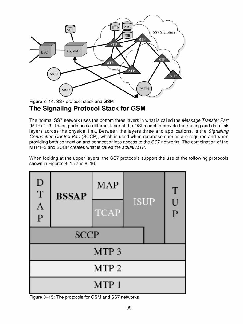
Figure 8−14: SS7 protocol stack and GSM
The Signaling Protocol Stack for GSM
The normal SS7 network uses the bottom three layers in what is called the Message Transfer Part(MTP) 1−3. These parts use a different layer of the OSI model to provide the routing and data linklayers across the physical link. Between the layers three and applications, is the SignalingConnection Control Part (SCCP), which is used when database queries are required and whenproviding both connection and connectionless access to the SS7 networks. The combination of theMTP1−3 and SCCP creates what is called the actual MTP.
When looking at the upper layers, the SS7 protocols support the use of the following protocolsshown in Figures 8−15 and 8−16.
Figure 8−15: The protocols for GSM and SS7 networks
99

Figure 8−16: The protocols for the wireless GSM architecture
Telephony User Part (TUP) For a voice circuit−switched call across the PSTN (refer toFigure 8−15).
•
ISDN User Part A newer implementation and replaces the TUP (refer to Figure 8−15).• Transaction Capabilities Application Part (TCAP) An application layer that supports thefeatures and functions of a network (refer to Figure 8−15).
•
MAP Sits on top of the TCAP as a means of supporting the difference application serviceentities for mobile users (refer to Figure 8−15).
•
Base Station Systems Application Part (BSSAP) A combination of the BSSMAP andDTAP (refer to Figure 8−16).
•
BSSMAP Transmits messages that the BSC must process. This applies generally to allmessages to and from the MSC where the MSC participates in RR management (refer toFigure 8−16).
•
Direct Transfer Application Part (DTAP) Transports messages between the mobile andthe MSC, where the BSC is just a relay function, transparent for the messages. Thesemessages deal with MM and CM (refer to Figure 8−16).
•
100

Chapter 9: CTI Technologies and Applications
Overview
Computer telephony systems can range from simple voice mail to multimedia gateways. Theequipment used in these systems includes Voice Response Units (VRUs), fax servers, speechrecognition and voice recognition hardware, and intelligent peripherals deployed by telephonecompanies and service bureaus.
Today's businesses need to leverage the power of these diverse, multi−user computer telephonysystems to improve productivity, give users more access to information, and provide communicationoptions and services to both customers and employees. Business customers can use the telephoneto automatically receive information about a product through a fax machine, while employees canaccess computer−managed voice, fax, and even data through telephones and computers toconnect offsite workers to the office and expand relationships with outside enterprises.
The computer telephony industry offers the power of sophisticated telephone systems to any sizebusiness the same way the PC industry exploded in the 1980s. In just over 10 years, the computertelephony industry has grown to encompass many diverse applications and technologies. In 1999alone, analysts estimate the revenue from multiuser computer telephony applications, developmenttoolkits, and services and technologies to be $10 billion worldwide.
Understanding Computer Telephony Technologies
Many manufacturers and value−added resellers (VARs) are committed to providing technologiesand products to customers for achieving success with automated call−processing applications.These products take advantage of technologies and enable users to store, retrieve, and manipulatecomputer−based information over a telephone network.
Voice Processing
Voice is the fundamental technology at the core of most computer telephony systems. Itencompasses both the processing and the manipulation of audio signals in a computer telephonysystem. Common tasks include filtering, analyzing, recording, digitizing, compressing, storing,expanding, and replaying signals.
Telephone Network Interfaces
Network interfaces enable computer telephony systems to communicate electrically within specifictelephone networks. Calls arriving from the Public Switched Telephone Network (PSTN) can becarried on a variety of lines, including the following:
Analog loop start• Analog ground start• Direct Inward Dial (wink start) lines• T−1/T3• E−1/E3• Integrated Services Digital Network (ISDN) Primary Rate Interface (PRI) and Basic RateInterface (BRI) lines
•
101

Network interfaces interpret signaling, provide data buffering, and include surge protection circuitry.
Tone Processing
Tone processing includes the capability to receive, recognize, and generate specific telephone andnetwork tones. This facilitates an application placing a call and monitoring its progress. Tones thatare processed include
Busy tones• Special information tones (SIT)• No answer (RNA)• Connection• Ringing• No ringing• Dial tones• Fax tones• Modem tones•
Facsimile (Fax)
Facsimile lets you transmit copies of documents and images over telephone lines to anotherlocation. To transmit and receive electronic faxes, PC−based systems use fax boards. Thiscomputer−based fax technology can improve productivity by enabling documents to be sent througha broadcast fax to a large number of people in a short period of time. People can also retrieve anynumber of documents on demand (FaxBack) that reside on a fax server.
Automatic Speech Recognition (ASR)
Automatic speech recognition (ASR) technology (also known as voice recognition) reliablyrecognizes certain human speech, such as discrete numbers and short commands, or continuousstrings of numbers, like a credit card number. ASR can be divided into two groups:
Speaker−independent ASR, which can recognize a limited group of words (usually numbersand short commands) from any caller.
•
Speaker−dependent ASR, which can identify a large vocabulary of commands from aspecific speaker. This is popular in password−controlled systems and hands−free workenvironments.
•
Text−to−Speech (TTS)
Text−to−speech (TTS) generates synthetic speech from text stored in computer files. TTS providesa spoken interface to frequently updated information and information stored in extensive computerdatabases. TTS is an economical way of giving customers telephone access to information thatwould be too expensive or impractical to record using voice technology.
Switching
Switching technology handles the routing, transfer, and connection of more than two parties in acall. Once the domain of private branch exchanges (PBXs) and proprietary switches, switches arenow available on boards that can be easily installed in PC−based computer telephony systems.
102

Understanding Computer Telephony Solutions
Customers use building block components to develop open systems products that are sold in all ofthe major computer telephony markets. These markets can be grouped into four major sections:Information Access and Processing, Messaging, Connectivity, and central office (CO)/AdvancedIntelligent Network (AIN).
Information Access and Processing Applications
Businesses worldwide are expanding their corporate communication systems to automateemployee access to information and the capability to process that information. For example, acustomer may want to check on the balance of a loan and then get a fax report of the adjustedinterest charges for early payment.
Information access and processing applications can improve communication and increase customerservice levels. These systems include AudioText, fax−on−demand (FOD), interactive voiceresponse (IVR), interactive fax response (IFR), and simultaneous voice and data.
AudioText
AudioText provides prerecorded information to callers. Businesses can offer callers a singlemessage or a choice of messages through touch−tone or ASR.
Voice Recording for Transaction Logging
With the pace of communications escalating and the demand for real−time information increasing,most of us are faced with the challenge of better managing our time and resources by establishingpriorities.
One of the toughest elements to manage is inbound telephony, mostly because we do not knowwho is calling and why. Therefore, we have choices on how to handle the incoming calls:
Screen the call by a personal assistant• Route the calls to voice mail• Answer the calls•
Another problem is dealing with our calls while away from the office. Callers are forced to eitherleave a message or to page us. Unfortunately, we spend a large portion of our valuable time playing"telephone tag." This costs time, opportunities to complete transactions, and money.
Newer systems can handle the phone process for us when they become available. Some of thesefeatures include the following:
Voice announce Knowing who is calling is the most important criteria in call management.By knowing who is calling, one can decide the priority and nature of the call before takingaction. Positive Caller Identification enables us to know who is calling, allowing us tomanage and prioritize calls. Callers can be identified by various methods:
Matching the automatic number identification (ANI) with a database or personalinformation manager (PIM).
♦
•
103

Having the caller speak their name.♦ Having the caller input their telephone or account number prior to transferring thecall.
♦
Follow−me Regardless of where you may be, you can be available to take that importantcall. Call Management enables you to take calls you want when you want them.
If an important customer calls your office while you are traveling, they will be identified by theCall Management system and your "Virtual Assistant" will try to locate you by callingpreviously programmed telephone numbers in the Call Management system. You may havedesignated your cellular telephone as your primary call−back choice. Your cellular telephonerings, you answer, and your Virtual Assistant says, "You have a call from (caller's voiceplays). Would you like to take the call?" At this point, you can take the call, elect to send it tovoice mail, or reroute to another associate. You can even choose to play one of manyprerecorded greetings to the caller.
While using your network PC, you can see the name of the caller on your screen and selectthe appropriate call−handling action. You can connect your PC to the Call Managementsystem remotely via Remote Access Server (RAS) or the Internet and manage your callsremotely as if you were sitting at your desk. The Call Management system can enable you touniquely handle calls from important business associates and customers. Let's suppose youare expecting a call from your boss and he is expecting you to provide him with an updateon a particular project. The Call Management system would enable you to record amessage, giving him the desired update, so that when he calls, the update would be playedfor him.
•
Single number availability Rather than giving out numbers for your office telephone, fax,cellular, and pager, you (and your customers) can enjoy the simplicity and convenience of asingle number. The Call Management system can recognize whether a person or fax iscalling and can handle the call accordingly. Your Virtual Assistant can provide your callerswith options to contact you, page you, or simply leave you a voice message with a call−backnumber.
Your Virtual Assistant can also be programmed to locate you and deliver faxes, voice mail,and e−mail messages. You can even have your Virtual Assistant make calls for you whenyou travel, so you do not have to deal with calling cards. The Virtual Assistant keeps yourtelephone directory and you can make calls from your directory.
•
Technology Enhancements
When CTI was first delivered, it was done through a large computing platform, either a mainframe ora high−end midrange computing system. These systems included such things as the IBMmainframe, AS/400, DEC VAX, or HP systems. Although they worked, they were expensive andsophisticated, requiring an extensive investment as well as application programming interfaces thatmade the service available only to large organizations.
The implementation of server−based or LAN−based platforms, however, has trickled down to thevery small organizations. No longer can one determine or assume that a company using CTIapplications is very large. As a matter of fact, many of the CTI applications are now rolling out onPC−based platforms for small organizations. Companies with 3, 5, or as many as 10 call−answeringor telemarketing positions have implemented CTI very effectively. These lower−cost solutions havemade CTI a reality within organizations around the world.
104

It was through LAN technology and not PBX technology that CTI actually got a foothold withinorganizations. Imagine if we had waited for the PBX manufacturers and the telephone companies toroll out CTI integration for us. We would probably still be waiting. In the past few years, however, thecomputer manufacturers have provided the push and the software developers have contributed theinnovations to make CTI a reality.
This relatively new yet rapidly accepted approach to using the server as the instrument to provideCTI has thrust CTI into the forefront of telecommunications technology. As mentioned earlier, thevoice server on a LAN is designed to connect directly to the public switch telephone network, handlecalls coming into the group, and then process those calls directly to the desktop. Priority customersand special handling arrangements enable specific users to work around the high−end PBX andCentrex platforms and go directly to the individual department or customer service group withoutproceeding through the corporate platform. This in turn changes the architecture, because of theCTI applications that can work on a server platform.
PBXs, once known for their large investments and proprietary nature, can now remain single−linetelephony service providers. When higher−end features and functions are necessary, the end usermerely has to buy computer−based software, as opposed to high−end PBX architectural software.Of course, the PBX manufacturers have recognized this shift in the technology implementation andall of the PBX manufacturers are now developing the CTI interfaces or the software with third−partydevelopers to reclaim customers. Because the PBX need only be an uncomplicated telephonesystem for the masses within an organization, the technology can last significantly longer. In the olddays of the PBX, the plan was to keep the system for a period of about 10 years. However, realitydictated that the PBX was changed on a basis of about five to seven years. This involved majorinvestments and changes within architecture, causing a significant amount of corporate stress.
As a quick side note, whenever a new PBX was installed, it usually meant that the Telecommanager within a corporation would be leaving soon. Regardless of how many technologicaladvancements or enhancements were installed, users' expectations were never met. Thefrustrations of the users and the complaints made to management usually led to the Telecommanager's demise. Now with the features and functions moved to a PC−based platform, theTelecom manager can breathe easier. Without the need to upgrade the PBX or change an entireinfrastructure, the Telecom manager can implement which features or functions are necessary andavailable on a department−by−department basis. On a large scale, all PBX features would beavailable to all users. By using the CTI implementation on a server, since features are purchased ona department−by−department basis, they are subsequently less expensive. This has been the boonof the 1990s.
Other Technologies
Because of the innovations in the telecommunications environment as well as the server marriage,many other applications and features can be made available by other producers. For example,through the use of the Telecom server on a LAN, the automated attendant, voice messaging, ACD,and IVR functions can all be united in a single server−based platform.
The developers of voice messaging systems' automated attendants recognized this opportunityseveral years ago. They leapfrogged the market, bypassing the PBX manufacturers, and developedsingle−card processing systems that could use high−end digital trunking capabilities directly into theservers. Using microprocessor control devices, these companies were able to write the necessarysoftware that would provide the capabilities of all of these features. No longer would an organizationhave to buy a room−sized voice messaging system; this function can now be performed on a
105
PC−based platform.
When voice messaging was first introduced, the size, heat, and cost of systems were exorbitant.Now, using PC−based systems, just about every vendor offers the capability of allowing severalhundred to several thousand active users on a voice messaging system or a call−processingsystem at a much lower cost. Actually, it's becoming much more difficult to tell a PBX performingCTI applications from a CTI server performing PBX capabilities. This convergence is blurring thelines between the various departments. Many of the organizations that now produce systems withthese capabilities may have once been niche market providers, but are now moving across theborder that once separated these two technologies. Just about every feature, function, andcapability can now be had using a very low−end server platform at a very reasonable price.
The integration includes features and functions such as
Voice messaging• Automated attendant• IVR• Text−to−speech• Speech−to−text• Directory services• Fax services• Fax−back services• Intranet access for catalogs•
Taking these one at a time, we'll see how they can all play together and provide unified messagingand integration capabilities. The capabilities of the integrated messaging and unified messagingservices enable the desktop user to functionally perform all day−to−day operations at a singleinterface device, now the desktop PC.
Automated Attendant
With technology moving as quickly as it is, the use of single processing cards in a PC can deliver acombination of voice messaging and automated attendant functions directly to the CTI application.A digital signal−processing capability can literally compress voice calls so that they can beconveniently stored on a hard disk drive. The voice is already in a digital form when it arrives from adigital trunk or digital line card; therefore, storage is a relatively simple technique. The applicationsoftware used in a voice mail system is basically a file service in which storage and retrieval can beeasily accommodated.
Integrated Voice Recognition and Response (IVR)
IVR enables customers to manipulate information in a computer database, such as retrieving anaccount balance and transferring funds from one account to another. These applications range fromAudioText and pay−per−call information systems that deliver a single audio message or a selectionof messages to transaction−based systems that enable callers to access accounts and updateinformation on a LAN−based or host−based database. AudioText entertainment lines are popularapplications in computer telephony markets.
IVR systems are primarily based on the same type of technology as the auto attendant and voicemail. Using a single digital−processing card, the capability now enables users to arrange forprescripted capabilities that will actually walk a caller through a menu. The IVR will play digitallystored messages and solicit a response from the caller at each step, usually in the form of a
106

touch−tone from a telephone set. The response from that tone will then cause the next step of themessage to be played in accordance with the script. This is useful when a user is trying to accessinformation from a host−based system, for example, and a played−back message will enable theuser to retrieve any form of information.
IVR has been used by several medical providers and insurance providers, enabling a caller to dial inand access information regarding a payment or the processing of claims by merely using atouch−tone telephone. When dialing into the IVR, the user is prompted each step of the way by thesystem. As the user enters an ID number, a query is sent to a database in a host−computingplatform. The appropriate information is then retrieved and played back. Using this CTI applicationsaves an immense amount of time for an organization, because this normally labor−intensiveactivity can now be achieved through technology.
Fax−Back and Fax Processing
The digital signal processor (DSP) card can also be programmed to function as a fax modem thatcan provide for the sharing of fax services within a single−server environment. A fax image can bedownloaded across a LAN, converted by a fax card, and transmitted across the network over adigital trunking facility. In the reverse direction, if an incoming fax is received from the network, it isthen converted back to a file format that is easily usable within the PC environment. This can theneither be stored in a fax server file for later retrieval by the individual recipient of the message orredirected by a fax operator. Some of these systems and services take more effort to implementand facilitate, but they may well be worth the effort in terms of an organization's needs.
A fax−back capability means that when a user dials into an organization equipped with CTIapplications, that user can be directed to a fax server that has a numerical listing of specificdocuments that the user can retrieve by keying in a telephone number. When the user enters thetelephone number, the server retrieves the fax from the file and then automatically transmits it to thedesignated telephone number the user has just entered. Through this application, cataloginformation or specific customer information can be retrieved without the use of human intervention.One can see how much time using these types of services could save.
Fax−on−Demand (FOD)
Fax capabilities are indispensable in the business world today. Businesses with dedicatedfax−based systems or with fax as an enhancement to their existing communications systems canautomatically deliver information on demand to their customers. For example, customers can dial inand listen to a menu telling them which documents are available by fax. They can make a selectionby speaking or by pressing a touch−tone digit and then enter the number of their fax machine toreceive the document.
Interactive Fax Response (IFR)
Interactive Fax Response (IFR) enables customers to automatically receive a fax in response to atransaction performed through either the telephone or a computer. For example, a customer mayreceive a printout of an account balance after having transferred funds.
E−mail Reader
An e−mail reader resides on a media server that uses TTS technology. E−mail readers translate theASCII text of an e−mail message (stripping out unnecessary header information) into voice that canbe retrieved by callers through any analog device, such as a telephone.
107
Text−to−Speech and Speech−to−Text
In speech−to−text applications, a prestored pattern of words can be used through the CTIapplication to enable a highly mobile workforce to dial into a server−based platform and literallyspeak to the machine, as opposed to using touch tones. Speech from the callers, whose voicepatterns are already stored in the computer, can then be converted into usable text using aserver−based CTI application. This is instrumental when the user cannot access a touch−tonetelephone. Without the touch−tone telephone, the user would have to carry a portable touch−tonepad generator, which is very inconvenient. Inevitably, the batteries on these devices die at the verymoment the user needs access to information. Consequently, the use of voice patterns or speechpatterns that have been prerecorded with a series of words, such as get, save, retrieve, file, and soon, can be used to facilitate and walk through a computing system.
The TTS applications are comparable in that when a user accesses a particular file, again without aterminal device, for example, the system can convert the text into a speech pattern. What thiseffectively means is that e−mail and other documents can literally be read back to us no matterwhere we are. This is exciting because an end user might well dial into the CTI application whiletraveling on the road and learn that he or she has six voice messages and four e−mail messageswaiting. Rather than that user being forced to log on with a different form of terminal device, thesee−mail messages can be read right down the telephone line to the end user, facilitating the easyretrieval, storage, or redirection of messages. It is through these types of services that the CTIapplications are drawing so much excitement.
Optical Character Recognition (OCR)
Another form of DSP technology can convert scanned images into text. When used with faxmachines or fax images, optical character recognition (OCR) can change an incoming fax into adocument that can easily be edited or incorporated into other types of applications. This wouldinclude editing a fax and placing it into a word processing document for easy editing capabilities.The additional storage capabilities could then convert the OCR, which usually would be a file ofsignificant size, into a text−based document, which would be much smaller. Furthermore, by usingthe OCR to scan a pre−typed document, for example, the application could transform the scanneddocument into a TTS application, which could be read aloud. One can just imagine the uses andapplications of some of these technologies.
Summary
Hopefully, this discussion of CTI will provide you with some appreciation of the capabilities andfeatures that contribute to the merger of computing and PBX architectures. The use of an onscreeninterface at a desktop PC enables users to manage and maintain their mailboxes for voicemessaging as well as e−mail. Beyond that, a visual display can be received directly to the desktop,outlining the number of faxes, e−mails, or voice messages waiting to be retrieved. With theintegration of the voice and text applications, the user can also see who the messages are from andprioritize the receipt of each of these messages based on some preconditioned arrangement. All ofthis facilitates the integration of the computer and telephony capabilities onto a single, simpleplatform that empowers the end user to access information more readily.
Moreover, with the implementation of CTI as a frontend processor for the organization'stelemarketing or order−processing departments, customers have the ability to retrieve information atwill. This use of touch−tone or voice response systems enables a customer to literally walk through
108

catalogs, check the status of orders, check inventories, or even check the process of billinginformation, all without human involvement. It is not the intent of this discussion to rule out the useof all humans, but rather show how humans can be more productive in performing the functions forwhich they were initially hired. By taking the repetitive "look−up"−type applications along with thedata applications and allowing them to be controlled by the end user (or customer), the organizationcan save a significant amount of time and money and better utilize the human resources they have.The industry, however, is now facing a severe shortfall of skill sets and talents that could facilitatesome of these functions. With the use of the CTI application, this human resources shortfall caneasily be supplemented through technology. As things progress even more, additional applicationssuch as video servers may well be added to this architecture and enable callers to view displays ona downloadable file, so that catalog information could be easily retrieved with a video clip that wouldshow exactly what the customer is ordering or buying. Moreover, as the video clips and the faxservices and voice messaging capabilities all become integrated into one tightly coupledarchitecture, customers could see the article, place the order, and literally "construct" the ordercustomized to their needs. One can only imagine some of the possibilities of these features andfunctions that will be available in the future, but as with anything else, the first steps must beimplemented.
In short, an organization must recognize the potential benefits that can be derived from a CTIapplication. Its capabilities are exciting because of all of the different ways CTI can be used. With aGUI−based system, a point−and−click, mouse−driven application on a desktop enables end usersas well as customers to literally walk their way through all catalogs and information.
109

Chapter 10: Integrated Services Digital Network(ISDN)
Overview
This chapter will describe the concept of the Integrated Services Digital Network (ISDN) and willfocus specifically on the following topics:
Its original goals• How it can be used• Some of the alternatives•
The world's telephone companies conceived ISDN in the early 1980s as the next generationnetwork. The existing voice networks didn't deal well with data for the following reasons:
One had to use modems to transmit data.• The data rates were around 9600 bps.• Connections (worldwide) were unreliable.•
Not only would the connection drop without notice, but also the error rate was high enough torequire a complex protocol to recover from errors. The back end of the network, that is, theinteroffice trunks, were practically all digital, with more being installed daily. The switching systemswere becoming digital just as quickly. It was expected that the only part of the network that wouldstill be analog was the local loop (our infamous last mile). It was a logical step to provide digitalcapability already in the network directly to the customer.
This created what is always called the local loop problem. The problem is that much of the localloop plant was installed between 40 and 60 years ago and had been designed for normal voicecommunications only. The local loop problem therefore is how to run high−speed digital data on thelocal loop. Several solutions to the local loop problem are discussed in this book, and the ISDNsolution is a little different from the solutions that will be presented in Chapter 16, "xDSL."
Although the digital network exists and the digital switching systems exist, ISDN has not made largeinroads into the customer premises. Once heralded as the solution for Internet access, it has beenovertaken by xDSL (although there is an ISDN−like DSL service called IDSL) and cable modems. Ithas found some success in the business community, specifically for telecommuting andteleconferencing.
Although greeted with enthusiasm by many equipment makers, ISDN has been treated coolly byseveral of the major North American carriers. The European monopoly carriers implemented ISDNin the major cities, while their rural telephone systems still use electromechanical switching. Thecommittees that defined ISDN concentrated on the interface.
Origins of ISDN
ISDN was a concept developed by the Consultative Committee on International Telegraph andTelephone (CCITT). The CCITT has since changed its name to the ITU−T, but it is still the samefolks, made up primarily of representatives of the world's government−owned monopoly carriers.Recall that in 1980 all telephone companies were monopolies and all were government owned and
110

run by the post office (thus, the name Post Telegraph and Telephone [PTT]). Canada and theUnited States were exceptions because most of the Telcos were private companies that had beengranted monopolies.
Although there were about 1,500 Telcos in the United States, AT&T, GTE, and ITT owned the bulkof the important ones that covered the large population centers. In Canada, the provincialgovernments owned the telephone company. Exceptions were in British Columbia, Ontario, andQuebec. Canada also has many small independent Telcos in the outlying areas.
Origins of the Standards
The CCITT is a consultative committee to the International Telecommunication Union (ITU) andhave recently changed their name to ITU−T. The ITU−T (CCITT) is a UN treaty organization and, assuch, each country is entitled to send representatives to any committee meeting. The representativetypically comes from the government−run PTT monopoly. The world's Telcos are becomingprivatized and competition is being permitted. This creates an interesting struggle within eachcountry to determine who will represent that country's interest at the ITU−T. Note that whendiscussing the organization's historical actions and composition, we call it the CCITT. When wediscuss its current actions, we call it ITU−T.
The name ITU−T came about due to the privatization trend separating telephone business from thepost office and the general elimination of telegraph service. Since its members were no longerPTTs, the organization couldn't be called CCITT. The CCITT was a consulting committee to the ITU,so the ITU−TSS (ITU−T) is the Telecommunications Standard subsection (TSS) of the ITU.
The CCITT is comprised of study groups (SG). Each SG has its own area of expertise. Here aresome of the better known ones related to ISDN:
SG VII on public data networks (X.25) X−series standards• SG VIII terminal equipment for telematic services• SG XI ISDN and telephone network switching and signaling• SG XII transmission performance of telephone networks and terminals• SG XV transmission systems• SG XVII data transmission over public telephone networks• SG XVIII digital networks, including ISDN•
Although we are cal l ing them standards, technical ly the CCITT and ITU−T publ ishrecommendations. The philosophy of the ISDN committee (essentially the Telcos) is to specify thecustomer interface first and then figure out how to support it in the network. The theory being that ifwe can get all the peripheral or end equipment makers to make equipment based on ourspecifications, then when we get ready to roll out the service, the store shelves will be stocked withinexpensive ISDN interface equipment.
Interfaces
The customer interface I.45x specifies the Basic Rate Interface (BRI). It was intended to becomethe standard subscriber interface.
The BRI specifies two bearer channels and a data channel. The two bearer channels would bear
111

the customer's information. The initial concept had this as being everything from analog telephonecalls (digitized) to teleconferencing data and these would be switched channels. The only differencebetween a conventional telephone circuit and a bearer channel is that the bearer channel would be64 KBps all the way to the customer. (Note in the current network, your analog telephone circuit isdigitized to 64 KBps at the local Telco office before being switched across the network. It is thenturned back into analog at the far end before being delivered to the called party.)
Now with BRI, we have not one, but two such telephone circuits. Since it is digital, we haveswitched digital 64 KBps to (theoretically) anywhere in the world.
The problem with the existing Telco network is that the signaling information shares the telephonechannel with the user information. With plain voice circuits, a customer doesn't notice or care. Withthe advent of modems, this represents a loss of channel bandwidth, and with digital transmission, itmeans a loss of usable bits per second. The customer is therefore stuck with 56 KBps, instead ofthe actual channel rate of 64 KBps.
The BRI interface therefore specifies a multifunctional data channel at 16 KBps that could handlesignaling (its primary function) and network data (X.25) when not needed for signaling. BRI istherefore referred to as 2B + D, two bearer channels and a data channel.
Figure 10−1 shows the BRI graphically and indicates the bandwidth allocation on the ISDNinterface. Remember that this is a time−division multiplexed (TDM) interface where the B, D, andoverhead bits are interleaved.
Figure 10−1: BRI bandwidth allocation
112

In Figure 10−2, the BRI is created by the Network Terminal type 1 (NT1). The NT1 creates afour−wire bus called the T interface onto which each ISDN device is connected. We will discuss theinterface designations user (U), terminal (T), system (S), and rate (R) later. Two points should bekept in mind. First, the boxes shown in Figure 10−2 can be combined in any reasonable way.Second, it is not necessary to have an NT2 element. This means that the S and T interfaces arelogically and physically identical. They have separate identities to allow us to describe thefunctionality of the NT2 element. The NT2 could create multiple S interfaces and perform theswitching to adjudicate access to the B channels on the T interface. Since the two interfaces are thesame, they are frequently referred to as the S/T interface. As described below, but not shown inFigure 10−2, up to eight devices can be connected to the bus.
Figure 10−2: NT1 creates the BRI.It is helpful for the following discussion to have a picture of the ISDN interface architecture handy,and Figure 10−3 serves this purpose. We have outlined the basic access. It provides 2B + D. Thetwo bearer channels shown on the left are simply access to network layer services. Both the linklayer protocol and network layer protocol completely depend on the service being accessed. Thedata channel has a link layer protocol defined as Link access protocol — Data (channel). The linklayer (which is essentially high−level data link control [HDLC]) provides sequenced acknowledgeddelivery. This reliable link layer service can be used by the network layer services provided acrossthe ISDN interface D channel. The most important of which is the signaling function used to set−upand teardown the B channels.
113

Figure 10−3: Architecture of the ISDN interfaceThe packet−switching access is not universally implemented, but it permits access to the worldwideX.25 packet−switching network. The telemetry system access is also generally unimplemented.Several telemetry experiments have been done in Europe and in the United States, but few resultedin a cost−effective solution. We may have to wait for new lower−cost technology. The concepts,discussed in the following paragraphs, are sound ones.
The higher−layer services could be almost anything. A typical example might be video conferencing.Here the higher−layer services would be the functions of the Codec.
If the ISDN B channels are used for Internet access, then IP would be the network services andTCP, HTTP, and so on would be the higher−layer services. The B and D channels are then justtimeslots on the bus that can be grabbed by any of the connected devices. The trick is how thetelephone, for example, keeps the computer from grabbing its timeslot while it is off−hook. Theanswer lies in the 48 KBps of overhead. In this 48 KBps, the NT1 provides timing to all the deviceson the bus. Remember this is a bidirectional channel, so there is 48 KBps of overhead going backas well. The station that wants to grab the D channel effectively puts its address in the contentionslot in the 48 KBps inbound bus. These bits are echoed by the NT1 as a confirmation of success.Effectively, the highest address will win since the one bits would overlay any zero bits of a device
114

with a lower address. When the terminal sees its address echoed in the outbound overheadchannel, it has won the right to send a packet (signaling or otherwise) on the data channel.
If the telephone has signaled the NT1 channel and grabbed a B1 channel, any other device sendinga signaling request for that B1 channel will receive a control packet from the NT1 indicating that it isbusy. Since one B channel is identical to another B channel, the NT1 will theoretically respond with"you may use the B2 channel." The actual operation depends on the implementation of the NT1 andterminal equipment.
This can get a little sticky when bonding channels. Essentially, bonding (that is, one device usingboth 64 KBps channels to get 128 KBps) must be done at call initiation. One of the channels can bedropped during the call, but it can't be added again later. This is because the called end (such asISP) may have already accepted a call on the other channel. The logical question is, why can't itaccept a mated or bonded channel on any other channel? Although this is a good question, theanswer is that when the rebonding takes place, the Telco network treats it like a brand new call.Thus, it can be routed via different offices and the timing relationship between the bonded Bchannels would not be preserved.
This brings up another interesting issue: Telco implementations vary widely. The number ofpossibilities is nearly limitless. Each Telco has chosen to implement a subset of ISDN based onwhat they think they can sell and still implement at a profit. Therefore, there is no such thing asstandard ISDN. Every implementation is unique.
Interface Components
The previous interface doesn't allow for switching on premises, which would be necessary if therewere multiple telephones.
The European and North American Telephone systems are quite different in operation. In NorthAmerica, extension telephones simply bridge onto the line, or connect in parallel. Adding a party toa call or transferring from one extension to another is as simple as picking up one telephone andputting down another. In the European system, specific actions (pushing the designated button) arerequired on the part of the parties to transfer a call. This also implies on−premise switching.
NT1
We have mentioned the function of the NT1. It creates the T interface for premise devices (from theU interface). In the original CCITT concept, the NT1 was provided by the Telco as part of the ISDNservice. The U interface was therefore only the concern of the Telcos with open networks (whichconcerned North America at the time). It is now important to understand on general principles.
NT2
This device would do the switching, permitting more than the standard eight devices to share the Tbus by creating perhaps multiple S buses. Therefore, an ISDN terminal equipment (TE) device can'treally tell if it is connected to an NT1 or NT2.
115

TE1
The terminal equipment type 1 (TE1) is a standard (there is that word again) ISDN terminal that iscapable of dealing with the B and D channels. In other words, it can interface with the S/T bus.
TE2
The terminal equipment type 2 (TE2) is a standard device having an RS−232 or V.35 interface. (InITU parlance, this is called a V−series interface.) It may be intelligent, but it doesn't have an ISDNinterface capable of handling the D and B channels.
TA
The terminal adapter (TA) is the semi−intelligent device that lets a TE2 connect to the S/T ISDNinterface. The primary function of the TA is to run the ISDN interface for our TE2. The functionalityvaries widely due to the manufacturers. Some are simple and support only one TE2; others supporttwo TE2s and an analog telephone. The TA need not be a stand−alone box; it can come on a PCcard and plug into the computer's internal bus. With the proper software to run the card, thisinstantly creates a TE1 out of your computer.
Thus, the BRI then was designed for small offices or home offices (SOHOs).
Physical Delivery
One of the more interesting parts of the ISDN service is the solution to the local loop problem.Remember our local loop is ancient and designed for voice. From Figures 10−1 and 10−2, weexpect it to support 192 KBps bidirectionally! This would not be a problem if we only had to go a fewhundred feet. Unfortunately, there aren't that many customers within a few hundred feet of thecentral office.
The problem is approached from the other end actually. If we want to reach 95 percent of thecustomers, what is the average length of the cable to them and what are the quality andcharacteristics of that cable?
Some of the answers to these questions you might find surprising. In cities, 95 percent of thecustomers are within 15,000 cable feet of the central office. When we go to suburbs and the ruralareas in particular, then all bets are off.
Figure 10−4 shows a typical local loop layout with emphasis on the fact that local loops, particularlythose in older parts of a city, are comprised of different gauges of cable and may have severalbridge taps. Although slightly exaggerated, one could imagine that all of the cable taps are on onepair. That is, at one time or another during the 60−year life of this particular cable plant, that pairwas used to provide telephone service to each of those different locations. Note also the gaugechange from 24 to 19 gauge. This was obviously not a problem for the analog telephone networkbecause it worked fine for 60 years on that cable.
116

Figure 10−4: Typical local loop layoutHigh−speed digital transmission presents a whole new set of problems. We will outline just the mainissues here. (See Chapter 16 for a more in−depth discussion of the transmission problems.) Thefundamental problem centers on the fact that a wire is an antenna. This is OK if we are in the radioor TV transmission business, but it is an unfortunate side effect of the telephone transmissionbusiness. The problem is worse at higher frequencies that characterize digital signals. If we use ourlocal loop to send digital signals containing high frequencies, the low frequency portion of the signalgoes a relatively long way. The high frequency portion of the digital wave is radiated off the wire andis delayed by the characteristics of the wire. The longer the wire, the worse the problem. The resultis that the signal dribbling out the end of the wire is weak and distorted because all the componentsdidn't arrive in time or with the right strength. Adjacent wires in the cable pick up the components ofour digital signal that are radiated. We call this crosstalk in the telephone business and theunwanted signal picked up is noise. The brute force method can be employed to remedy this.Sending a stronger signal makes more signals available at the destination, but also increases theamount of energy radiated.
As the telephone company, we must make sure that any new service added to our outside plant(local loops in aggregate) does not interfere with any existing service. Our goal of wanting to providemore distance must be tempered by the realities of crosstalk.
Interestingly enough, the European Telcos ignored the question of ISDN delivery, preferring toconcentrate on defining the S/T interface instead. Their theory was that "we're selling a service andhow we deliver it to the customer isn't important — we can always figure that out later." (Also sincethey were government monopolies, if the cost of delivery was high, they could always raise thetariff.)
The North American Telcos had a different situation. They were not allowed to sell or lease the NT1interface as part of the ISDN service and had to specify the electrical and logical interface at theTelco demarcation point. Therefore, the signaling on the local loop had to be worked out andstandardized before ISDN could be deployed.
117

The U Interface
The U interface is unique to North America and the open telephone network interconnection. Figure10−5 shows the U interface connecting to the NT1 and the NT1 in turn creating the internal S/T busto which up to eight ISDN devices can be connected. This U interface can be either a two−wire or afour−wire connection. In the following discussion, we concentrate on the two−wire connectionbecause it is the more technologically challenging. The four−wire interface requires much lesstechnology and can be delivered over a greater distance. Many early BRI interfaces were installedusing the four−wire interface for just these reasons. For wide−scale deployment, however, thetwo−wire interface has to be perfected, since the Telcos are not about to double the size of theiralready extensive outside plant.
Figure 10−5: The U interfaceAT&T (Bell Labs) came to the rescue with a technique known as 2B1Q (At this time, this was all partof AT&T. Since then, Bell Labs was spun off from AT&T as part of Lucent Technologies). Figure10−6 shows the 2 B1Q signal. Although it appears (and is) simple, it solves several problems:
118

Figure 10−6: 2B1Q technique for ISDN
It is easy to generate (that is, it is a simple wave form).• It minimizes crosstalk.• It will work on most local loops.•
Notice that each of the four levels contains two bits. Therefore, the signaling rate (baud rate) isone−half the bit rate. From our previous discussion of the S/T interface, we might conclude that thebit rate must be 192 KBps. Fortunately, those 48 KBps of overhead are only needed on the S/Tinterface to provide timing and priority (refer to Figure 10−1).
On the Telco side of the interface, we only need 2B + D and some overhead for timing and control.The total is 160 KBps. This means in engineering terms that the primary spectral peak is at about80 kHz. In layman's terms, it means we are only trying to send 80 kHz down the old local looptwisted pair wire. What we have effectively done is halved the bandwidth requirements of the line.This trade−off isn't free though; it means that the signal−to−noise ratio has to be better than if wewere to use a simpler encoding system.
The next problem is that the old local loop has different gauge wire and has bridge taps (refer toFigure 10−5). Unfortunately, when sending pulses down the line, we are going to get reflectionsfrom these gauge changes and bridge taps. These reflections show our transmitted signal muchlower in amplitude and delayed in time (Figure 10−6 shows this reflection as a dashed line). Thereflections will always be
Of the same magnitude and• At the same relative time from each of the cable plant anomalies•
Therefore, when the ISDN NT1 goes off−hook, it transmits a known pattern. That pattern containsall possible bit combinations (there are only 16 combinations). The receiver at the transmitting endthen monitors the resultant complex signal. Since it knows what it sent and can subtract that signal,it memorizes the resulting reflected energy. The NT1 stops and lets the central office end do thesame thing. Each end has learned the reflection characteristics of the local loop.
Now the clever part: Both ends can now simultaneously send data to the party at the other end.However, it is hard to listen to the relatively weak signal from the other end when you are alsotalking. This is where the learning comes in. Each transmitter can subtract its own transmitted signaland the reflections, which it knows to be there. After subtracting our transmitted stuff (andreflections), whatever is left over must be the data from the far end. Yes, it really works!
Unfortunately, we aren't quite home free. This old local loop doesn't handle all frequencies equally,so some of the signal components arrive out of the precise time (or phase) with the other parts ofthe signal, as mentioned above. This effectively distorts the signal. The U interface hardwaretherefore uses the old modem technique of equalizing the line. While each end trains itself onreflections, the opposite end receives the known signal, recognizes the distortion, and tunes itsequalizer to make the signal appear correct. If we were to independently measure the linecharacteristics (amplitude and phase) and the equalizer, we would (as you might expect) find themequal and opposite. The result is that the equalization process takes the distortion out of the line.
The 2 binary 1 quaternary (2B1Q) works so well that this basic technique is now the primarytechnology used by the local Telcos to deliver T−carrier service, instead of the old alternate markversion (AMI) technique. It will go twice as far before repeaters are required. Of course, the namehas been changed to confuse us and is now called High bit−rate Digital Subscriber Line (HDSL).
119

The Physical Interface
Another clever design feature of both the S/T and U interfaces is that they all use the same RJ−45type connector. Figure 10−7 shows the standard interface connector.
Figure 10−7: The standard interface connectorThe S/T and U interfaces carefully select the pin assignments so that accidentally plugging an S/Tconnector into a U interface and vice versa doesn't hurt anything. However, it won't work either.There was a great deal of discussion about the customer interface concerning how and whether thecarrier should provide power. In the current analog system, the carrier provides power to thetelephones so that they work, although commercial power is off. Shall this capability be preservedfor ISDN? Although the augment lasted several years, three powering mechanisms are providedacross the interface:
The customer provides power to the NT1.• The carrier provides power to the customer from the NT1.• The carrier provides a small amount of keep−alive power on the actual bus leads.•
Here is another opportunity for the implementations of the carriers to diverge. Most carriers don'tprovide power. The safe bet is for the customer to be able to power his own equipment in case of apower failure.
Applications of the ISDN Interface
The following section describes the areas in which ISDN functions, including multiple channels,telephone services, digital fax, analog fax, computer/video conferencing, signaling, telemetry, andpacket switching.
Multiple Channels
Figures 10−1 and 10−2 display the logical BRI interface. The plan is to provide access to everypossible home device. The original concept was for up to eight devices. After all, you only have twoB channels and one D channel to share among eight devices.
120

Telephone
The obvious starting point is the telephone, which is now a digital telephone. Instead of thetelephone conversation being analog from the handset to the central office where it becomesdigitized, the conversation can be digitized directly at the source and passed digitally all the waythrough the network to the other end.
Digital Fax
Fax machines now have to be digital. Therefore, the Group IV fax standard specifies 64 KBps faxoperation.
Analog Fax
Analog fax machines use a modem, so it has to plug into the telephone (or similar device) thatwould take the analog modem tones and digitize them at 64 KBps. This would provide compatibilitywith all existing Group III fax machines.
Computer/Video Conferencing
Our computer or video conferencing equipment can use one of the 64 KBps or bond both bearerchannels together for a 128 KBps digital channel across the network.
Signaling
The primary function of the data channel is to provide for signaling, that is, the setting up andtearing down of the switched bearer channels. At 16 KBps, the data channel has more bandwidththan is needed for signaling alone. Therefore, when it is not being used for its primary andhigh−priority signaling function, it could be used for other things.
Telemetry
This feature has never been well defined. The concept is that many household devices can beconnected to the data channel. This can include an energy management system that would let thepower company selectively turn off the refrigerator or air conditioner for an hour or so at peak usagetime. The concept also includes connecting the utility meters to permit remote monitoring and billing.Although several proof−of−concept trials of this technology have been conducted, apparently thecost of implementation outweighed the potential savings.
Packet Switching
The 16 KBps data channel has bandwidth to spare. Therefore, the local carrier can provide a dataservice on this excess bandwidth. X.25 is just maturing and is the logical packet−switchingtechnology to offer. As it turns out, all the data on the data channel, whether it is signaling data,telemetry data, or X.25 data, are always sent in packets anyway. (This packet−handling channelwas the logical genesis of Frame Relay. If we can distinguish different kinds of packets, why notframes too?)
These devices are all connected to the same 2B + D interface; therefore, three of them could be inoperation at one time. For example, the telephone could be using a B channel, the fax could beusing a B channel, and the computer could be doing X.25 packet switching. (Today we run all these
121

services over our Internet connection.)
Primary−Rate ISDN
The BRI interface offers 2B + D. The Primary Rate Interface (PRI) provides 23B + D and, in thiscase, all are 64 KBps channels. This should sound familiar. What technology provides 24 64−KBpschannels? Of course, the answer is T1. The physical interface for PRI then is simply a T1.Technically, it is a T1 with extended superframe framing (ESF). The obvious question is, how is PRIdifferent from an ordinary T1?
The answer is that at the physical interface it isn't any different. Channel 24 now becomes thesignaling channel. One might say that we have added common channel signaling to the T1. PRIthen is frequently used for a PBX interface where the full signaling capability of the D channel isneeded.
Figure 10−2 shows the S/T interface components for PRI. This same figure is then used to describethe BRI and PRI interfaces, but because it is a T1, we can add familiar labels to the diagramcomponents. The NT1 is now a Channel Service Unit (CSU), and the NT2 is now a private branchexchange (PBX). It could also be a router, but typically routers are members of dedicated networksand don't use switched channels. The Telcos charge more for a PRI because it offers many moreswitched−channel features. If a router needs to be connected to another router, an ordinary T1 willdo fine and cost less. Circumstances will occur when we need both our router and another deviceon the same interface and will periodically adjust the amount of bandwidth to each. For this uniqueapplication, PRI is ideal.
If we stick with our PBX example, the NT2 creates multiple S/T interfaces for TE1 or TA devices.TE1s are ISDN BRI telephones. What is interesting about the definition of the PRI interface is that itisn't limited to a single T1. Multiple T1s can be added to the PRI, so that up to 20 T1s can be part ofa single interface and the single 64 KBps D channel on the first T1 would control all. That is, asingle D channel could control 479−switched B channels.
H0 Channels
Equally interesting is that aggregated channels have been defined. These are known as Hchannels. An H0 channel is 384 KBps or six B channels treated and switched as a single channel.This means our PRI NT2 could call for an H0 to Atlanta, another to Phoenix, and one to Chicagoand still have five B channels to individually switch.
H11 Channels
The H11 channel is a 1.536 Mbps (T1) switched channel too. If our PRI NT2 had, let's say, 5 T1s, itcould configure any one of them as an H11 channel and another as 2 H0 channels with 12 Bchannels. This essentially gives us dial−up T1, 384 KBps, and 64 KBps clear channel service.
122

H12 Channels
The Europeans use an E1 system that has 32 channels, each 64 KBps. One channel is used fortiming and alarms and one is used for common channel signaling. In the PRI, channel 16 becomesthe D channel, so the E1 version gives 30B + D. The H12 channels are only in the E1 system andare 1,920 KBps. Again; theoretically this is switched E1, 384 KBps, and 64 KBps service.
Signaling on the D Channel
The signaling packets on the D channel are the same for BRI and PRI. In the early days of definingthe interfaces, an argument arose about whether to grant direct access to the signaling system bythe customers. As we indicated, Signaling System 7 (SS7) is the mechanism for managing thenetwork and it's logical to simply let the D channel use SS7 packets. Unfortunately, the moreparanoid faction won the argument, so the D channel signaling packets require a small amount ofconversion to change them from D channel signaling packets to SS7 packets. This is OK, becausethe D channel link layer frame is standard HDLC (Link access protocol for the D channel [LAP−D]),which can carry the packets on the D channel whether they are signaling packets or X.25 packets.
Figure 10−8 shows a D channel packet. If it has the look of an X.25 packet, it is not by accident.Since both X.25 and signaling packets are handled (time interleaved) on the D channel, it wasthought that a protocol discriminatory byte would be a good idea just in case the packet wasreceived by the wrong entity. (The link layer protocol makes this virtually impossible anyway, butjust in case . . .) The protocol discriminator byte pattern never occurs in X.25 and would beimmediately recognized as an illegal packet and discarded.
123

Figure 10−8: D−channel packetThe call reference value is essentially a random number chosen to identify a particular call.Because there could be many (479) calls in progress at once, you might need more than afixed−length value. (In order to prevent confusion about which call is doing what, you don't want toreuse those numbers too quickly.) All signaling packets associated with a given call will have thesame call reference value.
The message type indicates the format of the packet. The setup message, for example, would havethe called and calling telephone numbers in the information elements field. The call−clearingmessage would have a single−byte cause code in the information element field.
Of course, all of this wonderful capability isn't of much value if the service provider hasn'timplemented the backroom functions to enable these features for the customer. The carriers havesimply implemented that subset that they individually think they can sell. It should come as nosurprise that the offerings vary widely and all features are not generally compatible across carriers.
Installation Problems
It is not our intent here to denigrate the carriers, but rather to point out that installing ISDN for otherthan plain vanilla applications can be frustrating and time consuming.
124

The carriers come from a long tradition of providing voice services. Their entire managementsystem and technical system is designed around providing highly reliable (and profitable) voiceservices. ISDN is digitally based, the local distribution is digital, and the switching is digital.Historically, the Telcos have strictly partitioned the knowledge of each technical specialty. Theinstaller knows about local drop wires, pedestals, and telephones. The switchman knows aboutswitching. The outside plant folks know about cabling in the streets and on poles. The transmissionexpert knows about carrier systems. Moreover, no one knows it all!
Therefore, specially trained ISDN technicians are required to deal with the local loop. They mustknow the parameters for operation and be able to test it out. In the old days, the installer would hookhis butt to the line and listen. He could tell a lot about the local loop by the background noise. Sorry,you can't hear digital. Therefore, the technician now has to be trained in handling a special piece oftest equipment to make sure the line will support the data rate.
Because PRI is simply T1, the tuning of the local loop is understood; BRI, however, is a differentissue. We are now dealing with local loops. T1 is not normally delivered to residential loops, but itcould be. T1 is delivered on business loops. There is no real difference between business andresidential loops, but the Telcos do tend to run data circuits (T1s) in separate binder groups andthey tend to avoid the problems of many bridge taps, shown earlier in Figure 10−4.
Another complicating factor is that each carrier implements its own version of ISDN, making for afrustrating experience getting it installed and working. These different versions often lead tocompatibility problems end to end. As a rule, you can count on the 64 KBps B channels working endto end, and in most cases they can be bonded to 128 KBps. On the PRI, using switched H0 andswitched H11 channels is very iffy. The carriers just haven't implemented the switching algorithms toenable this feature.
BRI Application
One of the major uses of ISDN is in video conferencing. This is normally done by installing threeBRI lines. The video conferencing equipment has a built−in inverse multiplexer (mux). Figure 10−9shows a typical configuration. The three BRI interfaces are connected to the inverse mux and thecontrol panel enables the operator to specify how much bandwidth is to be used for thevideoconference. Although one could use 64 KBps for a videoconference, it is quite impractical. Aminimal usable videoconference is 128 KBps, and as long as someone else is paying for thebandwidth, 384 KBps is acceptable. This is the crux of the problem: How much bandwidth are wewilling to afford for the videoconference? The three BRI interfaces give you a choice in incrementsof 64 KBps to 384 KBps.
125

Figure 10−9: Typical configuration of the inverse muxThe inverse mux takes the commands from the control panel and provides the appropriate packetson the D channels to set up the amount of bandwidth required. The inverse mux is needed becauseit is essentially making up to six independent 64 KBps calls. The network routs these callsindependently. Therefore, if we are in Phoenix making conference calls to Atlanta, one of the callsmight go through Denver, Minneapolis, and Atlanta. Another might go to Albuquerque, Kansas City,St. Louis, and Atlanta. A third might go through El Paso, Dallas, Birmingham, and Atlanta. The pointis that each of these paths has a different length and delay. The inverse mux plays "scatter gather"by sending the digitized video in packets (actually frames) alternately over each of the circuits. Thepeer unit at the other end puts the frames back in order with the proper timing to provide the 384KBps channel to the coder/decoder (Codec). If we could afford a PRI, we could simply set up an H0channel to Atlanta.
Broadband ISDN
There has been much confusion over exactly what is broadband ISDN. This confusion stems fromat least two sources. First, the definition of the word broadband, and second from the fact that evenafter we are over that hurdle, no one knows what it means.
Definitions
The original meaning of broadband started with high−bandwidth as compared to low−bandwidthtelephone lines. The Telcos used the word wideband to describe some of their analog carriersystems that used frequency division multiplexing to put multiple telephone channels on a singletransmission facility. So when the Telcos were looking for a new name for their high−data−ratedigital service, they had an existing meaning for wideband. They chose the word broadband,despite the fact that this word (outside the Telcos' world) meant a high−bandwidth analogmultiplexed system. A cable TV system is a broadband system. In the early days of Local Area
126

Networks (LANs), Wang and several others used the analog cable TV technology (using widebandmodems) to provide computer connectivity. These were therefore broadband networks. Alongcomes broadband ISDN and everyone is naturally confused.
One could think of it as a high−bandwidth digital service. Actually, this is exactly how the Telcoswould like to sell it. Don't ask what it is or how it works. It is simply a high−data−rate−capabletransport service.
Originally then, the Telcos intended to offer this high−rate telephone service. How high a rate was indoubt. What did the customers need? Clearly, we can't sell something that the customers don'tneed.
There were a couple of stumbles along the way. First, there was a lot of hype about broadbandISDN, yet there was precious little supporting evidence in the Telco infrastructure. Second, it wasthe intent from the beginning to base the service on a statistical multiplexing type of service, a veryhigh−rate X.25 packet switching technology. It was clear to everyone at the time that such a sharednetwork would offer the customer more bandwidth while requiring less infrastructure bandwidth thanthe existing circuit−switched, time−division multiplexed network based on T1s, T3s, and T4s.
One of the stumbles grew out of the popularity of LANs. Why not become citywide or evencountrywide LAN providers? AT&T invented a thing called Switched Multimegabit Digital Service(SMDS). The LAN committee in the Institute of Electrical and Electronics Engineers (IEEE) grabbedthe idea and after about 10 years of study accepted the standard 802.6 as the Metropolitan AreaNetwork (MAN). This was an ingenious concept that used an access method known as distributedqueue dual bus (DQDB).
Figure 10−10 is a diagram of the DBDQ system. Although it looks like a ring, it is really two buses(one side of a T1) running in opposite directions. The Telco is the bus controller. It is well knownthat token passing busses are not efficient, since they effectively poll each station. The time taken inpolling when a station has no data is time that a station with data cannot lose. DQDB solves thisproblem by having a continuous set of packets flowing in both directions, which could be assured bythe Telco. These packets are small and are called cells. Sending empty cells doesn't hurt theefficiency. Each cell has a header that contains a busy or free bit and a request field. If station Dwishes to send something to station B (or to another station) serviced by the Telco on the clockwise(CW) bus, D places a reservation request on the counterclockwise (CCW) bus in the reservationfield. (It has been watching the CCW bus for reservations, so it has a queue of prior reservations.)Each free cell arriving on the CW bus causes one to be decremented from the queue. When thequeue is empty, the next free cell on the CW bus can be used for transmission. Yes, this system isa little complex. (If you really want to challenge your powers of visualization, try to envision thishappening in both directions at the same time.) The point of the discussion is that it is sort of ademand−based system and there are no collisions. If no one else has requested cells, then you canhave them all.
127

Figure 10−10: The distributed queue dual bus (DQDB) systemThe problem is that the rest of the protocol layer built upon the basic DQDB access scheme makesit very inefficient. The service is known as SMDS. Unfortunately, out of the 1.5 Mbps of a T1, youcan only use a little over 1 Mbps. Very few customers found that the service was cost effective.Another unfortunate aspect of the system is that the cells are not identical to ATM cells. Thus, touse ATM for transport, these cells have to be repackaged into ATM cells. The best part is that theTelco can implement it using existing T1 technology.
SMDS, then, was part of the broadband ISDN service offering. What about long−haul transport?That was left to ATM, which intended not to be a service per se, but as the implementationtechnology for broadband ISDN. You can now see that ATM was intended as the core technology(invisible to the customer) to support the Telco network of the future. Just as narrow−band ISDN(PRI and BRI) were intended to provide the network connection of the future, broadband ISDNservice was intended to be the high−rate interface. ATM would be the core technology supporting allof the services from circuit switching to packet switching.
ATM as the supporting technology was not ready when broadband ISDN was announced, so thecarriers couldn't provide the service. All eyes turned to the new kid on the block, ATM. Although notwell defined, like a kid, it had lots of promise. Who was to do the heavy lifting until ATM wasmature?
Frame Relay was developed to fill the void. The idea for Frame Relay came from both X.25concepts and from the D channel packet handling of ISDN. Frame Relay filled the need for
128

broadband service. Few customers actually needed the nosebleed speeds of ATM, and FrameRelay was a cost−effective replacement for dedicated lines. Being packet switched, it providedbandwidth on demand. ATM also provided bandwidth on demand at much higher rates.
Conclusion
ISDN, therefore, was a great technology−driven service that didn't really solve a business (or home)need. It is little wonder that ISDN is not widely implemented or used, but there are, as we havenoted, some clear exceptions. The most notable is video conferencing. Internet access is also apossibility, but ISDN can't compete with xDSL technology in performance for the cost. The ISDNprimary rate is used extensively in call centers, utilizing computer telephony integration to maximizetheir efficiency. PRI is also used in PBX applications, where the digital PBX can make use of thenetwork control and status information provided by the PRI.
129

Chapter 11: Frame Relay
Overview
Frame Relay is a fast packet−switching technology introduced in 1992. Its installed base hasskyrocketed since its development and introduction in the industry. No one could have everpredicted just how popular this technique would become, but the final outcome is that Frame Relayhas become the "bread and butter" service for many carriers. The reason is not as simple as onemight believe; therefore, this chapter will explore the details of what has led to the popularity inFrame Relay installations.
Moreover, some carriers have encountered problems with their installations because they did notunderstand the benefits or the operations of a Frame Relay service. Unfortunately, this is theepitaph of the telecommunications industry: the carriers (and specifically the long−distance carriers)do not understand data communications! Yes, they have some talented people on their staff, butthey have always stifled these individuals who knew what was happening. Instead, the carriers letthe voice and engineering folks become the spokespersons for the carriers in a datacommunications arena. How sad, they just never really got the point.
Even to this day, the voice people have not taken the time to learn data communications. Morespecifically, the carriers (Incumbent Local Exchange Carriers [ILECs] and Interexchange Carriers[IECs]) feel that their sales people do not need to know much about the technology, just how to sellthe product. Interestingly, this leads to the carrier sales representatives being less aware of theirown product than the customers they are attempting to sell to. Sales people do not need to bespecific engineers, but if you want to "walk the walk" you have to "talk the talk." How can the carrierssell a product when they do not know the basic concepts of data and, more specifically, FrameRelay?
Now in an era when all the voice carriers are trying to become data−literate and the data carriersare trying to become voice−literate, the voice people stand to lose in the overall transition becauseof the innate ability to mess up the data installation. Whenever we hear about a carrier's capabilityto handle data traffic, we seem to be mesmerized by the carrier's overall capabilities, instead ofunderstanding specific characteristics for processing and delivering data communications. Many ofthe more trusted names in the industry continue to tout their products and services, but fail to deliveron the promise of data communications because they churn their people over too often. The trainingthey provide their sales representatives is enough for these people to barely get by in discussing theproduct, but fails to cover the application of the product and the benefits that the customer can gain.
Frame Relay Defined
First, a definition of packet switching is in order because Frame Relay falls into the category of apacket−switching family.
Packet switching is a store and forward switching technology for queuing networks where usermessages are broken down into smaller pieces called packets. Each packet has its own associatedoverhead containing the destination address and control information. Packets are sent from sourceto destination over shared facilities and use a statistical time−division multiplexing (TDM) concept toshare the resources. Typical applications for packet switching include short bursts of data such aselectronic funds transfers, credit card approvals, point of sale equipment, short files, and e−mail.
130

Fast packet switching is a combination of packet switching and faster networking using high−speedcommunications and low−delay networking. Fast packet is a "hold and forward" technologydesigned to reduce delay, reduce overhead and processing, improve speed, and reduce costs. It isdesigned to run on high−speed circuits with low (or no) error rates. Errors are corrected at the twoends, instead of every step along the route.
Frame Relay, as stated, is a fast packet−switching technology used for the packaging andtransmission of data communications. Moreover, Frame Relay packages the data into a data linklayer frame (LAPF−Core Frame) used to carry the data across the network on a permanent virtualcircuit (PVC) without all the handling of the X.25 networks. Although X.25 acknowledges everypacket traversing the network, Frame Relay does not use acknowledgments (ACKs) or negativeacknowledgments (NAKs). Also, when an X.25 packet is corrupted, the network node requests aretransmission, which is not so on Frame Relay. Both of the services do, however, use a statisticalTDM concept. Table 11−1 is a summary of the comparison of X.25 and Frame Relay services.
Table 11−1: A summary of the X.25 and Frame Relay services
Service X.25 Frame RelayStatistical TDM Yes YesOSI layer used Layer 3 (Network) Layer 2 (Data link)ACK and NAK Yes, extensive NoneRetransmissions Yes, extensive done at each
node on the networkNone done by the Frame Relay nodes;retransmissions are requested byhigher−level protocols at the end
Packet/frame size Up to 128 bytes averagenetwork; up to 512 bytes insome implementations
Up to 1,610 bytes in networks; up to some4,096 bytes in some vendor products
Speed of transmission Up to 64 Kbps Starts at 56 Kbps; up to 50 Mbps,depending on the vendor products
By design, Frame Relay is focused on eliminating several of the older networking problems, yet inreality it does more to move the responsibility to others than to solve any of the older networkproblems. What it does, however, is come up with a streamlined type of communicationstransmission system, eliminating the older overhead. In the original days of data communications,networks were highly unreliable, yet today newer networks are very reliable due to the increaseduse of fiber in the backbone networks. Consequently, the entire older overhead dealing with errorrecovery is somewhat superficial. Frame Relay can eliminate this overhead and use the savedcapacity to carry more data. Frame Relay also assumes that if an error occurs, the higher−levelprotocols at the end−user level will be intelligent enough to correct the problem or request aretransmission. This can be a variable, depending on the implementation and what the end user iswilling to pay for these services.
What Can Frame Relay Bring to the Table?
Frame Relay in itself is merely a communications protocol designed to eliminate the overheaddiscussed previously. What one can expect from Frame Relay services is the use of thehigher−speed communications, the basis of the newer fiber−based Wide Area Networks (WANs).Taking advantage of the capacity improvements, Frame Relay can use the bandwidth on demandconcept to get faster data across the network. The use of excess capacities in a Frame Relay
131

network also brings newer ideas to the forefront. By allowing the end user to use extra capacity, thebottleneck of the older networks goes away. This excess usage is called the bandwidth on demandconcept.
Where People Use Frame Relay
Frame Relay is designed as a WAN technology primarily for data. When the deployment began, endusers and carriers alike all felt that digital voice (data) could ride on Frame services. However, thataside, the network and protocols were designed to carry data traffic across the WAN. Morespecifically, Frame Relay was developed to carry data traffic across the WAN and link Local AreaNetworks (LANs) to other LANs, as shown in Figure 11−1. The transmission of data across the localloop to the local telephone company's central office that is connected to the interexchange carriers'network switching system is handled by a leased T−1 or T−3 link. In Figure 11−1, a T−1 providesthe connection. Note also in this figure, the access device is through a dedicated Frame Relayrouter on both ends of the connection.
Figure 11−1: A typical Frame Relay connectionWhen Frame Relay was first introduced in 1992, the speeds were limited from 56 Kbps up to 1.544Mbps in North America and 64 Kbps up to 2.048 Mbps in the rest of the world. However, as timewore on, a small upstart company named Cascade Communications (acquired later by Ascend, whowas then acquired by Lucent) decided to set the world on fire by increasing the access speeds andinformation throughput to approximately 50 Mbps. The industry quickly jumped on this speed andmade Cascade the number one supplier in the industry at the time. Figure 11−2 shows theconnection at T−3 speeds on one end and Synchronous Optical Network (SONET) OC−1 on theother end of the connection. Note this was still used just for data transmission across the network. Ahigher−end router is installed on each end of the connection to facilitate the data throughput of up to50 Mbps.
132

Figure 11−2: A higher speed Frame Relay connectionThe next step was to use a different device to access the high−speed connection on a Frame Relaynetwork. Devices known as Frame Relay Access Devices (FRADs) were introduced to provide theaccess. This was done through a high−speed CSU/DSU, through a multiplexer, or some form of aswitching system. The FRAD enabled the access to be simplified for the end user and the networkprovider alike. In Figure 11−3, the FRAD is shown. Note the FRAD used here is through aCSU/DSU on one end and a high−speed T−3 multiplexer on the far end. The choices vary for theend user, so the flexibility of the access is one of the strong points for the Frame Relay network.
133

Figure 11−3: A FRAD used on each end of the circuit at high speeds
The Frame
When Frame Relay was developed, the important part of the data−carrying capacity was the use ofthe frame to carry the traffic and not have the same overhead as an older technology (such asX.25). The frame was filled with data as necessary, but it handled the speed and throughput via thehigh−speed communications and lower overhead.
In Figure 11−4, the frame is shown. The frame is a High−level Data Link Control (HDLC)−framedformat, as shown in this figure. The beginning of the frame (as with most HDLC formats) starts withan opening flag. Next, a two−byte sequence defines the addressing of the frame. This is called theData Link Connection Identifier (DLCI). By very nature of the title (DLCI), we can assume thatFrame Relay works at the data link layer. The DLCI is comprised of several pieces of information,shown later, but is normally a two−byte sequence. Provisions have been made to enable the DLCIto expand to up to four bytes, but very few implementations occur using more than the two−byteaddress. Following the DLCI is the information field. This is a variable length field. The initialstandard allowed for a variable amount of data is up to 1,610 bytes. This is sufficient for mostinstallations, but change always occurs when things are stable. The reason for the 1,610−byte fieldis to handle a frame from a LAN using a full frame of Ethernet traffic.
Figure 11−4: A Frame Relay frameThe Ethernet frame can be as large as 1,518 bytes (with overhead) and some subnet accessprotocol overhead (SNAP); the full frame should, therefore, accommodate the 1,610 bytes. TheEthernet frame is shown in Figure 11−5. This frame is the same size for an 802.3 IEEE frame or fora DIX Ethernet frame. Therefore, the variable data frame is sufficient to carry the traffic loads
134

necessary.
Figure 11−5: Ethernet and IEEE 802.3 frames fit into the Frame Relay frame.Following the data field in the Frame Relay frame is a cyclic redundancy check (CRC) used only tocheck for corruption. The CRC determines if the frame or the address information is corrupt. If so,the frame is discarded; if not, the frame is forwarded. There is no ACK or NAK in the Frame Relaytransmission along the route. Lastly, there is a closing flag on the frame, indicating that thetransmission of the frame is ended and the switching system can then process the entire frame. Inmany cases when a variable data field is used, the switches must allocate enough buffer space tohold a full frame, regardless of how full each frame is. This is somewhat wasteful across the WAN,but does provide the necessary flexibility to handle the traffic.
Shortly after Frame Relay was introduced with the 1610−byte information field, a new issue croppedup. What about the clients who use an IBM Token Ring? The Token Ring LANs can carry a variableamount of information up to 4,068 bytes. This means that a frame in the Frame Relay world is notlarge enough to carry a full token and the data must be truncated into three tokens to accommodatethe Token Ring. To solve this problem, the frame was expanded to accommodate up to 4,096 bytesin the information field. Not all suppliers supported this change, but the two major suppliers ofFrame Relay products (Cascade and Nortel) both adjusted their systems to accommodate the largerframe. This frame is shown in Figure 11−6 with a variable frame size of up to 4,096 bytes.
Figure 11−6: Modified frame size of the Frame Relay information field
The OSI Protocol Stack and Frame Relay
When we discuss the use of the data link protocols, one always compares the Open SystemsInterconnection (OSI) to whatever other protocol is being discussed. This book is no differentbecause one needs to understand where Frame Relay falls on the OSI stack and what FrameRelay's purpose is. The development of any new set of standards is usually done to improvenetwork performance. Frame Relay works at the data link layer to reduce the overhead associatedwith the movement of data across the wide area. Because we refer to Frame Relay as a WANtechnology, it is natural that the protocols will work with the improvements made in the network overthe past decades.
In the older days, data was shipped across the layer three protocols (such as X.25) to assure thereliability and integrity of the data. This is because the networks back in the 1970s were unreliable,so the protocols were put in place to accommodate this network flaw. The X.25 protocol worked atlayer three, as shown in Figure 11−7. The overhead associated with the transmission and receptionof the data on the X.25 networks was inordinate. To facilitate better data throughput and eliminatesome of the overhead, Frame Relay was developed. The comparison of Frame and X.25 to the OSImodel is shown in the figure. Two things were in place, however, to enable the use of Frame Relay
135

instead of X.25:
Figure 11−7: OSI compared to Frame and X.25 stacks
The networks were now improved through the mass deployment of fiber−based networkingtechnologies and the use of SONET protocols.
•
The networking strategies of many end users were based on router technologies andLAN−to−WAN communications instead of the older terminal−to−host intercommunications.
•
These two changes actually revamped the way we communicate. No longer did we have to use atiming relationship, as in the older data networks. Any form of data transmission could beaccommodated across the newer improved techniques and protocols.
With this comparison in mind, one will note that the Layer 2 protocol (in this case, Frame Relay)eliminates some of the overhead associated with the transmission of data. The need for networkaddressing using Layer 3 is reduced because many of the link architectures are based onpoint−to−point circuits or private networking techniques. Moreover, where the network address wasrequired to send the data to its end destination, Frame Relay uses the DLCI as the PVC connection.Therefore, by using PVCs, the routing of the data traffic is predetermined to occur across a highlyreliable direct connection to the far end. Switching and routing decisions are not required once theconnection is established because all the traffic for this connection between two end nodes followsthe same path. This mapping is done through the use of the DLCI address to presubscribe theconnection in a virtual circuit connection, as shown in Figure 11−8. The only time the traffic mighttraverse some other route is when a link failure occurs, but this is already mapped in the logic forthe connection. This is shown in the routing example in Figure 11−9 where the end nodes arepremapped in the Frame Relay switches across the network.
Figure 11−8: Mapping using the address and DLCI
136

Figure 11−9: A typical mapping of the DLCI in a Frame Relay networkBy using this arrangement of DLCI mapping across the network, the network can alsoa c c o m m o d a t e v a r i o u s o t h e r t y p e s o f t r a f f i c , s u c h a s I B M S y s t e m s N e t w o r kArchitecture/Synchronous Data Link Control (SNA/SDLC) traffic, which is very time−sensitive andtimes out if the traffic does not arrive in time. Moreover, if a customer is using an older form ofinteractive terminal traffic using some older 2770/3770 bisynchronous protocols, these can beplaced into the frame.
The concept of placing the traffic inside these frames is called tunneling. Clearly, what happens isthe traffic is sent inside the frame transparent to the network. No checks or validations are made onthe data through the network, reducing some of the delays of data handling. Also, while tunnelingthrough the network, the data is actually encapsulated inside the Frame Relay frame, so the onlyplace where the data is actually enacted on is at the two ends. There is some minor overheadassociated with the use of these other protocols, called SNAP, but the overhead is minimized. Thistunneling concept is shown in Figure 11−10 where the data is encapsulated inside the frame(tunneled).
137
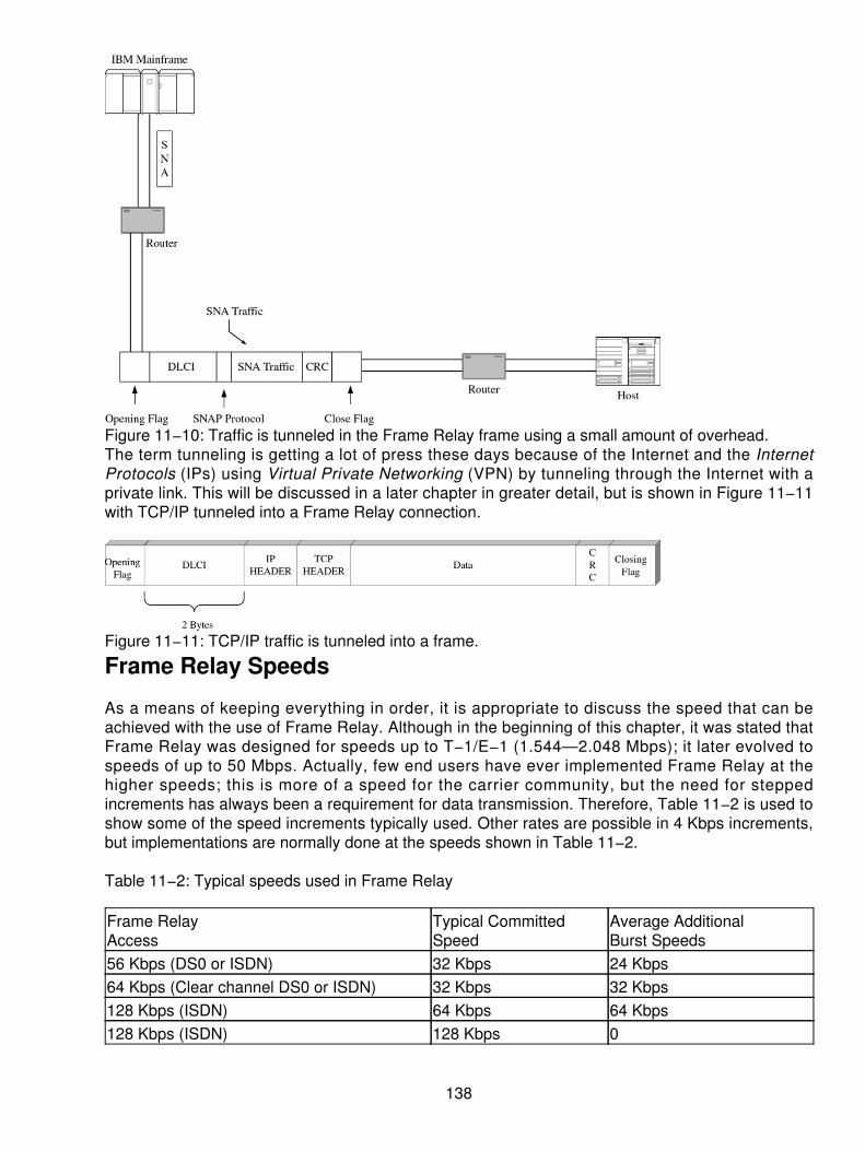
Figure 11−10: Traffic is tunneled in the Frame Relay frame using a small amount of overhead.The term tunneling is getting a lot of press these days because of the Internet and the InternetProtocols (IPs) using Virtual Private Networking (VPN) by tunneling through the Internet with aprivate link. This will be discussed in a later chapter in greater detail, but is shown in Figure 11−11with TCP/IP tunneled into a Frame Relay connection.
Figure 11−11: TCP/IP traffic is tunneled into a frame.
Frame Relay Speeds
As a means of keeping everything in order, it is appropriate to discuss the speed that can beachieved with the use of Frame Relay. Although in the beginning of this chapter, it was stated thatFrame Relay was designed for speeds up to T−1/E−1 (1.544—2.048 Mbps); it later evolved tospeeds of up to 50 Mbps. Actually, few end users have ever implemented Frame Relay at thehigher speeds; this is more of a speed for the carrier community, but the need for steppedincrements has always been a requirement for data transmission. Therefore, Table 11−2 is used toshow some of the speed increments typically used. Other rates are possible in 4 Kbps increments,but implementations are normally done at the speeds shown in Table 11−2.
Table 11−2: Typical speeds used in Frame Relay
Frame RelayAccess
Typical CommittedSpeed
Average AdditionalBurst Speeds
56 Kbps (DS0 or ISDN) 32 Kbps 24 Kbps64 Kbps (Clear channel DS0 or ISDN) 32 Kbps 32 Kbps128 Kbps (ISDN) 64 Kbps 64 Kbps128 Kbps (ISDN) 128 Kbps 0
138

256 Kbps 128 Kbps 128 Kbps256 Kbps 192 Kbps 64 Kbps384 Kbps 256 Kbps 128 Kbps512 Kbps 384 Kbps 128 Kbps1.544 Mbps 512 Kbps 256 Kbps1.544 Mbps 1.024 Mbps 512 Kbps2.048 Mbps[1] 1.024 Mbps 1.024 Mbps[1] In most implementations, when a customer exceeds 256 Kbps access, the normal installed linkfor access is a T−1 in North America at 1.544 Mbps. This is a pricing and an availability situation.
Frame Relay Access
A link is installed between the end−user location and the network carrier's node. The normal linkspeed is T−1, although many locations can and do use Integrated Services Digital Network (ISDN)or leased lines at lower rates. Some customers may choose to install a local loop at speeds up toT−3 (45 Mbps approximately) to support higher−speed access and faster data throughput. (In mostimplementations, when a customer exceeds 256 Kbps access, the normal installed link for access isa T−1 in North America at 1.544 Mbps. This is a pricing and an availability situation).
In many cases, the use of the T−3 will also allow for consolidation on the same link. Many of thecarriers (and in particular the LECs) will offer the T−3 access and enable Frame Relay throughput atrates up to 37 or 42 Mbps. Now the ILECs are offering flat−rate services and bundled capacities tobe more attractive to their end users. The ILECs are the local telephone companies with theirinstalled base of services and facilities. Often these ILECs are offering high−speed Frame Relayservices Local Access and Transport Area (LATA)−wide (or statewide, depending on thegeographic topology of the state and LATA boundaries) all for competitively priced services. Betteryet, some of the ILECs offer high−speed Frame Relay at speeds up to 10 Mbps across the LATA atcompetitive rates on either T−3 or an OC−1. The 0 to 10 Mbps bursts of data are designed for thevery large customer, but they may fit smaller organizations needing broadcast (or near−broadcast)quality for voice and video applications in the future.
Figure 11−12 is an example of the connection installed at a large organization yet fed across thenetwork by lower−speed feeds from branch offices at T−1 and lower rates. This scenario is likely themost common implementation for the near term, but will shift as the pricing model becomes moreconducive to the smaller organization.
139

Figure 11−12: Examples of connections at higher speeds
Overall Frame Relay Core Protocols
When the Frame Relay specification was developed, the primary goal was to carry data over theWAN. To handle this form of wide area communications, the core protocols for Frame Relay wereestablished using the revised version of the data link protocols. Instead of using the network layerprotocols, Layer 3 was gleaned down to efficiently carry the traffic while performing the samefunction as the network layer. Moreover, the data link layer was also streamlined to offer lessoverhead and processing on a link−by−link basis. Because the circuits across the wide area aremuch more reliable and error−free (thanks to fiber optics), the ACK and NAK functions can beeliminated. Furthermore, the use of PVCs in the connection eliminates the need for the sequencenumbering on the link. One can assume that if we send multiple frames onto a circuit between twoend points (even if it is a virtual circuit), the data will come out in the same sequence that it went inon the other end. Unless a frame is discarded, there should be no way that the data will arrive out ofsequence. Because the data should not arrive out of sequence, there should not be a need to dothe counting.
If, however, something goes wrong on the circuit, how then do we recover? The answer is that werely on the upper−layer protocols on both ends of the circuit (the transport layer) to recognize if thedata is missing. If a frame is lost, then a transport will request a retransmission from the sender.This eliminates much of the processing and checking at each node across the link. In Figure 11−13,the core protocols are shown for Frame Relay using a subset of the Q.922 data link layer for theactual link protocols.
140

Figure 11−13: The core protocols for Frame Relay mimic the ISDN standards.Q.922 is an ITU−specified protocol for ISDN. Frame Relay was developed as an offshoot of theISDN protocols because of the amount of work invested in the technologies and standards. As aresult, many of the core protocols for Frame Relay mimic the ISDN standards. This is helpful inunderstanding why and how the networks have evolved throughout the past 10 years to improvenative throughput and increase the acceptance of the standards.
Carriers' Implementation of IP−Enabled Frame Relay
Carriers are now offering IP−enabled services, enabling a customer to use an existing Frame Relayaccess link to tap into a connectionless Multiprotocol Label Switching (MPLS)−based IP backboneor a private IP network. The primary benefit is that achieving mesh connectivity within a customer'sVPN requires just a single "access" PVC from each remote site.
Many companies have already configured their networks in a hub−and−spoke configuration. Thus, itwould appear that there is no benefit to consider the IP−enabled offering. With traditional PVCs in ahub−and−spoke configuration, a PVC runs from each remote site to the central site. WithIP−enabled services, the customer installs one PVC at each site to the carrier network and anIP−enabled PVC at the central site.
Other organizations are moving to at least two PVCs per site, each terminating at a central point.This covers a few key areas within the IT group. First, the dual homing allows for load balancing.Next, by feeding the second PVC through a different route, the risk of downtime is minimized byalternate routing. Still an option is to have a regular site handling the routine traffic but a hot site forrecovery purposes located in a different location. In another instance, the company might run twomajor processing centers, such as one for back office functions and another for front−officefunctions such as customer service. Yet all sites typically need access to both locations. To facilitatethis, two PVCs per remote site are needed, creating the opportunity to justify IP−enabled FrameRelay. The break−even point occurs at low committed information rate (CIR) speeds where oneIP−enabled PVC reaches both sites. The price of the IP−enabled PVC is usually twice the cost of anormal PVC. When using higher−speed access and PVCs, the value is far more dramatic. As thespeed of the CIR increases, the IP−enabled PVC costs are more closely aligned to the traditional
141

PVC costs. As the speeds increase to the point where the prices are the same, you have twice theconnectivity for the same price.
Frame Relay Versus IP
We now compare the pros and cons of Frame Relay and IP. IP and applications such as VirtualPrivate Data Networks (VPDNs), intranets, and extranets have garnered a lot of mind share in theindustry today. Although these services show a lot of promise, today's services lackcomprehensiveness and robustness. They lack much of the potential functionality and serviceguarantees they can eventually deliver. Security and performance top the list of areas in whichnetwork managers will need to see improvements prior to seriously considering these services enmasse. Frame Relay's support for multiple protocols, its predictable and reliable performance, andthe wide availability of network management tools and service−level guarantees make it the mostlogical choice for a majority of the business applications used today. In Table 11−3, we draw acomparison of the Frame Relay and IP from a logical progression.
Table 11−3: Comparing Frame Relay and IP
Frame Relay IPMultiprotocol support Any−to−any connectivityPredictable and reliable performance Limited quality of service (QoS)Robust network managementcapabilities
Security concerns abound
Primarily intracompany connectivity Linking intercompany business partnersWAN only LAN or WANFocus is on logical connections versusintelligence
Dialup and international access available
Frame Relay has evolved to address the mass market's increasing bandwidth demand bysupporting connectivity up to DS−3 speeds. However, niche markets exist where end−user IPapplications require much more bandwidth. IP over SONET is one such solution. IP over SONET'sappeal for many users has been its management simplicity and transport efficiency when comparedto alternate solutions such as IP over ATM.
Voice over Frame Relay (VoFR)
Just as the industry was getting used to the idea of reduced overhead for data transmission, someradical thoughts began to surface in the industry. In the past, all data ran over voice networks,adjusted, and accommodated according to voice standards. But what if voice could run over a datanetwork instead? By using the capability of reduced overhead, more reliable circuits, and fasterthroughput, the network could be tuned to accommodate voice in the form of packets of data.
Much of the pressure for voice over any data technology has been based on cost in the past. Newerideas are based on efficiency and the convergence of the network protocols and services. Voice isfairly inefficient! Actual voice traffic is carried only about 25 percent of the time we are on aconnection. The rest of the time, we are sending silence (no information). If we can integrate the twonetworks and carry interleaved traffic (voice or data), then we can efficiently fill the network withtraffic all the time, instead of just sending idle conditions.
142

Thus, a new concept was born that could be accomplished through compression and interleavingthe data. Therefore, on a digital circuit, data is data and voice is too! The voice is just a data streamof ones and zeros. The Frame Relay Forum has been busy defining the standards for three serviceofferings, one of which is the VoFR specification. In conjunction with VoFR offerings, the forum wasbusy developing other protocols and specifications to support some of the unique challenges withreal−time data on a network. This includes the use of PVC fragmentation protocols and multilinkFrame Relay services.
The fragmentation protocols are necessary to support the different types of delay experienced onthe network for time−sensitive traffic (that is, voice). Interleaving the voice communications (usingsmall frames) onto a high−speed data link with larger frames is one way to handle this need. Thissharing of the same physical link enables both real−time and nondelay sensitive traffic to coexist yetreceive separate treatment as it moves across the network. The fragmentation of the traffic enablesvariability, depending on the speed of the link, the congestion, local timing needs, and the type ofservice being used. This makes the implementation of fragmentation available at various interfacepoints. In Figure 11−14, the use of a fragmentation procedure is shown in three different places: atthe User−to−Network Interface (UNI), at the Network−to−Network Interface (NNI), and on anend−to−end basis. These three ways enable enough flexibility to accommodate the different typesof service being delivered across the Frame Relay network.
Figure 11−14: Three places where fragmentation can take place in support of VoFRWith the implementation of VoFR, particularly with carrying international telephony traffic, the FrameRelay Forum introduced the specification FRF.11 that deals specifically with the voice side of thebusiness. This specification goes beyond the possibilities of fragmenting the data and incorporatesthe necessary steps of call setup and call teardown. The other major issues that the FRF.11 dealswith are as follows:
Analog−to−digital conversion• Digital−to−analog conversion (back to analog)• Compression techniques• The sizing and transmission of a frame of traffic•
Many of the specifications involve more sophisticated steps, such as handling various forms ofanalog traffic, including voice, fax, and compressed video communications. To accommodate thatneed, the FRF.11 handles a specification dealing with multiservice multiplexing. This covers theability to multiplex multiple voice and data channels on a single Frame Relay connection (or PVC).A gateway function is used in many cases to handle the various informational streams multiplexedonto a single PVC, as shown in Figure 11−15.
143

Figure 11−15: A Frame Relay gateway acts as the multiplexer of different services onto a singlePVC.Compressing the Information on VoFR
By using some industry−accepted standards for compression techniques, such as AdaptiveDifferential Pulse−Coded Modulation (ADPCM) or Code−Excited Linear Predictive Coding (CELP),the conversation can be compressed from 64 Kbps to a data stream of 40, 32, 24, or 16 Kbps usingADPCM compression techniques and down to 5 to 8 Kbps using the newer CELP standards.
Following this idea, the next step is to view how a service bureau approach might work using FrameRelay to act as an international callback service, or in the case of a corporation with multipleinternational locations, this service can be used for the intranet calls. One cannot underestimate therobustness and power of the Frame Relay networks. In many cases, the carriers are offeringthroughput across their backbone in the proximity of 99.99 percent of the Committed InformationRate (CIR) and with an availability of 99.5 percent or better. These two statistics absolutely beatanything we have ever seen from voice or data networks in the past. Notwithstanding the capabilityto achieve the throughput and availability statistics, the carriers will sign a service−level agreement(SLA) with these guaranteed throughput and availability characteristics without hesitation. Neverbefore have we seen such confidence and acceptance of a single−standard interface and networktopology to carry the WAN traffic.
Still, when one considers the possibility of running voice data across a network, it is uncomfortableto think that the voice networks have truly not kept pace with the developments of the datanetworking strategies. Do we really need another packet−switching technology, rather than improvethe ones we already have in place? The answer can be found in the overall characteristics of theFrame Relay networks already discussed here.
Provisioning PVCs and SVCs
The primary difference between PVCs and switched virtual circuits (SVCs) is whether theconnections are provisioned or established. Both types of connections need to be defined. The
144

difference is when the connections are defined and resources allocated.
The network operator typically provisions PVCs. The network operator can be the carrier (publicservices) or the MIS manager (private networks). Once the PVC is provisioned, the connection isavailable for use at all times unless there is a service outage. On the other hand, the end user, notthe network operator, establishes SVCs. Prior to each use, an SVC is established to the destinationend user. The connection is cleared after use.
SVCs are ideal for networks with highly meshed connectivity, highly intermittent applications,remote site access, and interenterprise communications. Each of these applications will bediscussed in more detail in the succeeding slides. SVCs are also ideal for networks that are notprimarily dependent on resources housed at a single location such as the headquarters site or atregional offices. In a nonhierarchical networking environment where there is a need to communicatewith many locations, SVCs can offer a viable solution. The advantages of SVCs are magnified asthe number of locations and the degree of connectivity requirements increase. Highly meshednetworks are becoming more common as more and more companies deploy intranets. It isconceivable that all end users will have their own Web page within the corporation. This willincrease the amount of peer−to−peer intracompany traffic. Additionally, it can offer a cost−effectivesolution for occasional inter−company connections to suppliers, partners, and even customers,provided that they all subscribe to the same public Frame Relay service.
Because SVCs only consume network bandwidth when there is information to send, it is a goodsolution for short duration applications. (PVCs also only consume bandwidth when there isinformation to send. The difference is in the amount of bandwidth that needs to be reserved for theconnection. In a PVC−based environment, the network operator must ensure that CIR can beguaranteed to all connections transmitting at any given time. This means that the network may haveto design for the worst case regardless of the applications' CIR utilization. In an SVC environment,the appropriate amount of CIR is allocated during the call.) Intracompany voice calls are anexcellent example. The average telephone call is only three minutes. SVCs are also ideal forscheduled, time−bound applications like videoconferencing. You may only need videoconferencingcapabilities every Monday morning from 9 to 10.
SVCs can be used in conjunction with PVCs for traffic overflow during peak traffic periods. Trafficoverflow is highly intermittent because, hopefully, overflow doesn't occur on a regular basis. When itoccurs, it only happens for a short time. If end users notice that overflow is occurring morefrequently, then it might be more cost−effective to increase the CIR of the PVC to accommodate theoverflow. SVCs can also provide a backup connection to a secondary host location if the primaryhost location fails or is unavailable.
Benefits of SVCs
Some public Frame Relay services' pricing structures are forcing end users to build star networkseven when the underlying traffic patterns warrant more meshing. Some pricing structures incanthigh subscription rates on ports, which result in star and hub−and−spoke configurations. Forexample, all remote offices may have direct connectivity to the headquarters location only.Remote−office−to−remote−office communication happens by tandeming through the headquartersrouter. The headquarters router and port connection can become bottlenecks. Network latencyincreases with tandeming.
With SVCs, a direct connection is established between the caller and the called party. There is thenno need to tandem through one or more nonterminating or nonoriginating end user locations for that
145

particular transmission. SVC usage can be tracked on a call−by−call basis. The information can beused to further optimize the network for billing purposes.
Frame Relay Selected for Wireless Data on GPRS
Newer wireless services known as the General Packet Radio Services (GPRSs) are designedaround the movement of IP datagrams (always−on Internet access) from a cell phone or personaldigital assistant (PDA) to the public Internet or a VPN connection to an intranet. Regardless of thedirection that the data is going to flow, the use of the IP services from the handset enables us to usethe network ad hoc. When an IP is created, it is packaged in a radio message. Once this messagegets to the base station, it is then encapsulated into a Frame Relay frame to be carried across thewireless carrier's network to a router. The Packet Control Unit (PCU) is, therefore, a form of aFRAD. Our packets are sent to the PCU where it is slotted into the Frame Relay service and carriedthrough the cellular network.
One might think about this and wonder why Frame Relay is used. First, it is widely deployed as anetworking architecture. Second, it is based on the PVC from the PCU to the network device calleda Serving GRPS Support Node (SGSN), as shown in Figure 11−16, which operates at speeds up to2.048 Mbps (the standard for the E−1). By connecting across this architecture, it is a virtual privateline adding some degree of security. Third, the standards allow for the sharing of the circuitry frommany devices by interleaving the data frames on the same physical channel. Fourth, it doesminimize the overhead on the channel.
Figure 11−16: The PCU uses Frame Relay to connect to the SGSN.In general, the use of Frame Relay has been continually climbing due to the robustness, industryacceptance, and wide availability. Many organizations are not ready to displace their networks bymoving to newer or different services. However, where the customer has used an IP−basednetwork, the use of managed services, burstable data rates, and inexpensive access of PVCs andSVCs combined now with IP−enabled Frame Relay continues to lend credibility and acceptance inthis networking standard. We can expect to see this around for a long time to come.
146

Chapter 12: Asynchronous Transfer Mode (ATM)
Overview
In 1992, a group of interested parties developed a set of standards−based specifications called theAsynchronous Transfer Mode (ATM). This was a step at developing a single set of standards for theintegration of voice, data, video, and multimedia traffic on a single backbone network. Prior to thisdevelopment, the industries offered separate standards and networks for voice, others for data, andstill others for video communications. Above and beyond that, data networks were also treateddifferently with separate data networks for point−to−point needs, dialup data, and packet−switcheddata transmissions.
Beyond being expensive, this concept also proved to be confusing to users of the networks. Shouldseparate networks be used or should an integrated approach be sought? Even beyond that, thosefew brave souls who tried the integrated approach were destined to more confusion because of thecarrier offerings being different. What the industry needed was a single way of handling all forms oftraffic and one network service that could carry the different forms of traffic. The end user waslooking for something that would clear up the confusion and make life simple. Hence, ATM wasborn.
Unfortunately, ATM can cause as much confusion as the older techniques, strictly by virtue of itsname. Why is ATM called asynchronous? Wasn't it designed to run on a synchronous networkingplatform and support synchronous traffic? The answer is yes! One can see that confusion reigns inthis industry just because of the naming conventions used to describe the various protocols andspecifications.
What Is ATM?
ATM is a member of the fast packet−switching family called cell relay. As part of its heritage, it is anevolution from many other sets of protocols. In fact, ATM is a statistical time−division multiplexed(TDMed) form of traffic that is designed to carry any form of traffic and enables the traffic to bedelivered asynchronously to the network. When traffic in the form of cells arrives, these cells aremapped onto the network and are transported to their next destination. When traffic is not available,the network will carry empty (idle) cells because the network is synchronous. In Figure 12−1, arepresentation of the traffic delivery is shown, and Figure 12−2 shows the carrying of idle cellsacross the network.
147
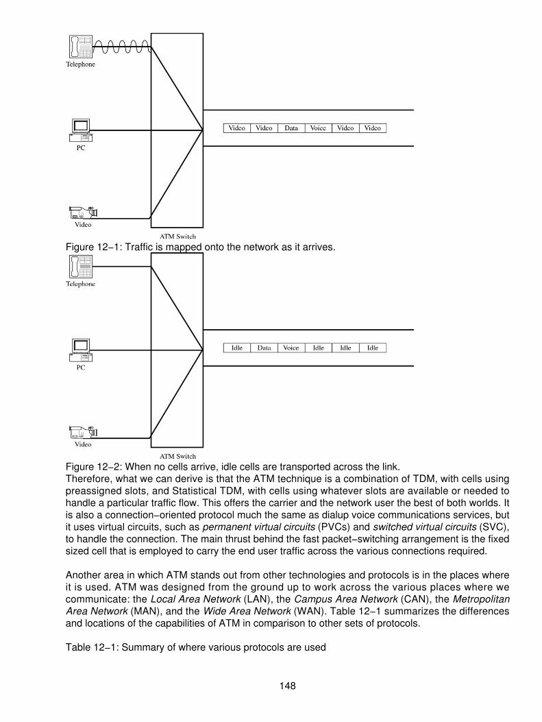
Figure 12−1: Traffic is mapped onto the network as it arrives.
Figure 12−2: When no cells arrive, idle cells are transported across the link.Therefore, what we can derive is that the ATM technique is a combination of TDM, with cells usingpreassigned slots, and Statistical TDM, with cells using whatever slots are available or needed tohandle a particular traffic flow. This offers the carrier and the network user the best of both worlds. Itis also a connection−oriented protocol much the same as dialup voice communications services, butit uses virtual circuits, such as permanent virtual circuits (PVCs) and switched virtual circuits (SVC),to handle the connection. The main thrust behind the fast packet−switching arrangement is the fixedsized cell that is employed to carry the end user traffic across the various connections required.
Another area in which ATM stands out from other technologies and protocols is in the places whereit is used. ATM was designed from the ground up to work across the various places where wecommunicate: the Local Area Network (LAN), the Campus Area Network (CAN), the MetropolitanArea Network (MAN), and the Wide Area Network (WAN). Table 12−1 summarizes the differencesand locations of the capabilities of ATM in comparison to other sets of protocols.
Table 12−1: Summary of where various protocols are used
148

Technology LAN CAN MAN WANDialup network X XLeased line X XEthernet X XGigabit Ethernet X X XToken Ring XFDDI XX.25 networks XFrame Relay XSMDS XATM X X X X
Why the Interest in ATM?
When one considers the disappointing capacities of past technologies, we can see why there is thehype for ATM. ATM will be the basis of many of our future broadband communications systems; assuch, it starts where other technologies stop. Many organizations have escalated their demandsand needs for raw bandwidth, yet no single entity has emerged as a clear−cut winner to deliver theservices necessary to support the demands of today's multimedia applications. Table 12−2compares the capacities of ATM to the other techniques we used in the past. This will give thereader a chance to see what the excitement is all about.
Table 12−2: Summary of speeds for various technologies
Technology Application SpeedsDialup analog switched Modem communications Up to 56 Kbps circuit using current
technologies. Stops at 33.6 Kbps usingolder modems.
Leased line Point to point T1 @ 1.544 Mbps normal, T3 @ 44.736Mbps occasionally.
Ethernet LAN shared/switched bus 10 to 100 Mbps normal, 1,000 and10,000 Mbps emerging.
Token Ring LAN shared ring switched 4 to 16 Mbps normal, or 1,000 Mbpsunder consideration.
FDDI X.25 Shared ring dialup or leasedline
100 Mbps normal. 56 Kbps top end inNorth America, 64 Kbps top end in restof world.
SMDS Frame Relay Shared/switched buspoint−to−point PVC
Up to 34 Mbps common. Starts at 56Kbps normally, top end is 50 Mbps.
ATM Switched PVC Starts at 1.544 Mbps, top end is 622Mbps today, 2.488 Gbps for futureapplication.
A lot of discussion is always bantered in the industry regarding the best way to handle data andvoice communications. There is a continual discussion on the difference between using ATM for thehigher−bandwidth−intensive applications and the use of gigabit Ethernet for the same applications.One cannot predict what the outcome will ultimately be, but it keeps the end user totally confused
149

and uncertain. What could happen is that a complement of both techniques will come rolling out toserve the application and support each other.
The use of ATM over other technologies is, however, an attractive alternative when considering thevarious aspects of the options. For example, ATM offers the following types of service, shown inTable 12−3, which may or may not be defined in other protocols.
Table 12−3: Summary of ATM features and functions
One technology for voice, data, video, and multimediaBandwidth on demand as neededScalable as needs dictateQuality of service (QoS) is well definedManagement systems and services prebuilt into ATMHardware−based switching instead of complicated routing and software schemes
ATM Protocols
It takes many protocols to support an ATM network, which is one of the issues that continuallycomes up as a negative from the supporters of the gigabit Ethernet crowd. To develop thenecessary interfaces in support of the various points within a network (networks are pretty complexin themselves), different protocols are necessary. The actual protocols needed depend on wherethe traffic originates, what transport mechanisms must be traversed, and where the traffic willterminate. To see this in a clear picture, a summary of protocols for the ATM user is shown in Table12−4 and is also shown graphically in Figure 12−3.
150

Figure 12−3: Graphic representation of the ATM protocol interfacesTable 12−4: Summary of where protocols are used for ATM
Location Protocol/SpecificationEnd user to LAN Private User to Network Interface (Private UNI)End user to WAN Public User to Network Interface (Public UNI)Between network nodes in a WAN Public Network Node to Network Node Interface (Public NNI)Between nodes in a interprivateWAN
Private Network Node to Network Node face (Private NNI)
Between carriers in a public network The Intercarrier Interface (ICI)Between a Frame Relay and anATM interface device
Frame User Network Interface (FUNI)
From a legacy router to the network Data Exchange Interface (DXI)On a LAN−to−LAN interconnection LAN Emulation (LANE)Between LAN nodes and othernetwork UNIs
Next Hop Routing (Resolution) Protocol
On a LAN, PBX, or CAN interface Multi−protocol over ATM (MPOA)One can see the reason why the gigabit Ethernet proponents support a simpler and less expansiveset of protocols when dealing with LAN technologies, now moving toward a WAN protocol withLayer 3 switching being developed. The problem with ATM is that in order to support the olderlegacy systems, many protocol points and interfaces are necessary. To get around the problem of"forklift" changes, the necessary protocols have been developed. Due to its protection mechanismfor existing systems, ATM is its own undoing from the opponents of the technique. Too often theopponents cite the different protocols needed instead of what they are actually doing. However, theuse of each of these protocols satisfies a specific need and should not be taken strictly as anoverhead problem, but as an interworking function. If all one can do is complain about the various
151
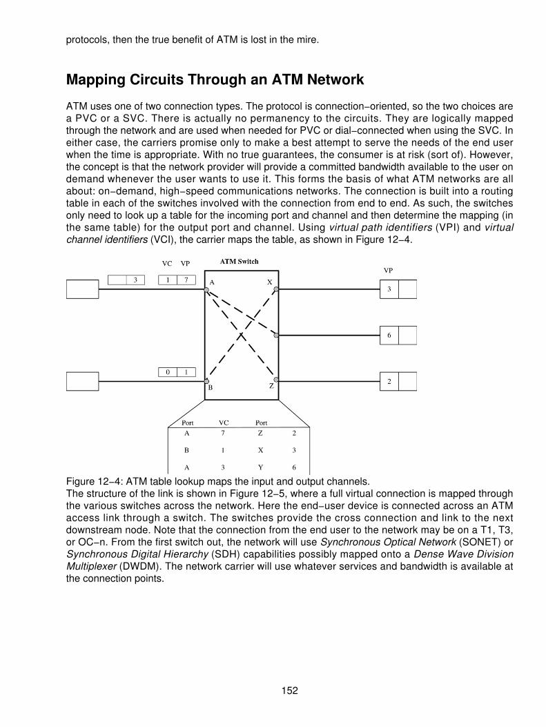
protocols, then the true benefit of ATM is lost in the mire.
Mapping Circuits Through an ATM Network
ATM uses one of two connection types. The protocol is connection−oriented, so the two choices area PVC or a SVC. There is actually no permanency to the circuits. They are logically mappedthrough the network and are used when needed for PVC or dial−connected when using the SVC. Ineither case, the carriers promise only to make a best attempt to serve the needs of the end userwhen the time is appropriate. With no true guarantees, the consumer is at risk (sort of). However,the concept is that the network provider will provide a committed bandwidth available to the user ondemand whenever the user wants to use it. This forms the basis of what ATM networks are allabout: on−demand, high−speed communications networks. The connection is built into a routingtable in each of the switches involved with the connection from end to end. As such, the switchesonly need to look up a table for the incoming port and channel and then determine the mapping (inthe same table) for the output port and channel. Using virtual path identifiers (VPI) and virtualchannel identifiers (VCI), the carrier maps the table, as shown in Figure 12−4.
Figure 12−4: ATM table lookup maps the input and output channels.The structure of the link is shown in Figure 12−5, where a full virtual connection is mapped throughthe various switches across the network. Here the end−user device is connected across an ATMaccess link through a switch. The switches provide the cross connection and link to the nextdownstream node. Note that the connection from the end user to the network may be on a T1, T3,or OC−n. From the first switch out, the network will use Synchronous Optical Network (SONET) orSynchronous Digital Hierarchy (SDH) capabilities possibly mapped onto a Dense Wave DivisionMultiplexer (DWDM). The network carrier will use whatever services and bandwidth is available atthe connection points.
152
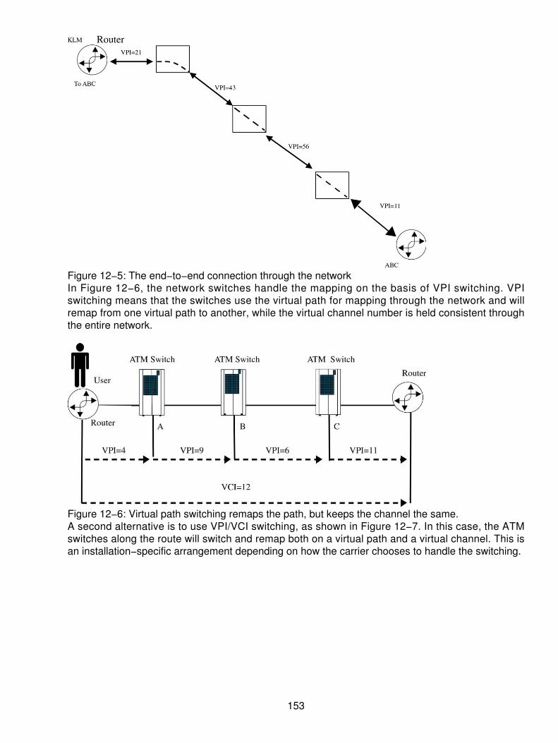
Figure 12−5: The end−to−end connection through the networkIn Figure 12−6, the network switches handle the mapping on the basis of VPI switching. VPIswitching means that the switches use the virtual path for mapping through the network and willremap from one virtual path to another, while the virtual channel number is held consistent throughthe entire network.
Figure 12−6: Virtual path switching remaps the path, but keeps the channel the same.A second alternative is to use VPI/VCI switching, as shown in Figure 12−7. In this case, the ATMswitches along the route will switch and remap both on a virtual path and a virtual channel. This isan installation−specific arrangement depending on how the carrier chooses to handle the switching.
153

Figure 12−7: The virtual path and virtual channel switches process and remap both elements.
The ATM Layered Architecture
Nearly all documents describe the layered architecture of every protocol against the OSI model as areference only. The ATM architecture is no different when trying to compare what the protocol isdoing. Using the OSI model as a base reference, the ATM layers fall typically in the bottom twolayers (data link layer and physical layer) of the architecture. ATM has been designed to run on aphysical medium such as SONET.
In Figure 12−8, the ATM layer is shown as the bottom half of Layer 2 in its equivalency. There is noreal way to draw true one−to−one mapping of the ATM and OSI models, but for purposes of thisdocument, it is done that way. Now the bottom half of the data link layer is ATM, but below the ATMlayer is the physical layer such as SONET or some other physical media dependent layer (SDH,DS3, and so on).
Figure 12−8: Comparing the OSI and ATM layered modelsMoving up the architectural map, we have the upper portion of Layer 2, the LLC equivalent, calledthe ATM adaptation layer (AAL). Within this portion of the Layer 2 protocol stack, several sublayersare seen, depending on the services required. For example, using Figure 12−9 as a reference, theuppermost portion of the layer is called the service specific convergence sublayer (SSCS). This
154

portion of the protocol stack is used when mapping Frame Relay, Switched Multimegabit DataService (SMDS), or another protocol to the ATM adaptation process. Under the SSCS is thecommon part convergence sublayer (CPCS). The combination of the SSCS and the CPCS make upthe convergence sublayer (CS). Convergence, as the name implies, is the changing and melding ofthe data into a common interface for the ATM networks. Following the CS portion of the upper layeris the next sublayer called the segmentation and reassembly (SAR). The SAR is where the data isprepared into a 48−byte payload prior to being submitted to the ATM layer for the header. The CSand the SAR combine to form what is known as the AAL. Table 12−5 shows the combination of theAAL types, the services being provided, and the working relationships between the AAL and thetype of service.
Figure 12−9: Upper−layer services of ATMTable 12−5: Types of AAL and services offered
Type of ServiceClass of Service A B C DTiming Synchronous Synchronous Asynchronous AsynchronousBit rates Constant Variable Variable VariableConnection type Connection oriented Connection
orientedConnectionoriented
Connectionlessoriented
AAL Type 1 Type 2 Type 3−4 Type 3−4−5
ATM Traffic Management
When dealing with traffic management, some of the goals of the ATM Forum and other developersinclude the following:
ATM must be flexible. It must meet the constantly changing demands of the user population.These goals mean that the demands for traffic will rise or fall as necessary, and thereforemanaging this traffic is of paramount importance.
•
ATM must meet the diverse needs of the end−user population. Many users will have varyingdemands for both high− and low−speed traffic across the network. Using a QoS capability
•
155

throughout the ATM network, a user can determine the performance and the capabilities ofhow the ATM network will meet their demands. These demands must be met in terms of thedelay or the actual delivery of the cells across the network. Diverse needs are always goingto be different, depending on the type of service (voice, data, video, or other traffic). Meetingthese diverse needs for multiple users across the single threaded network is a major goal intraffic management and traffic delivery.Cost efficiency is a must. If ATM is truly to succeed, traffic management must also includethe effective usage of all of the circuitry available. ATM is designed to reduce the inefficientcircuit usage by efficiently mapping cells into dead spaces, particularly when data isinvolved. In the past, variable amounts of data would be sent across the network. Although itis good for data because variations exist, such as the use of a fixed cell size and managingthat fixed cell throughout the network in terms of its performance, buffering and delaybecome the crucial issues addressed.
•
Robustness in the event of failure or in the event of excess demand is a requirement of thetraffic management goals. If the network is to be readily available for all users to be able totransmit information on demand, then the network must be very robust to accommodatefailures, link downtime, and so on. Through this process, the managing of traffic mustaccommodate such diverse needs on a WAN.
•
Fair allocation of traffic capacity is essential on a fair and equitable basis. The goal of the trafficmanagement scenario is to ensure that no one user would dominate the network; rather, all userswould have equal access and an equal shot at using the capacity on demand. Specific goals ofdelivery can be achieved through committed information capabilities, but the intent is really to fairlyarbitrate the traffic capacity and divide it up among multiple users. Traffic management is a set ofactions taken by network devices to monitor and control the flow of traffic on the network. Ahighway, for example, is built to carry a certain amount of traffic. Any more traffic at a given time (aone−hour period, for example) causes congestion. Congestion causes frustration and forces sometraffic to overflow to other roads. Each stream of traffic onto a network can carry a finite amount offlow. If the flow exceeds the capacity (bandwidth), then actions must be taken to minimize delays(red lights and green lights are used for flow control), control losses, redirect or discard traffic, andprevent collisions.
When using ATM networks, traffic management becomes critical. Too often the networks are builtaround fixed resources, which are finite and must be managed to provide equitable access andbandwidth to the end user. Network suppliers and carriers are, therefore, under constant pressureto get the best utilization from the networks.
Contention Management
Traffic in the form of asynchronous bursts of information (cells) enters the network at random times.This randomness is what causes the confusion and the unpredictability of the data. To manage thetraffic flow, buffers are used to enable the flow and ebb of traffic volumes. Because data tends to bevery bursty, it is extremely difficult to predict the demands of the network and the capacity needed ata given time. Therefore, when sufficient resources are not available, the use of buffers helps tooffset the immediate demands. It is this bursty traffic that produces a contention for the networkresources.
The use of "leaky buckets" in the buffering of the traffic helps to manage and control the flow oftraffic onto and through the network. The leaky bucket, as the name implies, is a buffer that isconstantly flowing. In Figure 12−10, a leaky bucket concept is shown with the two stages ofbuffering. Traffic enters into the buffers and is tagged, based on the amount of cells enabled by the
156

carrier. If the user exceeds the amount of cell flow per increment (per second, and so on), then thebuffer is filled and begins to empty out the bottom side. If more cells enter the buffer than areallowed, the cells are flagged for discard. A first in, first out (FIFO) concept is normally used tohandle the traffic as it flows, but the end user may flag specific traffic according to application,priority, and the like.
Figure 12−10: Leaky buckets allow for buffering of the traffic.ATM involves finding values that the network needs and making decisions about how the networkwill perform. These decisions involve taking action to ensure its availability to users and to ensurethat all current connections are receiving adequate service based on their class of service. Tofacilitate these decisions, the following performances are examined:
Cell loss ratio (CLR) The ratio of lost cells to the sum of the total number of lost andsuccessfully delivered cells.
•
Cell insertion rate The number of cells inserted into an ATM network within a specificperiod of time.
•
Severely errored cell ratio The ratio of severely errored cells (more than one bit of an errorin the header) to the number of successfully delivered cells.
•
Cell transfer capacity The maximum number of successfully delivered cells over a specifiedATM connection during a period of time (one second).
•
Cell transfer delay (CTD) The average delay and the arithmetic delay of a specified numberof cell delays. The cell delay variation (CDV) is the difference between a specific cell delayand the average. This variation causes the most problems, especially with real−time voiceand video.
•
Priority control Networks must adequately service buffers in the network nodes under allkinds of conditions. When congestion occurs (too many cells in the network), a prioritymechanism can be used in the following ways:
To remedy the situation Some cells can be discarded under congestioncircumstances.
♦
For congestion control Networks must prevent congested conditions from spreadingthroughout the network. In this case, no sender should be allowed to overwhelm anyreceiver, as the network will accommodate by discarding cells.
♦
•
157

As a Generic Cell Rate Algorithm (GCRA) The GCRA is an example of a genericterm. It refers to a virtual scheduling algorithm or a continuously leaky bucket andexpresses a complex series of formulas. In most network implementations, it iswidely known that the double leaky bucket algorithm is what we call the GCRA.Using the leaky bucket as a means of describing the GCRA is a good way to figureout exactly what is happening. The GCRA functions like a bucket with a hole in thebottom. The bucket leaks at a steady rate, no matter when water is poured into thebucket. The bucket may be initially empty, partially full, or full to the brim. As waterpours in, it may splash or completely overflow the bucket if poured in from a muchlarger container. Water emerges from the hole in the bucket at precisely the samerate at all times. (Of course, everyone knows there are no real buckets in computersand networks, although the term "bit−bucket" is constantly used.)
♦
As a counter or buffer The simplest leaky bucket implementation is a counter. Thecounter has a minimum value (usually 0) and a maximum value. With the emptybucket, it holds up to 100 cells. All of a sudden, 150 cells are delivered to thenetwork. This means that the bucket will overflow, or the 50 cells will be discardedbecause the buffer can only hold 100. At the bottom, the cells enter the network at aratio of 1 over the sustained cell rate (SCR). Cells will exit at a steady rate.
♦
The Double Leaky Bucket
In this double leaky bucket case, which was used in most of the early implementations of ATM, cellsarrive from the CPE across the UNI totally uncontrollable in time. All cells leaking into the networkare sent with a cell loss priority (CLP) equal to zero. As long as the arriving cells do not exceed agiven rate, they are admitted to the network unchanged. If the cell arrival rate exceeds the limitimposed by the network, namely the SCR of the connection, the cells in excess of this limit havetheir loss priority bits changed to one. The cells with a CLP equal to one are subjected to anotherleaky bucket with another limit. Any cells sent with a CLP equal to one already set are also added tothe cell stream. However, this time the limit corresponds to the maximum burst size of theconnection. Cells under the MBS are admitted onto the network, while any others are discarded.This double leaky bucket is shown in Figure 12−11.
158

Figure 12−11: A double leaky bucketHere are two functions in ATM network implementation that perform traffic control:
The connection administration control (CAC) Networks must set aside the proper amount ofresources to service a connection at the time of the connection, whether it was set up as aservice provision time on a semipermanent basis, or by means of a signaling protocoldynamically.
•
The usage parameter control Networks must police the UNI to make sure cell trafficvolumes do not affect overall network performance.
•
Traffic control and management can also be based on a credit− and debit−type system. As trafficenters the buffers, a certain amount of cells are authorized to enter the buffer. As the cells fill thebuffers, they use up the credits allowable. When any extra cells are introduced into the buffers, thena second stage buffer can be used for the traffic as being eligible for discard. If, in fact, the eligibilityfor discard is exceeded, any new cells are automatically flushed away. These mechanisms are usedto control the flow of data into the network. If some type of control is not used, the switches across
159

the wide area can get into trouble. Buffer overruns and system overloads can also occur. If thiscontinues to occur, the network suppliers cannot provide or live up to their guarantees for servicelevels. The continuous overruns across buffers and switches will cause severe congestion and snarlthe network to a grinding halt. Data from real−time applications will be delayed, requiring a requestfor retransmission from the upper layers in the protocol stacks, thereby causing even morecongestion. This is not a situation that can be taken lightly. To resolve the situation quickly, severaltraffic functions are used to manage the network and deliver the promised QoS, that elusive termeveryone banters around, but no one understands.
Categories of Service
Because of the risks associated with the congestion and the impairments to delivering the QoS,several techniques are used to shape the traffic and prevent massive congestion. The networkproviders offer specific service offerings based on the VPI and VCI for the end−user applications.These come in several types of services, as shown in Table 12−6 and constitute the way the trafficservice offerings can be provided.
Table 12−6: Comparing the categories of service
Service Category Equates toConstant bit rate (CBR) The equivalent of a dedicated point−to−point leased line. This type
of service is used when a specific amount of throughput is required,but it changes infrequently. The end user can commit to a fixedbandwidth and throughput and pay accordingly for the sustainedthroughput demands. The user will get and use a peak cell rate(PCR) from the carrier. This type of service can be used forreal−time applications such as videoconferencing, sustained filetransfers, telephony applications, audio applications, and the like.
Variable bit rate in real−time(VBR−rt)
This service is a variable rate of throughput typified by some of thesame real−time applications listed previously but not always thesame sustained rate of throughput. This service may also apply toapplications that cannot tolerate lengthy delays such as real−timeSNA traffic, financial transactions, compressed and packetizedvideo or voice applications, and some forms of multimedia. In thisservice, the customer will buy into a PCR, a Sustainable cell rate(SCR), and a Maximum Burst Size (MBS) for the traffic.
Variable bit rate (VBR−nrt) This service category is characteristic of nonreal−time bursts ofdata, but requires delivery guarantees from the carrier. This type ofconnection uses similar agreed−to definitions as listed in theprevious VBR−rt mode. This includes the PCR, SCR, and MBSmodes of data transmission. The real application here may be dataprocessing, transaction processing, banking and credit cardprocessing, and airline reservation services. Some process controlapplications also fall into this category.
Unspecified bit rate (UBR) UBR does not specify any form of QoS guarantees from thenetwork. Applications here can handle delay and latency without toomuch trouble. The network provider will make a best effort to deliverthe traffic within a reasonable amount of time. This can apply toapplications such as e−mail, file transfers, remote printing,LAN−to−LAN interconnections, and telecommuting services for a
160

small office/home office (SOHO).Available bit rate (ABR) The ABR is suited for applications that can definitely tolerate longer
delays on the network. The ABR adapts to whatever resources thenetwork has available, rather than a specified amount of throughput.Typically, the ABR also uses a minimum cell rate (MCR) as a meansof controlling the traffic. The network continually feeds backinformation on the regular traffic and therefore allocates the MCR tohold the connection alive, while other traffic runs across the networkin a priority over the ABR rate.
Getting to the Elusive QoS
Above and beyond the ways that the ATM networks allocate resources as shown in the categoriesof service described previously, other methods are used to get to the elusive QoS guarantees. ThePVCs in an ATM network can be provisioned with certain throughput parameters. The primaryparameters are listed here:
Cell loss ratio (CLR)• Maximum cell transfer delays (maxCTD)• Cell delay variations (CDVs)•
Each of these methods is described briefly here for the sake of knowing what the accomplished goalis:
The CLR is a means of determining the ratio of lost cells to the total number of cells thathave been transmitted. There are many reasons why cells get lost, yet the goal is to hold theamount of lost cells to a minimum. An ATM switch can discard calls that have beencorrupted, especially the header. Moreover, cells can be explicitly marked (tagged) aseligible for discard if the network gets congested. The formula for the ratio is as follows:
CLR = Lost cells/total cells transmitted
•
The CTD is calculated as the total amount of elapsed time from when a cell enters a network(a switch) until it exits the network. This takes into account the total amount of internodalprocessing time, buffering time, and propagation delays across whatever the medium isused.
CTD = Node processing 1…n + buffer 1…n + propagation n
•
The third formula is used to calculate the average amount of variations used in the celldelays. Often this is called jitter on the network where timing is lost or skewed a little to theleft of right of the average. The mean of the variations is the overall delay variation. This istypically used for applications requiring some real−time consequence, such as packetizedvoice or video.
•
Shaping the Traffic
The ITU−TSS defines four possible situations when a cell enters an ATM network:
Successfully delivered The cell arrives at the destination with less than time T−cell delay.•
161

An errored cell occurs A cell arrives with at least one detected bit error in the informationfield in the cell. Another possibility is the severely errored cell with information bits errorsequal to n or n>1.
•
Lost cells A cell either never arrives or arrives after the time T−cell delay, in which case it isdiscarded at the destination.
•
An inserted cell A cell contains an undetected error or is misdirected by an ATM node andtherefore shows up at the wrong destination.
•
In the bandwidth, the user is allocated a certain amount of capacity across the network. Clearly, thenetwork will perform in different peaks and valleys, as shown in this picture. As the increase of cellsper second grows and exceeds the network available rate for normal traffic over a period of time,the network will begin to discard cells. Although buffering might take place for certain periods oftime, cells will likely be discarded because the network won't be able to process all of them.
If the user exceeds the network rate, the cells will be discarded, and the user will, therefore, have toretransmit at a later time, as shown in Figure 12−12.
Figure 12−12: When a user exceeds the network rate, then cells are discarded.
Normal Bandwidth Allocation
If, in fact, the user does not exceed the network rate or the agreed−to rate the network will provide,and the user traffic is shaped, under the capacity, then the available capacity left over will beprovided to other users. Allocating this capacity on a fair and equitable treatment can far moreefficiently use the ATM network.
Once again, as the users exceed their network thresholds, the network will discard cells, but if theydo not exceed the network rate, the network should deliver all available cells delivered to thenetwork, as shown in Figure 12−13.
162

Figure 12−13: Cells enabled through the network when the user does not exceed the agreed−uponthroughput
What Is MPOA?
The goal of Multiprotocol on ATM (MPOA) is the efficient transfer of inter−subnet unicast data in aLANE environment. MPOA integrates LANE and Next Hop Resolution Protocols (NHRPs), alsoknown as Next Hop Routing Protocols, to preserve the benefits of LANE while enabling intersubnet,internetwork layer protocol communication over ATM Virtual Circuit Connections (VCCs) withoutrequiring routers in the data path. MPOA provides a framework for effectively synthesizing bridgingand routing with ATM in an environment of diverse protocols, network technologies, and IEEE 802.1virtual LANs (VLANs). This is designed to provide a unified paradigm for overlaying internetworklayer protocols on ATM. MPOA is capable of using both routing and bridging information to locatethe optimal exit from the ATM cloud.
MPOA enables the physical separation of internetwork layer route calculation and forwarding, atechnique known as virtual routing. This separation provides a number of key benefits:
It enables efficient intersubnet communication.• It increases manageability by decreasing the number of devices that must be configured toperform internetwork layer route calculation.
•
It increases scalability by reducing the number of devices participating in internetwork layerroute calculation.
•
It reduces the complexity of edge devices by eliminating the need to perform internetworklayer route calculation.
•
MPOA provides MPOA Clients (MPCs) and MPOA Servers (MPSs), and defines the protocols thatare required for MPCs and MPSs to communicate. MPCs issue queries for shortcut ATM addressesand receive replies from the MPS using these protocols. MPOA also ensures interoperability withthe existing infrastructure of routers. MPOs also make use of routers that run standard internetworklayer routing protocols, such as Open Shortest Path First (OSPF), providing a smooth integrationwith existing networks.
LANE
Whenever we deal with the choice of service offering, we wind up with confusion. Such was thecase when ATM was introduced as a means of replacing LANs such as Ethernet and Token Ring.
163

Users were confused as to when this would be done and why it should be done. Moreover, the costof such a change was not inconsequential. An Ethernet card sells for $10 to 20 and will support10/100 Mbps. However, an ATM LAN card will cost $200+ with some being offered at $400. Thus,the industry decided to resolve the confusion. A standard has been developed for encapsulatingand transmitting Internetwork protocols such as TCP/IP over ATM networks. One such protocol isLAN Emulation (LANE). To make it possible to continue using existing LAN application softwarewhile taking advantage of the increased bandwidth of ATM transmission, standards have beendeveloped to enable the operation of LAN layer protocols over ATM. LANE is one such method,enabling the replacement of 10 Mbps Ethernet or 4/16 Mbps Token Ring LANs with dedicated ATMlinks. It also enables the integration of ATM networks with legacy LAN networks. This softwareprotocol running over ATM equipment offers two major features:
The capability to run all existing LAN applications over ATM without change. The immediatebenefit is that it is not necessary to reinvest in software applications.
•
The capability to interconnect ATM equipment and networks to existing LANs and also thecapability to link logically separate LANs via one ATM backbone. The benefit is that ATMequipment may be introduced only where it is needed.
•
The function of LANE is to emulate a LAN (either IEEE 802.3 Ethernet or 802.5 Token Ring) on topof an ATM network. Basically, the LANE protocol defines a service interface for higher−layerprotocols, which is identical to that of existing LANs. Data is sent across the ATM networkencapsulated in the appropriate LAN Media Access Central (MAC) packet format. Thus, the LANEprotocols make an ATM network look and act like a LAN, only much faster.
Therefore, for LANE to operate as a traditional LAN, there must be the appearance of aconnectionless service. This is the most important function for LANE. The main objective of theLANE service is to enable existing applications to access the ATM network by way of MAC driversas if they were running over traditional LANs. Standard interfaces for MAC device drivers includeNetwork Driver Interface Specifications (NDIS), Open Data−link Interface (ODI), and Data−linkProvider Interface (DLPI). These interfaces specify how access to a MAC driver is performed.Although the drivers may have different primitives and parameter sets, the services they provide aresynonymous. LANE provides these interfaces and services to the upper layers.
LANE was designed to enable existing networked applications and network protocols to run overATM networks. It supports using ATM as a backbone for connecting "legacy" networks. It was alsodesigned to support both directly attached ATM end systems and end systems attached throughLayer 2 bridging devices. In addition, because one of the goals of ATM is to provide completeworldwide connectivity, it is important to enable multiple emulated LANs to exist on the samephysically interconnected ATM network shown in Figure 12−14. The choices for connecting the twoends together include the following:
164

Figure 12−14: The configuration of Ethernet and ATM combined
Ethernet−attached end systems may communicate with other Ethernet−attached endsystems through bridges across the ATM network in a backbone−type configuration.
•
ATM−attached end systems may communicate with ATM−attached servers and both maycommunicate with Ethernet−attached end systems via the bridges.
•
Significant portions of the LANE protocol were designed specifically to address the bridging−relatedissues. The specification refers to bridges generically as proxies. A proxy is any edge device thatneeds to forward LAN traffic, but may not have definitive information about the stations that arelocated on the legacy side.
The LANE configuration server takes requests from LANE clients and provides information on theLAN type being emulated and which LANE server to use. In its request, the LANE client mustprovide its ATM address as well as its 6−byte LAN address. The configuration server then providesthe ATM address of the LANE server, to which the client connects in order to join the emulatedLAN.
End stations and proxies are treated the same until they start communicating with the LANE server.The problem is that if the proxy is a bridge, it cannot know the MAC address of all the stations itmay serve. The bridge learns about stations over time.
An end station only needs to join the emulated LAN and set up the virtual circuits to communicateand the virtual circuits used to control the connection. It must inform the LANE server about suchthings as its desired maximum frame size and LAN type. A proxy client must register as a proxy.
One of the jobs a LANE server may tackle is translating MAC addresses into ATM addresses orpassing MAC addresses onto some device that can translate them.
One solution allowed under LANE for bridges involves a special virtual circuit for transmitting alladdress resolution requests that the LANE server can't resolve. The bridge can respond if theaddress is already in its address tables, and then employ its normal mechanisms to attempt toresolve the address for the emulation server. Otherwise, the bridge does nothing; if it does nothing,
165

the client must use the broadcast and unknown frame server (BUS) to broadcast unknown frames.
The BUS, in addition to assisting in address resolution, helps facilitate the delivery of small numbersof unicast packets — for example, those packets occasionally sent by network managementstations, where a virtual connection isn't really warranted. The BUS also delivers broadcasts andmulticasts.
What this means is that although the service is available for high−speed LANs and high−speedWANs, LANE melds the two services together into a single homogenous networking strategy for anorganization. A lot of hype was built into the delivery of LANE, yet the acceptance of LANE has metwith only mild enthusiasm.
Voice over DSL and over ATM (VoDSL and VoATM)
In general, a VoDSL system functions as an overlay solution to a DSL broadband access network,enabling a LEC or CLEC to extend multiline local telephone service off of a centralized voice switch.For example, some VoDSL solutions enable up to 16 telephone lines and high−speed continuousdata service to be provided over a single digital subscriber line (DSL) connection. A VoDSL solutiontypically consists of three components:
First, a carrier−class voice gateway that resides in the regional switching center (RSC) andserves as a bridge between the circuit−based voice switch and the packet−based DSLaccess network.
•
Second, an Integrated Access Device (IAD) resides at each subscriber premises andconnects to a DSL circuit. It also serves as a circuit/packet gateway and provides thesubscriber with standard telephone service via up to 16 analog plain old telephone service(POTS) ports and Internet service via an Ethernet connection.
•
Third is the management system.•
With VoDSL solutions, DSL broadband access networks now have the coverage, capacity, and costattributes to enable LECs and CLECs to deliver local telephone services as well as data services tothe small and midsize business markets as shown in Figure 12−15.
166

Figure 12−15: VoDSL can be provided easily.It has already been established that DSL access networks have the right bandwidth to serve thedata needs of small and midsize businesses. With VoDSL access solutions, this is true for servingthe local telephone service needs of those subscribers as well. Some VoDSL solutions are capableof delivering 16 telephone lines over a DSL circuit along with standard data traffic. Because 95percent of small businesses use 12 or fewer telephone lines, a single DSL circuit provides sufficientbandwidth to serve the voice needs of the vast majority of the market. In addition, if more than 16lines are required, most VoDSL solutions enable a provider to scale service by provisioningadditional DSL connections. In addition to providing the right capacity for providing local telephoneservice, DSL broadband access networks are very efficient in the way they deliver service.TDM−based transport services, such as a T1 line, require the bandwidth of the line to bechannelized and portions dedicated to certain services, such as a telephone line. Even if a call isnot active on that line, the bandwidth allocated to that line cannot be used for other purposes. DSLaccess networks are packet−based, allowing VoDSL solutions to use the bandwidth of a DSLconnection dynamically. VoDSL solutions only consume bandwidth on a DSL connection when acall is active on a line. If a call is not active, then that bandwidth is available for other services, suchas Internet access. This dynamic bandwidth usage enables providers to maximize the potential ofeach DSL connection, delivering to subscribers the greatest number of telephone lines and highestpossible data speeds.
Because telephony traffic is more sensitive to latency than data traffic, VoDSL solutions guaranteethe quality of telephone service by giving telephony packets priority over data packets onto a DSLconnection. In other words, telephony traffic always receives the bandwidth it requires, and datatraffic uses the remaining bandwidth. Fortunately, telephony traffic tends to be very bursty over thecourse of a typical business day, so the average amount of bandwidth consumed is minimal. Forexample, over a single 768 Kbps symmetric DSL connection, a LEC or CLEC could provide 8telephone lines (serving a PBX/KTS with 32 extensions) and still deliver data service with anaverage speed of 550 Kbps.
VoATM unites ATM and DSL technologies to deliver on the promise of fully integrated voice anddata services. VoATM meets all requirements in terms of QoS, flexibility, and reliability because theunderlying technology is ATM, a highly effective network architecture developed specifically to carrysimultaneous voice and data traffic.
167

ATM Suitability for Voice Traffic
Sometimes mistakenly associated with Voice over IP (VoIP), VoATM is a completely separatetechnology that predates VoIP. In contrast to IP and Frame Relay, ATM uses small, fixed−lengthdata packets of 53 bytes each that fill more quickly, are sent immediately, and are much lesssusceptible to network delays. (Delays experienced by voice in a Frame Relay or IP packet networkcan typically be 10 times higher than for ATM and increase on slower links.) ATM's packetcharacteristics make it by far the best−suited packet technology for guaranteeing the same QoSfound in "toll−quality" voice connections.
The part of ATM responsible for converting voice and data into ATM cells, the AAL, enables varioustraffic types to have data converted to and from the ATM cell and translates higher−layer services(such as TCP/IP) into the size and format of the ATM protocol layer. A number of AAL definitionsexist to accommodate the various types of network traffic. Those AAL types most commonly usedfor voice traffic are AAL1, AAL2, and AAL5.
VoATM with AAL1 is the traditional approach for CBR, time−dependent traffic, such as voice andvideo, and provides circuit emulation for trunking applications. ATM with AAL1 is still suitable forvoice traffic, but is not the ideal solution for voice services in the local loop because its design forfixed bandwidth allocation means network resources are consumed even when no voice traffic ispresent. AAL5 is used by some equipment manufacturers to provide VoATM, it provides support forVBR applications, and it is a better choice over AAL1 in terms of bandwidth used. However, themeans for carrying voice traffic over AAL5 is not yet fully standardized or widely deployed, andimplementations are usually proprietary.
ATM with AAL2 is the newest approach to VoATM. AAL2 provides a number of importantimprovements over AAL1 and AAL5, including support for CBR and VBR applications, dynamicbandwidth allocation, and support for multiple voice calls over a single ATM PVC. An additional andsignificant advantage of AAL2 is that cells carry content information. This feature enables the trafficprioritization for packets (cells) and is the key to dynamic bandwidth allocation and efficient networkuse.
Integrated Access at the Local Loop
Because DSL links are ready−made for voice and data, and ATM excels at carrying varied traffic,using VoATM over DSL over the local loop to the customer is a natural extension of these services.To enable the combination, equipment that supports VoATM is needed at each end of the localloop: a next−generation integrated access device (IAD) at the customer premises and a voicegateway at the CO as shown in Figures 12−16 and 12−17.
168

Figure 12−16: The IAD will add services for the future.
Figure 12−17: Combining the ATM and DSL at the local loopThese devices make it possible for the local exchange provider or the competitive DSL provider touse the existing facilities and still satisfy the needs of voice and data over the existing local loop.Using voice over the DSL circuit enables up to 16 simultaneous VoIP calls and Internet access tosimultaneously run over the bandwidth on the single cable pair.
169

Chapter 13: ATM and Frame Relay Internetworking
Overview
Since 1992, two major developments have rolled into the carrier networks. The first was theimplementation and rollout of Frame Relay networking protocols. Frame Relay met with immediatesuccess because of its ability to handle Wide Area Networking data traffic, replacing (orcomplementing) older X.25 networks. The network suppliers had to upgrade their equipment tosupport the newer protocols in their packet switches. Although Frame Relay met with instantsuccess, as described in Chapter 11, "Frame Relay," it was introduced as a data−only service forthe WAN. The commitment to equipment and labor to upgrade the network became a very heavyburden.
As with most carriers, network equipment has traditionally been depreciated over a 20−year period.Thus, when Frame Relay began rolling into the marketplace in 1992, the depreciation windowopened with an end−date of 2022 and counting. Frame Relay was deployed in every major networkaround the world because of its flexibility and cost advantages over the older protocols. The resultwas a widely deployed and well−accepted international standard for data communications.
The second major development introduced also in 1992 was ATM. ATM is a robust set of protocolsthat works in more than the WAN, but is designed to work across the various platforms of networkfrom the LAN, CAN, MAN, and WAN. Because it was designed as a transport set of protocols towork at layer 2 of the OSI equivalent model, ATM both competes with and complements the use ofFrame Relay. Yet, ATM goes further than just being a data transmission set of protocols. It isdesigned to carry voice, data, video, and high−speed multimedia traffic. As a broadbandcommunications set of protocols, ATM is the one set of operating protocols that meets theexpectations of the end user, local and long distance carrier, and the equipment manufacturersalike. But, like all new protocols that cross boundaries (between the voice and data worlds), ATMneeded some added enhancements that were not ready in 1992. Consequently, ATM did not startto catch on until late 1995 and early 1996. Moreover, ATM has been specified and studied to death,slowing its acceptance. Just before 2000, ATM was accepted and standardized as a set of protocolsfor the network providers throughout the world.
What remains is a problem with the rollout of the equipment and other associated interfaces. Wherethe carriers have endorsed and embraced Frame Relay, they now have to upgrade to an ATMbackbone network. This will require significant investments. Moreover, the carriers will still have theFrame Relay switches in the networks that are on the books, usable and still viable traffic handlingmachines. To solve the problem, several techniques were developed to enable legacy systems,new systems, Frame Relay, and ATM all work together. This concept has been deemed as FrameRelay and ATM internetworking. In reality, it is a form of interworking instead of internetworking.
ATM and Frame Relay Compared
One way to understand the interworking functionality of the two sets of protocols is to compare andcontrast the capabilities of the two protocols. Table 13−1 is used as an overall summary of the twotechniques in use today.
What you can see from the comparison is a summary of the characteristics of the two serviceofferings from the carriers. This is not the whole story, but it does give the reader a visual means ofseeing where and why the two techniques have become popular.
170
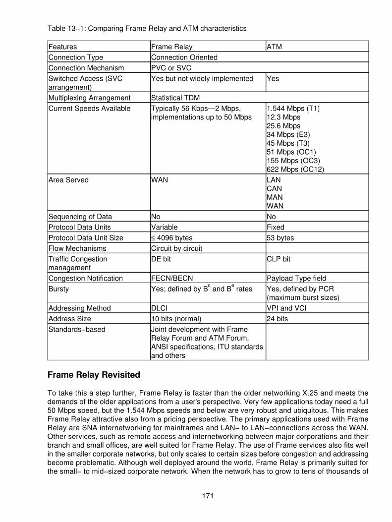
Table 13−1: Comparing Frame Relay and ATM characteristics
Features Frame Relay ATMConnection Type Connection OrientedConnection Mechanism PVC or SVCSwitched Access (SVCarrangement)
Yes but not widely implemented Yes
Multiplexing Arrangement Statistical TDMCurrent Speeds Available Typically 56 Kbps—2 Mbps,
implementations up to 50 Mbps1.544 Mbps (T1)12.3 Mbps25.6 Mbps34 Mbps (E3)45 Mbps (T3)51 Mbps (OC1)155 Mbps (OC3)622 Mbps (OC12)
Area Served WAN LANCANMANWAN
Sequencing of Data No NoProtocol Data Units Variable FixedProtocol Data Unit Size ≤ 4096 bytes 53 bytesFlow Mechanisms Circuit by circuitTraffic Congestionmanagement
DE bit CLP bit
Congestion Notification FECN/BECN Payload Type fieldBursty Yes; defined by Bc and Be rates Yes, defined by PCR
(maximum burst sizes)Addressing Method DLCI VPI and VCIAddress Size 10 bits (normal) 24 bitsStandards−based Joint development with Frame
Relay Forum and ATM Forum,ANSI specifications, ITU standardsand others
Frame Relay Revisited
To take this a step further, Frame Relay is faster than the older networking X.25 and meets thedemands of the older applications from a user's perspective. Very few applications today need a full50 Mbps speed, but the 1.544 Mbps speeds and below are very robust and ubiquitous. This makesFrame Relay attractive also from a pricing perspective. The primary applications used with FrameRelay are SNA internetworking for mainframes and LAN− to LAN−connections across the WAN.Other services, such as remote access and internetworking between major corporations and theirbranch and small offices, are well suited for Frame Relay. The use of Frame services also fits wellin the smaller corporate networks, but only scales to certain sizes before congestion and addressingbecome problematic. Although well deployed around the world, Frame Relay is primarily suited forthe small− to mid−sized corporate network. When the network has to grow to tens of thousands of
171

nodes, Frame Relay may run out of capacity and capability very quickly. Moreover, Frame Relay isalready in place so it is used more heavily. Figure 13−1 is a graphic representation of the use ofFrame Relay in the WAN by carriers and end−users alike. In this graphic, the Frame Relay switchesare deployed in the carriers' networks, whereas the routers on a LAN use the Frame Relayprotocols. This allows the interconnectivity across the WAN in a straightforward and cost efficientmanner. Frame Relay is also well suited for the bursty traffic typified across the LAN−to−WANnetworks.
Figure 13−1: Frame Relay in various placesATM Revisited
ATM, on the other hand, uses a fast relay systematic approach to data handling. By using thefixed−sized cells across the ATM switching fabric, the process of cell transmission can occur veryquickly. ATM supports added functionality and capability in differing applications, such as theintegration of voice and video across multiple platforms. Even though voice across ATM was slowerin developing, ATM was designed to carry the various traffic types in the cells. The ATM model isshown in Figure 13−2 where ATM was designed to work. This is a quick review of the twotechniques so that you will have an understanding of why they must interwork in order to achieveharmony across the networks.
172

Figure 13−2: ATM in various usesThis graphic shows the integration of the various forms of information (voice, data, and video), aswell as the locations in the LAN, CAN, MAN, and WAN. You can see that the piece parts installed atthe customer locations may include an ATM router, an ATM switch, or an ATM PBX (not shown inthe graphic). These changes require significant investments, not only by the consumer, but also bythe carriers where each of the LEC, CLEC, and IEC interfaces use ATM switches in the backbone.ATM switches cost great amounts of money for a carrier to install and maintain.
The Frame and ATM Merger
Because of the dilemma between the two differing techniques, both the ATM and Frame RelayForums took action to align the two standards more closely to allow for the interworking andinternetworking between them. Both protocols have very defined characteristics that make themdesirable. Both also have parameters that are easily matched up to the other. By aligning theseparameters together, the interworking function is more easily accomplished. The similaritiesbetween the two technologies make them complements of each other without creating a directconflict when properly planned. By combining both technologies, carriers and end users alike canprotect their investments and preserve the infrastructure of the networks in place today. Withoutmajor renovations to the architecture, logical progression from frame−based services to cell−basedservices in the future will become far more acceptable. As a matter of fact, the combinedtechnologies are rapidly being accepted and implemented throughout the industry.
Transparency Across the Network
The real goal is to provide for transparency across the network. End users running Frame Relayneed not concern themselves with the fact that the carrier is likely running ATM in the backbone.This is shown in Figure 13−3 where the carrier is providing high−speed connectivity across the
173

WAN, but the local attachment is using Frame Relay.
Figure 13−3: Frame and ATM coming togetherStill another way of looking at the network interworking is to have Frame Relay on one end andATM at the other end through the network (see Figure 13−4).
Figure 13−4: Frame Relay to ATM conversionsEither way, this is achieved with relative ease from the perspective of the carrier and the end user.Transparency is what is necessary to make this happen. The interworking functionality is a realitytoday.
174

Frame User−to−Network Interface (FUNI)
Providing the interfaces to the internetworking services, the ATM forum specified the FrameUser−to−Network Interface (FUNI) in order to allow frame−based services to access an ATMnetwork. FUNI allows traffic to be passed from the two different networking technologies by using anindustry−standardized interface. This provides the carrier and the user with a migration path for thefuture, while serving today's needs. The ATM forum was careful to describe the differences in twoterms before specifying the protocols needed: interworking and Internetworking. Although they mayappear to say the same thing, subtle differences exist between the two concepts. The two termsdefined are as follows:
Interworking A technique that allows the two systems on the ends to run Frame Relay asshown earlier in Figure 13−3, yet run ATM across the backbone. Thus, the systemsinterwork with each other. Frame Relay is on both sides of the network so we canencapsulate or tunnel the traffic through the ATM network, but the traffic entering and exitingthe backbone is still Frame Relay on both sides.
•
Internetworking Uses techniques to convert the traffic from one form to another, much thesame as a protocol converter or a gateway. A device that sits at the edge of the networkearlier performs the internetworking (or interworking) function (see Figure 13−4). The deviceis typically referred to as an IWF.
•
Taken one step further, the ATM Forum defined this interworking in two different categories:
Service interworking• Network interworking•
Network interworking means that Frame is supported through the ATM backbone. The operations ofthe network nodes are performing actual actions on the data in the form of a convergencesublayering function. Network interworking supports AAL5 as a specified and optional AAL3/4 in theperformance of its interface.
FUNI is capable of handling and supporting the basic functions at the UNI such as the following:
VPI/VCI multiplexing• Network management• Traffic and congestion control (shaping)• Operation, administration, maintenance, and provisioning (OAM & P) functions•
Although these functions are supported, they may be limited in their overall performance andfunctionality. FUNI does not support some of the traffic types (such as AAL 1 and 2), so therefore itdoes not support the corresponding signaling and traffic parameters for these traffic types. Inaddition, the FUNI is designed to support variable bit rate (nonreal time) and unspecified bit rateclass of traffic.
Data Exchange Interface (DXI)
Data Exchange Interface (DXI) is another of the interfaces used to internetwork various servicesacross an ATM backbone. Functionally, the FUNI and DXI provide the same services with minormodifications. DXI is used with legacy routers that are not ATM equipped, but use the DXI protocolsand interfaces to provide frame−based services to the Data Service Unit (DSU) on the circuit where
175

the cells are then generated. The DXI uses the DSU whereas the FUNI does not. Moreover, DXIdoes not use fractional T1 services, where FUNI can. A comparison of the FUNI and the DXIinterfaces is shown in Figure 13−5.
Figure 13−5: DXI and FUNI interfaces comparedWhen comparing the DXI and the FUNI interfaces as the means of internetworking the services, it isappropriate to view the overhead comparisons of frame−based services contrasted with thecell−based services of ATM (see Figure 13−6).
Figure 13−6: Contrast of frame− and cell−based servicesThe FUNI reference model as defined by the ATM forum is shown in Figure 13−7. The interworkingfunctionality gives an idea of the mapping of services across the FUNI to an ATM network. Theupper portion of the graphic represents the block flow; whereas the lower portion of the graphicshows the protocol stacks as they compare between the interworking functions.
176

Figure 13−7: FUNI reference modelWith this protocol analysis in mind, there are some subtleties between the Frame Relay protocoland the mapping across the ATM platform through the IWF on a network. In this case, the graphicshown in Figure 13−8 represents the interworking functions as they align to the reference modelshown. Once again, the upper portion of the graphic is the block diagram of the network, and thelower portion of the graphic shows the protocol stack.
Figure 13−8: ATM Interworking Function (IWF)
What Constitutes a Frame?
The market still is unsettled. More low−end, low−cost devices are being sold every day. Users aretrying to preserve their investments and hold the line on new, higher−cost investments as long aspossible. With the growth projection for this market, something had to be done. Interworking is theanswer. However, the frame−based services in legacy equipment and the Frame Relay devices will
177

still exist for some time to come. The frame is therefore important to provide the interoperations andinterworking between frame−based and call−based networking components. FUNI and DXI allowthe frame−based access to the ATM networks, while Frame Relay allows frame−based access to aFrame Relay network. DXI, FUNI, and Frame Relay have similar frame structures. The headers ofFUNI and DXI within the frames are identical to each other, but different from Frame Relay headers.The bit patterns fall in the same logical structure as a Frame Relay frame, so they can be mappedsomewhat consistently. Figure 13−9 compares the bit patterns of the frame structures for FUNI,DXI, and Frame Relay.
Figure 13−9: Comparing the framesWhen the frame is then segmented into cells, the DXI frame address and the FUNI frame addressfields can both be mapped to a VPI/VCI in ATM by using the same process. Frame Relayinterworking functions can use the same addressing map. The Frame Relay to ATM interworkingfunctions can also use other mapping of the data formats.
The next step from the original frame format is to segment the FUNI frame into ATM cells, using amapping of the frame address into an ATM VPI/VCI. This is shown in Figure 13−10 where the actualheader information is segmented into the cells and delineated into the appropriate VPI/VCI. TheCongestion Notification (CN) bit performs much the same function as the Forward ExplicitCongestion Notification (FECN) bit in Frame Relay. The network will set this bit during periods ofnetwork congestion in the same direction as the traffic flow where the congestion exists. The FrameRelay Backward Explicit Congestion Notification (BECN) bit does not have a suitable equal in theFUNI or the DXI.
178

Figure 13−10: FUNI segmented into cells
FUNI Interoperability
When a FUNI device needs to establish a switched virtual circuit to some end point, it doesn't matterwhat the other device is (FUNI, DXI, or ATM). The use of a call set−up mechanism in signaling isthe same as the ATM signaling procedure at the UNI. When FUNI traffic is delivered across theATM networks, it doesn't matter if the data terminates at another FUNI or an ATM device. Theseservice aspects are transparent to the network and the devices. Because FUNI is an ATM protocol,the multiprotocol encapsulation procedures at the ATM UNI are used at the FUNI, so there are noissues related to interoperability. Looking at Figure 13−11, one can see that the interoperabilityissues were addressed up front to prevent any downstream problems in the protocol orinteroperability standards for ATM.
Figure 13−11: FUNI, DXI, and ATM interoperability
Network Interworking
The network interworking function provides the transport of Frame Relay user traffic transparentlyacross the ATM link. It also handles the PVC signaling traffic over ATM. As already discussed, thisis sometimes called tunneling through the network. Other times it is called encapsulating the traffic.Regardless of the name it is given, the function provides for the transparent movement of end userFrame Relay information across the ATM network. The benefit is that with the tunneling orencapsulation formatting, the service is as good as though the end user has a leased line servicebetween the two end points. The benefit of this tunneling approach is connecting two Frame Relaynetworks across an ATM backbone. This is shown through the use of the network−interworking unitin Figure 13−12. The interworking function is shown as a separate piece of equipment between theFrame Relay and ATM network, which in some cases it is. However, newer implementations of thisarchitecture place the network interworking function and interfaces inside an ATM switch.Regardless of where it resides, the functionality is really important, not the location of the box. The
179

interworking function will allow for each Frame Relay PVC connection to be mapped on aone−to−one basis over an ATM PVC. In other cases, many Frame Relay PVCs can be bundledtogether across a single, higher−speed ATM PVC. The one−to−one or the one−to−many servicesallow more flexibility.
Figure 13−12: The network interworking function
Service Interworking Functions
The use of a service interworking function takes away some of the flexibility and transparencyacross the network. It actually acts more like a gateway (protocol converter) to facilitate theconnection and communications between different disparate pieces of equipment. Figure 13−13 is arepresentation of the interconnection of the service interworking devices across the network. Theend user actually sends traffic out across a Frame Relay network on its own PVC, and then it getspassed through the Frame Relay network to the service interworking function where the data is thenmapped to an ATM PVC. The IWF functionality provides the mapping of the DLCI to the VPI/VCI, aswell as other optional features. The IWF is shown as a separate box, whereas newerimplementations will have the dual mode functionality inside an ATM switch.
180

Figure 13−13: Frame/ATM service interworking function
The DXI Interface
Several times now the additional device mentioned in the frame and ATM interworking function isthe DXI interface. Using a legacy Frame Relay router, for example, one can still have access to theATM network on an internetworking basis. This prevents the old forklift mentality where all usershave to change hardware en masse when a new service is introduced. DXI is fairly straightforward,but does deserve some mention in its workings.
Preparing information for ATM coming from a router or a brouter DXI typically deals with a link toframe the data and prepare it for a DSU. Connecting the DXI link will be a high−speed connection ateither one of the following:
V.35• HSSI• EIA449/422•
DXI is an open interface for the brouter to the DSU where the DSU performs all of the DXIencapsulation. When using the V.35, all that is necessary is HDLC frame−formatted data streaminto the DSU from the router or brouter. The DXI transport services are provided within the DSU andthen passed to the ATM layer. Several different adaptation layer processes can be used.
DXI Mode 1 A/B
Two types of DXI modes exist: mode 1 and mode 2. When using mode 1, two additional types areavailable: either the 1A or the 1B. When using mode 1A or 1B, a simple and efficient encapsulationof the data is provided. Data can be transparently or efficiently passed into the ATM layer.
From the DTE device, a Service Data Unit (SDU) will be prepared and passed to the DXI data link.
181
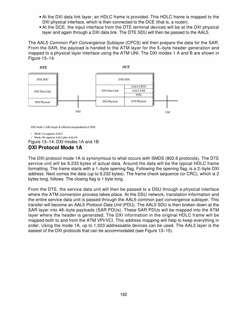
At the DXI data link layer, an HDLC frame is provided. This HDLC frame is mapped to theDXI physical interface, which is then connected to the DCE (that is, a router).
•
At the DCE, the input interface from the DTE terminal devices will be at the DXI physicallayer and again through a DXI data link. The DTE SDU will then be passed to the AAL5.
•
The AAL5 Common Part Convergence Sublayer (CPCS) will then prepare the data for the SAR.From the SAR, the payload is handed to the ATM layer for the 5−byte header generation andmapped to a physical layer interface using the ATM UNI. The DXI modes 1 A and B are shown inFigure 13−14.
Figure 13−14: DXI modes 1A and 1BDXI Protocol Mode 1A
The DXI protocol mode 1A is synonymous to what occurs with SMDS (802.6 protocols). The DTEservice unit will be 9,233 bytes of actual data. Around the data will be the typical HDLC frameformatting. The frame starts with a 1−byte opening flag. Following the opening flag, is a 2−byte DXIaddress. Next comes the data (up to 9,232 bytes). The frame check sequence (or CRC), which is 2bytes long, follows. The closing flag is 1 byte long.
From the DTE, the service data unit will then be passed to a DSU through a physical interfacewhere the ATM conversion process takes place. At the DSU network, translation information andthe entire service data unit is passed through the AAL5 common part convergence sublayer. Thistransfer will become an AAL5 Protocol Data Unit (PDU). The AAL5 SDU is then broken down at theSAR layer into 48−byte payloads (SAR PDUs). These SAR PDUs will be mapped into the ATMlayer where the header is generated. The DXI information in the original HDLC frame will bemapped both to and from the ATM VPI/VCI. This address mapping will help to keep everything inorder. Using the mode 1A, up to 1,023 addressable devices can be used. The AAL5 layer is theeasiest of the DXI protocols that can be accommodated (see Figure 13−15).
182

Figure 13−15: DXI protocol mode 1ADXI Protocol Mode 1B
As noted earlier, the DXI mode 1A supports the AAL5. The mode 1B supports AAL3/4 and AAL5(see Figure 13−16).
Figure 13−16: DXI mode 1BThe same process takes place at the DTE. First, a DTE SDU will be created. Next, the SDU will bepassed into an AAL3/4 CPSC. This layer will be framed and put across the data link layer at the DXIinterface and mapped onto the physical layer.
At the DCE, the data is passed to the DXI data link layer. Then it is mapped to the router as AAL3/4or AAL5. The data will be handed down into the SAR layer, passed to ATM, and finally processedout across the UNI to the ATM network (see Figure 13−17).
183

Figure 13−17: DXI protocol mode 1BXI Mode 2
The second way of handling the DXI is to use the protocol mode 2. DXI is used to provideconnectionless ATM network services, but is still important. The difference between mode 2 andmode 1A and B is that mode 2 can support up to 16,777,000 virtual connections either for AAL5 orAAL3/4 services. A DTE SDU of up to 64 KB long and a frame check sequence are all that are usedfor the SDU. The architecture of mode 2 uses the SDU from the DTE passed directly to the AALCPCS and then framed into a DXI data link layer and passed to the DXI physical interface. Thismode supports more virtual path identifiers than the normal mode 1. Entering the router, thephysical interface at the DXI level maps the SDU into the DXI data link and passes to the AAL3/4CPCS. The data is passed to the AAL3/4 SAR. Now the SAR is processed to the ATM layer wherethe header is generated and the data is mapped onto the UNI. The mode 2 SDU supports 64 KBcompared to mode 1, which supports 9,232 bytes. Refer to Figure 13−18 for a representation of theDXI mode 2.
184

Figure 13−18: DXI mode 2DXI Protocol Mode 2
The DTE processes the protocol SDU of 64 KB. The DTE will provide AAL3/4 encapsulation of theentire 64 KB, adding both header and trailer information, creating the AAL CPCS PDU. Now thePDU is mapped to the DSU as a DXI frame. The AAL3/4 CPCS PDU is then encapsulated as anHDLC frame containing the DXI information field after an opening flag. Note that the DXI informationfield is 4 bytes long this time. Greater addressing capabilities are possible for the virtualconnections. Using a 32−bit address, we can support 16,777,000 addresses.
Now the data will be framed. From there the frame check sequence and the closing flag are added.At the DSU, the protocol data unit will then be mapped using an encapsulation technique. Theencapsulation is retained for the PDU and then processed into SAR PDUs and onto the ATMportion of the DSU. Once again, the DXI addressing information is mapped both to and from theVPI/VCI within the ATM header for delivery across the ATM network. This is shown in Figure 13−19as the data is prepared in mode 2.
Figure 13−19: DXI protocol mode 2
Summary
Frame Relay and ATM can interwork and interoperate through several different techniques, whichgives the carrier a sense of comfort. Because the legacy systems of the past can still beaccommodated, the Frame Relay investments made in the early 1990s are still viable, and the ATMinvestments will be around for some time to come. Through the ATM protocols such as FUNI, endusers have comfort knowing their networks are not obsolete. By using the DXI interfaces andprotocols, the older Frame Relay routers, bridges, and brouters can stil l be used in anever−changing network environment. One can now see why the interworking functions from thenetworking and service functionality are so important. Millions of dollars of investment can still beused, and newer protocols can be deployed without making the entire network obsolete. This iswhat internetworking is all about!
185

Chapter 14: Cable TV Systems
Overview
The television broadcast signal, regardless of the standard used, is one of the most complex signalsused in commercial communications. The signal consists of a combination of amplitude, frequency,phase, and pulse modulation techniques all on a 6 MHz channel with a single sidebandtransmission process called vestigial sideband (VSB).
Cable TV appeared in the industry during the early 1960s. The initial networks installed used abasic tree architecture, in which all signals emanated from the head−end location and weredistributed to individual subscribers via a series of main trunks (trees), subtrunks (branches), andfeeders (twigs), as shown in Figure 14−1. This topology requires analog amplifiers to periodicallyboost signals to acceptable levels based on the service area being covered. However, all thebenefits of solving the gain/loss problems were offset by the introduction of noise and distortiondirectly attributed to the amplifiers. Analog amplifiers, as noted in any communications discussion,do nothing to eliminate noise (such as cross talk, white noise, Electromagnetic, and RadioFrequency Interference [EMI/RFI]).
Figure 14−1: The CATV architectureIn early 1988, the Community Antenna Television (CATV) companies discovered that fiberopticcables could be used as a means of improving the cable infrastructure both in quality and incapacity. The initial deployments used a Fiber−Based Backbone (FBB) overlay placed on top of theexisting tree networks to do the following
Improve performance• Reduce cascading amplifier problems• Increase reliability• Segment systems into smaller, regional areas• Facilitate targeted programming• Improve upstream performance•
186

These Hybrid Fiber Coaxial (HFC) networks drive the fiber closer to the consumer's door. They stilluse the conventional tree architecture, which branches off at the last mile (even if it is only a fewhundred feet, the reference to the last mile still prevails in the communications business) from thenode to the subscriber. Unfortunately, amplifiers may still be placed inefficiently, amplifier cascadesare often longer than necessary, and active counts per mile may be higher than needed.
Each of these factors increases the initial investment costs without improving the reliability of thenetwork or reducing the ongoing operating costs. Over the past decade, CATV networks havemigrated from the tree architecture, to the FBB, to the current HFC platform. Comparing the numberof nodes during this period of evolution, the industry has reduced node servicing from 5,000 to20,000 homes per node to approximately 500 homes. This 10−year migration illustrates the rapidadvancements that have taken place in the technology/cost structure.
Many CATV providers believe a balance between cost and service capacity at 500 homes per nodeis acceptable. However, if subscription rates explode, a CATV company's platform must be easilyadjustable to fewer nodes. In light of the initial investment costs of a system upgrade/rebuild,operators must continually consider a system that will improve reliability for the end user, whilereducing the initial costs and ongoing operating costs.
In the past, the CATV industry has designed systems uniformly; whether design began at the headend or at the node site, the coaxial portion of the system maintained the same look and feel of atree and branch. This usually meant optimizing the design through trial−and−error methods ofcascading devices to reach all areas of the system. This conventional approach to design wasbased on proven design techniques, which were developed prior to the broader range of designproducts available today.
The advent of fiber, combined with innovative new amplifier products and the need to considerfuture service capabilities (such as data and Internet access) and optimal costs, is the driving forcebehind the development of alternative design methods.
Cable Television Transmission
Television signals that are broadcast over the air in the United States are transmitted in 6 MHzchannels that are allocated to broadcasters by the Federal Communications Commission (FCC).The FCC regulates the location, power, and frequencies used by television stations, ensuring thatstations that use the same channel are sufficiently far apart so that they do not interfere with oneanother in any of the areas where they may be received. But preventing interference may alsorequire that two stations do not use adjacent channels in the same area for a more subtle reason. Inthe air, broadcast signal strength falls off rapidly with the distance from the transmitter, and as aresult, the signal from a nearby transmitter can be several orders of magnitude stronger than thatfrom a distant transmitter.
Because transmitters cannot contain their signal perfectly within their designated bandwidth andbecause receivers cannot perfectly discriminate between signals from adjacent channels, a strongnearby signal can interfere with a weak distant signal. This is known as the near−far problem, andthe result is that it is not always practical to use adjacent television channels in one area.
Television signals delivered over traditional cable television networks are sent the same way asthey are over the air: by dividing the cable spectrum into 6 MHz channels of bandwidth andmodulating each television signal into one channel. (This is an example of frequency−divisionmultiplexing [FDM].) But these cable systems can carry many more channels than broadcast
187

television for two reasons.
First, the near−far problem of broadcast television is not a problem on cable systems because allchannels can be transmitted at the same power level throughout the network, enabling adjacentchannels to be used on the cable.
Second, cable systems are not limited to the bandwidth that is designated by the FCC for broadcasttelevision; a cable can carry as many channels as the infrastructure will permit, which in modernsystems can be one hundred channels or more.
Because the transmission, or encoding, of analog television signals is done in the same manner asit is for broadcast television, receiving these signals is straightforward. But a television that is notbuilt specifically to receive cable will require an external receiver because a wider range offrequencies is used on cable systems and sometimes because a television receiver cannot properlydiscriminate between adjacent channels. This external receiver (a set−top box) retransmits aselected channel to one that the television can receive. Modern televisions, however, can often tunecable channels directly.
The Cable Infrastructure
The coaxial cable and broadband amplifier technologies define the essential capabilities of cablenetworks. But we also need to understand how real cable systems are actually built out of these andother components such as optical fiber since this introduces both technological and economicconstraints on using cable to support other communication applications. Although cable systems inthe United States were built independently by a variety of cable companies and equipmentproviders, the infrastructure is similar enough from system to system that we can talk about cablesystems in general terms. Much of what we need to understand is a matter of terminology used todescribe different parts of the network.
CATV has always been considered a one−way transmission system, designed to deliver TV andpackaged entertainment to the residential marketplace. As the development of the architecturesrolled out across the country, the CATV business, like other utility functions, became a monopoly.The industry enjoyed the freedom to offer products and services packaged to serve a localcommunity. As a utility, the CATV companies were granted exclusivity. There were few demandsplaced on the cable systems because the providers delivered a sufficient number of channels to theconsumer based on the coaxial technology used. The typical operator uses a 6 MHz channelcapacity that is then filtered to prevent overlapping signals from interfering with other TV channelsas shown in Figure 14−2. The channel filters then limit the overall capacity to approximately 4.2 to4.5 MHz to carry the TV signal. This is sufficient to deliver CATV broadcast quality signals to theconsumers' door for a fee.
188

Figure 14−2: Coaxial channel capacities at 6 MHzIn the event that the operator runs out of capacity, new techniques exist to offer as many as three orfour channels of TV on a single CATV 6 MHz capacity through the use of Moving Picture ExpertsGroup (MPEG) 2 or 3 standard compression. With a three− to four−fold increase in the channelcarrying capacity on the same cable, the operators find this rewarding. This is especially true whenthe new MPEG standard allows the increased capacity without requiring the CATV operator totrench new fibers or coaxial cables throughout the neighborhoods.
Once the cable is channeled into the current 6 MHz techniques with the bandpass filters allowing a4.5 MHz capacity, the carriers use the sideband capacities for other operations:
Filter guard bands (see Figure 14−3) can prevent two channels from interfering with eachother.
Figure 14−3: Guard bands prevent the channels from interfering with each other.
•
The horizontal black bar at the bottom of the TV screen, the vertical interval, usually containstest signals used by the broadcast system for online performance tests that will not interferewith the regular programming.
•
189

The audio information in a TV channel is a frequency−modulated carrier placed 4.5 MHzabove the visual carrier at less than 1/8 of its power.
•
The Cable Television Distribution System
In the beginning, early television cable distribution systems were established to serve communitieswhere residents could not receive over−the−air programming because of geographical interference.Atmospheric conditions and fading were crucial in the delivery of the airborne signals. Distance fromthe transmitters was also a critical factor, but may have been limited by the regulatory bodies (suchas the FCC and local utility commissions). When an area could not receive the signals for whateverreason, the logical distribution of a cable to these areas made prudent business sense. Regardlessof the reason, CATV was used to supplement commercial TV systems whether the consumer was
Behind a mountain• Out of the line of sight from the Omni directional antennae• Beyond the reception power area of a major broadcast provider•
The real issue was the monopoly that was established to provide an incentive for the cablecompanies to make the huge investments and attempt to service the consumer.
The term Community Antenna Television (CATV) has long since been extended to mean any regionwired for the reception of broadcast programming, whether or not good residential antennareception is available. Subscribers to these systems generally pay a monthly fee for the service,which usually includes increased channel selection, pay per view, and locally originatedprogramming. Newer services are continually being reviewed and introduced with the changes intechnology and the shift in regulation.
Signal Level
The cable system requires certain parameters in order to function properly. Originally distributed viaa microwave distribution (still done in some cases) and coaxial cables, the systems are underconstant scrutiny and change. Throughout the CATV system, power is distributed in the form of
TV and FM carriers• Test signals• Pilot tones• DC power• Noise•
Specified levels must be maintained at each point in the system to assure good performance. Thesignal levels at different frequencies are just as important. Here is how they are measured: CableTV uses FDM onto the coaxial cable, as shown in Figure 14−4.
190

Figure 14−4: Frequency−division multiplexing (FDM) on CATVThis frequency division allows the provider to multiplex various channels onto a single analog carriersystem and deliver the various forms of entertainment available on the cable. Not all providers arethe same, but many offer more than just TV and entertainment. Some of the providers offerhigh−quality stereo music. Others offer information such as Dow Jones or Reuters in the guardbands that travel along the cable. If the end user has a special receiver, the data are available. Ifnot, then the data are not available to the individual set. Actually, the data are travelling along thecable, but fit in the black horizontal bar on the bottom of the screen. These value−added servicesare an additional revenue generator for the cable company. The convenience for the end user iswhat drives the business case. Most users who cannot receive over−the−air programming (publicTV) probably have trouble receiving over−the−air radio, too!
Let's start with the cable itself. The characteristic impedance of distribution cable is 75 ohms (75Ω).This impedance is the amount of resistance that the cable signals "see" from the center conductorto the outer shield of the cable at the transmission frequencies. This impedance governs all thesignal voltage and currents traveling the cable as covered in Ohm's Law. Most CATV systemmeasurements involve a signal power difference that is one level relative to another. Voltagedifferential is an awkward measure of power differential because each time a power change ismeasured, the formula must be calculated. The decibel resolves difficulties in handling systempower figures.
Digital Video on Cable TV Systems
Digital service is a key enabling technology that will allow cable systems to deliver a multitude ofemerging services. High spectral efficiency, robust resistance to noise, and exceptional flexibilitypermit the installation of premium digital services, such as
Video on demand• Personal communications services (PCS) telephony• Commercial data transport•
Figure 14−5 is a representation of a multiservice cable operation that may well be the wave of the
191

future for the operators.
Figure 14−5: CATV services of the futureShown in this figure is the basic cable coming to the residence. The CATV suppliers have changedtheir basic architecture from a one−way cable to a two−way cable system using a FBB. At the localhub along the route, the cable is then terminated and the HFC equipment delivers the cable to thedoor interface. At the home (or office), the cable serves the telephony, entertainment, andhigh−speed data demands of the end user. The cable operator provides the network interface, andthe ancillary equipment is then hung off the cable. Subscribers already view these new capabilitieswith new expectations of high value and more reliable service.
As telephone companies (the local exchange carriers [LECs]), long distance companies (theinterexchange carriers [IECs]), and the cable companies compete to deliver digital services, a keydifferentiation will be the quality and reliability of service. Recent acquisition and merger activityshows the IEC and CATV merger taking off as a means of getting to the consumer's door. Ensuringquality of service (QoS) requires testing digitally modulated signals. Digital services willrevolutionize the way consumers view their CATV suppliers. As in an analog cable TV system,power and interference measurements are essential to maintaining digital cable TV services.Although the effects are different from impairments on an analog television signal, amplifiercompression and spurious interference will degrade digital signals.
Forming a Digital Video Signal
In CATV, all digital modulation formats define how the data bits correspond to both carrier phaseand amplitude, and how transitions between bits are made. Digital modulation formats oftenassociated with cable systems are 16 VSB, 64 Quadrature Amplitude Modulation (QAM),quadrature partial response (QPR), and Offset Quadrature Phase Shift Keying (OQPSK). However,there has been much discussion about 256 QAM for the future implementation of broadbandcommunications services. Regardless of the technique, these formats share commoncharacteristics in the time and frequency domains, driving common needs for measuring power andinterference. Cable digital audio services are often delivered to the head end by using the OQPSKformat.
192

Key Features of Digital Modulation
In the frequency domain, digital modulation produces a noise−like spectrum whose bandwidthdepends on the symbol rate, coding, and filtering used. The spectrum of unfiltered 64 QAM is 4.167Msymbols per second. This produces a 25 Mbps digital data stream. The bandwidth of the filtered64 QAM channel is approximately 4.2 MHz. Note that the broadband digital video signal issusceptible to spurious interference across the entire channel bandwidth, making control of analogand digital transmission spurs critical. Proper symbol filtering avoids spilling interference from adigital channel into adjacent video channels. 64 QAM uses six bits (26) and produces the techniquediscussed here. With 4.167 Msymbols per second and six bits per symbol, then the resultant yield is(4.167 x 6 bits = 25 Mbps).
DTV Solution Introduction
November 1, 1998, marked the beginning of a new era in the broadcast industry. After 10 years ofR&D and standards development, the Digital TV (DTV) revolution entered its implementation stage.Broadcasters are still gearing to plan as well as building up their DTV facilities. The broadcastersactually completed their implementation in the 10 largest cities three days early. Approximately13,176 pioneers (first purchasers) had acquired DTV sets at a roaring $7,000 apiece. Thebroadcasters implemented the standard based on the digital HDTV systems developed by theGrand Alliance. The Advanced Television Systems Committee (ATSC) standardized thisspecification. It consists of three subsystems:
Source coding and compression1. Service multiplex and transport2. Radio frequency (RF) transmission3.
Although this has met with some success, more has to be done with it. For example, antennas forDTV surfaced to the forefront of the discussion when everyone realized that Digital TV is an all ornothing proposition. Analog TV fades and gets snowy from distortion, distance, atmosphericconditions, and other issues. DTV is either there or not! If a user has a problem with reception, thena new antenna may be needed. If not enough bits make it to the set, the picture will either freeze ordisappear altogether. Anyone with a satellite transmission (for example, Direct TV or others) knowswhat this is like.
Cable TV providers should be able to overcome this problem with the cable itself, so long as theirreceivers are properly tuned. This may drive more customers to the CATV operators for their HDTVand DTV needs. The major networks will be broadcasting some of their programming by using DTVchannels. The cable companies are not mandated (yet) to carry DTV broadcasts. But if they chooseto do so, at issue is at what resolution they will carry and deliver DTV. DTV uses an 8−VSB signal,so the QAM used by some systems may have difficulty passing through the 8 VSB. Someincompatibilities may exist for the short term.
The source coding and compression deal with bit−rate reduction of video and audio. Thecompression layer transforms the raw video and audio samples into a coded bit stream that can bedecoded by the receiver to recreate the picture and sound. The video compression syntax conformsto the MPEG−2 video standard, at a nominal data rate of approximately 18.9 Mbps. The DolbyAC−3 audio compression is used in the ATSC DTV standard to provide 5.1 channel surround soundat a nominal rate of 384 Kbps.
193

The service multiplex and transport layer based on the MPEG−2 Systems Standard provides fordynamic allocation of video, audio, and auxiliary data. It utilizes a layered architecture withheaders/descriptors to provide flexible operating characteristics. The flexibility of the multiplex andtransport layer provides the means for multiple Standard Definition Television (SDTV) services. Thecable operators can send a single channel of HDTV programming or use a lower resolution SDTVand split the channel to simulcast multiple programs, including data transmissions. This all dependson which digital picture format the broadcaster uses and how the station allocates bits in the datatransport rate of the channel. Currently, the data rate of a 6 MHz channel is rated at 19.4 Mbps.
The flexibility of the ATSC system specifications could allow a broadcaster to mix different streamsof high and low data densities and transmit them simultaneously. An example of this may be to use8 Mbps for a sporting event and have three lower−rate programs at 3.8 Mbps each (such as anewscast or a soap opera). At the same time, all four programs will be very unlikely to use all theallocated bandwidth, so a statistical time−division multiplexing (TDM) technique can use theremaining bits for data transmission (see Figure 14−6).
Figure 14−6: Combining multiple streams on a single DTV channelThe transmission layer modulates a serial bit stream into a signal that can be transmitted over a 6MHz television channel. The transmission system is based on a trellis−coded, 8−level VSBmodulation technique for terrestrial broadcasting.
ATSC standard−based encoding systems are one of the key elements in DTV implementation.Encoding systems will be used in the entire broadcast chain. However, not every encoder in a DTVbroadcast chain has to be ATSC standard based. It should be noted that the FCC standardizes onlythe terrestrial−broadcasting signal. Cable operators are not required to adapt to this standard. Inaddition to the source coding, compression, and multiplexing, an encoding system provides ATSCstandard−based systems information, program guide, data, and interactive services along withvideo and audio.
The ATSC DTV standard, as well as MPEG 2, describes the bit stream syntax and semantics. Thestandards also specify the constraints and decoder models. However, encoding parameters are not
194

specified by the standards. Thus, encoder performance and systems implementation are left toencoder designers. Thus, standard compliance does not guarantee encoder performance.
In a standard 750 MHz system, consisting of a 5 to 40 MHz return bandwidth and a 52 to 750 MHzforward bandwidth, downstream broadcast services occupy the 52 to 550 MHz pass band. Theremaining 200 MHz is reserved for digital services.
The system's analog broadcast services consist of analog nonencrypted services (basic), analogencrypted premium services, and analog pay−per−view services. The digital broadcast servicesinclude digital audio programming, along with encrypted digitally compressed video programming.
Several different services, such as interactive video, cable modems, and HFC telephony make upthe interactive services.
Cable modem equipment utilized a two−way RF system with 64 QAM modulation in the downstreamdirection and QPSK modulation in the upstream direction. Data rates for the downstream andupstream paths were 27 Mbps and 1.7 Mbps, respectively.
Using the system bandwidth information shown earlier, the available bandwidth in the downstreamdirection is 698 MHz. Both broadcast and interactive services use this bandwidth. Availableupstream bandwidth is limited to 35 MHz, assuming that the entire 5 to 40 MHz bandpass isuseable.
Migration strategies for the network must be carefully planned. Selection of downsizablearchitecture is crucial in this planning process. Also, conducting detailed traffic studies about theseservices when they are first offered in the network is crucial.
CATV operators are currently in the limelight and will remain there for some time to come. Theemphasis on access to the door, deregulation, and merger mania in this industry has propelled theCATV operators into one of the driver seats of technology. Whether they choose to adjust to theirnewfound popularity or be gobbled up by new players looking for access depends on the individualcable operators across the country (and the world).
195

Chapter 15: Cable Modem Systems and Technology
Overview
In the late 1970s, a major battle arose in the communications and the computer industries.Convergence of the two industries was happening as a result of the implementation of the LocalArea Networks (LANs). In the local networking arena, users began to implement solutions to theirdata connectivity needs within a localized environment. Two major choices were available for theirinstallation of wiring: baseband coaxial cable and broadband coaxial cable.
The baseband cable was based on the Ethernet developments using a 20 MHz, 50Ω coax.Designed as a half−duplex operation, Ethernet allowed the end user to transmit digital data on thecable at speeds of up to 10 Mbps. Clearly, the 10 Mbps was maximum throughput, but wasattractive in comparison to the technology of twisted pair at the time (telephone wires were capableof less than 1 Mbps bursty data). Moreover, the use of the baseband technology allowed the data tobe digitally applied directly onto the cable system. No analog modulation was necessary to applythe data. It was dc input placed directly onto the cable. The signal propagates to both ends of thecable before another device can transmit. This is shown as a quick review in Figure 15−1. Tocontrol the cable access, the attached devices used Carrier Sense Multiple Access with CollisionDetection (CSMA/CD) as the access control. CSMA/CD allowed for the possibility that two devicesmay attempt to transmit on the cable at the same time, causing a collision and corruption of theactual data. As a result, the cable had to be very controlled, but in the late 1970s this was not a realissue.
Figure 15−1: CSMA/CD cable networks are collision domains.A second alternative was to use the broadband coaxial cable, operating at a total bandwidth ofapproximately 350 MHz in an analog FDM technique on a 75Ω cable. As a technology, thebroadband systems were well known because they were the same as Community AntennaTelevision (CATV), which had surfaced in the early 1960s. As a result, the technology was welldeployed and commodity priced. Moreover, the 350 MHz of capacity was attractive to the computerindustry and the communications industry partisans. The issues began to surface quickly regardingthe benefits and losses of using each technique (see Figure 15−2).
196
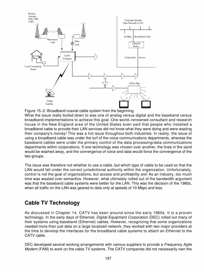
Figure 15−2: Broadband coaxial cable system from the beginningWhat the issue really boiled down to was one of analog versus digital and the baseband versusbroadband implementations to achieve this goal. One world−renowned consultant and researchhouse in the New England area of the United States even said that people who installed abroadband cable to provide their LAN services did not know what they were doing and were wastingtheir company's money! This was a hot issue throughout both industries. In reality, the issue ofusing a broadband cable was under the turf of the voice communications departments, whereas thebaseband cables were under the primary control of the data processing/data communicationsdepartments within corporations. If one technology was chosen over another, the lines in the sandwould be washed away, and the convergence of voice and data would force the convergence of thetwo groups.
The issue was therefore not whether to use a cable, but which type of cable to be used so that theLAN would fall under the correct jurisdictional authority within the organization. Unfortunately,control is not the goal of organizations, but access and profitability are! As an industry, too muchtime was wasted over semantics. However, what ultimately rolled out of the bandwidth argumentwas that the baseband cable systems were better for the LAN. This was the decision of the 1980s,when all traffic on the LAN was geared to data only at speeds of 10 Mbps and less.
Cable TV Technology
As discussed in Chapter 14, CATV has been around since the early 1960s. It is a proventechnology. In the early days of Ethernet, Digital Equipment Corporation (DEC) rolled out many oftheir systems using baseband (Ethernet) cables. However, recognizing that some organizationsneeded more than just data on a large localized network, they worked with two major providers atthe time to develop the interfaces for the broadband cable systems to attach an Ethernet to theCATV cable.
DEC developed several working arrangements with various suppliers to provide a Frequency AgileModem (FAM) to work on the cable TV systems. The CATV companies did not necessarily own the
197

broadband cable. Instead, this cable was locally owned in a high−rise office or a campus complexby the end user. The cable system provided a high bandwidth, but was very complex for the dataand LAN departments to understand. The reason was obvious: the broadband coax operated byusing frequency division multiplexing (FDM, or analog techniques), which was beyond the scope ofthe LAN administrators and the Data Processing departments. The voice people knew of analogtransmission, but had a hard time with digital transmission in those days. There was a silentdepartment in the crux of all the arguments — the video departments within many organizationsstayed out of the fight.
As DEC began to roll out various choices, the average user had to justify the connection of theanalog technologies (used as a carrier) with the digital data demands of the LAN. What manyorganizations did on a campus was to consolidate voice, data, LAN, and video on a single cableinfrastructure. What the industry came up with was a specification for 10 Broad 36 to satisfy theLAN needs over a coax cable. 10 Broad 36 stands for 10 Mbps on a broadband cable over 3,600meters using analog amplifiers. A classic representation of the combined services on 10 Broad 36 isshown in Figure 15−3.
Figure 15−3: Mixing services on a 10 Broad 36 cableThe data industry was distraught because this encouraged the use of an analog carrier system tomove the digital data. Over the years, however, this has been revisited several times. WangComputer Company developed a proprietary cable system for connecting WangNet systemstogether by using a dual broadband coax cable. This met with only limited success because of theproprietary nature of their interfaces and the pricing model they used. Technologically, the systemwas sound.
Later in the evolution of this service, the term broadband LANs became popularized. Ten MbpsEthernet grew to 100 Mbps, and then on to Gb Ethernet and now the introduction of 10 Gb Ethernetin the LAN and metropolitan area network (MAN). Justifying and enabling this high−speedcommunications service met with some resistance until the use of the various fiber and coaxialsystems emerged. By taking a quantum leap in the industry, the data and voice departments sawthe benefit and need of converging the two services to the desktop in order to offer voice and videoover the LAN. The 10 Mbps Ethernet and coaxial cables could not handle this offering. Enter thenew technology! Hybrids of coax and fiber were introduced to the desktop. Moreover, with theaccess to the Internet under constant scrutiny and pressure to add speed and capacity (voice andvideo on the Internet), the industry began to seek a new method of bypassing the local copper loopprovided by the telephone companies. The technology already at the door, of course, was the
198

CATV. So a new idea emerged: use the CATV to support the high−speed Internet access andbypass the local loop from telephone companies. Hence, cable modem technology changed theway we will do business for the future.
The New Market
The cable television companies are in the midst of a transition from their traditional core business ofentertainment video programming to a position as a full−service provider of video, voice, and datatelecommunications services. Among the elements that have made this transition possible aretechnologies such as the cable data modem. These companies have historically carried a numberof data services. These services have ranged from news and weather feeds, presented inalphanumeric form on single channels or as scrolling captions, to one−way transmission of dataover classic cable systems as discussed in Chapter 14, "Cable TV Systems."
Information providers are targeting upgraded cable network architecture as the delivery mechanismof choice for advanced high−speed data services. These changes stem from the commercial andresidential data communications markets. The PC and LAN explosion in the early 1980s was rapidlyfollowed by leaps in computer networking technology. More people now work from home,depending on connectivity from commercial online services (such as AOL, CompuServe, andProdigy) to the global Internet.
Increased awareness has led to increasing demand for data service, and for higher speeds andenhanced levels of service. Cable is in a unique position to meet these demands. The same highlyevolved platform that enables cable to provide telephony and advanced video services alsosupports high−speed data services. There appear to be no serious barriers to the cable deploymentof high−speed data transmission.
System Upgrades
The cable platform is steadily evolving into a hybrid digital and analog transmission system. Cabletelevision systems were originally designed to optimize the one−way, analog transmission oftelevision programming to the home. The underlying coaxial cable, however, has enough bandwidthto support the two−way transport of signals. The hybrid network is shown in Figure 15−4.
199

Figure 15−4: The new hybrid data networkGrowth in demand for Internet access and other two−way services has dovetailed with the trendwithin the industry to enhance existing cable systems with fiber optic technology.
Many cable companies are in the midst of the upgrade to HFC plants to improve the existing cableservices and support data and other new services. Companies are taking different approaches toonline service access. For some applications, customers may be accessing information storedlocally at or near the cable head−end or regional hub, such as the @Home®
[1] The reference here to @Home was the registered trademark of @Home Corporation. In 2001@Home filed bankruptcy and the company prepared to cease operations after February 28,2002.services being offered in many cities. This may be temporary until wide area cableinterconnections and expanded Internet backbone networks are in place to allow information accessfrom any remote site.
Cable Modems
Digital data signals are carried over radio frequency (RF) carrier signals on a cable system. Digitaldata utilizes cable modems, devices that convert digital information into a modulated RF signal andconvert RF signals back to digital information. The conversion is performed by a modem at thesubscriber premises, and again by head−end equipment handling multiple subscribers. Look atFigure 15−5 for a block diagram of the cable modem.
200

Figure 15−5: Block diagram of the cable modemA single 6 MHz channel can support multiple data streams or multiple users through the use ofshared LAN protocols such as Ethernet, commonly used in business office LANs today. This iswhere the industry began in the late 1970s when Ethernet networks were applied to the broadbandcoaxial networks.
Different modulation techniques are being tried to maximize the data speed that can be transmittedthrough a 6 MHz channel. Modulation techniques include Quadrature Phase Shift Keying (QPSK),Quadrature Amplitude Modulation (QAM), and Vestigial Side Band (VSB) amplitude modulation.Comparing the data traffic rates for different types of modems shows why the cable modem is sopopular under today's environment. Table 15−1 is a comparison of a file download of 500 KB usingdifferent techniques.
Table 15−1: Comparison of transmission speeds
Time to Transmit a Single 500 KB ImageTelephone Modem 28.8 Kbps 6—8 minutesISDN 64 Kbps 1—1.5 minutesCable Modem 10 Mbps Approximately 1 second[a] Source: CableLabs
Careful traffic engineering is being performed on cable systems so that data speeds are maximizedas customers are added. Just as office LANs are routinely subdivided to provide faster service foreach individual user, so too can cable data networks be custom tailored within each fiber node tomeet customer demand. Multiple 6 MHz channels can be allocated to expand capacity as well.
Some manufacturers have designed modems that provide asymmetrical capabilities, using lessbandwidth for outgoing signals from the subscriber. Cable systems in some locations may not havecompleted system upgrades, so manufacturers have built migration strategies into such modems to
201

allow for the eventual transmission of broadband return signals when the systems are ready toprovide such service and customers demand it. A representative sample of the way data speeds areprovided on cable modems is shown in Table 15−2.
Table 15−2: Representative asymmetrical data cable modem speeds
Sample Cable Modem Speeds Upstream DownstreamGeneral Instrument 1.5 Mbps 30 MbpsHybrid/Intel 96 Kbps 30 MbpsLANcity 10 Mbps 10 MbpsMotorola 768 Kbps 30 MbpsZenith 4 Mbps 4 Mbps
Standards
Modems are available today from a variety of vendors, all with their own unique technical approach.These modems are making it possible for cable companies to enter the data communicationsmarket now. In the longer term, modem costs must drop and greater interoperability is desirable.Customers who buy modems that work in their current cable system need assurance that themodem will work if they move to a different geographic location served by a different cablecompany. Furthermore, agreement on a standard set of specifications will allow the market to enjoyeconomies of scale and drive down the price of each individual modem. Ultimately, those modemswill be available as standard peripheral devices offered as an option to customers buying newpersonal computers at retail stores. The cable companies and manufacturers came togetherformally in December 1995 to begin working toward an open standard.
Leading U.S. and Canadian cable companies were involved in this development toward an opencable modem standard. Specifications were to be developed in three phases, and then bepresented to standards−setting bodies for approval as standards. Individual vendors were free tooffer their own implementations with a variety of additional competitive features and futureimprovements. A data interoperability specification will comprise a number of interfaces. Theresultant specification is called Data Over Cable Service Interface Specification (DOCSIS), whicharchitecturally is shown in Figure 15−6 as it relates to the TCP/IP protocol stack. Note that there areseveral sublayers added into the DOCSIS specification at the bottom layers (for example, layer 1and 2) of the protocol stack. This is to simplify the connection and add the dimension of security intothe DOCSIS specifications.
202

Figure 15−6: The DOCSIS modelSome interfaces reside within the cable network. Several of these system−level interfaces also willbe specified in order to ensure interoperability of such important functions as authentication forlogin/logout, ease of installation of cable modems for reliable customer activation, and spectrummanagement over the cable network's hybrid fiber/coaxial plant.
Return Path
The portion of bandwidth reserved for return signals (from the customer to the cable network) isusually in the 5 to 40 MHz portion of the spectrum. This portion of the spectrum can be subject toingress and other types of interference, and so cable systems offering two−way data services havebeen designed to operate in this environment.
Industry engineers have assembled a set of alternative strategies for return path operations.Dynamic frequency agility (shifting data from one channel to another when needed) may bedesigned into modems so that data signals may avoid unwanted interference as it arises. Otherapproaches utilize a gate that keeps the return path from an individual subscriber closed except forthose times when the subscriber actually sends a return signal. Demarcation filters, different returnlaser types, and reduced node sizes are among the other approaches, each involving tradeoffsbetween capital cost and maintenance effort and cost.
Return path transmission issues have already been the subject of two years of lab and field testingand product development. The full two−way capability of the coaxial cable already used in most
203

U.S. homes is now being utilized in many areas, and will be available in most cable systems soon.Full activation of the return path in any given location will depend on individual cable companycircumstances, ranging from market analysis to capital availability.
The spectrum used for the forward and reverse paths is shown in Figure 15−7 as an indication ofthe frequencies available and the overall management of the system. This also shows thatadditional 6 MHz channels can be set aside to handle the data traffic on the cable modems and thecables themselves.
Figure 15−7: Frequency spectrum allocated to the cable modems
Applications
Cable modems open the door for customers to enjoy a range of high−speed data services, all atspeeds hundreds of times faster than telephone modem calls. Subscribers can be fully connected,24 hours a day, to services without interfering with cable television service or phone service. Amongthese services are
Information services Access to shopping, weather maps, household bill paying, and so on• Internet access E−mail, discussion groups, and the World Wide Web• Business applications Interconnecting LANs or supporting collaborative work• Cablecommuting Enabling the already popular notion of working from home• Education Allowing students to continue to access educational resources from home•
The promises of advanced telecommunications networks, once more hype than fact, are now withinreach. Cable modems and other technology are being deployed to make it happen. Regardless ofthe technology selected, the main goal is to get the high−speed data communications on the cableadjacent to the TV and entertainment. This gives the CATV companies the leverage to act in anarbitrage situation, competing with the local telephone companies who have dragged their feet inmoving high−speed services to the consumer's door. As shown in Figure 15−8, there are severalup−and−down speed capabilities that can be shared to deliver asymmetrical speeds to theconsumer's door. In the particular figure, the download speed is up to 30 Mbps, whereas theupstream operates at 1.5 Mbps. For many, this is sufficient based on their applications.
204

Figure 15−8: Different speeds on the up−and−down stream flows
The Combined Corporate and End User Networking Strategies
The use of a single PC on a cable system is fine for the telecommuter (or cable commuter now), butwhat of the small office or home office where more than a single PC is connected? Figure 15−9 isan example of various ways the CATV connection can be accomplished. This figure uses anexample of local home networking with two PCs connected to a single cable modem. Most of theproviders have instructions on how to accomplish this and require a home user (or small user) todownload additional software to accommodate the dual connection on a single modem. The secondalternative to this is to have a router connected to the cable modem, such as a branch office router.The network is attached to the router, and the router is responsible to handle the dispersing of thetraffic onto the cable system. This can be a very effective use of the link. Next in the figure is aconnection to a hub, such as a 10 or 100 Base T connection into a LAN hub. Although the CATVproviders state this is not supported and will likely not work, it has been done and works pretty wellfor a small office or home office connection. Using the connection directly into the hub from thecable modem makes the modem available to more users instead of just a single PC. The hub willact as a bridging function onto the modem and concentrate the traffic through the individual devices.These configurations all work, but the providers do not support problems if they arise. You are onyour own if it does not work.
205

Figure 15−9: Multiple ways of connecting to the cable modem
A Final Thought
A final thought concerning the use of this technology is to understand the security concernsassociated with the cable modem. When the CATV systems are used, they are shared, high−speedEthernet backbone access to the Internet or other connections. One must be aware that on ashared cable, the PC is a peer to all others on the same cable, even though they are in physicallydifferent locations. In a community of 500 connections, there will be many people who acquire theservice from the CATV suppliers. The CATV company installs according to the appropriatetechnology, not according to security parameters. This is okay because they are merely providingthe bandwidth to gain access. It is the end user's responsibility to turn off all the leaks in the localsystem (the PC). By default, when you run a Microsoft windows environment and the appropriatenetworking software, the shares on the PC are turned on. The end user must therefore go in andturn them off. This means that if the shared services are not turned off, a user down the street, oracross the town, can double−click their network neighborhood icon and see all the other PCsconnected to the cable. Not only can they see the devices, but they can double−click the PC andsee the resources available on that PC. From there when a remote device has double−clicked yourPC, they can open your drives and see your files. Unless some provisions have been taken to blockthis access, the intruder (used as a method of entry only) can read, write, edit, or delete your files.Worse yet, while the intruder is on your system, you do not even know he is there.
Many users who have cable modem service from the cable companies are not aware of the risks.Worse, the installation personnel on these systems do not totally understand or they forget to pointout the risks. Therefore, users leave the PC on 100 percent of the time (day and night), makingaccess to their computers totally available. The cable modem is available 100 percent of the time,making the computer a target for hackers and mischievous users, without the permission or theknowledge of the penetrated computer owner. Be aware that the risk is there and find out how toshut these open doors before leaving your computer on the network. Do not assume that justbecause you shut your system off when you're not using it that you are protected, because whenyou do log on, you are exposed, and the perpetrator can get on your system while you are on it, too!Technology is a wonderful thing, but it must be controlled.
206

Chapter 16: xDSL
Overview
One of the major problems facing the incumbent local exchange carriers (ILEC) is the ability tomaintain and preserve their installed base. Ever since the Telecommunications Act of 1996, therehas been mounting pressure on the ILECs to provide faster and more correct Internet access. Inorder to provide the higher−speed communications abilities, these carriers have continually lookedfor new means of providing the service.
However, the ILECs have an installed base of unshielded twisted pair in the local loop that cannotbe ignored or abandoned. Therefore, a new form of communications was needed to work over theexisting copper cable plant. One of the technologies selected was the use of xDSL. The DSL familyincludes several variations of what is known as digital subscriber line. The lower case x in front ofthe DSL stands for the many variations. These will include
Asymmetrical digital subscriber line (ADSL)• ISDN (like) digital subscriber line (IDSL)• High bit−rate Digital Subscriber Line (HDSL)• Consumer Digital Subscriber Line (CDSL)• Single High Speed DSL (SHDSL)• Rate−adaptive digital subscriber line (RADSL)• Very high−bit rate digital subscriber line (VDSL)• Single or symmetric digital subscriber line (SDSL)•
One can see that the variations are many. Each DSL capability carries with it differences in speed,throughput, and facilities used. The most popular of this family under today's technology is the useof ADSL.
ADSL is a technology being provided primarily by the ILECs because the existing cable plant can besupported, and the speed throughput can vary, depending on the quality of the copper. However,the most important and critical factor in dealing with ADSL technology is the capability to supportspeeds between 1.5 Mbps up to 8.192 Mbps. At the same time, the ILEC can also support Plain OldTelephone Service (POTS) for voice or fax communications on the same line. What this means isthat the ILEC does not have to install all new cabling to support high−speed communications accessto the Internet.
ADSL Defined
ADSL is the new modem technology to converge the existing twisted pair telephone lines into thehigh−speed communications access capability for various services. Most people consider ADSL asa transmission system instead of a modification to the existing transmission facilities. In reality,ADSL is a modem technology used to transmit speeds of between 1.5 Mbps and 6 Mbps undercurrent technology. It is stated that in the future ADSL will support speeds of about 8.192 Mbps.This definition of the higher range of ADSL speeds is one that is yet to be proven; however, withchanges in today's technology one can only imagine that the speeds will be achievable.
Some of the many capabilities that are being considered through the use of the DSL family are theservices for converging voice, data, multimedia, video, and Internet streaming protocols services. Itis through these demands that the carriers see their future rollout of products and services to the
207

general consuming public. In Table 16−1, various theoretical speeds and distances of ADSLtechnologies are shown.
Table 16−1: Data rates for ADSL, based on installed wiring at varying gauges
Current Data Rate Wire Gauge Distance in K Feet Distance inKilometers
1.5 to 2.048 Mbps 24 18 5.51.5 to 2.048 Mbps 26 15 4.66.3 Mbps 24 12 3.76.3 Mbps 26 9 2.7
One should remember that the speeds and distances shown here are the theoretical limits based ongood copper. If the copper has been damaged or impaired in any way, then the speed anddistances will change accordingly (downward). The theoretical limits are what most engineers andproviders have been touting that their technologies can support. Reality is another thing, and theactual distances and speeds very likely will be less than those shown here. What is most importantis to assume that these speeds can be established and maintained on the installed base ofunshielded twisted pairs (UTP) of wire. As long as the ILEC can approximate these speeds today,the consumer will most likely not have much to complain about.
Modem Technologies
Before proceeding too far in this discussion, a review of modem technology is probably in line.Modems, or modulator/demodulator, were designed to provide for data communications across thevoice dial−up communications network. Through the use of modem technology introduced back inthe 1960s, users were able to transmit data across the voice networks at speeds varying between300 bps to 33,600 bps. Although this may seem like high−speed communication, our demands andneeds for faster communications quickly outstripped the capabilities of our current modem services,making the demand for newer services more evident. Higher−speed modems could be produced,but the economics and variations on the wiring system prove this to be somewhat impractical.Instead, the providers looked for a better way to provide data communications that mimic the digitaltransmission speeds we are accustomed to.
Using the telephone companies' voice services, the end user installed a modem on the local loop.This modem acts as the Data Circuit terminating Equipment (DCE) for the link. (DCE can also standfor data communications equipment.) As shown in Figure 16−1, a modem is used on the ILEC'swires to communicate across the Wide Area Networks (WANs) such as the long−distance voicenetworks. This figure shows that the modem is the interface to the telephone network limited to thequality of the local loop. The ILEC installs a voice−grade line on the local copper cable plant andenables the end user to connect the modem. The modem then converts the data from a computerterminal into a voice−equivalent analog signal. There is no real magic in modem communicationstoday, but in the early days of data communications, this was considered voodoo science. Themiracle of data compression and other multimodulation techniques quickly expanded the data ratesfrom 300 bps to today's 33.6 Kbps. Newer modems are touted to handle data at speeds of up to 56Kbps, but there are few who actually get data across the network at these rates. So, the reality of allthe pieces combined still has the consumer operating at approximately 33.6 Kbps. Newertechnologies will produce much higher compressed speeds of up to 230 to 300 Kbps on a modem,but these are now in their infancy. They are not a major factor in our communications networks yet.
208

Figure 16−1: Modems are installed at the customer's location and use the existing telephone wiresto transmit data across the voice network.
The Analog Modem History
In the early days of modem communications, the Bell telephone companies (or the independenttelephone companies) provided all services across North America. A customer desiring to transmitdata needed only to call the local supplier who would then install the dial−up telephone line, themodem, and all associated services to accommodate the desired data rates available. Leased lineswere used when specific speeds or volumes were anticipated, but not guaranteed by the dial−upservices. Regardless of the modem and lines used, the main provider was the key ingredient. Thelocal providers supported only what they knew they could meet, so speeds were often kept very lowfrom a guaranteed standpoint.
If the customer had a leased line and needed better or faster data, special equipment was installedon the line to reach these goals but at a higher monthly fee. Moreover, the technologicaladvancement of modem technology was not a priority for the local providers because they ownedthe installed base.
In 1968, things began to change! With court decisions allowing the introduction of competitivedevices and the connection of these devices on the regulated carrier's network, demands began toescalate. Restrictions on power output and energy levels were in place to prevent any interferencefrom the modems on the voice network. Also, the customer−provided modems were interconnectedthrough a data coupler (called a Data Access Arrangement [DAA]) provided by the local regulatedcarriers. This, of course, involved a fee for the connection through the telephone company thatprovided protection equipment.
Later, the Federal Communicat ions Commission (FCC) in the United States and theCommunications Radio and Television Commission (CRTC) in Canada allowed changes in the waythe interconnection was handled. Modem manufacturers were allowed to produce their productsaccording to a set of specifications and registrations, eliminating the need for the telephonecompany protection equipment and the fee associated with the monthly rentals.
209

Soon the market began to swell with modem products that could take advantage of the voicenetwork to transmit data. However, limitations still existed on the speeds and services enabled bythese newer devices. Most of the communications limitations came from the intent of the voicenetwork. The telephone network was designed to carry a voice call with reasonable andreproducible voice characteristics and quality. Limitations were placed on the overall throughput ofthe physical wires using special filters on the wires. However, the competition spurred thedevelopment of modem technologies over approximately 18 years from the old 300 bps speeds tothe current speeds we now accept (28.8 to 33.6 Kbps). In 1997, the introduction of the 56 Kbpsmodem was going to revolutionize the market and speed up data transmission to meet the demandsof the consumers. However, even at 56 Kbps, users were looking for more. The modems just didnot satisfy the demands for higher−speed Internet access and video demands. Hence, themovement to newer techniques to provide faster data communications across the local voicetelephone networks. Enter the DSL modem to meet the need.
IDSL
DSL refers to a pair of modems that are installed on the local loop (also called the last mile) tofacilitate higher speeds for data transmission. Network providers do not provide a line; they use theexisting lines in place and add the DSL modems to increase the throughput. DSL modems offerduplex operations — transmission in both directions at the same time. The speed of a DSL modemmay be 160 Kbps on copper at distances up to 18K using the twisted pair wires. The bandwidthused is from 0 to 80 kHz, as opposed to the arbitrarily limited 0 to 3300 Hz on a voice line. This isthe IDSL using the 144 Kbps full duplex, which gives us what is known as the Basic Rate Interface(BRI). As shown in Figure 16−2, the IDSL technique is all digital operating at two channels of 64Kbps for voice or nonvoice operation and a 16 Kbps data channel for signaling, control, and datapackets. ISDN was very slow to catch on, but the movement to the Internet created a whole new setof demands for the carriers to deal with. In fact, the carriers were caught off−guard when userdemand, which was moderate, escalated so quickly. Now more telephone companies (ILECs) andthe newer competitive LECs (CLECs) offer ISDN services for data at a very reasonable fee. Theterm IDSL is new, but the gist is the same. A DSL is used to deliver ISDN services. As thedeployment of IDSL was speeding up on the local loop, the providers developed a new twist, called"always on, ISDN" mimicking a leased set of channels that are always connected. By bonding thechannels together, Internet users can surf the Net at speeds of 128 Kbps in each direction. Note thisis asymmetrical DSL.
210
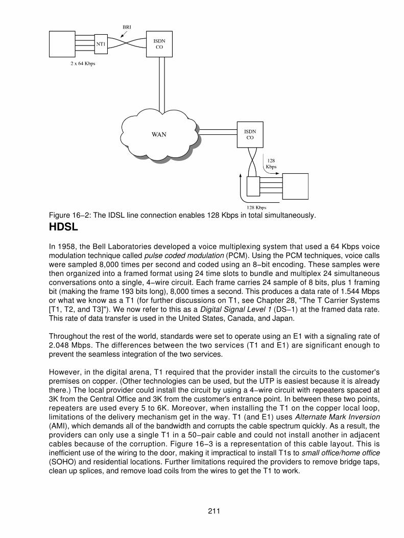
Figure 16−2: The IDSL line connection enables 128 Kbps in total simultaneously.
HDSL
In 1958, the Bell Laboratories developed a voice multiplexing system that used a 64 Kbps voicemodulation technique called pulse coded modulation (PCM). Using the PCM techniques, voice callswere sampled 8,000 times per second and coded using an 8−bit encoding. These samples werethen organized into a framed format using 24 time slots to bundle and multiplex 24 simultaneousconversations onto a single, 4−wire circuit. Each frame carries 24 sample of 8 bits, plus 1 framingbit (making the frame 193 bits long), 8,000 times a second. This produces a data rate of 1.544 Mbpsor what we know as a T1 (for further discussions on T1, see Chapter 28, "The T Carrier Systems[T1, T2, and T3]"). We now refer to this as a Digital Signal Level 1 (DS−1) at the framed data rate.This rate of data transfer is used in the United States, Canada, and Japan.
Throughout the rest of the world, standards were set to operate using an E1 with a signaling rate of2.048 Mbps. The differences between the two services (T1 and E1) are significant enough toprevent the seamless integration of the two services.
However, in the digital arena, T1 required that the provider install the circuits to the customer'spremises on copper. (Other technologies can be used, but the UTP is easiest because it is alreadythere.) The local provider could install the circuit by using a 4−wire circuit with repeaters spaced at3K from the Central Office and 3K from the customer's entrance point. In between these two points,repeaters are used every 5 to 6K. Moreover, when installing the T1 on the copper local loop,limitations of the delivery mechanism get in the way. T1 (and E1) uses Alternate Mark Inversion(AMI), which demands all of the bandwidth and corrupts the cable spectrum quickly. As a result, theproviders can only use a single T1 in a 50−pair cable and could not install another in adjacentcables because of the corruption. Figure 16−3 is a representation of this cable layout. This isinefficient use of the wiring to the door, making it impractical to install T1s to small office/home office(SOHO) and residential locations. Further limitations required the providers to remove bridge taps,clean up splices, and remove load coils from the wires to get the T1 to work.
211

Figure 16−3: The typical layout of the T1To circumvent these cabling problems, HDSL was developed as a more efficient way of transmittingT1 (and E1) over the existing copper wires. HDSL does not require the repeaters on a local loop ofup to 12K. Bridge taps will not bother the service, and the splices are left in place. This means thatthe provider can offer HDSL as a more efficient delivery of 1.544 Mbps. The modulation rate on theHDSL service is more advanced. Sending 768 Kbps on one pair and another 768 Kbps on thesecond pair of wires splits the T1. This is shown in Figure 16−4.
212

Figure 16−4: HDSL is impervious to the bridge and splices. The T1 is split onto two pairs.As already mentioned, HDSL runs at 1.544 Mbps (T1 speeds) in North America and at 2.048 Mbps(E1 speeds) in other parts of the world. Both speeds are symmetric (simultaneous in bothdirections). Originally, HDSL used two wire pairs at distances of up to 15K. HDSL at 2.048 Mbpsuses three pairs of wire for the same distances, but no longer. The most recent version of HDSLuses only one pair of wire and is expected to be more accepted by the providers. Nearly all theproviders today deliver T1 capabilities on some form of HDSL.
SDSL
The goal of the DSL family was to continue to support and use the local copper cable plant.Therefore, the need to provide high−speed communications on a single cable pair emerged. Most
213
local loops already employ single cable pair today; thus, it is only natural to assume the providerswould want this capability. SDSL was developed to provide high−speed communications on thatsingle cable pair but at distances no greater than 10K. Despite this distance limitation, SDSL wasdesigned to deliver 1.544 Mbps on the single cable pair. Typically, however, the providers offerSDSL at 768 Kbps. This creates a dilemma for the carriers because HDSL can do the same thingsas SDSL.
ADSL
SDSL uses only one pair of wires, but is limited in its distance to provide duplex, high−speedcommunications. Not all users require symmetrical speeds at the same time. ADSL was, therefore,designed to support differing speeds in both directions over a single cable pair at distances of up to18K. Because the speeds requested are typically for access to the Internet (or intranet), most userslook for higher speeds in a download direction and the lower speed for an upward direction.Therefore, the asymmetrical nature of this service meets those needs.
RADSL
Typically with equipment, installed assumptions are made based on minimum performancecharacteristics and speeds. In some cases, special equipment is used to condition the circuit toachieve those speeds. However, if the line conditions vary, the speed will be dependent on thesensitivity of the equipment. In order to achieve variations in the throughput and be sensitive to theline conditions, RADSL was developed. This gives the flexibility to adapt to the changing conditionsand adjust the speeds in each direction to potentially maximize the throughput on each line.Additionally, as line conditions change, you can see the speeds changing in each direction duringthe transmission. Many of the ILECs have installed RADSL as their choice, given the local loopconditions. Speeds of up to 768 Kbps are the preferred rates offered by the incumbent providers.
CDSL
Consumers are not all looking for symmetrical high−speed communication in order to achieveaccess to the Internet. Furthermore, the speeds of ADSL technology are more than the averageconsumer may be looking for. As a result, the lower−speed communications capability wasdeveloped by using CDSL as the model. With other forms of DSL (such as ADSL and RADSL),splitters are used on the line to separate the voice and the data communications. CDSL does notuse, nor need, a splitter on the line. Moreover, speeds of up to 1 Mbps in the download directionand 160 Kbps in the upward direction are provided. It is expected that the speeds and DSL will meetthe needs of the average consumer for some time to come. As a result, a universal ADSL workinggroup developed what is called ADSL−lite. This was ratified in late 1998, using the specificationsfrom this working group for delivery to the average consumer. Because of the changes in speedswith this technique, the telephone companies are in a position to support a lower−speed DSL strictlythrough the use of the modems without the concern for local loop. An example of this DSL−lite(G.Lite) service is provided with the Nortel 1 Mb modem.
SHDSL
SHDSL conforms to the International Telecommunications Union G.991.2 recommendations,leveraging capabilities of older DSL and other transport technologies, such as SDSL, HDSL andHDSL2, IDSL, ISDN, T−1, and E−1. One of the most significant improvements SHDSL brings to thebusiness market is increased reach — at least 30 percent greater than any earlier symmetric DSLtechnology. Furthermore, SHDSL supports repeaters, which further increase the reach capability ofthis technology.
214

Another critical advantage of SHDSL is its increase in symmetric bandwidth. In a typical installation,up to 2.3 Mbps will be available on a single copper pair. For greater bandwidth needs in the future,a 4−wire model that can provide up to 4.6 Mbps is also supported by the new standard. SHDSL isalso rate adaptive, enabling flexible revenue−generation models and enabling service providers tooffer service−level agreements that ensure businesses get the service they want, when they want it.
G.SHDSL stands for Symmetric High Bit Rate Digital Subscriber Loop defined by the new ITUGlobal Standard G991.2 as of February 2001. This service delivers voice and data services basedon highly innovative communication technologies and will thus be able to replace oldercommunication technologies such as T1, E1, HDSL, HDSL2, SDSL, ISDN, and IDSL in the future.
SHDSL provides high symmetric data rates with guaranteed bandwidth and low interference withother services. By supporting equal upstream and downstream data rates, G.SHDSL better fits theneeds of
Remote LAN access• Web−hosting• Application sharing• Video conferencing•
G.SHDSL targets the small business market. Multiple telephone and data channels, videoconferencing, remote LAN access, and leased lines with customer−specific data rates are among itsmany exciting characteristics. Spectrally friendly with other DSLs, it supports symmetric data ratesvarying from 192 Kbps to 2.320 Mbps across greater distances than other technologies.
In an ATM−based network on the customer side, an Integrated Access Device (IAD) is installed toconvert voice and data into ATM cells. An IAD can also contain some routing functionality. Data isconverted using AAL5 (ATM Adaptation Layer), while voice requires AAL1 (without compression) orAAL2 (with compression and micro cells). These cells are mapped together in the SHDSL frameand recovered later on in the DSLAM. An ATM switch routes the cells either to an Internet serviceprovider (ISP) or to a voice gateway that translates the voice cells back into the TDM world.
The voice part of the SHDSL frame will be treated in a similar fashion to normal ISDN or POTSservices. However, the data needs to be converted into ATM. This can be done either in an IAD,resulting in a mix of TDM and ATM on the SHDSL line, or at the central office side. In the secondcase, it is necessary to protect the data on the line. This can be easily done by an HDLC protocol.The division between voice and data should be done in the loop carrier so that the ATM cells can besent directly to the ATM backbone in order not to congest the PSTN network. This approach has theadvantage of being more bandwidth efficient because the HDLC overhead is smaller than the ATMoverhead. Additionally, the Segmentation And Reassembly (SAR) functionality can be centralized inthe DLC. However, because an IAD normally uses Ethernet to connect to a LAN, some intelligenceis required at the subscriber side to process the Ethernet MAC and also have SAR functionality.
VDSL
Clearly, changes will always occur as we demand faster and more reliable communicationscapabilities. It was only a matter of time until some users demanded higher−speed communicationsthan was offered by the current DSL technologies. As a result, VDSL was introduced to achieve thehigher speeds. If, in fact, speeds of up to 50 Mbps are demanded, then the distance limitations ofthe local cable plant will be a factor. In order to achieve the speeds, you can expect that a fiber feedwill be used to deliver VDSL. This technique will most likely carry ATM traffic (cells) as its primarypayload. The pilot program of Qwest Communications in Arizona leaves plans to deliver fiber to the
215

door, Fiber to the Home (FTTH), to provide voice, data, video, and multimedia communications tothe consumer. Although this pilot is still emerging, a lot of excitement has been generated over thepossibilities.
Table 16−2 summarizes the speeds and characteristics of the DSL technologies discussed. Theseare the typical installation and operational characteristics; others will certainly exist in variations ofinstallation and implementation.
Table 16−2: Summary of DSL speeds and operations using current methods
Service Explanation Download Upload Mode of OperationADSL Asymmetric
DSL1.5 to 8.192Mbps
16 to 640 Kbps Different up and downspeeds, one pair wire.
RADSL Rate AdaptiveDSL
64 Kbps to8.192 Mbps
16 to 768 Kbpsspeeds
Different up and down. Manycommon operations use 768Kbps. One pair wire.
CDSL Consumer DSL 1 Mbps 16 to 160 Kbps Now ratified as DSL−lite(G.lite). No splitters. One pairwire.
HDSL High−data rateDSL
1.544 Mbps inNorth America,
1.544 Mbps Symmetrical services. Twopairs of wire.
2.048 Mbps 2.048 Mbps inrest of world
IDSL ISDN DSL 144 Kbps(64+64+16) asBRI
144 Kbps(64+64+16) asBRI
Symmetrical operation.Onepair of wire. ISDN BRI.
SDSL Single DSL 1.544 Mbps,2.048 Mbps
1.544 Mbps,2.048 Mbps
Uses only 1 pair but typicallyprovisioned at 768 Kbps.One pair wire.
VDSL Very High datarate DSL
13 to 52 ± Mbps 1.5 to 6.0 Mbps Fiber needed and ATMprobably used.
SHDSL(G.SHDSL)
SingleHigh−speedDSL or 384Kbps
192 Kbps to2.360 Mbps or384 Kbps to4.720 Mbps
192 Kbps to2.360 MbpsUsing 2 pair. to4.720 Mbps
Using 1 pair.
The Hype of DSL Technologies
Why all the hype? Well the local providers are extremely excited if they can install higher−speedcommunications and preserve their local cable plant. No one wants to abandon the local copperloop, but getting more data reliably across the local loop is imperative. Therefore, the ability tobreathe new life into the cable plant is an extension of the facilities in place.
The consumer is looking for higher−speed access (primarily to access the Internet) for whatever theapplication. Yet, at the same time, consumers are looking for a bargain. They do not want to spenda lot of money on their communications services.
The providers are trying to bump up their revenues without major new investments. They would liketo launch as many new service offerings on their existing cable plant and increase the costs to theend user. This is a business decision, not a means of trying to rake the consumer over the coals.
216

Yet there has to be a happy medium of providing services and generating revenues with limits onexpenses. To do this, the xDSL family offers the opportunity to meet the demands while holdingdown investment costs. The key ingredient for success is to minimize costs and satisfy theconsumer. Make no mistake, if the local provider does not offer the high−speed services, someoneelse will.
xDSL Coding Techniques
Many approaches were developed as a means of encoding the data onto the xDSL circuits. Themost common are Carrierless Amplitude Phase Modulation (CAP) and discreet multitone (DMT)modulation. Quadrature with Phase Modulation (QAM) has also been used, but the important part isthe standardization. The industry, as a rule, selected DMT, but several developers and providershave used CAP. It is, therefore, appropriate to summarize both of these techniques. The SHDSLtechnology uses a trellis−coded pulse amplitude modulation (TCPAM) technique to gain the benefitsof the single−pair services or two−pair service.
Discreet Multitone
DMT uses multiple narrowband carriers, all transmitting simultaneously in a parallel transmissionmode. Each of these carriers carries a portion of the information being transmitted. These multiplediscrete bands, or, in the world of frequency division multiplexing, subchannels, are modulatedindependently of each other using a carrier frequency located in the center of the frequency beingused. These carriers are then processed in parallel form.
In order to process the multicarrier frequencies at the same time, a lot of digital processing isrequired. In the past, this was not economically feasible, but integrated circuitry has made this morerealistic.
The American National Standards Institute (ANSI) selected DMT with the use of 256 subcarriers,each with the standard 4.3125 kHz bandwidth. These subcarriers can be independently modulatedwith a maximum of 15 bits/second/Hz. This enables up to 60 Kbps per tone used. Figure 16−5shows the use of the frequency spectrum for the combination of voice and two−way datatransmission. In this representation, voice is used in the normal 0 to 4 kHz band on the lower end ofthe spectrum (although the lower 20 kHz is provided). Separation is enabled between the voicechannel and the upstream data communications, which operates between 20 kHz and 130 kHz.Then a separation is enabled between the upstream and the downstream channels. Thedownstream flow uses between 140 kHz and 1 MHz. As shown in this figure, the separation allowsfor the simultaneous up− and downstreams and the concurrent voice channel. It is on this spectrumthat the data rates are sustained. Each of the subchannels operates at approximately 4.3125 kHz,and a separation of 4.3125 kHz between channels is allocated.
217

Figure 16−5: The ANSI DMT specificationUsing DMT for the Universal ADSL Service (G.Lite)
Provisions for the high−speed data rates of full ADSL are good, but not every consumer is lookingfor the high data rates afforded on ADSL. Therefore, the Universal ADSL Working Group decided toreevaluate the need for the end user. What they determined is that many consumers needdownload speeds of up to 1.5 Mbps and upload speeds between 9.6 to 640 Kbps. As a result, theADSL Lite specification was designed to accommodate these speeds, as a logical steppingstone tothe higher−speed needs for the future. Initially introduced in early 1998, the specification wasratified in late 1998 to facilitate the lower throughput needs of the average consumer. DMT is thepreferred method of delivering the G.Lite specification and service, as it is now known. This involvesa slightly different method of delivering the service, but does accommodate the providers with a lessexpensive solution to provide full−rate ADSL.
There is no way to know if the network providers can support hundreds of multimegabit ADSL up−and download speeds on their existing infrastructure. But using the G.Lite specification can supportlower−demand users more efficiently. Similar to the DMT used in the ANSI specification, the carriersare divided as shown in Figure 16−6. Note that in this case, the high end of the frequency spectrumtops out at approximately 550 kHz instead of the 1 MHz range with ADSL.
Figure 16−6: The ANSI and UAWG G.Lite spectrum
218

To Split or Not to Split
Another issue of using ADSL is the use of splitters on the line. In normal ADSL and RADSL, thelocal provider uses a splitter on the line. ADSL modems usually include a POTS splitter, whichenables the simultaneous access to telephony applications and high−speed data access. Somevendors provision the service with an active POTS splitter device that allows the simultaneoustelephone and data access. Unfortunately, with an active device, if the power or the modem fails,then the telephone also fails. This is problematic because we are accustomed to having lifelineservices with our telephone systems that are always available, even if the power fails. The splitter isshown in Figure 16−7 as it is installed.
Figure 16−7: The splitter−enabled ADSL serviceA passive POTS splitter maintains the lifeline service of telephony even if the modem fails. This isimportant because the telephone line is powered from the line instead of an external power source.Telephony service will be available as much as we have always expected from the normal servicewe have always received.
A POTS splitter is a three−pronged device, enabling telephony and simultaneous up−and−downloading data access on the same copper loop. As shown in the previous figures, the POTS serviceoperates at the low end of the frequency spectrum. All the data signals are located in the higherfrequencies. These signals start between 20 to 25 kHz and above. The splitter provides a low passfilter between the copper line and the ADSL point on the modem.
One of the primary concerns is to enable a filter to block any transient noise coming from the POTSside of the line from crossing over into the ADSL side of the line. Ringing voltages can causesignificant impulse noise across the line, destroying the data. ADSL modem signals are alsoblocked from passing onto the POTS side of the line by the filters.
Most of the POTS splitters are passive. Passive filters provide higher degrees of reliability becausethey don't require power, they can isolate the equipment from surges on the line, and they canarrest lightning that may be coupled on the line. Active filters require power and are less adapted tosuppress the surges. In many countries around the world, active filters are a requirement.
The G.Lite specification uses a splitterless device to facilitate the installation of low−speed DSL
219

services. This is shown in Figure 16−8 for implementation. Without the splitter, there is less cost forthe provider and the issues of active versus passive splitters are eliminated. This provides adifferent approach.
Figure 16−8: The splitterless G.Lite installationCAP
CAP is closely aligned to QAM. QAM as a technique is widely understood in the industry and welldeployed in our older modems. Both CAP and QAM are a single−carrier signal technique. The datarate is divided into two and modulated onto two different orthogonal carriers before being combinedand transmitted. The main difference between CAP and QAM is in the way they are implemented.QAM generates two signals with a sine/cosine mixer and combines them onto the analog domain.
CAP, on the other hand, generates its two orthogonal signals and executes them digitally. Using twodigital transversal bandpass filters with equal amplitude characteristics and a p/2 difference inphase response, the signals are combined and fed into a digital−to−analog converter. Then the datais transmitted. The advantage of CAP over QAM is that CAP is done in silicon, which is moreefficient and less expensive.
CAP was one of the original proposals for use with ADSL technology. Unfortunately, this was aproprietary solution offered by a single vendor, which turned heads away from acceptance. CAP isshown in Figure 16−9 in its use of the frequency spectrum of the line. Most industry vendors agreethat CAP has some benefits over DMT but also that DMT has more benefits over CAP. The pointhere is that two differing technologies were initially rolled out for ADSL (and the other familymembers), which contradict each other in their implementation.
Figure 16−9: The spectral use of CAPCAP uses the entire loop bandwidth (excluding the 4 kHz baseband analog voice channel) to sendthe bits all at once. There are no subchannels, as found in the DMT technique. The lack ofsubchannels removes the concern about the individual channel transmission and problems. Toachieve the simultaneous send and receive capability, frequency division multiplexing is used, as is
220

echo cancellation. Many of the Regional Bell Operating Companies (RBOCs) have used or triedCAP in their installations, but have moved away from the CAP to a uniform use of DMT.
Provisioning xDSL
In the following figures, the various architectures of the xDSL implementations are shown. The pointto remember here is the goal of xDSL is to use the existing copper infrastructure and improve thespeed and throughput on the installed base of wires. Consequently, the installation processattempts to minimize the added equipment (particularly at the customer's premises) and the laborrequired to get the equipment installed.
In Figure 16−10, the design of an ADSL model and the model components are shown. The intent ofthe model is to show the infrastructure of the network from the customer premises to the networkprovider. This model also shows the splitters in place to facilitate the ADSL model.
Figure 16−10: The ADSL model as it is laid out from the customer premises to the service providerFigure 16−11 demonstrates the connection from the service provider to the rest of the world. Inmany cases, ADSL access to the local network access provider (the ILEC or other local loopprovider) is then passed on to the ISP. This is designed to run over an ATM backbone but not a firmrequirement. Therefore, the NAP will assign a DSL Access Multiplexer (DSLAM) card and assign anATM VPI and VCI as a default to carry the data into the ISP or other Network Service Provider(NSP).
221

Figure 16−11: Access from the NAP to the NSPThe application most commonly used is to gain high−speed access to the Internet. Many of the localservice providers install the ADSL service into a single PC at the end−user location, as shown inFigure 16−12. The local providers offer the customer a packaged deal with the followingcomponents:
Figure 16−12: The typical local installation
LAN NIC card operating at 10 Mbps•
222

DSL modem• Splitter• Management cables•
The local provider will normally advise the customer that the termination must be to a single PCequipped with the NIC card. In the United States, the customer owns the package when theinstallation is completed due to some of the regulatory constraints and the Public Utility Commissionrulings. This places the burden of maintenance and diagnostics on the end user rather than thelocal service provider. In the case of a LAN attachment described previously, the ADSL modem isset to bridge from the LAN to the ATM network interfaces rather than route.
In other cases when a LAN is present at the customer location and the end user wants to connectall the LAN devices to the high−speed outside network for Internet access or private networkaccess, the local carrier may suggest that a proxy server is a requirement. The proxy server (PCdedicated to act in this function) will then act as the gateway to the outside world for all devicesattached to the LAN (see Figure 16−13).
Figure 16−13: The proxy server in lieu of a single attached PCAn alternative to this approach is the direct connection to a LAN hub, such as that found in thetelephone closet. Keeping the connection active, the carrier will normally assign an IP address,using DHCP for a contracted period of time. Normally, this is a lease period of four hours, and thenthe network server (outside) will renegotiate and assign a new IP address for the end user. Thisprotects the end−user network from becoming visible on the Internet and helps to prevent some ofthe normal security risks associated from a hard connection to the Net (see Figure 16−14).
223
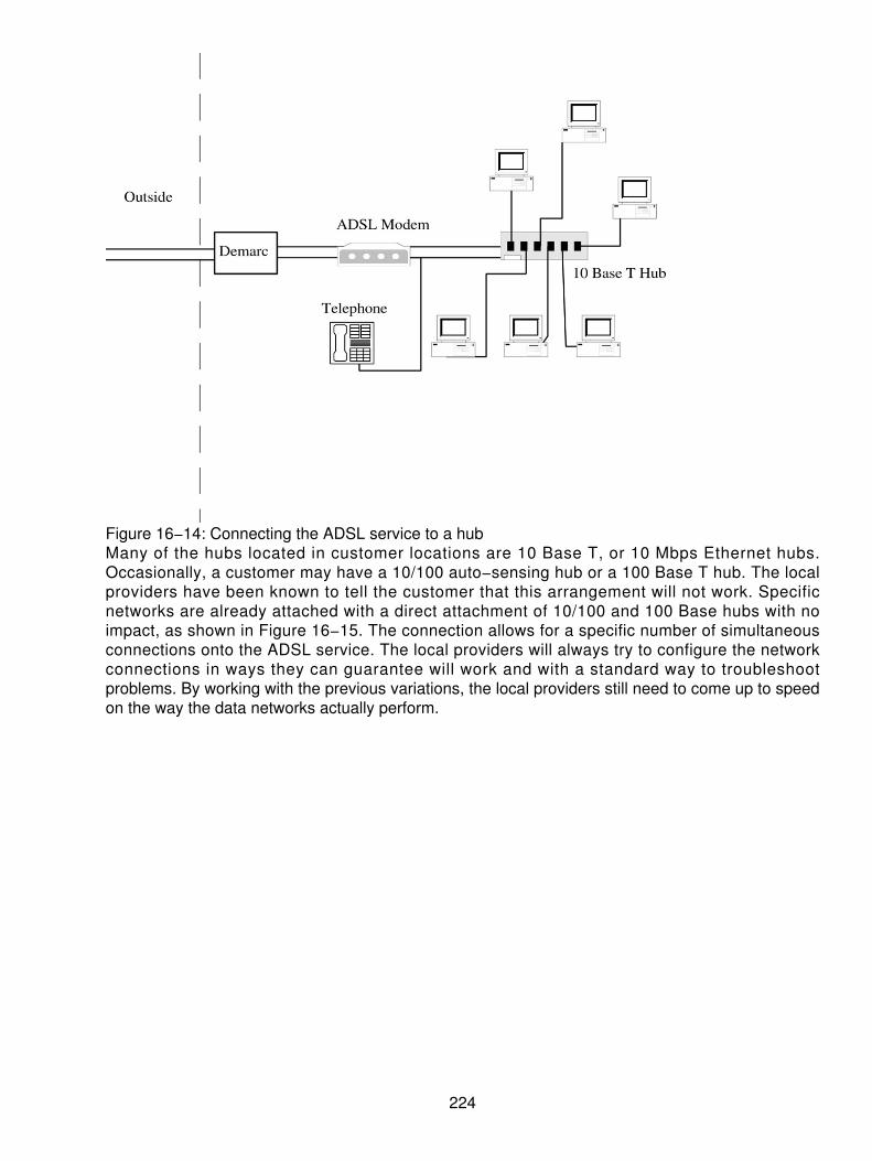
Figure 16−14: Connecting the ADSL service to a hubMany of the hubs located in customer locations are 10 Base T, or 10 Mbps Ethernet hubs.Occasionally, a customer may have a 10/100 auto−sensing hub or a 100 Base T hub. The localproviders have been known to tell the customer that this arrangement will not work. Specificnetworks are already attached with a direct attachment of 10/100 and 100 Base hubs with noimpact, as shown in Figure 16−15. The connection allows for a specific number of simultaneousconnections onto the ADSL service. The local providers will always try to configure the networkconnections in ways they can guarantee will work and with a standard way to troubleshootproblems. By working with the previous variations, the local providers still need to come up to speedon the way the data networks actually perform.
224

Figure 16−15: Connecting the ADSL modem directly through a 10/100 or a 100 Base T hub
Final Comment on Deployment
The use of ADSL service is catching on. However, the local providers (ILECs and CLECs) aredragging their feet. As of late 1998, there were only about 15 to 20,000 total ADSL modem pairsinstalled in the United States. In contrast, there were over 300,000 cable modems installed inresidences and businesses across the country. The local owners of the copper loop have to take amore aggressive approach to delivering the high−speed services, or the consumer will gosomewhere else.
As the market continues to mature and standards continue to develop, the local providers mustpreserve their infrastructure. Consumers (small and large alike) are demanding the higher−speedservices. As a stepping stone for residential− and home−based businesses, the acceptance andstandardization of the G.Lite specification will provide suitable transmission rates until the carrierscan complete their data strategies. 1 Mbps modems, for example, giving the end user a 1 Mbpsdownload speed and a lower 160 Kbps upload speed, will suffice for many today and into the nextmillennium.
For the larger consumers, a full−rate ADSL may be just what is needed, bringing 1.544 to 8 Mbpsdownloads and 768 Kbps uploads to the forefront of Internet access.
Where the consumer is reluctant to proceed with ADSL, the HDSL or the SDSL services are stillvery attractive alternatives, offering up to 1.544 to 2.048 Mbps symmetrical speeds or somevariation as already discussed.
In the future, when high−speed media are installed to the door or to the curb, the logicalsteppingstone will become the VDSL service, perhaps in the year 2003. Although trials are alreadyunderway, too much time passes until the results are compiled and analyzed. Therefore, the realityof VDSL for the masses is still a long way off.
225

226

Chapter 17: Microwave− and Radio−Based Systems
Overview
No one ever pays much attention to the microwave radio dishes mounted on towers, on the sides ofbuildings, or any other place. This technology has been taken for granted over the years. However,this nondescript industry has quietly grown into a $4.6 billion global business annually withexpectations that the market will reach approximately $10 billion by 2006. Table 17−1 is a possiblebreakdown of the distribution of wireless microwave services by category between 2002 and 2006.
Table 17−1: Possible market share for microwave products
Service 2002 2006Point−to−point microwave radios services $2.5 billion $4 billionPoint−to−multipoint microwave $700 million $2 billionWireless LAN microwave products $1.4 billion $4 billionTotal $4.6 billion $10 billion
Four major suppliers provide one−half of all the radio−based systems globally. Microwave has alsobecome a vital link in the overall backbone networks over the years. Now, it has achieved newacclaim in the wireless revolution, relaying thousands of telephone conversations from place toplace, bypassing the local landlines.
Microwaves (the actual radio waves) are between 1 mm and 30 cm long, and operate in afrequency range from 300 MHz to 300 GHz. Microwaves were first used in the 1930s, when Britishscientists discovered the application in a new technology called radar.
In the 1950s, microwave radio was used extensively for long−distance telephone transmission. Withthe need to communicate over thousands of miles, the cost of stringing wires across the countrywas prohibitive. However, the equipment was both heavy and expensive. The radio equipment usedvacuum tubes that were bulky as well as highly sensitive to heat. All of that changed dramaticallywhen integrated circuits and transistors were used in the equipment. Now the equipment is not onlylightweight, but also far more economical and easy to operate. In 1950, the typical microwave radioused 2,100 watts to generate three groups of radio channels (each group consists of 12 channels),yielding 36−voice−grade−channel capacity. Each voice grade channel operated at the standard 4kHz. Today, equipment from many manufacturers (and Harris/Farinon, specifically) requires only 22watts of output to generate 2,016 voice channels. Although there have been two orders ofmagnitude improvements in the quality of the voice transmission, the per−channel cost hasplummeted from just over $1,000 to just under $37. This makes the transmission systems veryattractive from a carrier's perspective. However, the use of private microwave radio has alsoblossomed over the years because of the cost and performance improvements. This is shown in thegraph reflected as Figure 17−1, which details why the use of microwave has become so wellaccepted in the industry.
227

Figure 17−1: Comparison of cost per channel over the yearsToday's microwave radios can be installed quickly and relocated easily. The major time delays areusually in getting through the regulatory process in a governmentally controlled environment.Several installations have taken over a year to be approved, only to have the radio system installedand running within a day or two. In many situations, microwave systems provide more reliableservice than landlines, which are vulnerable to everything including flooding, rodent damage,backhoe cuts, and vandalism. Using a radio system, a developing country without a wiredcommunications infrastructure can install a leading−edge telecommunications system within amatter of months. For these reasons, regions with rugged terrain or without any copper landlinebackbone in place find it easier to leap into the wireless age and provide the infrastructure at afraction of the cost of installing wires.
Throughout the world, government−owned and −controlled monopolies are being eliminated. Brazilopened its doors to international Telecom competition, allowing microwave radio systems and amobile telephone system supplied by North American firms. In Russia, one of the leading systemsmanufacturers installed an integrated network along a 3,600−mile gas pipeline. Using microwaveradios and digital telephone switches, this link sends data and voice from Siberia to Russia'ssouthern border. A similar system is used for the railroad system, using a trunked radio system,microwave radio−relay, and digital telephone switches. The telephone service may serve more thanthe railroad, incorporating hundreds of thousands of people residing alongside the railway line.
The cellular and Personal Communications Service (PCS) industries invested heavily in microwaveradios to interconnect the components of their networks. This is shown in Figure 17−2 where theinterconnection is used in the cellular world. In addition, a new use of microwave radio, calledmicro/millimeter wave radio, is bringing transmission directly into buildings through a newgeneration of tiny receiver dishes.
228

Figure 17−2: Cellular interconnection of microwave radioWinStar Communications, a Competitive Local Exchange Carrier (CLEC), pioneered the use ofmicro/millimeter wave radio communications in the 30+ GHz frequency range (actually 28 to 38GHz). This allowed the CLEC to deliver broadband communications to the consumer's door withoutthe use of telephone company wires. Unfortunately, the results were mixed as WinStarCommunications developed financial trouble and filed for bankruptcy protection in 2001 and wasacquired by IDT Corporation in December 2001.
The PCS industry chose microwave radio technology for the interconnection and backhaul transporton its expanding network. The PCS suppliers and the cellular suppliers do not want to pay the localtelephone company for monthly T1 access lines from the cell sites to the mobile switching sites.Therefore, to eliminate the monthly recurring charges, they have installed microwave radio systemsin the 18 to 23 GHz frequency range. Tens of thousands of new cell sites and PCS sites have beenconstructed and will continue to be constructed over the next few years, further expanding the useof microwave radio systems in each of these sites. As third−generation, handheld devices maketheir way into the industry, more wireless interconnectivity will be used.
Microwave also played a very crucial part of the PCS industry as the PCS systems use the 1.9 to2.3 GHz frequency band. Fixed systems operators such as police, fire, electric utilities, and somemunicipal organization occupied these frequencies. To accommodate the move of these users fromthe 2 GHz frequency band, microwave was used to relocate the users to a new band, as mandatedby the FCC. One study indicated that the PCS industry would spend over $3 billion in microwaveequipment and services by 2005.
Another large demand for microwave emerged in the Competitive Access Providers' (CAPs) market.CAPs offer long−distance access to customers at lower prices than the local telephone companiesand the newer competitors. The CAPs normally install their own fiber−optic wires. However, theyrecognize the benefit of expanding coverage to consumer building entrances, using a wireless,high−speed connection. The CAPs are supplementing their fiber−based networks with WirelessCAPs (WCAPs). WCAPs use microwave transmission to deliver the telecom service without the
229

need for a costly, wire−based infrastructure (see Figure 17−3).
Figure 17−3: Wireless interconnection of fiber and CAPsThe newer micro/millimeter−wave radios, which are smaller and usually less expensive than othermicrowaves, are also popular with these CAPs and PCS suppliers. They are used in urban areas toextend the fiber networks. These radio units use the high−frequency (or millimeter) bandwidth thathadn't been used before. Now, they are seen as a solution to increasing congestion in the lowerfrequency bands. An advantage of these systems is the small antennas that can be hidden onrooftops without interfering with zoning ordinances or creating aesthetic controversy.
Microwave is heavily used in radio and television systems. Satellite TV relies on microwaverepeaters on the satellite to retransmit TV signals to a receiving station. Microwave communicationvia satellite provides a more reliable signal than longer, land−based radio waves. It also improvesthe reception of the picture.
Some TV stations have been using microwaves to facilitate wireless communications from fieldcameras since 1992. What we continually hear about the "action cams" is a portable microwavesystem connected to a camera for real−time broadcast. Instead of being constrained to a fixedlocation, a news van can be driven and hooked up instantly, as shown in Figure 17−4. The systemshook up with a field camera with microwave units the size of a deck of cards. These can goanywhere and can operate from locations up to two miles from the van. Action and news istransmitted back to the van where it is relayed via microwave to the TV station. We have allexperienced the "news as it was happening" on TV from local events to worldwide events.
230

Figure 17−4: Action camera and microwave systems working together
Other Applications
A laptop computer with a credit card−sized PRISM radio chip set can now convert incomingmicrowave messages into binary code for computer processing and then convert them back intomicrowaves for transmission (see Figure 17−5). Similarly, microwave transmission is used in LANs,on corporate or college campuses, in airports, and elsewhere. Whether it is collecting data, relayingconversations, or beaming messages from space, microwave makes the wireless revolutionpossible.
231

Figure 17−5: Laptop computers can now send and receive microwave radio transmissions.No one can escape the wireless hype these days. The challenge is in wading through all theconfusion and misleading statements to decide whether an application fits the need. If you canmake sense of it all, you may find the solution to your connectivity needs.
First, one distinction will help to narrow the playing field. In this explosion of wireless technologies,there are two major categories worth mentioning:
Personal wireless devices• Wireless devices that are used between buildings (for voice, data, and video)•
Buying the wrong personal wireless device, such as a pager or cell telephone, is annoying, butinexpensive and easily replaceable. Yet, if you're a telecommunications manager, the wrong choiceto connect your sites together can have significant financial impact and your career can beshortened.
How Do You Make the Right Choices?
Telecommunications and information managers have many options to connect remote sites. Theoptions have expanded with all the wireless excitement and the expansion of VLSI integration,making the devices far more affordable. Today, there are more vendors trying to sell the end useron their products. The CLECs, CAPs, and Wireless CAPs are all vying for this portion ofconnectivity, but so, too, are the manufacturers.
How do you make sense of all the hype and make a decision consistent with corporate goals? Thatis not as complicated as it sounds. Conducting a needs assessment is critical to understanding theconnectivity goal. After your needs are determined, the next step is to find a solution that works.Does the solution offer a cost justification, and it can be delivered in a reasonable time?
232
Complications arise when vendors don't have the actual solution needed, but try to force thesolution to fit with their product. They further disparage the other vendors with fear, uncertainty, anddoubt about competing products. So step one is to determine the technical requirements. Mostorganizations look for bandwidth and reliability. If these two requirements can be reasonably met,one need only find a vendor to deliver the following:
What you need• When you need it• What is reasonable financially•
What About Bandwidth?
Bandwidth is always a touchy subject. It can become a "never satisfied drain" on the corporatebottom line if due diligence is not practiced. There is a direct relationship to cost and totalbandwidth. The more bandwidth needed, the greater the cost. Everyone would like as muchbandwidth as possible, and at the same time wants it to be affordable. Many people make themistake of buying more than they need, anticipating future growth. In this industry, prices keepfalling as competition increases. If an organization needs an OC−3 (155 Mbps) today, then layingfiber is probably the most affordable solution. However, 155 Mbps microwave systems are availableand the prices are constantly dropping, giving short−haul fiber a run for the money.
Conversely, if 10 Mbps Ethernet is the current rate of transmission, then this demand can beimmediately met. Additional bandwidth can be bought later. In two to three years, the costs willplummet so that the new requirements can be met with incremental or marginal costs.
It's wiser to buy bandwidth as you need it and not before (there will be a small amount ofincremental add−on, but limited). In the future, there will be the following:
More choices• Increased providers• Greater availability• Lower costs•
What should be done in the interim to satisfy the need? The answer is the following:
Lease (dark) fiber instead of paying the cost of installation• Lease services from the Incumbent Local Exchange Carrier (ILEC) or CLEC if sufficientbandwidth is available
•
Buy a wireless connection such as point−to−point microwave•
With a leased line (or a dark fiber) solution, the costs can be predictable, based on demand andagreed−upon bandwidth. Assuming physical facilities are available, take what is needed for theinterim and order more only when necessary. This is a good intermediate step to get the bandwidthso long as the recurring charges are not exorbitant.
The alternative to leasing physical circuits from the ILEC or CLEC is wireless acquisition. For aone−time fee and limited recurring maintenance charges, bandwidth can be purchased for theimmediate and future needs. If the wireless product delivers the bandwidth and reliability desiredand the payback is reasonable, then wireless may be the best choice. Consider, however, thefinancial life and return on the investment.
233
It doesn't make sense to order an OC−3 (155 Mbps) connection when the need is only for 10 Mbps.Yet there should be an upgrade path. As mentioned, leasing copper lines or fiber from the ILECallows a migration path. Growth can be accommodated as needed. Conversely, some wirelessproducts limit this growth option. Some products only handle growth to a T1 or a 10 Mbps channel.Consider the expandability before buying a wireless product.
How Much Is Enough?
The risks associated with buying bandwidth fall into the two categories pointed out earlier:
Buying too little bandwidth will increase incremental growth costs that can add up to morethan buying a larger quantity at the onset would.
•
Buying more bandwidth than immediately needed means paying for bandwidth that may notbe required for some time, or that will be less expensive in the future.
•
If a T1 line slows the voice and data access to the point that users are frustrated or unproductive,then T1 is not the solution! One year of the unproductive environment costs a fortune in lostproductivity.
If a couple of Ethernet channels are needed (at 10 Mbps each), and the organization invests in afiber optic connection, justifying the expense makes an interesting paradox.
Consider approximately how much bandwidth is needed. The answer is as much as it takes to keepthe data moving, voice calls coming, and users productive enough to sell (or whatever else themission is). There is no requirement for more, yet there must be at least that much. Meeting thisequation is the one that keeps the industry guessing, including the ILECs and the CLECs, as theydesign their networks.
What About Reliability?
Having too much bandwidth is possible. Having too much reliability is just the opposite.Organizations lose significant amounts of money when the network connection is too slow, but farmore when the link is down completely. One hour of network downtime can cost more than theprofits and productivity achieved from a year of uptime. In this scenario, automatic backup is anabsolute must. Buy the appropriate amount of bandwidth and make sure that the reliability is built in.Plan for the worst−case scenario! Consider an alternate backup plan. Use circuit−switched orpacket−switched (frame−switched) alternative connections in case of an outage.
The Choices Are Leased Lines, Fiber, or Microwave
Leased lines, fiber, and microwave each have benefits and drawbacks in terms of bandwidth,reliability, price, and delivery. The tendency is usually very application specific. Every case isdifferent in terms of terrain, line of sight, right of way, location of a Bell central office, and so on. A 1to 5 mile fiber choice can range in cost between $20,000 and several million dollars, depending onthe terrain requiring traversal. Similarly, a high−speed leased line can cost $600 a month or $20,000a month if it crosses Local Access and Transport Area (LATA) or other rate boundaries. No onesolution fits all possibilities for connectivity.
234

Using a wireless connection, the first, full−speed Ethernet speed solution was a major milestone.From this innovation, users had viable options, bridging the extremes between leased lines andfiber. Many users still limit their choices to the bottleneck of a T1 leased line or overpaying for a T3,which is too much bandwidth for the need.
Instead, you should find a solution that provides the needed bandwidth for a justifiable cost. Allthree solutions offer high reliability for the most critical connections, although a mission−critical pathmust be backed up.
Keep in mind also that the three choices are not mutually exclusive. They frequently work welltogether. Microwave handles "last−mile connectivity" to a fiber backbone or serves as a lower−cost,automatic backup as insurance against "backhoe fade."[1] As the author was preparing this update in Phoenix, Arizona, a major cable cut occurred in theChandler area, severing multiple fiber lines and disrupting local and long−distance service for morethan six hours. You should weigh each choice, based on which offers the best cost−to−benefit ratio.Cost includes installation, ongoing charges, upkeep, losses due to downtime, and organizationalproductivity.
Microwave and the Other Wireless Solutions
Prior to the 1970s, microwave was the most widely used wireless communications medium in theworld. Microwave usage is making a comeback now with end users. Many user organizations werereluctant to experiment with microwave radio transmission due to misconceptions surrounding thetechnology as well as confusion between the "wireless" products. It is important to recognize thatthe difference between one wireless device and another can be as different as fiber and copperwire. Both fiber and copper are "wired," but that is where the commonality ceases. The same is truebetween microwave and laser, spread spectrum, or cellular service.
There are even differences between one type of microwave and another. The differences are dueprimarily to their respective operating frequencies. Some frequencies are good for distances of 30or 40 miles and others can barely get you across an office park. Some can only support a couple ofT1s or a single video channel and others go to 10 to 45 Mb.
In Table 17−2, a comparison of distances and frequencies is used for representative purposes.Many times this is the best−case scenario.
Table 17−2: Comparison of frequency bands and distances (line of sight)
Frequency Distance2–6 GHz 30 miles10–12 GHz 20 miles18 GHz 7 miles23 GHz 5 miles28–30 GHz 1–2 miles
Microwave Radio Solutions
235

Private−user microwave systems are essentially the same as what the telephone company, FMradio stations, broadcasters, and fixed−site utility companies relied on before the implementation offiber. For example, the corkscrew−type antennas on news vans are shooting microwave signalsback to their TV and radio stations as shown earlier. FM radio stations still rely mainly onmicrowave. In fact, most microwave radio uses frequency modulation (FM) radio technology.
What can microwave offer an organization? Primarily, microwave combines huge bandwidth andreliability that is better than other wireless devices. In fact, microwave is typically far more reliablethan the leased−line specification (99.985 percent) for distances across the street to 20−plus milesaway. Microwave can deliver bandwidth up to 45 Mbps (and most demanded speeds in between). Aproperly configured system will sustain operation except in the most severe rainstorm where powerand telephone line outages would be expected.
The myths run rampant with radio−based systems. Despite the rumors about the various risks andperils for the radio signal, microwave usually operates 99.99−plus percent of the time. Microwave isnormally impervious to the following:
Snow• Sleet• Fog• Birds• Pollution• Sandstorms• Sunspot activity•
The real risk is water fade (water absorption) and multipath fade across bodies of water. These canbe accommodated for the most part in design of the radio path.
A microwave link can transmit Gb of data without dropping a single bit (or packet when a datatransmission uses packetized information). On copper wire, noise is always present. Thermal noisecauses a continuous hum, white noise, and the like. A microwave path can be so clear that if no oneis talking or sending data, the line is perfectly silent. This is difficult for the average layperson tounderstand.
Private User Microwave
Having proven that the bandwidth and reliability are readily available on a microwave system, mostpeople look for the negative side of private microwave. The unaware consumer assumes that theremust be some "gotcha" lurking in the background. One technology cannot be the most robust andreliable and yet not be the most favored. There has to be a major drawback to using microwave.The two largest drawbacks have always been the availability and the sticker price. Microwaveappears to be the most expensive wireless option (typically, between $20,000 to $100,000 for anend−to−end link). However, if greater bandwidth and reliability are the goals, then microwave is notas expensive as it appears superficially. The initial upfront cost avoids the bandwidth and reliabilitytrade−off with less expensive or less robust technologies.
If a critical connection requires high bandwidth and high reliability to prevent catastrophic lossesfrom downtime, then more money is required initially. The old saying "pay me now, or pay me later"applies here.
236

Another perceived drawback (handling over a Mbps) is the requirement to have line−of−sightbetween locations. Line−of−sight issues are rarely showstoppers.
First, only a small part of the remote site needs to be visible. Even if the other site is not visible,solutions exist. Actually, this is quite common. Look for high points that can be used to get visibilitybetween both sites. A passive or active repeater site can be implemented. Setting up a repeater isnot difficult, particularly with passive repeaters. The antennas are small and lightweight enough tobe placed almost anywhere: on a water or radio tower, utility pole, other rooftops, and so on. Analternative is to bounce the signal off a physical obstacle (such as a mountain) and use obstaclegains to get the signal through (see Figure 17−6).
Figure 17−6: Obstacle gain uses a bounced signal off a natural obstacle, such as a mountain.If a repeater is needed, rental space is often available on other towers. This is true in long haul andalso in localized communications. Renting space on an existing tower or a rooftop is not verydramatic. Leased space typically costs $200 per month per dish. Repeaters are shown in Figure17−7.
Figure 17−7: Repeater space can be rented from other suppliers.This assuages the fact that line−of−sight is a major drawback. Anyone who has ever negotiated
237

right−of−way for fiber knows how tedious that can be. With fiber, the right−of−way includes theentire physical length of the cable or conduit required for the connection. With microwave, theconcern is limited to a few physical points where the dish placement will occur and a few legalissues.
Another perceived drawback of microwave, aside from price and line−of−sight, has to do withgetting and maintaining the license to use. Licensing is a protection for the end user. It is a tediousprocess that provides structure and prevents interference and overlays in the frequency spectrum.Most organizations see this as a step for governmental control, but if a conflict arises, it can be thesalvation for the licensed user. License gives you the right to use a good, clear transmission path,and that is definitely positive. The FCC is quite efficient in approving licenses for private users, andspectrum is readily available for point−to−point applications.
Licensing involves contracting someone to do a frequency search and filing a FCC licenseapplication. The frequency search is to find unused, available frequencies. Those frequencies arethen reserved and filed, along with other pertinent data, on the appropriate FCC form. The processis normally completed within a few days, and it can cost $2,000 to have your vendor handle it foryou. An experienced vendor can usually assure that the FCC will grant your license by avoidingamateurish mistakes.
The 23 GHz frequency band, for example, is a very common frequency band for short−haul,private−user microwave systems. Most people confuse the band with the actual operatingfrequency. The 23 GHz band actually consists of 24 pairs of frequencies, ranging between 21.200and 23.600 GHz. The number can be doubled to 48 pairs of frequencies with minor antennachanges (changing polarization from vertical to horizontal).
The radio signal is narrowly focused by the antennas at each end of the link, and transmit power isonly about 60 milliwatts. These variables make it possible to use identical frequency pairs for twolinks originating from the same rooftop! By changing the polarization of the antennas and separatingthe signals, 10 degrees should provide the necessary separation and isolation.
When connecting LANs together with microwave radio systems or bridges, the important issue isselecting the right vendor. The vendor's qualifications and experience in both the LAN andmicrowave systems are paramount. Does the vendor possess the expertise to differentiate anetwork or bridge failure from a radio problem? Can the vendor provide turnkey services andassume total system responsibility? The correct vendor will ensure the successful implementation ofa LAN microwave link.
238

Chapter 18: MMDS and LMDS
Overview
Multichannel Multipoint Distribution Service (MMDS), also known wireless cable, is another wirelessbroadband technology for Internet access. MMDS has been around since the 1970s and is awell−tested wireless technology, which has been used for TV signal transmission for more than 30years. The service is delivered using terrestrial−based radio transmitters located at the highestlocation in a metropolitan area. Each subscriber receives the MMDS signal with an exclusive, small,digital receiver placed at your location with line of sight to the transmitters. MMDS channels come in6 MHz chunks and run on licensed and unlicensed channels. Each channel can reach transfer ratesas high as 27 Mbps (over unlicensed channels: 99 MHz, 2.4 GHz, and 5.7 to 5.8 GHz) or 1 Gbps(over licensed channels). Typically, a block of 200 MHz is allocated to a licensed carrier in an area.
MMDS is a broadcasting and communications service that operates in the ultra−high−frequency(UHF) portion of the radio spectrum between 2.1 and 2.7 GHz. MMDS is also known as wirelesscable. It was conceived as a substitute for conventional cable television (TV). However, it also hasapplications in telephone/fax and data communications.
In MMDS, a medium−power transmitter is located with an omni−directional broadcast antenna at ornear the highest topographical point in the intended coverage area. The workable radius can reachup to 70 miles in flat terrain (significantly less in hilly or mountainous areas). There is a monthly fee,similar to that for satellite TV service.
MMDS frequencies provide precise, clear, and wide−ranging signal coverage. Customers areprotected from interference from other users when the provider uses the licensed frequencies. Rain,snow, and fog do not interfere with signal performance as we saw in the microwave radio chapter(see Chapter 17, "Microwave− and Radio−Based Systems"). Many of the carriers use a super−cellconcept with a service area spanning a 35−mile radius from each of its MMDS transmitters.
The MMDS wireless spectrum originally consisted of 33 analog video channels, which were 6 MHzwide. The evolution of video technology into digital capacities enables the carriers to convert these33 analog MMDS channels into 99 digital, 10 Mbps data streams, enabling full Ethernetconnectivity. Therefore, a carrier with a normal operation can have as much as 1 Gbps of capacityat a single transmitter providing adequate capacities for most applications. This capacity is alsoreadily expandable by using a sector cell concept (see the analog cellular chapter to get a handleon sectors), which reuses the same frequency many times. The combination of super cells andsectors enable the carrier to reuse the same frequency many times by building multiple cell sites.When enough customers sign on and as their bandwidth demands grow, the growth in traffic can behandled expeditiously through a new cell or a new sector.
Limited Frequency Spectrum
The limited number of channels available in the lower radio frequency (RF) bands characterizesMMDS networks. Only 200 MHz of spectrum (between 2.5 GHz and 2.7 GHz) is allocated forMMDS use. This constraint reduces the effective number of channels in a single MMDS system. ForTV signals using 6 MHz of bandwidth, 33 channels can be fit into the spectrum. The FCC allowedfor digital transmission utilizing Code Division Multiple Access (CDMA), quadrature phase shiftkeying (QPSK), vestigial sideband (VSB), and Quadrature Amplitude Modulation (QAM) schemesyielding up to five bits per hertz (one gigabit per second total raw capacity for the band), and return
239

transmission from multiple sites within a 35 mile radius protected service area.
A new frequency band dedicated to digital MMDS services has been proposed, but this may beimpractical in the lower microwave frequencies due to the political and business pressures fromalternative video service providers. Moreover, higher transmitter power and antenna gain arerequired for broadcasting in this frequency range, which will require higher system costs. Higherfrequency bands are not chosen for MMDS due to higher free space or path attenuation. However,the FCC has actually allocated the 27.5 to 29.5 GHz band in the United States to Local MultipointDistribution Service (LMDS). It is presently intended to operate FM−based TV services, with eachservice occupying a 20 MHz bandwidth. Due to its limited range of transmission (3 to 5 milesradius), LMDS is not a good choice to provide wide area coverage of digital television service.
System Configuration
The typical configuration of an MMDS system is shown in Figure 18−1. The wireless systemconsists of head−end equipment (satellite signal reception equipment, radio transmitter, otherbroadcast equipment, and transmission antenna) and reception equipment at each subscriberlocation (antenna, frequency conversion device, and set−top device).
Figure 18−1: A typical MMDS arrangement Source: AMDSignals for MMDS broadcast at the transmitter site originate from a variety of sources, just like atcable head−ends. Satellite, terrestrial, and cable delivered programs, in addition to local basebandservices, comprise the material to be delivered over MMDS. All satellite−delivered basebandformats are remodulated and subsequently up−converted to microwave frequencies. Terrestriallydelivered signals are usually passed through a heterodyne processor prior to up−conversion to thedesired MMDS frequencies. Repeater stations can be used to direct MMDS signals to blockedareas. The typical range of a transmitting antenna can reach up to 35 miles, depending on thebroadcast power. Transmitters usually operate in the 1 to 100 watt range. This is substantially lowerthan the transmission power requirements of VHF and UHF terrestrial broadcasting stations. MMDSis a line−of−sight service, so it does not work well around mountains, but it will work in rural areas,where copper lines are not available.
240

The antenna is designed to receive vertically polarized or horizontally polarized signals, or both, atthe subscriber's location. The microwave signals are passed to a down−converter that converts thereceived signal to standard cable VHF or UHF channel frequencies. TV signals are then sentdirectly to a TV set or a set−top converter box.
Here's how a wireless cable system works:
The cable studio, along with the head−end, receives programming from a variety of sources(see the following section). Each source is assigned a channel number, processed toimprove quality, encoded, and then sent to a transmitter. The signal is broadcast in thesuper−high−frequency (SHF) range. Using an omni−directional transmit pattern, the signalreaches subscribers located up to 50 KM from the antenna, depending on the terrain andtransmit power.
1.
Wireless cable signals are received by the subscriber's small rooftop antenna, decoded (payTV), and down−converted to standard TV channels on the subscriber's TV set.
2.
One of the two systems are normally used for multiple−dwellings (condo, apartment, and soon) to receive and distribute wireless TV.
The building management pays for all units to receive the programming from a singlecommunal antenna. This agreed fee is usually based on the number of potentialviewers.
a.
In other buildings, a single community antenna is installed with each tenantsubscribing separately and billed separately by the cable company.
b.
3.
In all cases, deposits are paid by subscribers that cover receiver system costs, much likecable subscribers.
4.
Wireless Cable Sources
Programming can be provided from a variety of sources including
Reception of broadcasts from local TV stations• Playback of video tapes• Direct "live" feeds from various locations• Multiple satellite dishes receiving TV signals from around the world•
Unfortunately, the wireless cable industry has been riddled with failure. The smaller operators wereunable to generate a profitable business using the frequencies for the transmission of analog video.Several regional Bell operating companies (RBOCs) announced that MMDS would be their meansof effectively competing with the cable TV operators. Later they sold their MMDS properties off andcircled the wagons around their telephony infrastructure. BellSouth remained a significant providerof MMDS video service alongside its landline cable service (though several RBOCs like SBC andQwest built semi−successful landline cable TV services). The U.S. markets for residential video arecrowded by broadcast TV, direct broadcast satellite (DBS) and cable, and the limited channelcapacity of analog MMDS simply could not compete.
However, in 1999, the floodgates were opened as many providers began to revisit the opportunitiesto use the MMDS frequencies. What caused this resurgence of interest in this portion of thespectrum was MMDS. It is seen as a viable broadband service delivery option. The Internet haschanged everything. MMDS providers created Internet−focused subsidiaries. They upgraded theirnetworks with digital compression capabilities and rapidly installed a return channel to createinteractive capability. Unlike their counterparts operating in the LMDS band who mainly target
241

businesses in metro areas, the MMDS providers mostly want to tap the pent−up demand forbroadband digital data and TV directly into the home.
Advantages of Using MMDS
The following list includes some advantages of using MMDS:
It has chunks of under−utilized spectrum that will become increasingly valuable and flexible.• System implementation, which is little more than putting an installed transmitter on a hightower and a small receiving antenna on the customer's balcony or roof, is quick andinexpensive.
•
Because MMDS services have been around for 30 years, there is a wealth of experienceregarding the use and distribution of the services.
•
A single tower can provide coverage to a very large, densely populated area at a very reasonablecost to the service provider. Because a large number of users may share the same radio channels,data throughputs will be lower than they are for other broadband wireless options. The net result ispractical data throughput of 500 Kbps to 1 Mbps, which is ideal for small and midsize businesscustomers as well as residential consumers. Sprint's "Pizza Box" service is relatively inexpensive. InPhoenix, a 2 to 3 Mbps download and 256 Kbps upload capability typically costs between $29 and39 per month.[1]
[1] The reference to the pizza box is the diamond shape and dimensions (13.5 x 13.5") of theantenna looks like a pizza box on its side.
Internet Access
The hottest application for MMDS is Internet access; this differs from MMDS' original application ofone−way "wireless cable" service to deliver television programming. This application never provedpopular, and most license holders are now concentrating on data service. An MMDS connection isjust like any other ISP connection: normally a router port with a connection for the external ISPnetwork as shown in Figure 18−2. This is an Ethernet connection to a wireless modem.Alternatively, some vendors provide a wireless modem card for their routers. A cable runs from themodem to a radio, which connects to the antenna. The radio and antenna can be combined in onecompact unit. This antenna is mounted directly on your building or on a pole and points at theservice provider's tower. Future versions of the technology will omit the line−of−sight requirement.
Figure 18−2: The MMDS architecture key elements
Key Elements
The key elements of an MMDS system consist of the following pieces.
242

The Head−End
The key elements in optimizing transmitted signal levels are the selection of the head−end site andthe transmitting antenna, transmission feeders, channel combiners, channel diplexers, andtransmitters. The head−end's task is to distribute the signal to as many subscribers as possible.Choosing a site with good elevation and a clear line of sight to the service area provides realdividends. This is how the CATV companies do it with their community antenna, which then deliversthe signal over coax cables.
The Transmit Antenna
The bandwidth allocated to MMDS operators can vary from 200 to over 300 MHz, depending on thenumber of channels and their spacing. Wide bandwidth is a requirement of MMDS antennastogether with downward tilt and horizontal radiation patterns to concentrate on the signal in theservice area.
The Transmission Line
This is another critical component that can have a substantial effect on system losses. Majorhead−end sites typically use 50 or 100 watt transmitters, yet often only 50 percent of this powerreaches the antenna after passing through channel combiners and transmission feeders.Waveguides from the antenna to the radio equipment vary to reduce loss and add gain.
Channel Combiners
MMDS sites normally transmit a number of channels. Special filters (channel combiners) are usedto combine the outputs of the transmitters to the transmission feeder and antenna. The design ofthese combiners is critical to ensure they are stable with temperature, have low return loss, andprovide low pass band loss.
Local Multipoint Distribution Service (LMDS)
Whenever the concept of the competitive environment enters a discussion, two other discussionsensue: the WLL and the use of LMDS. This chapter will look at some of the movement in this areato understand how and why the last mile has become so critical in meeting the demands forhigher−speed broadband communications. Moreover, when looking at the incumbent localexchange carriers' (ILEC) copper−based plant, one can only marvel at the lack of foresight infending off the competition. The LECs have always been in control of the last mile and investedheavily in the copper−based plant they use. Given the unshielded, twisted−pair wiring scheme andthe band−limited channel capacity they deliver, one would expect them to write the cabling systemsdown (depreciate) as quickly as possible. Yet, to keep their costs competitively low, they havechosen the opposite route. Instead of fast depreciation, the LECs use a 20 to 30 year depreciationschedule on their cables. What this boils down to now is a cable plant that has not kept pace withthe demands of the user and is still on the books for the provider. This is a problem for the carriersbecause they can ill afford to walk away from the cables in place, yet they have to breathe new lifeinto an infrastructure that is limited in capacity. Moreover, the existing cable plant is prone to noiseand disruption as a matter of course. A graphic representation of the local loop and some troublespots is shown in Figure 18−3.
243

Figure 18−3: The local loop is prone to problems.
Enter the Competitive Discussion
As one discusses the possibility of the LEC having an inherent problem, there are several areasunder attack at this last mile. Already discussed in earlier chapters was the use of the local cable TVoperation's cable to carry voice and data communications. However, there are many areas that arebeing considered as competitive local loop concepts, as seen in Table 18−1.
Table 18−1: Multiple areas of competition at the local loop
Competitor Concept TechnologyCATV companies Cable TV for voice and Internet
accessCable modem technology
CATV companies Fiber to the Curb (FTTC), Coaxto the door for data and voiceplus entertainment
Hybrid Fiber Coaxial (HFC), (FTTC)
Cellular and PCS suppliers Broadband PCS as a singlenumber for all wireless voice,paging, and data access
PCS on TDMA and CDMA or GSM
Local competitors Broadband voice and dataservices on wireless local loop
LMDS and MMDS
CLECs Fiber or copper to the door SONET and local drops on copperNew wireless providers Wireless access through
various methodsWireless Local Loop (WLL)
Although many of these discussions center on new technology, the two that have gained the mostmomentum are the concept of the WLL and the LMDS. The following information will consider theseconcepts more closely.
244

WLL
The industry in general has placed a lot of emphasis on the WLL and predicts that millions ofsubscribers will enjoy the benefits of untethered communications before the turn of the century. Thismay or may not be aggressive, but it signals the point that the competitive machine is in full swing atthe last mile. Much of the growth being discussed will occur in areas where an infrastructure doesnot exist, such as third world countries installing the initial communications systems to theresidential and business user for the first time. Many countries across the globe still do not havebasic Plain Old Telephone Service (POTS), so it makes sense to consider a wireless connection. Insome cases, the use of a Radio in the Loop (RITL) concept or a Fixed Wireless Radio Access(FWRA) concept is what the countries have dubbed the services. Countries like Brazil and Chinawill reap many benefits from using a WLL concept, both financially and in the speed of installation.The cost of installation on a per user basis is much more favorable. One set of statistics shows thedifference of the installed cable versus a wireless local access method as seen in Table 18−2.
Table 18−2: Cost comparison for wired versus WLL
Technology Used Cost per User (in U.S. dollars)Copper local loop $ 5,500.00WLL $500.00 to $800.00[1]
[1]This figure will drop rapidly to approximately $200 to $300 per user as deployment continues andeconomies of s cale are achieved.
However, the emerging underdeveloped countries are not the only places where WLL technologywill be used. Instead, the developed countries around the world may also take advantage of theeconomies of scale and the financial benefits of installing the wireless local access. As a result, asmany as 50 million access lines may be deployed worldwide shortly after the turn of the century andrapid growth may follow the initial installations. The day of installing copper to the door has ceased;instead, the wireless technologies may be the mode of choice for the future. No longer can thecarriers afford the cost of installation and maintenance for the copper local loop.
Figure 18−4 is a representation of the overall concept of the WLL concept, without specifictechnology used but as a model for the carriers considering the use of wireless technology.
245

Figure 18−4: WLL conceptual model
Not for Everyone
The WLL will encourage many new opportunists to jump into the market, but few will survive. Eitherthe providers will be underfunded and will not survive the competition, or the larger providerslooking for market share in an area of operation will gobble up the smaller local providers. In eithercase, the number of providers will change, and the operators will continually be looking for new andcompetitive approaches to attract customers. Full service providers will offer the list of services asshown in Table 18−3. Others may offer pieces of these services. The point is that the end user islooking for a one−stop shopping approach and the leverage that comes with bundled services.
Too many providers will jeopardize the success of many, causing some form of shakeout, but onemust consider that the end user is willing to use one or more of the providers listed in the previoustable. What will likely occur is a merger or a joint offering with partnering providers to get to theconsumer's door. When one looks at the offerings and the carriers shown previously, it is obviousthat the services are disjointed. Some providers offer all the services, whereas others are justplanning the possible services they will offer. However, the infrastructure they choose to install mayhave an impact on their ability to service future demands. No one answer or solution jumps out rightnow, but changes will occur rather quickly in this business. The economics of getting the consumer(both residential and business) to buy into more than one offering will set the stage for futureservices. One can add the numbers and see where the providers want to take this. Table 18−4shows a summary of service offerings (on average) for the services used by the consumer. In thisparticular scenario, the consumer is a home office−based user or a residential user whose needsinclude various bundled services. If a carrier can offer the bundled services for a moderatedecrease in the monthly costs, one can expect 65 percent of those approached to churn.
Table 18−3: Summary of service offerings and providers today
Services Offered by Carriers Today and Future OfferingsProvider Voice Data Low
SpeedPoint toPoint Data
CATV VideoConferencing
InternetAccess (HighSpeed)
MultimediaServices
Yes Yes Yes, 10 Mbps Not avail.
246

Cablecompanies
Not avail,butpossible
Not avail,butpossible
Not avail, butpossible
LECs Yes Yes Yes No, butplanned
Yes Yes, 1.5Mbps
Limited
CLECs Yes Yes Yes No, butplanned
Yes/Limit Yes, 1.5Mbps
Limited
IECs Yes Yes Yes, butnot localloop
No, mergewith CATV
Yes, Limited Yes, 1.5Mbps
Limited
WLL Yes Yes Limited No, butpossible
Limited Yes, 10 Mbps Possible
Cellularproviders
Yes Yes No No No No No
PCSproviders
Yes Yes No No No Limited No
Table 18−4: Bundled versus individual services plans
Service Offering Average Monthly Price Bundled PriceCATV (basic cable) $8.00 $100.00Extended channel services[1] $23.00Basic Internet service provider access $20.00Data access for Internet at dial−up rates $25.00Dial tone for voice $25.00High speed Internet access 6 1+ Mbps $50.00 $35.00Long distance services (typical customer) $25.00 $15.00Equipment costs amortized (PC, modem,telephone, and so on) monthly
$30.00 $30.00
Cellular phone basic plan $50.00 $30.00Total monthly fees $256.00 $210.00[2]
[1] Excludes premium channel services (HBO, Showtime, and so on) and pay−per−view services.[2] The goal of the providers with one−stop shopping is to offer all the services at approximately$200.00 per month.
Using these bundled, one−stop pricing models, one can expect that the residential and smallbusiness customer will be tempted to use the service provider. Note that not all service providerswill offer the equipment (such as the PC or the modems), whereas others may. Many of thecompetitive local exchange carriers (CLECs) are toying with this idea for their total businessprovisioning. The smart provider will consider this bundled offering. As a means of meeting thecustomer's communications needs on a single bill, the consumer is a ready target.
However, some of the pieces may not be required. For example, many of the WLL providers includethe analog cellular suppliers and the PCS suppliers whose recent advertisements state thatconsumers can remove their wired telephone and use the cellular or PCS service for their home andbusiness needs. This is possible and has some merit. Thus, if the consumer takes this provider upon this advertisement, the carrier loses the bundling of a $25.00 monthly dial tone service. However,the cost of the cellular plan will increase in the number of minutes used, driving that plan cost up
247

higher. Effectively, this may become an even trade.
Another point here is the cost of the infrastructure. Once the CATV companies have delivered thebasic cable services, for example, the cost of any added usage or shared bandwidth on theirinfrastructure is usually marginal. Thus, the profitability and mark−up is that much higher. The wiredcarriers understand the benefit of one−stop shopping; now the WLL carriers are learning veryquickly.
What About the Bandwidth?
The bandwidth necessary for each of these services listed previously changes the rulesconsiderably. In many of the WLL providers' backbone, there is not enough bandwidth to supportthe number of users and the higher−speed services. For this reason, the marriage of the providersmay occur sooner than expected. If a cellular provider joins forces with a WLL microwave supplier,then the bandwidth for the fixed needs at the door is assured while the cellular provider handles thedemands of the roaming user. These combinations and permutations can be very complicated asthe number of providers expands and the services they offer shift in any direction. The interestingpoint will be to see how the total market plays out with an expectation that approximately five toseven providers will dominate, and the rest will be absorbed or fail.
Enter LMDS
LMDS, as its name implies, is a broadband wireless technology that is used to deliver the multipleservice offerings in a localized area. The services possible with LMDS include the following:
Voice dial−up services• Data• Internet access• Video•
Just as the network providers were getting used to the battlegrounds between the ILECs and thenew providers, RF spectrum was freed up around the world to support access and bypass services.Typically, the services operate in the RF spectrum above 25 GHz, depending on the licenses andspectrum controlled by the regulatory bodies. This offering operates as a point−to−point, broadbandwireless access method, which can provide two−way services. Because LMDS operates in thehigher frequencies, the radio signals are limited to approximately five miles of point−to−pointservice. This makes it somewhat like a cellular operation in the way the carriers lay out theiroperations and cells. An architectural concept for the LMDS operation is shown in Figure 18−5 fromthe perspective of the supplier to the user. This figure uses some of the premises that the service isconstrained to a localized area. (Occasionally in uncongested and unpopulated areas, the signalsare transmitted in much wider areas of coverage, similar to other wireless technologies. Thisreference to the five miles is within populated areas and the obstacles that will be encounteredwithin the areas.)
248

Figure 18−5: Typical LMDS service areas Source: LMDS Org.
The Reasoning Behind LMDS
Point−to−point fixed microwave radio has been in use for decades in the local loop environment.Many organizations (individual businesses, utility companies, and so on) required dedicated accessto their own private network facilities or to a carrier's point of presence (POP). As they wouldapproach the ILEC, the cost to run high−speed services to the business consumer's door wastypically prohibitive. The monopoly owning the embedded infrastructure could literally demand anyprice that seemed appropriate. This met with objections from the user, but as long as the monopolyexisted, there were few choices. The businesses, therefore, demanded frequency spectrum toinstall their own infrastructure at the last mile. The connection was typically in a special, set−asidefrequency band as shown in Figure 18−6, using distance−sensitive frequencies as listed in Table18−5.
249

Figure 18−6: Typical microwave point−to−point services of the pastTable 18−5: Typical microwave distances, bands, and operations
Frequency Band Distances Use2 to 6 GHz 30 miles Commercial, utility, fixed operation, TV10 to 12 GHz 20 miles Commercial, utility, fixed operation, TV, DBS18 GHz 7 miles Business, limited fixed operation23 GHz 5 miles Business, limited fixed operation25 GHz and above 3 to 5 miles Business, bypass operationThe problems of the fixed access methods using microwave in the past included the following:
Local ordinances were unfavorable to the use of the technology.• Local regulatory bodies had several restrictions.• Federal authorities limited the use.• Cost of building the tower.• Cost of security for the site.• Local power and other utilities might not be readily available.• Cost of the equipment was very high.• Maintenance costs were unnecessarily high.• Line−of−sight frequencies might not be readily available.• FCC−licensed technicians were required to do the maintenance (Reference to theU.S.−based operations. In other countries, similar requirements prevailed, such as CRTC inCanada and PTT in other parts of the world)
•
Each of the previous areas was somewhat limiting to the demands of the end user's ability to getaccess to the fixed point−to−point microwave systems. The largest organizations could financiallyjustify the use of this service because their needs were more demanding. However, smallerorganizations had to rely on alternative methods or service bureaus that could provide the access ata reduced rate.
250

From a carrier's perspective, however, the equation changes very quickly. Using LMDS services, anew provider can install the systems more readily due to the competitive environment beingintroduced worldwide. The monopolies no longer mandate or dictate what the local connectivity willbe like. The new providers can achieve the benefits of the LMDS world through the followingmeans:
Lower cost entry into the market.• Costs are deferred to later when services are needed. This moves the pricing model fromfixed to variable costs associated with demand, as opposed to fixed size increments.
•
Return on investments (ROI) are achieved more quickly, encouraging the provider to enterthe market.
•
Less risk of customer churn, leaving the carrier stuck with large investments.• Ease of installation and licensing makes the implementation faster.• Standards−based services and equipment, minimizing obsolescence and proprietarysolutions.
•
The carriers seem to have found a nirvana of technology and financial benefit in a single solution.The real issues then begin to work around the need, demand, and the method of delivery. Not allsystems are implemented the exact same way, so the carrier still has some choices, enabling evengreater flexibility in delivering the bandwidth to the door.
Network Architectures Available to the Carriers
As already stated, various means of installing leave the carrier choices. The bulk of the carriers willlikely standardize on a straight, point−to−point connectivity solution for their customers.Point−to−point TV distribution can also be provided with the LMDS offering. This increases theattractiveness of the LMDS supplier when the other services desired by the end user, such as voice,data (IP), and multimedia applications, are added to their TV distribution capability. The architectureof the LMDS will lend itself to these point−to−point services nicely. The primary pieces constitutingthe LMDS system are as follows:
The network operation center (NOC) contains all the management functions that manage allthe components of a much larger infrastructure.
•
The cabled infrastructure is usually fiber−based to connect the components of the LMDS tothe public−switched and private networks. The cabling will consist of T1/T3 or OC−1, OC−3or OC−12 connecting to the ATM and Internet backbones.
•
The base station (BS) is where the fiber−to−radio frequency conversion takes place; themodulation of the signal across the airwaves occurs here also.
•
The customer equipment, which can vary from user to user and by vendor, has to satisfy thedemands of the consumer.
•
The architecture also varies in the modulation of the signals onto the RF (airwaves), based on thechosen strategy of the vendor. Two predominant methods of using the technology are to use ananalog interface such as Frequency Division Multiple Access (FDMA) or a digital interface, usingTime Division Multiple Access (TDMA). The choice will vary, depending on the density of thesectors being served, the available financial choices and the overall quality desired. The morecommon implementation is to use a FDMA technique to serve the customer. The use of FDMAenables better coverage and density of the applications being served, and it uses a highermodulation technique to satisfy the system demands.
251

Modulation and Access Techniques
As already discussed, the modulation and access method falls into two primary categories, FDMAand TDMA. Each of these techniques differs but also creates other submodulation capabilities. Forthe broadband LMDS services, the system is usually separated into both phase and amplitudemodulation of the RF. Phase−shift keying (PSK) and amplitude modulation combinations have beensuccessfully used to achieve high rates of multiplexing and carrying capacities. The options of usingFDMA and TDMA are similar for the RF spectrum and will be discussed generically here.
The ultimate goal is to multiplex the most services and modulate the least amount of RF spectrumto achieve the same throughput. Table 18−6 is an example of the desired results of modulating lessamount of RF to get the same amount of effective throughput (in this case a 2 Mbps data rate). Thetable highlights the various methods used by different vendors to achieve the data rates such as thetechniques used to modulate the signal.
Table 18−6: Summary of modulation techniques available for LMDS in FDMA
Technique Used Modulation Method Bandwidth Required toSustain 2 Mbps Data Rate
Number of Bits perModulationTechnique
BPSK Binary Phase Shift Keying 2.8 MHz 1:1DQPSK Differential Quaternary Phase
Shift Keying1.4 MHz 2:1
QPSK Quaternary Phase ShiftKeying
1.4 MHz 2:1
8PSK Octal Phase Shift Keying 0.8 MHz 4:14−QAM Quadrature Amplitude
Modulation, 4 state1.4 MHz 2:1
16−QAM Quadrature AmplitudeModulation, 16 states
0.6 MHz 4:1
64−QAM Quadrature AmplitudeModulation, 64 states
0.4 MHz 6:1
We can see the capacities and differences available to modulate the signal over an FDMAtechnique. These variations are what will separate the supplier's ability to satisfy future demands tosustain a 2 Mbps data rate with the least amount of bandwidth.
In the TDMA alternative, time slots are more efficiently used to deliver the capacity to the end user,but the same techniques as listed previously are used, with the exception of the 64−QAM. Theproblem with a TDMA method is that the time slotting (fixed in most cases) uses more of thespectrum in overhead and therefore produces less efficiency in the RF side of the business. Eachcarrier must be aware that the extra overhead associated with this time slot usage can detract fromthe overall system performance.
Two−Way Service
The TDMA and FDMA modulation techniques on the LMDS network allow for the bidirectional flowbetween the carrier and the end user. In many cases, a different upstream is required than thedownstream. The ability to modulate differently enables this to be compensated for. The more
252

important factor is that the service will offer two−way communication. Many of the past servicesenabled only a one−way downstream with a dial−up upstream. This sounds incomprehensible forhigh−speed data, but for Internet access this method was used initially on an MMDS service andthen on LMDS in the initial rollout. Later evolution of the network architectures enabled the carriersto change direction and satisfy both directions for their data needs. Moreover, for two−way voice thetwo−way simultaneous transmission is a must.
When lower speed users are using the system, TDMA is an effective tool for their two−way voiceand data (dial up) needs. For simultaneous up and downstream services, using approximately 250MHz in each direction, the average number of TDMA users per 5 MHz of spectrum handling usedial−up service at the DS0 rate 80. This means that a sector (or cell) using five separate streams of5 MHz each, can achieve up to 4,000 simultaneous dial−up users. This is a reasonable use of thebandwidth. The overall network design on a wired world uses a 10:1 ratio of trunks to users. Using aslightly lower ratio for a wireless network connection to accommodate for fax and long−hold timetraffic (that is, Internet surfing) of approximately 8:1, the network supplier can achieve a servicelevel of 32,000 possible customers with normal demands in a sector (cell) with 250 MHz of RFspectrum. This is a reasonable amount of traffic capacity based on standard traffic engineeringdesign. Better ratios have been used in some networks, but the issues are coming with long holdtimes that exceed expectations. Using a conservative ratio of 5:1, the average network supplier canachieve service for 20,000 DS0 level users in a sector. Keep in mind that when higher−speeddemands are the requirement, an FDMA arrangement will enable more flexibility. This all dependson the overall demands of the network users.
Propagation Issues
Like any radio−based system, the issue of propagation is always a concern. Like the analog cellularnetworks of the past, there are several factors that contribute to the quality of the signal. Manyoperators have to consider that at the higher frequencies (over 25 GHz), rain fade will be a criticalfactor. The higher the frequency, the more susceptible to rain fade than lower frequencies. OneCLEC chose to use all 31 GHz radio equipment in their infrastructure to get to the customer's door.Other issues have a bearing on the design and layout of the system such as the following:
Distance• RF Interference (RFI)• Electromagnetic Interference (EMI)• Multipath fade• Frequency reuse•
In each case, the individual carrier will have to assess the overall system design specifications tomeet the needs of the consumer, either residential or business. No one solution is going to satisfyall systems providers or consumers. The constant shift in network architecture will be required in afine−tuning approach to provide the necessary quality.
Because these systems mimic the cellular network of the early 1980s, they have similar concerns.None of the concerns are insurmountable. The issue is that the carriers have a more fixed target,rather than a moving target in the wireless mobile networks. Each case, however, offers thecapability to service a wide−range of needs dictated by the customer, rather than the network itself.Progress comes in many ways.
253

Chapter 19: Specialized Mobile Radio (SMR)
Overview
The Specialized Mobile Radio (SMR) service was first established by the Wireless RadioCommission (part of the Federal Communications Commission [FCC]) in 1979 to provideland/mobile communications on a commercial basis. An SMR system consists of the following:
One or more base station transmitters• One or more antennas• End user radio equipment that usually consists of a mobile radio unit, either provided by theend user or obtained from the SMR operator for a fee
•
SMR users operate in either an interconnected mode or a dispatch mode:
Interconnected mode Links the mobile radio with the Public Switched Telephone Network(PSTN). An end user transmits a message via the mobile radio unit to the SMR base station.The call is then routed to the local dial−up telephone network, which enables the mobileradio unit to function as a mobile telephone.
•
Dispatch mode Allows two−way, over−the−air, voice communications between two ormore mobile units or mobile units and fixed locations.
•
SMR customers using dispatch communications include construction companies with several trucksat different jobs or an on−the−road trucking company with a dispatch operation in a central office.
SMR systems consist of two distinct types: conventional and trunked systems. A conventionalsystem allows the use of only one channel. If someone else is already using that end user'sassigned channel, the end user must wait until the channel is available, as shown in Figure 19−1. Incontrast, a trunked system combines channels and contains microprocessor capabilities thatautomatically search for an open channel. This search capability enables more users to be servedat any one time. A majority of the current SMR systems are trunked systems.
254

Figure 19−1: Conventional radio requires users to queue on a channel.Although SMR is primarily used for voice communications, systems are also being developed fordata and facsimile services. Additionally, the development of a digital SMR marketplace allows forthe features shown in Table 19−1.
Table 19−1: Features Possible with Digital SMR
Features of a Digital SMR NetworkTwo−way acknowledgment pagingInventory trackingCredit card authorizationAutomatic vehicle locationFleet managementRemote database accessVoicemail
SMR growth is attributed to these developments and features. For example, at the end of 1998,approximately 8.8 million vehicles and portable units were served by SMR systems. Severalradio−based systems have been introduced and used throughout the years. Many of theseoperated on a very specific frequency band and in specific geographic areas of the country in whichthey were approved. The purpose of a radio system is to provide the wireless technology to satisfyvarious needs as shown in Table 19−2.
Table 19−2: Radio Services Meeting the Need
Needs Addressed by Radio−Based SystemsEmergency operations (fire and police)Local transportation servicesLong haul communications over−the−road
255

Medical demands for ambulance servicesMaintenance operations such as the Dept. of Transportation for road systems
Although these services are old hat, they still demand the connectivity necessary to be reachable ata moment's notice. Over the years, the demands have changed and matured. The FCC andCanadian Radio−television and Telecommunications Commission (CRTC) have issued severalstandards and set aside frequency bands to accommodate these services. One of the primary goalswas to employ the use of SMR to help meet the need.
As SMR began rolling out, the obvious players who commanded the market share developed theproducts and services necessary to support the use of SMR. The bigger developers andmanufacturers (for example, Motorola, Ericsson, Sharp, Uniden, and others) developed productsand accessories to work in the industry and meet the demand of these users. SMR alsoincorporated different types of service into the major systems and operation, which included atelephone, pager and short messaging service, two−way dispatch radio, and data transmission. [1]
Motorola's iDEN™ technology is a classification of SMR that is based on a variety of proven radiofrequency (RF) technologies. The technology offers increased spectral efficiency and full−serviceintegration, two of the main benefits of digital communications. The iDEN is also the basis for theSMR system operated by NEXTEL, a competitor in the wireless business who now touts that theyhave better services and coverage than most of the personal communications services (PCS)suppliers.
[1] The data transmission service of the SMR system is limited to slow speed data, butimprovements will enhance this and increase the data rate to over 33 Kbps.
Improved Spectral Efficiency
The capacity to accommodate crowded markets and worldwide growth is a critical component ofiDEN. The development of this spectrally efficient technology allows multiple communications tooccur over a single analog channel. This expansion of the network gives users greater access to thenetwork and provides space for new and expanded services to be added without rebuilding theinfrastructure.
iDEN represents a significant step toward the integration of wireless business communicationssystems that meet today's demands for a one−stop process. Motorola used a combination oftechnologies to create the increased capacities and the combination of services. Much of theenhancements and increased capacities come from Motorola's Vector Sum Excited Linear Predictor(VSELP)[2] vocoding technique and Quadrature Amplitude Modulation (QAM) modulation process,as well as the Time Division Multiple Access (TDMA) channel splitting process.
[2] VSELP is a trademark of Motorola.
Motorola's VSELP−Coding Signals for Efficient Transmission
The key to the expanded capacity is the reduced transmission rate needed to send information.Motorola has developed a vocoder technology that handles the process as shown in Table 19−3.
Table 19−3: The VSELP Coding Process is Straightforward
The VSELP Coding ProcessCompresses voice signals
256

Creates digital packets of information (voice)Assigns the packets a time slotTransmitsReceives the information on the iDEN network
This vocoder, known as VSELP, compresses the voice signals to reduce the transmission rateneeded to send information. Moreover, VSELP provides for clear voice transmission by digitizingthe voice and providing high−quality audio under conditions that normally will result in a distortedanalog voice. Using speech extrapolation, the VSELP decoder can "repair" the loss of a speechsegment over the radio channel. The result is less distortion and interference (for example,break−up, static, and fading) as users move toward the periphery of the coverage area, enhancingthe clarity and quality of voice communications at the outskirts of a cell.
QAM Modulation
While the VSELP compresses the signal and reduces the transmission rate, QAM increases thedensity of the information. QAM modulation technology was specifically designed to support thedigital requirements of the iDEN network. Motorola's unique QAM technology transmits informationat a 64 Kbps rate. No other existing modulation technology transmits as much information in anarrow−band channel.
Multiplied Channel Capacity
Another essential element is the TDMA. TDMA is a technique for dividing the wireless radio channelinto multiple communication pathways. In the iDEN system, each 25 kHz radio channel is dividedinto six time slots. During transmission, voice and data are divided into packets. Each packet isassigned a time slot and transmitted over the network. At the receiving end, the packets arereassembled according to their time assignments into the original information sequence.
The Advantage of Integration
More than ever before, users are demanding multifunction devices that are simple to use. With theiDEN network, users need only one telephone to access voice dispatch, two−way telephony, shortmessage service, and future data transmission. This integration provides business users withflexible communications that enable users to access information in the most efficient and convenientway, no matter where they are in the system.
The SMR systems are part of a larger family of products that are classified as trunked radiosystems. Trunked radio involves a combination of wired and wireless communication typically foundin the emergency service operation, such as fire, police, and road−maintenance operations. What istrunked radio?
A Short Overview of Trunked Radio
Historically, these systems have provided one−to−many and many−to−one voice communicationsservice — also known as mobile dispatch services. These systems are operated by commercialentities, otherwise known as service providers that are in the business to resell their services toother entities for a profit. For over 100 years, the lines between telephone exchanges have beenshared between customers. In early telephone exchanges, operators would patch calls throughwhen a customer was located there. The operator just selected the next available circuit. Now theallocation is automatic, but the result is the same.
257
Radio channels were shared since the early days of radio. The operators had to listen on afrequency to determine if it was in use. Mobile telephone systems also required a customer to findan inactive channel manually. These systems were upgraded by hardware that could find a vacantmobile−telephone channel automatically and by two−way radios with subaudible (CompatibleTime−Sharing System [CTSS]) tone equipment. This equipment was available in the 1950s.
In the 1980s, microcomputers brought a revolution in controls. A computer could be installed insidea two−way radio. The result was the development of cellular telephones and trunked radios. Bothsystems have a central computer managing the system. The main computer communicates with themobile radios via an inaudible data signal.
When a trunked radio user wants to talk with someone on the same logical channel, he/she pressesthe microphone (Push to Talk) button. The radio sends a data signal to the controller requesting achannel. The controller responds with a physical channel number. The requesting radio switchesback to receive long enough to hear this information. At the same time, all radios in the system hearthe same data. These radio systems use repeaters. The base station transmits from a tall tower orbuilding on the base frequency. The mobile units listen on that frequency, but transmit on a pairedfrequency (the mobile frequency).
A trunked radio system gets its name from the trunk used in commercial telephone systems. A trunkis a communications path between two or more points, typically between the telephone company'scentral offices. Several different users share the telephone trunk, but each user is not aware of thissharing of lines. The caller places a call to another party, and the call is completed.
Radio communication over a trunked system is similar to the telephone system. The transmittingand receiving radio units can be thought of as the calling and called parties. Instead of telephonelines, the radio system uses radio channels to place calls. As with the telephone system, the radiousers are not aware of which trunk or radio channel they are communicating over. Trunking amultichannel radio system increases the efficiency of the radio and the radio channels.
The concept behind trunking is very simple. Trunked radio is the pooling of several radio channelsso that all the users in a given area have automatic access to any free channel. The result is asystem that can provide private, wide−area, wireless communication to many different users withoutinterference or interruption.
Trunked radio is very different from the old conventional radio where you had to contend withinterference and congestion. Trunked radio, the least expensive wireless service, allows bothdispatch communication and the ability to place and receive phone calls, similar to cellular.
A trunked radio system is always comprised of several radio channels. One channel acts as thecontrol channel (CC), while the others carry traffic. The CC is used for registrations, thetransmission of status messages, and for call requests. This is not unlike the cellular, radio−basedsystem using the paging and CCs in a cellular operation. The difference is that in a cellular radionetwork, there are several (19 to 21) channels set aside, whereas in trunked radio only one channelis needed (see Figure 19−2).
258

Figure 19−2: Control and talk channels in a trunked radio systemUpon requesting a call, a talk path is allocated on an exclusive basis to the subscriber from a pool ofradio channels. The call is processed on this channel. If the trunked radio system receivesadditional call requests, a different channel is allocated to the calling party from the pool. As soon asall channels are in use, new call requests are stored in a queue. When a channel becomesavailable, the requested call is switched to the first available channel on a first−in, first−out basis.
This method means that a call request need only be sent once. If the call cannot be set upimmediately, the system stores the call request and processes it later.
The Control Channel (CC)
Each radio cell consists of a Trunked Radio Exchange and a Radio Base Station (RBS). TheTrunked Radio Exchange can be used as a Master System Controller (MSC) or as a TrunkingSystem Controller (TSC). The Trunked Radio Exchange manages the radio channels of the RBSs.One of these channels is used as the CC. The SMR base is shown in Figure 19−3.
259

Figure 19−3: SMR base station and radio serviceWhen a mobile set is powered on, it automatically registers using the CC. Once the subscriberreceives a positive acknowledgement from the network, the mobile is registered on the trunkedradio system and can be used. The mobile is constantly in contact with the CC. If there is a callrequest, the trunked radio system checks whether the addressed subscriber is available. If he is notavailable, not registered, or engaged, this information is given to the caller. If the requestedsubscriber is available, the call is set up by the Trunked Radio Exchange, using a free trafficchannel. Status messages and short data are submitted on the CC.
Trunked radio systems are those which share a small number of radio channels among a largernumber of users. The physical channels are allocated as needed to the users who are assignedlogical channels. The users only hear units on the same logical channel. This uses the availableresources more efficiently since most users do not need the channel 100 percent of the time.
Service Areas and Licensing Blocks
Older 400 MHz channels are still in operation, as well as TV channel operation. Two sets offrequency bands are available for SMR operation: 800 MHz and 900 MHz. Approximately 19 MHz ofspectrum is available for use by SMR operators (14 MHz in the 800 MHz band and 5 MHz in the900 MHz band). The 800 MHz SMR systems operate on two 25 kHz channels paired, while the 900MHz systems operate on two 12.5 kHz channels paired. Due to the different sizes of the channelbandwidths allocated for 800 MHz and 900 MHz systems, the radio equipment used for 800 MHzSMR is not compatible with the equipment used for 900 MHz SMR.
The 900 MHz SMR service was first established in 1986 and initially employed a two−phaselicensing process. In Phase I, licenses were assigned in 46 Designated Filing Areas (DFAs),comprised of the top 50 markets. Following Phase I, the FCC envisioned licensing facilities in areasoutside these markets in Phase II. Meanwhile, licensing outside the DFA was frozen while thecommission completed the Phase I process. The freeze on licensing outside DFAs continued until1993, when Congress reclassified most SMR licensees as Commercial Radio Service (CMRS)providers and established the authority to use competitive bidding to select from among mutuallyexclusive applicants for certain licensed services. During the freeze, however, some DFA licensees
260

elected to become licensed for secondary sites (for example, facilities that may not causeinterference to primary licensees and must accept interference from primary licenses) outside theirDFA to accommodate system expansion.
In response to Congress' reclassification of the SMR service in 1993, the commission revised itsPhase II proposals and established a broad outline for the completion of licensing in the 900 MHzSMR band. The 200 channel pairs in the 900 MHz service have been allocated in the 896—901MHz and 935—940 MHz bands. Each MTA license gives the licensee the right to operatethroughout the MTA on the designated channels, except where a co−channel incumbent licensee isoperating already.
Frequencies have standard separation between the base and mobile pairs. Table 19−4, shows theoperating bands for the base and mobile radio and the separation between the channels.
Table 19−4: Frequency Pairing for SMR
Band Base Station Separation Mobile Device800 MHz 851—869 MHz 45 MHz lower 806—824 MHz900 MHz 935—940 MHz 39 MHz lower 896—901 MHz450—470 MHz 450—455 MHz 5 MHz higher 455—460 MHz450—470 MHz 460—465 MHz 5 MHz higher 465—470 MHzTV band 470—512 MHz 3 MHz higher 6 MHz TV channel
Innovation and Integration
Motorola's integrated digital−enhanced network technology and protocols combine dispatch radio,full−duplex telephone interconnect, short message service, and data transmission into a singleintegrated business communications solution. The digital technology was the result of studiesindicating that a high percentage of dispatch users carried cellular telephones and 30 percent ofcellular users carried pagers, along with an increase in demand for data communications. Fornetwork design efficiency, iDEN uses a standard seven−cell, three−sector reuse pattern.
The technology is designed to work around many SMR spectrum limitations as well. You can takeindividual channels and group them together to work as a single capacity. In cellularcommunications, the spectrum must be contiguous. Enhanced voice places iDEN−based servicesmore on par with TDMA, GSM, and Code Division Multiple Access (CDMA) vocoders.
Although dispatch mode is simplex and not full duplex, connections are quick. It's very efficient andvery fast. A typical cellular call with speed dial would take 7 to 10 seconds for a path to beestablished. With Motorola's product it takes about 1 second. Add in 140−character alphanumericdisplays (for short message capability) and direct, circuit−switched data support, and you getinnovation and integration in one neat little package.
Spectral Efficiency with Frequency Hopping
Geotek targets the same wireless niche with its digital frequency hopping, multiple access−basedtechnology, and networks. Geotek holds a near unique position as manufacturer and spectrumowner/service operator, offering an integrated suite of mobile office solutions for dispatch, fleetmanagement, and mobile businesses. Service offerings include dispatch, telephony, two−waymessaging, automatic vehicle location, and packet data.
261

Frequency Hopping Multiple Access (FHMA) technology lies at the core of Geotek's networks. ThisTDMA and spread−spectrum derivative, originally developed by the research and development armof the Israeli military, employs frequency hopping to achieve substantial benefits in flexibility andspectral efficiency.
FHMA achieves 25 to 30 times the capacity of existing analog technologies using a macrocellapproach. Macrocells typically cover areas up to 70 miles in diameter with up to 10 radial slices orsectors, incorporating from 5 to 20 microsites.
Within sectors, FHMA implements synchronized hops from one discrete frequency to another, in apredetermined manner at both the transmitter and receiver — you stay on one piece of spectrum foronly a short time.
FHMA slices information packets into pieces, shuffles, and then transmits them. Packet lossesresult in minimal degradation since sequential losses don't occur. In addition, the system usestwo−branch diversity, incorporating two separate antennas and receivers on both ends. This spacediversity ensures that the best incoming signals are chosen.
The system is built on TCP/IP, and every system user has an IP address. With its inherent dataintegration, the Internet logically becomes a larger part in Geotek's service strategy. Geotek'sautomatic vehicle location capability is illustrative of things to come. It has sophisticated businessdata applications that will drive the mobile business markets.
Digital Transition
Digital technology is an integral part of Ericsson's SMR and private radio systems (enhanced digitalaccess communications system [EDACS]), but not as an all−or−nothing requirement. Its systemscan migrate to all−digital configurations, as customer needs dictate. Ericsson's EDACS technologypackage employs standard trunked radio.
Ericsson's Aegis system, which is an all−digital system, uses an adaptive multiband encodingvocoder to transform analog voice signals to digital. After the vocoding process, error protectioncodes are added to the digitized audio stream. This process is further augmented with syntheticaudio regeneration, which replaces certain portions of the voice signal that are corrupted by noisewith usable segments of speech.
EDACS embeds its control information on the channel as well. This includes unit identification orpush−to−talk identification, priority scan information, and talk group segmentation. With errorcorrection and detection added, as well as channel signaling and synchronization, the combinedsignal transmits at 9,600 bits per second.
The combined voice and data encoding is an EDACS feature not all systems can match. Manyothers require separate channels for voice, data, and control signaling. EDACS combines all three,automatically compensating for periods of high demand and with no sacrifice in capacity orreliability.
Ericsson plans system enhancement and upgrades, such as TDMA. To date, its upgrade strategyhas been to protect the customers' embedded investment in private or SMR technology and providea painless and cost−effective move to digital.
262
Is There Still a Benefit from Two−Way Radio?
Frankly, yes! Any business with personnel in the field or any business where efficient use ofresources can reduce operating costs and increase profits will benefit from two−way radio. Now thatdoesn't leave out too many businesses, does it? In fact, hundreds of businesses, of all sizes andtypes, have mobile radios in use, and the list grows with each year. Police departments, deliveryservices, realtors, school systems, industrial plants, farmers, repair services, constructioncompanies, contractors, vending companies, and many more organizations save time and moneythrough the continued use of two−way radios. Clearly, some Cellular operators offer unlimited localcalling services or local−to−local calling plans. These offer some very attractive benefits, but theyare cellular calls requiring a call set up and tear down, different from the instant−on two−way mobileradio operation. Moreover, the cellular caller may experience congestion or busy tones that wouldnot be the case with the two−way radio option.
What Kind of Savings Can Your Business Expect?
How much does it cost you to operate just one of your vehicles per hour, including labor? Howmany hours of vehicle time could be saved every day with better scheduling and more control ofyour people? When you multiply these two numbers together, you'll quickly conclude that what atwo−way radio system costs doesn't even come close to what you can save.
By reducing operating costs and increasing productivity with your current workload, you may findyourself able to expand your business dramatically without investing a great deal more.
When Will You Need a Radio Service Provider?
Two−way radio as a concept is simple: wireless communication between two or more points.However, because radio waves follow a line−of−sight path, your required coverage area mayrequire a radio service provider to satisfy the need and the demand for coverage areas greater thana local private system can meet.
A two−way radio system generally consists of three types of units: a base station at a centraldispatching location, mobile stations used in vehicles, and hand−held portables utilizing batterypower. In today's business, conventional radio typically will not provide the wide−areacommunications that most businesses require. The cost for a business to construct its own radiosystem consisting of multiple tower sites can be too expensive. That's why an SMR system provideris used. Customers pay a small monthly fee to use the service, similar to cellular service. Thedifference is that you only pay a flat monthly fee, which allows for unlimited communication withouthigh monthly cellular bills! There's no per−minute charge!
263

Chapter 20: Cellular Communications
Overview
A lot has happened in the cellular world since its original introduction in 1984. In 1984 when cellularcommunications became the hot button in the industry, all systems used analog radiotransmissions. Many reasons were used to justify the cellular networks. These included very limitedservice areas, where you just could not get service where you wanted or needed it. Poortransmission haunted the operators because of the nature of the radio systems at the time. Usersexperienced excessive call setup delays. Heavy demand and limited channels were some of themost common problems in an operating area.
Analog cellular radio systems used Frequency Division Multiple Access (FDMA), which is an analogtechnique designed to support multiple users in an area with a limited number of frequencies.Analog radio systems use analog input, such as voice communications. Because these systemswere designed around voice applications, no one had any thought of the future transmission of data,fax, packet data, and so on from a vehicle.
Back then, no one was sure what the acceptance rate would be. Currently, there are over 100million cellular users in the United States. Approximately 100 to 150,000 new users sign up everymonth, yet 2001—2002 saw some significant slowdowns in the overall new subscriptions. Estimatesare that four of five new telephones sold today are wireless telephones. Therefore, acceptance hasbecome a nonissue. The new problem is not one of acceptance, but of retaining users. The churnratio has been as high as 15 to 20 percent and it costs the carriers approximately $300 to $400 toacquire and set up a new subscriber. This means that if the subscriber contributes $30.00 permonth to the carrier's payback revenue, it takes a minimum of 10 months for the carrier to breakeven.
The answer to the retention problem lies in packaging the service with the handset. By offeringservice plans with a usage fee of $0.10 to 0.15/minute, the acceptance rate has skyrocketed. Thecellular industry is still primarily an analog backbone. Estimates are that 90 to 95 percent of theUnited States has analog coverage, whereas the digital counterpart to the cellular networks onlycovers between 70 and 75 percent. Dual−mode telephones have become the salvation for cellularproviders because they would not be able to sustain their customer base without this offering.
Coverage Areas
The cellular operators build out their networks to provide coverage in certain geographicallybounded areas. This poses the following dilemmas for the providers:
The carriers need users (more) to generate higher revenues to pay off their investment.• They must continue the evolution from analog to digital systems, allowing more efficientbandwidth use.
•
Security and protection against theft is putting pressure on the carriers and users alike(analog cellular carriers lose close to $500 million in fraud). Today, cellular fraud takes manyforms:
Access fraud Illegally modifying phones to gain access to a cellular carrier'snetwork.
♦
•
264

Counterfeiting (cloning) Duplicating a val id Electronic Serial Number(ESN)/Mobile Identification Number (MIN) combination for use on a cloned phone.
♦
Tumbling Randomly changing the ESN and/or MIN after each phone call.♦ Subscription fraud Applying for cellular phone service with fraudulently obtainedcustomer information or false identification, and with no intention of paying for it.
♦
Call sell Reselling fraudulently obtained service, creating a cash−per−call scam.♦ Cellular theft Using a stolen phone until it is reported stolen.♦
Analog Cellular Systems
Analog systems do nothing for these needs. Using amplitude or frequency modulation techniques totransmit voice on the radio signal uses all of the available bandwidth. This means that the cellularcarriers can support a single call today on a single frequency. The limitations of the systems includelimited channel availability.
The analog system was designed for quick communication while on the road. Because this servicecould meet the needs of users on the go, the thought process regarding heavy penetration was onlyminimally addressed. However, as the major Metropolitan Service Areas (MSA) began expanding,the carriers realized that the analog systems were going to be too limiting. With only a single useron a frequency, congestion in the MSA became a tremendous problem. For example, a cellularchannel uses 30 kHz of bandwidth for a single telephone call!
Cellular was designed to overcome the limitations of the conventional mobile telephone. Areas ofcoverage are divided into honeycomb−type cells and a hexagonal design of smaller sizes, as shownin Figure 20−1. The cells overlap each other at the outer boundaries. Frequencies can be dividedinto bands or cells to prevent interference and jamming of the neighboring cell's frequencies. Thecellular system uses much less power output for transmitting. The vehicular transmitter uses 3 wattsof power, while the hand−held sets use only 3/10 watts. Frequencies can be reused much moreoften and are closer to each other. The average cell design is approximately 3 to 5 miles across.The more users who subscribe to a network, the closer the transmitters are placed to each other. Inrural areas, the cells are much farther apart.
265

Figure 20−1: The cell patternsFor normal operation, 3 to 5 miles may separate cell sites, but as more users complain of no servicedue to congestion, cell splitting occurs. A cell can be subdivided into smaller cells, reallocatingfrequencies for continued use. The smaller the cell, the more equipment and other components arenecessary. This places an added financial burden on the carriers as they attempt to match customerneeds with returns on investments.
Log On
When the vehicle telephone powers on, it immediately logs onto the network. First, the telephoneset sends a message to the Mobile Telephone Switching Office (MTSO). The MTSO is theequivalent of a Class 5 Central Office. It provides all the line−in−trunk interface capabilities, muchthe same as the CO will do.
The information sent to the MTSO includes the electronic serial number and telephone number fromthe handset. These two pieces of information combined will identify the individual device.
The telephone set will use an information channel to transmit the information. Several channels areset aside specifically for the purposes of logon capabilities (see Figure 20−2).
266

Figure 20−2: The logon process uses specific channels.
Monitoring Control Channels
Once a telephone set has logged on, it will then scan the 21 channels set aside as control channels.Upon scanning, the telephone will lock in on the channel that it receives the strongest. It will then gointo monitoring mode. Although the set has nothing to send, it will continue to listen to the monitoredchannel in the event the mobile telephone switching office has an incoming call for it. The telephoneuser has actually done nothing. Upon power−up, the set immediately will log onto the network,identify itself, and go into the monitoring mode.
Failing Signal
One can assume in vehicular communications that the vehicle will be in motion. As the vehiclemoves from cell to cell, it will move out of range from the first site, but come into range of thesecond site. The received signal on the monitoring channel will begin to fail (get too weak to hear),as shown in Figure 20−3. Immediately the telephone will rescan all the monitoring channels andselect a new one. After the vehicle finds a new channel, it will continue to monitor that channel untilsuch time as it rolls out of range again. This concept of rolling from site to site allows the vehicle tobe in constant touch with the mobile telephone switching office so long as the set is on.
267

Figure 20−3: The failing signal procedure
Setup of a Call
When the user wants to place a call, the steps are straightforward. The process is very similar tomaking a wired call:
Pick up the handset and dial the digits.1. After entering the digits, press the send key.2. The information is a dialogue between the MTSO and the handset.3. The MTSO receives the information and begins the call setup to a trunk connection.4. The mobile office scans the available channels in the cell and selects one.5. The mobile office sends a message to the handset, telling it which channel to use.6. The handset then tunes its frequency to the assigned channel.7. The mobile office connects that channel to the trunk used to set up the call.8. The call is connected, and the user has a conversational path in both directions.9.
Setup of an Incoming Call
When a call is coming in from the network, things are again similar to the wireline network:
The mobile office receives signaling information from the network that a call is coming in.1. The mobile office must first find the set, so it sends out a page through its network.2. The page is sent out over the control channels.3. Upon hearing the page, the set will respond.4. The mobile office hears the response and assigns a channel.5. The mobile office sends a message telling the set that it has a call and to use channel X.6. The set immediately tunes to the channel it was assigned for the incoming call.7. The phone rings, and the user answers.8.
268

Handoff
While the user is on the telephone, several things might happen. The first is that the vehicle ismoving away from the center of the cell site. Therefore, the base station must play an active role inthe process of handling the calls:
As the user gets closer to the boundary, the signal will get weaker.1. The base station will recognize the loss of signal strength and send a message to the mobileoffice.
2.
The mobile office will go into recovery mode.3. The MTSO must determine what cell will be receiving the user.4. The MTSO sends a message to all base stations advising them to conduct a quality of signalmeasurement on the channel in question.
5.
Each base station determines the quality of the received signal.6. They will advise the MTSO if the signal is strong or weak.7. The MTSO decides which base station will host the call. The handset is a passive player inthis role; the MTSO is in control of the hand off.
8.
Setting Up the Handoff
After the MTSO has determined which base station will be the new host for the call, it will thenselect a channel and direct the new base station to set up a talk path for the call. This is all done inthe background. An idle channel is set up in parallel between the base station and MTSO.
The Handoff Occurs
The original base station is still serving the call.1. The new base station will host the caller.2. The parallel channel has been set up.3. MTSO has notified the cells to set the parallel channel in motion.4. The MTSO sends a directive to the telephone to retune its frequency to the new onereserved for it.
5.
The telephone set moves from one frequency to the new one.6. The call is handed off from one cell to another.7. The caller continues to converse and never knew what happened.8.
This procedure is shown in Figure 20−4.
269

Figure 20−4: The handoff processCompletion of the Handoff
After the telephone has moved from one base station to the other, and one channel to another, thehandoff is complete. However, the original channel is now idle, but in parallel to the original call.Therefore, the base station notifies the MTSO that the channel is now idle. The MTSO is always incontrol of the call. It manages the channels and the handoff mechanisms. The MTSO commandsthe base station to set the channel to idle and makes it available for the next call.
The Cell Site (Base Station)
The preceding discussion centered on the process of the call and referred to the base station quitea bit. The cell is comprised of a 3− to 5−mile radius. The base station is comprised of all thetransmission and reception equipment between the base station and MTSO and the base station tothe telephone. The cell has a tower with multiple antennae mounted on the top. Each cell hasenough radio equipment to service approximately 45 calls simultaneously as well as to monitor allthe channels in each of the adjacent cells to it (see Figure 20−5). The equipment varies with themanufacturer and the operator, but typically, an operator will have 35 to 70 cells in a major location.
270

Figure 20−5: Seven−cell pattern
The Mobile Telephone Switching Office (MTSO)
The MTSO is a Class 5 Central Office (CO) equivalent. It provides the trunks and signalinginterfaces to the wireline carriers. It has a full−line switching component and the necessary logic tomanage thousands of calls simultaneously. Like the CO infrastructure, the MTSO uses digital trunksbetween the MTSO and the wireline carriers (Incumbent Local Exchange Carrier [ILEC],Competitive LEC [CLEC], or Interexchange Carrier [IEC]) either on copper, fiber, or microwave radiosystems.
At the MTSO, there is a separate trunk/line interface between the MTSO and the base station. Thisis the line side of the switch, and it is used for the controlling call setup. Normally, the MTSOconnects to the base station via a T1 operating line at 32 Kbps Adaptive Differential Pulse CodeModulation (ADPCM). This T1 will be on copper or microwave. A MTSO is a major investment,ranging from $2 to $6 million, depending on the size and the area being served.
Frequency Reuse Plans and Cell Patterns
Frequency reuse is what started the cellular movement. Planning permits the efficient allocation oflimited radio frequency spectrum for systems that use frequency−based channels (Advanced MobilePhone System [AMPS], Digital AMPS [DAMPS], and Global System for Mobile Communications[GSM]). Frequency reuse enables increased capacity and avoids interference between sites thatare sharing the frequency sets. Frequency plans exist that specify the division of channels among 3,4, 7, and 12 cells. They define the organization of available channels into groups that maximize
271

service and minimize interference.
As a mobile unit moves through the network, it is assigned a frequency during transit through eachcell. Because each cell pattern has one low−power transmitter, air interface signals are limited tothe parameters of each cell. Air interface signals from nonadjacent cells do not interfere with eachother. Therefore, a group of nonadjacent cells can reuse the same frequencies.
CDMA systems do not require frequency management plans because every cell operates on thesame frequency. Site resources are differentiated by their PN offset (phase offset of thePseudorandom Noise reference). Mobile channels are identified by a code that is used to spreadacross the baseband signal, and each can be reused in any cell. Using an N=7 frequency reusepattern, all available channels are assigned to their appropriate cells. It is not necessary to deployall radios at once, but their use has been planned ahead of time to minimize interference in thefuture (see Figure 20−5).
Overlapping Coverage
Each cell has its own radio equipment with an overlap into adjoining cells. This allows for themonitoring of the adjacent cells to ensure complete coverage. The cells can sense the signalstrength of the mobile and hand−held units in their own areas and in the overlap areas of eachadjoining cell. This is what makes the handoff and coverage areas work together. The graphic inFigure 20−6 shows the overlap coverage in the 7−cell pattern described previously.
Figure 20−6: Overlap coverage between the cells
272

Cell Site Configurations
The type of antenna used to support the air interface between the cell site and the mobile phonesdetermines the mode of operation of a cell site. When an omnidirectional antenna is used, the siteserves a single 360−degree area around itself (see Figure 20−7).
Figure 20−7: The omnidirectional antennaA single antenna supports the cell sites using the omnidirectional antenna for both send and receiveoperations. These devices cover the full 360−degree site independently. One transmit antenna isused for each radio frame at the site (one frequency group per radio frame). Two receive antennaedistribute the receive signal to every radio, providing diversity reception for every receiver at thesite.
Due to the site's capability to receive signals from all directions, transmissions from neighboringsites may interfere with the site's reception. When interference reaches unacceptable levels, the siteis usually sectorized to eliminate its capability to receive interfering information. Sectoring may alsocome into play when the site becomes so congested that the omnidirectional antennae cannotsupport the operations.
273
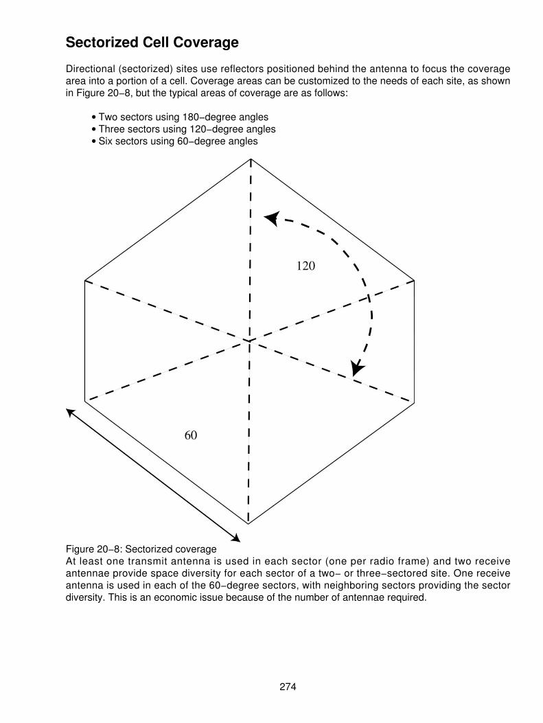
Sectorized Cell Coverage
Directional (sectorized) sites use reflectors positioned behind the antenna to focus the coveragearea into a portion of a cell. Coverage areas can be customized to the needs of each site, as shownin Figure 20−8, but the typical areas of coverage are as follows:
Two sectors using 180−degree angles• Three sectors using 120−degree angles• Six sectors using 60−degree angles•
Figure 20−8: Sectorized coverageAt least one transmit antenna is used in each sector (one per radio frame) and two receiveantennae provide space diversity for each sector of a two− or three−sectored site. One receiveantenna is used in each of the 60−degree sectors, with neighboring sectors providing the sectordiversity. This is an economic issue because of the number of antennae required.
274

Tiered Sites
This configuration places a low−power site in the same location with a high−power site. Mobileschange channels as they move across the boundary between the two in order to relieve congestionin the center, as shown in Figure 20−9. This configuration is used in all GSM and Code DivisionMultiple Access (CDMA) applications today. It is not supported on the older AMPS and DAMPSconfigurations, but may be used in newer implementations of AMPS and DAMPS. Each sectorrequires its own access/paging control channel to manage call setup functions. Voice traffic in eachsector is supported by radios connected to antennae supporting that sector.
Figure 20−9: Tiered cell coverage
Reuse of Frequencies
Frequency reuse enables a particular radio channel to carry conversations in multiple locations,increasing the overall capacity of the communications systems. Within a cluster, each cell usesdifferent frequencies; however, these frequencies can be reused in cells of another cluster.
One centralized radio site with 300 channels can have 300 calls in progress at any one time. The300 channels can be divided into four groups of 75 channels and still provide 300 calls at once.Dividing the service area into 16 sections called cells allows each cell to use one of the four groupsof channels, increasing the call−carrying capacity of the system by a value of 4 (1,200 calls at onetime).
The service area can be continually divided into smaller and smaller cells to obtain greatercall−carrying capacity, increasing the number of calls by a factor of four with each division. The limiton how many cells can be used is determined by this information:
The cost infrastructure at each cell• The processing power of the switch that controls the system• The minimum power output at each site•
275

Allocation of Frequencies
The allocation of frequencies based on the first cellular arrangement of AMPS was designed around666 duplex channels. The frequency ranges were allocated in the 825—845 MHz and 870—890MHz frequency bands. In each band, the channels use a 30 kHz separation, and 21 channels areallocated to control channels. Figure 20−10 is a representation of the channel allocation.
Figure 20−10: Frequency allocation for cellularThe FCC approved licenses for two operators of the cellular service; the wireline carrier (usually thetelephone company in the area) and the non−wireline carrier (a competitor to the local telephonecompany). The frequencies were equally split between the wireline and nonwireline operators. Thismeant that only half the channels were available to each carrier and two sets of control channelswere required.
Four signaling paths are used in the cellular network to provide for signaling and control, as well asvoice conversation. These can be broken into two basic function groups:
Call setup and breakdown• Call management and conversation•
Establishing a Call from a Landline to a Mobile
From a wired telephone, the local exchange office pulses out the cellular number called to theMTSO over a special trunk connecting the telephone company to the MTSO. The MTSO thenanalyzes the number called and sends a data link message to all paging cell sites to locate the unitcalled. When the cellular unit recognizes the page, it sends a message to the nearest cell site. Thiscell site then sends a data link message back to the MTSO to alert the MTSO that the unit has beenfound. This message further notifies the MTSO which cell site will handle the call.
The MTSO next selects a cell site trunk connected to that cell and sets up a network path betweenthe cell site and the originating CO trunk carrying the call (see Figure 20−11).
276

Figure 20−11: Call establishmentThe MTSO is now also called the Mobile Switching Center (MSC). It is the controlling element forthe entire system. The MSC is responsible for the following information:
All switching of calls to and from the cells• Blocking calls when congestion occurs• Providing necessary backup to the network• Monitoring the overall network elements• Handling all the test and diagnostic capabilities for the system•
This is the workhorse of the cellular system. The MSC relies on two different databases within thesystem to keep track of the mobile stations in its area.
The first of the two databases is called the Home Location Register (HLR). The HLR is a databaseof all system devices registered on the system and owned by the operator of the MSC. These arethe local devices connected to the network. The HLR keeps track of the individual device's locationand stores all the necessary information about the subscriber. This includes the name, telephonenumber, features and functions, fiscal responsibilities, and the like.
The second database is called the Visiting Location Register (VLR), which is a temporary databasebuilt on roaming devices as they come into a particular MSC's area. The VLR keeps track oftemporary devices while they are in an area, including the swapping of location information with thesubscriber's HLR. When a subscriber logs onto a network, and it is not home to that subscriber, theVLR builds a data entry on the subscriber and tracks activity and feature usage to be consistent forthe user.
Another set of databases is used by the MSC in some networks. These again are two separate anddistinct functions called the Equipment Inventory Register (EIR) and the Authentication Center(AuC). These are very similar to the databases used in the GSM networks and keep track ofmanufacturer equipment types for consistency. The authentication center is used to authenticate theuser to prevent fraudulent use of the network by a cloned device.
277

Chapter 21: Global Services Mobile Communications(GSM)
History of Cellular Mobile Radio and GSM
The idea of cell−based mobile radio systems appeared at Bell Laboratories in the early 1970s.However, the commercial introduction of cellular systems did not occur until the 1980s. Because ofthe pent−up demand and newness, analog cellular telephone systems grew rapidly in Europe andNor th Amer ica. Today, ce l lu lar systems s t i l l represent one of the fastest growingtelecommunications services. Recent studies indicate that three of four new phones are mobilephones. Unfortunately, when cellular systems were first being deployed, each country developed itsown system, which was problematic because
The equipment only worked within the boundaries of each country.• The market for mobile equipment manufacturers was limited by the operating system.•
Three different services had emerged in the world at the time. They were
Advanced Mobile Phone Services (AMPS) in North America• Total Access Communications System (TACS) in the United Kingdom• Nordic Mobile Telephone (NMT) in Nordic countries•
To solve this problem, in 1982, the Conference of European Posts and Telecommunications (CEPT)formed the Groupe Spécial Mobile (GSM) to develop a pan−European mobile cellular radio system(the acronym later became Global System for Mobile communications). The goal of the GSM studygroup was to standardize systems to provide
Improved spectrum efficiency• International roaming• Low−cost mobile sets and base stations (BSs)• High−quality speech• Compatibility with Integrated Services Digital Network (ISDN) and other telephone companyservices
•
Support for new services•
The existing cellular systems were developed on analog technology. However, GSM was developedusing digital technology.
Benchmarks in GSM
Table 21−1 shows many of the important events in the rollout of the GSM system; other eventswere introduced, but had less significant impact on the overall systems.
Table 21−1: Major events in GSM
Year Events1982 CEPT establishes a GSM group in order to develop the standards for a
pan−European cellular mobile system.
278

1985 A list of recommendations to be generated by the group is accepted.1986 Field tests are performed to test the different radio techniques proposed for the air
interface.1987 Time Division Multiple Access (TDMA) is chosen as the access method (with
Frequency Division Multiple Access [FDMA]). The initial Memorandum ofUnderstanding (MoU) is signed by telecommunication operators representing 12countries.
1988 GSM system is validated.1989 The responsibility of the GSM specifications is passed to the European
Telecommunications Standards Institute (ETSI).1990 Phase 1 of the GSM specifications is delivered.1991 Commercial launch of the GSM service occurs.1992 The addition of the countries that signed the GSM Memorandum of Understanding
takes place. Coverage spreads to larger cities and airports.1993 Coverage of main roads' GSM services starts outside Europe.1995 Phase 2 of the GSM specifications occurs. Coverage is extended to rural areas.
Commercial service was introduced in mid−1991. By 1993, 36 GSM networks were alreadyoperating in 22 countries. Today, you can be instantly reached on your mobile phone in over 171countries worldwide and on 400 networks (operators). As of May 2001, over 550 million peoplewere subscribers to mobile telecommunications. GSM truly stands for Global System for Mobiletelecommunications. Roaming is the ability to use your GSM phone number in another GSMnetwork. You can roam to another region or country and use the services of any network operator inthat region that has a roaming agreement with the GSM network operator in your homeregion/country. A roaming agreement is a business agreement between two network operators totransfer items, such as call charges and subscription information, back and forth as theirsubscribers roam into each other's areas.
GSM Metrics
The GSM standard is the most widely accepted standard and is implemented globally, owning amarket share of 69 percent of the world's digital cellular subscribers. Time Division Multiple Access(TDMA), with a market share close to 10 percent, is available mainly in North America and SouthAmerica. GSM, which uses a TDMA access, and North American TDMA are two of the world'sleading digital network standards. Unfortunately, it is currently technically impossible for users ofeither standard to make or receive calls in areas where only the other standard is available. Onceinteroperability is in place, users of GSM and TDMA handsets will be able to roam on the othernetwork type — subject to the agreements between mobile operators. This will make roamingpossible across much of the world because GSM and TDMA networks cover large sections of theglobal population and together account for 79 percent of all mobile subscribers, as shown in Figure21−1.
279

Figure 21−1: Market penetrations of GSM and TDMA
Cell Structure
In a cellular system, the coverage area of an operator is divided into cells. A cell is the area that onetransmitter or a small collection of transmitters can cover. The size of a cell is determined by thetransmitter's power. The concept of cellular systems is the use of low−power transmitters in order toenable the efficient reuse of the frequencies. The maximum size of a cell is approximately 35 km(radius), providing a round−trip communications path from the mobile to the cell site and back. If thetransmitters are very powerful, the frequencies cannot be reused for hundreds of kilometers, as theyare limited to the coverage area of the transmitter. In the past when a mobile communicationssystem was installed, the coverage blocked the reuse beyond the 25−mile coverage area andcreated a corridor of interference of an additional 75 miles. This is shown in Figure 21−2.
280

Figure 21−2: The older way of handling mobile communicationsThe frequency band allocated to a cellular mobile radio system is distributed over a group of cells,and this distribution is repeated in all of an operator's coverage area. The entire number of radiochannels available can then be used in each group of cells that form the operator's coverage area.Frequencies used in a cell will be reused several cells away. The distance between the cells usingthe same frequency must be sufficient to avoid interference. The frequency reuse will increase thecapacity in the number of users considerably. The patterns can be a four−cell pattern or otherchoices. The typical clusters contain 4, 7, 12, or 21 cells.
In order to work properly, a cellular system must verify the following two main conditions:
The power level of a transmitter within a single cell must be limited in order to reduce theinterference with the transmitters of neighboring cells. The interference will not produce anydamage to the system if a distance of about 2.5 to 3 times the diameter of a cell is reservedbetween transmitters. The receiver filters must also conform.
•
Neighboring cells cannot share the same channels. In order to reduce the interference, thefrequencies must be reused only within a certain pattern. The pattern may also be aseven−cell pattern similar to the AMPS networks, which is shown in Figure 21−3.
•
281

Figure 21−3: The seven−cell pattern Source: ETSI
In order to exchange the information needed to maintain the communication links within the cellularnetwork, several radio channels are reserved for the signaling information. Sometimes we use a12−cell pattern with a repeating sequence. The 12−cell pattern is really a grouping of three 4−cellclusters, as shown in Figure 21−4. The larger the cell pattern, the more the coverage areas tend towork. In general, the larger cell patterns are used in various reuse patterns to get the most out ofthe scarce radio resources as possible. The 21−cell pattern is by far the largest repeating pattern inuse today. The cells are grouped into clusters. The number of cells in a cluster determines whetherthe cluster can be repeated continuously within the coverage area.
Figure 21−4: The 12−cell pattern Source: ETSI
282

The number of cells in each cluster is very important. The smaller the number of cells per cluster,the greater the number of channels per cell. Therefore, the capacity of each cell will be increased.However, a balance must be found in order to avoid the interference that could occur betweenneighboring clusters. This interference is produced by the small size of the clusters (the size of thecluster is defined by the number of cells per cluster). The total number of channels per cell dependson the number of available channels and the type of cluster used.
Types of Cells
The density of population in a country is so varied that different types of cells are used:
Macrocells• Microcells• Selective or sectorized cells• Umbrella cells• Nanocells• Picocells•
Macrocells Macrocells are large cells for remote and sparsely populated areas. These cells canbe as large as 3 to 35 km from the center to the edge of the cell (radius). The larger cells placemore frequencies in the core, but because the area is rural, the macrocell typically has limitedfrequencies (channels) and higher−power transmitters. This is a limitation that prevents other sitesfrom being closely adjacent to this cell. Figure 21−5 shows the macrocell.
Figure 21−5: The macrocell
283
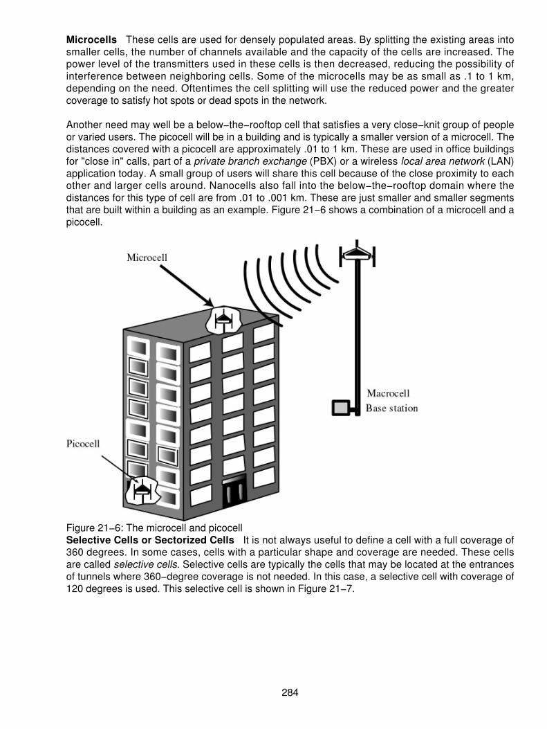
Microcells These cells are used for densely populated areas. By splitting the existing areas intosmaller cells, the number of channels available and the capacity of the cells are increased. Thepower level of the transmitters used in these cells is then decreased, reducing the possibility ofinterference between neighboring cells. Some of the microcells may be as small as .1 to 1 km,depending on the need. Oftentimes the cell splitting will use the reduced power and the greatercoverage to satisfy hot spots or dead spots in the network.
Another need may well be a below−the−rooftop cell that satisfies a very close−knit group of peopleor varied users. The picocell will be in a building and is typically a smaller version of a microcell. Thedistances covered with a picocell are approximately .01 to 1 km. These are used in office buildingsfor "close in" calls, part of a private branch exchange (PBX) or a wireless local area network (LAN)application today. A small group of users will share this cell because of the close proximity to eachother and larger cells around. Nanocells also fall into the below−the−rooftop domain where thedistances for this type of cell are from .01 to .001 km. These are just smaller and smaller segmentsthat are built within a building as an example. Figure 21−6 shows a combination of a microcell and apicocell.
Figure 21−6: The microcell and picocellSelective Cells or Sectorized Cells It is not always useful to define a cell with a full coverage of360 degrees. In some cases, cells with a particular shape and coverage are needed. These cellsare called selective cells. Selective cells are typically the cells that may be located at the entrancesof tunnels where 360−degree coverage is not needed. In this case, a selective cell with coverage of120 degrees is used. This selective cell is shown in Figure 21−7.
284

Figure 21−7: The selective cellTiered Cells A tiered cell is one where an overlay of radio equipment operates in two differentfrequencies and uses different sectors. The tiered cell is also a form of a selective cell.
Umbrella Cells Alongside a high−speed freeway, crossing very small cells produces anoverabundance of handovers among the different small neighboring cells. To solve this problem, theconcept of umbrella cells was introduced. An umbrella cell covers several microcells, as shown inFigure 21−8. The power level inside an umbrella cell is increased compared to the power levelsused in the microcells that form the umbrella cell. How does the cell know when to shift from amicrocell to an umbrella cell? When the speed of the mobile is too high, the mobile is handed off tothe umbrella cell. The mobile will then stay longer in the same cell (in this case, the umbrella cell).This will reduce the number of handovers and the work of the network. A large number of handoverdemands and the propagation characteristics of a mobile can help to detect its high speed. Theradio equipment is no longer forced to constantly change hands from cell to cell when using thisumbrella. This meets the goal of GSM in that the efficient use of the radio frequency (RF) spectrumis what is being achieved.
285

Figure 21−8: The umbrella cell
Analog to Digital Movement
In the 1980s, most mobile cellular systems were based on analog systems, including AMPS, TACS,and NMT. In fact, 95 percent of the United States has coverage from AMPS services, whereas only70 percent is covered with digital service. The roaming agreements used between cellular carriersin North America use AMPS for roaming. In many cases, the analog networks are starting to winddown in the major metropolitan areas; however, in rural communities, AMPS is still predominant.The GSM system was the first digital cellular system created from the onset. Different reasonsexplain the transition from analog to digital technology. Cellular systems experienced phenomenalgrowth. Analog systems were not able to cope with this increasing demand. To overcome thisproblem, new frequency bands and new technologies were suggested. Many countries rejected thepossibility of using new frequency bands because of the restricted spectrum (even though later on,other frequency bands were allocated for the development of mobile cellular radio). New analogtechnologies were able to overcome some of the problems, but were too expensive. The digitalradio was the best option (but not the perfect one) to handle the capacity needs in a cost−efficientmanner.
The decision to adopt digital technology for GSM was made in the course of developing thestandard. During the development of GSM, the telecommunications industry converted to digitalnetworking standards. ISDN is an example of this evolution. In order to make GSM compatible withthe services offered by ISDN, it was decided that digital radio technology was the best optionavailable.
Quality of service (QoS) can also be improved dramatically by using digital rather than analogtechnology. From the beginning, the planners of GSM wanted ISDN compatibility in the servicesoffered and to control the signaling used. The radio link imposed some limitations because thestandard ISDN bit rate of 64 Kbps could not be practically achieved.
Using the International Telecommunication Union−Telecommunication Standardization (ITU−T)definitions, telecommunication services can be divided into the following categories:
286
Teleservices• Bearer services• Supplementary services•
Teleservices
The most basic teleservice supported by GSM is telephony, the transmission of speech. It has anadded emergency service, where the nearest emergency service provider is notified by dialing threedigits. The emergency number 112 is used like 911 in North America. Group 3 fax, an analogmethod described in ITU−T recommendation T.30, is also supported with the use of an appropriatefax adapter.
A unique feature of GSM compared to older analog systems is the Short Message Service (SMS).SMS is a bidirectional service for sending short alphanumeric (up to 160 bytes) messages in astore−and−forward fashion. For point−to−point SMS, a message can be sent to another subscriberto the service, and an acknowledgement of receipt is provided to the sender. SMS can also be usedin a cell broadcast mode for sending messages such as traffic updates or news updates. Messagescan be stored in the Subscriber Identity Module (SIM) card for later retrieval. The SMS service hasbeen very well accepted with over one billion SMS messages being sent monthly.
As things progressed, Phase II of GSM introduced enhancements. For example, in the teleservices,half−rate voice coding was introduced. In the first phase, full−rate voice coding was used at a rate of13 Kbps for a voice conversation. Later the 6.5 Kbps vocoders were introduced for use at a networkoperator's choice. This enables the network operator to offer good speech quality to twice as manyusers without any additional radio resources. Essentially, we split the channel in half becausepeople actually carry traffic on the channel only 25 to 30 percent of the time.
Enhancements also included better SMS informational flow for point−to−point communications andthe use of point−to−multipoint communications. The 160−character SMS message was finallydocumented and became fully store−and−forward.
Bearer Services
The digital nature of GSM enables data, both synchronous and asynchronous, to be transported asa bearer service to or from an ISDN terminal. Data can use either the transparent service, with afixed delay but no guarantee of data integrity, or a nontransparent service, which guarantees dataintegrity through an Automatic Repeat Request (ARQ) mechanism, which unfortunately introduces avariable delay. The data rates supported by GSM are 300 bps, 600 bps, 1,200 bps, 2,400 bps, and9,600 bps. One can imagine in this new millennium that these data speeds are intolerable for themainstay of data transmission. In fact, if someone were to offer us Internet access at speeds of upto 9,600 bps, we would probably become very disinterested in the service. Yet, from a mobileperspective, these speeds were considered quite fast.
Enhancements from Phase II also included better throughput for data transmission using asynchronous dedicated packet data access operating at 2.4 to 9.6 Kbps. Phase I only acceptedasynchronous access to a dedicated packet assembler/dissembler (PAD). The access of datathrough a dedicated PAD at the entrance of an X.25 network enables access to a higher degree ofreliable data transport, helping to overcome the link layer problems on the radio.
Data is now available over the GSM Phase II at both send and receive speeds of up to 9.6 Kbps. Inthe earlier releases, slower data was more prevalent. The use of the GSM network enables theintegration of various network platforms such as
287

Plain old telephone service (POTS)• ISDN access and emulation• Packet data network access (X.25 and IP are the most common)• Circuit−switched data transfers across and X.25, X.31, and X.32 standards•
Because the data is being sent across a digital air interface, no modem is required at the mobilestation (MS) end.
Supplementary Services
Supplementary services (which are really the added features of the cellular networks) are providedon top of teleservices or bearer services and include features such as
Caller identification• Call forwarding The subscriber can forward incoming calls to another number if the calledmobile is busy (CFB), unreachable (CFNRc), or if no reply (CFNRy) occurs. Call forwardingcan also be applied unconditionally (CFU).
•
Call waiting• Multiparty conversations• Barring of outgoing (international) calls Different types of call barring services are available:
Barring of All Outgoing Calls (BAOC)♦ Barring of Outgoing International Calls (BOIC)♦ Barring of Outgoing International Calls except those directed toward the Home PLMNCountry (BOIC−exHC)
♦
Barring of All Incoming Calls (BAIC)♦ Barring of incoming calls when roaming (BICR)♦
•
Phase II enhancements to the supplementary services include the following:
Calling/Connected Line Identification Presentation (CLIP) This supplies the called user withthe ISDN of the calling user.
•
Calling/Connected Line Identification Restriction (CLIR) This enables the calling user torestrict the presentation.
•
Connected Line identification Presentation (CoLP) This supplies the calling user with thedirectory number he or she receives if his or her call is forwarded.
•
Connected Line identification Restriction (CoLR) This enables the called user to restrict thepresentation.
•
Call Waiting (CW) This informs the user, during a conversation, about another incomingcall. The user can answer, reject, or ignore this incoming call.
•
These are added supplementary services finishing off the list:
Call hold This puts an active call on hold.• Advice of Charge (AoC) This provides the user with online charge information.• Multiparty service This creates the possibility of establishing a multi−party conversation.• Closed User Group (CUG) This corresponds to a group of users with limited possibilities ofcalling (only the people of the group and certain numbers).
•
Operator−determined barring This provides restrictions of different services and call typesby the operator.
•
288

GSM Architecture
A GSM network consists of several functional entities whose functions and interfaces are defined.Figure 21−9 shows the layout of a generic GSM network. The GSM network can be divided intothree broad parts. The subscriber carries the MS, the Base Station Subsystem (BSS) controls theradio link with the MS, and the Network Subsystem, the main part of which is the Mobile SwitchingCenter (MSC), performs the switching of calls between the mobile and other fixed or mobile networkusers, as well as the management of mobile services such as authentication. The Operations andMaintenance Center, which oversees the proper operation and setup of the network, is not shown inthe figure. The MS and the BSS communicate across the Um interface, also known as the airinterface or radio link. The BSS communicates with the network service switching center across theA interface.
Figure 21−9: The GSM architectureThe added components of the GSM architecture (see Figure 21−10) include the functions of thedatabases and messaging systems:
Home Location Register (HLR)• Visitor Location Register (VLR)• Equipment Identity Register (EIR)• Authentication Center (AuC)• SMS Serving Center (SMS SC)• Gateway MSC (GMSC)• Chargeback Center (CBC)• Operations and Support Subsystem (OSS)• Transcoder and Adaptation Unit (TRAU)•
289
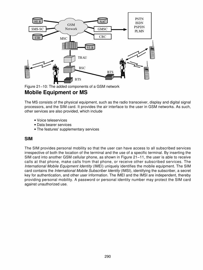
Figure 21−10: The added components of a GSM network
Mobile Equipment or MS
The MS consists of the physical equipment, such as the radio transceiver, display and digital signalprocessors, and the SIM card. It provides the air interface to the user in GSM networks. As such,other services are also provided, which include
Voice teleservices• Data bearer services• The features' supplementary services•
SIM
The SIM provides personal mobility so that the user can have access to all subscribed servicesirrespective of both the location of the terminal and the use of a specific terminal. By inserting theSIM card into another GSM cellular phone, as shown in Figure 21−11, the user is able to receivecalls at that phone, make calls from that phone, or receive other subscribed services. TheInternational Mobile Equipment Identity (IMEI) uniquely identifies the mobile equipment. The SIMcard contains the International Mobile Subscriber Identity (IMSI), identifying the subscriber, a secretkey for authentication, and other user information. The IMEI and the IMSI are independent, therebyproviding personal mobility. A password or personal identity number may protect the SIM cardagainst unauthorized use.
290
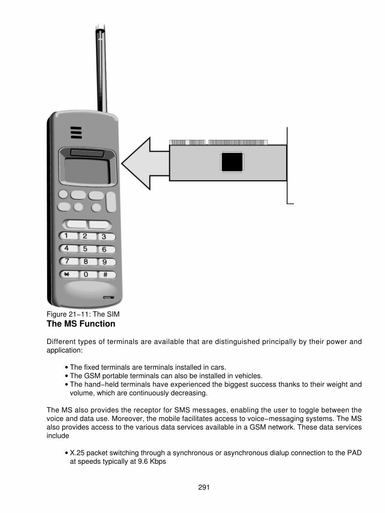
Figure 21−11: The SIMThe MS Function
Different types of terminals are available that are distinguished principally by their power andapplication:
The fixed terminals are terminals installed in cars.• The GSM portable terminals can also be installed in vehicles.• The hand−held terminals have experienced the biggest success thanks to their weight andvolume, which are continuously decreasing.
•
The MS also provides the receptor for SMS messages, enabling the user to toggle between thevoice and data use. Moreover, the mobile facilitates access to voice−messaging systems. The MSalso provides access to the various data services available in a GSM network. These data servicesinclude
X.25 packet switching through a synchronous or asynchronous dialup connection to the PADat speeds typically at 9.6 Kbps
•
291

General Packet Radio Services (GPRSs) using either an X.25− or IP−based data transfermethod at speeds up to 115 Kbps
•
High−speed, circuit−switched data at speeds up to 64 Kbps•
The data speeds will vary by application and other conditions, such as air interfaces across a hostilelink.
The Base Transceiver Station (BTS)
The BTS (see Figure 21−12) houses the radio transceivers that define a cell and handles the radiolink protocols with the MS. In a large urban area, a large number of BTSs may be deployed. Therequirements for a BTS are
Ruggedness• Reliability• Portability• Minimum cost•
Figure 21−12: The BTSThe BTS corresponds to the transceivers and antennas used in each cell of the network. A BTS isusually placed in the center of a cell. Its transmitting power defines the size of a cell. Each BTS hasbetween 1 and 16 transceivers, depending on the density of users in the cell. Each BTS serves asingle cell. It also includes the following functions:
Encoding, encrypting, multiplexing, modulating, and feeding the RF signals to the antenna• Transcoding and rate adaptation• Time and frequency synchronizing• Voice through full− or half−rate services• Decoding, decrypting, and equalizing received signals• Random access detection• Timing advances• Uplink channel measurements•
292

The Base Station Controller (BSC)
The BSC manages the radio resources for one or more BTSs. It handles radio channel setup,frequency hopping, and handovers. The BSC is the connection between the mobile and the MSC.The BSC also translates the 13 Kbps voice channel used over the radio link to the standard 64Kbps channel used by the Public Switched Telephone Network (PSDN) or ISDN. The BSC isbetween the BTS and the MSC and provides radio resource management for the cells under itscontrol. It assigns and releases frequencies and time slots for the MS. The BSC also handlesintercell handover. It controls the power transmission of the BSS and MS in its area. The function ofthe BSC is to allocate the necessary time slots between the BTS and the MSC. It is a switchingdevice that handles the radio resources. Additional functions include
Control of frequency hopping• Performing traffic concentration to reduce the number of lines from the MSC• Providing an interface to the Operations and Maintenance Center for the BSS• Reallocation of frequencies among BTSs• Time and frequency synchronization• Power management• Time−delay measurements of received signals from the MS•
BSS
The BSS is composed of two parts: the BTS and the BSC. These communicate across the specifiedAbis interface, enabling (as in the rest of the system) operations between components that aremade by different suppliers. The radio components of a BSS may consist of four to seven or ninecells. A BSS may have one or more base stations. The BSS uses the Abis interface between theBTS and the BSC. A separate high−speed line (T1 or E1) is then connected from the BSS to theMobile central office (CO), as shown in the architecture in Figure 21−13.
Figure 21−13: The BSS
The TRAU
Depending on the costs of transmission facilities from a cellular operator, it may be cost efficient tohave the transcoder either at the BTS, BSC, or MSC. If the transcoder is located at the MSC, it isfunctionally still a part of the BSS. This creates maximum flexibility of the overall network operation.The transcoder takes the 13 Kbps speech or data (at 300, 600, and 1,200 bps) multiplexes 4 of
293
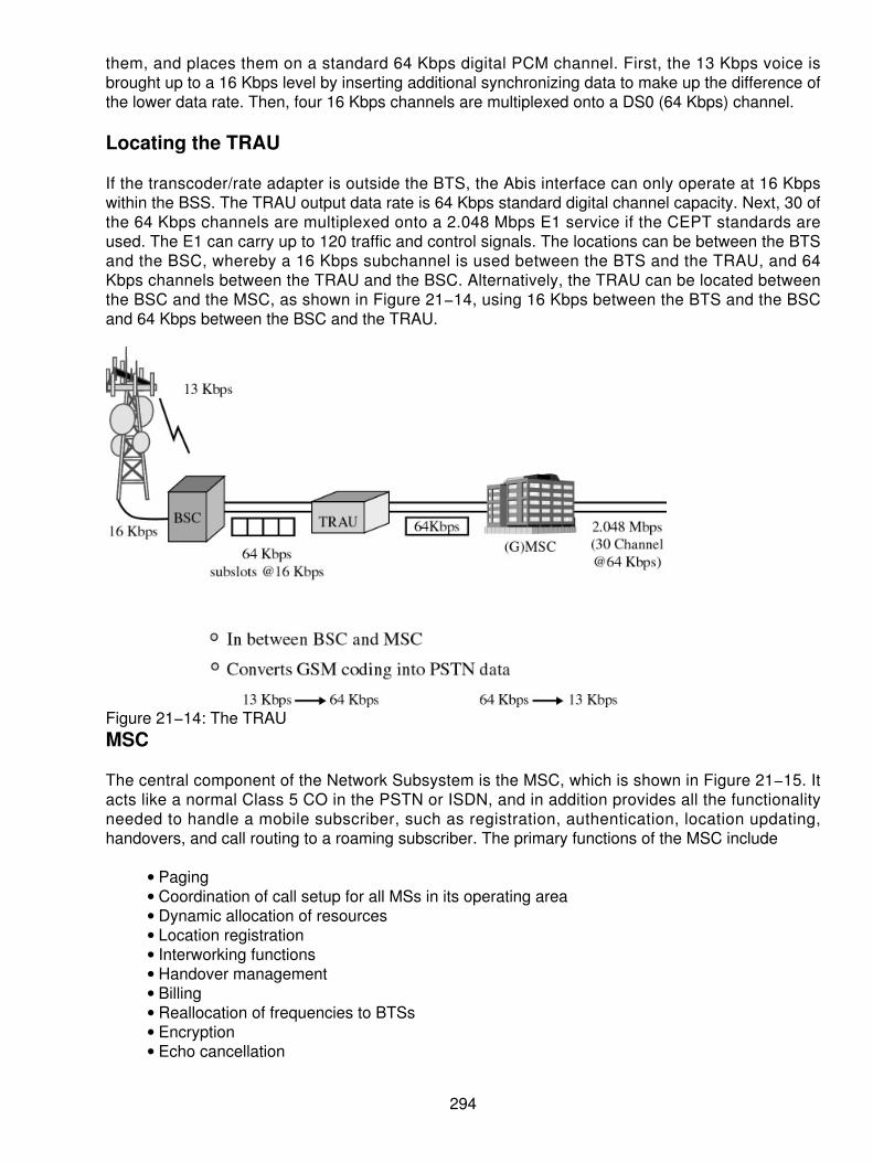
them, and places them on a standard 64 Kbps digital PCM channel. First, the 13 Kbps voice isbrought up to a 16 Kbps level by inserting additional synchronizing data to make up the difference ofthe lower data rate. Then, four 16 Kbps channels are multiplexed onto a DS0 (64 Kbps) channel.
Locating the TRAU
If the transcoder/rate adapter is outside the BTS, the Abis interface can only operate at 16 Kbpswithin the BSS. The TRAU output data rate is 64 Kbps standard digital channel capacity. Next, 30 ofthe 64 Kbps channels are multiplexed onto a 2.048 Mbps E1 service if the CEPT standards areused. The E1 can carry up to 120 traffic and control signals. The locations can be between the BTSand the BSC, whereby a 16 Kbps subchannel is used between the BTS and the TRAU, and 64Kbps channels between the TRAU and the BSC. Alternatively, the TRAU can be located betweenthe BSC and the MSC, as shown in Figure 21−14, using 16 Kbps between the BTS and the BSCand 64 Kbps between the BSC and the TRAU.
Figure 21−14: The TRAUMSC
The central component of the Network Subsystem is the MSC, which is shown in Figure 21−15. Itacts like a normal Class 5 CO in the PSTN or ISDN, and in addition provides all the functionalityneeded to handle a mobile subscriber, such as registration, authentication, location updating,handovers, and call routing to a roaming subscriber. The primary functions of the MSC include
Paging• Coordination of call setup for all MSs in its operating area• Dynamic allocation of resources• Location registration• Interworking functions• Handover management• Billing• Reallocation of frequencies to BTSs• Encryption• Echo cancellation•
294

Signaling exchange• Synchronizing the BSS• Gateway to SMS•
Figure 21−15: The MSCAs a CO function, it uses the digital trunks in the form of E1 (or larger) to the other networkinterfaces such as
PSTN• ISDN• PSPDN• Public Land Mobile Network (PLMN)•
These services are provided in conjunction with several functional entities, which together form theNetwork Subsystem. The MSC provides the connection to the public−fixed network (PSTN orISDN), and signaling between functional entities uses Signaling System Number 7 (SS7), which isused in ISDN and is widely used in current public networks.
The Gateway Mobile Services Switching Center (GMSC) is used in the PLMN. A gateway is a nodeinterconnecting two networks. The GMSC is the interface between the mobile cellular network andthe PSTN. It is in charge of routing calls from the fixed network towards a GSM user. The GMSC isoften implemented in the same machines as the MSC. A PLMN may have many MSCs, but it hasonly one gateway access to the wireline network to accommodate the network operator. Thegateway then is the high−speed trunking machine connected via E1 or Synchronous DigitalHierarchy (SDH) to the outside world.
The Registers Completing the Network Switching Systems(NSSs)
The Home Location Register (HLR) and Visitor Location Register (VLR), together with the MSC,provide the call−routing and roaming capabilities of GSM, called the NSS. The HLR contains all theadministrative information of each subscriber registered in the corresponding GSM network, alongwith the current location of the mobile. The current location of the mobile is in the form of a MobileStation Roaming Number (MSRN), which is a regular ISDN number used to route a call to the MSCwhere the mobile is currently located. One HLR exists logically per GSM network, although it maybe implemented as a distributed database. Figure 21−16 shows the HLR.
295

Figure 21−16: The HLRThe VLR contains selected administrative information from the HLR, which is necessary for callcontrol (CC) and provision of the subscribed services, for each mobile currently located in thegeographical area controlled by the VLR. Although each functional entity can be implemented as anindependent unit, most manufacturers of switching equipment implement one VLR together with oneMSC (see Figure 21−17) so that the geographical area controlled by the MSC corresponds to thatcontrolled by the VLR, simplifying the signaling required. Note that the MSC contains no informationabout particular MSs — this information is stored in the location registers.
Figure 21−17: The VLRThe other two registers are used for authentication and security purposes. The Equipment IdentityRegister (EIR) is a database that contains a list of all valid mobile equipment on the network, whereits International Mobile Equipment Identity (IMEI) identifies each MS. An IMEI is marked as invalid ifit has been reported stolen or is not type approved. The Authentication Center is a protecteddatabase that stores a copy of the secret key stored in each subscriber's SIM card, which is usedfor authentication and ciphering of the radio channel.
The Cell
As has already been explained, a cell, identified by its Cell Global Identity (CGI) number,corresponds to the radio coverage of a base transceiver station. In a macrocell environment, theradius distance is between 3 to 35 km. The distances are calculated on the basis of a round−tripbetween the BTS and the mobile to provide a sufficient bit error rate (BER) and power to satisfyquality speech.
296

Location Area
A location area (LA), identified by its location area identity (LAI) number, is a group of cells servedby a single MSC/VLR. One MSC/VLR combination has several LAs. The LA is part of the MSC/VLRservice area in which a MS may move freely without any updating of location messaging to theMSC/VLR controlling the LA.
MSC/VLR Service Area
A group of LAs under the control of the same MSC/VLR defines the MSC/VLR area. A single PLMNcan have several MSC/VLR service areas. MSC/VLR is a sole controller of calls within its area ofjurisdiction. To route a call to a MS, the path through the network links to the MSC in the MSC areawhere the subscriber is currently located. The mobile location can be uniquely identified becausethe MS is registered in a VLR, which is associated with an MSC.
PLMN A PLMN is the area served by one network operator, as shown in Figure 21−18. Onecountry can have several PLMNs, based on its size. The links between a GSM/PLMN network andother PSTN, ISDN, or PLMNs will be at the level of national or international transit. All incomingcalls for a GSM/PLMN will be routed to the GMSC. A GMSC works as an incoming transit exchangefor the GSM/PLMN. All mobile−terminated (MT) calls will be routed to the GMSC. Call connectionsbetween PLMNs or fixed networks must be routed through certain designated MSCs.
Figure 21−18: The PLMN
OSI Model — How GSM Signaling Functions in the OSI Model
The Open Standards Interface (OSI) is a guideline of how systems communicate transparently. SS7is used for signaling between the outside world and the GSM architectures. Moreover, SS7 is usedto communicate between the MSC and the HLR. To satisfy other functions in GSM architecture, themodel is applied for other services from the MS outward. In reality, the model works at the bottomthree layers of the OSI model for the bulk of the transmissions that take place in call setup andteardown, registration, and authentication, and so on. Thus, Layers 3, 2, and 1 of the OSI model aremost applicable.
OSI defines a communications subsystem consisting of functions that enable distributed applicationprocesses, resident on computers, to exchange information via an underlying data network. Thecommunications subsystem can be divided into two sublayers:
An application−dependent sublayer providing functions that are application−dependent butnetwork−independent
•
297

A network−dependent sublayer providing functions that are dependent on the underlyingdata network but are application−independent
•
Ensuring the transmission of voice or data of a given quality over the radio link is only part of thefunction of a cellular mobile network. A GSM mobile can seamlessly roam nationally andinternationally, which requires that registration, authentication, call routing, and location−updatingfunctions exist and are standardized in GSM networks. In addition, the fact that the geographicalarea covered by the network is divided into cells necessitates the implementation of a handovermechanism. The Network Subsystem performs these functions using the Mobile Application Part(MAP) built on top of the SS7 protocol, as shown in Figure 21−19.
Figure 21−19: SS7 and GSM working together
Layer Functionality
In the GSM architecture, the layered model integrates and links the peer−to−peer communicationsbetween two different systems. If we look across the platform, the underlying layers satisfy theservices of the upper−layer protocols. For example, at Layer 3, the Service Access Point (SAP)between Layer 3 and 2 addresses the services being served. Service Access Point Identifiers(SAPIs) describe the services that are provided by the various services from the upper and lowerlayers. Notifications are passed from layer to layer to ensure that the information has been properlyformatted, transmitted, and received. These primitives make the process complete. Severaldiscussions center on the chart of protocols, as shown in Figure 21−20. Refer to this chart for thenext block of protocol stack discussions.
298

Figure 21−20: The protocol stacks
MS Protocols
The signaling protocol in GSM is structured into three general layers, depending on the interface.Layer 1 is the physical layer, which uses the channel structures discussed previously over the airinterface. Layer 2 is the data−link layer. Across the Um interface, the data−link layer is a modifiedversion of the Link access protocol for the D channel (LAP−D) protocol used in ISDN, called Linkaccess protocol on the Dm channel (LAP−Dm). Across the A interface, the Message Transfer Part,Layer 2, of SS7 is used. Layer 3 of the GSM signaling protocol is divided into three sublayers: radioresource management (RR), mobility management (MM), and Connection Management (CM).
The MS to BTS Protocols
The RR layer oversees the establishment of a link, both radio and fixed, between the MS and theMSC. The main functional components involved are the MS, the BSS, and the MSC. The RR layeris concerned with the management of an RR−session, which is the time that a mobile is indedicated mode, as well as the configuration of radio channels, including the allocation of dedicatedchannels.
The MM layer is built on top of the RR layer and handles the functions that arise from the mobility ofthe subscriber, as well as the authentication and security aspects. Location management isconcerned with the procedures that enable the system to know the current location of apowered−on MS so that incoming call routing can be completed.
Location updating is when a powered−on mobile is informed of an incoming call by a pagingmessage sent over the PAGCH channel of a cell. One extreme would be to page every cell in thenetwork for each call, which is obviously a waste of radio bandwidth. The other extreme would befor the mobile to notify the system, via location−updating messages, of its current location at theindividual cell level. This would require paging messages to be sent to exactly one cell, but would bevery wasteful due to the large number of location−updating messages. A compromised solutionused in GSM is to group cells into LAs. Updating messages are required when moving betweenLAs, and MSs are paged in the cells of their current LA.
299

The CM layer is responsible for CC, supplementary service management, and Short MessageService (SMS) management. Each of these may be considered as a separate sublayer within theCM layer. CC attempts to follow the ISDN procedures specified in Q.931, although routing to aroaming mobile subscriber is obviously unique to GSM. Other functions of the CC sublayer includecall establishment, selection of the type of service (including alternating between services during acall), and call release.
BSC Protocols
After the information is passed from the BTS to the BSC, a different set of interfaces is used. TheAbis interface is used between the BTS and BSC. At this level, the radio resources at the lowerportion of Layer 3 are changed from the RR to the Base Transceiver Station Management (BTSM).The BTS management layer is a relay function at the BTS to the BSC. The RR protocols areresponsible for the allocation and reallocation of traffic channels between the MS and the BTS.These services include controlling the initial access to the system, paging for MT calls, the handoverof calls between cell sites, power control, and call termination. The RR protocols provide theprocedures for the use, allocation, reallocation, and release of the GSM channels. The BSC still hassome radio resource management in place for the frequency coordination, frequency allocation, andthe management of the overall network layer for the Layer 2 interfaces.
From the BSC, the relay is using SS7 protocols so the MTP 1−3 is used as the underlyingarchitecture, and the BSS mobile application part or the direct application part is used tocommunicate from the BSC to the MSC.
MSC Protocols
At the MSC, the information is mapped across the A interface to the MTP Layers 1 through 3 fromthe BSC. Here the equivalent set of radio resources is called the BSS MAP. The BSS MAP/DTAPand the MM and CM are at the upper layers of Layer 3 protocols. This completes the relay process.Through the control−signaling network, the MSCs interact to locate and connect to users throughoutthe network. Location registers are included in the MSC databases to assist in the role ofdetermining how and whether connections are to be made to roaming users. Each user of a GSMMS is assigned a HLR that is used to contain the user's location and subscribed services. Aseparate register, the VLR, is used to track the location of a user. As the users roam out of the areacovered by the HLR, the MS notifies a new VLR of its whereabouts. The VLR in turn uses thecontrol network (which happens to be based on SS7) to signal the HLR of the MS's new location.Through this information, MT calls can be routed to the user by the location information contained inthe user's HLR.
Defining the Channels
As we look at the radio operation, a channel can be defined in different ways. Oftentimes we hear achannel defined in RF. Other times we hear the physical channel being described thinking that it isradio frequency. Alas, the different definitions get in the way. For the definitions used, channels aredefined by looking at the matrix:
The radio channel is defined by the frequency used.1. Physical channels are indicative of the time slot that they occupy.2.
300

Logical channels are defined by the function that they provide or serve.3.
Frequencies Allocated
In reality, GSM systems can be implemented in any frequency band. However, several bands existwhere GSM terminals are available. Furthermore, GSM terminals may incorporate one or more ofthe GSM frequency bands listed in the following section to facilitate roaming on a global basis.
Two frequency bands, 25 MHz in each one, have been allocated by ETSI for the GSM system:
The band 890 to 915 MHz has been allocated for the uplink direction (transmitting from theMS to the BS).
•
The band 935 to 960 MHz has been allocated for the downlink direction (transmitting fromthe BS to the MS).
•
However, not all countries can use all of the GSM frequency bands. This is due primarily to militaryreasons and to the existence of previous analog systems using part of the two 25 MHz frequencybands. Figure 21−21 shows the frequencies.
Figure 21−21: The uplink and downlink frequencies
Primary GSM
When transmitting in a GSM network, the MS to the BS uses an uplink. The reverse channeldirection is the downlink from the BS to the MS. GSM uses the circa 900 MHz band. The frequencyband used is 890 to 915 MHz (mobile transmit) and 935 to 960 MHz (base transmit). The duplexchannel enables the two−way communications in a GSM network. Because telephony was theprimary service, a full−duplex channel is assigned with the 2 separate frequencies in a 45 MHzseparation.
To give the maximum number of users access, each band is subdivided into 125 carrier frequenciesspaced 200 kHz apart, using FDMA techniques. The spectrum assignment is shown in Figure21−22. Only 124 channels are used, where channel 0 is reserved and held as a guard band againstinterference from the lower channels. Each of these carrier frequencies is further subdivided intotime slots using TDMA. The frequency bands are usually split between two or more providers who
301

then build their networks. The channels are set at 200 kHz each. The ITU, which manages theinternational allocation of radio spectrum (among other functions), allocated the bands for mobilenetworks in Europe.
Figure 21−22: Spectrum bands for primary GSM
Radio Assignment
Each BTS is assigned a group of channels with which to operate. Any frequency can be assigned tothe BTS, as they are frequency agile. This enables the system to reallocate frequencies as neededto handle load balancing. Normally, the BTS can support upwards of 31 channels (frequencies);however, in actual operation, the operators usually assign from 1 to 16 channels per BTS. This is abusiness and practicality issue. The Absolute Radio Frequency Channel Number (ARFCN) is usedin the channel assignment at each of the frequencies.
Frequency Pairing
The pairing is shown as the way of handling the 45 MHz separations. Remember that channel 0was not used. It was reserved as a guard band from the lower frequencies to prevent interference.
Extended GSM Radio Frequencies
After the ETSI assigned the initial block of frequencies, a later innovation was to assign anadditional block of 10 MHz on the bottom of the original block. The reasoning was that futuredemands would require this capacity. This meant that the frequencies from 880 to 890 MHz for theuplink and 915 to 925 MHz were added. This created an additional 50 carriers. The carriers werenumbered 974 to 1,023 so that the channel assignments would not be confused with the initial GSMstandard. Once the added channels were implemented, the additional channels were still paired at45 MHz separations:
Channel 974 became the guard band for the lower frequencies below 880 MHz and 925MHz.
•
The initial channel 0 in the primary GSM band is now used because of this shift, as shown inFigure 21−23.
•
302
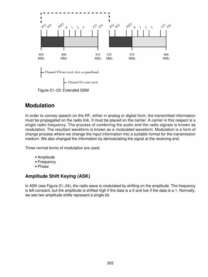
Figure 21−23: Extended GSM
Modulation
In order to convey speech on the RF, either in analog or digital form, the transmitted informationmust be propagated on the radio link. It must be placed on the carrier. A carrier in this respect is asingle radio frequency. The process of combining the audio and the radio signals is known asmodulation. The resultant waveform is known as a modulated waveform. Modulation is a form ofchange process where we change the input information into a suitable format for the transmissionmedium. We also changed the information by demodulating the signal at the receiving end.
Three normal forms of modulation are used:
Amplitude• Frequency• Phase•
Amplitude Shift Keying (ASK)
In ASK (see Figure 21−24), the radio wave is modulated by shifting on the amplitude. The frequencyis left constant, but the amplitude is shifted high if the data is a 0 and low if the data is a 1. Normally,we see two amplitude shifts represent a single bit.
303

Figure 21−24: ASKFrequency Shift Keying (FSK)
The alternative to ASK is FSK. In the case of FSK (see Figure 21−25), applying the data onto theradio wave modulates the carrier by changing the frequency. The amplitude is kept constant, andthe frequency is changed. Normally, a single frequency shift represents a bit of data.
Figure 21−25: FSKPhase Shift Keying (PSK)
In PSK, both the amplitude and the frequency are kept constant, so the changes are represented bya shift in the phase, as shown in Figure 21−26. The benefit of phase shifts is that multiple phasescan be used to represent more than one modulated bit. Under normal PSK, a shift in the phaserepresents a single bit; however, multiphase modulation enables multiple bits to be represented.The quadrature phase shifts (QPSK) will enable up to 2 bits per shift, whereas a quadrature andamplitude shift will enable 4 bits per phase shift.
304

Figure 21−26: PSKGaussian Minimum Shift Keying (GMSK)
GSM modulation works differently, as shown in Figure 21−27. Using Gaussian minimum shift keying(GMSK), the nature of the data moved from the MS is digital. For a digital transmission in GSM, thechosen modulation scheme needs to have good error performance in light of the noise andinterference in a mobile network environment. GMSK is a complex scheme based largely onmathematical functions. The basis of this scheme is offset quadrature phase shift keying (OQPSK),which offers the advantage of a fairly narrow spectral output. This is combined with a minimumtechnique that controls the rate of change of the phase of the carrier and the radiated spectrum willbe even lower. This also requires very careful planning at the sites to prevent interference andproduces only 1 bit per symbol. The combined functions of the baseband filter, the OQPSK, andGMSK modulation work to produce a compact transmission spectrum. This is important if adequateadjacent channel interference figures are to be met. The total symbol rate for GSM at 1 bit persymbol in GMSK produces 270.833 K symbols/second. The gross transmission rate of the time slotis 22.8 Kbps.
Figure 21−27: GMSK results
305

Access Methods
Because radio spectrum is a limited resource shared by all users, a method must be devised todivide up the bandwidth among as many users as possible. The choices are
TDMA• FDMA• Code Division Multiple Access (CDMA)•
GSM chose a combination of TDMA/FDMA as its method. The FDMA part involves the division byfrequency of the total 25 MHz bandwidth into 124 carrier frequencies of 200 kHz bandwidth. One ormore carrier frequencies are then assigned to each BS. Each of these carrier frequencies is thendivided in time, using a TDMA scheme, into eight time slots. One time slot is used for transmissionby the mobile and one for reception. They are separated in time so that the mobile unit does notreceive and transmit at the same time, a fact that simplifies the electronics.
FDMA
The FDMA part involves the division by frequency of the total 25 MHz bandwidth into 124 carrierfrequencies of 200 kHz bandwidth. One or more carrier frequencies are then assigned to each BS.Using FDMA, a frequency is assigned to a user, as shown in Figure 21−28. Therefore, the larger thenumber of users in an FDMA system, the larger the number of available frequencies must be. Thelimited available radio spectrum and the fact that a user will not free its assigned frequency until heor she does not need it anymore explains why the number of users in an FDMA system can bequickly limited.
Figure 21−28: FDMATDMA
TDMA is digital transmission technology that enables a number of users to access a single RFchannel without interference by allocating unique time slots to each user within each channel. Eachof the carrier frequencies is divided in time, using a TDMA scheme, into eight time slots, as shownin Figure 21−29. One time slot is used for transmission by the mobile and one for reception. Theyare separated in time so that the mobile unit does not receive and transmit at the same time, a factthat simplifies the electronics.
306

Figure 21−29: TDMATDMA enables several users to share the same channel. Each of the users, sharing the commonchannel, is assigned his or her own burst within a group of bursts called a frame. Usually, TDMA isused with an FDMA structure. In addition to increasing the efficiency of transmission, TDMA offers anumber of other advantages over standard cellular technologies. First and foremost, it can be easilyadapted to the transmission of data as well as voice communication. TDMA offers the capability tocarry data rates of 64 Kbps to 120 Mbps (expandable in multiples of 64 Kbps). This enablesoperators to offer personal−communication−like services including fax, voiceband data, and SMSs,as well as bandwidth−intensive applications such as multimedia and video conferencing. Unlikespread−spectrum techniques that can suffer from interference among the users, all of whom are onthe same frequency band and transmitting at the same time, TDMA's technology, which separatesusers in time, ensures that they will not experience interference from other simultaneoustransmissions.
CDMA
CDMA is characterized by high capacity and a small cell radius, which employs spread−spectrumtechnology and a special coding scheme. CDMA is the dynamic allocation of bandwidth. Tounderstand this, it's important to realize that in the context of CDMA, "bandwidth" refers to thecapability of any phone to get data from one end to the other. It doesn't refer to the amount ofspectrum used by the phone, because in CDMA, every phone uses the entire spectrum of its carrierwhenever it is transmitting or receiving, as shown in Figure 21−30. One of the terms you'll hear inconjunction with CDMA is "soft handoff." A handoff occurs in any cellular system when your callswitches from one cell site to another as you travel. In all other technologies, this handoff occurswhen the network informs your phone of the new channel to which it must switch. The phone thenstops receiving and transmitting on the old channel and commences transmitting and receiving onthe new channel. It goes without saying that this is known as a "hard handoff."
307

Figure 21−30: CDMAIn CDMA, however, every phone and every site are on the same frequency. In order to beginlistening to a new site, the phone only needs to change the pseudorandom sequence it uses todecode the desired data from the jumble of bits sent for everyone else. While a call is in progress,the network chooses two or more alternate sites that it feels are handoff candidates. Itsimultaneously broadcasts a copy of your call on each of these sites. Your phone can then pick andchoose between the different sources for your call and move between them whenever it feels like it.It can even combine the data received from two different sites to ease the transition from one to theother. CDMA is more efficient about that kind of thing. In both TDMA and CDMA, the outgoing voicetraffic is digitized and compressed. However, the CDMA codec can realize when the particularpacket is noticeably simpler (for example, silence or a sustained tone with little change inmodulation) and will compress the packet far more. Thus, the packet may involve fewer bits, andthe phone will take less time to transmit it. That's where this odd idea of what bandwidth means inCDMA comes in. In a real sense, bandwidth in CDMA equates to receive power at the cell. CDMAsystems constantly adjust power to make sure as little is used as necessary and compensate forthis by using coding gain through the use of forward error correction and other approaches that aremuch too complicated to go into. The chip rate is constant, and if more actual data is carried by theconstant chip rate, then less coding gain will occur. Therefore, it's necessary to use more powerinstead.
TDMA Frames
In GSM, a 25 MHz frequency band is divided, using an FDMA scheme, into 124 carrier frequenciesspaced 1 place from each other by a 200 kHz frequency band. Normally, a 25 MHz frequency bandcan provide 125 carrier frequencies, but the first carrier frequency is used as a guard band betweenGSM and other services working on lower frequencies. Each carrier frequency is then divided intime using a TDMA scheme. This scheme splits the radio channel, with a width of 200 kHz, into 8bursts, as shown in Figure 21−31. A burst is the unit of time in a TDMA system, and it lastsapproximately 0.577 ms. A TDMA frame is formed with 8 bursts and lasts, consequently, 4.615 ms.Each of the eight bursts that form a TDMA frame are then assigned to a single user.
308

Figure 21−31: TDMA framing and time slots
Time Slot Use
One time slot is used for transmission by the mobile and one for reception. They are separated intime so that the mobile unit does not receive and transmit at the same time, a fact that simplifies theelectronics. A separation is used with a three−time slot offset so that the mobile will not have tosend and receive at the same time.
GSM FDMA/TDMA Combination
To enable multiple access, GSM utilizes a blending of FDMA and TDMA. This combination is usedto overcome the problems introduced in each individual scheme. In the case of FDMA, frequenciesare divided up into smaller ranges of frequency slots and each of these slots is assigned to a userduring a call. Although this method will result in an increase of the number of users, it is not efficientin the case of high user demand. On the other hand, TDMA assigns a time slot for each user forutilizing the entire frequency. Similarly, this will become easily overloaded when encountering highuser demand. Hence, GSM uses a two−dimensional access scheme. GSM uses the combinedFDMA and TDMA architecture to provide the most efficient operation within the scope of price andreasonable data. The physical channels are TDMA time slots, and the radio channels arefrequencies. This scheme divides the entire frequency bandwidth into several smaller pieces as inFDMA and each of these frequency slots is to be divided into eight time slots in a full−rateconfiguration. Similarly, 16 time slots will be in a half−rate configuration.
Logical Channels
GSM distinguishes between physical channels (the time slot) and logical channels (the informationcarried by the physical channels). Several recurring time slots on a carrier constitute a physicalchannel, which is used by different logical channels to transfer information — both user data andsignaling. A channel corresponds to the recurrence of one burst every frame. It is defined by itsfrequency and the position of its corresponding burst within a TDMA frame. GSM has two types ofchannels:
The traffic channels used to transport speech and data information• The control channels used for network management messages and some channelmaintenance tasks
•
309

The Physical Layer
Each physical channel supports a number of logical channels used for user traffic and signaling.The physical layer (or Layer 1) supports the functions required for the transmission of bit streams onthe air interface. Layer 1 also provides access capabilities to upper layers. The physical layer isdescribed in the GSM Recommendation 05 series (part of the ETSI documentation for GSM). At thephysical level, most signaling messages carried on the radio path are in 23−octet blocks. Thedata−link layer functions are multiplexing, error detection and correction, flow control, andsegmentation to enable long messages on the upper layers.
The radio interface uses the LAP−Dm. This protocol is based on the principles of the ISDN LAPDprotocol. Layer 2 is described in GSM Recommendations 04.05 and 04.06. The following logicalchannel types are supported:
Speech traffic channels (TCH)
Full−rate TCH (TCH/F)♦ Half−rate TCH (TCH/H)♦ Broadcast channels (BCCH)♦ Frequency correction channel (FCCH)♦ Synchronization channel (SCH)♦ Broadcast control channel (BCCH)♦ Common control channels (CCCH)♦ Paging channel (PCH)♦ Random access channel (RACH)♦ Access grant channel (AGCH)♦ Cell broadcast channel (CBCH) (the CBCH uses the same physical channel as theDCCH)
♦
Dedicated control channels (DCCH)♦ Slow associated control channel (SACCH)♦ Stand−alone dedicated control channel (SDCCH)♦ Fast associated control channel (FACCH)♦
•
Speech Coding on the Radio Link
The transmission of speech is, at the moment, the most important service of a mobile cellularsystem. The GSM speech codec (coder and decoder), which will transform the analog signal (voice)into a digital representation, has to meet the following criteria:
It must have good speech quality, at least as good as the quality obtained with previouscellular systems.
•
Reduce the redundancy in the sounds of the voice. This reduction is essential due to thelimited capacity of transmission of a radio channel.
•
The speech codec must not be very complex because complexity is equivalent to high costs.•
The final choice for the GSM speech codec is a codec named Regular Pulse Excitation Long−TermPrediction (RPE−LTP). This codec uses the information from previous samples (this informationdoes not change very quickly) in order to predict the current sample. The speech signal is dividedinto blocks of 20 ms; these blocks are then passed to the speech codec, which has a rate of 13Kbps, in order to obtain blocks of 260 bits.
310

Channel Coding
Channel coding adds redundancy bits to the original information in order to detect and correct, ifpossible, errors that occurred during the transmission. The channel coding is performed using twocodes: a block code and a convolutional code.
The block code corresponds to the block code defined in the GSM Recommendations 05.03.The block code receives an input block of 240 bits and adds 4 zero tail bits at the end of theinput block. The output of the block code is consequently a block of 244 bits.
•
A convolutional code adds redundancy bits in order to protect the information. Aconvolutional encoder contains memory. This property differentiates a convolutional codefrom a block code. A convolutional code can be defined by three variables: n, k, and K. Thevalue n corresponds to the number of bits at the output of the encoder, k to the number ofbits at the input of the block, and K to the memory of the encoder.
•
Convolutional Coding
Before applying the channel coding, the 260 bits of a GSM speech frame are divided in threedifferent classes according to their function and importance. The most important class is the class Iacontaining 50 bits. The class Ib is next in importance, which contains 132 bits. The class II is theleast important, which contains the remaining 78 bits. The different classes are coded differently.First of all, the class Ia bits are block coded. Three parity bits, used for error detection, are added tothe 50 class Ia bits. The resultant 53 bits are added to the class Ib bits. Four zero bits are added tothis block of 185 bits (50 + 3 + 132). A convolutional code, with r = 1/2 and K = 5, is then applied,obtaining an output block of 378 bits. The class II bits are added, without any protection, to theoutput block of the convolutional coder. An output block of 456 bits is finally obtained.
311

Chapter 22: Personal Communications Services
Overview
There can be no doubt about the changes that have taken place in the industry since the inceptionof the personal communications services (PCS) in the mid−1990s. The entire industry has changed,making communications an integral component of our everyday life. What was once considered asfrivolous (or for the affluent only) in the past, has become commonplace today. Look around andsee where the personal communications systems have penetrated. What was once a businessservice is now an everyday component of students, housewives, business, and everyday people.The personal communicator, the simple wireless telephone, has become an indispensable tool forjust about every occupation. The days of having a simple pager are fast becoming obsolete as thepersonal communicator becomes more affordable and more competitively priced. Not that long ago,the industry was taken aback by the prospect of everyone having a personal telephone set. Today,that concept is closer to reality than ever before.
The communicator of today is not a broadband device. However, it is the precursor for the futuredevices. The newer ones will bring more bandwidth and more sophistication to our everyday lives.We have to merely walk before we run!
The PCSs have evolved from the wireless cellular and Global System for Mobile Communications(GSM) networks, so there is not a lot of excitement there. However, where the original wirelessnetworks were built on an analog−networking standard, the PCS architectures are built on digitaltransmission systems. Therefore, several different approaches are used to deliver the capacities atthe pricing models today. We shall discuss the evolution of these wireless systems and their abilityto propel us into the new millennium and the communicator of the future.
Digital Systems
Because Frequency Division Multiple Access (FDMA) uses the full 30 kHz channels for onetelephone call at a time, it is obviously wasteful (see Figure 22−1). FDMA, an analog technique, canbe improved a little by using the same frequency in a Time Division Duplex (TDD) mechanism.Here, one channel is used, and time slots are created. The conversation flows from A to B and thenfrom B to A. The use of this channel is slightly more efficient. However, when nothing is being sent,the channel remains idle. Because digital transmission introduces better multiplexing schemes, thecarriers wanted to get more users on an already strained radio frequency (RF) spectrum.
312

Figure 22−1: FDMA slottingAdditional possibilities for enhancing security and reducing fraud can be addressed with digitalcellular and PCS. Again, this appears to be a win−win situation for the carrier because it features
Fewer costs.• More users.• Better security.• Less fraud.• Obviously, the carriers welcomed some of these discussions.• Once the decision was made to consider digital transmission, the major problem was how,what flavor to use, and how to seamlessly migrate the existing customer base to digital.
•
The digital techniques available to the carriers are the following:
Time Division Multiple Access (TDMA)♦ Extended Time Division Multiple Access (ETDMA)♦ Code Division Multiple Access (CDMA)♦ GSM (using a slightly different form of TDMA)♦ Narrowband Advanced Mobile Phone Service (N−AMPS)♦
•
Carriers and manufacturers are using each of these systems. The various means of implementingthese systems has brought about several discussions regarding the benefits and losses of eachchoice.
Digital Cellular Evolution
As the radio spectrum for cellular and PCS continues to become more congested, the two primaryapproaches in North America use derivatives of
TDMA• CDMA•
313

Each of the moves to digital requires newer equipment, which means capital investments for thePCS carriers. Moreover, as these carriers compete for RF spectrum, they have to make significantinvestments during an auction from the FCC. This places an immense financial burden on thesecarriers before they even begin the construction of their networks.
TDMA
North American TDMA uses a time−division multiplexing (TDM) scheme, where time slices areallocated to multiple conversations. Multiple users share a single RF without interfering with eachother because they are kept separate by using fixed time slots. The current standard for NorthAmerican TDMA divides a single channel into six time slots. Then three different conversations usethe time slots by allocating two slots per conversation. This provides a three−fold increase in thenumber of users on the same RF spectrum. Al though TDMA deals typical ly wi th ananalog−to−digital conversion using a typical pulse code modulation (PCM) technique, it performsdifferently in a radio transmission. PCM is translated into a quadrature phase−shift keyingtechnique, thereby producing a four−phased shift, and doubling the data rate for data transmission.The typical time slotting mechanism for TDMA is shown in Figure 22−2.
Figure 22−2: North American TDMA for PCSThe wireless industry began to deploy the use of TDMA back in the early 1990s when the scare RFspectrum problem became most noticeable. The intent was to improve the quality of the radiotransmission as well as the efficiency usage of the limited spectrum available. TDMA correctly canincrease the number of users on the RF by three−fold. However, as more enhanced PCStechniques, such as micro and picocells, are used, the numbers can grow to as much as a 40−foldincrease in the number of users on the same RF spectrum. One can see why it is so popular.
TDMA has another advantage over the older analog (FDMA) techniques. Analog transmissionacross the 800 MHz frequency band (in North America, it is 800 MHz; in much of the world, it is 900MHz) supports one primary service — voice. The TDMA architecture uses a PCM input to the RFspectrum. Therefore, TDMA can also support digital services for data in increments of 64 Kbps. Thedata rate can support from 64 Kbps to the hundreds of megabits/second (120 Mbps).
The carriers like TDMA because of its ability to add data and voice across the RF spectrum and thecost associated with the migration from analog to digital. A TDMA base station (BS) costsapproximately $50 to $80,000 to migrate to digital from FDMA. This is an attractive opportunity forthe carriers developing PCS and digital cellular using the industry standards. The two standards inuse today include IS−54, which is the first evolution to TDMA from FDMA. The second is IS−136,the latest and greatest technology for 800 to 900 and 1900 MHz TDMA service. When the IS−136service was introduced, the addition of data and other services was introduced. These servicesinclude the Short Message Service (SMS), caller id display, data transmission, and other service
314
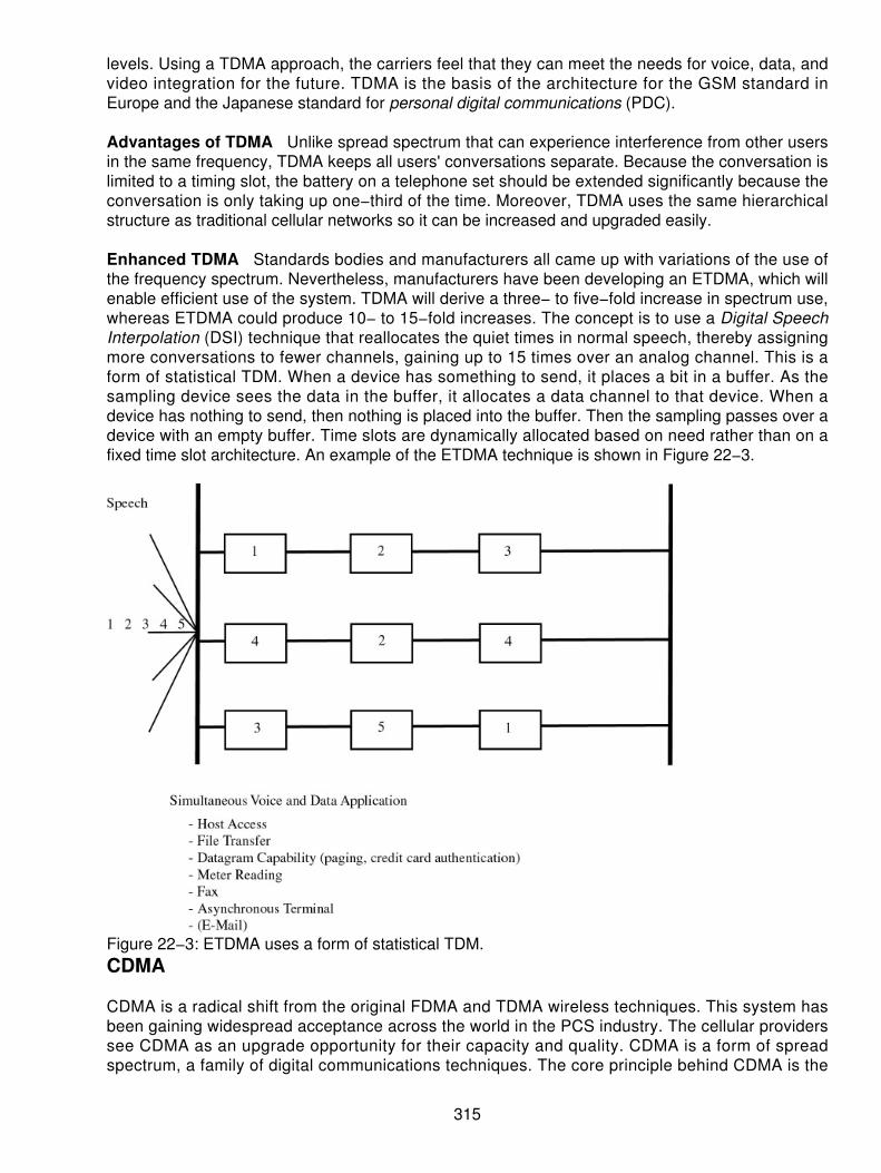
levels. Using a TDMA approach, the carriers feel that they can meet the needs for voice, data, andvideo integration for the future. TDMA is the basis of the architecture for the GSM standard inEurope and the Japanese standard for personal digital communications (PDC).
Advantages of TDMA Unlike spread spectrum that can experience interference from other usersin the same frequency, TDMA keeps all users' conversations separate. Because the conversation islimited to a timing slot, the battery on a telephone set should be extended significantly because theconversation is only taking up one−third of the time. Moreover, TDMA uses the same hierarchicalstructure as traditional cellular networks so it can be increased and upgraded easily.
Enhanced TDMA Standards bodies and manufacturers all came up with variations of the use ofthe frequency spectrum. Nevertheless, manufacturers have been developing an ETDMA, which willenable efficient use of the system. TDMA will derive a three− to five−fold increase in spectrum use,whereas ETDMA could produce 10− to 15−fold increases. The concept is to use a Digital SpeechInterpolation (DSI) technique that reallocates the quiet times in normal speech, thereby assigningmore conversations to fewer channels, gaining up to 15 times over an analog channel. This is aform of statistical TDM. When a device has something to send, it places a bit in a buffer. As thesampling device sees the data in the buffer, it allocates a data channel to that device. When adevice has nothing to send, then nothing is placed into the buffer. Then the sampling passes over adevice with an empty buffer. Time slots are dynamically allocated based on need rather than on afixed time slot architecture. An example of the ETDMA technique is shown in Figure 22−3.
Figure 22−3: ETDMA uses a form of statistical TDM.CDMA
CDMA is a radical shift from the original FDMA and TDMA wireless techniques. This system hasbeen gaining widespread acceptance across the world in the PCS industry. The cellular providerssee CDMA as an upgrade opportunity for their capacity and quality. CDMA is a form of spreadspectrum, a family of digital communications techniques. The core principle behind CDMA is the
315

use of the noise−floor to carry radio signals.
As its name implies, bandwidth greater and wider than normal constrained FDMA and TDMAchannels is used. Point−to−point communication is effective on the bandwidth that uses the noisewaves to carry the signal spread across a significantly wider radio carrier. Spread spectrum, whichwas employed back in the 1920s, has evolved from military security applications. It uses atechnique of organizing the RF energy over a range of frequencies, rather than a modulationtechnique. The system uses frequency hopping with TDM. At one minute the transmitter isoperating at one frequency; at the next instant it is on another. The receiver is synchronized toswitch frequencies in the same pattern. This is effective in preventing detection (interception) andjamming; thus, additional security is derived. These techniques should produce increased capacitiesof 10 to 20 fold over existing analog systems. Architecturally, the model for the system is shown inFigure 22−4.
Figure 22−4: The model for the CDMA systems Source: CDMA OrgOriginally conceived for commercial application in the 1940s, it was an additional 40 years beforethis technique became commercially feasible. The main factors holding back the use of CDMA werecost and complexity of operation. Today, the use of low−cost, high−density digital integrated circuits(ICs) that reduce the size and weight of the radio equipment makes the use of CDMA far morefeasible. Another area is an educational one, whereby the carriers needed to understand that theuse of optimal communications requires that the station equipment must regulate the power to thelowest possible levels to achieve the maximum performance. This, of course, flies in the face of thenormal operations that the carriers received their training.
Spread Spectrum Services
As the use of RF spectrum continued to put pressure on this limited resource, the systemsmanufacturers and regulators were searching for some way to share spectrum among multipleusers. Further, the sharing is compounded by the need to secure information while on airwaves.These pressures have led to the use of spread spectrum radio. The spreading portion of thesesystems using a chip set coded for your specific transmitter−to−receiver system. It can use multiplefrequencies (called hopping), or it can create a coded chip set. Regardless of the operation chosen,both are designed to spread energy over a broader range of frequencies to allow for less airtime ona specific bandwidth and to ensure the integrity of the information being sent.
316

Spread spectrum uses a technique of organizing the RF energy over a range of frequencies ratherthan a fixed frequency modulation (FM) technique. The system uses frequency hopping with TDM.At one minute the transmitter is operating at one frequency; at the next instant it is on another. Thereceiver is synchronized to switch frequencies in the same pattern as the transmitter. This iseffective in preventing detection (interception) and jamming. Thus, additional security is derived.These techniques should produce increased capacities in 10− to 20−fold over existing analogsystems.
In 1989, spread spectrum CDMA was commercially introduced as the solution to the bandwidthdemands of the industry. By using a spread spectrum frequency−hopping technique, developersannounced that they could achieve the desired frequency reuse patterns everyone wanted. Themodel for the network components mimics that of the GSM architecture shown in Figure 22−5.
Figure 22−5: The model of the CDMA network mimics the GSM architecture.Spread spectrum can use one of two different techniques: frequency hopping (FH) or directsequence (DS). In both cases, the synchronization between the transmitter and receiver is crucial.Both forms use a pseudorandom carrier; they just do it in different ways.
FH is not usually implemented in the commercial versions of CDMA. DS is used by commerciallyavailable CDMA. It is accomplished as a multiple of the more conventional waveform by using apseudonoise binary sequence at the transmitter. Noise and interference across the waveform areuncorrelated with the pseudonoise sequence, and thus become like noise. This increases thebandwidth when they reach the detectors. The signal−to−noise ratio (SNR) can be enhanced byusing filters that reject the interference.
The technique for the spread spectrum service is called CDMA. Many of the PCS carriers havechosen CDMA as their coding of choice. Since spread spectrum has been introduced at thecommercial level, the FCC allocated spectrum in the 1.9 GHz range. This group of frequencies isheavily used by microwave users operating in the 2 GHz range. The FCC feels that the spreadspectrum won't seriously impair the microwave users because it will appear only as random noise toany other frequency system operating in the same frequency ranges. However, as more users ofspread spectrum are inserted into a specific frequency range, the possibility of congestion andinterference exists. If you attempt to use this range of frequencies and congestion builds, then thedecision could be a wrong one. Despite the benefits of FH, the benefits may be overshadowed with
317

distance, utilization, and power constraints.
Consequently, when the FCC decided to allocate frequency spectrum to the PCS carriers, the fixedmicrowave users were told they had to find a new home. This means that the operators who hadradio systems in operation had to find new frequencies to use. Moreover, to facilitate the frequencychange, many of the fixed operators had to upgrade their equipment to work in the new frequencyband they found acceptable. Part of the auctions for the PCS frequencies included money set asideto help the fixed operators upgrade and move to a new frequency. This put added pressure on thewireless carriers to pay for the auctioned frequencies before building their infrastructure. The FCCraised approximately $13 billion in the auctions, but that placed the carriers in a negative position.They spent a lot of their capital up front to get the frequencies, before they could buy anyequipment.
The concepts of spread spectrum and of CDMA seem to contradict normal intuition. In mostcommunications systems, we try to maximize the amount of useful signals we can fit into a minimalbandwidth. In spread spectrum, we try to artificially spread a signal over a bandwidth much widerthan necessary. In CDMA, we transmit multiple signals over the same frequency band, using thesame modulation techniques at the same time. There are very good reasons for doing this. In aspread spectrum system, we use some artificial technique to broaden the amount of bandwidthused.
Capacity Gain
When you use the Shannon−Hartly law for the capacity of a bandwidth−limited channel, it is easy tosee that for a given signal powers the wider the bandwidth used, the greater the channel capacity.So if we broaden the spectrum of a given signal, we get an increase in channel capacity and/or animprovement in the SNR. This is true and easy to demonstrate for some systems but not for others.Ordinary FM systems spread the signal above the minimum theoretically needed, and they get ademonstrable increase in capacity. Some techniques for spreading the spectrum achieve asignificant capacity gain, but others do not.
CDMA alters the way we communicate by
Improving the telephone capacity of cellular operators• Improving quality of the voice communications and eliminating audible impairments ofmultipath fade
•
Reducing the incidence of dropped calls, especially during handoff• Providing reliability for data communications, that is, fax and Internet traffic• Reducing the number of sites to support a specific volume of traffic• Simplifying the site selection process• Reducing the average transmitter power output requirements• Reducing or eliminating interference with other electronic devices in the area• Limiting potential health risks• Reducing the operating costs because fewer cell sites are needed•
The CDMA Cellular Standard
With CDMA, unique digital codes, rather than separate radio frequencies are used to differentiatesubscribers. The codes are shared by both the mobile station (MS) and the BS and are called
318

pseudorandom code sequences. All users share the same range of radio spectrum. For cellulartelephony, CDMA is a digital multiple access technique specified by the TIA as IS−95. In 1993, theTIA gave its approval of the CDMA IS−95 standard. IS−95 systems divide the radio spectrum intocarriers that are 1.25 MHz wide as shown in Figure 22−6. One of the unique aspects of CDMA isthat although the number of phone calls that a carrier can handle is certainly limited, it is not a fixednumber. Rather, the capacity of the system will be dependent on a number of different factors.
Figure 22−6: CDMA uses a channel that is 1.25 MHz wide for all simultaneous callers.CDMA changes the nature of the subscriber equipment from a predominantly analog device to adigital device. CDMA receivers do not eliminate analog processing in its entirety, but they separatethe communications channels by a pseudorandom modulation technique that is applied to the digitaldomain, not based on frequencies. In fact, multiple users will occupy the same frequency bandsimultaneously.
Spread Spectrum Goals
Much of the action in the wireless arena includes the use of the frequency spectrum to its fullestwhile preserving its efficiency. The primary goal of spread spectrum systems is the substantialincrease in bandwidth of an information−bearing signal, greater than required for basiccommunications.
This increased bandwidth, though not used for carrying the signal, can mitigate possible problems inthe airwaves, such as interference or inadvertent sharing of the same channels. The cooperativeuse of the spectrum is an innovation that was not commercially available in the past.
Regulators around the world have set aside limited amounts of bandwidth to satisfy these services,so that the efficiency is kept high. The limited frequency spectrum allocated preserves upon the goalof using spectral efficiency, which is usually measured with one of the traffic engineeringcalculations (Erlang or Poisson) per unit in operation in a specified geography and in terms of perMHz. For example, cellular operators use a 25 MHz split between the two directions ofcommunications: 12.5 MHz of transmit and 12.5 MHz of receive spectrum. As technology
319
enhancements occur, practical ways of expanding the amount of coverage become a reality.
Spread Spectrum Services
As the use of RF spectrum continued to put pressure on this limited resource, the manufacturers ofsystems and regulators were searching for some way to share spectrum among multiple users.Furthermore, sharing is compounded by the need to secure information while on airwaves. Thesepressures have led to the use of spread spectrum radio. The spreading portion of these systemsusing a chip set coded for your specific transmitter−to− receiver system uses multiple frequencies(called hopping) as one method, or another technique of creating a coded chip set is used.
Both of these services are designed to spread as much energy over a broader range of frequenciesto enable less airtime on a specific bandwidth and to ensure the integrity of the information beingsent. The technique for the spread spectrum service is called CDMA. Many of the PCS carriershave chosen CDMA as their coding of choice. Because spread spectrum has been introduced at thecommercial level, the FCC allocated spectrum in the 1.9 GHz range. This group of frequencies isheavily used by microwave users operating in the 2 GHz range.
Synchronization
In the final stages of the encoding of the radio link from the BS to the mobile, CDMA adds a specialpseudorandom code to the signal that repeats itself after a finite amount of time. BSs in the systemdistinguish themselves from each other by transmitting different portions of the code at a given time.In other words, the BSs transmit time−offset versions of the same pseudorandom code. In order toassure that the time offsets used remain unique from each other, CDMA stations must remainsynchronized to a common time reference.
The primary source of the very precise synchronization signals required by CDMA systems is theGlobal Positioning System (GPS) as shown in Figure 22−7. GPS is a radio navigation system basedon a constellation of orbiting satellites. Because the GPS system covers the entire surface of theearth, it provides a readily available method for determining position and time to as many receiversas are required. The synchronization is maintained between the transmitter and receiver so thateach user device can be isolated in time. A representation of this is shown in Figure 22−8.
320

Figure 22−7: CDMA uses GPS to maintain synchronization of the systems. Source: NASA
Figure 22−8: The systems maintain synchronization to isolate each user.
Balancing the Systems
CDMA cell coverage is dependent upon the way the system is designed. In fact, three primarysystem characteristics — coverage, quality, and capacity — must be balanced off of each other toarrive at the desired level of system performance. In a CDMA system, these three characteristicsare tightly interrelated. Even higher capacity might be achieved through some degree ofdegradation in coverage and/or quality. Because these parameters are all intertwined, operatorscannot have the best of all worlds: three times wider coverage, 40 times capacity, and CD−qualitysound. For example, the 13 Kbps vocoder provides better sound quality but reduces systemcapacity as compared to an 8 Kbps vocoder.
Operators will have the opportunity to balance these parameters to best serve a particular area. Thebest balance point may change from cell site to cell site. Sites in dense downtown areas may trade
321

off coverage for increased capacity. Conversely, at the outer edges of a system, capacity could besacrificed for coverage area.
Common Air Interfaces
Two primary air interface standards are in use today: Cellular (824 to 894 MHz) uses theTIA/EIA/IS−95A. PCS (1,850 to 1,990 MHz) uses the ANSI J−STD−008. These two standards aresimilar in the features that they offer, with the exception of the frequency plan, mobile identities, andmessage fields. The standards provide some stability in the operation of the systems but maychange over time. However, looking at the forward and reverse CDMA channel can shed someadded light on what we can expect from the use of CDMA.
The Forward Channel
The forward CDMA channel is the cell site to mobile direction for communications. It carries traffic, apilot signal, and any overhead information required by the system. The pilot is a spread butotherwise unmodulated DSSS signal. The pilot and overhead channels establish and maintain thesystem timing and the station identity. The pilot is also used in the mobile−assisted handoff (MAHO)process as a signal strength indicator.
Transmission Speeds and Rates IS−95A uses a forward link that supports a speed of 9,600 bpsin the data−bearing channels. The forward error correction code rate is 1/2, and the pseudonoiserate is 1.2288 MHz (which is 128 x 9,600 bps). Recent events have seen that Verizon and SprintPCS are now offering data rates of up to 144 Kbps on their 2.5G wireless networks using CDMA.
Overhead Channels Three different types of overhead channels exist in the forward link. Theseinclude the pilot, sync, and paging channels. The pilot is a requirement for every station.
Pilot channel This is always code channel 0. It operates a demodulation reference for theMSs and a handoff level measurement reference.
•
Sync channel This carries a repeating message that identifies the individual station andthe absolute phase of the pilot sequence. The data rate of the sync channel is 1,200 bps.This mobile finds the framing boundary of the sync channel and times to it simply. It carries asingle repeating message that conveys timing and system configuration to the MS.
•
Paging channel This is used to communicate when the mobile is not assigned to a trafficchannel. It notifies the mobile of incoming calls and carries responses to the mobile access.Paging channels operate at 4,800 or 9,600 bps.
•
Traffic channels These are dynamically assigned channels in response to a mobile access. Thetraffic channel carries its data in a 20 ms frame.
The Reverse Channel
The reverse channel is the mobile−to−cell site communication channel. It carries traffic andsignaling information. A reverse channel is only active during calls associated with a specific MS orwhen access channel signaling takes place to the BS.
Transmission Speeds and Rates IS−95A uses a reverse link that supports a speed of 9,600 bpsin the access and traffic channels. The forward error correction code rate is 1/3, the code symbolrate is 28,800 symbols per second after six code symbols per modulation symbol are present, and
322

the pseudonoise rate is 1.2288 MHz.
Channelization The reverse CDMA channel consists of 242 −1 logical channels. One of thesechannels is permanently and uniquely associated with each MS. The mobile uses the logicalchannel whenever it passes traffic. The channel does not change upon a handoff. Other logicalchannels are used for access with the BS.
Walsh Codes
These are the primary transmission patterns used in CDMA mobile phone systems. A few dozenCDMA handsets can be operating within (sharing) the same 1.25 MHz of radio bandwidth, and it isimportant that the interference effects are minimized. Walsh codes serve to identify each transmitterto the base (or vice versa), and they spread the code (the chip rate) — which is the spreadspectrum effect.
However to reduce interference, each, on average, must counteract the effect of the others — if 50percent are transmitting a positively phased pulse at any moment, the other 50 percent should betransmitting a negatively phased pulse. This is possible only because all transmissions aresynchronized, and all use orthogonal Walsh codes.
If you toss a coin 50 times, you will most likely have an orthogonal Walsh code, which is 50 bits inlength. Do this a dozen times, and you'll have a dozen different orthogonal 50−bit codes, each quitedistinctive in its pattern. This is the basis of direct sequence code division multiplexing systems.
Traffic Channel
Traffic channels are the reverse of CDMA channels and are mobile unique. The traffic channelalways carries data in a 20 ms frame. Frames at the higher rates of rate set 1 and all those in rateset 2 use CRC codes to help assess the frame quality in the receiver.
Direct Sequence Spread Spectrum
CDMA is a direct sequence spread spectrum system. The CDMA system works directly on 64 Kbpsdigital signals. These signals can be digitized voice, ISDN channels, modem data, and so on.
Signal transmission consists of the following steps:
A pseudorandom code is generated, different for each channel and each successiveconnection.
1.
The information data modulates the pseudorandom code (the information data is spread).2. The resulting signal modulates a carrier. (Steps 1 to 3 are shown in Figure 22−9.)3.
323

Figure 22−9: The signal is prepared for transmission.The modulated carrier is amplified and broadcast (see Figure 22−10).
Figure 22−10: The modulated carrier is then amplified and broadcast across the airinterface.
4.
Signal reception consists of the following steps:
The carrier is received and amplified.1. The received signal is mixed with a local carrier to recover the spread digital signal.2. A pseudorandom code is generated, matching the anticipated signal. (Steps 1 to 3 of thereception are shown in Figure 22−11.)
Figure 22−11: The reception from the air interface occurs.
3.
The receiver acquires the received code and phase locks its own code to it.4. The received signal is correlated with the generated code, extracting the information data.(Steps 4 and 5 are shown in Figure 22−12.)
5.
324

Figure 22−12: The codes are stripped off and the actual data is extracted.
Seamless Networking with IS−41 and SS7
The whole intent of the IS−41 and SS7 interfaces is to enable the wireless carriers to communicatetransparently and seamlessly between and among each other. Moreover, with SS7 interfaces to thewireline networks, calls can enter or exit the wireless networks flawlessly. This has been ongoingsince 1994 and seems to be moving quite well. If the wireless carriers do not have physicalinterfaces to the telephone companies, they can use the Independent Telecommunications Network(ITN) to provide these services as a service bureau, for a fee. The interconnection between thenetworks provides industry standards−based internetworking.
Automatic Roaming
The IS−41 and SS7 provide many of the features for automatic roaming among providers, althoughmodifications will be necessary. First, it helps to define financial responsibility between the carriersfor their users. Second, it helps to provide the seamless interfaces between the wireless systemsand the SS7 interfaces between the wireline and wireless carriers.
As the system operates, automatic roaming allows for the discovery of a roamer. The providingsystem then learns the identity of the current serving CO or visited system and sends thatinformation to the home system. A profile is established for the roamer in the visited system,enabling the network to find the end user. This, in fact, is how the wireless providers handle locationportability. Lastly, the automatic roaming enables the setup for delivery for the calls.
The wireless suppliers have been moving toward transparency through their bill−and−keeparrangement. In reciprocal billing, they assume that the calls cost an equal amount of money for thecarriers to originate or terminate. Therefore, between wireless carriers, they do not charge eachother for terminating minutes. The wireline companies on the other hand are charging forterminating minutes at approximately $.02 to $.025 per minute. Thus, the carriers are looking for away to get away from the reciprocal billing and to get to a bill−and−keep arrangement with thewireline providers.
Cellular and PCS Suppliers
The cellular industry has been a success story to behold. Over the past 17 years, they have grownfrom nothing to over 100 million customers. With very few exceptions, the cellular carriers seethemselves as a complementary carrier to the ILEC business. Some of this comes from the fact thattwo parts of the cellular network started when the licenses were issued: Wireline carriers meant the
325

ILEC operated the regulated portion of the cellular network, and nonwireline meant the competition.In most cases, the ILEC who operated the wireline side of the business then spread out across thecountry as part of the nonwireline provider (competing for wireless services with their cousins).Therefore, the cellular industry is influenced heavily by the ILEC side of the business. The cellularproviders see themselves as complementing the wireline business instead of competing with it.
PCS and SMR providers seem to be the carriers seeking a niche in the market. As they offerservices to their customers they view themselves as an alternative to the ILEC wireline services andat the same time as complementary. Depending on how the customer reacts, the PCS providers willmove toward one position. In checking with several PCS suppliers, the argument to make the PCStelephone number the sole number came up. The providers offer the same features and functionsas the wireline service providers such as the following:
Call forwarding (busy or don't answer)• Voice messaging• Three−way calling• Caller ID• Call transfer•
The PCS providers are now saying that the customer can use the same number for their homenumber, their business number, and their traveling number. Why pay for two different lines andservice offerings when you can do it all on one telephone (and number)? Their speech is convincingsomewhat, but they fail to mention the cost of the airtime for receiving calls and the added cost formaking local calls. However, they are now packaging these services in such a way that they areinvisible.
Home Location Registers (HLRs) keep track of all network suppliers' users, based on their ownnetwork id. The database (HLR) has all the appropriate information to recognize the caller−by−userESN and mobile telephone number. The database controls the features and functions the user hassubscribed to. When a call comes into the network today, the called number is sent to the HLRresponsible for the number dialed. These are SS7 messages. The HLR then looks into its databaseand determines where the caller is located or if the user is on the air.
If the user is located somewhere else, a Visitor Location Register (VLR) entry exists at a remoteMSC. This entry has been updated by the remote end when the user activated the telephone(powered it on and registered) or when an already powered device rolls into range of a cell site fromthe new location. Then an SS7 message is sent out to the HLR that the called party is now insomeone else's Automatic Line Information (ALI) database.
If a call is coming in from the network, the SS7 inquiry comes into the HLR who then sends aredirect message to the remote MSC (the VLR) serving the end user.
Using this roaming capability, the database dips are occurring on a frequent basis. Many of thenetworks (wireless) are already taxing their databases. They are trying to move more informationout to the STP or the local switches rather than constantly hammering into the SCP.
Final Thoughts
PCS mimics the same basic services of GSM discussed in the preceding chapter. The primarydifference is that the PCS operators are primarily North American based whereas the GSMstandard has been implemented by the rest of the world. Differences exist in the overall operation,
326

but these systems operate in similar fashion. The ability of the PCS system to learn the identity ofthe roaming device is similar to the smart card used in Europe. The services enabling the COequipment and databases to communicate with each other and track the roamer simplifies thebilling and the service functions. Moreover, the feature transparencies available with PCS creates aseamless network atmosphere.
Although the two technologies are different, they are similar at the same time. The real value isachieved when the user can operate the wireless device (the phone) transparently between suppliernetworks, with the same look and feel as in the home system.
327

Chapter 23: Wireless Data Communications (MobileIP)
Overview
As the convergence of voice and data continues, a more discreet change is also coming into play.Although data is considered fixed to a location, the end user is now more mobile. This opens a newset of challenges for the industry and manufacturers alike because of the need for mobility. Whatonce was a simple procedure of connecting the user's modem to a land line now poses the need toconnect that same user to a device while mobile. Protocols need to be more f lexible,accommodating the mobile user as the device is moved from location to location. Moreover, thephysical devices (for example, the modems) must be moved often. In a dial−up, circuit−switchedcommunications arrangement, this is not a major problem. The user can unplug a modem,reconnect it to a landline elsewhere, and dial from anywhere.
However, when we use Internet Protocol (IP) as our network protocol, data is routed based on anetwork/subnetwork address. Routing tables keep track of where the user is located and route thedatagrams (packets) to that subnetwork (see Figure 23−1). When a mobile user logs on andattempts to dial in to the network, the IP address is checked against a routing table and routedaccordingly. Updating the tables can be extremely overhead intensive, and it can producesignificant amounts of latency in the Internet or intranet. Using an ICMP Route Discovery Protocol(IRDP), which is part of the Transmission Control Protocol/IP (TCP/IP) protocol suite, helps.However, when the IRDP process updates its tables, we use a lot of bandwidth. Figure 23−2 is anexample of the IRDP process where a message is generated by a host to learn all routes availableto get to and through the network.
Figure 23−1: Routing table
328

Figure 23−2: IRDP learns the new addresses and routers in the network.Something needs to be done to accommodate the use of mobile IP by an escalating number ofusers wanting to log on anywhere. Of course, one solution is to use the Dynamic Host ConfigurationProtocol (DHCP), which uses a server−based mechanism to allocate a new IP every time a userlogs onto the network or assigns a static IP address to a user who may be using a diskless PC. Thepurpose of the DHCP is to facilitate the mobile or not−permanently−attached user in an ISP networkwhere addresses are limited and casual users are the norm. So the industry has had to arrive at asolution allowing casual and nomadic users the same access while they travel (roam) as when theyare in their fixed office location.
Figure 23−3 shows the growth curve of wireless data users attempting to use mobile IP andwireless data communications over the past couple of years. In this graph we see that the numbersjustify the concern and the effort being afforded to the problem. The number of wireless users in theworld is escalating and the number of wireless data users shown in this graph will grow from 150million to 1 billion by 2006 if the carriers can roll out their products reliably. We are living in a mobilesociety where users want their data, when they want it, where they want it, and how they want it!What percentage of these wireless users will want data over their connection remains to be seen.However, early estimates are that over one−fifth will want their data in a mobile environment.
329

Figure 23−3: Wireless data subscribers (in millions)
IP Routing
When IP was first implemented, the routing scheme was based on tables that were kept in a router.The routers updated these tables periodically to keep the information current. A service advertisingprotocol was used to notify the downstream routers and hosts of the router's presence. As data wassent through the Internet (intranet or private network), the IP datagrams included both the sourceand destination address, as shown in Figure 23−4. Routers forwarded the data on the basis of thedestination address, the 32−bit address in IP version 4. Routers ignored the source address, lookingonly at the destination. Using the destination address, the router then concerned itself with the nethop. If a router received a datagram that was destined for a local address, it then sent the data tothe physical port for the Local Area Network (LAN) subnetwork it resided on. However, if the routerreceived a datagram that was for a destination that was not local, it forwarded the datagram to itsnext downstream neighbor. The routing process was done on the basis of hop−by−hop forwarding.
330

Figure 23−4: Routers look at the IP header for the destination network address.After receiving a datagram with an address that was local, the router would forward the data to itslocal physical port (the LAN). However, if a networked device was moved because the user wasmobile, the router continued to send the data to the destination network in its table. A mobile userwas therefore not going to receive any datagrams because IP did not guarantee delivery. This brokedown the whole process because the devices were mobile, especially in global networks withmobile workers. Conceivably, a user could travel to a remote office and attempt to plug in a laptopcomputer with a static IP address from corporate headquarters. Because the IP was static, all the IPdatagrams were sent along their way to the headquarters' router where the IP subnetwork addresswas registered.
Part of the Solution
One part of the solution is a change in IP version 4 that allows for mobile users. This mobile IPprocess is addressed in RFC 2002, which allows for the registration of home agents and foreignagents. A home agent is a registration process whereby a locally attached computer registers with aserver or router and gets entered into the routing table. Based on RFC 2002, a mobile device (eithera host or a router) can change locations from place to place without devastating effects. If mobile IPis in use by the device, the mobile device will not change its address when it moves from location tolocation. Instead, it will use an IP forwarding approach by using an "in−care−of" address obtainedfrom some serving device that knows of its presence. Using the home agent concept, the homeagent is a server or router on the home network. The home network maintains the mapping of themobile device's address to its current address.
Think of this in the context of the postal service. If you go on vacation for a month to Phoenix,Arizona, you still need to get your mail (for example, paychecks, bills, and so on). So, before goingaway, you go to the local post office and tell them to forward all your mail for the next month toPhoenix. The forwarding idea is shown in Figure 23−5. The postmaster will then make a note on themailbox where he or she sorts your mail. This note will say to forward all mail to P.O. Box 51108,Phoenix, AZ 85076−1108. So even though people are still sending mail to your address, the postoffice employees (your home office agents) are handling the forwarding to you, based on theinstructions you left behind.
331

Figure 23−5: Forwarding IP trafficWhen the vacation is over and you return to your normal domicile, you notify the local postmasterthat you are back. The local folks remove the forwarding address from your normal mailbox andthen resume delivery to the home address. The Phoenix postmaster, in the meantime, wasresponsible for knowing your temporary address while you were in his or her area. Therefore, thelocal postal people were handling the routing and delivery of the mail while you were in Phoenix.They were acting as your agents in the foreign location. The foreign agent received mail that wasmarked for your normal home address, but translated this into the current address. Thiscombination of local (home agent) and remote (foreign agent) agents makes the process work.
Now let's assume that after vacation, you leave Phoenix, but do not go home. Instead, you go on anextended business trip to San Francisco. The home agents then label the boxes to reflect thechanges that indicate mail is now to be forwarded to the new location.
Applications That Demand Mobile IP
What are the applications that will take advantage of the mobility of the user? Well, the first one isgoing to follow our example for mail. But e−mail is only one of many applications that users will wantto use. Other areas will include transaction processing (orders online), fax capabilities, File TransferProtocol (FTP), and Telnet. Telemetry applications and multimedia are all prime candidates. This isshown in Figure 23−6 where the applications will be paramount to the ability to move around.
332

Figure 23−6: Application of mobility in a data worldApplications are what the data transmission world is all about. So we need to have mobility in the IPworld in order to satisfy the applications for a mobile user.
In Table 23−1 the need for these application services becomes more evident. In this table, thedriving forces for the implementation of wireless data and mobility within the TCP/IP architecturesare more evident.
Table 23−1: Driving forces for mobile data
Market Forces Driving Mobility ValueConsumer use of computers Increasing. In North America, the average number of households
has climbed to 67 percent and users wired for interconnectivity.Remote access needs With more telecommuters, the need for remote access is
increasing at a 10 percent or better ratio each year. The number oftelecommuters is running at 18 million in 2001.
Users demands for the accessthey perceive
Users want access to their data when they want it, where they wantit, and how they want it. The driving force is that 250 millionsubscribers will be using wireless data by the end of 2003.
Wireless innovations Wireless data is still only available at 9.6 Kbps, even though it isadvertised at speeds of 33.6 Kbps. In the future, mobile data andIP users will expect 500 Kbps to 2 Mbps speeds from their wireless
333

data devices.Internet The growth on the Internet has been so dramatic that more users
expect the capability to log onto the Net and get their e−mail, FTP,and transmit other forms of data anywhere and anytime. Internetgrowth is slotted at 450 million users in the 2003—2004 period,growing to 700 million users by 2005—2006.
Speed Isn't Everything
Some of the driving forces shown in the table couple tightly with the throughput issues of datacommunications. However, speed is not the only issue driving the demand for mobility. The need forspeed and reliability are rapidly driving the users into a mobile environment. In the older days, thespeed would hold back the use and acceptance of data transmission. Popularity in other connectiondevices also sets the pace. An example of the devices is shown in Table 23−2. This lists the variousdevices people are looking to use.
Table 23−2: Speeds for wireless devices
Devices Expected SpeedsPersonal data assistants The current wireless connection is 28.8 Kbps. Expect this to grow
to 500 Kbps by the end of 2004.Laptop computers Current modem technology supports up to 56 Kbps downloadable
and 33.6 Kbps uploadable. In the future, users will expect 2—10Mbps.
Palmtop computers Same technology as laptops.Mobile telephones Current low−speed telephony with speeds of less than 19.2 Kbps
circuit−switched technology. The future demand will be speeds ofup to 128—170 Kbps and then 384 Kbps.
Paging systems Low−speed data from short messaging systems (SMS).
Variations in Data Communications (Wireless)
Several different flavors of data communications exist for wireless communications. Most peoplethink of the services as being one type only. Earlier the discussion considered the SMS,circuit−switched data, and packet−switched data. The variations in the different technologiesdepend on the innovations and the air interfaces.
Regardless of the different methods, there are still many variations in using the data transmissioncharacteristics with wireless applications and mobile users. In Table 23−3, a summary of the variousmethods is shown for the wireless communications techniques.
Table 23−3: Summary of methods for data
Method Air InterfaceCircuit switched TDMA
CDMAGSM
334

Packet switched RIMMotientCDPDIP
SMS Packet−switched separate
Possible Drawbacks with Wireless
Not everything with wireless data is perfect (it's the same for wireline). Occasionally, there will beproblems that must be overcome. The use of wired facilities has improved over the years with theuse of fiber optics in the backbone. Newer technologies have allowed the industry to improve theperformance of data to a 10−15 to 10−16 bit error rate. This was unheard of before the use of fiberand Synchronous Optical Network (SONET) in the backbone. The local loop (last mile) is theweakest link in the equation, producing bit error rates of 10−6. Still, today this is not as bad as it maysound because the distances we run on copper (the local loop) are being shortened daily. Theshorter the copper, the better the performance we achieve (because the weakest link is minimized,and the cables are correctable). Therefore, we see improved data performances on the localcopper−data transmission systems. However, wireless (air interfaces) have been traditionally errorprone, and the amount of frequencies available have always been limited. This interface is limited tothe point that many people have not wanted to use air interfaces in the past. With the culture shiftand the use of digital techniques to compound the data, air has become much more acceptable.
The wireless medium is also prone to more delay and latency than the wired world. In the wiredarena, the average delay for transmitting information across the nation networks is 50 msec or less.In the wired world, this delay can jump to more than 250 msec. At 250 msec, we find that echobegins to get out of control, requiring more equipment to handle this problem. However, whilehandling the echo control function, we introduce more latency and buffering of the real data. Thisalmost becomes a Catch−22 problem. The more the data is buffered and manipulated across themedium, the greater the risks of introducing errors.
Pros and Cons to Wireless
Some of the inherent problems bring other solutions and benefits to the table. For example, whenusing a wireless interface, the user is mobile and can go almost anywhere at whim. This allowsmore flexibility. However, the downside is that the use of cellular and Personal CommunicationsServices (PCS) systems causes data and call handover to occur, which can be detrimental to theoverall performance. Security issues cannot be ignored with data in the air. On a copper cable, datais slightly more secure because the medium is a little more difficult. The use of an interceptor in theairwaves is much simpler. Digital cellular and PCS make the data more secure than analog, but onestill has to be concerned with putting anything in the airwaves.
From the perspective of financial information, the wireless data can be very expensive. In thecircuit−switched arena, just as in voice, we pay the carrier a flat rate for a guaranteed amount ofusage. The price is fixed whether you use the minutes or not. If you exceed the minutes of usage,you pay a premium added cost for the overage usage. Some plans do allow you to pay for onlywhat you use; however, these plans tend to be at a higher cost per minute for all the minutes ofusage. Therefore, it becomes difficult to assess the best deal, depending on variable usage.Packet−switched data, such as Cellular Digital Packet Data (CDPD) and RAM Mobile Data services,can be less expensive when small amounts of data are transferred. Yet if the user transmits large
335

and lengthy files, the cost of packet switched data can be as much as 50 to 100 percent higher thancircuit−switched data. The variables are still less attractive to use the wireless data.
Other areas where differences exist are in the devices themselves. When dealing with a radiointerface (like a cell phone), we have to be aware of the battery life of the device. Powerconsumption with lengthy data transfers can be critical. The use of the overall battery life iscontingent upon the technology used, but current industry standards allow for 2 to 4 hours of talktime on a portable device (transmission time for data). Anything over that is prone to cut off andproduce errors. The digital sets are better equipped to handle the data transfers, but dual−modephones can be problematic when they are in analog mode.
336

Chapter 24: General Packet Radio Service (GPRS)
Overview
With the simultaneous gate−opening effects of technological innovation and industry deregulation,the demand for communications and available solutions is exploding. This demand is being fueledby the needs of people and businesses. The most visible evidence of the boom is within Internettraffic and e−commerce or m−commerce. However, it is less appreciated that an unprecedenteddemand exists from worldwide telephone subscribers. It took a century to get 700 million phonelines installed. Another 700 million will be deployed in the next 15 to 20 years — and that couldprove to be a conservative estimate. Although the majority of the new deployments will be wirelessphones — 700 million of them over the next 10 years — demand for wireline communications isalso exploding, driven in part by the need to access the Internet.
This explosion in demand is reflective of the dependence that people have on rapid, reliablecommunications to keep up with the fast pace of business. The success of the Global System forMobile Communications (GSM), the ubiquitous presence it has garnered, the emerging Internet,and the overall growth of data traffic in general all point to a significant business opportunity forGSM operators. The number of subscribers to the Internet worldwide is growing exponentially, asseen in Figure 24−1, and the growth has been dramatic. The following statistics from the middle of2001 add some credibility to the overall concept of a data−centric community that is also mobile:
Number of Internet users — 400 million• Number of wireless users — 700 million•
Figure 24−1: The number of telephone and Internet usersBy the year 2005, we can expect that more than 1 billion people will be mobile wireless users on aworldwide basis, and by 2006, more than 1 billion people will be Internet users. We are adding over100 million new Internet users per year. This growth is unheralded in the past century of thetelecommunications industry. The phenomenal growth in wireline Internet subscribers points to thepossibility of wireless operators capturing some of this market. This assumes that they can offercomparable price−performance capabilities. The factors that we can consider in the process are
337

Wireless users are ideal target subscribers for Internet providers.• Internet users are ideal target subscribers for GSM operators.•
Several movements in the Internet community will also force changes. The demographics of theuser will change dramatically as the world expands its wireless and Internet presence. The averageuser will be looking for developments in the new Internet that will provide a broader bandcommunications speed, the capability of using a network−enabled appliance, and a full networkcapable of sourcing all the needs and applications through high−end portals that can offer thegoods and services needed. Instant information for a mobile workforce is paramount.
In addition to customer demand, this revolution is greatly accelerated by technology disruptions.Three technologies are at the fundamental science level. One is summarized in the well−knownMoore's Law, which states that the capacity of an individual chip will double once every 18 to 24months. Therefore, silicon is covering the globe. That phenomenon has been going on for threedecades now and will be adding as much capacity in the next two years as has been created in thehistory of the semiconductor business. Nevertheless, the capacity is finally just getting to the pointwhere it's interesting. Two other technologies, although less well known, are changing just asrapidly, if not more so:
In optical, in the core of the network, dense wavelength division multiplexing (DWDM), usingmultiple colors of light to send multiple data streams down the same optical fiber, isdisrupting the rapid growth of Wave Division Multiplexing (WDM), further pushing theenvelope.
•
Wireless capacity is also exploding, enabling higher bandwidth for voice/data without fiber(45 Mbps — up to 2.5 Gbps with certain wireless tools and 10 Gbps are being discussed asa reality over the next decade).
•
Combined, these advances are making converged networks possible and inevitable, as well asimportant to plan for in business. Companies that understand and take advantage of thisconvergence will have a strategic advantage.
The New Wave of Internet User
During the next few years, the third−generation (3G) Internet will drive even further innovation andperformance. Figure 24−2 provides a summary of the steps. It began with the first−generation (1G)Internet, which was PC−driven. During this period, standards were established, and narrowbandservices were offered. This led to business model experimentation, new companies, and newbrands. In both wireline and wireless communications, users were satisfied with the PC−centricservices because the networks did not offer anything else. This led to a somewhat frustrated PCand Internet user on wireline networks, but an even greater level of frustration was evident in thewireless arena.
338

Figure 24−2: The steps in developing the 3G InternetToday, the 2G Internet is upon us. Trends underlying today's Internet include substantialpersonalization and the emergence of the business−to−business market. Regardless of thedownturn in 2001, the networks will reemerge.
Trends underlying the 3G Internet will drive the growth of the new economy in upcoming years:
First, as more people go online, in fact almost doubling, the online population will begin tonormalize, or resemble the overall U.S. population. The average age of the online user willgo up and his or her income will fall. This means that strong brand recognition increases inimportance, greater service levels to support less savvy online users will be required, andconvenience and ease of use will become vital. The good news is that these changes willdrive a greater comfort level with online shopping for the average online user, more thandoubling total spending online.
•
Second, broadband will create a personalized, interactive experience. Think of the Web onsteroids. Today's interactive experience will be radically enhanced.
Instead of instant text messaging, we will have easy access to instant audio andvideo messaging.
♦
Instead of today's chat rooms and discussion l ists, we wil l have far moresophisticated real−time collaboration tools.
♦
Today's grainy−streamed audio and video will have broadcast quality tomorrow. Thetwo−dimensional will be three−dimensional.
♦
•
Although the growth of PCs has slowed to roughly 3 percent per year, new information appliancesand communication devices are fast becoming the new power brokers with double−digit growth.Wireless telephones, personal digital assistants (PDAs), Blackberry devices, and GPRS terminalsare the new devices to behold. The power of the Web will be accessed through mobile phones,PDAs, cable set−top boxes, and even game controllers. Every office and household device in thefuture will be Internet Protocol (IP) addressable, enabling the user and supplier to better service theindividualized and customized needs.
This new economic model (although it appears to have gradually slowed) requires that we addressthe converged world, borrowing from each perspective. Both the world of voice networks and theworld of data networks have advantages. Both have a unique profile of strengths. Convergenceapplications will be practical when you are able to take the best of both worlds and deliver
339
real−world business value. In a nutshell, a converged world requires that our networks and accessmethods of the future be
Highly reliable• Broadband serviced• Scaleable• Multiservice oriented• Flexible and open• Exceptionally easy to use•
These thrusts are driving the data communications market into an explosive situation. The averagegrowth of our voice networks is 4 percent; however, in the data communications arena, the growthis still approximating 30 percent growth per year. This unparalleled growth consists of both goodsand services to meet the demands of customers, internal users, and the industry in general.
GPRS
GPRS is a key milestone for GSM data. It offers end users new data services and enablesoperators to offer radically new pricing options. Using the existing GSM radio infrastructure, up−frontinvestments for operators are relatively low. GPRS solutions began appearing initially in 1999through 2000 using the infrastructures that are already in place. Pricing for use of the voice side ofthe network has become commoditized, whereas pricing models for the new data access will causea revolution. One such threshold looks at an all−you−can−eat model whereby users of wirelessphones add a data subscription at $29.95 per month for unlimited use. Another such model is theone used in Japan by DoCoMo, charging a rate of the U.S. equivalent to $.0025 per packet. Otherswill emerge that will shake the industry mode and create new dynamics in the use of dataanywhere.
GPRS services were targeted at the business user. However, the services will soon be availablenetworkwide, targeting both the business and the residential consumer. The widespread adoptionand acceptance of GPRS will create a critical mass of users, driving down costs while offering betterservices. These components will form the basis of a healthy mobile data market with growth figurescomparable to GSM voice−only services today. Research by Infonetics indicates that the movementof the user community will also be to a more mobile community. In fact, the study indicates that by2005, more wireless devices will be used for the Internet than PCs on the Net, as shown in Figure24−3. This form of growth is again a driver that will force the rapid deployment by carriers andmanufacturers alike.
340

Figure 24−3: Within five years, more wireless devices will be used on the Internet than PCs.The GPRS Story
The GPRS is a new service that provides actual packet radio access for GSM and Time DivisionMultiple Access (TDMA) users alike. The main benefits of GPRS are that it reserves radio resourcesonly when data is available to send, and it reduces the reliance on traditional circuit−switchednetworks. Figure 24−4 is a basic stepping−stone description of the GPRS story. The increasedfunctionality expected from GPRS will decrease the incremental costs to provide the data services,which will increase the penetration of the data services, among the consumers and business usersalike.
Figure 24−4: The GPRS storyAdditionally, GPRS will improve the quality of data services measured in terms of reliability,response time, and features available. Unique applications will be developed in the future that willattract a broad base of mobile users and enable the individual providers to offer differentiatedservices. One way that GPRS improves upon the capacity capabilities of the network suppliers is toshare the same radio resources among all mobile stations (MSs) in a cell, thus providing effective
341

use of scarce resources. New core network elements will continue to emerge that will expandservices, features, and operations for our bursty data applications.
GPRS also provides an added step toward 3G networks. GPRS will enable the network operators toimplement IP−based core architecture for data applications. This will continue to proliferate newservices and mark the steps to 3G services for integrated voice and data applications.
What Is GPRS?
As stated previously, GPRS stands for General (or generic) Packet Radio Service. GPRS extendsthe packet data capabilities of the GSM networks from Packet Data on Signaling−channel Service(PDSS) to higher data rates and longer messages. For now, the use of GPRS shall be in thecontext of GPRS−GSM to distinguish it from the GPRS−136, the North American adoption of GPRSby the IS−136−based systems. GPRS is designed to coexist with the current GSM Public LandMobile Network (PLMN). It may be deployed as an overlay onto the existing GSM radio network.GPRS may also be implemented incrementally in specific geographic areas. An example of thisGPRS radio access may be deployed in some cells of a GSM network, but perhaps not all. As thedemand grows, coverage can be expanded. A network view of GPRS is shown generically in Figure24−5.
Figure 24−5: A GPRS network viewThe GPRS network fits in with the existing GSM PLMN as well as the existing packet data networks.GPRS PLMN provides the wireless access to the wired packet data networks. GPRS sharesresources between packet data services and other services on the GSM PLMN. GPRS PLMN alsointerworks with the Short Message Service (SMS) components to provide SMS over GPRS. Theintent is to provide a seamless network infrastructure for operations and maintenance of thenetwork.
GPRS is a packet−based data bearer service for GSM and TDMA (IS−136) networks, whichprovides both standards with a way to handle higher−data speeds and the transition to 3G. It willmake mobile data faster, cheaper, and more user friendly than ever before. By introducing packetswitching and IP to mobile networks, GPRS gives mobile users faster data speeds and particularlysuits bursty Internet and intranet traffic. For the subscriber, GPRS enables voice and data calls tobe handled simultaneously. Connection setup is almost instantaneous, and users can have
342

always−on connectivity to the mobile Internet, enjoying high−speed delivery of e−mails with largefile attachments, web surfing, and access to corporate Local Area Networks (LANs).
GPRS was defined by the European Telecommunications Standards Institute (ETSI) as a means ofproviding a true packet radio service on GSM networks. GSM equipment vendors are activelydeveloping systems that adhere to the GPRS specifications. At the same time, carriers whosenetworks are based on North American TDMA (NA−TDMA) (IS−136) have decided to deploy GPRStechnologies in their networks. Internetworking and interoperability specifications have beendeveloped between ANSI/IS−136 and GSM; therefore, this is a logical extension of the overallscheme. Figure 24−6 is an example of the internetworking arrangements that are planned for usewithin GPRS.
Figure 24−6: Internetworking strategies in GPRSThis creates a coup for the ETSI because up to now, IS−136 networks have been completely basedon Telecommunications Industry Association (TIA) standards and specifications. Today, GPRS isseen as one of the preliminary steps down a path that will someday lead to the convergence ofGSM and IS−136 networks.
Motivation for GPRS
GPRS was developed to enable GSM operators to meet the growing demands for wireless packetdata service that is a result of the explosive growth of the Internet and corporate intranets.Applications using these networks require relatively high throughput and are characterized by burstytraffic patterns and asymmetrical throughput needs. Applications, such as web browsing, typicallyresult in bursts of network traffic while information is being transmitted or received, followed by longidle periods while the data is being viewed. In addition, much more information is usually flowing tothe client device than is being sent from the client device to the server. GPRS systems are bettersuited to meet the demand of this bursty data need than the traditional circuit−switched wirelessdata systems.
GPRS allocates the bandwidth independently in the uplink and downlink. Another goal for GPRS isto enable GSM operators to enter the wireless packet data market in a cost−efficient manner. First,they must be able to provide data services without changing their entire infrastructure. The initialGPRS standards make use of standard GSM radio systems. This also includes GSM standard
343

modulation schemes and TDMA framing structures. By doing this, the cost implications areminimized in the cell equipment. Second, GSM operators must have flexibility to deploy GPRSwithout having to commit their entire network to it. GPRS provides the dynamic allocation andassignment of radio channels to packet services according to the demand.
Evolution of Wireless Data
Data support over 1G wireless networks started with Advanced Mobile Phone System (AMPS)circuit−switched data communications, as shown in the graph in Figure 24−7. This worked byattaching a cellular modem (a standard modem that supports the AMPS wireless interface) with alaptop computer. This began the evolution to the first wireless packet data networks — CellularDigital Packet Data (CDPD), with data rates up to 19.2 Kbps, as shown in the graph in Figure 24−8.CDPD works with AMPS networks and was initially designed for short intermittent transactions,such as credit card verification, e−mail, and fleet dispatch services. According to the Wireless DataForum, CDPD covered 55 percent of the U.S. population as early as the third quarter of 1998(3Q98). It has since grown to cover nearly 87 percent based on the proliferation of more wirelessusers. In addition, limited support for SMS was introduced to offer paging−like and text−messagingservices.
Figure 24−7: The timeline for circuit−switched data
344

Figure 24−8: The timeline for packet−switched dataIn 2G wireless networks, SMS services became the deployed architecture of choice. They use theexisting infrastructure of 2G wireless networks, with the addition of the Message Center component.2G also introduced asynchronous data and facsimile services over the air interfaces, with initial datarates of up to 14.4 Kbps. This enables users to fax and have dial−up access to an ISP account,corporate account, and the like. Packet data technology gained momentum in 2G, and then in 2.5Gnetworks. This includes GPRS and packet data support in Code Division Multiple Access (CDMA).Data rates for the packet switching currently range from 9.6 to 19.2 Kbps. In the future of 2G, wecan expect to see data rates at up to 115 Kbps. 3G, when it happens, will support data rates of 384Kbps to 2 Mbps. Multimedia and high−speed Internet access will be the expected, normalized dataaccess applications.
Wireless Data Technology Options
Today, GSM has the capability to handle messages via the SMS and 14.4 Kbps circuit−switcheddata services for data and fax calls. The maximum speed of 14.4 Kbps is relatively slow comparedto the wireline modem speeds of 33.6 and 56 Kbps. To enhance the current data capabilities ofGSM, operators and infrastructure providers have specified new extensions to GSM Phase II, asshown in Figure 24−9, to provide
345

Figure 24−9: Steps of implementation
High−Speed Circuit−Switched Data (HSCSD) by using several circuit channels• GPRS to provide packet radio access to external packet data networks (such as X.25 orInternet)
•
Enhanced Data rate for GSM Evolution (EDGE) using a new modulation scheme to provideup to three times higher throughput (for HSCSD and GPRS)
•
Universal Mobile Telecommunication System (UMTS), a new wireless technology using newinfrastructure deployment
•
These extensions enable
Higher data throughput• Better spectral efficiency• Lower call set−up times•
The way to implement GPRS is to add new packet data nodes in GSM/TDMA networks andupgrade existing nodes to provide a routing path for packet data between the mobile terminal and agateway node. The gateway node will provide interworking with external packet data networks foraccess to the Internet and intranets, for example. Few or no hardware upgrades are needed inexisting GSM/TDMA nodes, and the same transmission links will be used between BaseTransceiver Stations and Base Station Controllers for both GSM/TDMA and GPRS.
GPRS Roaming At the end of June 2001, 551 million GSM customers were on record, and 447operators in 170 countries have now adopted GSM. The expectation is that GSM growth willcontinue, and that it will have 700 million GSM customers by June 2002. As the growth continuesand more people disconnect from their wired phones, GSM will have 800 million customers by theend of 2003 and 1 billion customers by 2005. Obviously, this places a lot of growth on the providers'networks and puts more demand on the ability to use the service wherever and whenever we want.GSM Voice Roaming was a 15 billion Euro business in 1999, thus indicating that the masses areusing their phones today in a roaming manner. Some statistics about the wireless roamingenvironment in Europe are as follows:
346
540 million roaming calls were made in February 2000.• 750 million calls were predicted in June, July, and August 2000.• Data will account for between 20 and 50 percent of all global wireless traffic by 2004.• 8 billion SMS messages were sent in May 2000.• 10 billion SMS messages were sent in December 2000.• 1 billion SMS messages were sent per month in Europe alone in 2001.• GSM grew at 80 percent in 1999; PCs grew at 22 percent.• All terminals will be Internet enabled by the end of 2003.• More GSM terminals will be connected to the Internet than PCs by 2005.• Wireless devices will be responsible for 30 percent of all Internet traffic by 2005.•
The GSM Phase II Overlay Network
The typical GPRS PLMN enables a mobile user to roam within a geographic coverage area andreceive continuous wireless packet data services. The user may move while actively sending andreceiving data or may move during periods of inactivity. Either way, the network tracks the locationof the MS so that incoming packets can be routed to the MS when they arrive. The GPRS PLMNinterfaces with the MSs via the air interface. GPRSs will initially be provided using an enhancedversion of the standard GSM interface. The operators will evolve their networks to incorporate moreadvanced radio interfaces in the future so that they can deliver higher data rates to the end user.
The GPRS PLMN interfaces as an overlay to traditional public packet data networks using standardPacket Data Protocols (PDPs), as shown in Figure 24−10. The network layer protocols supportedfor interfacing with packet data networks include X.25 and the IP. Through these networks, the enduser is able to access public servers such as web sites and private corporate intranet servers.GPRS can also receive voice services via the GSM PLMN. Voice services and GPRSs may beaccessed alternately or simultaneously, depending on the MS's capabilities. Several classes of MSsare possible, which vary in degree of complexity and capability. The actual end−user data terminalused can be a smart phone, a dedicated wireless data terminal, or a standard data terminalconnected to a GPRS−capable phone.
347

Figure 24−10: The GPRS overlay on GSMCircuit−Switched or Packet−Switched Traffic
An On/Off model characterizes the typical Internet data. The user spends a certain amount of timedownloading web pages in quick succession, followed by an indeterminate time of inactivity duringwhich he or she may be reading the information, thinking, or maybe even have left the work space.In fact, the traffic is quite bursty (sporadic) and can be characterized as data packets averagingabout 16 Kbps in size with average interarrival times of about seven seconds. If a circuit−switchedconnection is used to access the Internet, then the bandwidth that is dedicated for the entireduration of the session is underutilized. This inefficient use of the circuit−switched example, shownin Figure 24−11, creates an undesirable scenario for the network operators. Instead, they would liketo fill the channels (circuits) to the highest reasonable level and carry as much billable traffic aspossible.
348
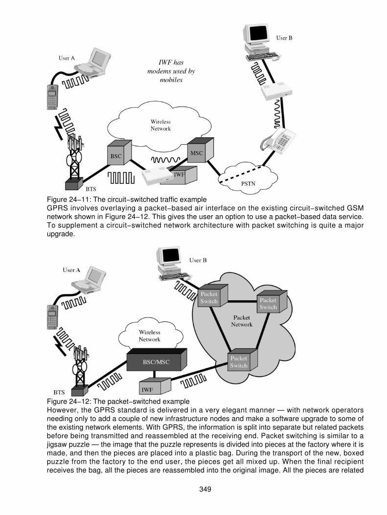
Figure 24−11: The circuit−switched traffic exampleGPRS involves overlaying a packet−based air interface on the existing circuit−switched GSMnetwork shown in Figure 24−12. This gives the user an option to use a packet−based data service.To supplement a circuit−switched network architecture with packet switching is quite a majorupgrade.
Figure 24−12: The packet−switched exampleHowever, the GPRS standard is delivered in a very elegant manner — with network operatorsneeding only to add a couple of new infrastructure nodes and make a software upgrade to some ofthe existing network elements. With GPRS, the information is split into separate but related packetsbefore being transmitted and reassembled at the receiving end. Packet switching is similar to ajigsaw puzzle — the image that the puzzle represents is divided into pieces at the factory where it ismade, and then the pieces are placed into a plastic bag. During the transport of the new, boxedpuzzle from the factory to the end user, the pieces get all mixed up. When the final recipientreceives the bag, all the pieces are reassembled into the original image. All the pieces are related
349

and fit together, but the way they are transported and reassembled varies by system, as seen inFigure 24−13. The Internet is another example of this type of a packet data network.
Figure 24−13: The pieces of GPRS and GSM fit together.GPRS Radio Technologies
Packet switching means that the GPRS radio resources are used only when users are actuallysending or receiving data. Rather than dedicating a radio channel to one mobile user for a fixedperiod of time, the available radio resources can be concurrently shared by several users. Thisefficient use of the scarce radio resources means that a larger number of GPRS users can sharethe same bandwidth and be served from a single cell. The actual number of users supporteddepends on the application being used and how much data each user has to send or receive.Because the spectrum efficiency is improved in GPRS, it is not as necessary to build idle capacitythat is only used during peak transmit hours. GPRS, therefore, lets the operator maximize systemusage and efficiency in a dynamic and flexible way.
In fact, all eight time slots of a TDMA frame can be made available to each user. However, as thenumber of simultaneous users increases, collisions will occur between the randomly arriving datapackets. This will cause queuing delays on the downlink. Therefore, the effective throughputperceived by each user decreases but more gracefully. The idea of concatenation or aggregation ofthe time slots to be available to one user makes this far more palatable for the end user tounderstand how he or she can bundle services together and run the data faster.
Cells and Routing Areas
The geographic coverage area of a GPRS network is divided into smaller areas known as cells androuting areas, as shown in Figure 24−14. A cell is the area that is served by a set of radio basestations (BSs). When a GPRS MS wants to send data or prepare to receive data, it searches for thestrongest radio signal that it can find. Once the mobile scans for the strongest signal and locates thestrongest BS, it then notifies the network of the cell it is receiving the strongest and selects it. At thispoint, the mobile listens to the BS for news of incoming data packets.
350

Figure 24−14: Cells and routing areasPeriodically, the MS uses its idle time to listen to transmissions from neighboring BSs and evaluatesthe signal quality of their transmissions. If the mobile determines that a different BS signal isreceived stronger (better) than the current base, then the mobile may begin to listen to the new BSinstead. This means that the mobile will listen to a different signal. The process of moving from oneBS to another is called cell reselection. In some cases, the MS informs the network that it haschanged cells by performing a location update procedure.
When data arrives for an idle MS, the network broadcasts a notice that it wants to establishcommunications with that mobile. This is called paging and is very similar to the paging process inwireless voice networks. A group of neighboring cells can be grouped together to form a routingarea. Network engineers use routing areas to strike a balance between location−updating traffic andpaging traffic. MSs that have been actively sending or receiving data are tracked at the cell level.(The network keeps track of the cell that they are currently using.) MSs that have been inactive(idle) are tracked at the routing area level (the network keeps track of the routing area).
Attaching to the Serving GPRS Support Node
When a GPRS MS wants to use the wireless packet data network services, it must first attach to aServing GPRS Support Node (SGSN), as shown in Figure 24−15. When the SGSN receives arequest from a MS, it makes sure that it wants to honor the request for service. Several factors mustfirst be considered:
Is the mobile a subscriber to GPRS? The act of verifying the MS's subscription information iscalled authorization.
•
Is the mobile who it says it is? The process of verifying the identity of the MS is calledauthentication.
•
What level of quality of service (QoS) is the station requesting? Has the mobile subscribedto the level of QoS being requested (is the owner willing to pay for it), and can the networkprovide this level of service while still providing the levels of service already promised to theother attached users?
•
351

Figure 24−15: Attaching to the SGSNOnce the SGSN decides to accept an attachment, it keeps track of the MS as the mobile movesaround in the coverage area. The SGSN needs to know where the mobile is in case data packetsarrive and need to be routed to the mobile. Attaching to the SGSN is similar to creating a logicalconnection (or pipe) between the mobile and the SGSN. The logical connection is maintained as themobile moves within the coverage area controlled by the SGSN. The attachment to an SGSN is notsufficient to enable the mobile to begin transferring packet data. To do that, the mobile needs toactivate (and possibly acquire) a PDP address (such as an IP address).
PDP Contexts
The PDP addresses are network layer addresses (Open Standards Interconnect [OSI] model Layer3). GPRS systems support both X.25 and IP network layer protocols. Therefore, PDP addressescan be X.25, IP, or both. Each PDP address is anchored at a Gateway GPRS Support Node(GGSN), as shown in Figure 24−16. All packet data traffic sent from the public packet data networkfor the PDP address goes through the gateway (GGSN). The public packet data network is onlyconcerned that the address belongs to a specific GGSN. The GGSN hides the mobility of the stationfrom the rest of the packet data network and from computers connected to the public packet datanetwork.
352

Figure 24−16: Obtaining a PDP context from the GGSNStatically assigned PDP addresses are usually anchored at a GGSN in the subscriber's homenetwork. Conversely, dynamically assigned PDP addresses can be anchored either in thesubscriber's home network or the network that the user is visiting. When a MS is already attached toa SGSN and wants to begin transferring data, it must activate a PDP address. Activating a PDPaddress establishes an association between the mobile's current SGSN and the GGSN that anchorsthe PDP address. The record kept by the SGSN and the GGSN regarding this association is calledthe PDP context. It is important to understand the difference between a MS attaching to a SGSNand a MS activating a PDP address. A single MS attaches to only one SGSN; however, it may havemultiple PDP addresses that are all active at the same time. Each of the addresses may beanchored to a different GGSN. If packets arrive from the public packet data network at a GGSN fora specific PDP address and the GGSN does not have an active PDP context corresponding to thataddress, it may simply discard the packets. Conversely, the GGSN may attempt to activate a PDPcontext with a MS if the address is statically assigned to a particular mobile.
Data Transfer
Once the MS has attached to a SGSN and activated a PDP address, it is now ready to begincommunicating with other devices. For example, a GPRS mobile is communicating with a computersystem connected to an X.25 or IP network. The other computer may be unaware that the MS is, infact, mobile. It may only know the MS's PDP address. The packets, as shown in Figure 24−17, needto be routed as follows:
353

Figure 24−17: The data transferAssume that the MS has attached to an SGSN and activated its PDP address. Packets sent fromthe other computer to the MS first travel across the public packet data network to reach the GGSNthat anchors the PDP address. From here, the GGSN must forward the packets to the SGSN towhich the MS is currently attached. Obviously, packets flowing in the reverse direction must be firstrouted through the SGSN and GGSN before being passed to the public packet data network.Communication between the GPRS Serving Nodes (GSNs) makes use of a technique known astunneling. Tunneling is the process of wrapping the network layer packets into another header sothat they can be routed through the GPRS PLMN IP backbone network. Inside the network, packetsare routed based on the new header alone, and the original packet is carried as the payload. Oncethey reach the far side of the GPRS network, they are unwrapped and continue along their waythrough the external network.
From this point onward, they are routed based on their original (internal) header. Using tunnelingwithin GPRS solves the mobility problem for the packet networks and helps to eliminate thecomplex task of protocol interworking. Mobile IP also makes use of tunneling to route packets tomobile nodes. In mobile IP, packets are only tunneled from the fixed network to the MS. Packetsflowing from the mobile to fixed nodes use normal routing. GPRS, by contrast, uses tunneling inboth directions.
GSM and NA−TDMA Evolution
Both GSM and NA−TDMA are evolving from 2G to 3G, and GPRS plays an important role in thisevolution. Some of the key points to note are as follows:
As evident, attempts are made to seek synergy between the two TDMA base systems now(as opposed to what happened 10 years ago).
•
GSM−GPRS standards and concepts are being adopted in North American TDMA asGPRS−136. The radio interface is being adapted to 30 kHz channels and an IS−136 DCCHchannel structure. In fact, many of the North American carriers (AT&T Wireless and VoiceStream, among others) are planning to offer GPRS on GSM as an evolution from theNA−TDMA architecture).
•
EDGE has adopted the eight−PSK−modulation scheme that is used for 136+.• 136HS and EDGE are being developed with synergy in mind. UWC−136 has embraced theGPRS/EDGE architecture for 200 kHz−wide 136HS Outdoors.
•
354

The North American and European proposals differ for the 2.0 Mbps systems. UWC−136continues to use a purely TDMA scheme, whereas CDMA−based UTRA is the RadioTransmission Technology (RTT) of choice for ETSI.
•
Applications for GPRS
Many applications fit into the mode of GPRS and IPs. These applications are merely a means to anend. In other scenarios, the features and applications can be met with other technologies. The issueat hand is that the use of GPRS facilitates these applications and drives the acceptance ratio. It iseasy to say that we can do anything with GPRS, but it is more practical to say at a minimum that wecan do the following:
Chat
Chat can be distinguished from general information services because the source of the informationis a person with the chat protocol, whereas it tends to be from an Internet site for informationservices. The information intensity, the amount of information transferred per message, tends to belower with chat, where people are more likely to state opinions than factual data. In the same wayas Internet chat groups have proven to be a very popular application of the Internet, groups oflike−minded people, so−called communities of interest, have begun to use nonvoice mobile servicesas a means to chat and discuss.
Because of its synergy with the Internet, GPRS would enable mobile users to participate fully inexisting Internet chat groups rather than needing to set up their own groups that are dedicated tomobile users. Because the number of participants is an important factor determining the value ofparticipation in the news group, the use of GPRS here would be advantageous.
GPRS will not, however, support point−to−multipoint services in its first phase, hindering thedistribution of a single message to a group of people. As such, given the installed base ofSMS−capable devices, we would expect SMS to remain the primary bearer for chat applications inthe foreseeable future, although experimentation with using GPRS is likely to commence soonerrather than later.
Textual and Visual Information
A wide range of content can be delivered to mobile phone users, ranging from share prices, sportsscores, weather, flight information, news headlines, prayer reminders, lottery results, jokes,horoscopes, traffic, location−sensitive services, and so on. This information does not necessarilyneed to be textual — it may be maps or graphs or other types of visual information.
The length of a short message of 160 characters suffices for delivering information when it isquantitative, such as a share price or a sports score or temperature. When the information is of aqualitative nature, however, such as a horoscope or news story, 160 characters is too short otherthan to tantalize or annoy the information recipient because they receive the headline or forecastbut little else of substance. As such, GPRS will likely be used for qualitative information serviceswhen end users have GPRS−capable devices, but SMS will continue to be used for delivering mostquantitative information services. Interestingly, chat applications are a form of qualitative informationthat may be delivered using SMS, in order to limit people to brevity and reduce the incidence ofspurious and irrelevant posts to the mailing list that are a common occurrence on Internet chatgroups.
355

Still Images
Still images such as photographs, pictures, postcards, greeting cards, presentations, and static webpages can be sent and received over the mobile network as they are across fixed telephonenetworks. It will be possible with GPRS to post images from a digital camera connected to a GPRSradio device directly to an Internet site, enabling near real−time desktop publishing.
Moving Images
Over time, the nature and form of mobile communication is getting less textual and more visual. Thewireless industry is moving from text messages to icons, picture messages to photographs,blueprints to video messages, movie previews being downloaded, and on to full−blown moviewatching via data streaming on a mobile device.
Sending moving images in a mobile environment has several vertical market applications, includingmonitoring parking lots or building sites for intruders or thieves and sending images of patients froman ambulance to a hospital. Videoconferencing applications, in which teams of distributedsalespeople can have a regular sales meeting without having to go to a particular physical location,are another application for moving images.
Web Browsing
Using circuit−switched data for web browsing has never been an enduring application for mobileusers. Because of the slow speed of circuit−switched data, it takes a long time for data to arrivefrom the Internet server to the browser. Alternatively, users switch off the images, just access thetext on the Web, and end up with text layouts on screens that are difficult to read. As such, mobileInternet browsing is better suited to GPRS.
Document Sharing/Collaborative Working
Mobile data facilitates document sharing and remote collaborative working. This lets different peoplein different places work on the same document at the same time. Multimedia applications combiningvoice, text, pictures, and images can even be envisaged. These kinds of applications could beuseful in any problem−solving exercise, such as fire fighting, combat (to plan the route of attack),medical treatment, advertising copy setting, architecture, journalism, and so on. This collaborativeworking environment can be useful anytime a user can benefit from having the ability to commenton a visual depiction of a situation or matter. By providing sufficient bandwidth, GPRS facilitatesmultimedia applications such as document sharing.
Audio
Despite many improvements in the quality of voice calls on mobile networks, such as Enhanced FullRate (EFR), they are still not broadcast quality. In some scenarios, journalists or undercover policeofficers with portable professional broadcast−quality microphones and amplifiers capture interviewswith people or radio reports that they have dictated and need to send this information back to theirradio or police station. Leaving a mobile phone on or dictating to a mobile phone would not givesufficient voice quality to enable that transmission to be broadcast or analyzed for the purposes ofbackground noise analysis or voice printing, where the speech autograph is taken and matchedagainst those in police storage. Because even short voice clips occupy large file sizes, GPRS orother high−speed mobile data services are needed.
356

Job Dispatch
Nonvoice mobile services can be used to assign and communicate new jobs from office−based staffto mobile field staff. Customers typically telephone a call center whose staff takes the call andcategorizes it. Those calls requiring a visit by a field sales or service representative can then beescalated to those mobile workers. Job dispatch applications can optionally be combined withvehicle−positioning applications, so that the nearest available suitable personnel can be deployed toserve a customer. GSM nonvoice services can be used not only to send the job out, but also as ameans for the service engineer or salesperson to keep the office informed of progress towardsmeeting the customer's requirement. The remote worker can send in a status message such as"Job 1234 complete, on my way to 1235."
The 160 characters of a short message are sufficient for communicating most delivery addresses,such as those needed for a sale or service, or some other job dispatch application, such as mobilepizza delivery and courier package delivery. However, the 160 characters require manipulation ofthe customer data, such as the use of abbreviations like St instead of Street. The 160 characters donot leave much space for giving the field representative any information about the problem that hasbeen reported or the customer profile. The field representative is able to arrive at the customer'spremises, but is not very well briefed beyond that. This is where GPRS will be beneficial to enablemore information to be sent and received more easily. With GPRS, a photograph of the customerand his or her premises could, for example, be sent to the field representative to assist in findingand identifying the customer. As such, we expect job dispatch applications will be an early adopterof GPRS−based communications.
Corporate E−mail
With up to half of employees typically away from their desks at any one time, it is important for themto keep in touch with the office by extending the use of corporate e−mail systems beyond anemployee's office PC. Corporate e−mail systems run on LANs and include Microsoft Mail, Outlook,Outlook Express, Microsoft Exchange, Lotus Notes, and Lotus cc:Mail. Because GPRS−capabledevices will be more widespread in corporations than among the general mobile phone usercommunity, more corporate e−mail applications are likely to use GPRS than Internet e−mailapplications whose target market is more general.
Internet E−mail
Internet e−mail services come in the form of a gateway service where the messages are not storedor mailbox services in which messages are stored. In the case of gateway services, the wirelesse−mail platform translates the message from SMTP, the Internet e−mail protocol, into SMS andsends it to the SMS Center. In the case of mailbox e−mail services, the e−mails are actually stored,and the user receives a notification on his or her mobile phone and can then retrieve the full e−mailby dialing in to collect it, forward it, and so on.
Upon receiving a new e−mail, most Internet e−mail users are not currently notified of this fact ontheir mobile phone. When they are out of the office, they have to dial in speculatively andperiodically to check their mailbox contents. However, by linking Internet e−mail with an alertmechanism, such as SMS or GPRS, users can be notified when a new e−mail is received.
Vehicle Positioning
This application integrates satellite−positioning systems that tell people where they are withnonvoice mobile services that enable people to tell others where they are. The Global Positioning
357

System (GPS) is a free−to−use global network of 24 satellites run by the U.S. Department ofDefense. Anyone with a GPS receiver can receive his or her satellite position and thereby find outwhere he or she is. Vehicle−positioning applications can be used to deliver several services,including remote vehicle diagnostics, ad hoc stolen vehicle tracking, and new rental car fleet tariffs.
The SMS is ideal for sending GPS position information such as longitude, latitude, bearing, andaltitude. GPS coordinates are typically about 60 characters in length. GPRS could alternatively beused.
Remote LAN Access
When mobile workers are away from their desks, they clearly need to connect to the LAN in theiroffice. Remote LAN applications encompass access to any applications that an employee woulduse when sitting at his or her desk, such as access to the intranet, his or her corporate e−mailservices, such as Microsoft Exchange or Lotus Notes, and to database applications running onOracle or Sybase. The mobile terminal, such as a hand−held or laptop computer, has the samesoftware programs as the desktop on it or cut−down client versions of the applications accessiblethrough the corporate LAN. This application area is therefore likely to be a conglomeration ofremote access to several different information types — e−mail, intranet, databases. This informationmay all be accessible through web browsing tools or require proprietary software applications on themobile device. The ideal bearer for remote LAN access depends on the amount of data beingtransmitted, but the speed and latency of GPRS make it ideal.
File Transfer
As this generic term suggests, file transfer applications encompass any form of downloadingsizeable data across the mobile network. This data could be a presentation document for a travelingsalesperson, an appliance manual for a service engineer, or a software application, such as AdobeAcrobat Reader, to read documents. The source of this information could be one of the Internetcommunication methods such as File Transfer Protocol (FTP), telnet, http, or Java, or from aproprietary database or legacy platform. Irrespective of the source and type of file being transferred,this kind of application tends to be bandwidth−intensive. Therefore, it requires a high−speed mobiledata service, such as GPRS, EDGE, or UMTS, to run satisfactorily across a mobile network.
Home Automation
Home automation applications combine remote security with remote control. Basically, you canmonitor your home from anywhere — on the road, on vacation, or at the office. If your burglar alarmgoes off, not only are you alerted, but also you can go live and see live footage of the perpetrators.You can program your video or switch on your oven so that the preheating is complete by the timeyou arrive home (traffic jams permitting). Your GPRS capable mobile phone really becomes theremote control device for your television, video, and stereo. Because the IP will soon beeverywhere, these devices can be addressed and fed instructions. A key enabler for homeautomation applications will be Bluetooth, which enables disparate devices to interwork.
These features and the driving motivators will propel the operators into the implementation ofGPRS. Moreover, the applications will offer many new opportunities to users that were previouslyunavailable. It is no wonder that the hype of GPRS is strong now. The next approach we will look towill be the architecture of the GPRS infrastructure. This will help the reader to understand theoverall architectural model used for GPRS.
358
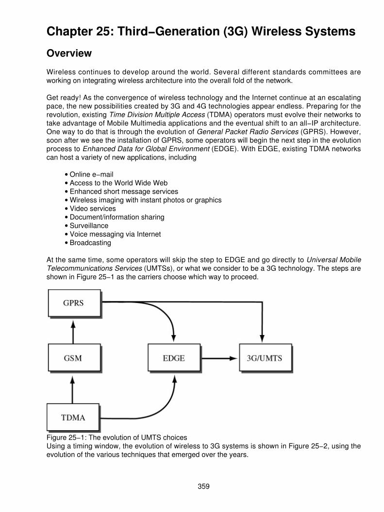
Chapter 25: Third−Generation (3G) Wireless Systems
Overview
Wireless continues to develop around the world. Several different standards committees areworking on integrating wireless architecture into the overall fold of the network.
Get ready! As the convergence of wireless technology and the Internet continue at an escalatingpace, the new possibilities created by 3G and 4G technologies appear endless. Preparing for therevolution, existing Time Division Multiple Access (TDMA) operators must evolve their networks totake advantage of Mobile Multimedia applications and the eventual shift to an all−IP architecture.One way to do that is through the evolution of General Packet Radio Services (GPRS). However,soon after we see the installation of GPRS, some operators will begin the next step in the evolutionprocess to Enhanced Data for Global Environment (EDGE). With EDGE, existing TDMA networkscan host a variety of new applications, including
Online e−mail• Access to the World Wide Web• Enhanced short message services• Wireless imaging with instant photos or graphics• Video services• Document/information sharing• Surveillance• Voice messaging via Internet• Broadcasting•
At the same time, some operators will skip the step to EDGE and go directly to Universal MobileTelecommunications Services (UMTSs), or what we consider to be a 3G technology. The steps areshown in Figure 25−1 as the carriers choose which way to proceed.
Figure 25−1: The evolution of UMTS choicesUsing a timing window, the evolution of wireless to 3G systems is shown in Figure 25−2, using theevolution of the various techniques that emerged over the years.
359

Figure 25−2: Time line for 3G/UMTS
GPRS
Probably the most important aspects of GPRS are that it enables data transmission speeds up to170 Kbps, it is packet based, and it supports the leading data communications protocols (IP and X.25).
GPRS operates at much higher speeds than current networks, providing advantages from asoftware perspective. Wireless middleware currently is required to enable slow speed mobile clientsto work with fast networks for applications such as e−mail, databases, groupware, or Internetaccess. With GPRS, wireless middleware will probably be unnecessary, making it easier to deploywireless solutions.
Although current wireless applications are text oriented, GPRS' high throughput finally makesmultimedia content, including graphics, voice, and video, practical. Imagine participating in avideoconference while waiting for your flight at the airport, something that is completely out of thequestion with today's data networks.
Why is packet data technology important? Because packet networks provide a seamless andimmediate connection to the Internet or corporate intranet, enabling access to existing Internetapplications, such as e−mail and web browsing, without dialing into an ISP. The advantage of apacket−based approach is that GPRS uses the medium, in this case the radio link, only as long asdata is being sent or received. Multiple users can share the same radio channel very efficiently. Incontrast, with current circuit−switched connections, users have dedicated connections during theirentire call, even if they are not sending data. Many applications have idle periods during a session.With packet data, users will only pay for the amount of data they actually communicate and not theidle time. In fact, with GPRS, users could be virtually connected for hours at a time and only incurmodest connect charges.
Although packet−based communication works well with all types of communications, it is especiallywell suited for frequent transmission of small amounts of data. We refer to this as short and bursty,such as real−time e−mail and dispatch (vehicles, field service). Packet is equally well suited forlarge batch operations and other applications involving large file transfers. However, when using
360

large file transfers, the cost can become very expensive compared to circuit−switched datatransmissions. GPRS supports the Internet Protocol (IP) as well as the X.25 protocol. IP support isincreasingly more important as companies look to the Internet as a way for their remote workers toaccess corporate intranets. This is true when using a Virtual Private Network (VPN). In the case ofVPNs, GPRS works well because of its GPRS Tunneling Protocol (GTP) that can secure the mobiledata while in transit on the wireless networks, and IPSec transfers can be used when transiting thewireline networks. The GTP is shown in Figure 25−3.
Figure 25−3: GTP with VPNsThe IP protocol is ubiquitous and familiar, but what is X.25, and why is support for it important? X.25defines a set of communications protocols that, prior to the Internet, constituted the basis of theworld's largest packet data networks. These X.25 networks are still widely used, especially inEurope and the Far East. Wireless access to these networks will benefit many organizations. Anyexisting IP or X.25 application will now be able to operate over a Global System for MobileCommunications (GSM) cellular connection. Think of cellular networks with GPRS service aswireless extensions of the Internet and existing X.25 networks as similar to a Local Area Network(LAN) connection. As a LAN connection, once a GPRS mobile station (MS) registers with thenetwork, it is ready to send and receive packets. A user with a laptop computer could be working ona document without even thinking about being connected, and then automatically receive newe−mail — although this is not 100 percent available today, it is coming. The user may decide tocontinue working on the document, then half an hour later read the e−mail message and reply to it.Throughout this time, the user has had a network connection, yet never dialed in. Furthermore,some versions of GPRS terminals allow for simultaneous voice and data communication. The usercan receive incoming calls or make outgoing calls while in a data session.
Because there is minimal delay before sending data, GPRS is ideally suited for applications such as
Extended communications sessions• E−mail communications• Chat• Database queries• Dispatch• Stock updates•
In addition, GPRS will remove many of the obstacles from the use of multimedia, graphicalweb−based applications because of the higher throughput that is possible. Mobile users will easilyuse graphically intensive web−based applications (Map Quest) to obtain directions. The protocol
361
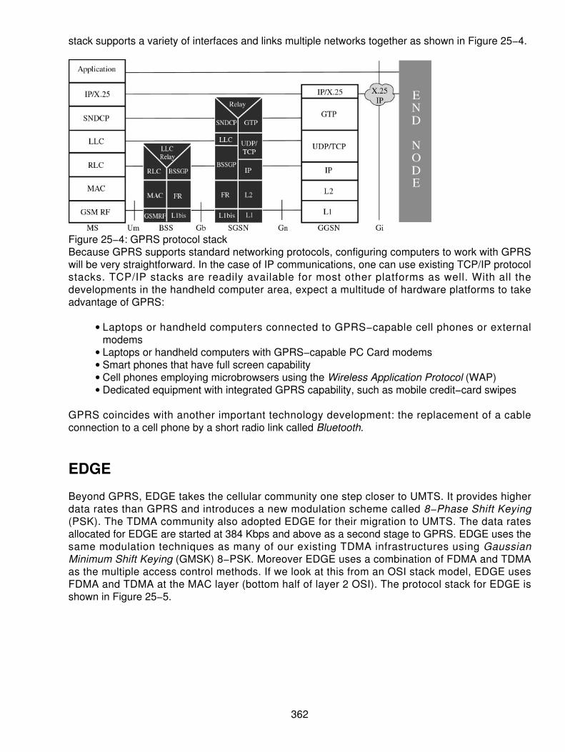
stack supports a variety of interfaces and links multiple networks together as shown in Figure 25−4.
Figure 25−4: GPRS protocol stackBecause GPRS supports standard networking protocols, configuring computers to work with GPRSwill be very straightforward. In the case of IP communications, one can use existing TCP/IP protocolstacks. TCP/IP stacks are readily available for most other platforms as well. With all thedevelopments in the handheld computer area, expect a multitude of hardware platforms to takeadvantage of GPRS:
Laptops or handheld computers connected to GPRS−capable cell phones or externalmodems
•
Laptops or handheld computers with GPRS−capable PC Card modems• Smart phones that have full screen capability• Cell phones employing microbrowsers using the Wireless Application Protocol (WAP)• Dedicated equipment with integrated GPRS capability, such as mobile credit−card swipes•
GPRS coincides with another important technology development: the replacement of a cableconnection to a cell phone by a short radio link called Bluetooth.
EDGE
Beyond GPRS, EDGE takes the cellular community one step closer to UMTS. It provides higherdata rates than GPRS and introduces a new modulation scheme called 8−Phase Shift Keying(PSK). The TDMA community also adopted EDGE for their migration to UMTS. The data ratesallocated for EDGE are started at 384 Kbps and above as a second stage to GPRS. EDGE uses thesame modulation techniques as many of our existing TDMA infrastructures using GaussianMinimum Shift Keying (GMSK) 8−PSK. Moreover EDGE uses a combination of FDMA and TDMAas the multiple access control methods. If we look at this from an OSI stack model, EDGE usesFDMA and TDMA at the MAC layer (bottom half of layer 2 OSI). The protocol stack for EDGE isshown in Figure 25−5.
362

Figure 25−5: EDGE protocol stackThe channel separations are 45 MHz, and the carrier spacing is a 200 kHz channel capacity, thesame as GSM and GPRS. The number of TDMA slots on each carrier is the same (eight) as theGSM and GPRS architecture. When a MS wants to transmit its data, it can request and use fromone to eight time slots per TDMA frame. Connectivity is handled via a packet− switched datanetwork such as IP and X.25. These can be public data networks or private data networks.
Although most carriers and service providers have plans to deploy enhanced mobile wirelessservices at higher speeds, the rollout of high−bandwidth wireless transport technology still facesmany challenges. On a positive note, widespread demand will be sufficient enough to supportcellular enhancements like high−speed data services and expanded voice capacity. Competitivepressures will also compel service providers to upgrade. The Radio Communications Sector of theInternational Telecommunications Union (ITU−R) has actually established five different standardsthat fall into the category of 3G/UMTS. Moreover, the telecommunication industry is growingincreasingly impatient to test the world markets for high−bandwidth wireless communicationservices. The ITU's IMT−2000 initiative may one day converge, but today many 3G proposals arestill under consideration, including
cdma2000 (an upgrade to cdmaOne)• UMTS• Wideband−Code Division Multiple Access (WCDMA)• Universal wireless communications (UWC−136)•
UWC−136 is based on TDMA as are Europe's GSM, Japan's personal digital cellular (PDC), andthe digital advanced mobile phone system (D−AMPS) used in the United States.
Existing 2G service providers have already applied for licenses to operate 3G networks around theglobe. Although it's unclear what 3G technologies will be adopted, the most 2.5G upgrades areGPRS and High−Speed, Circuit−Switched Data (HSCSD), an upgrade being considered by someGSM network operators. Beyond that, EDGE modulation extensions are planned, which will enableservice providers to offer even higher performance, enabling true 3G−like services.
The ITU currently embraces various proposed schemes to attaining the IMT−2000 3G vision. FromTDMA−based 2G providers of GSM and North American dual−mode cellular (NADC) services,
363
interim upgrades will come in the form of GPRS, HSCSD, and IS−136+, and will eventuallyconverge at EDGE for the next throughput upgrade (to 384 Kbps) before 3G.
What Is Special about EDGE?
EDGE is a new modulation scheme that is more bandwidth efficient than the GMSK modulationscheme used in the GSM standard. It provides a promising migration strategy for HSCSD andGPRS. The technology defines a new physical layer: 8−PSK modulation, instead of GMSK. 8−PSKenables each pulse to carry 3 bits of information versus the GMSK 1−bit−per−pulse rate. Therefore,EDGE has the potential to increase the data rate of existing GSM systems by a factor of three.
EDGE retains other existing GSM parameters, including a frame length, eight time slots per frame,and a 270.833 kHz symbol rate. The GSM 200 kHz channel spacing is also maintained in EDGE,enabling the use of existing spectrum bands. This fact is likely to encourage deployment of EDGEtechnology on a global scale.
UMTS
UMTS is a part of the ITU's IMT−2000 vision of a global family of 3G mobile communicationssystems. UMTS will play a key role in creating the future mass market for high−quality wirelessmultimedia communications that will approach 2 billion users worldwide by the year 2010.
UMTS is a modular concept that takes full advantage of the trend of converging existing and futureinformation networks, devices, and services, and the potential synergies that can be derived fromsuch convergence. UMTS will move mobile communications forward from where we are today intothe 3G services and will deliver speech, data, pictures, graphics, video communication, and otherwideband information direct to people on the move. UMTS is one of the major new 3G mobilecommunications systems being developed within the framework, which has been defined by the ITUand is known as IMT−2000.
Over the past decade, UMTS has gained the support of many major telecommunications operatorsand manufacturers because it represents a unique opportunity to create a mass market for highlypersonalized and user−friendly mobile access to tomorrow's untethered society.
UMTS will build on and extend the capability of today's mobile technologies (like digital cellular) byproviding increased capacity, data capability, and a much greater range of services. The launch ofUMTS services will see the evolution of a new, open communications universe, with players frommany sectors coming together to deliver new communications services, characterized by mobilityand advanced multimedia capabilities. The successful deployment of UMTS will require newtechnologies, new partnerships, and the addressing of many commercial and regulatory issues.
UMTS will enable tomorrow's wireless knowledge worker, delivering high−value broadbandinformation, commerce, and entertainment services to users via fixed, wireless, and satellitenetworks. UMTS will speed the convergence between voice, data, and multimedia to deliver newservices and create fresh revenue−generating opportunities. UMTS will deliver low−cost,high−capacity mobile communications, offering data rates up to 2 Mbps with global roaming andother advanced capabilities.
The next decade will see the emergence of 3G networks to fully realize mobile multimedia services.Enabling anytime, anyplace connectivity to the Internet is just one of the opportunities for 3Gnetworks. The major market opportunity builds on mobile networking to provide
364

Group messaging• Location−based services (GPS)• Personalized information• Infotainment•
Many new 3G services will not be Internet−based (they will be truly unique mobility services). Datawill increasingly dominate the traffic flows. Pent−up latent demand for mobile data services will jumpstart 3G networks. By 2005, more data than voice will flow over mobile networks. This is anamazing statistic considering that mobile cellular networks today are almost exclusively voice.
WCDMA
WCDMA is an ITU standard derived from CDMA and is officially known as IMT−2000 direct spread.WCDMA is a 3G mobile wireless technology offering much higher data speeds to mobile andportable wireless devices than commonly offered in today's market.
WCDMA can support mobile/portable voice, images, data, and video communications at up to 2Mbps (local area access) or 384 Kbps (wide area access). The input signals are digitized andtransmitted in coded, spread−spectrum mode over a broad range of frequencies. A 5 MHz widecarrier is used, compared with a 200 kHz wide carrier for narrowband CDMA.
WCDMA is the radio access technology selected by the European Telecommunications StandardsInstitute (ETSI) in January 1998 for wideband radio access to support 3G. WCDMA has sincebecome the most popular global 3G air interface mode and is being implemented across the GSMworld, but also in the TDMA world and in Japan by J−Phone and NTT DoCoMo. The competing airinterface mode to WCDMA is cdma2000, which is being implemented mainly in North America andin Japan by KDDI.
WCDMA can be added to the existing GSM core network. This will be particularly beneficial whenlarge portions of new spectrum are made available, for example, in the new−paired 2 GHz bands inEurope and Asia. It will also minimize the investment required for WCDMA rollout — it will, forexample, be possible for existing GSM sites and equipment to be reused to a large extent.
WCDMA Features
WCDMA offers very high capacity with 50 to 80 voice channels per 5 MHz carrier (compared with 8channels per carrier with 200 kHz for GSM). To achieve the very high data rates, WCDMA requiresa wide frequency band of between 5 MHz and 10 MHz (compared with a 200 kHz carrier for regularGSM).
With WCDMA, two frequency bands have been allocated — one for sending data from the terminaland one for receiving data on the terminal. This technique is called symmetric, that is, needing thesame amount of radio resources in the uplink and downlink.
WCDMA can be overlaid onto existing GSM, TDMA (IS−136), and CDMA (IS−95) networks.• WCDMA provides higher capacity and increased coverage: up to eight times more traffic percarrier compared to a narrowband CDMA carrier such as cdmaOne. This is achieved by upto 100 percent better usage of the frequency spectrum.
•
WCDMA supports Hierarchical Cell Structures (HCSs) by employing Mobile Assisted InterFrequency Handover (MAIFHO).
•
365

WCDMA enables the optional use of adaptive antenna arrays, a concept that enablesantenna pattern optimization, and hence extended range and reduced interference on aper−link basis.
•
WCDMA supports multiuser detection — a mechanism to reduce multiple accessinterference and enhance capacity.
•
WCDMA consists of a set of Radio Network Subsystems (RNSs), connected to the Core Networkthrough the lu interface. Each RNS is composed of one Radio Network Controller (RNC), controllinga group of logical elements, called Node B (or BTS), through the lub interface. Each Node B canserve one or several cells. Each RNS is responsible for the resources of its set of cells andperforms functions related to the overall system access, security and privacy, handover detection,decision and execution, and radio resource management and control, including connection set−upand release, as well as transfer of data packets.
WCDMA mobile terminal/phone users can be connected via the Uu (air) interface to one or moreNode B entities (this is called macro diversity). In the later case, those cells may be allocated todifferent RNSs. In such a case, one RNC is acting as the serving RNC and is supported by asecond RNC through the lur interface.
The protocols over the lu interface are divided into user plane protocols and control plane protocols.User plane protocols are required for the implementation of the radio access bearer service (that is,to carry the user data). The control plane protocols are required for controlling the connectionbetween the User Equipment (UE), the network, and the radio access bearers.
Mobile Internet — A Way of Life
The mobile Internet is about to enter our daily lives in a big way. It will change the way we keep intouch with our friends and family, the way we do business, the way we shop, the way we accessentertainment, and the way we conduct our personal finances.
The Internet is already a part of daily life for most of us, giving us access to a vast range ofinformation and online services from our desktop computers. As a way of conducting business, it isalso of growing importance to the global economy. Unlike today's fixed Internet, the mobile Internetwill give us access to these services and applications wherever we are, whenever it suits us, frompersonal mobile devices.
By 2004, there will be as many as 600 million users of mobile Internet services. This means thatmore people will use mobile Internet than fixed Internet. The market is already taking off. The chartshown in Figure 25−6 represents the 3G subscribers projected for the future.
366
Figure 25−6: Worldwide 3G subscribers in millionsTwenty billion SMS messages are sent worldwide every month. In Japan, there are more than 10million users of the iMode service — which is comparable with basic WAP service — and eachweek another 150,000 new iMode users are added. In a few years, many of us will wonder how wemanaged without the mobile Internet: It will become an invaluable part of our everyday lives. Givingus more opportunities to keep in touch with friends, family, and colleagues, empowering us to makefast, yet well−informed business decisions, giving us instant access to information and services andenabling us to purchase the things we need or desire — all in a handy, pocket−sized device. Wecan expect to see the following types of services from 3G products:
Customized infotainment• Multimedia messaging service• Mobile intranet/extranet Access• Mobile Internet access• Location−based services• Rich Voice•
Rich Voice
Rich Voice is a 3G service that is real time and two way. It provides advanced voice capabilities(such as Voice over IP [VoIP], voice−activated net access, and web−initiated voice calls), while stilloffering traditional mobile voice features (such as operator services, directory assistance, androaming). As the service matures, i t wi l l include mobi le videophone and mult imediacommunications.
At present, the mobile network value chain is centered on the network operator who captures morethan 90 percent of market revenues, dominated by income from voice−based services. It is widelyrecognized, however, that advancing technology, growth of Internet services, and new end−userdemands are challenging this traditional value chain.
The new, fast−changing value chain will have new players and entities, and many networkoperators are already adopting new business strategies to broaden their role and to defend theircompetitive position. The multimedia service provider will be one of the key players in themultimedia value chain. Revenues will increasingly be diverted to other market players than thetraditional.
The success of 3G will not just come from the mere combination of two existing successfulphenomena — mobility and the Internet. The real success of 3G will result from the creation of newservice capabilities that genuinely fulfill a market need. Meeting market demand is not just aquestion of technological capability and service functionality. Creating and meeting market demandrequires services and devices to be priced at acceptable levels. This requires economies of scale tobe present. The ability to benefit from economies of scale is one of the strongest market drivers for3G services. Universal Terrestrial Radio Access (UTRA) now includes both the Direct Sequenceand Time Code components of IMT−2000, and so it embeds both the Frequency Division Duplexing(FDD) access mode previously known as WCDMA as well as the Time Division Duplexing (TDD)modes previously known as TD−CDMA and TD−SCDMA. UTRA is now applicable to the majormarkets of Europe, China, South Korea, and Japan. UMTS promises significant economies of scale.
The need to protect existing investments in different 2G technologies has shifted the drive toward asingle global standard. When you add the significant event of the emergence of the Internet, theadditional capabilities of 3G become more focused on the provision of high data rates to delivermultimedia services. The emergence of the Internet as a mass−market content resource had
367

justified the need for such high data rate capabilities and has since shifted the emphasis topacket−switched, IP−based core networks. There is general acceptance within the industry that 3Gcore networks will eventually be all−IP based.
The solution was the introduction of the IMT−2000 family of systems concept for 3G. Oneconsequence of that solution is that a single global standard does not exist yet. However, the UMTSForum believes that progress of technology, operational deployments, and market requirements willcontinue toward convergence. Another consequence — important when considering marketperspectives — is that 3G now means different things in different parts of the world.
In Europe, 3G refers to the UMTS technology members of the IMT−2000 family, derived from GSMand deployed on new spectrum. There is a strong focus within the UMTS community oninternational roaming capabilities and the potential benefits of the economies of scale that resultfrom a common standard deployed across many nations. The same UMTS technology members willbe used in South Korea, China, Japan, and most of the Asian region. In the United States, 3G refersto derivatives of existing 2G technologies, deployed largely on occupied spectrum. 3G in the UnitedStates focus more on high data rates; international roaming capabilities are not a significantconcern. The United States has lagged behind other world regions in the deployment of 2G digitalcellular. Industry opinion is that it will continue to lag behind in the deployment of 3G. In Japan andSouth Korea, 3G means an opportunity to join the worldwide market.
In 2G technologies, GSM currently has 65 percent of the world market, shown in Figure 25−7.Japan has decided that its PDC 2G technology will not be evolved to 3G, but will be replaced by theUMTS/IMT−2000 technologies. The TDMA and GSM communities are working on harmonizationprocedures for the approach to 3G. The 15 percent of the world market currently using cdmaOnetechnology, mainly located in the United States and South Korea, has a transition path to theIMT−MC member of the IMT−2000 family, but is limited to existing spectrum.
Figure 25−7: GSM user population worldwideWith UMTS services, providers worldwide will be using multiband rather than multimode handsets— a much more attractive proposition for terminal manufacturers.
368

Applications of the Wireless Internet
Using the mobile (wireless) Internet as the model for the growth curves seen, the following aresome of the applications for moving to a wireless and a 3G environment:
Cutting the umbilical cord The first wave is making our familiar online services mobile —"cutting the cord" of the Internet. An example is using a laptop computer together with amobile phone to send and receive e−mail or surf the Net. Users can access Internet−basedservices at the airport, on a train, or in the park.
•
Pocket WWW The second wave, which has already begun, brings Internet services topocket mobile devices. Applications are specially adapted to work on mobile devices withsmall screens, for example, using WAP. Although this wave brings full, convenient mobility,it is still largely based around traditional Internet services, such as online banking, e−mail,and web access.
•
Real mobility in the Internet In the third wave, the full potential of the mobile Internet isrealized. Services, applications, and content are centered on the mobility, location, andsituation of the user — they become situation−centric.
•
This intelligence can be used to create highly valuable, personalized services. Mobile devices willbecome indispensable tools that enhance our daily lives. Services will be relevant, useful, andtimely. Figure 25−8 is a forecast of the growth and changes that will occur on the wireless Internetdevices over the next decade.
Figure 25−8: Growth figures of mobile multimedia devices on the Internet
Visions of Wireless
The convergence of high−speed wireless data communications, always−on mobile computingplatforms, and instant access to the Internet is driving the biggest shift in mobile computing sincethe advent of the computer itself. The day is coming when the mobile professional will be linkedwirelessly to the power of the Internet, no matter where on the globe he may find himself. He/shewill need instant access to critical corporate, personal and public data applications, such as e−mail,e−commerce, stock trading, weather, airline reservations, hotels, car rental agencies, and sportsinformation. The GSM/GPRS community becomes the gatekeeper to the needs of the true mobileprofessional.
There will be a consolidation in devices as manufacturers seek to meet customer needs whilecontrolling costs. Smart phones and Personal Digital Assistants (PDAs) will become talkative PDAs.3G Laptops and 3G Web Tablets, while keeping their separate identities, will both be handheld
369

Internet devices, hitting the high and low end of 3G users. Like all of the 3G devices, the 3G WebTablet will have a product lifecycle of its own through 2010. As innovative technology and customerdemand cause the accumulation of all new device capabilities, the 3G multimedia device or 3Gpersonal companion will become the sought after all−in−one mobile Internet tool for the middle ofthe decade. Others have predicted that by 2010, there will be a single wireless gadget that will meetall needs:
Smart phones/WAP phones These early devices provide content and web browsing.They use standard and new operating systems and protocols (like Pocket PC and WAP) andwill soon synchronize with other devices (like desktops and mobile phones). As WAPbecomes popular and takes advantage of the high data rates and always on capability thatGPRS will provide, these devices will naturally evolve into some of the first 3G devices at theeven higher 3G data rates. The Smart phone will evolve to a talkative PDA.
•
Talkative PDA Although there is room for improved coverage and quality, today you canpurchase a PDA that also has mobile voice communications (such as, radio modems forGSM, OmniSky). Besides their calendars, address books, and other organizing features,PDAs are thin and lightweight; many have color screens, and are quickly gaining computerstrength due to low power chip designs, screen miniaturization, and evolving operatingsystems. As they grow in computing capability while maintaining their hand−held form factor,they will continue to distinguish themselves from 3G laptops as less expensive, lesspowerful solutions. Examples are numerous with Palm, Casio, HP, and others leading thepack. The Kyocera phone and PDA combination are a new twist in the movement toward thePDA.
•
3G laptop (handheld Internet) Laptops today have modems and Personal ComputerMemory Card Internat ional Associat ion (PCMCIA) cards that enable wirelesscommunications. They continue to get smaller, lighter, and with more powerful computing.With the bandwidth offered with 3G, these powerful, portable computers will thrive with thecustom graphics, two−way video, and large file transfers for the future.
•
3G Web Tablet (handheld Internet) Appearing in 2000, Wireless Web Tablets, thesedevices offer portable Internet access by plugging into power and access at home andgaining limited mobility via a short wireless connection. As low−cost, lightweight, thin Internetappliances the size of magazines, these devices offer e−mail, robust Internet access, andweb browsing. Eventually, they will gain both full mobile access and synchronization withother devices via more powerful 3G spectrum.
•
3G multimedia device (personal companion) Today's slow connections based on lowbandwidth cause jerky video images. Compression techniques cannot overcome the needfor speed and capacity. 3G will answer this problem in the mobile world. There are manyvisions of the ultimate 3G devices, with some saying it will evolve from phones, others fromcomputers. Because there will be different 3G services addressing specific user needs, all ofthe previous devices will develop from both worlds. However, there will be a need for anall−powerful device that does quality VoIP, full Internet access, and two−way video.
•
In order to understand the role of next generation wireless services in the broader technologylandscape, it is important to understand the current state of the Internet industry and other enablingtechnologies that shape its development. The Internet is transitioning from an inexpensive mediumfor advertising, marketing, and customer support to a common platform for transactions andbusiness applications. At the same time, technological and commercial developments are meldingtogether information, communications, commerce, and entertainment into one large, consolidatedindustry. Part of the reason for this evolution is because more consumers are accessing the Internetusing multiple devices and over multiple communications networks. They are also changing theirbehavior and consumption patterns. In addition, tools and facilities are available that improve theconsumer Internet access experience.
370
Wireless access to the Internet is going to drive the overall development of the Internet for severalreasons:
Wireless enables service providers and Internet businesses to increase their mobile cultureand total service consumption.
•
The mobility and immediacy offered by wireless enables Internet content delivery andcommerce to be location independent.
•
The person−specific nature of wireless enables companies to develop customer profiles thatenable them to narrowcast and distribute better value−added information to customers.
•
Location−based facilities and services provide another tier of customer knowledge thatenables Internet businesses to deliver context−specific services that also improve customervalue.
•
In short, wireless is an opportunity for Internet businesses to learn more about their customers,understand their customers' consumption patterns, strengthen their customer relationships, andprovide more personalized services. This is a critical component of Internet business strategies andwhat wireless operators/service providers bring to the table in a full Internet solution.
The most important lifestyle users who draw on wireless access are as follows:
Business professionals This includes the high−value mobile users (such as busydecision makers). The services used will include intranet access, messaging, andscheduling systems.
•
Product managers These are users with specific occupational requirements for highvolumes of information while in a mobile mode. Requirements include remote and mobileaccess to corporate and external information.
•
Youth Often, early adopters of technology will be inclined to use instant messaging,games, and entertainment−oriented services.
•
Parents In many countries, both parents work and share the household responsibilities.• Senior citizens 3G will enable more reliable support electronically and reduce therequirement for labor−intensive support services such as medical monitor ing,location−based medical service, family, caretakers and caregivers, and social workers.
•
Positioning the Mobile Industry
In the light of the new business chain, the issue is to consider whether to simply provide a wirelessIP pipe to a service offering hosted elsewhere on the Internet, or to go for an interoperableend−to−end solution. The wireless IP pipe business using tunneling protocols will become acommodity operation, where cost, coverage, and data rate are the only competitive dimensions. Bycarefully developing and preselecting useful Internet−based mobility services with competitivetariffs, the user will be encouraged to buy into UMTS services.
At issue is the location of the subscriber profile records, which reflect the personalized servicechoices of the end user: message filtering options, choice of mobile information, and type of mobiledevice — correlated with name, billing address, mobile phone number, and e−mail address. Thisstore of data will permit additional returns through selectively targeted mobile e−commerce andadvertising. UMTS operators have three separate or combined possibilities:
They charge the subscriber on a metered call basis. This makes it possible to get a revenuestream via a small additional charge for mobile Internet services. It produces a return oninvestment well before mobile commerce and advertising become feasible. Added to the
•
371

traffic revenue, the operator can capture or selectively share this revenue with value chainpartners on its own terms.The operator provides IP−packet transport (such as GPRS based), which is necessary tointegrate Internet services with Intelligent Networking, voice, data, and fax services. Volumediscounts will become a possibility beyond billing for just time.
•
The operator will know the subscriber's location using emerging cellular positioningtechnologies. Positioning adds end−user value through information customization, such asdetails of the nearest restaurant or automatic conversion of e−mail to speech for a driver of amoving car. In the future, location information will enormously increase the revenues.
•
Wireless Internet will become one of the media channels for content providers, and wirelessnetwork operators will join in on the service values. The WAP−portal offerings of GSM operatorsand iMode offerings of NTT DoCoMo are examples of a new strategy. The mobile portals areunique because they are a solution in which operators and service providers can manage contentand integrate with communication and transactions.
The arrival of WAP and iMode are generally seen as the first steps in the convergence betweenmobile telecommunications, the Internet, and content industries.
Key Technologies
Some of the critical technologies essential for the successful introduction of UMTS include thefollowing.
UTRA
The ETSI decision in January 1998 on the radio access technique for UMTS combined twotechnologies — WCDMA for paired spectrum bands and TD−CDMA for unpaired bands — into onecommon standard. The network architecture is shown in Figure 25−9. This powerful approachpromises an optimum solution for all the different operating environments and service needs. Thetransmission rate capability of UTRA will provide at least 144 Kbps for full mobility applications in allenvironments, 384 Kbps for limited mobility applications in the macro and micro cellularenvironments, and 2.048 Mbps for low mobility applications particularly in the micro− and picocellenvironments. The 2.048 Mbps rate may also be available for short range or packet applications inthe macro−cellular environment, depending on deployment strategies, radio network planning, andspectrum availability.
372

Figure 25−9: The architecture for 3GMultimode Second Generation/UMTS Terminals
UMTS terminals will exist in a world of multiple standards, and this will enable operators to offermaximum capacity and coverage to their user base by combining UTRA with second generation(2G) and other 3G standards. Therefore, operators will need terminals that are able to interworkwith legacy infrastructures, such as GSM/DCS1800 and DECT, as well as other 2G worldwidestandards, such as those based on the U.S. AMPS standard, because they will initially have morecomplete coverage than UMTS. Many UMTS terminals will therefore be multiband and multimodeso that they can work with different standards, old and new. Achieving such terminals at a cost thatis comparable with contemporary single mode 2G terminals will become possible because oftechnological advances in semiconductor integration, radio architectures, and software radio.
Satellite Systems
At initial service launch in 2002, the satellite component of UMTS will be able to provide a globalcoverage capability to a range of user terminals. These satellite systems are planned using theS−band Mobile Satellite Service (MSS) frequency allocations identified for satellite IMT−2000 andwill provide services compatible with the terrestrial UMTS systems.
USIM Cards/Smart Cards
A major step forward, which GSM introduced, was the Subscriber Identity Module (SIM) or smartcard. It introduced the possibility of high security and a degree of user customization to the mobileterminal. SIM requirements, security algorithms, card, and silicon IC technology will continue toevolve up to and during the period of UMTS deployment.
The smart card industry will offer cards with greater memory capacity, faster CPU performance,contactless operation, and greater capability for encryption. These advances will enable the UMTSSubscriber Identity Module (USIM) to add to the UMTS service package by providing portable high−security data storage and transmission for users. As well as configuration software for the operationof any UMTS terminal, images, signatures, personal files, and fingerprints or other biometric datacould be stored, and then down− or up−loaded to or from the card.
Contactless cards will permit much easier use than with today's cards, for example, enabling thesmart card to be used for financial transactions and management, such as electronic commerce or
373

electronic ticketing, without having to be removed from a wallet or phone. It is expected that all fixedand mobile networks will adopt the same or compatible lower layer standards for their subscriberidentity cards to enable USIM roaming on all networks and universal user access to all services.Electronic commerce and banking using smart cards will soon become widespread, and users willexpect and be able to use the same cards on any terminal over any network.
New memory technologies can be expected to increase card memory sizes, making largerprograms and more data storage feasible. Several applications and service providers could beaccommodated on one card. In theory, the user could decide which applications/services he wantson the card, much as he does for his computer's hard disk. This is the challenge and opportunity forservice industries that evolving smart card technology presents.
IP Compatibility
UMTS is a modular concept that makes use of the trend towards the convergence of fixed andmobile networks and services, enabling a huge number of applications to be developed. As anexample, a laptop with an integrated UMTS communications module becomes a general−purposecommunications and computing device for broadband Internet access, voice, video telephony, andconferencing for either mobile or residential use.
The number of IP networks and applications is growing fast. Most obvious is the Internet, but privateIP networks (intranets) show similar or even higher rates of growth and usage. UMTS will becomethe most flexible broadband access technology because it allows for mobile, office, and residentialuse in a wide range of public and nonpublic networks. UMTS can support both IP and non−IP trafficin a variety of modes, including packet, circuit switched, and virtual circuit.
UMTS will be able to benefit from parallel work by the Internet Engineering Task Force (IETF) whilethey further extend their basic set of IP standards for mobile communication. New developmentslike IP version 6 enables parameters, such as quality of service (QoS), bit rate, and bit error rates(BERs), vital for mobile operation, to be set by the operator or service provider. Developments onnew domain name structures are also taking place. These new structures will increase the usabilityand flexibility of the system, providing unique addressing for each user, independent of terminal,application, or location.
UMTS has the support of many major telecommunications operators and manufacturers because itrepresents a unique opportunity to create a mass market for highly personalized and user−friendlymobile access to the information society. UMTS seeks to build on and extend the capability oftoday's mobile, cordless, and satellite technologies by providing increased capacity, data capability,and a far greater range of services using an innovative radio access scheme and an enhanced,evolving core network.
Spectrum for UMTS
WRC 2000 identified the frequency bands 1885 to 2025 MHz and 2110 to 2200 MHz for futureIMT−2000 systems, with the bands 1980 to 2010 MHz and 2170 to 2200 MHz intended for thesatellite part of these future systems. CDMA is characterized by high capacity and small cell radius,employing spread−spectrum technology, and a special coding scheme.
The capabilities of cdmaOne evolution have already been defined in standards. IS−95B providesISDN rates up to 64 Kbps. The next phase of cdmaOne is a standard knows as 1XRTT and enables144 Kbps packet data in a mobile environment. Other features available include a two−fold increasein both standby and talk time on the handset. All of these capabilities will be available in an existing
374

cdmaOne 1.25 MHz channel. The next phase of cdmaOne evolution will incorporate the capabilitiesof 1XRTT, support all channel sizes (5 MHz, 10 MHz, and so on), provide circuit and packet datarates up to 2 Mbps, incorporate advanced multimedia capabilities, and include a framework foradvanced 3G voice services and vocoders, including voice over packet and circuit data. Many of thesteps have already been taken.
There are now a number of flavors of CDMA as shown in Table 25−1.
Table 25−1: Variations of CDMA
CDMA Type DescriptionComposite CDMA/TDMA Wireless technology that uses both CDMA and TDMA. For large−cell
licensed band and small−cell unlicensed band applications. Uses CDMAbetween cells and TDMA within cells.
CDMA In addition to the original Qualcomm−invented N−CDMA (originally justCDMA) also known in the United States as IS−95. Latest variations areB−CDMA, WCDMA, and composite CDMA/TDMA. CDMA ischaracterized by high capacity and small cell radius, employingspread−spectrum technology and a special coding scheme. B−CDMA isthe basis for 3G UMTS.
CdmaOne First−Generation (1G) Narrowband CDMA (IS−95).cdma2000 The new 2G CDMA Memorandum of Understanding (MoU) specification
for inclusion in UMTS.
The cdma2000 Family of Standards
The cdma2000 family of standards includes core air interface, minimum performance, and servicestandards. The cdma2000 air interface standards specify a spread spectrum radio interface thatuses CDMA technology to meet the requirements for 3G wireless communication systems. Inaddition, the family includes a standard that specifies analog operation to support dual−mode MSsand base stations (BSs).
Purpose
The technical requirements contained in cdma2000 form a compatibility standard for CDMAsystems. They ensure that a MS can obtain service in a system manufactured in accordance withthe cdma2000 standards. The requirements do not address the quality or reliability of that service,nor do they cover equipment performance or measurement procedures. Compatibility, as used inconnection with cdma2000, is understood to mean any cdma2000 MS is able to place and receivecalls in cdma2000 or IS−95 systems. Conversely, any cdma2000 system is able to place andreceive calls for cdma2000 and IS−95 MSs. In a subscriber's home system, all call placements areautomatic. Similarly, call placement is automatic when a MS is roaming. To ensure compatibility,radio system parameters and call processing procedures are specified. The sequence of callprocessing steps that the MSs and BSs execute to establish calls is specified, along with the digitalcontrol messages and, for dual−mode systems, the analog signals that are exchanged between thetwo stations.
The BS is subject to different compatibility requirements than the MS. Radiated power levels, bothdesired and undesired, are fully specified for MSs in order to control the RF interference that oneMS can cause another. BSs are fixed in location, and their interference is controlled by proper
375

layout and operation of the system in which the station operates. Detailed call processingprocedures are specified for MSs to ensure a uniform response to all BSs. BS procedures that donot affect the MSs' operation are left to the designers of the overall land system. This approach towriting the compatibility specification is intended to provide the land system designer with sufficientflexibility to respond to local service needs and to account for local topography and propagationconditions. cdma2000 includes provisions for future service additions and expansion of systemcapabilities. The release of the cdma2000 family of standards supports Spreading Rate 1 andSpreading Rate 3 operation.
376

Chapter 26: Satellite Communications NetworkingSatellite communications have developed through the years. The first use of satellite technologywas in the military for voice communications in the early 1960s. Despite the advancements in thetechnology, commercial providers are prohibited from constructing and launching satellites at will.Despite these limitations, commercial satellites provide valuable information on meteorology,agriculture, forestry, geology, environmental science, and other areas.
Uses of Satellites in Agriculture
Many countries use satellite technology to improve agriculture. Satellites are used to determineproductive from nonproductive yields. In many cases, they use other services such as infraredvision. Satellite−based navigation, such as the Global Positioning System (GPS), a militaryinvention, also assists in the process of reviewing agricultural production. Farmers can keep track ofwhat they plant, fertilize, and spray. A farmer can now account for different kinds of soil, varying inacidity, organic content, and nitrogen levels. In addition, differences in drainage and treatment canbe determined. All this improves yield and prevents the waste of valuable chemicals. This practice iswell established in America. More than a dozen companies sell equipment used in agriculture.
Uses of Satellites in Oceanography
Satellites have found a niche in oceanography. In regional and local seas, satellites provide remotesensing, which gives a unique approach to monitoring the environment for the management of livingresources, fishing, navigation, and coastal erosion. All maritime nations now have access tovaluable information needed to manage the ocean boundaries that comprise their economic zone.
Countries use satellites in many adaptations. From military applications, agriculture, andoceanography, satellites have improved the overall performance of individual countries. Each of theapplications listed, however, uses significant amounts of data to perform and monitor thesefunctions.
Commercial Providers
NASA has been working with the U.S. commercial satellite industry to achieve seamlessinteroperability of satellite and terrestrial telecommunications networks. The high latency and noisecharacteristics of satellite links cause inefficiencies when using Transmission Control Protocol(TCP) in an environment for which it was not designed. These problems are not limited to airbornecommunications and may appear in other high latency and noisy networks. Considerations, such ashigher data rates and more users on data networks, can affect future terrestrial networks similar tothose posed by satellites today.
In the future, telecommunications networks with space stations, lunar stations, and planetarystations with their inherent latency, noise, and bandwidth characteristics need to be addressed. Fornow, the emphasis is on earth−orbiting communications satellites.
377
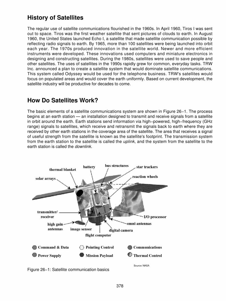
History of Satellites
The regular use of satellite communications flourished in the 1960s. In April 1960, Tiros I was sentout to space. Tiros was the first weather satellite that sent pictures of clouds to earth. In August1960, the United States launched Echo I, a satellite that made satellite communication possible byreflecting radio signals to earth. By 1965, more than 100 satellites were being launched into orbiteach year. The 1970s produced innovation in the satellite world. Newer and more efficientinstruments were developed. These innovations used computers and miniature electronics indesigning and constructing satellites. During the 1980s, satellites were used to save people andother satellites. The uses of satellites in the 1990s rapidly grew for common, everyday tasks. TRWInc. announced a plan to create a satellite system that would dominate satellite communications.This system called Odyssey would be used for the telephone business. TRW's satellites wouldfocus on populated areas and would cover the earth uniformly. Based on current development, thesatellite industry will be productive for decades to come.
How Do Satellites Work?
The basic elements of a satellite communications system are shown in Figure 26−1. The processbegins at an earth station — an installation designed to transmit and receive signals from a satellitein orbit around the earth. Earth stations send information via high−powered, high−frequency (GHzrange) signals to satellites, which receive and retransmit the signals back to earth where they arereceived by other earth stations in the coverage area of the satellite. The area that receives a signalof useful strength from the satellite is known as the satellite's footprint. The transmission systemfrom the earth station to the satellite is called the uplink, and the system from the satellite to theearth station is called the downlink.
Figure 26−1: Satellite communication basics
378

Satellite Frequency Bands
The three most commonly used satellite frequency bands are the C−band, Ku−band, and Ka−band.C−band and Ku−band are the two most common frequency spectrums used by today's satellites. Tohelp understand the relationship between antenna diameter and transmission frequency, it isimportant to note that there is an inverse relationship between frequency and wavelength — whenfrequency increases, wavelength decreases. As wavelength increases, larger antennas are requiredto receive the signal.
C−band satellite transmissions occupy the 4− to 8−GHz frequency ranges. These relatively lowfrequencies translate to larger wavelengths than Ku−band or Ka−band. These larger wavelengths ofthe C−band mean that a larger satellite antenna is required to gather the minimum signal strength.The minimum size of an average C−band antenna (shown in Figure 26−2) is approximately 2 to 3meters in diameter.
379

Figure 26−2: C−band satellite antennaKu−band satellite transmissions occupy the 11− to 17−GHz frequency ranges. These relatively highfrequency transmissions correspond to shorter wavelengths, and therefore a smaller antenna can
380
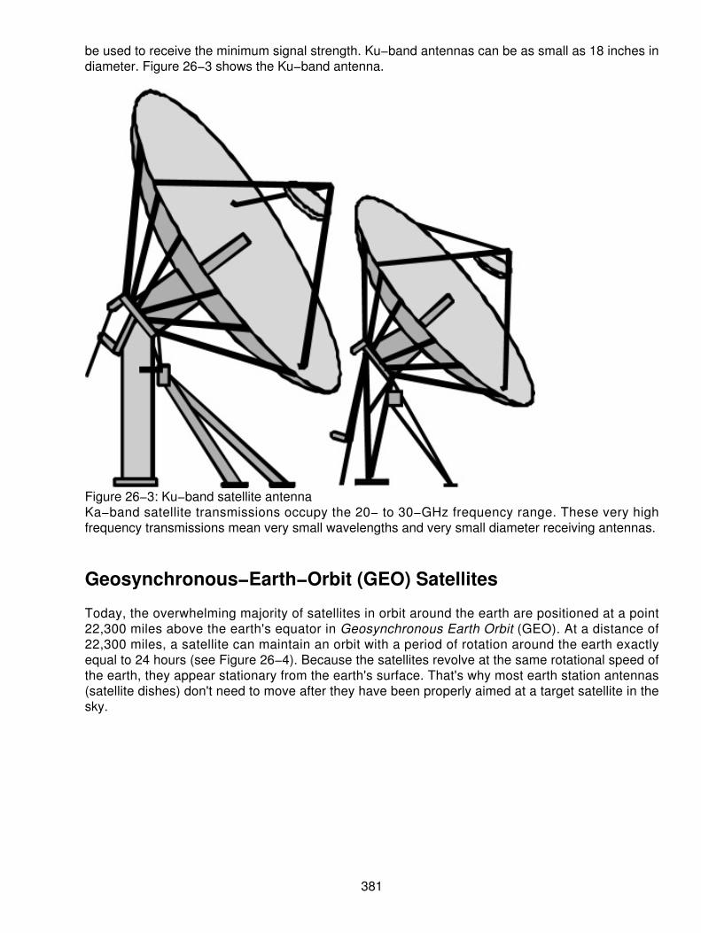
be used to receive the minimum signal strength. Ku−band antennas can be as small as 18 inches indiameter. Figure 26−3 shows the Ku−band antenna.
Figure 26−3: Ku−band satellite antennaKa−band satellite transmissions occupy the 20− to 30−GHz frequency range. These very highfrequency transmissions mean very small wavelengths and very small diameter receiving antennas.
Geosynchronous−Earth−Orbit (GEO) Satellites
Today, the overwhelming majority of satellites in orbit around the earth are positioned at a point22,300 miles above the earth's equator in Geosynchronous Earth Orbit (GEO). At a distance of22,300 miles, a satellite can maintain an orbit with a period of rotation around the earth exactlyequal to 24 hours (see Figure 26−4). Because the satellites revolve at the same rotational speed ofthe earth, they appear stationary from the earth's surface. That's why most earth station antennas(satellite dishes) don't need to move after they have been properly aimed at a target satellite in thesky.
381

Figure 26−4: Geosynchronous Orbit
Medium−Earth−Orbit (MEO) Satellites
During the last few years, technological innovations in space communications have given rise tonew orbits and totally new system designs. Medium−Earth−Orbit (MEO) satellite networks havebeen proposed that will orbit at distances of about 8,000 miles. Signals transmitted from a MEOsatellite travel a shorter distance, which translates to improved signal strength at the receiving end.This means that smaller, lighter receiving terminals can be used. Also, because the signal istraveling a shorter distance to and from the satellite, there is less transmission delay. Transmissiondelay is the time it takes for a signal to travel up to a satellite and back down to a receiving station.For real−time communications, the shorter the transmission delays, the better. For example, a GEOsatellite requires .25 seconds for a round trip. A MEO satellite requires less than .1 seconds tocomplete the job. MEOs operate in the 2 GHz and above frequency range.
Low−Earth−Orbit (LEO) Satellites
Proposed Low−Earth−Orbit (LEO) satellites are divided into three categories: little LEOs, big LEOs,and mega−LEOs. LEOs will orbit at a distance of only 500 to 1,000 miles above the earth. Thisrelatively short distance reduces transmission delay to only .05 seconds and further reduces theneed for sensitive and bulky receiving equipment. Little LEOs will operate in the 800 MHz (.8 GHz)range, big LEOs will operate in the 2 GHz or above range, and mega−LEOs will operate in the 20 to30 GHz range. The higher frequencies associated with mega−LEOs translate into more informationcarrying capacity and the capability of real−time, low−delay video transmission. MicrosoftCorporation and McCaw Cellular (now known as AT&T Wireless Services) have partnered to deploy288 satellites to form Teledesic, a proposed mega−LEO satellite network. Speeds are expected at64 Mbps downlink and 2 Mbps uplink.
Orbital Slots
With more than 200 satellites in geosynchronous orbit, how do we keep them from running into
382

each other or from attempting to use the same location in space? To tackle that problem,international regulatory bodies like the ITU and national government organizations like the FCCdesignate the locations on the geosynchronous orbit, where communications satellites can belocated. These locations are specified in degrees of longitude and are known as orbital slots. Inresponse to the huge demand for orbital slots, the FCC and ITU have progressively reduced therequired spacing down to only 2 degrees for C−band and Ku−band satellites.
Communications
The communications subsystem of a satellite is essential to the function of all satellites. There aremany different components used in spaceborne communications' subsystems including thefollowing:
Special antennas• Receivers• Transmitters•
All components must be highly reliable and low weight. Most satellites are fitted with beacons ortransponders, which help with easy ground tracking. Global receive and transmit horns receive andtransmit signals over wide areas on earth. Many satellites and ground stations have radio dishesthat transmit and receive signals to communicate. The curved dishes reflect outgoing signals fromthe central horn and reflect incoming signals. A satellite's ability to receive signals is also necessaryin order to trigger the return of data or to correct a malfunction if possible.
Satellite Installations
In Table 26−1, a list of the satellite installations by country is shown. The list shows the mainproviders and users of satellite transmission systems.
Table 26−1: Number of satellites in orbit by country around the world
Country In OrbitArgentina 1Australia 6Brazil 6Bulgaria 1Canada 16China 15CIS (Former Soviet Union) 1,322Czechoslovakia 1France 24Germany 15Hong Kong 1India 11Indonesia 6Israel 1
383

Italy 4Japan 55Korea (South) 2Luxembourg 4Mexico 4Portugal 1Spain 3Sweden 4Thailand 2Turkey 1United Kingdom 18United States 658Arab States 3Europe 27International 51NATO 8TOTAL 2,271
The technological and regulatory hurdles to create true high−speed satellite networks are fastbecoming past tense. Low− and mid−bandwidth systems such as Motorola's Iridium and Hughes'DirecPC can handle some of the needs immediately. These systems are nothing compared to thepromise of 2 Mbps, 20 Mbps, and even 155 Mbps streaming down from the sky. All that isnecessary is a small antenna, a black box, and a service provider. This will approximate the way webuy service from an ISP today.
Is it ready for prime time yet? Not yet! Iridium's universal telephone didn't kill the cellular telephone.So broadband satellite systems won't kill terrestrial lines. Broadband satellite creators agree thatbroadband satellite systems will complement terrestrial networks. These satellites will providehigh−speed service where terrestrial infrastructure does not exist. However, high−speed, low−costlandlines are here to stay.
Is there an application for the high−speed satellite networks? What makes them different from eachother? Each of the main systems is very different. Some of the most visible ones may prove themost difficult to implement. Some of the most staid−looking systems may beat every other system tothe punch.
Satellite communications are nothing new. For years, you could hook up a Very Small ApertureTerminal (VSAT) system and buy time on a satellite. The VSAT can deliver up to 24 Mbps in apoint−to−multipoint link (for example, a multicast) and up to 1.5 Mbps in a point−to−point link. Thesesystems are fine for predictable and quantifiable data transmission, but if you need to conductbusiness on the fly, they can be a problem. New techniques are required to handle the on−demandusage. Primary among them are more tightly focused beams and digital signal technology, whichtogether can increase frequency reuse (and thereby increase bandwidth) and reduce dish size frommeters to centimeters. Accordingly, you also need a large unused chunk of the electromagneticspectrum.
In 1993, NASA launched its Advanced Communication Technology Satellite, (ACTS). ACTS is anall−digital, Ka−band (20 to 30 GHz), spot−beam, GEO satellite system capable of deliveringhundreds of megabits per second of bandwidth. NASA showed that such a system could work. The
384

FCC has since granted orbital locations and Ka−band licenses to 13 companies including thefollowing:
EchoStar• Hughes• Loral• Motorola• Ka−Star• NetSat 28• PanAmSat• Teledesic•
All these companies aim to bring us bandwidth up to 155 Mbps to our home and office. Thesebroadband systems are not going online before 2000.
What will we do with this speed and capacity? Anything you want! Whatever landlines can do, thesatellite systems of the new millennium will also be able to do. In Table 26−2, the list of applicationscovered by broadband satellite communications is shown. These are representative applications;others will be developed.
Table 26−2: Applications for high−speed satellite communications
ApplicationsDesk−to−desk communicationsVideoconferencingHigh−speed Internet accessE−mailDigital and color faxTelemedicineDirect TV and videoTransaction processingInteractive distance learningNews and financial informationTeleradiology
Most of the market that needs data services seems to be well served by landlines. So, why is theemphasis on the use of airborne technology? An obvious market is in places that haveunderdeveloped communications infrastructures. In some countries, stringing copper or fiber is outof the question because of the initial cost and the terrain where it is needed. Still, a wirelesstelephone has some merit. You don't need a broadband satellite to make telephone calls; Iridiumand other LEO systems will likely serve that market.
So who does need this new class of broadband satellite communications? The answer ismultinational corporations. The main problem that satellite systems solve is getting high−bandwidthaccess to places without a high−bandwidth infrastructure. It's unlikely that a satellite system couldcompete with Digital Subscriber Line (xDSL) to the home or fiber to the office.
385

LEO Versus GEO
However, bandwidth is only half the story. The other half is latency. It's easy to talk abouthigh−bandwidth satellite systems, but that technology has existed in VSATs for years. GEOsatellites located at 22,300 miles above the equator induce 250 milliseconds (ms) of round tripdelay. With that kind of latency built into the system, (not counting latency added by the variousgateways and other translations), a telephone conversation is annoying. Any interactive dataintense application has to be nonlatency−sensitive. Online transaction processing will have aproblem using a GEO satellite system.
Moving the satellites closer to earth will help significantly. That's just what systems such asTeledesic[1] , Skybridge[2] , and Celestri[1] will do. With LEOs under 1,000 miles, these systemsreduce latency to .1 second. While GEOs are a well−known technology, LEOs are new. The biggestproblem is that you need a lot of them to get global coverage. At one point, Teledesic planned aconstellation of more than 842 satellites[3]. Until recently, the concept of launching dozens orhundreds of multimillion−dollar satellites was a pipe dream. Each of Teledesic's 288 satellites isestimated to cost $20 million.
Price is only one issue. Finding a company to launch all these satellites poses another obstacle.Teledesic set an 18−month to 2−year launch window to get its 288 satellites airborne. LEO systemplanners are talking about putting more satellites into orbit in the next 5 years than the world has putinto orbit over the past 40 years. Once the LEO satellites are in orbit, there's an entirely new set ofproblems. There's the matter of space junk.
[1] Teledesic is a joint venture between Microsoft and McCaw Cellular.[2] Skybridge is a venture of Alcatel of Belgium.[3] Teledesic dropped the number of required LEO satellites to 288 since the first announcement.
Niches in the GEO Sphere
LEOs will be good for high−speed networking, teleconferencing, Telemedicine, and interactiveapplications. GEOs will be better for information downloading and video distribution, such asbroadcasting and multicasting. We're able to use GEO satellites to transport at least 24 Mbps ofbroadcast IP data and over 2 Mbps of point−to−point TCP/IP data. The latter uses technologiessuch as TCP spoofing. Several vendors have been using this technique for years to deliver Internetand intranet content at high speed. Ground terminals can use similar TCP spoofing technologies.Nevertheless, there's still the 250 ms delay that you just can't get around. Any lossless protocol isgoing to have problems with this latency. Even if TCP spoofing works, TCP's 64 Kb buffer makesthis somewhat suspect, there's the matter of other protocols such as IBM's SNA and other real−timeprotocols that are designed around landline performance.
LEO Meets GEO
Motorola's Celestri plans an initial LEO constellation of 63 satellites coupled with one GEO satelliteover the United States. The LEO constellation and the GEO satellites will be able to communicatedirectly through a satellite−to−satellite network.
The hybrid configuration will enable Celestri to take advantage of LEO's shorter delays forinteractive uses and GEO's power in the broadcast arena.
386
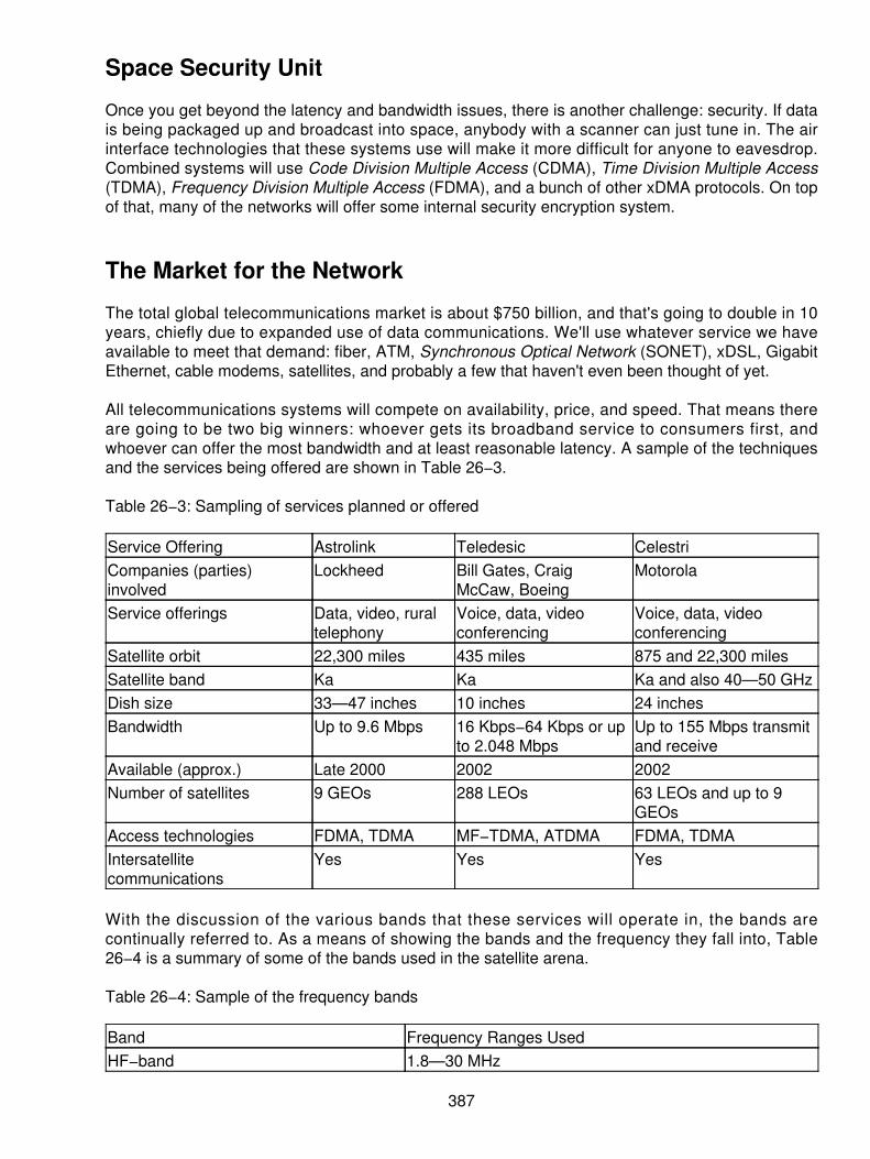
Space Security Unit
Once you get beyond the latency and bandwidth issues, there is another challenge: security. If datais being packaged up and broadcast into space, anybody with a scanner can just tune in. The airinterface technologies that these systems use will make it more difficult for anyone to eavesdrop.Combined systems will use Code Division Multiple Access (CDMA), Time Division Multiple Access(TDMA), Frequency Division Multiple Access (FDMA), and a bunch of other xDMA protocols. On topof that, many of the networks will offer some internal security encryption system.
The Market for the Network
The total global telecommunications market is about $750 billion, and that's going to double in 10years, chiefly due to expanded use of data communications. We'll use whatever service we haveavailable to meet that demand: fiber, ATM, Synchronous Optical Network (SONET), xDSL, GigabitEthernet, cable modems, satellites, and probably a few that haven't even been thought of yet.
All telecommunications systems will compete on availability, price, and speed. That means thereare going to be two big winners: whoever gets its broadband service to consumers first, andwhoever can offer the most bandwidth and at least reasonable latency. A sample of the techniquesand the services being offered are shown in Table 26−3.
Table 26−3: Sampling of services planned or offered
Service Offering Astrolink Teledesic CelestriCompanies (parties)involved
Lockheed Bill Gates, CraigMcCaw, Boeing
Motorola
Service offerings Data, video, ruraltelephony
Voice, data, videoconferencing
Voice, data, videoconferencing
Satellite orbit 22,300 miles 435 miles 875 and 22,300 milesSatellite band Ka Ka Ka and also 40—50 GHzDish size 33—47 inches 10 inches 24 inchesBandwidth Up to 9.6 Mbps 16 Kbps−64 Kbps or up
to 2.048 MbpsUp to 155 Mbps transmitand receive
Available (approx.) Late 2000 2002 2002Number of satellites 9 GEOs 288 LEOs 63 LEOs and up to 9
GEOsAccess technologies FDMA, TDMA MF−TDMA, ATDMA FDMA, TDMAIntersatellitecommunications
Yes Yes Yes
With the discussion of the various bands that these services will operate in, the bands arecontinually referred to. As a means of showing the bands and the frequency they fall into, Table26−4 is a summary of some of the bands used in the satellite arena.
Table 26−4: Sample of the frequency bands
Band Frequency Ranges UsedHF−band 1.8—30 MHz
387

VHF−band 50—146 MHzP−band 0.230—1.000 GHzUHF−band 0.430—1.300 GHzL−band 1.530—2.700 GHzFCC Digital Radio and PCS 2.310—2.360 GHzS−band 2.700—3.500 GHzC−band Downlink: 3.700—4.200 GHz
Uplink: 5.925—6.425 GHzX−band Downlink: 7.250—7.745 GHz
Uplink: 7.900—8.395 GHzKu−band (Europe) Downlink: FSS: 10.700—11.700 GHz
DBS: 11.700—12.500 GHzTelecom: 12.500—12.750 GHzUplink: FSS and Telecom: 14.000—14.800 GHzDBS: 17.300—18.100 GHz
Ku−band (America) Downlink: FSS: 11.700—12.200 GHzDBS: 12.200—12.700 GHzUplink: FSS: 14.000—14.500 GHzDBS: 17.300—17.800 GHz
Ka−band Roughly 18—31 GHz
Table 26−5 shows a sample of the satellite technologies that use the various bands and the size ofthe terminal and dish in satellite technologies.
Table 26−5: Summary of bands and types of terminals used
System Type FrequencyBands
Applications Terminal Type/Size Examples
Fixed satelliteservice
C and Ku Video delivery,VSAT, newsgathering,telephony
1 meter and larger fixed earthstation
HughesGalaxy,Intelsat
Direct broadcastsatellite
Ku Direct−to−homevideo/audio
0.3—0.6 meter fixed earthstation
DirecTV,Echostar,USSB
Mobile satellite(GEO)
L and S Voice andlow−speed data tomobile terminals
Laptopcomputer/antenna−mounted,but mobile
Inmarsat,AMSC
Big LEO L and S Cellular telephony,data, paging
Cellular phone and pagers;fixed phone booth
Iridium,GlobalStar
Little LEO P and below Position location,tracking,messaging
6 inches, omnidirectional OrbComm
Broadband GEO Ka and Ku Internet access,voice, video, data
20 cm, fixed Spaceway,Cyberstar,Astrolink
Broadband LEO Ka and Ku Internet access,voice, video, data,
Dual 20 cm trackingantennas, fixed
Teledesic,Skybridge,
388

video conferencing Celestri,Cyberstar
Satellite Characteristics
As already mentioned, satellite communications have three general characteristics that lead tointeroperability problems with systems that have not been designed to accommodate them:
Delay (or latency)1. Noise2. Limited bandwidth3.
It is important to understand each of these in general terms and in more detail. Since the inventionand installation of fiber optics, communications systems have been treated as ideal with very lowlatency, no noise, and nearly infinite bandwidth (the capacities are rapidly moving to terabitbandwidth from current fiber systems). These characteristics still have room for doubt anddevelopment, but for satellite communications, the characteristics of fiber can make it very difficultto provide cost−effective interoperability with land−based systems. The latency problem is foremostamong the three. Noise can be handled by the application of error control coding. Bandwidthefficiency is an important goal for satellite systems today, but will become increasingly important asthe number of users and data requirements increase.
Latency
We have seen that there is an inherent delay in the delivery of a message over a satellite link, dueto the finite speed of light and the altitude of communications satellites. As we stated, there isapproximately a 250 ms propagation delay in a GEO. These delays are for one groundstation−to−satellite−to−ground station route (or hop). The round−trip propagation delay for amessage and its reply would be a maximum of 500 ms. The delay will be proportionately longer ifthe link includes multiple hops or if intersatellite links are used. As satellites become more complexand include on−board processing of signals, additional delay may be added.
Other orbits are possible including LEO and MEO. The advantage of GEO is that the satelliteremains stationary over one point of the earth, allowing simple pointing of large antennas. The lowerorbits require the use of constellations of satellites for constant coverage, and they are more likelyto use intersatellite links, which result in variable path delay depending on routing through thenetwork.
Noise
The strength of a radio signal falls in proportion to the square of the distance traveled. For a satellitelink, this distance is very large and so the signal becomes very weak. This results in a low,signal−to−noise ratio. Typical bit error rates for a satellite link might be on the order of 10−7. Noisebecomes less of a problem as error control coding is used. Error performance equal to fiber ispossible with proper error control coding.
389

Bandwidth
The radio spectrum is a finite resource, and there is only so much bandwidth available. Typicalcarrier frequencies for current point−to−point (fixed) satellite services are 6/4 GHz (C band), 14/12GHz (Ku band), and 30/20 GHz (Ka band). Traditional C− and Ku−band transponder bandwidth istypically 36 MHz to accommodate one color television channel (or 1,200 voice channels). Onesatellite may carry two dozen or more transponders.
New applications, such as personal communications services, may change this picture. Bandwidthis limited by nature, but the allocations for commercial communications are limited by internationalagreements so that the scarce resource can be used fairly. Applications that are not bandwidthefficient waste a valuable resource, especially in the case of satellites. Scaleable technologies willbe more important in the future.
Advantages
Although satellites have certain disadvantages, they also have certain advantages over terrestrialcommunications systems. Satellites have a natural broadcast capability. Satellites are wireless, sothey can reach geographically remote areas.
There are major changes occurring in the design of communications satellite systems. Newbandwidth−on−demand services are being proposed for GEO. The Federal CommunicationsCommission constantly receives filings for new Ka−band satellite systems each year.
TCP/IP over Satellite
There has been a fair amount of press about TCP/IP, the networking protocol that the Internet andthe World Wide Web (WWW) rely on, not working properly over satellite. The claims are that theTCP/IP reference implementation's 4K buffer size limits channel capacity and data throughput toonly 64 Kbps. The argument is then used that the maximum buffer of 64K limits maximumthroughput to 1 Gbps. Therefore, the argument continues that GEO Ka−band satellite services areunsuitable for high−bandwidth applications, as the increased latency of a GEO connectiondecreases the available bandwidth.
TCP buffers are dimensioned as:
bandwidth x delay = buffer size
With a limited buffer size, a longer end−to−end delay decreases the space available to hold sparecopies of unacknowledged data for retransmission. This limits the throughput on a lossless TCPconnection.
However, this argument ignores the work done on larger buffer sizes for TCP in RFC1323, the largewindows effort. Work to expand TCP beyond its original, 16−bit buffer space has been going on forseveral years. Moreover, the effort and result of large windows is supported by several versions ofUNIX. The TCP buffer limit isn't as bad as it is made out to be. TCP copes with GEO delays quitenicely today. Individual, high−bandwidth GEO TCP links are possible with the right equipment andsoftware. Military applications have been using TCP/IP in many GEO−based networks for years.
390

GEO links are suitable for seamless intermediate connections in a TCP circuit. There is nothingdenying the use of many small TCP connections over a broadband link; GEO, fiber, and mostbroadband Internet connections contain a vast number of separate small pipes. The real issue withGEO versus LEO is the acceptability of the physical delay for two−way, real−time applications suchas telephony or video conferencing. Even then, the physical delay of GEO is balanced somewhat bythe increased switching times through a packet−based LEO network. Having multiple, narrow TCPpipes across satellites works well. Wide pipes with large buffer sizes can suffer from the higher biterror rate (BER) of satellites.
For TCP, implementing Selective Acknowledgements (RFC2018) and fast recovery (RFC2001) alsoimproves performance in the face of errors. There is much work in progress with theIP−over−Satellite and the TCP−over−Satellite working groups.
IP−over−satellite's primary advantage is that it can deliver large amounts of bandwidth tounderdeveloped areas where fiber does not exist. IP−over−satellite is also subject to a number ofadverse conditions that can significantly impact the effective throughput rates and networkefficiency. BERs, congestion, queue management, window size, and buffer status can all have aserious impact on the overall IP−over−satellite performance curves.
Another problem is the asymmetry encountered in back channel bandwidth, which in manyIP−over−satellite systems is only a fraction of the forward channel bandwidth. Because TCPemerged in advance of IP−over−satellite, TCP often gets mistakenly identified as the source of theproblem. It is the operating environment and not TCP alone that is the problem. The design of TCPis not optimized for conditions encountered during satellite transmissions.
The standard GEO round trip hop of 44,600 miles creates problems with the inherenttransmission−related delay, breaking down the flow of packets between the sender and receiver,especially at very high transmission speeds. TCP works well as a general−purpose protocol for acongested environment, such as the Internet. However, TCP perceives a satellite delay and bit erroras congestion and inherently slows down.
Satellite and ATM
Work has also been done on ATM over satellite. Standardization of ATM over satellite is underwayand several organizations are working in parallel. The ATM Forum's Wireless−ATM (WATM) grouphas done some work on ATM over satellite. The Telecommunications Industries of America (TIA)Communications and Interoperability group (TIA−TR34.1) works on interoperability specificationsthat facilitate ATM access and ATM network interconnect in both fixed and mobile satellitenetworks. TIA is collaborating with the ATM−Forum WATM group. The standard development forsatellite ATM networks is provided in ATM Forum contribution 98—0828. Other groups working onATM and satellite transmission include the following:
NASA NASA is working on the interoperability of satellite networks with terrestrialnetworks. ATM over satellite QoS results for Motion−JPEG is now publicly available.
•
European Space Research and Technology Center This group is also interested inATM−over−satellite research. They have carried out a broadband communications oversatellite study.
•
COMSAT COMSAT is one of the major players in providing ATM−over−satellite services.• Communications Research Center Communications Research Center BroadbandApplications and Demonstration Laboratory is testing and demonstrating informationhighway applications by using ATM via satellite.
•
391

RACE Research and Development in Advanced Communications Technologies InEurope, this organization has also funded various projects for ATM over satellite. The resultsof the RACE research projects are published as Common Functional Specifications (CFS).
•
Charting the Rules for the Internet
Everyone knows about the Internet. Fewer people, however, understand how it works. Very fewpeople know where the standards come from that shape how the Internet works. Those rules comefrom five groups, four of them loosely organized and consisting primarily of volunteers. For moredetails see Chapter 32 in this book, "The Internet".
The groups don't issue standards in the traditional sense, although their conclusions become theregulations by which the Internet operates worldwide. Instead, they agree on how things should bedone through discussion. The result is a surprisingly effective, if sometimes convoluted, system fordealing with the fast−growing and often unpredictable nature of the Internet. Like the Internet itself,the groups that oversee it have made recent innovations that continue to evolve and restructure.
The basic rules governing the Internet come out of two task forces:
The Internet Research Task Force looks at long−term research problems.1. The Internet Engineering Task Force (IETF) concentrates on more immediate issues suchas data transfer protocols and near−term architecture.
2.
IETF is the oldest group dedicated to Internet issues, having held its first meeting in 1986. At thetime, the nascent Internet was still primarily a federal research activity evolving out of ARPANET, amodest network developed by the U.S. Defense Advanced Research Projects Agency (DARPA).The IETF's work is divided among eight functional areas related to such issues as networkmanagement, routing, security, applications, and so on.
The activities of IETF and the Internet Research Task Force are coordinated by the InternetArchitecture Board. The board has no official role in operational matters and contributes in only aminor way to policy issues. The Internet Architecture Board and two Internet task forces fall looselyunder the umbrella of a fourth organization that is more formal, called the Internet Society.
The Internet links thousands of networks and millions of users who communicate by using hundredsof different types of software. They are able to do so because of Transmission ControlProtocol/Internet Protocol (TCP/IP), the general procedure for accurately exchanging packets ofdata adopted by ARPANET in the early 1980s. Other networks soon adopted TCP/IP as well, thuspaving the way for the global Internet of today. TCP/IP has been updated several times. It continuesto undergo modifications, including those designed to speed throughput, especially for longterrestrial and satellite links.
Tailoring IP Can Accelerate Throughput
Everyone who uses the Internet wants faster connections. The quest for speed has become a bigmarketing issue for terrestrial and satellite systems alike. However, no one system is inherently bestfor every application. Finding the most efficient way to connect is a matter of matchingcommunication needs to the unique characteristics of each option. The hardware involved is anobvious factor in system speed. Nevertheless, the protocols used by computers to talk to each other
392

ultimately control throughput. Internet protocols are constantly being revised, and faster versionsare coming that promise quicker data delivery over links of all kinds. Primarily the IETF coordinatesthe work. The IETF seeks continual improvement in the software that makes the Internet work, andit prefers solutions that benefit terrestrial as well as satellite network links.
The Internet works because all computers using it abide by the same rules, or protocols. The mostfundamental of these rules is the Internet Protocol (IP). Its primary function is to provide thedatagram that carries the address to which a computer is sending a message.
Guaranteeing that messages are received accurately over the Internet is the primary job of the TCP.TCP sends data in segments and waits for a confirmation message from the receiving computerbefore sending more. It reacts to traffic loads on the network, dynamically regulating the allowablerate of data transfer between the two computers in an attempt to maximize data flow withoutoverwhelming relay points or the capacity of the receiving computer.
TCP facilitates sending large data files accurately over transmission routes that may be plaguedwith bit errors or other forms of poor link quality. It also reduces throughput when it doesn't receiveacknowledgment as quickly as it expects. TCP assumes that any delays are due to trafficcongestion within the network. It responds by cutting back on the transmission rate; it then slowlyspeeds up again as long as no further delays are detected. The idea behind its slow−startmechanism is to match the output of the sending computer to the maximum throughput allowed bythe network at any moment. For the most part, TCP works just fine. However, pushing the ultimatethroughput capabilities of TCP has revealed shortcomings, especially on high−capacity links withhigh latency. The problem is that high latency slows TCP's slow−start mechanism dramatically,causing the protocol to restrict the amount of data that can be "in flight" between the sending andreceiving computers and preventing the link from being fully utilized.
The problem affects any high−delay path, whether terrestrial or by satellite. For high−bandwidthlinks, the result is a sharp drop in efficiency. For example, a message controlled by the mostcommonly used form of TCP can move through a cross−continent, OC−3 fiber link at only about 1.1Mbps, even though the line can handle 155 Mbps of throughput.
A packet of data can propagate across the United States and back through a dedicated copper wireor fiber in about 60 ms. It takes eight to nine times as long — 500 ms for the same packet to makethe round trip via satellite.
Individual LEO spacecraft promise very short propagation delays — as little as 12 ms from groundto satellite and back — because they fly closer to the ground. However, a single LEO spacecraftcan't "see" from coast to coast, so several such "birds" are required to relay a packet across theUnited States. LEO birds also are in motion relative to the ground, so their packet latency variescontinually, a characteristic that forces current forms of TCP to reassess the allowable throughputrate constantly. The net result is cross−country transmission delays for LEO systems akin to thoseof long terrestrial links.
Signal latency isn't the only factor in selecting an appropriate transmission medium, however. Eachalternative has its own attractions and challenges. More importantly, continuing adjustments to TCPpromise to improve performance for any high−latency network link.
393

Chapter 27: Low−Earth−Orbit Satellites (LEOs)
Overview
Quite a bit of discussion regarding wireless communications has already been covered in earlierchapters. However, a combination of two separate services and technologies are merging as newservices for broadband communications. These two services include long haul communications andthe use of personal communications services (PCSs). The technologies include the use of satelliteand the cellular concepts combined. Worldwide communications services can be achieved by thesetwo combined services, therefore some diligent effort should be made to understand just what ishappening in this arena. This truly brings home the concept of communications from anywhere toanywhere. The thought of being out in the middle of a lake and receiving a call, or rafting down ariver and making a call, boggles the mind. This is especially true when thinking about some of themore rural areas in the world where no telephone service infrastructure exists today. Yet, in a matterof a few years these remote locations, on mountaintops, in forests, in valleys, or on the sea will allbe reachable within a moment's notice. The infrastructure of a wired world will not easily lend itselfto this need, due to timing and cost issues. Therefore, the use of a wireless transmission system isthe obvious answer.
However, the use of cellular and personal communications devices still leaves a lot to be desired.First, the deployment of these services is always going to be in the major metropolitan areas, wherethe use and financial payback will be achieved. Thus, in the remote areas it will be decades, if notlonger, until the deployment ever works its way close to the remote areas. Enter the ability to seethe world from above the skyline! The industry decided to attempt servicing remote areas from asatellite capacity. This is not a new concept; the use of satellite transmission systems has beenaround for over thirty years. However, the application for an on−demand, dial−up satellite service isnew. This will have to be a lucrative business venture because the costs are still quite high. Look atthe Iridium project that took over five years to build and launch, only to meet with lax reception fromthe marketplace. This drove Iridium Inc., into bankruptcy in its first year of operation.
There are still approximately one dozen suppliers competing for space segment and frequencyallocation to offer voice, broadband data, paging, and determination services. In each case, theorganizations have selected various approaches on how to launch their service offerings and theuse of orbital capabilities to provide the service. In general, this discussion will cover the mostwidely discussed satellite technology today called Low−Earth Orbit (LEO). However, some addeddiscussion on the use of Mid−Earth Orbit (MEO) and Geosynchronous Orbit (GEO) satellite−basedcommunications, offerings, and applications must be addressed. As mentioned, there are over adozen organizations applying for the rights to use various orbital slots and frequencies to provideservice, in the various orbits as shown in Table 27−1. The licenses requested are being discussedat great length around the world as the future interoperable service.
Table 27−1: A summary of the number of competitors and the various orbits being sought
Orbit Number OfCompetitors
Status
Low−Earth 8 Pending licenses granted Orbit (LEO) based on veryspecific areas of coverage
Mid−Earth 4 Experimental licenses Orbit (MEO) granted forspecific areas of coverage
Geosynchronous 4 Licenses have already been Orbit (GEO) issued for
394

some, are experimental with others.
The table reflects the fast pace that is being created since the obvious train of thought is that thefirst company in the business, regardless of the orbit used, will gain the market share. Unfortunately,this did not quite happen with the Iridium network, which opened for service in 1998—1999. This isan expensive situation if some other carrier gets there first and takes the market by force. Ofcourse, there are still those who feel there is no need and that these systems will go bankrupt withinthe first few years.
Low−Earth Orbit
In December 1990, Motorola filed an application with the FCC for the purposes of constructing,launching, and operating a LEO global mobile satellite system known as Iridium. This was the hotbutton that sparked the world into a frenzy. Iridium was a concept of launching a series of 66satellites[1] Originally the Iridium proposal was for 77 satellites, but Motorola amended this number after theWorld Administrative Radio Council meeting in the spring of 1992. around the world to provideglobal coverage for a mobile communications service operating in the 1.610 to 1.6265 GHzfrequency bands. The concept was to use a portable or mobile transceiver with low profile antennasto reach a constellation of 66 satellites. Each of the satellites would be interconnected to oneanother through a radio communications system as they traversed the globe at 413 nautical milesabove the earth in multiple polar orbits[2] The original concept was to use 7 polar orbits with 11 satellites in each. This would provideworldwide coverage, much similar to an orange slice concept . This would provide a continuousline−of−sight coverage area from any point on the globe to virtually any other point on the globe,using a spot beam from the radio communications services on−board each of the satellites. The useof this spot beam concept, which had been discussed for years in the satellite industry, allowed forhigh frequency reuse capacities that had not been achieved before. Iridium wanted to provide theservices outlined in Table 27−2. Motorola also suggested that an interconnection arrangementwould be set up with all providers around the world through an arrangement with the local PostTelephone and Telegraph (PTT) organizations. The concept was sound, and the approach wouldhave provided for the coverage that was lacking in the past to remote areas. In the table, the twocolumns are used as exclusive of each other. The services can be provided in any of the coverageareas regardless of which service is selected.
Table 27−2: Services and coverage through the Iridium network
Type Of Service Coverage AreasVoice Communications Air, land, waterData Communications Air, land, waterPaging Air, land, waterRadio Determination Services Air, land, water
Each of the satellites was relatively small in terms of others that had been used. The electronicsinside each were very sophisticated, and the use of gateway controllers on earth provided thecommand and control service for the administration of the overall network. With the Iridium network,providing coverage in areas where cell sites would not have been practical expanded basic cellularcommunications. This is summarized in Table 27−3, which shows a feature comparison of thecellular concept versus the Iridium concept.
395

Table 27−3: Summary of cell sites versus Iridium cells
Cellular Networks Iridium NetworkSites are fixed Sites are the moving targetsUsers move from site to site User stays put, sites move the user from satellite to
satelliteAreas of coverage are 3—5 miles across Areas of coverage are 185—1100 miles acrossCoverage sporadic, not totally ubiquitous Worldwide coverage
The areas of coverage in the cellular and PCS networks primarily served populated geographicareas. There were areas that were not financially or operationally prudent to install services.Consequently, very rural areas, mountain terrain, and the like did not receive coverage at all. Underthe LEO concept, all areas not previously served could be easily accommodated. Iridium evenprovided coverage in the extreme rural areas, and during the Kosovo, Yugoslavia crisis. Theservices addressed by these satellites included the obvious, such as two−way voice but also otherservices that were not as evident. Table 27−4 is a summary of the actual services that wereprovided. This includes a minor description of the service and a potential target market. The list isstraightforward in a single line description.
Table 27−4: A summary of the initial features available on LEO networks
Radio Determination Services (RDSS) Will allow for the location of vehicle fleets, aircraft, marinevehicles, etc. RDSS will also be an integral locator servicefor all voice communications devices.
Voice communications (VC) Will allow on demand, dial−up digital voice communicationsfrom anywhere in the world.
Paging (P) A one−way paging service. The paging service includes analphanumeric display for up to two lines, but will expand toshort messaging services (SMS) at 160 characters.
Facsimile (Fax) A two−way facsimile service.Data communications (DC) An add−on device will allow the transmission of two−way
data. This capability will also allow for two−way messaging(e−mail) service across the network.
In Figure 27−1, the concept of the LEO arrangement is shown. In this particular case, the satellitesare traversing the earth's surface at a height of 400+ nautical miles above the earth, in a polar orbit.In the polar orbit, the satellite moves around the earth's poles and passes over any specific pointalong its path very quickly. The satellites move at approximately 7,400 meters per second indifferent orbits. Therefore, as one target site moves out of view, a new one comes into view atapproximately the same time. A handoff will take place between the individual satellites (using theKa band).
396
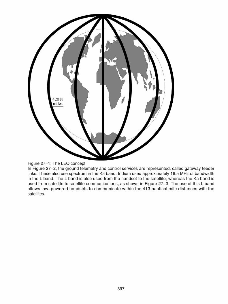
Figure 27−1: The LEO conceptIn Figure 27−2, the ground telemetry and control services are represented, called gateway feederlinks. These also use spectrum in the Ka band. Iridium used approximately 16.5 MHz of bandwidthin the L band. The L band is also used from the handset to the satellite, whereas the Ka band isused from satellite to satellite communications, as shown in Figure 27−3. The use of this L bandallows low−powered handsets to communicate within the 413 nautical mile distances with thesatellites.
397
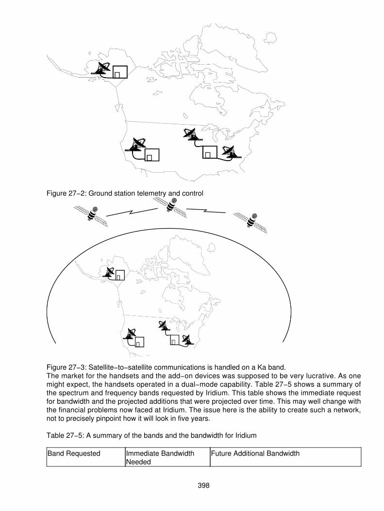
Figure 27−2: Ground station telemetry and control
Figure 27−3: Satellite−to−satellite communications is handled on a Ka band.The market for the handsets and the add−on devices was supposed to be very lucrative. As onemight expect, the handsets operated in a dual−mode capability. Table 27−5 shows a summary ofthe spectrum and frequency bands requested by Iridium. This table shows the immediate requestfor bandwidth and the projected additions that were projected over time. This may well change withthe financial problems now faced at Iridium. The issue here is the ability to create such a network,not to precisely pinpoint how it will look in five years.
Table 27−5: A summary of the bands and the bandwidth for Iridium
Band Requested Immediate BandwidthNeeded
Future Additional Bandwidth
398
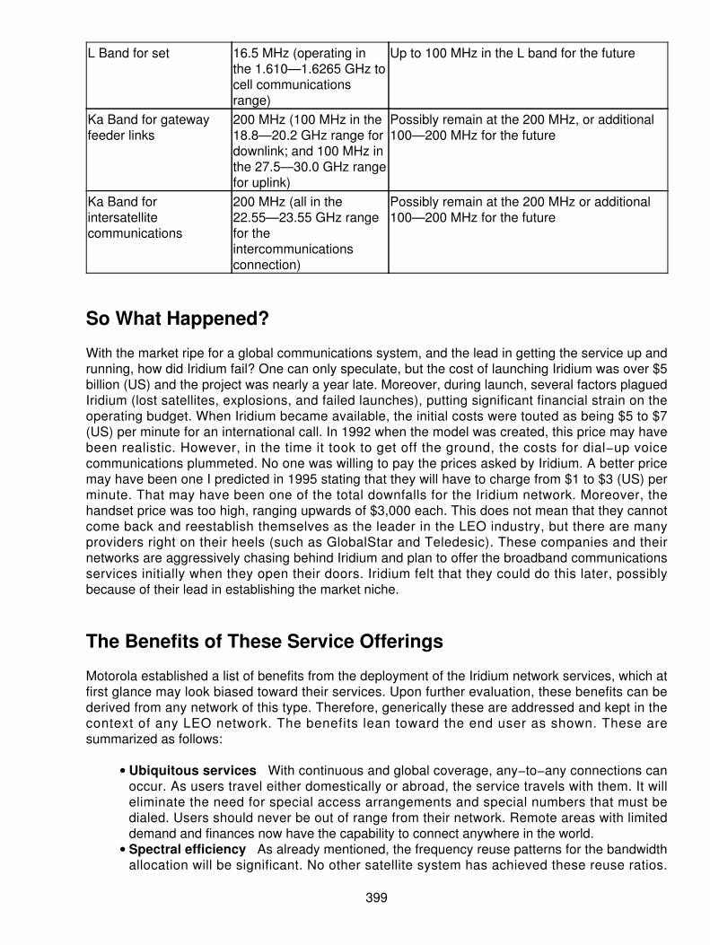
L Band for set 16.5 MHz (operating inthe 1.610—1.6265 GHz tocell communicationsrange)
Up to 100 MHz in the L band for the future
Ka Band for gatewayfeeder links
200 MHz (100 MHz in the18.8—20.2 GHz range fordownlink; and 100 MHz inthe 27.5—30.0 GHz rangefor uplink)
Possibly remain at the 200 MHz, or additional100—200 MHz for the future
Ka Band forintersatellitecommunications
200 MHz (all in the22.55—23.55 GHz rangefor theintercommunicationsconnection)
Possibly remain at the 200 MHz or additional100—200 MHz for the future
So What Happened?
With the market ripe for a global communications system, and the lead in getting the service up andrunning, how did Iridium fail? One can only speculate, but the cost of launching Iridium was over $5billion (US) and the project was nearly a year late. Moreover, during launch, several factors plaguedIridium (lost satellites, explosions, and failed launches), putting significant financial strain on theoperating budget. When Iridium became available, the initial costs were touted as being $5 to $7(US) per minute for an international call. In 1992 when the model was created, this price may havebeen realistic. However, in the time it took to get off the ground, the costs for dial−up voicecommunications plummeted. No one was willing to pay the prices asked by Iridium. A better pricemay have been one I predicted in 1995 stating that they will have to charge from $1 to $3 (US) perminute. That may have been one of the total downfalls for the Iridium network. Moreover, thehandset price was too high, ranging upwards of $3,000 each. This does not mean that they cannotcome back and reestablish themselves as the leader in the LEO industry, but there are manyproviders right on their heels (such as GlobalStar and Teledesic). These companies and theirnetworks are aggressively chasing behind Iridium and plan to offer the broadband communicationsservices initially when they open their doors. Iridium felt that they could do this later, possiblybecause of their lead in establishing the market niche.
The Benefits of These Service Offerings
Motorola established a list of benefits from the deployment of the Iridium network services, which atfirst glance may look biased toward their services. Upon further evaluation, these benefits can bederived from any network of this type. Therefore, generically these are addressed and kept in thecontext of any LEO network. The benefits lean toward the end user as shown. These aresummarized as follows:
Ubiquitous services With continuous and global coverage, any−to−any connections canoccur. As users travel either domestically or abroad, the service travels with them. It willeliminate the need for special access arrangements and special numbers that must bedialed. Users should never be out of range from their network. Remote areas with limiteddemand and finances now have the capability to connect anywhere in the world.
•
Spectral efficiency As already mentioned, the frequency reuse patterns for the bandwidthallocation will be significant. No other satellite system has achieved these reuse ratios.
•
399

Iridium was first to claim this capability of efficiency. RDSS portion of the Iridium network iscontained in the same spectral arrangement, freeing up 16.5 MHz of spectrum. This is aquantum leap in the efficient use of the spectrum.Public benefits due to flexible design The digital technology deployed allows the totalconnection for all voice and data services on a seven day by twenty−four hour basis. Thisallows the flexibility of service provisioning. The LEO overcomes some of the limitations ofthe higher transport systems, such as the delay in the round trip transmission. Because thesatellites are low, the user set needs a lower power output device. This orbit has beenselected to be the most flexible.
•
The potential to save lives It's common for the news media to publish stories of peoplestranded in remote areas with no life support systems who died because of their inability tocommunicate. The press today is filled with stories of cellular and PCS users notifyingauthorities of casualties. If only people in remote areas had a means of notifying authoritiesand/or rescue parties, their lives could be spared in the event they get into a life−threateningsituation.
•
Capabilities of the vendor Motorola states that they are uniquely qualified to providethese types of services due to their background in the development and sales of otherancillary equipment that works in the wireless world. Specifically, they have been one of themajor developers in the production, research, and development of private mobile−radioservices.
•
LEO deployment promotes international communications The LEO networks delivermodern digital−transmission services to remote areas of the world. The FCC and the U.S.government are attempting to use telecommunications as a strategic and economic tool tofoster development in these areas. Their goals are to
Promote the free flow of information worldwide♦ Promote the development of innovative, efficient, and cost−effective internationalcommunications services that meet the needs of users in support of commerce andtrade development
♦
Continuous development and evolution of a communications services and networksthat can meet the needs of all nations, and specifically those of developing nations.
♦
•
The above goals can be met with a mobile communications network such as that proposed in theLEO networks. An alternative is the Global Services Mobile (GSM) standard that is emergingthroughout the international arena.
Deployment and Spacing of Satellites
Motorola's concept of seven different orbits on a polar orbital path would lend itself to the potentialof collisions in mid−air if the spacing were not correct. Therefore, the spacing design had to takeinto account that the satellites were all traversing the same end−points where the paths would allcross. One can imagine that the two poles of the earth are the midpoints in the orbit. The Iridiumnetwork originally consisted of 77 satellites, however, a modification to the plans dropped thenumber of craft to 66. To assign or determine the best approach, Motorola took into account sixcritical criteria in determining the best approach:
The need to provide a single global coverage over the entire earth's surface for availability atall times. This means that each subscriber must have at least one satellite in view at alltimes to provide coverage.
1.
Some portion of each orbit must be available to allow for low−power outputs, whichaccommodates the recharging of the communications power subsystems. This minimizesthe size requirements of the craft.
2.
400

The relative spacing of the satellites and the line−of−sight relationships had to allow theon−board systems to control cross system linkage.
3.
Costs for the entire constellation was a concern in the selection of the orbit and spacingrequirements. Minimizing costs was a portion of the decision−making process.
4.
The angle of incidence from the end user to the spacecraft as measured from the horizon tothe line−of−sight communications process allowed link margins to accommodate thelow−powered user device. The slant angle was selected at 10 degrees to meet thesecriteria.
5.
The final criteria was the operational latitude of the spacecraft. Systems operating over 600nautical miles were affected more by radiation, which drives the cost up for the systems.Altitudes lower than 200 nautical miles required much more fuel and control over thepositioning of the craft, thereby driving up the cost. At 413 nautical miles, the fuelconsumption and command and control over the craft position coupled with the betterradiation performance; the cost and coverage ratios provided a better solution.
6.
The satellites were spaced at 32.7 degrees apart, traveling in the same basic direction and movingat approximately 16,700 miles per hour from north to south and 900 miles per hour westward overthe equator. Given this path, each satellite was designed to circle the earth approximately every 100minutes. At the equator, a single device would provide coverage. However, as the craft movedtoward the poles, overlap occurred, increasing the levels of coverage above and below the equator.The expected life cycle of the satellites was around five years.
The basic building blocks of the Iridium system provided the model for other networks ready tolaunch (such as Globalstar systems). In each case, the systems used proven technology for radiotransmission in well−established frequency bands. The basic system was composed of thefollowing:
The space segment comprised of the constantly moving constellation of satellites in a LEO.• A gateway segment comprised of earth station facilities around the world.• A centralized system control facility.• The launch segment to place the craft in the appropriate orbit.• A subscriber unit to provide the services to the end use.•
The Space Segment
The space segment consisted of small satellites, operating in the LEO, which were all networkedtogether as a switched digital communications system. In Figure 27−4, a sample outline of the beamcoverage with Iridium is shown. Each satellite used up to 37 separate spot beams to form the cellson the earth's surface. Multiple relatively small beams allowed the use of higher satellite antennagain and reduced RF power output. The system was designed to operate with up to 250independent gateways, although in its initial deployment only between 5 and 20 gateways. Figure27−5 is an overall view of the network communications through the gateways and the handsets.
401

Figure 27−4: The spot beam pattern from Iridium
Figure 27−5: The overall system through the gateways
402

The Cell Patterns
The satellites had the capability of projecting 37 spot beams on the earth. The spot beams formed aseries of overlapping, hexagonal patterns that would be continuous. The center spot beam wassurrounded by three outer rings of equally sized beams. The rings worked outward from the centerbeam in rings of 6, 12, and 18 spot beams. This pattern of a 37−cell pattern is shown in Figure27−6, using the center beam as the starting point where the pattern can be seen. A spot beam was372 nautical miles in diameter, and when combined they covered a circular area of approximately2,200 nautical mile diameter. The average time a satellite was visible to a subscriber wasapproximately nine minutes. A seven−cell frequency reuse was formed to produce the actualpattern shown in Figure 27−7.
Figure 27−6: The 37−cell patterns
403

Figure 27−7: A seven−cell frequency reuse patternTraffic Carrying Capacity
A 14−slot TDMA format is used, allowing each Iridium cell to be assigned an average of two timeslots. The average traffic capacity with a utilization of 16.5 MHz is 174 full−duplex voice channelsper cell.
Modulation Techniques
The modulation process and multiple access capabilities of Iridium were modeled after the
404

conventional terrestrial cellular networks, and particularly after the international GSM standard.Combining frequency and time division multiple access, the system also used a data or vocodervoice and digital modulation technique (that is, QPSK, MSK, and so on). Each subscriber unitoperated in a burst mode transmission by using a single carrier. The bursts were controlled toappear at the precise time necessary to be properly integrated into the TDMA frame.
The Gateway Segment
The gateway segment controlled user access to the network and provided interconnection to thePublic Switched Telephone Networks (PSTN). Two initial gateways in the United States divided theeastern and western parts of the country. Two added sites will be located in eastern and westernCanada to provide coverage throughout Canada and Alaska. Each of the gateways had thenecessary terminal and switching equipment to support the operations.
The Earth Terminal
The key to the earth terminal function was the use of up−and−down link capabilities with threeseparate RF front−ends supporting continuous service and high up−time availability. One of the RFfront−ends was used as an active up/downlink with one satellite. A second RF front−end was usedto establish communications with the next active satellite. The third provided a backup capability incase of an equipment failure and provided for diversity against any of the atmospheric conditionsthat can plague a typical satellite communications system (that is, sunspots, equinoxes, and so on),causing a degradation of service. As the satellites were the moving targets and the gateways werefixed, the antennas followed and tracked the nearest two satellites to them. The communicationsactive channels were handed off from the current satellite to the next active one coming into view,while the first disappeared from view. This handoff was designed to be transparent from the user'sperspective.
The Switching Equipment
Each gateway housed the necessary switching equipment to interface between the communicationspayload in the Ka band and the voice/data channels from the PSTN. The switching systemsperformed the following functions:
Transferred common channel signaling information from the PSTN to the RF portion of theIridium network
•
Transferred l ine and address signaling information from the PSTN to establishcircuit−switched calls
•
Supplied in−band tones and announcements to PSTN users calling onto the Iridium networkwith necessary progress tones and conditions
•
Digitally−switched PCM signals between channels derived from the terminal channels to thePSTN and provided channels to support the necessary in−band signaling capability for callcontrol and progress.
•
Interconnecting to the PSTN
Voice connections were designed to be fully compatible with applicable ANSI T1 standards for theUnited States and the CCITT G and Q Recommendations (International T1/E1 standards) for digitaltransmission systems using either SS7 or R1 signaling. The data channel specifications werecompatible with the OSI standards and with CCITT V and X series recommendations.
405

The System Control Portion
The system control segment (SCS) of the network provided the necessary control over the entiresatellite constellation. The SCS managed and controlled all the system elements, providing serviceon both the short− and long−term picture. The functionality of the SCS was divided into either activecontrol of the satellites and control over the communications assets within the satellites. The SCSmonitored and managed the overall network control sequencing, traffic load balancing, and peakconditions, as necessary.
Other Competitors to Iridium
As already mentioned earlier, several other suppliers have all the rights and licenses to launchsimilar communications services, using constellations of LEOs, either MEOs or Geostationay Orbits.This is the PCS of the future. The companies (at least seven others in the United States) are allvying for the l icenses to use the L band communications bandwidth to provide globalcommunications. These include some of the other big names in the business such as Qualcomm,Loral, TRW, Microsoft, and McCaw Communications. Each of the companies has a differentapproach to use, but they all share a common goal. Get there soon and offer high−speed digitalcommunications with Internet access, e−mail, voice over, IP, and demand video services.
Loral−Qualcomm
Loral−Qualcomm's (located in Palo Alto, California) approach is to use approximately 48 satellites ina big LEO arrangement similar to Iridium, but with less craft. Their network handle is Globalstarsystems. Qualcomm expects to use its expertise in the specialized mobile radio business and aCDMA arrangement that they pioneered. This service is currently two years behind schedule, but inthe process of launch with expected availability in 2000. Loral−Qualcomm will draw from itsexperience in the business by deploying their CDMA technology and attempt to reuse the frequencyspectrum as much as possible. Many of the initial service offerings from this company will includefleet tracking, locator services, and ultimately the extension of voice and data communications. Theuniqueness of the Loral−Qualcomm services is that the system is designed to fully complement thecellular and PCS industries by providing single service coverage from a single telephone to a singlenumber, through an intelligent network. Loral−Qualcomm did not plan to use a dual mode operatingset, but a single set that can interface to any network service without having the user make adecision. Globalstar systems constellation is shown in Figure 27−8. These folks stand to be a bigcontender in the LEO business.
406

Figure 27−8: Globalstar systems constellationRegardless of which suppliers succeed or fail, the gist of the topic is that satellites orbiting close tothe earth have a lot of merit. The orbit will be short lived (5 to 7 years) and the rotation in a polarorbit requires more handoff techniques, but the end result is that we achieve any−to−anyconnections regardless of where we are in the world. Moreover, the initial implementations usuallysuffer the pains of growth and sporadic coverage, whereas the newer implementations fix the ills ofthe initial systems. This means that changes will likely take place in whom the providers are, but theoverall concept of using the LEO orbits will remain.
407
Chapter 28: The T Carrier Systems (T−1/T−2 and T−3)
Overview
Meeting the high demands for voice, data, and multimedia communications, the larger corporationsin the world are moving to the high−speed digital communications of the T Carrier system. Thisincludes many of the copper and optical fiber−based systems. The hottest installation method todayis still the T−1. Although T−1 has been around since 1958, when it was first created, and then rolledout into the carrier communities in 1960, one would think this technique became old. However, T−1and T−3 are still the hottest method of connecting some of the services discussed in other chapters,such as
Frame Relay (FR)• Asynchronous Transfer Mode (ATM)• Point−to−point data lines• Internet access• Signaling systems• Computer−to−telephony integration• ISDN• xDSL (HDSL, CDSL)•
Why has this become such a popular method? The implementation of digital high−speedcommunications can be directly linked to the cost and convenience factors. T−1 became a veryprice competitive access method for nearly all the communications services needed.
Yet, there has been other activity in the form of T−3 or DS3 services to support the higher demandsfor the various multimedia and video applications. In both cases, T−1 and T−3 are now very popularin the commercial industry as a means of providing the connectivity desired to meet the continuingcommunications development within organizations. The pricing models now make these servicesmore readily affordable. Moreover, the enhancements to the digital circuits make this a tried andtrue technology. For example, today's tariffs make both T−1 and T−3 very price efficient andattractive. Even if a customer does not have enough volume to justify the use of a full T−1 or T−3,the prices enable the consumer to use portions of the services while holding excess capacity fornew applications, without causing undue budgetary hardships. A T−3, for example, costs the sameas between five and eight T−1s terminated at the same location. This is beyond a financial decisionand moves us to think of these services as application supportive.
Once a consumer or organization makes the leap into the digital circuit, the availability of bandwidthto host other services that was previously unavailable becomes paramount. Newer graphics andvideo services can be turned on, as needed, if the bandwidth is no longer the constraint.
This chapter will discuss the way the multiplexing and access of the digital services is facilitated.There are many other excellent publications that go deeper into the technologies. The reader canchoose to do further study if so desired.
The Difference Between T−x and DS−x
In many cases, the terms become problematic because we tend to intersperse them. Therefore,when discussing the different services, it becomes imperative to discuss the difference between aT−x and a DS−x.
408

T−x (such as T−1 and T−3) refers to the services acquired from a carrier or local provider byphysical layers one and two. The T carrier is a physical set of wires, repeaters, connectors, plugsand jacks, and so on. When referring to a T−1, we are actually describing the physical layerinterface to the provider networks. A T−1, for example, is a four−wire circuit (unless one of theHDSL or SDSL techniques is used with only one pair of wires). The four−wire circuit is installedbetween the local provider and the customer's premises, as shown in Figure 28−1. In this example,the provider will install the physical wires or use four wires from a 50 pair bundle on the local loop.From the Central Office (CO), the four wires will be cleaned up to remove splices, bridge taps, andload coils from the wires. At approximately 3,000 feet from the egress point at the CO, the providerwill install a digital repeater (or regenerator, as it is also called). Thereafter, every 5,000 to 6,000feet, another repeater is required until the last leg of the circuit. At approximately 3,000 feet from thecustomer's entrance point, the last repeater is installed. The provider then terminates the circuit atthe demarcation point in a jack. The customer uses a plug to connect the CPE to the circuit. Theseare all mechanical and electrical devices enabling the installation of the T carrier.
Figure 28−1: A typical T−1 carrier installationAfter the circuit is installed and the carrier is terminated, the customer then generates traffic (voice,data, video, and so on) across the circuit. This traffic is carried on the carrier at a digital rate, orwhat is called the Digital Signal level 1 (DS−1). DS−1 operates at a digital signaling rate of 1.544Mbps. The traffic is therefore called a DS−1. (Note in many cases this may be annotated as DS1.)
One can therefore see that there is a difference between the physical carrier and the signaling rateof the traffic carried on the circuit.
DS−1 Framing Review
DS−1 operates in a framed format (some cases exist where a customer may request a nonframedformat, but this is rare). The framer establishes the frame in a device called a Channel Service Unit(CSU). A frame consists of 193 bits of information created in a 125 µs. In a DS−1, there are 24 timeslots associated with the signal. Each time slot carries 8 bits of user information. When the CSUsets up the frame and has 24 slots of 8 bits each, it then adds one overhead bit for framingdelimitation. This creates the 193 bits referred to previously.
24 channels @ 8 bits per channel + 1 framing bit = 1 frame24 x 8 + 1 = 193 bits/frameContinuing the math, the 193 bit frames are generated 8,000 times per second:
193 bits/frame x 8,000 frames/sec. = 1.544 MbpsThis framing and formatting is shown in Figure 28−2.
409

Figure 28−2: A frame of information occurs 8,000 times/second.The frames of information are serially transmitted across a four−wire circuit and operate full duplex.This gives the end user a 1.544 Mbps in each direction simultaneously.
Pulse Coded Modulation (PCM)
Before going any further into the DS−1, it may be appropriate to review the modulation techniqueused to create the digital signal. When DS−1 was first created, it was designed around convertinganalog voice communications into digital voice communications. To do that, voice characteristicswere analyzed. What the developers learned was that voice operates in a telephony world in aband−limited channel operation. The normal voice will produce both amplitude and a frequencychange ranging from 100 to approximately 5,000 times a second. These amplitude and frequencyshifts address normal voices. However, the telephone companies decided long ago that carryingtrue voice would be too expensive and would not provide any real added value to the conversation.They then determined that the normal conversation from a human actually carries the bulk of theinformation when the frequency and amplitude shifts vary between 100 and 3,300 times per second.Armed with this information, the developer determined that reasonable and understandable voicecould be handled when carried across a band−limited channel operating at 3,000 cycles ofinformation per second (what was termed as a 3 kHz channel). Taking all the electromagneticspectrum available to them, the developers then channelized the frequency spectrum (in radiofrequencies [RF] and in electrical spectrum available on the cabling systems they had) to smallercapacities. The norm was set at 4 kHz channels. This is the foundation of the voice telephonenetwork.
From there, the providers of the infrastructure (the telephone companies) placed bandpass filters onthe facilities to limit the amount of electrical information that could pass across their wires (or anyother communications facility). Using a standard 4 kHz channel, they limited the bandpass to nomore than 3 kHz (see Figure 28−3).
410

Figure 28−3: Band−limited channel limits the amount of information carried to 3 kHz.Following up on this thought, the developers then wanted to convert the analog communications toa digital format. Here they studied the way the user modulates voice conversation. Now they hadsomething to work with. The voice modulated at a normal rate operates in the 3 kHz range but nowmust be converted to a digital signal consisting of 1s and 0s. Using the Nyquist theorem from 1934,the developers used a formula to convert the continuously changing amplitude and frequency shiftsto a discreet set of values represented by the 1s and 0s. Using a three−step process, as shown inTable 28−1, they determined that they could carry digital voice. The table represents the three stepsfollowed to do this conversion.
Table 28−1: The three−step process used to create the digital signal
Process Result1. Sample the analog wave at twice the highestrange of frequencies that can be carried acrossthe line. Using a 4 kHz channel capacity, thehighest range of frequencies allowable is 4,000.
A sampling rate of 8,000 times per second:4,000 x 2 = 8,000.
2. Quantify the values using a logical pattern of1s and 0s to represent the height of the signal atany point in time. This deals with the amplitudeshifts only.
Using an 8−bit sequence, the result is a total of256 combinations of amplitude that can berepresented. Although there may be moreamplitude heights (values), the 256 quantitieswere determined to be sufficient. 28 = 256possible combinations.
3. After the values are determined from thesamples, the final step is to encode the signalinto a digital format and transmit information inits digital format onto the wires.
A sample value of 5 on the positive side of thewave will then be represented as an 8−bit datastream. Binary 5 = 00000101.
Once the values were determined, the developers used another process. Setting the values inplace, they had to determine where along the wave the sample fell. They created a value system toshow the 256 levels by using the table shown in Table 28−2. First, the digital PCM signal isrepresentative of both positive and negative values. To reflect where along the wave the sample fell,the eighth bit in each sample is used as a sign (+/−) value. The other seven bits, therefore,represent the actual sample value. There are 128 points on the positive side of the wave and 128points on the negative side of the wave. In this table, we look at the major stepping points. Twodifferent formats are shown in the table, the PCM used in North America (and Japan) is Mµ−Law,whereas the rest of the world uses an A−Law method. These are different as shown.
Table 28−2: Summary of values for PCM in Mu−law and A−Law formats
411

Coded NumericalValue
Bit Number Comments
Mu−Law A−Law The left−most bit (bit12345678 12345678 number 1) is transmitted
+127 10000000 11111111 first. It is the most+ 96 10011111 11100000 significant bit. This bit is+ 64 10111111 11000000 used as the sign bit; it is a+ 32 11011111 10100000 1 for positive values, and it0 11111111 10000000 is a 0 for negative values.0 01111111 00000000−32 01011111 00100000 Note that 0 has two−64 00111111 01000000 different values. Bits 2 to 8−96 00011111 01100000 are inverted between−126 00000001 01111110 A−Law PCM and Mu−Law−127 00000000 01111111 PCM. In A−Law, all even bits are inverted
prior to transmission.
The E−1 Pattern
Because the A−Law was shown in the table for comparative purposes, it is also wise to introducethe concept of the E−1. In North America, the DS−1 is the way we use our digital services.However, most of the world adopted a different standard called the E series. The E−1 is theEuropean equivalent of a DS−1. There are many differences between the two that make themincompatible. The first is the companding method of creating the digital values as shown in theprevious table. Above and beyond the companding values (using A−Law), there are differencesbetween the formats used. An E−1 is a digital transmission rate that operates at 2.048 Mbpscompared to the DS−1, which operates at 1.544 Mbps. Moreover, the E−1 carries 32 channels of 64Kbps, whereas the DS−1 only carries 24 channels of 64 Kbps. Other multiplexing forms createhigher speed E series just as we do with the DS signals. The following table summarizes the DS−nseries compared to the E−n series. See Table 28−3 for the channel speeds of the digitaltransmission systems.
Table 28−3: Comparison of North American and European digital services
DS−n Channels Speed E−n Channels SpeedDS−0 1 64 Kbps E−0 1 64 KbpsDS−1 24 1.544 Mbps E−1 32 2.048 MbpsDS−2 96 6.312 Mbps E−2 128 8.448 MbpsDS−3 672 44.736 Mbps E−3 512 34.368 Mbps
The Framing Protocols: D4 Framing
Before transmitting the frames across the circuit, the CSU device uses protocols that describe otheractivities. One protocol is a framing convention to preserve timing, signaling, and check for errors.The older version of this protocol is called D4 framing. D4 is comprised of 12 samples from each of
412

the 24 inputs. The samples are held for a short time in a buffer by the CSU. When all 12 passes arecompleted, the CSU then places the framing bit on each of the frames and transmits the informationacross the link.
When preparing the 12 frames, however, the CSU will also do a few other things. In the sixth andtwelfth frames, the CSU will steal (rob) one bit from each of the 24 inputs and use this bit forsignaling. This means that the CSU steals the least significant bit from the sample and reassigns it.The unfortunate result of this framing convention is that it relegates the end user to only getting 7data bits and 1 signaling bit every sixth frame. The 7 bits are trusted, whereas the eighth bit issuspect for use as data (because it is signaling). This results in a data carrying capacity of 56 Kbps(7 bits x 8,000 frames/sec). This is shown in Figure 28−4, using the robbed bit signaling approach.
Figure 28−4: Robbed bit signaling in the D4 framing formatContrasting the E−1 and DS−1 Frame
Once again differences exist in the format of the framing patterns for the E−1 and the DS−1. TheDS−1 is shown with 24 channels operating at 64 Kbps, plus a framing bit (1 bit added to the24−byte samples) to create a frame of 193 bits, whereas the E−1 uses 32 channels of 64 Kbps.However, the first channel of an E−1 frame is used for synchronization, alarms, and internationalcarrier use combined. This means that only 31 channels are available to carry voice or data traffic.This frame format is shown in Figure 28−5. The use of the pattern shown in this frame format usesTime Slot 0 (TS0) for framing and synchronization. Then TS16 is used for signaling for the variouschannels in the payload, whereas the DS−1 uses robbed bit signaling as discussed previously orcommon channel signaling on TS24. These differences are significant enough to prevent an evenmapping from a DS−1 to an E−1.
413

Figure 28−5: An E−1 frame format
Extended Superframe Format (ESF)
As a means of overcoming the limitations of the D4 framing protocols, the industry developed anewer protocol called ESF. This is an extension of the 12−frame format in order to double the sizein the buffers at the CSU. When the CSU has 24 frames of information, the CSU will use theframing bit for more than just a locator bit. It will define where the signaling is handled and use thisframing bit for other things such as the following remember there are 8,000 framing bits per second:
2 K bits are used for framing.• 2 K bits are used for error checking (CRC−6).• 4 K bits are used for a maintenance and diagnostic capability to troubleshoot the circuit andimprove availability.
•
The framing format of the ESF is shown in Figure 28−6.
414

Figure 28−6: ESF improves uptime and error checking.After the framing bits had been addressed, another choice was used to handle the T−1 circuit. Asdescribed previously, the robbed bit signaling gets in the way of data transmission. It is not aproblem for voice communications but definitely impacts the data side of the business. To solve thisproblem, a technique called common channel signaling was introduced. The use of channel number24 was assigned for strictly signaling (call setup and teardown) for the other 23 channels. By usinga dedicated out−of−band signaling channel, the other 23 channels can carry all 64 Kbps for data,yielding a higher throughput per channel, but with a penalty of losing one channel from the T−1. Theformat of the common channel signaling arrangement is shown in Figure 28−7. This is a choice auser has to make. If all the user wants is voice communications, the robbed bit signaling will suffice.If, however, the user wants to transmit data, then the common channel signaling will be a potentialbenefit to the data transmission.
Figure 28−7: Common channel signaling uses channel number 24.Other Restrictions
Another problem surfaced when T−1 was introduced for data transmission. In order to synchronizethe carrier services, T−1 uses a byte synchronization plan. In every eight bits, there must be at leastone pulse (represented as a digital one) for the transmitters to derive their timing on the line. If voiceis the application, there are minimal problems with this constraint. As long as a party on theconversation is talking, there are sufficient numbers of 1s pulses transmitted to keep the linesynchronized. Yet, when data is transmitted, there may be strings of 0s transmitted continuously.This string of 0s will cause the transmitters to drift and lose timing.
To solve this problem, the Bell system introduced a "ones density requirement," which states that inevery eight bits transmitted there must be at least one digital 1. Further, no more than 15consecutive 0s may be transmitted in a row; otherwise, the timing will be lost. The solution tomeeting this rule is handled in the CSU. If the CSU receives eight 0s in a row, it will strip off theleast significant bit and substitute a 1 in its place. This will meet the requirements of the 1s density.
However, when the 0 is stripped off and a 1 substituted in its place (called pulse stuffing), there isno way to know when this is done or when it is not. Consequently, this solution meets the timing and
415

synchronization demands of the network but leaves the user with the risk that the eighth bit iswrong. This leads the user to only trusting the first 7 bits, but ignoring the eighth bit. Ultimately, theresult is seven usable bits instead of eight or a 56 Kbps throughput on the line instead of 64 Kbps(seven bits x 8,000 samples = 56 Kbps). This results in a lot of wasted bandwidth and a limitedthroughput for data transmission. The pulse stuffing mechanism is shown in Figure 28−8.
Figure 28−8: Pulse stuffing enables the timing to be preserved.
B8ZS
It did not take long before the user began to demand better efficiency of the T−1 line. Therefore, anewer technique is used called Bipolar (or binary) 8 Zero Substitution (B8ZS). With B8ZS, the CSUis responsible for substituting a long string of 0s, eight at a time, with a fictitious 8 bits to meet thedemands of the line synchronization, while at the same time enabling the receiving device torecognize that eight 0s were originally sent. The B8ZS inserts a bit pattern of 0001 1011, easilysatisfying the demands of the synchronization plan. By inserting these bits, the fourth and theseventh bits will be set as violations to the bipolar rule (alternate mark inversion [AMI]). Receiving abit pattern of 0001 1011 with a bipolar violation in positions 4 and 7 are recognized as a flag thateight 0s were intended. Therefore, the receiving CSU will strip off the fictitious word and reinsert all0s to the receiving device. This allows for clear−channel 64 Kbps data transmission. The B8ZS isshown in Figure 28−9.
416

Figure 28−9: B8ZS inserts an 8−bit pattern that is recognizable by the receiver as substituted.With all these problems and solutions, one can only wonder why everyone uses the T−1. Theprimary reason is the 1.544 Mbps throughput (or slightly less based on the restrictions) for voiceand data transmission. The second reason is the cost/benefits ratio associated with bundling theservices onto a single, four−wire circuit. Third is the benefit of all digital circuitry to the door. It isbecause of these three reasons that T−1 is the most widely used digital transmission service inNorth America.
T−2 Transmission (or DS−2)
For all its work, the T−1 was a beginning step to the North American Digital Hierarchy. From there,other multiplexing steps were instituted to get higher speed communication services. A secondmeans of achieving the high−speed communication is to multiplex four DS−1s into a DS−2. TheDS−2 (physically, it is a T−2) is a data channel carrying 96 channels of 64 Kbps each, plusoverhead yielding a nominal 6.312 Mbps data transmission speed. To create the DS−2, four DS−1signals are combined. This creates a DS−2 frame as shown in Figure 28−10. The DS−2 frame isoften referred to as the DS−2 M frame and consists of four subframes. Each of the subframes arelabeled: M1 though M4. A subframe consists of six blocks of information; each block contains 49bits.
417

Figure 28−10: A DS−2 M frameThe first bit in each block is an overhead bit. A DS−2 frame has 24 overhead bits. The remaining 48bits in each block are DS−1 information bits. Carrying this out then there are
48 DS1 bits/block x 6 blocks/subframe x 4 subframes/DS−2 frame = 1,152 DS−1information bits
The four subframes do not represent each of the separate DS−1 signals; instead a bit interleavingof the four DS−1 signals forms the DS−2 frame.
The overhead bits precede the data bits in each of the blocks. The data bits are interleaved, where0i designates the time slot devoted to DS−1 input i. After 48 information bits, 12 from each of theDS−1s, a new DS−2 overhead bit is inserted. The total number of DS−1 bits transmitted per secondin a DS−2 frame is therefore
DS−1 rate x 4 DS−1 signals/DS2 = information bits
1,544 Mbps x 4 DS−1 signals = 6.176 Mbps
The rate chosen for the DS−2 is 6.312 Mbps. This enables extra overhead for bit stuffing tosynchronize the signals.
DS−2 Bit Stuffing
The four DS−1 signals are synchronous to themselves but asynchronous to each other. This meansthey may be operating at different rates. To synchronize the signal, the multiplexers use a bitstuffing technique. (This was referred to as pulse stuffing in the DS−1 discussion.) Bit stuffing isused to adjust the incoming rates because they all differ.
Framing Bits for the DS−2
Framing bits (F−bits) form the frame alignment much the same as the DS−1 framing bit. There are atotal of eight framing bits in a DS−2 frame (two in each subframe). F−bits are located in the first bit
418

position in blocks 3 and 6 of each subframe. The frame alignment pattern is "01," which repeatsevery subframe. The F−bits are shown in Figure 28−11. Other overhead bits are also shown in theframing pattern. These include the following
Figure 28−11: The DS−2 overhead bits shown
M−bits (multiframe) There are four M−bits per DS−2 frame. These are always located inthe first bit position in each subframe.
•
C−bits (control) The C−bits are used to control bit stuffing. Three C−bits per subframe areenabled, also shown in Figure 28−11.
•
What this all boils down to is the information bits, overhead bits, and other inserted stuff bits allequate to a DS−2 framed format that produces the 6.312 Mbps data rate. The DS−2 rate is aprovider service, primarily used in the intermediate steps for achieving a DS−3 (called also a T−3)and for use in delivering a DS−2 to a remote terminal over a subscriber loop carrier with 96channels (called an SLC−96). Very few customers ever had the availability to use a DS−2. But onemust not view this as an unnecessary multiplexing rate because of the original method ofmultiplexing from a DS−1 to a DS−3; the intermediate rates were needed to control and format thesignals. This is a piece of history we should all remember.
One caveat bears mention. With the emergence of the ADSL services, the local providers weretrying to deliver a download rate from the network to the consumer for a 6 Mbps video rate and 2Mbps for data and POTS. The upload rates were lower, but the download rates approximated theDS−2 rate. (It is not classified as a DS−2; the reference here is for analysis to the speeds andaggregates we are now seeing from the suppliers).
419

DS−3 Service (T−3)
The next step in the evolution of digital transmission services is the T−3 or DS−3. This is ahigh−speed communication signal used by the larger organizations and the public carriers (localand long distance carriers). Because of its pricing and delivery, this was never practical except forthe largest of corporations and providers. The delivery on a copper−based plant used coaxial cableto reach and support the 44.736 Mbps rate of speed. Newer versions deliver the DS−3 on fiberoptics or microwave radio, but these are strictly media used to carry the signal. Getting the signal iswhat is important.
The DS−3 Frame Format
A two−step process is used when multiplexing to a DS−3. First, four DS−1s are multiplexed togetherto form a DS−2. Second, seven DS−2s are multiplexed together to form the DS−3. This is referredto as the M13 format and protocol. Literally, the same method is used to multiplex the seven DS−2sinto a DS−3 as was used to multiplex four DS−1s into a DS−2. In Figure 28−12, the framing formatis shown, which uses the M−13 Asynchronous Protocol. The DS−3 frame consists of sevensubframes, labeled as 1 through 7. Each subframe consists of eight blocks of data and each blockcontains 85 bits.
Figure 28−12: A DS−3 frameThe first bit in each block is an overhead bit, which make 56 overhead bits in the DS−3 frame. Theremaining 84 bits in a block are the DS−2 information bits. Doing the math on this, the total DS−2bits in a DS−3 frame is as follows:
84 DS−2 bits/block x 8 block/subframe x 7 subframes/DS−3
84 x 8 x 7 = 4704 bits
The seven subframes do not represent each of the separate DS−2 signals. Rather, the DS−3 frameis formed by bit interleaving the seven DS−2 signals. The interleaving process is the same as thatused for the DS−1s to the DS−2. After 84 information bits, 12 from each DS−2, an overhead bit isinserted. To get to the nominal number of DS−2 information bits in a DS−3 frame in a one−secondperiod, we see the math as follows:
DS−2 rate x 7 DS−2 = Number of bits carried
420
6.312 Mbps x 7 = 44.184 Mbps
The overall rate of the DS−3 is 44.736 Mbps, enabling extra overhead for bit stuffing and theoverhead bits used in the framing format.
DS−3 Bit Stuffing
The seven DS−2 signals are asynchronous to each other (because they may not have been formedin the same multiplexer). They may be operating at different rates. Bit stuffing is used to adjust thedifferent incoming signals. This is the same reasoning behind the bit stuffing in each of thepreceding discussions. Stuffing bits are used to justify the signals within the DS−3 frame, and theyprovide enough consistency for the multiplexers to derive the channels from within the DS−3 signal.In the eighth block of each subframe, an added stuffing slot is reserved to do this justification. Thelast block therefore may contain the following two choices:
1 overhead bit plus 84 information bits• 1 overhead bit, plus 1 stuffing bit, plus 83 information bits•
The stuffing bits reserved in the eighth block will occur in each of the seven subframes randomly.However, a stuff bit will occur in 7 of 18 frames but not always in the same place or the samepattern. This helps to make the transmitters asynchronous because one never knows how manybits will be used for overhead in each of the seven subframes.
The DS−3 Overhead Bits
As already stated, there are overhead bits allocated within the DS−3 frame for the purposes ofaligning the frames, providing indication of stuffing and other low−level functions. These are labeledas follows:
F−bits The framing bits form the frame alignment for the DS−3 signal. The F−bits arelocated in the first bit slot in blocks 2, 4, 6, and 8 of each subframe. The frame alignmentpattern is "1001" and repeated in every subframe.
•
M−bits The multiframing bits form the multiframe alignment signal. Three M−bits are usedin each DS−3 frame. The M−bits are located in the first bit slot in block 1 of subframes 5, 6,and 7. The DS−3 equipment uses the M−bit pattern "010" to locate the seven subframes.
•
C−bits These are used to control the bit stuffing. There are three C−bits per subframe, thus21 C−bits per DS−3 frame. These are numbered a Cij, with i designating the subframe and jdesignating the position of the C−bit in the subframe.
•
X−bits Two X−bits are designated for each DS−3 frame. These are located in the first bitslot of block 1 in subframes 1 and 2. The X−bits must be identical in any DS−3 frame (either00 or 11). The source may not change the X−bits more than once per second. These bitsare used for service messages as a low−level, transmitter−to−receiver form.
•
P−bits The P−bits (or parity bits) carry parity information. There are two P−bits per DS−3frame. The P−bits are located in the first bit slot of the first block in subframes 3 and 4. Abit−interleave parity check computes parity over the 4,704 information bits contained in theDS−3 frame. The state of the parity bits is always identical. The two bits are set to a "1" if theprevious frame contained an odd number of 1s, or the two bits are set to "0" if the previousframe had an even number of 1s.
•
421

Chapter 29: Synchronous Optical Network (SONET)
Overview
SONET is a standard developed by the Exchange Carriers Standards Association (ECSA) for theAmerican National Standards Institute (ANSI). This standard defines an optical telecommunicationstransport for U.S. Telecommunications. SONET standards provide an extensive set of operationalparameters for optical transmission systems throughout the industry. The North American industryuses the SONET specifications, whereas the rest of the world uses a close cousin defined asSynchronous Digital Hierarchy (SDH), which we will discuss in the next chapter. Between the twosets of standards, the industry attempted to define the roles of transport for the telecommunicationsproviders using optical fibers as the transport medium.
SONET provides more, though. It defines a means to increase throughput and bandwidth through aset of multiplexing parameters. These roles provide certain advantages to the industry, such as thefollowing:
Reduced equipment requirements in the carriers' network• Enhanced network reliability and availability• Conditions to define the overhead necessary to facilitate managing the network better• Definitions of the multiplexing functions and formats to carry the lower level digital signals(such as DS−1, DS−2, and DS−3)
•
Generic standards encouraging interoperability between different vendors' products• A flexible means of addressing current as well as future applications and bandwidth usage•
SONET defines the Optical Carrier (OC) levels and the electrical equivalent rates in theSynchronous Transport Signals (STS) for the fiber−based transmission hierarchy.
Background Leading to SONET Development
Prior to the development of SONET, the initial fiber−based systems used in the PSTN were allhighly proprietary. The proprietary nature of the products included the following:
Equipment• Line coding• Maintenance• Provisioning• Multiplexing• Administration•
The carriers were frustrated with the proprietary products because of interoperability problems,sole−source vendor solutions (which held the carriers hostage to one vendor), and cost issues.These carriers approached the standards committees and demanded that a set of operationalstandards be developed that would allow them to mix and match products from various vendors. In1984, a task force was established to develop such a standard. The resultant standard becameSONET.
422

Synchronizing the Digital Signals
SONET involves the synchronization of the digital signals arriving at the equipment. Keeping inmind that the signals may be introduced in one of three ways, it is important to attempt to geteverything on a common set of clocking mechanisms. In digital transmission, the normal way ofsynchronizing traffic is to draw a common clocking reference. In the hierarchy of clocking, systemsuse a stratum clocking architecture. The stratum references in North America come in a four−levelarchitecture. These are shown in Table 29−1.
Table 29−1: Summary of clocking systems
Stratum Reference Location Used Accuracy1 Primary Reference ±1 pulse in 1011 drawn from a GPS or the
National Reference Atomic clock2 Toll offices (Class 1 to 4) ±1.6 pulses in 108
3 End offices (Class 5) ±4.6 pulses in 106
4 Customer equipment ±32 pulses in 106 (multiplexer, channel bank,and so on)
In a set of synchronous signals, the digital transitions in the signals occur at the same rate. Theremay be a phase difference between the transitions in the two signals, but this would be in specifiedranges and limits. The phase differences can be the result of delay in systems, jitter across the link,or other transmission impairments. In a synchronous environment, all the clocks are traceable backto a common reference clock (the Primary Reference Clock).
If two signals are almost the same, they are said to be plesiochronous. Their transitions are close(or almost the same), and variations are contained within strict limits. The clocking between the twodifferent sources, although accurate, may be operating at a different rate.
Finally, if two signals are randomly generated and do not occur at the same rate, they are said to beasynchronous. The difference between two clocks is much greater, possibly running from a freerunning clock source.
Any one of these signals, synchronous, plesiochronous, or asynchronous, may arrive at a SONETmultiplexer to be formulated and transmitted across the network. SONET defines the means ofsynchronizing the traffic for transmission.
The SONET Signal
SONET defines a technique to carry many signals from different sources and at different capacitiesthrough a synchronous, optical hierarchy. The flexibility and robustness of SONET are some of itsstrongest selling points. Additionally, in the past, many of the high−speed, multiplexingarrangements (DS−2 and DS−3) used bit interleaving to multiplex the data streams through themultiplexers. SONET uses a byte−interleaved multiplexing format. This is a strong point because itkeeps the basic DS−0 intact throughout the network, making it easier to perform diagnostics andtroubleshooting. Byte interleaving simplifies the process and provides better end−to−endmanagement.
The base level of a SONET signal is called the Synchronous Transport Signal Level1 (STS−1),operating at 51.84 Mbps. The first step in using the SONET architecture is to create the STS−1.
423
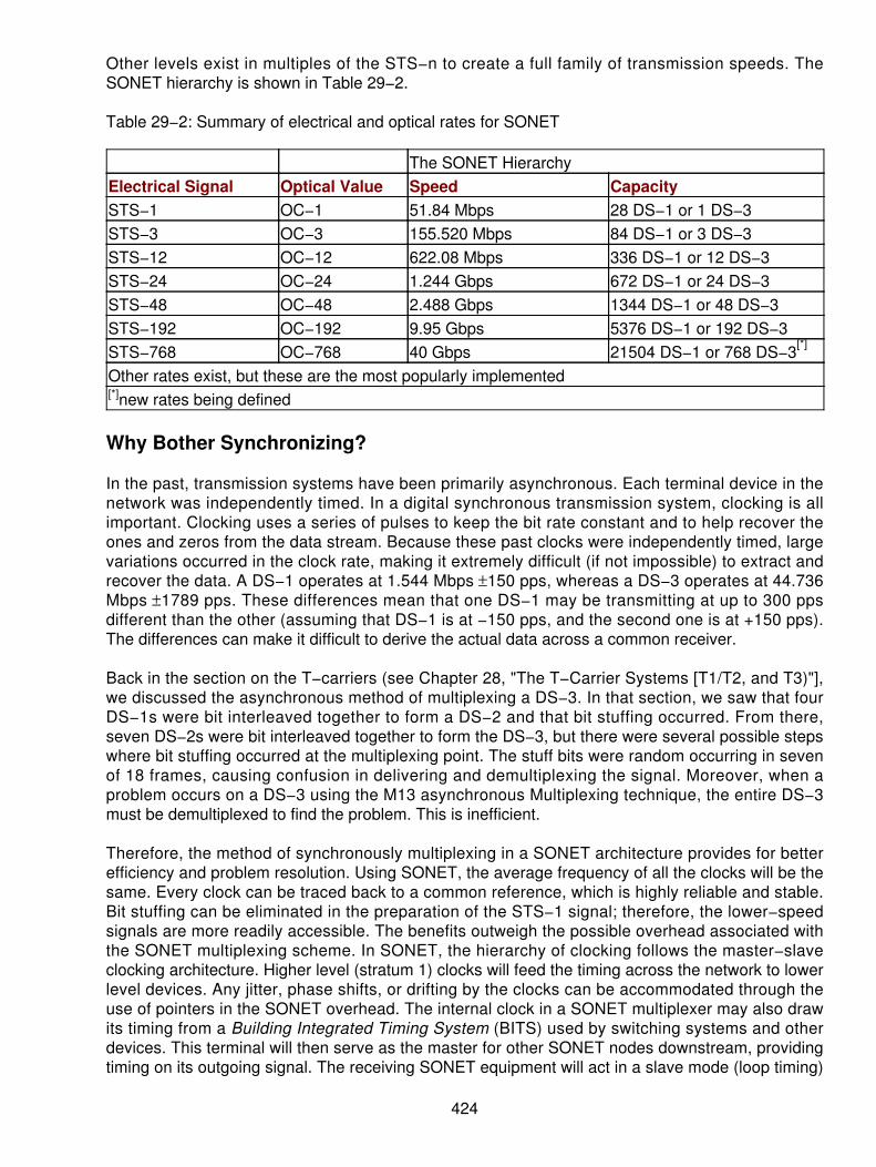
Other levels exist in multiples of the STS−n to create a full family of transmission speeds. TheSONET hierarchy is shown in Table 29−2.
Table 29−2: Summary of electrical and optical rates for SONET
The SONET HierarchyElectrical Signal Optical Value Speed CapacitySTS−1 OC−1 51.84 Mbps 28 DS−1 or 1 DS−3STS−3 OC−3 155.520 Mbps 84 DS−1 or 3 DS−3STS−12 OC−12 622.08 Mbps 336 DS−1 or 12 DS−3STS−24 OC−24 1.244 Gbps 672 DS−1 or 24 DS−3STS−48 OC−48 2.488 Gbps 1344 DS−1 or 48 DS−3STS−192 OC−192 9.95 Gbps 5376 DS−1 or 192 DS−3STS−768 OC−768 40 Gbps 21504 DS−1 or 768 DS−3[*]
Other rates exist, but these are the most popularly implemented[*]new rates being defined
Why Bother Synchronizing?
In the past, transmission systems have been primarily asynchronous. Each terminal device in thenetwork was independently timed. In a digital synchronous transmission system, clocking is allimportant. Clocking uses a series of pulses to keep the bit rate constant and to help recover theones and zeros from the data stream. Because these past clocks were independently timed, largevariations occurred in the clock rate, making it extremely difficult (if not impossible) to extract andrecover the data. A DS−1 operates at 1.544 Mbps ±150 pps, whereas a DS−3 operates at 44.736Mbps ±1789 pps. These differences mean that one DS−1 may be transmitting at up to 300 ppsdifferent than the other (assuming that DS−1 is at −150 pps, and the second one is at +150 pps).The differences can make it difficult to derive the actual data across a common receiver.
Back in the section on the T−carriers (see Chapter 28, "The T−Carrier Systems [T1/T2, and T3)"],we discussed the asynchronous method of multiplexing a DS−3. In that section, we saw that fourDS−1s were bit interleaved together to form a DS−2 and that bit stuffing occurred. From there,seven DS−2s were bit interleaved together to form the DS−3, but there were several possible stepswhere bit stuffing occurred at the multiplexing point. The stuff bits were random occurring in sevenof 18 frames, causing confusion in delivering and demultiplexing the signal. Moreover, when aproblem occurs on a DS−3 using the M13 asynchronous Multiplexing technique, the entire DS−3must be demultiplexed to find the problem. This is inefficient.
Therefore, the method of synchronously multiplexing in a SONET architecture provides for betterefficiency and problem resolution. Using SONET, the average frequency of all the clocks will be thesame. Every clock can be traced back to a common reference, which is highly reliable and stable.Bit stuffing can be eliminated in the preparation of the STS−1 signal; therefore, the lower−speedsignals are more readily accessible. The benefits outweigh the possible overhead associated withthe SONET multiplexing scheme. In SONET, the hierarchy of clocking follows the master−slaveclocking architecture. Higher level (stratum 1) clocks will feed the timing across the network to lowerlevel devices. Any jitter, phase shifts, or drifting by the clocks can be accommodated through theuse of pointers in the SONET overhead. The internal clock in a SONET multiplexer may also drawits timing from a Building Integrated Timing System (BITS) used by switching systems and otherdevices. This terminal will then serve as the master for other SONET nodes downstream, providingtiming on its outgoing signal. The receiving SONET equipment will act in a slave mode (loop timing)
424

with their internal clocks timed by the incoming signal. The standard specifies that SONETequipment must be able to derive its timing at a stratum level 3 or above.
The SONET Frame
SONET also defines a frame format in which to produce the basic rate of 51.84 Mbps (the STS−1).Each of the additions to the multiplexing rates is a multiple of the STS−1. The basic format consistsof a frame that is 80 bytes (columns) wide and 9 bytes high (rows). The basic STS−1 signal is thenapplied into this 810 byte frame. The frame is shown in Figure 29−1. The frame will occur 8,000times per second. If we calculate the math on this we have the following:
Figure 29−1: The SONET frame810 bytes x 8 bits/byte x 8000 frames/sec = 51.84 Mbps
Overhead
From the 810 byte frame, overhead is enabled in several ways to handle the Operations,Administration, Maintenance, and Provisioning services (OAM&P).
The first part of the overhead is defined as the transport overhead. The transport overhead uses thefirst three columns and all nine rows. This creates 27 bytes of transport overhead. As shown inFigure 29−2, the transport overhead is divided into two pieces. The first three columns and the firstthree rows (9 bytes) are used for section overhead. The remaining six rows in the first threecolumns (18 bytes) are used for line overhead.
425

Figure 29−2: The transport overhead is divided into section and line overhead.The remaining 87 columns and nine rows (783 bytes) are designated as the Synchronous PayloadEnvelope (SPE). Inside the SPE, an additional one column, nine rows high (9 bytes) is set aside forPath Overhead (POH). This is shown in Figure 29−3. After the POH is set aside, the resultingpayload is 774 bytes. In these 774 bytes, the services are then mapped into the frame. The STS−1payload can carry the following:
Figure 29−3: The SPE shown
1 DS−3• 7 DS−2s• 21 E−1s• 28 DS−1s•
Combinations of the previous payloads are also allowable. Two columns are reserved as fixed stuffcolumns; these are columns 30 and 59. The remaining 756 bytes carry the actual payload.
426

Inside the STS−1 Frame
The SPE can begin anywhere inside the STS−1 envelope. Normally, it begins in one STS−1 frameand ends there. However, it may begin in one STS−1 frame and end in another. The STS payloadpointer contained inside the transport overhead points to the beginning byte of an SPE. Thepossibilities then are that the frame can carry a locked payload or a floating payload. Floating, in thisregard, refers to the payload floating between two frames. The overhead associated with SONET isdesigned to let the receiver know where to look for its payload and extract the information at astarting point. This floating frame is shown in Figure 29−4.
Figure 29−4: A floating payload inside two frames
SONET Overhead
SONET provides significant overhead, enabling the simpler multiplexing techniques and improvedOAM&P operations. In the next discussion, the overhead is examined to better understand why somuch is dedicated to the overhead functions.
In Figure 29−5, the architecture of the SONET link is shown as defined by ECSA and ANSI. In thisreference, the link architecture is broken down into three parts:
427

Figure 29−5: The SONET architecture of the link
Section The section is defined as the portion of the link between two repeater functions orbetween a repeater and line terminating equipment. Sufficient overhead is enabled to detectand troubleshoot errors on the link between these two points (STE).
•
Line The line overhead provides sufficient information to detect and troubleshoot problemsbetween two pieces of Line Terminating Equipment (LTE).
•
Path The POH provides sufficient overhead to detect and troubleshoot problems betweenthe end−to−end path terminating Pieces of Equipment (PTE).
•
Section Overhead
The section overhead is shown in Table 29−3 and Figure 29−6. This overhead contains 9 bytes ofinformation that is accessed, generated, and processed by the section terminating equipment. Itsupports functions such as the following:
Performance monitoring• A local orderwire• Data communications channels for OAM&P messages• Framing information•
Table 29−3: The individual bytes are defined in the designation and their use
Byte DescriptionA1−A2 Framing bytes: These two bytes provide an indication of the start of an STS−1
frame.J0/Z0 Section Trace (J0) or Section Growth (Z0): This byte in each of the STS−1s in an
STS−n was originally defined as the STS−1 ID (C−1) byte. It has been redefined aseither the section trace byte (in the first STS−1 of STS−n) or as a growth byte(used in the second through nth STS−1s.)
B1 Section Bit Interleaved Parity code (BIP−8) byte: This is a parity code (using evenparity) used to check for transmission errors over a section of the link (a repeater).The value is calculated over all bits of the previous STS−n frame after scramblingand then placed in the B1 byte of the STS−1 before scrambling. This byte only
428

defines for STS−1 number 1 of an STS−n signal.E1 Orderwire: This is a 64 Kbps channel for a voice communications orderwire
between two repeater functions or a repeater and a line terminating equipment. Itallows for two technicians to talk to each other while they troubleshoot problems.
F1 Section User byte: This byte is set aside for users' choice. It terminates at allsection terminating equipment within a line. It can be read or written at each sectionterminating equipment on the line. This may be used for proprietary usermaintenance and diagnostic systems, or for SNMP functions on a user network.
D1−3 Section Data Communications Channel (DCC) bytes: This creates a 192 Kbps datachannel for diagnostics and testing for OAM&P. It uses a message−based channelfor remote locations to control alarms, monitoring, and other maintenancefunctions.
Figure 29−6: The section overheadLine Overhead
In Table 29−4, we see the line overhead, which occupies rows 4 through 9 in the first threecolumns. The line overhead used between two pieces of line terminating equipment provides for theOAM&P functions. This is more extensive than the section overhead. Figure 29−7 also shows itsposition in the overhead of the STS−1 frame.
Table 29−4: The individual bytes of the line overhead
Byte DescriptionH1−H2 STS Payload Pointers: These two bytes indicate the offset bytes between the pointer
and the first byte of the STS SPE. The pointer bytes are used in all STS−1s within anSTS−n to align the transport overhead in the STS−n and perform frequencyjustification. These bytes can also be used to indicate when concatenation is used orto indicate path Alarm Indications Status (AIS).
H3 Pointer Action byte: This byte is allocated for frequency justification. The H3 byte isused in all STS−1s within an STS−n to carry the extra SPE byte to either incrementor decrement the pointer.
B2 Line Bit Interleaves Parity code (BIP−8) byte: This parity code byte is used to
429

determine if a transmission error has occurred over the line. It uses even parity and iscalculated over all bits of the line overhead and STS−1 SPE of the previous STS−1frame before scrambling. The value is placed in the B2 byte of the line overheadbefore scrambling.
K1−K2 Automatic Protection Switching (APS) channel bytes: These two bytes are used forprotection signaling between two line terminating devices for bidirectional automaticprotection switching and for detecting Alarm Indication Signal on the Line (AIS−L)and Remote Defect Indication (RDI) signals.
D4−D12 Line Data Communications Channel (DCC) bytes: This creates a 576 Kbps channelcapacity for message signaling from a central location for OAM&P. These bytes areavailable for generic, internal, or external messages, or vendor−specific messages.The use of a protocol analyzer is needed to access the DCC.
S1/Z1 Synchronization Status byte (S1): The S1 byte is used for synchronization status ofnetwork elements. It is located in the first STS−1 of an STS−n. Bits 5 to 8 convey thesynchronization information.The Growth (Z1) byte is located in the second throughnth STS−1s of an STS−n and allowed for growth.
M0−M1 STS−1 REI−L (M0) byte is defined for STS−1 in an OC−1 or for the STS−1 electricalsignal. Bits 5 to 8 report on the Line Remote Error Indication function (REI−L, whichused to be called the FEBE).STS−n REI−L (M1) byte is located in the third STS−1 (inorder of appearance in the byte interleaved STS−n electrical or optical signal) in anSTS−n (where n ≥3) and is used for the REI−L function.
Z2 Growth (Z2) byte: This byte is located in the first and second STS−1s of an STS−3,and the first, second and fourth through nth STS−1s of an STS−n (where 12 ≤ n ≤48). These bytes are reserved for future growth.
E2 Orderwire byte: This orderwire byte provides a 64 Kbps channel between lineequipment for an express orderwire. It is a voice channel used by technicians, and isignored as it passes through the repeaters.
430

Figure 29−7: The line overhead of a SONET framePOH
The final piece of overhead is the POH contained inside the SPE. POH contains 9 bytes ofinformation starting at the first byte of the STS SPE. The POH provides for communication betweentwo path−terminating PTE. The PTE is where the actual multiplexing and demultiplexing functiontakes place as the services are mapped into the SONET frame. The functions supported by thePOH are as follows:
Performance monitoring of the STS SPE• Signal label the individually mapped payloads• Path status• Path trace•
The POH is shown in Table 29−5 and in Figure 29−8 to correlate them in the overall function of theSTS frame.
Table 29−5: The POH defined
Byte DescriptionJ1 STS Path Trace byte: This user programmable byte repetitively transmits a 64
byte, or a 16−byte (E.164) format string. This is used so the receiving end of thepath to verify it is still connected to the sending end.
B3 STS Path Bit Interleaved Parity code (path BIP−8) byte: This byte is even parityto check if an error has occurred across the entire path.
C2 STS Path Signal Label byte: This byte is used to identify the content of the STSSPE, including the status of the mapped payloads.
431

G1 Path Status byte: This byte is used to convey path terminating status andperformance characteristics back to the originating end. Bits 1 to 4 are used forATA Path REI−P (was referred to as the FEBE). Bits 5, 6, and 7 are for an STSPath RDI (RDI−P) signal, and bit 8 is not defined.
F2 Path User Channel byte: The byte is used for user communications betweenend−to−end elements. This may be a proprietary network management systemor an SNMP system to determine the status and alarms of the far end on thepath.
H4 VT Multiframe Indicator byte: This byte provides a general multiframe alignmentindicator for payload containers. Currently, it is only used for VT payloads.
Z3−Z5 Growth bytes: These bytes are undefined at this time.
Figure 29−8: POH in the STS frame
Virtual Tributaries
SONET is more than the STS frame; it also defines the sub−STS levels of payload that can becarried. The STS−1 payload can be subdivided into virtual tributaries, synchronous signals totransport lower−speed signals. The normal sizes defined by SONET are shown in Table 29−6.
Table 29−6: The values of the virtual tributaries defined for SONET
VT Bit Rate EquivalentDS−n Level
Required Bytes(Rows x Columns)
1.5 1.728 Mbps DS−1 27 (9 x 3)2 2.304 Mbps E−1 36 (9 x 4)3 3.456 Mbps DS−1C 54 (9 x 6)6 6.912 Mbps DS−2 108 (9 x 12)
432

SONET Multiplexing Functions
The primary principles of the SONET multiplexers are as follows:
Mapping the tributaries into the STS−n frame• Aligning the information by using the pointer information to determine where the first byte ofthe tributary is located
•
Multiplexing lower order signals are adapted to higher order signals• Stuffing of bits necessary to handle the various lower−speed, asynchronous channels, andfilling up the spare bits to keep everything in alignment
•
The SONET equipment provides these functions. SONET can carry very large payloads, as wehave seen in the hierarchy of the data speeds. Up to now, we have seen the primary mapping andlayout of an STS−1 (OC−1). SONET equipment can add the value necessary to protect investmentsby either lower−rate multiplexing or higher−rate multiplexing. If one looks at an OC−3, for example,the multiplexer will produce a larger STS frame. In this case, as shown in Figure 29−9, the frame isthree times larger or 270 bytes (columns) wide and nine rows high for a total of 2,430 bytes. Notefrom this figure the overhead for the STS−n is located in the beginning of the frame, whereas thePOH is located at the start of each payload.
Figure 29−9: The STS−3 (OC−3) frameAdd−Drop Multiplexing: A SONET Benefit
Another major benefit of the SONET specification is the ability to perform add−drop multiplexing.Even though network elements are compatible at the OC−N level, they may still differ from vendorto vendor. SONET doesn't attempt to restrict vendors to all providing a single product, nor does itrequire that they produce one of every type out there. One vendor may offer an Add−DropMultiplexer (ADM) with access to the DS−1 level only, whereas another may offer access to DS−1and DS−3 rates. The benefit of an ADM on a Wide Area Network (WAN) is to drop (demultiplex)only the portions of the optical stream required for a location and let the rest pass through withoutthe demultiplexing process. It would be extremely inefficient to have to demultiplex an entire OC−12,
433

for example, only to drop out one DS−1. The ability to extract only what is necessary helps toprevent errors, loss of data, and other delays inherent with older technologies. The add−dropmultiplexer makes this attractive for carriers to use in rural areas where they may bundle manylower−speed communications channels onto a single OC−1 or OC−3 to carry the information backto the central metropolitan areas. Moreover, beyond just dropping a digital signal out of ahigher−speed OC−n, the carrier can fill in what has been vacated. (For example, if a DS−1 isdropped off along the optical path, a new DS−1 can be multiplexed back into the OC−3 in its place.)This enables the carriers considerable flexibility. In Figure 29−10, an ADM is shown. Here portionsof the bandwidth can be dropped off, and additional new signals can be added in place of the datastream dropped out of the higher−speed signal. A single stage add−drop multiplexing function canmultiplex various inputs into an OC−n signal. At an add−drop site, only those signals that need to beaccessed are dropped and inserted. The remaining traffic continues through the network switchingsystem without requiring special processing.
Figure 29−10: Add−drop multiplexing with SONET
SONET Topologies
Several different topologies can be used in a SONET network by using the various multiplexers.These include the normal topologies most networks have been accustomed to over the years. Theyinclude the following:
Point−to−point• Point−to−multipoint• Hub and spoke• Ring•
It is the variations that enable the flexibility of SONET in the WANs built by the carriers but are nowbecoming the method of choice at many large organizations.
In each of the topologies, larger organizations are finding the benefits of installing highly reliable,interoperable equipment at the private network interfaces and access to the public networks.
Point−to−Point
The SONET multiplexer, the entry level PTE for an organization (or the equipment installed by theLEC at the customer's premises to access the network), acts as a concentrator device for themultiple lower−speed communications channels, such as DS−1 and DS−3. In its simplest form, two
434

devices are connected with an optical fiber (with any repeaters as necessary) as a point−to−pointcircuit. As the entry−level point into a SONET architecture, the inputs and outputs are identical. Inthis environment, the network can act as a stand−alone environment and not have to interface withthe public switched networks. See Figure 29−11 for the point−to−point multiplexing arrangement.
Figure 29−11: Point−to−point service with SONETPoint−to−Multipoint
The next step is to consider the point−to−multipoint arrangement. This will use a form of add−dropmultiplexing to drop circuits off along the way. In a large corporate network spanning the country (orany subset), a single, high−speed link may be employed. The SONET ADM is used for the task athand, dropping circuits out without demultiplexing the entire high−speed signal. In Figure 29−12, theADM is installed between two far−end locations so that signals can be added or dropped off asnecessary. This is a better solution than renting three different circuits between points A−B, A−C,and B−C, which adds to the complexity and cost. By using a circuit from A−B−C with ADMs, theservice can usually be more efficiently accommodated.
Figure 29−12: ADMs installed along the wayHub and Spoke
The hub and spoke method (sometimes referred to as the star network) enables some addedflexibility in the event of unpredicted growth or constant changes in the architecture of the network.SONET multiplexers can be hubbed into a Digital Cross−Connect where it is concentrated and thenforwarded on to the next node (see Figure 29−13). This is used in many larger organizations whereregional offices are located, and district or branch offices are tied into the network through the hub.Once again, the flexibility is there if a major change occurs in the network architecture or in theevent of major campaigns in the organization. Hubs will act as the cross−connect points to link thevarious echelons in the network together. These may be developed in a blocking or nonblockingmanner. Typically, some blocking may be enabled.
435

Figure 29−13: Hub and spoke in a SONET multiplexer networkRing
Next, the glory of SONET! In a ring architecture, where SONET automatic protection switching isemployed, the best of all worlds comes to fruition. In this topology, ADMs are used throughout thenetwork, and a series of point−to−point links are installed between adjoining neighbors. Thebidirectional capability places the most robustness into the network; however, unidirectionalservices can also be installed. The primary advantage of the ring architecture is survivability in theevent of a cable cut or a failure in a network node. The multiplexers have sufficient intelligence toreroute or reverse direction in the event of a failure. If more than one fiber link is installed, thesystems could use alternate paths, but they must recover in milliseconds (which APS on SONET isdesigned to do). Figure 29−14 shows the ring topology with dual fibers run (bidirectional service)between the ADMs.
Figure 29−14: Ring architecture of SONET multiplexers
Evolution of SONET in the Rest of the World
Following the work by ANSI in developing the SONET standards, the rest of the world began tomove in tandem. The ITU−TSS decided to define a synchronous standard that would addressinternetworking between the ITU and ANSI transmission hierarchies. In 1989, the ITU published theSDH standards. SDH is a world standard, whereas SONET is a North American standard. However,SONET is considered a subset of the SDH standards. Prior to the publication of the SDH standard,different rates and speeds were available in the North American community (which is the UnitedStates, Canada, and Japan) compared to the rest of the world. The ITU was looking for a means ofaccommodating the differences in a standardized package so that both standards could coexist.SDH marks one of the first steps in making that happen. However, although SDH sets a rate of
436

multiplexing and the derived speeds (and the means of achieving those speeds), some differencesbetween SONET and SDH exist. The packaging of the tributaries is different.
In Table 29−7, a comparison of the SONET and SDH architectures is shown. SDH defines theSynchronous Transfer Mode (STM) level N, whereas SONET defines the STS−n and the OC−n.
Table 29−7: Comparison of SONET and SDH rates
SONETSignal
Rate SDHSignal
SONETPayload
SDHPayload
OC−1 51.84 Mbps STM−0 28 DS−1or 1 DS−3
21 E−1
OC−3 155.52Mbps
STM−1 82 DS−1 or3 DS−3
63 E−1 or1 E−4
OC−12 622.08Mbps
STM−4 336 DS−1or 12 DS−3
252 E−1 or4 E−4
OC−48 2.488Gbps
STM−16 1344 DS−1or 48 DS−3
1008 E−1 or16 E−4
OC−192 9.953Gbps
STM−64 5376 DS−1or 192 DS−3
4032 E−1 or 64 E−4
The OC−n also has a compatible STS−n rate.
Even though the rates are the same, the packaging of the frames for SDH and SONET is different.
SDH
Ever since the standards bodies approved the recommendations for the SDH (and SONET), theservices have been effectively used to improve and revolutionize the industry. Significant costefficiencies and performance improvements have been shown. SDH provides a means for the restof the world to use the capabilities of fiber−based transport systems and multiplexing architecturesto improve upon the older Plesiochronous Digital Hierarchy (PDH), which was inefficient andexpensive.
Digital networks continue to expand in complexity and penetration within the carriers' networks, nowmoving closer to the consumer's door. High−speed communications prior to the formulation of SDHin 1990 operated at speeds of up to 139.364 Mbps. However, the carriers implemented coaxial andradio−based systems operating at 140 Mbps to 565 Mbps. The networks were severely constraineddue to the high cost of the transmission medium (coaxial cable, especially). The multiplexing ratesused plesiochronous rates, which led to the European PDH.
After the development of fiber and the enhancements of integrated circuitry, the newer transmissionspeeds and complex networking architectures became realistic. In Europe, the evolution anddeployment of ISDN also led to the proliferation of the B−ISDN standards, which enable a simplemultiplexing technique. In the United States, the Bell breakup prompted the local carriers to look forinteroperability and improvements in network management because of the proliferation of thenumber of carriers providing long distance services.
The ITU−TSS agreed that something had to be done to improve and standardize the multiplexingand the interoperability, while at the same time taking advantage of the higher capacity of opticalfiber. Older bit interleaving of multiplexers should be replaced by byte interleaving to afford betternetwork management. The new standard appeared as SONET in the North Americas, drafted by
437

Bellcore. Later, this same standard developed into the SDH/SONET standard, as approved by theITU. Although SONET and SDH were initially drafted in support of a fiber, radio−based system,supporting the same multiplexing rates became available.
438

Chapter 30: Synchronous Digital Hierarchy (SDH)[1]
Overview
As discussed in Chapter 29, "Synchronous Optical Network (SONET)," SONET is the high−speedoptical−based architecture for carriers and users alike. This optical−based networking strategy wasdeveloped in North America by the American National Standards Institute (ANSI). While the ANSIcommittees were working on SONET though, another movement was underfoot. In Europe thestandards committees were also wrestling with the logical replacement to the plesiochronous digitalhierarchy (PDH), which is an asynchronous multiplexing plan to create high−speed communicationschannels. The Europeans came up with a separate multiplexing hierarchy called the SynchronousDigital Hierarchy (SDH) in support of the SONET standards.
Ever since the standards bodies approved the recommendations for the SDH (and SONET), theservices have been effectively used to improve and revolutionize the industry. Significant costefficiencies and performance improvements have been shown. SDH provides a means for the restof the world to use the capabilities of fiber−based transport systems and multiplexing architecturesto improve upon the older PDH, which was inefficient and expensive. The PDH evolved in responseto the demand for plain old telephone services (POTS) and was not ideally suited to deliver theefficient use of bandwidth and high−speed services.
Digital networks continue to expand in complexity and penetration within the carriers' networks, nowmoving closer to the consumers' door. High−speed communications prior to the formulation of SDHin 1990 operated at speeds of up to 139.364 Mbps. However, the carriers implemented coaxial andradio−based systems operating at 140 Mbps to 565 Mbps. The networks were severely constraineddue to the high cost of the transmission medium (coaxial cable especially). The multiplexing ratesused plesiochronous rates, which led to the European PDH.
After the development of fiber and the enhancements of integrated circuitry, the newer transmissionspeeds and complex networking architectures became realistic. In Europe, the evolution anddeployment of Integrated Services Digital Network (ISDN) also led to the proliferation of theBroadband ISDN (B−ISDN) standards, which enables a simple multiplexing technique. In the UnitedStates, the Bell breakup prompted the local carriers to look for interoperability and improvements innetwork management because of the proliferation of the number of carriers providing long−distanceservices.
The International Telecommunication Union−Telecommunication Standardization Sector (ITU−TSS)agreed that something had to be done to improve and standardize the multiplexing and theinteroperability while at the same time take advantage of the higher capacity of optical fiber. Theolder bit interleaving of multiplexers should be replaced by byte interleaving to afford better networkmanagement. The new standard appeared as SONET in North America, drafted by BellCore[2].Later this same standard developed into the SDH/SONET standard as approved by the ITU.Although SONET and SDH were initially drafted in support of fiber, radio−based systems supportingthe same multiplexing rates also became available.
[1] This chapter comes from the Optical Switching and Networking Handbook, R. Bates,McGraw−Hill 2001.[2] The BellCore name has since been changed to TelCordia Technologies.
439
Why SDH/SONET
There are many reasons why SONET and SDH were necessary. The primary reason was thatprevious technology (PDH) was limited in many ways, such as
U.S. and European systems had little in common in their mapping and multiplexing systems.Therefore, expensive translators were required for transatlantic traffic on leased lines.
•
Standard equipment from different vendors in the same country was incompatible. Everyoneproduced a proprietary solution that worked with his or her own equipment.
•
Systems did not offer self−checking of equipment and network components. Expensivemanual checks were required, and extraordinary repair systems were the norm.
•
No standard for high bandwidth links existed. Everything maintained the proprietaryapproach. This created havoc in the industry and needed to be improved.
•
Not all of the multiplexing systems were synchronous. In the United States, anything aboveDS−1 bandwidth was asynchronously multiplexed, timed, and mapped.
•
Synchronous Communications
What does synchronous mean anyway? Why is it so important to the telecommunications industry?The easiest way to describe the need for synchronization is that the bits from one telephone call arealways in the same location inside a digital transmission frame such as a DS−1. In the UnitedStates, telephone calls using digital transmission systems create a DS−0. The DS−0s aremultiplexed, 24 per DS−1 channel. DS−1 lines are synchronously timed and mapped; therefore, it iseasy to remove or insert a call. Finding the location creates an easy add−drop multiplexingarrangement.
Plesiochronous
Plesiochronous means "almost synchronous." Variations occur on the timing of the line so bits arestuffed into the frames as padding. The digital bits (1s and 0s) vary slightly in their specific locationwithin the frame creating "jitter." This occurs on a frame−to−frame basis, creating ill timing andrequiring some other actions to make everything bear some semblance of timing. An example in theprevious chapter with the multiplexing of a DS−3 occurred when
Four DS−1 lines are bit−interleaved and multiplexed together to create a DS−2.• Seven DS−2 lines are bit−interleaved and multiplexed to create a DS−3.• If we need to isolate a particular call from a DS−3, the entire DS−3 must be demultiplexed tothe DS−1 level where we can then extract the individual DS−0s.
•
Very expensive equipment is needed at every Central Office (CO) to demultiplex andmultiplex high−speed lines across the backbone networks.
•
Consequently, the standards committees (both ANSI and the ITU) began working on solutions tothe multiplexing problems. The ultimate attempt was to develop a synchronous transmission systemthat could replace the plesiochronous transmission systems.
In Table 30−1, a summary and comparison of the rates of speed for worldwide speeds andhierarchical arrangements are shown. This table brings the differences to light when you comparethe speeds and multiplexed channels combined.
Table 30−1: Comparing the rates of speed for the various levels of the digital hierarchy in Kbps
440

Hierarchical Level North AmericanDS−x
EuropeanCEPT−x
JapaneseLevel
International Rates
0 64 64 64 641 1,544 2,048 1,544 2,0482 6,312 8,448 6,312 6,3123 44,736 34,368 32,064 44,7364 274,176 139,264 97,728 139,2645 564,992 397,200 564,992
In 1986, the International Telegraph and Telephone Consultative Committee (CCITT) published astandard set of transmission rates for SDH. The SDH standards finally emerged in 1992[3]. Theseare filed under the following standards:
G.707• G.708• G.709•
Using the same fiber, a synchronous network is able to increase the available bandwidth whilereducing the amount of equipment in the network. Moreover, the provisioning of SDH forsophisticated network management introduces much more flexibility into the overall networkingstrategies for the carriers.
SDH
As the synchronous equipment was rolled into the network, the full benefits became more apparent.The carriers experienced significant cost reductions and avoidances, less hardware, and increasedefficiencies in the multiplexing of the various rates established by the ITU SDH multiplexing.However, other benefits required fewer spares to be maintained in the network. Additional benefitswere had by the use of the SDH standard multiplexing formats, which could encapsulate the PDH,multiplexed signals inside the SDH transport. This protects the carriers' investments and preventsthe use of forklift technology. In fact, SDH offered the network operators the ability to future−prooftheir networks, enabling them to offer Metropolitan Area Network (MAN), Wide Area Network(WAN), and B−ISDN services on a single platform.
The SDH forms a multiplexing rate based on the STM−N frame format. The STM stands forSynchronous Transfer Mode. The STM−N general frame format works as follows. Similar to theSONET OC−1 (albeit larger), the basic STM−1 frame consists of
270 columns x 9 rows = 2,430 octets
9 columns x 9 rows = 81 octets section overhead
The remaining 2,349 octets create the payload. Higher rate frames are derived from multiples ofSTM−1 according to value of N. The standard STM−1 frame is shown in Figure 30−1. This is similarbut different from the frame in an OC−3.
441

Figure 30−1: The STM−1 frame formatsData Transmission Rates
In the standards, a number of transmission rates are defined or possible based on the multiplexingrates. Not all rates are commercially available; however, the rates are there in case a new rate isneeded. Similar to the SONET standards, SDH defines the Synchronous Transport Signal level N(STS−N) and the SDH level N (SDH−N). These define the electrical rate of multiplexing and theoptical rate of multiplexing, both working at the appropriate rate of speed necessary to map andmultiplex the higher rates of speed. The typical rates of speed and the appropriate STS and STMrates are shown in Table 30−2.
Table 30−2: Comparison of STS and STM rates
Electrical Rate Optical Rate SpeedSTS−1 STM−0 51.84 MbpsSTS−3 STM−1 155.52 MbpsSTS−9 STM−3 466.56 MbpsSTS−12 STM−4 622.08 MbpsSTS−18 STM−6 933.12 MbpsSTS−24 STM−8 1.244 GbpsSTS−36 STM−12 1.866 GbpsSTS−48 STM−16 2.488 Gbps
Only three of the hierarchical levels are actually defined in the standard and are commerciallyavailable. These are the STM−1, STM−4, and STM−16. Other rates will become available asneeded. As the multiplexing occurs and the overhead is subtracted from the payload, the actualthroughput is shown in Table 30−3. This table reflects the aggregates of throughput in the threecommercially available STM payloads.
Table 30−3: SDH payload compositions for the hierarchical rates
STM Level Data Rate Actual Payload1 155.52 Mbps 150.112 Mbps
442

4 622.08 Mbps 601.344 Mbps16 2.4883 Gbps 2.40537 Gbps
Some Differences to Note
Many of the actual rates in use are defined under the initial capacities of SONET in the CCITTstandards. The original SDH standard defined the transport of 1.5, 2, 6, 34, 45, and 140 Mbps withinthe transmission rate of 155.52 Mbps (the STM−1). SDH was intended to carry the SONET rates.However, the European manufacturers and carriers carry only the European TelecommunicationsStandards Institute (ETSI) defined PDH rates of 2, 34, and 140 Mbps. (The E−2 specification wasdeleted in the specification.) SDH really turns out to be more than just a set of multiplexing speedsand transport rates. It is also a Network Node Interface (NNI) defined by the ITU−TSS for worldwideuse, partially compatible with the ANSI SONET specification. Further, it is one of two options for theUser−to−Network Interface (UNI) to support the B−ISDN.
The Multiplexing Scheme
When trying to understand the SDH architecture, it is important to remember that the NorthAmericans have always done things one way and the Europeans (actually, the rest of the world)have done things in a different way. The two entities never seem to become harmonized. As aresult, the way the mapping and multiplexing was arranged differs from the way the standards andmultiplexing techniques work in the North American communities (ANSI and SONET). The languagediffers from what is used in SONET specifications.
As the framing and formatting begin with the STM−1 frame, using the equivalent of the OC−3specifications, the language begins to shift in a simple yet confusing manner. The STM−1 frame isshown in Figure 30−2 again but with a few differences. First, the frame does consist of 270 columnsand 9 rows, creating a frame of 2430 bytes. Second, there will be 8,000 frames per second (theframe time is 125 µ seconds). This creates the overall throughput of 155.52 Mbps, the same asSONET.
Figure 30−2: Size of the STM−1 frameAs the data are prepared to place in the frame, several different modes of transport are available. Atthe input, the data flows into a container with a size designation. For example, the C11 is the
443
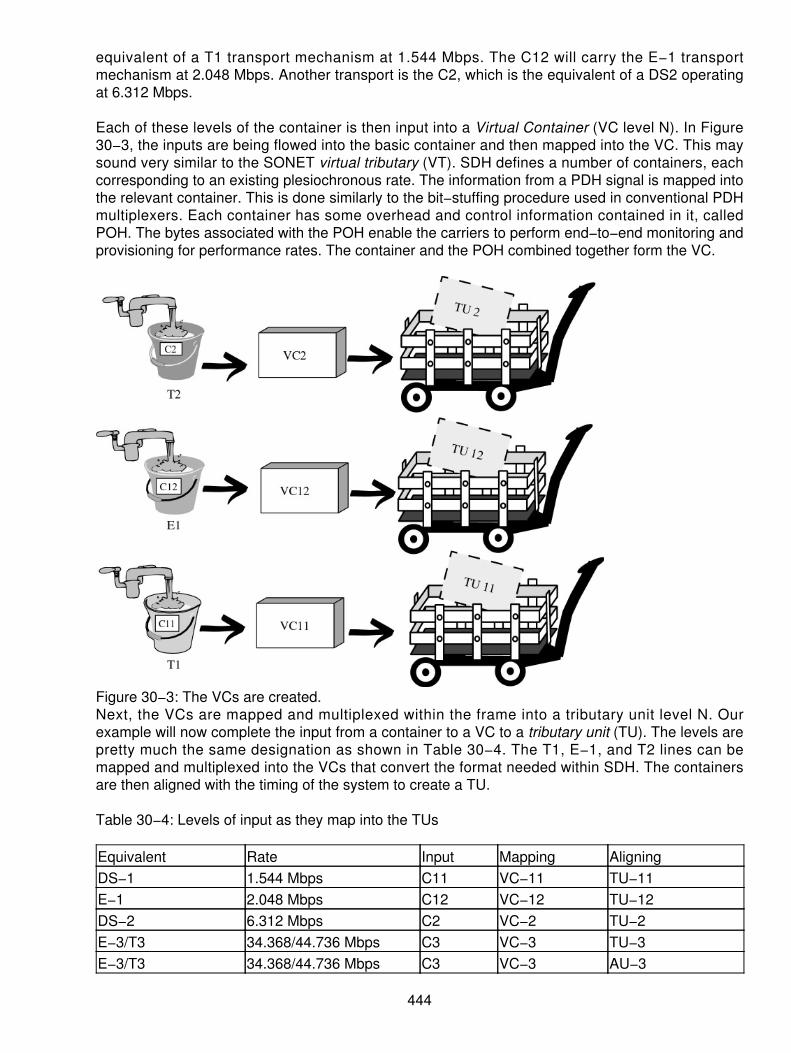
equivalent of a T1 transport mechanism at 1.544 Mbps. The C12 will carry the E−1 transportmechanism at 2.048 Mbps. Another transport is the C2, which is the equivalent of a DS2 operatingat 6.312 Mbps.
Each of these levels of the container is then input into a Virtual Container (VC level N). In Figure30−3, the inputs are being flowed into the basic container and then mapped into the VC. This maysound very similar to the SONET virtual tributary (VT). SDH defines a number of containers, eachcorresponding to an existing plesiochronous rate. The information from a PDH signal is mapped intothe relevant container. This is done similarly to the bit−stuffing procedure used in conventional PDHmultiplexers. Each container has some overhead and control information contained in it, calledPOH. The bytes associated with the POH enable the carriers to perform end−to−end monitoring andprovisioning for performance rates. The container and the POH combined together form the VC.
Figure 30−3: The VCs are created.Next, the VCs are mapped and multiplexed within the frame into a tributary unit level N. Ourexample will now complete the input from a container to a VC to a tributary unit (TU). The levels arepretty much the same designation as shown in Table 30−4. The T1, E−1, and T2 lines can bemapped and multiplexed into the VCs that convert the format needed within SDH. The containersare then aligned with the timing of the system to create a TU.
Table 30−4: Levels of input as they map into the TUs
Equivalent Rate Input Mapping AligningDS−1 1.544 Mbps C11 VC−11 TU−11E−1 2.048 Mbps C12 VC−12 TU−12DS−2 6.312 Mbps C2 VC−2 TU−2E−3/T3 34.368/44.736 Mbps C3 VC−3 TU−3E−3/T3 34.368/44.736 Mbps C3 VC−3 AU−3
444

E4 139.264 Mbps C4 VC−4 AU−4
Four T1s (TU 11), three E−1s (TU 12), or one T2 (TU 2) can be multiplexed into a TU Group 2 asshown in Figure 30−4. The architecture begins this way at the entry levels of the SDH.
Figure 30−4: Mapping and aligning into the TU Group 2The next step in the process is to develop a higher level of multiplexing. Here the TUs or TU Groupsare multiplexed into a higher level. Let's think of this as the T1/T2 and T3 architecture in NorthAmerica. Seven Tributary Group 2s are multiplexed into a TU Group 3. This is a T3 operating at the45 Mbps (+/−) rate of speed. The alternative to this is to take one T3 and place that into a TU Group3. This is shown in Figure 30−5 where seven of the TU Group−2s (TUG−2) or one TU 3 aremultiplexed into a TU Group 3 (TUG−3) and then carried into the system as an Administrative UnitGroup 3 (AUG−3).
Figure 30−5: The process of creating a TUG−3To make this even larger, the next step is to continue the multiplexing process. Therefore, three ofthe TUG−3s or one mapped E4 into a container 4 is then multiplexed into the next higher level inthe hierarchy called a Virtual Container 4 (VC−4). This is shown in Figure 30−6.
445

Figure 30−6: Creating the VC−4When the VC−4 is aligned into a SDH frame, it becomes the Administrative Group 4 carried throughthe system as Administrative Unit Group 4 (AUG−4). In Figure 30−7, this occurs and is aligned tothe SDH framing format of an E4 rate of 139.364 Mbps inside a 155.52 Mbps framed SDHtransport, STM−1.
Figure 30−7: The E4 is created inside an STM−1.One can see that the rates of multiplexing are very similar to the SONET specification; however,differences in the bit stuffing and clocking still exist inside this framing and formatting. Thecomparison now turns to the look and feel of the SONET tributary multiplexing and the SDHmultiplexing in the overall scheme of this transport system.
Figure 30−8 is a representation of using a SONET multiplexing arrangement to produce theAdministrative Unit 3 (which by all stretches of the imagination is the T3, or the seven T2s). Herethe AUG is the equivalent of three Administrative Unit 3s. One can now derive the fact that the threeadministrative units creating the administrative unit group s is an OC−3 operating at 155.52 Mbps.
Figure 30−8: The SONET tributary multiplexing schemeFinally, comparing the multiplexed rates into these AUGs in both SDH and SONET, the outcome isthe STM−N as shown in Figure 30−9. We can add the services as necessary to get to the STM−4,which is the 622.08 Mbps transport or the STM−16 that is our 2.488 Gbps transport system. Onecan see that the two systems are very closely aligned to each other; just different multiplexing andformatting arrangements are used in defining the overall platforms.
446

Figure 30−9: The final outcome of the SDH or SONET framingTable 30−5 is a comparison of the combined services just described, including the two systems, theelectrical rates and the payloads. This comparison also includes information regarding the overallframe size. Looking at the table shows that the industry standardization was somewhat successfulin getting the systems to align to each other and prevent some of the age−old problems of the past.
Table 30−5: Comparing SDH and SONET frame sizes and nomenclature
SDH SONET Fiber Mbps FrameSize
Rows/Frame PayloadBytes
Payload[*]Bytes/Row
STM−0 STS−1 OC−1 51.84 810 90 774 86STS−3 OC−3 155.52 2,430 270 2,322 258
STM−1 STS−3c OC−3c 155.52 2,430 270 2,340 260STS−12 OC−12 622.08 9,720 1,080 9,288 1,032
STM−4 STS−12c OC−12c 622.08 9,720 1,080 9,387 1,043STS−48 OC−48 2,488.32 38,880 4,320 37,152 4,128
STM−16 STS−48c OC−48c 2,488.32 38,880 4,320 37,575 4,175STM−64 STS−192 OC−192 9,953.28 155,520 17,280 148,608 16,152STM−256 STS−768 OC−768 39.81312 622,080 69,120 594,432 64,608[*]In some cases, the concatenated payloads will produce more bytes as the payloads are all in oneset of path overhead (POH). For example, if we eliminate the POH of two OC−1s when using anOC−3c, then the payload increases to 2,340 and the payload bytes per row increase by two.
In Figure 30−10, the overall structure of the VC multiplexing is shown as a graph in the flow of thechannels inside the overall STM−N as depicted by the ITU standard G.707. This is a simple way toview the overall structure of the SDH multiplexing scheme.
447

Figure 30−10: The multiplexing structure via G.707As the end user (vis−à−vis business user) becomes more dependent on the use of thecommunications infrastructure and the efficiencies that are possible, the use of this bandwidth isbecoming explosive. At one time, a gigabit of capacity was considered an enormous amount. Now,the gigabit to the desk is more the norm. Therefore, the use of this bandwidth constitutes one of thefastest segments of the growth in the industry. No longer can we be satisfied with just a basic voicecall. Instead, we are looking for the necessary bandwidth, on a global basis, to handle voice, data,video, and multimedia. Moreover, we require a network that is close to being 100 percent available.The PDH networks could not provide this service level or flexibility. However, the SDH networks canand will continue to offer virtually unlimited bandwidth.
In a synchronous network, all the equipment is timed (synchronized) to an overall network clock aswe saw in the chapter on SONET. The delay associated with transmission links may vary slightlyfrom link to link. Consequently, the location of the VCs within an STM−1 frame may not be fixed.The variations are handled using pointers associated with each VC. The pointer will point to thebeginning position of the VC in relation to the STM−1 frame. This pointer can be increased ordecreased as necessary to handle the variations in the position of the VC.
ITU G.709 defines different combinations of the VCs that can fill the payload of the STM−1 frame.The process of data fill in the containers and adding overhead is repeated many times at differentlevels in the SDH. This results in the nesting of smaller VCs within larger ones. The nesting processis repeated until the largest bundle (VC−4) is filled. After that, the filled VC−4 is loaded into thepayload of the STM−1 frame as shown in Figure 30−11. The pointer processing is different here inthe TSM−1 frame and a STS−3 frame in SONET.
448
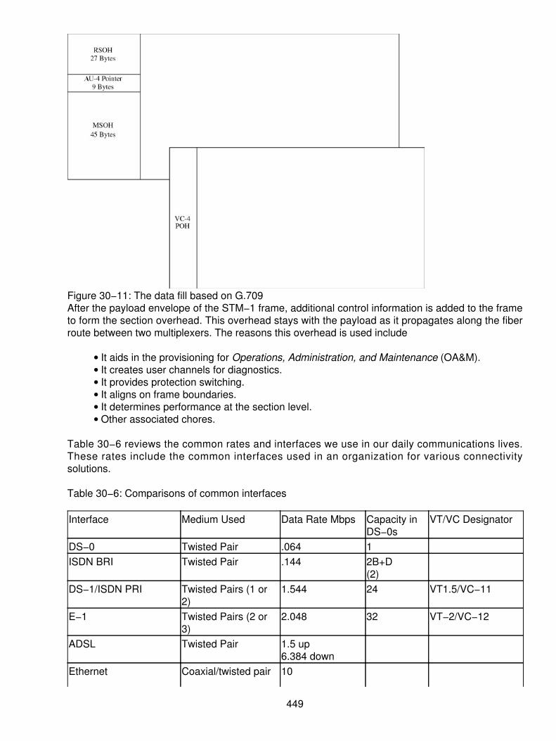
Figure 30−11: The data fill based on G.709After the payload envelope of the STM−1 frame, additional control information is added to the frameto form the section overhead. This overhead stays with the payload as it propagates along the fiberroute between two multiplexers. The reasons this overhead is used include
It aids in the provisioning for Operations, Administration, and Maintenance (OA&M).• It creates user channels for diagnostics.• It provides protection switching.• It aligns on frame boundaries.• It determines performance at the section level.• Other associated chores.•
Table 30−6 reviews the common rates and interfaces we use in our daily communications lives.These rates include the common interfaces used in an organization for various connectivitysolutions.
Table 30−6: Comparisons of common interfaces
Interface Medium Used Data Rate Mbps Capacity inDS−0s
VT/VC Designator
DS−0 Twisted Pair .064 1ISDN BRI Twisted Pair .144 2B+D
(2)DS−1/ISDN PRI Twisted Pairs (1 or
2)1.544 24 VT1.5/VC−11
E−1 Twisted Pairs (2 or3)
2.048 32 VT−2/VC−12
ADSL Twisted Pair 1.5 up6.384 down
Ethernet Coaxial/twisted pair 10
449

(4)E−3 Coaxial/fiber 34.368 512 VC−31T3 Coaxial/fiber/MW 44.736 672 VC−32STS−1 Coaxial 51.84 672Fast Ethernet Twisted pairs (4) or
fiber100
FDDI Fiber 100Gigabit Ethernet Fiber 1000STS−3 Coaxial 155.52 2,016E−4 Coaxial/fiber 139.368 2,048 VC−4OC−1 Fiber 51.84 672OC−3/STM−1
Fiber 155.52 2,016
OC−12/STM−4 Fiber 622.08 8,064OC−48/STM−16 Fiber 2,488.32 32,256OC−192/STM−64 Fiber 9,953.28 129,024
In the chart shown in Figure 30−12, we see that the use of the SONET and SDH equipmentbecame prevalent in the early 1990s. However, the movement is away from the older PDHtechnologies and more to the installation of newer SONET and SDH equipment. Within the carriercommunities, the movement is dramatic with virtually no older PDH equipment remaining in thepipeline for installation for the future. This market (PDH) is just about completely gone with thesynchronous marketplace exploding at a rate that exceeds anyone's wildest expectations.
Figure 30−12: Market for SONET/SDH equipment
450
Why the Hype?
The use of SDH affords significant benefits to the carrier, but there are also benefits to the end user.Clearly, any technology that is used in the infrastructure of the network must offer benefits to theend user and carrier alike. Otherwise, the user will not take advantage of the potential share of theservices. When we first introduced digital networking in the network, many users wanted to accessthe digital circuits. Bearing in mind, the carriers installed the digital services in the 1960s. Yet 1984was the first time they tariffed the use of the digital architecture to the customer's door. Mind you,certain exceptions existed. The author personally installed a special assembly in the mid−1970susing a T1 from Boston to California. This special arrangement was both expensive and difficult towork with because of the newness to end users. However, the carriers had the services in placeand converted the backbone networks (wide−area) to all digital−standards−based infrastructures.They needed to operate in this fashion to meet the demand for higher−speed communications,reliability expectations, and cost ratios.
Unfortunately, with the introduction of their networks and standards, there were still problems. TheNorth American carriers installed standards− based equipment in their networks whereas theEuropean carriers installed their own standards−based equipment. The major problem was that thetwo did not speak with each other. To solve the problem, gateways were required to interfacebetween the different pieces of equipment. However, when the SDH and SONET standards werecompleted, a new beginning was possible. The intention of both standards was to enableinteroperability and transparency between systems. SDH brings the following advantages:
High−speed transmission rates of up to 10 Gbps in today's backbone. SDH is suitable forthe overall carrier networks, which are the information superhighways of today.
•
Simplified process for add−drop multiplexing. When we compare this to the older systems,the PDH networks were extremely complicated. PDH required that we demultiplex an entireDS−3, for example, in order to get at an individual DS−0. It is now much easier to extractand insert low−bit rate services into or from the higher−speed services.
•
High reliability means high availability. With the SDH networks, providers can meet thedemands of their customers faster, better, and cheaper! The providers can now use astandard set of equipment to meet the need, eliminating the need for multiple spares anddifferent operations systems. Moreover, with the automatic protection switching (APS)services of the SDH, the network can heal itself when a component fails. This means thatthe customer never realizes that a network error or failure occurred.
•
Future networking equipment will be based on multiples of the SDH and SONET equipment.The perfect platform for the carriers is one that satisfies the demand without changes enmasse. SDH can satisfy the basic telephony needs, low− and high−speed datacommunications demands, and the newer demands of the Internet, specifically for streamingaudio and video capabilities. This also meets the need for video or multimedia on−demandservices, only recently becoming more popular.
•
Three words are crucial to the network operators and end−users alike, they are
Bandwidth• Bandwidth• Bandwidth•
The need for bandwidth cannot be overstated in the network today. There is never too much, onlyenough to satisfy the current need. As we see the use of the networks increasing, the carriers andmanufacturers are continually developing new SDH speeds and multiplexing rates to meet thatdemand. Recently, the OC−768 in SONET and the SDH−256 were developed to support up to 40
451

Gbps on a multiplexed circuit. Add to that the capability to perform multiple wavelength multiplexingpossibilities on a single piece of fiber, and we have terabits per second possibilities. That will holdus for a short term, but telecommunications services are like water. Water seeks its own level;telecommunications services increase when we have more bandwidth until we consume it all. Then,it is back to the drawing board to develop a new technique to increase the capacities again. This isa vicious circle, but one that is also extremely exciting as the thresholds are pushed to new levelsand limits.
The Model as It Pertains to SDH
Everything we do usually ties back to a reference to the international standards. For this we use theOpen Systems Interconnect (OSI) as a reference model. In general, SDH operates at the bottomlayer (Layer−1 Physical) of the OSI. This physical layer is subdivided into three separatecomponents. When we deal with this mapping on the OSI, we usually refer to four sub−layercomponents.
Similar to the SONET architecture, SDH networks are divided into various layers that are directlyrelated to the network topology:
The lowest layer is the physical transmission section, the medium in the form of the glass(fiber), but can also represent radio systems such as microwave or satellite.
•
Actually, the photonic layer is below the physical layer, where we turn the pulses into light(photons) and propagate them on the fibers. In many cases, the photonic and the physicallayers are combined.
•
The regenerator section is a path between repeaters. This is also at the physical layerbecause it involves that length of fiber between two repeaters. The overhead is called therepeater (or regenerator) section overhead (RSOH). Signaling across the medium alsooccurs at this level.
•
Following the repeater portion, we have the multiplexer overhead (MSOH) used by themultiplexers for the necessary overhead to track the operation of the circuits and OAM&P.The multiplex section deals with the part of the SDH link between two multiplexers where wemap and multiplex our services (DS−1) into the SDH transport.
•
Sitting on top of the MSOH are two VC layers. These two layers are a part of the mappingprocess whereby the individual tributary signals are placed inside the SDH payload. TheVC−4 is the mapping for the 139 Mbps payload, whereas the VC−12 are the individual E−1signals mapped into the SDH.
•
The overall picture of this is shown in Figure 30−13, the SDH layer model. In this figure, thephotonic layer is shown as a subset to the physical interface. Note that the Asynchronous TransferMode (ATM), POTS, and Internet Protocol (IP) networks are also shown in this figure in as much asthey fit into the overall scheme of the model.
452

Figure 30−13: SDH layer model contrast to OSIIn Figure 30−14, the mapping of the payloads occurs at the SDH multiplexer, whereby the nextportions of the circuit are added. This is shown in the path description in this figure.
Figure 30−14: Path mapping of SDHSDH brings the harmony to the overall multiplexing of the various signals and transport rates. It alsoacts as the gateway between SONET and SDH structure. It has been over a decade since theactual ratif ication of the standards, and now more than ever, the benefits are visible.Transcontinental links are now in heavy use across the world on fiber−based architectures. Thecosts of circuits between and among countries are at an all−time low due to the bandwidth. As moreequipment and carriers are deployed across the world, the World Wide Web of carriers and Internetaccess will definitely become the norm.
[3] CCITT is now called the ITU−TSS.
453

Chapter 31: Wave Division Multiplexing (WDM)
Overview
In the past few years, several major improvements have been made in the use of optical fibercommunications. In earlier discussions regarding the use of SONET (see Chapter 29, "SynchronousOptical Network [SONET]"), the issue of bandwidth surfaced. Not only does the issue of bandwidthkeep coming up but also the problem of just how quickly we consume all the bandwidth that is madeavailable. No matter how much or how fast we improve our spectrum availability, newer applicationscrop up that literally eat up all the capacity available to us.
To solve this problem, the use of frequency division multiplexing (FDM) with our light−basedsystems became a topic of research. What ensued was the ability to introduce various wavelengths(frequencies) of light on the same fiber cable and the resultant increase in possible throughput. Wehave seen increases that approximate between 16 to 30 times the original capacity of a single fiber.These capacities are now being pushed to the limit with variations being promised of up to 128times the capacity of the existing fiber technologies. What this means is that the old days of havingto replace the in−place fibers with new technology have been replaced with newer technology thatuses the in−place fiber, necessitating only the change in electronics on the line. We can expect tosee these advances provide virtually unlimited bandwidth without en masse changes in theinfrastructure. The future holds the promise of reduced costs, increased bandwidth utilization, andease of implementation that meet the demands of our higher speed communications.
WDM
Ten years ago, the implementation of the OC−48 SONET specification had the industry believingthat limitless bandwidth was available. One can just imagine that a mere decade ago the 2.5 ± Gbpscapacities of the optical fiber networks was innovative and exceeded our wildest imaginations abouthow we would ever fill these communications channels. Yet, the industry began to recognize thechanges in consumption patterns. In the demand for multimedia communications, video WANstarted to erode even the highest capacities available. To solve this problem, researchers began toexperiment with the use of more than one light beam on the same cable. Light operates in thefrequency spectrum similar to the older cable TV systems, employing FDM, as shown in Figure31−1.
Figure 31−1: FDM has been used by cable TV operators to carry more information on their coaxialcables.By using different radio frequencies on a cable TV system, the carriers were able to expand thenumber of TV channels available to them on the same coaxial systems. Why not do the same thingswith the various frequencies of light? Thus, a new era was born in the use of wavelength divisionmultiplexing. By adding a tightly separated wavelength of light on the same cable, more capacitycould be obtained.
454

In normal fiber transmission, the use of two standard wavelengths was originally deployed as shownin Figure 31−2. First, a red band of light was used to transmit the signal from the originating end. Ablue band was used at the opposite end. Therefore, the same cable could carry send−and−receivetraffic by using different color bands. The original OC−48 transmission (operating at 2.5 ± Gbps)was exciting, using a single wavelength of light and driving the signal over 20 to 30 miles of fiber.However, the carriers soon recognized that skyrocketing demand for the bandwidth would outpacethe throughput of this single wavelength transmission.
Figure 31−2: The colors of light separate the bands carried on the cable.Depending on the usage of various types, the life cycle of the OC−48 was anticipated to beapproximately two years. Clearly, the rapid increase in Internet access, cellular communications,high−speed data, and the multimedia improvements were on a collision course with the capacity ofthis OC−48 architecture. Choosing to move to a higher capacity multiplexing technique intime−division multiplexing (TDM) was a definite consideration. This led to the higher ratemultiplexing at the OC−192 level (9.953 Gbps±), a four−fold increase in the speed and throughputof the SONET networks. Yet, even though the increases were achieved to the OC−192 level, theinitial implementation was with one wavelength of light.
At the same time, OC−48, using two wavelengths, produced a 5 Gbps throughput on the samefibers, proving that the technology could work. Shortly after the introduction of the OC−192, strideswere taken to introduce OC−48 running four wavelengths (10 Gbps) or a single OC−192 using onewavelength.
Shortly after 10 Gbps were demonstrated, the designers began to experiment with a 20 Gbpscapacity, using eight wavelengths of OC−48 or two wavelengths at the OC−192 rate. Now the stagewas set to push the envelope as far as possible! It was only a matter of a few years before thedevelopers began introducing quantum leaps in their multiplexing ability. Now with multiples ofOC−48 and OC−192, the capabilities of fiber−based transmission exceeded their developers'wildest imagination. Capacities for the dense wavelength division multiplexing (DWDM) servicewere now ranging from 160 Gbps to as much as 400 Gbps. This is the first of many steps we canexpect to see in the near future. Some rumors indicate 128 wavelengths of OC−192 being possibleshortly after the turn of the century. That is 1.2 Tbps!
Table 31−1 summarizes the capacities of the DWDM today and what the future may hold. This tableshows the level of multiplexing, as well as the possible throughput we can expect for the future. Thistable also shows the number of wavelengths on the single mode fiber.
Table 31−1: A summary of current capacity of the DWDM services
455
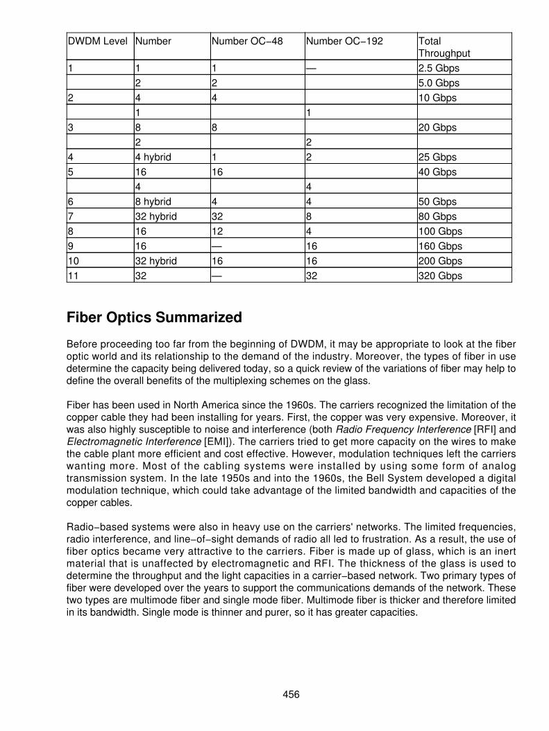
DWDM Level Number Number OC−48 Number OC−192 TotalThroughput
1 1 1 — 2.5 Gbps2 2 5.0 Gbps
2 4 4 10 Gbps1 1
3 8 8 20 Gbps2 2
4 4 hybrid 1 2 25 Gbps5 16 16 40 Gbps
4 46 8 hybrid 4 4 50 Gbps7 32 hybrid 32 8 80 Gbps8 16 12 4 100 Gbps9 16 — 16 160 Gbps10 32 hybrid 16 16 200 Gbps11 32 — 32 320 Gbps
Fiber Optics Summarized
Before proceeding too far from the beginning of DWDM, it may be appropriate to look at the fiberoptic world and its relationship to the demand of the industry. Moreover, the types of fiber in usedetermine the capacity being delivered today, so a quick review of the variations of fiber may help todefine the overall benefits of the multiplexing schemes on the glass.
Fiber has been used in North America since the 1960s. The carriers recognized the limitation of thecopper cable they had been installing for years. First, the copper was very expensive. Moreover, itwas also highly susceptible to noise and interference (both Radio Frequency Interference [RFI] andElectromagnetic Interference [EMI]). The carriers tried to get more capacity on the wires to makethe cable plant more efficient and cost effective. However, modulation techniques left the carrierswanting more. Most of the cabling systems were installed by using some form of analogtransmission system. In the late 1950s and into the 1960s, the Bell System developed a digitalmodulation technique, which could take advantage of the limited bandwidth and capacities of thecopper cables.
Radio−based systems were also in heavy use on the carriers' networks. The limited frequencies,radio interference, and line−of−sight demands of radio all led to frustration. As a result, the use offiber optics became very attractive to the carriers. Fiber is made up of glass, which is an inertmaterial that is unaffected by electromagnetic and RFI. The thickness of the glass is used todetermine the throughput and the light capacities in a carrier−based network. Two primary types offiber were developed over the years to support the communications demands of the network. Thesetwo types are multimode fiber and single mode fiber. Multimode fiber is thicker and therefore limitedin its bandwidth. Single mode is thinner and purer, so it has greater capacities.
456

Multimode Fiber
When fiber was first being used in the communications area, the technology was still developing.Multimode fiber was used as a means of carrying communications signals on the glass morereliably. Multimode, as the name implies, has multiple paths where the light can reach the end of thefiber. Single mode fiber, on the other hand, has only one path that the light can travel to get to theother end. Using a large piece (chunk) of pure glass, the developers extruded the fiber into muchthinner glass strands.
The multimode fiber is the thicker glass by today's standards. The multimode was developed in twodifferent types, step index and graded index, both operating differently. Figure 31−3 is arepresentation of the multimode fiber, using a step index mode. In this case, the glass is very thickat the center core (approximately 120 to 400 microns). The thickness of the glass is crucial to thepassage of the light and the path used to get from one end to another. The step index is the thickestform of fiber; using the core of 120 to 400 microns thick, the light is both refracted and reflectedinside the encased fiber. Because of the density of the glass, the center core refracts the light indifferent angles. At the same time, there is an outer cladding on the glass used to reflect the lightinto the center of the glass. This combination of refraction and reflection of the light, along with thedensity of the glass, causes the light to take different paths (or bounces) to the end of the cable.Different light beams inserted into the fiber will take different lengths of path and therefore differenttiming periods to get to the end of the cable.
Figure 31−3: Step index fiber opticsGraded Index Fiber Optics A second form of multimode fiber was the use of a graded index ofthe glass, as opposed to the step index. Essentially, the grading of the refraction levels of the lightwas changed to compensate for the amount of refraction and the density of the glass. In the stepindex, modal dispersion (spreading out of the light) was in part responsible for a reduction of thethroughput on the fiber. By using a grading of the density of the glass from the center core out, thecapacity of the fiber was increased. Simply stated, the more dense the glass was, the morerefractive the surface of the glass was, or the more refraction taking place, the longer the path. Byhaving a step index, the path of the outer part of the glass was longer than the path in the center ofthe glass. This meant that the light arrived in different times because the length of the path waslonger. Grading the center core to be a higher level of refraction and the outer parts of the glass tobe thinner (and less refractive), we could use the characteristics of the glass to get approximatelythe same length of a wave on the cable and therefore increase the speed of throughput. The gradedindex is shown in Figure 31−4. The better the grading of the index, the more throughput we canexpect. Currently, the two forms of graded index fiber use either a 62.5 micron or a 50 micron centerconductor with a 125 micron outer cladding on the glass.
Figure 31−4: A graded index fiber
457

Single Mode Fiber
As fiber became more popular and research was stepped up, a newer form of glass was developed.If the glass could be made so thin and so pure in the center, the light would have no choice but tofollow the same path every time. A single path (or single mode) between the two ends enabled thedevelopers to speed up the input because there was no concern about varying lengths of the pathas shown in Figure 31−5. Using a single mode fiber today, the thickness is approximately 8.3 to 10microns thick at the center. There is still an outer cladding on the outer edges to reflect the lightback into the center of the glass. The outer cladding is still approximately 125 microns. The singlemode fiber is where most of the activity is being generated today. Many of the telephone carriersdeployed a multimode fiber in their networks when it was first introduced. However, over the yearsthe multimode has given way to single mode fiber throughout the public carrier networks.
Figure 31−5: Single mode fiber is so pure and so thin that the light has only one path from end toend.Benefits of Fiber over Other Forms of Media
The benefits of fiber over other forms of media are shown in Table 31−2. However, it is important tonote that the fiber has been used extensively in the long distance telecommunications networks andthe local telephone company networks. It is more recently that a single mode fiber has worked itsway into the end user networks (LANs and CANs). With single mode fiber, the speeds areconstantly being upped, while the error performances are continually being improved. This tableconcentrates on the bit error rates and the speed of the cabling systems.
Table 31−2: Fiber−based advantages over other media
Advantage DescriptionLower errors Bit error rate (BER) approximates 10−15 for fiber, whereas copper will be
in the 10−4 to 10−8 range.Attractive cost per foot Cost per foot on fiber is now approximately $.20 compared to $.13 for
copper.Performance Immune from RFI and EMI without extra cost of shielding on copper.Ease of installation Ease of installation due to lower weight and thickness.Distances Greater distance with less repeaters. Now can achieve 30 to 200 miles
without repeaters. Copper and radio limited to less than 30 miles.Bandwidth improvements Fiber nearing 1 Tbps, copper 100 Mbps, and coax 1 Gbps.
458

Capable of carryinganalog and digital
Using TDM and WDM, the fiber is both digital and frequency multiplexedincreasing capacity.
Back to WDM
Now, back to the DWDM concept. There is no mistake that the demands and needs fortelecommunications services are growing. The combination of voice, data, and multimediaapplications that are constantly putting pressure on the infrastructure add to the growing problem.Where normal digital transmission systems use TDM and cable TV analog technologies use FDM,WDM is a combination of the two schemes combined. The use of TDM in a multiplexer breaks thebandwidth down to specific timeslots such as those found in SONET based networks. However, byusing the combination of frequency (different wavelengths) and time (timeslots), the fiber can beused to carry orders of magnitude more than traditional fiber−based systems. Figure 31−6 showsthe combination of the two multiplexing arrangements in a single format. Furthermore, there areseveral different wavelengths and colors of light that can be used to produce far more capacity.
Figure 31−6: Combinations of frequency and time multiplexing produce the results in WDM.No one can mistake the fact that telecommunications capacity needs are rapidly growing. DWDMwas developed to produce even better results on a single fiber pair than the original techniquesdeployed on the backbone networks. Expanding capacity with DWDM can produce some significantimprovements for today's technology. An example of this is the fact that some DWDM multiplexerscan produce up to 240 Gbps on each pair of fibers. This equates to a call carrying capacity of up to3.1 million simultaneous calls on a single pair of fiber. Now many of the carriers have installed atleast 12 pairs of fiber in their backbone networks. Performing the math yields a total of 37.2 millioncalls simultaneously on the fiber, using current technology before more fibers are required. This isobviously very attractive to the carriers who would prefer to get more service on their existinginfrastructure rather than installing more glass in the ground. WDM is particularly useful whencongestion begins to build up on the existing carrier−based networks. Surely, the equipment isexpensive, but the cost of adding multiplexing equipment or changing it out is far less expensivethan digging up the ground to lay more fibers. The electronics for the DWDM multiplexers arerapidly becoming very cost efficient.
Using different light wavelengths, DWDM simultaneously transmits densely packed data streams ona single fiber. By combining DWDM with special amplifiers and filtering equipment on the links, thecarriers can achieve unprecedented throughput on their existing single mode fiber. Current
459
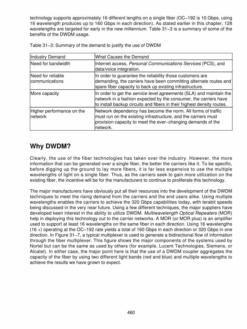
technology supports approximately 16 different lengths on a single fiber (OC−192 is 10 Gbps, using16 wavelength produces up to 160 Gbps in each direction). As stated earlier in this chapter, 128wavelengths are targeted for early in the new millennium. Table 31−3 is a summary of some of thebenefits of the DWDM usage.
Table 31−3: Summary of the demand to justify the use of DWDM
Industry Demand What Causes the DemandNeed for bandwidth Internet access, Personal Communications Services (PCS), and
data/voice integration.Need for reliablecommunications
In order to guarantee the reliability those customers aredemanding, the carriers have been committing alternate routes andspare fiber capacity to back up existing infrastructure.
More capacity In order to get the service level agreements (SLA) and maintain thenetwork in a fashion expected by the consumer, the carriers haveto install backup circuits and fibers in their highest density routes.
Higher performance on thenetwork
Network dependency has become the norm. All forms of trafficmust run on the existing infrastructure, and the carriers mustprovision capacity to meet the ever−changing demands of thenetwork.
Why DWDM?
Clearly, the use of the fiber technologies has taken over the industry. However, the moreinformation that can be generated over a single fiber, the better the carriers like it. To be specific,before digging up the ground to lay more fibers, it is far less expensive to use the multiplewavelengths of light on a single fiber. Thus, as the carriers seek to gain more utilization on theexisting fiber, the incentive will be for the manufacturers to continue to proliferate this technology.
The major manufacturers have obviously put all their resources into the development of the DWDMtechniques to meet the rising demand from the carriers and the end users alike. Using multiplewavelengths enables the carriers to achieve the 320 Gbps capabilities today, with terabit speedsbeing discussed in the very near future. Using a few different techniques, the major suppliers havedeveloped keen interest in the ability to utilize DWDM. Multiwavelength Optical Repeaters (MOR)help in deploying this technology out to the carrier networks. A MOR (or MOR plus) is an amplifierused to support at least 16 wavelengths on the same fiber in each direction. Using 16 wavelengths(16 +) operating at the OC−192 rate yields a total of 160 Gbps in each direction or 320 Gbps in onedirection. In Figure 31−7, a typical multiplexer is used to generate a bidirectional flow of informationthrough the fiber multiplexer. This figure shows the major components of the systems used byNortel but can be the same as used by others (for example, Lucent Technologies, Siemens, orAlcatel). In either case, the major point here is that the use of a DWDM coupler aggregates thecapacity of the fiber by using two different light bands (red and blue) and multiple wavelengths toachieve the results we have grown to expect.
460

Figure 31−7: A typical DWDM multiplexerBy using the fiber−based example for the increased capacity of the fiber, the DWDM methodappeals to many of the providers and carriers alike. The use of fiber−based multiplexing also addssome other enhancements that were not traditionally available in the past. Because the signal neverterminates in the optical layer, the interfaces can be bit rate and format independent, enabling theservice providers the opportunity to integrate DWDM easily with their existing equipment andinfrastructure, while still gaining the access to the untapped resources and capacities in the existingfiber.
DWDM combines multiple optical signals so they can be amplified as a group and transported overa single fiber, increasing the capacity. Each signal carried on the DWDM architecture can operate ata different rate (for example, OC−3, OC−12, OC−48, and so on) and in a different format (forexample, SONET, ATM cells, data, and so on). Using a mix and match approach enables thecarriers to achieve different rates of speed and aggregated throughput, depending on themultiplexing equipment used. Future DWDM developments are touted as being able to carry up to40 Lambda of OC−192 or a total of 400 Gbps. As a comparison, 400 Gbps will be 90,000 volumesof the encyclopedia in one second!
DWDM requires that the transmission lasers have a very tight wavelength tolerance so that thesignals do not interfere with each other. After all, the systems carry 16 or 32 different wavelengthson a single fiber. It is imperative that the tolerances be held tightly to prevent mass destruction ofthe data signals being generated on the fibers. The International Telecommunications Union (ITU)has specified 100 GHz standard spacing between the wavelengths, and most of the vendors arenow manufacturing lasers at the standards−based wavelengths for the combination into DWDM.
The most advanced today, using OC−192 lasers, has a tolerance of 0.1 nm, which is small enoughto preclude any interference between two adjacent wavelengths. Designing OC−192 DWDMsystems is ostensibly more difficult to design than the older OC−48 systems. The OC−192 systemsbeing deployed in the networks also use both unidirectional and bidirectional systems in support ofthe fiber and DWDM multiplexers. However, the future may change things very quickly. WhereOC−192 offers a 10 Gbps operation, the future offers an OC−768, which will create a fourfoldincrease in the capacities in the network. At the OC−768 rate, a multiplexing scheme will produce40 Gbps on a single fiber rate (SONET rate), which then can use the DWDM capabilities to create athroughput of up to four times the 320 Gbps rate currently available. That equals terabit speeds(1.28 Tbps)! However, the use of spacing on the various lambdas will actually enable up to 400Gbps and offer future speeds of up to 1.68 Gbps. What OC−768 will also bring to the table is acapability to concatenate the OC−192 levels. Today's current technology can use a concatenated
461

OC−48 but stops there in the bonding of higher speeds. In the future, as ISPs and traditionaltelephone carriers need to expand their capacities, the need to draw a 10 Gbps concatenatedthroughput will appear. Today, this is not a big concern. However, in three to five years, this willbecome a commonplace occurrence. Table 31−4 is a summary of some of the other things that weare expecting to occur over the next five to ten years in the area of fiber transport systems. Thistable takes advantage of the work being done in many of the labs and research facilities around theworld. The ability to push the envelope is what the communications industry is all about.
Table 31−4: A look at what DWDM and fiber rates will bring over the next decade
Technology and Capacities Current versus Future TechnologyDWDM at OC−192 and 40 λ Current technology capable of carrying 40 different
wavelengths (using ITU 100 GHz spacing) at 10 Gbps eachor a total of 400 Gbps. Currently, the industry has achieved atotal of 320 Gbps with the 400 Gbps rate in the very nearfuture.
DWDM at OC−192 and 80 λ The current spacing of 100 GHz, as specified by the ITU, isunder attack. The near future holds the promise of doublingthe number of wavelengths by using a 50 GHz spacing,enabling up to twice as many wavelengths on the same fiber(80) each operating at 10 Gbps.
DWDM at OC−768 and 40 λ This is a turn−of−the−century technology with up to 40 Gbpsper wavelength and 40 wavelengths or a total ofapproximately 1.6 Tbps.
DWDM at OC−768 and 80 λ By the year 2002, we can probably expect to see theOC−768 plus the use of 80 wavelengths or a 3.2 Tbpsthroughput on the fiber.
DWDM at OC−192 and 160 λ By the year 2005, we can expect to see that the wavelengths'decreased spacing and tighter tolerances on the fiber laserswill yield a total of 160 different wavelengths at 10 Gbps eachor back to the 1.6 Tbps rate.
DWDM at OC−768 and 160 λ This is likely a 2008 to 2009 technology that will again doublethe capacity and yield a total of 160 different wavelengths atthe OC−768 rate (40 Gbps) or netting 6.4 Tbps on a singlefiber.
These rates are all projected to be available in the next decade. However, as the technology seemsto be doubling every six to twelve months, the rates shown previously could happen as soon as2005! The issue is not how long it will take but the ability to drive better and faster data and othercommunications needs on the same fibers. The future holds a lot of excitement with these speeds.
462

Chapter 32: The InternetWe are accustomed to succinct definitions of systems and equipment. The Internet is a little difficultto describe in 25 words or less. The Internet is really a collection of privately owned networks. Byprivate, we mean that it is not owned by the government but by private and public companies. TheInternet Architecture Board (IAB) and the Internet Engineering Task Force (IETF) set standards.The Internet Society elects the IAB members. The IETF membership is voluntary.
A Brief History
The Internet began as Advanced Research Projects Agency Network (ARPANET). Becauseuniversities were working on research for the military, a means was desired to be able to shareresearch papers. Some say it started before ARPANET by informal agreements betweenuniversities to dial each other up and exchange e−mail. At the time, there were no formal protocolssuch as Internet Protocol (IP). These informal dial−up connections were using acoustic−coupledmodems at 1200 bps. Actually, there was no real network — only these agreements to forward mail.
ARPANET started with the first packet−switching technology. The first packet software was calledan Intermediate Message Processor (IMP) and was built under contract by Bolt, Bernak, andNewman. The goal was to remotely log into computers in Berkeley from UCLA. The initialexperiment didn't work, but it provided the basis for continued improvement, which lead toARPANET. The Internet began then as an interconnection of Interface Message Processors (IMPs)that could relay traffic between hosts. (A host was a mainframe or a minicomputer. Today, anydevice can interface to the network and run the networking protocols.)
The military changed the name of the project to Defense Advanced Research Projects Agency(DARPA). Under DARPA, the Internet continued to grow and expand. Outgrowths of this work wereWindows Microsoft Internet Commercial System (WMICS), Windows Internet Naming Service(WINS), Military Network (MILNET), and eventually Defense Data Network (DDN). The military,therefore, had no need any longer for DARPANET and handed it over to the National ScienceFoundation (NSF) and the Internet became NSFNET. The NSF was funding most of the researchanyway, and the universities were using some of that funding to support their Internet habit. Thegoal of the NSF was to provide shared access to supercomputers. Each university was naturallylobbying for its own supercomputer. Providing remote access via the Internet would be a lot lessexpensive for the NSF. The NSF funded the Internet from the mid−1980s until 1992 when benefitspreviously reserved for the academic community became apparent to all. What was happening wasthat students, who had had access to the Internet while on campus, were cut off upon graduation.They were therefore very creative in figuring out ways to hang onto their Internet accounts.
This created a set of haves and have−nots. The pressure built for the commercialization of theInternet. Continuing the funding became the pressing question. Under the NSF, the Internet hadgrown to include virtually all major schools. Since funding was from the government, access waseasy. If your school wanted access to the Internet, you simply called up your nearest associatedschool who had access to the Internet and asked for a port on their router. You then leased tocommunications lines of the appropriate bandwidth. You sent some money to the next school tohelp them pay for the additional router and communications capacity that they would need to haveto support your additional traffic going through their system.
Notice that we said that the Internet was a loose collection of many networks, and here we justadded another network. (By the early 1990s, the potential of the Internet was well recognized, andeveryone was clambering for access.)
463

The initial purpose of the Internet was to exchange data and make research papers available to theentire academic community. Universities would therefore have open hosts connected to theInternet. This meant that anyone could essentially log onto the host as an anonymous user, searchthrough the directories on the host server, and download whatever files were wanted. It's interestingto compare this free and easy access with today's world of networks protected by firewalls. Actually,it wasn't that free and easy because in the Unix operating system, files and directories havepermissions as to who can read and write to them.
The mechanism for doing this is a utility called File Transfer Protocol (FTP). In order to FTP, yoursystem (host) had to have the FTP client, and the target system had to have the FTP server readyand willing to process your request. If one is familiar with Unix and the directory structure of thetarget host, this isn't too difficult. For the average techno−peasant, however, it is beyond grasp.Surfing or browsing, as we know it today, was not easy. Only the patient, persistent, andknowledgable browsers were able to find what they were looking for.
The Internet is not a Bulletin Board Service (BBS). A BBS is essentially a host into which anybodycan dial and collect and receive information or messages. These services abounded in the late1980s and early 1990s. The Internet is not a timesharing service either, although some hostsprovide that service. Timesharing became popular in the 1970s when computers were tooexpensive to own for smaller companies so they would do remote computing utilizing dumbcomputers using services such as Tymnet and CompuServe Information Service (CIS). CIS grewinto an information resource provider and created agreements with Telenet and Tymnet to provideworldwide access while they developed their own worldwide network. The original CIS access wasvia dumb ASCII terminals at low data rates. They had a character−oriented information interfacethat was no friendlier than the Internet. Given the period, it offered a powerful service.
In the early 1990s, America Online (AOL) saw the benefits of the Internet and began to offer aninformation service via a Graphical User Interface (GUI) that was very easy to use. Although AOLwas a proprietary network, it rapidly added various information services in addition to theever−present e−mail. It is likely that its phenomenal growth is due in significant part to its ease ofsetup and use. Several information services came and went. We like to maintain that AOL and CISare not Internet service providers (ISPs) because their primary business is providing interactiveinformation services. All their computers are in one room. Rather than being connected to a networkof computers, you are connected (for all practical purposes) to one huge computer that offers manydifferent services. By comparison, the Internet consists of millions of computers connected tomillions of networks, each accessible from any other network. It is not obvious to the casualobserver that there is much difference today because the browser interface cleverly hides thecomplexities of connecting to multiple different computers and both systems seemingly haveendless amounts of information available. Today, both AOL and CIS permit seamless movementbetween their own information services and those available on the Internet. Selecting a link toinformation on the Internet causes the automatic launching of a browser.
AOL was the most successful of the information services, eventually buying CIS. This was primarilydue to marketing, low cost, and ease of use. (CIS was a little late introducing a GUI and when theydid, it was obscure, nonintuitive, and hard to use.)
AOL's membership snowballed because the more users there were, the more advertisers werewilling to pay for advertisements and offer services via AOL. The more services they offered, themore attractive they became to more subscribers. The best part was that AOL could now chargemore for its banner ads because that many more folks would view them when they signed on.
464
Early Internet Services
The Internet was, as indicated, difficult to use in the beginning, requiring knowledge of telnet andthe Unix command structure (not to be confused with the Telenet packet switching network). Telnetis a Unix utility that lets you remotely log into another host. Once you logged in, you had free reignof that system with two significant limitations:
You had to have an account on the target system (in the early days most systems would letyou log in as anonymous).
•
You could only access the directories and files for which general user permission wasgranted.
•
This permission system was so clever that a user could be granted permission to see a directoryand even run programs in it, but not be allowed to modify its content.
As indicated, when you found the file or program for which you were looking, you launched the FTPutility and downloaded it to your system. Searching for and finding things was difficult at best.
The next step in improving the utility of the information on the Internet was the development ofArchie, which was designed at McGill University in Canada. Archie essentially indexed FTP sites.The target machine had to run the Archie server, while your machine ran the Archie client. The goodpart was that the Archie server was accessible via an Archie client, e−mail, or telnet. Archie was agreat catalog on the Internet. Archie returned a list in Unix language that gave you host and filenames to use when you set up the FTP session. Archie was a step in the right direction of makingthe Internet easier to use, but you still needed to know how to use telnet and FTP.
Gopher
Gopher was also a client−server system. It provided a menu of choices, and it allowed you to set upbookmarks of locations you liked. Like previous Internet access, it was designed around the userhaving a dumb ASCII terminal. Thus, it provided menus and minimalist keystrokes to make aselection. That was the good part. Unfortunately, the single keystrokes were not always intuitive.The intent was that you would launch the Gopher client from your own host and communicate withthe Gopher server on the remote host. It was possible to telnet to a remote host and then to launchGopher, but this was painfully slow and created excessive network traffic. Remember that theinterconnection of hosts was often with 56 Kbps lines.
Veronica
There was some speculation as to the source of this name, but most people think it was namedafter Archie's girlfriend. Others insist it stood for a very easy, rodent−oriented net−wide index tocomputer archives, but this is unlikely. Veronica is an extension to Gopher that facilitated searchesand returned a list of hits (hits in this case were file names that matched the name in the originalsearch request). Veronica was also a client−server arrangement, where the Veronica server keepsthe database being searched.
By selecting one of the returned hits, you could get more information about it or transfer it back toyour computer. Veronica therefore automated the FTP process, but was still dumb terminal− andmenu−oriented.
465

Wide Area Information Service (WAIS)
Wide Area Information Service (WAIS) was another database search engine that allowed you toenter keywords and search a database for entries. Although the number of databases was large,finding this was still not easy because you were using Gopher to search WAIS.
World Wide Web (WWW)
The World Wide Web (WWW) has essentially replaced all of these older search engine capabilities.The early WWW often resorted to Gopher or WAIS to actually do the transfer.
The two developments that made the WWW useful were browsers, hypertext, and hyperlinks.Hypertext was a way of encoding formatting information, including fonts, in a document while usingplain ASCII characters. Hyperlinks were essentially addresses imbedded in the hypertext web page.By selecting the hyperlink, you were taken directly to a new page.
Browsers
Browsers basically automated the keyword search function that we had done via menus usingGopher. Browsers today are very large and complex programs. Look on your hard drive, and youwill find that the Netscape application is about 1.3 MB. With each revision, it gets larger and morecomplex as new features are added. Microsoft's browser is buried in the operating system, and it istherefore difficult to tell how big it is.
Marc Andreesen was instrumental in creating one of the first browsers called Mosaic. It became thefoundation of Netscape's Navigator. Netscape's success can be attributed to the fact that it followedthe AOL model of giving away the browser software. Netscape even gave away their source code toits browser on the theory that thousands of heads are better that a few, and eventually it will resultin a better product. This same philosophy made Linux such a strong operating system for PCplatforms. AOL later acquired Netscape, so what goes around comes around.
Browsers are also part of the client−server world. The money lies in getting the service providers tobuy your suite of server software that provides the data to the browsers. This suite of software mayprovide many other features and capabilities such as calendar, proxy, Lightweight Directory AccessProtocol (LDAP), and mail server functions as well.
Hypertext
In the Unix world (where this entire Internet started), there were only two kinds of files:
ASCII text−based files that were all the documentation, source code, and configuration files• Binary files that were the executable program files•
Unfortunately, no one considered fancy formatting, multiple fonts, graphics, and tables. ASCII textwas boring in the modern world of animated color. The question became, how can we add thiscapability?
Individual vendors' products, such as Microsoft Word™, utilize proprietary code sets in which thefont and size (for example) are imbedded. Other products, such as Corel WordPerfect™, chose toimbed special tag characters, indicating the beginning and end of special font and size groups of
466

characters. Unfortunately, with special (non−ASCII) characters imbedded in the text, these were nolonger text documents, but binary documents that could only be operated on by proprietaryvendor−specific programs that were not universally available or free.
How then could we keep the documents on the Internet open, free, standardized, and comprisedstrictly of ASCII characters so that anyone could read them? How could we extend the capabilitywithout making the previous version obsolete? A major problem with a specific vendor's productwas that when the new one came out, the older versions couldn't read the newer versions' formats.This was a major inconvenience, designed to force the users to upgrade to the latest version.
The solution was to go with the tag approach. Rather than using special characters as tags, wesimply used a sequence of ASCII characters, which meant something specific to the browser anddid not impair the capability of a dumb ASCII terminal to read them. For example, the tag<title>Important Subject</title> will cause the browser to display that line as a title. For the curious,you may view the source of a web page and see all these tags. All you have to do is go to the Viewmenu and select Source. You are then presented with all the original ASCII information. Although alittle difficult to read because of all the tags, all the text is there, as are all the references to otherweb pages (HREF) and all the font and formatting information. While we are on the subject, youmight try converting one of your text documents to rich text format. Here the formatting stuff is all inthe beginning of the document—just another (standardized) way of sending formatting informationin plain ASCII text format.
If you are using an older browser, it simply can't properly display the text within the new tag, but thetext is still there, and you can read it. Fortunately, new versions of the browser are readily availableand free for the downloading.
Hypertext then allows the standard ASCII text characters to define special formatting that thebrowser can display.
Hyperlink
A hyperlink is simply a pointer to another web page. It is the complete address to find the specifiedweb page. The link visible on the browser−presented web page might say something innocuous like"more info." If you view the source and search for the HREF or the "more info," following the HREF5will be the actual path to that page. Selecting the hyperlink caused a lot of background processing.The browser took the Universal Resource Locator (URL) and fabricates a query to that location justas though you had filled in that value manually in your browser window. It then sets up aconnection, downloads the desired page, and terminates the connection.
Universal Resource Locator (URL)
The URL is simply the Internet address of the web page. URLs are displayed in this form:http://www.tcic.com/. This URL takes you to TCIC's main web page. Selecting a hyperlink from thatpage takes you to a Universal Resource Identifier (URI), which points to the files in the directory treeof the host server. Each slash (/) in the name identifies a directory level on the server. In somecases where a document management system is employed to build and provide web pages, theseslashes are actually logical divisions within the resource and have nothing to do with actualdirectories. Today, the trend is to use dynamically built web pages. They can be better customized(see the discussion on cookies) to the user's needs, you don't have to store thousands of differentweb pages, and the processors are fast enough to create them quickly.
467

Directory/Domain Name Service (DNS)
One of the most interesting and important parts of the Internet is the Directory Name Service or theDomain Name Service (DNS). In short, the DNS system permits human−readable names to bequickly translated into IP addresses that are needed to route the packets across the network.
As is described in the addressing section, the IP address is structured by network and then by host.It is read from left to right by the router in trying to find the proper destination network.
The human−readable addresses are hierarchical from right to left. For example, take the [email protected]. F i rs t , we know that i t i s somewhere in the .com domain . I f I [email protected], I need to find Bud's address. It is very likely that the university has noidea of what the address might be. The local e−mail system therefore makes a query of theunnamed "." domain. This annotation is a signal to the Internet servers maintaining the databasesthat we are looking or a name of a user. There are several of these servers around the Internet,which are updated daily by the Internet Network Information Center (InterNIC) as names areregistered.
There is some controversy over the InterNIC's absolute control over domain names. (Someone hasto be in charge to prevent chaos, but change is underway with the introduction of competition in thisarea.) To register a domain name, one (or one's ISP) must contact the InterNIC (or a suitablecompetitor) and pay an annual fee. (Prior to the commercialization of the Internet, StanfordResearch Institute [SRI] performed this function). There are proposals to open other domains (forexample, .biz, .store, and so on) and let other entities administer the names within that domain.
Each country has a domain and administers these domain names themselves. All public entitiessuch as cities, counties, and states are under the .us domain. Some of the country domains are .ukfor United Kingdom, .cz for Czech, .de for Germany, .au for Australia, and so on.
Each domain then has its own DNS server, so when George is trying to send e−mail to Bud, hise−mail server asks the ."" domain for Bud's address. The ."" domain replies that it can only providethe address of the .com DNS. We then ask the .com DNS that replies with the DNS address ofTCIC. Since TCIC is really under an ISP, what we really get is the address of the DNS server at thatISP. Finally, we get Bud's real address. Now, this address is put into the e−mail packets, and theyare sent on their way. In addition, we, the users, never knew about all the fooling around that wentinto finding the address in the first place.
Java™
The early Internet was strictly ASCII text based. Then came the inclusion of Graphical InterchangeFormat (GIF) files. As indicated previously, these were simply references in the hypertext documentto a location that contained the graphic file that was displayed. Next, came the desire to automate oranimate web pages.
Sun Microsystems invented a clever (and, to some, controversial) language called Java, which is aregistered trademark of Sun Microsystems.
The basic problem was that to animate a page the local machine had to execute some software.This opened the door to viruses. Sun's clever idea was to have the browser execute the program,rather than the host hardware. The good part was that you were somewhat protected from maliciousprograms. The bad part was that the browser was interpreting the Java language on the fly, and thisinterpretation was slow. (Faster machines help a lot here.) The original idea was that the browser
468

could prevent the Java script from doing any damage (like wiping out the hard drive). Unfortunately,the more powerful we needed Java to become, the more capability it needed on our host machine.Microsoft, naturally, has its own approach to page automation called Active−X. The good part is thatit runs as machine code. The bad part is that it runs as machine code and can therefore containviruses. The user is given the opportunity to download or not download the Active−X code. If youtrust the source, go ahead and run it. If you are not sure, cancel the download and do without theanimations.
Surfing the Web
When you select a hyperlink, the browser creates a packet requesting a web page and sends it tothe specified URL. Your browser actually sets up a connection to the server. The server replies withthe requested file (web page) and the browser displays the page. Your browser now stores thispage in its cache memory so that after you have followed several other links, you can easily getback by selecting the Back button. The button retrieves the page out of the cache rather than havingto fetch it from the source (which, as you have experienced, could take a while). You shouldperiodically empty your cache. First, depending on the settings of your browser, it may never usethe cache again. Second, if the browser does always check the cache first, regardless of age, whenyou sign onto the site the next time a month later, the page you see is the old one from the cache.Actually, this is an exaggeration because the browser has a setting for how old a page can getbefore a fresh copy is fetched. You can just throw away the cache folder (it is safer to discard thecontents); your browser will build a new one when you launch it. If you do a lot of surfing, this cachecan take up a lot of disk space.
You can always force the browser to get a fresh copy of the page by selecting the Reload (orRefresh) button. This causes the browser to ignore whatever was cached. The fact that each pagecan contain multiple references to other pages anywhere in the world is the reason it is called theWorld Wide Web (also referred to the World Wide Wait). Links can take you anywhere, includingback where you started. There is no hierarchical structure to the Web.
Tracking Visitors
From a commercial point of view, we would like to know how many visitors or hits we have on ourweb page. (Here hit is defined as someone accessing our page, such as setting up a connection tous.) We can tally each connection and present that to potential advertisers as an indication of thepopularity of our page. First, the number of connections or hits to our page is only approximatelyrelated to the number of viewers. Here is why: if you happen to set the home page tohttp://www.tcic.com/, every time you launch your browser, you go there. It looks like a hit! The factthat you immediately go to some other book−marked page doesn't register. Second, depending onyour browser settings, you could revisit a page multiple times, but your browser has that pagecached. The web page owner then has no way of knowing that you are frequently referring to hispage during your online session. Third, if the client or user is surfing from behind a proxy, his localproxy server will provide your page whenever requested, saving network bandwidth, but the website owner again doesn't know that he has been hit once again.
Cookies
One of the more controversial aspects of the Web is the existence of cookies. Cookies are nothingbut an encoded set of information that the web server asks your browser to keep for it. The cookiessimply contain information about you and the sites you visit. They may contain information, such as
469

your credit card number, that you have entered while visiting a site. They may also contain links youselected from that web site. If you visit outfitter.com and you look at hiking boots, the next time youlog into that site, the first page may have backpacks and tents prominently displayed. The site readsthe cookies it left on your machine the last time you visited. It determined that you are an outdoortype (and decided it would be a high probability of sale for you on related outdoor equipment).However, you still have the ability to view all the other parts of the site because the index pagealways contains an index to other pages on the main page.
Cookies, then, are a convenient way for the vendor to keep information about site visitors withouthaving to keep a huge database of all visitors whether they are casual or frequent visitors.
You can throw away the cookie file anytime you want. The browser will rebuild it when it needs it.You can also read your cookie file by opening it in a text reader. Depending on the browser, thecookie file normally contains ASCII text. The information is normally encoded as a set of numbersthat is not meaningful to anyone but the originator of the cookie. Some web pages won't workcorrectly unless you have the cookies enabled. You may leave "Accept cookies" turned on anddiscard the file at the end of your session if you are paranoid about the information that might bestored therein.
Search Engines
Even if we have links to follow, there is no good way to find a specific set of information. We stillneed a database catalog we can search that lists sites that might contain the information we want.The search engines (such as Yahoo! and Google) provide a database to search very similar to theway Gopher and Veronica tools did in the past.
Enterprising individuals also developed "web crawlers" that would follow hyperlinks based on a keyword and fetch all the associated pages. You could start these crawlers, go to bed, and wake upwith a full disk. Today's databases are a combination of crawling and advertising. The business planof the search engine provider is to offer advertising along with the database information. Companiesthat pay more get a better position on each page. In a few cases, the ordering of the hits on thepage is a function of how much the information source paid to gets its listing put first. The goal ofthe game is to entice the web surfers to your site. Once there, you can either sell them something orpresent them with advertising for which you have been paid. The more visitors to your site, the moreyou can charge for the so−called "banner advertisements." For folks looking for information, thesebanner ads are just background noise. Being enticed to look at one will often lead you on aninteresting, but irrelevant, wild goose chase.
Standards
Within the Internet, standards are created and managed on a voluntary basis. The IETF makesrecommendations to the IAB for inclusion as standards. Remember that the whole Internet startedas a volunteer−based network, each building on what was done before. Anyone who determines anew feature is needed or a problem needs fixing creates a solution. That solution is implemented onone's own network, and when ready, it can be submitted to the IETF as a Request for Comment(RFC). It is then published on the relevant newsgroups for others to try it and comment on it. After ithas survived this torture test, it is ready for formal adoption. Because the whole Internet is voluntary,it is up to the network administrator to decide whether to use that RFC or not. Failure to implementit, however, may mean compatibility problems with other networks.
This process is very practical and very different from that used by the formal international standardsorganizations, such as the International Standards Organization (ISO) and the International
470

Telecommunications Union (ITU). These have a formal membership and a proposal submission andreview procedure that is designed to form a consensus.
Internet Operation
We have seen that the Internet is really a collection of independently owned and operated networks.The concept of networks was previously dominated by the telephone model. It had a centralswitching exchange and all information ran through this exchange. The telegraph network also usedcentralized switching. Like the telephone switching system, it, too, had telegraph lines thatconnected the switching centers. The telegraph−switching center was called a message switch.These message−switching centers were originally manually operated copy and relay centers. Later,paper tape with automatic punches and, finally, computers replaced the manual switching centers. Itbecame clear that some mechanism was needed to distinguish between the message content andthe control characters that were used by the computer to recognize the beginning and end of themessage.
Message switching with its telegraphy history was message integrity oriented. Each message wascarefully acknowledged. Losing messages was not acceptable. This formed the basis for reliablemessage transfer.
About the time the Internet was taking shape, the X.25 network protocol was being developed. Onemight say that the X.25 protocol is the successor to message switching. It was essentially designedwith the Telco model in mind. It was intended to make money by charging for packets, just as themessage−switching system was designed to charge for each message. The goal was to provideend−to−end message integrity.
A further impetus to the development of X.25 was the deregulation of the telephone equipmentmarket brought about by the Carterphone decision of 1968. Heretofore, modems were onlyavailable from the Telco, and the data rates were slow. At that time, the Telcos controlled telephonecalls between countries and all data (telex) messages went through what were known asinternational record carriers. Because they were the only carriers permitted to transport suchinternational traffic, the cost was high. Modems unfortunately fell into the hands of the travelingpublic who would make dial−up telephone calls across international boundaries and transmit data ata fraction of the cost of the "record traffic." The Telcos tried to control this, but it was hopeless. Theirnext attempt was to offer a slightly lower cost Public Data Network (PDN), which was the X.25network. Although it worked well, it really was still more costly (although more reliable) than usingthe Public Switched Telephone Network (PSTN). The X.25 network replaced the telex network tomost parts of the world. When traveling, using the X.25 network to contact, for example,CompuServe is often the most cost−effective way to do it.
One of the large steps forward that X.25 provided was that it made the transport mechanism (packetswitch) separate from the message content. The network was then optimized for packet transportand was completely independent of the message or its content. The maintenance of end−to−endconnectivity is a natural outgrowth of the Telco and message−switching history.
The operation of X.25 is very different from the IP. It is important at some point to draw thedistinction between the two protocols.
Without a full−blown discussion of the OSI Reference Model, let us start with the basic concepts ofpacket switching and the transport of packets across an X.25 network. Figure 32−1 is a picture ofthe Reference Model to be used as a reference as we discuss the operation of networking
471

protocols. A few quick notes are in order:
The physical layer attaches to whatever network is at hand. There could be multiple physicalconnections in any given system.
•
The data−link layer handles communications across the physical link only between adjacentmachines by putting data into frames.
•
The network layer must be consistent across the entire network, and it is where packetswitching is handled.
•
The transport layer handles end−to−end transport and integrity of data. The communicatingentities at the transport layer have no idea (very theoretically) that the underlying layers existor what their characteristics are.
•
Figure 32−1: The OSI model as the referenceX.25 is a Connection−Oriented Network Service (CONS). The IP provides, by contrast, aConnectionless Network Service (CLNS). This is the major difference, and as we shall see, itpervades the networking decisions made and the choices made for the functionality of the transportlayer. The details of how the packets are handled within the packet switches are very similar interms of how the queues are handled.
A connection is established by X.25 for the end user across the network. Although we said thattransport is responsible for end−to−end connections, the network layer can also choose to providethis capability. If our network layer is going to do this, then the transport layer need not be complexat all. You will note in the following discussion that the reference is to telephone terminology. Thereasons for this are now clear.
An X.25 connection is established by the end system across the network. The calling party sends asetup packet containing the address of the source and destination systems. Figure 32−2 shows thebasic network configuration. The packets travel on each leg of the journey in a link layer frame thatprimarily provides error detection and correction by using the frame check sequence (FCS) on alink−by−link basis. The packet containing the addresses permits each packet switch along the wayto make a routing decision about the best way to send the packet toward its destination.
472

Figure 32−2: Basic configuration of X.25 networksThe frame itself consists of a Flag (F) character at the beginning and end as delimiters of the frame.The address field (A) is rarely used, but logically contains the physical address of the device on thenetwork. The control field tells what kind of frame it is (data bearing or control) and can be used tocontain sequence and acknowledgement numbers. The FCS is a very powerful, 16−bit checksumsystem that is able to detect 99.998 percent of all errors. Given the quality of the circuits of the day,such a powerful error−detection scheme was necessary. The control field shown as C in Figure32−3 carries the sequence and acknowledgement numbers.
Figure 32−3: The Frame carrying the X.25 packetFigure 32−3 shows the relationship of a packet being carried inside a frame. Note that the frame isterminated (FCS evaluated and acknowledgement sent on each hop). The packet is reencapsulatedin a new frame for its hop across the next link. Chapter 11, "Frame Relay," discusses Frame Relay,which is the successor to X.25.
In addition to the routing information, the first packet also contains the very important LogicalChannel Number (LCN). You may think of it as a random number that is used by each packet switchinstead of the address. There are several benefits to doing this. First, you don't need to put thecomplete address in each packet, and second, you achieve a relationship between packet switchesthat lasts for the duration of the call. (The importance of this will only become clear later). Thisrelationship between packet switches is called a virtual circuit. You will find further discussions ofvirtual circuits in both Chapter 11 and Chapter 12, "Asychronous Transfer Mode."
Figure 32−4 shows the routing table (technically a switching table) in each packet switch shownearlier in Figure 32−2 that resulted from the call setup from caller to called system. This associationof ports and LCN create the virtual circuit across the network. This has several major implicationsfor overall network design:
473

Figure 32−4: The routing table example
All packets follow the same path between any source destination pair of end systems. (Thismakes maintaining sequencing of packets easy.)
•
Acknowledgements can be done link by link, using frame acknowledgements and end to endby using network−layer sequence numbers.
•
At setup time, we could determine the load on the packet switches and interconnecting linksbefore choosing that path.
•
This would enable Quality of Service (QoS) and Service Level Agreement (SLA) adherence. It mustbe clearly stated here that X.25 doesn't provide these services. However, the existence of a virtualcircuit relationship between packet switches for the duration of the connection is a necessarycondition to provide QoS and SLAs.
Connectionless Network Services (CLNS)
Now that we understand CONS, we can look at CLNS. IP is a CLNS. The apocryphal story, as is oftrepeated, is that IP was designed during the height of the Cold War. The military (funded byARPANET) wanted a bomb−proof network — one in which any of the lines or packet switches couldbe knocked out at any time and not seriously affect network operation. Therefore, the designerschose a dynamically routed CLNS. The philosophical differences between a CLNS and CONS arelarge, but each is a valid way to construct a network. The Internet has grown to become ahigh−volume worldwide network. Even some of the original designers are amazed at its capability tocontinue to grow yet maintain its robustness. More than a few doubters have been predictingInternet meltdown. Congestion has occurred due to lack of bandwidth connecting routers. Addingmore bandwidth has so far alleviated this condition. There was some discussion in the late 1990sthat the demand for bandwidth would exceed the supply in the year 2001. The technologybreakthrough of dense wave division multiplexing (DWDM discussed in Chapter 31) essentiallysolved the bandwidth problem. The solution isn't inexpensive per se, but it yields tremendousbandwidth for the price.
It is now easy to draw a comparison between X.25 and IP. Each IP packet (called a datagram) is astand−alone entity containing all the information needed to be routed from one end of the network tothe other. The lack of any formal associations between packet switches means that (theoretically)packets can be routed instantly and dynamically without regard for the final destination. Figure 32−5shows the relationship between frame and packet. Frames in the case of IP are only used for errorchecking. The control field (C) simply says that this frame contains data. Bad frames (for example,those failing the FCS check) are simply discarded. Error recovery will be left to the transport layer.
474
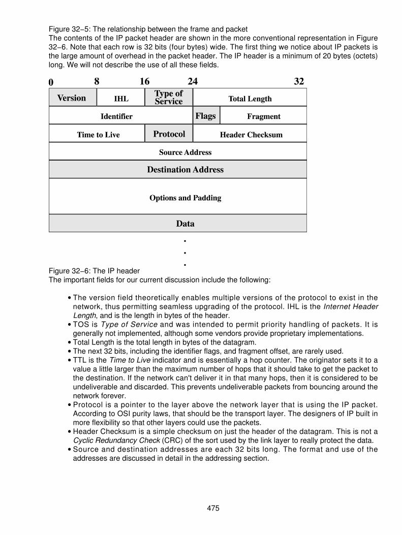
Figure 32−5: The relationship between the frame and packetThe contents of the IP packet header are shown in the more conventional representation in Figure32−6. Note that each row is 32 bits (four bytes) wide. The first thing we notice about IP packets isthe large amount of overhead in the packet header. The IP header is a minimum of 20 bytes (octets)long. We will not describe the use of all these fields.
Figure 32−6: The IP headerThe important fields for our current discussion include the following:
The version field theoretically enables multiple versions of the protocol to exist in thenetwork, thus permitting seamless upgrading of the protocol. IHL is the Internet HeaderLength, and is the length in bytes of the header.
•
TOS is Type of Service and was intended to permit priority handling of packets. It isgenerally not implemented, although some vendors provide proprietary implementations.
•
Total Length is the total length in bytes of the datagram.• The next 32 bits, including the identifier flags, and fragment offset, are rarely used.• TTL is the Time to Live indicator and is essentially a hop counter. The originator sets it to avalue a little larger than the maximum number of hops that it should take to get the packet tothe destination. If the network can't deliver it in that many hops, then it is considered to beundeliverable and discarded. This prevents undeliverable packets from bouncing around thenetwork forever.
•
Protocol is a pointer to the layer above the network layer that is using the IP packet.According to OSI purity laws, that should be the transport layer. The designers of IP built inmore flexibility so that other layers could use the packets.
•
Header Checksum is a simple checksum on just the header of the datagram. This is not aCyclic Redundancy Check (CRC) of the sort used by the link layer to really protect the data.
•
Source and destination addresses are each 32 bits long. The format and use of theaddresses are discussed in detail in the addressing section.
•
475

Options and Padding
IP provides some interesting options, one of which is forced routing. If forced routing is employed,the route to follow is specified in the options field. Padding is used to fill out the last field so that thedata field starts on an even 32−bit boundary.
Routers use the source and destination fields to send the packet to the next router. The Internetuses a best−effort, hop−by−hop routing system to keep the handling of the packets simple. Much ismade of the fact that the Internet is a CLNS and therefore can route packets almost arbitrarily andthose packets arrive out of order or not at all. Although it is theoretically true that a router couldchoose a different path for the next packet with the same destination address as the previouspacket, let us consider the practical realities. First, if the chosen route is good for the current packet,the chances are excellent that it is also good for subsequent packets. Second, the router normallyhas a limited number of entries in his routing table: the normal route, the secondary route, and thedefault gateway. Therefore, the number of different paths that the packet could theoretically take islarge. In practice, it is relatively small. The practical result is that most packets follow the same pathand generally arrive in order, but there are no guarantees.
Transmission Control Protocol (TCP)
For customers needing high−integrity, guaranteed, error−free delivery, a transport layer must bebuilt on top of IP. Transmission Control Protocol (TCP) provides the sequenced, acknowledgedreliable delivery mechanism. Figure 32−7 shows the format of the TCP packet called a segment.The important parts of the TCP segment for our discussion are the sequence number andacknowledgement numbers.
Figure 32−7: The TCP headerAlthough the IP packets carrying these TCP segments may arrive out of order, TCP can easilyresequence them. The acknowledgement field provides the reliable delivery part.
The Fields in the TCP Header
TCP's header is a minimum of 20 bytes (octets). The fields in the TCP header are as follows:
476

Source port and destination port The source and destination port numbers are used toidentify the listening agent that is using TCP to transfer data. IP uses the protocol field; TCPuses the port number. The port address, in conjunction with the IP address of the packet, isreferred to as the socket. Therefore, in order for a socket to exist, one needs both the IPaddress and the port address. Port addresses below 1024 are assigned by (or reserved forassignment) by the IETF. When you surf the Web, your browser always uses TCP port 80.One can provide web servers on other ports (for example, port 8080), but to use that port,the sender has to specify the port number after the host name because the default is port80. TCP actually has 65,535 ports available, but much less are used.
•
Sequence number The sequence numbers are not packet numbers, but rather bytenumbers such that if there were 100 bytes in a segment, the sequence number willincrement by 100 each time. This helps the recipient reserve the proper amount of bufferspace if it gets, let's say, the tenth segment first.
•
Flags The flags section is used to set up and tear down connections, as well as to push thefinal segment and get acknowledgements for the segments.
•
Window Window describes the flow control window. Rather than the more conventionalmechanism of on and off flow control, TCP uses a credit system where credit (in bytes) isgranted to the sender. When the sender has sent that many bytes, it must stop. Therecipient keeps this updated to provide for a continuous flow of data.
•
Checksum As on the IP packet, the checksum is not a CRC, but a simple checksum, and itis run on the entire TCP segment.
•
Urgent pointer The urgent pointer points to urgent data (if any). Theoretically, this handleshigher−priority data within a segment ahead of normal priority data.
•
Options (+ padding) Here again, options can be added to TCP. These fields need only beadded when the options are present. The field is always padded to even 32−bit boundaries.
•
TCP is an end−to−end protocol that makes sure that the data gets to the destination and in properorder. It accomplishes this by setting up a connection to the other end, much as X.25 sets up aconnection, except that it doesn't create a virtual circuit. Therefore, when you visit a web site, TCPsets up a connection so that you reliably get a complete web page. The page may consist of severalsegments and many packets, since each packet is about 576 bytes by default.
After the page has been delivered and acknowledged, the connection is torn down. When youselect the next URL or hyperlink, a new connection must be made. Remember that there is no wayto know whether the user will select another link on that same web site or a hyperlink to some othersite. Some browsers provide indications of this connection process on the bottom edge of thebrowser window.
User Datagram Protocol (UDP)
In the interest of thoroughness in a discussion about IPs, we need to mention User DatagramProtocol (UDP). It also is Transport Layer Protocol, but does not create connections. It is another"send and pray" protocol like IP. Who then would want such a thing? Consider the problem of adatabase query. You don't need a connection, but you need an answer quickly. If the answerdoesn't come back in a reasonable time, ask again.
Both the DNS and Simple Network Management Protocol (SNMP) use UDP. These are bothquery/response protocols. Figure 32−8 shows the UDP header in all its simplicity. By default, theUDP header is only 8 bytes (octets) long.
477

Figure 32−8: The UDP headerThe port addresses are the same as described for TCP. The length tells how long the segment is inbytes, and the checksum is, as with TCP, a simple sum over the whole segment.
IP Addressing
Now that we have a handle on the protocols that are going to be used, let's take a look at thestructure and significance of addressing and then we will discuss how routing is done.
The addressing scheme is important for obvious reasons. Addressing is used by the routers to findthe destination for the IP packets. One could imbue the routers with God−like knowledge of thenetwork, or the router could have a simple table to use to look up the next hop. If there is no entry inthe table, then send it to the default router. The whole Internet works because of this default routemechanism. If any device doesn't know how to return a packet, it sends it to the default router,known as the default gateway.
Routers Versus Gateways
A point of clarification is needed about routers and gateways. In the Internet community, routers andgateways get a little confused. In the previous discussion, we use the term router almostexclusively. As pointed out, in the Internet community, it is referred to as the default gateway.
The Internet terminology started before terms were standardized. A gateway was a box that satbetween two networks. Therefore, it was natural to refer to routers, especially ones connectingdifferent networks as gateways.
Today, a router is a box that operates at the network layer, reads IP addresses, and chooses thebest hop it can find to the destination network. A gateway is a device that handles protocolconversion. A mail gateway is a great example. If you are using IBM's PROFS mail system, youhave a mail gateway that reformats the messages and changes the characters in the message fromIBM's proprietary Extended Binary Coded Decimal Interchange Code (EBCDIC) to standard ASCIIcharacters.
When selecting the addressing scheme, the Internet designers chose their own path, rather thantaking a page from the telephone folks.
The designers were thinking in terms of networks for universities, government, and the military.They anticipated that there would be a few very large networks for the military, governmentagencies, and very large universities; some medium−sized networks; and many little networks forsmaller colleges.
478

Correspondingly, IP has three address formats, known as class A, B, and C addresses,respectively. A class D address format exists for multicasting to groups of destinations. Figure 32−9shows the IP address formats.
Figure 32−9: The Internet IP addressing schemeYou will note that in the IP packet format that the address is 32 bits long or four (4) bytes, which isrepresented in a dotted decimal format. Each byte is represented by a decimal number of the valueof that byte. This makes it relatively easy for humans to read and use the addresses.
A 4−byte address might look like this: 147.45.193.15. We can tell immediately that this is a Class Baddress. The first bit of the address is 0 for Class A and 1 for Class B. Class C addresses have thefirst 2 bits set to 1. Therefore, the class ranges are as follows:
Class A addresses are from 0 to 128.• Class B addresses are from 129 to 191.• Class C addresses are from 192 to 223.• Class D addresses for multipoint broadcast are from 224 to 239.• Class E addresses (reserved for special projects) are from 240 to 254.•
You will note that certain addresses aren't valid or used. "All zeros" means this network. "All ones"is the broadcast address.
Class A addresses were reserved for the largest organizations. The format of the address has 8 bitsreserved to define the network and 24 bits to define the host. Originally, a host was a computer thatwas smart enough to run IP and TCP. Today, every network−connected device contains acomputer, and therefore it has its own IP address. In fact, many devices have multiple IP addressesbecause they use different addresses for network management functions than the one they use fordata transfer. Therefore, it is very easy to run out of IP addresses.
A Class A address provides for 127 networks with over 16 million attached devices. A Class Baddress provides for 16,000 networks and 65,000 attached devices. A Class C address provides forabout 2 million networks and 255 attached hosts on each small network.
Now that we understand the format of addresses, let's see how we can use them. The first point isthat routers only route on the network address. The router doesn't care about the host address. Theassumption here is that the job of the router is to find the destination network and that all the hosts
479

behind that network address are all accessible thereafter. Imagine that the router is the interface toan Ethernet network where all the hosts are connected. Although this is conceivable for a Class Caddress with 255 hosts, it is mind boggling when one considers a Class A address.
As Figure 32−10 roughly depicts, there are examples of the three classes of networks connected tothe router. If a device on the 145.15.0.0 Class B network wants to send to a device on the 14.0.0.0network, all it does is send it to the router that forwards it to the Class A network. The routerconsiders the job done when it finds the 14.0.0.0 network. Now, clearly, it is silly not to mention thatit is unworkable to have 17 million devices on one Ethernet.
Figure 32−10: Different classes of IP addresses connected to a routerSubnetting
The solution to the problem is to subnet the 14.0.0.0 network into a bunch of smaller networks. Wedo not have to create subnets on even byte boundaries, but for the sake of discussion, we will breakthe Class A net into Class−C−like addresses. Figure 32−11 shows (without getting too carriedaway) what this might look like.
480

Figure 32−11: A subnetted class A addressThe first thing we note is that we have introduced another router because the only way to getbetween subnets is by using a router. So now, our first router (R−1) thinks it has found the 14.0.0.0net when it finds a port on the 14.1.1.0 network just as before. The second router (R−2) has to knowthat the 14.0.0.0 network has been subnetted into Class C nets, and that it isn't finished routing untilit finds the Class C addressed network. The way the router and all hosts know this is by being givena subnet mask that contains all 1's over the portion of the address that specifies the network.
The subnet mask for hosts on the 14.0.0.0 network in Figure 32−10 would be 255.0.0.0. The subnetmask for hosts on any of the networks from routers 2 or 3 would be 255.255.255.0. Thus, theserouters and hosts don't care if it is a Class A address; they route until they find the last network.
481

Figure 32−12: Class A subnetted with a firewall to the InternetThe good news is that we can now limit the size of our broadcast domains. Can you imagine whatwould happen on the 14.0.0.0 network (shown earlier in Figure 32−10) if we sent out a broadcastmessage looking for a particular station? Everyone everywhere would get it. Since nearly all of theClass A and Class B addresses have been assigned, the only addresses available are Class C, andthey are running out.
Network Address Translation (NAT)
The solution to the problem is to use Network Address Translation (NAT). NAT permits us to useany network addresses we want internally while looking to the outside world as though we were aClass C network. A few clever tricks make this work. First, we must have only one access point tothe Internet.
If we use, for example, IBM's Class A address internally, you can imagine the havoc that would becreated if one of our routers advertised that we were now IBM on the Internet.
482

To use NAT, our interface device to the Internet simply keeps a dynamic table that maps officialClass C addresses to the address of our internal user's Class A address. An internal user,14.1.4.25, for example, wants to surf the Internet. Our real address on the Internet (public address)is 245.123.237.0. The firewall then maps 14.1.4.25 to 245.123.237.1. The firewall will map this inboth directions. There is a secondary side benefit to providing NAT. Hackers will never know ourreal internal network addresses or address structure. They won't be able to tell servers fromterminals. It therefore makes it that much harder for them to hack into our network. With a properlyconfigured firewall, it is almost impossible anyway.
There are some obvious limitations, namely that we could theoretically only have 254 folks surfingthe Net at one time. If this is a serious limitation, another Class C address is requested from the ISPor the InterNIC.
Back to preventing havoc on the Internet. To prevent any possibility of the fact that we are using the14.0.0.0 address from ever getting out and creating havoc, we can legally use the 10.0.0.0 address.This address is "illegal" on the Internet.[1] Certain network addresses are nonroutable across the Internet as they are reserved for privateaddress space : (network 10 is an example of this). Any Internet router discovering a 10.0.0.0address in a packet will simply discard that packet. This effectively gives us a free Class A addressthat we can subnet any way we want. Our firewall still must do NAT because it is not polite to sendgarbage packets out on the Internet.
CompuServe and AOL use NAT between their internal address scheme and the real Internet.
DHCP, BOOTP, ARP, and RARP
The next dynamic addressing scheme is that used by most ISPs. They don't have enoughaddresses to be able to give a real Internet address to every subscriber. So, what they do isdynamically assign one to you when you sign on and put it back in the pool of unused numberswhen you sign off. This is called Dynamic Host Configuration Protocol (DHCP). These all doessentially the same thing, although there are significant technical differences. When you sign on,you contact the terminal server at the ISP, who in your stead goes and gets an IP address for you. Ifyou were to sign on from an Ethernet, you would send a broadcast message to all devices on yoursubnet asking the keeper of unused IP addresses to assign you one. In a large network, there aretwo ways to handle addressing. One is to permanently assign every device (host) an address. Theother is to use DHCP. There are arguments for both approaches.
Address Resolution Protocol (ARP) is a little different. It is used by a router to find the physicaladdress of a destination host when it has found the proper network. The router only hasnetwork−layer information in the packet. It needs to have a physical (Ethernet) address in order toactually deliver the packet. It uses the ARP to broadcast to all devices on the destination looking forthat device whose IP address matches the one for which it is looking. When the target hostresponds, the response contains the matching IP address and the physical, Ethernet address aswell.
Reverse Address Resolution Protocol (RARP) works just the opposite. The host knows its Ethernetaddress and sends out a broadcast to learn its IP address.
483

Routing
As we have indicated, IP routers route the datagrams to the next hop. Routing is accomplished bysimply looking in the routing table to find the next hop. This, of course, begs the question of wherethis table comes from.
Table 32−1 shows the routing table for router R−2 in Figure 32−11 and Figure 32−12. We havetaken the liberty of giving all the ports of the router the same final byte address, although it isconnected to different networks. Using this convention makes it easier to troubleshoot the networksince the router's address is always the same. If you are designing and building your own network,this is handy to remember.
Table 32−1: The routing table for router R−2
Destination Next Hop Hops Port#14.2.1.0 14.1.3.252 1 C14.2.2.0 14.1.3.252 1 C14.2.3.0 14.1.3.252 1 C14.1.1.0 Attached 0 A14.1.2.0 Attached 0 B14.1.3.0 Attached 0 C14.1.4.0 Attached 0 D145.15.0.0 14.1.1.254 1 A197.45.19.0 14.1.1.254 1 AAll others 14.1.1.254 1 A
In these diagrams, there is only a single path from any one location to another. This makes therouting table simple and static. We now introduce Figure 32−13. This is Figure 32−11 with twomajor changes. First, we are using the same diagram so we don't have to learn a whole new set ofnumbers, but now these are just addresses on the network and have nothing to do with NATanymore. Second, we introduce router R−4.
484

Figure 32−13: A new router is added to the network.Table 32−2, the routing table for router R−2, now has three additional entries marked by * becauseR−2 now has two ways to get to the 145, 197, and 14.2.3 network. Notice that the hop counts arelarger in each case because the connection is not direct. Notice also that we could have put entriesin for the 14.2.1.0 and 14.2.2.0 networks via R−1 as 3 hops away, but these entries, as well as theone added to the 197, are bogus entries. If R−3 (or R−1 in the case of the 197 network) is down,there is no point in sending packets, although we think that there is a route.
Table 32−2: The routing table for router R−2
Destination Next Hop Hops Port#14.2.1.0 14.1.3.252 1 C14.2.2.0 14.1.3.252 1 C14.2.3.0 14.1.3.252 1 C14.2.3.0* 14.1.1.254 2 A14.1.1.0 Attached 0 A14.1.2.0 Attached 0 B14.1.3.0 Attached 0 C14.1.4.0 Attached 0 D147.15.0.0 14.1.1.254 1 A
485

147.15.0.0* 14.1.3.254 2 C197.45.19.0 14.1.1.254 1 A197.45.19.0* 14.1.3.252 3 CAll others 14.1.1.254 1 A
Dynamic Routing Tables
You have seen how much fun it is building routing tables by hand. Imagine doing this for 1,000routers. What happens if there is a failure in the network? We would have to figure it out and sendout new tables. For this reason, networks use dynamic routing, whereby they learn who theirneighbors are and build their own routing table from that information. Two basic methods for doingthis are used on the Internet.
Routing Information Protocol (RIP) was the original mechanism for sending routing table updates.Its operation is very simple. Each router packs up its routing table into packets and sends thesepackets to all of its neighbors. The neighboring routers then pick through the received table to lookfor better routes to destination networks than they already have. If they find better routes, they putthem in their table. The process repeats itself. Clearly, if we do this once per day, then old or invalidroutes will remain in the table for at least a day. The more dynamic we want our network to be, themore often we should do the update. Unfortunately, this consumes lots of network bandwidth whendone too often. Every half a minute (30 seconds) to a few minutes seems to be a reasonable range.The irony here is that larger networks have a greater probability of something changing so theyhave to do it more often than smaller networks.
There are a couple of problems with RIP when the network gets big. The tables grow exponentially,and therefore it takes more and more router processing power to handle the table updates. Thesecond problem is that good news travels fast, but bad news (unavailability of routes) travels slowly.RIP works fine in small networks.
To handle the problem of exponentially growing routing tables, we break the network into routingdomains. These are called autonomous systems. The basic idea is that all the routers within arouting domain or autonomous system can exchange routing tables as usual. All routes to locationsoutside their domain are sent to the boundary router (frequently called a gateway router or simply agateway). The boundary router is also part of the local domain and is part of the exterior domain. Ituses a different protocol to exchange routing tables with its peers called Boundary GatewayProtocol (BGP). This keeps the volume of traffic between routing areas or autonomous systemsmanageable. Figure 32−14 depicts these routing domains. The Internet terminology (using gatewayfor router) is shown on the top of each figure, while the ISO standard terminology is placed beloweach figure.
486

Figure 32−14: Routing domainsThe next approach to the routing problem is to use the Open Shortest Path First (OSPF) protocol.This protocol was developed and standardized by the ISO. It differs from RIP in two significantways:
Only changes in network status are sent rather than the whole routing table. Thissignificantly cuts down on network overhead.
•
It creates a hybrid metric to use in lieu of a simple hop count to the route selection process.•
In RIP, the router cannot make a distinction between a T1 line and a 9600 bps line if they are both xhops to the destination. By adding this hybrid metric that includes a weighted average of hop count,data rate, error rate, delay, and even maximum transmission unit size, a communications cost forthat path can be calculated. True, it takes more router processing power to calculate all this, but itallows the router to make better route choices. OSPF isn't the only protocol that does this; each ofthe router vendors has invented a proprietary routing protocol.
Although OSPF is more efficient in the total volume of update information sent, there still comes atime in network size where the routing update information begins to affect the network bandwidthavailable. Therefore, ISO has defined a two−stage hierarchy of routing areas called level 1 and level2 areas. These are the same as autonomous systems with a different name. Level 1 routers are thelocal routers, and they exchange local data. Level 2 routers are the gateway routers, and they arethe interdomain routers.
Routing Versus Switching
There is a good deal of confusion over the issue of routing versus switching. Now that we havediscussed and given examples of each, let's see if we can make a clear distinction. This sectionbegan with a discussion of X.25 and packet switch. In X.25 we used the first packet to contain theaddress. That packet had to be routed to find the destination. In the process of doing the routing, avirtual circuit was set up by using the LCN that was now carried in every packet in lieu of theaddress. This is called a switching system because the table into which the packet switch must look
487

to find out what to do with each packet is small. For example, only those currently active virtualcircuits have entries. The packet switch can therefore process each packet very quickly. If the totalnumber of virtual circuits was limited to some number like 1024, you could set aside a block ofmemory and use the LCN as an index into the table.
A router, on the other hand, must have a complete table of all possible routes including, of course,the default route. Clearly, you could make the table smaller by using the default route more often,but that just moves the problem to another router. As we've discussed, this table growsexponentially with the size of the network. The addresses are neither hierarchical nor structurednicely to facilitate table searches. In addition, we have the problem of keeping the tables updated.The big efficiencies that switching shows over routing is not so much in table searching, where thereis an advantage, but in maintaining the routing tables. Most packet−switching systems use static(manually built) routing tables or use OSPF. Some use a separate control network to managerouting tables. Therefore, the table update problem does not have the impact on a packet−switchingnetwork as it does on a router−based network.
Real−time Applications
This subject is covered in detail in Chapter 33, "Voice−over IP (VoIP)". However, two points need tobe made. All of these packet−switching systems suffer from highly variable interpacket delay. Theconnectionless systems suffer from greater variability or are rather less predictable.
This arises from two sources: first, the queuing and routing functions in the routers or packetswitches, and second from the fact that the output port/path may be busy, requiring that the packetbe queued until its turn arrives. The systems we have discussed have no priority schemes forhandling one type of packet ahead of any other.
In order to handle real−time applications, such as VoIP, we must be able to control interpacketdelay and ideally control absolute end−to−end delay. This is for all practical purposes impossiblewith the Internet as it stands since it is a CLNS and made up of many different providers.
The virtual, circuit−based networks have a better chance since there is a relationship betweenpacket switches. To these, we need only add the capability to evaluate the internal congestion andthat of its external path to the next packet switch. Then, during call setup, the packet switches coulddetermine before setting up the virtual circuit whether it supports the delay or bandwidthrequirements of the requestor.
Multi−protocol Label Switching (MPLS)
Multi−protocol Label Switching (MPLS) is an attempt to "Band−Aid" virtual circuits onto a CLNS IPnetwork and is covered in greater detail in Chapter 34, "Multi−protocol Label Switching (MPLS)."The idea is to append a label (called also a tag, in which case it is referred to as tag switching) toeach packet. Since we already discussed X.25 and LCNs, this tag is essentially an LCN. Thus, therouters can create a virtual circuit across the network. We now have created an associationbetween routers. The routers can make a determination with their peers as to whether they have thecapability to support the QoS requested at virtual circuit setup time.
This additional capability leads to multiple−priority queuing systems inside the routers and packetswitches. Unfortunately, it can't address the in−and−out queuing times and the absolute
488
transmission delay between packet handlers. One way to address this problem is to employ an ATMnetwork (refer to Chapter 12).
Summary
One of the hottest vehicles used in the discussion of convergence between voice and data networksis the Internet. Only 10 percent of all the data in the world is running across the Internet. However,90 percent of the data runs on corporate private and Virtual Private Networks (VPNs) in 1999. Thiswill probably be true for the next few years. However, one major difference exists; these corporatenetworks are modeled after the Internet, creating intranets and extranets. Thus, we must be veryaware of what is happening in the world of data communications.
Moreover, the real−time applications such as VoIP, streaming audio, and streaming videoapplications are all placing added burden and traffic on the Internet. As the convergence continues,many changes will take place. These are the parts of the data network that draw the most attention.
489
Chapter 33: Voice over IP (VoIP)
Overview
Internet Protocol (IP) telephony is the emerging communications technology arising from theconvergence of the worldwide data infrastructure and the telecommunications network. Until now,the voice world and the data world have been largely separate. Voice traffic moves oncircuit−switched networks where a fixed path is established at call setup and maintained for theduration of the call. Network resources are allocated to the call, leading to a logical model oftime−based pricing. Over the years, millions of millions of dollars have been invested incircuit−switched technology, and these networks are considered extremely reliable pretty muchworldwide. Voice traffic growth is in the single digit category.
Data traffic has moved on packet−switched networks. Messages or files are broken up into smallpackets, and each packet is sent out onto the network on its own, typically with header informationcontaining the needed destination address and other descriptors. The series of packets movesthrough the network individually, and different packets may take different paths through the mesh ofrouters and switches. Packets do not necessarily arrive at the destination in the same order they leftthe sender, and some packets may be lost along the way. Network resources are shared, however,leading to a very efficient architecture. Often, packet−switched network access is priced at a fixedrate, depending on guaranteed bandwidth, but sometimes the network is priced on a usage basis,with users charged for the number of bytes they transmit.
The latest hype in the industry is the convergence of the voice and data transmission systems. Thisis nothing new because we have been trying to integrate voice and data for years. However, asubtle difference exists with today's convergence scenarios:
In the beginning, the convergence operation mandated that data be made to look like voice,then it could be transmitted on the same circuitry. Circuit−switched voice and data used theage−old techniques of a network founded in voice techniques.
•
Now, the convergence states that voice will look like data, and the two can reside inpacketized form on the same networks and circuitry. Circuit−switching technologies aremaking way for the packet−switching technologies.
•
These changes take advantage of the idle space in voice conversations, where it has beendetermined that during a conversation, only about 10 to 25 percent of the circuit time is actuallyutilized to carry the voice. The rest of the time, we are in idle condition by either of the following:
Listening to the other end• Thinking of a response to a question• Breathing between our words•
In this idle capacity, the compression of voice stream can facilitate less circuit usage and encouragethe use of a packetized form of voice. Data networking is more efficient because we have beenusing data packeting for years through packets, frames, or cells.
The use of a packet−switching transmission system enables us to interleave voice and data packets(video, too) where there is idle space. As long as a mechanism exists to recoup the information andreassemble it on the receiving end, it can be a more efficient use of bandwidth. It is just thisbandwidth utilization and effective saving expectations that have driven the world into a frenzy overpacketizing voice and interleaving it on a data network, especially the Internet.
490

A note on the cost of voice and data communications is probably in order here. (It is the opinion ofthis author.) Currently, the drive is to get free voice on a data network. In the early years of datacommunications, data always was given a free ride on the voice networks. Telecommunicationsmanagers diligently fine tuned their voice networks and allowed the data to run over the voicenetworks during the off hours (after hours). This use of the circuitry was paid for through the dial−upvoice communications. The concept was to use the Internet for voice communications in aPC−to−PC dialogue. If packets are packets, then voice should be as easy to digitize and send viathe Internet as any text message. The motive of course was toll avoidance. Because most peoplecan access the Internet via a local phone call, which is typically free in many North American locals,and because many people pay a fixed monthly ISP fee for nearly unlimited usage, the view is thatlong distance calls would be free. But this was only the beginning. Today, the drivers for IPtelephony include:
Toll avoidance by the end user• Access charge avoidance by competitive exchange carriers and long distance carriers• New services, such as the integration of customer records with voice communications• Preference for and experience with the Internet by the youth population• Streamlined networks (one network to manage)• Declining PC prices, which make Internet access more affordable• Portability of Internet access• Growing role of electronic commerce•
This method of providing data over the voice networks crept into some of the business hours whenreal−time communications were needed. However, many times the voice tie lines and leased lines(point−to−point circuits) usually had some reserve capacity. Therefore, the data was placed on thepoint−to−point circuits that were justified by voice. (History!) As the competition in thetelecommunications market heated up, we saw the costs for a minute of long distance drop from$.50 to $.65 per minute in North America down to an average cost today of about $.05 to $.10 perminute. This significant drop in cost has been the result of competition and technologicalenhancements. At the same time, the data convergence took advantage of this falling cost factor.Meanwhile, the data was migrating from a point−to−point technique on a dial−up connection to amore robust packet form of transmission, using X.25 or IP packet−switching techniques. The costper bit of data transmission was dropping rapidly. Then the introduction of the Internet came to thecommercial world. With the commercialization of the Internet in the early 1990s, the culture and thecost factors changed at an escalating pace. The cost of data transmission has been touted as beingfree on the Internet, the only cost being the access fees. However, the cost of data networking hasbeen rapidly declining on private line (intranets), drawing the attention from both a public and aprivate networking focus. This convergence has everyone looking for free voice by interleavingvoice on the data networks.
I agree with the scenario and would not attempt to detract from that goal. However, the other side ofthe equation is that the circuit−switched networks are continually driving the cost per minute forvoice down. Closely aligned to this paradigm is the fact that the North American long distancecompanies are now offering specials on their service. For example, in 1999, many of the carriersoffered $.05 per minute on nights and weekends, another carrier offered Fridays free, and so on.Looking closely at their advertisements, we see a culture changing slowly, moving its way into theindustry. It is this shift that makes one wonder if free voice on the data networks is as good a dealas we think. Alternatively, it may be the movement to draw the crowd in. I believe that the strategyfor the future is "give them the voice, they will buy the data!" However, we have to wait and see howthis plays out.
Contrasting the motivators, we should also consider a list of restraints, items preventing IP
491
telephony from happening or from taking off. These include
A lack of technical expertise, certainly compared to circuit−switched technology• An uncertain regulatory environment• The capability of the interexchange carriers (IECs) to lower their prices, thereby reducing themotivation to move to packet voice
•
A lack of user knowledge• Lower quality of voice signals when carried over packet networks• A lack of unified standards, leading to noninteroperability between hardware vendors andnetworks
•
Unproven reliability•
VoIP
The public telephone network and the circuit−switching systems are usually taken for granted. Overthe past few decades, they have grown to be accepted as almost 100 percent reliable.Manufacturers built in all the necessary stopgaps to prevent downtime and increase lifelineavailability of telephony. It was even assumed that when the commercial power failed, the telephonybusiness continued to operate. This did not happen accidentally, but through a very concerteddevelopment cycle brought about by the carriers and the manufacturers alike.
Access to a low−cost, high−quality worldwide network is considered essential in today's world.Anything that would jeopardize this access is treated with suspicion. A new paradigm is beginning todevelop because more of our basic communications occur in digital form, transported via packetnetworks such as IP, Asynchronous Transfer Mode (ATM), and Frame Relay. Packet datanetworking has matured over the same period of time that the voice technologies were maturing.The old basic voice and basic data networks have been replaced with highly reliable networks thatcarry voice, data, video, and multimedia transmissions. Proprietary solutions manufactured byvarious providers have fallen to the side, opening the industry to a more open and standards−basedenvironment.
In 1996, there was as much data traffic running on the networks as there was voice traffic.Admittedly, industry pundits are all still saying that 90 percent of the revenue in this industry isgenerated by voice applications. This may be an accounting problem because on average 57percent of all international calls originating in North America and going to Europe and Asia areactually carrying fax, not voice. Yet, they are considered dial−up voice communicationstransmissions because of the methodology used. Moreover, the voice market is growing atapproximately 3 to 4 percent per year, whereas data is growing at approximately 30 percent peryear. Because data traffic is growing much faster than telephone traffic, there has beenconsiderable interest in transporting voice over data networks (as opposed to the more traditionaldata over voice networks). Support for voice communications using IP, which is usually just calledVoIP, has become especially attractive given the low−cost, flat−rate pricing of the public Internet. Infact, toll quality telephony over IP has now become one of the important steps leading to theconvergence of the voice, video, and data communications industries. The feasibility of carryingvoice and call signaling messages over the Internet has already been demonstrated. Deliveringhigh−quality commercial products, establishing public services, and convincing users to buy into thevision are all still in their infancy. The evolution of all networks begins this way, so there is nomystique in it.
In VoIP networks, the packetization of voice happens in real time. VoIP also decreases thebandwidth utilized significantly because multiple packets can be transmitted simultaneously. The
492

Signaling System 7 (SS7) and Transmission Control Protocol (TCP)/IP networks are used togetherto set up and tear down the calls. Address Resolution Protocol (ARP) is also used in this process.The process of creating IP packets is as follows:
An analog voice signal is converted to a linear pulse code modulation (PCM) digital stream(16 bits every 125 µs).
1.
The line echo is removed from the PCM stream. It is further analyzed for silencesuppression and tone detection.
2.
The resulting PCM samples are converted to voice frames, and a vocoder compresses theframes. G.729A creates a 10 ms long frame with 10 bytes of speech. It compresses the 128Kbps linear PCM stream to 8 Kbps.
3.
The voice frames are integrated into voice packets. First, a Real−Time Protocol (RTP)packet with a 12 byte header is created. Then an 8 byte UDP packet with the source anddestination address is added. Finally, a 20 byte IP header containing source and destinationgateway IP addresses is added.
4.
The packet is sent through the Internet where routers and switches examine the destinationaddress, and route and deliver the packet appropriately to the destination. IP routing mayrequire jumping from network to network and may pass through several nodes.
5.
When the destination receives the packet, the packet goes through the reverse process forplayback. The IP packets are numbered as they are created and sent to the destinationaddress. The receiving end must reassemble the packets in their correct order (when theyarrive out of order) to create voice. The IP addresses and telephone numbers must bemapped properly.
6.
The characteristics of the circuit−switched networks and the IP−packet networks are compared inTable 33−1.
Table 33−1: Circuit−switched versus packet−switched network characteristics
Public−Switched TelephoneNetwork (PSTN)
IP
Designed for Voice only Packetized data, voice, and videoBandwidth assignment 64 Kbps (dedicated) Full−line bandwidth over a period of
timeDelivery Guaranteed Not guaranteedDelay 5 to 40 ms (distance
dependent)Not predictable (usually more thanPSTN)
Cost for the service Per minute for charges forlong distance, monthly flatrate for local access
Monthly flat rate for access
Voice quality Toll quality Depends on customer equipmentConnection type Telephone, PBX, switches
with Frame Relay and ATMbackbone
Modem, ISDN, T1/E1, gateway,switches, routers, bridges, backbone
Quality of Service (QoS) Real−time delivery Not real−time deliveryNetwork management Homogeneous and
interoperable at network anduser level
Various styles with interoperabilityestablished at the network layer only
Network characteristics(hardware)
Switching systems forassigned bandwidth
Routers and bridges for layer 3 and 2switching
493

Network characteristics(software)
Homogeneous Various interoperable softwaresystems
Access points Telephones, PBX, PABX,switches, ISDN, high−speedtrunks
Modem, ISDN, T1/E1, gateway,high−speed DSL and cable modems
IP telephony will also have to change somewhat. We will expect it to deliver interpersonalcommunications that end users are already accustomed to using. These added capabilities wouldinclude (but not be limited to) the following:
Calling Line ID (CLID)• Three−way calling• Call transfer• Voice mail• Voice−to−text conversions•
Users are very comfortable with the services and capabilities delivered by the telephone companieson the standard dial−up telephone set, using the touch−tone pad. IP telephony will have to matchthese services and ease−of−use functions in order to be successful.
IP telephony will not replace the circuit−switched telephone networks overnight; this will be acoexistence for the near future. In 2003, analysts expect that the amount of IP telephony willamount to 3 percent of all voice traffic domestically and approximately 10 to 15 percent ofinternational traffic. This amounts to 50 billion minutes of traffic, so it is consequential. One must beprepared for both alternatives to carrying voice in the next decade. Thus, the differences betweenthe two opposing network strategies wil l be ironed out, and the world may shift into apacket−switched voice network over the next decade.
QoS
An important feature of converged networks is that they support QoS features for the transfer ofvoice and video streams. QoS refers to a network's capability to deliver a guaranteed level ofservice to a user. The service level typically includes parameters such as minimum bandwidth,maximum delay, and jitter (delay variation).
One argument against IP−based telephony today is the lack of QoS. The manufacturers anddevelopers will have to overcome the objections by producing transmission systems that will assurea QoS for lifeline voice communications. Mission critical applications in the corporate world will alsodemand the capability to have a specified grade of service available. Applications that will be criticalinclude some of the technologies we discussed in Chapters 7, "Computer−to−Telephony Integration(CTI)," and 9, "CTI Technologies and Applications." The CTI applications with call centers beingweb enabled, interactive voice recognition, response, and other speech−activated technologies willdemand a QoS to facilitate the use of these systems. Each will demand the grade and QoSexpected in the telephone industry.
Another critical application for IP telephony will be the results of quality of voice transmission. Noisylines, delays in voice delivery, and clicking and chipping all tend to frustrate users on a voicenetwork. Packet data networks carrying voice services today may produce the same results.Therefore, overcoming these pitfalls is essential to the success and acceptance of VoIP telephonyapplications. Merely installing more capacity (bandwidth) is not a solution to the problem, but it is a
494

temporary fix. Instead, developers must concentrate on delivering several solution sets to theindustry such as those shown in Table 33−2.
Table 33−2: Different approaches to QoS
Strategy DescriptionIntegrated Services (IntServ) IntServ includes the specifications to reserve network resources in
support of a specific application. Using the Resource ReservationProtocol (RSVP), the application or user can request and allocatesufficient bandwidth to support the short− or long−term connection.This is a partial solution because IntServ does not scale well aseach networking device (routers and switches) must maintain andmanage the information for each flow established across their path.
Differentiated Services(DiffServ)
Easier to use than IntServ, DiffServ uses a different mechanism tohandle the flow across the network. Instead of trying to manageindividual flows and per−flow signaling needs, DiffServ uses DS bitsin the header to recognize the flow and the need for QoS on aparticular datagram−by−datagram basis. This is more scalable thanIntServ and does not rely solely on RSVP to control flows.
802.1p prioritization The IEEE standard specifies a priority scheme for the layer 2switching in a switched LAN. When a packet leaves a subnetwork ora domain, the 802.1p priority can be mapped to DiffServ to satisfythe layer 2 switching demands across the network.
The QoS requirements for IP telephony can therefore be summarized as shown in Table 33−3,which considers the layered approach that vendors will be aggressively pursuing. IP telephonydatagrams entering the network will be treated with a priority to deliver the QoS expected by the enduser. The routers and switches in the network will assign a high priority marking on each datagramcarrying voice and treat these datagrams specially. Queues throughout the network will beestablished with variable treatments to handle the voice datagrams first, followed by the datadatagrams.
Table 33−3: QoS requirements for IP telephony
Layer Addressed Technique Variable1 Physical port Variations of port definitions or the prioritization of port
interfaces based on application2 IEEE 802.1p bits Dedicated paths or ports for high bandwidth applications,
but very expensive to maintain3 IP addressing RSVP (IntServ) DS bits in the IP header (DiffServ)
An essential concept with QoS mechanisms is that they must be negotiated up front before the datatransfer begins, a process referred to as signaling. The purpose of this negotiation process is to givethe network equipment that is responsible for providing QoS an opportunity to determine if therequired network resources are available and in most cases reserve the required resources beforegranting a QoS guarantee to the client. The overall process consists of the following steps:
A client requests a resource.1. The network determines if the request can be fulfilled.2. The network signals yes or no to the request.3. If yes, it reserves resources to meet the need.4.
495
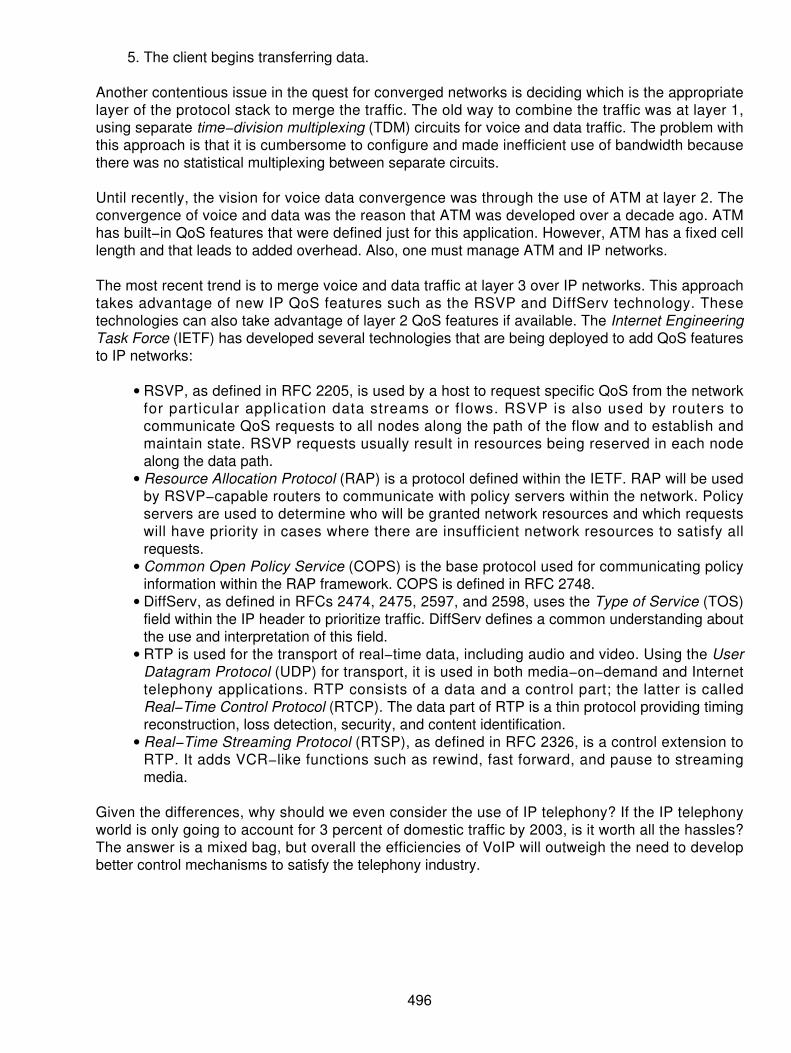
The client begins transferring data.5.
Another contentious issue in the quest for converged networks is deciding which is the appropriatelayer of the protocol stack to merge the traffic. The old way to combine the traffic was at layer 1,using separate time−division multiplexing (TDM) circuits for voice and data traffic. The problem withthis approach is that it is cumbersome to configure and made inefficient use of bandwidth becausethere was no statistical multiplexing between separate circuits.
Until recently, the vision for voice data convergence was through the use of ATM at layer 2. Theconvergence of voice and data was the reason that ATM was developed over a decade ago. ATMhas built−in QoS features that were defined just for this application. However, ATM has a fixed celllength and that leads to added overhead. Also, one must manage ATM and IP networks.
The most recent trend is to merge voice and data traffic at layer 3 over IP networks. This approachtakes advantage of new IP QoS features such as the RSVP and DiffServ technology. Thesetechnologies can also take advantage of layer 2 QoS features if available. The Internet EngineeringTask Force (IETF) has developed several technologies that are being deployed to add QoS featuresto IP networks:
RSVP, as defined in RFC 2205, is used by a host to request specific QoS from the networkfor particular application data streams or flows. RSVP is also used by routers tocommunicate QoS requests to all nodes along the path of the flow and to establish andmaintain state. RSVP requests usually result in resources being reserved in each nodealong the data path.
•
Resource Allocation Protocol (RAP) is a protocol defined within the IETF. RAP will be usedby RSVP−capable routers to communicate with policy servers within the network. Policyservers are used to determine who will be granted network resources and which requestswill have priority in cases where there are insufficient network resources to satisfy allrequests.
•
Common Open Policy Service (COPS) is the base protocol used for communicating policyinformation within the RAP framework. COPS is defined in RFC 2748.
•
DiffServ, as defined in RFCs 2474, 2475, 2597, and 2598, uses the Type of Service (TOS)field within the IP header to prioritize traffic. DiffServ defines a common understanding aboutthe use and interpretation of this field.
•
RTP is used for the transport of real−time data, including audio and video. Using the UserDatagram Protocol (UDP) for transport, it is used in both media−on−demand and Internettelephony applications. RTP consists of a data and a control part; the latter is calledReal−Time Control Protocol (RTCP). The data part of RTP is a thin protocol providing timingreconstruction, loss detection, security, and content identification.
•
Real−Time Streaming Protocol (RTSP), as defined in RFC 2326, is a control extension toRTP. It adds VCR−like functions such as rewind, fast forward, and pause to streamingmedia.
•
Given the differences, why should we even consider the use of IP telephony? If the IP telephonyworld is only going to account for 3 percent of domestic traffic by 2003, is it worth all the hassles?The answer is a mixed bag, but overall the efficiencies of VoIP will outweigh the need to developbetter control mechanisms to satisfy the telephony industry.
496

Applications for VoIP
Voice communications will remain a basic staple for the industry. The PSTNs will not be replaced,or dramatically changed for that matter, in the near term. The immediate need then for VoIPproviders is to deliver equal services, similar to the PSTN, at a lower cost of operation and to offer asuitable competitive product as an alternative. This alternative will increase the competition in theindustry and force stodgy providers into a new era of meeting the consumer's demands. The firstand foremost yardstick that everyone is using is the pricing model. Although switched voice is nowdown to $.05 to $.10 per minute, just what is the equilibrium price that should be used? When weconsider that the IECs' cost per minute is less than $.00125, the $.10 per minute charge they levyon corporate or residential consumers appears excessive. These pricing models are also changingas new technology is implemented in the Synchronous Optical Network (SONET) and densewavelength division multiplexing (DWDM) architecture as discussed in previous chapters. In Figure33−1, we see one of the basic scenarios of how the new providers may challenge the existinginfrastructure providers of telephony service. This assumes that a telephone−to−telephone accessmethod is used through the networks. This, by the way, is the preferred method because it uses thetools and techniques to which everyone is accustomed. The basic telephone set has become astaple in the business by having an ergonomically designed device that is easy to use. This is thebest way to handle the VoIP for a call. The telephone sets are designed to have the mouthpiececlose to the human's mouth and the ear piece that helps to screen out a lot of the ambient noise inthe room. Moreover, the sets are not actually doing any of the compression or conversions; theseare handled by the devices in the network such as gateways and gatekeepers, specifically designedfor this task.
Figure 33−1: Telephone to telephone through the IP networkVoIP can be used for just about any requirement for a telephony call. It can be used for fax and forvideo applications as well. From a single point−to−point call to a multiparty conference call and aweb−enabled call center application, the manufacturers have to devise tools and techniques tosupport the masses.
A second use for VoIP is shown in Figure 33−2, which uses a PC−to−telephone call. This is slightlyless desirable because the PC uses an integrated microphone and speakers for the most part.
497

Because they are not designed specifically for this application, they pick up all the noise in thebackground. Further, to prepare the real−time voice through the PC, the compression andconversion process occurs inside the PC, causing some clipping and chipping, echo, and otherforms or latency and distortion. It is not the best solution in the industry, but it does work.
Figure 33−2: PC−to−telephone calls over the IPThe third way to handle this is to use a PC−to−PC connection, which is the worst of the threescenarios. This one introduces the use of the PC substandard technology on both ends of theconnection, compounding the problems of echo, delay, clipping, and chipping. This is not the bestway to experiment with the technology. Moreover, I have seen people using PC−to−PCcommunications, whereby the caller places a telephone call over the PSTN to the party desired andtells the recipient to turn on their PC so that they can be called. This is ludicrous: If the IP systemdoes not know whether the called party is active and powered up, then you have to place atelephone call to tell the person to turn on their PC. Why not just have the conversation while youhave the called party on the line? This is just an aberration of the technology, but it highlights thefact that VoIP is not yet ready for prime time. There are several tools that IP telephony can bring tothe table, enabling the use of VoIP to handle
Voice−to−voice calls• Fax−to−fax communication• Voice−to−call centers• Voice−to−conference calling arrangements• PC−to−PC communication•
These various paths for handling VoIP are shown in Figure 33−3. The main point here is that thereare alternatives to VoIP being used as more than just a voice call. The benefit is enablingtechnologies to handle myriad options for now and in the future.
498

Figure 33−3: Various ways of using VoIPVoIP equipment must have the capability to handle the various options designed around the PSTNand cater to a wide range of configurations. Some of the applications are summarized in Table 33−4as a means of placing some semblance of order on the VoIP equipment market.
H.323 Protocol Suites
The IP telephony architecture must emulate the PSTN to accommodate the various ways ofinterconnecting. In Figure 33−4, the International Telecommunications Union (ITU) has set theH.323 specification to accommodate the various ways the IP telephony industry must work. Defininggateways and gatekeepers, H.323 is a mechanism for the manufacturers to produce the necessarydevices and protocol compatibility for interoperability in the PSTN and the Internet convergence.
499

Figure 33−4: ITU H.323 specifications define the various roles in IP telephony.Table 33−4: Summary of areas where VoIP equipment must work
Applications DiscussionInternet telephones Enhanced telephone sets, both wired and wireless, provide basic
telephony services across the Internet instead of the PSTN. Thesemay use a display that will display CLID and possibly some textmessaging capabilities.
Remote Access Branch office or Small Office/Home Office (SOHO) users canServices (RAS) gain necessary access to the corporate voice, data, video, and
multimedia applications using an intranet. The application here isthe home−based worker or telemarketer.
PC−based calls from atraveling person
Using the PC with an Internet connection (dial up from a mobile PCor connected through a community antenna television [CATV]modem in a hotel), a travelling user can access all of the corporateservices. Excellent for the road warriors in today's generation.
Web−enabled call centerservices
Call centers can be equipped with access to the Internet. As a usersurfs home pages and wants to place an order for a product or if aquestion arises, the user clicks a button on the PC screen to reacha real−time operator. Customer service applications like this willenhance the overall e−commerce industry and the telephonyapplications.
PSTN gateways As shown in Figure 33−3, the gateway function enables theinterconnection from the PSTN to t he Internet over a gateway. APC−based telephone can access the PSTN. Another application isfor a universal serial bus (USB) port telephone connected to a PCthat will have unlimited access to customers on the PSTN.
H.323 is an umbrella protocol consisting of a number of different subprotocols that are used tosupport audio, video, and data applications. There are three versions of H.323:
500

The ITU specified version 1 in 1996.• Version 2 was specified in 1998.• Version 3 is the mature signaling protocol.•
The H.323 suite was designed to
Provide video, audio, and data across various network types• Do point−to−point and multipoint conferences• Handle call control, multimedia environments, and prioritization• Function across a Local Area Network (LAN) or Wide Area Network (WAN).•
Its model is similar to Media Gateway Control Protocol (MGCP) in that it uses gateways to do themedia conversion and gatekeepers (the H.323 term for call agents) to do the signaling. The maindifference, however, is that unlike MGCP, H.323 was designed to work primarily with intelligentendpoints (such as IP−based telephones), whereas MGCP was intended to function with IntelligentAccess Devices (IADs) and simple, dumb, endpoints (such as a normal telephone). H.323 is acomplex protocol with a heavy code base. This makes it a very intelligent protocol, but it alsocauses it to be more expensive to build gateways, and it makes it more difficult to build a simple,reliable gateway. H.323 has a concentrated peer−to−peer architecture that does not enable easyscaling — a key concern to large network providers who need millions of connections. Othershortfalls include the following:
H.323 is based on TCP/IP, which can cause too much delay to make it practical.• It will connect over LANs that have no QoS control — an unacceptable solution.• Neither H.323 nor Session Initiation Protocol (SIP) was designed to interface with the PSTN— a drawback.
•
Figure 33−5 is a different view of the H.323 specifications for the VoIP standards, showing thevarious other protocol suites needed to support the standard. In this case, the terminal devicesrunning on various telephony protocols, such as ISDN terminals, H.320 terminals, and videoconferencing devices, are all accounted for in the H.323 specification. The standard also addressesthe various protocols for the gateways and gatekeepers on a LAN, as well as any compressiontechniques to manifest the VoIP capabilities in various points along the network.
501

Figure 33−5: H.323 in actionWhat also has to occur in the network is to use a layer 2 protocol to carry the IP traffic. Traditionally,a high−level data link control (HDLC) frame or a Point−to−Point Protocol (PPP) frame is used.However, to assure the QoS, the standards are recommending the use of ATM at the layer 2switching architecture. In most cases, ATM introduces added overhead by producing the cells to bemapped onto a SONET frame at the layer 1. However, what ATM does assure is the guaranteedbandwidth to deliver the necessary QoS. Only recently has a guaranteed QoS in Frame Relay (FR)been introduced. Figure 33−6 is a summary of the bandwidth needs and the QoS issues using theATM or FR networks to carry the VoIP traffic. It is through this combined use of layer 2 switchingand layer 3 network addressing that the systems are able to map and multiplex the traffic on thedata networks with any reliability. By the time this book is published, there will probably be three orfour new approaches that will emerge, each claiming to be the better way to handle the traffic forVoIP. In most cases, they will be efficient and better than what has been available previously. Thatdoesn't mean a thing because each of the techniques that exist today will be implemented andupgraded or improved over time. No one technology or technique stands to be the winning or killerapplication today.
502

Figure 33−6: The use of ATM or FR guarantees the QoS today.Delay and Jitter on VoIP Networks
Two of the major concerns today are the problems experienced with delay and jitter. The delayfactors can be the most disconcerting. In the past, the PSTN has been delivering real−time voiceacross the network with an average delay of 30 to 50 ms. When we experimented with satellitecommunications in the early 1980s, the end user community was disgruntled with the potentialdelays for real−time voice applications. The average delay on a satellite−based network ingeosynchronous orbit approximated 250 ms, which was intolerable for the end user. In the VoIPdelivery today, the average response and delay factors must be dealt with. On average, if a call isplaced across the Internet, the delays are from 800 ms to 2 seconds domestically. This is totallyunacceptable for the user community. It certainly does not lend itself to the conducting of businessconversations. When placing a call across the Internet overseas, the delay can be as much as 5seconds! Again, this will never do.
The delays have been the result of all the processing required throughout the network. One problemthat results from high end−to−end communications delay is the increase in echo whenever theround trip delay exceeds 50 ms. Because echo is viewed as a quality problem, VoIP systems mustaccommodate echo control in order to be accepted. Talkers will overlap themselves when the delayincreases if one−way transmission exceeds the 200 to 250 ms range. This was a major problemwith satellite transmission. Too often, talkers were over talking each other, causing total chaosduring the conversations. The budgeted delays for VoIP must be within the 200 to 250 ms range,and that is strictly the worst case. The VoIP systems have to strive for better response and delivery.
Jitter (variable delay) is a variation of the interpacket delivery introduced by the processing of eachpacket across the network, coupled with transmission delay across the medium. To solve theproblem for real−time applications, packets must be collected into a buffer and played out asneeded. By holding the packets just long enough to accommodate the longest delay in packetdelivery, the added delay can be devastating. This also requires that the VoIP equipment havesufficient buffers to accommodate these interpacket delays on an ongoing basis. The bigger thebuffers, the longer the potential delays.
503

Another major problem that one must contend with is the acceptable level of packet loss. Severalstudies have been conducted indicating that acceptable packet loss is less than 10 percent.Anything greater than 10 percent packet loss will be intolerable. The network can drop packetswhen peak loads are being experienced, causing some degree of loss. Moreover, packets can bediscarded in case of buffer overrun at the routers and switches across the network. These combinedproblems may move the packet−loss levels to an unacceptable range.
If we combine the various levels of processing delay and the risk of packet loss, we can see wherethe networks must accommodate the delay, along with the need for VoIP equipment to address theissue. Figure 33−7 is a representation of the delays that can be cumulatively added to a packetdelivery across the network.
Figure 33−7: Delays across a VoIP networkProtocol Stack
The VoIP protocol stack uses the benefits of a TCP/IP suite in which to run over the network. Figure33−8 is a representation of the protocols as they stack on top of each other. The primary areas areas follows:
504
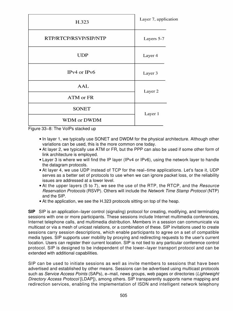
Figure 33−8: The VoIPs stacked up
In layer 1, we typically use SONET and DWDM for the physical architecture. Although othervariations can be used, this is the more common one today.
•
At layer 2, we typically use ATM or FR, but the PPP can also be used if some other form oflink architecture is employed.
•
Layer 3 is where we will find the IP layer (IPv4 or IPv6), using the network layer to handlethe datagram protocols.
•
At layer 4, we use UDP instead of TCP for the real−time applications. Let's face it, UDPserves as a better set of protocols to use when we can ignore packet loss, or the reliabilityissues are addressed at a lower level.
•
At the upper layers (5 to 7), we see the use of the RTP, the RTCP, and the ResourceReservation Protocols (RSVP). Others will include the Network Time Stamp Protocol (NTP)and the SIP.
•
At the application, we see the H.323 protocols sitting on top of the heap.•
SIP SIP is an application−layer control (signaling) protocol for creating, modifying, and terminatingsessions with one or more participants. These sessions include Internet multimedia conferences,Internet telephone calls, and multimedia distribution. Members in a session can communicate viamulticast or via a mesh of unicast relations, or a combination of these. SIP invitations used to createsessions carry session descriptions, which enable participants to agree on a set of compatiblemedia types. SIP supports user mobility by proxying and redirecting requests to the user's currentlocation. Users can register their current location. SIP is not tied to any particular conference controlprotocol. SIP is designed to be independent of the lower−layer transport protocol and can beextended with additional capabilities.
SIP can be used to initiate sessions as well as invite members to sessions that have beenadvertised and established by other means. Sessions can be advertised using multicast protocolssuch as Service Access Points (SAPs), e−mail, news groups, web pages or directories (LightweightDirectory Access Protocol [LDAP]), among others. SIP transparently supports name mapping andredirection services, enabling the implementation of ISDN and intelligent network telephony
505

subscriber services. These facil i t ies also enable personal mobil i ty. In the parlance oftelecommunications intelligent network services, this is defined as the ability of end users tooriginate and receive calls and access subscribed telecommunication services on any terminal inany location, and the ability of the network to identify end users as they move. Personal mobility isbased on the use of a unique personal identity. Personal mobility complements terminal mobility,that is, the ability to maintain communications when moving a single end system from one subnet toanother.
SIP supports five facets of establishing and terminating multimedia communications:
User location Determination of the end system to be used for communication• User capabilities Determination of the media and media parameters to be used forcommunication
•
User availability Determination of the willingness of the called party to engage incommunications
•
Call setup Ringing — establishment of call parameters at both the called and calling party• Call handling Transfer and termination of calls•
SIP can also initiate multiparty calls using a multipoint control unit (MCU) or fully meshedinterconnection instead of multicast. Internet telephony gateways that connect PSTN parties canalso use SIP to set up calls between them. SIP is designed as part of the overall IETF multimediadata and control architecture currently incorporating protocols such as RSVP for reserving networkresources, the RTP for transporting real−time data and providing QoS feedback, the RTSP forcontrolling delivery of streaming media, the SAP for advertising multimedia sessions via multicast,and the session description protocol (SDP) for describing multimedia sessions.
However, the functionality and operation of SIP does not depend on any of these protocols. SIP canalso be used in conjunction with other call setup and signaling protocols. In that mode, an endsystem uses SIP exchanges to determine the appropriate end system address and protocol from agiven address that is protocol independent. For example, SIP could be used to determine that theparty can be reached via H.323, obtain the H.245 gateway and user address, and then use H.225.0to establish the call. In another example, SIP might be used to determine that the called party isreachable via the PSTN and indicate the phone number to be called, possibly suggesting anInternet−to−PSTN gateway to be used. SIP does not offer conference control services, such as floorcontrol or voting, and does not prescribe how a conference is to be managed, but SIP can be usedto introduce conference control protocols. It does not allocate multicast addresses.
SIP can invite users to sessions with and without resource reservation. It does not reserveresources, but can convey to the invited system the information necessary to do this.
MGCP MGCP, an IETF draft, has been chosen as the initial protocol to provide the call controlnecessary to enable wide scale telephony over the Internet. MGCP also provides the interoperabilitybetween the Internet and legacy telephone networks. MGCP is ASCII based and resides in a UDPpacket, relying on a positive acknowledgment mechanism to deal with packet loss. As its basis,MGCP's stateless protocol was designed using a combination of Cisco Systems and Bellcore'sSimple Gateway Control Protocol (SGCP) and the level 3 Technical Advisory Committee's InternetProtocol Device Control (IPDC) specification. Combining these two protocols facilitated a singlespecification and, in turn, enabled faster deployment. To ensure security, MGCP uses the IPSecurity (IPSec) protocol and has the ability to use encryption on the media streaming at theterminal equipment.
MGCP works with several other protocols to provide the various functions that will be needed in the
506

Internet for VoIP. MGCP is used to communicate between a call agent and a gateway. Together,these help to make up the SoftSwitch architecture. The call agents (also referred to as mediagateway controllers) are the brains of the operation, and the gateways are the muscle. You needboth of them to complete a call over a public network using MGCP. The call agent sends commandsto the gateway and receives an acknowledgment for each one. An advantage to call agent/gatewayarchitecture is that new services can easily be introduced without having to swap or upgradegateways. This model appears as if it is a single gateway, but is actually distributed. This iscommonly referred to as the decomposed gateway architecture. Putting the call control functions inthe call agent and the media streaming functions in the gateway allows for both greater scalabilityas well as more simple, inexpensive, and reliable local access equipment.
The Gatekeeper The call agents or gatekeepers are scattered around the Internet and act astelephony routers. The call agent is required for signaling within a call, but is not involved inhandling the voice traffic. Each call agent, responsible for a number of gateways, accepts eventmessages from them and tells them how to process calls via a relatively small set of MGCPmessages and procedures. The call agents do not use the MGCP to talk to each other. Instead theyuse SIP and H.323 to intercommunicate. Network providers will normally set up several gateways toprovide access for their users or customers. One or more gatekeepers, or at a minimum access to agatekeeper from another provider, should be set up. These gatekeepers require the ability to routecalls to and from the PSTN and also route calls to and from customers of other network providers.
The Gateways A gateway is a device that is designed to join different components. A mediagateway joins disparate media (that is, CATV to DSL, and so on). In MGCP, signals are convertedbetween real−time circuits and packets, and between voice and packets. In MGCP, there are anumber of different types of gateways performing different tasks. Each type of gateway has adistinguishing name and enables voice to be encapsulated in packets. The gateways are primarilyconcerned with audio signal conversion and media streaming, while the gatekeepers deal mainlywith signaling functions. The gateways may be positioned at the customer premise where they canbe directly connected to Plain Old Telephone Service (POTS) telephones, a Private BranchExchange (PBX), or a data network. They can also be found at a point of presence (POP) orcolocation point where they can service larger numbers of users as well as provide other high leveltasks. Gateways can be associated with multiple gatekeepers to provide redundancy.
H.248/MEGACO H.248 is the name given to this protocol by the ITU and MEGACO is how it isrecognized today by the IETF. This is the first time that these two groups have worked on astandard together and is indicative of the future meshing of telecommunications and the Internet.H.248 has a lot of similarities to MGCP and is typically referred to as the protocol, which willeventually supersede it. H.248 uses the gateway/call agent architecture and also handles the callsetup much like MGCP; however, the naming of the parts and functions differs. H.248 also addsenough complexity to enable it to support video traffic. It is still a relatively immature protocol in theworld of signaling protocols.
507

Chapter 34: Multiprotocol Label Switching (MPLS)
Overview
No one can argue that the growth of the Internet has been exceptional. Depending on what reportyou read or what research house publishes, the numbers may differ slightly, but the overall result isthe same. The Internet is explosive. The events of 2000 and 2001 have caused the growth to slow abit, but overall we can expect to see continued growth and expansion of the Net. In October 2000, areported 93 million hosts were attached to the Internet, which represents an increase from 65 millionin the same period of 1999. In actuality, there have been over 60 million hosts attached over athree−year period. The graph shown in Figure 34−1 is a representation of the growth andprojections for the Internet with some statements estimating over a billion users and 750 millionhosts in 2008. Using any calculation method, this is still impressive.
Figure 34−1: Hosts attached to the Internet 1999 to 2008 estimatesWhether the Internet meets or exceeds the growth projections, one thing is certain — IP networkingwill be the standard networking protocol for the future, and the growth will place a burden on theability to process the data packets quickly. The more hosts and users logging onto the network, theexponential growth in routing tables and routers are needed to process the data. Because of themonstrous growth rates, the carriers and vendors alike need to find a more efficient way of dealingwith the traffic deluge. Optimizing the network efficiency is a critical goal today and for the future.Inherently, however, IP was not designed to be efficient. Thus, we need to create some bettersolutions for packet handling. In earlier chapters, we saw that several different techniques werebeing introduced to handle upper layer protocol traffic. To address lower layer traffic, MPLS becameone of the solutions sought after aggressively by the standards committees, vendors, and networkoperators alike.
Standard IP Networking
Let's start, then with a quick review of the IP addressing scheme. Why do that? Well, you know howbig the network is becoming unmanageable! You also know that the way you handle this growth andthe demands from the user is to install more routers and bandwidth. With IP, the end useraddresses are limited to one of three basic classes. So, in an IP address there are three classes
508

you may have requested. The three addresses include Class A, B, or C. In Figure 34−2, we see theaddress capacities. First, the IP address is currently based on a 32 bit field that is divided,depending on the class. Using a binary sequence of 232 we can have up to 4,294,967,296addressable devices. One would think that this is plenty of addresses (and correctly, this is true).However, the numbers were assigned in a problematic way that is now becoming a majoraddressing issue in the industry.
Figure 34−2: The addresses used in IPAs shown in the figure, we break the 32 bit sequence into 8 bit bytes. This is called the decimal dotdelimited number sequence. Using these 8 bits at a time, we can categorize the address as Table34−1 reflects.
The ranges of addresses by class are shown in Table 34−2 as a means of simplifying the ranges fortheir expected use.
These classes of addresses (also called classful addresses) were based on nice, neatconfigurations of 8 to 16 or 24 bit sequences for the address and the remaining bits for the hoststhat are attached. This also meant that when the addresses were issued, they were somewhatimpractical. Make no mistake that the intent was valid, but the wasteful way that the numbers weredoled out created longer−term problems.
Table 34−1: Networks assigned by the decimal dot delimited addresses
Class Address Bits Allotted forNetwork Number
Addresses WeActually Get
Bits Allotted forAttached Hosts
Hosts
A 8 (less 1) 7 123 24 16,777,216 (less 2)B 16 (less 2) 14 16,384 16 65,535 lessC 24 (less 3) 21 2,097,152 8 256 (less 2)
Table 34−2: Ranges for classes of addresses
Address Network RangesA 1.x.x.x through 126.x.x.x
509

B 128.0.x.x through 191.255.x.xC 192.0.0.x through 223.255.255.x
The first is that the numbers were assigned to a corporate location. A class "A" address, also calleda /8 (pronounced slash 8) address, which denotes that the address prefix (network number), is 8bits long. This means that the corporation needs to have all 16,777,214 (all 1s and all 0s wereeliminated) located at one location. This was impractical. Think of the number of routes that a routerwill have to maintain and the size of the tables needed to be able to route traffic to these devices.Simply adding memory to the router does not solve the problem, as many people think. Memory ischeap today, but some of the other considerations include
The demand for more CPU power to compute the routes quickly.• Routing topologies are changing significantly from the initial networks.• Changes are happening at an escalating rate.• Routers use cache memory for the forwarding tables. Caches are affected by the dynamicsof the networks, affecting the forwarding cache.
•
Sheer volume of information is exploding.•
Therefore, we find ourselves needing to subdivide the network into smaller pieces, called subnets. Asubnet is nothing more than divisions of the larger IP network into smaller pieces where all the hostsin a subnet are on the same physical network (that is, an Ethernet). In 1985, this problem came tothe surface and caused the Internet Engineering Task Force (IETF) to look at the use of subnetting.This was geared to take on the problems with the two level addressing hierarchies.
There are many reasons we may want to break the network into smaller pieces. These are shown inFigure 34−3. The figure is not broken into priorities or orders of importance but is just a means oflisting what the reasons may be for the subnetworking of an address.
510

Figure 34−3: Reasons for subnetworkingThis means that we attempt to break down IP addresses depending on the motivations as follows:
When the sites are geographically dispersed, we use a subnet function so that we do notneed different IP addresses in remote locations. Picture a company that has sites spreadacross the country. If we do not subnet, then each site will need its own IP.
•
Because of the departmental uniqueness in certain organizations, we find that they maywant to have a separate subnet. Different product l ines, for example, in a majorconglomerate.
•
We may have different protocols running on the network, and we separate the networks intosubnets to provide isolation. This is not necessarily a requirement as opposed to apreference. An example may be a financial organization running a mainframe with SystemsNetwork Architecture (SNA) traffic on one local area network (LAN) and Novell with FrontOffice word processing on another.
•
If traffic is voluminous, we may subnet the IP so that again we can isolate different trafficflows with bridging or routing techniques.
•
Some traffic conditions may conflict with others, especially protocols, but also in the amountor type of data that moves between groups.
•
Routers used internally between departments or buildings on a campus create a goodopportunity to subnet by building or department on a Campus Area Network (CAN). Thismay also be used in a university where the individual colleges (business, engineering, andchemistry) are all on their own subnet. An example of this arrangement in a business isshown in Figure 34−4.
•
511
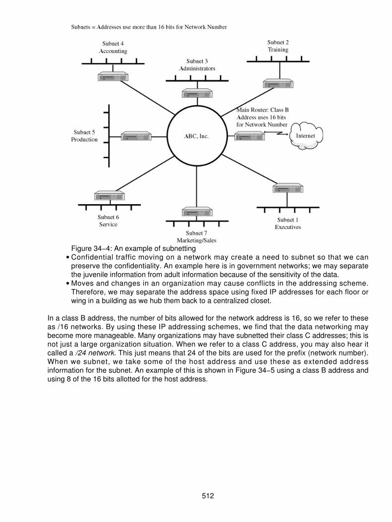
Figure 34−4: An example of subnettingConfidential traffic moving on a network may create a need to subnet so that we canpreserve the confidentiality. An example here is in government networks; we may separatethe juvenile information from adult information because of the sensitivity of the data.
•
Moves and changes in an organization may cause conflicts in the addressing scheme.Therefore, we may separate the address space using fixed IP addresses for each floor orwing in a building as we hub them back to a centralized closet.
•
In a class B address, the number of bits allowed for the network address is 16, so we refer to theseas /16 networks. By using these IP addressing schemes, we find that the data networking maybecome more manageable. Many organizations may have subnetted their class C addresses; this isnot just a large organization situation. When we refer to a class C address, you may also hear itcalled a /24 network. This just means that 24 of the bits are used for the prefix (network number).When we subnet, we take some of the host address and use these as extended addressinformation for the subnet. An example of this is shown in Figure 34−5 using a class B address andusing 8 of the 16 bits allotted for the host address.
512

Figure 34−5: A class B address subnettedSubnetting dealt with the routing problems by making sure that the subnet structure of a networkwas invisible to the outside world. It is an internal subnetting structure. The route from the Internet toany subnet of an IP address is the same, no matter which subnet the host is on. The outsidenetworks do not care what subnet that the host is on internally; they are primarily concerned withgetting the datagram to the entrance of the network, then the internal routing takes place based onthe subnet masking.
Subnet Masking
To be assured that we can separate the address space, each system in the subnet must have thesame subnet mask. The subnet mask distinguishes between the network bits, subnet bits, andinterface (host) bits. To do this, the mask must have the same number of bits as the IP address andis in the same format as the IP address. Though the mask has the same format as the IP address,its first byte always has a value of decimal 255, which is impossible for any IP addressableinterface. A network number 255 is nonaddressable. Because the devices process numbers greaterthan the masked number (so with an 8 bit byte, the numbering range is 0 to 255), the router looks atany number greater than 255, which there are none.
In Figure 34−6, we see a means of dealing with the public and private networking strategies usingthe subnets in a single router as the external gateway to the outside world. This shows that severallogical networks using subnet addressing are used to route the traffic internally. All traffic comingfrom the outside world comes into the router sitting at the edge of the network. The traffic isaddressed to network number 136.8.0.0. The router accepts the traffic, then forwards it to thesubnetworks based on the third octet of their address. The addresses have been broken down inblocks of 32 for simplicity.
513

Figure 34−6: Subnets reduce the confusion and the heavy routing needs.Natural masks use binary 1s in the network and subnet portion of the IP address while it uses binary0s to represent the host interface number. Figure 34−7 is an example of the subnet masking andthe way it is laid out. Routing protocol standards and definitions describing what happens inside theenterprise often refer to this as the extended address or the extended network prefix. Either way, weare looking at a subnetwork mask. The prefix length is equal to the contiguous ones in thetraditional mask. Therefore, when we look at address 130.5.5.25 with a subnet mask of255.255.255.0, we can also call this 130.5.5.25/24. The slash 24 (/24) defines the length of thenetwork prefix (extended) and is easier to understand for many people. We also need to recognizethat the routing protocols still must carry the full information of the subnet mask. No standardsenable us to define the length of the extended address field, so we must carry the full subnet maskin the routing protocols.
Figure 34−7: A subnet maskNatural masks were set up in octet boundaries when we first started subnetting. This represents thebits used in a class A, B, or C address. In Table 34−3, we can see the natural masks used by typeof address.
Table 34−3: The natural mask uses the octet boundaries by class of address
Class MaskA 255.0.0.0B 255.255.0.0C 255.255.255.0
514

Added bits in a mask beyond the natural mask for the network class indicate that subnetworkingoccurred. The notation of using the slash (/) enables us to define the number of added bit used inthe subnets. For example, we may see the notation of /22 or /26. This just indicates the way wehave used the subnets and the additional notations to follow.
Rules of Routing
When we move into a routing architecture, we must understand that routers are designed to passour IP datagrams across the network in one of two basic ways:
Local routing occurs when the datagram is sent directly to a host (device) on the samephysical network as the sender (that is, a LAN).
•
Indirect routing occurs when the intended device is not on the same physical network butresides somewhere else. IP must, therefore, forward the datagram to another device (suchas a router) to assist in the redirection of the IP datagram to the intended device.
•
Therefore, IP must decide if the destination device is on a local network by looking at the sourceand destination addresses. IP does many calculations while determining whether the devices arelocal to each other or not. Yet, a set of decisions can be made, and forwarding can occur. SeeTable 34−4 for some of the decisions that IP makes as it evaluate the address of each IP datagramit receives.
Table 34−4: The decision matrix for forwarding the IP datagrams
If ThenSource and destination IP addresses are in differentclass addresses (that is, an A and B).
Give the datagram to the router forforwarding.
Source and destination IP addresses are in the sameclass of address (a la both class B), but the networksare different.
Give the datagram to the router forforwarding.
Source and destination address are in the same classand same network but different subnets.
Give the IP datagram to the router forforwarding.
Source and destination IP addresses are in the samenetwork and the same subnet.
Send the datagram directly to thedestination.
This means that the routers look at the address using layer 3 protocols and then use layer 2 todeliver the IP datagrams by encapsulating the datagram in some layer 2 framing format. This is notmagic, just the natural evolution of the legacy routing decisions we had to make in the beginningstages of our network evolutions.
The next part is usually one of the more difficult to answer when routing IP datagrams. First, wemust ascertain if the source and destination addresses are on the same network. If they are not onthe same network, as seen in Table 34−4, then the datagram is sent to the local router for handlingand forwarding. Comparing the subnet field computes if the source and destination address are inthe same subnet. If they are in the same subnet, the subnet address field must be the same. This iscalculable by looking at the subnet field and seeing if the values are the same.
515

Variable Length Subnet Masks (VLSM)
In 1987, the IETF approved Request for Comments (RFC) 1009, which specifies how subnettednetworks can use more than one subnet mask. When there is more than one subnetwork maskassigned, the IP network is said to use var iable length subnet masks because theextended−network prefixes have different length.
The routing information protocol version one (RIP−1) only enables us to use a fixed length subnetmask across the entire network prefix. This means that RIP−1 only enables a single subnet mask ineach network number because it does not provide subnet−masking information as part of its routingtable update information. In the absence of this information however, RIP−1 makes very simpleassumptions about the subnet mask that is applied to any learned network in its table.
VLSM enables better use of IP address space assigned to an organization. One of the risks we hadwith the single subnet mask was that we could be locked into a fixed number of fixed−sizedsubnets. The variable subnets overcome some of the older limitations, but RIP−1 is the problem inthis case. VLSM also enables better routing structure as the networks are laid out. It enables theuse of route aggregation so that the routing tables can be held to a minimum. As we saw earlier,routing tables are becoming a good portion of the bottleneck in our overall networking strategy. It isnot as simple as throwing the memory at the routers to make the systems work better. Many of thecombined protocols are working against us. To this end we see that there must be more done tomake the networks perform more efficiently. This includes any way we can build the tables and themasking that we can use.
Requirements for the use of VLSM are not that much different from basic subnet masking. Theseinclude the following:
The protocols used to route our traffic must enable and carry extended−network−prefixinformation in each table advertisement message (Service Access Points [SAPs] andsolicitations).
•
All routers in the network must use a consistent forwarding algorithm for traffic using internalalgorithms based on the longest match of address and mask information.
•
When route aggregation is used, addresses must have a topological significance in theassignment of the addresses. If not, the routers may have a problem forwarding the traffic.
•
VLSM is now an accepted means of forwarding the traffic using newer routing protocols such asOSPF, IS−IS, EIS−IS, and now RIP−2. These protocols enable the extended addressing of thenetwork prefix to be variable, depending on the route taken with each advertisement and solicitationmessage traversing the network.
The Longest Match Syndrome
As already stated, all routers must use a consistent approach in the forwarding algorithms, basedon the longest match. The use of VLSM creates an environment where a set of networks with thelonger extended−network−prefix may create subnetwork relationships. The routers will gather routeadvertisement and solicitation information and build their tables. As they capture the information,hundreds or thousands of entries steer the data to the same end−point. The longer address matchis considered, the more specific address and forwarding information. The shorter the subnet match,the more generic the route. Routers now use the longest matching extended−network−prefix to bemore specific when forwarding traffic.
516
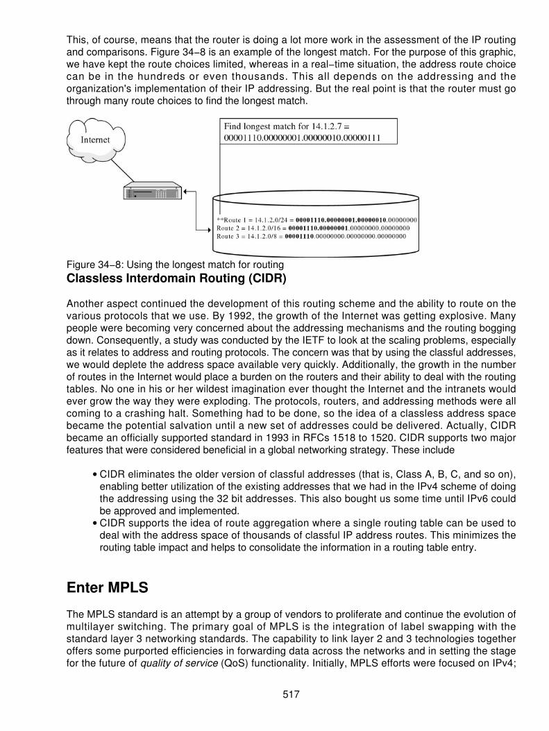
This, of course, means that the router is doing a lot more work in the assessment of the IP routingand comparisons. Figure 34−8 is an example of the longest match. For the purpose of this graphic,we have kept the route choices limited, whereas in a real−time situation, the address route choicecan be in the hundreds or even thousands. This all depends on the addressing and theorganization's implementation of their IP addressing. But the real point is that the router must gothrough many route choices to find the longest match.
Figure 34−8: Using the longest match for routingClassless Interdomain Routing (CIDR)
Another aspect continued the development of this routing scheme and the ability to route on thevarious protocols that we use. By 1992, the growth of the Internet was getting explosive. Manypeople were becoming very concerned about the addressing mechanisms and the routing boggingdown. Consequently, a study was conducted by the IETF to look at the scaling problems, especiallyas it relates to address and routing protocols. The concern was that by using the classful addresses,we would deplete the address space available very quickly. Additionally, the growth in the numberof routes in the Internet would place a burden on the routers and their ability to deal with the routingtables. No one in his or her wildest imagination ever thought the Internet and the intranets wouldever grow the way they were exploding. The protocols, routers, and addressing methods were allcoming to a crashing halt. Something had to be done, so the idea of a classless address spacebecame the potential salvation until a new set of addresses could be delivered. Actually, CIDRbecame an officially supported standard in 1993 in RFCs 1518 to 1520. CIDR supports two majorfeatures that were considered beneficial in a global networking strategy. These include
CIDR eliminates the older version of classful addresses (that is, Class A, B, C, and so on),enabling better utilization of the existing addresses that we had in the IPv4 scheme of doingthe addressing using the 32 bit addresses. This also bought us some time until IPv6 couldbe approved and implemented.
•
CIDR supports the idea of route aggregation where a single routing table can be used todeal with the address space of thousands of classful IP address routes. This minimizes therouting table impact and helps to consolidate the information in a routing table entry.
•
Enter MPLS
The MPLS standard is an attempt by a group of vendors to proliferate and continue the evolution ofmultilayer switching. The primary goal of MPLS is the integration of label swapping with thestandard layer 3 networking standards. The capability to link layer 2 and 3 technologies togetheroffers some purported efficiencies in forwarding data across the networks and in setting the stagefor the future of quality of service (QoS) functionality. Initially, MPLS efforts were focused on IPv4;
517

however, the basic technology is far reaching with hooks to other network layer protocols such asAsynchronous Transfer Mode (ATM), Frame Relay, and so on. The real benefit to the use of MPLSis that it can be used on any media at any layer that can pass data packets. MPLS basicspecifications are contained in RFC 3031. With MPLS, conventional network layer routing (IProuting) determines a path through the network. Once the path is selected, data packets are thenswitched through each node as they traverse the network. Moreover, the use of QoS, trafficengineering, and Virtual Private Network (VPNs) are discussions that continually stress the moreefficient use of IP networking.
Traffic Engineering
Traffic engineering is the process of selecting network paths so the traffic patterns can be balancedacross the various route choices. Routing with the older Interior Gateway Protocol (IGP) algorithmsmay select circuits, resulting in unbalanced utilization. Consequently, some circuits becomecongested, while others sit idle. Manipulating the IGP metrics can provide the necessary trafficengineering. However, this is difficult to manage when networks are large and have many alternateroutes. Figure 34−9 shows an example of the routing protocols used in many networks. BorderGateway Protocol (BGP) sits outside the network at the edge, whereas OSPF runs in the core of thenetwork.
Figure 34−9: Combined protocols used in the networkUsing Figure 34−10, we see the route that will be selected through the network using the OSPFprotocols. The traffic will be designed to always travel in the upper segment of the network becausethis is the shortest path through the net. However, what can happen is the links on this portion of thenetwork will get congested, whereas the lower route will never get used because the pathalgorithms will not point to the longer route.
518

Figure 34−10: The path with conventional routing algorithmsMPLS enables us to direct packets over a specific route to traverse the network as shown in Figure34−11. This explicit form of routing makes sure that certain types of traffic follow a prespecifiedpath. Explicit routing is available in the source routing options of traditional IP. Because this is aprocessor−intensive activity, it was not heavily accepted or implemented. MPLS takes advantage ofthis explicit routing. MPLS also provides the ability to analyze fields outside the IP packet headerwhen determining the explicit route for a data packet.
Figure 34−11: The chosen route with MPLS specified routingQoS Routing
QoS routing is the ability to choose a route for specific data streams to provide a desired level ofservice such as for Voice over IP (VoIP). The level of service can specify acceptable levels ofbandwidth, delay, or packet loss in the network. Much of this information can be seen in the type ofservice (ToS) field in an IP header. This provides the intelligence to deliver different levels of servicebased on overall network policies. Providing a network path delivering a desired QoS often requiresthe use of explicit routing. This requires a finer level of granularity than that provided by standardtraffic engineering. There are two approaches to providing QoS routing in an MPLS environment:
519

The MPLS label contains class of service (CoS) information. As traffic flows through thenetwork, this information can be used to selectively prioritize traffic at each network hop.
•
The MPLS network can provision multiple paths between entrance and exit points. Eachpath is engineered to provide a different level of service.
•
In a traditional connectionless oriented network (such as IP), every router uses a layer−3 routingalgorithm (the normal ones we see are Open Shortest Path First [OSPF] and BGP). As a packettraverses through the network, each router along the path makes an independent forwardingdecision for that packet. Using the packet header addresses, as well as instructions from the routingalgorithm, the router chooses the next hop destination for the packet. In an IP network, this involvesmatching the destination address stored in the IP header in every packet with the most specificroute obtained from the IP routing table. This matching and comparing sequence determines thenext hop destination for the packet. This is obviously very processor intensive. In a normalconnectionless network, this takes place on a hop−by−hop basis to get to the distant end.
MPLS Forwarding Model
MPLS has emerged as the preferred technology to provide QoS, traffic engineering, and VPNservices on the Internet. Using MPLS, the optimal path through the network is determined andtagged first. Thereafter, as packets enter the MPLS network, the input routers and switches use thelayer 3 header to assign the packets to one of these predetermined paths. A label is attached to theend−to−end path information in the packet. MPLS creates a forwarding hierarchy by using a labelstacking process to better handle the traffic given the conditions that exist. The label accompaniesthe data packet as it traverses the network. All other routers along the path use the label todetermine the next hop address (device) instead of the IP address. Because these devices onlyoperate on information in the label, processor−intensive analysis and classification of the layer 3header occur only at the entrance to the network. This eliminates much of the overhead used in thenetwork and expedites the overall processing of data. Once the MPLS network is established,added enhancements can be used to activate the MPLS services and capabilities. These includeother label switching protocols like IP switching, Resource Reservation Setup Protocol (RSVP), andothers.
MPLS also interacts with other class of service mechanisms and specifically with the IntServ andDiffServ IP mechanisms discussed earlier. MPLS is an advanced form of packet forwarding, whichreplaces the existing forwarding process based on the best match of destination address with alabel−swapping model. Another term that is used is Forwarding Equivalence Class (FEC); theMPLS label is the encoded value of the FEC.
In comparison with an ATM core network, non−MPLS ATM switches do exactly that: They switchATM cells between interfaces, but they know nothing about the payload contained in the cells.MPLS−enabled switches also switch ATM cells (at layer 2) but also use different labels — theVPI/VCI settings in the cells. MPLS brings the performance characteristics of layer 2 network withthe connectivity and network services of layer 3 networks.
An ATM label switching router does not reassemble IP packets when switching between two ATMinterfaces. The label for any received ATM cell is derived from the VPI/VCI in the cell; so long as thecell is to be retransmitted over another ATM interface, the switch will do so immediately. If the ATMlabel switching router also has an Ethernet interface, then it will perform frame switching betweenthe ATM and Ethernet interfaces. This means that it will reassemble the ATM cells into a single IPpacket but will then switch it onto the Ethernet interface based on the MPLS information derivedfrom the MPLS label and will not need to examine the layer 3 IP information in the frame.
520

MPLS Components
MPLS networks comprise the following elements and are shown in Figure 34−12:
Label Edge Routers (LERs) Located at the boundaries of the MPLS network. In an ATMnetwork, LERs may well be the routers placed at the edge of the ATM network. LERs applylabels to packets for transmission across the MPLS network; traffic from multiple sources tothe same destination can share labels.
•
Label Switch Routers (LSRs) Switch IP packets or cells based on the labels found in them.LSRs can also support full layer 3 routing functions for unlabeled packets.
•
Label Switch Paths (LSPs) Define the path taken through the MPLS network for a givenlabel. In an ATM network, the LSP is equivalent to an ATM VC.
•
Label Distribution Protocol (LDP) Used to distribute label information between LSRs andLERs. As well as defining a new protocol, existing protocols, such as BGP and RSVP, havebeen extended to enable label distribution to be stacked on them.
•
Figure 34−12: The components of MPLSIn ATM networks, the label can actually be the VCI/VPI in the ATM header. In frame relay networks,the Data Link Control Indicator (DLCI) in the frame relay header can be used. In LANs, the MPLSlabel has to be added to the existing MAC frame between the layer 2 header (dynamic−link library[DLL] header) and the layer 3 data elements of the frame.
The real issue is that many new and old protocols can work together to meet the demands of theexplosive IP networking growth as seen in the Internet. As MPLS rolls out, any layer twofunctionality will be complemented with the use of the label switching associated with MPLS. A labelis a label, so whether we use the Ethernet standards, ATM, Frame Relay, or Point−to−PointProtocol (PPP) (VPNs), they all can be improved upon through the use of MPLS.
As the network continues to grow and evolve, other scenarios will likely present themselves todefine and improve upon the various protocols that have been discussed throughout this book. Noone set of rules ever works for every network scenario. MPLS adds some newer means of providingselective routing through a growing network. This enables us to provide a CoS, QoS, or any otherlabel we want to discuss.
521

Chapter 35: Intranets and Extranets
Overview
We begin with an attempt at a definition. Most of the buzzwords around the Internet are easy todefine until we get to made−up words like intranet and extranet. These words were invented byjournalists to describe Internet technology employed within an organization rather than outside theorganization.
Intranet is essentially an Internet with a small i. In particular, it implies the web implementation onour internal internet. Now, what do we do about telecommuters of all descriptions? An answer is togive our telecommuters access to our intranet via the Internet, again using web technology.
Extranets are simply our Intranet extended to permit access to our organization by our businesspartners. That is, a web or a net interface designed specifically to support our business partners andfield offices. This also could be a Virtual Private Network (VPN) if that level of security wererequired. You will note here the mixing of field offices and customers. If we were consistent, the fieldoffices would be covered under intranet, while customers were covered under extranet.
Here again, when journalists make up words without clearly defining them, you get this interestingblurring of definitions.
By our definition, if the external employee (telecommuter and so on) has access to our internalnetwork applications, then we are providing an intranet. That is, access isn't limited to our externalweb site, but extends to our internal web site and perhaps to File Transfer Protocol (FTP), telnet,and other applications. If our external business partner, or field office, only has access to ourexternal web site or to an external FTP server, then we are providing an extranet.
Please note that these definitions are not universal. What you call it isn't nearly as important as whatit does. The goal of our intranet is to facilitate our business — that is, to help it work better internallyand with our correspondent employees.
Whether your organization is geographically diverse or simply growing rapidly, maintaining uniformcommunications across the organization is the challenge. Distributing information — for example,policy and procedures manuals in paper format — proves to be very ineffective. First, they aren'tread because people have work to do that they consider more important. Second, by the time theyneed the information and read the manual, it is long since out of date. Large companies can keep afull−time employee busy running around putting change pages in all the policy and proceduresmanuals. Therefore, it is no surprise that the policy and procedures manual is one of the first to beimplemented on our intranet. Putting it on web pages with a good index and many cross−referencesmakes it easy to use and find related topics. Keeping it current is also as easy as updating thenecessary pages.
Notification of the changes to the manual with a hot link to the affected page may be sent by e−mailto make sure that the latest procedure is followed. This is a lot better than implementing the oldchange page mentality by using e−mail. That is, instead of sending our change packaged, thechanges are sent as e−mail attachments. Although this may seem easy to the sender, it has theeffect of killing the e−mail system. These attachments (typically huge files compared to normale−mail) use up the disk space quickly. If the system administrators are on top of things, they will getmore disk space. Most mail systems (actually any system) don't deal well with very full disks, so ifthey let it slide, the mail system will continue to crash. This reduces the perceived reliability of the
522

whole computing environment.
Managing the Intranet
The group that is selected initially to develop the intranet is the network group. After all, who knowsmore about networks? And isn't this an intranet? Unfortunately, these folks usually have their platecompletely full of moves, adds, changes, and upgrades of all kinds. Their orientation is to get itworking and get the heat off.
A better suggestion is to create or give the task to an infrastructure group or tools group whoseposition in the organization is such that they have an overview of the organization's overall businessobjectives and direction. To be successful, this group absolutely must have management support.This group will then "design" the intranet. The group will specify what design applications will beserved and from which locations each service or capability will be accessible. If this group lacks thetechnical know−how to do this, it must set forth the overall objectives and hire a consulting firm tofigure out a plan and help make cost/performance tradeoffs.
There is also a tendency to make this group, which soon becomes dubbed the webmasters, thebottleneck for all changes to any of the web pages. Their job is to set standards and formats so thatthe web pages from the various groups have a consistent look and feel. Their job should not be tomake and approve all changes to every page. With current web tools, it is possible to design andspecify stylesheets, forms, and templates to be used by the individual departmental webmasters. Tomaintain consistency in our web appearance, we do need to have a coordinated set of webmasters.The department level tends to make the most sense. (Here "department" could also mean "project"in a project−oriented business.) Even in this case, where departments are large, the webmastertends to become a bottleneck for changes to the pages. Remember that the more dynamic the page(meaning it is frequently updated with new information), the more it will be used.
Another idea is to (within the design guidelines) automate web page creation so that updating theweb pages is almost as easy as sending an e−mail. Time spent in getting the proper tools to makeweb publishing easy will pay off because more people will use this powerful tool. Web publishingshould be as easy as drag and drop to encourage folks to communicate via the web pages.
The secondary benefit is that as more information is contained on our web pages, the less needthere is to send e−mail attachments.
Web Page Organization
A common complaint is "I can't find anything!"
There are several ways to attack this problem. The first is to calmly sit down and design theorganizational structure of the information on the Web. A second, less organized way is tocross−link information everywhere. This cross−linking of pages will cause problems in the future aswe outgrow one web server and want to distribute the load across two or more. The problem isparticularly acute if each department not only has its own web pages but also runs its own webserver. True, the Web was designed to permit access of any machine from anywhere, but when westart to put boundaries around our web pages in the form of firewalls and proxy servers, eachmachine is essentially treated as a separate entity with separate permissions.
523

The point for our discussion topic here is that moving pages around can break links to other pages.This just causes a lot of hatred and discontent (not to mention the drudgery of finding and repairingall the broken links), which could easily have been avoided by applying a little design thought aheadof time. Here again, consultants can help. Cross−linking web pages is not the ideal solution, but ifproperly indexed, it can serve nicely for a relatively small intranet.
The better solution, in general, is to purchase one of the many document management systems.Some of these are also marketed as knowledge management systems. These systems typicallyprovide a nice web−like graphical user interface (GUI) on top of a database engine. There are manybenefits to using a relational database as the actual storage vehicle for the documentation. Itpermits referencing that same document from multiple, apparently different locations. The updateddocument is automatically seen from all of the different locations because there is really only onedocument in the database. These document management systems permit the storing of all differentkinds of documents and drawings in all different formats.
It is often shortsightedly dictated that we will standardize on a given vendor's office automation suiteand put everything in that format. What then happens is that we acquire a nearly equal−sizedorganization that is using a different operating system (OS) and different applications. We now havethe cross−platform, cross−application problem.
We have actually experienced the following types of problems with e−mail attachments. The Macpeople send an attachment to everybody. The PC people who are running the same officeautomation software can't open the document because it doesn't have the proper file extension,such as .doc. The Mac people never heard of file extensions, so they never remember to put themon in the first place. When the Unix users get the document, they just delete it and never try to readit because it just comes up as garbage. The Unix people have tools that they can use to decode andread the document, but it isn't as easy as point and click. The Unix users have to save thedocument as a file, launch a compatible program on another server, and then transfer the file beforethey can read it. It is much easier to throw it away! After all, it is only administrative nonsense!
The document management system does not automatically alleviate the previous problem. Properdesign and standards can help this cross−platform problem. Specify the standard for the documentmanagement system as some universally readable format, such as HTML or Adobe Acrobat. Allplatforms can read these document formats directly from the browser. (True, the browser mustlaunch the Acrobat reader, but it can easily do that on all platforms and OSs.)
Again, the document management system makes keeping and organizing different types ofdocuments easier, but it does not do the organizational thinking for you! You must still design thesystem. There is no substitute for thinking about the organizational structure beforehand. Plan whatkinds of data are to be put in each section and who needs to insert, read, and modify each piece ofdata.
Document management will also permit the storing of any type of document. If desired, eachdocument can be stored in its native word processing format as well as in an Acrobat or HTMLpage.
It is assumed here (not always a valid assumption) that everyone in a given department has thesame desktop environment, so that those working on a document together also have the tools tomodify it. Snapshots of the document can be published in Acrobat or HTML format for others toreview.
To help with the organization of data with the intranet, several companies have found librarians to
524
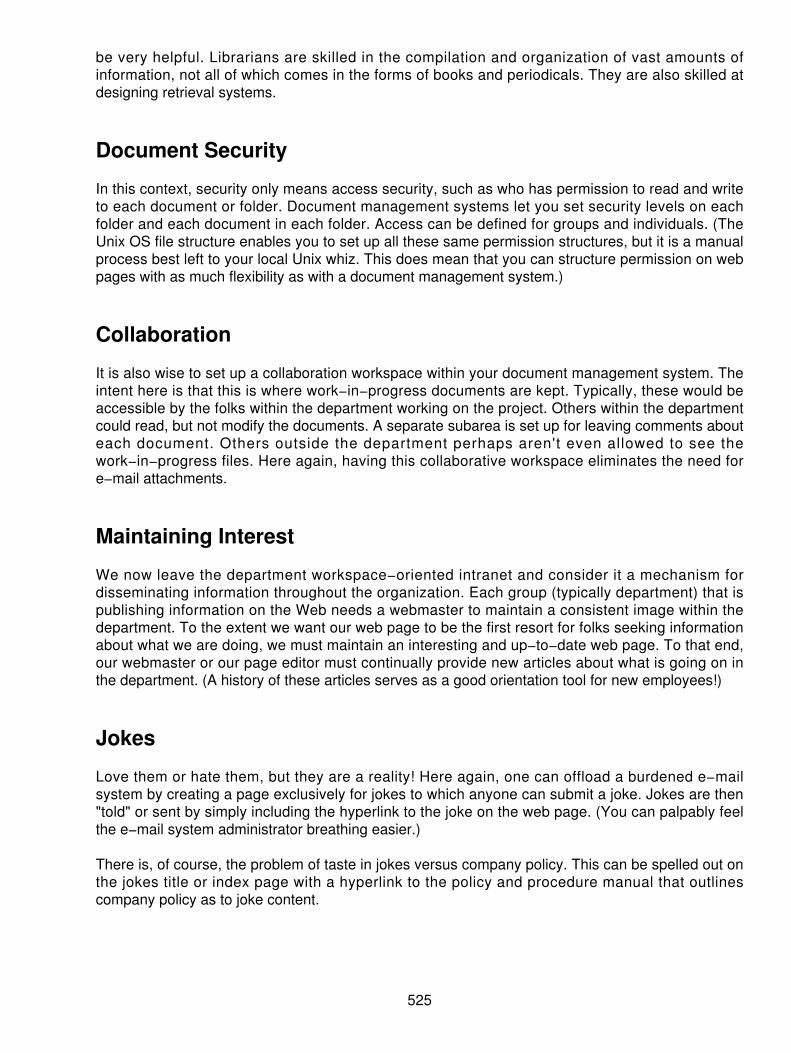
be very helpful. Librarians are skilled in the compilation and organization of vast amounts ofinformation, not all of which comes in the forms of books and periodicals. They are also skilled atdesigning retrieval systems.
Document Security
In this context, security only means access security, such as who has permission to read and writeto each document or folder. Document management systems let you set security levels on eachfolder and each document in each folder. Access can be defined for groups and individuals. (TheUnix OS file structure enables you to set up all these same permission structures, but it is a manualprocess best left to your local Unix whiz. This does mean that you can structure permission on webpages with as much flexibility as with a document management system.)
Collaboration
It is also wise to set up a collaboration workspace within your document management system. Theintent here is that this is where work−in−progress documents are kept. Typically, these would beaccessible by the folks within the department working on the project. Others within the departmentcould read, but not modify the documents. A separate subarea is set up for leaving comments abouteach document. Others outside the department perhaps aren't even allowed to see thework−in−progress files. Here again, having this collaborative workspace eliminates the need fore−mail attachments.
Maintaining Interest
We now leave the department workspace−oriented intranet and consider it a mechanism fordisseminating information throughout the organization. Each group (typically department) that ispublishing information on the Web needs a webmaster to maintain a consistent image within thedepartment. To the extent we want our web page to be the first resort for folks seeking informationabout what we are doing, we must maintain an interesting and up−to−date web page. To that end,our webmaster or our page editor must continually provide new articles about what is going on inthe department. (A history of these articles serves as a good orientation tool for new employees!)
Jokes
Love them or hate them, but they are a reality! Here again, one can offload a burdened e−mailsystem by creating a page exclusively for jokes to which anyone can submit a joke. Jokes are then"told" or sent by simply including the hyperlink to the joke on the web page. (You can palpably feelthe e−mail system administrator breathing easier.)
There is, of course, the problem of taste in jokes versus company policy. This can be spelled out onthe jokes title or index page with a hyperlink to the policy and procedure manual that outlinescompany policy as to joke content.
525

Forms
The bane of everyone's existence is having to fill out forms to order everything from pencils tosoftware. Our intranet is a perfect mechanism for putting all of the forms online with required andoptional fields. When the form is properly filled out, it is then submitted. Submission can takeseveral forms. In a web−oriented system (as opposed to a document−management−based system),the form is typically e−mailed to the required department. In a document−management−basedsystem, the completed form is simply saved in the proper work−in−progress area. The structure ofHTML forms is such that it is easy to have required and optional fields.
These forms can extend to travel request forms, making reservation preferences (if the corporationhas an internal travel office), and filling out expense forms.
Transition Intranet Solutions
These applications could be placed in either the intranet or extranet category. Here we are talkingabout tightly integrated business partners or field offices who resell our product or services and whoneed real−time access to the status of their order.
Portal Products or Customized Web Pages
Companies that market their products through competing resellers need to support their customersin an evenhanded manner. The reseller will frequently sign onto our web page in the presence of acustomer to show that we are an integrated partnership. Typically, this is done by showing our webpage with the partner's business logo prominently displayed. Clearly, the provider doesn't want thecustomer to know that this same product is available from a cross−town competitor. We can do thiswith customized web pages.
When reseller A signs onto our web site, we show our web page with our and his or her logo alongwith the product index of our products that he or she is authorized to resell. When reseller B signsonto our web page, we show our web page with a different logo and products.
This can be accomplished by using specialized software (called portal products) designed topresent a different face to each customer, your document management system, or your web serversoftware. Each provides the capability to require a login and password to view certain pages.
Along these lines, other passwords may be required of dealers to see their individualized price lists.These can be structured as wholesale and retail sheets so that the sales office can show thecustomer the retail or wholesale price sheet as required.
These portal products, as summarized previously, don't really do anything you can't do by usingyour document management system or your enterprise server software. So before you invest, youneed to ask the question: "Are they easier to learn to use than using the tools you already have andthat your staff is accustomed to using?"
The key to the question lies in the fact that the pages supporting your sales organizations need tohave up−to−date information. Old information quickly becomes unused and ignored. When buildingthese web pages, there is no substitute for understanding how information is used within yourcompany.
526
Building a Community
In large organizations with widely varying territories, we still need a sense of community and thefeeling that we are all part of the same team. Sales representatives in different markets needdifferent information because the competitive environment is different in different sections of thecountry or world. Yet they are all selling the same products. Our web site, therefore, needs toprovide the specific market−related information, and it needs to be up−to−date. At the same time,we need to build a sense of community and share, for example, sales strategies that work well.
It is also possible that our direct marketing team and our resellers may be addressing the samecustomers. (This scenario tends to occur in rapidly growing companies before their marketing plansand structure are fully mature. This condition also occurs with large chain stores that do bothwholesale and retail business. The stores may go after the same customer as a corporate accountin a common geographic area.)
An intranet can help tremendously with information, if it is used. Therefore, before deploying theintranet, it is wise to contact all departments, agencies, and branches involved to get input aboutwhat they would like to see from the intranet. This gives them an opportunity to feel that they are apart of the development and may yield some ideas that have not been thought of by the homeoffice.
Warning: Look out for corporate office arrogance! The people who were given this project are full ofthemselves and their new high−visibility project. The reality is that no one knows better what to do inorder to make sales than the workers in the trenches.
Warning number two: Look out for "too−busy−itus." The field offices have a full plate and, whenpresented with a request for input, they frequently do the following:
Don't really understand what corporate is up to• Don't realize how important their input is• Won't take the time to understand the issues and create thoughtful input•
The predictable result is that when the system is made operational, there comes a hue and cry fromthese field office folks about what is wrong and how it ought to be changed. Because the system isreally for their benefit, as well as the corporate benefit, their involvement is essential from thebeginning. Therefore, we recommend forming a working group (ideally, with a working area on ourweb server or document management system) to work out the design goals and structure of ourcommunity−building intranet.
When introducing the intranet to a noncomputer−oriented business, it may require hands−ontraining. This may have to extend down to how to start up the computer, launch the browser, getonline, find data, save or use data, and then sign off. Do not underestimate the amount of traininginvolved! This even goes for high−tech companies. The problem is that current software productsare so complex and will do so many things that the operation of the software can't be totally intuitive.Because of the flexibility offered, even setting the initial options requires a systems administrator.
If the system is used for order entry, entering those orders ought to be as easy and as similar to theexisting order entry process as possible to minimize training. Building HTML forms from the paperforms minimizes retraining. (If the data needs to be in a different format for the back−end system, letthe computer system reformat the data.) Users feel comfortable seeing their old familiar form with anew electronic face. They are not so intimidated, and you will not get as many service or help−desk
527

calls.
For noncomputer−oriented business, outsourcing development of the intranet is the best idea. It willbe faster with fewer hassles than developing the skills and technology in house. In any case, it mustbe treated as a full−blown project with a formal written specification for what the vendor is to do andwhat constitutes success. The other alternative is a time and materials relationship with yourconsultants to keep working on the problem until you are satisfied. Understand then that this willtake a while and cost more than a predefined contract.
Bulletin Board Service
Although we are touting the benefits of an intranet here, some companies can benefit from a simplebulletin board service where information is posted on the Web to inform people. This is not adocument management system, but a simple posting of training seminars — when and where theyare held, and what the prerequisites are (if any). It is almost guaranteed that once the intranet isbuilt and information is available, the implementation group will be deluged with suggestions on howit can be further used to improve business operations.
Customer Service
Although we discuss customer service to external customers in the next section, the same issuesand attitudes need to be applied to our intranet. The suggestions will come rolling in. To maintainthe involvement of everyone using the system, it is imperative that you have a system set up toaddress and accept these suggestions.
Providing a prompt e−mail response is a good way to acknowledge the receipt of a question,complaint, or suggestion. Having a formal system for posting the arrival of a suggestion, and postingthe disposition, keeps everyone involved. Simple suggestions may be handled quickly. Theimplementation of the change can be posted with a "thank you" for the suggestion note to theoriginator. Some suggestions may require the formulation of a project team to implement them. Thatfact and a proposed schedule should also be posted on the system designer's web page.
Thin Clients
Depending on your environment, a thin client intranet is definitely worth considering. Thin clientmeans that each of the client machines (typically a PC) has (in the extreme) no local hard drive andno floppy drive. It is a network−connected device only. When it is turned on in the morning, itreceives its download from the server. The server provides it with all the operating software itneeds. There are actually two implementations of thin client. One is like a Unix terminal where theterminal device only knows how to run the display. The entire application runs on the server (theapplication server). The second implementation is where the desktop device is a PC that isintelligent enough to run the application (for example, a browser), but has no local storage andreceives the browser and OS software as a download from the file server.
The big advantage is that our intranet is now virus free (more on viruses later). The client systemscan't introduce viruses from floppy disks because there aren't any. The main server is managed bythe computer services department and backs it up every night. Desktop hard drive crashes are athing of the past. The downside is (and this is very much a function of your operating environment)
528

that when everyone arrives at 8:01 and turns on the PC, they all request a download at once. Thistaxes the network and the file server. The bigger the environment (the number of PCs), the greaterthe load on the system is. A compromise position is to provide the local PC with a hard drive to holdthe OS and the local applications.
Using the Unix dumb terminal with an application server can (again depending on yourenvironment) save the expense of a full−time employee who would otherwise be needed to performsystem administration on all the desktops.
Extranets
We now take the advantages of intranets and extend them to our business partners and clients.They, like our intranet clients, will access our network over the Internet. Here we describe theapplications and don't worry about the implementation. Later, we will cover design of an extranetinterface and security measures you may want to implement. Our extranet must project our imageto the business community with which we are dealing. It should inspire confidence and project animage of trustworthiness. We should indicate what security steps are taken when handling creditcard transactions, for example.
Inventory Management
Wholesale
The first example of an extranet is a wholesaler who must maintain inventory to handle transientdemand as well as his contract quantities. The normal cost of distribution is about 18 percent of thecost of goods. This can be reduced to about 5 percent with the application of an extranet andelectronic commerce. The wholesalers can now do just−in−time inventory control. Depending on thegoods involved, the wholesaler may be able to get overnight shipment from providers, thus reducingthe need for large inventories. The goods can be drop−shipped directly to the client's location. Witha good e−commerce extranet, the wholesaler also has visibility into the source's inventories toimmediately determine what delivery promises to make to clients.
Secondary Markets
The next revolution in e−commerce is in secondary markets. Here the source (manufacturer orgrower) has made a product, satisfied major contracts, and has remnants left over from theproduction run or parts that don't quite meet the original specifications. These could be textiles withflaws or paint off color for the major buyer.
Integrated circuits (chips) don't perform at 600 MHz, but do perform at 300 MHz. Historically, thesecircuits were either thrown out (which effectively raised the cost of production on the remaining"good" parts), or a wholesaler (speculator) would buy the stuff at deeply discounted prices in hopesthat they could be sold.
The extranet offers the capability to put the inventory online and accept bids. This can be done bythe Original Equipment Manufacturer (OEM) or by a wholesale dealer who markets the parts on theWeb without having to transport them from the OEM location. When the product is sold, it isdrop−shipped by the OEM.
529

Privacy Issues
One could say that privacy is at odds with security. The better we can verify who the calling party is,the more secure our Web (extranet). The trick is to verify identity without compromising orappearing to compromise the privacy of our customers. This is a double−edged sword. You needthe tools to maintain info about your visitors to verify their identity, but these tools can also beabused.
In an attempt to improve security on the Web and to facilitate tracking down hackers, Intel put aserial number in each chip that could be read by browsers (any software really). Thus, we couldtrack the users of the machine as they visited various web sites if the browser put that number ineach transaction. Although much excitement was created over tracking individuals, remember thatsome machines have multiple users. Therefore, we really only know which computer visited the site.That is okay for tracking hackers (how many times does a burglar sneak into the house to use theInternet connection?), but it is insufficient for tracking purchasing profiles.
The privacy advocates Primary Information Center and Junk Busters lead the attack against thisinvasion of privacy. The World Wide Web Consortium (W3C) has developed a platform for PrimaryPreferences Project (P3P). The intent is to build an industry−wide mechanism for controlling privacyinformation. The goal is that the web site publicly publishes its privacy control mechanisms to everybrowser that visits the site.
The site's privacy practices profile might define what data they collect and what their rules are forpassing (selling?) that data to other marketing entities. (The obvious question is what is theenforcement mechanism for this policy? What assurances do we, the customer, have that it is beingfollowed?) Here is where we as a site provider must engender confidence and trust.
When configuring your browser, you specify or set up the preferences for privacy practices that youexpect from the sites you visit. You also fill in a user profile that stores some or all of your personaldata. These data are then sent to web sites whose privacy practices match your privacy practicesprofile that you set up. These data could include e−mail addresses, name, billing information, andpersonal preferences in clothing, music, food, hobbies, and so on. Our privacy profile might includethe conditions under which we permit our data to be shared, sold, or used. We could specify theother types of sites with whom we would permit our data to be shared.
P3P is really a plan to create a common protocol between the browser and the web site (server) tocollect and exchange privacy data. It defines the structure and words that define privacy practices. Italso defines a protocol used for exchanging these data between browser and server. Thus, theprivacy data is only transferred if the privacy profile set by the user matches the practices publishedby the site. Both Netscape and Microsoft intend to support the P3P standard.
This is a sensitive subject and therefore getting agreement between those who want the informationand want to traffic in it and those who want to protect the information totally will be in perpetualconflict. Our observation is that the probability that the browser profile and the site profile will indeedmatch up goes down geometrically with the number of elements or rules in the profile.
(Just for a fun example: If the site has four rules, A, B, C, and D, each of which can be true (1) orfalse (0), and the browser has the matching four permissions, then the probability of all fourmatching up is 0.5 x 0.5 x 0.5 x 0.5 = 0.0625 or about 6 percent. If we add one more rule E, then ithalves the probability to 3 percent.)
530

Our prognostication is that acceptance of P3P will be slow because of these conflicting goals. Moreon this can be found at http://www.w3c.org/.
Perishable Goods Application
Most producers of perishable goods (for example, fruit, vegetables, and flowers) have long−termcontracts with transportation and distribution companies who market their goods and provide aguaranteed income for a certain quantity of goods. What becomes of surplus production? It typicallygoes on the spot market. That is, the goods are transported to a physical intermediatemarket/warehouse where they are then purchased by wholesalers.
This can mean that the goods are sold at deeply discounted prices, or that they are put on aconsignment spot market. The producer has no idea if the product will sell or not and absolutely hasno price guarantee. The consignee may sell the entire product and tell the producer that only half ofit was sold. The ultimate buyer has no idea of how old (fresh) the product really is and has no realrecourse if the product turns out to be substandard.
Several companies are using extranets to provide a direct link between the source producer andwholesalers. The trick is to contact a reliable transport company that provides timely, reliabledelivery. This is another case of seeking to eliminate the physical transportation to an intermediatestaging point. This takes time and diminishes the freshness of the product.
Offering the goods for sale on our extranet lets the wholesalers buy directly, thereby improving theproduct freshness at the retailer by days to a whole week. Working financing into the deal allows theproducers to get paid upon shipment while giving the wholesaler 30 to 60 days to pay. The productis fresher and therefore worth enough extra to cover the financing costs.
Here we have a product clearinghouse that greatly cuts down on time to market and at the sametime matches up buyer and seller. When a financial clearinghouse backs this business, it instillsconfidence in the producer and buyer that the transactions will be handled properly in a timelymanner and everyone will get paid.
Purchasing Cooperatives
The capability to form purchasing cooperatives that can negotiate volume pricing with suppliers isanother growing extranet application. Smaller businesses from parts stores to building contractorscan pool their requirements and approach the supplier with volume deals.
The second major advantage is getting the orders correct. This almost can't be emphasizedenough. It can take a full−time employee to verify orders, process the paperwork, send back theincorrect stuff, and get credit for it while reordering the proper parts.
Finding out immediately if the product is in stock and when the delivery time will be cuts down onlocal inventory requirements. (Many parts and even drugstores practice just−in−time inventorywhere they will order the part for next−day delivery.) The ability to see the supplier's inventory onlinepermits shopping at alternate sources should your normal supplier be out of stock.
This system can work across the Web or, in the case of banks and brokerage houses, across theextranet with special software. The client portion runs on the user's desktop workstation and the
531

server software portion runs on the server or mainframe.
Brokerage houses, for example, supply their good clients with desktop software. In this manner,they standardize the software and guarantee interoperability. The same model works forconstruction projects. If the customer (for example, a construction company) uses the standardizedproject management software, the supplier can then read the bill of material required and bid onsupplying the components. The suppliers then become business partners with their customers. Thisalso helps the suppliers plan their production schedules and inventory levels. (Ford has had such asystem in place for over 10 years. The suppliers see the production schedule and supply the partsby contract just in time. The reduction of on−site inventory has more than paid for theimplementation of the system. The original system used the X.25 network and custom software.)The objective is eventually to be able to run paperless projects.
Boeing's 777 was the first paperless airplane. They were able to maintain schedule and, moreimportantly, the parts fit better, minimizing production line rework.
Outsourcing
Whether the problem is to manage a large project with just−in−time delivery of component parts orsubcontracted services or a just−in−time maintenance service, all can be done over the Net.
The requirements are the following:
A common database• A common mechanism (interface) for accessing that database• The ability to set up different views of the data•
Each contributor to the project needs only to see that set or subset of data relative to his or herportion of the project.
A good example of this might be an airline that outsources some or all of its services. For example,it has a schedule for the following:
Flight crew• Cabin crew• Airframe maintenance• Engine maintenance• Reservation agents• Gate agents• Ticket counter agents•
Flights themselves• Seat reservations• Meals (catering)• Wheelchairs• Cabin cleaning• Refueling•
The list is almost endless. Most airlines outsource catering and fueling services, but they couldoutsource everything. Although the crews typically work for the airline, they are treated almost asoutsource subcontractors. The flight and cabin crew members individually bid on each flight. Theirbid is accepted or rejected, not on price, but on seniority. Maintenance could be handled the sameway and for small startup airlines it typically is. (Small startup airlines, to keep initial investmentcosts down, outsource many more services than the major carriers.)
The flight hours of the plane are published on the Extranet page. Then the maintenance companyprepares a bid and crew to handle the scheduled maintenance stop. Note that the maintenancecompany doesn't need to see the catering schedule, nor almost any of the other schedules. Each
532

contributor to the overall project has its own view of the common project database that contains allof the schedules. The capability to provide these different views, as discussed, can be implementedby using the inherent system file permissions, a "portal" software product, or a data managementsystem.
Watch for these outsourcing trends using extranets not only for airlines, but also for design andconstruction projects both large and small.
Computer Hardware Vendor
Typically, the delivery of a complex hardware server system (especially complex customizedconfigurations containing multiple product lines) requires months of delivery time. When thecustomer is dealing with a local representative who may be halfway around the world from theproductions source, getting the order right and delivered on time is nearly impossible.
The field office creates the order for the system, doing the best job it can in specifying theconfiguration. Unfortunately, they typically have no idea of what the production schedules orinventory levels are. This can result in long delays in the fulfillment of the order.
Here is a typical example: The customer orders a system with 2, 9GB hard drives. What theconfigurator in the field office couldn't know is that the factory has stopped ordering 9GB drives andhas gone to 18GB drives as the standard drive. The order waits on the shelf until some 9GB drivescan be ordered and delivered. Note that the order−processing folks can't take it upon themselves tosubstitute an 18GB drive. Two 9GB drives were ordered, and that is what must be delivered!
Now let's examine the same delivery problem with an extranet, where the production schedules andinventory levels are available to the field offices by signing onto our home office web site.
The sales representative, or technical support representative, can log into the site with the customerright there. The parts and price list are right there. They can use the online system configurationsoftware to select hardware components, including redundant power supplies and processors, ifrequired. When they get to specifying the 2 9GB drives, they find that inventory is nonexistent, andthere is a 60−day wait if they are backordered. They find that the 18GB drives are in stock. Thecustomer, on the spot, opts for the 18GB drives because it means a difference in delivery schedulefrom 2 weeks to 2 months. (The customer planned on mirroring the data on the drives and thereforeneeded 2 physical drives instead of the single 18GB drive.)
The customer is ecstatic with our ability to be responsive to his or her needs and to deliver theequipment so quickly.
Automating Customer Service
The two issues to be addressed here are the following:
Improving the responsiveness of our customer service organization or function• Reducing the cost of providing the service•
(Some companies have found the ideal solution. They charge their customers to provide servicethat a well−designed product wouldn't require.)
533

The basic problem is that having technical folks respond to e−mail customer service queries isboring for the individual. They soon develop a bad attitude and quit. Having nontechnical personnelrespond has the danger of responses not being technically correct (or even close in some cases).Therefore, the need to create a low−cost, accurate, automated e−mail response system isabsolutely necessary.
The answers to simple and standard e−mail queries can be handled by a completely automatedsystem. An example of this is that a customer can order parts by e−mail. If the customer is willing toinclude the part number and catalog number, it greatly minimizes the probability of error. Althoughthis is an idealized example of a query/response from an automated system point of view, itillustrates one end of the spectrum of capabilities.
In real life, customers will mix multiple unrelated topics in an e−mail. (We know we do it all the time.)The trick then for the automated system is to accurately parse the content of the e−mail for subjects,verbs, and objects. The analysis of the query then eliminates the chaff and identifies the importantcontent. The success or failure of the system depends upon the complexity of the topics and issues.Take a test drive before you buy!
The two goals of improving service while lowering costs are often in conflict. Our opinion is thatgood responsive customer service should outweigh the cost consideration. Who is the company tothe customers? Well, at first it is the salesperson who sold the product (unless it is bought off theshelf in a store) and after that it is the customer service representative/system. Future sales (viaword of mouth) rest upon the responsiveness of our customer service.
Ever more, our corporate image is our web site backed up by the customer service system. Astechnology improves, more and more automation can be applied to the customer service problem.Our preferred design approach for an automated system is to automatically scan and parse thee−mail looking for issues. It's important to fabricate an immediate, automatic response outlining theissues detected. This response always includes a hyperlink to the specific web page that addressesthose issues. This would include a pointer to frequently asked questions. For those subjects notrecognized or identified, that fact is relayed to the customer. "The following issues have been sentto our research department."
If more information is known to be required, then the automated response can make that query. Thegoal is to keep the customer in the automated system while still being responsive. For some numberof queries (ideally, a small number), a human will have to respond. This implies a hierarchy oftechnical ability, each of which in turn analyzes the query, asks for more information if needed, andpasses the request to the next level if it can't resolve the problem at that level.
Within a short while, you will learn what standard customer queries are and be able to automate theresponses to these. The trick is to detect the "out of the normal" queries and quickly pass them tothe human hierarchy of knowledge response team.
This system structure provides the customer with an immediate response that is correct (or nearlyso) or a response indicating that this problem requires some research. What is most important isthat the customer feels that he has been heard and his problems are being handled. Ideally, thecustomer is also told approximately how long it will take for the answer to his or her problem to beresearched and formulated. Our experience is that customers are willing to wait a couple of days ifthey know that the response they will receive will be accurate and to the point.
Our interaction with vendors who have a poorly designed human interface on their product is thatthey have many more requests for help than if the product were more intuitive. Their product is fairly
534

technical, their customer service is overloaded, and their business is handled by people in ahierarchical system. The problem is that because there is no continuity in a given customer'srequest, a sequence of queries about the same subject receives answers that are mostly tangentialto the query at hand. This does not instill confidence in the customer base. Needless to say, thiscustomer is losing market share.
Implementing Extranets
In order to provide some sort of consistency, some definitions are required. These are not universal(and will be violated frequently in the trade press), but will help with the following discussions.
Intranet
An internal network is comprised of one or more LANs, interconnected with one or more routersrunning the Internet Protocol (IP). (So far, this is only an internet with a small i.)
The bulk of our traffic on this Net is web−based. That is, we have one or more web servers, and allof the clients are running a browser. Our primary means of communicating is using the Web.(Technically, mail is a different set of application protocols, but most browsers also provide a mailcapability.) Perhaps we should say that the primary interface that our users use for their data is viatheir browser. This network may be geographically far flung where dedicated lines (or Frame Relay)are used to connect our routers. There is no connection to the Internet. Now, here is where thingsget touchy. If we were to use VPN technology between our corporate locations, one could arguethat it is still an intranet.
Extranet
We are connected to the Internet and specifically permit access to our network (or portions of ournetwork) by our customers.
We are now at risk from all sorts of hackers, crackers, and freaks. The goal then is to keep them out(or at least slow them down and make them work for it) while giving our friends and customers"free," that is, unfettered, access.
The first step then is to install a firewall. A firewall is simply a machine whose job it is to examineeach packet arriving and verify whether it is permitted, based on a set of rules. This set of rules isreferred to as the rule base. Firewalls essentially operate at the IP and Transmission ControlProtocol (TCP) levels of the protocol stack. This means that the firewall examines each packet tosee if it is coming from and going to the proper IP address, and that it contains the proper orpermitted TCP port number. You can set up firewalls to be a one−way valve. If you do this, youremployees can surf the Net at will and send out any kind of packet, but your firewall will not permitany unsolicited packets. (This means that mail won't work; for example, the firewall won't let in anypackets, including mail.) The other problem with this approach is that it will permit your employeesto hack on the Net. If they are caught, the corporation may be liable, so think about this issue. Thisis not to say that firewalls are not useful, but to point out that simplistic solutions will not achieveyour objectives.
Performing basic packet filtering on source and destination IP addresses is a useful feature whencombined with additional firewall capabilities. It was initially believed that a firewall was the solutionto all our Internet security problems. The limitations of a firewall−only implementation are now
535

apparent. If we only need to communicate between specific networks or specific devices with fixedIP addresses, a firewall is a fine solution.
TCP Filtering
The next level of checking that the firewall provides is to check inside the TCP packet for a portnumber. For example, the standard TCP port for Hypertext Transfer Protocol (HTTP) is port 80.(Any port could be used in this example. Port 8080 is another port that is frequently used byproxies.)
The firewall now checks for IP addresses (which might say any IP address) and the port number inthe TCP packet. This means that unless the port is open through the firewall, you can't get thatservice (for example, HTTP or FTP). This provides for a more general audience. Now instead offiltering an IP address, one can say, "Let anybody from any IP address come through the firewall,but only if he is doing HTTP on port 80 to a specific server." This means that we could have otherweb pages on other servers on port 80 internally, but they would not be available because thefirewall limits access to a specific server. Clearly, we can allow access to as many servers asdesired.
Our presentation is a little simplistic since it makes the assumption that the OS on which the firewallsoftware is running is itself secure and unhackable. Not only is this not generally true, but it isimpossible to secure the OS perfectly. (For example, there are known attacks to a Unix−basedsystem that is running send mail. Therefore, the send mail application should not be present on yourfirewall machine. A properly maintained OS will have this door closed — see the followingexplanation.) So, it isn't just enough to run a firewall; that firewall must be run on a "locked down"OS.
An aside on attacks: There are two general kinds of attacks against systems. One is called thedenial−of−service attack. In this case, the hacker sends one or thousands of packets to the server,causing it to spend all its processing power processing these garbage packets so that it has no timeleft over to do its real job, such as serve up web pages. The second kind of attack is more invasive.In this case, the attacker tries to gain access to the machine, preferably as the super user. If theattacker achieves this, the system is literally wide open. As a super user, the attacker can set upaccounts on the machine, read any file, wipe out any file, and so on. Very clever hackers willtherefore edit the log files so that they show no trace of the hackers' presence. There are a coupleof ways to keep log files. One is to frequently copy the log file to an obscure directory and changeits name so that its name does not contain "log" (for example, call it bob). The second is to encryptthe file. The latter is only convenient if the firewall application provides this option. The former onlyworks if the log file is copied often enough to capture the hacker's presence before the log file getscleaned.
Constant vigilance must be maintained to ensure that the OS has the latest patches that close offdiscovered holes. Because the Unix community is open, as each attack is discovered, patches arewritten and posted to newsgroups where your system administrator can download and install them.
Despite the fact that Unix isn't perfect, the rapid availability of fixes for bugs and holes nearly asquickly as they are discovered means those diligent system administrators can maintain a verysecure OS. Our security experts generally agree that the preferred OS is Unix for firewalls andproxy servers. There are frequently reports of break−ins to web servers, and the more noteworthyare those belonging to the Department of Defense — because they should know better. Inpractically every case, the hole (or weakness) exploited by the hacker is a known hole, the fix for
536

which has been available from the newsgroup for six to nine months before the attack took place.The fault lies then with sloppy or nonexistent system administration. An equal number of holes existin proprietary OSs; however, one must wait for the vendor to release a patch. This isn't always aspeedy process.
Stand−Alone System
It is highly recommended that the firewall run on a dedicated machine. Figure 35−1 is a classicfirewall drawing with the external network to the left and our protected network to the right. To saveon hardware costs, it is tempting to run the web server as another task on the same machine. Thisis not wise because, if the hacker manages to crack the OS, they have access to the wholemachine and any applications running on it. As a stand−alone machine, they can crack into thefirewall, but can't go any farther. This assumes that the other machines on your network won't allowaccess (for example, they don't allow telnet) from the now defunct firewall.
Figure 35−1: A classic firewall implementationTo further protect against this problem, we introduce the DMZ (see Figure 35−2). It is highlyrecommended that you not implement the network in Figure 35−1. The DMZ, as we shall see, is aprotected area into which all external traffic goes. That means, ideally, that no external traffic flowsthrough the firewall to our internal network. It all goes to servers in the DMZ.
Figure 35−2: The DMZ provides a protected area where all traffic flows.Figure 35−3 shows the relationship of the DMZ to the logical firewall. Although we think and talkabout firewalls as a single entity, when we are using a DMZ, it is logically two firewalls.
537

Figure 35−3: The relationship of the DMZ to the firewall actually creates two firewalls.Note that the DMZ is another communications port on the firewall (typically, an Ethernet port with itsown subnet address). The firewall may now have up to six sets of rules for traffic from the following:
Outside to inside• Inside to outside• Outside to DMZ• DMZ to outside• DMZ to inside• Inside to DMZ•
In general then, we will put all services accessible by external folks in the DMZ and allow none ontoour internal network. (We all recognize that there will be exceptions to this rule. In all cases, makesure that you design the firewall rules carefully so as not to get any unintended consequences.)Figure 35−3 shows the FTP, mail, and web (HTTP) servers in the DMZ.
Virus Checking
With the constant threat of viruses arriving in mail attachments and via other mechanisms, somefirewall vendors also offer virus checking. Because the processing load on the firewall can beenough for one machine, the virus−checking function is offloaded onto another machine that alsoresides in the DMZ. The process works like this. The firewall recognizes a mail attachment on themail message. Before forwarding the mail message to the mail server, it first sends it to the viruschecker that opens the attachment and scans it for known viruses. It would do the same for a fileforwarded to the FTP server. If there is no problem, the virus checker tells the firewall that all is OK,and the message is delivered. If a virus is detected, there are several options available, dependingon the vendor's implementation:
Discard the message.• Notify the system administrator by e−mail or pager.• Clean the file by removing the virus and pass the message on.• Return the message to the sender.• Send an e−mail to the sender.• Send an e−mail to the recipient.•
538

In some cases, these options can be combined. Note also that not all vendors support all theseoptions.
The virus−checking function is no better than the latest information it has about viruses. Therefore, ifyou choose to implement virus checking, it places another task on the system administrators toperiodically log into the virus vendor's web site and download the latest virus profiles. Although thissounds like an easier solution to manage than desktop virus checking, according to the vendorsthemselves, it is not a substitute for desktop virus checking. Again, the desktop virus checking isonly effective if the virus profiles are kept up−to−date. If you are getting the feeling that maintainingnetwork security is a perpetual struggle and (depending on the size of your shop) requires adedicated system administrator, you are getting the right feeling.
Firewall Rules Bases
Most firewalls operate (or should operate) from the position that nothing is permitted except thatwhich is specifically allowed by a rule in the rule base. Some early firewall products required that theadministrator learn the syntax of the rule base. Most firewalls available today offer an easy−to−useGUI interface. Table 35−1 shows a typical rule base as one might see it from a GUI.
Table 35−1: A typical rule base viewed through a GUI
539

The basic rule here is to put the most frequently used rule first. You don't want the firewall searchingthrough and applying a whole bunch of rules that rarely apply before it gets to the one that isneeded. All this searching takes precious processing power. Therefore, the permission of anysource, external or internal, can contact the Web_server machine, but it may only use HTTP. (Since
540

the port isn't specified, it is assumed to be the default port 80.) Note that any source can send mailto mail_server. We have also installed another web server (cust_Web) especially for our customers.This one is only accessible by devices attached to specific network addresses belonging to ourcustomers (for example, custnet1 and custnet2). There is a list of network addresses in the firewall'srule base — one for each customer. There are normally other rules in the table that tend to bevendor−specific. For example, the tracking column lets you specify if you want a short or long logentry every time this rule is invoked.
Next, the FTP users are at machines called goonie, charlie, and goofie (these are really aliases forspecific IP addresses). They are the only devices allowed to FTP to FTP_server. In the last rule ofour example, we are also restricting FTP to internal machines called lisa, albert, and shortstuff.
The rule allowing mail_server to talk to our_mail server indicates that mail_server is only a mailforwarder. It isn't the real mail server. It is only allowed to talk to our real mail server with our_mail. Ifsomehow, mail_server is hacked, it won't stop our internal mail server. In addition, you don't want toput the real mail server or your internal web server in the DMZ because then all your internal traffichas to go through the firewall, increasing its burden (see "Firewall Performance (Again)").
The next to last rule allows goofie to telnet to shortstuff. Although this seems innocent enough, thequestion is, Where can the user go from here? This gets into password administration, which isbeyond our scope. The issue is that normally a single username/password file is used system−wideso that we only have to administer access permissions in one place. If we allow telnet from goofie,then the user at goofie has a login account and could telnet to other servers in the internal network.The solution is to have (and maintain) separate accounts on the server lisa.
Note that there are no rules permitting anyone to talk to virus_checker. There are also no rulespermitting icmp−echo (ping), so that would−be hackers cannot use this tool to discover servers inthe DMZ or on our network.
Firewall Performance (Again)
Although we mentioned it previously, firewall performance can be a bottleneck. The more traffic werun through the firewall, the greater the potential for a bottleneck. Again, it is essential to have anunderstanding of the traffic flow. How many packets per second must the firewall handle? In ourexample, we would add up mail, web, FTP, and telnet traffic. Remember that mail is handled twiceby the firewall and three times if the virus checker is employed. After you have determined the trafficvolumes, check with the hardware and software vendors of your firewall package to determine if youhave sized the system correctly.
Proxies
Simplistically, you may think of a proxy as an application−level firewall. In the case of web proxies, itcan serve to direct, redirect, or limit access through the proxy to servers and specific URLs.
Although the proxy may be placed in parallel with the firewall, our preference is to put it behind thefirewall. Remember, we may use several firewalls in parallel to handle the traffic load. Extreme caremust be taken to make sure that you have a consistent rule set across all firewalls.
541

Forward Proxy
There are two kinds of proxies. Your company uses a forward proxy to limit where your employeesare permitted to surf. ISPs use proxies to limit the options that their members have. They don't limitdestination web sites (although they could exclude known porn sites), but they limit their membersto HTTP and FTP. This limits some of their hacking options. Also, the queries to the remote websites appear to be coming from the proxy instead of from the individuals user's terminal because theproxy masks the user address by replacing it with its own.
Reverse Proxy
A reverse proxy is used as a frontend for a web server. (A large server farm would implement anarray of proxies.) Requests to www.anywhere.com are routed to our proxy that forwards the requestto server content_server (the keeper of the real web page). The surfer thinks it is talking to serverwww for all requests. This makes it nice for the webmaster, who is in the process of replacingcontent_server with bigger_server. All of our user's links remain the same; we just change wherethe proxy points. As previously, we can limit which URLs the proxy permits. So we could have twoweb servers, but only the content of one is visible to the outside world.
The proxy (both forward and reverse) also helps reduce network traffic and content_server load.The proxy caches every requested web page. The next request to that same server, whether it isfrom the same or a different source, is satisfied out of cache without having to go back to thecontent_server. If the ISP has a proxy array, it will eventually contain all the popular web pages,thus minimizing the number of requests sent out across the Internet. The reverse proxies at thecontent provider's location also cache popular pages. The rules as to how much to cache and whento go back to the content_server for the latest version of the page may be set up in the proxy server.In fact, at a large site with a large array of servers, the popular pages are downloaded into theproxies at low traffic time, and they serve the web requesters. This improves site reliability andflexibility.
Figure 35−4 shows a typical proxy array behind a firewall. Each of the proxies directly connected tothe firewall provides an interface to one or more servers, usually handling a given subject. Theproxy in front of the other proxies has servers of related subjects, and the front−end proxy steers therequest to the appropriate proxy that is caching that subject. This array then acts to share the loadand provides for backup in case of a proxy failure.
542

Figure 35−4: A typical array of proxy devices sitting behind the firewall
Proxy Security
Figure 35−5 shows a hypothetical configuration. Note that there are two proxy functions. One is aproxy for the internal web server bigger_server, and the other is a proxy for cust_Web. At this point,our options begin to expand (read "get complex"). Whereas the proxy could simply map requestfrom the surfer to the server, it could also require that the surfer has an account on the proxy andlog in to see a particular server. We can take this to whatever extreme satisfies our paranoia. Forexample, we could issue account IDs and passwords to our customers. First, they must log into theproxy. Then they must log into cust_Web to see their specific information. (If we were paranoid, wecould make them log into the firewall first.) We would only let our remote offices see the web pageson bigger_server and they must log into the proxy first. This is another safeguard against hackersmucking with our web page.
543

Figure 35−5: A hypothetical flow through the firewall to the proxy and then on to the applicableserver in the DMZThe LDAP server is the keeper of the user database of username and password. These users canbe segregated into groups such as sales, customer1, customer2, marketing, engineering, andcustomer support. The proxies then could restrict access, based on group membership. Note thatthe LDAP function may be a single point of failure. Therefore, consideration should be given toproviding access to a backup LDAP that has been synchronized to the main one. Setting up(designing the database structure) and maintaining the LDAP server is a significant effort dependingon the experience of your staff. Maintenance of the LDAP database will also take administrative andsupport staff time.
Although the servers in the DMZ here have been drawn as separate boxes for clarity, some of thefunctions could be combined into one machine. This appears to be cost effective, but remember, if itis that machine that is being hacked, you could lose all services it provides.
Proxies can also do redirection. When a server is taken down and another takes its place at acompletely different address, the proxy can simply redirect the user to the new URL.
We discussed securing the OS on the firewall. The same should be done for the proxy. It too shouldbe secured with all of the latest OS patches installed. Applications such as send mail that are notneeded should not be running.
Administration
For both firewalls and proxies, the safest way to administer them is to require the administrator tolog into the system console. That said, what about remote administration?
Your local proxy/firewall can be administered from inside your secured network. The safest solutionhere is for the firewall to limit administration access to a few specific machines. Here we meandesktop machines, not multi−user hosts. Few of us work in an organization where everyone is so
544

occupied contributing to the bottom line that he or she has no time or inclination to "explore" (hack)systems on the network.
For remote administration, you are going to have to open the administration port to the world. Thedifference between the proxy and the firewall function from our discussion is not crystal clear. Inaddition, in products today, their functionality is melding.
Firewalls
In our discussions, we have limited firewall functionality to IP and TCP layers. It is the gatekeeperfor our network or DMZ. Its functionality and configuration should be considered company privateinformation. The extent that a hacker knows what kind of firewall we are running and itsconfiguration gives the hacker a better clue as to where to start when attacking our network.
Proxy
We have used the proxy as an application−level filter that is able to filter (or force) access to specificservers. We use it to hide the true identity of our servers and limit the pages that our visitors areallowed to see and the functions (HTTP, FTP) that they are allowed to perform at each server.When designing a web site, all references within that web site should be relative references (forexample, relative to the existing server). Web pages containing absolute references will be passeddirectly back to the user who will now have the name (or IP address) of the server. The proxy won'thelp because, in this case, only diligence on the part of the webmaster will fix this problem. It is alsoa good idea to avoid using IP addresses when identifying servers for two reasons. First, you don'twant the external world to know your IP addresses. Second, if you need to upgrade a server from asmaller machine to a bigger one, you have to ferret out every reference to the old IP address andchange it — a maintenance nightmare. The solution is to use aliases via the Domain Name System(DNS).
Domain Name System (DNS)
The DNS is simply a listing of the device IP and the human−readable name (alias). A site orcompany usually runs two DNS systems — one for the internal (protected) network and one for theexternal network. When a query for www.company.com arrives, the DNS returns the IP of the server(or proxy) that is designated as www. The external DNS then will only point to proxies, while theinternal DNS will point to the actual servers.
Internal web pages that are available or viewable by external users should only reference other webpages by their external DNS alias. You can have as many aliases as you want for an IP address. Ifyou fail to follow this rule, here is what happens. A page is delivered to a user that referencesanother page in the internal system by its IP address. When the user selects that link, the firewallsays permission denied.
If you were to use the internal alias for the server in the delivered web page, when the user selectsthat reference, he gets a no DNS entry error. Therefore, the rule is when you deliver a page to anexternal user, that user must have a mechanism to resolve the actual address and have permissionvia the proxy/firewall to access the designated server.
If the pages are viewable by both internal and external folks, then the internal and external DNSentries have to be the same so that all of the links work properly.
545

Fungible Services
Clearly, the firewall can take on proxy services and the proxy can take on firewall services. Werecommend using two separate boxes to improve security. Investigate your firewall vendorthoroughly. Research as much information as you can before making a decision. A beautiful,easy−to−use GUI is wonderful, but what you really want is the best security on the market.Remember, setting up the firewall, proxy, and web servers is not a "spare−time" operation. You willhave to dedicate individuals to these tasks. The maintenance of these servers must also bebudgeted.
We also recommend designing an internal policy with a review board to review changes to thefirewall and proxy configurations. The goal here is to put a damper on statements like "Oh, we'll justopen up this port for that function." Indeed, that may be a good idea, but it may also have othersecurity implications.
Since the firewall is the keeper of the keys to the kingdom, its configuration should be treated ascompany private. The more a hacker knows about your firewall, the easier his job is. The proxyconfiguration on the other hand is only going to permit access to selected protocols on selectedservers so it is easier to manage and maintain. Unfortunately, as new servers and proxies for themare added, firewall adjustments must also be made to permit those connections.
546

Chapter 36: Network Management SNMP
Overview
Simple Network Management Protocol (SNMP) is the Internet standard for monitoring andmanaging devices connected to the Internet or your own intranet. It defines a data set structure ofinformation that each device may provide called a Management Information Database (MIB). It alsomakes provisions for individual vendor−based, customized MIBs. A vendor then can provide thestandard set of parameters and also extend that set with "custom" information, such as"vendor−specific" information. These data are collected, kept, and reported by an agent that runs onthe managed device. We call this agent the managed function.
A management function resides on a workstation or host, and interacts with the managed functionor agent. The management function must have a copy of the MIB profile loaded for each managedfunction, plus any vendor−specific profile.
In this manner, a standard management function can interact with the standard MIB, while avendor−specific management function may be used to glean more specific information. Thesecustom MIBs are also registered with the Internet Advisory Board (IAB).
Thus, you find standards−based systems, such as HP's OpenView, and vendor−specific systems,such as Fore's ForeView and Cisco's CiscoView, that are compatible and work with OpenView.
Network Management Goals
The ultimate goal of network management is to improve system uptime. The CEO of anorganization may see it as another overhead expense. The CIO should see it as a tool formaintaining a near 100 percent uptime.
The higher the system availability, the less equipment is needed, the lower the cost of running thenetwork, and the more efficient the organization will be that utilizes its resources.
Everyone in the corporate management structure needs a clear understanding of the goals ofnetwork management, and the amount of time and effort required to reach those goals. Networkmanagement is a great tool for proactively managing the network and collecting alarms and alerts atthreshold levels that are below the "Houston, we've got a problem" level. It has often been said thatif you do have a failure, then the network management didn't work! Unfortunately, many networkmanagement systems are viewed as disaster recovery mechanisms rather than disaster avoidanceand prevention mechanisms.
One must also consider the point of diminishing returns. Whereas you may be able to achieve99.9999 percent uptime, the cost in additional redundant equipment and failover systems may notbe justified for your enterprise. Here is a good time to plug for disaster recovery plans. Everyenterprise must have a disaster recovery plan. In the context of network management systems,what is the plan of action if multiple (unlikely) failures occur? The likely events should already behandled by the network design. (In this context, the building burning down or an earthquakerendering it uninhabitable is an unlikely event.) At one extreme, the plan may state, "We close upshop and go out of business" or "We wait until the flood waters recede, clean up, buy newequipment, and start over." Although these aren't recommended plans, they are plans and indicatethat management has done some thinking about the problem. At the other extreme is a company,
547

for example, a stock exchange or a hospital, which must keep going at all costs. In this case,alternate facilities are identified that contain computing equipment that can take over if their ownequipment fails. A set of network connections is in place to provide connectivity to all of thecustomers/branch offices, including a backup network management. The downtime is minimal.Namely, the downtime would be the time it takes to load the backup configuration on backupmachines, plus the time it takes to switch over the network connections and — we're up!
History
In the days of centralized systems, the host or mainframe was about the only smart device in thesystem. The rest of the devices in the network were relatively dumb and could be reset whennecessary by the host.
Figure 36−1 shows a typical centralized network configuration. Most of the remote devices in thenetwork were connected to the host by dedicated lines. At the larger remote locations, a remoteconcentrator, or controller, is used to multiplex multiple terminals on the single data line. At smallerlocations, a single terminal may exist. Dial−up lines may serve some low−traffic locations. But, inany case, there were not multiple paths in the network. It was strictly hub and spoke. Networkmanagement consisted of monitoring the status of all phone lines and modems. Dial backup for thededicated lines was often used when high availability was required. This technique is still usedtoday to back up our Frame Relay connection. Today, an ISDN line can provide 128 Kbps dialbackup.
Figure 36−1: Typical centralized network configurationAs we have migrated from the centralized model to the distributed computing model, every elementin the network is now intelligent.
Figure 36−2 depicts a typical distributed processing system. The Wide Area Network (WAN)technology isn't important per se in that it may be leased as a service from a network provider whowill generally not allow our management system visibility into his network components. What isimportant is that the WAN connection must be available in all of our locations and that it provides aninexpensive high−performance interconnection.
548
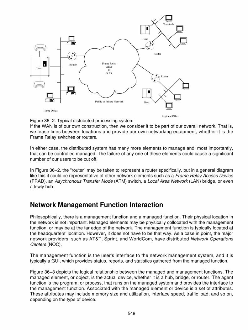
Figure 36−2: Typical distributed processing systemIf the WAN is of our own construction, then we consider it to be part of our overall network. That is,we lease lines between locations and provide our own networking equipment, whether it is theFrame Relay switches or routers.
In either case, the distributed system has many more elements to manage and, most importantly,that can be controlled managed. The failure of any one of these elements could cause a significantnumber of our users to be cut off.
In Figure 36−2, the "router" may be taken to represent a router specifically, but in a general diagramlike this it could be representative of other network elements such as a Frame Relay Access Device(FRAD), an Asychronous Transfer Mode (ATM) switch, a Local Area Network (LAN) bridge, or evena lowly hub.
Network Management Function Interaction
Philosophically, there is a management function and a managed function. Their physical location inthe network is not important. Managed elements may be physically collocated with the managementfunction, or may be at the far edge of the network. The management function is typically located atthe headquarters' location. However, it does not have to be that way. As a case in point, the majornetwork providers, such as AT&T, Sprint, and WorldCom, have distributed Network OperationsCenters (NOC).
The management function is the user's interface to the network management system, and it istypically a GUI, which provides status, reports, and statistics gathered from the managed function.
Figure 36−3 depicts the logical relationship between the managed and management functions. Themanaged element, or object, is the actual device, whether it is a hub, bridge, or router. The agentfunction is the program, or process, that runs on the managed system and provides the interface tothe management function. Associated with the managed element or device is a set of attributes.These attributes may include memory size and utilization, interface speed, traffic load, and so on,depending on the type of device.
549

Figure 36−3: Logical relationship between the managed and manager functionsAs one might suspect, there is a protocol defined between the management function and the agentthat defines the format and content of each of the commands, responses, and traps. RFC 1905governs these protocols. RFC 1907, in turn, governs the content of the SNMP messages. SNMPv2,also known as MIB−II or mib−2, is the dominant definition set today and has superseded theSNMPv1 mib−1. Version 2 greatly expands the detail available from the managed agent.
The agent is the interface to the management function and may accept commands to setparameters (such as timeouts, thresholds, and, in some cases, system operational parameters,such as group membership addresses or routing tables) as well as provide status upon request.The agent can also send unsolicited messages (called traps) indicating alarm conditions. The name"trap" comes from the capability of the manager function to set a threshold (trap), and should thiscondition be met, the agent sends off an unsolicited message. All other messages sent by themanaged function agent are a result of GetRequest or GetNextRequest queries.
It should be clear that the data reported by a device like a hub is a lot less complex than the datafrom something like a router. The hub needs to report Ethernet collisions on the LAN, the number offrames handled, the number of errored frames, and so on. The router, on the other hand, hasrouting tables, queue sizes, memory utilization, central processing unit (CPU) utilization, and so on.
To keep this all straight, the management function must know about the content of each MIB oneach device. In other words, it must have a complete database identical to the one on the manageddevice so that when it receives the information, it can place it in the appropriate location. When anew device is installed in the network, its MIB content and format must be loaded into the machine(typically, a host or a workstation) providing the management function. Likewise, the agent softwaremust be installed in the managed device.
This emphasizes an important point. Setting up and running a network management system is morethan a casual undertaking. It requires a commitment on the part of management to provide theresources and purchase the appropriate tools.
Database Structure
The MIB content is defined by the RFCs listed in Table 36−1.
Table 36−1: Relevant standards that apply the network management
RFC Definition1155 Structure and identification of management information for TCP/IP−based Internets1156 Management Information Base for network management of TCP/IP−based
550

Internets1157 Simple Network Management Protocol (SNMP)1158 Management Information Base for network management of TCP/IP−based
Internets: MIB−II1159 Message Send Protocol1160 Internet Activities Board1161 SNMP over OSI1270 SNMP communications services1271 Remote network monitoring Management Information Base1900 Renumbering needs work1901 Introduction to community−based SNMPv21902 Structure of Management Information for Version 2 of the Simple Network
Management Protocol (SNMPv2)1903 Textual Conventions for Version 2 of the Simple Network Management Protocol
(SNMPv2)1904 Conformance Statements for Version 2 of the Simple Network Management
Protocol (SNMPv2)1905 Protocol Operations for Version 2 of the Simple Network Management Protocol
(SNMPv2)1906 Transport Mappings for Version 2 of the Simple Network Management Protocol
(SNMPv2)1907 Management Information Base for Version 2 of the Simple Network Management
Protocol (SNMPv2)1908 Coexistence between Version 1 and Version 2 of the Internet−standard Network
Management Framework1909 An Administrative Infrastructure for SNMPv2
Table 36−1 is a listing of the relevant standards that apply the network management in general andS N M P a n d R M O N i n p a r t i c u l a r . T h e c o m p l e t e l i s t i n g i s a v a i l a b l e f r o mhttp://rfc.fh−koeln.de/rfc/html_gz/rfc.html.gz.
It is worth noting that the contents of the MIBs are defined by using Abstract Syntax Notation 1(ANS.1). This is a language that allows a succinct definition of the content in terms of numeric oralpha characters.
It takes a little practice to be able to read the descriptions because ANS.1 is very much like aprogramming language. If it becomes necessary to delve into the contents of the MIBs, werecommend one of the books in the bibliography.
The content is organized according to a logical structure, called a Structure of ManagementInformation (SMI). The actual SMI structure is defined internationally by the RFC as a tree, usingbranches of the tree for various organizations. Figure 36−4 is a partially filled−in example of thistree. Each data element is unique because its path from the root through the various branches andtwigs to the leaf is unique. Vendors may choose to customize the content of their MIBs under theirinternationally assigned vendor number.
551

Figure 36−4: SMI structure defined as a treeThose familiar with computer file system structures will recognize this tree. Whether you call thenodes or levels "folders" or "directories," one contained within another allows different leaf notes tohave the same name yet be unique because the path to that data is different. E−mail presents asimple example of this. JohnSmith6BigCompany.com and JohnSmith6Big University.edu aredifferent people with a common name. They are distinguished globally because the path to each isdifferent. (First, you must go to the .edu as opposed to the .com domain and then you go to theBigCompany or the BigUniversity.)
Figure 36−4 shows the internationally agreed−to structure and the numbers to each level. Like a filesystem, this sequence is read from the highest−level (tree root) to the lowest−level leaf, where theactual data element resides. For example, you can find out what kind of a system you are managingb y g o i n g t o 1 . 3 . 6 . 1 . 2 . 1 . 1 . 1 . T h i s i s t h e p a t h :iso.identified−organization.dod.internet.management.mib−2.system.SysDescription.
The SNMP data are contained in 1.3.6.1.2.1.11. Vendor−specific MIBs are under 1.3.6.1.4.1; that isiso.identifiedorganization.dod.internet.private. enterprises.
Architecture
Commands are sent from the network management function to the agent either to set parameters orto collect status information. When status is requested, the agent replies with a Response message.The agent is also capable of sending an unsolicited status message if some previously definedthreshold is exceeded.
Figure 36−5 shows the architecture of the SNMP function and how the functions are related to theISO's Open Systems Interconnect (OSI) model.
552

Figure 36−5: SNMP functions and how they are related to the ISO's OSI modelAs shown, SNMP runs on top of a standard Internet protocol stack where User Datagram Protocol(UDP) is used at the transport. UDP is a connectionless protocol and, like IP, does not set up aconnection between communicating entities. In a query/response protocol like SNMP, a connectionis not necessary. If the target device fails to respond to a query, simply send the query again. If itwere necessary to set up a connection for short queries, it would actually make the system slower.
The underlying physical network is irrelevant because it can be Ethernet or a Frame Relay network.From an OSI point of view, SNMP and its interaction with the manager and managed functionsencompass the upper three layers of the protocol stack. A discussion as to which functions belongto which layer usually winds up in a religious argument, so we will consider that SNMP and themanagement functions are an undivided upper−layer set of protocols.
The commands and responses are indicated in Figure 36−5. The actual names (and assignednumbers) for them are delineated in Figure 36−4.
Figure 36−6 shows how the SNMP message is carried nested within the protocol layers. Since ourdiscussion must remain general, we take it that the link layer protocol typically has some leader andheader information and some trailer bits. The link layer frame carries the IP packet across the linklayer connection to the next router. The IP datagram header has the routing information that lets therouters direct this packet to its final destination. The UDP header, frankly, doesn't do much. TheSNMP message is contained in the UDP datagram. The version field insures that we are conversingwith another agent of the same version. The community field is important because it is the securityfunction. Our SNMP function can therefore only collect information from members of our owncommunity. This prevents your competitor from picking the brains of your equipment attached to theInternet. The Protocol Data Unit (PDU) type specifies whether there is a GetRequest,GetNextRequest, SetRequest, Response, or a Trap. The error fields are used to identify SNMPerrors, such as tooBig, noAccess, or badValue. The error pointer points to the location of theoffending data field. Each Object Identifier (OID) then is included, followed by its value (see Figure36−4).
553

Figure 36−6: The SNMP message carried within the protocol layersIt is clear that this is a Simple Network Management System. The messages are simple andstraightforward, and all of the items in the MIB are defined either by the standards bodies or by thevendors themselves. (If it is so simple, why are the books on the subject two inches thick?)
Remote Monitoring (RMON), although not nearly as widely used as SNMP, is simply anothermechanism for keeping a database on the performance of network elements. Figure 36−4 breaksout a small portion of the Ethernet statistics, part of the statistics category under RMON. Thesetables exist for Token Ring as well.
Network Management System Issues
If one had to ascertain the performance of one's network by evaluating the detailed content of eachof these message types, it could drive one to drink. Fortunately, there are network monitoringsystems (the network management function) with GUI interfaces. Unfortunately, these products arenot fully mature and easy to use. In the following paragraphs, we provide some insight as to what tolook for when purchasing one of these systems.
Bundling
It has always been in the interest of the seller to bundle features into feature packages. They canthen charge more for the package because it contains so many features. Unfortunately, thepackage usually contains only a few of the features that we want. It is in the interest of the user thento have things unbundled so that you only need to buy the specific features that you want.
The first question that needs to be asked of the vendor is whether his feature sets are bundled.What is included in the basic package? What features are extra? Is installation included? Isimplementation support included? (As indicated, the installation and configuration of a networkmanagement system is not easy for the uninitiated. You can anticipate the need for plenty of vendorhelp.)
The GUI
The fact that the network management has a graphical user interface (GUI) does not mean that it isintuitive or even easy to use. Each vendor has a different approach. The people who use the tool towatch the network don't necessarily understand the interrelationships of all of the protocols andelements that are being managed. The GUI should permit high−level management to be easilyaccomplished while providing the capability to see deeper into the system as the operators becomemore sophisticated.
554

Network Size
How large a network will the network management system handle? Most network managementsystems will handle the average to small network with no problem. It should not be assumed thatthe network management system is infinitely extensible. This issue goes to the core of the networkmanagement system's internal database design. (Ideally, the purchaser/user/operator shouldn'thave to know or worry about this, but limitations in the database design will affect the number ofnodes that can be handled.) We point out here merely that the design of the database affects theefficiency with which data can be extracted. It, therefore, has a direct impact on systemperformance. Performance can be improved by keeping the entire database in memory.Unfortunately, the size of the memory either limits the size of the database or creates aperformance impact when the database can no longer be contained within the system memory. Theother alternative is to grow the system memory to match the size of the network. In the worst case,the network management system application may become unstable and crash as the database sizeis exceeded. (This behavior has been noted in published tests of the leading network managementsystem products.)
The user of the GUI, therefore, should not have to know how the database objects are structured inorder to retrieve information. For instance, it is frequently desirable to be able to compare theperformance statistics of one device with another similar, but not identical, device. This may beaccomplished with varying degrees of success with different products. Although routers and bridgesperform different functions, it is frequently useful to be able to compare the total number of frames,or packets, handled by each one as the load on the network varies. Another useful metric is thenumber of errored frames, or packets, per period of different network loads from these differentdevices. Unfortunately, not all network management systems permit such comparisons. In somecases, it is impossible; in others, it is merely difficult.
Another important question is: what percent of your network bandwidth is used by the networkmanagement system? Ideally, it should be 1 percent or less. This is significant since most SNMPdata are collected by polling (sending GetRequests). Trap data only arrives if the thresholds thathave been set in the devices have been exceeded. Therefore, it is important that the networkmanagement system have a user−programmable polling priority system so that important devices,like routers and firewalls, are sampled more frequently than end devices, such as workstations. Thismaintains the current status of the important devices and eventually collects information on the endstations while minimizing the impact on network traffic by the network management system.
Web−Enabled GUI
Being able to view reports via a browser eliminated the need to collect, duplicate, and distributereports. With this feature, anyone who wants the report (and has the proper permission) may collectthe report from the network management system. This worthwhile feature is far from universal.
Alarm History
Keeping a history of the exception condition is so useful that we count it as a necessity. It is not onlynecessary to be able to identify problem areas and equipment, but also to keep a history of similarproblems on that and similar equipment. Keeping history alone is not sufficient. The networkmanagement system must permit searching the data and displaying historical trends. Trendanalysis is the key here. Remember that the goal of a network management system is to maximizeuptime. This cannot be achieved by reacting to problems. It can only be accomplished byanticipating problems. Therefore, in addition to keeping a historical record that lets us find out whenand where this problem last appeared, the network management system can, with the proper
555

software, do a linear regression on the historical data and predict when (but probably not where) theproblem might next appear. If, for example, the problem were a hardware failure associated with aparticular component, the frequency of failure might tell us when it might appear again. If theproblem were traffic related, such as buffer overflow, and the consequence was a system slowdownor crash, then the historical traffic data could allow us to identify potential trouble spots that exhibitsimilar traffic profiles to the failed node. Then we could go back and look at traffic through the failednode from last week/month/year and use that data as a threshold, or trap value, to predict failures ofsimilar nodes under similar traffic conditions.
Alarm Presentation
Alarms must be programmable and presented in a logical fashion so that they convey the relativeimportance of the message. Programmable filters are a "must" to permit concentration on the mostimportant alarms first.
Statistics
It should be noted that the more statistics the network management system keeps, the more data itmust collect from all components (agents) in the network, and therefore the more traffic will beadded to the network by the network management system. Again, the goal is to try to keep thebandwidth requirements of the network management system down to 1 percent of network traffic. Insmall networks, this is easy to achieve. In networks of thousands of nodes, a thoughtful use ofalarms and a prioritized polling sequence must be employed to achieve this goal.
Free Trials
There is no better way to learn about a network management system than to live with it for a fewmonths before you buy it. This provides the opportunity to find out how user−friendly the networkmanagement system really is. The vendor's demonstration always looks good. They showcase theirstrengths and minimize their weaknesses. Their presenter is thoroughly familiar with the productand can really make it sing. (How long did it take her to become that proficient?)
In reality, it is often difficult to take advantage of a prepurchase trial offer. Although the vendor iswilling to let you try the software for a few months, it takes management commitment to dedicateresources within the organization to this trial. A network management system is not something thatcan be evaluated in someone's (nonexistent) spare time. Remember, it isn't the initial outlay that isimportant, but the ongoing lifecycle costs.
Network Mapping
Much is made of this "gee−whiz" feature. And, to be sure, it is a convenience to have a networkmanagement system that will create a network map. (One could argue that we should have beenkeeping the network map up−to−date as we designed and grew the network. Unfortunately, mostnetworks and especially LANs were never really designed; they just grew.) How the mappingfunction works and what information is available from the map is more important than the map itself.First, the map should be readable. Second, it should permit zooming in and out. In the"show−me−the−whole−network" mode, the map of a large network will be too dense to read. Itshould provide the capability to zoom in until the subsystem of interest is displayed.
The mapping function from different vendors works with varying degrees of success. There are twobasic ways of implementing the mapping function. The network management system can useSNMP information from each agent, or it can observe the traffic on the network. The SNMP
556

approach yields a map more quickly, but can only display managed devices. Tracking traffic flowcan theoretically find every interface or port on the network, but could take months of operation tofinally determine a map. (In some cases, it is impossible to create a map.)
Thus, two points must be made. First, accumulating the information to draw the map is not a10−minute job. Depending on the size of the network, it could take hours to days to months.Second, the accuracy of the map is dependent on how extensively each node on the networksupports SNMP. For example, several prominent vendors don't support standard MIBs. As noted,there are standard MIBs and vendor−specific MIBs. In order for your network management systemto utilize the vendor−specific MIBs, they must be loaded into the manager function. For normal (hereread "simple") networks, the mapping function works well and fairly quickly. That means it works forEthernets connected with routers and bridges, where each interface on the router is its own subnet.Today, however, we tend to use fully switched Ethernets where each device is on its own switchedport from a LAN switch. The advantage is that each port is buffered so that there are no collisionson the network. A second advantage is that one can create virtual LANs (VLAN) where devices ondifferent ports of the switch can be made members of the same broadcast domain or subnet. Thispermits you to design traffic flows on the various LAN segments in order to minimize response timesand keep broadcast traffic confined to those devices that are members of the same logical net. Thedisadvantage from a network management system point of view is that it is difficult or impossible forthe mapping function to create a map because there are managed devices hiding behind, or within,other managed devices. This is especially true if the LAN switch doesn't support transparentbridging or standard SNMP MIBs. The next fly in the ointment is the development of Emulated LANs(ELANs). These are similar to VLANs, where we are emulating LANs by using an ATM switch andedge devices that are LAN switches. Here again, the ATM switch and edge device may not providethe MIB support necessary to build an accurate map of your network.
We tend to expect too much from the mapping function. Consider the difference between the logicaland physical network. In the first case (see Figure 36−7), the logical and physical networks are thesame. We would expect the mapping function to find or draw this picture.
Figure 36−7: Logical and physical networks
557
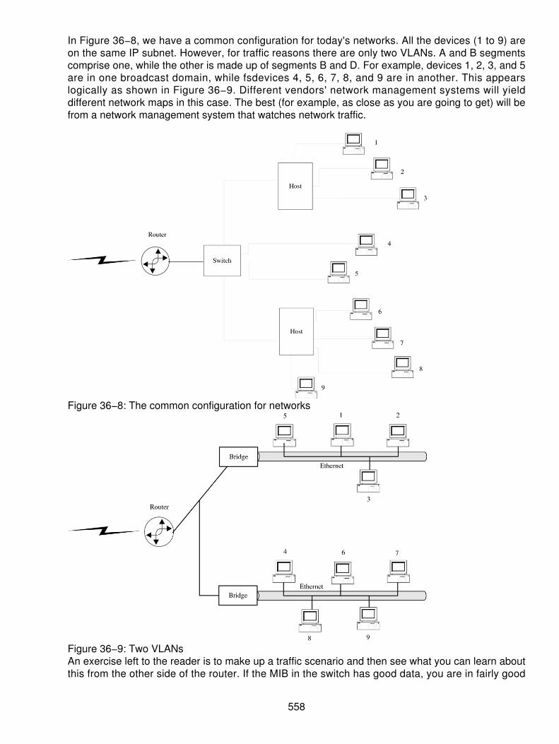
In Figure 36−8, we have a common configuration for today's networks. All the devices (1 to 9) areon the same IP subnet. However, for traffic reasons there are only two VLANs. A and B segmentscomprise one, while the other is made up of segments B and D. For example, devices 1, 2, 3, and 5are in one broadcast domain, while fsdevices 4, 5, 6, 7, 8, and 9 are in another. This appearslogically as shown in Figure 36−9. Different vendors' network management systems will yielddifferent network maps in this case. The best (for example, as close as you are going to get) will befrom a network management system that watches network traffic.
Figure 36−8: The common configuration for networks
Figure 36−9: Two VLANsAn exercise left to the reader is to make up a traffic scenario and then see what you can learn aboutthis from the other side of the router. If the MIB in the switch has good data, you are in fairly good
558

shape. If it doesn't support the standard MIB, it is hopeless. Although most of the industry hassupported SNMPv2 for several years, there has always been contention among the vendors and asignificant amount of noncompliance. The noncompliant vendors are opting for their own customMIB.
SNMPv3
Part of this contention is due to shortcomings of SNMPv2 that require fixing. There are also someadditions that are needed to support higher−speed networks. SNMPv3 adds a GetBulk command, abetter Set command, a unique ID for each SNMP agent, and 64−bit counters to accommodateGigabit Ethernet. Perhaps the most important new feature is the addition of real security in theSNMP packets. The GetBulk command essentially says "gimme the whole MIB." This is importantbecause it reduces the polling traffic that was created by multiple GetNext commands. Although thiswill have a minimal impact on reducing the network management system traffic on a small network,it will be a major benefit to large networks.
Although MIB data can be fetched remotely, there is no way to remotely manage SNMP agents.SNMPv3 adds this feature, along with the capability to describe agents within agents (the problemidentified in Figures 36−8 and 36−9). Namely, the problem is that switches and hubs behind otherswitches and routers are difficult (to impossible) to find. SNMPv3 provides the mechanism to do thisif (and it is a big if) SNMPv3 is supported by all the vendors involved. The same problem exists hereas with the previous versions of SNMP — standards compliance is not universal. Many vendorshave opted for vendor−specific MIBs (shown in Figure 36−4) under 1.3.6.1.4.1. This means that thenetwork management system must have a current complete copy of the MIB in order to be able tomanage the device (agent). The Desktop Management Task Force (DTMF) is trying to standardizethe various data types in a more useful form via the Common Information Model (CIM).
Although the forgoing seems critical of SNMPv1 and v2, one must remember the era in which theywere born. The functionality and memory in managed devices (for example, hubs) were extremelylimited. Today, with cheap memory and processing power in every device, many more capabilitiescan be added at little or no cost.
Security
The initial design of SNMP included a modicum of security by using the community field (see Figure36−6) to identify devices belonging to our management community. This was satisfactory before thedays of inexpensive and capable network sniffers. With today's technology, it is not difficult to collectSNMP packet header information and either steal the information or substitute the content. Stealingcontent allows the hacker to build a map of our network for later exploitation. Substituting thecontent of our Set commands could be disastrous. One hopes that there are no hackers on ourinternal network, but in today's world, one is never sure. Our paranoia turns to prudence if we arerunning interconnections of our network over the public Internet without the benefit of a VirtualPrivate Network (VPN). Before becoming too paranoid, one must remember that the hacker musthave physical access to the network backbone, a sniffer, the time and will to hack, and the desire todo mischief. The probability of the confluence of all these attributes is relatively low in absolute orreal terms.
Given our paranoia, if the hacker is able to collect frames and packets, he can collect thecommunity information and therefore control any of our devices that are preconfigured for remotemanagement.
559

SNMPv3 solves this problem by encrypting the packet content and by establishing an authenticationmechanism. All this is possible today because memory and processing power are readily availablein the managed devices.
The new RFCs 2274 and 2275 provide for a User−based Security Model (USM) and a Views−basedAccess Control Model (VACM). These RFCs set forth a scheme for today and provide for futureexpansion to include possibly public key authentication and directory integration.
The USM uses a distributed security control mechanism with a user name and passworddisseminated from a centralized system. The user list, or access list, is distributed (securely usingencryption) to each managed element. The remote agent does enforcement. Thus, the networkmanagement system user must log into each managed agent. Access to each MIB element can beput under password control. The USM specifies authentication and encryption functions, while theVACM specifies the access control rules. Each managed device can therefore keep a log ofaccesses and by whom (just as a firewall or proxy server logs each access). Although perhaps notimportant for hubs, it is very important for sensitive devices such as routers, switches, and firewalls.Previous versions of SNMP could not create this important audit trail.
In addition to encrypting the packet contents (for example, using Data Encryption Standard [DES]),each packet contains a time stamp to synchronize the network management system with themanaged agent. This prevents the man−in−the−middle from recording the queries and commands,analyzing them, substituting his content, and playing them back at a later time. The USM alsospecifies its own MIB so that the passwords and user names can be remotely and securelymaintained. Thus, although enforcement of access is done by each MIB agent, the user name andpassword can be centrally maintained and distributed to each managed agent by using the specifiedencryption technique. This means that a network authentication server must exist just for SNMP.
In the final analysis, it is your choice whether or not to implement the security features. There aredefinite benefits and costs associated with installing and maintaining the authentication server andits database.
Java
Sun Microsystems is pushing Java as a mechanism for enhancing the flexibility of SNMP. As wehave seen, SNMP defines MIB−1, MIB−2, and MIB−3. Even though we can capture data onhigher−speed elements and control network components securely, if changes are needed to theSNMP agents, software must be loaded (typically, manually) in each managed device.
The Java concept is that each agent has memory and CPU cycles to spare. Why not have it as aJava virtual machine? The network management system would then download the new functionalityto each or all devices.
SNMP was designed to manage elements like routers, switches, and hubs. Managing remoteservers, desktop machines, or applications' processes was never considered. The introduction of aJava−based system permits the management of higher−layer functions while maintainingcompatibility and coexistence with SNMP.
There are several problems to overcome before Java can become a popular network managementsystem tool. The first is performance. As an interpretive language, it is processor intensive andslow. Solutions for this problem involve compiling the Java code on the fly as it is downloaded to thetarget machine. The code then runs in native mode. Sun's Hot Spot compiler and Microsoft's Just inTime (JIT) compiler are designed to do this.
560

The good part is that the network manager can easily maintain the same revision level of the agentsin all devices throughout the network. Unfortunately, this threatens the market for vendor−specificnetwork management system solutions. The best advice is to stay tuned as vendors and standardsorganizations try to solve the problems of complex networks of today and the even more complexnetworks of tomorrow. History has shown that during the early stages of development anddeployment, there are multiple solutions from a variety of vendors — all incompatible with oneanother. As the technology (and markets) mature, the industry hones in on the essential featuresand functions that are accepted and supported industry−wide. These then become the corefunctionality on top of which each vendor builds his proprietary extensions.
561

List of FiguresChapter 3: Virtual Private Networks
Figure 3−1: Hub and spoke arrangement for TIE linesFigure 3−2: The VPN uses the PSTN as the backbone
Chapter 4: Data Virtual Private Networks (VPNs)
Figure 4−1: Tunnels provide secure access for VPNs.Figure 4−2: Competitors may actively pursue your data.Figure 4−3: Hackers break in just to prove their prowess.Figure 4−4: The pieces that must be considered for securityFigure 4−5: Security key management is used for IPSec.Figure 4−6: The L2TP packetFigure 4−7: The various forms of IP packetsFigure 4−8: Compatible routers are used at each location for VPN services.Figure 4−9: Stand−alone firewallFigure 4−10: The firewall and VPN box working in parallel
Chapter 5: Advanced Intelligent Networks (AINs)
Figure 5−1: AIN architecture frameworkFigure 5−2: Basic CTI applicationFigure 5−3: AIN protocol stackFigure 5−4: Growth in AIN services around the world
Chapter 6: Local Number Portability (LNP)
Figure 6−1: Comparison of business and residential user concerns over service providerchangeFigure 6−2: Basic LNP networkFigure 6−3: LNP terminologyFigure 6−4: The LRN in useFigure 6−5: LNP scenarioFigure 6−6: Unconditional triggerFigure 6−7: The AIN modelFigure 6−8: LIDB model for 0 plus calling cardFigure 6−9: Operator service effectsFigure 6−10: E911 calling with LNPFigure 6−11: Wireless E911 substitutes a number for call routing.Figure 6−12: Simplifying the wireless E911 call
Chapter 7: Computer Telephony Integration (CTI)
Figure 7−1: The CTI capability using a screen−popping serviceFigure 7−2: The integrated PBX as a voice server between two separate LANs
Chapter 8: Signaling System 7 (SS7)
Figure 8−1: Per−trunk signaling preceded SS7 but was slowFigure 8−2: Out−of−band signaling used the high frequencies
562
Figure 8−3: SS7 architectural beginningsFigure 8−4: Associated signalingFigure 8−5: Nonassociated signalingFigure 8−6: Quasi−associated signalingFigure 8−7: The signaling link architectureFigure 8−8: Linksets combinedFigure 8−9: Routes and routesetsFigure 8−10: SS7 protocolsFigure 8−11: Call set−up with ISUPFigure 8−12: The SCTP sublayersFigure 8−13: The SCTP relates to MTP−2Figure 8−14: SS7 protocol stack and GSMFigure 8−15: The protocols for GSM and SS7 networksFigure 8−16: The protocols for the wireless GSM architecture
Chapter 10: Integrated Services Digital Network (ISDN)
Figure 10−1: BRI bandwidth allocationFigure 10−2: NT1 creates the BRI.Figure 10−3: Architecture of the ISDN interfaceFigure 10−4: Typical local loop layoutFigure 10−5: The U interfaceFigure 10−6: 2B1Q technique for ISDNFigure 10−7: The standard interface connectorFigure 10−8: D−channel packetFigure 10−9: Typical configuration of the inverse muxFigure 10−10: The distributed queue dual bus (DQDB) system
Chapter 11: Frame Relay
Figure 11−1: A typical Frame Relay connectionFigure 11−2: A higher speed Frame Relay connectionFigure 11−3: A FRAD used on each end of the circuit at high speedsFigure 11−4: A Frame Relay frameFigure 11−5: Ethernet and IEEE 802.3 frames fit into the Frame Relay frame.Figure 11−6: Modified frame size of the Frame Relay information fieldFigure 11−7: OSI compared to Frame and X.25 stacksFigure 11−8: Mapping using the address and DLCIFigure 11−9: A typical mapping of the DLCI in a Frame Relay networkFigure 11−10: Traffic is tunneled in the Frame Relay frame using a small amount ofoverhead.Figure 11−11: TCP/IP traffic is tunneled into a frame.Figure 11−12: Examples of connections at higher speedsFigure 11−13: The core protocols for Frame Relay mimic the ISDN standards.Figure 11−14: Three places where fragmentation can take place in support of VoFRFigure 11−15: A Frame Relay gateway acts as the multiplexer of different services onto asingle PVC.Figure 11−16: The PCU uses Frame Relay to connect to the SGSN.
Chapter 12: Asynchronous Transfer Mode (ATM)
Figure 12−1: Traffic is mapped onto the network as it arrives.
563

Figure 12−2: When no cells arrive, idle cells are transported across the link.Figure 12−3: Graphic representation of the ATM protocol interfacesFigure 12−4: ATM table lookup maps the input and output channels.Figure 12−5: The end−to−end connection through the networkFigure 12−6: Virtual path switching remaps the path, but keeps the channel the same.Figure 12−7: The virtual path and virtual channel switches process and remap bothelements.Figure 12−8: Comparing the OSI and ATM layered modelsFigure 12−9: Upper−layer services of ATMFigure 12−10: Leaky buckets allow for buffering of the traffic.Figure 12−11: A double leaky bucketFigure 12−12: When a user exceeds the network rate, then cells are discarded.Figure 12−13: Cells enabled through the network when the user does not exceed theagreed−upon throughputFigure 12−14: The configuration of Ethernet and ATM combinedFigure 12−15: VoDSL can be provided easily.Figure 12−16: The IAD will add services for the future.Figure 12−17: Combining the ATM and DSL at the local loop
Chapter 13: ATM and Frame Relay Internetworking
Figure 13−1: Frame Relay in various placesFigure 13−2: ATM in various usesFigure 13−3: Frame and ATM coming togetherFigure 13−4: Frame Relay to ATM conversionsFigure 13−5: DXI and FUNI interfaces comparedFigure 13−6: Contrast of frame− and cell−based servicesFigure 13−7: FUNI reference modelFigure 13−8: ATM Interworking Function (IWF)Figure 13−9: Comparing the framesFigure 13−10: FUNI segmented into cellsFigure 13−11: FUNI, DXI, and ATM interoperabilityFigure 13−12: The network interworking functionFigure 13−13: Frame/ATM service interworking functionFigure 13−14: DXI modes 1A and 1BFigure 13−15: DXI protocol mode 1AFigure 13−16: DXI mode 1BFigure 13−17: DXI protocol mode 1BFigure 13−18: DXI mode 2Figure 13−19: DXI protocol mode 2
Chapter 14: Cable TV Systems
Figure 14−1: The CATV architectureFigure 14−2: Coaxial channel capacities at 6 MHzFigure 14−3: Guard bands prevent the channels from interfering with each other.Figure 14−4: Frequency−division multiplexing (FDM) on CATVFigure 14−5: CATV services of the futureFigure 14−6: Combining multiple streams on a single DTV channel
Chapter 15: Cable Modem Systems and Technology
564

Figure 15−1: CSMA/CD cable networks are collision domains.Figure 15−2: Broadband coaxial cable system from the beginningFigure 15−3: Mixing services on a 10 Broad 36 cableFigure 15−4: The new hybrid data networkFigure 15−5: Block diagram of the cable modemFigure 15−6: The DOCSIS modelFigure 15−7: Frequency spectrum allocated to the cable modemsFigure 15−8: Different speeds on the up−and−down stream flowsFigure 15−9: Multiple ways of connecting to the cable modem
Chapter 16: xDSL
Figure 16−1: Modems are installed at the customer's location and use the existing telephonewires to transmit data across the voice network.Figure 16−2: The IDSL line connection enables 128 Kbps in total simultaneously.Figure 16−3: The typical layout of the T1Figure 16−4: HDSL is impervious to the bridge and splices. The T1 is split onto two pairs.Figure 16−5: The ANSI DMT specificationFigure 16−6: The ANSI and UAWG G.Lite spectrumFigure 16−7: The splitter−enabled ADSL serviceFigure 16−8: The splitterless G.Lite installationFigure 16−9: The spectral use of CAPFigure 16−10: The ADSL model as it is laid out from the customer premises to the serviceproviderFigure 16−11: Access from the NAP to the NSPFigure 16−12: The typical local installationFigure 16−13: The proxy server in lieu of a single attached PCFigure 16−14: Connecting the ADSL service to a hubFigure 16−15: Connecting the ADSL modem directly through a 10/100 or a 100 Base T hub
Chapter 17: Microwave− and Radio−Based Systems
Figure 17−1: Comparison of cost per channel over the yearsFigure 17−2: Cellular interconnection of microwave radioFigure 17−3: Wireless interconnection of fiber and CAPsFigure 17−4: Action camera and microwave systems working togetherFigure 17−5: Laptop computers can now send and receive microwave radio transmissions.Figure 17−6: Obstacle gain uses a bounced signal off a natural obstacle, such as amountain.Figure 17−7: Repeater space can be rented from other suppliers.
Chapter 18: MMDS and LMDS
Figure 18−1: A typical MMDS arrangement Source: AMDFigure 18−2: The MMDS architecture key elementsFigure 18−3: The local loop is prone to problems.Figure 18−4: WLL conceptual modelFigure 18−5: Typical LMDS service areas Source: LMDS Org.Figure 18−6: Typical microwave point−to−point services of the past
Chapter 19: Specialized Mobile Radio (SMR)
565

Figure 19−1: Conventional radio requires users to queue on a channel.Figure 19−2: Control and talk channels in a trunked radio systemFigure 19−3: SMR base station and radio service
Chapter 20: Cellular Communications
Figure 20−1: The cell patternsFigure 20−2: The logon process uses specific channels.Figure 20−3: The failing signal procedureFigure 20−4: The handoff processFigure 20−5: Seven−cell patternFigure 20−6: Overlap coverage between the cellsFigure 20−7: The omnidirectional antennaFigure 20−8: Sectorized coverageFigure 20−9: Tiered cell coverageFigure 20−10: Frequency allocation for cellularFigure 20−11: Call establishment
Chapter 21: Global Services Mobile Communications (GSM)
Figure 21−1: Market penetrations of GSM and TDMAFigure 21−2: The older way of handling mobile communicationsFigure 21−3: The seven−cell pattern Source: ETSIFigure 21−4: The 12−cell pattern Source: ETSIFigure 21−5: The macrocellFigure 21−6: The microcell and picocellFigure 21−7: The selective cellFigure 21−8: The umbrella cellFigure 21−9: The GSM architectureFigure 21−10: The added components of a GSM networkFigure 21−11: The SIMFigure 21−12: The BTSFigure 21−13: The BSSFigure 21−14: The TRAUFigure 21−15: The MSCFigure 21−16: The HLRFigure 21−17: The VLRFigure 21−18: The PLMNFigure 21−19: SS7 and GSM working togetherFigure 21−20: The protocol stacksFigure 21−21: The uplink and downlink frequenciesFigure 21−22: Spectrum bands for primary GSMFigure 21−23: Extended GSMFigure 21−24: ASKFigure 21−25: FSKFigure 21−26: PSKFigure 21−27: GMSK resultsFigure 21−28: FDMAFigure 21−29: TDMAFigure 21−30: CDMAFigure 21−31: TDMA framing and time slots
566

Chapter 22: Personal Communications Services
Figure 22−1: FDMA slottingFigure 22−2: North American TDMA for PCSFigure 22−3: ETDMA uses a form of statistical TDM.Figure 22−4: The model for the CDMA systems Source: CDMA OrgFigure 22−5: The model of the CDMA network mimics the GSM architecture.Figure 22−6: CDMA uses a channel that is 1.25 MHz wide for all simultaneous callers.Figure 22−7: CDMA uses GPS to maintain synchronization of the systems. Source: NASAFigure 22−8: The systems maintain synchronization to isolate each user.Figure 22−9: The signal is prepared for transmission.Figure 22−10: The modulated carrier is then amplified and broadcast across the airinterface.Figure 22−11: The reception from the air interface occurs.Figure 22−12: The codes are stripped off and the actual data is extracted.
Chapter 23: Wireless Data Communications (Mobile IP)
Figure 23−1: Routing tableFigure 23−2: IRDP learns the new addresses and routers in the network.Figure 23−3: Wireless data subscribers (in millions)Figure 23−4: Routers look at the IP header for the destination network address.Figure 23−5: Forwarding IP trafficFigure 23−6: Application of mobility in a data world
Chapter 24: General Packet Radio Service (GPRS)
Figure 24−1: The number of telephone and Internet usersFigure 24−2: The steps in developing the 3G InternetFigure 24−3: Within five years, more wireless devices will be used on the Internet than PCs.Figure 24−4: The GPRS storyFigure 24−5: A GPRS network viewFigure 24−6: Internetworking strategies in GPRSFigure 24−7: The timeline for circuit−switched dataFigure 24−8: The timeline for packet−switched dataFigure 24−9: Steps of implementationFigure 24−10: The GPRS overlay on GSMFigure 24−11: The circuit−switched traffic exampleFigure 24−12: The packet−switched exampleFigure 24−13: The pieces of GPRS and GSM fit together.Figure 24−14: Cells and routing areasFigure 24−15: Attaching to the SGSNFigure 24−16: Obtaining a PDP context from the GGSNFigure 24−17: The data transfer
Chapter 25: Third−Generation (3G) Wireless Systems
Figure 25−1: The evolution of UMTS choicesFigure 25−2: Time line for 3G/UMTSFigure 25−3: GTP with VPNsFigure 25−4: GPRS protocol stackFigure 25−5: EDGE protocol stack
567

Figure 25−6: Worldwide 3G subscribers in millionsFigure 25−7: GSM user population worldwideFigure 25−8: Growth figures of mobile multimedia devices on the InternetFigure 25−9: The architecture for 3G
Chapter 26: Satellite Communications Networking
Figure 26−1: Satellite communication basicsFigure 26−2: C−band satellite antennaFigure 26−3: Ku−band satellite antennaFigure 26−4: Geosynchronous Orbit
Chapter 27: Low−Earth−Orbit Satellites (LEOs)
Figure 27−1: The LEO conceptFigure 27−2: Ground station telemetry and controlFigure 27−3: Satellite−to−satellite communications is handled on a Ka band.Figure 27−4: The spot beam pattern from IridiumFigure 27−5: The overall system through the gatewaysFigure 27−6: The 37−cell patternsFigure 27−7: A seven−cell frequency reuse patternFigure 27−8: Globalstar systems constellation
Chapter 28: The T Carrier Systems (T−1/T−2 and T−3)
Figure 28−1: A typical T−1 carrier installationFigure 28−2: A frame of information occurs 8,000 times/second.Figure 28−3: Band−limited channel limits the amount of information carried to 3 kHz.Figure 28−4: Robbed bit signaling in the D4 framing formatFigure 28−5: An E−1 frame formatFigure 28−6: ESF improves uptime and error checking.Figure 28−7: Common channel signaling uses channel number 24.Figure 28−8: Pulse stuffing enables the timing to be preserved.Figure 28−9: B8ZS inserts an 8−bit pattern that is recognizable by the receiver assubstituted.Figure 28−10: A DS−2 M frameFigure 28−11: The DS−2 overhead bits shownFigure 28−12: A DS−3 frame
Chapter 29: Synchronous Optical Network (SONET)
Figure 29−1: The SONET frameFigure 29−2: The transport overhead is divided into section and line overhead.Figure 29−3: The SPE shownFigure 29−4: A floating payload inside two framesFigure 29−5: The SONET architecture of the linkFigure 29−6: The section overheadFigure 29−7: The line overhead of a SONET frameFigure 29−8: POH in the STS frameFigure 29−9: The STS−3 (OC−3) frameFigure 29−10: Add−drop multiplexing with SONETFigure 29−11: Point−to−point service with SONET
568

Figure 29−12: ADMs installed along the wayFigure 29−13: Hub and spoke in a SONET multiplexer networkFigure 29−14: Ring architecture of SONET multiplexers
Chapter 30: Synchronous Digital Hierarchy (SDH)
Figure 30−1: The STM−1 frame formatsFigure 30−2: Size of the STM−1 frameFigure 30−3: The VCs are created.Figure 30−4: Mapping and aligning into the TU Group 2Figure 30−5: The process of creating a TUG−3Figure 30−6: Creating the VC−4Figure 30−7: The E4 is created inside an STM−1.Figure 30−8: The SONET tributary multiplexing schemeFigure 30−9: The final outcome of the SDH or SONET framingFigure 30−10: The multiplexing structure via G.707Figure 30−11: The data fill based on G.709Figure 30−12: Market for SONET/SDH equipmentFigure 30−13: SDH layer model contrast to OSIFigure 30−14: Path mapping of SDH
Chapter 31: Wave Division Multiplexing (WDM)
Figure 31−1: FDM has been used by cable TV operators to carry more information on theircoaxial cables.Figure 31−2: The colors of light separate the bands carried on the cable.Figure 31−3: Step index fiber opticsFigure 31−4: A graded index fiberFigure 31−5: Single mode fiber is so pure and so thin that the light has only one path fromend to end.Figure 31−6: Combinations of frequency and time multiplexing produce the results in WDM.Figure 31−7: A typical DWDM multiplexer
Chapter 32: The Internet
Figure 32−1: The OSI model as the referenceFigure 32−2: Basic configuration of X.25 networksFigure 32−3: The Frame carrying the X.25 packetFigure 32−4: The routing table exampleFigure 32−5: The relationship between the frame and packetFigure 32−6: The IP headerFigure 32−7: The TCP headerFigure 32−8: The UDP headerFigure 32−9: The Internet IP addressing schemeFigure 32−10: Different classes of IP addresses connected to a routerFigure 32−11: A subnetted class A addressFigure 32−12: Class A subnetted with a firewall to the InternetFigure 32−13: A new router is added to the network.Figure 32−14: Routing domains
Chapter 33: Voice over IP (VoIP)
569

Figure 33−1: Telephone to telephone through the IP networkFigure 33−2: PC−to−telephone calls over the IPFigure 33−3: Various ways of using VoIPFigure 33−4: ITU H.323 specifications define the various roles in IP telephony.Figure 33−5: H.323 in actionFigure 33−6: The use of ATM or FR guarantees the QoS today.Figure 33−7: Delays across a VoIP networkFigure 33−8: The VoIPs stacked up
Chapter 34: Multiprotocol Label Switching (MPLS)
Figure 34−1: Hosts attached to the Internet 1999 to 2008 estimatesFigure 34−2: The addresses used in IPFigure 34−3: Reasons for subnetworkingFigure 34−4: An example of subnettingFigure 34−5: A class B address subnettedFigure 34−6: Subnets reduce the confusion and the heavy routing needs.Figure 34−7: A subnet maskFigure 34−8: Using the longest match for routingFigure 34−9: Combined protocols used in the networkFigure 34−10: The path with conventional routing algorithmsFigure 34−11: The chosen route with MPLS specified routingFigure 34−12: The components of MPLS
Chapter 35: Intranets and Extranets
Figure 35−1: A classic firewall implementationFigure 35−2: The DMZ provides a protected area where all traffic flows.Figure 35−3: The relationship of the DMZ to the firewall actually creates two firewalls.Figure 35−4: A typical array of proxy devices sitting behind the firewallFigure 35−5: A hypothetical flow through the firewall to the proxy and then on to theapplicable server in the DMZ
Chapter 36: Network Management SNMP
Figure 36−1: Typical centralized network configurationFigure 36−2: Typical distributed processing systemFigure 36−3: Logical relationship between the managed and manager functionsFigure 36−4: SMI structure defined as a treeFigure 36−5: SNMP functions and how they are related to the ISO's OSI modelFigure 36−6: The SNMP message carried within the protocol layersFigure 36−7: Logical and physical networksFigure 36−8: The common configuration for networksFigure 36−9: Two VLANs
570

List of TablesChapter 3: Virtual Private Networks
Table 3−1: Comparison of usage sensitive and fixed leased line costs
Chapter 4: Data Virtual Private Networks (VPNs)
Table 4−1: Mix of methods used to pick from
Chapter 8: Signaling System 7 (SS7)
Table 8−1: Components of the SS7 networksTable 8−2: The configuration of linksets
Chapter 11: Frame Relay
Table 11−1: A summary of the X.25 and Frame Relay servicesTable 11−2: Typical speeds used in Frame RelayTable 11−3: Comparing Frame Relay and IP
Chapter 12: Asynchronous Transfer Mode (ATM)
Table 12−1: Summary of where various protocols are usedTable 12−2: Summary of speeds for various technologiesTable 12−3: Summary of ATM features and functionsTable 12−4: Summary of where protocols are used for ATMTable 12−5: Types of AAL and services offeredTable 12−6: Comparing the categories of service
Chapter 13: ATM and Frame Relay Internetworking
Table 13−1: Comparing Frame Relay and ATM characteristics
Chapter 15: Cable Modem Systems and Technology
Table 15−1: Comparison of transmission speedsTable 15−2: Representative asymmetrical data cable modem speeds
Chapter 16: xDSL
Table 16−1: Data rates for ADSL, based on installed wiring at varying gaugesTable 16−2: Summary of DSL speeds and operations using current methods
Chapter 17: Microwave− and Radio−Based Systems
Table 17−1: Possible market share for microwave productsTable 17−2: Comparison of frequency bands and distances (line of sight)
Chapter 18: MMDS and LMDS
Table 18−1: Multiple areas of competition at the local loop
571
Table 18−2: Cost comparison for wired versus WLLTable 18−3: Summary of service offerings and providers todayTable 18−4: Bundled versus individual services plansTable 18−5: Typical microwave distances, bands, and operationsTable 18−6: Summary of modulation techniques available for LMDS in FDMA
Chapter 19: Specialized Mobile Radio (SMR)
Table 19−1: Features Possible with Digital SMRTable 19−2: Radio Services Meeting the NeedTable 19−3: The VSELP Coding Process is StraightforwardTable 19−4: Frequency Pairing for SMR
Chapter 21: Global Services Mobile Communications (GSM)
Table 21−1: Major events in GSM
Chapter 23: Wireless Data Communications (Mobile IP)
Table 23−1: Driving forces for mobile dataTable 23−2: Speeds for wireless devicesTable 23−3: Summary of methods for data
Chapter 25: Third−Generation (3G) Wireless Systems
Table 25−1: Variations of CDMA
Chapter 26: Satellite Communications Networking
Table 26−1: Number of satellites in orbit by country around the worldTable 26−2: Applications for high−speed satellite communicationsTable 26−3: Sampling of services planned or offeredTable 26−4: Sample of the frequency bandsTable 26−5: Summary of bands and types of terminals used
Chapter 27: Low−Earth−Orbit Satellites (LEOs)
Table 27−1: A summary of the number of competitors and the various orbits being soughtTable 27−2: Services and coverage through the Iridium networkTable 27−3: Summary of cell sites versus Iridium cellsTable 27−4: A summary of the initial features available on LEO networksTable 27−5: A summary of the bands and the bandwidth for Iridium
Chapter 28: The T Carrier Systems (T−1/T−2 and T−3)
Table 28−1: The three−step process used to create the digital signalTable 28−2: Summary of values for PCM in Mu−law and A−Law formatsTable 28−3: Comparison of North American and European digital services
Chapter 29: Synchronous Optical Network (SONET)
Table 29−1: Summary of clocking systems
572

Table 29−2: Summary of electrical and optical rates for SONETTable 29−3: The individual bytes are defined in the designation and their useTable 29−4: The individual bytes of the line overheadTable 29−5: The POH definedTable 29−6: The values of the virtual tributaries defined for SONETTable 29−7: Comparison of SONET and SDH rates
Chapter 30: Synchronous Digital Hierarchy (SDH)
Table 30−1: Comparing the rates of speed for the various levels of the digital hierarchy inKbpsTable 30−2: Comparison of STS and STM ratesTable 30−3: SDH payload compositions for the hierarchical ratesTable 30−4: Levels of input as they map into the TUsTable 30−5: Comparing SDH and SONET frame sizes and nomenclatureTable 30−6: Comparisons of common interfaces
Chapter 31: Wave Division Multiplexing (WDM)
Table 31−1: A summary of current capacity of the DWDM servicesTable 31−2: Fiber−based advantages over other mediaTable 31−3: Summary of the demand to justify the use of DWDMTable 31−4: A look at what DWDM and fiber rates will bring over the next decade
Chapter 32: The Internet
Table 32−1: The routing table for router R−2Table 32−2: The routing table for router R−2
Chapter 33: Voice over IP (VoIP)
Table 33−1: Circuit−switched versus packet−switched network characteristicsTable 33−2: Different approaches to QoSTable 33−3: QoS requirements for IP telephonyTable 33−4: Summary of areas where VoIP equipment must work
Chapter 34: Multiprotocol Label Switching (MPLS)
Table 34−1: Networks assigned by the decimal dot delimited addressesTable 34−2: Ranges for classes of addressesTable 34−3: The natural mask uses the octet boundaries by class of addressTable 34−4: The decision matrix for forwarding the IP datagrams
Chapter 35: Intranets and Extranets
Table 35−1: A typical rule base viewed through a GUI
Chapter 36: Network Management SNMP
Table 36−1: Relevant standards that apply the network management
573