Breakup of Liquid Jets
10
International Association of Scientific Innovation and Research (IASIR) (An Association Unifying the Sciences, Engineering, and Applied Research) International Journal of Emerging Technologies in Computational and Applied Sciences (IJETCAS) www.iasir.net IJETCAS 13-353; © 2013, IJETCAS All Rights Reserved Page 487 ISSN (Print): 2279-0047 ISSN (Online): 2279-0055 Breakup of Liquid Jets K. S. Agrawal Assistant Professor, Department of Chemical Engineering Faculty of Technology and Engineering, The M. S. University of Baroda, Vadodara, Gujarat, India __________________________________________________________________________________________ Abstract: For fundamental analysis of the transport of mass or heat in a dispersed system, accurate knowledge of behavior of jet is prerequisite. For generation of high interfacial area breaking of liquid jet in to small droplet is necessary. Liquid jet breakup is a complex phenomenon and dependent on many factors like velocity of jet, pressure difference, geometry of nozzle, temperature of both fluid, properties of fluid like their density, viscosity ,surface tension, vapor pressure etc. Here different characteristics of jet are discussed. The most important parameter for this phenomenon is the Weber number (We) calculated from the diameter of the large structures. Indeed, the main parameters that can affect the secondary atomization are acceleration of drop by external flow, shear due to the differential speed between liquid and gas and surface tension. In this paper different aspect of jet behavior like jet length, flow regions of free turbulent jet, types of jet disintegration, effect of different variables on liquid jet breakup, etc. are discussed. The major factors which affect the characteristics of jet are viscosity of liquid, turbulence and environmental pressure. The effect of oscillating pressure and cavitations are also discussed. In this paper an attempt is made to present a literature survey on jet breakup. Key words: factors for jet breakup, liquid jet, breakup of jet, length of jet, primary and secondary atomization. __________________________________________________________________________________________ I. Introduction The turbulent flow is desired to increase the rate of transfer per unit area or to help dispersion of one fluid to another and to create more interfacial area, for most of mass transfer between gas and liquid. Dispersion of one fluid to another is a complex phenomenon and depends on many factors like velocity of jet, pressure difference, geometry of nozzle, temperature of both fluids, properties of fluid like their density, viscosity, surface tension, vapor pressure, etc. When a liquid is injected into another fluid at velocity above specific velocity, jet forms. This jet continues to be intact to certain length and then breaks to drop. The breakup of a liquid jet radiating into another fluid was studied by many investigator since century. These drops result into the generation of large new surface. The prediction of dynamics of jet and calculation of quantity and size of drops are very important. Jet break up has been studied extensively both practically and theoretically. Theoretical development started by elegant analysis of Plateau and Rayleigh. It has been stated by Plateau (1873) that jet breakup in segments having equal length of times of the jet radius. Rayleigh (1879a) and (1879b) explained that hydrodynamic instability is responsible for the jet breakup. Weber (1931) studied the effects of the density of the ambient fluid and liquid viscosity. Further, Tomotika (1935) extended Rayleigh stability analysis to a viscous cylinder surrounded by a viscous fluid and explain about an optimum ratio of viscosities of the jet to the ambient fluid at which jet attains the maximum growth rate. Christiansen and Hixon (1957) stydied inviscid liquid jet in inviscid liquid. Chandrasekhar (1961) accounted the liquid viscosity as well as the liquid density, which was not considered by Rayleigh and mathematically proved that as the viscosity increases the breakup rate of jet reduces and drop size increases. They further conclude that breakup of viscous liquid jet is by capillary pinching mechanism under vacuum. (Lin and Reitz 1998). Sterling and Sleicher (1975) studied liquid jets injected in to air and analysed the aerodynamic interaction between the jet. and air. They developed an equation for the growth rate. II. Behavior of jet Free jet A free jet, after leaving the nozzle, will entrain the surrounding fluid, expand and decelerate. Approximately, total momentum which is conserved as jet momentum is transferred to the entrained fluid. In the literature it has also been defined that when the cross-sectional area of jet is less than 1/5 then the cross section of surrounding region then jet is considered to be free jet in case of both fluid, surrounding fluid and jet fluid, are same. While the turbulent jet having Reynolds number greater than 2000 is considered to be a free jet. (Perry et al., 2007) Jet length The high velocity liquid jet coming out of nozzle situated at the top of ejector flowing through the stagnant fluid surrounding it maintains its identity for a substantial distance (Figure 1). It may is observed for the jet issuing from the nozzle having uniform and constant velocity that
-
Upload
independent -
Category
Documents
-
view
5 -
download
0
Transcript of Breakup of Liquid Jets

International Association of Scientific Innovation and Research (IASIR) (An Association Unifying the Sciences, Engineering, and Applied Research)
International Journal of Emerging Technologies in Computational
and Applied Sciences (IJETCAS)
www.iasir.net
IJETCAS 13-353; © 2013, IJETCAS All Rights Reserved Page 487
ISSN (Print): 2279-0047
ISSN (Online): 2279-0055
Breakup of Liquid Jets K. S. Agrawal
Assistant Professor, Department of Chemical Engineering
Faculty of Technology and Engineering, The M. S. University of Baroda,
Vadodara, Gujarat, India
__________________________________________________________________________________________
Abstract: For fundamental analysis of the transport of mass or heat in a dispersed system, accurate knowledge
of behavior of jet is prerequisite. For generation of high interfacial area breaking of liquid jet in to small
droplet is necessary. Liquid jet breakup is a complex phenomenon and dependent on many factors like velocity
of jet, pressure difference, geometry of nozzle, temperature of both fluid, properties of fluid like their density,
viscosity ,surface tension, vapor pressure etc. Here different characteristics of jet are discussed. The most
important parameter for this phenomenon is the Weber number (We) calculated from the diameter of the large
structures. Indeed, the main parameters that can affect the secondary atomization are acceleration of drop by
external flow, shear due to the differential speed between liquid and gas and surface tension. In this paper
different aspect of jet behavior like jet length, flow regions of free turbulent jet, types of jet disintegration, effect
of different variables on liquid jet breakup, etc. are discussed. The major factors which affect the characteristics
of jet are viscosity of liquid, turbulence and environmental pressure. The effect of oscillating pressure and
cavitations are also discussed. In this paper an attempt is made to present a literature survey on jet breakup.
Key words: factors for jet breakup, liquid jet, breakup of jet, length of jet, primary and secondary atomization.
__________________________________________________________________________________________
I. Introduction The turbulent flow is desired to increase the rate of transfer per unit area or to help dispersion of one fluid to
another and to create more interfacial area, for most of mass transfer between gas and liquid. Dispersion of one
fluid to another is a complex phenomenon and depends on many factors like velocity of jet, pressure difference,
geometry of nozzle, temperature of both fluids, properties of fluid like their density, viscosity, surface tension,
vapor pressure, etc.
When a liquid is injected into another fluid at velocity above specific velocity, jet forms. This jet continues to be
intact to certain length and then breaks to drop. The breakup of a liquid jet radiating into another fluid was
studied by many investigator since century. These drops result into the generation of large new surface. The
prediction of dynamics of jet and calculation of quantity and size of drops are very important.
Jet break up has been studied extensively both practically and theoretically. Theoretical development started by
elegant analysis of Plateau and Rayleigh. It has been stated by Plateau (1873) that jet breakup in segments
having equal length of times of the jet radius. Rayleigh (1879a) and (1879b) explained that hydrodynamic
instability is responsible for the jet breakup. Weber (1931) studied the effects of the density of the ambient fluid
and liquid viscosity. Further, Tomotika (1935) extended Rayleigh stability analysis to a viscous cylinder
surrounded by a viscous fluid and explain about an optimum ratio of viscosities of the jet to the ambient fluid at
which jet attains the maximum growth rate. Christiansen and Hixon (1957) stydied inviscid liquid jet in inviscid
liquid. Chandrasekhar (1961) accounted the liquid viscosity as well as the liquid density, which was not
considered by Rayleigh and mathematically proved that as the viscosity increases the breakup rate of jet reduces
and drop size increases. They further conclude that breakup of viscous liquid jet is by capillary pinching
mechanism under vacuum. (Lin and Reitz 1998). Sterling and Sleicher (1975) studied liquid jets injected in to
air and analysed the aerodynamic interaction between the jet. and air. They developed an equation for the
growth rate.
II. Behavior of jet
Free jet
A free jet, after leaving the nozzle, will entrain the surrounding fluid, expand and decelerate. Approximately,
total momentum which is conserved as jet momentum is transferred to the entrained fluid. In the literature it has
also been defined that when the cross-sectional area of jet is less than 1/5 then the cross section of surrounding
region then jet is considered to be free jet in case of both fluid, surrounding fluid and jet fluid, are same. While
the turbulent jet having Reynolds number greater than 2000 is considered to be a free jet. (Perry et al., 2007)
Jet length
The high velocity liquid jet coming out of nozzle situated at the top of ejector flowing through the stagnant fluid
surrounding it maintains its identity for a substantial distance (Figure 1). It may is observed for the jet issuing
from the nozzle having uniform and constant velocity that

K. S. Agrawal, International Journal of Emerging Technologies in Computational and Applied Sciences, 5(5), June-August, 2013, pp. 487-
496
IJETCAS 13-353; © 2013, IJETCAS All Rights Reserved Page 488
The velocity remain uniform and constant in the core
the area of core decreases with distance from the nozzle,
the core is bounded by an increasing turbulent jet, in which the radial velocity decreases with distance
from the centerline of the jet,
the core is shrinking and disappears at some distance from the nozzle,
but the turbulent jet maintains its integrity further than the point at which the core disappeared however
its velocity steadily decreases,
the radial velocity in the jet decreases and a pressure increases in as per the Bernoulli principle
There is simultaneous surrounding fluid enters into the jet and is absorbed, accelerated and blended into the
enlarged jet. This process is called entrainment.
Figure 1 : Flow of a submerged circular jet (Rushton and Oldshue, 1953).
In this process there are also strong shear stresses at the boundary of the jet and the surrounding liquid. Due to
these stresses strong eddies are generated at the boundary and create considerable turbulence, which causes the
intimate mixing action. It is also established that liquid flow at high velocity and entrainment of large quantity
alone do not sufficient for thorough mixing. Enough time and space is must for the streams to mix together
satisfactorily by the mechanism of entrainment. (McCabe et al., 1993)
Liquid jet break-up length
Breakup length of round liquid jet was measured by Eroglu et al. (1991) in annular coaxial air streams. They
further observed that the decreasing breakup length with increasing Weber number and they also found that
liquid jet length increases by increasing Reynolds number. They gave following expression:
where = central tube inner radius and = liquid intact length. Here Weber ( ) and Reynolds numbers ( )
are based on gas and liquid relative velocity.
In similar attempt numerical analysis of jet breakup is performed by Kazuya et al. (2004) using the Moving
Particle Semi-implicit (MPS) method in – two dimensions. Effects of the Weber number and the Froude
number on the jet breakup length agree well with experimental data. The breakup length with gravity is from 70
to 80% of the experimental data. They expressed as the following expression:
where , , and are jet breakup length, nozzle width, Weber number and Froude number, respectively.
However, the coefficient 1.2 by the MPS method is a little smaller than experimentally obtained values 1.5 for
alcohol and 3.0 for water.
Richards et al. (1994) compared results obtained experimentally and numerically for jet length till break up as
well as jet and drop shapes. He concluded that numerical method shows a greater sensitivity of jet length to
Reynolds number.
Flow regions of free turbulent jet
Tuve (1953) and Davies (1972) have explained break up length differently. A turbulent free jet is normally
considered to be consisting of four flow regions that are:
Region of flow establishment is up to the 6.4 times nozzle diameter. In this region there is a core
having conical shape and the velocity is same as at the discharge of the nozzle. As jet proceed away
from the discharge of the nozzle, slowly boundary between jet and surrounding reduces to centerline.
Here this region is considered to be terminated.
Next transition region is up to the 8 times diameter of nozzle.
Region of established flow is the foremost region of the jet. Here, the radial velocity profile is self-
conserving with respect to centerline velocity.
In terminal region centerline velocity reduces rapidly. For air jets, the residual velocity will reduce to
less than 0.3 m/s which is considered to be still air.

K. S. Agrawal, International Journal of Emerging Technologies in Computational and Applied Sciences, 5(5), June-August, 2013, pp. 487-
496
IJETCAS 13-353; © 2013, IJETCAS All Rights Reserved Page 489
Several researchers (Tie et al., 2011; Pfeifer et al., 2010; Leick, 2008; Yongyingsakthavorn et al., 2004;
Smallwood and Gulder, 2000, Kufferath et al., 1999; Wolfe et al., 1964) have reported the jet behavior.
III. Types of primary atomization
The liquid jet behavior is a critical step in mass and heat transfer operations. There are mainly three categories
of mechanisms (Meyers, 2006) of jet disintegration namely:
Mechanical primary atomization
Liquid jet is injected at high speed through a small hole in a gaseous medium at rest. This type of atomization is
supposed to have very strong difference in pressure between the upstream and downstream of the orifice. This
type of jet is also called free jet. This type of atomization of jet is used in jet ejectors.
Aerodynamic primary atomization
Liquid jet injected at low speed in the chamber surrounded by a gas jet injected at high speed. This type of
coaxial jet is also called assisted jet. This type of atomization of jet is used in high energy venturi scrubber
(HEVS).
Impact primary atomization
When atomization is performed by impact of two liquid jets or a liquid jet to a wall, it is called impact primary
atomization.
The understanding of the phenomenon of primary atomization is still not clear due to the difficulty in
observation of primary fracture of jet in the dense zone of the flow. Moreover there are strong changes in
topology of interface and quick transfer between the phases in this zone very rapidly, alter the properties of the
drops/bubbles before they reach experimentally observable conditions. However, recently due to the
improvement of measurement techniques (holography technology and probes of optical fiber) understanding of
the dense fog area has become possible.
The current study involves mechanical primary atomization by multi nozzle jet ejector. Review of literature
published about mechanical primary atomization is given as under:
Mechanical primary atomization
Faeth (1999, 1990) and Reitz and Bracco (1986) have given exhaustive review of literature on mechanical
atomization. Ohnesorge and Angew (1936) provided the first classification of different schemes based on the
Reynolds and Ohnesorge numbers. Reitz (1978) clarified the uncertainty of classification proposed by
Ohnesorge and Angew.
Lin and Reitz (1998) as well Atay (1986, 1987) discussed various regimes of breakup of liquid jets injected into
Figure 2 : Break up time and/or jet breakup length as a function of jet exit velocity
[Adopted from (1) Atay (1986), (2) Lin and Reitz (1998)]
(1) (2)
both stagnant and co-flowing gases. Available criteria for the alteration from one regime to another have been
reviewed by them. They proposed a convenient method of categorizing jet breakup regimes by considering the
length of the coherent portion of the liquid jet or its unbroken length, as a function of the jet exit velocity, ,
[Refer Figure 2(1) and Figure 2(2)].
They identified four main breakup regimes which were based on combinations of inertia of liquid, surface
tension and forces of aerodynamic acting on the jet. The regimes are named as follows
(1) The Rayleigh regime,
(2) The first wind-induced regime,
(3) The second wind-induced regime and
(4) The atomization regime.
These regimes are summarized as in Table 1.
Region A and B of figure (2) shows that after the dripping flow regime , the breakup length linearly
increases in beginning as jet velocity increases till it reaches maximum and then start decreases. It is also clear

K. S. Agrawal, International Journal of Emerging Technologies in Computational and Applied Sciences, 5(5), June-August, 2013, pp. 487-
496
IJETCAS 13-353; © 2013, IJETCAS All Rights Reserved Page 490
that the drops are pinched of having comparable diameter to the jet. These two breakup regimes, which are
understood properly, related to the Rayleigh and first wind-induced breakup regimes.
Table 1 : Jet breakup regimes (Lin and Reitz, 1998 and Atay, 1986) Type of Regime Jet velocity
Break up length
in terms of
Diameter of drop,
Webber no,
Rayleigh Je t Breakup Regime
First Wind Induced Breakup
Regime
Second Wind Induced Breakup
Regime
Atomization Regime
* is the relative velocity between jet and gas, do= diameter of nozzle,
Hoeve et al.(2010) presented classification of droplet formation regimes graphically as figure 3 . They
presented on the radius of jet vs liquid velocity .They also plotted Re, Oh and We lines calculated on the
property of pure water. The blue colored strip shows droplet formation by
Figure 3:Classification of. droplet formation regimes
the breakup of continuous liquid jet in Rayleigh breaking regime (jetting) which is bounded by a lower and
upper critical velocity (indicated by Weber numbers, Wel=4 to Weg) . As the jet size decreases the Rayleigh
breakup velocity range becomes wider for example for 1 mm jet the range is 0.35 to 2.3 m/s and for 17 and 110
m/s for a 1 µm jet.
However, there is variation in observation about breakup-length trends beyond the first wind-induced breakup
regime. Haenlein (1932) stated that the jet breakup length increases with increasing jet velocity again. [region C
in Figure 2], and then suddenly reduces to zero [region D Figure 2] while McCarthy & Malloy (1974) reported
that the breakup length discontinues shortening and elongation of the jet with changes in the jet velocity.
Castleman (1931) observed that the breakup occurs at some jet diameters from the orifice, while DeJuhasz
(1931) claims that disintegration begin within the nozzle itself.
Theories developed for jet breakup have been reported by various investigators as tabulated in Table 2.
Table 2 : References on jet breakup and primary atomization References Theory of jet breakup
Ranz (1956) Breakup by balancing inertial forces with surface tension forces, neglecting viscous shear
stress.
Fraser et al. (1962) Hydraulic atomization of rapidly moving liquid sheet.
Reitz (1978,2004) Atomization and other breakup regimes of a liquid jet
Ingebo (1991) Liquid Jet breakup in sonic- velocity gas flow.
Frago and Chigier (1992) Pulsating and super pulsating breakup process.
Chigier & Reitz. (1996) Air- blast coaxial atomization.
Kankkunen et al. (1997) Sheet breakup mechanism of black liquor.
Meier et al. (1997) Breakup of very low velocity liquid jets.
Geschner et al. (2001, 2004) Disintegration of sinusoidally forced liquid jet.
Herrero et al. (2007) Air blast atomization of swirling viscous annular liquid sheet (alginate solution)
Tie Li et al. (2011), Tamaki et al. (2007, 2010) and Yongyingsakthavorn et al. (2004) have reported that there
are still other parameters which effect the breakup of jet: physical properties of fluid, the nozzle geometry, the
surrounding gas (stagnant or moving, atmospheric or pressurized).
IV. Effect of various variables on liquid jet breakup
Effect of the environmental pressure
Reitz and Bracco (1986) noted that the atomization regime can be obtained for low-speed fluid when it is
injected into a highly pressurized environment. The length of intact surface decreases with increasing
environmental pressure to a certain value.

K. S. Agrawal, International Journal of Emerging Technologies in Computational and Applied Sciences, 5(5), June-August, 2013, pp. 487-
496
IJETCAS 13-353; © 2013, IJETCAS All Rights Reserved Page 491
Faeth (1990, 1995), Tseng et al (1992a, b), and Ruff et al (1992) studied the structure of an atomized spray in a
pressurized environment. Atomized spray in a pressurized environment shows a very dense area, called the
liquid core, at the outlet of ejector. Chehroudi et al. (1985) found that the faster rate of mixing results in high
pressures of the surrounding environment. However, these effects are relatively low. Faeth (1999) noted that
for the aerodynamic forces influence the atomization. Similar study was also done recently by
Kufferath et al. (1999).
Effect of turbulence
Properties of jet are highly dependent on the state of development of the turbulence at injector outlet. Faeth
(1995) confirms this by varying the output conditions of the jet. It seems that mixing rates are increased greatly
in the layer of liquid mixture with the degree of turbulence of the liquid jet. Wu et al. (1995) and Wu and Faeth
(1995, 1993) proposed an analysis for fully turbulent jets developed at injector outlet, to estimate the average
Sauter diameter (SMD) of drops produced early in the process of atomization and position of primary rupture.
Wu et al. (1995) assume that the drops are formed when the kinetic energy of the smallest eddy is comparable to
the energy of surface tension necessary to form a drop of similar size. This principle was already envisaged by
Kolmogorov (1949). Similar effect of turbulence has also been studied by Kufferath et al (1999).
Effect of liquid viscosity
In general, increasing the viscosity of the fluid must tend to delay breakup of the liquid jet as it balances the
forces of inertia. Indeed, this parameter is taken care in the calculation of the Reynolds number of the liquid.
Reitz and Bracco (1982) studied the influence of the viscosity of liquid by varying the proportion of glycerol
and water in the liquid phase. They showed that instabilities are strongly dampened when the viscosity increases
resulting in the formation of a laminar liquid jet. The angle of the fog is not influenced by changes in viscosity.
Finally, the position of the primary break shifts downstream. Lefebvre (1989) showed that the viscosity plays a
role in the average diameter of drops formed. It was noted that the SMD increases with viscosity. Indeed when
the viscosity increases, the internal turbulence of the fluid decreases and leads to an increase in wavelength of
instabilities. This then results in a thickening (of liquid) produced disintegration as a result of the primary
atomization. However, established atomization regime (high Reynolds number and Weber number), it appears
that viscosity does not influence the primary atomization phenomenon but only influences the secondary
breakage. Tamaki and Shimizu (2002) studied effect of kinematic viscosity .
They studied the break up length and Sauter mean diameter (SMD) of highly viscous liquid sprayed at injection
pressure up to 15 MPa. They concluded that the disintegration behavior of the spray and the spray
characteristics are independent of kinematic viscosity. They have invented new atomization enhancement nozzle
(sharp edge with additional gap and bypass) which is able to atomize highly viscous liquid at low injection
pressure. Similar conclusion was made by Krzeczkowski (1980) in the study of measurement of liquid droplet
disintegration mechanism. Contrary to this Herrero et al. (2007) concluded that when viscosity decreases there is
shorter breakup length.
Effect of cavitation The phenomena of cavitation can be expressed as the formation of vapor pockets (or
bubbles) as a result of lowering pressure in a liquid jet. Cavitation is observed in nozzles of liquid atomizer. This
question has been studied by many researchers. (Tamaki, 2009, Tamaki et al. 2001, 1998; Sou et al., 2009, 2007,
2006; Schmidt, 1997; Soteriou et al., 1995; Hiroyasu et al., 1991; Chaves et al., 1991; Bergwerk, 1959). As a
result of many experiments conducted by many researchers, it has been determined that strong turbulence in the
nozzle hole, induced by the cavitation phenomena, contribute enormously to the disintegration of the liquid jet.
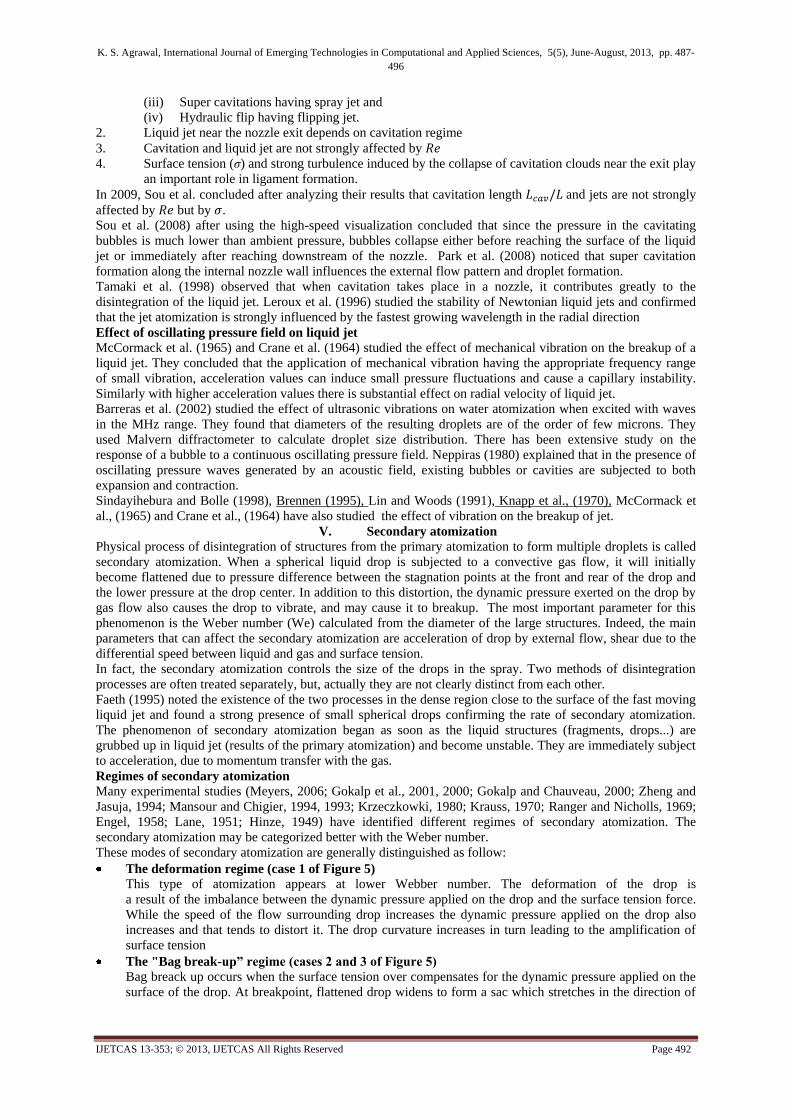
Sou et al. (2007) investigated the effect of cavitation on the flow in the nozzle and liquid jet atomization. They
concluded the findings as (Refer Figure 4):
1. Cavitation in the nozzles and liquid jet can be classified into the four regimes
(i) No cavitation having wavy jet,
(ii) Developing cavitation having wavy jet,
Figure 4: Images of cavitation in a 2D nozzle and liquid jet (water) (Suo et al., 2006)
K. S. Agrawal, International Journal of Emerging Technologies in Computational and Applied Sciences, 5(5), June-August, 2013, pp. 487-
496
IJETCAS 13-353; © 2013, IJETCAS All Rights Reserved Page 492
(iii) Super cavitations having spray jet and
(iv) Hydraulic flip having flipping jet.
2. Liquid jet near the nozzle exit depends on cavitation regime
3. Cavitation and liquid jet are not strongly affected by
4. Surface tension (σ) and strong turbulence induced by the collapse of cavitation clouds near the exit play
an important role in ligament formation.
In 2009, Sou et al. concluded after analyzing their results that cavitation length and jets are not strongly
affected by but by .
Sou et al. (2008) after using the high-speed visualization concluded that since the pressure in the cavitating
bubbles is much lower than ambient pressure, bubbles collapse either before reaching the surface of the liquid
jet or immediately after reaching downstream of the nozzle. Park et al. (2008) noticed that super cavitation
formation along the internal nozzle wall influences the external flow pattern and droplet formation.
Tamaki et al. (1998) observed that when cavitation takes place in a nozzle, it contributes greatly to the
disintegration of the liquid jet. Leroux et al. (1996) studied the stability of Newtonian liquid jets and confirmed
that the jet atomization is strongly influenced by the fastest growing wavelength in the radial direction
Effect of oscillating pressure field on liquid jet
McCormack et al. (1965) and Crane et al. (1964) studied the effect of mechanical vibration on the breakup of a
liquid jet. They concluded that the application of mechanical vibration having the appropriate frequency range
of small vibration, acceleration values can induce small pressure fluctuations and cause a capillary instability.
Similarly with higher acceleration values there is substantial effect on radial velocity of liquid jet.
Barreras et al. (2002) studied the effect of ultrasonic vibrations on water atomization when excited with waves
in the MHz range. They found that diameters of the resulting droplets are of the order of few microns. They
used Malvern diffractometer to calculate droplet size distribution. There has been extensive study on the
response of a bubble to a continuous oscillating pressure field. Neppiras (1980) explained that in the presence of
oscillating pressure waves generated by an acoustic field, existing bubbles or cavities are subjected to both
expansion and contraction.
Sindayihebura and Bolle (1998), Brennen (1995), Lin and Woods (1991), Knapp et al., (1970), McCormack et
al., (1965) and Crane et al., (1964) have also studied the effect of vibration on the breakup of jet.
V. Secondary atomization
Physical process of disintegration of structures from the primary atomization to form multiple droplets is called
secondary atomization. When a spherical liquid drop is subjected to a convective gas flow, it will initially
become flattened due to pressure difference between the stagnation points at the front and rear of the drop and
the lower pressure at the drop center. In addition to this distortion, the dynamic pressure exerted on the drop by
gas flow also causes the drop to vibrate, and may cause it to breakup. The most important parameter for this
phenomenon is the Weber number (We) calculated from the diameter of the large structures. Indeed, the main
parameters that can affect the secondary atomization are acceleration of drop by external flow, shear due to the
differential speed between liquid and gas and surface tension.
In fact, the secondary atomization controls the size of the drops in the spray. Two methods of disintegration
processes are often treated separately, but, actually they are not clearly distinct from each other.
Faeth (1995) noted the existence of the two processes in the dense region close to the surface of the fast moving
liquid jet and found a strong presence of small spherical drops confirming the rate of secondary atomization.
The phenomenon of secondary atomization began as soon as the liquid structures (fragments, drops...) are
grubbed up in liquid jet (results of the primary atomization) and become unstable. They are immediately subject
to acceleration, due to momentum transfer with the gas.
Regimes of secondary atomization
Many experimental studies (Meyers, 2006; Gokalp et al., 2001, 2000; Gokalp and Chauveau, 2000; Zheng and
Jasuja, 1994; Mansour and Chigier, 1994, 1993; Krzeczkowki, 1980; Krauss, 1970; Ranger and Nicholls, 1969;
Engel, 1958; Lane, 1951; Hinze, 1949) have identified different regimes of secondary atomization. The
secondary atomization may be categorized better with the Weber number.
These modes of secondary atomization are generally distinguished as follow:
The deformation regime (case 1 of Figure 5)
This type of atomization appears at lower Webber number. The deformation of the drop is
a result of the imbalance between the dynamic pressure applied on the drop and the surface tension force.
While the speed of the flow surrounding drop increases the dynamic pressure applied on the drop also
increases and that tends to distort it. The drop curvature increases in turn leading to the amplification of
surface tension
The "Bag break-up” regime (cases 2 and 3 of Figure 5)
Bag breack up occurs when the surface tension over compensates for the dynamic pressure applied on the
surface of the drop. At breakpoint, flattened drop widens to form a sac which stretches in the direction of

K. S. Agrawal, International Journal of Emerging Technologies in Computational and Applied Sciences, 5(5), June-August, 2013, pp. 487-
496
IJETCAS 13-353; © 2013, IJETCAS All Rights Reserved Page 493
the flow. As a result of disruptions to the flow, the bag drills leading gradually to its disintegration into
fine droplets
The " Bag break-up” regime (cases 4 and 5 of Figure 5)
There are two theories explaining this type of disintegration. The first (Hwang et al., 1996) assumes that
the disintegration of the liquid fragment is due to the uprooting of theboundary layer that forms on the
surface of the drop as a result of the shear with the gasstream. The second theory (Hinze, 1955, 1959; Liu
and Reitz, 1997) is based on the elongation of the ends of the drop in the direction of flow. Capillary
waves are then formed on the surface of the drop which leads to the production of ligaments in the
direction of the flow which will disintegrate drops. Figure 5: Different schemes of secondary
atomization (Meyers, 2006)
The “Catastrophic break-up" regime (cases 6, 7 and 8 of Figure 5)
This involves high speed. The process takes place in two stages. First low wavelength disturbances
(type Rayleigh-Taylor instabilities) are formed on the upstream
surface of drop because of its high acceleration. And then Kelvin - Helmholtz instabilities occur
leading to the formation of several ligaments bursting into droplets.
There exist some other theories of secondary break up for different specific situations. Hopfinger (2001)
considers only three scenarios of secondary breakage: breakage by shear, breakage by the turbulence of the gas
and breakage by collision between the drops.
The criteria for transition between regimes
The transition between these different regimes is often defined through two dimensionless numbers. Many
authors use Weber number and Reynolds number for distinguishing regimes.
Gelfland (1996) proposes the following criteria to test the regime:
• : deformation and rupture first type
• : failure by shear plan
• : catastrophic failure
Gokalp et al. (2001) have also studied and presented the criteria of transition between regimes.
Time of breakup of drops to droplet
An important parameter characterizing the phenomenon of secondary atomization is the time of "breakup". This
is the interval of time between the formation of drops and their disintegration to droplets. A first expression is
given by Hinze (1955, 1959):
We

K. S. Agrawal, International Journal of Emerging Technologies in Computational and Applied Sciences, 5(5), June-August, 2013, pp. 487-
496
IJETCAS 13-353; © 2013, IJETCAS All Rights Reserved Page 494
O'Rourke and Amsden (1987) proposed a model (TAB: Taylor Analogy Breakup) based on the Taylor
instabilities theory. The drop is regarded as a mass-spring system where the external force is the aerodynamic
force of the gas, the call back spring force is the force of surface tension and the damping force of the system is
fixed by the viscosity of the liquid. They get a similar equation as above where the value of constant equal to
. Similar study was done by other scientists also. Krzeczkowski (1980) plotted time vs. We for methanol,
water, ethanol, butanol, 50% aqueous solution of glycerin and glycerin and compared the results with other
researchers (Littaye, 1943; Engel, 1958; Levich, 1962). The results are different from the earlier reported work.
However Engel's formula fits somewhat to his results.
VI. Summary and recommendations
Liquid jet first disintegrate to small droplet which is termed as primary atomization. Then of disintegration of
structures from the primary atomization to form multiple droplets is called secondary atomization. The Two
methods of disintegration processed are often treated separately, but, actually they are not clearly distinct. The
phenomenon of secondary atomization begins as soon as the liquid structures (fragments, drops...) are grubbed
up in liquid stream (results of the primary atomization) and become unstable. They are immediately subject to
acceleration, due to exchange of quantity of movement with the gas.
The length of jet is a inverse function of Weber number and direct function of Reynold number and Froud
number.
The length of jet is a inverse function of Weber number and direct function of Reynold number.( Eroglu et
al. (1991))
Free turbulent jet have four regions: Region of flow establishment, transition region, established flow
region and terminal region.
There are three type of primary atomization: mechanical, aerodynamic and impact.
Secondary atomization has four regimes: deformation regime ( , bag break-up regime,
bag break-up regime and catastrophic break-up regime( ).
Time of breakup may be calculated by co-relation given by Hinze (1955, 1959)
The jet length and time of break up are the function of different factor such as: geometry of ejector,
viscosity, velocity of jet, surface tension, surrounding pressure, oscillating pressure etc.
cavitation in the nozzles and liquid jet have four regimes and effect type of jet..
References [1]. Atay I., Gordon, L., and Richard, T., (1987), Fluid flow and gas absorption in an ejector venturi scrubber, Environmental
Progress, 6 (3), 198-203.
[2]. Atay, I., (1986), Fluid flow and gas absorption, in an ejector venturi scrubber, Dissertationlty for the degree of Doctor of
Engineering Science, New Jersey Institute of Technology.
[3]. Barreras, F., Amaveda, H., Lozano, A., (2002), Transient high-frequency ultrasonic water atomization, Experiments in Fluids,
33, 405–413.
[4]. Bergwerk, W., (1959), Flow pattern in diesel nozzle spray holes, Proceedings of the Institution of Mechanical Engineers, 173,
655.
[5]. Brennen, C.E., (1995), Cavitation and Bubble Dynamics, Oxford University Press.
[6]. Castleman, R. A., (1931), Mechanism of atomization of liquids, U.S. National Bureau of Standard Journal Research, 6, 281.
[7]. Chandrasekhar, S., (1961), The capillary instability of a liquid jet, In Hydrodynamic and Hydromagnetic Stability, Oxford,
Oxford University Press, 537-542.
[8]. Chaves, H., Knapp, M., Kubitzek, A., Obermeier, F., and Schneider, T., (1991), Experimental study of cavitation in the nozzle
hole of diesel injectors using transparent nozzles, Society of Automotive Engineers, Paper No. 950290, 645-657.
[9]. Chehroudi, B., Onuma, Y., Chen, S., and Bracco, F., (1985), On the intact core of full-cone sprays, SAE, Paper No. 850126.
[10]. Chigier, N., and Reitz, R. D., (1996), Regimes of jetbreakup and breakup mechanisms (physical aspects). In Recent Advances in
Spray Com-bustion: Spray Atomization and Drop Burn-ing Phenomena, 1, 109–35.
[11]. Christiansen, R. and Hixson, A., (1957), Breakup of a liquid jet in denser liquid, Ind. Eng. Chem., 1017
[12]. Crane, L., Birch, S., and McCormack, P. D., (1964), The effect of mechanical vibration on the breakup of a cylindrical water jet
in air, British Journal of Applied Physics, 15, 743-750.
[13]. Davies, (1972), Turbulence Phenomena, Academic, New York.
[14]. DeJuhasz, K.J. (1931). Dispersion of Sprays in Solid Injection Oil Engines. Transaction of the ASME (OGP), 53, 65.
[15]. Engel, O. G., (1958), Fragmentations of water drops in the zone behind an air shock, Journalof Research of the National Bureau
of Standards, 60, 245.
[16]. Eroglu, H., Chigier, N., and Farago Z., (1991), Coaxial atomizer liquid intact lengths, Phys. Fluids, A.3, 303–308.
[17]. Faeth, G., (1990), Structure and atomization properties of dense turbulent sprays, In 23rd International Symposium on
Combustion, The Combustion Institute, 1345–1352.
[18]. Faeth, G., (1995), Structure and breakup properties of sprays, International Journal of Multiphase Flow, 21, 99-127. Tseng, L.,
(1992a), Effects of gas density on the structure of liquid jets in still gases, AIAA,30, 1537–1544.
[19]. Faeth, G., (1999), Liquid atomization in multiphase flows : a review, In 30th AIAA Fluid Dynamics Conference, Paper Number
99, 3639.
[20]. Frago, Z., and Chigier, N., (1992), Morphological classification of disintegration of round liquid jet in a coaxial airstream,
Atomization and spays, 2, 137–152.
[21]. Fraser, R. P., and Paul Eisenklam Norman, (1962), Drop formation from rapidly moving liquid sheets, AIhE Journal, 8(5), 672-
680.

K. S. Agrawal, International Journal of Emerging Technologies in Computational and Applied Sciences, 5(5), June-August, 2013, pp. 487-
496
IJETCAS 13-353; © 2013, IJETCAS All Rights Reserved Page 495
[22]. Gelfland, B., (1996), Droplet breakup phenomena in flows with velocity lag, Progress inEnergy and Combustion Sciences, 22,
201–26.
[23]. Geschner, F., Chaves, H., and Obermeier, F. (2001), Investigation of Different Phenomena of the Disintegration of a Sinusoidally
Forced Liquid Jet. ILASS-Europe, Zurich, 2-6 September.
[24]. Geschner, F., Chaves, H., and Obermeier, F. (2004), Non-Dimensional Map for the Appearance of Spray Structures of a
Periodically Excited Liquid Jet, DFG Schwerpunk programm Fluidzerst Aaubung und SprAuhvorg Aange DFG-Priority
Program Atomization and Spray Processes, Dortmund, 18-19 March.
[25]. Gokalp, I., and Chauveau, C., (2000), Improving droplet break-up and vaporization models by including high pressure and
turbulence effects, Atomization and Sprays, 10, 475–510.
[26]. Gokalp, I., Chauveau, C., Morin, C., and Vieille, B., (2001), Cassure et vaporisation desgouttes : effets de la pression, In
Combustion Dans Les Moteurs Fusees, Actes du Colloquede Synthese du Groupe de Recherche, CNES/CNRS/ONERA/SNECMA.
[27]. Gokalp, I., Vieille, B., and Bodele, E., (2000), Modeling droplet break-up effects forhighpressure cryogenic spray combustion
codes. In 36th AIAA/ASME/SAE/ASEE JointPropulsion Conference and Exhibits, Huntsville (USA), July.
[28]. Haenlein A., (1932), On the Disruption of a Liquid Jet, National Advisory Committee Aeronautics, Technical Memorandum, 659.
[29]. Herrero Edgar, Vallea, P., Del, E. M. M., and Galan, M. A., (2007), Instability study of an annular liquid sheet of polymer
produced by atomization, Proceedings of European Congress of Chemical Engineering (ECCE-6) Copenhagen, 16-20
September.
[30]. Herrero Edgar, Vallea, P., Del, E. M. M., and Galan, M. A., (2007), Instability study of an annular liquid sheet of polymer
produced by atomization, Proceedings of European Congress of Chemical Engineering (ECCE-6) Copenhagen, 16-20
September.
[31]. Hinze, J. O., (1949), Forced deformations of viscous liquid globules, Applied ScientificResearch, 1(1), 263-272.
[32]. Hinze, J. O., (1955), Fundamentals of the hydrodynamic mechanism of splitting in dispersionprocesses, AIChE J, 1(3), 289-295.
[33]. Hinze, J., (1959), Turbulence, New-York : Mc Graw-Hill.
[34]. Hiroyasu H., Arai M., and Shimizu M., (1991), Breack up length of a liquid jet and internal flow in a nozzle, Procedings of
ICLASS-91, Paper No. 26.
[35]. Hoeve, W., Gekle, S., Snoeijer, J., Versluis, M., Brenner, M. and Lohse D. (2010), Breakup of diminutive Rayleigh jets, Physics
of fluids, 22, 122003-1 to122003-11
[36]. Hopfinger, E., (2001), Atomization of a Liquid Jet by a Coaxial Gas Jet : A Critical Review,In Combustion Dans Les Moteurs
Fusées, Actes du Colloque de Synthèse du Groupe de Recherche CNES/CNRS/ONERA/SNECMA, Toulouse, Cité de l’Espace
(FRANCE), June.
[37]. Ingebo Robert D., (1991), Effect of gas mass flux on cryogenic liquid jet breakup, Paper Presented at Space Cryogenics
Workshop, Clevlend,OH, USA, June.
[38]. Kankkunen, A. and Nieminen, K., (1997), Black liquor sheet breakup mechanisms and the effect on drop size, International
Journal of Fluid Mechanics Research, 24 (1-3), 350-357.
[39]. Kazuya Shibata, Seiichi Koshizuka, and Yoshiaki Oka, (2004), Numerical analysis of jet breakup behavior using particle method,
Journal of Nuclear Science and Technology, 41, 7, 715–722.
[40]. Knapp, R.T, Daily, J.W., and Hammitt, F.G. (1970). Cavitation, New York, McGraw-Hill.
[41]. Kolmogorov, A., (1949), On the disintegration of drops by turbulent flows. dokl. acad. nauk. SSSR, 66, 825–828.
[42]. Krauss, W. E., (1970), Water Drop Deformation and Fragmentation Due to Shock WaveImpact, Ph.D. Thesis, University of
Florida.
[43]. Krzeczkowski Stefan A., (1980), Measurement of liquid droplet disintegration mechanisms, In I. J. Multiphase Flow, 6, 227-239.
[44]. Kuferath, A., Wende, B., and Leuckel, W., (1999), Influence of liquid flow conditions on spray characteristics of internal-mixing
twin fluid atomizers, International Journal of Heat and Fluid Flow, 20, 513-519.
[45]. Lane, W. R., (1951), Shatter of Drops in Streams of Air, Industrial and EngineeringChemistry, 43, 1312.
[46]. Lefebvre, H., (1989), Atomization and Sprays, Hemisphere Pub. Cor., New York.
[47]. Leick Philippe, (2008), Quantitative investigations about the influence of nozzle geometry and ambient gas density on the
primary break-up region of diesel sprays, Dissertation submitted for Doctor of Engineering to Technical University Darmstadt.
[48]. Leroux, S., Dumouchel, C., Ledoux, M., (1996), The Stability Curve of Newtonian liquid Jets, Atomization and sprays, 6, 623-
647.
[49]. Levich, V. G., (1962), Physicochemical Hydrodynamics, Prentice Hall, New York.
[50]. Lin, S. P., and D. R. Woods. (1991), A branching liquid jet, Physics of Fluids, A3, 241- 244.
[51]. Lin, S. P., and Reitz, R.D., (1998), Drop and spray formation from a liquid jet, Annual Review of Fluid Mechanics, 30, 85–105.
[52]. Littay, G., (1943), Sur l’atomisation of liquids, Wydawnictwo Naukowo-Techniczne.
[53]. Liu, Z., and Reitz, R., (1997), An analysis of the distortion and breakup mechanisms of highspeed liquid drops, Inter. J. of
Multiphase Flow, 23 (4), 631–650.
[54]. Mansour, A. and Chigier, N., (1994), Effect of turbulence on the stability of liquid jets andresulting droplet size distributions,
Atomization and Sprays, 4, 583-604.
[55]. Mansour, A., and Chigier, N., (1993), A phase doppler investigation of co-axial air blastatomizers, Fluid Mechanics and Heat
Transfer in Spray, ASME 270, 95-101.
[56]. McCabe, W. L., Smith, J. C., and Harriott Peter, (1993), Unit Operations in Chemical Engineering, International Edition, 7th
Edition, McGraw- Hill Inc., New Delhi.
[57]. McCarthy, M. J., and Molloy, N.A., (1974), Review of stability of liquid jets and the influence of nozzle design, Chemical
Engineering Journal, 7, 1.
[58]. McCormack, P.D., Crane, L., and Birch, S., (1965), An experimental and theoretical analysis of cylindrical liquid jets subjected
to vibration, British Journal of Applied Physics, 16, 395-408.
[59]. Meier, G.E.A., Loose, S., and Stasicki, B., (1997), Unsteady Liquid Jets, Applied Scientific Research, 58, 207-216.
[60]. Meyers Nicolas, (2006), Mod´elisation de la combustion cryotechnique avec prise en compte de l’atomisation primaire du jet
d’oxyg‘ene liquide, May, Universite D’aix-Marseille, France.
[61]. Neppiras, E.A., (1980), Acoustic Cavitation, Physics Report, 61, 160-251.
[62]. O’Rourke, P., and A. Amsden, (1987), The TAB method for numerical calculations of spraydroplet breakup, SAE Paper,
(872089).
[63]. Ohnesorge, W., and Angew, Z., (1936), Math. Mech., 11, 136–159.
[64]. Park, S. H., Suh, H. K., and Lee, C. S., (2008), Effect of cavitation flow on the flow and fuel atomization characteristics of
biodiesel and diesel fuels, Energy and Fuels, 22, 605-613.

K. S. Agrawal, International Journal of Emerging Technologies in Computational and Applied Sciences, 5(5), June-August, 2013, pp. 487-
496
IJETCAS 13-353; © 2013, IJETCAS All Rights Reserved Page 496
[65]. Perry, R.H., Green, D.W., and Maloney, J.O., (1997), Perry’s Chemical Engineers’ Handbook, Seventh ed., The McGraw-Hill
Companies, Inc., New York.
[66]. Pfeifer C., Kuhan D. and Class A., (2010), Coupled measurement of droplet size distribution and velocity distribution in a fuel
spray with digital imaging analysis under elevated pressure, 15th Int Symo on Applications of Laser Techniques to Fluid
Mechanics, Lisbon, July 5-8.
[67]. Plateau, J., (1873), Statique experimentale et the-orique des liquids soumie aux seules forcesmoleculaire, Paris: cauthier vil-lars,
1, 2, 450-495.
[68]. Ranger, A. A., and Nicholls, J. A., (1969), Aerodynamic shattering of liquid drops, AIAAJournal, 7, 285.
[69]. Ranz, W. E., (1956), On sprays and spraying, Department of Engineering Resources, Pennsylvania State University, Bulletin 65.
[70]. Rayleigh L, (1879b),On the instability of jets, Proc. London Math. Soc., 10, 406-46.
[71]. Rayleigh, L., (1879a), On the capillary phe-nomenon of jets., Proc. R. Soc. London., 29,
71-97
[72]. Reitz Rolf, D., (2004), Modeling the primary breakup of high-speed jets, Atomization and Spray, 14 (1), 99.
[73]. Reitz, R. and Bracco, F., (1986), Mechanics of breakup of round liquid jets, Volume 3,Chapter 10, 233–249.
[74]. Reitz, R. D., (1978), Atomization and Other Breakup Regimes of a Liquid Jet, Ph. D. Dissertation, Princeton University.
[75]. Reitz, R., and Bracco, F., (1982), Mechanism of atomization of a liquid jet, Phys. Fluids 25 (10).
[76]. Richards, J. R., Lenhoff, A. M. and Beris, A. N., Dynamic breakup of liquid-liquid jets, Phys. Fluids, 6(8), 2640-2655.
[77]. Ruff, G., Wu, P., Bernal, L., and Faeth, G., (1992), Continuous and dispersed-phase structure of dense non-evaporating pressure-
atomized sprays, J. Prop. Power, 8, 280–289.
[78]. Rushton, J. H. and Oldshue, J. Y., (1953), Mixing: present theory and practice, Chem. Eng. Prog., 49, 161.
[79]. Schmidt, D., P., Rutland, C., J., and Corradini, M. L., (1997), A Numerical Study of Cavitating Flow Through Various Nozzle
Shapes, Society of Automotive Engineers, Paper No. 971597.
[80]. Sindayihebura, D., and Bolle, L., (1998), Ultrasonic atomization of liquid: stability analysis of the viscous liquid film free
surface. Atomization Sprays, 8, 217-233.
[81]. Smallwood, G. J., and Gulder, O. L., (2000), Views on the structure of transient diesel sprays, Automization and Sprays, 10 (3-5),
355-386.
[82]. Soteriou, R., Andrews, R., and Smith, M., (1995), Direct injection diesel sprays and the effect of cavitation and hydraulic flip on
atomization, Society of Automotive Engineers, Paper No. 950090, 27-51.
[83]. Sou A., Maulana, M. I., Hosokawa, S. and Tomiyama, A., (2008), Ligament Formation Induced by Cavitation in a Cylindrical
Nozzle, Journal of Fluid Science and Technology, 3,5, 633-644.
[84]. Sou, A., Hosokawa, S., and Tomiyama, A., (2009), Dimensionless Numbers on Cavitation in a Nozzle of Pressure Atomizers,
ICLASS 2009, 11th Triennial International Annual Conference on Liquid Atomization and Spray Systems, Vail, Colorado USA,
July.
[85]. Sou, A., Maulana, M. I., Hosokawa, S., and Tomiyama, A., (2007), Effect of cavitation in a nozzle on liquid jet atomization,
International Journal of Heat and Mass Transfer, 50, 17-18, 3575-3582.
[86]. Sou, A., Tomiyama, A., Hosokawa, S., Nigorikawa, S., and Maeda, T., (2006), Cavitation in a two-dimensional nozzle and liquid
jet atomization (ldv measurement of liquid velocity in a nozzle), Japan Society of Mechanical Engineering, International
Journal, Series B, 49(4), 1253-1259.
[87]. Sterling, M., and Sleicher, C., (1975), The instability of capillary jets, J. Fluid Mech., 68, 477
[88]. Tamaki N., Shimizu M., and Hiroyuki, (2001), Enhancement of the Atomization of a liquid jet by cavitation in a nozzle hole,
Atomization and Sprays, 11, 2, 125-137.
[89]. Tamaki, N. A., Kato, K., Imano and Kato, K., (2010), Improvement of atomization characteristics of spray by multi-hole nozzle
for pressure atomized type injector, ILASS – Europe 2010, 23rd Annual Conference on Liquid Atomization and Spray Systems,
Brno, Czech Republic, September.
[90]. Tamaki, N., (2009), Effects of cavitation in a nozzle hole on atomization of spray and development of high-efficiency
atomization enhancement nozzle, 11th International Conference on Liquid Atomization and Spray Systems, Vail Colorado, USA,
26-30 July.
[91]. Tamaki, N., and Shimizu, M., (2002), Enhancement of atomization of high-viscous liquid jet by pressure atomized nozzle ,
ILASS – Europe, September 9-11.
[92]. Tamaki, N., Nishida, Y. and Hosokawa, T., (2007), Practical study on high-dispersion and high-penetration diesel injection
nozzle: 1st report, effects of geometric shape of high dispersion atomization enhancement nozzle on atomization of intermittent
spray, Proc. 21st Institute for Liquid Atomization and Spray Systems-Europe, CD-R, 6.
[93]. Tamaki, N., Shimizu, M., Nishida, K., and Hiroyasu, (1998), Effects of cavitation and internal flow on atomization of a liquid
jet, Atomization and Sprays, 8, 2, 179-197.
[94]. Tie Li Keiya, and Nishida Hiroyuki Hiroyasu, (2011), Droplet size distribution and evaporation characteristics of fuel spray by a
swirl type atomizer, Fuel, 90, 2367-2376.
[95]. Tomotika, S., (1935), On the instability of a cylindrical thread of a viscous liquid surrounded by another viscous fluid, Proc. R.
Soc. Lon-don Ser. A., 150, 322-37.
[96]. Tseng, L., and Wu, P., (1992b), Dispersed-phase structure of pressure-atomized sprays at various gas densities, J. Prop. Power,
8, 1157-1166.
[97]. Tuve, (1953), Heat. Piping Air Cond., 25(1), 181–191.
[98]. Weber, C.Z., (1931), Zum zerfall eines flus-sigkeitsstrahles, Math. Mech.,11, 136–54.
[99]. Wolfe, H. E., and Andersen, W.H., (1964), Kinetics mechanism and resultant droplet sizes of the aerodynamic breakup of liquid
drops, Aero jet General Corporation, CA, USA, Report no-0395-04(18)SP.
[100]. Wu, P., and Faeth, M., (1993), Aerodynamic effects on primary breakup of turbulent liquids, Atomization and Sprays, 3, 265–
289.
[101] . Wu, P., Miranda, R. and Faeth, G., (1995), Effect of initial flow conditions on primary breakup of non turbulent and turbulent
round liquid jets, Atomization and Sprays, 5, 175–196.
[102]. Yongyingsakthavorn, P., Vallikul, P., Fungtammasan, B., Dumouchel, C., and Joulain, P., (2004), An Investigation on Line-of-
Sight and Local Drop Size Distributions of Palm Oil Based Biodiesel Sprays Using Laser Diffraction Data, The Joint
International Conference on Sustainable Energy and Environment (SEE), December 1-3.
[103]. Zheng, Q., and Jasuja, A., (1994), Droplet size and velocity correlations for a coaxial airblast atomized jet, In Proc. ICLASS,
664–671.