BON:BON book.pdf
458
-
Upload
khangminh22 -
Category
Documents
-
view
2 -
download
0
Transcript of BON:BON book.pdf


Your attention please!
The following text was published as a book by Prentice Hall in 1994. It has since gone out of print, and the copyright was formally reversed back to the authors Kim Waldén and Jean-Marc Nerson in 2001. We have decided to make the text publicly available with the following provision. You may download and copy the text at will, but as soon as some part is extracted and presented out of context of the complete book, there must always be a clearly visible reference to the book and its authors, and also a pointer to the website www.bon-method.com (since the printed book is no longer available) so that any reader of the partial content can quickly find the original full text. The text of this provision must also be included in any such presentation.

Seamless
Object-Oriented
Software
Architecture
Analysis and Design of Reliable Systems
Kim Waldén
Jean-Marc Nerson
Printed version
September 6, 1994


Contents
Series editor’s preface xi
Preface xiii
Part I Introduction 1
1 Object-oriented software development 3
1.1 Introduction 3
1.2 Seamlessness 7
1.3 Reversibility 7
1.4 Software contracting 9
2 The BON approach 11
2.1 Introduction 11
2.2 What is not in BON 12
2.3 Other methods 15
2.4 The BON position 16
2.5 Characteristics of the notation 17
2.6 Static and dynamic models 24
Part II The model 27
3 The static model—classes and clusters 29
3.1 Introduction 29
3.2 BON modeling charts 30
3.3 System state information 35
3.4 Typed class interfaces 36
3.5 Class header 37
3.6 Indexing clause 37
v

vi CONTENTS
3.7 Inheritance clause 39
3.8 Class features 39
3.9 Class invariant 47
3.10 Graphical and textual specification 48
3.11 The BON assertion language 49
3.12 The BON predicate logic 52
3.13 Assertions and partial functions 57
3.14 Scalable system description 59
3.15 Class headers 59
3.16 Clusters 60
4 Static relations 65
4.1 Inheritance relations 65
4.2 Client relations 69
4.3 Class vs. object dependencies 86
4.4 Indirect client dependencies 88
4.5 Semantic links 89
5 The dynamic model 90
5.1 Introduction 90
5.2 Dynamic charts 93
5.3 Dynamic diagrams 99
Part III The method 117
6 Issues of a general method 119
6.1 Introduction 119
6.2 Simulating an ideal process 120
6.3 Enterprise modeling 121
6.4 What is analysis and what is design? 122
6.5 Reuse 125
6.6 User centered design 129
6.7 Roles of analysis objects 135
6.8 Modeling a system interface 136
6.9 System usage 140
6.10 A paradigm shift 142

CONTENTS vii
7 The BON process 143
7.1 The BON deliverables 143
7.2 Characteristics of the process 148
7.3 Task 1: Delineate system borderline 152
7.4 Task 2: List candidate classes 160
7.5 Task 3: Select classes and group into clusters 162
7.6 Task 4: Define classes 166
7.7 Task 5: Sketch system behaviors 168
7.8 Task 6: Define public features 171
7.9 Task 7: Refine system 172
7.10 Task 8: Generalize 174
7.11 Task 9: Complete and review system 175
8 BON standard activities 178
8.1 Finding classes 178
8.2 Classifying 189
8.3 Clustering 194
8.4 Defining class features 198
8.5 Selecting and describing object scenarios 203
8.6 Working out contracting conditions 205
8.7 Assessing reuse 212
8.8 Indexing and documenting 215
8.9 Evolving the system architecture 220
Part IV Case studies 229
9 A conference management system 231
9.1 System borderline 232
9.2 Candidate classes in the problem domain 235
9.3 Class selection and clustering 236
9.4 Class definition 242
9.5 System behavior 252
9.6 Formal class description 260
10 A video recorder 270
10.1 System borderline 270

viii CONTENTS
10.2 Candidate classes 274
10.3 Class selection and clustering 275
10.4 Class definition 279
10.5 System behavior 283
10.6 Formal class description 286
10.7 Final static architecture 288
11 Relational and object-oriented coexistence 289
11.1 From data storage to object persistence 290
11.2 Object models and relational models 293
11.3 A relational database wrapper 295
11.4 Interfacing an existing relational schema 303
11.5 Querying a persistent object model 312
11.6 Persistent object management 315
11.7 Automatic generation of SQL statements 324
11.8 Full static architecture 331
12 Exercises 332
12.1 Clustering a problem domain 332
12.2 Defining class relationships 334
12.3 Assertions and classification 335
12.4 Dynamic behavior 336
12.5 Prescription and description 337
12.6 Traffic-control system 338
12.7 Dice game 339
12.8 Car rental company 340
12.9 Truck freight 341
12.10 Real-time process control 345
Part V Appendices 347
Appendix A BON textual grammar 349
A.1 Introduction 349
A.2 The syntax notation 350
A.3 BON specification 352
A.4 Informal charts 352

CONTENTS ix
A.5 Static diagrams 354
A.6 Class interface description 355
A.7 Formal assertions 357
A.8 Dynamic diagrams 358
A.9 Notational tuning 359
A.10 Lexical components 359
Appendix B BON textual examples 364
B.1 BON specification 364
B.2 Informal charts 365
B.3 Static diagrams 367
B.4 Dynamic diagrams 374
Appendix C BON quick reference 381
Appendix D Other approaches 386
Appendix E Glossary of terms 388
References 411
Index 425

x CONTENTS

Series editor’s preface
A rumor has been spreading for some time among people that follow progress inobject-oriented analysis and design: “Wait for BON!” Those not in the knowwould ask what in the world BON could be. Indeed, the publicity around theBusiness Object Notation has been modest—an article in the Communications ofthe ACM, presentations at a workshop or two, public seminars in Europe andNorth America, tutorials at TOOLS and other conferences—but it was enough toattract the attention of many O-O enthusiasts who were dissatisfied with thelimitations of first-generation analysis methods. In the meantime, BON wasbeing taught to many practitioners, applied in numerous industrial projects, andrepeatedly polished as a result.
As this book finally reaches publication it is certain to cause a major advancein the field of object-oriented methods. Its most remarkable feature is thethoroughness with which it applies object-oriented principles, unencumbered byleftovers from earlier methods. Going O-O all the way is not a matter ofdogmatism, but the secret for obtaining the real benefits of the method, followingin particular from two principles developed at length in the book: seamlessdevelopment, the removal of artificial gaps and mismatches between successivesoftware development activities; and reversibility, the recognition that at any stepof the development process, including implementation and maintenance, it mustbe possible to update the results of earlier phases such as analysis and design,and still maintain full consistency between the analysis, design, implementationand maintenance views. By ensuring seamlessness and reversibility it is possibleto obtain a continuous software development process, essential to the quality ofthe resulting products.
This book is also one of a select few in the OOAD literature that pays seriousattention to the question of software reliability, by using some elements offormal reasoning, in particular assertions, as a way to specify semantic propertiesof a system at the earliest possible stage.
Following the presentation of the model and method in parts I, II, and III, alarge section of the book (part IV) is devoted to a set of in-depth case studies andto exercises, drawn for the most part from projects in which the authors acted as
xi

xii SERIES EDITOR’S PREFACE
consultants. This abundant practical material will help readers apply the ideas ofBON to their own application areas.
From now on, no one will be able to claim knowledge of object-orientedanalysis and design who has not read Kim Waldén and Jean-Marc Nerson.
Bertrand Meyer

Preface
In the past few years, object-oriented techniques have finally made the passagefrom the programming-in-the-small island to the mainland of programming-in-the-large. Accompanying this transition has been a change in the role andperception of software methods: in addition to their well-established use in theearliest stages of a project—requirements analysis and system specification—they are increasingly viewed as providing the intellectual support needed acrossthe entire software construction process, through design and implementation tomaintenance and reengineering. The object-oriented approach is best suited toachieve this seamlessness of the software development process, without which itwould not be possible to meet the quality and productivity challenges thatconfront the software industry.
This book shows how a consistent set of object-oriented abstractions can beapplied throughout the process, based on three major ideas: seamlessness,reversibility, and contracting.
Seamlessness, as in the first word of the title, follows from the observationthat the similarities between the tasks to be carried out at the various steps of aproject far outweigh their inevitable differences, making it possible to obtain acontinuous process that facilitates communication between the various actorsinvolved, ensures a direct mapping between a problem and its software solution,and results in a high level of quality for the final product.
Reversibility means that the seamless procedure must work in both directions:if one modifies a system that has already reached the implementation phase—afrequent case in practice—it must be possible to reflect the modification back tothe higher levels of design, specification, and analysis. Without suchreversibility the products of these earlier stages would soon become obsolete,raising disturbing questions about their very role in the software process. Sincecurrent object-oriented methods are still dominated by hybrid approaches—thatis to say, encumber the application of object-oriented principles with techniquesdrawn from non-object-oriented analysis methods and with constructs drawnfrom non-object-oriented languages—reversibility has so far been almost absentfrom the concerns of the object-oriented literature.
xiii

xiv PREFACE
The contract model was introduced to a wider audience as early as 1988 byBertrand Meyer in his magnificent introductory book Object-Oriented SoftwareConstruction (OOSC), which quickly became, and still is, the standard referenceon basic object-oriented concepts. In a sense, the present book is a continuationof OOSC, carrying some of its software engineering ideas to their logicalconclusion in the area of analysis and design. The result is a method called BON(Business Object Notation) which contains a set of concepts and correspondingnotations to support object-oriented modeling centered around the threeprinciples of seamlessness, reversibility, and software contracting.
In the rapidly growing field of object-oriented software development, manysubfields have now accumulated enough experience and techniques to warrantbooks of their own. When presenting our ideas, we therefore had to make achoice: either to cover most of the interesting areas and remain shallow, or tolimit the scope and leave room for more substance. We chose the latter, andBON concentrates on the basic application-independent ideas of general analysisand design of software systems.
We have also refrained from including yet another explanation of the basicobject-oriented concepts. There are two main reasons for this. First, theconcepts may be simple enough to define, but understanding their implications ina deeper sense takes much longer. Therefore, a short overview will not beenough for those who do not already understand the concepts, while a moresubstantial discussion will add significant volume and be utterly boring toexperienced readers. Second, in the general spirit of this book, we believe goodtexts should be reused rather than rewritten each time they are needed.
So we will assume that the meaning of classes, instances (objects),polymorphism, dynamic binding, etc., is already familiar to the reader. If not,we recommend the OOSC book cited above (a significantly revised secondedition is to appear during 1994). As a small compensation for a basic overview,we have included a reasonably extensive glossary of terms with briefexplanations of the most important BON concepts and many of the familiarobject-oriented terms. It can be used by the novice as a starting point for furtherreading, and by the knowledgeable reader to find out more precisely what flavorwe have chosen for widely used terms whose meaning is not fixed in the object-oriented literature.
BON was initiated in 1989 by Jean-Marc Nerson, then chief developer of theISE Eiffel 2.2 environment, who presented early ideas in a tutorial at the secondTOOLS conference held in Paris in 1990. The ideas were picked up at EneaData in Sweden by Kim Waldén, then technically responsible for the company’sEiffel distribution in Scandinavia, who started to teach courses on BON inSweden shortly after. This was the beginning of a collaboration which graduallyled to a joint development of the notation and method. The BON technique was

PREFACE xv
applied in several industrial developments, and Jean-Marc published threearticles in 1991−92. However, we soon realized that more substantialdocumentation on the subject would be necessary to make the method availableto a wider audience, and in 1993 we made the bold decision to jointly publish abook on BON (bold, because the only time available for this work was eveningsand weekends).
As is often the case with visions whose fulfillment requires far more resourcesthan are available, it is best not to understand the full extent of the workbeforehand—then you can just go ahead and do it anyway, which is whathappened with this book although at the expense of our friends and families.However, we found that writing about something you believe in wholeheartedlyhas the mysterious capacity of extending the number of daily hours well beyondthe standard 24 (in itself a possible subject of another book). If we succeed incommunicating to our readers just a small fraction of the joy involved in writingthis book, the effort will have been worthwhile.
Scope of the book
The book is intended for software professionals as well as for students at thegraduate and undergraduate levels. We believe it can be read by anyone who hasacquired a general understanding of the problems of software engineering, andwho has some inclination for abstract thinking.
The knowledgeable software engineer used to dealing with practical solutionsmay discover that it is not all that easy to keep analysis and design models freefrom premature implementation decisions. On the other hand, to achieve a deepunderstanding of the technology, it is probably even more important for the high-level analyst to occasionally take an object-oriented design (not necessarilylarge) all the way through implementation. Never to do this is somewhat liketrying to become a mountaineer without ever climbing: there is little replacementfor watching polymorphism and dynamic binding in live action.
Book structure
The book consists of an introduction, three main parts, and five appendices. Themain parts treat in order: the concepts and notations of BON; the BON processfor producing analysis and design models; and a practical part with three casestudies and exercises.
The introduction (chapters 1−2) discusses the general principles which haveguided the development of BON and positions the method relative to otherapproaches.
The model part (chapters 3−5) explains the static and dynamic models of BONand the corresponding notation. Untyped modeling charts are used for the very

xvi PREFACE
early phases, and these are later refined into fully typed descriptions withsemantic specifications added. This part is the core of the book around whicheverything else is built, so it should be read carefully. (Sections 3.11−3.13 onthe BON assertion language may be skipped on first reading by those lessinterested in formal specification.)
The method part (chapters 6−8) describes how work is carried out with BON.It starts with a discussion of a number of general modeling issues (chapter 6).This serves as background for a detailed description of the BON process tasks,presented in chapter 7. These tasks concentrate on what should be produced (thedeliverables). Finally, chapter 8 discusses the standard modeling activitiesneeded to produce the desired results, and is focused on how to attack the varioussubproblems.
The practical part (chapters 9−12) then presents three case studies and anumber of exercises (collected in chapter 12). The three case studies model inturn: a conference management system; the control system of a video recorder;and a mapping between a relational database and an object model.
The concluding five appendices contain in order: a complete grammar for theBON textual language; a number of examples in the form of textual versions forseveral of the graphical diagrams presented earlier in the book; a quick referenceto the BON notation; a list of references to other analysis and design approaches;and a glossary of terms.
Acknowledgments
BON started as an attempt to extend the concepts of the Eiffel language into therealm of analysis and design, so indirectly we owe our greatest debt to itsdesigner Bertrand Meyer. His systematic effort to introduce the powerful idea ofsoftware contracting to the systems development industry, and make it part ofeveryday software engineering, has served as our main source of inspiration. Wealso thank him for valuable comments and discussions on draft versions of thebook, and for his general moral support.
We gratefully acknowledge the reviewers of Prentice Hall for their insightfulcritique and supportive attitude, and Brian Henderson-Sellers for taking the timeto read a full draft and provide helpful comments. We thank Hans Marmolin forsharing his views on user-centered design and for letting us present his referencemodel in chapter 6.
We thank the members of the European consortium “Business Class”, derivedfrom the ESPRIT II Research and Development Program, which partlysponsored early work on BON through the development of a Design Workbenchunder the project leadership of Jean-Pierre Sarkis.

PREFACE xvii
We would also like to thank the staff at Enea Object Technology, many ofwhom have served as guinea pigs when new ideas were tried out. Special thanksgo to Per Grape, who followed the text closely as it developed, read a number ofsuccessive book drafts, and contributed several improvements to the overallmethod and notation. Nils Undén, Björn Strihagen, and Michael Öberg read fulldrafts and helped weed out early mistakes. Magnus Lövkvist raised severalissues during the application of BON in a commercial project, which lead toimprovements of the text, and Roland Persson provided interesting views fromhis experience with Smalltalk applications. Daniel Rodríguez, Björn Strihagen,Lennart Gustafsson, Jan Erik Ekelöf, Niklas Odenteg, Mike Henry, and MichaelÖberg used BON in several contexts and provided valuable feedback. We thankthem all for their contributions.
We are grateful to Anders Johansson from Cap Programator for helpfulcomments on successive drafts, and for his strong support of the BON approach.Thanks also to Roy Clarke from LM Ericsson Data and Keith Gunn from SHLSystemhouse for their detailed comments on the English language and fordetecting errors in some of the examples through careful reading. Special thanksto Michael Öberg and Juha Juslin, present and former managers of Enea ObjectTechnology, for their positive attitude regarding the production of this book.
The initial impulse on object-oriented analysis and design leading to the basicideas that later became BON was given by David J. Hopkins. The BONacronym was first coined by Christine Mingins, and later reinterpreted as“Business Object Notation”. In all, the BON method and notation has beeninfluenced and recast by more than four years of continuous industrial practiceand experience.
Finally, we express our gratitude to all friends and family members for bearingwith us during a full year of almost total anti-social behavior.
Stockholm and ParisAugust 1994
K. W.J.-M. N.

Trademark notice
All trade names, service names, trademarks, or registered trademarksmentioned in this book are property of their respective owners.
Authors’ addresses
Kim Waldén, Enea Data ABBox 232, S-183 23 Täby, SwedenElectronic mail: [email protected]
Jean-Marc Nerson, Société des Outils du Logiciel,104 rue Castagnary, 75015 Paris, FranceElectronic mail: [email protected]

Part IIntroduction

2 PART I

1 Object-oriented softwaredevelopment
1.1 INTRODUCTION
What is the potential of the object-oriented paradigm? How much improvementof the software development process can we reasonably expect from using thistechnology, which 25 years after its initial invention finally seems to beconquering the software industry?
Fred Brooks, in his well-known article “No Silver Bullet: Essence andAccidents in Software Engineering” [Brooks 1987], divides the difficulties ofbuilding software into essence and accidents. The essence of a piece of softwareis a construct of interlocking concepts: data sets, relationships among data items,algorithms, and function invocations. This construct is the general architectureof the software—that part of its logical structure which is independent of anyparticular machine representation, but still detailed enough to allowunambiguous translation to executable code. The accidents, by contrast, areeverything else—all the gory details and contortions necessary for representingthe essence in a given computing environment.
Brooks believes the hard part of building software is the specification, design,and testing of the essential conceptual constructs, as opposed to representingthem and testing the fidelity of the representations (the accidental part). If this istrue, he concludes, building software will always be hard. Languages and tools,no matter how powerful, can only take us that far when the real problem is todecide what exactly we want to express.
At first sight, Brook’s conclusion may seem to invalidate all claims thatobject-oriented abstraction has the potential to increase software productivity bya significant factor. In fact, if object-oriented techniques are mainly taught andused to build new systems from scratch, as often seems to be the case in industrytoday, only marginal productivity improvements can probably be expected. If,on the other hand, the emphasis is shifted from individual systems to the
3

4 OBJECT-ORIENTED SOFTWARE DEVELOPMENT
production and use of tailorable software components, a profound changebecomes possible.
Benefits of a reusability approach
There are two reasons for optimism. First, the cost of software can still bereduced by an order of magnitude by removing most of the accidental difficultiesfrom industrial software engineering—maybe not for a single system version, butsurely over a product’s life cycle. Methods and implementation languages arenot enough, however, to achieve this cost reduction, no matter how conceptuallypowerful and highly automated. We also need access to a large base of reusablecomponents which encapsulate the basic concepts that are being reinvented overand over in today’s industrial software projects.
Second, reusable abstractions are not limited to hiding accidental difficulties,but can also be used to attack the essence of software design. The complexityinvolved in solving a problem depends not only on the problem, but just as muchon the primitive concepts available for reasoning about the problem. So if wecan increase the expressive power and understandability of these primitives invarious problem areas, the complexity of corresponding abstract designs can alsobe reduced.
As a side effect, investing in reuse brings another crucial advantage. Softwarecomponents that are used and reused many times in many different contextsstand the chance of acquiring much higher quality through successiveimprovement than is ever economically feasible for components that are justused within a single project. This enables new abstractions to gradually evolveuntil they become conceptually strong enough to become part of the systemdeveloper’s standard vocabulary. This may, in turn, lead to the discovery of newuseful abstractions at yet higher levels that would otherwise not have been foundowing to the initial effort required.
Initial difficulties
There has been significant effort invested over the past two decades to build anduse repositories of software components for industrial systems development.Although certain application areas have seen some successes, achieving a highdegree of reuse in the general case has turned out to be much more difficult inpractice than first expected. Much of the failure has been attributed toorganizational shortcomings, such as lack of clear responsibility roles (reusemanagers), no consistent management policy, lack of automated tools support,and conflicts with short-term project budgets. Other problems are commercial innature, such as how to protect reusable designs enough to make the effortinvested worthwhile for the originators. These problems do not go away just

INTRODUCTION 5
because we switch technology, and must still be solved.But the key to it all is object-oriented abstraction—the only technique flexible
enough for building the general components needed. Since reuse efforts havemainly relied on traditional techniques, it is no surprise that they have largelyfailed. As long as we lack the basic means to produce the right components,formal organization and automated browsing tools can do little to help. On theother hand, object-orientation does not automatically solve all problems, andmany object-oriented projects have also reported difficulties attaining their reusegoals.
This, however, must not be taken as a sign that large-scale reuse isunattainable in practice, or that the object-oriented approach does not work. Onthe contrary, there are a number of reasons why these initial difficulties are onlyto be expected. First, most industrial object-oriented projects are still usinghybrid languages or hybrid methods, or both. The resulting mix of partlycontradictory concepts creates confusion and delays the mental shift necessary totake full advantage of the new approach. The requirement of backwardcompatibility for hybrid languages also makes it impossible to support cleanly allof the central object-oriented concepts, which in turn makes the construction ofhigh-quality component libraries difficult.
Second, even if the technical means are a prerequisite and must come first, theorganizational aspects are also crucial. Many projects have failed because ofinadequate training, lack of management support or reuse coordination. Theseare problems that must be addressed in parallel, particularly for largeorganizations.
Third, the size and quality of commercially available class libraries is highlyvariable, and even the best object-oriented environments only cover a small partof what one would wish for. Since good abstractions need to be developedincrementally with many alternative approaches tried, it will naturally take sometime before we can expect anything close to a complete encapsulation of themost commonly reinvented software components.
The road to reuse of knowledge
If we compare the current trend towards object-oriented languages with thetransition to high-level languages in the 1970s and early 1980s, the situation,although it has many similarities, is also quite different. The control structuresof languages like Pascal and C embody abstractions that the assemblyprogrammers were already using mentally (often occurring as comments in somepseudo-Algol notation), so the big payoffs were immediate. When the tediousand error-prone translations of these constructs into sequences of machineinstructions were no longer needed, work could proceed as before, only muchfaster.

6 OBJECT-ORIENTED SOFTWARE DEVELOPMENT
In some important areas, the same is true when moving from what can beconsidered a traditional language today (such as Pascal or C above) to a goodobject-oriented environment. The ability to use off-the-shelf componentsrepresenting the basic data structures so fundamental for almost any computingalgorithm (lists, hash tables, queues, stacks), without the need to know anythingabout their implementation, is a direct parallel. Another such area is graphicalinterfaces. But object-oriented abstraction means much more, since it can alsobe used to create new concepts in almost every conceivable area. This means itsgreatest potential (in the long run) lies not in representing the concepts withwhich we are already familiar, but rather in serving as a vehicle for inventingnew ones.
This is the main reason why object-oriented technology is a technology ofinvestment more than of short-term profit (even if the latter is by no meansprecluded). The really big payoffs will come from reuse at more domain-specific levels. It is possible to capture whole application types in so-calledframeworks, and only tailor the small portions that need to be different from onesituation to another. Successful frameworks are hardly ever conceived as suchfrom the beginning. Rather they evolve by gradual adaptation of a group ofcomponents solving a particular problem into also solving other, similarproblems that occur in practice. The usefulness of the resulting structures is thusempirically proven, which guarantees low cost/benefit ratios.
So we must not despair if things appear to go slowly—after all, we arereaching for the stars. The future potential is enormous, and even thoughextensive training and organizational support is necessary and not free, we neednot go very far down the road to reuse before our investment starts to showreturns. And from there, things will only get better.
In this book, we will present a view of object-oriented analysis and designderived from the basic premise that extensive software reuse is indeed essential,and that it can be attained in practice provided we take advantage of the object-oriented concepts in a way that is compatible with this goal. This viewemphasizes certain aspects of object-oriented technology which we think havenot been sufficiently addressed.
What exactly, then, are the object-oriented qualities that have the capacity toturn software reuse into standard practice and finally give the term softwareengineering its intended meaning? In addition to the extreme flexibility providedby the class concept—allowing us to build open components that can becombined and tailored through inheritance—three crucial aspects of object-orientation already mentioned in the preface, seamlessness, reversibility, andsoftware contracting, deserve much more attention than they have had so far inthe literature on analysis and design. We will take a look at them in order.

SEAMLESSNESS 7
1.2 SEAMLESSNESS
The object-oriented approach is the only method known to date that has thepotential to turn analysis, design, and implementation of general softwaresystems into a truly seamless process. A smooth transition from userrequirements over analysis and design into running systems has been the goal ofsoftware engineering for over 20 years, but traditional methods (although oftenclaiming to have the solution) have generally failed in practice. This is notsurprising, since the designers of concepts and notations for such methods areforced to choose between Scylla and Charybdis. Either you provide an easytranslation to some traditional programming language, which forces the notationto become just another procedural language (often introducing more complexitythan it solves), or you invent a completely different high-level notation and keepthe barrier between specification and code.
What makes object-orientation so attractive is that the same abstractionmechanism (the class) can be used in all development phases. The basicconcepts needed to model objects representing such external notions as hospitals,airplanes, and wide area networks are not essentially different from what isneeded for objects representing quadruple precision floating point numbers,street addresses, or process dispatchers. The semantic interpretation of theabstractions encapsulated by the classes may vary, but the general problemremains the same: to specify class consistency, relations with other classes, andbehavior through applicable operations.
Being able to keep the same paradigm from initial feasibility study all the waythrough production and maintenance of a working system brings enormousadvantages. Communication between project members with different roles isgreatly improved when the basic concepts are the same for everybody.Education is facilitated and the artificial barriers between specifiers andimplementors vanish, making room for a holistic view of the system life cycle.Seamlessness also facilitates requirements traceability. Since the classesintroduced in the analysis phase will still be present in the final system, tracingthe propagation of initial requirements through design and implementationbecomes much easier.
1.3 REVERSIBILITY
True seamlessness means more than just easy transition from specification toimplementation. Far too many object-oriented methods rely on the unspokenassumption that the analysis and design notation will only be used in the earlydevelopment phases, and then translated once into program code—objectoriented or not. But at some point (in fact, very soon) the initial system will be

8 OBJECT-ORIENTED SOFTWARE DEVELOPMENT
modified to meet new requirements. Ideally, this would mean changing first thetopmost descriptions, and then successively propagating all changes downwardsuntil the code is reached. However, this is not the way it works in practice formost systems.
Since high-level specification can only represent a crude sketch of a system,lots of details and problems ignored at that point will have to be taken care ofbefore the specifications can be made executable. This means that a whole newworld of abstractions in terms of implementation language concepts will becreated, and the main interest and creative effort will gradually shift to thisenvironment. Successive refinements and corrections will tend to be applieddirectly to the program code, since only there do we have enough expressivepower to resolve all obscurities and detailed decisions that could not beaddressed by the specifications. And some of these details will nearly alwaysturn out to have a significant impact on the system structure. (If the programcode could be automatically generated from the specifications, the latter wouldsimply become our new programming language and we would not need to talkabout the lower levels at all.)
However, if abstract system description is to keep its value beyond the firsttranslation into program code, changes to the code must be reflected back intothe specifications at regular intervals. Here is where all traditional methodsbreak down. If the conceptual primitives used by the specification andimplementation languages, respectively, cannot be directly mapped to each other(which is always the case in non-object-oriented approaches) this will lead to acreeping divergence between specification and implementation. It simplybecomes too expensive to keep the two worlds consistent as the system evolves,since this would mean repeated non-trivial translations between more or lessincompatible conceptual structures.
In fact, even if you try hard to keep all specifications up to date, there is noway of knowing if they really are (because of the conceptual mismatch) sopeople will usually not trust them anyway. After all, only the executablespecifications, that is the program code, ever get to talk to the hardware whichcarries out the system actions. It is the complete program code that decideswhether the airplane will take off and land safely, not the blueprints drawn by theanalyst / designer. A correct system can run without problems even if itsspecification is wrong, but not the reverse. Therefore, when we need to choosein practice which description to favor, the choice is easy.
The value of the specifications is therefore directly related to the ease bywhich they can be seamlessly translated to and from program code. Thoseclaiming that only the very high-level requirements and analysis models matter,without giving any hint as to how the mapping to and from the executable codecan be done, do not seem to have fully understood what it means to manage the

REVERSIBILITY 9
multi-billion dollar investment represented by today’s software. It is probablynot a coincidence that the high-level modeling concepts of object-orientedtechnology were discovered by people who were struggling to master thecomplexity of programming.
Unlike any other approach, the object-oriented method is inherently reversible.Since the classes of analysis and design can be made part of the final system, anychanges to the implementation affecting the structure and interface of theseclasses then become immediately visible, but only if we refrain from includingelements from other fields, such as entity−relationship diagrams, state transitiondiagrams, or data flow diagrams as standard parts of our approach. Mixingparadigms breaks the reversibility and introduces new complexity, which will inmost cases outweigh the expected benefits.
This does not mean that such techniques can never be used in object-orientedsystems. Some applications may benefit from an occasional entity−relationshipdiagram, and modeling certain abstractions using state transition diagrams can beextremely powerful, but basing a general method on them misses the point.Instead, we should take advantage of the special qualities of object-orientation:its simplicity, coherence, and extreme generality. It provides the same supportfor abstraction at all levels without forcing them to be viewed in any particularway. This makes the approach unique among development methods, and itsbasic concepts have proved sufficient to specify and implement most of thesoftware we need, almost regardless of application area.
1.4 SOFTWARE CONTRACTING
Software designed for reuse needs to be of extra high quality, since its potentialto increase productivity also brings the risk of causing much more harm thanbefore. Writing most of the software from scratch in traditional style at least hasthe advantage of limiting the effects of mistakes to the particular system beingdeveloped. However, if an inadequate software component is used in thousandsof applications, the accumulated damage can be very high indeed. To a certainextent this is countered by the extensive testing a heavily reused piece ofsoftware is subjected to, but testing can only reveal a small percentage ofpotential errors and whenever the usage pattern changes, previously concealedproblems are likely to manifest themselves.
The whole idea of the object-oriented approach is to design software to mirrorthe high-level concepts in various application domains by building successivelymore powerful components in layers of abstractions, each standing on theshoulders of the previous ones. We know of no better way to master complexity,but it also means that the resulting structure becomes totally dependent on thecorrect functioning of its constituent parts; if some of the central abstractions

10 OBJECT-ORIENTED SOFTWARE DEVELOPMENT
fail, the whole building may fall apart. It is therefore even more important thanbefore to find ways to guarantee software correctness.
Fortunately, in recent years a very promising method has been proposed tobring elements from the research fields of abstract data types and formalspecification into standard use in software engineering. This is the theory ofsoftware contracting [Meyer 1992c]. The idea is to use assertions to define thesemantics of each class. The prerequisites and resulting behavior of eachoperation are specified through pre- and postconditions , and the overall classconsistency through the class invariant . These semantic specifications thenform the basis for a contract between each class, the supplier , and all classesusing its operations, the clients . A software system is viewed as a network ofcooperating clients and suppliers whose exchange of requests and services areprecisely defined through decentralized contracts.
Based on the contracts, a consistent error handling mechanism is possible. Ifthe assertions are monitored at run-time, contract violations can be made to causesystem exceptions. Decentralized handlers may then be defined andimplemented as part of a general exception management facility to take care oferror recovery.
Software contracting represents a significant step towards the routineproduction of correct software and should be included in any object-orientedanalysis and design method aimed at building reliable, high-quality professionalproducts.

2 The BON approach
2.1 INTRODUCTION
The method described in this book is called BON, which stands for “BusinessObject Notation”. It presents a set of concepts for modeling object-orientedsoftware, a supporting notation in two versions—one graphical and one textual—and a set of rules and guidelines to be used in producing the models. BONfocuses on the fundamental elements of analysis and design, and the method ismeant to be integrated with and adapted to the various development frameworksand standards that may apply in different organizations.
BON supports general software development with no special application typesin mind, and is particularly aimed at products with high demands on quality andreliability. The concepts and notations are designed to encourage a reusabilityapproach by emphasizing the points raised in the previous chapter: seamlessness,reversibility, and software contracting. Contrary to the somewhat resignedattitude found also in many object-oriented camps about the attainability ofmassive reuse, we claim that this is indeed the major goal of the technique.
BON does not introduce any fundamentally new concepts; the basic object-oriented ideas combined with elements from software specification are sufficientas primitives. Rather it is the detailed definition and arrangement of the conceptsexpressed by a scalable notation that can make a qualitative difference. (To acertain extent, BON is defined by what it does not include, since seamlessnessand simplicity are the guiding stars.)
The reader may of course wonder whether this goal could not have beenachieved without introducing a new notation when so many have already beenpublished. Could we not just adapt one of the more widely used existingnotations to fulfill our purpose? Unfortunately not. Although the concepts usedin many proposed methods may seem to be more or less the same (classes,operations, relations), there are subtle differences below the surface that preventa one-to-one mapping between them. Since a notation is just a way of presentingthe underlying concepts in a comprehensive and readable form, reuse does notwork in this case.
11

12 THE BON APPROACH
The field of object-oriented analysis and design is still young and immature,and it is only natural that many competing approaches and accompanyingnotations will continue to emerge until it is time for a general shake-out. Eventhough this may create some confusion for potential users, it is really in their bestinterest. Standardizing too early is extremely harmful, since it narrows themodeling perspective and stands in the way of real understanding. (We arepleased to see that this view is shared by many well-known specialists in thefield through a recent open letter “Premature Methods StandardizationConsidered Harmful” [Mellor 1993].)
2.2 WHAT IS NOT IN BON
Many existing methods for analysis and design, probably the majority, includeeither data modeling using some variant of the entity−relationship approach (ERmodeling [Chen 1976]) or finite state machines (FSM modeling), or both, as asignificant part of their high-level system description. The idea is to combine thestrengths of these techniques (which are well understood and have been in usefor a long time in traditional environments) with those of the object-orientedconcepts, in order to benefit from both worlds.
However, such approaches seriously impede the seamlessness and reversibilityadvocated in the previous chapter. In our view, this disadvantage far outweighsany benefits gained. With FSM modeling, the impedance mismatch is obvioussince there is no easy mapping between the state transition graphs and aneventual implementation (unless we actually model every object as a statemachine, thereby giving up all abstractional power of the class concept). WithER modeling, the situation is a bit more complicated.
Why not ER modeling?
Proponents of analysis-level ER modeling claim that binary associations aremore general than references between classes, since in the latter case explicitdesign choices have been made that are still kept open in the former. This is ofcourse true, since a particular association between two classes can be representedin many ways. However, the alternatives kept open by restricting all classdependencies to binary associations are usually not the interesting ones.
In fact, in order to arrive at a good system model we cannot keep everythingopen, because this would effectively prevent us from understanding the problem.So the question is not whether design decisions should be made, but rather whichones to make.
ER modeling is of course no exception to this. On the contrary, just as manyarbitrary or questionable decisions must be taken in order to arrive at an ER

WHAT IS NOT IN BON 13
model, as with a pure object-oriented model. In the latter case, we must choosewhich concepts to model as classes and which ones should become operations onthe classes. With ER modeling, we must instead choose which concepts torepresent as entities, which ones will become attributes of the entities, and whichones will become associations between them. This is by no means easier or lesssusceptible to change than choosing classes and operations.
For example, an attribute in ER modeling is viewed as a “property” of anentity, and is represented by a value. But what is a property? Consider the entityEMPLOYEE and the concept of being the most popular person in a servicedepartment. Clearly, being most popular is a personal property, but modeling itas an attribute of EMPLOYEE may be quite wrong from the system’s point ofview. The employee abstraction may not know about its condition, and the onlyway this knowledge will manifest itself may instead be as a combination ofattributes of other entities, perhaps STATISTICS and CUSTOMER_POLL.
So we have a problem here: either an attribute is thought of as correspondingdirectly to a data value stored in the entity, in which case it is too low level, orelse it is just a vague “property”, which is too high level, since it does not tell usenough about the system. The object-oriented middle way is a class operationreturning a value, which may be of any type. This avoids premature decisionsabout where various values will be stored, but still tells enough about the systembehavior to allow for seamless transition into implementation.
Another trouble spot is what level of “normalization” to choose for theattributes and relations between entities. A binary association between twoentities A and B is generally not supposed to tell anything about how A and Bare connected (other than through semantic labels, such as “works for” and thereverse role “employs”). By this reasoning, the transitive law must also apply: ifB is in turn associated to C through the association “has child”, then A isassociated to C through “works for parent of”, and C to A through “is child toemployer of” (see figure 2.1). Since ER models are usually connected graphs,applying the law recursively yields a diagram where every entity has a binaryassociation to every other entity.
A B
C
works foremploys
has child
has parent
works for parent of
is child to employer of
Figure 2.1 ER modeling: transitive law

14 THE BON APPROACH
Therefore, only the relations considered most important are included in thegraph, while the rest remain implicit. Some authors recommend separating anorthogonal base of independent attributes and relations, and mark the others asderived if they are shown at all. However, it is far from evident which ones tochoose as the orthogonal base, and it is also not clear what “derived” means.
For example, consider the entities depicted in figure 2.2. We may pick thetwo associations between MOTHER−SON and MOTHER−DAUGHTER as theorthogonal base. The brother−sister association between SON−DAUGHTERthen becomes derived, since for any pair of SON and DAUGHTER we can inferwhether they are siblings or not. But we could also have chosen any other two asthe orthogonal base (assuming brother−sister means full siblings, sharing bothparents).
SON DAUGHTER
MOTHER
has sisterhas brother
has daughter
has mother
has son
has mother
Figure 2.2 ER modeling: derived relations
Moreover, properties of derivability are often global in nature. From theviewpoint of the SON, the mother and sister roles may be equally important, andthe fact that one happens to be derivable from the other should not always beemphasized. On the contrary, it may later turn out that the mother role in thesystem can also be fulfilled by the entity STEPMOTHER, and then thederivability will no longer hold.
For the same reason, the difference between derived attributes and baseattributes is not always clear either. To determine derivability one must oftenmake premature assumptions about the underlying information content. Theseproblems disappear with a pure object-oriented approach, since we are thenconcentrating on system behavior rather than on what information needs to bestored. Since this behavior is what is needed to fulfill system functionality,placing the emphasis there results in much more resilience to future change.
The bottom line is that we give up the seamlessness inherent in an object-oriented approach if we mix in ER modeling at the analysis and design levels,but we do not get much in return. In practice, real systems often have severalhundred potential entities and relations between them. The resulting completeER diagram becomes huge and is essentially a flat structure.

WHAT IS NOT IN BON 15
To achieve some locality, large diagrams are often split up into smalleroverlapping parts, where each part contains some group of entities together witha subset of mutual relations. This is made possible by the more or less arbitraryomission of associations. The technique resembles the splitting of programflowcharts in older days, but instead of leaving lots of dangling arrows withreferences to other diagrams, the borderline relations are simply suppressed.However, this does not change the inherent flatness of the structure, and ratherthan the “zooming” capability so important for understanding a large system, weare stuck with a form of “panning”.
The emphasis on associations as a modeling concept separated from objectbehavior favors a global system view. It breaks encapsulation and concentratesmore on short-term detail than on local concepts that may have the potential tosurvive longer. ER modeling as part of an analysis and design approach will nothelp us find classes which represent interesting concepts with the potential ofbeing used in other contexts, except solving part of the current problem. Theseamlessness and reversibility inherent in object-oriented development cantherefore not be fully exploited, which in turn works against reuse. Furthermore,we do not need this type of separate association, since the object-orientedprimitives can be used directly to model any concepts we want.
For these reasons, BON has been designed to follow a different track. Ratherthan trying to include concepts from traditional data modeling or the so-calledstructured techniques with all their accompanying drawbacks, a more fruitfulalliance is sought: the combination of object-oriented flexibility with the clarityand expressive power of strong typing and formal contracts between classes.
2.3 OTHER METHODS
Somewhere between 20 and 50 object-oriented methods have been published todate (depending on which ones are viewed as separate approaches) and thenumber is still growing. Therefore, any kind of short summary will necessarilybecome oversimplified and unfair to some. Moreover, most of the methods arecontinuously evolving and so it is very difficult to know whether you are reallycriticizing the latest version or just something that is already considered obsoleteby the authors.
The reader will therefore not find the usual overview of analysis and designmethods in this book, but is instead referred to the many summaries andcomparisons already available, as for example in [Graham 1994, Wilkie 1993].A list of publications on other approaches can be found in appendix D.
BON concentrates on the seamless, reversible specification of software, usingthe contract model. The basic difference compared to most other methods thusbecomes obvious in the light of the previous discussion. The majority of the

16 THE BON APPROACH
methods listed in appendix D are hybrid methods based on ER modeling and/orFSM modeling. Some are oversimplified and not expressive enough, whileothers are trying to include too much and therefore lack the simplicity necessaryto be an effective help in the search for reusable abstractions.
A few methods are purely object oriented, and as such approaches with whichwe sympathize. However, none of them employ strong typing, which makes itpractically impossible to deal with software contracting, other than throughnatural language.
We will not go into any detail regarding the strong and weak points of otherproposed methods, since this is not the purpose of this book. An extensivebibliography on object-oriented literature in general can be found in[Booch 1994].
2.4 THE BON POSITION
Because of its flexibility, it is not difficult to find mappings into other domainswhich would seem to indicate that object-oriented modeling is really equivalentto finite state machine modeling, or data modeling with operations added, orprocess modeling with signal passing, or even functional abstraction. However,these mappings are not very useful (they are applicable in much the same senseas any procedural program is equivalent to a Turing machine). To achieve fullbenefit from the technology one needs to concentrate on the aspects which aremost important.
Object-oriented encapsulation is an extremely general approach. It can beused to capture abstractions of such clarity that they act as live teachers toanyone reading the specifications. On the other hand, inappropriateencapsulation can create a mess of incomprehensible complexity. The classconcept takes no stand about what is represented; it is up to the designer to fillthe corresponding type with meaning. In many other disciplines this attitude ofgenerality would be considered too tolerant, but in software production it isexactly the quality we seek.
Since software is developed to meet just about any conceivable need, theconcepts used to mold it must be tailorable in any desired direction. As soon aswe think we know what is best in all situations and start imposing one detailedmodel for all needs, we are doomed to fail for applications that need a differentview of the world. Our imagination is inherently limited, and the blacksmith’schild tends to see the world as a collection of tilt hammers and iron bars.Engineers brought up in environments where system size is measured inthousands of modules are often convinced that any development needs at leastten layers of standardized structure descriptions before detailed design can evenbegin, while garage floor developers may regard anything beyond a big

THE BON POSITION 17
whiteboard and a good language environment as mere bureaucratic obstacles.Only the basic concepts for expressing object-oriented abstractions are general
enough to reconcile these extremes; the rest has to do with tailoring and shouldnot be included in a general method. Strong typing and the software contractmodel, on the other hand, fit like a glove on this flexible instrument and canprovide the support for correctness and reliability needed by the softwareindustry without impairing its generality.
With the previous discussion as background, we are now ready to present thebasic principles underlying the design of the BON notation.
2.5 CHARACTERISTICS OF THE NOTATION
Generality
The notation is not restricted to any specific application domains, nor does it tryto cover every special need that may arise for certain applications or for certainprogramming languages used. Instead, BON concentrates on what is essentialfor object-oriented development in general, and tries to define a consistentnotation to support the corresponding concepts. The user is then free tocomplement the notation with whatever more might be needed for a particularproject.
Seamlessness
BON regards the seamless approach as the only possible road to extensive futurereuse. Formalisms from other fields, which are often adapted and used as part ofproposed object-oriented analysis and design methods, such as state transitiondiagrams, process diagrams, Petri nets, entity−relationship diagrams, data flowcharts, etc., are therefore not addressed in BON. In case one should want to usesome of them as extra support in some projects or application domains, there areenough existing notations to select from. In particular, we recommend thestatecharts of David Harel as complementary notation for state transitiondiagrams, which can be very helpful for some applications [Harel 1988].
Reversibility
To promote reuse and achieve true seamlessness, the core elements of a notationfor analysis and design should represent concepts that are directly mappable notonly to, but also from, an executable object-oriented language.
Besides making it possible to maintain long-term consistency betweenspecification and implementation, reversibility is also important for the reuse ofanalysis and design elements. We cannot expect the current set of proposed

18 THE BON APPROACH
notations for analysis and design to be standardized in the near future. Asadvocated earlier, this is not even desirable, since we first need more experiencefrom their use in real projects. Therefore, broad reuse of high-level specificationelements will have to rely on something more stable. A small extension of awidely available standardized object-oriented language can fill the need for acommon reusable and exchangeable representation, whose graphical view mayvary. At present, Eiffel [Meyer 1992a] seems a good candidate as the referencelanguage for such a notation.
The great advantage with this approach is that the notation can be guaranteedto map easily to a set of concepts proved to be implementable in practice, andwith adequate efficiency for industrial software products. The notation shouldalso be applicable to already existing networks of classes and then used as ahigh-level documentation aid. The ability to generate high-level views oncollections of classes developed without notational support would mean atremendous advantage when trying to understand large, external class libraries.
Scalability
The system examples found in textbooks on analysis and design are nearlyalways small, which is natural since important points need to be illustratedwithout being obscured by too much irrelevant detail. However, we must makesure that the notation will scale up, and still be useful for large systems. Adiagram for a toy example might look nice and clean using almost any notation,but facing real-life systems is quite another story.
The first thing to note is that whenever system size reaches more than 20−30classes, we need something more than the class concept to describe its structure:a facility to group classes into higher-level units. We will use the term clusteringfor such a facility, and a group of classes chosen according to some criterion willbe called a cluster . The reason clusters are normally not included among thebasic concepts of object-oriented languages is that classes are reusableabstractions that may be grouped differently at different times and in differentcontexts. The cluster therefore represents a much looser structuring than theclass, and the exact configuration of classes is more flexibly handled by systemdescriptions outside the programming language proper.
In fact, during implementation we usually need at least two ways of clusteringthe classes in a system. First, we need to tell the compiler environment where tolook for classes that are being referenced by other classes. This is often donethrough specification of a number of class directories, and a search order.Different class versions can then be substituted by simple modification of thesearch list. Second, we need a different clustering to be used in analysis anddesign diagrams (usually with more layers for the high-level classes) whose

CHARACTERISTICS OF THE NOTATION 19
purpose it is to make the system more understandable to human readers.The second thing to note when scaling up is that flat partitioning is not enough
to get comprehensive views of large systems. We need views at different levelsof detail and the ability to “zoom” between them. The BON notation uses nestedclustering and element compression to achieve this. Element compression meansrepresenting a set of graphical or textual elements with a simpler element, itscompressed form . A typical example is the use of icons in window-basedgraphical user interfaces. Elements containing compressed forms may in turn becompressed, yielding a powerful method to create views at different levels.
Since the level of compression can be independently selected for eachstructural element (recursively), the user may freely choose the amount of detailshown for each part of a system. New interesting aspects can be shown incomprehensive form while still keeping the overall structure for easy reference.This is what is meant by scalability , a major goal in the design of BON.
A few simple changes in the compression levels may lead to a dramaticallydifferent architectural diagram, making the approach particularly well suited forautomatic tool support. Although often used in advanced systems for structureddocument manipulation (see for example [Meyer 1988b]), this powerful ideadoes not seem to have been exploited in other analysis and design methods.
Typed interface descriptions
A class interface consists of the syntax and semantics of its operations. Thesyntactic part of an operation, often called its signature , consists of its name, thenumber and types of its arguments (if any) and the type of its return value (ifany). There are two basic policies with regard to types—static typing anddynamic typing.
Static typing means that the user must specify the types of all operationsignatures (along with the types of all local variables used) in the class text. Thispolicy is employed by most object-oriented languages which are targeted atindustrial software production, for example C++ [Stroustrup 1992] and Eiffel[Meyer 1992a], and permits type checking at compile time, as well as generationof efficient code.
Dynamic typing means that only the names of operations and arguments arespecified in the class text, while the actual object types are decided at run-time.This policy is employed by languages where extreme flexibility is deemed moreimportant than safety and efficiency, notably Smalltalk [Goldberg 1983].
What many analysis and design approaches fail to recognize is that statictyping not only permits early type checking and implementation efficiency—it isalso an essential aid for system specification. Assigning types to entities is reallyclassification, which increases the information content of a set of interface

20 THE BON APPROACH
descriptions considerably. (A type in this context refers either to a basic typelike an integer, a real number, a boolean value, or to a class.)
Instead of having to rely on a combination of uncertain naming conventionsand general comments to guess what types of object will be bound to whatnames at run-time, the reader can see the types directly. The precise propertiesof each type can then be found by simply inspecting the corresponding class orbasic type, so readers are automatically provided with a data dictionary .
As a simple example we may take a class attribute that will refer to a sortedlist of airplanes (where the order relation could be based on the number of seatsfor passenger planes and the load capacity for freighters). In Smalltalk theuntyped attribute name would typically be something like:
fleetOfSortedAircraft
which may be compared with the corresponding typed Eiffel declaration:
fleet: SORTED_LIST [AIRCRAFT]
The amount of precise information conveyed by the two forms is very different.(In fact, the Smalltalk community is beginning to recognize the lack of statictyping as a problem, and extensions to add typing to the language have beenproposed [Bracha 1993, Wirfs-Brock 1991] .)
BON adopts a fully typed notation for class interfaces, but also provides avery high-level untyped view to be used in communication with non-technicalpeople.
Support for software contracting
The theory of software contracting [Meyer 1992c] is an important advance in thequest for correctness and robustness in professional software products. As waspointed out in the previous chapter, these qualities become even more importantfor reusable components, whose behavior will affect many applications. Sincesoftware contracting means adding specification elements to classes, it is ideallysuited as part of a method for object-oriented analysis and design.
Despite this, the contracting idea is at best briefly mentioned in books andarticles on the subject, but seldom emphasized the way it deserves. One reasonmay be that few other methods employ a typed notation for specifying classinterfaces, and without typed interface descriptions of each class, it is difficult toexpress software contracts formally. So besides its general classification power,typing also plays an important role in software contracts.
Another crucial point is that seamlessness requires an object-oriented systemand its specification to be based on the same conceptual view of the world. Thisimportant principle needs elaboration.

CHARACTERISTICS OF THE NOTATION 21
The specification elements or assertions used in software contracts (pre- andpostconditions and class invariants) are statements about the state of the systembefore and after applying certain operations. Since an object-oriented systemshould be defined exclusively by the external behavior of its objects, the systemstate is only available indirectly through public operations, called queries, whichare applicable to the objects.
Including lower-level details, like state variables, in external specificationswould break the encapsulation. Therefore, the primitive elements in assertionsare object queries and basic constants, which may be combined by operators toform logical expressions. The semantics of each query used in an assertion is inturn specified by the class of the object on which the query is applied. So anobject-oriented system specification is a set of classes, some or all of whoseoperations are defined in terms of the specification of other classes in the set(recursively).
Most of the objects queried in assertions will also be part of system execution,and thus the corresponding classes part of the implementation. This is fairlyobvious, since there would not be much point in specifying the behavior of theobjects in a system by mostly reasoning about the behavior of an entirelydifferent set of objects. Some classes may have been introduced strictly forspecification purposes, such as predicate logic support or advanced setoperations, but these may still be implemented to enable assertion checking atrun-time.
Classes will be added in later phases for two main reasons: incomplete initialspecification and choice of implementation. But the conclusion is that an object-oriented system and its specification should share the same base of classabstractions. The idea is that in a well-designed system, most of the classes andoperations needed in specifications to capture the necessary state information arealready available as part of the system. The rest can be added as new applicationclasses, new operations on existing application classes, or as generalspecification support classes.
The result is a system which contains its own decentralized specification as anintegral part. The class operations are partly defined by successively referring toalready specified operations whose semantics are known, thus making them fit touse as extensions of the specification language. Care must of course be taken toavoid circular specification and the classes need to be checked and tested insuitable order to give a well-defined result, but these are issues that must beaddressed by any method.
The great advantage of the approach is that when specification andimplementation share the same set of abstractions, system changes willautomatically be applied to both at the same time. Instead of having to witnesstheory and reality gradually drift apart as a system evolves over time, software

22 THE BON APPROACH
managers can now watch the two act as one organic unit turning in concert tomeet the changing requirements of a competitive market.
The specification language of BON uses first-order predicate logic to combinestate functions. This is not enough to fully specify a system, but it takes us asignificant step forward. The recursive contracting model represents a powerfulview of software development that can help produce systems of much greaterclarity and correctness.
Simplicity
Perhaps the most important of all general principles for conceptual models, aswell as for notations, is simplicity. The deep results of the natural sciences seemto indicate that nature is inherently simple—that complexity is only introducedby our lack of understanding. The essence is well captured by the French writerand aviator Antoine de Saint-Exupéry:
It seems that the sole purpose of the work of engineers, designers, andcalculators in drawing offices and research institutes is to polish andsmooth out, lighten this seam, balance that wing until it is no longernoticed, until it is no longer a wing attached to a fuselage, but a formfully unfolded, finally freed from the ore, a sort of mysteriously joinedwhole, and of the same quality as that of a poem. It seems thatperfection is reached, not when there is nothing more to add, but whenthere is no longer anything to remove. [Terre des hommes, 1937]
Of course there is still a long way to go before object-oriented analysis anddesign reaches the maturity of airplane construction, but the above may serve asa main source of inspiration.
The BON notation strives for simplicity and tries to minimize the number ofconcepts. For example, there are only two basic relations between classes: theinheritance relation and the client relation. To obtain multiple views of a system,we also need relations between classes and clusters and between clusters andclusters. However, instead of introducing new concepts we use the compressionmechanism discussed earlier to generalize the class relations, and give themwell-defined semantics when clusters are involved.
The classes of a system need to be grouped according to various criteria inorder to make their structural and functional properties visible. Although thenature of these groups may be very different—subsystems, classes with relatedfunctionality, heirs of a common ancestor, individual parts of a whole—BONuses only one concept to cover them all: the cluster. Also, there is only one typeof inheritance; differences in purpose and semantics are instead taken care of bycontracting elements.

CHARACTERISTICS OF THE NOTATION 23
Space economy
The abstract concepts underlying the elements of a graphical notation arecertainly much more important than the particular symbols used. Discussingdetails of geometric shapes becomes meaningless unless you know exactly whatyou want to illustrate. However, this does not mean that the notation isunimportant. On the contrary, if it were, we could just forget about fancygraphics requiring special equipment and software and use only plain text. Thereason we still insist on a graphical presentation is the possibility ofcommunicating views of the underlying model much faster and more accuratelyto a human user.
A graphical notation is a language, and like any language it can give rise toendless discussions about individual elements—should we use single or doublearrows, ellipses or rectangles, dashed or continuous borderlines?—whose meritsare very much related to personal taste, cultural context, and plain habit. (Again,this does not mean that such elements are unimportant or basically equivalent,only that it is difficult to achieve consensus about them.) However, there is oneaspect of any notation designed to give a global overview of a potentially largeand complex structure which is important regardless of the details, and that iseconomy of space .
The amount of information that can be conveyed by an overview of some partof a system—a cluster, a group of clusters, a group of related classes—is verymuch dependent on what can be made to fit on one page (where a page is aterminal screen, a paper sheet, or whatever can be inspected in one glance).Breaking up an integral context into several pieces that must be viewedseparately is extremely detrimental to the global picture. Since systems oftenrequire that quite a few classes be shown simultaneously for the user to getcomprehensive views of the system structure and the relations between its parts,it becomes very important to avoid wasting space.
The BON notation pays attention to this problem by providing compressedforms for all space-consuming graphical layouts. For example, it is toorestrictive (as in many other notations) to have a full class interface withoperations and attributes as the only way to show a class. In BON, thecompressed form of a class is simply its name enclosed in an ellipse (possiblyannotated by small graphical markers). Similarly, BON provides the iconizationof clusters and compression of relationships between classes belonging todifferent clusters into relationships between clusters.
It is often possible to pack a considerable amount of information in one high-level view of a system (or part if it), and still keep the view on one page. Thekey is interactive tailoring by successive compression and expansion of variousparts of a diagram until the user’s intent is optimally conveyed.

24 THE BON APPROACH
Basis for intelligent case tools
Well-designed object-oriented systems tend to be small compared to traditionallydeveloped systems with equivalent functionality. This is because commonpatterns of behavior are reused in layers of abstraction rather than repeated overand over with small variations; flat code is thus transformed into systemstructure. However, the advantages gained are not completely free—there is aprice to pay for the increased flexibility and reduction of overall complexity.The compact object-oriented code is by necessity more intricately structured inorder to achieve more functionality per line of text. Particularly, extensive use ofinheritance tends to fragment the class text. It is often very hard to grasp the fullabstraction represented by classes which have maybe 10−20 ancestors alongmultiple lines of heritage if the only means is inspecting the bodies of the classesinvolved.
Obviously, we need automatic tool support. For example, as client to a classwe are not necessarily interested in its position in a classification structure.Therefore, we need a tool that can present the full set of operations of any class,whether these operations were inherited or not. One of the great advantages withthe increased semantic content in a typed object-oriented notation with softwarecontracts is that it provides the foundation for much more intelligent object-oriented case tools than is possible in untyped environments.
2.6 STATIC AND DYNAMIC MODELS
There are many ways to describe a software system, but all descriptions can becharacterized as being either static or dynamic . Static descriptions document thestructure of a system: what the components are and how these components arerelated to each other. They do not take time into consideration, but are eithertime independent or represent snapshots at certain points in time.
Static descriptions are of two kinds: they either tell you something about thestructure of the system software (that is, how the program modules are organizedin the eventual implementation), or they tell you something about the structure ofthe interacting components that come into play when the system is executed.Both are of course necessary for maintainability of the software being developed,but the good news is that with a pure object-oriented language the same staticdescription can be used to capture both aspects. Since a class describes thebehavior of a certain type of object—and nothing else—using the class as thebasic program module makes the static structure of the class text in the softwaresystem map directly to the structure of the objects at execution time.
Dynamic descriptions, by contrast, document how the system will behave overtime. In an object-oriented context, this means describing how objects interact at

STATIC AND DYNAMIC MODELS 25
execution time; how they invoke operations on each other (passing messages inSmalltalk terminology) and how the information content of the system changes,as reflected by the values of the class attributes (state variables) in the system.
These two types of description are very different, and confusion can easilyarise unless they are kept apart. An object-oriented system is best viewed as astructured collection of classes, each being a (possibly partial) implementation ofan abstract data type. The classes constitute the blueprints specifying thebehavior of each object (class instance) created during a system session. Atsystem execution time, on the other hand, only communicating objects will exist,while the classes are left on the engineer’s desk. Each object will behave asprescribed by its class (serving as its genetic code), but just like a biologicalcreature it has no access to what is actually governing its pattern of behavior.
The analysis and design of an object-oriented system using the BON methodwill result in static and dynamic descriptions of the system being developed.The static descriptions form the static model of the system. This model containsformal descriptions of class interfaces, their grouping into clusters as well asclient and inheritance relations between them, showing the system structure. Thedynamic descriptions, on the other hand, make up the system’s dynamic model .This model specifies system events , what object types are responsible for thecreation of other objects, and system execution scenarios representing selectedtypes of system usage with diagrams showing object message passing.
Part II (chapters 3−5) will describe these views in detail, the graphical notationused, as well as the underlying concepts. Part III (chapters 6−8) will then bedevoted to the BON method, containing rules and guidelines to be used inproducing the models.

26 THE BON APPROACH

Part IIThe model

28 PART II

3 The static model—classesand clusters
3.1 INTRODUCTION
The static model shows the classes making up the system, their interfaces, howthey are related to each other, and how they are grouped in clusters. Itconcentrates on the what part and downplays the how. It also fits well whenobject-oriented formal specification techniques are used in the early developmentstages (for an overview, see [Lano 1994]).
There are two parts to the static model. The first part is a collection of veryhigh-level untyped modeling charts, which can be used early in the analysisprocess to enhance communication with domain experts and end-users, and aspartial documentation aimed at non-technical people. The charts work much likea set of structured memos to help sort out the initial disorder and overwhelmingamount of requirement details (often contradictory) so common in earlymodeling. They were inspired by the index cards used in the CRC method atTektronix [Beck 1989].
The second part is a structured description containing fully typed classinterfaces and formal specification of software contracts. This is the main part ofthe static model in BON, and its notation has been developed with graphicalmanipulation tools in mind. Classes are grouped into clusters, and clusters mayin turn contain both classes and other clusters.
There are two variants of the BON notation: graphical BON and textual BON.The graphical form is intended for use with automatic tool support as well as forsketches on paper and whiteboards. It contains a mixture of drawing elementsand text elements, but the text elements are considered graphical as well, sincetheir location in a two-dimensional figure may be used to convey information.
The textual form is intended for communicating BON descriptions betweenvarious automatic processing tools and for maintaining evolving architectures bysimple file editing in environments that lack dedicated BON case tools. It also
29

30 THE STATIC MODEL—CLASSES AND CLUSTERS
has a formal grammar defined, which may be used as a compact description ofthe whole set of BON’s notational concepts, as well as to clarify possibleambiguities that may occur in the natural language descriptions.
There is a one-to-one structural mapping between the graphical and textualform of a BON description, but the textual language does not (for obviousreasons of simplicity) contain any description of spatial layout. It is thuspossible to generate many different diagrams from the same textual description(all topologically equivalent). The much more complex problem of choosing agood presentation layout is left to the designers of BON case tools.
Since graphical BON is the most readable and compact form, it will be thepreferred notation in this book. The corresponding textual forms will only bementioned occasionally in the general description of the BON method. Thecomplete formal grammar of textual BON and examples of its usage arecollected in appendices A and B.
This chapter will describe the basic elements of the static model: the classesand clusters. We will start with the untyped modeling charts and then proceed totyped class interface descriptions. We will see that textual descriptions can bemade much more concise using graphical representations of the specificationelements. The formal specification language of BON, based on first-orderpredicate logic, will be described.
Finally, we look at the scalability of the BON graphical notation throughcompression and expansion: how classes may be compressed into headers, howclusters may be iconized, and so forth. The next chapter will then be devoted tothe static relations between classes and clusters.
3.2 BON MODELING CHARTS
Very early in the process, informal charts may be used to communicate basicideas to non-technical people like end-users, customers, and domain experts.These charts may also later serve as very high-level documentation for thesystem, and be stored with the more formal descriptions by a case tool. Thereare three types of modeling chart in the static model:
• system chart
• cluster chart
• class chart
The layout of the charts has been chosen so as to give a feeling of physical cards.Much of the advantages reported from the use of CRC index cards [Beck 1989]stems from the social communication they give rise to when analysts and peoplefrom the customer side work together to make a first model of the problem, and

BON MODELING CHARTS 31
actually pass the cards around in order to fill in the information needed.The modeling charts can be used in a similar way if they are printed in fixed
format as templates on paper and then filled in manually during modelingsessions. The analyst can later transfer the information to a case tool, which willstore it as complementary documentation. The case tool may also translate theinformation in the class charts into a form that can be used as the beginning ofthe more formal class interface specification.
System charts
The system chart (exactly one per system) contains a brief description of eachtop-level cluster in the system. In BON, a system consists of one or moreclusters, each of which contains a number of classes and/or subclusters. Byconvention, BON does not allow classes at the topmost level, so each classbelongs to exactly one (immediately) enclosing cluster. An example of a systemchart for a car rental system is shown in figure 3.1.
The header of a modeling chart is separated from its body by a double linewith the top two rows in standard format. The first row has the chart type to theleft (SYSTEM in this case) followed by the name of the system/cluster / classdescribed and a chart sequence identification. Sequencing is needed, since all
SYSTEM CAR_RENTAL_SYSTEM Part: 1/1
PURPOSESystem keeping track of vehicles and rentalagreements in a car rental company.
INDEXINGauthor: Jean-Marc Nersonkeywords: vehicle, rental
Cluster Description
CONTRACT_ELEMENTS Concepts that have to do with rental agreements such ascontracts, clients, means of payment, rentals.
RENTAL_PROPERTIES Properties of individual rentals such as vehicle, rate, extraoptions, insurance policy, certified drivers.
VEHICLE_PROPERTIES Properties of rentable vehicles such as availability, location,models.
OPTIONS Selectable rental options.
OPTION_TYPE Types of options available such as two-door versus four-doormodels, automatic versus manual transmission, sunroof andhifi stereo equipment.
SUPPORT General support classes for handling of time and date,executable commands and data structures.
Figure 3.1 System chart for a car rental system

32 THE STATIC MODEL—CLASSES AND CLUSTERS
the entries might not fit on a single chart. The second row has a comment clauseto the left describing the purpose of the chart, and an indexing clause to the right.The indexing clause contains a number of index entries, and each index entryconsists of a keyword with a list of words attached. The number of entries andwhat keywords to use is decided per project. The purpose is to record interestingproperties of systems, classes, and clusters, and to facilitate browsing.
Note that the indexing clause in figure 3.1 has two keywords: author andkeywords. The name of the second keyword suggests, of course, that by theconventions used for recording indexing information in the organization wherethis car rental system is developed, vehicle and rental will be consideredkeywords. However, this last interpretation occurs inside the target system andhas nothing to do with the general syntactic keyword construct of BON charts.From BON’s perspective vehicle and rental are just words attached to thekeyword keywords.
The above illustrates an important point in all types of abstract modeling—therisk of confusing language with metalanguage. The distinction may be obviousin this example, but there are much more subtle cases where our culturalbackground makes it all too easy to automatically assign meaning to words andsymbols also in contexts where we are not supposed to.
Cluster charts
A cluster chart contains a brief description of each class and subcluster in thecluster. Subcluster names are enclosed in parentheses to separate them fromclass names. The recommended procedure is to list all classes first, and then thesubclusters, if any. This is because subclusters often group local services that areused by the topmost classes in a cluster. A subcluster may, for example, containall specialized descendant classes of a given class.
Clusters may be nested to any depth. Two cluster charts are shown infigure 3.2, where the first cluster contains a subcluster described by the secondchart. Cluster chart headers are similar to system chart headers, but the namenow refers to the cluster instead. The indexing clause contains an entry withkeyword cluster, listing the nearest enclosing cluster of the class.
Class charts
The class charts model individual classes. Classes are viewed as black boxes,and the information in the class charts is the result of answering the followingquestions:
• What information can other classes ask from this class? This translatesinto queries applicable to the class.

BON MODELING CHARTS 33
CLUSTER ORGANIZATION Part: 1/1
PURPOSEHandles all major events occurring duringthe organization and completion of aconference.
INDEXINGauthor: Kim Waldén, Jean-Marc Nersonkeywords: organization, staff
Class / (Cluster) Description
CONFERENCE The root class of the conference system.
PROGRAM Information about the final conference program and itspreparation.
TIMETABLE Repository of scheduled events.
(COMMITTEES) The committees engaged in the conference organization totake care of the technical and administrative parts.
CLUSTER COMMITTEES Part: 1/1
PURPOSEGroups all general and special types ofcommittees.
INDEXINGcluster: ORGANIZATIONauthor: Kim Waldén, Jean-Marc Nersonkeywords: committee, scientific board,
steering board
Class / (Cluster) Description
COMMITTEE General committee abstraction.
STEERING_COMMITTEE Committee in charge of practical arrangements.
PROGRAM_COMMITTEE Committee in charge of selecting technical contributions.
Figure 3.2 Cluster chart
• What services can other classes ask this class to provide? This translatesto commands applicable to the class.
• What rules must be obeyed by the class and its clients? This translatesinto constraints on the class.
In this book, when we talk about something (like operations or constraintsabove) being applicable to a class, we really mean applicable to the objectswhose behavior is described by the class. Since classes in BON are strictlyviewed as description, not as objects, there should be no risk of confusion.
An example of two class charts is given in figure 3.3. The class chart headeris similar to those of the system and cluster charts. The comment entry(explicitly labeled “type of object”) contains a short description of the purpose of

34 THE STATIC MODEL—CLASSES AND CLUSTERS
CLASS CITIZEN Part: 1/1
TYPE OF OBJECTPerson born or living in a country
INDEXINGcluster: CIVIL_STATUScreated: 1993-03-15 jmnrevised: 1993-05-12 kw
Queries Name, Sex, Age, Single, Spouse, Children, Parents,Impediment to marriage
Commands Marry. Divorce.
Constraints Each citizen has two parents.At most one spouse allowed.May not marry children or parents or person of same sex.Spouse’s spouse must be this person.All children, if any, must have this person among their parents.
CLASS NOBLEPERSON Part: 1/1
TYPE OF OBJECTPerson of noble rank
INDEXINGcluster: CIVIL_STATUScreated: 1993-03-15 jmnrevised: 1993-05-12 kw, 1993-12-10 kw
Inherits from CITIZEN
Queries Assets, Butler
Constraints Enough property for independence.Can only marry other noble person.Wedding celebrated with style.Married nobility share their assets and must have a butler.
Figure 3.3 Class charts: types of citizen
the class. Keywords for version control have been added to the indexing clause,since classes represent the evolving basic components of a system (keeping trackof changes to clusters is usually not very interesting). After the chart header anumber of dynamic entries follow, specified only when non-empty:
• Inherits from– lists classes that are direct ancestors to this class.
• Queries– lists applicable queries (value return; may not change system state).
• Commands– lists applicable commands (no value return; may change system state).

BON MODELING CHARTS 35
• Constraints– lists consistency requirement of the class and its operations as well as
general business rules and other information that may affect the designand implementation of the class.
The constraints may later be translated into formal assertions on the class (pre-and postconditions and class invariants), but also serve as a kind of formattedmemo for the class. Some constraints at the early analysis level may recordinformation that will never become formal assertions, but rather serve as a guidefor future design decisions (see the Conference case study for some examples).This is the reason we have chosen the name constraints for this field in the BONclass charts, rather than the more precise assertions.
This completes the description of the static untyped modeling charts in BON,and we may proceed to the notation used for more exact specification. Butbefore we do, we will say a few words to clarify how the operations of a classrelate to the system state.
3.3 SYSTEM STATE INFORMATION
So far, we have deliberately refrained from discussing state variables (classattributes in this book), since the internal state of an object is not part of itsinterface. In some languages, notably Eiffel [Meyer 1992a], attributes may beexported as read-only variables. However, this is just a convenient trick tosimplify language syntax and should not affect the way we think about thevisible operations of a class. Conceptually, an exported attribute should beviewed as a function returning the value of some hidden state information thatjust happens to have the same name.
The only visible part of an abstract data type is its operations with pre- andpostconditions and the class invariant. Whether it stores necessary historyinformation as internal variables or just magically remembers the past is none ofthe client’s business as long as the data type behaves according to its softwarecontract.
In this book, we will use the term class feature or just feature to cover both theoperational aspects and the state aspects of class operations. In manyapplications—particularly when persistent objects are involved—the designeroften has an early idea about which features should be implemented as statevariables, but there is no reason to make future change harder by letting thedesign depend on these ideas. Often the decision whether to store a value as adata attribute or instead compute it each time it is needed is only a question ofspace / time tradeoff which should be postponed as long as possible. Therefore,the BON notation does not include symbols for state variables.

36 THE STATIC MODEL—CLASSES AND CLUSTERS
3.4 TYPED CLASS INTERFACES
Using modeling charts may be a good way to start analysis, particularly whennon-technical people are involved, but the analyst/designer will soon needsomething more expressive. This leads us to the main part of the BON notation:the structured static diagrams with typing and software contracts.
Class interfaces will be described first; then we will go through the BONassertion language in more detail. At the end of this chapter class clustering willbe discussed. The static relations are postponed until the next chapter.
A class interface consists of a number of sections, some of which may beempty. The sections are:
• Class header
• Indexing clause
• Inheritance clause
• Class features
• Class invariant
Compression of interface sections
Class interfaces may be described either textually or graphically. Each graphicaldescriptive element in BON has two representations: one expanded form and onecompressed form. With the exception of the class header, each section in agraphical class interface (empty or not) may be compressed, which means it willbe hidden.
The whole class interface may also be compressed; it is then represented by itsheader enclosed in an ellipse. We will see more of this at the end of the chapter,when clustering and scaling is discussed.
Graphical representation
The graphical form of a class interface with all sections expanded is shown infigure 3.4. The full interface may look a bit crowded, but in practice only a fewsections will be displayed at a time (we are assuming automated case toolsupport here). The indexing section, for example, is usually hidden unlessexplicitly requested. Note also that the restricted sections of a class interface (asexplained below) only come in during detailed design; the early phases shouldalways concentrate on public features.
We will now look at each interface section in turn, and show its specificationin both textual and graphical BON.

CLASS HEADER 37
CLASS_NAME
Indexing information
Inherits: PARENTCLASSES
Public features
A, B, C
Features only visibleto classes A, B, C
Invariant
Class invariant
Figure 3.4 Class interface: expanded sections
3.5 CLASS HEADER
The class header consists of the class name, which may be annotated to highlightcertain key properties of the class. The complete set of header annotations isshown in figure 3.5.
3.6 INDEXING CLAUSE
The indexing clause contains general information about a class to be used forbrowsing and configuration management purposes. It consists of a list of indexentries, and each index entry is a keyword followed by a list of words. Thesemantic interpretation of keywords and the conventions to be used in creatingindexing information are decided per project. The indexing clause may forexample contain references to arbitrary text, graphics, and perhaps sound, and beused as the starting point for an advanced multi-media class librarydocumentation system. A simple indexing clause is shown in figure 3.6.
What keywords to use for the classification of items via indexing clausesdepends strongly on the environment in which they are used. It is probably bestto start out with very terse information and gradually let each new keywordjustify its inclusion as an index entry when experience shows that it is reallyuseful. It is important that both users and providers of indexing clauses perceivethe contents as relevant information, not as yet another administrative burden.

38 THE STATIC MODEL—CLASSES AND CLUSTERS
CLASS HEADER ANNOTATIONS
Graphical form Textual form Explanation
NAME reused class NAMEClass is reused from a library of existingcomponents.
●
NAME persistent class NAME Class instances are potentially persistent.
NAME[G, H] class NAME [G , H] Class is parameterized.
*NAME deferred class NAME
Class will not be fully implemented: it has noinstances and is only used for classificationand interface definition purposes.
+NAME effective class NAME
Class is implementing the interface ofa deferred class, or reimplementingthe interface of an ancestor.
▲
NAME interfaced class NAMEClass is interfaced with the outside world:some class operation encapsulates externalcommunication (function calls, data, etc.).
NAME root class NAMEClass is a root class: its instancesmay be created as separate processes.
Figure 3.5 Complete set of class header annotations
synonyms: car, transportation meansapplication_domains: car rental, car leaseauthor: John W. Smithversion: 1.1revision_date: March 30, 1992spec_refs: srs.1.3.3, srs.3.4.7keywords: rental, agency, car, vehicle, automobile
Figure 3.6 Indexing clause for a VEHICLE class

INHERITANCE CLAUSE 39
3.7 INHERITANCE CLAUSE
The inheritance clause lists all parents of the class, if any. It corresponds to the“Inherits from” entry in the class modeling chart.
3.8 CLASS FEATURES
The features of a class are grouped into feature clauses, which may havedifferent degrees of visibility:
A. Public features, visible to any client class.
B. Restricted features, available only to a certain group of other classes. Suchfeatures are often implementation oriented and therefore only exported toclasses whose implementations are allowed to depend on them.
Since different features may have different restrictions, there can be anynumber of restricted feature clauses, each listing the set of classespermitted to use them. Listing the single name NONE yields a privatefeature clause, not visible to any other class.
Restricted sections are rarely used at the analysis level, but may comeinto play when BON is used for detailed design and the implementationlanguage is known.
Feature names
Within each feature clause, the feature names are listed with optional markersshowing their implementation status, as illustrated by figure 3.7.
FEATURE NAMES
Graphical form Textual form Explanation
name* deferred name Non-implemented featurename+ effective name Implemented featurename++ redefined name Reimplemented feature
Figure 3.7 Feature implementation status
A feature may be marked as:
• deferred , which means the feature will not be implemented in this class,but in some descendant class. This implies that the class is also deferred,that is cannot have instances of its own, and is used exclusively throughinheritance.

40 THE STATIC MODEL—CLASSES AND CLUSTERS
• effective , which means the feature will be implemented in this class.Usually this signifies that a deferred feature was inherited and given animplementation, but the marker may also be used just to emphasize thatthe feature will have an implementation.
• redefined , which means an effective feature is inherited from anotherclass, and the implementation changed.
Feature signatures
Class features are fully typed in BON. This means that the signature (numberand type of possible arguments and return value) is specified for each feature.Figure 3.8 shows the symbols used.
FEATURE SIGNATURES (partial table)
Graphical form Textual form Explanation
name: TYPE name: TYPE Result type– arg: TYPE −> arg: TYPE Input argument
Figure 3.8 Typed signatures
If a feature returns a value, its name is followed by the corresponding typeseparated by a colon. (The table is partial, since it is also possible to expressvariants of client relations, namely aggregations and shared results. Theseadditional signatures will be explained in the next chapter.) As an example, thesignature of a feature returning the seat number for a given passenger is shownbelow:
seat_assignment: NUMERIC– passenger: PERSON
Feature renaming
After the feature name with its possible return type declaration, there may followa rename clause which makes it possible to specify occasional feature renamingsthat may occur when a class inherits from another class. The clause consists of apair of curly braces enclosing the name of the class from which the renamedfeature was inherited (not always obvious with multiple inheritance) and the oldfeature name separated by a dot. The rename clause looks the same in bothgraphical and textual form. An example is shown below, where the featureco_pilot is inherited from class VEHICLE under the name co_driver and thenrenamed.

CLASS FEATURES 41
class AIRCRAFT inherit …
co_pilot++: PILOT { ^VEHICLE .co_driver }
The feature was also redefined as indicated by the ++ symbol into returning thetype PILOT instead of DRIVER. However, the original return type is not shownin the rename clause. Since redefinitions may affect the full signature of afeature (including the types of input arguments), we must look at the interface ofclass AIRCRAFT to find out more details. The caret of the rename clausesuggests that the names refer to entities “above this class”.
The next few lines of the feature specification may contain an optional headercomment (each line preceded by a double dash) giving a terse description of thepurpose of the feature. Then the input arguments follow, if any, each precededby a small arrow.
Assertions
Finally, after the possible arguments, an optional precondition and an optionalpostcondition follow in turn. The notation used for assertions is shown infigure 3.9.
ASSERTIONS
Graphical form Textual form
? routine preconditions requireroutine preconditions
! routine postconditions ensureroutine postconditions
[written in invariant section]class invariant
invariantclass invariant
Figure 3.9 Software contracting clauses
The precondition states a predicate that must be true when the feature is calledby a client. It is the client’s responsibility to ensure that the precondition isindeed fulfilled before calling a supplier.
The postcondition states a predicate that must be true when the feature hasbeen executed and the supplier object returns control to the client. Given that theprecondition is true on feature entry, it is the supplier’s responsibility to ensurethat the postcondition is true before returning control to the client.
The laws of software contracting [Meyer 1992c] restrict the semantics ofdescendant classes so as not to violate the abstraction carefully crafted by the

42 THE STATIC MODEL—CLASSES AND CLUSTERS
ancestors. For example, it may be good practice for a RECTANGLE class toredefine the implementation of an area feature inherited from a general classPOLYGON to obtain better efficiency, but it would be a disaster if the redefinedfeature suddenly started to return the circumference instead. The laws ofcontracting reduce this risk by stipulating the following:
1. The class invariants of all ancestors must also be obeyed by all children.
2. Inherited preconditions may only be weakened . This means a newimplementation may never restrict the circumstances under which a clientcall is valid beyond what has been specified by the ancestor. It may,however, relax the rules and also accept calls that would have beenrejected by the ancestor.
3. Inherited postconditions may only be strengthened . This means a newimplementation must fulfill what the ancestors have undertaken to do, butmay deliver more.
Contrary to some other environments, notably Smalltalk, the concepts of subtypeand subclass are viewed as identical in BON. Therefore, specification of types isdirectly transferred to specification of the corresponding classes, which is whythe semantically strong contracting laws make sense. Coupled with these lawsBON assumes what is known as the covariant rule for inherited features, whichsays that signatures of redefined features may only be of the same correspondingtypes as before, or descendant types .1
Example
We will use the two classes described by the class charts in figure 3.3 as anexample, and give the corresponding formal specifications in both textual andgraphical form. The textual description is shown in figure 3.10 and figure 3.11,and the graphical equivalent in figure 3.12.
The deferred class CITIZEN models a citizen in a country. The first threefeatures are queries returning the name, sex, and age of the current citizen object,each of type VALUE, while the fourth feature returns a possible spouse of typeCITIZEN. The next features are also queries, children and parents, bothreturning SET [CITIZEN] since there can be more than one of each attachedrelative.
1 Some object-oriented notations and languages have instead adopted the contravariant rule , stat-ing that signatures may only be redefined into ancestor types. This can lead to a simpler mathe-matical model of the type system, but is in our experience much too restrictive for practical use inlarge developments.

CLASS FEATURES 43
deferred class CITIZENfeature
name , sex , age: VALUE
spouse : CITIZEN − − Husband or wife
children , parents : SET [CITIZEN] − − Close relatives, if any
single: BOOLEAN − − Is this citizen single?ensure
Result <−> spouse = Voidend
deferred marry − − Celebrate the wedding.−> sweetheart : CITIZENrequire
sweetheart /= Void and can_marry (sweetheart)ensure
spouse = sweetheartend
can_marry : BOOLEAN − − No legal hindrance?−> other: CITIZENrequire
other /= Voidensure
Result −> (single and other .singleand other not member_of childrenand other not member_of parentsand sex /= other .sex)
enddivorce − − Admit mistake.
requirenot single
ensuresingle and (old spouse).single
endinvariant
single or spouse .spouse = Current ;parents .count = 2;for_all c member_of children it_holds
(exists p member_of c .parents it_holds p = Current)end − − class CITIZEN
Figure 3.10 Formal specification using textual BON
Then a query follows whose BOOLEAN result tells whether the current citizenis single or not. The semantics of the feature is specified through apostcondition. The condition states that the return value of single will be true ifand only if spouse returns Void (no spouse object attached to current citizen).Result is a predefined variable carrying the return value of a query. The symbols↔ and ∅ stand for equivalence and void reference respectively (see figure 3.13).
The next public feature is marry , a deferred command (shown by an asteriskin figure 3.12) that returns no value, but instead alters the object state. It requires

44 THE STATIC MODEL—CLASSES AND CLUSTERS
effective class NOBLEPERSONinherit
CITIZENfeature
assets: NUMERIC − − The bare necessities of life
butler: CITIZEN − − Irons the morning paper
redefined spouse: NOBLEPERSON − − Lord or Lady
effective marry − − Celebrate with style.−> fiancee: NOBLEPERSONensure
butler /= Void;assets <= old assets + fiancee .assets − $50 ,000
endend − − class NOBLEPERSON
Figure 3.11 Formal specification (continued)
an input argument (marked by an arrow) also of type CITIZEN. The formalargument is named sweetheart, so that it can be referenced in the semanticspecification of the feature.
The precondition states that marry may only be invoked if there is asweetheart available, and there is no impediment to marriage between the twoparties. The postcondition asserts that unless legal reasons forbid, execution ofthe command marry will indeed attach sweetheart as the spouse of the currentCITIZEN object.
Legal hindrance is defined by the next query, can_marry, which rules outbigamy and incest and allows only heterosexual unions. It may only be called ona non-void citizen. BON assertion expressions use the common syntax o .f (a , b)to mean invocation of feature f on object o with input arguments a and b.
The feature divorce , which comes next, is also a command. It requires thecitizen to be non-single, so there will be somebody to divorce. Thepostcondition then ensures that after the divorce, both parties will indeed besingle again.
To express this, we use the special symbol old, which refers to the value anexpression would have returned, had it been evaluated just before calling thefeature. The parentheses are used to alter operator precedence, so the featuresingle is applied to the old spouse object, but with the current system state (afterexecution of divorce). Writing old spouse .single would mean applying single tothe old spouse object with the old system state (before execution of divorce),which would return false since the citizens were then still married.
We save the invariant for the next section, and turn to the second interface—that of the class NOBLEPERSON. The class is effective (header marked withplus symbol in the graphical form) and the inheritance clause shows it is a child

CLASS FEATURES 45
CITIZEN *
name , sex , age: VALUE
spouse: CITIZEN− − Husband or wife
children , parents: SET [CITIZEN]− − Close relatives, if any
single: BOOLEAN− − Is this citizen single?
! Result ↔ spouse = ∅
marry*− − Celebrate the wedding.
– sweetheart: CITIZEN
? sweetheart ≠ ∅ andcan_marry (sweetheart)
! spouse = sweetheart
can_marry: BOOLEAN− − No legal hindrance?
– other: CITIZEN
? other ≠ ∅
! Result → (single and other .singleand other ∉ childrenand other ∉ parentsand sex ≠ other .sex)
divorce− − Admit mistake.
? ¬ single
! single and (old spouse).single
Invariant
single or spouse .spouse = @;parents .count = 2;∀ c ∈ children • (∃ p ∈ c .parents • p = @)
NOBLEPERSON +
Inherits: CITIZEN
assets: NUMERIC− − The bare necessities of life
butler: CITIZEN− − Irons the morning paper
spouse++: NOBLEPERSON− − Lord or Lady
marry+
− − Celebrate with style.– fiancee: NOBLEPERSON
! butler ≠ ∅;assets ≤ old assets + fiancee .assets
− $50 ,000
Figure 3.12 Equivalent specification using graphical BON
of CITIZEN. (In figure 3.12, this may also be seen from the single arrow which,as we shall see in the next chapter, represents the inheritance relation.)
The first two features of NOBLEPERSON represent necessary extensions: anassets feature of type NUMERIC (absolutely essential, considering the ridiculousprices charged for good hunting grounds these days), and the obligatory

46 THE STATIC MODEL—CLASSES AND CLUSTERS
ASSERTION ELEMENTS
Graphical BON Textual BON Explanation
∆ name delta name Attribute changedold expr old expr Old return value
Result Result Current query result@ Current Current object∅ Void Void reference
+ − * / + − * / Basic numeric operators^ ^ Power operator// // Integer division\\ \\ Modulo
= = Equal≠ /= Not equal< < Less than≤ <= Less than or equal> > Greater than≥ >= Greater than or equal
→ −> Implies (semi-strict)↔ <−> Equivalent to¬ not Not
and and And (semi-strict)or or Or (semi-strict)xor xor Exclusive or
∃ exists There exists∀ for_all For all| such_that Such that
• it_holds It holds∈ member_of Is in set∉ not member_of Is not in set
: type : type Is of type{ } { } Enumerated set. . . . Closed range
Figure 3.13 Elements of assertions
manservant. The third feature redefines the spouse query so it will now returnNOBLEPERSON, thus satisfying both tradition and the covariant rule. Finally,the marry command is defined to reflect what is expected from a high-classwedding. The signature is again changed, and the postcondition extended toensure that noble couples who link their destinies will not lack domestic support,and that each party will have access to the accumulated fortune minus theamount that must be spent to ensure a wedding with style.

CLASS FEATURES 47
Evaluation order
Logical conjunction (and), disjunction (or), and implication (implies) have so-called semi-strict interpretation in BON assertions. This means that thecorresponding binary expressions are assumed to be evaluated left to right, sothat if the left operand is true (in the case of or) or false (in the case of and orimplies) the result will be directly inferred without evaluating the right operand.
This makes the precondition of marry above meaningful also when sweetheartis not attached to any object. With the standard interpretation of the logicalconnectives, the precondition would not be fully specified since the expressioncan_marry (sweetheart) is not defined for void arguments.
Therefore, some care must be taken when BON assertions are translated toimplementation languages. For example, in Eiffel and then and or else have tobe used, while in C++ the corresponding operators already have semi-strictsemantics. A language-specific case tool could allow individual expressions tobe marked as strict (in case they can be evaluated in any order), to allow foroptimized assertion checking.
3.9 CLASS INVARIANT
Before explaining the details of the invariant example, we would like to reassurethose readers who are likely to break out in a rash when exposed to anythingreminiscent of mathematical formulas: there is nothing in the BON method thatforces you to write formal specifications. The symbols in figure 3.13 are onlythere to help you when you want to specify something exactly, and avoid the riskof misunderstandings always present in natural language.
If you do want precise specifications, all usable notations tend to look a bitscary at first, but once gotten used to they can provide enormous help and reallyput the user in control. A very interesting example showing how difficult it canbe to express even very small everyday problems in natural language withenough precision to allow correct and unambiguous implementation can befound in [Meyer 1985]. However, during early analysis, the need for lengthyformal statements is mostly quite limited.
With this in mind, we proceed with our social example. The class invariantclause of class CITIZEN, which expresses consistency constraints for the wholeclass as an abstraction, contains three statements. They must always be true bothbefore a visible feature is called by a client and after feature execution, justbefore returning to the client.
The first invariant statement says that if you are a citizen, you must be eithersingle or else married to somebody who is also married to you (the @ symbol infigure 3.12 stands for current object , cf. figure 3.13). The second statement

48 THE STATIC MODEL—CLASSES AND CLUSTERS
simply says a citizen has always exactly two parents (not necessarily alive, butthat does not alter the fact). The SET class is typically a reused library class withwell-known semantics and a feature count returning the current number ofelements.
The third statement is a trifle more complicated. It uses the familiarquantification symbols from predicate logic, “for all” and “there exists” (seefigure 3.13), to assert that if you are a citizen with children, each one of themmust have you as one of their parents.
The interpretation is as follows. For each child c which is a member of the listof children of this citizen, the statement inside parentheses holds. Thisstatement, in turn, says that there is a parent p among the members of the list ofparents to c, such that p is the current object (this citizen).
3.10 GRAPHICAL AND TEXTUAL SPECIFICATION
The graphical class interfaces are not to be viewed as yet another set of modelingcharts to be filled in slightly differently. While the untyped charts are mainlyused in the very early phases in communication with people from the problemdomain (where a certain amount of manual handling can often be an advantage),the graphical forms clearly need case tool support. Some people, being moreused to plain text specifications as in figures 3.10 and 3.11, might find thesymbols used in figure 3.12 somewhat confusing at first.
However, the symbols are really just abbreviations of their textualcounterparts, and the result is a much more compact specification. The graphicalspecification elements have been designed to be simple also to draw by hand forwhiteboard engineering sessions and when no case tool is available. When usedfor sketching, the rounded boxes are probably not drawn and the differentsections written as indented blocks delimited by the class name and textual labelslike inherit and invariant.
Once a reader has become familiar with the graphical elements, this form canbe read much faster. Care has been taken to only introduce graphical symbolswhere they really serve a good purpose, and to keep them as simple as possible.
The use of ? and ! for pre- and postconditions, respectively, may requiresome explanation. Obviously, when new symbols are introduced it will never bepossible to please everyone, since the associations they trigger depend too muchon general background and personal taste. However, the most important point isthat they are simple and unambiguous enough to feel natural after some time ofusage.
One may object that the interrogative/imperative meaning of the two symbolscould just as well have been used to specify whether a feature is a query or acommand. This may be true, but since types of results and arguments are

GRAPHICAL AND TEXTUAL SPECIFICATION 49
specified using the familiar colon separator which can hardly be misunderstood,the reader will quickly learn that the framed symbols signal assertions and notfeature signatures. What is then important in the long run, is that it should not bepossible to confuse the assertion symbols with each other.2
The graphical assertion symbols should be read as follows. Before anoperation is executed it is checked against the software contract:
? cond − − “Does the client fulfill his part of the deal?”
! cond − − “If so, the following condition is guaranteed!”
With this interpretation in mind, there should be no risk of confusion. (Using theinterrogation metaphor is reminiscent of Hoare’s CSP language [Hoare 1978],where the same characters signify input and output.)3
This concludes the general description of how to write formal class interfacespecifications in BON. Before we proceed to discuss system scalability, we willspend the next sections on a more detailed description of the language used forspecifying software contracts. Readers who find the semantic specificationaspects of modeling boring may proceed directly to section 3.14.
3.11 THE BON ASSERTION LANGUAGE
Assertions in BON are statements about properties of objects. Externally, suchproperties show up as system behavior, but viewed from the inside of an object,properties of other objects can only manifest themselves through return valuesfrom queries to the objects. Since an assertion must have a truth value, onlyqueries that return objects of type BOOLEAN may be used directly as assertions.
However, non-boolean query results are still useful in two ways: as targets ofnew queries, or as input arguments to queries on other objects. As long as thelast query returns a BOOLEAN, any type of object may be part of such queryexpressions. This enables system properties to be captured indirectly by thesuccessive combination of query results from individual objects.
2 This was a problem with older versions of the BON notation, and readers who have seen earlierexamples [Nerson 1991, Nerson 1992b, Nerson 1992a] may note quite a few improvements andgeneral simplifications of the graphical class interfaces in this book.3 The main source of inspiration, however, was some correspondence between the French novel-ist Victor Hugo and his publisher, said to be the shortest in history. Hugo, who was away, wrotea letter inquiring about how his latest book Les Misérables had been received by the public.When the publisher opened the envelope, he found a single question mark written across thepage. Since the book had been a great success, the reply was equally economic—a single excla-mation point.

50 THE STATIC MODEL—CLASSES AND CLUSTERS
A number of specification elements are available for use in pre- andpostconditions and class invariants to express semantic properties of classbehavior. We will now return to figure 3.13 where the complete list is found,and look at each group of related elements in order.
State changes
The first group in this table contains two special symbols that can only occur inpostconditions of command features. The delta symbol indicates that executionof the command may lead to a state change affecting the feature name. Thismeans that the next time name is invoked, it may return another value than itwould, had it been called just before the current command was executed.
Name is thus assumed to be a function returning a value representing aninteresting state for the object that has the feature. Whether it actuallycorresponds to a state variable or not is left to implementation, so the modifiedstate may very well be indirect through changes to several concealed statevariables.
The old symbol refers to the value of expr just before calling the command(old captures the whole system state as it was when the call was made). Usingold makes it possible to specify how the values returned by functions maychange as a result of executing a command. Most often old is used to quantifychanges in abstract attributes. For example, count = old count + 1 expresses thatcount was increased by one.
Basic object expressions
The second group contains symbols referring to the current result to be returnedby a query, the current object , and the special value for void reference . The lasttwo are central concepts of the object-oriented execution model. Any assertionstarts by querying the current object, or one or more possible input argumentobjects in the case of pre- and postconditions. We also frequently need toexpress whether an object is attached to a reference or not. The Result symbol isneeded to express postconditions in queries.
Since an unqualified query implicitly refers to the current object, no specialsymbol is needed for such a call, but it is needed to supply the current object asinput argument to a query on some other object.
Constant values of basic types, such as 17, 3.14, false, ’C’, and "Fahrenheit451", are also directly available. Each value represents an immutable objectaccessible by a function whose name is precisely the value itself (expressed bythe notation above). So even if a constant occurs in several places, it is alwaysattached to the same object; there are no copies of basic values. (We may thinkof the basic value functions as inherited from a top-level class ANY.)

THE BON ASSERTION LANGUAGE 51
We have chosen INTEGER, REAL, BOOLEAN, CHARACTER, and STRINGas default basic value types. This set may be changed depending onimplementation language, and BON value types need not be represented as such.For efficiency, the most basic string type is nearly always implemented as areference type, and defined by a special system class.
Numeric expressions
Objects of numeric type may be combined by the usual numeric operators, whichare in the third table segment. These (as well as the relational and booleanoperators in the following segments) are prefix and infix operators for ease ofexpression, but using them is really no different from any query invocation. Forexample,
a + 5 * b
should be thought of as
a.plus (5.times (b))
Adopting this view makes the object-oriented model extremely simple, sincealmost everything can be expressed as feature invocation in the end. (Theimplications of this are discussed further in the chapter on dynamic modeling.)
Relational expressions
The fourth table segment contains the standard relational operators. The resultsof two queries may be combined using the = or ≠ operator to express that thecorresponding objects are, or are not, identical.4 If the return types of the querieshave a common ancestor defining an order relation, the results may also becombined using the <, ≤, >, ≥ operators.
Basic boolean expressions
In the second last table segment, we find the standard logical operators forbuilding boolean expressions. As we have explained earlier, implication is semi-strict, meaning that the implied part (the consequent) in P → Q will only beevaluated if P (the antecedent) is true. If P is false, the result of the implicationis considered false regardless of Q. This is important for dealing with partialfunctions.
4 Since objects may have reference type or value type, the precise semantics of the equality andnon-equality operators is allowed to depend on the target language.

52 THE STATIC MODEL—CLASSES AND CLUSTERS
We have chosen the symbols → and ↔ for logical implication andequivalence, respectively, rather than ⇒ and ⇔. There are two main reasons forthis. First, in order to use only standard characters for portability, textual BONrequires multi-character operators. Combining => and <=> with the relationaloperators <=, >=, =, /= in the same boolean expressions makes the result veryhard to read. Choosing single arrows avoids this confusion.
Second, in formal logic, the single arrow forms are more commonly used asboolean connectives when building a single proposition, while the double arrowsare used when proving theorems from chains of propositions.
This leaves the last table segment containing the basic elements of first-orderpredicate logic used in BON to reason about sets of objects.
3.12 THE BON PREDICATE LOGIC
Basic boolean expressions are easy to translate into efficient code, so assertionsbuilt from them can be made optionally executable for testing purposes.Contract violations may then trigger exception handlers, which may be used forprecise error reporting and recovery. However, the semantics that can beconveyed with only basic boolean expressions is limited.
For lower-level implementation details, it goes a surprisingly long way andmay raise the level of correctness and understandability of a system significantly.Replacing so-called defensive programming by clearly defined responsibilitiesand a large number of executable assertions is perhaps the most generallyefficient way available today for reducing the cost of test and error repair. Wewill discuss this issue in more detail in section 8.6.
But for analysis and design we need to go a step further. Whether it will everbe possible to find a purely formal method to be applied by the average softwareengineer to mainstream systems development projects remains to be seen.Instead, we are trying to find a reasonable balance between simplicity and powerof expression. This is no easy task, since success depends very much on whatturns out to be useful in practice.
The possibility to use queries on other objects is crucial, since this is whatenables the recursive specification necessary for large systems. It also permitsdynamic extension of the specification language to support various applicationareas. Classes (often generic) expressing fundamental semantic properties abouta problem domain then act as new specification elements.
The basic specification notation may of course also be extended, and moreexperience from use in real systems will guide the future direction of the BONassertion language. So far, we have taken a conservative approach and onlyadded the predicate logic extensions described in this section. However,predicate logic can be used to form boolean expressions involving properties of

THE BON PREDICATE LOGIC 53
object groups ranging over sets, which is significantly more than is possible withonly propositional logic.
Set operations
The sets used in assertions are usually standard library container classes, such asSET, SEQUENCE, TABLE, and STACK. We assume they all contain a booleanquery returning whether a given object is an element in the set or not. Thisoperation and its inverse are defined by the infix symbols ∈ and ∉ (pronounced“is in” and “is not in”) as seen in figure 3.13. (Although a client is only allowedto remove the top element from a STACK container, the query elem ∈ my_stackis still supposed to return true if elem is one of the hidden elements.)
Besides querying objects to obtain references to sets, there is also a way toconstruct new sets by direct enumeration of elements enclosed in braces. The“..” operator may be used to specify intervals for the two basic types INTEGERand CHARACTER. For example,
i ∈ {2, 5, 8..13}char ∈ { ’a’. . ’z’}primary_color ∈ {"red " , "green " , "blue " }nephew ∈ {huey , dewey , louie}
assert that the object referenced by i is one of the integers 2, 5, 8, 9, 10, 11, 12,13; that char refers to a lower case character; that primary_color is attached toone of the string constants "red", "green", or "blue"; and that nephew refers toone of the objects huey, dewey, or louie.
Quantifiers
Using quantifiers and groups of variables, each ranging over a set of objects, wemay express properties that must hold for the object groups referred to by thevariables. There are two types of quantified statements: universal andexistential.
• Universal quantification asserts that every combination of the quantifiedvariables satisfying the conditions of a range expression will also satisfy agiven proposition.
• Existential quantification asserts that at least one combination of thequantified variables satisfying the conditions of a range expression willalso satisfy a given proposition.
The initial quantifier ∀ or ∃ (pronounced “for all” and “there exists”) tells whichtype of quantification we are dealing with. A general quantified statement has

54 THE STATIC MODEL—CLASSES AND CLUSTERS
the following abstract syntax (extracted from the grammar in appendix A):
Quantification =∆∆ Quantifier Range_expression [ Restriction ] Proposition
The quantifier is followed by a range expression which selects an initial set ofobjects (or set of object groups, if there is more than one formal variablepresent). Next an optional restriction follows, which may be used to select asubset of the initial set, and finally comes the proposition. If the quantifier is ∀,the quantification states that the proposition is true for all elements of theresulting set. If the quantifier is ∃, it means instead that the proposition is truefor at least one of the elements.
Quantified variables
There are two types of specification elements that can be used in a rangeexpression: member ranges and type ranges. A type range states that eachvariable in a list of formal variables must be of a given type, while a memberrange states that the variables must all belong to a given set of objects. Beloware some examples:
∀ v: VEHICLE [Restriction ] Proposition∀ c ∈ children [Restriction ] Proposition∃ x , y: REAL [Restriction ] Proposition
The first ranges over all objects of type VEHICLE, the second over all childrenin a set, and the third over all pairs of type REAL. The expression children (aquery on the current object) is assumed to return a container type whosesemantics defines the ∈ operator for the corresponding data structure.
Notice that the elements of the set denoted by a range expression are acombination of one object for each of the variables specified. Thus, if the formalvariables are v1 , v2 , v3 ranging over the corresponding sets R1 , R2 , R3, theproposition will apply to tuples in the cartesian product set R1 × R2 × R3.
Several range specifications may be combined in a range expression separatedby a semicolon, and the two types above may be combined. For example,
∃ c ∈ children; b ∈ baby_sitters [Restriction ] Proposition∀ b: BOSS; o ∈ clerks [Restriction ] Proposition
talks about the existence of a combination of one child and one baby sitter, andall combinations of one BOSS object and one object from the set clerks.
Finally, if the range part is omitted for a variable list, this is interpreted as anabbreviation for type ANY. Thus, the first two and the last two of the followingassertions are equivalent:

THE BON PREDICATE LOGIC 55
∀ x , y [Restriction ] Proposition∀ x , y: ANY [Restriction ] Proposition∀ a , r: REAL [Restriction ] Proposition∀ a; r: REAL [Restriction ] Proposition∀ a: ANY; r: REAL [Restriction ] Proposition
Propositions
The proposition clause consists of the symbol • (pronounced “it holds”)followed by a boolean expression. It provides the condition that must be true forall of the selected elements, or for at least one, depending on the quantifier.
In the invariant of a class representing a table of ELEM objects which areinserted and retrieved by a key value of type KEY, the following are possible(equivalent) assertions:
∀ e ∈ @ • (∃ k: KEY • item (k) = e)∀ e: ELEM • e ∈ @ → (∃ k: KEY • item (k) = e)
They both state that each element in the table must have a key associated with it.(The @ symbol signifying current object is used here to refer to the setrepresented by the container class itself.)
The alert reader will have noted that the ∈ symbol has been used in twoslightly different ways. In the propositional part, ∈ simply means the infix formof the “is in” query that must be defined for any container type participating inBON assertions. Since the query returns a boolean result, it may be used likeany other boolean expression to build successively more complex propositions.
However, the notational elements of the primary range selection (just after thequantifiers ∀ and ∃) are not boolean expressions. Therefore, in this context thesymbol ∈ has a different meaning and is instead pronounced “in” (thecorresponding type range symbol ":" is pronounced “of type”). This simplifies alarge number of standard assertions considerably. Instead of being forced towrite
∀ p: T • p ∈ S → P
where the declaration of T is superfluous (since it is already implicit in the typeof p) we may simply write
∀ p ∈ S • P
By analogy with the above, we also allow the range symbol ":" to be used as aboolean operator in the propositional part (then pronounced “is of type”) toexpress whether an object is of a given type or not. Thus a: T will return true ifthe (dynamic) type of a is T and false if not.

56 THE STATIC MODEL—CLASSES AND CLUSTERS
This makes it possible to specify different things about objects returned byqueries depending on the dynamic type of the result, which is often necessarywhen reasoning about polymorphic structures. For example, if the classNIGHT_CLUB keeps its guest record as a SET [PERSON], but has differentadmission rules for objects of type MAN and WOMAN, this can be captured bythe class invariant:
∀ g ∈ guests •g: FEMALE → g .age ≥ 20 ;g: MALE → g .age ≥ 25
Following the general object-oriented rule to search for dynamic binding, wecould instead have introduced a deferred feature is_old_enough_for_night_clubsin a common ancestor class PERSON, and let MAN and WOMAN provide theirown versions. Then the simpler invariant
∀ g ∈ guests • g .is_old_enough_for_night_clubs
would suffice. However, this is generally not a good idea when the distributedconcept (as in this case, night club age limit) has nothing to do with the basicabstractions, but instead reflects specific client usage, that is a possible supplierrole .
Range restriction
The optional restriction clause consists of the symbol | (pronounced “suchthat”) followed by a boolean expression. It reduces the initial set of object tuplesby a subselection according to a boolean condition on the formal variables.Strictly, the restriction clause is not necessary, since each assertion
Quantifier Primary_range | C • P
can be rewritten as
Quantifier Primary_range • C → P
However, we still think it is important to add a restriction construct, because itsimplifies many assertions and encourages a more natural way of thinking aboutthe propositions. Consider the assertions in figure 3.14. All six are logicallyequivalent statements, but the syntactic groupings express quite different lines ofthought, which has a profound effect on human readability.
In the context of animals being transported together, the first two assertionsare statements about lions, the next two about hungry lions, and the last twoabout lion−zebra combinations. Depending on where the focus of interest lies,we may prefer one of these views to the others.

THE BON PREDICATE LOGIC 57
Alternative views on joint transportation
∀ a , b ∈ animal_transport •a: LION → ((a .hungry and b: ZEBRA) → a .eats (b))
∀ a , b ∈ animal_transport | a: LION •(a .hungry and b: ZEBRA) → a .eats (b)
∀ a , b ∈ animal_transport •(a: LION and a .hungry) → (b: ZEBRA → a .eats (b))
∀ a , b ∈ animal_transport | a: LION and a .hungry •b: ZEBRA → a .eats (b)
∀ a , b ∈ animal_transport •(a: LION and b: ZEBRA) → (a .hungry → a .eats (b))
∀ a , b ∈ animal_transport | a: LION and b: ZEBRA •a .hungry → a .eats (b)
Figure 3.14 Equivalent assertions
In each of the three cases above, the form using a restriction clause is morereadable. There are two main reasons for this. First, it requires less parenthesesand avoids nested implications, which are always hard to understand. Second, assoon as the restriction clause has been read, the proposition can be interpreted inthe new local context. This permits us to deal with one thing at a time asopposed to unrestricted assertions, which must be understood as a whole.
3.13 ASSERTIONS AND PARTIAL FUNCTIONS
In the specification examples so far, we have implicitly assumed that all queriesused in logical expressions always return well-defined values. However, this isnot automatically the case, since we often need queries that are partial functionsto return interesting system states. Such queries return meaningful values onlywhen the corresponding preconditions are true.
Therefore, we must ensure that no precondition violation can occur whenqueries are evaluated as part of an assertion. (We are not talking aboutimperative execution here, only the logical evaluation of query expressionsneeded to establish the meaning of an assertion.) Any precondition violationwould yield an undefined query result, making the assertion lose its truth valuefor the corresponding object values.
For example, one might find the following assertion natural for expressing theexistence of at least one pair of matching elements with the same integer index intwo arrays A and B:

58 THE STATIC MODEL—CLASSES AND CLUSTERS
∃ i: INTEGER • A .item (i) = B .item (i)
However, since the quantification is only bound to integers in general, theassertion has no meaning for indexes that fall outside the range of either A or B.So we have to use a more restricted quantification ensuring that the values wetalk about are within the range of both data structures:
∃ i: INTEGER | A .has_index (i) and B .has_index (i) •A .item (i) = B .item (i)
The reason why implication is defined as semi-strict in BON is the possibility touse the operator as a kind of “if-statement” in a proposition. For example,
∀ p: PERSON • p ≠ Void → p .name ≠ Void
states that whenever a PERSON object is attached to p, that person must have aname. With the usual definition of P → Q, the above assertion would not bewell defined. For similar reasons (as already explained in 3.8), the connectivesand and or are also semi-strict in BON, permitting assertions like:
p ≠ Void and p .name ≠ Voidp = Void or p .name ≠ Void
There are a number of possible approaches for dealing with non-denoting termsthat may appear as a result of partial function evaluation [Farmer 1990,Parnas 1993], but they all introduce other complexities that have to be dealt withinstead. A discussion of these falls beyond the scope of this book. For anintroduction to the logic of programming and the semantics of programminglanguages see [Hehner 1984, Meyer 1990a].
Although including the restrictions needed to guard against preconditionviolations generally leads to longer assertions than what is possible with some ofthe alternative semantic models, this is less of a problem in an object-orientedenvironment.
First, more high-level features will generally be available to express therestrictions more compactly. In a traditional language environment, the secondlast assertion (transcribed into object notation) would more likely look like:
∃ i: INTEGER | A .min ≤ i and i ≤ A .max and B .min ≤ i and i ≤ B .max •A .item (i) = B .item (i)
Second, a formal notation no matter how cleverly designed can only be used inpractice to specify a small subset of all interesting system properties. The realleverage will come from successively extending the specification language withelements in the form of queries to problem domain classes. Only the object-oriented extensibility provides enough flexibility to express exactly what we

ASSERTIONS AND PARTIAL FUNCTIONS 59
want; formal languages with comparable expressive power will be too complexfor routine use in the software industry.
3.14 SCALABLE SYSTEM DESCRIPTION
We now have a means of specifying the basic components in our system—theclasses—which captures both the syntax and semantics of the services theyprovide. The rest of this chapter shows how the class components can begrouped recursively into higher-level structures using clustering.
The possibility to compress and expand the graphical descriptive elements ofBON addresses the scaling and partitioning problems discussed earlier, whichalways arise when large system architectures are modeled graphically. Byselecting a mixture of compressed and expanded forms, many different viewscan be obtained at various levels of detail.
Levels of description
There are three basic levels of static description in BON:
• system level
• cluster level
• class level
The system level shows a set of clusters. The cluster level shows a set of classesand possibly other clusters. Finally, the class level shows class interfaces withtheir operations and contracts. The system and cluster levels may each compriseseveral levels of nesting. For example, a large system may first be partitionedinto a number of subsystems (which will be clusters) and each subsystem mayagain have subsystems (more clusters). As long as we only show clusters we arestill at the system level. When class headers start to appear we are at the clusterlevel, and this continues until we show class interfaces. At that point we havereached the class level.
Nothing prevents us from mixing the levels of detail in a view by showing,say, a cluster with only a few class headers expanded into class interfaces. Inthat case, the description is said to be at the lowest level contained in the view.
3.15 CLASS HEADERS
Building a static diagram often begins with the identification of a number ofclasses and some relations between them, so class headers play an important rolein BON.

60 THE STATIC MODEL—CLASSES AND CLUSTERS
Graphical representation
A class header is represented graphically by an ellipse. The class name is analphanumeric string with possible underscores, whose first character isalphabetic. The name, with possible annotations, is centered inside the ellipse(upper case, bold italic font recommended).
The class header annotations translate to top annotations and bottomannotations. Top annotations appear above the class name and bottomannotations below the name inside the ellipse. The complete set of headerannotations was shown in figure 3.5. Figure 3.15 contains a set of annotatedclass headers illustrating various uses and combinations of the class headerannotations (or just header annotations for short).
CONTROL_PANEL●
TRANSACTION▲
MAILER
HASH_TABLE[T, U]
*FLYING_OBJECT
+HELICOPTER
▲
INPUTVECTOR
[G]
* ▲
SESSION
Figure 3.15 Examples of annotated class headers
Compression of classes
A class header is the compressed form of a class interface.
3.16 CLUSTERS
A cluster represents a group of related classes (and possibly other clusters)according to a selected point of view. Classes may be grouped differentlydepending on the particular characteristics one wants to highlight. Possiblecriteria are:
• subsystem functionality• user categories• application-domain-dependent factors• reuse versus new development• hardware or software platforms

CLUSTERS 61
• license restrictions versus public domain• abstraction level• cohesion grouping or factorization
A class could for example be at the same time a user interface class, a reusedclass, and a class supporting the X window platform. Such a class would thenqualify for membership in at least three different clusters. However, to avoidambiguity and confusion we need to lay down some rules for clustering.
System views
By a system view we mean a partitioning of the classes of a system into a set ofclusters, such that each class belongs to exactly one cluster. This does not meanwe have to use only one type of classification criteria for the clustering; someclusters may represent subsystems, others general functionality, and still othersjust groups of classes with the same ancestor. But for each individual class, oneof the possible groupings must be selected.
There may be several system views defined for a given system, but in practiceonly one is used during analysis and design. Since the cluster structure willevolve gradually as system development progresses, it usually becomes toocomplicated to support several views simultaneously. However, if (as shouldalways be our goal) part of the classes developed in a software project are laterrefined and merged with a general class library, their classification will probablybe quite different in that context.
Nested clusters
Besides classes, clusters may also contain other clusters. This makes it possibleto collect clusters which are only used locally, and group them with their clientclasses. It also gives a facility for nesting subsystems of a large system to anydesired depth. In fact, very large systems will often have several layers ofclusters representing subsystems before any classes appear.
The cluster nesting is part of the system view. This means that not onlydifferent partitioning of the same set of classes, but also different nesting of thesame set of clusters, will lead to different views. As modeling proceeds, patternsare often detected that will cause the developers to restructure sets of existingclasses in order to better understand their roles.
Notice that the system (defined by a set of classes and its root class) and thesystem view (defined by grouping the classes into possibly nested clusters) areindependent concepts. Changing the clustering does not affect the system, onlyhow we view it, while changing a class leads to a new system but does not affectthe clustering structure.

62 THE STATIC MODEL—CLASSES AND CLUSTERS
Graphical representation
A cluster is drawn as a box with rounded corners representing the cluster bodywith the name in a separate rounded box (the cluster tag). The tag is positionedjust outside the cluster body touching its borderline. Cluster names follow theclass name convention: alphanumeric strings with possible underscores, startingwith an alphabetic character. Underlining the name signifies a reused cluster, inanalogy with the class header notation. The name is centered inside the tag, andupper case roman font is recommended to make the label differ from classnames. A cluster tag may appear anywhere along the cluster borderline tofacilitate the presentation of complicated diagrams. An example of a datastructure cluster with two other clusters nested inside (one reused and one newlydeveloped) is shown in figure 3.16.
The line style of clusters must be different from the one chosen for classes.The recommended practice is to use continuous borderlines for class interfacesand class headers and dashed borderlines for cluster bodies and cluster tags.BON was designed with case tool support in mind, and recommendations likethe one above are mainly directed to implementors of software generating BONgraphical diagrams. When used on paper or whiteboard, the fact that it is mucheasier to draw continuous lines by hand may take precedence.
Layered clustering—not hierarchical development
Since every class belongs to exactly one cluster in a system view, the resultingcluster structure is a hierarchy. However, this does not mean that BON favorstop-down hierarchical development in any way. On the contrary, such anapproach to object-oriented analysis and design suffers from many of the worstdisadvantages of the traditional methods. It forces the developer to makepremature decisions with far-reaching consequences very early in the project,when problem understanding is still vague and many of the central abstractionshave not yet crystallized.
Instead, the overwhelming initial complexity may be gradually reduced bysuccessively modeling parts of the system that we do understand (and there arenearly always such parts). When good abstractions have been found for theseareas, what is left will be somewhat easier to grasp thus allowing for newpatterns to be recognized and abstracted. Of course, we should not postpone thehard parts, since this may give a false sense of rapid progress and later lead tovery unpleasant surprises. The general idea is to divide and conquer. We willstill discover errors at times and have to redo things, but the effects will usuallybe more local and less catastrophic.
When more and more of the abstractions (classes) are in place, we maygradually discover that some of them are only used in certain subparts of the

CLUSTERS 63
LINEAR_SORT QUICKSORT RADIX_SORT
INSERTION_SORT SHELLSORT HEAPSORT
TOPOLOGICAL_SORT SORT_MERGE
SORTING
*GRAPH WEIGHTED_GRAPH
DIRECTED_GRAPH UNDIRECTED_GRAPH
BIPARTITE_GRAPH DENSE_GRAPH
GRAPHS
DATA_STRUCTURES
Figure 3.16 A nested data structure cluster
system and reflect this by nested clustering. However, the potential reusabilityof the classes of inner clusters is not affected by such a hierarchy. If we laterfind more global use for them, we simply move the corresponding clusters out oftheir local clusters. The cluster structure just serves to document how the classesare used in this system, not how they could be reused in other systems.
Local naming
Clusters may correspond to different conceptual domains, so it is quite naturalthat two classes in different clusters could have the same name but modelentirely different concepts.

64 THE STATIC MODEL—CLASSES AND CLUSTERS
For example, in an administrative system for a vocational school the classBOARD could appear in the SCHOOL_ADMINISTRATION cluster and in theMATERIALS cluster used in the carpentry classes. There is really no reason toprohibit such name clashes during analysis and design, since they are easilyresolved by the context in which they appear.
Similarly, clusters which are nested inside different clusters may also bepermitted to have the same name. When the design is eventually turned intoimplementation, the name clashes must be resolved through renaming orqualification schemes in the object-oriented languages used, but this is merely asyntactic problem.
To maintain a clear typographical difference between type names and rolenames (type usage), we will consistently use upper case for class names andlower case for class features in this book. A set of recommended naming rulesare discussed in section 8.4.
Compression of clusters
A cluster is compressed into its tag attached to an empty, iconized body. When acluster icon is expanded (or opened), its constituent parts first become visible incompressed form, thus showing class headers and cluster icons (see figure 3.17).The inner parts may then be opened recursively, until we reach the classinterfaces.
LIFE_GUARD
WATCHTOWER
EQUIPMENT
BEACH_SURVEILLANCE
Figure 3.17 An iconized cluster

4 Static relations
This chapter describes the relations between classes and clusters in the staticmodel. Only two kinds of static relations are needed in object-oriented systems,inheritance relations and client relations. By combining them in various waysand letting the resulting network of classes be guided by well-defined softwarecontracts, almost any type of semantic modeling needed can be achieved.Moreover, we will see how the system scalability can be further refined byextending the compression/expansion facilities to also include relations.
4.1 INHERITANCE RELATIONS
A class may inherit from one class (single inheritance), from several classes(multiple inheritance), or several times from the same class (repeatedinheritance). Inheritance is simply defined as the inclusion in a class, called thechild, of operations and contract elements defined in other classes, its parents. Aclass that is either parent or grandparent (recursively) of a class is called anancestor of the class. Similarly, a class that is either child or grandchild(recursively) of a class is called a descendant of the class.
Inheritance may translate differently depending on the object-orientedlanguage used, so the definition is kept very general in BON. A special form ofcomplementary documentation called semantic links may be attached toinheritance relations to show the designer’s intent in each case. These aredescribed in a later section.
Graphical representation
An inheritance relation is represented by a single arrow pointing from the childto its parent, called an inheritance link. Inheritance links may be broken to avoidcrossing other elements, but the recommended practice for case tools is to onlyuse horizontal and vertical directions. A set of inheritance links representingseveral children of the same class (or several parents of the same class) may be
65

66 STATIC RELATIONS
joined to simplify a diagram. In the case of direct repeated inheritance, insteadof drawing n inheritance links, one may use one link with a marker attached(small lozenge) containing the count.
The diagrams in figure 4.1 illustrate different types of graphical inheritancerepresentation. From left to right and top to bottom it shows: single inheritanceusing horizontal and vertical links, direct repeated inheritance, multipleinheritance combined with indirect repeated inheritance, and single inheritancewith joined links. (Direct repeated inheritance makes sense if the multiplyinherited features are separated through renaming.)
COLD_STORE FREEZER
REFRIGERATOR
INDEX
TRIPLE_INDEX
3
*FLYING_OBJECT
+AIRCRAFT
+ROCKET
SPACE_SHUTTLE*
VEHICLE
+BICYCLE
+BOAT
+CAR
Figure 4.1 Different type of inheritance
Inheritance involving clusters
The inheritance relation can be generalized to apply also to clusters:
1. If all elements (classes or clusters) in a cluster X inherit (directly orindirectly) from an element A outside of X, then the cluster X is said toinherit from A. All direct inheritance links from elements in X to A canthen be compressed into one inheritance link from X to A.
2. If an element A outside a cluster Y inherits (directly or indirectly) from allelements in Y, then A is said to inherit from Y. All direct inheritance linksfrom A to elements in Y can then be compressed into one link from A to Y.

INHERITANCE RELATIONS 67
3. An inheritance link between two elements can be compressed into beinghidden (not shown in a diagram).
Rules 1 and 2 state that in order for a cluster to be child or parent of anotherelement, all elements inside the cluster must have a corresponding relation to thiselement. (We shall see later that the corresponding rules for client relations onlyrequire that some enclosed element is involved in the relation. This is not theonly possible convention, but it is the one we have found most useful in practice.We will give some more justification for it in the discussion on client relations.)Rule 3 makes further simplification possible by presenting less information.
Notice that we used the word element instead of class in rules 1 and 2 above toallow for recursive compression. This is essential already for large inheritancestructures, but will become even more important for client relations. In fact,recursive compression is the central key to achieving system scalability. Threeexamples are shown in figure 4.2.
A
B C
D E
CHILDREN
A
B C
D E
CHILDREN F
B C
D E
PARENTS
Figure 4.2 Compressed inheritance relations
The leftmost diagram shows a cluster after application of rule 1. We can inferthat the classes B, C, D, and E all inherit either directly or indirectly from classA, but we cannot strictly tell which inheritance is direct. For example, althoughB appears to be a top-level class in the cluster (implying direct inheritance fromA), it need not be. It could be a child of E with the inheritance link hiddenthrough application of rule 3. However, in practice the developer knows enoughabout the system structure to rule out such esoteric possibilities, and thendiagrams containing a large number of inheritance links can often be greatlysimplified without losing information (see 5.17).
The reason rules 1 and 2 only talk about replacement of direct inheritancelinks is that we often want to keep local inheritance visible also after applyingone of these compressions, since it conveys additional information. To hidemore, we just continue the compression process by applying rule 3 a number of

68 STATIC RELATIONS
times, as illustrated by the middle diagram in figure 4.2. The rightmost diagram,at last, shows an application of rule 2.
We do not need to define inheritance between two clusters separately. Whensuch a relation exists, it can be obtained by repeated application of rules 1 and 2as shown in figure 4.3. From the initial view (upper left), we may either applyrule 1 twice to get the upper right diagram, or apply rule 2 three times to get thelower left diagram.
C D E
CHILDREN
A B
PARENTS
C D E
CHILDREN
A B
PARENTS
C D E
CHILDREN
A B
PARENTS
C D E
CHILDREN
A B
PARENTS
Figure 4.3 Recursive compression
If we choose the first alternative, applying rule 2 once more yields the finalresult (lower right). Conversely, if we choose the second alternative, applyingrule 1 will yield the same result. In practice, a cluster inheriting from a classoccurs often, a class inheriting from a cluster is less common, and a clusterinheriting from a cluster is rare.

INHERITANCE RELATIONS 69
Compression of inheritance relations
Case tools may employ different strategies for the compression of inheritancerelations, as long as they comply with rules 1−3 above. For example, it may beadvantageous to hide all inheritance relations to certain groups of classes in orderto emphasize some overall aspect of the system. Typical candidates forexclusion are general support classes, but also application classes considered lessimportant in the context studied.
4.2 CLIENT RELATIONS
A client / supplier relationship, or client relation for short, between a client classA and a supplier class B means that A uses services supplied by B. This leads toa class dependency between A and B, which means that if the specification of Bis changed, A may have to be changed too (its specification or implementation orboth). However, it also leads to a potential object dependency between instancesof A and B (or of descendants of A and B) when the system is executed. We willreturn to the distinction between class and object dependencies in section 4.3.
Static relations between classes
It has become popular (and sometimes profitable) in recent years to compilesuperficial articles and industry reports comparing various methods for object-oriented analysis and design, which result in checkboxes with answers to thequestions: “Does notation X support concept Y?” The underlying assumptionseems to be that whenever a concept can be identified that may have an influenceon system behavior, being able to express that concept in an analysis and designnotation increases the power of the method. The BON approach disagrees withthis attitude.
Analysis and design is all about abstraction. We want to get away from detailsthat we do not necessarily need to keep track of, and leave them to underlyingstructuring mechanisms and automatic support. This is why we group objectsinto classes and classes into inheritance networks. In BON, contrary to manyother methods, there is no direct notation for expressing static dependenciesbetween objects—only between classes.
The reason is again reversibility. An object-oriented system is specified as astructured collection of classes with precisely defined interfaces. It is throughthe classes—and only through them—that object behavior is defined. Therefore,if we make dependencies between individual objects (class instances) part of ourhigh-level static notation, there are two possibilities. Either the object structurecan be inferred from the class structure and vice versa (which means the notationis not needed in the first place) or there is no simple mapping, in which case we

70 STATIC RELATIONS
break the seamlessness of the approach. When we need to emphasize structuraldetails about individual class instances, this is instead done through assertions inthe corresponding class interfaces.
Associations and aggregations
There are three types of client relation: association, shared association, andaggregation. Each relation represents the supplier being used by the client tofulfill a certain role. There can be several relations from one client to the samesupplier class, whose instances are then used to play multiple roles.
An association between a client class and a supplier class means that (atsystem execution time) some instances of the client class may be attached to oneor more instances of the supplier class. A particular instance of the supplier classmay take part in many such attachments, thus permitting supplier objects to beshared by different clients.
A shared association between a client class and a supplier class is a specialcase meaning that whenever an instance of the client class is attached to aninstance of the supplier class, it will always be to the same supplier instance (orone in a fixed set). This permits specific instances to be shared by all clientobjects of a certain type. BON includes notation to express this type ofrelationship, as we will see later.
An aggregation relation between a client class and a supplier class means thateach client instance may be attached to one or more supplier instances whichrepresent “integral parts” of the client instance. The parts may in turn have clientrelations to other classes, which may be aggregations (subparts) or associations.
Aggregation (whole vs. parts) is an important semantic concept, useful whenthinking about the properties of objects in a system—which is why it has aspecial notation in BON—but not so easy to define exactly. For example, someoperations applied to the whole will naturally propagate to its parts. Moving ahouse will automatically move all the rooms inside. On the other hand, paintinga house does not in general mean that each room gets painted. Selling a housemay seem to imply that everything inside goes with it, but it is fully possible tosell an apartment building without selling any of the owner apartments containedin it.
Sometimes the internal parts of an object can only be accessed by the objectitself and therefore cannot be shared by any other client. In other cases, it maybe more practical for the enclosing class to export some of the parts as publicoperations. Deleting an object usually means that all its aggregated parts willalso be deleted, but even in this case there are other possible strategies.
The conclusion is that the modeler must be allowed some freedom in using theaggregation concept, and that its exact semantics will probably vary from one

CLIENT RELATIONS 71
context to another also within the same system. Therefore, we cannot prescribeany particular implementation of aggregation relations compared to ordinaryassociations. That will depend on the objects involved, the languageenvironment, as well as general efficiency considerations.
However, we can state one absolute rule for aggregations: a particular objectcan be an integral part of at most one other object. For example, an engine canonly be part of one vehicle (at a time) but may be referenced by other parties,such as the manufacturer, the owner’s service garage, and the vehicle registrationauthorities.
All types of client relations may be labeled with the names (in the client class)of the features giving rise to the relation. These names should mirror thecorresponding role played by the supplier.
Graphical representation
A client relation is represented by a double line extending from the client to thesupplier. We call this line a client link. Client links may be broken to avoidcrossing other elements, but just as for inheritance relations the standard rule isto only use horizontal and vertical directions. (Again, these arerecommendations for case tool construction; on whiteboard and paper we do notimpose any such restriction.) Association links end with an arrowhead pointingto the supplier, as illustrated by figure 4.4.
PERSON ADDRESS CITYresidence location
Figure 4.4 Association relations
Aggregation links end with an open brace, as in figure 4.5. A client link canbe labeled with one or several names, corresponding to class features in theclient which cause the relation. In the case of multiple labels, the link representsmultiple relations of the same type, one for each name.
The reader may wonder why the particular directions for class relations werechosen in BON. Well, there are also valid arguments for using the reverseconventions. For example, inheritance links pointing from parent to child couldindicate feature propagation or extension of functionality, and links fromsupplier to client could suggest provision of service. However, signaling
VEHICLE MOTOR CYLINDER{propulsion {combustion_chamber
Figure 4.5 Aggregation relations

72 STATIC RELATIONS
dependency is usually more important: a child depends on its parents and needsto know about them, but not the reverse. Similarly, a client depends on itssuppliers and needs to know about them, but not the reverse. In fact, a majorpoint in object-oriented development is that classes should not know beforehandto what extent they will be used as suppliers or parents during their lifetimes.
Bidirectional links
A set of client association links in each direction between two classes may becombined into one double link with an arrowhead at each end, as in figure 4.6.
CUSTOMER
SHOPPING_CENTER
preferred_mall
shoppers: SET […]
MOTHER CHILDchildren
mom
brothers , sisters
SON DAUGHTER
OFFSPRING
Figure 4.6 Bidirectional association links
In the case of labeled bidirectional links, we need a convention to show whichrelation each label refers to. The rule is simply to put each label closer to thesupplier side. In figure 4.6 preferred_mall thus refers to a feature in classCUSTOMER of type SHOPPING_CENTER, while shoppers refers to a feature inSHOPPING_CENTER of type SET [CUSTOMER]. The latter is an example ofthe use of generic classes in client relation labels, and will be explained later.(Note that only bidirectional links require labels to be put closer to the supplierside in order to remove ambiguity. For the vast majority of links, which areunidirectional, labels may be put anywhere along the link.)
Bidirectional aggregation links might seem like a contradiction in terms: twoobjects cannot both be part of each other. However, we must recall that clientrelations are between classes, and it is not impossible for a class A to have anintegral part of type B and class B to have an integral part of type A, providedthat different class instances are involved. In fact, such recursive structuresoften occur in practice. Figure 4.7 shows three examples: the first is the famousRussian doll, and the second illustrates a common type of document, where eachsection consists of an introduction followed by the main text. The third examplein figure 4.7 shows a bidirectional client link where one end is aggregation and

CLIENT RELATIONS 73
RUSSIAN_DOLL
{my_matrusjka
SECTION
SECTION_LIST
{
{
subsections: SET […]
main_text
{
introduction
TEAM
PLAYER{
preferred_team
members: SET […]
Figure 4.7 Bidirectional aggregation links
the other association. A team has members, but some members may secretlydream of playing in another team.
Multidirectional links
To simplify diagrams with many relations, we allow client links to be joined asshown in figure 4.8. The five airplane parts in the figure could also have beencollected in a subcluster with the parts relations compressed into a clusterrelation. This is the recommended style when there are many parts.
HOUSE
ROOF
CELLAR
{
{
AIRCRAFT
WING FUSELAGE TAIL
LANDING_GEAR COCKPIT
{ {
{
{
{
Figure 4.8 Grouped client links
When several clients share the same supplier (figure 4.9), placing a label neara client means that it only corresponds to a relation from that client, while near asupplier means that all the clients are related to the supplier through this name.
Finally, we may also have several clients and several suppliers. Then thesemantics is as follows: each client has a relationship to each supplier of the typeindicated (arrowhead or brace). Figure 4.10 shows four network nodes sharing a

74 STATIC RELATIONS
STOCK_TRADING
PROJECT_PLANNING
DATE
black_thursday
milestone
WATCH
CD_PLAYER
BATTERY{power_source
Figure 4.9 Avoiding ambiguities by label placement
FILE_SERVER ERROR_LOG
WORKSTATION PC TERMINAL PRINTER
host { log
Figure 4.10 Multiple clients and suppliers
file server, each node keeping a private error log. When there are severalsuppliers, labels are only permitted to be put close to a supplier, since close to aclient would be ambiguous.
Joining only suppliers without any clients is not permitted for more than twoclasses, since a network where all ends of the double lines have an arrow or abrace attached looks too confusing: any interpretation would be ad hoc , anddifficult to remember. A number of bidirectional links (described in the previoussection) can be used instead. Joining only clients without any suppliersobviously does not make sense.
Links involving generic suppliers
Generic classes are special in that they do not correspond to one type each, but toa potential group of types. Each new combination of actual parameters given toa generic class will derive a new type. (This is sometimes called typeinstantiation , but we use the alternative term type derivation in this book toavoid confusion with the term class instantiation , which means creating objectsas instances of classes.)

CLIENT RELATIONS 75
One characteristic of genericity is that it is generally not possible to concludethe client dependencies of a generic class by simply inspecting its interface (andpossibly private features), as can be done with non-generic classes in a typedenvironment. The information needed is distributed among the clients, and thedependencies are therefore deduced by the supporting compiler environment.This calls for some special conventions with respect to the graphical notation.
Before embarking on a description of these conventions, we make it clear thatthe BON notation does not support all possible uses of genericity. First,recursive propagation of formal parameters from one generic class to another canlead to very complex situations, where full understanding requires inspection ofthe interfaces proper (and perhaps also the code). Second, a very detailedgraphical notation would require the target language to be fixed.
However, there are a few typical cases where the use of genericity can be veryhelpful already during analysis and early design—most of them involving verygeneral data structures—so we want to provide some notational support but stillkeep things simple. There are two main situations in which generic derivationarises: through a generic supplier class or through a generic parent class. Welook first at generic suppliers.
Assume that a geometric figure has a list of points outlining its border. Thiscan be expressed using the notation described so far, as shown in figure 4.11.
FIGURELIST[T]
POINTborder item
Figure 4.11 Indirect client dependency through generic derivation
To highlight that the client relation to class POINT (labeled item) correspondsto a generic derivation (that is, a declaration of type item: T inside class LIST,rather than item: POINT), we use the formal generic parameter as a label marker.The marker is in a different font (bold, non-italic in this case) to show that it isnot a type but a formal name. The name or parenthesized list of names of theclient features whose signatures contain the generic derivation may precede themarker, separated by a colon.
This is shown in figure 4.12, where we have also added a center point to thefigure. The label now shows that the type of the feature item in class LIST is the
FIGURELIST[T]
POINTborder item: T
center
Figure 4.12 Generic label marker

76 STATIC RELATIONS
formal parameter T generically derived as POINT to form the client dependencyexpressed by this link.
Compacted generic links
However, the generic classes involved in analysis and design are oftenextensively reused library classes, representing high-level data structures. Insuch cases, it is generally much more informative to emphasize the indirectrelationship between the client class and the data structure elements. Knowingthat a figure consists of points is normally more important than knowing if thepoints are kept as a set or as a sequence. The structural properties can theninstead be put as additional information on the client/supplier links, thus playingthe role of semantic labels often found in entity−relationship diagrams.
To achieve this, we allow client relations arising from generic derivation to becompacted. This means that links to the corresponding generic class aresuppressed, and the generic class name appears instead as part of a label on alink connecting the client and the supplier corresponding to a derived genericparameter.
The label of such a compacted link contains the name of the generic classfollowed by its actual type parameters in square brackets, where the parametercorresponding to the supplier has been replaced by an ellipsis. The name orparenthesized list of names of the corresponding client features may precede thegeneric class name, separated by a colon. Using this form simplifies theprevious diagram (figure 4.13).
FIGURE POINTborder: LIST […], center
Figure 4.13 Compacted generic relation
When several client classes use the same generic supplier or there is more thanone generic parameter, the benefits of the compacted forms become even moreapparent. In figure 4.14, the upper part shows the full client dependenciesresulting from two derivations each of the generic classes LIST and TABLE,while the corresponding compacted forms are in the lower part.
The TABLE class is an example of a very general class with more than onegeneric parameter, used to store various elements for later retrieval through aspecified key of some type. Only classes that inherit from class KEY may beused at the second generic parameter position in a TABLE derivation (shown bythe → KEY suffix), which guarantees the existence of an operation forconstructing a unique key code.

CLIENT RELATIONS 77
SONLIST[T]
PARENTexpenses assets
BASEBALL_CARD
(first , last): T
ACCOUNT
(first , last): T
NURSE
SURGEON
TABLE[U, V→KEY]
PATIENT_ID
DATE
patients
duties
key: V
key: V
PATIENT
item: U
OPERATION
item: U
SON BASEBALL_CARD
expenses: LIST […]
PARENT ACCOUNTassets: LIST […]
NURSE PATIENTpatients: TABLE […, PATIENT_ID]
SURGEON OPERATIONduties: TABLE […, DATE]
Figure 4.14 Multiple generic derivation

78 STATIC RELATIONS
We see that besides being much simpler to read, the compacted relations alsoremove the ambiguity regarding who is really related to what list or tableelements. Even if labels like expenses and patients give hints as to what theyrefer to, we cannot be sure.
In contrast to the semantic labels used in ER modeling, whose meaning suffersfrom the vagueness of natural language, the semantics of the generic classes usedin client relation labels can be precisely specified through formal assertions.Carefully defining a set of high-level generic classes may thus serve as anextension of the BON notation to tailor it to the needs of different applicationareas.
Links involving generic parents
Besides the direct derivation of a generic supplier class, there is also the casewhen a class inherits from a generic parent, and thus creates a client dependencyto the derived type parameters. This can be expressed as in figure 4.15, wherewe again use a generic marker in the label, this time preceded by an arrow toindicate the inheritance relation involved. The corresponding compacted form isshown in the lower part of the figure.
SEQUENCE[T]
BYTE→ T
FILE
FILE BYTE→ SEQUENCE […]
Figure 4.15 Generic client relation through inheritance
Role multiplicity
There can be many client relations between the same two classes A and B. Sofar, we have expressed this by attaching several labels to the same graphical linkfrom A to B. In some cases (though not very often), one might want toemphasize the number of links rather than the names. As an alternative tolabeling, it is therefore possible to use a marker (small lozenge, similar to the oneused for direct repeated inheritance) containing the number of links. Multiplicity

CLIENT RELATIONS 79
markers may also be attached to bidirectional client relations. The lozenge isthen split in two parts to indicate the direction corresponding to each number.This is shown in figure 4.16, which expresses the following:
• Arriving aliens hold two attachments to landing document.
• An apartment contains three attachments to room.
• A house has one architect and each architect has three house attachments.
VISITING_ALIEN LANDING_DOCUMENT2
APARTMENT ROOM{3
HOUSE ARCHITECT3 1
Figure 4.16 Multiplicity markers
Before proceeding, we want to make it completely clear that the above numericalmarkers are not there to express multiplicity in the traditional data modelingsense. There is a fundamental difference here: multiplicity notation in datamodeling is about the number of class instances (often called object instances intraditional contexts), while BON’s multiplicity markers refer to the number ofdifferent roles under which a certain class is used by another class (note the wordattachment in the list above explaining figure 4.16).
Since one normally gets a much clearer picture by naming the roles instead ofjust counting them, multiplicity markers are used very sparingly with BON.Usually, the previous diagram would be something along the lines of figure 4.17.
However, the multiplicity included in most other object-oriented analysis anddesign notations simply mirrors the instance multiplicity from data modeling.The reasons for emphasizing this information are historical: the multiplicityaffects the way database records are designed in traditional environments.
But with an object-oriented approach this is no longer a problem, since ithandles instance multiplicity as a duck takes to water. The designer whoseobject-oriented systems must be extensively restructured because we must nowhandle two objects of a certain class instead of just one should not be trustedwith industrial projects. Therefore, in our opinion, a constraint on the number ofinstances of a certain class (of the type many-to-one, one-to-one, etc.) is

80 STATIC RELATIONS
VISITING_ALIEN LANDING_DOCUMENT
immigration_form ,customs_form
APARTMENT ROOM{kitchen , bedroom: SET […],
living_room: SET […]
HOUSE ARCHITECTdesigner
summer_house ,winter_cottage ,main_residence
Figure 4.17 Naming, rather than enumerating, roles
irrelevant information at the system level, and should instead be placed where itbelongs: in the class interface specifications as part of the software contract.
Instance multiplicity
Whether we use multiplicity markers or labels in BON, they only expresspotential associations and aggregations. For example, in figure 4.16 an instanceof class VISITING_ALIEN may (at different times during system execution) beassociated with zero, one, or two instances of class LANDING_DOCUMENT.What the diagram really means is that class VISITING_ALIEN contains exactlytwo entities of type LANDING_DOCUMENT, but how and when these entitieswill be bound to objects of the corresponding type is decided dynamically.
Perhaps surprisingly, this also applies to aggregations. The APARTMENTobjects of figure 4.17 are probably thought of as containing their ROOM objectsdirectly when created, but this is not a general property of abstractions modelingpart-of relations. Clearly, an electronic document may be regarded as consistingof its pages, sections, and paragraphs at any point in time, even if this structure isallowed to change dynamically. The Russian doll in figure 4.7 may also beconsidered an aggregation. Each doll has another smaller doll as a potentialsubpart, but at some point we must find an empty doll. The same holds for anyrecursive parts explosion: at least some of the classes used in the modeling mustdescribe objects that sometimes have subparts and sometimes not.
This shows that aggregation cannot be identified with what is known as valuetypes or expanded types in object-oriented languages, that is types whose objectsare fully expanded already when system execution starts. Such types are usefulfor performance reasons (or in some cases, like heavy numerical processing,even necessary), but they are issues of implementation, not of high-levelmodeling.
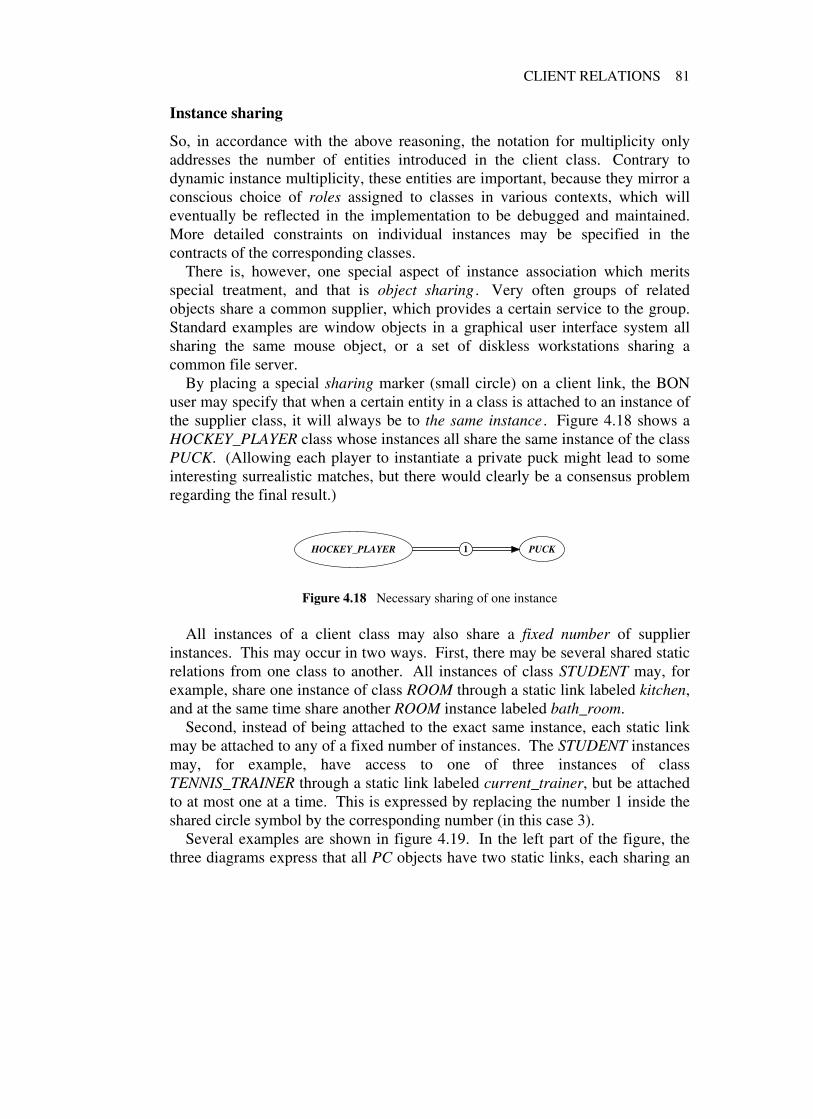
CLIENT RELATIONS 81
Instance sharing
So, in accordance with the above reasoning, the notation for multiplicity onlyaddresses the number of entities introduced in the client class. Contrary todynamic instance multiplicity, these entities are important, because they mirror aconscious choice of roles assigned to classes in various contexts, which willeventually be reflected in the implementation to be debugged and maintained.More detailed constraints on individual instances may be specified in thecontracts of the corresponding classes.
There is, however, one special aspect of instance association which meritsspecial treatment, and that is object sharing . Very often groups of relatedobjects share a common supplier, which provides a certain service to the group.Standard examples are window objects in a graphical user interface system allsharing the same mouse object, or a set of diskless workstations sharing acommon file server.
By placing a special sharing marker (small circle) on a client link, the BONuser may specify that when a certain entity in a class is attached to an instance ofthe supplier class, it will always be to the same instance . Figure 4.18 shows aHOCKEY_PLAYER class whose instances all share the same instance of the classPUCK. (Allowing each player to instantiate a private puck might lead to someinteresting surrealistic matches, but there would clearly be a consensus problemregarding the final result.)
HOCKEY_PLAYER PUCK1
Figure 4.18 Necessary sharing of one instance
All instances of a client class may also share a fixed number of supplierinstances. This may occur in two ways. First, there may be several shared staticrelations from one class to another. All instances of class STUDENT may, forexample, share one instance of class ROOM through a static link labeled kitchen,and at the same time share another ROOM instance labeled bath_room.
Second, instead of being attached to the exact same instance, each static linkmay be attached to any of a fixed number of instances. The STUDENT instancesmay, for example, have access to one of three instances of classTENNIS_TRAINER through a static link labeled current_trainer, but be attachedto at most one at a time. This is expressed by replacing the number 1 inside theshared circle symbol by the corresponding number (in this case 3).
Several examples are shown in figure 4.19. In the left part of the figure, thethree diagrams express that all PC objects have two static links, each sharing an

82 STATIC RELATIONS
PCFILE_
SERVER2 1
PCFILE_
SERVER
1server1
1server2
PCFILE_
SERVER1
server1 ,server2
PCFILE_
SERVER2
PCFILE_
SERVER2
server
PCFILE_
SERVER2 3
Figure 4.19 Different ways to express sharing
instance of class FILE_SERVER. (These two instances could actually be thesame, but are probably not.) The links are unnamed in the upper diagram, andnamed in the other two. The lower diagram is exactly equivalent to the middleone, only more readable and compact.
Turning to the right part of the figure, the upper diagram shows a PC classwhose instances may be alternatively attached to one of two FILE_SERVERobjects. The middle diagram is exactly the same, only the link has now beenlabeled. The lower diagram, at last, shows that each PC object has two sharedstatic relations to class FILE_SERVER, where each link may be attached to oneof three specific FILE_SERVER objects.
Finally, figure 4.20 shows how local sharing within several related groups canbe factored using inheritance. If a parent class contains a shared client relation to
*SHAREHOLDER
MICROSOFT_SHAREHOLDER
ENEA_SHAREHOLDER
SUN_SHAREHOLDER
SHAREHOLDERS
*COMPANY
MICROSOFT ENEA_DATA
SUN_MICROSYSTEMS
COMPANIES
1dividend_payer
Figure 4.20 Sharing through inheritance

CLIENT RELATIONS 83
a supplier class, but the corresponding feature is deferred, this means that sharingwill be effected by descendant classes. In figure 4.20, the shareholder classescorresponding to each company will make the deferred feature dividend_payereffective by defining an implementation for it, which ensures that all instances ofthis class (and possible descendant classes) will share the same supplier object(in this case, an instance of the proper company).
If, by contrast, the dividend_payer feature had been declared effective alreadyin class SHARE_HOLDER, all instances of all the companies would have sharedthe same supplier object, which is not what was wanted in this case. Once afeature representing a shared relation has been effected, it cannot be redefined bya descendant class since this would violate the global sharing.
Client relations involving clusters
Just like the inheritance relation, the client relation may be generalized to applyalso to clusters. Figure 4.21 shows an example. The ORGANIZATION cluster ofa conference system is a client of the CONFERENCE_DATA cluster, which in
REGISTRATIONPERSON
CONFERENCE_EVENT
attendee
{registrations: SET […]
CONFERENCE_DATA
●
COMMITTEE
CONFERENCEPROGRAM_COMMITTEE
ORGANIZING_COMMITTEE
{ program {organization
ORGANIZATION
chair , members: SET […],referees: SET […],conf_event
*SEND_OUT
…
CORRESPONDENCE
calls: SET […],answer
Figure 4.21 Client relations involving clusters

84 STATIC RELATIONS
turn is a client of the class SEND_OUT in a third cluster. The labels refer tofeatures of classes in the client cluster that are clients of some class in thesupplier cluster, but we cannot tell which ones from the diagram. However, thenames often provide enough guidance for the analyst/designer who has workedextensively with the model to know more or less which classes are involved. Ifmore information is needed, the client links may be expanded to present insteada view like the diagram in figure 4.22.
REGISTRATIONPERSON
CONFERENCE_EVENT
attendee
{registrations: SET […]
CONFERENCE_DATA
●
COMMITTEE
CONFERENCEPROGRAM_COMMITTEE
ORGANIZING_COMMITTEE
{ program {organization
ORGANIZATION
chair ,members: SET […]
referees: SET […]
1 conf_event
*SEND_OUT
…
CORRESPONDENCE
calls: SET […]
answer
Figure 4.22 Expanded client relations between clusters
Here, the individual class relations between clusters have become visible atthe expense of a more complicated diagram. This is a typical example of scalingin BON, which is so fundamentally important for large systems. If we wantmore detail, we expand down to the individual class interfaces; to get moreoverview, we compress into clusters at higher levels. The labels may of coursebe hidden if we are only interested in the general structure of a system.
As was pointed out earlier, the semantics of client relations involving clustersis different from the corresponding semantics of inheritance relations. While an

CLIENT RELATIONS 85
inheritance relation having a cluster at either end carries over to relations with allclasses in the cluster, client relations only refer to at least one class in eachcluster.
This might seem a bit strange at first sight, but is really quite straightforward.The general semantics of inheritance is that of “all or nothing”—either you aremy son and then you have all my genes, or you are not my son at all. A childclass cannot select the operations to inherit from its parent; it receiveseverything. (It can , however, modify the behavior of chosen operations, whichwe may think of as computational mutation , but contrary to biological mutationonly modifications that are in accord with the software contract collectively laiddown by the ancestors are accepted.)
By contrast, the general semantics of being a client is that of “free choice”. Aclient can request any service provided by a supplier class, but is not obliged touse everything. So if we think of the classes of a cluster as somewhat analogousto the operations of a class, the conventions used for cluster relations are easy toremember. The rules for generalizing client relations to involve clusters may beput more precisely:
1. If one or more elements (classes or clusters) in a cluster X are clients of anelement A outside of X, then the cluster X is said to be a client of A. Allthe corresponding client links can then be compressed into one client linkfrom X to A.
2. If an element A outside a cluster Y is a client of one or more elements in Y,then A is said to be a client of Y. All the client links can then becompressed into one link from A to Y.
3. A client link between two elements can be compressed into being hidden(not shown in a diagram).
All three cases occur frequently in practice, and have to do with the scaling levelchosen. Notice again the use of element instead of class in the above definitionto allow for recursive compression. As was shown earlier for inheritancerelations (figure 4.3), client relations between classes in two different clustersmay be successively compressed into client relations between the two clusters.For large systems, many levels of cluster compression is common practice.
Compression of client relations
Case tools may employ different strategies for compression of client relations, aslong as they comply with rules 1−3 above. For example, it may be advantageousto be able to hide all client relations to certain groups of classes in order toemphasize some overall aspect of the system. Typical candidates for exclusion

86 STATIC RELATIONS
are general support classes, but also application classes considered less importantin the context studied.
Compression of labels
The labels of a client link between two classes are compressed as follows:
• Unidirectional links . If there is more than one label attached to the link,the labels are compressed into the first label with a marker (ellipsis)indicating that not all labels are shown. If there is only one label (markedor not) it is compressed by being hidden.
• Bidirectional links . The unidirectional rules apply separately to the labelgroups of each direction. Recall that labels on bidirectional links must beplaced closer to the supplier.
• Multidirectional links . The unidirectional rules apply separately to thelabel groups closest to the same client or to the same supplier. Recall thatif there are multiple suppliers, then labels can only be put close to one ormore of the suppliers, which means the names correspond to features in allthe clients.
4.3 CLASS VS. OBJECT DEPENDENCIES
There is a fundamental difference between dependencies among the elements ofa system (the objects) and among their descriptive elements (the classes). Thefull collection of objects at run-time is potentially a set of gargantuanproportions, and would be totally unmanageable if the elements always had to bedealt with individually. Fortunately, object-oriented development reduces thisset by orders of magnitude by grouping objects with similar behavior intoclasses. The collective dependency of objects of type A on objects of type B maythen be captured through one dependency link from class A to class B.
However, even with this reduction the resulting number of dependencies maybecome quite large. The good news is that another of the object-oriented keyfeatures—inheritance with dynamic binding—can carry the reduction one stepfurther (one example being the factored sharing of figure 4.20). We will clarifythe principle with yet another example. The classes in figure 4.23 representsome different vehicle types and a set of potential owners. Since any owner canown any vehicle, there are nine class dependencies to keep track of. These havebeen compressed into one cluster dependency for convenience. (Recall that aclient relation between clusters X and Y means that at least one class in X is aclient of at least one class in Y; here all classes in X happen to be clients of allclasses in Y, which is somewhat unusual.)

CLASS VS. OBJECT DEPENDENCIES 87
CAR TRUCK
BUS
VEHICLES
PERSON COMPANY
TRUST
OWNERS
Figure 4.23 Multiple class dependencies
If, instead, we let the vehicles and owners inherit from common ancestorsencapsulating the interaction as depicted in figure 4.24, the scene changesradically. The nine class dependencies have now been reduced to just one.
*VEHICLE
CAR TRUCK
BUS
VEHICLES
*ASSET_HOLDER
PERSON COMPANY
TRUST
OWNERS
owner
Figure 4.24 Factored class dependencies
The object dependencies have not changed—CAR objects are still clients ofCOMPANY objects and so forth (and the deferred ancestors are neverinstantiated)—but the big win is that the vehicle classes and the owner classeshave become totally independent of each other. Changes to one class do notaffect the correctness of the others, whereas in the first case changing, adding, ordeleting an owner class would potentially require modification of all vehicleclasses.
The bottom line is this: if we can only control our class definitions to makesure all objects will behave correctly at execution time, we can forget about thecomplexity of object dependencies—they will take care of themselves. That iswhy we must concentrate on classes and downplay individual objects.

88 STATIC RELATIONS
4.4 INDIRECT CLIENT DEPENDENCIES
A client relation between a client class A and a supplier class B means A isdependent on services supplied by B. The services of B may be used forspecification, as part of the public interface of A, or behind the scenes in theimplementation of A. A client link from A to B may correspond to one or moreof the following cases:
1. A public feature in A returns a value of type B (or a type derived from B, ifB is generic).
2. An input argument of a public feature in A is of type B.
3. An actual parameter in a generic type derivation specified in A as part ofthe public interface is of type B.
4. The implementation of A uses an entity of type B. This includes thesignatures of private features, as well as state variables and local variablesused inside features.
In BON, as we have seen, dependencies arising from public query return valuesand generic derivation (cases 1 and 3 above) may be captured directly in clientlabels. Regarding public input arguments and implementation (cases 2 and 4above), these can be captured by unlabeled client links. Extending the labelingsyntax to also cover these cases would confuse the notation and does not seemworthwhile. When more precise information is needed, we can turn to theformal class interfaces and/or the source code.
It is a general principle in BON to strive for direct correspondence betweenthe information expressed by client links in static diagrams and the formalinterfaces of the classes involved. Therefore, the colon separating query namesfrom their return type in class interfaces can be adorned to show the type ofrelation (association, shared association, or aggregation). Since the two lasttypes of client relation have been explained at length in this chapter, we maynow present the full feature signature table (figure 4.25), for which a partialversion was earlier given in chapter 3.
FEATURE SIGNATURES (full table)
Graphical form Textual form Explanation
name: TYPE name: TYPE Result typename:{ TYPE name:{ TYPE Aggregation result type
name:(n) TYPE name:(n) TYPE Shared result type (n objects)– arg: TYPE −> arg: TYPE Input argument
Figure 4.25 Typed signatures revisited

SEMANTIC LINKS 89
4.5 SEMANTIC LINKS
A semantic link is an annotation associated with an inheritance or client relationbetween two classes that details the designer’s intent when defining therelationship. Examples of semantic links are listed in figure 4.26, but the list isextensible. The semantic links are stored as comments with the correspondingrelations.
Inheritance Client/Supplier
[DESCENDANT] is a [PARENT] [CLIENT] requests [SUPPLIER]
[DESCENDANT] behaves like [PARENT] [CLIENT] uses [SUPPLIER]
[DESCENDANT] implements [PARENT] [CLIENT] needs [SUPPLIER]
[DESCENDANT] combines [PARENT] [CLIENT] has a [SUPPLIER]
[PARENT] defers to [DESCENDANT] [CLIENT] consists of [SUPPLIER]
[PARENT] factors out [DESCENDANT] [SUPPLIER] provides [CLIENT]
Figure 4.26 Typical examples of semantic links

5 The dynamic model
5.1 INTRODUCTION
The static model of a system shows the high-level classes grouped into clustersand the relationships between them (client and inheritance). It also shows theclass operations, their signatures and semantic specification through pre- andpostconditions, as well as the overall consistency rules for the correspondingobjects expressed as class invariants. These are the class contracts sofundamentally important for reliable systems. Getting them right is a big steptowards mastering the task of systems development.
However, even if the semantics of the class operations is clearly specified(which is certainly not the case for most systems today), a crucial detail stillremains: their implementation. Procedural functions do not magically disappearjust because we structure our systems as collections of classes. On the contrary,we probably get many more of them than with traditional approaches, but withtwo main differences. First, the operations are not global to the system but localto the context in which they serve their purpose: the respective classes. Second,they are normally much smaller and easier to understand, since the abstractionsthey use as elements can be made to mirror the problem domain that much better.
But easy does not mean trivial. There is no such thing as an automaticgenerator of class operations from a semantic description of a class (unless ofcourse the description is a full program in which case nothing has been gained).That is why we still need programming languages to describe the proceduralsteps of our class operations in enough detail to be executable by a machine.
Analysis and design does not include implementation, but it does includeensuring that implementation is indeed possible at reasonable cost and withadequate performance of the resulting product. Therefore, we need at least avague idea already at the early development stages of how the operations of ourhigh-level classes can fulfill their specifications by calling other operations (inthe same or in other classes). To help capture and communicate this idea is thepurpose of the BON dynamic model.
90

INTRODUCTION 91
Object-oriented execution
One of the really nice things about object-oriented abstraction is that there arevery few basic concepts to keep track of. This has led to an extremely simpleexecution model. A full execution of a system is simply the invocation of oneoperation on a so-called root object. When this operation terminates, systemexecution is over. The root object is instantiated automatically from the rootclass by the system environment when the corresponding process is started.
A class operation performs a set of actions in sequence. There are only twopossibilities for each action: either terminate the operation by returning to thecaller, or invoke another operation. Since the decision whether to return or makea new call—and if so, what other operation to call—may depend on the systemstate, we also need a few basic control primitives. In fact, we only need two:multiple choice and iteration, both based on a boolean condition.
Except for these control primitives, everything in an object-oriented executioncan be boiled down to operation invocation.5 This includes basic arithmetic andlogic, which traditionally uses operand/operator expressions that do notresemble feature calls. However, this is just a syntactic convention. Forexample, the expression
n + 5 < k ∗ 2
can be rephrased as
n .plus (5).less_than (k .times (2))
without changing any semantics. Some object-oriented languages support prefixand infix forms of class operations, making it possible to write calls like theexpression above in the familiar algebraic style.
What the above shows is that not only the object-oriented specification model,but also the corresponding implementation model have an inherent coherence,simplicity and beauty that are truly remarkable. This is crucial for our approach,where the goal is to achieve true seamlessness not by reflecting low-level detailsof code in the analysis and design, but by bringing high-level abstraction all theway down to the executable instructions. When the artificial barriers betweenthe noble art of specification and the dirty (but unfortunately necessary)workmanship of implementation have been torn down, and we realize that thereis no conceptual difference between the two, then we can hope for some realprogress in software productivity.
5 Well, almost; for completeness we do need a few more very basic primitives, like state variableassignment and test for object equality.

92 THE DYNAMIC MODEL
What should be captured by a dynamic model?
The previous section showed that feature calls, or message passing betweenobjects, are what constitute a system execution. Consequently, this is whatshould be expressed in a dynamic model as a complementary view to the staticmodel. Using a notation based on other concepts again loses reversibility andbreaks the seamlessness of the approach.
Nevertheless, we have yet seen very little useful notation for documentingobject communication in books on analysis and design. Mostly, they dwell for apage or two on an oversimplified scenario of perhaps four or five objects whoseinteractions are illustrated by the equivalent of an event trace diagram (a diagramwith objects on one axis and time on the other). Realizing that the expressivepower of such diagrams is much too weak for real-life systems, they then quicklymove on to methods outside the object-oriented world, mostly state transitiondiagramming and/or data flow analysis.
In our view, functional modeling with data flow analysis should not be used atall in an object-oriented method, since the impedance mismatch and modelconfusion it introduces far outweigh any benefits gained. It can always bereplaced by better ways of arriving at good abstractions.
State transition diagramming, on the other hand, is a powerful technique thatis sometimes very useful also in object-oriented contexts. When large amountsof discrete events need to be handled by an object, finite state machines (FSMs)may be used to systematically take care of all possible combinations that canoccur, and to give each required action its natural place in a general structure. Asimple introduction to FSMs can be found in [Allworth 1990].
But it is important to understand that this technique is not a panacea. Torecommend that each class should model its internal behavior using statemachines is, in our view, totally inappropriate. It is like proposing that allmathematical functions should be described by enumerating their return valuesfor each input value. This is fully possible on computers using a fixed storagesize to represent their numbers, but it is hard to conceive of a more simple-minded approach, the side effects being increased complexity, waste of space,and total lack of reusability.
On the contrary, the goal to strive for is always higher-level abstractions thatcan be naturally described with much fewer parameters—where we do not needto use what is known as the British Museum method of explicit enumeration.Only for the unfortunate cases, where no nice continuous abstractions can befound for the behavior, do we call upon the state machine brigade to come in andsort out the disorder and transform the unstructured spaghetti logic intocontrollable and structured spaghetti logic (all global dependencies still there, butnow sorted and tagged).

INTRODUCTION 93
A typical such case, where state modeling can be of great help, is the design ofuser interfaces, where many alternative actions can be chosen by the user invarious contexts and the system has no way of predicting what the next choicewill be. When state diagramming is needed, there are many well-provennotations to choose from, so BON does not invent its own variant. Instead, werecommend David Harel’s statechart formalism [Harel 1988], which has theability to structure large diagrams through nesting.
The conclusion is that although state diagramming may be useful in specialcases, the dynamic model of a general object-oriented method should insteadconcentrate on describing behavior through simple message passing betweenobjects in the system. However, a more expressive notation than event tracediagrams is needed.
The BON dynamic notation uses sequence labels to capture time, which freesthe second spatial dimension of a diagram to show the interaction between alarger number of objects than is possible with event trace diagrams. Moreover, itcontains an object grouping facility that can capture more general scenarios andalso illustrate dynamic binding. Potential message passing between selectedobjects is shown using a third kind of relationship, the message relation .
Besides object communication, the dynamic model contains three additionalBON modeling charts. These are: the event chart , which records incoming andoutgoing system events; the scenario chart , containing descriptions of selectedobject communication scenarios; and the object creation chart , showing whatclasses create new instances of what other classes. The informal charts and thedynamic notation for expressing object interaction will be described in detail inthe rest of this chapter.
5.2 DYNAMIC CHARTS
System events
A system may be viewed as a “black box” whose behavior is defined by theresponse it gives to various stimuli. A stimulus that can change the course ofaction of a system and make it react is called a system event . System events areof two kinds. An external event is triggered by something in the external worldover which the system has no control. Examples of incoming external events areuser terminal input, calls from other systems, arrival of data from sensorydevices, and hardware clock interrupts.
An internal event, on the other hand, is triggered by the system itself as part ofits reaction to one or more external events. Some of the internal events areoutgoing, which means that they send stimuli to the outside world triggering an(outgoing) external event, mostly as a response to external input.

94 THE DYNAMIC MODEL
For example, a user at a workstation may click on a menu to print a certainreport. The receipt of the mouse click is then an external event, which may leadto a whole series of internal events triggering various parts of the system tosearch databases, compile information, and send the result to a printer. At leastone of these internal events (not necessarily the last one) will be an outgoinginternal event representing the system response, perhaps directed to a networkspooler.
Event charts
The object interactions which make up the execution of a system are ultimatelycaused by external events. Therefore, it is often a good idea to compile a list ofexternal events that may trigger object communication representing principaltypes of system behavior. The event list is then used as a guide for choosing thescenarios to include in a dynamic model of the system. However, only a smallsubset of all possible external events is interesting and representative enough tobe listed.
For example, to register a new subscriber for a monthly comic magazine, anoperator may first click on a principal subscription menu, then choose the entryfor the complete Carl Barks Library in color, then enter the name and address ofthe subscriber along with the subscription period, and finally click on the button“accept subscription”. In this series of operator actions, each mouse click willconstitute an external system event (in fact, usually two: one when the mousebutton is depressed and one when it is released). Depending on the supportingsystem (widget handling, mouse tracking, etc.) each character keystroke may ormay not be an individual event, and each of these events may lead to a largenumber of operations being applied to many objects.
But the only event in the above sequence likely to be included in a high-levelsystem dynamic model is the receipt of “accept subscription”. This eventcorresponds to the commit statement of a transaction, and is probably asignificant part of the system behavior. The other events have to do with howthe necessary subscription data is actually collected and transmitted, and sincethis can be implemented in many different ways, the details will in most casesnot be decided until later. Unless a novel interface model is part of the systemdesign, the menu selections will just follow the standard practice of some basicgeneral GUI library, and thus not be included in the dynamic model.
The idea is to capture a small number of external events each triggering aprincipal type of system behavior, so that a representative set of scenarios can bechosen. These scenarios will then sketch how the necessary actions can becarried out by communicating objects (which are instances of the classes in thestatic model) to achieve the desired behavior. Figure 5.1 shows a BON event

DYNAMIC CHARTS 95
chart for a conference system, collecting some interesting incoming externalevents. For each external event, the event chart lists the types of object that maybecome involved as part of the system response.
EVENTS CONFERENCE_SUPPORT Part: 1/2
COMMENTSelected external events triggeringrepresentative types of behavior.
INDEXINGcreated: 1993-02-15 kwrevised: 1993-04-07 kw
External (incoming) Involved object types
Request to register a submittedpaper
CONFERENCE, PROGRAM_COMMITTEE, PAPER
Request to accept a paper CONFERENCE, PROGRAM_COMMITTEE, PAPER,STATUS
Request to assign a paper to asession
CONFERENCE, PROGRAM_COMMITTEE,PROGRAM, PAPER, PAPER_SESSION
Selection of a session chairperson CONFERENCE, PROGRAM_COMMITTEE,PROGRAM, PAPER_SESSION, PERSON
Request to register an attendee CONFERENCE, ORGANIZING_COMMITTEE,REGISTRATION, PERSON
Request to print conferenceattendee list
CONFERENCE, ORGANIZING_COMMITTEE,REGISTRATION, PERSON, ATTENDEE_LIST
Figure 5.1 Event chart: incoming external events
Analogously, the event chart gives the same information for a list of importantinternal outgoing events as shown in figure 5.2. Since all outgoing events areindirectly triggered by incoming events, the outgoing events listed all have oneor more corresponding incoming external events.
For example, the outgoing event “call for papers is sent” was probablytriggered by an incoming event “request to send call for papers” resulting fromuser keyboard input. Or else the calls may be sent automatically at some presetdate, but then the system clock interrupt may be considered as the incomingexternal triggering event. Similarly, each incoming external event usually has acorresponding outgoing event. A request to register a conference participant willalmost certainly yield some kind of confirmation being sent back to the user—atleast indirectly by issuing a standard system prompt as opposed to an errormessage—indicating that the registration was successful.
In either case, both the incoming and the outgoing events will point to thesame scenario, so there is normally no need to list both related events in the

96 THE DYNAMIC MODEL
EVENTS CONFERENCE_SUPPORT Part: 2/2
COMMENTSelected internal events triggering systemresponses leaving the system.
INDEXINGcreated: 1993-02-15 kwrevised: 1993-04-03 kw
Internal (outgoing) Involved object types
Call for papers is sent CONFERENCE, ORGANIZING_COMMITTEE,PERSON, MAILING
Invitations are sent CONFERENCE, ORGANIZING_COMMITTEE,PERSON, MAILING
A paper is sent to referees CONFERENCE, ORGANIZING_COMMITTEE,PAPER, STATUS, REVIEW, PERSON
An invoice is sent CONFERENCE, ORGANIZING_COMMITTEE,REGISTRATION, PERSON, INVOICE,INVOICE_FORM
Warning issued for exceedingtutorial session capacity
CONFERENCE, REGISTRATION, TUTORIAL
An author notification is sent CONFERENCE, PROGRAM_COMMITTEE,PERSON, PRINT_OUT*, LETTER_FORM
Figure 5.2 Event chart: outgoing internal events
event chart. Outgoing events like “warning issued for exceeding conferencecapacity” are different, since these are triggered when the system state reachescertain values. Such triggering states are of course also the indirect result ofincoming events, like trying to register one more attendee, but it is not alwayseasy to know exactly which ones, so we normally record this group of outgoingevents separately.
System scenarios
A system scenario is a description of a possible partial system execution. It canbe viewed as a sequence of events initiated by one or more triggering events(internal or external) and showing the resulting events in order of occurrence.Some of the events in a scenario will usually be external, but not always.Particularly during design there may be many interesting, purely internalscenarios that are worth capturing as part of the high-level system description.
Anyway, the great majority of events in most scenarios will be internal events;that is, generated by the system itself. As we recall from the beginning of thischapter, object-oriented system execution is really nothing but message passingbetween objects, so all events except the incoming external ones are caused by

DYNAMIC CHARTS 97
operations being applied to objects. Some of these operations change the systemstate (the commands), and some of them do not (the queries).
When describing the internal events of our scenarios, we basically have twochoices:
1. View the system as a finite state machine and let the events correspond totransitions between certain interesting system states.
2. View the system as a set of communicating objects, and let the eventscorrespond to message passing between them.
Most books on analysis and design containing any kind of elaborate notation fordynamic modeling seem to take the first approach, and then use some kind ofstate diagramming technique. However, this approach immediately runs intotrouble, because there is no natural mapping from the state diagrams to the staticmodel of the system classes.
BON instead takes the second approach, viewing internal events as operationsapplied to objects. Then every message passed from one object to another can bedirectly related to the corresponding classes and operations specified in the staticmodel. So rather than representing different worlds with no logical connectionbetween them other than the poor developer’s brain, as is the case with statemachine approaches, the static and dynamic models can now reinforce eachother and lead to a better understanding of the system under construction.
We will see in section 5.3 what dynamic diagrams with message passing maylook like.
Scenario charts
Using the system event chart as a starting point, we may select a set ofinteresting system scenarios to illustrate important aspects of the overall systembehavior. A short description of each scenario (for which a dynamic diagrammay later be produced) is then collected in the system’s scenario chart . Anexample is figure 5.3. Each entry has two short descriptions: the first is just afew words which can also be used as a scenario name for quick reference, andthe second a few sentences explaining the scenario a little more.
Object creation charts
Investigating the creation of new objects may serve as a link between the staticand dynamic models. Some classes in a static diagram may be marked asdeferred, which means they contain operations that will never be implemented inthe class itself, but only in descendant classes. Such classes will never beinstantiated, so objects of the corresponding type cannot occur in the dynamic

98 THE DYNAMIC MODEL
SCENARIOS CONFERENCE_SUPPORT Part: 1/1
COMMENTSet of representative scenarios to showimportant types of system behavior.
INDEXINGcreated: 1993-02-16 kw
Send out calls and invitations:Using mailing lists and records of previous conference attendees and speakers, prepare andsend out calls for papers and invitations to attend the conference.
Create sessions and chairs:Partition the conference into sessions of suitable length; allocate session rooms and select achairperson for each session.
Register paper and start review process:A paper is registered and three referees are selected; the paper is sent to each referee, andthe paper status is recorded.
Accept paper and notify authors:A submitted paper is selected and an acceptance date is entered; a notification letter iscreated and sent to the authors.
Assign paper to session:A session suitable for the paper is selected and the paper is entered in the list ofpresentations for that session.
Register attendee:An attendee is registered with his/her address and selected tutorials are recorded.
Print conference attendee list:All registrations are scanned and a list with attendee names, addresses and affiliations isproduced and sent to a printer.
Print badge:An attendee is selected, and the corresponding badge is printed in appropriate format.
Figure 5.3 Scenario chart for a conference system
model. All other classes, however, must potentially have objects created at somepoint during system execution, otherwise they are superfluous and should beremoved (unless, of course, we are developing libraries of reusable classes).
Thinking through how objects are created may thus help find possible fossilclasses, but it also helps the developer form an impression of how some of theoperations in the dynamic diagrams may be realized. The idea is to produce anobject creation chart , where for each class that may create other objects, thetypes of these objects are listed. (Only high-level analysis classes are consideredhere; keeping track of created lower-level objects is not the intention.) Anexample for the conference system is shown in figure 5.4.
The class PRESENTATION in the creation chart is a deferred class with theclasses PAPER and TUTORIAL as descendants. Note that deferred classes mayoccur in the left column of object creation charts, because a deferred class maycontain operations that create other objects. Regardless of whether these

DYNAMIC CHARTS 99
CREATION CONFERENCE_SUPPORT Part: 1/1
COMMENTList of classes creating objects in the system.
INDEXINGcreated: 1993-02-18 kw
Class Creates instances of
CONFERENCE PROGRAM_COMMITTEE, TECHNICAL_COMMITTEE,ORGANIZATION_COMMITTEE, TIME_TABLE
PROGRAM_COMMITTEE PROGRAM, PAPER, PAPER_SESSION, PERSON
TECHNICAL_COMMITTEE TUTORIAL, TUTORIAL_SESSION, PERSON
ORGANIZATION_COMMITTEE MAILING, ADDRESS_LABEL, STICKY_FORM,REGISTRATION, PERSON, INVOICE, INVOICE_FORM,ATTENDEE_LIST, LIST_FORM, POSTER_SIGN,POSTER_FORM, EVALUATION_SHEET,EVALUATION_FORM, STATISTICS
PRESENTATION* STATUS, PERSON
PAPER REVIEW, ACCEPTANCE_LETTER, REJECTION_LETTER,LETTER_FORM, AUTHOR_GUIDELINES
TUTORIAL ACCEPTANCE_LETTER, REJECTION_LETTER,LETTER_FORM
REGISTRATION CONFIRMATION_LETTER, LETTER_FORM, BADGE,BADGE_FORM
Figure 5.4 Object creation chart
operations will actually be implemented by the deferred class or by its children,if we know their invocation may lead to the creation of objects of certain types,this information should not have to be duplicated in all descendant classes. Bylisting the classes STATUS and PERSON in the entry for PRESENTATION, wecan avoid repetition for the child classes PAPER and TUTORIAL, and mayinstead focus on the differences.
It is usually best to exclude frequently reused library classes, such as SET,TABLE, and DATE, from the creation chart, since it is rarely interesting to followthe creation of such objects in detail.
5.3 DYNAMIC DIAGRAMS
Objects
We are now ready to describe the BON dynamic notation used in systemscenarios. A dynamic diagram consists of a set of communicating objects

100 THE DYNAMIC MODEL
passing messages to each other. An object is represented by its type, that is itsclass name, and an optional object qualifier.
Graphical representation
Objects are represented graphically by rectangles to make them stand out fromthe class ellipses. An effort is made in BON to make the dynamic and staticdiagrams look different enough to preclude any confusion between them. Thereis a deep semantic difference between a class and its instances that is sometimesvery obvious, but may at times be quite subtle, depending on the discussioncontext and the general backgrounds of the people trying to communicate.
Mixing statements about classes with statements about class instances in thesame context is akin to mixing language and metalanguage in the same phrases;it can easily lead to severe misunderstandings. Static and dynamic descriptionsshould therefore be kept strictly apart and not be allowed to share the samediagrams.
The name of the corresponding class is centered inside the rectangle in uppercase (bold italic font recommended). A single rectangle in a diagram alwaysrefers to an individual object, so two single rectangles with the same name willrefer to two individual objects of the same type. A qualifying identifier may bewritten below the class name, enclosed in parentheses (lower caserecommended), to distinguish several objects of the same type occurring atdifferent positions in a dynamic diagram.
An object rectangle may be double, in which case it refers to a set of objects ofthe corresponding type. Passing a message to a double object rectangle meanscalling some object in the set. Three single objects and one set of objects areshown in figure 5.5.
CONTROL_TOWER FLIGHT
QUEUE(arrivals)
QUEUE(departures)
Figure 5.5 Objects are identified by class name, context, and optional id
Additional object qualifiers should only be used when really needed, sincehaving a lot of them may easily clutter a diagram and lead to more confusionthan help. Even if there is more than one object of a certain type in a diagram,individual identification is not always interesting, or else the spatial context maybe enough to tell which object is which.

DYNAMIC DIAGRAMS 101
Message relations
In this book, we switch freely between the message passing metaphor and thefeature call metaphor (objects invoking operations on each other) depending onwhat view is most convenient for the particular issue being discussed. We maythus at times talk about sending a message to an object, calling a class feature, orinvoking an operation on an object, but this will always mean the same thing.
For the relationship between a calling object and the callee, we use the termmessage passing relation or message relation for short.
Graphical representation
A message sent from one object to another is represented graphically by a dashedarrow extending from the calling object to the receiving object. The messagearrows (or message links) may be labeled with sequence numbers. Thesenumbers serve a double purpose. First, they represent time in the scenario, that isthe order in which calls are made. Second, they correspond to entries in ascenario box where the role of each call may be described using free text.
In this way dynamic diagrams can be kept clean and easy to read, while thenatural language text in the scenario boxes provides the freedom to expressspecial semantic details at greater length when needed. The scenario box has aheader containing a scenario name, which is the corresponding short entry of thescenario chart. An example is shown in figure 5.6.
DRIVER
OWNER
CAR ENGINE
1, 6
2, 4 3, 5
Scenario: Borrow a car and go for a ride
1 Driver obtains keys from car owner2 Driver turns ignition key3 Engine starts4 Driver removes ignition key5 Engine stops6 Driver returns keys to owner
Figure 5.6 A BON dynamic diagram
A message relation is always potential; that is, we cannot tell from thediagram whether the call will actually occur in a specific execution. Forexample, if the car battery is flat, turning the ignition key may not lead to anymessage being sent from the CAR object to the ENGINE object. Also, obtainingkeys from a car owner (label 1 in figure 5.6) may involve asking several ownersor the same owner several times before someone is persuaded to lend their car.
For reasons of simplicity and abstraction, we exclude all forms of conditionalcontrol (such as multiple choice and iteration) from the BON dynamic notation,

102 THE DYNAMIC MODEL
and instead let it be implicit in the message relations. For the same reasons, wealso exclude any data flow indications. Some messages will implicitly causereturn values to be passed in the reverse direction, but this is not shown in thediagrams. In case we need to express more, separate dynamic notations may beused as a complement. The path expressions for high-level descriptions ofpatterns of interaction between object groups described in [Adams 1994] may bea candidate.
Bidirectional links
A set of message relations in each direction between two objects (or sets ofobjects) may be expressed by a double link with an arrowhead at each end, likein figure 5.7.
HUNGRY_PERSON CLOCK
PERSON
12
3
4
Scenario: Time watch
1 Notification at noon requested2 Clock sends “time for lunch” message3 Hungry person tells colleagues4 Colleagues respond
Figure 5.7 Bidirectional message links
As in the static notation, this is just a compacted form of individual relations,and we employ the same convention to show which direction each sequencelabel corresponds to. A label is always put closer to the supplier object, that isthe object being called (the receiver). In figure 5.7, label 1 therefore represents acall from the hungry person to the clock, and label 2 refers to the clockresponding. Similarly, message 3 refers to the hungry person summoning thelunch team members, while message 4 represents their answers.
Multidirectional links
To simplify diagrams with many relations, we allow message links to be joined,as shown in figure 5.8. A joined message link must have at least one calling
BRAIN
LEG
LEG
1Scenario: Take a walk
1 Legs are told to move
Figure 5.8 Concurrency: send to many

DYNAMIC DIAGRAMS 103
object and one receiving object attached, and it represents potential calls from allthe callers to all the receivers. Placing a label close to a caller means that itrefers to messages from this caller to all receivers in the diagram.
Joining multiple calls from the same caller, as in figure 5.8, is also a way ofgrouping concurrent messages: we may not be interested in whether the right orthe left leg takes the first step, as long as it leads to a useful walk. (The notationmay mean true concurrency, or simply that we do not care.)
Similarly, placing a label close to a receiver refers to messages from all callersin the diagram to this object (or set of objects). This is illustrated by figure 5.9,where a pilot needs to receive clear signals from various sources both inside andoutside the airplane before taking off, but where no particular order is required.
PILOT
CABIN_CREW
CONTROL_TOWER
1Scenario: Get ready for takeoff
1 Pilot receives “seat belts fastened”,“cabin doors secured”, and “runway clear”
Figure 5.9 Concurrency: receive from several
In figure 5.10, labels 1 and 2 represent messages from one parent to bothchildren, while labels 3 and 4 represent messages from both parents to one of thechildren.
FATHER DAUGHTER
MOTHER SON
1 4
2 3
Scenario: Farewell at train station
1 Father gives children an extra $50 each2 Mother gives children boxed lunches3 Parents tell son never to ski out of bounds4 Parents tell daughter what men are really after
Figure 5.10 Concurrency: multiple send to many
Object grouping
We have seen that the simple labeling and joining conventions of the dynamicdiagrams introduced so far already give us the possibility to express manydifferent types of object communication. But we may take a significant stepfurther, which is particularly important for scenarios containing a larger set ofinteracting objects. This step is the ability to send messages between groups ofobjects.

104 THE DYNAMIC MODEL
An object group is a set of objects treated as a unit in some message passingcontext. An object group may contain single objects (corresponding to singlerectangles), sets of objects (corresponding to double rectangles), and also otherobject groups. A message link to an object group is simply the compression ofone or several message links to one or several of the elements in the group.Similarly, a message link from an object group is the compression of one orseveral message links from one or several of the group elements.
Graphical representation
Object groups are drawn as boxes with rounded corners representing the groupbody with an optional group label in a separate rounded box. The group label (ifpresent) is positioned just outside the group body touching its borderline. BONrecommends letting dynamic group labels start with a capital letter with the restin lower case, to make them stand out from static cluster labels. A group labelmay appear anywhere along the group borderline to facilitate the presentation ofcomplicated diagrams. Some examples are shown in figure 5.11.
A B
Callers
RECEIVER
CALLER A B
Receivers
C D
Callers
A B
Receivers
A B
A B
1
2
Figure 5.11 Compressed message relations
The line style must be different from the one chosen for objects, andpreferably also from classes and clusters. The recommended practice is to usecontinuous borderlines for objects, and to use dotted borderlines for objectgroups and group labels.
Compression of objects and groups
An object group is compressed into its group label attached to an empty,iconized body (see figure 5.12). Unlabeled object groups cannot be compressed.When a group icon is expanded (or opened), its constituent parts first become

DYNAMIC DIAGRAMS 105
LIFE_GUARD
WATCHTOWER
Equipment
Beach_surveillance
Figure 5.12 An iconized object group
visible in compressed form, thus showing objects and other group icons. Theinner parts may then be opened recursively, until the objects are reached.
Messages involving object groups
Message relations between callers and receivers may be compressed as follows:
1. If one or more elements (objects, sets of objects, or groups) in a groupsend messages to an element outside the group, all the message linksinvolved can be compressed into one message link from the group to theoutside element.
2. If one or more elements (objects, sets of objects, or groups) in a groupreceive messages from an element outside the group, all the message linksinvolved can be compressed into one message link from the outsideelement to the group.
3. A message link between two elements can be compressed into beinghidden (not shown in a diagram).
Compression of message relations
When object groups are being compressed or expanded in a dynamic diagram,the labels and corresponding entries in the scenario boxes may have to berenumbered to reflect the overall message sequencing. Case tools may employdifferent strategies as long as they comply with rules 1−3 above.
Recursive messages
It is often important to express recursive message passing in a dynamic diagram.Figure 5.13 shows three different cases. The first case represents a specificobject calling itself, and is therefore drawn using a single rectangle. The secondcase shows a set of objects of a certain type calling objects in the same set.
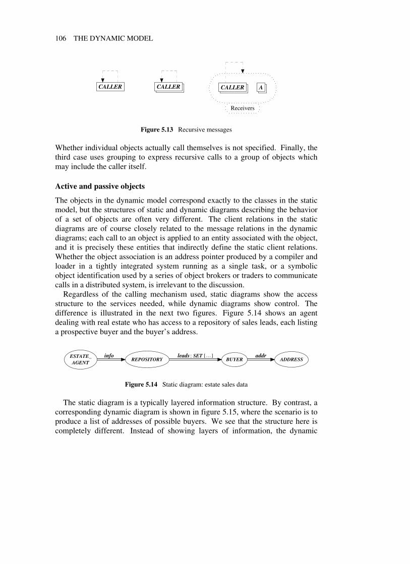
106 THE DYNAMIC MODEL
CALLER CALLER CALLER A
Receivers
Figure 5.13 Recursive messages
Whether individual objects actually call themselves is not specified. Finally, thethird case uses grouping to express recursive calls to a group of objects whichmay include the caller itself.
Active and passive objects
The objects in the dynamic model correspond exactly to the classes in the staticmodel, but the structures of static and dynamic diagrams describing the behaviorof a set of objects are often very different. The client relations in the staticdiagrams are of course closely related to the message relations in the dynamicdiagrams; each call to an object is applied to an entity associated with the object,and it is precisely these entities that indirectly define the static client relations.Whether the object association is an address pointer produced by a compiler andloader in a tightly integrated system running as a single task, or a symbolicobject identification used by a series of object brokers or traders to communicatecalls in a distributed system, is irrelevant to the discussion.
Regardless of the calling mechanism used, static diagrams show the accessstructure to the services needed, while dynamic diagrams show control. Thedifference is illustrated in the next two figures. Figure 5.14 shows an agentdealing with real estate who has access to a repository of sales leads, each listinga prospective buyer and the buyer’s address.
ESTATE_AGENT
REPOSITORY BUYER ADDRESSinfo leads: SET […] addr
Figure 5.14 Static diagram: estate sales data
The static diagram is a typically layered information structure. By contrast, acorresponding dynamic diagram is shown in figure 5.15, where the scenario is toproduce a list of addresses of possible buyers. We see that the structure here iscompletely different. Instead of showing layers of information, the dynamic

DYNAMIC DIAGRAMS 107
BUYER
ESTATE_AGENT
REPOSITORY
ADDRESS SET
1
2
3
4
Scenario: List prospective buyer addresses
1 Get leads2 Get next buyer in set of leads3 Get address from buyer4 Ask address to print itself
Figure 5.15 Dynamic diagram: active and passive objects
diagram shows the estate agent as the only caller in the scenario, while all otherobjects simply act as data containers.
An object sending a message is said to be active, while the receiving objectsare passive. Being active or passive is a role; to carry out its task when called asa passive object, the called object may have to call other objects and thus becomeactive. Many objects, perhaps most, will thus act in both capacities at differenttimes. However, it is often interesting in a dynamic context to separate theobjects playing the active parts from the passive ones, since the former are theones causing things to happen. In BON dynamic diagrams, this is immediatelyvisible through the occurrence and direction of the message relations.
When building a dynamic scenario with the aid of a corresponding staticdiagram, it is then very important to realize that an indirect call chain to print theaddress of the next buyer in the structure shown in figure 5.14, which can bewritten:
info .leads .item .addr .print
does not mean that ESTATE_AGENT calls REPOSITORY, which calls SET,which then calls BUYER, which in turn calls its ADDRESS object. Instead,ESTATE_AGENT calls REPOSITORY to get a reference to a SET of leads.Using the reference, ESTATE_AGENT then makes a second call to the SETobject to get the next BUYER object, then a third call to BUYER getting itsADDRESS object, and then a last call to this ADDRESS asking it to print itself.
This is what is really expressed by the call above. Nested calls of this type areonly allowed for syntactic convenience, and are semantically equivalent to:
info: REPOSITORYs: SET [BUYER]b: BUYERa: ADDRESS

108 THE DYNAMIC MODEL
s := info .leadsb := s .itema := b .addra .print
If we use local variables for implementation as above, the corresponding staticstructure becomes the one in figure 5.16. However, we normally do not wantthis reflected in our high-level static diagrams, since it only makes them moredifficult to read. Therefore, an essential property of a case tool is to permit thehiding of client dependencies resulting from local variables or private features.
ESTATE_AGENT
REPOSITORY BUYER ADDRESSinfo leads: SET […] addr
a
s: SET […], b
Figure 5.16 Modified static diagram
A more complex example: moving graphical objects
To give the reader a general idea of the potential strength of the BON dynamicnotation, we will spend the rest of this chapter on two examples where the objectinteraction is a little more complex.
The first example will show how the notation can be used to express dynamicbinding. Assume we want to model a simple graphical editor with grouping. Astatic diagram for the editor is shown in figure 5.17. It can handle three types ofgraphical object: pixel map objects for arbitrary images, graphical text objectswith variable font and point size, and geometric objects consisting of a set ofdefining points and a shape. All the geometric figures inherit from the deferredclass FIGURE, which is associated with a set of graphical points.
Selected objects may be grouped and treated as a unit, for example whenmoved, rotated, or resized. To be of any use, groups may also contain othergroups besides primitive objects. This is conveniently expressed in figure 5.17by letting all graphical objects (including the FIGURE objects) inherit from asecond deferred class DISPLAY_OBJECT, and then letting the GROUP classhave an aggregation relation to a set of DISPLAY_OBJECT.
Since a DISPLAY_OBJECT can be either a primitive graphical object or agroup, we get the required recursion for free through dynamic binding.Combining generic derivation with inheritance in this fashion is a very common

DYNAMIC DIAGRAMS 109
LINE
ELLIPSE
CIRCLE
RECTANGLE
SQUARE
GEOMETRIC_FIGURES
*FIGURE
PIXEL_MAP
TEXT GROUP
DISPLAY_ELEMENTS
POINT*
DISPLAY_OBJECT
{
members: SET […]points: SET […]
Figure 5.17 Graphical objects with grouping (static diagram)
and powerful method to handle complex structures with object-orientedmodeling. We also note that by using clustering and compression of inheritancelinks it is possible to express quite entangled classification structures with veryfew arrows. Without the compression possibility, this diagram would be at leastan order of magnitude more difficult to read.
Now let us try to illustrate a dynamic scenario where a group object is beingmoved. A group created by the editor is shown in figure 5.18.
Hello
Figure 5.18 Graphical editor example: a grouped object with nesting

110 THE DYNAMIC MODEL
The group contains a nested group and two geometric objects: a square and acircle. The inner group contains one smaller circle and a graphical text object.The thick, dashed boxes just illustrate the grouping, and are not part of thegraphical figures.
The need for two-dimensional object diagrams
The typical way to show object communication found in other approaches, suchas OMT [Rumbaugh 1991], the Booch method [Booch 1994], and OOSE[Jacobson 1992], is through one-dimensional sequencing diagrams called eventtrace diagrams or interaction diagrams . Figure 5.19 shows a diagram of thistype for our small example, without the graphical points that are part of thegeometric figures.
OUTERGROUP
OUTERSET SQUARE
OUTERCIRCLE
INNERGROUP
INNERSET
INNERCIRCLE TEXT
next group member requested
square asked to move
outer circle asked to move
inner group asked to move
next inner group member requested
inner circle asked to move
text asked to move
Figure 5.19 Move example group: event trace diagram
The eight objects involved (excluding the points)—two groups, two set objectscontaining group elements, and four primitive figures—just about hit the limitfor what can be expressed with reasonable readability in one-dimensionaldiagrams. Including the points would clutter the figure. Considering thesimplicity of the example, it is clear that diagrams of the type represented byfigure 5.19 are too weak for dynamic modeling. This may be compared withfigure 5.20 which uses the two-dimensional BON notation.
Freeing the time axis has made the actual communication diagram smaller,while moving the temporal explanations to a separate place. The spatialpositioning of objects in two dimensions permits them to be locally grouped.We have therefore been able to drop the qualifying identifiers for the SET andCIRCLE objects, since the geometric contexts give enough information.

DYNAMIC DIAGRAMS 111
SET SET
SQUARE GROUP(outer)
GROUP(inner) TEXT
CIRCLE CIRCLE
1
2
3
4
5
6
7
Scenario 1: Move example group
1 Next outer group member requested2 Square asked to move3 Outer circle asked to move4 Inner group asked to move5 Next inner group member requested6 Inner circle asked to move7 Text asked to move
Figure 5.20 Move example group: two-dimensional BON diagram
The increased space available now permits us to go one step further toillustrate the movement of geometric objects in more detail. We assume thatsuch an object is moved by moving, in turn, its defining points (a circle may bedefined by two points: its origin and one point on the circumference).Figure 5.21 shows the resulting diagram. It now contains 11 single objects and 3object sets without looking too crowded, while the corresponding event tracediagram would no longer be readable.
General scenarios need object grouping
What is immediately striking, however, is that the scenario feels very special;instead of showing individual move examples, one would want to capture thegeneral scenario of moving any group. To do this, we must employ the groupingfacility. A first attempt is illustrated in the upper diagram of figure 5.22.
Collecting the geometric figures in one group and the non-geometric ones inanother,6 makes it possible to illustrate the various cases of dynamic binding thatmay occur. Call 1 of scenario 3 gets the next group member. Applying the
6 We assume it is clear from the context when the word group refers to an object group in thedynamic notation, and when it denotes a group in the editor example.

112 THE DYNAMIC MODEL
SET SET SET
POINT SQUARE GROUP(outer)
GROUP(inner) TEXT
SET CIRCLE CIRCLE SET
POINT POINT
1
2
3
4
5
6
7
8
9
10
11
12
13
Scenario 2: Move example group
1 Next outer group member requested2 Square asked to move3 Next square point requested4 Point asked to move5 Outer circle asked to move6 Next outer circle point requested7 Point asked to move
Scenario 2: (continued)
8 Inner group asked to move9 Next inner group member requested10 Inner circle asked to move11 Next inner circle point requested12 Point asked to move13 Text asked to move
Figure 5.21 Move example group: extended to include points
move operation on this member then has to be split into calls 2−6, since differentthings happen depending on the type of member. In fact, only one of call 2, call3, or calls 4−6 will occur for a given member.
The diagram may be further improved as shown in scenario 4 (lower part offigure 5.22) by nesting the groups that hold the polymorphic objects. We thenget a diagram which illustrates the dynamic binding of the move operation verydirectly. If we compare scenario 4 with the static description in figure 5.17, wesee that the similarity is striking.
The deferred classes DISPLAY_OBJECT and FIGURE, which are neverinstantiated, are replaced in the dynamic diagram by two object groups (outerand inner). Moreover, the inheritance relations between the pairsCIRCLE−ELLIPSE and SQUARE−RECTANGLE, respectively, are not shown inthe dynamic diagram. It would have been possible to use one more layer ofnested groups to include them, but when geometric shapes are manipulated,circles and ellipses are usually not perceived as related objects, and the sameholds for squares vs. rectangles. Therefore, the scenario looks more naturalwithout this last grouping.

DYNAMIC DIAGRAMS 113
LINE CIRCLE SQUARE
RECTANGLE ELLIPSE
POINT
6
GROUP
SET
1
2
4
5
TEXT
PIXEL_MAP
3
Scenario 3: Move any group
1 Next group member requested2 Subgroup member asked to move3 Non-geometric figure asked to move4 Geometric figure asked to move5 Next point of geometric figure requested6 Point asked to move
GROUP
TEXT
PIXEL_MAP
LINE CIRCLE SQUARE
RECTANGLE ELLIPSE
Display_elements
POINT
4
SET
1 3
2
Scenario 4: Move any group
1 Next group member requested2 Group member asked to move3 Next point of geometric figure requested4 Point asked to move
Figure 5.22 Polymorphism: needs object grouping

114 THE DYNAMIC MODEL
A different use of object grouping
Finally, we show a second example where grouping is useful, but where theobjects called are not necessarily related through common inheritance.Figure 5.23 contains a typical scenario that can be divided into sequentialsubtasks with some shared data between them.
It shows the general interactions needed to deal with an insurance company asa result of a car accident without personal injury. Getting the car fixed may bedivided into three phases. First, various reports are filled out to document whatreally happened and establish damages for which the insurance holder may be
OWNERINSURANCE_
ADJUSTER7 3
DAMAGE_REPORT
SETTLEMENT8
2
6
4
WITNESS
POLICE
INSURANCE_INSPECTOR
Accident_report INSURANCE
STANDARD_PRICE_LIST
APPROVED_GARAGES
Evaluation
RENTAL_COMPANY
GARAGE
Repair
9
15
Scenario 5: Settlement of claims for damages resulting from car accident
1−3 Owner obtains necessary statements and certificates from involved parties,fills in damage report, and sends it to insurance company.
4−7 Insurance adjuster evaluates damage claims and sends settlement statementback to owner.
8−9 Owner agrees on car rental and repair details based on settlement.
Figure 5.23 Grouping into sequential subtasks

DYNAMIC DIAGRAMS 115
entitled to compensation. These reports are based on statements from peoplebeing involved or witnessing the accident, and may need formal certification byan insurance inspector and perhaps the police. This is captured by message linksfrom the OWNER object to the object group labeled “Accident_report”, to theDAMAGE_REPORT object, and to the insurance company, representing formalsubmission of the claims.
Second, an adjuster at the insurance company makes an evaluation of theclaims based on the accident report and the general terms of the applicableinsurances. A maximum cost is often specified based on agreed standards onacceptable repair charges for various types of damage, and sometimes theinsurance company will only accept certain trusted garages to do the job. Themessage link from INSURANCE_ADJUSTER to the “Evaluation” object groupillustrates this. The result of the evaluation is a formal settlement statement fromthe insurance company, approving or disapproving parts or all of the owner’sclaims (message links to SETTLEMENT and back to OWNER).
Based on the outcome of this, the owner may then carry out the third phase ofthe scenario, which is to negotiate with a suitable garage and perhaps also rent acar to replace the one under repair (message link to “Repair” group).
This example is very different from the graphical editor for two reasons. First,the messages sent to the objects in the groups may represent operations that aretotally unrelated and therefore do not mirror any inheritance structure in thesystem. Second, the object groups may not correspond to any kind of groupingin the static model of the system, but simply represent a convenient way ofviewing a somewhat complicated scenario to make it easier to understand.
There are many such cases in practice, where a system—perhaps consisting ofa number of loosely connected heterogeneous components as is becoming moreand more common in distributed environments—is used in a way that createsabstractions that were never part of the system model. In fact, an importantcharacteristic of really useful systems is often that they provide a certain numberof basic facilities that the user can combine in different ways to create usagepatterns that the system designers could never anticipate (and should not try to).
Use cases
So system usage can give rise to abstractions of its own that may be worthmodeling, but we must also issue a word of warning in this context. Systematicelaboration of use cases , as advocated in OOSE [Jacobson 1992], is often a goodway to gain more insight into what is really needed in a system. But using themas the basis for system decomposition risks ending up with a product whosestructure reflects system usage more than long-term concepts. We will return tothis issue in chapter 6.

116 THE DYNAMIC MODEL
For these reasons, the dynamic diagrams in BON are normally not as stable asthe static model, and will frequently change as we gain more insight into theproblem. In fact, some dynamic diagrams will just serve as temporary help toevolve the static model, and will be thrown away at later stages. Others maysurvive longer and fill a role as complementary system documentation.

Part IIIThe method

118 PART III

6 Issues of a generalmethod
6.1 INTRODUCTION
Developing high-quality professional software requires great intellectual skillsand long experience. It is a creative process that can never be replaced by therigid procedures of an ultimate “methodology”. Unless we are working in a verynarrow application area, the possible variations in system views make the task offinding a good model too close to general human problem solving, which justdoes not lend itself to any useful formalization.
Despite the fact that everybody in the trade knows this (except perhaps forsome bubble and arrow specialists who have never really been forced toimplement their own diagrams), there is a remarkable gullibility in many parts ofthe software community. Somewhat like instant cures for baldness, almost anykind of simplistic ad hoc procedure seems to sell if it only promises to turngeneral systems development into an orderly, controllable procedure. A tailoredvariation of the generic approach in figure 6.1 is then often used.
The universal method M (apply recursively when required)
1. This is the important beginning step, where we solve the first part of the problem.2. Welcome to the middle of the method: in this step we solve the second part.3. Now all that remains is solving the last part, and we will soon be done.
Figure 6.1 The archetype of many software “methodologies”
So the manager’s secret dream of totally manageable (and easilyexchangeable) employees for software development is still far off, and the readershould not expect any miracles from the BON method either in this respect. Itsgoal is to provide the developer with a strong set of basic concepts andcorresponding notation to be used as a framework for creative thinking,
119

120 ISSUES OF A GENERAL METHOD
complemented by a set of guidelines and recommended procedures that may helpin the search for good models. BON can never substitute for talent, but it canhope to serve as an inspiration for developing one’s personal skills.
The reader may also have noted that we use the term method for theseguidelines and procedures, rather than the more popular buzzword“methodology”. This is for two reasons. First, using a longer name does not addany substance to a method, and second, according to available dictionaries thelatter form simply does not have the intended meaning:
method, n.1. a way of proceeding or doing something esp. a systematic or regular one.2. orderliness of thought, action, etc.3. (often pl .) the techniques or arrangement of work for a particular field or subject.
methodology, n.1. the system of methods and principles used in a particular discipline.2. the branch of philosophy concerned with the science of method and procedure.
(Collins English Dictionary, 3rd edn, 1992)
Since BON is presenting a view of its own rather than trying to unify whateverybody else in the field is doing, we will discuss a method in this book andnot worry too much about methodology. The BON method will introduce arecommended analysis and design process consisting of nine major tasks to becarried out. Each task uses a set of input sources and produces a set of well-defined deliverables (either new or updated) as part of the end result.
To complete the tasks, a developer will be involved in a number of standardactivities (also nine as it happens), some of them more related to analysis(problem domain) and some more related to design (solution space). Theseactivities may occur in varying degrees during several of the tasks, and aretherefore considered orthogonal to the process.
This chapter will discuss some issues that are considered important in theBON method for analysis and design. The next chapter will then describe thenine major tasks of the BON process: what should be performed and whichdeliverables to produce. Finally, chapter 8 will discuss the typical analysis anddesign activities that will occur as part of carrying out the individual tasks of theprocess.
6.2 SIMULATING AN IDEAL PROCESS
Anyone who has been involved in intellectually taxing activities—trying tounderstand and solve a complex problem—knows that the process of arriving ata good solution is far from regular. On the contrary, the most common

SIMULATING AN IDEAL PROCESS 121
impression during the course of the effort is often a sense of total disorder andutter confusion. This is also true for cases where the final result eventually turnsout to be very simple and elegant, and the greatest sense of confusion is oftenexperienced shortly before the crucial perspective is discovered.
So the bad news is that a rational modeling process, where each step followslogically from the previous ones and everything is done in the most economicorder, does not exist. Complex problem solving just does not work that way.But the good news is that we can fake it. We can try to follow an establishedprocedure as closely as possible, and when we finally have our solution(achieved as usual through numerous departures from the ideal process), we canproduce the documentation that would have resulted if we had followed the idealprocess [Parnas 1986].
This gives us a number of advantages:
• The process will guide us, even if we do not always follow it. When weare overwhelmed by the complexity of a task, it can give us a good ideaabout how to proceed.
• We will come closer to rational modeling if we try to follow a reasonableprocedure instead of just working ad hoc .
• It becomes much easier to measure progress. We can compare what hasbeen produced to what the ideal process calls for, and identify areas wherewe are behind (or ahead).
Such an ideal process is part of BON and will be presented in the next chapter,but first we will discuss some general modeling issues.
6.3 ENTERPRISE MODELING
Object-oriented analysis may be used as the top-level instrument for the designand implementation of software, but its modeling capabilities extend far beyondthat. Any type of scenario consisting of a number of actors exhibiting certainbehaviors is potentially a candidate for object-oriented modeling, regardless ofwhether computers will be involved at some point or not.
For example, human communication and mutual understanding within anorganization may be greatly enhanced by creating unified models of company-wide concepts and tasks and their interactions. This type of analysis, often calledenterprise modeling , may very well turn out to be one of the major areas ofapplication for object-oriented techniques in the future. In large organizations,one can hardly overestimate the importance of a common view of the terms andconcepts used as a basis for making decisions in various areas of responsibility.

122 ISSUES OF A GENERAL METHOD
Object-oriented techniques have a great potential for enterprise modeling,which needs both the abstractional power to model very diverse organizationalentities, and the simplicity to be understandable to a large number of people withvarious roles and backgrounds. The metaphor of describing reality as a set ofcommunicating objects that can be asked to behave in certain ways through a setof applicable operations seems to be very appealing to many people outside thecomputer industry. This is of course no coincidence, since it resembles the waywe normally classify things around us and make decisions by picturingalternative future scenarios in our minds.
One may argue that enterprise modeling needs more than the basic object-oriented concepts to be expressive enough. This may very well be true forcomplicated cases, but the additional needs are probably quite different fordifferent types of organization.
6.4 WHAT IS ANALYSIS AND WHAT IS DESIGN?
If we interpret the words analysis and design according to their normal use inmost disciplines, the question in the section title becomes trivial. Analysismeans taking things apart for examination, while design is to work out thestructure or form of something. Both activities are of course needed in all phasesof software development, although different parts and structures may be involvedat different times.
In recent years, however, the terms have gradually started to acquire analternative meaning in the object-oriented world. The approximate consensus inmany current books and articles seems to be the following:
• Object-oriented analysis means creating an object-oriented model from theexternal requirements (a model of the problem).
• Object-oriented design means refining the analysis model into a high-levelobject-oriented model of a solution.
In our opinion, more appropriate terms should be found for the activities above,since the words analysis and design are much too general and useful to be robbedof their original meaning. The ambiguity introduced creates even greaterconfusion in a field that is difficult enough as it is. However, until somethingbetter catches on, we accept the new interpretation as de facto usage.
In this book, we will therefore use analysis and design in both the new and thetraditional sense. Analysis classes and design classes will refer to abstractions atdifferent levels in our system (problem vs. solution). Both categories will ofcourse emerge through analysis of various prerequisite conditions. On the otherhand, the reader should not be surprised to find hybrid statements like “designing

WHAT IS ANALYSIS AND WHAT IS DESIGN? 123
an analysis model”. The intended meaning of each term should be clear from thecontext.
Recursive analysis and design
If we go back to normal language usage, analysis means investigating the detailsof something, while design means building a new structure. Whenever wedecide the form of something, we are designing—no matter if we are building amodel for the real-time distribution of X-ray pictures in a wide area network ofhospitals or figuring out the best organization for storing prime numbers. Andevery design needs analysis in order to be carried out properly.
Object-oriented technology yields a very flexible recursive model here. First,the initial requirements are analyzed and an initial model is designed. The classstructure and public interfaces of this model then become a new set ofrequirements for the next level of abstraction. The dual application ofanalysis / design is then repeated the number of times needed to reach the desiredlevel. This usually means executable code at some point, but not necessarily.
Since class interfaces only specify how the corresponding objects shouldbehave—not what internal mechanism may be used to achieve this behavior—the recursive model is not just theoretically pleasing, but highly realistic andusable in practice. The idea that any software development should be dividedinto exactly three parts (analysis, design, and implementation) is in fact arbitrary.
Multiple language metaphor
Since we are never interested in data per se in a system (only in variousmanifestations of it) we should employ the philosophy of the abstract data type.All data is viewed only indirectly through the behavior of certain black boxobjects which can return values or change information. Whether the objectssupplying information actually store the values or just cheat by asking otherobjects behind the scenes, the clients do not want to know about.
The collective interface of a set of classes specialized to solve a certaingeneral task is actually a language tailored to applications in the correspondingarea. Therefore, designing an object-oriented model of a certain problem domainbehavior can be viewed as designing a language in which it is easy to expressthat type of behavior. (This perspective was presented already in 1969 byEdsger Dijkstra in his seminal monograph “Notes on Structured Programming”[Dijkstra 1972]. There, program development is viewed as the successive designof languages for a series of abstract machines.)
Once the language is there, it is a simple matter to specify the high-levelbehavior and also modify it later, provided we stick to the area which thelanguage was meant for. Instead of twisting our high-level concepts to fit an

124 ISSUES OF A GENERAL METHOD
obsolete standard language whose limitations we cannot do anything about (thereality of most programmers for the last 30 years), we can simply change therules and invent new specialized languages as needed.
What remains is then to implement the operations of the new language. Wetherefore create a second language consisting of classes with operations that areparticularly good at expressing the behavior needed by the operations of the firstlanguage, so they can be easily implemented. This is repeated until theinnermost language can be understood and translated into executable code bysome compiler (or we stop earlier if no execution is desired). Of course, we takecare not to invent languages which are close to existing ones, and all the generalprinciples for constructing good class libraries apply [Johnson 1988,Meyer 1994a].
Note that when we talk about multiple languages in the object-oriented sense,we are referring to semantic content. The syntax of the languages remainsuniform at all levels (feature calls on objects), and seamlessness can thus bepreserved in spite of the great diversity.
So a system model consists of many layers of abstraction, each viewed as aspecialized language. Some of the layers may be hierarchically nested, whileothers extend orthogonally across the system. Therefore, no natural borderlinebetween design and implementation exists; what is considered design will justhave to be decided from one case to another. And what is more—in spite ofmany authors giving the opposite impression—there is no clear dividing linebetween the analysis and design models either.
What is problem and what is solution?
The world has no a priori structure. A bird flying across a forest looking for agood place to build a nest will certainly classify the trees very differently fromthe lumberjack who is at the same time clearing his way below the foliage insearch of material for his employer’s new line of ship fittings. And if we couldtalk to the neurons firing off the classification patterns in the lumberjack’s brain,they would probably consider the whole concept of tree arbitrary and useless. Soanyone who thinks reality is just there for the analyst to discover is in for asurprise.
To understand a problem, we need to impose a structure on its parts—but agood structure is defined by what we want to achieve. If our task is tocomputerize some manual work in an organization, we can often start from a setof concepts and views more or less shared by the people involved. We may haveto study the area for a long time to detect these views, and when we do, it onlymeans we have a better understanding of the problem and how things are carriedout today. It does not necessarily mean we should keep the views (not even their

WHAT IS ANALYSIS AND WHAT IS DESIGN? 125
core elements) when transferring to the electronic world. Sometimes traditionalconcepts carry over very naturally; sometimes the new opportunities inherent inautomatic processing may change the picture completely.
So we need to create an analysis model whose abstractions make it easy tounderstand the desired system behavior, but are still flexible enough to allowmany different realizations. This may result in classes representing tangibleobjects, but may just as often result in classes that are abstractions of what usersconsider independent concepts of the enterprise or of more general concepts theusers have not even thought about. In fact, physical objects in the problemdomain, which many books recommend as a starting point, are often too specialto be suitable as classes at the highest level in the resulting analysis model (seefor example the case study modeling a video recorder). We should often look forsomething beyond the common view held by actors in the problem domain, sinceour classification needs are not necessarily the same as theirs.
6.5 REUSE
Reusability should always be our goal, and the aim with shifting to object-oriented development is that the amount of reuse should increase dramaticallycompared with traditional approaches.
Levels of reuse
This increased reuse comes from several levels of abstraction. We candistinguish at least three such levels:
• The basic level whose components are expected to be needed by almostany application, regardless of type.
• The domain level covering typical needs in a certain application area.
• The corporate level containing reusable components tailored to thespecific needs of the enterprise.
At the basic level, expected to be part of any good object-oriented languageenvironment, there are the fundamental data structures of lists, sets, stacks,arrays, hash tables, and trees that constitute the archetypical “wheel” of softwareengineering since they are constantly reinvented day and night, at high cost, byprogrammers all over the world using traditional languages.
The basic implementation algorithms are known to any literate programmer,yet have enough variation to prevent effective reuse in all but the object-orientedapproaches. Large, coherent, and extensively used data structure libraries existin Smalltalk and Eiffel, while the hybrid character of C++ and its ad hoc memory

126 ISSUES OF A GENERAL METHOD
management makes the creation and combination of such libraries much harder.Another prominent component at the basic level is support for standardized
graphical interface elements. Only very special applications can still afford torepeat the enormous effort invested in GUI toolkits like X/Motif or MicrosoftWindows, yet most users expect graphical interfaces in modern systems.Higher-level object-oriented models can be built on top of standard toolkits, andprovide developers with the means of creating very sophisticated user interfacesat very low cost through easy reuse. The class libraries should then supportdistinctive user metaphors like the MVC model for Smalltalk [Krasner 1988],InterViews for C++ [Linton 1989], Nextstep’s Workspace for Objective-C, orEiffelBuild and EiffelVision for Eiffel [Meyer 1994b].
At the domain level, we should expect in the future to be able to buy oracquire reusable components for most of the familiar problems connected with acertain application type rather than developing these ourselves. However, theofferings so far are quite limited, so we may have to wait some time before thisbecomes reality. In the meantime, many such components will have to bedeveloped and maintained as part of the corporate-level class library. Goodlibraries at this level may become the most valuable assets a corporation mayhave in the future, since they represent accumulated knowledge that can becapitalized. This is perhaps especially important in the software business, whoseturnover rate is extremely high.
Reuse policy
Besides trying to locate already existing reusable components, it is alsoimportant to take an active decision regarding the future reusability of thesoftware under development. Even if the sign of a good object-orienteddeveloper is in fact a Pavlovian reflex of almost physical nausea whenever afamiliar pattern must be repeated, there is always a short-term cost associatedwith building reusable software. This cost may very well be regained alreadythrough increased clarity and reuse within the scope of the project, but notalways.
At the basic reuse level, reusability should always be our first concern, since itnormally pays off immediately. Developing a well-structured set of classes forbuilding error messages, manipulating general strings, handling command linearguments, etc., does not cost very much in a good object-oriented environment(in case they are not already available). Repeating ad hoc solutions over andover, on the other hand, will not only cost more in the long term, but also hinderthe fundamental shift of attitude so extremely important for the next generationof programmers: that it is possible to take control instead of just being controlledby the course of events (see the last section of this chapter).

REUSE 127
When a developer builds a reusable component that encapsulates a recurringproblem pattern, this is not only an act of reducing future workloads—it alsorepresents a significant personal investment. By constructing components,developers gain insight into parts of problem domains that will improve theirfuture ability to construct good models at all levels. It leads to greater jobsatisfaction, since everybody wants to be on top of things instead of just beingused by the circumstances. The increased enthusiasm will wear off on othersthrough discussions at whiteboards and over coffee, and will gradually lead to asubstantial increase in the so-called human capital currently being recognized bythe economic sciences as the real asset of modern society.
So, we should in fact go for reusability even when it appears to cost a littlemore in terms of time and salary, since in the long term it will not. However,there is a limit to everything and it is particularly important that if we invest inreusable components, the anticipated reuse should also happen in practice.
Since future reuse of more specialized elements at the corporate or domainlevels depends on many factors, these must be actively addressed beforedetermining how much should be invested here. If the company’s productstrategy changes, reusable components supporting what was produced yesterdaymay quickly be rendered useless. High-quality libraries that remain aestheticmonuments in a software database make no one happy, least of all theoriginators.
Just as for any other project activities we must make a cost / benefit analysis todecide where we should put our money and effort, and when. For the applicationof this economic principle in a software engineering context, see for example[Boehm 1981].
Planned vs. accidental reuse
There is a debate going on in some object-oriented circles about whether reuseshould be “planned” or “accidental”. The more orthodox school seems toadvocate that we should only allow reuse of software initially built to bereusable. We find this line of argument very strange.
First, if all reuse were planned beforehand there would not be any point incalling it “reuse”, since it would just be plain usage. We do not say “Today Ireused my word processor,” because the word processor was built to be executedany number of times compiling various documents. A class library is nodifferent; if it was built as a general toolbox open to anyone, when we say we are“reusing” a class from this library, we really mean “using”.
Second, the fact that the word reuse has a flavor of unplannedness about it isno coincidence, but an important strategic point. The reason to move fromtraditional to object-oriented techniques is not only to get more flexibility for

128 ISSUES OF A GENERAL METHOD
building families of abstractions from scratch, but also to get out of thestraitjacket of deciding too much too soon (cf. the open−closed principle in[Meyer 1988a]).
In fact, the rapid changes in technology and software requirements guaranteethat we will only know (or even suspect) for a minority of cases what will beneeded in the future. Therefore, restricting reuse to what can be successfullyplanned would not leave us much better off than with the old techniques.
The decision whether to reuse a piece of existing software should only bebased on how well it can solve the current problem. Anything else is beside thepoint, and we would much rather reuse a good-quality class built without athought of ever being used outside its context, than employ a planned “reusable”component of poor quality.
It is true that developing highly reusable software is not easy, and effectivereuse does not happen by itself just because we now have classes instead ofsubroutines. Careless reuse of small heterogeneous pieces here and there may ofcourse risk losing consistency and miss global patterns. But this is no differentfrom the general problem with any evolving system. When successive additionstend to degrade the initial system integrity we must restructure and generalize, nomatter if the added pieces were new or reused.
In practice, so-called accidental reuse will therefore mostly require somemodification to the set of classes in order to make them more general, morerobust, and better documented, but this is just a logical consequence of theincremental nature of object-oriented development.
Sometimes we know that we are going to need a whole set of relatedabstractions, and then we may plan early for a large library of reusablecomponents. In most cases, however, we simply cannot see this until the systemhas evolved for some time. In the meantime, we are much better off with“accidental reuse” than with no reuse at all.
Reuse manager
Reuse of other people’s products requires trust. If we do not have strong reasonsto believe that the quality and understandability of a reusable class is indeed highenough, we will prefer to create a new class to gain full control. This isparticularly true in good object-oriented environments where the development ofnew abstractions requires so much less effort. The “not invented here” syndromemay sometimes play a part, but not nearly as often as many people seem to think.
In fact, it is our experience that good developers who are accustomed toroutinely creating reusable abstractions are also very eager to reuse existingwork, as long as they can trust the quality. The standards of a reusable librarymust be therefore be high, so that people can always rely on the components and

REUSE 129
do not need to think twice about using them (provided the functionality fits).Since the cost of reuse also depends very much on the difficulty of identifyingsuitable candidates, easy access to well-indexed class libraries through efficientclass browsers and good general documentation becomes extremely important asthe number of components grows large.
For both these reasons, if we want to promote a corporate database of reusablecomponents, particularly in large organizations where the people involved do notall know each other, somebody must be assigned the responsibility of keepingthis database in good shape. The classes must be consistent and adhere to certaincompany standards, so it becomes easy to judge whether a particular componentis suitable or not.
We call such a responsible person a reuse manager , and the role should beassigned to somebody with high skills in three areas: abstract modeling, thetechnology and problem domain embodied by the reusable components, andhuman communication. Some even claim that without assigning a suitableperson to this role and setting aside a budget for it, reuse on a broad scale withinan organization will just never happen [Goldberg 1991].
Besides administrating the professional components, an important task of thereuse manager is to take care of potentially reusable software. Very often goodideas arising in projects are only carried to a point sufficient to cover the needsof the current development, as time and budget will not permit the investmentneeded to create a product usable in more general contexts. The work done maynevertheless be quite substantial, and it is then important to pave the way forfuture capitalization of the effort.
Therefore, a high-quality component library is not enough—there should alsobe a less demanding formal collection of software artifacts, which may be calleda reuse repository . Project software with the potential of becoming fully fledgedreusable components, or simply representing general designs that may be ofinterest to other projects, should be submitted to the reuse manager for inclusionin the reuse repository.
The repository must be consistently organized and documented well enoughfor users to assess the potentials of its elements. However, the quality of theindividual contributions must be allowed to vary much more than in thecorresponding component library.
6.6 USER CENTERED DESIGN
As computer-based tools are becoming part of the everyday life of a rapidlyincreasing number of professionals, the concept of system usability is consideredmore and more important. It has even been given an ISO definition [ISO 1990]:

130 ISSUES OF A GENERAL METHOD
A concept comprising the effectiveness, efficiency and satisfactionwith which specified users can achieve specified goals in a particularenvironment.
In this section, we will briefly discuss a reference model for an approach calleduser centered design presented by Hans Marmolin in [Marmolin 1993], aiming toapply the results from the research on human−computer interaction to the designof software.
Roles of users and computers
Since the 1960s there has been a gradual paradigm shift in the sciences of bothpsychology and computing. The majority of researchers now view computers asvehicles for enhancing the human intellect rather than ultimately replacing it.(Some AI researchers still advocate, like Douglas Hofstadter [Hofstadter 1980],that it may, at least theoretically, be possible to describe the human mind byalgorithms. However, the theoretical physicist Roger Penrose recently presenteda very intriguing and convincing reasoning to the contrary [Penrose 1989].)
Since users normally know best how to solve their own professional problems,a system should not try to lay out a rigid work plan in advance. Rather it shouldprovide basic facilities to be combined freely by users, thus taking advantage ofthe unique capabilities of humans to analyze complex situations, recognizepatterns, follow many threads simultaneously, and adapt quickly to newrequirements from the environment.
A reference model for user centered design
The model for human−machine interaction chosen in [Marmolin 1993] viewsuser behavior as a goal-oriented process, and human−machine interaction as astepwise transformation from goal to primitive actions through a number oflevels describing different aspects of the interaction. These levels are of coursein reality tightly interlaced, and must be chosen somewhat arbitrarily (up to 12different levels have been suggested by other researchers). Marmolin uses onlythree, thus keeping the model simple:
• The pragmatic level . A description in goal-oriented terms of the tasks auser should be able to solve assisted by the system (the user requirements).
• The conceptual level . A description in system-related terms of functions,objects, and processes that can be used to achieve the goals.
• The interface level . A description of how to deal with system functionsand objects and of the words and symbols that must be used to activate

USER CENTERED DESIGN 131
them. This includes the physical operations needed, and the physicalpresentation of information by the system.
The user achieves a goal by successively laying out a strategy for approaching itstepwise through a series of actions which can be solved by the system. Themore knowledge the user has about the system properties on all its conceptuallevels, the easier it becomes to translate a goal into an effective set of physicaloperations applied to the user interface.
For example, the user goal to clean up a text file directory (pragmatic level)must be translated into a series of subgoals like creating safety backups,removing old files, reorganizing and renaming (still pragmatic level). Eachsubgoal must then be translated into functions applicable to system objects, likeremoving a file by submitting its corresponding representation to a garbage bin(conceptual level). Finally, these conceptual actions must be translated intosyntactically correct system actions, like depressing a mouse key on the file iconand dragging it to the garbage bin icon (interface level).
During the course of the action, both goals and strategy are often modifiedbased on information about what has happened so far. For example, looking atthe set of file icons in the directory as it gradually becomes more readable mayreveal that a changed file structure (perhaps a merge with some other directory)would in fact be preferable. Relevant system feedback to stop unnecessary workor unwanted effects is therefore extremely important for usability.7
In terms of this model, the purpose of user centered design can be defined asfinding ways to decrease the cognitive distance between the successive levels.By designing the conceptual level to map naturally to the goals represented bythe user requirements, finding relevant system functions for a task is facilitated;by reflecting the system concepts in the user interface, choosing the rightkeystrokes or mouse clicks to invoke a chosen function becomes obvious.
The model represents, of course, a highly simplified view of reality,disregarding the strong dependencies between the levels. Nevertheless, it cangive new insights into the problem of designing usable systems. We will looksome more at the aspects of interaction represented by each level.
7 We certainly do not speak for the kind of feedback that used to be standard practice in manyearly traditional environments (“Welcome to the File Copier XYZ, Copyright QED: 0001 filescopied”). Rather, we favor the UNIX principle to shut up when things proceed according to plan,and only report anomalies or obvious dangers of unintended results. Routine verbosity alwayshides relevant information.

132 ISSUES OF A GENERAL METHOD
The pragmatic aspect
The tasks at the pragmatic level are directly related to the user’s representation ofthe problem domain, which usually contains much more than what is in thesystem. So the basic concepts at this level are domain specific and systemindependent, but the system concepts chosen must facilitate the transformation ofgoals and tasks at the pragmatic level into a series of system actions.
The most characteristic property of such a transformation is that it is not asequential process guided by a well-defined plan. The order and application oftasks vary; several tasks are often in process simultaneously, even if they cannotbe done in parallel. The human limitations in memory capacity and precisionusually prevent any effective long-term planning. The strategies tend to befuzzy, variable, and flexible depending on continuous reassessments of thesituation. Humans seem to solve problems by going back and forth betweenvarious tasks in a seemingly “random walk” towards a goal [Cypher 1986].
The conceptual aspect
The domain-level tasks must be expressed by the user in terms of functions andobjects supplied by the system [Moran 1983]. Computer systems are regardedby users as complex models of reality, which they are constantly trying tounderstand by relating new experiences with the system to previous ones. Theuser gradually builds a model of the system, and only the functions in accordwith this model are ever used. The user’s perception of a system is incompleteand partly wrong, based on analogies and seldom corrected, since it is oftenpossible to find reasonable (but erroneous) explanations for the system behaviorin various situations [Carroll 1982].
Efficient interaction requires that the model offered by the system (on whichits design is based) closely matches the user’s mental model of the system. Thefact that users often perceive word processors in close analogy with their mentalmodel of a typewriter has been studied, showing how the matching parts wereeasily mastered while the differences gave rise to many errors and slow typing[Douglas 1983].
An important aspect of this level has to do with the user’s choice of systemfunctions to fulfill a certain task. A user does not always choose the best way ofsolving a problem, but rather one which minimizes the subjective cost of usage.This cost is based on the effectiveness of the functions, their perceivedcomplexity, how well they are understood, and the effort required to learn how touse them. These factors are valued differently by different users.
So-called naive users tend to favor simple functions, even if they are not veryeffective and may require unnecessary repetitions. They value minimal studyand often overrate the difficulty of learning new and more efficient functions.

USER CENTERED DESIGN 133
They prefer to use well-known procedures, while experienced users tend to learnmore functions, valuing usability more than extreme simplicity. Usually, only asmall fraction of the functions offered by an environment is used routinely. Itwas found that among the 400 commands generally available on UNIX systemsin the beginning of the 1980s, the 20 most frequently used covered 70% of allusage [Kraut 1983].
The interface aspect
Having decided what system functions to use for a given domain-level task, thenext step a user has to perform is to invoke the selected functions bytransforming them into a series of physical operations (keying commands,selecting from menus, dragging and dropping, pressing buttons, etc.). This maybe considered the syntactic part of the total translation from subgoal to action.The user’s perception of the system is often strongly guided by the interface,since the continuous process of using it tends to play a far more important rolethan formal education (“if everything else fails—read the manual”).
This routine of “learning by doing” often leads to naive models and rigidsystem usage: what is known to have worked before is repeated even when theuser suspects it is not the right way. It is important to recognize this practice,and that users will learn by making mistakes. Therefore, care must be takenregarding system responses to strange or unexpected user behavior.
Another thing to note is that learning is often unevenly distributed over thesystem functions, so the average degree of user knowledge may not be all thatrelevant. Occasional users may know some functions well, while experiencedprofessional users often are occasional users of some functions.
Finally, three different cognitive states of a user may be distinguished whenworking with the interface model of a system: a verbal, a spatial, and acontrolling state. The verbal state corresponds to command dialogs, the spatialto direct manipulation dialogs (drawing, pointing, dragging), and the controllingstate to multiple choice dialogs (menus, buttons, function keys).
For example, when editing a document in a multi-media environment the userswitches between various forms of interaction. Sometimes the text content ischanged, sometimes the document layout is manipulated, and sometimespredefined document processing functions are invoked. Choosing an interfacethat forces a cognitive state that does not match the current interaction formclosely (such as going through a menu hierarchy to move a figure) often leads totime delays and increased error frequency because of the extra mentaltransformations required. Particularly when a user is trying to solve a difficultproblem that requires deep concentration, cognitive state changes forced by thecomputing tools can be very taxing.

134 ISSUES OF A GENERAL METHOD
User metaphors
A significant characteristic of a good system is that it presents a clear abstractmodel of what is going on during execution. Instead of just offering chunks ofvaguely related functions and letting the user group them to create enoughstructure to figure out what to do, the system should actively support the mentalpicture of a virtual world populated with certain actors that behave according toclearly understandable rules. This applies regardless of whether the user ishuman or another program (since somewhere behind a client call there lurks aprogrammer with the same basic needs to understand how to use the systemproperly). We call this mental picture a user metaphor .
A metaphor can often be chosen to mimic analogous physical environmentsthat are part of the cultural heritage of most users and therefore natural to use andeasy to remember [Lakoff 1980]. For example, if a system for handlingdocuments supports the metaphor of a set of ordered racks with drawers, whereeach drawer contains a number of folders with individual documents in it, it doesnot take many seconds for a user to transpose the familiar layout of an office intothat of the screen.
Some of these metaphors may be quite elaborate and thus very expressive, butsince they are so well known, people do not perceive them as intricate. Wetherefore get a full-blown communication language between the user and acomplex system for free, and we get immediate acceptance also from users whowould not touch anything that had the slightest air of complexity about it.
Graphical user interfaces have done much to popularize this idea, since in thiscase the metaphor is so obvious that it can hardly escape anybody. When thegraphical interface paradigm—mostly developed at Xerox PARC in the 1970s[Kay 1977]—was first presented to the people on a broad scale through theintroduction of the Macintosh computer in 1984, so-called naive computer userscould do the most amazing things right from the start, without even needing amanual. This was a true revolution made possible by hardware advances, butalso by the necessary mental shift of software developers.
The important thing to remember about user metaphors, though, is that theymust be part of the user’s general knowledge. Therefore, it is not enough to talkto other developers (no matter how experienced) to find out what mappings touse. Interviews with several potential users, preferably in their normalworkplaces, can reveal what mental pictures most of them share regarding theirwork, and what metaphors will therefore be likely to succeed in practice[Lovgren 1994].
The fact that direct manipulation of graphical icons through dragging anddropping using mouse buttons is often very appealing to inexperienced computerusers does not automatically mean that it is the best way to communicate for a

USER CENTERED DESIGN 135
more sophisticated user. However, mouse clicks just represent command syntax;if we prefer a good textual language, this may be offered as an alternativewithout affecting the underlying metaphor.
Modeling of interaction levels
Marmolin has gone a step further and devised a user centered design methodbased on the reference model described above. In his method, the threeinteraction levels are mapped into three corresponding representations of thesystem: a requirements model, a design model, and an interface model[Marmolin 1993].
Such a general partitioning of the analysis model is not done in BON, becauseits usefulness depends very much on the kind of application we are developing.Maintaining a requirements model separate from the analysis model tends tobreak the seamlessness of the approach. It may still be worthwhile for largesystems that are planned to be implemented in several different versions, or havespecial demands for requirements tracing, but for most systems one model willbe enough.
As we will advocate in a following section, it is not clear where an interfacemodel stops and a corresponding conceptual model starts, and the importance ofthe interface part will vary greatly from one system to another. However, theinteraction levels and metaphor concept described in this section should be partof the developer’s mindset and actively guide the analysis and design process.
6.7 ROLES OF ANALYSIS OBJECTS
If our goal is flexible systems that are likely to evolve gracefully over time tomeet new requirements, we should not put all our emphasis on de facto objects inthe problem domain (physical things, organizations, items handled, commondomain terms, etc.).
Finding such objects is often a great help when trying to understand theproblem, and some of them will serve as initial candidates to become classes.However, many of them are only manifestations of more general underlyingpatterns, which are what we should try and capture instead. Also, moving to acomputerized solution usually opens up entirely new possibilities, which maycall for a modified (or radically changed) set of basic concepts.
Anyway, no matter what model we come up with, the degree of potential reuseof the abstractions is always variable. Some classes will represent stableabstractions, such as general information structures, basic interaction facilities,and concepts fundamental to the enterprise or application domain. Others willreflect specialized, volatile behavior, acting more like temporary glue between

136 ISSUES OF A GENERAL METHOD
comparatively stable components. The classes in a system will therefore playdifferent roles, which has lead some practitioners to look for a fixed roleseparation that can form a basis for a general analysis method.
For example, OOSE [Jacobson 1992] recommends using three different typesof analysis classes (called entity objects, interface objects, and control objects)depending on which one of three orthogonal system aspects (information,presentation, or behavior) is considered most prominent for the correspondingabstraction.
Entity objects are meant to represent more stable abstractions containinglonger-term information needed by the system, control objects encapsulate themore volatile system behavior, while interface objects take care of externalcommunication. Grouping the analysis classes into these three categories leads,in their view, to systems that are more adaptable to requirement changes.
Although a role separation is certainly useful in any system’s analysis model(BON uses clustering for this) and will most probably lead to more flexibledesigns if done correctly, imposing one standard initial classification on theanalysis abstractions in every system is too restrictive. Any predefined set ofclassification criteria will be arbitrary, and therefore counterproductive in caseswhere these criteria are less relevant.
As we will argue below, the external interface of a system usually consists ofseveral layers, and what exact parts of it are to be considered the stable “essence”of the interface is by no means obvious. Therefore, assigning the interfaceresponsibility to a specific set of classes at an early stage usually means takingpremature design decisions which instead lead to less flexibility.
Moreover, what is important for achieving robust architectures is not to searchfor “behavior” versus “information”; it is to look for abstractions which are asstable as possible. This has to do with the respective generality (in theapplication context) of the encapsulated behavior, not with whether it needs tostore information or not.
Object oriented abstraction supports free classification, and it must remain freeif we are to take full advantage of its potential. Instead, the professionalsoftware engineer must be familiar with many different architectures, theirstrengths and weaknesses, and be able to choose one that best fits the conditionsof a given project.
6.8 MODELING A SYSTEM INTERFACE
Systems as objects
At the highest level, a system can be viewed as a black box exhibiting certainwell-defined behaviors in response to various incoming stimuli. So if we can

MODELING A SYSTEM INTERFACE 137
identify the main types of incoming stimuli and specify the actions that should betaken by the system for each of them, we could in principle always view asystem as one object whose operations correspond to the various responses toincoming stimuli from the external world.
In practice, however, the complete interface between a system and itsenvironment is much too large and contains too many different types ofcommunication to be modeled by just one class. Even if the number of top-levelservices available to the users of a system (where a user could also be anothersystem or hardware device—not just a human operator) may be small, manyauxiliary functions are usually needed. Primary commands will often triggerseries of information exchanges between system and user to pass data throughscreen forms or graphical widgets, read from secondary storage files, handleexternal interrupts, or follow the conventions of various communicationprotocols.
The full system interface is therefore mostly distributed over many classes,some dealing with input from the keyboard and pointing devices, otherscommunicating with the underlying file system or some database handler, yetothers exchanging information with external processes. Although control isalways initiated from some top-level objects in the system (ultimately one persystem process—the root objects), the actual detailed communication with theexternal world is delegated to more specialized objects.
Front and back ends of systems
There are two main aspects of a system interface: passive and active. Thepassive system interface is the part that can be requested to perform some actionon behalf of an external user.8 This is the front end of the system. The activesystem interface, on the other hand, is the part that asks for services from theexternal world (files, databases, other systems), usually as part of servicing someincoming request. This is the system’s back end.
These two types of interface play very different roles and cannot be seen asjust encapsulations of the incoming and outgoing events respectively. Anoutgoing event could be either an active request (issued by the system) for anexternal service, or a passive response to an external request (issued by a systemuser). Analogously, an incoming event may be either an external request from asystem user, or a response from an external system to a previous request from thesystem. Some external systems may play both roles: sometimes responding torequests from the system, sometimes issuing requests to it.
8 Unless clearly stated in the context, a system user always refers to any external actor (human ormachine) requesting services from the system.

138 ISSUES OF A GENERAL METHOD
Most of the active external system interface is elaborated during design, sinceit has more to do with how a service is to be fulfilled than what is to be done.However, sometimes well-defined external systems are important prerequisitesthat are really part of the system requirements, and then some of the back endmay have to be modeled already during analysis. Here, we will concentrate onthe passive interface, that is the collective services available to system users.
Several levels of interface
So what is it that really constitutes the interface to the system services?Superficially it can be viewed as the union of all the parts of the various objectshandling external information interchange, since this is where the actualinteraction between the system and its environment takes place. However, thisview is usually too simplistic, because interfacing a system does not just meanpassing some data back and forth, but rather communicating with an underlyingmetaphor.
Pinpointing exactly where this communication takes place is generally noteasy and sometimes not even possible when many classes in several layerscollectively model the metaphor. If the American ambassador in Moscowcommunicates with the Russian president through an interpreter, does that meanthe interface object is the president or the interpreter? Well, it depends on whatis considered important in the situation.
For example, assume we have a library metaphor offering the mental pictureof a set of books to a certain type of system user. The internal system modelactually handling the books may view them differently—as sortable objects, ascopyrighted material, as stock items of certain size and weight, as assets withcertain values—but the users view them as books.
The next question is how they should be presented to the user—as text lineson an alphanumeric terminal, as icons on a graphical display, as audio recordingsfor visually handicapped users? Given a graphical representation, how should itbe detailed—books standing up or lying down, variable size or just one standard,possible to manipulate graphically or just simple icons? Given a detailed view,which look and feel should we pick—Macintosh style manipulation, X/Motif,Windows?
Some of the detailed views are usually not addressed during analysis, butsometimes they are part of the requirements and must be taken into account. Ashas been argued before, there is no objective level of abstraction for analysis,since what is special in one context may be quite general in another. What weshould always strive for is a set of abstractions that will be as resilient as possiblewith respect to future requirement changes, but the nature of those changes iscompletely dependent on what we are developing.

MODELING A SYSTEM INTERFACE 139
No special analysis interface classes
What the previous section tries to show is that there is (in general) nofundamental “system interface” that can always be isolated and modeled asspecial classes. Rather, the communication between user and system passesthrough many layers of abstraction which gradually shift the focus of interestfrom sequences of basic mechanical data into the higher-level concepts actuallysymbolized by the data.
The codes of individual keys on a keyboard and the button clicks andcorresponding coordinates of pointing devices are translated step by step overhigher-level concepts such as graphical menus, buttons, and icons into objectscollecting information that are beginning to mirror the objects of the chosenmetaphor. Where the actual interface lies (which can supposedly change andtherefore should be replaceable) varies radically from one system to another. Infact, we can usually expect changes at many levels—the one closest to theexternal world need not be the most volatile—so the classes collectively makingup the interface should be treated just like any other set of evolving abstractions.The same general principles apply for finding common patterns and to separatedifferent concerns.
The most natural interface to a domain object is captured by the abstractoperations that a user would want to apply to it, and those operations should (ingeneral) be viewed as operations on the domain object itself, not as operations onsome artificial interface object. Typical domain objects in our last examplemight be books and bookshelves. Suppose we want to allow a move operationon books so they can be transferred by the user from one shelf to another.Modeling a separate book interface object containing a version of this operationwould in most cases not make sense at all, but only increase complexity anddecrease understandability.
On the contrary, the interface aspect when moving the book is a minor onethat should not be allowed to influence the analysis model at all, but bepostponed to later design. What is important here is the user’s mental picture ofmoving an abstract book between abstract shelves that is so easy to comprehendbecause of its similarity to the physical reality in most cultures. This metaphor iswhat will make the system understandable and accepted; the details involvedwhen telling the machine to do it can usually wait.
Of course the traditional GUI aspects are by no means unimportant for users,but they belong to another domain more or less independent of our application.So when we say that the details can wait, we assume that there will be adequatepackages to choose from during design. Considering the amount of effortinvested in major graphical interface packages, redoing such designs is notaffordable for normal applications anyway.

140 ISSUES OF A GENERAL METHOD
Again, this is not to say that interface objects are never interesting. On thecontrary, if the handling of many graphical views of the same underlying conceptis deemed important or other changes can be anticipated that would be mucheasier to meet if the interface is modeled separately, interface objects can be veryuseful. Since external interface modeling can be done in many different ways,the normal procedure is to adopt a model supported by the developmentenvironment chosen for implementation.
However, without special knowledge of the system to be modeled, there is noa priori reason to favor a separate external interface abstraction before any othergood way of structuring the system. Designing robust software is always atradeoff between possible directions of future flexibility. Since a limited amountof effort is available for each development, rigidly favoring just a few of thesedirections will only decrease the chances of finding the abstractions that reallypay off for a particular system.
6.9 SYSTEM USAGE
There are two aspects of any systems development: short-term requirements andlong-term investment. Both are important for systems development.
The short-term requirements are often the direct reason to start a project, andfulfilling them is necessary to finance the development. These requirements aremostly expressed in terms of how this particular system is going to be used. Thelong-term investment has to do with how the system should be structured bothinternally and externally to be correct and reliable, easy to use, and easy to adaptto future requirement changes. Part of this investment has to do with findingcomponents that can be reused not only in modified versions of this system, butalso in other systems.
A good analysis and design method should concentrate on the investmentaspect, since this will yield the greatest payoff in the long run. However, aprerequisite is of course that the short-term conditions be met. Therefore systemusage is always an important factor in all developments.
A scenario in BON describes a characteristic type of system usage whosedetails may vary, like registering an attendee in a conference system, orpreprogramming a recording on a VCR unit. Systematically going throughscenarios is a good way of finding new classes and of checking the completenessof the evolving static structure of abstractions. However, always using scenariosas the top-level abstractions from which the system architecture is successivelyderived, as advocated in OOSE [Jacobson 1992] (where scenarios are called usecases), is going too far.
The goal is to find stable abstractions that lead to robust systems, but theseabstractions may be found using different approaches. In some applications,

SYSTEM USAGE 141
certain usage patterns may be very stable (sometimes even regulated by formalbusiness rules or standards), and then it may be quite helpful to model thesepatterns as separate classes in the system. A case in point is the telephonebusiness, where a phone call has survived many different technologies and beenexecuted by the user in more or less the same fashion since the beginning of thecentury. Under such circumstances the use cases “come for free”, and we maybenefit directly from the information they contain.
But when the requirements (as is usually the case) are vague and incomplete,it may simply not be cost-effective to spend a large part of the project budget onthe systematic elaboration of many volatile use cases. Since use cases are only ameans to an end, understanding what underlying problem the user is trying tosolve is often more important. And the best way to reach this understanding isnot always by concentrating early on individual use cases (describing how theuser is going to work), but rather spending the initial effort on importantconcepts that will affect this work.
Once a clear understanding of the problem is reached and the right conceptsestablished, a radically different set of use cases may instead fall out as a resultof this understanding, perhaps fairly late in the process. Always basing theinitial modeling on use cases suffers from many of the same disadvantages as themore traditional approaches of functional decomposition and data flow analysis;unless the use cases are very stable, much of the initial effort may later prove tobe wasted.
One may of course argue that once a good system model has been found (bywhatever means), the use cases should have become much more stable, andmodeling them as abstractions in their own right would then simplifyrequirements tracing and make minor changes to individual use casescomparatively easy to do in future releases of the system.
However, this is not necessarily so. Since the set of use cases only representsone possible way of communicating with an underlying abstract model, allowingthis particular usage to affect the system structure in any deep sense may insteadmake it more difficult to maintain a clear model and detect in what directions theusage could change to become more effective. Everything has a cost attached,and the important thing is to develop a nose for where the efforts should beconcentrated to yield the best return in a given situation. Sometimes use casesare a major help when structuring a system, sometimes they are less important.
Of course, use cases may never be ignored altogether. Before modeling startsthe analyst has always formed at least a rough idea about the collective set of usecases, detailed enough to allow an initial small set of classes to be selected.Depending on available user metaphors and other problem domain knowledge,the modeling of these classes may continue up to a point where furtherelaboration becomes difficult. It is then often useful to group use cases and go

142 ISSUES OF A GENERAL METHOD
through them in detail to obtain more information about how to proceed.However, this is not just a question of assigning operations to already
identified classes. On the contrary, the needed system behavior successivelyrevealed by the use cases should instead make the analyst go back to the drawingboard and check for new classes (abstractions) that will help create a moreunderstandable and reusable system. Recall that there is no a priori problemdomain reality; how you choose to view it depends entirely on what you want todo with it. Therefore, the initial class structure will be far from fixed.
This switching between investigation of use cases and refinement of theevolving class structure may be iterated several times. For each iteration, onlythe operations which are very basic to the nature of the abstractions found shouldbe assigned; the bulk of the operations come later when the class structure hasreached some stability. Often many use cases are studied in parallel to detectcommon patterns of needed behavior as early as possible, but the focus ofinterest should always be on the underlying static model.
Class operations may sometimes fall out naturally from system usage, butmore often use cases will instead hint at some interesting underlying pattern,perhaps leading to a modified system architecture. Whether this pattern isdetected or not depends on the analyst’s abstraction skills—not on any simpletranslation scheme.
6.10 A PARADIGM SHIFT
We conclude this chapter on method issues by drawing attention to afundamental principle applicable to all software development, which lies at theheart of the BON approach. The next two chapters will then develop the BONmethod and the standard activities involved in performing its recommendedtasks.
Object-oriented modeling and implementation with software contracts is verymuch a question of changed attitudes. Instead of making an attempt at a solutionand then testing the result to see whether you succeeded, you should learn totrust your thoughts and structure your results enough to know that you are rightbefore testing begins. You should be willing to bet your last dollar that yoursolution is (at least in principle) correct.
This is of course not fully possible or feasible in all cases, but the paradigmshift behind it is absolutely crucial. Once you discover that you can be in controlinstead of just being controlled by circumstances, your life changes radically andthere is no return. The new peace of mind and intellectual liberation is just toogreat to ever let you fall back into the sloppy cut-and-try behavior practiced byprogrammers who do not know there is an alternative. The importance of thisinsight is very well expressed by Harlan Mills in [Mills 1975].

7 The BON process
With the discussion in the previous chapter as background, we now turn to therules and guidelines recommended in BON. This chapter will present a generalmethod for analysis and design, viewed as an idealized process with nine tasks.The next chapter will concentrate on the standard activities that arise as part ofcompleting the tasks. Before embarking on a description of each process task inBON, we will take a look at the standardized BON deliverables.
7.1 THE BON DELIVERABLES
The goal of the BON process is to gradually build the products or deliverablesshown in figure 7.1. The relative weights of these deliverables are far fromequal. Clearly, the leading roles are played by the static architecture diagramsand the class interfaces. These represent the most precise specification of thestructure and behavior of the system that will exist prior to implementation, andthe idea is that in a suitable object-oriented language environment they shouldseamlessly be evolved into a set of executable classes. The thrust of the BONmethod is aimed at producing this static, declarative model.
Some of the object scenario diagrams may also be important, since they cangive the developer a good idea of how to implement major public operations inthe classes related to the problem domain. However, to a large extent the role ofthe dynamic scenarios is to help discover classes and suitable structures in thestatic model, and also serve as a check that what has been modeled is indeedcapable of realizing important aspects of the system behavior.
The static charts are used during early analysis, and for communication withnon-technical people and domain experts. Their relative importance variesgreatly depending on the problem area, how well the task is understood, and thebackgrounds of the people involved with problem analysis and others who needto understand early system descriptions. Depending on the circumstances, thesecharts may or may not be kept as part of the final system documentation. If kept,they should be automatically updated to reflect the evolving system.
143

144 THE BON PROCESS
System chartDefinition of system and list of associated clusters. Only onesystem chart per project; subsystems are described throughcorresponding cluster charts.
SYSTEM CHART
SSSSSSSSSSSSSS
SSSSSSSSSSSSSS
SSSSSSSSSSSSSS
SSSSSSSSSSSSSS
SSSSSSSSSSSSSS
SSSSSSSSSSSSSS
Cluster chartsDefinition of clusters and lists of associated classes andsubclusters, if any. A cluster may represent a full subsystemor just a group of classes.
CLUSTER CHART
SSSSSSSSSSSSSSS
SSSSSSSSSSSSSSS
SSSSSSSSSSSSSSS
SSSSSSSSSSSSSSS
SSSSSSSSSSSSSSS
SSSSSSSSSSSSSSS
Class chartsDefinition of analysis classes in terms of commands, queries,and constraints, understandable by domain experts and non-technical people.
CLASS CHART
SSSSSSSSSSSS
SSSSSSSSSSSS
SSSSSSSSSSSS
SSSSSSSSSSSS
SSSSSSSSSSSS
SSSSSSSSSSSS
Class dictionaryAlphabetically sorted list of all classes in the system, showingthe cluster of each class and a short description. Should begenerated automatically from the class charts/interfaces.
Class dictionarySSSSSSSSSS SSSSSSSSSS SSSSSSSSSS
SSSSSSSSSS SSSSSSSSSS SSSSSSSSSS
SSSSSSSSSS SSSSSSSSSS SSSSSSSSSS
◊ Static architectureSet of diagrams representing possibly nested clusters, classheaders, and their relationships. Bird’s eye view of thesystem (zoomable).
Static architecture
◊ Class interfacesTyped definitions of classes with feature signatures andformal contracts. Detailed view of the system.
Class interface
Creation chartsList of classes in charge of creating instances of other classes.Usually only one per system, but may be repeated forsubsystems if desirable.
CREATION CHART
SSSSSSSSSSSSSSSS
SSSSSSSSSSSSSSSS
SSSSSSSSSSSSSSSS
SSSSSSSSSSSSSSSS
SSSSSSSSSSSSSSSS
SSSSSSSSSSSSSSSS
Event chartsSet of incoming external events (stimuli) triggeringinteresting system behavior and set of outgoing externalevents forming interesting system responses. May berepeated for subsystems.
EVENT CHART
SSSSSSSSSSSSS
SSSSSSSSSSSSS
SSSSSSSSSSSSS
SSSSSSSSSSSSS
SSSSSSSSSSSSS
SSSSSSSSSSSSS
◊ Scenario chartsList of object scenarios used to illustrate interesting andrepresentative system behavior. Subsystems may containlocal scenario charts.
SCENARIO CHART
SSSSSSSSSSSSSSSS
SSSSSSSSSSSSSSSS
SSSSSSSSSSSSSSSS
SSSSSSSSSSSSSSSS
SSSSSSSSSSSSSSSS
SSSSSSSSSSSSSSSS
◊ Object scenariosDynamic diagrams showing relevant object communicationfor some or all of the scenarios in the scenario chart.
Object scenario1
2
Figure 7.1 BON deliverables: ◊ indicates the most important ones

THE BON DELIVERABLES 145
However, during system design the typed descriptions will dominate. In manycases where the problem is well known and the technical level of the peopleinvolved is high, one may prefer to skip the class charts altogether and godirectly for typed descriptions. This may be done either with full graphicalsupport through a case tool supporting BON, or by using a mixture of thegraphical and textual BON notations (with any personal simplifications oradditions that fit the situation). Regardless of case tools, the latter is commonduring whiteboard sessions among engineers.
The dynamic model may also be of interest during early design. In largesystems, there may be many internal events that will lead to interesting non-trivial behavior, so the BON user is free to extend the event and scenario chartsto also reflect corresponding internal scenarios that may benefit from a dynamicdescription. In such cases, local event charts, scenario charts, and objectscenarios may be needed for some of the major subsystems.
Reversibility
The BON deliverables are not independent of each other. On the contrary, thereare close mappings between several of them, which is precisely the idea ofseamless, reversible software engineering. Depending on the situation (type ofsystem, its size, the people involved), the analysis information gathered by thedevelopers and the design decisions taken may enter the system model throughdifferent deliverables. The modeling information captured may then bepropagated to other deliverables either manually or automatically, or through acombination of both. An overview of all BON deliverables and theirinterdependencies is given in figure 7.2.
Two complementary types of mapping are shown in the figure: those thatrequire non-trivial human decisions (single arrows), and those that can beautomated, at least in part (double arrows). The idea is that a developer shouldbe free to work with the type of deliverable that best fits the situation, and thenuse mapping rules and automated support to generate or update other relateddeliverables. For example, one project team may choose to initially produce alarge set of class charts, and later proceed to generate templates for thecorresponding typed class interfaces, while another project may start directlywith the typed versions, but still be able to generate the class charts fordocumentation purposes.
What is perhaps even more important is that reversibility allows themechanism used for creating a given BON deliverable to change during thecourse of a software project. A typical way of working may be to start with thehigh-level untyped charts combined with some partial static diagrams anddynamic scenarios. Later, when the requirements have become more stable and

146 THE BON PROCESS
SYSTEM CHART
SSSSSSSSSSSSSS
SSSSSSSSSSSSSS
SSSSSSSSSSSSSS
SSSSSSSSSSSSSS
SSSSSSSSSSSSSS
SSSSSSSSSSSSSS
CLUSTER CHART
SSSSSSSSSSSSSSS
SSSSSSSSSSSSSSS
SSSSSSSSSSSSSSS
SSSSSSSSSSSSSSS
SSSSSSSSSSSSSSS
SSSSSSSSSSSSSSS
CLASS CHART
SSSSSSSSSSSS
SSSSSSSSSSSS
SSSSSSSSSSSS
SSSSSSSSSSSS
SSSSSSSSSSSS
SSSSSSSSSSSS
Class interface
Class text(source code)
Class dictionarySSSSSSSSSS SSSSSSSSSS SSSSSSSSSS
SSSSSSSSSS SSSSSSSSSS SSSSSSSSSS
SSSSSSSSSS SSSSSSSSSS SSSSSSSSSS
Static architecture
Object scenario1
2
SCENARIO CHART
SSSSSSSSSSSSSSSS
SSSSSSSSSSSSSSSS
SSSSSSSSSSSSSSSS
SSSSSSSSSSSSSSSS
SSSSSSSSSSSSSSSS
SSSSSSSSSSSSSSSS
CREATION CHART
SSSSSSSSSSSSSSSS
SSSSSSSSSSSSSSSS
SSSSSSSSSSSSSSSS
SSSSSSSSSSSSSSSS
SSSSSSSSSSSSSSSS
SSSSSSSSSSSSSSSS
EVENT CHART
SSSSSSSSSSSSS
SSSSSSSSSSSSS
SSSSSSSSSSSSS
SSSSSSSSSSSSS
SSSSSSSSSSSSS
SSSSSSSSSSSSS
STATIC MODEL
DYNAMIC MODEL
LEGEND:intellectual help to create/update
possible (partial ) automaticgeneration
Figure 7.2 Dependencies between BON deliverables
the problem is better understood, typing will be needed to advance the systemmodel. The intellectual effort is then usually shifted to the formal classinterfaces, and subsequent updates carried out directly on these.
At that point in time (after the initial class charts have been converted intoclass interface templates) there is a choice. We may choose to discard theuntyped static charts as we move into a more precise typed system description,or we may choose to keep them as documentation. In the latter case, automaticsupport is needed to maintain consistency between the charts and the evolvinginterfaces.
Several BON deliverables thus have dual roles in systems development. Theymay initially act as intellectual guides for finding a good architecture withcorresponding typed class interfaces, and later as high-level documentation ofthe system.
Roles of deliverables
To make it clear how the deliverables are meant to be used in BON, we now lookin more detail at the dependency arrows in figure 7.2, and begin with the staticmodel. The chain of single line arrows extending from the system chart, over
THE BON DELIVERABLES 147
cluster charts and class charts, into formal class interfaces (and eventuallyimplementation) indicates that manual creation of these deliverables and thecorresponding input of modeling information should proceed from left to right.The same set of deliverables is also connected through a chain of double linearrows, indicating that automatic generation is possible in both directions.
The idea is that information entered in one deliverable may be used as theintellectual basis for creating or modifying the next deliverable to the right in thechain. Templates can be automatically generated, but since deliverables to theright represent refinements, new information needs to be added manually.However, when changes are to be reversed (propagated right to left) in the chain,a much higher degree of automatic support is possible and should be used. Thisis why the single arrows only go in one direction.
As a project progresses, the deliverables directly modified by the developmentteam tend to be further to the right in the chain (typically formal interfacesduring design and source code during implementation). Automatic reversegeneration then becomes more essential for maintaining consistency, particularlybecause of the increased volume and level of detail. The class dictionary, forexample, which contains an alphabetically sorted class index, should always becreated automatically from the class charts and/or the formal interfaces.
The static charts are also connected with the static architecture through singlearrows in both directions. Typically, initial charts give rise to partial staticdiagrams, which may then be independently elaborated giving rise to new ormodified charts. Since feature names correspond to labels in static diagrams,and inheritance as well as different types of client relations are part of both thestatic architecture and the class interfaces, automatic propagation andconsistency checking is possible between them.
The double arrow from the class text to the static model indicates that it ispossible to generate unlabeled client links between classes to show a relation thatoccurs for implementation reasons, but is not part of the public interface of anyclass. Although BON is not concerned with how implementation will be carriedout, it may sometimes be essential to show that a certain set of importantimplementation classes—for example, encapsulating an external databaseinterface that may be part of the system requirements—will be used behind thescenes without specifying any details.
Finally, we look at the dynamic model. Here there are only single arrows,since no automatic generation is possible. The event charts serve ascomplementary help to select and describe scenarios of typical system usage,which are collected in scenario charts. The scenario charts and the creationcharts (whose content is guided by the static architecture) then jointly form thebasis for the object diagrams. The construction of these diagrams may, in turn,lead to changes in both event charts and creation charts.

148 THE BON PROCESS
Although the static and dynamic models are two very different types of systemdescription, they are closely related since the communicating objects in theobject diagrams correspond exactly to the classes in the static architecturedescribing the behavior of each object. It is therefore possible to alternatelywork on the static architecture and the object scenarios—whichever seems mostlikely to yield new insights depending on the current degree of problemunderstanding—and then propagate any additions and changes to the othermodel.
7.2 CHARACTERISTICS OF THE PROCESS
Thus, having discussed the BON deliverables, we may turn to look at the systemdevelopment process whose aim it is to create them. A summary of the processtasks is shown in figure 7.3. The tasks are listed in an approximate order ofexecution, and represent the ideal process referred to in [Parnas 1986].However, the BON user is free to change the order of the tasks or make anyother deviation from the ideal process that will help fulfill the goals of aparticular project, as long as the required static and dynamic models areeventually produced.
Risk-driven development strategy
In fact, there are always aspects of a system development project that must beallowed to take priority over any predefined work procedures. After all, thedirect aim of such a project is nearly always to deliver a product with adequatefunctionality and performance to a customer on time and within budget.
Therefore, all software development procedures should be risk driven. Thismeans that the level of depth and detail in various parts of a probleminvestigation should always be adapted to the potential future cost ofmisunderstanding or modeling something incorrectly. Good high-level earlydescriptions, particularly for large and complex systems, are therefore oftenhighly unbalanced in terms of elaboration of their different parts.
Instead of falling into the trap of modeling well-known concepts in great detailduring the early phases (and get a false sense of rapid progress), we should take adeep breath and dive straight into the tricky problems. Eventually, we will haveto deal with them anyway, and postponement only increases the risk ofunpleasant surprises or even catastrophe later in the project.
Although this book is not about project management, we would like toemphasize the importance of continually assessing and controlling the high-riskelements in software development projects; see for example [Charette 1989]. Inthe USA, the Department of Defense and NASA have long been strong

CHARACTERISTICS OF THE PROCESS 149
TASK DESCRIPTION BON DELIVERABLES
1Delineate system borderline. Find majorsubsystems, user metaphors, use cases.
SYSTEM CHART, SCENARIO CHARTS
2List candidate classes. Create glossary oftechnical terms.
CLUSTER CHARTS
GNIREHTAG
3Select classes and group into clusters.Classify; sketch principal collaborations.
SYSTEM CHART, CLUSTER CHARTS,
STATIC ARCHITECTURE,
CLASS DICTIONARY
4Define classes. Determine commands,queries, and constraints.
CLASS CHARTS
5Sketch system behaviors. Identify events,object creation, and relevant scenariosdrawn from system usage.
EVENT CHARTS, SCENARIO CHARTS,
CREATION CHARTS,
OBJECT SCENARIOS
GNIBIRCSED
6Define public features. Specify typedsignatures and formal contracts.
CLASS INTERFACES,
STATIC ARCHITECTURE
7Refine system. Find new design classes,add new features.
CLASS INTERFACES,
STATIC ARCHITECTURE,
CLASS DICTIONARY, EVENT CHARTS,
OBJECT SCENARIOS
8 Generalize. Factor out common behavior.CLASS INTERFACES,
STATIC ARCHITECTURE,
CLASS DICTIONARY
GNINGISED
9Complete and review system. Producefinal static architecture with dynamicsystem behavior.
Final static and dynamic models;all BON deliverables completed.
Figure 7.3 The BON process: initial version of deliverables underscored
advocates of risk analysis and management as a major instrument to controlsoftware development.
The above does not mean we cannot start by modeling the more familiar partsof a system. On the contrary, this is often a good way to reduce initialcomplexity so we can begin to see the wood rather than just trees. However, theeasy modeling should only be taken far enough to cleanly separate certainfamiliar patterns from the more difficult parts.
Once we understand these patterns, we can set them aside and return to themlater when the hard parts are also under control. This strategy increases thechances of detecting potential trouble spots early in a project, so they can benipped in the bud.

150 THE BON PROCESS
Process tasks
As shown in figure 7.3, the tasks are loosely grouped in three phases with thefollowing aims:
• Gathering analysis information (tasks 1−3).
• Describing the gathered structure (tasks 4−6).
• Designing a computational model (tasks 7−9).
The partial ordering for some of the tasks is clearly fixed. For example, it wouldnot make sense to complete the final architecture before we have delineated thesystem borderline or define features before the corresponding classes have beenselected. But some of the tasks are often reversed in practice, depending on thenature of the problem at hand. The following tasks are flexible in this respect:
Task 1 (delineate system borderline) is sometimes postponed to after task 3when the idea of what the system is supposed to do is initially veryvague. In such cases, we may need to design a first preliminary objectmodel before it can be decided what should fall within the scope of thesystem and what should not.
Task 4 (untyped class definition) is often skipped in projects where all partiesinvolved have high technical skills and long experience and is insteadreplaced by a typed, more formal definition. If desired, the class chartsmay then be later generated from the formal interfaces.
Task 5 (sketching system behavior) is sometimes done very early, perhapsalready as part of task 1, for systems where a large part of the initialrequirements are expressed as complex global actions.
Task 8 (generalization) may be applied already in the early analysis phase incase a fine grain abstract view of the problem domain is crucial forsubsequent system design and implementation.
Each task in the BON process has a set of input sources, is controlled byacceptance criteria, and produces a set of deliverables that become part of theanalysis and design documentation. The deliverables that are created or updatedas a result of each task being carried out are listed in the rightmost column offigure 7.3 (with the initial version of each deliverable underscored).
As was pointed out in the introductory chapter, BON concentrates on thegeneral aspects of analysis and design and does not address the full developmentlife cycle of object-oriented software engineering. Instead, the method is keptsmall, while still covering the issues that are central to a wide variety ofapplications in both large and small projects. Once these are understood and

CHARACTERISTICS OF THE PROCESS 151
mastered, it should not be difficult to extend or modify parts of the method tomeet specific needs.
Besides analysis and design, there are also many more important issuesinvolved in conducting successful object-oriented software developmentprojects, many of them highly enterprise dependent. Therefore, the BONprocess is meant to be integrated with other processes and tailored to suit thespecific rules and policies of the software production environment in which it isgoing to be used. For example, since formal quality assurance procedures willbe highly variable from one project to another, the acceptance criteria listed inthe boxes accompanying the description of each process task (see the followingsections) are to be understood only as simple reviewing hints.
For the rest of this chapter, we will discuss each process task in more detailwith the emphasis on what should be produced and in what order. The nextchapter will then examine the typical analysis and design actions involved, andwill be more concerned with how to find the abstractions and structures neededto produce the deliverables.
Although (as was argued at some length in the previous chapter) drawing aprecise line between analysis and design can only be done arbitrarily, we will usea simple definition to roughly discriminate between the two:
1. As long as we only deal with classes that can be considered directly relatedto the problem domain and restrict ourselves to the public features of theseclasses, we are doing analysis. We call these classes analysis classes.
2. When we begin adding classes and features that are not directly related tothe problem domain, design has begun. We call the new classes designclasses.
With this definition, tasks 1−6 focus on analysis and tasks 7−9 deal with design.The above view on analysis and design seems to work reasonably well in
practice, but the definition is of course cheating. In general, there is no way oftelling for sure whether a certain class can be considered “directly related to theproblem domain” or not. This is a matter of judgment, since there is no objectivereality to compare with—just as in politics, every view of a problem domain isrelated to what you want to achieve.
However, even if we are not always sure whether we are doing analysis ordesign (or implementation for that matter), so be it. We should still be able toapply the same powerful principles of abstraction and not worry too much. Afterall, it is the usefulness of the resulting models that counts, not what we think wedid to achieve them.
We will now define and discuss each of the nine process tasks in more detail.Each task description will start by displaying a standardized box summarizing

152 THE BON PROCESS
the general results produced by the task, what specific BON deliverables areaffected, and what input sources and acceptance criteria to use. (The latter areonly hinted at, since quality assurance requirements vary greatly from oneorganization to the next.)
7.3 TASK 1: DELINEATE SYSTEM BORDERLINE
GENERAL RESULTS BON DELIVERABLES
• Major subsystems• User metaphors• Incoming and outgoing information flow• Major system functionality• Typical use cases• Reused libraries and reuse policy
SYSTEM CHART
SSSSSSSSSSSSSS
SSSSSSSSSSSSSS
SSSSSSSSSSSSSS
SSSSSSSSSSSSSS
SSSSSSSSSSSSSS
SSSSSSSSSSSSSS
SCENARIO CHART
SSSSSSSSSSSSSSSS
SSSSSSSSSSSSSSSS
SSSSSSSSSSSSSSSS
SSSSSSSSSSSSSSSS
SSSSSSSSSSSSSSSS
SSSSSSSSSSSSSSSS
INPUT SOURCES ACCEPTANCE CRITERIA
• Customer requirements• Domain experts, end-users• Knowledge of implementation platforms
and run-time environments• Comparable systems or prototypes• Available reusable components• General rules and regulations
• Customer acceptance procedure• Quality assurance plan
This task is concerned with what is going to be modeled and what will be ourprincipal view of the world that we are trying to understand and formalize. It isan extremely important task, since it sets the stage for everything else in thesubsequent modeling work, and should not be taken lightly. Particularly sincethe initial difficulties may be quite different depending on system size andmodeling purpose, we will spend some time discussing various aspects of thetask.
System borderline
Analysis is the study of concepts and procedures in a problem domain. Whatconstitutes the problem domain in a certain modeling situation depends entirelyon the purpose of the investigation. As discussed in the previous section, object-oriented analysis may be used to model with the intent of producing software, orjust to increase the understanding in some area of interest.
If we produce a very general analysis model of some business operations, itwould make perfect sense to talk about “design” and even “implementation” ofvarious organizations by elaborating this analysis model in different directions,even if no software or computers were ever to be involved. Since design has to

TASK 1: DELINEATE SYSTEM BORDERLINE 153
do with finding a form that suits a certain purpose, the borderline between it and“the problem” is really just a matter of convention.
However, using design and implementation in this broad sense wouldprobably not serve any useful purpose when describing the BON process(although it may certainly do so in other contexts). Therefore, when discussingthe process tasks and the corresponding standard activities in BON, analysis willmean creating an object-oriented model of the problem, and design will meanrealizing this model in a computerized environment.
Implementation, finally, will mean translating design into program text using aselected programming language. Usually, however, this language is knownalready during design and is then likely to influence the design model chosen.When BON is just used for enterprise modeling, design or implementation willnot be considered.
Delineate the system borderline means to decide what aspects of a problemarea should be modeled at the highest level, and what will be the communicationbetween elements in this model and the external world. It may include modelingviews of external systems, such as database management systems and GUIpackages, or this may be left to design. It all depends on what is consideredfixed and what may change.
Subsystems
For small systems, possible partitioning into loosely coupled subsystems canoften be postponed to the general class clustering of task 3, but if the system islarge, the organizational question regarding work groups becomes an importantissue already from the start. Since massive communication between manypeople is extremely costly and error prone (even worse when geographicaldistances are involved), having small groups of people working on separate partsof a system is always a major principle for large developments.
Sometimes it even takes precedence over other principles, so that, forexample, a certain amount of fine grain reuse may be sacrificed in order toachieve more independence between groups working in parallel. Softwareproduction is a series of compromises, and being a good engineer means havinga nose for which compromises pay off and which ones do not. This kind ofknowledge does not come from books, but from a combination of talent and theright sort of experience.
Thus, when analysis and design of a large system is to proceed concurrently,the major subsystems should be decided already as part of the initial task, so anappropriate work organization can be found. It is then important to make thesystem parts as logically independent as possible to minimize groupinterdependencies and facilitate final system integration.

154 THE BON PROCESS
Since there is always a risk of premature decisions if the problem is not verywell understood, it is usually better to produce a high-level model of a largesystem first. When this model has been iterated several times, it will be mucheasier to select the best partitioning into subsystems and then scale up andproceed with a number of parallel developments.
In creating the initial model, we must be careful not to advance the design“breadth first” without having fully investigated the most difficult parts of theproblem. This often means we need to go very deep on some parts of thesystem, and often take one or two central ideas all the way down toimplementation (on a small scale) to make sure they will work.
The initial modeling should be carried out by a small group chosen from thebest people available. (What often happens when you try to gain time byviolating this rule may be read in Fred Brook’s classical essay collection TheMythical Man-Month [Brooks 1975].) When a core design has been producedand tested we are much safer, and the risk of steering in the wrong directionwhen many people come aboard and costs really start to accelerate is greatlyreduced. This is precisely in line with the risk-driven development strategydiscussed before.
User considerations
One of the major factors to consider when outlining the system borderline is theprospective computer user. Below are some guiding principles taken from[Marmolin 1993].
• Identify usage. Describe the situation in which the system will be used: goalsof the enterprise, roles, tasks, resources, flows of information, work processes,social relations. Try to understand the interplay between the computer-supported activities and other tasks to be carried out.
• Identify user groups. Describe the different types of users involved in termsof: knowledge, competence, experience, attitude, frequency of usage. Are thegroups homogeneous or variable? It may be necessary to design alternativedialog forms depending on user type, variable help levels, allow personalizedconfiguration, plan for selective user training, etc. Is the system a central partof the user’s tasks or just peripheral? Physically straining (long hours ofterminal input), or just a complement to more demanding intellectual work?
• Worst case principle. Design the system interface particularly for the userswho are expected to be in most need of assistance. The problem is of courseto strike a balance between the extreme simplicity required by some groupsand the rich functionality needed by others.

TASK 1: DELINEATE SYSTEM BORDERLINE 155
• Metaphor principle. Base the design model on one or more metaphors fromthe users’ professional environment or cultural background [Booth 1989].These should be documented early, and used as input for the searching andselection of candidate classes in the problem domain. (Be sure to alsodocument all important differences between the system model and what themetaphors would indicate.) Some would regard selection of user metaphors asdesign, but in our view it is clearly analysis (in the new sense of the word),because the concepts involved will nearly always be close to either theproblem domain or some other external reality which is familiar to the user.
• Minimality principle. Include exactly the functionality needed to solve usertasks—no more, no less. This recognizes the importance of striving for asmall number of orthogonal functions, which will be perceived as relevant bythe users and therefore often used. Functions seldom or never used yield amore complex system model making the simple functions also more difficultto understand.
The principle is of course a guideline rather than a strict rule. In practice, aset of specialized functions is often needed for certain situations or byadvanced users, but these functions should then be kept in separate layers inboth the user interface and the documentation, so they do not interfere withnormal usage.
• Identify potential semantic errors. Try to think of possible semanticmisunderstandings that may cause the user to misinterpret the effect of afunction. Making the design model explicit and using metaphors decreasesthe risk of semantic errors, but the problem is generally difficult. Mismatchesbetween the design model and the user’s mental model is one cause formisunderstandings; semantic inconsistencies in the system is another.
Common semantic errors may be countered in three ways: better education,better documentation (including on-line help), or modified metaphors.Continuous feedback regarding current processes and system state is importantto help users detect errors. A problem is the inherent conflict betweenproviding enough information, on the one hand, and not disturbing the user’swork by supplying useless information or forcing unnecessary confirmation ofintentional operations, on the other.
A feasible compromise in many situations is to concentrate on decreasingthe risk of irreparable damage by providing stepwise “undo/redo” facilities,and possibilities to interrupt and resume ongoing processes.
• Use transparent modeless dialogs. Transparency means that the dialog has anatural and direct relation to the interface. Ideally, the user should not beaware of any interface, but only of objects that can be directly manipulated in

156 THE BON PROCESS
obvious ways [Shneiderman 1983]. Modeless means that the meaning of auser function is the same regardless of system state. If modes are necessary tostructure a large set of different system behaviors, they should be naturallyrelated to the user task. The principle is to permit the user to do anything atany time, since humans do not solve problems sequentially according to well-defined plans.
The goal is not really to remove modes, but to remove what appears to bemodes to the user. For example, if the user must explicitly toggle betweenmodes (like drawing mode, text mode, and command mode) to makesubsequent input be interpreted as intended, this may lead to confusion anddifficulties in learning the system.
If, instead, there are three types of window, whose purposes are obvious bytheir graphical appearance (like canvas, editor, and command interpreter), allthe user needs to do is place the pointing device in the desired environment(which is then highlighted as confirmation) and start performing actionsnatural in this context. The modes, which are still there logically for thesystem to interpret, have disappeared from the user’s perception.
An analogous example is the ordinary telephone whose interface is sofamiliar to people in the industrial world that it has become invisible (that is,until you try to remember the baroque sequences of stars and number signsneeded to redirect your phone, or order a wake-up call).
External communication
When we have chosen what parts of the problem domain to model and whatgeneral viewpoint to use, we should look at the communication between theelements in the chosen model and the external world. This includes listing majordata flows coming into and leaving the system. Frequency rates and sizes areimportant for systems that will handle heavy loads of on-line transactions orcapture large amounts of external sensory data in real time.
Data typically enters the system through terminal input (keyboard or mouse),pipes, files, distributed objects, sensory devices, or notifications from othersystems, and leaves it through terminal output (screen, printers, or multimedia),remote calls, pipes, files, and drivers for electronic devices. Data flows will bepart of the incoming and outgoing events that represent the abstract stimuli andcorresponding responses from the system viewed as a black box. These aredocumented in an initial version of the system event chart.
Only the basic information content is considered at this stage, since the exactform of data communication should not be decided too early. Major aspects ofthe user interface, such as which user metaphors to choose, should be dealt withearly since this may have a strong influence on the overall design of the system,

TASK 1: DELINEATE SYSTEM BORDERLINE 157
but the data flow details as well as what specific widgets and dialog sequences touse are best postponed.
Major functionality
Starting from the user requirements and guided by the identified externalcommunication and user metaphors, we produce structured lists of desiredsystem functionality. Even if we have not yet decided on classes, most of thefunctionality can often be grouped into sections relating to different concepts ofthe system—user metaphors are particularly helpful here, since their elementsare obvious candidates for future classes.
A certain number of clusters are defined and documented in the system chart.These represent subsystems or other groups of classes to be defined later, whichare separated according to various criteria. For large systems this work may bevery substantial and constitute the first real structuring of our model, while smallsystems may initially contain only one cluster. We will discuss clustering inmore detail later under task 3.
Typical scenarios
From the listed data flows and initial event chart we also identify a number oftypical examples of system usage, or object scenarios. These are documented ina first version of the system scenario chart, and will be used later to build thecorresponding dynamic scenario diagrams as complement to the static diagrams.Depending on the nature of the problem, we may choose to do the dynamicmodeling already at the very beginning, and in that case we will also producefirst versions of the creation chart and the object scenarios in this task.
Incremental development
The initial requirements are often vague and inconsistent since customers rarelyknow exactly what they want. This is not because customers are generally stupidor unable to make firm decisions, but because the software to be developed ismostly aimed at supporting rather special activities. Unless there already exists acompletely analogous system to compare with, only clairvoyant people willknow beforehand how useful certain initial ideas will turn out to be whenimplemented in practice, and how much you can get at what cost.
If the modeling can be followed to its logical conclusion through use of a goodobject-oriented language, there are great opportunities to provide early feedbackto users and customers. Instead of spending six months negotiating the details ofa 2000 page requirements document, and then proceeding for two years toimplement a system where half of the functionality is inadequate because of

158 THE BON PROCESS
early misunderstandings having been cast in concrete (and the other half possiblyobsolete at the time of delivery), a much more adaptive approach is possible.
By implementing only small portions at a time, starting with a very generalframework and proceeding to elaborate and flesh out functionality in thedirections shown by experience to be the most fruitful, enormous amounts ofwasted effort can be avoided; see for example [Boehm 1981, Gilb 1988]. Thisapproach is in complete harmony with the object-oriented philosophy of findingwell-defined reusable abstractions at all levels.
Look for reusable components
The project team should always search actively for possible libraries to reuse,since it is there that the future potential lies for increasing productivity by anorder of magnitude. A decision to reuse is of course always a tradeoff betweenhow well the available functionality fits the current problem, what generalquality it has, how its future maintenance is taken care of, and so on. This mustbe weighed against the corresponding factors and extra cost of developing newsoftware.
As the availability of reusable software increases, it becomes more and moreimportant to have a good knowledge of where to search for suitable components.Being connected to a global network like the Internet [Quarterman 1990,Krol 1992], both for general inquiries on product information and for easy accessto the very impressive stock of high-quality freeware that is currently being builtby universities and non-profit organizations (for example, MIT, Stanford, and theFree Software Foundation), will soon become a strategic necessity for manydevelopers.
Establish reuse policy
We should make a conscious decision as early as possible regarding the level ofinvestment in the future reusability of the system we are going to design andeventually build. This is important, since a high degree of reusability demandsmuch more effort in terms of careful design, generality, robustness, extensivetesting, and thorough documentation than is needed for a piece of software that isonly to be part of one particular context.
Reuse within a project should always be standard practice, since it pays offdirectly and serves to foster the needed software culture. Reuse between projectsis of course a matter of the overall life cycle costs of the systems involved—nowand in the future. Heavy reuse of mediocre components is dangerous, even ifmoney appears to have been saved in the beginning, since it may createdependencies that will delay production of the good abstractions.

TASK 1: DELINEATE SYSTEM BORDERLINE 159
Often, a compromise works well here: build as much reusable software aspossible within the budget of the project, but with the emphasis on meeting thespecific requirements of this contract. This often means that many ideas aresketched with only parts of their potentials realized, but care is taken to pave theway for future generalization. Then, when the product has been delivered andaccepted, devote a special investment budget for capitalizing from the project byturning the best ideas produced into reusable libraries.
Scaling
The system we are modeling may be very small or very large. A large systemwill probably have to be split into many subsystems, but this does not necessarilymean that modeling becomes more complex. If we can build a top-levelstructure in which the subsystems are viewed only at a very high level, a modelof the whole system may still be understandable enough to be managed by asmall group of people. Reasonably independent subsystems can then be givencomplete BON processes of their own, and only the uppermost level of eachsubsystem need affect the behavior of the total system.
Depending on the goal of a project, the top-level modeling can be verydifferent. If the underlying implementation platform is fixed for the foreseeablefuture, details of its architecture will probably affect the analysis model. There isnothing a priori wrong or too specialized about this, since what is special in onecontext may be quite general in another. The aim is to be as resilient as possibleto future requirement changes, but the nature of those changes will varydepending on the type of development.
On the other hand, if you are designing a public service like a mobiletelephone system, what you want to model at the top level should probably becompletely independent of both the underlying platforms and their physicaldistribution. Instead, it becomes all important to have a strong user metaphor,which may survive the technological advances for a long time and will lend itselfto many highly different realizations. The model will then be expressed in termsof the metaphor, and even if the underlying design and implementation may leadto huge subprojects, the model can still be kept manageable.
As with all problem solving, the key to mastering complexity is scalable layersof abstraction, enabling the thinker to concentrate on one thing at a time.
Environmental restrictions
Before proceeding to concentrate on the internal modeling of the delineatedsystem, make sure that the basic capabilities and limitations of the externalenvironment in which the system will run are well understood. An elegantanalysis and design model which is based on certain assumptions about available

160 THE BON PROCESS
services from an underlying operating system or database manager may suddenlyprove unimplementable in practice when it is later discovered that theassumptions were wrong.
This is particularly dangerous when moving into a new type of environment.For example, developers who have only been exposed to highly flexibleoperating systems with few limitations, such as UNIX, may easily considercertain basic facilities so fundamental that the thought of checking never occursto them.
7.4 TASK 2: LIST CANDIDATE CLASSES
GENERAL RESULTS BON DELIVERABLES
• First list of classes based on problemdomain terminology
• Glossary of technical terms and conceptsused in problem domain
CLUSTER CHART
SSSSSSSSSSSSSSS
SSSSSSSSSSSSSSS
SSSSSSSSSSSSSSS
SSSSSSSSSSSSSSS
SSSSSSSSSSSSSSS
SSSSSSSSSSSSSSS
INPUT SOURCES ACCEPTANCE CRITERIA
• Problem space• User metaphors• Specifications of implementation
platform(s) and external interfaces
• Approval by end-users and domainexperts
This task is the real starting point of the object-oriented development process.From the problem domain we can often extract a number of de facto conceptsthat are candidates to become classes. We will say more about this when theBON activities are discussed in the next chapter. The various actors in the usermetaphors as well as documented interfaces to external systems are also obviousclass candidates.
What we produce here is a list of candidate classes, which means we shouldnot be too critical about including a concept from the problem domain—better tohave too many concepts than risk missing some of the important ones. In fact, itis sometimes possible to choose between several disjoint sets of concepts, eachrepresenting a different way of partitioning the problem space. Seeing theoverlapping candidates listed together can then make it easier to pick the bestconsistent set. So the list will nearly always contain some candidates that willnot become classes, and others that will perhaps become several classes.
Classes vs. objects
You sometimes hear people argue that early analysis should concentrate on theobjects and not worry too much about the classes. Primarily, the reasoning goes,

TASK 2: LIST CANDIDATE CLASSES 161
we detect a number of actors in the problem domain (the objects) and only laterdoes it become clear how these objects may be grouped into classes. However,this is a misunderstanding of what objects and classes stand for.
In object-oriented analysis we are not concerned with objects per se. On thecontrary, our aim is to describe them only indirectly—through their behavior.Everything else is irrelevant and should be excluded from the analysis model. Inan object-oriented context, we have one and only one way of describing objectbehavior, and that is through classes (disregarding the hybrid approaches, againstwhich this book is trying to make a case). This means that even if there is onlyone object of a certain type, the description of its behavior will still be called aclass. The name is well chosen, because no matter what object is modeled, it isalways possible to envision more objects of the same type—now or in thefuture—and the class will then automatically cover the behavior of these objectsas well. (The class actually describes a pattern of behavior, since two individualobjects of the same type may behave differently depending on system state.)
So when we do not know initially whether two objects behave according to theexact same rules or not, we simply model them as different classes until weknow better. Our initial attempts at classifying the problem domain will have tobe iterated many times anyway, and merging several classes into one is no worsethan splitting up a class found to represent more than one abstraction, orchanging the inheritance structure.
Since object-oriented development downplays individual objects (of whichthere are often a great many) and instead concentrates on the different types ofbehavior (of which there are much less), the term is really a misnomer.However, starting to push class-oriented technology as a solution to theproblems of modern society might be misunderstood in some circles.
Glossary of terms
Besides a list of candidate classes, we also produce a glossary of technical terms.This is particularly important in problem domains that use special terminologywhose meaning is not obvious to the analysts and designers. The glossaryshould stress points where misunderstandings may occur, and will be used lateras a guide for naming the features of problem domain classes.
It is vital that analysts and users/domain experts understand each other’s termsprecisely, otherwise wrong interpretations may easily lead to incorrect systemrequirements. In most cases, it is probably easier for the computer professional(being familiar with applying modeling to widely different areas) to adjust theterminology to that of the problem domain than vice versa. However, sometimescommon problem domain terms contain ambiguities or connotations that may benecessary for discussing complicated matters between domain experts, but will

162 THE BON PROCESS
only be a hindrance in the abstract model. Then it may be better to agree onsome alternative terms to use in the joint work between analysts and domainpeople.
7.5 TASK 3: SELECT CLASSES AND GROUP INTO CLUSTERS
GENERAL RESULTS BON DELIVERABLES
• Problem-domain-related classesgrouped into clusters
• First static architecture with someinheritance and client relations
INPUT SOURCES
• Possible subsystems• List of candidate classes• Glossary of technical terms
ACCEPTANCE CRITERIA
• Class and cluster management systemwith automatic consistency checks
SYSTEM CHART
SSSSSSSSSSSSSS
SSSSSSSSSSSSSS
SSSSSSSSSSSSSS
SSSSSSSSSSSSSS
SSSSSSSSSSSSSS
SSSSSSSSSSSSSS
CLUSTER CHART
SSSSSSSSSSSSSSS
SSSSSSSSSSSSSSS
SSSSSSSSSSSSSSS
SSSSSSSSSSSSSSS
SSSSSSSSSSSSSSS
SSSSSSSSSSSSSSS
Static architectureClass dictionarySSSSSSSSSS SSSSSSSSSS SSSSSSSSSS
SSSSSSSSSS SSSSSSSSSS SSSSSSSSSS
SSSSSSSSSS SSSSSSSSSS SSSSSSSSSS
In this task we start working with the raw material collected in task 2. Beginningwith the list of candidates, we form an initial set of concepts to model as classes.
High-level class properties
At this point we may also start thinking about certain key properties of theclasses. Some objects may need to be persistent, which means that they must notbe deleted when the system execution terminates, but instead be saved for laterretrieval. Use of an external database for this may have been specified in task 1(delineating system borderline) or we may decide storage form later, duringdesign.
Some of the selected classes may be deferred (in some circles called abstract),which means they will never be fully implemented but instead rely ondescendant classes to fill in the necessary details. Deferred classes cannot beinstantiated and will therefore not be part of the object scenarios. Thecorresponding actors at system execution time will be instances of effectivedescendant classes.
Some classes may be externally interfaced, which means they encapsulatesome external communication (function calls, data retrieval, etc.).
Some classes may be parameterized (also called generic), which means theygive rise to different types depending on a set of type parameters. This iscommon for various types of container classes.

TASK 3: SELECT CLASSES AND GROUP INTO CLUSTERS 163
Similarity and collaboration
Some of the classes are usually easy to select, while others are more difficult.When we get stuck, the best way to proceed is usually to start grouping theclasses we have selected according to the two main aspects supported by object-oriented classification: similarity and collaboration.
Similarity refers to common patterns of behavior, and is captured byinheritance relations. Collaboration, on the other hand, refers to objects usingthe services of each other, and is expressed by client relations.
Do not be misled by those who claim that inheritance is implementationoriented and should be postponed to later phases. On the contrary, inheritance isclassification of behavior just as much as is the grouping of objects into classes.If the behavior pattern of two objects is exactly the same, we describe them byone class; if it differs only slightly, we describe them by two classes relatedthrough inheritance. In both cases we are reducing the amount of behaviordescription, which helps us master complexity and get a clearer understanding ofthe problem space. Of course inheritance can be used prematurely to reflectthings that are in fact solution oriented and should not occur in the analysismodel, but so can any other modeling facility.
Possible system views
Local modeling of smaller groups of classes to find relations between them willoften help us detect patterns that can guide us in selecting clustering criteria. Agiven set of classes may be grouped into clusters according to many differentaspects: subsystem functionality, concepts of a certain application domain,subparts of the same whole, children of a common ancestor, encapsulation ofexternal systems or devices, and so on. Figure 7.4 shows a possible system view(partitioning into clusters) of a set of classes representing different cars and theirtires.
The same set of classes may also be viewed as in figure 7.5 without changingany relations between the classes or any class interfaces. However, in practice itis usually too much trouble to maintain several independent system views, soonly one is chosen. The retained view represents a compromise betweenpossible aspects that could be of interest. The grouping criteria are thus chosenfor each individual cluster, depending on what is deemed most important withrespect to the particular classes involved. Some clusters will representsubsystems, others general libraries, yet others simple groupings of parts ordescendants of a common ancestor.
Note that system views in BON are views that may be expressed as ahierarchical partitioning of the classes making up the system. There are alsoother views of interest to the developer, which cannot in general be expressed as

164 THE BON PROCESS
BMW
VOLKSWAGEN
CONTINENTAL
GERMAN_IMPORT
CAR
TIRE
STOCK
FERRARI
FIAT
PIRELLI
ITALIAN_IMPORT
Figure 7.4 Trade-oriented view of cars and tires
PIRELLI TIRE CONTINENTAL
SPARE_PARTS
CAR
BMW
FERRARI
DE_LUXE
VOLKSWAGEN
FIAT
STANDARD
VEHICLES
Figure 7.5 Repair-oriented view of same classes
a single hierarchy. For example, the process structure of a system is orthogonalto the classes and their relations, since each process may be built from variousoverlapping subsets of the same set of classes making up the behaviorcomponents.
An object-oriented process execution means instantiation of a root object andthe execution of its initialization routine. Each root object thus gets a separate

TASK 3: SELECT CLASSES AND GROUP INTO CLUSTERS 165
thread of control, and will in most cases trigger the creation of a series of newobjects before its execution terminates. Some of these objects may in turn startother processes by instantiating new root objects using the same or different rootclasses. (For a thorough discussion of the object-oriented execution model, see[Meyer 1988a].)
A single partitioning of the classes to show system structure is usually notenough when many processes are involved, since the same class may be usedand viewed differently in different processes. Therefore, each process usuallygets its own static and dynamic model. However, it is also possible to let anumber of root classes share the same static diagram if a partitioning can befound that suits them all.
Process structure is related to the general issue of object-oriented concurrency,whose research is still in its infancy. Until more is understood about what isreally needed in concurrent modeling, BON does not try to invent yet another adhoc notation to be used in all cases. Instead, the BON user is encouraged toemploy complementary notations adapted to the particular project to show morecomplicated concurrent behavior and process structure. A very interestingattempt to merge the process and class concepts can be found in [Meyer 1993b].
Gradual evolution of a good model
The method of first selecting some initial groups of classes, then trying to gainmore understanding by working locally with classification within each group, isreminiscent of the common strategy for doing jig-saw puzzles. First you walkaround the table collecting pieces of a certain color, a certain pattern, a certainshape, and so forth. Then you sit down and try to relate these pieces to eachother. Some of the pieces will turn out to belong elsewhere, but others will fitand little by little the outline of a rose bush, a stone wall, an old castle willbecome visible. Then a glimpse of the bigger picture may flash by. Since a redpetal can be detected in one of the cracks of the stone wall, you begin to suspectthat the rose bush is in fact close to the wall…
After modeling the local groups for some time, new insights have been gainedand it may be possible to go back and select some more classes from thecandidate list and fit them into one of the groups. Then, gradually, some of thegroups may be joined into larger groups, while others become clusters of theirown. The initial cluster charts and set of static diagrams are built successively,and the system chart updated to reflect the current status.
The clustering criteria will often change several times before a final model islaid down. Some clusters may be there already from the first task (delineatingsystem borderline), because certain reasonably independent subsystems wereidentified early from the system requirements. But most clusters will grow out

166 THE BON PROCESS
of the increased understanding that comes from refining the initial model, andrepresent views that were not initially apparent.
In the puzzle analogy, we might start to connect sets of pieces based onvarious criteria (a certain mixture of color nuances, certain interlocking shapes,etc.), which may allow us to build rather sizable structures in the form of disjointislands. After some time, however, we may see quite different patterns emerge,some within groups (a pond in the meadow, a cottage in the wood), and someextending across groups (a cart track passing the pond into the wood, the bluesky partly visible through the foliage), and these may then be viewed as moreimportant than the initial criteria for completing the global picture.
The analysis and design task is of course different, since its pieces can becombined in so many ways resulting in pictures ranging from the grotesque tothe divine. The risk of going in the wrong direction is therefore greater, but wealso have the advantage of being able to carve the individual pieces to makethem fit.
The static architecture at the end of this task will still be fragmentary, sincethere is no point in trying to connect everything too early—better to graduallyrefine the modeling of each cluster until the corresponding roles have becomeclear. The global picture will be decided later.
7.6 TASK 4: DEFINE CLASSES
GENERAL RESULTS BON DELIVERABLES
• Classes defined by queries, commands,and constraints
• Updated glossary of terms
CLASS CHART
SSSSSSSSSSSS
SSSSSSSSSSSS
SSSSSSSSSSSS
SSSSSSSSSSSS
SSSSSSSSSSSS
SSSSSSSSSSSS
INPUT SOURCES ACCEPTANCE CRITERIA
• System and cluster charts• Typical use cases• Glossary of terms
• End-user / customer acceptance
Having selected and grouped an initial set of classes, the next task is to defineeach class in terms of the information it can be asked to return, the services it canbe asked to provide, and the general rules that must be obeyed by the class andits clients.
This is done by filling in the BON class charts, where the above translates toqueries which are functions that return information about the system statewithout changing it, commands which do not return any information but mayinstead alter the state, and constraints listing general consistency conditions andbusiness rules to be obeyed.

TASK 4: DEFINE CLASSES 167
A short class description along with brief indexing information is also entered(see the class chart layout in chapter 3). Naming conventions are quite importantfor class features, and we will return to this issue in the next chapter.
Class charts may initially be used as structured memos to collect informationfor further elaboration into typed descriptions, and later as documentation keptup to date through automatic extraction from the formal interfaces.
Analysis and polymorphism
A typical sign of the hybrid character of most object-oriented analysis and designmethods published to date is their neglect of the real hallmark of object-orientedtechnology, namely polymorphism. Since polymorphism and dynamic bindingare what really distinguish true object-oriented languages from the ones merelysupporting modularization and data abstraction, like Ada and Modula 2, onewould expect any object-oriented method to give this issue the attention itdeserves.
However, looking closer at the literature reveals that little attention is paid toit. Readers may easily get the impression that inheritance and dynamic bindingare implementation issues, when nothing could be further from the truth. In factpolymorphism is a very important aid by which the complexity of requirementsspecifications can be reduced.
Without polymorphism, descriptions of similar system functions applicable tomany different but related objects need to be repeated in the class of eachspecific object type. Furthermore, clients of such related classes need to haveone separate static client relation for each of the related object variants it maycall during execution. With polymorphism, the dependencies can often bereduced by an order of magnitude (cf. figure 4.24).
So we should actively look for polymorphism of operations as early aspossible in analysis and design to increase clarity and enhance maintainability.Since names in the class charts are inherited through the “Inherits from:” clause,polymorphism may already be expressed in these charts. Both the static and thedynamic diagrams in BON support polymorphism and dynamic binding (cf.figures 4.20, 5.17, 5.22).
Glossary of terms
The glossary of technical terms produced earlier serves as a general guide fornaming features of the analysis classes. However, sometimes a problem domainterm corresponds to several features or some other name is chosen for reasons ofbetter clarity or consistency with other classes. Such deviations from the featurenames that would normally be expected by end-users and problem domainexperts should be documented to facilitate communication.

168 THE BON PROCESS
7.7 TASK 5: SKETCH SYSTEM BEHAVIORS
GENERAL RESULTS BON DELIVERABLES
• Object creation chart• Event and scenario charts• Object scenarios
INPUT SOURCES
• Early scenario charts• Major system functionality• Typical use cases• Incoming and outgoing information flow
ACCEPTANCE CRITERIA
• Consistency with static model• End-user / customer acceptance
EVENT CHART
SSSSSSSSSSSSS
SSSSSSSSSSSSS
SSSSSSSSSSSSS
SSSSSSSSSSSSS
SSSSSSSSSSSSS
SSSSSSSSSSSSS
SCENARIO CHART
SSSSSSSSSSSSSSSS
SSSSSSSSSSSSSSSS
SSSSSSSSSSSSSSSS
SSSSSSSSSSSSSSSS
SSSSSSSSSSSSSSSS
SSSSSSSSSSSSSSSS
CREATION CHART
SSSSSSSSSSSSSSSS
SSSSSSSSSSSSSSSS
SSSSSSSSSSSSSSSS
SSSSSSSSSSSSSSSS
SSSSSSSSSSSSSSSS
SSSSSSSSSSSSSSSS
Object scenario1
2
In this task we start elaborating the dynamic model of our system. As a result oftask 1 (delineating system borderline) we already have an initial scenario chartcapturing the most important types of system usage. A vague idea of this usageis always a prerequisite for finding initial candidate classes and selectingbetween alternative views of the problem domain. At some point, however, amore detailed and exhaustive picture of potential system usage can be of greathelp in refining and advancing the growing static model.
Depending on the nature of the problem, this task is of variable importanceand may also be carried out very early. Therefore, as was pointed out at thebeginning of this chapter, task 5 is often merged with task 1 when the initialrequirements are expressed through many complex actions, but with lessapparent structure.
Object creation
Executing an object-oriented system means starting up one or more processes insome operating system environment. Initially only one class instance exists foreach process—its root object. The root objects will then, directly or indirectly,create all other objects needed to serve the requests issued by the system users.Investigating which classes are responsible for creating new instances of whichother classes serves as a link between the static and dynamic models. Findingout when new objects are created may help the developer spot new staticdependencies and hint at possible realizations of system operations in thedynamic scenarios. The result is entered into the system creation chart.
Checking for object creation may be done using two approaches, and it isoften best to use both in parallel. First, go through all classes and for each classthink of situations in which an instance of the class may be created. For all such

TASK 5: SKETCH SYSTEM BEHAVIORS 169
situations, find out which class will act as creator and add the class of the createdinstance to the corresponding entry list of the creator. Second, start at the rootclass(es) and try to decide which other objects may be created by thecorresponding root object. For all classes of the created objects, try to decidewhich other instances they may create, and so forth.
The potential creation of a certain type of object by a group of related classescan sometimes be factored, so that this creation is always handled by a commonancestor. If this is the case, the class of the created objects is inserted into thecreation entry only for the ancestor, to avoid unnecessary repetition. Thisapplies also when the ancestor is a deferred class with no instances of its own.
Objects are introduced in a system execution in two different ways: bycreating new objects or by retrieving old persistent objects, that is objects thatwere created by an earlier system execution and saved in a database or filesystem. For an introduction to object-oriented databases, see [Cattel 1991].
Event and scenario charts
A system event chart is produced and the first version of the scenario chart fromtask 1 (delineating system borderline) is refined. For large systems, it may bedesirable to split these charts into several groups depending on context (type ofuser, subsystem). This may also be done for the creation chart.
Since the partitioning of a chart is not necessarily tied to a specific cluster oruser group, we have no special entry for the context in these charts. Instead, aparenthesized word or phrase indicating the context may be added to the systemname in the headers of charts that are split into several groups.
Finding scenarios
The BON method concentrates on object-oriented analysis and design, and doesnot cover activities in the very early phases of feasibility studies and domainanalysis often necessary to obtain the initial requirements of the system[Prieto-Diaz 1987, Arango 1989]. Structured interviewing techniques applied tousers and domain experts are often helpful here [Scott 1991] as well asfamiliarity with the current research results in the field of man−machineinteraction [Marmolin 1993].
A technique to find the desired system behavior called Object BehaviorAnalysis (OBA) is described in [Rubin 1992]. It starts by first identifying whatneeds to take place in general, the system behaviors, and proceeds to assign thisbehavior to initiators and participants. These play different roles in the system,which will help us understand which parts of the system need to takeresponsibility for providing various services and managing system information.The result is recorded in scripts and glossaries.

170 THE BON PROCESS
How many scenarios?
Except for extremely specialized systems, the primitive requests that may beissued by a user can be combined in an (at least for practical purposes) infinitenumber of ways. So our aim when listing scenarios is certainly not to try andcapture every possible usage. Rather we group them into sets of significant typesof usage, and let each type be represented by a scenario entry in the scenariochart. By selecting an appropriate level of abstraction for the scenarios, it isalways possible to cover the full system usage in this way even if many of thedetails will be ignored for each category.
The number of different scenarios selected depends very much on the type ofsystem and how the requirements are expressed. If a flat scenario structure is notenough, grouping by context may be used as indicated above. Some of thescenarios will later be illustrated by one or more object diagrams, but notnecessarily all. We should make sure to list each principle type of usage in thescenario charts even if later we do not consider it worthwhile to illustrate themall by object diagrams. Less ambitious pencil and paper checking covering alarger number of scenarios may also be a good way of ensuring completenessand improve the static structure.
Scenarios to guide static modeling
The study of object scenarios is closely related to static modeling. As recalledfrom the discussion on use cases in the previous chapter, scenarios are mainlyused in BON as complementary guides to choosing a proper view of the worldand to continuously keep modeling on the right track. Although meeting therequirements embodied in the scenarios is necessary for a successful project, theemphasis should always be on the evolving static model populated withincreasingly stable and flexible abstractions that will solve not only today’sproblems, but also some of tomorrow’s.
Planned reuse is of course important, and not preparing at all for changes thatseem likely to occur in the future should be as unthinkable for an object-orienteddeveloper as stubbing out a cigar on somebody’s living room carpet. How mucheffort to invest in each case is another matter, but ignoring the issue is just notpart of good engineering behavior. However, the future changes envisioned arealways more or less limited to simple analogies with what we already have.Only a few human beings are capable of producing truly original thoughts, andthen only occasionally, so we must realize that many changes will never beanticipated.
To meet this we must strive to develop an instinct for the kind of abstractionsthat will increase the probability of unexpected reuse. This is somewhat like thesense of positional strength that good chess players acquire. Although they have

TASK 5: SKETCH SYSTEM BEHAVIORS 171
no chance to sort out all possible ways in which they may be attacked in thefuture, they still know that certain formations of forces give great advantages.
7.8 TASK 6: DEFINE PUBLIC FEATURES
GENERAL RESULTS BON DELIVERABLES
• Typed class interfaces with publicfeature signatures and software contracts(pre- and postconditions, classinvariants)
• Updated static architecture
Class interface Static architecture
INPUT SOURCES ACCEPTANCE CRITERIA
• Class charts with queries, commands,and constraints
• System and cluster charts• Glossary of terms
• Consistency with static architecture• Features cover external events in event
charts and selected scenarios inscenario charts
In this task, the informal class descriptions found in the class charts resultingfrom task 4 (define classes) are translated into fully typed class interfaces withsoftware contracts. The queries become functions which return information,while the commands become procedures which may change the system state.The constraints translate into pre- and postconditions on the operations and classinvariants for the whole class. The signature of each public operation isspecified (types of input arguments, if any, and type of returned value in the caseof functions).
Since we are still dealing with the public features of the problem domainclasses, this task is considered the last part of analysis. In practice, mostcontracting details will be elaborated during design, since it is often much easierto express exact formal assertions about classes and operations when a morerefined structure has been decided.
However, quantifiable facts regarding the problem domain that are knownalready at the analysis stage should if possible be expressed formally, since ithelps communicate a more exact picture of what is going to be needed to meetthe system requirements. But in most cases there will not be that manyquantifiable facts very early in the process.
Typing of features leads to client relations being discovered “for free”, sincean input argument or a function return value of a certain class type automaticallymeans there is a static client dependency between the class containing the featureand the corresponding supplier class. This may in turn lead to remodeling andupdating of the static architecture. Moreover, thinking through possible returntypes of queries usually increases problem understanding considerably.

172 THE BON PROCESS
The typing is in fact very important for advancing the static model, so unlessclose collaboration with many users and other problem domain representativesdominates the analyst’s work (and sometimes even then), a simplified typednotation is often used very early on as a supplement to (or replacement for) theclass charts. Also, since the BON graphical notation for class interfaces wasdesigned with case tools in mind, it needs automatic support. Therefore, if notool is available the user is free to use any hybrid form of textual and graphicalnotation that feels comfortable. The underlying specification is what isimportant.
7.9 TASK 7: REFINE SYSTEM
GENERAL RESULTS BON DELIVERABLES
• New design classes• Restricted features• Detailed network of clusters and classes• More complete software contracts
INPUT SOURCES
• Class interfaces• Static architecture
ACCEPTANCE CRITERIA
• Consistency with object creation chart• Consistency with object scenarios
Class interface Static architecture
EVENT CHART
SSSSSSSSSSSSS
SSSSSSSSSSSSS
SSSSSSSSSSSSS
SSSSSSSSSSSSS
SSSSSSSSSSSSS
SSSSSSSSSSSSS
Object scenario1
2
Class dictionarySSSSSSSSSS SSSSSSSSSS SSSSSSSSSS
SSSSSSSSSS SSSSSSSSSS SSSSSSSSSS
SSSSSSSSSS SSSSSSSSSS SSSSSSSSSS
This task begins the design part of the BON process, and will therefore include arepetition of many activities already performed for the analysis classes, nowapplied to new design classes.
As we have pointed out several times before, there is no clear differencebetween analysis and design, because it is always a matter of opinion whichclasses should be considered modeling the problem domain (analysis) and whichare part of the solution space (design). Sometimes the concepts used by peoplein the problem domain carry over more or less completely to an analysis model,and then the distinction may seem obvious.
However, the feeling is deceptive since there is no objective reality to“discover”; every analysis model is a conscious choice of viewing the problemdomain in a way that is believed favorable to achieve certain purposes (and is infact the first step towards a solution). Therefore, if the analysis modelcorresponds very closely to the problem domain, it may mean we have a natural

TASK 7: REFINE SYSTEM 173
straightforward mapping, but it may also mean we have superficially acceptedtoo many concepts without thinking through their roles in a software system.
Compressed design tasks
Judging by the amount of text and number of BON process tasks devoted toanalysis, the reader may get the impression that this is the overshadowing part ofthe work that needs to be done before implementation. However, this is just aresult of the iterative nature of object-oriented development. Sometimes, whenthe problem domain is unknown to the analyst and the resulting design job—once the problem is understood—turns out to be small, there may of course be abias towards analysis. But usually more time is spent on design compared toanalysis, since many more details have to be taken into account.
However, the reason we only have three design tasks in BON is that many ofthe general techniques of finding new abstractions, elaborating old ones, refiningthe class relation structure, and adding more software contracts, have alreadybeen applied during the analysis tasks, so we do not need to describe them againin connection with design. Also, the tasks that need most guidelines areprobably the initial ones, when the developer is still overwhelmed by seeminglyunstructured complexity in the problem area and requirements text. Once asystem model begin to stabilize, much more insight has been gained and workcan often continue by analogy with what has already been accomplished.
Proceeding into design
Refinement of the analysis model into design is done by adding new designclasses and working out more detail:
• new design classes with detailed interfaces
• new class relations
• more detailed contracting conditions
• possibly restricted features in highly interdependent classes
• refined clustering
The system behavior descriptions may be complemented by design-orientedscenarios, especially for larger subsystems. Sometimes essential parts of thesystem’s interface, such as which GUI packages to use, are postponed untildesign. Initial feedback from end-users may then again become important, oncesuch decisions are taken.
As the system structure grows larger, more detailed consistency checking canbe made between static model and dynamic scenarios, including the life cycles of

174 THE BON PROCESS
important objects. If an object-oriented language with a good garbage collectoris to be used, the developer need usually not worry about destruction of thetransient objects during design, but for persistent objects destruction is a logicalproblem which must be accounted for as part of the system behavior.
7.10 TASK 8: GENERALIZE
GENERAL RESULTS BON DELIVERABLES
• Updated class interfaces and staticarchitecture
• More deferred classes
INPUT SOURCES
• Static model
ACCEPTANCE CRITERIA
• Consistency with object scenarios
Class interface Static architecture
Class dictionarySSSSSSSSSS SSSSSSSSSS SSSSSSSSSS
SSSSSSSSSS SSSSSSSSSS SSSSSSSSSS
SSSSSSSSSS SSSSSSSSSS SSSSSSSSSS
Generalization is a continuous procedure that should always go on in the back ofthe developer’s mind, since it is so closely related to pattern detection. Much ofit must be applied very early in the process, since having enough generality builtin from the outset affects the basic flexibility and understandability of the systemmodel. However, there is also strong pressure to produce working results in aproject, and some of the early class structures may have to be altered many timesbefore the model becomes stable.
Therefore, it is often too expensive to do all generalization work very early inthe process, because the frequent changes may render much of this work useless.The best way to proceed is often not to use a very deep inheritance structure atthe beginning, while many alternatives may still be tried. Later, when the set ofclasses and operations become more clear, a better structure can usually beinferred as several superimposed patterns become visible. Multiple inheritanceoften requires the developer to choose between many different possiblecombinations, where it is not obvious which view is best. Having a morecomplete picture of what is needed in the system often helps when making suchdecisions.
There are two important types of generalization. The first type yields astructure that pays off immediately by making the current system smaller, easierto understand, or more efficient, while the second type is an investment for thefuture by yielding a more robust system. How much effort to spend on thesecond type must be a conscious decision, since its payoff is very muchdependent on the expected lifetime of the product, what kind of changes can beenvisioned, and the overall generality of the system components considered.

TASK 8: GENERALIZE 175
It may often be a good idea to have a fully separate generalization phaseapplied to a product directly after release and acceptance by a customer. Thatway it will not interfere with the project time schedules, but still be appliedbefore the project members are scattered into new assignments and graduallyforget the finer details of the system.
Such a separate phase requires a budget of its own, and of course a generalappreciation in the organization for an act that may on the surface seem to havenegative productivity in terms of produced source code; the resulting system willoften be smaller after a successful generalization process. However, it can be anexcellent opportunity to capitalize upon the otherwise volatile knowledge gainedby the development team, and to do it without too much time pressure.
Another possible point in time for a generalization phase is just before a newproject is scheduled to begin. The project members will then be likely to have ahigh motivation, since the results will be immediately useful in the newdevelopment.
7.11 TASK 9: COMPLETE AND REVIEW SYSTEM
GENERAL RESULTS BON DELIVERABLES
• Reviewed static and dynamic models• Reusable class interfaces• Class text templates
INPUT SOURCES
• Static and dynamic models• Creation and event charts
ACCEPTANCE CRITERIA
• Syntactic validation of each class• Consistency of inherited and combined
class invariants• Consistency of pre- and postconditions
of polymorphic routines
Class interface Static architecture
EVENT CHART
SSSSSSSSSSSSS
SSSSSSSSSSSSS
SSSSSSSSSSSSS
SSSSSSSSSSSSS
SSSSSSSSSSSSS
SSSSSSSSSSSSS
Object scenario1
2
Class dictionarySSSSSSSSSS SSSSSSSSSS SSSSSSSSSS
SSSSSSSSSS SSSSSSSSSS SSSSSSSSSS
SSSSSSSSSS SSSSSSSSSS SSSSSSSSSS
In this final task we polish and complete the evolving models. The overallsystem consistency is thoroughly checked, and the final documentationproduced. What language or languages to use for implementation is usuallydecided before design starts, since it is important to have this knowledge as earlyas possible. Hybrid object-oriented languages may limit the design approachesthat can be used without breaking the seamlessness. For example, heavy use ofmultiple or repeated inheritance during design is not a good idea if theimplementation language will only support single inheritance.

176 THE BON PROCESS
Class text templates are often generated from the BON specifications as partof this final task. Such generation should be as automatic as possible, preferablydone by a case tool, and future changes to the class text should be fed back to thespecifications to achieve reversibility.
Root classes
Definition of the root class (or root classes, if many executable processes areinvolved) is usually postponed until the end of design. Root classes shouldnormally be small and easy to change when systems requirements change. Atypical extension that should always be considered is the inclusion of the initialsystem as a subsystem to some other system.
When this occurs, it is of great help if the system top level was alreadystructured to facilitate such a transition. Ideally, one should only need to changeone or more root classes to make the system start in its new role as a subsystemand perhaps add a few classes for communication with the new environment.
Merging and splitting classes
We make a final check that our classification has not been taken too far. If someclasses are found to be redundant, they should be removed or merged with otherclasses. Very large classes or routines should be split using intermediate classes.Implementation dependencies between classes are examined, which may indicatethat some public features should instead be selectively exported (only to a groupof related classes). Such decisions are of course highly dependent on the kind ofsupport offered by the implementation language.
Contracting consistency
We also go through all classes and corresponding features to finalize theirsoftware contracting clauses and check for consistency. Care should be takenthat multiple inheritance does not violate the contracts by combining abstractionsthat do not fit together. In the case of polymorphic features, possibleredefinitions must abide by the contracting laws; that is, preconditions may onlybe weakened and postconditions may only be strengthened.
Completeness and minimality
By going through the event chart, creation chart, and object scenarios once again,we convince ourselves that all behavior needed to take care of user requests isembodied by the classes in the static model, and that no unnecessary classes orfeatures are specified.

TASK 9: COMPLETE AND REVIEW SYSTEM 177
If a class or an operation is not used in the system it does not automaticallymean it should be removed; we could be developing reusable libraries or someunused features could be included for reasons of symmetry and abstractionalbalance. However, anything that cannot by traced back to at least one scenarioshould be questioned.
User documentation
Finally, we stress the importance of producing high-quality user documentationfor all aspects of the system which are visible to the external world. This is notan easy task, and is usually quite expensive in terms of time and skill needed, butit is still well worth the investment. Particularly for an elegantly designedcomplex system, this documentation is the only guarantee you have that at leastsome of the users will actually understand and use what you have spent so muchsweat and creativity to design.
Use the most talented writers you can find among the people who knowenough about the system. Better to have a good writer with a reasonabletechnical background to create the manuals, guided by an expert, than put atechnical guru with low writing skills on the job. (And we are not talking aboutwriters who are used to producing a six foot stack of formal documentationconforming to current military standards here, but the ones whose letter to theeditor of the local newspaper will cause the politicians to install a bump in theroad in front of the day care center first thing next morning.)
Requirements traceability
To facilitate the tracing of functional requirements on a system into various partsof its design and implementation, a requirements cross-reference should bemaintained. For each individually identifiable requirement, the classes andclusters realizing the behavior needed to fulfill the requirement should be listed.

8 BON standard activities
This chapter discusses nine standard activities that a developer will be involvedwith as part of performing the tasks defined by the BON process. The activitiesare as follows:
1. Finding classes
2. Classifying
3. Clustering
4. Defining class features
5. Selecting and describing object scenarios
6. Working out contracting conditions
7. Assessing reuse
8. Indexing and documenting
9. Evolving the system architecture
These standard activities are orthogonal to the process in the sense that they mayall occur to some degree as part of many of the BON process tasks. The firstfour are continuously repeated during both analysis and design. The fifth occursmostly during analysis, but may also be repeated during design of large systems.The last four, finally, are chiefly part of the design tasks. We will look now ateach activity in turn.
8.1 FINDING CLASSES
A common question asked by many newcomers to the field of object-orienteddevelopment is something like: “Well, this encapsulation stuff—inheritance,polymorphism, and all—sure seems powerful, but how do I find the classes?”Our first reaction when faced with this question, often at the end of introductory
178

FINDING CLASSES 179
courses on object-oriented concepts, was one of astonishment. The questionmight as well have been: “I am thinking of starting this company; I do not knowyet what it is going to do, but I want it to be successful. How do I find the basicideas of the enterprise?”
It seemed strange that anybody would hope for a simple answer. (No doubtthere are many books and courses which are more than willing to share theirsecret of how to enter the Fortune magazine’s Global 500 list, but the onlydetectable correlation between them and practical success is probably theauthors’ royalties.)
Object-oriented abstraction is completely neutral; it will carry out any kind ofencapsulation—good or bad, abstract or concrete—with full discretion, noquestions asked. What it can provide is a very clear and structured way ofexpressing and gradually evolving good ideas, but the semantic content of goodideas for realizing system behavior remains the result of talented andexperienced engineering. Only superficial details can be captured by rigidprocedures, while the hard parts—the ones that really count—can only bemastered through deep understanding of the problem combined with carefulselection among many possible approaches.
However, there are a great number of partial solutions to common problemsand other tricks of the trade that should be familiar to any developer. Knowingabout them as early as possible will help speed up the long period of hard workand study which is a prerequisite for becoming a good designer. (The otherprerequisites of talent and general attitude are more difficult to change, butexposure to powerful ideas may sometimes have a deep effect on the latter.)
Each partial solution addresses a certain aspect of a problem and may serve asguideline or general principle when problems of a similar type are encountered.Familiarity with a large number of such principles and standard solutions tosmall problems enables the designer to detect many common patterns duringproblem analysis and re-examination of the evolving system model. This willthen provide constant feedback about how to proceed.
Precisely because they focus on different problem aspects, many guidelinesand principles are contradictory, and the basic engineering task is to decidewhich aspect is more important in a given situation. We will try to cover someof the principles and guidelines in this chapter, and we now return to the questionof how to find the classes, which is the same as finding good abstractions.
What is an abstract data type?
When we say that an object-oriented system is viewed as a structured collectionof abstract data types (implemented as classes), it is important to understand theessence of the term. An abstract data type is an encapsulation of behavior—the

180 BON STANDARD ACTIVITIES
emphasis is on “abstract”, not on “data”. Therefore, one should not fall into thetrap of viewing abstract data types as protected data records with accessingoperations attached, which may be tempting for people used to traditional datamodeling.
On the contrary, the main purpose of an abstract data type is to remove alltrace of internal structure by defining data exclusively through behavior, that isby defining the semantics of applicable operations [Guttag 1977]. And the wordabstract means that the available operations should not reflect the internalstructure, but instead capture the external properties of the underlying concept.Only those aspects of an object that you are willing to let all clients depend onshould be part of the public interface, otherwise the class will just implement aconcrete data type.
The principle of hiding internal structure and concentrating on externalbehavior when defining classes has been called “responsibility-driven design” incontrast to “data-driven design” [Wirfs-Brock 1989].
The importance of names
So a class, viewed as an implementation of an abstract data type, should capturethe essential properties of a concept through precisely defined external behavior(rather than by information stored). As in all other disciplines, consistentnaming of the concepts handled by a system is a major key to properunderstanding and efficient communication between its users and developers.Good names act as helpful guides which automatically coordinate humanthoughts in the right direction, while inappropriate or misleading names areconstant distractors highly increasing the risk of misunderstanding, no matterhow brilliant the underlying concepts.
In fact, the names of the classes and their operations make up the words andphrases of the language in which the application is expressed. And anybody whohas been involved in language design knows how important even small detailscan be for the resulting clarity and ease of expression. Therefore, naming is animportant part of systems design which should not be taken lightly. Designingsoftware means producing a description aimed for others to read and understand,both humans and machines. Machines will not get confused by bad naming, buthumans will (and not just other people but also the designer six months later).
So understandability is always the first concern and is directly tied to theresulting quality of the software. The personal egocentric naming style mustyield once and for all, and be replaced by a reversed attitude. It is not the readerwho is responsible for understanding what a program or a design is all about, it isinstead the responsibility of the writer to make sure that everything is expressedso clearly that it will be impossible for any reader to get the wrong impression.

FINDING CLASSES 181
Of course a certain background must be assumed from readers and there isalways a cost and a limit associated with everything. The importance of preciseunderstanding will also vary from one case to another, but the paradigm shift iscrucial. Describing software should be like writing a political article for a dailynewspaper: it had better be convincing to make a difference.
Consistency of style is extremely important for understandability. Therefore,when you are maintaining someone else’s text, unless you are prepared to rewriteeverything, it is usually better to adopt the general style of the document even ifyou consider it inferior to your own.
Naming classes
Classes describe objects that encapsulate behavior. An object does not representa behavior but should be thought of as an actor that will respond to variousmessages with well-defined behaviors. In rare cases a class may only define onepublic operation, but we should then always be able to envision more in thefuture. If not, the class is probably not an independent concept and shouldinstead be merged with other classes.
For this reason, class names should be nouns with or without qualifyingadjectives, like WINDOW, BUTTON, or RED_BUTTON. Sometimes singleadjectives could be used as abbreviations, but then there is always an implicitnoun in the background. However, since class names are usually global to asystem, names like HELPFUL or LAST are almost always too general to beappropriate. Clearly, this type of qualifier may be applied to more than oneconcept in a system. For class features, on the other hand, where the enclosingclass defines a local context, names like the above are common.
Class names should always represent one object of the corresponding type,and thus use singular form. The reason is simple: since every class describes apossible set of objects, the alternative would be to always use the plural form.This would not make sense, since it would only yield longer names withoutadding any information. Also, since signature types are often specified oneentity at a time, using the plural form for class names would make normal typedeclarations look utterly confusing:
favorite_book: BOOKS
gives the impression that not just one but a whole set of books are preferred. (Itis still possible to use the name BOOKS to signify a class handling a wholecollection of books, but in such cases BOOK_SET or SET [BOOK] is moreclear.)
Much more can be said about how to choose good and consistent names forclasses, but most of it applies to any naming used to classify concepts in some

182 BON STANDARD ACTIVITIES
problem domain (in fact, this is exactly what the classes are supposed to do). Fora general text on classification principles see for example [Ogden 1923].
Analysis classes and design classes
A class can represent any concept that may be viewed as a black box with aspecified behavior. In the analysis phase we form a perception of the problemdomain, which will then serve as a basis for subsequent design. This is theanalysis model and the classes are called the analysis classes of the system.They should normally be expressed in problem domain terminology and thecorresponding concepts along with the visible operations defined should makesense to users and domain experts with respect to the activities modeled.
As was pointed out before, this is not an objective model of reality but asubjective view chosen with the intent of facilitating future design andimplementation of a system whose basic behavior is known. It is in fact thebeginning of a design. If too little is known about the desired system behavior,we will not have enough information to decide how the problem domain shouldbe viewed, and then we must instead continue our study of the generalrequirements.
The new classes that are added during design and implementation arebackground classes, which deal with concepts that are not of immediaterelevance to the user’s perception of the system. These may be called designclasses and implementation classes respectively. If the separation of analysisfrom design is not always easy (since analysis always encompasses an elementof design), drawing the line between design and implementation is even morearbitrary. Since both activities deal with finding a suitable representation for ananalysis model on some computing equipment, any precise separation is mostly amatter of taste.
Tangible objects
Some authors seem to imply that the analysis classes linked to the problemdomain should reflect tangible objects. Tangible objects (things you canperceive with your physical senses) are important in the physical world, sincethey convey a sense of reality and may affect us in a very direct way.9 However,in the electronic world this difference disappears; a class representing a car is nomore tangible than one that models the job satisfaction of employees. What
9 In a deeper sense, a bus is of course also an abstract concept made up by the human mind forpractical reasons, but when it hits you crossing the abstract street without looking at the abstractlights, you will know the difference.

FINDING CLASSES 183
counts is how important the concepts are to the enterprise, and what you can dowith them. The assumption that tangible objects should be generally more stablethan non-tangible objects is also false. You only need to take a look at the pilesof last year’s models of physical products at the city dump to see how stable theyare.
Moreover, tangible objects are very often manifestations of more abstractunderlying ideas which are easily missed if modeling is centered on physicalappearance. Of course, software may be directly in control of expensive ordangerous physical equipment whose classes may then play a special role in thesystem, but this is no different from classes in charge of abstract informationwhose correctness may be life-critical in, say, an intensive care unit of a hospital.
Deferred classes
Deferred classes, that is classes specifying one or more features withoutproviding implementation for them, serve as design skeletons to be completed bydescendant classes. These may then tailor the partially defined behavior indesired directions. Specifying strong postconditions for such deferred featuresrestricts the semantics of the tailored versions, ensuring that important principleswill still apply in the descendants. Using correspondingly weak postconditionswill exert less control, but instead leave more room for variation.
The general principle is not to overspecify, but include as postcondition onlywhat must be expected of every conceivable version implementing this feature.On the other hand, whenever such constraints do exist we should take care tospecify them since they represent important semantic information.
If all features are deferred, the class comes very close to an abstract data type.As the system model evolves, more deferred classes tend to be added (usually byinsertion of more levels in the inheritance hierarchies), since this provides moregenerality and makes it easier to meet future requirement changes.
The dual roles of a designer
It is important to realize that designing object-oriented software implies that twovery different roles have to be fulfilled at the same time: the client role and thesupplier role. Like the right and left hand of a pianist they must work in concert,but at the same time independently.
The client role deals with selecting the basic building blocks to use, and thesupplier role deals with how to combine these building blocks to achieve adesired behavior. Designing means constantly switching between these tworoles. Let us examine the implications a little closer.
Design usually proceeds by refining several classes at a time, collectivelyrepresenting some layer of abstraction. However, to get the general idea it

184 BON STANDARD ACTIVITIES
suffices to look at a single class. Assume the external behavior of this class hasbeen fully specified, and our job is to design its internal workings. A typicalapproach would be the following.
Assume the supplier role. Look at the operations of already available classesand try to tentatively combine them to see if they are sufficient as basiccomponents for the behavior we are trying to build. If we can envisage areasonably simple implementation using only these operations, we are done, elsewe switch to the client role. (The duration of this first attempt may be anythingfrom days for a complicated class when we already have a large stock of suitablesupplier classes, down to less than a second if we have nothing appropriate.)
As client we now try to think of what new abstractions would be suitable forconveniently expressing the missing parts of the behavior. As argued in aprevious chapter, this can be viewed as designing a mini-language for the type ofbehavior we are modeling. Depending on the generality and potential power ofthe new language we come up with, our focus of interest will switch from theproblem to the new abstractions for a longer or shorter period.
Recall that an essential part of object-oriented development should always beinvestment for the future. Therefore, we should actively seek abstractions thatdo at least a little more than just solve the present (mostly rather special)problem. This means that refinement of new abstractions to take advantage oftheir future potential is a natural part of the process. We must of course take carenot to spend a large part of the project budget on costly deviations from our basictask, but even the short-term revenue is often enough to finance a little extrawork. In the long run, this attitude will pay off handsomely.
In fact, after some elaboration many such independent abstractions will yieldinsights and new potentials that may even affect the initial requirements. If thenew outlook enables a whole new set of facilities more or less for free, whichwill solve the user’s problems equally well or much better, even the most hard-headed customer may rapidly switch attitude.
So after working locally with the abstractions until they are reasonablyunderstood, we again assume the supplier role and start combining the newoperations to fill the holes in our behavior model. If the behavior we aredesigning for belongs to the analysis classes, part of our activities in the supplierrole will be to sketch object scenarios. We then keep switching roles back andforth until we have completed the desired behavior.
When we think of new abstractions in the client role, an important point is notto strive for an optimal solution to every single problem (as in traditional designby stepwise refinement [Wirth 1971]), but to always take into account what wealready have. First, we need to take care not to solve the same problem twicewith only slight variations—much better then to invest some effort obtaining oneversion general enough to be used in both cases. Second, choosing abstractions

FINDING CLASSES 185
is always a tradeoff between quality and the cost of development. “The best isthe enemy of the good,” as observed by Voltaire.
A world of recursive behavior
Abstract data types transform data into behavior, and as client we dealexclusively with the external behavior of our building blocks. In this role, weshould therefore never think of data as bits stored in fields inside various objects,but only as something abstract which will manifest itself indirectly, throughwell-defined behavior. Where the knowledge comes from that enables oursupplier objects to behave in the proper way is none of our concern as client.
Since we are also familiar with the supplier camp (our second nature asdevelopers), we do know what usually goes on behind the scenes: our suppliersare in fact jotting down pieces of information here and there. However, if someof them were able to use divine inspiration instead, we would not care as long asthey fulfill their contracts.
As suppliers, on the other hand, we are concerned with combining what wehave into some behavior that we have undertaken to deliver. This is a verydifferent role. To fulfill it we need two things: a set of references to a number ofuseful objects to call, and the knowledge of how and when to call them. This isthe only information each object must have—nothing else is needed.
We will use an analogy with telephone calls as an illustration here, and wewill also allow ourselves to become anthropomorphic for a while (viewing theobjects as intelligent creatures). Contrary to Edsger Dijkstra’s well-knownassertion that “the use of anthropomorphic terminology when dealing withcomputing systems is a symptom of professional immaturity” [Dijkstra 1982],we believe it can be very useful at times.
So think of the set of recorded object references as numbers in the supplier’spersonal telephone book. Its content will be the information stored in eachobject. Invoking an operation on an object corresponds to picking up thereceiver and dialing a number in the phone book, either to ask the answeringobject to do something or just to receive a new telephone number. If required,we start the conversation by reading some of the other numbers in our phonebook to the answering object.
Amazingly, the only thing an object ever does (inside the system) is call otherobjects and exchange telephone numbers—nothing else. At first, this does notseem to make any sense at all—where is the useful work? What benefit can wepossibly get from a system that can do only one thing: juggle telephonenumbers—albeit with stunning dexterity?
Well, the answer lies of course in the external communication. A completelyisolated object-oriented system is no more useful to the surrounding world than a

186 BON STANDARD ACTIVITIES
configuration of elementary particles that have never been measured and thusnever confronted by laboratory workers. Therefore, some telephone calls willactually be answered by special kinds of objects that have some magic way ofmaking things happen in the physical world.
If asked to, some of them may convert a telephone number into patternsvisible to the human eye as glowing fluorescence on a video display screen ortraces of carbon powder burned into paper. Others will sound the lunch bell; yetothers may send a whole battery of missiles to sink a hostile fleet of warships.So the system’s juggling of phone numbers has but one purpose: to make theseexternally connected objects do the right things at the right time.
But what about internal value representation? Whatever happened to ourfamiliar integers, floating point numbers, and strings? The answer is that variousvalue representations are only useful concepts when thinking about internalimplementation algorithms. Every implementation has to choose some basicrepresentation, but when a system is viewed from the outside, there is no reasonto treat basic values any differently from other objects. They can only beexperienced indirectly anyway—through the physical behavior of someexternally connected device.
Encapsulated behavior
The reader may consider the last subsections as a deviation from the maindiscussion of this first BON action, which is how to find classes. However, wethink the view presented helps to get a deeper understanding of what is reallybehind the object-oriented ideas.
One thing that should be clear after this discussion is that it is very dangerousto talk about object-oriented encapsulation as being centered on data, unless it isperfectly clear to the audience that data is to be interpreted in the abstract sense,as well-defined behavior. This is something entirely different from the view ofencapsulated records of data fields, which focus on internal structure.
Since data is nothing but potential behavior, there is nothing strange orstylistically wrong with encapsulating a typical process in a class, even if thesystem state affected by the process is not maintained by the objects of this class.A class is not obliged to record hidden information to become a respected citizenin the object world; if it can fulfill its behavior without taking notes, all thebetter.
For example, if a parsing operation for some language syntax is needed, it isnot reasonable to make it a feature of a general string handling class, since thefairly specialized parsing facility can hardly be regarded as a natural operationthat should be part of any string. On the contrary, an important principle of classdesign is to include only features that are intimately linked with the abstraction

FINDING CLASSES 187
maintained by the class. Mixing several abstractions in one makes reuse moredifficult.
One possibility would be to put the specialized behavior in a descendant class,say PASCAL_STRING, which inherits from STRING and adds the ability to parsePascal syntax. However, this is not the natural way to view things, since one ofthe main purposes of a parser is to decide whether a string actually conforms tothe given language. Therefore, the parser must be able to analyze any string, notjust those that are already known to be correct. (The parser would actually haveto be called already at object creation in order to ensure the class invariant!)
There are many cases like this, where behavior is best encapsulated with nointernal data, and services instead applied to objects passed as input arguments.Such classes may be termed tool classes, as they supply general facilitiesapplicable to objects that need them (cf. facility inheritance in 8.2). Of coursethe most common classes are still those which maintain some internalinformation, but we are covering the less obvious cases here.
How many features?
The appropriate number of features in a class may vary a great deal. It alldepends on what abstraction is encapsulated. Some classes maintain informationthat is often requested in many different forms by clients and may need quite afew features to do it. This does not necessarily mean that such classes becomedifficult to understand, since understandability is more a function of how manydifferent concepts you are faced with than sheer volume.
For example, a document handling class that contains 100 separate operationsto set various font options (we are not saying this is the right way ofencapsulating fonts, but not necessarily wrong either) may in fact only be dealingwith one or a few underlying concepts which are quite familiar and easy to grasp.Ease of selecting the right operation is then reduced to having nicely organizedmanual pages.
On the other hand, a class with an order of magnitude fewer features whosesemantics depend on each other in some intricate manner may be much moredifficult to understand and maintain. The most important principle is not to mixseparate abstractions in the same class. The average size may be 10−20 featuresper class. If you have 50 features it may still be acceptable, but you should beprepared to defend your position with good arguments.
A class should not contain too few features either, since this is often a sign ofweak abstraction. Either vital features may be missing, or the class should infact be merged with other classes. If a class has only one feature, something isnearly always wrong. We are of course referring to effective classes here; top-level deferred classes may have perfectly good reasons to have only one feature,or even none at all.

188 BON STANDARD ACTIVITIES
Completeness and layered design
A class should be complete in the sense that enough operations are provided toeffectively use all aspects of the underlying abstraction. If a container class hasan insert operation, it must also have a corresponding remove operation,10 evenif that feature is not needed by the system giving rise to the new class. The extraeffort is a small price to pay for the enhanced future reusability.
A good principle is to design a basic layer of primitive features which aresufficient to guarantee completeness of the class, but which are also necessary inthe sense that they cannot easily be expressed in terms of each other. This givesa lower bound for what must be implemented right away, and a solid base forunderstanding the abstraction.
For many classes, however, the basic layer will not be enough to expresscommonly wanted behavior without tedious repetition of primitive operations.Then we should add a second layer of convenience features, which areexclusively phrased in terms of the primitives. These should be visible in theclass interface layout as a separate group, which are not logically needed tounderstand the class.
Following the principle of layered design also makes it much easier toredefine features inherited from complicated classes and to add new ones.
Class or operation?
A common decision which is not always easy to take is whether a certainbehavior should be implemented as a separate class or just as an operation in aclass. There is no simple answer to this question, since so many factors mayinfluence the choice. Some criteria are suggested in [Halbert 1987]. Forexample, any of the following may be a sign that a new class should be created:
• The behavior can be shared and reused by more than one class.
• The behavior is complex and difficult to relate naturally to an alreadyexisting class.
• The behavior is very specialized, and even if it could be related to anexisting class only some clients of that class will want to use it.
In the last case the behavior should probably be put in a descendant class.
10 Unless, of course, we are modeling a special container from which nothing should ever beremoved, like for example a (non-political) history log.

FINDING CLASSES 189
Classes for high-level specification
Already at the topmost analysis level we need some basic concepts to describehow things in the problem domain are structured. Support for this must beincluded in any analysis notation, and BON uses the clustering mechanismcombined with client and inheritance relations. However, much of the additionalnotation included in other approaches, such as semantic labeling or multiplicitymarkers, is not necessary in an object-oriented approach.11 Since the classconcept (whose main purpose is to capture abstraction) is already there, it can beused directly to express more detail. Therefore, we should define a standard setof generic classes, such as
SET [T], SEQUENCE [T], SORTED_LIST [T],
TABLE [T , KEY], QUEUE [T]…
for use as specification elements for very high-level information structures. Aswe have seen in chapter 4, such generic classes may then be attached as labels torelations between other classes in BON static diagrams. Other candidates forhigh-level specification are classes dealing with:
• finite state machines: STATE [T], TRANSITION [T]
• commands: COMMAND
• units of measurement: TIME , DATE , UNIT , AMOUNT
• various types of value: VALUE , NUMERIC , BOOLEAN
• domain-specific general categories
The precise set chosen depends very much on the application, but it is importantto make it consistent, orthogonal, and well defined. The great advantage of thisapproach is that the specification elements are easily extensible and can be givena precise definition through assertions in the corresponding classes, as opposedto ambiguous labels expressed in natural language.
8.2 CLASSIFYING
The classification activity consists of combining a set of selected classes to seehow they may be related in terms of similarity and collaboration. This meansfinding inheritance and client relations between classes that we already have.
11 BON allows semantic links as structured comments in more complicated cases, but these areused sparingly and are not very important.

190 BON STANDARD ACTIVITIES
(Finding classes in the first place is of course also classification, but that isconsidered an activity of its own and is not included in the BON classifyingactivity.)
Inheritance vs. client usage
Very often we have a choice between reusing the facilities of some class byeither inheriting from it, or using it as client. The question of when to do whichis by no means trivial, since both have their pros and cons. The basic rule is thatwhen you are satisfied with the services offered by a class you should just use itas client, while if you need to alter part of its behavior you should inherit from it.
As client you are comfortably shielded from the implementation of a supplierclass. You know that as long as the supplier interface (including the softwarecontract) does not change, its internal workings may evolve without affectingyou at all. On the other hand, the specified behavior is then all you get, whileinheritance gives you the possibility to tailor inherited features (as long as yourmodifications do not violate inherited contract clauses).
Inheritance therefore implies greater freedom, but as a consequence you are nolonger protected from changes in the ancestor’s internal structure (freedom withresponsibility). Some object-oriented languages offer special mechanisms thatcan be used by a class to limit the freedom of descendant classes (called privatemode in C++). However, using such protection mechanisms may do more harmthan good. As was argued in chapter 6, if we limit reuse to what can be foreseenwe are in trouble. Therefore, an ancestor should not try and figure outbeforehand in what ways its basic concepts may be reused in the future.
Prohibiting descendant classes from accessing certain parts of the ancestor’sinternal structure introduces restrictions that may easily lead to code repetition orunnecessarily complicated circumventions in future classes. A descendant classmust still know exactly what it is doing and take full responsibility, since it is notpossible to modify inherited features in a safe way if the ancestor’simplementation is treated like a black box. Important principles that shouldnever be violated by any descendant class are instead put in the contract clausesof inherited specifications.
A typical situation when it is more advantageous to inherit rather than be aclient is when several features implemented by some other class are to be offereddirectly by the new class as well. If we are just a client of the old class, everyreused feature that is going to be part of the new interface needs to bereimplemented, since it is not possible to re-export features from a supplier class.Even if each implementation is only a few lines (since it can call thecorresponding features of the old class), the repetition of many features can bedetrimental to clarity and future maintenance.
CLASSIFYING 191
This often occurs in connection with multiple inheritance. A commonexample is a class WINDOW that inherits both from TREE and RECTANGLE,the first ancestor implementing the structural properties needed for nestedwindowing, and the second implementing graphical properties like move, resize,and so forth.
The effect of using inheritance here (even if none of the features inherited ischanged in any way) is that all the reused properties can be exported byWINDOW without a single line of new code. Being client, on the other hand,would imply reimplementation of a large number of features. (Such repetitionsare quite common with single inheritance, since only one aspect of a many-faceted concept may then participate in an inheritance structure.)
Facility inheritance
Another typical situation in which inheritance may be preferable occurs when aclass encapsulates a set of functions whose results depend only on the inputarguments, not on any recorded internal state. For example, the standardtrigonometric functions are often contained in a class that is simply inherited byany class requiring the facilities (which again assumes multiple inheritance).The alternative—to declare and instantiate a dummy object just to use it forcalling these functions—is somewhat awkward.
p: TRIGONOMETRY<create a new instance and attach to p>...
a := p .cosine (b)
The required qualification and extra lines of code look confusing, and theunnecessary object creation may be resource consuming if the encapsulatedfeature is called in a tight loop. Inheriting from classes that add only functionsbut no data fields may cause some extra work for the compiler, but should notcost anything at run-time.
Since inherited operations become part of the local name space of a class (andof all its descendants), the names of such general utility functions should beeasily recognizable to prevent confusion with names of features of the mainabstraction encapsulated by the class. If this is not the case, either renaming orthe dummy object approach should be considered.
When a class is designed for heavy reuse, it may also be important to limit theamount of facility inheritance. Clients to the class will not be affected (unlessthe inherited facilities are reexported), but the corresponding names must betaken into account by descendant classes and may interfere with later extensionsin new directions.

192 BON STANDARD ACTIVITIES
Inheritance for grouping
It is often a good idea to isolate interface details to external software (such asdatabase systems and graphical packages) in separate classes to facilitate futurealternative implementations. However, the model offered by the externaloperations may have to be completed by system abstractions before it can serveas a coherent encapsulation of the external facilities in a class. These addedabstractions are probably not entirely independent of the external model, butoften independent of many of its smaller details.
Therefore, encapsulating the features that contain direct calls to the externaloperations in a separate implementation class, and letting this class be inheritedby another class containing the necessary additional abstractions, can oftenenhance clarity. Inheritance is then used for grouping rather than for potentialreuse, but if the external system is for example ORACLE version 6, having acommon prefix for each of the implementation classes, like for exampleORACLE_CURSOR and ORACLE_WARNINGS, makes it easy to see whichclasses must immediately be checked when version 7 is later installed.
Inheritance of secondary properties
The possibility to inherit secondary properties from other classes is an essentialadvantage. By secondary, we mean that these properties are not the onesprimarily associated with the abstraction encapsulated by the class. They maynevertheless be important.
For example, if class FIGURE inherits from class PRINTABLE, this means theinstantiated graphical objects will know how to print themselves. Using thename PRINTABLE rather then PRINTER for the class specifying the printoperation indicates that we do not really view classes inheriting from it (likeFIGURE above) as little printers, but as objects which among other things alsocan take care of their own display.
The distinction is important, because a property like being printable is seldomsomething we want to use as a main classification category for our classes.Keeping a somewhat low profile is therefore essential so as not to disturb themain conceptual structure, particularly since there may be quite a few suchproperties around. (Classes inherited to acquire secondary properties are calledmixins in Common Lisp Object System, CLOS, environments [Gabriel 1991].)
Because the secondary properties are so general, the ancestor classes willoften just contain a specification for them, while their implementations are left todescendant classes. In typed notations, such abstract specification plays anadditional major role by permitting constrained generic derivation.
Consider a general list class which stores its elements in sorted order. Such aclass must require that the elements to be stored have an order relation among

CLASSIFYING 193
them, otherwise sorting will not make sense. To ensure this, it can be specifiedas a constrained generic class SORTED_LIST [T −> COMPARABLE]. Theactual generic parameter T must then be a descendant of class COMPARABLEknown to contain the required feature "<" (infix form of less_than), which willguarantee that sorting is possible. The "<" operation will be deferred in classCOMPARABLE, and later defined for each descendant class. So by simplyinheriting from COMPARABLE and defining one small operation, classes likePASSENGER_AIRLINER and AIR_FREIGHTER may each take part in sortedlists very elegantly. The first may, for example, define order by number of seatsand the second by tons of load capacity.
Beware of reverse modeling
A common trap that beginners in the object-oriented field sometime fall into ismodeling the world upside down. Figure 8.1 shows a typical case.
DECK_CRANE STOWAGE_SPACE
WHEELHOUSE STEERING_ENGINE
FACILITIES
CARGO_STEAMER
Figure 8.1 Incorrect modeling of attributes
Since multiple inheritance makes it possible to easily merge properties fromother classes, some designers may be tempted to use inheritance as a means ofgradually including all facilities needed in a class. This is somewhat tricky,because it might actually work by accident (all the way through toimplementation), until future enhancement attempts show that something is verywrong in the model.
So why is the design in figure 8.1 so wrong when we have just discussedlegitimate inheritance of secondary properties and general utilities? Well, thecrucial difference is that although we considered the earlier inherited properties

194 BON STANDARD ACTIVITIES
as secondary, they were still properties of the whole objects described by theclass. When class AIRLINER is made a descendant of class COMPARABLE, theinherited features define an order relation applicable to the whole aircraft, whilethe features inherited by CARGO_STEAMER were certainly not meant to applyto a whole ship.
For example, if class DECK_CRANE has a public operation turn, this willbecome part of the interface of CARGO_STEAMER. Therefore, when trying toavoid an iceberg suddenly emerging out of the thick mist, all the skipper willhave time to see before being thrown head first into the Labrador Sea is the cranecheerfully turning its jib across the deck.
The classes of the FACILITIES cluster represent parts of the freighter ratherthan aspects of it, and should of course be used as suppliers instead of ancestors.The turn operation in class CARGO_STEAMER would steer the vessel, whileanother operation turn_crane is implemented by calling turn on an attribute oftype DECK_CRANE. In this way, the freighter is modeled as an aggregation ofits parts, which is the correct view.
Note that keeping the inheritance and fixing the name clash by renaming turninto turn_crane would only hide the modeling error temporarily. Inheriting froma set of classes means it must be reasonable to view the descendant as a specialcase of each of the ancestor classes simultaneously. All inherited contractualobligations (feature postconditions and class invariants) must also be fulfilled bythe descendant. Thus, the risk of conflict is high when combining abstractionsthat do not represent orthogonal concepts.
However, there may not be that many contract clauses specified initially tosound the alarm, and this makes the reverse modeling trap dangerous(particularly if the situation is a bit less obvious than in the example above).Things may seem perfectly normal at first, just as several people can work at thesame desk with entirely different problems until they start mixing things up anduse each other’s private notes as a basis for their own decisions—then theseemingly innocent procedure suddenly turns into chaos.
8.3 CLUSTERING
Object-oriented structuring is a way of organizing functionality. Any large set ofconcepts needs to be structured in several levels to be comprehensible to thehuman mind. The first and most fundamental level is the class, whichencapsulates a set of related functions in such a way that the resulting group canbe viewed as describing a whole new concept. Such concepts, corresponding toabstract objects with well-defined behavior, can then be used as larger mentalpieces by which to understand the world.

CLUSTERING 195
The human brain has an amazing capacity to relate different behaviors to eachother by detecting patterns of similarity and inventing new names for whatever isbehind such similarities. Therefore, matching this capacity requires a very largeset of highly overlapping abstract concepts captured by classes. If each of theoverlapping classes were to be described from scratch, the resulting descriptionswould become too large, and we would not be able to remember enough of themto explain a complicated scenario.
Here is where the second structuring level comes in, namely inheritance. Bydescribing the behavior of a new object type only in terms of differences fromthe behavior of existing types, large groups of related abstractions can beunderstood with an order of magnitude less effort. This already goes a long waytowards what is needed to build complicated systems, but is still not enough. Weneed a third structuring facility to group sets of collaborating object types (notonly similar types) into smaller recognizable units, which can be used aselements of a higher-level system description.
In BON, this unit of description is the cluster. Recursive clustering can beused to impose a hierarchical structure on the set of classes in a system, whichwe call a system view. Hierarchies have proven very useful in manyclassification areas as an effective and simple way of organizing large sets ofconcepts for easy overview and reference. Even very large sets require relativelyfew hierarchical levels for complete classification of their elements.12
However, since the classes in a system need to be used freely by other classes(the more general the abstraction, the more important the reuse), we cannot letthe hierarchical partitioning be strict. Doing this would mean letting in againmany of the drawbacks of traditional approaches through the back door.Therefore, the system view of hierarchical clusters is imposed on the classesindependently of the basic client and inheritance relations between them.
Compared to classes and their relations, the clustering represents a muchlooser structure that should be easy to modify from one system version toanother. This enables the combination of systematic order and adaptive freedomneeded for flexible systems. With a relatively small effort and perhaps somenew or modified classes as additional glue, clustering may be used forprogramming-in-the-large [DeRemer 1976] using sets of existing classes.
12 For example, to classify 10,000 elements with an average of 22 elements per cluster, only 3levels are needed.

196 BON STANDARD ACTIVITIES
Cohesion and coupling
That clustering is not bound by class relations does not mean there is noconnection between the two. On the contrary, several important principlesapply, but none of them is absolute. One such principle (mentioned already in1968 in a short essay by Larry Constantine [Constantine 1968]) is to maximizecluster cohesion and minimize cluster coupling.
Maximizing cohesion means putting classes which collaborate closely in thesame cluster, while minimizing coupling means having as few dependencies aspossible between classes in different clusters. The rationale behind the principleis obvious: a cluster defines a local context in some sense, and it is desirable thatlocal contexts can evolve in parallel without interfering too much with eachother. On the other hand, to be comprehensive as a whole, related abstractionsshould be kept together.
However, we stress again that the principle is only a guideline. Somecommonly needed abstractions (notably the fundamental data structures) need tobe easily available in many contexts and should therefore not be hindered by anyrule of low coupling. This calls for extra high quality and stability of suchabstractions, since large parts of any system are likely to become dependent onthem, but the resulting reuse is much more important in this case.
A general coupling rule which is less difficult to follow is to restrict cyclesbetween classes (where both classes use facilities from each other) to occur onlywithin the same cluster.
Interface classes
A good way to decrease dependencies between clusters (and emphasize theneeded ones more clearly) can be to collect all externally accessible features inone or more classes serving as the cluster interface. This is particularly usefulfor clusters encapsulating subsystems or black-box frameworks (see below).
The interface classes may also serve as the subsystem specification, which isan advantage when clusters are assigned to parallel work groups. The rest of theclasses in the cluster are support classes whose purpose is to provide additionalinternal abstractions needed by the interface classes. (If, as is often the case,generally useful classes are discovered among the internal abstractions, these canbe moved to some library cluster for use in other parts of the system as well.)
Client−server interfaces
When even greater separation is desirable, as is becoming more and moreimportant in large distributed applications, the whole subsystem may be viewedas just one class by all other system parts. An instance of this class becomes a

CLUSTERING 197
server object with a set of visible operations available, and these operations maybe invoked through some standardized mechanism used for all client−servercommunication in the system.
Such invocation is typically implemented by symbolic message passing, andmay involve general dispatcher objects known as traders or brokers[Marshak 1991, OMG 1991] as well as client and server proxies if theapplication is distributed. In the latter case, proxy classes can makecommunication completely transparent to application classes, whether data justpasses between adjacent objects in the same address space or is in fact convertedup and down the communication layers and passed between heterogeneousapplications in a wide area network. In either case, the subsystem will onlyappear as one abstract object to the rest of the world, and what happens behindthe scenes will not affect the clients at all, as long as each party obeys the servercontract.
Same level of abstraction
The classes in a cluster should usually be kept on roughly the same level ofabstraction with respect to the concepts they handle. If a cluster VEHICLEScontains the classes CAR, TRUCK, BUS, ENGINE, BODY, and WHEEL, onemight consider breaking out the last three and putting them in a separate clusterVEHICLE_PARTS. If the classes of the VEHICLE cluster then turn out to be theonly users of the VEHICLE_PARTS classes in the system we are modeling, thelatter cluster may be nested inside the first.
To obtain uniform levels of abstraction, we usually need to create severalclusters that represent only conceptual groupings of classes. This is often goodduring early analysis to render more visibility to the roles played by the analysisclasses. However, during detailed design and implementation this rule shouldnot be taken too far since the resulting fragmentation at lower levels may domore harm than good.
Frameworks
Encapsulating common types of behavior in subroutine libraries only works forbehavior that can be expressed by simple combinations of fixed algorithmsselectable by a small number of input arguments. Whenever common patternsare instead, as is often the case, more intricately laced with the surroundingbehavior, the only way to avoid complete repetition of the pattern—in traditionalapproaches—is to copy some program skeleton and edit it manually.
The problem of course is not the editing, which is easy enough using modernprogramming tools, but the fact that the borderline between the common patternand the adaptation disappears the moment we edit the skeleton. From then on,

198 BON STANDARD ACTIVITIES
the resulting code must be maintained as a separate whole, and we can no longerbenefit from the fact that most of it just represents standard behavior.
However, with inheritance we can keep the pattern intact, and still be able todo all the required incremental modifications. A reusable object-oriented designcapturing a higher-level pattern will in most cases consist of several classesworking as a unit to achieve a certain type of tailorable behavior. Such a designis called a framework, and contains a deferred class for each major componentviewed by the user, who is then supposed to tune the behavior by defining thedeferred operations in descendant classes.
Often a library of effective classes is also supplied for use when defaultbehavior is enough for some of the components. There are essentially two typesof frameworks each representing a different degree of maturity of the design.The types may be called white-box and black-box frameworks, and are discussedin a Smalltalk context by Johnson and Foote in an article proposing a set ofdesign rules, many of which agree with the BON approach [Johnson 1988].
In a white-box framework, tailoring is done by replacing chosen operations byany new behavior seen fit. This gives fine grain control but often makes itdifficult to modify the default behavior without detailed knowledge of theinternal design of the framework classes.
In a black-box framework the user may only supply new behavior usingvisible features defined in the framework. This gives less control, but makes theuser independent of the internal structure of the framework. Only the visibleinterface of its components must be understood.
8.4 DEFINING CLASS FEATURES
Assignment of features never starts with a blank set of classes. In fact, if it does,this is a sign of incorrect modeling. Since classes are only to be defined in termsof behavior, unless we have at least a vague idea of some of the basic features ofa class (perhaps not yet written down), we do not know enough to decidewhether it should be a class. Classes and very basic operations go hand in hand.
However, our initial idea about the features will not necessarily be the best orthe only reasonable one. Therefore, trying to define in more detail the featuresthat lurk at the back of our mind—choosing names and signatures, writing downtheir constraints—will give us more insight. We may then proceed to definemore features, either needed to fulfill system behavior or to make the abstractioncomplete. The whole process becomes an iteration, shifting between findingnew classes, moving behavior between classes, and defining more and morefeatures and contracting details. The classification and clustering will also be anatural part of this “multiple tactics” approach.

DEFINING CLASS FEATURES 199
Initially, we should concentrate on what may be called the basic layer (cf. 8.1),that is features that are essential for using the abstraction encapsulated by theclass, and which cannot be easily expressed in terms of other features. Later,when the classes have stabilized, we may start adding convenience features.Such features may in fact be essential for practical use, but are not necessary forunderstanding the class and can therefore be postponed.
Naming features
The feature names are part of the language chosen for expressing an application.In 8.1 we already stressed the importance of choosing appropriate names for ourabstractions, and we now proceed to give some rules for how to name varioustypes of behavior.
Since natural language is such an integrated part of our intellectual culturecarrying with it so many useful common connotations, we should only departfrom it when we have good reasons. One reason may be the greater precisionneeded in formal languages (for example, when expressing contracting clauses),another may be brevity. However, since the object-oriented model is particularlygood at capturing concepts usually expressed in natural language, the naming ofclasses and operations generally does not need to depart very much from normaldescription. This is a particularly important point for the analysis model (whichneeds to be understandable by non-computer professionals), but also for thesubsequent design.
We should take advantage of this opportunity to stay close to natural languagewhen choosing our naming conventions. This does not mean our ideal should bethe style of the great epics, whose richness will be too much for our purposes,but rather the terse dialect used in newspaper headlines. There, the phrases areoften carefully chosen to trigger very precise associations from the shortestpossible text.13
The style guidelines of Eiffel [Meyer 1992a] contain many good principles onhow syntactic conventions, spatial layout, and grammatical categories can beused to balance the desired degrees of precision, brevity, and consistency. Anumber of such principles are discussed in the following subsections.
Distinction from class names and clear word separation
There should be a clear syntactic difference between class names and featurenames, so that readers do not have to hesitate for a second about whether a name
13 The reader may not agree that conveying correct information is always the first concern inheadlines, but the potential is there.

200 BON STANDARD ACTIVITIES
refers to a type or to the use of a type. This distinction is extremely important,since grave misunderstandings may result if the concept of class is confused withthe concept of class instance. The BON convention is to use only upper caseletters for type names, and only lower case for feature names.
There should be a way to incorporate the blanks of multiple word conceptsinto names, so the individual words are still visible. Without this possibility,expressive naming becomes very difficult. BON recommends using underscoresto signify blank spaces between words. Other common conventions use in-wordcapitalizations, dashes, or combinations of these.
Of the three possibilities in figure 8.2, the second is very confusing inarithmetic expressions and requires blanks to surround minus operators, whilethe third deviates very much from natural language text.
easy_to_read_name : SOMETYPE − − BON standard
harder−to−read−name: SOMETYPE − − Not recommended
MuchHarderToReadName : SOMETYPE − − Not recommended
Figure 8.2 Possible naming syntax
Avoid abbreviation—but do not overqualify!
Since classes may collaborate with other classes representing entirely differentconcepts, their names should be complete enough to avoid ambiguity. Featurenames always have the context of their class, and so can sometimes be madeshorter; on the other hand features are often more specialized and may thereforerequire longer names. (We are talking about visible feature signatures here; localvariables with their limited scope may often use shorter names for simplicitywithout risk of confusion.)
The overall goal is clarity and ease of reading. Therefore, we should makenames as long as needed to avoid ambiguity, but then always strive for shortnames since excessive length per se is also one of the worst enemies of clarity.
One very important principle is never to include in a name facts that arealready clear from context. For example, if a class IBM includes a list of itsemployees the feature could be named employees, but under no circumstancesibm_employees. The IBM prefix is redundant and should not be used (unless ofcourse the class for some reason happens to also contain an employee list ofsome competitor).
This type of error is rather common among beginners in the object-orientedfield who are used to global name qualification. We also strongly disagree withthe rules employed in many of Grady Booch’s earlier books, recommendingnames like:

DEFINING CLASS FEATURES 201
theSensoraRoomitsSemaphore
In our opinion, this is extremely bad style and can only decrease readability andincrease confusion when used routinely. (We are pleased to see that in the latestedition describing the Booch method [Booch 1994] the number of names of theabove type has been reduced by an order of magnitude.)
Grammatical categories
Features that are commands represent actions taken, and should use verbs inimperative form as names: enter, quit, remove. Queries, on the other hand,represent access to information and should describe the result rather than theprocess of fetching the information. Therefore, a noun possibly qualified by anadjective should be used: speed, temperature, red_light. In contrast to classnames, feature names always have a type as local context and so may often omitthe noun of a qualified item without losing clarity: last, next, shortest.
Queries returning a boolean value representing a simple “yes” or “no” can usetwo forms, either an interrogative phrase, is_full, is_empty, or just an adjective,full, empty.
How many arguments?
If many input arguments are needed for a feature to fulfill its contract, this isusually a sign that something is wrong in the system structure. A major principleof object-oriented design is to reduce the need for heavy information flowbetween local actors in the system (and do it without resorting to globalvariables!). Therefore, the number of arguments of a class feature shouldnormally be fewer than for a corresponding subroutine in a traditional language.
Also, the calling syntax used by most object-oriented notations furtherdecreases this number by 1, since typical function calls like f (a , b) will insteadhave the form a .f (b).
If many arguments still seem to be needed after several restructuring attempts,a solution may be to create a new class as an aggregation of some of thearguments, thus reducing the number of objects passed in one call. Also, neveruse optional values as arguments, but instead define separate features to setdesired options.
As a result, the average number of feature arguments in an object-orientedsystem can often be kept below one (the ISE Eiffel Base library of fundamentaldata structures containing 1823 features reports an average of 0.4 arguments to afeature [Meyer 1994a]).

202 BON STANDARD ACTIVITIES
Naming consistency
There is always an inherent conflict in any naming: should a name emphasize thespecific or the general properties of the concept it refers to? There is no simpleanswer to this question; it all depends on what will usually give the most relevantinformation when the name is presented to a user. Squeezing too much detailinto a name may be just as bad as having too little or useless information.
In UNIX environments, files are organized as directory hierarchies with localnaming within each directory. Software products are routinely distributed assingle directories (containing as many sublevels as needed) and then pluggedinto a larger customer structure. When installing a specific product it may bedifficult to know what to do, since products are so heterogeneous. Some of themmay be directly executable, while others require several hours of detailedconfiguration and compilation before they can be used.
The de facto standard that has evolved is to always supply a file namedREADME at the top level. This is an extreme example of a situation wheregenerality means everything and specificity will only come later. The name inall its simplicity represents an enormously powerful semantic concept. Whetherthe product consists of a few files that may be used to print an aphorism eachtime a user logs off for lunch, or a fully fledged language environment whosecorrect installation may be of the utmost importance to the organization, theinstaller will know exactly what to do: just read the file and follow theinstructions!
In object-oriented systems, especially large ones, we are often faced withsimilar problems. Scanning through the features of many classes to select theappropriate ones for a particular task usually requires discarding many names,while only picking out a few. If too much detail is part of the names (or worse,only detail) it becomes difficult to find quickly the interesting categories.
Therefore, when naming features in libraries with many related types or inframeworks, the higher-level category aspects are often far more important forease of use than detailed precision. This may require some unorthodox namingat times.
Notable examples are the naming schemes in the data structure libraries ofSmalltalk-80 [Cook 1992] and Eiffel [Meyer 1990b, Meyer 1994a]. Somestandard names chosen in the latter environment capturing higher-level behaviorshared by many container classes are shown in figure 8.3.
It may seem strange, at first, to be faced with names like put and removeinstead of the usual push and pop when dealing with stacks, but the advantagesare usually grasped soon enough by programmers. In fact, once the power ofthis principle has been understood, people will often start promoting it in manycontexts.

SELECTING AND DESCRIBING OBJECT SCENARIOS 203
Name Behavior
item element accesscount number of significant items in the structurehas membership test for given itemput insert or replace itemforce like put but will always succeed if possible;
may for example resize structure if fullremove remove itemwipe_out remove all itemsempty test for emptinessfull test for lack of space
Figure 8.3 Some standard feature names for container classes
8.5 SELECTING AND DESCRIBING OBJECT SCENARIOS
The amount of work needed to find representative object scenarios depends verymuch on the type of system to be developed. In new situations, where there is noprevious manual task or users that can be studied, a more elaborate scenarioanalysis may be required. The essence of such an analysis is to start fromexisting technical and organizational conditions and try to envisage in detail howa supporting system could be used.
First, a number of probable situations are selected and described as concretelyas possible in terms of a series of activities, user tasks and goals, input/outputrequirements, and presentation formats. One or more of these descriptions arethen elaborated with respect to roles, tasks, and needs for computer support. Asystematic procedure described in [Gould 1988, Marmolin 1993] is shown infigure 8.4.
Scenario analysis is chiefly used as a general help to generate or test newideas, particularly in new and unfamiliar situations. Therefore, it is veryimportant to choose representative scenarios that really show how the usersinteract with the system. An advantage of this approach is that it gives acomplete picture of the situations chosen, while the disadvantage of course isthat it will be based on just a few, possibly irrelevant examples. An excerpt froma scenario analysis is shown below.
The conditions are the following: a multi-media system providinginformation about available traveling destinations is to be developed.This system (called the travel guide) will be available for customers attravel agencies, so they may browse among alternatives and make afirst selection while waiting to be serviced at the front desk.

204 BON STANDARD ACTIVITIES
• Determine technical and organizational conditions for the scenarios
• Identify tasks to be supported and possible system functions
• Describe concretely and in detail three imagined situations of system use– one containing common simple tasks– one containing common difficult tasks– one containing rare but critical and difficult tasks
• For each situation– describe the scene– describe the actors– describe who does what– describe important events in the external world
• Describe concretely and in detail how the users might use the system– describe the various working operations– describe user roles, goals, tasks, actions, how these are controlled, etc.– describe for each operation the system support, function, commands, etc.– describe the course of events and system support using pencil and paper
simulation• Analyze the scenarios and adapt the system support to derived requirements
– analyze work flows, information flows, and interaction– analyze tasks and form subtasks (make a task model)– analyze system usage problems and define support requirements
• Repeat with new situations and new tasks, and adapt the system continuouslyto new requirements
Figure 8.4 Scenario analysis: a systematic approach
…On a cold day in January Mr P decides to surprise his wife on herbirthday with a week of unplanned vacation in a warmer climate. Heenters the local travel agency and walks up to the travel guide. Themessage “Where would you like to go? (press here)” flashes on thescreen with a picture of a finger pointing to the text.
Mr P puts his finger on the message and a menu labeled “Selectby…” pops up. Mr P picks the alternative “Weather” and a panelshowing various weather conditions is displayed. Mr P then realizesthat besides romance the financial side is also a major factor, so hepresses “Cost” and a new panel consisting of several price groupsemerges. He chooses 2 weeks and 2 persons for < $2000 and thenreturns to the weather panel. There he selects 95% probability ofsunshine and > 20 °C day-temperature.
He then tries his combination by pressing the “OK” button. After afew seconds of background music the message “Sorry, nothingavailable” appears on the screen. Mr P then tries 75% sunshine and >18 °C, and the system answers with a list of possible travel destinations

SELECTING AND DESCRIBING OBJECT SCENARIOS 205
and the text “For more information, select destination”. He presses“Mallorca” and picks the first alternative from the resulting menu“Major sights, Hotels, Recreations”. A video recording with samplesof the island’s cultural attractions appears on the screen…
Roles of scenarios
Scenarios can be of very different complexity. A scene like the one justdescribed illustrates how a complete problem, which we may called a user task,is solved. Such scenarios can be broken down into more primitive pieces calleduser actions (selecting weather conditions, submitting a choice).
Some scenarios representing major user tasks will often be worked out alreadyduring task 1 in the BON process, since these can be of great help in guiding theinitial static modeling and convey a better understanding of what general view ofthe problem domain to adopt. If the user problems to be solved are reasonablyunderstood at a bird’s eye level, the initial user task scenarios will hopefully berealistic even if some of their details may change. So being as complete aspossible is of major importance here.
Later, when the basic class structure begins to stabilize, more scenariosrepresenting user actions will be added, enough to cover all types of primitiveuser behavior at some level of abstraction. This can be done, since we nowunderstand the details better (usually during task 5 in BON).
However, the best partitioning may not always be two fixed levels—user tasksand user actions. For simple systems there is perhaps no reason to separate thetwo, while more complicated behavior may require more levels. Groupingaccording to other criteria, such as user categories or subsystems, may also behelpful.
Therefore, no explicit structuring is enforced by the BON charts—there isonly one type of scenario chart and scenario diagram. When a tailored structureis needed, we simply recommend adding a category name in parentheses to thename field of each scenario chart.
8.6 WORKING OUT CONTRACTING CONDITIONS
The BON approach focuses on the theory of software contracting, which weconsider the most important principle in existence today for constructing correct,reliable software. No other technique proposed so far has the potential to turnsoftware development into the long-awaited discipline of engineering envisionedby Douglas McIlroy in his contribution to the now famous NATO conference in1968 [McIlroy 1976], and meet the challenge for an, as yet unrealized, softwarecomponents industry.

206 BON STANDARD ACTIVITIES
The theory, called design by contract [Meyer 1988a, Meyer 1992c], is actuallyan elegant synthesis of the essential concepts in three major fields of computingresearch: object-orientation [Nygaard 1970],14 abstract data types [Guttag 1977,Gougen 1978], and the theory of program verification and systematic programconstruction [Floyd 1967, Hoare 1969, Dijkstra 1976].
Design by contract
Most pieces of software text in today’s systems are only partially understood bytheir developers. The central task of each subprogram may be clear enough (andsometimes even documented), but as every experienced programmer knows it isthe unusual cases, or even the ones that are never supposed to occur, that presentthe real problems. Since it is never exactly spelled out who is responsible for theexceptional cases—the supplier of a subprogram, or its clients—importantprerequisites for various algorithms are often either checked in many places, ornot checked at all.
The general feeling of distrust resulting from this practice has lead to adesperate style of blind checking known as defensive programming, which leadsto even less understandable software with more errors because of the complexityintroduced by the added redundant code. So the only solution is to create insteadan atmosphere of mutual trust by specifying precisely who is responsible forwhat part of a complex system behavior. This is what design by contract is allabout.
The idea is to treat each subprogram as a subcontractor who undertakes todeliver some service (specified by a postcondition), but only if certainprerequisites are fulfilled (the precondition). The key opening the gate to futuretrust and order—so that you can finally know that you are right when designing aprogram instead of just guessing [Mills 1975]—is not as one may think thepostcondition (which specifies what the supplier will do), but instead theprecondition (which specifies what the supplier will not do).
To take an example, suppose you are to define a subprogram to calculate thesquare root of a real number. If you expect this program to work under allconditions, you are in fact mixing two completely different tasks into one:
• Finding and returning the square root of a non-negative number.
14 Simula, the first object-oriented language, not only introduced the remarkable concepts ofinheritance and dynamic binding already in 1967, but was also the direct inspiration of almost alllater work on abstract data types. It included the strong typing of Algol 60, but had generalizedthe single stack model into a multiple stack machine, which enabled encapsulation ofautonomous objects.

WORKING OUT CONTRACTING CONDITIONS 207
• Returning something reasonable when the input turns out to be negative(assuming the output must be real).
For the first task we have a number of well-understood and efficient numericalmethods dating all the way back to Newton to choose from as supplier. For thesecond task, we do not have a clue. Obviously the client has made a mistake,and there is no way we can know what is a reasonable response.
Therefore, the only approach that makes any sense is to lift the secondproblem off the shoulders of the supplier (who is not competent to handle itanyway) and instead let it be the responsibility of the client not to ask impossiblequestions. This may sometimes require explicit testing on the client side, but if itdoes, there is no better place to do it. Usually the context will lead the client toknow without testing that the precondition is indeed fulfilled, something which isnever true for the supplier.
Contracting as a mutual benefit
The software contracting model has much in common with standard practices inhuman society. For example, suppose you are in Stockholm and must deliver animportant package to an address at the other end of the city.15 Then you mayeither deliver the package yourself, or engage a mail carrier to do it for you. Ifyou choose the latter alternative and employ the services of “Green Delivery”(Stockholm’s bicycle courier), the standard agreement between you and thecourier looks like the one shown in figure 8.5. When two parties agree onsomething in detail, the resulting contract protects both sides:
• It protects the client by specifying how much must be done.
• It protects the supplier by specifying how little is acceptable.
The obligations of one party become the benefits of the other. As an aside
Party Obligations BenefitsClient Provide package of maximum
weight 35 kg, maximum dimensionsparcel: 50 × 50 × 50 cm,document: 60 × 80 cm. Pay 100 SEK.
Get package delivered to recipientwithin central city limits in 30 minutesor less without having to worry aboutbad weather or traffic jams.
Supplier Deliver package to recipientin 30 minutes or less, regardlessof traffic and weather conditions.
No need to deal with deliveriestoo big, too heavy, or not prepaid.
Figure 8.5 A contract
15 The example is a slight modification of the one used in [Meyer 1992c].

208 BON STANDARD ACTIVITIES
(provided the contract covers everything) each obligation will also bring anadditional benefit: if the condition says you must do X, then X is all you need todo. This may be called the No Hidden Clauses rule: sticking to the minimumrequirements of the contract is always safe for each party.
Regardless of the No Hidden Clauses principle there are usually external lawsand regulations whose purpose it is to prevent unfair contract clauses. Forexample, if your package happens to contain a famous oil painting by AndersZorn the courier service is not permitted to drop it in the nearest garbagecontainer simply because it violates the precondition by measuring 80 by 90centimeters.
Such external regulations, which are part of the general context in which thecontractors work, correspond to the class invariants of software contracts.
Laws of subcontracting
Polymorphism with dynamic binding is the main key to software flexibility. Ithas the power to remove most of the discrete case analysis so error prone andvulnerable to future changes—yet so abundant in traditional software. However,flexibility is meaningless unless the resulting software is correct, andpolymorphism can be very dangerous in this respect.
Unless we are very careful when redefining an inherited operation, we mayeasily end up with a system where only some of the implementations that may bedynamically invoked will actually produce the expected result. What is there toprevent a redefined area function from returning, in some cases, the diameterinstead? Without clear semantic rules, nothing but fuzzy naming conventionsand the folklore of software engineering.
The problem is more subtle than it may appear at first sight, because even ifevery descendant class has a fully visible and correct specification of itsbehavior, chaos may still ensue. For example, if we need to compute the area ofa list of geometric figures referred to by an entity of type LIST [FIGURE], all wecan look at as client is the specification of the area operation as it appears inclass FIGURE. During execution many different specialized versions of areamay be called dynamically, but we cannot check their correspondingspecifications when writing the list traversing code, if for no other reason thanbecause some of the corresponding classes may not yet exist!
Therefore, we must have strict rules that guarantee that any future descendantclass (whose operations may be invoked on our behalf whether we like it or not)must fulfill the promises that were given by its ancestors. This leads directly tothe laws of subcontracting:
• A descendant class must fulfill the class invariant of the ancestor.

WORKING OUT CONTRACTING CONDITIONS 209
• A descendant class may never weaken the postcondition of a redefinedfeature (since this would mean delivering less than specified by theancestor).
• A descendant class may never strengthen the precondition of a redefinedfeature (since this would mean imposing restrictions on the client notspecified by the ancestor).
Note that nothing prevents a descendant class from strengthening postconditions(doing even better than promised) or weakening preconditions (imposing evenfewer restrictions).
Note also that the above rules must be obeyed for every ancestor in the case ofmultiple inheritance, and will therefore prevent the combination of incompatibleabstractions. This is extremely important for building the complicatedinheritance lattices needed by, for example, the general data structure libraries ofstrongly typed language environments.
Where to put consistency checking
Design by contract offers an alternative to the blind checking of defensiveprogramming by specifying a clear division of responsibility between client andsupplier regarding the checking of various details of system consistency:
• The client is responsible for guaranteeing the precondition when calling.
• The supplier is responsible for guaranteeing the postcondition whenreturning.
Therefore, we have to choose where to put our tests for consistency. Either acondition is part of the precondition and must be ensured by the client, or it isremoved from the precondition and must then be handled by the supplier.
Which alternative to choose must be decided case by case based on manyfactors, but the guiding star should always be the resulting simplicity andunderstandability of the system architecture. A rule of thumb is that if mostclients need their own special treatment depending on some condition, it is betterto put it in the precondition, while if the behavior alternatives are more or lessstandard for most clients, it may be simpler for the supplier to deal with them.
Classes as specification elements
As was argued in chapter 2, we should not strive to make the specification of anobject-oriented system independent of its design, since this would defeat itspurpose. Maintaining two entirely different descriptions (one for the systemspecification and one for its implementation) does not make sense, because

210 BON STANDARD ACTIVITIES
specifications of large systems become large no matter what language wechoose. Therefore, separating the two worlds will only give us inconsistencyproblems and more difficult maintenance for rapidly evolving systems.
So the specification elements used must in the end be translatable into object-oriented expressions, involving feature calls on objects of the classes which arepart of the system design. These classes are the only abstractions that cancapture the complex behavior of the system through simple notation (providedthe design is good) as using an independent system specification wouldnecessitate starting from scratch. Instead, specification and implementation mustshare the same abstraction base, since the executable code should only be theinnermost part of a layered design of abstractions.
Partial recursive specification will not tell us the whole truth about a system,but it will tell us nothing but the truth, and it has the flexibility andincrementality we seek. Any other approach breaks the seamlessness and is inour view doomed to fail as a road to mastering the industrial development oflarge and complex systems.16 Complete specification of large industrial systemswill probably never become feasible anyway, if only because of the constantchanges involved.
Run-time monitoring of assertions
An important side effect of the recursive specification approach described is thatassertions may be translated into procedural code and monitored duringexecution. Basic boolean expressions map directly to programming languageprimitives, while the first-order quantifications of BON assertions may beimplemented as functions. We take the simple class PERSON in figure 8.6 as anexample. Its invariant expresses that if you are a person, then each of yourchildren has you for one of its parents. (@ is the BON graphical symbol forcurrent object.)
The corresponding Eiffel code, which may be generated by a case tool, isshown in figure 8.7. The control structure of Eiffel, from−until−loop−end,should be self-explanatory and the LINKED_LIST class is a cursor structure,which may be traversed by invoking features start and successions of forth untilthe state after is reached (meaning the cursor is positioned just after the list).The standard feature item returns the list element at the cursor position andResult is a predefined local variable containing a function’s return value.(Entities of type BOOLEAN are initialized to false by default, so Result can beused directly in the second function of figure 8.7.)
16 We are talking about general systems development here; certain critical or highly specializedsoftware may of course still at times benefit from other techniques.

WORKING OUT CONTRACTING CONDITIONS 211
PERSON
name , address: VALUE
children , parents: LIST [PERSON]
Invariant
∀ c ∈ children • (∃ p ∈ c .parents • p = @)
Figure 8.6 Consistency requirement: your children are really yours
class PERSONfeature
name , address: VALUE
children , parents: LINKED_LIST [PERSON]
generated_assertion_1 : BOOLEAN isdo
fromchildren .start; Result := true
untilchildren .after
loopResult := Result and generated_subassertion_1 (children .item)children .forth
endend
generated_subassertion_1 (c: PERSON): BOOLEAN isdo
fromc .parents .start
untilc .parents .after
loopResult := Result or (c .parent .item = Current)c .parents .forth
endend
invariantgenerated_assertion_1
end
Figure 8.7 Class with generated assertion routines

212 BON STANDARD ACTIVITIES
When specification elements are implemented using procedural code, we mustbe extremely careful not to introduce any side effects, since this may change thesemantics of the system when the assertions are monitored. Moreover, since anyfeature returning interesting information about the system state is a potentialspecification element, the rule of side-effect-free functions acquires an evengreater importance.
Systematic exception handling
The contract theory also enables a very powerful exception handling mechanismto be applied during system execution. Since routines are not just small pieces ofreusable software text, but precisely specified individual implementations, it ispossible to introduce a notion of failure. Failure occurs when an execution of aroutine is for some reason unable to fulfill its part of the contract.
An exception in a routine can be triggered in one of three ways: a supplierreturns failure, an assertion is violated, or a signal is received from thesurrounding hardware/operating system. (Note that assertion violation includesviolation of the postcondition just before returning, as well as violation of asupplier precondition just before calling, since the latter is the client’sresponsibility.)
Exceptions may be processed by handlers, which will restore the classinvariant for the current object and then either admit failure or else execute thewhole operation again (after, for example, setting some flags). Admitting failuremeans triggering, in turn, a failure exception in the caller.
Since this book focuses on analysis and design and the details of exceptionhandling are closely linked with the programming environment, we will not gofurther. The interested reader is referred to [Meyer 1992c, Meyer 1992a].
Finally, the violation of an assertion means that some implementation did notbehave according to the specification. It is important to understand that this is asign of a software (or possibly hardware) error. Things that may be expected tohappen, no matter how seldom, must be part of the system specification andshould therefore be handled in the main logic of the class features.
8.7 ASSESSING REUSE
Since BON is directly targeted at promoting reuse, we have chosen to viewvarious work related to it as a standard activity when completing the tasksoutlined in the BON process. This entails both the assessment of when existingsoftware may be reused for parts of the product under development, anddecisions regarding how much effort should be invested in future reusability ofthe new software produced.

ASSESSING REUSE 213
A changed attitude
An extremely important driving force in making large-scale reuse come true insoftware projects is the general attitude of the developers and (perhaps evenmore importantly) managers involved. A designer must actively seek reuse aspart of the routine work. Normally, as much time should be spent on reading oldcode, looking at design descriptions, browsing through component indexes,reading related literature, as is spent creating new code or designs.
Just as building an extensive network of human contacts has long been a mainstrategy in many professions, we must learn how to make the most of availablechannels to reduce the amount of new software development. In fact, for anycomplex functionality needed there should be only two alternatives: either reuse(and possibly adapt) existing software or, if this is not possible or feasible,develop something which may be reused in the future. One-shot developmentsshould be restricted to the easy parts within a system.
Make the complex parts reusable
It is clear that large parts of the systems developed to support human activitieswill always be very special and not worth the effort to be made highly reusable.This is natural, since human endeavors are constantly changing and many ideas(perhaps most) will just be abandoned before long in favor of others. But behindevery complex problem—no matter how special—there are always aspects ofmore general patterns.
The trick is to detect these patterns and capture them as class abstractions.With this strategy, every complex special problem will instead be viewed as aless complex (non-reusable) combination of general (reusable) patterns, wherethe latter will take care of the complexity. There will still be a substantialamount of non-reusable code, but the important point is that this code iscomparatively straightforward, and we can afford to throw most of it away later.
In fact, for general systems, it is an important point of minimizingdevelopment effort that significant amounts of trivial code should be thrownaway between releases of rapidly evolving products! This is the essence ofprogramming-in-the-large [DeRemer 1976], where the non-reusable code isviewed as temporary glue to configure the high-quality standard units used tobuild systems in a certain domain.
The alternative would be to develop too much in advance, without reallyknowing whether it will ever be used in the future. Potentially reusable butnever used components developed at high cost represent as much waste ofmoney as the old tradition of doing the same things over again. However,solving a complex problem without making at least some classes also applicablein more general contexts should be looked upon by any developer as a failure.

214 BON STANDARD ACTIVITIES
Not only reuse of classes
The object-oriented technique is a very powerful vehicle for capturing andreusing concepts. This means that not only existing classes, but any kind ofearlier effort in the problem area may have the potential for reuse, because reuseis anything that will reduce the intellectual effort and time required to produce asoftware system.
The traditional scavenging of old software to try and find useful pieces of codeand / or designs still applies. In fact, it may sometimes be more fruitful to gothrough well-designed traditional programs solving related problems and re-engineer the solutions found into class abstraction than to start from a mediocreclass library. Good designs in non-object-oriented languages tend to use (albeitnot always consciously) the ideas of encapsulation and virtual machines broughtforward by Dijkstra [Dijkstra 1972] and Parnas [Parnas 1972, Parnas 1979], andare usually straightforward to carry over into the object-oriented world.
However, in the case of more obscure designs the benefits gained can easilybe offset by the effort needed to understand and rework. As expressed in[Krueger 1992]:
For a software reuse technique to be effective, it must reduce thecognitive distance between the initial concept of a system and its finalexecutable implementation.
Cognitive distance is defined as “the amount of intellectual effort that must beexpended by software developers to take a software system from one stage ofdevelopment to another.”
Encapsulation of non-object-oriented software
An especially important reuse technique, which may very well turn out to be amajor strategy in many application areas for gradual migration from oldtechnologies, is object-oriented encapsulation of existing components written intraditional languages. This can be done in several ways, for example:
• by external subroutine calls from class features
• by calling class features from traditional software
• by invocation of external programs from class features
The first alternative is particularly suitable for well-documented and stableexternal subroutine libraries. (A class that encapsulates a set of external routinesis often called a class wrapper.) It is often quite easy to make a firstencapsulation, which directly mirrors the conceptual model represented by the

ASSESSING REUSE 215
library routines. As a side effect, the quality of the old software may often beimproved by including contracting elements. Depending on how well theencapsulated concepts fit the problem area, these may then be extended by moreor less elaborate object-oriented models, using the primitive features as buildingblocks. The second, inverted, approach may be advantageous when it isdesirable to let an old application keep central control, but facilitate the additionof new functionality. Both approaches permit successive replacement of oldparts by new object-oriented ones.
The third alternative is very important in connecting already existing localsystems in networks using client−server techniques. Object-oriented languageswith good interfaces to other languages can act as a very efficient gluingmechanism between heterogeneous components. With relatively little effort, anobject-oriented system can tie together the complex behavior of a large numberof existing products, and present a user interface that effectively removes theconceptual walls between them. What used to be a world of completely separateproducts, often with baroque historical interfaces, is then turned into one uniformsystem with automatic information exchange behind the scenes.
Assess impact of future changes
An important principle in designing reusable software is to constantly makethought experiments as to what would happen if certain requirements currentlytaken for granted were to change in the future. This gives an idea of therobustness of the product.
Possible areas to investigate include the information structure, the userinterface, the number and categories of users, speed requirements, persistencyrequirements, security, platforms. Of course we cannot afford to take every far-fetched possibility into consideration, but sometimes small preparations tofacilitate future changes in certain directions can be made at low cost if they arealready built in during the initial design.
8.8 INDEXING AND DOCUMENTING
Another important aspect of software reuse is the problem of selecting the propercomponents from the base of available software. In this connection there are twoobvious truths (also pointed out in [Krueger 1992]), which may effectivelyprevent reuse in practice:
• To select an artifact for reuse, you must know what it does.
• To reuse an artifact effectively, you must be able to find it faster than youcould build something of comparable quality.

216 BON STANDARD ACTIVITIES
The first truism shows the importance of abstract documentation (above thesource code level), which is of course equally important for maintenance. Infact, maintenance is only a special case of reuse because whenever a change insystem behavior is contemplated, one must always consider what is most costeffective: to modify the existing system or redesign it from scratch.
The second truism shows the need of various classification indexes, rangingfrom very simple to very refined depending on the size and complexity of theavailable software base. Because of their importance, we consider indexing andabstract documentation a standard activity in BON.
Abstract documentation
Useful documentation needs to be abstract, which means that many details ofwhat is described are omitted. This is the only way to communicate complicatedideas between people, since the human capacity of keeping many things in mindsimultaneously is extremely limited [Miller 1956, Miller 1975]. However, thedifference between being abstract as opposed to just incomplete is that the detailsto be skipped are chosen with care. The idea is to find concepts that can be usedto group various similarities, so that details do not need to be individuallyenumerated. Moreover, the concepts chosen must be easy to understand inrelation to the expected backgrounds of readers, and have enough precision forthe type of description.
At the heart of the documentation of an object-oriented software system arethe class interfaces. They are the final components that define the systembehavior and whose correctness is a prerequisite for usable software. Therefore,the classes need abstract documentation to be understandable, and, what is more,the documentation needs to be precise. The precision aspect becomes graduallymore important as more software is reused and systems grow larger. Without it,we cannot see any possibility of a successful large-scale software componentsindustry.
Software contracting with strong typing has the potential to attain the requiredprecision, and do it without breaking the all-important seamlessness of softwaredevelopment. The core of the documentation of a class should therefore be thesoftware contract between client and supplier. The specification of the contractshould be an integral part of each class, and not something maintained on theside.
Besides class documentation, we also need documentation at the cluster level(for those clusters representing subsystems or frameworks) and of the generalsystem architecture at yet higher levels for large systems. Such additionaltechnical documentation, as well as the various kinds of user manuals needed,may be attached to the respective cluster levels in the system static architectureby a case tool.

INDEXING AND DOCUMENTING 217
Class interface documentation
Two important tools are needed to produce useful class interface documentationfrom class texts: a class abstractor and a class flattener. The first one removesall implementation details leaving only the signature, the pre- and postconditionsand descriptive comments for each feature, and the class invariant. The secondeliminates the inheritance structure of a class by including all inherited features(with possible renaming and redefinition taken into account) so that its fullinterface becomes visible. Combining the two produces a complete abstractinterface for a class which is guaranteed to be correct.
Without the class flattener a user may have to scan through a large number ofancestors and compile the interface mentally. Doing this in a multipleinheritance environment with 10−20 ancestors, with some renaming andredefinition needed, and still hoping to understand everything, would seemoptimistic indeed.
Among the object-oriented languages, only Eiffel [Meyer 1992a] and Sather[Omohundro 1991] include assertions as fully fledged language features, whichin combination with the strong typing makes it straightforward to implement theabstraction tools mentioned above. To some extent, assertions can be emulatedby preprocessor macros in C++ [LeJacq 1991], but full run-time monitoring—including enforcement of the laws of subcontracting—requires direct languagesupport.
Documenting frameworks
Object-oriented frameworks, often encapsulating fairly complex designs that canbe tailored by users, are generally quite difficult to document in a way that isboth precise and easy to comprehend. They often contain many layers ofabstraction and a large number of details that need to be understood at times bysome users, while a typical user may only need to know about a small subset.The problem is how to structure the documentation in such a way that aninexperienced user can get the required information without being disturbed bytoo much detail, yet be able to go deeper whenever the need arises.
The possibility of improving current practice of framework documentation byusing an idea developed in another domain by the British architect ChristopherAlexander is currently being investigated [Johnson 1992]. Alexander used theterm pattern for a description of how to solve a particular type of problem. Hethen designed and carefully structured a set of such patterns (253 design preceptsconnected to urban development) into a “pattern language” that would captureenough professional architectural knowledge in a document to enable laypersonsto use it for designing their own homes and communities [Alexander 1977].

218 BON STANDARD ACTIVITIES
Instead of describing all the facilities and concepts of a framework as a map ofits static structure, the pattern language technique focuses on standard ways ofusing the framework to solve typical user problems. By choosing patterns thatcover the most important aspects of what users may want to do, a user cancombine these primitive patterns to solve more complex problems.
Within each pattern, the details believed to be needed most often by users aredescribed first, and special usage only later. The reader may choose how far togo with each pattern before moving on to the next. When specialized behaviorconcerning some system aspect is later needed, the corresponding pattern can beread again in more detail.
Indexing guidelines
Each index entry in an indexing clause consists of a keyword serving as anindex, and a list of attached words serving as index values. The choice ofindexes and values is left open for a given library or installation to define its ownconventions. Some guidelines for such conventions taken from [Meyer 1994a]are listed below:
• Keep indexing clauses short (3 to 8 entries is typical). May change in thefuture as the needs of cataloging and retrieval tools are better understood.
• Avoid repeating information that may be automatically extracted from therest of the class.
• Use a set of standardized indexes for properties that apply to many classes(such as choice of representation).
• For values, define a set of standardized possibilities for common cases.
• Include positive information only. For example, the indexing clause of aclass that does not have any representation should not contain the entryrepresentation: N/A, but simply no entry with keyword representation. Areasonable query language will still make it possible to use query pairs like<representation , NONE>.
The following are some examples of standard index terms and typical values fora general data structure library. Index term description gives a short overview ofthe abstraction represented by the class. Index term names records alternativenames for a structure. The abstraction implemented by a class LIST, forexample, may also be known as a “sequence”. Index term access records themode of access to the data structures. Standard values include one or more ofthe following:
• fixed (only one element accessible at a time, as in a stack or queue)

INDEXING AND DOCUMENTING 219
• fifo (first-in-first-out policy)
• lifo (last-in-first-out)
• index (access by an integer index)
• key (access by a non-integer key)
• cursor (access through a client-controlled internal cursor)
• membership (availability of membership test)
• min , max (availability of operations for accessing minimum or maximum)
Index term size indicates size limitation. Common values include:
• fixed (size fixed at creation, cannot be changed)
• resizable (initial size fixed; explicitly resizable possibly at some cost)
Index term representation indicates choice of representation, for example:
• array (contiguous, direct access)
• linked (linked structure)
Style of comments
Every class feature should have a header comment attached as part of theabstract feature specification. The header comment should be informative, clear,and concise. Brevity is in fact an extremely important quality for comments ingeneral (as well as for most text). To be effective, comments need to have a veryhigh signal-to-noise ratio, otherwise they lead to inattentive reading and thus lossof information. Quoting one of the main rules in Strunk and White’smasterpiece The Elements of Style [Strunk 1979]: “Omit needless words!”
The following rules taken from [Meyer 1992a] should help achieve brevitywithout losing vital information. Avoid repeating information which is obviousfrom the signature or from contract details already specified by the pre- andpostconditions. For example, the header comment should not have the form
tangent: LINE− − Tangent to circle c through point p
– c: CIRCLE– p: POINT
but simply
− − Tangent to c through p

220 BON STANDARD ACTIVITIES
Avoid noise words and phrases such as “Return the…” explaining the purposeof queries, or “This routine updates…” explaining a state changing command.Instead of
− − This routine updates the display according to the user’s last choice.
use
− − Update display according to last user choice.
Header comments should begin with a capital letter like a regular sentence, andnot contain word abbreviations. They should have the following syntactic form:
• For commands: imperative sentence ending with a period, as in the lastexample.
• For non-boolean functions: nominal phrase, such as “Tangent…” above.
• For boolean functions: interrogation phrase ending with question mark, asin “Is current node a leaf?”
Use consistent language; if one comment refers to “Length of string…” the nextshould not say “Update string width…”.
8.9 EVOLVING THE SYSTEM ARCHITECTURE
System design proceeds by the gradual refinement of an initially incomplete,abstract structure. This is the essence of object-oriented modeling: not to decidetoo much too soon. However, refinement means not only working out moredetail and filling in missing parts—going from the abstract to the concrete—butalso changing parts of the model as our understanding increases. The systemwill usually have aspects whose modeling is less obvious, and the best way togain more insight is then often to pick one possible approach and elaborate it inmore detail.
So the modeling can be viewed as a succession of iterations betweenreasonably “consistent” system stages, each hopefully representing a better viewthan the previous one, until we reach a point of acceptance. In this concludingsection on the last of the BON standard activities, we will discuss some generalprinciples for evolving an initial system model.
Avoid premature abstraction
Abstraction is strong medicine, which means that the view of the worldrepresented by the set of abstractions available to us has a very profoundinfluence on the way we think. Therefore, just as good abstractions will act as

EVOLVING THE SYSTEM ARCHITECTURE 221
experienced local guides in their respective problem domains, automaticallyshowing us the best views, misleading or ad hoc abstractions can be verydangerous.
Instead of trying to obtain as many layers of abstraction as possible, we shouldsearch for the powerful abstractions. This may sound trivial (or void of content,since we cannot objectively measure what is powerful) but it is still a crucialpoint in modeling.
Each time we introduce a new abstraction by encapsulating some behavior (orsome data, which the reader should at this point be convinced is the same thing),we protect its users from changes behind the scenes. But we do it at a cost: fromnow on this new concept needs to be part of our vocabulary and will influenceour decisions on how to structure the software (in this, as well as in futureversions of the system). If the concept is a strong abstraction, which means itcan be used to solve many interesting variations of some problem and hasintuitively clear semantics, then this cost is more than offset by the benefits itbrings. In fact, having to remember and take new strong concepts into accountin future situations will be a strength rather than a burden, since they may veryquickly indicate solutions that are otherwise not easy to see. But for mediocreconcepts the payoff is not at all clear, and for weak concepts the net effect ofencapsulation is often negative.17
It is therefore often better to initially model a problem directly in terms ofsomewhat lower-level strong abstractions than to prematurely introduce a set ofintermediate-level weak abstractions. The reason is that if we start thinking interms of the weak abstractions and reuse them heavily, it will distort our view ofthe system and make it more difficult to find the higher-level strong abstractionslater.
If, on the other hand, we continue to employ lower-level strong abstractions aslong as we only see weak abstractions at the higher level, common usagepatterns of the small building blocks will eventually emerge, and indicate howhigher-level strong abstractions can be built to encapsulate them. Prematurelyintroduced weak abstractions may prevent us from ever seeing these patterns.
Strong design means strong dependencies
System design cannot be, and should not try to be, equally flexible in alldirections. The characteristic of good design is precisely that it is expressed in
17 Note that a strong concept does not have to be potentially reusable in other systems. Since sys-tem evolution (hopefully) means heavy reuse of the components of the previous system version,a very special concept can still be a strong abstraction in the context of the system in which itwas conceived.

222 BON STANDARD ACTIVITIES
terms of a small number of well-defined strong concepts capturing the essence ofsome problem area. Consistent modeling in terms of these concepts (andconsequently strong dependence on them) is what enables future requirementchanges to be met by simple incremental adaptation instead of extensiveredesign.
Trying to guard against all types of changes, on the other hand, will only leadto weak design or no design at all, since the only order equally easy to modify inall directions is random order. Therefore, minimizing the number of clientdependencies for each class by systematically encapsulating all collaborativebehavior needed in just a few supplier classes, as for example advocated by theLaw of Demeter [Lieberherr 1989], represents a driving force towards lessconsistent global design. Instead of gradually leading to a system in which manyclasses trust a smaller number of strong abstractions enough to call them directly,the evolution tends to favor many weak abstractions each calling only a smallnumber of other weak abstractions.
Superficially, such a system may seem easier to maintain, since from a localstandpoint each class appears less vulnerable to changes in other classes, but thisis an illusion. Taking a look at the bigger picture will reveal that most classescontain too many features (often representing flexibility in directions not needed)which duplicate similar behavior and mix several abstractions. There will bemuch more code to maintain, and the general building blocks, instead of beingsmall, clear, and orthogonal, tend to be large, fuzzy, and overlapping.
Specialization and generalization
There are an infinite number of strong concepts that may be potentially useful insystems development. However, only a very small fraction of them will ever beneeded. Therefore—since we are not equipped with divine foresight—we shouldresist the temptation to develop too much too soon, and instead let experienceguide the direction of our evolving conceptual base. A typical technique,directly supported by object-oriented abstraction, is successive specialization andgeneralization of the concepts found to be most useful in practice.
The corresponding classes will often start by offering an initial set of basicbehavior, which may be adapted in descendant classes (specialization). This isthe least painful process, since it requires no change at all to the old software.After some time, however, it often turns out that some descendant class C onlyneeds part of the behavior inherited from B. The solution is then to isolate thisbehavior in a separate class A, which now becomes an ancestor of both B′(containing what is left of B after the extraction) and C.
This is an example of generalization capturing the common parts of twoclasses. It is more of a corrective action than specialization, since some source

EVOLVING THE SYSTEM ARCHITECTURE 223
code must be changed. However, if the external interface of B can be kept intact(which is often the case) only minimal changes are needed, since old client codeusing B will continue to work as before.
Deferred classes as program templates
Another important empirical input regarding what abstractions to choose is thediscovery of common patterns of behavior, not only in connection withspecialization / generalization as above, but also between previously unrelatedclasses. Behavior patterns that are closely intertwined inside highly variablebehavior are often not possible to capture by traditional subroutines. It istherefore common practice in many environments to use templates orskeletons—pieces of software text representing the fixed parts of somebehavior—and then add the variable parts through a copy and edit procedure.
In object-oriented environments such templates can often be represented bydeferred classes with the variable parts filled in by descendant classes definingimplementations for the deferred features. This is a great advantage, since thepattern can be maintained in one place and only the variable parts need to beaddressed individually.
Reuse through discovery rather than invention
Software design of well-understood small problems may often profit from thetechnique of stepwise refinement [Dijkstra 1972, Wirth 1971], going from theabstract to the concrete (provided an eye is kept on what abstractions are alreadyavailable, so we do not invent them again in slightly different form). But a majorpart of large systems design, and particularly of system evolution, is to proceedin the reverse direction: from the concrete to the abstract.
There are two good reasons for this. First, we need the benefit of reusingclasses already developed and proven in practice, which necessarily has a flavorof “bottom-up” design to it. Second, many common patterns will only emergeafter several concrete problems have been implemented (or designed) and theresulting behavior compared. This is to say that a large part of the reusableabstractions in a system (perhaps the majority) will, in the long run, have beendiscovered rather than invented.
This “empirical reuse” has the great advantage of being based on realityinstead of foresight, so the corresponding abstractions do not risk being leftunused. Of course we should always try to go beyond what is immediatelyneeded and find more general concepts behind the common patterns observed,but not to look too far, because reality may soon enough take a new andunexpected direction.

224 BON STANDARD ACTIVITIES
Implementation as a road to abstraction
Implementation is an extremely important vehicle in the search for reusabledesigns, because most abstractions are not born in their final form, but ratherevolve gradually. We will have to accept working with software in a constantstate of evolution, and this fact must not be disregarded by languages andmethods.
Therefore, the implementation of a class should not be viewed as an arbitrarylow-level solution with no abstractional value for reuse. On the contrary, if doneproperly, it is a great guide to how similar behavior can be implemented. Asopposed to many abstract designs on the drawing board, it also often stood thetest of actual usage.
Therefore, separating specification from representation in implementationlanguages, by providing one inheritance mechanism for subtyping and anotherfor code sharing, as advocated by some researchers, does not promotereusability. The inheritance of concrete classes without code sharing meansmissing one of the main points of object-oriented development: solving eachparticular problem only once.
This is perhaps even more apparent when several classes are involved. Awhite-box framework is defined in [Johnson 1988] as a reusable object-orienteddesign where the reusing developer is granted access (through inheritance) to theinternal structure of a set of classes, while in a black-box framework only visiblefeatures may be used (cf. 8.3).
Most frameworks need to start in white-box form to permit fine grainadaptation of behavior by using also the private routines of the inherited classes.As a heavily reused design matures, it is often possible to evolve a white-boxframework into black-box form, and achieve the advantages of strongerencapsulation and clearer abstraction. However, this is not possible orworthwhile for all frameworks.
Nevertheless, inheriting a good implementation means getting access to anabstract interface. Although this interface is at a somewhat lower level andsomewhat less clearly specified than the corresponding external client interfaces(because of its greater level of control), it is still a substantial abstractionrepresenting a good deal of accumulated knowledge of the problem at hand. Asnoted in [Johnson 1988], denying the value of sharing representation meansdenying the value of white-box frameworks, both as a means for reuse and as avehicle for discovering more powerful abstractions.
Make regular conceptual summaries
Systems development is no easy task, at least not if the ambition is to find goodand clean solutions. Often the situation will be perceived as chaotic, but this

EVOLVING THE SYSTEM ARCHITECTURE 225
seems to be a necessary ingredient in all complex problem solving and shouldnot be feared. However, when all the central concepts are in doubt and thegeneral confusion among the designers seems greater than ever, this could be thesign of two very different states:
• The design process could be very close to a point where the thick mist willsuddenly disperse to reveal a new-born, clean solution in all its splendor.
• The process could be very far from a solution, perhaps pursuing a dead-end route.
The trouble is, there is no easy way to tell which one. Therefore, as a means ofspeeding up the process in the first state, or discovering and escaping from thesecond state, a comprehensive overview of concepts and problems agreed uponshould be performed in writing at regular intervals.
To assure a globally consistent view (albeit subjective), this should be done byone or a few designers, each covering a relatively independent set of concepts.When the rest of the group compare the view to their own, previously unknowndisagreements will surface. Writing down design thoughts for others to read isan excellent means of testing their degree of maturity; things you cannot explain,usually you do not fully understand. Much of the error detection andcorresponding improvements of designs often results from merely systematicdocumentation.
Seek polymorphism
Polymorphism with dynamic binding is the acid test for object-orientedness. Itprovides the unique capability of eliminating case analysis before applying anoperation to an object in a family of related types, where each member may needa slightly different version of the operation. This permits the application of awhole group of similar operations to a set of similar objects in just a singlefeature call, letting the system worry about connecting each object to the correctimplementation at run-time.
Polymorphism is the natural thing to use when we are only interested in thesimilar aspects of a set of operations (which is very often the case). Thesimilarity is captured by giving each version the same name, and then thinking interms of applying one operation to one or more objects instead of the actual setthat may be involved behind the scenes.
A common ancestor of the object types, specifying this name andcorresponding signature, is enough to achieve the desired effect. Pre- andpostconditions capturing the essence of the similarity addressed will assure thecorrect semantics for each version, present and future, through the laws ofsoftware subcontracting.

226 BON STANDARD ACTIVITIES
This makes it possible to apply an important rule for maximizing theseparation of concerns in a system, which has been named the single choiceprinciple by Bertrand Meyer:
Whenever a software system must support a set of alternatives, theexhaustive list should be known by only one component in the system.
Following this principle as closely as possible leads to considerably smallersystems which are easier to maintain and understand. We can only do this byactively promoting polymorphism as early as possible in the developmentprocess.
On library design
We conclude this chapter by touching briefly on some library design principles.An object-oriented library is meant to be used by many developers, and to coversome problem area (small or large) in a reasonably complete, yet flexible way.This automatically implies higher demands on correctness, documentation,robustness, ease of use, and efficiency, than for systems developed with a specialenvironment and user group in mind. Great as the potential benefit of goodlibraries may be, equally much damage can be caused by a heavily reused low-quality piece of software, so extra effort has to be invested.
Precondition checking
Since heavily reused libraries are (hopefully) of better quality than averagesoftware and are extensively tested, one may jump to the false conclusion thatrun-time monitoring of assertions is not of much value once a library hasstabilized. However, what is then forgotten is that a violated precondition is nota sign of error in the supplying feature, but in the client.
Therefore, it is extremely profitable to specify formally as many of theprecondition clauses as possible in library routines, and leave the checking on,since this is a very effective way of catching errors in the applications that usethem. As opposed to postconditions, the checking of preconditions tends to becheap in terms of memory and CPU power consumed, since many conditions canbe expressed as simple boolean expressions.
Consistency
As mentioned earlier in 8.4, consistency becomes all important for large librariesregarding naming, concepts, user metaphors, and functionality. Here, similarityof related operations by choosing the same name for them extends beyondpolymorphism. When searching through a large number of partially unknown

EVOLVING THE SYSTEM ARCHITECTURE 227
abstractions for some desired functionality, we need a way to first do a quickcategorization in order to come up with a crude selection. Then we can afford tolook a little closer at the specifications of the candidates in this smaller set.
Defining a basic layer of operations to cover the functionality of a complicatedclass, and then complementing these by convenience features, may also beimportant in this context.
Inversion of control
The purpose of a library is to capture and reuse knowledge of how certain typesof problems can be solved. Most libraries act as passive but resilient toolboxescontaining good abstractions that the user can choose from, combine, and adaptin desired directions (for example, data structures, graphical figures, GUIwidgets, mathematical functions). The idea is that only the user—who has thebig picture—knows enough to select and combine the right components for thejob.
However, for certain well-understood problems the outline of a wholecomponent, or in some cases a whole application, can be captured as reusableknowledge in a library, then often called a framework. In frameworks, the top-level control is often reversed, so that the user instead plays the passive part.The basic behavior is then furnished by the framework, but can be adapted byinformation passed from the user, or by the framework calling user-suppliedroutines. Such frameworks can play the role of structured templates for solvingcomplex problems using standard methods.
Toolkits
Some frameworks addressing complex problems require many similar details tobe supplied by the user. When a large number of classes need to be defined,even if each one of them is straightforward enough, the sheer quantity may soonbecome unmanageable.
Therefore, one may need to go a step further and use a dedicated applicationthat will generate most of the information required by the framework from muchsimpler input (either interactively or from stored files). Such applications maybe called object-oriented toolkits. Typical areas that may benefit from toolkit-generated class text include GUI applications, finite state machine applications,and object-oriented parsers. We conclude this chapter with a few examples.
In Glazier [Alexander 1987], Smalltalk classes and methods are generatedusing the MVC model to create new types of windows from interactive userspecifications combining a set of primitive window elements. The user does notneed to know the rather complicated details of the Smalltalk windowingframework supporting the MVC paradigm to use Glazier.

228 BON STANDARD ACTIVITIES
In EiffelBuild [Meyer 1994b], complete Eiffel applications can be generatedusing the EiffelVision encapsulation of Motif and OpenLook and an extensibleset of standard command classes. The user builds a GUI window hierarchyinteractively by selection and placement of standard widgets, and then connectsmouse and keyboard events in respective widgets to corresponding commandsby graphical drag-and-drop. A user extensible set of standard commands areavailable as icons on a palette. Commands can be made state dependent and thecorresponding state transition graph defined using a graphical FSM editor.
In both these cases, a large number of tedious and error-prone details can behidden from the user, who can still tailor the result by editing the resultingclasses. This is particularly important when the requirements change constantly,as they do in rapid prototyping or research applications. The third exampleproblem area, parsing, is perhaps even more typical in this respect.
The Eiffel parsing library [Hucklesby 1989, Meyer 1994a] supports automaticparsing of languages expressed in LL(1) grammar form. Each grammaticalconstruct becomes a separate class, which gives interesting possibilities for theclean separation between the syntax and semantics of a language.
However, the resulting number of classes for a realistic language is much toolarge to maintain by hand, particularly when the language itself is evolving andeach version may be described using several alternative grammars. The toolkitPG [Grape 1992] automatically generates classes directly from grammarsexpressed in a compact extended BNF notation.
Finally, a whole object-oriented programming environment may also beviewed as a toolkit whose purpose it is to support the generation of generalapplications. Some interesting new principles for such a toolkit can be found in[Meyer 1993a].

Part IVCase studies

230 PART IV

9 A conferencemanagement system
This and the next two chapters will be devoted to showing the use of the BONmethod and notation for object-oriented modeling in three significant casestudies coming from different problem areas. Two of them were inspired byworking systems, and partly extracted from effective implementations.
The three areas exemplified will be a simple information system, a high-levelhardware encapsulation, and the mapping between an object model and arelational data model. This chapter contains the first case study, whose objectiveis to model an information system to support the management of a technicalconference.
The system should help the organizers follow up a series of events takingplace during the preparation of the technical program, and to handle incomingcontributions and attendee registrations. The basic tasks of the conferencesystem are the following:
• Monitor the scheduled events and check that all actions required arecarried out in time.
• Automate the process of most conference tasks avoiding duplication ofeffort, and produce warnings to make sure deadlines will not be missed.
• Serve as a repository of information useful to both the technical andorganizational committees.
The typical conference we have in mind consists of three main parts: a set oftechnical sessions presenting recent research and development results, a numberof half-day lectures (tutorials) on various topics related to the conference theme,and an exhibition part featuring industrial applications in the area, mostlycommercial products. The technical presentations are usually bound andpublished in conference proceedings, which are distributed to the attendees uponarrival at the registration desk, and also sold separately.
231

232 A CONFERENCE MANAGEMENT SYSTEM
9.1 SYSTEM BORDERLINE
Users
It is customary to split the conference tasks between three reasonablyindependent parties:
• A program committee responsible for the technical program. Thisincludes inviting researchers and developers in the field to contributematerial (call for papers), assigning contributed papers and tutorials tosuitable reviewers, selecting the contributions to include in the finalprogram, and grouping them into sessions and subject tracks.
• An organizing committee responsible for general policies and logistics.This includes advertising and general mailings (invitations to attend),decisions on pricing and capacities, sponsor negotiations, rental of suitablepremises, conference lunches and special evening arrangements,accommodation prebookings, registration handling (attendees andexhibitors), confirmation letters, publishing, tutorial notes, participationlists, and attendee badges.
• An accounting department taking care of the financial side. This includesinvoicing, follow up on payment, and subsequent balance statistics ongross sales and expenditures.
In many disciplines the major conferences are international, which means thatcommittee members as well as speakers and attendees may come from any partof the world. It is then very unlikely that the people responsible for theconference will all share the same geographical location. Particularly theprogram committee is in most cases a highly distributed group and will forpractical reasons usually have only one common meeting to decide what papersto include in the final program. The organizing committee may be morehomogeneous, but is usually separated from the program committee. Finally, thefinancial side may use a standard system already present at one of the organizingparties, or leave the task to an independent commercial service bureau.
This usually results in the use of unrelated software by the different groups.An invoicing and accounting system with conference add-ons will perhapssatisfy the administrative people, while the program committee members mayuse some generally available software, like a spread-sheet program, to recordsubmissions and review reports.
The program committee receives contributions and sends letters of acceptanceor rejection. Even if in practice the organizing committee may take over thebookkeeping, duplication of information and parallel updates without careful

SYSTEM BORDERLINE 233
synchronization inevitably lead to oversights resulting in the wrong letter beingsent, duplicate letters, or no letter at all in some cases.
To counter this, a more rigorous system may define exact formats for datainterchange between heterogeneous systems along with orderly procedures forkeeping all distributed data consistent. In this example, however, we will justassume one single support system, which will have all facts available and beresponsible for the overall consistency. This may be achieved if distantcommittee members only communicate messages to the central system, whichthen handles all correspondence with attendees and contributors.
Incoming information
Typical information entering the system is:
• registration form
• payment (bank wire, credit card slip, check)
• submitted paper or tutorial
• purchase order
• reviewer report
Figure 9.1 shows an example of what to expect of a registration entry format.
<Title> Dr<Last name> Maugham<First names> Julia Rachel<Affiliation> Advanced Spacecraft Intl.<Country> USA<Postal address> 1010 Bourbon Street<City zip code> New Orleans LA 70100<Telephone> 504 333 22 11<Facsimile> 504 444 55 10<Electronic mail> [email protected]<Selected tutorials> T3, T13, T21, T10<Conference days> 2<Amount paid> $1675.00<Entitled rate> A<Registration number> 341<Registration date> 1993-12-30
Figure 9.1 Registration sample

234 A CONFERENCE MANAGEMENT SYSTEM
Outgoing information
Typical information leaving the system is:
• call for papers, invitations, promotional material
• letters of confirmation, acceptance, rejection
• attendee tickets
• preliminary and final program
• invoices, reminders
• proceedings, tutorial notes
• evaluation forms, badges
• session signs and posters
• list of attendees, financial status
Figures 9.2 and 9.3 show examples of an invoice and a financial report. In orderto find risk areas, we might ask ourselves what could go wrong in a poorlydesigned support system. Possible negative effects include low credibility
Participant: Adams Matthews StefensonReference: 301Date: January 5, 1994
INVOICE∞∞∞∞∞∞
WaO−Oh! ’94 Registration − Regular Rate
Quantity Description Unit Price Total
1 Conference 2 days $ 495.00 $ 495.00
4 Tutorials $ 295.00 $ 1180.00
TOTAL AMOUNT $ 1675.00
Payment:
• by check to the order of Intl. Conference Management Service Inc.
• by bank wire to the following banking references: ICMS − LA County Bank, Burbank,California, account number: 00T9486Q094
Figure 9.2 Invoice sample

SYSTEM BORDERLINE 235
STATISTICS − January 15, 1994
Number of registered persons: 890Number of exhibitors: 62Number of registered persons to Tutorial T1: 55Number of registered persons to Tutorial T2: 62...
..
.
Conference fee gross sale: $ 445,000Exhibition fee gross sale: $ 124,000Expenditures: $ 375,000
Current Balance: $ 194,000
Figure 9.3 Report summary sample
(conflicting information sent to speakers), loss of revenue (poor handling ofregistrations), incorrect estimates regarding the number of luncheons,simultaneous translation headphones, accommodation needs, and so on.
Well-identified functionalities of the system correspond to specific user roleswith assigned responsibilities. Some of them will be captured by representativescenarios and illustrated through dynamic diagrams. The aim of our analysis anddesign is roughly to decide what concepts in the problem domain are importantenough to be modeled as classes (thus affecting the software architecture), andwhat should just be mapped into object states.
A conference support system may range from a quite simple system withlimited functionality to quite ambitious software addressing a considerableamount of things perhaps not directly related to the event itself. One of themajor benefits in using the object-oriented approach is that it often enables acontinuous evolution without invalidating anything related to the initialrequirements and the working implementation.
Therefore, we will deliberately accept incomplete specifications and will seethat despite the fuzzyness of our initial set of requirements, we can still organizeour development around a few simple abstractions. Even for a small systemused by a limited number of people, we can design and release a first self-contained functional version, and then gradually extend it with add-ons in muchthe same way as is often formalized in large-scale industrial developmentsthrough incremental deliveries [Gilb 1988].
9.2 CANDIDATE CLASSES IN THE PROBLEM DOMAIN
When looking for our first list of classes to start the modeling, our main concernis to review de facto classes observed in the problem space and try to capture the

236 A CONFERENCE MANAGEMENT SYSTEM
most significant ones. There is no ideal world to discover here, but a bit ofmodeling practice will help us develop a feeling for what kind of problemdomain abstractions are worth considering at the highest analysis level, andwhich decisions should definitely be postponed till later.
For example, although CONFERENCE_ROOM may be a tangible object inthe problem domain, it is not important enough to start working with, whereasREGISTRATION and COMMITTEE seem to capture profound roles with majoreffects on the task of organizing a conference. The first candidate classes areshown in figure 9.4. They are ordered alphabetically by name, because in realsituations when the number of candidates tends to be larger than in this example,grouping by affinity does not work well and only makes it more difficult toquickly find a class in the chart.
Different user groups have different views of the system, and some problemdomain concepts will be important to some users and ignored by others. Forexample, exhibitor booths with their various sizes and prices will be of interest tothe organizing committee (as they represent a considerable source of income),while the program committee may not even worry about whether there will be anexhibition or not.
Other concepts may be shared by several user groups, but we must not forgetthat such concepts are then never viewed in exactly the same way. For example,a tutorial may be viewed by the program committee as a piece of structuredinformation of a certain technical quality, which belongs to a certain educationaltrack.
The same tutorial may primarily be viewed by the organizing committee as acommercial offering, whose degree of success (and corresponding revenue)depends on the number of enlisted participants and the resulting scores of theevaluation forms. Finally, the people in the copy shop preparing the tutorialnotes will probably view it as a stack of documents whose important propertiesare things like master copy quality, time of arrival, single or double pagedprinting, binding method, and relative popularity (more work for successfultutorials).
For concepts like this, we must decide which user viewpoints to support, sincethis may highly affect the corresponding class abstractions. (In our example,class TUTORIAL will be defined from the conference management viewpointignoring the documentation aspects.)
9.3 CLASS SELECTION AND CLUSTERING
From the first identified set of classes, we may now start considering candidatepartitions dividing our system into different clusters. These upper-level clustersrepresent the internal model of the basic system functionalities. We choose four

CLASS SELECTION AND CLUSTERING 237
CLUSTER CONFERENCE MANAGEMENT SYSTEM Part: 1/1
PURPOSEGeneral conference administration support.
INDEXINGkeywords: conference system, first
gathered analysis classes
Class / (Cluster) Description
ATTENDEE Registered person attending the conference.
COMMITTEE Peers organizing the conference and performing a fairevaluation of the contributions to obtain a well-balancedprogram of high-quality technical presentations reflecting themajor directions of the current research and industrialdevelopment in the field.
CONFERENCE System for managing a selected domain event of a few days’duration, consisting of technical presentations, a choice ofshort tutorial courses lectured by domain experts, and acommercial trade show displaying industrial advances in thefield.
CONTRIBUTOR Person listed in the final conference program.
PAPER Authored technical paper submitted to the programcommittee chairperson.
PROGRAM Description of conference events.
REFEREE Program committee member refereeing submitted technicalpapers for possible acceptance in the technical conferenceprogram.
REGISTRATION Record of attendee participation keeping track of affiliation,selected sessions, and registration fees.
SEND_OUT Message sent from the committees to anyone involved in theevent, such as attendees, speakers, staff, and conferencesuppliers, regardless of the physical media used (electronicmail, postal letter, or facsimile).
TASK Elementary action performed by the management systemupon receipt of an external event, or because of someinformation contained in the agenda.
TUTORIAL Short training course submitted to the program committeechairperson addressing a specific topic in the field.
Figure 9.4 First candidate classes
clusters, as shown in figure 9.5, to capture what we view as fairly distinctresponsibilities of the system. We also provide a textual description for eachintroduced cluster, which will be the basis for any further discussion between theusers of the system and its designers.
The clusters are iconized according to the BON notation, and will be expandedlater when more is known about the classes contained in each cluster. With this

238 A CONFERENCE MANAGEMENT SYSTEM
ORGANIZATION TECHNICAL_EVENTS
PRINT_OUTS REGISTRATION
CONFERENCE_MANAGEMENT_SYSTEM
SYSTEM CONFERENCE MANAGEMENT SYSTEM Part: 1/1
PURPOSEGeneral conference administration support.
INDEXINGdomain: information systemfunctionality: conference organization,
registration follow-upkeywords: conference, course, trade show,
attendee registration
Cluster Description
ORGANIZATION Handles all major events occurring during the organization ofthe conference, from the initial decision of its title, date,duration and estimated budget, all the way to successfulcompletion.
TECHNICAL_EVENTS Is responsible for putting together the program, recording thestatus of all contributions, checking in referee reviews, andfollowing a precise timetable for what has to be done andwhen.
REGISTRATION Collect any registration data needed for invoicing, productionof lists, printing of badges, and automated sending offormatted letters. Store every piece of information related towhatever may change the cost/benefit ratio of the conference:attendee registrations, exhibitor registrations, cancellations,room booking, catering, etc.
PRINT_OUTS Record every possible format used to print out something ofinterest to the conference: preformatted letters, badges withregistration information, final program listing selection andfiltering criteria, up-to-date final program description, andsession signs to post on conference doors.
Figure 9.5 First cluster definition sketch
cluster partitioning, we may now attempt to assign the first identified set ofclasses to the chosen clusters. This will still be somewhat tentative, since noclass chart has yet been written. Only a more systematic description of the classproperties and constraints may confirm the appropriateness of our choice.

CLASS SELECTION AND CLUSTERING 239
Since all classes so far, except CONFERENCE and PROGRAM, seem torepresent concepts that can have several variants and therefore perhaps result ininheritance hierarchies, we mark them as deferred until we know more. Theresult is shown in figure 9.6, where CONFERENCE has been selected as the rootclass. A common ancestor PRESENTATION of classes PAPER and TUTORIALhas also been introduced (the heirs are not shown in the figure).
CONFERENCE
*COMMITTEE
ORGANIZATION
*TASK PROGRAM
*PRESENTATION
*SESSION
TECHNICAL_EVENTS
*REGISTRATION
*ATTENDEE
*CONTRIBUTOR
*REFEREE
REGISTRATION
*SEND_OUT
*LISTING
PRINT_OUTS
CONFERENCE_MANAGEMENT_SYSTEM
Figure 9.6 Management and registration close-up
At this point, it becomes possible to outline dependencies between theclusters. It is worth noting that the cluster dependencies in figure 9.6 imply anorder relationship that could help in staffing and scheduling a “cluster-based”software development. We may therefore plan to benefit from a layeredapproach. In a good design, it is often possible to direct the client relations fromthe application specific clusters, through intermediate clusters, down to theutility clusters. General utilities can usually be made application independent,whereas application-dependent clusters are more closely related to thecorresponding problem domain.

240 A CONFERENCE MANAGEMENT SYSTEM
Clearly, cluster PRINT_OUTS encapsulates capabilities that are potentiallyreusable in a system that does not have anything to do with conferencemanagement and organization. The cluster can be designed and implementedwith facilities such as:
• formatting text according to predefined format templates (used for printingbadges, poster signs, etc.)
• automatically laying out a letter selecting from a number of predefinedstyles: kind invitation, acknowledgment of receipt, friendly reminder, etc.
• selecting ready-to-use text substitution elements according to letterrecipient: male or female, attendee or speaker.
Classification
Looking closer at our first general classes reveals there are numerous variantsthat may have to be considered, for example:
Registrationsadvance registration, discount registration, complementary registration(press, exhibitors, VIPs)
Contributorsconference speaker, co-author, keynote speaker, tutorial speaker, panelmoderator, panel speaker, session chairperson
Committeesprogram committee, organizing committee
Send outscontributor send out, attendee send out, supplier send out
Paperrejected paper, selected paper
To model systematic variations between similar objects we basically have twodifferent strategies to choose from: either rely on classification by inheritance, ortranslate adaptations into object states using client relations. If similar objectswill often be handled together but still require different treatment depending onthe exact variant, then inheritance is often preferable since it allows dynamicbinding of tailored operations.
An extremely important principle in systems development is to get rid of asmany case discriminations as possible, since these are very sensitive to systemchanges and therefore make maintenance much more difficult. However,inheritance is not always feasible, particularly when many variants can be

CLASS SELECTION AND CLUSTERING 241
combined or when the roles played by an object can change dynamically. Whileclient relations can vary over time, inheritance relations are fixed.
If we try to use inheritance to classify the roles of people attending theconference, as illustrated in figure 9.7, we soon witness a combinatorialexplosion. We find that even multiple inheritance is not enough to model all
PERSON
CONF_COM_MEMBER
ORG_COM_MEMBER
TUT_COM_MEMBER
PROG_COM_MEMBER
REVIEWER VISITOR
CONF_ATTENDEE
TUT_ATTENDEE
CONF_TUT_ATTENDEE
SPEAKER AUTHOR
INVITED_SPEAKER
CONF_SPEAKER
TUT_SPEAKER
Figure 9.7 Partial classification attempt
possible role combinations, because:
• most program committee members are probably reviewers,but maybe not all
• a program committee member can also be a speaker
• some speakers are probably reviewers, etc.
Looking back at classes such as REFEREE, CONTRIBUTOR, and ATTENDEEintroduced in the first candidate list, we realize that we cannot keep all theseroles as classes. Instead, we replace them with one simple class PERSON,whose objects will have registration properties to model the various attendeeprofiles needed.
The same situation comes up with registrations. The numerous combinationsof registration types would pollute an attempted inheritance classification withfork and join cycles, similar to what we saw in figure 9.7. So we will once againrely on internal properties and stick with a single class REGISTRATION.Fortunately, these problems do not arise with simpler classification schemes,involving for example presentations and committees.
However, before committing ourselves any further as to what classificationstructures to use, it is now time to sketch a set of analysis class charts in order togain more insight into the properties of the corresponding abstractions.

242 A CONFERENCE MANAGEMENT SYSTEM
9.4 CLASS DEFINITION
This task, involving untyped class specifications on our way to more formalinterfaces, is usually required when a system is delivered to end-users orcustomers who do not have a very clear idea of what they want. Although thechart format suggested by BON is designed to help further translation into classspecifications based on abstract data types, it also resembles a formatted memoused to record major aspects of the problem.
One way to start defining the classes is to go back to the first classdescriptions (candidate list in figure 9.4) and outline a more elaborate version ofeach entry, taking the changes discussed so far into account. Usually each classdescription raises new abstractions that may in turn become class charts.
Organization
The first two charts address the conference as a whole and the committees incharge of steering the event technically and practically, as shown in figure 9.8.
CLASS CONFERENCE Part: 1/1
TYPE OF OBJECTGeneric conference
INDEXINGcluster: ORGANIZATIONkeywords: conference, scientific meeting
Queries Name, Location, Conference capacity,Organizing committee, Program committee,Program, Budget, Attendees, Insurance policy
Commands Prepare. Close down.
Constraints Run only once a year.Total registrations ≤ conference capacity.Location serviced by an international airport.Accommodation capacity ≥ conference capacity.Insurance policy subscribed.Organized in collaboration with sponsors.
CLASS COMMITTEE Part: 1/1
TYPE OF OBJECTConference committee
INDEXINGcluster: ORGANIZATIONkeywords: reviewers, experts, managers
Queries Chairperson, Members
Commands Set up. Select chairperson.
Constraints Chairperson is committee member.
Figure 9.8 Conference and committee class charts

CLASS DEFINITION 243
We see that the CONFERENCE class has a number of constraints attached.Some of these may later be turned into assertions in a typed class interface (pre-and postconditions and class invariants), but there are also facts, intentions, rules,etc., that do not translate into formal specifications but are still interesting torecord.
For example, easy access to an international airport is an importantconsideration when choosing the conference premises. But it may not bemeaningful to express this formally in a system, since what should be considered“easy access” may require human judgment on a case-by-case basis to balancebetween measurable properties such as number of international flights to thisairport, commuting distance from airport, frequency of shuttle buses, taxicapacity at bus terminal, etc. This type of constraint may instead become part ofan on-line set of guiding instructions in an implementation to help system usersmake the right decisions.
Note that there is a difference between constraints of the type just describedand constraints that are in fact absolute rules, only too complicated to beexpressed formally. The latter kind may still be part of formal assertions in theform of comments. After all, the main purpose of assertions is specification,while the possibility of run-time checking is a great asset but no prerequisite.
Although we need to model committees with different responsibilities (likeprogram and organizing committees), they will all have members and achairperson, so we begin by encapsulating these features in a general classCOMMITTEE to be used as ancestor.
It is common to let a separate group of people handle tutorials, since theeducational aspects (and also commercial—successful tutorials can be asubstantial help in financing the conference) may need somewhat different skillscompared to selecting which scientific reports to include. The tutorial group isoften a subset of the program committee, but could be formed separately. Sinceseveral of its tasks are similar to handling the scientific contributions (registeringincoming proposals, accepting or rejecting, grouping into subject tracks), itseems natural to model the group as a committee of its own.
However, handling the scientific part does require formal procedures, such aspeer reviewing and transfer of copyrights, which are not needed for tutorials, sowe cannot use the exact same class. Figure 9.9 shows a feasible staticarchitecture to capture what we have just discussed.
The class TECHNICAL_COMMITTEE encapsulates what needs to be added tothe general COMMITTEE abstraction in order to also handle submittedpresentations, while ORGANIZING_COMMITTEE instead adds a great deal ofadministrative features. Finally, class PROGRAM_COMMITTEE adds featuresfor sending out call for papers and for supervising a formal reviewing process. Itwill also contain a tutorial subcommittee of type TECHNICAL_COMMITTEE.

244 A CONFERENCE MANAGEMENT SYSTEM
COMMITTEE
TECHNICAL_COMMITTEE
ORGANIZING_COMMITTEE
PROGRAM_COMMITTEE
CONFERENCE
{
tutorial_committee
{ scientific_board
{
steering_board
Figure 9.9 Committee classification
Note that it would not be appropriate to name the latter classTUTORIAL_COMMITTEE, since that would model program committees asspecial kinds of tutorial committees, which is clearly wrong. On the other hand,since the features that will be in any technical committee (of which the programcommittee is a special case) seem enough to fulfill the behavior of a tutorialsubcommittee, we see no need for a separate TUTORIAL_COMMITTEE class. Ifmore specialized tutorial needs come up later during design, the latter class maybe added as a sibling to PROGRAM_COMMITTEE.
As a consequence of our discussion, all the committee classes are effectiveclasses. Even if we do not yet see any need for direct client use of the top classCOMMITTEE, it may become useful as a simple encapsulation of a set ofmembers with a chairperson, so there is no reason to mark it as deferred. Wetherefore remove the deferred marker introduced in figure 9.6. The class chartsfor the committees are shown in figure 9.10.
The size of the program committee has been limited by constraints to 40members. To achieve a good balance between theory and practice, we have alsodecided to spread the committee members evenly between industry andacademia so that the numbers differ by at most four. Moreover, publishinglimitations, the capacity of the conference premises, the number of parallelsessions wanted, and the duration of each talk and of the whole conference willjointly restrict the number of papers that may be accepted. As seen in the chart,this limit has been set to 30 in our example.
Finally, the last committee chart found in figure 9.10 shows the behaviorneeded for the organizational part. Although the substance of the program isprepared by the program committee, the final mailing is channeled through theorganizing committee, so consistency may be ensured and duplication avoided.Since committee members are just SET [PERSON], the same person may belongto any number of committees.

CLASS DEFINITION 245
CLASS TECHNICAL_COMMITTEE Part: 1/1
TYPE OF OBJECTConference technical committee
INDEXINGcluster: ORGANIZATIONkeywords: scientific community
Inherits from COMMITTEE
Queries Received submissions
Commands Define submission guidelines. Register submission.Accept submission. Reject submission. Group submissions.
CLASS PROGRAM_COMMITTEE Part: 1/1
TYPE OF OBJECTConference program committee
INDEXINGcluster: ORGANIZATIONkeywords: scientific community,
reviewers, peers
Inherits from TECHNICAL_COMMITTEE
Queries Tutorial subcommittee, Acceptance standards,Review meeting, Referees
Commands Prepare call for papers. Dispatch submission to reviewers.Enter review results. Select session chairs. Prepare final program.
Constraints Members ≤ 40.Industrials − Academics ≤ ±4.Final selected papers ≤ 30.
CLASS ORGANIZING_COMMITTEE Part: 1/1
TYPE OF OBJECTConference organization committee
INDEXINGcluster: ORGANIZATIONkeywords: non-profit organization,
steering committee
Inherits from COMMITTEE
Queries Contracted exhibition services, Contracted publisher,Regulation policy, Sponsors
Commands Mail call for papers. Mail final program. Mail exhibition kit.Handle registrations. Send final papers to publisher.Print and bind final tutorial notes.Schedule paper and tutorials sessions.Print attendee list. Collect evaluation sheets.
Figure 9.10 Specialized committee class charts

246 A CONFERENCE MANAGEMENT SYSTEM
Conference program
With the committee responsibilities and corresponding classification sorted out,we may now proceed to take a closer look at the conference program. Aprogram consists of tutorials and technical presentations selected by the programcommittee members during their unique and timely review meeting ending withheartbreaking decisions (a rejection rate of 2/3 or more is often necessary toachieve good technical quality at a popular scientific conference). Often, forreasons of time and travel expenses, only a small part of the program committeewill in fact attend the meeting, while the rest of the members make theircontributions as reviewers.
The definition of the conference program directly yields its constituent parts.The chart for class PROGRAM (figure 9.11) defines two queries, Agenda andContributions, to access the sessions and the selected papers and tutorials. Thegeneral PRESENTATION class encapsulates common properties of technicalpapers and tutorials. We have chosen to move class PROGRAM to theORGANIZATION cluster (cf. figure 9.6), since putting a program together
CLASS PROGRAM Part: 1/1
TYPE OF OBJECTAll information pertaining to the finalconference program and its relatedpreparation
INDEXINGcluster: ORGANIZATIONkeywords: agenda, program of sessions
Queries Paper and tutorial submission deadline, Final contribution deadline,Preliminary program, Contributions, Agenda
Commands Update. Print.
Constraints Final deadline = submission deadline + 4 months.Contributions accepted by program committee.
CLASS PRESENTATION Part: 1/1
TYPE OF OBJECTSubmitted paper or tutorial
INDEXINGcluster: TECHNICAL_EVENTSkeywords: scientific result, technical
achievement
Queries Presentation code, Title, Authors, Status, Speakers
Commands Accept. Reject. Hold.
Constraints Presentation code and title must be unique.
Figure 9.11 Program and presentation class charts

CLASS DEFINITION 247
involves keeping track of deadlines, sending reminders, and so forth, while classPRESENTATION remains in the TECHNICAL_EVENTS cluster.
Usually, there are many types of presentation: tutorial, technical paper,keynote address, invited talk on a special topic, panel session, poster session,“birds of a feather” session, workshop, and so on. For the sake of simplicity wewill only detail two specific cases here: technical paper sessions and tutorialsessions. We define the special behavior needed for papers and tutorials,respectively, as shown in figure 9.12.
CLASS TUTORIAL Part: 1/1
TYPE OF OBJECTSubmitted tutorial
INDEXINGcluster: TECHNICAL_EVENTSkeywords: speech, lecture, training, public
seminar
Inherits from PRESENTATION
Queries Capacity, Number of attendees,Technical prerequisite, Track, Duration
Constraints Number of attendees ≤ capacity.
CLASS PAPER Part: 1/1
TYPE OF OBJECTSubmitted paper
INDEXINGcluster: TECHNICAL_EVENTSkeywords: contribution, publication,
article
Inherits from PRESENTATION
Queries Review reports, Average score
Commands Award best paper. Transfer copyright to publisher.
Constraints Not already published when submitted.
Figure 9.12 Tutorial and paper class charts
Note how the constraints section is again used to record business rules. In thiscase, class PAPER states that a submitted paper must not have been publishedbefore (or even submitted to another conference, to be more restrictive). Even ifthis cannot be automatically checked, it is an important piece of information thatmay perhaps be made part of the author and/or submission guidelines.
We may now sketch the static architecture of the analysis classes associatedwith the technical program: its published incarnation and its presentation-basedformat (figure 9.13). Note that all classes containing dynamically interesting

248 A CONFERENCE MANAGEMENT SYSTEM
SESSION
●
PAPER_SESSION●
TUTORIAL_SESSION
●
PAPER●
TUTORIAL
*PRESENTATION
●
STATUS
●
REVIEW
presentations: SET […] lecture
reviews: SET […]
Figure 9.13 Technical events classes
data have been marked as persistent, which means that at system shut-down thecorresponding instances must be saved on secondary storage (object or relationaldatabase, file system, etc.) for later retrieval. In a typical information system,such as this, many classes tend to be persistent.
Class PRESENTATION is marked as deferred because it contains commandsfor accepting or rejecting a submission, which needs to be done differentlydepending on type of presentation. Class SESSION, on the other hand, might besufficient for workshops, panel sessions, etc., and is therefore not deferred. Wedo not show the charts for the session classes, nor status and review (we willreturn to them when we look at the formal class interfaces).
Registration
The next cluster to examine is the registration part of the system. We can modelregistrations and their connections with attendees in several ways. Onepossibility is to mirror the incoming pre-registrations, which often list severalparticipants from the same organization, and enter only one registration perreceived order (group registration). This may seem nice and simple, but amoment’s reflection reveals that it would in fact be a very inflexible solution.
If individual attendees can only be found through the correspondingregistration numbers, we will be in trouble each time a company calls to changeor cancel the registration for one person in a group registration. Each attendeemay also choose a combination of tutorials, so one registration for each attendeewith a two-way client relation between classes PERSON and REGISTRATIONseems a smarter choice (figure 9.14).

CLASS DEFINITION 249
●
REGISTRATION●
PERSONattendee
registration
Figure 9.14 Registration and person static coupling
The PERSON class solves the classification problem raised earlier regardingattendee roles. Each instance represents a person who is entitled to visit all orparts of the conference, and will be attached to a corresponding registrationrecording the terms. This will automatically lead to the proper badge beingprinted, and a speaker will therefore not risk being refused entry to his owntechnical session because an official prepaid registration was never issued! (Thisactually happened to one of the authors some years ago in San Diego.)Figures 9.15 and 9.16 show the corresponding class charts.
CLASS REGISTRATION Part: 1/1
TYPE OF OBJECTRecord of attendee participation, keepingtrack of affiliation, selected sessions, andregistration fees
INDEXINGcluster: REGISTRATIONkeywords: conference registration,
permission to attend, authorization
Queries Attendee, Conference days, Selected tutorials,Date, Amount paid, Invoice sent, Confirmed
Commands Confirm participation. Invoice referred to attendee.Send practical information documents.
Constraints Invoice has no effect for free access attendees.
Figure 9.15 Registration class chart
CLASS PERSON Part: 1/1
TYPE OF OBJECTPerson whose address is kept track of bythe conference: committee member,(potential) attendee, referee, speaker, etc.
INDEXINGcluster: REGISTRATIONkeywords: conference attendee, speaker,
exhibitor, lecturer, visitor, participant,authorized person
Queries Name, Title, Affiliation, Address, Country, Registration
Commands Register. Cancel registration. Substitute other person.
Constraints Anyone entitled to visit the conference is registered.
Figure 9.16 Person class chart

250 A CONFERENCE MANAGEMENT SYSTEM
Printed material
During the preparation of the conference program and incoming registrations,different types of letters are sent out by the conference management system:invitations, confirmations, acceptance and rejection letters, and so on. A greatdeal of other material is also printed before and during a conference, such asaddress labels, evaluation sheets, attendee badges, and invoices. A deferred classPRINT_OUT encapsulates general facilities for formatting and printingdocuments, which in turn use a set of predefined templates describing the generallayout of different types of printed material, as illustrated in figure 9.17.
*PRINT_OUT
MAILINGADDRESS_
LABELCONFIRMATION_
LETTER
AUTHOR_GUIDELINES
ACCEPTANCE_LETTER
REJECTION_LETTER
BADGEEVALUATION_
SHEETPOSTER_
SIGN
ATTENDEE_LIST
STATISTICS INVOICE
PRINT_OUTS
LETTER_FORM
BADGE_FORM
STICKY_FORM
INVOICE_FORM
POSTER_FORM
LIST_FORM
EVALUATION_FORM
TEMPLATES
*DOCUMENT_FORM
layout
Figure 9.17 Print support
Typically, the template classes will specify fonts, point sizes, logos, linedrawings, etc., used for the various blocks of information in a document of acertain type, while the information contents of each block will be supplied by thespecific printout class.
Conference management
Arranging a conference means a great deal of interaction with other parties(authors, attendees, exhibiting companies, conference sites, hotels, travel agents,exhibition service contractors, publisher, reviewers, committee members).Having a successful program with satisfied participants requires a lot ofinterdependent tasks to be carried out, agreements to be checked, deadlines to be

CLASS DEFINITION 251
met, and logistics to be planned.Trying to go a little further in our sketch of the initial set of classes, we may
now take a design decision, which is to introduce a dedicated class to help collectand keep track of various important time-related activities. The class, which wecall TIMETABLE, will act as a data repository that is checked by the top-levelclass at regular intervals to help follow up scheduled events and producewarnings if important deadlines are about to be missed. This results in the partialarchitecture shown in figure 9.18.
CONFERENCE
●
TIMETABLE
●
PROGRAM*
SESSION
●
REGISTRATION
●
PROGRAM_COMMITTEE
●
ORGANIZING_COMMITTEE
{
{
attendees: SET […]
reminder
{program agenda: SET […]
Figure 9.18 Conference management
When the system is restarted each morning, say, the root class CONFERENCEchecks the timetable to see if anything pressing needs to be done first. It thenissues warnings, prints recommendations, invokes appropriate actions in thecommittee classes, or whatever the level of ambition in the implementation callsfor. The normal operation would then typically be to enter some kind ofstandard command input loop, and let the users input registrations, select papers,schedule sessions, etc., at their choice.
The class chart of the timetable is shown in figure 9.19. The submission andfinal contribution deadlines were moved from the PROGRAM class intoTIMETABLE in order to have a comprehensive overview of all important time-related events that need to be followed up. No commands are specified, sincethe interface to TIMETABLE is not yet decided. One reasonable solution is tostore the time information in a plain parameter file, and simply use a text editorto dynamically change entries when circumstances call for it.
Deadlines in relation to conference sites, hotels, caterers, etc., are mostly opento discussion and may thus change several times during the conferencepreparation, and if not enough good-quality papers and tutorials have beenreceived, it may be necessary to extend submission deadlines. The automaticchecking will probably need to be done more frequently as certain importantdates get closer.

252 A CONFERENCE MANAGEMENT SYSTEM
CLASS TIMETABLE Part: 1/1
TYPE OF OBJECTKeep track of important dates anddeadlines
INDEXINGcluster: ORGANIZATIONkeywords: conference events, deadlines,
reminder, control, follow-up
Queries Today’s date, Frequency of checking, Last checked date,Advertising dates, Call for papers mailing dates,Invitation mailing dates, Manuscript submission deadline,Formal review deadline, Review meeting date,Final paper deadline, Final program at latest,Lunch orders at latest, Hotel reservations at latest,Author notification at latest, Early payment discount deadline
Constraints Checks performed at regular intervals.
Figure 9.19 Timetable class chart
9.5 SYSTEM BEHAVIOR
Events and scenarios
Using our initial sketchy description of the system and the first set of gatheredanalysis classes, we may now outline a set of significant incoming externalevents that will lead to interesting system behavior. These events (incomingstimuli) result in the creation of new objects, or the passing of informationbetween active objects, or the entry and propagation of external data into activeobjects. Some of them will also cause significant outgoing system responses tobe produced by internal actions.
A set of incoming events are collected in the chart shown in figure 9.20. Asecond chart captures outgoing events that are system responses triggered after achain of external incoming and internal events is activated (figure 9.21). Inpractice, it is usually not worthwhile to try and provide a complete set (in anysense) of all possible event and scenario types. The aim is to select someexamples illustrating the most typical and important usage (concentrating onpotential trouble spots), and see how they map to the static architecture. Sincethere is always a cost involved in working out a scenario and scenarios representsome of the things most volatile to system architectural changes, they should notbe overdone.
Particularly for an evolving system with fuzzy requirements, as in this case,the scenarios should mainly be viewed as a set of throw-away elaborations thatwill help us check and improve the evolving static model, and not, for example,as the formal basis of a future system test batch. System testing and long-termdocumentation have many other aspects, and should be addressed separately.

SYSTEM BEHAVIOR 253
EVENTS CONFERENCE MANAGEMENT SYSTEM Part: 1/2
COMMENTTypical incoming events triggeringinteresting system behavior.
INDEXINGkeywords: external events, incoming
stimuli
External (incoming) Involved object types
A contribution is registered CONFERENCE, PROGRAM_COMMITTEE,PRESENTATION*
The formal review results ofsubmitted paper are entered
CONFERENCE, PROGRAM_COMMITTEE, PAPER,REVIEW
A contribution is accepted orrejected
CONFERENCE, PROGRAM_COMMITTEE,PRESENTATION*, STATUS
An accepted contribution isattached to a session
CONFERENCE, PROGRAM_COMMITTEE,PROGRAM, SESSION, PRESENTATION*
A session chairperson is selected CONFERENCE, PROGRAM_COMMITTEE,PROGRAM, PAPER_SESSION, PERSON
An attendee is registered CONFERENCE, ORGANIZING_COMMITTEE,REGISTRATION, PERSON
Figure 9.20 Incoming events
We will limit ourselves to four scenarios in this example, while in a realdevelopment we would probably select some more. The chosen scenarios arelisted in the scenario chart shown in figure 9.22, which acts as the front page ofthe dynamic model, summarizing the dynamic object diagrams to follow.
What relations to emphasize
Whenever a message is expected to be exchanged between two objects, it isnecessary to verify that the calling object can reach the receiver object. Thismeans there must be transitive closure on client/supplier links between theclasses of the sender and receiver objects, respectively.
However, this does not necessarily mean it will be possible to follow publicquery links from the sender to the receiver class. Several client dependencieswill arise through private features and through local variables used in theimplementation of public features. Whether such implicit client relations areshown in the corresponding static diagrams or not, is a question of what we wantto emphasize and must be left to the designer’s good judgment.
Several considerations come in here. First, even when client relations betweenclusters may be derived from the types of public features, we do not necessarily

254 A CONFERENCE MANAGEMENT SYSTEM
EVENTS CONFERENCE MANAGEMENT SYSTEM Part: 2/2
COMMENTTypical outgoing events.
INDEXINGkeywords: internal events, outgoing
responses
Internal (outgoing) Involved object types
Call for papers is sent CONFERENCE, ORGANIZING_COMMITTEE,PERSON, MAILING
Invitations are sent CONFERENCE, ORGANIZING_COMMITTEE,PERSON, MAILING
A paper is sent to referees CONFERENCE, PROGRAM_COMMITTEE, PAPER,STATUS, REVIEW, PERSON
Warning issued for exceedingtutorial session capacity
CONFERENCE, REGISTRATION, TUTORIAL
An author notification is sent CONFERENCE, PROGRAM_COMMITTEE,PERSON, PRINT_OUT*, LETTER_FORM
An invoice is sent to a prepayingattendee
CONFERENCE, ORGANIZING_COMMITTEE,REGISTRATION, PERSON, INVOICE,INVOICE_FORM
A badge is printed CONFERENCE, ORGANIZING_COMMITTEE,REGISTRATION, PERSON, BADGE, BADGE_FORM
The conference attendee list isprinted
CONFERENCE, ORGANIZING_COMMITTEE,REGISTRATION, PERSON, ATTENDEE_LIST,LIST_FORM
Figure 9.21 Outgoing events
want to show them in high-level views of the system. This is because differentclient relations resulting from analysis and design choices are not necessarilyequally profound or stable.
Some relations may mirror very deep model decisions, while others are theresimply because we have been forced to make a choice between equally feasiblealternatives. The latter types are more likely to change over time, and in order toreflect the more fundamental properties of a system architecture, they may be leftout of some static diagrams.
On the other hand, there may be a very profound client dependency betweentwo problem domain classes, even if the exact client relations are not reflectedby return types of public features. Such client dependencies may be animportant part of the high-level views, but cannot be labeled, since we do notwant to decide yet how the necessary connection will actually be implemented.

SYSTEM BEHAVIOR 255
SCENARIOS CONFERENCE SUPPORT Part: 1/1
COMMENTScenarios selected for study.
INDEXINGkeywords: paper evaluation, notification,
registration, badge printing
Input review results and compute score:The scores found in the formal review reports for a submitted paper are entered into thesystem, and an average score is computed for later use at the program committee reviewmeeting.
Accept or reject a paper and notify authors:A submitted paper is selected and an acceptance or rejection date is entered; a notificationletter is sent to the first author.
Register attendee:An attendee is registered with his/her address, and selected tutorials are recorded.
Print attendee badge:An attendee is selected, and the corresponding badge is printed in the appropriate format.
Figure 9.22 Scenario chart
Since the dynamic connection between two objects will also imply some sortof static chain between them (either before or behind the curtains in an eventualimplementation), working with dynamic scenarios often helps clarify modelingquestions of the kind just raised.
First scenario
The first object scenario deals with the input of review results, and is illustratedin figure 9.23. The scenario describes the main steps involved in finding a paper
PROGRAM_COMMITTEE
CONFERENCE
REVIEW
PAPER1 2, 3, 7
4, 6
5: User input
Scenario 1: Input review results and compute score
1−2 One of the submitted papers is selected3−5 Formal review scores are input6−7 Score average is computed and stored
Figure 9.23 First object scenario

256 A CONFERENCE MANAGEMENT SYSTEM
and entering its corresponding review results. Since an eventual implementationwill involve many details that we still want to keep open, the idea is to includeonly essential object communication in an object diagram.
For example, to find a desired paper the user might first click on “showsubmitted papers” in the main menu of class CONFERENCE, then repeatedlyselect “next paper” from a local menu in class PROGRAM_COMMITTEE untilthe sought paper appears on the screen. However, in a different implementationthe user may instead click directly on “find paper” in CONFERENCE and input apattern matching string for the desired title.
Since there are so many possible ways to let a user navigate in an informationsystem, there is no point in trying to specify what classes will take care of thesuccessive user control input. Instead, we concentrate only on the informationcontent entering the system at various steps in a scenario.
So the initial user interaction is not included in the diagram, but we assumethat the CONFERENCE object is somehow told to select a paper. This, in turn,leads to a message being sent to the PROGRAM_COMMITTEE object, which isin charge of the list of submissions (1). PROGRAM_COMMITTEE then consultsits set of papers until the right paper is found (2).
This will typically mean iterative calls to a generic SET class to obtain onePAPER object after the other, telling each of them to present some identification(title, authors, etc.) and let user interaction decide when to stop. However, as wehave just argued, the details of such interactions are better left to later phases.Moreover, we normally do not want to clutter object diagrams with messages tostandard container objects. Instead, we use stacked object icons to imply listsand sets.
So the message labeled 2 in the diagram is actually an abstraction of anavigation within a set of objects, which may eventually involve other objects ina final implementation (not only design objects and general utility objects, butalso analysis objects). For example, when presenting information about eachpaper in order to let the user select the proper one, there are several alternatives.If author names are part of the information, then PERSON objects will beinvolved also in this step, but this will not be the case if only titles are presentedduring the search.
When the PAPER object has been selected, PROGRAM_COMMITTEE calls itto obtain the corresponding set of REVIEW (3), whose members are thensuccessively called to input the referee scores (4). In the diagram, we representthe user input required to transfer the scores to the system as an external messagesent to a corresponding REVIEW object (5). This does not necessarily mean thatthe actual user interaction takes place in class REVIEW, since (again) the detailsof user terminal input are typical implementation issues that should be kept openat this stage.

SYSTEM BEHAVIOR 257
However, we still want to be able to show the interesting fact that externaluser data will be entering the system as part of the scenario. Therefore, theconvention is to depict the data entry as a user input message directed to thereceiving object, even if it may be implemented differently. The input may forexample first be accepted by a centralized user input object, whose features willbe called by PROGRAM_COMMITTEE, which will in turn send the data toREVIEW.
Unless there are special reasons, we do not care to illustrate externalcommunication that only results in browsing through a system or running up anddown menu hierarchies. Therefore, external incoming messages depicted inobject diagrams will correspond to incoming data flow or selections leading tonew objects being created or read from secondary storage; that is, interactionsthat imply some significant change to the system state and its informationcontents.
Similarly, outgoing messages will correspond to something substantial leavingthe system, like data transferred to external media, calls to other systems, printedreports, etc., and not just trivial things like writing a prompt or an error messageon a user’s terminal.
Finally, when all reviewer scores have been entered, the set of REVIEW isagain consulted by PROGRAM_COMMITTEE, which computes an averagescore (6), and sends it to the PAPER object for storage (7).
Second scenario
The next scenario, which illustrates the acceptance procedure for an individualpaper, is in figure 9.24. The first part of the scenario shows the messagesinvolved in recording the acceptance status of a paper. Steps 1−2 first select theproper paper (same as in previous scenario). PROGRAM_COMMITTEE thensends an accept or reject message to the paper (3), which in turn tells thecorresponding STATUS object to change the paper status (4).
This will need user input for setting the date of acceptance or rejection (5).Again, we use the convention to depict user input as directed to the object whichwill hold the information (STATUS in this case), regardless of the way it is goingto be implemented.
The second part of the scenario shows the author notification procedure. First,PROGRAM_COMMITTEE sends a message to PAPER (6) to get the authors,which is a SET [PERSON], and then consults this list to obtain the first author(7). Depending on the decision reached, PROGRAM_COMMITTEE then createsthe proper form of notification letter (8), which involves a conditional choicebetween two alternatives: rejection or acceptance. Both are covered by passingthe message to an object group rather than to individual objects.

258 A CONFERENCE MANAGEMENT SYSTEM
ACCEPTANCE_LETTER
REJECTION_LETTER
LETTER_FORM
PROGRAM_COMMITTEE
PERSON
CONFERENCE
PAPER
STATUS
1
2, 3, 6
4
5: User input
7
8, 9
10
11: Letter printed
Scenario 2: Accept or reject a paper and notify authors
1−2 A paper is selected3−5 Acceptance or rejection date is entered6−7 The first author of the paper is selected8 A notification letter is created9−11 The letter is sent to first author
Figure 9.24 Second scenario
Finally, the notification letter is told to print itself (9), which makes it consultthe proper format template (10), and then the formatted letter leaves the system,probably directed to some external print spooling system (11). The actualmailing is assumed to be done manually. The inclusion in the final program ispostponed until the final version of the article is received for inclusion in theproceedings.
Note that the reviewer scores do not enter the picture here, because these havealready been scrutinized at the program committee’s formal review meeting.Scenario 2 only effects the decisions taken at that meeting.
Third scenario
This scenario shows the registration of a conference attendee (figure 9.25). Theuser directs the system to enter registration information, which transfers controlto the ORGANIZING_COMMITTEE (1), which in turn creates a newREGISTRATION object (2). The registration data is input (3), which is markedas a message from the external world to the REGISTRATION object, againregardless of how the data entry will actually be implemented.
Based on the input data, a PERSON object is either created or reused from theexisting set of persons in the conference database and the corresponding address

SYSTEM BEHAVIOR 259
PERSON
ORGANIZING_COMMITTEE
CONFERENCE
TUTORIAL REGISTRATION
1
2, 5, 7
4
6
3: User input
Scenario 3: Register attendee
1−3 A new registration is created4−5 Attendee references are recorded6−7 Selected tutorials, if any, are registered
Figure 9.25 Third scenario
information is entered or updated (4). (In accordance with our earlier designdecision, each listed person in a group registration from an organization will beregistered separately to enable individual changes for each participant.) ThePERSON object is then recorded in the REGISTRATION (5). Then, again basedon the received input, possibly selected tutorials are recorded in the sameREGISTRATION (6−7).
Fourth scenario
The last scenario (figure 9.26) shows an attendee badge being printed for aperson who is entitled to visit some part of the conference. The attendee isselected from the registration database (any person with permission to visit theconference in any capacity must already have been registered), and a badge isprinted according to the information stored in the corresponding registration,using the proper format description.
Besides printing the attendee name tag, the badge object may also outputinstructions requesting some manual attachments to the badge, such as ribbons ofvarious colors stating the title of attendees with special functions: conferencechair, speaker, session chair, staff, program committee, etc. A registrationcategory code could be used to discriminate between the roles of differentattendees, and prevent, for example, a keynote speaker being invoiced forvisiting the conference.

260 A CONFERENCE MANAGEMENT SYSTEM
REGISTRATION
ORGANIZING_COMMITTEE
CONFERENCE
PERSON BADGE
BADGE_FORM
1
2
3 4
5
6: Badge printed
Scenario 4: Print attendee badge
1−3 Attendee is selected4−6 A badge is created and printed
Figure 9.26 Fourth scenario
9.6 FORMAL CLASS DESCRIPTION
Each class can now be described in a more thorough and formal manner,deciding the signature of each query and command, starting from the firstdefinitions in the class charts. For each feature in a formal class interface, thetype of each input argument as well as the return type (in the case of a query) isspecified as either a user-defined class type, or a predefined analysis class type.
Besides signature specifications, which give the abstract syntax of thecorresponding feature calls, formal assertions are used to specify semanticproperties through pre- and postconditions and a class invariant. The bulk ofthese semantic specification elements will usually be created during detaileddesign and implementation.
Predefined types for analysis and design
Predefined types are very general abstractions that can be reused in a widevariety of analysis models, and each development organization working withBON should define a standardized extensible set of such types with well-definedsemantics. In this example, we assume the basic predefined types BOOLEAN,VALUE, and SET.
The BOOLEAN type has value semantics, which means it is always attached toan object and can therefore never be void (the attached value is either true orfalse). The same is true for very basic numeric types, such as INTEGER andREAL, but these are normally considered too special to be used at the highest

FORMAL CLASS DESCRIPTION 261
analysis level. Since we want to keep the representation of various values openas long as we can, we only use the familiar low-level types in case they areactually part of the requirements (such as when re-enginering existing softwarewhere already specified interfaces must be kept unchanged).
However, BOOLEAN is a notable exception, since although it will probablymap directly to some type in most implementation languages, it represents afundamental concept in logical reasoning and is therefore in fact extremelygeneral (in a sense, much more general and high level than typical top-levelabstractions such as airplanes and hospitals).
The SET type is a general generic container class that can be used to hold anyspecified type of elements. Note that we are referring to very general dataabstractions without committing ourselves to any implementation. Therefore,abstract data containers also represent high-level concepts that may be used toreason about any kind of analysis objects.
While BOOLEAN and SET may often map directly to specific implementationclasses or to basic types, VALUE has more a flavor of TBD (To Be Decided)about it. At the early stages of modeling, we often come across a large numberof queries returning various pieces of interesting information, but whose exactformat we do not yet want to fix.
For example, the capacity query in the CONFERENCE class (figure 9.27) mayreturn just an INTEGER stating the maximum number of attendants. However,we may also find more specific information useful: how much latitude before thecrowding level becomes unacceptable vs. absolute limit (local fire regulations),all available space already included or possibility to increase capacity (lastminute rental of adjacent annexes), etc.
Using a STRING would mean freedom to express more such details to ahuman user, but instead prevent easy automatic comparison. Using a dedicatedanalysis class CAPACITY could solve both problems, but also means increasedcomplexity. Since the capacity considerations are not part of the fundamentalsystem structuring questions, we would like to leave the corresponding decisionsfor later.
One possibility would be to just leave capacity untyped (which is the standardapproach in many other methods), but the BON spirit is to use a very generaltype instead. By specifying VALUE, we express that the information returnedwill not be any of the high-level analysis classes modeled so far, that it could(and often will) be a very basic type, but also leaves open later refinement into anew type defined by a design or implementation class. The idea is to encouragethe analyst not to make premature decisions, but still maximize the possibility toexpress and reason about things that should be decided.
Therefore, use of the VALUE type is very common, particularly in typicaladministrative information systems like our conference example. If we know we

262 A CONFERENCE MANAGEMENT SYSTEM
are dealing with a piece of numeric information, we could use the basic typeNUMERIC, which guarantees that the standard arithmetic operations will bedefined for the corresponding object (but still does not preclude a stringrepresentation, if so desired).
We will now look at the translation from charts to formal interfaces, onesystem area at a time.
Organization cluster
We begin with the organizational part of the conference, and look first at the rootclass with its associated program and list of important dates. The interfacespecifications for these classes are shown in figure 9.27. The organizing andprogram committees as well as the conference program are seen as integral partsof the conference. This is emphasized by using the aggregation variant of thecorresponding client relations.
CONFERENCE ●
name: VALUE
location: VALUE
capacity: VALUE
budget: VALUE
insurance_policy: VALUE
reminder: TIMETABLE
program:{ PROGRAM
attendees: SET [REGISTRATION]
steering_board:{ ORGANIZING_COMMITTEE
technical_board:{ PROGRAM_COMMITTEE
run
Invariant
steering_board ≠ ∅;technical_board ≠ ∅;program ≠ ∅;insurance_policy ≠ ∅;attendees .count ≤ capacity;¬ steering_board .sponsors .empty
PROGRAM ●
preliminary_program: SET [SESSION]
agenda: SET [SESSION]
update_agenda
TIMETABLE ●
today: DATE
last_checked: DATE
check_every: DURATION
ad_runs: SET [DATE]
call_for_papers: SET [DATE]
manuscript_deadline: DATE
final_deadline: DATE
lunch_orders_before: DATE
hotel_reservations_before: DATE
notification_within: DURATION
early_payment_before: DATE
check
{
{
Figure 9.27 Conference and program

FORMAL CLASS DESCRIPTION 263
In the invariant of class CONFERENCE, this is emphasized by specifying thatthe references to these parts must not be void, and so must be set up already atobject creation time. Since the committee members may not all have beenselected when the system is first started (and the program is usually empty or justcontains a preliminary sketch), the parts may of course be gradually filled withcontent. The invariant just specifies that the conference object must always beattached to the corresponding objects, empty or not.
Two features of class SET, the queries empty (returning true if there are noelements in the set) and count (returning the number of elements), are also usedto express assertions about sponsors and number of attendees. We have chosento delegate the responsibility of maintaining a set of sponsors to theORGANIZING_COMMITTEE, but the constraint stating that the conferenceshould be organized in collaboration with sponsors (see the class chart infigure 9.8) belongs to the conference proper rather than the committee class.
This is the reason why the assertion ¬ steering_board .sponsors .empty isplaced in the conference class, and not in the organizing committee class.Generally, if every object of a class must obey certain rules under allcircumstances, these rules belong in the invariant of the class. But if the rulesare just imposed because the class is being used by other classes in a restrictivecontext, then the rules belong in assertions about the client classes.
Looking at the class chart (figure 9.8) again shows that of the three commandsdefined there (prepare, run, close down) only run was kept. This is not unusual,and again shows the hybrid character of the class charts serving both as initialclass definitions and as generalized memos. They often contain operationswhich mirror actions in the problem domain, but which may later turn out tohave no counterpart in a computerized system.
As a conference organizer, we may have a clear view of three distinct phasesregarding the tasks to be carried out. First we prepare everything during a periodof several months (marketing, program preparation, pre-registration, etc.), thenwe actually run the conference during some usually extremely hectic days, andfinally we close it down and take care of the aftermaths.
However, for a support system this division hardly makes any sense, since thesame system should be run on a day-to-day basis for as long as it may help itsusers. So it becomes natural to have a single run command that will execute atstartup time each day, read in whatever persistent objects were saved in previoussystem sessions, check important deadlines, output reminders, and then acceptgeneral user commands.
In the reminder class TIMETABLE, we have assumed the existence of twobasic temporal classes, which may be part of a general reusable time utilitycluster, as shown in figure 9.28. Class DATE represents an absolute point intime, while DURATION represents a relative time period. The timetable is

264 A CONFERENCE MANAGEMENT SYSTEM
DATE DURATION
TIME_UTILITIES
Figure 9.28 Temporal utilities
supposed to be checked at regular intervals (expressed by the query check_every)and author notifications must be sent within a certain time limit after the formaldecisions have been reached.
The class interfaces of the committees with their classification are shown infigure 9.29. The reader may have noted that there are no input arguments in thefeature signatures of our high-level analysis classes specified so far. This is nocoincidence, since the input information required at the upper system levels oftenneeds user interaction whose details it would be premature to specify already inthe analysis model.
Therefore, when modeling interactive systems, input arguments usually startto appear in BON formal class descriptions only during design. In the case whenwe model a system that mainly interacts with other systems, or develop reusableclass libraries, things may be quite different.
In figure 9.29 we see that the class ORGANIZING_COMMITTEE has somequeries whose return types are SUPPLIER objects or sets thereof. However, weare not going to define the supplier class in our analysis model, so one mightquestion its use. Why not just specify VALUE at this point, and then refine thetype later in the process, when more is known?
The reason is that although it may not be possible (or desirable) at an earlystage to decide any interface details for a certain group of values, we may stillsuspect that they will have enough things in common to warrant separation bychoosing a special ancestor type for them. Simply assigning VALUE as the typewould not capture that similarity.
In the PROGRAM_COMMITTEE interface (figure 9.29), we have an exampleof feature redefinition. Any TECHNICAL_COMMITTEE object has a set ofsessions attached, since what makes the corresponding class different from ageneral COMMITTEE is the handling and selection of presentations to beincluded in a program. In class PROGRAM_COMMITTEE, we add the formalreviewing process and a subcommittee feature as a further specialization. Sincewe know that the elements in the sessions set must be of type PAPER_SESSION,we can redefine the feature to return this type of set. The redefinition isspecified by two plus signs, signifying that the feature is “twice implemented”.

FORMAL CLASS DESCRIPTION 265
PROGRAM_COMMITTEE ●
Inherits: TECHNICAL_COMMITTEE
referees: SET [PERSON]
tutorial_committee: TECHNICAL_COMMITTEE
acceptance_criteria: VALUE
sessions++: SET [PAPER_SESSION]
select_papers{ ^TECHNICAL_COMMITTEE .select_presentations }
select_session_chairs
! ∀ s ∈ sessions • (s .chair ∈ members)
prepare_call_for_papers
send_to_reviewers
enter_review_scores
prepare_final_program
Invariant
members .count ≤ 40
ORGANIZING_COMMITTEE ●
Inherits: COMMITTEE
publisher: SUPPLIER
exhibit_service: SUPPLIER
regulation_policy: VALUE
sponsors: SET [SUPPLIER]
send_call_for_papers
send_final_program
send_exhibition_kit
handle_registrations
prepare_proceedings
prepare_tutorial_notes
schedule_sessions
print_attendee_list
collect_evaluation_sheets
COMMITTEE
chairperson: PERSON
members: SET [PERSON]
set_up
! ¬ members .empty
select_chair
! ¬ chairperson .empty
Invariant
chairperson ∈ members
TECHNICAL_COMMITTEE ●
Inherits: COMMITTEE
submissions: SET [PRESENTATION]
sessions: SET [SESSION]
register_submission
select_presentations
! ¬ sessions .empty
group_submissions
define_guidelines
Figure 9.29 Committees
Since tutorial_committee uses the general class for technical committees, thereis no corresponding specialization in which to redefine the sessions feature forthe tutorial committee. Instead, PROGRAM_COMMITTEE becomes responsiblefor ensuring that the elements in the set tutorial_committee .sessions will always

266 A CONFERENCE MANAGEMENT SYSTEM
have type TUTORIAL_SESSION. In the first case, redefinition permits staticchecking by a compiler that the session elements will have the correct subtype,while in the second case only dynamic checking is possible.
Finally, we note that feature select_presentations has been renamedselect_papers to better reflect its usage in this subclass. (See section 3.8 for adescription of the BON graphical class interface symbols.)
Registration cluster and technical events cluster
The coupling between the persistent classes REGISTRATION and PERSON isdetailed in figure 9.30.
REGISTRATION ●
attendee: PERSON
registered_at: DATE
amount_paid: VALUE
invoice_sent: BOOLEAN
confirmed: BOOLEAN
paper_sessions: BOOLEAN
selected_tutorials: SET [TUTORIAL]
Invariant
¬ paper_sessions → tutorials .count > 0;attendee ≠ ∅; registered_at ≠ ∅
PERSON ●
registration: REGISTRATION
name: VALUE
affiliation: VALUE
address: VALUE
postal_mail: VALUE
email: VALUE
phone: VALUE
fax: VALUE
Figure 9.30 Registration
Each registration is attached to one, and only one, person. This permits us toeasily specify a different set of tutorials and to make individual changes also forattendees that were collectively enlisted by one organization. Applicablecompany discounts and the like will be distributed on each attendee.
Conversely, each person entitled to visit all or parts of the conference willautomatically have a registration created and a registration attribute may beadded, if desired, to record the reason for complimentary non-paid access rights(invited speaker, sponsor representative, committee member). The invariantstates that a registration must imply access to either the scientific program orsome tutorial (or both).
The interfaces for the classes which are part of the technical program areshown in figure 9.31, and the final static architecture of the conference system infigure 9.32. The invariants of the session classes state that all presentations

FORMAL CLASS DESCRIPTION 267
PAPER ●
Inherits: PRESENTATION
copyright_transferred: BOOLEAN
reviews: SET [REVIEW]
final_score: VALUE
award_best_paper
transfer_copyright
? status .accepted ≠ ∅
! copyright_transferred
accept+
reject+
TUTORIAL ●
Inherits: PRESENTATION
capacity: VALUE
attendee_count: VALUE
prerequisite_level: VALUE
track: VALUE
duration: DURATION
accept+
reject+
PRESENTATION *
code: VALUE
title: VALUE
authors: SET [PERSON]
status: STATUS
speakers: SET [PERSON]
accept*
! status .accepted ≠ ∅
reject*
! status .rejected ≠ ∅
Invariant
∀ p , q: PRESENTATION |p ≠ q • p .code ≠ q .code
and p .title ≠ q .title
STATUS ●
received: DATE
review_started: DATE
accepted: DATE
rejected: DATE
final_received: DATE
Invariant
received ≤ review_started;review_started ≤ final_received;accepted = ∅ or rejected = ∅
REVIEW ●
reviewer: PERSON
score: VALUE
comments: TEXT
Invariant
score ∈ { ’A’ . . ’D’}
SESSION
chair: PERSON
code: VALUE
track: VALUE
start , end: DATE
conference_room: VALUE
Invariant
start < end
PAPER_SESSION ●
Inherits: SESSION
presentations: SET [PAPER]
Invariant
∀ p ∈ presentations •p .status .accepted ≠ ∅
TUTORIAL_SESSION ●
Inherits: SESSION
lecture: TUTORIAL
Invariant
lecture .status .accepted ≠ ∅
Figure 9.31 Technical events

268 A CONFERENCE MANAGEMENT SYSTEM
COMMITTEE
●
ORGANIZING_COMMITTEE
●
TECHNICAL_COMMITTEE
●
PROGRAM_COMMITTEE
{
tutorial_committee
COMMITTEES
●
CONFERENCE●
PROGRAM
●
TIMETABLE
{program
reminder
{
scientific_board , steering_board
ORGANIZATION
●
REGISTRATION●
PERSONattendee
registration
REGISTRATION
SESSION
●
PAPER_SESSION
●
TUTORIAL_SESSION
*PRESENTATION
●
PAPER●
TUTORIAL
●
REVIEW●
STATUS
presentations: SET […] lecture
reviews: SET […] status
TECHNICAL_EVENTS
*PRINT_OUT
*DOCUMENT_FORM
layout
MAILINGADDRESS_
LABEL
CONFIRMATION_LETTER
INVOICE
ACCEPTANCE_LETTER
REJECTION_LETTER
AUTHOR_GUIDELINES
POSTER_SIGN
BADGEEVALUATION_
SHEET
ATTENDEE_LIST
STATISTICS
PRINT_OUTS
LETTER_FORM
BADGE_FORM
STICKY_FORM
INVOICE_FORM
POSTER_FORM
LIST_FORM
EVALUATION_FORM
TEMPLATES
OUTPUT
Figure 9.32 Complete static architecture

FORMAL CLASS DESCRIPTION 269
attached must be accepted, while the more complicated invariant of thepresentation class says that the code and title of each submission must be unique.
To express the latter, we let p and q range over all pairs of PRESENTATIONobjects, and assert that the corresponding attributes are different. The invariantof class REVIEW asserts that the score is always one of the four characters ’A’through ’D’ expressed as membership of an enumerated set. (See section 3.12for a full description of the BON predicate logic.)

10 A video recorder
In this case study, we will model the software control system for a simple videotape recorder. The purpose is to show the danger of concentrating too much onthe underlying hardware to be modeled. Classes that reflect tangible hardwareobjects may occur at some point during detailed design and implementation, butthey may not be the ones to use at the topmost level of a system if we want toachieve reusability.
10.1 SYSTEM BORDERLINE
Most standard hardware components in a modern video cassette recorder (VCR)can be controlled by micro computer logic, thus enabling easily tailorableoperation for different needs. Our task is to produce a high-level design of thecontrol program to be installed in the Micro Computer Unit (MCU) of the new,simple, but reliable and aggressively priced model Multronic 2001, currentlybeing developed at the Bonasonic company.
The technical manager of the Home Video Division has just returned from athree-day seminar on object-oriented abstraction and software contracting, and isvery enthusiastic about its potential for reuse of knowledge and increasedproduct quality. Although the hardware and main functions have already beencompleted, there is still time to apply the new ideas to the controlling software,whose implementation is just about to start.
Knowing the dangers of rushing into new technology without adequatebackground, the manager has engaged a consultant for in-house training inobject-oriented analysis and design, and to support the software engineers duringthe initial system modeling.
Internal operation
The principle mechanical components of the video recorder are sketched infigure 10.1. The model has four heads: two rotating video heads, a fixed
270

SYSTEM BORDERLINE 271
Guide Guide
Audio/sync headHead 1
Head 2
Eraser headPinch roller
Capstan shaft
Supply reel Take-up reel
Brakesolenoid
Brakesolenoid
Guide
Video drum
Cassette
Figure 10.1 Video recorder: tape in read/write position
audio / sync head, and a fixed eraser head. The audio head handles recording andplayback of sound, and also reads sync pulses telling the current location of amoving tape. The identical video heads are mounted on a rotating drum and areused for playback or recording of a video signal, depending on current mode.
The rotating heads scan the tape, receiving or recording one picture frame perrevolution. Since the two heads are mounted at 180°, they can take alternateturns: when one head is about to leave the tape, the other enters and takes care ofthe next frame. The rotation makes it possible to scan and show a still picturealso when the tape is stopped in load position (pause function). The fixed eraserhead is used to demagnetize the tape just before recording.
The machine has five separate motors: a cassette motor, a load motor, a drummotor, a reel motor, and a capstan motor. When a cassette is inserted in themachine, it is pulled in by the cassette motor in two steps: first in, then down.Sensors report cassette-in and cassette-down respectively, and a time-out is usedto eject a tape that has not reached the down position within 5 seconds.
When a cassette is down, the tape position is controlled by the load motor.The tape has three positions reported by sensors: released, sync only, or loaded.To eject the cassette, the tape needs to be in the released position. For fastforward or rewind, the load motor brings the tape into contact with the audiohead so recorded sync pulses can be read. For playback or record, it brings the

272 A VIDEO RECORDER
tape to the loaded position shown in figure 10.1 by moving the two guidesinwards on each side of the video drum.
On playback or recording, the pinch roller is pressed against the capstan shaftby a pinch roller solenoid, and the capstan motor moves the tape. The windingand unwinding of the tape reels in the cassette is controlled by the reel motor. Areel idler is pressed against either reel depending on direction, and the reel motorthus rotates the corresponding take-up reel.
The tape tension at each reel is reported by sensors and used to control the reelspeeds through the reel motor on the take-up side, and through the reel brakesolenoid on the supply side. Sensors also detect write-protected mode andbeginning and end of tape, so the reel motor can be safely stopped and full reelbrakes applied in time.
The Multronic 2001 includes a data bus that is used by the MCU to addressthe ICs controlling various hardware components.
External operation
The front panel of the VCR is shown in figure 10.2. Besides the standardplayback and recording functions, up to 32 channels may be preset for easyreception of satellite stations, and up to eight recordings can be programmed inadvance.
PLAYRECEJECT STOP
REW FFPAUSEPOWERMENU NEXT PREV
SELECT ACCEPT CANCEL
CHANNEL
1 2 3 4 5
6 7 8 9 0
VHSVHSFRONT LOADING SYSTEM
MON13:05 10
0237REC
Bonasonic Multronic 2001
Figure 10.2 Video recorder: front panel
The channel is selected by the UP and DOWN channel buttons or by thenumeric keyboard. The current time is shown in the left upper part of the displaywindow, and the current channel in the right upper part. When a cassette isloaded, a tape-in indicator lights up in the middle part of the display, and thecurrent mode of operation and tape position is shown. In figure 10.2, the VCR isrecording from channel 10 and the position counter has reached 237. Thebuttons below the window are used to control tuning of channels, setting theclock, and programming recordings. Pressing the MENU button displays a

SYSTEM BORDERLINE 273
selection list in the lower part of the window, as shown in figure 10.3. In thiscase there was no cassette in the machine, so the upper middle part of the displayis off.
tune 1 2 3 4 5 6 7 8
MON13:06 10
Figure 10.3 Video recorder: selection menu
Setting the clock, tuning a station, or programming the timer at position 1−8can now be done by first positioning the rectangular cursor using the NEXT andPREV buttons and then pressing the SELECT button. Programmed recordings aremarked by a small dot below the corresponding position.
The left part of figure 10.4 shows timer programming and the right part showshow to set the clock. Both dialogs can be carried out while the tape is operating,for example rewinding as in the right display. Input is entered from the numerickeyboard into the current field, and the rectangular cursor is automaticallyadvanced upon valid completion of a field. The cursor can also be moved usingNEXT and PREV to correct individual entries. When a record is completed it isstored by pressing the ACCEPT button, while pressing CANCEL leaves the menudialog and returns to normal operation.
08 25MONTH DAY HOUR MIN
MON13:06 10
0123PROG CHAN DATE START END 04 03 0222 14:10 15:45
MON13:06 10
0312STOP
Figure 10.4 Video recorder: timer and clock dialogs
If tuning is selected, the VCR starts searching for the next available station atthe video input, and the tune entry flashes until a station is found. PressingACCEPT then stores the tuned frequency at the current channel.
Playback, recording, and tape positioning can also be controlled by thebattery-powered infrared remote controller shown in figure 10.5. In the back ofthe chassis there are some connection sockets to external equipment and a switchto select input from either a video camera or a tuner.
System viewpoint
The enclosing hardware and specified functionality defines the system borderlineexactly, so we do not need to spend initial time figuring out what parts of the

274 A VIDEO RECORDER
RECCHANNEL
PAUSE REW FF
STOP PLAY
Remote Control UnitBonasonic
Figure 10.5 Video recorder: remote controller
problem domain should be modeled or identifying external information flow,metaphors, and typical use cases. In this case study, understanding therequirements is enough to start looking for initial classes.
10.2 CANDIDATE CLASSES
An often recommended method to find classes is to look for de facto problemdomain structure. In a piece of tangible equipment like a video recorder, theseparate physical parts which need to be dealt with then become obviouscandidates for abstraction. If we can identify the parts that have programinterfaces, this will give us an initial structure to work with.
A first attempt
From the requirements in the previous sections we can identify several groups ofprogram-interfaced components: motors, solenoids, heads, sensors, buttons,display window, and remote controller. We can collect this information in a firstcluster chart, as shown in figure 10.6.
The first five candidates in the chart represent deferred classes, since thecorresponding hardware components will have different interfaces and thereforeneed to modify the available operations. The button and keyboard classes, on theother hand, will probably only need to return an input code. The cassette slotalso works somewhat like a load button, since when a cassette is inserted farenough, this is detected by a sensor which will trigger the rest of the cassettetransport.

CLASS SELECTION AND CLUSTERING 275
CLUSTER VCR_UNIT Part: 1/1
PURPOSEControlling software for the BonasonicMultronic 2001 video recorder.
INDEXINGkeywords: video recorder, first
candidate classes
Class / (Cluster) Description
MOTOR Device to control various movable parts in the VCR: cassettetransport, tape path, tape movement, drum rotation, capstanshaft rotation.
SOLENOID Magnetic coil to attract or repel certain movable parts: reelbrakes, pinch roller.
HEAD Electromagnet for reading, writing, or erasing information onthe tape: video heads, audio head, eraser head.
SENSOR Detector reporting certain physical conditions: start or end oftape, tape path position, cassette inserted, cassette down, tapeprotected, signal sent from remote controller.
DISPLAY_WINDOW Device displaying visible information to user: current timeand channel, tape-in, mode of operation, winding position,menu selection, timer dialog, clock dialog.
OPERATION_BUTTON Button pushed by user to operate the VCR: playback, record,stop, pause, rewind, fast forward, eject, channel up or down.
CONTROL_BUTTON Button for selecting options: enter menu, program recording,set clock.
KEYBOARD Set of buttons for entering numeric input: 0−9.
LOAD_SLOT Slot for entering tape cassette.
TIMER Hardware clock that can deliver interrupts at certain presetpoints in time.
TUNER AFC device that can search for tunable stations and switchbetween a number of frequencies stored in memory.
FRONT_PANEL VCR front containing buttons, display, and cassette slot.
REMOTE_CONTROLLER Device transmitting an infra-red light signal when one of itsbuttons is pushed by the user.
MCU Micro computer unit housing the control program.
Figure 10.6 First candidate classes
10.3 CLASS SELECTION AND CLUSTERING
In the next task, we proceed to select analysis classes from the candidates, thenclassify and possibly group them into a cluster structure. The deferredcandidates, except DISPLAY_WINDOW, each have a distinct set of candidate

276 A VIDEO RECORDER
subclasses identifiable from the requirements. The corresponding set of classescan be grouped into clusters, as shown in figure 10.7.
The subclasses to DISPLAY_WINDOW cannot be inferred from the text, sincewe do not know what distinct LED matrixes or other display elements the frontpanel display window consists of. Several types of displayed information may
*MOTOR
LOAD_MOTOR
REEL_MOTOR
DRUM_MOTOR
CASSETTE_MOTOR
CAPSTAN_MOTOR
MOTORS
TAPE_EXTREME
TAPE_LOADED
TAPE_SYNCPOS
TAPE_TENSION
TAPE_PROTECTED
CASSETTE_IN
CASSETTE_DOWN
IR_SIGNAL
SENSORS
*SENSOR
VIDEO_HEAD
AUDIO_HEAD
ERASER_HEAD
HEADS
*HEAD
*SOLENOID
REEL_BRAKE
PINCH_ROLLER
SOLENOIDS
Figure 10.7 Similarity grouping
share the same physical components, while more complex information (forexample the menu dialog) probably needs to use several physical components.
The LOAD_SLOT class is not needed, since the sensor CASSETTE_IN willdetect the user inserting a tape. The remote controller has a set of operationalbuttons, while the front panel also has a set of control buttons to set options.This can be expressed with aggregation relations. Grouping the button classesinto a BUTTONS cluster and then enclosing what we have plus the TIMER andTUNER classes in a VCR_UNIT cluster produces the architecture shown in

CLASS SELECTION AND CLUSTERING 277
figure 10.8. The VCR_UNIT comprises the hardware components which areused by the MCU to control the home video system.
Assessing the architecture
Now it is time to take a look at the analysis classes arrived at so far, and try toassess their potential reusability with respect to future changes. We seem tohave encapsulated the current hardware components fairly well, so that low-levelinterface details may be hidden from the upper layers of the MCU logic. Insteadof deciding directly what particular IC pins should go high or low to start motors,set video signal directions, apply brakes, etc., higher-level operations can beapplied to abstractions of the components.
However, if we start thinking of what operations the selected classes shouldhave, we realize that we are in trouble. The class MOTOR should probably havea stop operation, but that is just about all we can say at this level of generality.Some motors have only two modes, constant speed in one direction or off, othershave several speeds and may reverse the direction. The speed might be finetuned by varying the input voltage, or by applying brakes to increase theresistance. Motors may be mechanically combined to perform several functionsas one unit. There are even recorders that use only one motor to replace all fivein our example.
Moreover, motors that need exact speed control, like drum motors, reelmotors, and capstan motors, are usually controlled by servo systems in separate
REMOTE_CONTROLLER
OPERATION_BUTTON
CONTROL_BUTTON
KEYBOARD
BUTTONS
{
SET […]
FRONT_PANEL
{
TUNER
TIMER
MOTORS
*MOTOR
HEADS
*HEAD
SOLENOIDS
*SOLENOID
SENSORS
*SENSOR
VCR_UNIT
MCU
Figure 10.8 First static architecture

278 A VIDEO RECORDER
ICs. Similar variability holds for tape heads, sensors, and solenoids. Also, theBUTTONS cluster, REMOTE_CONTROLLER, and FRONT_PANEL classesmirror the physical structure of the recorder, but since buttons representextremely simple abstractions, the chosen classification will probably not helpsystem maintenance very much.
Although our classes represent general components that are widely used inmany video recorders, they are (with the exception of TIMER and TUNER) eithernot very interesting or else too special to use at the earliest analysis level. Weshould look for something more general.
A second attempt
So we forget about specific hardware components for the moment, and lookinstead at the main services offered by a video home system (VHS). Our aim isto avoid the conceptual straitjacket resulting from choosing too specialabstractions at the highest level, but still impose some useful structure that canbe reused in future versions of the Multronic model and perhaps also in otherBonasonic VCR products.
It seems reasonable to separate two parts: one for magnetic signal handlingand one for the mechanical transportation of tape and heads. We call theseclasses VIDEO_CONTROLLER and TAPE_CONTROLLER respectively. TheTIMER and TUNER classes of our previous attempt also seem general enoughfor most video systems.
Another general service, which will be more and more important for futuremodels, is user control of options. All modern video systems offer specialfunctions like programmable recordings, programmable tape editing, simulatedstereo on playback, audio dubbing, child locking, and so on.
Using these functions requires an interface that is somewhat more complicatedthan just pressing one button. On the other hand, since we have no directpointing device or fully fledged alphanumeric keyboard (too space consuming tobe useful), we need some simple consistent metaphors to let the user input allrequired information without too much difficulty.
The Multronic interface has simple menus with some navigational buttons anda numeric keyboard as the physical interface for option control. We can use thisto create a general concept of sequential menu containing a set of entries andsome predefined commands to shift the focus between entries, select a submenu,input a value to an entry, leave the menu, etc. This is captured by the deferredclass MENU, and the effective subclasses in the Multronic system are calledOPTIONS, PROGRAM, and CLOCK respectively. The new static architecture isshown in figure 10.9. As we can see, it is entirely different from our first attemptin figure 10.8. The corresponding cluster charts are found in figure 10.10.

CLASS SELECTION AND CLUSTERING 279
VIDEO_CONTROLLER
OPERATION
TAPE_CONTROLLER
OPTIONS
PROGRAM
CLOCK
MENUS
*MENU
TUNER
TIMER
PRESET_RECORDING
VCR_UNIT
Figure 10.9 Second static architecture
10.4 CLASS DEFINITION
Having selected and grouped the analysis classes, we now proceed to look attheir operations. The class chart for OPERATION is shown in figure 10.11; ithas one command for each operational button on the front panel.
The corresponding buttons at the remote controller lead to codes transmitted tothe IR sensor. We do not model any button classes, but instead let theEVENT_HANDLER class take care of all panel button events and signals fromthe timer, tuner, and sensors, and direct them to the proper objects. This schemetherefore includes the remote controller, whose trivial program is not modeled.
Each button may yield a unique code, or perhaps a group code coupled with aposition number within the group, depending on the hardware component used.The event handler may use tables or other means to trigger correspondingoperations in the VCR_UNIT classes (FSM modeling is a typical candidate here).We do not care about the details, but prefer to leave things open not to precludedifferent strategies.
The interface of the class OPERATION is very close to the user metaphorabout what goes on in the VCR. No particular hardware components areassumed at this level. There will probably be more operations to take care ofvarious sensor events, but since we do not know how much of this will behandled by local ICs and what will have to be dealt with by the micro processor,they are left out until future detailed design.

280 A VIDEO RECORDER
CLUSTER VCR_UNIT Part: 1/1
PURPOSEControlling software for the BonasonicMultronic 2001 video recorder.
INDEXINGkeywords: video controller classes
Class / (Cluster) Description
OPERATION General operation of the video recorder.
VIDEO_CONTROLLER Operates the magnetic signal handling part of the recorder,such as directing the heads to amplify the signal from tape orfrom input channel depending on recording or playback.
TAPE_CONTROLLER Operates all movable mechanical parts to position the tape,move the cassette, rotate the drum and capstan, etc.
TIMER Keeps track of programmed recordings and returns a signalwhen the hardware clock reaches preset times.
PRESET_RECORDING Stores one programmed recording with channel number andstart / stop time.
TUNER Searches for receivable stations and stores their frequenciesfor easy selection.
MENU Deferred class containing a sequence of entries and a numberof standard commands to move between entries, selectalternatives, input values, etc.
EVENT_HANDLER Handles all external events, like interrupts from sensors,clock interrupts, buttons pressed on front panel, or signalreceived from remote controller. Directs each event to theobject responsible for taking care of it.
(MENUS) Subcluster containing classes inheriting from class MENU.
CLUSTER MENUS Part: 1/1
PURPOSEDifferent types of menu classesencapsulating user selections.
INDEXINGkeywords: video recorder, user menus
Class / (Cluster) Description
OPTIONS Menu for tuning stations and selecting submenus to set clockor program recordings.
PROGRAM Menu interface for programming.
CLOCK Menu interface to reset system clock.
Figure 10.10 Analysis clusters, second attempt

CLASS DEFINITION 281
CLASS OPERATION Part: 1/1
TYPE OF OBJECTMain VCR operation.
INDEXINGcluster: VCR_UNITkeywords: video recorder, main operation
Commands Load cassette. Eject cassette.Playback. Record. Stop. Pause.Fast forward. Rewind. Forward cue. Reverse cue.Channel_up. Channel_down. Input a digit.
Figure 10.11 Main operation
The display details in the requirements text are also considered too special forthe analysis model, and are left until we know more about the hardware displayelements to use. The cueing operations forward cue and reverse cue stand formedium speed tape transport, allowing a user to skip over sections of a recordingwhile still viewing its contents (rapidly moving frames, usually with significantdistortion). The next charts are the controller classes in figure 10.12. These
CLASS VIDEO_CONTROLLER Part: 1/1
TYPE OF OBJECTHandler of the magnetic part of a VCR.
INDEXINGcluster: VCR_UNITkeywords: video recorder, magnetic signal
Queries Is VCR in playback mode? Is VCR in recording mode? Current channel
Commands Playback. Record. Set channel.
Constraints Memory for 32 channels.
CLASS TAPE_CONTROLLER Part: 1/1
TYPE OF OBJECTHandler of the mechanical part of a VCR.
INDEXINGcluster: VCR_UNITkeywords: video recorder, mechanical part
Queries Tape in read/write position? Tape in sync position? Tape released?Cassette loaded? Tape stopped? Tape normal forward? Tape fast forward?Tape rewinding? Tape cueing forward? Tape cueing reversed?
Commands Move tape to read/write position. Move tape to sync position.Release tape. Load cassette. Stop tape. Eject cassette.Run tape normal forward. Run tape fast forward. Rewind tape.Cue tape forward. Cue tape reversed.
Constraints Move to read/write or sync position requires loaded cassette.Inserted cassette which has not reached bottom in 5 seconds is ejected.
Figure 10.12 Subsystem controllers

282 A VIDEO RECORDER
classes have boolean queries reporting on the various modes of the mechanicaland magnetic subsystems of the VCR. Since the operational buttons allcorrespond to potential mode changes, the commands and queries come in pairs:to enter a mode and to check whether a mode is in effect or not.
Next, we turn to the menu classes. We choose a number of standardoperations encapsulated in the abstract class MENU. The names of theoperations are fixed, but they need to cover a fair amount of variable behavior,so we keep their semantics flexible. Each of them is defined for each specificmenu type to produce the desired behavior. The class chart for MENU is shownin figure 10.13.
CLASS MENU Part: 1/1
TYPE OF OBJECTMenu navigation and data entry.
INDEXINGcluster: VCR_UNITkeywords: video recorder, abstract menu
Queries Is this menu open?
Commands Open this menu. Shift focus to next entry. Shift focus to previous entry.Select. Accept. Cancel. Delete. Input numeric value.
Figure 10.13 Menu class with standard operations
The abstract menu keeps a list of entries, and the commands to open the menuand shift focus between its entries should be defined to display whatever userfeedback is suitable. The class structure is independent of what type of hardwaredisplay is used, if any. Select, accept, cancel, and delete are standard commandsthat often make sense in menus, but do not always have to be used.
For example, in the options menu of the Multronic, select means tuning astation or opening the clock or one of the program positions, depending oncurrent entry, accept means storing the last tuned frequency if the current entry istune, cancel always means leaving the menu and returning to normal operation,while delete means clearing the current programmed recording or last storedfrequency.
In the clock setting and programming submenus of the Multronic, the entriesare fields in the user input record, and accept means accepting a completed valueand resetting the clock or program position. To facilitate class definition, wecould implement the commands as no-operations rather than deferred in MENU,so subclasses only need to define those actually used. The free implementationof the commands combined with the mapping from the event handler intodesired class operations can cope with quite a few variations of user input infuture Bonasonic models. The remaining classes, PRESET_RECORDING,
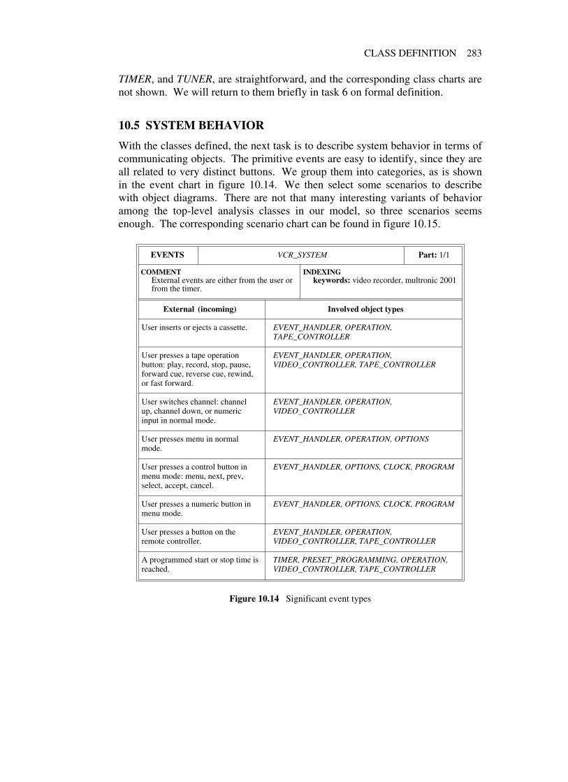
CLASS DEFINITION 283
TIMER, and TUNER, are straightforward, and the corresponding class charts arenot shown. We will return to them briefly in task 6 on formal definition.
10.5 SYSTEM BEHAVIOR
With the classes defined, the next task is to describe system behavior in terms ofcommunicating objects. The primitive events are easy to identify, since they areall related to very distinct buttons. We group them into categories, as is shownin the event chart in figure 10.14. We then select some scenarios to describewith object diagrams. There are not that many interesting variants of behavioramong the top-level analysis classes in our model, so three scenarios seemsenough. The corresponding scenario chart can be found in figure 10.15.
EVENTS VCR_SYSTEM Part: 1/1
COMMENTExternal events are either from the user orfrom the timer.
INDEXINGkeywords: video recorder, multronic 2001
External (incoming) Involved object types
User inserts or ejects a cassette. EVENT_HANDLER, OPERATION,TAPE_CONTROLLER
User presses a tape operationbutton: play, record, stop, pause,forward cue, reverse cue, rewind,or fast forward.
EVENT_HANDLER, OPERATION,VIDEO_CONTROLLER, TAPE_CONTROLLER
User switches channel: channelup, channel down, or numericinput in normal mode.
EVENT_HANDLER, OPERATION,VIDEO_CONTROLLER
User presses menu in normalmode.
EVENT_HANDLER, OPERATION, OPTIONS
User presses a control button inmenu mode: menu, next, prev,select, accept, cancel.
EVENT_HANDLER, OPTIONS, CLOCK, PROGRAM
User presses a numeric button inmenu mode.
EVENT_HANDLER, OPTIONS, CLOCK, PROGRAM
User presses a button on theremote controller.
EVENT_HANDLER, OPERATION,VIDEO_CONTROLLER, TAPE_CONTROLLER
A programmed start or stop time isreached.
TIMER, PRESET_PROGRAMMING, OPERATION,VIDEO_CONTROLLER, TAPE_CONTROLLER
Figure 10.14 Significant event types

284 A VIDEO RECORDER
SCENARIOS VCR_SYSTEM Part: 1/1
COMMENTTypical behavior triggered by user and/orbuilt-in timer.
INDEXINGkeywords: video recorder, multronic 2001
Program a recording:User enters the options menu, selects a program position, and sets time interval and stationto record.
Execute programmed recording:A preset time is reached and a station is recorded for the chosen time interval.
Find recording, play, and rewind:User inserts a cassette, finds a program and plays it, then rewinds the tape and restores thecassette.
Figure 10.15 Three scenarios
Any button pressed is caught by the EVENT_HANDLER class, which willdirect the event to the proper object depending on button and VCR mode. Someuser actions have no effect in certain modes, such as pressing ACCEPT in normal(non-menu) mode or pressing REC when the recorder is already recording.Whether this is detected in the event handler or in the corresponding controllerobject is kept open. The object diagram for the first scenario is shown infigure 10.16. We do not model exactly how numeric values are input, sincevarious shortcuts may be applied to reduce the number of keystrokes.
The second scenario could be thought of as triggered by an internal event, butwe prefer to view the event as external (coming from the hardware clock). Weassume the clock interrupt is caught directly by the TIMER class without passing
OPERATION
EVENT_HANDLER
OPTIONS PROGRAM
TIMER
PRESET_RECORDING
1
23
4
5, 6
7
8
Scenario 1: Program a recording
1 User presses MENU button2 Options menu is opened3 User selects a program position4 A program record is opened5 User inputs numeric values6 User presses ACCEPT
7 Completed record is passed to timer8 Timer stores program data
Figure 10.16 First scenario

SYSTEM BEHAVIOR 285
PRESET_RECORDING
TIMER
OPERATION
TAPE_CONTROLLER
VIDEO_CONTROLLER
1
2, 4, 8
9
5, 6 3, 7
Scenario 2: Execute a programmed recording
1−3 The programmed channel is selected4 Timer tells controller to start recording5 Tape controller told to move to read/write6 Tape controller told to run tape normal forward7 Video controller told to record
8−9 Recording is stopped after programmed interval
Figure 10.17 Second scenario
through EVENT_HANDLER. The resulting object diagram is in figure 10.17.Finally, the third scenario is shown in figure 10.18. When the tape is stopped,
both controllers may or may not be involved depending on whether the magneticsignal should be affected. Therefore, we put message label 11 before the forkpoint in the diagram. This concludes the dynamic modeling, and we turn againto the static architecture to look in more detail at the class features.
EVENT_HANDLER
OPERATION
TAPE_CONTROLLER
VIDEO_CONTROLLER
1, 3, 6, 10, 13
11
2, 4, 5, 7, 8, 12, 14 9
Scenario 3: Find recording, play, and rewind
1−2 User inserts cassette3 User presses FF4 Tape controller told to move to sync5 Tape controller told to run tape fast forward6 User presses PLAY7 Tape controller told to run normal forward8 Tape controller told to move to read/write9 Video controller told to record10 User presses STOP11 Controllers told to stop12 Tape controller told to release tape
13−14 User ejects cassette
Figure 10.18 Third scenario

286 A VIDEO RECORDER
10.6 FORMAL CLASS DESCRIPTION
What remains is the last analysis task: to translate the class charts into moreformal class interface descriptions. Since we do not want to specify too manydetails for the VCR at the analysis level, there are not many contracting clausesto fill in. They will come later during detailed design and implementation. Theclasses for programming and tuning are shown in figure 10.19.
MENU *
is_open: BOOLEAN− − Is menu open?
open
forth
back
select
accept
cancel
delete
input– INTEGER
PROGRAM +
Inherits: MENU
OPTIONS +
Inherits: MENU
CLOCK +
Inherits: MENU
TUNER
tune
store
TIMER
store_program– PRESET_RECORDING
delete_program– INTEGER
? n ∈ {1..8}
PRESET_RECORDING
channel: INTEGER
start , stop: TIME
Invariant
channel ∈ {1..32}
Figure 10.19 Menus, timer, and tuner
Figure 10.20 shows the interfaces of the top-level operational class and thetwo controller classes. We see that at this general level, there is not (yet) muchmore information in the formal class interfaces, as compared to thecorresponding class charts. However, they are much more compact, allowingmore comprehensive views of groups of classes with some of their relations.
We show in figure 10.20 that class OPERATION will be a client of the twocontroller classes, but we do not know at this stage what features will cause thecorresponding relations.

FORMAL CLASS DESCRIPTION 287
TAPE_CONTROLLER
− − Queries
is_rw: BOOLEAN− − Is tape in read/write position?
is_sync: BOOLEAN− − Is tape in audio sync position?
is_released: BOOLEAN− − Is tape ejectable?
is_loaded: BOOLEAN− − Is cassette loaded?
is_stop: BOOLEAN− − Is tape in stop position?
is_fwd: BOOLEAN− − Is tape running normal forward?
is_fast_fwd: BOOLEAN− − Is tape running fast forward?
is_rewind: BOOLEAN− − Is tape rewinding?
is_fwd_cue: BOOLEAN− − Is tape cueing forward?
is_rev_cue: BOOLEAN− − Is tape cueing reversed?
− − Commands
move_to_rw
move_to_sync
release_tape
load
eject
fwd
fast_fwd
rewind
fwd_cue
rev_cue
Invariant
is_rw xor is_sync xor is_released
VIDEO_CONTROLLER
is_play: BOOLEAN− − Is video in playback mode?
is_rec: BOOLEAN− − Is video in recording mode?
channel: VALUE− − Current channel
play
record
set_channel– INTEGER
Invariant
¬ (is_play and is_rec)channel ∈ {1..32}
OPERATION
load_cassette
eject
play
record
stop
pause
fast_forward
rewind
forward_cue
reverse_cue
channel_up
channel_down
input– INTEGER
Figure 10.20 Controller classes

288 A VIDEO RECORDER
10.7 FINAL STATIC ARCHITECTURE
This concludes the analysis part of the BON process. To proceed further withthis case study we would need more information on the hardware used for theMultronic model. Therefore, we will stop here, and the final static structure ofour VCR system is shown in figure 10.21.
PROGRAM
OPTIONS
CLOCK
MENUS
*MENU
TUNER TIMER
PRESET_RECORDING
TIME
OPERATION
TAPE_CONTROLLER
VIDEO_CONTROLLER
VCR_UNIT
EVENT_HANDLER
Figure 10.21 Final static architecture
Comparing this architecture with our first analysis model in figure 10.8 givesus a clear illustration of the important insight that there is no objective reality.Models only exist in relation to what you want to do with them. Useful astangible objects may be for providing a starting point for building a systemmodel, they must always be treated with suspicion precisely because they aretangible and therefore in most cases somewhat special. What tend to survive inthe long term are often the more abstract underlying ideas.

11 Relational and object-oriented coexistence
How should one model persistent objects and relationships between them in anobject-oriented system? This question often arises in application domains whereinformation systems play a central role. As argued in chapter 2, a strong casecan be made against entity−relationship modeling and its variations in object-oriented contexts, since it breaks the inherent seamlessness of the approach.However, even if object-oriented technology is now rapidly moving towardscommercial acceptance on a broad scale, relational databases will most likelycontinue to play an important role as data repositories for a long time yet,including many object-oriented applications.
There are several reasons for this. First of all, statistics have proven that theaverage lifetime of stored data is far greater than the average lifetime ofapplications handling the data. Thus while applications are being modified andreplaced, corporate data, although extended and updated, tends to remain whereit sits. Therefore, many information systems have grown extremely large and thecost of a complete data conversion may not always be justifiable.
Moreover, databases are often accessed and manipulated by many differentapplications in heterogeneous environments (often geographically distributed),and it may not be worthwhile to rewrite all of these applications to comply with adifferent database organization. Other reasons may have to do with companypolicies, previous investment in database software and expertise, performancerequirements (transaction processing, concurrent updates, average uptime), anddata security (consistency controls, recovery/rollback, authorization).
The conclusion is that bridges are often needed between the relational andobject-oriented worlds. The purpose of this last case study is to discuss howobject models and relational models can be made to coexist in a system. Theapproaches illustrated are drawn from actual working implementations, but sincea full discussion could easily fill a book of its own, they have been considerablysimplified.
289

290 RELATIONAL AND OBJECT-ORIENTED COEXISTENCE
11.1 FROM DATA STORAGE TO OBJECT PERSISTENCE
Let us first recall what is needed by an object-oriented execution model. Object-oriented applications handling massive quantities of data often end up using andcreating large numbers of objects. Most existing object-oriented environmentsstill run on top of operating systems that do not support the basic run-timerequirements of an object-oriented approach: built-in object allocation, automaticreclamation of unreachable objects (garbage collection) regardless of physicallocation, and transparent paging at the object level of both transient andpersistent objects. Until basic facilities like these become widely available aspart of standardized families of operating systems, each object-orientedenvironment needs to implement all or part of them as a separate virtual machine(run-time system).
Not to burden applications with implementation details, object-orientedenvironments must offer powerful means to handle both transient and persistentobjects. Large quantities of transient objects can often be taken care of bytraditional garbage collection in combination with virtual memory managementat the operating system level. Small amounts of persistent objects, in turn, canbe encapsulated by the run-time system using database library classes interactingwith an ordinary file system. However, to handle a potentially very largenumber of persistent objects, more complete database capabilities are usuallyrequired. A mapping is needed whenever object-oriented applications interfacewith legacy systems or with databases that do not interoperate with an object-oriented environment.
Interoperability in this context means more than just a basic coupling. Owingto the high level of object integration required (object type and format,polymorphism) distribution transparency of objects with implicit access via thedevelopment environment is rapidly becoming an important issue. Sometechnical approaches addressing the problems involved are beginning to emerge,whose aim is to support the notion of an “object bus” and connect heterogeneousobject-oriented applications directly at the object level [OMG 1991].
Seamlessness between execution model and persistent data means that valuesand types directly map the class instances used by the execution model; there isno “impedance mismatch” between primary memory and disk-resident data. Anideal solution completely frees client applications from storage details andpermits virtual addressing of an infinite object space. In such cases, the object-oriented run-time system transparently pages in or out clusters of objectsaccording to their status and behavior in the application: frequency of access,reachability, expected lifetime, and so forth.
Consider the following program fragment from a developer’s standpoint. Thedeclaration and qualified call translate at execution time into: “apply routine

FROM DATA STORAGE TO OBJECT PERSISTENCE 291
register defined and exported by class CUSTOMER to an instance ofCUSTOMER (or one of its descendant classes) attached to an attribute calledattendee.”
attendee: CUSTOMER...
attendee .register
In a fully transparent persistent environment, the above is complemented by:“regardless of the effective location of the object referred to by attendee at thetime the call is executed.”
An object is persistent if its existence is independent of the system session inwhich it was created. A persistent object continues to exist until it eitherbecomes unreachable or is explicitly deleted. Various techniques can beemployed in object-oriented environments to make an object persistent.Figure 11.1 depicts some possibilities.
1 customer := new persistent CLIENT
2 customer: persistent CUSTOMER
3
persistent class CUSTOMER...
endcustomer: CUSTOMER
4
class CUSTOMERinherit PERSISTENT...
endcustomer : CUSTOMER
5
persistent_collection : PERSISTENT_UNIVERSEcustomer: CUSTOMER...
persistent_collection .put (customer)
Figure 11.1 Various persistency schemes
The first three examples in figure 11.1 introduce specific language constructs:(1) extended object creation mechanism, (2) extended type declaration of entitiesreferring to objects, and (3) extended class declaration mechanism. The last twoexamples use predefined classes to achieve persistency: (4) all children to acommon ancestor become persistent, and (5) a persistent object container acceptsany object reference, and all objects inserted into the container automaticallybecome persistent.

292 RELATIONAL AND OBJECT-ORIENTED COEXISTENCE
Regardless of the specific mechanism used, we may adopt the following deeppersistency principle: all objects reachable through successive references from apersistent object also become persistent. This ensures consistency of the systemstate (class invariants). Unless the transitive closure of objects referred to by apersistent object is also stored, some objects may become invalid.
Objects explicitly made persistent through some scheme like the ones infigure 11.1 are sometimes called persistent roots (not to be confused with rootobjects starting up system executions). All other objects may dynamically be ornot be persistent, depending on whether they can be reached from a persistentroot or not.
Persistency in BON is defined as a class property and persistent classes can bemarked as such by a special class header annotation (bullet). This is often ofinterest during analysis, since figuring out what objects need to survive systemsessions may be a good way to increase problem understanding. However, itwould be too restrictive to require that only persistent objects can be instantiatedfrom a class marked as persistent.
There may be situations in a system where a temporary object needs to behaveexactly like a persistent one, and forcing the creation of two nearly identicalclasses in such cases does not make much sense. Therefore, marking a class aspersistent in BON means that its objects are potentially persistent.
We conclude this section by stating two principles regarding persistency,which are important for the seamlessness and reversibility of the BON approach.The aim is to keep analysis and design models simple and consistent,independently of where the objects will ultimately reside.
Principle 1
There should be no syntactic distinction between persistent and transientdata in terms of how they are defined and used.
Principle 2
The persistent object model should be designed as a seamless part of thefull static model.
With these preliminaries we are ready to take a look at the problems involvedwhen object persistency (or part of it) is to be based on an underlying relationalmodel. We will discuss an approach for achieving a high degree of transparencywith regard to object retrieval and update—in spite of the structural differencesbetween object models and relational databases. The focus will be on thedynamic construction of queries to reduce as much as possible the staticdependency of applications on the actual database schema.

OBJECT MODELS AND RELATIONAL MODELS 293
11.2 OBJECT MODELS AND RELATIONAL MODELS
Our objective is to design an integration layer that can access data in differentstorage formats and automatically convert between them. This layer may alsohave its own local repository, which may be used for caching to avoid constantdata transfer through a gateway. The kind of environment envisioned isillustrated in figure 11.2.
Objects
Integration Layer
SQL Gateway
RelationalDatabase
ObjectDatabase
Repository
SQL
ObjectApplication
Data
Figure 11.2 Transparent integration of heterogeneous storage
Different forms of coupling are possible. At the highest level of integration,persistent class instances are stored along with their features and classdescriptions. With a more pragmatic approach, only the data part (statevariables) of persistent objects is stored. In both cases, the database needs to beclosely integrated with the execution model.
However, when the logical structure of the available persistent storage istotally unrelated to the object model (relational databases, flat files, indexedfiles) a separate interface layer is needed to do the necessary transformations. Infigure 11.2 a SQL interpreter is used as backend to retrieve and store data in arelational database.18
In either case, it should be possible to define application object models, wherethe persistency decisions are kept completely free from any implementationchoice, and all application objects are accessed the same way whethertransparently constructed from external data or not.
18 The relational data language SQL was earlier named SEQUEL and is usually pronounced asthough it still were. We therefore write “a SQL…” rather than “an SQL…”.

294 RELATIONAL AND OBJECT-ORIENTED COEXISTENCE
Integrity constraints
A number of data integrity rules are usually enforced in a relational system toprevent certain types of inconsistencies from entering the database. These rules,commonly known as integrity constraints, address various aspects of thesemantic content of stored data. We will mention a few of them below, and seehow they translate to a BON object model.
Domain integrity refers to type checking between the values used in queryexpressions and the declared types of the corresponding entities. All RDBMSprovide the necessary level of checking to avoid any violation of the type systemrules. Since BON is statically typed, it is assumed that the supportingenvironment (CASE tool at the analysis and design level, and programmingsystem at the implementation level) will detect any type error.
Referential integrity has to do with the consistency of references betweenschema elements. Whenever an entry in a relational table refers by a foreign keyvalue to an entry in another table, that other table must exist and have an entrywith matching primary key value. Any modification of the database contentmust keep all related tables consistent and prevent the introduction of unmatchedreferences. These checks are usually supported at the RDBMS level. It isassumed in BON that referential integrity is captured by assertions in classdescriptions. In the example given in figure 11.3, integrity is guaranteed by thepostconditions associated with the routines bid_farewell and retire.
COMPANY
staff: SET [EMPLOYEE]
bid_farewell– leaving_person: EMPLOYEE
! leaving_person ∉ staff;leaving_person .retired
EMPLOYEE
working_place: COMPANY
retire
! retired
retired: BOOLEAN
Figure 11.3 Referential integrity in class contracts
User-defined integrity is usually taken care of by stored procedures or triggersin relational databases. With BON it is part of the object-oriented datadescription. The creation routines of a class are responsible for ensuring thateach object of the class is created in a consistent state. Any operation changingthe state of the object will, if necessary, trigger other monitoring operations toensure that the consistency is maintained.
At execution time, depending on the supporting environment, integrityviolations may invoke exception handlers, rollback procedures, and otherrecovery mechanisms.

OBJECT MODELS AND RELATIONAL MODELS 295
We now turn to the design of an integration layer coupling an object modelwith a SQL gateway. There are three aspects of such a layer that need to beaddressed:
• How to retrieve data from an existing relational database.
• How to regenerate application objects from the retrieved data.
• How to design a relational schema suitable to store and retrieve a givenpersistent object model.
Our aim is to find a generic model to tackle the problems, which is asindependent as possible of both the object-oriented application and the relationaldatabase system used.
11.3 A RELATIONAL DATABASE WRAPPER
Short overview of the relational model
In relational databases, information is modeled as relations defined on finite setsof data values called domains. A relation is a set of ordered lists of data valuescalled tuples.
Each tuple is an element of the cartesian product of domains D1×D2×D3…(set of all possible ordered lists of values with one element drawn from eachdomain). Each occurrence of a domain in the definition of a relation is called anattribute, and the same domain may occur several times. Note the differencebetween domain and attribute: a domain is a basic pool of permissible values,while an attribute represents the use of a domain within a relation.
Domains and relations are implemented as tables with m rows and n columns.Each row corresponds to a tuple (an element in the set), and each column to arelational attribute. For this reason, RDBMS vendors usually use the termstable, column, and row instead of relation, attribute, and tuple.
The great majority of relational systems are normalized, which means that alldomain elements must be atomic values. All values in a given domain have thesame type chosen from a small set of predefined basic types, such as: INTEGER,FLOAT, DOUBLE, DATE, CHAR, STRING, MONEY. Each attribute (orcolumn) of a relation has a name, so it can be referred to without using itsrelative position, and a type, which is the basic type of the correspondingdomain.
Relations are usually defined with constraints imposed on the tuples to avoiddata duplication or cross-dependency. A common constraint on a relation is torequire that each tuple be uniquely identifiable by a subset of the attribute values.Such a subset is called a primary key. Often one attribute is enough to identify

296 RELATIONAL AND OBJECT-ORIENTED COEXISTENCE
tuples, in which case we have a single-attribute primary key.Access to relational data is achieved through general set operations: selection,
projection, product, join, union, intersection, and difference. In addition totables predefined in the relational schema, new tables may be createddynamically through such operations. The data access set operations areexpressed in a relational database language called SQL (Structured QueryLanguage) used to store, retrieve, and modify information in the database. (SQLhas become the de facto standard in the relational database world, and wasaccepted as an international standard by ISO in 1987. The latest ISO version,SQL/92, became ratified in 1992 [Date 1993].)
In figure 11.4, three example tables are shown: CUSTOMER, INVOICE, andPRODUCT. The header of each table shows the table name and the names ofeach attribute. Below the double line are the tuples, whose values conform to thebasic type of each attribute (these types are not shown in the table).
The most frequently exercised operations in relational database applicationsare usually simple selections of tuples whose attribute values satisfy certainconditions, insertion or deletion of tuples, and change of attribute values in
CUSTOMER
Client_Id Name Address Zip_Code
A45 Jack’s Snack 899 Ventura Blvd, La Cienaga CA 92340L20 Red Lobster 9B Nathaniel Hawthorne, Tauton MA 02780
Primary key: (Client_id)
INVOICE
Purchase_Order Product_number Qty Client_Id
940120-010 1022 500 A45
940322-093 1024 80 Y89
Primary key: (Purchase_Order, Product_number)
PRODUCT
Product_number Description Unit_Price
1022 Corned Beef 1.54 oz can 0.991023 Snails in garlic butter 0.8 oz bag 4.991024 Peeled tomatoes 1.9 oz bottle 1.99
Primary key: Product_number
Figure 11.4 Tables from a relational schema

A RELATIONAL DATABASE WRAPPER 297
tuples. Selection is mostly combined with projection, which means that only asubset of the attribute values are retrieved.
The join operation is important for more complex retrieval. For example,assume we want a list of all customers who ordered products with a unit price ofat least five dollars. The result should be presented as a table with the followingattributes: client id, client name, client address, product description.
The combination of these attributes does not exist as a table per se in ourschema, but it is possible to join our three tables to obtain the requestedinformation. Using SQL syntax, the selection can be expressed as follows:
select CLIENT.client_id, name, address, descriptionfrom CLIENT, INVOICE, PRODUCTwhere CLIENT.client_id = INVOICE.client_id and
INVOICE.product_number = PRODUCT.product_number andPRODUCT.unit_price >= 5.0
The result of a selection query is generally a set. Therefore, SQL providesfacilities to iteratively fetch each matching row. A cursor maintained by thedatabase server points to the currently retrievable row, and standard operationscan be used to move the cursor from one row to another within the result.
The relational model for database management, originated in the late 1960s byE. F. Codd, has a strong mathematical foundation [Codd 1970]. It has beenthoroughly researched and a large number of rules and criteria for relational dataorganization and manipulation have been proposed [Codd 1985a, Codd 1985b,Codd 1990]. For good comprehensive overviews of the area, see [Date 1990,Date 1983, Date 1993].
Designing a database interface cluster
Any cluster layer interfacing a relational database and an object-oriented systemwould be responsible for managing server sessions, maintaining the relationalschema, performing queries and updates, and doing the mapping between rowsand objects. To summarize this, let us define the major abstractions of such alayer and group them as shown in the cluster chart of figure 11.5.
We can also display the classes in a first static architecture sketch as shown infigure 11.6. The implementation of each model class will encapsulate a set ofexternal calls to the database server. The DATABASE_INTERFACE cluster is aclient of class ANY because any type of object may become persistent and thusneed to receive external data.
Our first aim is to outline the interface of a general reusable cluster foraccessing a relational database. The specification of this cluster is at a rathertechnical level, so we will skip the class chart definitions and move directly tothe formal class descriptions.

298 RELATIONAL AND OBJECT-ORIENTED COEXISTENCE
CLUSTER DATABASE_INTERFACE Part: 1/1
PURPOSELayer to make relational databasemanipulations transparent.
INDEXINGkeywords: object and relational
coexistence, rdbms interface
Class / (Cluster) Description
DB_SESSION Session manager responsible for handling the connection tothe database server and for tracking the proper or non-propercompletion of all transactions.
DB_QUERY SQL wrapper sending selection commands to the databaseserver.
DB_CHANGE SQL wrapper sending store, update, and delete commands tothe database server.
DB_RESULT Representation of one matching row returned by the databaseserver in response to a SQL selection.
Figure 11.5 First candidate classes in interface layer
▲
DB_SESSION▲
DB_CHANGE
▲
DB_QUERY▲
DB_RESULTcursor
DATABASE_INTERFACE
ANY
Figure 11.6 First cluster sketch
Class DB_SESSION encapsulates the most important primitives to handletransactions between an application and the database server. Its interface isoutlined in figure 11.7.
Class DB_QUERY sends SQL selection queries to the database server andstores the resulting table rows. Clients can then iterate on the result supplying acallback routine to process the table rows, one by one. The interface descriptionof class DB_QUERY is shown in figure 11.8.
Typically, the callback object will be the client object itself, inheriting fromACTION and defining the execute feature. Since the client already has areference to the DB_QUERY object on which the iteration was invoked, theexecute routine will be able to access the database cursor of the correspondingselection.

A RELATIONAL DATABASE WRAPPER 299
DB_SESSION ▲
connect− − Connect application to database server.
! is_connected
disconnect− − Disconnect application from database server.
! ¬ is_connected
commit− − Update database with last modifications.
? is_connected
rollback− − Backup to previous state.
? is_connected
is_connected: BOOLEAN− − Is application connected to the database server?
transaction_status: VALUE− − Status of last performed transaction
Figure 11.7 Encapsulation of a database session
Class DB_RESULT represents the database cursor pointing to the current tablerow returned by the database server. It is responsible for the conversion of datafields from the SQL structure on the server side into corresponding basic objectattributes that may be accessed in a normal way by the object model. Any of thefields can thus be inspected, which gives clients full control to do whateverprocessing is needed.
However, in many cases the main part of the action for each returned row willbe to transfer some or all of the data fields into the corresponding attributes ofsome result object. Therefore, the load_object command of DB_RESULT (seefigure 11.8) will automatically convert and load data from the fields of thecurrent row into an object supplied as an argument.
Each basic attribute of the argument object that has a name and a type whichmatches an attribute of the table row will be set to the corresponding value. Anobject attribute is considered basic if its type corresponds directly to a typedefined in the relational database. The mapping from one type system to anothercan be preset in a utility class and accessed when needed.
It is the client’s responsibility to ensure that each basic object attribute whichis to receive a value corresponds exactly (by name and type) to one of the table

300 RELATIONAL AND OBJECT-ORIENTED COEXISTENCE
DB_QUERY ▲
query− − Select table rows from database.
– sql_selection: STRING
iterate_on_result− − Start an iteration on resulting rows.
over: BOOLEAN− − More rows to iterate on?
! Result ↔ (row_action = ∅ orcursor = ∅ or row_action .over)
cursor: DB_RESULT− − Current resulting table row
count: VALUE− − Number of rows in result
row_action: ACTION− − Object implementing an execute− − routine for each iteration
set_action– action: ACTION
! row_action = action
DB_RESULT ▲
count: VALUE− − Number of columns in row
attribute_value: ANY− − Value at index
– index: INTEGER
attribute_name: STRING− − Name at index
– index: INTEGER
attribute_index: VALUE− − Index of attribute name
– name: STRING
load_object− − Load object from current row.
– receiver: ANY
DB_CHANGE ▲
modify− − Insert, update, or delete− − information in database.
– sql_statement: STRINGACTION *
over: BOOLEAN− − Stop calling execute?
execute*
cursor
row_action
Figure 11.8 Encapsulation of relational storage and retrieval
row attributes. Furthermore, the names and types of the attributes of an objectmust be dynamically accessible at execution time for the automatic data transferto work. In object-oriented environments where this information is not available,a corresponding table (preferably generated from the corresponding classdescription by some tool) may have to be attached to each persistent class.
Note that the automatic loading does not require all basic attributes of thereceiving object to match columns in the table row, nor all columns tocorrespond to an object attribute. Only basic attributes with matching name andtype will be transferred. This convention has two advantages:

A RELATIONAL DATABASE WRAPPER 301
• Some basic object attributes may be left out of a query if they areconsidered uninteresting in some context (perhaps given default values).
• Several objects of different type may be loaded, one at a time, from thesame query result. This will be important for our design of the higher-level layers.
Class DB_CHANGE, finally, is simply used to pass a SQL statement requestingan update, deletion, or insertion in the relational database.
Mapping non-basic object attributes
So far, we have only discussed storage and retrieval of basic object attributes.Usually, however, the attributes of most objects in an object model will be amixture of basic and non-basic types. If we look at the class REGISTRATIONfrom the conference case study, whose interface is repeated in figure 11.9, wefind two attributes that relate to other model classes, namely PERSON andTUTORIAL.
REGISTRATION ●
attendee: PERSON
registered_at: DATE
amount_paid: VALUE
invoice_sent: BOOLEAN
confirmed: BOOLEAN
paper_sessions: BOOLEAN
selected_tutorials: SET [TUTORIAL]
Figure 11.9 A persistent class description
These attributes represent object references which cannot be mapped directlyto relational attributes. (In this case study, we will assume that all typed featuresof persistent model objects represent class attributes rather than functions, unlessotherwise stated.)
However, we can use the automatic data transfer previously described to havethe basic attributes of a REGISTRATION object (registered_at, amount_paid,invoice_sent, confirmed, and paper_sessions) automatically initialized from thedatabase rows. In an eventual implementation, general types such as VALUE infigure 11.9 will have been specialized to a basic type of the programminglanguage making the correspondence to the relational types clear. A possible

302 RELATIONAL AND OBJECT-ORIENTED COEXISTENCE
mapping could be the one in figure 11.10.The PERSON and TUTORIAL objects corresponding to attendee and
selected_tutorials can then be initialized separately with rows coming from otherrelations, and the corresponding references filled in by the application objectresponsible for restoring REGISTRATION objects.
Name Type
REGISTERED_AT DATE(MM/DD/YY,HH24.MI.SS)AMOUNT_PAID FLOATINVOICE_SENT CHAR(1)CONFIRMED CHAR(1)PAPER_SESSIONS CHAR(1)
Figure 11.10 Relational table representing class REGISTRATION
When a persistent object structure is stored in the database, we must capturethe unique identity of each object through primary keys in the database tables.Sometimes basic attributes already exist, whose values can be used to fullyidentify each object. In our case, it might be possible to use registered_at as theprimary key, provided that time information of enough granularity is includedand that registrations are not entered simultaneously.
If such an attribute (or group of attributes) does not exist, we need to add anextra field containing a unique identifier. Such an extra field may also be usefulfor efficiency purposes when the existing primary key is long and many otherpersistent objects will refer to this one.
Object reference attributes may be stored as fields pointing to other tablesrepresenting the referenced objects (so-called foreign keys). Different strategiesmay be used to represent references between model objects, depending on thecorresponding instance multiplicity.
• If the reference is one-to-one (as for attendee in class REGISTRATIONabove), an extra field in either one of the tables REGISTRATION orPERSON containing a primary key to the other is enough.
• If the reference is one-to-many (as for children in a class MOTHER), anextra field in the table representing the “many” pointing to the tablerepresenting the “one” will do.
• If the reference is many-to-many (as for selected_tutorials above), we mayneed to represent the relation as a joint table TUTORIAL_ATTENDENCEcontaining two primary keys: one pointing to table REGISTRATION andone to TUTORIAL.
However, if the maximum number of instances referred to by either sideis low, another possibility is to map the reference into a fixed number ofextra fields containing either a zero reference or a primary key value.

A RELATIONAL DATABASE WRAPPER 303
For example, if the maximum number of tutorials each person mayattend is four, a separate table can be avoided by adding attributestutorial1, tutorial2, tutorial3, and tutorial4 to table REGISTRATION.
There are also various strategies for mapping inheritance relations to relationaldatabase schemas. For overviews, see [Rahayo 1993, Premerlani 1994,Blaha 1994].
A scenario
We conclude this section with a scenario illustrating how an application may usethe query facility with automatic data transfer. The dynamic diagram is shownin figure 11.11.
CLIENT_OBJECTDB_SESSION
REGISTRATION
DB_QUERY
DB_RESULT1 9
4
6
10
7 2, 3, 5, 8
Scenario: Query database and load result
1−3 A client object starts a database session, creates a queryobject, and invokes a SQL query on it.
4−7 The client creates a new registration and starts an iteration onthe query result, supplying itself as action object. The queryobject resets the cursor to point to the next resulting row, andinvokes the client action routine.
8−10 The action routine obtains the cursor object and tells it to loadthe registration object from the table row.
Figure 11.11 Scenario showing access and automatic load
11.4 INTERFACING AN EXISTING RELATIONAL SCHEMA
Another important issue for the database encapsulation is the structure of therelational schema (what precise tables and attributes we need to access). Variousfactors affect the design of such a schema.

304 RELATIONAL AND OBJECT-ORIENTED COEXISTENCE
Factors determining the schema
Basically, there are two situations regarding choice of data organization:
• The relational schema mapping the object model will not be used for anyother purpose.
• The relational schema is also used by other applications that do notnecessarily have exactly the same view of the world.
In the first case, the database can be used as an implementation vehicle withrelational tables replacing flat files, indexed files, or any other data storagefacility. This situation leaves a great deal of freedom in designing the relationalschema, and data administrators may capture the object model in a way that bestfits the application. The goal is then to find a suitable tradeoff between amapping giving good performance and one that is easy to understand andmaintain.
In the second case, many additional factors must be taken into account. Oftenthe schema and associated database (or a significant part of it) is a legacy to oursystem, which we may not be able to do anything about. The way attributes aredistributed in the object model may then be very different from the organizationof the corresponding data on the relational side.
This may result in SQL queries performing complicated joins across numerousscattered tables, which may degrade performance. Often the solution is toperform a number of pre-joins on selected tables and store them temporarilyduring an object-oriented session. The initial cost at session start is then offsetby the improved performance during data transfer between the models.
With a growing number of heterogeneous applications sharing persistentinformation across networks, the ability to adapt to existing structures isimportant. In fact, even if the schema can be optimally tailored to an objectmodel (no initial legacy), the database organization tends to become much morerigid once it has been filled with large amounts of data.
As time passes, the object model will gradually change (perhaps even fasterthan with traditional models, because of the inherent flexibility of the object-oriented approach). The impedance mismatch may then make it too expensive tocontinually modify the relational structures to keep up with the changes. Thismeans we may have to face the legacy situation soon enough, even in caseswhere the only applications ever accessing the data are object oriented!
The rest of this case study will be devoted to a detailed discussion of howexisting schemas can be mapped to model objects. We will design a set ofclusters of reusable classes enabling applications to become independent of theexact database organization, and show how this cluster fits in with the generaldatabase encapsulation presented in the previous section.

INTERFACING AN EXISTING RELATIONAL SCHEMA 305
We will see how the design can be done gradually in layers raising the level ofabstraction to overcome the structural differences between the relational andobject models.
Schema dependency
If a typed implementation language is used, making static changes in the objectmodel implies recompilation of the application. This is reasonable, and usuallycorresponds to a new version of the software. However, updates of the relationalschema in a database shared by many applications may occur frequently (newcolumns added to tables, new tables added, minor reorganizations for efficiency).A solution which forces recompilation and reinstallation of an application eachtime a schema change occurs is therefore too rigid in most cases.
For this reason, we should strive to keep our applications free from exactknowledge of the mapping between the object model and the relational database.Rather than placing complete information directly in the static class structureabout the names of each database column accessed and the table it resides in, themapping should be dynamically reconfigurable by modification of data in somerepository. But how can we obtain adequate performance without integrating therelational structure in our object-oriented applications?
A virtual database
One solution is to define a virtual database containing a set of virtual tables, andthen make applications statically dependent only on this database. (Such virtualtables are known as views in RDBMS terminology.) If the virtual database ischosen reasonably close to the real database, the conversion between the twoschemas will be straightforward, and can be effected by SQL statementsdynamically maintained as stored procedures or persistent strings. This givesfreedom to rename and create new tables in the database and to rename andmove around columns between them without changing the static structure of theapplications.
Regarding the logical representation of each column in the database, theamount of freedom depends of course on the complexity of the mapping. If thedatabase stores temperature in degrees Fahrenheit and the object model uses theCelsius scale, we cannot expect SQL to hide this fact. Also, even if the SQLdialect provided by the database server would allow expressions to retrieve twodatabase columns given_names and last_name and directly return a concatenatedattribute name to the object model, it will hardly be possible to do the reverse onupdate.
Therefore, the logical structure of the real database must usually be mirroredby the virtual database, and applications must be statically dependent on the

306 RELATIONAL AND OBJECT-ORIENTED COEXISTENCE
representation form chosen for each column interacted with. However,independence of the exact tables in which the columns reside, as well as of anytable or column renaming, is still a great advantage.
Each virtual table is represented by a class encapsulating a set of basicattributes. The virtual table classes (which collectively represent the databasevisible to the application) will be named row classes. Instances of row classesare called row objects and each row object will act as a gateway to the realdatabase.
Each virtual table is chosen so that there is a simple mapping between itsattributes and the attributes of the real database tables. The persistency classeswill encapsulate operations to do the conversion using a SQL database server.However, the corresponding SQL statements will be maintained outside theapplication to always reflect the current state of the real database schema. Anapplication can load the correct SQL mapping at startup time or, in case it needsto run continuously for a long time, be triggered to reload any change that mayoccur during execution.
An example application
To illustrate the above approach, let us select four of the persistent classes fromthe conference case study (chapter 9). The corresponding class descriptions,showing only the features which we assume will be implemented as attributes,are repeated in figure 11.12.
We also assume there is a corporate database which is to be used for mappingrelevant parts of our object model. In the corporate database, we find four tablescontaining information that can be used to represent the basic attributes ofclasses PERSON and REGISTRATION. These are shown in figure 11.13. Thereare no existing tables corresponding to classes TUTORIAL or PRESENTATION.
The CUSTOMER and AFFILIATION tables come from the company’sgeneral customer register and the INVOICE table from its accounting system.The REGISTRATION table is assumed to have been designed as part of an oldersystem which handles conference registrations but not the technical program.We also assume that at present there is nothing we can do to change the formatsof these tables. This represents a kind of legacy situation not uncommon inpractice.
Since some objects are more difficult than others to map to a relationalsystem, it may be an advantage to have a relational and object-orientedpersistency mix. In this case, we choose to store and retrieve PERSON andREGISTRATION objects in the relational database, while TUTORIAL objectswill be stored using some object persistency mechanism provided in thelanguage environment.

INTERFACING AN EXISTING RELATIONAL SCHEMA 307
REGISTRATION ●
attendee: PERSON
registered_at: DATE
amount_paid: VALUE
invoice_sent: BOOLEAN
confirmed: BOOLEAN
paper_sessions: BOOLEAN
selected_tutorials: SET [TUTORIAL]
PERSON ●
registration: REGISTRATION
name: VALUE
affiliation: VALUE
address: VALUE
postal_mail: VALUE
email: VALUE
phone: VALUE
fax: VALUE
TUTORIAL ●
Inherits: PRESENTATION
capacity: VALUE
attendee_count: VALUE
prerequisite_level: VALUE
track: VALUE
duration: DURATION
PRESENTATION *
code: VALUE
title: VALUE
authors: SET [PERSON]
status: STATUS
speakers: SET [PERSON]
OBJECT_MODEL
Figure 11.12 Simplified persistent object model
This strategy also fits well with general performance considerations. Since thetutorial objects are relatively few and frequently accessed, they should remain inmain memory during system execution. Person and registration objects, on theother hand, may occur in great numbers but only the ones currently beingprocessed need fast access.
The general access, manipulation, and update of our object model andcorresponding relational data can now be outlined as follows:
• Creation of new tutorial objects.These objects must be present before any registrations can be accepted,since choice of tutorials is part of the registration data. Before thereference to speakers and authors is filled in, the CUSTOMER andAFFILIATION tables are searched to check whether some of the persons

308 RELATIONAL AND OBJECT-ORIENTED COEXISTENCE
CUSTOMERName Type
CUSTOMER_CODE INTSALUTATION CHAR(4)LAST_NAME CHAR(32)FIRST_NAME CHAR(32)MIDDLE_INITIAL CHAR(1)COMPANY INTEXTENSION CHAR(16)POSITION INTDEPARTMENT CHAR(32)
AFFILIATIONName Type
COMPANY_CODE INTCOMPANY_NAME CHAR(32)ACTIVITY INTCOMPANY_SIZE INTSTREET CHAR(32)BUILDING CHAR(32)ZIP_CODE CHAR(8)CITY CHAR(32)COUNTRY_CODE INTCOUNTRY_NAME CHAR(32)FAX CHAR(16)PHONE CHAR(16)EMAIL CHAR(16)
REGISTRATIONName Type
PERSON_CODE INTENTRY_DATE DATEDISCOUNT_RATE FLOATCONFERENCE CHAR(1)TUTORIAL1 CHAR(8)TUTORIAL2 CHAR(8)TUTORIAL3 CHAR(8)TUTORIAL4 CHAR(8)CONFIRMATION DATEINVOICE INT
INVOICEName Type
INVOICE_CODE INTCUSTOMER INTISSUED_DATE DATEPAYMENT_DATE DATEPAYMENT_TYPE CHAR(8)AMOUNT_PAID FLOATAMOUNT_RECEIVED FLOATVAT FLOAT
Figure 11.13 Relational tables in an existing database
are already present in the corporate database. If this is the case, allattribute values of the PERSON objects are initialized with thecorresponding values from the database. Persons not found in the databasewill be created and initialized from the input data on the object model side.
• Creation of new registration objects.These objects are created from registration input data and will refer to thealready defined tutorial objects. As above, assigning the referenceattendee will either retrieve an old PERSON object from the database, orcreate a new object.
• Update relational database.Database updates may be performed at regular intervals, or whenrequested by an operator. Unless some personal data needs to be

INTERFACING AN EXISTING RELATIONAL SCHEMA 309
corrected, the CUSTOMER and AFFILIATION tables will only beupdated if new persons have been entered in the object model. TheREGISTRATION table will be updated for each new registration andwhen existing ones are modified. The latter occurs, for example, when aletter of confirmation has been sent or a tutorial selection is changed.
A virtual database interface
We are now in a position to start putting things together and sketch a generaldesign for mapping persistent objects to relational systems whose tables are notin direct accordance with the object structure. We will use the architecturedepicted in figure 11.14.
●
REGISTRATION●
PERSON
PERSISTENT_OBJECTS
REGISTRATION_MANAGER
PERSON_MANAGER
STORAGE_MANAGEMENT
REGISTRATION_ROW
PERSON_ROW
VIRTUAL_RDB
*PERSISTENT
*STORAGE_MANAGER
ROW*
ACTION
RDB_INTERFACE
model_object
manager
Figure 11.14 Persistent object management (outline)
The two row classes of the virtual database are defined in figure 11.15. Theyare the virtual relational representation of the corresponding persistent objects.A row class encapsulates the interface of the RDB cluster. It may be given aSQL selection, in which case it will create a DB_QUERY object, attach itself toit, and forward the query.

310 RELATIONAL AND OBJECT-ORIENTED COEXISTENCE
ROW
session: DB_SESSION
db_query: DB_QUERY
cursor: DB_RESULT
? db_query ≠ ∅
! Result = db_query .cursor
query– sql_selection: STRING
update– sql_statement: STRING
insert– sql_statement: STRING
iterate_on_result
over: BOOLEAN
! Result ↔(db_query = ∅ or db_query .over)
load_from_cursor
? db_query ≠ ∅ and cursor ≠ ∅
attach_to_query– holder: ROW
? holder ≠ ∅
! db_query = holder .db_query
set_action– action: ACTION
? db_query ≠ ∅
! db_query .row_action = action
REGISTRATION_ROW
Inherits: ROW
person_code: INTEGER
entry_date: STRING
conference: STRING
tutorial1 , tutorial2 ,tutorial3 , tutorial4: STRING
confirmation: STRING
issued_date: STRING
amount_paid: REAL
invoice: INTEGER
PERSON_ROW
Inherits: ROW
customer_code: INTEGER
last_name: STRING
first_name: STRING
middle_initial: STRING
company: INTEGER
company_name: STRING
street: STRING
zip_code , city: STRING
country_name: STRING
fax , phone , email: STRING
Figure 11.15 Table row classes
The set_action and iterate_on_result commands can then be used to scanthrough the resulting table rows and load_from_cursor will load the current rowobject, so it can be further processed. The resulting rows must of course containall columns corresponding to the attributes of the row object, so it can be loaded.This is the responsibility of the client passing the SQL query.
Each persistent class will have two other classes corresponding to it: a rowclass representing the object in the virtual database, and a manager class to dothe conversion between the representations. Each manager will only know the

INTERFACING AN EXISTING RELATIONAL SCHEMA 311
internal format of the row objects it is responsible for.Comparing the columns of figure 11.13 with the row classes shows that the
attributes of PERSON_ROW correspond directly to a subset of the columns ofCUSTOMER and AFFILIATION, which can easily be obtained by join andprojection using SQL. The same is true for REGISTRATION_ROW with respectto tables REGISTRATION and INVOICE. Note, however, that the clients of thevirtual database know only about the virtual tables, and not even the row classknows about the scattering in the real database. There is no static trace of tablesCUSTOMER, AFFILIATION, and INVOICE.
Since we are using a corporate customer base to store personal data about allconference attendees, one may ask what to do with participants who have nocompany affiliation. Such questions are typical for legacy situations wherestructures are reused for purposes slightly different from the initial intention. Inthis case we assume that we can invent and store a special COMPANY_CODErepresenting private participants and simply leave the correspondingCOMPANY_NAME column blank for these entries.
We will return in the next section to the issue of how queries can be formed inthe object model to retrieve persistent object structures. For now, let us justassume that the proper SQL requests will at some point be supplied as anargument to the query feature of the row object.
As already mentioned, it is perfectly legal for a query to return more columnsthan what is needed to load a given row object. First, there may be a need for theclient (in its row action) to check certain data in the cursor structure that will notbe transferred to the row object. Second, if a suitable naming convention is usedso that the destination of each attribute can be inferred dynamically from itsname, a client can use the result of a single SQL query to fill several row objects,one at a time, without the need for unique attribute names across the row classes.
Since non-matching attributes are ignored in each transfer, no conflicts willoccur. A standard solution would be to use the SQL renaming facility (SELECT… AS) to give each resulting column a name related to the proper row objectattribute, regardless of what names are used in the database tables.
For example, if the data for both a REGISTRATION_ROW and aPERSON_ROW were to be returned by the same SQL query, we could usenames “REGISTRATION_ROW$ENTRY_DATE” etc. for columns whosedestination is the former object and “PERSON_ROW$FIRST_NAME” etc. forthose aimed for the second object.
If the object to be loaded is of type NAME and has an attribute attr theconversion routines would look for columns named “NAME$ATTR” andtransfer the corresponding value. (A SQL statement of type “SQL NAMES ARE...$...” introducing some character not used for other purposes would ensureunambiguous interpretation.)

312 RELATIONAL AND OBJECT-ORIENTED COEXISTENCE
11.5 QUERYING A PERSISTENT OBJECT MODEL
Besides a basic mechanism for the retrieval and storage of persistent objects, weneed a way to express what objects we want. The general issues of object-oriented query languages are still at the research stage with different directionsfavoring procedural or declarative approaches. Most concrete proposals from thelatter school, so far, have been based on relational algebra (Object SQL); see forexample [Kim 1990, Loomis 1991].
However, many commercial applications (probably the majority) do not needthe full power of relational algebra to fulfill their functionality, since the types ofretrieval performed are pretty much known in advance. Therefore, simplicityand flexibility is often more important than complete generality.
In this section, we will look at a simple approach that can be incorporated withour relational database encapsulation to express a fairly broad class of queries ina very natural way. It can also be used as a basis for automatic translation intoSQL statements, provided that the queries are not too complex.
Query frames
The idea is to transpose the technique of Query-by-Example [Zloof 1977] to theobject-oriented world. Rather than passing a query as a string expressed in somequery language, we may simply supply a template describing the retrievalcriteria for each attribute of a persistent object. The storage manager responsiblefor retrieving the corresponding type of object may then inspect the template andreturn the objects matching the criteria.
A possible scheme would be the following: the client creates a new object ofthe required persistent type, fills in the attributes that will serve as retrievalcriteria, and calls a retrieve operation on the object. The supplier side will thenfill in the missing attributes by returning all matching objects, one by one, usingthe iteration facilities described earlier.
However, there are some disadvantages with this approach. First, basicattributes that are not of reference type (like INTEGER or REAL) always havevalues. Therefore, there is no obvious way to signal whether an attribute of thistype has been set or not.
If a query result contains a real attribute temperature, a value 0 in the templatecould mean either null (all objects wanted), or zero (only objects of temperaturezero wanted). This can be circumvented by defining special values (usually thelargest representable negative numbers) and letting clients use these to signifynull values for reals and integers.
However, a more severe drawback is that the selection criteria are limited toexact equality. If this is all we need, the approach is nice and simple, but moreexpressiveness is usually required. So we are going to use a more general

QUERYING A PERSISTENT OBJECT MODEL 313
approach, which is to define for each persistent class a corresponding queryframe.
The query frame of a class is a class containing attributes with the samenames, but where all basic types have been replaced by ANY (a predefined typeto which all other types conform), and all class types have been replaced by thetype of its corresponding query frame. The query frame class corresponding toclass REGISTRATION is shown in figure 11.16.
Using objects of this kind to set up a query frame structure, rather than theobjects themselves, opens up new possibilities for expressing criteria.
REGISTRATION_FRAME
attendee: PERSON_FRAME
registered_at: ANY
amount_paid: ANY
invoice_sent: ANY
confirmed: ANY
paper_sessions: ANY
selected_tutorials: SET [TUTORIAL_FRAME]
Figure 11.16 Query frame for class REGISTRATION
Retrieval by example
For each basic attribute of the query frame, there are two choices:
1. The frame attribute is set to a value of the same type as that of thecorresponding attribute in the model object, in which case the selectioncriterion becomes exact equality on this value. This is an importantoption, since we may want to compute the corresponding valuedynamically without being forced to convert the result into a string.
2. The frame attribute is set to a string, in which case the criterion may be anexpression in any language chosen. For attributes in the model object ofstring type, we are then faced with a small ambiguity: string values willalways be interpreted as criteria expressions rather than as literal values.So if the expression "> ’Johnson’" normally means “all values sorted after’Johnson’”, some escape conventions are needed to express a literal matchof the same string. However, this is not much of a problem, since evenvery simple string matching languages will need facilities for resolvingsuch situations anyway.

314 RELATIONAL AND OBJECT-ORIENTED COEXISTENCE
The two types of attribute initialization may be freely mixed in a query. As anillustration, consider the query frames set up in figure 11.17 for the selection of aset of registrations. The query asks for all registrations entered after March 15,1994, where an invoice was sent, less than $500 has been paid, and the attendeelives in the USA.
REGISTRATION_FRAME
attendee
registered_at: "> ’1994-03-15’ "
amount_paid: "< 500 "
invoice_sent: true
confirmed: Void
paper_sessions: Void
selected_tutorials: Void
PERSON_FRAME
registration: Void
name: Void
affiliation: Void
address: "LIKE ’%USA%’"
postal_mail: Void
email: Void
phone: Void
fax: Void
Figure 11.17 Selection of registration objects using query frames
It is also possible to allow lists of query frame structures, each representing apossible selection on the attribute values of the object and its supplier objects.Such a list would then represent logical or of the selection criteria set up by eachframe structure.
Retrieval by key
It is important for a client to be able to cut off the retrieval of deep structures, sothat not everything needs to be transferred at once. Particularly, there may berecursive object structures that simply cannot be retrieved in just one SQLstatement. To this end, we employ the convention that whenever an attribute ofclass type (representing a reference to another object) is set to Void in a queryframe, the corresponding object is not retrieved. This is the case forselected_tutorials in figure 11.17. If the attribute had been initialized with anempty SET [TUTORIAL], the tutorial objects would have been retrieved too foreach registration.
When an object reference is cut off in a query frame by initializing an attributeof class type to Void in a retrieval by example, it does not necessarily mean thatthe client will not be interested in the corresponding object. It may be wantedafter some inspection of the retrieved data.

QUERYING A PERSISTENT OBJECT MODEL 315
Assume a terminal operator scans through a large number of registrationobjects without retrieving the corresponding attendee fields until a particularregistration is reached, at which point the personal data suddenly becomesinteresting. It would then be awkward if the application had to have a provisionfor reinitializing a parallel REGISTRATION_FRAME object (this time with theattendee reference initialized to an empty PERSON object rather than Void), andthen retrieve the same registration once more in order to get the personal data.
However, this will not be needed, since even if the PERSON object was notretrieved the first time, the REGISTRATION_MANAGER has the keyinformation in the corresponding REGISTRATION_ROW object to get it directlyfrom the database.
11.6 PERSISTENT OBJECT MANAGEMENT
We will now take our design one step further, and establish enough detail tooutline a full scenario from start to end of a simple persistent object retrieval. Tothis end, we extend the upper level of the preliminary sketch in figure 11.14 andintroduce a few more classes as shown in figure 11.18 to capture the generalprinciples involved.
PERSISTENT_OBJECT_MODEL
APPLICATION
QUERY_FRAMES*
QUERY_FRAME
*PERSISTENT
MANAGER_TABLE
STORAGE_MANAGEMENT*
STORAGE_MANAGER
model_object
manager
Figure 11.18 Persistent object management
Our aim is to keep as much persistency detail as possible out of the classdefinitions of the model objects. Therefore, the only static differences between aclass whose objects are potentially persistent and one whose objects are justtransient are the following two.

316 RELATIONAL AND OBJECT-ORIENTED COEXISTENCE
First, a persistent class must inherit from the class PERSISTENT (seefigure 11.18). This will enable clients to invoke retrieval operations on theobjects and iterate through sets of matching instances. Second, it will need toredefine the signature of retrieve_by_example. The argument supplied asretrieval criteria for a persistent REGISTRATION object, for example, must bedefined as REGISTRATION_FRAME.
Each type of persistent object is retrieved and stored in the underlyingdatabase by a corresponding manager class, and all manager classes inherit fromSTORAGE_MANAGER. The idea is not to build static knowledge into thepersistent classes by specifying the exact type of manager needed to take care ofthe corresponding objects. Instead, there will be a dynamic mapping available,so that persistent objects can invoke their proper manager by simply stating theirown type. Since the class name is already a unique type identification, amapping from class name strings to the corresponding manager will be enough(to keep the discussion simple, we assume that the persistent classes are non-generic).
The class name of an object can often be obtained dynamically frompredefined system classes in many object-oriented environments. One of twostandard techniques may then often be used for manager routing:
• If there are facilities in the environment to create a new instance of a classdirectly from the class name, we only need a mapping to the class name ofthe manager.
• If this is not possible but there is an “object cloning” facility available, wemay instead use object templates. At system initialization, one instance ofeach persistent manager class is created to serve as a cloning template, anda table of type TABLE [STORAGE_MANAGER , STRING] is set up to mapeach persistent class name into a reference to one of the template objects.The returned reference is then forwarded to a cloning facility, which willinstantiate a new copy of the object,
The class MANAGER_TABLE in figure 11.18 is assumed to take care of themapping, using some suitable technique. When called upon to access persistentdata, the features of PERSISTENT will thus look up the proper manager andestablish the bidirectional client link between the object and its manager.
It is important to note that although the two classes PERSISTENT andSTORAGE_MANAGER depend on each other, they are independent of whichsubtype the other party will have. The specific manager class that will do theactual conversion work must of course have full access to the attributes of thepersistent object, so REGISTRATION_MANAGER will statically depend onREGISTRATION, but not the reverse (see figure 11.18).

PERSISTENT OBJECT MANAGEMENT 317
Also, in this design we have assumed one manager for each persistent objecttype. However, this is not necessary when dynamic routing is used. If there area large number of persistent classes in a system, their management will probablytend to repeat typical patterns, and it may then be desirable to have fewer, moregeneral, managers to take care of groups of persistent object types.
We now proceed to look at the collaborating features of the two commonancestors of persistent classes and storage managers respectively.
Persistent objects
The interface of class PERSISTENT is shown in figure 11.19. The first time apersistency operation is called on a persistent object, the appropriate managertemplate will be located through a routing table shared by all persistent objects.A new storage manager will then be created and attached to the managerattribute of the persistent model object, and a back reference assigned in themanager object.
Three forms of retrieval, retrieve_by_example, retrieve_by_command, andload_from_cursor, are available for persistent objects. All three commands willbe transparently forwarded to the appropriate storage manager without anyprocessing. Note that the only thing that needs to be changed when the featureretrieve_by_example is redefined in a persistent class is the type of the queryframe argument. All implementation logic will reside in the correspondingmanager.
The first retrieval form implements the high-level selection criteria suitable forapplication clients, which should be independent of any lower-level accessdetails. However, even the storage managers should know the low-level detailsonly of the objects they manage. Note that this includes what is defined by thecorresponding persistent class, but does not include what is defined by any of itssupplier classes.
For example, to retrieve a REGISTRATION object, the registration managerwill (in most cases) need to retrieve a corresponding PERSON object referred toby attendee. However, it would be most unfortunate if the mapping of theattributes of class PERSON into attributes of the virtual relational database (oreven worse, to the real database) had to be statically known by classREGISTRATION_MANAGER.
If this were the case, we would need to create and maintain managerimplementations not only for each persistent class, but also for each combinationof a persistent class using another one as client. In a system with a large numberof persistent classes, the situation would soon become unmanageable.
One improvement would be to let the registration manager call aPERSON_MANAGER to have the attendee part retrieved and translated.

318 RELATIONAL AND OBJECT-ORIENTED COEXISTENCE
PERSISTENT *
retrieve_by_example*– frame: QUERY_FRAME
retrieve_by_command– STRING
load_from_cursor– holder: STORAGE_MANAGER
? holder ≠ ∅
store
iterate_on_result− − Process each matching instance.
over: BOOLEAN− − More instances left?
! Result ↔ (instance_action = ∅ orinstance_action .over ormanager = ∅ or manager .over)
instance_action: ACTION− − Object to process each instance
! manager = ∅ → Result = ∅;manager ≠ ∅ →
Result = manager .instance_action
set_action– action: ACTION
! instance_action = action
routing_table:(1) MANAGER_TABLE
manager: STORAGE_MANAGER
Invariant
manager ≠ ∅ ↔manager .model_object = @
STORAGE_MANAGER *
Inherits: ACTION
retrieve_by_example*– frame: QUERY_FRAME
retrieve_by_command*– STRING
load_from_cursor*– holder: STORAGE_MANAGER
? holder ≠ ∅
store*
iterate_on_result*− − Process each matching instance.
over: BOOLEAN− − More instances left?
! Result ↔ (instance_action = ∅ orinstance_action .over orrow_object = ∅ or row_object .over)
instance_action: ACTION− − Object to process each instance
set_action– action: ACTION
! instance_action = action
model_object*: PERSISTENT
row_object*: ROW
Invariant
model_object ≠ ∅ ↔model_object .manager = @
Figure 11.19 Collaborations for persistency management
However, this would create a lot of static dependencies between differentmanagers (somehow mirroring the dependencies between the correspondingmodel objects, but with enough differences to create maintenance problems). Soa better solution is to go a step further, and always channel any persistencyoperation through the persistent objects themselves.
This is where the alternative retrieval forms retrieve_by_command andload_from_cursor come in. They are both meant for storage managers rather

PERSISTENT OBJECT MANAGEMENT 319
than application clients. The arguments supplied when invoking these operationscan be used for communication between managers, but the routing will be doneby the corresponding model object, so that no unwanted static dependencies arecreated.
The iteration features are similar to the ones already discussed for the lower-level clusters. An application can attach an action object (usually itself) and thenreceive a callback for each retrieved object instance matching the selectioncriteria.
Storage managers
A storage manager translates persistent data between a model object and acorresponding virtual relation (in case the instances are stored in a relationaldatabase, as for REGISTRATION and PERSON in our example) or some otherstorage (in case the instances are stored elsewhere, as for TUTORIAL). We willonly discuss the relational aspect in this case study.
The three forms of retrieval are different. The first, retrieve_by_example, willcause the manager to read the supplied query frame object (or object structure, if“inner” frame objects are also included) and use the attribute information to finda suitable SQL query that will return the data required to set up the matchingobjects.
As was argued earlier, it is desirable to minimize the static dependencies onthe exact organization of the real database, which is why we introduced a virtualrelational database represented by the row classes. However, the SQLstatements certainly need to be phrased in terms of the current database schema,so how can we avoid becoming statically dependent on that schema when puttingthe queries together?
We will return to the issue of automatic generation of SQL queries in theconcluding section, but for now we will only assume that whatever steeringinformation needed to dynamically construct the SQL statements that may occurin our system (not always that many different types) is somehow maintainedoutside the compiled executables. Applications will thus not need recompilationwhen schema changes occur that do not affect the logical organization of thepersistent objects, which is our goal.
Unless we come up with a good automatic translation for a broad class ofqueries, the stored tables may have to be structured ad hoc and perhaps not be sotrivial to maintain. However, even with a low level of automatic support, weshould be better off than if we are forced to change our compiled classes for eachminor schema change.
We assume that a class SQL_MAPPINGS will encapsulate a set of mappingprimitives, which will be used by the managers to dynamically build the required

320 RELATIONAL AND OBJECT-ORIENTED COEXISTENCE
SQL statements. In an ambitious approach, the mapping data required wouldprobably be stored with the objects in the relational database.
The retrieve_by_command feature is mainly used when a manager needs toobtain an object through its primary key. As was explained in an earlier section,a REGISTRATION_FRAME query object may be set up to cut off the retrieval ofpersonal data by initializing the attendee reference to Void. The registrationmanager will then only retrieve the basic attributes of REGISTRATION, but willkeep the primary key to the corresponding PERSON object in case it is requestedlater.
A common scenario may be a terminal operator quickly browsing through alarge number of registrations with retrieval of the personal data turned off.When certain field values appear on the screen, the operator becomes interestedand orders the personal data to be filled in. The registration manager will thentypically be in the middle of its callback execute routine processing the currentinstance of an iterate_on_result, and have a truncated REGISTRATION asmodel_object.
The application object (which receives the order while waiting for input in itscallback action) then creates an empty PERSON_FRAME object, assigns it to theattendee attribute of the REGISTRATION_FRAME object, and issues a newretrieve_by_example on the same registration object.
The registration manager then detects that a new retrieve has been issued inthe middle of an iteration, which leads to a different action. Rather than as arequest for a new retrieval of model objects, the query is now understood as arequest to retrieve more of the deep structure of the REGISTRATION instancealready available. The degree of depth in such a new retrieval is again controlledby the values (void or non-void) of the non-basic attributes of the frame objectand its suppliers, recursively. In the case of PERSON, there is no furtherstructure to retrieve.
So the manager rescans the query frame and detects that the attendee attributeis no longer void and should be filled in. The registration manager thengenerates a suitable SQL query to obtain the missing data and invokes aretrieve_by_command on an empty PERSON object with the SQL string asargument. It then attaches itself as action object and starts a separateiterate_on_result, which will only return one PERSON object since it wasretrieved by its primary key. The translated person object is then assigned to theregistration object and control is returned to the application execute routine,which displays the missing data on the screen and the operator can continuebrowsing.
(The conventions just described represent of course a rather special designdecision, but the idea is to convince the reader that reasonably clean solutions areindeed possible.)

PERSISTENT OBJECT MANAGEMENT 321
Finally, the third form of retrieve, load_from_cursor, directs the manager toload its model_object with relational data obtained by another manager.
When composite objects like REGISTRATION are to be retrieved from thedatabase, the most efficient way is usually to let the database server do therequired joins to obtain both the registrational and personal data at once. Thismeans that a registration manager will construct the full query and supply it to aREGISTRATION_ROW object, which will call the database server and get a setof table rows in return.
The registration manager then invokes a load_from_cursor on the row objectto load all basic attributes of the registration, and the manager can translate theseinto the registration object. However, the person attributes for the attendeesupplier object remain, and they cannot be loaded and translated by thismanager, since we do not want cross-dependencies on internal formats.
Instead, the registration manager simply creates an empty PERSON object andinvokes load_from_cursor on it, supplying itself as cursor holder. The personobject does not know anything about cursors, but it can propagate the request toa PERSON_MANAGER, which will then access the supplied manager argument,extract the corresponding REGISTRATION_ROW, and supply it to aPERSON_ROW as argument of an attach_to_query.
The person manager invokes load_from_cursor on the PERSON_ROW object,which (since it has been reattached) will then transfer data from the cursor heldby the registration row, and then translates the resulting row attributes into theperson object. The registration manager can now use the retrieved person objectto complete its registration object.
A full retrieval scenario
We are now ready to present a complete scenario describing how a persistentregistration object is retrieved from the database. A dynamic object diagramwith its accompanying scenario box can be found in figure 11.20. However, forthe interested reader, we will also go through each step in more detail below andmention the operations involved.
A typical scenario would proceed as follows.
1. A client initializes a REGISTRATION_FRAME with attribute attendeeattached to a PERSON_FRAME object to signify that the personal data ofeach registration should also be retrieved. The attributes (of both frameobjects) whose values are to be part of the selection criteria are set tomirror the conditions. The client then invokes retrieve_by_example on aREGISTRATION object, supplying the query frame as argument.
The registration object invokes a corresponding retrieve_by_example onits REGISTRATION_MANAGER passing the query frame. If the

322 RELATIONAL AND OBJECT-ORIENTED COEXISTENCE
APPLICATION_CLIENT REGISTRATION_FRAME
REGISTRATION
REGISTRATION_MANAGER
REGISTRATION_ROW
DB_QUERYDB_RESULT
PERSON_MANAGER
PERSON
PERSON_ROW
1
2, 8
18, 30 3, 94
5, 10, 13, 17
126, 11, 14
7
16 15
2527
26
1931
2129 20
22, 24, 2823
Scenario: Retrieval of persistent registration objects
1−2 The client initializes a query frame with selection criteria, and asks aregistration object to retrieve matching instances.
3−7 The registration object calls a registration manager, which inspects the queryframe and sends the appropriate SQL statements to a registration row object.The row object forwards the query to the database server, which returns acursor structure.
8−10 The client tells the registration object to iterate on the result, that is load thematching objects one by one, each time giving the client a callback to processthe instance. The request is forwarded to the registration manager, whichstarts an iteration on the registration row, supplying itself as action object.
11−12 The registration row starts an iteration on the cursor structure, forwardingthe manager as action object. The manager action is called with the cursorpointing to the data of the first matching object.
13−19 The registration manager tells the registration row to load itself from thecursor, and sets the basic attributes of the registration object by translatingfrom the corresponding row attributes. It then creates a person object andtells it to load itself from an existing cursor, supplying itself as cursor holder.
20−23 The person object forwards the load request to a person manager, whichobtains the registration row from the registration manager argument. Theperson manager tells a person row to attach itself to an existing cursorstructure held by the registration row.
24−31 The person manager tells the person row to load itself from the current cursorand sets the attributes of the person object. The registration managercompletes the registration by inserting a reference to the person object, andcalls the client action routine for application processing.
Figure 11.20 Typical retrieval scenario

PERSISTENT OBJECT MANAGEMENT 323
registration object has no manager, a new one is created and attached usingthe shared routing table.
2. The registration manager then translates the query frame attribute values toappropriate SQL statements, and calls query on a REGISTRATION_ROWwith the query string as argument (see figure 11.15 for the interface of rowclasses). The REGISTRATION_ROW attaches itself to a DB_QUERYobject and calls its query operation passing the SQL string. A set of tablerows is then returned from the database server (see figure 11.8 for theinterface of the database encapsulation).
3. The client uses set_action on a REGISTRATION to attach an action objectfor processing (usually itself) and then calls iterate_on_result on theregistration, which is passed to the iterate_on_result of the manager. Theregistration manager calls set_action on the REGISTRATION_ROWsupplying itself as action object, followed by an iterate_on_result on therow.
4. The REGISTRATION_ROW transfers the manager as action object to theDB_QUERY and calls its iterate_on_result. The DB_QUERY creates aDB_RESULT representing the first matching table row and invokes theexecute callback in the registration manager. The manager then callsload_from_cursor on the REGISTRATION_ROW, which then callsload_object through the cursor feature of DB_QUERY, supplying itself asreceiving object.
5. The DB_RESULT object loads matching attributes of the first row of theresult into the REGISTRATION_ROW object. The execute routine of theregistration manager then proceeds to translate the row object attributesinto the REGISTRATION object.
6. All basic attributes of the registration have now been loaded, and theregistration manager proceeds to retrieve person data while stillperforming its execute callback routine. The registration manager createsa new PERSON object and invokes load_from_cursor on the empty object.The cursor holder passed as argument to load_from_cursor is a referenceto the REGISTRATION_MANAGER itself.
The PERSON object then invokes load_from_cursor on itsPERSON_MANAGER (attached to the person object via feature manager).The REGISTRATION_MANAGER reference just received by the PERSONobject is again passed as cursor holder in this second call.
7. The load_from_cursor command in the PERSON_MANAGER starts bygetting a reference to a REGISTRATION_ROW through the row_object

324 RELATIONAL AND OBJECT-ORIENTED COEXISTENCE
feature of the registration manager passed in as argument. It then invokesattach_to_query on the PERSON_ROW referred to by feature row_object,passing as argument the registration row. The effect is to connect theperson row to the cursor structure held by the registration row.
When this has been done, the person manager issues aload_from_cursor on the PERSON_ROW. The person row callsload_object on the cursor of its newly connected DB_QUERY andsupplies itself as receiver argument. The DB_RESULT object now loadsmatching attributes of the first row of the result into the PERSON_ROWobject.
8. The person manager translates the person row object attributes into thePERSON object. Control is then returned to the execute routine of theregistration manager, which finishes its work by attaching the personobject to the registration, which then becomes complete. It then invokesthe callback routine of the client.
9. The execute of the client then processes the returned persistent object.When the routine exits, control is returned to the execute of the registrationmanager, which returns it to the DB_QUERY, which moves the cursor tothe next resulting table row and again invokes a callback in the manager.
10. The above scenario continues until no more resulting rows remain, or theapplication client has signaled termination by setting the over feature of itsaction object to true. When this happens, the manager will propagate thedecision by setting its own over feature, and this will make theiterate_on_result of DB_QUERY return control instead of issuing acallback. The corresponding iterate_on_result of the manager alsoreturns, and the client may proceed at the point of its initial iteration call tothe registration object.
We will conclude the case study with a discussion on how much automaticsupport is feasible for the generation of SQL queries.
11.7 AUTOMATIC GENERATION OF SQL STATEMENTS
Since the SQL queries must be expressed in terms of the real database schema,we do not want to have them hard-wired into our software applications. So weare faced with two problems:
• We need to obtain dynamically the mapping between our virtual databaseand the real database in order to generate a SQL selection statement thatwill return the proper columns for our row classes.

AUTOMATIC GENERATION OF SQL STATEMENTS 325
• We need to find a way for application clients to express selection criteriasolely in terms of model object attributes, which can be dynamicallytranslated into SQL statements on the real database.
These are challenging requirements which are not easy to meet. If we were toinvent an object-oriented query language completely unrelated to SQL, thedynamic translation would most likely become intractable. However, if weimpose some suitable restrictions on the permitted queries and on the relationalmappings used, new possibilities open up.
Model queries
The idea is to use SQL syntax transposed to the model object attributes. If thestrings assigned to the attributes of a query frame object are valid SQLexpressions restricting the corresponding model object attributes, a simpletranslation scheme is possible. With this approach, the query frames offigure 11.17 are equivalent to the query shown in figure 11.21, expressed in anobject-oriented SQL notation.
selectregistered_at, amount_paid, invoice_sent, confirmed,paper_sessions, attendee.name, attendee.affiliation,attendee.address, attendee.postal_mail, attendee.email,attendee.phone, attendee.fax
whereregistered_at > ’1994-03-15’ andamount_paid < 500 andinvoice_sent = true andattendee.address LIKE ’%USA%’
Figure 11.21 An object-oriented SQL query
Such a notation may also be used by application clients as an alternative to thequery frames of retrieve_by_example. A selection is then passed as a string toretrieve_by_command. If all attributes that are part of the selection criteria in themodel object are representable as SQL expressions built from columns in the realdatabase, the translation is reduced to simple substitution.
We may still allow some criteria involving object attributes that cannot betransformed to SQL expressions using the database schema, but then thesecriteria cannot be part of the selection sent to the database server. Acorrespondingly larger number of table rows will thus be retrieved, and the onesnot matching the non-translatable criteria filtered out a posteriori by the managerof the persistent object type.

326 RELATIONAL AND OBJECT-ORIENTED COEXISTENCE
Attribute mappings
The mapping facilities that are needed for storage managers to make automaticconversions are encapsulated in the class SQL_MAPPINGS, whose interface isoutlined in figure 11.22. All mappings are between strings and can bemaintained as simple editable tables and, for example, be stored as persistentstrings in the database.
SQL_MAPPINGS
db_select: STRING− − Table columns of real database− − corresponding to persistent_class
– persistent_class: STRING
db_from: STRING− − Tables corresponding to persistent_class
– persistent_class: STRING
db_join_condition: STRING− − Table join condition in real database− − corresponding to a non-basic attribute− − of a persistent class. Argument format:− − "CLASS_NAME.attribute_name"
– attribute: STRING
db_attribute_expr: STRING− − Table column expression in real database− − corresponding to a non-basic attribute− − of a persistent class. Argument format:− − "CLASS_NAME.attribute_name"
– attribute: STRING
db_update_pattern: STRING− − SQL template for generation of real database− − update from attributes of row_class
– row_class: STRING
Figure 11.22 Query generation primitives
The first four features return information needed to build queries that can besent to the database server. A generated query consists of three parts:
• The table columns that need to be selected to provide enough informationfor building each persistent instance.
• The join conditions for the natural joins to be performed between tablesrepresenting a client and tables representing a supplier. For example, classREGISTRATION needs to join its tables with those of class PERSON toobtain the data corresponding to the attribute attendee.

AUTOMATIC GENERATION OF SQL STATEMENTS 327
• The selection criteria expressed as SQL conditions on the retrieveddatabase table columns.
The target columns of the selection are precisely the attributes of thecorresponding row classes. The call db_select ("REGISTRATION " ) wouldreturn:
"REGISTRATION.PERSON_CODE as REGISTRATION_ROW$PERSON_CODE,REGISTRATION.ENTRY_DATE as REGISTRATION_ROW$ENTRY_DATE,REGISTRATION.PAPER_SESSIONS as REGISTRATION_ROW$CONFERENCE,REGISTRATION.TUTORIAL1 as REGISTRATION_ROW$TUTORIAL1,REGISTRATION.TUTORIAL2 as REGISTRATION_ROW$TUTORIAL2,REGISTRATION.TUTORIAL3 as REGISTRATION_ROW$TUTORIAL3,REGISTRATION.TUTORIAL4 as REGISTRATION_ROW$TUTORIAL4,REGISTRATION.CONFIRMATION_DATE as
REGISTRATION_ROW$CONFIRMATION_DATE,REGISTRATION.INVOICE as REGISTRATION_ROW$INVOICE,INVOICE.ISSUED_DATE as REGISTRATION_ROW$ISSUED_DATE,INVOICE.AMOUNT_PAID as REGISTRATION_ROW$AMOUNT_PAID"
If the selection includes personal data, a db_select ("PERSON " ) will also beneeded to add the corresponding columns to the format of the retrieved rows.
Besides the selected columns, we need to accumulate all tables that participatein the resulting selection. These could in principle be extracted from the formerstrings, since we store all column selections qualified by table name to avoid anyname clashes. However, sometimes table alias names must be used forunambiguous reference (see the next section).
We therefore store the table reference strings separately, and the calls db_from("REGISTRATION " ) and db_from ("PERSON " ) yield, respectively:
"REGISTRATION, INVOICE""CUSTOMER, AFFILIATION"
Next, we need to build the restriction clause on the rows initially selected. Thismust include the corresponding join condition for each “inner” object. Callingdb_join_condition ("REGISTRATION.attendee " ) would return:
"REGISTRATION.PERSON_CODE = CUSTOMER.CUSTOMER_CODE"
In fact, when the basic attributes of a class are stored in more than one table,there will be join conditions involved besides the ones introduced by “inner”objects. Therefore, entries may also have to be stored for the class namesthemselves, not just for each of their non-basic attributes. This is the case forboth our classes and the calls db_join_condition ("REGISTRATION " ) anddb_join_condition ("PERSON " ) will return the following strings:
"REGISTRATION.INVOICE = INVOICE.INVOICE_CODE"

328 RELATIONAL AND OBJECT-ORIENTED COEXISTENCE
"CUSTOMER.COMPANY = AFFILIATION.COMPANY_CODE"
which must also be part of the restriction clause. Finally, before completing thegenerated query by appending the selection criteria supplied by the client object,each model object attribute occurring in these criteria needs to be substituted bya corresponding SQL expression in terms of the real database columns. To thisend, the calls:
db_attribute_expr ("REGISTRATION.registered_at " )db_attribute_expr ("REGISTRATION.amount_paid " )db_attribute_expr ("REGISTRATION.invoice_sent " )db_attribute_expr ("PERSON.address " )
will return the following strings, respectively:
"REGISTRATION.ENTRY_DATE""INVOICE.AMOUNT_PAID""INVOICE.ISSUED_DATE is not null""PERSON.STREET || ’, ’ PERSON.ZIP_CODE || ’, ’ PERSON.CITY|| ’, ’ COUNTRY_NAME"
Self-joins
Assume a conference system which also keeps track of alternative arrangements(often called spouse programs) for people accompanying attendees. A possiblemodel is shown in figure 11.23.
PERSON
name: VALUEaddress: VALUE
ATTENDEE ●
Inherits: PERSON
registration: REGISTRATIONcompanion: COMPANION
COMPANION ●
Inherits: PERSON
selected_tour: VALUEattendee: ATTENDEE
Figure 11.23 Simplified model for ATTENDEE and COMPANION
An ancestor class PERSON contains common attributes, while ATTENDEEand COMPANION add the needed extensions.
If for some legacy reasons we want to use only one relational table to storeboth types of object, letting each row represent either a conference attendee orsomeone accompanying an attendee, such a table containing personal data couldlook like the one in figure 11.24. A row representing an attendee would leavethe selected tour column blank, while a companion row would have companioncode zero.

AUTOMATIC GENERATION OF SQL STATEMENTS 329
PARTICIPATORName Type
PARTICIPATOR_CODE INTNAME VARCHAR(50)ADDRESS VARCHAR(50)REGISTRATION_CODE INTCOMPANION_CODE INTSELECTED_TOUR CHAR(12)
Figure 11.24 Table covering both ATTENDEE and COMPANION
At first glance, it may seem as though an ATTENDEE object would need to bebuilt from two SQL queries: the first selecting the attendee row and the secondselecting a possible companion based on the retrieved value of the companioncode column. However, this is not necessary.
We could enter a companion row with blank name and address fields, and letit represent the “empty” companion. In each row representing anunaccompanied attendee, the corresponding key value would be used ascompanion code, thus ensuring referential integrity.
The SQL selection below could then be generated (column renaming omittedfor brevity), and the resulting rows would contain all data needed to regeneratethe complete ATTENDEE objects, one by one.
selectATTENDEE.NAME, ATTENDEE.ADDRESS,COMPANION.NAME, COMPANION.ADDRESS, COMPANION.SELECTED_TOURREGISTRATION.REGISTERED_AT, ...
fromPARTICIPANT as ATTENDEE, PARTICIPANT as COMPANION,REGISTRATION
whereATTENDEE.name = ’John Hopkins’ andATTENDEE.COMPANION_CODE = COMPANION.PARTICIPANT_CODE andATTENDEE.REGISTRATION_CODE = REGISTRATION.REGISTRATION_CODE
The generation scheme
To summarize, the generation of a SQL query using the features ofSQL_MAPPINGS would proceed as follows:
1. Scan the query frames to find out how many objects must be instantiatedfrom each table row returned by the SQL query. This is recursivelycontrolled by the client, which can either initialize a reference to a non-basic object in the query frame, or leave it as Void.

330 RELATIONAL AND OBJECT-ORIENTED COEXISTENCE
2. Construct the select-part by appending the database attribute list of thecorresponding row class for each object that is to be loaded from aresulting table row. This is done through repeated calls to db_select.(Here, as in the following steps, we implicitly assume that any neededkeywords and comma separators are also inserted.)
3. Construct the from-part by appending the database tables involved foreach object (repeated calls to db_from).
4. Start constructing the where-part by appending the join condition for eachmodel object, as well as for each attribute referring to a participating“inner” object (like attendee in our example). This is done throughrepeated calls to db_join_condition.
5. Translate all selection criteria supplied by the client query frames that areexpressed in terms of model object attributes into equivalent criteriaunderstandable by the database server. This is accomplished bysubstituting the corresponding SQL expressions of the real table columnsusing calls to db_attribute_expr.
6. Complete the where-part by appending the resulting criteria strings.
Updating the database
The generation of SQL statements for updates and insertions is much simpler.Since all data, including primary keys, is available in the row objects, we onlyneed to store SQL templates to be filled in with current attribute values. The calldb_update_pattern ("REGISTRATION " ) would return:
update REGISTRATION set"ENTRY_DATE = :entry_date, CONFERENCE = :conference,TUTORIAL1 = :tutorial1, TUTORIAL2 = :tutorial2,TUTORIAL3 = :tutorial3, TUTORIAL4 = :tutorial4,CONFIRMATION_DATE = :confirmation_date, INVOICE = :invoicewhere PERSON_CODE = :person_code"
Preceding a name by a colon is the usual SQL placeholder notation to signifythat a value will be dynamically substituted. The manager could either use thepattern to fill in a complete SQL statement for immediate execution, or put it in astored procedure to be furnished by attribute values using the dynamic SQLconventions for argument passing.
The issued_date and amount_paid attributes are not part of the pattern, sincein our legacy example we assume that these values will only be read by theconference system, while the corresponding updates are done by a separateinvoicing system.

AUTOMATIC GENERATION OF SQL STATEMENTS 331
Moreover, we have omitted insert and delete from our design for simplicity,but the mappings for these features can be handled similarly.
11.8 FULL STATIC ARCHITECTURE
Finally, we present the complete architecture of our persistency layers infigure 11.25, showing how it all fits together. As can be seen, the differentlayers are well separated and the static dependencies between them have beenreduced to a minimum.
*PRESENTATION
●
PERSON●
REGISTRATION●
TUTORIAL
PERSISTENT_OBJECT_MODEL
APPLICATION
QUERY_FRAMES
TUTORIAL_MANAGER
REGISTRATION_MANAGER
PERSON_MANAGER
STORAGE_MANAGEMENT
REGISTRATIONROW
PERSON_ROW
VIRTUAL_RDB
▲
DB_SESSION▲
DB_CHANGE▲
DB_RESULT▲
DB_QUERYcursor
RDB_INTERFACE
ROW*
ACTION
row_action
*STORAGE_MANAGER
row_object
SQL_MAPPINGS
*QUERY_FRAME
*PERSISTENT
model_object
manager
instance_action
MANAGER_TABLE
routing_table1
Figure 11.25 Persistent object mapping: full static architecture

12 Exercises
12.1 CLUSTERING A PROBLEM DOMAIN
(This exercise requires the preliminary reading of chapters 3−4.)
Analysis classes relate directly to a problem domain. However, depending onthe selected viewpoint, different logical groupings may be defined to satisfycriteria such as high cohesion, low coupling, and a (possibly nested)classification structure emphasizing important aspects of system usage.
1. Partition the cluster TRANSPORTATION given in figure 12.1 according tothe three alternate viewpoints: Crew Member, Passenger, Manufacturer.
AIRCRAFT CAPTAINFLIGHT_
ATTENDANT CABIN
SEAT RESERVATION AIRLINERLUNCH_SERVICE
SPECIAL_MEAL
SEGMENT FLIGHT CAPACITY
EXIT_DOOR
ALTITUDETRAFFIC_
CONTROLLER SPEED
TRANSPORTATION
Figure 12.1 Cluster TRANSPORTATION
2. The set of analysis classes given in figure 12.2 was inspired by[Rumbaugh 1991]. Suggest appropriate viewpoints corresponding to thetwo different clusterings, and replace the temporary symbols C1, C2, …by self-explanatory names.
332

CLUSTERING A PROBLEM DOMAIN 333
GHOST LADY
LORD COOK
C1
CASTLE
STAIRS FLOOR
CORRIDOR ROOM
WINDOW STONE
C4
TOWER DUNGEON
BOILING_OIL DUNGEON
DRAWBRIDGE
C2
{
C3
GHOST LADY
WINDOW COOK
BOILING_OIL LORD
DRAWBRIDGE
C1
CASTLE
STAIRS FLOOR
CORRIDOR ROOM
STONE TOWER
MOAT DUNGEON
C2
Viewpoint 1:
Viewpoint 2:
Figure 12.2 Two alternative cluster partitionings based on different viewpoints
3. The initial analysis of a vacation cruise system has led to a set of classesgiven in figure 12.3. For each of the three different viewpoints TravelAgent, Vacationer, and Captain, draw the system borderline that leaves outthe classes considered irrelevant in a system based on this viewpoint.

334 EXERCISES
LIFE_BOAT TWIN_BED_CABIN
SINGLE_CABIN
CAPTAIN DEPOSIT
SWIMMING_POOL
CLUB_MED TRIPMIDSHIP_OFFICER
SAFETY_BOX
UPPER_DECK
PRICELOWER_
DECKLANDMARK LATITUDE
SOCIAL_PROGRAM
CRUISE_LINER
WEEK FLAG BOOKING
VACATION_CRUISE
Figure 12.3 Cluster VACATION_CRUISE
12.2 DEFINING CLASS RELATIONSHIPS
(This exercise requires the preliminary reading of chapter 4.)
For each numbered requirement, identify candidate classes and define the type ofrelationship involved between the candidate classes. Argue your choice.
1. All factory rooms have a buzzer triggered by a central clock to signal theend of the working day.
2. Architects are often involved in different concurrent projects.
3. A country has a capital city.
4. Political parties, such as the Republican party, the Democratic party, andthe Libertarian party, have voters and supporters.
5. A road connects two cities.
6. Teaching assistants are Ph.D. students and faculty members. They get amonthly payroll check from the university administration.
7. All files are defined as a sequence of bytes. A file can be a text file, adirectory, or a special file. A text file can be replaced by a symbolic linkto a plain file. A plain file can be either a binary file or a sequential datafile. A file belongs to exactly one file system.
8. An undirected graph consists of a set of vertices and a set of edges. Edgesconnect pairs of vertices.
9. Project planning starts with a list of tasks. Each task is recursivelydecomposed into subtasks until elementary tasks are reached. Resources

DEFINING CLASS RELATIONSHIPS 335
are then allocated for each elementary task. One resource is the taskschedule, defined by a starting time and a duration. The resourcesavailable for a non-elementary task are determined by looking at theresources for each of its subtasks.
12.3 ASSERTIONS AND CLASSIFICATION
(This exercise requires the preliminary reading of chapters 3−4.)
1. Given the interface of class PERSON in figure 12.4, add a precondition tothe command marry expressing that one can only marry someone who isnot already married. Assuming two distinct person references john andhelen, sketch one or more restricted features that may be used by animplementation of marry to ensure that
john .marry (helen)
is strictly equivalent to
helen .marry (john)
2. Write the class interfaces of BRIDE and GROOM in a way that ensuresthat each person can only be married to persons of the opposite sex, andonly to one at a time.
PERSON
spouse: PERSON
marry– other: PERSON
! spouse = other
Invariant
spouse ≠ ∅ → spouse .spouse = @
BRIDE GROOM
MARRIAGE
Figure 12.4 Class PERSON and cluster MARRIAGE
3. Given the utility class FAMILY in figure 12.5, make it an ancestor of theclass PERSON in figure 12.4 and extend the contracts in classes PERSON,BRIDE, and GROOM to keep the parent−child relationship consistent andprevent brothers and sisters from marrying each other.

336 EXERCISES
FAMILY
father , mother: PERSON
children: SET [PERSON]
Figure 12.5 Class FAMILY
12.4 DYNAMIC BEHAVIOR
(This exercise requires the preliminary reading of chapter 5.)
The requirements for claim processing within a product selling organizationleads to the scenario description and dynamic diagram given in figure 12.6. Thediagram captures the main control flow of a claim processing system.
A customer’s complaint is received by a salesperson and initiates a claimprocedure. A claim form is sent to the product manager and to other persons. Acopy of the form is routed to the technical services responsible for the defect asindicated by the salesperson.
The technical department makes a report with diagnosis and corrective actiontaken. The report is passed back to the product manager, who accepts or turnsdown the claim. The salesperson eventually authorizes reimbursement orreplacement products as settlement.
Extend the dynamic model as indicated below. (Recall that message relationssignify the flow of control, not of data. Therefore, passive informationcontainers have incoming arrows when accessed by active client objects, butoutgoing arrows only when calling in turn some other object.)
1. Define a “quick settlement” scenario whereby the customer and thesalesperson immediately agree on a settlement over the phone for low-value products.
2. Update the scenario (dynamic diagram and textual description) so thatsomebody (salesperson, sales manager, or receptionist) phones thecustomer to explain the settlement when a decision has been reached.
3. Update the scenario to include persons in charge of following each claimthrough the claim handling procedure. If decisions are delayed, customersshould be notified of current status to avoid repeated soliciting.
4. Update the scenario to show shipment of replacement products, orreimbursement checks, respectively.

DYNAMIC BEHAVIOR 337
SALESPERSON DELIVERY
CLAIM_FORM
PRODUCT_MANAGER SALES_MANAGER
ACCOUNTANTSETTLEMENTCLAIM_REPORT
LOGISTICS
PRODUCT_DEVELOPMENT
QUALITY
TECH_DEP
1: Incoming external event (phone call)
2
3
4
5
6
7
8
9
10
11
12
13
14: Outgoing internal event (letter)
Scenario 1: Process a claim
1 A phone call is received by a receptionist and directed to a salesperson.
2−3 Salesperson checks delivery, and fills out a claim form according tocustomer’s complaint.
4−5 Salesperson sends claim form to product manager with copies to persons intechnical department.
6−8 Technical department considers the claim, makes a claim report, andforwards result to product manager.
9−11 Product manager consults claim report, makes settlement decision, and tellssales manager.
12 Sales manager forwards claim report with authorization to accountingdepartment.
13−14 Accounting department sends letter with customer settlement: reimbursementor replacement of product.
Figure 12.6 Dynamic scenario of claim processing system
12.5 PRESCRIPTION AND DESCRIPTION
(This exercise and the following ones require the preliminary reading ofchapters 3−5.)
Consider the following problem solving requirement:
338 EXERCISES
A shepherd wishes to move a cabbage, a lamb, and a wolf across a bridge in acarriage. The carriage can only transport one item at a time. If the lamb is leftalone with the cabbage, the cabbage will be eaten. If the lamb is left alone withthe wolf, the lamb will be eaten.
Assume a scenario where everything is safely transported across the bridgewith a minimum number of trips, and infer the following static modelinginformation.
1. List the analysis classes.
2. Group the analysis classes into clusters and draw the static architecture.
3. Outline class features.
4. Define assertions to ensure that no item will be eaten.
5. Define a class invariant to ensure that the transportation will terminate(finite number of trips).
6. Express the successful strategy using a scenario and a dynamic diagram.
7. Referring to your resulting design, look for a will_eat feature that you mayhave introduced and implement it in your favorite object-orientedlanguage.
12.6 TRAFFIC-CONTROL SYSTEM
The following specification is taken from [Korson 1990].A software system manipulates the hardware for traffic control located at an
intersection. The hardware includes a set of sensors, the traffic lights, and acontrol box. The software reads the state of the sensors, determines the newstate for the intersection, and signals the lights to change. In addition, the systemis to have other capabilities, such as a test option to cycle the lights through theset of configurations. The system can also be set to a default state, which mightbe flashing yellow in one direction and red in the other. The sensor indicates thepresence (or absence) of a vehicle in a particular lane.
There are several kinds of sensors with different internal workings, all of theminterrupt−driven with a bit set whenever the sensor is tripped. After the decisionto change the state of the intersection, every sensor is reset. This particularintersection uses three-color lights for go-straight lanes. Each light has a currentstate, a set of valid next states, and a default state. The controller physicallycontains the switches for the lights, the data stores for the sensors, and a clockfor timing the state of the poll/decision cycle. The controller software reads theclock, polls the sensors, determines the next state, and sends the signals tochange the lights.

TRAFFIC-CONTROL SYSTEM 339
1. Delineate the software system borderline and the interface with thehardware.
2. List implementation details that can be excluded from the analysis model.
3. List a first set of analysis classes mapping the problem domain.
4. Define the scenario and associated dynamic diagram describing twovehicles arriving concurrently at the intersection from different directions.
5. Estimate the number of objects (class instances) referred to in yourdynamic model.
6. Outline the static architecture and the class descriptions.
12.7 DICE GAME
At the OOPSLA ’89 Conference in New Orleans (USA), a contest was organizedby Tom Love and presented to different representatives of the object-orientedlanguage community. The aim was to compare designs and solutions resultingfrom tools, methods, and languages available at that time. The following is anoutline of the problem requirements.
A dice game called “Greed” is played between two or more players. Five diceare rolled from a cup, and the winner is the first player to score 5000 points. Toenter the game, 300 points are needed on the first roll. If the first roll is greaterthan 300, the player has the option to stop and keep the initial score or tocontinue. On continuing, only the dice that have not yet scored may be rolled. Ifall the dice score (in one or multiple rolls) the player may start a new turn byrolling all five dice. A player may continue rolling as long as a score is made oneach roll. An individual roll producing no points is called a “bust”. When a bustoccurs, all points accumulated during the turn are lost and the turn ends. Threeof a kind score 100 times the face value of one die, unless the face value is 1 inwhich case the score is 1000. Single values of 1 and 5 score 100 and 50,respectively.
1. List candidate classes and define the analysis charts of a system that wouldmonitor the “Greed” game: players, scores, rules, display of results.
2. Outline the class interfaces with public features.
3. Outline a first static diagram.
4. Outline a scenario and dynamic diagram corresponding to a “bust.”
5. Look for analysis classes that may be generalized for use in any dicegame.

340 EXERCISES
6. Consider the different alternatives for adding a graphical interface to theinitial set of model classes.
12.8 CAR RENTAL COMPANY
A car rental company wishes to computerize its car reservation and invoicingsystem. All vehicles are delivered from and returned to the same location. Thesystem will help keep track of vehicles, making single or block reservations, andissuing invoices based on the pricing structure and running promotions.
The company has several different car models from different manufacturers inits fleet of vehicles. The models are grouped in price categories. Different rentalplans are available: daily time and mileage rate, daily rate including unlimitedmileage, weekly rates, and a special weekend rate for vacationers.
The price charged by the car rental company is established in advance for agiven period. The price for a given model depends on the price category, thetype of customer, and the rental plan chosen. Corporate customers get a specialdiscount on normal rates, but not on special weekend rates.
The company finds it important to have information available on the optionswhich may be fitted to certain car models, such as two or four doors, automaticor manual transmission, anti-lock brakes, cruise control, and so forth. Theinformation on what is actually fitted to the cars in the rental fleet mustcorrespond to the information on options provided by the car suppliers. There isno charge for these options, but customers will often request some of them whenreserving cars, and the company wishes to try to meet such requests.
In addition to the fitted options there are optional non-fitted extras, such asroof-rack, trailer, snow-chains, and child seats. These extras may be requested ata special additional charge. Different optional insurance plans are also availableat extra charge.
A customer may handle a car reservation directly, through a travel agent, orthrough another company. The reservation may request certain options andextras. The means of payment is usually indicated at reservation time, but maybe changed when the car is returned. Reservations are accepted for a givenadvance period, and cars are tracked daily according to their status: available,booked, rented, under maintenance, being repaired, etc.
1. A first analysis resulted in the static architecture depicted in figure 12.7.Assign possible labels to client/supplier relationships. Look for missingclasses and clusters.
2. Draw the associated dynamic model corresponding to a block booking oftwo cars: a two-door Volkswagen with manual gears and a Chevy withautomatic transmission and roof-rack. The selected rental plan specifies

CAR RENTAL COMPANY 341
CONTRACT
*CLIENT
*MEANS_OF_PAYMENT
RENTAL
CONTRACT_ELEMENTS
DATE
SUPPORT
*VEHICLE
*RATE
*EXTRA
*INSURANCE
DRIVER
RENTAL_ITEMS
AVAILABILITY LOCATION
MODEL
*OPTION
OPTION_TYPE
VEHICLE_PROPERTIES
CAR_RENTAL_SYSTEM
Figure 12.7 Static outline of the car rental system
unlimited mileage, one week rental, corporate rate, and collision damageinsurance policy.
3. A smart reuse manager has noticed that an existing corporate componentlibrary already includes the classes PRODUCT, STORAGE_AREA,PRICING, CONSUMER, DELIVERY, and AVAILABILITY, resulting froma previous project dealing with stock management for a grocery store.Adapt the car rental classification to take advantage of these classes.
12.9 TRUCK FREIGHT
A system is designed to automate the preparation of freight transportation ontrucks. Truck carriers must comply with strict transportation regulations. Inaddition, they may become liable for any damage caused by an improperdelivery in case the regulations were not faithfully observed. The system should

342 EXERCISES
help assess the nature of the transported shipment and produce the legaldocuments that truck drivers must handle.
The different laws and ordinances regulating the traffic of trucks on roadskeep changing: new ones are issued, others become obsolete. A product may beprohibited for road transportation in some country, or in a geographic area.Regulations are based on the type of freight: type of substance, oversized oroverweight loads, perishable products.
The regulations constrain the selection of the itinerary and the delivery timeframe. For instance, some toxic substances may not be transported acrosspopulated areas, or at night; fresh fish must be transported from the harbor to theretailers in less than two days; and livestock may not be transported for acontinuous duration of more than 5 hours.
Therefore, the truck carrier company is responsible for assessing the nature oftransported products and delivering the freight in good condition, on time, andwithout violating the regulations.
Each truck load is defined by the properties of the transported goods. Theshipping company constantly queries and updates a freight database, andmanages the translation between the technical descriptions given by the customerfor each freight and their legal counterparts in terms of product classes,restrictions on the itinerary, transportation periods, and the level of qualificationrequired for the truck driver. The system should support the following tasks:
• Perform a formal evaluation of a product to be transported, based oninformation provided by the manufacturer. For chemical substances, theevaluation is based on physical properties.
• Given the product identification code thus established, define the bestpossible itinerary from a starting point to a destination with possiblerestrictions on geographic areas and roads.
• Assign a truck driver with suitable qualifications for the type, weight, andsize of the freight.
Products are categorized hierarchically in three levels: the class of the substance,the group within the class, and the identification code within the group. Aproduct may belong to several classes, groups, and codes, but only one is said tobe the major criterion while the others are considered minor criteria.
Special attention is paid to hazardous products, which are evaluated accordingto their physical characteristics such as: flash point, boiling point, solubility, andchemical components. Below are some examples:
• The flash point classifies a product within class 1 (inflammable liquids).
• The toxic effect classifies a product within class 2 (toxic substances).

TRUCK FREIGHT 343
• The corrosive effect classifies a product within class 3 (corrosivesubstances).
• The perishability classifies a product within class 4 (rapidly degradablesubstances).
A substance may be of class 1, 2, and 3, but only one class is retained as themajor criterion. Within each class, groups are established and identified by onealphabetic character. Below are some groups defined for class 2 (toxicsubstances).
• 2.A: Very poisonous products with a flash point below 21 °C and a boilingpoint below 200 °C, which do not belong to class 1.
• 2.B: Organic substances with a flash point ≥ 21 °C and non-inflammableorganic substances.
• 2.C: Metal−organic substances and carbonyls.
• 2.D: Non-organic substances that react with water, water soluble liquids,and acids of poisonous gases.
• 2.E: Other non-organic substances.
Finally, for each group, identification codes are assigned to the product orsubstance. Below are some codes within 2.C (metal−organic substances andcarbonyls):
• 2.C.10: Refrigerated perishable fruits or vegetables.
• 2.C.28: Live stock.
• 2.C.31: Organic lead compounds.
A first analysis produced the cluster sketch in figure 12.8 and one class chartshown in figure 12.9. Continue the analysis by doing the following:
1. List the analysis classes and produce a class dictionary.
2. Define a first static model by completing the initial set of clusters andclasses.
3. Define a dynamic scenario describing the assignment of a truck driver to ashipment.
4. Suggest a design that would make it possible to adapt the system to mostfuture regulation changes without the need to modify any source code.

344 EXERCISES
●
GOODS
●
BASIC_PRODUCT
*PHYSICAL_PROPERTY{SET […]
SHIPMENT
LIVE_STOCK FURNITURE
CHEMICALS GROCERIES
FREIGHT
ORGANICNON_
ORGANIC
CARBONYLMETAL_
ORGANIC
COMPOUNDS
*S_CLASS
*S_GROUP
*TOXICITYS_CODE
CHARACTERISTICS
CLASSES GROUPS
Figure 12.8 Partial cluster partitioning of truck freight system
CLASS BASIC_PRODUCT Part: 1/1
TYPE OF OBJECTElement defined in security data and storedin database.
INDEXINGcluster: PRODUCTcreated: 1994-04-06 jmn
Queries Eatable? Live? Flammable?Corrosive? Water_soluble?Flash_point, Boiling_point, Solubility,Description, Hazardousness,Substance class, Substance group, Substance code
Commands Assign substance class.Assign substance group.Assign substance code.
Figure 12.9 BASIC_PRODUCT class chart

TRUCK FREIGHT 345
5. Assume there are less than 50 class categories and groups, but thousandsof identification codes. Investigate how this may or may not impact yourdesign choices.
12.10 REAL-TIME PROCESS CONTROL
In a fragrance company, the industrial production of perfumes employs achemical reaction controlled by some real-time software. A liquid mixture madefrom raw vegetal essences is poured into a tank, and the heat is increased until itreaches a certain peak controlled by external sensors.
There is also a feedback of elements flowing out of the boiler. The outgoingsteam is kept until it complies with some trade secret combination of essencesthat are input as control parameters by the company chief executives and bytechnicians (nicknamed “noses”) in charge of maintaining the accuracy ofexisting or newly created fragrances. When perfection has been reached, thesteamed combination is forwarded to a cooling system.
A first analysis of the software resulted in the cluster chart shown infigure 12.10.
The system has several control points, three of which are listed below:
• C1: control point to regulate the liquid valve
CLUSTER Fragrance_production Part: 1/1
PURPOSEClasses controlling the chemical reactionsinvolved in producing various exactfragrances.
INDEXINGcreated: 1993-05-23 jmn
Class / (Cluster) Description
CONTROLLER Actor responsible for monitoring the boiling process undernormal operational conditions.
HEATING Device enabling change of temperature accessed through thecontroller.
PIPE Incoming and outgoing parts where the mixture is flowing.
SENSOR Actor retrieving external values.
TANK Container of mixture (liquid and steam) flowing throughpipes and heated with heating system.
STEAM_REACTION Actor used to record and check the production of steam fromthe mixed reaction liquid.
Figure 12.10 FRAGRANCE_PRODUCTION cluster chart

346 EXERCISES
• C2: control point to regulate the steam valve
• C3: control point to regulate the heating process
Each control point has a corresponding sensor:
• S1: checking the liquid level in the tank
• S2: checking the steam pressure in the tank
• S3: checking the temperature level in the tank
In addition, the system must comply with some physical constraints: the waterlevel, pressure, and temperature in the tank must range between certain lowerand upper bounds. The corresponding values (which vary depending on the typeof reaction currently in process) are dynamically entered by the system operator.
To optimize the production process, the system must also enforce thefollowing monitoring strategy:
• If the tank becomes too hot, the system should first try to add more coldliquid within a preset time frame. If after that the temperature is still toohigh, the pressure is decreased during another time frame. If this alsoproves insufficient, the heat is reduced as a last resort.
• If the tank becomes too cold, the reverse procedure is employed: firstincrease the heat, then increase the pressure, and then reduce the amountof incoming liquid.
What should be considered too hot and too cold, as well as the lengths of thetime frames, are input system parameters entered by the operator or retrievedfrom a database.
1. Define the first architectural draft of the system.
2. Describe the different classes listed in the cluster chart.
3. How would you express the constraints at the design level? What will beleft to the programming phase?
4. Draw a dynamic diagram representing a complete production phase:incoming of fragrance mixture, control of its compound elements,optimization of the process according to the physical sensor values, andtransfer of the resulting steam into the cooler.

Part VAppendices

348 PART V

Appendix A:BON textual grammar
A.1 INTRODUCTION
This appendix presents a formal syntax specification of the BON textualnotation, which is useful for automatic processing and for maintenance of BONdesigns where no case tool is available. The specification gives a comprehensiveoverview of all notational concepts in BON, facilitating the construction ofparsers for translating BON charts and diagrams into other desired formats.
Communicating BON designs from either case tools or text files to other toolswith well-defined interfaces is thus straightforward. Interesting possibilities inthis respect include configuration management tools, commercial DBMSenvironments, and widely available document processors and desktop publishingtools. For example, it is not very difficult to create templates for the informalBON charts, using some of the more advanced word processors. With textualBON it is then possible to mix the interactive input of charts with automaticgeneration from information stored elsewhere.
The formal description also gives the reader a second chance to resolvepossible unclarities that always lurk in natural language descriptions. Nothingcan compensate for the precision of a formal notation when it comes tocommunicating the difficult cases unambiguously.
On the other hand, a language grammar is much harder to read to get a generaloverview of a notation than are typical examples of language usage. For thisreason, and since a fair portion of the BON textual notation has not been shownelsewhere in the book, the next appendix will provide the interested reader withtextual equivalents to some of the graphical BON diagrams presented earlier.
The textual version of BON does not include any means for describing thelayout of diagrams. This would require an independent set of concepts largelyorthogonal to the BON structural elements. Such a language may emerge lateras a result of experience with case tools supporting BON.
349

350 BON TEXTUAL GRAMMAR
A.2 THE SYNTAX NOTATION
We will present the BON textual grammar in an extended BNF (Backus NaurForm), where the extensions are very close to the ones used in [Meyer 1992a].The syntax notation is based on the following concepts.
Any syntactically meaningful part of a BON textual specification, such as acluster, a class, or an assertion, is called a component. The structure of allcomponents of a certain category is described by a construct, and an individualcomponent conforming to this description is called a specimen of the construct.
Each construct has a unique construct name, which is a single word in romanfont starting with a capital letter. For example, Class_chart, Feature_clause, andObject_group are construct names, and the corresponding specimens are anyindividual class chart, feature clause, etc., that may be built according to the rulesspecified by the grammar.
Every construct is either terminal or non-terminal. A specimen of a terminalconstruct is called a lexical element or a token. The set of tokens make up thebasic vocabulary which may be used to construct sentences in the language, andtheir internal structure is not described by the grammar. The set of tokens areeither considered known a priori, or else described separately (usually throughregular expressions applied to sequences of individual characters, or by informallanguage).
Non-terminals, on the other hand, are described in terms of other constructs,either terminal or non-terminal. Such a description is called a production for theconstruct, and has the following form:
Construct =∆∆ right-hand-side
By convention, every non-terminal construct appears (through its constructname) as the left-hand side of exactly one production. Terminal constructs, onthe other hand, may only appear on the right-hand side (by definition). Thesymbol =∆∆ means “is defined as”.
The right-hand side of a production specifies the structure of the left-handconstruct, and since every non-terminal construct has a production attached, thecorresponding specimen can always be recursively decomposed into sequencesof tokens.
It is not always possible to tell whether a construct is terminal or non-terminalwithout checking if it occurs as the left-hand side of a production or not.However, two common token types are written using different typography foreasy identification: keywords (in lower case boldface) and fixed operators(enclosed in double quotes). There are three basic types of production, whichhave the following forms.

THE SYNTAX NOTATION 351
Aggregate
Defines the construct as a fixed sequence of construct parts. One or moreelements in the sequence may be marked as optional by enclosing them in squarebrackets. For example:
Parenthesized =∆∆ "(" Expression ")"
Inheritance_relation =∆∆ Child inherit [ "{" Multiplicity "}" ]Parent [ Semantic_label ]
defines Parenthesized as a left parenthesis followed by an Expression followedby a right parenthesis, and Inheritance_relation as a Child construct followed bythe keyword inherit, then an optional multiplicity part (Multiplicity enclosed inbraces), then a Parent construct, then an optional Semantic_label.
Choice
Defines the construct as one of a fixed number of alternative constructs. It iswritten as a non-empty sequence of constructs separated by vertical bar. Theproduction
Expression =∆∆ Quantification | Call | Operator_expression | Constant
therefore means that an Expression is a Quantification, or a Call, or anOperator_expression, or a Constant.
Repetition
Defines the construct as a variable length sequence of specimens of anotherconstruct, possibly separated (if more than one element) by a given separator.The separator (if any) may be either terminal or non-terminal. A repetition right-hand side is written in one of the two forms below:
{ Element_construct Separator_construct … }
{ Element_construct Separator_construct … }+
The first form signals that the sequence may be empty, while the second requiresat least one element. Omitting the separator construct means that multipleelements are concatenated without separators in this type of sequence. Beloware some examples. The first production defines an Index_list as a sequence ofone or more Index_clause, separated by a semicolon. The second defines

352 BON TEXTUAL GRAMMAR
Features as a sequence of one or more Feature_clause without any separator.The third production defines a Dynamic_ref as zero or more Group_prefixfollowed by a Dynamic_component_name.
Index_list =∆∆ { Index_clause ";" … }+
Features =∆∆ { Feature_clause … }+
Dynamic_ref =∆∆ { Group_prefix … } Dynamic_component_name
With these preliminaries, we are now ready to give the full syntaxspecification of the BON textual notation. The grammar is defined in thefollowing sections and then concluded by a discussion of the lexical components,summing up the keywords and operators used.
A.3 BON SPECIFICATION
Bon_specification =∆∆ { Specification_element … }+
Specification_element =∆∆ Informal_chart | Class_dictionary |Static_diagram | Dynamic_diagram |Notational_tuning
A.4 INFORMAL CHARTS
Informal_chart =∆∆ System_chart | Cluster_chart | Class_chart |Event_chart | Scenario_chart | Creation_chart
Class_dictionary =∆∆ dictionary System_name{ Dictionary_entry … }+
endDictionary_entry =∆∆ class Class_name cluster Cluster_name
description Manifest_textblock
System_chart =∆∆ system_chart System_name[ indexing Index_list ][ explanation Manifest_string ][ part Manifest_string ][ Cluster_entries ]end
Cluster_entries =∆∆ { Cluster_entry … }+
Cluster_entry =∆∆ cluster Cluster_name description Manifest_textblockSystem_name =∆∆ Identifier

INFORMAL CHARTS 353
Index_list =∆∆ { Index_clause ";" … }+
Index_clause =∆∆ Identifier ":" Index_term_listIndex_term_list =∆∆ { Index_string "," … }+
Index_string =∆∆ Manifest_string
Cluster_chart =∆∆ cluster_chart Cluster_name[ indexing Index_list ][ explanation Manifest_string ][ part Manifest_string ][ Class_entries ][ Cluster_entries ]end
Class_entries =∆∆ { Class_entry … }+
Class_entry =∆∆ class Class_name description Manifest_textblockCluster_name =∆∆ Identifier
Class_chart =∆∆ class_chart Class_name[ indexing Index_list ][ explanation Manifest_string ][ part Manifest_string ][ inherit Class_name_list ][ query Query_list ][ command Command_list ][ constraint Constraint_list ]end
Query_list =∆∆ { Manifest_string "," … }+
Command_list =∆∆ { Manifest_string "," … }+
Constraint_list =∆∆ { Manifest_string "," … }+
Class_name_list =∆∆ { Class_name "," … }+
Class_name =∆∆ Identifier
Event_chart =∆∆ event_chart System_name[ incoming | outgoing ][ indexing Index_list ][ explanation Manifest_string ][ part Manifest_string ][ Event_entries ]end
Event_entries =∆∆ { Event_entry … }+
Event_entry =∆∆ event Manifest_string involves Class_name_list

354 BON TEXTUAL GRAMMAR
Scenario_chart =∆∆ scenario_chart System_name[ indexing Index_list ][ explanation Manifest_string ][ part Manifest_string ][ Scenario_entries ]end
Scenario_entries =∆∆ { Scenario_entry … }+
Scenario_entry =∆∆ scenario Manifest_string description Manifest_textblock
Creation_chart =∆∆ creation_chart System_name[ indexing Index_list ][ explanation Manifest_string ][ part Manifest_string ][ Creation_entries ]end
Creation_entries =∆∆ { Creation_entry … }+
Creation_entry =∆∆ creator Class_name creates Class_name_list
A.5 STATIC DIAGRAMS
Static_diagram =∆∆ static_diagram [ Extended_id ] [ Comment ]component Static_block end
Extended_id =∆∆ Identifier | IntegerComment =∆∆ { Line_comment New_line … }+
Line_comment =∆∆ "− −" Simple_stringStatic_block =∆∆ { Static_component … }
Static_component =∆∆ Cluster |Class |Static_relation
Cluster =∆∆ cluster Cluster_name[ reused ] [ Comment ][ Cluster_components ]
Cluster_components =∆∆ component Static_block endClass =∆∆ [ root | deferred | effective ]
class Class_name [ Formal_generics ][ reused ] [ persistent ] [ interfaced ] [ Comment ][ Class_interface ]
Static_relation =∆∆ Inheritance_relation | Client_relation

STATIC DIAGRAMS 355
Inheritance_relation =∆∆ Child inherit [ "{" Multiplicity "}" ]Parent [ Semantic_label ]
Client_relation =∆∆ Client client [ Client_entities ] [ Type_mark ]Supplier [ Semantic_label ]
Client_entities =∆∆ "{" Client_entity_expression "}"Client_entity_expression =∆∆ Client_entity_list | Multiplicity
Client_entity_list =∆∆ { Client_entity "," … }+
Client_entity =∆∆ Feature_name | Supplier_indirection | Parent_indirectionSupplier_indirection =∆∆ [ Indirection_feature_part ":" ] Generic_indirection
Indirection_feature_part =∆∆ Feature_name | Indirection_feature_listIndirection_feature_list =∆∆ "(" Feature_name_list ")"
Parent_indirection =∆∆ "−>" Generic_indirection
Generic_indirection =∆∆ Formal_generic_name | Named_indirectionNamed_indirection =∆∆ Class_name "[" Indirection_list "]"
Indirection_list =∆∆ { Indirection_element "," … }+
Indirection_element =∆∆ "..." | Named_indirectionType_mark =∆∆ ":" | ":{" | Shared_mark
Shared_mark =∆∆ ":" "(" Multiplicity ")"
Child =∆∆ Static_refParent =∆∆ Static_refClient =∆∆ Static_ref
Supplier =∆∆ Static_refStatic_ref =∆∆ { Cluster_prefix … } Static_component_name
Cluster_prefix =∆∆ Cluster_name "."Static_component_name =∆∆ Class_name | Cluster_name
Multiplicity =∆∆ IntegerSemantic_label =∆∆ Manifest_string
A.6 CLASS INTERFACE DESCRIPTION
Class_interface =∆∆ [ indexing Index_list ][ inherit Parent_class_list ]Features[ invariant Class_invariant ]end
Class_invariant =∆∆ AssertionParent_class_list =∆∆ { Class_type ";" … }+
Features =∆∆ { Feature_clause … }+

356 BON TEXTUAL GRAMMAR
Feature_clause =∆∆ feature [ Selective_export ][ Comment ]Feature_specifications
Feature_specifications =∆∆ { Feature_specification … }+
Feature_specification =∆∆ [ deferred | effective | redefined ]Feature_name_list [ Type_mark Type ][ Rename_clause ][ Comment ][ Feature_arguments ][ Contract_clause ]
Contract_clause =∆∆ Contracting_conditions endContracting_conditions =∆∆ Precondition | Postcondition | Pre_and_post
Precondition =∆∆ require AssertionPostcondition =∆∆ ensure AssertionPre_and_post =∆∆ Precondition Postcondition
Selective_export =∆∆ "{" Class_name_list "}"Feature_name_list =∆∆ { Feature_name "," … }+
Feature_name =∆∆ Identifier | Prefix | InfixRename_clause =∆∆ "{" Renaming "}"
Renaming =∆∆ "^" Class_name "." Feature_nameFeature_arguments =∆∆ { Feature_argument … }+
Feature_argument =∆∆ "−>" [ Identifier_list ":" ] TypeIdentifier_list =∆∆ { Identifier "," … }+
Prefix =∆∆ prefix ’"’ Prefix_operator ’"’Infix =∆∆ infix ’"’ Infix_operator ’"’
Prefix_operator =∆∆ Unary | Free_operatorInfix_operator =∆∆ Binary | Free_operator
Formal_generics =∆∆ "[" Formal_generic_list "]"Formal_generic_list =∆∆ { Formal_generic "," … }+
Formal_generic =∆∆ Formal_generic_name [ "−>" Class_type ]Formal_generic_name =∆∆ Identifier
Class_type =∆∆ Class_name [ Actual_generics ]Actual_generics =∆∆ "[" Type_list "]"
Type_list =∆∆ { Type "," … }+
Type =∆∆ Class_type | Formal_generic_name

CLASS INTERFACE DESCRIPTION 357
Unary =∆∆ delta | old | not | "+" | "−"Binary =∆∆ "+" | "−" | "*" | "/" |
"<" | ">" | "<=" | ">=" |"=" | "/=" | "//" | "\\" | "^" |or | xor | and | "−>" | "<−>" | member_of | ":"
A.7 FORMAL ASSERTIONS
Assertion =∆∆ { Assertion_clause ";" … }+
Assertion_clause =∆∆ Boolean_expression | CommentBoolean_expression =∆∆ Expression
Expression =∆∆ Quantification | Call | Operator_expression | ConstantQuantification =∆∆ Quantifier Range_expression [ Restriction ] Proposition
Quantifier =∆∆ for_all | existsRange_expression =∆∆ { Variable_range ";" … }+
Restriction =∆∆ such_that Boolean_expressionProposition =∆∆ it_holds Boolean_expression
Variable_range =∆∆ Member_range | Type_rangeMember_range =∆∆ Identifier_list member_of Set_expression
Type_range =∆∆ Identifier_list ":" Type
Call =∆∆ [ Parenthesized_qualifier ] Call_chainParenthesized_qualifier =∆∆ Parenthesized "."
Call_chain =∆∆ { Unqualified_call "." … }+
Unqualified_call =∆∆ Identifier [ Actual_arguments ]Actual_arguments =∆∆ "(" Expression_list ")"
Expression_list =∆∆ { Expression "," … }+
Operator_expression =∆∆ Parenthesized | Unary_expression | Binary_expressionParenthesized =∆∆ "(" Expression ")"
Unary_expression =∆∆ Prefix_operator ExpressionBinary_expression =∆∆ Expression Infix_operator Expression
Set_expression =∆∆ Enumerated_set | Call | Operator_expressionEnumerated_set =∆∆ "{" Enumeration_list "}"
Enumeration_list =∆∆ { Enumeration_element "," … }+
Enumeration_element =∆∆ Expression | IntervalInterval =∆∆ Integer_interval | Character_interval
Integer_interval =∆∆ Integer_constant ". ." Integer_constantCharacter_interval =∆∆ Character_constant ". ." Character_constant

358 BON TEXTUAL GRAMMAR
Constant =∆∆ Manifest_constant | Current | VoidManifest_constant =∆∆ Boolean_constant | Character_constant |
Integer_constant | Real_constant |Manifest_string
Sign =∆∆ "+" | "−"Boolean_constant =∆∆ true | false
Character_constant =∆∆ "’" Character "’"Integer_constant =∆∆ [ Sign ] Integer
Real_constant =∆∆ [ Sign ] RealManifest_textblock =∆∆ String_begin String String_end
String =∆∆ { Simple_string New_line … }+
Manifest_string =∆∆ String_begin Simple_string String_end
A.8 DYNAMIC DIAGRAMS
Dynamic_diagram =∆∆ dynamic_diagram [ Extended_id ] [ Comment ]component Dynamic_block end
Dynamic_block =∆∆ { Dynamic_component … }Dynamic_component =∆∆ Scenario_description |
Object_group |Object_stack |Object |Message_relation
Scenario_description =∆∆ scenario Scenario_name [ Comment ]action Labeled_actions end
Labeled_actions =∆∆ { Labeled_action … }+
Labeled_action =∆∆ Action_label Action_descriptionAction_label =∆∆ Manifest_string
Action_description =∆∆ Manifest_textblockScenario_name =∆∆ Manifest_string
Object_group =∆∆ [ nameless ] object_group Group_name [ Comment ][ Group_components ]
Group_components =∆∆ component Dynamic_block endObject_stack =∆∆ object_stack Object_name [ Comment ]
Object =∆∆ object Object_name [ Comment ]

DYNAMIC DIAGRAMS 359
Message_relation =∆∆ Caller calls Receiver [ Message_label ]Caller =∆∆ Dynamic_ref
Receiver =∆∆ Dynamic_refDynamic_ref =∆∆ { Group_prefix … } Dynamic_component_nameGroup_prefix =∆∆ Group_name "."
Dynamic_component_name =∆∆ Object_name | Group_nameObject_name =∆∆ Class_name [ "." Extended_id ]Group_name =∆∆ Extended_id
Message_label =∆∆ Manifest_string
A.9 NOTATIONAL TUNING
This will be explained in the next section.
Notational_tuning =∆∆ Change_string_marks |Change_concatenator |Change_prefix
Change_string_marks =∆∆ string_marks Manifest_string Manifest_stringChange_concatenator =∆∆ concatenator Manifest_string
Change_prefix =∆∆ keyword_prefix Manifest_string
A.10 LEXICAL COMPONENTS
We conclude this chapter with a discussion of the lexical components, which areused to form BON textual descriptions in accordance with the grammar definedin the preceding sections. These components are the terminal constructs that donot appear as the left-hand side of any production in the grammar, and thereforeneed to be described separately.
Identifiers
The Identifier construct is defined as a sequence of alphanumeric charactersincluding underscore. An identifier must begin with an alphanumeric characterand must not end with an underscore (whose purpose really is to mimic wordseparation). Letter case is not significant, but using consistent style rules isimportant.
The recommended BON standard is to use all upper case names for class andcluster names, all lower case for feature names, and lower case beginning with acapital for object groups and constants values. We also strongly recommedusing underscore for word separation rather than, for example, in-wordcapitalization, since this greatly enhances readability.

360 BON TEXTUAL GRAMMAR
Free operators
The Free_operator construct represents feature names used as infix and prefixoperations. Such operations may be textual keywords, such as the boolean andand or, but are more often composed of special characters, like "+", "**", "=>",etc.
The purpose is usually to make object-oriented expressions (which are alwaysfeature calls in the end) look very similar to the formalisms used in somediscipline thus providing a more compact and readable notation for the problemat hand. Since it is difficult to foresee exactly what operator combinations maybe needed, BON only defines the Free_operator construct as a sequence of non-spacing printable characters that does not conflict with any of the predefinedones. However, in practice, more restrictions are added by each developmentenvironment.
Comments
Major analysis and design elements, such as static diagrams, clusters, classes,object groups, etc., often need to have comments attached to them in order toexplain overall modeling aspects that have no natural place among theconstituent parts at lower levels.
Therefore, the BON textual notation recognizes comments to majorspecification elements as part of the grammar, thereby encouraging the standardplacement of them. This also provides a parser with the possibility to check andpossibly enforce certain strategic descriptions. However, besides the placesrecognized by the grammar, comments may be inserted anywhere in a BONtextual description, except inside strings.
Strings
The construct Simple_string is defined as any string of characters not containinga New_line character. The non-terminal construct Manifest_string is aSimple_string enclosed in the pair of terminals String_begin and String_end.Similarly, the non-terminal Manifest_textblock is a sequence of Simple_stringseparated by New_line and enclosed by the same pair of terminal constructs (seethe grammar above).
These delimiters are defined by default as a string containing one double quotecharacter. The character sequence "show some class, don’t treat me like anobject" is then interpreted as a Manifest_string. However, to facilitate theaccommodation of double quotes inside strings without having to insert escapecharacters, the delimiting strings may be changed (often to some controlcharacters in connection with automatic processing).
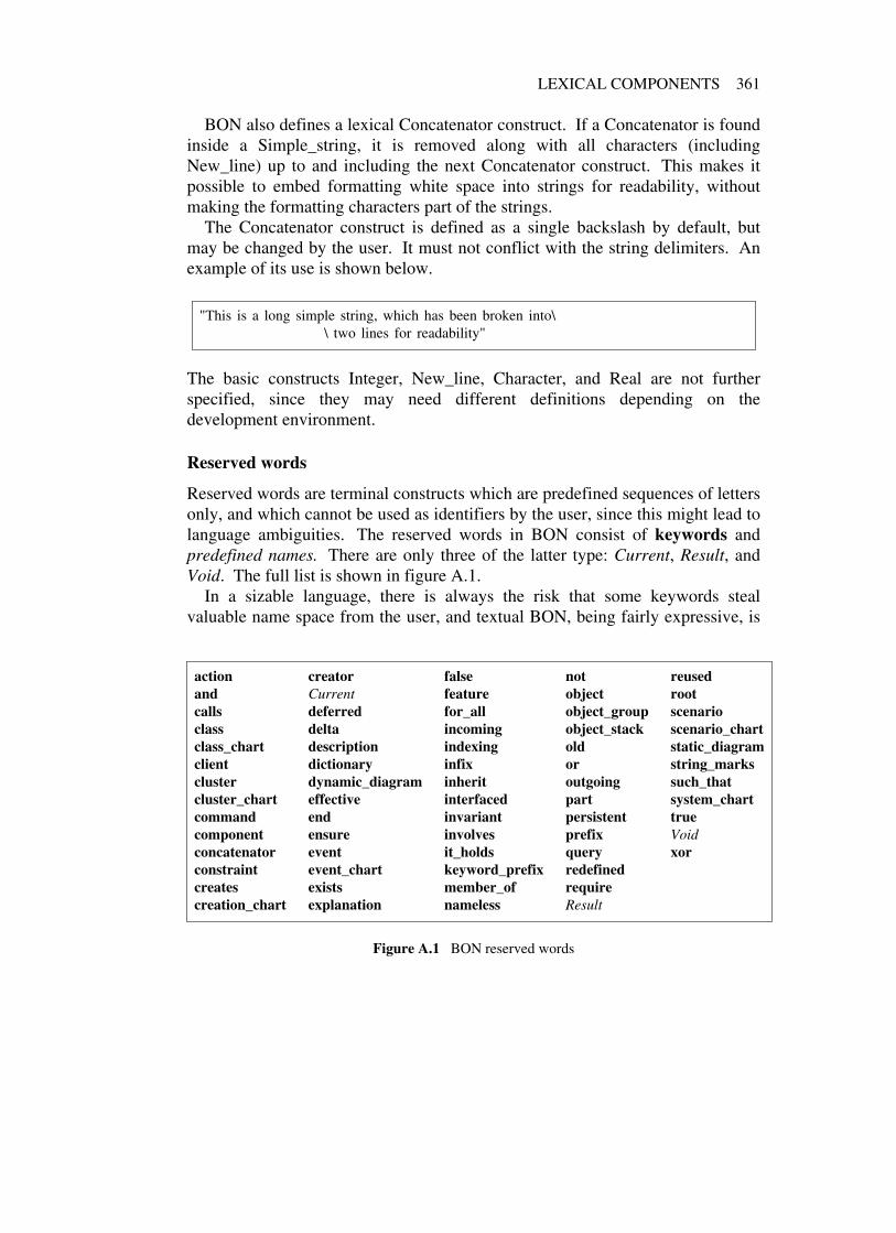
LEXICAL COMPONENTS 361
BON also defines a lexical Concatenator construct. If a Concatenator is foundinside a Simple_string, it is removed along with all characters (includingNew_line) up to and including the next Concatenator construct. This makes itpossible to embed formatting white space into strings for readability, withoutmaking the formatting characters part of the strings.
The Concatenator construct is defined as a single backslash by default, butmay be changed by the user. It must not conflict with the string delimiters. Anexample of its use is shown below.
"This is a long simple string, which has been broken into\\ two lines for readability"
The basic constructs Integer, New_line, Character, and Real are not furtherspecified, since they may need different definitions depending on thedevelopment environment.
Reserved words
Reserved words are terminal constructs which are predefined sequences of lettersonly, and which cannot be used as identifiers by the user, since this might lead tolanguage ambiguities. The reserved words in BON consist of keywords andpredefined names. There are only three of the latter type: Current, Result, andVoid. The full list is shown in figure A.1.
In a sizable language, there is always the risk that some keywords stealvaluable name space from the user, and textual BON, being fairly expressive, is
action creator false not reusedand Current feature object rootcalls deferred for_all object_group scenarioclass delta incoming object_stack scenario_chartclass_chart description indexing old static_diagramclient dictionary infix or string_markscluster dynamic_diagram inherit outgoing such_thatcluster_chart effective interfaced part system_chartcommand end invariant persistent truecomponent ensure involves prefix Voidconcatenator event it_holds query xorconstraint event_chart keyword_prefix redefinedcreates exists member_of requirecreation_chart explanation nameless Result
Figure A.1 BON reserved words

362 BON TEXTUAL GRAMMAR
no exception. To counter this disadvantage, BON defines a terminal constructKeyword_prefix, which is empty by default.
By defining Keyword_prefix as the string "$", for example, we may changethe syntax of BON so all keywords now need to be prefixed by a dollar sign, thusfreeing all the corresponding normal words for use in specification of the systemunder development.
Special symbols
Finally, we collect the complete set of special symbols used in BON with anoverview of their meaning (figure A.2). Each of them has been described earlierin the book. The ones marked as operators (except for the type operator ":") canbe viewed as class features of infix form that may be redefined by descendantclasses.
Conclusion
The BON textual notation is a full specification language for object-orientedsystem designs, whose purpose is threefold:
• It can be used to communicate exact specifications between various toolsand environments, thus taking advantage of the advances in manyindependent areas of presentation.
• It can be used for better understanding of the concepts underlying thegraphical notation and for settling ambiguities. With today’s widelyavailable parser generator utilities, the task of writing a parser for thelanguage becomes easy.
• It provides a means of storing and updating a specification in a simpleway, using standard text editors, which can serve as an alternative to adedicated case tool. It may be feasible to copy small whiteboard diagramswith pencil on paper in connection with design sessions, but maintaininglarger specifications requires more. Anybody who has experienced thepain of trying to keep evolving graphical figures up to date without strongautomatic support knows only too well what we are talking about.
Finally, regarding the different presentations that may be generated from a BONtextual description, we have not tried to cover graphical layout in the textuallanguage. The basic graphical appearance of each textual concept has beendefined earlier in this book, along with validity constraints and rules for howrelational arrows may be combined, labels be positioned, etc. But what validalternative to choose is left to the strategies of the individual case tool.

LEXICAL COMPONENTS 363
SYMBOL NAME USE
−− double dash Introduces comments
’ single quote Encloses character constants
" double quote Encloses prefix and infix operator names
, comma General element separator
; semicolon Separator for parent lists, assertionclauses, and indexing clauses
( ) parentheses Grouping of expressions, multiplicity
[ ] square brackets Encloses generic parameters
{ } braces Encloses restricted export lists, renaming,enumerated sets
+ − * / Arithmetic operatorsplus, minus, times,division
// \\ Integer division, modulo operatorsdouble slash, doublebackslash
^ up arrow Power operator, renaming
< > less than, greater than Relational operators
<= >= Relational operatorsless than or equal,greater than or equal
= /= equal, not equal Equality and non-equality
−> right arrow, implies Feature arguments, constrained genericity,logical implication
<−> equivalence Logical equivalence
. dot Feature calls, renaming, relationalreferences, object_id
.. double dot Interval marker
: colon Type mark, type operator, index separator
:{ aggregate mark Indicates aggregate supplier
Figure A.2 BON special symbols

Appendix B:BON textual examples
B.1 BON SPECIFICATION
In this appendix, we will show the corresponding textual version of some of thegraphical BON descriptions presented earlier in the book. This will giveinterested readers a feeling for the textual language without the need to decodeeverything from the grammar given in the previous appendix.
A BON textual specification consists of a sequence of one or more of thefollowing types of specification element, which may be given in any order:
• Informal chart (system, cluster, class, event, scenario, creation)
• Class dictionary
• Static diagram
• Dynamic diagram
• Notational tuning
The last type of specification does not address the system being modeled, butmay be used to dynamically alter some lexical details regarding the terminalsymbols recognized by textual BON. Three operations are available forlanguage tuning:
• string_marks to change the default double quote string delimiter
• concatenator to change the default backslash string concatenator
• keyword_prefix to alter the names of all textual BON keywords into newnames, where each old name is prefixed by a given string.
The class dictionary is meant to be generated automatically from the class chartsand / or class interfaces, so no corresponding BON chart format is specified for it.
364

BON SPECIFICATION 365
We will look at the informal charts and the static and dynamic diagrams in order,and discuss some of the choices made in the design of textual BON.
B.2 INFORMAL CHARTS
The informal charts are enclosed in <name>_chart … end blocks, and thekeywords delimiting their respective fields correspond closely to the labels usedin the graphical forms. The class charts for CITIZEN and NOBLEPERSON(from chapter 3) are shown in figure B.1, and two cluster charts are in figure B.2.
class_chart CITIZENindexing
cluster: "CIVIL_STATUS " ;created: "1993-03-15 jmn";revised: "1993-05-12 kw"
explanation"Person born or living in a country"
part "1/1 "query
"Name " , "Sex " , "Age " , "Single " , "Spouse " , "Children " , "Parents " ,"Impediment to marriage"
command"Marry " , "Divorce "
constraint"Each citizen has two parents.","At most one spouse allowed.","May not marry children or parents or person of same sex.","Spouse’s spouse must be this person.","All children, if any, must have this person among their parents."
end
class_chart NOBLEPERSONindexing
cluster: "CIVIL_STATUS " ;created: "1993-03-15 jmn";revised: "1993-05-12 kw", "1993-12-10 kw"
explanation"Person of noble rank"
part "1/1 "inherit CITIZENquery
"Assets " , "Butler "constraint
"Enough property for independence.","Can only marry other noble person.","Wedding celebrated with style.","Married nobility share their assets and must have a butler."
end
Figure B.1 Class charts: types of citizen (cf. figure 3.3)

366 BON TEXTUAL EXAMPLES
cluster_chart ORGANIZATIONindexing
author: "Kim waldén", "Jean-marc nerson";keywords: "organization " , "staff "
explanation"Handles all major events occurring during the\\ organization and completion of a conference."
part "1/1 "class CONFERENCEdescription
"The root class of the conference system."class PROGRAMdescription
"Information about the final conference program\\ and its preparation."
class TIMETABLEdescription
"Repository of scheduled events."cluster COMMITTEESdescription
"The committees engaged in the conference organization\\ to take care of the technical and administrative parts."
end
cluster_chart COMMITTEESindexing
cluster: "ORGANIZATION " ;author: "Kim waldén", "Jean-marc nerson";keywords: "committee " , "scientific board", "steering board"
explanation"Groups all general and special types of committees."
part "1/1 "class COMMITTEEdescription
"General committee abstraction."class STEERING_COMMITTEEdescription
"Committee in charge of practical arrangements."class PROGRAM_COMMITTEEdescription
"Committee in charge of selecting technical contributions."end
Figure B.2 Cluster chart (cf. figure 3.2)
It is possible to include new line characters verbatim in most of the descriptivetext fields of the charts, since these are defined as Manifest_textblock in thegrammar. However, we have chosen not to do so, because in a case tool withwindow resizing capabilities we would need to reformat text fields to fit thecurrent window size anyway. Instead, we use the string concatenator "\" to buildsimple strings from line formatted specification input.

INFORMAL CHARTS 367
Descriptive text fields consisting of a number of semantically separablephrases, such as query, command, and constraint, are syntactically defined as asequence of Manifest_string separated by a comma.
B.3 STATIC DIAGRAMS
Cluster structure
The next examples, figures B.3 and B.4, show the nesting of static components.
static_diagram First_system_breakdowncomponent
cluster CONFERENCE_MANAGEMENT_SYSTEMcomponent
cluster ORGANIZATIONcluster TECHNICAL_EVENTScluster PRINT_OUTScluster REGISTRATION
endend
Figure B.3 First cluster definition sketch (cf. figure 9.5, upper part)
Cluster components are enclosed in component … end blocks, unless thecluster is empty in which case the cluster name suffices. (An empty cluster willbe displayed graphically as an icon, but whether a non-empty cluster will beiconized or not has to do with the presentation format, which is not addressed bytextual BON.)
As in the examples, static and dynamic diagrams may have names attached foridentification and readability. Since such names are not significant for themodeled system (unlike, for example, class and cluster names), we define themas Extended_id (either Identifier or Integer). This may sometimes be practicalfor automatically generated textual diagrams.
Class headers
Figure B.5 shows a set of annotated class headers. There is only one syntacticClass construct, so headers are described by omitting the Class_interface part.
Inheritance relations
The next examples show inheritance relations of various types. Multiplicity maybe specified by a number enclosed in braces, as seen in figure B.6, where theclass TRIPLE_INDEX inherits three times from class INDEX. The joined

368 BON TEXTUAL EXAMPLES
static_diagram Nested_data_structurescomponent
cluster DATA_STRUCTUREScomponent
cluster SORTING reusedcomponent
class LINEAR_SORTclass QUICKSORTclass RADIX_SORTclass INSERTION_SORTclass SHELLSORTclass HEAPSORTclass TOPOLOGICAL_SORTclass SORT_MERGE
endcluster GRAPHScomponent
deferred class GRAPHclass WEIGHTED_GRAPHclass DIRECTED_GRAPHclass UNDIRECTED_GRAPHclass BIPARTITE_GRAPHclass DENSE_GRAPH
endend
end
Figure B.4 A nested data structure cluster (cf. figure 3.16)
static_diagramcomponent
root class CONTROL_PANELclass TRANSACTION persistentclass MAILER interfacedclass HASH_TABLE [T , U]deferred class FLYING_OBJECTeffective class HELICOPTERclass INPUT reused interfacedclass VECTOR [G] reuseddeferred class SESSION interfaced
end
Figure B.5 Annotated class headers (cf. figure 3.15)

STATIC DIAGRAMS 369
relational arrows in figure 4.1, on the other hand, have no correspondence intextual BON. Figure B.7 shows the inheritance between classes and clusters.We use dot notation on the cluster names involved to refer to classes residinginside nested clusters, as seen in the figure. This makes it possible to have localname spaces for classes in different clusters at the analysis level, and also
static_diagramcomponent
class COLD_STOREclass FREEZERclass REFRIGERATORclass INDEXclass TRIPLE_INDEXdeferred class FLYING_OBJECTeffective class AIRCRAFTeffective class ROCKETclass SPACE_SHUTTLEdeferred class VEHICLEeffective class BICYCEeffective class BOATeffective class CARREFRIGERATOR inherit COLD_STOREFREEZER inherit COLD_STORETRIPLE_INDEX inherit {3} INDEXAIRCRAFT inherit FLYING_OBJECTROCKET inherit FLYING_OBJECTSPACE_SHUTTLE inherit AIRCRAFTSPACE_SHUTTLE inherit ROCKETBICYCLE inherit VEHICLEBOAT inherit VEHICLECAR inherit VEHICLE
end
Figure B.6 Different type of inheritance (cf. figure 4.1)
documents more clearly what cluster interdependencies we have in our diagrams.If the implementation language supports renaming of classes on a cluster basis,possible name clashes may easily be resolved later.
Client relations
Labels attached to client relations are enclosed in braces, as seen in figure B.8,which contains a number of compacted generic links. Here (as in figure B.7) wehave split the figure into multiple diagrams. The third diagram in figure B.8 hadto be separated to avoid name clashes on the classes involved, which wouldmake the specification ambiguous. The first and second diagrams wereseparated to obtain the grouping of the static components contained in the figure.

370 BON TEXTUAL EXAMPLES
static_diagram 1component
cluster PARENTScomponent
class Aclass B
endcluster CHILDRENcomponent
class Cclass Dclass E
endCHILDREN .C inherit PARENTS .ACHILDREN .C inherit PARENTS .BCHILDREN .D inherit PARENTS .ACHILDREN .D inherit PARENTS .BCHILDREN .E inherit PARENTS .ACHILDREN .E inherit PARENTS .B
end
static_diagram 2component
cluster PARENTS component … endcluster CHILDREN component … endCHILDREN inherit PARENTS .ACHILDREN inherit PARENTS .B
end
static_diagram 3component
cluster PARENTS component … endcluster CHILDREN component … endCHILDREN .C inherit PARENTSCHILDREN .D inherit PARENTSCHILDREN .E inherit PARENTS
end
static_diagram 4component
cluster PARENTS component … endcluster CHILDREN component … endCHILDREN inherit PARENTS
end
Figure B.7 Recursive abstraction (cf. figure 4.3)
Although we have had no example so far in the book of nested genericderivation, this does occur in practice not too infrequently. The BON notationtherefore supports nested generic type parameters in compacted client relations,so that several levels of indirection through standard container classes can beremoved and diagrams concentrated on the essential concepts for the modeling.

STATIC DIAGRAMS 371
static_diagram 1component
class BASEBALL_CARDclass SONclass LIST [T] reusedclass PARENTclass ACCOUNTSON client {expenses} LISTPARENT client {assets} LISTLIST client {(first , last): T} BASEBALL_CARDLIST client {(first , last): T} ACCOUNT
end
static_diagram 2component
class NURSEclass PATIENTclass SURGEONclass OPERATIONclass TABLE [U , V−>KEY] reusedclass PATIENT_IDclass DATENURSE client {patients} TABLESURGEON client {duties} TABLETABLE client {item: U} PATIENTTABLE client {item: U} OPERATIONTABLE client {key: V} PATIENT_IDTABLE client {key: V} DATE
end
static_diagram 3component
class SONclass BASEBALL_CARDclass PARENTclass ACCOUNTclass NURSEclass PATIENTclass SURGEONclass OPERATIONSON client {expenses: LIST […]} BASEBALL_CARDPARENT client {assets: LIST […]} ACCOUNTNURSE client {patients: LIST […, PATIENT_ID]} PATIENTSURGEON client {duties: LIST […, DATE]} OPERATION
end
Figure B.8 Multiple generic derivation (cf. figure 4.14)
Each occurrence of […] in the label of a compacted link refers to the supplierclass. For example,
FIGURE client {SET [SET […]]} POINT
expresses that class FIGURE has some entity of type SET [SET [POINT]].

372 BON TEXTUAL EXAMPLES
Figure B.9 shows some indirect client dependencies resulting from the genericderivation of parent classes. The braces enclose the client entity part, whichdescribes what causes the relation. The entity part may express genericindirection through a parent class as in figure B.9, role multiplicity as infigure B.10, and multiple feature labels as in figure B.11. Aggregation relationsare expressed by a corresponding type mark between the client entity part andthe supplier.
static_diagram 1component
class SEQUENCE [T] reusedclass BYTEclass FILEFILE inherit SEQUENCESEQUENCE client {−> […]} BYTE
end
static_diagram 2component
class FILEclass BYTEFILE client {−> SEQUENCE […]} BYTE
end
Figure B.9 Generic client relation through inheritance (cf. figure 4.15)
static_diagramcomponent
class VISITING_ALIENclass LANDING_DOCUMENTclass APARTMENTclass ROOMclass HOUSEclass ARCHITECTVISITING_ALIEN client {2} LANDING_DOCUMENTAPARTMENT client {3} :{ ROOMHOUSE client {1} ARCHITECTARCHITECT client {3} HOUSE
end
Figure B.10 Multiplicity markers (cf. figure 4.16)
Since role multiplicity maps to a fixed number of static relationships betweena client and a supplier, each playing a different role during execution, thecorresponding numbers are just a replacement for client labels. It is thereforesyntactically natural to place the corresponding multiplicity numbers in the same

STATIC DIAGRAMS 373
static_diagramcomponent
class VISITING_ALIENclass LANDING_DOCUMENTclass APARTMENTclass ROOMclass HOUSEclass ARCHITECTVISITING_ALIEN client {immigration_form , customs_form} LANDING_DOCUMENTAPARTMENT client {kitchen , bedroom: SET […], living_room: SET […]} :{ ROOMHOUSE client {designer} ARCHITECTARCHITECT client {summer_house , winter_cottage , main_residence} HOUSE
end
Figure B.11 Naming rather than enumerating roles (cf. figure 4.17)
position as the labels (enclosed in braces, and before the type mark).Multiple sharing of instances, on the other hand, corresponds to one entity
being dynamically attached to a fixed number of possible instances duringexecution. Therefore, such instance multiplicity is instead enclosed in ordinaryparentheses and put after the type mark as can be seen in figure B.12.
In diagram 6 of this figure, we have an example where both types ofmultiplicity are used simultaneously to express that a PC class has two clientrelations, each dynamically sharing three instances of class FILE_SERVER. Thenext example shows the static relations between elements inside and betweendifferent clusters (figure B.13).
static_diagram 1component
class PCclass FILE_SERVERPC client {2} : (1) FILE_SERVER
end
static_diagram 2component
class PCclass FILE_SERVERPC client {server1} : (1) FILE_SERVERPC client {server2} : (1) FILE_SERVER
end
static_diagram 3component
class PCclass FILE_SERVERPC client {server1 , server2} : (1) FILE_SERVER
end
static_diagram 4component
class PCclass FILE_SERVERPC client : (2) FILE_SERVER
end
static_diagram 5component
class PCclass FILE_SERVERPC client {server} : (2) FILE_SERVER
end
static_diagram 6component
class PCclass FILE_SERVERPC client {2} : (3) FILE_SERVER
end
Figure B.12 Different ways to express sharing (cf. figure 4.19)

374 BON TEXTUAL EXAMPLES
static_diagram Graphical_editor− − This diagram shows the basic design of a graphical editor with grouping facilities.
componentcluster DISPLAY_ELEMENTS − − Contains different display objectscomponent
cluster GEOMETRIC_FIGURES − − Subcluster with geometric figurescomponent
class LINEclass ELLIPSEclass CIRCLEclass RECTANGLEclass SQUARECIRCLE inherit ELLIPSESQUARE inherit RECTANGLE
enddeferred class FIGUREclass PIXEL_MAPclass TEXTclass GROUPGEOMETRIC_FIGURES inherit FIGURE
enddeferred class DISPLAY_OBJECTclass POINTDISPLAY_ELEMENTS inherit DISPLAY_OBJECTDISPLAY_ELEMENTS .GROUP client {members: SET […]} :{ DISPLAY_OBJECTDISPLAY_ELEMENTS .FIGURE client {points: SET […]} POINT
end
Figure B.13 Graphical objects with grouping (cf. figure 5.17)
Class interfaces
The textual notation for the technical events classes of the Conference case studyis shown in figure B.14. The textual form needs a few more delimiters tobecome unambiguous than the corresponding graphical form. For example,contract clauses must be terminated by end. Finally, we show a textual form ofthe overall static architecture of the Conference study in figure B.15 andfigure B.16.
B.4 DYNAMIC DIAGRAMS
We conclude with some dynamic diagrams. Objects are represented graphicallyby the respective class name optionally qualified by a parenthesized object id.Usually only a few objects need to be qualified in graphical dynamic diagrams,since the spatial context will be enough to identify most of them; this holds alsofor multiple instances of the same class. However, since textual descriptionshave no positional information available, we always need the qualification

DYNAMIC DIAGRAMS 375
static_diagram Technical_eventscomponent
class REVIEW persistentfeature
reviewer: PERSONscore: VALUEcomments: TEXT
invariantscore member_of { ’A’ . . ’D’}
endclass STATUS persistentfeature
received: DATEreview_started: DATEaccepted: DATErejected: DATEfinal_received: DATE
invariantreceived <= review_started;review_started <= final_received;accepted = Void or rejected = Void
endclass PAPER persistentinherit
PRESENTATIONfeature
copyright_transferred: BOOLEANreviews: SET [REVIEW]final_score: VALUEaward_best_papertransfer_copyright
requirestatus .accepted /= Void
ensurecopyright_transferred
endeffective accepteffective reject
enddeferred class PRESENTATIONfeature
code: VALUEtitle: VALUEauthors: SET [PERSON]status: STATUSspeakers: SET [PERSON]deferred accept
ensure status .accepted /= Void enddeferred reject
ensure status .rejected /= Void end
invariantfor_all p , q: PRESENTATION such_that
p /= q it_holds p .code /= q .code andp .title /= q .title
endclass TUTORIAL persistentinherit PRESENTATIONfeature
capacity: VALUEattendee_count: VALUEprerequisite_level: VALUEtrack: VALUEduration: DURATIONeffective accepteffective reject
endclass PAPER_SESSION persistentinherit SESSIONfeature
presentations: SET [PAPER]invariant
for_all p member_of presentations it_holdsp .status .accepted /= Void
endclass SESSIONfeature
chair: PERSONcode: VALUEtrack: VALUEstart , end: DATEconference_room: VALUE
invariant start < endendclass TUTORIAL_SESSION persistentinherit
SESSIONfeature
lecture: TUTORIALinvariant
lecture .status .accepted /= VoidendPAPER inherit PRESENTATIONTUTORIAL inherit PRESENTATIONPAPER_SESSION inherit SESSIONTUTORIAL_SESSION inherit SESSIONPAPER client REVIEWPRESENTATION client STATUSPAPER_SESSION client PAPERTUTORIAL_SESSION client TUTORIAL
end
Figure B.14 Technical_events (cf. figure 9.31)

376 BON TEXTUAL EXAMPLES
static_diagram Conference_architecture− − This diagram shows the overall architecture of the Conference Management system.
componentcluster ORGANIZATIONcomponent
cluster COMMITTEEScomponent
class COMMITTEEclass ORGANIZING_COMMITTEE persistentclass TECHNICAL_COMMITTEE persistentclass PROGRAM_COMMITTEE persistentORGANIZING_COMMITTEE inherit COMMITTEETECHNICAL_COMMITTEE inherit COMMITTEEPROGRAM_COMMITTEE inherit TECHNICAL_COMMITTEEPROGRAM_COMMITTEE client {tutorial_committee} :{ TECHNICAL_COMMITTEE
endroot class CONFERENCE persistentclass PROGRAM persistentclass TIMETABLE persistentCONFERENCE client {scientific_board , steering_board} :{ COMMITTEESCONFERENCE client {program} :{ PROGRAMCONFERENCE client {reminder} TIMETABLE
end
cluster REGISTRATIONcomponent
class REGISTRATION persistentclass PERSON persistentREGISTRATION client {attendee} PERSONPERSON client {registration} REGISTRATION
end
cluster TECHNICAL_EVENTScomponent
class SESSIONclass PAPER_SESSION persistentclass TUTORIAL_SESSION persistentdeferred class PRESENTATIONclass PAPER persistentclass TUTORIAL persistentclass REVIEW persistentclass STATUS persistentPAPER_SESSION inherit SESSIONTUTORIAL_SESSION inherit SESSIONPAPER inherit PRESENTATIONTUTORIAL inherit PRESENTATIONPAPER_SESSION client {presentations: SET […]} PAPERTUTORIAL_SESSION client {lecture} TUTORIALPAPER client {reviews: SET […]} REVIEWPRESENTATION client {status} STATUS
end
Figure B.15 Complete static architecture, part 1 (cf. figure 9.32)

DYNAMIC DIAGRAMS 377
cluster OUTPUTcomponent
cluster TEMPLATESclass LETTER_FORMclass BADGE_FORMclass STICKY_FORMclass INVOICE_FORMclass POSTER_FORMclass LIST_FORMclass EVALUATION_FORM
endcluster PRINT_OUTScomponent
class MAILINGclass ADDRESS_LABELclass CONFIRMATION_LETTERclass INVOICEclass ACCEPTANCE_LETTERclass REJECTION_LETTERclass AUTHOR_GUIDELINESclass POSTER_SIGNclass BADGEclass EVALUATION_SHEETclass ATTENDEE_LISTclass STATISTICS
enddeferred class PRINT_OUTdeferred class DOCUMENT_FORMTEMPLATES inherit DOCUMENT_FORMPRINT_OUTS inherit PRINT_OUTPRINT_OUT client {layout} DOCUMENT_FORM
endORGANIZATION client OUTPUTORGANIZATION client TECHNICAL_EVENTSORGANIZATION client REGISTRATIONREGISTRATION client OUTPUTREGISTRATION client TECHNICAL_EVENTSTECHNICAL_EVENTS client REGISTRATIONTECHNICAL_EVENTS client OUTPUT
end
Figure B.16 Complete static architecture, part 2 (cf. figure 9.32)
whenever more than one object of the same class occur in a textual diagram.Again we use dot notation for separation, and require such object names to be
suffixed by an Extended_id (either Identifier or Integer) for unique reference.Figure B.17 shows an example where such qualification is needed.
We note that the objects GROUP .outer and GROUP .inner were qualifiedalready in figure 5.21, while the other object identities could all be inferred fromcontext. In the textual form, these objects had to be qualified by integer suffixes,

378 BON TEXTUAL EXAMPLES
dynamic_diagram Move_groupcomponent
scenario "Scenario 2: Move example group"action
"1" "Next outer group member requested""2" "Square asked to move""3" "Next square point requested""4" "Point asked to move""5" "Outer circle asked to move""6" "Next outer circle point requested""7" "Point asked to move""8" "Inner group asked to move""9" "Next inner group member requested""10" "Inner circle asked to move""11" "Next inner circle point requested""12" "Point asked to move""13" "Text asked to move"
endobject SQUAREobject CIRCLE.1object CIRCLE.2object TEXTobject GROUP .outerobject GROUP .innerobject SET.1object SET.2object SET.3object SET.4object SET.5object_stack POINT.1object_stack POINT.2object_stack POINT.3GROUP .outer calls SET.1 "1"GROUP .outer calls SQUARE "2"SQUARE calls SET.2 "3"SQUARE calls POINT.1 "4"GROUP .outer calls CIRCLE.1 "5"CIRCLE.1 calls SET.3 "6"CIRCLE.1 calls POINT.2 "7"GROUP .outer calls GROUP .inner "8"GROUP .inner calls SET.4 "9"GROUP .inner calls CIRCLE.2 "10 "CIRCLE.2 calls SET.5 "11 "CIRCLE.2 calls POINT.3 "12 "GROUP .inner calls TEXT "13"
end
Figure B.17 Move example group (cf. figure 5.21)
probably appended by a generating case tool.Similarly, we need an identification for unnamed object groups in order to
refer to it by message relations. This is illustrated in figure B.19, where thename Group was assigned to the nameless group.

DYNAMIC DIAGRAMS 379
dynamic_diagram Claim_settlement− − This dynamic diagram groups typical sequential subtasks.
componentscenario "Scenario 5: Settlement of claims for damages resulting from car accident"action
"1-3 " "Owner obtains necessary statements and certificates\\ from involved parties, fills in damage report, and\\ sends it to insurance company."
"4-7 " "Insurance adjuster evaluates damage claims and sends\\ settlement statement back to owner."
"8-9 " "Owner agrees on car rental and repair details based\\ on settlement. "
end
object_group Accident_reportcomponent
object WITNESSobject POLICEobject INSURANCE_INSPECTOR
end
object_group Evaluationcomponent
object INSURANCEobject STANDARD_PRICE_LISTobject APPROVED_GARAGES
end
object_group Repaircomponent
object RENTAL_COMPANYobject GARAGE
end
object OWNERobject INSURANCE_ADJUSTERobject DAMAGE_REPORTobject SETTLEMENTOWNER calls Accident_report "1"OWNER calls DAMAGE_REPORT "2"OWNER calls INSURANCE_ADJUSTER "3"OWNER calls SETTLEMENT "8"OWNER calls Repair "9"INSURANCE_ADJUSTER calls DAMAGE_REPORT "4"INSURANCE_ADJUSTER calls Evaluation "5"INSURANCE_ADJUSTER calls SETTLEMENT "6"INSURANCE_ADJUSTER calls OWNER "7"
end
Figure B.18 Grouping into sequential subtasks (cf. figure 5.23)

380 BON TEXTUAL EXAMPLES
dynamic_diagram Evaluate_papercomponent
scenario "Scenario 2: Accept or reject a paper and notify authors"action
"1-2 " "A paper is selected""3-5 " "Acceptance or rejection date is entered""6-7 " "The first author of the paper is selected""8" "A notification letter is created""9-11 " "The letter is sent to first author"
end
nameless object_group Groupcomponent
object ACCEPTANCE_LETTERobject REJECTION_LETTER
end
object LETTER_FORMobject_stack PERSONobject PROGRAM_COMMITTEEobject CONFERENCEobject_stack PAPERobject STATUSCONFERENCE calls PROGRAM_COMMITTEE "1"PROGRAM_COMMITTEE calls PAPER "2, 3, 6"PROGRAM_COMMITTEE calls PERSON "7"PROGRAM_COMMITTEE calls Group "8, 9"PAPER calls STATUS "4"Group calls LETTER_FORM "10"Group calls Outside_world "11: Letter printed"Outside_world calls STATUS "5: User input"
end
Figure B.19 Paper evaluation (cf. figure 9.24)

Appendix C:BON quick reference
BON deliverables: dependencies
SYSTEM CHART
SSSSSSSSSSSSSS
SSSSSSSSSSSSSS
SSSSSSSSSSSSSS
SSSSSSSSSSSSSS
SSSSSSSSSSSSSS
SSSSSSSSSSSSSS
CLUSTER CHART
SSSSSSSSSSSSSSS
SSSSSSSSSSSSSSS
SSSSSSSSSSSSSSS
SSSSSSSSSSSSSSS
SSSSSSSSSSSSSSS
SSSSSSSSSSSSSSS
CLASS CHART
SSSSSSSSSSSS
SSSSSSSSSSSS
SSSSSSSSSSSS
SSSSSSSSSSSS
SSSSSSSSSSSS
SSSSSSSSSSSS
Class interface
Class text(source code)
Class dictionarySSSSSSSSSS SSSSSSSSSS SSSSSSSSSS
SSSSSSSSSS SSSSSSSSSS SSSSSSSSSS
SSSSSSSSSS SSSSSSSSSS SSSSSSSSSS
Static architecture
Object scenario1
2
SCENARIO CHART
SSSSSSSSSSSSSSSS
SSSSSSSSSSSSSSSS
SSSSSSSSSSSSSSSS
SSSSSSSSSSSSSSSS
SSSSSSSSSSSSSSSS
SSSSSSSSSSSSSSSS
CREATION CHART
SSSSSSSSSSSSSSSS
SSSSSSSSSSSSSSSS
SSSSSSSSSSSSSSSS
SSSSSSSSSSSSSSSS
SSSSSSSSSSSSSSSS
SSSSSSSSSSSSSSSS
EVENT CHART
SSSSSSSSSSSSS
SSSSSSSSSSSSS
SSSSSSSSSSSSS
SSSSSSSSSSSSS
SSSSSSSSSSSSS
SSSSSSSSSSSSS
STATIC MODEL
DYNAMIC MODEL
LEGEND:intellectual help to create/update
possible (partial ) automaticgeneration
381

382 BON QUICK REFERENCE
BON deliverables: description (◊ indicates the most important ones)
System chartDefinition of system and list of associated clusters. Only onesystem chart per project; subsystems are described throughcorresponding cluster charts.
SYSTEM CHART
SSSSSSSSSSSSSS
SSSSSSSSSSSSSS
SSSSSSSSSSSSSS
SSSSSSSSSSSSSS
SSSSSSSSSSSSSS
SSSSSSSSSSSSSS
Cluster chartsDefinition of clusters and lists of associated classes andsubclusters, if any. A cluster may represent a full subsystemor just a group of classes.
CLUSTER CHART
SSSSSSSSSSSSSSS
SSSSSSSSSSSSSSS
SSSSSSSSSSSSSSS
SSSSSSSSSSSSSSS
SSSSSSSSSSSSSSS
SSSSSSSSSSSSSSS
Class chartsDefinition of analysis classes in terms of commands, queries,and constraints, understandable by domain experts and non-technical people.
CLASS CHART
SSSSSSSSSSSS
SSSSSSSSSSSS
SSSSSSSSSSSS
SSSSSSSSSSSS
SSSSSSSSSSSS
SSSSSSSSSSSS
Class dictionaryAlphabetically sorted list of all classes in the system, showingthe cluster of each class and a short description. Should begenerated automatically from the class charts/interfaces.
Class dictionarySSSSSSSSSS SSSSSSSSSS SSSSSSSSSS
SSSSSSSSSS SSSSSSSSSS SSSSSSSSSS
SSSSSSSSSS SSSSSSSSSS SSSSSSSSSS
◊ Static architectureSet of diagrams representing possibly nested clusters, classheaders, and their relationships. Bird’s eye view of thesystem (zoomable).
Static architecture
◊ Class interfacesTyped definitions of classes with feature signatures andformal contracts. Detailed view of the system.
Class interface
Creation chartsList of classes in charge of creating instances of other classes.Usually only one per system, but may be repeated forsubsystems if desirable.
CREATION CHART
SSSSSSSSSSSSSSSS
SSSSSSSSSSSSSSSS
SSSSSSSSSSSSSSSS
SSSSSSSSSSSSSSSS
SSSSSSSSSSSSSSSS
SSSSSSSSSSSSSSSS
Event chartsSet of incoming external events (stimuli) triggeringinteresting system behavior and set of outgoing externalevents forming interesting system responses. May berepeated for subsystems.
EVENT CHART
SSSSSSSSSSSSS
SSSSSSSSSSSSS
SSSSSSSSSSSSS
SSSSSSSSSSSSS
SSSSSSSSSSSSS
SSSSSSSSSSSSS
◊ Scenario chartsList of object scenarios used to illustrate interesting andrepresentative system behavior. Subsystems may containlocal scenario charts.
SCENARIO CHART
SSSSSSSSSSSSSSSS
SSSSSSSSSSSSSSSS
SSSSSSSSSSSSSSSS
SSSSSSSSSSSSSSSS
SSSSSSSSSSSSSSSS
SSSSSSSSSSSSSSSS
◊ Object scenariosDynamic diagrams showing relevant object communicationfor some or all of the scenarios in the scenario chart.
Object scenario1
2

BON QUICK REFERENCE 383
BON process: tasks and activities
TASK DESCRIPTION BON DELIVERABLES
1Delineate system borderline. Findsubsystems, user metaphors, use cases.
SYSTEM CHART, SCENARIO CHARTS
2List candidate classes. Create glossary oftechnical terms.
CLUSTER CHARTS
GNIREHTAG
3Select classes and group into clusters.Classify; sketch principal collaborations.
SYSTEM CHART, CLUSTER CHARTS,
STATIC ARCHITECTURE,
CLASS DICTIONARY
4Define classes. Determine commands,queries, and constraints.
CLASS CHARTS
5Sketch system behaviors. Identify events,object creation, and relevant scenariosdrawn from system usage.
EVENT CHARTS, SCENARIO CHARTS,
CREATION CHARTS,
OBJECT SCENARIOS
GNIBIRCSED
6Define public features. Specify typedsignatures and formal contracts.
CLASS INTERFACES,
STATIC ARCHITECTURE
7Refine system. Find new design classes,add new features.
CLASS INTERFACES,
STATIC ARCHITECTURE,
CLASS DICTIONARY, EVENT CHARTS,
OBJECT SCENARIOS
8 Generalize. Factor out common behavior.CLASS INTERFACES,
STATIC ARCHITECTURE,
CLASS DICTIONARY
GNINGISED
9Complete and review system. Producefinal static architecture with dynamicsystem behavior.
Final static and dynamic models;all BON deliverables completed.
STANDARD ACTIVITIES
1 Finding classes2 Classifying3 Clustering4 Defining class features5 Selecting and describing object scenarios6 Working out contracting conditions7 Assessing reuse8 Indexing and documenting9 Evolving the system architecture

384 BON QUICK REFERENCE
BON notation: charts and interfaces
SYSTEM SYSTEM_NAME Part:
PURPOSE INDEXING
Cluster Description
CLUSTER CLUSTER_NAME Part:
PURPOSE INDEXING
Class / (Cluster) Description
CLASS CLASS_NAME Part:
TYPE OF OBJECT INDEXING
Inherits from
Queries
Commands
Constraints
EVENTS SYSTEM_NAME Part:
COMMENT INDEXING
External (in/out) Involved object types
SCENARIOS SYSTEM_NAME Part:
COMMENT INDEXING
Scenario 1:Description 1
CREATION SYSTEM_NAME Part:
COMMENT INDEXING
Class Creates instances of
INFORMAL CHARTS
CLASS INTERFACE
CLASS_NAME
Indexing information
Inherits: PARENTCLASSES
Public features
A, B, C
Features only visibleto classes A, B, C
Invariant
Class invariant
name*, name+, name++ deferred / effective / redefinedname: TYPE result typename:{ TYPE aggregation result typename:(n) TYPE shared result type{ ^CLASS_NAME .name } rename clause– name: TYPE input argument? , ! pre- and postcondition
FEATURE SIGNATURES
∆ name attribute name may changeold expr previous value of expr@, ∅ current object, void reference+, −, ∗ , / , ^, // , \\ arithmetic op=. ≠ , <, ≤ , >, ≥ relational op→ , ↔ , ¬, and , or , xor boolean op∃ , ∀ , | , • predicate logic op∈, ∉, { }, . . set op: TYPE type op
ASSERTION SYMBOLS

BON QUICK REFERENCE 385
BON notation: static and dynamic diagrams
NAME reused
●
NAME persistent
NAME[G, H]
parameterized
*NAME deferred
+NAME effective
▲
NAME interfaced
NAME root
CLASS HEADERS
Scenario:
1 description
2 …
SCENARIO BOX
NAME one object
NAME(id)
one object (qualified)
NAME one or more objects
OBJECT HEADERS
NAME
cluster
NAME
cluster (iconized)
CLUSTERING
object group(unnamed)
NAME
object group
NAME
object group (iconized)
OBJECT GROUPING
STATIC LINKS
inheritance
client association
{ client aggregation
MULTIPLICITY
3 2 4 of relation
1 of shared instances
DYNAMIC LINKS
message passing
DYNAMIC LABELS
1, 2 sequence number
STATIC LABELSnamename1 , name2TYPE […]
name: TYPE […]
(name1 , name2): TYPE […]
→ TYPE […]

Appendix D:Other approaches
Below is a list of references to other approaches to object-oriented analysis anddesign. Only work that presents a distinct method has been included.
ASTS Development Method 3 (ADM3)[Firesmith 1993]
the Booch Method[Booch 1994]
Class-Relation[Desfray 1992]
Class, Responsibility, Collaboration (CRC)[Beck 1989]
the Fusion Method[Coleman 1994]
General Object-Oriented Design (GOOD)[Seidewitz 1987]
Hierarchical Object-Oriented Design (HOOD)[Robinson 1992]
Methodology for Object-Oriented Development (MooD)[Siemens 1993]
Methodology for Object-Oriented Software Engineering of Systems (MOSES)[Henderson-Sellers 1994]
Object Behavior Analysis (OBA)[Rubin 1992]
386

OTHER APPROACHES 387
Object Modeling Technique (OMT)[Rumbaugh 1991]
Object-Oriented Analysis/Object-Oriented Design (OOA/OOD)[Coad 1991a, Coad 1991b]
Object-Oriented Analysis/Object-Oriented Design Language (OOA/OODLE)[Shlaer 1992]
Object-Oriented Role Analysis, Synthesis, and Structuring (OORASS)[Reenskaug 1992]
Object-Oriented Semantic Networks[Berard 1991]
the Object-Oriented Software Development Method[Colbert 1989]
Object-Oriented Specification (OOS)[Bailin 1989]
Object-Oriented Structured Design (OOSD)[Wasserman 1990]
Object-Oriented Systems Analysis (OSA)[Embley 1992]
Objectory / OOSE[Jacobson 1992]
Ptech[Martin 1992]
Responsibility-Driven Design (RDD)[Wirfs-Brock 1990]
Semantic Object Model (SOM)[Velho 1992, Velho 1994]
Semantic Object Modelling Approach (SOMA)[Graham 1994]
Synthropy[Cook 1994]
Uniform Object Notation/Synthesis[Page-Jones 1990]

Appendix E:Glossary of terms
ABSTRACT CLASS. See DEFERRED CLASS.
ABSTRACT DATA TYPE. A type of data structure (often abbreviated ADT)defined exclusively through its external behavior. An ADT is specified by anumber of applicable operations, how each operation may be invoked (thesignature), and its effect (the semantics).
ABSTRACT FEATURE. See DEFERRED FEATURE.
ABSTRACTION. A conceptual model of something, which suppresses detailsthat are less interesting in a certain context and instead emphasizes what isessential. Abstraction is the key tool for humans to understand the world—without it reasoning would not be possible. However, since essentiality isnot an objective quality, the value of an abstraction depends entirely onwhat it is used for.
ACCESS CONTROL. The selective mechanism by which clients are grantedaccess to the features of a class. Public features are accessible to all clients,while restricted features may only be used by a specified group of clients.A private feature can only be called on the current object, and only by otherfeatures in the same class (or recursively by the feature itself). See alsoINFORMATION HIDING.
ACTIVE OBJECT. An object playing an active role, that is driving a thread ofcontrol by calling other objects. The called objects then play the part ofpassive objects. Since being active is a role, the same object can be activein one scenario and passive in another. The role of acting in both capacities(being called and also calling other objects) is sometimes referred to asagent, and the corresponding objects are then called agents.
ACTOR. Anything that can call a system object from the outside, such as ahuman operator, a sensory device, or another system.
388

GLOSSARY OF TERMS 389
AGENT. See ACTIVE OBJECT.
AGGREGATION. A composition of a group of objects into an integral unit.
AGGREGATION RELATION. A relation between an object and one of its integralparts. The exact semantics of this relation may vary from one case toanother within the same system.
ANALYSIS. In normal usage, the process of breaking something down into itsconstituent parts to find out how it works. However, object-orientedanalysis is often used in the alternative meaning of building a model of aproblem domain.
ANCESTOR CLASS. A class from which another class, the DESCENDANT, inheritsdirectly or indirectly.
APPLICATION. An executable system modeling some problem domain.
ARCHITECTURE. The major components of a system and the structuralrelations between them.
ASSERTION. A software contracting element expressed as a logical statement(predicate). The assertions discussed in this book are routine pre- andpostconditions and class invariants, which are used to define the semanticsof a class without regard to implementation details. Complementaryassertions, such as loop invariants, loop variants, and free assertions, maybe used for reasoning about the correctness of a given implementation.
ASSOCIATION. A relationship denoting a logical dependency between twoclasses.
ATTRIBUTE. A property of an object manifested as a function returning avalue.
BEHAVIOR. The way an object reacts to calls from other objects. The top-levelobject of a system, the root object (or root objects, in the case of concurrentobject execution), is considered called by whatever starts the correspondingprocess.
BINARY ASSOCIATION. A relationship between two entities in anentity−relationship model.
BINDING. The attachment of an object to an entity. An entity, in BONterminology, is any symbol used to refer to an object. See also STATIC
BINDING and DYNAMIC BINDING.
BOOLEAN ALGEBRA. See PROPOSITIONAL LOGIC.

390 GLOSSARY OF TERMS
BOTTOM-UP DESIGN. The construction of something new from already existingparts. Opposite of TOP-DOWN DESIGN. Extensive reuse implies (bydefinition) a great deal of bottom-up design.
BROKER. A special object, acting as mediator between client and serverobjects in distributed object-oriented applications. The term was introducedin the “Object Management Architecture Guide” published by the ObjectManagement Group and X/Open [OMG 1990], and is an abbreviation forobject request broker (ORB).
BUSINESS RULES. Norms of a business that should not be violated by anysystem action. Such rules often manifest themselves as constraints on thepersistent objects of the system.
CANDIDATE CLASS. A concept that is a candidate to become a class in anobject-oriented model. The first set of candidate classes usually resultsdirectly from a study of the problem domain.
CASE DISCRIMINATION. The explicit enumeration of a set of possible systemstates and specification of a corresponding action for each case. Much ofthe potential of the object-oriented approach lies in reducing the number ofcase discriminations in a system by an order of magnitude through thesystematic use of polymorphism and dynamic binding. (See also SINGLE
CHOICE PRINCIPLE.)
CHILD CLASS. A class that inherits directly from another class (the PARENT).
CLASS. A description of the behavior of certain kinds of objects, calledinstances of the class. In this book, a class is viewed as an implementationof an abstract data type, and the semantics of the corresponding operationsis specified through software contracts.
CLASS ATTRIBUTE. A state variable (sometimes called instance variable) of aclass. In this book, we do not consider the concept of metaclass as used inSmalltalk.
CLASS FEATURE. See FEATURE.
CLASS INSTANCE. An object built according to the description in a class; anynumber of instances may be built from the same class.
CLASS INTERFACE. The collective interface of all the features of a class. Thepublic interface is defined by the set of public features.
CLASS INVARIANT. An assertion about every object of a certain class. Theclass invariant must be satisfied before and after execution of any public

GLOSSARY OF TERMS 391
feature of the class. This is more committing than the contracts ofindividual features, since not only all existing features but also all featuresadded in the future must obey the class invariant.
CLASS METHOD. In Smalltalk, a class method refers to an operation applicableto the class itself rather than to an instance of the class. In this book,however, a class is not viewed as an object but merely as a description ofobject behavior. Therefore, a class method (or class feature) just means afeature of a class.
CLASSIFICATION. Systematic placement of objects in categories with respect tosimilarities and differences, often resulting in hierarchical orderings such asthe Linnaean system for classification of plants and animals. The science orpractice of classification is often called taxonomy after the branch ofbiology concerned with classification of organisms.
CLIENT. Either a client object calling another object (the supplier object), or aclient class encapsulating a call to an object of another class (the supplierclass). See also SUPPLIER.
CLIENT−SERVER. A general model in which a consumer (the client) canrequest service from a producer (the server) without knowing where theserver is located (apart from its name) or how the services are implemented.
CLUSTER. A group of classes and/or other clusters selected according to somecriteria to form a conceptual unit. A system may be partitioned into ahierarchical structure of non-overlapping clusters, called a system view.The same set of classes can be partitioned into different system views, butfor practical purposes only one is usually maintained for a particularsystem. Clusters may be related to other clusters and also to individualclasses (in the same, or in other clusters).
CLUSTERING. The act of designing a cluster structure. The selection criteriaare usually highly variable from one system to another, and also within thesame system. Some clusters may represent fully fledged subsystems, whileothers merely collect a small group of classes with a common ancestor.
COHESION. A qualitative measure of how strongly the components of amodule are related to each other. A highly cohesive module concentrateson a single task, and is therefore much easier to understand and maintain,compared to one with low cohesion, which coincidentally groups manyunrelated tasks into one. See also COUPLING.
COLLABORATION. A term used to signify the cooperation of a set of objectscalling each other to perform some overall task. See also RESPONSIBILITY.

392 GLOSSARY OF TERMS
COMMAND. An operation on an object which does not return any value, butwhich may change the system state. See also QUERY.
COMPONENT LIBRARY. A repository containing reusable components.
COMPRESSION. In BON notation, most graphical elements can be compressedinto less space consuming forms, or hidden completely. A case tool wouldkeep the full information in its internal model, so compressed elements mayagain be expanded. Compression and expansion can be applied recursively,and the level of detail chosen for each part of a system diagram.
CONCRETE CLASS. See EFFECTIVE CLASS.
CONSTRAINT. Signifies some rule or restriction that applies to an object type orsome of its operations. Complements the queries and commands of BONclass charts to capture the semantics of a class, or general business rules.Some identified constraints usually translate into formal assertions duringlater phases, while others may instead influence the system design.
CONSTRUCTOR. An operation which is given control directly after the creationof an object (before returning to whatever object issued the creation call) inorder to complete the initialization. Constructors are needed when thedefault initialization values for the attributes of an object are not enough. Inparticular, a constructor must ensure that the class invariant is satisfieddirectly after an object is created. Some implementation languages permitthe specification of alternative constructors for a given class.
CONTAINER CLASS. A class representing a data structure that can hold objectsas elements.
CONTRACT MODEL. See DESIGN BY CONTRACT.
CONTRAVARIANT RULE. A rule stating that argument types of a featuresignature may be redefined to (and only to) ancestor types. See alsoCOVARIANT RULE.
CONTROL FLOW. The logical paths taken during execution of a systemdepending on various conditions of the system state.
COUPLING. A qualitative measure of module interconnection in a softwarestructure. Low coupling means that each module is relatively independentof other modules. This makes the system easier to understand and maintain,since it is possible to investigate one part in isolation without having to dealwith the rest of the system concurrently. See also COHESION.
COVARIANT RULE. A rule stating that argument types of a feature signature

GLOSSARY OF TERMS 393
may be redefined to (and only to) descendant types. See alsoCONTRAVARIANT RULE.
CURRENT OBJECT. Except for the root object (which is called from thesurrounding operating system environment), the only way to invoke afeature of a class is to apply it to an object. While the feature is executing,this object then becomes the current object and is implicitly referred towhenever an unqualified call or an assignment to a state variable occurs.
DATA ABSTRACTION. An encapsulation of data that hides internal structuraldetails and instead presents an external interface to clients.
DATA DICTIONARY. A description of all data types used in a software system.The term is typically used in connection with data modeling and relationaldatabase management systems.
DATA FLOW DIAGRAM. A graph showing the major data flows of a system atexecution time and the successive transformation of data. Data flowdiagrams (DFDs) are part of structured analysis methods.
DATA HIDING. See INFORMATION HIDING.
DATA MODELING. A modeling technique concentrating on the central datastructures of a system, particularly the persistent parts. The most commonapproaches used in this context are variants of the entity−relationship (ER)modeling [Chen 1976].
DATABASE. A repository for storage of persistent data. A database could beanything from a flat file to a multi-disk, multi-platform distributed data set.
DBMS. Acronym for database management system. The mainstream DBMSproducts have developed from hierarchical systems, over network systems,into relational systems (RDBMS) and object-oriented database managementsystems (ODBMS).
DEFENSIVE PROGRAMMING. A programming style, also referred to as blindchecking, where redundant error control is inserted in the program code.This leads to increased complexity and programs which are more difficult tounderstand and maintain. The reason for defensive programming isgenerally that no clear division of responsibility between client and supplierexists in the system. By contrast, the software contracting model specifiesexactly who is responsible for what, and therefore represents the opposite ofdefensive programming.
DEFERRED CLASS. A class containing at least one feature which has noimplementation (and never will have). Deferred classes cannot be

394 GLOSSARY OF TERMS
instantiated, but serve as partial specification for all correspondingdescendant classes, which will fill in the missing details. Deferred classesare sometimes called abstract, and if no features are implemented, adeferred class can come very close to the mathematical specification of anabstract data type. See also EFFECTIVE CLASS.
DEFERRED FEATURE. A feature that has no implementation (and never willhave). It serves instead as a (full or partial) specification of all implementedversions of the feature that may occur in descendant classes. The oppositeis EFFECTIVE FEATURE.
DELEGATION. Refers to shared behavior in object-oriented systems usingprototypes instead of classes [Lieberman 1986]. Delegation enables objectsto reuse part of the knowledge stored in a prototype object representing thedefault behavior of a concept. This approach is adopted by the languageSelf [Ungar 1987].
DERIVED ATTRIBUTE. An attribute in ER modeling that can be inferred fromother attributes.
DESCENDANT CLASS. A class which inherits directly or indirectly from anotherclass, the ANCESTOR.
DESIGN. In normal usage, the process of arranging or building something froma set of components. However, object-oriented design is often used in thealternative meaning of building a computer representation of an analysismodel.
DESIGN BY CONTRACT. A view of software development as a series ofdocumented contracting decisions [Meyer 1992b]. In this book we use thephrase “software contracting”.
DESTRUCTOR. A class feature which is executed when an object of thecorresponding class is finally destroyed. May be invoked by an automaticgarbage collector or through some other mechanism.
DOMAIN ANALYSIS. The analysis of a certain problem domain, particularlywith the intent of finding common concepts that could be captured asreusable abstractions.
DOMAIN EXPERT. A person with great skills and experience in a certainproblem domain area.
DYNAMIC BINDING. A mechanism permitting different behavior to result fromthe same feature call. Depending on the exact type of object attached to theentity on which a feature is called, different implementations may be

GLOSSARY OF TERMS 395
invoked at different points in time. The mechanism is crucial to eliminatethe abundance of case discriminations that occur in most systems developedwith traditional techniques. Dynamic binding is usually combined withinheritance. See also POLYMORPHISM.
DYNAMIC CHART. An informal BON chart recording dynamic behavior. Thereare currently three types of dynamic chart: event chart, scenario chart, andcreation chart. See also STATIC CHART.
DYNAMIC MODEL. A model capturing a high-level description of the typicalexecution of a system in terms of time-ordered events. It concentrates onthe how part to serve as complement to the what part represented by theSTATIC MODEL.
DYNAMIC TYPE. The actual type of object attached to an object reference atany given moment. See also STATIC TYPE.
DYNAMIC TYPING. A typing scheme where each object has a well-definedtype, but where the type of each symbol used in a description is notexplicitly specified. Type correctness can only be checked at run-time.Smalltalk is an example of an object-oriented language with dynamictyping. See also STATIC TYPING.
EFFECTIVE CLASS. A class all of whose features are effective. Objects takingpart in a system execution must be instances of effective classes. See alsoDEFERRED CLASS.
EFFECTIVE FEATURE. A feature which has an implementation attached to itsspecification. Opposite of DEFERRED FEATURE.
ENCAPSULATION. See INFORMATION HIDING.
ENTITY. The term entity in BON stands for any symbol used to refer to anobject, such as a state variable, a feature argument, or a local variable.
ENTITY−RELATIONSHIP DIAGRAM. A diagram showing the data entities in asystem and the relationships between them, usually adorned with semanticlabels. Often abbreviated ER diagram or ERD.
ER MODELING. Abbreviation for entity−relationship modeling, which uses ERdiagrams to describe the most important data elements in a system(particularly the persistent parts).
EVENT. See SYSTEM EVENT.
EVENT TRACE. A graph or table showing a series of events that may occur in asystem. Event trace diagrams usually represent time on one axis andcommunicating objects on the other.

396 GLOSSARY OF TERMS
EXCEPTION HANDLING. The handling of contract violations at execution time.A contract violation occurs when something happens which is outside thescope of the system specification.
EXPANSION. See COMPRESSION.
EXTENSIBILITY. A system quality permitting many requirements changes to beincorporated in the system without extensive redesign and correspondinghigh cost.
FEATURE. An operation applicable to an object. The term feature also coversthe concept of class attribute at implementation time, that is state variables.
FEATURE CALL. The invocation of an operation on an object.
FINITE STATE MACHINE (FSM). A machine which accepts a sequence of inputevents and produces a sequence of output events. Each input and outputevent belongs to a finite set of events, and each output event depends bothon the corresponding input event and on the past history of input events.Typical examples of FSMs are telephone switching circuits and vendingmachines.
FIRST-ORDER LOGIC. A logic where the formal elements may range overobjects in sets, but not over all subsets of sets.
FRAMEWORK. A set of classes representing an object-oriented abstract design.Typically, a user may tailor the behavior of a framework by client calls topublic framework routines, or by definition or redefinition of featuresinherited from framework classes.
FSM MODELING. Using finite state machines (FSMs) to describe the dynamicbehavior of a system or some of its parts.
GARBAGE COLLECTION. The reclamation of allocated object space that is nolonger needed in a system. Memory management is a central issue inobject-oriented systems, since very often large numbers of objects arecreated which only live for a relatively short time. The primary memoryoccupied by these transient objects needs to be reused lest the system runout of available object space. Modern automatic garbage collectors canrelieve the user of the tedious and extremely error-prone task of manualmemory administration with little execution overhead.
GENERALIZATION. The act of detecting a general pattern in a concrete problemsolution and capturing the higher-level essence, so it can be reused to solverelated problems. This is often done by introducing new deferred classes inthe inheritance hierarchies of a system. See also SPECIALIZATION.

GLOSSARY OF TERMS 397
GENERIC CLASS. See PARAMETERIZED CLASS.
GROUP. See OBJECT GROUP.
HIERARCHY. A structure with a top-level component, where each componentmay have any number of subcomponents, and where each component(except the top component) is a subcomponent of exactly one othercomponent.
HYBRID TECHNIQUE. A technique mixing different paradigms in the sameapproach.
IDENTITY. See OBJECT IDENTITY.
IMPLEMENTATION. The refinement of a software design to the point where theresulting description is directly executable on some supporting platform.
INCREMENTAL DEVELOPMENT. A software development technique which startsby producing a system with minimal functionality, barely enough to beuseful, and then proceeds to gradually add functionality in smallincrements. Since each successive system version is tested and validated byactual usage, the risk of going in the wrong direction is greatly reduced andthe cost estimation for each increment becomes much more feasiblecompared to large monolithic developments. Incremental developmentmatches the basic object-oriented ideas very well.
INDEXING. The addition of keywords and index terms to classes in order toimprove documentation and facilitate the search for reusable components inclass libraries.
INFORMATION HIDING. A technique whereby implementation details likely tochange in the future are hidden from the authors of client modules, who areinstead presented with a public interface. In spite of the name, the intent isusually not so much to hide the information as to prevent clients frombecoming dependent on it.
INHERITANCE. A mechanism allowing a module to share the behavior definedin another module, but still be able to modify it and to add new behavior.Some researchers advocate separation between inheritance of specificationand inheritance of implementation, but this book takes the opposite view.
INSTANCE. See CLASS INSTANCE.
INSTANCE MULTIPLICITY. The number of instances of a given class that maybe attached to another object through a named reference. Often expressedas a range and referred to as a “cardinality constraint” in data modeling.See also ROLE MULTIPLICITY.

398 GLOSSARY OF TERMS
INSTANCE SHARING. The same object being attached to several other objects,which then share its resources.
INSTANCE VARIABLE. The Smalltalk name for state variables.
INSTANTIATION. The process of creating new objects according to thedescription in a class.
INTERFACE CLASS. A class serving as (part of) the interface to a cluster ofclasses. Classes outside the cluster only use the interface classes, whilethese in turn use the rest of the classes in the cluster to implement theexternal behavior.
INVARIANT. See CLASS INVARIANT.
LATE BINDING. See DYNAMIC BINDING.
LAYER. A set of classes and corresponding operations at the same level ofabstraction. See also CLUSTER.
LEVEL OF ABSTRACTION. A set of system components representing distinctconcepts in a given context. The levels of abstraction in a system arepartially ordered so that a given component depends only on components atthe same or lower levels.
LINK. The graphical representation of a relation between elements in BON.Client links and inheritance links relate classes and clusters in staticdiagrams, while message links relate objects and object groups in dynamicdiagrams.
MEMBER FUNCTION. A class feature in C++ terminology. Corresponds to aquery or a command in BON terminology, depending on whether or not itreturns a value.
MESSAGE. A feature call in Smalltalk terminology.
METACLASS. A Smalltalk concept whose instances are classes. There is nocorrespondence to metaclasses in BON, since classes are strictly regarded asdescriptions of object behavior, and not as objects.
METALANGUAGE. A language used to reason about another language. Mixinglanguage and metalanguage without a clear syntactic separation between thetwo levels can lead to severe misunderstandings.
METHOD. A technique or arrangement of work for a particular field or subject.
METHOD (OF A CLASS). A class feature in Smalltalk terminology.

GLOSSARY OF TERMS 399
METHODOLOGY. Often used as a synonym for method, but signifies moreproperly the system of methods used in a discipline, or the general scienceof method and procedure.
MIXIN. In CLOS terminology, a class which is inherited to get access tocertain utility features.
MULTIPLE INHERITANCE. A mechanism allowing one class to inheritsimultaneously from more than one parent class.
MULTIPLICITY. See INSTANCE MULTIPLICITY and ROLE MULTIPLICITY.
NAMING. The procedure of giving names to concepts in a system. Propernaming is extremely important for the understandability of a system.
OBJECT. The basic components of an object-oriented system, exhibiting well-defined behavior in response to a number of applicable operations. Alsocalled CLASS INSTANCE.
OBJECT CLASS. Sometimes used in data modeling to signify a type of object,as opposed to OBJECT INSTANCE. In object-oriented contexts, the term isconfusing and should not be used.
OBJECT DIAGRAM. A graphical description of a scenario showing messagepassing between objects.
OBJECT GROUP. A group of objects that are treated collectively in somecontext. In a BON dynamic diagram, messages may be passed to an objectgroup signifying that one or more of the objects are called.
OBJECT GROUPING. The process of finding adequate object groups.
OBJECT IDENTITY. The concept of a unique identity which distinguishes anobject from all other objects, regardless of whether their internal structuresand values coincide or not. All objects are created with a unique identity inan object-oriented system, so the user need not worry about introducingaccess keys.
OBJECT INSTANCE. Sometimes used in data modeling to signify an instance ofa type, as opposed to OBJECT CLASS. In object-oriented contexts, the term isconfusing and should not be used.
OBJECT MANAGEMENT. The storage and retrieval of persistent objects.
OBJECT-ORIENTED. A term signifying that a certain system or method includessupport for abstract data types combined with inheritance, polymorphism,and dynamic binding.

400 GLOSSARY OF TERMS
OBJECT-ORIENTED ABSTRACTION. An abstraction represented as a class, whichdescribes the behavior of a certain type of object through applicableoperations.
OBJECT-ORIENTED ANALYSIS. An object-oriented model of a problemdomain—or the process of creating such a model.
OBJECT-ORIENTED DATABASE. A database and corresponding environmentwith direct support for storing not only the data parts of an object, but alsoits operations and references to other objects.
OBJECT-ORIENTED DESIGN. An object-oriented model of a computerrepresentation of a problem—or the process of creating such a model.
OBJECT-ORIENTED ENCAPSULATION. See OBJECT-ORIENTED ABSTRACTION.
OBJECT-ORIENTED EXECUTION. System execution viewed exclusively as a setof objects passing messages to each other.
OBJECT-ORIENTED IMPLEMENTATION. Implementation of software using anobject-oriented language.
OBJECT-ORIENTED MODEL. A model expressed as a structure of classes withspecified operations, related through inheritance and client dependencies.
OBJECT-ORIENTED MODELING. The process of creating an object-orientedmodel.
OBJECT-ORIENTED PROGRAMMING LANGUAGE. An executable language whichdirectly supports abstract data types, inheritance, and dynamic binding. Thethree object-oriented languages attracting most attention in industry todayare C++, Smalltalk, and Eiffel.
OBJECT-ORIENTED SOFTWARE DEVELOPMENT. The process of developingsoftware using object-oriented analysis, design, and implementation.
OBJECT-ORIENTED SPECIFICATION. The process of specifying a system as a setof cooperating objects with well-defined behavior. Software contractingcombined with strong typing can be used to capture the semantics of such asystem.
OBJECT-ORIENTED SYSTEM. A system built using object-oriented techniques.Notice that this is not the same as a system exhibiting object-oriented usermetaphors, such as graphical items that may be manipulated by the user,resizing of windows, drag and drop, and so forth. The latter kinds of systemneed not be object oriented at all (although this is certainly an advantage fortheir future maintenance).

GLOSSARY OF TERMS 401
OBJECT STATE. That part of the system state that has an effect on the futurebehavior of an object. Object state often corresponds to one or moreATTRIBUTES of the object, but this does not necessarily mean that data isstored in the object itself.
ODBMS. Acronym for object database management systems. (This term isgradually replacing the longer name OODBMS as the “-oriented” part isbeing dropped.)
OOA. Acronym for object-oriented analysis.
OOD. Acronym for object-oriented design.
OOPL. Acronym for object-oriented programming language.
OPERATION. See FEATURE.
OVERLOADING. A mechanism permitting the same name to be used indifferent contexts with different meanings.
PARADIGM. A fundamental way of viewing a problem area which is generallyaccepted by a large number of people. A paradigm is generally difficult toquestion, because its perceived truth is often an integral part of a culture andhas a profound impact on how we think. Its followers may not be aware ofthe paradigm at all; they just unconsciously take its implications forgranted. Switching to object-oriented modeling means a paradigm shift forsome people, notably those heavily trained in the so-called structuredtechniques.
PARAMETERIZED CLASS. A class from which a number of related types may bederived, depending on a number of furnished type parameters. STACK[BOOK] and STACK [INTEGER] are typical examples of two typesderived from the same parameterized class STACK [T]. Also called genericclass.
PARENT CLASS. A class from which another class, the CHILD, inherits.
PARTIAL FUNCTION. A function which is not defined for all possible argumentvalues (as opposed to a TOTAL FUNCTION).
PARTIAL ROUTINE. A query or command which is not defined for all possibleargument values and system states (thus having a precondition which isdifferent from true). Partial routines play a central role in softwaredevelopment, since in many cases they permit a much simpler and concisesolution compared to a corresponding total routine, which has to handle lotsof irrelevant cases for which there is no reasonable response. Combining

402 GLOSSARY OF TERMS
partial routines with software contracts allows precise specification of whois responsible for checking: the client or the supplier.
PASSIVE OBJECT. See ACTIVE OBJECT.
PERSISTENT CLASS. A class whose instances are persistent.
PERSISTENT OBJECT. An object whose life span is independent of any systemsession. It may reside in either primary or secondary storage.
PHYSICAL OBJECT. An object perceived as physical by people in a problemdomain.
POLYMORPHISM. A mechanism by which a named reference, also called anentity, can be attached to objects of different type at different points in time.Unconstrained polymorphism (as in Smalltalk) permits any entity to refer toany type of object, while in a typed language (such as Eiffel) an entity mayonly be attached to objects of the declared type or a descendant type.Polymorphism is sometimes used as a synonym for DYNAMIC BINDING.
POSTCONDITION. A predicate which must be true just after the execution of apublic feature, provided the feature’s precondition was fulfilled when theexecution started. See also PRECONDITION.
PRECONDITION. A predicate that must be true when a public feature is calledby a client. See also POSTCONDITION.
PREDICATE LOGIC. A logic that apart from constant objects also uses formalvariables ranging over objects in its expressions. Predicate logic is ageneralization of propositional (or sentential) logic, and is also known aspredicate calculus.
PRIVATE FEATURE. A feature which is not publicly available to clients. It mayonly be invoked on the current object by features in the same class.
PROBLEM DOMAIN. A certain application area or other context, in which aproblem is to be solved with the help of computer software.
PROGRAMMING-IN-THE-LARGE. The act of combining high-level componentsinto tailored configurations to fit the needs of a particular application. Theterm was coined in [DeRemer 1976], which discusses moduleinterconnection languages.
PROPERTY. An (abstract) attribute of an object, either accessible directlythrough some query or else indirectly inferable through system behavior.
PROPOSITIONAL LOGIC. A logic whose expressions are built from primitive

GLOSSARY OF TERMS 403
sentences (considered true or false) and logical connectives, such as not,and, or, implies, equals. Also known as propositional calculus, sententiallogic, or boolean algebra.
PROTOCOL. A Smalltalk term denoting the collective signatures of all features(methods) of a class.
PROXY. An object acting on behalf of another object, but appearing to theclient as being that other object. Typically used in distributed object-oriented systems to implement transparent calls across networks inclient−server architectures.
PUBLIC FEATURE. A feature which is publicly available to all clients.
PURE TECHNIQUE. A technique which does not mix elements of otherparadigms with its own view.
QUERY. An operation on an object which returns a value, but does not alter thesystem state. See also COMMAND. Strict separation of object behavior intostate changing procedures (commands) and side-effect-free value returningfunctions (queries) is of fundamental importance for the ability to reasonabout the correctness of a class.
RECURSIVE SPECIFICATION. A specification technique in which the conceptualbase for expressing specification and implementation is the same.Removing the artificial barriers between specification and implementation(which is possible with object-oriented abstraction) gives developers achance to keep code and specification consistent during the lifetime of asystem, since the two will move in concert.
REDEFINITION. A modification in a descendant class of the implementation ofan inherited feature.
RELATION. A dependency between two entities; used in this book as anabbreviation for the term relationship. BON includes three types ofrelation: inheritance, client, and message.
RELATIONSHIP. See RELATION.
RENAMING. A modification of the name of an inherited feature in a descendantclass. This is a purely syntactic device, which allows more proper names tobe used when the role of an inherited concept is altered.
REPEATED INHERITANCE. The same feature being inherited more than oncefrom a class.
RESPONSIBILITY. A term used to emphasize the behavior of an object rather

404 GLOSSARY OF TERMS
than its structure. An object may be responsible for certain system actionsand for maintaining certain information, but instead of dealing directly withthe processing or data storage, the object may call on other objects behindthe scenes to do the job. See also COLLABORATION.
RESTRICTED FEATURE. A feature which is only publicly available to specificclients.
REUSABLE LIBRARY. See COMPONENT LIBRARY.
REUSE MANAGER. Someone responsible for the component libraries and formaintaining the reuse policy of an organization.
REUSED CLASS. A class that is reused and possibly adapted from previousdevelopments. Marked with underscore in BON static diagrams.
REVERSIBILITY. The possibility of seamlessly translating changes made duringa certain development phase back into earlier phases, so as to maintainconsistency.
ROBUSTNESS. The ability of a system to function reasonably also in situationsthat should never occur according to the system specifications. Robustnesscannot be defined precisely, but includes things like restoring classinvariants, guarding persistent data from corruption, stating the problem asclearly as possible to a system operator, saving traces for manual recovery,etc.
ROLE. The purpose for which a certain class is used. Roles in combinationwith their corresponding types are crucial for understanding a system, sincethey reflect not only what abstractions are employed, but also how they areused in various contexts.
ROLE MULTIPLICITY. The number of client relations from a client class to asupplier class. Each relation corresponds to the supplier being used by theclient to fulfill a certain role. The number of instances involved in eachrelation may vary. See also INSTANCE MULTIPLICITY.
ROLE NAME. The name of a role, usually captured as a symbol (entity) whichis attached to an object. Sometimes the role name is the same as the classname, which means the class is just used in its general sense. In other casesthe role name may reflect a typical specialization or a type of usage that wasnever anticipated.
ROOT CLASS. A class of which one instance will be created when an object-oriented process is started, and whose initialization routine drives theexecution.

GLOSSARY OF TERMS 405
ROOT OBJECT. The root class instance created when an object-orientedexecution starts.
SCALABILITY. The ability of a method and notation to scale up from smalltextbook examples to sizable real applications without losing usability. Fora notation, a “zooming” capability is essential so views can be presented atdifferent levels without losing the overall system structure. BON usescompression and expansion to achieve this.
SCENARIO. A script of a possible system execution showing the objectsinvolved, which other objects they call, and the temporal order of thesecalls.
SEAMLESSNESS. The quality of natural translation from problem domainspecification, over system design, into executable code. To be reallyeffective with respect to reuse and ease of maintenance, seamlessness needsto be combined with REVERSIBILITY.
SELF. The Smalltalk term for the CURRENT OBJECT. Corresponds to this inC++ and Current in Eiffel.
SEMANTIC DATA MODEL. A data model capturing the usage and meaning ofinformation in a system that can be used as a basis for structuring thesystem data.
SEMANTIC LABEL. In ER modeling, a label on a relationship between twoentities stating its meaning. Sometimes used in BON as an attachment to aninheritance link to convey the designer’s intent, or as a complement to therole name of a client link.
SERVER. An object which provides a number of services to clients, often inparallel.
SERVICE. One or a set of related operations that may be requested from aserver.
SIDE EFFECT. A system state change taking place as a result of calling a valuereturning function. Side effects are dangerous, because when they occur,there is no guarantee that a query will return the same result when calledrepeatedly. This makes logical reasoning about program correctness muchmore difficult. Maintaining a clear separation between state changingcommands and side-effect-free queries may sometimes require a few extrainstructions in an implementation, but the cost is negligible in view of theadded clarity of the system.
SIGNATURE. The type of the return value of a feature, if any, and the number

406 GLOSSARY OF TERMS
and types of all arguments, if any. The signature specifies the syntax of afeature call, while contracting elements in the form of assertions capture itssemantics.
SINGLE CHOICE PRINCIPLE. A principle stating that whenever there is a choicebetween a number of alternatives which the system needs to keep track of,the exact list should be known in only one module. The advantage is thatupdates to the list can be done in one place and will immediately take effectin all other parts of the system. With object-oriented techniques it ispossible to come close to a strict application of this principle by relyingheavily on dynamic binding.
SINGLE INHERITANCE. The process of inheriting from at most one parent class.
SOFTWARE CONTRACTING. See DESIGN BY CONTRACT.
SOFTWARE ENGINEERING. A term which was invented by Douglas McIlroy in1968 and presented at a NATO conference [McIlroy 1976]. It expressed awish for the future rather than a description of the way software wasproduced at the time. McIlroy envisioned a software components industry,and the greatest potential of the object-oriented approach today lies in theeventual realization of this dream, which has proved much more difficultthan expected.
SOFTWARE SYSTEM. A set of executable components cooperating to fulfill acertain purpose.
SPECIALIZATION. The act of adding more detail to a general pattern in order tosolve a problem which fits the principles of the pattern. This is often doneby introducing new descendant classes in the inheritance hierarchies of asystem. See also GENERALIZATION.
STATE. A summary of the current situation in some context (state of affairs).See also SYSTEM STATE and OBJECT STATE.
STATE TRANSITION DIAGRAM. A graph depicting a number of states andpossible transitions between them.
STATE VARIABLE. A physical class attribute holding a value.
STATIC BINDING. The act of deciding which version of a routine will beinvoked as a result of a feature call based only on the static type of thereference used for calling the feature. Static binding contradicts one of themost important ideas in the object-oriented paradigm: to favorpolymorphism and dynamic binding. If it is to be applied for efficiency,this should be done automatically behind the scenes by an optimizing

GLOSSARY OF TERMS 407
compiler, since only then can it be guaranteed that the statically boundversion is also the correct one.
STATIC CHART. An informal BON chart recording static structure. There arecurrently three types of static chart: system chart, cluster chart, and classchart. See also DYNAMIC CHART.
STATIC MODEL. A model which shows the structure of a system: how modulesand objects are related and depend on each other. A static modelconcentrates on the description of a system’s behavior embodied in thespecification given by the system classes, representing the what part. Seealso DYNAMIC MODEL.
STATIC TYPE. The declared type of an object reference. During systemexecution, only objects of this type or descendant types may be attached tothe reference. See also DYNAMIC TYPE.
STATIC TYPING. A typing scheme (also called strong typing) where each objecthas a well-defined type, and where the type of each symbol used in adescription is explicitly specified. In a statically typed language, a compilercan check before execution that there will always be an appropriateimplementation to take care of every feature call. Eiffel and (to a lesserextent) C++ are examples of object-oriented languages with static typing.
STEPWISE REFINEMENT. A method of successively refining a high-level designuntil an executable level is reached.
STIMULUS. See SYSTEM EVENT.
STRONG TYPING. See STATIC TYPING.
SUBCLASS. A class which inherits from another class, directly or indirectly.Same as DESCENDANT CLASS.
SUBSYSTEM. A sizable part of a system, which is relatively independent ofother parts and reasonably complete with regards to its function.
SUPERCLASS. The Smalltalk term for ANCESTOR CLASS.
SUPPLIER. Either a supplier object being called by another object (the clientobject), or a supplier class encapsulating a feature which is called by afeature of another class. See also CLIENT.
SYSTEM. See SOFTWARE SYSTEM.
SYSTEM BEHAVIOR. The collective behavior of the objects in a system.
SYSTEM EVENT. Something to which a system will respond with a certain

408 GLOSSARY OF TERMS
behavior. Typical events are keyboard input, data from sensory devices,and calls from other systems.
SYSTEM STATE. The sum of all information stored in a system. The systemstate is a representation of its history of events, although only those eventsthat were actually recorded (explicitly or implicitly) may influence thefuture behavior of the system. Depending on system state and incomingevents, the state may be changed by the commands in the system. Such achange is also called a transition from one state to another.
SYSTEM VIEW. In BON terminology, a system view is a hierarchicalpartitioning of the classes of a system into possibly nested clusters. Theclustering structure is orthogonal to the classes and does not change thesemantics or interfaces of these. The structure is merely a help for a humanreader to better understand the system, albeit a very important one. Severalsystem views are possible for the same set of classes, but in practice onlyone is elaborated.
TANGIBLE OBJECT. See PHYSICAL OBJECT.
THIS. The C++ term for CURRENT OBJECT. Corresponds to self in Smalltalkand Current in Eiffel.
TOP-DOWN DESIGN. A method of starting with the functions required at thehighest level of a system and recursively decomposing these functions intosmaller parts until an executable level is reached.
TOTAL FUNCTION. A function which is defined for all possible argumentvalues, as opposed to a PARTIAL FUNCTION.
TRANSIENT OBJECT. The opposite of PERSISTENT OBJECT. Transient objects aredestroyed when the execution of a system is over.
TRANSITION. A change from one state to another. See SYSTEM STATE.
TRADER. Roughly equivalent to object request broker. The term wasintroduced by the Advanced Network Systems Architecture (ANSA) project[Marshak 1991].
TUPLE. An ordered set of values, each from a specific domain. The term isused in the relational data model, and usually called row in commercialDBMS products and industry. A relation in this model (usually called tablein industry) is a set of tuples drawn from the same cartesian product ofdomains.
TYPE. The pattern of behavior of a certain kind of object, specified as a

GLOSSARY OF TERMS 409
number of applicable operations and their semantics. A type is roughlyequivalent to a class in this book, except that parameterized classes give riseto different types, depending on the type of the furnished parameters.
TYPE DERIVATION. The act of deriving a specific type from a generic(parameterized) class.
TYPE INSTANTIATION. See TYPE DERIVATION.
TYPING. The policy with regard to types employed by a language. See alsoSTATIC TYPING and DYNAMIC TYPING.
USE. In this book, using a class means being a client of the class.
USE CASE. A type of usage of a system. Roughly equivalent to a scenario inBON.
USER METAPHOR. The mental model a system user has of the internalworkings of a system.
VIEW. See SYSTEM VIEW.
VIRTUAL FUNCTION. In C++, a feature whose calls will be effected usingdynamic binding.
VISIBILITY. Specifies whether an operation is available to a client or not.Public features are always available, while restricted features may only beused by a certain group of classes and private features may only be calledon the current object by features of the same class.
VOID REFERENCE. A reference which is not attached to any object.

410 GLOSSARY OF TERMS

References
Adams 1994.Greg Adams and Jean-Pierre Corriveau. “Capturing Object Interactions.”Proc. Technology of Object-Oriented Languages and Systems (TOOLS 13,Versailles, France, Mar. 1994), Prentice Hall, Hemel Hempstead, England,1994.
Alexander 1977.Christopher Alexander, Sara Ishikawa, and Murray Silverstein. A PatternLanguage. Oxford University Press, New York, 1977.
Alexander 1987.James H. Alexander. “Painless Panes for Smalltalk Windows.” Proc.Object-Oriented Programming Systems, Languages, and Applications(OOPSLA ’87) in ACM SIGPLAN Notices 22(12), Orlando, FL, Oct. 1987,pp. 287−294.
Allworth 1990.R. T. Allworth and R. N. Zobel. Introduction to Real Time SoftwareDesign. 2nd edn, Macmillan, London, 1990.
Arango 1989.Guillermo Arango. “Domain Analysis: From Art to EngineeringDiscipline.” Proc. Fifth Int. Workshop on Software Specification andDesign, Pittsburgh, PA, May 1989, pp. 152−159.
Bailin 1989.Sidney C. Bailin. “An Object-Oriented Requirements SpecificationMethod.” Commun. ACM 32(5), May 1989, pp. 608−623.
Beck 1989.Kent Beck and Ward Cunningham. “A Laboratory for Teaching Object-Oriented Thinking.” Proc. Object-Oriented Programming Systems,Languages, and Applications (OOPSLA ’89) in ACM SIGPLAN Notices24(10), New Orleans, LA, Oct. 1989, pp. 1−6.
Berard 1991.Ed Berard. “Object-Oriented Semantic Networks.” Berard SoftwareEngineering Inc., Gaithersburg, MA, 1991.
411

412 REFERENCES
Blaha 1994.Michael Blaha, William Premerlani, and Hwa Shen. “Converting OOModels into RDBMS Schema.” IEEE Software 11(3), May 1994, pp.28−39.
Boehm 1981.Barry W. Boehm. Software Engineering Economics. Prentice Hall,Englewood Cliffs, NJ, 1981.
Booch 1994.Grady Booch. Object-Oriented Analysis and Design with Applications. 2ndedn, Benjamin/Cummings, Redwood City, CA, 1994.
Booth 1989.P. Booth. An Introduction to Human−Computer Interaction, chapter 4.Lawrence Erlbaum Assoc., Hillsdale, NJ, 1989.
Bracha 1993.Gilad Bracha and David Griswold. “Strongtalk: Typechecking Smalltalk ina Production Environment.” Proc. Object-Oriented Programming Systems,Languages, and Applications (OOPSLA ’93) in ACM SIGPLAN Notices28(10), Washington, DC, Oct. 1993, pp. 215−230.
Brooks 1975.Frederick P. Brooks, Jr. The Mythical Man-Month. Addison-Wesley,Reading, MA, 1975.
Brooks 1987.Frederick P. Brooks, Jr. “No Silver Bullet: Essence and Accidents ofSoftware Engineering.” IEEE Computer 20(4), Apr. 1987, pp. 10−19.
Carroll 1982.J. M. Carroll and J. Thomas. “Metaphor and the Cognitive Representationof Computing Systems.” IEEE Trans. Systems, Man, and CyberneticsSMC−12(2), Mar./Apr. 1982.
Cattel 1991.R. G. G. Cattel. Object Data Management: Object-Oriented and ExtendedRelational Database Systems. Addison-Wesley, Reading, MA, 1991.
Charette 1989.Robert N. Charette. Software Engineering Risk Analysis and Management.McGraw-Hill, New York, 1989.
Chen 1976.Peter Pin-Shan Chen. “The Entity−Relationship Model—Toward a UnifiedView of Data.” ACM Trans. Database Systems 1(1), Mar. 1976, pp. 9−36.
Coad 1991a.Peter Coad and Edward Yourdon. Object-Oriented Analysis. 2nd edn,Prentice Hall, Englewood Cliffs, NJ, 1991.

REFERENCES 413
Coad 1991b.Peter Coad and Edward Yourdon. Object-Oriented Design. Prentice Hall,Englewood Cliffs, NJ, 1991.
Codd 1970.E. F. Codd. “A Relational Model of Data for Large Shared Data Banks.”Commun. ACM 13(6), June 1970, pp. 377−387.
Codd 1985a.E. F. Codd. “Is your DBMS really relational?” Computer World, Oct. 14,1985, pp. ID/1−9.
Codd 1985b.E. F. Codd. “Does your DBMS run by the rules?” Computer World, Oct.21, 1985, pp. 49−60.
Codd 1990.E. F. Codd. The Relational Model for Database Management: Version 2.Addison-Wesley, Reading, MA, 1990.
Colbert 1989.E. Colbert. “The Object-Oriented Software Development Method: Apractical approach to object-oriented development.” Proc. Tri-Ada, NewYork, 1989.
Coleman 1994.Derek Coleman, Patrick Arnold, Stephanie Bodoff, Chris Dollin, HelenaGilchrist, Fiona Hayes, and Paul Jeremes. Object-Oriented Development:The Fusion Method. Prentice Hall, Englewood Cliffs, NJ, 1994.
Constantine 1968.Larry L. Constantine. “The Programming Profession, ProgrammingTheory, and Programming Education.” Computers and Automation 17(2),1968, pp. 14−19.
Cook 1994.Steve Cook and John Daniels. Designing Object Systems. Prentice Hall,Hemel Hempstead, England, 1994.
Cook 1992.William R. Cook. “Interfaces and Specifications for the Smalltalk-80Collection Classes.” Proc. Object-Oriented Programming Systems,Languages, and Applications (OOPSLA ’92) in ACM SIGPLAN Notices27(10), Vancouver, Canada, Oct. 1992, pp. 1−15.
Cypher 1986.A. Cypher. “The Structure of User Activities.” In User Centered SystemDesign, D. A. Norman and S. W. Draper (eds). Lawrence Erlbaum Assoc.,Hillsdale, NJ, 1986.

414 REFERENCES
Date 1983.C. J. Date. An Introduction to Database Systems, Vol. II. Addison-Wesley,Reading, MA, 1983.
Date 1990.C. J. Date. An Introduction to Database Systems, Vol. I. 5th edn, Addison-Wesley, Reading, MA, 1990 (6th edn to appear 1994).
Date 1993.C. J. Date with Hugh Darwen. A Guide to the SQL Standard. Addison-Wesley, Reading, MA, 1993.
DeRemer 1976.Frank DeRemer and Hans H. Kron. “Programming-in-the-Large versusProgramming-in-the-Small.” IEEE Trans. Software Engineering SE-2(2),June 1976, pp. 80−86.
Desfray 1992.P. Desfray. Ingénerie des Objets: Approche class-relation application àC++. Editions Masson, Paris, 1992.
Dijkstra 1972.Edsger W. Dijkstra. “Notes on Structured Programming (EWD 249,Technical Univ. Eindhoven, 1969).” In Structured Programming, C.Anthony R. Hoare (ed.). Academic Press, London, 1972, pp. 1−82.
Dijkstra 1976.Edsger W. Dijkstra. A Discipline of Programming. Prentice Hall,Englewood Cliffs, NJ, 1976.
Dijkstra 1982.Edsger W. Dijkstra. “How to Tell Truths that Might Hurt?” In SelectiveWritings on Computing: A Personal Perspective. Springer-Verlag, NewYork, 1982, pp. 129−131.
Douglas 1983.S. Douglas and Thomas P. Moran. “Learning text-editing semantics byanalogy.” Proc. ACM Human Factors in Computing Systems (CHI ’83),Boston, MA, Dec. 1983.
Embley 1992.David W. Embley, Barry D. Kurtz, and Scott N. Woodfield. Object-Oriented Systems Analysis: A Model-Driven Approach. Prentice Hall,Englewood Cliffs, NJ, 1992.
Farmer 1990.William M. Farmer. “A Partial Functions Version of Church’s SimpleTheory of Types.” The Journal of Symbolic Logic 55(3), Sept. 1990, pp.1269−1291.

REFERENCES 415
Firesmith 1993.Donald G. Firesmith. Object-Oriented Requirements Analysis and LogicalDesign: A Software Engineering Approach. John Wiley, New York, 1993.
Floyd 1967.Robert W. Floyd. “Assigning Meanings to Programs.” Proc. Symposium inApplied Mathematics 19, J. T. Schwartz (ed), American MathematicalSociety, 1967, pp. 19−31.
Gabriel 1991.Richard P. Gabriel, Jon L. White, and Daniel G. Bobrow. “CLOS:Integrating Object-Oriented and Functional Programming.” Commun. ACM34(9), Sept. 1991, pp. 28−38.
Gilb 1988.Tom Gilb. Principles of Software Engineering Management. Addison-Wesley, Reading, MA, 1988.
Goldberg 1991.Adele Goldberg. “Object-Oriented Project Management.” Technology ofObject-Oriented Languages and Systems (TOOLS 4, Paris, Mar. 1991),tutorial documentation, SOL, Paris, 1991.
Goldberg 1983.Adele Goldberg and David Robson. Smalltalk-80: The Language and itsimplementation. Addison-Wesley, Reading, MA, 1983.
Gougen 1978.Joseph A. Gougen, Jim W. Thatcher, and E. G. Wagner. “An InitialAlgebra Approach to the Specification, Correctness, and Implementation ofAbstract Data Types.” In Current Trends in Programming Methodology,Raymond T. Yeh (ed.). Prentice Hall, Englewood Cliffs, NJ, 1978, pp.80−149.
Gould 1988.J. D. Gould. “How to Design Usable Systems.” In Handbook of HumanComputer Interaction, chapter 35, M. Helander (ed.). Elsevier SciencePublisher, North-Holland, New York, 1988.
Graham 1994.Ian Graham. Object-Oriented Methods. Addison-Wesley, Wokingham,England, 1994.
Grape 1992.Per Grape and Kim Waldén. “Automating the Development of Syntax TreeGenerators for an Evolving Language.” Proc. Technology of Object-Oriented Languages and Systems (TOOLS 8, Santa Barbara, Aug. 1992),Prentice Hall, Englewood Cliffs, NJ, 1992, pp. 185−195.

416 REFERENCES
Guttag 1977.John V. Guttag. “Abstract Data Types and the Development of DataStructures.” Commun. ACM 20(6), June 1977, pp. 396−404.
Halbert 1987.Daniel C. Halbert and Patrick D. O’Brien. “Using Types and Inheritance inObject-Oriented Programming.” IEEE Software 4(5), Sept. 1987, pp.71−79.
Harel 1988.David Harel. “On Visual Formalisms.” Commun. ACM 31(5), May 1988,pp. 514−530.
Hehner 1984.Eric. C. R. Hehner. The Logic of Programming. Prentice Hall, EnglewoodCliffs, NJ, 1984.
Henderson-Sellers 1994.Brian Henderson-Sellers. Book Two of Object-Oriented Knowledge: TheWorking Object. Prentice Hall, Englewood Cliffs, NJ, 1994.
Hoare 1969.C. Anthony R. Hoare. “An Axiomatic Basis for Computer Programming.”Commun. ACM 12(10), Oct. 1969, pp. 576−583.
Hoare 1978.C. Anthony R. Hoare. “Communicating Sequential Processes.” Commun.ACM 21(8), Aug. 1978, pp. 666−677.
Hofstadter 1980.Douglas R. Hofstadter. Gödel, Escher, Bach: An Eternal Golden Braid.Random House, Vintage Books, New York, 1980.
Hucklesby 1989.Philip Hucklesby and Bertrand Meyer. “The Eiffel Object-Oriented ParsingLibrary.” Proc. Technology of Object-Oriented Languages and Systems(TOOLS 1, Paris, Nov. 1989), SOL, Paris, 1989, pp. 501−507.
ISO 1990.ISO WD 9241-11. Ergonomic Requirements for Office Work with VisualDisplay Terminals (VDTs), Part 11: Usability Statements, Version 2.5Committee draft. International Organization for Standardization, 1990.
Jacobson 1992.Ivar Jacobson, Magnus Christerson, Patrik Jonsson, and Gunnar Övergaard.Object-Oriented Software Engineering: A Use Case Driven Approach.Addison-Wesley, Wokingham, England, 1992.
Johnson 1992.Ralph E. Johnson. “Documenting Frameworks using Patterns.” Proc.Object-Oriented Programming Systems, Languages, and Applications(OOPSLA ’92) in ACM SIGPLAN Notices 27(10), Vancouver, Canada, Oct.

REFERENCES 417
1992, pp. 63−76.Johnson 1988.
Ralph E. Johnson and Brian Foote. “Designing Reusable Classes.” Journalof Object-Oriented Programming 1(2), June/July 1988, pp. 22−30, 35.
Kay 1977.Alan C. Kay. “Microelectronics and the Personal Computer.” ScientificAmerican, Sept. 1977, pp. 231−244.
Kim 1990.Won Kim. Introduction to Object-Oriented Databases. The MIT Press,Cambridge, MA, 1990.
Korson 1990.Tim Korson and John D. McGregor. “Understanding Object-Oriented: AUnifying Paradigm.” Commun. ACM 33(9), Sept. 1990, pp. 40−60.
Krasner 1988.Glenn E. Krasner and Stephen T. Pope. “A Cookbook for Using the Model-View-Controller User Interface Paradigm in Smalltalk-80.” Journal ofObject-Oriented Programming 1(3), Aug./Sept. 1988, pp. 26−41, 48−49.
Kraut 1983.R. Kraut, S. Hanson, and J. Farber. “Command Use and Interface Design.”Proc. ACM Human Factors in Computing Systems (CHI ’83), Boston, MA,Dec. 1983.
Krol 1992.Ed Krol. The Whole Internet: User’s Guide and Catalog. O’Reilly andAssociates, Inc., Sebastopol, CA, 1992.
Krueger 1992.Charles W. Krueger. “Software Reuse.” Computing Surveys 24(2), June1992, pp. 131−183.
Lakoff 1980.George Lakoff and Mark Johnson. Metaphors We Live By. University ofChicago Press, Chicago, 1980.
Lano 1994.Kevin Lano and Howard Haughton (eds). Object-Oriented SpecificationCase Studies. Prentice Hall, Hemel Hempstead, England, 1994.
LeJacq 1991.Jean Pierre LeJacq. “Semantic-Based Design Guidelines for Object-Oriented Programs.” In Journal of Object-Oriented Programming: Focuson Analysis and Design. SIGS Publications, New York, 1991, pp. 86−97.
Lieberherr 1989.Karl L. Lieberherr and Ian M. Holland. “Assuring Good Style for Object-Oriented Programs.” IEEE Software 6(5), Sept. 1989, pp. 38−48.

418 REFERENCES
Lieberman 1986.Henry Lieberman. “Using Prototypical Objects to Implement SharedBehavior in Object-Oriented Systems.” Proc. Object-OrientedProgramming Systems, Languages, and Applications (OOPSLA ’86) inACM SIGPLAN Notices 21(11), Portland, OR, Nov. 1986, pp. 214−223.
Linton 1989.Mark A. Linton, John M. Vlissides, and Paul R. Calder. “Composing UserInterfaces with InterViews.” IEEE Computer 22(2), Feb. 1989, pp. 8−22.
Loomis 1991.Mary E. S. Loomis. “Objects and SQL.” Object Magazine 1(3), 1991, pp.68−78.
Lovgren 1994.John Lovgren. “How to Choose Good Metaphors.” IEEE Software 11(3),May 1994, pp. 86−88.
Marmolin 1993.Hans Marmolin. User Centered System Design. UI Design AB (inSwedish), Linköping, Sweden, June 1993.
Marshak 1991.David S. Marshak. “ANSA: A Model for Distributed Computing.”Network Monitor 6(11), Patricia B. Seybold, Boston, MA, Nov. 1991.
Martin 1992.James Martin and James J. Odell. Object-Oriented Analysis and Design.Prentice Hall, Englewood Cliffs, NJ, 1992.
McIlroy 1976.M. Douglas McIlroy. “Mass-produced Software Components.” In SoftwareEngineering Concepts and Techniques (1968 NATO Conf. on SoftwareEngineering), J. M. Buxton, Peter Naur, and Brian Randell (eds). VanNostrand Reinhold, New York, 1976, pp. 88−98.
Mellor 1993.Stephen J. Mellor, Sally Shlaer, Grady Booch, James Rumbaugh, JimSalmons, Timlynn Babitsky, Sam Adams, and Rebecca J. Wirfs-Brock.“Open letter to the industry: Premature Methods Standardization ConsideredHarmful.” Journal of Object-Oriented Programming 6(4), July/Aug. 1993.
Meyer 1985.Bertrand Meyer. “On Formalism in Specifications.” IEEE Software 2(1),Jan. 1985, pp. 6−26.
Meyer 1988a.Bertrand Meyer. Object-Oriented Software Construction. Prentice Hall,Hemel Hempstead, England, 1988.

REFERENCES 419
Meyer 1988b.Bertrand Meyer. “Cépage: Toward Computer-Aided Design of Software.”The Journal of Systems and Software 8(5), Dec. 1988, pp. 419−429.
Meyer 1990a.Bertrand Meyer. Introduction to the Theory of Programming Languages.Prentice Hall, Hemel Hempstead, England, 1990.
Meyer 1990b.Bertrand Meyer. “Tools for the New Culture: Lessons from the Design ofthe Eiffel Libraries.” Commun. ACM 33(9), Sept. 1990, pp. 69−88.
Meyer 1992a.Bertrand Meyer. Eiffel: The Language. Prentice Hall, Hemel Hempstead,England, 1992.
Meyer 1992b.Bertrand Meyer. “Design by Contract.” In Advances in Object-OrientedSoftware Engineering, Dino Mandrioli and Bertrand Meyer (eds). PrenticeHall, Hemel Hempstead, England, 1992, pp. 1−50.
Meyer 1992c.Bertrand Meyer. “Applying ‘Design by Contract’.” IEEE Computer25(10), Oct. 1992, pp. 40−51.
Meyer 1993a.Bertrand Meyer. “What is an Object-Oriented Environment?” Journal ofObject-Oriented Programming 6(4), July/Aug. 1993, pp. 75−81.
Meyer 1993b.Bertrand Meyer. “Systematic Concurrent Object-Oriented Programming.”Commun. ACM 36(9), Sept. 1993, pp. 56−80.
Meyer 1994a.Bertrand Meyer. Reusable Software: The Base Object-oriented ComponentLibraries. Prentice Hall, Hemel Hempstead, England, 1994.
Meyer 1994b.Bertrand Meyer. An Object-Oriented Environment: Principles andApplication. Prentice Hall, Hemel Hempstead, England, 1994.
Miller 1956.G. A. Miller. “The Magical Number Seven, Plus or Minus Two: SomeLimits on Our Capacity for Processing Information.” The PsychologicalReview 63(2), Mar. 1956, pp. 81−97.
Miller 1975.G. A. Miller. “The Magical Number Seven after Fifteen Years.” In Studiesin Long Term Memory, A. Kennedy (ed.). John Wiley, New York, 1975.
Mills 1975.Harlan D. Mills. “How to Write Correct Programs and Know It.” Proc. Int.Conf. Reliable Software, Los Angeles, CA, Apr. 1975, pp. 363−370.

420 REFERENCES
Moran 1983.T. Moran. “Getting into a System: External, Internal Task MappingAnalyses.” Proc. ACM Human Factors in Computing Systems (CHI ’83),Boston, MA, Dec. 1983.
Nerson 1991.Jean-Marc Nerson. “Extending Eiffel Toward O-O Analysis and Design.”Proc. Technology of Object-Oriented Languages and Systems (TOOLS 5,Santa Barbara, July/Aug. 1991), assoc. paper, Prentice Hall, EnglewoodCliffs, NJ, 1991, pp. 377−392.
Nerson 1992a.Jean-Marc Nerson. “O-O development of a date and time managementcluster.” Journal of Object-Oriented Programming 5(1), Mar./Apr. 1992,pp. 39−46.
Nerson 1992b.Jean-Marc Nerson. “Applying Object-Oriented Analysis and Design.”Commun. ACM 35(9), Sept. 1992, pp. 63−74.
Nygaard 1970.Kristen Nygaard, Ole-Johan Dahl, and Bjørn Myhrhaug. The Simula 67Common Base Language. Norwegian Computing Center, Publ. No. S−22,Oslo, Oct. 1970.
Ogden 1923.C. K. Ogden and I. A. Richards. The meaning of meaning. London, 1923.
OMG 1990.OMG, Object Management Group and X/Open. “Object ManagementArchitecture Guide 1.0.” OMG TC Document 90.9.1, Nov. 1990.
OMG 1991.OMG, Object Management Group and X/Open. “The Common ObjectRequest Broker: Architecture and Specification.” OMG Document Number91.12.1, Dec. 1991.
Omohundro 1991.Stephen M. Omohundro. “The Sather Language.” Report: InternationalComputer Science Institute, Berkeley, CA, 1991.
Page-Jones 1990.Meilir Page-Jones, Larry L. Constantine, and Steven Weiss. “ModelingObject-Oriented Systems: The Uniform Object Notation.” ComputerLanguage 7(10), Oct. 1990, pp. 69−87.
Parnas 1972.David Lorge Parnas. “On the Criteria To Be Used in Decomposing Systemsinto Modules.” Commun. ACM 15(12), Dec. 1972, pp. 1053−1058.

REFERENCES 421
Parnas 1979.David Lorge Parnas. “Designing Software for Ease of Extension andContraction.” IEEE Trans. Software Engineering SE-5(2), Mar. 1979, pp.128−137.
Parnas 1993.David Lorge Parnas. “Predicate Logic for Software Engineering.” IEEETrans. Software Engineering 19(9), Sept. 1993, pp. 856−862.
Parnas 1986.David Lorge Parnas and Paul C. Clements. “A Rational Design Process:How and Why to Fake It.” IEEE Trans. Software Engineering SE-12(2),Feb. 1986, pp. 251−257.
Penrose 1989.Roger Penrose. The Emperor’s New Mind. Oxford University Press, NewYork, 1989.
Premerlani 1994.William J. Premerlani and Michael R. Blaha. “An Approach for ReverseEngineering of Relational Databases.” Commun. ACM 37(5), May 1994,pp. 42−49.
Prieto-Diaz 1987.Ruben Prieto-Diaz. “Domain Analysis for Reusability.” Proc. IEEEComputer Software and Applications Conference (COMPSAC ’87), Tokyo,Oct. 1987, pp. 23−29.
Quarterman 1990.John S. Quarterman. The Matrix: Computer Networks and ConferencingSystems Worldwide. Digital Press, Digital Equipment Corporation,Maynard, MA, 1990.
Rahayo 1993.Wenny J. Rahayo and Elizabeth Chang. “A Methodology for Transformingan Object-Oriented Data Model to a Relational Database.” Proc.Technology of Object-Oriented Languages and Systems (TOOLS 12,Melbourne, Australia, Nov./Dec. 1993), Prentice Hall, Englewood Cliffs,NJ, 1993.
Reenskaug 1992.Tryggve Reenskaug, Egil P. Andersen, Arne Jorgen Berre, Anne Hurlen,Anton Landmark, Odd Arild Lehne, Else Nordhagen, Eirik Nêss-Ulseth,Gro Oftedal, Anne Lise Skaar, and Pål Stenslet. “OORASS: Seamlesssupport for the creation and maintenance of object oriented systems.”Journal of Object-Oriented Programming 5(6), Oct. 1992, pp. 27−41.
Robinson 1992.Peter Robinson. Hierarchical Object-Oriented Design. Prentice Hall,Englewood Cliffs, NJ, 1992.

422 REFERENCES
Rubin 1992.Kenneth S. Rubin and Adele Goldberg. “Object Behavior Analysis.”Commun. ACM 35(9), Sept. 1992, pp. 48−62.
Rumbaugh 1991.James Rumbaugh, Michael Blaha, William Premerlani, Frederick Eddy, andWilliam Lorensen. Object-Oriented Modeling and Design. Prentice Hall,Englewood Cliffs, NJ, 1991.
Scott 1991.A. C. Scott, J. E. Clayton, and E. L. Gibson. A Practical Approach toKnowledge Acquisition. Addison-Wesley, Reading, MA, 1991.
Seidewitz 1987.E. Seidewitz and M. Stark. “Towards a General Object-Oriented DesignMethodology.” Ada Letters 7(4), July/Aug. 1987.
Shlaer 1992.Sally Shlaer and Stephen J. Mellor. Object Lifecycles: Modeling the Worldin States. Prentice Hall, Englewood Cliffs, NJ, 1992.
Shneiderman 1983.Ben Shneiderman. “Direct Manipulation: A Step Beyond ProgrammingLanguages.” IEEE Computer 16(8), Aug. 1983, pp. 57−69.
Siemens 1993.Siemens Nixdorf Informationssysteme AG. “MooD V1.0—Methodologyfor Object-Oriented Development: Introduction.” Frankfurt / Main,Germany, 1993.
Stroustrup 1992.Bjarne Stroustrup. The C++ Programming Language. 2nd edn, Addison-Wesley, Reading, MA, 1992.
Strunk 1979.William Strunk, Jr. and E. B. White. The Elements of Style. Macmillan,New York, 1979.
Ungar 1987.David Ungar and Randall B. Smith. “Self: The Power of Simplicity.” Proc.Object-Oriented Programming Systems, Languages, and Applications(OOPSLA ’87) in ACM SIGPLAN Notices 22(12), Orlando, FL, Oct. 1987,pp. 227−242.
Velho 1992.Amândio Vaz Velho and Rogerio Carapuça. “SOM—A Semantic ObjectModel: Towards an Abstract, Complete and Unifying Way to Model theReal World.” Proc. Third Int. Conference on Dynamic Modeling ofInformation Systems, Noordwijkerhout, The Netherlands, 1992, pp. 65−93.

REFERENCES 423
Velho 1994.Amândio Vaz Velho and Rogerio Carapuça. “Attribute: A Semantic andSeamless Construct.” Proc. Technology of Object-Oriented Languages andSystems (TOOLS 13, Versailles, France, Mar. 1994), Prentice Hall, HemelHempstead, England, 1994.
Wasserman 1990.Anthony Wasserman, Peter A. Pircher, and Robert J. Muller. “The Object-Oriented Structured Design Notation for Software Design Representation.”IEEE Computer 23(3), Mar. 1990, pp. 50−63.
Wilkie 1993.George Wilkie. Object-Oriented Software Engineering: The ProfessionalDeveloper’s Guide. Addison-Wesley, Wokingham, England, 1993.
Wirfs-Brock 1991.Allen Wirfs-Brock. “Does Smalltalk need types?” Journal of Object-Oriented Programming 4(6), Oct. 1991, pp. 62−67.
Wirfs-Brock 1989.Rebecca J. Wirfs-Brock and Brian Wilkerson. “Object-Oriented Design: AResponsibility-Driven Approach.” Proc. Object-Oriented ProgrammingSystems, Languages, and Applications (OOPSLA ’89) in ACM SIGPLANNotices 24(10), New Orleans, LA, Oct. 1989, pp. 71−75.
Wirfs-Brock 1990.Rebecca J. Wirfs-Brock, Brian Wilkerson, and Lauren Wiener. DesigningObject-Oriented Software. Prentice Hall, Englewood Cliffs, NJ, 1990.
Wirth 1971.Niklaus Wirth. “Program Development by Stepwise Refinement.”Commun. ACM 14(4), Apr. 1971, pp. 221−227.
Zloof 1977.M. M. Zloof. “Query-by-Example: A Data Base Language.” IBM SystemsJournal 16(4), 1977, pp. 324−343.

424 REFERENCES

Index
BON keywords are in boldface. Page numbers in boldface indicate places ofdefinition or main discussions of the corresponding topic. Page numbers initalics refer to a corresponding entry in appendix E: “Glossary of terms.”
AA
Abstract class, see Class, deferredAbstract data type, 179−180, 183, 186, 206,
242, 388Abstract feature, see Feature, deferredAbstraction, 388
for reuse, 170−171layer of, 183, 217, 221premature, 220−221strong, 221, 222weak, 221, 222
Access control, 388Accidents, see under Software engineeringAcid test for object-orientedness, 225Active object, 388Actor, 388Ada, 167ADT, see Abstract data typeAgent, 389Aggregation, see under ClientAggregation relation, 389Alexander, Christopher, 217Algol, 5Analysis, 389, 400
meaning of, 122−123, 151, 153,172−173
recursive, 123tasks, see under BON process
Analysis class, 9, 98, 122, 136, 143, 151,172, 182, 184, 197, 252, 260, 275, 277
Ancestor, see under Class
ANSA (Advanced Network SystemsArchitecture), 408
Anthropomorphism, 185Application, 389Architecture, 389Assertion, see under Software contractingAssertion language, see BON assertion
languageAssociation, see under ClientAttribute, 389
abstract, 50change, see Deltaexported, 35of class, see under Class
Attribute (relational), 295
BB
Barks, Carl, 94Behavior, 389Bidirectional link, see under Client and
MessageBinary association, 389Binding, 389Blind checking, see Defensive programmingBNF (Backus Naur Form), 350BON acronym, 11BON activities, 120BON approach, 11−25
general, 11−12position, 16−17
425

426 INDEX
what is not included, 12−15Bonasonic, 270, 278, 282BON assertion language, 49−59
basic boolean expressions, 51−52basic object expressions, 50−51logical quantifiers, 53−54numeric expressions, 51predicate logic, 52−57, 402propositions, 55−56quantified variables, 54−55range restriction, 56−57relational expressions, 51semi-strict boolean operators, 47, 51set operations, 53state changes, 50
BON deliverables, 143−148, 152roles of, 146−148
BON dynamic model, 90−116, 168−171dynamic diagram, 99−116external event, 93−94internal event, 93−94object creation, 168−169object-oriented execution, 91, 164, 400purpose, 90relations, see under Messagesystem event, 93−96, 156, 407telephone call analogy, 185−186what should be captured, 92−93
BON modeling charts, 30−35, 93, 143−145class chart, 32−35, 242−251, 263,
279−283cluster chart, 32, 280creation chart, 97−99, 157, 168, 176event chart, 94−96, 169, 176, 252, 253,
254, 283scenario chart, 97, 157, 169, 252−253,
255, 283−284system chart, 31−32, 157, 238
BON notationand case tools, 24characteristics of, 17−24economy of space, 23generality, 17graphical form, 29, 45reversibility, 17−18scalability, 18−19seamlessness, 17simplicity, 22textual form, 29−30, 43, 44, 349−362,
364−378typing, 19−20
BON process, 120, 143−177acceptance criteria, 150, 151, 152analysis tasks, 151, 152−172candidate classes, 160−161, 235−236,
274, 390class definition, 150, 166−167, 242−251,
279−283class selection, 162−166, 236−241,
275−279clustering, 162−166, 236−241, 275−279completing the design, 175−177design tasks, 151, 172−177feature definition, 171−172, 260−269,
286finding classes vs. objects, 160−161formal contracts, 171−172generalization, 174−175input sources, 152refining system, 172−174system behavior, 168−171, 252−259,
283−285system borderline, 152−160, 232−235,
270−274BON standard activities, 178−228
assessing reuse, 212−215classifying, 189−194clustering, 194−198defining class features, 198−202evolving the system architecture,
220−228finding classes, 178−189indexing and documenting, 215−220selecting and describing object scenarios,
203−205working out contracting conditions,
205−212BON static model, 29−64, 65−89
relations, see under Client andInheritance
BON textual examples, 364−378class headers, 367−368client relations, 369−373cluster structure, 367−368dynamic diagrams, 374−378informal charts, 365−367inheritance relations, 367−369static diagrams, 367−374

INDEX 427
BON textual grammar, 349−362class interface description, 355−357comments, 360construct, 350−352dynamic diagrams, 358−359formal assertions, 357−358free operators, 360identifier, 359informal charts, 352−354lexical components, 359−362notational tuning, 359production, 350reserved words, 361, 361−362special symbols, 362, 363static diagrams, 354−355strings, 360−361syntax notation, 350−352
Booch, Grady, 110, 200BOOLEAN, 260, 261Boolean algebra, 389Boolean expression, see under BON
assertion languageBottom-up design, 223, 390Broker, 197, 390Brooks, Fred, 3Business rules, 390
CC
C, 5C++, 19, 47, 126, 190, 217, 398, 400, 405,
407, 408, 409Candidate class, see under BON processCase discrimination, 208, 225, 240, 390Case studies
1, see Conference management system2, see Video recorder3, see Relational and O-O coexistence
Celsius, A., 305Changed attribute, see DeltaChart, see BON modeling chartsChild, see under ClassClass, 390
abstract, see deferredabstractor, 217ancestor, 65, 389as blueprint for object creation, 25as specification element, 189, 209−210
attribute, 35basic layer, 199behavior, 32−35, 160−161child, 65, 390class or operation, see under Modelingcompleteness, 188compression of, see under Compressed
formconstraint, see Constraintconvenience feature, 199de facto, 135, 160, 236deferred, 38, 39, 98−99, 162, 169, 183,
187, 198, 223, 239, 244, 248, 274, 278,393
definition, see under BON processdependencies, 69−70, 86−87descendant, 65, 394distinction from instance, 100, 200effective, 38, 162, 187, 198, 244, 395factored dependencies, 82−83, 86−87feature, see Featureflattener, 217formal interface, see typed interfacegeneric, see parameterizedheader annotations, 37, 38, 59, 60how to find, see under BON standard
activitiesimplementation oriented, 192instantiation, 74, 398interfaced, 38, 162invariant, 10, 21, 35, 47−48, 50, 55, 56,
90, 171, 187, 194, 208, 209, 210, 212,217, 243, 260, 263, 266, 269, 390
layered design, 188letter case conventions, 60, 64, 100, 200mixin, see Mixinnaming, 181−182number of features, 187object, 405operation, see Featureparameterized, 38, 162, 401parent, 65, 401pattern of behavior, 161persistent, 38, 248relations, see under Inheritance and
Clientrepresentation, see under Graphical and
Textual representationresponsibility, see under Software

428 INDEX
contractingreused, 38root, 38, 176, 239, 251, 404split and merge, 176typed interface, 19−20, 36−49, 171−172,
216, 260−269, 286untyped interface, see under BON
modeling chartsClass attribute, 390Class chart, see under BON modeling chartsClassification, 20, 61, 109, 124, 125, 136,
163, 165, 176, 189, 192, 195, 198, 216,240, 241, 244, 246, 249, 264, 278, 391
Class instance, 390Class interface, 390Class method, 391Class-oriented technology, 161Client, 10, 391
aggregation, 70−71, 262, 276, 389aggregation and value types, 80aggregation link, 71association, 70, 389association link, 71bidirectional link, 72−73, 86compacted generic link, 76−78compression of relation, see under
Compressed formentity, 80, 84generic label marker, 75hiding local dependencies, 108, 253−255indirect dependencies, 88instance multiplicity, 80, 397instance sharing, see shared associationlabel, 71, 84label placement, 72, 73−74link, 71links involving generic parents, 78links involving generic suppliers, 74−78multidirectional link, 73−74, 86multiplicity marker, 78object sharing, see shared associationproxy, 197relation, 69−86, 253−255relations involving clusters, 83−86responsibility, 41, 209role, 70, 71, 404role multiplicity, 78−80, 404role naming, 79shared association, 70, 81−83, 398
sharing marker, 81unidirectional link, 72, 86usage vs. inheritance, 190−191
Client−server, 196−197, 215, 391Client vs. supplier role, 183−185CLOS, 192, 399Cluster, 391
client relations, see under Clientcompression of, see under Compressed
forminheritance, see under Inheritanceletter case conventions, 62name, 62representation, see under Graphical and
Textual representationsemantics of compressed relations,
66−69, 84−86tag, 62
Cluster chart, see under BON modelingcharts
Clustering, 18−19, 60−64, 157, 162−166,236−241, 275−279, 391
by gradual abstraction, 62−63by informal charts, 31−32client−server interface, 196−197cohesion and coupling, 196, 391, 392different views of same classes, 163gradual compression, 67−68hierarchical structure, 62, 195interface classes, 196layered approach, 239local naming, 63−64nested cluster, 32, 61points of view, 60−61, 236reused cluster, 62same level of abstraction, 197system view, 61, 163−164, 195, 408
Codd, E. F., 297Cohesion, see under ClusteringCollaboration, 163, 189, 391Column (relational), 295Command, see under FeatureComments, see under BON textual grammarComponent library, 392Compressed form, 19, 392, 396
of class, 60of client labels, 86of client relations, 85−86of cluster, 64

INDEX 429
of inheritance relations, 66−69of interface sections, 36of message relations, 105of object group, 104−105rules for, 36, 60, 66−69, 85−86, 104−105
Compression, see Compressed formConcatenator, 359, 365Concrete object, see Modeling, physical
objectConcurrent modeling, 165Conference management system, 231−269
candidate classes, 235−236class definition, 242−251class selection and clustering, 236−241final static architecture, 268formal class description, 260−269system behavior, 252−259system borderline, 232−235
Constantine, Larry, 196Constrained generic derivation, 192−193Constraint, 33, 166, 171, 238, 243, 244, 247,
263, 392Construct, see under BON textual grammarConstructor, 392Container class, 53, 55, 162, 188, 189, 202,
256, 261, 370, 392Contract model, see Software contractingContract violation, see under Software
contractingContravariant rule, 42, 392Control flow, 392Correctness, see under Software contractingCoupling, see under ClusteringCovariant rule, 42, 392CPU, 226CRC method, 29, 30Creation chart, see under BON modeling
chartsCSP language, 49Current, 43, 45, 46, 47, 55, 211Current object, 50, 393Current result, see Result
DD
Data abstraction, 393Database, 393Data dictionary, 20, 393
Data-driven design, 180Data flow, 156, 257Data flow analysis, 92Data flow diagram, 393Data hiding, see Information hidingData integrity, 294Data modeling, 393DBMS, 393Deep persistency principle, 292Defensive programming, 206, 209, 393Deferred class, see under ClassDeferred feature, see under FeatureDelegation, 394Delta, 46, 50Demeter, Law of, 222Department of Defense, 149Derived attribute, see under ER modelingDescendant, see under ClassDesign, 394, 400
detailed, 16, 36, 39, 197, 260, 270, 279,286
meaning of, 122−123, 151, 153,172−173
of libraries, see Library designrecursive, 123tasks, see under BON process
Design by contract, 206−212, 394Design class, 9, 122, 151, 172, 173, 182Destructor, 394Dijkstra, Edsger, 123, 185, 214Distributed applications, 196Domain analysis, 169, 394Domain expert, 29, 30, 143, 161, 162, 167,
169, 182, 394Domain integrity, see under Integrity
constraintsDomain (relational), 295Dual role of designer, 183−185Dummy object, see under ObjectDynamic binding, 14, 56, 82−83, 86−87,
108−109, 112, 167, 208, 225−226, 240,394
Dynamic chart, 395Dynamic diagram, see Object diagramDynamic model, 24−25, 145, 146, 147, 395
graphical editor example, 108−112, 374separation from static model, 25, 100
Dynamic type, 395Dynamic typing, see under Typing

430 INDEX
EE
Editor example, see under Dynamic modelEffective class, see under ClassEffective feature, see under FeatureEgocentric naming, 180Eiffel, 18, 19, 35, 47, 126, 199, 202, 217,
228, 400, 402, 405, 407, 408EiffelBuild, 126Eiffel parsing library, 228EiffelVision, 126, 228Encapsulation, see Information hidingEnd-user, 29, 30, 167, 173, 203, 242Enterprise modeling, 121−122, 153Entity, 395Entity−relationship, see ER modelingEntity−relationship diagram, 395ER modeling, 16, 395
case against, 12−15derived attribute, 14, 394transitive law, 13
Essence, see under Software engineeringEvent, 395Event chart, see under BON modeling chartsEvent handler, 279, 284, 285Event trace diagram, 92, 93, 110, 395Exception handling, see under Software
contractingExecution model, see under BON dynamic
modelExercises, 332−346
assertions and classification, 335car rental company, 340−341class relationships, 334−335dice game (Greed), 339−340dynamic behavior (claim processing),
336−337prescription and description (cabbage,
lamb, and wolf), 337−338problem domain clustering (viewpoints),
332−333real-time process control (perfume
production), 345−346traffic control system, 338−339truck freight, 341−345
Existential quantifier, see ExistsExists, 43, 45, 46, 53, 54, 55, 58, 211Expanded form, see Compressed formExpansion, see Compressed form
Extensibility, 396External communication, 156−157, 257External event, see under BON dynamic
model
FF
Factoring, see Modeling, generalizationFahrenheit, G. D., 305Feature, 35, 39−46, 396
abstract, see deferredarguments, see signaturecommand, 33, 166, 171, 260, 282, 392deferred, 39−40, 198, 388, 394effective, 40, 395header comment, 219implemented, see effectiveletter case conventions, 64, 200local variable, 19, 88, 108, 200, 210, 253name, 39−40naming, 199−205number of arguments, 201pre- and postcondition, 10, 21, 35,
41−46, 48, 50, 90, 171, 183, 194, 206,207, 208, 209, 212, 217, 219, 225, 226,243, 260, 402
private, 39, 253, 402public, 36, 39, 43, 143, 151, 171, 176,
403query, 32, 166, 171, 260, 282, 403redefinition, 39−41, 217, 264−266, 403renaming, 40−41, 217, 266, 403restricted, 39, 173, 404signature, 19, 40−41, 171, 260, 405type, see signature
Feature call, 41, 44, 47, 50, 396Finite state machine, see FSMFirst-order logic, 22, 30, 52, 396For_all, 43, 45, 46, 53, 54, 55, 56, 57, 58,
211, 267Formal interface, see Class, typed interfaceFormal specification, see BON assertion
languageFormal syntax, see BON textual grammarFormatted memo, 242Fortune magazine, 179Framework, 6, 197−198, 202, 216, 396
black-box, 196, 198, 224

INDEX 431
documentation, 217−218toolkits, see under Library designwhite-box, 198, 224
Free Software Foundation, 158FSM, 92, 228, 279, 396FSM modeling, 12, 16, 17, 92−93, 97, 396Fuzzy requirements, 157, 252
GG
Garbage collection, 174, 290, 396Generalization, see under ModelingGeneric class, see Class, parameterizedGeneric derivation, 74−78Glazier, 227Glossary of terms, see under Problem
domainGraphical BON, see under BON notationGraphical editor example, see under
Dynamic modelGraphical representation
of call, see Messageof class header, 59, 60of class interface, 36−48of client relations, 71−86of cluster, 62of inheritance relations, 65−68of message, 101−103of object, 100of object group, 104of object set, 100vs. textual representation, 48−49
Green Delivery, 207Group, see Object groupGUI (Graphical User Interface), 94, 126,
139, 153, 173, 227, 228
HH
Hardware encapsulation, 270, 273, 274, 277Harel, David, 17, 93Hierarchy, 397High-level language, 5Hofstadter, Douglas, 130Hugo, Victor, 49Human−computer interaction, see User
centered design
Hybrid technique, 397Hybrid vs. pure techniques, 12−15, 167
II
IBM, 200Icon, 19Identifier, see under BON textual grammarIdentity, see Object identityImplementation, 397
as road to abstraction, 224Implementation class, 182Implemented feature, see Feature, effectiveIncremental development, 157−158, 397Indexing, 397Indexing clause
of BON modeling chart, 32of typed interface, 37
Indexing guidelines, 218−219Informal chart, see BON modeling chartsInformal interface, see BON modeling chartsInformation hiding, 397Inheritance, 397
as classification, 163, 240−241compression of, see under Compressed
formfor grouping, 192involving clusters, 66−69link, 65multiple, 40, 65, 66, 174, 175, 176, 191,
193, 209, 217, 241, 399of facilities, 191of non-orthogonal concepts, 194of secondary properties, 192−193of specification vs. representation, 224protecting descendants, the case against,
190relation, 65−69repeated, 65, 66, 175, 403single, 65, 66, 175, 406vs. client usage, 190−191
Inheritance clauseof BON class chart, 34of typed interface, 39
Instance, see Class instanceInstance multiplicity, see under ClientInstance sharing, see under ClientInstance variable, 398

432 INDEX
Integrity constraints, 294−295domain integrity, 294referential integrity, 294user-defined integrity, 294
Interaction diagram, see Event trace diagramInterface
formal, see Class, typed interfaceinformal, see BON modeling charts
Interface class, 398Internal event, see under BON dynamic
modelInternet, 158InterViews, 126Invariant, see under ClassISO (International Organization for
Standardization), 129, 296It_holds, 43, 45, 46, 55, 56, 57, 58, 211, 267
JJ
Join (relational tables), 297
KK
Keyword_prefix, 359, 365
LL
Language design, 180Late binding, 398Law of Demeter, 222Layer, 398Level of abstraction, 398Lexical components, see under BON textual
grammarLibrary design, 226−228
consistency, 226−227inversion of control, 227precondition checking, 226toolkits, 227−228
Link, 398Linnaeus, Carolus, 391Local variable, see under FeatureLogical quantifier, see under BON assertion
languageLove, Tom, 339
MM
Macintosh, 134, 138Marmolin, Hans, 130McIlroy, Douglas, 205, 406MCU (Micro Computer Unit), 270, 272, 277Member function, 398Member_of, 43, 45, 46, 53, 54, 55, 56, 57,
265, 267, 286, 287Memo, 242, 263Message, 398
bidirectional link, 102caller, 102compression of, see under Compressed
formconcurrent, 103equivalence with call, 101label, 101label placement, 102, 103link, 101multidirectional link, 102−103receiver, 102recursion, 105relation, 93, 101−106time order, 101
Message passing, see Feature callMetaclass, 398Metalanguage, 398Method, 398
faking an ideal process, 120−121generic approach, 119no substitute for skill, 119, 120vs. methodology, 120
Method (of a class), 398Methodology, 119, 120, 399Mills, Harlan, 142MIT, 158Mixin, 192, 399Modeling
class or operation, 188conceptual summaries, 224−225confusing inheritance with aggregation,
193−194factoring, see generalizationgeneralization, 150, 174−175, 222−223,
396human problem solving, 121, 132importance of free classification, 136interface classes, 139−140

INDEX 433
no a priori structure, 124−125, 142, 236,288
physical object, 125, 135, 182−183, 236,270, 274, 288, 402
problem vs. solution, 124−125puzzle analogy, 165−166roles of analysis objects, 135−136several interface levels, 138specialization, 222−223, 406strong design means strong
dependencies, 221−222system front and backend, 137−138system interface, 136−140
Modeling chart, see BON modeling chartsModula 2, 167Moscow, 138Motif, 228Multidirectional link, see under Client and
MessageMultiple inheritance, see under InheritanceMultiple language metaphor, 123−124, 180,
184Multiplicity, 399Multiplicity marker, see under ClientMVC (Model−View−Controller), 126, 227
NN
Name space, 191Naming, 399
abbreviation, 200−201consistency, 202−205grammatical categories, 201importance of, 180−181of class, see under Classof feature, see under Featureoverqualification, 200−201style guidelines, 199−201, 202−205word separation, 200
NASA (Naval Aeronautic and SpaceAdministration), 149
NATO (North Atlantic Treaty Organization),205, 406
Nested cluster, see under ClusteringNewton, Isaac, 207Nextstep, 126Nip trouble spots in the bud, 149No Hidden Clauses rule, 208
NUMERIC, 262Numeric expressions, see under BON
assertion language
OO
OBA (Object Behavior Analysis), 169Object, 399
active, 106−107caller, 253cloning, 316communication, see Messagecreation, 97−99, 168−169, 191de facto, see under Classdependencies, 69−70, 86−87, 253−255dummy, 191indirect call chain, 107letter case conventions, 100life cycle, 174multiplicity, see Client, instance
multiplicitypassive, 106−107persistent, 162, 169, 174, 248, 263,
289−292, 293, 295, 301, 302, 309, 311,312, 315, 316, 402
physical, see under Modelingqualifier, 100receiver, 253relations, see under Client and Messagerepresentation, see under Graphical and
Textual representationroot, 137, 168, 169scenario, see Scenariosharing, see under Clientstate, 35transient, 290, 408
Object class, 399Object diagram, 99−116, 399
claim settlement example, 114−115, 379moving nested group of figures, 109−112need for grouping, 111−112need for two dimensions, 110−111
Object group, 103−105, 399compression of, see under Compressed
formlabel, 104letter case conventions, 104
Object grouping, 93, 103−106, 399Object identity, 399

434 INDEX
Object instance, 399Objective-C, 126Object management, 399Object-oriented, 399Object-oriented abstraction, 400
as application language, see Multiplelanguage metaphor
as investment, 6, 184benefits of, 3−6, 16encapsulated behavior, 186−187generality of, 7, 9, 16guidelines and principles, 179mappings to other domains, 16organizing functionality, 194−195
Object-oriented analysis, see AnalysisObject-oriented database, 169, 400Object-oriented design, see DesignObject-oriented encapsulation, 400Object-oriented execution, see under BON
dynamic modelObject-oriented implementation, 400Object-oriented method, see MethodObject-oriented model, 400Object-oriented modeling, 400Object-oriented programming language, 400Object-oriented software development,
3−10, 400Object-oriented specification, 400Object-oriented system, 400Object set, see under Graphical
representationObject SQL, 312Object state, 401ODBMS, 401Old, 43, 44, 44, 45, 46, 50OMG (Object Management Group), 390OMT, 110OOA, 401OOD, 401OOPL, 401OOPSLA, 339OOSE, 110, 115, 136, 140Open−closed principle, 128OpenLook, 228Operation, 401ORACLE, 192ORB (Object Request Broker), 390Other methods, 15−16Overloading, 401
PP
Panning, 15Paradigm, 401Paradigm shift, 142Parameterized class, see under ClassParent, see under ClassParnas, David, 214Partial function, 51, 57, 58, 401Partial routine, 401Pascal, 5, 187Passive object, 402Pattern language, 217Pavlov, Ivan Petrovich, 126Penrose, Roger, 130Persistent class, 292, 293, 300, 306, 310,
316, 402Persistent object, see under ObjectPersistent root, 292Petri net, 17PG toolkit, 228Physical object, see under ModelingPolymorphism, 14, 56, 108−109, 112, 167,
176, 208, 225−226, 402Pre- and postcondition, see under FeaturePredicate logic, see under BON assertion
languagePremature abstraction, 220−221Premature standardization, 12Primary key, 295, 302, 320Private feature, see under FeatureProblem domain, 48, 52, 58, 90, 120, 123,
125, 127, 129, 132, 135, 141, 142, 143,150, 151, 152, 155, 156, 160, 161, 162,167, 168, 171, 172, 182, 189, 205, 221,239, 274, 402
glossary of terms, 161−162, 167Process structure, 164−165Production, see under BON textual grammarProgramming-in-the-large, 195, 213, 402Program templates, 223Program verification, 206Property, 402Propositional logic, 402Protocol, 403Proxy, 403Pure technique, 403Pure vs. hybrid techniques, 12−15, 167Puzzle analogy, see under Modeling

INDEX 435
Quality assurance, 151Quantified variables, see under BON
assertion languageQuery, see under FeatureQuery-by-Example, 312Query frame, 312−313
RR
README file, 202Recursive analysis, see under AnalysisRecursive design, see under DesignRecursive language design, see Multiple
language metaphorRecursive specification, 52, 403Redefinition, see under FeatureReferential integrity, see under Integrity
constraintsRelation, 403
client, see under Clientcompression of, 66−69, 83−86, 105direction of arrows, 71−72inheritance, see under Inheritancejoin, 66, 73−74, 103link, see under Client, Inheritance, and
Messagemessage, see under Message
Relational and O-O coexistence, 289−331automatic data transfer, 299−301database wrapper, 295−303dynamic routing, 317factors determining the schema, 304−305full retrieval scenario, 321−324full static architecture, 331generation of SQL statements, 324−331interfacing an existing schema, 303−311mapping non-basic attributes, 301−303object models and relational models,
293−295object persistence, 290−292persistent object, 315−324querying a persistent model, 312−315retrieval by example, 312−314schema dependency, 305storage manager, 315−324virtual database, 305−306
Relational model, 295−297Relation label, see Client, labelRelationship, see RelationRenaming, see under FeatureRepeated inheritance, see under InheritanceReserved words, see under BON textual
grammarResponsibility, see under Software
contractingResponsibility-driven design, 180Result, 43, 45, 46, 50Reusable library, 129, 404Reuse, 4−6, 170−171, 212−215, 270, 277
assess impact of future changes, 215benefits of, 4changed attitude, 213component base, 4, 177, 215cost/benefit, 127data structures, 6encapsulation of existing software,
214−215graphical interfaces, 6importance of quality, 9initial difficulties, 4−5investment in human capital, 127levels, 125−126look for components, 158“not invented here” syndrome, 128not only of classes, 214of analysis and design elements, 17of class, 38of cluster, 62of knowledge, 5−6of the complex parts, 213planned vs. accidental, 127−128, 190policy, 126−127, 158−159reasons for failure, 5reinventing the wheel, 125through discovery, 223through generalization, 175
Reused class, 404Reuse manager, 128−129, 404Reuse repository, 129Reversibility, 6, 7−9, 11, 12, 15, 17−18, 69,
92, 145−148, 176, 404Risk-driven development, 148−149, 154Robustness, see under Software contractingRole, see under ClientRole multiplicity, see under Client

436 INDEX
Role name, 404Role naming, see under ClientRoot class, see under ClassRoot object, see under ObjectRow (relational), 295
SS
Saint-Exupéry, Antoine de, 22Sather, 217Scalability, 18−19, 159, 405
level of description, 59, 67−69, 83−86,109
Scenario, 96−97, 140, 143, 157, 169−171,203−205, 405
analysis, 203−205as guide to static modeling, 170−171box, 101design oriented, 173how many, 170internal, 145name, 101of conference system, 252−259of VCR system, 283−285roles, 205travel guide example, 204−205
Scenario chart, see under BON modelingcharts
Seamlessness, 6−7, 11, 12, 14, 15, 20, 70,91, 92, 135, 145, 175, 210, 216, 290, 405
in both directions, see ReversibilitySelf, 405Self (language), 394Semantic data model, 405Semantic label, 76, 78, 189, 405Semantic link, 65, 89, 189Semantic specification, see BON assertion
languageSemi-strict boolean operators, see under
BON assertion languageServer, 405Server proxy, 197Service, 405SET, 42, 48, 53, 56, 72, 99, 107, 110, 189,
244, 256, 257, 260, 261, 263Set operations, see under BON assertion
languageShared association, see under Client
Side effect, 212, 405Signal-to-noise ratio, 219Signature, see under FeatureSimilarity, 163, 189, 195, 225, 226Simplicity principle, 22Simula, 206Single choice principle, 226, 406Single inheritance, see under InheritanceSmalltalk, 19, 20, 42, 126, 202, 227, 390,
391, 395, 398, 400, 402, 403, 405, 407,408
Software components, see Reuse, componentbase
Software contracting, 6, 9−10, 11, 20−22,171, 205−212, 406
and inheritance, 42, 208−209and partial functions, 57−59as mutual benefit, 207−208assertion, 10, 21, 35, 41−48, 49−59, 243,
389assertion monitoring, 210−212CITIZEN example, 34, 42−48, 365class invariant, see under Classconsistency, 176contract violation, 10, 212correctness, 10, 20exception handling, 212, 396importance of precondition, 206laws of subcontracting, 208−209, 217,
225pre- and postcondition, see under Featureresponsibility, 209, 237, 243, 403robustness, 20, 404
Software correctness, see under Softwarecontracting
Software engineering, 3, 7, 10, 14, 125, 127,406
accidents of, 3, 4essence of, 3, 4life cycle, 150, 158separate generalization phase, 175too much too soon, 213, 220, 222
Software specificationand program code, see Reversibilityclasses for, 189, 209−210, 260−262common abstraction base, 20, 21, 210problems with traditional approaches,
7−9recursive approach, 21−22, 210

INDEX 437
semantics, see BON assertion languageusefulness, 8−9
Software system, 406Specialization, see under ModelingSpecial symbols, see under BON textual
grammarSpecification, see Software specificationSQL gateway, 293SQL (Structured Query Language), 293,
295, 296, 297, 298, 305, 306, 309, 311,312, 319, 320, 321, 323, 324−331
Standardizationpremature, 12
Stanford, 158State, 406
change, see Deltaof system, 35previously saved, see Old
Statecharts, 17State transition diagram, 406State variable, 21, 35, 406Static binding, 406Static chart, 407Static model, 24−25, 143, 146, 407
separation from dynamic model, 25, 100Static type, 407Static typing, see under TypingStepwise refinement, 223, 407Stimulus, see BON dynamic model, system
eventStockholm, 207Stored procedure, 294String_marks, 359, 365Strong abstraction, 221, 222Strong typing, 407Strunk, William Jr., 219Subclass, see Class, descendantSubsystem, 59, 60, 61, 145, 153−154, 157,
159, 163, 165, 169, 173, 176, 196, 197,205, 407
Subtype vs. subclass, 42Such_that, 46, 56, 57, 58, 267Superclass, see Class, ancestorSupplier, 10, 407
generically derived, 75relation, see Client relationresponsibility, 42, 209
Supplier vs. client role, 183−185Syntax notation, see under BON textual
grammarSystem
as a “black box”, 93, 136, 156delineate borderline, 150, 152−160,
232−235, 270−274event, see under BON dynamic modelexception, see under Software
contractingfunctionality, 157scenario, see Scenariostate, see under Statestimulus, 93, 156, 252view, see under Clustering
System behavior, 90−116, 150, 176, 407System chart, see under BON modeling
chartsSystem documentation, 177, 180−181
abstract vs. incomplete, 216importance of quality, 177newspaper headline style, 199of class interfaces, 217style guidelines, see under Namingstyle of comments, 219−220
System event, see under BON dynamicmodel
System execution, see BON dynamic modelSystem usability, 129System usage, 140−142
patterns as abstraction, 115volatility, 115−116
TT
TABLE, 53, 76, 99Table (relational), 295Tangible object, see Modeling, physical
objectTBD (To Be Decided), 261Tektronix, 29Telephone call analogy, see under BON
dynamic modelTextual BON, see under BON notationTextual representation
vs. graphical representation, 48−49This, 408Tool class, 187Toolkit, see under Library designToo much too soon, see under Software

438 INDEX
engineeringTop-down design, 408Total function, 408Trader, 197, 408Transition, 408Transitive closure, 253Tuple, 295, 408Type, 20, 408Type derivation, 74, 409Typed interface, see under ClassType instantiation, see Type derivationTyping, 409
as classification, 20dynamic, 19, 395importance of, 19−20information conveyed by, 20static, 19, 171−172, 407
UU
Universal quantifier, see For_allUNIX, 131, 133, 202Untyped interface, see under BON modeling
chartsUse, 409Use case, 115, 140−142, 409User centered design, 129−135
a reference model, 130−133conceptual aspect, 132−133interface aspect, 133pragmatic aspect, 132principles, 154−156roles of users and computers, 130
User-defined integrity, see under Integrityconstraints
User metaphor, 134−135, 138, 155, 157,159, 160, 274, 278, 279, 409
VV
VALUE, 260, 261, 264VCR (Video Cassette Recorder), 270, 272,
273, 278, 279, 282, 284, 286, 288
VHS (Video Home System), 278Video recorder, 270−288
candidate classes, 274class definition, 279−283class selection and clustering, 275−279external operation, 272−273final static architecture, 288first static architecture, 277formal class description, 286general menu classes, 278, 282internal operation, 270−272system behavior, 283−285system borderline, 270−274
View, 409Views
at different levels, see ScalabilityVirtual function, 409Visibility, 409Void, 43, 44, 45, 46, 58, 262, 266, 267Void reference, 43, 50, 260, 409Voltaire, 185
WW
Weak abstraction, 221, 222Whiteboard, 17, 29, 48, 62, 71, 127, 145,
362White, E. B., 219Whole vs. parts, see Client, aggregationWindows, 126, 138Workspace, 126
XX
Xerox PARC, 134X/Motif, 126, 138
ZZ
Zooming capability, 15, 19Zorn, Anders, 208