
Body Movement and Heart Beat Monitoring For Coma Patient ...
11
ISSN(Online): 2319-8753 ISSN (Print): 2347-6710 International Journal of Innovative Research in Science, Engineering and Technology (A High Impact Factor, Monthly, Peer Reviewed Journal) Visit: www.ijirset.com Vol. 7, Special Issue 2, March 2018 Copyright to IJIRSET www.ijirset.com 101 Body Movement and Heart Beat Monitoring For Coma Patient Using IoT Dr.R.Josphine Leela M.E , Ph.D ., 1 , K.Hamsageetha 2 , P.Monisha 3 , S.Yuvarani 4 Professor, Department of IT, Panimalar Institute of Technology, Chennai, India 1 UG Scholar, Department of IT, Panimalar Institute of Technology, Chennai, India 2-4 ABSTRACT: Detection of changes due to movement in a real-time video is a very important tool. Patient movement & monitoring system is a system that is used to detect movement changes in the patient. Those changes may be either abnormal behavior or unusual changes made by the patient in the absence of a doctor. This paper presents the method of patient movement monitoring system for those patients that are taking medical treatment in both local and foreign hospitals with the help of frames comparison approach. In this project, FLUX sensors are fixed in two hands of the patient when there is any movement in hands the sensor sends information to the doctors by wireless communication. GLASS SETUP with EYEBALL sensor is fixed in the patient’s eye when any motions in the eye the sensor sense the value and send information to the doctor. MEMS is used to find the patient's leg movement and all the information is wirelessly transferred through IOT module and monitored in PC HEARTBEAT and the TEMPERATURE sensors are used to find the heart rate and the temperature of the patient. KEYWORDS: coma patient; flux sensor; eyeball sensor; mems sensor; heartbeat sensor; a temperature sensor; pressure sensor. I. INTRODUCTION As seen everywhere the quantum of the accident happens very high, if there is an accident, the patients are admitted in ICU (Intensive Care Unit), In such condition, the patient may go in a coma state. Coma is a state of unconsciousness in which a person cannot be awakened; fails to respond normally to painful stimuli, light, or sound; lacks a normal wake- sleep cycle, and does not initiate voluntary actions. Coma may occur for various reasons, such as intoxication, a disease or infection that affects the central nervous system (CNS), a serious injury, and hypoxia, or oxygen deprivation. Doctors will check the affected person's movements and reflexes, response to painful stimuli, and pupil size. Doctors will observe breathing patterns to help diagnose the cause of the coma. They also check the skin for signs of any bruises due to trauma. To determine the affected person's level of consciousness, doctors may speak loudly or press on the angle of the jaw or nail bed. Doctors will watch for signs of arousal, such as vocal noises, eyes opening or movement. And also will test reflexive eye movements. These tests can help determine the cause of the coma and the location of brain damage. For monitoring the patient physically it is usually happening in hospitals where two or three hospital staff needed to monitor the patient 24*7 for watching if there is movement or not, but this is not efficient method to get maximum efficiency. So this project helps to monitor the patient physically for every moment. The system developed based on Flex sensor, Eyeball sensor, MEMS body sensor, Heartbeat sensor, Temperature sensor and the Pressure sensor which is used to design a system which monitors the movement of the person at coma stage and alerts automatically by sending a message to the concerned person using IOT.
-
Upload
khangminh22 -
Category
Documents
-
view
0 -
download
0
Transcript of Body Movement and Heart Beat Monitoring For Coma Patient ...
ISSN(Online): 2319-8753 ISSN (Print): 2347-6710
International Journal of Innovative Research in Science, Engineering and Technology
(A High Impact Factor, Monthly, Peer Reviewed Journal)
Visit: www.ijirset.com
Vol. 7, Special Issue 2, March 2018
Copyright to IJIRSET www.ijirset.com 101
Body Movement and Heart Beat Monitoring For Coma Patient Using IoT
Dr.R.Josphine Leela M.E , Ph.D.,1, K.Hamsageetha 2
, P.Monisha3, S.Yuvarani 4
Professor, Department of IT, Panimalar Institute of Technology, Chennai, India1
UG Scholar, Department of IT, Panimalar Institute of Technology, Chennai, India2-4
ABSTRACT: Detection of changes due to movement in a real-time video is a very important tool. Patient movement & monitoring system is a system that is used to detect movement changes in the patient. Those changes may be either abnormal behavior or unusual changes made by the patient in the absence of a doctor. This paper presents the method of patient movement monitoring system for those patients that are taking medical treatment in both local and foreign hospitals with the help of frames comparison approach. In this project, FLUX sensors are fixed in two hands of the patient when there is any movement in hands the sensor sends information to the doctors by wireless communication. GLASS SETUP with EYEBALL sensor is fixed in the patient’s eye when any motions in the eye the sensor sense the value and send information to the doctor. MEMS is used to find the patient's leg movement and all the information is wirelessly transferred through IOT module and monitored in PC HEARTBEAT and the TEMPERATURE sensors are used to find the heart rate and the temperature of the patient. KEYWORDS: coma patient; flux sensor; eyeball sensor; mems sensor; heartbeat sensor; a temperature sensor; pressure sensor.
I. INTRODUCTION As seen everywhere the quantum of the accident happens very high, if there is an accident, the patients are admitted in ICU (Intensive Care Unit), In such condition, the patient may go in a coma state. Coma is a state of unconsciousness in which a person cannot be awakened; fails to respond normally to painful stimuli, light, or sound; lacks a normal wake-sleep cycle, and does not initiate voluntary actions. Coma may occur for various reasons, such as intoxication, a disease or infection that affects the central nervous system (CNS), a serious injury, and hypoxia, or oxygen deprivation. Doctors will check the affected person's movements and reflexes, response to painful stimuli, and pupil size. Doctors will observe breathing patterns to help diagnose the cause of the coma. They also check the skin for signs of any bruises due to trauma. To determine the affected person's level of consciousness, doctors may speak loudly or press on the angle of the jaw or nail bed. Doctors will watch for signs of arousal, such as vocal noises, eyes opening or movement. And also will test reflexive eye movements. These tests can help determine the cause of the coma and the location of brain damage. For monitoring the patient physically it is usually happening in hospitals where two or three hospital staff needed to monitor the patient 24*7 for watching if there is movement or not, but this is not efficient method to get maximum efficiency. So this project helps to monitor the patient physically for every moment. The system developed based on Flex sensor, Eyeball sensor, MEMS body sensor, Heartbeat sensor, Temperature sensor and the Pressure sensor which is used to design a system which monitors the movement of the person at coma stage and alerts automatically by sending a message to the concerned person using IOT.
ISSN(Online): 2319-8753 ISSN (Print): 2347-6710
International Journal of Innovative Research in Science, Engineering and Technology
(A High Impact Factor, Monthly, Peer Reviewed Journal)
Visit: www.ijirset.com
Vol. 7, Special Issue 2, March 2018
Copyright to IJIRSET www.ijirset.com 102
II. EXISTING SYSTEM IN THE MEDICAL FIELD FOR CONTINUOUS MONITORING There are many continuous monitoring systems available in the medical field such as life scope vismo PVM-2703. A. LIFESCOPE VISMO PVM-2703 This machine enables to monitor ECG, pulse respiration, NIBP(non - invasive blood pressure amplifier), temperature. A large touchscreen enables quick and intuitive operation. Some of the features are listed below: • Simple operation • Touch screen provides easy and intuitive operation • 3 hours of continuous monitoring of battery power Even though this machine provides good facilities to the health care system it contains some disadvantages too. It is very expensive. The medical staff needs to manually record the parameters for every ten minutes which can cause human errors while recording.
III. LITERATURE SURVEY
SURVEY 1 : “Analysis and Monitoring of Coma Patients using Wearable Motion Sensor System”.
1. DESCRIPITION: a) AUTHOR:SnehaChowdaryKoganti, Dr. H N Suma, Appaji M. Abhishek.
b) Publication: INTERNATIONAL JOURNAL OF SCIENCE AND RESEARCH (IJSR) ISSN (ONLINE):
2319-7064,VOLUME 4 ISSUE 9, SEPTEMBER 2015. c) Concept: In this paper, Wearable Motion sensor system is used to monitor the body movements such as
eye blink movement and hand movement to detect the conscious state of an individual. This system will be helpful in assisting the doctor about the health condition of the unconscious patient and alerting the doctor whenever care is required. This system will assist the doctor by giving an alarm about the health condition of the patient, when the set of vital signals recorded are out of the normal range. These results are displayed on the computer and on the Liquid crystal display(LCD).
d) Technique: Wearable Motion Sensor System. e) Drawbacks: Sometimes due to the critical condition of the patient there will be a difficult in measuring
the pulse at the finger. SURVEY 2:“Emergency Fall Incidents Detection in Assisted Living Environments Utilizing Motion,Sound and Visual Perceptual Components”.
1. DESCRIPITION: a) AUTHOR:CharalamposN.Doukas,IliasMaglogiannis. b) Publication:IEEE TRANSACTIONS ON INFORMATION TECHNOLOGY IN BIOMEDICINE, VOL.
15, NO. 2, MARCH 2011. c) Concept: The main objective of this paper utilizes video, audio, and motion data captured from the
patient’s body using appropriate body sensors and the surrounding environment, using overhead cameras and microphone arrays. Appropriate tracking techniques are applied to the visual perceptual component enabling the trajectory tracking of persons, while proper audio data processing and sound directionality analysis in conjunction to motion information and subject’s visual location can verify fall and indicate an emergency event.
d) Technique:Motion and Sound Data Acquisition,Human Body Visual Tracking and Sound Processing and Event Detection.
ISSN(Online): 2319-8753 ISSN (Print): 2347-6710
International Journal of Innovative Research in Science, Engineering and Technology
(A High Impact Factor, Monthly, Peer Reviewed Journal)
Visit: www.ijirset.com
Vol. 7, Special Issue 2, March 2018
Copyright to IJIRSET www.ijirset.com 103
e) Drawbacks: The body sensor networks are still considered as invasive technology and require special treatment by users (e.g., proper body placement, battery replacement, etc.).
SURVEY 3: “A wearable device for measuring eye dynamics in real-world conditions”.
1. DESCRIPITION: a) AUTHOR:Simon Knopp, Philip Bones, Stephen Weddell, Carrie Innes, and Richard Jones. b) Publication:35TH ANNUAL INTERNATIONAL CONFERENCE OF THE IEEE EMBS OSAKA,
JAPAN, 3 - 7 JULY, 2013. c) Concept: Drowsiness and lapses of responsiveness have the potential to cause fatalities in many
occupations. One subsystem of a prototype device which aims to detect these lapses as they occur is described.A head-mounted camera measures several features of the eye that are known to correlate with drowsiness. The system was tested with eight combinations of eye colour, ambient lighting, and eye glasses to simulate typical real-world input conditions. A task was completed for each set of conditions to simulate a range of eye movement—saccades, tracking, and eye closure.
d) Technique: Image processing. (OmniVision OV77351 image sensor). e) Drawbacks: The camera module uses an OmniVision OV77351 image sensor.
SURVEY 4:“A Model-Driven Methodology for the Design of Autonomic and Cognitive IoT-Based Systems: Application to Healthcare”.
1. DESCRIPITION: a) AUTHOR:EmnaMezghani, Ernesto Exposito, and Khalil Drira. b) Publication:IEEE TRANSACTIONS ON EMERGING TOPICS IN COMPUTATIONAL
INTELLIGENCE, VOL. 1, NO. 3, JUNE 2017. c) Concept: The ultimate goal of these patterns is providing generic and reusable solutions for
elaborating flexible smart IoT-based systems able to perceive the collected data and provide decisions. These patterns are articulated within a model driven methodology a set of patterns for developing a flexible cognitive monitoring system to manage patients’ health based on heterogeneous wearable devices. The proposed modeldescribes the sensors measurements and protocols, identifiessimple and complex filters to process the received data anddetects symptoms to enable the adaptation.
d) Technique: Model driven methodology. e) Drawbacks: Insufficient analysis. Expense implementing prototyping.
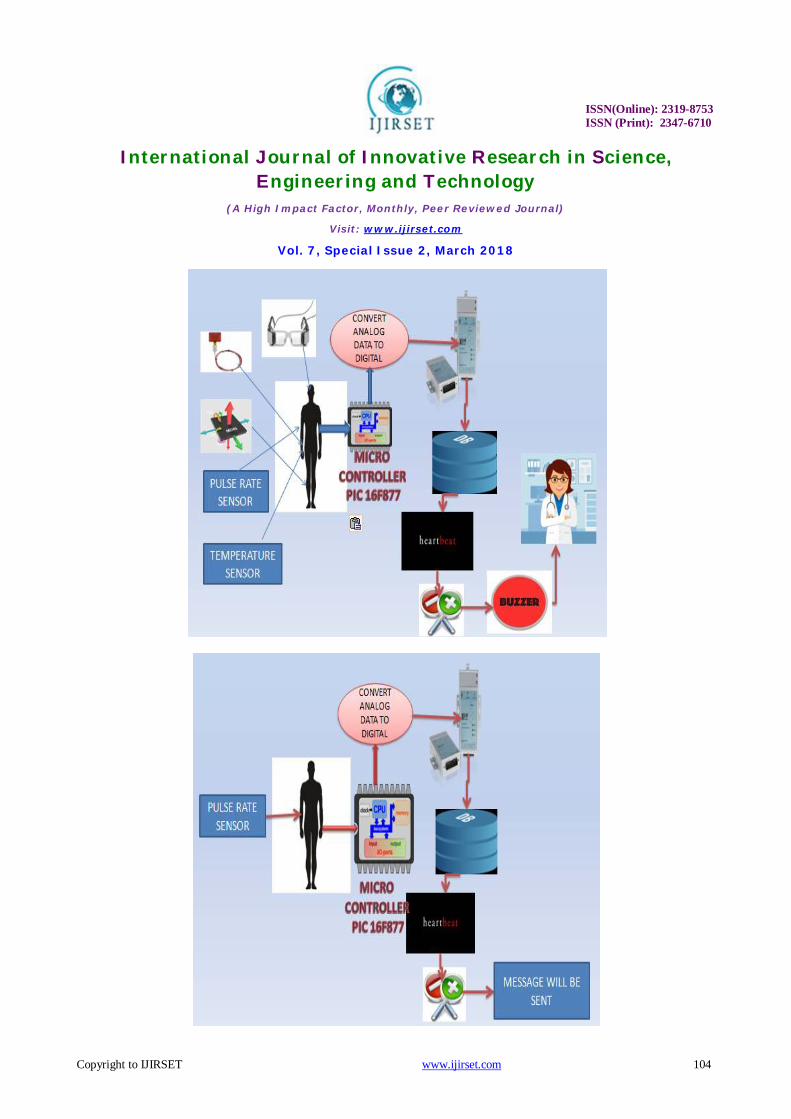
IV. SYSTEM ARCHITECTURE AND IMPLEMENTATION
In this project the finger movement detects using flex sensor.The flex sensors output in the form of analog voltage that varies with what amount of degree it bends. The analog outputs from the sensors are then sending to the PIC 16F877 microcontroller. ARM processor processes the signals and performs the operation according to the input of the flex sensor. Whenever the eyelid blink, the eye blink detector detects that movement using IR paired sensor. These input further to the microcontroller and further process on it and MEMS body sensor placed on chest of the person, it shows status of the body moved right side or left side. Finally send message to the concerned person through IOT modem.
ISSN(Online): 2319-8753 ISSN (Print): 2347-6710
International Journal of Innovative Research in Science, Engineering and Technology
(A High Impact Factor, Monthly, Peer Reviewed Journal)
Visit: www.ijirset.com
Vol. 7, Special Issue 2, March 2018
Copyright to IJIRSET www.ijirset.com 104
ISSN(Online): 2319-8753 ISSN (Print): 2347-6710
International Journal of Innovative Research in Science, Engineering and Technology
(A High Impact Factor, Monthly, Peer Reviewed Journal)
Visit: www.ijirset.com
Vol. 7, Special Issue 2, March 2018
Copyright to IJIRSET www.ijirset.com 105
V. SYSTEM REQUIREMENTS
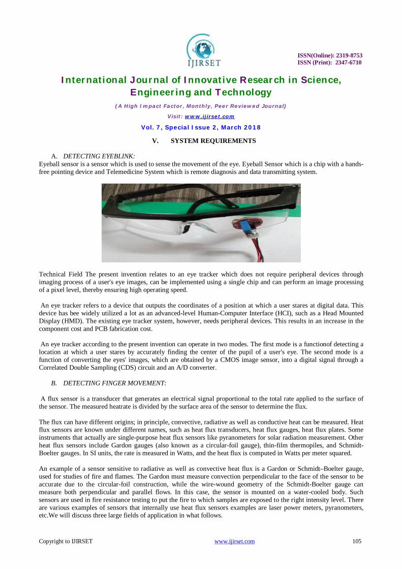
A. DETECTING EYEBLINK: Eyeball sensor is a sensor which is used to sense the movement of the eye. Eyeball Sensor which is a chip with a hands-free pointing device and Telemedicine System which is remote diagnosis and data transmitting system.
Technical Field The present invention relates to an eye tracker which does not require peripheral devices through imaging process of a user's eye images, can be implemented using a single chip and can perform an image processing of a pixel level, thereby ensuring high operating speed. An eye tracker refers to a device that outputs the coordinates of a position at which a user stares at digital data. This device has bee widely utilized a lot as an advanced-level Human-Computer Interface (HCI), such as a Head Mounted Display (HMD). The existing eye tracker system, however, needs peripheral devices. This results in an increase in the component cost and PCB fabrication cost. An eye tracker according to the present invention can operate in two modes. The first mode is a functionof detecting a location at which a user stares by accurately finding the center of the pupil of a user's eye. The second mode is a function of converting the eyes' images, which are obtained by a CMOS image sensor, into a digital signal through a Correlated Double Sampling (CDS) circuit and an A/D converter.
B. DETECTING FINGER MOVEMENT:
A flux sensor is a transducer that generates an electrical signal proportional to the total rate applied to the surface of the sensor. The measured heatrate is divided by the surface area of the sensor to determine the flux. The flux can have different origins; in principle, convective, radiative as well as conductive heat can be measured. Heat flux sensors are known under different names, such as heat flux transducers, heat flux gauges, heat flux plates. Some instruments that actually are single-purpose heat flux sensors like pyranometers for solar radiation measurement. Other heat flux sensors include Gardon gauges (also known as a circular-foil gauge), thin-film thermopiles, and Schmidt-Boelter gauges. In SI units, the rate is measured in Watts, and the heat flux is computed in Watts per meter squared. An example of a sensor sensitive to radiative as well as convective heat flux is a Gardon or Schmidt–Boelter gauge, used for studies of fire and flames. The Gardon must measure convection perpendicular to the face of the sensor to be accurate due to the circular-foil construction, while the wire-wound geometry of the Schmidt-Boelter gauge can measure both perpendicular and parallel flows. In this case, the sensor is mounted on a water-cooled body. Such sensors are used in fire resistance testing to put the fire to which samples are exposed to the right intensity level. There are various examples of sensors that internally use heat flux sensors examples are laser power meters, pyranometers, etc.We will discuss three large fields of application in what follows.

ISSN(Online): 2319-8753 ISSN (Print): 2347-6710
International Journal of Innovative Research in Science, Engineering and Technology
(A High Impact Factor, Monthly, Peer Reviewed Journal)
Visit: www.ijirset.com
Vol. 7, Special Issue 2, March 2018
Copyright to IJIRSET www.ijirset.com 106
C. DETECTING LEG MOVEMEN: (Micro-Electro-Mechanical Sensor)
The offered product is a low power, low profile capacitive micromachined Accelerometer that is used to measure the proper acceleration of the devices such as process control systems, pumps, fans, rollers, compressors, etc. Apart from this, this product is known for its outstanding performance and accuracy. Can be used to measure vibration in vehicles, we offer this multipurpose product at very reasonable prices.
1. Features
• A 1-pole low pass filter • Temperature compensation • Environment-friendly • Self Test for Freefall Detect Diagnosis • Signal Conditioning with Low Pass Filter • Robust Design
ISSN(Online): 2319-8753 ISSN (Print): 2347-6710
International Journal of Innovative Research in Science, Engineering and Technology
(A High Impact Factor, Monthly, Peer Reviewed Journal)
Visit: www.ijirset.com
Vol. 7, Special Issue 2, March 2018
Copyright to IJIRSET www.ijirset.com 107
• High Shocks Survivability • OG-Detect to detect linear freefall • G-Select for the selection between 2 sensitivities
1.1. Product highlights:
• 3mm x 5mm x 1.0mm LGA-14 Package • Sleep Mode: 3 µA • High Sensitivity (800 mV/g @ 1.5g) • Selectable Sensitivity (±1.5g, ±6g) • Fast Turn On Time (0.5 ms Enable Response Time)
2. Mems accelerometer
Acceleration is a measure of how quickly speed changes. Just as a speedometer is a meter that measures speed, an accelerometer is a meter that measures acceleration. You can use an accelerometer's ability to sense acceleration to measure a variety of things that are very useful to electronic and robotic projects and designs:
• Acceleration • Tilt and tilt angle • Incline • Rotation • Vibration • Collision • Gravity
3. Mems gyroscope:
A gyroscope is a device for measuring or maintaining orientation, based on the principles of angular momentum. In essence, a mechanical gyroscope is a spinning wheel or disk whose axle is free to take any orientation. Although this orientation does not remain fixed, it changes in response to an external torque much less and in a different direction than it would without the large angular momentum associated with the disk's high rate of spin and moment of inertia. Since external torque is minimized by mounting the device in gimbals, its orientation remains nearly fixed, regardless of any motion of the platform on which it is mounted.
The LPY4150AL is a low-power dual-axis micromachined gyroscope capable of measuring angular rate along pitch and yaw axes. It provides excellent temperature stability and high resolution over an extended operating temperature range (-40 °C to +85 °C). The LPY4150AL has a full scale of ±1500 dps and is capable of detecting rates with a -3 Db bandwidth up to 140 Hz. The device includes a sensing element composed of a single driving mass, kept in continuous oscillation and capable of reacting, based on the Coriolis principle, when an angular rate is applied. A CMOS IC provides the measured angular rate to the external world through an analog output voltage, allowing high levels of integration and production trimming to better match sensing element characteristics. ST's family of gyroscopes leverages on the mature and robust manufacturing process already used for the production of micro-machined accelerometers. ST is already in the field with several hundred million sensors which have received excellent acceptance from the market in terms of quality, reliability and performance. The LPY4150AL is available in a plastic land grid array (LGA) package, which ST successfully pioneered for accelerometers.Today ST has the widest manufacturing capability and strongest expertise in the world for production of sensors in plastic LGA packages.
ISSN(Online): 2319-8753 ISSN (Print): 2347-6710
International Journal of Innovative Research in Science, Engineering and Technology
(A High Impact Factor, Monthly, Peer Reviewed Journal)
Visit: www.ijirset.com
Vol. 7, Special Issue 2, March 2018
Copyright to IJIRSET www.ijirset.com 108
Features • 2.7 V to 3.6 V single-supply operation • Wide operating temperature range (-40 °C to +85 °C) • High stability over temperature • Analog absolute angular-rate outputs • Two separate outputs for each axis (1x and 4x amplified) • Integrated low-pass filters • Low power consumption • Embedded power-down • Embedded self-test • Sleep mode • High shock and vibration survivability • ECOPACK® RoHS and “Green” compliant
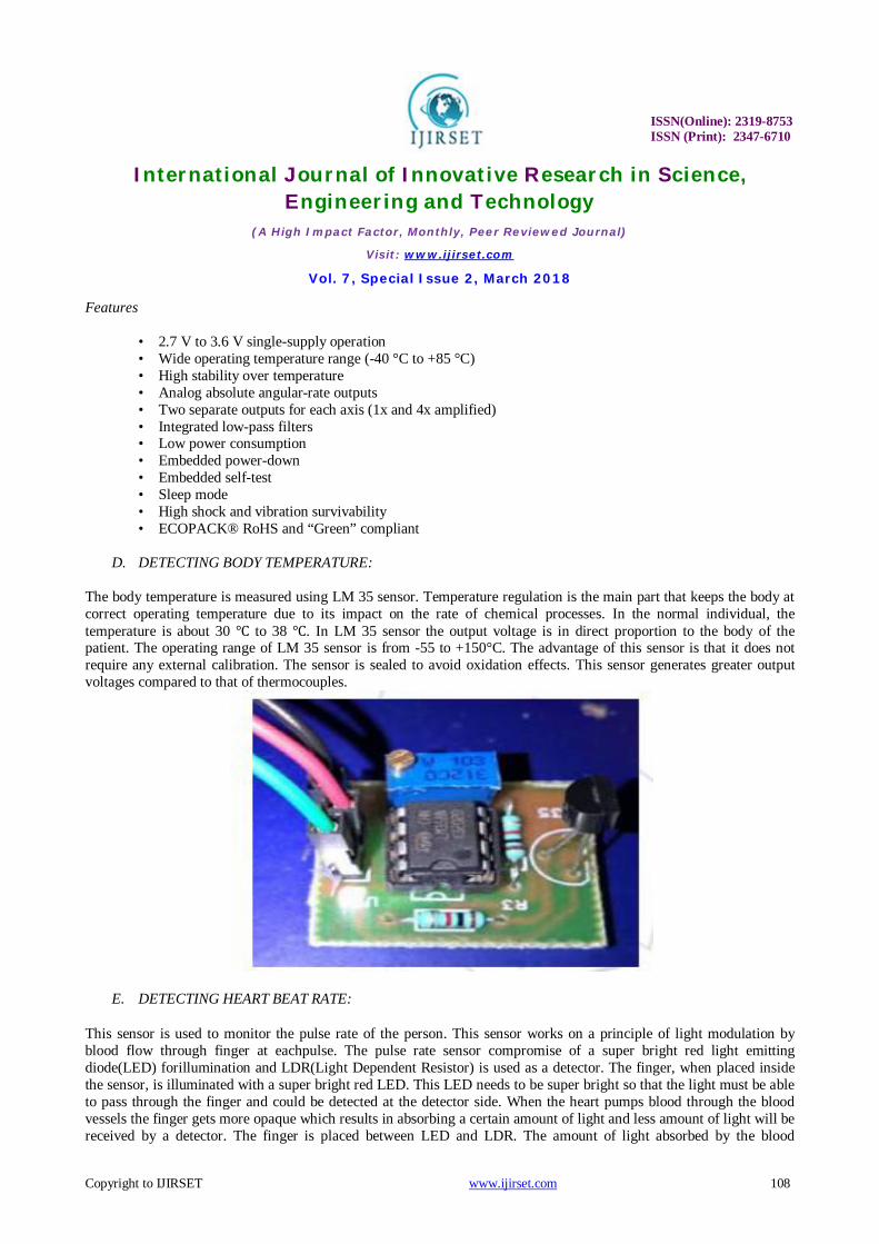
D. DETECTING BODY TEMPERATURE: The body temperature is measured using LM 35 sensor. Temperature regulation is the main part that keeps the body at correct operating temperature due to its impact on the rate of chemical processes. In the normal individual, the temperature is about 30 ℃ to 38 ℃. In LM 35 sensor the output voltage is in direct proportion to the body of the patient. The operating range of LM 35 sensor is from -55 to +150°C. The advantage of this sensor is that it does not require any external calibration. The sensor is sealed to avoid oxidation effects. This sensor generates greater output voltages compared to that of thermocouples.
E. DETECTING HEART BEAT RATE: This sensor is used to monitor the pulse rate of the person. This sensor works on a principle of light modulation by blood flow through finger at eachpulse. The pulse rate sensor compromise of a super bright red light emitting diode(LED) forillumination and LDR(Light Dependent Resistor) is used as a detector. The finger, when placed inside the sensor, is illuminated with a super bright red LED. This LED needs to be super bright so that the light must be able to pass through the finger and could be detected at the detector side. When the heart pumps blood through the blood vessels the finger gets more opaque which results in absorbing a certain amount of light and less amount of light will be received by a detector. The finger is placed between LED and LDR. The amount of light absorbed by the blood

ISSN(Online): 2319-8753 ISSN (Print): 2347-6710
International Journal of Innovative Research in Science, Engineering and Technology
(A High Impact Factor, Monthly, Peer Reviewed Journal)
Visit: www.ijirset.com
Vol. 7, Special Issue 2, March 2018
Copyright to IJIRSET www.ijirset.com 109
depends on the blood volume in that area. The signal obtained at the detector end will be in the form of the electrical signal which is proportional to pulse rate. LDR works on a principle of its change in resistivity when a light is an incident on it. The light intensity is inversely proportional to resistance change which results in voltage drop. The detector signal varies with each pulse.
F. LCD DISPLAY A liquid crystal display or LCD draws its definition from its name itself. It is a combination of two states of matter, the solid and the liquid. LCD uses a liquid crystal to produce a visible image. Liquid crystal displays are super-thin technology display screen that is generally used in laptop computer screen, TVs, cell phones and portable video games. LCD’s technologies allow displays to be much thinner when compared to cathode ray tube (CRT) technology. Liquid crystal display is composed of several layers which include two polarized panel filters and electrodes. LCD technology is used for displaying the image in the notebook or some other electronic devices like mini computers. Light is projected from a lens on a layer of liquid crystal. This combination of colored light with the grayscale image of the crystal (formed as electric current flows through the crystal) forms the colored image. This image is then displayed on the screen.
An LCD is either made up of an active matrix display grid or a passive display grid. Most of the Smartphone’s with LCD display technology uses active matrix display, but some of the older displays still make use of the passive display grid designs. Most of the electronic devices mainly depend on liquid crystal display technology for their display. The liquid has a unique advantage of having low power consumption than the LED or cathode ray tube.

ISSN(Online): 2319-8753 ISSN (Print): 2347-6710
International Journal of Innovative Research in Science, Engineering and Technology
(A High Impact Factor, Monthly, Peer Reviewed Journal)
Visit: www.ijirset.com
Vol. 7, Special Issue 2, March 2018
Copyright to IJIRSET www.ijirset.com 110
Liquid crystal display screen works on the principle of blocking light rather than emitting light. LCD’s requires the backlight as they do not emit light by them. We always use devices which are made up of LCD’s displays which are replacing the use of cathode ray tube. Cathode ray tube draws more power compared to LCD’s and is also heavier and bigger. A liquid crystal cell consists of a thin layer (about 10μm) of a liquid crystal sandwiched between two glass sheets with transparent electrodes deposited on their inside faces. With both glass sheets transparent, the cell is known as transmissive type cell. When one glass is transparent and the other has a reflective coating, the cell is called reflective type. The LCD does not produce any illumination of its own. It, in fact, depends entirely on illumination falling on it from an external source for its visual effect.
G. POWER SUPPLY Almost all basic household electronic circuits need an unregulated AC to be converted to constant DC, in order to operate the electronic device. All devices will have a certain power supply limit and the electronic circuits inside these devices must be able to supply a constant DC voltage within this limit. That is, all the active and passive electronic devices will have a certain DC operating point, and this point must be achieved by the source of DC power. The DC power supply is practically converted to each and every stage in an electronic system. Thus a common requirement for all these phases will be the DC power supply. All low power system can be run with a battery. But, for the long time operating devices, batteries could prove to be costly and complicated. The best method used is in the form of an regulated power supply a combination of a transformer, rectifier and a filter .
As shown in the figure above, a small step down transformer is used to reduce the voltage level to the devices needs. In India, a 1 Ø supply is available at 230 volts. The output of the transformer is a pulsating sinusoidal AC voltage, which is converted to pulsating DC with the help of a rectifier. This output is given to a filter circuit which reduces the AC ripples and passes the DC components to get the regulator 5v power supply.
H. BUZZER The buzzers are composed utilizing piezoelectric materials for superior and for simplicity of fuse into the frameworks. They are low power utilization components. These are utilized for alarming a specialist at whatever point the detected signs are outside the ordinary esteems and at whatever point physical developments are recorded.
ISSN(Online): 2319-8753 ISSN (Print): 2347-6710
International Journal of Innovative Research in Science, Engineering and Technology
(A High Impact Factor, Monthly, Peer Reviewed Journal)
Visit: www.ijirset.com
Vol. 7, Special Issue 2, March 2018
Copyright to IJIRSET www.ijirset.com 111
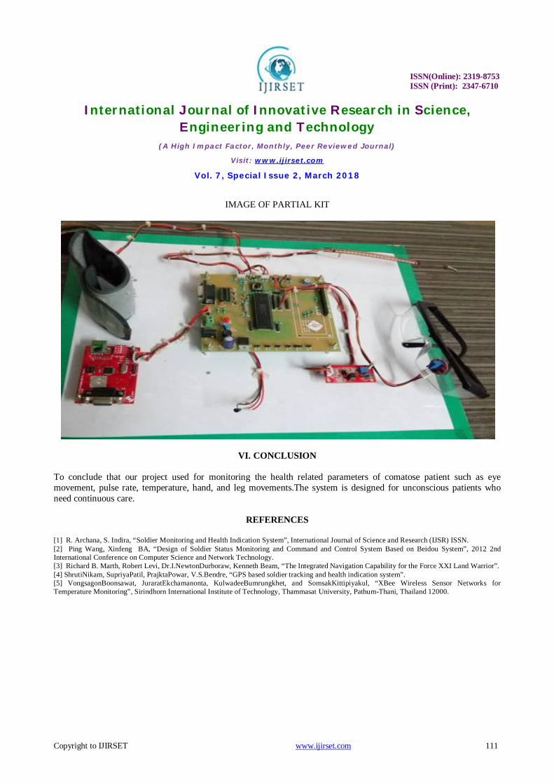
IMAGE OF PARTIAL KIT
VI. CONCLUSION
To conclude that our project used for monitoring the health related parameters of comatose patient such as eye movement, pulse rate, temperature, hand, and leg movements.The system is designed for unconscious patients who need continuous care.
REFERENCES
[1] R. Archana, S. Indira, “Soldier Monitoring and Health Indication System”, International Journal of Science and Research (IJSR) ISSN. [2] Ping Wang, Xinfeng BA, “Design of Soldier Status Monitoring and Command and Control System Based on Beidou System”, 2012 2nd International Conference on Computer Science and Network Technology. [3] Richard B. Marth, Robert Levi, Dr.I.NewtonDurboraw, Kenneth Beam, “The Integrated Navigation Capability for the Force XXI Land Warrior”. [4] ShrutiNikam, SupriyaPatil, PrajktaPowar, V.S.Bendre, “GPS based soldier tracking and health indication system”. [5] VongsagonBoonsawat, JuraratEkchamanonta, KulwadeeBumrungkhet, and SomsakKittipiyakul, “XBee Wireless Sensor Networks for Temperature Monitoring”, Sirindhorn International Institute of Technology, Thammasat University, Pathum-Thani, Thailand 12000.