BMA DMV/11-1/2-2 D/GB/F/I
10
1 … 10 229 335 DMV 505-520/11 Druckabgriffe / Pressure taps 1, 2, 3, 4 Verschlußschraube Sealing plug G 1/8 DIN ISO 228 Die Verschlußschrauben1,2,3 können auch durch einen Meßstutzen G 1/8 DIN ISO 228 ersetzt werden. Screw plugs 1,2,3 may also be re- placed by a measuring socket G 1/8 DIN ISO 228. Betriebs- und Montagean- leitung Doppelmagnetventil Typ DMV-D.../11 Typ DMV-DLE.../11 Nennweiten Rp 1/2 - Rp 2 Operation and assembly instructions Double solenoid valve Type DMV-D.../11 Type DMV-DLE.../11 Nominal widths Rp 1/2 - Rp 2 Einbaulage Installation position Elektrischer Anschluß Electrical connection IEC 730-1 (VDE 0631 T1) Max. Betriebsdruck Max. operating pressure p max. = 500 mbar V1+V2 Klasse A, Gruppe 2 V1+V2 Class A, Group 2 V1+V2 nach / acc. / EN 161 U n ~(AC) 230 V oder/or/ ~(AC) 110 V - 120 V, =(DC) 48 V; =(DC) 24 V - 28 V Einschaltdauer/Switch-on duration/ 100 % Umgebungstemperatur Ambient temperature -15 C … +60 C Schutzart Degree of protection IP 54 nach / acc. / IEC 529 ( DIN 40 050) Familie 1 + 2 + 3 Family 1 + 2 + 3 1 + 2 + 3 Erdung nach örtlichen Vorschriften Grounding acc. local regulations P1 L1 N Mp 2 1 3 V1 V2 P2 L2 PE L2 P2 L1 P1 N MP 2 PE 3 1 2 3 1 1 4 4 4 4 V1 p = 500 mbar max. V2 1 2 3 1 2 3 4 4 DMV 525/11 Druckabgriffe / Pressure taps 1, 2, 3, 5 Verschlußschraube Sealing plug G 1/8 DIN ISO 228 Die Verschlußschrauben1,2,3,5 kön- nen auch durch einen Meßstutzen G 1/8 DIN ISO 228 ersetzt werden. Screw plugs 1,2,3 and 5 may also be replaced by a measuring socket G 1/8 DIN ISO 228. 4 Verdeckte Verbindungsbohrung für Systemzubehör. Concealed connecting bore for system accessories. 3 2 1 4 5 3 2 1 p max. = 500 mbar 1 2 3 5 4 1 2 3 5 4 V1 V2 [mbar] EN 161 [ V ] C 0 +60 -15 IEC 529 ➞ ➞ ➞ ➞ ➞ ➞ ➞ ➞ ➞ ➞ ➞ ➞ Gas Gaz EN 161 FIN FIN FIN D GB RC
-
Upload
khangminh22 -
Category
Documents
-
view
0 -
download
0
Transcript of BMA DMV/11-1/2-2 D/GB/F/I
1 … 10
229
335
DMV 505-520/11Druckabgriffe / Pressure taps
1, 2, 3, 4VerschlußschraubeSealing plug
G 1/8 DIN ISO 228
Die Verschlußschrauben1,2,3 könnenauch durch einen Meßstutzen G 1/8DIN ISO 228 ersetzt werden.Screw plugs 1,2,3 may also be re-placed by a measuring socket G 1/8DIN ISO 228.
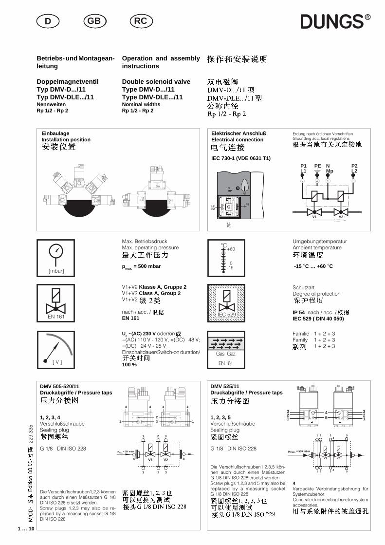
Betriebs- und Montagean-leitung
DoppelmagnetventilTyp DMV-D.../11Typ DMV-DLE.../11NennweitenRp 1/2 - Rp 2
Operation and assemblyinstructions
Double solenoid valveType DMV-D.../11Type DMV-DLE.../11Nominal widthsRp 1/2 - Rp 2
EinbaulageInstallation position
Elektrischer AnschlußElectrical connection
IEC 730-1 (VDE 0631 T1)
Max. BetriebsdruckMax. operating pressure
pmax. = 500 mbar
V1+V2 Klasse A, Gruppe 2V1+V2 Class A, Group 2V1+V2
nach / acc. /EN 161
Un ~(AC) 230 V oder/or/~(AC) 110 V - 120 V, =(DC) 48 V;=(DC) 24 V - 28 VEinschaltdauer/Switch-on duration/
100 %
UmgebungstemperaturAmbient temperature
-15 °C … +60 °C
SchutzartDegree of protection
IP 54 nach / acc. /IEC 529 ( DIN 40 050)
Familie 1 + 2 + 3Family 1 + 2 + 3
1 + 2 + 3
Erdung nach örtlichen VorschriftenGrounding acc. local regulations
P1L1
NMp
2 1 3
V1 V2
P2L2
PE
L2P2
L1P1
NMP
2
PE
3
1
231 1
4444
V1
p = 500 mbarmax.
V2
1 2 3
1 2 3
4 4
DMV 525/11Druckabgriffe / Pressure taps
1, 2, 3, 5VerschlußschraubeSealing plug
G 1/8 DIN ISO 228
Die Verschlußschrauben1,2,3,5 kön-nen auch durch einen MeßstutzenG 1/8 DIN ISO 228 ersetzt werden.Screw plugs 1,2,3 and 5 may also bereplaced by a measuring socketG 1/8 DIN ISO 228.
4Verdeckte Verbindungsbohrung fürSystemzubehör.Concealed connecting bore for systemaccessories.
321
45
321
pmax. = 500 mbar
1 2 3 54
1 2 3 54
V1 V2
[mbar]
EN 161
[ V ]
°C
0
+60
-15
IEC 529IEC 529
➞ ➞ ➞ ➞➞ ➞ ➞ ➞➞ ➞ ➞ ➞
Gas Gaz
EN 161
FIN DK SFIN DK SFIN DK SD GB RC

2 … 10
229
335
fab
Rp
cd
e
Einbaumaße/Dimensions/ [mm]
Rp
Rp 3/4
Rp 1 1/4
Rp 2
Rp 2
Rp 3/4
Rp 1 1/4
Rp 2
Rp 2
Imax.~(AC)240 V
0,20
0,28
0,37
0,46
0,20
0,28
0,37
0,46
ÖffnungszeitOpening time
< 1 s
< 1 s
< 1 s
< 1 s
20 s
20 s
20 s
20 s
e
232
254
333
400
232
254
323
400
c
35
45
45
88
35
45
45
88
a
93
124
124
162
93
124
124
162
Einbaumaße/Dimensions/
[mm]d
134
150
190
255
160
179
218
275
b
141
174
201
239
141
174
201
239
GewichtWeight
[kg]
2,1
4,6
5,6
12,1
2,2
4,7
5,7
12,3
TypType
DMV-D 507/11
DMV-D 512/11
DMV-D 520/11
DMV-D 525/11
DMV-DLE 507/11
DMV-DLE 512/11
DMV-DLE 520/11
DMV-DLE 525/11
Pmax.[VA]
45
65
90
110
45
65
90
110
f
73
99
99
103
73
99
99
103
Doppelmagnetventil durch geeigneten Schmutzfänger vor Verunreinigungen schützen, Sieb ist eingebaut.Protect double solenoid valve from fouling using suitable dirt traps. Sieve is installed.
Verschluß- und Verbindungsschrauben sachgemäß anziehen.Werkstoffpaarung Druckguß – Stahl beachten!Tighten plugs and union screws properly.Make sure of proper material combinations, e.g. diecast – steel!
Pla
tzb
edar
f für
Mag
netw
echs
elsp
ace
req
uire
men
ts fo
r fit
ting
sol
enoi
d
Pla
tzb
edar
f für
Mag
netw
echs
elsp
ace
req
uire
men
ts fo
r fit
ting
sol
enoi
d
g
---
--
--
123
--
--
--
123
Gerät darf nicht als Hebel benutzt werden!Do not use unit as lever!
Rp 1/2 3/4 1 1/4 2Mmax. 105 225 475 1100 [Nm] t ≤ 10 sTmax. 50 85 160 250 [Nm] t ≤ 10 s
Geeignetes Werkzeug einsetzen! Schrauben kreuzweise anziehen!Please use proper tools! Tighten screws crosswise!
max. Drehmomente/Systemzubehör M4 M5 M6 M8 G1/8 G1/4 G1/2 G3/4max. torque/System accesories
2,5 Nm 5 Nm 7 Nm 15 Nm 2,5 Nm 7 Nm 10 Nm 15 Nm
DMV 507-520/11 DMV 525/11
Rp
ab
cd
e
fg
[Nm]
18
19
Chrom
e Stee
l ✸ M
ade i
n Ger
many
ISO 7005-2
DMVV1 V2
➟
➟ Mmax.
Tmax. Mmax.
3 … 10
229
335
43
21
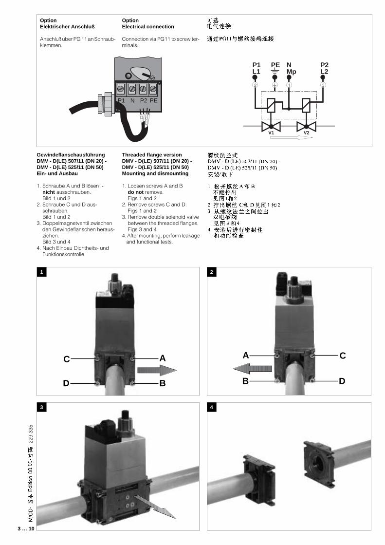
GewindeflanschausführungDMV - D(LE) 507/11 (DN 20) -DMV - D(LE) 525/11 (DN 50)Ein- und Ausbau
1. Schraube A und B lösen - nicht ausschrauben. Bild 1 und 22. Schraube C und D aus- schrauben. Bild 1 und 23. Doppelmagnetventil zwischen den Gewindeflanschen heraus- ziehen. Bild 3 und 44. Nach Einbau Dichtheits- und Funktionskontrolle.
Threaded flange versionDMV - D(LE) 507/11 (DN 20) -DMV - D(LE) 525/11 (DN 50)Mounting and dismounting
1. Loosen screws A and B do not remove. Figs 1 and 22. Remove screws C and D. Figs 1 and 23. Remove double solenoid valve between the threaded flanges. Figs 3 and 44. After mounting, perform leakage and functional tests.
OptionElektrischer Anschluß
Anschluß über PG 11 an Schraub-klemmen.
OptionElectrical connection
Connection via PG11 to screw ter-minals.
P1L1
NMp
2 1 3
V1 V2
P2L2
PE
P1 N P2 PE
C
D
A
B
A
B
C
D
4 … 10
229
335
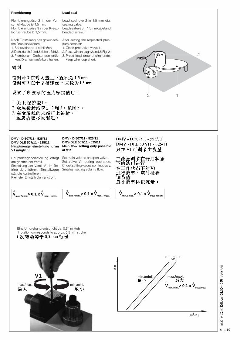
Plombierung
Plombierungsöse 2 in der Ver-schlußklappe Ø 1,5 mm.Plombierungsöse 3 in der Kreuz-lochschraube Ø 1,5 mm.
Nach Einstellung des gewünsch-ten Drucksollwertes.1. Schutzklappe 1 schließen.2. Draht durch 2 und 3 ziehen, Bild 2.3. Plombe um Drahtenden drük-
ken, Drahtschlaufe kurz halten.
Lead seal
Lead seal eye 2 in 1.5 mm dia.sealing valve.Lead seal eye 3 in 1.5 mm capstandheaded screw.
After setting the requested pres-sure setpoint:1. Close protective valve 1.2. Route wire through 2 and 3, Fig. 2.3. Press lead around wire ends,
keep wire loop short.2
3
05/98
1
DMV - D 507/11 - 525/11DMV-DLE 507/11 - 525/11Hauptmengeneinstellung nur anV1 möglich!
Hauptmengeneinstellung erfogtam geöffnetem Ventil.Einstellung am Ventil V1 im Be-trieb durchführen, Einstellwerteständig kontrollieren.Kleinster Einstellvolumenstrom:
DMV - D 507/11 - 525/11DMV-DLE 507/11 - 525/11Main flow setting only possibleat V1!
Set main volume on open valve.Set valve V1 during operation.Check setting values continuously.Smallest setting volume flow:
O
Vmin. / mini.> 0.1 x Vmax. / maxi.
OO
Vmin. / mini.> 0.1 x Vmax. / maxi.
O O
Vmin. / mini.> 0.1 x Vmax. / maxi.
O
[m /h]3
∆ p
∆V°
max./maxi.min./mini
max./maxi. min./mini.
V1
Eine Umdrehung entspricht ca. 0,5mm Hub1 rotation corresponds to approx. 0.5 mm stroke
OO
Vmin./mini.> 0.1 x Vmax./maxi
5 … 10
229
335
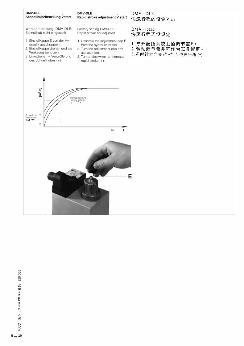
DMV-DLERapid stroke adjustment V start
Factory setting DMV-DLE:Rapid stroke not adjusted
1. Unscrew the adjustment cap E from the hydraulic brake.2. Turn the adjustment cap and use as a tool.3. Turn a-clockwise = increase rapid stroke (+).
DMV-DLESchnellhubeinstellung Vstart
Werkseinstellung DMV-DLE:Schnellhub nicht eingestellt
1. Einstellkappe E von der Hy- draulik abschrauben.2. Einstellkappe drehen und als Werkzeug benutzen.3. Linksdrehen = Vergrößerung des Schnellhubes (+).
[m /
h]
3
[s] t
WerkseinstellungFactory setting
SchnellhubFast stroke
° °
E
6 … 10
229
335
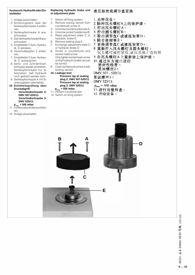
Austausch Hydraulik oder Ein-stellteller
1. Anlage ausschalten. 2. Sicherungslack über der
Senkkopfschraube A entfer-nen.
3. Senkkopfschraube A aus-schrauben.
4. Zylinderkopfschraube B aus-schrauben.
5. Einstellteller C bzw. Hydrau-lik D abheben.
6. Verschlußstopfen E entfer-nen.
7. Einstellteller C bzw. Hydrau-lik D austauschen.
8. Senk- und Zylinderkopf-schraube wieder eindrehen.Senkkopfschraube nur sofestziehen, daß Hydrauliknoch gedreht werden kann.
9. Senkkopfschraube A mit Si-cherungslack überziehen.
10. Dichtheitsprüfung überDruckabgriff:
Verschlußschraube 2:DMV 507-520/11.Verschlußschraube 3:DMV 525/11.
pmax. = 500 mbar.11. Funktionskontrolle durchfüh-
ren.12. Anlage einschalten
Replacing hydraulic brake unitor adjustment plate
1. Switch off firing system.2. Remove locking varnish from
countersunk screw A.3. Unscrew countersunkscrew A.4. Unscrew socket headscrew B.5. Raise adjustment plate C or
hydraulic brake D.6. Remove sealing plug E7. Exchange adjustment plate C
or hydraulic brake D8. Screw in countersunk and
socket head screw.Only tighten socket head screwso that hydraulic brake can justbe turned.
9. Coat countersunk screw A withlocking varnish.
10. Leakage test:Pressure tap at sealingplug 2: DMV 507-520/11Pressure tap at sealingplug 3: DMV 525/11
pmax. = 500 mbar.11. Perform functional test.12. Switch on firing system.
E
B A
C
D
7 … 10
229
335
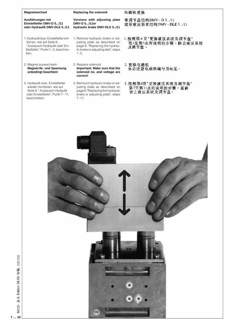
Magnetwechsel
Ausführungen mitEinstellteller DMV-D 5.../11oder Hydraulik DMV-DLE 5../11
1. Hydraulik bzw. Einstellteller ent- fernen, wie auf Seite 6 : " Austausch Hydraulik oder Ein- Stellteller", Punkt 1 - 5, beschrie- ben.
2. Magnet auswechseln. Magnet-Nr. und Spannung unbedingt beachten!
3. Hydraulik bzw. Einstellteller wieder montieren, wie auf Seite 6 " Austausch Hydaulik oder Einstellteller", Punkt 7 - 11, beschrieben.
Replacing the solenoid
Versions with adjusting plateDMV-D 5.../11orhydraulic brake DMV-DLE 5../11
1. Remove hydraulic brake or ad-justing plate as described onpage 6: "Replacing the hydrau-lic brake or adjusting disk", steps1 -5.
2. Replace solenoid Important: Make sure that the
solenoid no. and voltage arecorrect!
3. Remount hydraulic brake or ad-justing plate as described onpage 6:"Replacing the hydraulicbrake or adjusting plate", steps7 -11.
8 … 10
229
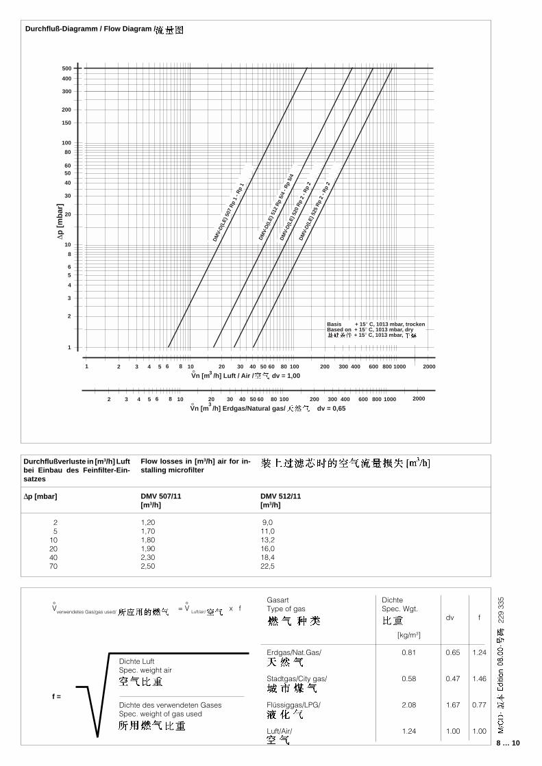
335Gasart
Type of gas
Erdgas/Nat.Gas/
Stadtgas/City gas/
Flüssiggas/LPG/
Luft/Air/
DichteSpec. Wgt.
[kg/m3]
0.81
0.58
2.08
1.24
dv
0.65
0.47
1.67
1.00
f
1.24
1.46
0.77
1.00
Dichte LuftSpec. weight air
Dichte des verwendeten GasesSpec. weight of gas used
f =
Vverwendetes Gas/gas used/ =° V Luft/air/ x f°
Durchfluß-Diagramm / Flow Diagram /
Durchflußverluste in [m3/h] Luftbei Einbau des Feinfilter-Ein-satzes
∆p [mbar]
2 510204070
Flow losses in [m3/h] air for in-stalling microfilter
DMV 507/11[m3/h]
1,201,701,801,902,302,50
DMV 512/11[m3/h]
9,011,013,216,018,422,5
∆p
[m
bar
]
Vn [m /h] Luft / Air / dv = 1,00°
2
3
4
5
6
1
8
10
20
30
40
60
80
100
50
20 30 40 50 6010 80 100 200 300 400 600 800 1000 2000
Basis + 15° C, 1013 mbar, trockenBased on + 15° C, 1013 mbar, dry + 15° C, 1013 mbar,
1 2 3 4 5 6 8
200
150
Vn [m /h] Erdgas/Natural gas/ dv = 0,65°20 30 40 50 6010 80 100 200 300 400 600 800 1000 20002 3 4 5 6 83
3
500
400
300
DM
V-D
(LE
) 507
Rp
1 - R
p 1
DM
V-D
(LE
) 520
Rp
2 - R
p 2
DM
V-D
(LE
) 512
Rp
5/4
- Rp
5/4
DM
V-D
(LE
) 525
Rp
2 - R
p 2

9 … 10
229
335
Zylinderschraube DIN 912, 8.8Socket head screw acc.DIN 912, 8.8
DMV 507/11 M6 x 30DMV 512-520/11 M8 x 40DMV 525/11 M8 x 25
Montage-Set FRI + DMVSet FRI + DMV
FRI 505,507 + DMV 507FRI 510,512 + DMV 512,520
Meßstutzen mit DichtringSet of setscrews
G 1/8G 1/4
ErsatzmagnetReplacement solenoid
DIN 43 650 PG11DMV 507/11 1111 1161DMV 512/11 1211 1261DMV 520/11 1212 1262DMV 525/11 1411 1461
Verschlußstopfen V2V2 sealing plug
DMV 507/11 -DMV 520/11
Teller für MagnetbefestigungDisk for attaching solenoid
DMV 507/11 - DMV 520/11
FiltereinsatzFilter insert
DMV 507/11DMV 512/11 - DMV 520/11
Haltering für FiltereinsatzSupporting ring
DMV 507/11DMV 512/11 - DMV 520/11
010 280222 943215 683
219 967219 968
219 008022 335
auf Anfrageon request
223 047
222 909
214 276214 525
214 274214 587
Ersatzteile / ZubehörSpare parts / Accessories
Bestell-NummerOrdering No.
Ersatzteile / ZubehörSpare parts / Accessories
Verschlußschraube, flach mitO-RingLocking screw
G 1/8
Schmutzfänger, SiebDirt trap, sieve
DMV 507/11DMV 512/11DMV 520/11DMV 525/11
Set Zündgasflansch G1/2G 1/2 start gas flange set
Adapter-Set für GW A2 mitAnschluß G 1/4Adapter set for GW A2 fittedwith G 1/4 port
DMV 507/11 - DMV 525/11
HydraulikbremseHydraulic brake
DMV 507/11 - DMV 525/11
EinsteckscheibeInsert washer
DMV 507/11 - DMV 520/11DMV 525/11
Leitungsdose, SchwarzLine socket, black
GDMW, 3 pol. + E
AnschlußflanschConnection flange
DMV 507 Rp 1/2DMV 507 Rp 3/4DMV 507 Rp 1DMV 512-520 Rp 1DMV 512-520 Rp 1 1/4DMV 512-520 Rp 1 1/2DMV 512-520 Rp 2DMV 525 Rp 2
O-Ring, EN geprüftO-ring, EN tested
DMV 507/11 57 x 3,0DMV 512-520/11 75 x 3,5DMV 525/11
Bestell-NummerOrdering No.
221 017
222 920222 919222 919215 505
219 007
222 982
auf Anfrageon request
081 273053 405
210 319
222 341222 342222 001222 343222 344221 884221 926215 384
215 947215 986227 637

10 … 10
229
335
Flanschflächen schützen.Schrauben kreuzweiseanziehen.
Direkter Kontakt zwi-schen Doppelmagentven-til und dem aushärtendemMauerwerk, Betonwän-den, Fußböden ist nichtzulässig.
Nennleistung bzw. Druck-sollwerte grundsätzlicham Gasdruckregelgeräteinstellen. Leistungsspe-zifische Drosselung überdas Doppelmagnetventil.
Rohrleitungsdichtheits-prüfung: Kugelhahn vorden Armaturen / DMVschließen.
Nach Abschluß von Ar-beiten am Doppelma-gnetventil: Dichtheits-kontrolle und Funktions-kontrolle durchführen.
Niemals Arbeiten durch-führen, wenn Gasdruckoder Spannung anliegt.Offenes Feuer vermeiden.Öffentliche Vorschriftenbeachten.
Bei Nichtbeachtung derHinweise sind Personen-oder Sachfolgeschädendenkbar.
Pipeline leakage test: clo-se ball valve upstream offittings/DMV.
On completion of work onthe double solenoid valve,perform a leakage andfunction test.
Never perform work if gaspressure or power is ap-plied. No naked flame.Observe public regula-tions.
If these instructions arenot heeded, the result maybe personal injury or dam-age to property.
Protect flange surfaces.Tighten screws cross-wise.
Do not allow any directcontact between the dou-ble solenoid valve andhardened masonry, con-crete walls or floors.
Always adjust nominaloutput or pressure set-points on the gas pres-sure regulator and per-formance-specific throt-tling using the DMV
Arbeiten am Doppelma-gnetventil dürfen nur vonFachpersonal durchge-führt werden.
Work on the double sole-noid valve may only beperformed by specialiststaff.
Bei Teilewechsel auf ein-wandfreie Dichtungenachten.
When changing parts,make sure that seals arein good condition.
p [mbar]
[m / h]3V°
Safetyfirst
O.K.
Änderungen, die dem technischen Fortschritt dienen,vorbehalten / We reserve the right to make alterationsin the course of technical improvement