
A 16 Gb/s/Link, 64 GB/s Bidirectional Asymmetric Memory Interface
Upload
khangminh22Category
view
3download
0
NESTRIClED
Dl51¡ 3
Fll.E: IEGHI
*
NOIICET 7l¡I¡ documenl conløinr informclíon offccling lhe Nqfionol Defense
of tåe Uníted Sløle¡ wíll¡in fhe mooning ol tåe Espronoge Act, 50 U. S, C.,
3l ond 32, s¡ amanded. Il¡ lrcnemlt¡ion or lhc tcvclalíon of íf¡ con-
tentt tn ony manner' lo on unosfåorizcd penon fu proñlôíled ôy log.
T. O. NO. Or-9oCC-l
PILOT'S FLIGHT OPER/ITINGINS TRUC?rIONS
ARMY MODEL NAVY MODET
UC -43 GB -2AIRPLANES
,)Ros¡ -C¡ould e.o., St. Loul¡, Mo. . 8¿l¡f3. 20, 000
*
JULY 30, 1943

RESTTIClID T. O. No. 0l-90CC'l
Published by authority of the Commanding General,.Army Air Forces, and
accepted by the Chief of the Bureau of Aetonautics. As the text was Pfe'
pafed prior to the adoption of AN specifications, a Technical Order number
is used in lieu of an AN number.
tlts rUrilCfitO¡ illy !¡ USED rY ?¡n¡Oilllll rilDlrHQ S¡rVtC¡ I0 Tlll Uillf¡D SI ItS 0r lrs Atll¡s
P¿¡a8taph !.d. of Ârny Regutation 380't lelat¡vê to tho h¡odling of
"rest¡icted" prioted mrtter ir guoted below'
"d. Di¡semination of ¡est¡icted matter.-The ígforaation côÍtrlned ¡n
rest¡icted documcnt¡ ¿nd úe essc¡tial chrracteristics of ¡estricted m¡te¡ialoay be givcn to tnt þ|ttof, hnou$ to bc in tbe sentict ol lbc Uníled States
ørà b pnsort of wdoabted loyaby and disnelion ubo a¡e cooÞerdtinS
UsÎ O; nIYISID PAGES
NOI'È.. A bcavy black vertical line, to the left of the text on re'vised pages, indicater
thc cxtent of the revisi,on. This line is omitted wbere 50 pefaent Of tbe page i¡ revised'
f[is icsr:e coûfains no ¡evisions
in Goaer¡øent uorh, bnt ç'ill not be communicated to the public ot to the
p!i!s except by euthorized milltary public relations âgenciês"'
Tlris ieroitt thc i¡sue of "re¡tricted" publications to civilian contract âbd
othet accredited.schools eqaged in training personnel fo¡ Gove¡nment
work, to civilian conce¡ns conttacting for overhaul and repair of airc¡aft
or aiicraft accessories, and to ¡imil¡r comrùêrc¡al organizatioos'
'be lccu¡ed on Bcqui¡ition, ÂAF Form 102,- at pfotcr¡bed lo AAF ßegu-l¡tiont lt'102. Subn¡tä;;;;A iäsioï r¡ii¿ r"¡'riurã,-ti-r,¡o-. .tt¡o. ¡ic C o. No.00-2!-3 roidctailo on dict¡¡butio¡ or¡hrtt bc ¡ubmi¡tcd ¡o¡ Chief ;lõ;il;ñãi-Acronaut¡c¡, Navy Deprrtment, Wa¡hinston. D. Cl
A
lDDmgHAl CO?llt of rhir publication areynouíei¡lon¡ to: Commrndinß Gcaetal, Air ServiceÍìt¡n¡i"l O¡de¡s. (Reque¡ts lrom Naval ¡ctivities
IEgTlIGTED

RESTRICTED
Sectíon Pøge
I Description ..-.-.....". ......1-141. Âirplane 1
2. Fower Plant I3. Controls and Operational Equipment--...--.1-14
II Pilot's Operating Instructions -.---.-15-201. Flight Restrictions r52. Before Entering Pilot's Compartrnent---..... t53. On Entering Pílot's Cornpartment--.-----...--. 15
4. Startíng the Engine -..--.------.---.:--........-.-..-..15-16
5. Engine Warm-Up L6
6. Engine and Accessory Test..-.-...--.................- 16
7. Taxying8. Take.Ofip. Engine Failure During Take-Ofi.................. 17
r0. €limb t711. Supercharger ..-.........- .--.-----.----.- 17
12. General Flying Characteristics .. -.-......---.... 17-1813. Engine Failure During Flight.---"".-.."...-....-.- lE
.-......--.-..-t6.t7
T. O, No. 0t-90CGl
TABIE OF CONTEI{TS
18-r919
Scctìon Pøge
18. Night Ftying L9
t919. Emergency Exit2O. Ä,pproach, Landing and Cross.wind
Landing2r. Stopping Bngine22. Beforc Leaving the Âirp1ane...........-..........
2A
20
III Flight Oporation Data."..-........ ........2t-241. Flight Plartning 2l
Specific Engine Flight Chart UC-43 andGB-Z...... 22Take-Off, Climb, and Landing Chart
IJC-43 and G&2 23t6 Flight¡Operation Instruction Chart
UC-4, an{ GB-2 24
IV Communications Equipment -"-------25-28l. General Description 2'2. Operating Insúuctions -.----.--25-27
3. Operation Notes for Pilor.--.-..."..."-..-..-....--. 28
9-2A
14. Stalls15. Spins16. Maneuvers Prohibited .--..-...--.. i917. Diving ...........-....-- 19
AppendixU.S.A.-British Glossary of Nomenclature......-..-....--3O-3 r
RESTRICTED

Ðlrtvt,,rto
I
a
_ \aS] I.oz9
Ia.ooc)o
T'T '',äei tui1t .i¡.r *t.?,e
ætrta
=Irt0
,'-¡._-r . !
Fígare (-Tbree-Qtarter Rear Vìeut, UC-43 ¿nd GB-2

RESTRICTED T. O. No. 0l-90CCl
SECTTON I
DEtCr¡PltOH
I, .IIRPLANE,
a, GenuøL4he Models ÍJC-43 and GB-2 Trans-port (persoäñËl) Airplanes are single-engioed, nega-tive stagger biplanes, with seadag arrangemeots forpilot, copilot, and three passeagers, and cargo spaceaccommodating cargo weighing up ro 12t pounds.The airplaaes are powered'wíth a 9 cylinder radial,air-cooled, Model R-9S5-4N.3 or AN-l Pratt andVhitney engioe, whicb drives r rwo blade HamiltonSt¿ndard or Constant Speed Propeller. Elecricallyoperated landiag gear, tail wheelo and wing laps ereprovided. Br¡&,es are hydraulically operated. Theepprorinete overall dimensions are aE follow¡:Length. ,...26ç" ¡t/2ir..Height. ... I ft. o in.Span.. ....32 ft.O in.
b, FseI and Oì1.
(1) Frel-Speciñcation AN-VV-F-776 Octane,Gnde 9r.
(2, Oil.-SpeciÊcation AN-W-O-446, ViscosityGrade ll2O for sunner, Grade 11OO for winrer, andGrade IOSO for ertremely cold weather.
c, Access to Aírplerc.
(t) Crcu, ad Passeager¡.-Access to the airplaoeis gaioed through the cabio door (6gure 2) oo theleft side of the airplane.
Fígurc H-argo Door
2. POIVER PLÁNT.
The R-98J-ÂN-3 or AN-l Praa snd Vhitaey engineis a 9 cylinder radial, air-cooled, aircraft type engine.The engine has a direct drive to the propeller shaft andhas a built in blowe¡ with a l0:l ratio. The engine isequipped for the operation of a Hamilton Standardconstant speed propeller which utilizes engine oilpressure for changiog the propeller pitch. The pro-peller is 8 ft. 3 inches in diameter, having a pitchrange betweeo Llo low pítch and 26" high pitch. For
Pìgrc H.obín Dær
(2) C.argo,-Access to cargo space is throughcargo door (Égure 3) on the Ieft side of the airplaneiust aft of tbe cabin door.
by meanc of a constaot speed goverûor set by the pro-peller conuol locatcd oo the inst¡umenr panel.
3. CONTRO¿.î IND OPERATIONAL EQUTPMENT.
e. Flíght Controls.
(t) Coatwl Column,-^fhe cootrol column is theswing ovcr type. It may be swung over ia tight bypulliog b¡ck on the pia (ñgue 1-57) h the center ofthe control cotumn.
CAIITION: Ite cont¡ol wheel canoot beswung over ia flight unless the nose of theairplane is raised (STICK BACK) so thatwheel will cle¡r coürparr br¡cket.(2) Elesator Táæ Teb ContmL-A rouad knob
(6gure 4-58) located on the control column actuatesthe elevator tab. By turning knob clockwise the nose of
-f - RESTRICTED

RESTRICTED T. O. No. 0l-90CC-l
Y
57
58Conrol Column Release PinElevator Tab Control
Figrre 4- Control Column
the airplane will go down, counterclockwise the nose
*'ill go up.
(3) Radder Control.-Conventional pedal tyPe
¡udder controls are provided for both pilot and co'pitot. Toe brakes are provided on the pilot's rudderpedals only.
(4) Rudder Trim Tøh Control.-Operating the
crank (figure 5 ) marked "RUDDER TAB," in theroofofthe airplane, actuates the rudder tab. The crankis turned clockwise to relieve Pressure on the rightrudder pedal.
(J) Fla7 Control,-Flaps are electrically operated.The flap switch (6gure 14-68) is located in center ofthe instrument panel. No provisions are made foremergency hand operation.
CAUTION; DO NOT EXTEND FLAPS${/HEN THE INDICATED AIR-SPEED EX.CEIDS llo M.P.H. (95 knots).NO,TE: THE FLAPS MAY BE PLACED INANY INTERMEDIATE POSITION BYPL,ACING THE S\øITCH IN THENEUTRAL POSITION.
b, Lønding Gear and Tail lYbeel Retruction Controls,
(r) Motor switch and lock are controlled by thesame lever located on the instrument panel (figure9-60).
(p) Handcrank for emergency operation is lo-cated ôh the left cabin sidewall. Pull to center of. air-plane to engage handcrank (figure 1o).
(3) Position Lights for indicating full up or fulldown position of landing gea,r are located on theinstrument panel (figure 9-61).
NOTE. See Section II of this Handbook foroPeration instructions on landing gear.
Ø) Taìl lYlteel LocL-T'¿il wheel lock conrol(6gure lL-64> is located under the instrument panelabove the pilot's rudder pedals. To lock tail wheel,push control lever to the right, to unlock push controlro the left.
CAUTION: Do not attempt to unlock tailwheel unless airplane is moving in a straightline.
()) Parhing Braàes,--The parking brake conrol(frgure l1-65) is the push-pull type, located at the leftof the fuse panel iust under the instrument panel. Tooperate parking brake, turn handle one-quarter turnclockwise, pull on orake handle, at the same time de-press the toe brakes.
NOTE: TOE BRAKES MUST BE DE-PRESSED AT THE TIME THE PARKINGBRAKE IS SET.
Figurc 5 - Rsdder Tab Cøntrol
II
I
t RESTRICTED

RESTRICÏED T. O. No. 0l-90CC.l
I2
3
45
67
I9
10l1t2l3ú
Signal Pistol Cartridge HolderCopilot's SeatCopilot's Seat ParachuteRadioSignal FlaresRear SeatCabin DoorPassenger ParachuteData CaseMap CaseParachute HarnessPassenger ParachuteSigoal Pistol (Stowed)"V" Type Anteona
L5 Engine Fire Extinguisher Bottlel6 Copilot's Flashlight17 Instrument Panel18 Fuselage Fuel TankL9 Control Column20 Loop Antenna2l Pilot's Flashlight22 Pilot's Seat23 Pilot's Seat Parachute24 Hand Fire Extioguisher25 Hoisting Sling26 Miscellaneous Equipment Stowage Box27 Cargo Doorz8 Tail tVheel
Figtre 6 - C-abín Content
-3. RESTRICTED

RESTRICTED T. O. No. 0l-90CGl
Fìg:r" 7 - Ul Systctd Dlagrem
OIL TANK CAPACITY -45 U,S. GALS.5.4IMP. GALS.
@
@
@
@
OIL COOLER AIR DUCT
OIL COOLER
BY.PASS VALVE
oY" otL DRATN
@
@@
@
OIL TEMP A PRESSURE GAIJG€
A¡R DUCT CONTROL
BY -PASS CONTROL
VENT LINE
4. RËSTRICTED

RESTRICTED T. O. No. 0l-90CGl
Fígtre 8 - Fael System Diøgrøm
5
WING TANKS - 23 U.S.GALS.I7 IMPGALS.
FUSELAGE TANK -29 U.S.GALS.24 IMPGALS.
FUEL PUMP
WOBBLE PUMP
PRIMER
FUEL WARNING LIGHT UNIT
SELECTOR VALVES
FUEL STRAINER
FUEL PRESSURE GAUGE
@@
RESTRICTED

RESÏRICTED T. O. No. 0l-90CC-l
Figtre lO
Løndkg Gear Emergency Hønd Crøal
FígrcYlandkg Gcar C¡ntrol l¿set
60 Landiog Gear Cootrol6r Landing Gear \9araing Lights62 R.C.Á,. Range Filter Selector Swiæh
Fìgare 11
TaíI Vþscl Loch øod
ParLkg Brahe Høzdlc
-ó RESTßlCTED

RESTRICTED
Figrc lÞTbnt h C.ffirftl
c, Engìøe @ttmls"
(tl Tbronlc Cøtttv,l-Pll.sh pull ty?€ (tgurc 12)located io thc ccnter of the igtrr¡nent pmel
(2) ltlí*ttrc Contml,-loeæd bclow thc throttleconcol (tgure 13). Therc i¡ no ¡¡¡too¡tic adiustmeotPush ín for ricb nirnrre, pull otrt for lean lnirßure.
(3) Pmp e ll r C,onùol (Co*stant Sp ecd).-Push con-trol (6gure t1-67) in, to incre¿sc eod pull coatrol outto dec¡easc r.p.m. Thc control i¡ locatcd et the top ofthe íncttseent panel above the 0ap switcb.
(4) O¡l Heøl Control (Rødìøtor Shúter).-Pullcontrol (figure L5.76') to raise oil temperature.
(t, Oil ByPess Cnntml (Fadåaør B¡Pøss).-Pullconrol (6gure 15-71) to by.pese oil radiator forengine warn up.
(6) Cørbr.r.ør Hcat Cût"ot (Maniþld Hear),.-Pull coouol (tgure 1t-77) fo¡ addition¡l heat Car-buretor rir he¡t (manifold heat) ory be used sheqicing coaditions af,e prevaleat
(7) Fsel Sy&em &nÛnls"
(ø) Vobbh P*mþ.4bc wobble pu"'p handle(frgure 16) fu locaæd on the right side of the cabinbelow tbe wiadow.
T. O. No. 0l-90CGl
66 Fuel Va¡ning Lights67 Propeller Cootrol
Figtre I þPwpeller Coúrol
(b) Fsel Tanþ, Selector V¿ltes Qfigare I7).-Thefuet selecto¡ valves are located on the right side of thecabin, iust above the floor.
CAUTION: Upper selector valve must beturned to "LO'!fER VALVE" position beforelower valve can be used.
(c) Engíøe Prìmer Pamþ,-To use primer (figure15-74) turo counterclockwise to unlock, and pumphandle.
(dl Fsel Warning Ligbt.4he warning light(ñgure 14-66, is on the instrument paoel, iust left ofthe propeller control.Fìgtre I 3-Illìxtvre Cantro I
7 RESÏRICÏED

RESÏRICTED
Cabin Heat ControlOil By-Pass ConrolStarter SwitchIgnition Switch
78
T. O. No. 0l-90CC-l
74757677
Map Light
PrimerInstrument LightOil Heat ControlCarburetor Heat Control
7A
7l7273
Figure l5-Controls on Center of Instrument Pøncl
RESTRICTED

RESTRICTED T. O. No. 0l-90CGt
- -(c) Fael Guge.-Tbc g¡uge (ûgure r8.Er) islocated on thc loç'cr left portion of the instru¡nenrponel and is con$oll€d by a rwitch (tg;ute r&Er). Thcgaqgc showr the amount of fuel in rhe tank iaáicatedby thu poinær on the ¡witch.
(8) Vøcwæ &nøzl (figtre r9),-Located belowfuse panel. Turn to ventu¡i in event of vacuum purnpfailu¡e.
d, ElecfiìcøI fuztnh d Eqaípment,
(l) Illøster Battctl Sltìrch,-lvbcter Baæery Switch(figure 20) is msu¡tcd os úe left forw¿rd windowsill aca¡ the instn¡sear pæel
NOTE. Thfu nüfucü @ts ofr ¡lt the etecricrldrcuits.
{21 Geærú¡ C,øøt*øll.f¡aíûnL-To h¡m gcûèratoron ¡od o4 u¡c tbc ülr¡ûch (fuurc at-st) tbat isnouatcd os tåe frrc ¡nocl.
Fígto t6-Yotbh Ptnp
(l) Ignìtíon Saútcb.4he igaition switchceoter
of the iostrument paael.
(4) Startcr Suítclt,-'fhe switch is (figure tt-72,loceted under the ignitioa ¡n'itcb.
(5) Aìr Tcmþerctzrc Schcø¡ Sar¡rcb.--fhe switch(ñgure 22-94, is conncced to thc air tempcranrregauge (figure 22-95r.Turn kaob to position No. I forCarbu¡etor Air Temperaû¡rc or porition No. 2 foroutside Air Te'nperatue.
(6) F tel Ge*ge Tenh Sclcctot Saitcb,{hc switch(ñgure f 8-Sl) is located on the lower left portion ofthe iostrumenr paoel ners to fucl gauge.
(7) C-abin Lìgltts.-I;rghting is from a dome lightabove the rear seat, tçro rnap lights ín cabin wall atthe top of the windsbield, end m'o instn¡ment lightswhich fosus on the paoel from top of thc cabin.
Fìgrc U-F tel Selecnr Valaes
(ø) The Dome Light switcb i¡ buílt ioto theligbt.
(å) Map light switcb is located on the inst¡u-ment panel left of the Radio Azimuth conrrol (figurel r-78).
-9- RESTRICTED

RESTRICTED
80 Elevator Tab Pocition I¡dicato¡Er Fuel Gauge ¿nd Selector Switch82 Redio Transmitter ¿{E¡letcr
Fígrc lÞFzcl Gatgc and Scl¿cþt Saútcb
(c) Iactrumeot Light switch (Égure rl'75) is
loc¡ted to the right of the ignition ccritch oa tüe
instrunent panel.
(E) Ltídkg Lígltts.4vn on switches (6gure
2 r-EB) fo¡ eíther of the rwo laoding lights. Tbe lightsare mouated on the lower side of the bottom wingr.
CÅIü7ION: Do not lower la¡ding ligbts witbindicated air speed greater than lr0 n.P.h.(91 knoa). Use only one light et a dne,wbenever possible. f,}o oot use for more thaath¡ec mioutes at e tim€, or test oPerate morethan âve scconds.
(9) Position Lígbts.4he posidon light switches(ñgure 2r-36) are located on tbe left side of the fuse
penel.
(to) Rccognìtíon Ligbx.4he recognition lightsç'itche¡ end key (ñgure 23-98, rre located at the ex'treme right side of the instrument panel.
(lt) Pitot Hear.-The pitot heat switch (ñgure2l-87') is located on the fuse panel and should beswitched to "ON" under icing condition.
(tz'¡ Fløshlìgár¡.-Flashlights are mounted inholders located adiacent to thopilot's left rudder pedal,aod copilot's right rudder pedal on the front of thecabin wall.
(t3) Fuse Pønel.-ßuses and sPares for all circuitsare located on this panel. (See ñgure 21-90).
Figrc 2ÞMøstcr Battery Suitclt
e, Heating and Vcntihtíon,(t\ Cabìn He¿t Control.-Pull the control koob
(6gure f 5-7o) on left side of the fuse panel for cabinheat.
(2) Ventílation,(c) Cold air duct valve controls (ñgure 2l-89)
are located on the right side of the fuse panel. Push
for ventilation.(b) Exbeust Vc¡aílaþn-The erhaust ventilator
is in the roof of the cabin. Rotate to oPen or close.
(c) Sídc Vkdop*4he side windows on theside of thc pilot and copilot can be lowe¡ed for eddi'tional ventilation,
T. O. No. 0l-90CC.l
ð.. -..---
rÐF-'
Fìgare l9-Vacsuß Selcctor Valuc
. 10. RESTRICTED
RESTRICTED T. O. No. 0l.90Cel
l
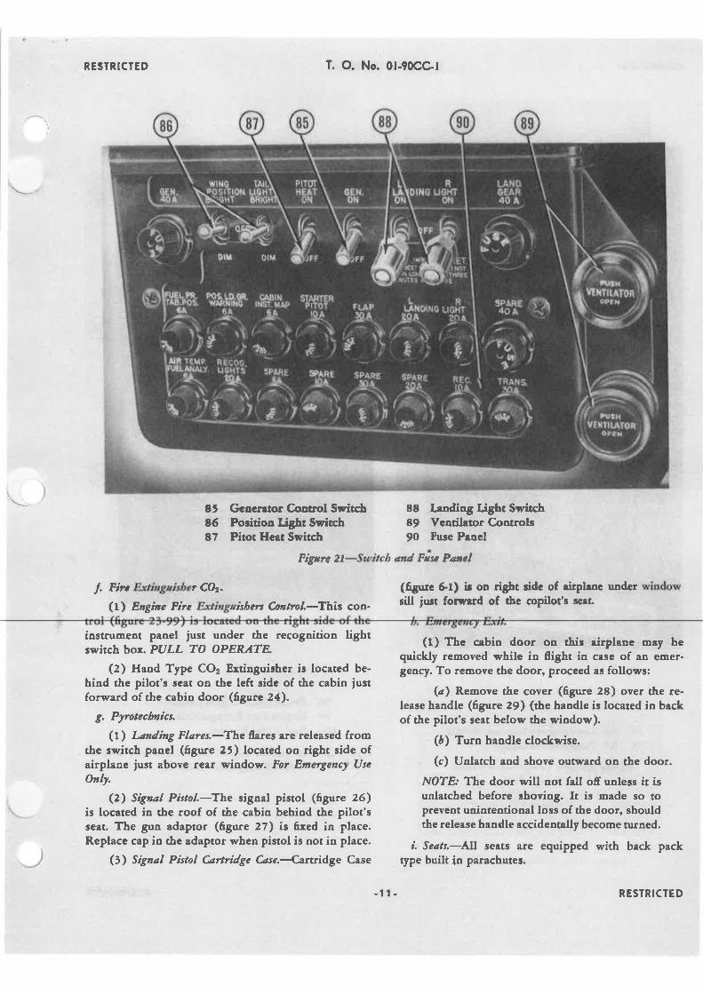
E5 Gcocn¡or C,or¡trol Svitch86 Po¡itioq tbht Swftch87 Pitot Heat Swiæh
EE kodiag Light Switch89 Vcatil¡tor C.ontrcls90 F¡.ce P¡ncl
Fígrc 2l-Suítcb end Frsc Pæel
l. Fín Ertiægrísbø CO2.
(t) Engìne Firc Ertkgzíshers C.ø*ol.{bis con-
(ñgr¡¡e 6,,l) ¡r oa dgbt ¡idc of eirplrnc uadel w¡lrdowrill just forçerd of tbc copilot's seat
iostrumeot panel iust unde¡ tbe recogoitioa lightswitch box,. PULL TO APERATE
(2) Haod Type CO2 Ertinguisher ic located be-hind the pilot's s€at oo the left side of the cabin iustforward of the cabin door (tgure 24).
g. Pyotecbzìcs,
(l) Lon¿ing Flares,-The lares a¡e released fromthe switcb panel (6gure 25) located oo right side ofairplane just above rear wiodow. For Emergency Use
OrU,
(z) SþøI Pistol.:Íhe sigoal pistol (6gure 26)is located in the roof of the cabio behiod the pilot'sseat. The guo adaptor (tgure 27) is ñ¡ed in place.Replace cap in the adaptor when pistol ir oot in place.
(3) Sìgnal Pìsþl Crrtri¿ge C,¿se,4,artidge Case
(f ) Thc cebin door on thi¡ eirplanc oey bequiclcly ¡emoved q¡hile in 0ight in case of ôo €trrer.geocy. To ¡emove the door, proceed as follows:
(ø) Remove the cover (tgu"e 28) over the re-lease handle (figure 29) (the handle is located in backof the pilot's seat below the window).
(å) Turn handle clockwise.
(c) Uolatch and shove outward on the door.
NOT& The door will not fall off ualess it isunlatched before shoving. It is nade so toprevent uoiotentional loss of the door, shouldthe release handle accidentally become tu¡ned.
í. Scøts,-llll seats are equipped with back packtype buili in parachutes.
-11- RESTRICTED

RESTRICTED
94 Âir Temperature Selector Switcb95 Air Temperature Gauge
Fígre 2ÞAír Tcmþerature Sutìtch
T. O. No. 0lr90CC-l
98 Recogaition Lights Control99 Eagine Fire Extiaguisher C,ontrol
lOO Fuel Valve Pl,acard
Fìgtrc 23-Recogaílion Lígbts Cüúnl Box aad EngincFíre Extkplsùer Cøstrols
-t t. RESTRICTED

RESÏRICTED
Fìgue z4-Hand Fìre Extingaíshcr
(t) Pìlot's øad C.øpilot's Scøß,4he Pilots' seats
are mounted on slides aad may be moved fore and aft.The release lever (tgure 30) is on the oute¡ frontcorner of each seat. It src tltat tlte seøts are secarellhcþed k place belore tahe-ofr,
i. Maþ and Detu C.eses,
(1, Ìúaþ C¿sa-The Map Case (Égure 6'1o) isloc¡ted in the c¿bin door. To uolock combination
(4') Engine Coaer.-The engine cover is stowed inthe cargo compartment.
(7) Engine Comþartment CaId Air Dact Plrys,-These plugs are for cold weather operation and whennot in use are stowed in the cargo conpr¡rtnrent.
(6) Èngìne Tool Kít,{he engine tool kit isstowed in the cargo cosrparí''eot.
(7) Brahc Bleedet Hose.4he bleeder hose usedfor brake repair and mainteaance is stowed in thecargo comp¡rrtmeût when not in use.
(8) First ÁA Kir,lhe trst aid kit is stowed iothe cargo comparune¡rt until assigned a place in thecabin by the service.
(9) Airþlane ønd Eqúpmeøt Møìntenence ltvløwøls,
-All manuals pertaining to this airplane will be foundia the cargo compartneot.
(ro) Ke¡s.-Two sets of keys are provided for thecabin door and cergo conpsrtrneot doo¡.
(CøserClosedl
T. O. No. 0l.90CC-l'
number. Roll dials to these nunber¡ ¿nd turs knob toopen. The combin¿tioo of the lock may be cbanged toaoy three digit n"mber.
(Z) Deta C*se,{he Dat¡ Ca¡e (figure 6-9) ¡s
accessible from the cabia by unsnapping tbe cover onthe back sbelf and zipping the shelf cover back.
h" Illìscellmeoas Eqaiþmcnt,
(t) Hoístíng SIìng:-T¡. hoisting sling (ñgure6-2J) is stoç,ed io the cargo comParunent.
(2) Propeller Tools.-The propeller tools are in-cased ia a bag and are stowed in the cargo com-
Partment.(3) C.abin CoId Aír Plag-The cabin cold air duct
plugs for cold weather operation are stowed ín thecargo conPartment wheo not in use.
(Coaer Open)
Figare 21-Emergency Fkre Release Panel
-13. RESTRICTED
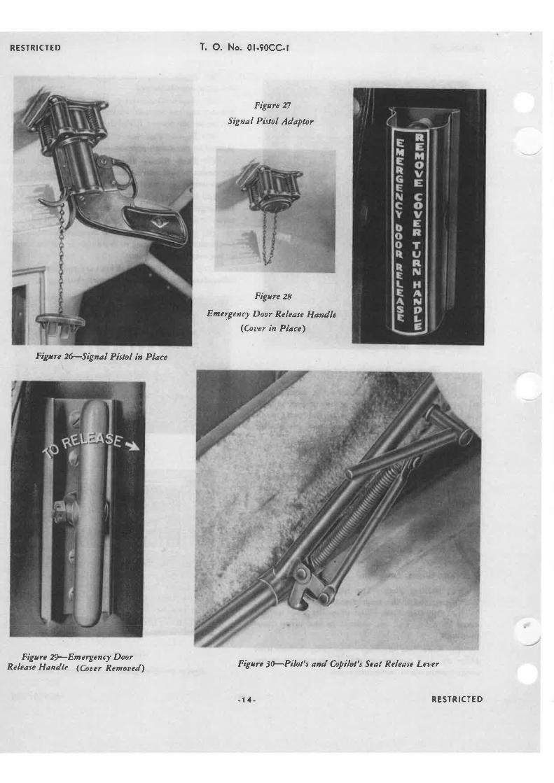
RESTRICTED
Fìgtre 2FSigneI Pìstol ì¡ PI¿ce
Figtre 2*Emergency DoorRelease Handle (Couer Remoued)
T. O. No. 0l-90CC-l
Fìgtre 27
Signøl Pistol Adaptor
Figare 28
Emergency Door Rclease Handlc(Couer ìn Pløce')
Fìgarc 3ÞPìlor's and Coþilol's Seøl Release Lercr
-t 4. RESTRICTED

RESTRICTED T. O. No. 0l-90CC-l
sEcTroN ilPILOT'S OPERATING INSÎRUCTIONS
I. FLIGHT REST'RTCTIONS.
a. Loops, rolls, spins, and inverted flying are piohi-bited.
å. Do not exceed diving speed of 24o m.p.h.
c. Do not exceed overspeed dive of 2860 r.p.m. for over30 seconds.
d, Do not exceed 22o0 r.p.m. in level flight.
e. Do not lower landing ge r above ll0 m.p.h. indi-cated air speed.
f. Do not lower wing flaps above ll0 m.p.h. indicatedair speed.
g. Do not extend landing lights above I l0 m.p.h. in-dicated air speed.
2. BEFORE ENTERING PILOT'S COMPARTMENT,
Determine the proper loading of the airplane. A load-ing chart is posted in the cabin of the airplane whichgives proper fuel loads (ûgure 3l) for various loadingconditions. Always take off and land on the main fueltanks.
SPEGIAL FUEL RÊSTRICNONS
uB€ fuSru¡c fN( Foi Î^x¡orr ilo L^þr¡a.ñLl' FUa€LlCg Î^Ll atfoRc ¡rll'r¡o rßa lllr(a,uf ni€ frNÍt 8¿¡oRt u3Ù{€ 7u¡tllct flH.F|LL tottl trto f^tt8 llFolt uDÊ¡ trro l^ñct.u8e uttcR wüoñl|¡ t€foi¡ lorEß uß0 1l¡t(8,
(3) Check warning, recognition lights, and posi-tion.lights.
(4) Check coodition of landing and signal flareequipment.
c. Check for all flights.
(l) Ignition switch-"OFF" position.
(2) Landing gear control handle-"DOtVN" posi.tion.
(3) Flap control handle-"UP" position.
(4) Parking brakes "ON."
(5) See that controls are free.
(6) Place carburetor air (Manifold Heat) controlon "COLD" position - (frgure lr-77) then possiblebackfires id starting will not damage the inductlon sys-
tem.
(7) Oil Heat Control (radiator shutter)"HOT" position for winter and "COLD" position forsummer (6gure 15-76).
(S) Oil By-pass Control (radiator by.pass) on"HOT" position forwinter and on "COLD" for sum-mer (6gure 15-71).
(9) Vacuum selector valve on engine pump.
NOTË; VALVts ON "VENTURI" FOR AUX-ILIARY VACUUM SUPPLY.
( lO) Fuel Selector Valve on "MÂIN TANK" posi-tion (ñgure l7). Upper valve on "MAIN POSITION,"lower valve on "OFF" position.
NOTË.. Upper fuel selector valve must be
* rto@ àø, Þtrø a t È¡oü
ilêGÂßF NINDq
ocouPÀilts rOIAL noiTfusæ UPPfßtt*6
ôurlH PaâacautEg
6250¡X)
ta¿0t9
Lo{tltrtff6
--*g¿ttl
ooo
at3?6
ã¡GGA6€
aaao?o
-0 ÍÈiu {.Ig
tetc¿t
_ v¡î.te
vi.€
at4aal
tIo
t?
Ilaaa
4I
Irlx mcxmÊ
tooo Îxru e.
8em,aa
vß.86t[.
tailo
a tttO TÍRU IQI
t9vÂt.
a6låi.
aavi
ilor ro
Itrffl P^R^caulE
t¿lo BlU t2t
¿cY^1.
..vl.
lroilo
{vn.
Figute 3l-Specíal Fuel Restrhtìoss
3. ON ENTERING PILOT'S COMPARTMENT.
¿. Check form lA.á. Special check for Night Flying.
(l) Check the functioning of all cabin end instru-ment ligha.
(2) Check oper¡tion of the landing ligha. Do nottest operate for more than 5 seconds.
lower vaìve can be used (figure 23-l0o).
4. STIRTING THE ENGINË.
a. Cold. Engina-With ignition switch "OFF' pullthe prop through four or 6ve revolutions by hand.
NOTEr If the engine has been idle for morethan 2 hours or if excessive priming has beenused during startiog attempts, be sure com-bustion chambe¡s are clea¡ of fluids. Difficultyin turning over is an indication of liquid lock,STARTING THE ENGINE WITH EXCES.SIVE OIL OR FUEL IN THE CYLINDERSMAY RESULT IN BENT OR BROKENRODS.
- 15- RESTRICfED

RESTRICTED T. O. No. 0l-90CC-l
å. Mixture control "ltULL RtCll" position. (See6gure 13.)
c. Throttle control about r/a ¡s l/4 inch open-equiva.lent to 6O0-8OO r.p.m.
l. Propeller control "HIGH PITCH" or low r.p.m.-full out (6gure 14-67r.
e. Operate wobble pump easily to obtaio at least 31/2
lbs. fuel pressure. Not over l0 lbs.
f. Prime engine with 7 full strokes for cold engineand 3 or 4 for warm engine.
WARNING: DO NOT OVER PRIME EN-GINE.
NOTE,' Do not pump throttle in an eftort toprime engine. Use primer to prevenr stalling.
g. Master switch "ON" (Égure 2O).
å. Generato¡ switch "ON" (6gure 2l-85).
i. Start engine by pushing starter button'(figure 15.72). Allow the engine to turn over 4 or 5 revolutionsbefore turning ignition switch "ON" (6gure 15.73').
CAUTION: If engine back6res, open throttlefull open and immediately rerurn throtle toclosed position, to prevent fire in carburetor.In cold weather, the engine will run better ifCarburetor Heat is applied until engine is turn-ing smoothly.
'. ËN6INE-WARM.UP.
¿, Check oil pressure at once, if not 20 lbs._ in 30seconds, shut ofi engine and have investigation made.
å. Warm-up at 600-800 r.p.m. after oil gauge showspre.ssu¡e, shift propeller ro low pitch, or take-ofi, posi-tion (oil pressure ar leasr 50 lbs.).
r. Ivlinimum oil temperature for l0O0 r.p.m. or over,lo4' F. (40. C.).
/. Avoid prolonged ground running. Do not exceedmaximum allowable cytinder head temperature 4B2o F.(250' c.).
e. Maxirnum oil pressure during waun-up, 9O lbs.sg. in.
f. Normal oil pressure 75 to 85 lbs.
g. Normal oil temperarure l40o to lSOo F. (@o to80' C.). Maximum l8t' F. (85" C.).
å, Fuel pressure, minimum 3 lbs. sq. in. in idlingand { lbs. sq. in. in operating.
6. ENGTNE IND ICCESSORY TEST.
a. Afrcr engine is warmed up check functioning of
each nragneto 'àt 29't Hg. manifold pressure with pro-peller in both full low and full high pitch. Maximumallowable drop on one magneto in high pitch is 75 r.p.m.
å. Check functioning of propeller by operating con-trol through its range several times, particulady in coldweather.
c. Check for generator charge on ammeter.
d. Minimum suction 3/4".
IÏ¡ARNING: MAXIMUM ALLO\ùüABLEHEAD TEMPERATURE 480" F. (2500 C.).
7. TAXYTNG,
ø. Unlock tail wheel.
á. Visibility is poor when taxying - the airplaneshould be swung from side to side to check for obstacles.
c. Use surface controls to control direction of air-plane as much as possible when taxying and avoid usingbrakes any more than absolutely necessary.
d, Use brakes with caution when taxying, parricu-latly if the airplane is lightly loaded or has no load onRear Seat.
e. DO NOT TAXY lylTH FLAPS EXTENDED.
8. TAKE-OFF.
a, Beforc turning into the wind for take-ofi, checkthe following:
(l) Fuel tank selector valve on main tank.
(2) Check for freedom of all controls.
(3) Check that pilots' sears are locked in positionon seat slide tubes.
(4) Trim tabs are in take-off position. Eleaator tabsboald be set so tbat tbe indicato¡ need.le sbops in thegleen, approximately midway berween 0 and l. Ruddertab should be trimmed for power drawn in climb. Rud-der conrol is adequate for full power.
(5) Propeller in full low pitch (forward).
(6) Mixture control full rich.
(7) Primer locked in "OFF" position.
(8) Carburetor Air (Manifold Heat) control full"COLD" (forward).
IYARNING: If icing conditions are prevalenr,blow out carburetor immediately prior to take-ofr, with conrol in full "HOT" position. Thentake-off with control in full "COLD" positionand adjust for carbu¡etor ice immediately aftertake-off.
(9) Oil by-pass valve cont¡ol closed (in).
- tó- RESTRICTED

RESTRICTED T. O. No. 0l-90CGl
( lO) Regulate oil shutter to maintain proper oiltemperaturtsminimum 104' F. (4O" C.). Maximurn oiltemperan¡re, lE5" F. (85" C.).
(11) Minimum oil pressure, 50 lbs. sq. io. Maxi-mum 90lbs. sq. in.
(12) M¡nirnum fuel pressure 4 lbs. sq. in. Maxi.mum fuel pressure 6lbs. sq. in.
å. Turn suaight down the ruoway, move forwardslightty, aod lock the tail wheel. Always lock thc tailwheel prior to take-off-move handle to right
c. Retract the landing gear ns soon as ship is in theair.
WARNING: Be sure that sufficient speed hasbeen obtained so that the airplane will aotsetde back to the ground afte¡.the laoding gearhas staned reuacting. The landing gear shouldbe retracted ru¡ soon as possible as the rate ofclimb iscreases considerably, and in event ofpower failure the glide a.'gle of the airplaneis much latter with the gear retracted.
d. Manifold pressure !7" Hg.maxi¡nu- ¡t 23OO r.p.m.Reduce th¡ottle immediately upon cleariag all obstaclesto not exceed 33.5" Hg. Then reduce propelter conEolto not exceed 220O r.p.m. Maximum allowable headtemp€ratur$, 482" F. (2t0' C.).
9. ENG¡NE FAILURE DURINC TAKE.OFF,
¿. The procedure to follow in this emergency willdepend upon the speed attitude, Ioading, suroundingterrain, and wind conditions - existing at that tirne.This airplane has some very desirable cha¡acteristicswhich the pilot may take full advantage of, by exercisinggood judgment and propet technique.
å. Pull mixture co¡trol back to the "IDLE CUT,OFF'
belly landing-little damage to airplane or passengersoccurs in a propedy executed belly landing. Io case ofdoubt in an emergency laading, keep the ubecls re-lracled, The f,aps can be used for the approach butshould be ret¡acted at the last moment to save themfrom being damaged" No falting out ç'ill be experiencedas the f,aps are lifted. The lower wings are close to thegrouod and therefore a¡e afieaed by tbe *GROUND
CUSHION" during a belly laoding. The airplane canbe belly-landed in the usual high-angte-of attack posi-tion until the tail suikes the grouad, after q,hich it willsettle forwa¡d rrithout undue shock, using the groundcushion of air to prevent slamming.
ro. cuMB,
¿. Climb the airplane at best climb speed, 9j ro loom.p.h. (82 to 87 knots). Gain attitude quickly on take-ofi so that in event of power failu¡e the eirplane willhave enough altitude so thar a suitable spot may be pickedfor a landi.g.
å, Check head temperature frequently-if over allow-able (250' C. or 482o F.) increase airspeed. Check oiland ca¡buretor air temperatures.
II. SUPERCHARGBR.
The supercharger or blower gear is built into the en-gine and no manuel conüol is provided for ic Do notexceed 33.5" Hg. manifold a¡d 22ú r.p.m. at any timeIot c<.rntinuous operation.
12. GENERAL FLYING CHARACTER¡STICS.
a, Srdbilìry,Åtability is excellent under all normalloading conditions and light maneuven¡.
(t) The rudde¡ aad elevaror trirn tabs providedare very eftective and shoutd be used to ease conuol pressu¡es at all times.
c. Turn the ignition to the 'OFF" positíon.
d, Do NOT move the wheel or control column vio-lently-let the airplane level iaelf
. out graduatly.
¿. The landing gear should remain up until the air-plane is approaching the boundary of the fietd for theernergency landing. Then, as late as possible, the wheelsshould be dropped and the usual and oormal power.ofilaoding made.
(t) Turn ofi generator and master svitch beforeerntacting ground.
f. In case of an emergency belly laoding on levelground, the ground run is from IOO to IJO feet. If youar€ not absolutely sure that the area picked to set theship down in is zuitable Í.ot a wheel landing, rnake a
to recover by iaelf, with only slight aid from the pilot.This requires le*ç efio¡r in lying the airptane and theride is actually smoothe¡.
b, Speed Range,-T\is airplane has a broad speedrange with a high cruising speed aod a low landingspeed. All controls are very efiective throughout tbe en-tire range and even through the stall.
e Use fuel from tanks in following sequence aodñll taolc in reverse of sequence given. Use upper wingtanks first, then lower wing tanks, and fuselage ønklast. Make all ratce.ofts and landings or lying at lowaltitudes on fuselage or (main) tank.
d. SØhen switching to another fuel tank, be carefulto stop valve on "CLICK." SØatch fuel pressure indi-
-17- RESTRICTED

RESTRICTED
cator and be ready to use wobble pump if fuel Pressuredoes not build up to 4 lbs. immediately.
e. Maximum cruising economy will be obtained withmixtures set at .08o, with manifold pressure f¡om 25"
to 28" Hg. and propeller adjusted between l8OO to 2O0O
r.p.m. All maximum Power oPerations should be done
with mixtures set at .100. Head temPerature should be
checked constantly, 450' F. (232" C, for continuous
oPeration).
f. Under icing conditions use just enough carburetor(manifold) heat to prevent icing in order to maintain
constant manifold Pressure for level flight'
g. Glidíng.-The airplane has an unusually flat glid-ing angle. It is approximately l5 to I with the wheels
in a retract position, at an indicated air speed of toom.P.h.
b. Clinb Without Pouter.
(l) Another factor of safety for pilots who must
ffy at a low altitude, is that the airplane will climb about
4OO to 5OO feet without power at cruising speeds' Inorder to check this performance, the altimeter should
be noted and the airplane flown at normal cruisingspeed. The throttle can then be closed and the mixturecontrol pulled all the way back, and simultaneously' the
wheel should be pulled back steadily until the airplanereaches an angle of attack of about 45". [t should be
held in this position until it ¡eaches the top of its climband thc conÚol forces lighten, then the wheel can be
eased and the ship allowed to stal¡ by itself with a con-
sequent dropping of the nose. As the stall occurs' the
altitude should be noted on the altimete¡ The amount
that is gaincd rvill be from 400 to 500 feot, thus in case
a power failurc occurs at a low altitude the pilot can pullthe airplanc up from 4o0 to 5o0 feét to allow time todiscover the bcst available landing area.
(2) tf a turn is not required, with 5oo ft. altitudeand no wind, a landing can be made I mile ahead ofthe position. If a tu¡n is required, landing can be made
approximately t/t mile to each side or t/n mile behind.
The ship should be kept in a practically stalled posi'tion in order not to use too much radius of turn (noallowance made for wind). Practice in stalled turns inthis airptane will show that there is little or no danger
in them. However, if the airplane is loaded with a fulltail-heavy loading, with baggage and people in therear, it should be given a little mo¡e consideration than
whcn it is loaded only in the front seats.
13. ËNGTNE FAILURE DURTNG FLIGHT,
a, The nose will not drop much below the horizonif restrained by pulling back on the wheel. If the engine
failure occurs at low altitude a climb without power of{00 to 5Oo feet will aftord an oPPoltunity to pick a suit'able place to land. (Refer to No. ll b. of this section.)
å. Tu¡n the ignition switch "OFF'."
r. 'Iurn fuel selector valve "OÞ'F."
d. Propeller control in full high pitch.
e. Generator switch "OFF."
f. lf a suitable landing 6eld is available, glide to a
normal power-ofi landing. If not, keep tbe landing geør
in tbe retract position and make a belly landing.
g. Turn Master Switch "OFF," before contactingground.
14. STALIS.
a, There is no tendency to fall ofi into a spin froma stall. Little control is required to keep the airplanein a stable position.
å. It is suggested that pilots who fly this airplanefamiliarize themselves with the stall characteristics ofthe airplane. They should try a gradually approachedstall at a comfortable altitude and they will ñnd thatfull lateral control is retained at all times and that theycan actually fly the airplane in a stall without losingcontrol of the airplane. In a gradually approached stallwith thc power oft (as would be the case in making an
approa.'h for landing), a speed will be reached at whichthe lower wing'will stall without pennitting the upperwing to stall. The lower wing being forward, negative
stagger, the nose of the airplane will drop a fcw degrees
until the lower wing "unstalls" and rcsumes its lift. Atthis point the nose will again rise and the cycle will be
repeated with a sort of forward and aft rocking motionwhile the lower wing stalls and then regains its lift.Considerable buffeting of a harmless type will occur dur-ing such a stall. In the meantime, the upper wing is com.
pletely "unstalled" and inasmuch as the ailerons arc
placed on the upper wing, full lateral control can bc
eftected. Gradual turns can be made to the right and leftwith power ofi and the wheel all the way back duringthe operation of stalling and "unstalling" the lowerwing.
( t ) The above procedure should be tried withwheels up and wheels down, flaps up and flaps down,power on and powe¡ off, and combinations of all these
conditions should be experienced as well as unstalledparrial-power flight at low speeds of from 55 to 6o
m.p.h. to demonstrate the excellent con$ol character-istics at low speeds.
c. Stalling Speeds.
\ùüheels and flaps up-throttle back to throttle stop,
T. O. No. 0l-90CC-l
- 18 - RESTRICTED
RESTRICTED T. O. No. 0l-90CC-l
50 m.p.h.
\ùíheels down and flaps uppower off, 55 m.p.h.
\flheels down and flaps down-power ofr,55 m.p.h.
Slheels and flaps up-power on, 50 m.p.h.
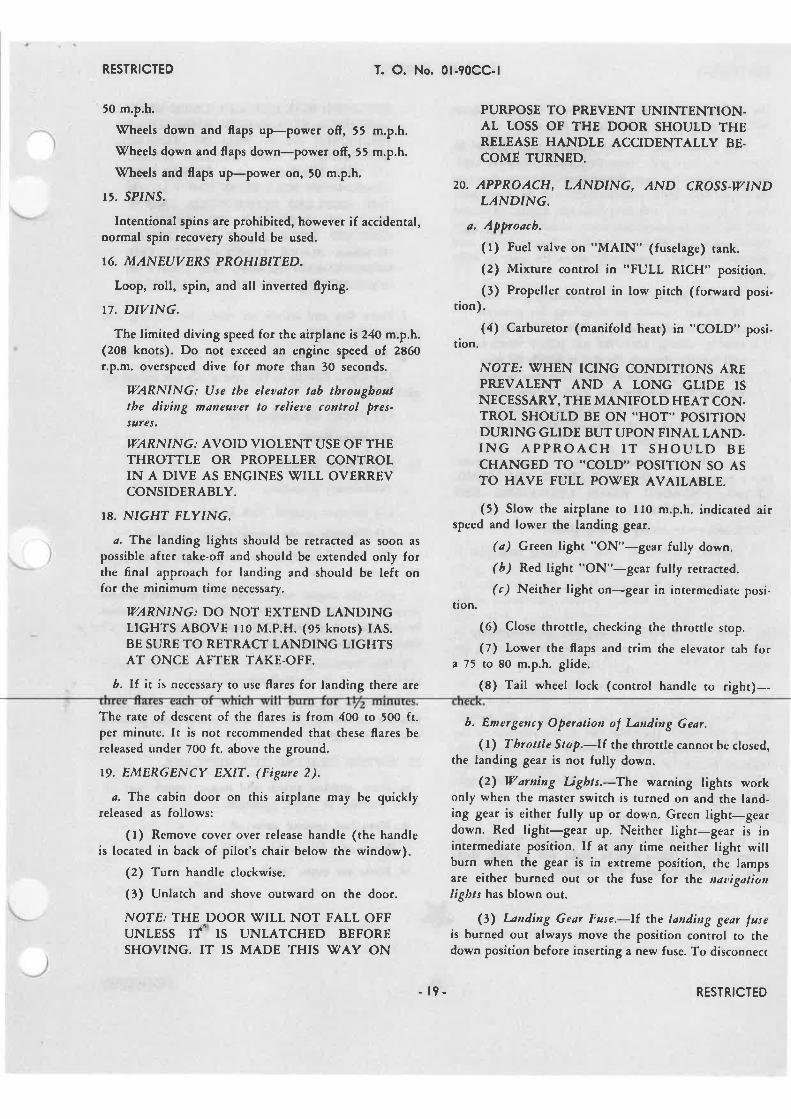
15. SP¡NS.
Intentional spins are prohibited, however if accidental,norrnal spin recovery should be used.
16. MAN EUVERS PROHIBIT ED.
Loop, roll, spin, and all inverted flying.
17. DIVING.
The limited diving speed for the airplane is 24o m.p.h.(208 knots). Do not exceed an engine speed of 2860r.p.m. overspeed dive for more than 30 seconds.
IVARNING: Use the eleaatot tab tbrougboattbe diaing maneutel to relìette control þres-s4fes.
IVARNING:.{VOID VIOLENT USE OF THETHROTTLE OR PROPELLER CONTROLIN A DIVE AS ENGINES WILL OVERREVCONSIDERABLY.
18. NIGHT FLYTNG.
a, The landing lights should be retracted as soon as
possible after take-off and should be extended only forthe final approach for landing and should be left onfor the minimum time necessary.
WARNING: DO NOT EXTEND LANDINGIIGHTS ABOVE I l0 M.P.H. (95 knots) IAS.BE SURE TO RETRACT LANDING LIGHTSAT ONCE A}-TER TAKE.OFF.
b. lf it is necessary to use flares for landing rhere are
PURPOSE TO PREVENT UNINTENTION.AL TOSS OF THE DOOR SHOULD THERELEASE HANDLE ACCID¡NTALLY BE.COME TURNED.
20. APPROACH, LÅND|NG, IND CROSS.IZTND¿.,dNDTNG.
a, Appoach.
(l) Fuel valve on "MAIN" (fuselage) tank.
(2) Mixture control in "FULL RICH" position.
(3) Propeller control in low pitch (forward posi-tion).
(4) Carburetor (manifold heat) in "COLD" posi.tion.
NOIE; \ü(/HEN ICING CONDITTONS AREPREVALENT Ä,ND A LONG GLIDE ISNECESSARY, THE MANIFOLD HEAT CON.TROL SHOULD BE ON "HOT'' POSITIONDURING GLIDE BUT UPON FINAL LAND.ING APPROACH IT SHOULD BECHANGED TO "COLD" POSITION SO ASTO HAVE FULL PO\ùíER AVAIL^ABLI.
(5) Slow the airplane to llo m.p.h. indicated airspeed and lower the landing gear.
(a) Green light "ON"-gear fully down.
(b) R.ed light "ON"-gear fulty retracted.
(c) Neither light on-gear in intermediate posi.tion.
(6) Close throttle, checking the throttle stop.
(7) Lower the flaps and mim the elevator tab fora 15 ¡o 80 m.p.h. glide.
(8) Tail wheel lock (control handle to right)-
The rate of descent of the flares is from 4O0 to 5OO ft.per minute. It is not recornmended that these flares bereleased under 7O0 ft. above the ground,
19. EMERGENCY EXIT. (Figure 2).
¿. The cabin door on this airplane may be quicklyreleased as follows:
(r) Remove cover ove¡ release handle (the handleis located in back of pilot's chair below the window).
(2) Turn handle clockwise.
(3) Unlatch and shove outward on the door.
NOTE: THE DOOR \IILL NOT FALL OFFUNLESS IT, IS UNL,{TCHED BEFORESHOVING. IT IS MADE THIS \ù7AY ON
b. Emergercy Operutìon ol l-anding Gear,
(l) 7'hrottle Stop,-IÍ the throttle cannor be closed,the landing gear is not fully down.
(21 Warning Ughts.-The warning lights workonly when the master switch is turned on and the land-ing gear is eirher fully up or down. Green light-geardown. Red light-gear up. Neither tight-gear is inintermediate position. If at any time neither light willburn when the gear is in extreme position, the lampsare either burned out or the fuse for the tatigøti¿tttligbts has blown out.
()) Landing Gear Fuse.-lf the landhtg gear luseis burned out always move the position control to thedown position before inserting a new fuse. To disconnect
- t9- RESTRICTED

RESTRICTED T. O. No. 0l-90CGl
the landing gear circuit, remove the 40 amp fuse. Sparefuses are ca¡ried in a holder in the fuse panel.
(4\ Hand.nanh. - The landing gear should belowered by hand only when the electric circuit to land-ing gear motor has been disconnected (remove fuse) orthe motor fails. Move position cont¡ol to the down posì-
tion, Engage crank and turn clockwise (about 44 turns)until the gear is completely down. Green warning lightshould come on, clicking sound no longer heard, andthrottle will close completely when the gear is fullydown.
NOIÈ¡ The position of the landing ge Ì maybe checked visually by observing the positionof slide on the slide tube. The slide may beseen by rolling down the left pilot's windowand looking through the slot in which the win-dow moves. The slide and slide tube may be seen
through this window slot. Perfo¡rn this visualcheck on the ground before f,ying the airplaneand note the position of the slide when the gearis completely down.
(a) Pull handcrank toward the center of the air-plane to eogage - DO NOT LEAVE THE HAND-CRÄNK ENGAGED WHEN OPERATING THEGEAR ELECTRICALLY.
c. Avoid over cooling in long glides.
d. I-anding Technique. -.As a landing technique itis recommended that the airplane be trimmed to glidear a speed of 70 to 8o m.p.h. during the approach. Thelanding can be made without further adiustment of theelevator tab, although a reasonable control force willbe necessary to prevent the airplane from climbing inthe event that power is applied. Make contact with theground in "three point" position.
(t) It is common practice for some pilots to at-tempt to land the airplane at high speed. In a highspeed landiog the smallest rise or bump in the runwaysurface will throw the front end of the airplane in theair and the airplane will fly again with considerable en-
thusiasm because of the fact that the excess speed is cap.able of producing a lift of two to th¡ee times the weightof the airplane.
e. C¡oss-Vínd Landíngs,
(r) Cross-wind landings may easily be made atrecommended gliding speeds. Take out all side driftbefore contacting whecls with runway.
NOTE; DO NOT ATTEMPT CROSS-IüíINDLÂNDINGS AT A FÁ,STER SPEED THANNECESSARY AS IT $TILL BE ALMOSTIMPOSSIBLE TO KEEP THE TAII WHEELON THE GROUND. AS Â RTSULT THECROSS.IT/IND VILL BLO\ü/ THE TAIL OFTHE AIRPLANE DOWN-IüT/IND AND IT\üíILL BE DIFFTCULT TO AVOID ,TGROUND LOOP AFTER THE FRONTSTHEELS HAVE CONTACTED THEGROUND AND DURING THE TTME THEAIRPL.ANE IS LOSTNG ITS EXCESS SPEED.
f. Raise flap and unlock tail wheel for taxying. Usebrakes with caution.
g. Emergency tahe-off ìf landìng not completed,
(1) Open throttle to full power. Do not exceed en.gine limis.
(2) Retract the landing gear.
(3) Raise flaps.
21, STOPPING ENGTNE.
a, Prelimínary ptocedarc,
(r) Mixture control "Full Rich."
(2) Throttle to the normal idling position.
(3) Run the propeller in "high pitch" back posr-tion of prop control.
({) Idle engine until cylinder head temperatur€sdrop below 302' F. (150" C.). The r.p.m. should thenbe increased to between l0O0 and ll00 r.p.m. fo¡ 15
seconds to assure scavenging of the c¡ankcase oil.
å. The following procedure wilt be followed uponcompletion of the preliminary procedure.
(t) IdIe engine at 8fi) ro lü)0 r.p.m. and placemixture control in "Idle Cut-Ofr," or full lean positionto stop the engine.
22, BEFORE LEAVING THE AIRPL/INE.
a, Place ignition switch and master switch and allother switches in "OFF' position.
å. Turn fuel selector valve ofi.
c. Make sure that parking brake is on.
d. Make out Form "14."
+20- RESTRICTED

RESTRICTED T. O. No. 0l-90CC-l
sEcltoN iltFLIGHT OPERATION DATA
I. FIJGHT P¿.áNNING.
The following outline may be used as a guide to assistpersonnel in the use of the FLIGHT OPER TION IN.SïRUCTION CHART for flight planning purposes.
¿, If the light plan calls for a conrinuous flight wherethe desired cruising power and air speed are reasonablyconstant after take.ofi and climb to 50(D feet, the fuelrequired and flight time may be computed as a "singlesection flight."
( I ) rtíithin the limits of the airplane, the fuel re-quired and flying time for a given mission depend largelyupon the speed desired. tùlith all other factors rernainingequal in an airplane, speed is obtained at a sacritce ofrange, and range is obtained at a sacriñce of speed. Thespeed is usually determined after considering the urgencyof the light ploaed against the range required. The timeof take-oft is adjusted so as to have the dight arrive atits destination at the pre-determined time.
(2) Select the FLIGHT OPERr{,TION INSTRUC-TION CHART for the gross weight to be used ar take.off. Locate the largest figure entered under gph (gal-lons per hour) in colus¡n I on the lower half of thechart. Muttiply this 6gure by the number and/or fuac-tion of hours desired for reserve fuel. Add the resulting6gure to the number of gallons set forth in footnoteNo. 2, and subtract the total from the amount of fuelin the airplane prior to starting the engine. The Águreobtained as a result of this computation will representthe amount of gasoline available and applicable forflight planning purposes on rhe RANGE IN AIRMILES section of the FLIGHT OPERATION IN-
miles (with no wind) to be flown. Operating valuescontained in the colurnn number in which this figureappears, represent the highest cruising speed possibleat the range desired; however, the airplane may be oper.ated in accordance with values contained under OPER-ATTNG DATÁ, in any column of a higher number withthe flight plan being completed ar a saciÉce of speedbut at an increase in fuel economy.
(4) Using the same column nurnber selected byapplication of insuuctions conrained in the last para.graph, determine the indicated air speed (in m.p.h. orknots, whichever is applicable to the calibration of in-struments ia the airplane) and gallons per hour listedat sea level in the lower section of the chart unde¡ thesubtitle OPERATING DATA. Divide this "IAS" intothe ai¡ miles to be flown and obtain the calculated flightdu¡ation in minutes, whicb can then be converted intohours and minutes and deducted from the desired ar.rival time at destination in orde¡ to obtain the take-ofi time (without consideration for wind). To allow forwind correction, calculate a new corrected Ground Speedwith the aid of a flight calculato¡ or by a navigator'striangle of velocities.
(5) The airplane and engine operating valueslisted below OPERATING DATA in any single num-bered column are calculated to give constant miles pergallon at
^ny altitude listed. Therefore, the airplane
rnay be operated ^t ^ny
altitude and at the correspond-ing set of values given so long as they are in the samecolumn listing the range desired.
CAUTION: Ranges listed in column I under
(3) Select a figure in the fuel column equal to, orthe next entry less than, the available amount of fuelin the airplane as determined in paragraph t. d, (z')above. Move horizontally to the right or left and selecta 6gure equal to, ot the next entry greater than, the air
altitudes given above the ranges, and the engineand airplane operating data listed underOPER TTING D^Tå, will give constant milesper gallon if operation is consistent with valuesset opposite the listed altitudes.
-2t - RESTRICTED

?
-
AIRPLANE MODETS
.N.B.{Y.V.-c_1p
.t{êYY..9.9.:.?.
SPECIFIC E]IG¡]IEFTIGIIT CIIARÎ
ENGINE 'IAODELS
.Wâ.Ee . . Jß'. .E.:99.9.:.4.N.-- 9. .
f .9!N9.!.q.. g?.tF.p . q!${gF)
,urAx. pGRmrss¡8¡.E DMNG RPlt. . . 3gç9conomor¡ AItOW^¡1f, Oll Od'.sutt7noil
r,lÄL CONÍ. 9r 9. . .u.s.orzxr. .9...3. . .rvrP.PflHR
MAX. CRUISE 1..9. . . u.s.orzHr . . ?.-f . . u,tP.PrlHn
iltN. sPÉctHc U.S.QTIHI. . .-. . .ltllP.PflHR
SUPCTCHANGR TYPE: RJE! GIADE: OCTA}¡E (SPEC. AN-VV- F-776)
m nmumDUtAno¡trniluftst
5
5
IEMAIKS: AVOID OVERSPEED O|VE OF 2860 R. P. M. FOR OVER 30 SEC.
m^inmu¡lcn. rEilP.
.F
500
500
500
500
450
450
450
260
260
260
260
232
232
232
R'H. ROÙI'|GÆ/Hrlå{G.r
tn?.
4t
4r
32
32
2t
t8
17.
u.s.
49
49
39
39
25
22
2t
MilruTEcoñnotPOSlrtON
FULLRICHFULLRICHFULLRICHFULLR¡CH
o85
o80
o80
usE touvItowRtÊtott:
1û
=o6
cnmcAr ÆrruoE
NO l^rn
2000
?ooo
4500
4500
8300
7200
8700
cootArttEt?.
'Íc
ot!rEt¿
F
t¿to-r67
r85
r40
'c60-75
85
60
HOTSE-FOWA
450
450
400
400
300
270
24o
olltt:trul¡
0¡l5o. rNJ
70-9090
50to
,$ANIFOTD¡rESSUrErioosn
37
37
33
33
28
28
26
¡uEttrl3sulE
ltl/30. rx.,
5
6
4
2
rPÀT
2300
2300
220o
2?oo,
2000
r800
r700
OPRAÍINGCONDMON
TAKEOFf
WARËMENGENCI
I'IIUTARY
,SANMUMCOIìITINUOUS
,vlAin¡rurvrCRUISE
illNtr$urrisPÉCIHC
col{sulrPnoñr
cot'tolÍoùt
DCSITED
ilAXt¡tu¡t¡IINI'YIUâA
IDUNG
octtf2'-<ogH
Сnv,FñIrt(,
Ioz9
II.octc)I
I
l\,¡\¡I
ÐIrtv,
2ôI'l(,

RESTRICTED T. O. No. 0l-90CGl
Htr¡l
ooçt0nlD
88l¡)(\¡ E Egç
ootrtoÞIrI N I
tút f\lóo
Ë
taa It 8Ron
ooloor.l N
8 gRfiO nf¡$i
Ë
3I !t
oootDtoC\lal(\¡
á
II ¿/ e
6rôÈqd
tlj jr OL¡ag!l
ooTOsfo
ooOtt:ú)N
o: 8P8Þc(\
ool\O!9Ir
II
c)rO¡looo
lD(\l
Ë
ttIt
oorrú)Þt
oo-G¡t lô¡
o ooco totscro rt(l|c tt
È úì lflFÞ
Ë
Iñã¡9l G¡G¡
ooÀl
oo
I
tÉ
¡I¡ I !r (Dçoo!f
3888gDçr'lo:
ooctoorlÞll$
þoo(ltlolott
Inrotld
tlÞG|(\l
a]IÐ-¡9¡aea
Io-
úìaIa þ
oooSflc't\c,l¡rlGlûIo ooGo oÞ]iO f|ôl-
J
!I i
c{ olÞo ol(\¡{út
ËaI lrtl
oot'O-ODo¡-
t!j oolgH úì lrls8#It
ggBR oo(\l
888oç(\
aü
oq þ
oooolootÈ
ESç(\l
út r\ôt-lott
Ë
3
ItooooNoçtooctrl(\l P 8gR
Þ clr}Ñ l'lDÞt\ l-(ot\È
j¡g
lËrloott fl3:¡I
¡ ¡ oÞoo olo(Do!loûô¡
ooooooÀr1\ç
oor'úl1(l1
e?þ
ooOGIooI .\|-
=SGl¡\gor
Ë
t-Ir
ç,oO r.t|otÌteql(\¡ 8e8E
ro ç(u -
¿
!t ¿
jro útric N|o
G¡ -i
j5
ta #gloo-Í)!!
{¡II €Àfg fct tD
dEl¡il88o¡Þ
8RrtN
ooo cegtÍ
ItooG|rôOl-eS
oF-tÈ
ONÞNÞ{t
I:Ða¡aÐ
cot ú
ìat
Iroo-o(oto
oorDo¡N-
oocl c@ fsiD r¡úr líDGl - ê
I o o! or-OÈl lbf\
-ìa-t
!loo|ql ú),ft st
aË
oooo
¿I¡ ¡ oro
o|oloo)oo
oooooooEo¡Þl'(\lt!rl
P(\¡
8$RgoflI |oN
¡t ai -ortñ ItooolrlO(D
¿á
ll,gtgo;
Þfo'(D
Ë
IIr
e888(Dú)|ftN P89Fl\çlr,ôI
¿
II
E
ta!r
ooloûçÞt!j
qql' rlt
@oitot
U, f,¿¡äãe*2åÊp.r¡¡ 6
4
Taü
TËtTII¡tÊIIIF
¡-g?¡,
zÞa^-â55o
I¡tT
þ
ti¡z
a
r¡:coIc
tC
o
ìaãa Ë lc
oooQoooî oooooç(o ft
tI
Þt)att¡oolrt(\¡
rII!,È
tIt
hg
Þôa:JI
oooGI
IIoGI
a
t
IÉ
o
IIr-I
tIIt}IT
I
¡¡cÐFC¡lGt¡¡Þg.¡¡¡¡¡Cl!
ltaoro(,IIäa{l!aotIt
¡¡JÞt-o:?,r'JJÐl}
ËEÞör3¡¡lsiu,-[;.26Þ¡aa.('iz9-
EAázo<Þ-l¡¡3ãoo
aI
óaâ
I3otIfI,rtËJ
rtIriI;áT
t
ii,ld{ IT.i
! iI
a¿Joo25BoIù¡t
(Ð
=CÐoI
=¡rlg)
r¡CÐt-TI-
T
Ia.
l¡ IIÈ
f)I ¡r r)GloÞOotols
taIr
8e88(oltcrl - ¡s¡Ooo
ooooo¡ß|¡ot -(o!'ÂlGI
È
e,Ç I!gtootl,9g
I5
¿J
I ¡ l¡)(\lglo' s8ltrlooooÕ9r-N¡¡Þrl N
t!j O(\lcl q;
r¡c)$¡td Ir
ooll)ol\O
tÈ 5g 8ENÚI
I:-Ð-ôaa
l|IT
Irc)ooo; C,roooratsl-
ooocOçol.l-¡-ç G
c(aoooÞ()ro
o(o(\l
Írooo -oO1\
¡ìt
ãrglootDo(\¡-
¡ r!13 ¡!ll .il3
IÉ
oooJ'
I¿
¿J
¡ ¡ roGlo¡o|
Þooro¡ E
or\('!oIIoI- I ¡!li o!li .il: is
EI ¡ etü!a t
1' l¡ l¡
v,J¡¡lô9+
rl,t¡¡ =
3¡4
tF ¡a
Cll
åa
-
c¡t-ilr
Tli¡!iâ¡i3atI3
II2dt!Ë?
¡ltoo(\lç
ooort
ú
l!aoGI
üt!t9ûãFT-õ7Ê
t
rI
l.lna
t
ooNG¡
II-!ttã 3li
o6olrt
ooo'.)
!to
l¡
3À
C¡¿os2(tÞ2rD2oo2
-{t¡¡o2 ¡¡1
ootoo(\¡ort to
LÞCaac,
aIf¡!
Ilr(¡Ë0'
l¡¡¡¡g'
TË¡'
)
RESTRICTED-23 -

EXTERNAL LOAD ITEMSNONE
¡atllUcnOrat tOf U3ilO CllAll¡ S¡bct ß¡o ia frrl colru oqool loc ho llna fold ffif ol lwl ir oiy'oæ. llwr hciufo! fo flr rigtrla bS od rdæl o G9m tqúol þ r ,rúfr $oi ltrr oi nile¡ to brfim, Vdiæt btlor oid ogpodtr dnird wiring olli{udr reod oprim wirhg cædilftn XOfllr lAf Avcit otixn @¡r¡.l¡ h C.fni I
crcry' in ffigæt. ll Coln lll, lll, lV f ï loçcd tho rigfrt progcdvrty givr im ia rogr ol tærißo ii rpe.d. Pl Xú¡h¡d ÈüÍr.flrl.P.I Golæ )c ]lqr lGl,H.[ æ oppruinotr mirul vclû f.tnfürc. lDl Fq ç¡¿ ¡rlnrcr. fob<,í ord miFlory ¡æ doto æ ßrfrdir lfir rppr lJt æ ol cficf.
oro y'¡aot ArlllxAlt clutStxc coilDtTtoxS 0'þ r¡tllvt ¡Utl, AIIOWAI{CO
v rrll. r xeltlat3t r¡
^tt ¡ttttx^rmcal
783 67S
88U
80653r
ì156* *
38030u
59ìl529u80
38832S
27U
227t5275
r97IJ¿
85
o?rr^?rxc oAta
t¡.t.¡.7.r-
r.t. u,aG?.lt.
Il,t.I. ft
i
lzoI 700I 700
r38l t20 ta
2Uru0 122 t9
t 700r 700I 700
tu0 t22 252827
I I7
6
tu0 t22r\0 t22
Statutt
tuuu.3.Glß
l2lr03
008070
co60u0
3020t0ongÍt
^!Lr¡ 'ltf
3æm2t000
2000
tã000t2009000
ó000
3000
s. L.
|lr tvlatal rr atl ¡trat ¡atôt t¡ art rtlt¡
JtArult ta^Ullci¡t ¡tarufa llauncat IIATUT¡ NAUÎICAI
I8 U.S
709
LLONS NOT ¡ ItAEt-E ß7tl8
I GHT
ô\B6t\
6r9550u8¡
538u7Bl¡r9
652580506
6875 cl¡Il3 !
ut33uu27tt
358298238
u353722S0
3783rU252
r88r2862
2CEr3888
179
r20ño
2t1lu572
otlr^Ttxc D^Îa o?ll^ltxG D^t^ ottl^Ît¡6 D^1^
t.À5. rt.a.3.l r.?.t.t.x. ¡rct3 lx. ll3
t.a.s. i u.?.rcr: lt¡. ¡¡
II
l.?.x. r.À3. I r.tt.m¡
x.?.li. Èt
ï:.,r{t.xl: jrun
u.t,c.
H-
Iu.t,o.).x.TU
200020002000
ru8t5Etå8
127 ?2 25LEAil!36?\.5 25,18¡tI u5 P7 25,LEAlt
t8501 t38 I t8t850i tu7 t281850 r57 r3e
2t |23 t.Etl¡
3U ,22,24.5 22-25.5TI'2000
20002000
r65r65t'lìt
rurl P7 23 LEA¡|
rr¡u 27. 5 22 LElrlr 850 r58
t58I srt
t37t35l3ll
21 '20I )t3 2t r85 5 rg
;ucHr o?Elttlox1. . .
txttluclfor clttrl3I:¡f. . -
4 250${¡:t5
ol. wT.. 3800 70u¡Dttx.
a.t.r.
R98ã-AN-3
I
MODELuc- 43: ö:H _:e
u.l.e.r.t.
5l5t
!¡ nd!I¡.
5
6
tûllu.13*¡rer
t@
008070
0000tt0
302Ato
on!ÌtatLra ilÛ
30000
25m2mt6000ræo9000
ô000
3ms-L
t[fttro¡llrd
F. R.
F. R.
I lrtl con. ¡orm¡ta¡a¡ rr ^r¡
rrtt¡xauilcar
at I t.ffi
58U
5t0u5u398
3u0283227
r0u7035
I
r70il3
r uñt
t.t. aaorrtt.l..t ¡olmil
37
37
at 3.1.
360
3tu?782ull
2r0t83r3g
tl
230(
230(
Í^rullal rt,m
672
3ð032028t
588522lt58
2u220 I
r60
392aÒA
28 I
r98r30AE
emfrc
t¡cdtanrtYtofl
TE
AI 3.L
utu
t2t8tu0
,lIt
ÐrrvtÐã,rt(7
I
]\t¡
:{Izo
C'
.oooo
IIaIID
Ðtrtatt
7ÃIrt0
li) t¡arc¡no e¡.t¡ruo¡
þ lr* 18 u.cortGcfto rcr Ft¡f Ar¡ tt¡ttt^lull.3. OAIS..= . - rrr. GALI. fC[ w^l¡ ur.¡s 9. 000 ¡¡¡1 ¡¡1¡¡r,¡¡
lot! lllllll!: U¡o ^rtrltct
FU L L R I CH: . f00LEAH:.080
Anx n O 9tlo Xoftr: U¡ l¡t¡t¡¡or* aba¡ tæry lin orll
r,¡.t: lô¿¡c.b¿ A¡r SF¿¡.t.: x.n¡lol¿ Pr.sÞ f 16. HglU 3.G.1.t.: U. 5. €¡llo¡¡ P¡¡ Hourtxt -G.r.H.: lÃF.i.l G.lloil P.. Hoútt.r-, Fsll ¡IÉtd.¡.r.: 5o¡ L¡vol
F.R.: ÊULL RICX
t^rl;ort ^xo
cu¡ttEtul¡ fl,eL Êows toUf¡ FU¡r ¡tO¡ t^r.ts rN txa ¡OtIOwrxG ltPPFn uIl,lc_ r lìuFe ¡flxrì Fr AGE
m lo -',tcnc mx Rrofi tun- toa ^lotftoi
¡ t€aL o?utroaa ¡lr^.
ttD Ícuñt¡ At¡ rtsJ¡t a¡yi t¡¡.1Êct yo r¡vE¡(f, aãn '(¡crÎ
cxtcf

RESÏRICTED T. O. No. 0l-90CGl
SECTION IYCOMMUNICATIONS EOUIPMENT
L, GENERÅL DESCRIPT¡ON.
a, The radio installation consists of a Model RC-loCB Receiver, MN20C Loop ,{ntenna and ModelTA-64 Transmitter set equipped with a range 6lter,microphone, telegraph key and headphones.
b. Receíaer,-The receiver is calibrated and adiustedto receive the Radio Range frequencies as shown inthe following tabulation.BandL..15O.- 400.KCSBand 2 .4oo.-11oo. KCSBand 3 2.- 5. MCSBand 4 5.- lo. MCS
No provisions are made for other frequencies to bereceived with this installation.
c, Transmirte¿-The transmider will operate on anyfrequency between 2.8 to f 2.O MCS that the radiotechnician sets it ro, and for which crystals are pro-vided. It is capable of t¡aosrnitting voice or straightC$l sigoals. The effective range of the transmitrer fordependable voice ransmission is approximately 25miles.
d, Interpbon¿-There is no interphone system usedin the communication equipmeot of this airplaoe.
2. OPER.âT ING INSTRUC?|IONS.
a. Receioe¡,
(l) Turn the OFF-VOLUME switch clockwise(6gure 32- 1Ot ). Plug headphones in plug receptacle onbottom of rernote control unit, and turn the OFF-VOLUME control knob to the right until a frying
(3) Turn the C.\ü7.-M.V.C.-A.V.C. switch (ñgure32-lO7)to the desired position. C.\ü1. positioo ôperaresthe beat frequency oscillator for reception ofcoatiauouswave signals, M.V.C. position permits control of re.ceiver sensitivity, aod .{,.V.C, position permits controlof audio output aod the receiver sensitivity is atmaximum.
(4) Adjust VOTUME conrrol for the desiredsignal level.
(:) The switch marked XTAL OFF AND XTALON (tgure 32-f 08), performs no funcion in the com-muoicatioos system on this airplane.
NOT& !øHEN TUNING RECEIVER FORA DEFTNITE TREQUENCY, ÂLSTAYSTURN DIAL Á, LITTLE TO EACH SIDEOF THE FREQUENCY CALIBRATTONMARK TO FIND THE POTNT TTHERETHE SIGNAL IS STRONGEST. THIS PRO.CEDURE IS TO BE FOLLOTTED WHENRECEIVER SELECTOR SITITCH IS ONM.V.C.(6) Aoti-Rain.Static recepdoo.
(a) Operate on C.Sg. or M.V.C. as desired.
(å) Snap the ANTenna-Loop switch (frgare 32-1O9) on the azimuth control to loop.
(c) Tune in station.
(/) Rotate the azimuth control for maximumoutput of headset.
(e) If station is to the left or right of the air-plane's course it will occasionally be necessary to
(2) Select the desired frequency range (Band t,2, 3, or 4) on frequency switch (6gure ,2-tO6),
CAUTION: FOR ALL NORMAL (VOICEoR RANGE) RECEPTTON, THE R.C.A.RANGE FILTER SELECTOR S\TøITCH (FIG.URE 9-62) SHOUTD BE SET TO ,,BOTH."TO RECETVE THE RADrO RANGE (MC\ùø)\ÙTITH LESS POSSIBILITY OF VOICEINTERFERENCE, SET THE SELECTORS!øITCH TO "RANGE.'' TO RECEIVEVOICE VITH LESS POSSIBILITY OFRANGE INTERFERENCE SET THESELECTOR S!/ITCH TO "TELEPHONE."rT rs PossrBLE To REcErvE vorcE (rNTHE BACKGROUND) TTHEN THESETECTOR SVITCH IS SET ON "RA,NGE.''
signal.
(/) Adjust VOLUME conrrol for the desiredsignal lane.
(7) For Radio-Range Reception.NOTE: FOR RADTO RANGE RECEPTIONIT IS NECESSARY TO HAVE EITHER AMAP SHO!øING THE RADIO RANGECOURSE AND CHARACTERISTIC OR TOKNO\tr THE LOCATION OF THE COURSEAND ITS CHARACTERISTIC A AND NSIGNAT AREAS.
(a) Snap the ANTenna-Loop switch (figure 32-l09) on the Azimuth control to ANT.
(å) Turn the plane so as ro intercept the radiorange course. The A and N signals will blend into a
.95- RESTRICIED
RESTRICTED T. O. No. 0l-90CC.l
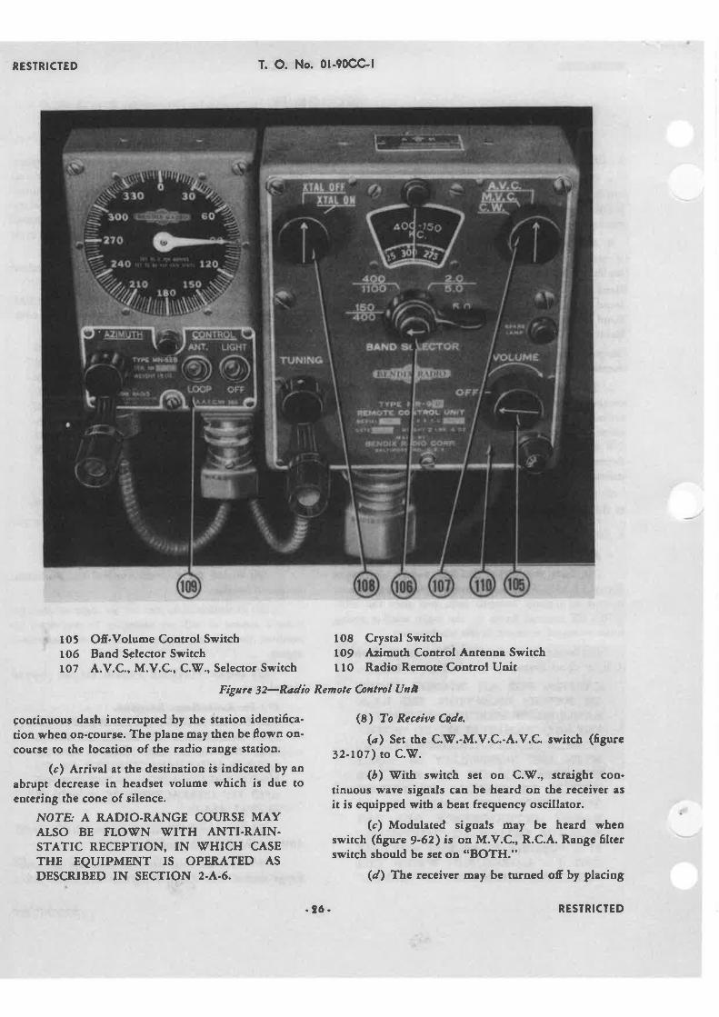
Ofr-Volume Control Switch 1o8 Crystal SwitchBaod Selector Switch ro9 Azimuth Coatrol Aateooa SwitchA.V.C., M.V.C., C.!l'., Selector Switch 110 R¿dio Remote Control Unit
Pígarc 32-R¿dìo Renote Coøtml Unù
rotr06l07
çontinuous dash interrupted by the station identifica-tioa when on-course. The plane may then be florro on'courie to the locatioo of the radio range station.
(c) Ârrival at the destinatioo is iadicated by ao
abrupt decrease in headset volume which is due toeotering the cone of ¡ilence.
NOTE. A RADIO-RANGE COURSE MAYALSO BE FLOITN STITH ANTI.RAIN.STATIC RECEPTION, IN VHICH CASETHE EQUIPMENT IS OPER¡,TID ASDESCRIBED IN SECTION 2.4.6.
(8) To Receíae C.qde.
(a) Set the C.!V.-M.V.C.-A.V.C. ss'itch (6gure32-ro7) to C.!1.
(å) Vith switch set on C.V., straight con-tinuous wave signals cen be heard on the receiver as
it is equipped with a beat frequencl oscillator.
(c) Modulated signals may be heard whenswitch (ñgure 9-62) is on M.V.C., R.C.A. Range 6lterswitch should be set on "BOTH."
(d) The receiveî mey bc tu¡oed off by placing
-?6 - RESTRICTED

RESÏRICTED
l12 Remote Cootrol Frequency SwitchI 13 C.!f., Phone Selector Switch
Fìgtre 3 3-Transm ìtter Remote Contro I
the "OFF-VOLUME" control in its "OFF" position,but do not turo off transmitter switch (figure ,3-ll2)as it would take approximately Êve minutes before thetubes would be warm enough to transmit.
b, Trønsmitrer,
(l) Micropbone Instractions,
(a) Hønd Microþbone. (Figare 34-115). - Placemicrophone in either hand, holding the insrument inan upright positioo, close to or even touching the lips.By pressing the round button on uPper side of micro'
phone, voice will be transmitted through the instru-ment.
(2\ Transmìttìng Etiqaette.-Before traosmitting,adiust radio receiver to the same frequency as the sta-tion you desire talking to and "listen in" to be sure theoperator is not talking to someone else. If the stationis transmining, take advantage of the opponunity tomore accurately set the airplaoe receiver on theassigoed frequency, and when the other operator isthrough proceed with your transmission.
(3) Voíce Tratsmissiøn.
(a) Set traosmitter remote control unit switch(figure 33-lL3) to "PHONE."
T. O. No. 0l-90CC-l
f
O-*û
-r
Fnro. 2
e@
"ecw /æ
l(IY MICRPHONg
FRSa! r
E@
115 Hand Microphone116 Transmitter Key
Figare 34-Transmitter Key
Fìgare 35-Radío Headphrtnes
(å) Vhen the selector switch (ûgure 3 3- 1 I 2 ) isset to "FREQ. I or 2" p¡ess the microphone button andwait for the antenna ammeter (ñgure 18-82 ) to come toa full stop, about one-third of its swing. Start talking,and speak slowly, distinctly, and in a normal tone ofvoice. Shouting will seriously distort the voice signal.
G) Code Transmìssíot.
(ø) Set transmitter remote conrol unit switch(figure 33-LL3, to "CV."
(å) Rotate the channel selector switch (ûgure33-Ll2) to the desired channel.
(c) Intelligence may now be conveyed bymanipulation of the telegraph key (figure 34-l16).
-97 - RESTRICTED

RESTRICTED
3. OPERATION NOTES FOR PILOT,
a, U*øble to Receìae,
(t) ,{scenain tbat receiver "OFF-VOLUME," ison.
(2) Asccrtain tbat .{.V.C., M.V.C., o¡ C.V. is inproper position and ma&ing a good contacL lestreceiver operetion on baod k¡own to be in use.
(3 ) Systematically check fo¡ s€cure connecdonsio all cable¡ and wires aboutthe ¡adio controls startingwith head-phones (tgure 35) and endiog et the ¡e-ceive¡ cost¡ot uait (ñgure 32-r10).
(4) Cbeck all switches and dials for proper set-
tings to be sure thar all are making good electricalconoection and are oot set somewhere berweenpositioar.
(!) Turn volume co¡trol througb its entire rangeto test for aa intermittent short circuit on cone iso-lated pocition when receiver is inoperativc.
(6) Check fuse and matre sure it is tight in holde¡.
b, Unøble þ Trassmì¡
(1) Check proper pocítioa of sç'itches.
(2) €heck if microphone or key iacks are in aadsecure.
(3) Cbeck fuse aod aake sure it is tight in bolder.
T. O. No. 0l-90CC-l
-ã
-98- RESTRICTED

RESTRICTED T. O. No. 0l-90CC-l
2. Gyro Horizon.1. Turn lndicato¡{. Baok and Turn lndicator5. Altimete¡(¡. Ratc of Climb Indicator7. Fuel P¡essure rVarning Li¡ht8. Mixture Conrolg. Throtrle
10. Compassll. Propeller Control12. rVing Flap Switch1.1. Landing Gear Position Lights14. Tachomerer19. Cylinder Temperature16. Clock17. Manifold Pressurc Gage
19. FueI/Ai¡ Ratio Gage20. Suction Gagc21, Ait Tcmpcraturc Gagc22. Ait Temperature Sclecto¡ Switch23. Recognition Lights Cont¡ol B<¡x
24, Fire Extinguisher Control25. Fuel Tank Selecto¡ Switch26. Radio Remote Control Uni¡27. Radio Azimuth Control Unit28. Ammete¡29. Copitot'r Rudder Pedals
.10. Map Light Switch
.11. Carbu¡etor Heater C¡rntr<¡l
12. Oil Heate¡ Control.1.1. Ventilator Control.14. Vcn¡ila¡o¡ Cont¡ol
Figare )6-Pilot's Instrumeil Pauel
-29 '
.ì(r. Engioe Primer Pump
.17. Starter Button
.18. Ignition Switch
.I9. Fuse and Switch Panel{0. Oil Bypass Control41. Cabin Heater C<¡nt¡ol42. Qrwl Flap Conrol4.ì. Landing Gear Operating C<¡ntrol44, Tail rVheel Lock Control{5. Pilot's Rudder Pedals46. R.C.A. Range Filter Selecr<¡r Swi¡ch47. Radi¡¡ Transnrirter Remo¡e Conrrtrl48, Fuel Gage Selecror Swirch{9. Fuel Gage5t). flevator Tab Rrsition ¡ndicatorJl. Radio Frequency Arnmete¡
RESTRICTED

RESTRICTED T. O. No. 0l-90CC-l
APPENDIT ¡
U.S.A._BRIÎISH GIOSSAR' OF NOMENCLATURE
u.s.A. BRITISH
Pressure reservoir.{erial.{ccumulatorRadio track beaconApproach beamPlain connecting rodTest after overhaulBomb-aimerRing spannerGas volumeSetscrewCloud heightNon-return valveCbord lineFork iointFlying conuolsMotor generator (4.C. or D.C.)Second pilotSplit pinEarthenware iarJack (hydrautic)Drift angleInterconnecting sleeve or trousers
Jettison valveTail unitEgressCheese headed screwÂir cleanerCountersunk head screwInstrument flying(to) F¡etPetrolAlighting gearRunning-inAll up weightEarth.Artiñcial horizonAutomatic pilotCourseParaffinlüØrist pin^A,lightlüØeak
PortMooring guySpring washerLoop aerialBoost
AccurnulatorAntennaBattery, storageBeacon, radio rangeBeam,landingBlade connecting rodBlock testBombardier or bomberBox-end wrenchCapacit¡ nominal gasCap screwCeilingCheck valve (hydraulic)ChordClevisCootrolsConverterCopilotCotter piaCrockCylinderDriftDuct, ai¡Dump valveEmpennageExitFillister screwFilter, airFlathead screwFlying blindGallGasoiine (gas)Gear landingGreen runGross weightGroundGyro horizonGyro pilotHeadingKeroseneKnuckle pinLandLeanLeftLine rnooringLock washerLoop, radioManifold pressure
-30- RESIRICTED

-RESÏRICÏED
Mast, radioMeter, driftMeter, frequencyOil panPadPalnutPanel, center wing, center of inboard panelPanel, outboardPilotPin, pistonReticuleRÍghtScreenSetscrewShipSlushing compoundSocket wrenchSpannerSpeed, indicated air (I.A.S.)Stabilizer-horizontalStabilizer-verticalStackStrut, oleoTachometerTagTest clubI ubeValveIleight emptySØindshield
T. Q. No. 0l-90CC.l
APPEXDIX I
u.g.A.-¡ntflsH GtoggAnt oF xoltENcLATUßE
u.s.Â. BRITISH
Rod aerialDrift sight\ùØavemeter
Crankcase sumpAccessory mounting face
!.ock nutCentre section planeOuter PlaneSpigotGudgeon pinGraticuleStarboardFilterGrub screwÂircraftCorrosion inhíbitorBox spannerC-spanner,A,ir-speed indicator readingTailplaneFinPipe (single)Compression legEngine speed indicatorLabelTest fanValveCockTareIØindscreen
)-3t- RESTRICTED

Copyright © 2022 FDOKUMEN